MM 447 503 582 D00370 D00288
User Manual: D00370
Open the PDF directly: View PDF ![]() .
.
Page Count: 60
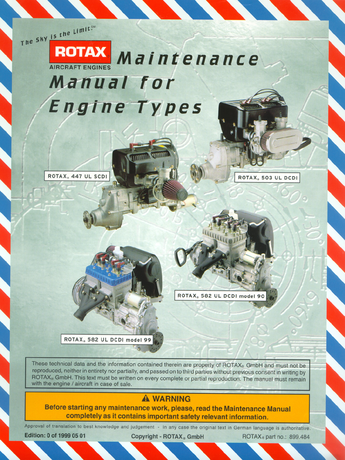

MAINTENANCE MANUAL
AIRCRAFT ENGINES
page 1 - 2
Initial issue, May 01/99
Effectivity: 447 UL SCDI, 503 UL DCDI, 582 UL DCDI /mod. 99
d00288
1) Table of contents ...................................................................................................... 2
2) Index ......................................................................................................................2 - 1
3) List of the current pages .....................................................................................3 - 1
4) Table of amendments ..........................................................................................4 - 1
5) Introduction ..........................................................................................................5 - 1
5.1) Remarks ............................................................................................................. 5 - 2
5.2) Engine serial number.......................................................................................... 5 - 2
6) Safety .................................................................................................................... 6 - 1
6.1) Repeating symbols............................................................................................. 6 - 1
6.2) Safety information .............................................................................................. 6 - 1
6.3) General operating and safety instructions .......................................................... 6 - 3
7) Technical documentation ....................................................................................7 - 1
7.1) Use for intended purpose ................................................................................... 7 - 1
7.2) Instruction .......................................................................................................... 7 - 1
8) General..................................................................................................................8 - 1
8.1) Description ......................................................................................................... 8 - 1
8.2) Technical data .................................................................................................... 8 - 1
8.2.1) 447 UL SCDI ..................................................................................... 8 - 1
8.2.2) 503 UL DCDI ..................................................................................... 8 - 3
8.2.3) 582 UL DCDI and 582 UL DCDI mod.99 ............................................ 8 - 5
8.3) Components ....................................................................................................... 8 - 8
8.3.1) 447 UL SCDI ..................................................................................... 8 - 8
8.3.2) 503 UL DCDI ..................................................................................... 8 - 9
8.3.3) 582 UL DCDI ................................................................................... 8 - 10
9) Maintenance..........................................................................................................9 - 1
9.1) General proceeding instructions ......................................................................... 9 - 1
9.2) Trouble shooting ................................................................................................. 9 - 1
9.3) Basic information ............................................................................................... 9 - 2
9.4) Auxiliary tools .................................................................................................... 9 - 2
9.5) Measuring tools .................................................................................................. 9 - 2
9.6) Special tools and devices .................................................................................. 9 - 3
9.7) Consumable materials ........................................................................................ 9 - 3
9.7.1) Two stroke oil .................................................................................... 9 - 3
9.7.2) Lithium grease .................................................................................. 9 - 3
9.7.3) Multi-purpose grease LZ.................................................................... 9 - 3
9.7.4) Corrosion inhibiting oil MOBILARMA 524 .......................................... 9 - 3
9.7.5) Grease MOLYKOTE G-N ................................................................... 9 - 3
9.7.6) LOCTITE Anti-Seize 76710 ............................................................... 9 - 3
9.7.7) SILASTIC.......................................................................................... 9 - 3
9.7.8) LOCTITE "574 orange" ..................................................................... 9 - 4
9.7.9) LOCTITE "648 green" ....................................................................... 9 - 4
9.7.10) LOCTITE "221 violet"........................................................................ 9 - 4
9.7.11) MICRONORM shot blasting abrasive ................................................ 9 - 4
9.7.12) Lapping fleece SR 4600 A - very fine grading ................................... 9 - 4

Effectivity: 447 UL SCDI, 503 UL DCDI, 582 UL DCDI /mod. 99
MAINTENANCE MANUAL
AIRCRAFT ENGINES
page 1 - 3
Initial issue, May 01/99
d00288
9.7.13) Cleaning agents ................................................................................ 9 - 5
9.8) Securing elements ............................................................................................. 9 - 5
9.8.1) Safety wiring ..................................................................................... 9 - 5
9.8.2) Nut securing...................................................................................... 9 - 7
9.10) Treatment of corrosion and surface damages..................................................... 9 - 8
9.11) Engine preservation and engine back to operation ............................................. 9 - 8
10) Maintenance Checks..........................................................................................10 - 1
10.1) Periodical maintenance .................................................................................... 10 - 1
10.2) Maintenance Schedule ..................................................................................... 10 - 2
11) Maintenance of the various systems: ..............................................................11 - 1
11.1) Ground test ...................................................................................................... 11 - 1
11.2) Level check of liquids....................................................................................... 11 - 1
11.3) Retorque cylinder head nuts (only on 447 UL SCDI and 503 UL DCDI) ............ 11 - 2
11.4) Retorque of exhaust manifold screws: ............................................................. 11 - 2
11.5) Checking of the rewind starter rope.................................................................. 11 - 2
11.5.1) Rewind starter dismantling:............................................................. 11 - 3
11.5.2) Rewind starter reassembly: ............................................................ 11 - 3
11.6) Check electric starter gear ............................................................................... 11 - 3
11.7) Inspection of spark plugs ................................................................................. 11 - 3
11.8) Replacement of spark plugs............................................................................. 11 - 4
11.9) Check of the ignition system............................................................................ 11 - 5
11.10) Check and clean inside of spark plug connectors ............................................ 11 - 5
11.11) Checking of V - belt tension (only on fan cooled 441 and 503 engines) ............ 11 - 6
11.12) Lubricate Ball joints .......................................................................................... 11 - 6
11.13) Replace exhaust muffler springs ...................................................................... 11 - 6
11.14) Lubricate control cables ................................................................................... 11 - 7
11.15) Check propeller balance and tracking ............................................................... 11 - 7
11.16) Inspect propeller mounting bolts ...................................................................... 11 - 7
11.17) Clean and oil air filter........................................................................................ 11 - 7
11.17.1) Application of new air filters: ........................................................... 11 - 7
11.17.2) Cleaning of used air filters: ............................................................. 11 - 8
11.18) Check and replacement of fuel filter ................................................................. 11 - 8
11.19) Clean carburetors and check for wear .............................................................. 11 - 8
11.20) Replace jet needle and needle jet..................................................................... 11 - 9
11.21) Clean and check fuel pump.............................................................................. 11 - 9
11.22) Check gearbox oil level, replace gearbox oil .................................................... 11 - 9
11.23) Checking and adjusting of gearbox, preload of springs (B- type gearbox) .......11 - 10
11.24) Renewing of the rotary valve lubrication oil (582 UL DCDI /mod. 99 only) .......11 - 11
11.25) Inspection of the cylinder head and piston crown ............................................11 - 11
11.26) Inspection of the piston rings ..........................................................................11 - 11
11.27) Check piston diameter ....................................................................................11 - 12
11.28) Piston ring, checking of gap and axial play .....................................................11 - 13
11.29) Checking of cylinder diameter and roundness .................................................11 - 14
11.30) Replace cylinder head-, cylinder base- and exhaust gaskets ..........................11 - 15
11.31) Inspect pins and bearings ...............................................................................11 - 15
11.31.1) Piston pin: .....................................................................................11 - 15
11.31.2) Piston pin bearing: .........................................................................11 - 15
11.33) General overhaul of the engine........................................................................ 11 - 16
11.32) Inspect crankshaft and replace outer seals.....................................................11 - 16

MAINTENANCE MANUAL
AIRCRAFT ENGINES
page 1 - 4
Initial issue, May 01/99
Effectivity: 447 UL SCDI, 503 UL DCDI, 582 UL DCDI /mod. 99
d00288
12) Required inspections after limits of operation have been exceeded: ..........12 - 1
12.1) Exceeding of max. permissible engine speed .................................................. 12 - 1
12.2) Exceeding of max. permissible cylinder head temperature............................... 12 - 1
12.3) Exceeding of max. permissible exhaust gas temperature ................................ 12 - 2
12.4) Fuel pressure below specified value................................................................. 12 - 2
13) ROTAX® Authorized Distributors .....................................................................13 - 1

Effectivity: 447 UL SCDI, 503 UL DCDI, 582 UL DCDI /mod. 99
MAINTENANCE MANUAL
AIRCRAFT ENGINES
page 2 - 1
Initial issue, May 01/99
d00368
A
Air filter 11 - 7
Auxiliary tools 9 - 2
B
Ball joints 11 - 6
Basic information 9 - 2
Bearings 11 - 15
C
Carburetors 11 - 8
Cleaning agents 9 - 5
Components 8 - 8
Consumable materials 9 - 3
Crankshaft 11 - 16
Current pages 3 - 1
Cylinder diameter and round-
ness 11 - 14
Cylinder head and piston crown
11 - 11
Cylinder head nuts 11 - 2
Cylinder head temperature 12 -
1
D
Documentation 7 - 1
E
Electric starter gear 11 - 3
Electric system 9 - 7
Engine speed 12 - 1
Exhaust gas temperature 12 -
1
Exhaust manifold screws 11 -
2
Exhaust muffler springs 11 - 6
F
Fuel filter 11 - 8
Fuel pressure 12 - 1
Fuel pump 11 - 9
G
Gasket 11 - 15
Gearbox 11 - 9
General 8 - 1
General overhaul of the engine
11 - 16
Grease 9 - 3
Ground test 11 - 1
I
Ignition system 11 - 5
Index 2 - 1
Introduction 5 - 1
J
Jet 11 - 9
L
Lapping fleece 9 - 4
Level check of liquids 11 - 1
Limits of operation 12 - 1
Lithium grease 9 - 3
LOCTITE 9 - 3
M
Maintenance 9 - 1
Maintenance Checks 10 - 1
Maintenance of the varions
systems 11 - 1, 12 - 1
Maintenance Schedule 10 - 2
Measuring tools 9 - 2
MOLYKOTE 9 - 3
Multimeter 9 - 2
N
Needle jet 11 - 9
Nut securing 9 - 6
O
Oil control cables 11 - 7
Operating-hours-related checks
10 - 1
Oscilloscope 9 - 2
P
Periodical maintenance 10 - 1
Pins 11 - 15
Piston diameter 11 - 12
Piston rings 11 - 11
Propeller balance and tracking
11 - 7
Propeller mounting bolts 11 - 7
Propeller shaft 9 - 7
PU adhesive 9 - 3
R
Retorque cylinder head nuts 11
- 2
Retorque of exhaust manifold
screws 11 - 2
Rewind starter rope 11 - 3
Rotary valve lubrication 11 - 11
ROTAX® Authorized Distributors
13 - 1
2) Index

MAINTENANCE MANUAL
AIRCRAFT ENGINES
page 2 - 2
Initial issue, May 01/99
Effectivity: 447 UL SCDI, 503 UL DCDI, 582 UL DCDI /mod. 99
d00368
S
Safety 6 - 1
Safety information 6 - 1
Safety instructions 6 - 3
Safety wiring 9 - 5
Seasonal checks 10 - 1
Securing elements 9 - 5
SILASTIC 9 - 3
Spark plug connectors 11 - 5
Spark plugs 11 - 3, 11 - 4
Special tools and devices 9 - 3
Stroboscope 9 - 2
T
Table of amendments 4 - 1
Table of contents 1 - 2
Technical data 8 - 1
Technical documentation 7 - 1
Trouble shooting 9 - 1
Two stroke oil 9 - 3
U
Used air filters 11 - 8
V
V - belt tension 11 - 6
Vernier callipers 9 - 2
Effectivity: 447 UL SCDI, 503 UL DCDI, 582 UL DCDI /mod. 99
MAINTENANCE MANUAL
AIRCRAFT ENGINES
page 3 - 1
Initial issue, May 01/99
d00369
3) List of the current pages
section page date section page date
1 1 - 1 99 05 01
1 - 2 99 05 01
1 - 3 99 05 01
1 - 4 99 05 01
2 2 - 1 99 05 01
2 - 2 99 05 01
3 3 - 1 99 05 01
3 - 2 99 05 01
4 4 - 1 99 05 01
4 - 2 99 05 01
5 5 - 1 99 05 01
5 - 2 99 05 01
6 6 - 1 99 05 01
6 - 2 99 05 01
6 - 3 99 05 01
6 - 4 99 05 01
7 7 - 1 99 05 01
7 - 2 99 05 01
8 8 - 1 99 05 01
8 - 2 99 05 01
8 - 3 99 05 01
8 - 4 99 05 01
8 - 5 99 05 01
8 - 6 99 05 01
8 - 7 99 05 01
8 - 8 99 05 01
8 - 9 99 05 01
8 - 10 99 05 01
9 9 - 1 99 05 01
9 - 2 99 05 01
9 - 3 99 05 01
9 - 4 99 05 01
9 - 5 99 05 01
9 - 6 99 05 01
9 - 7 99 05 01
9 - 8 99 05 01
10 10 - 1 99 05 01
10 - 2 99 05 01
11 11 - 1 99 05 01
11 - 2 99 05 01
11 - 3 99 05 01
11 - 4 99 05 01
11 - 5 99 05 01
11 - 6 99 05 01
11 - 7 99 05 01
11 - 8 99 05 01
11 - 9 99 05 01
11 - 10 99 05 01
11 - 11 99 05 01
11 - 12 99 05 01
11 - 13 99 05 01
11 - 14 99 05 01
11 - 15 99 05 01
11 - 16 99 05 01
12 12 - 1 99 05 01
12 - 2 99 05 01
13 13 - 1 99 05 01
13 - 2 99 05 01
13 - 3 99 05 01
02773
MAINTENANCE MANUAL
AIRCRAFT ENGINES
page 3 - 2
Initial issue, May 01/99
Effectivity: 447 UL SCDI, 503 UL DCDI, 582 UL DCDI /mod. 99
d00369
section page date section page date
02773
Effectivity: 447 UL SCDI, 503 UL DCDI, 582 UL DCDI /mod. 99
MAINTENANCE MANUAL
AIRCRAFT ENGINES
page 4 - 1
Initial issue, May 01/99
d00370
0 1 ÷ 13 all 99 05 01 not required 99 05 01 AA/HeC
4) Table of amendments
date remark for date of date
no. section page of approval approval from of signature
change authorities issue
02774

MAINTENANCE MANUAL
AIRCRAFT ENGINES
page 4 - 2
Initial issue, May 01/99
Effectivity: 447 UL SCDI, 503 UL DCDI, 582 UL DCDI /mod. 99
d00370
date remark for date of date
no. section page of approval approval from of signature
change authorities issue
02773

Effectivity: 447 UL SCDI, 503 UL DCDI, 582 UL DCDI /mod. 99
MAINTENANCE MANUAL
AIRCRAFT ENGINES
page 5 - 1
Initial issue, May 01/99
d00371
5) Introduction
Thank you for using a ROTAX® aircraft engine.
Before carrying out maintenance work on the engine, carefully read the Maintenance Manual.
It provides you basic information on safe operation of the engine.
If any passages of the Manual are not understood or in case of any questions, please, contact
an authorized Distribution- or Service Centers for ROTAX® aircraft engines.

MAINTENANCE MANUAL
AIRCRAFT ENGINES
page 5 - 2
Initial issue, May 01/99
Effectivity: 447 UL SCDI, 503 UL DCDI, 582 UL DCDI /mod. 99
d00371
5.1) Remarks
The purpose of this Manual is to familierize the maintenance staff approved by the
local aviation authorities with some basic maintenance and safety information.
For competent maintenance and servicing, please, refer to the documentation
provided in the Operator's Manual, Installation Manual and Illustrated Parts Catalog.
For additional engine-, maintenance- and parts information you may also contact the
nearest ROTAX® aircraft engine distribution partner.
5.2) Engine serial number
On all enquiries or spare parts orders, always indicate the engine serial number, as
the manufacturer makes product improvement modification to the engine. The engine
serial number is located on the top of the crankcase, magneto side or the ignition
cover (see fig. 001, 002, 003).

Effectivity: 447 UL SCDI, 503 UL DCDI, 582 UL DCDI /mod. 99
MAINTENANCE MANUAL
AIRCRAFT ENGINES
page 6 - 1
Initial issue, May 01/99
d00372
6) Safety
Although the mere reading of such an instruction does not eliminate a hazard, the understand-
ing and application of the information will promote correct use.
The information and components-/system descriptions contained in this Maintenance
Manual are correct at the time of publication. ROTAX®, however, maintains a policy of
continuous improvement of its products without imposing upon itself any obligation to install
them on its products previously manufactured.
ROTAX® reserves the right at any time to discontinue or change specifications, designs,
features, models or equipment without incurring obligation.
The illustrations in this Maintenance Manual show the typical construction. They may not
represent in full detail or the exact shape of the parts which have the same or similar function.
Specifications are given in the SI metric system with the USA equivalent in brackets.
Where
precise accuracy is not required, some conversions are rounded off for easier use.
6.1) Repeating symbols
This Manual uses the following symbols to emphasize particular information. These
indications are important and must be respected.
▲ WARNING: Identifies an instruction which, if not followed, may cause
serious injury including the possibility of death.
■ ATTENTION: Denotes an instruction which, if not followed, may severely
damage the engine or other component.
◆ NOTE: Indicates supplementary information which may be needed to
fully complete or understand an instruction.
6.2) Safety information
▲ WARNING: This engine, by its design, is subject to sudden stoppage! Engine
stoppage can result in forced landings, no power landings or crash
landings. Such crash landings can lead to serious injury or death.
▲ WARNING: Never fly the aircraft equipped with this engine at locations, air-
speeds, altitudes, of other circumstances from which a successful
no-power landing cannot be made, after sudden engine stoppage.
Aircraft equipped with this engine must only fly in DAYLIGHT VFR
conditions.
▲ WARNING: This is not a certificated aircraft engine. It has not received any
safety or durability testing, and conforms to no aircraft standards.
It is for use in experimental, uncertificated aircraft and vehicles only
in which an engine failure will not compromise safety.
User assumes all risk of use, and acknowledges by his use that he
knows this engine is subject to sudden stoppage.

MAINTENANCE MANUAL
AIRCRAFT ENGINES
page 6 - 2
Initial issue, May 01/99
Effectivity: 447 UL SCDI, 503 UL DCDI, 582 UL DCDI /mod. 99
d00372
☞It should be clearly understood that the choice, selection and use
of this
particular
engine on any aircraft is at the sole discretion and responsibility of the aircraft
manufacturer, assembler and owner/user.
☞Due to the varying designs, equipment and types of aircraft, ROTAX® makes no
warranty or representation on the suitability of its engine’s use on any particular
aircraft. Further, ROTAX® makes no warranty or representation of this engine’s
suitability with any other part, component or system which may be selected by
the aircraft manufacturer, assembler or user for aircraft application.
☞You should be aware that any engine may seize or stall at any time. This could
lead to a crash landing and possible severe injury or death. For this reason we
recommend strict compliance to the maintenance, operation and any additional
information which may be given to you by your dealer.
☞Select and use proper aircraft instrumentation. This instrumentation is not
included in the ROTAX® engine package. Only approved instrumentation can be
installed.
☞Unless in a run-up area, never run the engine with the propeller turning while on
the ground. Do not operate engine if bystanders are close.
☞To prevent unauthorized use, never leave the aircraft unattended with the engine
running.
☞Keep an engine log and respect engine and aircraft maintenance schedules.
Keep the engine in top operating condition at all times. Do not operate any aircraft
which is not properly maintained or has engine operating irregularities which have
not been corrected.
☞Keep an engine log and enter any unusual engine behaviour. Do not fly unless you
have corrected a given problem and recorded the remedy in the log.
☞Since special tools and equipment may be required, engine servicing should only
be performed by an authorized ROTAX® engine dealer or a qualified trained
mechanic approved by the local airworthiness authority.
☞To eliminate possible injury or damage, ensure that any loose equipment or tools
are properly secured before starting the engine.
☞Never leave your aircraft or other vehicle unattended while the engine is running.
If operated by someone else you could be sued even if the use was unauthor-
ized by you.
☞When in storage protect the engine and fuel system from contamination and
exposure.
☞Never operate the engine and gearbox without sufficient quantities of lubricating
oil.
☞Periodically verify level of coolant on 582 UL DCDI and 582 UL DCDI mod. 99.
☞Never exceed maximum rated rpm. and allow the engine to cool at idle for several
minutes before turning off the engine.

Effectivity: 447 UL SCDI, 503 UL DCDI, 582 UL DCDI /mod. 99
MAINTENANCE MANUAL
AIRCRAFT ENGINES
page 6 - 3
Initial issue, May 01/99
d00372
☞Operating the engine at high rpm. at low throttle position, for example during
descent, may increase engine and exhaust temperatures and cause critical
overheating. Always compensate and match rpm. with throttle position.
☞Maintain your engine in top condition and assume it's going to quit running at any
time. Leave yourself a way out in the event of unexpected failure.
☞Never mix fuel in an enclosed area, or where fumes could reach the ignition point.
☞Make sure all engine controls are operative, that you know ON and OFF positions
of throttle and ignition, that they are easily accessible, and that you can operate
them instinctively without hesitation.
☞Never refuel if fuel could be spilled on hot engine components. Use only safety
approved fuel containers and never transport fuel in an unsafe manner.
☞Check engine suspension frequently as well as the drive components, fuel lines,
wiring, and fuel and air filters.
☞Check for fuel contamination, air vents, etc. Protect engine while not in use from
any contamination entering fuel or carburetion system, but be sure to remove
storage protection before starting the engine.
6.3) General operating and safety instructions
☞Please, observe besides the instructions in our documentation also the generally
valid safety- and accident preventive prescriptions and legal regulations as well
as the relevant regulations by the competent aeronautical authorities.
☞The information contained in the Maintenance Manual is based on data and
experience and is considered to be applicable for a professional technician under
normal working conditions. The instructions given in the Maintenance Manual are
useful and necessary supplements to personal instruction, but can by no means
substitute theoretical and practical personal instruction.
☞The manufacturer or supplier has no influence on the personnel and operational
conditions of the buyer and assumes no responsibility for sustaining effect of the
personal instructions.
☞ We point to the fact that spare parts and accessories not supplied as genuine
ROTAX® parts are not tested and therefore not released by ROTAX®. Installation
and/or use of such products may change and negatively affect the constructive
properties of the engine. For damages due to use of non-genuine parts and
accessories ROTAX® refuses any liability.
☞Unauthorized modifications and use of components or accessories not corre-
sponding with the installation instructions exclude any liability of the manufac-
turer.
☞The engine is accurately tested before delivery, this however does not exclude
hazards in case of incompetent handling.
☞Before taking the engine into operation, make yourself familiar with the respective
controls and their function. Searching during operation is too late! In case of
vibrations or unusual noise, stop the engine and remedy the cause.

MAINTENANCE MANUAL
AIRCRAFT ENGINES
page 6 - 4
Initial issue, May 01/99
Effectivity: 447 UL SCDI, 503 UL DCDI, 582 UL DCDI /mod. 99
d00372
☞Attention when draining hot oil: Danger of scalds!
☞Disposal of used oil, fuels and filters as per local regulations.
☞Liquids emerged (fuel or acids) can penetrate the skin and cause bad caustic
injury. In case of accident immediately consult a doctor as bad infections may be
engendered.
☞Cleaning the engine with lye or alkaline solutions is forbidden, as a matter of
principle. Use of a high pressure cleaner may cause engine failures and rust
formation.
☞When working on the electric system and on the engine, first detach the cable of
the minus-pole and then of the plus-pole of the battery! When connecting the
cables, first connect the plus- and then the minus-pole.
☞Firmly attach the engine removed from the aircraft on an assembly trestle.
☞Do not let the engine run in a closed room (poisoning hazard)!
☞Always observe the engine while running from a secure place.
☞When stopping the engine, switch off ignition and remove ignition key.
☞Before refuelling, always stop the engine and remove ignition key. Do not refuel
in closed rooms. Immediately clean off spilt fuel.
☞At handling of fuel be very careful - increased fire danger! Never refuel in the
vicinity of open flames or sparks able to ignite. Do not smoke when refuelling.
☞Only use oil and fuel of the specified quality and store them in approved
containers only.

Effectivity: 447 UL SCDI, 503 UL DCDI, 582 UL DCDI /mod. 99
MAINTENANCE MANUAL
AIRCRAFT ENGINES
page 7 - 1
Initial issue, May 01/99
d00373
7) Technical documentation
The information given in the
— Installation Manual
— Operator's Manual
— Maintenance Manual
— Service Informations
— Spare Parts List
is based on data and experience that are considered applicable for professionals under
normal conditions.
■ ATTENTION: Due to the fast technical progress and fulfilment of particular specifications
of the customers, it may occur that existing laws, safety prescriptions,
constructional and operational regulations cannot be transferred com-
pletely to the object bought, in particular for special constructions, or may
not be sufficient.
◆ NOTE: The illustrations in this Maintenance Manual are stored in a graphic data file
and are provided with a consecutive irrelevant number.
This number (00123) is of no significance for the content.
7.1) Use for intended purpose
☞The engines are intended for use in non certified aircraft. In case of doubt the
regulations of the national authorities or the respective sportive federations have
to be observed.
☞Use for intended purpose also means respecting the prescribed operational-
maintenance and repair conditions. This also increases the engine lifetime.
☞Never run the engine without propeller, this causes inevitably engine damage and
hazard of explosion.
7.2) Instruction
Engines require instructions regarding their application, use, operation, maintenance
and repair.
Technical documentation and directions are useful and necessary complementary
elements for personal instruction, but can by no means substitute theoretical and
practical instructions. These instructions should cover explanation of the technical
context, advice for operation, maintenance, use and operational safety of the engine.
☞This engine must only be operated with accessories supplied, recommended and
released by ROTAX®. Modifications are only allowed after consent by the engine
manufacturer.

MAINTENANCE MANUAL
AIRCRAFT ENGINES
page 7 - 2
Initial issue, May 01/99
Effectivity: 447 UL SCDI, 503 UL DCDI, 582 UL DCDI /mod. 99
d00373
■ ATTENTION: Spare parts must meet with the requirements defined by the engine
manufacturer. This is only warranted by use of GENUINE ROTAX®
parts and/or accessories (see illustrated parts catalog).
They are available only at the authorized ROTAX® Distribution- and
Service partners.
If using other than GENUINE ROTAX® parts and/or accessories,
any warranty by ROTAX® becomes void (see Warranty Condi-
tions).

Effectivity: 447 UL SCDI, 503 UL DCDI, 582 UL DCDI /mod. 99
MAINTENANCE MANUAL
AIRCRAFT ENGINES
page 8 - 1
Initial issue, May 01/99
d00374
8) General
The engine in principle consists of several main components and auxiliary units described
in the following paragraphs.
8.1) Description
Refer to section 7 in the current Operator’s Manual 447 UL SCDI - 503 UL DCDI - 582
UL DCDI mod. 99.
8.2) Technical data
8.2.1) 447 UL SCDI
Description: Two-cycle, two-cylinder in line
egine, mixture lubrication, fancooled
or free air cooled
Bore: 67,5 mm (2,657 in.)
Stroke: 61 mm (2,40 in.)
Displacement: 436,5 ccm (26,635 cu.in.)
Compression ratio: theoretical 9,6 effective 6,3
Power output: 1-carburetor: 29,5 kW (40,0 HP) at 6500 RPM
Max. torque: approx. 46 Nm at 6000 RPM.
Max. rpm: 6800 RPM.
Direction of engine rotation: counter-clockwise, viewed towards
p.t.o. (without reduction gear-box)
Cylinder: 2 light alloy cylinders with cast iron
sleeves
Piston: Cast aluminium piston with 2 piston
rings
Piston/cylinder clearance: 0,05 (.00197 in.)
Ignition system: breakerless DUCATI capacitor
discharge single ignition with mag-
neto generator
Generator output: 170 W AC at 6000 1/min. and 13,5 V
Ignition timing: 1,88 mm = .0740 in. (18 O) B.T.D.C.
Spark plug: 14 mm, BR8ES
Electrode gap: 0,5 mm (.02 in.)
Carburetor: BING 36 mm (1,417 in.), cable
choke
Fuel pump: pneumatic fuel pump DF 44
Fuel: regular Gasoline, octane number
not below MON 83 or RON 90
(unleaded preferred)

MAINTENANCE MANUAL
AIRCRAFT ENGINES
page 8 - 2
Initial issue, May 01/99
Effectivity: 447 UL SCDI, 503 UL DCDI, 582 UL DCDI /mod. 99
d00374
Lubrication oil of engine: SUPER 2-stroke oil (for high per-
formance air cooled 2-cycle en-
gines, proposed ASTM/CEC stand-
ard API-TC) mixing ratio 1 : 50 (2
per cent)
Lubrication oil of gear-box: Gear oil, API-GL5 or GLSAE 140
EP, or 85 W - 140 EP
Starter: Rewind Starter
Direction of prop. shaft rotation: clockwise, viewed towards propel-
ler flange
Cooling: Fan cooled or free air cooled
Weight: Engine without carburetor, intake
silencer, fuel pump, exhaust sys-
tem: 26,80 kg (59,00 lb.)
Optional features: Intake silencer: for l-carburetor engine version
■ ATTENTION: If engine is sup-
plied without intake silencer, the
carburetor calibration must be modi-
fied for use with intake silencer.
After-muffler: After-muffler to be fitted in addition
to the standard muffler.
Air filter: l) to be fitted directly on carburetor
2) to be fitted on the intake silencer
Electric starter: electric starter, magneto side,
without rewind starter (gearbox is
possible)
Rectifier-regulator: 1) 866 080 requires minimum load
of 12 V (l Amp) to regulate
2) 264 870 no minimum load is re-
quired
Reduction gearbox: with torsional shock absorber
type „B“: ratios available: i= 2,0 / 2,24 / 2,58 /
3,0 max. allowed moment of inertia
of propeller: 3000 kg cm 2
type „C“: ratios available: i= 2,62/3,0/3,47/4,0
max. allowed moment of inertia of
propeller: 6000 kg cm 2
High altitude compensator: automatic high altitude adjustment
of carburetor calibration, with modi-
fied carburetor (on request)

Effectivity: 447 UL SCDI, 503 UL DCDI, 582 UL DCDI /mod. 99
MAINTENANCE MANUAL
AIRCRAFT ENGINES
page 8 - 3
Initial issue, May 01/99
d00374
8.2.2) 503 UL DCDI
Description: two-cycle two cyl. engine in
line, mixture lubrication or oil injec
tion lubrication, fan cooled or free
air cooled.
Bore: 72,0 mm (2,84 in.)
Stroke: 61 mm (2,40 in.)
Displacement: 496,7 ccm (30,31 cu.in.)
Compression ratio: theoretical 10,8
Power output: a) single carb.: 34,0 kW (46 hp)
at 6500 RPM
b) twin carb.: 37,0 kW (50,0 hp ) at
6600 RPM
Max. torque: a) 51 Nm
b) 55 Nm
Max. rpm: 6800 RPM.
Direction of engine rotation: counter-clockwise, viewed towards
p.t.o. (without reduction gear-box)
Cylinder: 2 light alloy cylinders with cast iron
sleeves
Piston: Cast aluminium piston with 2 piston
rings, one semi-trapez ring (top)
and one rectangular ring
Piston/cylinder clearance: 0,07 ÷ 0,08 mm (.0028 ÷ .0032 in.)
Ignition system: breakerless DUCATI capacitor dis-
charge dual ignition with magneto
generator.
Generator output: 170 W AC at 6000 RPM and 13,5 V
Ignition timing: 1,47 mm = .059 in. (16 O) BTDC
Spark plug: 14 mm, BR8ES
Electrode gap: 0,4 ÷ 0,5 mm (.016 ÷ .02 in.)
Carburetor: 2 x Bing 36 mm (1,42 in.), cable
choke
Fuel pump: pneumatic fuel pump DF 52
Fuel: regular Gasoline, octane number
not below MON 83 or RON 90
(unleaded prefered)
Lubrication oil of engine: 1) oil-in-fuel with Super-two stroke
oil, proposed ASTM/CEC standard
API-TC, mixing ratio 1:50 (2%)
2) by oil pump (optional) with the
same oil
■ Attention: pour point 10 O C be-
low lowest operating temperature

MAINTENANCE MANUAL
AIRCRAFT ENGINES
page 8 - 4
Initial issue, May 01/99
Effectivity: 447 UL SCDI, 503 UL DCDI, 582 UL DCDI /mod. 99
d00374
Lubrication oil of gear-box: Gear oil, API-GL5 or GL6 SAE 140 EP,
or 85 W - 140 EP
Starter: Rewind starter
Direction of prop. shaft rotation: Clockwise, viewed towards propel-
ler flange
Cooling: Air cooled by axial fan, or free air for
special applications
Weight without carburetor, intake silencer, fuel pump, exhaust system:
30,4 kg (67,0 lb.)
Optional features:
After-muffler: After-muffler to be fitted in addition
to the standard muffler.
Air filter: l) to be fitted directly on carburetor
2) to be fitted on the intake silencer
Electric starter: 1) electric starter, magneto side,
without rewind starter (gearbox is
possible)
2) electric starter on “E” type gear-
box
Rectifier-regulator: 1) 866 080 requires minimum load
of 12 V (l Amp) to regulate
2) 264 870 no minimum load is re-
quired
Reduction gearbox: with torsional shock absorber
Type „B“: ratios available: i= 2,0 / 2,24 / 2,58 / 3,0
The gearbox i = 3,0 can be deliv
ered only installed on engine. The
max. allowed moment of inertia of
the propeller is 3000 kg cm 2
Type „C“ and “E”: ratios available: i= 2,62 / 3,0 / 3,47 / 4,0
Max. allowed moment of inertia
of propeller: 6000 kg cm 2
High altitude compensator: Automatic high altitude adjustment
of carburetor calibration, with modi-
fied carburetor (on request)

Effectivity: 447 UL SCDI, 503 UL DCDI, 582 UL DCDI /mod. 99
MAINTENANCE MANUAL
AIRCRAFT ENGINES
page 8 - 5
Initial issue, May 01/99
d00374
8.2.3) 582 UL DCDI and 582 UL DCDI mod.99
Description: Two-cycle, two-cylinder-, in line ro-
tary valve engine, mixture lubrica-
tion or by oil injection, liquid cooled,
with integrated water pump and two-
way thermostat.
Engine configurations: dual ignition, 2-carburetors
Bore: 76,0 mm (2,99 in.)
Stroke: 64,0 mm (2.52 in.)
Displacement: 580,7 ccm (35,44 cu.in.)
compression ratio: Theoretical: 11,5 - effective: 5,75
power output: a) 48 kW (64,4 hp SAE) at 6500 RPM;
b) 40 kW (53,6 hp SAE) at 6000 RPM;
Match propeller to achieve above
indicated full load r.p.m. as per en-
gine version.
Torque: a) 75 Nm (55,3 ft.lb.) at 6000 RPM;
b) 68 Nm (50,1 ft.lb.) at 5500 RPM;
Max. rpm.: a) 6800 RPM.
b) 6400 RPM.
Direction of rotation: Counter-clockwise, viewed towards
p.t.o. (without reduction gearbox)
Cylinder: 2 light alloy cylinders with cast iron
sleeve
Piston: Cast aluminium piston with 2 piston
rings
Ignition system: Breakerless DUCATI capacitor dis-
charge dual ignition with magneto
generator
Generator output: 170W AC at 6000 RPM and 13,5 V
Ignition timing: 1,96 mm = .077 in. (18 O) BTDC
Spark plug: 14 mm, BR8ES
Electrode gap: 0,5 mm (.02 in.)
Rotary valve: 924 200, cut-off section 132 O
Rotary valve timing: Opens 130O BTDC - closes: 50O
ATDC
Measured on crankcase openings,
± 4 O tolerance
Carburetor: 2 x BING 36, cable choke
Fuel pump: Pneumatic fuel pump DF 52

MAINTENANCE MANUAL
AIRCRAFT ENGINES
page 8 - 6
Initial issue, May 01/99
Effectivity: 447 UL SCDI, 503 UL DCDI, 582 UL DCDI /mod. 99
d00374
Fuel: Regular or premium gasoline, oc-
tane number not below MON 83 or
RON 90 (unleaded preferred)
Lubrication oil of engine: 1) Oil-in-fuel with Super-two stroke
oil, proposed ASTM/CEC standard
API-TC, mixing ratio 1:50 (2%)
2) By oil pump (optional) with the
same oil
Attention: pour point 10 O C below
lowest operating temperature
Lubrication oil of reduction gear: Gear oil API-GL5 or GL6, SAE 140
EP, or 85 W-140 EP
Direction of propeller shaft: Clockwise, viewed towards propel-
ler flange
Starter: Rewind starter
Standard version includes : Engine with
- carburetors with clamps
- fuel pump
- exhaust system
Weight: 29,3 kg (64,6 lb.)
(without: exhaust system,
carburetor, intake silencer, fuel
pump, radiator)
Optional Features
Oil pump lubrication: The engine is lubricated by an oil
pump fitted to the engine. The
carburetor is supplied with pure
gasoline.
Intake silencer: 2) For 2-carburetor engine version
■ ATTENTION: If engine was sup-
plied without intake silencer, the
carburetor calibration must be modi-
fied for use with intake silencer.
After-muffler: Special after-muffler to be fitted in
addition to the exhaust muffler.
Airfilter: l) To be fitted directly on carburetor
2) To be fitted in the intake silencer
3) Double filter (one filter for both
carburetors)

Effectivity: 447 UL SCDI, 503 UL DCDI, 582 UL DCDI /mod. 99
MAINTENANCE MANUAL
AIRCRAFT ENGINES
page 8 - 7
Initial issue, May 01/99
d00374
High altitude compensator: Automatic high altitude adjustment
of carburetor calibration, with modi-
fied carburetor (on request)
Electric starter: l) Rewind starter with electric starter,
p.t.o. side, for engine without gear
box,
2) Electric starter, magneto side,
without rewind starter (gearbox is
possible)
Rectifier-regulator: 1) 866 080 requires minimum load of
12 V (1 A) to regulate
2) 264 870 no minimum load is re-
quired.
MAINTENANCE MANUAL
AIRCRAFT ENGINES
page 8 - 8
Initial issue, May 01/99
Effectivity: 447 UL SCDI, 503 UL DCDI, 582 UL DCDI /mod. 99
d00374
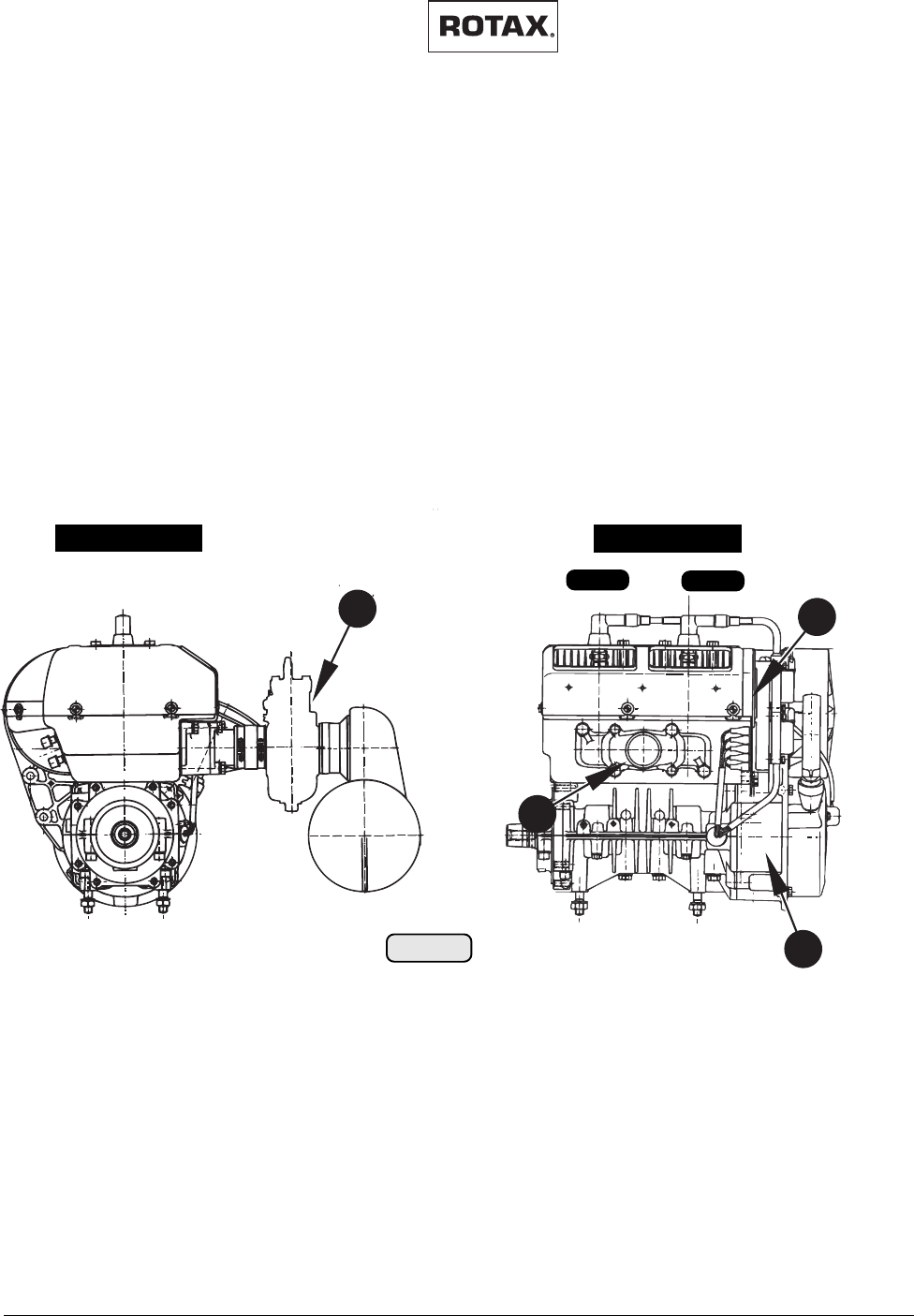
PTO view lateral view
Cyl. 1 Cyl. 2
411
10
3
02781 02782
fig. 001
8.3) Components
See fig. 001, 002, and 003.
(1) Propeller flange
(2) Propeller gear box
(3) Intake manifold
(4) Carburetor
(5) Water pump
(6) Exhaust manifold
(7) Electric starter
(8) Oil pump
(9) Electronic module(es) of ignition unit
(10) Ignition housing
(11) Engine serial number
(12) Oil tank
8.3.1) 447 UL SCDI
◆ Note: Illustration shows 447 UL with rewind starter, intake silencer,
without gearbox.
Effectivity: 447 UL SCDI, 503 UL DCDI, 582 UL DCDI /mod. 99
MAINTENANCE MANUAL
AIRCRAFT ENGINES
page 8 - 9
Initial issue, May 01/99
d00374
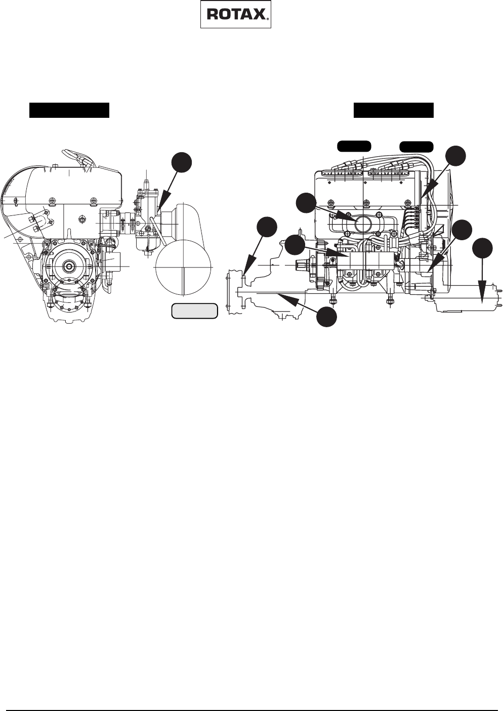
PTO view lateral view
Cyl. 1 Cyl. 2
1
4
9
10
11
3
2
02780 02779
fig. 002
8.3.2) 503 UL DCDI
◆ Note: Illustration shows 503 UL DCDI with electric starter, intake si-
lencer, and “B” type gearbox.
7
MAINTENANCE MANUAL
AIRCRAFT ENGINES
page 8 - 10
Initial issue, May 01/99
Effectivity: 447 UL SCDI, 503 UL DCDI, 582 UL DCDI /mod. 99
d00374
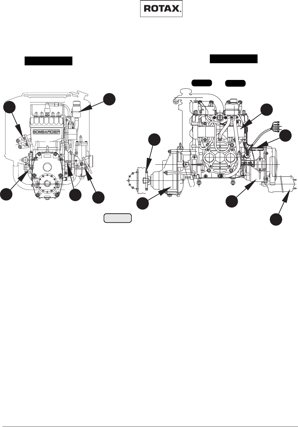
PTO view lateral view
Cyl. 1 Cyl. 2
1
2
4
5
6
8
9
7
10
11
02781 02043
fig. 003
◆ Note: Illustration shows 582 UL DCDI with electric starter and “B” type
gearbox.
12
8.3.3) 582 UL DCDI

Effectivity: 447 UL SCDI, 503 UL DCDI, 582 UL DCDI /mod. 99
MAINTENANCE MANUAL
AIRCRAFT ENGINES
page 9 - 1
Initial issue, May 01/99
d00375
9) Maintenance
In this Manual the maintenance of the engines 447 UL SCDI, 503 DCDI and 582 UL DCDI
and 582 UL DCDI mod. 99 are described. The Manual is subdivided into sections and
description of function of the various systems. Some overlapping maintenance instructions
are treated as generally valid information at the beginning of this section.
The information given in the Maintenance Manual is based on data and experience which is
considered to be applicable for a skilled mechanic under normal working conditions. The
guidelines given in the Maintenance Manual are useful and necessary supplements to
training. They, however, cannot substitute competent theoretical and practical personal
instruction.
Maintenance of engines and systems requires special knowledge and special tools.
We particularly emphasize that parts and accessories not supplied as genuine ROTAX®
parts are not verified for suitability by ROTAX® and thus are not released for use. Installation
and/or use of such products may possibly change or negatively influence the design
characteristics of the engine. For damages resulting from use of non-genuine parts and
accessories ROTAX® refuses any liability.
Non-authorized modifications as well as the use of components and auxiliary components
not corresponding to the installation instructions exclude any liability of the engine manufac-
turer.
Besides our instructions in the documentation supplied, also respect the generally valid
safety and accident preventive directives and legal regulations.
9.1) General proceeding instructions
When carrying out maintenance and service work, respect without fail the safety
regulations. At maintenance of cooling, lubricating and fuel system take care without
fail that no contamination, metal chips, foreign material and/or dirt enters the system.
Use only mallet (plastic or rubber) for dis- and re-assembly of parts.
Never loosen or tighten screws and nuts with pliers but only with the specified tools.
Before each reassembly check assembled components for missing parts. Only use
the adhesives, lubricating, cleaning agents and solvents indicated in the maintenance
instructions. If not respected, damage may be the consequence.
Exactly observe the tightening torques for screws and nuts. Overstretching or too
loose tightening may cause severe engine damage.
Before re-using parts disassembled, clean, check and refit them per instructions.
9.2) Trouble shooting
In the Operator’s Manual there is a list of possible failures as well as indication of
possible remedy. For details refer to the Repair Manual 462-532-582.
See current Operator’s Manual for engine types 447 UL SCDI, 503 DCDI, 582 UL
DCDI mod. 99.
MAINTENANCE MANUAL
AIRCRAFT ENGINES
page 9 - 2
Initial issue, May 01/99
Effectivity: 447 UL SCDI, 503 UL DCDI, 582 UL DCDI /mod. 99
d00375
9.3) Basic information
To warrant correct servicing of the engine, the use of genuine parts is required. Use
of special tools, devices and lubricating media is necessary.
▲ WARNING: Only qualified personnel trained especially for this engine are
allowed to carry out the maintenance and service work.
Only use clean screws and nuts. Check the contact faces and threads for damages.
In case of doubt, use new screws and nuts.
Always replace self-locking nuts once removed.
Respect without fail the tightening torques indicated in the respective table.
Replace all sealing rings, gaskets, lock washers, O-rings and oil seals at engine
re-assembly.
9.4) Auxiliary tools
See fig. 004.
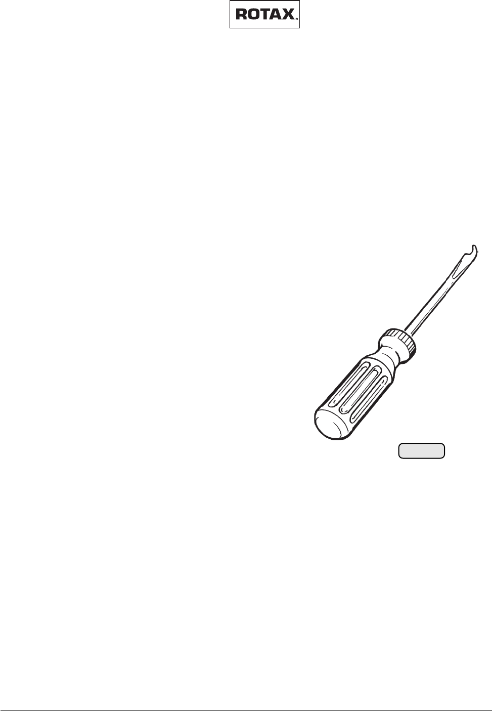
– Screwdriver ground to shape for piston pin circlip removal
– Compression tracer and 2 pressure gauges, adapter for
dial gauge in spark plug thread
– Stud extraction tool
– Scraper, lapping fleece, grinding wheel, cover
sheet, adhesive tape
– Cleaning agent, approved cleaners, funnel,
graphite marker.
9.5) Measuring tools
Vernier callipers,
Dial gauge,
Micrometer, internal micrometer,
Feeler gauge,
Stroboscope: Supply voltage 8 - 15 V. Flash triggering by inductive pick-up.
Multimeter: Electronic, 3 1/2 digits indication.
Current range 10 A.
Direct voltage range 200 V minimum.
Resistance range 200 W ÷ 2 MW
Acoustic continuity tester.
Oscilloscope: 2 channels
Analogous
Sensitivity 5 mV to 5V/div
Frequency limit 50 MHz
▲ WARNING: Using these instruments, observe the manufacturer's specifica-
tions.
00141
fig. 004

Effectivity: 447 UL SCDI, 503 UL DCDI, 582 UL DCDI /mod. 99
MAINTENANCE MANUAL
AIRCRAFT ENGINES
page 9 - 3
Initial issue, May 01/99
d00375
9.6) Special tools and devices
For the special tools required, refer to the current engine, illustrated parts catalog.
9.7) Consumable materials
9.7.1) Two stroke oil
In principle motor oil is used for lubrication of components during re-
assembly, except where specified otherwise. Use only oils specified in the
"Lubricant Chart" in order to avoid chemical reaction.
9.7.2) Lithium grease
Is used on all electrical connections, to avoid leakage current. After
assembly is complete, apply Lithium grease to the connection as anti-
corrosive.
9.7.3) Multi-purpose grease LZ
Generally usable, neutrally coloured multipurpose grease, water resistant
and highly adherent. Usable for temperatures from -35°C to +120°C (-31°F
to 248° F). The grease resists to mechanical load.
9.7.4) Corrosion inhibiting oil MOBILARMA 524
Corrosion inhibiting oil, unsoluble in water, hydrocarbon basis with addi-
tives. The pour point is below -18° C ( -3° F).
▲ WARNING: When handling chemicals, respect the generally valid
safety directives.
9.7.5) Grease MOLYKOTE G-N
Is used on highly loaded bearing positions as initial lubrication and at press
fits for prevention of fretting corrosion. MOLYKOTE is applied to both
components mated. It is especially mentioned where to use it.
9.7.6) LOCTITE Anti-Seize 76710
High-temperature lubricating and anti-corrosion agent. LOCTITE Anti-
Seize is always applied on both components mated and warrants for
maintenance-free bearing seats due to the hermetically sealed sliding
surface.
9.7.7) SILASTIC
Is used for vibration damping of the exhaust system springs.Run a bead
of silastic from one end to the other of the springs.

MAINTENANCE MANUAL
AIRCRAFT ENGINES
page 9 - 4
Initial issue, May 01/99
Effectivity: 447 UL SCDI, 503 UL DCDI, 582 UL DCDI /mod. 99
d00375
9.7.8) LOCTITE "574 orange"
Is a sealing material used as an alternative to conventional solid gaskets
where a high friction factor and exactly defined distance between parts is
required. LOCTITE sealing compound is a solvent-free liquid gasket
applied to the sealing surfaces. After assembly it cures under hermetical
conditions with metal contact within several hours. This gives a sealing
completely adapted to the surface structure of the parts to be sealed.
Its surface sealing properties are guaranteed for temperature range
between - 55°C and + 200°C (- 67°F to + 390°F). No corrosion is possible
in the sealing gap.
9.7.9) LOCTITE "648 green"
Heavy duty adhesive or screw securing agent. Its cure time depending on
the materials and temperatures is max. 12 hours and it resists tempera-
tures from -55° C (- 67°F) up to +175° C (347° F). To separate parts
secured by this agent, it may be necessary to heat the parts to approx.
250° C (480° F).
9.7.10) LOCTITE "221 violet"
Medium duty adhesive or screw securing agent suitable for materials of
different properties. In case of strain the stress is distributed evenly over
the whole surface of connection. The adhesive connection creates her-
metic sealing for gas and liquids. This sealing property protects the parts
from corrosion.
LOCTITE 221 is suitable for screws and nuts up to M12 threads and for low
duty connections.
9.7.11) MICRONORM shot blasting abrasive
This abrasive is suitable for local and gradual very fine treatment of steel
parts with rust film (propeller shaft). The MICRONORM shot blasting
abrasive does not contain any noxious matter, is approved by the compe-
tent authorities and warrants for optimum cleaning. The granulates used
are of sizes 40 to 60 µ. The surface roughness to be achieved is 0,5 - 1 µ
representing a microfinish of the parts.
9.7.12) Lapping fleece SR 4600 A - very fine grading
Is sold by the meter and used for manual removal of smaller rust spots or
oxidation, especially for optimum ground connections. It is most appropri-
ate for removal of LOCTITE from surfaces or threads to make them
metallic clean. Before reapplying LOCTITE, clean surfaces with nitro-
thinner or degreasing agent (CASTROL ZA 30 or OMV - SOFT SOL).
When using solvents, mind the safety regulations for persons and environ-
ments.
Effectivity: 447 UL SCDI, 503 UL DCDI, 582 UL DCDI /mod. 99
MAINTENANCE MANUAL
AIRCRAFT ENGINES
page 9 - 5
Initial issue, May 01/99
d00375
9.7.13) Cleaning agents
▲ WARNING: Use only approved cleaning agents (e.g. fuel, varsol,
etc.) for cleaning metal parts.
Do not use cold cleaner on lye base degreasing agents. Do not clean
coolant- and oil hoses with aggressive solutions. Clean off remains of
sealing compound with sealant remover.
Soak combustion chamber, piston and cylinder head with cleaning agent
and remove combustion residues with a bronze brush. Very good results
were achieved with CASTROL "Clenvex 2000" as a cold cleaning agent
on a basis of laboratory fuel and kerosine. It is a solvent - cold cleaner, free
of halogen, on base of selected fuel fractions, and it is biologically
disposable.
Never use caustic or corrosive cleaning agents.
▲ WARNING: Proceed with great caution when using solvents. Inhal-
ing of vapours is hazardous to health. Always dispose of
solvent as per environmental regulations.
9.8) Securing elements
■ ATTENTION: Self-locking nuts, cotter pins, tab washers and safety wires must
be replaced each time they have been removed.
Respect without fail all additional indications regarding securing and sealing means
and lubrication of fixation elements. Adhere to specified tightening torques.
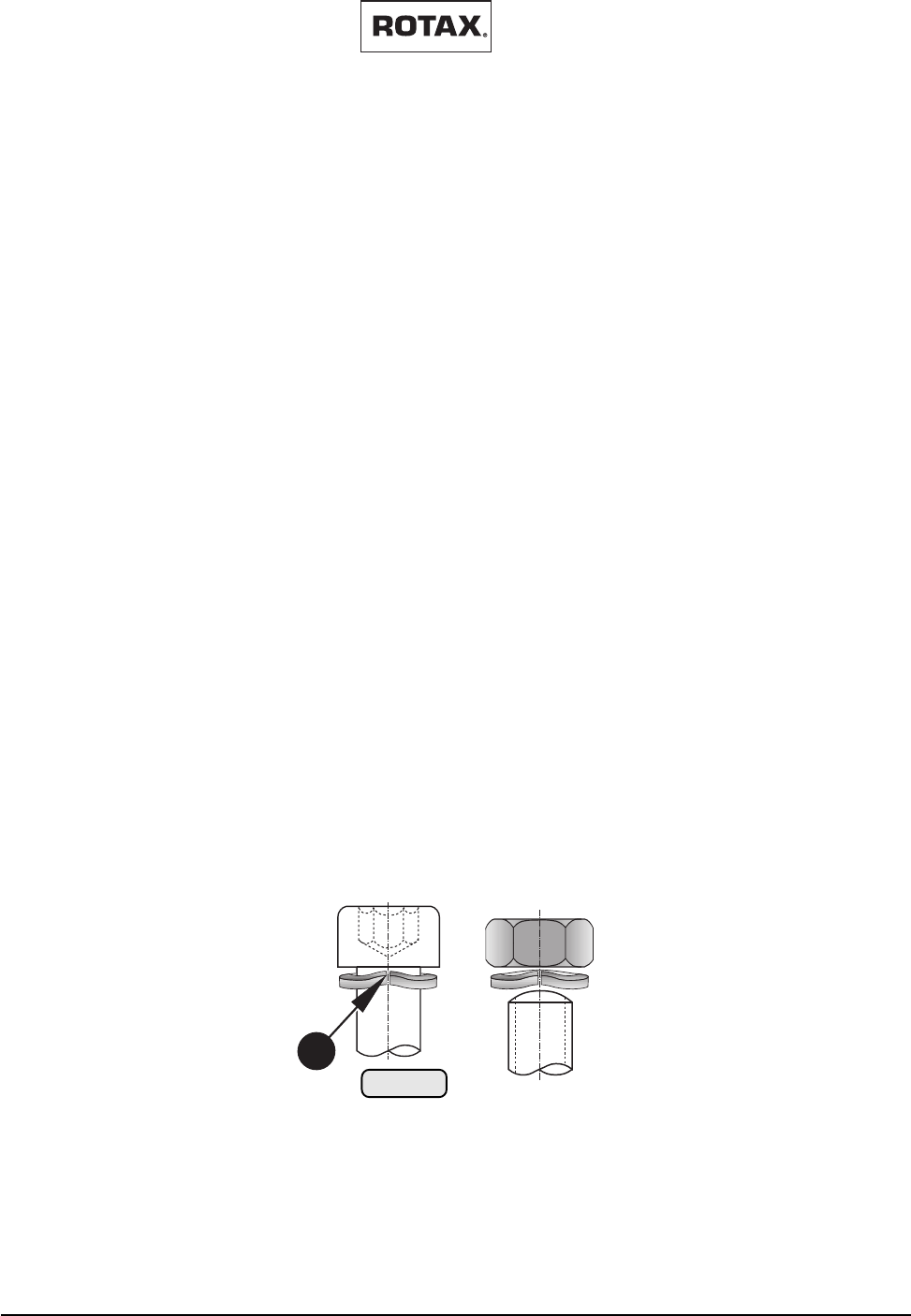
■ NOTE: Fit the lock washers with the bent up ends (1) facing the screw head
or nut.
1
00144
fig. 005
MAINTENANCE MANUAL
AIRCRAFT ENGINES
page 9 - 6
Initial issue, May 01/99
Effectivity: 447 UL SCDI, 503 UL DCDI, 582 UL DCDI /mod. 99
d00375
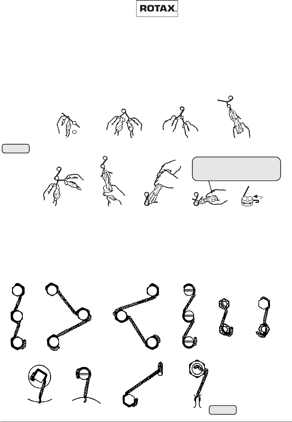
9.8.1) Safety wiring
See fig. 006 and 007.
Safety wiring serves to secure screws or nuts to prevent unintended
loosening. The screws or nuts are secured by a 0,8 mm (.0315 in.) safety
wire twisted 3 to 4 turns per 10 mm (.4 in.). The wire must by no means be
overstretched.
fig. 007
00146
Twist wire several times
up to next screw
Pass through
safety wire Pass wire through and
stretch it with pliers
Turn twisted wire end
around screw
Stretch wires and
twist approx. 4 times Bend wire end and
press it towards
screw
Cut off excess
length of wire
Twist wire around the
screw
Wind wire end around
the screw
FINAL CHECK
Safety wiring between screws must
not be loose!
00145
fig. 006
▲ WARNING: As a principle, all external engine components and
accessories must be wire-secured for safety reasons.
Various typical applications of safety wiring

Effectivity: 447 UL SCDI, 503 UL DCDI, 582 UL DCDI /mod. 99
MAINTENANCE MANUAL
AIRCRAFT ENGINES
page 9 - 7
Initial issue, May 01/99
d00375
9.8.2) Nut securing
When using a self-locking nut, take care that the polyamide insert ring on
nuts according to DIN 985 as well as the securing element on nuts
according to DIN 980 is positioned towards outside.

MAINTENANCE MANUAL
AIRCRAFT ENGINES
page 9 - 8
Initial issue, May 01/99
Effectivity: 447 UL SCDI, 503 UL DCDI, 582 UL DCDI /mod. 99
d00375
9.10) Treatment of corrosion and surface damages
At longer standstill it may occur that a rust film forms on various metal parts. With
considerable corrosion or heavily corroded screws, nuts, shims, bearings, bushes
etc., an exchange is inevitable.
Propeller shaft
The flange of the propeller shaft is likely to get a rust film. A special treatment is only
possible with propeller shaft removed. After covering all bearing seats with plastic
adhesive or a plastic tube, the propeller flange can be treated with MICRONORM shot
blasting abrasive with incorporated anticorrosive.
At heavy rust damage, when the material is affected, renewal of the propeller shaft
is necessary.
Electric system
Formation of a rust film on the permanent magnets in the magneto flywheel and on the
metal cores of the pick-ups is harmless. Replace screws and lock washers at heavy
oxidation or rust formation. Before reassembly clean all contact surfaces of the
screws removed and apply LITHIUM grease. Take care that no foreign material falls
into the magneto flywheel. Clean cable shoes and apply LITHIUM grease to the
contact surfaces to assure lasting contact.
Check contact between plugs and/or fasten connections by separation test, if
necessary apply contact spray to increase conductivity.
9.11) Engine preservation and engine back to operation
Refer to current Operators Manual 447 UL SCDI- 503 UL DCDI- 582 UL DCDI
mod.99.

Effectivity: 447 UL SCDI, 503 UL DCDI, 582 UL DCDI /mod. 99
MAINTENANCE MANUAL
AIRCRAFT ENGINES
page 10 - 1
Initial issue, May 01/99
d00376
10) Maintenance Checks
▲ WARNING: Work on the engine is only allowed to be carried out by experienced two
stroke mechanics. See Chapter 9.3).
The scheduled maintenance checks consist of the following groups:
10.1) Periodical maintenance
Time-related checks
These are checks prescribed after reaching defined hours of operation, to avoid
engine troubles by preventive maintenance. A description of work to be carried out
at specific time intervals is defined in the “MAINTENANCE SCHEDULE“.
Seasonal checks
All rubber parts like hoses, rubber dampers, rubber coupling, carburetor socket etc.
must be renewed every five years or as required by condition.
MAINTENANCE MANUAL
AIRCRAFT ENGINES
page 10 - 2
Initial issue, May 01/99
Effectivity: 447 UL SCDI, 503 UL DCDI, 582 UL DCDI /mod. 99
d00376
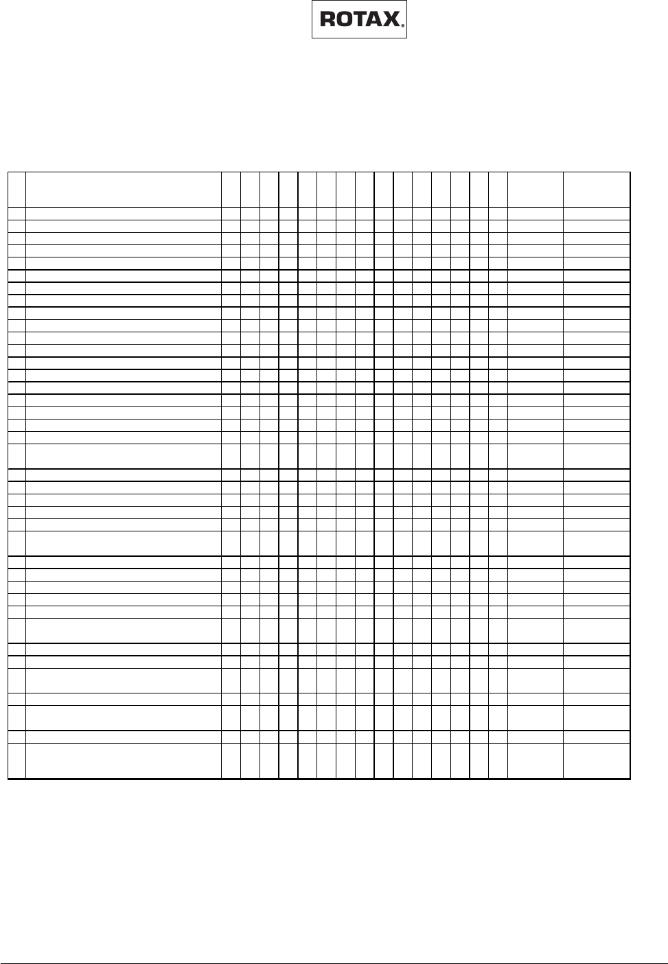
Checks and work
2 h
10 h
12,5 h
25 h
50 h
75 h
100 h
125 h
150 h
175 h
200 h
225 h
250 h
275 h
300 h
chapter si
g
nature
1 Ground run X 11.1
2 Level check of liquids X 11.2
3 Retorque cylinder head nuts 1) X 11.3
4 Retorque exhaust manifold screw s 1) X X 11.4
5 Check rew ind starter rope 10) X 11.5
6 Check electric starter gear X X X X X 11.6
7 Inspect spark plugs 10) X 11.7
8Replace spark plugs XXXXXXXXXXX 11.8
9 Check ignition system X 11.9
10 Check and clean inside spark plug caps 10) X 11.10
11Checking of V- belt tension X XXXXXXXXXXX 11.11
12Lubricate ball joints XXXXXXXXXXX 11.12
13 Replace exhaust muffler springs X X X 11.13
14Lubricate control cables 3) XXXXXXXXXXX 11.14
15 Check propeller balance and tracking 2,3) XXXXXXXXXXX 11.15
16 Inspect propeller mounting bolts 3) 11.16
17Clean and oil air filter XXXXXXXXXXX 11.17
18 Check fuel filter X X X X X X X X X 11.18
19 Replace fuel filter X 11.18
20 Check carburetor(s) and re-adjust (idle speed,
cable tension, ...) X XXXXXX 11.19
21 Clean carburetor(s) and check for w ear X X X X X 11.19
22 Replace jet needle and needle jet X 11.20
23 Check fuel pump (measure fuel pressure) X X X 11.21
24 Check gearbox oil level X X X X X X X X X 11.22
25 Replace gearbox oil X X X 11.22
26 Check and adjust gearbox, preload of springs
(type B gearbox) X X 11.23
27 Replace rotary valve lubrication oil X 11.24
28 Inspect cylinder head and piston crow n 4) X X X X X 11.25
29 Inspect piston rings for free movement 5) X X X X X 11.26
30 Check piston diameter 7) X 6) X 6) X X 6) X 11.27
31 Piston ring: check gap 7,11) X 6) X 6) X X 6) X 11.28
32 Piston ring: check axial clearance (rectang.
Ring) 8,12) X 6) X 6) X X 6) X 11.28
33 Check cylinder diameter 7,11) X 6) X 6) X X 6) X 11.29
34 Cylinder: check for roundness 7,11) X 6) X 6) X X 6) X 11.29
35 Replace cylinder head-, cylinder base- and
exhaust-gasket 8) X 6) X 6) X X 6) X 11.30
36 Inspect piston pin and bearing X 11.31
37 Inspect crankshaft and replace outer seals if
necessary X 11.32
38 General overhaul of engine 9) X 11.33
Checks and work
2 h
10 h
12,5 h
25 h
50 h
75 h
100 h
125 h
150 h
175 h
200 h
225 h
250 h
275 h
300 h
10.2) Maintenance Schedule
The following maintenance is planned and necessary for ROTAX 447 UL SCDI, 503
UL DCDI, 582 UL DCDI and 582 UL DCDI mod. 99:
1) and after every replacement of gasket(s)
2) also after any damage
3) according to instructions of manufacturer
4) if carbon layer is more than 0,5 mm thick, decarbonize
5) if piston ring sticks clean and replace if necessary
6) if used in very dusty atmosphere
7) wear limit see Service Information 5 UL 91
8) If cylinder has been dismantled
9) To be carried out every five years or
every 300 hours whichever comes first.
contact authorized distributor or service
center.
10) To be examined after every 12,5 hours
of operation.
11 Necessary only if piston rings are not
freely moving
02948

Effectivity: 447 UL SCDI, 503 UL DCDI, 582 UL DCDI /mod. 99
MAINTENANCE MANUAL
AIRCRAFT ENGINES
page 11 - 1
Initial issue, May 01/99
d00377
11) Maintenance of the various systems:
11.1) Ground test
Check smooth engine run. Furthermore verify take-off RPM of engine and compli-
ance with all limits.
11.2) Level check of liquids
Verify capacity of all operation liquids.
Such as:
Fuel capacity
Oil quantity for rotary valve drive (on engine 582 only)
Oil level in gearbox (see section 11.22)
Oil level for oil injection lubrication
Coolant level (on engine 582 only)
MAINTENANCE MANUAL
AIRCRAFT ENGINES
page 11 - 2
Initial issue, May 01/99
Effectivity: 447 UL SCDI, 503 UL DCDI, 582 UL DCDI /mod. 99
d00377
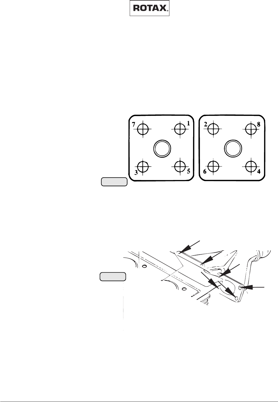
Diagram for torquing sequence when
manifolds are in place
Tightening torque: 22 Nm (195 in.lb.)
02884
fig. 008
02885
fig. 009
11.3) Retorque cylinder head nuts (only on 447 UL SCDI and 503 UL DCDI)
▲ WARNING:Engine must be cool for retorquing procedure of cylinder head nuts.
◆ NOTE: Consider both cylinders as one unit because they are joined by
exhaust and intake manifolds. Use a cross sequence for tightening the
nuts, starting from the center. Ensure that cowl screws are torqued
less than the head nuts.
11.4) Retorque of exhaust manifold screws:
The screws of the exhaust manifold must be retightened to the specified torque.
Tightening torque for 503 UL DCDI and 582 UL DCDI: 22 Nm (195 in lb)
Tightening torque for 447 UL SCDI: 25 Nm (221 in lb)
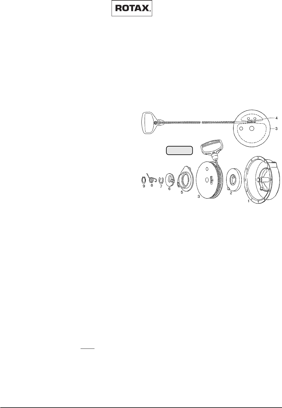
11.5) Checking of the rewind starter rope
Check starter rope condition according to mainte-
nance schedule. Replace when worn or frayed.
To change the starter rope, follow the procedure
outlined (the numbers stated in brackets refer to the illustration).
Effectivity: 447 UL SCDI, 503 UL DCDI, 582 UL DCDI /mod. 99
MAINTENANCE MANUAL
AIRCRAFT ENGINES
page 11 - 3
Initial issue, May 01/99
d00377
11.5.1) Rewind starter dismantling:
First remove the rewind starter assembly from the engine.
Second, remove the snap ring (9), loop spring (8), circlip (7), pawl lock (6),
and the pawl (5).
Pull out the starter rope fully to the end, hold starter housing (1) and rope
sheave (3) together In their position. There is an opening in the rope
sheave. The key clamp
(4) visible in the opening
must be pushed out in
the opposite sense of
the pulling direction. Pull
the rope out of the rope
sheave.
11.5.2)
Rewind starter reassembly:
Insert the new starter
rope into the rope
sheave, fit the key clamp
in the same position as it
was before and refit the parts (5), (6),
(7), (8) and (9).
▲ WARNING: Do not remove spring container (2), this might cause
injuries.
Do not operate the engine if the rewind starter is defective.
Most starter problems are due to improper handling.
11.6) Check electric starter gear
Inspect teeth and check free- wheeling of overrun clutch. Ensure neat fit of stop collar
and circlip and proper shape of spring.
Check free movement of pinion on the coarse thread.
◆ NOTE: For further details see current Repair Manual 462-532-582.
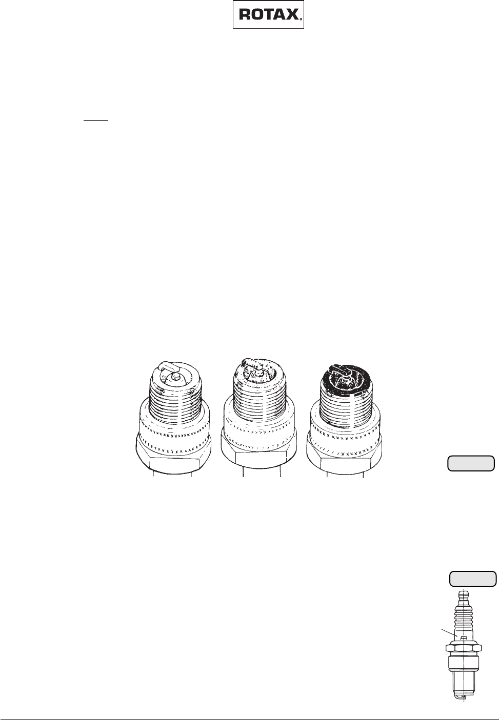
11.7) Inspection of spark plugs
Due to varying fuel properties etc., check according to maintenance schedule.
Replace as required or annually: Provided that spark plug heat range and the
carburetor calibration are correct, the spark plugs will have a brownish tinge at the
electrodes of both spark plugs after full load operation.
On engines with single carburetor, one sooty spark plug usually indicates a bad plug
or faulty ignition system. If both plugs are sooty with oil deposits, carburation and air
system should be checked. On engines with two carburetors you should switch the
carburetor to trace the problem.
■ ATTENTION: Do not switch the carburetors on 618 UL DCDI because the
jetting is different.
02939
fig. 010
MAINTENANCE MANUAL
AIRCRAFT ENGINES
page 11 - 4
Initial issue, May 01/99
Effectivity: 447 UL SCDI, 503 UL DCDI, 582 UL DCDI /mod. 99
d00377
■ ATTENTION: Always change both plugs. Never interchange plugs from one
cylinder to the other.
If both plugs have "white" electrodes with "melt" droplets, first suspect lean mixture.
If calibration is correct and there is no evidence of manifold leaks, lack of fuel, or
incorrect float settings, don't change the plugs to a colder range. Check if cooling
system is operating correctly.
■ ATTENTION: Heavy oil deposits on the electrodes and insulator may cause
engine problems, exchange regularly according to maintenance
schedule, or at any indications of trouble.
If, after cleaning or changing the spark plugs, you still have an ignition problem, check
to see if only one cylinder is affected or both. Some thought to what is common to both
systems or only one will isolate the problem more efficiently. If no external fault is
found, the ignition unit must be checked.
■ ATTENTION: Never clean spark plugs with an abrasive cleaner.
Remember to correctly gap your plugs with a wire gauge (see technical data, section
8.2). Spark plugs must be torqued (see section 11.7). If problems occur too
frequently, cause must be determined and rectified.
11.8) Replacement of spark plugs
The following type of spark plugs may be used at renewal of the spark plugs:
◆ NOTE: The resistance spark plug can be distinguished by the part
no. and by the designation. Tightening torque: 27 Nm (238
in lb) only on cold engine.
part no. spark plugdesignation
897 050 spark plug without resistance B8ES
897 055 spark plug with resistance BR8ES
◆ NOTE: The "R" in the designation denotes the resistance of approx.
5 kW
,
which results in better R.F.I. suppression.
overheated
(light gray)
normal
(brownish)
fouled
(black)
BR8ES
02792
fig. 011
0279102790
01155
fig. 012
Effectivity: 447 UL SCDI, 503 UL DCDI, 582 UL DCDI /mod. 99
MAINTENANCE MANUAL
AIRCRAFT ENGINES
page 11 - 5
Initial issue, May 01/99
d00377
02890
fig. 013
11.9) Check of the ignition system
Verify all electrical connections for good contact and ensure they are free of corrosion
.
Inspect the wiring for wear, damage and corrosion.
Before flight the function of the two ignition circuits (on 503 and 582) must be checked.
For checking the ignition unit the engine must be operated at 3000 to 3500 1/min and
alternately ignition circuit 1 and 2 must be switched off. The RPM-drop must not
exceed max. 300 1/min.
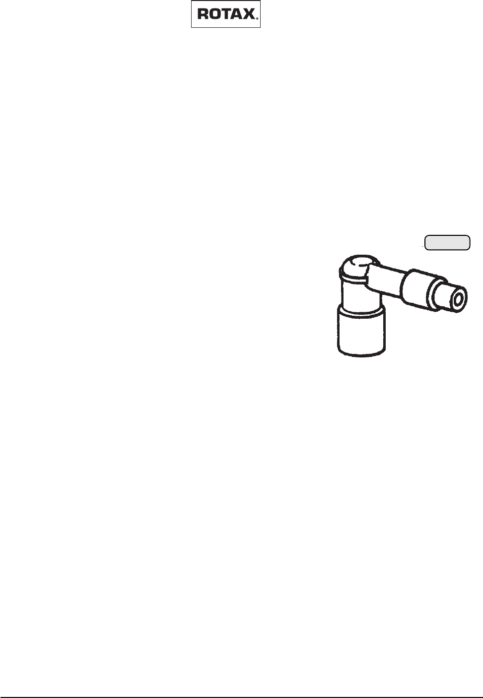
11.10) Check and clean inside of spark plug connectors
Inspect spark plug connector for cracks, burn-off, dampness and fouling. Check
connection with ignition cable and fitting of rain protection cover. The resistance value
of the standard spark plug connector is 4,5 ÷ 5,5 kW.
For various applications radio interference suppres-
sion plug connectors must be used according to
respective regulations. These are more prone to trou-
bles than the standard resistor type connector, due to
the metal shielding.
Resistance of these connectors is 0,8 ÷ 1,2 kW.
Never pull off spark plug connector on a running
engine.
Clean contact surfaces in the spark plug connectors as required.
■ ATTENTION: On engine installation with spark plugs down, it is highly recom-
mended to additionally secure spark plug caps.
MAINTENANCE MANUAL
AIRCRAFT ENGINES
page 11 - 6
Initial issue, May 01/99
Effectivity: 447 UL SCDI, 503 UL DCDI, 582 UL DCDI /mod. 99
d00377
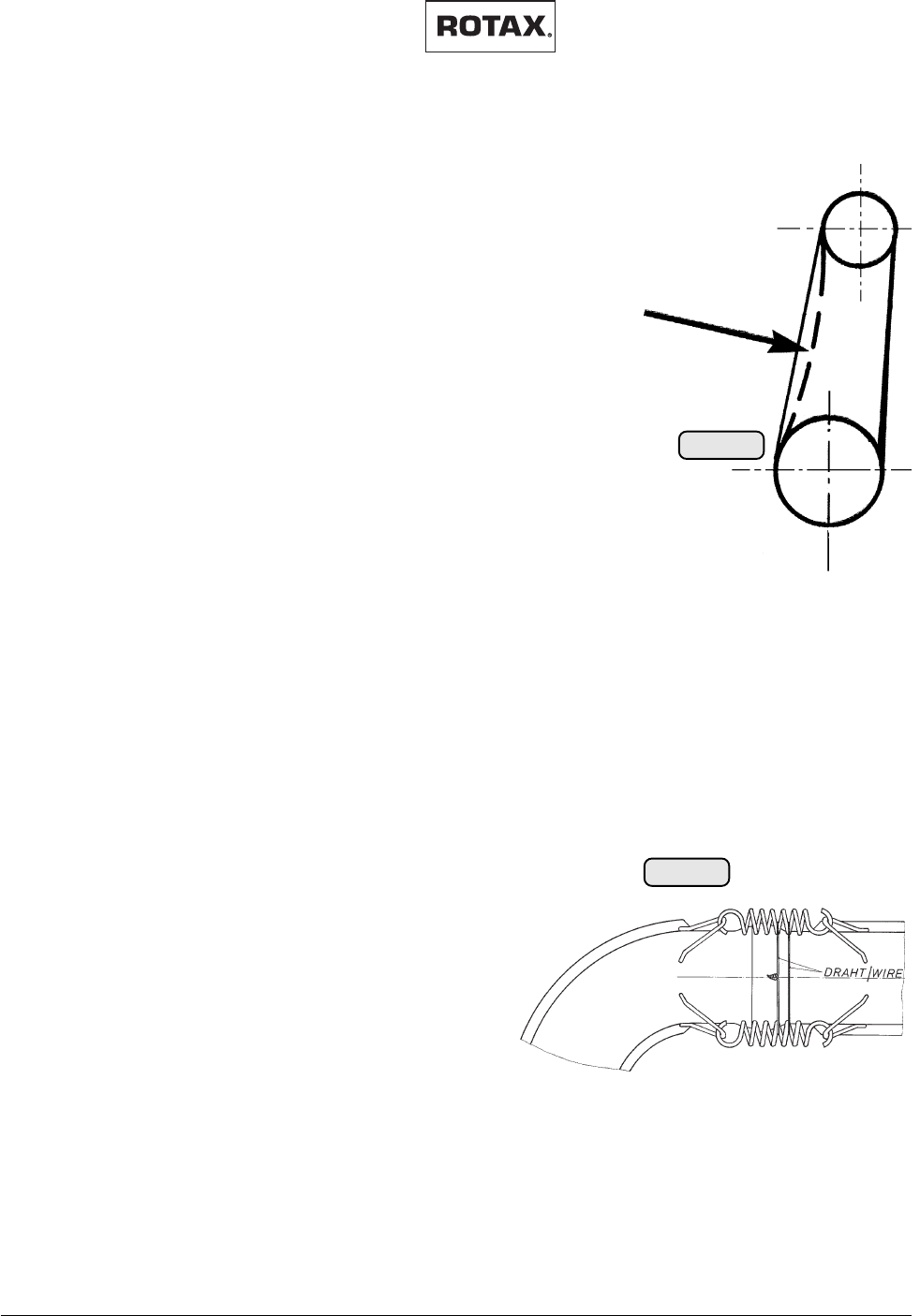
11.11) Checking of V - belt tension (only on fan cooled 447
and 503 engines)
Replace belt if frayed or if it can no longer be tensioned
to specification.
The tension of the V-belt can be adjusted by shims
between the V-belt pulley half and the fan (resp. the
protection sheave on 503). The V-belt is correctly
tensioned when it can be depressed 9 - 10 mm (.35 ÷ .39
in.) to indicated force "F" (in the middle between the 2 V-
belt sheaves).
11.12) Lubricate Ball joints
Check exhaust system prior to every flight for tightness,
physical damage or changes in sound pattern. Espe-
cially inspect springs and hooks.
The muffler has to be supported on vibration damping
blocks. All ball joints have to be greased regularly with heat resistant lubricant (e.g.
LOCTITE Anti-Seize, 297 434) to avoid gripping or seizing of joints and consequent
breaking of exhaust components.
11.13) Replace exhaust muffler springs
The muffler must be suspended on engine and frame and also be secured against
loss without squeezing the ball joints.
Secure the muffler springs by wire against loss. The sketch illustrates a possibility
how to interconnect the exhaust springs to prevent the vibration of these springs and
thus pre-mature wear.
V - belt deflection
9 - 10 mm
35 - 39 in.
F = 50 N
F= 11 lbf
F
fig. 014
02891
02895
fig. 015
Effectivity: 447 UL SCDI, 503 UL DCDI, 582 UL DCDI /mod. 99
MAINTENANCE MANUAL
AIRCRAFT ENGINES
page 11 - 7
Initial issue, May 01/99
d00377
11.14) Lubricate control cables
Verify and lubricate all control cables in accordance with maintenance schedule of the
aircraft builder.
◆ NOTE: Observe oil specification of the aircraft builder.
11.15) Check propeller balance and tracking
A new propeller must be balanced to better than 1gm to avoid vibration problems and
overstressing of the drive system. Used propellers may be max. 2,5 gm out of
balance.
11.16) Inspect propeller mounting bolts
Proceed according to propeller manufacturer instructions.
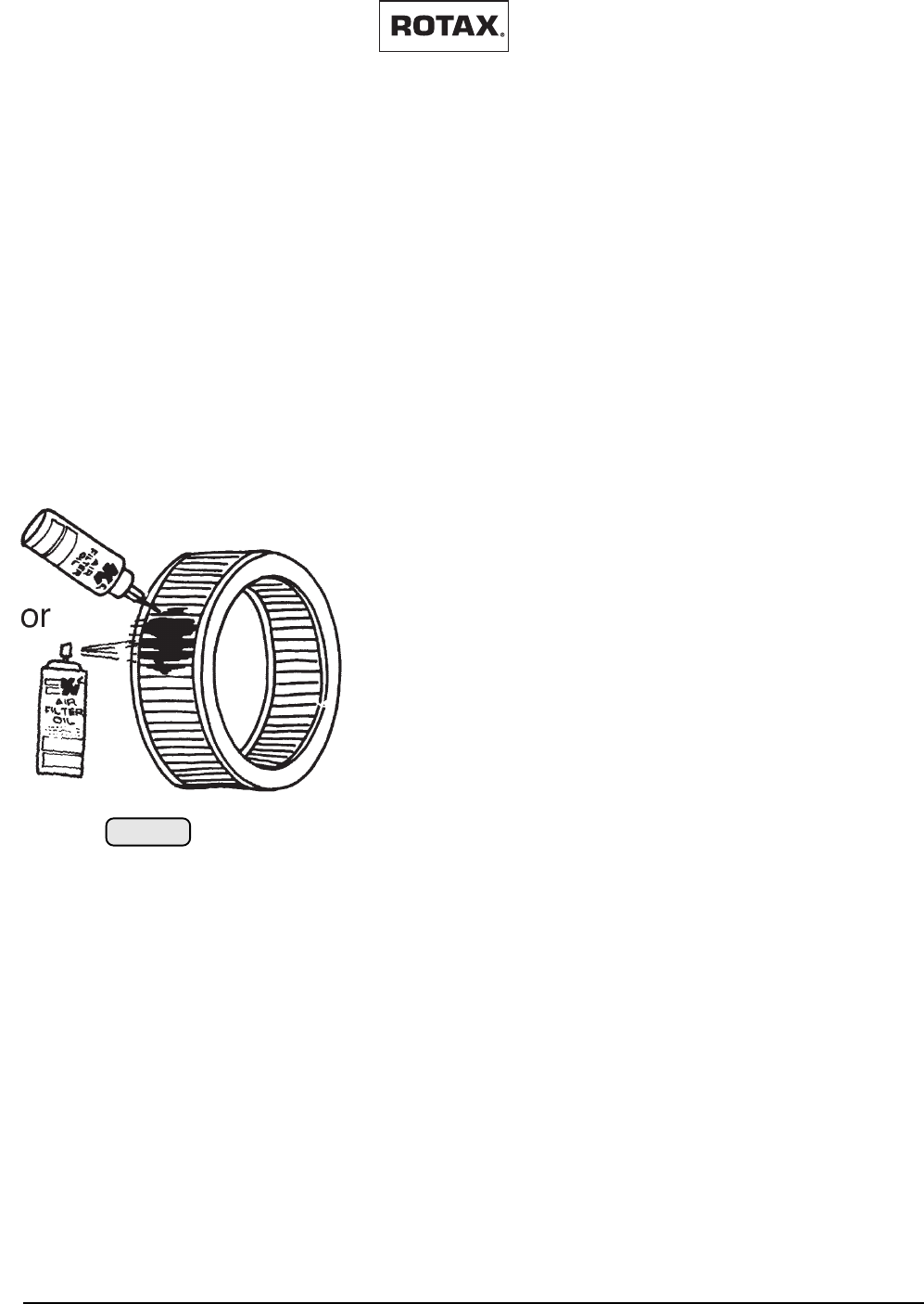
11.17) Clean and oil air filter
11.17.1) Application of new air filters:
For a higher life-span and optimal engine protection the
filter corrugations have to be moisturized with oil. Unoiled
filters lose their effectiveness against dirt and dust.
Every corrugation of the filter has to be sprayed with oil.
After 5 - 10 minutes the filter mat will be soaked with oil,
noticeable on the uniform red colouring.
Never use gear oil, diesel, 2-stroke oil or motor oil as they
attract water.
If necessary, apply filter grease on sealing face, but don’t
grease clamp connection of filter.
02892
fig. 016
MAINTENANCE MANUAL
AIRCRAFT ENGINES
page 11 - 8
Initial issue, May 01/99
Effectivity: 447 UL SCDI, 503 UL DCDI, 582 UL DCDI /mod. 99
d00377
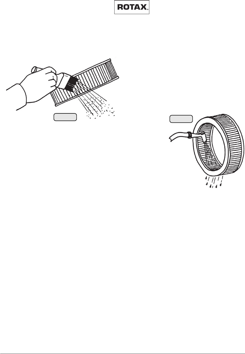
11.17.2) Cleaning of used air filters:
First, lightly tap off surface dirt and wet with cold
water. Roll filter in filter cleaning and degreasing
fluid.
Never use gasoline, steam, caustic liquids, de-
tergents or high pressure cleaning.
The level of the cleaning fluid should be approx.
3/4 of the height of corrugations. Dirty fluid must
not run inside of filter. Allow at least 5 minutes to
dissolve the dirt.
After that, rinse
filter with cold
water from in-
side to outside.
02893
fig. 017
02894
fig. 018
Shake off and let it dry in free
air. Don’t dry with compressed
air, over naked flame or with hot air fan.
Prior to installation, service filter with oil
(see previous chapter).
Filter due for renewal depends on
enviromental conditions, but at the latest after
300 hours of operation.
11.18) Check and replacement of fuel filter
The flow through the filter may be restricted due to the long term build up
of dirt. A more serious type of blockage, which can occur quite rapidly is
caused by a reaction between detergents in certain two-stroke oils and
water in the fuel.
Both types of blockage may be difficult to detect visually. If blockage is
suspected, renew fuel filter or filter element. Subsequently avoid water
contamination of fuel.
11.19) Clean carburetors and check for wear
Attend to the following:
- Stop engine at raised speed and verify float level.
- Inspect carburetor assy. for leakage.
- Check float valve for easy operation.
- Inspect clip of jet needle for wear.
- Inspect sieve sleeve.
- Clean the carburetor with fuel as required.
◆ NOTE: For further details see also current Repair Manual 462-
532-582
Effectivity: 447 UL SCDI, 503 UL DCDI, 582 UL DCDI /mod. 99
MAINTENANCE MANUAL
AIRCRAFT ENGINES
page 11 - 9
Initial issue, May 01/99
d00377
11.20) Replace jet needle and needle jet
The needle jet and jet needle must only be exchanged by a mechanic with
experience on two-stroke engines and in accordance with the relevant
Repair Manual 462-532-582, section carburetor.
11.21) Clean and check fuel pump
- Inspect the fuel pump.
- Verify the fuel pressure: 0,2 - 0,5 bar (3 - 7 p.s.i).
11.22) Check gearbox oil level, replace gearbox oil
For draining the oil, remove magneto drain plug.
Replenish oil, until oil emerges at the respective lower oil level plug.
■ ATTENTION: The two large ventilation bores on both sides have to
remain always open to warrant dissipation of heat at
gearbox type C and E.
Wire-secure vent screw, oil level plugs and drain plugs.
◆ NOTE: Illustration shows “B” type gearbox
02998
fig. 019
For oil quality see technical data
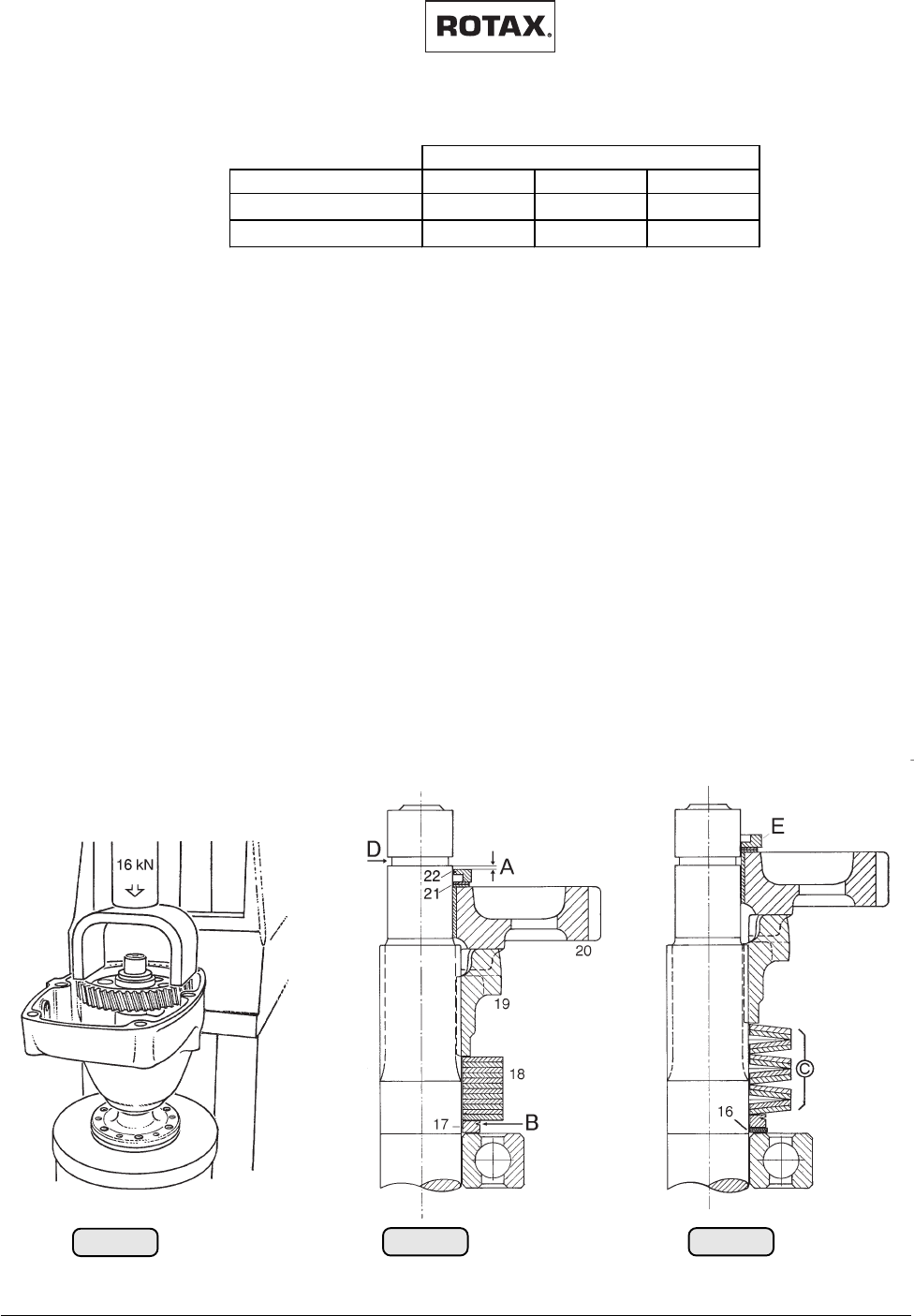
MAINTENANCE MANUAL
AIRCRAFT ENGINES
page 11 - 10
Initial issue, May 01/99
Effectivity: 447 UL SCDI, 503 UL DCDI, 582 UL DCDI /mod. 99
d00377
* refer to latest revision of the current installation manual.
11.23) Checking and adjusting of gearbox, preload of springs
(B- type gearbox)
Place gearbox on a suitable support under hand press. Place the mounting
yoke, part no. 876 880 on the dog gear (20) (see “disassembly and
judgement”). Place angular ring (22) upside down (with “L” shape down-
wards (see ill.) on prop shaft to facilitate reading of the distance A. Apply
a load of 16 kN (3600 lbs) on the dog gear via the mounting yoke. With this
load, disk springs will be completely compressed.
■ ATTENTION: Do not exceed maximum load of 16 kN (3600 lbs),
otherwise cover or dog gear will be damadged.
With springs in compressed state, measure A, the distance from top side
of angular ring to lower edge of groove (see illustration). Relieve pressure,
remove all items from prop shaft and compensate distance A, by placing
appropriate shims (16) under distance ring (17). Shims are available as
spare parts in the sizes 0,1 / 0,2 / 0,3 / 0,5 and 1,0 mm.
LOADED RELIEVED
02895
fig. 022
02896
fig. 021
02899
fig. 020
02978
gearbox type
position of installation* B C/CL E/EL
SZ 330 cm3200 cm3400 cm3
SS 300 cm3120 cm3180 cm3

Effectivity: 447 UL SCDI, 503 UL DCDI, 582 UL DCDI /mod. 99
MAINTENANCE MANUAL
AIRCRAFT ENGINES
page 11 - 11
Initial issue, May 01/99
d00377
11.24) Renewing of the rotary valve lubrication oil (582 UL DCDI /mod.
99 only)
Drain oil completely. For complete emptying, the engine must be inclined.
Afterwards refill the oil tank. Allow some time for settling. Crank the engine
by hand several times to vent the system.
Fill tank to max. mark and after a short trail run verify the oil level again.
11.25) Inspection of the cylinder head and piston crown
Remove the cylinder head as per the current and relevant Repair Manual.
Deposits on combustion chamber in cylinder head and on piston crown
must not exceed 0,5 mm (0,02 in).
Excessive deposits must be removed carefully with lapping fleece.
▲ WARNING: Clean the pistons not installed in the engine but on the
bench, to prevent carbon deposits ending up in the
engine.
11.26) Inspection of the piston rings
Remove cylinder head and cylinder as per the current and relevant Repair
Manual.
Verify easy movement of the piston rings. A sticking ring must be removed,
use piston ring pliers when replacing rings.
If several rings have to be removed ensure assignment to the respective
piston.
Clean removed piston rings and renew as required.
Never overstress piston ring as the ring would lose its pretension and the
molybdenum coating might break off.
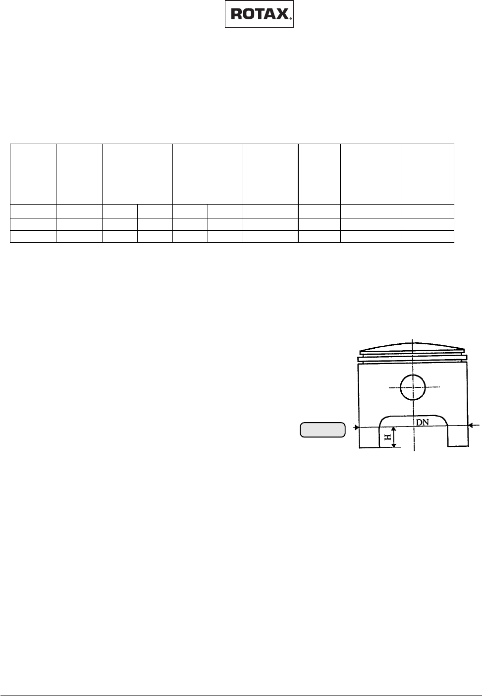
MAINTENANCE MANUAL
AIRCRAFT ENGINES
page 11 - 12
Initial issue, May 01/99
Effectivity: 447 UL SCDI, 503 UL DCDI, 582 UL DCDI /mod. 99
d00377
Engine
Type
ROTAX
part. No. Oversizes2)
available
Height H
[mm]1)
piston to
wall
clearence
[mm]
new
piston to
wall
clearence
[mm]
Wear Limit
447 UL 886050 67,45 67,46 67,445 67,455 2 20,8 0,05-0,07 0,15
503 UL 996245 71,93 71,94 71,925 71,935 2 18 0,07-0,09 0,2
582 UL 888590 75,94 75,95 75,935 75,945 2 20,5 0,06-0,08 0,15
Notes: 1) Dimensions H = Height for measurement of the nominal diameter on new piston
perpendicular to the center axis of the piston pin. For used pistons measuring the
2) Please find nominal value of oversize pistons in the respective parts list.
Stamped on
piston crown
Nominal
Diameter DN ±
0,005 mm
__biggest diameter is also valid.
11.27) Check piston diameter
The dimension of the pistons must be in the range as stated in the table
below.
02950
fig. 023
03125
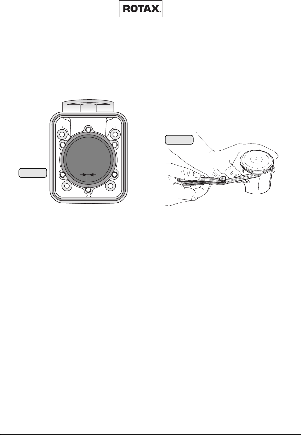
Effectivity: 447 UL SCDI, 503 UL DCDI, 582 UL DCDI /mod. 99
MAINTENANCE MANUAL
AIRCRAFT ENGINES
page 11 - 13
Initial issue, May 01/99
d00377
11.28) Piston ring, checking of gap and axial play
Remove piston rings, using piston ring pliers. Never overtension rings,
otherwise ring loses its pretension, and Molybdenum coating will break off.
Ensure to refit used piston rings into same location and position as before
removal. A new rectangular ring may be fitted either way up.
Piston rings are checked for end gap and flank clearance. With ring fitted,
clearance of flank can be checked by feeler gauge.
To measure the end gap "A" of a piston ring, position ring in a new cylinder
using piston as pusher and check gap by feeler gauge. To check the end
gap on a used ring for wear limit, position ring in the corresponding cylinder.
1st ring
Dimension wear limit mm (in.)
ring gap ................................................................ 1mm .........................0,039
ring clearence ....................................................... 0,2 mm ..................... 0,008
2nd ring
Will be renewed when the 1st ring is replaced.
A
02897
fig. 024
02898
fig. 025
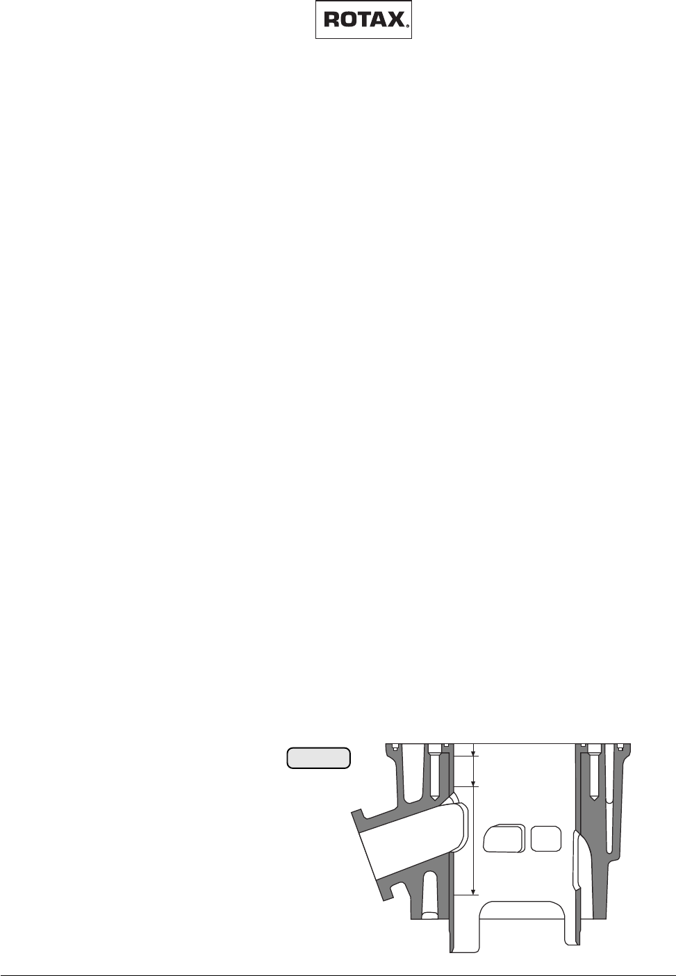
MAINTENANCE MANUAL
AIRCRAFT ENGINES
page 11 - 14
Initial issue, May 01/99
Effectivity: 447 UL SCDI, 503 UL DCDI, 582 UL DCDI /mod. 99
d00377
11.29) Checking of cylinder diameter and roundness
Cylinders are machined to 2 tolerance groups, marked on the spigot either red
or green. The difference in bore dia. is 0,01 mm. Suitable pistons are available
in the same colour code.
Dimension new mm (in.) wear limit mm (in.)
out of round ..........0,00 ÷ 0,02 (0,00÷ 0,0008) .................... 0,05 (0,002)
conicity................. 0,00 ÷ 0,03 (0,00÷ 0,0012) .................... 0,08
(0,0032)
Dimension new mm (in.) wear limit mm
(in.)
Type 447 UL
Cylinder standard red .......... 67,50 ÷ 67,51 (2,6575 ÷2,6579).............67,59(2,66)
Cylinder standard green....... 67,51 ÷ 67,52 (2,6579 ÷2,6583) .............67,60(2,661)
Cylinder (1st oversize, red)... 67,78 ÷ 67,79 (2,8444 ÷2,8448)...........67,87(2,848)
Cylinder (1st oversize, green) 67,79 ÷ 67,80 (2,8448 ÷ 2,8452)67,88 . (2,848)
Cylinder (2nd oversize, red) ...68,00 ÷68,01 (2,8543÷2,8547)68,09 ... (2,858)
Cylinder (2nd oversize, green) 68,01 ÷ 68,02 (2,8547÷2,8551)68,10 ... (2,858)
Type 503 UL
(standard, red) ...................... 72,00 ÷ 72,01 (2,835 ÷ 2,836) ........... 72,10
(2,8385)
Cylinder (standard, green) .... 72,01 ÷ 72,02 (2,8350÷2,8354)72,10 ... (2,8385)
Cylinder (1st oversize, red)....72,25 ÷72,26 (2,8444÷2,8448)72,35 ... (2,848)
Cylinder (1st oversize, green) 72,26 ÷ 72,27 (2,8448 ÷ 2,8452)72,35 . (2,848)
Cylinder (2nd oversize, red) ...72,50 ÷72,51 (2,8543÷2,8547)72,60 ... (2,858)
Cylinder (2nd oversize, green) 72,51 ÷ 72,52 (2,8547÷2,8551)72,60 ... (2,858)
Type 582 UL
Cylinder (standard, red) 76,01 ÷ 76,02 (2,9925÷ 2,9929)76,10 (2,996)
Cylinder (standard, green) 76,02 ÷ 76,03 (2,9929÷ 2,9933)76,10 (2,996)
Cylinder (1st oversize, red) 76,26 ÷ 76,27 (3,0023÷ 3,0027)76,35 (3,006)
Cylinder (1st oversize, green) 76,27 ÷76,28 (3,0027÷ 3,0031)76,35 (3,006)
Cylinder (2nd oversize, red) 76,51 ÷ 76,52 (3,0122÷ 3,0129)76,60 (3,016)
Cylinder (2nd oversize, green) 76,52 ÷76,53 (3,0123÷ 3,013)76,60 (3,016)
◆ NOTE: Diameter readings are taken in crankshaft axis and 90°
across.
c. 5 mm (.2 in.) below top
of cylinder
c. 5 mm (.2 in.) above
exhaust port
c. 5 mm (.2 in.) above
spigot cut-away
02937
fig. 026
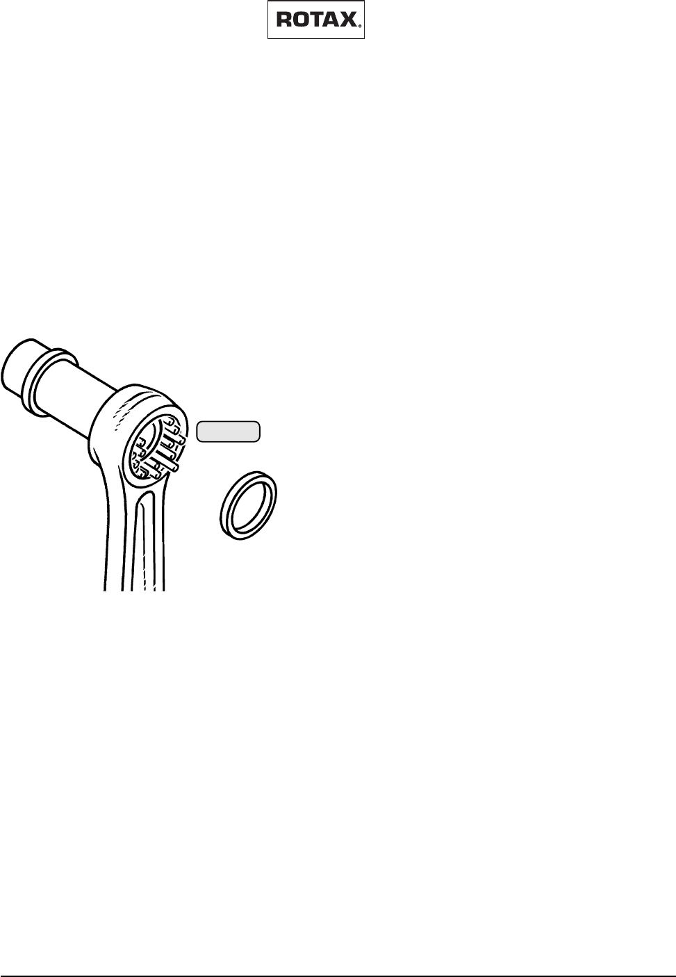
Effectivity: 447 UL SCDI, 503 UL DCDI, 582 UL DCDI /mod. 99
MAINTENANCE MANUAL
AIRCRAFT ENGINES
page 11 - 15
Initial issue, May 01/99
d00377
11.30) Replace cylinder head-, cylinder base- and exhaust gaskets
◆ NOTE: Necessary only if cylinders have been removed.
11.31) Inspect pins and bearings
11.31.1) Piston pin:
Check piston pin for wear and pitting at bearing contact surface
and take diameter readings.
Dimension new mm (in.) wear limit mm (in.)
Piston pin ................ 17,997÷ 18,0 (0,7085 ÷ 0,709) ................. 17,97 (0,707)
■ ATTENTION: Renew piston pin at detection of
perceptible traces of wear, even if
dimensions are correct, at begin
nings of pitting or discoloration. Al
ways renew piston pin circlips af
ter every removal.
11.31.2) Piston pin bearing:
The needle cage has been superseded by a cageless
needle bearing, increasing life-span essentially due to
higher load capacity. The cageless needle bearing is a
needle bearing with 31 needles and 2 thrust washers.
On engine 582 UL this needle bearing has been fitted
since the beginning of serial production.
◆ NOTE: It is strongly advised to fit the cageless piston
pin bearing (part no. 832 320) at engine re-
pair.
Inspect needles for wear and pitting. With one needle
visibly damaged, renew all 31 needles.
02941
fig. 027
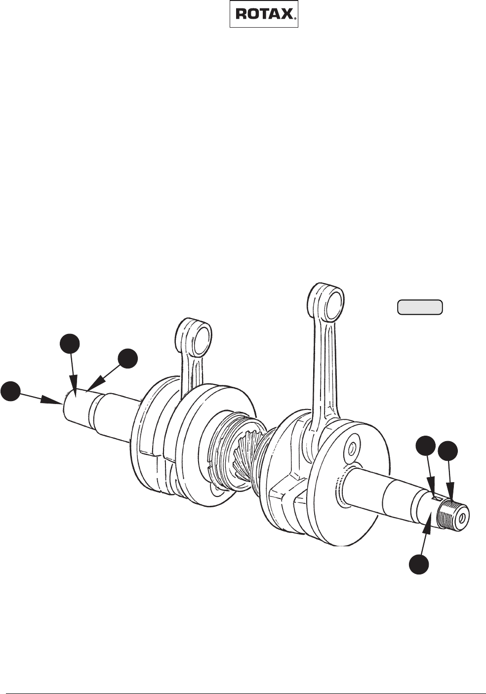
MAINTENANCE MANUAL
AIRCRAFT ENGINES
page 11 - 16
Initial issue, May 01/99
Effectivity: 447 UL SCDI, 503 UL DCDI, 582 UL DCDI /mod. 99
d00377
11.32) Inspect crankshaft and replace outer seals
The crankshaft is a built-up design with single components
connected by pressfit.
— Check taper (1) on both ends of crankshaft.
— Check external (2) and internal (3) thread.
— Check groove (4) for Woodruff key on magneto-side.
— Inspect outer oil seals. Replace as necessary according to
latest revision of the relevant repair manual 462-532-582.
— Check crankshaft for concentricity on PTO side (5). (Crank
shaft fitted in the crankcase):
maximum out of round: 0,03 mm
— Inspect for corrosion.
11.33) General overhaul of the engine
For a general engine overhaul, the engine has to be shipped to an
authorized distributor or Service Center.
1
2
3
4
1
02938
fig. 028
5

Effectivity: 447 UL SCDI, 503 UL DCDI, 582 UL DCDI /mod. 99
MAINTENANCE MANUAL
AIRCRAFT ENGINES
page 12 - 1
Initial issue, May 01/99
d00387
12) Required inspections after limits of operation have been ex-
ceeded:
12.1) Exceeding of max. permissible engine speed
Remove the cylinders and inspect the pistons for seizure.
12.2) Exceeding of max. permissible cylinder head temperature
Remove the cylinders and inspect the pistons for seizure and piston crown for
depressions.

MAINTENANCE MANUAL
AIRCRAFT ENGINES
page 12 - 2
Initial issue, May 01/99
Effectivity: 447 UL SCDI, 503 UL DCDI, 582 UL DCDI /mod. 99
d00387
12.3) Exceeding of max. permissible exhaust gas temperature
Remove the cylinders and inspect the pistons for seizure.
12.4) Fuel pressure below specified value
Remove the cylinders and inspect the pistons for seizure. Also inspect crankshaft
end seals for leakage.

Effectivity: 447 UL SCDI, 503 UL DCDI, 582 UL DCDI /mod. 99
MAINTENANCE MANUAL
AIRCRAFT ENGINES
page 13 - 1
Initial issue, May 01/99
d00378
13) ROTAX® Authorized Distributors
1) E U R O P E
AUSTRIA:
➤➤
➤➤
➤
HB - FLUGTECHNIK GES.M.B.H.
Dr. Adolf Schärf Str. 44
A-4053 HAID
Tel.: 07229 / 79104/79117, Fax: 07229 / 79104 15
Contact person: Ing. Heino Brditschka
BULGARIA:
➤➤
➤➤
➤
GERGANOV - AIRCRAFT EINGINES LTD.
25B-Post 20, 23 peh. Shlp. polk Blvd.
BG-6100 KAZANLAK
Tel.: 431 / 27 247, Fax: 431 / 23 777
Contact person: Radosslav D. Gerganov
CROATIA / former YUGOSLAVIA
(except SLOVENIA):
➤➤
➤➤
➤
SHAFT D.O.O.
B.L. Mandica 161 a
HR-54000 OSIJEK
Tel. + Fax:031 / 280-046
Contact person: Ing. Ivan Vdovjak
CZECHIA:
➤➤
➤➤
➤
TEVESO S.R.O.
Skroupova 9441
CS-50002 HRADEC KRALOVE
Tel.: 049 / 56 30 127, Fax: 049 / 56 30 226
E-mail: teveso@mbox.vol.cz
Contact persons: Ing. Samal / Ing. Halek
DENMARK / THE NETHERLANDS:
➤➤
➤➤
➤
FLIGHT-CENTER
Flugplatz
D-27777 GANDERKESEE, GERMANY
Tel.: 04222 / 3789, Fax: 04222 / 6042
E-mail: flightcenter@olis.de
Contact person: Robert Heilig
FINLAND / NORWAY/ SWEDEN/
ESTONIA/ LATVIA / LITHUANIA
➤➤
➤➤
➤
LYCON ENGINEERING AB
Härkeberga, SE-74596 ENKÖPING
Tel.: 171 414039; FAX: 171 414116
E-mail: info@lycon.se
Contact person: Yard Johansson
FRANCE / BELGIUM / MONACO /
LUXEMBURG:
➤➤
➤➤
➤
MOTEUR AERO DISTRIBUTION
11 Blvd Albert 1
98000 MONACO
Tel.:7 93 30 17 40, Fax: 7 93 30 17 60
E-mail: mad.rotax@worldnet.fr
Contact person: Patrick Coyette
GERMANY:
for postcodes 0-5-6-7-8-9:
➤➤
➤➤
➤
FRANZ AIRCRAFT ENGINES VERTRIEB GMBH
Am Eckfeld 6e, D-83543 ROTT AM INN
Tel.: 08039 / 90350, Fax: 08039 / 9035-35
E-mail: Franz-Aircraft.EF@t-online.de
Contact person: Eduard Franz
for postcodes 1-2-3-4:
➤➤
➤➤
➤
FLIGHT-CENTER
Flugplatz
D-27777 GANDERKESEE
Tel.: 04222 / 3789, Fax: 04222 / 6042
E-mail: flightcenter@olis.de
Contact person: Robert Heilig
GREAT BRITAIN / IRELAND /
ICELAND:
➤➤
➤➤
➤
SKYDRIVE LTD.
Burnside, Deppers Bridge
LEAMINGTON Spa. CV 33 OSU
Tel.: 1926 / 612 188, Fax: 1926 / 613 781
E-mail: skydrive@avnet.co.uk
Contact person: Nigel Beale
GREECE / CYPRUS:
➤➤
➤➤
➤
KINISI
Ellis 1 str. , GR-14563 KIFISSIA
Tel.: 01 / 620 8611; Fax: 01/ 625 0026
Contact person: Michael Poulikakos
Nick Siganos
HUNGARY:
➤➤
➤➤
➤
HALLEY
Baktai út 45, P.O. Box 425
H-3300 EGER
Tel.: 36 / 313-830, Fax: 36 / 320-208
ITALY / MALTA:
➤➤
➤➤
➤
ICARO MOTORI S.R.L.
Via Emilia, 61/B
I-27050 REDAVALLE (PV)
Tel.: 0385 / 74 591, Fax: 0385 / 74 592
E-mail: icaro@energy.it
Contact person: Corrado Gavazzoni
POLAND:
➤➤
➤➤
➤
FASTON LTD.
ul. Szeroka 2
PL-05-860 PLOCHOCIN
Tel.: 22 / 722-5858; Fax: 22 / 840-0196
Contact person: Wojtek Madry, Manager
ROMANIA:
➤➤
➤➤
➤
S.C. BERIMPEX S.R.L.
Str. Dr. Taranu Grigore No. 8, Ap. 2, Sector 5
R-76241 BUCHAREST
Tel.: 1-410 90 03; Fax: 1-410 9020
E-mail: c_berar@sunu.rnc.ro
Contact person: Dr. Christian Berar
Edition 1999 01 05

MAINTENANCE MANUAL
AIRCRAFT ENGINES
page 13 - 2
Initial issue, May 01/99
Effectivity: 447 UL SCDI, 503 UL DCDI, 582 UL DCDI /mod. 99
d00378
SLOVAKIA:
➤➤
➤➤
➤
TEVESO S.R.O.
Skroupova 441
CS-50002 HRADEC KRALOVE
Tel.: 049 / 56 30 127, Fax: 049 / 56 30 226
E-mail: teveso@mbox.vol.cz
Contact persons: Ing. Samal / Ing. Halek
SLOVENIA:
➤➤
➤➤
➤
PIPISTREL d.o.o.
Strancarjeva Ul. 11
5270 AJDOVSCINA
Tel. 065 63 873, Fax: 065 61 263
E-mail: pipistrel@eunet.si
Contact person: Ivo Boscarol
SPAIN / PORTUGAL:
➤➤
➤➤
➤
AVIASPORT S.A.
Almazara 11
E-28760 TRES CANTOS (MADRID)
Tel.: (91) 803 77 11, Fax: (91) 803 55 22
E-mail: aviaspor@bcsnetwork.es
Contact person: Mariano de Castro
SWITZERLAND / LIECHTENSTEIN:
➤➤
➤➤
➤
FRANZ AIRCRAFT ENGINES VERTRIEB GMBH
Am Eckfeld 6e, D-83543 Rott am Inn, GERMANY
Tel.: 08039 / 90350, Fax: 08039 / 9035-35
E-mail: Franz-Aircraft.EF@t-online.de
Contact person: Eduard Franz
TURKEY:
➤➤
➤➤
➤
KLASIK HALI A.S.
Klasik Hali is Merkezi, Bozkurt Caddesi No. 25/A
35230 Kapilar / IZMIR TURKEY
Tel.: (232) 441 4911; Fax: (232) 445 1285
Contact person: Tahir Önder, President
2) A M E R I C A
CANADA:
➤➤
➤➤
➤
ROTECH RESEARCH CANADA, LTD.
6235 Okanagan Landing Rd.
VERNON, B.C., V1H 1M5, Canada
Tel.: 250 / 260-6299, Fax: 250 / 260-6269
E-mail: inquiries@rotec.com
website: www.rotec.com
NORTH / MIDDLE / SOUTH AMERICA:
➤➤
➤➤
➤
KODIAK RESEARCH LTD.
P.O. Box N 7113
Marlborough House Cumberland Street
NASSAU, BAHAMAS
Tel.: 242 / 356 5377, Fax: 242 322 6784
E-mail: custsupport@kodiakbs.com
website: www.kodiakbs.com
3) A U S T R A L I A
➤➤
➤➤
➤
AIRCRAFT ENGINE DISTRIBUTORS PTY. LTD.
P.O. Box 84, Boonah, QLD. 4310
Tel.: 07 5463 2755, Fax: 07 5463 2987
E-mail: sales@austflight.com.au
Contact person: Jim Fenton
➤➤
➤➤
➤
BERT FLOOD IMPORTS PTY. LTD.
P.O. Box 61, LILYDALE, VICTORIA 3140
Tel.: 03 / 9735 5655, Fax: 03 / 9735 5699
E-mail: flood@smart.net.au
Contact person: Bert Flood
NEW ZEALAND:
➤➤
➤➤
➤
TIPPINS INTERNATIONAL
P.O. Box 192, Tuakau
SOUTH AUCKLAND
Tel.: 09 / 233 - 4898, Fax: 09 / 233 - 4798
E-mail: data@ets.co.nz
Contact person: Murray Tippins
4) A F R I C A
EGYPT:
➤➤
➤➤
➤
AL MOALLA
P.O. Box 7787, ABU DHABI
Tel.: (2) 723 248, Fax: (2)788 073
E-mail: almoalla@emirates.net.ae
Contact person: Hussain Al Moalla
ANGOLA / BOTSWANA / LESOTHO /
MADAGASCAR / MALAWI /
MOZAMBIQUE / NAMIBIA / SOUTH
AFRICA / SWAZILAND / ZAMBIA / ZIM-
BABWE:
➤➤
➤➤
➤
AVIATION ENGINES ANDACCESSORIES (PTY)
LTD
Private Bag X10021, Edenvale 1610, South Africa
Tel.: 011 / 455 4203/4/5/6/9, Fax: 011 / 455 4499
E-mail: flying@iafrica.com
Contact person: Mike Blyth
5) A S I A
CHINA / HONG KONG / MACAO:
➤➤
➤➤
➤
DUEN MU CO.
Flat A, 3/F, Kam Meng Fung
Industrial Building,
6 Hong Man Street, Chai Wan,
HONG KONG
Tel.: 2756 5725, Fax: 2754 4774
E-mail: cali@tfhtech.com
Contact person: W. C. Choi
CIS:
➤➤
➤➤
➤
AVIAGAMMA JSCo.
P.O. Box 51, 125 057 MOSCOW
Tel.: 095 / 158 31 23, Fax: 095 / 158 6222
E-mail: vkrag@city.line.ru
Contact person: Vladimir Andriytschuk
General Director

Effectivity: 447 UL SCDI, 503 UL DCDI, 582 UL DCDI /mod. 99
MAINTENANCE MANUAL
AIRCRAFT ENGINES
page 13 - 3
Initial issue, May 01/99
d00378
INDIA:
➤➤
➤➤
➤
GREAVES LIMITED
22-A, Janpath
NEW DELHI - 110 001
Tel.: 11/338 50 61/338 26 53 (Dir.), Fax:11/37 82
553 Tlx.: 031-62663
E-mail:
greaves@GRVSDEL.XEEDEL.XEEMAIL.com
Contact person: Wg Cdr S.N. Chhabra
Divisional Manager
INDONESIA / MALAYSIA / PHILIPPINES
/SINGAPORE / THAILAND / TAIWAN:
➤➤
➤➤
➤
TPA PTE LTD.
12 Little Road, #02-01/02
Lian Cheong Industrial Building
Singapore 536986
Tel.: (65) 289 8022
Fax: (65) 289 1011
E-mail:aviation@tpa.com.sg
Contact person: Chan Nyuk Lin
IRAN:
➤➤
➤➤
➤
H.F. DORNA CO.
P.O. Box 16315-345, Tehran
Tel.: 21 285 4827, Fax: 21 284 1831
Contact persons: Y. Antesary
ISRAEL:
➤➤
➤➤
➤
CONDOR-AVIATION INDUSTRIES LTD.
P.O. Box 1903, 14 Topaz st.
Cesaria 38900
Tel.:06 / 6265080, 90 / 50-290189
Fax: 06 / 62650 95
E-mail: condor@netvision.net.il
Contact person: David Viernik
J A P A N :
➤➤
➤➤
➤
JUA, LTD.
1793 Fukazawa, Gotemba City
SHIZUOKA PREF 412
Tel.: 550 / 83 8860, Fax: 550 / 83 8224
Contact person: Yoshihiko Tajika, President
KOREA:
➤➤
➤➤
➤
HWA YOUNG MEDICAL & SCIENCE CO.
Office address:
401 KeumKang Building
1439-1, Seocho 1 dong, seocho-ku, SEOUL 137-071
Tel.: 02 / 3472-0271-5,
Fax: 02 / 3472-0276 (02/3471-4753)
Contact person: John Lee, President
Mailing address:
SL Kang Nam
P.O. Box 918, SEOUL
PAPUA NEW GUINEA:
➤➤
➤➤
➤
BERT FLOOD IMPORTS PTY. LTD.
P.O. Box 61, LILYDALE, VICTORIA 3140
AUSTRALIA
Tel.: 03 / 9735 5655, Fax: 03 / 9735 5699
E-mail: flood@smart.net.au
Contact person: Bert Flood
UNITED ARAB. EMIRATES:
➤➤
➤➤
➤
AL MOALLA
P.O. Box 7787
ABU DHABI
Tel.: 2 / 723 248, Fax: 2 / 788 073
E-mail: almoalla@emirates.net.ae
Contact person: Hussain Al Moalla