BETTIS G13 D102754x012
User Manual: BETTIS G13
Open the PDF directly: View PDF ![]() .
.
Page Count: 74
www.Fisher.com
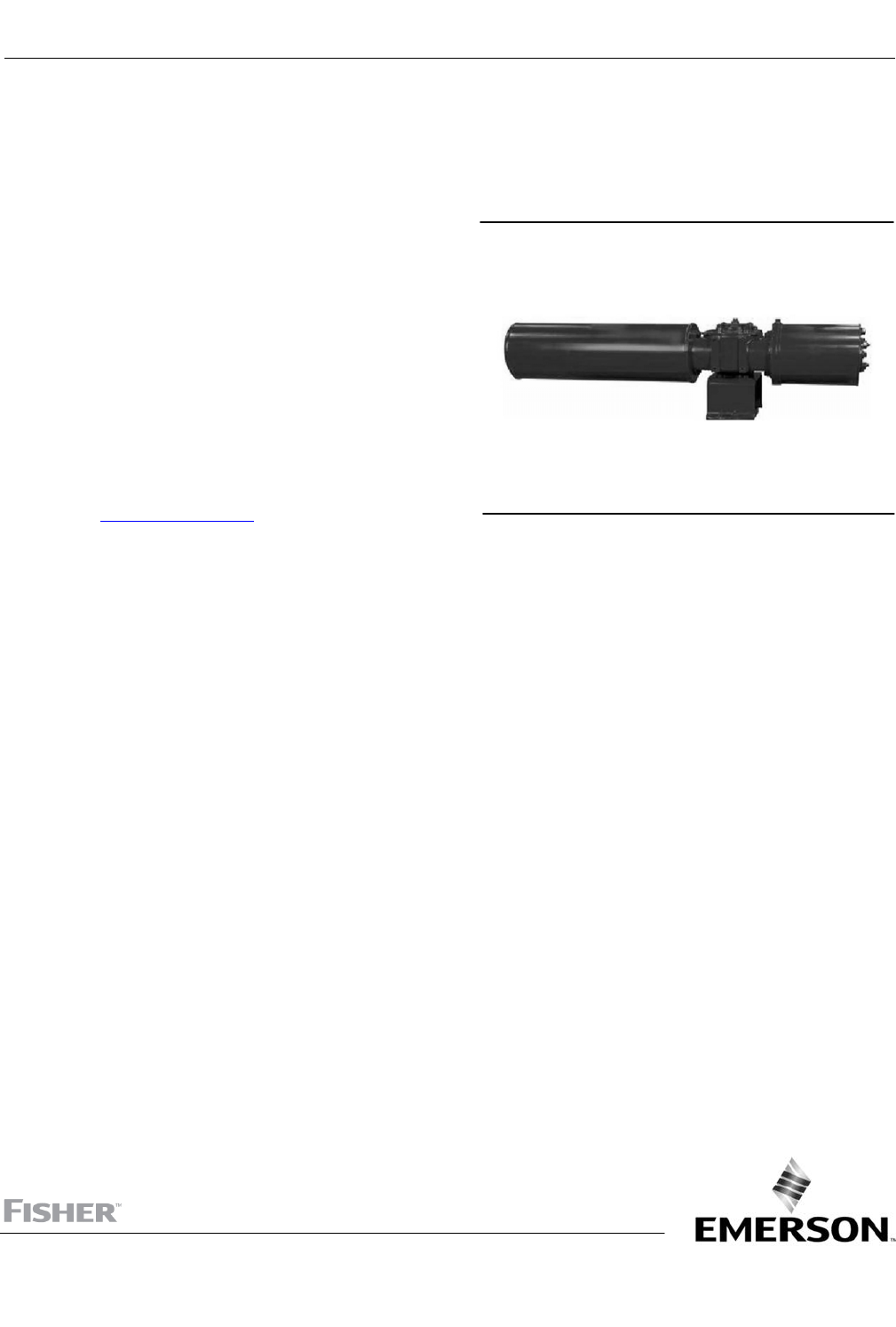
Service Instructions for Fisher™ G01 through
G13 Pneumatic Actuators
This instruction manual was prepared by Actuation
Technologies.
Do not install, operate or maintain this product
without being fully trained and qualified in valve,
actuator and accessory installation, operation and
maintenance.
To avoid personal injury or property damage it is
important to carefully read, understand, and follow all
of the contents of this manual, including all safety
cautions and warnings.
If you have any questions about these instructions,
contact your Emerson sales office or Local Business
Partner before proceeding.
Fisher G2 Pneumatic Actuator
X1407
Instruction Manual
D102754X012
G01 through G13
September 2017

Instruction Manual
D102754X012
G01 through G13
November 2016
2
Emerson Automation Solutions
Marshalltown, Iowa 50158 USA
Sorocaba, 18087 Brazil
Cernay, 68700 France
Dubai, United Arab Emirates
Singapore 128461 Singapore
www.Fisher.com
The contents of this publication are presented for informational purposes only, and while every effort has been made to ensure their accuracy, they are not
to be construed as warranties or guarantees, express or implied, regarding the products or services described herein or their use or applicability. All sales are
governed by our terms and conditions, which are available upon request. We reserve the right to modify or improve the designs or specifications of such
products at any time without notice.
E 2004, 2017 Fisher Controls International LLC. All rights reserved.
Fisher is a mark owned by one of the companies in the Emerson Automation Solutions business unit of Emerson Electric Co. Emerson Automation Solutions,
Emerson, and the Emerson logo are trademarks and service marks of Emerson Electric Co. All other marks are the property of their respective owners.
Neither Emerson, Emerson Automation Solutions, nor any of their affiliated entities assumes responsibility for the selection, use or maintenance
of any product. Responsibility for proper selection, use, and maintenance of any product remains solely with the purchaser and end user.
Service Instructions
124840E Rev. G
March 2017
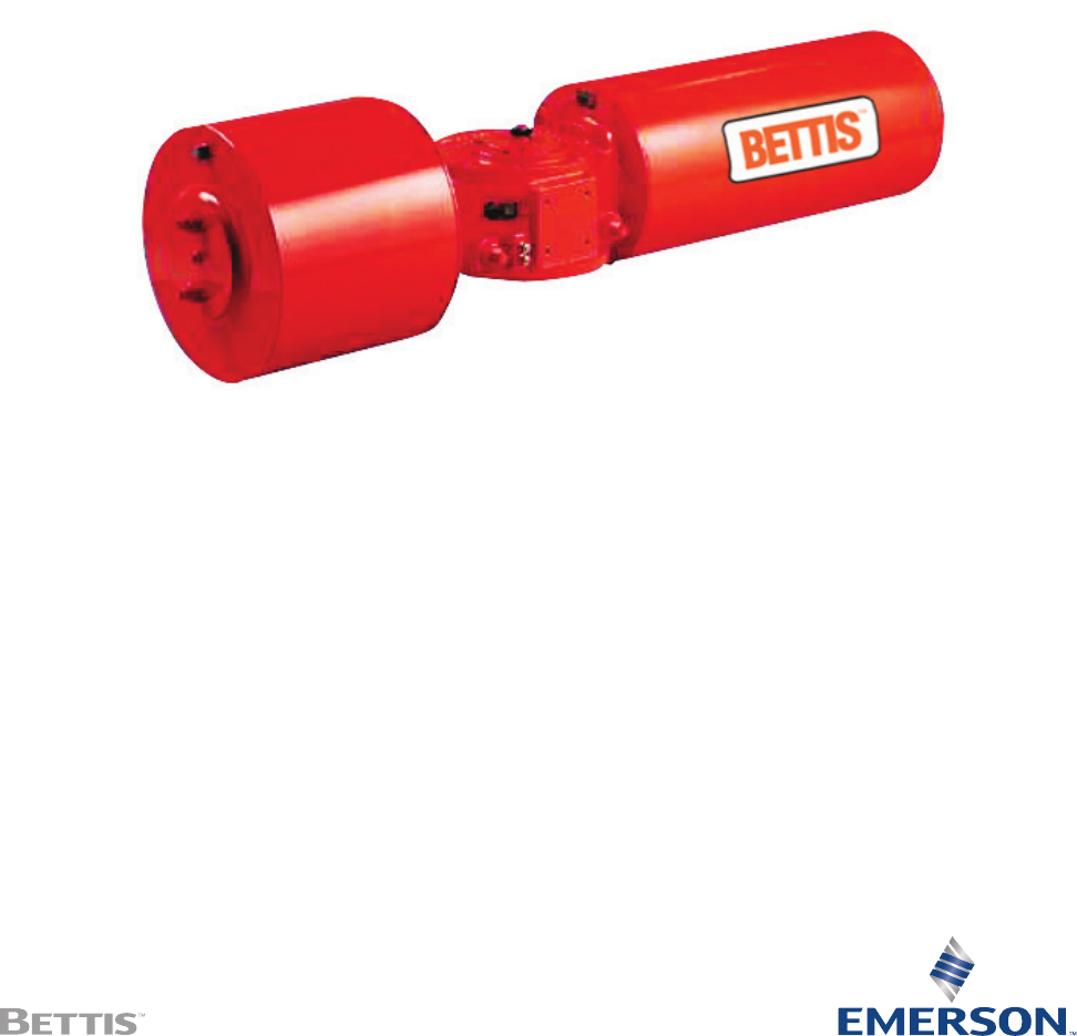
G/GH/GHC Series Pneumatic Actuators
Disassembly and Reassembly

I
Service Instructions
124840E Rev. G
Table of Contents
March 2017
Table of Contents
Table of Contents
Section 1: Introduction
1.1 General Service Information ......................................................................... 1
1.2 Denitions ................................................................................................... 2
1.3 General Safety Information ........................................................................... 2
1.4 Bettis Reference Materials ............................................................................. 3
1.5 Service Support Items .................................................................................. 3
1.6 Lubrication Requirements ............................................................................ 4
1.7 General Tool Information .............................................................................. 4
1.8 Actuator Storage ........................................................................................... 4
1.9 Actuator Installation ..................................................................................... 4
1.10 Actuator Start-up .......................................................................................... 5
1.11 Actuator Operation ....................................................................................... 6
Section 2: Actuator Disassembly
2.1 General Disassembly ..................................................................................... 7
2.2 Pneumatic Power Module Disassembly ......................................................... 8
2.3 Drive Module Disassembly .......................................................................... 11
2.4 Blind End Cap Module Removal ................................................................... 14
2.5 M3 Handwheel or M3 Hex Drive Hub Removal ........................................... 14
2.6 M3 Jackscrew Disassembly .......................................................................... 14
2.7 Extended Stop Blind End Cap Disassembly .................................................. 15
Section 3: Actuator Reassembly
3.1 General Reassembly .................................................................................... 16
3.2 Drive Module Reassembly ........................................................................... 16
3.3 Pneumatic Power Module Reassembly ........................................................ 21
3.4 G2 and G3 Early Model Pneumatic Power Module Reassembly..................... 26
3.5 Blind End Cap Module Reassembly .............................................................. 29
3.6 M3 Jackscrew Reassembly ........................................................................... 29
3.7 M3 Handwheel or M3 Hex Drive Hub Installation ......................................... 31
3.8 Extended Stop Blind End Cap Reassembly .................................................... 32
3.9 Actuator Testing ......................................................................................... 32
Section 4: Field Conversions
4.1 Fail Mode Reversal (CW to CCW, Or CCW to CW) For G and GH Only ............ 34
4.2 Converting Double-Acting Actuator to Spring-Return ................................. 34
4.3 Converting Spring-Return Actuator to Double-Acting ................................. 34
4.4 Add an M3 Jackscrew to Blind End Cap Module ............................................ 35
4.5 Add an M3 Jackscrew to Power Module Outer End Cap ................................ 35
4.6 Add an M3 Jackscrew to Spring Module ....................................................... 35
4.7 Add an Extended Stop (ES) to Blind End Cap Module ................................... 35
4.8 Add an Extended Stop (ES) to Power Module Outer End Cap ........................ 35
4.9 Add an Extended Stop (ES) to Spring Module .............................................. 36

II
Table of Contents
March 2017
Service Instructions
124840E Rev. G
Table of Contents
Section 5: Module Removal and Installation
5.1 Spring Module Removal .............................................................................. 37
5.2 Spring Module Installation .......................................................................... 39
5.3 Pneumatic Power Module Removal ............................................................. 43
5.4 Pneumatic Power Module Installation ......................................................... 44
5.5 G2 Thru G13 Powr Swivl Removal (Excludes GH/GHC Model Actuators) ...... 46
5.6 G2 Thru G13 Powr Swivl Module Installation
(Excludes GH/GHC Model Actuators) ........................................................... 46
Section 6: Actuator Support Information
6.1 G/GC/GH/GHC Module Weights By Item Number
And Actuator Housing Size .......................................................................... 48
6.2 G01 Tool Style and Wrench Size .................................................................. 49
6.3 G/GC2 Tool Style and Wrench Size............................................................... 50
6.4 G/GC3 Tool Style and Wrench Size GH2/GHC2 for Item No 3-20 to 3-130 .... 50
6.5 G/GC4 Tool Style and Wrench Size GH3/GHC3 For Item No 3-20 to 3-130 ... 51
6.6 G/GC5 Tool Style and Wrench Size GH4/GHC4 For Item No 3-20 to 3-130 ... 51
6.7 G/GC7 Tool Style and Wrench Size GH5/GHC5 For Item No 3-20 to 3-130 ... 52
6.8 G/GC8 Tool Style and Wrench Size GH7/GHC7 For Item No 3-20 to 3-130 ... 52
6.9 G/GC10 Tool Style and Wrench Size GH8/GHC8 For Item No 3-20 to 3-130 . 53
6.10 G13 Tool Style and Wrench Size GH10/GHC10 For Item No 3-20 to 3-130 ... 53
Section 7: Troubleshooting
7.1 Fault Insertion ............................................................................................. 54
7.2 Operational Test .......................................................................................... 55
Section 8: Removal and Decommissioning
8.1 Removal and Decommissioning .................................................................. 56
Section 9: Document Revision ............................................57
Appendix A: List of Tables ...................................................58
Appendix B: List of Drawings ..............................................59

Service Instructions
124840E Rev. G
March 2017
1
Section 1: Introduction
Introduction
Section 1: Introduction
1.1 General Service Information
1.1.1 This service procedure is offered as a guide to enable general maintenance to
be performed on Bettis™ G/GC01XXX, G/GC2XXX, G/GC3XXX, G/GC4XXX, G/
GC5XXX, G/GC7XXX, G/GC8XXX, G/GC10XXX, G13XXX, and GH/GHC2XXX, GH/
GHC3XXX, GH/GHC4XXX, GH/GHC5XXX, GH/GHC7XXX, GH/GHC8XXX Spring-
Return (SR) Series Single Power Module Pneumatic Actuators. These procedures
can also be used on Bettis GXX2XX Double-Acting Series Twin Power Modules
Pneumatic Actuators.
1.1.2 Normal recommended service interval for this actuator series is ve years.
NOTE:
Storage time is counted as part of the service interval.
1.1.3 This procedure is applicable with the understanding that all electrical power and
pneumatic pressure has been removed from the actuator.
1.1.4 Remove all piping and mounted accessories that will interfere with the module(s)
that are to be worked on.
1.1.5 This procedure should only be implemented by a technically competent technician
who should take care to observe good workmanship practices.
1.1.6 Numbers in parentheses, ( ) indicate the bubble number (reference number) used
on the Bettis Assembly Drawing and Actuator Parts List.
1.1.7 This procedure is written using the stop screw side of the housing (1-10) as a
reference and this side will be considered the front side of the actuator.
The housing cover (1-20) will be the top of the actuator.
1.1.8 Actuator module weights are listed in Section 6 Table 6.1.
1.1.9 When removing seals from seal grooves, use a commercial seal removing tool or a
small screwdriver with sharp corners rounded off.
1.1.10 Use a non-hardening thread sealant on all pipe threads.
CAUTION: FOLLOW MANUFACTURER'S INSTRUCTIONS
Apply the thread sealant per the manufacturer’s instructions.
1.1.11 Bettis recommends that disassembly of the actuator should be done in a clean
area on a workbench.
March 2017
Service Instructions
124840E Rev. G
2
Section 1: Introduction
Introduction
1.2 Definitions
WARNING:
If not observed, user incurs a high risk of severe damage to actuator and/or fatal injury to personnel.
CAUTION:
If not observed, user may incur damage to actuator and/or injury to personnel.
NOTE:
Advisory and information comments provided to assist maintenance personnel to carry out
maintenance procedures.
NOTE:
This product is only intended for use in large-scale xed installations excluded from the
scope of Directive 2011/65/EU on the restriction of the use of certain hazardous substances
in electrical and electronic equipment (RoHS 2).
ES:
Extended stop screw (for travel stop adjustment over a full 100° degree travel range).
ES is not intended for use as a manual override.
M3:
Manual jackscrew override
GC/GH/GHC:
Canted / High pressure / High Pressure Canted (Canted Yoke) G-Series actuator
1.3 General Safety Information
1.3.1 Products supplied by Bettis, in its “as shipped” condition, are intrinsically safe if the
instructions contained within this Service Instruction are strictly adhered to and
executed by well trained, equipped, prepared and competent personnel.
WARNING: FOLLOW WARNING AND CAUTION SIGNS
For the protection of personnel working on Bettis actuators, this procedure should be
reviewed and implemented for safe disassembly and reassembly. Close attention should be
noted to the WARNINGS, CAUTIONS and NOTES contained in this procedure.

Service Instructions
124840E Rev. G
March 2017
3
Section 1: Introduction
Introduction
WARNING: FOLLOW COMPANY SAFETY PROCEDURES
This procedure should not supersede or replace any customer’s plant safety or work
procedures. If a conict arises between this procedure and the customer’s procedures the
differences should be resolved in writing between an authorized customer's representative
and an authorized Bettis representative.
1.4 Bettis Reference Materials
1.4.1 Assembly Drawing for G/GC01 through G/GC10 and G13 Double-Acting One
Power Module Pneumatic Series Actuators use part number 116422.
1.4.2 Assembly Drawing for G01 through G13 Double-Acting Twin Power Module
Pneumatic Series Actuators use part number 115678.
1.4.3 Assembly Drawing for G/GC01 through G/GC10 and G13 Spring-Return One
Power Module Pneumatic Series Actuators use part number 115674.
1.4.4 Assembly Drawing for GH/GHC 2 through 10, Spring-Return One Power Module
Pneumatic Series Actuators use part number 140952.
NOTE:
If you require a specic Assembly Drawing (IE: GXX-M3 OR HYD) please contact Emerson
Actuation Technologies Bettis by phone or email at Info.actuationtechnologies@emerson.com
1.5 Service Support Items
1.5.1 Bettis Module Service Kit.
NOTE:
Although the below part numbers say GXX, they can also be used on G/GC/GH/GHCXX
actuators.
1.5.2 For rod extension retainer nut tool part number, refer to the table below.
NOTE:
These tools are required only when extension rod assembly (1-50) or (9-50) is removed or
when a new extension rod assembly is installed.
Table 1. Rod Extension Retainer Nut Tool Part Number
ACTUATOR
MODEL
BETTIS
PART NUMBER
ACTUATOR
MODEL
BETTIS
PART NUMBER
G01 None Required G5/G7 117369
G2 123616 G8/G10 117368
G3/G4 117370 G13 122849
1.5.3 Commercial leak testing solution.
1.5.4 Non-hardening thread sealant.

March 2017
Service Instructions
124840E Rev. G
4
Section 1: Introduction
Introduction
1.6 Lubrication Requirements
NOTE:
Lubricants other than those listed in steps 1.6.1 should not be used without prior written
approval of Bettis Product Engineering.
1.6.1 All temperature services (-50°F to +350°F)/(-45.5°C to 176.6°C) use Bettis ESL-5
lubricant. ESL-5 lubricant is contained in the Bettis module service kit in tubes and
the tubes are marked ESL-4, 5 and 10 lubricant.
1.7 General Tool Information
1.7.1 Tools: All tools/Hexagons are American Standard inch (Imperial). Large adjustable
wrench, two (2) large screwdrivers, Allen wrench set, set of open/box-end
wrenches, rubber or leather mallet, torque wrench (up to 1600 foot pounds / 2169
N-m), breaker bar, and a drive socket set. For recommended tool and wrench sizes
refer to Section 6, Tables 6.2 through 6.10.
1.8 Actuator Storage
For applications where the actuator is not placed into immediate service, it is
recommended that the actuator be cycled with regulated clean/dry pneumatic pressure
at least once per month. Indoor storage, if available, is recommended for all actuators.
Care should be taken to plug all open ports on actuator and controls to keep out foreign
particles and moisture. Actuators should not be stored in an atmosphere that is harmful to
resilient seals. Contact factory for extended storage period.
1.9 Actuator Installation
1.9.1 Since there are many valve and actuator combinations, it is not practical to include
detailed instructions for each type. Mountings are designed to be as simple as
possible to keep the guess work out of the installation.
1.9.2 Actuators that are shipped from the factory with the travel stops adjusted for
approximately ninety degree rotation. Generally, it is necessary to make slight
travel stop adjustments once the actuator is installed onto the valve. Refer to the
valve manufacturer's recommendations for specic requirements. When the valve
has internal stops, the actuator should be adjusted at the same points.
NOTE:
The actual "stopping" should be done by the actuator. If the valve does not have internal
stops, adjust the actuator to the full open position. Using this as a reference point, rotate
the valve closed and adjust to the valve manufacturer's specications for total rotation.

Service Instructions
124840E Rev. G
March 2017
5
Section 1: Introduction
Introduction
1.9.3 Good instrument practices are also recommended. Clean/dry regulated
pneumatic pressure is essential for long service life and satisfactory operation.
It should be noted that new pneumatic lines often have scale and other debris in
them and these lines should be purged of all foreign material.
NOTE:
Scale and debris can damage control valves, solenoids, and seals.
1.10 Actuator Start-up
1.10.1 Prestart-up checks
1. Inspect to ensure the unit has been mounted onto valve properly. Gear
ange mounting bolts, stem key, setscrew(s) are installed and secured.
2. No tubing damaged or accessories dislodged during the shipping or the
installation.
3. Indicated position conrms valve position.
4. All switching valves in normal operating position as per
SCHEMATIC / INSTRUCTIONS
1.10.2 Check Connections
1. Pneumatic / hydraulic components connected as per schematic enclosed or
in service manual supplied.
2. Pneumatic supply connected to the identied ports.
3. Electrical connection terminals are secured.
4. Wiring as per enclosed diagram or service manual supplied.
1.10.3 When actuator is rst placed into service, it should be cycled with regulated
pneumatic pressure. This is necessary because the seals have been stationary,
causing them to take a "set". Therefore, the actuator should be operated through
several cycles to exercise the seals so as to achieve a service ready condition.
1.10.4 The actuator speed of operation is determined by a number of factors includes:
1. Power supply line length
2. Power supply line size
3. Power supply line pressure
4. Control valve and tting orice size
5. Torque requirements of the valve
6. Size of the actuator
7. Setting of speed controls
8. Hydraulic Manual Override (where available)

March 2017
Service Instructions
124840E Rev. G
6
Section 1: Introduction
Introduction
1.10.5 Due to the interaction of these variables, it is difcult to specify a "normal"
operating time. Faster operating time may be obtained by using one or more of
the following:
1. Larger supply lines
2. Larger control valve
3. Higher supply pressure *
4. Quick exhaust valves
— * Not to exceed maximum operating pressure of actuator or control components
1.10.6 Slower operating time may be obtained by using ow control valves to meter the
exhaust. Excessive exhaust ow metering may cause erratic operation.
1.11 Actuator Operation
1.11.1 Controlled Operation: Controlled operation is accomplished by pressurizing and/or
depressurizing the appropriate cylinder inlet(s) of a double-acting. Do not exceed
pressures indicated on actuator nameplate.
1.11.2 Manual Operation: All pressure must be vented or equalized on both sides of the
pneumatic piston prior to manual operation.

Service Instructions
124840E Rev. G
March 2017
7
Section 2: Actuator Disassembly
Actuator Disassembly
Section 2: Actuator Disassembly
2.1 General Disassembly
WARNING: DANGEROUS GAS AND/OR LIQUIDS
It is possible, that the actuator may contain a dangerous gas and/or liquids. Ensure that
all proper measures have been taken to prevent exposure or release of these types of
contaminants before commencing any work.
2.1.1 Section 2 - Actuator Disassembly is written to either completely disassemble
the entire actuator or can be used to disassemble individual modules as needed
(pneumatic power module or drive module, etc.).
WARNING: BEWARE OF COMPRESSED SPRING
Do not remove spring module while spring is compressed
WARNING: READ WARNING TAGS
Actuators equipped with a spring cartridge mounted M3 jackscrew or an extended stop
(ES) read warning tag wired to the spring cartridge cover plate
2.1.2 When the spring module is to be removed it should be removed from the drive
module prior to the pneumatic power module removal or disassembly.
2.1.3 The pneumatic power module can be disassembled while still attached to the drive
module or the pneumatic power module can be removed from the drive module and
disassembled separate to the actuator (refer to Section 5 - Module Removal
And Installation).
2.1.4 To ensure correct re-assembly; that is, with pneumatic power module or spring
module on same end of drive module as was, mark or tag right (or left) and mark
mating surfaces.
2.1.5 For spring module removal refer to Section 5 step 5.1.

March 2017
Service Instructions
124840E Rev. G
8
Section 2: Actuator Disassembly
Actuator Disassembly
2.2 Pneumatic Power Module Disassembly
NOTE:
Review Section 2 steps 2.1.1 through 2.1.5 General Disassembly before proceeding with
Pneumatic Power Module Disassembly.
NOTE:
If the actuator model is a GXX2XX Series (two same size power modules with one module
mounted on each side of the drive module) then do the following steps on both power
modules simultaneously or complete one power module and then repeat section 2.2 on
the second power module
WARNING: REMOVE PRESSURE FROM CYLINDERS
If not already removed disconnect all operating pressure from actuator power cylinders.
WARNING: FOLLOW CORRECT DISASSEMBLY STEPS
If the actuator is spring-return then the spring cartridge must be checked to verify that
the spring(s) are in their extended position before the pneumatic power module is
disassembled from the drive module (refer to Section 5.1 through step 5.1.6).
2.2.1 Mark and record location of the ports on outer end cap (3-80) and inner end cap (3-10).
NOTE:
If actuator is equipped with a spring module complete step 2.2.2. If actuator is a double-
acting model skip step 2.2.2 and go to step 2.2.3.
2.2.2 Remove breather assembly (12) from outer end cap (3-80).
2.2.3 Refer to Assembly Drawing page 2 of 2 Detail "E". Remove two socket cap screws
(3-130), with lockwasher (3-140), from outer end cap (3-80).
NOTE:
If the power module is equipped with an M3 jackscrew remove the M3 jackscrew using
Section 2.6.5 for G/GH01 models and Section 2.6.6 for G/GH2 and G/GH3 models.
2.2.4 Outer end cap (3-80) removal as follows:
2.2.4.1 G/GC01 through G/GC10, G13, and GH/GHC2 through GH/GHC10
standard end cap (3-80) removal. Continue at step 2.2.5.
2.2.4.2 G/GC01-M3 jackscrew disassembly from outer end cap (3-80)
2.2.4.2.1 Remove M3 handwheel or M3 hex drive hub from M3 (3-290)
per Section 2.5.

Service Instructions
124840E Rev. G
March 2017
9
Section 2: Actuator Disassembly
Actuator Disassembly
2.2.4.2.2 Refer to Assembly Drawing page 2 of 2 Detail "E". If not already
removed unscrew and remove two socket cap screws (3-130),
with lockwasher (3-140), from outer end cap (3-80).
2.2.4.2.3 Remove socket cap screw (3-130) with lockwasher (3-140)
from keeper (3-360).
2.2.4.2.4 Remove keeper (3-360) from outer end cap (3-80).
2.2.4.2.5 Push jackscrew (3-290) back into the outer end cap far enough
so that the jackscrew adapter (3-280) will not interfere with the
removal of hex nuts (3-90). Continue at step 2.2.5.
2.2.4.3 G/GC/GH/GHC02 & G/GC/GH/GHC3-M3 jackscrew disassembly from
outer end cap (3-80)
2.2.4.3.1 Remove M3 handwheel or M3 hex drive hub from M3 (3-290)
per Section 2.5.
2.2.4.3.2 Unscrew and remove hex at nut (3-300) from G2/G3 M3
jackscrew (3-290).
2.2.4.3.3 Unscrew and remove two socket cap screws (3-320) from G2/
G3 M3 adapter (3-280).
2.2.4.3.4 Remove M3 jackscrew (3-290) from outer end cap (3-80).
Continue at step 2.2.5.
2.2.5 Remove two tie bar hex nuts (3-90) from outboard side of outer end cap (3-80).
2.2.6 The t between cylinder (3-70) and outer end cap (3-80) is very tight. Break end
cap free by tapping with a breaker bar on lip provided on the end cap. Remove
outer end cap (3-80) from cylinder (3-70).
CAUTION: CAREFULLY REMOVE END CAP CYLINDER
Do not damage O-ring groove when removing end cap from cylinder.
NOTE:
When removing cylinder (3-70) off of piston (3-30), tilt the cylinder 15° to 30° with respect
to actuator centerline.
2.2.7 Remove cylinder (3-70) from inner end cap (3-10).
CAUTION: USE CORRECT TOOLS
Do not use pipe wrench to remove tie bars.
2.2.8 TIE BAR REMOVAL:
NOTE:
G/GC01, G/GC/GH/GHC2 and G/GC/GH/GHC3 models have ats on outboard end
of tie bars (3-20) for wrench placement.

March 2017
Service Instructions
124840E Rev. G
10
Section 2: Actuator Disassembly
Actuator Disassembly
2.2.8.1 Remove G/GC01, G/GC/GH/GHC2 and G/GC/GH/GHC3 tie bars (3-20) as follows:
2.2.8.1.1 Unscrew tie bars (3-20) from inner end cap (3-10). Pull the tie
bars out of the inner end cap far enough to expose the O-ring
seals (4-80).
2.2.8.1.2 Remove O-ring seals (4-80) from the inboard end of tie bars (3-20).
2.2.8.1.3 Remove tie bars (3-20) by pulling the tie bars out and through
piston (3-30).
NOTE:
G/GC4 models have ats on outboard end of tie bars (3-20) for wrench placement.
NOTE:
G5 through G13, and GH/GHC5 through GH/GHC10 models have a female square
on the out board end of tie bars (3-20) for wrench placement.
2.2.8.2 Remove G4 through G13 tie bars (3-20) as follows: Unscrew and remove
tie bars (3-20) from inner end cap (3-10) and piston (3-30).
2.2.9 Remove piston as follows: (On early G2 and G3 models equipped with outboard
and inboard tie bar nuts skip this step and go to step 2.2.11).
2.2.9.1 Refer to Assembly Drawing page 2 of 2 Detail "D". Remove two split ring
halves (3-50) and one retainer ring (3-60) from outboard side of piston (3-30).
NOTE:
Piston (3-30) acts as the retainer for inboard split ring halves (3-50). When remov-
ing the piston be careful to not lose inboard split ring halves (3-50).
2.2.9.2 Remove piston (3-30) and two split ring halves (3-50) from piston rod (3-40).
NOTE:
Steps 2.2.10 is used only on early G2 and G3 models equipped with outboard and inboard
tie bar nuts.
2.2.10 Remove early model G2 and G3 pistons as follows:
2.2.10.1 Refer to Assembly Drawing page 2 of 2 Detail "D". Remove two split ring
halves (3-50) and one retainer ring (3-60) from inboard side of piston (3-30).
NOTE:
Piston (3-30) acts as the retainer for outboard split ring halves (3-50).
2.2.10.2 Slide piston (3-30) toward the inner end cap (3-10) until the out board
split ring halves is exposed enough for removal. Remove outboard split
ring halves from piston rod (3-40).

Service Instructions
124840E Rev. G
March 2017
11
Section 2: Actuator Disassembly
Actuator Disassembly
2.2.10.3 Remove piston (3-30) and two split ring halves (3-50) from piston rod (3-40).
2.2.11 Remove O-ring seal (4-70) from piston rod (3-40).
2.2.12 Remove hex cap screws (3-100) with lockwashers (3-110) from housing (1-10).
2.2.13 Remove inner end cap (3-10) off of piston rod (3-40).
NOTE:
On early model G2 and G3 actuators remove two hex nuts (3-90) from housing (1-10).
These two nuts will be loose after tie bars (3-20) are removed in step 2.2.8.1 and will be
located in the area where the piston rod passes through the housing (1-10).
NOTE:
The piston rod (3-40) removal as outlined in step 2.2.14 is only required when the piston
rod is being replaced or when the drive module is to be disassembled.
2.2.14 Unscrew and remove piston rod (3-40) from drive module.
2.3 Drive Module Disassembly
NOTE:
Review Section 2 steps 2.1.1 through 2.1.5 general disassembly before proceeding with
drive module disassembly.
2.3.1 If not already removed remove piston rod (3-40) from drive module.
NOTE:
If the actuator is equipped with submerged stop screws with stop screw covers (1-195)
then proceed to and complete steps 2.3.2.1 and 2.3.2.2 prior to doing step 2.3.2.
2.3.2 Mark stop screws (1-180) left and right. The setting of stop screws (1-180) should
be checked and setting recorded before stop screws are loosened or removed.
NOTE:
Stop screws will be removed later in this procedure.
2.3.2.1 Hold stop screw cover (1-195) in place and remove pipe plug (1-260).
2.3.2.2 Hold submerged stop screw (1-180) in place and remove stop screw
cover (1-195).

March 2017
Service Instructions
124840E Rev. G
12
Section 2: Actuator Disassembly
Actuator Disassembly
NOTE:
For steps 2.3.3 through 2.3.10 refer to Assembly Drawing page 2 of 2 Section A-A, Detail
“F” on drawing part number 115674 and Detail “G” on drawing part number 116422.
2.3.3 Before removing position indicator (1-220), record or mark its position.
Remove position indicator (1-220).
NOTE:
Step 2.3.4 is used only on G01, GH/GHC 2 and GH/GHC 3 drive modules. Drive modules GH/
GHC4 through G/GC/GH/GHC10 and G13 will skip steps 2.3.4 and continue with step 2.3.5.
2.3.4 Remove one vent check assembly (13) from top of housing cover (1-20).
2.3.5 Unscrew and remove hex cap screws (1-160) with lockwashers (1-170) from yoke
cover (1-150).
2.3.6 Remove yoke cover (1-150) from housing cover (1-20).
2.3.7 Mark and record the orientation of the position indicator assembly (1-140) in
relation to the top of yoke (1-70).
2.3.8 Remove position indicator assembly (1-140) from top of yoke (1-70).
2.3.9 Remove spring pin (1-100) from top of yoke (1-70).
2.3.10 Remove hex cap screws (1-110), with lockwashers (1-115) from housing cover (1-20).
NOTE:
Steps 2.3.11 and 2.3.12 are used only on G/GC/GH/GHC5, G/GC/GH/GHC7, G/GC/GH/
GHC8 & 10 drive modules. Drive modules G/GC01, G/GC/GH/GHC2 through 4 will skip
steps 2.3.11 and 2.3.12 and continue with step 2.3.13.
2.3.11 Remove hex cap screws (1-120), with lockwashers (1-115), from housing cover
(1-20).
2.3.12 Using hex cap screws (1-110), install into holes vacated by hex cap screws (1-120).
Use these hex cap screws to jack the housing cover up for removal. Alternately rotate
the hex cap screws clockwise until housing cover (1-20) is clear of housing (1-10).
NOTE:
G/GC01, G/GC/GH/GHC2 through 4 model housing cover will have cast tabs for placing
prying tools to aid in cover removal.
2.3.13 Remove housing cover (1-20) from housing (1-10).
NOTE:
Groove pins (1-130) will remain in housing cover (1-20) when housing cover is removed
from housing (1-10). Groove pins (1-130) should not be removed from housing cover (1-
20) unless they are damaged and require new replacements.

Service Instructions
124840E Rev. G
March 2017
13
Section 2: Actuator Disassembly
Actuator Disassembly
2.3.14 Refer to Assembly Drawing page 2 of 2 Detail "B". Remove guide bar (1-90) from
housing (1-10).
2.3.15 Remove top yoke pin thrust bearing (2-10) from top of yoke pin (1-80).
2.3.16 Rotate the arms of yoke (1-70) to the center position of housing (1-10).
2.3.17 Remove yoke (1-70) with yoke pin (1-80), guide block (1-30) and two yoke/guide
block bushings (2-30), by lifting yoke up and out of the housing (1-10).
2.3.18 Remove bottom yoke pin thrust bearing (2-10) from inside bottom of housing (1-10).
2.3.19 Remove yoke pin (1-80) by inserting 3/8"-16 UNC screw into top of the yoke pin
and pull straight up and out.
2.3.20 Remove guide block (1-30) from between the arms of yoke (1-70).
2.3.21 Remove yoke/guide block bushing (2-30) from top of guide block (1-30).
2.3.22 Remove yoke/guide block bushing (2-30) from the top of the lower yoke arm of yoke (1-70).
NOTE:
G01 model actuators skip steps 2.3.23 through 2.3.25 and continue disassembly at step 2.3.26.
2.3.23 Refer to Assembly Drawing page 2 of 2 Detail "B". Use Bettis tool part numbers
117368 (G8/G10), 117369 (G5/G7), 117370 (G3/G4), 122849 (G13) or 123616
(G2) and remove retention retainer nut assemblies (1-60) from guide block (1-30).
On spring-return actuators also remove retention retainer nut assemblies (9-60).
These tools can be used for GC/GH/GHC models of equivalent size.
2.3.24 Remove extension rod assembly (1-50) from guide block (1-30). On spring-return
actuators also remove rod extension assembly (9-50).
NOTE:
On G/GC models only (Non GH/GHC): One spherical washer (1-40) will be removed from guide
block (1-30) when extension rod assembly is removed. On spring-return actuators also one spherical
washer (9-40) will be removed from guide block (1-30). On GH/GHC actuators, there is no extension
rod assembly; the piston rod is fastened directly into the guide block assembly instead.
2.3.25 Remove the remaining spherical washer (1-40) from guide block (1-30). On spring-
return actuators also remove the remaining spherical washer (9-40) from guide
block (1-30).
2.3.26 Unscrew and remove two stop screw nuts (1-190) from stop screws (1-180).
2.3.27 Unscrew and remove two stop screws (1-180) from front of housing (1-10).
2.3.28 Housing (1-10) vent check assembly removal as follows:
2.3.28.1 G01, G/GC/GH/GHC2 and G/GC/GH/GHC3 housing (1-10) unscrew and
remove one vent check assembly (13) from the front of housing (1-10).
2.3.28.2 G/GC/GH/GHC4 through G/GC/GH/GHC10 and G13 housing (1-10)
unscrew and remove two vent check assembly’s (13) from the front of
housing (1-10).
2.3.29 The following items do not need to be removed from their assembled locations
unless being replaced by new items: Two guide bar bearings, two yoke bearings
(2-40), yoke pin bearing and yoke pin thrust bearing (2-10).

March 2017
Service Instructions
124840E Rev. G
14
Section 2: Actuator Disassembly
Actuator Disassembly
2.4 Blind End Cap Module Removal
2.4.1 Remove hex cap screws (5-20), with spring lockwashers (5-30), from blind end cap (5-10).
2.4.2 Remove blind end cap (5-10) from end of housing (1-10).
2.5 M3 Handwheel or M3 Hex Drive Hub Removal
2.5.1 M3 HANDWHEEL OR HEX DRIVE HUB REMOVAL FROM M3 STUD.
2.5.1.1 Using pin punch drive out two grooved pins (10-20) and (10-30) from
handwheel hub or hex drive hub (10-10).
2.5.1.2 Remove handwheel or hex drive hub (10-10) from M3 stud (5-50).
2.5.2 EARLY MODEL G2 & G3 M3 HANDWHEEL AND HEX NUT REMOVAL FROM
JACKSCREW
2.5.2.1 Remove hex nut, lockwasher from M3 jackscrew.
2.5.2.2 Remove handwheel from M3 jackscrew.
2.5.2.3 Using pin punch drive out spiral pin from outboard end of M3 jackscrew
2.5.2.4 Remove hex nut from M3 jackscrew, and handwheel.
2.6 M3 Jackscrew Disassembly
NOTE:
The jackscrew bearing retainer (7-110) / (5-110), needle bearing thrust washer assembly
(7-100) / (5-100) or retainer ring (7-90) / (5-90) does not require disassembly from the
jackscrew assembly (7-40) / (5-50) except for the need to replace worn parts.
For disassembly of these items refer to step 2.6.7. Remove M3 handwheel or M3 hex drive
hub per Section 2.5.
2.6.1 G01-M3 JACKSCREW DISASSEMBLY FROM BLIND END CAP
2.6.1.1 Remove M3 handwheel or M3 hex drive hub per Section 2.5.
NOTE:
See note 2.6 before proceeding with step 2.6.1.2 through 2.6.1.4.
2.6.1.2 Unscrew and remove socket cap screw (5-120) with lockwasher (5-130)
from keeper (5-140).
2.6.1.3 Remove keeper (5-140) from blind end cap (5-10).
2.6.1.4 Remove M3 jackscrew (5-50) from blind end cap (5-10).
2.6.2 G2-M3 and G3-M3 JACKSCREW DISASSEMBLY FROM BLIND END CAP
2.6.2.1 Remove M3 handwheel or M3 hex drive hub per Section 2.5.
NOTE:
See 2.6 note before proceeding with step 2.6.2.2 through 2.6.2.4.

Service Instructions
124840E Rev. G
March 2017
15
Section 2: Actuator Disassembly
Actuator Disassembly
2.6.2.2 Unscrew and remove hex at nut (5-60) from G2/G3 M3 jackscrew.
2.6.2.3 Unscrew and remove two socket cap screws (5-120) from G2/G3 M3
adapter.
2.6.2.4 Remove M3 jackscrew (5-50) from blind end cap (5-10).
2.6.3 G01-SR-M3 JACKSCREW DISASSEMBLY FROM SR-M3 ADAPTER PLATE
2.6.3.1 Remove M3 handwheel or M3 hex drive hub per Section 2.5.
NOTE:
See 2.6 note before proceeding with step 2.6.3.2 through 2.6.3.4.
2.6.3.2 Unscrew and remove hex at nut (7-50) from M3 jackscrew assembly
(7-40).
2.6.3.3 Remove retainer ring (7-55) from M3 adapter (7-45).
2.6.3.4 Remove M3 jackscrew assembly (7-40) from M3-SR adapter plate (7-10).
2.6.4 G2 AND G3-SR-M3 JACKSCREW DISASSEMBLY FROM SR-M3 ADAPTER PLATE
2.6.4.1 Remove M3 handwheel or M3 hex drive hub per Section 2.5.
NOTE:
See 2.6 note before proceeding with step 2.6.4.2 through 2.6.4.4.
2.6.4.2 Unscrew and remove hex at nut (7-50) from M3 jackscrew assembly
(7-40).
2.6.4.3 Unscrew and remove two socket cap screws (7-120) from M3 adapter
(7-40).
2.6.4.4 Remove M3 jackscrew (7-40) from M3-SR adapter plate (7-10).
2.6.5 M3 THRUST BEARING DISASSEMBLY FROM M3 JACKSCREW ASSEMBLY
2.6.5.1 Remove M3 bearing retainer (5-110) / (7-110) from inboard end of M3
jackscrew assembly (5-50) / (7-40).
2.6.5.2 Remove needle roller thrust bearing (5-100) / (7-100) from M3 bearing
retainer (5-110) / (7-110).
2.6.5.3 Remove retainer ring (5-90) / (7-90) from M3 jackscrew assembly
(5-50) / (7-40).
2.7 Extended Stop Blind End Cap Disassembly
2.7.1 Unscrew and remove hex nut (5-60) from ES stop screw (5-50).
2.7.2 Remove ES stop screw (5-50) from ES blind end cap (5-10).

March 2017
Service Instructions
124840E Rev. G
16
Section 3: Actuator Reassembly
Actuator Reassembly
Section 3: Actuator Reassembly
3.1 General Reassembly
CAUTION: CHECK SHELF LIFE OF SEALS
Only new seals, which are still within the seal’s expectant shelf life, should be installed into
the actuator being refurbished.
3.1.1 Remove and discard all old seals and gaskets.
3.1.2 All parts should be cleaned to remove all dirt and other foreign material prior
to inspection.
3.1.3 All parts should be thoroughly inspected for excessive wear, stress cracking,
galling and pitting. Attention should be directed to threads, sealing surfaces and
areas that will be subjected to sliding or rotating motion. Sealing surfaces of the
cylinder, tie bars and piston rod must be free of deep scratches, pitting, corrosion
and blistering or aking coating.
CAUTION: REPLACE WITH NEW PARTS
Actuator parts that reect any of the above listed characteristics should be replaced with new parts.
3.1.4 Before installation coat all moving parts with a complete lm of lubricant.
Coat all seals with a complete lm of lubricant, before installing into seal grooves.
NOTE:
The parts and seals used in the actuator will be assembled using lubricant as identied in
section 1 step 1.6.1.
3.1.5 For spring module installation refer to Section 5 step 5.2.
3.2 Drive Module Reassembly
NOTE:
Review section 3.1 General Reassembly before proceeding with Drive Module Reassembly
Refer to Assembly Drawing page 2 of 2 Detail "B" for section drawing of guide block.
3.2.1 If guide bar bearing (2-20) is being replaced install new bearing into guide block (1-30).
NOTE:
The guide bar bearing (2-20) must be pressed into guide block guide bar bore with the
seam located ±5 degrees of the top or bottom centerline as shown in section A-A.

Service Instructions
124840E Rev. G
March 2017
17
Section 3: Actuator Reassembly
Actuator Reassembly
NOTE:
G01 model actuators skip steps 3.2.2 through 3.2.13 and continue reassembly at step
3.2.14.
3.2.2 Lubricate guide block (1-30), two spherical washers (G/GC only)(1-40), and one
extension rod assembly (G/GC only)(1-50).
NOTE:
STEPS 3.2.3 – 3.2.13 FOR G/GC MODELS ONLY (Not GH/GHC):
3.2.3 Install one spherical washer (1-40) into the side of guide block (1-30).
NOTE:
The spherical side of washer (1-40) will be facing to the outside of guide block (1-30).
3.2.4 Install second spherical washer (1-40) over threaded end of extension rod assembly (1-50).
NOTE:
The spherical side of the washer will go on the extension rod assembly facing the
head of the extension rod assembly.
3.2.5 Install extension rod assembly (1-50) into guide block (1-30) and up against the
rst spherical washer (1-40).
3.2.6 Install extension retainer nut assembly (1-60) over extension rod assembly (1-50)
and screw into guide block (1-30).
3.2.7 Tighten extension retainer nut assembly (1-60) until extension rod assembly
(1-50) cannot move. Back off the extension retainer nut assembly (1-60) just
enough to allow for extension rod assembly (1-50) to move freely.
NOTE:
Steps 3.2.8 through 3.2.13 are to be completed when the actuator is equipped with a
spring module. If the actuator is double-acting then skip steps 3.2.8 through 3.2.13 and
continue actuator reassembly starting with step 3.2.14.
3.2.8 Lubricate two spherical washers (9-40) and one extension rod assembly (9-50).
3.2.9 Install one spherical washer (9-40) into the side of guide block (1-30).
NOTE:
The spherical side of washer (9-40) will be facing to the outside of guide block (1-30).
3.2.10 Install second spherical washer (9-40) over threaded end of extension rod assembly (9-50).

March 2017
Service Instructions
124840E Rev. G
18
Section 3: Actuator Reassembly
Actuator Reassembly
NOTE:
The spherical side of the washer will go on the extension rod assembly facing the
head of the extension rod assembly.
3.2.11 Install extension rod assembly (9-50) into guide block (1-30) and up against the
rst spherical washer (9-40).
3.2.12 Install extension retainer nut (9-60) over extension rod assembly (9-50) and screw
into guide block (1-30).
3.2.13 Tighten extension retainer nut assembly (9-60) until extension rod assembly
(9-50) cannot move. Back off the extension retainer nut assembly (9-60) just
enough to allow for extension rod assembly (9-50) to move freely.
NOTE:
Steps 3.2.14 and 3.2.15 are to be completed when the actuator is double-acting and
equipped with a Blind end cap extended stop screw.
3.2.14 Install guide block stop plug (5-50) into guide block (1-30).
3.2.15 Install and tighten rod extension retainer nut assembly (5-80) over guide block
stop plug (5-50) and screw into guide block (1-30).
NOTE:
Consult Houston, Texas Bettis Service Coordinator for “yoke bearing, yoke pin bearing or
yoke/guide block bushing installation information.
3.2.16 If the two yoke bearings (2-40) are being replaced, install new bearing into housing
cover (1-20) and housing (1-10).
NOTE:
The yoke bearing (2-40) must be pressed into housing (1-10) and housing cover (1-20).
Install the yoke bearings with the bearing seam located 45° ±5° degrees from the yoke arm
slot when yoke (1-70) is rotated to its full clockwise position.
3.2.17 If the two yoke pin bearings (2-10) are being replaced install new bearing into
housing cover (1-20) and housing (1-10).
3.2.18 Lubricate two yoke/guide block bushings (2-30) and install onto top and bottom
sides of guide block (1-30).
NOTE:
The guide block (1-30) should be already pre-assembled with extension rod assembly and
associated parts assembled in the guide block.
3.2.19 Install guide block (1-30), with yoke guide block bearings (2-30), between arms of
yoke (1-70).

Service Instructions
124840E Rev. G
March 2017
19
Section 3: Actuator Reassembly
Actuator Reassembly
3.2.20 Install one O-ring seal (2-50) into inner diameter seal groove in the bottom of
housing (1-10).
3.2.21 Coat the bearing surfaces of yoke (1-70) with lubricant and install into housing (1-10).
3.2.22 Align hole in guide block (1-30) with the matching holes in the two yoke/guide
block bushings (2-30) and the slots in the arms of yoke (1-70).
NOTE:
The yoke pin can be held in place by installing a screw into the .375-16UNC tapped hole in
the upper end of yoke pin (1-80).
3.2.23 Install yoke pin (1-80) by inserting into the upper yoke arm, upper yoke/guide
block bushing, guide block, lower yoke/guide block bushing, lower yoke arm and
resting on lower yoke pin thrust bearing (2-10).
3.2.24 Install guide bar (1-90) into either side of housing (1-10) by inserting through the
housing, through guide block and then insert the guide bar into the other side of
housing (1-10).
3.2.25 Refer to Assembly Drawing page 2 of 2 Section A-A. Install spring pin (1-100) into
the top of yoke (1-70).
3.2.26 Install position indicator assembly (1-140) onto the top of yoke (1-70) and over
spring pin (1-100).
NOTE:
Refer to Section 2 step 2.3.7 for correct installation position.
3.2.27 Install O-ring (2-50) into housing cover (1-20).
3.2.28 Install O-ring seal (2-60) into housing cover (1-20).
3.2.29 Install housing cover (1-20), being careful not to damage O-ring seals (2-50) and (2-60).
3.2.30 Place lockwashers (1-115) onto hex cap screws (1-110).
NOTE:
On G/GC/GH/GHC7,8,10 and G13 model actuators apply thread adhesive, Loctite 242, to
threads of hex cap screws (1-110). Reference Assembly Drawing note number 8.
3.2.31 Install hex cap screws (1-110) with lockwashers (1-115) through housing cover
(1-20) and into housing (1-10).
NOTE:
Leave hex cap screws (1-110) nger tight - do not tighten.

March 2017
Service Instructions
124840E Rev. G
20
Section 3: Actuator Reassembly
Actuator Reassembly
NOTE:
Do this step only if groove pins (1-130) have been pulled or if the pins are being replaced.
Drive groove pins (1-130) through housing cover (1-20) and into housing (1-10).
The groove pins should be ush with the cover.
3.2.32 Torque tighten hex cap screws (1-110) until a nal lubricated torque, as listed in
the following table, has been achieved.
Table 2. Housing Cover Screw Quantity and Torque Table
MODEL
G/GC/
GH/GHC
QTY
TORQUE
(±5 % Percent)
MODEL
G/GC/
GH/GHC
QTY
TORQUE
(±5 % Percent)
Lbf-ft. N-m Lbf-ft. N-m
G01 4 40 54 7 8 100 136
2 6 40 54 8 12 100 136
3 8 40 54 10 16 100 136
4 8 40 54 G13 20 340 461
5 8 100 136
NOTE:
Complete step 3.2.34 on G/GC/GH/GHC5, 7, 8, 10 and G13 model actuators. For G01 and
G/GC/GH/GHC2 through G/GC/GH/GHC4 model actuators skip step 3.2.34 and proceed to
step 3.2.35.
3.2.33 On G/GC/GH/GHC5, 7,8,10 and G13 models
3.2.33.1 Place lockwashers (1-115) onto hex cap screws (1-120).
NOTE:
Hex cap screw (1-120) are only used as "hole" llers and to protect threads
from environment.
3.2.33.2 Install and tighten hex cap screws (1-120) with lockwashers (1-115).
3.2.34 Install thrust bearing (2-110) onto position indicator (1-140).
3.2.35 Install O-ring seal (2-100) onto position indicator (1-140).
3.2.36 Install upper bearing (2-120) into yoke cover (1-150).
3.2.37 Install rod wiper (2-80) into yoke cover (1-150).
3.2.38 Install O-ring seal (2-70) into yoke cover (1-150).
3.2.39 Install yoke cover (1-150) onto housing cover (1-20) and over position indicator
assembly (1-140).
NOTE:
During yoke cover installation be careful not to damage O-ring seal (2-70) and rod
wiper (2-80).

Service Instructions
124840E Rev. G
March 2017
21
Section 3: Actuator Reassembly
Actuator Reassembly
3.2.40 Place lockwashers (1-170) onto hex cap screws (1-160).
3.2.41 Install and tighten hex cap screws (1-160) with lockwashers through yoke cover
(1-150) and into housing cover (1-20).
3.2.42 Vent check assembly installation as follows:
3.2.42.1 G01, G/GC/GH/GHC2 and G/GC/GH/GHC3 housing (1-10) using pipe sealant
install one vent check assembly (13) into the front of housing (1-10).
3.2.42.2 G01, G/GC/GH/GHC2 and G/GC/GH/GHC3 housing (1-10) using pipe sealant
install one vent check assemble (13) into the top area of housing cover (1-20).
3.2.42.3 G/GC/GH/GHC4,5,7,8,10 and G13 housing (1-10) using pipe sealant
install two vent check assemblies (13) into the front of housing (1-10).
3.2.43 Refer to Section 2 step 2.3.3 for correct position indicator placement. Install position
indicator (1-220) over the exposed shaft of position indicator assembly (1-140).
3.2.44 Install stop screw nuts (1-190) onto stop screws (1-180).
3.2.45 Install O-ring (2-90) onto stop screws (1-180).
3.2.46 Install two stop screws (1-180) into two stop screw holes on the front of
housing (1-10).
3.2.47 Adjust both stop screws (1-180) back to settings recorded earlier in Section 2 at
step 2.3.2.
3.2.48 Tighten both stop screw nuts (1-190) securely.
3.3 Pneumatic Power Module Reassembly
NOTE:
For early model G2 and G3 actuators with double nuts on the power module use section
3.4 for reassembly.
Refer to Section 2 step 2.1.4 for the correct installation location for piston rod (3-40).
THE ACTUATOR MUST BE IN THE APPROPRIATE OVERTRAVEL POSITION. Conrm over-travel
position by observing the guide block (1-30) is against the inner wall of housing (1-10).
3.3.1 Lubricate piston rod (3-40) and insert through the side of housing (1-10).
3.3.1.1 G2 through G13 screw piston rod (3-40) onto extension rod assembly
(1-50).
3.3.1.2 G01 only screw piston rod (3-40) onto guide block (1-30).
3.3.2 After conrming initial thread engagement rotate piston rod into extension rod
assembly (1-50) as listed in the following table.
WARNING: TURN ACCORDING TO TABLE
After initial thread engagement the Piston rod must be rotated clockwise the minimum
number of turns listed in the following table.
March 2017
Service Instructions
124840E Rev. G
22
Section 3: Actuator Reassembly
Actuator Reassembly
Table 3. Piston Rod Torque Information
ACTUATOR
MODEL
G/GC/GH/
GHC
12345 7 8 10 G13
MINIMUM
NO TURNS 610 10 10 13 14 20 25 31
3.3.3 Torque tighten piston rod (3-40) to the lubricated torque as listed in the
following table.
Table 4. Torque Tighten Piston Rod
HOUSING
MODEL
G/GC/GH/
GHC
TORQUE
(±5 % Percent)
HOUSING
MODEL
G/GC/GH/
GHC
TORQUE
(±5 % Percent)
Lbf-ft. N-m Lbf-ft. N-m
G01 90 122 7 240 325
2 90 122 8 240 325
3 90 122 10 240 325
4 240 325 G13 240 325
5 240 325
3.3.4 Refer to Assembly Drawing page 2 of 2 Detail "C". Install one rod wiper (4-10) into
inner end cap (3-10).
3.3.5 Install one rod bushing (4-20) into inner end cap (3-10).
3.3.6 Coat one Polypak seal (4-30) with lubricant and install, lip rst, into inner
end cap (3-10).
CAUTION: CHECK SEAL DIRECTION
Install the Polypak seal with energizer ring facing outboard side (away from housing).
3.3.7 Install one O-ring seal (4-90) into seal groove located on the inboard face of inner
end cap (3-10).
3.3.8 Install inner end cap (3-10) on to housing (1-10).
NOTE:
The pressure inlet port should be positioned in the same position as recorded in section 2.2
step 2.2.1.
3.3.9 Place lockwashers (3-110) onto hex cap screws (3-100).
3.3.10 Install and tighten hex cap screws (3-100)(GH/GHC7 model will have 4 more bolts
than the standard G and 2 more bolts on the GH/GHC8,10 models than the standard
G), with lockwashers, through housing (1-10) and into inner end cap (3-10).
3.3.11 Refer to Assembly Drawing page 2 of 2 Detail "D". Install one O-ring seal (4-70) into
the seal groove in piston rod (3-40).
3.3.12 Apply lubricant to two sets of rod T-seal components (4-50).

Service Instructions
124840E Rev. G
March 2017
23
Section 3: Actuator Reassembly
Actuator Reassembly
NOTE:
The T-seal is composed of one rubber seal and two split skive-cut back-up rings.
3.3.12.1 Install two sets of rod T-seals (4-50) into the internal diameter seal
grooves of piston (3-30).
3.3.12.2 Install a back-up ring on each side of the T-seal.
3.3.12.3 When installing the back-up rings, do not align the skive-cuts.
3.3.12.4 If the back-up rings are too long and the rings overlap beyond the skive-
cuts, then the rings must be trimmed with a razor sharp instrument.
3.3.13 Install two split ring halves (3-50) into the inner most groove in piston rod (3-40)
and retain by installing the recessed area of piston (3-30) onto the piston rod and
over the two split ring halves (3-50).
3.3.14 Install two split ring halves (3-50) into the piston rod, in front of the piston
installed in the previous step, and retain with retainer ring (3-60).
3.3.15 Install one O-ring seal (4-40) onto the outer diameter seal groove of inner end cap (3-10).
3.3.16 Coat one D-ring seal (4-60) with lubricant and install into the piston external seal groove.
NOTE:
The at side of the D-ring seal go down into the seal groove.
3.3.17 Coat two tie bars (3-20) with lubricant and install by carefully pushing tie bars
through piston (3-30) and rod T-seal (4-50).
3.3.18 Screw tie bars (3-20) into inner end cap (3-10) and tighten until the threads bottom
out.
3.3.19 Refer to Assembly Drawing page 2 of 2 Detail "E". Coat two O-ring seals (4-80) with
lubricant and install into outer end cap (3-80).
3.3.20 Apply lubricant to one O-ring seal (4-40) and install into the outer diameter O-ring
groove of outer end cap (3-80).
3.3.21 Apply lubricant to the bore of cylinder (3-70).
CAUTION: CAREFULLY INSTALL THE CYLINDER
If needed, when installing the cylinder, hammer on the end of the cylinder only with a non
metallic object.
3.3.22 Install lubricated cylinder (3-70) over piston (3-30) and onto inner end cap (3-10).
When installing the cylinder over the piston seal tilt cylinder 15 to 30 degrees to
piston rod.
3.3.23 OUTER END CAP (3-80) INSTALLATION AS FOLLOWS: G01-M3 use step 3.3.23.1,
G2-M3 and G3-M3 use step 3.3.23.2 and standard outer end cap use step 3.3.23.3.
NOTE:
The outer end cap (3-80) pressure inlet port should be positioned in the same position as
recorded in Section 2.2 step 2.2.1.

March 2017
Service Instructions
124840E Rev. G
24
Section 3: Actuator Reassembly
Actuator Reassembly
3.3.23.1 G01-M3 OUTER END CAP INSTALLATION
3.3.23.1.1 Apply a light coating of lubricant to threads of jackscrew (3-290).
3.3.23.1.2 Screw jackscrew adapter (3-280) onto jackscrew (3-290).
NOTE:
The smaller round end of the jackscrew adapter will install on
the jackscrew pointing to the outboard end of the jackscrew.
3.3.23.1.3 Position the jackscrew with the inboard end of the jackscrew
located with the needle bearing thrust washer assembly (3-
350) up against or near the jackscrew adapter (3-280).
3.3.23.1.4 Lightly lubricate O-ring seal (6-20) and install into O-ring
groove on the outboard side of the jackscrew adapter (3-280).
3.3.23.1.5 Insert jackscrew (3-290) through inboard side of the outer end
cap (3-80).
3.3.23.1.6 Install outer end cap (3-80) over tie bars (3-20) and into
cylinder (3-70).
3.3.23.1.7 Install tie bar nuts (3-90) onto tie bars (3-20).
NOTE:
Do not tighten nuts.
3.3.23.1.8 Install the jackscrew adapter keeper (3-360) into the groove
exposed on the outboard side of the jackscrew adapter (3-280).
3.3.23.1.9 Lightly lubricate O-ring seal (6-30) and install onto the
outboard end of the jackscrew. Push the O-ring (6-30) down
the jackscrew until it contacts the jackscrew adapter (3-280).
3.3.23.1.10 Install at hex nut (3-300) onto jackscrew (3-290). Rotate the
at hex nut (3-290) until it is up against O-ring seal (6-30).
3.3.23.1.11 Install outer end cap (3-80) over tie bars (3-20) and into
cylinder (3-70). Continue at step 3.3.24.
3.3.23.2 G/GC/GH/GHC 2 & G/GC/GH/GHC 3-M3 OUTER END CAP INSTALLATION
3.3.23.2.1 Lightly lubricate O-ring seal (6-10) and install into O-ring
groove in the M3 hole in the outer end cap (3-80).
3.3.23.2.2 Install the jackscrew (3-290) through the outboard side of the
outer end cap (3-80).
3.3.23.2.3 Apply a light coating of lubricant to threads of jackscrew (3-290).
3.3.23.2.4 Screw jackscrew adapter (3-280) onto jackscrew (3-290).
NOTE:
The small round end of the M3 adapter will install on the jack-
screw pointing to the inboard end of the jackscrew.

Service Instructions
124840E Rev. G
March 2017
25
Section 3: Actuator Reassembly
Actuator Reassembly
3.3.23.2.5 Position the jackscrew with the inboard end of the jackscrew
located with the needle bearing thrust washer assembly (3-340)
up against or near the jackscrew adapter (3-280).
3.3.23.2.6 Install outer end cap (3-80) over tie bars (3-20) and into cylinder
(3-70).
3.3.23.2.7 Install tie bar nuts (3-90) onto tie bars (3-20).
NOTE:
Do not tighten nuts.
3.3.23.2.8 Install two socket cap screws (3-320) through jackscrew
adapter (3-280) and tighten into the outer end cap (3-80).
3.3.23.2.9 Lightly lubricate O-ring seal (4-150) and install onto the
outboard end of the jackscrew. Push the O-ring (4-150) down
the jackscrew until it contacts the jackscrew adapter (3-280).
3.3.23.2.10 Install at hex nut (3-300) onto jackscrew (3-290). Rotate the
at hex nut (3-300) until it is up against the O-ring seal (4-150).
WARNING: DO NOT OVERTIGHTEN NUT (3-300)
Excessive tightening could damage the seal (4-150) and prevent it from sealing properly.
Nut should be hand-tight plus 1/4 to 1/2 turn.
3.3.23.2.11 Install outer end cap (3-80) over tie bars (3-20) and into
cylinder (3-70). Continue at step 3.3.24.
3.3.23.3 STANDARD OUTER END CAP INSTALLATION Install outer end cap (3-80)
over tie bars (3-20) and into cylinder (3-70).
3.3.24 Install tie bar nuts (3-90) onto tie bars (3-20). Torque tighten tie bar nuts,
alternately in 100 foot pound / N-m increments, until a nal lubricated torque, as
listed in the following table, has been achieved.
Table 5. Tie Bar Nuts
HOUSING
MODEL
TORQUE
(±5 % Percent) HOUSING
MODEL
TORQUE
(±5 % Percent)
Lbf-ft. N-m Lbf-ft. N-m
G01 120 163 G7/GH5 500 678
G2 120 163 G8/GH7 500 678
G3/GH2 150 203 G10/GH8 1200 1627
G4/GH3 150 203 G13/GH10 1600 2169
G5/GH4 400 542
3.3.25 Install lockwashers (3-140) onto socket cap screws (3-130).
3.3.26 Install and tighten socket cap screws (3-130), with lockwashers (3-140), into outer
end cap (3-80).

March 2017
Service Instructions
124840E Rev. G
26
Section 3: Actuator Reassembly
Actuator Reassembly
NOTE:
If the outer end cap (3-80) has an ES stop screw completed steps 3.3.26 through 3.3.29.
3.3.27 If not already removed then remove hex nut (3-190) and old O-ring seal (4-100).
3.3.28 Install new O-ring seal (4-100) onto the ES stop screw and up against outer end cap
(3-80).
3.3.29 Install hex nut (3-140) on to ES. After adjusting to proper position tighten ES stop
screw.
NOTE:
Step 3.3.29 is not required if the power module is equipped with an ES stop screw or a M3
jackscrew.
3.3.30 If removed, using pipe dope, install pipe plug (3-120) into outer end cap (3-80).
3.3.31 Apply sufcient pneumatic pressure to outer end cap (3-80) pressure inlet port to
move the piston to its full inboard position (next to inner end cap).
3.3.32 Remove pneumatic pressure from outer end cap (3-80).
3.3.33 Install breather assembly (12) in outer end cap (3-80).
NOTE:
Individual actuators may not have reducer bushing (14) depending on port and breather
size.
3.4 G2 and G3 Early Model Pneumatic Power
Module Reassembly
NOTE:
Early G2 and G3 pneumatic power modules where equipped with tie bars that had nuts on
both ends of the tie bars (3-20) – double nuts.
Refer to Section 2 step 2.1.4 for the correct installation location for piston rod (3-40).
THE ACTUATOR MUST BE IN THE APPROPRIATE OVERTRAVEL POSITION. Conrm over-travel
position by observing the guide block (1-30) is against the inner wall of housing (1-10).
3.4.1 Refer to Assembly Drawing page 2 of 2 Detail "C". Install one rod wiper (4-10) into
inner end cap (3-10).
3.4.2 Install one rod bushing (4-20) into inner end cap (3-10).
3.4.3 Coat one Polypak seal (4-30) with lubricant and install, lip rst, into inner end cap (3-10).
CAUTION: CHECK SEAL DIRECTION
Install the Polypak seal with energizer ring facing outboard side of inner end cap (3-10).

Service Instructions
124840E Rev. G
March 2017
27
Section 3: Actuator Reassembly
Actuator Reassembly
3.4.4 Install piston rod (3-40) through inner end cap (3-10).
NOTE:
The piston rod end with retainer grooves to be on the outboard side of inner end cap (3-10).
3.4.5 Apply lubricant to two sets of rod T-seal components (4-50).
NOTE:
The T-seal is composed of one rubber seal and two split skive-cut back-up rings.
3.4.5.1 Install two sets of rod T-seals (4-50) into the internal diameter seal
grooves of piston (3-30).
3.4.5.2 Install a back-up ring on each side of the T-seal.
3.4.5.3 When installing the back-up rings, do not align the skive-cuts.
3.4.5.4 If the back-up rings are too long and the rings overlap beyond the skive-
cuts, then the rings must be trimmed with a razor sharp instrument.
3.4.6 Coat one D-ring seal (4-60) with lubricant and install into the piston external seal
groove.
NOTE:
The at side of the D-ring seal goes down into the seal groove.
3.4.7 Install piston (3-30) onto piston rod (3-40).
NOTE:
The cast rib side of the piston is to be facing away from the outboard side of inner
end cap (3-10) or position piston (3-30) on the piston rod so that the retainer
grooves are on the out board side of the piston.
3.4.8 Refer to Assembly Drawing page 2 of 2 Detail "D". Install O-ring seal (4-70) into the
seal groove in the outboard end of piston rod (3-40).
3.4.9 Install two split ring halves (3-50) into the outer most groove in piston rod (3-40)
and retain by installing the recessed area of piston (3-30) over the two split halves
(3-50).
3.4.10 Install two split ring halves (3-50) into the piston rod, in back of the piston and
retain with retainer ring (3-60).
3.4.11 Coat two tie bars (3-20) with lubricant and install by carefully pushing tie bars
through piston (3-30) and rod T-seal (4-50).
3.4.12 Install two tie bar O-ring seals (4-80) onto the inboard end of tie bars (3-20) and
into the O-ring grooves provided.
3.4.13 Insert the tie bars through inner end cap (3-10) and screw hex nuts (3-90) onto
inboard end of the tie bars.

March 2017
Service Instructions
124840E Rev. G
28
Section 3: Actuator Reassembly
Actuator Reassembly
NOTE:
Screw the tie bars through the hex nuts (3-90) until one complete thread is exposed.
3.4.14 Refer to Assembly Drawing page 2 of 2 Detail "E". Install two tie bar O-ring seals
(4-80) onto the outboard end of tie bars (3-20) and into the O-ring grooves provided.
3.4.15 Apply lubricant to one O-ring seal (4-40) and install into the outer diameter O-ring
groove of outer end cap (3-80).
3.4.16 Apply lubricant to the bore of cylinder (3-70).
CAUTION: CAREFULLY INSTALL THE CYLINDER
If needed, when installing the cylinder, hammer on the end of the cylinder only with a
non-metallic object.
3.4.17 Install lubricated cylinder (3-70) over piston (3-30) and onto inner end cap (3-10).
When installing the cylinder over the piston seal tilt cylinder 15 to 30 degrees to
piston rod.
NOTE:
If the power module is equipped with a M3 jackscrew pre-assemble the M3 jackscrew to
the outer end cap (3-80) per Section 3.6.
3.4.18 Install outer end cap (3-80) over tie bars (3-20) and into cylinder (3-70).
NOTE:
The pressure inlet port should be positioned in the same position as recorded in
section 2.2 step 2.2.1.
3.4.19 Install tie bar nuts (3-90) onto tie bars (3-20). Torque tighten tie bar nuts,
alternately in 100 foot pound increments, until a nal lubricated torque, as listed in
the following table, has been achieved.
Table 6. Early G2 and G3 Tie Bar Nuts
HOUSING
MODEL
TORQUE
(±5 % Percent) HOUSING
MODEL
TORQUE
(±5 % Percent)
Lbf-ft. N-m Lbf-ft. N-m
G2 120 163 G3 150 203
3.4.20 Install lockwashers (3-140) onto socket cap screws (3-130).
3.4.21 Install and tighten socket cap screws (3-130), with lockwashers (3-140), into outer
end cap (3-80).
3.4.22 Install pneumatic power module per Section 5 steps 5.4.

Service Instructions
124840E Rev. G
March 2017
29
Section 3: Actuator Reassembly
Actuator Reassembly
3.5 Blind End Cap Module Reassembly
NOTE:
If the blind end cap has an M3 jackscrew or ES stop screw that has been removed from the
blind end cap then pre-assemble the M3 or ES into the blind end cap per Section 3.6 or 3.8.
3.5.1 Install O-ring seal (6-10) into the O-ring groove in blind end cap (5-10).
3.5.2 Install lockwashers (5-30) onto hex cap screws (5-20).
NOTE:
Verify that steps 3.2.14 and 3.2.15 have been completed prior to commencing with step 3.5.3.
3.5.3 Install blind end cap (5-10) onto end of housing (1-10).
3.5.4 Install and tighten hex cap screws (5-20) with lockwashers (5-30) through housing
(1-10) and into blind end cap (5-10).
3.6 M3 Jackscrew Reassembly
NOTE:
This section is to be completed when the M3 jackscrew has been disassembled from the
blind end cap or from the SR-M3 adapter plate (7-10).
If the thrust bearing assembly has been disassembled from the M3 jackscrew stud then pre
assemble the thrust bearing assembly to the M3 jackscrew stud as per Section 3.6.5.
3.6.1 G01-M3 JACKSCREW REASSEMBLY TO M3 BLIND END CAP
3.6.1.1 Apply a light coating of lubricant to threads of M3 assembly (5-50).
3.6.1.2 Screw M3 adapter (5-45) onto M3 assembly (5-50).
NOTE:
The smaller round end of the M3 adapter will install on the M3 assembly
pointing to the outboard end of the M3 assembly.
3.6.1.3 Position the M3 assembly with the inboard end of the M3 located with
the needle bearing thrust washer assembly (5-100) up against or near the
M3 adapter (5-45).
3.6.1.4 Lightly lubricate O-ring seal (6-20) and install into O-ring groove on the
outboard side of the M3 adapter (5-45).
3.6.1.5 Insert M3 assembly (5-50) through inboard side of the M3 blind
end cap (5-10).
3.6.1.6 Install the jackscrew adapter keeper (5-140) into the groove exposed on
the outboard side of the M3 adapter (5-45).

March 2017
Service Instructions
124840E Rev. G
30
Section 3: Actuator Reassembly
Actuator Reassembly
3.6.1.7 Lightly lubricate O-ring seal (6-30) and install onto the outboard end of
the M3 jackscrew assembly. Push the O-ring (6-30) down the M3 until it
contacts the M3 adapter (5-45).
3.6.1.8 Install at hex nut (5-60) onto M3 assembly (5-50). Rotate the at hex
nut (5-60) until it is up against the O-ring seal (6-30).
3.6.2 G2-M3 & G3-M3 JACKSCREW REASSEMBLY TO M3 BLIND END CAP
3.6.2.1 Lightly lubricate O-ring seal (6-10) and install into O-ring groove in the
M3 hole in the blind end cap (5-10).
3.6.2.2 Install the M3 jackscrew assembly (5-50) through the inboard side of the
blind endcap (5-10).
3.6.2.3 Apply a light coating of lubricant to threads of M3 assembly (5-50).
3.6.2.4 Screw M3 adapter (5-45) onto M3 jackscrew assembly (5-50).
NOTE:
The small round end of the M3 adapter will install on the M3 assembly
pointing to the inboard end of the M3 assembly.
3.6.2.5 Position the M3 assembly with the inboard end of the M3 located with
the needle bearing thrust washer assembly (5-100) up against or near the
M3 adapter (5-45).
3.6.2.6 Install two socket cap screws (5-120) through jackscrew adapter (5-45)
and tighten into blind end cap (5-10).
3.6.2.7 Lightly lubricate O-ring seal (6-30) and install onto the outboard end of
the M3 jackscrew assembly. Push the O-ring (6-30) down the M3 until it
contacts the M3 adapter (5-45).
3.6.2.8 Install at hex nut (5-60) onto M3 assembly (5-50). Rotate the at hex
nut (5-60) until it is up against the O-ring seal (6-30).
3.6.3 G01-SR-M3 JACKSCREW REASSEMBLY TO M3-SR ADAPTER PLATE
3.6.3.1 Apply a light coating of lubricant to the threads of jackscrew assembly
(7-40).
3.6.3.2 Install jackscrew adapter (7-45) onto the nonbearing end of jackscrew
assembly (7-40).
3.6.3.3 Install jackscrew adapter (7-45) through M3 adapter plate (7-10).
3.6.3.4 Retain jackscrew adapter (7-45) with retainer ring (7-55).
3.6.4 G2-M3 & G3-SR-M3 JACKSCREW REASSEMBLY TO M3-SR ADAPTER PLATE
3.6.4.1 Apply a light coating of lubricant to the threads of jackscrew assembly
(7-40).
3.6.4.2 Install jackscrew adapter (7-45) onto the nonbearing end of M3 assembly (7-40).
3.6.4.3 Install jackscrew adapter (7-45) through adapter plate (7-10).
3.6.4.4 Install two socket cap screws (7-120) through jackscrew adapter (7-45)
and tighten into adapter plate (7-10).
3.6.5 M3 THRUST BEARING REASSEMBLY TO JACKSCREW ASSEMBLY
3.6.5.1 Apply a coating of lubricant to the internal hole located on the inboard
end of M3 assembly (5-40) / (7-50).

Service Instructions
124840E Rev. G
March 2017
31
Section 3: Actuator Reassembly
Actuator Reassembly
3.6.5.2 Install the wire retainer ring (5-90) / (7-90) into the internal hole of
M3 assembly until retainer ring opens up into its groove inside the M3
assembly.
3.6.5.3 Pre-assemble the needle bearing thrust washer assembly (5-100) / (7-
100) as follows:
3.6.5.3.1 Apply lubricant to one thrust washer and install onto bearing
retainer (5-110) / (7-110).
3.6.5.3.2 Apply lubricant to needle bearing and install onto bearing
retainer (7-110) and up against thrust washer installed in step
3.6.5.3.1.
3.6.5.3.3 Apply lubricant to the remaining thrust washer and install onto
bearing retainer (5-110) / (7-110) and up against the needle
bearing installed in step 3.6.1.3.2.
3.6.5.4 Install the pre-assembled needle bearing thrust washer assembly (5-100)
/ (7-100) into the open hole located on the inboard end of M3 assembly
(5-50) / (7-40).
NOTE:
Press or push the bearing retainer (5-110) / (7-110) into the M3 assem-
bly forcing the retainer ring (5-90) / (7-90) onto the neck of the bearing
retainer (5-110) / (7-110).
3.7 M3 Handwheel or M3 Hex Drive Hub
Installation
3.7.1 M3 HANDWHEEL OR HEX DRIVE HUB INSTALLATION TO M3 JACKSCREW
3.7.1.1 Install handwheel or hex drive hub (10-10) onto M3 jackscrew (7-40).
3.7.1.2 Install two grooved pins (10-20) and (10-30) through handwheel hub or
hex drive hub (10-10) and through M3 jackscrew (7-40).
3.7.2 EARLY MODEL G2 & G3 M3 HANDWHEEL AND HEX NUT INSTALLATION
3.7.2.1 Screw the slotted nut onto the outboard end of the M3 jackscrew with
the slot facing toward the cylinder end cap. Screw the nut until one of the
slots in the nut is aligned with the cross drilled "through hole" in the stud.
CAUTION: CHECK SLOT ALIGNMENT
When aligning the slot and the cross drilled hole make certain that the back of the slot is at
least one thread from being aligned with the hole.
3.7.2.2 Insert the spiral pin through the slotted nut and through the jackscrew
stud making sure that equal amounts of the spiral pin is exposed on both
sides of the slotted nut and the jackscrew stud.
3.7.2.3 For actuators equipped with a M3 jackscrew and require an optional
handwheel, install handwheel using the following procedure:
3.7.2.3.1 Place the handwheel onto M3 jackscrew and over the pinned
slotted nut.

March 2017
Service Instructions
124840E Rev. G
32
Section 3: Actuator Reassembly
Actuator Reassembly
NOTE:
The hub of handwheel has a cast hexagon hole that ts over the
pinned slotted nut.
3.7.2.3.2 Place lockwasher onto M3 jackscrew up against handwheel
hub.
3.7.2.3.3 Install and tighten hex nut onto M3 jackscrew and screw nut up
against the lockwasher.
3.8 Extended Stop Blind End Cap Reassembly
3.8.1 Apply a light coating of lubricant to the threads of ES stop screw (5-50).
3.8.2 Install hex nut (5-60) onto the ES stop screw (5-50).
3.8.3 Install ES stop screw (5-50) through ES blind end cap (5-10).
3.9 Actuator Testing
3.9.1 Leakage Test - All areas where leakage to atmosphere may occur are to be
checked, using a commercial leak testing solution.
CAUTION: DO NOT EXCEED OPERATING PRESSURE
Pressure applied to the actuator is not to exceed the maximum operating pressure rating
listed on the actuator name tag. Test the actuator using a properly adjusted self relieving
regulator, with gauge.
3.9.2 Cycle the actuator ve times at the nominal operating pressure (NOP) as listed
on the actuator name tag or the customer's normal actuator supply pressure. If
excessive leakage across the pistons is noted, generally a bubble which breaks
three seconds or less after starting to form, cycle the actuator ve times as this will
allow the seals to seek their proper service condition.
3.9.3 Apply NOP pressure to the pressure port in inner end cap (3-10) and allow the
actuator to stabilize.
3.9.4 Apply a commercial leak testing solution to the following areas:
3.9.4.1 Joint between inner end cap (3-10) and cylinder (3-70). This checks
cylinder to inner end cap O-ring seal.
3.9.4.2 The port hole in the outer end cap (3-80). This checks the piston D-seal
to cylinder (3-70), O-ring seal (4-70), and rod T seal (4-50).
NOTE:
If excessive leakage across the piston remains, the actuator must be disassembled and the
cause of leakage must be determined and corrected.
3.9.4.3 The vent check port hole in housing. This checks Polypak seal (4-30) that
seals piston rod (3-40) to inner end cap (3-10).
3.9.4.4 Remove pressure from the pressure inlet port.

Service Instructions
124840E Rev. G
March 2017
33
Section 3: Actuator Reassembly
Actuator Reassembly
3.9.5 If an actuator was disassembled and repaired, the above leakage test must be
performed again.
3.9.6 Shell Pressure Test – Optional pressure test could be performed on PED certied
actuator by applying pressure to both sides of the piston simultaneously for a
period of two (2) minutes. If any leakage occurs across a static seal, the unit must
be disassembled and the cause of leakage determined and corrected.
WARNING: PED PRESSURE TESTING
The actuators main pressure bearing parts will be tested in controlled conditions in
accordance with the requirement of PED by pressuring both sides of the piston to avoid
damage and over torquing of the actuator components. If further future testing in the eld
is necessary, Emerson should be contacted for guidance.

March 2017
Service Instructions
124840E Rev. G
34
Section 4: Field Conversions
Field Conversions
Section 4: Field Conversions
4.1 Fail Mode Reversal (CW to CCW, Or CCW to
CW) For G and GH Only
NOTE:
GC/GHC actuators must not undergo fail mode reversal without specic knowledge and
acceptance of the resulting torque output. If a symetrical yoke is being used during the
process, then fail mode reversal will not affect the torque output.
4.1.1 Remove spring module per Section 5.1.
4.1.2 Remove pneumatic power module per Section 5.3.
4.1.3 Reinstall the spring module onto the opposite end of housing (1-10), as it was
previously located per Section 5.2.
4.1.4 Reinstall the pneumatic power module onto the opposite end of housing (1-10) as
it was previously located per Section 5.4.
4.2 Converting Double-Acting Actuator
to Spring-Return
4.2.1 Remove the blind end cap module per Section 2.4.
4.2.2 If pneumatic power module needs to be relocated due to fail mode requirements
(fail counter-clockwise) use Section 5.3 for removal and Section 5.4 for installation.
NOTE:
Skip step 4.2.3 when working on G01-SR models and continue at step 4.2.4.
4.2.3 Install the SR Powr Swivl Module per Section 5.6.
4.2.4 Install the spring module per Section 5.2.
4.3 Converting Spring-Return Actuator
to Double-Acting
4.3.1 Remove the spring cartridge per Section 5.1.
4.3.2 If pneumatic power module needs to be relocated due to fail mode requirements
(fail counter-clockwise) use Section 5.3 for removal and Section 5.4 for installation.
NOTE:
Skip step 4.3.3 when working on G01-SR models and continue at step 4.3.4.

Service Instructions
124840E Rev. G
March 2017
35
Section 4: Field Conversions
Field Conversions
4.3.3 Remove the spring cartridge Powr Swivl Module per Section 5.5.
4.3.4 Install the blind end cap module per Section 3.5.
4.4 Add an M3 Jackscrew to Blind End Cap Module
4.4.1 Remove blind end cap module per Section 2.4.
4.4.2 If new M3 blind end cap module is not pre assembled with the M3 then assembly
M3 to the blind end cap (5-10) per Section 3.6 steps 3.6.1 or 3.6.2.
4.4.3 Install the assembled M3 blind end cap module per Section 3.5.
4.4.4 To install the M3 Handwheel or M3 drive hub refer to Section 3.7.
4.5 Add an M3 Jackscrew to Power Module Outer End Cap
4.5.1 Remove outer end cap (3-80) per Section 2.2 steps 2.2.5 and 2.2.6.
4.5.2 If new M3 outer end cap (3-80) is not pre assembled with the M3 then assembly
M3 to the outer end cap (3-80) per Section 3.3 steps 3.3.22.1 or 3.3.22.2.
4.5.3 Install the assembled M3 outer end cap (3-80) per Section 3.3 steps 3.3.23.1.11 or
3.3.22.2.11 and 3.3.24 through 3.3.26.
4.5.4 To install the M3 Handwheel or M3 drive hub refer to Section 3.7.
4.6 Add an M3 Jackscrew to Spring Module
4.6.1 Remove G-SR (7-10) adapter plate per Section 5.1 steps 5.1.2 and 5.1.3.
4.6.2 If new M3 G-SR adapter plate (7-10) is not pre assembled with the M3 then
assembly M3 to the G-SR cover plate (7-10) per Section 3 steps 3.6.3 or 3.6.4.
4.6.3 Install the assembled M3 adapter plate (7-10) onto the spring cartridge out end
per Section 5.2 steps 5.2.11 through 5.2.15.
4.6.4 To install the M3 Handwheel or M3 drive hub refer to Section 3.7.
4.7 Add an Extended Stop (ES) to Blind
End Cap Module
4.7.1 Remove blind end cap module per Section 2.4.
4.7.2 If new ES blind end cap module is not pre assembled with the ES then assembly ES
to the blind end cap per Section 3.8.
4.7.3 Install the assembled ES blind end module per Section 3.5.
4.8 Add an Extended Stop (ES) to Power Module
Outer End Cap
4.8.1 Remove outer end cap per Section 2.2 steps 2.2.5 and 2.2.6.
4.8.2 If new ES outer end cap is not pre assembled with the ES then assembly ES to the
end cap per Section 3.8.
4.8.3 Install the assembled ES outer end (3-80) per Section 3.3 steps 3.3.22.3, 3.3.24
through 3.3.26.

March 2017
Service Instructions
124840E Rev. G
36
Section 4: Field Conversions
Field Conversions
4.9 Add an Extended Stop (ES) to Spring Module
4.9.1 Remove G-SR (7-10) adapter plate per Section 5.1 steps 5.1.2 and 5.1.3.
4.9.2 If new ES G-SR adapter plate (7-10) is not pre assembled with the ES then assembly
ES to the G-SR cover plate as follows:
4.9.2.1 Install ES stud (7-40) into adapter plate (7-10).
4.9.2.2 Install O-ring seal (6–30) onto outboard end of ES (7-40) and up against
outboard side of adapter plate (7-10).
4.9.2.3 Install stop screw nut (7-50) onto outboard end of ES (7-40).
4.9.3 Install the assembled ES adapter plate (7-10) onto the spring cartridge out end per
Section 5.2 steps 5.2.11 through 5.2.15.

Service Instructions
124840E Rev. G
March 2017
37
Section 5: Module Removal and Installation
Module Removal and Installation
Section 5: Module Removal and Installation
NOTE:
When the spring module is to be removed it should be removed from the drive module prior to the pneu-
matic power module removal or disassembly.
WARNING: DO NOT REMOVE COMPRESSED SPRING
Do not remove spring module while spring is compressed.
WARNING: READ WARNING TAGS
Actuators equipped with a spring cartridge mounted M3 jackscrew or an extended stop (ES) read warning
tag wired to the spring cartridge cover plate.
5.1 Spring Module Removal
WARNING: DO NOT REMOVE COMPRESSED SPRING
Do not remove spring module while spring is compressed.
NOTE:
Review section 2.1 General Disassembly before proceeding with Spring Module Disassembly.
NOTE:
The setting of stop screws (1-180) should be checked and setting recorded before stop
screws are loosened or removed.
NOTE:
G2-SRF and G3-SRF use step 5.1.1. G01-SR, G2-SR, G3-SR through G13 skip step 5.1.1 and
start at step 5.1.2.
5.1.1 G2-SRF and G3-SRF unscrew and remove pipe plug (7-10) from spring cartridge
assembly (5-10). Skip steps 5.1.2, 5.1.3 and start at step 5.1.4.
WARNING: CAREFULLY MOUNT ON COVER PLATE
If an M3, M3HW jackscrew or extended stop (ES) is mounted in the spring module cover plate
(7-10), the M3, M3HW or ES should not contact the end of the spring module tension rod.

March 2017
Service Instructions
124840E Rev. G
38
Section 5: Module Removal and Installation
Module Removal and Installation
5.1.2 Unscrew hex cap screws (7-20) with lockwashers (7-30) from cover plate (7-10) or
if spring module has a M3-SR adapter plate (7-10) or a SR-ES adapter plate remove
safety wire from hex cap screws (7-20) and then remove hex cap screws (7-20).
5.1.3 Remove the cover plate (7-10) from spring cartridge assembly (5-10).
5.1.4 Apply pneumatic pressure to inner end cap (2-40) port “A” to compress the spring
enough to move the yoke off the stop screw on the spring module side of the drive
module.
5.1.5 Loosen the stop screw nut (1-190) located on the stop screw that is closest to or
next to spring module.
5.1.6 Unscrew stop screw (1-180) that is closest to or next to spring module (unscrew or
back out until the load is removed from the stop screw).
5.1.7 Remove pneumatic pressure from pressure inlet port of inner end cap (3-10).
CAUTION: CAREFULLY MOUNT ON COVER PLATE
Due to the weight and size of spring cartridge assembly (5-10), heavy duty support
equipment will be required when removing spring cartridge assembly from the actuator
housing. Refer to section 6 for spring cartridge module weights.
5.1.8 The spring cartridge "pre-load" must be removed before spring cartridge assembly
(5-10) is removed from housing (1-10). Refer to steps 5.1.4 through 5.1.6 for
spring cartridge "pre-load" removal.
5.1.9 Remove breather assembly (12) from outer end cap (3-80) port “B”.
CAUTION: DO NOT EXCEED OPERATING PRESSURE
The maximum pressure to be applied in step 5.1.10 is 25 PSIG.
5.1.10 Apply pneumatic pressure, not to exceed the maximum as indicated in the above
“CAUTION”, to the pressure inlet port “B” of outer end cap (3-80) to move the
spring cartridge tension rod hex nut out of its cast hex seat.
NOTE:
If pneumatic pressure is not available to apply to the pressure inlet port “B” located in outer
end cap (3-80) then remove pipe plug (3-120) or if equipped with an extended stop (ES)
remove the ES. Using a long rod go through the outer end cap pipe plug or ES vacant port
hole and push on the piston rod so as to move the spring cartridge tension rod hex nut out
of its cast hex seat.
5.1.11 Unscrew the spring cartridge tension rod from the drive module. The tension rod
can be rotated for removal by going through the open end of spring cartridge
assembly with a square male drive extension.
5.1.12 Remove hex cap screws (5-20) with lockwashers (5-30) from housing (1-10).
5.1.13 Remove spring cartridge assembly (5-10) from actuator housing (1-10).
Service Instructions
124840E Rev. G
March 2017
39
Section 5: Module Removal and Installation
Module Removal and Installation
WARNING: DO NOT CUT SPRING CARTRIDGE
Under no circumstances should the spring cartridge assembly (5-10) be cut apart, as the
spring is pre-loaded and the spring cartridge is a weld assembly.
5.2 Spring Module Installation
CAUTION: USE LIFTING EQUIPMENT
Due to the weight and size of spring module, heavy duty support equipment will be
required when installing spring cartridge module to the actuator housing. For the
approximate weight of the spring cartridge refer to Section 6.
WARNING: CHECK OVERTRAVEL POSITION
Actuator must be in the appropriate overtravel position (Refer to detail “A” on warning
tag attached to spring module access hole cover or to Bettis drawing part number 130084
for G01 models or part number 123650 for G2 through G13 models). Conrm over-travel
position by observing the guide block (1-30) is against the inner wall of housing (1-10).
NOTE:
The setting of stop screws (1-180) should be checked and setting recorded before stop
screws are loosened or removed.
5.2.1 On stop screw (1-180), that is located on the same side of the housing as spring
cartridge (5-10), loosen stop screw nut (1-190).
5.2.2 Unscrew or back out stop screw (1-180) to achieve over-travel as illustrated in
detail “A” on warning tag attached to spring module cover plate or to Bettis
drawing part number 123650.
5.2.3 Install O-ring seal (6-20) into the O-ring groove in the inboard end of spring
cartridge assembly (5-10).
5.2.4 Using lifting equipment move spring module up to housing (1-10) and align spring
cartridge tension rod with extension rod assembly (9-50) for G2 through G13
models or G01 models align spring cartridge with tapped hole in guide block (1-30).
WARNING: EXECUTE STEPS CAREFULLY
Complete step 5.2.5 To avoid severe injury to personnel or incur major damage to the actuator.
5.2.5 SPRING CARTRIDGE TENSION ROD TO ROD EXTENSION INSTALLATION AS
FOLLOWS:
5.2.5.1 Using a male square drive extension, go through the open end of
spring odule (5-10) and rotate the tension rod nut until initial thread
engagement is achieved.
March 2017
Service Instructions
124840E Rev. G
40
Section 5: Module Removal and Installation
Module Removal and Installation
NOTE:
Conrm initial thread engagement of rod extension (9-50) to tension rod; or for
GH/GHC models, conrm initial thread engagement of tension rod to guide block.
5.2.5.2 After conrming initial thread engagement rotate tension rod into
extension rod assembly (9-50) per the following table.
WARNING: CHECK TENSION ROD TURNS
After initial thread engagement the tension rod must be rotated clockwise the minimum
number of turns listed in the following table.
Table 7. Rod Rotation
ACTUATOR
MODEL
G/GC/GH/GHC
1 2 3 4 5 7 8 10 G13
MINIMUM NO
TURNS 6 10 10 10 13 14 20 25 31
WARNING: CHECK TENSION ROD INSTALLATION
When screwing tension rod into extension rod assembly (9-50) make certain that the
tension rod and extension rod assembly threads do not cross-thread.
5.2.6 Torque tighten the spring cartridge tension rod as listed in the following table.
Table 8. Spring Cartridge Tension Rod Torque Table
HOUSING
MODEL
G/GC/GH/
GHC
TORQUE
(±5 % Percent)
HOUSING
MODEL
G/GC/GH/
GHC
TORQUE
(±5 % Percent)
Lbf-ft. N-m Lbf-ft. N-m
G01 50 68 7 240 325
2 90 122 8 240 325
3 90 122 10 240 325
4 240 325 G13 240 325
5 240 325
5.2.7 Install lock washers (5-30) onto hex cap screws (5-20).
5.2.8 Install hex cap screws (5-20) with lockwashers (5-30) through housing (1-10) and
into spring cartridge assembly (5-10) and tighten.
5.2.9 Install O-ring seal (6-10) into the O-ring groove in the outboard end of spring
cartridge assembly (5-10).
Service Instructions
124840E Rev. G
March 2017
41
Section 5: Module Removal and Installation
Module Removal and Installation
NOTE:
G2-SRF and G3-SRF use step 5.2.10. G01-SR, G2-SR, G3-SR through G13-SR skip step
5.2.10 and start at step 5.2.11.
5.2.10 Using pipe sealant on the threads install pipe plug (7-10) in the vacant hole in out
board end of spring cartridge assembly (5-10). Skip steps 5.2.10 through 5.2.13
and start at step 5.2.14.
5.2.11 Install lockwashers (7-30) onto hex cap screws (7-20).
5.2.12 Install the cover plate (7-10) or install M3 adapter plate (7-10) onto the outboard
end of spring cartridge assembly (5-10).
5.2.13 Install and tighten hex cap screws (7-20) with lockwashers (7-30) through cover
plate (7-10) and into spring cartridge assembly (5-10).
5.2.14 Torque tighten hex cap screws (7-20) until a nal lubricated torque, as listed in the
following table, has been achieved.
Table 9. Hex Cap Screws (7-20) Torque Table
HOUSING
MODEL
G/GC/GH/
GHC
TORQUE
(±5 % Percent)
HOUSING
MODEL
G/GC/GH/
GHC
TORQUE
(±5 % Percent)
Lbf-ft. N-m Lbf-ft. N-m
G01 30 41 7 135 183
2 30 41 8 240 325
3 30 41 10 285 386
4 65 88 G13 340 461
5 65 88
5.2.15 On M3, M3HW and ES models install Monel wire (6-130) through each hex cap
screw (7-20) per the following steps:
NOTE:
The following steps provide guidelines for wire locking hex cap screws to discourage screw
loosening and removal in applications where screw removal could be hazardous.
5.2.15.1 Make sure hex cap screws are tightened to their specied torque.
5.2.15.2 Using required lengths of .31 diameter Monel wire as provided in the
module ordered. When replacing Monel wire use the following table for
wire length requirements.
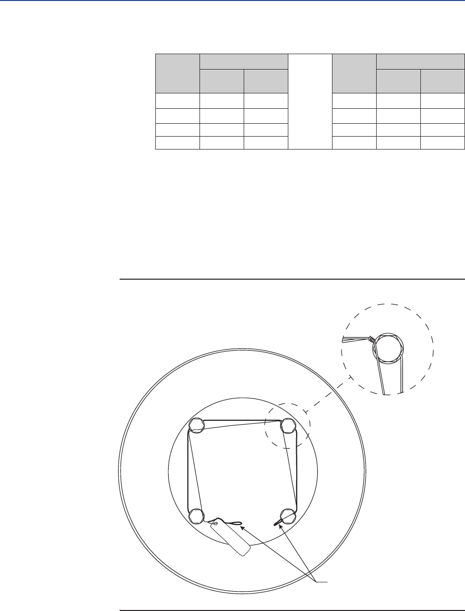
March 2017
Service Instructions
124840E Rev. G
42
Section 5: Module Removal and Installation
Module Removal and Installation
Table 10. Wire Length Requirements
MODEL
G/GC/
GH/GHC
LENGTH MODEL
G/GC/
GH/GHC
LENGTH
Inch mm Inch mm
G01-SR 36 914.4 5-SR 66 1676.4
2-SR 44 1117.6 7-SR 79 2006.6
3-SR 48 1219.2 8-SR 88 2235.2
4-SR 55 1397.0 G10-SR 110 2794.0
5.2.15.3 Twist the end of both wires together and insert one through the drilled
hole in the hex cap screw head, pass the second wire over the screw head
and twist it three (3) times around the rst wire at a location where the
rst wire exits the screw head.
5.2.15.4 Repeat the procedure until the second wire is twist tied to the screw head
through wire of the last screw head.
5.2.15.5 Attach caution tag and twist tie the wires from the last screw head to the
twisted wires of the rst screw head. See following for illustration.
Figure 1 Tag Attachment Guide
TWIST FOUR ENDS
TOGETHER
TAG

Service Instructions
124840E Rev. G
March 2017
43
Section 5: Module Removal and Installation
Module Removal and Installation
5.2.16 If removed install stop screw nuts (1-190) onto stop screws (1-180).
5.2.17 If removed install O-ring (2-90) onto stop screws (1-180).
5.2.18 If removed install two stop screws (1-180) into two stop screw holes on the front
of housing (1-10).
5.2.19 Adjust both stop screws (1-180) back to settings recorded earlier in Section 5.
5.2.20 Tighten both stop screw nuts (1-190) securely.
5.3 Pneumatic Power Module Removal
CAUTION: USE LIFTING EQUIPMENT
Due to the weight and size of spring module, heavy duty support equipment will be
required when installing spring cartridge module to the actuator housing. For the
approximate weight of the spring cartridge refer to Section 6.
5.3.1 Standard Outer end cap with pipe plug use step 5.3.1.1, outer end cap with
extended stop (ES) use step 5.3.1.2, G2 or G3 outer end cap with M3 or M3HW use
step 5.3.1.3 and G01 outer end cap with M3 or M3HW use step 5.3.1.4.
5.3.1.1 Standard outer end cap - Remove pipe plug (3-120) from outer end cap (3-80).
5.3.1.2 ES outer end cap:
5.3.1.2.1 Loosen ES nut (3-190).
5.3.1.2.2 Unscrew ES (3-180) and remove from outer end cap (3-80).
5.3.1.3 G2 or G3 M3/M3HW outer end cap:
5.3.1.3.1 Remove socket cap screws (3-320) from M3 adapter (3-280).
5.3.1.3.2 Remove M3 adapter (3-280) from outer end cap (3-80).
5.3.1.4 G01M3/M3HW outer end cap:
5.3.1.4.1 Remove socket cap screw (3-130) from M3 keeper (3-360).
5.3.1.4.2 Remove M3 keeper (3-360) from M3 adapter (3-360) and outer
end cap (3-80).
5.3.1.4.3 Remove M3 jackscrew (3-290) with M3 adapter (3-360) from
outer end cap (3-80).
5.3.2 Using a male square drive extension, go through outer end cap (3-80) and unscrew
piston rod (3-40) from the drive module.
5.3.3 Remove hex cap screws (3-100) with lockwashers (3-110) from housing (1-10).
NOTE:
When removing power module from housing (1-10) be careful not to lose O-ring seal (4-90).
5.3.4 Remove power module from actuator housing (1-10).

March 2017
Service Instructions
124840E Rev. G
44
Section 5: Module Removal and Installation
Module Removal and Installation
5.4 Pneumatic Power Module Installation
5.4.1 Check to verify that O-ring seal (4-90) is properly seated in its seal groove located
on the housing side of inner end cap (3-10).
NOTE:
G2 and G3 models (older models) conrm that the two inboard hex nuts (3-90) ats are
aligned to t into the slot located in the end of housing (1-10).
5.4.2 Using lifting equipment move the power module up to the drive module and align
piston rod (3-40) as follows:
5.4.2.1 G2 through G13 models align piston rod (3-40) with power module
extension rod assembly (1-50).
5.4.2.2 G01 models align piston rod (3-40) with the drive module guide block
(1-30).
5.4.3 Using a male square drive extension, go through outer end cap (3-80) and install
piston rod (3-40) as follows:
WARNING: CHECK TENSION ROD TURNS
After initial thread engagement the tension rod must be rotated clockwise the minimum
number of turns listed in the following table.
Table 11. Rod Rotation
ACTUATOR
MODEL
G/GC/GH/GHC
1 2 3 4 5 7 8 10 G13
MINIMUM
NO. TURNS 6 10 10 10 13 14 20 25 31
5.4.3.1 G2 through G13 screw piston rod (3-40) onto extension rod assembly (1-
50). GH/GHC2 through GH/GHC10, screw Piston Rod (3-40) directly into
Guide Block (1-30)
5.4.3.2 G01 only screw piston rod (3-40) onto guide block (1-30).
CAUTION: DO NOT CROSS THREAD PISTON RODS
When screwing piston rod into the G2 through G13 extension rod assembly (1-50) and G/
GC/GH/GHC piston rod into guide block (1-30) or G01 guide block (1-30) make certain that
the piston rod and extension rod assembly/guide block threads do not cross-thread.
5.4.4 Torque tighten piston rod (3-40). Refer to Section 3 step 3.3.2 for correct torque
value.

Service Instructions
124840E Rev. G
March 2017
45
Section 5: Module Removal and Installation
Module Removal and Installation
Table 12. Spring Cartridge Tension Rod Torque Table
HOUSING
MODEL
G/GC/GH/
GHC
TORQUE
(±5 % Percent)
HOUSING
MODEL
G/GC/GH/
GHC
TORQUE
(±5 % Percent)
Lbf-ft. N-m Lbf-ft. N-m
G01 90 122 7 240 325
2 90 122 8 240 325
3 90 122 10 240 325
4 240 325 G13 240 325
5 240 325
5.4.5 Install lock washers (3-110) onto hex cap screws (3-100).
5.4.6 Install hex cap screws (3-100) with lockwashers (3-110) through housing (1-10)
and screw into inner end cap (3-10).
5.4.7 Standard Outer end cap with pipe plug use step 5.4.7.1, outer end cap with
extended stop (ES) use step 5.4.7.2, G2 or G3 outer end cap with M3 or M3HW use
step 5.4.7.3 and G01 outer end cap with M3 or M3HW use step 5.4.7.4.
5.4.7.1 Standard outer end cap - Using pipe dope, install pipe plug (3-120) into
outer end cap (3-80).
5.4.7.2 ES outer end cap:
5.4.7.2.1 Screw ES (3-180) into outer end cap (3-80).
5.4.7.2.2 Install ES nut (3-190) on to ES (3-180).
5.4.7.3 G2 or G3 M3/M3HW outer end cap:
5.4.7.3.1 Install M3 adapter (3-280) into outer end cap (3-80).
5.4.7.3.2 Install socket cap screws (3-320) through M3 adapter (3-280)
and into outer end cap (3-80).
5.4.7.4 G01M3/M3HW outer end cap:
5.4.7.4.1 Remove socket cap screw (3-130) from M3 keeper (3-360).
5.4.7.4.2 Remove M3 keeper (3-360) from M3 adapter (3-360) and outer
end cap (3-80).
5.4.7.4.3 Remove M3 jackscrew (3-290) with M3 adapter (3-360) from
outer end cap (3-80).

March 2017
Service Instructions
124840E Rev. G
46
Section 5: Module Removal and Installation
Module Removal and Installation
5.5 G2 Thru G13 Powr Swivl Removal
(Excludes GH/GHC Model Actuators)
CAUTION: MAINTAIN GUIDE BAR RETENTION
While step 5.5.1 is in progress be sure to maintain guide bar retention when moving the guide block.
5.5.1 Push the guide block to the side of housing (1-10) that will expose the extension
rod assembly (1-50).
NOTE:
The guide block can be moved by inserting a long non metallic rod through the
hole where the blind end cap was removed and pushing on the guide block.
5.5.2 Refer to Assembly Drawing page 2 of 2 Detail "B". Use Bettis tool part number as
listed in chart in section 1 step 1.2.1 to remove retainer nut assembly (1-60) from
the guide block (1-30).
CAUTION: DO NOT DROP SPHERICAL WASHERS
When removing rod extension assembly from guide block be careful not to drop one of the
spherical washers inside the housing.
5.5.3 Remove rod extension assembly (1-50) from guide block (1-30).
NOTE:
One spherical washer (1-40) will be removed from guide block (1-30) when extension rod
assembly is removed.
5.5.4 Remove the remaining spherical washer (1-40) from guide block (1-30).
5.6 G2 Thru G13 Powr Swivl Module Installation
(Excludes GH/GHC Model Actuators)
WARNING: CONFIRM OVER-TRAVEL POSITION
The actuator must be in the appropriate over-travel position. Conrm over-travel position
by observing the guide block (1-30) is against the inner wall of housing (1-10).

Service Instructions
124840E Rev. G
March 2017
47
Section 5: Module Removal and Installation
Module Removal and Installation
CAUTION: MAINTAIN GUIDE BAR RETENTION
While step 5.6.1 is in progress be sure to maintain guide bar retention when moving the guide block.
5.6.1 Push the guide block to the required side of the housing (1-10).
NOTE:
The guide block can be moved by inserting a long rod through either end of the
housing and pushing on the guide block.
5.6.2 Lubricate two spherical washers (1-40), and one extension rod assembly (1-50).
5.6.3 Install one spherical washer (1-40) into the side of guide block (1-30).
NOTE:
The spherical side of washer (1-40) will be facing to the outside of guide block (1-30).
5.6.4 Install second spherical washer (1-40) over threaded end of extension rod assembly
(1-50).
NOTE:
The spherical side of the washer will go on the extension rod assembly facing the
head of the extension rod assembly.
5.6.5 Install extension rod assembly (1-50) into right of guide block (1-30) and up
against the rst spherical washer (1-40).
5.6.6 Install extension retainer nut assembly (1-60) over extension rod assembly (1-50)
and screw into guide block (1-30).
5.6.7 Tighten extension retainer nut assembly (1-60) until extension rod assembly (1-
50) cannot move. Back off the extension retainer nut assembly (1-60) just enough
to allow for extension rod assembly (1-50) to move freely.

March 2017
Service Instructions
124840E Rev. G
48
Section 6: Actuator Support Information
Actuator Support Information
Section 6: Actuator Support Information
6.1 G/GC/GH/GHC Module Weights By Item
Number And Actuator Housing Size
Table 13. G/GC/GH/GHC Module Weights by Item Number and Actuator Housing Size
ITEM
NO.
G01
WT.
2
WT.
3
WT.
4
WT.
5
WT.
7
WT.
8
WT.
10
WT.
G13
WT.
MODULE
DESCRIPTION
1Lbs. 83 110 162 280 545 1025 1495 2550 4625 Drive Module
Kg 38 50 73 127 247 465 678 1157 2098
3Lbs. 69 N/A N/A N/A N/A N/A N/A N/A N/A 8” Dia. Power
Module
Kg 31 N/A N/A N/A N/A N/A N/A N/A N/A
3Lbs. 68 80 N/A N/A N/A N/A N/A N/A N/A 9” Dia. Power
Module
Kg 30.5 36 N/A N/A N/A N/A N/A N/A N/A
3Lbs. 75 73.5 88 N/A N/A N/A N/A N/A N/A 10” Dia. Power
Module
Kg 34 33 40 N/A N/A N/A N/A N/A N/A
3Lbs. 86 86 104 130 N/A N/A N/A N/A N/A 12” Dia. Power
Module
Kg 39 39 47 59 N/A N/A N/A N/A N/A
3Lbs. 96 96 114 145 N/A N/A N/A N/A N/A 14” Dia. Power
Module
Kg 44 44 51 66 N/A N/A N/A N/A N/A
3Lbs. N/A 135 145 168 295 N/A N/A N/A N/A 16” Dia. Power
Module
Kg N/A 61 66 76 134 N/A N/A N/A N/A
3Lbs. N/A N/A 235 260 305 585 N/A N/A N/A 20” Dia. Power
Module
Kg N/A N/A 107 118 138 265 N/A N/A N/A
3Lbs. N/A N/A N/A 340 410 735 911 N/A N/A 24” Dia. Power
Module
Kg N/A N/A N/A 154 186 334 413 N/A N/A
3Lbs. N/A N/A N/A 505 590 810 1225 1120 N/A 28” Dia. Power
Module
Kg N/A N/A N/A 229 268 367 556 508 N/A
3Lbs. N/A N/A N/A N/A 977 1100 1260 1440 N/A 32” Dia. Power
Module
Kg N/A N/A N/A N/A 443 499 572 653 N/A
3Lbs. N/A N/A N/A N/A 1243 1400 1525 1755 N/A 36” Dia. Power
Module
Kg N/A N/A N/A N/A 564 653 692 796 N/A
3Lbs. N/A N/A N/A N/A N/A N/A 1975 2205 - 40” Dia. Power
Module
Kg N/A N/A N/A N/A N/A N/A 896 1000 -
3Lbs. N/A N/A N/A N/A N/A N/A N/A N/A 3120 44” Dia. Power
Module
Kg N/A N/A N/A N/A N/A N/A N/A N/A 1415
3Lbs. N/A N/A N/A N/A N/A N/A N/A N/A - 48” Dia. Power
Module
Kg N/A N/A N/A N/A N/A N/A N/A N/A -
3Lbs. N/A N/A N/A N/A N/A N/A N/A N/A 4130 52” Dia. Power
Module
Kg N/A N/A N/A N/A N/A N/A N/A N/A 1873
5Lbs. 160 225 320 564 975 2740 3545 4975 10010 SR1 Spring
Module
Kg 73 102 145 256 442 1243 1608 2257 4541
5Lbs. 158 215 310 549 980 2630 2345 4515 9275 SR2 Spring
Module
Kg 72 98 141 249 445 1193 1064 2048 4207
Table 10 (continued).......

Service Instructions
124840E Rev. G
March 2017
49
Section 6: Actuator Support Information
Actuator Support Information
ITEM
NO.
G01
WT.
2
WT.
3
WT.
4
WT.
5
WT.
7
WT.
8
WT.
10
WT.
G13
WT.
MODULE
DESCRIPTION
5Lbs. 153 215 295 534 925 2410 3085 4095 8060 SR3 Spring
Module
Kg 153 98 295 534 925 2410 3085 4095 8060
5Lbs. 144 200 280 474 860 2210 N/A 3735 7325 SR4 Spring
Module
Kg 65 91 127 215 390 1002 N/A 1694 3323
5Lbs. N/A 200 N/A N/A N/A N/A N/A N/A N/A SRA5 Spring
Module
Kg N/A 91 N/A N/A N/A N/A N/A N/A N/A
5Lbs. N/A 180 N/A N/A N/A N/A N/A N/A N/A SRA6 Spring
Module
Kg N/A 82 N/A N/A N/A N/A N/A N/A N/A
5Lbs. N/A 220 310 N/A N/A N/A N/A N/A N/A SRF1 Spring
Module
Kg N/A 100 141 N/A N/A N/A N/A N/A N/A
5Lbs. N/A 210 300 N/A N/A N/A N/A N/A N/A SRF2 Spring
Module
Kg N/A 95 136 N/A N/A N/A N/A N/A N/A
5Lbs. N/A 210 285 N/A N/A N/A N/A N/A N/A SRF3 Spring
Module
Kg N/A 95 129 N/A N/A N/A N/A N/A N/A
5Lbs. N/A 195 270 N/A N/A N/A N/A N/A N/A SRF4 Spring
Module
Kg N/A 88 122 N/A N/A N/A N/A N/A N/A
5Lbs. N/A 205 N/A N/A N/A N/A N/A N/A N/A SRF5 Spring
Module
Kg N/A 93 N/A N/A N/A N/A N/A N/A N/A
5Lbs. N/A 185 N/A N/A N/A N/A N/A N/A N/A SRF6 Spring
Module
Kg N/A 84 N/A N/A N/A N/A N/A N/A N/A
6.2 G01 Tool Style and Wrench Size
Table 14. G01 Tool Style and Wrench Size
ITEM
NO.
WRENCH
SIZE
ITEM
QTY LOCATION OR DESCRIPTION RECOMMENDED TOOL STYLE
1-110 9/16" 4 Hex Cap Screws Socket
1-160 1/2" 4 Hex Cap Screws Socket
1-180 3/8” Sq. 2 Stop Screws Open End or Adjustable
1-190 1-15/16” 2 Hex Jam Nuts Open End or Adjustable
3-20 3/8” 2 Tie Bar (ats) Open End or Adjustable
3-40 3/8” Sq. 1 Piston Rod Male Drive Extension
3-90 1-1/8” 2 Standard Hex Nuts Socket
3-100 9/16” 4 Hex Cap Screws Socket
3-120 5/8” Sq. 1 Pipe Plug Open End or Adjustable
3-130 3/16” 2 Socket Cap Screws Allen
5-20 9/16” 4 Hex Cap Screws Socket
7-20 9/16” 4 Hex Cap Screws Socket
12 1” 1 Breather Assembly Socket
13 3/4” 2 Vent Check Assembly Open End
- 3/8” Sq. 1 Tension rod Male Drive Extension

March 2017
Service Instructions
124840E Rev. G
50
Section 6: Actuator Support Information
Actuator Support Information
6.3 G/GC2 Tool Style and Wrench Size
Table 15. G/GC2 Tool Style and Wrench Size
ITEM
NO.
WRENCH
SIZE
ITEM
QTY LOCATION OR DESCRIPTION RECOMMENDED TOOL STYLE
1-110 9/16” 6 Hex Cap Screws Socket
1-160 9/16” 4 Hex Cap Screws Socket
1-180 3/8” Sq. 2 Stop Screws Open End or Adjustable
1-190 1-1/8” 2 Hex Jam Nuts Open End or Adjustable
3-20 3/8” 2 Tie Bar (ats) Open End or Adjustable
3-40 3/8” Sq. 1 Piston Rod Male Drive Extension
3-90 1-1/8” 2 Standard Hex Nuts Socket
3-100 9/16” 4 Hex Cap Screws Socket
3-120 5/8” Sq. 1 Pipe Plug Open End or Adjustable
3-130 3/16” 2 Socket Cap Screws Allen
5-20 9/16” 6 Hex Cap Screws Socket
7-20 9/16” 4 Hex Cap Screws Socket
12 1” 1 Breather Assembly Socket
13 3/4” 2 Vent Check Assembly Open End
- 3/8” Sq. 1 Tension rod Male Drive Extension
6.4 G/GC3 Tool Style and Wrench Size
GH2/GHC2 for Item No 3-20 to 3-130
Table 16. G/GC3 Tool Style and Wrench Size, GH2/GHC2 for Item No 3-20 to 3-130
ITEM
NO.
WRENCH
SIZE
ITEM
QTY LOCATION OR DESCRIPTION RECOMMENDED TOOL STYLE
1-110 9/16" 8 Hex Cap Screws Socket
1-160 9/16" 4 Hex Cap Screws Socket
1-180 1/2” Sq. 2 Stop Screws Open End or Adjustable
1-190 1-5/16” 2 Hex Jam Nuts Open End or Adjustable
3-20 1/2” 2 Tie Bar (ats) Open End or Adjustable
3-40 3/8” Sq. 1 Piston Rod Male Drive Extension
3-90 1-5/16” 4 Standard Hex Nuts Socket
3-100 9/16” 6 Hex Cap Screws Socket
3-120 5/8” Sq. 1 Pipe Plug Open End or Adjustable
3-130 3/16” 2 Socket Cap Screws Allen
5-20 9/16” 6 Hex Cap Screws Socket
7-20 9/16” 4 Hex Cap Screws Socket
12 1” 1 Breather Assembly Socket
13 3/4” 2 Vent Check Assembly Open End
- 3/8” Sq. 1 Tension rod Male Drive Extension

Service Instructions
124840E Rev. G
March 2017
51
Section 6: Actuator Support Information
Actuator Support Information
6.5 G/GC4 Tool Style and Wrench Size
GH3/GHC3 For Item No 3-20 to 3-130
Table 17. G/GC4 Tool Style and Wrench Size GH3/GHC3 for Item No 3-20 to 3-130
ITEM
NO.
WRENCH
SIZE
ITEM
QTY LOCATION OR DESCRIPTION RECOMMENDED TOOL STYLE
1-110 9/16” 8 Hex Cap Screws Socket
1-160 9/16” 4 Hex Cap Screws Socket
1-180 3/4” Sq. 2 Stop Screws Open End or Adjustable
1-190 1-13/16” 2 Hex Jam Nuts Open End or Adjustable
3-20 5/8” 2 Tie Bar (ats) Open End or Adjustable
3-40 1/2” Sq. 1 Piston Rod Male Drive Extension
3-90 1-5/8” 2 Standard Hex Nuts Socket
3-100 3/4" 6 Hex Cap Screws Socket
3-120 5/8” Sq. 1 Pipe Plug Open End or Adjustable
3-130 3/16” 2 Socket Cap Screws Allen
5-20 3/4" 6 Hex Cap Screws Socket
7-20 9/16” 4 Hex Cap Screws Socket
12 1” 1 Breather Assembly Socket
13 3/4" 2 Vent Check Assembly Open End
- 3/4” 1 Tension rod Male Drive Extension
6.6 G/GC5 Tool Style and Wrench Size
GH4/GHC4 For Item No 3-20 to 3-130
Table 18. G/GC5 Tool Style and Wrench Size GH4/GHC4 for Item No 3-20 to 3-130
ITEM
NO.
WRENCH
SIZE
ITEM
QTY LOCATION OR DESCRIPTION RECOMMENDED TOOL STYLE
1-110 3/4” 8 Hex Cap Screws Socket
1-120 3/4” 4 Hex Cap Screws Socket
1-160 9/16” 6 Hex Cap Screws Socket
1-180 7/8" Sq. 2 Stop Screws Open End or Adjustable
1-190 2-3/8” 2 Heavy Hex Jam Nuts Open End or Adjustable
3-20 1/2” Sq. 2 Tie Bar (ats) Open End or Adjustable
3-40 1/2” Sq. 1 Piston Rod Male Drive Extension
3-90 2” 2 Standard Hex Nuts Socket
3-100 3/4” 8 Hex Cap Screws Socket
3-120 1-1/8” Sq. 1 Pipe Plug Open End or Adjustable
3-130 3/16” 2 Socket Cap Screws Allen
5-20 3/4” 8 Hex Cap Screws Socket
7-20 9/16” 4 Hex Cap Screws Socket
12 1” 1 Breather Assembly Socket
13 3/4” 2 Vent Check Assembly Open End
- 3/4” 1 Tension rod Male Drive Extension

March 2017
Service Instructions
124840E Rev. G
52
Section 6: Actuator Support Information
Actuator Support Information
6.7 G/GC7 Tool Style and Wrench Size
GH5/GHC5 For Item No 3-20 to 3-130
Table 19. G/GC7 Tool Style and Wrench Size GH5/GHC5 for Item No 3-20 to 3-130
ITEM
NO.
WRENCH
SIZE
ITEM
QTY LOCATION OR DESCRIPTION RECOMMENDED TOOL STYLE
1-110 3/4” 8 Hex Cap Screws Socket
1-120 3/4” 4 Hex Cap Screws Socket
1-160 9/16” 8 Hex Cap Screws Socket
1-180 1” 2 Stop Screws Open End or Adjustable
3-20 3/4” Sq. 2 Tie Bar (female square) Male Drive Extension
3-40 3/4” Sq. 1 Piston Rod Male Drive Extension
3-90 2-3/8" 2 Standard Hex Nuts Socket
3-100 15/16" 8 Hex Cap Screws Socket
3-120 1-1/8" Sq. 1 Pipe Plug Open End or Adjustable
3-130 3/16” 2 Socket Cap Screws Allen
5-20 15/16” 8 Hex Cap Screws Socket
7-20 9/16” 8 Hex Cap Screws Socket
12 1" 1 Breather Assembly Socket
13 3/4” 2 Vent Check Assembly Open End
- 3/4” 1 Tension rod Male Drive Extension
6.8 G/GC8 Tool Style and Wrench Size
GH7/GHC7 For Item No 3-20 to 3-130
Table 20. G/GC8 Tool Style and Wrench Size GH7/GHC7 for Item No 3-20 to 3-130
ITEM
NO.
WRENCH
SIZE
ITEM
QTY LOCATION OR DESCRIPTION RECOMMENDED TOOL STYLE
1-110 3/4” 12 Hex Cap Screws Socket
1-120 3/4” 4 Hex Cap Screws Socket
1-160 9/16” 8 Hex Cap Screws Socket
1-180 1-1/4” 2 Stop Screws Open End or Adjustable
3-20 3/4” Sq. 2 Tie Bar (female square) Male Drive Extension
3-40 3/4” Sq. 1 Piston Rod Male Drive Extension
3-90 2-3/4” 2 Heavy Hex Nuts Socket
3-100 1-1/8” 8 Hex Cap Screws Socket
3-120 1-5/16” Sq. 1 Pipe Plug Open End or Adjustable
3-130 3/16” 2 Socket Cap Screws Allen
5-20 1-1/8” 8 Hex Cap Screws Socket
7-20 1-1/8” 8 Hex Cap Screws Socket
12 1” 1 Breather Assembly Socket
13 3/4” 2 Vent Check Assembly Open End
- 3/4” 1 Tension rod Male Drive Extension

Service Instructions
124840E Rev. G
March 2017
53
Section 6: Actuator Support Information
Actuator Support Information
6.9 G/GC10 Tool Style and Wrench Size
GH8/GHC8 For Item No 3-20 to 3-130
Table 21. G/GC10 Tool Style and Wrench Size GH8/GHC8 for Item No 3-20 to 3-130
ITEM
NO.
WRENCH
SIZE
ITEM
QTY LOCATION OR DESCRIPTION RECOMMENDED TOOL STYLE
1-110 3/4” 16 Hex Cap Screws Socket
1-120 3/4” 4 Hex Cap Screws Socket
1-160 9/16” 8 Hex Cap Screws Socket
1-180 1-1/2” 2 Stop Screws Open End or Adjustable
3-20 3/4” Sq. 2 Tie Bar (female square) Male Drive Extension
3-40 3/4” Sq. 1 Piston Rod Male Drive Extension
3-90 3-1/2” 2 Heavy Hex Nuts Socket
3-100 1-5/16” 8 Hex Cap Screws Socket
3-120 1-5/16” Sq. 1 Pipe Plug Open End or Adjustable
3-130 3/16” 2 Socket Cap Screws Allen
5-20 1-1/8” 8 Hex Cap Screws Socket
7-20 1-5/16” 8 Hex Cap Screws Socket
12 1” 1 Breather Assembly Socket
13 3/4” 2 Vent Check Assembly Open End
- 3/4” 1 Tension rod Male Drive Extension
6.10 G13 Tool Style and Wrench Size
GH10/GHC10 For Item No 3-20 to 3-130
Table 22. G13 Tool Style and Wrench Size GH10/GHC10 for Item No 3-20 to 3-130
ITEM
NO.
WRENCH
SIZE
ITEM
QTY LOCATION OR DESCRIPTION RECOMMENDED TOOL STYLE
1-110 1-1/8” 20 Hex Cap Screws Socket
1-120 1-1/8” 4 Hex Cap Screws Socket
1-160 9/16” 12 Hex Cap Screws Socket
1-180 2" Sq. 2 Stop Screws Open End or Adjustable
3-20 3/4” Sq. 2 Tie Bar (female square) Male Drive Extension
3-40 3/4” Sq. 1 Piston Rod Male Drive Extension
3-90 4-1/4” 2 Heavy Hex Nuts Socket
3-100 1-11/16” 8 Hex Cap Screws Socket
3-120 1-7/8” Sq. 1 Pipe Plug Open End or Adjustable
3-130 3/16” 2 Socket Cap Screws Allen
5-20 1-13/16” 8 Hex Cap Screws Socket
7-20 1-1/8” 8 Hex Cap Screws Socket
12 1” 1 Breather Assembly Socket
13 3/4” 2 Vent Check Assembly Open End
- 3/4” 1 Tension rod Male Drive Extension

March 2017
Service Instructions
124840E Rev. G
54
Section 7: Troubleshooting
Troubleshooting
Section 7: Troubleshooting
7.1 Fault Insertion
In the unlikely event of a fault developing, the following Fault Location Table is provided to
assist the service engineer to perform troubleshooting. This table is designed to cover as wide
a range of Emerson Bettis actuators as possible. Reference to equipment not supplied should
be ignored.
Table 23. Fault Location Table
SYMPTOM POTENTIAL CAUSES REMEDY
Erratic movement
Irregular supply of operating
medium
Check operating medium for consistent
supply pressure and correct as necessary
Inadequate lubrication Dismantle, relubricate and reassemble
Worn parts
Dismantle. Visually inspect for
signicant wear. Actuator replacement
may be required
Defective valve Consult the valve OEM's documentation
Short stroke
Incorrectly set stops
(valve and /or actuator)
Check the position of the travel stops and
readjust as necessary
Hardened grease Dismantle, remove any hard grease,
Relubricate and reassemble
Debris left in the cylinder or
housing during maintenance
Disassemble cylinder assembly to remove
debris. Reassemble cylinder assemble as
necessary
Defective valve Consult the valve manufacturer's
documentation
Apparent lack
of torque
Inadequate supply pressure
Ensure supply pressure is above the minimum
operating pressure of the actuator and that
output torque produced at supply pressure
exceeds valve torque demand
Incorrect speed control settings Adjust speed controls to increase ow
Exhaust port blocked Remove and clean the exhaust port silencers
and replace
Pipe work blocked, crushed
or leaking
Examine the pipe work for blockages,
crushed pipe or leakage. Clear or replace as
necessary
Defective controls
Examine the controls, refurbish or renew as
necessary. Refer to component
manufacturer's documentation
Defective piston seal
Dismantle the cylinder assembly, remove
the defective piston seal. Fit new seal and
reassemble
Defective rod seal Dismantle the cylinder assembly, remove the
defective rod seal. Fit new seal and reassemble
Defective housing seal
Dismantle the housing assembly, remove the
defective seal. Fit new seal
and reassemble
High valve torque or valve seized Consult the valve OEM documentation

Service Instructions
124840E Rev. G
March 2017
55
Section 7: Troubleshooting
Troubleshooting
7.2 Operational Test
7.2.1 Full Stroke Test
The “Full Stroke Test” (“On-line”) must be performed to satisfy the PFDAVG (average
probability of failure on demand) value. The full stroke test frequencies will be
dened by the nal installer to achieve the dened SIL level.
7.2.1.1 Procedure
7.2.1.1.1 Stroke the actuator/valve assembly two complete open/close
cycles with complete closing of the valve.
7.2.1.1.2 Verify the open/close cycles functioned correctly (e.g. check
locally, or automatically via Logic solver, the correct movement
of the actuator/valve).
Upon successful completion of the above described Full Stroke Test procedure, the
“Test Coverage” can be considered 99%.
7.2.2 Partial Stroke Test (when requested)
The “Partial Stroke Test” (“On-line”) can be performed to improve the PFDAVG value
and to satisfy PFDAVG (average probability of failure on demand) value. A typical
partial stroke value is 15% of the stroke and the recommended test interval is
about every one to three months.
7.2.2.1 Procedure
7.2.2.1.1 Operate the actuator/valve assembly for No° 1 open/close
cycles 15% of the stroke.
7.2.2.1.2 Verify the partial stroke test functioned correctly (e.g. check
locally, or automatically via logic solver, or via the PST system
the correct movement of the actuator/valve was 15% of the
stroke).
NOTE:
The above test is only applicable on systems equipped with a partial stroke feature.

March 2017
Service Instructions
124840E Rev. G
56
Section 8: Removal and Decommissioning
Removal and Decommissioning
Section 8: Removal and Decommissioning
8.1 Removal and Decommissioning
WARNING: FOLLOW PROPER PROCEDURE
Always follow safe work practices remove and disassemble G-Series actuator.
The below basic procedure should not supersede or replace any customer’s plant safety
or work procedures. If a conict arises between this procedure and the customer's
procedures, the differences should be resolved in writing between an authorized
customer’s representative and an authorized Emerson/Bettis representative.
CAUTION: ISOLATE AND POWER OFF ACTUATOR
Make sure actuator is isolated before removing from valve. Turn OFF the power medium and
bleed off all pressure rst, including storage tank (if present). Next, bleed off pilot pressure,
disconnect: pneumatic pressure supply, pilot tubing and electrical wiring (if equipped).
Before starting the disassembly, a large area should be created around the actuator so to
allow any kind of movement.
Separate the parts composing the actuator according to their nature (ex. metallic, and
plastic materials, uids etc.) and send them to differentiated waste collection sites, as
provided for by the laws and provisions in force.
8.1.1 Drain tanks and remove tubing from actuator. Remove accessories (if equipped)
and controls from actuator.
8.1.2 Remove all equipment mounted on top of actuator (limit switches, end of stroke
valve, and relevant pneumatic/electric connection, etc.)
8.1.3 Remove mounting bolts and actuator is ready to be removed from valve.
For complete actuator tear down refer to Section 2 of the manual.

Service Instructions
124840E Rev. G
March 2017
57
Section 9: Document Revision
Document Revision
Section 9: Document Revision
Table 24. Revision Overview
ECN DATE REV BY * DATE
Released Sept.1998 A B. Cornelius Sept.1998
17787 Dec. 2001 B UPDATED C. Ross Dec. 2001
18190 Aug. 2003 C UPDATED B. Jumawan Aug. 2003
VAWCO252 Dec. 2009 D UPDATED D. Blahnik Dec. 2009
VAWCO1779 Nov. 2012 E UPDATED C. Rico Nov. 2012
VAWCO2746 June 2015 F UPDATED C. Rico June 2015
* Signatures on le Bettis, Houston, Texas

March 2017
Service Instructions
124840E Rev. G
58
Appendix
Appendix
Appendix A: List of Tables
Table 1 Rod Extension Retainer Nut Tool Part Number ....................................................... 3
Table 2 Housing Cover Screw Quantity and Torque Table ................................................. 20
Table 3 Piston Rod Torque Information ............................................................................ 22
Table 4 Torque Tighten Piston Rod .................................................................................. 22
Table 5 Tie Bar Nuts ......................................................................................................... 25
Table 6 Early G2 and G3 Tie Bar Nuts ............................................................................... 28
Table 7 Rod Rotation ....................................................................................................... 40
Table 8 Spring Cartridge Tension Rod Torque Table ......................................................... 40
Table 9 Hex Cap Screws (7-20) Torque Table .................................................................... 41
Table 10 Wire Length Requirements .................................................................................. 42
Table 11 Rod Rotation ....................................................................................................... 44
Table 12 Spring Cartridge Tension Rod Torque Table ......................................................... 45
Table 13 G/GC/GH/GHC Module Weights By Item Number And Actuator Housing Size ...... 48
Table 14 G01 Tool Style and Wrench Size ........................................................................... 49
Table 15 G/GC2 Tool Style and Wrench Size ....................................................................... 50
Table 16 G/GC3 Tool Style and Wrench Size GH2/GHC2 For Item No 3-20 to 3-130 ........... 50
Table 17 G/GC4 Tool Style and Wrench Size GH3/GHC3 For Item No 3-20 to 3-130 ........... 51
Table 18 G/GC5 Tool Style and Wrench Size GH4/GHC4 For Item No 3-20 to 3-130 ........... 51
Table 19 G/GC7 Tool Style and Wrench Size GH5/GHC5 For Item No 3-20 to 3-130 ........... 52
Table 20 G/GC8 Tool Style and Wrench Size GH7/GHC7 For Item No 3-20 to 3-130 ........... 52
Table 21 G/GC10 Tool Style and Wrench Size GH8/GHC8 For Item No 3-20 to 3-130 ......... 53
Table 22 G13 Tool Style and Wrench Size GH10/GHC10 For Item No 3-20 to 3-130 ........... 53
Table 23 Fault Location Table ............................................................................................. 54
Table 24 Revision Overview ............................................................................................... 57
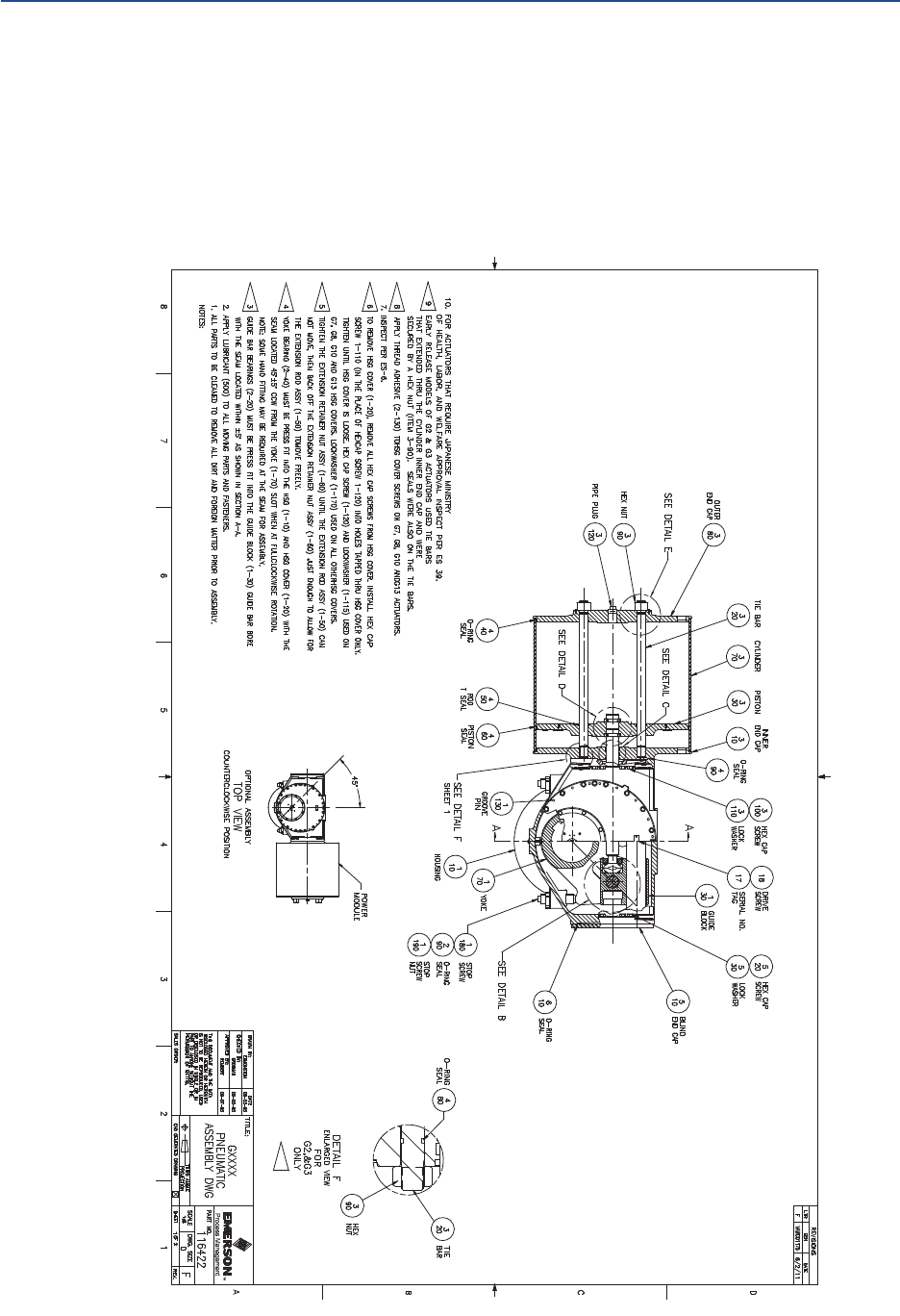
Service Instructions
124840E Rev. G
March 2017
59
Appendix
Appendix
Appendix B: List of Drawings
B.1 Part No. 116422, GXXXX Pneumatic Assembly
Drawing, Sheet 1 of 2
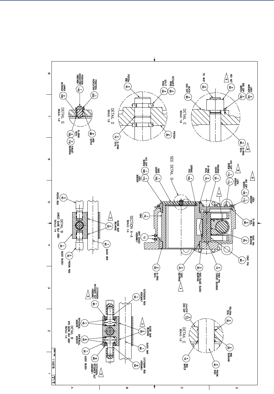
March 2017
Service Instructions
124840E Rev. G
60
Appendix
Appendix
B.2 Part No. 116422, GXXXX Pneumatic Assembly
Drawing, Sheet 2 of 2
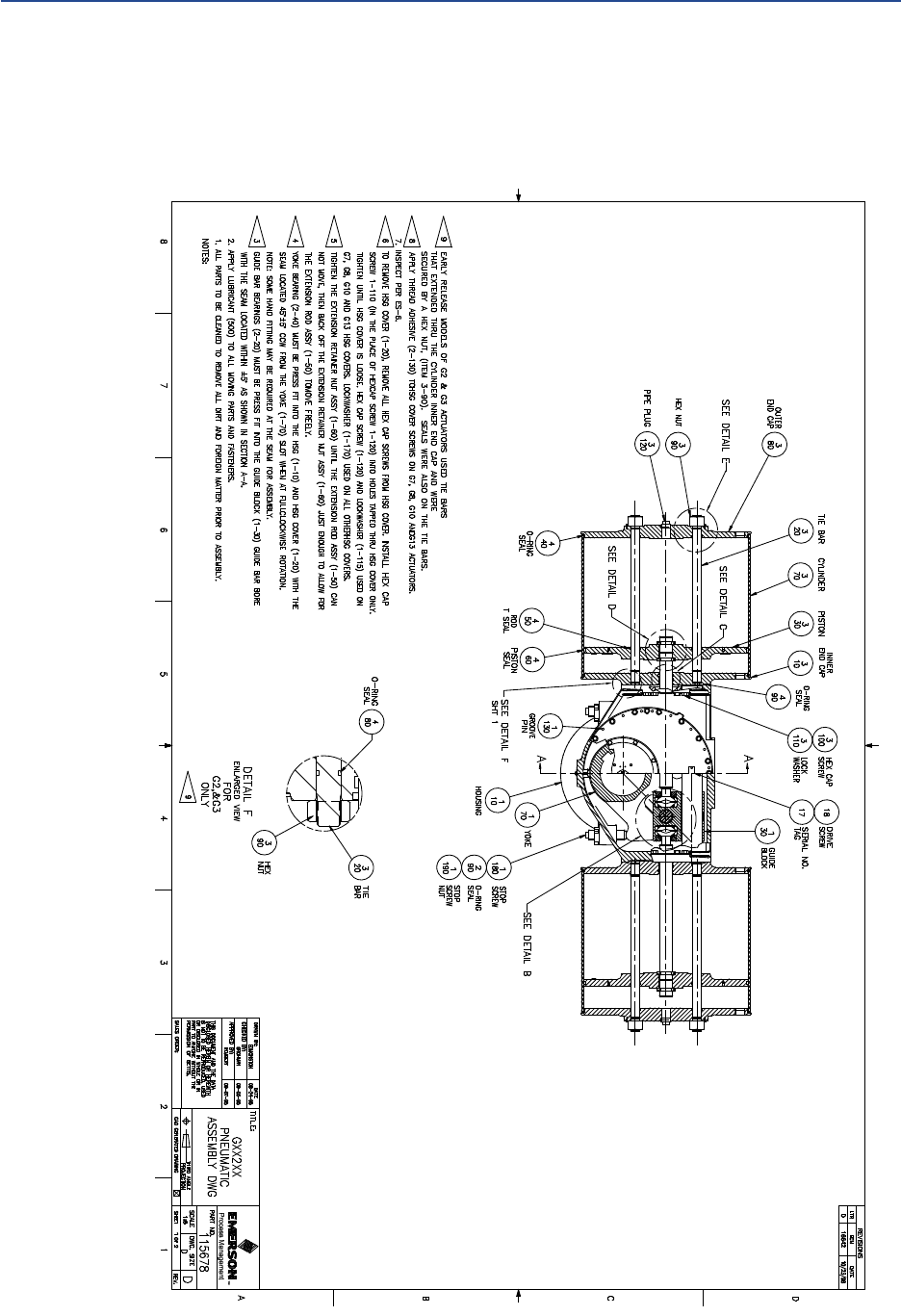
Service Instructions
124840E Rev. G
March 2017
61
Appendix
Appendix
B.3 Part No. 115678, GXX2XX Pneumatic Assembly
Drawing, Sheet 1 of 2
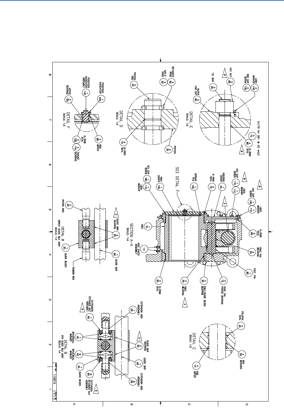
March 2017
Service Instructions
124840E Rev. G
62
Appendix
Appendix
B.4 Part No. 115678, GXX2XX Pneumatic Assembly
Drawing, Sheet 2 of 2
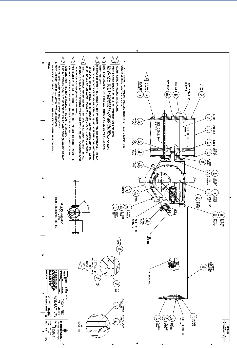
Service Instructions
124840E Rev. G
March 2017
63
Appendix
Appendix
B.5 Part No. 115674, GXXXX-SRX Pneumatic
Assembly Drawing, Sheet 1 of 2
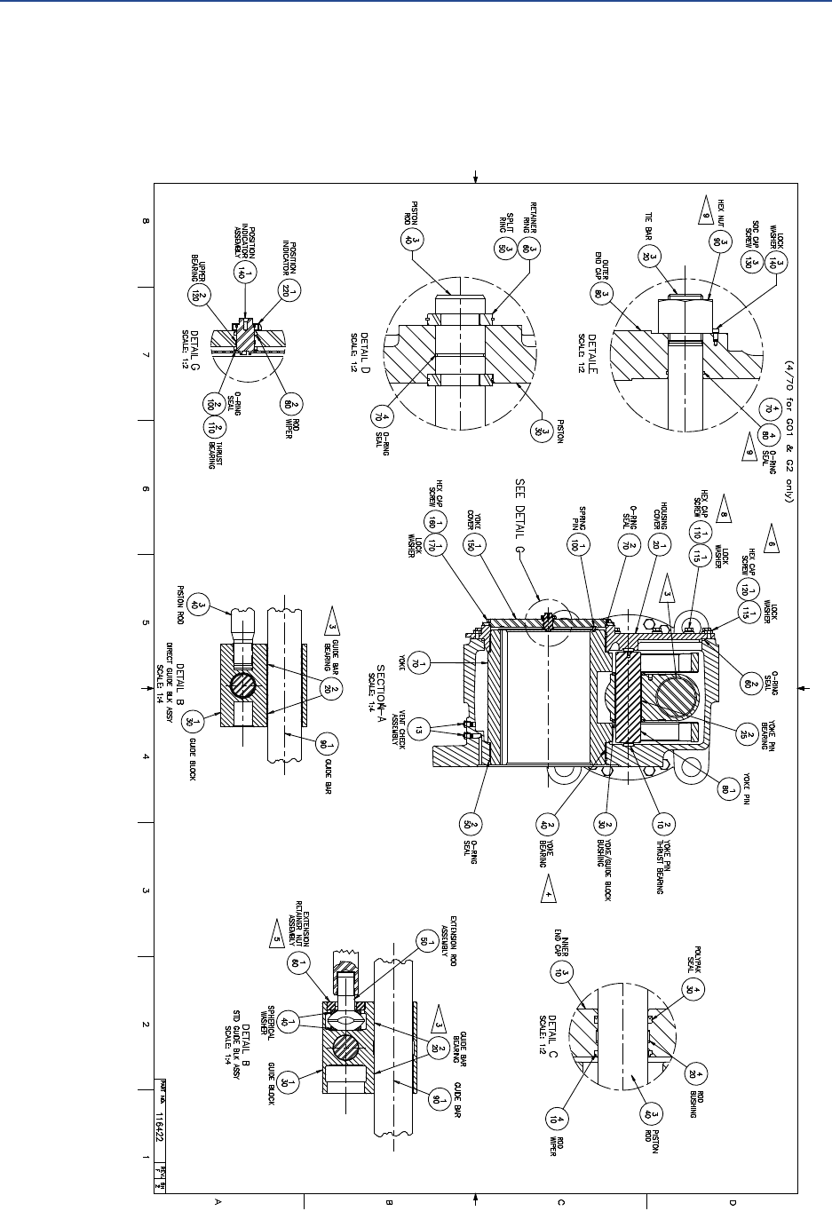
March 2017
Service Instructions
124840E Rev. G
64
Appendix
Appendix
B.6 Part No. 115674, GXXXX-SRX Pneumatic
Assembly Drawing, Sheet 2 of 2
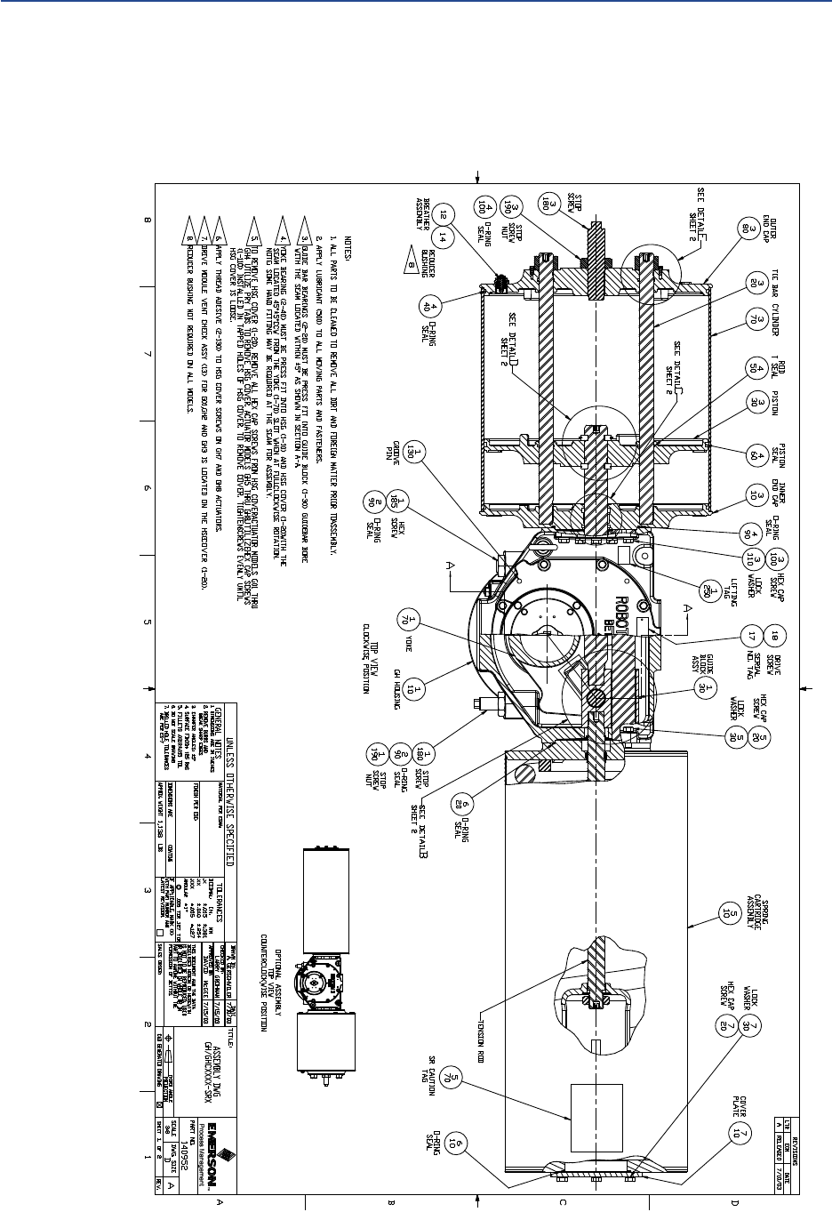
Service Instructions
124840E Rev. G
March 2017
65
Appendix
Appendix
B.7 Part No. 140952, GH/GHCXXXX-SRX Pneumatic
Assembly Drawing, Sheet 1 of 2
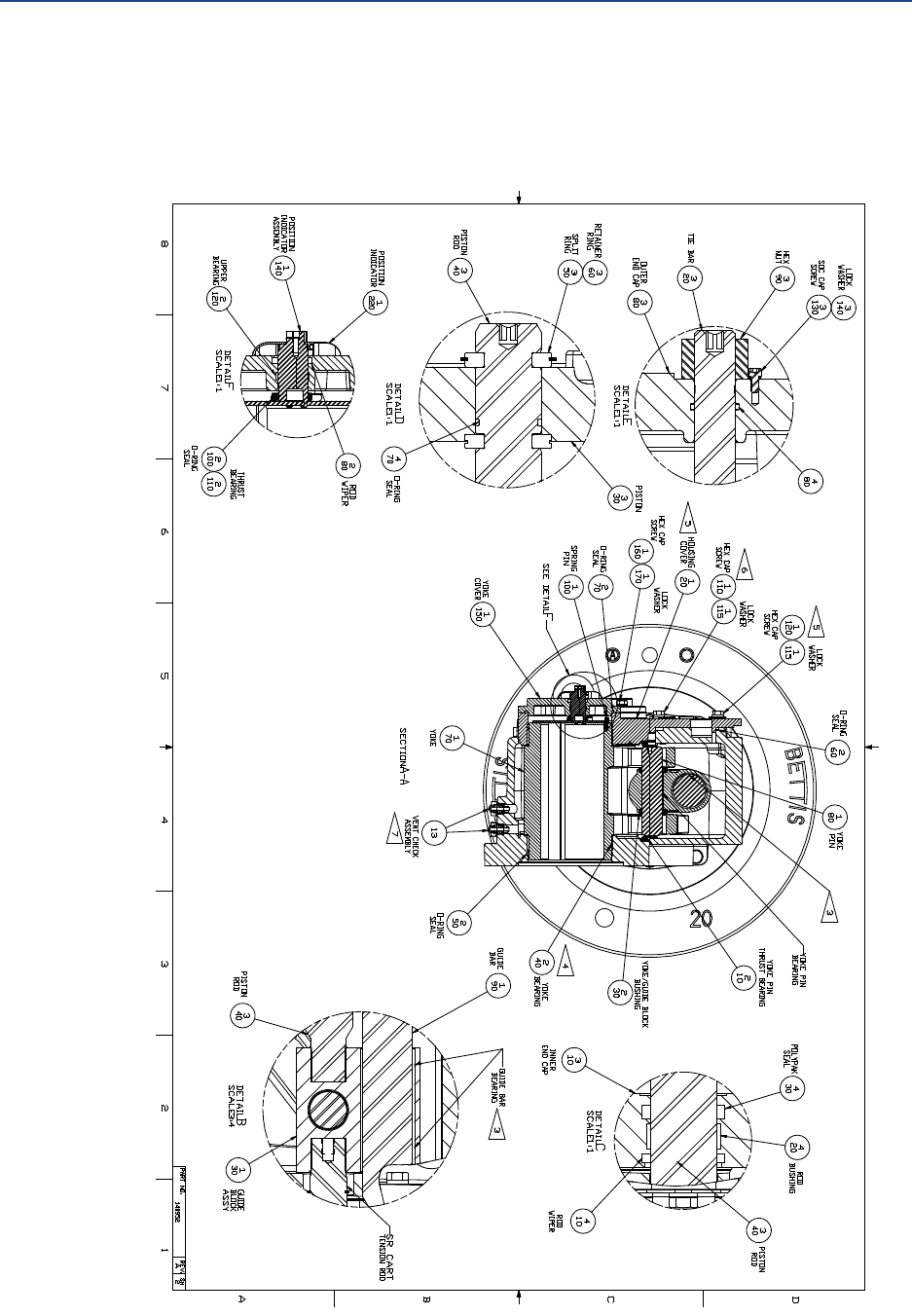
March 2017
Service Instructions
124840E Rev. G
66
Appendix
Appendix
B.8 Part No. 140952, GH/GHCXXXX-SRX Pneumatic
Assembly Drawing, Sheet 2 of 2

For complete list of sales and manufacturing sites, please visit
www.emerson.com/actuationtechnologieslocations or contact us at
info.actuationtechnologies@emerson.com
World Area Configuration Centers (WACC) offer sales support, service,
inventory and commissioning to our global customers.
Choose the WACC or sales office nearest you:
NORTH & SOUTH AMERICA
19200 Northwest Freeway
Houston TX 77065
USA
T +1 281 477 4100
F +1 281 477 2809
Av. Hollingsworth
325 Iporanga Sorocaba
SP 18087-105
Brazil
T +55 15 3238 3788
F +55 15 3228 3300
ASIA PACIFIC
No. 9 Gul Road
#01-02 Singapore 629361
T +65 6777 8211
F +65 6268 0028
No. 1 Lai Yuan Road
Wuqing Development Area
Tianjin 301700
P. R. China
T +86 22 8212 3300
F +86 22 8212 3308
MIDDLE EAST & AFRICA
P. O. Box 17033
Dubai
United Arab Emirates
T +971 4 811 8100
F +971 4 886 5465
P. O. Box 10305
Jubail 31961
Saudi Arabia
T +966 3 340 8650
F +966 3 340 8790
24 Angus Crescent
Longmeadow Business Estate East
P.O. Box 6908 Greenstone
1616 Modderfontein Extension 5
South Africa
T +27 11 451 3700
F +27 11 451 3800
EUROPE
Berenyi u. 72- 100
Videoton Industry Park
Building #230
Székesfehérvár 8000
Hungary
T +36 22 53 09 50
F +36 22 54 37 00
www.emerson.com/bettis
©2017 Emerson. All rights reserved.
The Emerson logo is a trademark and service mark of Emerson Electric Co.
BettisTM is a mark of one of the Emerson family of companies.
All other marks are property of their respective owners.
The contents of this publication are presented for information purposes
only, and while every effort has been made to ensure their accuracy,
they are not to be construed as warranties or guarantees, express or
implied, regarding the products or services described herein or their use
or applicability. All sales are governed by our terms and conditions, which
are available on request. We reserve the right to modify or improve the
designs or specifications of our products at any time without notice.
