Appa View / The Manual D24view
User Manual: View / the Manual DV-1000 User Manual
Open the PDF directly: View PDF ![]() .
.
Page Count: 188 [warning: Documents this large are best viewed by clicking the View PDF Link!]

DV--1000t
DirectVIEW
Manual NumberD--24VIEW--M

1
Rev A
M
a
n
u
a
l
R
e
v
i
s
i
o
n
s
If you contactusinreferencetothismanual,be sure and include the revision number.
Title:DV--1000 DirectVIEWä
ManualNumber:D--24VIEW--M
IssueDateEffective Pages Description ofChanges
Original1/94 OriginalIssue
2’nd Edition 8/95 Completerevision
RevA9/95
RevB2/96
Third
Edition
7/97 Cover/Copyright
Survey
Contents
Manual History
1-1-- 1-18
2-1-- 2-11
3-1-- 3-12
4-1-- 4-65
5-1-- 5-7
6-1-- 6-34
7-1-- 7-18
A-1-- A-3
B-1-- B-4
C-1-- C-6
Index
Completerevision
Downsizeformat
Added support forDL130,DL250,DL350,
and DL450 CPUs
RevA12/97 Contents
Manual History
1--2,1--3
2--2,2--3
4--58 -- 4--61
6--2
Revised Chapter1, Introduction entries
Added RevAchanges
Updated both pagesto newerformat
Deleted use ofdual DV-1000swithDL430
Added sixinstructionsto“MoveNumeric
Data”section ofprogram (revised thison
the example programdisk,made Rel2.1)
Reworded Note neartop ofpage
RevB5/98 Manual Revisions
2--4,2--10,4--39,4--46,
4--47,4--61,6--19
Examplesdiskette(Rel.
2.2)
Added RevBchanges
Made minorcorrectionsbeforereprinting
Revised example programs sotheywill
workwith all DirectSOFT versions

1
i
TableofContents
Chapter1:Getting Started
Introduction 1--2.........................................................................
The Purpose of thisManual1--2.........................................................
SupplementalManuals1--2.............................................................
TechnicalSupport1--2.................................................................
Chapters1--3.........................................................................
DirectVIEW1000 DataAccess Unit Overview1--3.........................................
DirectVIEWt1000 Features 1--4..........................................................
Getting Acquainted 1--4................................................................
Display1--5..........................................................................
Keypad 1--5..........................................................................
Cables1--5...........................................................................
SoftwareExampleson Disk 1--5.........................................................
DirectSOFT Support1--5..............................................................
Display and KeypadBasics 1--6..........................................................
ClearV-MemoryFirst! 1--6.............................................................
Keypad 1--6..........................................................................
Keypad ConventionsUsed inthisManual1--6............................................
CHGPRE Key(Change Preset)1--7.....................................................
MSGKey(Message)1--7..............................................................
STATKey(Status)1--7.................................................................
CURSORand +/-- Keys 1--7............................................................
OPTKey(OptionalModes)1--8.........................................................
CLEARand ENTERKeys 1--8..........................................................
Setup Parameters,theKey toDV-1000 Success!1--9.......................................
Purpose ofSetup Parameters1--9.......................................................
Programming Setup Parameters1--9....................................................
Quick TourofDV-1000 Operation 1--10.....................................................
StatusDisplayMode 1--10...............................................................
Message DisplayMode 1--11............................................................
Change PresetMode 1--12..............................................................
BitControlMode 1--13..................................................................
OperatorInterface Design Basics 1--14.....................................................
Man-Machine Interface 1--14............................................................
Monitorand Control1--15...............................................................
PurposesofMonitoring 1--15............................................................
PurposesofControl1--15...............................................................
FrequentlyAskedQuestions 1--16.........................................................
Specifications 1--18.......................................................................

i
i
Table ofContents
Chapter2:Installation Guide
Introduction 2--2.........................................................................
Step1:Choosing SingleorDualDV-1000s 2--2............................................
Dual DV-1000 Operating Characteristics 2--3.............................................
DL130,DL230 Connection 2--3.........................................................
DL240 Connection 2--3................................................................
DL250,DL350,DL430,DL440,DL450 Connection 2--3....................................
Step2:PLCSelection 2--4................................................................
Step3:Selecting aMounting Location 2--5................................................
Step4:PanelMounting 2--6..............................................................
Step5:CableSelection 2--7..............................................................
DL105,DL205,DL350,DL450 Connection 2--7...........................................
DL430,DL440 Connection 2--7.........................................................
CustomCables2--8...................................................................
Step6:Connecting theDV-1000 totheCPU2--9...........................................
Step7:Installing theExamplePrograms 2--9..............................................
Step8:Starting DirectSOFT 2--11..........................................................
Initializethe CPU2--11..................................................................
Loading an ExampleProgram2--11.......................................................
Chapter3:DV-1000 Setup Parameters
Overview3--2...........................................................................
Purpose ofSetup Parameters3--2.......................................................
Location ofSetup Parameters3--2......................................................
TypesofSetup Parameters3--2.........................................................
Howthe DV-1000 UsesSetup Parameters3--3............................................
Setup ParameterLadderRung 3--3......................................................
ParameterDefinitions 3--4................................................................
V-MemoryMaps3--6..................................................................
Entering Setup Parameters 3--7...........................................................
MethodsforEntering the Setup Parameters3--7..........................................
ParameterSetup ByLadderProgram3--7................................................
Using theLDA Instruction forPointerSetup Parameters 3--8...............................
Powerup DefaultOperationalMode 3--9...................................................
Powerup DefaultSetup Parameter3--9...................................................
Powerup Sequence 3--10................................................................
Powerup DefaultExampleProgram3--11..................................................
ChapterSummary 3--12...................................................................
SummaryofKeyPoints3--12............................................................

i
i
i
Table ofContents
Chapter4: MessageDisplay Mode
Overview4--2...........................................................................
Feature List4--2......................................................................
Message Priority4--2..................................................................
SystemRequirementsforExamplePrograms4--3.........................................
DL405 Requirements4--3..............................................................
DL350 Requirements4--3..............................................................
DL205 Requirements4--4..............................................................
DL105 Requirements4--4..............................................................
SystemMessages 4--5...................................................................
Selecting Message Mode 4--5...........................................................
Fault Instruction Message 4--5..........................................................
SystemErrorDisplay4--6..............................................................
Viewing Message Logs(DL240,DL250,DL350,DL440 and DL450 Only)4--6.................
FaultMessage Log (DL240,DL250,DL350,DL440 and DL450 Only)4--7....................
SystemErrorLog (DL240,DL250,DL350,DL440 and DL450 Only)4--8......................
UserMessages 4--9......................................................................
Setup ParametersforUserMessages 4--10.................................................
Message DataParameters4--10.........................................................
Choosing DataBlock Locations4--10.....................................................
LadderExamplefor Message Setup Parameters4--11......................................
ParameterSetup Program#1 4--11.......................................................
Displaying Numbers 4--13.................................................................
Displaying Changing Values4--14........................................................
Displaying Text4--15......................................................................
ASCII Codes4--15.....................................................................
Using LDD and OUTDInstructions 4--17....................................................
Turning DataintoMessages 4--19..........................................................
Numbering ofDisplayPositions4--19.....................................................
DisplayMaps4--19.....................................................................
HowMessage DataGetstothe Display4--20..............................................
CombinedNumeric and TextDisplays 4--21................................................
ParameterSetup Program#2 4--22.......................................................
Unmasking NumericPositions4--23......................................................
Placing Numbersand TextTogether4--24.................................................
Using theASCII Constant (ACON)Instruction 4--25.........................................
ACONExampleProgram#1 4--26........................................................
Choosing ACONBoxTextLength 4--27...................................................
ACONExampleProgram#2 4--29........................................................
Continued,nextpage

i
v
Table ofContents
Chapter4,continued
MessageDisplay Applications and Techniques 4--32........................................
MultipleMessage Displays 4--32.........................................................
DynamicText4--36.....................................................................
Blinking Text4--38......................................................................
PolaritySign forNumericOutput4--41....................................................
Embedded Time and Date(DL240,DL250,DL350,DL440 and DL450 Only)4--44..............
BarGraph Example,(DL240,DL250,DL350,DL440 and DL450 Only)4--49...................
BarGraph Example,DL240 Analog Potentiometers4--53....................................
AutomaticScrolling Display,(DL240,DL250,DL350,DL440 and DL450 Only)4--57.............
Embedded DecimalPoint4--62..........................................................
ChapterSummary 4--65...................................................................
SummaryofKeyPoints4--65............................................................
Chapter5:StatusDisplay Mode
Overview5--2...........................................................................
StatusDisplayFormat5--2.............................................................
Selecting Byte orWordDisplays 5--3....................................................
Selecting theAddress 5--4...............................................................
Selecting theDataType 5--5..............................................................
Using theBookmark 5--6.................................................................
ChapterSummary 5--7...................................................................
SummaryofKeyPoints5--7............................................................

v
Table ofContents
Chapter6:ChangePreset Mode
Overview6--2...........................................................................
“Change Preset”Defined 6--2...........................................................
How Change PresetWorks 6--2.........................................................
Title and DataFields6--3...............................................................
PresetTitleTypesAvailable 6--3........................................................
Setup ParametersforChangePreset Mode 6--4............................................
Location ofPresetVariable Lists6--4....................................................
Pointerand Block Sizes6--4............................................................
Change PresetSetup Program6--5......................................................
Establishing the Lists6--6..............................................................
Accessing ChangePresetVariables 6--8..................................................
Selecting the List toDisplay6--8........................................................
CursorPositioning OnTitle orData 6--9..................................................
Changing the PresetValue 6--9.........................................................
Pre--labeled Timerand CounterPresets 6--10...............................................
Scrolling Through Change PresetLists6--12...............................................
Using PresetsWithTimerBoxInstructions6--13............................................
Using PresetsWithCounterBoxInstructions6--13.........................................
User-titledPresets 6--14...................................................................
User-Titled TextLabels6--14.............................................................
DefaultUserTitle List6--17..............................................................
User-titled TextExample 6--19...........................................................
Individual DefaultUserTitles6--22........................................................
Combination Titles Example 6--25.........................................................
ChangePresetPassword6--28............................................................
Unlocking Access toChange Presets6--28................................................
Locking Access toChange Presets6--29..................................................
Forgot the Password? 6--29.............................................................
SpecialTopics forChangePresets 6--30...................................................
Timerand CounterPresetswithCustomTitles6--30........................................
Buffered PresetValues6--31.............................................................
Operator’sGuidetoChangePreset Mode 6--32.............................................
Selecting the List toDisplay6--32........................................................
CursorPositioning OnTitle orData 6--32..................................................
Scrolling Through Change PresetLists6--33...............................................
Changing the PresetValue 6--33.........................................................
EnteringaPassword 6--33...............................................................
Locking Access toChange Presets6--33..................................................
ChapterSummary 6--34...................................................................
SummaryofKeyPoints6--34............................................................

v
i
Table ofContents
Chapter7:BitControlMode
Overview7--2...........................................................................
Keypad Function inBitControl7--3......................................................
Accessing BitControl7--3..............................................................
Setup ParametersforBitControl7--4.....................................................
Using theKeypadToDoBitControl7--6..................................................
Selecting BitControland StatusModes7--6..............................................
Keypad BitMapping 7--7...............................................................
Exiting BitControlMode 7--8............................................................
BitControlApplications 7--9.............................................................
I/O Debug 7--9........................................................................
BitControlWithMessage DisplayMode 7--11..............................................
Multiplexed BitControl7--15.............................................................
BitControlToggleFunction 7--17.........................................................
ChapterSummary 7--18...................................................................
SummaryofKeyPoints7--18............................................................
AppendixA:Troubleshooting Guide
Troubleshooting GuideA--2..............................................................
AppendixB:Reference Data
Setup ParameterTables B--2..............................................................
ASCII TableB--4.........................................................................
AppendixC:DV-1000 Worksheets
MessageDisplay WorksheetsC--2........................................................
FaultMessagesC--2...................................................................
Message DisplayOutputMapsC--3......................................................
DisplayOutput GridsC--4...............................................................
ChangePresetWorksheetC--5............................................................
CreateTitle ListsC--5..................................................................
Timerand CounterNumbering Conversion ChartC--6......................................
Index

1
1
Getting Started
In ThisChapter....
—Introduction
—DirectVIEWä1000 Features
—DisplayandKeypadBasics
—Setup Parameters, the KeytoDV-1000 Success
—QuickTourofDV-1000 Operation
—OperatorInterface DesignBasics
—FrequentlyAskedQuestions
—Specifications
G
e
t
t
i
n
g
S
t
a
r
t
e
d
1
-
-
2
Getting Started
Introduction
DV1000
Howto
Use
Thismanualshowsthe variousfeatures
and modesof the DirectVIEW1000
(DV-1000).Yourapplication mayrequire
the use ofsome of thesemodes,orall of
them.Thismanualcan helpyou decide
whichmodesto use,and howto
configurethe CPUtosupport the
DV-1000 inthosemodes. Inthe
chapterson DV-1000 operational
modesthere are example programsto
helpyou writethe required supporting
ladderprogram.Ifyou are a newuser,
however,you mayneed torefertothe
User Manualforthe PLCyou are using.
The OP-1500 and OP-1510
Operatorpanelsmaybe
reconfigured to exchange data
withyourprogrammable
controller.
The OP-1500 and OP-1510
Operatorpanelsmaybe
reconfigured to exchange data
withyourprogrammable
controller.
The DL105 User Manual(D1-USER-M),
the DL205 User Manual
(D2--USER--M), the DL305 User
Manual(D3-USER-M;makesureyou
havethe version covering the DL350
CPU)and the DL405 User Manual
(D4--USER--M) containrelated
information,such asthe instruction set
definitionsforyourCPUtype. In
addition, the DirectSoft Quick Start
Manual(QS-DSOFT-M) mayalso be
useful.Thesemanualsare not
absolutelynecessaryto usethe
DV-1000,butmightcomein handyfor
an occasionalreference.
Werealizethateven though westriveto be the best, wemayhave arranged our
information insuchaway you cannot find whatyou arelooking for.First, check these
resourcesforhelpinlocating the information:
STableofContents-- chapterand section listing ofcontents,inthe front
of thismanual
SQuick GuidetoContents-- chaptersummarylisting on the nextpage
SAppendices -- referencematerialforkeytopics
SIndex -- alphabetical listing ofkeywords,at the end of thismanual
You can alsocheck ouronline resourcesforthe latestproductsupportinformation:
SInternet-- the address ofourWeb siteishttp://www.plcdirect.com
SBulletinBoardService (BBS)-- call (770)--844--4209
If you still need assistance,pleasecall usat800--633--0405. Ourtechnicalsupport
group isglad toworkwithyou in answering yourquestions.Theyare available
Mondaythrough Fridayfrom9:00 A.M. to 6:00 P.M.EasternStandardTime. If you
haveacommentorquestion aboutanyofourproducts,services,or manuals,please
fill outand returnthe ‘Suggestions’cardthatwas shipped withthismanual.
ThePurpose of
thisManual
S
u
p
p
l
e
m
e
n
t
a
l
M
a
n
u
a
l
s
TechnicalSupport
G
e
t
t
i
n
g
S
t
a
r
t
e
d
1
-
-
3
Getting Started
The maincontentsof thismanualare organized intothe following seven chaptersand
AppendicesA,Band C:
Getting Started
providesan overviewof the featuresand providesgeneral
specifications.The importance ofsetup parametersand what they
do areshown.“Quick TourofDV--1000 Operation”coversthe
operationalmodesand the mainfeaturesofeachmode.Alistof
FrequentlyAsked Questionsislocated nearthe end of this chapter.
Installation Guide
explainshowtoselect the CPUtype and a communications cable,
howtomount the unitinacontrolpaneland connectit toyour
CPU,and howtoinstall the example programsdisk and start
DirectSOFT to beginyourladderprogram.
DV--1000 Setup Parameters
explainsthe purpose ofsetup parameters,howtheyare used,and
givesexample programs.Specialtopics include selecting the
Powerup DefaultMode.
MessageDisplay Mode
showshowto access System Messages,including ErrorMessages
and FaultMessages.ItcoversUserMessages,and showshowto
createyourowntextand numericoutputand includes several
example programs.
StatusDisplay Mode
tellshowtoviewthe statusofCPUdatatypes(X,Y,GX,C,SP,T,
CT,S,Vand P).
ChangePreset Mode
coversthe conceptofchanging V-memorydata, the three typesof
titles you mayattachtothe valuesaslabels,and password protec-
tion (optional)forchanging presetvalues.AnOperator’sGuide
coversthe keypad procedureforchanging presets.
BitControlMode
discusseshowto enterand exitBitControlMode,and howto useit
inmachine debug applications.
Troubleshooting Guide
AppendixAprovidesalistof typicalproblems you mayencounter
along withthe mostlikely causesand solutions.
Reference Data
AppendixBprovidesthe setup parametertablesand a table
ofASCII charactersand theirhexASCII codes.
DV--1000 Worksheets
AppendixCprovidesworksheetsthatyou may copyand useto
plan yourapplication program.
T
h
e
D
V
-
1
0
0
0
i
s
a
s
m
a
l
l
,
l
o
w
-
c
o
s
t
d
a
t
a
a
c
c
e
s
s
unitwhichconnectsdirectlyto all DL105,DL205
and DL405 CPUs,and toDL305 modelshaving
aD3--350 CPU(itisnotcompatiblewiththe
otherDL305 CPUs). Itsmain purposeisto
provide access for monitoring and controlling
datainthe CPU,and isusuallypermanently
installed in an operatorinterface,butitcan also
be used portablyasa debugging tool.
DirectVIEW(DV-1000)
Chapters
1
2
3
4
5
6
7
A
B
C
DirectVIEW1000
DataAccess Unit
Overview
G
e
t
t
i
n
g
S
t
a
r
t
e
d
1
-
-
4
Getting Started
DirectVIEWä1000 Features
T
h
e
D
i
r
e
c
t
V
I
E
W
ä
1
0
0
0
(
D
V
-
1
0
0
0
)
h
a
s
severaldifferentmodeswhich are
accessiblefromits keypad.Mostmodes
requiresomeladderlogicinthe PLCand
setup parametersinV-memory,which are
essentialforthe DV-1000 tofunction!This
manualcontainsmanyprogramexamples
to acquaintyou with all the capabilitiesof the
DV-1000,and helpyou withthe required
setup parametersand ladderprogram.
Some of the mainfeaturesand benefitsare:
DirectVIEW(DV-1000)
SWorks with all DL105,DL205 and DL405 CPUs,and DL350 CPUs
SFeaturesa 4-line by16-characterback-litdisplay
SMonitorsV-memorydatavalues
SDisplays textand numericdata generated withyourladderprogram
SCan change preset(anyV-memory)values
SDisplays CPU-generated error messages(message log)
SSinglecableconnection toCPU
SEasy snap-inmounting
SThe DV-1000 deviceisULrListed
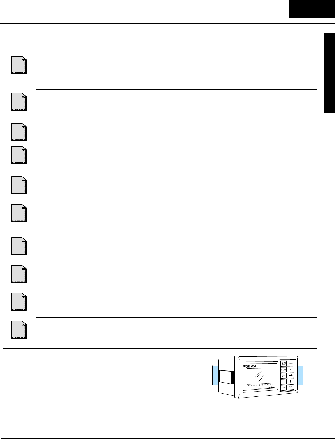
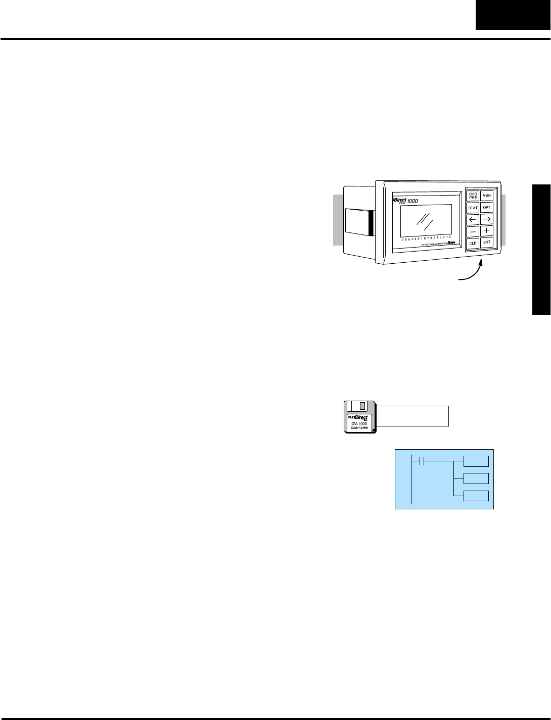
Beforeconnecting the DV-1000 toyourPLC,we’ll firststudyitsmainfeatures.The
drawing belowshowsafrontand rearviewof the unit. The 4-line by16-character
displayisback-lit forviewing invariousambientlighting conditions.You can control
the contrastof the LCD segmentsbyadjusting a potentiometeraccessiblewith a
small screwdriverunderthe bottomof the unit. Tothe rightof the displayisakeypad
featuring ten keys.These are general-purposekeys thatallowyou toselectvarious
operating modes,selectparticulardatafor monitoring,and tochange datavalues.
The DV-1000 isdesigned tofitinto a rectangularcutoutinthe controlpanelofan
operatorinterface.Aretention clip on eachside keepsitin place afterinstallation.A
modularjack at the rearof the unitprovidesan easy connection tothe CPU.
Retention Clip
4 Line by16 CharacterBack-litDisplay
ContrastAdjustmentScrew
Keypad
FrontviewRearview
Phone Jack
styleconnector
Getting Acquainted
G
e
t
t
i
n
g
S
t
a
r
t
e
d
1
-
-
5
Getting Started
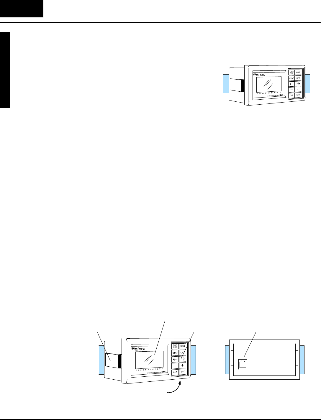
The DV-1000 display contains4linesby
16 characters,and eachcharacteris
formed bya 5 x7 LCD dotmatrix.The
unit’sinternalprocessorgeneratesan
ASCII characterset, and outputsmenu
messagesassociated withthe keypad.
7654321076543210
S T A T U S : R U N
S T E P : F O R M P A R T
M O L D T E M P . 3 2 7 F
L O T N O . 4 1 6 3
You can createyourownmessagesbyusing ladderlogicand specialsetup
parametersinV-memory.The permanentnumbersbelowthe bottomedge of the
displaylabel individualbitsofbyte orwordstatusdisplays.
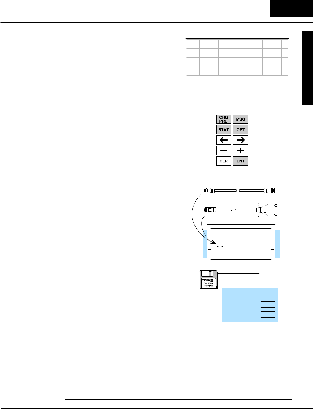
T
h
e
k
e
y
p
a
d
c
o
n
t
a
i
n
s
t
e
n
k
e
y
s
,
l
o
c
a
t
e
d
along the rightside of the DV-1000.The
primary keys on the unithaveablue
colored background,and are dedicated
forchanging the operationalmodes.
The secondary keys have a gray
colored background,and are
multi-purposekeys used forcursor
movementsand incrementing or
decrementing valuesinthe display.
Displaymessages
OptionalModes
Cursor right
IncrementValue
Enter
Change Preset
MonitorStatus
CursorLeft
DecrementValue
Clear
There are basicallytwotypesofcables
thatmaybe used withthe DV-1000.The
type you will use dependsmainlyon the
PLCtype thatwill connect toyour
DV-1000.Therefore, the appropriate
cablemustbe ordered asaseparate
item.See Chapter2forspecificpart
numberinformation forthe propercable.
OR
The chapterson individualmodes contain
several ladderprogramexamples.A
diskettecontaining the filesforthese
examplesisincluded withthismanual.
The diskettesymbol inthe margin beside
an example programindicatesitison the
diskette.See the section nearthe end of
Chapter2, titled “Installing the Example
Programs”.
a:\filename.prj
NOTE:The DL430 CPUdoesnotsupportall instructionsused inthe example
programs.
NOTE:DirectSOFT Release 2.0 programming software hasa utilitytoconfigurethe
DV-1000;however,before using thisutilityitisimportant to understand the
V-memoryrelationship between the DV-1000 and the PLC.See the DirectSOFT
UsersManual(DA-DSOFT-M) for moreinformation.
Display
Keypad
Cables
SoftwareExamples
on Disk
G
e
t
t
i
n
g
S
t
a
r
t
e
d
1
-
-
6
Getting Started
Display and KeypadBasics
This section will familiarizeyou with howto usethe keypad,along withthe display
responseforeachkey you press. Itspurposeisnot to demonstrate all of the modes
ordisplay screens.The remaining chaptersinthismanualcontainthatinformation.
NOTE:These exercisesmustbe done inasafelearning environment. DONOTuse
aCPUthatisactually controlling a process,in orderto avoid accidentally changing
V-memorydata needed bythe ladderprogram.
The following exercisesassumethe DV-1000 isonline withthe PLC,and the CPU
program,V-memory,and systemparametersareclear. If yourCPUhasrandomdata
intheselocations, then yourdisplays will likelynotmatchthe examples.
1.Connect the communications cablefromyourpersonalcomputer
communicationsport toyourPLC’sprogramming porton the CPU.
2.StartDirectSOFT on yourpersonalcomputer.
3.Selectalinkto go online withthe CPU.
4.Saveyourprogramtoaproject file,ifyou have a programnotyetsaved.
5.Verifythe CPU isin program mode.Fromthe menu bar,selectPLC, then
PLCModes, then Program.Then select“OK”,orpress Return.
6.Fromthe menu bar,selectPLC, then ClearPLCmemory,then All.Then
select“OK”,orpress Return.
7.FromPLCmenu,chooseSetup, then InitializeScratchpad.Thisensures
the DV-1000 setup parametersareinitialized tozeros.
Y
o
u
m
a
y
r
e
c
a
l
l
t
h
a
t
t
h
e
k
e
y
p
a
d
i
s
color-coded,based on keyfunctions.The
blue keys are dedicated forchanging the
operationalmodes.The gray keys are
multi-purpose,used forcursor
movementsand incrementing or
decrementing valuesinthe display.
Displaymessages
OptionalModes
CursorRight
IncrementValue
Enter
Change Preset
MonitorStatus
CursorLeft
DecrementValue
Clear
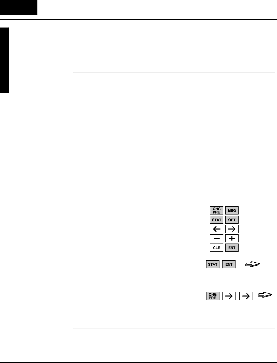
Thismanualuses somekeypad
conventions.When keypad entriesare
required,key symbol(s)will be shown,
preceded bythe word“Press”.Example 1
asks you to press the StatusKeyfollowed
bythe Enterkey.Example 2 asks you to
press the ChangePresetkey, followed by
pressing the CursorRightKeytwice.The
graphicarrowpointstothe resulting
displaybeside orbelowthe key sequence.
PRESS
PRESS
Example 2
Example 1
NOTE:When pressing multiplekeys orpressing a keyrepetitivelyin a key
sequence,pleasepause forasecond between keystrokes.Thisallowsthe DV-1000
timeto process eachkeystroke beforethe nextkeypad entryoccurs.
ClearV-memory
First!
Keypad
Keypad
ConventionsUsed
inthisManual
G
e
t
t
i
n
g
S
t
a
r
t
e
d
1
-
-
7
Getting Started
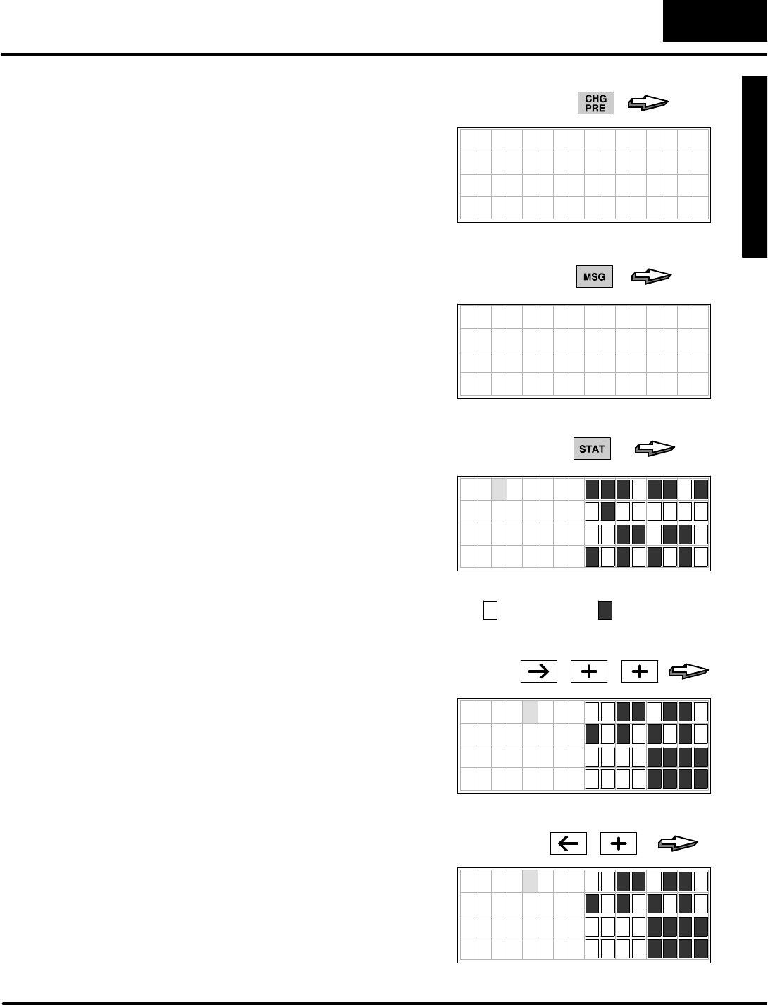
Press the ChangePresetKeywhen you
need tochange V-memorydata.This
mode requires setup parametersin
V-memory.BecauseV-memoryis cleared
at thispoint, you will see the error
message tothe right, whichisnormal.
Notethe absence ofacursorinthis
display,indicating the cursorkeys are
disabled.7654321076543210
* S E T U P E R R O R *
C H E C K V A L U E I N
V 7 6 2 0 T O V 7 6 2 2
PRESS
Press the MSGkeytoviewmessages
fromthe CPU.Thismode requires setup
parametersinV-memory.However,since
V-memoryispresently cleared the display
showsavalid default“message”,
consisting ofall zeros.
7654321076543210
0000000000000000
0000000000000000
0000000000000000
0000000000000000
PRESS
Press the StatusKeytoviewthe current
statusofvariousCPUmemorylocations.
Thismode doesnotrequiresetup
parametersinV-memory.The default
memorytype displayed upon entryto
MonitorStatusMode isthe Xinput type,
starting withX0.The righthalfof the
display showseightdiscrete points(one
byte)perline.The particularbinarypattern
showntothe rightisan example only.Your
specificdisplaydependson the current
statusofyoursystem.
PRESS
7654321076543210
X 0 0
X 1 0
X 2 0
X 3 0
=binary0,=binary1
The CursorRightand Left Keys move
the cursoron the top line,and the Plus(+)
and Minus(--) Keys scroll the display
addresses. If the displayisinStatusMode
asabove,press the CursorRightKeyto
movethe cursorovertothe adjacent“0”.
Withthe cursoroverthe address,press
the Plus(+)KeytwicetoincrementX00 to
becomeX20.
PRESS
7654321076543210
X 2 0
X 3 0
X 4 0
X 5 0
Nowpress the Minus(--) Keytwiceto
decrement the top displayline back to
X00.The Plusand Minus keys are also
used toselectdatatypes,aswell.First
press the CursorLeft keytomovethe
cursoroverthe top line “X”.Nowpress the
Plus(+)Keyonce,and the “X”sinthe
displaywill change to“Y”s.
7654321076543210
Y 0 0
Y 1 0
Y 2 0
Y 3 0
PRESS
CHGPREKey
(Change Preset)
MSGKey
(Message)
STATKey
(Status)
CURSORand
+/-- Keys
G
e
t
t
i
n
g
S
t
a
r
t
e
d
1
-
-
8
Getting Started
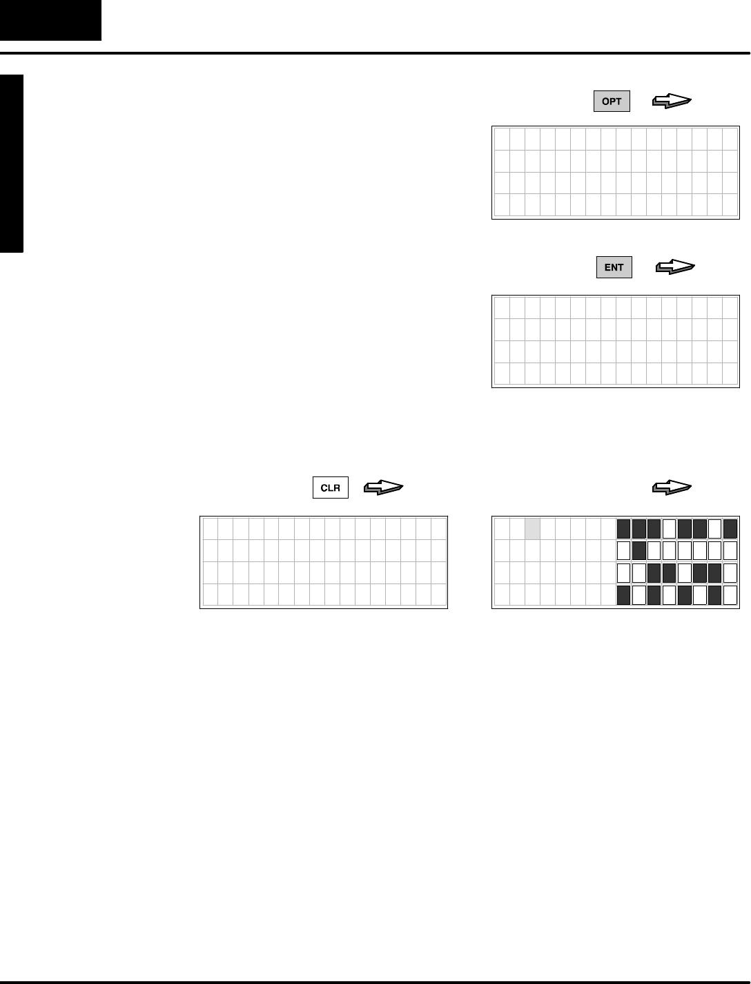
Press the OptionalModes keyto gain
access tothree utilitieswhich do nothave
dedicated keys.The displaywill list three
items:BitControl,Password,and Show
Err/Msg.
7654321076543210
O P T I O N
1 B I T C O N T R O L
2 P A S S W O R D
3 S H O W E R R / M S G
PRESS
Laterwe’ll usethe Plus(+)and Minus(--)
keys toselect the itemnumber.Nextwe
selectBitControlmode bypressing the
Enterkey.The displaybelowappears,
asking ustoconfirm ourchoice.
7654321076543210
D O Y O U W A N T B I T
CONTROL MODE?
YES:PUSH ENT KEY
NO :PUSH CLR KEY
PRESS
At the moment, wewill decline actuallyentering BitControlmode,bypressing the
Clearkey.The message “ExitBitControlMode”confirmsourchoice,and then the
displayautomaticallyreturnstoStatusDisplayMode aftera1second delay.
7654321076543210
EXIT BIT
CONTROL MODE
PRESS
7654321076543210
X 0 0
X 1 0
X 2 0
X 3 0
(1sec.delay)
Nowthatyou arefamiliarwiththe keypad and displayresponses,you’rereadyto
learnthe secret tosuccessful DV-1000 programming.
OPTKey
(OptionalModes)
CLEAR and
ENTER Keys
G
e
t
t
i
n
g
S
t
a
r
t
e
d
1
-
-
9
Getting Started
Setup Parameters,theKey toDV-1000 Success!
MostDV-1000 modesrequiresetup parameters.Refertothe figure below.These
areV-memorylocationsinthe CPUreserved forDV-1000 use.Theirpurposeis:
Setup parameters simplytell theDV-1000 wheretofind itsdisplay data.
Accordingly,theDV-1000 is completelylostwithoutits setup parameters!
READ
(atpowerup)
READ
(repeatedly)
V--MemorySpace
UserData
Setup Parameters
MESSAGE
DATA
LadderProgram
WRITE
Typically, the ladderprogramwritesthe setup parameterstoV-memoryon the first
CPUscan.These point tothe locationsofblocks ofdata(alsowritten bythe ladder
program),whichthe DV-1000 needsto generatemessages,presetlists,etc.By
reading setup parametersafterpowerup, the DV-1000 isabletolocate and read its
operationaldatafromthe data blocks elsewhereinV--memory.The DV-1000
re-readsthese data blocks continuouslyduring operation.
Tothe rightisatypicalprogramoutline
tosupport the DV-1000. Onthe first
scan, the firstrung places setup
parametersintheir reserved
V-memorylocations.The main
programfollows,whichmovesdatato
orfromthe data blocks referenced by
the setup parametersasrequired.
Chapter3covers setup parametersin
general.Then,eachchapteron an
operationalmode includes several
setup examplesforthatmode.
MainProgram
Setup Parameters
END
SP0
Wehighlyrecommend reading Chapter3on Setup Parametersthoroughly
before attempting to use anymodethatrequires setup parameters!
Purpose of
Setup Parameters
Programming
Setup Parameters
G
e
t
t
i
n
g
S
t
a
r
t
e
d
1
-
-
1
0
Getting Started
Quick TourofDV-1000 Operation
The Quick Tourisdesigned to acquaintyou withthe primarymodesof the DV-1000.
Mostof the modesrequireladderprogramsupportinthe CPU,and consequently,
somelearning on yourpart. Also,manyapplicationsdo notrequirethe programming
ofall DV-1000 modes.Therefore,itisimportant to begin byfirstidentifying the
mode(s) mostneeded foryourapplication.Werecommend all newusersread
Chapters 1,2,and 3thoroughly.Then you can choosefromChapters4through 7
the appropriatematerialforyourapplication.
StatusDisplayMode isaccessible atanytime bypressing the StatusKey.It does
notrequiresetup parameters.The 32-bitstatusdisplayisthe defaultupon entryto
StatusDisplayMode,as shown below.A64-bitstatusdisplayisalsoselectable.
7654321076543210
X 0 0
X 1 0
X 2 0
X 3 0
LSBMSB
(X07) (X00)DatatypeAddress
=binary0,
=binary1
7654321076543210
X 0 0
X 2 0
X 4 0
X 6 0
6
4
-
B
i
t
S
t
a
t
u
s
3
2
-
B
i
t
S
t
a
t
u
s
Inthe left displayabove, the left columnliststhe variabletype (Xinthis case).The
nextcolumnliststhe octaladdress.The top rowdisplays the statusofdiscreteinputs
X00 through X07 (or,X00 toX17 on the top rowof the right-mostdisplay).
DatatypesX,Y, GX,C,SP,T,CT,S,V,and Pare
accessiblein a circularlist, as showntothe right.
Cursorkeys letyou select the datatype for
viewing.NotethatsomeCPUsfeatureslightly
fewerdatatypes.
Thismode featuresa“bookmark”,which
recordsthe datatype and address of the
V-memorylocation being viewed when you exit
StatusDisplay.Itcan be recalled duringalater
use ofStatusDisplayMode laterwith onlyan
extrakey-stroke.
X
Y
GXC
SP
T
CT
S
V
P
DatatypesVand Pareshown as4-digit
hexadecimalnumbers.Cursorkeys allow
you torandomlyaccess variousaddress
locations.Ifyou need tochange the data
value(s),refertothe section on Change
PresetMode.7654321076543210
V 2 1 0 0 4 D 4 1
V 2 1 0 1 4 3 4 8
V 2 1 0 2 4 9 4 E
V 2 1 0 3 4 5 2 0
StatusDisplay
Mode
(see Chapter5)
G
e
t
t
i
n
g
S
t
a
r
t
e
d
1
-
-
1
1
Getting Started
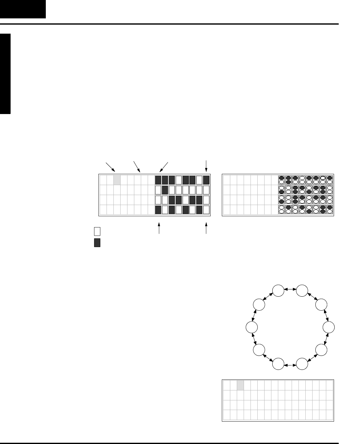
InMessage DisplayMode,displayoutput
can be fromone of three differentsources:
System Messages(includesFault
Messagesand Error Messages),and
User Messagesas shown.
FaultMessagesare generated byusing
the FaultMessage Boxinladderlogic.
SystemError Messagesare automatically
generated bythe CPUupon an error
event. FaultMessagesand SystemError
Messageshave displaypriorityoverUser
Messages.
User Messagesletyou create numeric
and textoutput tothe entire displayunder
ladderlogic control.OnlyUser Messages
requiresetup parameters.
FaultMesssage
ErrorMessage
7654321076543210
CONVEYOR SPEEDS
L i n e 1 = 1 2 3 f p m
L i n e 2 = 4 5 6 f p m
L i n e 3 = 7 8 9 f p m
UserMessage
* P A R T J A M , Z O N E 1
E 0 4 2 N O C P U B A T T
DL240,DL250,DL350,DL440 and DL450 CPUs can record up to 16 Error
Messagesand 16 FaultMessagesinseparatemessage logsas shown below. It
attachesatime/datestamptomessageswhen theyoccur.Thesemaybe viewed
individuallywiththe DV-1000.
DATETIMEFAULT MESSAGE
01 08/10/95 09:35:50 PARTJAMMED
02 08/11/95 08:00:43 BINEMPTY
03 08/11/95 07:15:53 OVERTEMP
04 08/20/95 17:22:48 LOWFLOW
05 08/30/95 17:22:24 PUMPFAULT
06 08/30/95 17:22:24 GATE STUCK
: : : :
16 08/02/95 9:22:16 SETUPINVALID
E
x
a
m
p
l
e
M
e
s
s
a
g
e
L
o
g
User Messagesrequireladder
programming and setup parameters.
Chapter4includes severalexample
programsdesigned toshowyou howto
add thesefeaturestoyourownmessages:
SInclude textwith numericaldata
SBlinking characters
SMultiplescreenswith paging
SSigned numbers(+/--)
STime and datestampinmessage
SCreate bargraphsforanalog data
SLong messagesthatscroll
7654321076543210
MACHINE STATUS
F a u l t = B i n E m p t y
Time =11:32:57AM
Date =07/05/95
7654321076543210
1
2
3
4
Bargraph Display
Time and DateStamp
MessageDisplay
Mode
(see Chapter4)
G
e
t
t
i
n
g
S
t
a
r
t
e
d
1
-
-
1
2
Getting Started
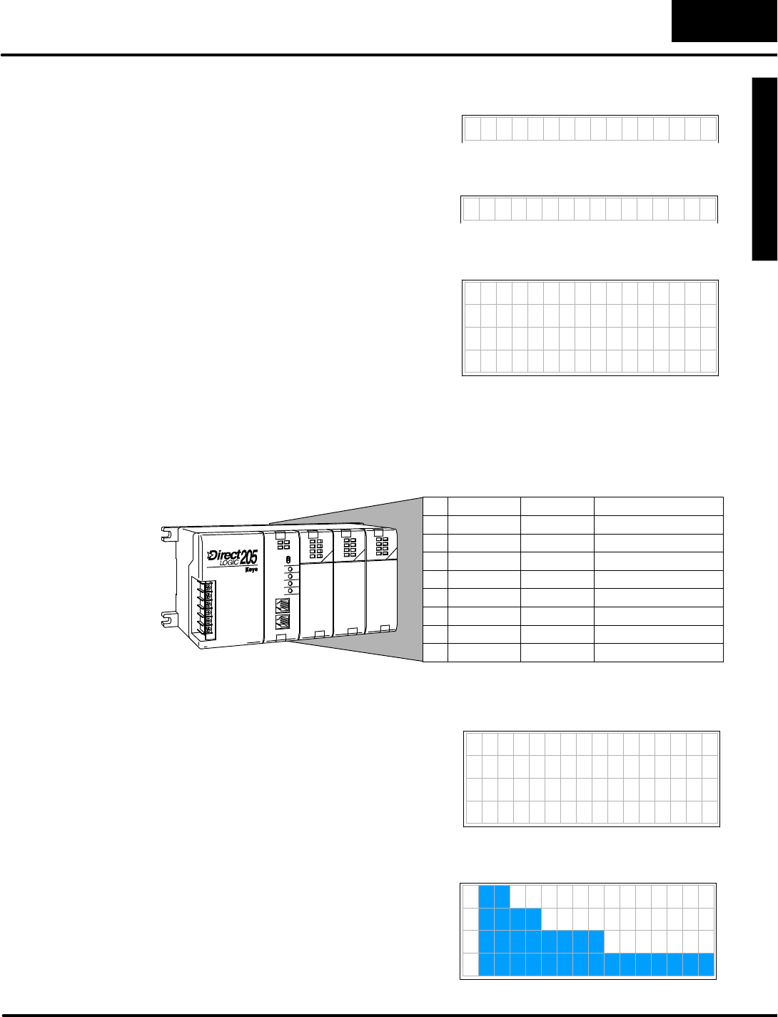
Change PresetMode presentsdatathatyou can
viewon the displayand editwiththe keypad.Setup
parametersarerequired.Titles(labels)accompany
the data,giving them meaning foryourapplication.
“Change Preset”justmeans“change V-memory
datavalue”.Password protection isalso available,
ifdesired.7654321076543210
My Title 0000
My Title 0000
My Title 0000
My Title 0000
TITLE
FIELD
DATA
FIELD
Three typesof titlesare availableinChange PresetMode:
SUser--titled Presetsallowyou to
createyourowntextlabelofup to
eightcharactersinlength.
SPre-titled Timerlabels(1to 99)are
availableifyou havetimersand can
useready-made labels.
SPre-titled Counterlabels(1to 99)are
availableifyou havecountersand
can useready-made labels.
M y T i t l e 0 0 0 0
T I M E R 1 0 0 0 0
C O U N T E R 1 0 0 0 0
W
i
t
h
p
r
o
p
e
r
s
e
t
u
p
p
a
r
a
m
e
t
e
r
s
,
y
o
u
c
a
n
establishlistsofpresetswithtextlabels
you create.The Change PresetMode has
built-in display scrolling capability.You
can scroll tothe variable name of the data
you want tochange,movethe cursorto
the datafield,and change the data using
the keypad.Like using thumb-wheel
switches, the datainV-memory changes
immediatelytomatchthe display.
U
S
E
R
T
I
T
L
E
S
D
A
T
A
H i A l a r m 0 0 0 0
L o A l a r m 0 0 0 0
S o a k T i m e 0 0 0 0
T e m p 1 0 0 0 0
G a l / M i n 0 0 0 0
T e m p 2 0 0 0 0
V a l u e 0 0 0 0
S e t P o i n t 0 0 0 0
Change Presetoperation isdepicted below.Setup parameterspoint tothe location
of title and datalistsinV-memory,also defining the listlength.The DV-1000 presents
these asmatched lists,sothatatitle and its corresponding data aretogetheron the
same displayline.Keypad entries can requestdatachanges,whichimmediately
updatesthe dataonthe displayand the datainV-memory.Finally, the ladderlogic
programusesthe newdatato updatethe machine controlprocess.
V--MemorySpace
UserV-memory
Setup Parameters
TITLES
DATALadderProgram
7654321076543210
My Title 0000
My Title 0000
My Title 0000
My Title 0000
TITLES DATAChange data
fromkeypad
ChangePreset
Mode
(see Chapter6)
G
e
t
t
i
n
g
S
t
a
r
t
e
d
1
-
-
1
3
Getting Started
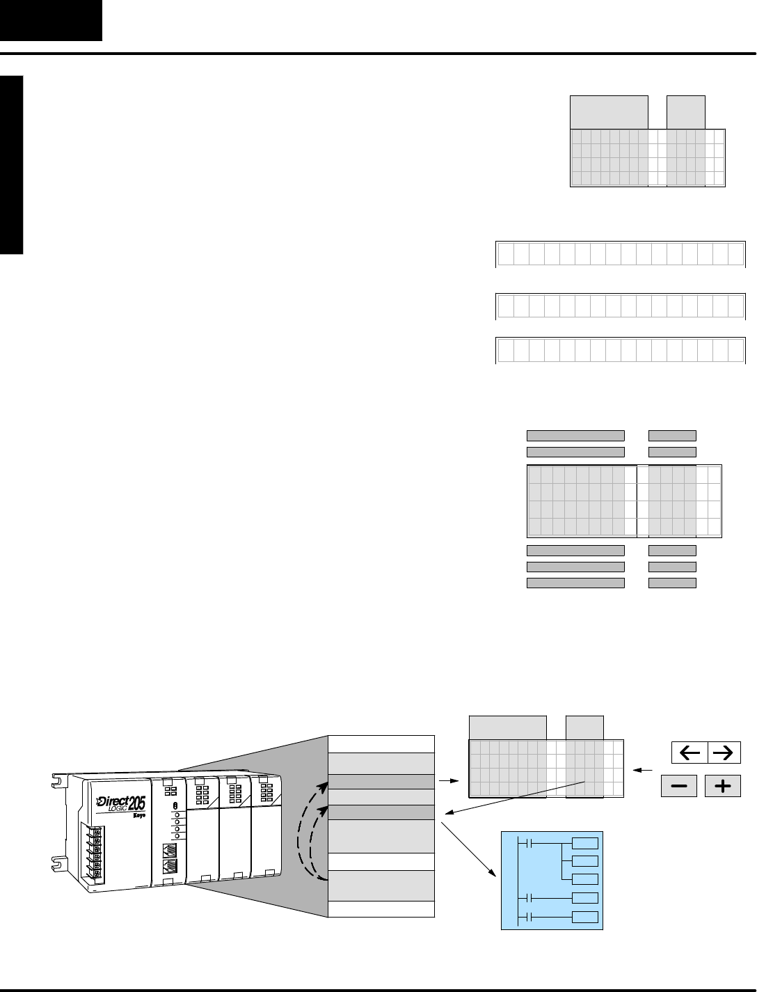
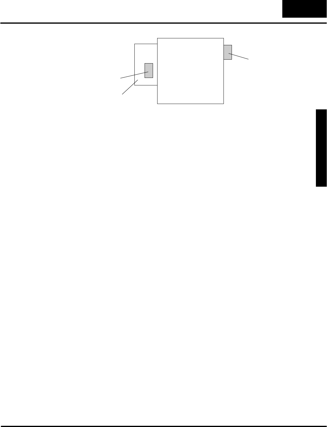
BitControlMode temporarilyreassignseightkeys on the keypad fordedicated
controlofeight I/O bits.A Setup Parameterisrequired.Inthe drawing below, the
setup parameterpointstoasystemI/O location foreitherX,Y,C,orGXtype I/O
points.Thisexample’s setup parameterpointsto a controlrelaylocation,controlling
the firsteightrelays.The keypad switchesoperate asmomentary,normallyopen
switches.When ladderlogicusesthese bitcontrolI/O pointsasinputs,keypad
entries can request I/O bitstoturn on aslong as keys are pressed.
V--MemorySpace
SystemI/O
UserV-memory
Setup Parameters
WRITE
READ
X
Y
C
GX
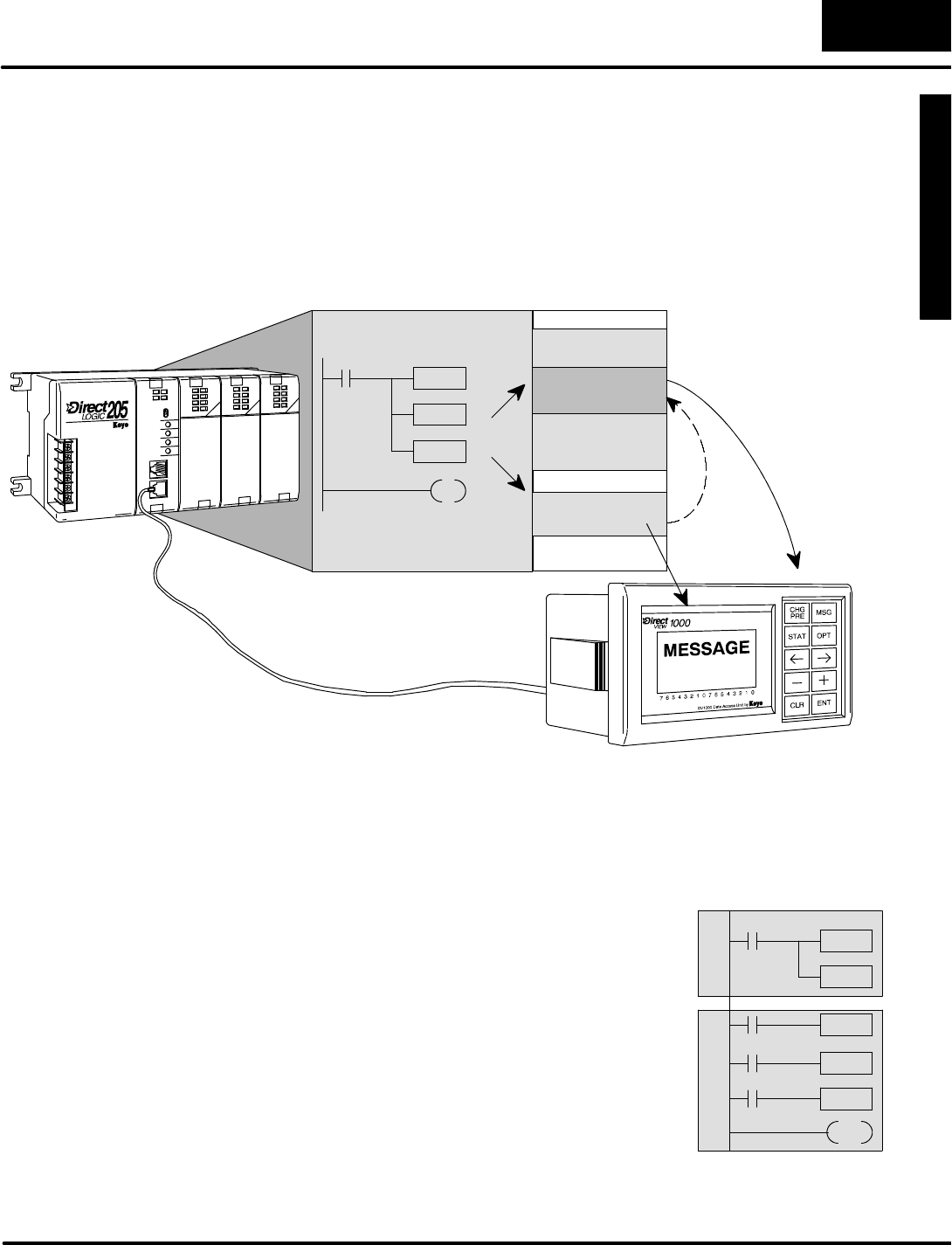
Whilethe keypad isinBitControlMode, the displaymaybe in either Message
Display,StatusDisplay,orChange PresetMode.
WARNING:BitControlModeisdesignedfordebug purposes only.Thereisno
automaticindication thatnormalkeypadfunctionalityhas beensuspended.
With a simple parametersetup and ladder
program,you can useBitControlMode to
turn on an outputmodule’soutputpoints.
Inthe examplesystemtothe right, the
eightkeys shownfromthe keypad have
been configured toturn on controlrelays
C0through C7.Then the mainladder
programusesthesetoturn on outputsY0
through Y7.8 pt
Output
8 pt
Input
8 pt
Input
C0
C2
C4
C6
C1
C3
C5
C7
BitControlMode
(see Chapter7)
G
e
t
t
i
n
g
S
t
a
r
t
e
d
1
-
-
1
4
Getting Started
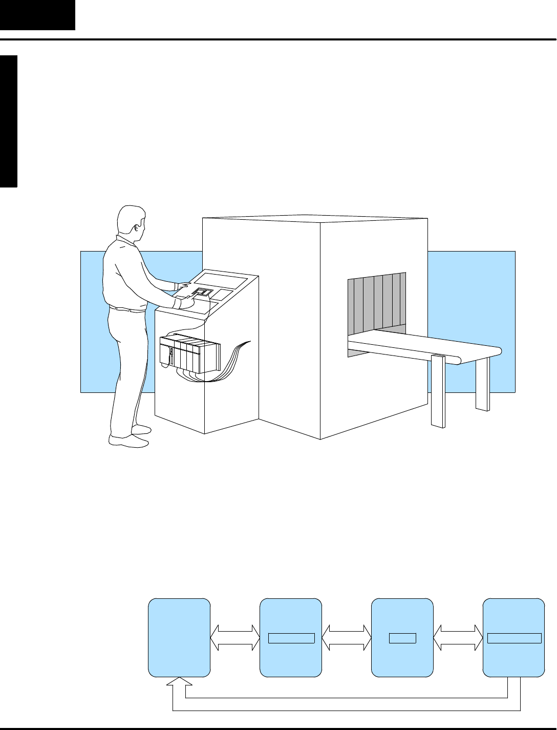
OperatorInterface Design Basics
The DV-1000 providesaccess toPLCdatatothe userwhilethe CPU isrunning the
RLL program,and the process or machine isrunning. Inmostapplications, the
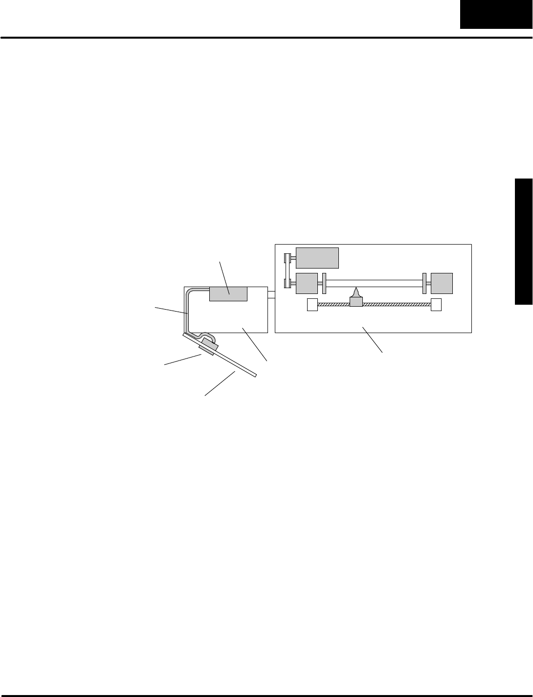
DV-1000 isa permanentpartof the operatorinterface.The operator’spanelshown
inthe drawing below isat the top of the controlcabinet, located at the side of the
machine.The operatorpanelcontainsall the dedicated operatorinterface devices,
such as switches,gauges,controlknobs,etc.The DV-1000 isone of these devices
whichformsthe entire operatorinterface.
Inthe transparentviewof the controlcabinet, followthe singlecablefromthe
DV--1000 tothe PLC inside.Fromthere,awiring bundleconnectsit through the rear
of the controlcabinet tosensorsand otherfield deviceslocated inside the machine.
The conveyorwhichmovesthe product through the machine mayalso be controlled
bythe PLC.
Nextwe examine the interaction and flowofinformation between all the playersin
the man-machine interface.The following diagramarrangestheminthe orderthey
communicate.
DV-1000 PLCMACHINEOPERATOR
Man-Machine
Interface
G
e
t
t
i
n
g
S
t
a
r
t
e
d
1
-
-
1
5
Getting Started
Action beginswiththe human operator,who wantstoknowthe machine statusor
make an adjustment tothe process.Fromthe controlpanel, the operatorcan access
datathrough the DV-1000,whichconnectstothe PLC inside the controlcabinet. In
turn, the PLCconnectstothe machine orfactoryprocess through wiring tosensors,
relays,solenoids,motors,and so on.
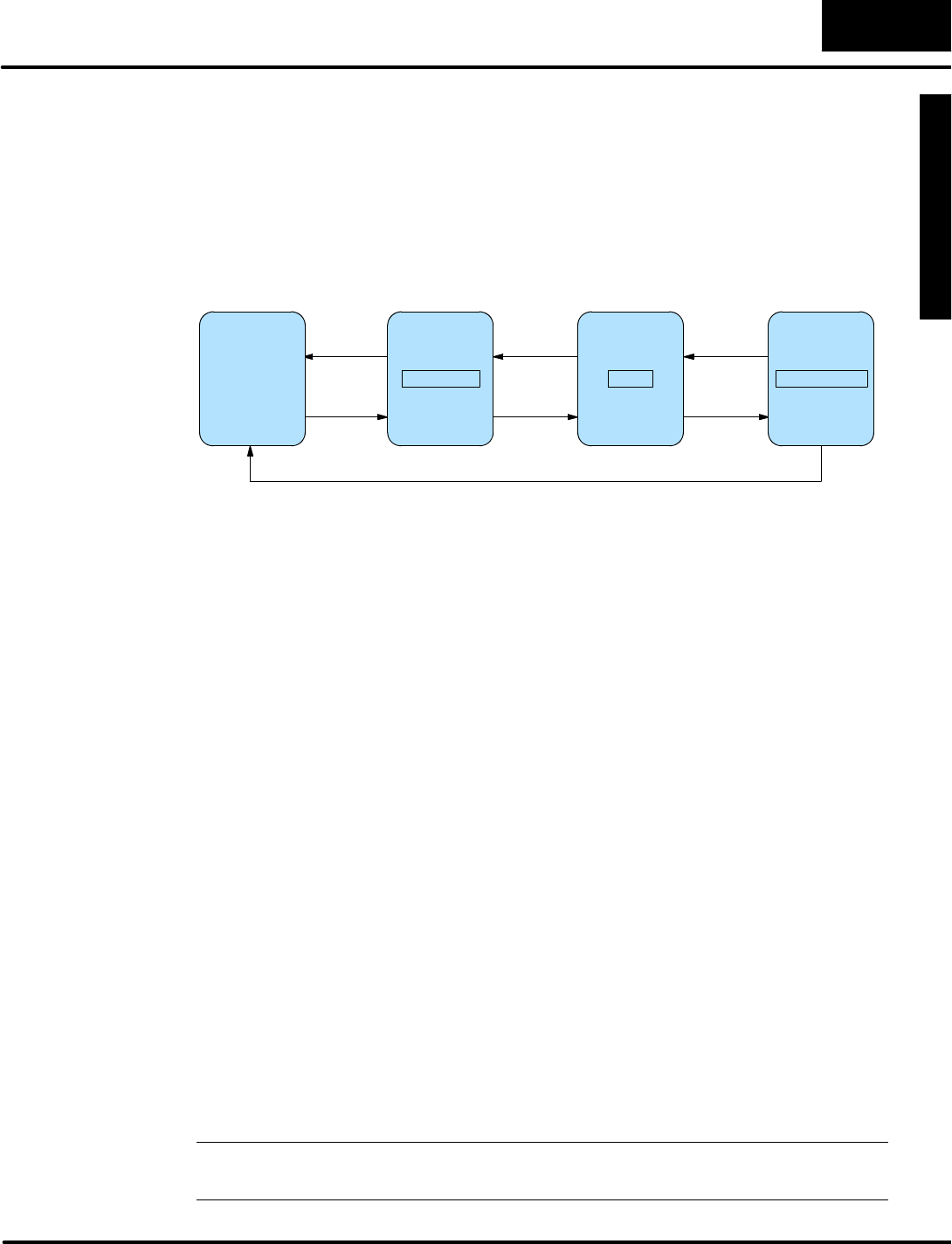
The DV-1000 features severaloperating modesthatmaybe used in a varietyof
ways.Butata basiclevel,itprovidestwotypesofaccessesto data:monitorand
control. Refertothe drawing below.
Monitor
ControlWrite
ReadInputs
Outputs
Monitorproductqualityorprocess performance
DV-1000 PLCMACHINE
Keypad
Display
OPERATOR
The drawing showsthe flowofinformation between the operatorand the machine or
process.
The controlpanelcommunicatesthe statusof the machine orprocess tothe
operator.Some of the kindsofinformation itconveys are:
SProduction totals
SMachine setup and process statusinformation
SQuality controlstatistics
SI/O pointstatusfortroubleshooting
UseMessageDisplay Mode(see Chapter4)forthesetypesofmessages.For
example,a diagnosticmessage thatsays “PartJam,Zone 3”givesan operatora
good idea of the nature of the problemand itslocation.UseStatusDisplay Mode
(see Chapter5)toviewthe PLC’sI/O bitstatusfortroubleshooting.
The controlpanelenablesan operatortochange the process instructionsor
setpoints.Some of the goalsaccomplished by control inputsare:
SChange a process variablesetpointduring runtime(such as
temperature)in orderto optimizethe process or machine performance
SSelecta particularproductsetup fromamenu
SPerform machine debug byturning on specific controlbitsoroutputs
SManuallyjogamachine orincrement through process stepsin orderto
tocleara partjamorfaultcondition
SControlmajor machine functions(Start, Stop,etc.)*see note below*
UseChangePreset Mode(see Chapter6)tochange process variablesorselecta
productsetup menu.UseBitControl(see Chapter7)for machine debug tasks.
NOTE:Forcontrolling major machine functions such asStart, Stop,Run,Jog,etc,
werecommend using individualdedicated controldevices,not the DV-1000 keypad.
Monitorand
Control
Purposes of
Monitoring
Purposes of
Control

G
e
t
t
i
n
g
S
t
a
r
t
e
d
1
-
-
1
6
Getting Started
FrequentlyAskedQuestions
NOTE:If you have generalquestionsregarding the DV-1000 and yourapplication,
pleasecheck the following listof typicalquestionswereceive.Ifyou have already
installed orprogrammed yourDV-1000 and are having difficulties,refertothe
Troubleshooting Guide inAppendixAat the end of thismanual. If you still need
assistance,pleasecall ustoll--free fortechnicalsupport.
CanIuse theDV-1000 tochangedatainthePLC?
Yes.There aretwomodesavailableforchanging PLCdata:
SChange PresetMode lets you individuallyeditV-memorylocationsasa
4-digitBCD number, fromalistofeither16 or32 datawordlocations,and
up to99timerpresetsand 99 counterpresets(depending on CPUtype).
SBitControlMode dedicates8 of the 10 keys on the keypad forsingle-bit
control.These operate aseightmomentary,normallyoff pushbuttons.
Istherepassword protection for modes thatallowtheoperatortochangePLCdata?
Yes, thereisforChange PresetMode.See Chapter6for moreonthistopic.
HowmanyDV-1000s can be connectedtothePLC?
Amaximumof twoDV-1000smaybe directly connected tothe DL240 and DL450
CPUs.See Chapter2forotheroptions,and general information on thistopic.
CanthePLCcause theDV-1000 toalways powerup ina certainmode?
Yes.The powerup defaultmode maybe selected byusing a particularentryinthe
parametersetup table.See Chapter3for moreonthistopic.
Isthereaway tocause theDV-1000 tostay inBitControlMode(oranymodethatIchoose)?
You can setup the DV-1000 to powerup in particular modes.However,if the
operatorpresses certainkeys on the keypad, thistakesthe DV-1000 outofits
originalpowerup mode.
CanthePLCcause theDV-1000 tochangemodes during normaloperation (PLCrun mode)?
No.Afterestablishing the powerup mode, furtherDV-1000 mode changesonly
occurupon keypad entry.
When does theDV-1000 readits setup parametersfromthePLC?
These areread one timejustafterpowerup,and anytime a mode change is
requested fromthe keypad.
What’sthebestway toentersetup parameters?
Werecommend imbedding the setup asa partof the ladderprogram.UsingaSP0
contacton the rung,itonlyexecuteson the firstPLCscan.See Chapter3for more on
setup parameters.
Ineedto display thephrase “TEMP1”,followed bythepresentvalueof thetemperatureinPLC
V-memory,and alsotoallowchanging thatvaluerighton thedisplay. Isthere a way to do this?
Yes.UseChange PresetMode,with user-titled labels.

G
e
t
t
i
n
g
S
t
a
r
t
e
d
1
-
-
1
7
Getting Started
CanIuse theDV-1000 tochangetimerorcounterpresetsinthePLC?
Yes.The Change PresetMode will letyou do this.See Chapter6for more
information on thistopic.
Canthedisplay showmoreASCII charactersthanjustlettersof the alphabet?
Yes, the DV-1000 charactersetincludes severalspecialsymbols.See AppendixB
foracompletelisting ofcharactersand symbolswiththeirASCII codes.
DoIhave toentertheASCII codes ininstruction boxes,orcanI just typeintheletters?
Actually,you maydo iteitherway.The LD/OUTand LDD/OUTD instructionsmay
placeASCII codesinthe text table,orthe ACON instruction box can convert
charactersinthe boxtoASCII codes(see Chapter4for moreonthistopic).
Ineedtoshowmorethanthedisplay’s4lines of text.CanIscroll orswap display screens?
Yes.The properladderlogicwill allowyou to do this.Examplesofmultiple display
screensand scrolling techniquesmaybe found inChapter4.
CanIuse theDV-1000 keypadtocontrolmachinefunctions, like Start,Stop,StepJog,Run,etc.?
Whiletechnicallypossible,westronglyrecommend againstthistype of
application.Major machine controlfunctionsare bestimplemented withlarger,
dedicated switches,knobs,etc.The keys on the DV-1000 areintended primarilyfor
variousmonitoring functions,orforoccasionally changing V-memoryPresetValues.
See the nextquestion and answer!
Arethereotheroperatorinterfaces availablefromPLCDirect?
Yes.Pleasecall ourTechnicalSupportLine (1--800--633--0405)forthe latest
information on otherDirectLOGICcompatible productsavailablefromusorfrom
industryaffiliates.
CanthePLCsense whentheoperator makes keypadentries?
It depends.BitControlMode isdesigned forgeneralkeydetection foreightof the ten
availablekeys,which areredefined fromtheirnormalfunction. Inthe other modes,
DV-1000 keypad activity cannotbe detected inthe PLC.
Canthedisplay indicatewhentheDV-1000 isinBitControlMode?
Yes,butwithsome qualification.The display can be inMessage DisplayMode and
the keypad inBitControlMode simultaneously(whichis selectable asa powerup
defaultmode).Ladderprogramming can detectkeypad activity,and coordinatethe
message displayto provide visualfeedback fromthe keypad entry.However, the
operatorcan leavethe Message/BitControlModesif theydesire.
CanIdisplayanumeric valueinMessageModewithaleading +/-- sign?
Yes.An exampleladderprogramthatdoesthisisinChapter4.
CanIdisplayablinking textmessageduring analarm condition?
Yes.An exampleladderprogramthatdoesthisisinChapter4.
Iplanto use theDV-1000 onlywithaDL105 orDL205.Aretherelow-costDirectSOFT
programming packages availablejust forthese models?
Yes.The PC--PGM-105 and PC--PGM--205 programming packagesare available,
each atan attractive priceforthe DL105-onlyand DL205-onlyusers.
Whatisthepurpose of thethe adjustmentscrewat thebottomof theDV-1000 housing?
Rotatethis screwto adjust the contrastof the LCD segmentson the display.

G
e
t
t
i
n
g
S
t
a
r
t
e
d
1
-
-
1
8
Getting Started
Specifications
CPUsSupported
DL130,DL230,DL240,DL250,
DL350,DL430,DL440,and DL450
CPUs(see Section 2,Step5for
specific communication portand
cabling information)
StatusDisplay
Displays 16 or32 pointbitstatus
forthe following datatypes
X,Y, GX,C,SP,T,CT,S
Displays numeric valuesfor
Vand Pdatatypes.
Cables and Connectors
ForDL105/DL205/DL350/DL450 --
Part#DV--1000CBL 6.6ft. (2m)
CablewithRJ12 connectors
ForDL430/DL440/DL450 -- 2
methods:Part#D4--1000CBL,
6.0ft. (1.85m) CablewithanRJ12
and a 15-pinmaleD-sub connector
(preferred),
orPart#FA-CABKIT,Usethe
Universal CableKit to attachthe
DV-1000CBLtothe CPUport
ChangePresetValues
DL130,DL230 and DL240 CPUs
up to 16 user-titled values
DL250,DL350 and all DL405
CPUsup to 32 user-titled values
Alsoincludes:
1--99 valuestitled asTIMERxx
1--99 valuestitled asCOUNTERxx
MessageDisplay
One4x16 character message
displayisavailable(message must
be inCPUprogram)
Displays textand embedded
numeric valueswhich updatewith
the application program
Displays PLCSystemError
Messagesand FaultMessage
Outputs
BitControl
Assigns8contiguouspointstothe
DV-1000 keypad
Eightkeys on the keypad operate
asmomentarynormallyopen
pushbutton switches
Bitdatatypeswhichcan be
assigned are:X,Y, GX,and C
Environmental
Operating Temperature 32 to 122 °F(0to50°C)..............
Storage Temperature--4to 158 °F(--20 to70°C)................
Humidity30 to 95%(non-condensing)...........................
EnvironmentalAirNocorrosive gases...................
Vibration MILSTD810C514.2...........................
Shock ResistanceMILSTD810C516.2...................
NoiseImmunityNEMAICS3--304.....................
RegulatoryAgency ApprovalsULrListed........
Power150 mA@5VDC.............................
obtained through PLCport
Dimensions5.12”Wx2.83”Hx1.03”D........................
130mm Wx72mm Hx26mm D
Weight5.8oz.(165.7 g).............................

1
2
Installation Guide
In ThisChapter....
—Introduction
—Step1:Choosing Single orDual DV-1000s
—Step2:PLCSelection
—Step3:SelectingaMountingLocation
—Step4:PanelMounting
—Step5:CableSelection
—Step6:Connectingthe DV-1000 tothe CPU
—Step6: Installingthe ExamplePrograms
—Step8:StartingDirectSOFT

G
e
t
t
i
n
g
S
t
a
r
t
e
d
I
n
s
t
a
l
l
a
t
i
o
n
G
u
i
d
e
2
-
-
2
Installation Guide
Introduction
This section guides you through the process ofinstalling the DV-1000 inyour
application.You can usethe relevantsectionsto either make a permanent
installation,orjustatemporary connection on yourdesktop fordeveloping your
application program.The installation stepsinthis section are:
SStep 1:Choosing Single orDual DV-1000s
SStep 2:PLCSelection
SStep 3:SelectaMounting Location
SStep 4:PanelMounting
SStep 5:CableSelection
SStep 6:Connecting the DV--1000 tothe CPU
SStep 7: Installing the ExamplePrograms
SStep 8:Starting DirectSOFT
Afterthe installation,you’ll be readyto begin programming and using yourDV-1000.
NOTE:. If you havetroublewhile programming orusing yourDV-1000,refertothe
Troubleshooting Guide inAppendixAof thismanual.
Step1:Choosing SingleorDualDV-1000s
DL240,DL250,DL350,DL440 and DL450 CPUs can support twoDV-1000 units
(DL130,DL230 and DL430 CPUs can supportonlyone DV-1000:DL130 and DL230
CPUsonlyhave one communicationsportand onlythe top communicationsporton
aDL430 maybe used toconnectaDV-1000).Connectingasecond DV-1000 tothe
CPUrequiresno additionalprogramming beyond whatisrequired forthe firstone.
Whilemostapplicationsonlyrequire one DV-1000 per machine,orperPLC,
occasionallyitisadvantageoustoaddasecond one.Refertothe drawing below.For
example,somemachineshavetwo operatorstationsthataresome distance apart.
In othercases, the machine needsonlyone controlpanel,butasecond DV-1000
placed elsewhereonthe machine couldmakeitmoreconvenient forpersonnelto
access data(such asmonitoring machine status).
DV-1000
OperatorPanel#1
DV-1000
OperatorPanel#2
Machine orProcess
MachineWith TwoOperatorPanels
FirstSecond
I
n
s
t
a
l
l
a
t
i
o
n
G
u
i
d
e
2
-
-
3
Installation Guide
Machine orProcess
OperatorPanel
DV-1000
DV-1000
MachineWithOperatorPaneland Monitoring Station
First
Second
To helpyou decide whetherdual DV--1000sareright foryourapplication,welist
some of the operating characteristics:
SBothDV-1000s sharethe samesetup parametertableinthe CPU’s
V-memory.Afterpowerup, theybothread the same parameters,and
read the same data blocks elsewhereinV-memoryfor message data,
preset titles,and so on.
SIf you selecta powerup defaultmode otherthan “PreviousMode”,both
unitswill powerup inthe mode you select(viathe setup parameter).
SThe keypadsoperateindependently,sothe DV-1000s can be placed in
differentmodesduring operation.
SIn all monitoring functions, the unitsoperateindependently. One unitcan
viewXinputpointstatuswhilethe otherviewsV-memorylocations, for
example.
SIn all controlfunctions, the unitsoperateinalogicalORfashion.Either
unitcan change a preset, and the resultisreflected at the otherunitas
well.Bitcontrolalsoworks inalogicalORfashion.
Knowing these operating characteristics,you need onlyone DV-1000 connected to
the CPUas you develop the application program.When yourprogramming is
finished,justplug inthe second DV-1000!
TheDL240 and DL450 CPUs arebestsuitedfordualDV-1000 applications,
because bothDL240 communication portsand the top and middleDL450 portsmay
connectdirectlytoDV-1000s.Besuretoconfigure both portsforK-sequence
protocol.
TheDL250,DL350 and DL440 CPUscan connect totwoDV-1000s,butnotas
simplyasaDL240 orDL450.The variousmethodsare asfollows:
SByadding DataCommunication Modules(DCM),you can connect
additional DV-1000s.
SAsecond DV--1000 maybe connected directlytothe CPU,byusing the
bottomcommunication portand adding an external+5Vsupply(since
the bottomportdoesnotsupply+5V).Usethe cable diagramslaterin
this chapterforconnectorpin-outinformation.
SADL405 SmartSlice productcan connect to one DV-1000 (appliesto
DL405 productsonly).
DualDV-1000
Operating
Characteristics
DL240,DL450
Connection
D
L
2
5
0
,
D
L
3
5
0
,
DL440,
Connection
G
e
t
t
i
n
g
S
t
a
r
t
e
d
I
n
s
t
a
l
l
a
t
i
o
n
G
u
i
d
e
2
-
-
4
Installation Guide
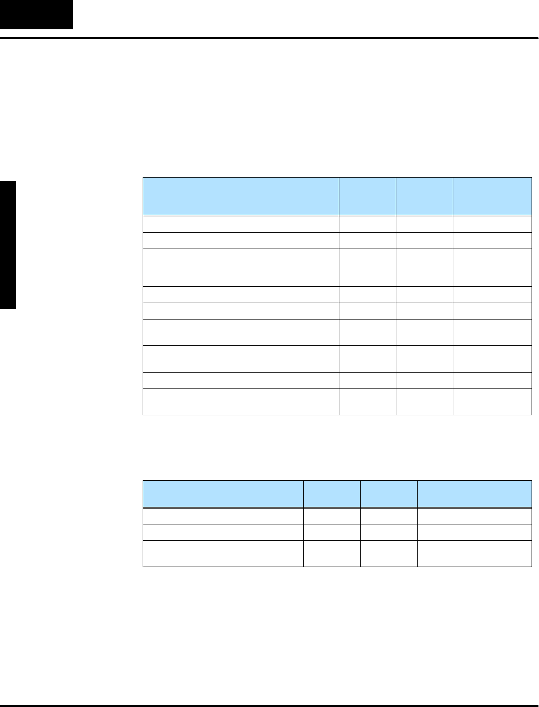
Step2:PLCSelection
The DV-1000 works with all DL105,DL205 and DL405 seriesCPUs,in addition to
DL350 CPUs.At thispointyou mayalready know whichPLCfamilyand type best fits
yourapplication.However,differencesinthe availabilityof featuresexist thatyou
maywant tofactorintoyourdecision.The table belowoutlinesthe feature
differences.
DV-1000 FEATURES DL105
DL230
DL240 DL250,DL350,
DL430,DL440,
DL450
SelectablePower-up Mode YesYesYes
Textand NumericMessagesYesYesYes
StatusAvailable ofV-MemoryDataTypes:X,Y,C,
SP,T,CT,
S,V,P
X,Y,C,
SP,T,CT,
S,V,P
X,Y,GX,C,SP,
T,CT,S,V,P
Change PresetLocations16 16 32
Change PresetPasswordYesYesYes
Titled TimerPresetValues,Number
Available
16 99 99
Titled CounterPresetValues,Number
Available
16 99 99
BitControlYesYesYes
NumberofDV-1000sConnectableDirectly
toCPU
1 2 1 (2forDL450)
Alsoconsiderthe availabilityofcertainfeaturesin eachCPUtype thatsupports
programming forthe DV-1000,given inthe following table.
CPUFeatures ThatSupport
DV-1000 Programming
DL130
DL230
DL430 DL240,DL250,DL350,
DL440,DL450
ACONInstruction (ASCII Const.)YesNoYes
MOVMCInstruction YesNoYes
Can ConnectCPUsimultaneously
toDV-1000 and DirectSOFT
NoYesYes
Overall, the DL240,DL250,DL350,DL440 orDL450 CPUsarethe bestchoicesfor
DV-1000 applications.The maininconveniencewiththe DL430 isitslack ofACON
and MOVMC instructionsthathelpinMessage DisplayMode.Use of the DL130 or
DL230 requires switching its singlecommunicationsportbetween the DV-1000 and
DirectSOFT programming whileyou are developing the ladderprogram.
I
n
s
t
a
l
l
a
t
i
o
n
G
u
i
d
e
2
-
-
5
Installation Guide
Step3:Selecting aMounting Location
Before actuallyinstalling the DV-1000 inyourapplication,werecommend doing a
sketch of the controlpaneloroperatorinterface,orwhereverthe DV-1000 will be
installed. One goal in doing this sketchisto determine the length ofcable needed to
connect the DV-1000 tothe PLC.The sketch needstoshowthe DV-1000 and the
PLCtowhichitconnects.Trytoinclude the following details:
SOperatorPanel location on machine orfactoryfloor
SOperatorPanel layout, including DV-1000 mounting location(s)
SControl Cabinetlayout, including PLCmounting location
SElectricalcableconnecting DV-1000 toPLC(showing cablelength)
Machine orProcess
PLC
ExampleApplication Sketch(Top View)
IndustrialLathe
DV-1000 Control Cabinet
Electrical
Cable
OperatorPanel
If yourapplication requirestwoDV-1000sinthe operatorinterface,include them
bothinthe sketch. If possible,do Step 3 beforefinalizing yourapplication layout.
Thisplanning mayeliminatethe need tomake a customcableinthe eventstandard
cablesaretoo short foryourinitial layout.
G
e
t
t
i
n
g
S
t
a
r
t
e
d
I
n
s
t
a
l
l
a
t
i
o
n
G
u
i
d
e
2
-
-
6
Installation Guide
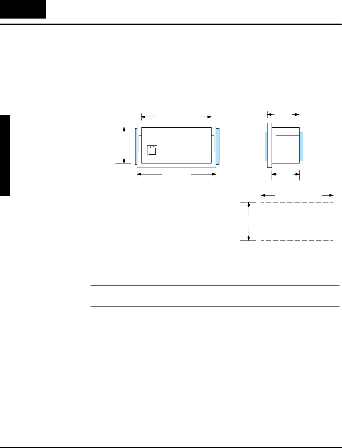
Step4:PanelMounting
The DV-1000 isdesigned to easily snap intoarectangularcutoutin a controlpanelor
othersurface panelat the machine. On eachside of the housing thereisaretention
cliptokeep the unitin place afterinstallation.The drawing belowgivesthe physical
dimensionsof the DV-1000 housing.
(125mm)
4.92 ”(34mm)
1.34 ”
(26mm)
1.03 ”
(67mm)
2.64 ”
Back Side
(130mm
5.12 ”
The panelcut-outdimensionsareshowntothe
right. This sizerectanglewill provide
necessary clearanceforthe bodyof the unit,
butwill allowthe outerhousing bezeltocover
the edgesof the cut-out fora nicefinished
appearance.The optimumpanelthickness for
using the retention clipsis1/16”to 1/8”.
(125.5mm
4.94 ”
(67.3mm)
2.65 ”PanelCut-out
Dimensions
When yourpanelcut-outisfinished,you’rereadytomount the DV-1000 inthe
controlpanel.Simplypushitinfromthe front, and itwill snap into place. If you need to
removethe DV-1000,justpress the retention clipsinwardwhile pushing the unit from
the reartowardthe panel’sfrontside,and itshouldjustslip out.
NOTE:If possible,avoidmounting othercontrolpaneldevicesdirectlyunderthe
DV-1000.Doing somayinterferewith access tothe brightness adjustmentscrew.
I
n
s
t
a
l
l
a
t
i
o
n
G
u
i
d
e
2
-
-
7
Installation Guide
Step5:CableSelection
Inthis step weselect the appropriatecabletoconnect the DV-1000 toyourCPU.
Cables comeintwoversions,which differinthe connectortype atone end. One
version isforconnection to all DL105,DL205 and DL350 CPUs.The otherisfor
DL430 and DL440 CPUs.DL450 CPUs can use eitherversion.
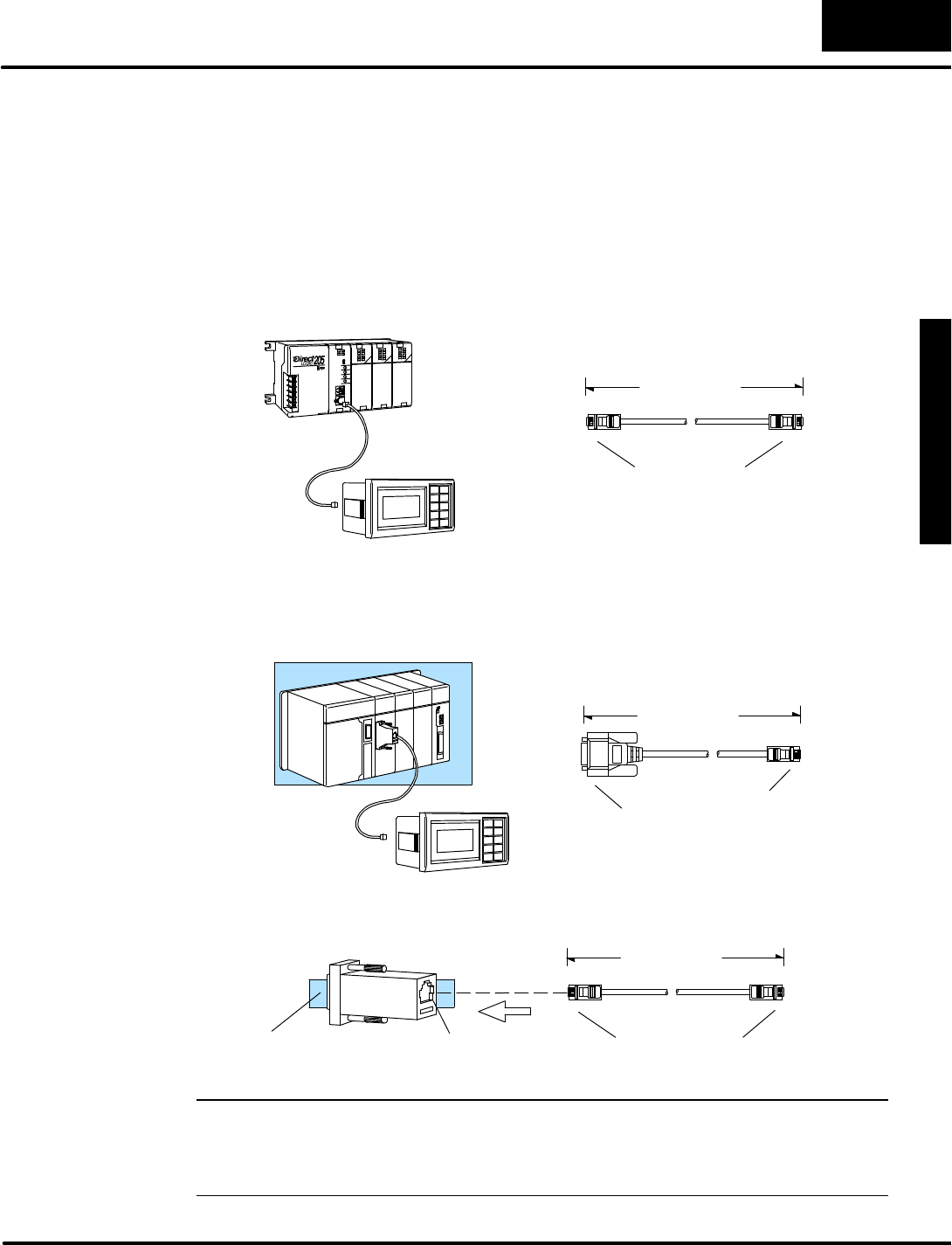
The DV-1000 connectstothe single phone-jack-stylecommunicationsporton a
DL130 orDL230, the top porton a DL250,DL350,orDL450,orto eitherporton a
DL240.The standardcable and itspartnumberarelisted inthe following figure.
6.6ft/2m
Phone Jack style
connector (RJ12),
6-conductor
UsePartNo.DV-1000CBL
The DV-1000 connectstothe 15-pintop porton DL430 and DL440 CPUsand the
middle porton DL450 CPUs.The bottomporton theseCPUsdo notprovide the
needed +5V.There aretwomethodsfor making theseconnections,shown below.
Method 1(preferred):UsePartNo.D4-1000CBL
6.0ft/1.85m
Phone Jack style
connector (RJ12)
15-pinD-sub
connector (male)
Universal15 pin
D--sub connector
Std phone jack
Method 2:UsePartNo.FA-CABKIT
7.0ft/2.15m
Phone jack style
connector (RJ12)
Connectsto
DV-1000
Connectsto
CPU
Shielded Cable
Non-shielded Cable
Connects
toDV-1000
Connectsto
CPU
NOTE:The DV-1000 usesKsequence protocoltocommunicatetothe PLC.Some
TI435âCPUs couldreliably connect to onlyone device atatime using Ksequence
protocol.Ksequence protocol isavailable on all portson DL105,DL205,DL405 and
DL350 CPUs.
DL105,DL205
DL350,DL450
Phone Jack Style
Connection
DL430,DL440,
DL450 15-Pin
Connection
G
e
t
t
i
n
g
S
t
a
r
t
e
d
I
n
s
t
a
l
l
a
t
i
o
n
G
u
i
d
e
2
-
-
8
Installation Guide
The firstmethod (the preferred method)usesaspecialshielded cablewith a
modularphone-jack-styleconnectoron one end and a 15-pinD-shell connectoron
the other.The connectorsplug directlyintothe DV-1000 and CPUport.
The second method usesa non-shielded cable and an adapterplug fromthe cable
kit. The cable(same asDL105,DL205,DL350,DL450 cable)hasamodular
phone-jack-styleconnectoratboth ends,so eitherend will connect tothe DV-1000.
The otherend connectsto an adaptertogofroma 6-conductor modularto a
15-conductorD-shell toconnect tothe CPUport.
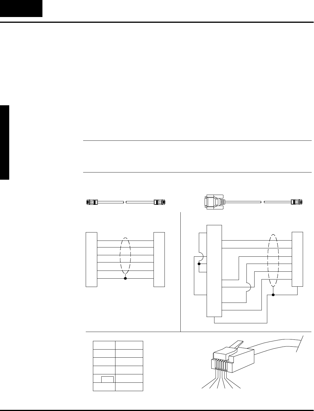
Insome applicationsthe length of the standardPLCDirectcablemaynotbe quite
long enough.You maymakeyourowncable,butobservethe following guidelines:
SUseashielded type cable.Besuretoconnectits shield atboth endsto
the appropriateconnectorpins.
SDo notexceed 15 feetinlength.
NOTE:The standardcablesare approximately6feetlong.Ifyou have determined
the need foracablelongerthan 6 feet, you mayuse a slightlylongerone (up to 15
feet).The noiseimmunityof the DV-1000 communicationsmaydecreasewith
cableslongerthan 15 feet.
3
4
5
1
2
6
1
2
3
4
7
8
11
12
13
14
15
Shield
Shield
RJ12
15 PinD-shell
6
5
4
3
2
1
Shield
1
2
3
4
5
6
RJ12RJ12
DL105,DL205,DL350,
DL450 Connection
DL430,DL440,DL450 Connectio
n
6
5
4
3
2
1
RJ12 ConnectorPin-out
PinInformation
2
RX
TX
5+5VDC
6
1
3
4
Common
Common
+5VDC
CustomCables
I
n
s
t
a
l
l
a
t
i
o
n
G
u
i
d
e
2
-
-
9
Installation Guide
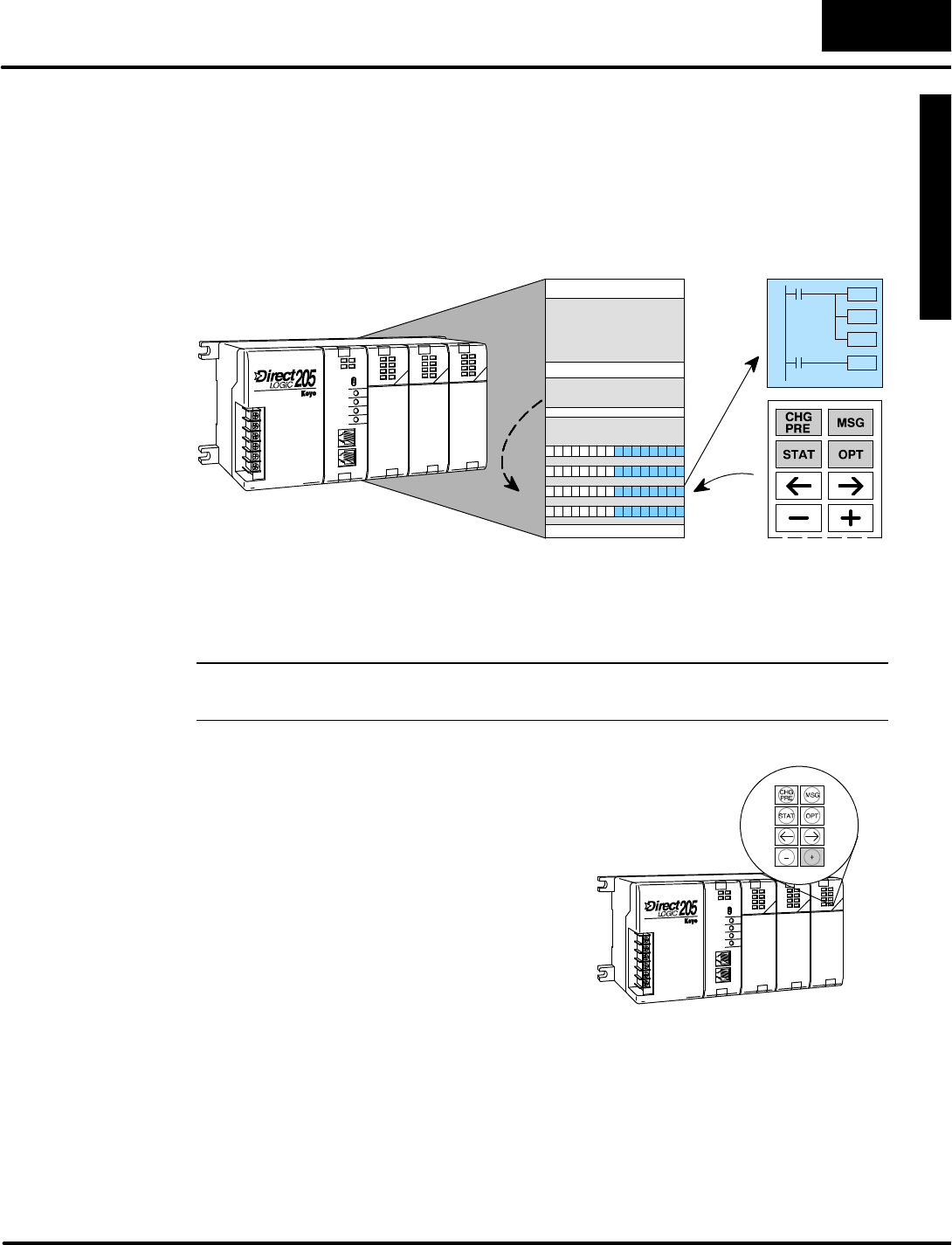
Step6:Connecting theDV-1000 totheCPU
Inthe first fivestepswe haveselected the numberofDV-1000s,PLCtype,decided
wheretomount the PLCand DV-1000,and selected the propercabletoconnect
them.Now we’rereadytoconnect the DV-1000 tothe CPU.Afterdoing so, turn on
the PLCbyapplying electricalpower. If properly connected, the DV-1000 will turn on
wheneverthe PLC ison (the CPU“PWR”LED isilluminated).The back-lightis
always on wheneverthe DV-1000 ispowered.
Afterthe DV-1000 ispowered,you can
adjust the display contrast. An adjustment
screw isaccessible at the bottomof the
unit through a small hole.Use a small
Philips screwdriverto adjust the contrast
forambientlighting conditionsand desired
viewing angle.
ContrastAdjustmentScrew
(on bottomofunit)
In almostall cases, the DV-1000 displaywill showsomemessage at firstpowerup.
The exactmessage on the displaydependsmostlyon the currentCPUmode,but
alsothe contentsofCPUprogram memoryand variablememory.
Step7:Installing theExamplePrograms
Adiskette ofexample programsis
included withthismanual.All of the
example programsinthe manualare on
the diskette. One of the bestways tolearn
the DV-1000 istoload and run these
programs. It ispossibletoload the
examplesfromthe diskette.However,we
recommend copying themtothe hard
driveinyourcomputer,and keep the
originaldisketteinasafe place.
a:\filename.prj
Toinstall the example programsifusing Windows 3.1, followthesesteps:
1.Make a newdirectoryon the hard driveinyourcomputer.Forexample,
if the hard driveisdriveC, type:
MD C:\DV--1000
2.Copyall the filesfromthe example programdisk tothe newdirectory.For
example,if the disketteisin driveA:and the hard driveisdriveC:, type:
COPY A:\*.*C:\DV--1000\*.*

G
e
t
t
i
n
g
S
t
a
r
t
e
d
I
n
s
t
a
l
l
a
t
i
o
n
G
u
i
d
e
2
-
-
1
0
Installation Guide
Toinstall the example programsifusing WIN95, followthesesteps:
1.Select the Explorericon and open. If the hard driveisdriveC,select the
(C:) icon.
2.Make a newdirectoryinthe hard drive ofyourcomputer.Forexample,
Select the Filemenu, then selectNewand then Folder.Noticethe New
Foldericon thatappears.Select the folderand nameit“DV-1000”by
selecting the Filemenu and selecting Rename.Type inthe newname.
3.Copyall the contentsof the example programdisk. Insert the diskettein
driveA,and selectand open the 3 1/2Floppy(A)icon.Noticethe disk
containstwo directoriesand one text file:“130_230”,“240_450”,and
“Readme.txt”.Selectall three byopening the Editmenu and selecting
SelectAll. Open the Editmenu again and selectCopy.
4.Pastethe programdisk contentsintothe new C drive“DV-1000”directory.
Open the “DV-1000”directory,open the Editmenu and selectPaste.
Afterthesesteps,you’rereadytostartDirectSOFT and run the example programs.
Open the READMEfileinthe examplesdirectoryforinstructionson whichsetof
examplesto usewithyourPLC.Usethe examplesinthe 105 directoryifusing any
DL105 MicroPLC.Usethe examplesinthe 230 directoryifusing a DL205 with a
D2--230 CPU.Usethe 240_250 examplesifusing a DL205 with a D2--240 or
D2--250 CPU.Usethe 350_405 examplesifusingaDL305 withaD2--350 CPUor
anyDL405 CPU.

I
n
s
t
a
l
l
a
t
i
o
n
G
u
i
d
e
2
-
-
1
1
Installation Guide
Step8:Starting DirectSOFT
The DV-1000 relieson the ladderprogramand setup parametersinV-memoryfor
much ofitsoperation.Beforewe beginthe seriesofexamplesand lessonsinthe
following chapters,itisimportant to getyourCPU inaknownstarting state. Onlythen
will the examplesinthe following chaptersinthismanual workor makesensetoyou.
The starting condition of the PLCthatwe need iswith program memory cleared,and
V-memory cleared.The following stepswill guide you through thisprocess.
1.Connect the communications cablefromyourpersonalcomputer
communicationsport toyourPLC’sprogramming porton the CPU.
2.StartDirectSOFT on yourpersonalcomputer.
3.Selectalinkto go online withthe CPU.
4.Savethe project fileto disk at thistime,ifyou created a programinthe PLC
thathasnotbeen saved to disk.
5.Verifythe CPU isin program mode.Fromthe menu bar,selectPLC, then
PLCModes, then Program.Then select“OK”,orpress Return.
6.Fromthe menu bar,selectPLC, then ClearPLCmemory,then All.Then
select“OK”,orpress Return.
7.FromPLCmenu,chooseSetup, then InitializeScratchpad.Thisensures
the DV-1000 setup parametersareinitialized tozerovalues.
NOTE:If you are usingaDL130 orDL230 CPU,you probablynoticed bynowthatit
hasonlyone communicationsport. Therefore,you will havetoswap
communications cablesinthatportin orderto alternatelyuseDirectSOFT and the
DV-1000 withthe CPU.UsingaDL240 CPU which hastwo portswill alleviatethis
inconvenience.
Toload an example programfromthe DV-1000 directoryon the hard drive,do the
following:
1.Select the Files menu, then OpenProject.
2.Adialog boxwill appear.Select the disk and directorywherethe example
programsreside (forexample,driveC:, directory\DV-1000).
3.Select the file name of the programyou wishtoload, then OK.When the
programhasloaded,itsladder rungswill appearon the monitorscreen.
4.Select the PLCmenu, then Connect, then select the linkto use.All the
programexamplesaresaved withoutPLC linkinformation,soyou haveto
re-connect toyourparticularCPU. If amessage appearswhich asks you to
select the source ofprogramtoview,selectDisk.
5.Ensurethe CPU isinProgram mode.Then download the programtothe
CPU.Select the Filemenu,WriteProgram..., then selectTo PLC.
6.When the programhasdownloaded,put the CPU inRun Mode.Select the
PLCmenu,PLCModes..., then selectRun.
7.Then followthe directionswiththe example programfromthismanual.
Usually you will haveto usethe keypad to get the DV-1000 in a particular
mode tosee the programoperate.
InitializetheCPU
Loading an
ExampleProgram

1
3
DV-1000 Setup
Parameters
In ThisChapter....
—Overview
—ParameterDefinitions
—Entering Setup Parameters
—Usingthe LDAInstruction forPointerSetup Parameters
—PowerupDefault OperationalMode
—ChapterSummary
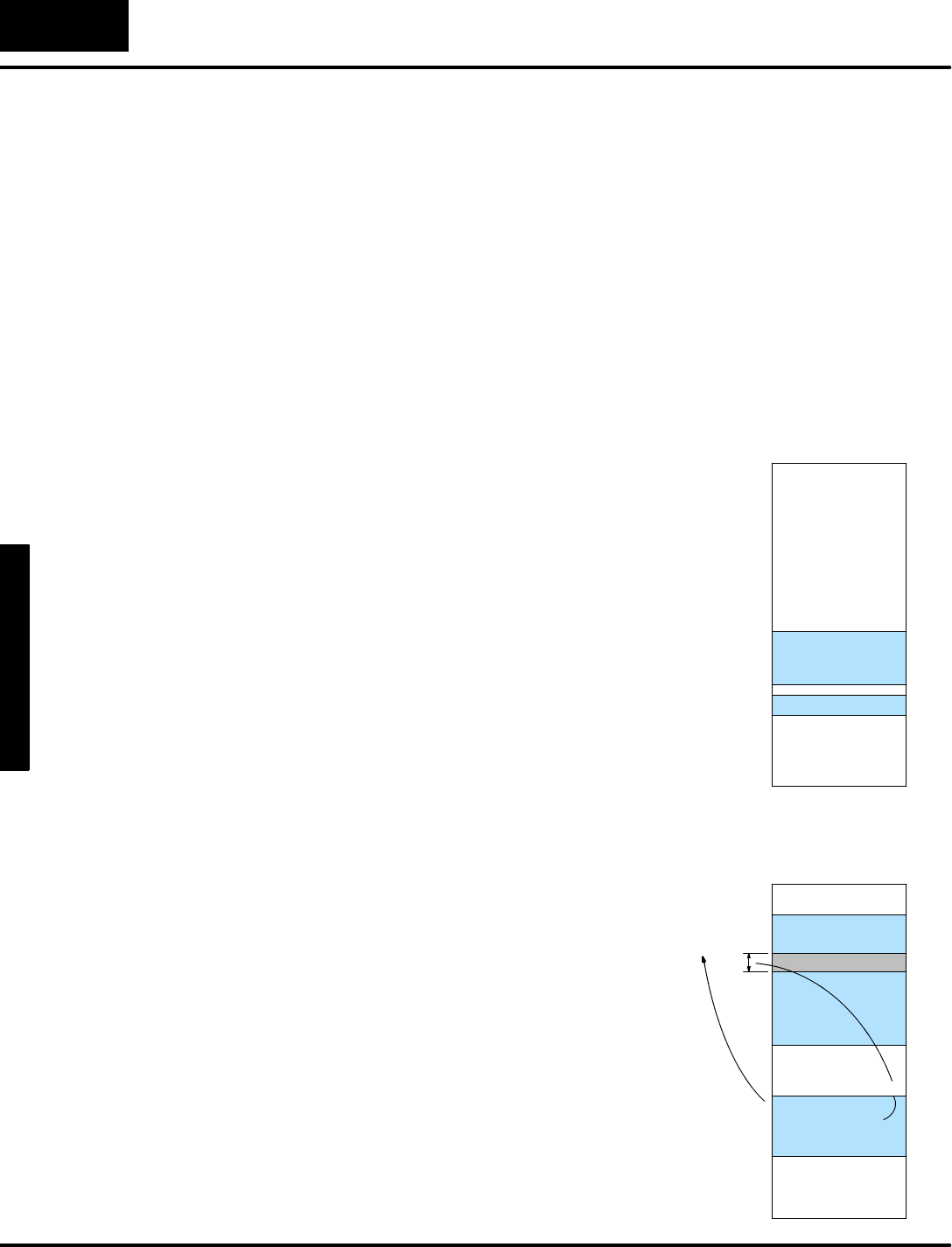
D
V
-
1
0
0
0
S
e
t
u
p
P
a
r
a
m
e
t
e
r
s
3
-
-
2
DV--1000 Setup Parameters
Overview
Some of the operationalmodesof the DV-1000 have user-selectablefeatureswhich
requiresome userprogramming beforethosemodesmaybe used. Inthe Display
and Keypad Basics exercise ofChapter1wesawsome“Setup Error” messages
occur.Thesewere normalbecausetherewere no setup parametersentered forthe
mode requested byourkeypad entry.The goalof this chapteristo define the setup
parameter requirementsforall DV-1000 modes,and then showhoweasy itisto
programthese parameters.
All setup parametersresideintheCPU’sV-memory space,notintheDV-1000.
Thisisthe most fundamentalconceptin understanding setup parameters.The
DV-1000 hasno user memoryofitsown. Instead,a block ofV-memorylocationsis
reserved inthe CPUspecificallyforthesesetup parameters.
A
t
p
o
w
e
r
u
p
,
t
h
e
D
V
-
1
0
0
0
r
e
a
d
s
t
h
e
s
e
t
u
p
parametersfromthe CPU’sV-memory.
Refertothe image ofV-memorytothe
right. The memorymap startsat the top at
V0000,and itswidthisone dataword.
Setup parametersoccupyV-memory
locationsfromV7620 toV7627 on all
CPUs,and fromV7720 toV7722 on all
CPUsexceptDL130 and DL230 CPUs,
which uselocationsV7640 toV7642.
Although theyaretechnically separated
intotwo blocks, thismanualsimplifiesthe
discussion by combining theseinto one
block.All subsequentdrawingsof this
memorymap show DV-1000 setup
parametersasone data block.
V7620 to
V7627
V7720 to
V7722*
V0000
V--MemorySpace
Setup Parameters
Parameters cont’d
End ofV--
Memory
*DL130 and DL230 CPUsuselocations
V7640 toV7642 instead ofV7720 toV7722.
The individualdatawordcontentsofsetup
parametersbelong to one of three typesof
functions:
SPointers-- simplypoint tothe starting
V-memoryaddress ofanotherdata
block inthe UserData portion of
V-memorythatcontainsinformation
usefultothe DV-1000.
SBlock sizes --tellshowmany
V--memorylocations(datawords)are
inthe block referenced bythe
associated pointer.
SData-- constantswhichthe DV-1000
readsforconfiguration purposes.
V0000
V--MemorySpace
Data
End ofV--
Memory
UserData
Pointer=xxxx
Block Size=y
Vxxxx
Setup Parameters
DV-1000 Data
Purpose ofSetup
Parameters
Location ofSetup
Parameters
Types ofSetup
Parameters
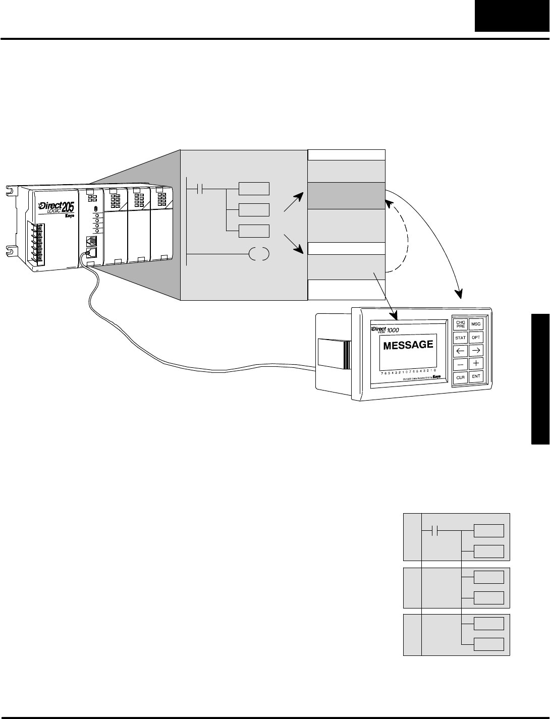
D
V
-
1
0
0
0
S
e
t
u
p
P
a
r
a
m
e
t
e
r
s
3
-
-
3
DV-1000 Setup Parameters
Asan example,let’slookathowthe DV-1000 uses setup parametersto display
messages.Atpowerup, the ladderprogramwritesthe setup parameters.The
DV-1000 usesthe pointersand block sizestofind the message dataforexample,as
shown below.During operation, the DV-1000 readsthe message datarepeatedly,
and interpretsit tocreate an outputon the display.
READ
(atpowerup)
READ
(repeatedly)
V--MemorySpace
UserData
Setup Parameters
MESSAGE
DATA
LadderProgram
WRITE
The DV-1000 appliesthe same basicprocedureto all modeswhichrequiresetup
parameters:
SRead the setup parametersatpowerup.
SRead orwritethe associated dataforeachmode during normal
operation.
M
o
s
t
o
p
e
r
a
t
i
o
n
a
l
m
o
d
e
s
o
f
t
h
e
DV-1000 requiresetup parameters.
You’ll firstneed to decide whichmodes
arerequired inyourapplication.You
can even develop and test the ladder
programforeachmode separately.
However,all the setup parameter
instructionsmaybe combined into a
singlerung,as showntothe right.
Afterthe setup parameter rung, the
main programbegins.
SP0
Setup Parameters:
MessageDisplay
ChangePreset
BitControl
HowtheDV-1000
Uses Setup
Parameters
Setup Parameter
LadderRung
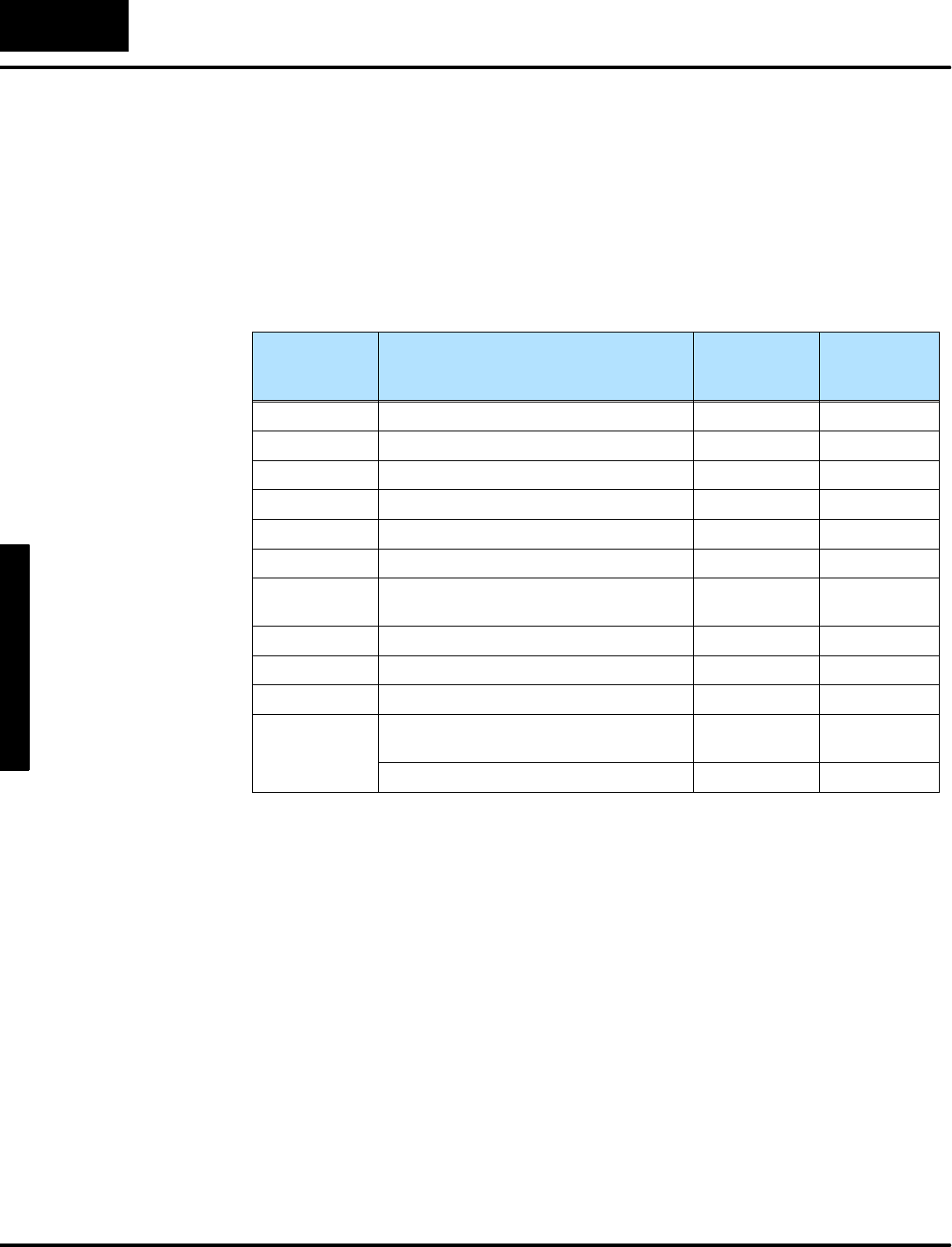
D
V
-
1
0
0
0
S
e
t
u
p
P
a
r
a
m
e
t
e
r
s
3
-
-
4
DV--1000 Setup Parameters
ParameterDefinitions
The setup parameters consistofatotalofeleven V-memorylocations.Together,
they containseveralpointers,block sizes,and data.The following tableshowsthe
setup parametersasone group.Following the description ofeach parameter, the
DV-1000 mode which usesthatparameterislisted.The remaining column
referencesotherchaptersfor moreinformation on howto usespecific setup
parameters.Thistable appliesto all CPUs.
PLC CPU
V-memory
Locations
DV-1000 ParameterDescription Operational
Mode
See Chapter
Number
V7620 Change PresetValuesPointerCHGPRE6
V7621 Change PresetTitlesPointerCHGPRE6
V7622 Change PresetBlock SizeCHGPRE6
V7623 NumericMessage PointerMSG4
V7624 TextMessagesPointerMSG4
V7625 BitControlPointerBITCNTRL 7
V7626 Powerup OperationalMode Power-up
Default
3
V7627 Change PresetValue PasswordCHGPRE6
V7720*Titled TimerPresetValue PointerCHGPRE6
V7721*Titled CounterPresetValue PointerCHGPRE6
V7722*,
High byte
L
o
w
b
y
t
e
Titled TimerPresetBlock SizeCHGPRE6
LowbyteTitled CounterPresetBlock SizeCHGPRE6
*DL130 and DL230 CPUsuse differentmemorylocationshere:V7640 instead of
V7720,V7641 instead ofV7721,and V7642 instead ofV7722.
The tableonthe following page givesfurtherdetailsabout the setup parameters.
Following each parameterdescription, the nextcolumn givesthe properdatatype
foreach parameter. In general,pointersare address locationswhich arein octal.
Block sizesaresimplythe numberofV-memorylocations,soit’seasiest tothinkof
these quantitiesasBCD numbers. Otherdatasuch asthe passwordisalsoaBCD
number.The ranges columnslist the acceptablerange ofaddressesforpointers,or
simple numericrangesforblock sizesand data.Besuretofind the columnforthe
particularCPUyou are using.

D
V
-
1
0
0
0
S
e
t
u
p
P
a
r
a
m
e
t
e
r
s
3
-
-
5
DV-1000 Setup Parameters
PLC CPU
V-memory
Locations
DV-1000
Parameter
Description
Data
Type
DL130
DL230
Ranges
DL240,
Ranges
DL250
DL350
DL430
Ranges
DL440
Ranges
DL450
Ranges
V7620 Change
Preset
Values
Pointer
OctalV2000 to
V2377,
V4000 to
V4177
V2000 to
V4377
V1400 to
V7377
V1400 to
V7377,
V10000 -
V17777
V1400 to
V7377,
V10000 -
V37777
V7621 Change
Preset
Titles
Pointer
OctalV2000 to
V2377,
V4000 to
V4177
V2000 to
V4377
V1400 to
V7377
V1400 to
V7377,
V10000-
V17777
V1400 to
V7377,
V10000-
V37777
V7622 Change
Preset
Block Size
BCD 1-- 16 1 -- 16 1 -- 32 1 -- 32 1 -- 32
V7623 Numeric
Message
Pointer
OctalV2000 to
V2377,
V4000 to
V4177
V2000 to
V4377
V1400 to
V7377
V1400 to
V7377,
V10000-
V17777
V1400 to
V7377,
V10000-
V37777
V7624 Text
Message
Pointer
OctalV0000 to
V2377,
V4000 to
V4177
V2000 to
V4377
V1400 to
V7377
V1400 to
V7377,
V10000-
V17777
V1400 to
V7377,
V10000-
V37777
V7625 BitControl
Pointer
OctalX,Y,or
C
V--mem.
locations
X,Y,or
C
V--mem.
locations
X,Y,GX,
orC
V--mem.
locations
X,Y,GX,
orC
V--mem.
locations
X,Y,GX,
orC
V--mem.
locations
V7626 Power-up
Operational
Mode
BCD 0,1,2,
12,3
0,1,2,
12,3
0,1,2,
12,3
0,1,2,
12,3
0,1,2,
12,3
V7627 Change
Preset
Value
Password
BCD 0000 to
9999
0000 to
9999
0000 to
9999
0000 to
9999
0000 to
9999
V7720*Titled Timer
Preset
Value
Pointer
Octal-- V2000 to
V4377
V1400 to
V7377
V1400 to
V7377,
V10000-
V17777
V1400 to
V7377,
V10000-
V37777
V7721*Titled
Counter
PresetValue
Pointer
Octal-- V2000 to
V4377
V1400 to
V7377
V1400 to
V7377,
V10000-
V17777
V1400 to
V7377,
V10000-
V37777
V7722*,
High byte
Titled Timer
Preset
Block Size
BCD -- 1to 99 1 to 99 1 to 99 1 to 99
V7722*,
Lowbyte
Titled
Counter
PresetBlock
Size
BCD -- 1to 99 1 to 99 1 to 99 1 to 99
*DL130 and DL230 CPUsusememorylocationsV7640 thruV7642 here.
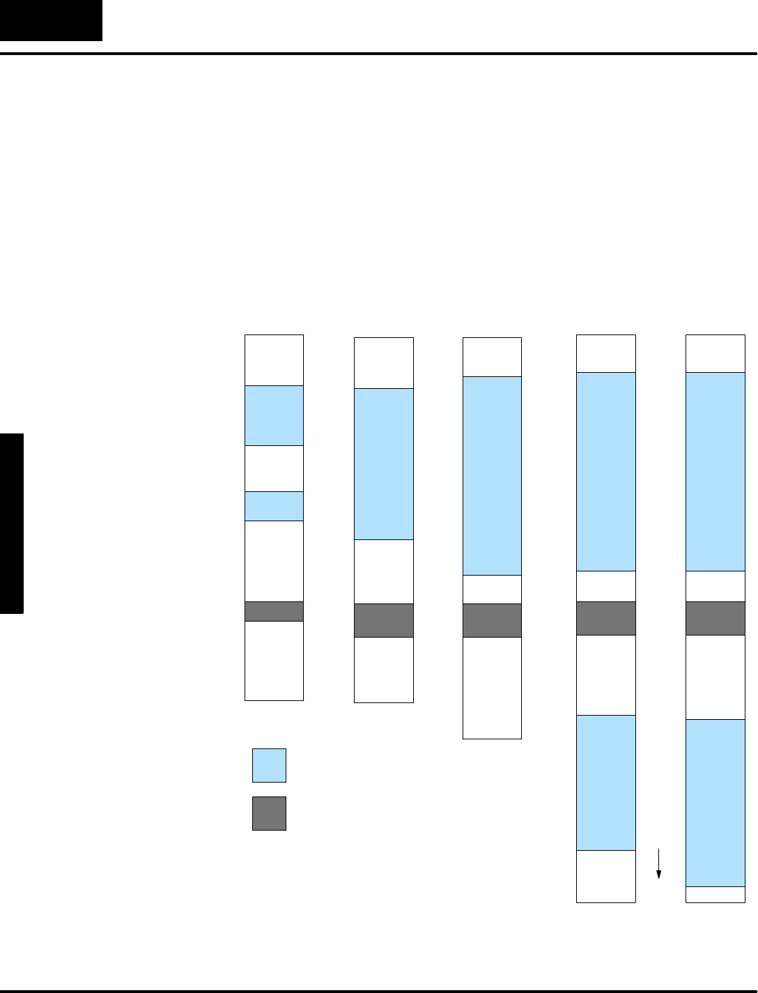
D
V
-
1
0
0
0
S
e
t
u
p
P
a
r
a
m
e
t
e
r
s
3
-
-
6
DV--1000 Setup Parameters
The following figuresummarizesthe V-memorymap information forthe eightCPUs
listed inthe previoustable.Thesememorygraphs showthe identical location of the
setup parametersforall CPUtypes.The amountofuserdatamemory space
increaseswith eachCPUtype fromleft toright. ForeachCPU, the setup parameters
which are pointersmustpoint tospacewithinthe userdataspaceshown.
In ordertosimplifyexamplesinthismanual,wewill confine DV-1000 related datato
amemoryarea common to all CPUtypes.Therefore, the exampleswill use a block
ofmemory starting atV2000.Thisallows specificexampleladderprogramstowork
forall CPUtypes.The onlyexception tothisisthatDL130 and DL230 CPUsdo not
havememorylocationsV7720--V7722 and useV7640--V7642 instead.
V2000
V2377
V4000
V4177
V7620
V7647
DL130
DL230
V--Memory
DL240
V--Memory
UserDataSpace
DV-1000 Setup Parameters
The V-memoryaddresseslistedare
the octalmemory startingandending
referencesforthe shadedareas.
V2000
V4377
V7620
V7722
DL250
DL350
DL430
V--Memory
V1400
V7377
V7620
V7722
DL440
V--Memory
V1400
V7377
V10000
V17777
V7620
V7722
DL450
V--Memory
V1400
V7377
V7620
V7722
V10000
V37777
V-MemoryMaps
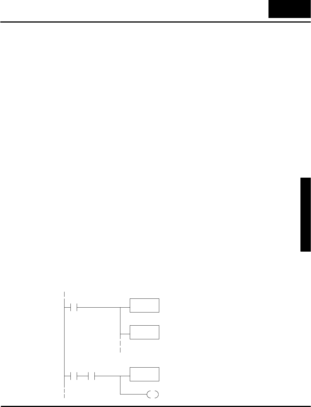
D
V
-
1
0
0
0
S
e
t
u
p
P
a
r
a
m
e
t
e
r
s
3
-
-
7
DV-1000 Setup Parameters
Entering Setup Parameters
Three maintechniquesare availableforsetting the valuesof the DV-1000 setup
parameters:
Using yourRLL/RLLPLUSprogram-- (the recommended approach)Ladderlogic
initializesanyrequired setup parametersduring the firstscan (usecontactSP0).
The DV-1000 readsthese atpowerup orwhen a keypad entryrequestsamode
change.Thismethod hasthe advantage ofimbedding the setup parametervaluesin
the mainladderprogramwhichrelieson them,also enabling you to add comments
tothe setup parameters.
Using theDirectSOFT memory editororDV-1000 setup utility-- You can usethe
memoryeditororDV-1000 setup utilityinDirectSOFT to enterthe propersetup
parametervaluesinspecificV-memorylocations.Bothmethodsprovide toolsto
allowyou to quicklyentervaluesasdifferentdatatypes(BCD/HEX, Octal,Text...).
The disadvantage to using thesemethodsisthe setup parametersaresusceptibleto
change orloss withnoindication given tothe user.Somescenariosare:
SThe batterywhichsupportsretentiveV-memorylocations can become
weakor maybe removed,causingaloss ofsetup parametersinthe
CPUV-memoryduring a powerfailure.
SSomeone elsemayinadvertentlyeditparametervalues,overwriting the
originalsettings.
SIf someone swapsthe CPUforanotherand copiesthe ladderprogram
fromthe oldtothe new CPU,itiseasy toforgetaboutcopying the setup
parametersaswell.
Because of thesescenariosand their resulting confusion,werecommend the first
method above:initializing the setup parametersinthe application ladderprogram.
Toinitializesetup parameters, the ladderprogram mustload the desired constants
intospecificV-memorylocations.The DV-1000 readsits setup parametersfrom
V-memoryateach powerup,and afteramode change fromthe keypad.The ladder
programneedsonlytoinitializesetup parameterson the firstscan.Soon afterthe
firstscan, the DV-1000 retrievesits setup parametersfromV-memory,and uses
themthereafter.The following general ladderprogramshowsthe recommended
ladderprogramarrangement.
SP0LD
K1234
X
Load the desired setup value intothe accumulator (“K1234”
isan example only).Sometimesthiswill beaconstant, or
othertimesan octaladdress.
Afterthe parametersetup rung(s)above,we beginthe
normal ladderprogram.Useyouractualprogramforthis
and the following rungs.
OUT
Vxxxx
Then placethe value inthe properV-memorylocation for
the selected setup parameter.
X
Y
Repeat the above procedureforasmany setup parameters
asarerequired bythe DV-1000 modesto be used.
FirstScanOnly,LoadSetup Parameters
Main LadderProgramBegins
Use theLDA instruction whenloading octaladdresses!
Methodsfor
Entering theSetup
Parameters
ParameterSetup
ByLadderProgram
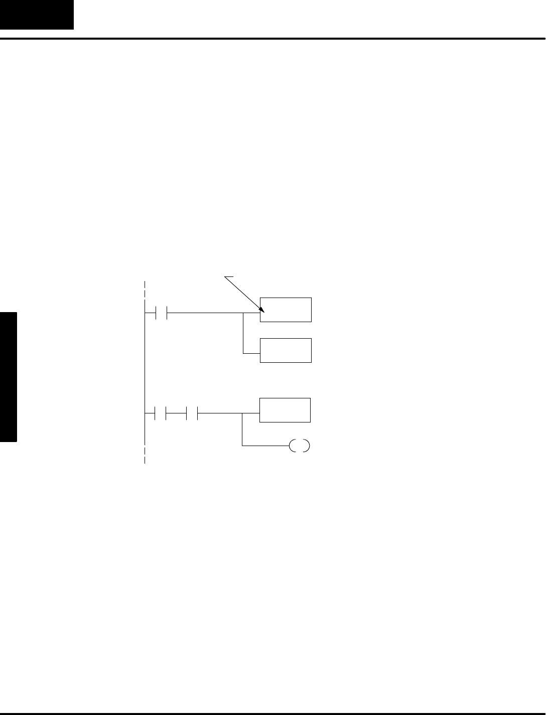
D
V
-
1
0
0
0
S
e
t
u
p
P
a
r
a
m
e
t
e
r
s
3
-
-
8
DV--1000 Setup Parameters
Using theLDA Instruction forPointerSetup Parameters
The previous section on the Power-up Defaultparameterdemonstrateshowto
programaconstantinthe setup parametertable and see the results.Mostof the
remaining parametersare of the address pointertype.Wewill only coverthe general
case ofpointersinthis section,sorefertospecific chapterson the modes
corresponding to any specificpointerstype parameters you maybe interested in.
It isusuallyeasiest tothinkofaddress pointersasoctalnumbers,justastheyare
numbered inthe I/O map.However, the address pointersmustbe stored in hex
format. The LoadAddress (LDA)boxinstruction makesthe octal-to-hex
conversion automatically.The following ladderexample assumes you wanta pointer
toV-memorylocation (octal)V2000.
SP0LDA
O2000
Usethe LDA(Load Address)instruction toload the octal
numberinthe box(2000,inthisexample)intothe
accumulator,automatically converting it toitshexadecimal
equivalent. The number (octal)2000 isjustan example.
OUT
Vxxxx
Placethe value inmemorylocation Vxxxx (replace“xxxx”
withthe actual location of the setup parameteryou are
programming).
FirstScanOnly,LoadAddress PointerSetup Parameter
XAfterthe parametersetup rung(s)above,we beginthe
normal ladderprogram.Useyouractualprogramforthis
and the following rungs.
X
Y
Main LadderProgramBegins
You mustusethe letter “O”forthe octalnumbertofollow.
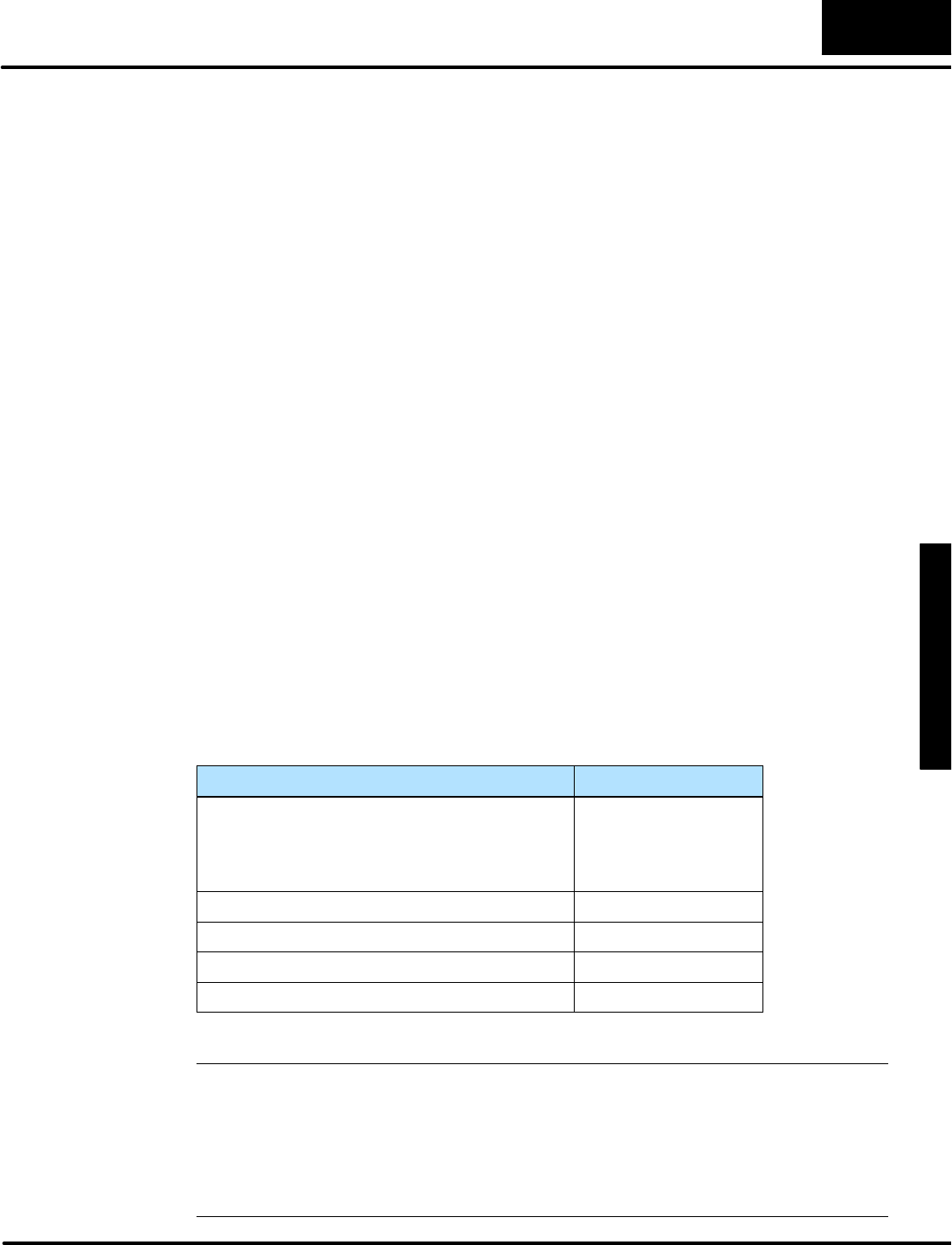
D
V
-
1
0
0
0
S
e
t
u
p
P
a
r
a
m
e
t
e
r
s
3
-
-
9
DV-1000 Setup Parameters
Powerup DefaultOperationalMode
Wewill beginto usesetup parameterswiththe simplestand most fundamentalof
themall: the powerup defaultmode.Asingleconstantinthe setup parametertableis
all that’srequired.The keypad and displayexerciseinChapter1 demonstrated that
severaloperationalmodesare available byusing the keypad. In an actualfactory
installation,itisunlikelythatan operatorwill be present to usethe keypad ateach
systempowerup.Therefore,itisimportant to provide a method to determine
beforehand the mode the DV-1000 automaticallyentersatpowerup. It’sa good idea
to programthe powerup defaultparameter,regardless ofwhichDV-1000 mode(s)
you intend to use.The availableselectionsare:
SEnterpreviousmode (atpower-down)
SEnterChange PresetMode
SEnter Message DisplayMode withoutBitControl
SEnter Message DisplayMode withBitControl
SEnterStatusDisplayMode
In ordertoselect the properpower-up defaultmode foryourapplication,you need to
knowsomething abouthowthe DV-1000 will be used inthe finished machine or
factoryprocess. Insomesituations,asingle operatorwill frequentlyusethe keypad
and change DV-1000 modesfromone to another.Theymayexpect the DV-1000 to
remaininthe mode theywerelastusing,even aftera powercycle.The firstchoice on
the listabovewill do this. In othersituations,multiple personnel will usethe keypad.
Or, the application mayusethe DV-1000’sdisplaymainlyfor monitoring purposes. In
thesecases you maywant tosetup the DV-1000 to enteraspecificoperational
mode ateverypowerup,whichthe remaining selectionsinthe listwill do.
Asingle parameterselectsthe powerup defaultoperationalmode,stored inBCD
formatatV7626.The following tableliststhe defaultchoicesand the required setup
parameters.
Power-up DefaultOperationalModeV7626 BCD Value
PreviousMode:
Change Preset, or
Message Mode,or
StatusMode
0000
Change Preset0001
Message Mode withoutBitControlMode 0002
Message Mode withBitControlMode 0012
StatusMode 0003
NOTE:The power-up default“PreviousMode” (code 0000)will powerup anyof
three modes,butBitControl isnotoffered (forsafetyreasons).So,even ifyou
manuallyput the DV-1000 inBitControlMode beforethe powercycle, the unitwill not
powerup inBitControlMode.Thisisdone forsafetyreasons,becausethereisno
constantindication that the unitisinBitControlMode. If you want the DV-1000 to
powerup inBitControlMode,you mustchoose“Message Mode withBitControl”by
entering “0012”inlocation V7626.
Powerup Default
Setup Parameter
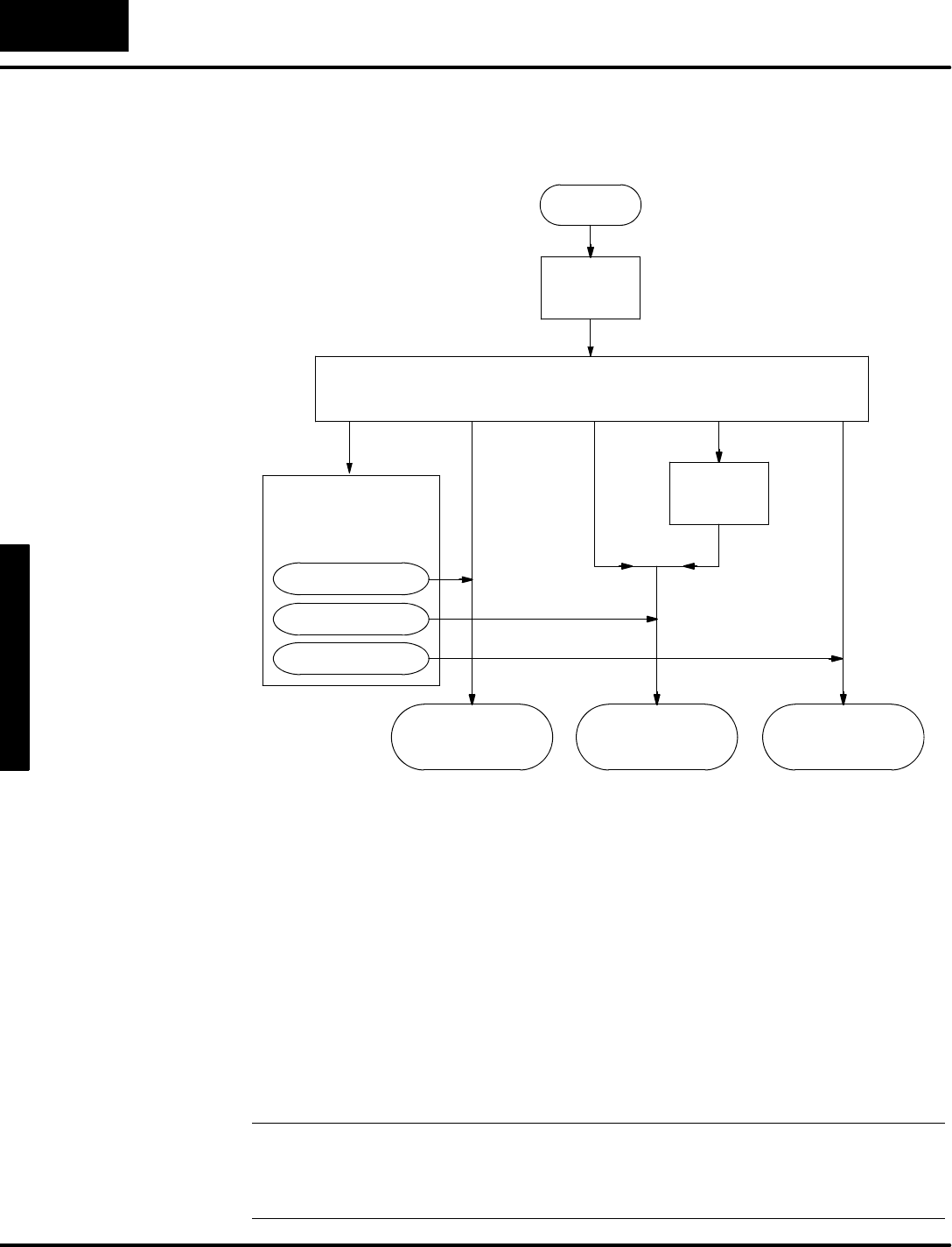
D
V
-
1
0
0
0
S
e
t
u
p
P
a
r
a
m
e
t
e
r
s
3
-
-
1
0
DV--1000 Setup Parameters
The following flowchartshowsthe DV-1000’sactionson powerup.ItbeginswithBit
Controldisabled.Then itreadsthe setup parameteratV7626 forthe power-up
defaultmode.
Powerup
0000 0001 0002 0012 0003
Examine contentsofV7626 forpower-up defaultmode.
Enter
ChangePreset
Mode
Enable
BitControl
Mode
Enter
StatusDisplay
Mode
Enter
MessageDisplay
Mode
Recall Mode at
Previous
Powerdown
ChangePreset
MessageDisplay
StatusDisplay
Disable
BitControl
Mode
Select the value to placeinV7626 according tothe desired defaultpowerup mode:
SPreviousMode (atpower-down) -- Powerdownin eitherChange Preset,
Message Display,orStatusDisplaymodes.The DV-1000 will powerup
inthe previousmode.
SChange PresetMode -- the operatorusesthe keypad tochange data
valuesatselected memorylocations shownonthe display.
SMessage DisplayMode -- displaymessages(textand numbers).This
can be withorwithoutBitControlMode,becausethe twomodesare
independent. Message DisplayMode (once entered)utilizesonlythe
display,whileBitControlMode (once entered)utilizesonlythe keypad.
SStatusDisplayMode -- tomonitorvaluesofV-memorylocations
selected fromthe keypad.
NOTE:If you useMessage Mode withBitControlenabled asthe power-up default,
werecommend using yourladderprogramtowriteamessage tothe DV-1000
displayindicating bitcontrolmode.See the chapteron BitControlMode for more
details,including an example program.
Powerup Sequence
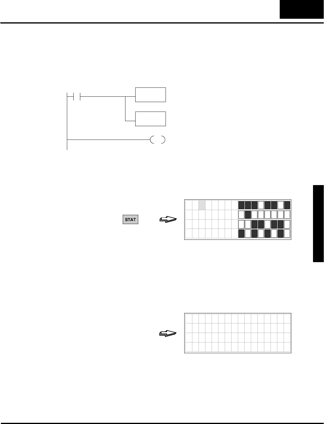
D
V
-
1
0
0
0
S
e
t
u
p
P
a
r
a
m
e
t
e
r
s
3
-
-
1
1
DV-1000 Setup Parameters
Now we give an exampleladderprogramto enterthe Power-up Default Operational
Mode you haveselected inV7626.The programuses“Message Mode withoutBit
Control”,just forexample.AnEND coil on the lastrung makesthisacomplete but
simple example program.
SP0LD
K2
Load the constantK2intothe accumulator, toselect
Message mode withoutBitControl.
Afterthe parametersetup rung(s)above,we beginthe
normal ladderprogram. Insertyouractualprogrambefore
the end coil.
OUT
V7626
Placethe value inmemorylocation V7626, the location of
the Power--up DefaultOperation Mode selection.
END
LoadSetup Parameters
FirstScanOnly
Totest the programand confirm ourunderstanding of the Powerup Defaultmode,
enterthe programaboveintoyourCPU.Then put the CPU inrun mode,whichwill
placethe constantK2inmemorylocation V7626 on the firstscan.Nowfollowthe
stepsbelowtotest the Powerup Default feature.
PRESS
7654321076543210
X 0 0
X 1 0
X 2 0
X 3 0
The goal isjust to havethe DV-1000 insomemode otherthan the powerup default
whichwe haveselected inthe programabove. It isnow inStatusDisplayMode.Now
power-cyclethe DV-1000 byunplugging itor removing powertothe CPU.Then
restore power,and do notpress any keyon the DV-1000 keypad at thispoint. The
displaybelow(orperhapsasetup error message)should appearafter2 or3
seconds.This confirmsthe DV-1000 read the constantK2 defaultselection atV7626
and entered the Message DisplayMode whichwe had chosen.
7654321076543210
0000000000000000
0000000000000000
0000000000000000
0000000000000000
(NOKEY PRESS
REQUIRED)
Powerup Default
ExampleProgram

D
V
-
1
0
0
0
S
e
t
u
p
P
a
r
a
m
e
t
e
r
s
3
-
-
1
2
DV--1000 Setup Parameters
ChapterSummary
Now we havecovered the varioustypesofsetup parameters,and theirlocationsin
V-memory.The Powerup Defaultparameterand LDAinstruction have been covered
in detail.The remainderof the setup parametersare discussed in eachchapteron
the corresponding modes.
Now wemay summarizesome of the keypointswe havelearned aboutsetup
parametersinthis chapter:
SSetup parametersoccupyV-memoryinthe CPU,notDV-1000 memory.
SThe DV-1000 onlyreadsthe setup parametersatpowerup,orwhen a
keyon the keypad ispressed.
SIt’sa good idea to programthe powerup defaultparameter,regardless
ofwhichDV-1000 mode(s)you intend to use.
SParametersbelong to one of three types:Pointers,Block Sizes,orData.
SEnterpointersasoctal(address)numbers,while block sizesand data
are always BCD numbers.
SYou can programsetup parametersusing yourRLL programorby
editing V-memorydirectly.However,itisgenerallymore desirableto use
the RLL program.
SYou onlyneed to programthe setup parametersonceinaladder
program.Usethe specialcontactSP0to activatethe setup rung on the
firstscan only.
SYou onlyneed to programsetup parametersforthe mode(s)you intend
to use.The instructionstosetup the variousmodesmaybe combined
intothe samerung.
SAll ladderexamplesinthismanualuseV-memoryuserdataspace
starting atV2000. Inthisway, the examples shownwill workacross the
variousCPUtypes.
SIt isgenerallybest tochart(plan)yourV-memorymap beforewriting the
application RLL program.Thisensurestherewill be V-memory space
availableforthe DV-1000’sdata blocks forthe mode(s)used.
Summaryof
Key Points

1
4
Message
Display Mode
In ThisChapter....
—Overview
—System Messages
—User Messages
—Setup ParametersforUser Messages
—DisplayingNumbers
—DisplayingText
—UsingLDD andOUTDInstructions
—TurningDataIntoMessages
—CombinedNumeric andTextDisplays
—Usingthe ASCII Constant(ACON)Instruction
—MessageDisplayApplicationsandTechniques
—ChapterSummary
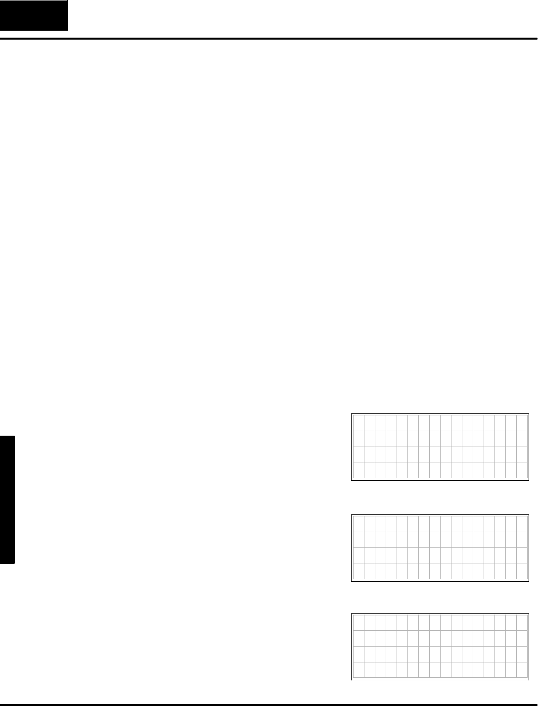
M
e
s
s
a
g
e
D
i
s
p
l
a
y
M
o
d
e
4
-
-
2
Message DisplayMode
Overview
The Message DisplayMode of the DV-1000 providesamonitoring function. It
supportsSystem Messagesfromthe CPU(no setup parametersrequired).
SError Messages
SFAULTinstruction messagesfromladderlogic
The DL240,DL250,DL350,DL440 and DL450 CPUsrecordamessage log of16
error messagesand 16 FAULTinstruction messages,eachwithatime/datestamp.
The DV-1000 providesaccess tothesemessage logsfromits keypad.
WithMessage DisplayMode you can createyourown displays (User Messages)
using setup parametersand ladderprogramming.
SCreatetextornumericmessages
SMixtextand numericmessages
SImplementblinking (flashing)characters, foralarm conditions,etc.
SCreatemultiplescreensthatletyou switchfromone to another
SDisplay signed values(+/-- sign followsactualvalue)
SEmbed a decimalpointin a number
SEmbed the time and dateinamessage
SUsethe extended ASCII characterset foreffects such asanalog bar
graphs,orothersymbolicinformation
SGeneratelong messagesthatcontinuously scroll through the display
I
n
M
e
s
s
a
g
e
D
i
s
p
l
a
y
M
o
d
e
,
d
i
s
p
l
a
y
o
u
t
p
u
t
can comefromthree sources:(System)
FaultMessagesand Error Messages,and
(DV-1000)User Messages.Tothe right
are examplesofeach.
In normalconditions,user messagesare
the defaultdisplay.However,system
messageshave displaypriority.For
example,if the batteryisremoved the
error message “E042 NOCPUBATT”
temporarilyreplacesthe user message.
When a FaultMessage Boxisexecuted,
itsdisplayoutputhaspriorityoverboth
systemerror messagesand user
messages.When the cause ofa higher
prioritymessage ceases, the nextlower
prioritymessage reappearsautomatically.
The prioritized orderis:
1.SystemFaultMessage (highest)
2.SystemError Message
3.User Messages(lowest)
SystemFaultMesssage
7654321076543210
* P A R T J A M , Z O N E 1
7654321076543210
E042 NO CPU BATT
SystemErrorMessage
7
6
5
4
3
2
1
0
7
6
5
4
3
2
1
0
CONVEYOR SPEEDS
L i n e 1 = 1 2 3 f p m
L i n e 2 = 4 5 6 f p m
L i n e 3 = 7 8 9 f p m
UserMessage
FeatureList
MessagePriority
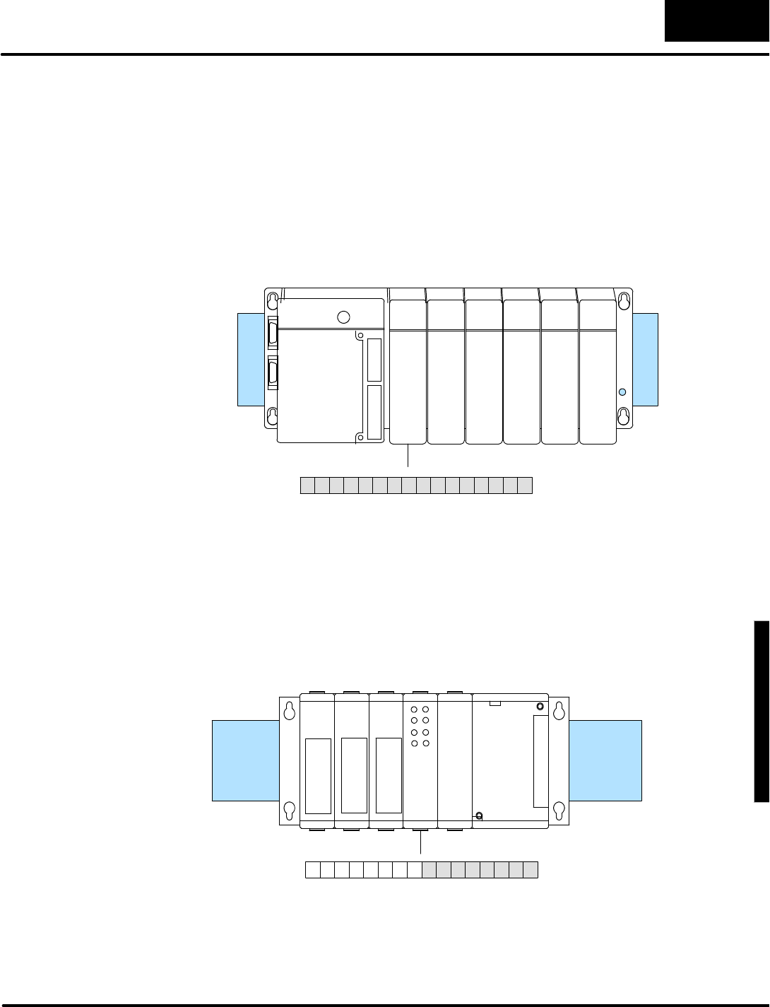
D
i
s
p
l
a
y
i
n
g
M
e
s
s
a
g
e
s
w
i
t
h
D
i
r
e
c
t
V
I
E
W
1
0
0
0
M
e
s
s
a
g
e
D
i
s
p
l
a
y
M
o
d
e
4
-
-
3
Message DisplayMode
Aquick waytolearn howthe DV-1000 works istoload an example program related
toyourapplication,and beginmodifying it to do whatyou wantit to do.Example
ladderprogramsinthis chapteroccasionallyrequire an external input tocausethe
displaytochange insome particularway.The programsrequire up totwoinputs:X0
and X1.So, thisisa good timeto prepareyoursystemtorun the example programs
as you arrive ateach one.
If you are usingaDL405 system,werecommend using the inputsimulator module. If
you locateitinthe base asthe closestinputmoduletothe CPU,itwill log in asX0
through X17 as showninthe following diagram:
X
1
7
16pt
Input
InputSimulator
MSB LSB
X
0
X0
--
X17
X
7
X
1
0
013456789101112131415 2Bit
Slot0Slot1Slot2Slot3Slot4Slot5
If you are usingaDL305 sytemwithaDL350 CPU,werecommend using the input
simulator.Ifyou locateitinthe base asthe closestinputmoduletothe CPU,itwill log
in asX0through X7 as showninthe following diagram:
X
1
7
MSB LSB
X
0
X
7
X
1
0
013456789101112131415 2Bit
InputSimulator
X0
--
X7
8pt
InputDL350
CPU
System
Requirementsfor
ExamplePrograms
DL405
Requirements
DL350 CPU
Requirements

M
e
s
s
a
g
e
D
i
s
p
l
a
y
M
o
d
e
4
-
-
4
Message DisplayMode
If you are usingaDL205 system,werecommend using the inputsimulator. If you
locateitinthe base asthe closestinputmoduletothe CPU,itwill log in asX0through
X7 as showninthe following diagram:
8pt
Input
X0
--
X7
Slot0Slot1Slot2Slot3Slot4
X
1
7
MSB LSB
X
0
X
7
X
1
0
013456789101112131415 2Bit
InputSimulator
If you are usingaDL105 systemwithDC inputs,werecommend using the input
simulator,shown below,which providesfourinputswitchesforinputsX0through X3.
DC-powered versionsneed twowiresfromthe powerinput tothe twoleft-most
terminalson the simulator.The inputsimulatorwill notworkinDL105swithACtype
inputs.See the DL105 User Manual(D2-USER-M) for moreinformation on the input
simulator.
NOTE:When starting DirectSOFT,be suretoinitializethe CPUscratchpad orsome
example programswill notwork(inputsX0 and X1will be inactive).FromPLCmenu,
chooseSetup, then InitializeScratchpad.
X
1
7
MSB LSB
X
0
X
7
X
1
0
013456789101112131415 2Bit
X
1
engineering
ON
OFF
FACTS
F1--04SIM
InputSimulator
X0SwitchX1Switch
DL205
Requirements
DL105
Requirements
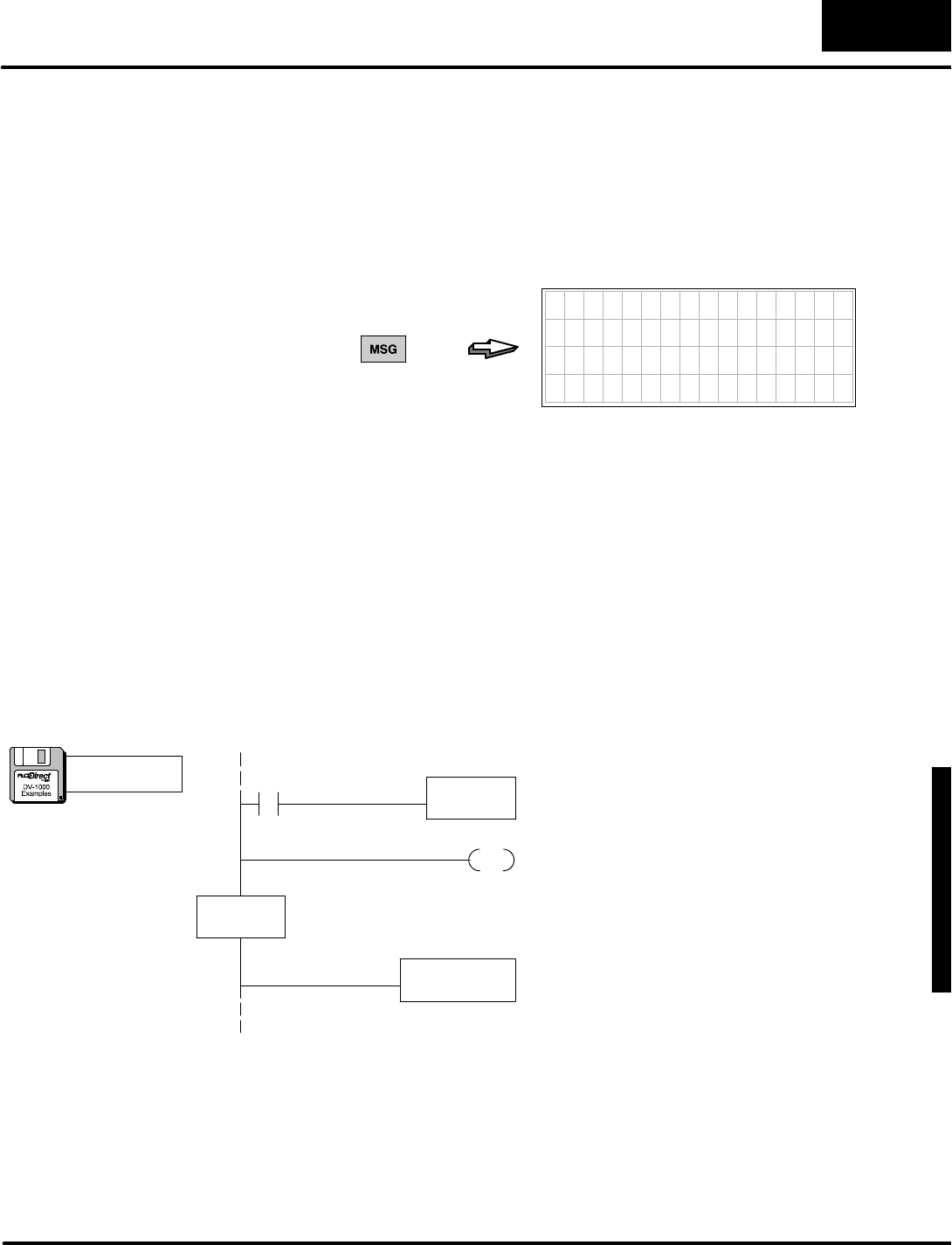
D
i
s
p
l
a
y
i
n
g
M
e
s
s
a
g
e
s
w
i
t
h
D
i
r
e
c
t
V
I
E
W
1
0
0
0
M
e
s
s
a
g
e
D
i
s
p
l
a
y
M
o
d
e
4
-
-
5
Message DisplayMode
SystemMessages
You may selectMessage DisplayMode atanytimefromthe keypad bypressing the
MessageKey(unless the keypad isinBitControlMode).User messagesrequire
setup parameterstotell the DV-1000 wheretofind itsmessage datainV-memory. If
the parametersare notsetand V-memory containsall zeros, the displaybelow will
appear.
7654321076543210
0000000000000000
0000000000000000
0000000000000000
0000000000000000
PRESS
The nextsection showshowto programthe setup parametersand generateyour
ownmessage.However,wefirstdiscuss the higherpriority system messages.
SystemErrorsand the FaultMessage instruction boxinladderlogicgenerates
messagesforthe outside world.They can be viewed using DirectSOFT,a
Hand-heldProgrammer,orthe DV-1000.The DL240,DL250,DL350,DL440 and
DL450 CPUsretain a log ofup to 16 systemerror messagesand a log ofup to 16
faultmessageswhichmayalsobeviewed.
The following ladderprogramexamplewill send a FaultMessage tothe displayas
long as contactX0ison.When X0 goesoff, the displayreturnstothe user-generated
message.Although the FAULTinstruction can display23 characterson a Hand-Held
Programmer,limit thenumberofcharactersto15 fortheDV-1000 (top line).
FAULT
K1
OutputaFaultMessage when X0isactive.Constant
K1referencesthe Data Labelarea thatcontainsthe
textmessage.NOTE:If using DL105 be sureCPUis
initialized tomakeX0 operational.
X0
FaultMessage
Usethe ASCII Constant(ACON)boxtotype the text
forthe FaultMessage.Limit thisline to15characters
maximum.
END
DLBL
K1
ACON
BINEMPTY
The end coil terminatesthe main programsection.
The Data Labelboxmarks the beginning ofa data area
containing ACONorNCONboxes.The reference
numberforthisarea is“1”,specified byK1.
Selecting
MessageMode
FaultInstruction
Message
a:\msg1.prj
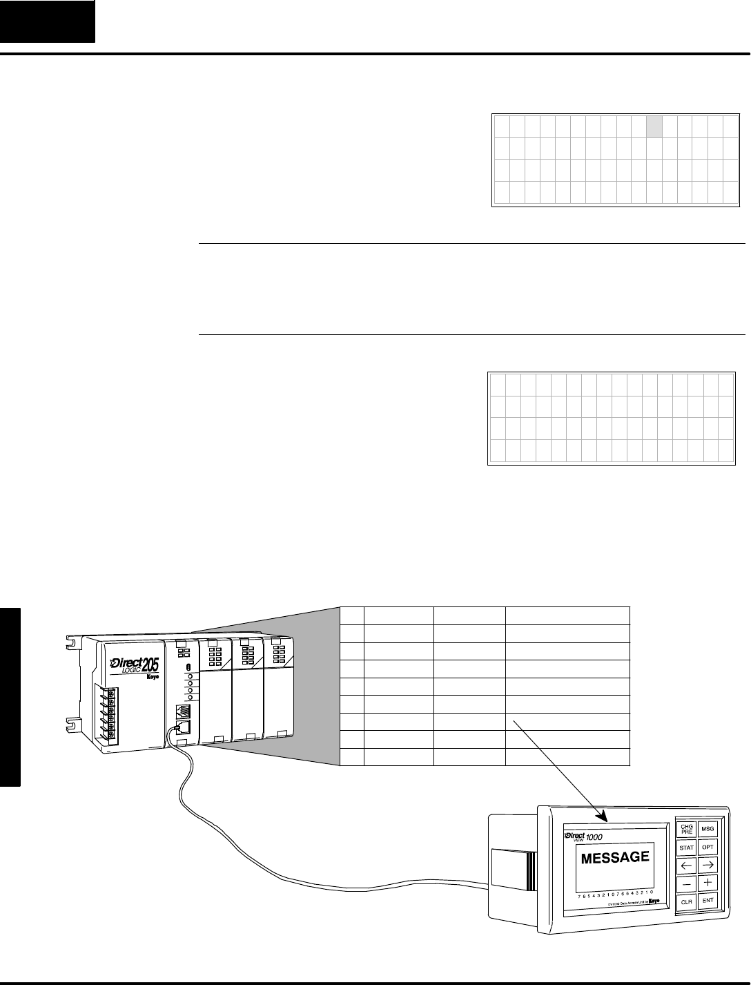
M
e
s
s
a
g
e
D
i
s
p
l
a
y
M
o
d
e
4
-
-
6
Message DisplayMode
Load the programabove and testitby
turning on X0.WhileX0ison, the fault
message will be displayed.When itis
turned off, the faultmessage isremoved
and the originalmessage displayreturns.
FaultInstruction Messsage
7654321076543210
*BIN EMPTY
NOTE:The ladderprogramabove generatesfaultmessageswhichimmediately
appearon the display.However,notethat the faultinstruction makesan entryinto
the faultmessage log on eachscan the faultboxisactive.Therefore, thisapproach
fillsup the message log in16CPUscanswith duplicate entries.Tomake onlyone
entryinthe log perfaultevent, usethe nextladderexamplewiththe PDcoil.
Systemerror messages createtheirown
textwhen the erroreventoccurs.When
the DV-1000 isinMessage Mode, the
errorcode and message are displayed as
long asthe errorpersists. Or,you may
press the ClearKeyto acknowledge the
message,and itwill be removed fromthe
log and fromthe display.7654321076543210
E 0 4 2 N O C P U B A T T
SystemErrorMessage
The DL240,DL250,DL350,DL440 and DL450 CPUsrecord up to 16 SystemError
Messagesand 16 FaultMessagesinseparatemessage logs.The PLCattachesa
time/datestampto each errororfaultmessage when theyoccur.Thesemaybe
viewed one atatimewiththe DV-1000,asdepicted inthe following figure.
READ
DATETIMEFAULT MESSAGE
01 08/10/95 09:35:50 PARTJAMMED
02 08/11/95 08:00:43 BINEMPTY
03 08/11/95 07:15:53 OVERTEMP
04 08/20/95 17:22:48 LOWFLOW
05 08/30/95 17:22:24 PUMPFAULT
06 08/30/95 17:22:24 GATE STUCK
: : : :
16 09/02/95 9:22:16 SETUPINVALID
ExampleMessageLog
SystemError
Display
Viewing
MessageLogs
(DL240,DL250,
DL350,DL440 and
DL450 Only)
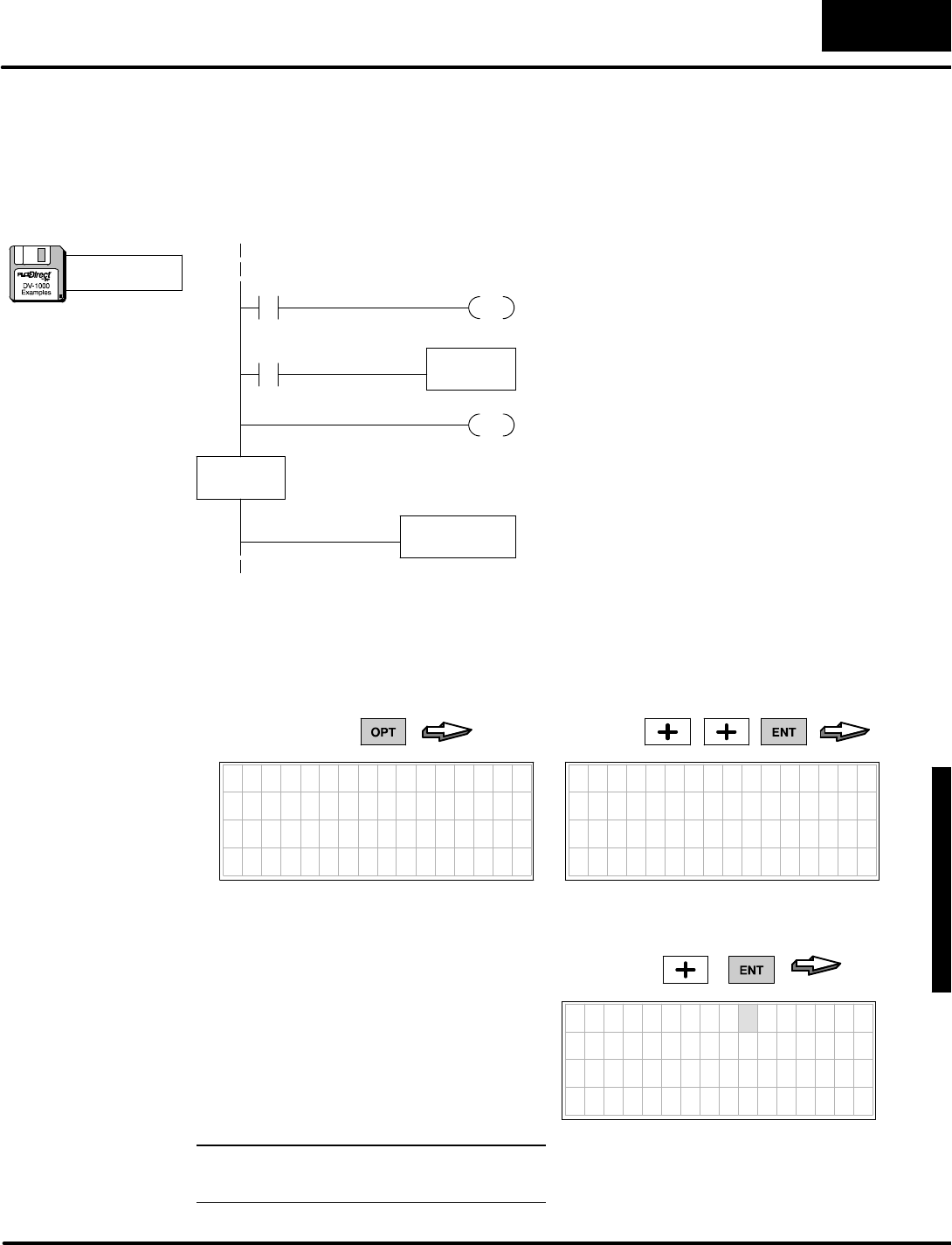
D
i
s
p
l
a
y
i
n
g
M
e
s
s
a
g
e
s
w
i
t
h
D
i
r
e
c
t
V
I
E
W
1
0
0
0
M
e
s
s
a
g
e
D
i
s
p
l
a
y
M
o
d
e
4
-
-
7
Message DisplayMode
The faultmessage log recordsa newentryon eachscanafaultmessage boxis
active.Thismeansthatifwe usethe previousladderexamplewith a simpleswitch
activating the faultmessage, the faultmessage log will fill up with duplicate
messagesinjust16 scans.Afterthat, morefaultmessagesjustoverwrite existing
log entries.Therefore,we add a PDcoil (positive differential)which activatesforone
scan when the off-to-on transition ofX0 occurs.
FAULT
K1
C0
FaultMessage,OneScanOnly
Usethe ASCII Constant(ACON)boxtotype the text
forthe FaultMessage.Limit thisline to15characters
max.
END
DLBL
K1
ACON
BINEMPTY
The end coil terminatesthe main programsection.
The Data Labelboxmarks the beginning ofa data area
containing ACONorNCONboxes.The reference
numberforthisarea is“1”,specified byK1.
X0
PD
C0
TurnonC0forone scan when X0makesan
OFF-to-ONtransition.
Outputafaultmessage wheneverC0isactive.
Because of the PDcoil,onlyone errorlog entryoccurs
foreach event.
Enterthe programabove orload it fromthe example disk intoyourCPU.Aftergoing
toRUN Mode, turnX0 on and off oncetocause one faultmessage entryinthe
message log.The message logsare accessible using the OptionsMenu.Press the
OptionsKeytoreachthe menu shown below.Then usethe Plus(+)Keytomove
the cursoroverthe thirdmenu selection,SHOWERR/MSG.
7654321076543210
O P T I O N
1 B I T C O N T R O L
2 P A S S W O R D
3 S H O W E R R / M S G
PRESS
7654321076543210
SHOW ERR/MSG
1 E R R O R L I S T
2 M E S S A G E L I S T
PRESS
Finally,select the message listusing the
Plus(+)Key,and press Enter.Hereisthe
lastentryinthe message log,and itshould
showthe resultsofyour running the
programabove.Usethe Minus(--) Keyto
move upwardthrough the log when
multiple entriesexist, and the Plus(+)Key
tomove downward.
NOTE:FaultMessage timestamps
include hundredthsofasecond.
7654321076543210
B i n E m p t y
0 7 / 2 5 / 9 5
15:57:24:86
PRESS
Fault MessageLog
(DL240,DL250,
DL350,DL440 and
DL450 Only)
a:\msg2.prj
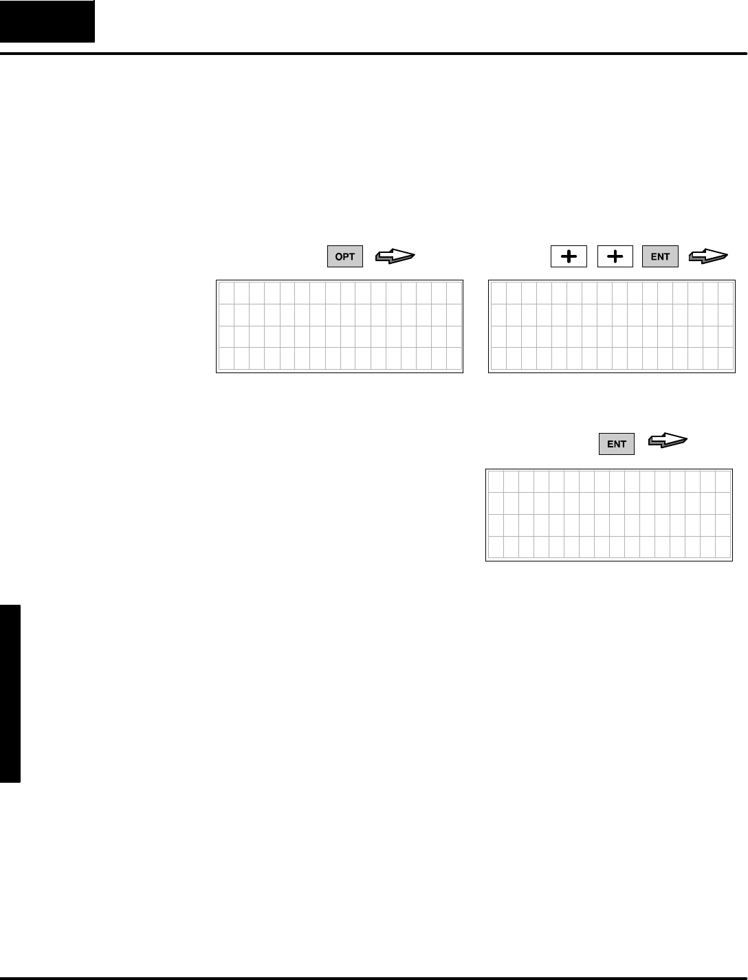
M
e
s
s
a
g
e
D
i
s
p
l
a
y
M
o
d
e
4
-
-
8
Message DisplayMode
The SystemErrorLog featureinthe CPUrecordsa newentrywhenevereach error
firstoccurs.Noladderlogicisrequired tocreatethe log.Log entries consistofan
errorcode, textdescription,and a time/datestamp.The log recordsup to 16 error
events.Each erroreventmaylastafewmilliseconds,or manyhours,butonlyone
log entryismade perevent. Subsequentsystemerrors create newentriesinthe log.
Toviewthe SystemErrorLog,usethe sameOptionsMenu asthe FaultMessage
Log,bypressing the OptionsKey.Then usethe Plus(+)Keytomovethe cursor
overthe thirdmenu selection,SHOWERR/MSG.
7654321076543210
O P T I O N
1 B I T C O N T R O L
2 P A S S W O R D
3 S H O W E R R / M S G
PRESS
7654321076543210
SHOW ERR/MSG
1 E R R O R L I S T
2 M E S S A G E L I S T
PRESS
Finally,select the errorlistusing the Enter
Key.The displaytothe rightshowsalow
battery voltage eventasthe lastentryin
the message log.Usethe Minus(--) Key
toreviewupwardthrough the log
whenever multiple entriesexist, and the
Plus(+)Keytomove downward.
7654321076543210
E 0 4 1 C P U B A T T E R -
Y L O W
0 7 / 2 5 / 9 5
2 1 : 2 5 : 1 0
PRESS
SystemErrorLog
(DL240,DL250,
DL350,DL440 and
DL450 Only)
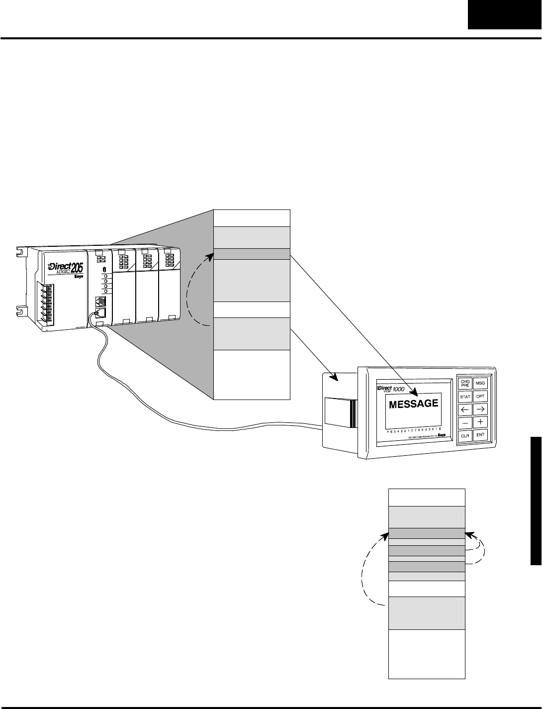
D
i
s
p
l
a
y
i
n
g
M
e
s
s
a
g
e
s
w
i
t
h
D
i
r
e
c
t
V
I
E
W
1
0
0
0
M
e
s
s
a
g
e
D
i
s
p
l
a
y
M
o
d
e
4
-
-
9
Message DisplayMode
UserMessages
User Messagesrelyon datastored inV-memoryto actually createthe message.The
process is showninthe following figure.Afterpowerup, the DV-1000 readsthe setup
parameters.Certain parameters can be programmed to point to otherblocks of
information inV-memory.The DV-1000 readsthe textand numericdata pointed to
bythe setup parameters.Then itcombinestextand numericdatafollowing simple
rulestocreatethe displayoutput. Then itreadsthe V-memorymessage data again,
and repeatsthe process overand over.
V--MemorySpace
UserV-memory
Setup Parameters
MESSAGE
READ
(atpowerup)
READ,
repeatedly
The DV-1000 currentlyreadsthe setup
parametersatpowerup,and when a key
on the keypad ispressed.Thismeansthat
the ladderprogramcannotsimply change
the pointervalue for message data.
Instead,itmustmove newdataintothe
originalmessage data block.This chapter
coversthe use ofACONand MOVMC
instructions,whichmakethistask easier.
V--MemorySpace
UserV-memory
Setup Parameters
MESSAGE
MSGDATA1
MSGDATA2
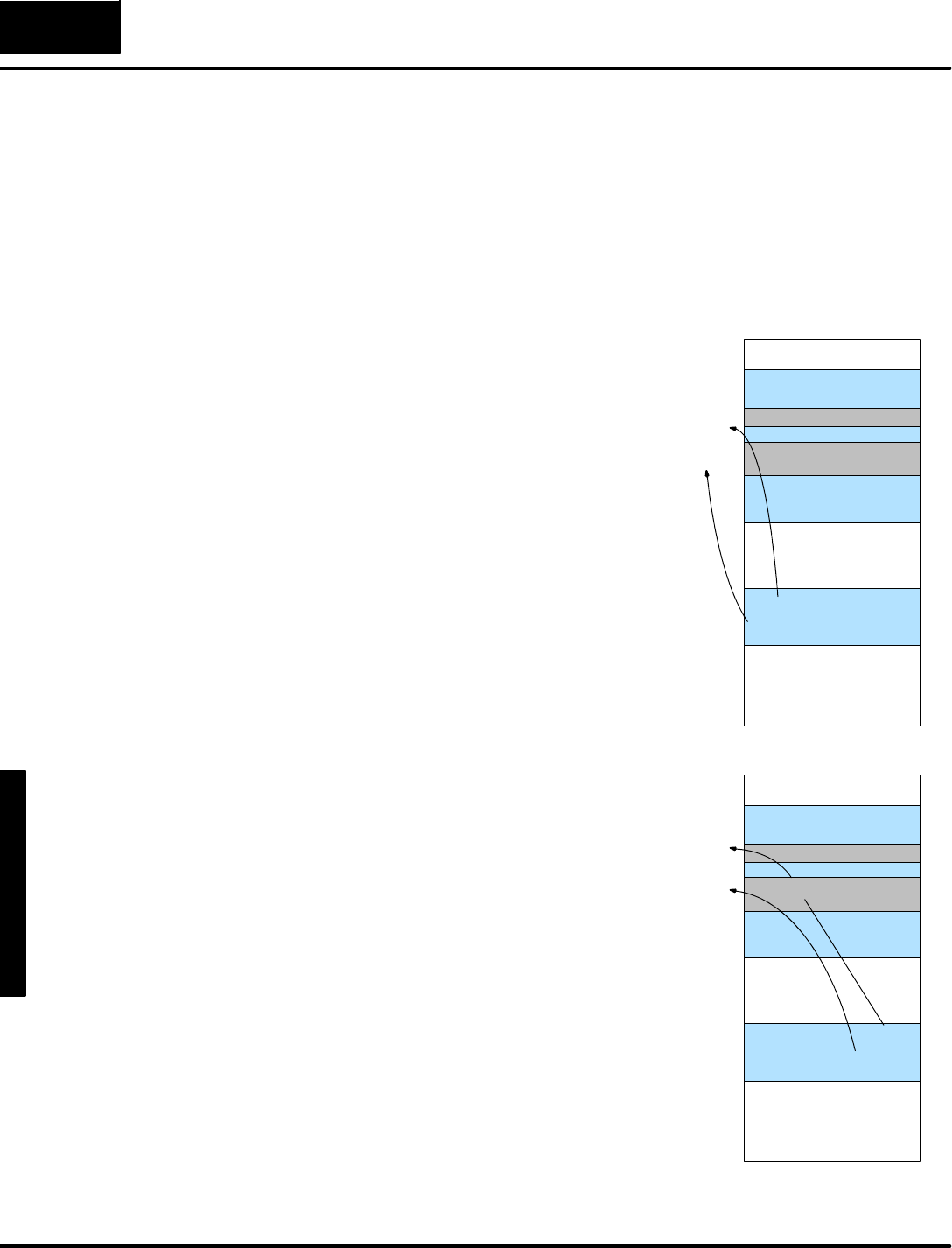
M
e
s
s
a
g
e
D
i
s
p
l
a
y
M
o
d
e
4
-
-
1
0
Message DisplayMode
Setup ParametersforUserMessages
The DV-1000 is capable ofdisplaying numbersoralphabeticalcharacters,ora
combination ofboth(alphanumeric).All of the programming to do thismustbe
contained inthe CPU’sladderlogicprogram.Thismeansthata portion of the ladder
programisdedicated tothe DV-1000 operation,whilethe remainderof the program
handlesmachine orprocess operation.The Message DisplayMode doesrequire
setup parameters(see Chapter3foran introduction tosetup parameters).
There aretwo pointersinthe setup
parameterswhich pertaintomessage
displays:
SNumericMessage Pointer
STextMessage Pointer
Thesetwosetup parametersarelocated
atV7623 and V7624 respectively.The
diagramtothe rightshowshowthe values
xxxx and yyyy point tothe address
locationsofblocks ofdatainthe userdata
space ofV-memory.
The relativesizesof the shaded blocks
indicatethat the textdata block (32 words)
istwicethe size of the numericdata(16
words).We explainwhythisistrue a bit
laterinthis chapter.These block sizesare
fixed (thereisno block sizesetup
parameterforthese).
V0000
V--MemorySpace
End ofV--
Memory
UserData
NumericPointer=xxxx
TextPointer=yyyy
Vxxxx NumericData
TextData
V7623
V7624
Vyyyy
Setup Parameters
Now we decide whereto place our
numericand textdata blocks foruseinthe
example programsinthis chapter.As
described inChapter2,wewill use an
availablememoryarea common to all
CPUtypes,starting atV2000.Therefore,
numericdata occupies16 wordlocations,
fromV2000 toV2017.We’ll arbitrarily
placethe text tablestarting atV2100. It
occupies32 wordlocations,extending
downtoV2137.Notethateithertextor
numericdatamaybe placed firstin
V-memory.However, the blocks mustnot
overlap each other,butone may
immediatelyfollowthe other.
The locationswe havechosen herefor
numericand textdata are examplesonly.
The location you chooseforyour
application maybe different.
V0000
V--MemorySpace
End ofV--
Memory
UserData
NumericPointer=2000
TextPointer=2100
V2000 NumericData
TextData
V7623
V7624
V2100
V2017
V2137
MessageData
Parameters
Choosing Data
Block Locations

D
i
s
p
l
a
y
i
n
g
M
e
s
s
a
g
e
s
w
i
t
h
D
i
r
e
c
t
V
I
E
W
1
0
0
0
M
e
s
s
a
g
e
D
i
s
p
l
a
y
M
o
d
e
4
-
-
1
1
Message DisplayMode
Nowthatwe havechosen locationsfornumericand textdata,wecan createthe
setup portion of the ladderlogicprogram.The following ladderprogramlocatesthe
data blocks according tothe memorymap on the previouspage.Also,weinclude
instructionswhichmakeMessage Mode the DV-1000 power-up defaultmode.For
the ladderexamplesinthis chapter, the DV-1000 will automaticallypowerup in
Message DisplayMode.All ladderexamplesinthis chapterwill usethe following
programasthe firstrung to programthe setup parameters.
SP0LDA
O2000
Load octaladdress 2000 intothe accumulator.This
instruction automatically convertsthe address intoits
hexadecimalequivalent.
OUT
V7623
Output thisaddress toV7623, the location of the setup
parameterwhichisthe numericmessage block pointer.
ParameterSetup:Numeric and TextData
LDA
O2100
Load octaladdress 2100 intothe accumulator.This
instruction automatically convertsthe address intoits
hexadecimalequivalent.
OUT
V7624
Output thisaddress toV7624, the location of the setup
parameterwhichisthe textmessage pointer.
FirstScanOnly
LD
K2
Load the constantK2(BCD)intothe accumulator.The
value “2”correspondstoMessage DisplayMode asthe
Power-up DefaultMode.This step isoptional.
OUT
V7626
Output the constant2toV7624, the location of the
Power-up Defaultsetup parameter.
Optional
Afterentering the setup program
above,you can testitbypowering up
the PLCand DV-1000.Notethat the
V-memorydata areasmustbe cleared
(all zeros).The displaytothe rightwill
appearwithoutyourhaving to usethe
keypad.7654321076543210
0000000000000000
0000000000000000
0000000000000000
0000000000000000
LadderExample
forMessageSetup
Parameters
ParameterSetup
Program#1
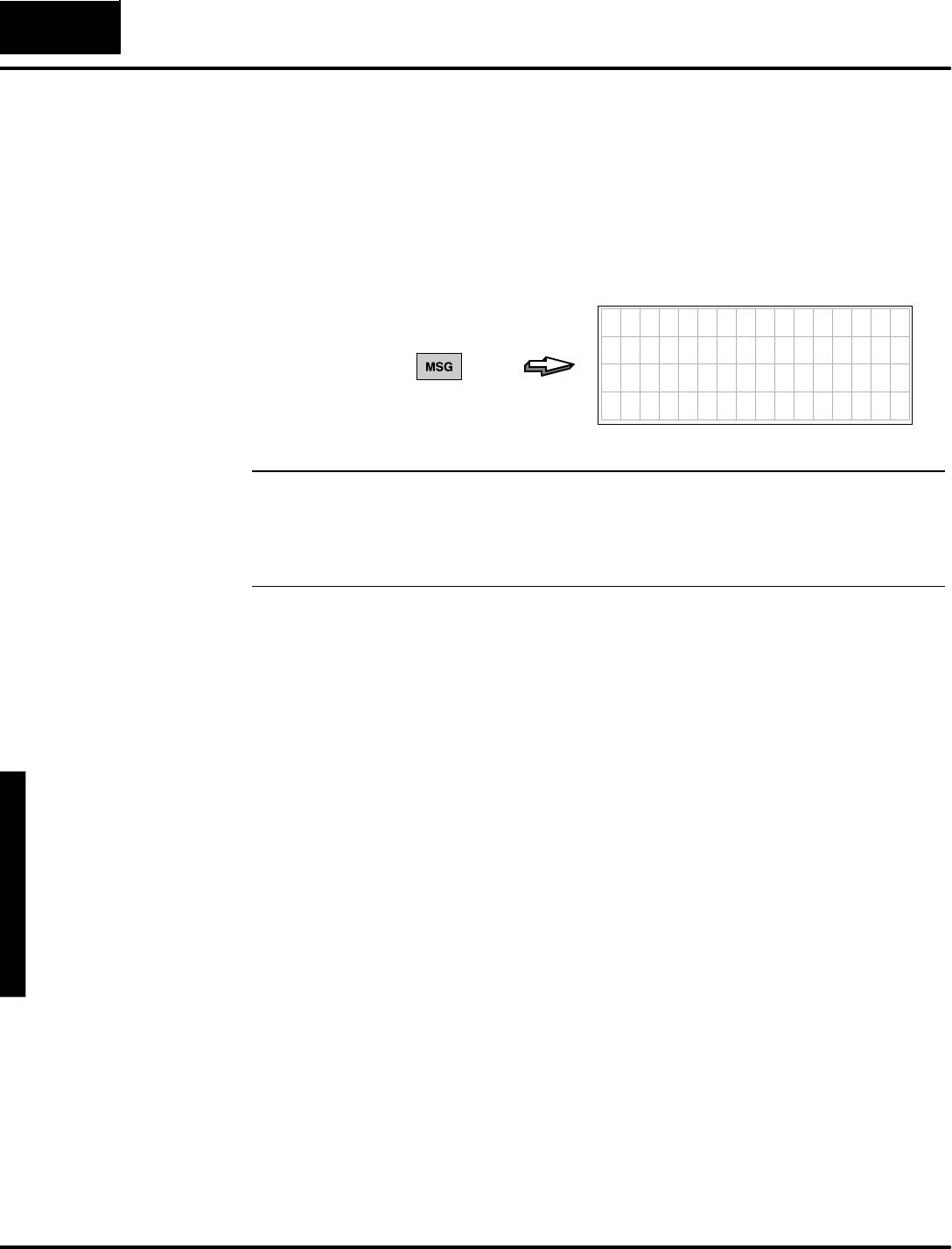
M
e
s
s
a
g
e
D
i
s
p
l
a
y
M
o
d
e
4
-
-
1
2
Message DisplayMode
As you programand usethe DV-1000,itwill eventuallybe in other modeswhen you
need to usethe Message DisplayMode.Justpress the MessageKeyon the
keypad. If the setup parametersexistand arevalid, the message displaywill appear.
If theyare not, the error message will be displayed:“Setup ParameterError”. If this
occurs,examine the parametersetup rung inthe ladderprogram,using the program
above asan example.Verifythe numericand textdata blocks arelocated in
available userdataspace ofV-memory(refertoChapter3forCPU-specificmemory
maps).
7654321076543210
0000000000000000
0000000000000000
0000000000000000
0000000000000000
PRESS
NOTE:Remembertoload the example programswhilethe CPU isin program
mode.Afterloading the program, takethe CPUfromprogram mode torun mode.
Mostof the examplesinthis chapterhaveafirstscan rung (SP0).Thisrequiresa
program-to-run mode transition orpowercycle,orthe examplemaynotwork
properly!
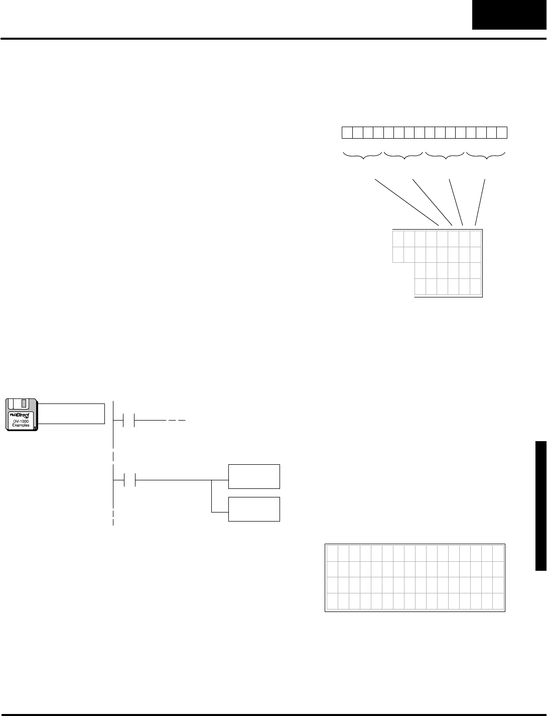
D
i
s
p
l
a
y
i
n
g
M
e
s
s
a
g
e
s
w
i
t
h
D
i
r
e
c
t
V
I
E
W
1
0
0
0
M
e
s
s
a
g
e
D
i
s
p
l
a
y
M
o
d
e
4
-
-
1
3
Message DisplayMode
Displaying Numbers
V
a
l
u
e
s
i
n
t
h
e
n
u
m
e
r
i
c
d
a
t
a
b
l
o
c
k
a
r
e
organized as16-bitnumbers.Thesemay
be BCD orhexnumbers. In eithercase,
they containfourdigits.The exampleto
the rightshowsmemorylocation V-2000,
whichcontainsthe number “3765”.
The DV-1000 interpretsthe numericdata
block directly,and displays themas
numbers.The value “3765”automatically
appearson the displayinthe
corresponding numericdisplayposition
when the same numberexistsin
V-memory,and isreferenced bythe setup
parameters.
MSB LSB
Digit1Digit2Digit3Digit4
0 10 1 1 0 1 1 1 0 1 1 0 0 1 0
013456789101112131415 2Bit
3
2
1
0
3 7 6 5
NumericOutput
V2000
The following exampleshowshoweasy itisto displaya numberfromyourladder
logicprogram.All you need isthe setup programinthe previous section, followed by
arung thatplacesthe number “1234”asthe firstnumericdata block entry.The
DV-1000 then displays the numberat the corresponding firstnumericposition on the
display.
SP0LD
K1234
Load the arbitrary constant“1234”intothe accumulator.
Thisisthe numberwewill display.We onlyneed todothis
once,on the firstscan.
OUT
V2000
Output the constant“1234”tolocation V2000, the first
numericdatalocation.This value will appearinthe first
numericposition inthe display,shown below.
FirstNumericDataLocation Programmed
FirstScan
(Setup Parameter rung here)
SP0
Afterloading the programabove,you can
testitbytaking the PLCfromProgramto
Run Mode.The BCD constant“1234”
appearsinthe firstnumericposition of the
display,inthe upperrightcorner.We
discuss the entire displayoutputpositions
a bit furtherinthis chapter.7654321076543210
0000000000001234
0000000000000000
0000000000000000
0000000000000000
a:\msg3.prj
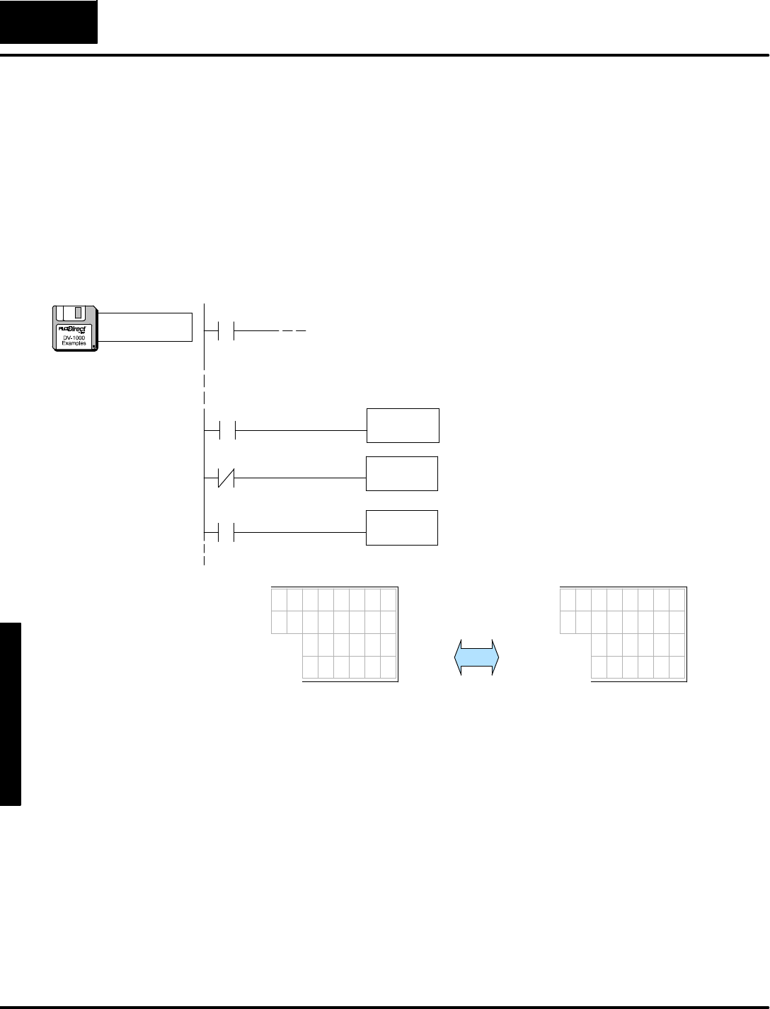
M
e
s
s
a
g
e
D
i
s
p
l
a
y
M
o
d
e
4
-
-
1
4
Message DisplayMode
Inrealapplications, the numbers you want to displaywill often be changing.Process
variables such astemperature, flowrate,orconveyorspeed can be displayed inreal
time.Whilethe setup parametersarewritten onlyonce(firstCPUscan),process
variablesmustbe constantlywritten. In ourexample,itmeanswriting a changing
numbertolocation V-2000.The DV-1000 takes care of the restof the work.Because
oursetup parameters specifythe location of the numeric(and text)data, the
DV-1000 constantly scansthesesothatany change can be observed inthe display.
Tosimulate a changing value,we usethe following program rungstojustalternate
between twovalues.Itusesaspecialrelay contactSP4 asa1second timer (1/2sec.
on,1/2sec.off).Keeping the ParameterSetup rung,add the following rungsasthe
main program.
SP4LD
K1234
Forthe firsthalfofeachsecond,load the arbitrary constant
1234 intothe accumulator.SpecialcontactSP4ison 1/2
second,and off 1/2second.
Demonstration ofChanging Values
SP1OUT
V2000
Outputwhatevervalue isinthe accumulatortolocation
V2000.Halfof the timeitwill be “1234”and the otherhalfof
the timeitwill be “5678”.
Always On
SP4LD
K5678
Forthe second halfofeachsecond,load the arbitrary
constant5678 intothe accumulator.SpecialcontactSP4is
on 1/2second,and off 1/2second.
1Sec Timer
(Setup Parameter rung here)
SP0
3 2 1 0
0 0 0 0 5 6 7 8
0000000
0 0 0 0 0 0
0 0 0 0
3 2 1 0
0 0 0 0 1 2 3 4
0 0 0 0 0 0 0
0 0 0 0 0 0
0 0 0 0
Alternates
every 1/2
second
The pointis:Yourladderprogramneedstowritethe Setup Parametersonlyon the
firstscan,butitmustupdatethe numericand textdatainV-memoryasoften astheir
contentchanges.The DV-1000 readsthe numericand textdatarepeatedlyduring
operation. If the textornumericdatachanges, the displaythen automaticallyfollows.
Displaying
C
h
a
n
g
i
n
g
V
a
l
u
e
s
a:\msg4.prj
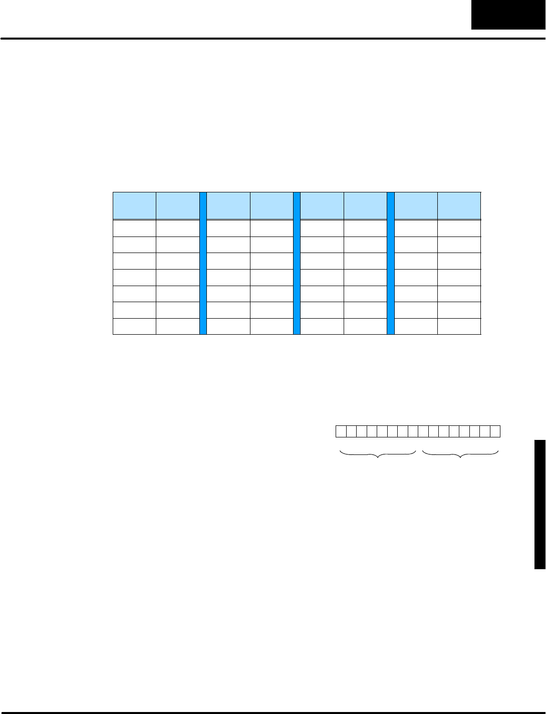
D
i
s
p
l
a
y
i
n
g
M
e
s
s
a
g
e
s
w
i
t
h
D
i
r
e
c
t
V
I
E
W
1
0
0
0
M
e
s
s
a
g
e
D
i
s
p
l
a
y
M
o
d
e
4
-
-
1
5
Message DisplayMode
Displaying Text
Nextwe discuss howto displaytextinmessage displays.The textdata block is
located atV2100 inthese examples(onlybecausethatiswhere oursetup
parameterhasdefined it to be).However,wecannotplace alphabeticalcharacters
directlyinV-memory. Instead,we use a numeric code whichrepresentstext
characters,called ASCII codes.Below isa portion of the ASCII tablewhichlists
capital letters(see AppendixBforthe completetable ofcharactersand symbolswith
theirASCII codes).
ASCII
Code
Char.ASCII
Code
Char.ASCII
Code
Char.ASCII
Code
Char.
41 A48 H4FO56 V
42 B49 I50 P57 W
43 C4AJ51 Q58 X
44 D4B K 52 R59 Y
45 E4CL 53 S5AZ
46 F4DM54 T-- --
47 G4EN55 U-- --
AnASCII code isan 8-bitbinarynumber (byte) representing a singletextcharacter
orsymbol.Therefore,eachV-memorylocation (16-bitdataword)in ourtext table
can containtwoASCII codes,representing twocharacters.
T
h
e
e
x
a
m
p
l
e
t
o
t
h
e
r
i
g
h
t
u
s
e
s
t
h
e
c
a
p
i
t
a
l
letters“A”and “Z”.The ASCII codesfor
these are 41 and 5A(in hexadecimal)
respectively.Memorylocation V2100 is
the first textdatalocation,shown
containing the codesforthe letters“A”and
“Z”.
V
2
1
0
0
MSB LSB
013456789101112131415 2Bit
Second
Char.Code
5A=“Z”
First
Char.Code,
41 =“A”
0
0 0 0 0 01011 0 1 01
0 1
A
S
C
I
I
C
o
d
e
s

M
e
s
s
a
g
e
D
i
s
p
l
a
y
M
o
d
e
4
-
-
1
6
Message DisplayMode
Usethe following ladder rung asthe main programtoload the ASCII codesfor “A”
and “Z”intothe first textdatalocation (keep the Setup Parameter rung inthe
program).
SP1LD
K415a
Load the ASCII codesforthe letters“A”and “Z”intothe
accumulator.
OUT
V2100
Output the ASCII textdatatolocation V2100, the first text
datalocation.The corresponding letters“A”and “Z”will
displayinthe first textlocation inthe display,shown below.
FirstTextDataLocation Programmed
Always On
(Setup Parameter rung here)
SP0
Afterloading the programabove,you can
testitbytaking the PLCfromProgramto
Run Mode.The letters“AZ”appearinthe
first textposition of the display,inthe
upperleft corner.Unless you havecleared
V2000, the number “1234”or “5678”from
the previousexamplewill be displayed in
the upper rightcorner.
7654321076543210
AZ00000000001234
0000000000000000
0000000000000000
0000000000000000
a:\msg5.prj
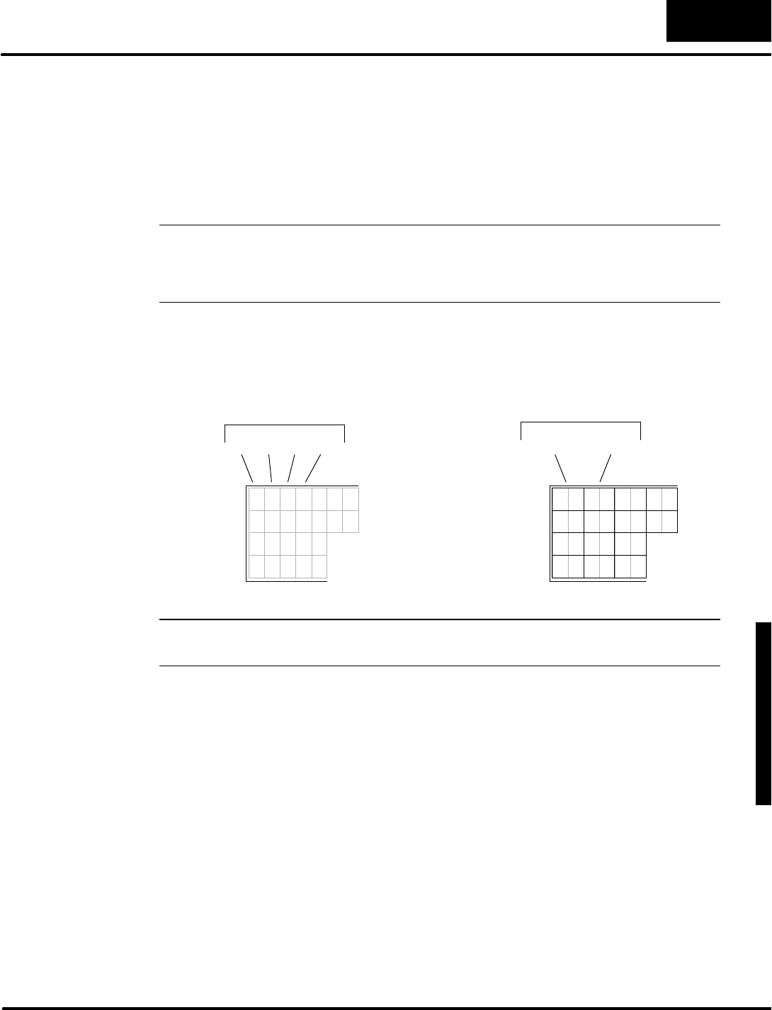
D
i
s
p
l
a
y
i
n
g
M
e
s
s
a
g
e
s
w
i
t
h
D
i
r
e
c
t
V
I
E
W
1
0
0
0
M
e
s
s
a
g
e
D
i
s
p
l
a
y
M
o
d
e
4
-
-
1
7
Message DisplayMode
Using LDD and OUTDInstructions
The regularLDand OUTinstruction manipulatesa 16--bitword,updating twoASCII
characterson the display.However,wecan usethe Load Double(LDD)and Out
Double(OUTD)tomanipulate 32--bitdoublewords,updating fourcharactersata
time(twotextpositions)!
NOTE:Ifyou haveless than 10 charactersto place,using the LDD instruction(s)isa
good choice.However,forplacing morethanadozencharacters adjacently,
theACONInstruction ismucheasierand more efficient.See the section on
using the ACON instruction on page 4--25.
Supposewe placethe characterstring “ABCD”inthe first twotextpositions.The
ASCII datafor “ABCD”will be stored inV2100,and V2101, the first two datawordsin
the textdata block.
7 6 5 4 3
A B C D
41 42 43 44
ASCII Codes
7 6 5 4
1 32 ...
TextDisplay
Positions
Display
Output
V-Memory
V2100 V2101
NOTE:You mustswap positionswiththe firstand second pairofASCII codesin a
LDD instruction.Read the following discussion tolearnwhythisisnecessary!
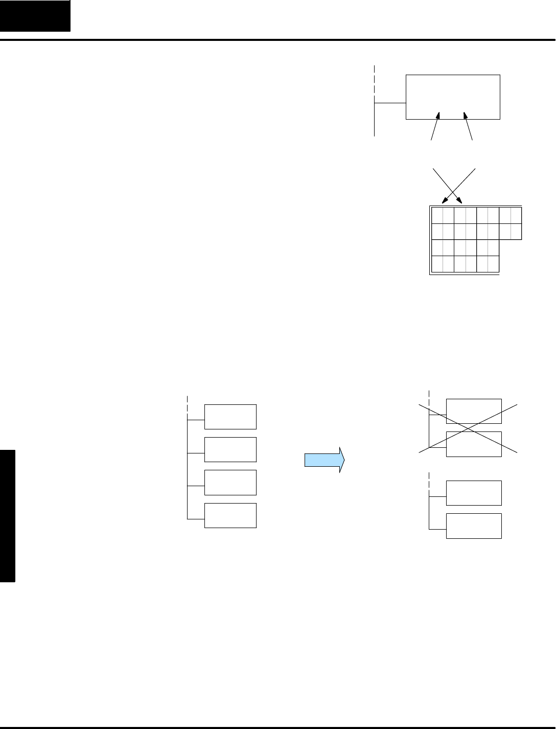
M
e
s
s
a
g
e
D
i
s
p
l
a
y
M
o
d
e
4
-
-
1
8
Message DisplayMode
The Load DoubleInstruction acceptsan
8-digitconstantK,representing two 16-bit
words.The mostsignificantwordxxxx is
on the left inthe LDD box.However, the
DV-1000 displays the textof the most
significantwordonthe right. Thismeans
thatyou mustswap orderof the two pairs
ofASCII codesinthe LDD boxrelativeto
how itisdisplayed.
The reason forthis swap isthatweread
fromleft toright, and the ASCII codesare
stored fromlower memoryaddress to
higher memoryaddresses. Onthe other
hand,computerdata numbering goes
from right(leastsignificant)toleft (most
significant).
LDD
Kxxxxyyyy
Mostsignificant
word(V2101)
Leastsignificant
word(V2100)
7 6 5 4
1 32 ...
Now let’susethe LDD instruction to place“ABCD”inthe first twotextpositions. Inthe
following figure, the method using the regularLDand OUTinstructionsison the left.
Onthe rightare examplesusing the LDD and OUTD instructions,withoutthe swap
(wrong)and withthe swap (correct).
LDD
K41424344
OUTD
V2100
LD
K4142
OUT
V2100
LD
K4344
OUT
V2101
LDD
K43444142
OUTD
V2100
LDand OUTInstructionsLDD and OUTDInstructions
Using Using
Wrong!
Correct!
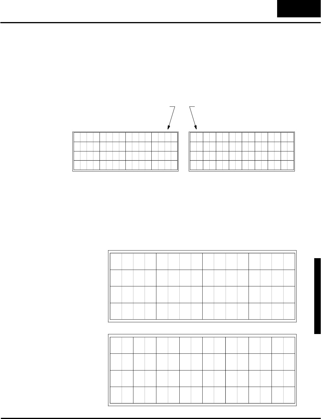
D
i
s
p
l
a
y
i
n
g
M
e
s
s
a
g
e
s
w
i
t
h
D
i
r
e
c
t
V
I
E
W
1
0
0
0
M
e
s
s
a
g
e
D
i
s
p
l
a
y
M
o
d
e
4
-
-
1
9
Message DisplayMode
Turning DataintoMessages
Now we have displayed a numberand sometextusing single entries(one V-memory
location)inthe numericand text tables.You have probablynoticed that the first
locationsarein oppositecornersof the display.Refertothe figure below.Numeric
positionsincrement fromright toleft,like LSB toMSB orientation.Textpositions
increment fromleft toright,justasweread froma book.We numberthe positionsin
octal,and startwithzero.
7654321076543210
3
7654321076543210
0
37
20
11
2
22
31 33
13
4
24
15
35
26
17
61 3 5 7
27
36343230
10
25
16
2321
12 14
2 1 0
13 11
6 4
16 14
7
10
1517
12
5
NumericDisplay PositionsTextDisplay Positions
(Octalnumbering ofpositions)
Firstnumericposition First textposition
The display containsatotalof16 numericand 32 textpositions.Each position
correspondsto one V-memorylocation (16-bitword).Each numericposition
occupies4characterspaces,while eachtextposition occupies2characterspaces.
The example programsinthismanualbeginsnumericdata block atV2000 and text
block data atV2100.The figure belowshowshownumericand textdatalocations
map to physical locationson the DV-1000 display.Because of the octalnumbering,
thedisplay position numbers are equaltothe address offsets!
0
37
20
11
2
22
31 33
13
4
24
15
35
26
17
61 3 5 7
27
36343230
10
25
16
2321
12 14
Text
Display Map
V2100
V2137
V2120
V2111
V2102
V2122
V2131 V2133
V2113
V2104
V2124
V2115
V2135
V2126
V2117
V2106V2101 V2103 V2105 V2107
V2127
V2136V2134V2132V2130
V2110
V2125
V2116
V2123V2121
V2112 V2114
3 2 1 0
13 11
6 4
16 14
7
10
1517
12
5
Numeric
Display Map
V2003 V2002 V2001 V2000
V2013 V2011
V2006 V2004
V2016 V2014
V2007
V2010
V2015V2017
V2012
V2005
Numbering of
Display Positions
Display Maps
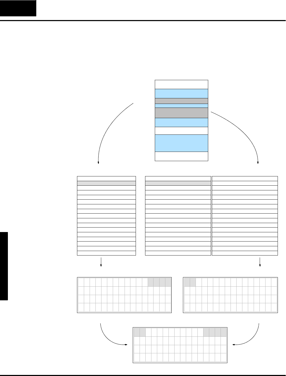
M
e
s
s
a
g
e
D
i
s
p
l
a
y
M
o
d
e
4
-
-
2
0
Message DisplayMode
The figure belowshowsthe numericand textdatainV-memory.Fromthere, follow
the arrowsto detailed numericand text tableswhichshowthe V-memory contents
forthe examplesthusfarinthis chapter.Notice howthe offset fromthe base address
(V2000 and V2100)foreach data block correspondsto actualdisplayposition
numbering.Followthe arrowstothe bottomof the page,wherethe DV-1000
combinesnumericand textinformation into one display.
NumericDisplay OutputTextDisplay Output
Position NumberV-Memory
0 12342000
1 00002001
2 00002002
3 00002003
4 00002004
5 00002005
6 00002006
7 00002007
10 2010 0000
11 00002011
12 00002012
13 00002013
14 00002014
15 00002015
16 00002016
17 00002017
NumericData
Position Data TextV-Memory
0 415A A2100
1 00002101
2 00002102
3 00002103
4 00002104
5 00002105
6 00002106
7 00002107
10 2110 0000
11 00002111
12 00002112
13 00002113
14 00002114
15 00002115
16 00002116
17 00002117
20 00002120
21 00002121
22 00002122
23 00002123
24 00002124
25 00002125
26 00002126
27 00002127
30 00002130
31 00002131
32 00002132
33 00002133
34 00002134
35 00002135
36 00002136
37 00002137
Position Data TextV-Memory
Z
TextData
V0000
End of
V-Memory
UserData
NumericPointer=2000
TextPointer=2100
V2000 NumericData
TextData
V7623
V7624
V2100
V2017
V2137
V-MemorySpace
DV-1000 Display
7654321076543210
AZ00000000001234
0000000000000000
0000000000000000
0000000000000000
7654321076543210
0000000000001234
0000000000000000
0000000000000000
0000000000000000
7654321076543210
A Z
Setup Parameters
HowMessageData
GetstotheDisplay
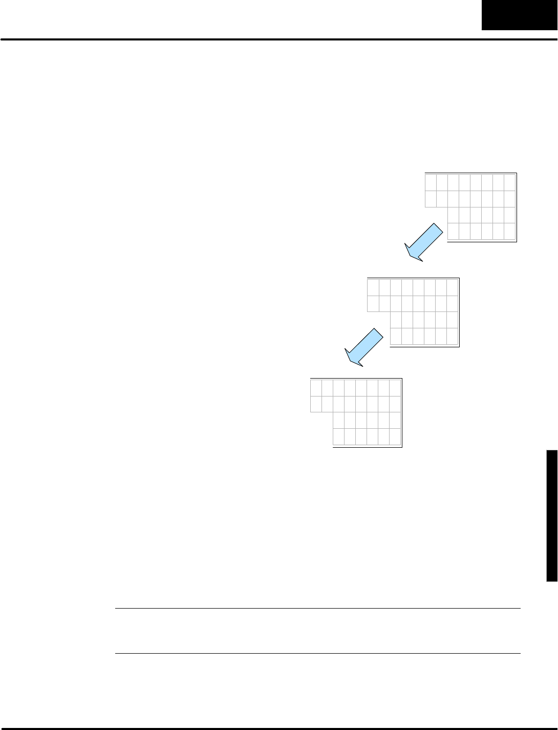
D
i
s
p
l
a
y
i
n
g
M
e
s
s
a
g
e
s
w
i
t
h
D
i
r
e
c
t
V
I
E
W
1
0
0
0
M
e
s
s
a
g
e
D
i
s
p
l
a
y
M
o
d
e
4
-
-
2
1
Message DisplayMode
CombinedNumeric and TextDisplays
Obviously, textand numbers cannotoccupythe same position on the actual
DV-1000 displayat the sametime.The twoV-memorydata blocks certainly coexist,
but the DV-1000 givesdisplayprioritytothe textdata.Eachtextcharacter’sdata
masks the corresponding numericaldigitif the text’sASCII code is20 (hex)or
greater.
3 2 1 0
A
B
C
D
3 2 1 0
0 0 0 0 0 0 0 0
0000000
0 0 0 0 0 0
0 0 0 0
NumericOutput
TextOutput
3 2 1 0
0 0 A0 0 0 0 0
000B0 0 0
000C0 0
000D
ActualDisplay Output
I
t
i
s
c
o
n
v
e
n
i
e
n
t
t
o
t
h
i
n
k
o
f
t
h
e
t
e
x
t
outputasacontrolmask fornumeric
output. Refertothe figuretothe
right. If the numericdata block in
V-memoryisall zeros, the matching
numericoutputisalsozeros,as
shown.Nowsupposethe textdatais
also all zeros(null characters),
except forfour randomlocationsas
shown.TextdataASCII codes41
through 44 hexproducesthe letters
A,B,C,and D.Now wecometothe
actualdisplayoutput. It isa
combination of the numericand text
outputcharacters.The DV-1000
usesasimple principleto determine
what to displayin eachcharacter
location:
Anytextcharacterwhich has an
ASCII code equalto20 (hex)or
greater masks (blocks) the
numericdigitinthe samedisplay
position.That’sit. Thisworks on a
c
h
a
r
a
c
t
e
r
-
b
y
-
c
h
a
r
a
c
t
e
r
b
a
s
i
s
.
One of the first things you maywant todoinyoursetup programisfullymask all
numericaloutput, sowe beginwith a blankdisplay(unless you useACONboxesto
fill the entire display).Thisisanalogousto“starting withaclean slate”.Then all the
mainladderprogramhasto do iswritetextwhere desired,and unmask numerical
positionswhere numbersare desired.Perhapsthe bestcharacterto useisthe
spacecharacter,ASCII code 20 (hex).The displayhas64 characterpositions,
requiring 32 wordsof2020 hex.Forthe DL405 CPUs,usethe FILL instruction.For
the DL105,DL205 and DL350 CPUs,you can useasingle LDD instruction followed
by sixteen OUTD instructions.
NOTE:You mayrecall seeing the displayfilled withzero(0)characterswhen you
firstpowered up the DV-1000.Sincethe textdata unmasked all the numeric
locations, the numericoutput(all zeros)wasdisplayed.

M
e
s
s
a
g
e
D
i
s
p
l
a
y
M
o
d
e
4
-
-
2
2
Message DisplayMode
SP0LDA
O2000
Load octaladdress 2000 intothe accumulator.This
instruction automatically convertsthe address intoits
hexadecimalequivalent.
OUT
V7623
Output thisaddress toV7623, the location of the setup
parameterwhichisthe numericmessage pointer.
ParameterSetup:Numeric and TextData
LDA
O2100
Load octaladdress 2100 intothe accumulator.This
instruction automatically convertsthe address intoits
hexadecimalequivalent.
OUT
V7624
Output thisaddress toV7624, the location of the setup
parameterwhichisthe textmessage pointer.
FirstScanOnly
LD
K2
Load the constantK2(BCD)intothe accumulator.The
value “2”correspondstoMessage Mode asthe Power-up
DefaultMode.
OUT
V7626
Output the constantK2toV7624, the location of the
Power-up Defaultsetup parameter.
If you are usingaDL405 type CPU,add the following laddersection tothe parameter
setup programabove.The FILL instruction isidealforthis situation.
LD
K20
Load the constantK20 (hex)intothe accumulator.Thisis
equivalent to32(decimal), the numberofdatawordsinthe
textdata block.
LDA
O2100
Load octaladdress 2100 intothe accumulator.This
instruction automatically convertsthe address intoits
hexadecimalequivalent.
FILL
K2020
Fill 32 locations,starting atV2100,with 2020 (hex),which
isthe ASCII codesfortwospacecharacters.
Fill TextDataWithSpacesDL405 CPUs
If you are usingaDL105,DL205 orDL350 type CPU,add the following ladder
section tothe parametersetup programat the top of thispage.The FILL instruction
boxisnotavailablefortheseCPUs,sothe programusesone LDD boxand 16 OUTD
boxes.Rememberthat this section executesonlyon the firstscan (overall scan time
isnotaffected).
LDD
K20202020
Load fourASCII codes constantK20 (hex)intothe
accumulator.Thisproducesfourspacecharacters.
OUTD
V2100
Output the datatomemorylocationsV2100 and V2101.By
using the OUTD(OutDouble)instruction,wecan load two
V-memorywordlocationswith one instruction.
OUTD
V2102
Fill TextDataBlock WithSpaces
Output the datatomemorylocationsV2102 and V2103.
OUTD
V2136
Output the datatomemorylocationsV2136 and V2137.
Thisisthe lastof32 OUTDboxinstructionsinthisgroup
which programsall 64 display characterstobespaces.
InsertOUTDboxinstructionshereformemorylocations
V2104 toV2134.Remember,onlyuse even-numbered
memorylocations!
DL105/DL205/
DL350 CPUs
ParameterSetup
Program#2
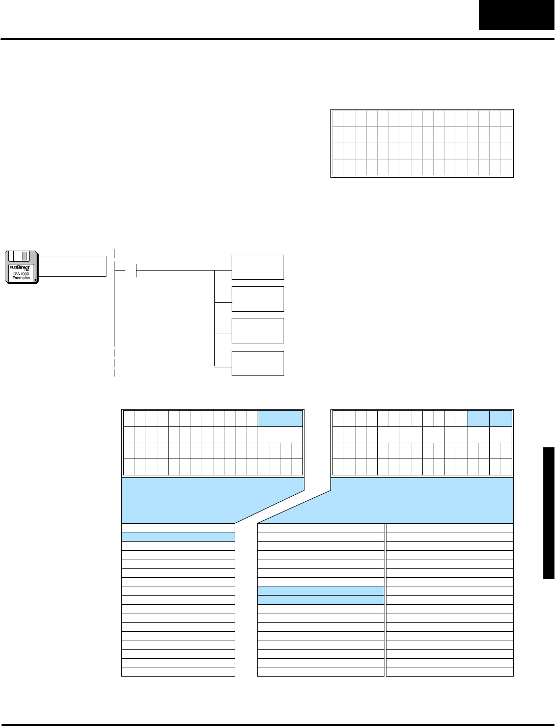
D
i
s
p
l
a
y
i
n
g
M
e
s
s
a
g
e
s
w
i
t
h
D
i
r
e
c
t
V
I
E
W
1
0
0
0
M
e
s
s
a
g
e
D
i
s
p
l
a
y
M
o
d
e
4
-
-
2
3
Message DisplayMode
The setup programon the previouspage masks all numericpositionsasastarting
point. Now we add the mainladderprogram.Itloadsthe number,and then unmasks
the corresponding specificnumericdisplaypositions.
Asan example,let’splace a numberinthe
firstnumericposition thatvariesfrom0to
999.However, the V-memory contentswill
varyfrom0000 to 0999.Wecan leavethe
leading0masked,and onlyunmask the
three digitswewant to display,as shown
tothe right. 7654321076543210
999
Now we’rereadytowritethe mainladderprogram,whichfollows.Itplaces“0999”in
the firstnumericdatalocation,and then unmasks the three displaypositionsof
interest. We usethe null character,ASCII code “00”, to unmask the numericoutput.
LD
K999
Load the value “999”inthe accumulator.
OUT
V2000
Output the datatomemorylocation V2000.The actual
contentsofV2000 are“0999”.However, the nextinstruction
will leavethe leading “0”masked,and unmask the “999”.
LDD
K2000
Use a Load Double(LDD)to placethe ASCII codesfora
space“”characterfollowed bythree null charactersinto
the accumulator (rememberthe swap effect forLDD box).
OUTD
V2106
Output the datatomemorylocationsV2106 and V2107.
The OutDoubleinstruction updatestwotextpositionsat
atime(two datawords).
SP0
FirstScan
7654321076543210
3
7654321076543210
0
37
20
11
2
22
31 33
4
24
35
26
135
27
36343230
10
252321
2 1
13 11
6
16 14
7
10
1517
12
5 12 13 14 154
Position Data TextV-Memory
0 20202100
1 20202101
2 20202102
3 20202103
4 20202104
5 20202105
6 20002106
7 00002107
10 2110 2020
11 20202111
12 20202112
13 20202113
14 20202114
15 20202115
16 00002116
17 00002117
20 20202120
21 20202121
22 20202122
23 20202123
24 20202124
25 20202125
26 20202126
27 20202127
30 20202130
31 20202131
32 20202132
33 20202133
34 20202134
35 20202135
36 20202136
37 20202137
Position NumberV-MemoryPosition Data TextV-Memory
0 09992000
1 00002001
2 00002002
3 00002003
4 00002004
5 00002005
6 00002006
7 00002007
10 2010 0000
11 00002011
12 00002012
13 00002013
14 00002014
15 00002015
16 00002016
17 00002017
NumericDisplay PositionsTextDisplay Positions
NumericDataTextData
16 17
0 6 7
Unmasking
NumericPositions
a:\msg6.prj
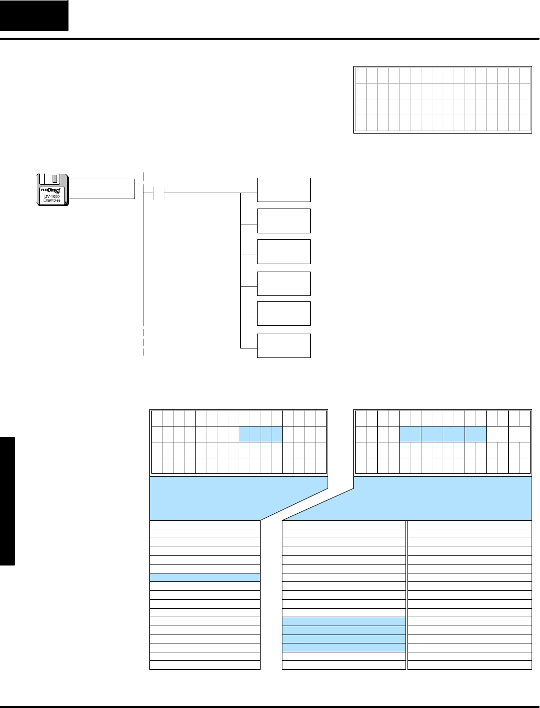
M
e
s
s
a
g
e
D
i
s
p
l
a
y
M
o
d
e
4
-
-
2
4
Message DisplayMode
Still using a blankdisplayasastarting
point, let’s createadisplayfeaturing both
textand numbers.Sincethereismore
flexibilityintextplacement, we plan the
displaylayoutaround using numeric
position #5 forthe content“123”.The
following programwritestextand numeric
mask charactersinthe sameway.
7654321076543210
P S I = 1 2 3
LD
K123
Load the value “123”inthe accumulator.
OUT
V2005
Output the datatomemorylocation V2005.The actual
contentsofV2005 are“0123”.However, the lastinstruction
will leavethe leading “0”masked,and unmask the “999”.
LDD
K493d5053
Use a Load Double(LDD)to placethe ASCII codesforthe
characters“PSI=”intothe accumulator.Rememberthe
LDD instruction swapsthe textoutputpositions.
OUTD
V2112
Output the datatomemorylocationsV2112 and V2113.
The OutDoubleinstruction updatestwotextpositionsata
time(two datawords).
SP1
Always On
LDD
K2000
Use a Load Double(LDD)to placethe ASCII codesforone
space(masks leading 0)and three null characters
(unmasks “123”).
OUTD
V2114
Output the datatomemorylocationsV2114 and V2115.
The OutDoubleinstruction updatestwotextpositionsata
time(two datawords).
7654321076543210
3
7654321076543210
0
37
20
11
2
22
31 33
4
24
35
26
135
27
36343230
10
252321
2 1
13 11
6
16 14
7
10
1517
12
12 13 14 15
Position Data TextV-Memory
0 20202100
1 20202101
2 20202102
3 20202103
4 20202104
5 20202105
6 20002106
7 00002107
10 2110 2020
11 20202111
12 50532112
13 493d2113
14 20002114
15 00002115
16 20202116
17 20202117
20 20202120
21 20202121
22 20202122
23 20202123
24 20202124
25 20202125
26 20202126
27 20202127
30 20202130
31 20202131
32 20202132
33 20202133
34 20202134
35 20202135
36 20202136
37 20202137
Position NumberV-MemoryPosition Data TextV-Memory
0 00002000
1 00002001
2 00002002
3 00002003
4 00002004
5 01232005
6 00002006
7 00002007
10 2010 0000
11 00002011
12 00002012
13 00002013
14 00002014
15 00002015
16 00002016
17 00002017
NumericDisplay PositionsTextDisplay Positions
NumericDataTextData
16 17
0 6 7
5 4
Placing Numbers
and TextTogether
a:\msg7.prj
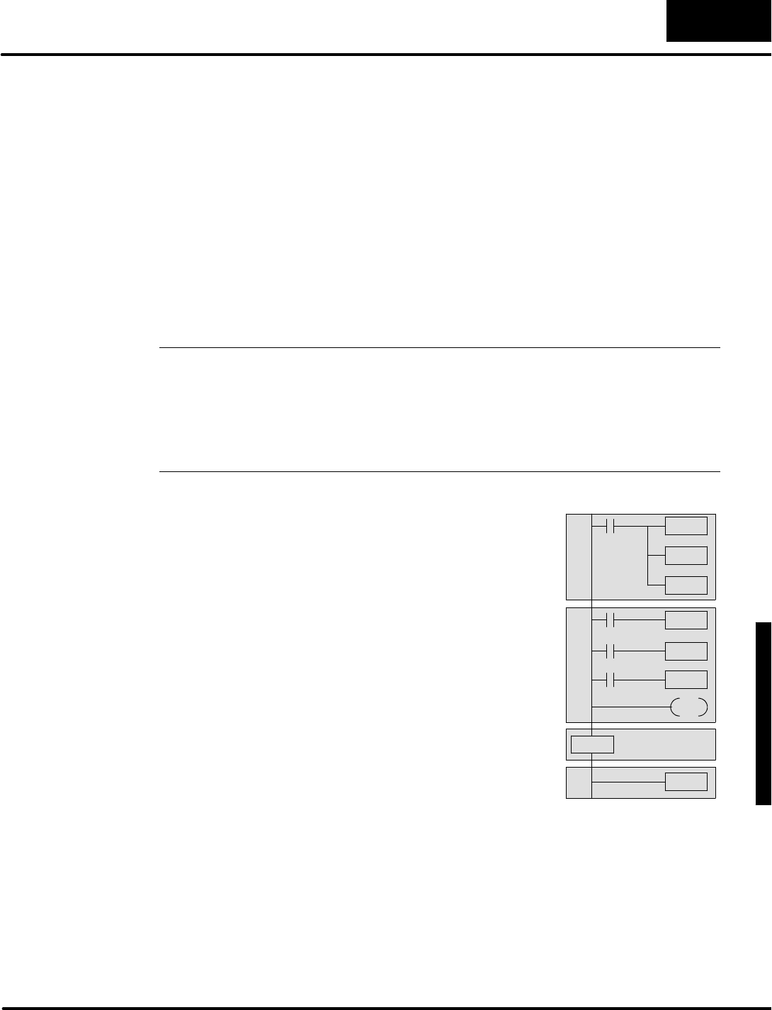
D
i
s
p
l
a
y
i
n
g
M
e
s
s
a
g
e
s
w
i
t
h
D
i
r
e
c
t
V
I
E
W
1
0
0
0
M
e
s
s
a
g
e
D
i
s
p
l
a
y
M
o
d
e
4
-
-
2
5
Message DisplayMode
Using theASCII Constant (ACON)Instruction
The examples sofarinthis chapterhavecovered DV-1000 displaybasics.The Load
Double(LDD)instruction loadsASCII valuesintomemoryforonlyfourcharactersto
be displayed.Thismethod requireslooking up ASCII valuesfromatable(or
memorizing the table),and can potentiallyuse a lotofLDD and OUTD instructions.
Fortunately, the ACON instruction (ASCII Constant)providesan easier method of
textentry.The ACONboxisavailable on DL105,DL205 and DL350 CPUsand on
DL440 and DL450 CPUs(notavailableonDL430 CPUs).Using DirectSOFT,you
can type the characters you wantdirectlyinthe instruction box!Afterlearning the
LDD method and the ACONmethod,you can use eitherone orboth,based on
individualpreferencesand yourapplication.
NOTE:Inthe CPU, the basicACONfunction boxonlyacceptstwocharacters. If you
are using a Hand-heldProgrammerincreating ladderlogictorun the DV-1000
display,notethatitsACON instruction islimited totwocharacters.However,
DirectSOFT permits you to enterup tofortycharacters.DirectSOFT createsan
extended ACONboxforcharacterentry, then subdividesitintomultiple 2-character
ACONboxeswhen downloading the programtothe CPU.This section assumes you
are using DirectSOFT.
Using the ACONmethod of textentry
addsnew ladderelementsonto our
existing program.The figuretothe
rightshowsan outline of the program.
The setup parameter rung isfirst, as
described inChapter2.The main
programfollows,justaswe have been
creating main programexamplesin
this chapter.
Afterthe end of the main program (and
the End Coil),we add a Data Label
box.Itannouncesthe data boxwhich
follows,and allowsthe main program
toreferencethe data boxbythe label.
The ACON(ASCII Constant)box
followsasthe lastprogramelement.
MainProgram
DataLabel
ASCII Constant
Setup Parameters
END
The main programsection receivesa new instruction, too.The MOVMC(Move
MemoryCartridge)instruction readsthe ACONdata(the textdata)intoV-memory
spacesothe mainladderprogramcan useit. Notethat the MOVMCrequires
supporting datatobeloaded ontothe stack beforeitsuse.The following example
showshowthisprocess works.
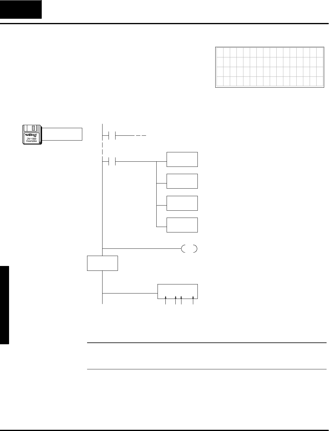
M
e
s
s
a
g
e
D
i
s
p
l
a
y
M
o
d
e
4
-
-
2
6
Message DisplayMode
N
o
w
w
e
c
r
e
a
t
e
a
p
r
o
g
r
a
m
e
x
a
m
p
l
e
t
o
u
s
e
the ACON instruction.The example
displaytothe rightshows“Aline of text!”
asthe message on the firstline.Even
though thisis15 characters, the ACON
boxmustcontain an even numberof
characters(we’ll use 16).And, this
examplestill usesa blankdisplayasa
starting point(setup program#2).
7654321076543210
A l i n e o f t e x t !
D
e
s
i
r
e
d
D
i
s
p
l
a
y
LD
K8
Load the numberofdatalocations.Thiswill be the
numberofcharacterpairs,sowe use 8 becausethere
are16characterstotal.NOTE:The constantisa hex
number!
LD
K0
Load the address offset. FornearlyeveryMOVMC
used forACONdata, therewill be zero offset(useK0).
LDLBL
K1
Use a Load Data Label(LDLBL)toread the ASCII data
fromthe Data Labelafterthe END coil.The “K1”inthis
instruction referencesthe constantK1inthe DLBL box.
MOVMC
V2100
Movethe dataintoV-memory starting atV2100,using
the abovethree boxes’datawhichison the stack.
So,itwill read 8 words,withzero offset, fromthe data
boxinstructionsafterData Labelnumber1(K1).
SP0
Main
Program
Usethe ASCII Constant(ACON)boxto entertext
charactersdirectlyfromthe keyboard.The entrymust
be an even numberofcharacters,withamaximumof
40 characters.Here,wetypeaspacecharacterafter
the !character, to have16characterstotal.
END
DLBL
K1
ACON
Aline of text!
DataLabel
ACON Box
The end coil terminatesthe main programsection.
The Data Labelboxmarks the beginning ofa data area
containing ACONorNCONboxes.The reference
numberforthisarea is“1”,specified byK1.
(Setup Parameter rung here)
SP0
spaces:1111
Werecommend using the ACONmethod wheneveryou need to putseveral
characterson the display.
NOTE:AppendixCcontains someworksheetsto useincreating yourown
messages.Itincludesaworksheet forloading ASCII codesindividuallyand another
worksheet forusing ACONboxes.
ACONExample
Program#1
a:\msg8.prj
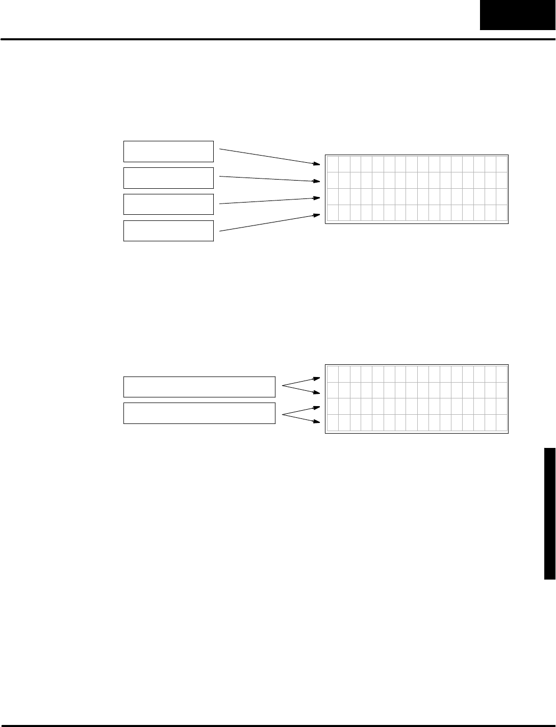
D
i
s
p
l
a
y
i
n
g
M
e
s
s
a
g
e
s
w
i
t
h
D
i
r
e
c
t
V
I
E
W
1
0
0
0
M
e
s
s
a
g
e
D
i
s
p
l
a
y
M
o
d
e
4
-
-
2
7
Message DisplayMode
Afterusing the ACON instruction to placealine of texton the firstdisplayrow,we’re
readytocreate a full-displaymessage covering all four rows.The previousexample
used one 16-characterACONbox.Ifwe extend thismethod to generate a message
forthe entire display,we’ll need fourACONboxesinseparate datalabelareas.The
organization ofACONboxesto displaytextisasfollows:
7654321076543210
aaaaaaaaaaaaaaaa
bbbbbbbbbbbbbbbb
cccccccccccccccc
dddddddddddddddd
ACON
aaaaaaaaaaaaaaaa
ACON
bbbbbbbbbbbbbbbb
ACON
cccccccccccccccc
ACON
dddddddddddddddd
You mayrecall that the ACON instruction box(using DirectSOFT)can acceptup to
40 characters.Although there aremanypossiblecombinations,atleast twoACON
boxesarerequired tofill the DV-1000’s64-characterdisplay.Totakemaximum
advantage of the ACONbox capacity,let’s create a displayusing just twoACON
instructions.Using equally-sized ACONboxes,each one contains32 characters
whichwill fill tworows,as shown below:
ACON
aaaaaaaaaaaaaaaabbbbbbbbbbbbbbbb
ACON
ccccccccccccccccdddddddddddddddd
7654321076543210
aaaaaaaaaaaaaaaa
bbbbbbbbbbbbbbbb
cccccccccccccccc
dddddddddddddddd
The textinthe 32-characterACONBoxeswrapsaround fromone rowto a second
rowon the display.Thismakes veryefficientuse of the ACON instruction.However,
you havetocarefully countcharactersand spaces sothe displayoutputdoeswhat
you wantit to do.
When writing yourown programs,usethe length ofACONtext thatbest fits your
application and isthe easiest foryou to use. Inthe interestofconserving space,most
of the examplesinthis chapterwhich useACONsusethe 32-characterversion.
However, the programs could have used twice asmany16-characterACONboxes
instead.
Choosing ACON
BoxTextLength
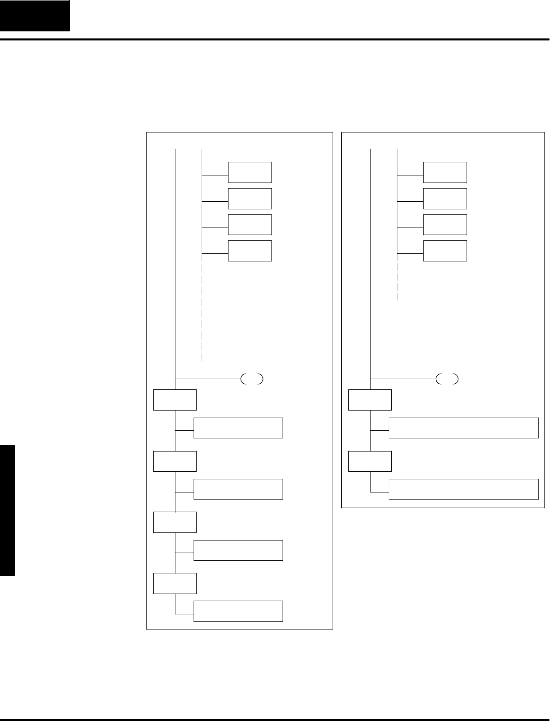
M
e
s
s
a
g
e
D
i
s
p
l
a
y
M
o
d
e
4
-
-
2
8
Message DisplayMode
The following ladderprogramoutlines showequivalent16-characterand
32-characterACONboxmethodsto generatethe same displayoutput. It assumes
the textdata block beginsatV2100,butyour memorymap maydiffer.
Row1
LD
K8
LD
K0
LDLBL
K1
MOVMC
V2100
END
DLBL
K1
ACON
aaaaaaaaaaaaaaaa
DLBL
K2
ACON
bbbbbbbbbbbbbbbb
DLBL
K4
ACON
cccccccccccccccc
ACON
dddddddddddddddd
DLBL
K3
LD
K10
LD
K0
LDLBL
K1
MOVMC
V2100
END
DLBL
K1
ACON
aaaaaaaaaaaaaaaabbbbbbbbbbbbbbbb
DLBL
K2
ACON
ccccccccccccccccdddddddddddddddd
Row2
Row3
Row4
Row1 and 2
Row3 and 4
MOVMCforDLBL1MOVMCforDLBL1
MOVMCforDLBL2
(movesrow2 datatoV2110)
MOVMCforDLBL3
(movesrow3 datatoV2120)
MOVMCforDLBL4
(movesrow4 datatoV2130)
MOVMCforDLBL2
(movesrow3 datatoV2120)
16--CharacterACONs32-CharacterACONs
(K10 hex=
16 decimal)
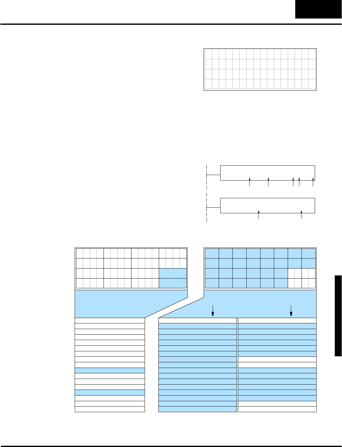
D
i
s
p
l
a
y
i
n
g
M
e
s
s
a
g
e
s
w
i
t
h
D
i
r
e
c
t
V
I
E
W
1
0
0
0
M
e
s
s
a
g
e
D
i
s
p
l
a
y
M
o
d
e
4
-
-
2
9
Message DisplayMode
T
h
i
s
e
x
a
m
p
l
e
s
h
o
w
s
t
h
e
t
r
u
e
p
o
w
e
r
o
f
t
h
e
ACONmethod of textentryincreating
displaytothe right. It showsthe machine
numberand status, followed bya part
countand production ratein partsper
hour.Remember, the numericlocationsof
“1234”and “57” mustbe unmasked inthe
t
e
x
t
d
a
t
a
.
7654321076543210
MACHINE NO.5
S T A T U S = R U N
Part count= 1234
Parts/hour= 57
D
e
s
i
r
e
d
D
i
s
p
l
a
y
Also,becausethe ACONtextcoversthe entire display, thereisno need towrite
spacesto all characterpositionstocreateablank starting display.Therefore,wecan
usethe simplerSetup Program#1 thatjustsetsup the numericand textdata blocks.
ACONboxes can containamaximumof40 characters.The DV-1000 display
contains64 characters,sowe arbitrarilyusetwo equally-sized ACONboxes,at32
characterseach. Insertspacesforblankdisplaylocations,counting themprecisely.
SDataforthe firstACONbox contains
the top twolinesofdisplaytext, and
beginsatV2100.
SDataforthe second ACONbox
containsthe bottomtwolinesof
displaytext, and beginsatV2120.
ACON
MACHINENO.5STATUS=RUN
ACON
Partcount=Parts/hour=
spaces:55
spaces:41 1 1 4
7 6 5 4 3 2 1 0 7 6 5 4 3 0
3
7 6 5 4 0 3 2 1 0
37
26 27
36
2 1
13 11
6
16
7
1517
12
Position Data TextV-Memory
0 4D41 M2100
1 4348 C2101
2 494EI2102
3 4520 E2103
4 4E4F N2104
5 2E35 .2105
6 20202106
7 20202107
10 2110 5354 S
11 4154 A2111
12 5553 U2112
13 203D2113
14 20522114
15 554EU2115
16 20202116
17 20202117
20 5061 P2120
21 7274 r2121
22 20632122
23 6F75 o2123
24 6E74 n2124
25 3D20 =2125
26 00002126
27 00002127
30 5061 P2130
31 7274 r2131
32 732F s2132
33 686F h2133
34 7572 u2134
35 3D20 =2135
36 20202136
37 00002137
Position NumberV-MemoryPosition Data TextV-Memory
0 00002000
1 00002001
2 00002002
3 00002003
4 00002004
5 00002005
6 00002006
7 00002007
10 2010 1234
11 00002011
12 00002012
13 00002013
14 00572014
15 00002015
16 00002016
17 00002017
A
H
N
O
5
T
T
S
=
R
N
a
t
c
u
t
a
t
/
o
r
N
u
m
e
r
i
c
D
i
s
p
l
a
y
P
o
s
i
t
i
o
n
s
T
e
x
t
D
i
s
p
l
a
y
P
o
s
i
t
i
o
n
s
NumericDataTextData
16 17
0 6 7
5 4
2 1
14
10
0
20
30
10 11
31
1
21
3 2
2
22
32
12
1
33
3
23
13
7 6
4
24
34
14
5 4
35
5
25
15
ACON Box1dataACON Box2data
The following programplacesnumericand textdataintothe locations shown above.
ACONExample
Program#2

M
e
s
s
a
g
e
D
i
s
p
l
a
y
M
o
d
e
4
-
-
3
0
Message DisplayMode
(Setup Parameter rung here)
SP0
LD
K1234
Load the number “1234”intothe accumulator.Your
programwouldread in datafroman analog input
moduleforthis step,etc.
OUT
V2010
Place“1234”inthe numericdata block location
corresponding to numericdisplayposition 10.
LD
K57
Load the number “57”intothe accumulator.
OUT
V2014
SP1
LoadValues IntoNumericDataBlock
Place“57”inthe numericdata block location
corresponding to numericdisplayposition 14.
Always On
LD
K10
Load the numberofdatalocations,whichis16
words(10 hex),or32 characters.
LD
K0
Load the address offset. FornearlyeveryMOVMC
used forACONdata, therewill be zero offset(use
K0).
LDLBL
K1
Read fromthe ACONfollowing Data LabelK1.
MOVMC
V2100
Move dataintoV-memory starting atV2100,
corresponding tothe top twolineson the display.
SP0
Move ACON DataInto TextDataBlock
LD
K10
Load the numberofdatalocations,whichis16
words(10 hex),or32 characters.
LD
K0
Load the address offset. FornearlyeveryMOVMC
used forACONdata, therewill be zero offset(use
K0).
LDLBL
K2
Read fromthe ACONfollowing Data LabelK2.
MOVMC
V2120
Movethe dataintoV-memory starting atV2120,
corresponding tothe bottomtwolineson the
display.
FirstScan
END The end coil terminatesthe main programsection.
LDD
K0
Load the constantzero(ASCII null character) into
the accumulator.
OUTD
V2126
Placezerosintextoutputposition 26 and 27.This
unmasks numericposition 10.
LDD
K2020
Use a Load Doubleto update4characterspaces.
The K2020 actuallyimpliesK00002020.The zeros
unmask the numeric“57”,and the spaces(2020)
hide itsleading zeros.
SP0
Unmask NumericLocations
OUTD
V2136 Placezerosintextoutputposition 36,and spaces
in outputposition 37.
FirstScan
a:\msg9.prj
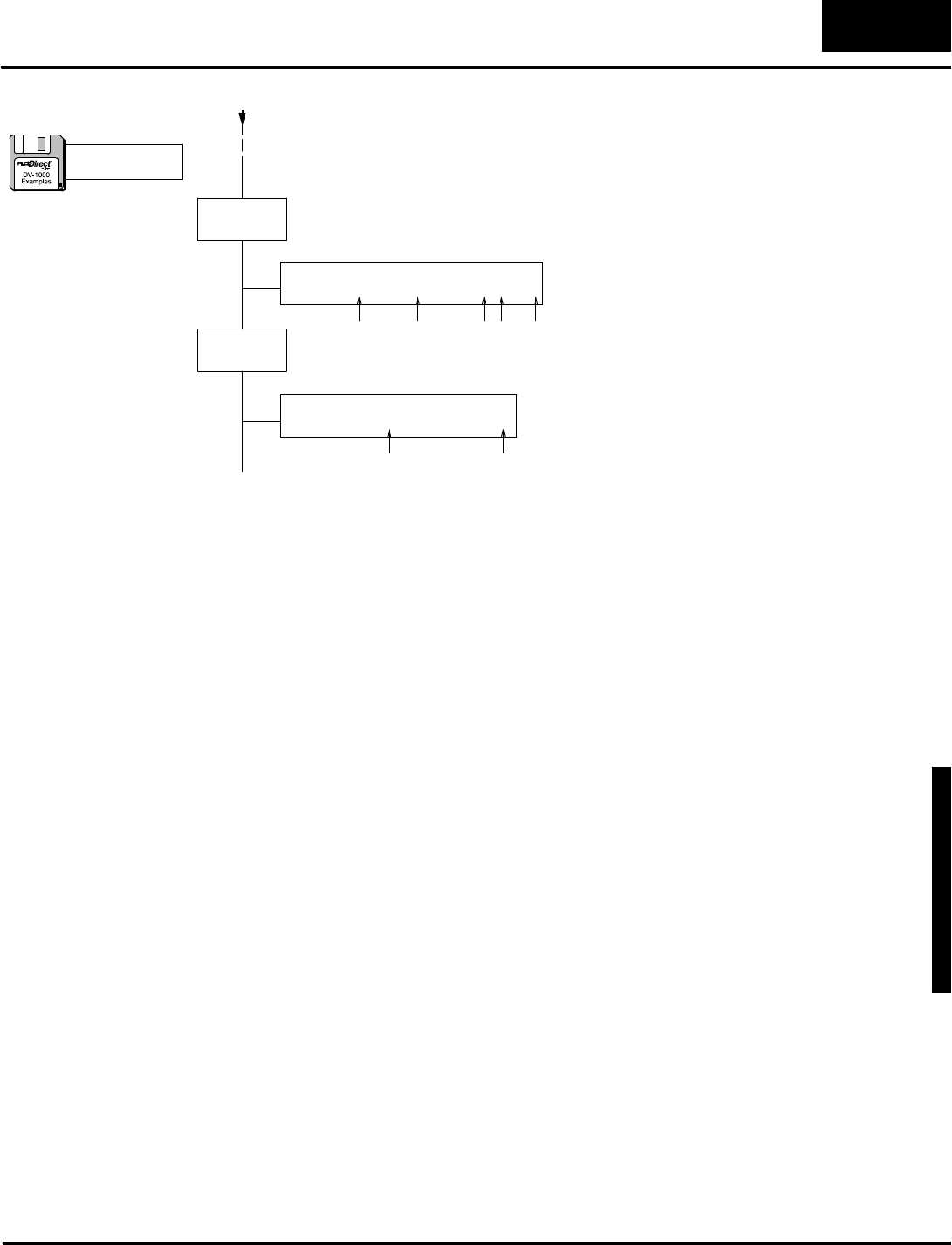
D
i
s
p
l
a
y
i
n
g
M
e
s
s
a
g
e
s
w
i
t
h
D
i
r
e
c
t
V
I
E
W
1
0
0
0
M
e
s
s
a
g
e
D
i
s
p
l
a
y
M
o
d
e
4
-
-
3
1
Message DisplayMode
UseASCII Constant(ACON)boxesto entertext
charactersdirectlyfromthe keyboard.
DLBL
K1
ACON
MACHINENO.5STATUS=RUN
DataforTop 2Display Lines
The Data Labelboxmarks the beginning ofa data
area containing ACONorNCONboxes.The
reference numberforthisarea is“1”,specified by
K1.
DLBL
K2
ACON
Partcount=Parts/hour=
DataforBottom2Display Lines
UseASCII Constant(ACON)boxesto entertext
charactersdirectlyfromthe keyboard.
spaces:5 5
spaces:44 11 1
(continued)
a:\msg9.prj
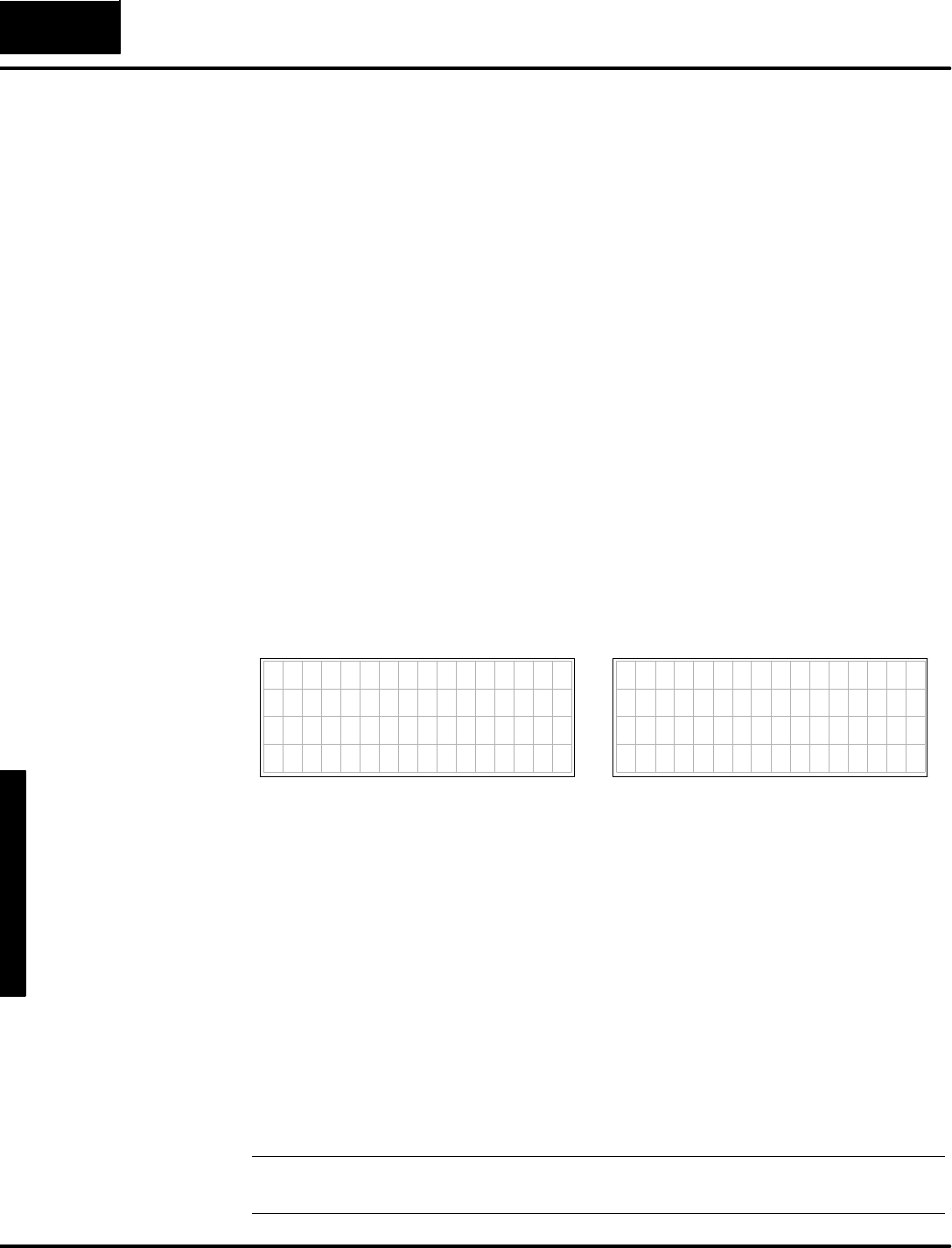
M
e
s
s
a
g
e
D
i
s
p
l
a
y
M
o
d
e
4
-
-
3
2
Message DisplayMode
MessageDisplay Applications and Techniques
The material inthis chapterup tothispointhasdemonstrated basicproceduresin
getting information tothe display.The following examplesbuild on thisfoundation,
showing solutionstotypicalapplications.These programsarethe “bellsand
whistles”of the displayfunction. It’sa good idea to get the basicdisplay screen
working first, and then carefullyadd portionsof thesetechniquestofine-tune your
application program.The specialdisplayapplicationswewill coverare:
SMultiplemessage displays
SBlinking text
SDynamictext
SEmbedding the time and dateinamessage
SPolarity sign fornumbers
SBarGraph Displays
SAutomaticScrolling Displays
InMessage Mode, the DV-1000 continuously scansthe numericand textdatain
V-memorytocombine theirinformation and createasingle display screen.To
change the displaymessage,wemustupdatethe numericand/ortextdata blocks in
V-memoryaccordingly. It’spossibleto alternate between two or more display
screens,based on some arbitraryevent. Forexample,supposewewanteitherof the
following display screensto appear,based on an operatorinput:
7654321076543210
TOTAL PRODUCTION
Line 1=11111111
Line 2=22222222
Line 3=33333333
7654321076543210
CONVEYOR SPEEDS
L i n e 1 = 1 2 3 f p m
L i n e 2 = 4 5 6 f p m
L i n e 3 = 7 8 9 f p m
Display Screen1Display Screen2
In ordertochooseaprogramming strategy,wemustdo the following:
SChoose numberofdisplay screens
SCreatethe message (numericand text)data
SDecide whatevent triggersdisplay screen changes
Inthisexample,we have 2 display screens, the contentsare as shown,and the
displaywill change based on the state ofX0(OFF =Display1, ON=Display2).An
inputsimulatororsimpleswitchisusefulforcreating switchX0.Sincemostof the
display charactersinthe two display screensare different, wewill useACONsto
move datain and outof the textand numerictables.The ladderprogramwill need to
updatethe textcharactersonce aftereach display screen change,becausethey
remainfixed thereafter.The one-shot(positive differential)function boxwill help us
write newdisplaydatajustonce.However, the numericdatamustbe constantly
updated,becauseitchangesinrealtimewiththe user machine orprocess. Inthis
case,wewill repeat the update eachPLCscan.
NOTE:If using DL105,be suretoinitializethe CPUorinputX0will notactivate.
FromPLCmenu,chooseSetup, then InitializeScratchpad.
MultipleMessage
Displays

D
i
s
p
l
a
y
i
n
g
M
e
s
s
a
g
e
s
w
i
t
h
D
i
r
e
c
t
V
I
E
W
1
0
0
0
M
e
s
s
a
g
e
D
i
s
p
l
a
y
M
o
d
e
4
-
-
3
3
Message DisplayMode
(
S
e
t
u
p
P
a
r
a
m
e
t
e
r
r
u
n
g
h
e
r
e
)
SP0
LD
V0
Load the timervalue (whichismapped tolocation V0
and V1)intothe accumulator.Herewe onlyuse 16 bits
of the timervalue.
OUT
V2005
Placethe numberinthe numericdata block location
corresponding to numericdisplayposition 5.
OUT
V2011
OUT
V2015
LoadValues IntoNumericDataBlock
TMRAF
K99999999
Useatimer (fastaccumulating type)to generate a
changing number.Yourapplication will haveitsown
sourcesfor real-time process data,sothisrung will be
different. Notethat thisisa 32-bit timer.
T0
T0
T0
X0
OUTD
V2004
OUTD
V2010
OUTD
V2014
X0
PDActivatecontrolrelayC0for1scan when X0 goesfro
m
OntoOff.
C0
X0
LD
K10
LD
K0
LDLBL
K1
SP0X0
LDD
V0
PDActivatecontrolrelayC1for1scan when X0 goesfro
m
Off toOn.
C1
X0
C0
LoadScreen1Datainto TextDataBlock
MOVMC
V2100
Placethe numberinthe numericdata block location
corresponding to numericdisplayposition 11.
Placethe numberinthe numericdata block location
corresponding to numericdisplayposition 15.
X0Off =Screen1
X0On=Screen2
Load the timervalue (whichismapped tolocation V0
and V1)intothe accumulator.Herewe use all 32 bits
of the timervalue.
Placethe numberinthe numericdata block location
corresponding to numericdisplayposition 4.
Placethe numberinthe numericdata block location
corresponding to numericdisplayposition 10.
Placethe numberinthe numericdata block location
corresponding to numericdisplayposition 14.
Load the numberofdatalocations,whichis16 words
(10 hex),or32 characters.
Load the address offset. FornearlyeveryMOVMC
used forACONdata, therewill be zero offset(useK0).
Read fromthe ACONfollowing Data LabelK1.
Move dataintoV-memory starting atV2100,
corresponding tothe top twolineson the display.
Note:
a:\msg10.prj

M
e
s
s
a
g
e
D
i
s
p
l
a
y
M
o
d
e
4
-
-
3
4
Message DisplayMode
OUTD
V2114
OUTD
V2124
OUTD
V2134
LD
K10
LD
K0
LDLBL
K3
SP0X0
LDD
K0
C1
MOVMC
V2100
Load the accumulatorwithASCII codesfornull
characters(zeros), to unmask numericdisplay
positions.
Unmask textdisplaypositions14 and 15.
LD
K10
LD
K0
LDLBL
K2
MOVMC
V2120
OUTD
V2114
OUTD
V2116
LDD
K0
LD
K10
LD
K0
LDLBL
K4
MOVMC
V2120
LoadScreen2Datainto TextDataBlock
Load the numberofdatalocations,whichis16 words
(10 hex),or32 characters.
Load the address offset. FornearlyeveryMOVMC
used forACONdata, therewill be zero offset(useK0).
Read fromthe ACONfollowing Data LabelK2.
Move dataintoV-memory starting atV2120,
corresponding tothe bottomtwolineson the display.
Load the numberofdatalocations,whichis16 words
(10 hex),or32 characters.
Load the address offset. FornearlyeveryMOVMC
used forACONdata, therewill be zero offset(useK0).
Read fromthe ACONfollowing Data LabelK3.
Move dataintoV-memory starting atV2100,
corresponding tothe top twolineson the display.
Load the numberofdatalocations,whichis16 words
(hex),or32 characters.
Load the address offset. FornearlyeveryMOVMC
used forACONdata, therewill be zero offset(useK0).
Read fromthe ACONfollowing Data LabelK4.
Move dataintoV-memory starting atV2120,
corresponding tothe bottomtwolineson the display.
Unmask textdisplaypositions24 and 25.
Unmask textdisplaypositions34 and 35.
Load the accumulatorwithASCII codesfornull
characters(zeros), to unmask numericdisplay
positions.
Unmask textdisplaypositions14 and 15.
Unmask textdisplaypositions16 and 17.
(continued)
a:\msg10.prj

D
i
s
p
l
a
y
i
n
g
M
e
s
s
a
g
e
s
w
i
t
h
D
i
r
e
c
t
V
I
E
W
1
0
0
0
M
e
s
s
a
g
e
D
i
s
p
l
a
y
M
o
d
e
4
-
-
3
5
Message DisplayMode
END PlaceanEND coil heretomarkthe end of the
main program.Following thisarethe ACON
boxes containing screen data.
DLBL
K1
ACON
CONVEYORSPEEDSLine 1=fpm
Screen1,Top 2Lines The Data Labelboxreferenced byK1 preceeds
the following ACONbox.
DLBL
K2
ACON
Bottom2Lines
DLBL
K3
ACON
TOTALPRODUCTIONLine 1=
Screen2,Top 2Lines
DLBL
K4
ACON
Line 2=Line 3=
Bottom2Lines
ThisACONbox contains32 characters.Besure
tocarefully count the spacestomatchthe
display.
OUTD
V2124
OUTD
V2126
OUTD
V2134
OUTD
V2136
Unmask textdisplaypositions24 and 25.
Unmask textdisplaypositions26 and 27.
Unmask textdisplaypositions34 and 35.
Unmask textdisplaypositions36 and 37.
SAME
Line 2=fpmLine 3=fpm
spaces:1 2 1 5
spaces:1 5 1 1 5
spaces:1 1 1 8
spaces:1 8 1 8
1
1
(continued)
a:\msg10.prj
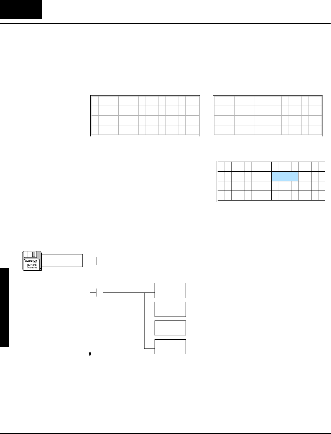
M
e
s
s
a
g
e
D
i
s
p
l
a
y
M
o
d
e
4
-
-
3
6
Message DisplayMode
Insome display screensit’sdesirabletochange onlyakeyword ortwo upon certain
events,leaving mostof the textintact. Wemightcall thisa“forms”type screen.The
unchanging textisthe form,and the dynamictextoccupiesblanks withinthe form. In
thisexample, the display screen reportsthe statusofamachine.The operational
Manualand Automaticmodesappearas“MAN”,and “AUTO”,asinthese displays:
7654321076543210
M A C H I N E S T A T U S :
M O D E = A U T O
7654321076543210
MACHINE STATUS:
MODE= M A N
X0=Off X0=On
Now wecan decide howtowritethe
dynamictextladderprogram.We’ll use
the ACONtextentrymethod forthe basic
form of the screen,whichwill include
“MACHINE STATUSMODE=”.The
dynamictextwill occupytextpositions14
and 15.7654321076543210
0
37
20
11
2
22
31 33
13
4
24
35
26
17
61357
27
36343230
10
25
16
2321
12
DynamicTextDisplay Positions
1514
The dynamictextwill followthe state of the inputswitchcontactX0.When X0=Off,
“MAN”will be displayed.When X0=On,“AUTO”will be displayed.The following
ladderlogicoutputsthesescreens.
(Setup Parameter rung here)
SP0
Load FormTextData
LD
K10
LD
K0
LDLBL
K1
SP0
MOVMC
V2100
Load the numberofdatalocations,whichis16 words
(10 hex),or32 characters.
Load the address offset. FornearlyeveryMOVMC
used forACONdata, therewill be zero offset(useK0).
Read fromthe ACONfollowing Data LabelK1.
Move dataintoV-memory starting atV2100,
corresponding tothe top twolineson the display.
Note:Ifusing DL105 be sureCPUisinitialized
tomake inputsX0 and X1operational.
DynamicText
a:\msg11.prj
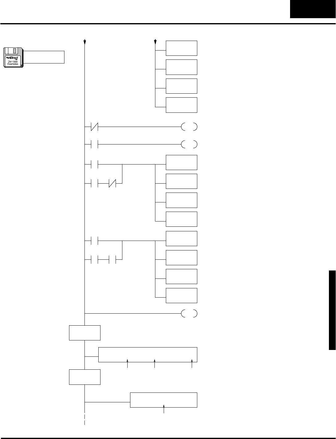
D
i
s
p
l
a
y
i
n
g
M
e
s
s
a
g
e
s
w
i
t
h
D
i
r
e
c
t
V
I
E
W
1
0
0
0
M
e
s
s
a
g
e
D
i
s
p
l
a
y
M
o
d
e
4
-
-
3
7
Message DisplayMode
LD
K4d41
OUT
V2114
LD
K4e20
SP0X0
C0
OUT
V2115
Load the ASCII codesfor “MA”.
Placethe ASCII codesinthe textdata block
location corresponding totextdisplayposition
14.
Load the ASCII codesfor “N”.
Placethe ASCII codesinthe textdata block
location corresponding totextdisplayposition
15.
OUT
V2114
LD
K544f
SP0X0
C1
OUT
V2115
Load the ASCII codesfor “AU”.
Placethe ASCII codesinthe textdata block
location corresponding totextdisplayposition
14.
Load the ASCII codesfor “TO”.
Placethe ASCII codesinthe textdata block
location corresponding totextdisplayposition
15.
DLBL
K1
ACON
MACHINE STATUS:MODE=
Screen FormDataThe Data Labelboxreferenced byK1,preceeds
the following ACONbox.
ThisACONbox contains32 characters.Besure
tocarefully count the spacestomatchthe
display.
END AnEND coil marks the end of the main program.
LD
K4155
DLBL
K2
ACONThisACONbox contains32 space characters.
Besuretocarefully count the spacestomatch
the display.
PDActivatecontrolrelayC0for1scan when X0
goesfromOntoOff.
C0
X0
PDActivatecontrolrelayC1for1scan when X0
goesfromOff toOn.
C1
X0
LD
K10
LD
K0
LDLBL
K2
MOVMC
V2120
Load the numberofdatalocations,whichis16
words(10 hex),or32 characters.
Load the address offset. Fornearlyevery
MOVMCused forACONdata, therewill be zero
offset(useK0).
Read fromthe ACONfollowing Data LabelK2.
Move dataintoV-memory starting atV2120,
corresponding tothe bottomtwolineson the
display.
spaces:32
spaces:1 3 9
(continued)
a:\msg11.prj
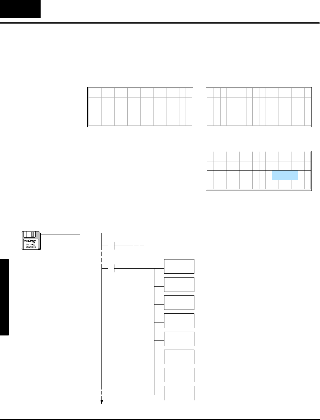
M
e
s
s
a
g
e
D
i
s
p
l
a
y
M
o
d
e
4
-
-
3
8
Message DisplayMode
Undercertainconditions such asalarm orfaultreporting you maywant toimplement
blinking (orflashing)text. Building on the previousexample,we add an ALARMS
category. If there are no alarms, the text field afterthe word“ALARMS”isblank. If
thereisan alarm condition such asa partjam, the word”JAM” will appearinthe text
field and blinkata1Hzrate.
7654321076543210
M A C H I N E S T A T U S
M O D E = A U T O
ALARMS= J A M
7654321076543210
MACHINE STATUS
M O D E = M A N
ALARMS=
X0=Off,X1=Off X0=On,X1=On
Now wecan decide howtowritethe
blinking textladderprogram.We’ll use
the ACONtextentrymethod forthe basic
form of the screen,whichwill include
“MACHINE STATUS,MODE=”,and
“ALARMS=”.The blinking textwill occupy
textpositions25 and 26.7654321076543210
0
37
20
11
2
22
31 33
13
4
24
35
17
61357
27
36343230
10 16
2321
12
Blinking TextDisplay Positions
1514
2625
The following programbuildson the dynamictextexample. It uses specialrelay
SP4,which alternatesbetween On and Off ata 1 Hzratetocreatethe blinking effect.
(Setup Parameter rung here)
SP0
Load FormTextData
LD
K10
LD
K0
LDLBL
K1
SP0
MOVMC
V2100
Load the numberofdatalocations,whichis16 words
(10 hex),or32 characters.
Load the address offset. FornearlyeveryMOVMC
used forACONdata, therewill be zero offset(useK0).
Read fromthe ACONfollowing Data LabelK1.
Move dataintoV-memory starting atV2100,
corresponding tothe top twolineson the display.
LD
K10
LD
K0
LDLBL
K2
MOVMC
V2120
Load the numberofdatalocations,whichis16 words
(10 hex),or32 characters.
Load the address offset. FornearlyeveryMOVMC
used forACONdata, therewill be zero offset(useK0).
Read fromthe ACONfollowing Data LabelK2.
Move dataintoV-memory starting atV2120,
corresponding tothe bottomtwolineson the display.
Top 2Lines
Bottom2Lines
Note:Ifusing DL105 be sureCPUisinitialized
tomake inputsX0 and X1operational.
Blinking Text
a:\msg12.prj

D
i
s
p
l
a
y
i
n
g
M
e
s
s
a
g
e
s
w
i
t
h
D
i
r
e
c
t
V
I
E
W
1
0
0
0
M
e
s
s
a
g
e
D
i
s
p
l
a
y
M
o
d
e
4
-
-
3
9
Message DisplayMode
LD
K4D41
OUT
V2114
LD
K4E20
SP0X0
C0
OUT
V2115
Load the ASCII codesfor “MA”.
Placethe ASCII codesinthe textdata block
location corresponding totextdisplayposition
14.
Load the ASCII codesfor “N”.
Placethe ASCII codesinthe textdata block
location corresponding totextdisplayposition
15.
LD
K4155
OUT
V2114
LD
K544f
SP0X0
C1
OUT
V2115
Load the ASCII codesfor “AU”.
Placethe ASCII codesinthe textdata block
location corresponding totextdisplayposition
14.
Load the ASCII codesfor “TO”.
Placethe ASCII codesinthe textdata block location
corresponding totextdisplayposition 15.
PDActivatecontrolrelayC0for1scan when X0
goesfromOntoOff.
C0
X0
PDActivatecontrolrelayC1for1scan when X0
goesfromOff toOn.
C1
X0
PDActivatecontrolrelayC2for1scan when X1
goesfromOntoOff, orwhen X1ison and SP4
goesfromOntoOff.
C2
X1
PDActivatecontrolrelayC3for1scan when X1is
on and SP4 goesfromOff toOn.
C3
X1
LD
K2020
OUT
V2125
SP0X1
C2
OUT
V2126
Load the ASCII codesforspaces,in orderto
blankthe text thatblinks.
Placethe ASCII codesinthe textdata block
location corresponding totextdisplayposition 25.
Placethe ASCII codesinthe textdata block
location corresponding totextdisplayposition 26.
LD
K4a41
OUT
V2125
LD
K4d20
SP0X1
C3
OUT
V2126
Load the ASCII codesfor “JA”.
Placethe ASCII codesinthe textdata block
location corresponding totextdisplayposition 25.
Load the ASCII codesfor “M”.
Placethe ASCII codesinthe textdata block location
corresponding totextdisplayposition 26.
SP4
X1SP4
BlinkOff
BlinkOn
Manual
Auto
SP4=1Hz
(continued)
a:\msg12.prj
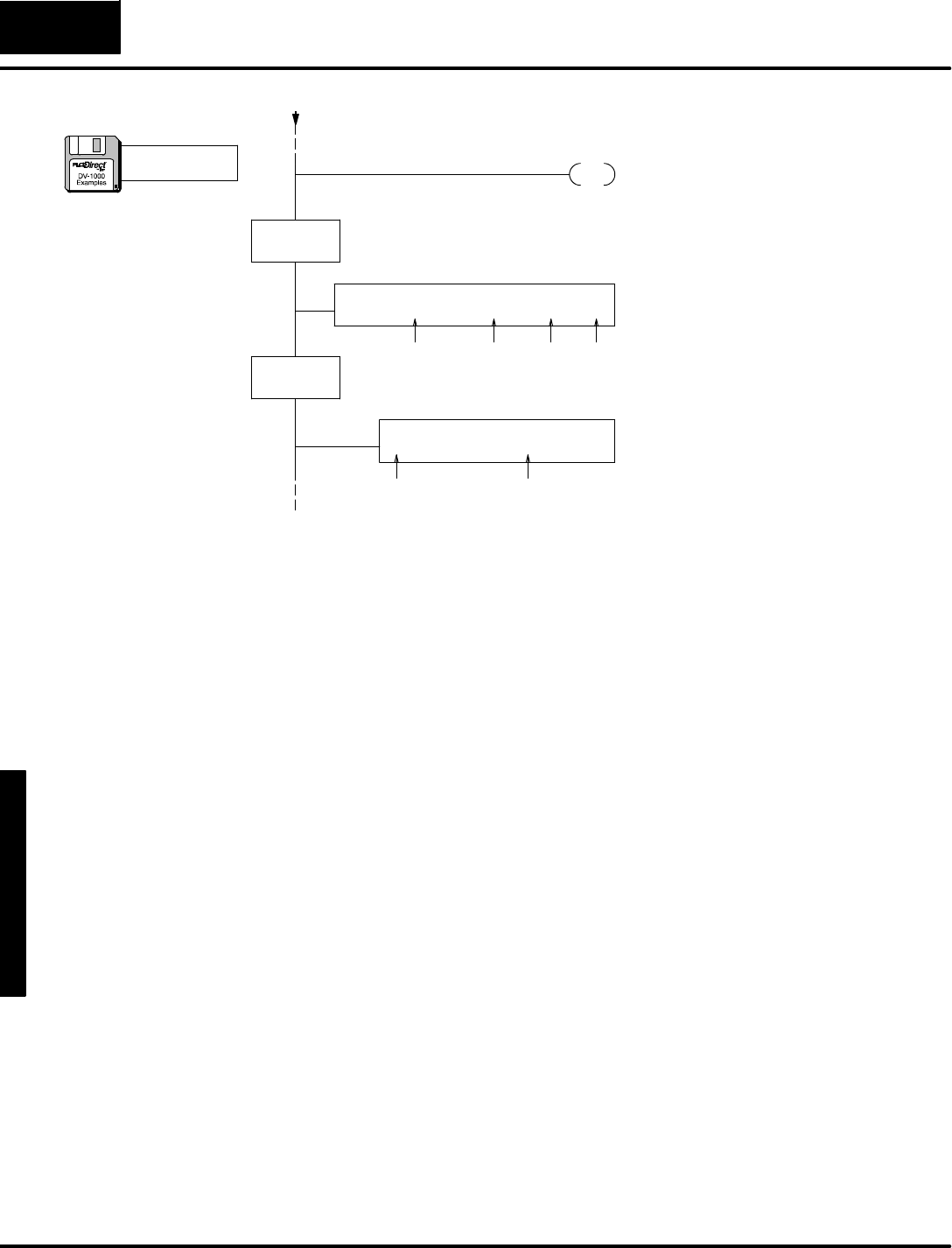
M
e
s
s
a
g
e
D
i
s
p
l
a
y
M
o
d
e
4
-
-
4
0
Message DisplayMode
DLBL
K1
ACON
MACHINE STATUS:MODE=
Screen FormDataThe Data Labelboxreferenced byK1,preceeds
the following ACONbox.
ThisACONbox contains32 characters.Besure
tocarefully count the spacestomatchthe
display.
END PlaceanEND coil,marking the end of the main
program.
ACON
ALARMS=
ThisACONbox contains32 characters.Besure
tocarefully count the spacestomatchthe
display.
DLBL
K2
spaces:23
spaces:1 3 1 9
2
(continued)
a:\msg12.prj
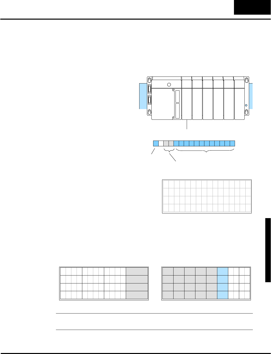
D
i
s
p
l
a
y
i
n
g
M
e
s
s
a
g
e
s
w
i
t
h
D
i
r
e
c
t
V
I
E
W
1
0
0
0
M
e
s
s
a
g
e
D
i
s
p
l
a
y
M
o
d
e
4
-
-
4
1
Message DisplayMode
Withthe DV-1000 you can use plus(+)or minus(--) characterstoindicatethe
algebraic sign ofnumericoutput. Tocoordinate numericand textoutput, the ladder
program mustexamine the sign bit forthe value and then select the appropriate
polarity sign fordisplaypurposes.Sign bitsoften occurwith bipolarinputsoroutputs
with analog modules,asinthe following example.
T
o
t
h
e
r
i
g
h
t
i
s
a
t
y
p
i
c
a
l
a
n
a
l
o
g
inputmoduleinstallation. Its
inputwordmapstoV40400.
However, the inputwordis
shared among fourchannelsof
the analog module. Onlyone
channel isactive on eachscan.
Ladderlogicdecodesthe active
channelbits,and storeseach
channel’sdataseparately.
Inthisfashion,one channel’s
dataisupdated eachscan .We
attachtothisprocess the task of
re--writing thatchannel’spolarity
sign inthe textoutput.
16pt
Input
Analog Module
V40400
X0
--
X17
MSB LSB
DataBits
Active
C
h
a
n
n
e
l
B
i
t
s
Sign Bit
Inthisexample,numericdisplay
positions0,4,10,and 14 showthe value
foreach of the fourchannels.The
remainderof the displayarea istext
output, including the (+)and (--)
characters.
7654321076543210
A n a l o g C h 1 +3 2 9 3
I n p u t s C h 2 -2 4 1 8
C h 3 +1 6 4 4
C h 4 -5 7 6 5
The textdisplayis created using twoACONboxinstructions.Then,ladderlogic
unmasks the eight textlocations corresponding tothe fournumericpositionsby
writing null characters.Then activechannelbitsX14 and X15 are examined and the
appropriate polarity characteriswritten totextpositions5,15,25,and 35.
respectively.
7 6 5 4 3 2 1 0 7 6 5 4 3 0
3
7 6 5 4 0 3 2 1 0
37
26 27
36
2 1
13 11
6
16
7
1517
12
NumericDisplay PositionsTextDisplay Positions
16 17
6 7
5 4
2 1
14
10
0
20
30
10 11
31
1
21
3 2
2
22
32
12
1
33
3
23
13
7 6
4
24
34
14
5 4
35
5
25
15
0
NOTE:Thisprogramexampleiswritten forthe systemwiththe analog moduleinslot
0.Ifyou want to use a 16-pointinputsimulatorinstead,itwill alsowork.
The following ladderprogramexamplecreatesthe displayofsigned numbers. It is
written forthe PLCsystemshown above.
PolaritySign for
NumericOutput

M
e
s
s
a
g
e
D
i
s
p
l
a
y
M
o
d
e
4
-
-
4
2
Message DisplayMode
(Setup Parameter rung here)
SP0
Load FormTextData
LD
K10
LD
K0
LDLBL
K1
SP0
MOVMC
V2100
Load the numberofdatalocations,whichis16 words
(10 hex),or32 characters.
Load the address offset. FornearlyeveryMOVMC
used forACONdata, therewill be zero offset(useK0).
Read fromthe ACONfollowing Data LabelK1.
Move dataintoV-memory starting atV2100,
corresponding tothe top twolineson the display.
LD
K10
LD
K0
LDLBL
K2
MOVMC
V2120
Load the numberofdatalocations,whichis16 words
(10 hex),or32 characters.
Load the address offset. FornearlyeveryMOVMC
used forACONdata, therewill be zero offset(useK0).
Read fromthe ACONfollowing Data LabelK2.
Move dataintoV-memory starting atV2120,
corresponding tothe bottomtwolineson the display.
Top 2Lines
Bottom2Lines
LDD
K0
OUTD
V2106
OUTD
V2116
OUTD
V2126
OUTD
V2136
Load zerosforthe null ASCII character, for
unmasking numericoutputon the display.
Unmask textpositions6 and 7,corresponding to
numericoutputposition 0.
Unmask textpositions16 and 17,corresponding to
numericoutputposition 4.
Unmask textpositions26 and 27,corresponding to
numericoutputposition 10.
Unmask textpositions36 and 37,corresponding to
numericoutputposition 14.
Unmask
NumericOutput
LD
K202b
Load the ASCII codesforaspaceandaplussign
when the sign bitisnotset.
ReadSign Bit,
Create+/-- Sign
LD
VX0
X17
Load the inputwordfromV-memory corresponding to
YinputsY0toY17.
Mask off the upperfourbits,preserving the analog
value represented bythe lower12 bitsof the data
word.
ANDD
Kfff
BCD Convert the 12-bitbinary value toa4-digitBCD
number (range is0to 4095,notcounting the sign bit).
Ch1
LD
K202d
Load the ASCII codesforaspaceandaminussign
when the sign bitis set.
X17
SP1
LoadAnalog InputWord
a:\msg13.prj

D
i
s
p
l
a
y
i
n
g
M
e
s
s
a
g
e
s
w
i
t
h
D
i
r
e
c
t
V
I
E
W
1
0
0
0
M
e
s
s
a
g
e
D
i
s
p
l
a
y
M
o
d
e
4
-
-
4
3
Message DisplayMode
OUT
V2000
X15 Channel1 dataisbeing sentwhen X15 and X14 are
off. The Outinstruction movesthe datafromthe
accumulatortoV2000,numericdisplayposition 1.
X14
Movethe ASCII dataforthe algebraic sign fromthe
stack intothe accumulator.
POP
OUT
V2105
Placethe accumulatorcontents(algebraic sign in
ASCII code)intothe textdisplayposition 5, for
channel1.
END PlaceanEND coil,marking the end of the main
program.
DLBL
K1
ACON
Analog Ch1 InputsCh2
Screen TextDataThe Data Labelboxreferenced byK1,preceeds
the following ACONbox.
ThisACONbox contains32 characters.Besure
tocarefully count the spacestomatchthe
display.
DLBL
K2
ACON
Ch3 Ch4
ThisACONbox contains32 characters.Besure
tocarefully count the spacestomatchthe
display.
The Data Labelboxreferenced byK1,preceeds
the following ACONbox.
Ch2
Ch3
Ch4
Ch1
OUT
V2004
X15 Channel2 dataisbeing sentwhen X15 isoff and X14
ison.The Outinstruction movesthe datafromthe
accumulatortoV2004,numericdisplayposition 4.
X14
Movethe ASCII dataforthe algebraic sign fromthe
stack intothe accumulator.
POP
OUT
V2115
Placethe accumulatorcontents(algebraic sign in
ASCII code)intothe textdisplayposition 15, for
channel2.
OUT
V2010
X15 Channel3 dataisbeing sentwhen X15 ison and X14
isoff. The Outinstruction movesthe datafromthe
accumulatortoV2010,numericdisplayposition 10.
X14
Movethe ASCII dataforthe algebraic sign fromthe
stack intothe accumulator.
POP
OUT
V2125
Placethe accumulatorcontents(algebraic sign in
ASCII code)intothe textdisplayposition 5, for
channel3.
OUT
V2014
X15 Channel4 dataisbeing sentwhen X15 and X14 are
on.The Outinstruction movesthe datafromthe
accumulatortoV2014,numericdisplayposition 14.
X14
Movethe ASCII dataforthe algebraic sign fromthe
stack intothe accumulator.
POP
OUT
V2135
Placethe accumulatorcontents(algebraic sign in
ASCII code)intothe textdisplayposition 35, for
channel4.
spaces:1 6 6
7 13spaces:6
1
(continued)
a:\msg13.prj
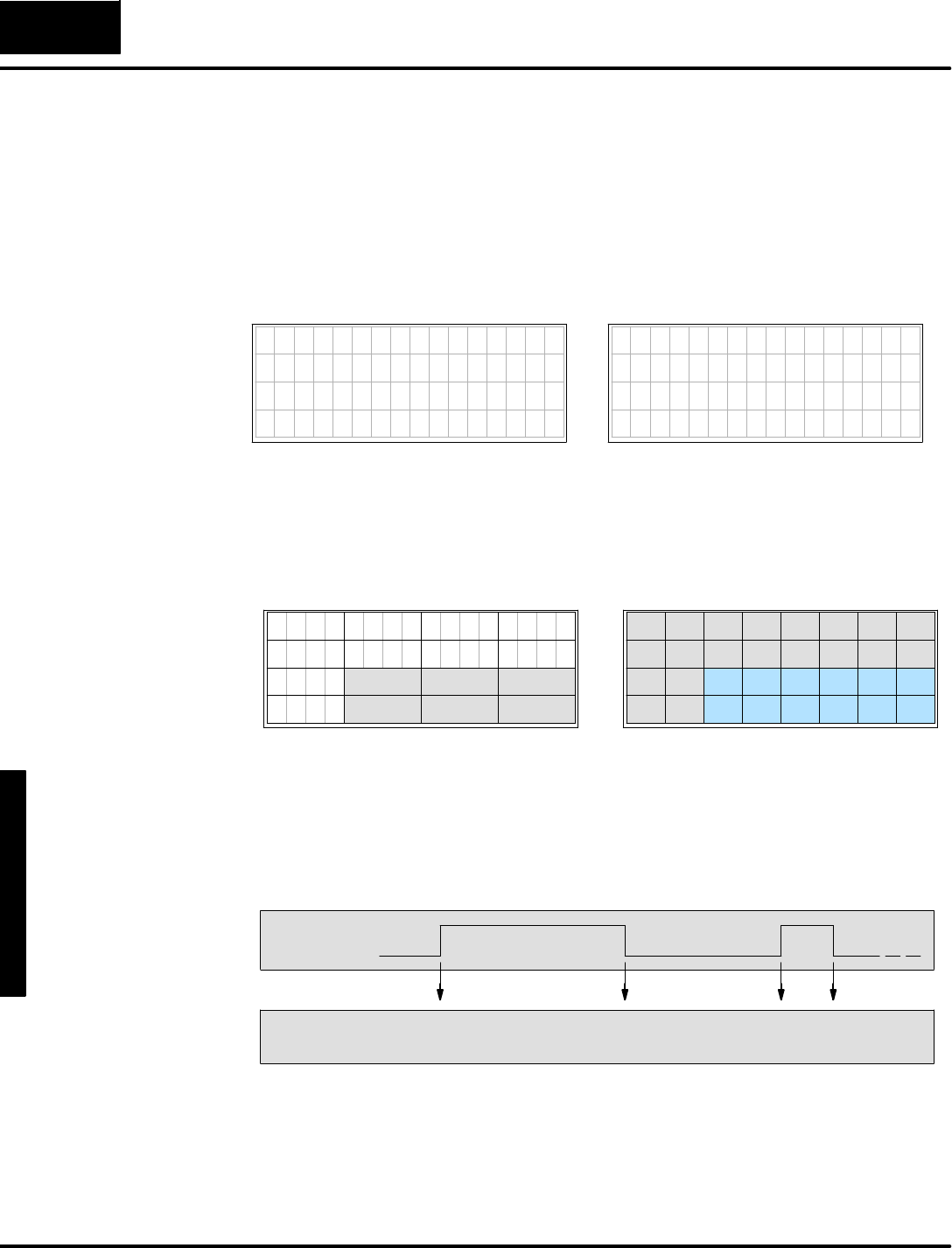
M
e
s
s
a
g
e
D
i
s
p
l
a
y
M
o
d
e
4
-
-
4
4
Message DisplayMode
Insome applications you maywant to embed time and dateinformation in a
message displayoutput. The DL240,DL250,DL350,DL440 and DL450 CPUshave
built-inreal-timeclocks. Inatypicalapplication, the time and date are displayed
when a systemfaultoccurs,along withthe fault type.The example programinthis
section shows you howtocreatethe displayoutputbelow. Onthe left, the display
showsa basictext form without the faultcondition.When the particularfault“Bin
Empty”occurs, the displayfillsinthe fault, time,and datefieldsinthe form,shown on
the right.
NormalDisplay,X0=Off
7654321076543210
MACHINE STATUS
F a u l t =
T i m e =
D a t e =
FaultDisplay,X0=On
7654321076543210
MACHINE STATUS
F a u l t = B i n E m p t y
Time =11:32:57AM
Date =07/05/95
The programusesacombination ofACONboxes,LD/OUTand LDD/OUTD
instructionstocreatethe textportion of the display.The sixnumericdisplaypositions
contain both numbersand text formatting characters such as”:”or “/”. Insome
cases, the numbershaveto be shifted to align themwiththe formatting characters.
7 6 5 4 3 2 1 0 7 6 5 4 3 0
3
7 6 5 4 0 3 2 1 0
2 1
13
67
17
NumericDisplay PositionsTextDisplay Positions
16 17
6 7
5 4
2 1
14
10
0
20
30
10 11
31
1
21
3 2
2
22
32
12
1
33
3
23
13
7 6
4
24
34
14
5 4
35
5
25
15
0
12
16
11
15
26 27
36 37
The following diagramshowsthe state of the faultinputsignaland the resulting
displayactions. Ourexampleladderprogram monitorsthe state of the faultsignal
through discreteinputX0. Inthe Off-to-Ontransition, the ladderprogramwrites“Bin
Empty”,and fillsinthe time and date data.When inputX0makesthe On-to-Off
transition, the programerasesthe “BinEmpty” message and the time and date
information.Futuretransitionsof the X0signalcausethe same displayupdates.
OFF
Fault
ON
Display
Updates
WRITE“BinEmpty”
WRITEtime and date
ERASE “BinEmpty”
ERASE time and date
WRITE
(same)
ERASE
(same)
Ateach displayupdate, the ladderprogramneedsonlytowritethe newtextoutput
datatothe textdata block one time.So, the programusesaPD(positive differential)
coil tosense bothOff-to-On and On-to-Off transitionsofX0.The controlrelays C0
and C1 areonforjustone scan,respectively. Inthiswaythe ladderprogramonlyhas
to displayupdateswhen the faultsignalX0makesatransition,greatlyminimizing
anyimpact tothe PLCscan time.
Embedded Time
and Date
(DL240,DL250,
DL350,DL440 and
DL450 CPUsOnly)
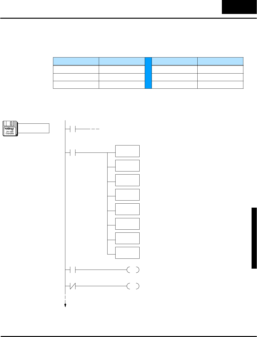
D
i
s
p
l
a
y
i
n
g
M
e
s
s
a
g
e
s
w
i
t
h
D
i
r
e
c
t
V
I
E
W
1
0
0
0
M
e
s
s
a
g
e
D
i
s
p
l
a
y
M
o
d
e
4
-
-
4
5
Message DisplayMode
Real-timeclock dataisavailableinsystemV-memory(DL240,DL250,DL350,
DL440 and DL450 CPUs),at the addressesinthe table below. If the current time and
dateinyourPLCrequires setting,useDirectSOFT’smenu “PLC”, then “Settings”,
then “Calendar”.
TimeDataLocation DateDataLocation
HoursV7770 DayV7772
MinutesV7767 MonthV7773
SecondsV7766 YearV7774
The following program reportsthe time and datewhen the errorinputX0turnson.
The display clearsthe information when X0turnsoff.
(Setup Parameter rung here)
SP0
LD
K10
LD
K0
LDLBL
K1
MOVMC
V2100
SP0
PDActivatecontrolrelayC0for1scan when X0 goesfrom
Off toOn.
C0
X0
PDActivatecontrolrelayC1for1scan when X0 goesfrom
OntoOff.
C1
X0
WriteBasicMessageForm
Load the numberofdatalocations,whichis16 words
(10 hex),or32 characters.
Load the address offset. FornearlyeveryMOVMC
used forACONdata, therewill be zero offset(useK0).
Read fromthe ACONfollowing Data LabelK1.
Move dataintoV-memory starting atV2100,
corresponding tothe top line on the display.
LD
K10
LD
K0
LDLBL
K2
MOVMC
V2120
Load the numberofdatalocations,whichis16 words
(10 hex),or32 characters.
Load the address offset. FornearlyeveryMOVMC
used forACONdata, therewill be zero offset(useK0).
Read fromthe ACONfollowing Data LabelK2.
Move dataintoV-memory starting atV2120,
corresponding tothe bottomtwolineson the display.
Top Line
Bottom2Lines
a:\msg14.prj
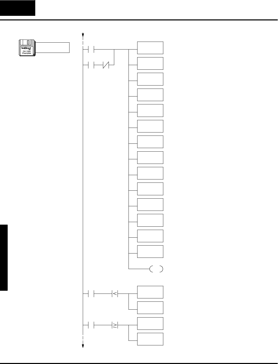
M
e
s
s
a
g
e
D
i
s
p
l
a
y
M
o
d
e
4
-
-
4
6
Message DisplayMode
LDD
K3d20
Load the ASCII codestwo null characters(0000),
followed bythe ASCII codesfor“=”.
OUTD
V2122
Placethe characters“=”tothe rightof“Time”,on the
thirdrowof the display,and unmask the twocharacter
positionsforthe hoursdigits.
LDD
K3a3a00
OUT
V2124
Placethe colonson the thirdline of the displayforthe
time output, and placethe null characters sothey
unmask the minutesdigits.
OUTUsecontrolrelay contactC2to extend the logicof this
rung tomorerungs, toAND withrelationalcontacts.
LDD
K3d20
Load the ASCII codesfortwo null characters(0000),
followed bythe ASCII codesfor“=”.
OUTD
V2132
LDD
K2f2f00
OUTD
V2134
LDD
K414d0000
If the hours value isless than 12, then load the ASCII
codesfor “AM”.The null characters(0000)unmasks
the minutesdigits.
OUTD
V2126
Placethe “AM”characterstothe rightof the time
displayon the thirdrow.
C2
Load the ASCII codesforacolon, two null characters,
and anothercolon.
Placethe characters“=”tothe rightof“Date”,on the
fourthrowof the display,and unmask the two
characterpositionsforthe yearsdigits.
Load the ASCII codesfora“/”, two null characters,
and another “/”.
Placethe “/”characterson the fourthline of the
displayforthe date output, and placethe null
characters sotheyunmask the month digits.
LDD
K20200000
OUTD
V2136
Load the ASCII codesfortwospaces, followed bytwo
null characters.
Placethesecharacterson the fourthline.The null
charactersunmask the yeardigits,and the spaces
mask the last twocharacterpositions.
C2
V7770 K12
LDD
K504d0000
OUTD
V2126
Hours,AMand PM
LD
K8
LD
K0
LDLBL
K3
SP0X0
C0
WriteFaultMessage
MOVMC
V2110
Load the numberofdatalocations,whichis8words
(16 characters).
Load the address offset. FornearlyeveryMOVMC
used forACONdata, therewill be zero offset(useK0).
Read fromthe ACONfollowing Data LabelK3.
Move dataintoV-memory starting atV2110,
corresponding tothe second line of the display.This
writesthe fault type tothe display.
C2V7770 K12 If the hours value is12 orgreater, then load the ASCII
codesfor “PM”.The null characters(0000)unmasks
the minutesdigits.
Placethe “PM”characterstothe rightof the time
displayon the thirdrow.
(continued)
a:\msg14.prj
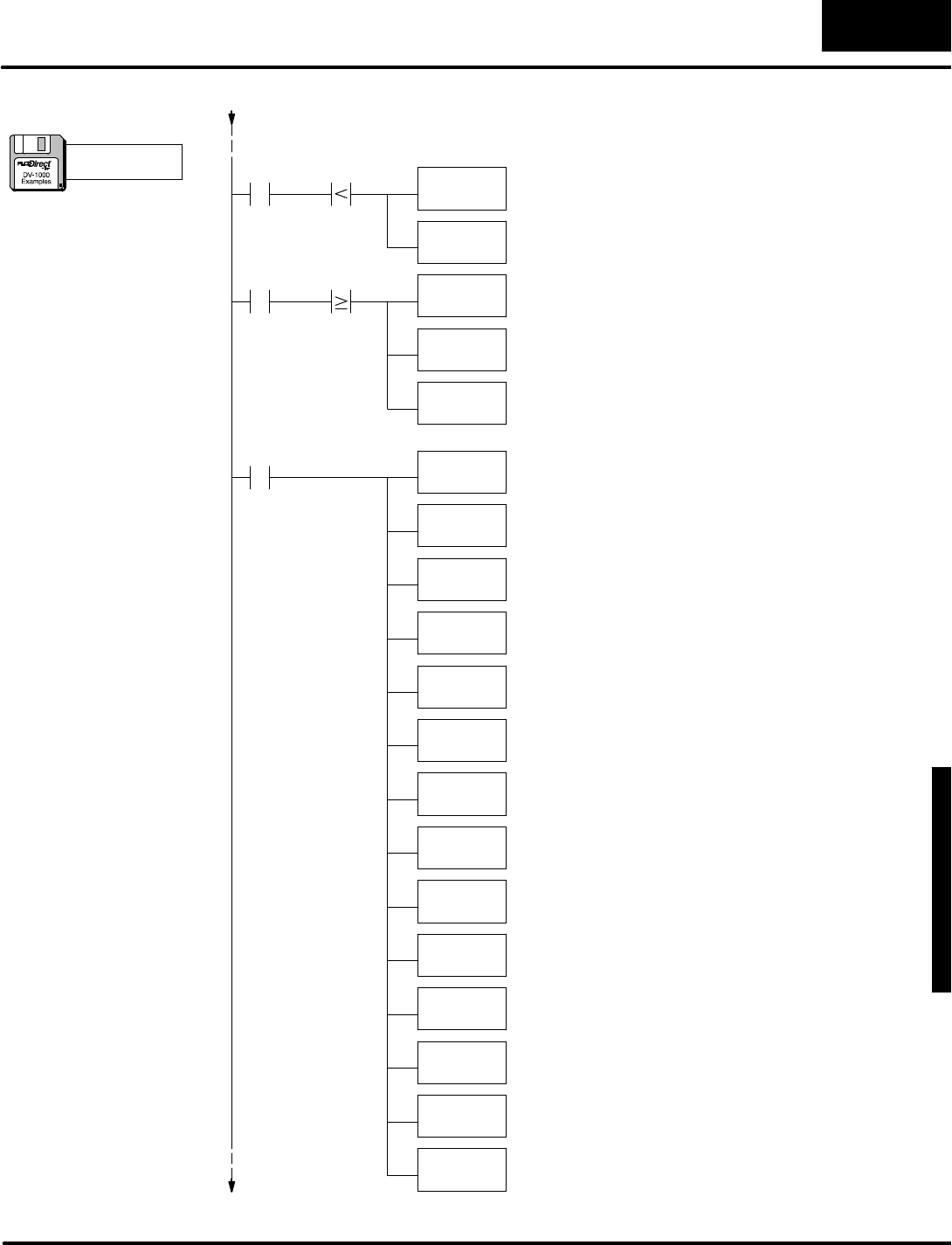
D
i
s
p
l
a
y
i
n
g
M
e
s
s
a
g
e
s
w
i
t
h
D
i
r
e
c
t
V
I
E
W
1
0
0
0
M
e
s
s
a
g
e
D
i
s
p
l
a
y
M
o
d
e
4
-
-
4
7
Message DisplayMode
LD
V7767
SHFL
K4
Shift the minutesdigitsone digit(4 bits)tothe left in
the accumulator.
C2
LD
V7770
OUTD
V2012
C2V7770 K13 LD
V7770
Load the hours value fromthe real-timeclock source
inV-memoryintothe accumulator.
SUBD
K12
Subtract12 fromthe hours value.This converts
24-hourtimeto 12-hourtimeconvention.
OUTD
V2012
Placethe hoursdigitsinthe propernumericposition on
the thirdrow.
OUT
V2011
Placethe minutesdigitsinthe propernumericposition
on the thirdrow.
Load the minutes value fromthe real-timeclock
sourceinV-memoryintothe accumulator.
LD
V7766
SHFL
K8
Shift the secondsdigitstwo digits(8 bits)tothe left in
the accumulator.
OUT
V2010
Placethe secondsdigitsinthe propernumericposition
on the thirdrow.
Load the seconds value fromthe real-timeclock
sourceinV-memoryintothe accumulator.
LD
V7773
Load the monthvalue fromthe real-timeclock source
inV-memoryintothe accumulator.
OUT
V2016
Placethe month digitsinthe propernumericposition
on the fourthrow.
LD
V7772
SHFL
K4
Shift the daydigitsone digit(4 bits)tothe left inthe
accumulator.
OUT
V2015
Placethe daydigitsinthe propernumericposition on
the fourthrow.
Load the day value fromthe real-timeclock sourcein
V-memoryintothe accumulator.
LD
V7774
SHFL
K8
Shift the yeardigitstwo digits(8 bits)tothe left inthe
accumulator.
OUT
V2014
Placethe yeardigitsinthe propernumericposition on
the fourthrow.
Load the yearvalue fromthe real-timeclock sourcein
V-memoryintothe accumulator.
Minutes
Seconds
Day
Month
Year
24-hrto12-hrClock
C2V7770 K13 Load the hours value fromthe real-timeclock source
inV-memoryintothe accumulator.
Placethe hoursdigitsinthe propernumericposition on
the thirdrow.
(continued)
a:\msg14.prj

M
e
s
s
a
g
e
D
i
s
p
l
a
y
M
o
d
e
4
-
-
4
8
Message DisplayMode
Usethe ASCII Constant(ACON)boxto entertext
forthe top twolinesof the display.Itcontains32
characters,counting the spaces.
DLBL
K1
ACON
MACHINE STATUSFault=
DataforTop 2Display Lines
DLBL
K2
ACON
Time=Date=
DataforBottom2Display Lines
LD
K20202020
OUT
V2113
OUTD
V2114
SP0X0
C1
ClearFaultMessage
Load the ASCII codesfor4spacesintothe
accumulator.
Cleartextposition 13.
Cleartextpositions14 and 15.
OUTD
V2116
Cleartextpositions16 and 17.
OUT
V2123
OUTD
V2124
Cleartextposition 23.
Cleartextpositions24 and 25.
OUTD
V2126
Cleartextpositions26 and 27.
OUT
V2133
OUTD
V2134
Cleartextposition 33.
Cleartextpositions34 and 35.
OUTD
V2136
Cleartextpositions36 and 37.
END PlaceanEND coil,marking the end of the main
program.
Usethe ASCII Constant(ACON)boxto entertext
forthe top twolinesof the display.Itcontains32
characters,counting the spaces.
DLBL
K3
ACON
Fault=BinEmpty
DataforSecond Display Line
Usethe ASCII Constant(ACON)boxto entertext
forthe second line of the display.Itcontains16
characters,counting the spaces.
spaces:1 2 10
spaces:10 10
spaces:1 1
1 1
(continued)
a:\msg14.prj
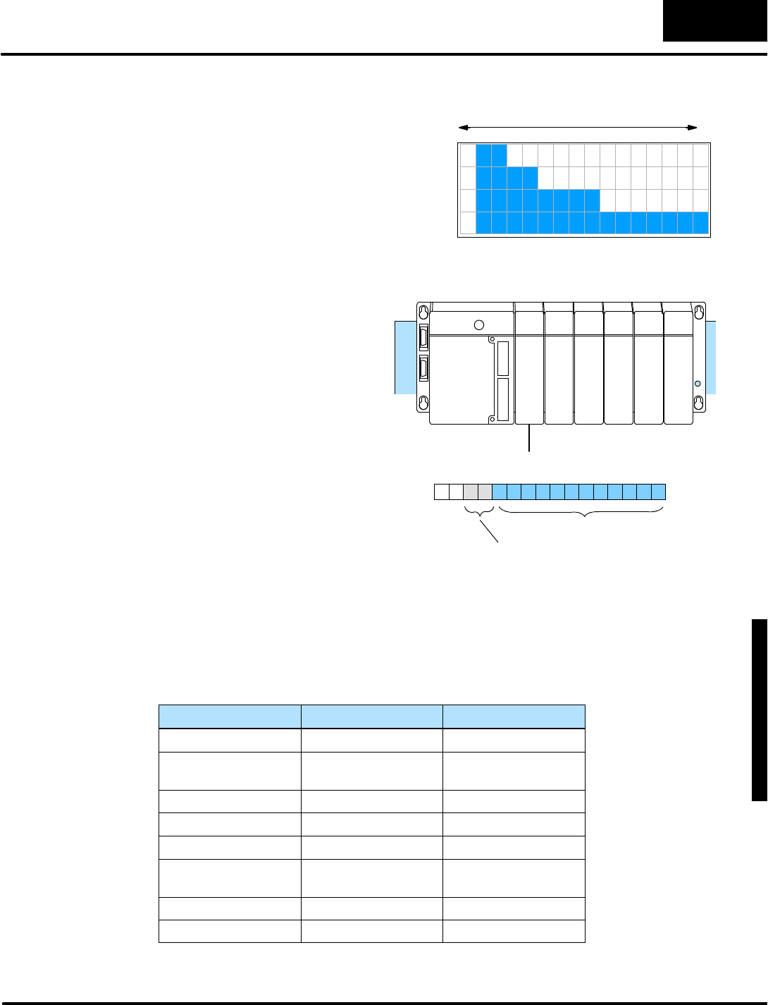
D
i
s
p
l
a
y
i
n
g
M
e
s
s
a
g
e
s
w
i
t
h
D
i
r
e
c
t
V
I
E
W
1
0
0
0
M
e
s
s
a
g
e
D
i
s
p
l
a
y
M
o
d
e
4
-
-
4
9
Message DisplayMode
T
h
i
s
e
x
a
m
p
l
e
c
r
e
a
t
e
a
f
o
u
r
-
c
h
a
n
n
e
l
l
i
n
e
a
r
bargraph using the DV-1000’sextended
ASCII characterset. The ASCII code FF
(hex)producesasolid block character.
The ladderprogramgeneratestextoutput
to displayarowof thesecharacterswhose
lengthisproportionalto a numericalvalue.
The remainderofeachrowconsistsof
spaces(20 hex).This createsthe bar
graph effect. 7654321076543210
1
2
3
4
B
a
r
g
r
a
p
h
D
i
s
p
l
a
y
minmax
T
h
e
f
i
g
u
r
e
t
o
t
h
e
r
i
g
h
t
s
h
o
w
s
a
analog inputmoduleinthe first
moduleslotinthe base. Itspoints
map toX0toX17,corresponding
to datawordV40400 in
V-memory. Itsinputwordis
shared among the fourchannels
of the analog module. Onlyone
channel isactive on eachscan.
Ladderlogicdecodesthe active
channelbits,and store each
channel’sdataseparately.
The bargraph displayupdateis
independent fromthe channel
value update process.
16pt
Input
Analog InputModule
V40400
V40403
X0
--
X17
V40401
MSB LSB
DataBits
Active
C
h
a
n
n
e
l
B
i
t
s
The ladderprogramtocreatethisdisplayupdatesonlyone textposition (two
characters)perCPUscan.The following tablelistslocation ofanalog valuesand
pointersthe programusestokeep track ofwhereitisinthe overall displayupdate.
Sincethere are 64 characters(32 textpositions)inthe display, the programisableto
updatethe entire displayevery32 CPUscans.The programaddsapproximatelyfive
millisecondstothe scan time ofaDL240 CPU.
Variable Location Range ofvalues
RawAnalog valuesV2200 -- V2203 0000 -- FFFF
Processed Analog
Values
V2204 -- V2207 0001 -- 0010
CharacterPointerV2210 0 -- 15
RowPointerV2211 0 -- 3
RawAnalog PointerV2212 O2200 -- O2203
Processed Analog
Pointer
V2213 O2204 -- O2207
TextDataPointerV2214 O2100 -- O2137
Scratchpad numberV2215 --
BarGraph Example
(DL240,DL250,
DL350,DL440 and
DL450 CPUsOnly)

M
e
s
s
a
g
e
D
i
s
p
l
a
y
M
o
d
e
4
-
-
5
0
Message DisplayMode
(Setup Parameter rung here)
SP0
LoadChannelDataValues
LD
V40400
SP1Load the contentsofV40400 (X0toX17)intothe
accumulator.
LD
K0
OUT
V2210
OUT
V2211
LDA
O2200
OUT
V2212
Load the constantK0intothe accumulator.
Initializethe characterpointertozero.Thispointsto
one of16 characterson the currentrow.
Load the octaladdress 2200 intothe accumulator.
V2200 isthe location of the rawanalog data.
Initializethe rawanalog value pointeratV2212 to
point tothe firstanalog value atV2200.
SP0
Firstscan only
Initializethe rowpointertozero.Thispointsto one of
4rowsofcharacterson the display.
LDA
O2204
OUT
V2213
Load the octaladdress 2204 intothe accumulator.
V2204 isthe location of the processed analog data.
Initializethe rawanalog value pointeratV2213 to
point tothe firstanalog value atV2204.
LDA
O2100
OUT
V2214
Load the octaladdress 2100 intothe accumulator.
V2100 isthe beginning ofdisplaytextdata.
Initializethe displaytextpointeratV2214 to point to
the first textdisplaylocation atV2100.
InitializeVariables
Ch1
OUT
V2200
X15 Channel1 dataisbeing sentwhen X15 and X14 are
off. The Outinstruction placesthe datainV2200,
storing the rawdataforchannel1.
X14
Ch2
OUT
V2201
X15 Channel2 dataisbeing sentwhen X15 isoff and X14
ison.The Outinstruction placesthe datainV2201,
storing the rawdataforchannel2.
X14
Ch3
OUT
V2202
X15 Channel3 dataisbeing sentwhen X15 ison and X14
isoff. The Outinstruction placesthe datainV2202,
storing the rawdataforchannel3.
X14
Ch4
OUT
V2203
X15 Channel4 dataisbeing sentwhen X15 and and X14
are off. The Outinstruction placesthe datainV2203,
storing the rawdataforchannel4.
X14
a:\msg15.prj
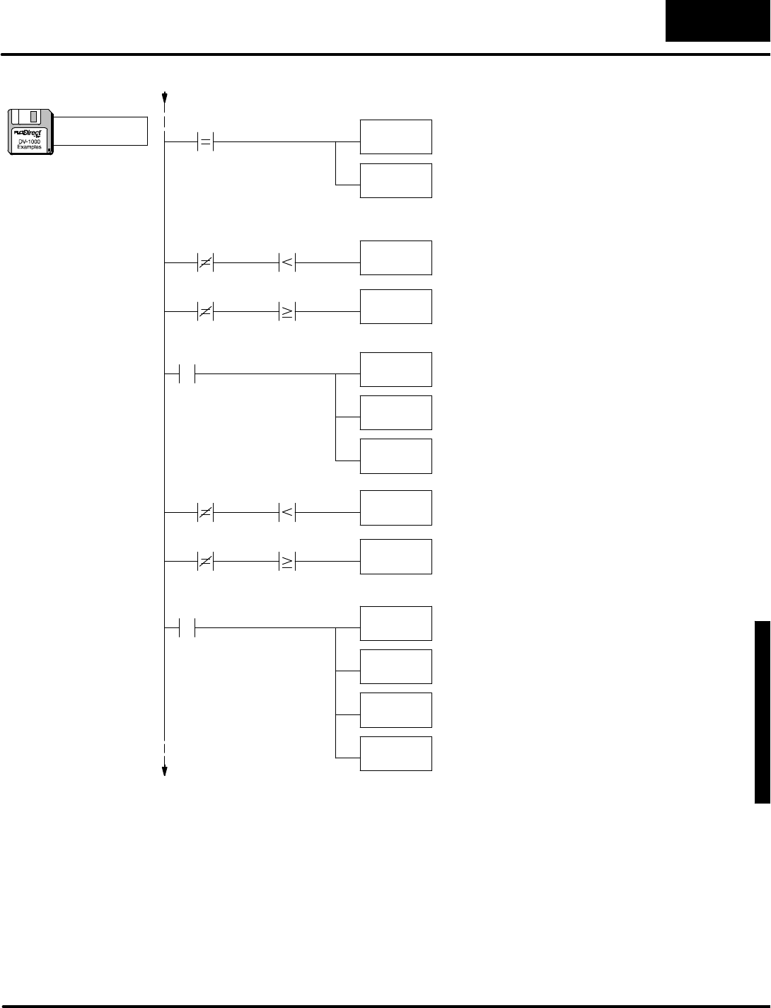
D
i
s
p
l
a
y
i
n
g
M
e
s
s
a
g
e
s
w
i
t
h
D
i
r
e
c
t
V
I
E
W
1
0
0
0
M
e
s
s
a
g
e
D
i
s
p
l
a
y
M
o
d
e
4
-
-
5
1
Message DisplayMode
LD
K31
ADD
V2211
LD
Kff
V2210
LD
K20
Load the ASCII constant for “1”intothe accumulator.
Wewill modifythiswith an offset tocreate numbers1
through 4.
Usethe rowdata asan offset forthe ASCII codes.
Thiswill numberthe displayasrows1through 4.
SHFL
K8
OUT
V2215
INCB
V2210
If the processed analog value isless than the
characterpointer,load the ASCII code forthe solid
block character (bargraph component)intothe
accumulator.
If the processed analog value isequalto orgreater
than the characterpointer,load the ASCII code for
the spacecharacter (blanks bargraph)intothe
accumulator.
Movethe “ff”or “20”intothe second nibble of the
accumulator.
Savethe accumulatorcontentsatV2215 whilewe
calculatethe lowernibble.
SP1
WriteBarGraph Components
W
r
i
t
e
C
h
a
n
n
e
l
L
a
b
e
l
s
K0
V2210 K0V2210 P2213
V2210 K0V2210 P2213
Increment the characterpointer,in ordertomakethe
nextcompare.
LD
Kff
LD
K20
If the processed analog value isless than the
characterpointer,load the ASCII code forthe solid
block character (bargraph component)intothe
accumulator.
If the processed analog value isequalto orgreater
than the characterpointer,load the ASCII code for
the spacecharacter (blanks bargraph)intothe
accumulator.
V2210 K0V2210 P2213
V2210 K0V2210 P2213
OR
V2215
OUT
P2214
INCB
V2210
Combine the contentsof the accumulator (lower
nibble)withthe saved contentsofV2215 (upper
nibble).We haveaword nowreadytowrite.
Writethe bargraph word(2characters)tothe proper
textposition’saddress,pointed tobyV2214.
SP1
Increment the characterpointer,in ordertomakethe
nextcompare.
INCB
V2214
Increment the textdata pointer,in ordertowriteto
the next textposition on the display.
(continued)
a:\msg15.prj

M
e
s
s
a
g
e
D
i
s
p
l
a
y
M
o
d
e
4
-
-
5
2
Message DisplayMode
LD
K0
OUT
V2210
V2210 Load “0”intothe accumulator.
Reset the characterpointeratV2210 tozero.
E
n
d
o
f
R
o
w
K10
INCB
V2211
Increment the rowpointeratV2211.
LD
P2212
Load the nextrawanalog value intothe accumulator
forprocessing.
ANDD
kfff
Mask off anybitsabovethe lower12 bits,such as
channelselectnumbers,etc.Thisasumes12-bit
analog values.
SHFR
K8
Discardthe lower8 bits,and usethe upper4 bitsto
scalethe value from0to15(0tofhex).
OUT
P2213
Writethe processed analog value tothe proper
address,pointed tobyV2213.
INCB
P2213
Increment the processed analog value pointer.
INCB
V2212
Increment the rawanalog value pointer.
INCB
V2213
Add one tothe processed analog value, toscaleit
from1to16(1to 10 hex).
LDA
O2200
OUT
V2212
V2211 Load the beginning address of the rawanalog values
intothe accumulator.
Reset the rawanalog value pointeratV2212 to point
toV2200.
K4
LDA
O2204
OUT
V2213
LDA
O2100
OUT
V2214
LD
K0
Load the constantzerointothe accumulator.
OUT
V2210
Reset the characterpointertozero.
OUT
V2211
Reset the rowpointertozero.
END PlaceanEND coil,marking the end of the program.
End ofDisplay
Load the beginning address of the processed analog
valuesintothe accumulator.
Reset the processed analog value pointeratV2213 to
point toV2204.
Load the beginning address of the textdata block into
the accumulator.
Reset the textdata pointeratV2214 to point to
V2100.
(continued)
a:\msg15.prj
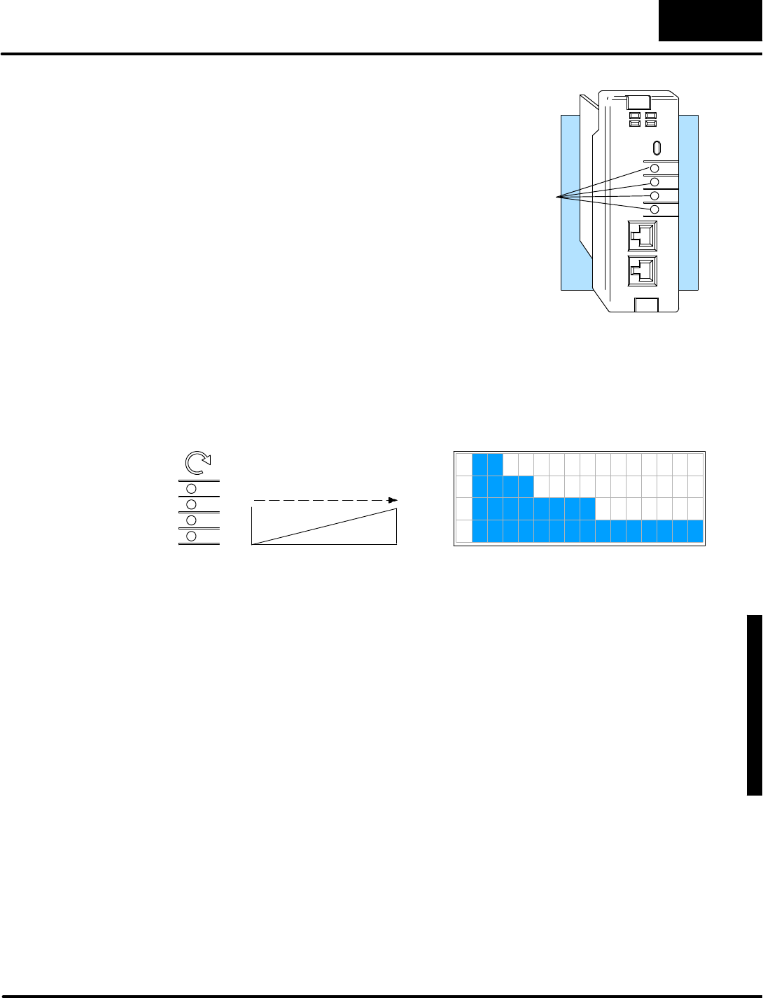
D
i
s
p
l
a
y
i
n
g
M
e
s
s
a
g
e
s
w
i
t
h
D
i
r
e
c
t
V
I
E
W
1
0
0
0
M
e
s
s
a
g
e
D
i
s
p
l
a
y
M
o
d
e
4
-
-
5
3
Message DisplayMode
The DL240 CPUfeaturesfourbuilt-in
analog potentiometers. Inthisexamplewe
modifythe previousbargraph programto
read thesefourinputs.The
potentiometersare accessibleonthe front
bezel withasmall screwdriver.These
potentiometersmap directlyintosystem
V-memoryas8-bitnumbers,having a
resolution of1 partin 256.
CH1
CH2
CH3
CH4
RUN
TERM
RUN
CPU
PWR
BATT
PORT1
PORT2
DL240
CPU
Analog Pots
The ladderlogicprogramtakesthe range of0to 255 and re-scalesit to 0 to 15. Inthis
way, the numberofsegmentson eachrowcan varyfrom0to 15,in proportion tothe
potentiometeradjustment.
7654321076543210
1
2
3
4
0
Turn clockwiseto
increasevalue.
Max
CH1
CH2
MinMax
Display Output
CH3
CH4
PotentiometerAdjust
Tosee thisprogramwork,justload the filefromdisk,and placethe PLC inRun Mode.
BarGraph
Example,
DL240 Analog
Potentiometers

M
e
s
s
a
g
e
D
i
s
p
l
a
y
M
o
d
e
4
-
-
5
4
Message DisplayMode
(Setup Parameter rung here)
SP0
LD
K0
OUT
V7640
OUT
V7642
LDA
V7644
OUT
V7646
Load the constantK0intothe accumulator.
Set the bottomofChannel1range tozero.
SP0
Firstscan only
LD
K15
OUT
V7641
Load the constantK15 intothe accumulator.
LDA
V7643
OUT
V7645
SetUpAnalog PotentiometerScalings
LD
K0
OUT
V2210
OUT
V2211
LDA
O3774
OUT
V2212
Load the constantK0intothe accumulator.
Initializethe characterpointertozero.Thispointsto
one of16 characterson the currentrow.
Load the octaladdress 3774 intothe accumulator.
V3774 isthe location of the analog data.
Initializethe rawanalog value pointeratV2212 to
point tothe firstanalog value atV2200.
SP0
Firstscan only
Initializethe rowpointertozero.Thispointsto one of
4rowsofcharacterson the display.
LDA
O2204
OUT
V2213
Load the octaladdress 2204 intothe accumulator.
V2204 isthe location of the processed analog data.
Initializethe rawanalog value pointeratV2213 to
point tothe firstanalog value atV2204.
LDA
O2100
OUT
V2214
Load the octaladdress 2100 intothe accumulator.
V2100 isthe beginning ofdisplaytextdata.
Initializethe displaytextpointeratV2214 to point to
the first textdisplaylocation atV2100.
InitializeVariables OUT
V7647
Set the bottomofChannel2range tozero.
Set the bottomofChannel3range tozero.
Set the bottomofChannel4range tozero.
Set the top ofChannel1range to 15.
Set the top ofChannel2range to 15.
Set the top ofChannel3range to 15.
Set the top ofChannel4range to 15.
a:\msg16.prj
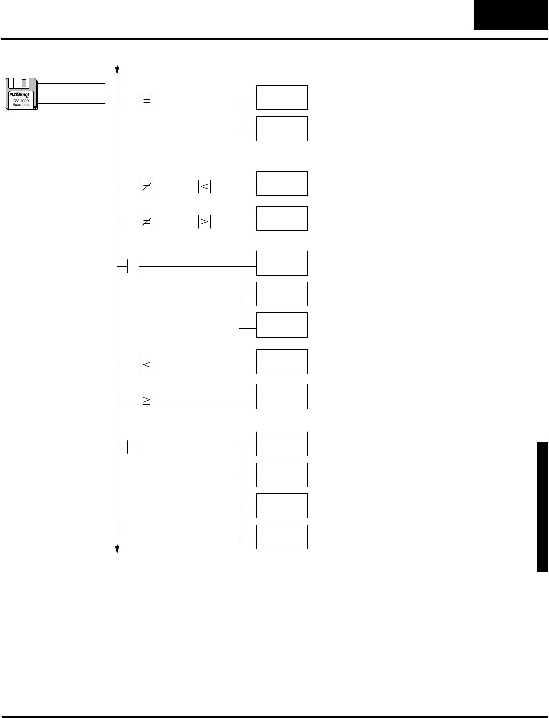
D
i
s
p
l
a
y
i
n
g
M
e
s
s
a
g
e
s
w
i
t
h
D
i
r
e
c
t
V
I
E
W
1
0
0
0
M
e
s
s
a
g
e
D
i
s
p
l
a
y
M
o
d
e
4
-
-
5
5
Message DisplayMode
LD
K31
ADD
V2211
LD
Kff
V2210
LD
K20
Load the ASCII constant for “1”intothe accumulator.
Wewill modifythiswith an offset tocreate numbers1
through 4.
Usethe rowdata asan offset forthe ASCII codes.
Thiswill numberthe displayasrows1through 4.
SHFL
K8
OUT
V2215
INCB
V2210
If the processed analog value isless than the
characterpointer,load the ASCII code forthe solid
block character (bargraph component)intothe
accumulator.
If the processed analog value isequalto orgreater
than the characterpointer,load the ASCII code for
the spacecharacter (blanks bargraph)intothe
accumulator.
Movethe “ff”or “20”intothe second nibble of the
accumulator.
Savethe accumulatorcontentsatV2215 whilewe
calculatethe lowernibble.
SP1
WriteBarGraph Components
W
r
i
t
e
C
h
a
n
n
e
l
L
a
b
e
l
s
K0
V2210 K0V2210 P2213
V2210 K0V2210 P2213
Increment the characterpointer,in ordertomakethe
nextcompare.
LD
Kff
LD
K20
If the processed analog value isless than the
characterpointer,load the ASCII code forthe solid
block character (bargraph component)intothe
accumulator.
If the processed ananlog value isequalto orgreater
than the characterpointer,load the ASCII code for
the spacecharacter (blanks bargraph)intothe
accumulator.
V2210 P2213
V2210 P2213
OR
V2215
OUT
P2214
INCB
V2210
Combine the contentsof the accumulator (lower
nibble)withthe saved contentsofV2215 (upper
nibble).We haveaword nowreadytowrite.
Writethe bargraph word(2characters)tothe proper
textposition’saddress,pointed tobyV2214.
SP1
Increment the characterpointer,in ordertomakethe
nextcompare.
INCB
V2214
Increment the textdata pointer,in ordertowriteto
the next textposition on the display.
(continued)
a:\msg16.prj

M
e
s
s
a
g
e
D
i
s
p
l
a
y
M
o
d
e
4
-
-
5
6
Message DisplayMode
LD
K0
OUT
V2210
V2210 Load “0”intothe accumulator.
Reset the characterpointeratV2210 tozero.
E
n
d
o
f
R
o
w
K10
INCB
V2211
Increment the rowpointeratV2211.
LD
P2212
Load the nextrawanalog value intothe accumulator
forprocessing.
BINConvert the accumulatorcontentsto binary.
OUT
P2213
Writethe processed analog value tothe proper
address,pointed tobyV2213.
INCB
P2213
Increment the processed analog value pointer.
INCB
V2212
Increment the rawanalog value pointer.
INCB
V2213
Add one tothe processed analog value, toscaleit
from1to16(1to 10 hex).
LDA
O3774
OUT
V2212
V2211 Load the beginning address of the analog valuesinto
the accumulator.
Reset the rawanalog value pointeratV2212 to point
toV2200.
K4
LDA
O2204
OUT
V2213
LDA
O2100
OUT
V2214
LD
K0
Load the constantzerointothe accumulator.
OUT
V2210
Reset the characterpointertozero.
OUT
V2211
Discardthe lower8 bits,and usethe upper4 bitsto
scalethe value from0to15(0tofhex).
END PlaceanEND coil,marking the end of the program.
End ofDisplay
Load the beginning address of the processed analog
valuesintothe accumulator.
Reset the processed analog value pointeratV2213 to
point toV2204.
Load the beginning address of the textdata block into
the accumulator.
Reset the textdata pointeratV2214 to point to
V2100.
(continued)
a:\msg16.prj
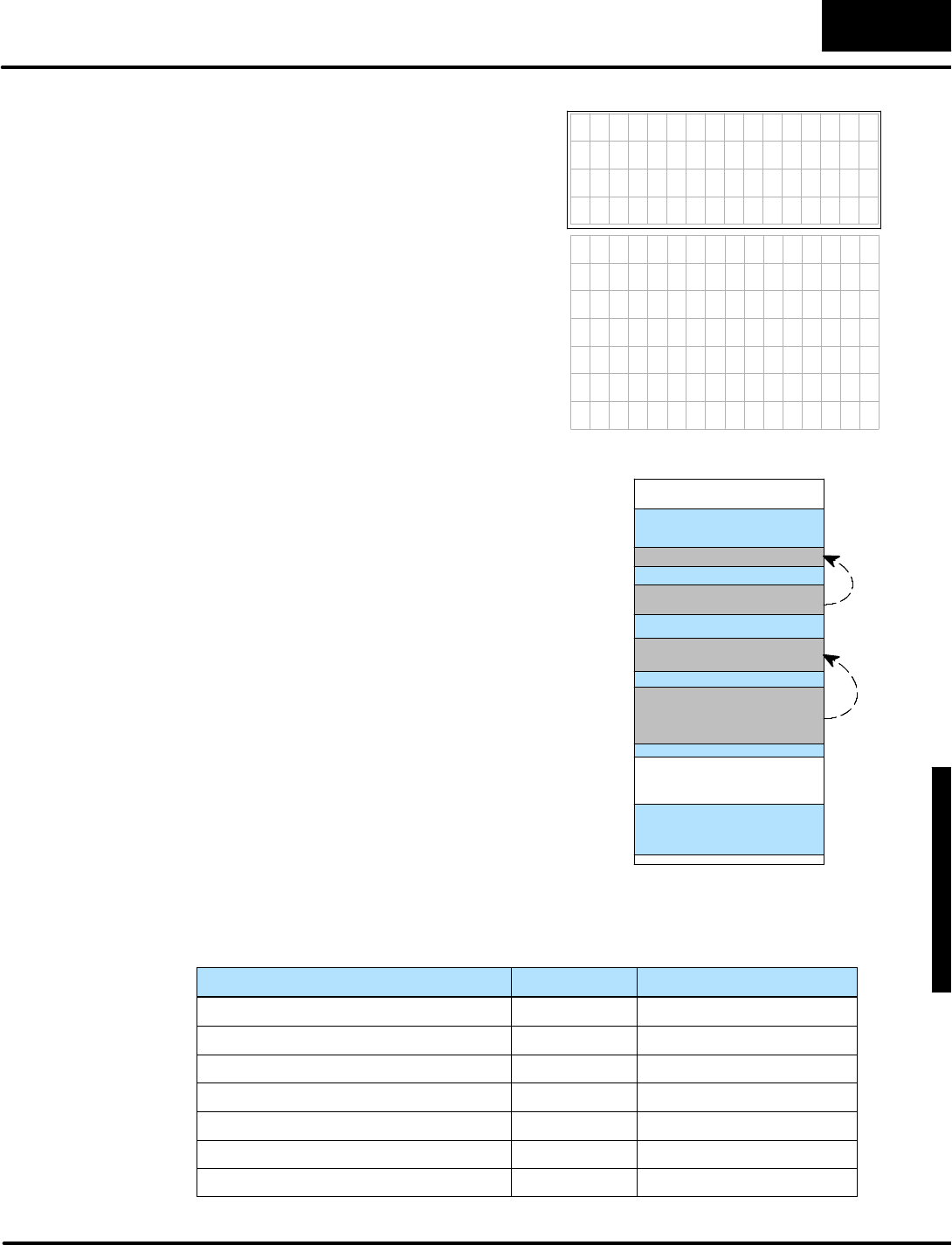
D
i
s
p
l
a
y
i
n
g
M
e
s
s
a
g
e
s
w
i
t
h
D
i
r
e
c
t
V
I
E
W
1
0
0
0
M
e
s
s
a
g
e
D
i
s
p
l
a
y
M
o
d
e
4
-
-
5
7
Message DisplayMode
Occasionally you maywant tomonitora
listofprocess parameterslargerthan the
DV-1000 display can showatone time.
Earlierinthis chaptera“dualdisplay”
exampleswitched between twosetsof
information. Inthisexample, the
automatic scrolling technique provides
hands-free monitoring ofmultiplescreens
ofinformation.
The list tothe rightcontains10 items,
followed bya blankline item.The example
programscrollsdownthe listone item
everytwoseconds,and startsagainwith
the firstitem.
Lot Number 3293
Setpoint 2418
A c t u a l T e m p 1 6 4 4
High Alarm 5765
L o w A l a r m 1 6 4 4
T a n k 1 L v l 5 7 6 5
T a n k 2 L v l 1 6 4 4
F l o w R a t e 5 7 6 5
T e m p 1 1 6 4 4
T e m p 2 8 2 1 9
The information to be displayed will
obviouslynot fitinthe standard numeric
and textdata blocks.Consequently,we
havetochoose a method ofmoving the
dataintothe standard data blocks.Refer
tothe memorymap tothe right.
Setup Parametersdefine the standard
numericblock (atV2000)and textdata
block (atV2100)asinthe otherexamples
inthis chapter.However,aseparate
numericlist(atV2040)and textlist(at
V2200)containsthe all information to be
scrolled through the display.Therefore,
the main program movesa different
portion of the listsintothe corresponding
data blocks everytwoseconds.Sincethe
DV-1000 constantlyre-readsthe data
blocks (pointed to bythe setup
parameters),itcompletesthe scrolling
effect.
V0000
V--MemorySpace
UserData
NumericPointer=2000
TextPointer=2100
V2000 NumericDataBlock
TextDataBlock
V7623
V7624
V2100
V2017
V2137
TextList
V2200
V2040 NumericList
Setup Parameters
Toscroll the displaymessage, the ladderprogramon the nextpage createsand
usesthe following variablestomanage the datainthe scrolling process.
Variable Location Range ofvalues
List ItemPointerV4000 0 toX
ItemPointerDuring Scroll V4001 Xto(X+3)
TextListAddress OffsetV4002 0 to40(hex)
TextListAddress PointerV4003 2200 to 3010 (octal)
NumericDataBlock Address PointerV4004 2000 to 2014 (octal)
NumericListAddress PointerV4005 2040 to(2040 +X) (octal)
ListLength(called “X”) V4006 1 to20(hex)
Automatic
Scrolling Display
(DL240,DL250,
DL350,DL440 and
DL450 CPUsOnly)

M
e
s
s
a
g
e
D
i
s
p
l
a
y
M
o
d
e
4
-
-
5
8
Message DisplayMode
(Setup Parameter rung here)
SP0
LD
K58
LD
K0
LDLBL
K1
MOVMC
V2200
LDD
K0
Load the constantK58 (hex)intothe accumulator.
Thisisthe numberofwords(88 decimal)we need to
movetocreatethe textdatalist. Counting the words
inthe ACONboxes,we have 20+20+20+20+8=88.
Load the constantK0intothe accumulaor.Thisisthe
offset forMOVMC,and isusually zero.
SP0
Firstscan only
OUT
V4000
OUTD
V2206
Initializethe itemnumber.
OUTD
V2216
OUTD
V2226
InitializeVariables
OUTD
V2236
Load the datalabelK1into he accumulator.The data
isafterthe labelK1.
Movethe datatothe V-memoryarea starting at
V2200.Thisinstruction usesthe three numbersfrom
the stack whichweloaded above.
Load the constantK0into all 32 bitsof the
accumulator.
Unmask the numericposition foritem1.
Unmask the numericposition foritem2.
Unmask the numericposition foritem3.
Unmask the numericposition foritem4.
OUTD
V2246
OUTD
V2256
OUTD
V2266
OUTD
V2276
OUTD
V2306
OUTD
V2316
LD
Kb
OUT
V4006
Load the constantKb hex(or11 decimal)intothe
accumulator.
Set the listlength atV4006 to11items.
Unmask the numericposition foritem5.
Unmask the numericposition foritem6.
Unmask the numericposition foritem7.
Unmask the numericposition foritem8.
Unmask the numericposition foritem9.
Unmask the numericposition foritem10.
Move textdata
Unmask numeric
positions
SetUpScroll Timer
TMR
K20 T0
T0ConfigureTimer0 asatwo-second self-resetting
timer.
a:\msg17.prj

D
i
s
p
l
a
y
i
n
g
M
e
s
s
a
g
e
s
w
i
t
h
D
i
r
e
c
t
V
I
E
W
1
0
0
0
M
e
s
s
a
g
e
D
i
s
p
l
a
y
M
o
d
e
4
-
-
5
9
Message DisplayMode
LD
V4001
SHFL
K3
If C0ison,ascroll isin progress.Load the item
numberduringascroll intothe accumulator.
Multiplythe itemnumberbyeightby shifting itsbinary
formtothe left three digits.This createsan address
offset.
T0
SP0
SET
LDA
O2100
Load the octaladdress forV2100 intothe
accumulator.
OUT
V4003
Set the textdata pointeratV4003 to point toV2100.
LDA
O2000
Load the octaladdress forV2000 intothe
accumulator.
OUT
V4004
Set the numericdata pointeratV4004 to point to
V2000.
C0
LD
V4000
Load the currentitempointerintothe accumulator.
OUT
V4001
Copythe listitempointerintoV4001, the itempointer
used during the scroll.
INCB
V4000
Increment the listitempointeratV4000.
V4000 V4006 LD
K0
If the listitempointeratV4000 equalsthe listlength
atV4006,load zerointothe accumulator.
OUT
V4000
Set the listitempointeratV4000 tozero.
C0
OUT
V4002
Placethe address offsetequalto eight timesthe item
pointerintothe textdata address offsetpointer
location atV4002.
LD
K8
Load the constantK8intothe accumulator,sincewe
need tomove8words(16 charactersper row).
LDA
O2200
Load the octaladdress forV2200 intothe
accumulator.Thisisthe base address of the source
dataforthe textASCII codes.
BCD Convert the numberinthe accumulatortoBCD
format.
SetC0 every2seconds.C0isactiveforfourscans
and isthen reset. ContactSP0 ensureswe update
the display starting withthe firstscan.
InitializeVariables forNewDisplay
Move DataforNthItem
BCD Convert the numberinthe accumulatortoBCD
format.
ADD
V4002
Add the base address inthe acumulatorwiththe
offsetinV4002, to get the completesource address
of the textdata.
Move TextData
MOV
P4003
BINConvert the BCD numberinthe accumulatorto
binaryformat.
Move eightwords(16 characters)fromthe source
address tothe destination address.
(continued)
a:\msg17.prj

M
e
s
s
a
g
e
D
i
s
p
l
a
y
M
o
d
e
4
-
-
6
0
Message DisplayMode
ADD
V4001
Add the listitemnumberduring the scroll atV4001 to
the accumulatorcontents.
LDA
O2040
Load the listitempointerintothe accumulator.This
createsasource address fornumericlistdata.
OUT
V4001
Placethe newly calculated numericlistsource
address pointerintoitslocation atV4005.
LD
P4005
Load the numericlistdata pointed to byV4005 into
the accumulator.
OUT
P4004
Placethe dataintothe numericdata block destination
,
pointed to bythe address pointeratV4004.
LD
V4003
Load the current textdata pointervalue intothe
accumulator.
ADDD
K8
Increment the accumulatorcontentsby8.Thisadds
eight tothe textdata pointer.
OUT
V4003
Updatethe textdata pointerwiththe newly calculated
value.Thisisasource address.
LD
V4004
Load the currentnumericdata block pointerintothe
accumulator.
Move Numeric
Data
IncrementText
Address
Pointer
Increment
Numeric
Address
Pointer
BCD Convert the numberinthe accumulatortoBCD
format.
BINConvert the BCD numberinthe accumulatorto
binaryformat.
BCD Convert the numberinthe accumulatortoBCD
format.
BINConvert the BCD numberinthe accumulatorto
binaryformat.
BCD Convert the numberinthe accumulatortoBCD
format.
BIN
OUT
V4005
LD
V4001
OUT
V4001
Placethe converted value back intolocation V4001.
LD
V4001
Load the listitemnumberatlocation V4001 intothe
accumulator.
BCD Convert the numberinthe accumulatortoBCD.
Load the listitemnumberatlocation V4001 intothe
accumulater.
Placethe converted value back intolocation V4001.
Convert the BCD numberinthe accumulatorto
binaryformat.
(continued)
a:\msg17.prj

D
i
s
p
l
a
y
i
n
g
M
e
s
s
a
g
e
s
w
i
t
h
D
i
r
e
c
t
V
I
E
W
1
0
0
0
M
e
s
s
a
g
e
D
i
s
p
l
a
y
M
o
d
e
4
-
-
6
1
Message DisplayMode
The next fourACONboxeshold 40
characters(20 words).The text they
contain arethe listcontents.Besureto
carefully count the spaces.
DLBL
K1
ACON
LotNumberSetpointActualT
DataforVariableList
SAME
ACON
empHigh AlarmLowAlarm
ACON
Tank1 LvlTank2 LvlFlow Rat
ACON
eTemp 1 Temp 2
Hereweinclude somespacesat the
end of the list, sothat the blankline at
the end of the listhas16 spaces
(requires8words).
ACON
The datalabelK1marks the beginning of
the ACON(ASCII constant)boxeswhich
follow.
spaces:1 6 8 1
spaces:5 1 6 1 7
spaces:1 1 6 1 1 6 1
spaces:7 1 10 1 10
C0
RST
Load the octaladdress forV2000 intothe
accumulator.
OUT
V4001
Set the listitemnumberduringascroll tozero.
C0
V4001 V4006 LD
K0
If the listitempointerduringascroll atV4001 is
equaltothe listlength atV4006,load the
constantzerointothe accumulator.
V4003 K460
LDA
O2000
Set the numericdata block pointeratV4004 to
the base destination address value forV2000.
OUT
V4004
END
If ascroll isin progress (C0ison)and the text
destination address atV4003 equalshexK460
(2140 octal), the displayupdateisdone.So,
resetC0.
PlaceanEND coil tomarkthe end of the main
program.
Check ifDisplay UpdateisComplete
OUT
V4004
Updatethe numericdata block pointerwith
the newly calculated value.Thisisa
destination address.
INCB
V4001
Increment the listitempointerduringascroll
byone.
BINConvert the BCD numberinthe accumulator
to binaryformat.
ADDD
K4
Increment the accumulatorcontentsby4.This
addsfourtothe numericdata block pointer.
1
6
spaces:
(continued)
a:\msg17.prj
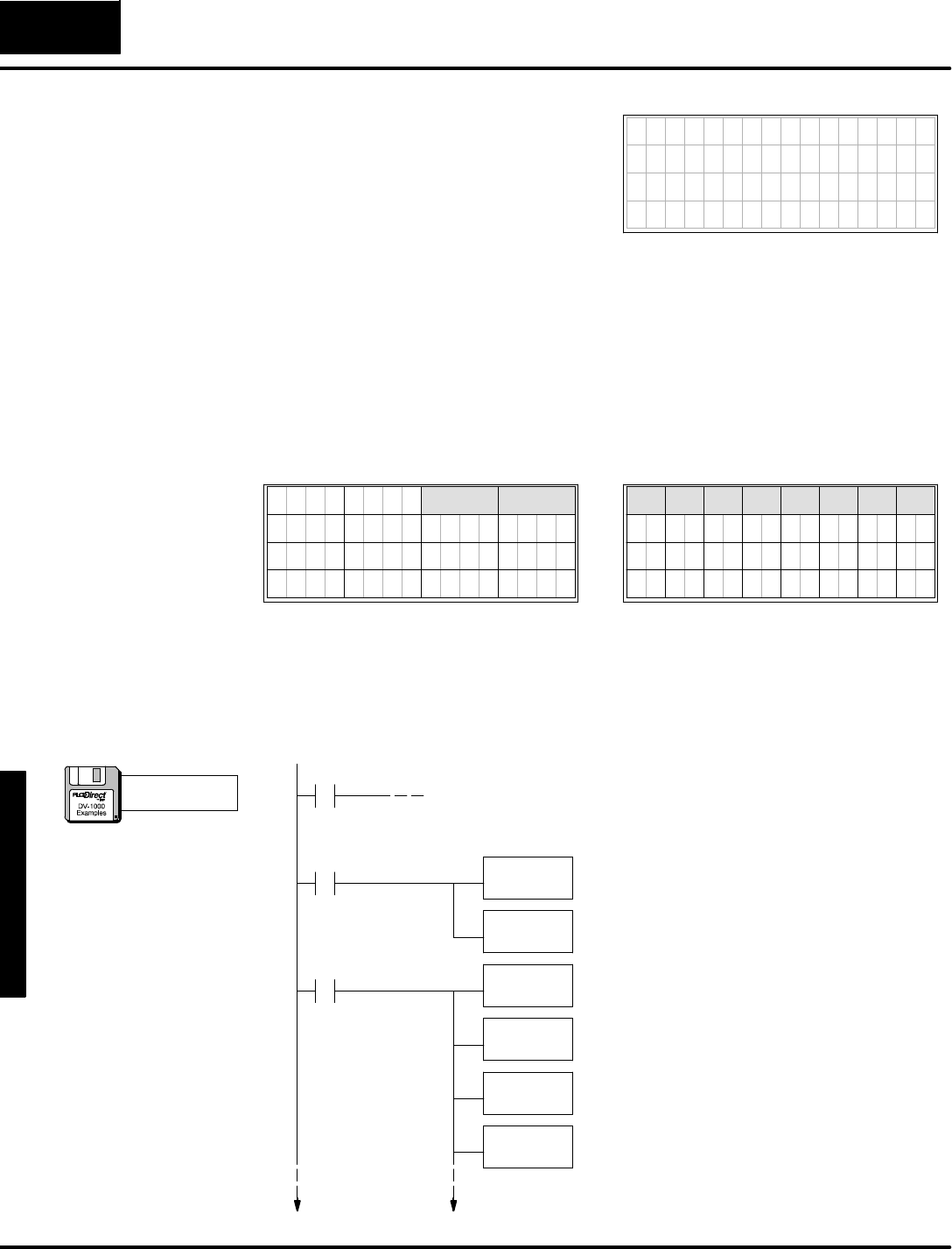
M
e
s
s
a
g
e
D
i
s
p
l
a
y
M
o
d
e
4
-
-
6
2
Message DisplayMode
Some process variableswill include a
fractionalpart thatyou maywant to display
byusing a decimalpoint. The example
screen tothe rightdisplays an oven
temperaturewitharesolution of tenthsofa
degree Fahrenheit.
7654321076543210
OvenTemp=6553.5F
The decimalpointoccupiesacharacterposition inthe middle of the number,
becauseseparate decimalpointsegmentsare notbuiltinto eachcharacterordigit
field.The ladderprogrambeginswith a binarynumberwhichcan varyfrom0toffff
hex,or0to 65535 decimal.The numberisan integer,butisactuallyten timeslarger
than the actualoven temperaturein degrees.This createsan implied decimalpoint
inthe location shown,sowecan displaytenthsofa degree.The ladderprogram
readsthe oven temperaturefromV2200, then convertsit toBCD and displays itin
the appropriate numericoutputdisplaypositions.
7 6 5 4 3 2 1 0 7 6 5 4 3 0
3
7 6 5 4 0 3 2 1 0
37
26 27
36
2
13 11
6
16
7
1517
12
NumericDisplay PositionsTextDisplay Positions
16 17
6 7
5 4
2 1
14
10
0
20
30
10 11
31
1
21
3 2
2
22
32
12
1
33
3
23
13
7 6
4
24
34
14
5 4
35
5
25
15
01
The programusesACONboxesto generatetext for “OvenTemp”and the remaining
blank spaceonthe display.The decimalpointand the “F”characterarewritten
specificallytotextpositionsembedded with null characters(ASCII code =0)which
unmasks the digits.Shift and add instructions splitapart the number’sdigitsto place
themin numericdisplaypositions0 and 1,making roomforthe decimalpoint.
(Setup Parameter rung here)
SP0
LD
Kffff
OUT
V2200
SP1
Load TemperatureValue
Load the ffff hex(representing 6553.5 decimal)asthe
oven temp. fordemo purposes. In actualapplications
thisnumberwill comefroman analog inputmodule.
Output the datatoV2200,wherethe programwill read
and convert thisnumber.
LD
K10
LD
K0
LDLBL
K1
MOVMC
V2100
Load the numberofdatalocations,whichis16 words
(10 hex),or32 characters.
Load the address offset. FornearlyeveryMOVMC
used forACONdata, therewill be zero offset(useK0).
Read fromthe ACONfollowing Data LabelK1.
Move dataintoV-memory starting atV2100,
corresponding tothe top twolineson the display.
Top 2Lines
SP0
WriteText
Embedded
DecimalPoint
a:\msg18.prj

D
i
s
p
l
a
y
i
n
g
M
e
s
s
a
g
e
s
w
i
t
h
D
i
r
e
c
t
V
I
E
W
1
0
0
0
M
e
s
s
a
g
e
D
i
s
p
l
a
y
M
o
d
e
4
-
-
6
3
Message DisplayMode
LDD
K3d00
Load ASCII codesfortwo null characters(0000),
followed by“=”and a null character.Remember, the
two pairsofcharacterpositions swap forLDD
instructions.
OUTD
V2104
Placethe characterstothe rightof“OvenTemp”on the
top row.Rememberthatnull charactersunmask their
corresponding numericpositions.
LDD
K46002e
OUTD
V2106
Placethesecharacterson the top line of the display.
The null charactersunmask numericoutputinthe
corresponding characterpositions.
LD
V2200
Load the binarytemperaturevalue fromV2200 intothe
accumulator.
BCD
SHFR
K8
OUT
V2001
Load the ASCII codesfora decimalpoint(period), two
null characters,and the “F”.Remember, the two pairs
ofcharacterpositions swap forLDD instructions.
Convert the value toBCD,leaving the resultinthe
accumulator.
Shift the bitstothe right8 places,representing two
BCD digits.Thisleavesthe three mostsignificant
digitsinthe accumulator.
Placethe three mostsignificantdigitsin numeric
position 1,located atV2001.
LD
K10
LD
K0
LDLBL
K2
MOVMC
V2120
Load the numberofdatalocations,whichis16 words
(10 hex),or32 characters.
Load the address offset. FornearlyeveryMOVMC
used forACONdata, therewill be zero offset(useK0).
Read fromthe ACONfollowing Data LabelK2.
Move dataintoV-memory starting atV2120,
corresponding tothe bottomtwolineson the display.
Bottom2
Lines
SP1
LD
V2200
Load the binarytemperaturevalue fromV2200 intothe
accumulator.
BCD
SHFL
K8
OUT
V2000
Convert the value toBCD,leaving the resultinthe
accumulator.
Shift the bitstothe left 8 places,representing twoBCD
digits.Thismovesthe twoleastsignificantdigitstothe
left two places.
Placethe twoleastsignificantdigitsin numeric
position 0,located atV2000.
GetTemp.
Value
(continued)
a:\msg18.prj
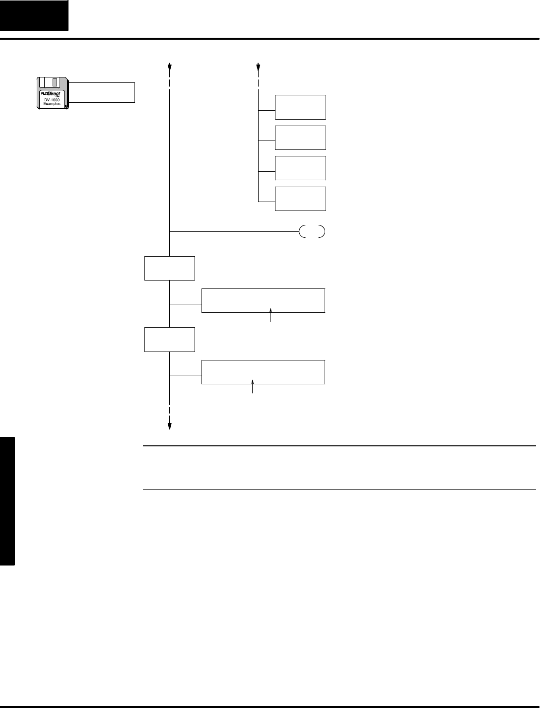
M
e
s
s
a
g
e
D
i
s
p
l
a
y
M
o
d
e
4
-
-
6
4
Message DisplayMode
Bottom2
Lines
SHFR
K4
Shift the bitstothe right4 places,representing one
BCD digit. Thismovesthe leastsignificantdigitback
one digit tothe right, leaving roomfor “F”at the end.
ANDD
Kf0
Thisforcesall digitstothe left of the leastsignificant
digit tozero.
ADD
V2000
Now wecombine the isolated leastsignificantdigit
back withthe otherdigit. However,ithasbeen shifted
tothe right tomakeroomforthe decimalpoint.
OUT
V2000
Output the two LSDsto numericoutputposition 0.
Theyarespaced apartone digit, tomakeroomforthe
decimalpoint, and have been moved tothe left to
makeroomforthe “F”.
END PlaceanEND coil,marking the end of the main
program.
DLBL
K1
ACON
OvenTemp
Screen TextDataThe Data Labelboxreferenced byK1,preceeds
the following ACONbox.
ThisACONbox contains32 characters.Besure
tocarefully count the spacestomatchthe
display.
DLBL
K2
ACONThisACONbox contains32 spaces.Thesefill
the bottomtwolinesof the display.
The Data Labelboxreferenced byK2,preceeds
the following ACONbox.
spaces:24
32spaces:
NOTE:The resulting BCD numberinV2000 and V2001 isusefulonlyfordisplay
purposes.The actualnumericalvalue isnotvalidforuseinfurthercomputations
(refertothe originalvalue inV2200).
(continued)
a:\msg18.prj

D
i
s
p
l
a
y
i
n
g
M
e
s
s
a
g
e
s
w
i
t
h
D
i
r
e
c
t
V
I
E
W
1
0
0
0
M
e
s
s
a
g
e
D
i
s
p
l
a
y
M
o
d
e
4
-
-
6
5
Message DisplayMode
ChapterSummary
Now we havecovered howto useMessage DisplayMode tocommunicatethe
statusof the machine toitsoperator.
Wemay summarizesome of the keypointswe havelearned aboutgenerating
messagesinthis chapter:
SSystem Messageshave priorityoverUser Messages.
SUser Messages can contain numericalvalues,ortext.
SNumericand TextPositionsrepresentone 16-bitword ofinformation.
SNumericand Textoutputmaybe viewed simultaneouslyon the same
display.Textoutputhasmask and unmasking controlovernumeric
output.
STextis stored inV-memoryinthe form ofASCII codes.
SLadderprograms can load textdataviathe LD/OUT,LDD/OUTD,and
MOVMC/ACON instructions.
SLDD (Load Double)instructionsrequireyou toswap positionsof the
ASCII codesof the first twocharacterswiththe second twocharacters,
withrespect toleft-to-rightdisplayposition orientation.
SACONboxesisthe preferred method forcreating message data
wheneveryou havemorethan a dozen charactersto placetogetheron
the display.
Summaryof
Key Points

1
5
StatusDisplay Mode
In ThisChapter....
—Overview
—Selectingthe Address
—Selectingthe Data Type
—Usingthe Bookmark
—ChapterSummary
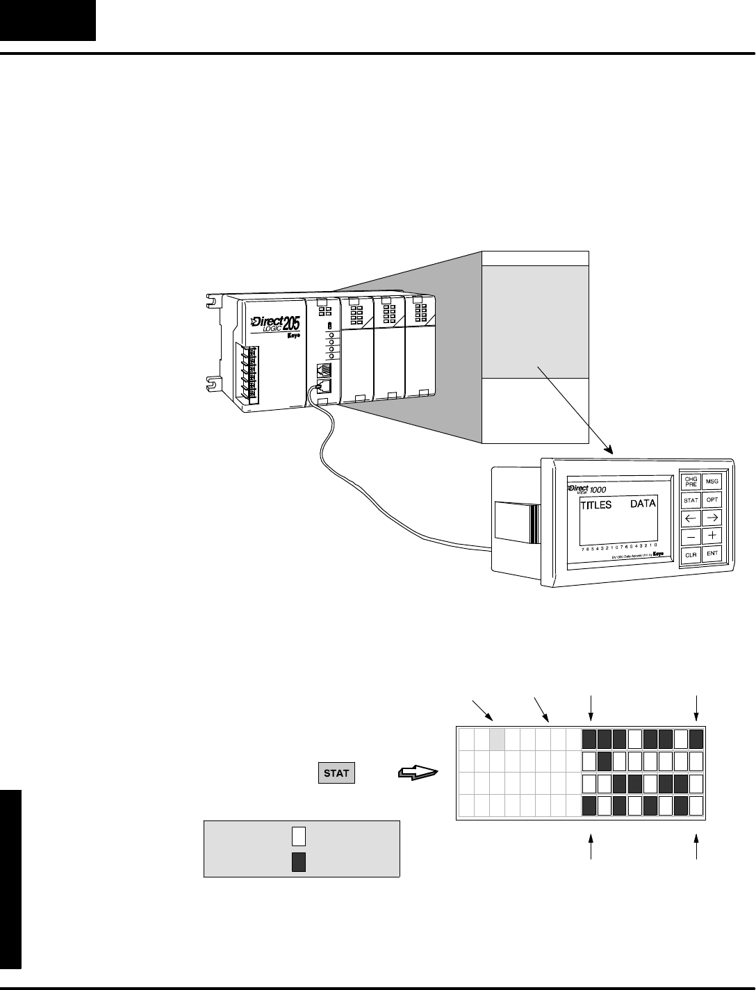
D
i
s
p
l
a
y
i
n
g
M
e
s
s
a
g
e
s
w
i
t
h
D
i
r
e
c
t
V
I
E
W
1
0
0
0
M
o
n
i
t
o
r
i
n
g
P
L
C
D
a
t
a
S
t
a
t
u
s
D
i
s
p
l
a
y
M
o
d
e
5
-
-
2
StatusDisplayMode
Overview
StatusDisplayMode allows you toviewV-memorydatainthe CPU.It requiresno
setup parametersorsupporting ladderlogic!Therefore,you can walkup to any
DL105,DL205,DL405 PLCorDL305 with a DL350 CPU,and connectaDV-1000 to
viewvariousCPUdatatypes.Thismakesthe DV-1000 a greatdebugging toolfor
machine startupsorfortroubleshooting inthe field.
V--MemorySpace
UserV-memory
READ
StatusDisplayMode isaccessible atanytime bypressing the StatusKey(unless
the keypad isinBitControlMode). It doesnotrequiresetup parameters,butyou may
selectitasthe defaultmode atpowerup (see Chapter3).The defaultdisplayupon
StatusDisplayMode entryis shown below.
PRESS
7654321076543210
X 0 0
X 1 0
X 2 0
X 3 0
LSBMSB
(X07) (X00)
Legend:=binary0
=binary1
DatatypeAddress
The left columnliststhe datatype (Xinthe example).The nextcolumnliststhe octal
address,and the data bitsareonthe right. Sothe top rowshowsthe statusof the
eightdiscreteinputsX00 through X07 inrealtime.Recall that there are8bitsina
byte,and two bytes (16 bits)inadataword!
StatusDisplay
Format
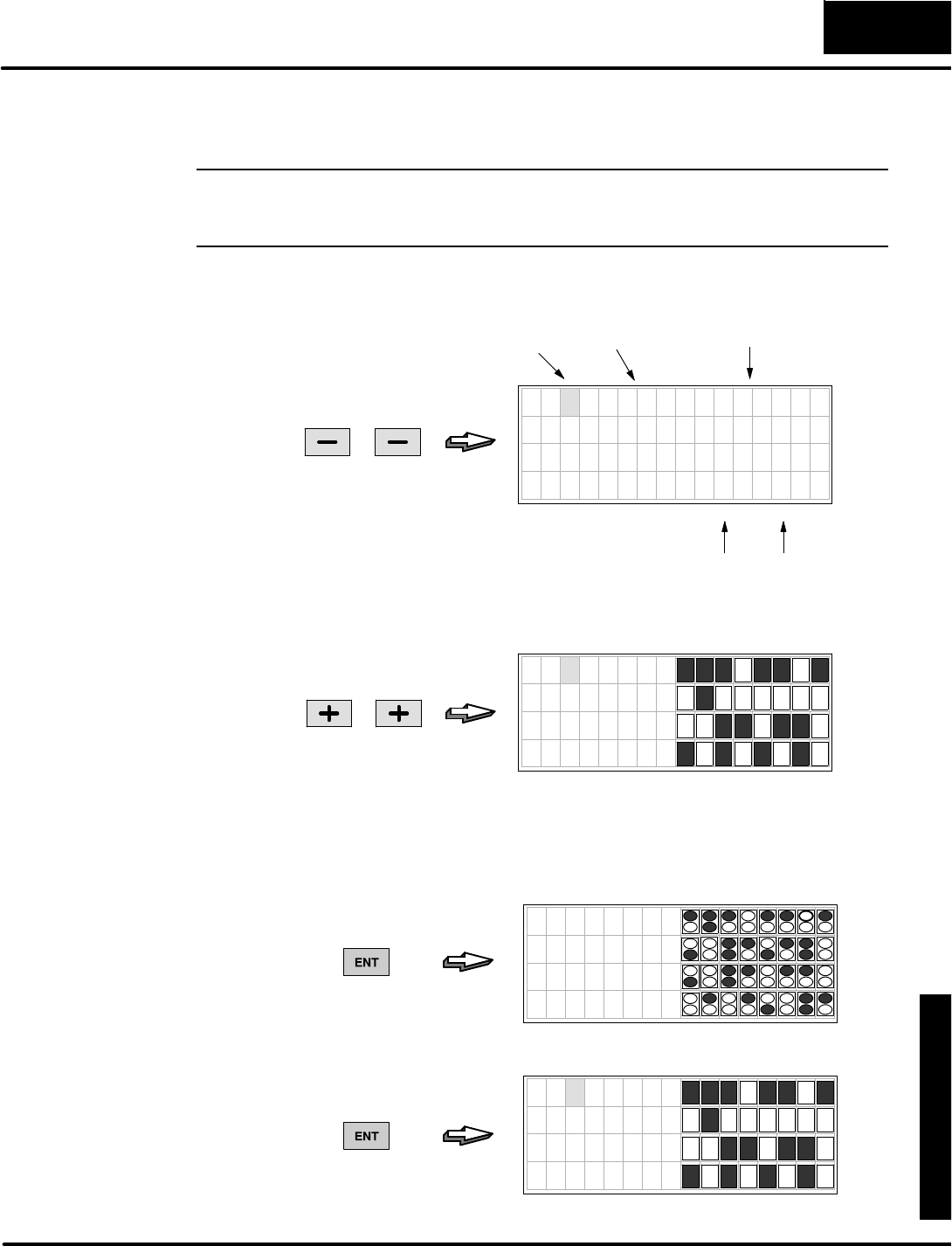
D
i
s
p
l
a
y
i
n
g
M
e
s
s
a
g
e
s
w
i
t
h
D
i
r
e
c
t
V
I
E
W
1
0
0
0
M
o
n
i
t
o
r
i
n
g
P
L
C
D
a
t
a
S
t
a
t
u
s
D
i
s
p
l
a
y
M
o
d
e
5
-
-
3
StatusDisplayMode
If you can switchthe inputatX0 on and off, do so and watchthe displayresponse.
Across the bottomof the screen faceplateisthe bitnumbering, fromLSB toMSB.
NOTE:The binarybitpatternsor4-digitwordvaluesinthese displays are arbitrary
examples.The bitpatternsorvalueson yourDV-1000 dependson the state ofyour
CPUprogramand process.
Datatypes such asPorVare displayed as4-digitBCD orhexadecimalnumbers.
Step tothe Vdatatype bypressing the Minus(--) Keytwice.
PRESS
LSDMSD
BCD orHexValueDatatypeAddress
7654321076543210
V 2 1 0 0 4 D 4 1
V 2 1 0 1 4 3 4 8
V 2 1 0 2 4 9 4 E
V 2 1 0 3 4 5 2 0
Nowreturntothe Xdatatype bypressing the Plus(+)keytwice.
PRESS
7654321076543210
X 0 0
X 1 0
X 2 0
X 3 0
The defaultdisplayaboveshowsfourbytes,or32 bitsofdata.You can vieweight
bytes,or64 bitsbypressing the EnterKey. Inthe example displaybelow, the top line
showsX00 through X07,and X10 through X17 directlybelow.Toreturnto 32-bit
displayformat, justpress the EnterKeyagain.
7654321076543210
X 0 0
X 2 0
X 4 0
X 6 0
PRESS
PRESS
7654321076543210
X 0 0
X 1 0
X 2 0
X 3 0
(selectsfourdatawords)
(selectsfourbytes)
Selecting Byteor
WordDisplays
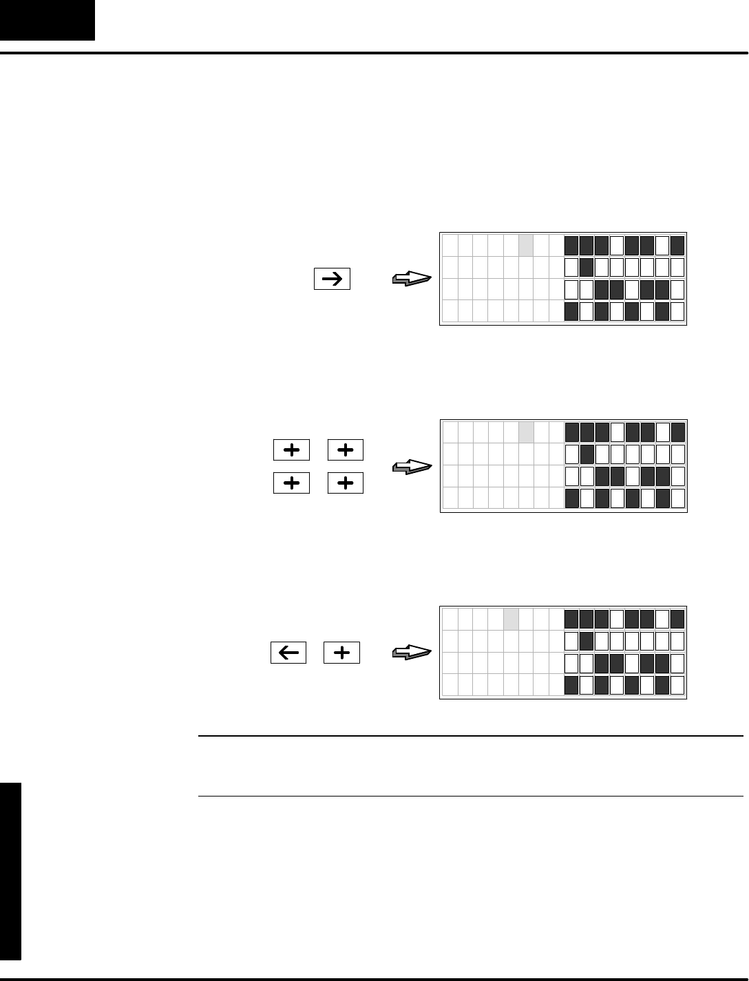
D
i
s
p
l
a
y
i
n
g
M
e
s
s
a
g
e
s
w
i
t
h
D
i
r
e
c
t
V
I
E
W
1
0
0
0
M
o
n
i
t
o
r
i
n
g
P
L
C
D
a
t
a
S
t
a
t
u
s
D
i
s
p
l
a
y
M
o
d
e
5
-
-
4
StatusDisplayMode
Selecting theAddress
The defaultaddress of the top line statusis“00”The DV-1000 automaticallydisplays
consecutive addresseson the remaining three lines.Addressesforthe entire
displayis selected fromthe top line only.Therefore, the cursor remainson the top
line.Tochange the address,movethe cursortothe rightbypressing the Cursor
Rightkeyonce.The cursor movestothe 10’splace.
7654321076543210
X 0 0
X 1 0
X 2 0
X 3 0
PRESS
Withthe cursoroverthe 10’splace,press the Plus(+)Keyfourtimes.Eachtimethe
address incrementsby10 (octal),until the display showsthe statusforX40 through
X77.
7654321076543210
X 4 0
X 5 0
X 6 0
X 7 0
PRESS
Toincrement the 100’splace,press the CursorLeft key,and then the Plus(+)Key.
Nowthe top line address changesfrom40 to 140,and consecutive addressesfollow.
Using thistechnique,you can selecthigh numbered addressesquickly.
7654321076543210
X 1 4 0
X 1 5 0
X 1 6 0
X 1 7 0
PRESS
NOTE:Sincethe bitpatternsdisplayatleast8 bitson eachrow, the unitsdigitof the
address isalways “0”.Therefore, the cursorcannotbe moved tothe unitsposition in
the address forediting.
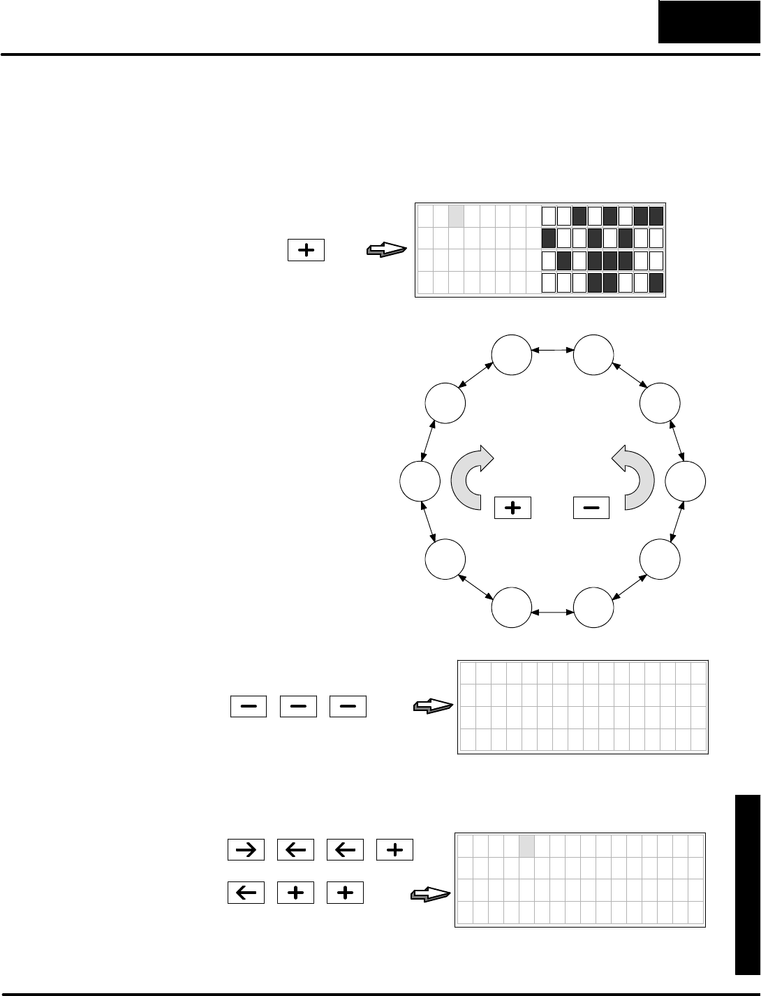
D
i
s
p
l
a
y
i
n
g
M
e
s
s
a
g
e
s
w
i
t
h
D
i
r
e
c
t
V
I
E
W
1
0
0
0
M
o
n
i
t
o
r
i
n
g
P
L
C
D
a
t
a
S
t
a
t
u
s
D
i
s
p
l
a
y
M
o
d
e
5
-
-
5
StatusDisplayMode
Selecting theDataType
You can viewvariousV-memorydatatypesbyusing the Plus(+)and Minus(--) Keys
on the keypad.Beginning fromthe defaultdisplay,verifythat the cursorisoverthe
“X”.Then press the Plus(+)Keytoviewthe statusofYoutputbitsas shown below.
7 6 5 4 3 2 1 0 7 5 4 3 2 0
Y 0 0
Y 1 0
Y 2 0
Y 3 0
PRESS
6 1
DatatypesX,Y, GX,C,SP,T,CT,
S,V,and Pare accessiblein a
circularlist, as showntothe right.
However,you may see one ortwo
fewerdatatypes,based on your
PLCtype.Pressing the Plus(+)
Keydisplays the nextdatatype in
the clockwisedirection.Pressing
the Minus(--) Keydisplays the
nextdatatype inthe
counter-clockwisedirection.
DatatypesVand Pare displayed
in hexadecimalformatratherthan
asdiscrete bits.Asan example,
let’s viewVtype data now.
Increment the displayfromYtype
toVtype bypressing the Minus
(--) Keythree times.
X
Y
GXC
SP
T
CT
S
V
P
PRESSPRESS
7654321076543210
V 0 0 0 0 0
V 1 0 0 0 0
V 2 0 0 0 0
V 3 0 0 0 0
PRESS
(selectVtype)
Bydefault the displaybeginswithV0through V3.Now wecan change the address to
the location ofdatawewishtoview.The exampleselectsthe data atV2100.
7654321076543210
V 2 1 0 0 4 D 4 1
V 2 1 0 1 4 3 4 8
V 2 1 0 2 4 9 4 E
V 2 1 0 3 4 5 2 0
PRESS
PRESS
(change address to 2100)
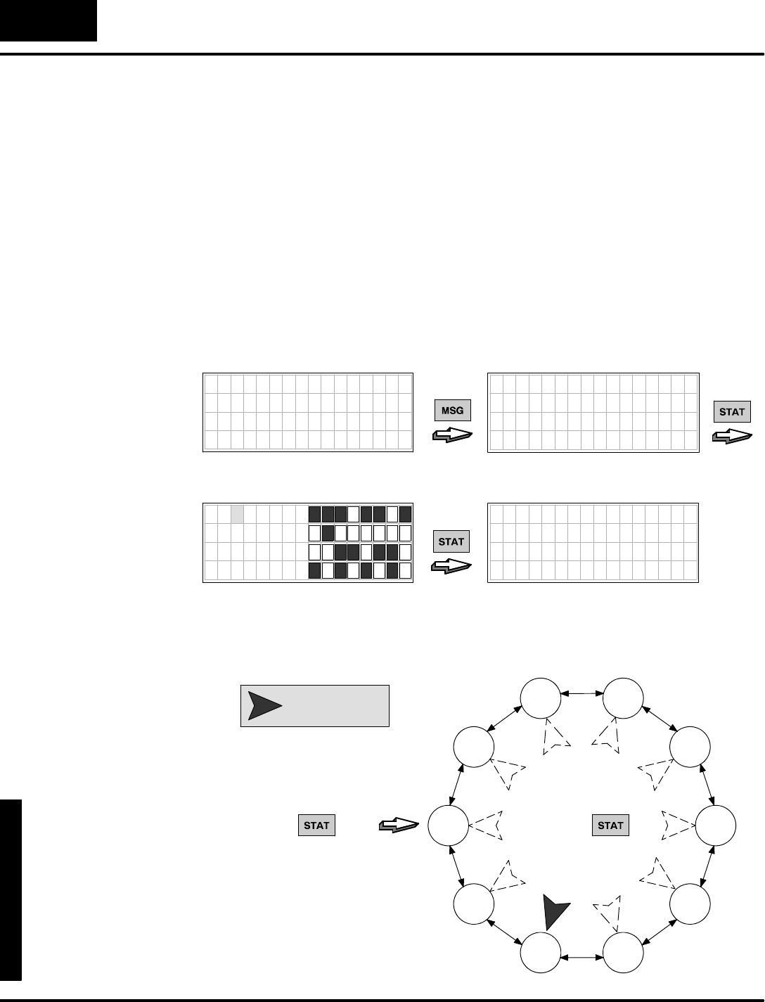
D
i
s
p
l
a
y
i
n
g
M
e
s
s
a
g
e
s
w
i
t
h
D
i
r
e
c
t
V
I
E
W
1
0
0
0
M
o
n
i
t
o
r
i
n
g
P
L
C
D
a
t
a
S
t
a
t
u
s
D
i
s
p
l
a
y
M
o
d
e
5
-
-
6
StatusDisplayMode
Using theBookmark
Asaconveniencethe StatusDisplayMode featuresa“bookmark”,oramemoryof
the datatype and address lastselected inStatusMode.Thispermits you tolater
returntoStatusDisplayMode,and usethe bookmarkto easilyrecall the lastdata
type and address location you wereviewing.
To demonstrate howthisworks,supposeyou areviewing the memory contentsat
V2100,as you were at the end of the previous section (selectV2100 at thistimeifyou
have notalreadydone so).Now,supposeyou need tocheck for messagesusing
Message Mode (Press the MessageKey).Afterviewing anymessage,wewant to
returntoStatusMode,displaying V2100 contents.To do this,press STATonceto
viewthe defaultX00 data.Then press STATa second timetoreturntothe
bookmark,and the data atV2100 immediatelyappearson the display!
7
6
5
4
3
2
1
0
7
6
5
4
3
2
1
0
X 0 0
X 1 0
X 2 0
X 3 0
7
6
5
4
3
2
1
0
7
6
5
4
3
2
1
0
V 2 1 0 0 4 D 4 1
V 2 1 0 1 4 3 4 8
V 2 1 0 2 4 9 4 E
V 2 1 0 3 4 5 2 0
7 6 5 4 3 2 1 0 7 6 5 4 3 2 1 0
MACHINE STATUS
F a u l t = B i n E m p t y
Time =11:32:57AM
Date =07/05/95
7654321076543210
V 2 1 0 0 4 D 4 1
V 2 1 0 1 4 3 4 8
V 2 1 0 2 4 9 4 E
V 2 1 0 3 4 5 2 0
O
r
i
g
i
n
a
l
S
t
a
t
u
s
M
o
d
e
D
i
s
p
l
a
y
PRESS
PRESS
PRESS
E
x
i
t
t
o
M
e
s
s
a
g
e
M
o
d
e
EnterStatusModeAgainReturntoBookmark
The bookmark servesasa pointertothe previously viewed datatype and address in
StatusMode,asdepicted below.The bookmarkis setwhen you exitStatusDisplay
Mode,and itcan reference anyof the datatypesalong withvalid addresses.
X
Y
GXC
SP
T
CT
S
V
P
PRESS
V2100
PRESS
(first time) (secondtime)
=Bookmark
(default)
Note:The bookmarkisresetduring
a powerloss tothe DV-1000.

D
i
s
p
l
a
y
i
n
g
M
e
s
s
a
g
e
s
w
i
t
h
D
i
r
e
c
t
V
I
E
W
1
0
0
0
M
o
n
i
t
o
r
i
n
g
P
L
C
D
a
t
a
S
t
a
t
u
s
D
i
s
p
l
a
y
M
o
d
e
5
-
-
7
StatusDisplayMode
ChapterSummary
Now we havecovered howto useStatusDisplayMode toviewV-memory contents.
Wemay summarizesome of the keypointswe havelearned aboutsetup
parametersinthis chapter:
SStatusMode requiresno setup parameters.
SFordiscrete bitdisplays,you can selectbyte orwordformatbytoggling
the EnterKey.
SThe cursor remainson the top line atall times.The addressesof the
three rowsbelowthe top line areconsecutivetothe top line address.
SDatatypesareselected fromacircularlistusing the Plus(+)and Minus
(--) Keys.
SAfterpowerup, the DV-1000 recordsthe variabletype and address you
wereviewing an timeyou exitStatusDisplayMode,saving itasa
bookmark.Afterusing other modesand returning toStatusDisplay
Mode,you can press the EnterKeytwicetoreturntothe variabletype
and address previously viewed.
SThe bookmarkisalways resetateach powerup.
Summaryof
Key Points

1
6
ChangePreset Mode
In ThisChapter....
—Overview
—Setup ParametersforChangePresetMode
—AccessingChangePresetVariables
—Pre-labeledTimerandCounterPresets
—User-titled Presets
—Combination TitlesExample
—ChangePresetPassword
—SpecialTopicsforChangePreset
—Operator’sGuidetoChangePresetMode
—ChapterSummary
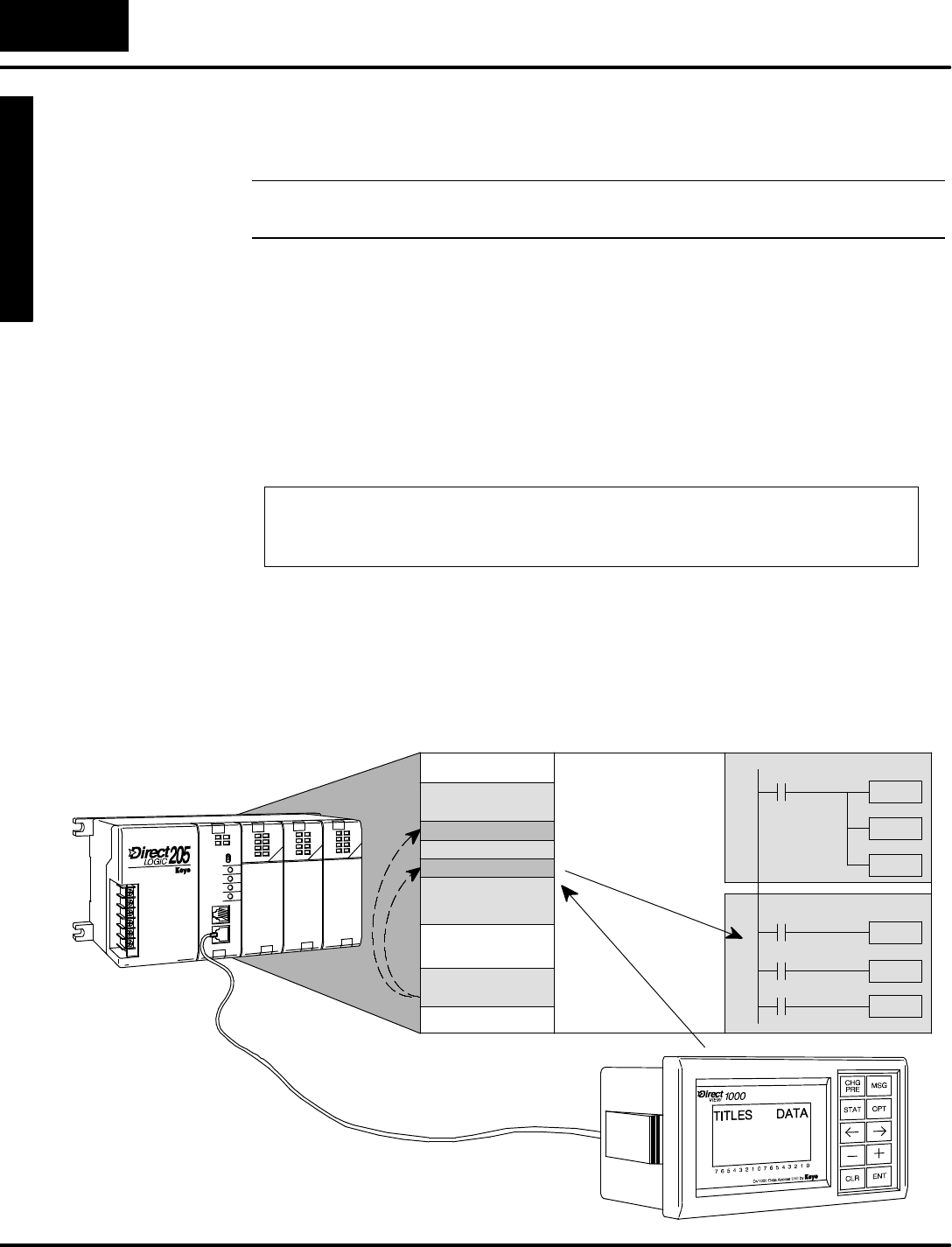
M
o
n
i
t
o
r
i
n
g
P
L
C
D
a
t
a
C
o
n
f
i
g
u
r
a
t
i
o
n
f
o
r
C
h
a
n
g
i
n
g
P
r
e
s
e
t
V
a
l
u
e
s
Mode
Change Preset
C
h
a
n
g
e
P
r
e
s
e
t
6
-
-
2
Change PresetMode
Overview
NOTE:DV-1000swhich have nothad firmware upgrade toversion 1.5will nothave
Timerand CounterPresetswhen usedwithDL130 and DL230 CPUs.
Change PresetMode allows you toviewV-memory contentsand change them
directlyfromthe DV-1000 keypad.We usethe word“preset”becauseitisnormally
associated with process controlparameters such astimerand counterpresets.
Historically,a“preset”isavalue accessibletothe operatorforadjusting whilethe
machine orprocess isoperating. Often implemented using thumb-wheelswitches,
one adjustsproductqualityand machine performance bymaking a seriesof typically
carefuland incrementalchangestocontrolparameters.
The DV-1000 Change PresetMode emulatesthe thumb-wheelaccess to adjustPLC
controlparameters.However, the term “preset” reallyincludesall ofUserV-memory,
notjust timersand counters.This conceptis soimportant, we emphasizeithere:
“ChangePreset”means“ChangeV-MemoryData”!
Change PresetMode allows you tomonitorand change V-memorydatafromthe
DV-1000 keypad.Refertothe figure below.The ladderprogramwritesthe setup
parametersinV-memory(usuallyon the firstscan).Thesecontain pointerstotitles
(textlabelsforthe data)and tothe dataitself. The DV-1000 readsthese and provides
access to edit the data.When the operatorusesChange PresetMode, the DV-1000
writesnewvaluestothe selected datainV-memory.Then the ladderprogram reads
the data(usuallyon every scan)and usesitasacontrolparameterforthe process.
V--MemorySpace
UserV-memory
Setup Parameters
TITLES
DATA
MainProgram
Setup Parameters
LadderProgram
WRITE
READ
“ChangePreset”
Defined
HowChange
PresetWorks
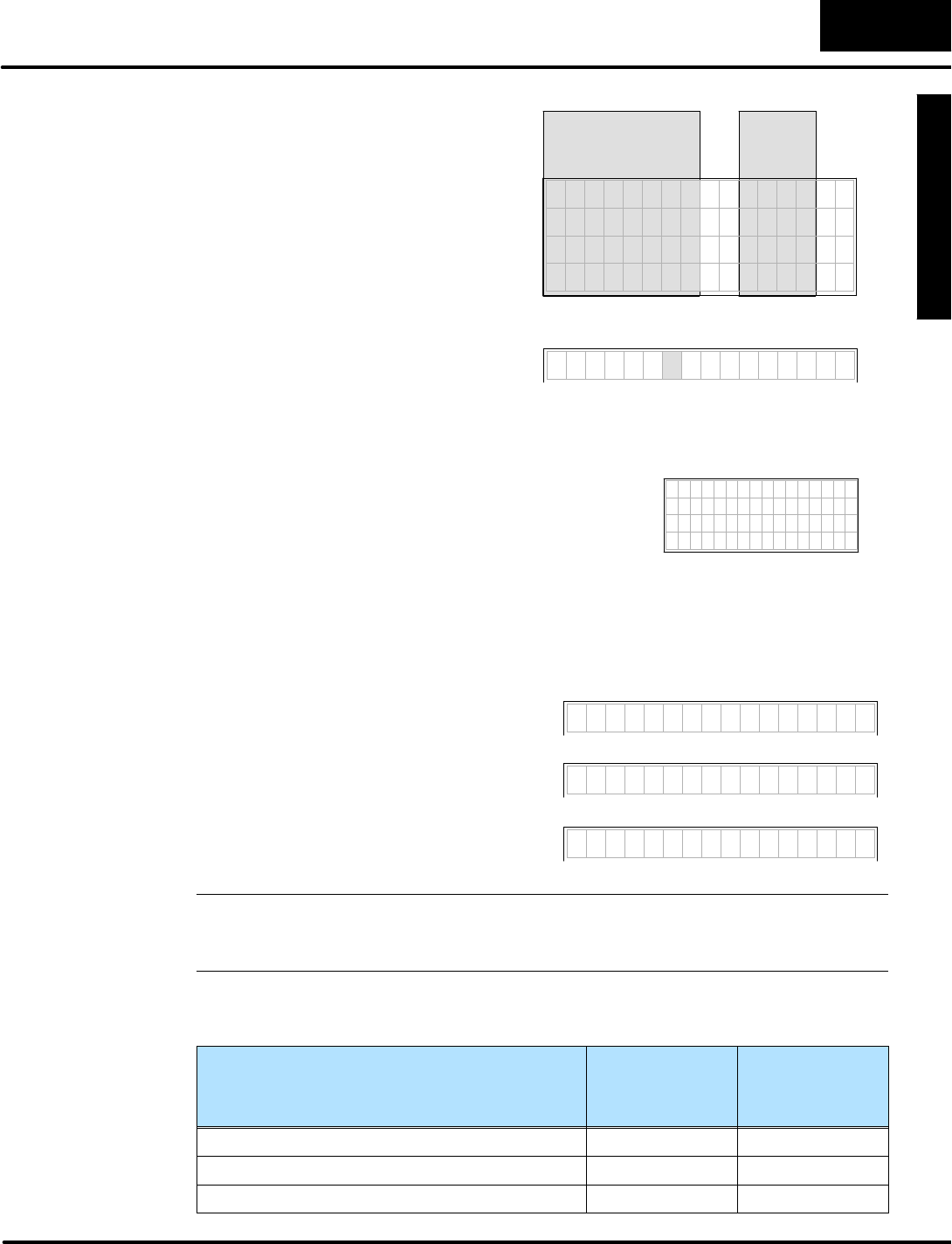
M
o
n
i
t
o
r
i
n
g
P
L
C
D
a
t
a
C
o
n
f
i
g
u
r
a
t
i
o
n
f
o
r
C
h
a
n
g
i
n
g
P
r
e
s
e
t
V
a
l
u
e
s
C
h
a
n
g
e
P
r
e
s
e
t
M
o
d
e
6
-
-
3
Change PresetMode
Change PresetMode presentsdata
thatyou can viewon the displayand
editwiththe keypad.The display
formatisrelativelyfixed.Showntothe
right, the titlefield on eachline
occupiesthe firsteightornine
characterpositions.All datais
presented inthe rightcolumn as
4-digitBCD numbers,representing a
16-bitword.7654321076543210
a b c d e f g h 0 0 0 0
a b c d e f g h 0 0 0 0
a b c d e f g h 0 0 0 0
a b c d e f g h 0 0 0 0
TITLEFIELD DATA
FIELD
You may skipcreating yourowntitles
and use default titlesas showntothe
right. Withthe setup parametervalue
the DV-1000 will automaticallyusethe
V-memoryaddress forthe titles.
V 2 3 0 0 3 5 8 6
Titles(labels)accompanythe data,giving them
meaning foryourapplication.The title and datalists
maybe longerthan the display can showatone
time,but the lengthsare programmable and are
equal.7654321076543210
SetPoint 0352
SoakTime 0020
Hi Alarm 0375
Lo Alarm 0325
Three typesof titlesare availableinChange PresetMode,as shown below.
User--titled Presetsallowyou tocreateyourowntextlabelofup to eightcharactersin
length.The remaining Pre-titled Timerand Counterlabelsare“canned” (orfixed),
However, theyareconvenient to usewhen you need generictimerorcounterlabels.
M y T i t l e 0 0 0 0
T I M E R 1 0 0 0 0
C O U N T E R 1 0 0 0 0
1.User-TitledV-MemoryPresets
(createyourowntext titles)
2.Pre-Titled TimerPresets
(usecanned Timer1toTimer99 list)
3.Pre-TitledCounterPresets
(usecanned Counter1toCounter99 list)
NOTE:The Pre-titled Timerand CounterPresetsonlylabelV-memorydata on the
DV-1000 display.Theydo notdirectly controlTimerand Counterboxparameters.
Also, the timerand counterpresetnumbering isin decimal,notin octal!
The availabilityand numberof titletypes varieswiththe CPUtype connected tothe
DV-1000.Refertotable belowforthe availabilityof featuresforyourparticularCPU.
FeatureDL130,DL230,
DL240
DL250,DL350
DL430,DL440
DL450
AvailableUser-titled Presets16 32
AvailablePre-labeledTimerPresetLabels99 99
AvailablePre-labeledCounterPresetLabels99 99
Title and Data
Fields
PresetTitleTypes
Available
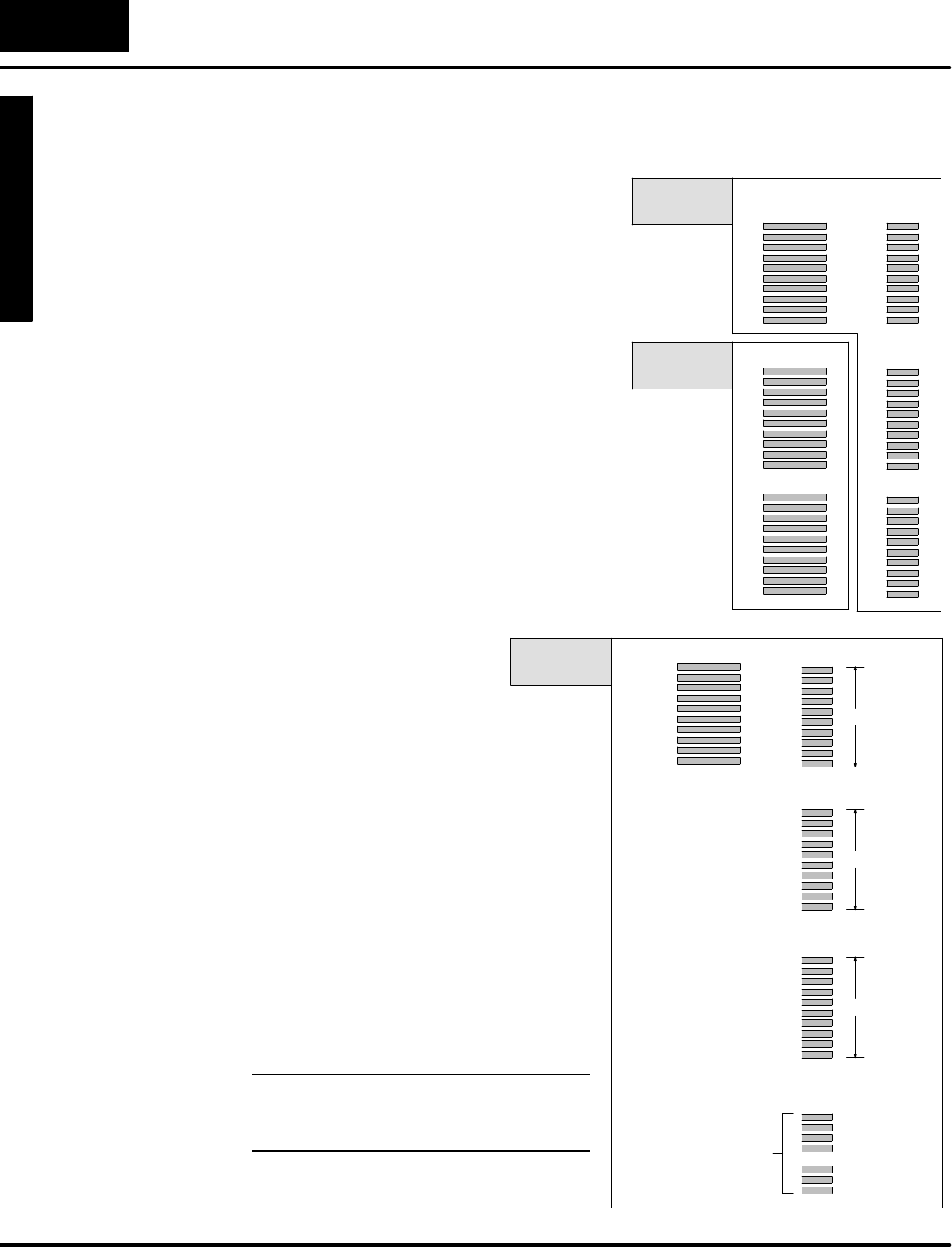
M
o
n
i
t
o
r
i
n
g
P
L
C
D
a
t
a
C
o
n
f
i
g
u
r
a
t
i
o
n
f
o
r
C
h
a
n
g
i
n
g
P
r
e
s
e
t
V
a
l
u
e
s
Mode
Change Preset
C
h
a
n
g
e
P
r
e
s
e
t
6
-
-
4
Change PresetMode
Setup ParametersforChangePreset Mode
A
t
t
h
i
s
p
o
i
n
t
w
e
d
o
a
b
i
t
o
f
o
r
i
e
n
t
a
t
i
o
n
b
y
discussing wherethe listsreside.
SPLCV-memory containsall the data
value lists,along withUserPreset
titles(inASCII code form).These
listsrequireladderprogramming,
and we provide example programsin
this chapterto helpyou do this.
STimertitlesand Countertitlesare
located inthe DV--1000,and cannot
be changed.Therefore,no
programming isrequired forthese.
The maximumnumberofUser-titled
Presetsis16 forDL130,DL230 and
DL240 CPUs,and 32 forDL250,DL350
and all DL405 CPUs.Amaximumof99
Timer--titled presetsand 99 Counter- titled
presetsare available on all systems.
USERPRESET
Titles
TIMERTitles
COUNTERTitles
V-Memory
Data
PLC
V-Memory
DV-1000
Firmware
T
h
e
l
i
s
t
s
w
h
i
c
h
r
e
s
i
d
e
i
n
V-memoryrequiresetup
parametersaswell as
ladderprogramming.The location of
setup parametersislisted inthe table on
the following page.
Setup parametersforChange Preset
Mode listsareasubsetof the DV-1000
setup parameters.Theyinclude both
pointerand block sizetypes.Pointers
specifythe beginning addressesofeach
list. Block sizesare a constant that
specifythe length ofeachlistpair.
SThe length of the titleslistand data
list foreachtitletype isalways the
same,sothe block sizespecifies
both.
SThe lengthsof the three typesof
listsmaybe equal,ordifferent.
NOTE:Eachlistmusthave atleastone
entry.You cannotuse zeroforanyof the
three block size(listlength)parameters.
PLC
V-Memory
USERPresetsUSERTitles
Vaaaa Vxxxx
Vyyyy
Vzzzz
TIMER Data
COUNTER Data
K3
K2
K1
Pointers
Block
sizes
Setup Parameters
V7600 --
V7622
V7720 --
V7722
Vaaaa to
Vzzzz
K1,K2,K3
Location ofPreset
VariableLists
Pointerand
Block Sizes
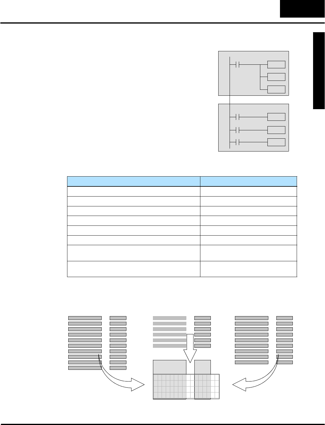
M
o
n
i
t
o
r
i
n
g
P
L
C
D
a
t
a
C
o
n
f
i
g
u
r
a
t
i
o
n
f
o
r
C
h
a
n
g
i
n
g
P
r
e
s
e
t
V
a
l
u
e
s
C
h
a
n
g
e
P
r
e
s
e
t
M
o
d
e
6
-
-
5
Change PresetMode
The ladderprogram required tosetup the
DV-1000 forChange PresetMode is very
simple. Infact, the setup programneedsonlyto
executeonthe firstscan (usecontactSP0).The
thingsthatitmustdo are:
SSpecifythe location of the titlesand data.
SSpecifythe length of title and datalists.
SCreate a password(ordisableit)
SLoad textdataintothe area forusertitles,
ifUser-titled Presetsare used.
The first three of theseitemsare partof the setup
parameterlocation data.Laterinthis chapterwe
include severalexampleladderprograms.
MainProgram
Setup Program
LadderProgram
The following tableliststhe subsetof the DV-1000 setup parameterswhich pertain
onlytoChange PresetMode.
V-MemoryLocation Setup ParameterDescription
V7620 UserPresetDataPointer
V7621 UserPresetTitlesPointer
V7622 UserPresetBlockSize
V7627 ChangePresetPassword
V7720 (DL130 andDL230 CPUsuseV7640)TitledTimerDataPointer
V7721 (DL130 andDL230 CPUsuseV7641)TitledCounterDataPointer
V7722,highbyte(DL130 andDL230 CPUsuse
Location V7642)
TitledTimerPresetBlockSize
V7722,lowbyte(DL130 andDL230 CPUsuse
Location V7642)
TitledCounterPresetBlockSize
The resultofprogramming thesesetup parametersis shown below.The listlengths
areindependentlyprogrammable,as shown.The Usertitlestextisalsoselectable.
7
6
5
4
3
2
1
0
7
6
5
4
3
2
1
0
abcdefgh 0000
abcdefgh 0000
abcdefgh 0000
abcdefgh 0000
TITLE
FIELD
DATA
FIELD
U
S
E
R
T
i
t
l
e
s
V
-
M
e
m
o
r
y
Data
T
I
M
E
R
T
i
t
l
e
s
C
O
U
N
T
E
R
Titles
OROR
V
-
M
e
m
o
r
y
Data
V
-
M
e
m
o
r
y
Data
ChangePreset
Setup Program
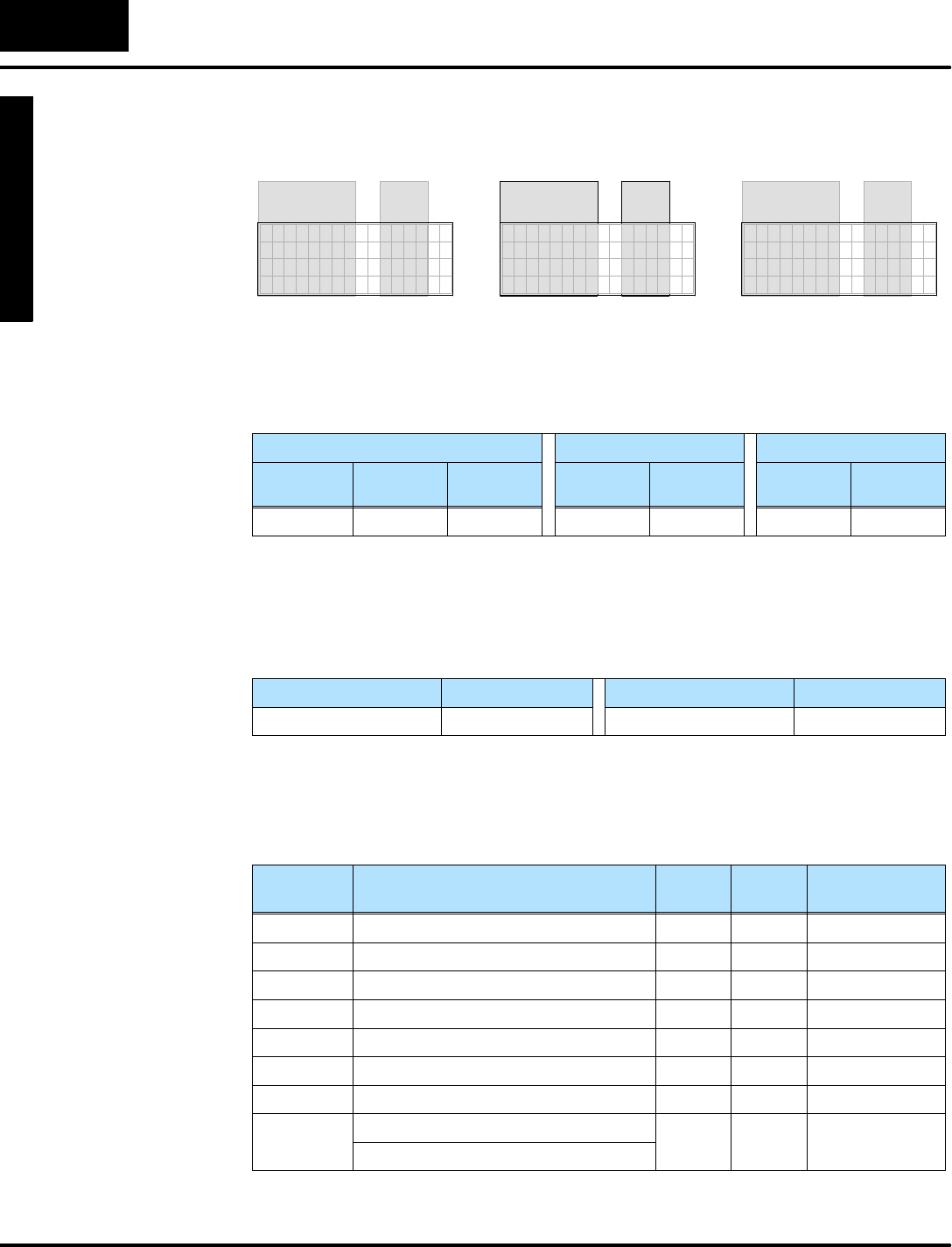
M
o
n
i
t
o
r
i
n
g
P
L
C
D
a
t
a
C
o
n
f
i
g
u
r
a
t
i
o
n
f
o
r
C
h
a
n
g
i
n
g
P
r
e
s
e
t
V
a
l
u
e
s
Mode
Change Preset
C
h
a
n
g
e
P
r
e
s
e
t
6
-
-
6
Change PresetMode
Asa beginning example,let’sprogramthe setup parametersforthe minimumlist
sizesand typesacceptabletothe the DV-1000.Theminimumlengthforeachtitle
listisonetitle each.
7654321076543210
TIMER 1 0000
TIMER
TITLES
DATA
7654321076543210
COUNTER 1 0000
COUNTER
TITLES
DATA
7654321076543210
My Title 0000
USER
TITLES
DATA
Also,wecan selectdefaultusertitleswhichtell the DV-1000 to usethe V-memory
address forusertitlesinstead oflooking fortext. Thisisdone byusing “FFFF”forthe
Usertitle address pointer.Aworksheet form ofourChange Presetselections
follows:
UserPresetsTimerPresetsCounterPresets
TextTitles Text
Locations
Data
Locations
Titles Data
Locations
Counter
Titles
Data
Locations
(default) -- V2300 Timer1V2301 Counter1V2302
Finally,wemakesome defaultchoicesjust to getstarted.Wewill disablethe Change
Presetpasswordfornow(Change PresetPasswordis covered in detail furtherin
this chapter).And,we’ll choosethe Powerup DefaultMode tobeChange Preset.
PasswordPasswordValuePowerup ModePowerup Value
Disable 0000 ChangePreset0001
Using the worksheetselections can determine the setup parameters.The numbers
arein boldtextinthe following table.Notethat the UserPresetTitlesPointerwill
normallylistan octaladdress.However,we programitwith“FFFF”in ordertoselect
defaultusertitles.
V-Memory
Location
Setup ParameterDescription FormatValueNotes:
V7620 UserPresetDataPointerOctal2300 StartatV2300
V7621 UserPresetTitlesPointerOctalFFFF Usedefault title
V7622 UserPresetBlockSizeBCD 0001 1title
V7626 PowerupModeBCD 0001 ChangePreset
V7627 ChangePresetPasswordBCD 0000 Disabled
V7720*TimerDataPointerOctal2301 StartatV2301
V7721*CounterDataPointerOctal2302 StartatV2302
V7722*TimerPresetBlockSize(highbyte)BCD 0101 one timer,
o
n
e
c
o
u
n
t
e
r
CounterPresetBlockSize(lowbyte)
o
n
e
c
o
u
n
t
e
r
*DL130 and DL230 CPUsuse differentmemorylocationshere:V7640 instead of
V7720,V7641 instead ofV7721,and V7642 instead ofV7722..
Establishing the
Lists
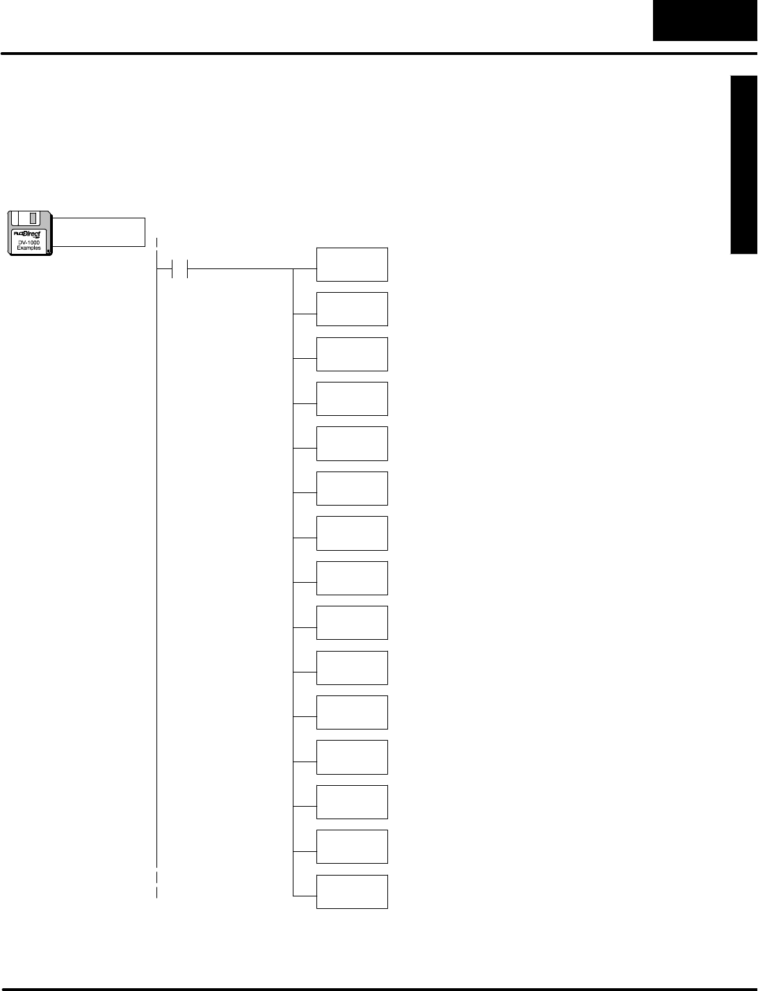
M
o
n
i
t
o
r
i
n
g
P
L
C
D
a
t
a
C
o
n
f
i
g
u
r
a
t
i
o
n
f
o
r
C
h
a
n
g
i
n
g
P
r
e
s
e
t
V
a
l
u
e
s
C
h
a
n
g
e
P
r
e
s
e
t
M
o
d
e
6
-
-
7
Change PresetMode
Now we usethe information inthe setup parametertabletowritethe program.Be
sureto payattention tothe datatype (octalorBCD)ofeachinstruction thatloadsto
the accumulator.Thisexample onlyrequiresparametersetup (no main program
required).Load thisprogramintoyourCPU,and followthe discussion on the next
page tosee how itperformsthe worksheetchoices.
SP0LDA
O2300
Load octaladdress 2300 intothe accumulator.V2300 isthe
beginning location of the userpresetvalues.
OUT
V7620
Output thisaddress toV7620, the location of the setup
parameterforthe beginning address ofuserpresetvalues.
ParameterSetup:ChangePreset
LD
Kffff
Load the hex constantFFFF intothe accumulator.
OUT
V7621
Output this constant toV7621, the location ofsetup
parameterforthe starting address of the titletextblock.
FirstScanOnly
LD
K1
Load the constantK1(BCD)intothe accumulator.
OUT
V7622
Output the constant1toV7622, the location of the setup
parameterforthe User-titled labelblock size.
LD
K0
Load the constantK0intothe accumulator.
OUT
V7627
Output the constantK0toV7627, the location of the
Change PresetPasswork.The value of0000 disablesit.
LDA
O2301
Load the octaladdress 2301 intothe accumulator.
OUT
V7720
Output the octaladdress 2301 toV7720, the location of the
setup parameterforthe starting address of the Timer
Presets.NOTE:DL130 and DL230 CPUsusememory
location V7640,notV7720.
LDA
O2302 Load the octaladdress 2302 intothe accumulator.
OUT
V7721
LD
K101 Load the constantK101 intothe accumulator
OUT
V7722
Output the constant101 toV7722, the location of the block
size bytesforTimerand Countertitled data.This selects
one each.NOTE:DL130 and DL230 CPUsusememory
location V7642,notV7722.
Output the octaladdress 2302 toV7721, the location of the
setup parameterforthe starting address of the Counter
Presets.NOTE:DL130 and DL230 CPUsusememory
location V7641,notV7721.
OUT
V7626
Output the constantK1toV7626, the location of the
Powerup DefaultMode setup parameter.The value of0001
selectsChange PresetMode.
a:\preset1.prj
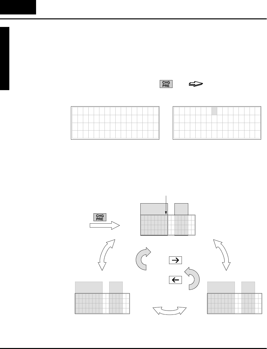
M
o
n
i
t
o
r
i
n
g
P
L
C
D
a
t
a
C
o
n
f
i
g
u
r
a
t
i
o
n
f
o
r
C
h
a
n
g
i
n
g
P
r
e
s
e
t
V
a
l
u
e
s
Mode
Change Preset
C
h
a
n
g
e
P
r
e
s
e
t
6
-
-
8
Change PresetMode
Accessing ChangePresetVariables
If you haveloaded the example programinthe Setup Parameters section,we’re
readytosee how itwill perform foran operator.To enterChange PresetMode,press
ChangePreseton the keypad. If the setup parametersforChange PresetMode are
missing orincomplete,you will see the displaybelowon the left.
7654321076543210
* S E T U P E R R O R *
C H E C K V A L U E I N
V 7 6 2 0 T O V 7 6 2 2
PRESS
... withoutpropersetup program... withpropersetup program
7654321076543210
V 2 3 0 0 0 0 0 0
The three change presetlistswe programmed inthe firstexamplesetup programare
accessible asacircularlist. Refertothe figure below.Upon entrytoChange Preset
Mode, the firstdisplayisautomaticallythe User--titled list. Fromthere,usethe Right
Arrowand Left Arrowkeys tomovetothe timertitlesand countertitlesdisplays.
PRESS
PRESS
CursorPosition
PRESS
EnterChange PresetMode
7654321076543210
V 2300 0000
USER
TITLES
DATA
7654321076543210
TIMER 1 0000
0
TIMER
TITLES
DATA
7654321076543210
COUNTER 1 0000
COUNTER
TITLES
DATA
Selecting the
List toDisplay
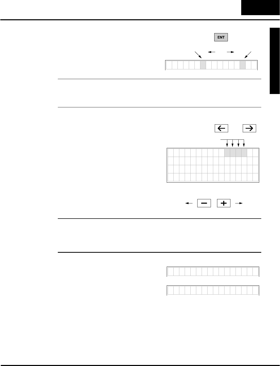
M
o
n
i
t
o
r
i
n
g
P
L
C
D
a
t
a
C
o
n
f
i
g
u
r
a
t
i
o
n
f
o
r
C
h
a
n
g
i
n
g
P
r
e
s
e
t
V
a
l
u
e
s
C
h
a
n
g
e
P
r
e
s
e
t
M
o
d
e
6
-
-
9
Change PresetMode
Press the EnterKeytotogglethe cursor
fromthe titletothe datafield and back. In
the titlefield, the cursoralways occupies
the right-mostcharacterposition .When
the cursorisinthe datafieldyou areready
to edit the data.
Title
Position
PRESS
Data
Position
toggles
V 2 3 0 0 0 0 0 0
NOTE:Dataisrestricted tothe range of0000 to 9999 inChange PresetMode. If the
datayou areviewing alreadyhasone or more digitsinthe hexadecimalrange (A
through F),you mayonly view it. The DV-1000 classifiesthe entire numberas
hexadecimal,and will notallowkeypad entriesto editits value.
Oncethe cursorisinthe data position,use
the Rightand Left Arrowkeys tomove
the cursoramong the fourdigitpositions.
Thisworks incircularfashion,somoving
past the end of the datajumpsthe cursor
tothe opposite end of the datavalue.
Toincrementa digit, press the Plus(+)
Key.To decrementa digit, press the
Minus(--) Key.The range ofinputchange
isfrom0000 to 9999,BCD. Incrementing a
digitpast9 ordecrementing itpast0
automatically carriesto orborrowsfrom
(respectively)the digit(s)tothe left of the
cursorposition.
7654321076543210
V 2 3 0 0 1 2 3 4
DigitPositions
PRESS OR
PRESS
0000 9999
WARNING:Changing thepresetvalueon thedisplay as above immediately
changes the valueinPLCV-memory(thedisplay isnotbuffered).Equipment
damageorpersonnel injurymay occurfromimproperuse of thismode.Be
sureto pause a momentaftereachkeystroke toallowfortheDV-1000 display
update,sothatyou are viewing currentvalues ofChangePresetvariables.
The datafieldsinthe timerand counter
displays are edited in exactlythe same
wayasthe User-titled Presets.
T I M E R 1 0 0 0 0
C O U N T E R 1 0 0 0 0
CursorPositioning
On TitleorData
Changing the
PresetValue
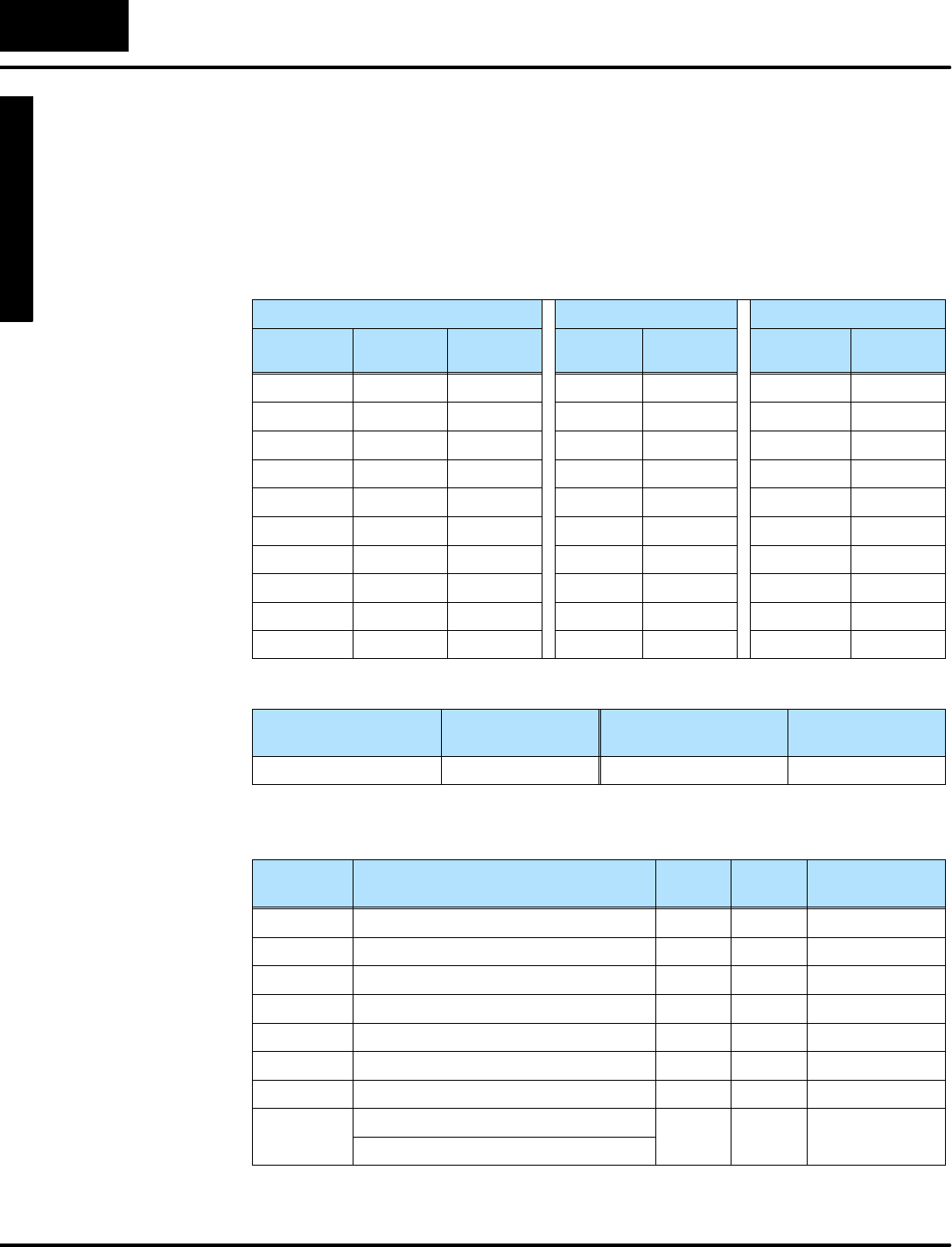
M
o
n
i
t
o
r
i
n
g
P
L
C
D
a
t
a
C
o
n
f
i
g
u
r
a
t
i
o
n
f
o
r
C
h
a
n
g
i
n
g
P
r
e
s
e
t
V
a
l
u
e
s
Mode
Change Preset
C
h
a
n
g
e
P
r
e
s
e
t
6
-
-
1
0
Change PresetMode
Pre--labeled Timerand CounterPresets
Pre-labeled Timerand CounterPresetsaresimplerthan User-titled Presets,sowe
discuss thesefirst. Rememberthatoursetup mustinclude atleastone ofeachtitle
type.So,wechoose one User-titled Preset, (using the defaultlabel),sixteen
Pre-titled TimerPresets,and seven Pre-titled CounterPresets.The following table
summarizesourselections.
UserPresetsTimerPresetsCounterPresets
TextTitles Text
Locations
Data
Locations
Titles Data
Locations
Counter
Titles
Data
Locations
(default)V2200 Timer1V2300 Counter1V2320
Timer2V2301 Counter2V2321
Timer3V2302 Counter3V2322
Timer4V2303 Counter4V2323
Timer5V2304 Counter5V2324
Timer6V2305 Counter6V2325
Timer7V2306 Counter7V2326
Timer8V2307
... ...
Timer16 V2317
Weselectno password,and useChange Presetasthe Powerup DefaultMode.
Password
Enable/Disable
PasswordValuePowerup ModePowerup Value
Disable 0000 ChangePreset0001
Using the worksheetabovewecan determine the setup parameters.The numbers
arein boldtextinthe following table.
V-Memory
Location
Setup ParameterDescription FormatValueNotes:
V7620 UserPresetDataPointerOctal2200 startatV2200
V7621 UserPresetTitlesPointerOctalFFFF default titles
V7622 UserPresetBlockSizeBCD 11title
V7626 PowerupModeBCD 0001 ChangePreset
V7627 ChangePresetPasswordBCD 0000 Disabled
V7720*TimerDataPointerOctal2300 startatV2300
V7721*CounterDataPointerOctal2320 startatV2320
V7722*TimerPresetBlockSize(highbyte)BCD 1607 16 timers,
7
c
o
u
n
t
e
r
s
CounterPresetBlockSize(lowbyte)
7
c
o
u
n
t
e
r
s
*DL130 and DL230 CPUsuse differentmemorylocationshere:V7640 instead of
V7720,V7641 instead ofV7721,and V7642 instead ofV7722..
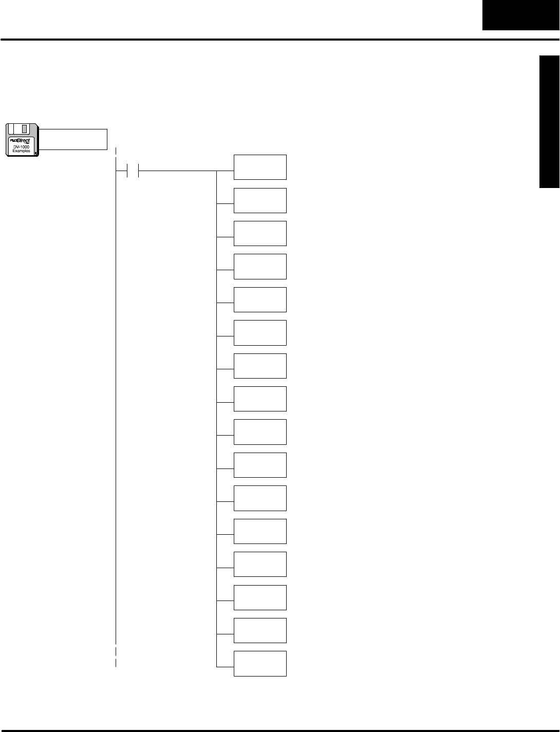
M
o
n
i
t
o
r
i
n
g
P
L
C
D
a
t
a
C
o
n
f
i
g
u
r
a
t
i
o
n
f
o
r
C
h
a
n
g
i
n
g
P
r
e
s
e
t
V
a
l
u
e
s
C
h
a
n
g
e
P
r
e
s
e
t
M
o
d
e
6
-
-
1
1
Change PresetMode
Inthis step we usethe information inthe setup parametertabletowritethe program.
Besureto payattention tothe datatype (octalorBCD)ofeachinstruction thatloads
tothe accumulator.Load thisprogramintoyourCPU,and usePresetMode tosee
how itperformsthe worksheetchoices.
SP0LDA
O2200
Load octaladdress 2200 intothe accumulator.V2200 isthe
beginning location of the userpresetvalues.
OUT
V7620
Output thisaddress toV7620, the location of the setup
parameterforthe beginning address ofuserpresetvalues.
ParameterSetup:ChangePreset
LD
Kffff
Load the hex constantKFFFF intothe accumulator.
OUT
V7621
Output this constant toV7621, the location ofsetup
parameterforthe starting address of the titletextblock.
FirstScanOnly
LD
K1
Load the constantK1(BCD)intothe accumulator.
OUT
V7622
Output the constantK1toV7622, the location of the setup
parameterforthe User-titled labelblock size.
LD
K0
Load the constantK0intothe accumulator.
OUT
V7627
Output the constantK0toV7627, the location of the
Change Presetpassword.The value of0000 disablesit.
LDA
O2300
Load the octaladdress 2300 intothe accumulator.
OUT
V7720
Output the octaladdress 2300 toV7720, the location of the
setup parameterforthe starting address of the Timer
Presets.NOTE:DL130 and DL230 CPUsusememory
location V7640,notV7720.
LDA
O2320 Load the octaladdress 2320 intothe accumulator.
OUT
V7721
LD
K1607 Load the constantK1607 intothe accumulator.
OUT
V7722
Output the constantK1607 toV7722, the location of the
block size bytesforTimerand Countertitled data.This
selects sixteen timersand seven counters.NOTE:DL130
and DL230 CPUsusememorylocation V7642,notV7722.
Output the octaladdress 2320 toV7721, the location of the
setup parameterforthe starting address of the Counter
Presets.NOTE:DL130 and DL230 CPUsusememory
location V7641,notV7721.
LD
K1
Load the constantK1intothe accumulator.
OUT
V7626
Output the constantK1toV7626, the location of the
Powerup DefaultMode setup parameter.The value of0001
selectsChange PresetMode.
a:\preset2.prj
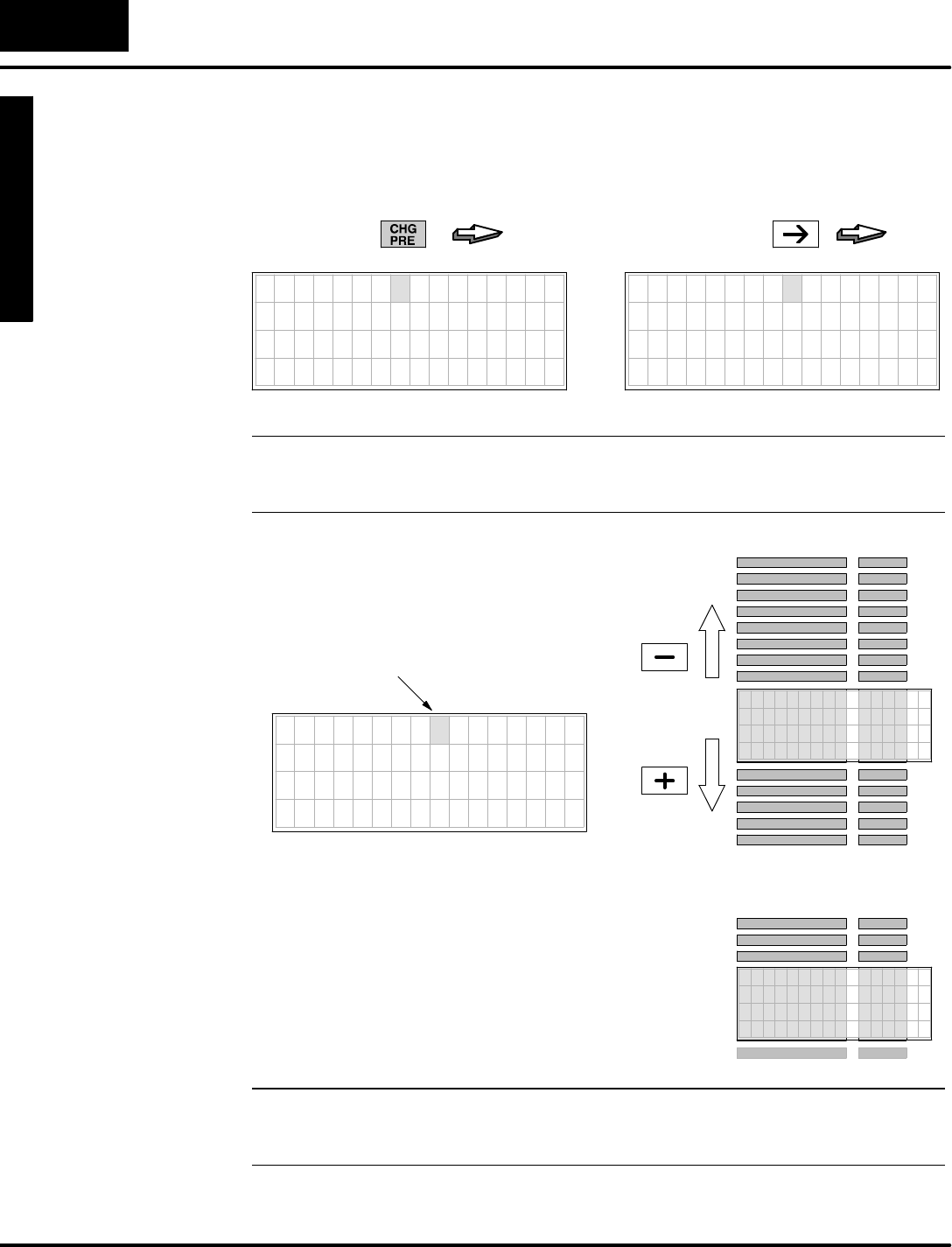
M
o
n
i
t
o
r
i
n
g
P
L
C
D
a
t
a
C
o
n
f
i
g
u
r
a
t
i
o
n
f
o
r
C
h
a
n
g
i
n
g
P
r
e
s
e
t
V
a
l
u
e
s
Mode
Change Preset
C
h
a
n
g
e
P
r
e
s
e
t
6
-
-
1
2
Change PresetMode
If you haveloaded the Timer/Counterexample programon the previouspage,we’re
readytosee how itwill perform foran operator.First, enterChange PresetMode by
pressing ChangePreseton the keypad.Then press the RightArrowKeytomove
tothe timertitleslist.
PRESS
7654321076543210
V 2 2 0 0 0 0 0 0
7654321076543210
T I M E R 1 0 0 0 0
T I M E R 2 0 0 0 0
T I M E R 3 0 0 0 0
T I M E R 4 0 0 0 0
PRESS
NOTE:In orderforthe newsetup parameterstotake effect, you musteitherpress a
key(preferablyChangePreset),orpower-cyclethe PLC.Eithereventcausesthe
DV-1000 tore-read its setup parametersfromV-memory.
W
i
t
h
T
i
m
e
r
P
r
e
s
e
t
T
i
t
l
e
s
s
e
l
e
c
t
e
d
,
l
e
a
v
e
the cursoroverthe titlesfield.Then use
the Plus(+)Keytoscroll downward.By
repeating this you can access all sixteen
timers.Then usethe Minus(--) Keyto
scroll upwardthrough the list.
TIMERTITLES DATA
TIMER 9 0000
TIMER10 0000
TIMER11 0000
TIMER12 0000
TIMER15 0000
TIMER14 0000
TIMER13 0000
TIMER 8 0000
TIMER 7 0000
TIMER 6 0000
TIMER 5 0000
TIMER 4 0000
TIMER 3 0000
TIMER 2 0000
TIMER 1 0000
7
6
5
4
3
2
1
0
7
6
5
4
3
2
1
0
T I M E R 9 0 0 0 0
T I M E R 1 0 0 0 0 0
T I M E R 1 1 0 0 0 0
T I M E R 1 2 0 0 0 0
CursorPosition
PRESS
PRESS
TIMER16 0000
A
c
c
e
s
s
t
o
C
o
u
n
t
e
r
p
r
e
s
e
t
s
w
o
r
k
s
j
u
s
t
l
i
k
e
timerpresetlabels.Press the Cursor
RightKeytomovetothe countertitles
display.You can then scroll through all
seven countertitlesbyusing the Plus(+)
Keytoscroll downward,and the Minus(--)
Keytoscroll upward.
COUNTER
TITLES
DATA
COUNTER 4 0000
C O U N T E R 5 0 0 0 0
COUNTER 6 0000
COUNTER 7 0000
COUNTER 3 0000
COUNTER 2 0000
COUNTER 1 0000
NOTE:AppendixCof thismanualcontainsaworksheet forChange Preset
applications.Italsoincludesa decimal-to-octalconversion tableto helpcorrelate
timerlabelnumberswiththe numbering ofactualtimersand countersinthe CPU.
Scrolling Through
ChangePreset
Lists
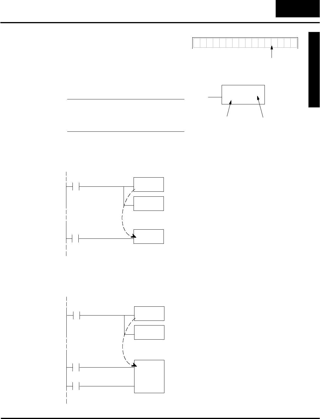
M
o
n
i
t
o
r
i
n
g
P
L
C
D
a
t
a
C
o
n
f
i
g
u
r
a
t
i
o
n
f
o
r
C
h
a
n
g
i
n
g
P
r
e
s
e
t
V
a
l
u
e
s
C
h
a
n
g
e
P
r
e
s
e
t
M
o
d
e
6
-
-
1
3
Change PresetMode
Asmentioned at the beginning of this
chapter,Timerand CounterPresetLabels
serve onlytolabeldata on the DV-1000
display.Theselabelstreatall user
V-memoryequally,and do notdirectly
adjustladderlogictimerorcounter
instruction boxpresets. Instead,you use a
common V-memoryreference.
NOTE:The timerpresetinthe timerbox
mustnotbeaconstantKx,ifyou want the
Change Presetmode to adjust the timer
preset!
TMR
Bbbb
Taaa
Timernumber
TimerBox
TimerPreset
T I M E R 1 0 0 0 0
TimerPresetatV2300
SupposewelocatePre-labeled “Timer1”preset to be atV2300,asinthe previous
example.Now,wecan associateitwith an actualtimerinaladderprogram.
SP0LDA
O2300
Load octaladdress 2300 intothe accumulator.
OUT
V7720
Output thisaddress toV7720, the location of the setup
parameterforthe beginning address ofTimer-titled
Presets.
Setup Program
TMR
V2300
TurnonTimer1when X0ison.EnterV2300 inthe preset
fieldforthe timer.
T1
X0
MainProgram
SupposewelocatePre-labeled “Counter1”presetatV2320,asinthe previous
example.Now,wecan associateitwith an actualcounterinaladderprogram.
SP0LDA
O2320
Load octaladdress 2320 intothe accumulator.
OUT
V7721
Output thisaddress toV7721, the location of the setup
parameterforthe beginning address ofCounter-titled
Presets.
Setup Program
CNT
V2320
IncrementCounter1when X0makesan off-to-on
transition.When the countervalue reachesthe preset
value inV2320, the counterstatusbitcomeson. InputX1
resetsthe counterand turnsoff the counterstatusbit.
CT1
X0
MainProgram
X0
Using PresetsWith
TimerBox
Instructions
Using PresetsWith
CounterBox
Instructions
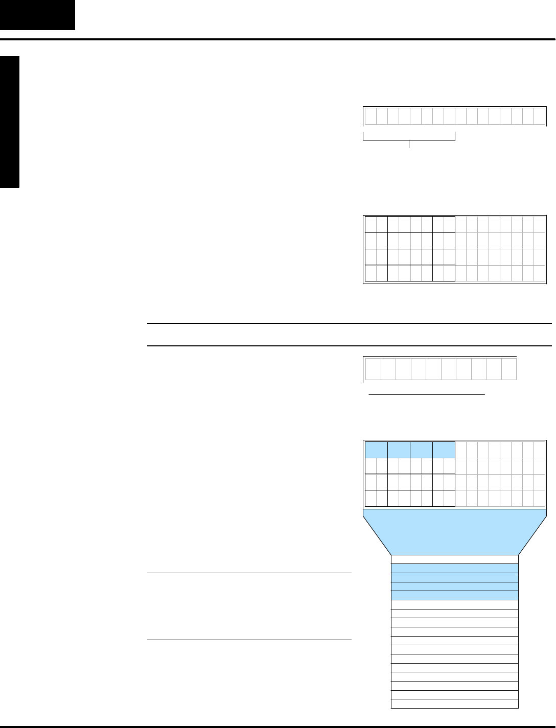
M
o
n
i
t
o
r
i
n
g
P
L
C
D
a
t
a
C
o
n
f
i
g
u
r
a
t
i
o
n
f
o
r
C
h
a
n
g
i
n
g
P
r
e
s
e
t
V
a
l
u
e
s
Mode
Change Preset
C
h
a
n
g
e
P
r
e
s
e
t
6
-
-
1
4
Change PresetMode
User-titledPresets
The User--titled Change Presetdisplay
allows you tocreateyourowntext titlesof
up to eightcharactersinlength each.The
User--titlelistcan include from1to either
16 or32 titles(depending on CPUtype).
There arefourdisplaypositionspertitleto
the left ofeachrow.The DV-1000 reserves
the rightside ofeachrowfordisplaying the
presetdata,sothese do notmap intotitle
textpositions.Eachtextdisplayposition
correspondsto one V-memorylocation,
whichcontainstwo 8--bitASCII codes.
The displaypositionsare numbered in
octal, to helpyou referencethemto
corresponding V-memoryaddresses.
7654321076543210
0
10
5
2
12
15 17
7
1 3
1614
4
1311
6
TextDisplay Positions
a b c d e f g h 0 0 0 0
Usertitle
NOTE:The completeASCII tableforthe DV-1000 isinAppendixB.
Now weconsiderthe arbitrarytitle
“abcdefgh”on the top line of the display.
We haveto programV-memorywiththe
textdatainthe properlocation.Here are
the steps:
SWechoosethe User-titled Preset
titles starting address. Ourexample
arbitrarilyusesV2200.
SWechooseablock size ofone (one
title).Thismeanswereserve and
programfourV-memorylocationsfor
asingletitle.
SWe usethe textdisplayposition map
to programthe properfour
V-memorylocationswithASCII
codes.
NOTE:Thislistmaybe up to 16 or32 titles
long (maximumdetermined byCPUtype).
Tocalculatethe numberofV-memory
locationsrequired,justmultiplythe
numberof titlesbyfour.
Position Data TextV-Memory
0 4142 a2200
1 4344 c2201
2 4546 e2202
3 4748 g2203
4 00002204
5 00002205
6 00002206
7 00002207
10 2210 0000
11 00002211
12 00002212
13 00002213
14 00002214
15 00002215
16 00002216
17 00002217
b
d
f
h
TextDisplay Positions
TextData
7654321076543210
10
5
12
15 17
7
1614
4
1311
6
abcdefgh
ASCII codes
41 42 43 44 45 46 47 48
0 21 3
User-Titled
TextLabels
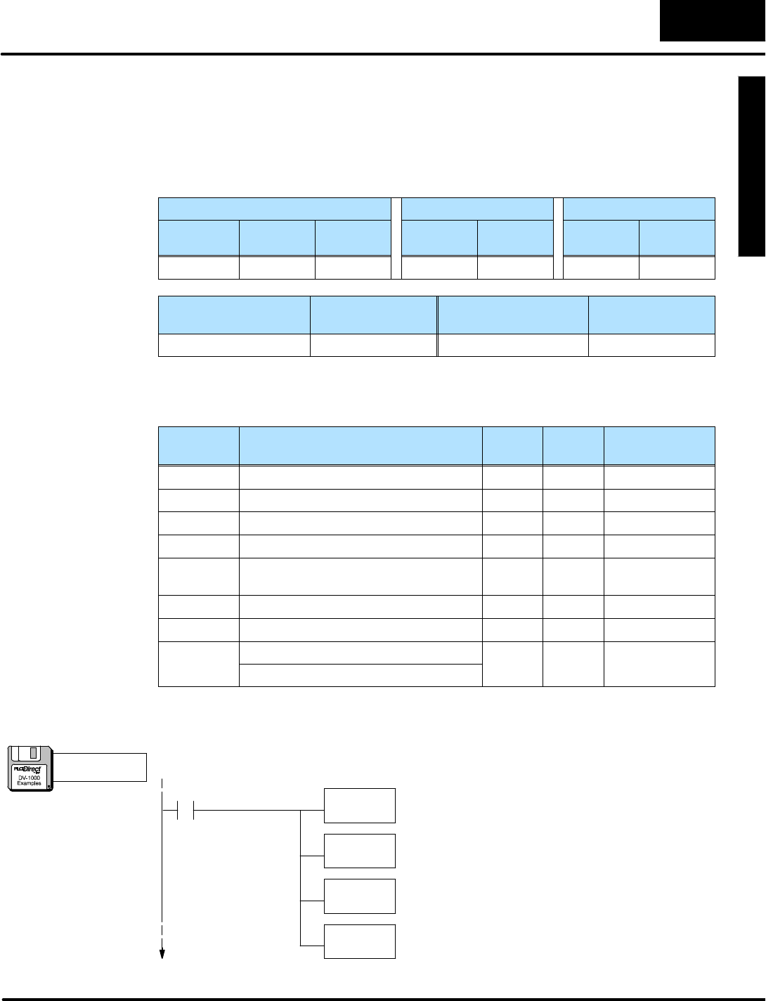
M
o
n
i
t
o
r
i
n
g
P
L
C
D
a
t
a
C
o
n
f
i
g
u
r
a
t
i
o
n
f
o
r
C
h
a
n
g
i
n
g
P
r
e
s
e
t
V
a
l
u
e
s
C
h
a
n
g
e
P
r
e
s
e
t
M
o
d
e
6
-
-
1
5
Change PresetMode
Afterchoosing the titlesand datato preset, wecan fill out the following application
worksheet. The fourUserPresetsData Locationsarelisted,and the text titlesareleft
blank.Notethatwe have one timerand counterlisted,because all three preset types
musthave atleastone entry.Finally,weselect the password(disabled)and the
powerup mode.We arbitrarily chooseChange Presetasthe Powerup DefaultMode.
UserPresetsTimerPresetsCounterPresets
TextTitles Text
Locations
Data
Locations
Titles Data
Locations
Counter
Titles
Data
Locations
abcdefg V2200 V2300 Timer1V2304 Counter1V2305
Password
Enable/Disable
PasswordValuePowerup ModePowerup Value
Disable 0000 ChangePreset0001
Using the worksheetabovewecan determine the setup parameters.The numbers
arein boldtextinthe following table.
V-Memory
Location
Setup ParameterDescription FormatValueNotes:
V7620 UserPresetDataPointerOctal2300 startatV2300
V7621 UserPresetTitlesPointerOctal2200 startatV2200
V7622 UserPresetBlockSizeBCD 0001 1title
V7626 PowerupModeBCD 0001 ChangePreset
V7627 ChangePresetPasswordBCD 0000 Disablepass-
word
V7720*TimerDataPointerOctal2301 startatV2304
V7721*CounterDataPointerOctal2302 startatV2305
V7722*TimerPresetBlockSize(highbyte)BCD 0101 one timer,
o
n
e
c
o
u
n
t
e
r
CounterPresetBlockSize(lowbyte)
o
n
e
c
o
u
n
t
e
r
*DL130 and DL230 CPUsuse differentmemorylocationshere:V7640 instead of
V7720,V7641 instead ofV7721,and V7642 instead ofV7722..
SP0LDA
O2300
Load octaladdress 2300 intothe accumulator.V2300 isthe
beginning location of the userpresetvalues.
OUT
V7620
Output thisaddress toV7620, the location of the setup
parameterforthe beginning address ofuserpresetvalues.
P
a
r
a
m
e
t
e
r
S
e
t
u
p
:
C
h
a
n
g
e
P
r
e
s
e
t
LDA
O2200
Load octaladdress 2200 intothe accumulator.V2200 isthe
beginning location of the userpreset titles.
OUT
V7621
Output this constant toV7621, the location ofsetup
parameterforthe starting address of the titletextblock.
FirstScanOnly
a:\preset3.prj
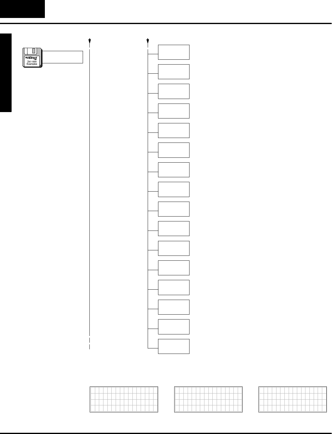
M
o
n
i
t
o
r
i
n
g
P
L
C
D
a
t
a
C
o
n
f
i
g
u
r
a
t
i
o
n
f
o
r
C
h
a
n
g
i
n
g
P
r
e
s
e
t
V
a
l
u
e
s
Mode
Change Preset
C
h
a
n
g
e
P
r
e
s
e
t
6
-
-
1
6
Change PresetMode
LD
K1
Load the constantK1(BCD)intothe accumulator.
OUT
V7622
Output the constant1toV7622, the location of the setup
parameterforthe User-titled labelblock size.
LD
K0
Load the constantK0intothe accumulator.
OUT
V7627
Output the constantK0toV7627, the location of the
Change Presetpassword.The value of0000 disablesit.
LDA
O2301
Load the octaladdress 2301 intothe accumulator.
OUT
V7720
Output the octaladdress 2300 toV7720, the location of the
setup parameterforthe starting address of the Timer
Presets.NOTE:DL130 and DL230 CPUsusememory
location V7640,notV7720.
LDA
O2302 Load the octaladdress 2302 intothe accumulator.
OUT
V7721
LD
K101 Load the constantK101 intothe accumulator.
OUT
V7722
Output the constant101 toV7722, the location of the block
size bytesforTimerand Countertitled data.This selects
one timerand one counter.NOTE:DL130 and DL230
CPUsusememorylocation V7642,notV7722.
Output the octaladdress 2305 toV7720, the location of the
setup parameterforthe starting address of the Counter
Presets.NOTE:DL130 and DL230 CPUsusememory
location V7641,notV7721.
LD
K1
Load the constantK1intothe accumulator.
OUT
V7626
Output the constantK1toV7626, the location of the
Powerup DefaultMode setup parameter.The value of0001
selectsChange PresetMode.
LDD
K63646162
Load ASCII constantsfor “abcd”inthe accumulator.
Remembertoswap positionsbetween the firstand second
pairofASCII codes.
OUTD
V2200
Placethe ASCII codesinthe User-titled textdata block.
Rememberto use onlyeven-numbered addresseswith
LDD/OUTDinstructions.
LDD
K67686566
Load ASCII constantsfor “efgh”inthe accumulator.
Remembertoswap positionsbetween the firstand second
pairofASCII codes.
OUTD
V2202
Placethe ASCII codesinthe User-titled textdata block.
Rememberto use onlyeven-numbered addresses.
Load
“abcdefgh”
The following diagramshowsthe resulting displays fromthe programexample
above.
7654321076543210
TIMER 1 0000
7654321076543210
COUNTER 1 0000
7654321076543210
abcdefgh 0000
a:\preset3.prj
(
c
o
n
t
i
n
u
e
d
)
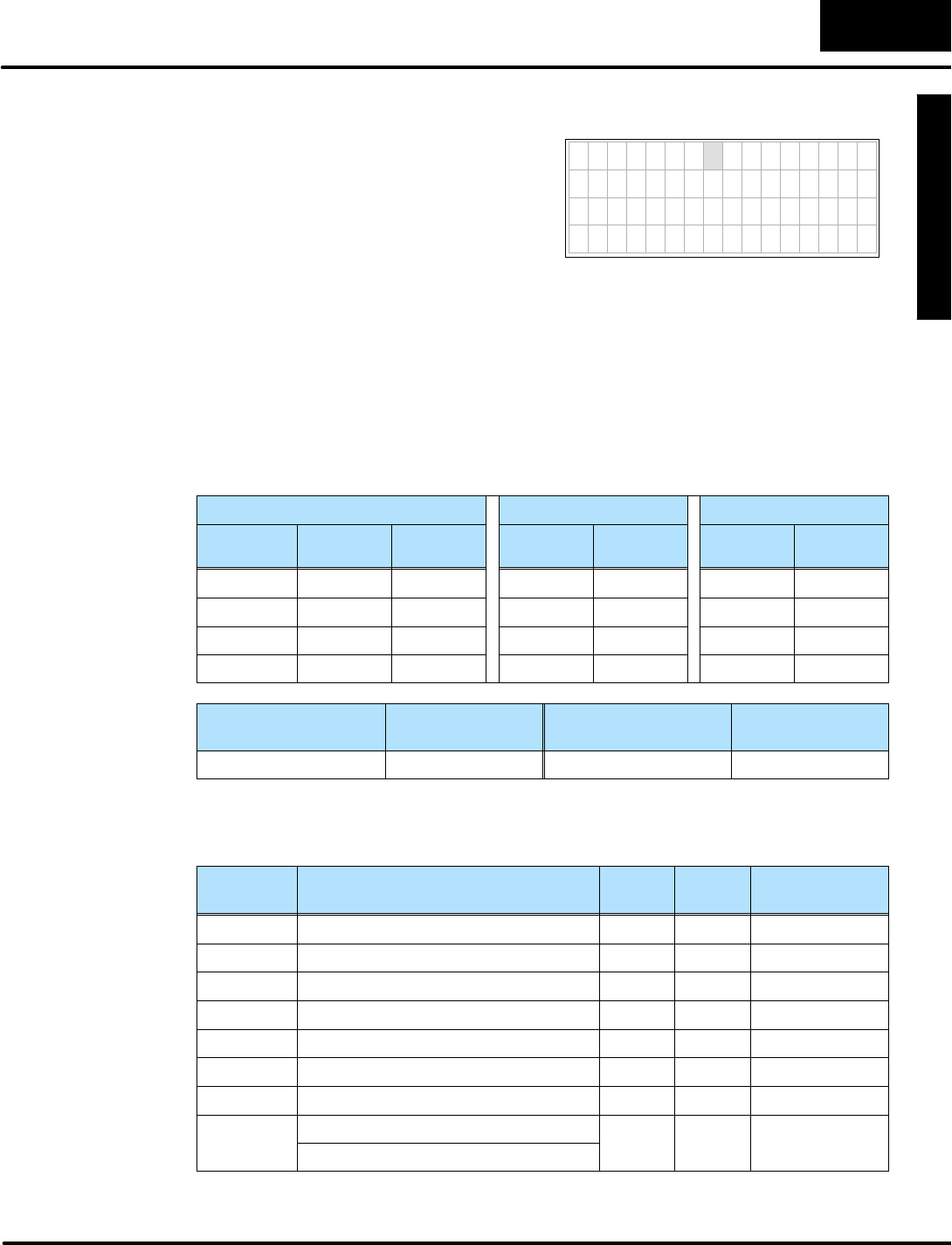
M
o
n
i
t
o
r
i
n
g
P
L
C
D
a
t
a
C
o
n
f
i
g
u
r
a
t
i
o
n
f
o
r
C
h
a
n
g
i
n
g
P
r
e
s
e
t
V
a
l
u
e
s
C
h
a
n
g
e
P
r
e
s
e
t
M
o
d
e
6
-
-
1
7
Change PresetMode
7654321076543210
V 2 3 0 0 0 0 0 0
V 2 3 0 1 0 0 0 0
V 2 3 0 2 0 0 0 0
V 2 3 0 3 0 0 0 0
Perhapsthe simplestapplication of
Change Preset titlesisthe default
user-titled presets.Supposewe are
debuggingamachine,and justwant to
preset fourV-memorylocations:V2300 --
V2303.Weselect the default titles(Vxxxx
addresses)as showntothe right. Thisisa
handy short-cutwheneverit’s
unnecessarytoinvest the timein
programming fancy text titles.
DesiredDisplay
To select thedefault titles, justenter“FFFF”inV7621, the setup parameterfor
the User-titled PresetPointer.
The titleselectionsaresummarized inthe following table.Notethe inclusion ofone
timerand counter,because all three preset typesmusthave atleastone entry.
Finally,weselect the password(disabled)and the powerup mode.We arbitrarily
chooseChange Presetasthe Powerup DefaultMode.
UserPresetsTimerPresetsCounterPresets
TextTitles Text
Locations
Data
Locations
Titles Data
Locations
Counter
Titles
Data
Locations
(V2300)V2300 Timer1V2304 Counter1V2305
(V2301)V2301
(V2302)V2302
(V2303)V2303
Password
Enable/Disable
PasswordValuePowerup ModePowerup Value
Disable 0000 ChangePreset0001
Using the worksheetabovewecan determine the setup parameters.The numbers
arein boldtextinthe following table.
V-Memory
Location
Setup ParameterDescription FormatValueNotes:
V7620 UserPresetDataPointerOctal2300 startatV2300
V7621 UserPresetTitlesPointerOctalFFFF usedefault title
V7622 UserPresetBlockSizeBCD 44titles
V7626 PowerupModeBCD 0001 ChangePreset
V7627 ChangePresetPasswordBCD 0000 Disabled
V7720*TimerDataPointerOctal2304 startatV2304
V7721*CounterDataPointerOctal2305 startatV2305
V7722*TimerPresetBlockSize(highbyte)BCD 0101 one timer,
o
n
e
c
o
u
n
t
e
r
CounterPresetBlockSize(lowbyte)
o
n
e
c
o
u
n
t
e
r
*DL130 and DL230 CPUsuse differentmemorylocationshere:V7640 instead of
V7720,V7641 instead ofV7721,and V7642 instead ofV7722..
DefaultUser
TitleList
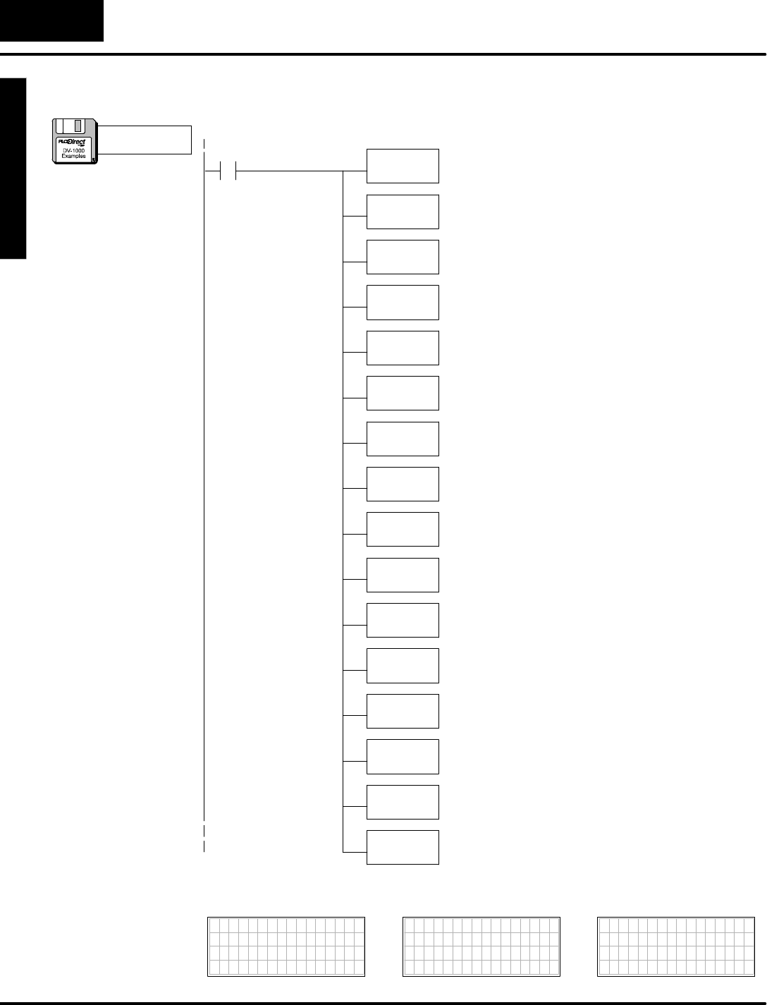
M
o
n
i
t
o
r
i
n
g
P
L
C
D
a
t
a
C
o
n
f
i
g
u
r
a
t
i
o
n
f
o
r
C
h
a
n
g
i
n
g
P
r
e
s
e
t
V
a
l
u
e
s
Mode
Change Preset
C
h
a
n
g
e
P
r
e
s
e
t
6
-
-
1
8
Change PresetMode
The following programexample usesthe previous setup tableinformation.
SP0LDA
O2300
Load octaladdress 2300 intothe accumulator.V2300 isthe
beginning location of the userpresetvalues.
OUT
V7620
Output thisaddress toV7620, the location of the setup
parameterforthe beginning address ofuserpresetvalues.
ParameterSetup:ChangePreset
LD
Kffff
Load the hex constantFFFF intothe accumulator.
OUT
V7621
Output this constant toV7621, the location ofsetup
parameterforthe starting address of the titletextblock.
FirstScanOnly
LD
K4
Load the constantK4(BCD)intothe accumulator.
OUT
V7622
Output the constant4toV7622, the location of the setup
parameterforthe User-titled labelblock size.
LD
K0
Load the constantK0intothe accumulator.
OUT
V7627
Output the constantK0toV7627, the location of the
Change PresetPassword.The value of0000 disablesit.
LDA
O2304
Load the octaladdress 2304 intothe accumulator.
OUT
V7720
Output the octaladdress 2304 toV7720, the location of the
setup parameterforthe starting address of the Timer
Presets.NOTE:DL130 and DL230 CPUsusememory
location V7640,notV7720.
LDA
O2305 Load the octaladdress 2305 intothe accumulator.
OUT
V7721
LD
K101 Load the constantK101 intothe accumulator.
OUT
V7722
Output the constantK101 toV7722, the location of the
block size bytesforTitled Timerand Counterdata.This
selectsone each.NOTE:DL130 and DL230 CPUsuse
memorylocation V7642,notV7722.
Output the octaladdress 2305 toV7721, the location of the
setup parameterforthe starting address of the Counter
Presets.NOTE:DL130 and DL230 CPUsusememory
location V7641,notV7721.
LD
K1
Load the constantK1intothe accumulator.
OUT
V7626
Output the constantK1toV7626, the location of the
Powerup DefaultMode setup parameter.The value of0001
selectsChange PresetMode.
The following diagramshowsthe resulting displays fromthe programabove.
7654321076543210
TIMER 1 0000
7654321076543210
COUNTER 1 0000
7654321076543210
V2300 0000
V2301 0000
V2302 0000
V2303 0000
a:\preset4.prj
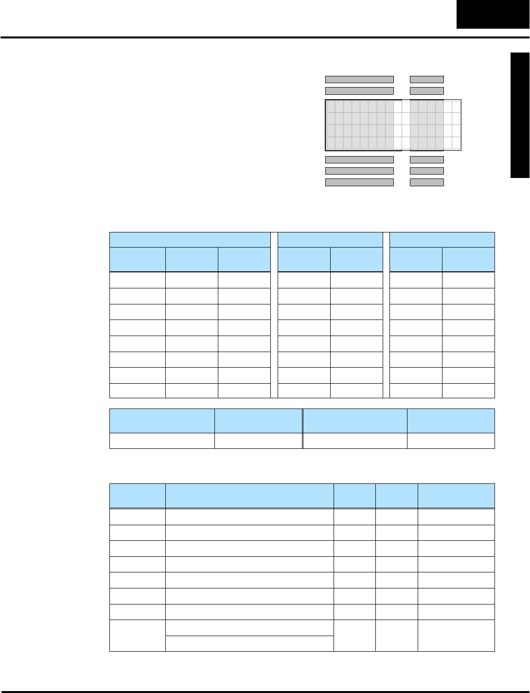
M
o
n
i
t
o
r
i
n
g
P
L
C
D
a
t
a
C
o
n
f
i
g
u
r
a
t
i
o
n
f
o
r
C
h
a
n
g
i
n
g
P
r
e
s
e
t
V
a
l
u
e
s
C
h
a
n
g
e
P
r
e
s
e
t
M
o
d
e
6
-
-
1
9
Change PresetMode
Now wewill write ourownUserTitles,
choosing meaningfulnamesforatypical
application.The list(showntothe right)is
eightitemslong,morethan the display
can showatone time.However, the
DV-1000 automaticallyadds scrolling
capability.Wewill disablethe password,
and chooseChange Presetasthe
Powerup DefaultMode.
USERTITLES DATA
H i A l a r m 0 0 0 0
L o A l a r m 0 0 0 0
S o a k T i m e 0 0 0 0
T e m p 1 0 0 0 0
G a l / M i n 0 0 0 0
T e m p 2 0 0 0 0
A c t u a l 0 0 0 0
S e t P o i n t 0 0 0 0
The following tablelistsourchoices.The ASCII codesforthe textof the User-titled
PresetsbeginsatV2200.Eachtitle’stextoccupiesfourV-memorylocations. One
timerand counterarelisted,just tomeet the required minimum.
UserPresetsTimerPresetsCounterPresets
TextTitles Text
Locations
Data
Locations
Titles Data
Locations
Counter
Titles
Data
Locations
SetPointV2200 V2300 Timer1V2310 Counter1V2311
Value V2204 V2301
HiAlarmV2210 V2302
Lo alarmV2214 V2303
SoakTimeV2220 V2304
Temp1V2224 V2305
Temp2V2230 V2306
Gal/MinV2234 V2307
Password
Enable/Disable
PasswordValuePowerup ModePowerup Value
Disable 0000 ChangePreset0001
Using the worksheetabovewecan determine the setup parameters.The numbers
arein boldtextinthe following table.
V-Memory
Location
Setup ParameterDescription FormatValueNotes:
V7620 UserPresetDataPointerOctal2300 startatV2300
V7621 UserPresetTitlesPointerOctal2200 startatV2200
V7622 UserPresetBlockSizeBCD 88titles
V7626 PowerupModeBCD 0001 ChangePreset
V7627 ChangePresetPasswordBCD 0000 Disabled
V7720*TimerDataPointerOctal2310 startatV2310
V7721*CounterDataPointerOctal2311 startatV2311
V7722*TimerPresetBlockSize(highbyte)BCD 0101 one timer,
o
n
e
c
o
u
n
t
e
r
CounterPresetBlockSize(lowbyte)
o
n
e
c
o
u
n
t
e
r
*DL130 and DL230 CPUsuse differentmemorylocationshere:V7640 instead of
V7720,V7641 instead ofV7721,and V7642 instead ofV7722.
User-titled Text
Example
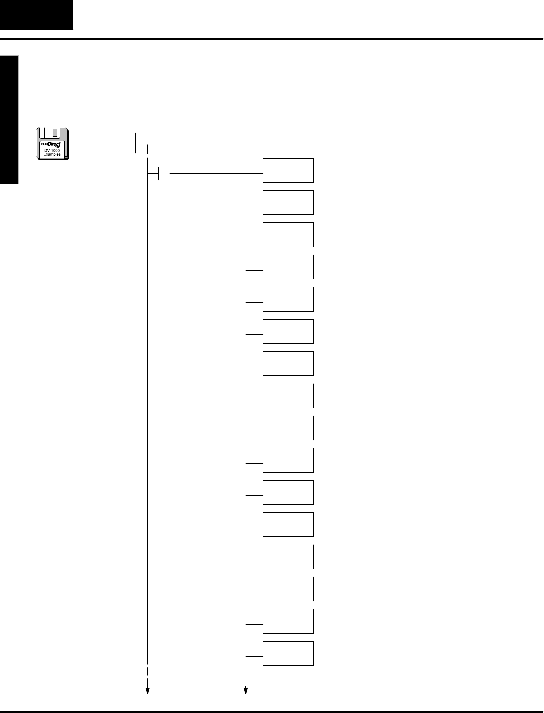
M
o
n
i
t
o
r
i
n
g
P
L
C
D
a
t
a
C
o
n
f
i
g
u
r
a
t
i
o
n
f
o
r
C
h
a
n
g
i
n
g
P
r
e
s
e
t
V
a
l
u
e
s
Mode
Change Preset
C
h
a
n
g
e
P
r
e
s
e
t
6
-
-
2
0
Change PresetMode
Inthis step we usethe information inthe setup parametertabletowritethe program.
The firstportion programsthe setup parameters.The second portion writesthe
User-Titled textdata using MOVEMCand ACONboxes.See the Message Display
Mode chapterforinformation on howtheseinstructionswork,ifnecessary.
SP0LDA
O2300
Load octaladdress 2300 intothe accumulator.V2300 isthe
beginning location of the userpresetvalues.
OUT
V7620
Output thisaddress toV7620, the location of the setup
parameterforthe beginning address ofuserpresetvalues.
P
a
r
a
m
e
t
e
r
S
e
t
u
p
:
C
h
a
n
g
e
P
r
e
s
e
t
LDA
O2200
Load octaladdress 2200 intothe accumulator.V2200 isthe
beginning address of the User-titled textdata.
OUT
V7621
Output this constant toV7621, the location ofsetup
parameterforthe starting address of the titletextblock.
FirstScanOnly
LD
K8
Load the constantK8(BCD)intothe accumulator.
OUT
V7622
Output the constantK8toV7622, the location of the setup
parameterforthe User-titled labelblock size.
LD
K1
Load the constantK1intothe accumulator.
OUT
V7626
Output the constantK1toV7626, the location of the
Powerup DefaultMode setup parameter.The value of0001
selectsChange PresetMode.
LD
K0
Load the constantK0intothe accumulator.
OUT
V7627
Output the constantK0toV7627, the location of the
Change PresetPassword.The value of0000 disablesit.
LDA
O2310
Load the octaladdress 2310 intothe accumulator.
OUT
V7720
Output the octaladdress 2310 toV7720, the location of the
setup parameterforthe starting address of the Timer
Presets.NOTE:DL130 and DL230 CPUsusememory
location V7640,notV7720.
LDA
O2311 Load the octaladdress 2311 intothe accumulator.
OUT
V7721
LD
K101 Load the constantK101 intothe accumulator
OUT
V7722
Output the constantK101 toV7722, the location of the
block size bytesforTitled Timerand Counterdata.This
selectsone each.NOTE:DL130 and DL230 CPUsuse
memorylocation V7642,notV7722.
Output the octaladdress 2311 totoV7721, the location of
the setup parameterforthe starting address of the Counter
Presets.NOTE:DL130 and DL230 CPUsusememory
location V7641,notV7721.
a:\preset5.prj
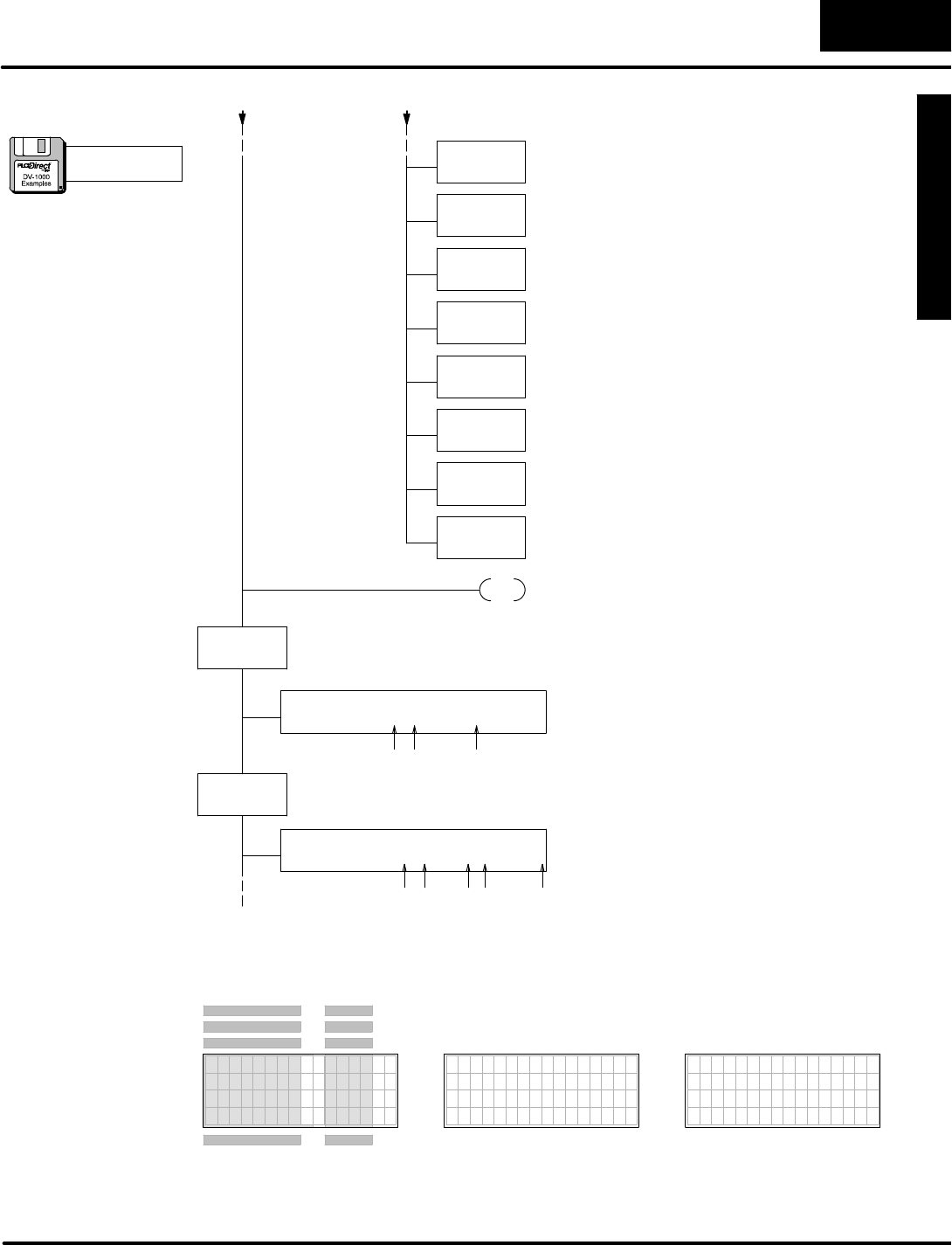
M
o
n
i
t
o
r
i
n
g
P
L
C
D
a
t
a
C
o
n
f
i
g
u
r
a
t
i
o
n
f
o
r
C
h
a
n
g
i
n
g
P
r
e
s
e
t
V
a
l
u
e
s
C
h
a
n
g
e
P
r
e
s
e
t
M
o
d
e
6
-
-
2
1
Change PresetMode
LD
K10
Load the numberofdatalocations,whichis16 (10
hex)words(fourtitlesforatotalof32 characters).
LD
K0
Load the address offset. FornearlyeveryMOVMC
used forACONdata, therewill be zero offset(use
K0).
LDLBL
K1
Read fromthe ACONfollowing Data LabelK1.
MOVMC
V2200
Move dataintoV-memory starting atV2200.
LD
K10
Load the numberofdatalocations,whichis16 (10
hex)words(32 characters).
LD
K0
Load the address offset. FornearlyeveryMOVMC
used forACONdata, therewill be zero offset(use
K0).
LDLBL
K2
Read fromthe ACONfollowing Data LabelK2.
MOVMC
V2220
Movethe dataintoV-memory starting atV2220.
Move ACON Data
Into TextData
Block
END The end coil terminatesthe main programsection.
Usethe ASCII Constant(ACON)boxto entertext
charactersdirectlyfromthe keyboard.
DLBL
K1
ACON
SetPointActualHiAlarmLo Alarm
DataforTitles 1 -- 4The Data Labelboxmarks the beginning ofa data
area containing ACONorNCONboxes.The
reference numberforthisarea isK1.
DLBL
K2
Usethe ASCII Constant(ACON)boxto entertext
charactersdirectlyfromthe keyboard.
ACON
SoakTimeTemp 1 Temp 2 Gal/Min
DataforTitles 5 -- 8The reference numberforthisarea isK2.
spaces:2 1 1
spaces:1 2 1 2 2
The following diagramshowsthe resulting displays fromthe programabove.
7654321076543210
TIMER 1 0000
7654321076543210
COUNTER 1 0000Lo Alarm 0000
S o a k T i m e 0 0 0 0
Temp 1 0000
Temp 2 0000
Hi Alarm 0000
Actual 0000
Setpoint 0000
Gal/Min 0000
a:\preset5.prj
(
c
o
n
t
i
n
u
e
d
)
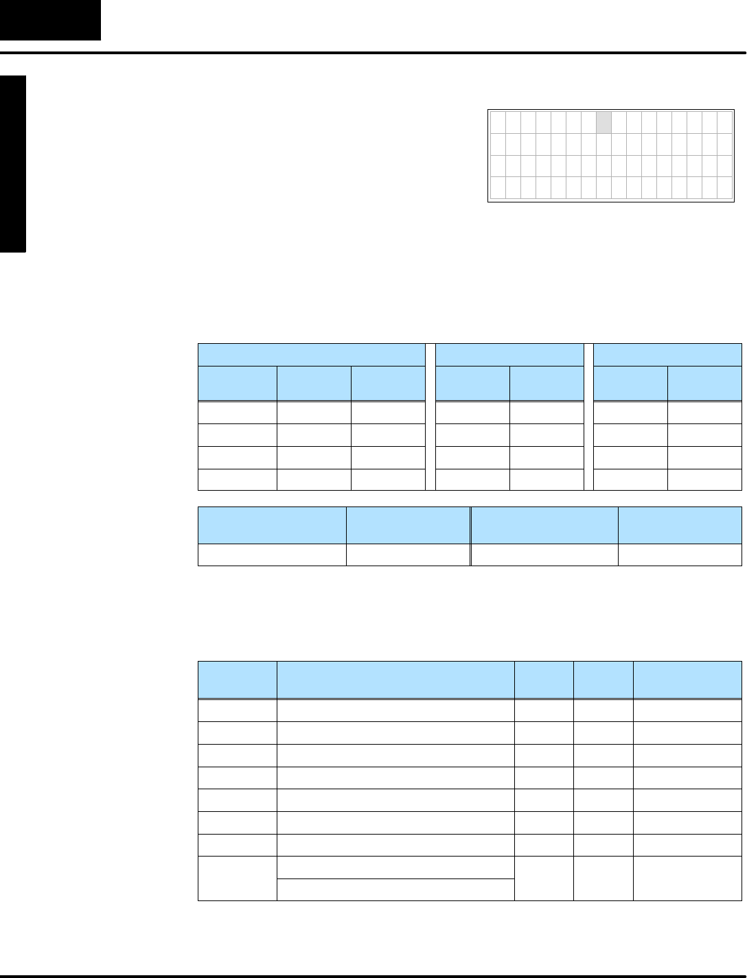
M
o
n
i
t
o
r
i
n
g
P
L
C
D
a
t
a
C
o
n
f
i
g
u
r
a
t
i
o
n
f
o
r
C
h
a
n
g
i
n
g
P
r
e
s
e
t
V
a
l
u
e
s
Mode
Change Preset
C
h
a
n
g
e
P
r
e
s
e
t
6
-
-
2
2
Change PresetMode
7654321076543210
S e t P o i n t 0 0 0 0
A c t u a l 0 0 0 0
V 2 3 0 2 0 0 0 0
V 2 3 0 3 0 0 0 0
The User-titled presetsalso providesan
option thatlets you havecustomtitlesand
the default(Vxxx)titles.The setup forthis
isjustasifall the titlesarecustom.
However,ifall the ASCII codes(4word
locations)foranytitle(s)isall zeros, then
the DV-1000 substitutesthe default title
instead.
DesiredDisplay
To selectanindividualdefault title, justenter“0000 0000”foritstextdata.
The titleselectionsaresummarized inthe following table.Notethe inclusion ofone
timerand counter,because all three preset typesmusthave atleastone entry.
Finally,weselect the password(disabled)and the powerup mode.We arbitrarily
chooseChange Presetasthe Powerup DefaultMode.
UserPresetsTimerPresetsCounterPresets
TextTitles Text
Locations
Data
Locations
Titles Data
Locations
Counter
Titles
Data
Locations
SetpointV2200 V2300 Timer1V2304 Counter1V2305
ActualV2204 V2301
(V2302)V2210 V2302
(V2303)V2214 V2303
Password
Enable/Disable
PasswordValuePowerup ModePowerup Value
Disable 0000 ChangePreset0001
Using the worksheetabovewecan determine the setup parameters.The numbers
arein boldtextinthe following table.
V-Memory
Location
Setup ParameterDescription FormatValueNotes:
V7620 UserPresetDataPointerOctal2300 startatV2300
V7621 UserPresetTitlesPointerOctal2200 usedefault title
V7622 UserPresetBlockSizeBCD 44titles
V7626 PowerupModeBCD 0001 ChangePreset
V7627 ChangePresetPasswordBCD 0000 Disabled
V7720*TimerDataPointerOctal2304 startatV2304
V7721*CounterDataPointerOctal2305 startatV2305
V7722*TimerPresetBlockSize(highbyte)BCD 0101 one timer,
o
n
e
c
o
u
n
t
e
r
CounterPresetBlockSize(lowbyte)
o
n
e
c
o
u
n
t
e
r
*DL130 and DL230 CPUsuse differentmemorylocationshere:V7640 instead of
V7720,V7641 instead ofV7721,and V7642 instead ofV7722.
IndividualDefault
UserTitles
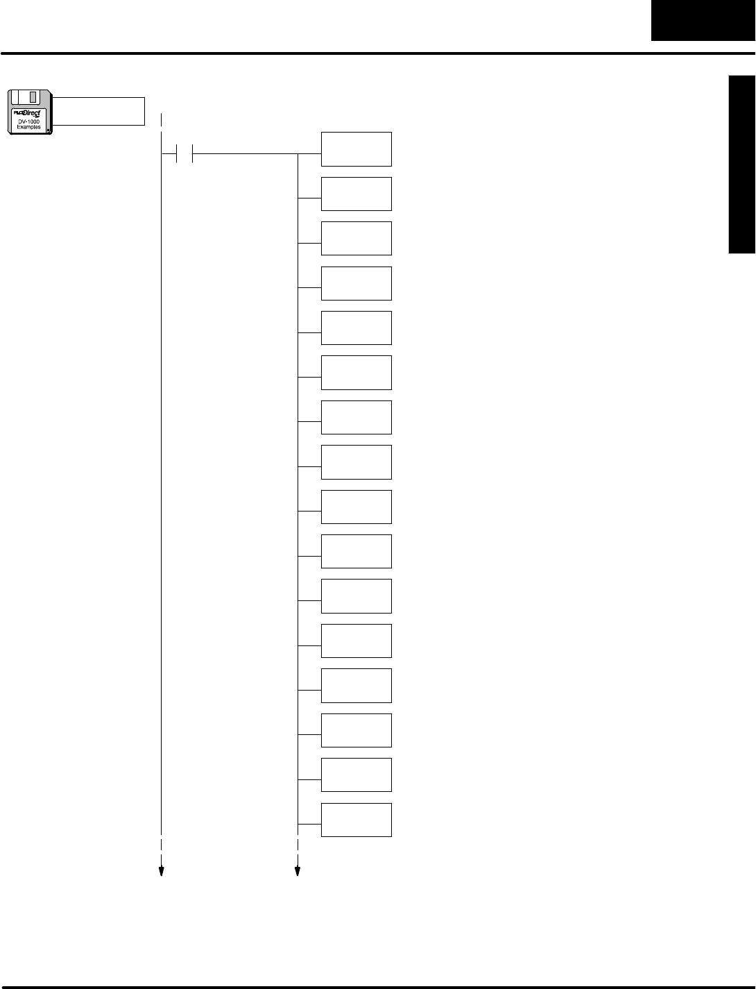
M
o
n
i
t
o
r
i
n
g
P
L
C
D
a
t
a
C
o
n
f
i
g
u
r
a
t
i
o
n
f
o
r
C
h
a
n
g
i
n
g
P
r
e
s
e
t
V
a
l
u
e
s
C
h
a
n
g
e
P
r
e
s
e
t
M
o
d
e
6
-
-
2
3
Change PresetMode
SP0LDA
O2300
Load octaladdress 2300 intothe accumulator.V2300 isthe
beginning location of the userpresetvalues.
OUT
V7620
Output thisaddress toV7620, the location of the setup
parameterforthe beginning address ofuserpresetvalues.
P
a
r
a
m
e
t
e
r
S
e
t
u
p
:
C
h
a
n
g
e
P
r
e
s
e
t
LDA
O2200
Load octaladdress 2200 intothe accumulator.V2200 isthe
beginning address of the User-titled textdata.
OUT
V7621
Output this constant toV7621, the location ofsetup
parameterforthe starting address of the titletextblock.
FirstScanOnly
LD
K4
Load the constantK4(BCD)intothe accumulator.
OUT
V7622
Output the constant4toV7622, the location of the setup
parameterforthe User-titled labelblock size.
LD
K1Load the constantK1intothe accumulator.
OUT
V7626
Output the constantK1toV7626, the location of the
Powerup DefaultMode setup parameter.The value of0001
selectsChange PresetMode.
LD
K0Load the constantK0intothe accumulator.
OUT
V7627
Output the constantK0toV7627, the location of the
Change PresetPassword.The value of0000 disablesit.
LDA
O2304 Load the octaladdress 2304 intothe accumulator.
OUT
V7720
Output the octaladdress 2304 toV7720, the location of the
setup parameterforthe starting address of the Timer
Presets.NOTE:DL130 and DL230 CPUsusememory
location V7640,notV7720.
LDA
O2305 Load the octaladdress 2305 intothe accumulator.
OUT
V7721
LD
K101 Load the constantK101 intothe accumulator
OUT
V7722
Output the constant101 toV7722, the location of the block
size bytesforTimerand Countertitled data.This selects
one each.NOTE:DL130 and DL230 CPUsusememory
location V7642,notV7722.
Output the octaladdress 2305 toV7721, the location of the
setup parameterforthe starting address of the Counter
Presets.NOTE:DL130 and DL230 CPUsusememory
location V7641,notV7721.
a:\preset6.prj
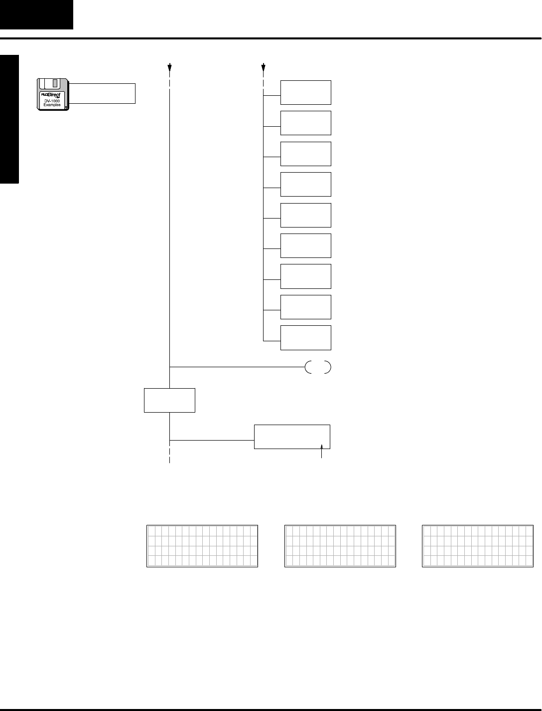
M
o
n
i
t
o
r
i
n
g
P
L
C
D
a
t
a
C
o
n
f
i
g
u
r
a
t
i
o
n
f
o
r
C
h
a
n
g
i
n
g
P
r
e
s
e
t
V
a
l
u
e
s
Mode
Change Preset
C
h
a
n
g
e
P
r
e
s
e
t
6
-
-
2
4
Change PresetMode
LD
K8
Load the numberofdatalocations,whichis8
words(twotitlesforatotalof16 characters).
LD
K0
Load the address offset. FornearlyeveryMOVMC
used forACONdata, therewill be zero offset(use
K0).
LDLBL
K1
Read fromthe ACONfollowing Data LabelK1.
MOVMC
V2200
Move dataintoV-memory starting atV2200,
corresponding tothe top twolineson the display.
Move ACON Data
Into TextData
Block
END The end coil terminatesthe main programsection.
Usethe ASCII Constant(ACON)boxto entertext
charactersdirectlyfromthe keyboard.
DLBL
K1
ACON
SetPointActual
DataforTitles 1 -- 2The Data Labelboxmarks the beginning ofa data
area contraining ACONorNCONboxes.The
reference numberforthisarea isK1.
LDD
K0
Load zerosintothe accumulator.
OUTD
V2210
Placethe zerosintothe textspacefortitle 3.
Rememberto use onlyeven addressesinOUTD
instructions.
OUTD
V2212
Loadzeros as
ASCII codes for
Titles 3 -- 4
Placethe zerosintothe textspacefortitle 3.
OUTD
V2214
Placethe zerosintothe textspacefortitle 4.
OUTD
V2216
Placethe zerosintothe textspacefortitle 4.
spaces:2
The following diagramshowsthe resulting displays fromthe programabove.
7654321076543210
TIMER 1 0000
7654321076543210
COUNTER 1 0000
7654321076543210
SetPoint 0000
Actual 0000
V2302 0000
V2303 0000
a:\preset6.prj
(
c
o
n
t
i
n
u
e
d
)
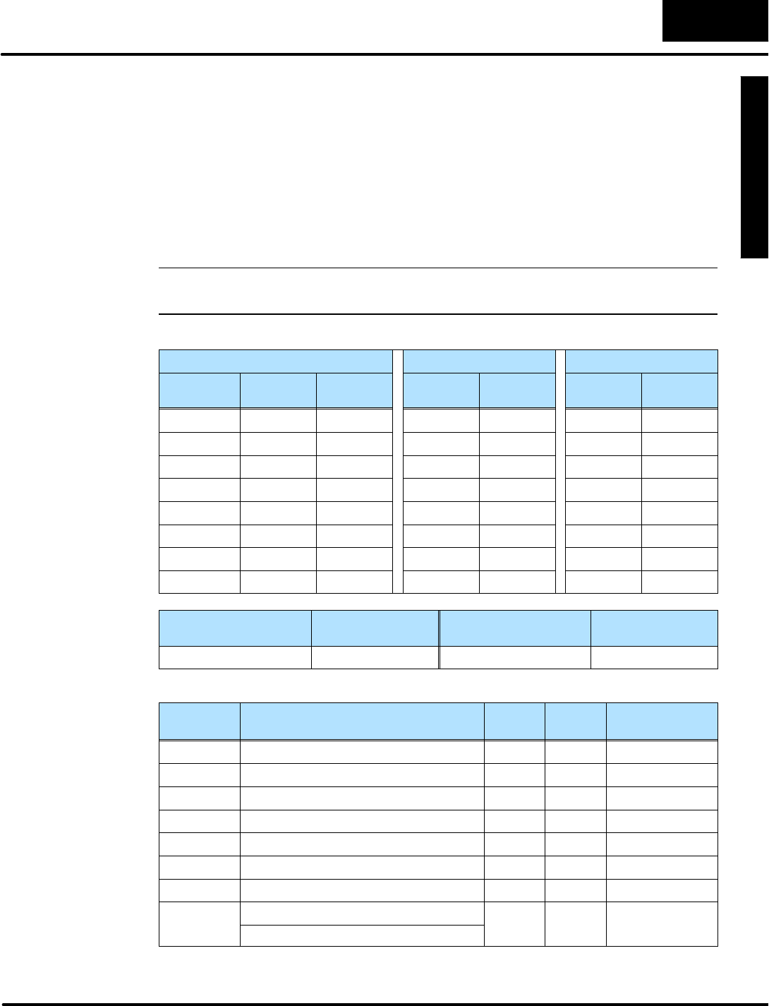
M
o
n
i
t
o
r
i
n
g
P
L
C
D
a
t
a
C
o
n
f
i
g
u
r
a
t
i
o
n
f
o
r
C
h
a
n
g
i
n
g
P
r
e
s
e
t
V
a
l
u
e
s
C
h
a
n
g
e
P
r
e
s
e
t
M
o
d
e
6
-
-
2
5
Change PresetMode
Combination Titles Example
Asacomprehensive example,we’ll useseveralpresetsofeachtype of title,and use
a password.
SSixUser--titled PresetsplustwoDefaultUser-titled Presets
SFivePre-titled TimerPresets
SEightPre-titled CounterPresets
SPassword=1234,Powerup DefaultMode isChange Preset
NOTE:Afterloading the programforthisexample,a password entryisrequired in
ordertochange presets.The nextsection coversthe Change PresetPassword.
The following tablesummarizesourchoicesabove.
UserPresetsTimerPresetsCounterPresets
TextTitles Text
Locations
Data
Locations
Titles Data
Locations
Counter
Titles
Data
Locations
SetPointV2200 V2300 Timer1V2310 Counter1V2330
Value V2204 V2301 Timer2V2311 Counter2V2331
HiAlarmV2210 V2302 Timer3V2312 Counter3V2332
Lo AlarmV2214 V2303 Timer4V2313 Counter4V2333
(V2304)V2220 V2304 Timer5V2314 Counter5V2334
(V2305)V2224 V2305 Counter6V2335
MixSpeed V2230 V2306 Counter7V2336
SoakTimeV2234 V2307 Counter8V2337
Password
Enable/Disable
PasswordValuePowerup ModePowerup Value
Enable 1234 ChangePreset0001
Using the worksheetabovewecan determine the setup parameters(boldtext).
V-Memory
Location
Setup ParameterDescription FormatValueNotes:
V7620 UserPresetDataPointerOctal2300 startatV2300
V7621 UserPresetTitlesPointerOctal2200 startatV2200
V7622 UserPresetBlockSizeBCD 88titles
V7626 PowerupModeBCD 0002 MessageMode
V7627 ChangePresetPasswordBCD 1234 code=1234
V7720*TitledTimerDataPointerOctal2300 startatV2300
V7721*TitledCounterDataPointerOctal2320 startatV2320
V7722*TimerPresetBlockSize(highbyte)BCD 0508 5timers,
8
c
o
u
n
t
e
r
s
CounterPresetBlockSize(lowbyte)
8
c
o
u
n
t
e
r
s
*DL130 and DL230 CPUsuse differentmemorylocationshere:V7640 instead of
V7720,V7641 instead ofV7721,and V7642 instead ofV7722.
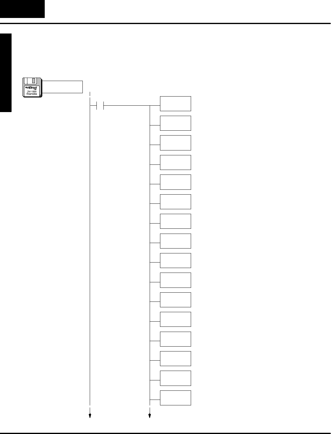
M
o
n
i
t
o
r
i
n
g
P
L
C
D
a
t
a
C
o
n
f
i
g
u
r
a
t
i
o
n
f
o
r
C
h
a
n
g
i
n
g
P
r
e
s
e
t
V
a
l
u
e
s
Mode
Change Preset
C
h
a
n
g
e
P
r
e
s
e
t
6
-
-
2
6
Change PresetMode
Inthis step we usethe information inthe setup parametertable and worksheet to
writethe program.The setup parameterportion isfirst, followed bythe MOVMCfor
the ACONboxes. One portion of the programloads zerosinforthe ASCII codesof
the text titles,sothe defaultVxxxx labelsappearforthosetitles.
SP0LDA
O2300
Load octaladdress 2300 intothe accumulator.V2300 isthe
beginning location of the userpresetvalues.
OUT
V7620
Output thisaddress toV7620, the location of the setup
parameterforthe beginning address ofuserpresetvalues.
P
a
r
a
m
e
t
e
r
S
e
t
u
p
:
C
h
a
n
g
e
P
r
e
s
e
t
LDA
O2200
Load the octaladdress 2200 intothe accumulator.
OUT
V7621
Output the address toV7621, the location ofsetup
parameterforthe starting address of the titletextblock.
FirstScanOnly
LD
K8
Load the constantK8(BCD)intothe accumulator.
OUT
V7622
Output the constantK8toV7622, the location of the setup
parameterforthe User-titled labelblock size.
LD
K1234
Load the constantK1234 intothe accumulator.
OUT
V7627
Output the constantK1234 toV7627, the location of the
Change PresetPassword.The passwordwill be “1234”.
LDA
O2310
Load the octaladdress 2310 intothe accumulator.
OUT
V7720
Output the octaladdress 2310 toV7720, the location of the
setup parameterforthe starting address of the Timer
Presets.NOTE:DL130 and DL230 CPUsusememory
location V7640,notV7720.
LDA
O2330 Load the octaladdress 2330 intothe accumulator.
OUT
V7721
LD
K508 Load the constantK508 intothe accumulator.
OUT
V7722
Output the constantK508 toV7722, the location of the
block size bytesforTimerand Countertitled data.This
selectsfivetimersand eightcounters.NOTE:DL130 and
DL230 CPUsusememorylocation V7642,notV7722.
Output the octaladdress 2330 toV7721, the location of the
setup parameterforthe starting address of the Counter
Presets.NOTE:DL130 and DL230 CPUsusememory
location V7641,notV7721.
LD
K2
Load the constantK2intothe accumulator.
OUT
V7626
Output the constantK2toV7626, the location of the
Powerup DefaultMode setup parameter.The value of0002
selectsMessage DisplayMode.
a:\preset7.prj
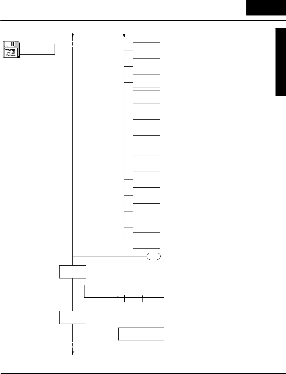
M
o
n
i
t
o
r
i
n
g
P
L
C
D
a
t
a
C
o
n
f
i
g
u
r
a
t
i
o
n
f
o
r
C
h
a
n
g
i
n
g
P
r
e
s
e
t
V
a
l
u
e
s
C
h
a
n
g
e
P
r
e
s
e
t
M
o
d
e
6
-
-
2
7
Change PresetMode
LD
K10
Load the numberofdatalocations,whichis16 (10
hex)words(fourtitlesforatotalof32 characters).
LD
K0
Load the address offset. FornearlyeveryMOVMC
used forACONdata, therewill be zero offset(use
K0).
LDLBL
K1
Read fromthe ACONfollowing Data LabelK1.
MOVMC
V2200
Move dataintoV-memory starting atV2200,
corresponding tothe first fourtitles.
LD
K8
Load the numberofdatalocations,whichis8words
(16 characters).
LD
K0
Load the address offset. FornearlyeveryMOVMC
used forACONdata, therewill be zero offset(use
K0).
LDLBL
K2
Read fromthe ACONfollowing Data LabelK2.
MOVMC
V2230
Movethe dataintoV-memory starting atV2230,
corresponding totitles7 and 8.
Move ACON Data
Into TextData
Block
END The end coil terminatesthe main programsection.
LDD
K0
Load a doublewordconstantzerointothe
accumulator.
OUTD
V2220
Placezerosinthe text titlelocation forthe fifthtext
title.
Use DefaultTitles
forTitles 5 and 6
OUTD
V2222
Placezerosinthe text titlelocation forthe fifthtext
title.
OUTD
V2224
Placezerosinthe text titlelocation forthe sixthtext
title.
OUTD
V2226
Placezerosinthe text titlelocation forthe sixthtext
title.
Usethe ASCII Constant(ACON)boxto entertext
charactersdirectlyfromthe keyboard.
DLBL
K1
ACON
SetPointActualHiAlarmLo Alarm
Text forTitles 1 -- 4The Data Labelboxmarks the beginning ofa data
area containing ACONorNCONboxes.The
reference numberforthisarea is specified byK1.
DLBL
K2
Usethe ASCII Constant(ACON)boxto entertext
charactersdirectlyfromthe keyboard.
ACON
MixSpeedSoakTime
Text forTitles 7 and 8
spaces:
spaces:2 11
a:\preset7.prj
(
c
o
n
t
i
n
u
e
d
)
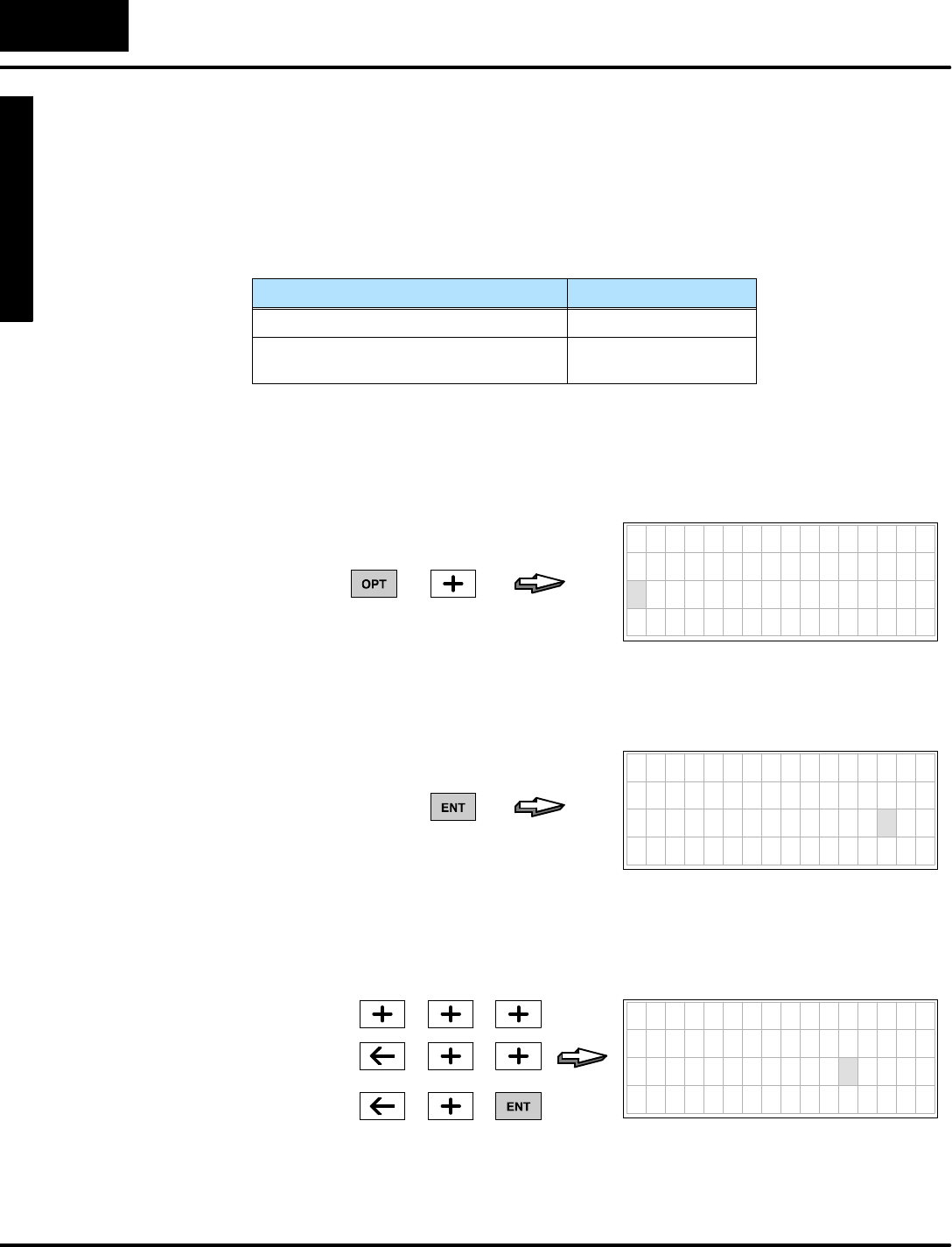
M
o
n
i
t
o
r
i
n
g
P
L
C
D
a
t
a
C
o
n
f
i
g
u
r
a
t
i
o
n
f
o
r
C
h
a
n
g
i
n
g
P
r
e
s
e
t
V
a
l
u
e
s
Mode
Change Preset
C
h
a
n
g
e
P
r
e
s
e
t
6
-
-
2
8
Change PresetMode
ChangePresetPassword
If the setup parametersarevalidyou will be ableto enterChange PresetMode.And,
if the passwordisdisabled (V7627 =“0000”),you may change presets.However,ifa
password existsinV7627,access will be locked.When thisoccurs,pressing the
EnterKeywill notmovethe cursortothe datafieldforediting.
FeatureV7627 Contents
PasswordDisabled0000
Password Enabled,
password=0001 to 9999
0001 to 9999
To unlock access tochange presets,go tothe password utilityunderthe Options
Menu.Justpress the OptionsKey,and the menu on the displaybelow will appear.
Then press the Plus(+)Keytocursorfromitem1toitem2(password utility).
7654321076543210
O P T I O N
1 B I T C O N T R O L
2 P A S S W O R D
3 S H O W E R R / M S G
PRESS
Then press the EnterKey,and the password displaybelow will appear.The cursor
will be overthe right-mostdigitof the password.
7654321076543210
P A S S W O R D
0 0 0 0
PRESS
Supposethe passwordis“1234” (V7627 =“1234”).Now,usethe Plus(+)Keyto
increment the digits,and the arrowkeys tomovethe cursorfromdigit to digit. After
incrementing to“1234”,press the EnterKeytosubmit the password.
7654321076543210
P A S S W O R D
1 2 3 4
PRESS
Unlocking Access
toChangePresets
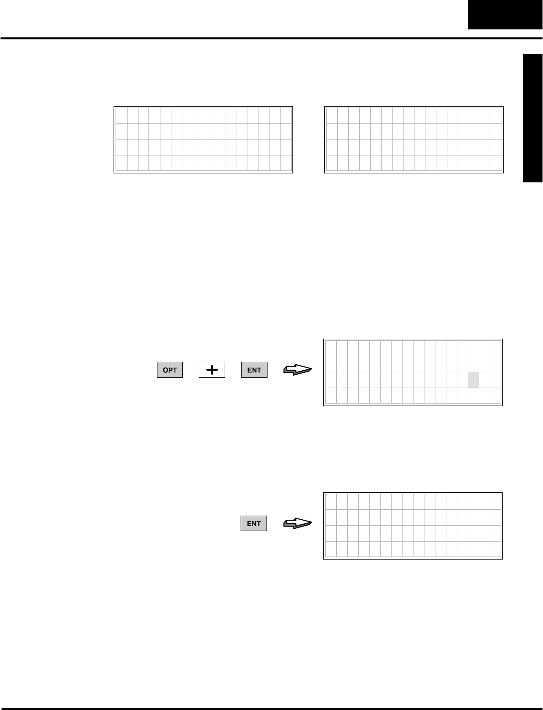
M
o
n
i
t
o
r
i
n
g
P
L
C
D
a
t
a
C
o
n
f
i
g
u
r
a
t
i
o
n
f
o
r
C
h
a
n
g
i
n
g
P
r
e
s
e
t
V
a
l
u
e
s
C
h
a
n
g
e
P
r
e
s
e
t
M
o
d
e
6
-
-
2
9
Change PresetMode
If the passwordsubmitted matchesthe one stored inV-memory(V7627), the display
on the left will appear. If the password entrywasincorrect, the displayon the rightwill
appear.
7654321076543210
PASSWORD MATCH
1 2 3 4
7654321076543210
WRONG PASSWORD
1 2 2 3
When you submit the correctpassword, the DV-1000 automaticallyreturnstothe
Change PresetMode.And,you will have access tochange presets. Incorrect
password entriesare noted inthe display,and the display continuesto promptyou
forthe correctpassword.To aborta password entryattempt, justpress one of the
keys forthe otherDV-1000 modes.
After making the desired changesto presets,you maywant tolock access againto
Change PresetMode.Thisistypical when the DV-1000 isaccessibletomultiple
personnelon the factoryfloor.Tolock access,returntothe password utilityagain by
pressing the OptionsKey,selecting “Password”,and pressing Enter.The following
displaywill appear.
7654321076543210
P A S S W O R D
0 0 0 0
PRESS
Withoutincrementing the passwordvalue,justpress the EnterKeyagain.The
displaybelow will appear,indicating thataccess tochange presetshasbeen locked
(notethat the “0000”doesnotindicatethat the password hasbeen changed tothat
number).
7654321076543210
P A S S W O R D L O C K E D
0 0 0 0
PRESS
Afterthe displayindicates“PASSWORD LOCKED”foramoment, itautomatically
returnstoChange PresetMode.Access tochanging presetswill be locked,sothe
EnterKeywill no longer movethe cursorovertothe datafield.Unlocking access
again onlyrequiresentering the valid password,as shownonthe previouspage.
If the machine operatorforgetsthe password and hasno other record ofit, you can
usethe DV-1000’sStatusDisplayMode toviewthe contentsofV7627.Then go back
tothe OptionsMenu and enterthe password.Notethat the “Operator’sGuide to
Change PresetMode”laterinthis chapterintentionallydoesnotinclude thistip!
Locking Access to
ChangePresets
Forgot the
Password?
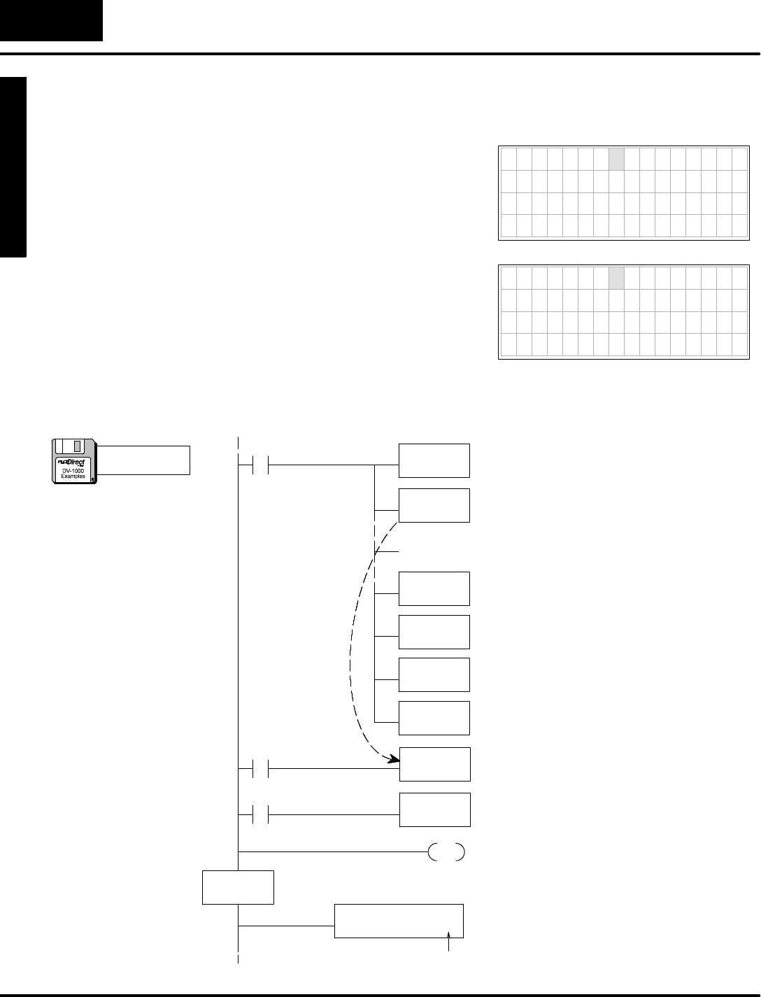
M
o
n
i
t
o
r
i
n
g
P
L
C
D
a
t
a
C
o
n
f
i
g
u
r
a
t
i
o
n
f
o
r
C
h
a
n
g
i
n
g
P
r
e
s
e
t
V
a
l
u
e
s
Mode
Change Preset
C
h
a
n
g
e
P
r
e
s
e
t
6
-
-
3
0
Change PresetMode
SpecialTopics forChangePresets
If yourapplication program requires
timerand counterpresets,remember
that the pre-labeled Timerand Counter
Preset titlesinthe DV-1000 aretherejust
foryourconvenience. Instead ofusing
the generictitles such as“Timer1”you
mayprefer moremeaningfultitlesfor
yourapplication such asthoseshownto
the upper right.
Counterpreset titles can also be custom
titlesifyou prefer.Some examplesare
listed inthe displaytothe lower right.
7654321076543210
S t o p T i m e 0 2 1 0
D e l a y 1 3 9 9
R u n T i m e 2 8 4 7
D w e l l 0 0 5 3
7654321076543210
P a r t C N T 0 5 7 5
L e n g t h 1 1 3 3 0
T o t a l R u n 0 5 7 5
Q C P A S S 0 5 4 3
The following examplecreatestwotimers,using “StopTime”and “Delay”fortimer
titles.The titletextisloaded withthe ACONand MOVEMC instructions.
LD
K8
Load the numberofdatalocations,whichis8
words(twotitlesforatotalof16 characters).
LD
K0
Load the address offset. Fornearlyevery
MOVMCused forACONdata, therewill be
zero offset(useK0).
LDLBL
K1
Read fromthe ACONfollowing Data LabelK1.
MOVMC
V2200
Move dataintoV-memory starting atV2200,
corresponding tothe top twolineson the
display.
Move ACON Data
Into TextData
Block
END The end coil terminatesthe main program
section.
Usethe ASCII Constant(ACON)boxto entertext
charactersdirectlyfromthe keyboard.
DLBL
K1
ACON
StopTimeDelay
DataforTitles The Data Labelboxmarks the beginning ofa
data area containing ACONorNCONboxes.
SP0LDA
O2300
Load octaladdress 2300 intothe accumulator.
OUT
V7620
Output thisaddress toV7720, the location of the
setup parameterforthe beginning address of
User-titled Presets.
TMR
V2300
TurnonTimer0when X0ison.The presetvalue for
Timer0isatV2300.Note:If using DL105 be sure
CPUisinitialized tomakeX0 operational.
T0
X0
MainProgram
TMR
V2301
TurnonTimer1when X1ison.The presetvalue for
Timer1isatV2301.(Include asmanyof theserungs
as you havetimersorcounters).
T1
X1
Insert the other rungsof the setup programhere.They
aretypicalforUser-titled presets.(The disk example
is complete.)
Setup Program
spaces:3
Timerand Counter
Presetswith
CustomTitles
a:\preset8.prj
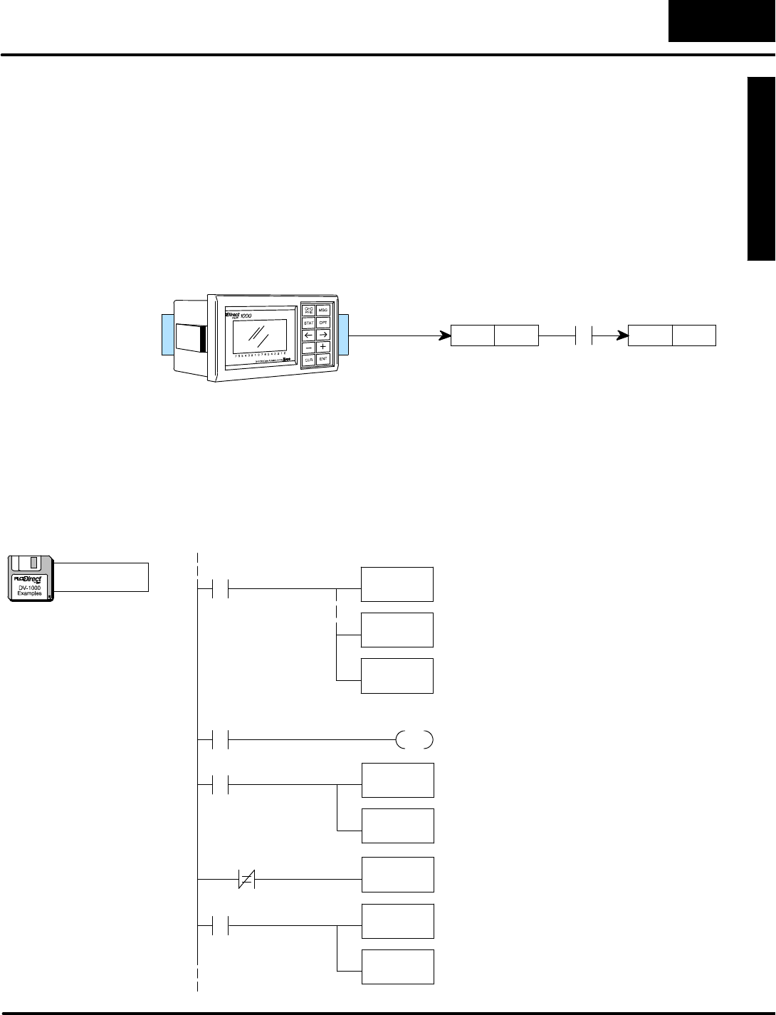
M
o
n
i
t
o
r
i
n
g
P
L
C
D
a
t
a
C
o
n
f
i
g
u
r
a
t
i
o
n
f
o
r
C
h
a
n
g
i
n
g
P
r
e
s
e
t
V
a
l
u
e
s
C
h
a
n
g
e
P
r
e
s
e
t
M
o
d
e
6
-
-
3
1
Change PresetMode
V-memory values change immediatelywhen you edit theminChange PresetMode.
Thisis safelydone ifyou makerelatively small incrementalchangesand monitor
theireffectson the process.However,some applicationsmayrequireyou tomake a
singlestep change to one or more presets.Situationsthatmayrequirethisinclude:
SChangingasingle preset to a newvalue,avoiding valuesin between
SChanging severalpresetsto newvaluesat the samemoment(scan)
SCoordinating a presetchange with otherexternalevents
Wecan solvethese problemsbyusing Change Preset to update a temporary
variable.See the figure below.When the ladderprogramdetectsan eventcontact, it
copiesthe temporary variabletothe permanentvariablelocation.
V2200 XXXX
Temporarypreset
V2300 XXXX
Permanentpreset
X0
Change Preset
(edit) (copy)
Inthe following program, the permanentpresetvalue isatV2300 and the temporary
presetvalue isatV2200.Wewouldliketo updateV2300 onlywhen inputX0 hasan
off-to-on transition.The programalso hasatime-out feature.Forexample,entera
newvalue inlocation V2200.V2200 and V2300 no longer matchsothe timer
starts.TurnonX0within30secondsto updateV2300 tomatchthe newV2200 value.
If X0isnot turned on within30secondsofentering the newvalue the program
automatically changesV2200 back tomatchthe originalV2300 value.Notethat
changing Timer1’spresetvalue changesthe amountof time allowed toturn on X0.
OUT
V2200
CopyPreset to
TempValue
SP0Place normalChange Presetsetup rung here.Note
thatweconfigurethe temporarypresetatV2200 as
the Change Presetarea.
LD
V2300
Load the presetvalue atV2300 intothe accumulator.
TMR
K300
TurnonTimer1when V2200 and V2300 are not
equal.Thismeansthe operatorbegan editing V2200,
buthasnotmade the change finalbyusing X0.
T1
V2200
MainProgram
T1
Setup Program
C0
X0
PD
C0TurnonC0forone scan when X0makesan
OFF-to-ONtransition.Note:If using DL105 be sure
CPUisinitialized tomakeX0 operational.
LD
V2200
OUT
V2300
LD
V2300
Load the presetatV2300 intothe accumulatorwhen
the 30 secondsofTimer1 hasexpired.The operator
edited V2200,butdid not finalizethe change withX0.
OUT
V2200
V2300
Overwritethe temporary value thatwas changed by
the operator.NowV2300 and V2200 are equal,and
Timer1isturned off on the nextscan.
Load the temporarypresetvalue which hasbeen
edited intothe accumulator.
Change the actualpresetatV2300 tomatchthe
temporarypresetvalue when X0triggerson.
Updatethe temporarypresetvalue tomatchthe
permanentpresetvalue ateverypowerup,sothey
begin asequivalents.Remember, the operatoronly
seesthe temporary variableinV2200.
BufferedPreset
Values
a:\preset9.prj
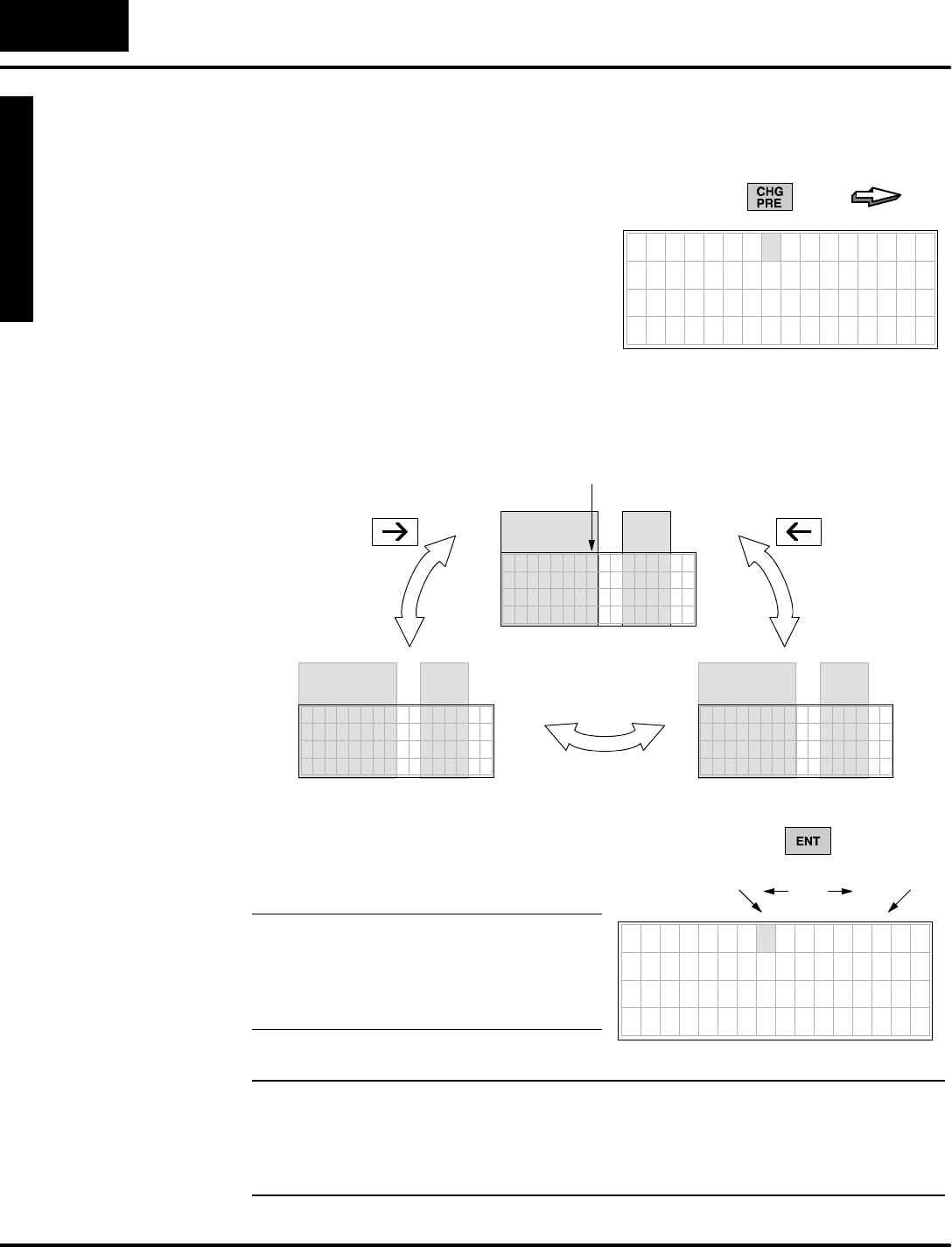
M
o
n
i
t
o
r
i
n
g
P
L
C
D
a
t
a
C
o
n
f
i
g
u
r
a
t
i
o
n
f
o
r
C
h
a
n
g
i
n
g
P
r
e
s
e
t
V
a
l
u
e
s
Mode
Change Preset
C
h
a
n
g
e
P
r
e
s
e
t
6
-
-
3
2
Change PresetMode
Operator’sGuidetoChangePreset Mode
This2-page guide contains condensed
instructionsfor machine operatorson how
to useChange PresetMode. It assumes
the DV-1000 installation and
programming arecomplete.
To enterChange PresetMode,justpress
the ChangePresetKeyon the keypad.
The User-titled Presetswill appear.
PRESS
7654321076543210
S e t P o i n t 0 4 2 5
A c t u a l 0 4 3 2
H i A l a r m 0 4 5 0
L o A l a r m 0 3 9 5
05
Three change presetlistsare accessibleinacircularlist. Refertothe figure below.
Upon entrytoChange PresetMode, the firstdisplayisautomaticallythe User--titled
list. Fromthere,usethe RightArrowand Left ArrowKeys tomovetothe timertitles
and countertitlesdisplays.
PRESS
CursorPosition
7654321076543210
V2300 0000
USER
TITLES
DATA
7654321076543210
T I M E R 1 0 0 0 0
TIMER
TITLES
DATA
7654321076543210
COUNTER 1 0000
COUNTER
TITLES
DATA
PRESS
Press the EnterKeytotogglethe cursor
between the title and datafields.When the
cursorisinthe datafieldyou arereadyto
edit the data.
NOTE:If pressing the EnterKeydoesnot
movethe cursortothe data position,
access tochange presetsislocked.You
must firstenterthe correctpassword(see
nextpage).
Title
Position
PRESS
Data
Position
toggles
7654321076543210
S e t P o i n t 0 0 0 0
A c t u a l 0 0 0 0
V 2 3 0 2 0 0 0 0
V 2 3 0 3 0 0 0 0
WARNING:Changing thepresetvalueon thedisplay immediately changes the
valueinPLCV-memory(thedisplay isnotbuffered).Equipmentdamageor
personnel injurymay occurfromimproperuse of thismode.Be sureto pause
amomentaftereachkeystroke toallowfortheDV-1000 display update,sothat
you are viewing currentvalues ofChangePresetvariables.
Selecting the
List toDisplay
CursorPositioning
On TitleorData
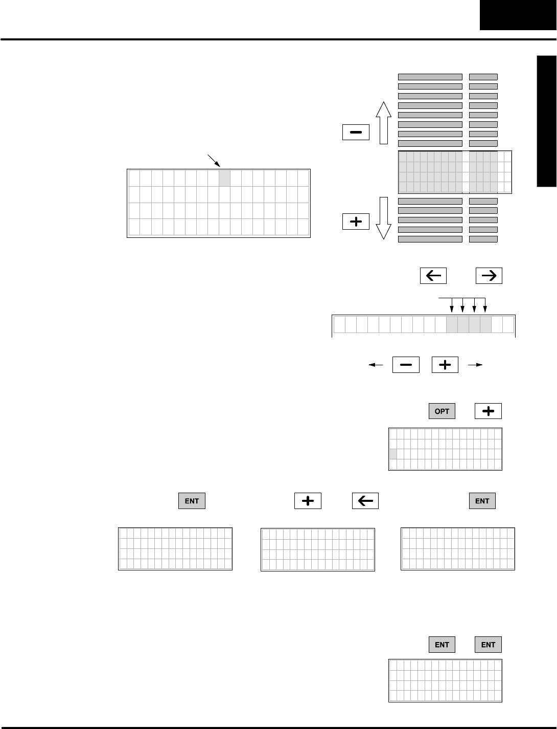
M
o
n
i
t
o
r
i
n
g
P
L
C
D
a
t
a
C
o
n
f
i
g
u
r
a
t
i
o
n
f
o
r
C
h
a
n
g
i
n
g
P
r
e
s
e
t
V
a
l
u
e
s
C
h
a
n
g
e
P
r
e
s
e
t
M
o
d
e
6
-
-
3
3
Change PresetMode
Toscroll the displaywindowdownward or
upwardthrough a selected list, position
the cursoroverthe title(usethe EnterKey
totoggleitsposition between the title or
data.Then usethe Plus(+)and Minus(--)
Keys toscroll the display.
TIMER 9 0000
TIMER10 0000
TIMER12 0000
TIMER13 0000
TIMER16 0000
TIMER15 0000
TIMER14 0000
TIMER 8 0000
TIMER 7 0000
TIMER 6 0000
TIMER 5 0000
TIMER 4 0000
TIMER 3 0000
TIMER 2 0000
TIMER 1 0000
7654321076543210
T I M E R 9 0 0 0 0
T I M E R 1 0 0 0 0 0
T I M E R 1 1 0 0 0 0
T I M E R 1 2 0 0 0 0
CursorPosition
PRESS
PRESS
TIMER99 0000
Withthe cursorinthe data position,use
the CursorRightand CursorLeft keys to
moveitamong the fourdigitpositions.
Press the Plus(+)Keytoincrementa
digit, and the Minus(--) Keyto decrement
it. The range ofinputchange isfrom0000
to 9999,BCD. Incrementing past9 or
decrementing past0carriesto orborrows
from (respectively)the digit(s)tothe left of
the cursorposition.
V 2 3 0 0 1 2 3 4
DigitPositions
PRESS OR
PRESS
0000 9999
To entera password,press the OptionsKeytoview
the Optionsmenu.Press the Plus(+)Keytomove
the cursortothe password option.Then press the
EnterKey.Usethe Plus(+)Keyand CursorKeys
toincrement the passwordcode tothe correct
value.Then press Enter.7654321076543210
OPTION
1 B I T C O N T R O L
2 P A S S W O R D
3 S H O W E R R / M S G
PRESS
7654321076543210
PASSWORD
0000
PRESS PRESS
7654321076543210
PASSWORD
1234
7654321076543210
P A S S W O R D M A T C H
1 2 3 4
PRESS
(asneeded)
and
Forcorrectpassword entries, the message “PASSWORD MATCH”isbriefly
displayed.The DV-1000 returnstothe previous(Change Preset) Mode. Incorrect
passwords yieldthe message “WRONGPASSWORD”.
If yourDV-1000 setup requiresa password,you can
lock access again afterchanging presets.Just
followthe instructionsaboveforentering a
password,butenter “0000”forthe password.The
message “PASSWORD LOCKED”confirms your
action.Nowaccess tochanging presetsislocked.
PRESS
7654321076543210
P A S S W O R D L O C K E D
0 0 0 0
Scrolling Through
ChangePreset
Lists
Changing the
PresetValue
Entering a
Password
Locking Access to
ChangePresets

M
o
n
i
t
o
r
i
n
g
P
L
C
D
a
t
a
C
o
n
f
i
g
u
r
a
t
i
o
n
f
o
r
C
h
a
n
g
i
n
g
P
r
e
s
e
t
V
a
l
u
e
s
Mode
Change Preset
C
h
a
n
g
e
P
r
e
s
e
t
6
-
-
3
4
Change PresetMode
ChapterSummary
Now we havecovered Change Preset titletypesand howto editdata using the
keypad.
Wemay summarizesome of the keypointswe havelearned aboutChange Preset
Mode inthis chapter:
SChange PresetsimplymeansChange V-memorydata.
SChanging dataonthe displayimmediatelychangesthe value inthe
PLC.Thereisno prompt forconfirmation of the change.
SIn orderforthe change ofa preset(V-memorydata)tochange the
behaviorofyourprocess,someinstruction(s)inthe ladder main
programhastoread the V-memorydata and useit.
SThree typesofpreset titlesare availableinChange PresetMode.
SIf you useChange PresetMode inyourapplication,all three titletypes
mustbe setup foratleastone title.Thismeansthe three block size
setup parametersmustbe equalto one orgreater.
SAccess tochanging presets can be password protected with password
codes0001 -- 9999.Ifyou do notwishto use a password,programthe
code “0000”intothe passwordlocation to disablethe passwordfeature.
SIf you are usingaTimerorCounterBoxInstruction and you want to
change itspresetvalue withPresetMode,itmustbeaVxxxx variable
type,notaconstantKx!
SIf preferred,you can haveUser-titled presetlabelsfortimersand
countersinthe ladderprogram.The pre-labeled timerand countertitles
arejust foryourconvenience,and toconserveV-memorywhen
required.
SChange PresetMode will allowthe editing ofBCD numbers(0000 to
9999).IfaV-memorylocation containsa hexnumber,Change Preset
will notallowthe editing ofits value!
SThe setup programforchange PresetMode can generallybe confined
to executeonthe firstscan,asdo all the programexamplesinthis
chapter.
SThe Operator’sGuide nearthe end of this chaptercontainsinstructions
foramachine operatoron howtochange presets.Feelfree tocopyits
two pagesand postiton the machine asaresourceforitsoperator(s).
SAppendixCcontainsworksheetsforChange PresetMode foryou to
copyand usetocreateyourapplication program.
Summaryof
Key Points

1
7
BitControlMode
In ThisChapter....
—Overview
—Setup ParametersforBitControl
—Usingthe KeypadTo DoBitControl
—BitControlApplications
—ChapterSummary
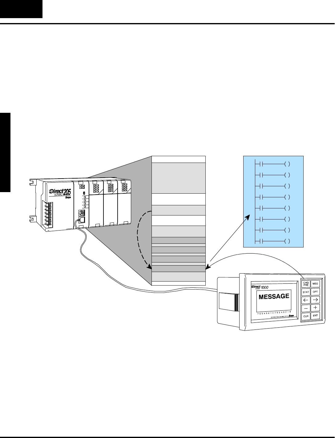
M
o
n
i
t
o
r
i
n
g
P
L
C
D
a
t
a
C
o
n
f
i
g
u
r
a
t
i
o
n
f
o
r
C
h
a
n
g
i
n
g
P
r
e
s
e
t
V
a
l
u
e
s
C
h
a
n
g
i
n
g
I
/
O
w
i
t
h
D
i
r
e
c
t
V
I
E
W
1
0
0
0
B
i
t
C
o
n
t
r
o
l
Mode
7
-
-
2
BitControlMode
Overview
BitControlMode permits you to usekeys on the DV-1000 keypad forindividual
controlofeight I/O bits.The typesof I/O bitsthatmaybe controlled areX,Y,and C.
The GXtype isalso available on DL405 CPUsonly.For mostapplications,Ctype
(controlrelays)arethe bestchoice.
The following figureshowsan expanded viewof the PLC’sV-memory space.A
DV-1000 setup parameterinV-memorypointstoasystemI/O dataword. It may
point toanX,Y,C,orGXwordlocation (we usecontrolrelays (C)asan example).
The DV-1000 keypad will controlthe lower8 bitsof the word.Atpowerup the
DV-1000 readsthisBitControlsetup parameter.Then,wheneveryou selectBit
ControlMode the DV-1000 keypad controls(writes)the state of the eight I/O bits.
V--MemorySpace
SystemI/O
UserV-memory
Setup Parameters
GXI/OPoints
XInputs
YOutputs
CControlRelays
C
C
C
C
C
C
C
C
LadderProgram
WRITE
READ
The drawing aboveshowshowthe DV-1000 keypad can controleightbitsin
V-memory.However, foranything meaningfulto happen something else hastoread
the bitsand acton theirstatus.Thismayoccurintwoways:
SForX,C,and GXinput types,ladderlogicmustreferencethe bit
addressesasan inputcontact.
SForYand GXoutput types,an outputmodule pointmustexistat the
addresses. Inthis casethe ladderprogram mustnotreferencethe
same outputbits,in orderto avoidaconflict.
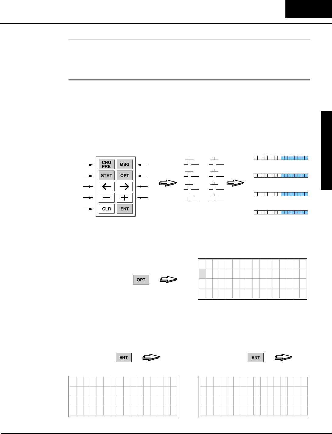
M
o
n
i
t
o
r
i
n
g
P
L
C
D
a
t
a
C
o
n
f
i
g
u
r
a
t
i
o
n
f
o
r
C
h
a
n
g
i
n
g
P
r
e
s
e
t
V
a
l
u
e
s
C
h
a
n
g
i
n
g
I
/
O
w
i
t
h
D
i
r
e
c
t
V
I
E
W
1
0
0
0
B
i
t
C
o
n
t
r
o
l
Mode
7
-
-
3
BitControlMode
WARNING:BitControl isdesignedfordebug purposes only.Major machine
functions suchas Start,Stop,Run,Jog,etc.need dedicatedelectrical
controlswithlabels.TheDV-1000’sBitControlModedoes notgive a constant
indication that thenormalkeypadfunctionshave changed! Misuse of thistool
canleadto damageofequipmentor risk ofseriousinjuryto personnel.
InBitControlMode, the keys marked withindexnumbersinthe figure belowassume
newfunctionality.Theyoperate asmomentarypush-buttons,normallyoff. When
pressed,each of the eightkeys will turnonitsassociated I/O bit. Theymap to either
X,Y,C,orGXtypes.When the keyisreleased, the I/O bitautomaticallyturnsoff.
Press the ClearKeyto exitBitControlMode.The Enterkeyisnotused.
0 1
2
4
6
3
5
7
BitControlKeys
0
2
4
6
1
3
5
7
Momentary,N.O.Push-buttons
X
Y
C
GX
OR
OR
OR
Press =1,
Release=0
I/OBits
Exit
ToselectBitControlMode,go tothe optionsmenu bypressing the OptionsKey.Bit
Control isthe firstof three items you may select, sothe cursorwill alreadybe
positioned overitemone.
7654321076543210
O P T I O N
1 B I T C O N T R O L
2 P A S S W O R D
3 S H O W E R R / M S G
PRESS
Press EntertoselectBitControl.The displaymessage will then ask fora
confirmation ofyourchoice byasking “Doyou wantBitControlMode?”At thispoint,
when you press Enterthe setup error message will be displayed as shown below. In
the nextsection weshowhoweasy itistochoose propersetup parameters.
7654321076543210
* S E T U P E R R O R *
C H E C K V A L U E I N
V 7 6 2 5
(withoutsetup program)
7654321076543210
D O Y O U W A N T B I T
CONTROL MODE?
YES:PUSH ENT KEY
NO :PUSH CLR KEY
PRESS PRESS
Keypad Function
inBitControl
Accessing Bit
Control
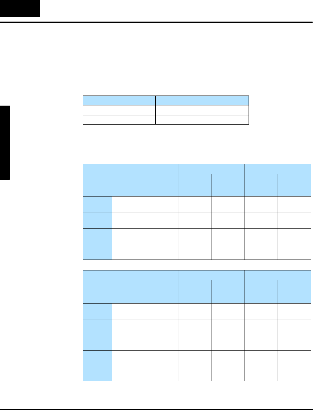
M
o
n
i
t
o
r
i
n
g
P
L
C
D
a
t
a
C
o
n
f
i
g
u
r
a
t
i
o
n
f
o
r
C
h
a
n
g
i
n
g
P
r
e
s
e
t
V
a
l
u
e
s
C
h
a
n
g
i
n
g
I
/
O
w
i
t
h
D
i
r
e
c
t
V
I
E
W
1
0
0
0
B
i
t
C
o
n
t
r
o
l
Mode
7
-
-
4
BitControlMode
Setup ParametersforBitControl
The following tableliststhe subsetof the DV-1000 setup parameterswhich pertainto
Change PresetMode.The parameteratV7625 selectsthe address of the
bit-controlled wordinsystemI/O space.The parameteratV7626 selectsthe
powerup defaultmode.
V-MemoryLocation Setup ParameterDescription
V7625 BitControlI/OPointer
V7626 PowerupDefaultMode
Now we havetochoosethe I/O address of the bitswewant tocontrol.Refertothe
columnsinthe following tableswhichcorrespond tothe type ofCPU inyoursystem.
Since ourPLCsmap theirdiscreteI/O bitsintoV-memory,we havetochoosethe
corresponding address.
DL130,DL230 DL240 DL250,DL350
I/OTypeDiscrete
Address
(octal)
Word
Address
(octal)
Discrete
Address
(octal)
Word
Address
(octal)
Discrete
Address
(octal)
Word
Address
(octal)
Input
Points
X0-- X177 V40400 --
V40407
X0-- X477 V40400 --
V40423
X0-- X777 V40400 --
V40437
Output
Points
Y0-- Y177 V40500 --
V40507
Y0-- Y477 V40500 --
V40523
Y0-- Y777 V40500 --
V40537
Control
Relays
C0-- C377 V40600 --
V40617
C0--C377 V40600 --
V40617
C0-C1777 V40600 --
V40677
Global
Inputs
N/AN/AN/AN/AN/AN/A
DL430 DL440 DL450
I/OTypeDiscrete
Address
(octal)
Word
Address
(octal)
Discrete
Address
(octal)
Word
Address
(octal)
Discrete
Address
(octal)
Word
Address
(octal)
Input
Points
X0-- X477 V40400 --
V40423
X0-- X477 V40400 --
V40423
X0--
X1777
V40400 --
V40477
Output
Points
Y0-- Y477 V40500 --
V40523
Y0-- Y477 V40500 --
V40523
Y0--
Y1777
V40500 --
V40577
Control
Relays
C0--C737 V40600 --
V40635
C0--
C1777
V40600 --
V40677
C0--
C3777
V40600 --
V40777
Global
Inputs
GX0--
GX777
V40000 --
V40037
GX0--
GX1777
V40000 --
V40077
GX0--
GX2777
GY0--
GY2777
V40000 --
V40137
V40200 --
V40377

M
o
n
i
t
o
r
i
n
g
P
L
C
D
a
t
a
C
o
n
f
i
g
u
r
a
t
i
o
n
f
o
r
C
h
a
n
g
i
n
g
P
r
e
s
e
t
V
a
l
u
e
s
C
h
a
n
g
i
n
g
I
/
O
w
i
t
h
D
i
r
e
c
t
V
I
E
W
1
0
0
0
B
i
t
C
o
n
t
r
o
l
Mode
7
-
-
5
BitControlMode
Forexample,supposewe assign BitControltothe eightcontrolrelays C0toC7.The
table above givesthe address of these asV40600,whichwe enteratV7625.Finally,
weselectMessage Mode withBitControlbyentering “0012”inV7626.The following
programdoesthe parametersetup forthesechoices.
SP0LDA
O40600
Load octaladdress 40600 intothe accumulator.V40600 is
the location ofC0toC17.
OUT
V7625
Output thisaddress toV7625, the location of the setup
parameterforBitControl.
ParameterSetup:BitControl
LD
K12
Load the BCD constantK12 intothe accumulator.Itisthe
code toselectBitControland Message Mode.Thisis
optional,as you may selecta differentpowerup mode.
OUT
V7626
Output this constant toV7626, the location ofsetup
parameterforthe defaultpowerup mode.
FirstScanOnly
a:\bitctrl1.prj
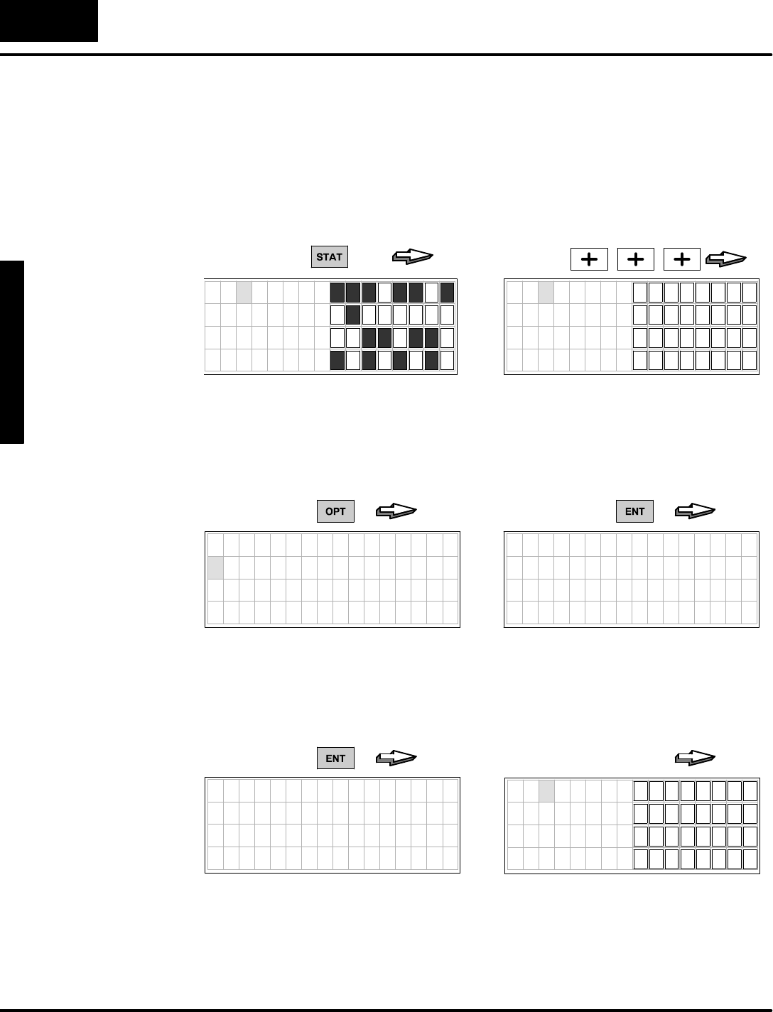
M
o
n
i
t
o
r
i
n
g
P
L
C
D
a
t
a
C
o
n
f
i
g
u
r
a
t
i
o
n
f
o
r
C
h
a
n
g
i
n
g
P
r
e
s
e
t
V
a
l
u
e
s
C
h
a
n
g
i
n
g
I
/
O
w
i
t
h
D
i
r
e
c
t
V
I
E
W
1
0
0
0
B
i
t
C
o
n
t
r
o
l
Mode
7
-
-
6
BitControlMode
Using theKeypadToDoBitControl
This section requiresthe parametersetup programof the previous section to be
loaded inyourCPU. If you have done so,we’rereadytosee first-hand howbitcontrol
works fromthe keypad.The setup parameteryou haveloaded forV7625 pointsto
controlrelays C0toC7,located atV40600.Now,enterStatusDisplayMode tosee
bitcontrol work.Then selectvariabletype “C”.
PRESS
7654321076543210
X 0 0
X 1 0
X 2 0
X 3 0
PRESS
7654321076543210
C 0 0
C 1 0
C 2 0
C 3 0
NOTE:when using someCPUs, the plus
(+)onlyneedsto be pressed once.
WithStatusMode setup,nowusethe OptionsMenu toselectBitControlMode.
7654321076543210
OPTION
1 B I T C O N T R O L
2 PASSWORD
3 S H O W E R R / M S G
PRESS
7654321076543210
D O Y O U W A N T B I T
CONTROL MODE?
Y E S : P U S H E N T K E Y
N O : P U S H C L R K E Y
PRESS
PRESS
7654321076543210
Y O U A R E I N
B I T C O N T R O L M O D E
(Automatic...)
(withsetup program)
7654321076543210
C 0 0
C 1 0
C 2 0
C 3 0
NOTE:Line3(SHOWERR/MESG)
doesnotapplytosomeCPUs.
Afterselecting BitControl, the StatusMode displayautomaticallyreturns.The
keypad isnow inBitControlMode,and the displayisinStatusMode!Thispermitsus
to observechangesinC0toC7inrealtimeforBitControlkeyactions.Notethat the
display cursorisabsentnow,becausethe keypad function has changed.
Selecting
BitControland
StatusModes
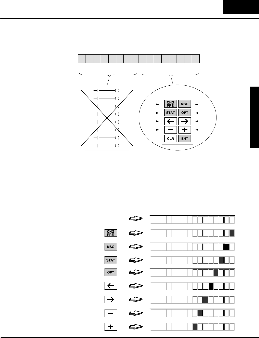
M
o
n
i
t
o
r
i
n
g
P
L
C
D
a
t
a
C
o
n
f
i
g
u
r
a
t
i
o
n
f
o
r
C
h
a
n
g
i
n
g
P
r
e
s
e
t
V
a
l
u
e
s
C
h
a
n
g
i
n
g
I
/
O
w
i
t
h
D
i
r
e
c
t
V
I
E
W
1
0
0
0
B
i
t
C
o
n
t
r
o
l
Mode
7
-
-
7
BitControlMode
Now wecan haveacloserlookat the statusof the bitsinV40600 during bitcontrol. In
the figure below, the keypad mapsto bits0through 7 as shown.
MSB LSB
013456789101112131415 2Bit
0 1
2
4
6
3
5
7
Bits8to 15
reserved
(Do notuse)
V
4
0
6
0
0
C12
C13
C14
C15
C16
C17
C11
C10
C0C7C10C17
Bits0to 7
mappedto
keypad
NOTE:Sincethe DV-1000 doeswordwrite operations,itwrites zerosto bits8
through 15 (C10 toC17).Therefore,avoid using these eight I/O pointsinyourladder
programin orderto avoidaconflict. ThisholdstrueforanyX,YC,and GXI/O
pointwordaddress pointedto byV7625.
To observeBitControl in action, followthe keystrokesinthe following diagram.
Noticethe relative binaryweighting ofeachkey,and the normally-off momentary
nature ofeachkey switch.
PRESS
PRESS
PRESS
PRESS
PRESS
PRESS
PRESS
PRESS
(NoKeyPressed)
C 0 0
C 0 0
C 0 0
C 0 0
C 0 0
C 0 0
C 0 0
C 0 0
C 0 0
MSB LSB
KeypadBit
Mapping
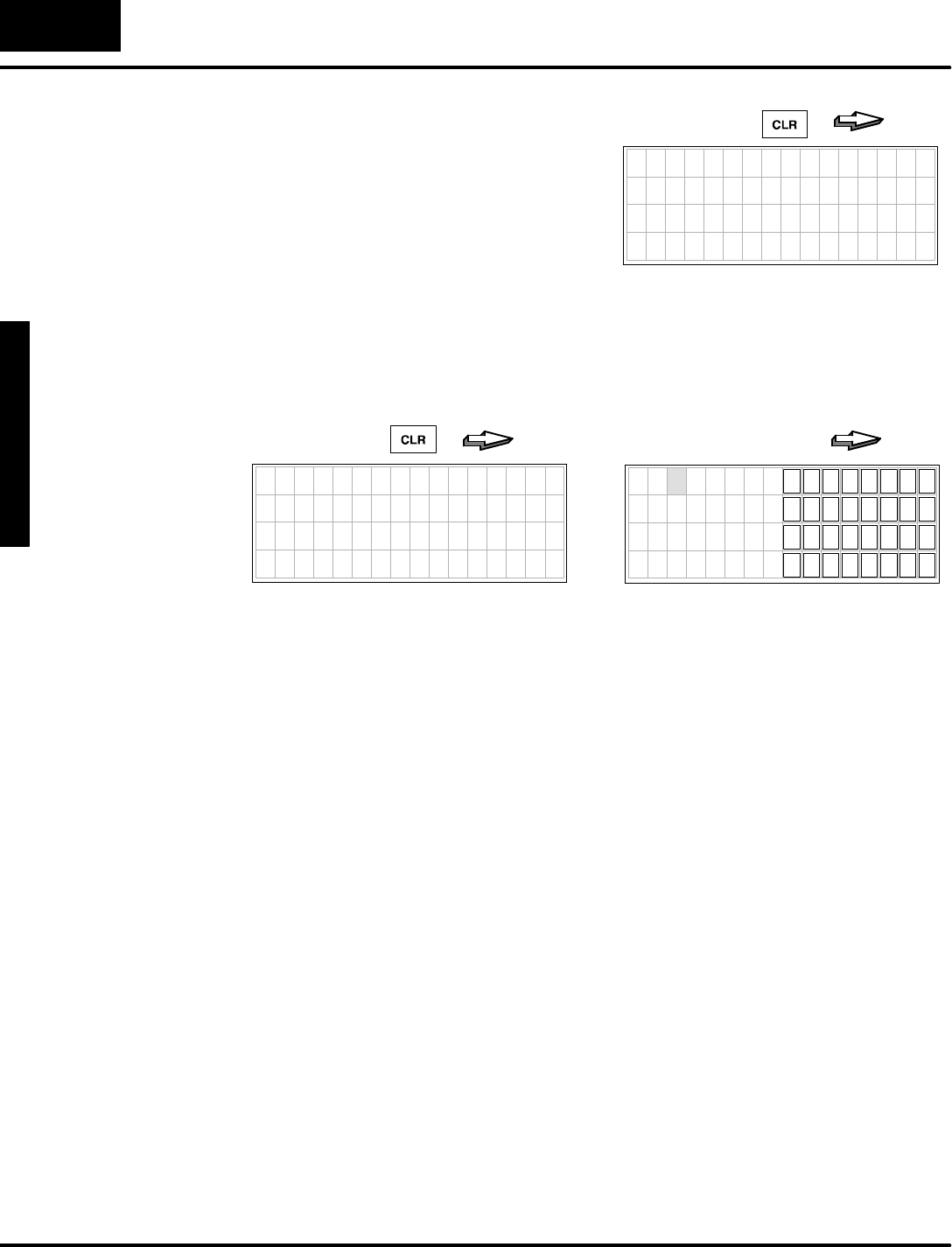
M
o
n
i
t
o
r
i
n
g
P
L
C
D
a
t
a
C
o
n
f
i
g
u
r
a
t
i
o
n
f
o
r
C
h
a
n
g
i
n
g
P
r
e
s
e
t
V
a
l
u
e
s
C
h
a
n
g
i
n
g
I
/
O
w
i
t
h
D
i
r
e
c
t
V
I
E
W
1
0
0
0
B
i
t
C
o
n
t
r
o
l
Mode
7
-
-
8
BitControlMode
Whilethe keypad isinBitControlMode,
the displaymaybe in eitherStatus
Display,Message Display,orChange
PresetModes.When you want the keypad
toresume normalfunction,press the
ClearKeyto exitBitControlMode.
7654321076543210
D O Y O U W A N T B I T
CONTROL MODE?
YES:PUSH ENT KEY
NO :PUSH CLR KEY
PRESS
Next, press the ClearKeyasecond timetoconfirm the exit. An exitmessage
appearsbriefly.Then the displayreturnstothe previousmode,and the keypad
resumesitsnormalfunction associated withthe displaymode. Inthe previous
section weweremonitoring the statusofC0toC7 ataddress V40600.Noticethat the
cursor returnstoindicate normalkeypad functionality.
PRESS
7654321076543210
E X I T B I T
CONTROL MODE
(Automatic...)
7654321076543210
C 0 0
C 1 0
C 2 0
C 3 0
Exiting BitControl
Mode
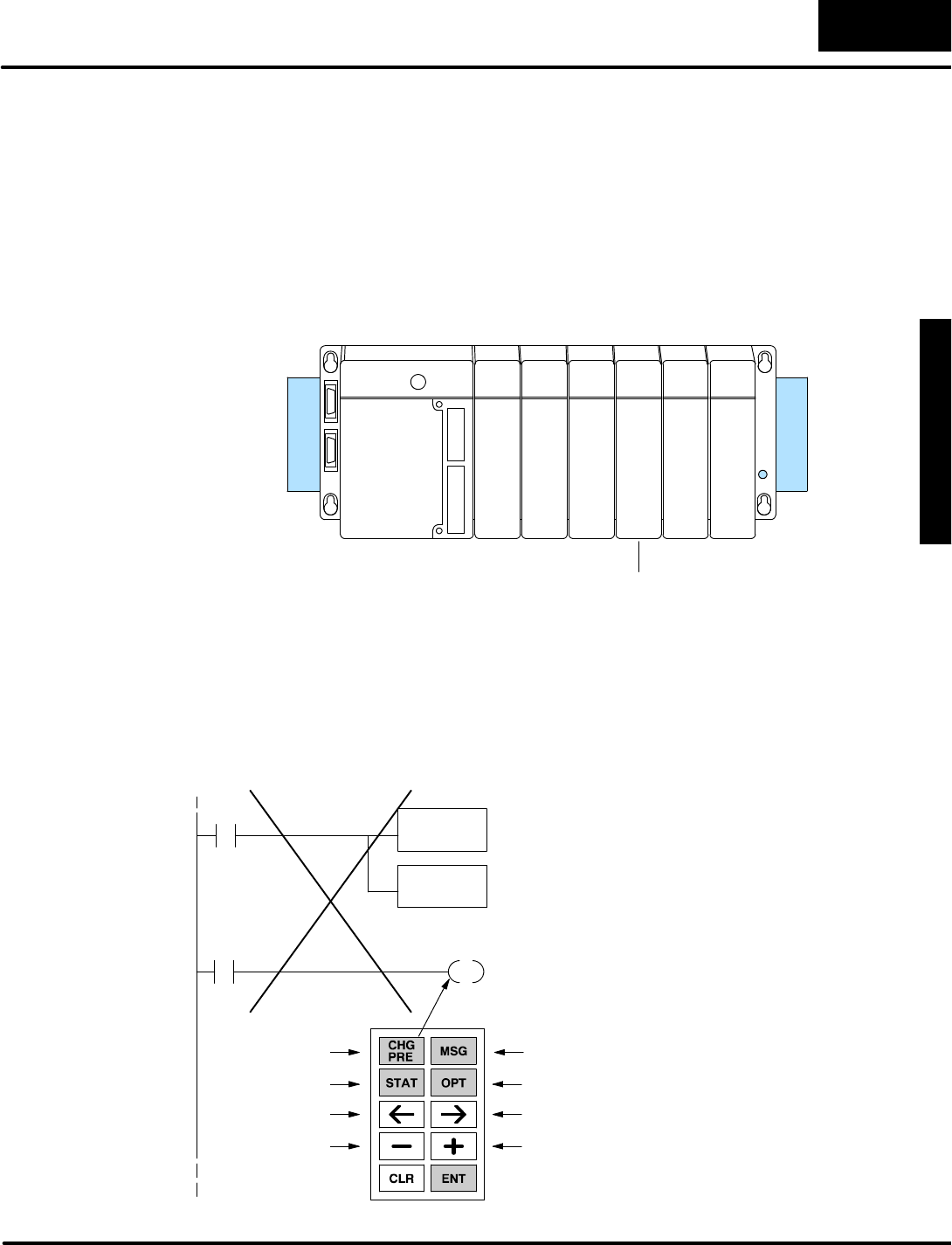
M
o
n
i
t
o
r
i
n
g
P
L
C
D
a
t
a
C
o
n
f
i
g
u
r
a
t
i
o
n
f
o
r
C
h
a
n
g
i
n
g
P
r
e
s
e
t
V
a
l
u
e
s
C
h
a
n
g
i
n
g
I
/
O
w
i
t
h
D
i
r
e
c
t
V
I
E
W
1
0
0
0
B
i
t
C
o
n
t
r
o
l
Mode
7
-
-
9
BitControlMode
BitControlApplications
BitControlMode ismostoften used fordebugging machinesorprocesses.Using
the setup parameteratV7625 wecan configureBitControlforX,Y,C,and GXtypes
of I/O points. It’sa good idea to plan the I/O points you want to useinBitControl,and
integrateitintothe mainladderprogram.The mainreason isthatBitControl
requestsI/O pointson. ItisnotaforcedI/O feature!
Forexample,considerthe systemshown below.Supposewewant totestoutputY0
using BitControl.
8pt
Input
8pt
Input
16pt
Output
16pt
Output
16pt
Output
16pt
Input
X0
--
X7
X10
--
X17
X20
--
X37
Y0
--
Y17
V40500
Y20
--
Y37
Y40
--
Y57
The I/O address ofY0toY17 isatV40500.The following programexamplesetsup
BitControlMode forY0toY7.ItshowsY0 being normally controlled byX0.However,
ladderlogicwill overwritetheDV-1000’srequested on stateofY0 at the end of
every scan,because Y0is alsoreferencedas an outputcoil intheprogram!
See the nextexampleforthe proper method todothis.
SP0LDA
O40500
Load octaladdress 40500 intothe accumulator.V40500 is
the location ofY0toY17.
OUT
V7625
Output thisaddress toV7625, the location of the setup
parameterforbitcontrol.
ParameterSetup:BitControl
MainProgram
X0Y0
0 1
2
4
6
3
5
7
Y0isnormally controlled byX0inthe application.Itisalso
requested on during BitControl,when the Change Preset
Keyispressed.
WRONG!
I/O Debug
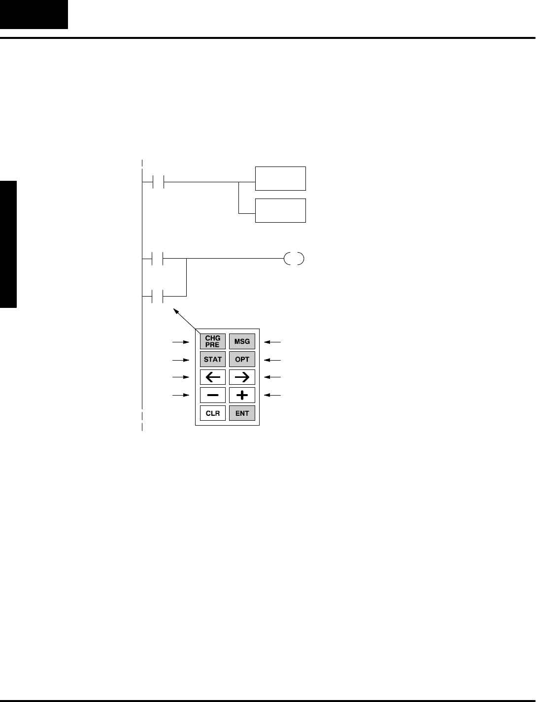
M
o
n
i
t
o
r
i
n
g
P
L
C
D
a
t
a
C
o
n
f
i
g
u
r
a
t
i
o
n
f
o
r
C
h
a
n
g
i
n
g
P
r
e
s
e
t
V
a
l
u
e
s
C
h
a
n
g
i
n
g
I
/
O
w
i
t
h
D
i
r
e
c
t
V
I
E
W
1
0
0
0
B
i
t
C
o
n
t
r
o
l
Mode
7
-
-
1
0
BitControlMode
Instead of trying to bitcontrolY0 directly,we use a controlrelayand do a logicalOR
withthe normalcontrol logicforY0.Then wesetup BitControlMode forC0toC7.
Nowthe conflictiseliminated,becauseC0isonlyreferenced asan inputinthe
program.
SP0LDA
O40600
Load octaladdress 40600 intothe accumulator.V40600 is
the location ofC0toC17.
OUT
V7625
Output thisaddress toV7625, the location of the setup
parameterforbitcontrol.
ParameterSetup:BitControl
MainProgram
X0Y0
0 1
2
4
6
3
5
7
Y0isnormally controlled byX0inthe application.Itisalso
controlled byC0whichisrequested on during BitControl,
when the Change PresetKeyispressed.
CORRECT!
C0

M
o
n
i
t
o
r
i
n
g
P
L
C
D
a
t
a
C
o
n
f
i
g
u
r
a
t
i
o
n
f
o
r
C
h
a
n
g
i
n
g
P
r
e
s
e
t
V
a
l
u
e
s
C
h
a
n
g
i
n
g
I
/
O
w
i
t
h
D
i
r
e
c
t
V
I
E
W
1
0
0
0
B
i
t
C
o
n
t
r
o
l
Mode
7
-
-
1
1
BitControlMode
The ladderprograminthisexample
coordinatesBitControlkeypad entries
withMessage Displayoutput. The display
announcesthe twomodesas shown,and
prompts you to press anybitcontrolkey.
When any keyispressed, the message on
the bottomline changesto namethe key
pressed.7654321076543210
BIT CONTROL MODE
& M E S S A G E M O D E
P r e s s K e y s - - - - >
(no key pressed)
PRESS
7654321076543210
B I T C O N T R O L M O D E
& M E S S A G E M O D E
P r e s s K e y s - - - - >
C H G P R E K e y
7654321076543210
B I T C O N T R O L M O D E
& M E S S A G E M O D E
P r e s s K e y s - - - - >
M S G K e y
PRESS
The ladderprogramhasno meansof forcing the displayintoMessage Display
Mode,northe keypad intoBitControlMode.However, thesemodesmaybe
selected fromthe keypad,aswell asprogrammed asthe powerup default. The
programcreatesthe displayoutputwithACONand MOVMC instructions.Load the
programbelow,and placethe CPU inrun mode.Then powercyclethe CPU,and it
should enterBitControland Message DisplayModes.Watchthe bottomline of the
displayrespond as you press eachBitControlkey.
NOTE:Thisexamplecontains certaininstructionsincluding LDLBL,DLBL,ACON,
and MOVMC which are discussed in detail inChapter4.Refertothe the section
“Using the ASCII Constant(ACON)Instruction”for moreinformation.
Setup ParametersforBitControland MessageMode
LDA
O40600
OUT
V7625
LD
K12
OUT
V7626
LDA
O2100
Load the octaladdress forV40600 intothe
accumulator.C0through C17 mapstoV40600.
Output the address intoV7625, the location of the bit
controlregister.The bitcontrolkeys controlC0toC7.
Outputourpowerup defaultcode toV7626, the
location of the Powerup Defaultsetup parameter.
Load the octaladdress forV2100 intothe
accumulator.
SP0
Firstscan only
Load the constantK12 intothe accumulator.K12 is
the code forthe powerup defaultmodesMessage
DisplaywithBitControl.
OUT
V7624
Output the address intoV7624, the location of the
textdata block pointerforMessage DisplayMode.
BitControlWith
MessageDisplay
Mode
a:\bitctrl2.prj
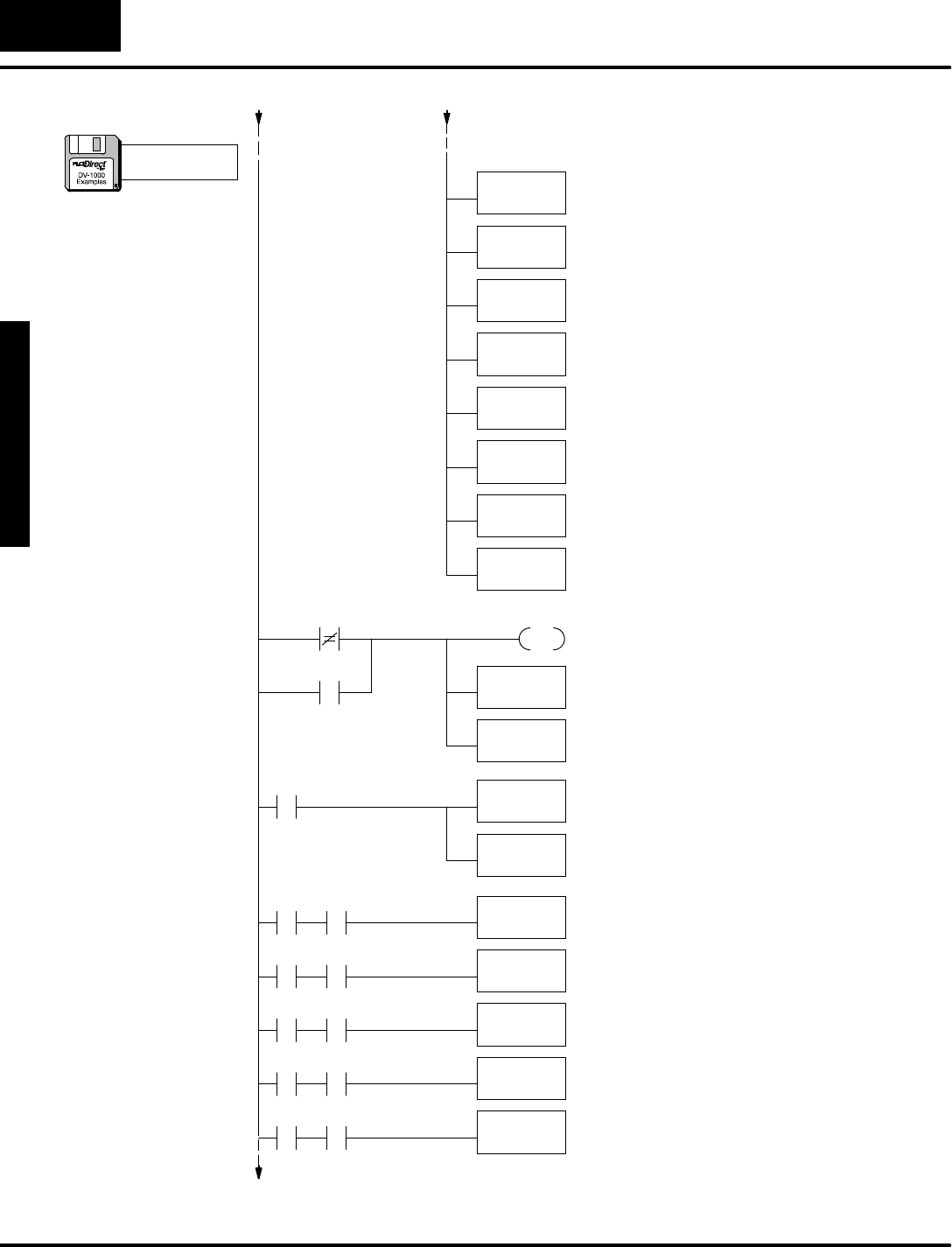
M
o
n
i
t
o
r
i
n
g
P
L
C
D
a
t
a
C
o
n
f
i
g
u
r
a
t
i
o
n
f
o
r
C
h
a
n
g
i
n
g
P
r
e
s
e
t
V
a
l
u
e
s
C
h
a
n
g
i
n
g
I
/
O
w
i
t
h
D
i
r
e
c
t
V
I
E
W
1
0
0
0
B
i
t
C
o
n
t
r
o
l
Mode
7
-
-
1
2
BitControlMode
LD
K10
LD
K0
LDLBL
K1
MOVMC
V2100
LD
K8
LD
K0
LDLBL
K2
MOVMC
V2120
LD
VC0
Load the currentkeypad bitpatternintothe
accumulator.
V40600 V2000
PD
ActivatecontrolrelayC20 for1scan when the
keypad’sbitpattern atV40600 changesfromthe saved
pattern atV2000.
C20
C20
OUT
V2000
LD
K8
LD
K0
C20 LDLBL
K3
C0
C20 LDLBL
K4
C1
C20 LDLBL
K5
C2
C20 LDLBL
K6
C3
C20 LDLBL
K7
C4
SP0
Top 2Display Lines
ThirdDisplay LineLoad the numberofdatalocations,whichis8
words(one line, foratotalof16 characters).
Load the address offset. FornearlyeveryMOVMC
used forACONdata, therewill be zero offset(use
K0).
Read fromthe ACONfollowing Data LabelK2.
Move dataintoV-memory starting atV2120.
Load the numberofdatalocations,whichis16 (10
hex)words(twolines, foratotalof32 characters).
Load the address offset. FornearlyeveryMOVMC
used forACONdata, therewill be zero offset(use
K0).
Read fromthe ACONfollowing Data LabelK1.
Move dataintoV-memory starting atV2100.
Overwritethe saved bitpattern atV2000,whichis
one scan old.Thispreparesforthe comparison
againonthe nextscan.
The nextseveralrungswithC20 contactexecutefor
1scan when the keypad bitpatternchanges.Load
the constantK8intothe accmulator.
Load the address offset. FornearlyeveryMOVMC
used forACONdata, therewill be zero offset(use
K0).
Read fromthe ACONfollowing Data LabelK3if the
CHGPRE Keyispressed.
Read fromthe ACONfollowing Data LabelK4if the
MSGKeyispressed.
Read fromthe ACONfollowing Data LabelK5if the
STATKeyispressed.
Read fromthe ACONfollowing Data LabelK6if the
OPTKeyispressed.
Read fromthe ACONfollowing Data LabelK7if the
Arrow<-- Keyispressed.
(continued)
a:\bitctrl2.prj
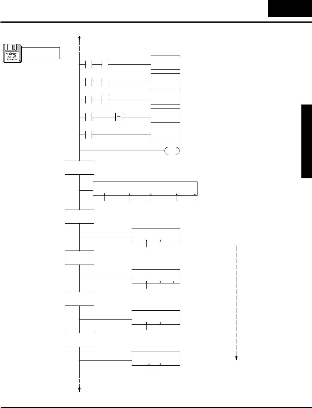
M
o
n
i
t
o
r
i
n
g
P
L
C
D
a
t
a
C
o
n
f
i
g
u
r
a
t
i
o
n
f
o
r
C
h
a
n
g
i
n
g
P
r
e
s
e
t
V
a
l
u
e
s
C
h
a
n
g
i
n
g
I
/
O
w
i
t
h
D
i
r
e
c
t
V
I
E
W
1
0
0
0
B
i
t
C
o
n
t
r
o
l
Mode
7
-
-
1
3
BitControlMode
END Markthe end of the main programwithanEnd Coil
.
C20 LDLBL
K8
C5
C20 LDLBL
K9
C6
C20 LDLBL
K10
C7
C20 LDLBL
K11
C20 MOVMC
V2130
VC0K0
UseASCII Constant(ACON)boxesto ente
r
textcharactersdirectlyfromthe keyboard.
DLBL
K1
ACON
BITCONTROLMODE& MESSAGEMODE
DataforTop 2Display Lines
The Data Labelboxesmarkthe beginning ofa
data area containing ACONboxes.The constant
in each boxisthe reference numberforthe text
datawhichfollows.
DLBL
K2
ACON
Press Keys -------->
Datafor3rdDisplay Line
UseASCII Constant(ACON)boxesto entertext
charactersdirectlyfromthe keyboard.
spaces:1 1
spaces:21 11 1
DLBL
K3
ACON
CHGPRE Key
spaces:1 1
DLBL
K4
DataforBottomDisplay (foreachkey)
ACON
MSGKey
spaces:1 9
5
DLBL
K5
ACON
STATKey
spaces:1 8
Read fromthe ACONfollowing Data LabelK8if
the Arrow-->Keyispressed.
Read fromthe ACONfollowing Data LabelK9if
the Minus(--) Keyispressed.
Read fromthe ACONfollowing Data LabelK10 if
the Plus(+)Keyispressed.
Read fromthe ACONfollowing Data LabelK11 if
no keyispressed.
Move dataintoV-memory starting atV21300.
same
(continued)
a:\bitctrl2.prj
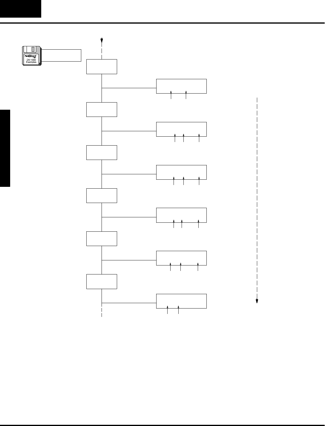
M
o
n
i
t
o
r
i
n
g
P
L
C
D
a
t
a
C
o
n
f
i
g
u
r
a
t
i
o
n
f
o
r
C
h
a
n
g
i
n
g
P
r
e
s
e
t
V
a
l
u
e
s
C
h
a
n
g
i
n
g
I
/
O
w
i
t
h
D
i
r
e
c
t
V
I
E
W
1
0
0
0
B
i
t
C
o
n
t
r
o
l
Mode
7
-
-
1
4
BitControlMode
DLBL
K6
ACON
OPTKey
UseASCII Constant(ACON)boxesto entertext
charactersdirectlyfromthe keyboard.
spaces:1 9
DLBL
K7
ACON
Arrow<-- Key
spaces:1 1
DLBL
K8
DataforBottomDisplay (foreachkey),cont’d
ACON
Arrow-->Key
spaces:1 1
4
DLBL
K9
ACON
Minus(--) Key
spaces:1 1
DLBL
K10
ACON
Plus(+)Key
spaces:1 4
DLBL
K11
ACON
(no keypressed)
spaces:1
4
3
1
1
same
(continued)
a:\bitctrl2.prj
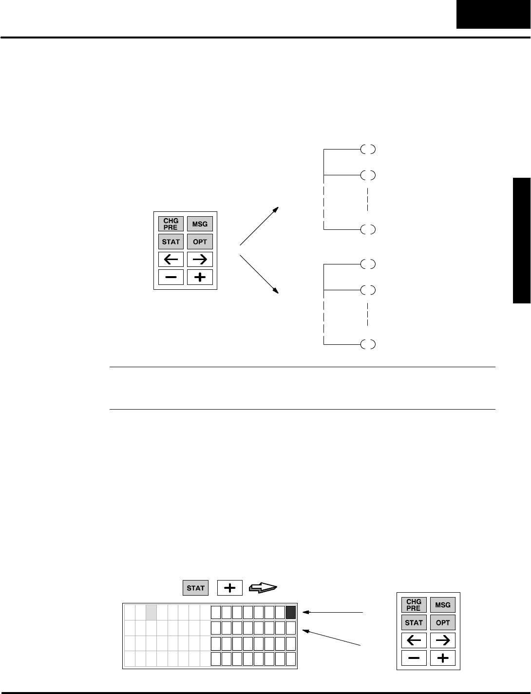
M
o
n
i
t
o
r
i
n
g
P
L
C
D
a
t
a
C
o
n
f
i
g
u
r
a
t
i
o
n
f
o
r
C
h
a
n
g
i
n
g
P
r
e
s
e
t
V
a
l
u
e
s
C
h
a
n
g
i
n
g
I
/
O
w
i
t
h
D
i
r
e
c
t
V
I
E
W
1
0
0
0
B
i
t
C
o
n
t
r
o
l
Mode
7
-
-
1
5
BitControlMode
Insome applications you mayneed bitcontrolofmorethan 8 bitsfromthe keypad.
Using ladderlogic,you can share(multiplex)the bitcontrolkeys among multiple
outputs.Refertothe drawing below.Forexample,when the machine isin“Mode 0”
the keypad’sbitcontrolmapsto outputsY0through Y7.During “Mode 1”the keypad
controlsY10 through Y17. Inthisway,eightkeys aremultiplexed among sixteen
outputpoints.
Mode 0
Y0
Y1
Y7
Y10
Y11
Y17
Mode 1
Outputs,
Y0-- Y7
Outputs,
Y10 -- Y17
0
2
4
6
1
3
5
7
NOTE:The operator mustbe informed astowhichmode isactive before and during
keypad useforbitcontrol. One method isto useladderlogictosend a message to
the DV--1000 displayindicating which outputsare underbitcontrol.
Inthisexample,wewill usethe state ofdiscreteinputX0toindicatethe mode of the
machine.X0=OFF isMode 0,and X0=ON isMode 1.The ladderlogicprogramon
the following page mapsthe bitcontrolkeys tocontrolrelay contactsC0through C7
(see setup rung).The main programthen usesX0inconjunction withthe control
relays tocontroleitherthe firstorsecond bankofYoutputpoints.
Load the example programinthe CPUand placethe CPU inRun Mode.You can use
StatusDisplayMode tosee the programwork.Press the StatusKeyfollowed bythe
Plus(+)Keytoviewthe statusofYoutputpoints.Then placethe keypad inBit
ControlMode bypressing the OptionsKeyand selecting BitControlfromthe menu.
When the statusdisplayreturns,you can change between Mode 0 and Mode 1 using
a discreteinputatX0.Then observethe corresponding group ofYoutputs.
PRESS
7654321076543210
Y 0 0
Y 1 0
Y 2 0
Y 3 0
Mode 0
(X0=OFF)
Mode 1
(X0=ON)
0
2
4
6
1
3
5
7
MultiplexedBit
Control
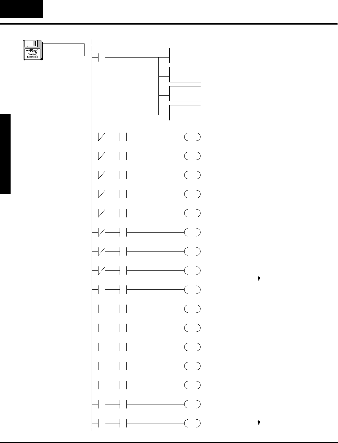
M
o
n
i
t
o
r
i
n
g
P
L
C
D
a
t
a
C
o
n
f
i
g
u
r
a
t
i
o
n
f
o
r
C
h
a
n
g
i
n
g
P
r
e
s
e
t
V
a
l
u
e
s
C
h
a
n
g
i
n
g
I
/
O
w
i
t
h
D
i
r
e
c
t
V
I
E
W
1
0
0
0
B
i
t
C
o
n
t
r
o
l
Mode
7
-
-
1
6
BitControlMode
Setup ParametersforBitControl
LDA
O40600
OUT
V7625
LD
K3
OUT
V7626
Load the octaladdress forV40600 intothe
accumulator.C0through C17 mapstoV40600.
Output the address intoV7625, the location of the bit
controlregister.The bitcontrolkeys controlC0toC7.
Outputourpowerup defaultcode toV7626, the
location of the powerup defaultsetup parameter.
SP0
Firstscan only
Load the constantK3intothe accumulator.K3isthe
code forthe powerup defaultmode StatusDisplay
Mode.
X0
OUTWhen X0isOFF, the machine isinMode 0. Inthis
mode wemap the bitcontrolkeys tocontroloutputsY0
through Y7.Note:If using DL105 be sureCPUis
initialized tomakeX0 operational.
Y0
MainProgram
C0
X0
OUT
Y1
C1
X0
OUT
Y2
C2
X0
OUT
Y3
C3
X0
OUT
Y4
C4
X0
OUT
Y5
C5
X0
OUT
Y6
C6
X0
OUT
Y7
C7
X0
OUTWhen X0isON, the machine isinMode 1. Inthis
mode wemap the bitcontrolkeys to outputsY10
through Y17.
Y10
C0
X0
OUT
Y11
C1
X0
OUT
Y12
C2
X0
OUT
Y13
C3
X0
OUT
Y14
C4
X0
OUT
Y15
C5
X0
OUT
Y16
C6
X0
OUT
Y17
C7
SAME
SAME
a:\bitctrl3.prj
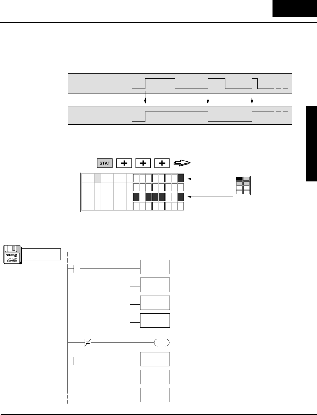
M
o
n
i
t
o
r
i
n
g
P
L
C
D
a
t
a
C
o
n
f
i
g
u
r
a
t
i
o
n
f
o
r
C
h
a
n
g
i
n
g
P
r
e
s
e
t
V
a
l
u
e
s
C
h
a
n
g
i
n
g
I
/
O
w
i
t
h
D
i
r
e
c
t
V
I
E
W
1
0
0
0
B
i
t
C
o
n
t
r
o
l
Mode
7
-
-
1
7
BitControlMode
The keypad inBitControlMode operatesasmomentary switches,as you mayrecall.
Abitison onlywhen its corresponding keyispressed.Thisexamplefeaturesasmall
programwhichchangesthe momentarynatureinto a latching,ortoggling function.
You can press akeyoncetoturnonabit, then press itagaintoturn off the bit!
RELEASED
Key PRESSED
Toggle
Function OFF
ON
Afterloading the programbelow,placethe DV-1000 inStatusDisplayMode.Then
monitorthe statusofcontrolrelays C00 through C39 as shown below.The keypad is
mapped toC0through C7,and the corresponding toggled bitsarefromC20 toC27.
PRESS
7
6
5
4
3
2
1
0
7
6
5
4
3
2
1
0
C 0 0
C 1 0
C 2 0
C 3 0
Keypad bits
Toggled bits
2.Release“0”and noticethatC0turnsoff
butC20 stays on.
3.Press “0”againtoturnC20 off.
1.Press “0” (CHG
PRE).Noticethat
C0 and
corresponding bit
C20 bothturn on.
The keypad mustbe inBitControlMode totogglethe bitsas shown above.Press the
OptionsKey,selectBitControl,and the statusdisplaywill return automatically.
Setup ParametersforBitControl
LDA
O40600
OUT
V7625
LD
K3
OUT
V7626
Load the octaladdress forV40600 intothe
accumulator.C0through C17 mapstoV40600.
Output the address intoV7625, the location of the bit
controlregister.The bitcontrolkeys controlC0toC7.
Outputourpowerup defaultcode toV7626, the
location of the powerup defaultsetup parameter.
SP0
Firstscan only
Load the constantK3intothe accumulator.K3isthe
code forthe powerup defaultmode StatusDisplay
Mode.
V40600 K0
C30
PD
ActivatecontrolrelayC30 for1scan when any keyis
pressed on the keypad.
C30
LD
V40601
XOR
V40600
OUT
V40601
Load the contentsofV40601 intothe
accumulator(C20 toC37).Thisisused asthe toggle
image registerinthisprogram.
The XORresultsareinthe accumulator,and itisthe
newtoggle bitimage.Output thistoV40601,
replacing the oldtoggleimage.
Do an exclusiveORfunction on the accumulator
contentsand the keypad image atV40600.This
effectivelydoesthe toggleinversion foreach bit.
MainProgram
BitControl
ToggleFunction
a:\bitctrl4.prj

M
o
n
i
t
o
r
i
n
g
P
L
C
D
a
t
a
C
o
n
f
i
g
u
r
a
t
i
o
n
f
o
r
C
h
a
n
g
i
n
g
P
r
e
s
e
t
V
a
l
u
e
s
C
h
a
n
g
i
n
g
I
/
O
w
i
t
h
D
i
r
e
c
t
V
I
E
W
1
0
0
0
B
i
t
C
o
n
t
r
o
l
Mode
7
-
-
1
8
BitControlMode
ChapterSummary
Now we havecovered BitControlMode and demonstrated howtoturn on specific
I/O bitsusing the keypad.
Wemay summarizesome of the keypointswe havelearned aboutBitControlMode
inthis chapter:
SBitControlMode onlyappliestothe keypad.The display can be in any
one of the otherthree modesduring BitControl.
SThe keypad operatesasnormallyopen,momentary switchesduring bit
control.
SOnlythe lowereightbitsofV-memorylocationsmaybe directly
addressed bybitcontrol.
SAfterselectingaV-memorylocation forbitcontrol,do notuseitsupper
eightbits(the DV-1000 overwritesthesewhile updating the whole
V-memoryword).
SIf ladderlogic containsan outputpoint thatreferencesthe same address
asthe bitcontrolled register,aconflictexists.The PLCscan will
overwritethe keypad request.
Nowyou havethe necessaryinformation toinstall and useyourDV-1000!
Summaryof
Key Points

1
.A
Troubleshooting
Guide
In ThisAppendix....
—TroubleshootingGuide

A
p
p
e
n
d
i
x
A
T
r
o
u
b
l
e
s
h
o
o
t
i
n
g
G
u
i
d
e
A
p
p
e
n
d
i
x
B
A
S
C
I
I
t
o
H
E
X
C
r
o
s
s
R
e
f
.
A
-
-
2
Troubleshooting Guide
Troubleshooting Guide
Oneor more exampleprogramsinthismanualdo notoperateproperly.What’swrong?
Check forthe following possiblecauses:
SMostof the example programsinclude firstscan rungsusing SP0
contacts.The CPUneedstomakeaprogram-to-run mode transition in
orderfortheserungsto execute.UseDirectSOFT todothis.
SThe program mayrequire an external inputsuch asX0 orX1.Check the
systemconfiguration requirementslisted forthe exampletowork.
SThe DL430 CPUdoesnotsupportsomeinstructions such asMOVMC
and ACONboxeswhich occurinthe examples.The DL130 and DL230
do notsupportpointervariables(type P).
When pressing someof the keys on theDV-1000,adisplay message appearsthatsays “Setup
Error,Check ValueinV(xxxx)”.HowcanIeliminatethese error messages?
For mostof the DV-1000 modes, two orthree PLCV-memorylocationsmustbe
loaded withsetup parameters.The range ofV-memory setaside forthispurposeis
described inChapter3. If you havemanuallyentered these parametersatone time,
theynowmayhave becomecorrupted forone ofseveralpossiblereasons.We
recommend imbedding parametersetup datainladderlogic(firstscan rung only).
See Chapter3for moreonthistopic.
Using ChangePreset ModeIattempt tochangetimerorcounterpresets.However,thetimeror
counterpresetdoes notactually changewhenthePLCprogramisrunning.What’swrong?
The mostlikelyproblemisthat the counterortimerboxinthe ladderprogramhasa
constantKxxxx selected asa preset. You will need to edit the timerorcounterboxto
instead referenceaV-memorylocation forthe preset. The Change Preset function
cannotchange an instruction box’s constant. Pleasesee the examplesinChapter6.
Ican’tget thenumericdatainMessageDisplay modeto putnumberson the screen.
Potentialsourcesof thisproblemare:
SThe numeric setup parameteratV7623 maynotbe pointing tothe area
ofV-memorywherethe value resides.
SThe textdatamaybe masking the number(s)ifitsASCII codesare 20
hexorgreaterintextpositions corresponding to numericpositions
whereyou want the numbersto appear.
SThe displayisnotinMessage DisplayMode.
Whydoes ChangePresetkeypadentries take solong torespond and updatethedisplay?
The delay you areseeing isdue tocommunication time between the DV-1000 and
the CPU.Ifscreen updateslag behind,itcan causeyou to overshoot the desired
value.Forbestresults,pauseasecond between key strokes.
InladderlogicIchangethetextornumericpointerto point toa second block ofdata.However,
theDV-1000 onlyreadstheoriginaldatablock.Whyisthat?
The DV-1000 onlyreadsthe setup parametertablejustafterpowerup. If you want to
change the displaydata,you’ll need tomove newdataintothe originaltextand/or
numericdata blocks.An exampleinChapter4showsthe ladderlogicrequired to do this.

A
p
p
e
n
d
i
x
A
T
r
o
u
b
l
e
s
h
o
o
t
i
n
g
G
u
i
d
e
A
-
-
3
Troubleshooting Guide
Iamnotabletochangepresetvalues,eventhough Ihave enteredthe correctpassword(orthe
passwordisdisabled).What’swrong?
See if the number(s)you aretrying to editare hexnumbers.Remember,Change
PresetMode onlyworks forBCD numbers(0000 to 9999).Also,makesurethe
switchonthe frontofyourCPU isnotinthe “Run”position (use“Term”).
TheACON(ASCII Constant) instruction boxwill only accept twocharacters, whilethe examples
inthemanualshowmanymore characters.What’stheproblem?
You are probablyusingaHand-heldProgrammerto enterladderlogic.Thisisok,but
the extended ACONboxfunctionality you are expecting isprovided bythe PC-based
DirectSOFT programming software.The Hand-heldProgrammeraccessesthe
CPU’s standardACONboxfunction,which acceptstwocharacters.Thisis
described inChapter4.
The keypadseemsto belocked up.WhenIpress keys thedisplay does notchange.Whyisthat?
Therecan be two differentcausesof thisproblem:
SIt maybe that the DV-1000 isinBitControlMode.Thistemporarily
changesthe keypad functionality.Press the ClearKeyfollowed bythe
EnterKeyto exitBitControlMode.
SThe DV-1000 setup parametersmaybe invalid, thereby confusing
DV-1000 firmware.ThisismostlikelyifyourCPU isnewand its setup
parameterlocationsforthe DV-1000 have neverbeen programmed.
Followthe instructionsinChapter2toinitializethe CPUscratchpad
memory,which places zerosin all thesesetup parameterlocations.
WhenIuseaLDD instruction toloadtextdata(ASCII codes),thedisplay outputswapsthe
position of thetwo pairsofcharacters.Why?
Thisisnormal.The reason behind thiseffect, along with an example,is showninthe
section inChapter4, titled “Loading TextUsing the LDD and OUTDInstructions”.
Thedisplay backlightison,butno characters everappearon thedisplay foranyof themodes.
This condition occurswhen the DV-1000 is connected tothe second
communicationsportonaDL240 thatis configured incorrectly.Using DirectSOFT,
select the PLCmenu, then Setup, then SecondaryPort.Set the port for9600 baud,
8 data bits,1stop bit, odd parity.
WhenIviewthe contentsof the setup parameterlocations,the setup pointervalues arewrong. It
seems something isoverwriting the setup datawhichtheladderprogramwrites on thefirstscan.
Rememberthat the LDAinstruction whichloadsoctaladdressesinthe setup
programconvertsthe octalnumbersto hexnumbers. It’slikelythat the values you
see arethe correcthexrepresentationsof the octaladdresses.
WhentheDV-1000 powersup,theonlything itdoes isdisplay the error message“E320 TIME
OUT”.The keypadalso does notwork.Whatistheproblem?
The message you see isgenerated bythe DV-1000. It isunableto establish
communicationswiththe CPU.Check the following tofind the source of the problem:
SThe communications cablemaybe faulty. Inspect the contactsfordust,
etc., orchange cables.
SIf you havemade a customcable,itmaybe that the cable pinoutsare
reversed (the RJ12 connectoron one end isinstalled upside down).Pin
1 ofone end shouldconnect to pin6of the opposite end!Refertothe
customcable drawing inChapter2.

1
B
Reference Data
In ThisAppendix....
—Setup ParameterTables
—ASCII Table
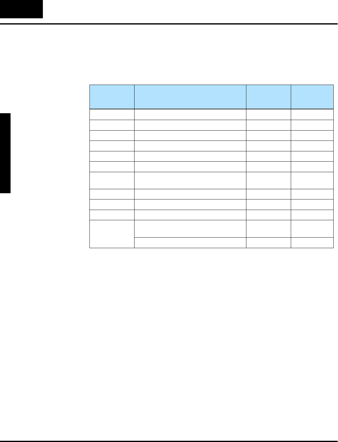
A
p
p
e
n
d
i
x
B
R
e
f
e
r
e
n
c
e
D
a
t
a
B
-
-
2
ReferenceData
Setup ParameterTables
The following tableincludesall the setup parametersforthe variousmodesof the
DV-1000.
PLC CPU
V-memory
Locations
DV-1000 ParameterDescription Operational
Mode
See Chapter
Number
V7620 Change PresetValuesPointerCHGPRE6
V7621 Change PresetTitlesPointerCHGPRE6
V7622 Change PresetBlock SizeCHGPRE6
V7623 NumericMessage PointerMSG4
V7624 TextMessagesPointerMSG4
V7625 BitControlPointerBITCNTRL 7
V7626 Powerup OperationalMode Power-up
Default3
V7627 Change PresetValue PasswordCHGPRE6
V7720*Titled TimerPresetValue PointerCHGPRE6
V7721*Titled CounterPresetValue PointerCHGPRE6
V7722*,
High byte
L
o
w
b
y
t
e
Titled TimerPresetBlock SizeCHGPRE6
LowbyteTitled CounterPresetBlock SizeCHGPRE6
*DL130 and DL230 CPUsuse differentmemorylocationshere:V7640 instead of
V7720,V7641 instead ofV7721,and V7642 instead ofV7722.
The next tablerepeatsthe setup parameterlist, butgivesthe valid address range for
eachCPUtype and the datatype foreachsetup parameter.

A
p
p
e
n
d
i
x
B
R
e
f
e
r
e
n
c
e
D
a
t
a
B
-
-
3
ReferenceData
PLC CPU
V-memory
Locations
DV-1000
Parameter
Description
Data
Type
DL130
DL230
Ranges
DL240,
Ranges
DL250
DL350
DL430
Ranges
DL440
Ranges
DL450
Ranges
V7620 Change
Preset
Values
Pointer
OctalV2000 to
V2377,
V4000 to
V4177
V2000 to
V4377 V1400 to
V7377 V1400 to
V7377,
V10000 -
V17777
V1400 to
V7377,
V10000 -
V37777
V7621 Change
Preset
Titles
Pointer
OctalV2000 to
V2377,
V4000 to
V4177
V2000 to
V4377 V1400 to
V7377 V1400 to
V7377,
V10000-
V17777
V1400 to
V7377,
V10000-
V37777
V7622 Change
Preset
Block Size
BCD 1-- 16 1 -- 16 1 -- 32 1 -- 32 1 -- 32
V7623 Numeric
Message
Pointer
OctalV2000 to
V2377,
V4000 to
V4177
V2000 to
V4377 V1400 to
V7377 V1400 to
V7377,
V10000-
V17777
V1400 to
V7377,
V10000-
V37777
V7624 Text
Message
Pointer
OctalV0000 to
V2377,
V4000 to
V4177
V2000 to
V4377 V1400 to
V7377 V1400 to
V7377,
V10000-
V17777
V1400 to
V7377,
V10000-
V37777
V7625 BitControl
PointerOctalX,Y,or
C
V--mem.
locations
X,Y,or
C
V--mem.
locations
X,Y,GX,
orC
V--mem.
locations
X,Y,GX,
orC
V--mem.
locations
X,Y,GX,
orC
V--mem.
locations
V7626 Power-up
Operational
Mode
BCD 0,1,2,
12,30,1,2,
12,30,1,2,
12,30,1,2,
12,30,1,2,
12,3
V7627 Change
Preset
Value
Password
BCD 0000 to
9999 0000 to
9999 0000 to
9999 0000 to
9999 0000 to
9999
V7720*Titled Timer
Preset
Value
Pointer
Octal-- V2000 to
V4377 V1400 to
V7377 V1400 to
V7377,
V10000-
V17777
V1400 to
V7377,
V10000-
V37777
V7721*Titled
Counter
PresetValue
Pointer
Octal-- V2000 to
V4377 V1400 to
V7377 V1400 to
V7377,
V10000-
V17777
V1400 to
V7377,
V10000-
V37777
V7722*,
High byteTitled Timer
Preset
Block Size
BCD -- 1to 99 1 to 99 1 to 99 1 to 99
V7722*,
LowbyteTitled
Counter
PresetBlock
Size
BCD -- 1to 99 1 to 99 1 to 99 1 to 99
*DL130 and DL230 CPUsusememorylocationsV7640 thruV7642 here.

A
p
p
e
n
d
i
x
B
R
e
f
e
r
e
n
c
e
D
a
t
a
B
-
-
4
ReferenceData
ASCII Table
There areseveralversionsof the ASCII charactercodesforvarious computerplatformsand output
devices.The following tableliststhe ASCII characters supported bythe DirectVIEWä1000.
HEX ASCII HEX ASCII HEX ASCII HEX ASCII HEX ASCII HEX ASCII HEX ASCII HEX ASCII
00 ---- 20 40 @60 ‘80 ---- A0---- C0---- E0a
01 ---- 21 !41 A61 a81 ---- A1hC1---- E1ä
02 ---- 22 ”42 B62 b82 ---- A2?C2---- E2ß
03 ---- 23 #43 C63 c83 ---- A3?C3---- E3e
04 ---- 24 $44 D64 d84 ---- A4\C4---- E4µ
05 ---- 25 %45 E65 e85 ---- A5gC5---- E5s
06 ---- 26 &46 F66 f86 ---- A6---- C6---- E6?
07 ---- 27 ’47 G67 g87 ---- A7---- C7---- E7q
08 ---- 28 (48 H68 h88 ---- A8---- C8---- E8----
09 ---- 29 )49 I69 i89 ---- A9---- C9---- E9----
0A---- 2a *4AJ6Aj8A---- AA ---- CA ---- EA?
0B---- 2B+4BK6Bk8B---- AB ---- CB ---- EB´
0C---- 2C,4CL6Cl8C---- AC ---- CC ---- EC----
0D---- 2D-- 4DM6Dm8D---- AD ---- CD ---- ED----
0E---- 2E.4EN6En8E---- AE---- CE---- EE n
0F---- 2F/4FO6Fo8F---- AF---- CF---- EFö
10 ---- 30 050 P70 p90 ---- B0—D0---- F0p
11 ---- 31 151 Q71 q91 ---- B1---- D1---- F1q
12 ---- 32 252 R72 r92 ---- B2---- D2---- F2?
13 ---- 33 353 S73 s93 ---- B3---- D3---- F38
14 ---- 34 454 T74 t94 ---- B4ID4---- F4O
15 ---- 35 555 U75 u95 ---- B5---- D5---- F5ü
16 ---- 36 656 V76 v96 ---- B6---- D6---- F6S
17 ---- 37 757 W77 w97 ---- B7---- D7---- F7?
18 ---- 38 858 X78 x98 ---- B8---- D8---- F8x
19 ---- 39 959 Y79 y99 ---- B9---- D9---- F9u
1A---- 3A:5AZ7Az9A---- BA ?DA ---- FA----
1B---- 3B;5B[7B{9B---- BB ---- DB jFB----
1C---- 3C<5C---- 7C|9C---- BC ---- DC ---- FC----
1D---- 3D=5D]7D}9D---- BD ---- DD ---- FD÷
1E---- 3E>5E^7E?9E---- BE---- DE---- FE----
1F---- 3F?5F_7F?9F---- BF---- DFhFF J
NOTE:If anyof the non-useablecharactersnoted as---- are used forthe messagesortitlesinthe DV--1000,
the characterwill notdisplay.

1
C
DV-1000
Worksheets
In ThisAppendix....
—MessageDisplayWorksheets
—ChangePresetWorksheets
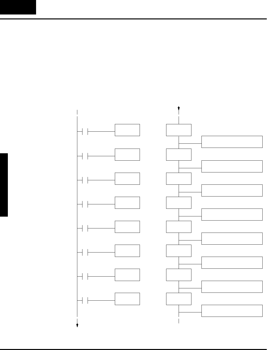
A
p
p
e
n
d
i
x
C
D
V
-
1
0
0
0
W
o
r
k
s
h
e
e
t
s
C
-
-
2
DV-1000 Worksheets
MessageDisplay Worksheets
The Fault Instruction can outputup to23characters.Werecommend limiting it to 15
characters sothe text fitswithinthe DV-1000’stop line.The following worksheet
showsladderprogramsegments. Onthe left arethe Faultboxes(yoursmaybe
spread throughoutyourprogram,and use differentpermissivecontact
arrangements). Onthe rightarethe corresponding datalabelsand ACONboxes.
Each activeFaultbox can causethe message inthe corresponding ACONBoxto be
displayed.Rememberthat the maximumnumberofofData Labelsis64,and the
Data Labelnumbersare hexadecimal.
F
a
u
l
t
M
e
s
s
a
g
e
I
n
s
t
r
u
c
t
i
o
n
s
DLBL
K1
ACON
_______________________
FAULT
K1
D
a
t
a
L
a
b
e
l
A
r
e
a
DLBL
K2
DLBL
K3
DLBL
K4
DLBL
K5
DLBL
K6
DLBL
K7
DLBL
K8
ACON
_______________________
ACON
_______________________
ACON
_______________________
ACON
_______________________
ACON
_______________________
ACON
_______________________
ACON
_______________________
FAULT
K2
FAULT
K3
FAULT
K4
FAULT
K5
FAULT
K6
FAULT
K7
FAULT
K8
Fault Messages
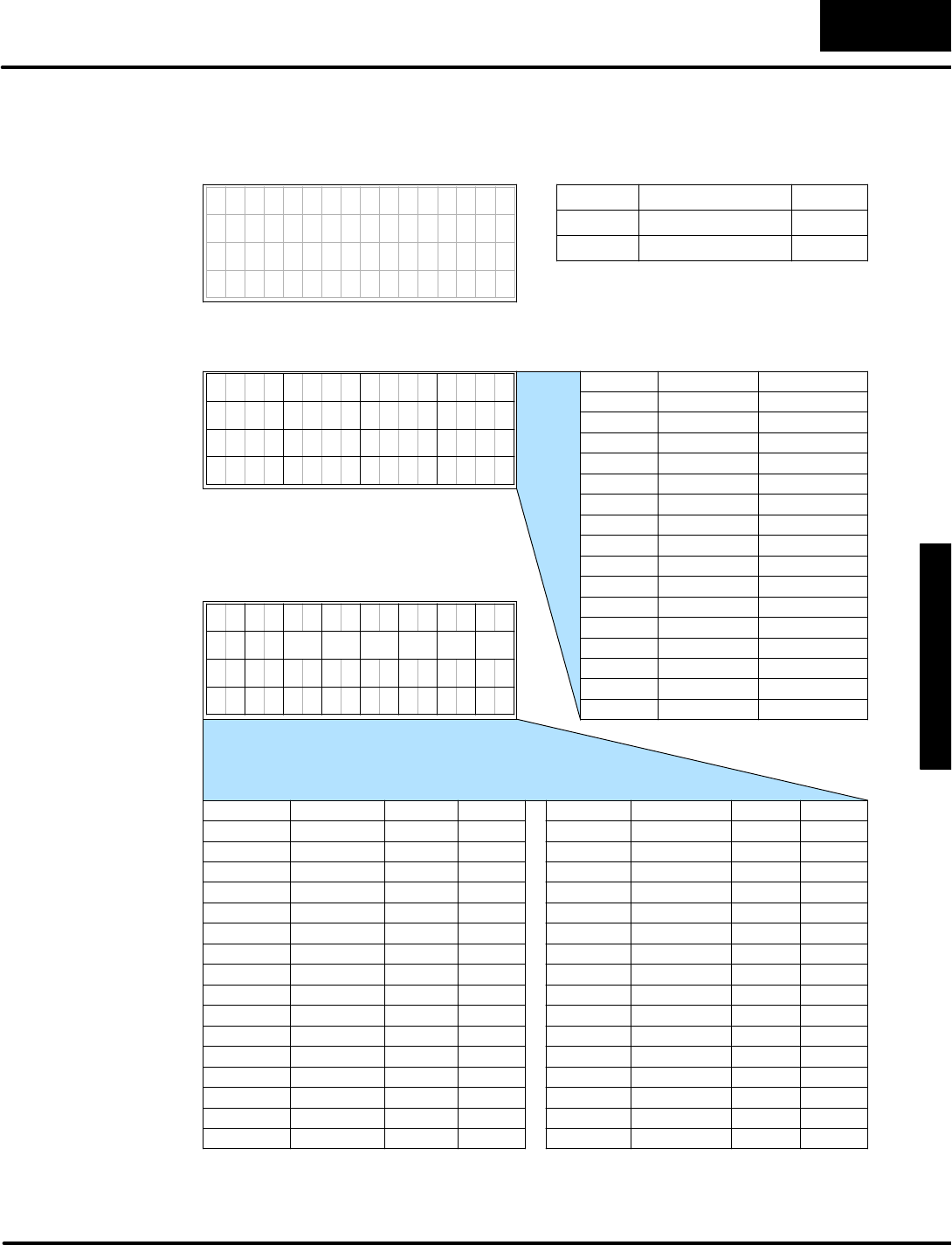
A
p
p
e
n
d
i
x
C
D
V
-
1
0
0
0
W
o
r
k
s
h
e
e
t
s
C
-
-
3
DV-1000 Worksheets
Forcombined numericand textoutput, thisworksheetcan helpyou organizethe
numbersand ASCII codeswiththe proper memorylocations.
7654321076543210
3
7654321076543210
0
37
20
11
2
22
31 33
4
24
35
26
135
27
36343230
10
252321
2 1
13 11
6
16 14
7
10
1517
12
12 13 14 15
Position Data TextV-Memory
0
1
2
3
4
5
6
7
10
11
12
13
14
15
16
17
20
21
22
23
24
25
26
27
30
31
32
33
34
35
36
37
Position NumberV-Memory
Position Data TextV-Memory
0
1
2
3
4
5
6
7
10
11
12
13
14
15
16
17
NumericDisplay Positions
TextDisplay Positions
NumericData
TextData
16 17
0
6 7
5 4
7654321076543210
D
e
s
i
r
e
d
D
i
s
p
l
a
y
TextData
Address ValueSetup Parameter
V7623 NumericPointer
V7624 TextPointer
MessageDisplay
Output Maps

A
p
p
e
n
d
i
x
C
D
V
-
1
0
0
0
W
o
r
k
s
h
e
e
t
s
C
-
-
4
DV-1000 Worksheets
The following displaygridsareforgeneral-purposemessage displayplanning.
0
37
20
11
2
22
31 33
13
4
24
15
35
26
17
61 3 5 7
27
36343230
10
25
16
2321
12 14
Text
Output
3 2 1 0
13 11
6 4
16 14
7
10
1517
12
5
Numeric
Output
NumericDataStarting Address =V__________
TextDataStarting Address =V__________
0
37
20
11
2
22
31 33
13
4
24
15
35
26
17
61 3 5 7
27
36343230
10
25
16
2321
12 14
Text
Output
3 2 1 0
13 11
6 4
16 14
7
10
1517
12
5
Numeric
Output
NumericDataStarting Address =V__________
TextDataStarting Address =V__________
Display Output
Grids
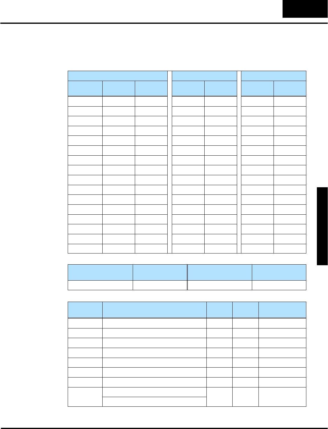
A
p
p
e
n
d
i
x
C
D
V
-
1
0
0
0
W
o
r
k
s
h
e
e
t
s
C
-
-
5
DV-1000 Worksheets
ChangePresetWorksheet
Choosethe text titlesforthe User-titled presetsand the numberof timerand counter
preset titles.Rememberto use atleastone ofeachtitletype in all cases.
UserPresetsTimerPresetsCounterPresets
TextTitles Text
Locations
Data
Locations
Titles Data
Locations
Counter
Titles
Data
Locations
Timer1Counter1
Password
Enable/Disable
PasswordValuePowerup ModePowerup Value
Usethe worksheetaboveto determine the setup parametervaluesbelow.
V-Memory
Location
Setup ParameterDescription FormatValueNotes:
V7620 UserPresetDataPointerOctalstartingatV...
V7621 UserPresetTitlesPointerOctalstartingatV...
V7622 UserPresetBlockSizeBCD # of titles
V7626 PowerupModeBCD
V7627 ChangePresetPasswordBCD
V7720*TitledTimerDataPointerOctalstartingatV...
V7721*TitledCounterDataPointerOctalstartingatV...
V7722*TimerPresetBlockSize(highbyte)BCD xx timers,
y
y
c
o
u
n
t
e
r
s
CounterPresetBlockSize(lowbyte)
y
y
c
o
u
n
t
e
r
s
*DL130 and DL230 CPUsuse differentmemorylocationshere:V7640 instead of
V7720,V7641 instead ofV7721,and V7642 instead ofV7722.
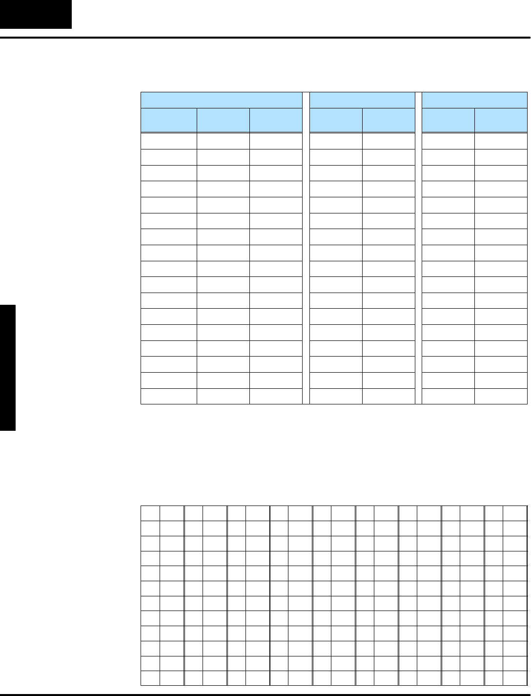
A
p
p
e
n
d
i
x
C
D
V
-
1
0
0
0
W
o
r
k
s
h
e
e
t
s
C
-
-
6
DV-1000 Worksheets
Usethe table belowasacontinuation worksheet.
UserPresetsTimerPresetsCounterPresets
TextTitles Text
Locations
Data
Locations
Titles Data
Locations
Counter
Titles
Data
Locations
Timerand Counterlabelnumbering on the DV-1000 isfrom1to 99,decimal.This
allowsthe machine operatorthe convenience ofusing decimalnumbers.However,
timersand counternumbersinthe CPUsare numbered in octal,starting with 0. If you
decide to associatethe first timerand/orcounterlabelswiththe first timerand
counterboxesinthe CPU, the following table providesthe required conversion.
DOctDOctDOctDOctDOctDOctDOctDOctDOct
1 0 12 13 23 26 34 41 45 54 56 67 67 102 78 115 89 130
2 1 13 14 24 27 35 42 46 55 57 70 68 103 79 116 90 131
3 2 14 15 25 30 36 43 47 56 58 71 69 104 80 117 91 132
4 3 15 16 26 31 37 44 48 57 59 72 70 105 81 120 92 133
5 4 16 17 27 32 38 45 49 60 60 73 71 106 82 121 93 134
6 5 17 20 28 33 39 46 50 61 61 74 72 107 83 122 94 135
7 6 18 21 29 34 40 47 51 62 62 75 73 110 84 123 95 136
8 7 19 22 30 35 41 50 52 63 63 76 74 111 85 124 96 137
9 10 20 23 31 36 42 51 53 64 64 77 75 112 86 125 97 140
10 11 21 24 32 37 43 52 54 65 65 100 76 113 87 126 98 141
11 12 22 25 33 40 44 53 55 66 66 101 77 114 88 127 99 142
Timerand Counter
Numbering
Conversion Chart

1
Index
A
ACONInstruction,4--25 to 4--31
ASCII Table,AppendixB
B
BitControlMode
Debugging applications,1--15,7--9to 7--10
Message display coordination,7--11 to 7--14
Multiplexed bitcontrol,7--15
Overview,7--2to 7--3
Quick Tour,1--13
Setup parameters,7--4
Togglefunction,7--17
C
Change PresetMode
Accessing presetvariables,6--8
Buffered presetvalues,6--31
Combination titles,6--25 to 6--27
Controlling a process,1--15
Individualdefaultusertitles,6--22 to 6--24
Operator’sGuide,6--32 to 6--33
Overview,6--2to 6--4
Password,6--28 to 6--29
Preset titlelists,6--6to 6--7
Quick Tour,1--12
Setup parameters,6--4to 6--7
Timerand counterpresets,6--10 to 6--12,6--30
Titlesavailable,6--3
User-titled presets,6--14 to 6--24
User-titled text, 6--19 to 6--22
Communication cables,1--5,2--7to 2--8
D
Display,1--5,1--6to 1--8
E
Errormessage,4--4to 4--7
Overview,4--2
Example programs.See Programexamples
F
Faultmessage,4--4to 4--7
Overview,4--2
FrequentlyAsked Questions,1--16 to 1--17
I
Installation
Mounting Location,2--5
PanelMounting,2--6
PLCSelection,2--4
K
Keypad,1--5,1--6to 1--8
Bitcontrolfunction,7--3,7--6to 7--7
L
LDD instruction,Used fortextoutput, 4--17 to 4--18

I
n
d
e
x
-
-
2
M
Message DisplayMode
ACONinstruction,4--25 to 4--31
Bargraphs,4--49 to 4--56
Bitcontrolcoordination,7--11 to 7--14
Blinking text, 4--38 to 4--40
Combining numbersand next, 4--19 to 4--24
Displaypositions,4--18 to 4--19
Dynamictext, 4--36 to 4--37
Embedded time and date,4--44 to 4--48
Howto displaynumbers,4--13 to 4--14
Howto displaytext, 4--15 to 4--16
Howusermessageswork,4--9,4--20
Monitoring a process,1--15
Multiple displays,4--32 to 4--35
Overview,4--2to 4--4
Polarity sign fornumericoutput, 4--41 to 4--43
Quick Tour,1--11
Scrolling display,4--57 to 4--61
Setup parameters,4--10 to 4--12,4--22 to 4--23
System messages,4--5to 4--8
Unmasking numericpositions,4--23
O
OperatorInterface
Design Basics,1--14 to 1--15
Role ofDV-1000,1--2
Using single ordualDV-1000s,2--2to 2--3
Operator’sGuide toChange PresetMode,6--32 to 6--33
OUTDinstruction,Used fortextoutput, 4--17 to 4--18
P
Password,6--28 to 6--29
Powerup defaultoperationalmode,3--9to 3--11
Presets.See Change PresetMode
Programexamples
Bargraphs,4--49 to 4--56
Bitcontroltoggle,7--17
Bitcontrolwithmessage display,7--11 to 7--14
Blinking text, 4--38 to 4--40
Diskette,1--5
Dynamictext, 4--36 to 4--37
Embedded decimalpoint, 4--62
Embedded time and date,4--44 to 4--48
Installation,2--9
Loading,2--10
Multiple displays,4--32 to 4--35
Multiplexed bitcontrol,7--15
Polarity sign fornumericoutput, 4--41 to 4--43
Scrolling display,4--57 to 4--61
Systemrequirements,4--4
Timerand counterpresets,6--10 to 6--13
User-titled presets,6--14 to 6--24
S
Setup parameters
Bitcontrolmode,7--4
Change presetmode,6--4to 6--7
Definitions,3--4to 3--5
General,1--9
Howto enter,3--7
Loading address pointers,3--8
Message displaymode,4--10 to 4--12,4--22 to 4--24
Overview,3--2to 3--3
Powerup defaultmode,3--9to 3--11
Specifications,1--18
StatusDisplayMode
Address selection,5--4
Bookmark,5--6
Datatype selection,5--5
Monitoring a process,1--15
Overview,5--2
Quick Tour,1--10
T
Timerand counterpresets,6--10 to 6--13,6--30
