Bristol PIP CW_30 DPC 3330 Upgrade Kit Control Wave D301437x012
User Manual: Bristol ControlWave CW_30
Open the PDF directly: View PDF ![]() .
.
Page Count: 80
www.EmersonProcess.com/Bristol
Product Information Package
PIP-CW_30 Upgrade Kit
Mar., 2007
CW_30 Hardware
ControlWave_30
HARDWARE INSTALLATION GUIDE
For u
pg
rade of the 3330 DPC
IMPORTANT! READ INSTRUCTIONS BEFORE STARTING!
Be sure that these instructions are carefully read and understood before any
operation is attempted. Improper use of this device in some applications may result in
damage or injury. The user is urged to keep this book filed in a convenient location for
future reference.
These instructions may not cover all details or variations in equipment or cover
every possible situation to be met in connection with installation, operation or main-
tenance. Should problems arise that are not covered sufficiently in the text, the pur-
chaser is advised to contact Bristol for further information.
EQUIPMENT APPLICATION WARNING
The customer should note that a failure of this instrument or system, for
whatever reason, may leave an operating process without protection. Depending upon
the application, this could result in possible damage to property or injury to persons.
It is suggested that the purchaser review the need for additional backup equipment
or provide alternate means of protection such as alarm devices, output limiting, fail-
safe valves, relief valves, emergency shutoffs, emergency switches, etc. If additional
in-formation is required, the purchaser is advised to contact Bristol .
RETURNED EQUIPMENT WARNING
When returning any equipment to Bristol for repairs or evaluation, please note
the following: The party sending such materials is responsible to ensure that the
materials returned to Bristol are clean to safe levels, as such levels are defined and/or
determined by applicable federal, state and/or local law regulations or codes. Such
party agrees to indemnify Bristol and save Bristol harmless from any liability or
damage which Bristol may incur or suffer due to such party's failure to so act.
ELECTRICAL GROUNDING
Metal enclosures and exposed metal parts of electrical instruments must be
grounded in accordance with OSHA rules and regulations pertaining to "Design
Safety Standards for Electrical Systems," 29 CFR, Part 1910, Subpart S, dated: April
16, 1981 (OSHA rulings are in agreement with the National Electrical Code).
The grounding requirement is also applicable to mechanical or pneumatic in-
struments that include electrically-operated devices such as lights, switches, relays,
alarms, or chart drives.
EQUIPMENT DAMAGE FROM ELECTROSTATIC DISCHARGE VOLTAGE
This product contains sensitive electronic components that can be damaged by
exposure to an electrostatic discharge (ESD) voltage. Depending on the magnitude
and duration of the ESD, this can result in erratic operation or complete failure of the
equipment. Read supplemental document S14006 at the back of this manual for
proper care and handling of ESD-sensitive components.
Bristol 1100 Buckingham Street, Watertown, CT 06795
Telephone (860) 945-2200

WARRANTY
A. Bristol warrants that goods described herein and manufactured by Bristol are free
from defects in material and workmanship for one year from the date of shipment
unless otherwise agreed to by Bristol in writing.
B. Bristol warrants that goods repaired by it pursuant to the warranty are free from
defects in material and workmanship for a period to the end of the original warranty
or ninety (90) days from the date of delivery of repaired goods, whichever is longer.
C. Warranties on goods sold by, but not manufactured by Bristol, are expressly limited
to the terms of the warranties given by the manufacturer of such goods.
D. All warranties are terminated in the event that the goods or systems or any part
thereof are (i) misused, abused or otherwise damaged, (ii) repaired, altered or
modified without Bristol's consent, (iii) not installed, maintained and operated in
strict compliance with instructions furnished by Bristol, or (iv) worn, injured or
damaged from abnormal or abusive use in service time.
E. THESE WARRANTIES ARE EXPRESSLY IN LIEU OF ALL OTHER
WARRANTIES EXPRESS OR IMPLIED (INCLUDING WITHOUT LIMITATION
WARRANTIES AS TO MERCHANTABILITY AND FITNESS FOR A PARTICULAR
PURPOSE), AND NO WARRANTIES, EXPRESS OR IMPLIED, NOR ANY
REPRESENTATIONS, PROMISES, OR STATEMENTS HAVE BEEN MADE BY
BRISTOL UNLESS ENDORSED HEREIN IN WRITING. FURTHER, THERE ARE
NO WARRANTIES WHICH EXTEND BEYOND THE DESCRIPTION OF THE
FACE HEREOF.
F. No agent of Bristol is authorized to assume any liability for it or to make any written
or oral warranties beyond those set forth herein.
REMEDIES
A. Buyer's sole remedy for breach of any warranty is limited exclusively to repair or
replacement without cost to Buyer of any goods or parts found by Seller to be
defective if Buyer notifies Bristol in writing of the alleged defect within ten (10) days
of discovery of the alleged defect and within the warranty period stated above, and if
the Buyer returns such goods to Bristol's Watertown office, unless Bristol's Water-
town office designates a different location, transportation prepaid, within thirty (30)
days of the sending of such notification and which upon examination by Bristol
proves to be defective in material and workmanship. Bristol is not responsible for
any costs of removal, dismantling or reinstallation of allegedly defective or defective
goods. If a Buyer does not wish to ship the product back to Bristol, the Buyer can
arrange to have a Bristol service person come to the site. The Service person's
transportation time and expenses will be for the account of the Buyer. However,
labor for warranty work during normal working hours is not chargeable.
B. Under no circumstances will Bristol be liable for incidental or consequential
damages resulting from breach of any agreement relating to items included in this
quotation, from use of the information herein or from the purchase or use by Buyer,
its em-ployees or other parties of goods sold under said agreement.

How to return material for Repair or Exchange
Before a product can be returned to Bristol for repair, upgrade, exchange, or to verify
proper operation, form (GBU 13.01) must be completed in order to obtain a RA (Return
Authorization) number and thus ensure an optimal lead time. Completing the form is very
important since the information permits the Bristol Repair Dept. to effectively and
efficiently process the repair order.
You can easily obtain a RA number by:
A. FAX
Completing the form (GBU 13.01) and faxing it to (860) 945-3875. A Bristol Repair
Dept. representative will return call (or other requested method) with a RA number.
B. E-MAIL
Accessing the form (GBU 13.01) via the Bristol Web site (www.bristolbabcock.com)
and sending it via E-Mail to brepair@bristolbabcock.com. A Bristol Repair Dept.
representative will return E-Mail (or other requested method) with a RA number.
C. Mail
Mail the form (GBU 13.01) to
Bristol Inc.
Repair Dept.
1100 Buckingham Street
Watertown, CT 06795
A Bristol Repair Dept. representative will return call (or other requested method)
with a RA number.
D. Phone
Calling the Bristol Repair Department at (860) 945-2442. A Bristol Repair Depart-
ment representative will record a RA number on the form and complete Part I, then
send the form to the Customer via fax (or other requested method) for Customer
completion of Parts II & III.
A copy of the completed Repair Authorization Form with issued RA number should be in-
cluded with the product being returned. This will allow us to quickly track, repair, and
return your product to you.

Bristol Inc. Repair Authorization Form (off-line completion)
(Providing this information will permit Bristol Inc. to effectively and efficiently process your return. Completion is required
to receive optimal lead time. Lack of information may result in increased lead times.)
Date___________________ RA #___________________SH_ Line No.____________
Standard Repair Practice is as follows: Variations to this is
practice may be requested in the “Special Requests” section.
• Evaluate / Test / Verify Discrepancy
• Repair / Replace / etc. in accordance with this form
• Return to Customer
Please be aware of the Non warranty standard charge:
• There is a $100 minimum evaluation charge, which is
applied to the repair if applicable (√ in “returned”
B,C, or D of part III below)
Part I Please complete the following information for single unit or multiple unit returns
Address No. (office use only) Address No. (office use only)
Bill to : Ship to:
Purchase Order: Contact Name:____________________________________
Phone: Fax: E-Mail:
Part II Please complete Parts II & III for each unit returned
Model No./Part No. Description
Range/Calibration S/N
Reason for return : Failure Upgrade Verify Operation Other
1. Describe the conditions of the failure (Frequency/Intermittent, Physical Damage, Environmental Conditions,
Communication, CPU watchdog, etc.)
(Attach a separate sheet if necessary)
2. Comm. interface used: Standalone RS-485 Ethernet Modem (PLM (2W or 4W) or SNW) Other:______________
3. What is the Firmware revision? _____________________ What is the Software &version?
Part III If checking “replaced” for any question below, check an alternate option if replacement is not available
A. If product is within the warranty time period but is excluded due
to Bristol’s warranty clause, would you like the product: repaired returned replaced scrapped?
B. If product were found to exceed the warranty period,
would you like the product: repaired returned replaced scrapped?
C. If product is deemed not repairable would you like your product: returned replaced scrapped?
D. If Bristol is unable to verify the discrepancy, would you like the product: returned replaced *see below?
* Continue investigating by contacting the customer to learn more about the problem experienced? The person to contact
that has the most knowledge of the problem is: ______________________________ phone_____________________
If we are unable to contact this person the backup person is: _________________________ phone_____________________
Special Requests: ____________________________________________________________________________________
____________________________________________________________________________________________________
Ship prepaid to: Bristol Inc., Repair Dept., 1100 Buckingham Street, Watertown, CT 06795
Phone: 860-945-2442 Fax: 860-945-3875 Form GBU 13.01 Rev. B 04/11/06

Bristol
Training
GET THE MOST FROM YOUR BRISTOL
BABCOCK INSTRUMENT OR SYSTEM
• Avoid Delays and problems in getting your system on-line
• Minimize installation, start-up and maintenance costs.
• Make the most effective use of our hardware and software.
• Know your system.
As you know, a well-trained staff is essential to your operation. Bristol Inc. offers a full
schedule of classes conducted by full-time, professional instructors. Classes are offered
throughout the year at three locations: Houston, Orlando and our Watertown, CT
headquarters. By participating in our training, your personnel can learn how to install,
calibrate, configure, program and maintain any and all Bristol products and realize the full
potential of your system.
For information or to enroll in any class, contact our training department in Watertown at
(860) 945-2343. For Houston classes, you can also contact our Houston office, at (713) 685-
6200.
A Few Words About Bristol Inc.
For over 100 years, Bristol® has been providing innovative solutions for the measurement
and control industry. Our product lines range from simple analog chart recorders, to
sophisticated digital remote process controllers and flow computers, all the way to turnkey
SCADA systems. Over the years, we have become a leading supplier to the electronic gas
measurement, water purification, and wastewater treatment industries.
On off-shore oil platforms, on natural gas pipelines, and maybe even at your local water
company, there are Bristol Inc. instruments, controllers, and systems running year-in and
year-out to provide accurate and timely data to our customers.
Getting Additional Information
In addition to the information contained in this manual, you may receive additional assis-
tance in using this product from the following sources:
Help Files / Release Notes
Many Bristol software products incorporate help screens. In addition, the software typically
includes a ‘read me’ release notes file detailing new features in the product, as well as other
information which was available too late for inclusion in the manual.
Contacting Bristol Inc. Directly
Bristol's world headquarters is located at 1100 Buckingham Street, Watertown,
Connecticut 06795, U.S.A.
Our main phone numbers are:
(860) 945-2200
(860) 945-2213 (FAX)
Regular office hours are Monday through Friday, 8:00AM to 4:30PM Eastern Time,
excluding holidays and scheduled factory shutdowns. During other hours, callers may leave
messages using Bristol's voice mail system.
Telephone Support - Technical Questions
During regular business hours, Bristol's Application Support Group can provide telephone
support for your technical questions.
For technical questions about TeleFlow products call (860) 945-8604.
For technical questions about ControlWave call (860) 945-2394 or (860) 945-2286.
For technical questions regarding Bristol’s OpenEnterprise product, call (860) 945-3865
or e-mail: scada@bristolbabcock.com
For technical questions regarding ACCOL products, OpenBSI Utilities, UOI and all other
software except for ControlWave and OpenEnterprise products, call (860) 945-2286.
For technical questions about Network 3000 hardware, call (860) 945-2502.
You can e-mail the Application Support Group at: bsupport@bristolbabcock.com
The Application Support Group maintains an area on our web site for software updates and
technical information. Go to: www.bristolbabcock.com/services/techsupport/
For assistance in interfacing Bristol hardware to radios, contact Bristol’s Communication
Technology Group in Orlando, FL at (407) 629-9463 or (407) 629-9464.
You can e-mail the Communication Technology Group at:
orlandoRFgroup@bristolbabcock.com
Telephone Support - Non-Technical Questions, Product Orders, etc.
Questions of a non-technical nature (product orders, literature requests, price and delivery
information, etc.) should be directed to the nearest sales office (listed on the rear cover of
this manual) or to your Bristol-authorized sales representative.
Please call the main Bristol Inc. number (860-945-2200) if you are unsure which office
covers your particular area.
Visit our Site on the World Wide Web
For general information about Bristol Inc. and its products, please visit our site on the
World Wide Web at: www.bristolbabcock.com
Training Courses
Bristol’s Training Department offers a wide variety of courses in Bristol hardware and
software at our Watertown, Connecticut headquarters, and at selected Bristol regional
offices, throughout the year. Contact our Training Department at (860) 945-2343 for course
information, enrollment, pricing, and scheduling.
PIP-CW_30 Upgrade Kit Contents / 0 - 1
PIP-CW_30 Upgrade Kit
Hardware Installation Guide
TABLE OF CONTENTS
SECTION TITLE PAGE #
SECTION 1 – ControlWave_30 INTRODUCTION...................................... 1
SECTION 2 – ControlWave PROGRAMMING ENVIRONMENT......................... 1
SECTION 3 – PHYSICAL DESCRIPTION ............................................ 3
3.1 CW_30 CPU Board Overview............................................................................................ 3
3.1.1 CW_30 CPU Board Serial Comm. Port Connectors......................................................... 6
3.1.2 CW_30 CPU Board Ethernet Ports .................................................................................. 6
3.1.2.1 Ethernet CPU Engine 10/100Base-T Connectors ............................................................ 6
3.1.3 CW_30 CPU Board Memory.............................................................................................. 8
3.1.4 CW_30 CPU Board Configuration Jumpers..................................................................... 8
3.1.5 CW_30 CPU Board Configuration Switches .................................................................... 9
3.1.6 CW_30 CPU Board LEDs................................................................................................ 10
3.2 CW_30 Communication Board (CB) Overview .............................................................. 12
3.2.1 Setting CB Board DIP Switches ..................................................................................... 12
3.2.2 Setting CB Board Configuration Jumpers ..................................................................... 15
3.2.3 CB Board LED Indicators ............................................................................................... 16
3.2.4 CB Board Communication Port Information ................................................................. 17
SECTION 4 – ControlWave_30 CONFIGURATION.................................. 18
4.1 Step 1 - Hardware Configuration ................................................................................... 18
4.2 Step 2 - Software Installation on the PC Workstation.................................................. 23
4.3 Step 3 - Establish Communications using either LocalView or Netview,
and Run the Flash Configuration Utility ....................................................................... 23
4.4 Step 4. - Create an Application-specific Control Strategy in
ControlWave Designer..................................................................................................... 23
4.5 Step 5 - Create Application Specific Web Pages OPTIONAL) ...................................... 24
4.6 Step 6 - Create an Open BSI Network Containing the CW_30,
or add the CW_30 to an Existing Open BSI Network ................................................... 25
4.7 Step 7 - Download the Application-specific Control Strategy
into the CW_30 DPC........................................................................................................ 25
SECTION 5 – OPERATIONAL DETAILS........................................... 25
5.1 Downloading the Application Load................................................................................. 26
5.2 Upgrading CW_30 Firmware.......................................................................................... 26
5.2.1 Using LocalView to Upgrade CW_30 Firmware ............................................................ 26
5.2.2 Using Hyperterminal to Upgrade CW_30 Firmware .................................................... 30
5.2.3 Remote Upgrade of CW_30 Firmware............................................................................ 32
5.3 Core Updump ................................................................................................................... 32
SECTION 6 – GENERAL SERVICE NOTES ........................................ 33
6.1 Extent of Field Repairs.................................................................................................... 33
6.2 Disconnecting RAM Battery ........................................................................................... 33
0 - 2 / Contents PIP-CW_30 Upgrade Kit
PIP-CW_30 Upgrade Kit
Hardware Installation Guide
TABLE OF CONTENTS
SECTION TITLE PAGE #
SECTION 6 – GENERAL SERVICE NOTES (Continued) ............................ 33
6.3 Maintaining Backup Files............................................................................................... 34
SECTION 7 – WINDIAG DIAGNOSTICS ........................................... 34
7.1 Diagnostics Using WINDIAG ......................................................................................... 36
7.1.1 Communication Diagnostic Port Loop-back Tests......................................................... 36
7.1.2 Serial Comm. Port External Loop-back Test Procedure ............................................... 36
7.1.3 Ethernet Port Diagnostics............................................................................................... 38
7.1.3.1 10/100Base-T (RJ-45 – Twisted Pair) Port Hardware Setup ........................................ 39
7.1.3.2 Ethernet Port Diagnostic Test Execution ...................................................................... 39
7.1.3.3 Loop-back Out Twisted Pair Test RUN Button ............................................................. 40
7.1.3.4 Return Hardware Address Test RUN Button................................................................ 40
7.1.3.5 Ethernet Port Diagnostic Error/Failure Messages........................................................ 40
SECTION 8 – DISPLAY/KEYPAD ASSEMBLY OPERATION ......................... 40
8.1 Operation of the Dual-button/Display/Keypad Assembly ............................................. 41
SECTION 9 – CW_30 SPECIFICATIONS ........................................... 44
9.1 CW_30 CPU Board Specifications .................................................................................. 44
9.1.1 CPU Board Communication Port Specifications ........................................................... 44
9.1.2 CPU Board 3.3V Power Supply Specifications............................................................... 44
9.1.3 CPU Board Environmental Specifications ..................................................................... 45
9.2 CW_30 Communication Board (CB) Specifications ....................................................... 45
9.2.1 CB Board Connectors ...................................................................................................... 45
9.2.2 CB Board Communication Port Specifications .............................................................. 45
9.2.3 CB Board 3.3V Power Supply Specifications ................................................................. 45
9.2.4 CB Board Environmental Specifications........................................................................ 45
APPENDICES
4 X 20 DISPLAY-KEYBOARD ASSEMBLY..........................................................Appendix DKA
MATERIAL SAFETY DATA SHEETS..........................................................................Appendix Z
REFERENCED Bristol CUSTOMER INSTRUCTION MANUALS
WINDIAG - Windows Diagnostics for Bristol Controllers......................................D4041A
Open BSI Utilities Manual ...................................................................................... D5081
Getting Started with ControlWave Designer.......................................................... D5085
ACCOL Translator User Guide ............................................................................... D5086
Web_BSI Manual...................................................................................................... D5087
ControlWave Designer Reference Manual .............................................................. D5088
ControlWaveMICRO Quick Setup Guide ................................................................ D5124
ControlWave Designer Programmer’s Handbook................................................... D5125

PIP-CW_30 Upgrade Kit Hardware Upgrade Installation Guide / Pg. 1
ControlWave_30
HARDWARE INSTALLATION GUIDE
SECTION 1 - ControlWave_30 INTRODUCTION
DPC 3330 can be field upgraded to become a ControlWave_30 DPC (herein referred to as
CW_30) by utilizing the hardware provided in an installation kit. Upgrade will require
removal of the standard DPC 3330 CPU and Comm./ECOM Boards and then adding the
CW_30 CPU (CPU) and CW_30 Communication (CB) Boards provided in the upgrade kit.
ControlWave® products have been designed and integrated as a highly adaptable, high
performance Distributed Open Controller family with exceptional networking capability
that provides a complete Process Automation Management Solution. The CPU and CB
Boards were designed with an emphasis on providing high performance with low power
consumption and scalability.
The CPU Module utilizes Sharp’s LH7A400 System-on-Chip Advanced RISC Machine
(ARM) microprocessor with 32-bit ARM9TDMI Reduced Instruction Set Computer (RISC)
Core. In addition to the microprocessor and control logic, the CPU Board includes two com-
munication ports that can be individually configured for RS-232 or RS-485 operation, 1MB
of battery backed Static RAM (SRAM), 4MB of Synchronous Dynamic RAM (SDRAM),
512kB Boot/Downloader FLASH, 16MB simultaneous read/write FLASH, an I/O Bus
Connector, up to two optional Ethernet ports.
In addition to Idle and Watchdog LEDs, there are six status LEDs located on the CPU
Board that will display run time status information. Two LEDs are also provided for each
Comm. Port.
CW_30 Distributed Process Controllers provide the following key features:
• ARM processor provides exceptional performance and low power consumption
• Ten independently configurable asynchronous serial communication ports (RS-
232/RS-485) and one 3-wire serial RS-232 Utility Port
• Up to two optional Ethernet ports (10/100Base-T)
• Optional Expansion Comm. Modules with/without built-in modem
• Wide temperature range: (-40 to +70°C) (-40 to 158°F)
• Utilizes existing DPC 3330 Chassis, Power Supply and I/O Boards
• RS-232/RS-485 Comm. Ports provided with LED status Indicators
• Battery backup for the real-time clock and the system’s SRAM is provided by a 3.0V,
300mA-hr lithium coin cell battery located on the CPU Board Ass’y.
• Class I, Div. 2 Hazardous Location approval
SECTION 2 - ControlWave PROGRAMMING ENVIRONMENT
The ControlWave programming environment uses industry-standard tools and protocols to
provide a flexible, adaptable approach for various process control applications in the water
treatment, wastewater treatment, and industrial automation business.
Pg. 2 / Hardware Upgrade Installation Guide PIP-CW_30 Upgrade Kit
The ControlWave programming environment consists of a set of integrated software tools
which allow a user to create, test, implement, and download complex control strategies for
use with Bristol’s CW_30 Distributed Process Controller.
The tools that make up the programming environment are:
• ControlWave Designer load building package offers several different methods for
generating and debugging control strategy programs including function blocks, ladder
logic, structured languages, etc. The resulting process control load programs are fully
compatible with IEC 61131-3 standards. Various communication methods are offered,
including TCP/IP, serial links, as well as communication to Bristol’s Open BSI soft-
ware and networks.
• The I/O Configuration Wizard, accessible via a menu item in ControlWave Designer,
allows you to define process I/O modules in the CW_30 and configure the individual
mapping of I/O points for digital and analog inputs and outputs.
• The ACCOL3 Firmware Library, which is imported into ControlWave Designer, in-
cludes a series of Bristol specific function blocks. These pre-programmed function blocks
accomplish various tasks common to most user applications including alarming,
historical data storage, as well as process control algorithms such as PID control.
• The OPC Server (Object Linking and Embedding (OLE) for Process Control) allows
real-time data access to any OPC [Object Linking and Embedding (OLE) for Process
Control] compliant third-party software packages.
• A series of Configuration Controls are available for setting up various aspects of the
system such as historical data storage, system security, and soft switches. Additional
Data Access Controls are also available for retrieval of real-time data values and
communication statistics. The configuration controls and the data access controls utilize
ActiveX technology and are called through a set of fixed Web pages, compatible with
Microsoft® Internet Explorer. Alternatively, developers can place the controls in third-
party ActiveX compatible containers such as Visual BASIC or Microsoft® Excel.
• User-defined Web Pages - If desired, user-defined web pages can be stored within a
PC to provide a customized human-machine interface (HMI).
• Flash Configuration Utility – Parameters such as the BSAP local address, IP ad-
dress, etc. are set using the Flash Configuration Utility, accessible via Open BSI
LocalView or NetView.
Note: DPC 3330s that are upgraded with “CW_30 Hardware,” must have their
ACCOL application load converted to an IEC 61131 ControlWave Program Load.
This is accomplished via the ACCOL Translator (see User Guide D5086).
PIP-CW_30 Upgrade Kit Hardware Upgrade Installation Guide / Pg. 3
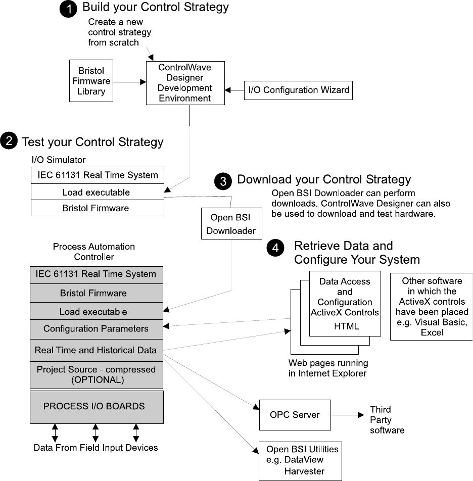
Figure 1 - ControlWave - Control Strategy Software Diagram
SECTION 3 - PHYSICAL DESCRIPTION
CW-30 Upgrade kits are comprised of the following major components:
• CW_30 CPU Board (CPU) Overview (Section 3.1)
• CW_30 Communication Board (CB) Overview (Section 3.2)
3.1 CW_30 CPU Board Overview
The multilayer CPU Board provides CW_30 CPU, I/O monitor/control, memory and
communication functions. CW_30 CPU Boards operate over an extended temperature range
with long-term product reliability.

Pg. 4 / Hardware Upgrade Installation Guide PIP-CW_30 Upgrade Kit
CW_30 CPU Boards are based on a 32-bit ARM9TDMI RISC Core Processor. The CPU
Board is specified to operate on CW_30 (+12Vdc or +24Vdc systems) and with a system
clock speed of 150 MHz. In addition to the microprocessor and control logic, the CPU Board
includes two independently (DIP-Switch) configurable communication ports (RS-232/RS-
485) (COM5 & COM6), up to two optional Ethernet ports (10/100Base-T), CPU Memory
consists of 1MB of battery backed Static RAM (SRAM), 512kB Boot/Downloader FLASH
and 16MB simultaneous read/write FLASH.
CPU Boards are provided backup power via a coin cell socket that accepts a 3.0V, 300mA-hr
lithium battery. This 3.0V battery provides backup power for the real-time clock and the
system’s Static RAM (SRAM). Backup power is enabled when Configuration Jumper W3
(just below the battery) is installed in position 1 to 2.
If the 3.3Vdc that powers the unit goes out of specification, a supervisory circuit on the CPU
Board switches the battery voltage to the CPU’s SRAM and RTC.
The system SRAM is specified to have a standby current of 20:A for each part (1MB),
(40:A maximum) (plus 2uA for the RTC). For a system containing 2MB of system SRAM, a
worst-case current draw of 42:A allows a battery life of approximately 7142 hours.
A supervisory circuit is used to switch to battery power when VCC falls out of specification.
For maximum shelf life, the battery may be isolated from the circuit by removing the
Backup Enable Jumper W3 from position 1 to 2 and then installing it in position 2 to 3. If
the Real-time clock looses its battery backup a ControlWave Designer system variable bit
(_QUEST_DATE) is set. This bit can be used to post a message or alarm to the PC (see the
ControlWave Designer Programmer’s Handbook - D5125, System Variables Section).
Basic CPU Board components and features are summarized as follows:
• LH7A400 System-on-Chip 32-bit ARM9TDMI RISC Core microprocessor
• Supports process control loads that are fully compatible with IEC 61131-3 standards
• 512KB FLASH Boot/Downloader, 29LV040B, 90 nS, 8-bit access
• 1MB SRAM, 3.3V, 256 x 16, 70 nsec., with Battery Back-up
• 4 MB SDRAM via two 1M x 16, 100MHz SDRAMs configured as a 1M x 32-bit array.
• 16MB simultaneous read/write FLASH, 90 nsec.
• 2 user configurable serial Comm. ports (RS-232/RS-485) (COM5 & COM6) (compatible
with existing 3330 communication cables)
• 2 optional Ethernet ports (10/100Base-T)
• I/O Bus Interface, control for up to 12 I/O Boards
• MAC address in serial EEPROM
• Spread Spectrum clock for lower EMI
• Serial Real Time Clock with battery backup
• 8-Position general-purpose switch bank plus a 4-Position recovery switch bank
• Coin cell socket accepts a 3.0V, 300mA-hr lithium battery
• Six Status LEDs, 6 Comm. Port LEDs plus Watchdog, Idle and Comm. Port LEDs
• 3-wire (RS-232) Utility Port: Provides compatibility with existing FLASH load cable
used with the 3330 CPU.
PIP-CW_30 Upgrade Kit Hardware Upgrade Installation Guide / Pg. 5
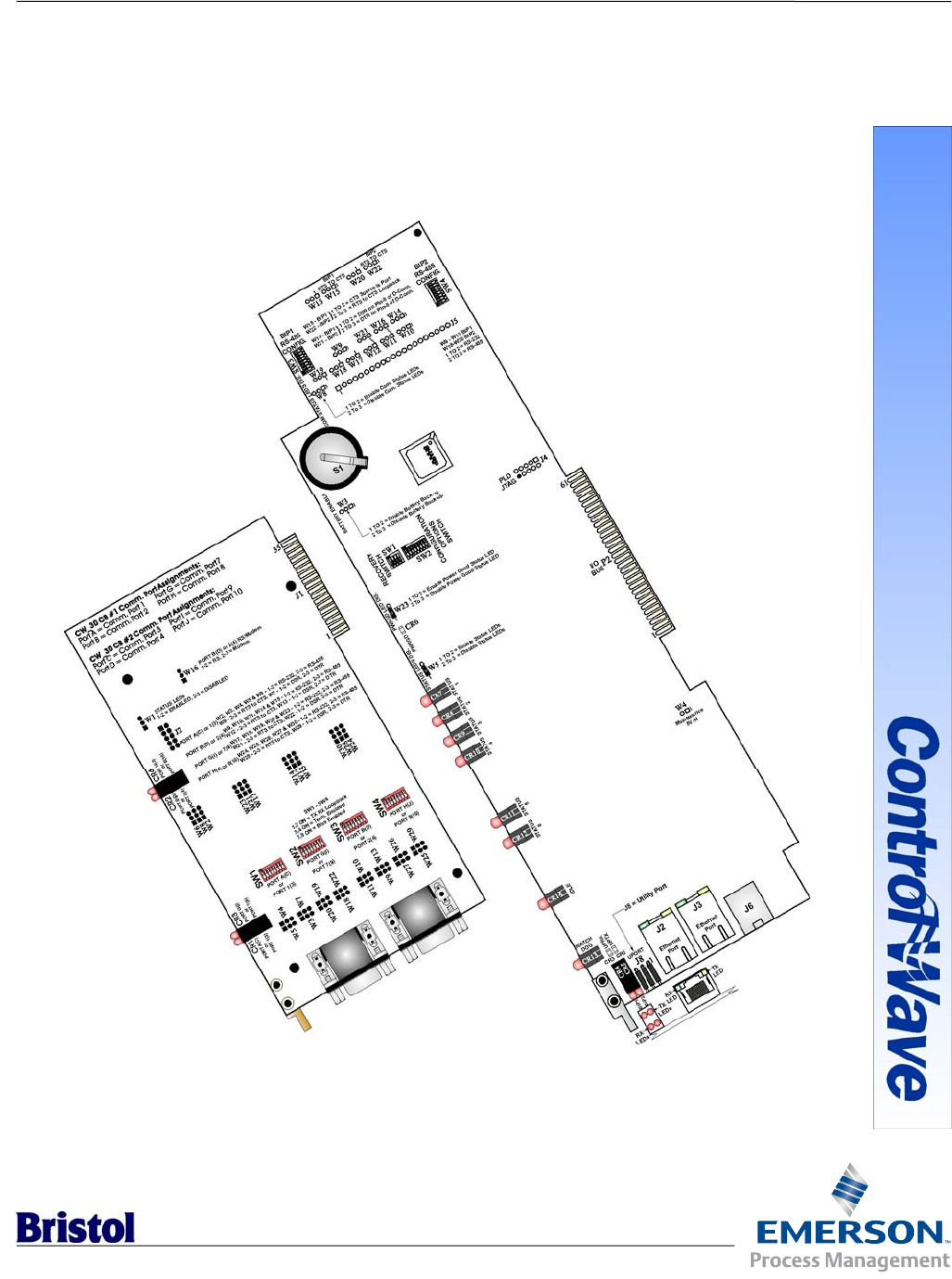
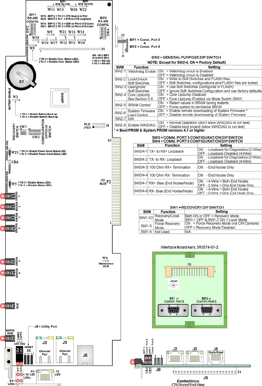
Figure 2 – CW_30 CPU Board Component Identification Diagram

Pg. 6 / Hardware Upgrade Installation Guide PIP-CW_30 Upgrade Kit
3.1.1 CW_30 CPU Board Serial Comm. Port Connectors
The CPU Board supports up to two serial communication ports (COM5 and COM6). COM5
and COM6 are interconnected to a Comm. Interface Board Assembly that contains two
Female D-Type connectors (see Table 10 for Comm. Port D-type connector pin
assignments). The interface cable is connected to J5 on the CW_30 CCPU Board and P2 on
the Comm. Interface Board Assembly (Bristol Part No. 392574-01-2). Comm. Interface
Board Assembly Connector BIP1 supports Comm. Port 5 while connector BIP2 supports
Comm. Port 6. When configured for RS-485 operation Comm. Port 5 and Comm. Port 6
receivers are enabled by DTR the RS-485 driver is enabled by RTS. An eight position DIP-
Switch (SW3) is assigned to Comm. Port 5 and another (SW4) is assigned to Comm. Port 6.
These switches provide user configuration of RS-485 port receiver biasing and termination
as well as 2-wire or 4-wire operation.
3.1.2 CW_30 CPU Board Ethernet Ports
Connection to the Ethernet can be established via one or two Ethernet Ports situated on the
CPU Board. Ethernet Ports utilize 10/100Base-T RJ45 modular connectors (J1 & J2) that
typically provide a twisted pair interface to an Ethernet Hub. Ethernet Port Jacks are
equipped with two LEDs that function as follows: yellow = TX, green = RX activity.
3.1.2.1 Ethernet CPU Engine 10/100Base-T Connectors J2 & J3
8-pin 10/100Base-T Connectors J2 and J3 typically provide connection to a twisted pair
Ethernet via an Ethernet Hub. Both ends of the Ethernet cable are equipped with modular
RJ45 connectors. A typical hub provides eight (8) 10/100Base-T RJ45 ports (with port 8
having the capability to link to another hub or to an Ethernet communication port. The
cable used between a CPU Module Expansion Board’s Ethernet 10/100Base-T connector
and an Ethernet Hub has a one-to-one wiring configuration as shown in Figure 4. Table 1
provides the assignment and definitions of 8-pin 10/100Base-T Connectors J2 & J3.
It is possible to connect two nodes in a point-to-point configuration without the use of a
Hub. However; the cable used must be configured such that the TX± Data pins are
connected to the RX± Data pins (swapped) at the opposite ends of the cable (see Figure 3).
The maximum length of one segment (CPU to Hub) is 100 meters (328 feet). The use of
Category 5 shielded cable is recommended.
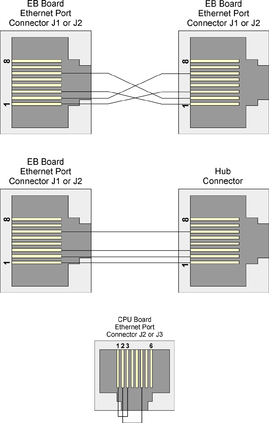
Table 1 - Ethernet 10/100Base-T Connectors J2 & J3 Pin Assignments
Pin # Description Pin # Description
1TX+ Transmit Data+ 5 Not Connected
2TX- Transmit Data- 6RX- Receive Data-
3RX+ Receive Data+ 7 Not Connected
4 Not Connected 8 Not Connected
Note: TX & RX are swapped at Hub’s.
PIP-CW_30 Upgrade Kit Hardware Upgrade Installation Guide / Pg. 7
Figure 3 - Point-to-Point 10/100Base-T Ethernet Cable
Figure 4 - Standard 10/100Base-T Ethernet Cable (CPU Board to Hub)
Figure 5 - 10/100Base-T Connector (P2) with Cable Configured for Loopback
Pg. 8 / Hardware Upgrade Installation Guide PIP-CW_30 Upgrade Kit
3.1.3 CW_30 CPU Board Memory
Boot/downloader FLASH
Boot/download code is contained in a single 512Kbytes FLASH IC. 4-Position DIP-Switch
SW1’s position 3 allows start-up menu options to be displayed or boot-up from system
FLASH. If SW1-3 is closed (ON) when a reset occurs, the boot-up code will cause a recovery
menu to be sent out the Utility Port (on the CPU Board) to a terminal program running on
an external host computer. Note: Recovery Mode will also be initiated if CPU Board Switch
SW1 positions 1 and 2 are both set ON or OFF when a reset occurs.
FLASH Memory
The base version of the CPU Board has 16Mbytes of 3.3V, simultaneous read/write (DL)
FLASH memory. System Firmware and the Boot Project are stored here.
System Memory (SRAM)
The CPU Board has 1Mbyte of static RAM, implemented with two 256K x 16, 70
nanosecond asynchronous SRAMs. All random access memory retained data is stored in
SRAM. During power loss periods, SRAM is placed into data retention mode (powered by a
backup 3.0V lithium battery). SRAM’s operates at 3.3V and are packaged in a 44-pin
uTSOP. Critical system information that must be retained during power outages or when
the system has been disabled for maintenance is stored here. Data includes: Last states of
all I/O, historical data, retain variables and pending alarm messages not yet reported.
Synchronous Dynamic RAM (SDRAM)
The CW_30 CPU Board contains 4 Mbytes of Synchronous Dynamic RAM (SDRAM)
implemented with two 1M x 16, 100MHz Synchronous DRAMs. The running application is
stored here. This allows the system to run faster than it will from the FLASH memory.
SDRAM is not battery-backed.
3.1.4 CW_30 CPU Board Configuration Jumpers
CW_30 CPU Boards provide 18 User Configuration Jumpers that function as follows:
• W3 - Enable/Disable Battery Back-up Selection
1 to 2 = Enable Battery Back-up
2 to 3 = Disable Battery Back-up
• W5 - Status LED Enable/Disable Selection
1 to 2 = Enable Status LEDs
2 to 3 = Disable Status LEDs
• W8 - Serial Comm. Port Status LED Enable/Disable Selection
1 to 2 = Enable Serial Comm. Port Status LEDs
2 to 3 = Disable Serial Comm. Port Status LEDs
• W9 - BIP1 (Comm. Port 5) Configuration Selection Note: W10 through W13 ditto
1 to 2 = Set for RS-232 Operation
2 to 3 = Set for RS-485 Operation
• W14 - BIP1 (Comm. Port 5) DSR/DTR Control
1 to 2 = DSR on Pin-8 of D-type Connector
2 to 3 = DTR on Pin-8 of D-type Connector

PIP-CW_30 Upgrade Kit Hardware Upgrade Installation Guide / Pg. 9
• W15 - BIP1 (Comm. Port 5) Control
1 to 2 = CTS Source is from Port
2 to 3 = RTS to CTS Loopback
• W16 - BIP2 (Comm. Port 6) Configuration Selection Note: W17 through W20 ditto
1 to 2 = Set for RS-232 Operation
2 to 3 = Set for RS-485 Operation
• W21 - BIP2 (Comm. Port 6) DSR/DTR Control
1 to 2 = DSR on Pin-8 of D-type Connector
2 to 3 = DTR on Pin-8 of D-type Connector
• W22 - BIP2 (Comm. Port 6) Control
1 to 2 = CTS Source is from Port
2 to 3 = RTS to CTS Loopback
• W23 - Power Good LED Control
1 to 2 = Enable Power Good LED
2 to 3 = Disable Power Good LED
3.1.5 CW_30 CPU Board Configuration Switches
Four user-configurable DIP Switches are provided on the CW_30 CPU Board. Eight-bit
DIP-Switch SW2 is provided for user configuration settings while four-bit DIP-Switch SW1
provides forced recovery functions. Eight-bit DIP-Switch SW3 provides loopback,
termination control, and receiver bias settings for the Comm. Port 5 when it has been
configured for RS-485 operation (via jumpers W9 through W13). Eight-bit DIP-Switch SW4
provides loopback, termination control, and receiver bias settings for Comm. Port 6 when it
has been configured for RS-485 operation (via jumpers W16 through W20).
Table 2 – CW_30 CPU Board (General Purpose Switch SW2) Assignments
Note: Except for SW2-4, ON = Factory Default
SW# Function Setting - (ON = Factory Default)
SW2-1 Watchdog Enable ON = Watchdog circuit is enabled
OFF = Watchdog circuit is disabled
SW2-2 Lock/Unlock
Soft Switches
ON = Write to Soft Switches and FLASH files
OFF = Soft Switches, configurations and FLASH files are locked
SW2-3 Use/Ignore
Soft Switches
ON = Use Soft Switches (configured in FLASH)
OFF = Ignore Soft Switch Configuration and use factory defaults
SW2-4 Core Updump
See Section 3.6
ON = Core Updump Disabled
OFF = Core Updump Enabled via Recovery Switch (SW1)
SW2-5 SRAM Control ON = Retain values in SRAM during restarts
OFF = Force system to reinitialize SRAM
SW2-6 System Firmware
Load Control
ON = Enable remote downloading of System Firmware *
OFF = Disable remote downloading of System Firmware
SW2-7 N/A
SW2-8 Enable WINDIAG ON = Normal Operation (don’t allow WINDIAG to run test)
OFF = Disable boot project (allow WINDIAG to run test)
* = Boot PROM version 4.7 or higher and System PROM version 4.7 or higher

Pg. 10 / Hardware Upgrade Installation Guide PIP-CW_30 Upgrade Kit
Table 3 – CW_30 CPU Board (Switch SW1) Assignments CPU/System
Recovery Mode/Local Mode Control (Note: SW1-4 not used)
Switch Function Setting
SW1-1/2 Recovery/Local Mode * Both ON or OFF = Recovery Mode
SW1 OFF & SW2 ON = Local Mode
SW1-3 Force Recovery Mode * ON = Force Recovery Mode (via CW Console)
OFF = Recovery Mode disabled
* = Note: Only the CPU Board Switch SW1 settings listed in this table have been tested.
Table 4 – CW_30 CPU Board Switch SW3/SW4 Assignments
RS-485 Loopback & Termination Control (COM5 = SW3 & COM6 = SW4)
Switch RS-485 Function
Switch ON Setting
SW3/4-1 TX+ to RX+ Loopback/2-Wire ON - Only for Diagnostics
SW3/4-2 TX− to RX− Loopback/2-Wire ON - Only for Diagnostics
SW3/4-3 100 Ohm RX+ Termination ON - End Nodes Only
SW3/4-4 100 Ohm RX− Termination ON - End Nodes Only
SW3/4-7 RX+ Bias (End Nodes/Node) ON - 4-Wire = Both End Nodes
ON - 2-Wire = One End Node Only
SW3/4-8 RX− Bias (End Nodes/Node) ON - 4-Wire = Both End Nodes
ON - 2-Wire = One End Node Only
3.1.6 CW_30 CPU Board LEDs
CW_30 CPU Boards are equipped with 15 LEDs. Table 5 provides CPU Board LED
assignments. Table 6 provides definitions for the six Status LEDS.
Table 5 – Assignment of CW_30 CPU Board LEDs
LED Ref. Function Color LED Ref. Function Color
CR2 Utility Port TX Red CR8 Status 2 Red
CR3 Utility Port RX Red CR9 Status 3 Red
CR4 - Top COM5 (BIP1) TX Red CR10 Status 4 Red
CR4 -
Bottom
COM5 (BIP1) RX Red CR11 Status 5 Red
CR5 - Top COM6 (BIP2)TX Red CR12 Status 6 Red
CR5 -
Bottom
COM6 (BIP2) RX Red CR13 Watchdog Red
CR6 Power Good Green CR14 Idle Red
CR7 Status 1 Red
Note: Optional Ethernet Port Jacks are equipped with two LEDs that function as
follows: Yellow = TX, Green = RX activity.
Two red LEDs provide for the following status conditions when lit: WD (CR13 - Indicates a
Watchdog condition has been detected) & IDLE (CR14 - Indicates that the CPU has free
time at the end of its execution cycle. Normally, it should be ON most of the time. When the
Idle LED is OFF, it indicates that the CPU has no free time, and may be overloaded). The
green Power Good LED (CR6) is on when power is within specification. Six status LEDs
provide run time status codes.
PIP-CW_30 Upgrade Kit Hardware Upgrade Installation Guide / Pg. 11
Table 6
System Status Codes for Status LCDs CW_30 CPU Board (see Figure 6)
LED
6
CR12
LED
5
CR11
LED
4
CR10
LED
3
CR9
LED
2
CR8
LED
1
CR7
Status
In
Hex
Indication
Definition
0 0 0 0 0 0 00 Application Running
0 0 0 0 0 1 01 Unit in Diagnostic Mode
0 0 0 0 1 1 03 Unit Running Diagnostics
0 0 0 1 0 0 04 Flash XSUM Error
0 0 0 1 0 1 05 Error Initializing Application Device
0 0 0 1 1 1 07 Flash Programming Error
0 0 1 0 0 0 08 Using Factory Defaults *
0 0 1 0 0 1 09 Battery Failure Detected *
0 1 0 0 0 0 10 Waiting in Recovery Mode
0 0 1 0 1 0 0A Currently Loading the Boot Project
0 0 1 0 1 1 0B System Initialization in Progress
0 1 0 0 1 0 12 Error Testing SRAM
1 0 0 0 0 0 20 Application Loaded
1 0 1 0 0 0 28 Stopped at a Break Point
1 1 0 0 0 0 30 No Application Loaded
1 1 1 0 0 0 38 Running with Break Points
1 1 1 0 1 1 3B Waiting for Power-down (after NMI)
1 1 1 1 1 0 3E Waiting for Updump to be Performed
1 1 1 1 1 1 3F Unit Crashed (Watchdog Disabled)
* = Flashed at startup
Figure 6 – CW_30 CPU Status LED Hexi-decimal Codes

Pg. 12 / Hardware Upgrade Installation Guide PIP-CW_30 Upgrade Kit
3.2 CW_30 Communication Board (CB) Overview
CW_30 Communication Boards provide either four or two (depopulated version of Four Port
CB) communication ports which utilize 9-pin, D-Type, female connectors. Up to 2 CBs can
be installed in a CW_30. CB Board communication ports are labeled as follows:
First 4-Port CB contains Ports 1, 2, 7, & 8 (resides in Communication Socket #1).
Second 4-Port CB contains Ports 3, 4, 9 & 10 (resides in Communication Socket #2).
First 2-Port CB Contains Ports 1 & 2 (resides in Communication Socket #1).
Second 2-Port CB Contains Ports 3 & 4 (resides in Communication Socket #2).
Standard 9-Pin D-Type Connectors are used in the two port version of the CB and dual
stacked D-Type Connectors are used on four port versions. When the DPC contains two 4-
Port CBs, a maximum of ten ports are available (four on each CB and two on the CW_30
CPU Board). When two 2-Port CBs are installed in a CW_30 DPC, a maximum of six ports
are available (two on each CB assembly and two on the CW_30 CPU Board).
The communication ports can be configured for an RS-485 or RS-232 interface. The former
is required for BSAP network communications, while the latter is required for devices such
as a PC or printer. However; these ports can also be configured for other applications. For
example, port 1 can be configured to interface with a PC while ports 2, 3, 4, etc. can be
configured for use with options such as modems and printers. It should be noted that only 2-
Port CBs (Port 2) will support piggyback modems, and that RASCL "redundancy," and use
of a Hand Held Terminal aren’t supported.
3.2.1 Setting CB Board DIP Switches
The procedure for setting DIP switches is identical for the two different board versions
except that the 4-Port Communication Board contains four DIP switches while the 2-Port
CB contains two DIP switches. When an individual switch (toggle) is pressed to the right it
is set to its ON position (see Figure 7). Switches SW1 through SW4 control port
configuration and are assigned as follows:
SW1 - Controls Port 1/3
SW2 - Controls Port 7/9
SW3 - Controls Port 2/4
SW4 - Controls Port 8/10
Figure 7 - Enlarged View of SW1-SW4
PIP-CW_30 Upgrade Kit Hardware Upgrade Installation Guide / Pg. 13
Figure 8 - CW_30 - 2-Port CB Board Component Identification Diagram
Pg. 14 / Hardware Upgrade Installation Guide PIP-CW_30 Upgrade Kit
Figure 9 - CW_30 - 4-Port CB Board Component Identification Diagram

PIP-CW_30 Upgrade Kit Hardware Upgrade Installation Guide / Pg. 15
Switch functions are provided for RS-485 operation, in Table 7.
Table 7 – CB Board DIP Switches SW1 - SW4 - RS-485 Configuration Selections
SW1- SW4 Function Setting
1 TX+ to RX+ Loopback ON = Loopback Enabled, 2-Wire
OFF = Loopback Disabled, 4-Wire
2 TX− to RX− Loopback ON = Loopback Enabled, 2-Wire
OFF = Loopback Disabled, 4-Wire
3 RS-485 Termination ON = Termination Installed
OFF = No Termination
4 RS-485 Termination ON = Termination Installed
OFF = No Termination
5 OFF
6 OFF
7 RS-485 Bias Termination ON = Bias Enabled
OFF = No Bias
8 RS-485 Bias Termination ON = Bias Enabled
OFF = No Bias
Setting switches SW1 through SW4 does not complete the set-up configuration. The
jumpers listed in Table 7 must also be set to complete the procedure.
Note: When the DPC is specified with an internal 1200 bps Private Line (PL) Modem., 9600
bps Publicly Switched Telephone Network (PSTN) Modem, or a 1200 bps PL/PSTN Modem,
refer to the appropriate Customer Instruction Manual, i.e., CI-1200-PL, CI-9600 (PSTN), CI-
9600A (PSTN) or CI-1200 (PL/PSTN). For details on the Fiber Optic Interface, refer to
Appendix FA of Instruction Manual CI-3330.
3.2.2 Setting CB Board Configuration Jumpers
The 4-Port CB and 2-Port CB Boards contains up to twenty-one configuration jumpers to
set various communication parameters. The location of these jumpers is shown in Figures 8
and 9. The jumpers are set according to Table 8.
Table 8 – CB Board Configuration Jumper Settings
Jumper Description Setting Configuration
W1 Comm. Port Status LED
Control
1 to 2
2 to 3
Enable Comm. Status LEDs
Disable Comm. Status LEDs
W2 Port 1/3 Configuration 1 to 2
2 to 3
Port 1/3 = RS-232
Port 1/3 = RS-485
W3 Port 1/3 Configuration 1 to 2
2 to 3
Port 1/3 = RS-232
Port 1/3 = RS-485
W4 Port 1/3 Configuration 1 to 2
2 to 3
Port 1/3 = RS-232
Port 1/3 = RS-485
W5 Port 1/3 Configuration 1 to 2
2 to 3
Port 1/3 = RS-232
Port 1/3 = RS-485
W6 Port 1/3 RTS/CTS Control 1 to 2
2 to 3
Port 1/3 CTS Source is from Port A/C
Port 1/3 RTS to CTS Loopback
W7 Port 1/3 DSR/DTR Selection 1 to 2
2 to 3
Port 1/3 Pin 8 = DSR
Port 1/3 Pin 8 = DTR

Pg. 16 / Hardware Upgrade Installation Guide PIP-CW_30 Upgrade Kit
Table 8 - CB Board Configuration Jumper Settings (Continued)
Jumper Description Setting Configuration
W8 Port 1/3 Configuration 1 to 2
2 to 3
Port 1/3 = RS-232
Port 1/3 = RS-485
W9 Port 2/4 Configuration 1 to 2
2 to 3
Port 2/4 = RS-232
Port 2/4 = RS-485
W10 Port 2/4 Configuration 1 to 2
2 to 3
Port 2/4 = RS-232
Port 2/4 = RS-485
W11 Port 2/4 Configuration 1 to 2
2 to 3
Port 2/4 = RS-232
Port 2/4 = RS-485
W12 Port 2/4 RTS/CTS Control 1 to 2
2 to 3
Port 2/4 CTS Source is from Port B/D
Port 2/4 RTS to CTS Loopback
W13 Port 2/4 DSR/DTR Selection 1 to 2
2 to 3
Port 2/4 Pin 8 = DSR
Port 2/4 Pin 8 = DTR
W14 Port 2/4 Configuration 1 to 2
2 to 3
Port 2/4 = RS-232
Port 2/4 = RS-485
W15 Port 2/4 Configuration 1 to 2
2 to 3
Port 2/4 = RS-232
Port 2/4 = RS-485
W16 Port 7/9 RS-XX/Modem
Control
1 to 2
2 to 3
Port 7/9 = RS-232 or RS-485
Port 7/9 = Modem
W17 Port 7/9 Configuration 1 to 2
2 to 3
Port 7/9 = RS-232
Port 7/9 = RS-485
W18 Port 7/9 Configuration 1 to 2
2 to 3
Port 7/9 = RS-232
Port 7/9 = RS-485
W19 Port 7/9 Configuration 1 to 2
2 to 3
Port 7/9 = RS-232
Port 7/9 = RS-485
W20 Port 7/9 Configuration 1 to 2
2 to 3
Port 7/9 = RS-232
Port 7/9 = RS-485
W21 Port 7/9 RTS/CTS Control 1 to 2
2 to 3
Port 7/9 CTS Source is from Port G/I
Port 7/9 RTS to CTS Loopback
W22 Port 7/9 DSR/DTR Selection 1 to 2
2 to 3
Port 7/9 Pin 8 = DSR
Port 7/9 Pin 8 = DTR
W23 Port 7/9 Configuration 1 to 2
2 to 3
Port 7/9 = RS-232
Port 7/9 = RS-485
W24 Port 8/10 Configuration 1 to 2
2 to 3
Port 8/10 = RS-232
Port 8/10 = RS-485
W25 Port 8/10 Configuration 1 to 2
2 to 3
Port 8/10 = RS-232
Port 8/10 = RS-485
W26 Port 8/10 Configuration 1 to 2
2 to 3
Port 8/10 = RS-232
Port 8/10 = RS-485
W27 Port 8/10 Configuration 1 to 2
2 to 3
Port 8/10 = RS-232
Port 8/10 = RS-485
W28 Port 8/10 RTS/CTS Control 1 to 2
2 to 3
Port 8/10 CTS Source is from Port H/J
Port 8/10 RTS to CTS Loopback
W29 Port 8/10 DSR/DTR Selection 1 to 2
2 to 3
Port 8/10 Pin 8 = DSR
Port 8/10 Pin 8 = DTR
W30 Port 8/10 Configuration 1 to 2
2 to 3
Port 8/10 = RS-232
Port 8/10 = RS-485
3.2.3 CB Board LED Indicators
The CB provide a TX and RX indicator for each communication channel. TX will light when
the channel is transmitting data and RX lights when the channel is receiving data.
Depending upon the data activity, the LEDs may blink or appear continuously lit during
communication activity. The LEDs will be out when there is no activity (see Figures 8 & 9).

PIP-CW_30 Upgrade Kit Hardware Upgrade Installation Guide / Pg. 17
3.2.4 CB Board Communication Port Information
CB Boards will have 2 or 4 serial communication ports that are supported by 9-pin female
D-type connectors that have pinouts the same as the DPC 3330 ECOM Boards (see Figures
8 and 9 and Table 10). All CB Board Comm. Ports can be individually user configured for
RS-232 or RS-485 operation.
The following information is provided to support use of CB Board Comm. Ports:
• When configured for RS-232 operation, CB Comm. Ports support RTS, DTR, CTS, DCD
and DSR modem control signals.
• RS-232 transceivers are enabled by the port’s DTR signal, i.e., when DTR goes high the
port becomes active.
• Each RS-232 transceiver has one active receiver while in the power-down mode
(disabled). DCD is connected to the active receiver.
• When configured for RS-485 operation, the CB Comm. Port receiver is enabled by DTR
while the driver is enabled by RTS.
• For RS-485 operation, an eight-position DIP switch (one per port) enables receiver
biasing and termination as well as two-wire and 4-wire selection.
• A 15-pin header (J4) supports the following CW_30 external communication device
options on 2-Port CB Board Comm. Port 2/4: Multipurpose Interface Board (MIB), Radio
Delay Interface (RDI), Transmitter Interface Board (TIB), 1200 Baud and 9600 Baud
Modems.
• Optional CW_30 Piggy-back modems are supported by ports 2/4 on 2-Port CBs only.
Table 9 - CB Board Connector J4 - Modem Option Header Pin Designations
Pin # Signal
2 GND
3 VCC5
4 +15V
5 -15V
6 TXD
7 RTS
8 DTR
9 RXD
10 CTS
11 DSR
12 DCD
Note: Pins 1, 13, 14 and 15 are unpopulated.
Table 10 - CB Board RS-232/RS-485 D-Type Connector Pin Assignments
Note: Identical to CW_30 CPU Bd. Ports 5 & 6 on Intf. Bd. Ass’y. 392574-01-2
Pin # Signal
RS-232
Description:
RS-232 Signals
Signal
RS-485
Description:
RS-485 Signals
1 DTR Data Terminal Ready Output TXD+ Transmit Data +
2 TXD Transmit Data Output TXD− Transmit Data −
3 RXD+ Receive Data +
4 RXD Receive Data Input RXD− Receive Data −
5 RTS Request To Send Output
6 CTS Clear To Send Input

Pg. 18 / Hardware Upgrade Installation Guide PIP-CW_30 Upgrade Kit
Table 10 - CB Board RS-232/RS-485 D-Type Connector Pin Assignments
(Continued)
Note: Identical to CW_30 CPU Bd. Ports 5 & 6 on Intf. Bd. Ass’y. 392574-01-2
Pin # Signal
RS-232
Description:
RS-232 Signals
Signal
RS-485
Description:
RS-485 Signals
7 DCD Data Carrier Detect Input
8* DTR/DSR
Data Terminal Ready/
Data Set Ready Input
9 GND Ground GND Ground
* Jumper Configured, typically set for DTR on Pin-8
SECTION 4 - ControlWave_30 CONFIGURATION
There are seven (7) main steps required to configure a CW_30 DPC. This document
provides an overview of these steps with an emphasis on the installation and configuration
of the hardware. This section is also intended to serve as a reference for users who may
have already upgraded at least one CW_30 DPC.
4.1 Step 1 - Hardware Configuration
This involves unpacking the CW_30 upgrade hardware, setting switches and setting
jumpers on the new CW_30 boards, replacing the DPC 3330’s CPU and ECOM Boards with
the CW_30 boards, reconnecting any permanent communication cables, and connecting a
communications cable to a PC workstation to facilitate downloading the application load. To
upgrade the DPC 3330 to a CW_30, follow Hardware Configuration steps 1 through 5
below:
1. Remove the CW_30 boards from their carton. Remove all communication cables and the
CPU and ECOM Boards from the DPC 3330 being upgraded. (see Figures 2, 8 and 9 as
required). Note make sure the Comm. Cables are identified for proper
reinstallation.
2. Make sure that the Lithium Backup Battery has been enabled, i.e., Backup Battery
Jumper W3 on the CW_30 CPU should be installed across jumper posts 1 and 2.
Configure the CW_30 CPU Board’s DIP Switches and Jumpers. Figure 2 and Tables 2
through 4 provide information on Switch Settings. Jumper settings are provided in
Figure 2 and in section 3.1.5. Install the CPU Board into the CW_30.
3. Configure the DIP Switches and Jumpers on CB1 (and CB2 if provided) (see Figures 8
and 9). Section 3.2.1 and Table 7 provide information on CB Board DIP Switches.
Section 3.2.2 and Table 8 provide information on CB Board Jumpers. If required remove
the optional modem(s) from the ECOM Board(s) removed from the DPC 3330 in
Hardware Configuration step # 1 and reinstall the modem onto replacement CB
Board(s). Remember, only 2-Port CB Boards support TIBs, RDIs, MIBs or
Modems. Install the replacement CB Board(s) into the CW_30.
4. Connect the communication port cables removed in step 1. Connect the CW_30 CPU’s 3-
Wire Utility Port to a Communication Port of a PC (typically PC COMM. Port 1).
A CW_30 can be configured as a Master or Slave node on either a MODBUS network or
a BSAP network. A variety of communication schemes are available. Three com-
munication ports are contained on the CW_30 CPU Board. 2 or 4 communication ports

PIP-CW_30 Upgrade Kit Hardware Upgrade Installation Guide / Pg. 19
are contained on each CB Board. These communication ports are discussed in Section
3.1.2, 3.1.5 and 3.1.6 (CPU) and 3.2, 3.2.1, 3.2.2 and 3.2.4 (CB). Two (2) Ethernet
communication ports are available on the CPU Board (see Section 3.1.3). Serial RS-
232/485 communication ports are designated as follows:
CW_30 CPU Board:
COM5 - Port BIP1 (physically located on the Interface Board Assembly): (9-Pin Female
D-Type) RS-232 or RS-485 operation (Configured by CPU Jumpers W9 through
W15) (RS-485 operation utilizes CPU Switch SW3). Note: This port was
named BIP1 on original DPC 3330s. When set for factory defaults, COM5
defaults to 9600 baud, 8-bits, no parity, 1 stop bit, BSAP/ControlWave Designer
protocol operation.
COM6 - Port BIP2 (physically located on the Interface Board Assembly): (9-Pin Female
D-Type) RS-232 or RS-485 operation (Configured by Jumpers W16 through
W22) (RS-485 operation utilizes Switch SW4). Note: This port was named
BIP2 on original DPC 3330s. When set for factory defaults, COM6 defaults
to 9600 baud, 8-bits, no parity, 1 stop bit, BSAP/ControlWave Designer protocol
operation.
Utility Port - 3-Wire RS-232 (for FLASH Firmware and Core Updumps) (Utilizes CCPU
Switch SW1). The Utility Port operates at 115.2 Kbaud and utilizes the
1KXModem or Xmodem protocol.
CW_30 CB Boards:
COM1 - Port 1 on the 1st CCB: (9-Pin Female D-Type) RS-232 or RS-485 operation
(Configured by CB Jumpers W2 through W8) (RS-485 operation utilizes CB
SW1). Note: This port was named A on original DPC 3330s. When set for
factory defaults, COM1 defaults to 115 Kbaud (RS-232), BSAP operation.
COM2 - Port 2 on the 1st CB: (9-Pin Female D-Type) RS-232 or RS-485 operation
(Configured by CB Jumpers W9 through W16) (RS-485 operation utilizes CB
SW3). Note: This port was named B on original DPC 3330s. When set for
factory defaults, COM2 defaults to 9600 baud, 8-bits, no parity, 1 stop bit,
BSAP/ControlWave Designer protocol operation.
COM3 - Port 3 on the 2nd CB: (9-Pin Female D-Type) RS-232 or RS-485 operation
(Configured by CB Jumpers W2 through W8) (RS-485 operation utilizes CB
SW1). Note: This port was named C on original DPC 3330s. When set for
factory defaults, COM3 defaults to 9600 baud, 8-bits, no parity, 1 stop bit,
BSAP/ControlWave Designer protocol operation.
COM4 - Port 4 on the 2nd CB: (9-Pin Female D-Type) RS-232 or RS-485 operation
(Configured by CB Jumpers W9 through W16) (RS-485 operation utilizes CB
Switch SW3). Note: This port was named D on original DPC 3330s. When
set for factory defaults, COM4 defaults to 9600 baud, 8-bits, no parity, 1 stop
bit, BSAP/ControlWave Designer protocol operation.
COM7 - Port 7 on the 1st CB: (9-Pin Female D-Type) RS-232 or RS-485 operation
(Configured by CB Jumpers W17 through W23) (RS-485 operation utilizes CB
SW2). Note: This port was named G on original DPC 3330s. When set for
factory defaults, COM7 defaults to 9600 baud, 8-bits, no parity, 1 stop bit,
BSAP/ControlWave Designer protocol operation.
COM8 - Port 8 on the 1st CB: (9-Pin Female D-Type) RS-232 or RS-485 operation
(Configured by CB Jumpers W24 through W30) (RS-485 operation utilizes CB
SW4). Note: This port was named H on original DPC 3330s. When set for
factory defaults, COM8 defaults to 9600 baud, 8-bits, no parity, 1 stop bit,
BSAP/ControlWave Designer protocol operation.
Pg. 20 / Hardware Upgrade Installation Guide PIP-CW_30 Upgrade Kit
COM9 - Port 9 on the 2nd CB: (9-Pin Female D-Type) RS-232 or RS-485 operation
(Configured by CB Jumpers W17 through W23) (RS-485 operation utilizes CB
SW2). Note: This port was named I on original DPC 3330s. When set for
factory defaults, COM9 defaults to 9600 baud, 8-bits, no parity, 1 stop bit,
BSAP/ControlWave Designer protocol operation.
COM10 -Port 10 on the 2nd CB: (9-Pin Female D-Type) RS-232 or RS-485 operation
(Configured by CB Jumpers W24 through W30) (RS-485 operation utilizes CB
Switch SW4). Note: This port was named J on original DPC 3330s. When
set for factory defaults, COM10 defaults to 9600 baud, 8-bits, no parity, 1 stop
bit, BSAP/ControlWave Designer protocol operation.
4.1 Step 1 - Hardware Configuration (Continued)
Communication Ports COM1 through COM10 and the Utility Port support serial
asynchronous operation as listed above. Communication ports COM1 through COM10
can be configured for local communications, i.e., connected to a PC loaded with
ControlWave Designer and OpenBSI software. The Utility Port (J8 on the CW_30 CPU
Board) is used for FLASH firmware loads or Core Updumps. The pin labels for the
various RS-232/485 interface connectors are provided in Table 10 (see Figure 10 for RS-
232 wiring diagrams and CPU Port J8 Pin assignments).
RS-232 & RS-485 Interfaces
CW_30 DPC RS-232 & RS-485 communication schemes are discussed herein.
RS-232 Ports
An RS-232 interface supports Point to Point, half-duplex and full-duplex
communications (20 feet maximum, using data quality cable). Half-duplex com-
munications supported by the CW_30 utilize MODBUS or BSAP protocol, while full-
duplex is supported by the Point to Point (PPP) protocol. CW_30 RS-232 ports utilize
the cable shown in Figure 10A - Top) to interconnect with other devices such as a PC,
printer, another ControlWave series unit (other than a CW_10/30/35) when the CW_30
DPC is communicating using the full-duplex PPP protocol. The half-duplex cable of
Figure 10A (Bottom), is utilized when the CW_30 is connected to a ControlWave series
unit (other than a CW_10/30/35) and is running other than the PPP protocol. If
communicating with a Bristol series 3305, 3310, 3330, 3335 RTU/DPC or to another
CW_30//35/10 DPC/RTU, one of the cables shown in Figure 10B must be used.
CW_30 CPU Board’s Utility Port utilizes the cable shown in Figure 10C.
Note: The following facts regarding CW_30 RS-232 serial communication ports should
be observed when constructing communications cables:
• DCD must be high to transmit (except when dialing a modem)
• Each RS-232 transceiver has one active receiver while in powerdown mode
(disabled); the DCD signal is connected to the active receiver.
• CTS must be high to transmit.
• When port is set for full-duplex operation - RTS is always ON.
• DTR is always high (when port is active); DTR enables RS-232 Transceivers.
• When port is set for half-duplex operation - CTS must go low after RTS goes low.
• All RS-232 Comm. ports support RTS, DTR, CTS, DCD and DSR control signals.
PIP-CW_30 Upgrade Kit Hardware Upgrade Installation Guide / Pg. 21
Figure 10 - Communication Port RS-232 Cable Wiring Diagram
RS-485 Ports
CW_30 DPCs can use an RS-485 communication port for local network communications to
multiple nodes up to 4000 feet away. Since this interface is intended for network
communications, Table 12 provides the appropriate connections for wiring the master, 1st
slave, and nth slave. Essentially, the master and the first slave transmit and receive data
on opposite lines; all slaves (from the first to the "nth") are paralleled (daisy chained) across
the same lines. The master node should be wired to one end of the RS-485 cable run. A 24-

Pg. 22 / Hardware Upgrade Installation Guide PIP-CW_30 Upgrade Kit
gauge paired conductor cable, such as Belden 9843 should be used. Note: Only half-duplex
RS-485 networks are supported.
Table 11 - RS-485 Port
Connector Pin Assignments (COM1 through COM10))
Pin
#
Signal
RS-485
Description:
RS-485 Signals
1 TXD+ Transmit Data + Output
2 TXD− Transmit Data − Output
3 RXD+ Receive Data + Input
4 RXD− Receive Date − Input
9 Power Ground Ground
Receiver biasing and termination as well as 2/4-wire selection are enabled by eight-
position DIP-Switches situated on the CW_30 CPU Board for COM5 and COM6 or on
CW_30 CCB Boards for COM 1 through COM 4 and COM7 through COM10 as follows:
COM1: CB Board #1 Switch SW1 (see Figures 8 & 9) (see Table 7)
COM2: CB Board #1 Switch SW3 (see Figures 8 & 9) (see Table 7)
COM3: CB Board #2 Switch SW1 (see Figures 8 & 9) (see Table 7)
COM4: CB Board #2 Switch SW3 (see Figures 8 & 9) (see Table 87
COM5: CPU Board Switch SW3 (see Figure 2) (see Table 4)
COM6: CPU Board Switch SW4 (see Figure 2) (see Table 4)
COM7: CB Board #1 Switch SW2 (see Figures 8 & 9) (see Table 7)
COM8: CB Board #1 Switch SW4 (see Figures 8 & 9) (see Table 7)
COM9: CB Board #2 Switch SW2 (see Figures 8 & 9) (see Table 7)
COM10: CB Board #2 Switch SW4 (see Figures 8 & 9) (see Table 7)
Table 11 provides the connector pin assignments for all CW_30 RS-485 communication
ports. Tables 4 & and 7 provide the RS-485 termination and loopback control Switch
Settings for the RS-485 Ports on the CPU and CB Boards (respectively).
To ensure that the “Receive Data” lines are in a proper state during inactive transmis-
sion periods, certain bias voltage levels must be maintained at the master and most dis-
tant slave units (end nodes). These end nodes also require the insertion of 100-Ohm
terminating resistors to properly balance the network. CPU and CB Board switches
must be configured at each node to establish proper network performance. This is ac-
complished by configuring the appropriate CPU/CB Board Switches so that the 100-
Ohm termination resistors and biasing networks are installed at the end nodes and are
removed at all other nodes on the network (see Table 4 for CPU Boards and Table 7 for
CB Boards).
Table 12 - RS-485 Network Connections
(see Table 11 for CW_30 RS-485 Port Pin # Assignments)
From
Master
To 1st
Slave
To nth
Slave
TXD+ RXD+ RXD+
TXD− RXD− RXD−
RXD+ TXD+ TXD+
RXD− TXD− TXD−
GND/ISOGND*
GND/ISOGND* GND/ISOGND*
* ISOGND with Isolated RS-485 Ports Only!
PIP-CW_30 Upgrade Kit Hardware Upgrade Installation Guide / Pg. 23
Note: Pins 1, 2, 3, 4 & 9 of Series 3305, 3310, 3330, 3335 & 3340 RTU/DPC RS-485 Comm.
Ports are assigned as follows: 1 = TXD+, 2 = TXD-, 3 = RXD+, 4 = RXD- & 9 = ISOGND.
4.1 Step 1 - Hardware Configuration (Continued)
5. Apply power to the CW_30 DPC. Continue with Steps 2 through 7 below (Sections 4.2
through 4.7 and 5.1) and the CW_30 will be ready for on line operation.
4.2 Step 2 - Software Installation on the PC Workstation
ControlWave Designer software must be installed on the PC. This is accomplished by
installing the ControlWave Designer Package from the Open BSI CD ROM.
You must install the Open BSI Network Edition. For information on minimum system
requirements and more details of the installation, see the installation procedure in Chapter
2 of the Open BSI Utilities Manual (document # D5081).
IMPORTANT:
When you start ControlWave Designer, you will be reminded to register the
software. Unregistered software can only be used for a maximum of 30 days. For
more information on the registration process, see Chapter 2 of the Open BSI
Utilities Manual (document# D5081).
4.3 Step 3 - Establish Communications using either LocalView or NetView,
and run the Flash Configuration Utility
Communications must be established with the CW_30 using either LocalView or NetView.
The CW_30 CPU Board ships from the factory with a default Flash configuration. Most
users will need to edit this configuration to set the IP address (if using Ethernet – default
IP address = 10.0.1.1 with IP Mask = 255.255.255.0), BSAP local address, user accounts,
and port parameters. This can be done in one of two ways:
• Either open the supplied Flash Configuration Profile (FCP) file and modify it, directly in
the Flash Configuration Utility, or in a text editor,
• or retrieve existing Flash Parameters directly from the unit, and edit them in the Flash
Configuration Utility.
Detailed information on the Flash Configuration Utility and LocalView is included in
Chapter 5 of the Open BSI Utilities Manual (document # D5081). NetView is described in
Chapter 6 of that same manual.
4.4 Step 4 - Create an Application-specific Control Strategy in Control-
Wave Designer
At this point, you can create your application-specific control strategy using ControlWave
Designer. If you are upgrading this unit from a DPC 3330 ACCOL II-based unit, you can
start by using the ACCOL Translator utility to take an existing ACCOL II load, and convert
it to a ControlWave Designer project. You will then need to examine the translated project,
and modify it, as necessary, to re-work logic that is unsupported in ControlWave Designer.
Pg. 24 / Hardware Upgrade Installation Guide PIP-CW_30 Upgrade Kit
If you don’t have a pre-existing ACCOL load to translate, you can create an all-new project
in ControlWave Designer. This involves opening a new project using the ‘ControlWave
MICRO’ template, defining I/O boards using the I/O Configurator, and creating a program
using one or more of the five supported IEC 61131 languages (FBD, ST, SFC, LD, or IL).
Some of these languages are text based, others use graphical diagrams. The choice is up to
you, depending upon your particular application.
The ControlWave MICRO Quick Setup Guide (document # D5124) includes a simple LD
example. Additional examples are included in the manual, Getting Started with
ControlWave Designer (document # D5085). More detailed information about
ControlWave Designer and IEC 61131 is included in the ControlWave Designer Reference
Manual (document # D5088).
The ACCOL3 Firmware Library, which is automatically accessible through the template
referenced above, includes a series of function blocks which perform a variety of process
control and communication functions. These can be included within your program to
perform various duties including PID control, alarming, calculations, etc. Detailed
information about each function block is included in the ControlWave Designer on-line
help files.
On the variables declaration page(s) in ControlWave Designer, you will need to mark any
variable you want to make accessible to external programs, such as Open BSI’s DataView
utility, as “PDD”. Similarly, any variables which should be collected into a database, or
exported using the OLE for Process Control (OPC) Server must be marked as “OPC”.
Variables marked as OPC can be built into a text file by the Open BSI Signal Extractor.
The text file can then be used in the creation of a database for human machine interface
(HMI) software such as OpenEnterprise, or Iconics’ Genesis. These HMI software packages
require that the "Datatype conversion enable" option be selected when generating the
file using Signal Extractor. Information about the Open BSI Signal Extractor is included in
Chapter 12 of the Open BSI Utilities Manual (document # D5081).
Once the program has been created, it is assigned to an executable task. The entire project
is then saved and compiled.
Debugging of your completed control strategy program can be performed using the built-in
debugger, and the I/O Simulator. Optionally, you can also use the I/O Simulator to simulate
the outputs on your I/O boards, as your project executes. Note, however, that the I/O
Simulator only supports the IPCxx resource; therefore, to use it, you will need to add a
second resource (IPCxx) to your project, and make copies of your tasks and global variable
worksheets under the new resource.
NOTE:
From this point on, the order of steps may be varied, somewhat,
depending upon the requirements of the user's application.
4.5 Step 5 – Create Application-specific Web Pages (OPTIONAL)
ControlWave series controllers, including the CW_30, can optionally export data to user-
created web pages.
A series of ActiveX controls for data collection and configuration are provided on the Open
BSI CD that can be included as part of these web pages (For information on the ActiveX
controls, see the Web_BSI Manual (document# D5087).

PIP-CW_30 Upgrade Kit Hardware Upgrade Installation Guide / Pg. 25
You can use whichever HTML creation package you want to create the pages, however, all
ControlWave web pages must be viewed within Microsoft® Internet Explorer.
The web pages may reside either on the PC workstation, or they can be downloaded into
FLASH memory at the CW_30. If stored at the CW_30, you must use the ControlView
utility to retrieve the page (using FTP) for viewing in Internet Explorer.
4.6 Step 6 – Create an Open BSI Network Containing the CW_30, or add the
CW_30 to an Existing Open BSI Network
In order for the CW_30 unit to function as part of a Bristol network, it is necessary to
include it in the Bristol network.
If no Bristol network exists:
You need to run Open BSI’s NetView software on the PC workstation in order to define
a Bristol network. A series of software wizards are used to define a Network Host PC, a
network, and the DPC/RTUs (controllers) assigned to the network. Finally, com-
munication lines must be specified which handle the address assigned to the CW_30.
Chapters 3 and 4 of the Open BSI Utilities Manual (document # D5081) include ‘quick
start’ examples for performing these steps. More detailed information is included in the
NetView chapter (Chapter 6) of D5081.
If a Bristol network already exists:
You will need to add the CW_30 to the existing network using NetView’s RTU Wizard.
Chapter 6 of the Open BSI Utilities Manual (document # D5081) includes different sub-
sections depending upon whether you are adding the unit to a BSAP network, or an IP
network.
4.7 Step 7 – Download the Application-specific Control Strategy into the
CW_30 DPC
Either ControlWave Designer or the Open BSI 1131 Downloader allows you to download
your completed control strategy (application load) file into the CW_30 DPC. Users
download the control strategy into the BOOT Project area of FLASH memory; this ensures
that if the CW_30 DPC is reset, or if there has been a failure of the backup battery, that the
control strategy can be restarted from the beginning, i.e., from the BOOT Project in FLASH
memory.
The Open BSI 1131 Downloader also allows the user to download files (such as user-created
web pages) into FLASH memory in the ControlWave_30 DPC. These can then be uploaded
to the PC using the ControlView utility. To download the application load, see Section 5.1
titled Downloading the Application Load.
SECTION 5 - OPERATIONAL DETAILS
CW_30 DPCs are shipped from the factory with firmware that allows the unit to be con-
figured in conjunction with an IEC 61131, application program. This section provides in-
formation as follows:
- Steps required to download the application load and place the unit into ‘Run’ mode.
- Steps required to download system firmware.
- Core Updumps
Pg. 26 / Hardware Upgrade Installation Guide PIP-CW_30 Upgrade Kit
5.1 Downloading the Application Load
Any CW_30 DPC must have a configured application load before it can be placed into
operation. For units being upgraded with the hardware discussed herein, this will require
connection of the CW_30 DPC to a PC running Windows NT (4.0 or higher), Windows 2000 or
Windows XP Professional and equipped with ControlWave Designer software & OpenBSI
software. Configuration of the application load must be performed by an individual familiar
with the various programming tools. The following software user documentation is referenced:
Getting Started with ControlWave Designer Manual - D5085
ControlWave Designer Reference Manual - D5088
Open BSI Utilities Manual - D5081
Web_BSI Manual - D5087
An application load download can be initiated, i.e., from ControlWave Designer, or from the
OpenBSI 1131 Downloader for CW_30 DPC Nodes.
1. Make sure that the CW_30 CPU’s Recovery Switch (SW1) is set in ‘Local Mode,’ i.e.,
SW1-1 set to the OFF position and SW1-2 set to the ON position.
Note:
From the factory, COM1 defaults to 115.2 Kbaud (RS-232) using the BSAP
Protocol. Don’t connect COM1 to a PC unless the PC’s RS-232 port in
question has been configured for BSAP operation.
2. Once the CW_30 DPC project has been defined, communications and configuration
parameters have been set, perform the download according to either ‘ControlWave
Designer’ (see D5088 - chapter 11) or ‘The Open BSI 1131 Downloader’ (see D5081 -
Chapter 7).
3. After the download has been completed leave the CPU Mode Switch (SW1) in the ‘Local
Mode’ position.
5.2 Upgrading CW_30 Firmware
CW_30 CPU Boards ship from the factory with system firmware already installed. If an
upgrade of the system firmware is required, use one of the procedures below to download
the new or replacement firmware from the PC. Upgrade of system firmware via LocalView
FLASH Mode requires OpenBSI 5.1 (or newer). If you have an older version of OpenBSI,
FLASH upgrades are to be performed via HyperTerminal. You will need a binary (*.BIN)
system firmware file that is read as follows: c_30450.bin (where c_3 is the product code and
0450 is the release number). Upgrade of an unattended CW_30 can be accomplished from a
remote PC. This capability is introduced in Section 5.2.3.
5.2.1 Using LocalView to Upgrade CW_30 Firmware
NOTE
Your CW_30 DPC must be set to Recovery Mode ENABLE (ON) prior to per-
forming the FLASH upgrade, then set to Recovery Mode DISABLE (OFF) after the
upgrade. On CW_30 DPCs this is accomplished via the CPU Board’s Recovery
Switch SW1. Set SW1-3 to the ON position for Recovery Mode. After setting SW1-3
to the ON position, turn power OFF and then ON again.
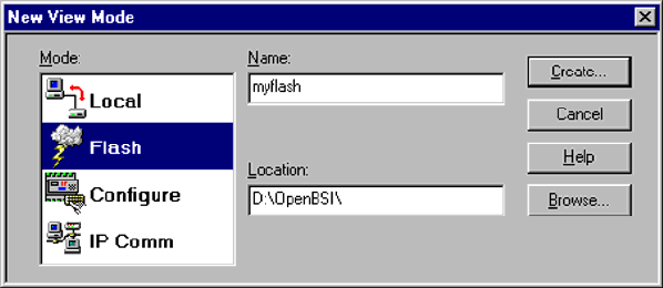
PIP-CW_30 Upgrade Kit Hardware Upgrade Installation Guide / Pg. 27
A communication cable (see Figure 10C) must be connected to the Utility Port on the
CW_30 CPU Board and to any RS-232 port on the associated PC. The PC’s RS-232 port
used for this purpose must be set to run at 115.2 Kbaud. CW_30 CPU Switch SW1,
position, 3 must be set ON.
Start LocalView, Choose FLASH, Enter A Name, Click on [Create]
Start LocalView by clicking on: Start Æ Programs Æ OpenBSI Tools Æ LocalView. The
New View Mode dialog box will appear (see Figure 11).
Figure 11 - Local View - New View Mode Menu
"Mode"
Choose 'Flash' for the mode.
"Name"
Enter a name for the View Mode File in the "Name" field.
"Location"
If you want to store the View Mode File in a directory other than that shown in the
"Location" field, enter the new location there, or use the [Browse] push button to find
the directory.
When the "Mode", "Name", and "Location" have been specified, click on the [Create] push
button to activate the Communication Setup Wizard.
Step 1 - Communication Setup
Choose the communication port you want in the What port would you like to use: field.
Click on the [Next] pushbutton to activate the next wizard.
Step 2 - Flash RTU Setup
In the Flash RTU Setup Wizard, you need not set the RTU type or local address, since these
are unused in this mode. Click on the [Next] push button to activate the Flash Data Setup
Wizard.
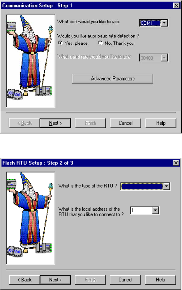
Pg. 28 / Hardware Upgrade Installation Guide PIP-CW_30 Upgrade Kit
Figure 12 - Communication Setup: Step 1 Menu
CW_30
Figure 13 - Flash RTU Setup Menu
Step 3 - Flash Data Setup
Complete the following fields in the Flash Data Setup Wizard:
"Please enter the name of the binary file to Flash"
To upgrade system firmware, you must specify the path and name of a binary (*.BIN)
file on your hard disk containing the firmware.
Click on [Finish] to install the specified BIN file in FLASH memory at the DPC.
Once the Flash download has begun, you will NOT be allowed to shut down LocalView,
unless you cancel the download, or it has been completed.
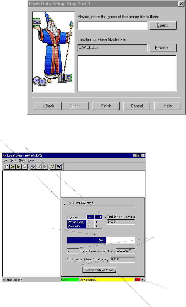
PIP-CW_30 Upgrade Kit Hardware Upgrade Installation Guide / Pg. 29
The progress of the Flash download will be displayed in the window. Any mismatch in file
versions, or if the type of .BIN file does not match the type of RTU/DPC, the download will
be aborted.
D:\OpenBSI\c_30450.bin
Figure 14 - Flash Data Setup Menu
Progress of the
flash download
Message area
‘Mod’ indicates
unsaved changes
to LVG file.
Total number of bytes in BIN file
Number of bytes
already downloaded
Path and filename of BIN file
If necessary, click here
to cancel the flash
do
wnl
oad
These fields do
NOT apply to
Controlwave-series
units.
D:\OpenBSI\c_30450.bin
Figure 15 - LocalView Downloading System Firmware Menu
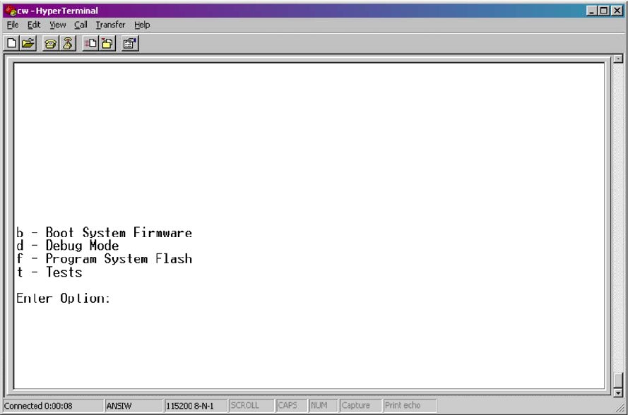
Pg. 30 / Hardware Upgrade Installation Guide PIP-CW_30 Upgrade Kit
Once the download has completed, set CPU Board Switch SW1-3 to the OFF position and
then turn power OFF and then ON again.
5.2.2 Using HyperTerminal to Upgrade CW_30 Firmware
A communication cable (see Figure 10C) must be connected to the CW_30 CPU Board’s
Utility Port and to any RS-232 port on the associated PC. The PC’s RS-232 port used for
this purpose must be set to run at 115.2 Kbaud. CW_30 CPU Board Switch SW1, position, 3
must be set to the ON position.
1. If not already running, apply power to the associated PC.
2. Start the HyperTerminal program on the PC. Note: HyperTerminal is a Windows 95 (or
newer) application utility program. If using HyperTerminal for the first time, set the
communications properties (for the PC Port being utilized) via the Properties Menu as
follows: Bits per second: = 115200, Data bits: = 8, Parity: = None, Stop bits: = 1, and Flow
control: = None. After setting the communications properties, click OK.
3. Set the CW_30 CPU Board’s Recovery Switch (SW1) for ‘Recovery Mode,’ i.e., set CPU
Board Switch SW1-3 to the ON position.
4. Apply power to the CW_30 DPC. The resident BIOS will initialize and test the
hardware, this process is referred to as POST (Power On Self Test).
Unless there is a problem status code 10 (Status LED #5 ON) will be posted to the CPU
Board’s Status LEDs. Detection of a fault during POST will be posted on the Status
LEDs. When the Power On Self Test has completed, a system status code will be posted
to the Status LEDs (see Table 6 and Figure 6).
Figure 16 - HyperTerminal Recovery Mode Menu
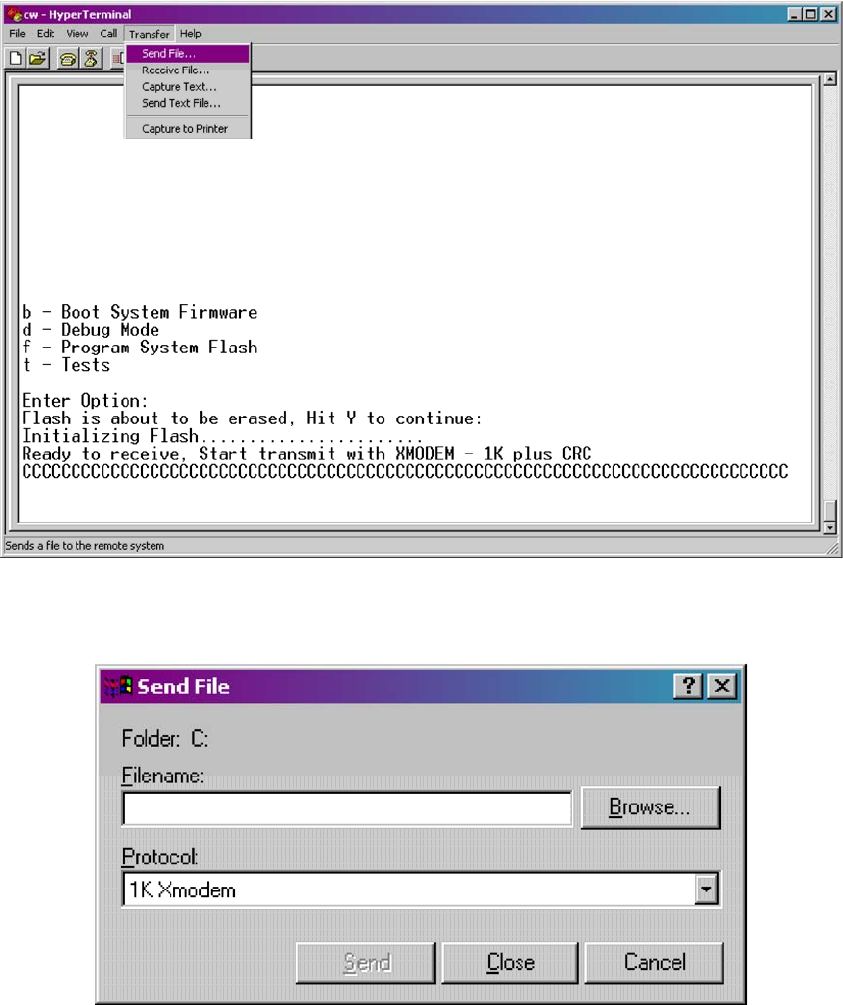
PIP-CW_30 Upgrade Kit Hardware Upgrade Installation Guide / Pg. 31
From the HyperTerminal Recovery Mode menu (Figure 16), press the ‘F’ key to enter
FLASH download. A message will be displayed warning that the FLASH is about to be
erased; press the ‘Y’ key at the prompt. The screen will display dots as the flash devices
are being erased; this could take a few minutes.
5. When the FLASH is ready for download the letter C will be displayed on the screen. In
the HyperTerminal command bar click on Transfer and then Send File (see Figure 17).
In the Send File Dialog Box (see Figure 18), select “1KXmodem” for the protocol, enter
the filename of the appropriate .bin file in the format “C_3xxxx.bin” (where xxxx varies
from release to release). Click on the Send button to start the download (see Figure 18).
When the HyperTerminal Recovery Mode Menu of Figure 16 appears, the download has
completed.
Figure 17 - HyperTerminal FLASH Download Menu
(Ready to Download) - (Transfer/Send File Selected)
Figure 18 - HyperTerminal Flash Download (Send File Dialog Box)
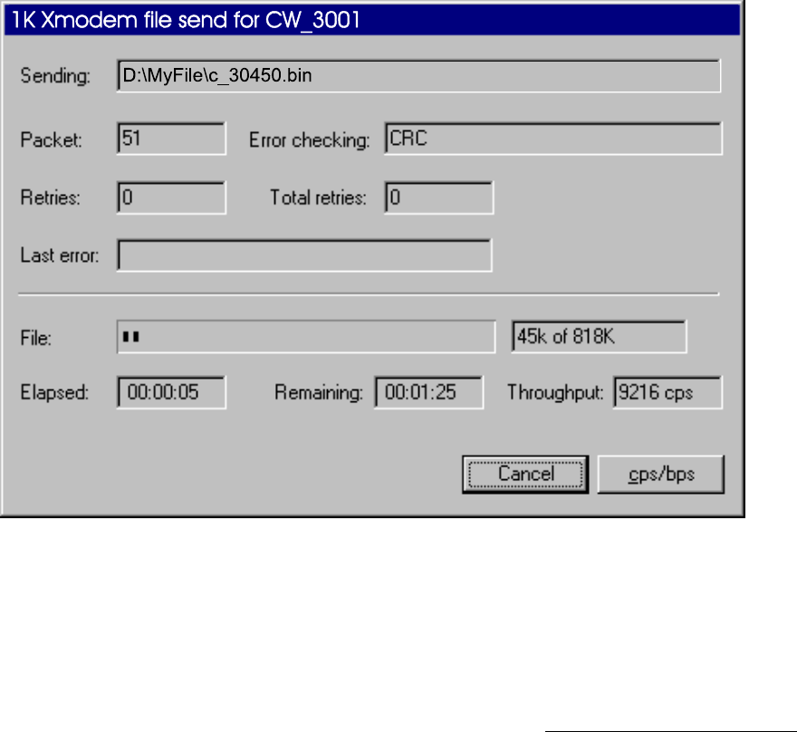
Pg. 32 / Hardware Upgrade Installation Guide PIP-CW_30 Upgrade Kit
6. Close the HyperTerminal program. The communication cable connected between the
CW_30 DPC and the PC can be removed if desired.
7. Set the CPU Board’s Recovery Switch (SW1) for ‘Local Mode,’ i.e., set SW1-1 OFF and
SW1-2 ON). Set SW1-3 OFF and then switch power OFF/ON.
Once the CW_30 DPC is running its application load, status codes will be posted to the six
Status LEDs on the CPU Board. These Status LED (Hex) Codes are listed in Table 6 (see
Figure 6).
Figure 19 - HyperTerminal FLASH Download (Download in Process)
5.2.3 Remote Upgrade of CW_30 Firmware
It is possible to download system firmware into an unattended remote CW_30 DPC. This
function can only be accomplished if CPU Board Switch SW2-6 (associated with the unit in
question) is set in the ON position (factory default). The procedure for performing a remote
download of system firmware is discussed in Appendix J of the Open BSI Utilities Manual
(document D5081). Note: Remote Upgrade of CW_30 Firmware requires Boot PROM
version 4.7 or higher and System PROM version 4.7 or higher.
5.3 Core Updump
In some cases a copy of the contents of SRAM and SDRAM can be uploaded to a PC for
evaluation by Bristol, Inc. engineers. This upload is referred to as a ‘Core Updump.’ A Core
Updump may be required if the CW_30 Distributed Process Controller repeatedly enters a
‘Watchdog State’ thus ill effecting system operation. A Watchdog State is entered when the
system crashes, i.e., a CPU timeout occurs due to improper software operation, a firmware
glitch, etc. In some cases the Watchdog State may reoccur but may not be logically
reproduced.
PIP-CW_30 Upgrade Kit Hardware Upgrade Installation Guide / Pg. 33
‘Crash Blocks’ (a function of firmware provided for watchdog troubleshooting) are stored in
CPU RAM. The user can view and save the ‘Crash Blocks’ by viewing the Crash Block
Statistic Web Page (see Chapter 4 of the Open BSI Technician’s Toolkit - D5087). Crash
Block files should be forwarded to Bristol, Inc. for evaluation. If additional information is
required to evaluate the condition, a Core Updump may be requested by Bristol. Once the
file generated by the Core Updump has been forwarded to Bristol, it will be evaluated and
the results will be provided to the user.
Follow the five steps below to perform a Core Updump.
1. Set CPU Board Switch SW2-1 OFF (Disable Watchdog Timer). If Switch SW2-4 is ON,
set it to OFF (Enable Core Updump). Note: The factory default setting for SW2-4 is
OFF.
2. Wait for the error condition (typically 3F on CPU Board Status LEDs).
3. Connect CW_30 DPC’s Utility Port to a PC (see Figure 10C).
4. Set CPU Board Switch (SW1- Recovery) so that SW1-1 and SW1-2 are both in either the
ON position or the OFF position.
5. Start the PC’s HyperTerminal Program (at 115.2kbaud) and generate a file using the
1KX-Modem protocol. Save the resulting Core Updump in a file to be forwarded to
Bristol, Inc. for evaluation.
When the Core Updump has been completed, set the CPU Board’s Recovery Switch as
follows: SW1-1 is in the OFF position & SW1-2 is in the ON position.
SECTION 6 - GENERAL SERVICE NOTES
Certain questions or situations frequently arise when servicing the CW_30 DPC. Some
items of interest are provided in Sections 6.1 through 6.3.
6.1 Extent of Field Repairs
Field repairs to a CW_30 DPC are strictly limited to the replacement of complete modules.
Component replacement on a CW_30 DPC Module constitutes tampering and will violate
the warranty. Defective CW_30 DPC components (printed circuit boards, LCD Displays,
etc.) must be returned to Bristol, Inc. for authorized service.
6.2 Disconnecting RAM Battery
The CW_30 DPC’s Lithium RAM battery cannot be replaced while power is on. Once the
RAM battery has been replaced, the unit will still execute its FLASH-based application load
(Boot Project) upon power-up, but all of the current process data will have been lost. Upon
power-up, the unit will act as though it had just been booted and it will revert back to the
initial values specified in its application load. The battery may be disabled by setting the
CW_30 CPU Board’s Battery Backup Board Jumper (W3) in position 2 to 3.
Pg. 34 / Hardware Upgrade Installation Guide PIP-CW_30 Upgrade Kit
6.3 Maintaining Backup Files
It is essential to maintain a backup disk of each application load file to guard against an
accidental loss of process configuration data. Without a backup record, it will be necessary
to reconfigure the entire application load; that can be a very time consuming procedure.
Always play it safe and keep backup copies of your operating system loads. A copy of the
application load can be loaded into CW_30 DPC FLASH memory and/or saved to a PC’s
Hard Drive as a ZIP file.
SECTION 7 - WINDIAG DIAGNOSTICS
Bristol’s WINDIAG Software is a diagnostic tool used for testing CW_30 DPC electronics
including, I/O circuitry, CPU memory, communications ports, etc., for proper performance.
The CW_30 DPC must be communicating with a PC equipped with the WINDIAG program.
CW_30 CPU Board configuration switch SW2-8 must be set to the OFF (Closed) position to
enable diagnostics. Communication between the CW_30 DPC (with/without application
loaded) and the PC can be made via a Local or Network Port with the following restrictions:
• CW_30 CPU Board Switch SW2-8 must be OFF to run the WINDIAG program. Setting
SW2-8 OFF will prevent the ‘Boot Project’ from running and will place the unit into
diagnostic mode.
• The CW_30 communication port connected to the PC (running the WINDIAG program)
must match the speed of the PC. All serial communication ports (except COM1) can be
configured for 9600 baud, 8-bits, no parity, 1 stop bit, BSAP/ControlWave Designer
protocol operation by setting CW_30 CPU Switch SW2-3 OFF This can also be
accomplished via user defined Soft Switches.
• Communication port COM1 is forced to 9600 baud operation when CW_30 CPU
Switches SW2-3 and SW2-8 have both been set OFF. COM1 can also be set to 9600 baud
operation via user defined Soft Switches.
To use the WINDIAG program place any critical process (associated with the CW_30 DPC
unit in question) under manual control. WINDIAG cannot be run while the CW_30 DPC
application is running. Set CW_30 CPU Board Switch SW2-8 to the OFF position. Perform
steps 1 through 6 below.
1. Start the OpenBSI NetView Program. A menu similar to Figure 20 will appear.
2. To start the WINDIAG program, go to the Start Program’s menu, select OpenBSI Tools,
then select Utilities Programs and then select Diagnostics.
3. Once WINDIAG has been entered, the Main Diagnostics Menu of Figure 21 will appear.
4. Select the module to be tested. Enter any prompted parameters (slot #, etc.). WINDIAG
will perform the diagnostics and display pass/fail results.
5. After all diagnostic testing has been performed, exit the WINDIAG program and then
exit the NetView Program if there aren’t any other CW_30 units to be tested.
When you close the NetView program you will be prompted as to whether or not you
want to close the OpenBSI program; select Yes.
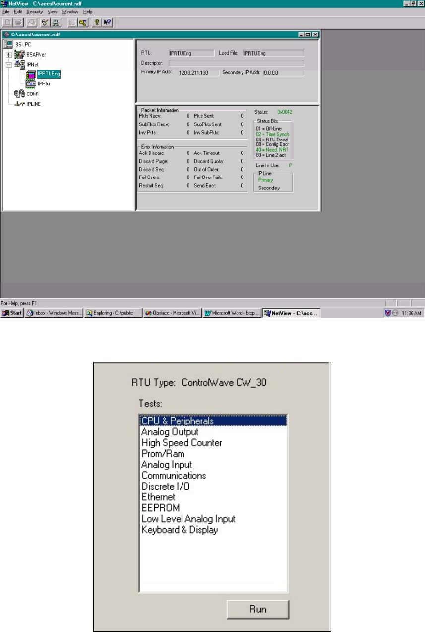
PIP-CW_30 Upgrade Kit Hardware Upgrade Installation Guide / Pg. 35
Figure 20 - NetView Startup Menu - Example with Multiple Networks
Figure 21 - WINDIAG Main Diagnostics Menu
6. Set CW_30 CPU Board Switch SW2-8 to the ON (Open) position and reboot the unit.
The CW_30 DPC should resume normal operation.
Pg. 36 / Hardware Upgrade Installation Guide PIP-CW_30 Upgrade Kit
7.1 Diagnostics Using WINDIAG
CW_30 electronics can be tested using the WINDIAG program. From WINDIAG’s Main
Diagnostics Menu (see Figure 18) the following diagnostic tests can be performed:
CPU & Peripherals Diagnostic: Checks the CPU Board [except for RAM & PROM
(FLASH)].
PROM/RAM Diagnostic: Checks the CPU Board’s RAM and PROM (FLASH)
hardware.
EEPROM Diagnostic: Checks I/O Module EEPROM on an I/O Module.
Communications Diagnostic: Checks all Comm. Ports - The External loop-back tests
require the use of a loop-back plug.
Ethernet Diagnostic: Checks Ethernet Port 1 and 2 on the CPU Board.
Analog Output Diagnostic: Checks AOs on various AO Modules.
Analog Input Diagnostic: Checks AIs on various AI Modules.
Low Level Analog Input Diag.: Checks AIs on the Low Level AI Module.
Discrete I/O Diagnostic: Checks DIs or DOs on various DI and DO Modules.
High Speed Counter Diagnostic: Checks HSCs on various High Speed Counter Modules.
Keyboard & Display Diagnostics Checks Keyboard/Keypad & Display hardware
Information on serial communication port loop-back testing is provided herein. For
additional information on WINDIAG tests, see document D4041A.
7.1.1 Communication Diagnostic Port Loop-back Tests
WINDIAG’s Communications Diagnostic Menu (see Figure 24) provides for selection of the
communication port to be tested. Depending on the type of network (RS-232 or RS-485) and
the port in question, a special loop-back plug is required as follows:
Ports 1 through 10 - RS-232: use a 9-pin male D-type loop-back plug or loop-back wires
(see Fig. 22).
Ports 1 through 10 - RS-485: use a 9-pin male D-type loop-back plug or loop-back wires
(see Fig. 23) or configure CW_30 CPU Switches (SW3 and
SW4) and/or CB Switches (SW1, SW2, SW3 and SW4) for
loopback operation (see Tables 4 & 7).
This group of tests verifies the correct operation of the Communication Interface. COM1,
through COM10 can be tested with this diagnostic. The CW_30 communication port that is
connected to the PC (local or network and used for running these tests) can’t be tested until
diagnostics has been established via one of the other ports, i.e., to test all CW_30 serial RS-
232/485 communication ports (via WINDIAG), communications with the PC will have to be
established twice (each time via a different port). It should be noted that the CW_30
communication port that is connected to the PC (RS-232, RS-485 or Ethernet) must be good
for WINDIAG to run the Communications Diagnostics
7.1.2 Serial Comm. Port External Loop-back Test Procedure
1. Connect an external loop-back plug or loop-back wires to the Communication Port to be
tested (see Figures 22 and 23). For RS-485 Loopback testing, CPU Switch SW3 and/or
SW4 can be configured for loopback operation (see Table 4).
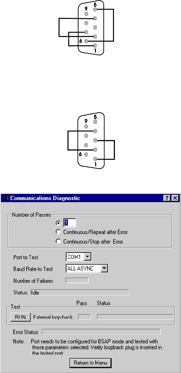
PIP-CW_30 Upgrade Kit Hardware Upgrade Installation Guide / Pg. 37
9-Pin Male
“D” Connector
Loop-back Plug
(Looking from rear/wire side of Plug)
6 = CTS
7 = DCD
4 = RXD
2 = TXD
1 = DTR
5 = RTS
Figure 22 - RS-232 Loop-back Plug/Wires
9-Pin Male
“D” Connector
Loop-back Plug
(Looking from rear/wire side of Plug)
2 = TXD_
4 = RXD
3 = RXD+
1 = TXD+
_
Figure 23 - RS-485 Loop-back Wires
Figure 24 - WINDIAG’s Communications Diagnostic Menu
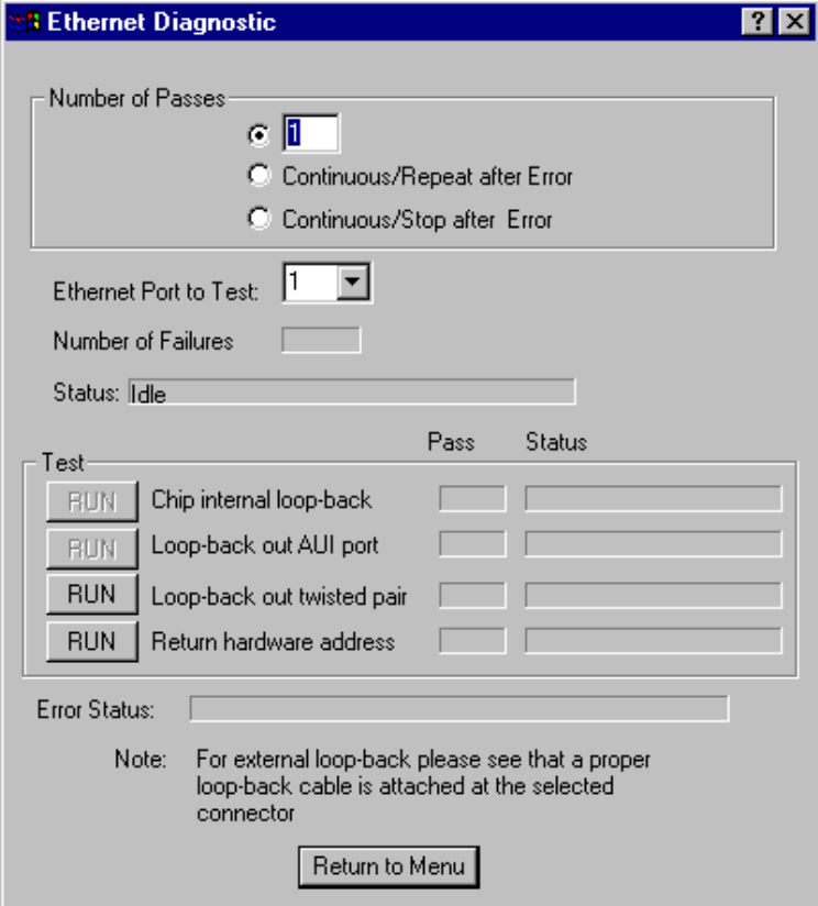
Pg. 38 / Hardware Upgrade Installation Guide PIP-CW_30 Upgrade Kit
2. Type "1," "2," "3," etc. (up to "10") for the port to test.
3. Set baud rate to test to 115200 baud or ALL ASYNC and the number of passes to 5.
4. Click on RUN button next to External loop-back.
Test responses:
a) Success - All sections of test passed
b) Failure - TXD RXD Failure
- CTS RTS Failure
Execution time < 5 sec.
7.1.3 Ethernet Port Diagnostics
The Ethernet Diagnostic menu of Figure 25 is entered from the WINDIAG Main Diagnostic
Menu (Figure 21). This menu provides four poke points (three associated with Ethernet
circuitry test and one that provides the Return Hardware Address [which resides in
FLASH]). These tests verify the operation and integrity of the PCNET (Ethernet) Controller
and the Ethernet port hardware on the CPU Board and CB Board.
Figure 25 - Ethernet Diagnostic Menu
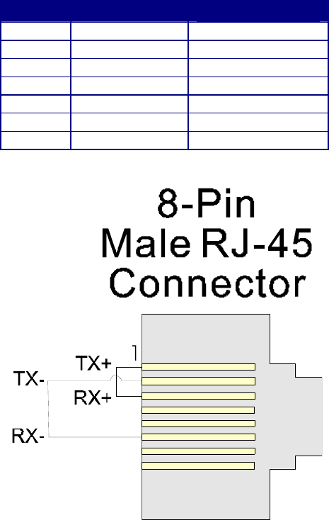
PIP-CW_30 Upgrade Kit Hardware Upgrade Installation Guide / Pg. 39
7.1.3.1 10/100Base-T (RJ-45 - Twisted Pair) Port Hardware Setup
The 10/100Base-T Port typically provides an interface (4-twisted pair) to an Ethernet Hub.
To configure the system for the Loop-Back Out Twisted Pair diagnostic test either remove
the standard R-J45 cable from the CPU Board's R-J45 connector and replace it with an R-
J45 cable configured for loop-back, or remove the R-J45 cable associated with the port in
question from the hub and install the unterminated end into an RJ-45 Jack configured for
loop-back. Table 13 provides the pin identification and description for the RJ-45 port. Pin-1
(TX+) must be connected to Pin-3 (RX+) and Pin-2 (TX-) must be connected to Pin-6 (RX-)
for proper loop-back test configuration (see Figure 26).
If the "Loop-Back Out Twisted Pair" Test RUN button is selected while the port is attached
to an Ethernet Hub, a Failures Status will be posted.
Table 13 - Ethernet 10/100Base-T (RJ45) Connector Pin Assignments
Pin # Pneumonic Description
1 TX+ Transmit Data+
2 TX- Transmit Data-
3 RX+ Receive Data+
4 - Not Connected
5 - Not Connected
6 RX- Receive Data-
7 & 8 - Not Connected
Figure 26 - RJ-45 Ethernet Loop-back Plug
7.1.3.2 Ethernet Port Diagnostic Test Execution
There are four unique test buttons provided on the Ethernet Diagnostic Menu. Note: Only
the "RUN Loop-back out twisted pair" and "RUN Return hardware address" tests are
applicable to CW_30 units, i.e., the "RUN Chip internal loop-back" and "RUN Loop-back
out AUI port" tests aren’t applicable. The applicable tests are discussed below.
Pg. 40 / Hardware Upgrade Installation Guide PIP-CW_30 Upgrade Kit
7.1.3.3 Loop-back Out Twisted Pair Test RUN Button
Set the Number of Passes. Make sure that the port is properly configured with a cable or
jack for loop-back testing (see Section 7.1.3.1). Click on the "RUN Loop-back out twisted
pair" Test button. The test will proceed and return either 'Success' or one of the following
responses under the STATUS column:
Fail - No Hardware Present
- Loop-back Send Failed
- Loop-back Receive Failed
- Loop-back Compare Failed
- Error Information Returned
When you have finished with Ethernet Diagnostic Loop-back testing, be sure to return the
hardware to its normal operating configuration, i.e., disconnect the loop-back cable or jack-
plug and reconnect the Ethernet cable to both the CW_30 Ethernet port and the Ethernet
Hub.
7.1.3.4 Return Hardware Address Test RUN Button
Set the Number of Passes. Click on the "Return hardware address" Test button. The test
will proceed and if successful the hardware address will be displayed. The hardware
address will appear as 00-10-41-XX-XX-XX. The prefix 00-10-41 appears for all Bristol
Ethernet Comm. ports. The remainder of the hardware address is unique for each board
manufactured and is stored in EEPROM. If the error message "Error Information
Returned" is displayed instead of the hardware address, and the unit has been programmed
with a proper hardware address, the CPU Module should be replaced.
7.1.3.5 Ethernet Port Diagnostic Error/Failure Messages
If either a "No Hardware Present" or "Error Information Returned" message is displayed,
ensure that the loop-back test requirements have been properly established (see Section
7.1.3.1). If test requirements have been met and the cable associated with the port test in
question is known to be good, the CPU Module should be replaced with a good unit.
In the case of a "Loop-back Send Failed," "Loop-back Receive Failed" or Loop-back Compare
Failed" message, check the cable in question. If the cable associated with the port test in
question is known to be good, the CPU Module should be replaced with a good unit.
SECTION 8 – DISPLAY/KEYPED ASSEMBLY OPERATION
CW_30s support Display/Keypad assemblies (local or remote) that were present prior to the
conversion to the ControlWave platform. Additionally, connector J6 on the CW_30’s CPU
Board accommodates connection to one of two unique remote Display/Keypad Assemblies;
one with a dual-button Keypad (see Figure 27) and one with a 25-button Keypad (see
Figure 2-28). Both Display/Keypad assemblies utilize identical 4 x 20 LCD Displays. Each
Display/Keypad assembly employs a unique microcontroller based Display/Keypad
Interface Circuitry (situated on the remote Display/Keypad assembly that drive the LCD
Display and interfaces the Keypad. Interface to the CW_30 is made via a cable equipped
with two plugs. This cable connects to the RJ-45 Display Jack (J3) on the CW_30
Expansion Board and RJ-45 Jack (J1) on the remote Display or Display/Keypad assembly.
A potentiometer is provided on the Display or Display/Keypad to set the contrast of the
LCD Display.
PIP-CW_30 Upgrade Kit Hardware Upgrade Installation Guide / Pg. 41
Figure 2-27 provides mounting hardware information for the Dual-button Display/Keypad
Assembly. Operation of the Dual-button Display/Keypad Assembly is discussed in Section
2.4.5.1 of this document.
Figure 2-28 provides mounting hardware information for the 25-button Display/Keypad
Assembly. Information on configuring the ‘Display Function Block’ (required to configure
the Display associated with the 25-button Display/Keypad Assembly) is provided in
ControlWave Designer’s On-Line Help.
Note: Operation of the 25-button Display/Keypad Assembly is discussed in Ap-
pendix DKA of this document.
8.1 Operation of the Dual-button Display/Keypad Assembly
The Display will have a timeout of 20 minutes. If there has been no keypad activity for this
time the display will “logout,” i.e., the display will be turned off and scrolling stopped until
a key press occurs. When a key press occurs after a timeout the display will return to the
opening screen.
If a shorter timeout of the display is needed for power savings, another timeout may be
implemented. The processor connected to the display will control the timeout. When the
timeout occurs the display will be blanked, but communications between the CW_30 CPU
and display processor will still occur. The display processor will ignore posting the
messages to the screen when in the low power mode. When a key is pressed the display
processor will return to displaying information to the display.
Displays are organized into screens as follows:
Opening Screen: User defined strings
List Selection Screen: List Name
List Number
<Blank Line>
<Blank Line>
The List Selection screen is entered from the main opening screen by pressing the right
arrow. Once here the operator can select which list is to be viewed. The operator can
traverse though different list numbers by pressing the down arrow key. When the list to be
scrolled is shown on the display, pressing the right arrow key will bring the operator to the
Display Element screen.
Display Element Screen: <Blank Line>
<Blank Line>
Variable Name
Variable Name
The Display Element screen is entered from the list selection screen by pressing the right
arrow. Once here the operator can view the variables in the list. Once entered the first
element of the list is displayed and then next element will be displayed after the scroll
timeout occurs. The scrolling will continue displaying the next element in the list and then
wrapping around to the beginning of the list. The down arrow key will toggle the display
through hold and scroll mode. Pressing the right arrow key will bring the operator to the
list selection screen.
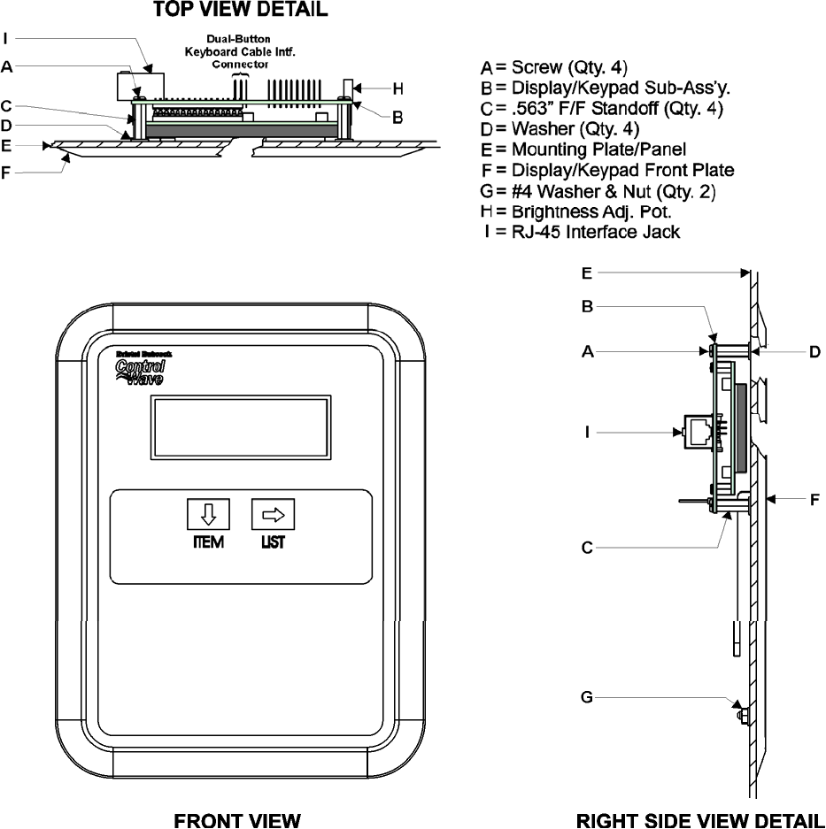
Pg. 42 / Hardware Upgrade Installation Guide PIP-CW_30 Upgrade Kit
Figure 27 - Dual-button Display/Keypad Assembly Installation Drawing
Display/Keypad Assemblies are supported by Automatic Mode and Manual Mode.
Automatic Mode
In Automatic mode a set of screens (based on the application load) are displayed. The
application programmer provides strings for the opening screen. From there the firmware is
responsible for displaying the screens and responding to key presses. Screens are fixed and
start off with an opening screen, which displays user information passed into the function
block. Users can view a list to select which list is to be scrolled. Once the list to be scrolled
has been selected, the user can scroll through the list by pressing the down arrow key. List
elements will be displayed automatically, scrolling at a predetermined rate (determined by
iiScrollTime). The user may pause on a variable by pressing the right arrow key. Pressing
the right arrow key again will cause the list to start scrolling again.
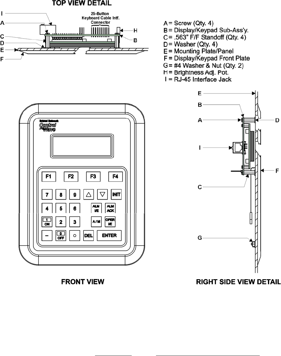
PIP-CW_30 Upgrade Kit Hardware Upgrade Installation Guide / Pg. 43
The essence of Automatic mode is that the user can supply inputs into the function that will
determine which list can be displayed, but cannot change the menu or display. The user is
allowed to select a list and to start/stop scrolling.
Figure 2-28 - 25-Button Display/Keypad Assembly Installation Drawing
Manual Mode
In Manual Mode the programmer is responsible for creating each screen and displaying the
next desired screen, based on key inputs. The programmer has access to all lines of the
display and can provide any string that he/she desires to display. Special formats that must
be adhered to that allow the programmer to display what they want on the screen are
provided in the description of iaScrnSruct in the ACCOL 3 Display function block within
ControlWave Designer’s On-Line Help. It should be noted that currently, Manual Mode
does not support reading Keypad key-presses. Note: Manual Mode operation requires
ControlWave Firmware 4.50 or newer.

Pg. 44 / Hardware Upgrade Installation Guide PIP-CW_30 Upgrade Kit
SECTION 9 - CW_30 SPECIFICATIONS
9.1 CW_30 CPU Board Specifications
Processor: Sharp’s LH7A400 32-bit System-on-Chip with 32-bit
ARM9TDMI RISC Core
Memory: 16 Mbytes of simultaneous read/write FLASH
1 Mbyte of on-board SRAM
512 Kbytes FLASH Boot/Downloader
4 Mbytes of SDRAM
Real Time Clock: A Semtech SH3000 support IC provides a full BCD clock
calender with programmable periodic/wakeup interrupt and
a programmable clock generator with adjustable spectrum
spreading.
Connectors: (see Table 14)
Table 14 - CPU Board Connector Summary
Ref. # Pins Function Notes
P2 62-pin Backplane Intf. CW_30 I/O Bus Interface
J2 8-Pin Ethernet Female Port # 1 10/100Base-T
J3 8-Pin Ethernet Female Port # 2 10/100Base-T
J5 21-pin Off-board Serial Comm. Port Intf.
Connector (RS-232/485)
Interfaced via a cable to COM5 and
COM6 on Interface Board Ass’y.
No. # 392574-01-2.
J8 3-pin RS-232 Utility Port 115.2 Kbaud to PC for Firmware
Flash and Core Updumps
9.1.1 CPU Board Communication Port Specifications
CPU Board Comm. Ports: J8: 3-pin In-line – Utility Port (RS-232)
J5: 21-pin Interface (Via cable) to Off-board serial Comm.
Ports BIP1/COM5 and BIP2/COM6 (which reside on
Interface Board Assembly 392574-01-2) COM5 & COM6
are individually configurable for RS-232 or RS-485
operation and utilize 9-Pin D-Type Female Connectors
J2: 8-pin 10/100Base-T (Female) Ethernet Port 1
J3: 8-pin 10/100Base-T (Female) Ethernet Port 1
Baud Rate: 300 to 115Kbps for RS-232 or RS-485
See Table 9 for connector pin assignments
9.1.2 CPU Board 3.3V Power Supply Specifications
Input: +5Vdc
Output Voltages: +3.3Vdc ±1%
Output Current: 0.6A Max. @ 3.3Vdc
Output Ripple P/P: +3.3V Output: 10mV

PIP-CW_30 Upgrade Kit Hardware Upgrade Installation Guide / Pg. 45
9.1.3 CPU Board Environmental Specifications
Temperature: Operating: -40 to +158 °F (-40 to +70 °C)
Storage: -40 to +185 °F (-40 to +85 °C)
Relative Humidity: 0-95% Non-condensing (Operating & Storage)
Vibration: 1g acceleration over 10 to 150 Hz
.5g acceleration over 150 to 2000 Hz
RFI/Emissions: In conformity with the following standards: ENV 50140
Radio-frequency electromagnetic field amplitude modulated
EMV
9.2 CW_30 Communication Board (CB) Specifications
9.2.1 CB Board Connectors
Table 15 – CB Board Connector Summary
Ref. # Pins Function Notes
J1 36-pin Backplane Intf. CW_30 I/O Bus Interface
J3
Bottom
9-pin RS-232/485 Serial Comm. Port 1/3
(Bottom Left)
Female D-Type:
1 on CB#1, 3 on CB#2
J5
Bottom
9-pin RS-232/485 Serial Comm. Port 2/4
(Bottom Right)
Female D-Type:
2 on CB#1, 4 on CB#2
J3
Top
9-pin RS-232/485 Serial Comm. Port 7/9
(Top Left)
Female D-Type: 7 on CB#1, 9 on
CB#2 (Not On 2-Port CBs)
J5
Top
9-pin RS-232/485 Serial Comm. Port 8/10
(Top Right)
Female D-Type 8 on CB#1, 10 on
CB#2 (Not on 2-Port CBs)
9.2.2 CB Board Communication Port Specifications
CB Board Comm. Ports: see Table 15
Baud Rate: 300 to 115Kbps for RS-232 or RS-485
See Table 10 for connector pin assignments
9.2.3 CB Board 3.3V Power Supply Specifications
Input: +5Vdc
Output Voltages: +3.3Vdc ±1%
Output Current: 0.6A Max. @ 3.3Vdc
Output Ripple P/P: +3.3V Output: 10mV
9.2.4 CB Board Environmental Specifications
Temperature: Operating: -40 to +158 °F (-40 to +70 °C)
Storage: -40 to +185 °F (-40 to +85 °C)
Pg. 46 / Hardware Upgrade Installation Guide PIP-CW_30 Upgrade Kit
Relative Humidity: 0-95% Non-condensing (Operating & Storage)
Vibration: 1g acceleration over 10 to 150 Hz
.5g acceleration over 150 to 2000 Hz
www.EmersonProcess.com/Bristol
Product Information Package
PIP-CW_30 Upgrade Kit
Nov., 2006
CW
_
30 Dis
p
la
y
/Ke
yp
ad
(
25 Ke
y
s
)
ControlWave_30 DISPLAY/KEYPAD
(with 25 Keys) ASSEMBLY GUIDE
Appendix DKA
PIP-CW_30 Upgrade Kit Appendix DKA – Display/Keypad Contents / 0 - 1
APPENDIX DKA
ControlWave_30 DISPLAY/KEYPAD
(with 25 Keys) Assembly Guide
TABLE OF CONTENTS
SECTION TITLE PAGE #
DKA1.1 OVERVIEW ..............................................................................................................DKA-1
DKA2.1 DISPLAY FUNCTION BLOCK DESCRIPTION....................................................DKA-2
DKA2.1.1 DISPLAY Function Block Parameters ....................................................................DKA-2
DKA3.1 PREPARING THE ControlWave PROJECT...........................................................DKA-3
DKA4.1 USING THE KEYPAD .............................................................................................DKA-4
DKA4.1.1 Scrolling.....................................................................................................................DKA-5
DKA4.1.2 Signing-On ................................................................................................................DKA-6
DKA4.1.3 Using the Clock Functions ....................................................................................... DLA-7
DKA4.1.3.1 Changing the Time ...................................................................................................DKA-8
DKA4.1.3.2 Changing the Date....................................................................................................DKA-8
DKA4.1.4 Choosing a Variable List from the List Menu.........................................................DKA-8
DKA4.1.5 Moving Through a Variable List..............................................................................DKA-9
DKA4.1.6 Changing Variable Parameters ...............................................................................DKA-9
DKA4.1.7 Signing-Off ..............................................................................................................DKA-12
DKA5.1 KEYPAD IDENTIFICATION & INSTALLATION INFO....................................DKA-13
NOTE: The Dual-button Display/Keypad Assembly is discussed in Section 8.1 of
PIP-CW_30 Upgrade Kit.
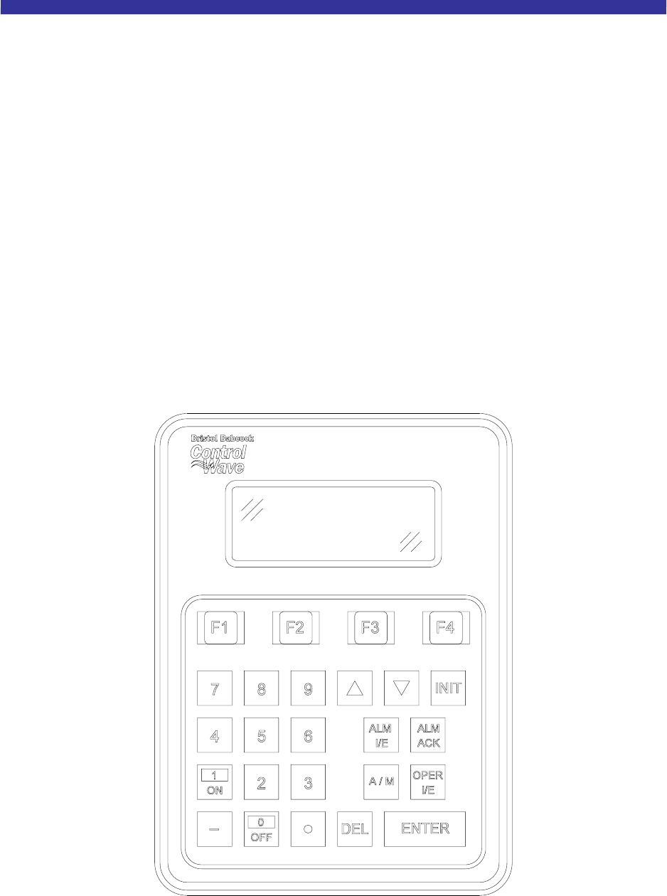
PIP-CW_30 Upgrade Kit Appendix DKA - Display/Keypad / DKA-1
Appendix DKA
DISPLAY/KEYPAD ASSEMBLY GUIDE
DKA1.1 OVERVIEW
Bristol Display/Keypad assemblies provide a local, user interface for the ControlWave
3330 (CW_30) DPC. These assemblies allow an operator or engineer to view and modify
variable values and associated status information, via an ACCOL3 Function Block.
Variables can include inputs, process variables, calculated variables, constants, set-points,
tuning parameters and outputs used in a measurement or control application. Status bits
include alarm state, alarm acknowledge, control, manual, and questionable data.
Setting up the Display/Keypad is a simple matter of configuring a Display Function Block
in the ControlWave Designer project.
The Display/Keypad is comprised of a four line by twenty character liquid crystal display,
with adjustable LCD Contrast, and a 25 button membrane key matrix. Each key has a
microswitch for positive tactile feedback. This means that as you firmly depress the keys,
you will feel it click as it engages. In the case of the CW_30 DPC, the Display/Keypad is
located (typically panel or Enclosure Front Cover mounted) within the proximity of the
CW_30 and is installed in the field by field service personnel, user, integrator, contractor,
etc.
Figure 1 - Display/Keypad Assembly – 25 Button Keypad & 4 X 20 Display

DKA-2 / Appendix DKA - Display/5x5Keypad PIP-CW_30 Upgrade Kit
Display/Keypad Assemblies are supported by Automatic Mode and Manual Mode.
Automatic Mode
In Automatic Mode a set of screens (based on the application load) are displayed. The
application programmer provides strings for the opening screen. From there the firmware is
responsible for displaying the screens and responding to key presses. Screens are fixed and
start off with an opening screen, which displays user information passed into the function
block. Users can view a list to select which list is to be scrolled. Once the list to be scrolled
has been selected, the user can scroll through the list by pressing the down arrow key. List
elements will be displayed automatically, scrolling at a predetermined rate (determined by
iiScrollTime). The user may pause on a variable by pressing the right arrow key. Pressing
the right arrow key again will cause the list to start scrolling again.
The essence of Automatic Mode is that the user can supply inputs into the function that
will determine which list can be displayed, but cannot change the menu or display. The
user is allowed to select a list and to start/stop scrolling.
Manual Mode
In Manual Mode the programmer is responsible for creating each screen and displaying the
next desired screen, based on key inputs. The programmer has access to all lines of the
display and can provide any string that he/she desires to display. Special formats that must
be adhered to that allow the programmer to display what they want on the screen are
provided in the description of iaScrnSruct in the ACCOL 3 Display function block within
ControlWave Designer’s On-Line Help. It should be noted that currently, Manual Mode
does not support reading Keypad keypresses. Note: Manual Mode operation requires
ControlWave Firmware 4.50 or newer.
If you're setting up the keypad, follow the configuration instructions provided in Section E3
of this appendix.
If your keypad has already been set up, Section DKA4.1 will tell you how to use the keypad
and interpret the display.
DKA2.1 DISPLAY FUNCTION BLOCK DESCRIPTION
Keypad and display control/configuration are handled by the DISPLAY Function Block.
This function block allows an operator to view/change variable data or to be allowed to
scroll through lists of variable data based upon their login privileges.
In order for the keypad and display to operate, the ControlWave Designer project must
include a properly configured DISPLAY Function Block. Use ControlWave Designer to
configure this function block and assign the parameters according to the four steps covered
in Section 3.
DKA2.1.1 DISPLAY Function Block Parameters
Referring to Figure 2, various DISPLAY Function Block Parameters are available. For
information on configuring the Display Function Block, please reference on-line help in
ControlWave Designer.

PIP-CW_30 Upgrade Kit Appendix DKA - Display/Keypad / DKA-3
Figure 2 - ACCOL3 DISPLAY Function Block Parameters
DKA3.1 PREPARING THE ControlWave PROJECT
In order for the keypad and display to operate, the ControlWave Designer project must
include a properly configured Display Function Block. Once the Keypad is operating, a user
who has signed on with a password can scroll through the names of variable lists and
choose a list to read or change. Use Up Arrow and Down Arrow keys to select the Username
and use the numeric keys to enter your password. The steps that follow describe how to
configure this function block.
Step 1: Creating the Identifier Display
The Identifier Display is the first display to appear when the Display Function Block is
initialized and begins to execute. This display will look similar to Figure 3. Each of the first
three lines of the display contains the text value of a string variable. These string variables
are created utilizing iaScrnStruct parameters of the Display Function Block (See Figure 2)
and your computer keyboard. Since this is the first display that the user will see, you may
want the display to contain general information such as the node name of the controller or
the process that the controller is monitoring.
The bottom line on the display is called the legend line. It shows which function keys are
currently active and their purpose. Function keys are those keys on the Keypad that are
marked ([F1] through [F4]). Function key assignments are preconfigured and cannot be
changed. Using function keys is described in Section DKA4.1, Using the Keypad.
The legend line in Figure 3 shows that the user has two choices: to Log-in (using [F1]) or
scroll (using [F2]).

DKA-4 / Appendix DKA - Display/5x5Keypad PIP-CW_30 Upgrade Kit
Figure 3 - Creating the Identifier Message
Step 2: Defining a Scroll List
Once the Keypad is operating properly, you can automatically scroll through a list of
variables created via DISPLAY Function Block Parameters iiList2Scroll and iiListMode.
Scrolling can be done without entering a password. The variables in the list are displayed
one at a time and in the same order in which they were entered in the variable list.
Later, we'll discuss other variable lists that can be accessed with the keypad. To distinguish
this list from others, let's call this variable list the Scroll List.
Enter the number of a variable list to be scrolled. This variable list becomes the Scroll List.
The Scroll List can contain different types of variables (that is, logical, analog and string).
You can create a specific scroll variable list or use any list in the ControlWave Project.
Each variable in the Scroll List will be displayed for the number of seconds defined by the
iiScrollTime parameter. If you don't specify a time for this parameter, the hold time will be
two seconds. If you signed-on and then started scrolling you will be signed-off in 20 minutes
if no keys are pressed. If you don’t want to automatically stop scrolling after 20 minutes,
sign-off (INIT key) before starting scrolling.
Step 3: Assigning Passwords
A valid RTU username/password combination must be entered to go beyond the initial
displays. Passwords can be any combination of numbers up to 16 digits in length, from
0000000000000000 to 9999999999999999. If none are specified, the default values are
system for User-name and 666666 for Password (read/write access).
Step 4: Status Information
Enter a variable name on the odiStatus terminal.
See On Line Help in ControlWave Designer for Status Values.
The next section describes how to use the Keypad to access variable information.
DKA4.1 USING THE KEYPAD
The Identifier Display is the starting point from which you can go to other displays. It
shows an identification message and the words Login and Scroll at the bottom of the screen
(see Note 1). The identification message may contain the name of the controller, the plant
equipment it is monitoring, or the variables you can expect to see when you use this
display.
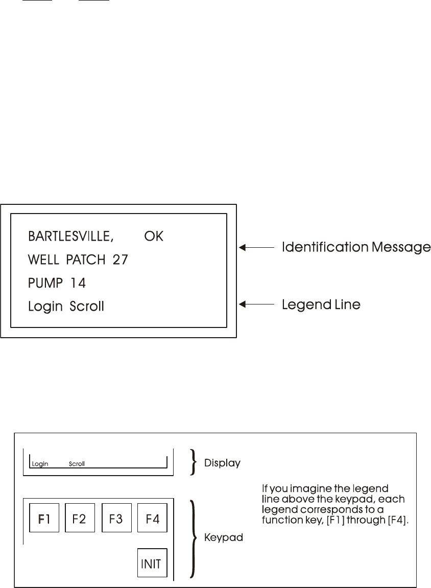
PIP-CW_30 Upgrade Kit Appendix DKA - Display/Keypad / DKA-5
Note 1 : If your display shows something else, press the [F4] key until you see the words
Login and Scroll on the bottom line.
If your screen is blank, turn the brightness screw clockwise. This screw is located to
the left of the Keypad (looking at the rear of the 25-Button Display/Keypad As-
sembly (see Figure 17). If no letters appear, the controller has not been program-
med properly to operate the keypad.
The words Login and Scroll at the bottom of the screen are on the legend line. It tells you
which function keys (that is, key [F1] through [F4]) are active and their purpose at that
time.
Up to four legends can appear on the legend line. The legend on the far left corresponds to
the function of the [F1] key. The assignment for the [F4] key is on the far right. Keys [F2]
and [F3] are described to the left and right of center. When no legend appears, that function
key is not active at that time. For example, in Figure 4 only [F1] and [F2] are active.
Figure 4 - The Identifier Display
From the Identifier Display, you have two choices. Pressing [F1] will allow you to sign-on if
you have a password. By pressing [F2] you can activate automatic scrolling through a list of
variables.
Figure 5 - Identifier Display Legends and Corresponding Keypad Alignment
for 25 Button Membrane Key Matrix Keypad System
DKA4.1.1 Scrolling
To begin automatic scrolling, press [F2] from the Identifier Display (Figure 4). Variable in-
formation will appear on the screen and remain there for 1 to 30 seconds (default = 2). The
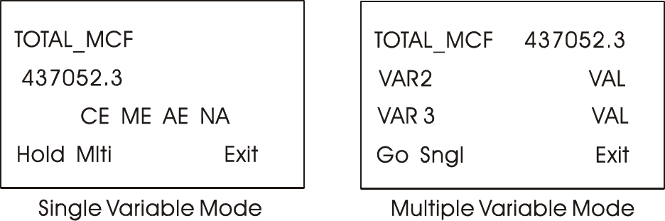
DKA-6 / Appendix DKA - Display/5x5Keypad PIP-CW_30 Upgrade Kit
variable name appears on the first line. The variable value appears on the second line and
status information appears on the third line. An example is shown in Figure 6.
When all variables in the list have been displayed, they will be shown again in the same
order. This is called Single Variable Mode.
Pressing Mlti [F2] activates Multiple Variable Mode. Multiple Variable Mode displays up to
three (3) variables and their values on the screen simultaneously. Pressing Sngl [F2]
terminates Multiple Variable Mode and returns you to Single Variable Mode.
Figure 6 - Scrolling
Press HOLD [F1] to halt scrolling. Changing variable values will continue to be displayed.
Press GO [F1] to resume scrolling.
Press EXIT [F4] to return to the Identifier Display (Figure 4).
DKA4.1.2 Signing-On
To access the List Menu, you must first sign-on with a proper password. From the
Identifier Display (Figure 4), press [F1]. The screen will look like Figure 7A or 7C. If the
display looks like Figure 7C:
Someone else has already signed on. Go to the paragraph below that starts "Once you
have successfully signed on,…".
If the display looks like Figure 7A:
Select the Username (default = system) by using the Up and Down Arrow Keys. If the
Username system is displayed and no other Username is available (i.e., no others have
been assigned), press [ENTER].
Enter a password using the 0 to 9 keys. For security, asterisks will appear as you enter
the digits. If you make a mistake, press [F1] and try again or use the delete key to
delete the previously pressed key action. The default password is 666666 (used when a
password is not known or no password has been assigned). After typing the password,
press [ENTER].
If your password is not recognized, the asterisks will be erased after you press
[ENTER]. Check your password and try again.
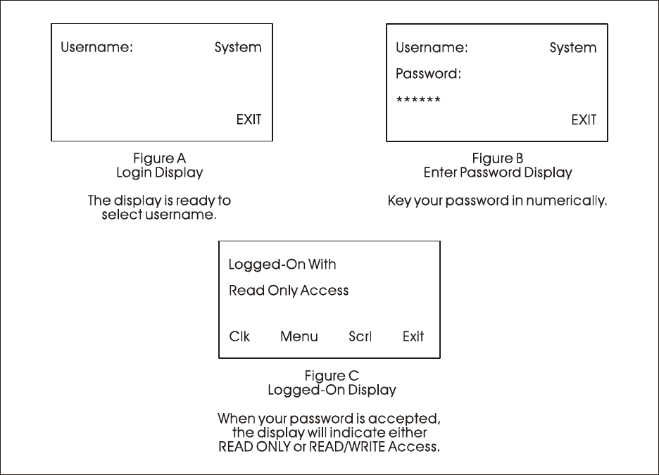
PIP-CW_30 Upgrade Kit Appendix DKA - Display/Keypad / DKA-7
Figure 7 - Logging On
Once the correct password has been entered, the display will look like Figure 7C.
When the second line shows READ/WRITE, you can read and write variable parameters.
When it shows READ ONLY you cannot change variable parameters. You are only permit-
ted to read variable information. If your display shows READ ONLY and you want to
change variable values, sign-off (press the [INIT] key) and log on with a username and
password that provides Read/Write privileges.
Once you have successfully signed on, the legend line will show that you have four options.
You can view and change the time and date of the local clock, access more variable lists,
Scroll, or return to the Identifier Display. Use function keys F1 through F4 to select the
next menu (F1 = Clock, F2 = Menu, F3 = Scroll list & F4 = Exit). Let's start by setting the
local clock.
DKA4.1.3 Using the Clock Functions
From the Logged-On Display (Figure 7C), press [F1]. The screen will show the present date
and time and will look like Figure 8. Follow the instructions below to change the time or
date. When you're finished, press [F4] to exit.
Today's date is shown in the first line in the format month/day/year.
The current time is shown in the form of hours:minutes:seconds.
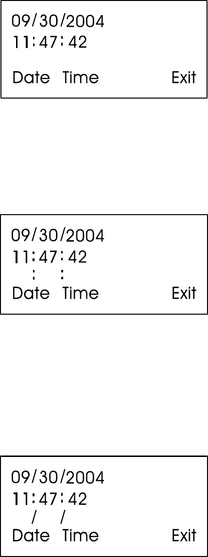
DKA-8 / Appendix DKA - Display/5x5Keypad PIP-CW_30 Upgrade Kit
Figure 8 - Clock Display
DKA4.1.3.1 Changing the Time
From the display shown in Figure 8, press Time [F2]. Colons (:) will appear on the third
line. Enter the new time there and press [ENTER]. Valid times range from 00:00:00 to
23:59:59. Invalid entries will be ignored. The display will be updated to show the new time.
Figure 9 - Time Set Display
If you make a mistake while entering the new time, use [DEL] to backspace and delete one
character at a time.
DKA4.1.3.2 Changing the Date
From the clock display (Figure 8, press [F1]. Slash marks (/) will appear on the third line.
Enter the new date there and press [ENTER].
Figure 10 - Date Set Display
If you make a mistake while entering the new date, use [DEL] to back space and delete one
character at a time. Press [F4] to return to the Logged-On Display (Figure 7C).
DKA4.1.4 Choosing a Variable List from the List Menu
The List Menu is another area where variable information can be seen. As explained earlier
in this section, your first opportunity to read variable information is by choosing the
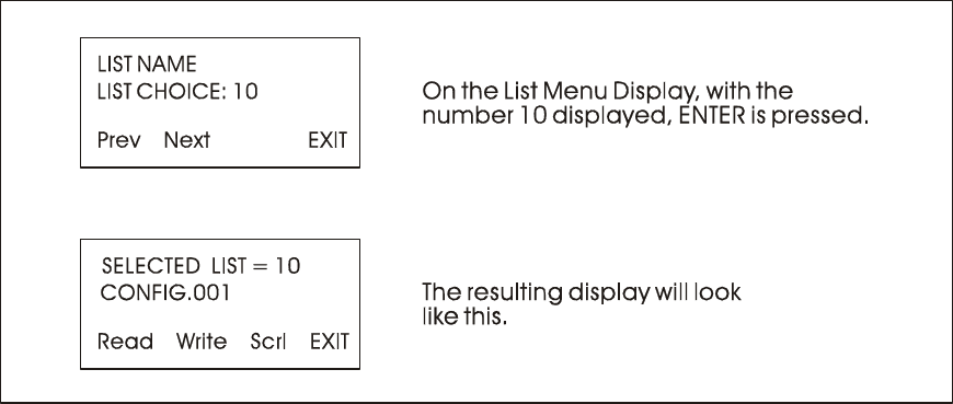
PIP-CW_30 Upgrade Kit Appendix DKA - Display/Keypad / DKA-9
SCROLL function from the Initial Display. The variable name and value are presented
from the Scroll List. This function is available to all users even without signing-on.
The List Menu will show other groups of variable which you can choose to read. This in-
formation will be more detailed than the Scroll List.
To get to the List Menu, choose MENU (press [F2]) from the Logged-On Display (Figure
7C).
Figure 11 - Using the List Menu Display
The first variable list number in the menu will appear on the second line.
Press PREV (F1) and NEXT (F2) to see the other variable lists that are available in the List
Menu. You can also use the Up and Down Arrow Keys to scroll through the various lists. To
move directly to a list, enter the list number, then press [ENTER].
DKA4.1.5 Moving Through a Variable List
After READ (F1) or WRITE (F2) has been pressed, the display will show the first variable
in the list. An example is shown in Figure 12. Each time NEXT (F2) is pressed; the display
will show the next variable in the list. PREV (F1) will show the previous variable. You can
also use the Up and Down Arrow Keys to move through a list.
Automatic wraparound occurs in either direction. When you reach the end of the list, [F1]
will display the first variable again. At the top of the list, [F2] will display the last variable.
DKA4.1.6 Changing Variable Parameters
From Figure 11, you can change variable parameters by pressing F2 [Write]. Then follow
the directions summarized below (see Note 2).
Note 2: If your display does not contain the legend Write in the legend line, your password
will only allow you to read variables. If you want to change variable values at this
time, you must first log-off and then log-on using the correct password. See your
Systems Engineer for the correct password.
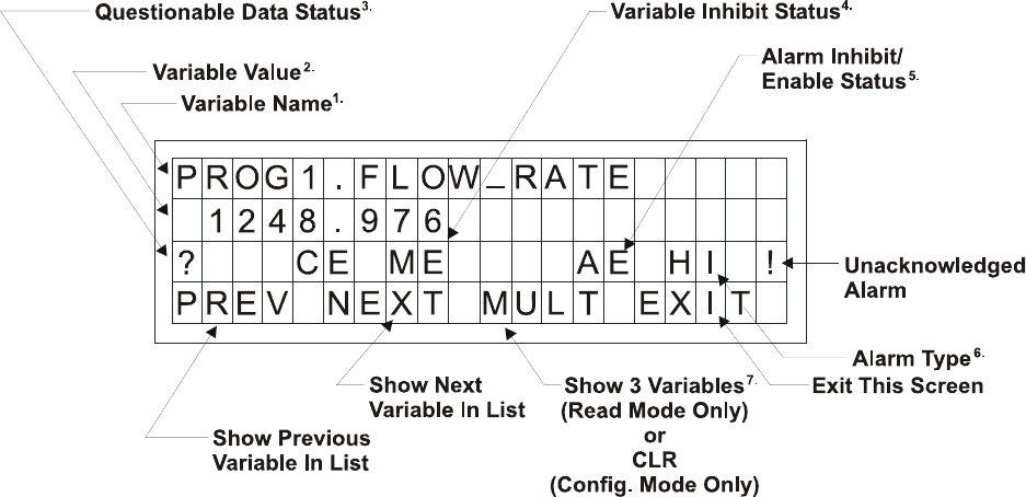
DKA-10 / Appendix DKA - Display/5x5Keypad PIP-CW_30 Upgrade Kit
Before making any changes, first check the signal inhibit status field (See Figure 12). When
the display shows ME (manual enable) you can change variable parameters. When it shows
MI (manual inhibit), you cannot alter the parameters of this variable. If the field indicates
MI, press the OPER I/E key to change it to ME.
To change an analog value:
Press CHNG (F3) to clear the third line. Use the number keys 0 through 9 to enter the
new value. The minus sign and period are also permitted. Press [ENTER].
If you make a mistake, press CHNG (F3) and enter the number again or use the [DEL]
key to erase a character.
Another way to enter new values is by using the arrow up and arrow down keys (located
below the [F3] key and left of the [INIT] key). These keys will raise and lower the value
by 1% of the displayed amount.
To change the status of a logical variable:
Press CHNG (F3), then use either the down and up arrow keys or the [0/OFF] and
[1/ON] keys to change the state of a logical variable. If the [0/OFF] and [1/ON] keys are
used, you must also press [ENTER].
Figure 12 - Interpreting Variable Information
To acknowledge an alarm:
Press [ALM ACK].
To change the alarm enable/inhibit status for alarm variables:
Press [ALM I/E] key. (Note: This will only inhibit alarm reporting, and not alarm level
detection.)

PIP-CW_30 Upgrade Kit Appendix DKA - Display/Keypad / DKA-11
Notes for Figure 12
1. Variable Name (Example 1: @GV.FLOW_RATE) (Example 2: @GV.TOTAL_FLOW_RATE)
2. Value - analog value, string value, or logical value. Values which cannot fit in this field will be
shown as asterisks.
Analog values are displayed in floating point format, for example, 0.0125, 99.627, and 1287.66.
When the value cannot be shown in floating point format, scientific format is used
(1.287668E+10 or 1.25E-02 for example).
3. Questionable Data Status - for analog variables, column 1 will be clear if the status is valid. It
will display a question mark if the status is questionable.
4. Variable Inhibit Status
CE (Control Enable) means this variable can be updated by the ControlWave project.
CI (Control Inhibit) means the variable cannot be updated by the ControlWave project.
ME (Manual Enable) means the variable can be changed manually.
MI (Manual Inhibit) means the variable cannot be changed manually.
5. Alarm Enable (for alarm variables only)
AE - variable is alarm enabled (changes will be reported).
AI - variable is alarm inhibited (changes will not be reported).
6. Alarm State
For Analog Variables: For Logical Variables:
HH - high-high alarm TA - true alarm
HI - high alarm FA - false alarm
LO - low alarm CA - change-of-state alarm
LL - low-low alarm
! - alarm is unacknowledged
Notes for Figure 12 (Continued)
7 Multiple Signal Display
In Read Mode, pressing MULT (F3) will display the variable name extension, value, and units
for three variables at one time. These variables include the variable displayed when NEXT (F2)
was pressed and the next two variables in the list. Press SNGL [F3] to return to viewing one
variable at a time (see Figure 12A).
Figure 12A - Example of MULT Display in READ Mode
Variables are shown below as they would appear in SNGL mode.

DKA-12 / Appendix DKA - Display/5x5Keypad PIP-CW_30 Upgrade Kit
1) String
SITE_NAME
WEST SUNBURY PUMP STATION
CE ME
2) Analog
TOTAL_FLOW_RATE
1260.578
CE MI
3) Logical
FLOW_ALARM
OFF
CE MI AE NA
DKA4.1.7 Signing-Off
Once you have logged-on, use the [INIT] key at any time to log-off. When this key has been
pressed, the screen will look like Figure 13. Press Yes (F1) to sign-off. You are signed-off
when the Identifier Display (Figure 3C) appears.
If you do not want to log-off, press Exit (F4) to leave the Log-Off Display.
Once you are signed-on an automatic sign-off will occur if 20 minutes has elapsed since the
last key was pressed.
Figure 13 - Log-Off Display
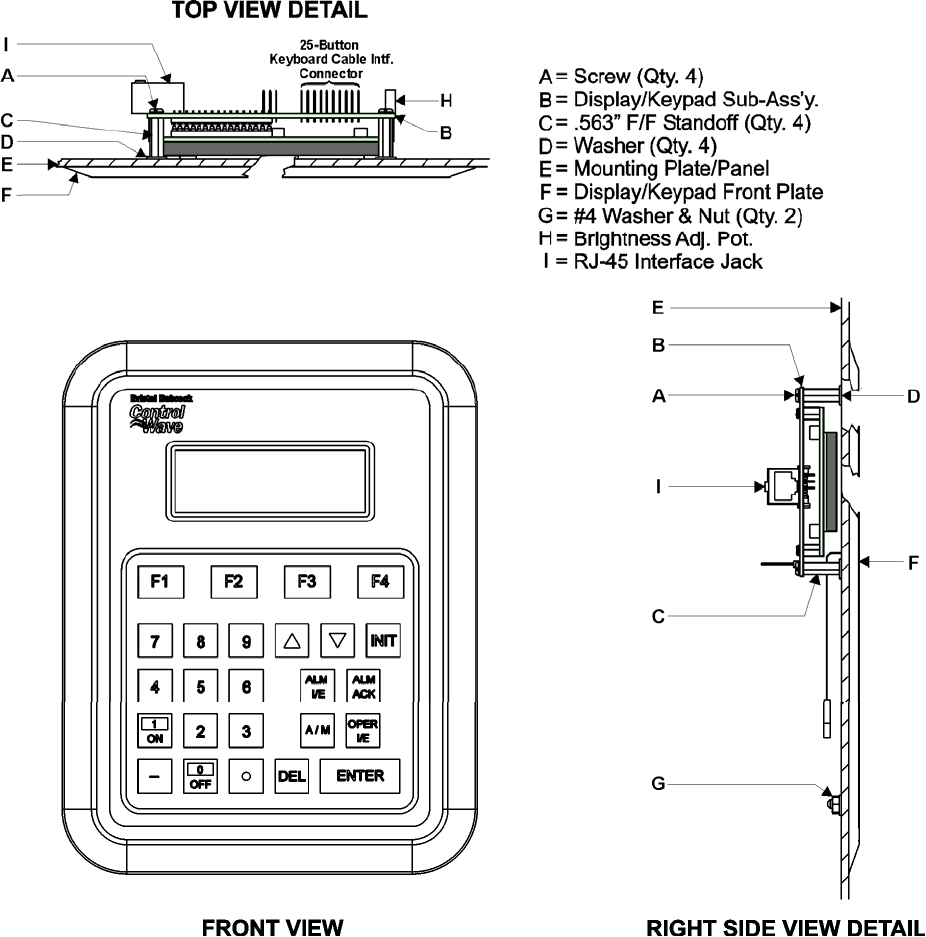
PIP-CW_30 Upgrade Kit Appendix DKA - Display/Keypad / DKA-13
DKA5.1 KEYPAD IDENTIFICATION & INSTALLATION INFO.
Figure 14 - 25-Button Display/Keypad Assembly Installation Drawing
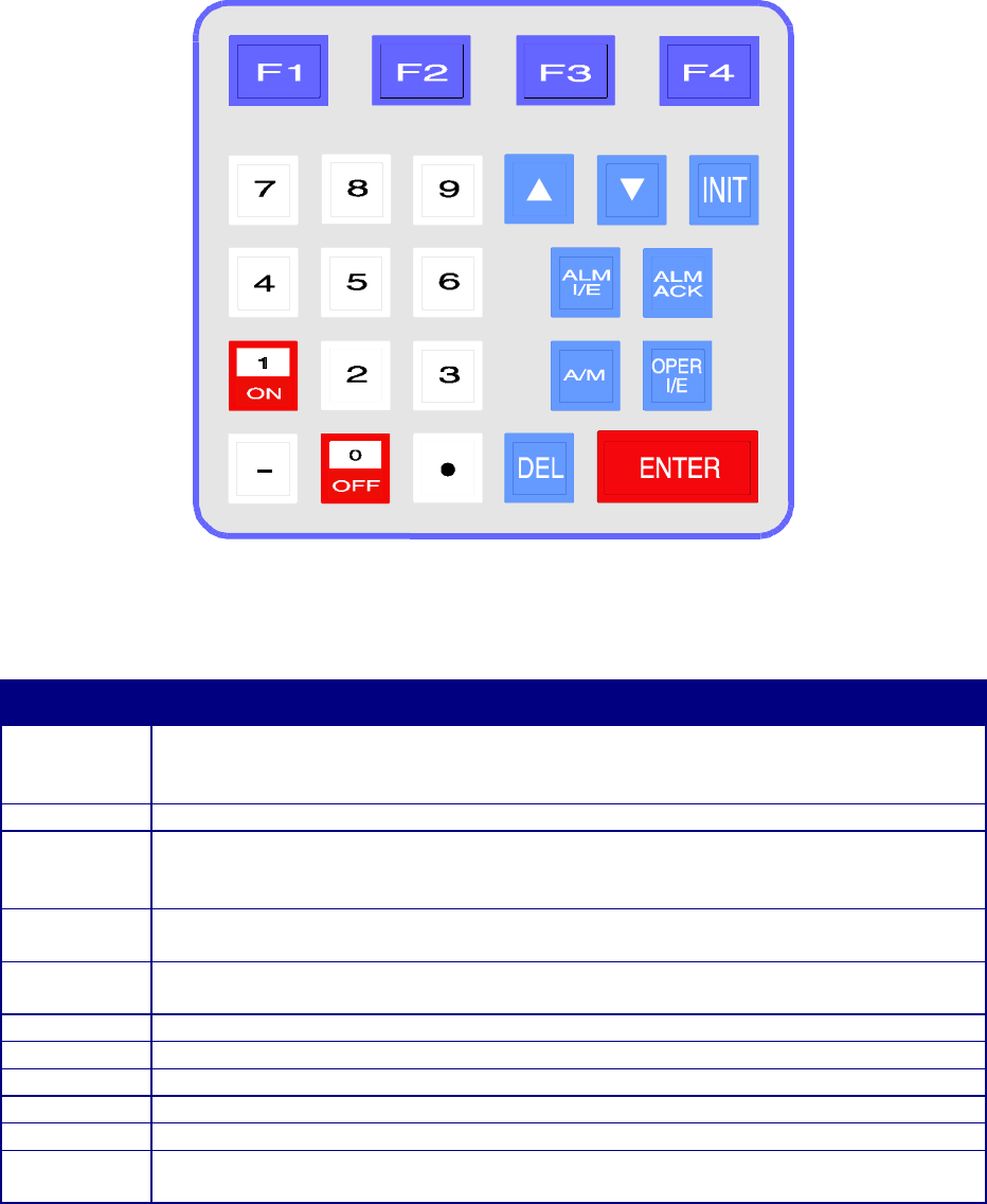
DKA-14 / Appendix DKA - Display/5x5Keypad PIP-CW_30 Upgrade Kit
Figure 15 - 25 Button Keypad
Table 1 - 25 Button Keypad Keys
KEY
FUNCTION
F1, F2, F3,
F4
Function keys will take on a variety of different functions depending on the
situation. The function of these keys is listed on the legend line (bottom line) of the
display.
INIT The INIT key is used to terminate the keyboard session and sign-off.
0 to 9, -, .
These keys are used to change the value of analog variables in the
CONFIGURATION mode. The 0/OFF and 1/ON keys are used to change the state
of logical variables.
Δ Each press of this key will raise an analog variable value by 1% of the displayed
value or turn a logical variable ON.
∇ Each press of this key will lower an analog variable value by 1% of the displayed
value or turn a logical variable OFF.
ALM I/E Use this key to enable or inhibit alarm variables.
ALM ACK Use this key to acknowledge alarms.
A/M Toggle between AUTO (CE) and MANUAL (CI) with this key.
OPER I/E Toggle between manual inhibit (MI) and enable (ME) with this key.
DEL Use this backspace key to erase digits that have been entered on the keypad.
ENTER This key is used to enter new data from the display into the controller, e.g.,
password or variable values.

09/26/06 Appendix Z – PIP-CW_30 Upgrade Kit MSDS
ControlWave_30
Material Safety Data Sheets
A Material Safety Data Sheet is provided herein to comply with OSHA’s Hazard Com-
munication Standard, 29 CFR 1910.1200. This standard must be consulted for specific
requirements.
Material Safety Data Sheets are provided in the order listed in Table Z-1 below.
TABLE Z-1
MSDS for ControlWave_30 Instruction Document
(PIP-CW_30 Upgrade Kit)
Manufacturer General Description Part Number
DURACELL 3V Lithium Manganese
Dioxide Battery DL 2450
Bristol, Inc. Part Number = 395620-01-5
The 3V Lithium Manganese Dioxide Battery is situated on the CW_30 CCPU Board.
BLANK PAGE
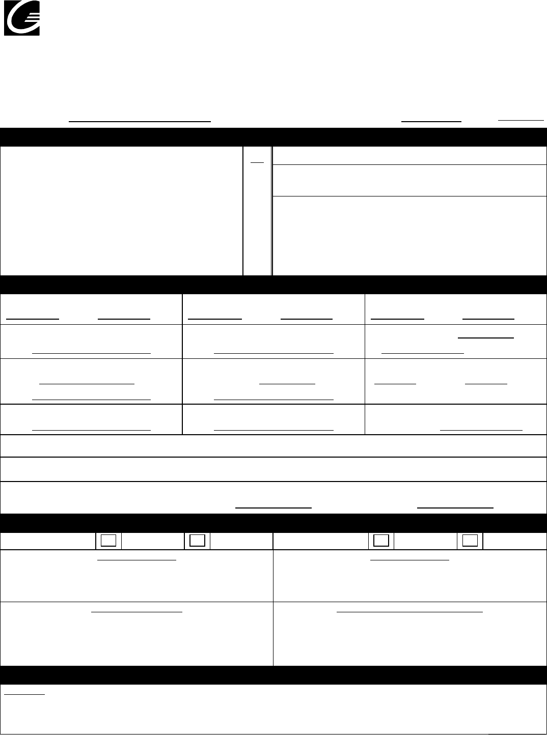
Gillette
Environment
Health and Safet
y
37 A Street
Needham, MA 02492
Tel 781.292.8151
Page 1 of 4
MATERIAL SAFETY DATA SHEET
NAME: DURACELL LITHIUM MANGANESE DIOXIDE COIN BATTERIES
CAS NO: Not applicable Effective Date: 8/8/03 Rev: 3
A. — IDENTIFICATION
% Formula: Mixture Mixture
Man
g
anese Dioxide
(
1313-13-9
)
65-75 Molecular Weight: NA
Pro
py
lene Carbonate
(
108-32-7
)
10-15
Lithium
(
7439-93-2
)
5-10 Synonyms: Lithium Man
g
anese Dioxide Coin Cells:
Gra
p
hite
,
s
y
nthetic
(
7440-44-0
)
5-10 3V-DL2016
;
DL2025
;
DL2430
;
DL2450
;
1
,
2-Dimethox
y
ethane
(
110-71-4
)
1-10 DL2032
;
DL1616
;
DL1620
Lithium Perchlorate
(
7791-03-9
)
<1.5
B. — PHYSICAL DATA
Boiling Point Melting Point Freezing Point
NA °FNA °CNA °FNA °CNA °FNA °C
Specific Gravity (H2O=1) Vapor Density (air=1) Vapor Pressure @ °F
NA NA NA mm Hg
Evaporation Saturation in Air Autoignition Temperature
(Ether =1) (by volume@ °F) °F°C
NA NA NA
% Volatiles Solubility in Water
NA NA pH NA
Appearance/Color Coin cells. Contents dark in color.
Flash Point and
Test Method(s) 1,2-Dimethoxyethane (Approximately 3-7% of contents): 42.8 °F, 6°C (Closed Cup)
Flammable Limits in Air
(% by volume) Lower NA %Upper NA %
C. — REACTIVITY
Stability Xstable unstable Polymerization may occur Xwill not occur
Conditions to Avoid Conditions to Avoid
Do not heat, crush, disassemble, short circuit or
recharge.
Not applicable
Incompatible Materials Hazardous Decomposition Products
Contents incompatible with strong oxidizing agents. Thermal degradation may produce hazardous fumes
of manganese and lithium; oxides of carbon and other
toxic by-products.
* IF MULTIPLE INGREDIENTS, INCLUDE CAS NUMBERS FOR EACH NA=NOT AVAILABLE
Footnotes
Not applicable
GMEL# 2033.3

Page 2 of 4
D. — HEALTH HAZARD DATA
Occupational Exposure Limits PEL’s, TLV’s, etc.)
8-Hour TWAs: Manganese Dioxide (as Mn) - 5 mg/m3 (Ceiling) (OSHA); 0.2 mg/m3 (ACGIH/Gillette)
1,2-Dimethoxyethane - 0.15 ppm (Gillette)
Graphite (all kinds except fibrous) - 2 mg/m3 (synthetic, ACGIH); 15 mg/m3 (total, OSHA);
5 mg/m3 (respirable, OSHA)
These levels are not anticipated under normal consumer use conditions.
Warning Signals
Not applicable
Routes/Effects of Exposure
These chemicals and metals are contained in a sealed can. For consumer use, adequate hazard warnings are
included on both the package and on the battery. Potential for exposure should not exist unless the battery
leaks, is exposed to high temperature, is accidentally swallowed or is mechanically, physically, or electrically
abused.
1. Inhalation Not anticipated. Respiratory (and eye) irritation may occur if fumes are released due to heat or
an abundance of leaking batteries.
2. Ingestion An initial x-ray should be obtained promptly to determine battery location. Batteries lodged in
the esophagus should be removed immediately since leakage, burns and perforation can occur
as soon as 4-6 hours after ingestion. Irritation to the internal/external mouth areas may occur
following exposure to a leaking battery.
3. Skin a. Contact
Irritation may occur following exposure to a leaking battery.
b. Absorption
Not anticipated.
4. Eye Contact Irritation may occur following exposure to a leaking battery.
5. Other Not applicable
E. — ENVIRONMENTAL IMPACT
1. Applicable Regulations All ingredients listed in TSCA inventory.
2. DOT Hazard Class - Not applicable
3. DOT Shipping Name - Not applicable
While lithium batteries are regulated by IATA and ICAO, the type of lithium batteries offered for sale by DURACELL are
considered non-hazardous per provision A45 of the IATA Dangerous Goods Regulations and provision A45 of the ICAO
Technical Instructions For The Safe Transport Of Dangerous Goods By Air. Per section A45 of the IATA and ICAO
regulations, properly marked, labeled and packaged DURACELL consumer lithium batteries, which are of the solid cathode
type, with less than 1g lithium per cell and less than 2g lithium per battery, are exempt from further regulation. When these
batteries are separated to prevent short circuits and properly packaged in strong packaging (except when installed in electronic
devices), they are acceptable for air transport as airfreight without any other restrictions. In addition, when installed in
equipment or when no more than 24 cells or 12 batteries meeting the A45 provision are shipped, they are not subject to
special packaging, marking, labeling or shipping documentation requirements. Thus, these batteries are not considered
hazardous under the current regulations and are acceptable for air transport.
Environmental Effects
These batteries pass the U. S. EPA's Toxicity Characteristic Leaching Procedure and therefore, maybe
disposed of with normal waste.
GMEL# 2033.3

Page 3 of 4
F. — EXPOSURE CONTROL METHODS
Engineering Controls
General ventilation under normal use conditions.
Eye Protection
None under normal use conditions. Wear safety glasses when handling leaking batteries.
Skin Protection
None under normal use conditions. Use butyl gloves when handling leaking batteries.
Respiratory Protection
None under normal use conditions.
Other
Keep batteries away from small children.
G. — WORK PRACTICES
Handling and Storage
Store at room temperature. Avoid mechanical or electrical abuse. DO NOT short or install incorrectly.
Batteries may explode, pyrolize or vent if disassembled, crushed, recharged or exposed to high temperatures.
Install batteries in accordance with equipment instructions. Replace all batteries in equipment at the same
time. Do not carry batteries loose in pocket or bag.
Normal Clean Up
Not applicable
Waste Disposal Methods
No special precautions are required for small quantities. Large quantities of open batteries should be treated
as hazardous waste. Dispose of in accordance with federal, state and local regulations. Do not incinerate,
since batteries may explode at excessive temperatures.
GMEL# 2033.3

Page 4 of 4
H. — EMERGENCY PROCEDURES
Steps to be taken if material is released to the environment or spilled in the work area
Evacuate the area and allow vapors to dissipate. Increase ventilation. Avoid eye or skin contact. DO NOT
inhale vapors. Clean-up personnel should wear appropriate protective gear. Remove spilled liquid with
absorbent and contain for disposal.
Fire and Explosion Hazard Extinguishing Media
Batteries may burst and release hazardous decomposition products when
exposed to a fire situation. See Sec. C.
As for surrounding area. Dry
chemical, alcohol foam, water or
carbon dioxide. For incipient
fires, carbon dioxide extinguishers
are more effective than water.
Firefighting Procedures
Cool fire-exposed batteries and adjacent structures with water spray from a distance. Use self-contained
breathing apparatus and full protective gear.
I. — FIRST AID AND MEDICAL EMERGENCY PROCEDURES
Eyes
Not anticipated. If battery is leaking and material contacts eyes, flush with copious amounts of clear, tepid
water for 30 minutes. Contact physician at once.
Skin
Not anticipated. If battery is leaking, irrigate exposed skin with copious amounts of clear, tepid water for a
least 15 minutes. If irritation, injury or pain persists, consult a physician.
Inhalation
Not anticipated. Respiratory (and eye) irritation may occur if fumes are released due to heat or an abundance
of leaking batteries. Remove to fresh air. Contact physician if irritation persists.
Ingestion
Consult a physician. Published reports recommend removal from the esophagus be done endoscopically
(under direct visualization). Batteries beyond the esophagus need not be retrieved unless there are signs of
injury to the GI tract or a large diameter battery fails to pass the pylorus. If asymptomatic, follow-up x-rays
are necessary only to confirm passage of larger batteries. Confirmation by stool inspection is preferable
under most circumstances. If mouth area irritation/burning has occurred, rinse the mouth and surrounding
area with clear, tepid water for at least 15 minutes.
Notes to Physician
1) For information on treatment, telephone (202)-625-3333 collect.
2) Potential leakage of less than 50 milligrams of propylene carbonate (CAS #108-32-1) and
dimethoxyethane (CAS #110-71-4).
3) Dimethoxyethane readily evaporates.
4) Under certain misuse conditions and by abusively opening the battery, exposed lithium can react with
water or moisture in the air causing potential thermal burns or fire hazard.
Replaces # 1461
The information contained in the Material Safety Data Sheet is based on data considered to be accurate, however, no warranty is
expressed or implied regarding the accuracy of the data or the results to be obtained from the use thereof.
MSDS-4 (8/95) GMEL# 2033.3
BLANK PAGE

Product Information Package
PIP-CW_30 Upgrade Kit
Mar., 2007
CW_30 Hardware Installation Guide
The information in this document is subject to change without notice. Every effort has
been made to supply complete and accurate information. However, Bristol, Inc.
assumes no responsibility for any errors that may appear in this document.
If you have comments or questions regarding this manual, please direct them to your
local Bristol sales representative, or direct them to one of the addresses listed at left.
Bristol, Inc. does not guarantee the accuracy, sufficiency or suitability of the software
delivered herewith. The Customer shall inspect and test such software and other
materials to his/her satisfaction before using them with important data.
There are no warranties, expressed or implied, including those of merchantability and
fitness for a particular purpose, concerning the software and other materials delivered
herewith.
The Emerson logo is a trade mark and service mark of Emerson Electric Co.
Trademarks or copyrighted products mentioned in this document are for information
only, and belong to their respective companies, or trademark holders.
Copyright (c) 2007, Bristol, Inc., 1100 Buckingham St., Watertown, CT 06795. No part
of this manual may be reproduced in any form without the express written permission of
Bristol, Inc.
Emerson Process Management
Bristol, Inc.
1100 Buckingham Street
Watertown, CT 06795
Phone: +1 (860) 945-2262
Fax: +1 (860) 945-2525
www.EmersonProcess.com/Bristol
Emerson Electric Canada, Ltd.
Bristol Canada
6338 Viscount Rd.
Mississauga, Ont. L4V 1H3
Canada
Phone: 905-362-0880
Fax: 905-362-0882
www.EmersonProcess.com/Bristol
Emerson Process Management
BBI, S.A. de C.V.
Homero No. 1343, 3er Piso
Col. Morales Polanco
11540 Mexico, D.F.
Mexico
Phone: (52-55)-52-81-81-12
Fax: (52-55)-52-81-81-09
www.EmersonProcess.com/Bristol
Emerson Process Management
Bristol Babcock, Ltd.
Blackpole Road
Worcester, WR3 8YB
United Kingdom
Phone: +44 1905 856950
Fax: +44 1905 856969
www.EmersonProcess.com/Bristol
Emerson Process Management
Bristol, Inc.
22 Portofino Crescent,
Grand Canals Bunbury, Western Australia 6230
Mail to: PO Box 1987 (zip 6231)
Phone: +61 (8) 9725-2355
Fax: +61 (8) 8 9725-2955
www.EmersonProcess.com/Bristol
