Phoenix Gold Speaker System VSS4 Dec Installation Hout
User Manual: Phoenix Gold Speaker System VSS4
Open the PDF directly: View PDF ![]() .
.
Page Count: 20

DCC Decoder and Sound
Installations

Tony’s Decoder Installations
57 River Rd. Box 1023, Essex Jct., VT. 05452 Toll Free: 800-978-3472 Fax: 802-878-5550 Email: info@tonystrains.com
Web: www.tonystrains.com
We Offer and Support More DCC Products Than Anyone!
Table of Contents
Decoder basics _
Basic decoder installation _
Selecting a Decoder _
Isolating the motor _
Athearn HO Diesel Installation _
IHC 2-6-0 Installation _
Special application decoders _
Hints and Tips _
N Scale decoder selection chart courtesy of Digitrax _
HO Scale decoder selection chart courtesy of Digitrax _
Links to Install Examples _
Retroframes for N scale _
Installation Diagrams _
Decoder Installation Examples:
Athearn SD70 MAC and Athearn F3 _
Atlas GP7 and LifeLike Proto 2000 SD60 _
Kato AC4400 and Intermountain F-Units _
Stewart F-Units and Walthers SW-1 _
Brass Steam and Bachmann Climax _
Atlas N GP40-2 and Micro-Trains FT _
Fix for Rear LED Leakage on SoundTraxx LC Decoders _
Appendix:
Tool List _
Standard Decoder hook-up and sockets _
Decoder Comparison Matrix _
DCC Sound System Comparison _
Speakers for DCC Sound _
Using low-voltage lamps with DCC Decoders _
Using LEDs with DCC Decoders _
Text and images here are used with the permission of Kalambach Publishing, Train Control Systems, and Digitrax.
1
1
1
2
2
2
3
4
5
6
7
8
10
12
13
14
15
16
17
18
i
ii
iii
v
vii
ix
xi

Tony’s Decoder Installations
57 River Rd. Box 1023, Essex Jct., VT. 05452 Toll Free: 800-978-3472 Fax: 802-878-5550 Email: info@tonystrains.com
Web: www.tonystrains.com
We Offer and Support More DCC Products Than Anyone!
1
Decoder basics
Before delving into decoder installation in detail, let's start with some general guidelines
• Use the proper tools. Invest in a good soldering iron and high-quality solder.
• A list of suggested tools and where you can get them has been included in this packet. Decoder installation is not
a job for your old soldering gun!
• Insulate all connections. I recommend 1/16” or 3/64” diameter heat-shrink tubing. Plastic electrical tape is not an
acceptable substitute since it has a habit of unwrapping itself. Kapton tape is the best option
• Use the proper size wire. Most decoders come equipped with 28 or 30AWG stranded wire. However, this may not
he heavy enough to handle surge currents caused by a short between the locomotive trucks. Heavier wire, such
as 24AWG, is a better choice for jumpers between truck pickups.
Disassemble locomotives carefully. Refer to the exploded parts diagram that comes with the locomotive when taking
an engine apart. For complex models it’s a good idea to label the parts and place them in a multi-compartment box.
• Isolate the motor. Before installing a decoder, the two motor terminals must be electrically isolated from the
chassis or frame.
• Reliable track pickup is essential. Most of today's plastic diesels feature all-wheel pickup. With few exceptions,
most brass locomotives (and some brass diesels) don't. They use the drivers (or lead truck in the case of brass
diesels) to pick up from the right rail and the tender wheels (or rear diesel truck) to pick up from the left rail. This
usually results in erratic operation. Consider adding wipers or other extra pickups before installing a decoder.
• Do not exceed the decoder's current rating. You can use a lower-rated motor with a decoder rated at a higher
current, but not vice-versa. Also, provide adequate ventilation. Decoders heat up under load or when operated
near the rated output current.
• Neatness counts. Don't allow any exposed wires or components to touch the metal chassis or weights. Use
caution when wiring headlights. When headlights are wired to the decoder, be sure to add the total current of the
headlights to the motor current. (See Lighting and Led Guide and Applicable Resistors)
• Equip each locomotive with its own decoder. A decoder in each locomotive provides better performance and lets
you tune the performance of that particular locomotive. Economizing here will cost you more!
• Use decoder addresses that are easy to remember. You may recall that GP35-2 no. 266 has an address of “4,”
but Will your operators? We suggest using the last two digits o4 the 4 Digits of the locomotive number. It’s also a
good idea to place a self-adhesive label listing the decoder type and address on the underside of each
locomotive. If you have two locos with the same numbers you can easily remove/ paint over the first or last digit to
make a new number.
Basic decoder installation
All the major Manufacturers such as Atlas, Kato, Life-Like, and Stewart and others have made decoder installation a
breeze in their newer locomotives by including a receptacle (See diagram in appendix) that's pre-wired for a DCC
decoder.
You simply remove the factory-installed plug. Plug in the appropriate decoder, and you're ready to go. But before you
can do this you need to determine which decoder is the best to use. All decoder installations include the following steps:
(1) Select a decoder that fits inside the body shell and has the required current rating.
(2) Tony’s Decoder Comparison Matrix is a handy reference for selecting sizes and features.
(3) Isolate the motor from the track pickups.
(4) Install the decoder along with wiring for any extra effects, and
(5) Test the completed installation.
With many Bachmann steam locomotives there are yellow capacitors that need to be removed in order for optimal
operation. If they are not removed you may experience poor speed control.
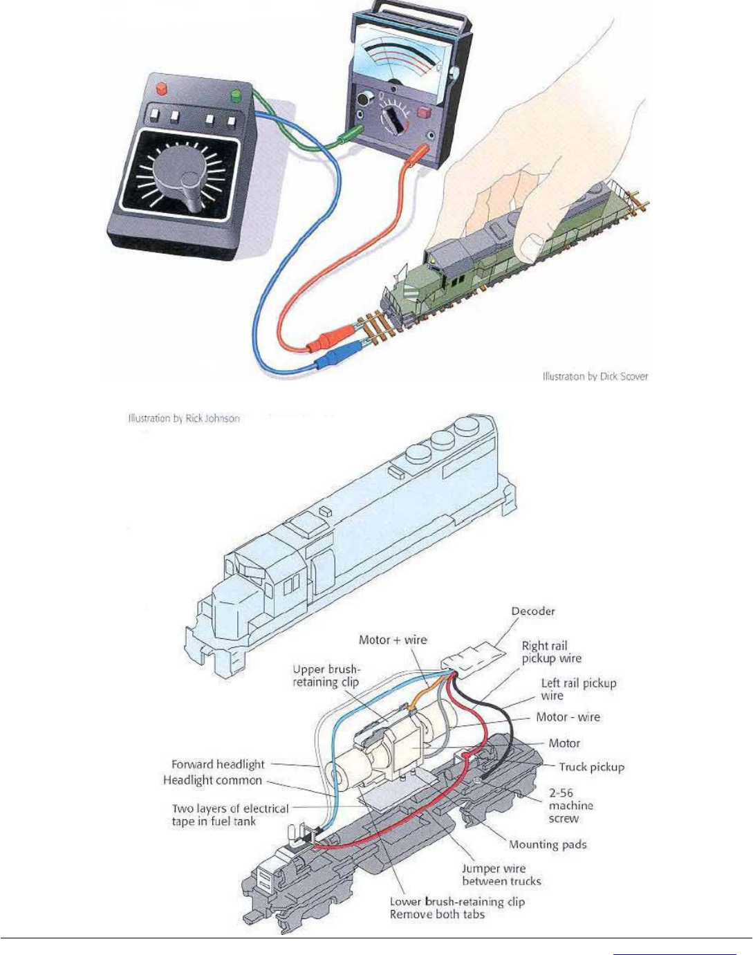
Selecting a decoder
The decoder size will be dictated by the amount of room inside the engine or tender. You also need to select a
decoder with a current rating higher than the stall current of the motor. It's best to measure the stall current on your
particular locomotive. (See Figure 1)
Set the meter on the DC amps scale. Grasp the locomotive so it doesn't take off and turn the power pack to full.

Tony’s Decoder Installations
57 River Rd. Box 1023, Essex Jct., VT. 05452 Toll Free: 800-978-3472 Fax: 802-878-5550 Email: info@tonystrains.com
Web: www.tonystrains.com
We Offer and Support More DCC Products Than Anyone!
2
Push down until the engine stalls and note the current. This is the "stall" current. One decoder can drive multiple motors,
provided the sum of the stall currents doesn't exceed the decoder's current rating.
Isolating the motor
The motor must be completely isolated from all track pickup points. If the locomotive has it built-in command
control socket the motor is already isolated. But an older model, or one without it built-in socket, means you need to find
and eliminate all connections between the motor brushes and track pickups. This is usually the biggest problem people
have when they first step into command control.
Diesel locomotives are fairly straightforward, but in brass steam locomotives the mechanical pickups can he quite
ingenious and well hidden. Use it volt-ohm meter to verify electrical isolation. Set your meter on the ohms (resistance)
scale and touch both probes together. The meter will indicate a short. You don't want to see this indication when you're
checking for motor isolation! Place one of the probes on it brush and touch the other probe to the chassis or left rail pickup
wire and then move it to the right rail pickup wire. If the motor is isolated you will read an open circuit. Move the probe to
the other brush and repeat the tests. If both tests indicate an open circuit, the motor is isolated and you can safely
proceed with decoder installation.
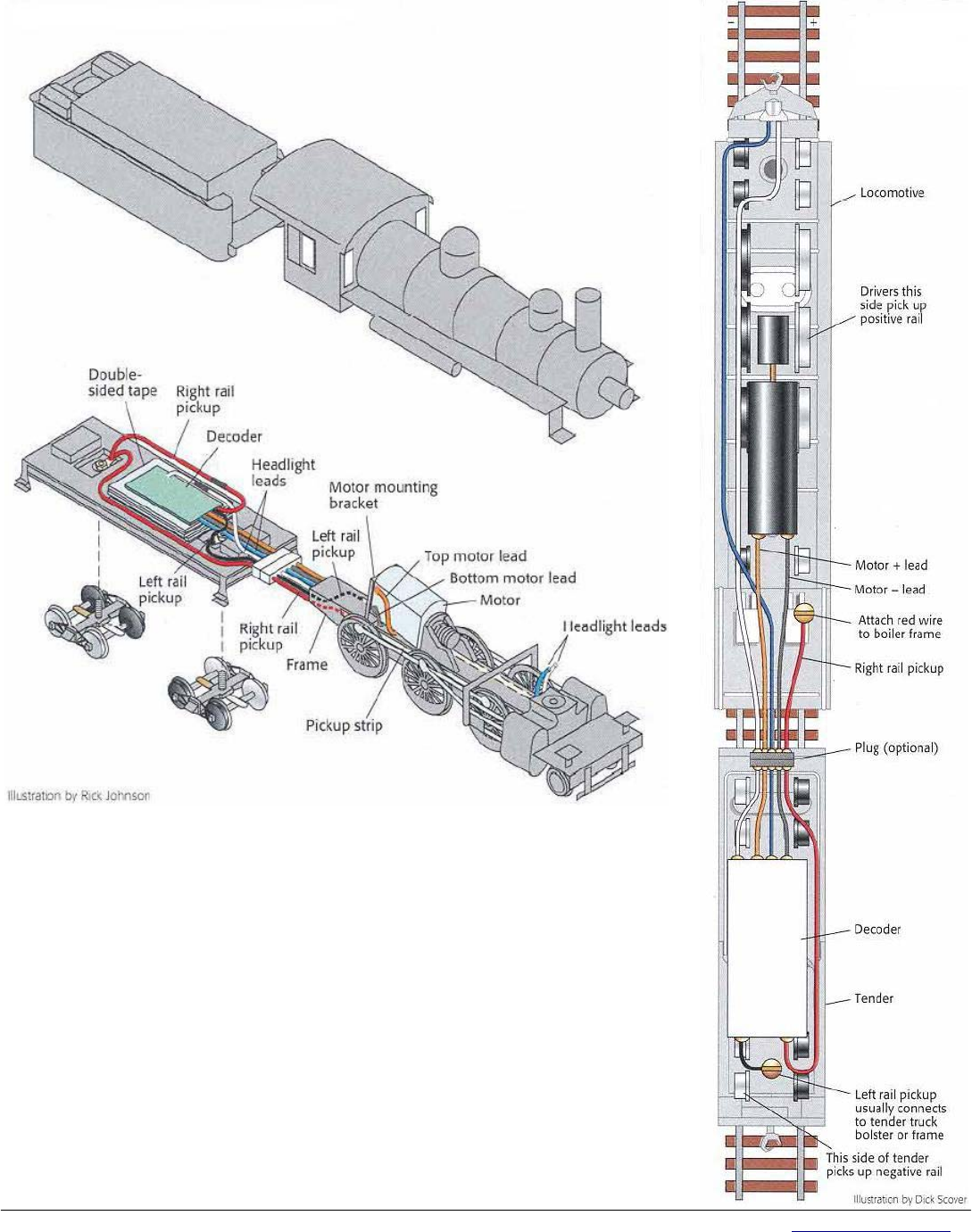
Athearn HO diesel installation (See Figure 2)
Since most HO railroads have at least one Athearn diesel, showing how to equip one with a decoder seemed an
excellent start in place for us. Athearn motors aren't isolated from the frame, so the first step is to change that.
Remove the shell from the frame and discard the metal connector clip. Don't remove the brush-retaining clips located
underneath. Next pull up on the motor until the mounting pads pop out of the holes. The drive train will slip apart as the
motor comes out. Set these components aside. Place a strip of nylon-reinforced strapping tape on the floor of the fuel
tank. Completely cover the shiny metal area where the motor was sitting, but be sure to keep the tape clear of the motor
mount holes. The brushes are held in place with clips, and we'll be soldering the motor connection wires directly to these.
Pry off both clips, being careful not to let the brush springs and brushes fly across tile room.
Cut the two small prongs from the underside of the bottom brush clip and file smooth. The decoder's color-coded
wires should comply with the NMRA-recommended coding Shown in table 1. Solder the gray motor - (minus) wire to the
outside of the curved end of the lower brush clip. Replace the brush and spring and snap the clip back onto the motor,
then solder the orange motor + (plus) wire to the center of the upper brush clip. Reinstall the brush and spring. Snap the
clip back in place then set the motor aside for now. The track pickup wires connect with the chassis. Drill and tap it hole in
the chassis for a 2-56 brass machine screw where it won't interfere with the body. Next, solder the left rail pickup wire
(black) to the top of the bolt.
Carefully reinstall the motor by reseating the rubber pads and test the motor to ensure it's completely isolated.
Now solder the red right rail pickup wire to the top of the metal tab on the truck. Jump the two trucks together using it short
length of red wire. Mount the decoder using a piece of double-sided tape. Snap the body back onto the frame and your
decoder is ready for programming. The extra wires on the decoder are for optional effects including headlights and other
functions. Consult the decoder instruction booklet for suggestions and limitations. The diagram shows how we equipped
our Athearn engines with directional lighting.
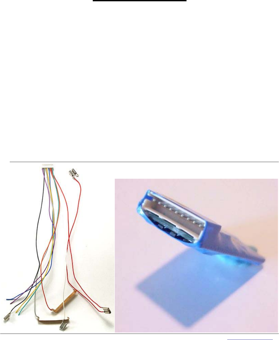
There is a special harness made by Digitrax that simplifies conventional Athearn installation, DHAT. This harness
can be used on any decoder that has the JST connector. (See photos on Page 4)
IHC HO 2-6-0 installation (See Figure 3)
It's a little trickier to install decoders in steam locomotives, but it isn't difficult. Just keep in mind how most
steamers pick up power from the rails and deliver it to the motor. Since brass locomotives need to be approached on a
(almost) case-by case basis, we're going to describe steamer installation using International Hobby Corporation's 2-6-0
Mogul. The engine picks up power from the drivers on both sides. The front tender truck picks up power from the left rail
and the rear truck picks up from the right rail. Two wires between the tender and locomotive transmit power from the
tender to the motor.
To install the decoder, remove the boiler mounting screws and gently lift the boiler from the frame. Next, remove
the screw securing the motor mounting bracket and carefully lift the motor until you see the wires between the motor wires

Tony’s Decoder Installations
57 River Rd. Box 1023, Essex Jct., VT. 05452 Toll Free: 800-978-3472 Fax: 802-878-5550 Email: info@tonystrains.com
Web: www.tonystrains.com
We Offer and Support More DCC Products Than Anyone!
3
and the pickup strips. Cut these motor wires but don't cut the pickup wires from the tender. Unsolder the remains of the
original motor wires and discard. Solder two new wires to the sides of the motor. Use the wires supplied with the decoder
and he sure they are at least 6" long. Connect these to the decoder motor output. Route the two new motor wires back
toward the tender following the same path as the power pickup wires. You may want to place a small plug between the
locomotive and tender.
Remount the motor then slide the frame and motor assembly back into the boiler. Pull the wires back toward the
tender and ensure the boiler fits properly. Install the pilot truck brass tensioner and mounting screw. Then install the screw
underneath the cab. Finally, reattach the pilot truck. Modifications to the engine are complete. You should have the two
original pickup wires and two additional wires extending from the back of the locomotive frame.
We'll be mounting the decoder inside the tender but first we need to insulate the tender pickups from the frame.
Remove the tender shell. The two pickup wires are soldered to brass tabs on top of the truck screws. Leave these in place
and solder two lengths of wire to connect each of the brass tabs with the two decoder input wires. Insulate the splice with
heat-shrink tubing.
Solder the two motor wires to the motor wires of the decoder. If you're connecting the headlight or backup light to
the decoder, make those connections now in accordance with the decoder manufacturer's instructions.
Insulate the metal weight inside the tender using electrical tape and install the decoder with double-sided tape.
Check for loose connections, bare wires, or metal in contact with the decoder. Test the locomotive to ensure proper
operation. If the locomotive direction is reversed, simply swap the motor wires.
Special Application Specific decoders are available for the following locomotives:
TTX:
TTX/GP7: Proto 2000 GP7, 9, 20 30 38 60, SD 45,60 Integrated Direct Plug
TTX/RS2; KATO RS2 and most Intermountain and Atlas Diesels Integrated Direct Plug
TTX/Atlas1234: All Atlas S, Alco Switchers, circuit board replacement decoder.
TTX/SW900: All Proto 2000 SW Switchers, circuit board replacement decoder.
Digitrax
DH163A0: Athearn F3-7, Atlas B40-8, GP7, GP38, GP40, RS1, RS3, RSD4/5, RS11, RSD4, RSD5, RSD12, SD35,
U33C, U36C, circuit board replacement decoder.
DN122K2: Kato N RDC circuit board replacement decoder.
DN163A0: Atlas N B23-7, B30-7, B36-7, C-628, Dash 8-40B, Dash 8-32BWH, GP30, GP35, GP38, GP40, GP40-2, H15-
44, H16-44, SD-7, SD-9, SD-24, SD35, Trainmaster, U25B, circuit board replacement decoder.
DN163A1: Atlas N SD50, SD60, SD60M, circuit board replacement decoder.
DN163I0: Intermountain N SD40T Tunnel motor circuit board replacement decoder.
DN163I1A/B: Intermountain N FT A/B
DN163K0A: Kato N E-8, PA-1, P42 Genesis, circuit board replacement decoder.
DN163K0B: Kato N F3 A&B circuit board replacement decoder.
DN163K1B: Kato N AC4400CW, C44-9, SD40
DN163K2: Kato N RS2, RSC2, SD80/90MAC
DN163M0: MicroTrains FT circuit board replacement decoder.
NCE
DASR: same as DH163A0
N12A0: same as DN163A0
N12A0e: same as DN163I0
N12A1: Same as DN163A1
NIMFTA/B: same as DN163I1A/B
Lenz
Lenz Gold Mini D: all European steam locos with a 6-pin socket
TCS
A4X: Same as DH163A0
A6X: Same as DH163A0 with built-in 1.5V power supply for lights
Tony’s Decoder Installations
57 River Rd. Box 1023, Essex Jct., VT. 05452 Toll Free: 800-978-3472 Fax: 802-878-5550 Email: info@tonystrains.com
Web: www.tonystrains.com
We Offer and Support More DCC Products Than Anyone!
4
Hints And Tips
• Make sure loco runs on DC FIRST
• Make sure decoder can handle current draw of the motor
• When mounting decoder insolate all metal from touching the decoder
• Make sure motor brushes are insolated from frame and pick-up
• Make sure wheels and track are clean
• After install check the loco on the program track for any shorts
• Make sure you have a clean tip on your soldering iron
• Solder all electrical connections
• Don’t rely on the draw bar for tender pick-up
• Never use glue to hold things in place (you may need to move it in the future)

Tony’s Decoder Installations
57 River Rd. Box 1023, Essex Jct., VT. 05452 Toll Free: 800-978-3472 Fax: 802-878-5550 Email: info@tonystrains.com
Web: www.tonystrains.com
We Offer and Support More DCC Products Than Anyone!
5
N scale Decoder Selection Chart Courtesy of Digitrax
Manufacturer Locomotive Model Recommended Digitrax Decoder
Arnold S-2 DZ143, DZ123
Atlas 2 6 0 DZ143, DZ123
2 Truck Shay DZ143, DZ123
Baldwin V0-1000 DZ143, DZ123
B23-7 DN163A0
B30-7, B36-7 DN163A0
C-628 DN163A0
Dash 8-40B DN163A0
Dash 8-32BWH DN163A0
GP-7 Pre 1995 DZ143, DZ123 with frame modification
GP30 & GP35 DN163A0
GP38 DN163A0
GP40, GP40-2 DN163A0
H 15-44, H16-44 DN163A0
RS-1 DZ143, DZ123 (Frame Modification Required)
RS-3 DZ143, DZ123
SD-7 DN163A0
SD-9 DN163A0
SD-24 DN163A0
SD35 DN163A0
SD50 DN163A1
SD60, SD60M & SD50 DN163A1
Trainmaster DN163A0
U25B DN163A0
Athearn P59PHI DZ143, DZ123
Bachmann Doodlebug DZ143, DZ123
Spectrum 2-8-0 DZ143, DZ123
F7 A&B DZ143, DZ123
ConCor Northern 4-8-4 DZ143PS, DZ123PS
Kato C44-9W DN163K1B
E-8 DN163K0A
F3 A&B DN163K0B
Mikado DZ143, DZ123 (Tender Install with Frame Mod)
PA-1 DN163K0A
P42 Genesis DN163K0A
RDC DN122K2
RS2 & RSC2 DN163K2
SD40, SD40-2 DN163K1B
SD70 MAC DN163K1B
SD80/90MAC Series DN163K2
ER Models Sharknose DN141E2
Intermountain FT DZ143 with frame modification
SD40T DN163I0
LifeLike Alco S-1 Switcher DZ143, DZ123
2-8-8-2 Mallet DZ143, DZ123 Mount in cab, motor is isolated
FA1/FB1 DZ143, DZ123
F7 DZ143, DZ123
F40PH DZ143, DZ123
GP18 DZ143, DZ123
GP20 DZ143, DZ123
GP38-2 DZ143, DZ123
SD7 DZ143, DZ123
SW1200 Installation Instructions DZ143, DZ123
Micro Trains FT DN163M0xx
Roundhouse-MDC 2 8 0 DZ143, DZ123
Steam Locomotives
Most N scale Steam DZ143, DZ123 (Tender Install)
Other N scale Locos DZ143, DZ123 with Replacement Frame* or Frame Modification

Tony’s Decoder Installations
57 River Rd. Box 1023, Essex Jct., VT. 05452 Toll Free: 800-978-3472 Fax: 802-878-5550 Email: info@tonystrains.com
Web: www.tonystrains.com
We Offer and Support More DCC Products Than Anyone!
6
HO Scale Selection Chart Courtesy of Digitrax
Manufacturer Loco Model Premium Decoder Recommended Basic Decoder Recommended
Athearn Genesis F3-7 DH163A0 DH123D
Genesis 2-8-2 DH163D DH123D
Genesis 4-6-2 DH163D DH123D
Genesis SD70-75 DH163A0, DH163D DH123D
GP60M RTR Plus AND all other RTR Plus DH163D DH123D
Regular Diesels DH163AT DH123AT
Atlas AEM7 DZ143 DZ123
B40-8 DH163A0
C30-7 DH163IP DH123P, DZ123PS
C424, C425 DH163K0, DH163IP DH123PS, DZ123PS
DASH 8-40B DH163PS DH123PS
DASH 8-40C DH163PS DH123PS
GP7 (Pre 2003) DH163A0, DH163D DH123D
GP7 (2003 and later) DH163IP, DH163PS DH123PS, DZ123PS
GP38 (Decoder Upgrade) DH163A0
GP40 (Decoder Upgrade) DH163A0
H-15-44 DH163PS DH123PS
RS1 & RS3 DH163A0, DH163K0
RS3 DH163A0, DH163K0
RSD4/5 DH163A0, DH163K0
RS-11 DH163A0, DH163K0 DH123D
RSD4, RSD5, RSD12 DH163A0, DH163K0
S-2, S-4 DZ143 DZ123
SD24 DH163PS DH123PS
SD35 (Decoder Upgrade) DH163A0
U23B DH163IP DH123P, DZ123PS
U33C & U36C DH163A0, DH163P DH123P, DZ123PS
Bachmann Spectrum 2-10-0 DH163IP DH123P, DZ123PS
Spectrum 3 Truck Shay DZ143 DZ123
Spectrum Steam Engines DZ143 DZ123
Spectrum 4-6-0 DH163PS DH123PS
GE E-33 Electric DH163PS DH123PS
Hogwart’s Express (Installation Instructions) DH163D DH123D
Thomas the Tank (Installation Notes) DH163D DH123D
ER Models Baldwin Sharknose DH163D DH123D
FP7 DH163D DH123D
Bowser locos with
Pittman Motors
DH163D DH123D
InterMountain F3-F9 DZ143PS DZ123PS
F7 DH163IP
Kato C44-9W DH163IP DZ123PS
Dash 8 DH163IP
C424 C1425 ATAS DH163K0
GP35 DH163K0 DH123D
NW-2 DH163D with Replacement Frame,
DZ143
DH123D
RS2/RSC-2 DH163IP or DZ143PS DZ123PS
SD40-2 DH163K0, DN142, DH163D, DH163IP
w/frame mod
DH123D
SD45 DH163K0, DH163IP
SD70 DH163IP
SD80/90 DH163P DH123P
LifeLike Heritage 0-6-0 DH163L0 DH123D
Heritage 0-8-0 DH163L0 DH123D
Heritage 2-8-4 DH163L0 DH123D
Heritage 2-8-8-2 DH163IP DZ123PS
BL2 DH163D DH123D
BUDD Units (RDC) DH163D DH123D
DL109 DH163D DH123D
FA1/FB1 DH163P DH123P, DH123D
FA2/FB2 DH163D DH123D
E6/E7 (Proto 2000) Mars Light Installation Note DH163P DH123P

Tony’s Decoder Installations
57 River Rd. Box 1023, Essex Jct., VT. 05452 Toll Free: 800-978-3472 Fax: 802-878-5550 Email: info@tonystrains.com
Web: www.tonystrains.com
We Offer and Support More DCC Products Than Anyone!
7
E8/E9 (Proto 2000) App Note DH163D DH123D
F3A/B (Proto 1000) DH163D DH123D
GP7 (Proto 2000) DH163L0 DH123D
GP9 (Proto 2000) DH163L0 DH123D
GP18 DH163L0 DH123D
GP20 DH163L0 DH123D
GP30 DH163L0 DH123D
GP38-2 DH163L0 DH123D
GP60 (Proto 2000) See app note DH163L0 DH123D
PA/PB DH163D DH123P, DH123D
P1K C Liners DH163D DH123D
P1K Erie Builts DH163D DH123D
S-1 See application note DH163PS DH123PS or DZ123PS
S-3 Alco (Proto 2000) DZ143PS DZ123PS (Change Bulbs to
12V)
SD7 DH163D DH123D
SD9 DH163IP DH123D
SD45 DH163L0 DH123D
SD60/SD60M See app note DH163L0 DH123D
SW8/900/600 DZ143 DZ123
Life Like Diesels with DCC Medium Socket DH163PS DH123PS or DZ123PS
MDC Four Truck Shay DZ143PS DZ123PS
Rivarossi Allegheny DH163PS DH123PS or DZ123PS
Heisler DZ143PS
Stewart Baldwin AS16 (Kato drive) DH163K0, DH163D DH123D
C628 DH163D, DH163P DH123P, DH123D
C630 DH163D, DH163P DH123P, DH123D
F3-7, F9 A&B DH163K0 DH123D
FT DH163P DH123P
U25B DZ143PS DZ123PS
U25C (Kato drive) DH163K0, DH142 DH123D
Baldwin AS16 (Kato drive) DH163K0, DH142 DH123D
VO1000 DZ143PS DZ123PS
Trix Big Boy DH163PS DH123PS or DZ123PS
Walthers All Locos DH163D, DZ143 DH123D
HO Locos with DCC
Medium Socket
DH163P DH123P
Most HO Locos Not
Listed Above
DH163D DH123D
Links to Install Examples
• http://www.tcsdcc.com/installation_pictures_and_inform_index.htm
• http://www.digitrax.com/decsel.php
• http://www.dcc-mueller.de/decoder/decode_e.htm
• http://www.trainweb.org/nrmrc/dcc/conversions.html
• http://www.mainerailroads.org/dcccorner.html
• http://www.wiringfordcc.com
Tony’s Decoder Installations
57 River Rd. Box 1023, Essex Jct., VT. 05452 Toll Free: 800-978-3472 Fax: 802-878-5550 Email: info@tonystrains.com
Web: www.tonystrains.com
We Offer and Support More DCC Products Than Anyone!
8
Retroframes for N Scale
Locomotive frames must be precisely manufactured to give the correct orientation and tolerances for drive train
components, and alignment of the motor and electrical pickups, etc. to produce a smooth-running and quiet
locomotive. Aztec and Southern Digital follow different approaches in the way they produce their retroframes.
Aztec uses OEM frames from the locomotive manufacturer or the customer and mills them on precise computer-
controlled milling machines to create wiring channels and space for the decoder. These frames do not void the
manufacturer's warranty, and most manufacturers will accept locomotives with Aztec frames for repair.
Southern Digital creates a copy of the die cast original frame modified with the wiring channels and space for the
decoder. These are then copy cast in rubber molds in lower temperature, but more dense, alloys than the original.
Each approach achieves its purpose of converting an analog locomotive into a digital locomotive. The following table
indicates some of the differences between the approaches and the companies:
Aztec TrackMaster Frame Southern Digital Digi-Frame
Milled OEM frame New cast frame
Less weight than original frame More weight than OEM frame
No filing of frame or adjustments required Hardened frame but brittle, touchup filing only required
Individual, detailed instructions per frame Individual, detailed instructions per frame
Decoder wire lengths specified Decoder wire lengths specified
Shell mounting "nubs" retained Shell mounting "nubs" retained
Strong, straight frame Strong, straight frame
Currently, frames are, or have been, available for the following diesel locomotives:
Locomotive Aztec TrackMaster Frame Southern Digital Digi-Frame
Atlas RS-1, RS-3, RS-11, RSD-4/5, RSD-12 ¥ ¥
Atlas GP7, GP9, GP30, GP35, GP40 ¥ ¥
Atlas SD7, SD9 ¥ ¥
Atlas U25B ¥ ¥
Con-Cor S2 4-8-4 ¥
Con-Cor E7/8 A/B, PA/PB-1, DL-109/110, FM ¥
Tony’s Decoder Installations
57 River Rd. Box 1023, Essex Jct., VT. 05452 Toll Free: 800-978-3472 Fax: 802-878-5550 Email: info@tonystrains.com
Web: www.tonystrains.com
We Offer and Support More DCC Products Than Anyone!
9
Kato F3/7 A/B ¥ ¥
Kato GP38-2, GP50 ¥ ¥
Kato SD40, SD45 ¥ ¥
Kato U30C, C30-7 ¥ ¥
Life-Like C-Liner A and B units ¥ ¥
Life-Like C424 ¥
Life-Like E6/7 ¥
Life-Like FA1/FB1 ¥ ¥
Life-Like FA2/FB2 ¥
Life-Like F7 ¥
Life-Like GP20 ¥
Life-Like GP60 ¥
Life-Like SD7 ¥
Notes:
Due to short supply of some OEM frames, Aztec may require your existing frame as a trade-in. Check at their web
site: http://www.aztectrains.com. Aztec also posts the instructions sheets for installing decoders in the frames they
produce. Check their web site.
Southern Digital Digi-Frames are fairly brittle, and have been known to break from incorrect handling or dropping of
either the frame alone or the frame in a locomotive. Southern Digital also had, at one time, some problems with frame
dimensions; watch out for these if purchasing on the used market or over the Internet.
New frames are added by the manufacturers from time to time, and some are discontinued, so check with the
manufacturer or dealer for availability.
Tony’s Decoder Installations
57 River Rd. Box 1023, Essex Jct., VT. 05452 Toll Free: 800-978-3472 Fax: 802-878-5550 Email: info@tonystrains.com
Web: www.tonystrains.com
We Offer and Support More DCC Products Than Anyone!
10
Fi
g
. 1
Fi
g
. 2
Tony’s Decoder Installations
57 River Rd. Box 1023, Essex Jct., VT. 05452 Toll Free: 800-978-3472 Fax: 802-878-5550 Email: info@tonystrains.com
Web: www.tonystrains.com
We Offer and Support More DCC Products Than Anyone!
11
Fi
g
. 3 Fi
g
. 4
Tony’s Decoder Installations
57 River Rd. Box 1023, Essex Jct., VT. 05452 Toll Free: 800-978-3472 Fax: 802-878-5550 Email: info@tonystrains.com
Web: www.tonystrains.com
We Offer and Support More DCC Products Than Anyone!
12
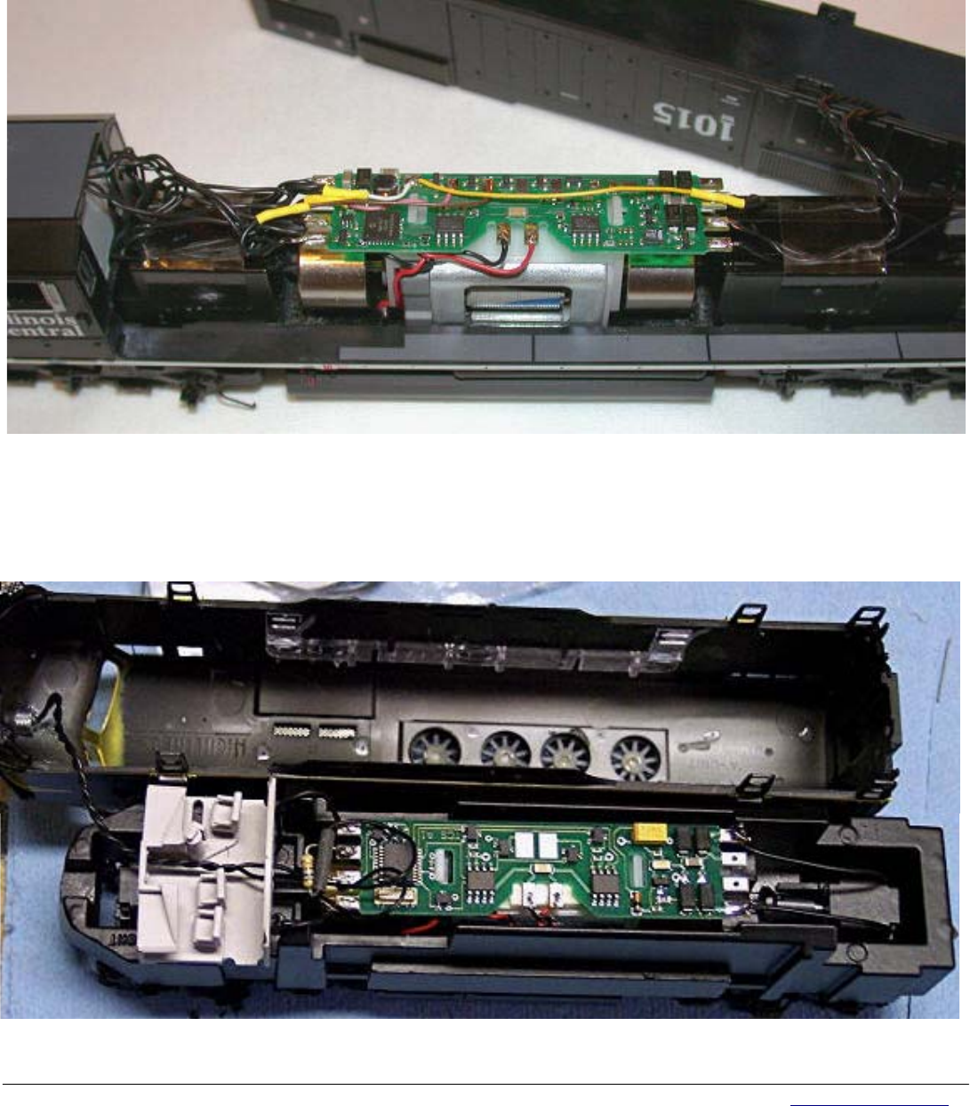
Athearn SD70 MAC
The on board 1.5 volt regulated power supply on the A6X decoder was used to power all six light bulbs on this loco! No
voltage dropping resistors are needed! The blinking ditch lights were hooked up to function 3 and 4 and programmed for
alternately blinking operation.
Athearn F3
This is a photo of the installation of an A4X decoder in an Athearn Genesis F3A. The installation is very simple. The
decoder installation in a B-unit is the same except no lighting to deal with. Solder all connections to the board, the plastic
retaining clips do not ensure solid contact. With Athearn locos you need to use 750-ohm resistors in series with the 1.5-
volt bulbs.
Fi
g
. 5
Fi
g
. 6
Tony’s Decoder Installations
57 River Rd. Box 1023, Essex Jct., VT. 05452 Toll Free: 800-978-3472 Fax: 802-878-5550 Email: info@tonystrains.com
Web: www.tonystrains.com
We Offer and Support More DCC Products Than Anyone!
13
Atlas GP7
The A4X drop in decoder replaces the original light board. Important note. Be very careful when installing the original
bulbs on the decoder. The bulb leads are not insulated and can short against components on the decoder and damage it.
Use care to align the bulbs so that when body shell is installed the light pipes do not move against the bulbs and cause a
short circuit on the decoder! A piece of electrical tape placed under the light bulb leads is also a good idea to protect
against short circuits.
Lifelike Proto 2000 SD60
1. Unplug DCC socket board and remove two screws securing light board. Remove light board from locomotive; it is
not needed.
2. Turn DCC socket board over so that sockets face up. Use one of screws removed from the light board to secure
DCC Socket to frame. See below.
3. Either replace the stock 6-volt light bulbs with 12-volt bulbs or solder a 240-ohm resistor in line with the bulbs.
4. Plug decoder into 9-pin plug. Next, plug the harness with the decoder into the 8-pin NMRA DCC socket. Notice
how a screw is used to secure DCC socket board with sockets facing up.
Installation of decoder and P2K harness is now complete!
Fi
g
. 7
Fi
g
. 8
Tony’s Decoder Installations
57 River Rd. Box 1023, Essex Jct., VT. 05452 Toll Free: 800-978-3472 Fax: 802-878-5550 Email: info@tonystrains.com
Web: www.tonystrains.com
We Offer and Support More DCC Products Than Anyone!
14
Kato AC4400
There are several choices of Plug N Play decoders that will fit in the DCC socket provided on the lighting board. Shown
below is the DP5X. The T1 with a short harness could also be used.
Intermountain F-Units
We recommend wiring the number board lights to a separate function, as the current draw of all four bulbs on one function
output can potentially blow that output. A TCS DP5X is shown in the photo.
Fi
g
. 9
Fi
g
. 10
Tony’s Decoder Installations
57 River Rd. Box 1023, Essex Jct., VT. 05452 Toll Free: 800-978-3472 Fax: 802-878-5550 Email: info@tonystrains.com
Web: www.tonystrains.com
We Offer and Support More DCC Products Than Anyone!
15
Stewart F-Units
Most any decoder with a wired plug should be able to fit, such as the T1 from TCS, DH123D from Digitrax, or the D15SRP
from NCE.
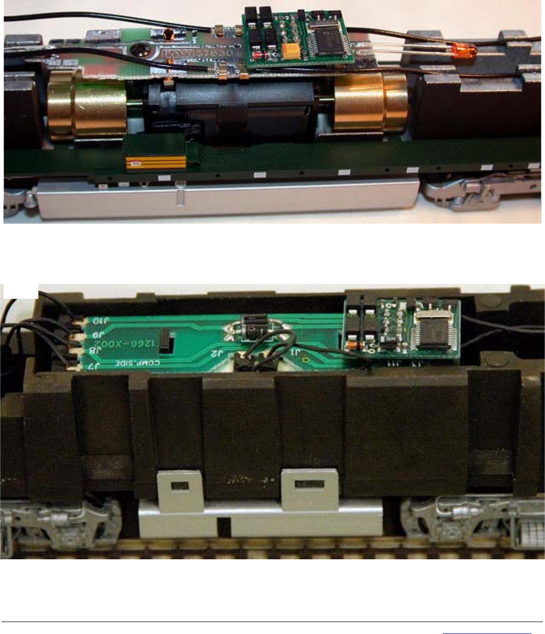
Walthers SW-1
This photo shows a M1 decoder installation in a Walthers EMD SW1 diesel switcher. The decoder fits nicely in the cab
area of the loco. Some minor changes are needed. The original light board is used and must have traces cut in several
places. Milling of the loco frame is also needed to provide routing for the gray motor wire and clearance for the bottom
motor brush.
Fi
g
. 11
Fi
g
. 12
Fi
g
. 13
Tony’s Decoder Installations
57 River Rd. Box 1023, Essex Jct., VT. 05452 Toll Free: 800-978-3472 Fax: 802-878-5550 Email: info@tonystrains.com
Web: www.tonystrains.com
We Offer and Support More DCC Products Than Anyone!
16
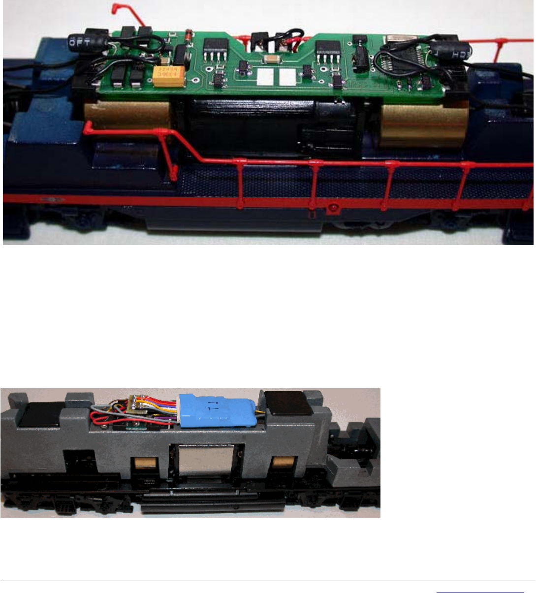
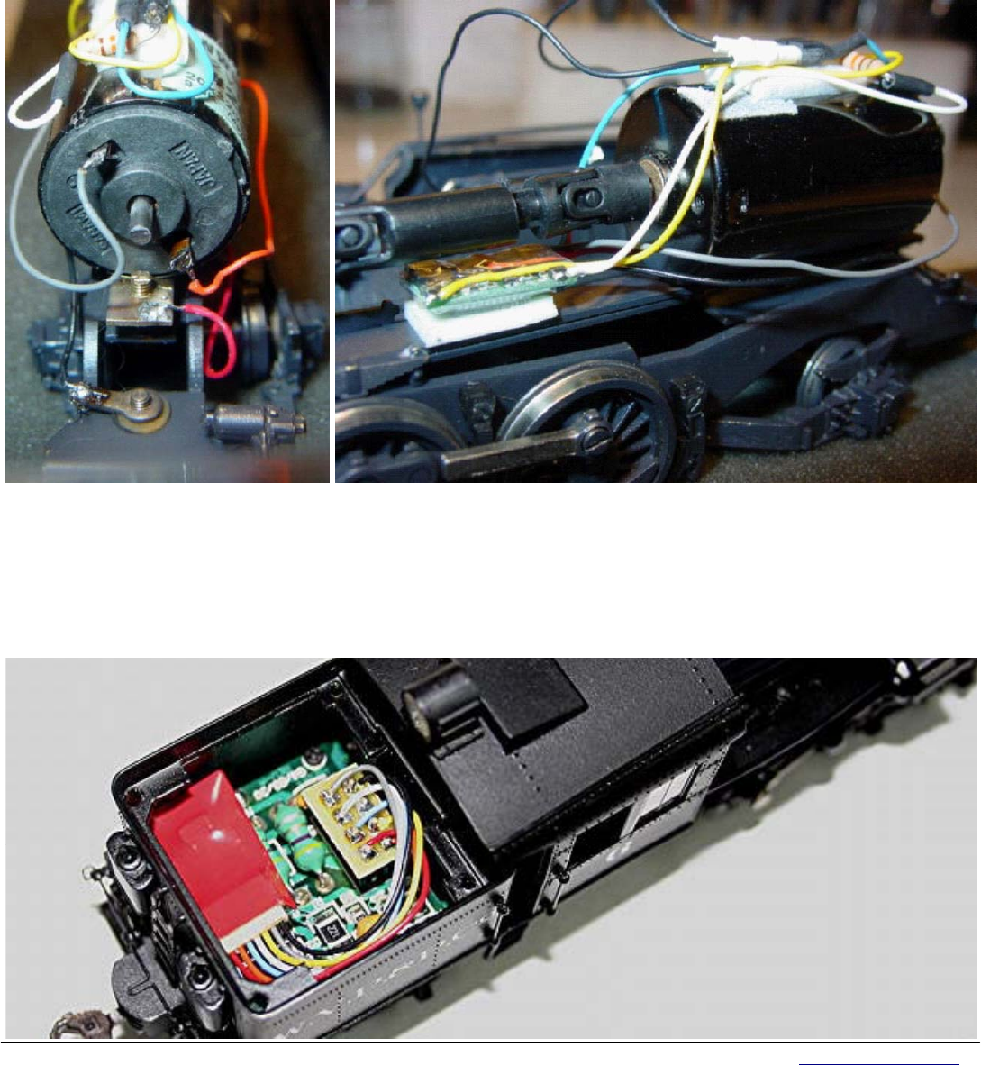
Brass Steam
The decoder leads were connected as follows: Red to engine frame (right) Orange to motor lead (right) Black to draw bar
(left) Grey to motor lead (left)
The locomotive runs great with excellent slow speed. I hope this little case study helps alleviates fears of
installation of your decoders on brass steam locomotives. It’s really a snap if you just follow some simple rules and do it
the same way every time. Photo on the right shows the decoder mounted with double stick tape foam tape to the brass
motor mounting bracket underneath the drive shaft.
Bachmann Climax
An MC2 decoder with short harness was used to make this an easy and clean installation! Top photo shows before
installation bottom photo shows decoder installed. The yellow capacitor closest to the 8 pin NMRA plug should be clipped
before decoder installation.
Fi
g
. 14 Fi
g
. 15
Fi
g
. 16

Tony’s Decoder Installations
57 River Rd. Box 1023, Essex Jct., VT. 05452 Toll Free: 800-978-3472 Fax: 802-878-5550 Email: info@tonystrains.com
Web: www.tonystrains.com
We Offer and Support More DCC Products Than Anyone!
17
Atlas N GP40-2
The atlas N scale locos use a few different replacement board type decoders that make installations much easier,
especially since there is no need to worry about the lighting. This is an installation using the DH163A0 decoder, which fits
a wide range of Atlas N scale diesel locomotives.
Micro-Trains FT
Like the above installation this is a board replacement decoder, but it requires that the frame be isolated from the
underside of the decoder with kapton tape. Without N scale board replacement decoders most N scale diesels would
require extensive milling in order to fit a decoder inside.
Fi
g
. 17
Fi
g
. 18
Tony’s Technical Information Notes
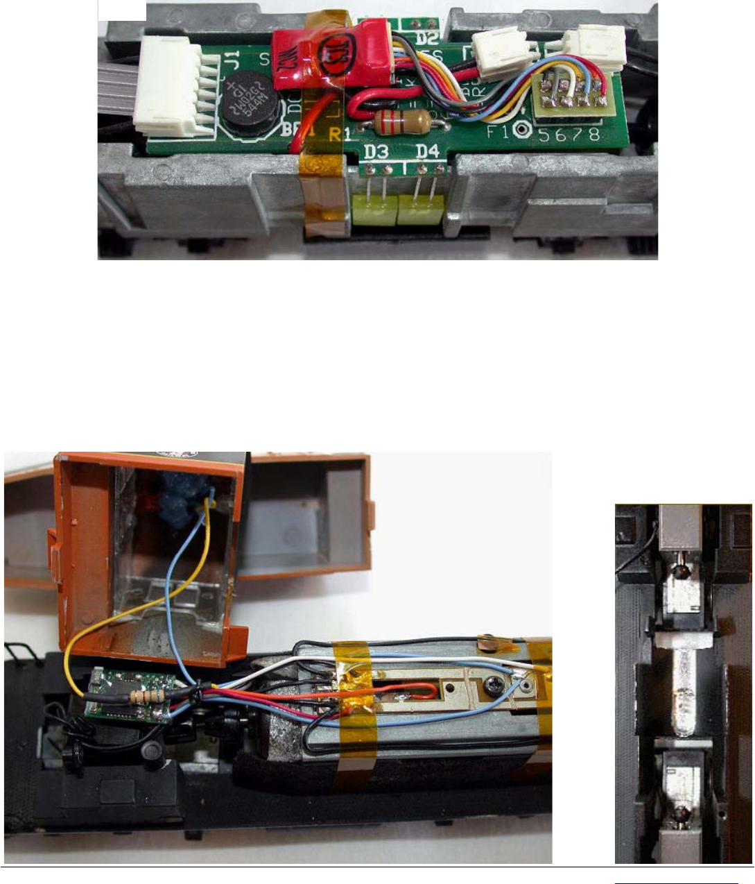
Fix for Rear LED Leakage on
SoundTraxx LC Decoders
This series of tech notes is designed to help modelers with DCC decoder installation. Much of the
information comes from questions asked by modelers and ideas we have found. This note covers a possible fix for the rear
light LED leakage problem when using an LED for the rear light on some SoundTraxx LC decoders.
THE PROBLEM
There have been a number of modelers using the SoundTraxx LC decoder that have installed white LEDs as backup lights.
SoundTraxx recommends using lamps instead of LEDS for this application. There is no problem with the headlight using LEDs, but
the rear light has a leakage problem that causes the LED to glow or blink when the air pump, bell or whistle is running. It does not
come on at full brightness, just enough of a glow to be noticed.
The LC problem comes from a series of small pules that occur on the rear light function output, the yellow lead. These short pulse are
too short for a lamp to respond. The LED will respond to very low power and microsecond pules. Lamps are slow to respond and
take a lot power. LEDs take very little power and turn on instantly.
Finding a Fix
A number for local modeler have asked me to look into this blinking problem. One modeler gave up and final just turned off the air
pump. Then Tony forwarded an E-mail to me from Roger Smith who had the leakage problem. Roger came up a solution that used a
micro relay to cut off the power to the rear LED when the front LED is on. This circuit works by cutting off the power to the rear LED
when the front LED is on. This is OK if the front light is on. If you turn the front light off, the problem returns to the rear light. We felt a
better solution would be to fix the rear light so it
would be totally off unless turned on.
Roger and I went back a forth a couple of times
with a number of other suggestions. The final
solution had to be simple and use a minimum of
small parts.
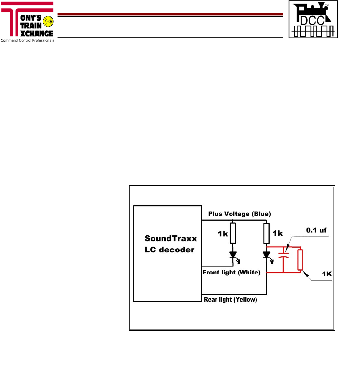
The Fix
An LED acts like an open circuit until it has
enough voltage to turn on. Putting a capacitor in
parallel with the LED would absorb the pulses.
But was a problem because there was no way
to discharge the capacitor and it would simple
pick up a charge until the LED turned on.
Putting a 1K resistor in parallel solved this by
allowing the capacitor to discharge between the
short pulses. This would keep it off but turn on
when the rear light was selected.
The final version only uses two small parts. A
0.1uf capacitor and a 1K resistor. The added 1K
resistor can be a 1/8 watt or 1/4 watt resistor.
The 0.1uf capacitor like Radio Shack 272-135 (2
in a package) is rated at 50 volts and is in small
size. This capacitor is not polarized.
My thanks to Roger for his help in finally getting this fix done!
LEDs Available at Tony’s
We stock a variety of LEDs in different sizes and colors. Check our website for a list of available LEDs at discount prices.
(www.tonystrains.com ) or call us at 1-800-978-3472.
DONF 05Oct05
The two added parts are shown in red
