Dggrid Manual V64
User Manual:
Open the PDF directly: View PDF ![]() .
.
Page Count: 40
!
DGGRID version 6.4
User Documentation for
Discrete Global Grid Generation Software
Kevin Sahr
!
!

Copyright © 2018 Kevin Sahr
This documentation is part of DGGRID.
DGGRID is free software: you can redistribute it and/or modify it under the terms of the GNU
Affero General Public License as published by the Free Software Foundation, either version 3 of
the License, or (at your option) any later version.
DGGRID is distributed in the hope that it will be useful, but WITHOUT ANY WARRANTY;
without even the implied warranty of MERCHANTABILITY or FITNESS FOR A
PARTICULAR PURPOSE. See the GNU Affero General Public License for more details.
You should have received a copy of the GNU Affero General Public License along with the
DGGRID source code. If not, see <https://www.gnu.org/licenses/>.
Credits
DGGRID was primarily written in C++ by Kevin Sahr. See the file CHANGELOG.md that
comes with the source code for additional contributors.
The original DGGRID specifications were developed by (in alphabetical order): A. Ross Kiester,
Tony Olsen, Barbara Rosenbaum, Kevin Sahr, Ann Whelan, and Denis White.
DGGRID uses the following external libraries (included with the DGGRID source code):
• Angus Johnson’s Clipper library; see http://www.angusj.com.
• The gnomonic projection code is adapted from Gerald Evanden’s PROJ.4 library; see
http:// everest.hunter.cuny.edu/mp/software.html.
• George Marsaglia’s multiply-with-carry “Mother-of-all-RNGs” pseudo-random number
generation function.
DGGRID version 6.4 was released September 18, 2018
www.discreteglobalgrids.org!

User Documentation for DGGRID version 6.4
Table of Contents
1. Introduction 2
2. Metafile Format 3
3. General Parameters 4
4. Specifying the DGG 5
5. Controlling Grid Generation 10
6. Specifying Generated Grid Output 12
7. Outputting Grid Statistics 14
8. Performing Address Conversions 15
9. Binning Point Values 16
10. Presence/Absence Binning. 17
Appendix A. DGGRID Metafile Parameter 18
Appendix B. Default Values for Preset DGG Types 24
Appendix C. DGG Address Forms 25
Appendix D. Characteristics of ISEA Hexagonal DGGs 26
Aperture 3 (ISEA3H) 26
Aperture 4 (ISEA4H) 27
Mixed Aperture 4 and 3 (ISEA43H) 28
Notes 31
Appendix E. The Superfund_500m DGG 32
Appendix F. References 38
page of 138

User Documentation for DGGRID version 6.4
1. Introduction
DGGRID is a command-line application designed to generate and manipulate icosahedral
discrete global grids (DGGs) [Sahr et al., 2003]. A single execution of DGGRID can perform
one of five distinct operations:
1. Grid Generation. Generate the cells of a DGG, either covering the complete surface of the
earth or covering only a specific set of regions on the earth’s surface.
2. Address Conversion. Transform a file of locations from one address form (such as
longitude/latitude) to another (such as DGG cell indexes).
3. Point Value Binning. Bin a set of floating-point values associated with point locations into
the cells of a DGG, by assigning to each DGG cell the arithmetic mean of the values which are
contained in that cell.
4. Presence/Absence Binning. Given a set of input files, each containing point locations
associated with a particular class, DGGRID outputs, for each cell of a DGG, a vector indicating
whether or not each class is present in that cell.
5. Output Grid Statistics. Output a table of grid characteristics for the specified DGG.
DGGRID is designed to be run from the Unix command line. DGGRID requires a single
command line argument, the name of a “metafile,” which is a text file that describes the actions
that DGGRID is to perform in that run. Thus DGGRID is executed by typing at the command
line:
dggrid metaFileName.meta
The metafile consists of a series of key-value pairs that tell DGGRID how to proceed. The
format of this metafile is described in the next section. The rest of the sections in this
documentation give more detail on setting up metafile parameters to control the execution of
DGGRID. !
page of 238

User Documentation for DGGRID version 6.4
2. Metafile Format
Metafiles are text files in which each line is either a comment, a blank line, or a key-value pair
that designates the value of a parameter for DGGRID. Blank lines are ignored by DGGRID.
Lines beginning with ‘#’ are comments and are also ignored by DGGRID.
A parameter is specified by a single line of the form:
parameterName value
Parameter names are not case sensitive. A parameter can be of one of five types. The five
parameter types, with a description of their legal values, are:
1. boolean. Legal values are TRUE and FALSE (case sensitive).
2. integer. Any integer is a legal value.
3. double. Any real number, specified in decimal form, is a legal value.
4. string. The remainder of the line following the parameter name is interpreted as the value. 5.
choice. Legal values consist of one of a finite set of keywords specific to that parameter. The
values of choice parameters are not case sensitive but by convention are usually written in all
capital letters.
Some parameters are only used for specific operations or when specific other parameter
conditions prevail. All parameters have a default value which is used if no value is specified.
Detailed information on each parameter is given in the following sections and in Appendix A.
Repeating a parameter specification within the same metafile over-writes the previously
specified value; the last value given for a particular parameter will be used.
Note that a number of parameters from previous versions of DGGRID are still active in the code
but are not described in this documentation; that is because those parameters have not been fully
integrated with the new features in this beta release. Those parameters will be fully restored in a
future release.
See the example metafiles that come with the DGGRID source code distribution for examples of
parameter specification.
page of 338

User Documentation for DGGRID version 6.4
3. General Parameters
In this section we describe the parameters which are used by every run of DGGRID.
As described in Section 1, each run of DGGRID consists of one of five distinct modes of
operation. The operation is specified using the choice parameter dggrid_operation. The
allowable values for this parameter are:
GENERATE_GRID - perform grid generation (see Sections 5 and 6)
TRANSFORM_POINTS - perform address conversion (see Section 8)
BIN_POINT_VALS - perform point value binning (see Section 8)
BIN_POINT_PRESENCE - perform presence/absence binning (see Section 9)
OUTPUT_STATS - output a table of grid characteristics (see Section 10)
All operation modes require the specification of a single DGG. The parameters for specifying a
DGG are described in Section 4.
The integer parameter precision specifies the number of digits to the right of the decimal
place DGGRID is to use when outputting floating point numbers.
The integer parameter verbosity is used to control the amount of debugging information
which is printed by DGGRID. Valid values are from 0 to 3. The default value, 0, gives minimal
output, which includes the value of all active parameter settings. It is not recommended that you
increase this value.
page of 438

User Documentation for DGGRID version 6.4
4. Specifying the DGG
Background
As described in [Sahr et al., 2003], a DGG system can be specified by a set of independent
design choices. The first design choice is the desired base polyhedron; DGGRID can generate
DGGs that have an icosahedron as their base polyhedron. The remaining primary design choices
are:
1. The orientation of the base polyhedron relative to the earth.
2. The hierarchical spatial partitioning method defined symmetrically on a face (or set of faces)
of the base polyhedron. This usually includes specifying the cell topology and an aperture,
which determines the area ratio between cells at sequential resolutions.
3. The transformation between each face and the corresponding spherical surface.
4. The resolution (or degree of recursive partitioning).
The current version of DGGRID supports DGGs that use either the Icosahedral Snyder Equal
Area (ISEA) projection [Snyder, 1992] or the icosahedral projection of R. Buckminster Fuller
[1975] (as developed analytically by Robert Gray [1995] and John Crider [2008]). DGGRID can
generate grids with cells that are triangles, diamonds, or hexagons. Grids with a triangle or
diamond topology must use an aperture of 4, while hexagon grids can use an aperture of 3, 4, or
a mixed aperture sequence consisting of some number of aperture 4 resolutions followed by
aperture 3 resolutions down to the desired resolution. DGGRID can also generate the
Superfund_500m DGG (see Appendix E), which is a mixed aperture hexagonal grid that uses
the Fuller projection and a condensed hierarchical indexing.
Detailed information about the parameters that specify each of the DGG design choices are given
below, along with a discussion on specifying the spherical earth radius. Appendix D gives a
table of DGGs which can be generated by DGGRID; the table lists the parameters for each DGG
and the corresponding characteristics of each resulting grid.
Preset DGG Types
DGGRID provides a number of preset DGG types for your use. A preset type can be chosen by
specifying one of the following values for the choice parameter dggs_type:
CUSTOM (default) - indicates that the grid parameters will be specified manually (see
below)
SUPERFUND - the Superfund_500m grid (see Appendix D)
ISEA4T - ISEA projection with triangle cells and an aperture of 4
ISEA4D - ISEA projection with diamond cells and an aperture of 4
ISEA3H - ISEA projection with hexagon cells and an aperture of 3
ISEA4H - ISEA projection with hexagon cells and an aperture of 4
ISEA43H - ISEA projection with hexagon cells and a mixed sequence of aperture 4
resolutions followed by aperture 3 resolutions
page of 538

User Documentation for DGGRID version 6.4
FULLER4T - FULLER projection with triangle cells and an aperture of 4
FULLER4D - FULLER projection with diamond cells and an aperture of 4
FULLER3H - FULLER projection with hexagon cells and an aperture of 3
FULLER4H - FULLER projection with hexagon cells and an aperture of 4
FULLER43H - FULLER projection with hexagon cells and a mixed sequence of aperture
4 resolutions followed by aperture 3 resolutions
Each preset grid type sets appropriate values for all of the parameters that specify a DGG. The
default values for each preset grid type are given in Appendix B. These default preset values can
be overridden by explicitly setting the desired individual parameters in your metafile as
described below. In particular, note that all preset grid types have a default resolution of 9; a
desired DGG resolution can be specified using the parameter dggs_res_spec (see below).
Manually Setting DGG Parameters
The following parameters are used to describe a specific DGG instance.
1. Specifying the orientation: The orientation of a DGG base icosahedron relative to the earth
can be specified explicitly, randomly determined, or set so that a specified point is maximally
distant from icosahedron vertices, by setting the choice parameter
dggs_orient_specify_type to SPECIFIED, RANDOM, or REGION_CENTER
respectively.
If dggs_orient_specify_type is set to SPECIFIED the DGG orientation is determined
by the location of a single icosahedron vertex and the azimuth from that vertex to an adjacent
vertex. The double parameters dggs_vert0_lon and dggs_vert0_lat are used to
specify the location of the vertex, and the double parameter dggs_vert0_azimuth to
specify the azimuth to an adjacent vertex; all or these parameters are in decimal degrees. Note
that the default DGG placement, which is symmetrical about the equator and has only a single
icosahedron vertex falling on land, is specified by:
dggs_vert0_lon 11.25
dggs_vert0_lat 58.28252559
dggs_vert0_azimuth 0.0
If dggs_orient_specify_type is set to RANDOM the orientation of the DGG is randomly
determined. All parameter values (including the randomly generated values for a vertex location
and azimuth used to orient the grid) will be output for your information to the file specified by
the string parameter dggs_orient_output_file_name. Some control over the random
specification of the grid orientation is afforded by the choice parameter rng_type and the
integer parameter dggs_orient_rand_seed. The choice parameter rng_type indicates
which pseudo-random number generator to use. A value of RAND indicates that the C standard
library rand/srand functions should be used. A value of MOTHER (the default) indicates that
George Marsaglia’s “Mother-of-all-RNGs” function should be used. The seed value for
page of 638

User Documentation for DGGRID version 6.4
DGGRID to use to initialize the pseudo-random number sequence can be set using the integer
parameter dggs_orient_rand_seed.
If the current operation involves only a small region on the earth’s surface it is often convenient
to orient the grid so that no icosahedron vertices occur in the region of interest. Such an
orientation can be specified by setting dggs_orient_specify_type to REGION_CENTER
and then specifying the center point of the region using the double parameters
region_center_lon and region_center_lat (both in decimal degrees).
All operations require that at least one DGG be specified. A single DGG may be used by setting
the integer parameter dggs_num_placements to 1 (the default). Alternatively, you may
perform the desired operation on multiple DGGs by setting dggs_num_placements to the
desired number. If the grid orientation is randomly chosen, this will perform the desired
operation on multiple randomly oriented grids. The parameters for each grid will be output to a
separate file based on the value of dggs_orient_output_file_name, with an additional
suffix indicating the grid number (0001 to 000n where n equals the value of
dggs_num_placements). This suffix will also be used to designate the corresponding output
files (as specified in the particular operation being performed). Note that if
dggs_orient_specify_type is set to any value other than RANDOM all of the grids
generated will have exactly the same orientation.
2. Specifying the hierarchical spatial partitioning method: The hierarchical partitioning
method used to generate the DGG is specified by choosing a grid topology and aperture (defined
as the ratio of areas between cells in a given DGG resolution and the next finer resolution). The
topology is specified using the choice parameter dggs_topology with one of the values:
HEXAGON (default), TRIANGLE, or DIAMOND.
DGGRID can create grids that are produced using a single aperture, as well as hexagon grids
produced using a mixed aperture of some number of aperture 4 resolutions followed by aperture
3 resolutions. The type of aperture is specified using the choice parameter
dggs_aperture_type with a value of either PURE (default) or MIXED43. If a PURE
aperture type is specified then the desired aperture is specified with the integer parameter
dggs_aperture. The valid values for aperture are dependent on the chosen topology.
DGGRID can create HEXAGON DGGs with an aperture of 3 or 4, and DIAMOND and
TRIANGLE DGGs with an aperture of 4.
If a MIXED43 aperture type is specified then the parameter dggs_aperture is ignored.
Instead, the integer parameter dggs_num_aperture_4_res (default 0) specifies the
number of resolutions which use aperture 4; the remaining grid resolutions up to the desired grid
resolution (see the next subsection) are generated using aperture 3. Note that the parameter
dggs_num_aperture_4_res is ignored with PURE aperture grids. Only HEXAGON
topology grids may use the MIXED43 aperture type.
3. Specifying the projection: The regular polygon boundaries and points associated with DGG
cells are initially created on the planar faces of an icosahedron; they must then be inversely
page of 738

User Documentation for DGGRID version 6.4
projected to the sphere. The desired projection to use for this is specified by the choice parameter
dggs_proj. The valid values are ISEA, which specifies the Icosahedral Snyder Equal Area
projection [Snyder, 1992], or FULLER, which specifies the icosahedral Dymaxion projection of
R. Buckminster Fuller [1975] (as developed analytically by Robert Gray [1995] and John Crider
[2008]). The ISEA projection creates equal area cells on the sphere at the expense of relatively
high shape distortion, while the Fuller projection strikes a balance between area and shape
distortion. See Gregory et al. [2008] for a more detailed discussion of these trade-offs.
4. Specifying the resolution: The desired DGG resolution can be specified using one of three
methods chosen using the choice parameter dggs_res_specify_type with one of the
following values:
SPECIFIED (default) - the desired resolution is explicitly specified by setting the value
of the integer parameter dggs_res_spec (default 9).
CELL_AREA - the desired resolution is set to the DGG resolution whose cell area is
closest to the area specified by the double parameter
dggs_res_specify_area (in square kilometers).
INTERCELL_DISTANCE - the desired resolution is set to the DGG resolution whose
intercell distance is closest to the distance specified by the double parameter
dggs_res_specify_intercell_distance (in kilometers).
If CELL_AREA or INTERCELL_DISTANCE is specified, then the desired area or intercell
distance (as applicable) is rounded up or down to the nearest grid resolution based on the value
of the boolean parameter dggs_res_specify_rnd_down; a value of TRUE indicates round
down, a value of FALSE indicates round up. The chosen resolution is always output by
DGGRID for your information. The calculation of cell areas and intercell distances uses the
value specified for the earth radius (see Subsection 5 below).
If the dggs_type is specified to be SUPERFUND then the only supported value for
dggs_res_specify_type is SPECIFIED, and the maximum resolution is 9.
DGGRID will attempt to generate grids up to a maximum resolution of 35 (except in the case of
SUPERFUND grids, which have a maximum resolution of 9). However, the maximum resolution
which can be successfully generated by DGGRID is a function of the specified grid topology,
projection, the size of data types on the machine on which DGGRID is compiled and executed,
and the location of the generated grid region relative to the faces of the underlying icosahedron.
When generating very high resolution grids the user should be aware that even if DGGRID
reports success the indexes and output cell geometries should be checked by the user to make
sure that they are not degenerate.
5. Specifying the earth radius: The choice parameter proj_datum specifies a datum that
DGGRID will use to determine the spherical radius of the earth. The legal values for this
parameter are given below, along with the earth radius that they indicate:
WGS84_AUTHALIC_SPHERE (default): 6371.007180918475 km
page of 838

User Documentation for DGGRID version 6.4
WGS84_MEAN_SPHERE: 6371.0087714 km
CUSTOM_SPHERE: the earth radius (in kilometers) will be read from the double
parameter proj_datum_radius
Note that the earth radius is not used in the process of generating grid geometries in geodetic
coordinates; such generation is performed on a unit sphere. The radius is only used in
determining the grid resolution (when dggs_res_specify_type is not SPECIFIED) and
in generating grid statistics in kilometers.!
page of 938

User Documentation for DGGRID version 6.4
5. Controlling Grid Generation
Specifying the value GENERATE_GRID for the choice parameter dggrid_operation will
tell DGGRID to create all, or some portion of, the specified DGG (see the previous section).
The choice parameter clip_subset_type controls the amount of the grid that will be
generated. Setting the parameter clip_subset_type to WHOLE_EARTH will generate the
entire earth at the specified resolution.
To generate just a portion of the earth you must specify one or more files containing polygons
which DGGRID will use to determine the portion of the grid to generate. DGGRID supports
two clipping file formats: ARC/INFO Generate files and ESRI Shapefiles. To specify a clipping
file format, set the parameter clip_subset_type to AIGEN for ARC/INFO Generate files or
to SHAPEFILE for ESRI Shapefiles.
The ARC/INFO Generate file format is a text file format that provides a way to create clipping
regions manually, using just a text editor. For reference, the ARC/INFO Generate polygon file
format consists of a text file containing a series of polygons. Each polygon is described by an
entry of the form (assuming n vertices, in clockwise order):
integerPolygonID centerPtLon centerPtLat
vert1Lon vert1Lat
vert2Lon vert2Lat
...!
vertnLon vertnLat
vert1Lon vert1Lat
END
The centerPtLon and centerPtLat values in the first line of the polygon description can be
omitted when creating DGGRID clipping files.
To indicate the end of the file the last polygon is followed by an extra:
END
For example, the following ARC/INFO Generate file would specify a single triangular clipping
polygon in southern Oregon:
1
-122.7083 42.1947
-121.5000 42.5000
-122.5688 42.4300
-122.7083 42.1947
END
END
page of 10 38

User Documentation for DGGRID version 6.4
Though both the ARC/INFO Generate and ESRI Shapefile formats support holes, DGGRID
does not. Therefore holes in the clipping files will be interpreted by DGGRID as regular
polygons.
If clip_subset_type is set to AIGEN or SHAPEFILE then the string parameter
clip_region_files should be set to a space-delimited list of file names containing
polygons to use for clipping. These polygons must be specified using geodetic (latitude/
longitude) coordinates. Limitations in DGGRID require that each clipping polygon be no more
than approximately 60° of great circle arc in extant in any direction. The exact limitation is
determined by the relationship between each polygon and the underlying icosahedron; DGGRID
will let you know if a polygon is too large for the grid generation you are attempting. In that
event you must break the polygon into smaller polygons before using it in a clipping file.
The polygon intersection library uses an integer grid, the coarseness of this grid is determined by
the parameter clipper_scale_factor. Clipping with a very high resolution grid can
sometimes produce incorrect results due to the coarsness of this clipping grid; if this occurs try
increasing the value of clipper_scale_factor (the default value is 1000000). Note that
doing so will limit the extent of the region that can be clipped.
Intersections between the clipping polygons and the DGG cells are performed in the specified
DGG projection space, with the great circle arcs between adjacent vertices in the original
clipping polygons transformed into straight lines on the projection plane. If adjacent vertices in
the original clipping polygons are too far apart this may result in an inaccurate representation of
the region boundary in the clipping space. This effect can be minimized by introducing
additional points into the great circle arcs before projection. Setting the double parameter
geodetic_densify to some arc length (in decimal degrees) will cause DGGRID to
introduce extra points into each edge arc so that no two vertices are more than the specified
distance apart. Setting geodetic_densify to 0.0 (the default) indicates that no such
densification is to be performed.
The cells for a given set of cell sequence numbers can be generated by setting the parameter
clip_subset_type to SEQNUMS. Then clip_region_files must be set to one or more
text files containing the list of cell sequence numbers to be generated. A single cell will be
generated at most once; duplicate sequence numbers in the input will be ignored.
Note that a single execution of DGGRID can take several hours, depending on the resolution of
the grid being generated and the number and complexity of the clipping polygons. You can
control the frequency of feedback during grid generation by setting the integer parameter
update_frequency. The value of this parameter specifies the number of cells that will be
tested for inclusion before outputting a status update. The default value is 100000.
page of 11 38

User Documentation for DGGRID version 6.4
6. Specifying Generated Grid Output
The grid cells generated by a DGGRID run with the value GENERATE_GRID specified for the
choice parameter dggrid_operation can be output as cell boundaries, cell center points, or
both. All DGG output from DGGRID is given in geodetic (longitude/latitude) coordinates in
decimal degrees.
The choice parameters cell_output_type and point_output_type specify the desired
output file format for cell boundaries and cell points respectively. Each of these parameters may
have the following values:
NONE - indicates that no output of that type will be performed
AIGEN - indicates that the cell/point output should be in ARC/INFO Generate file format
SHAPEFILE - indicates that the cell/point output should be in ESRI Shapefile format.
KML - indicates that the cell/point output should be in KML (Google Earth) format
The file name prefix to use for the boundary or point output file is specified using the string
parameter cell_output_file_name or point_output_file_name respectively.
DGGRID will add the appropriate file suffix to the specified prefix name, depending on the
chosen file format.
DGG output files created by DGGRID can be quite large, depending on the size of the region
being generated and the resolution of the grid. The generated cell boundaries and/or points can
be output across multiple files by setting the integer parameter
max_cells_per_output_file to the maximum number of cells to output to a single file.
Setting the parameter to 0 (the default) will cause DGGRID to output all cells to a single file, no
matter how large. If max_cells_per_output_file is greater than 0, output files are
distinguished by appending a “_1”, “_2”, etc. to each output file name.
Since cell boundaries are only true regular polygons in the chosen projection space it may be
desirable to introduce additional points into the cell edges to better preserve the boundary shape
after inverse projection to longitude/latitude coordinates. The number of additional points to
introduce into each edge is specified by the integer parameter densification. A value of 0
(the default) indicates that no densification should be performed.
A unique integer cell identifier is output along with each cell boundary or point. The integer
identifier type is specified using the choice parameter output_cell_label_type, which
can have one of three values:
GLOBAL_SEQUENCE (default when dggs_type is not SUPERFUND) - the identifier is the
appropriate value in a linear sequence 1 to n, where n is the total number of cells in the
whole earth DGG
page of 12 38

User Documentation for DGGRID version 6.4
ENUMERATION - the generated cells are numbered from 1 to n, where n is the total number of
cells generated
SUPERFUND (preset default when dggs_type is SUPERFUND) - the identifier is a condensed
Superfund_500m index (see Appendix D). This value must be (and can only be) used when
dggs_type is SUPERFUND.
When output is to an ESRI Shapefile the cell identifier is stored in a global_id field. The
ESRI Shapefile format limits integer fields to 32-bit integer size, which is not sufficient for
storing the identifiers associated with high resolution DGGs. Therefore DGGRID creates the
Shapefile field global_id as a fixed width string with a width specified by the integer
parameter shapefile_id_field_length (default 11).
The color and width of KML output cell boundaries can be controlled using the string parameter
kml_default_color (default ffffffff or opaque white) and the integer parameter
kml_default_width (default 4) respectively. KML color values are expressed in 8 digit
hexadecimal notation of the form aabbggrr, with two hexadecimal digits (00 to ff) each for the
alpha, blue, green, and red components.!
page of 13 38

User Documentation for DGGRID version 6.4
7. Outputting Grid Statistics
Specifying the value OUTPUT_STATS for the choice parameter dggrid_operation causes
DGGRID to output a table of grid characteristics for the specified DGG (see Section 4). The
output table will consist of all grid resolutions from 0 up to and including the specified DGG
resolution. The values output for each resolution are the number of cells, the area of a hexagonal
cell in square kilometers, the intercell distance in kilometers, and the characteristic length scale
(CLS). The CLS is the diameter of a spherical cap of the same area as a hexagonal cell of the
specified resolution; this metric was suggested by Ralph Kahn. The calculation of cell areas and
intercell distances uses the specified earth radius (see Section 5.5). Area and distance values are
calculated in the projection plane; the actual values for individual cells will vary based on the
characteristics of the chosen projection.
The integer parameter precision (default 7) specifies the number of digits to the right of the
decimal point to output for each floating point value.!
page of 14 38

User Documentation for DGGRID version 6.4
8. Performing Address Conversions
Setting the choice parameter dggrid_operation to TRANSFORM_POINTS tells DGGRID
to perform address conversion. DGGRID reads the input file specified in the string parameter
input_file_name. It interprets each line of the file as consisting of an address followed by
optional arbitrary text. The components of the address (if any) must be delimited by the character
indicated within double quotes in the string parameter input_delimiter, and if there is text
following the address it must also be separated from the address by that character. The address
must be a valid address under the address form indicated in the choice parameter
input_address_type (see Appendix C). Addresses of types other than GEO are
interpreted as addresses in a DGG specified as per Section 4.
Each input address is transformed to an address of the form indicated by the choice parameter
output_address_type. For all values of output_address_type except for AIGEN
(see below) each transformed address is output using the value of output_delimiter to
separate any address components. The addresses are output to the file specified in the string
parameter output_file_name. If there was additional text on the input line following the
address, then an output delimiter followed by that text is appended to the output line.
If output_address_type is AIGEN then the output will be in ARC/INFO Generate file
format. For each input address, the output will consist of the cell polygon of the DGG cell
corresponding to the input address. Any additional text on the input lines following the addresses
will be ignored.
The TRANSFORM_POINTS operation can be used to determine the DGG cells that correspond
to a set of input geodetic coordinates by using an input_address_type of GEO and an
output_address_type corresponding to the desired DGG indexing (e.g., SEQNUM). Note
that DGGRID cannot be used to transform between two different DGGs in a single run, since
only one DGG can be defined per run. However, this can be accomplished in two steps by first
using DGGRID to transform cell addresses in the input DGG into GEO addresses, and then using
a second run of DGGRID to transform those GEO addresses into the desired output DGG.!
page of 15 38

User Documentation for DGGRID version 6.4
9. Binning Point Values
Setting the choice parameter dggrid_operation to BIN_POINT_VALS tells DGGRID to
bin a set of floating-point data values associated with geodetic coordinates into the cells of a
DGG(s) specified as per Section 4. The binning is performed by assigning to each DGG cell the
arithmetic mean of the values which are contained in that cell.
DGGRID reads each of the input files specified in the string parameter input_files. Each
line in each file should consist of a longitude, a latitude (both in decimal degrees), and a floating-
point value. These three values must be delimited by the character indicated within double quotes
in the string parameter input_delimiter. DGGRID then bins these values into the cells of
the specified DGG(s).
DGGRID outputs the cell address and value associated with each cell, one cell per line, into the
file specified in the string parameter output_file. The cell addresses are output in the form
indicated by the choice parameter output_address_type (see Appendix C), using the
character specified by parameter output_delimiter to separate any address components
and to separate the address from the associated value. By setting the choice parameter
cell_output_control you can limit DGGRID to only outputting those cells which
contain values (OUTPUT_OCCUPIED) or have DGGRID output all cells (OUTPUT_ALL), in
which case cells in which no values occurred will be output with a value of 0.0.
If the data to be binned covers a substantial portion of the earth’s surface, then the choice
parameter bin_coverage should be set to GLOBAL. If the data covers only a relatively small
portion of the earth’s surface then bin_coverage should be set to PARTIAL. This allows
DGGRID to make trade-offs between speed and memory usage. GLOBAL data sets are binned
more quickly, but may fail at higher DGG resolutions due to memory restrictions. PARTIAL
data sets are binned more slowly, but can often be binned at higher resolutions (depending on the
actual extent of the data set).
page of 16 38

User Documentation for DGGRID version 6.4
10. Presence/Absence Binning.
Setting the choice parameter dggrid_operation to BIN_POINT_PRESENCE tells
DGGRID to perform presence/absence binning into the DGG(s) specified as per Section 4.
The input to this operation is a set of files, with each file containing a set of locations associated
with one specific class of objects. The names of the input files are specified as a space-delimited
list of file names in the string parameter input_files. The locations in the files must be
specified as longitude/latitude in decimal degrees, one per line, with the components separated
by the character indicated within double quotes in the string parameter input_delimiter.
Each location can be followed, on the same line, by arbitrary text which is ignored by DGGRID.
DGGRID determines which classes occur in which cells in the specified DGG(s). DGGRID
outputs the results for each cell, one cell per line, into the file specified in the string parameter
output_file. The output for each cell consists of a cell address and a presence/absence
vector, separated by the character specified (inside double quotes) in the string parameter
output_delimiter. The cell addresses are output in the form indicated by the choice
parameter output_address_type (see Appendix C), using the value of
output_delimiter to separate any address components. The presence/absence vector
consists of a string of 0’s and 1’s. The length of the string corresponds to the number of input
files (and therefore to the number of classes). Each character in the string indicates whether the
corresponding class is present (indicated by a 1) or not present (indicated by a 0) in the cell
specified on that line. The first character in the string corresponds to the class represented by the
first file listed in input_files, the second character corresponds to the second file listed in
input_files, and so forth. Additionally, if the boolean parameter output_count is set to
TRUE the number of classes present in a each cell is output in between the address and the
presence/absence vector.
By setting the choice parameter cell_output_control you can limit DGGRID to only
out-putting those cells which contain at least one class of object (OUTPUT_OCCUPIED) or have
DGGRID output all cells (OUTPUT_ALL), in which case cells containing no input-specified
locations would have presence/absence vectors consisting entirely of 0’s.
If the in put locations cover a substantial portion of the earth’s surface, then the choice parameter
bin_coverage should be set to GLOBAL. If the locations covers only a relatively small
portion of the earth’s surface then bin_coverage should be set to PARTIAL. This allows
DGGRID to make trade-offs between speed and memory usage. GLOBAL location sets are
processed more quickly, but may fail at higher DGG resolutions due to memory restrictions.
PARTIAL location sets are processed more slowly, but can often use higher resolution DGGs
(depending on the actual extent of the input locations).
page of 17 38
User Documentation for DGGRID version 6.4
Appendix A. DGGRID Metafile Parameter
Parameter Name
(Type)
Description
Allowed Values
(v)
Default
Notes
Used When
bin_coverage
(choice)
are values
distributed over
most of the globe
or only a relatively
small portion?
GLOBAL
PARTIAL
GLOBAL
allows
DGGRID to
determine how
to trade-off
speed vs.
memory usage
dggrid_operation is
BIN_POINT_VALS or
BIN_POINT_PRESENCE
cell_output_file_name
(string)
cell boundary
output file name
prefix
any
“cells”
cell_output_type is
AIGEN, SHAPEFILE,
or KML
cell_output_control
(choice)
designates which
cells to output
OUTPUT_ALL
OUTPUT_OCCUPIED
OUTPUT_ALL
OUTPUT_ALL -
output all
cells, even if
no input
values were
associated
with them
OUTPUT_OCCUPIED
- output only
cells with
associated
input values
dggrid_operation is
BIN_POINT_VALS or
BIN_POINT_PRESENCE
cell_output_type
(choice)
cell boundary
output file format
NONE
AIGEN
SHAPEFILE
KML
GEOJSON
AIGEN
dggrid_operation is
GENERATE_GRID
clip_region_files
(string)
space delimited
list of files that
specify grid
clipping
any
“test.gen”
dggrid_operation is
GENERATE_GRID
clip_subset_type
(choice)
specifies how
portion of DGG
to generate will
be determined
WHOLE_EARTH
AIGEN
SHAPEFILE
SEQNUMS
WHOLE_EARTH
dggrid_operation is
GENERATE_GRID
clip_type
(choice)
method for
determining
whether a cell is
included by a
clipping polygon
POLY_INTERSECT
POLY_INTERSECT
dggrid_operation is
GENERATE_GRID
clipper_scale_factor
(integer)
number of cell
inclusion tests to
perform between
outputting status
updates
1 ≤ v
1000000
dggrid_operation is
GENERATE_GRID
densification
(integer)
number of points-
per-edge
densification to
use when
generating cell
boundaries
0 ≤ v ≤ 500
0
v of 0
indicates no
densification
dggrid_operation is
GENERATE_GRID
page of 18 38
User Documentation for DGGRID version 6.4
dggrid_operation
(choice)
specifies the
operation to be
performed by this
run of DGGRID
GENERATE_GRID
BIN_POINT_VALS
BIN_POINT_PRESENCE
TRANSFORM_POINTS
OUTPUT_STATS
GENERATE_GRID
always
dggs_aperture
(integer)
desired DGGS
aperture
3, 4
4
dggs_aperture_type
is PURE
dggs_aperture_type
(choice)
is the aperture
sequence
constant or
mixed?
PURE
MIXED43
PURE
dggs_topology is
HEXAGON
dggs_num_aperture_4_res
(integer)
number of
aperture 4
resolutions in a
mixed aperture
sequence
0 ≤ v ≤ 35
0
dggs_aperture_type
is MIXED43
dggs_num_placements
(integer)
number of grid
placements to use
1 ≤ v
1
if
dggs_orient_
specify_type
is not RANDOM
all
placements
will be the
same
dggrid_operation is
GENERATE_GRID
dggs_orient_output_
file_name
(string)
name of file for
output of multiple
DGGS placement
parameter values
any
“grid.meta”
dggs_num_placements
> 1
dggs_orient_rand_seed
(integer)
seed for
orientation
random number
generator
0 ≤ v
77316727
dggs_orient_specify
_type is RANDOM
dggs_orient_specify_type
(choice)
how is the DGG
orientation
specified?
RANDOM
SPECIFIED
REGION_CENTER
SPECIFIED
dggrid_operation is
GENERATE_GRID
dggs_proj
(choice)
projection used
by the DGGS
ISEA
FULLER
ISEA
all operations
dggs_res_spec
(integer)
specified DGG
resolution
0 ≤ v ≤ 35
9
if dggs_type
is SUPERFUND
then
0 ≤ v ≤ 9
dggs_res_specify_
type is SPECIFIED
dggs_res_specify_area
(double)
desired cell area
1.0 ≤ v
100
dggs_res_specify_
type is CELL_AREA
dggs_res_specify_
intercell_distance
(double)
desired intercell
distance
1.0 ≤ v
100
dggs_res_specify_
type is
INTERCELL_DISTANCE
Parameter Name
(Type)
Description
Allowed Values
(v)
Default
Notes
Used When
page of 19 38
User Documentation for DGGRID version 6.4
dggs_res_specify_
rnd_down
(boolean)
should the
desired cell area
or intercell
distance be
rounded down (or
up) to the nearest
DGGS
resolution?
TRUE
FALSE
TRUE
dggs_res_specify_
type is CELL_AREA or
INTERCELL_DISTANCE
dggs_res_specify_type
(choice)
how is the DGGS
resolution
specified?
SPECIFIED
CELL_AREA
INTERCELL_DISTANCE
SPECIFIED
dggrid_operation is
GENERATE_GRID
dggs_topology
(choice)
desired cell shape
HEXAGON
TRIANGLE
DIAMOND
HEXAGON
all operations
dggs_type
(choice)
specify a preset
DGG type
CUSTOM
SUPERFUND
ISEA3H
ISEA4H
ISEA43H
ISEA4T
ISEA4D
FULLER3H
FULLER4H
FULLER43H
FULLER4T
FULLER4D
CUSTOM
see
Appendix B
for preset
parameter
value details
all operations
dggs_vert0_azimuth
(double)
azimuth from
icosahedron
vertex 0 to vertex
1 (degrees)
0.0 ≤ v ≤ 360.0
0
dggs_orient_
specify_type is
SPECIFIED
dggs_vert0_lat
(double)
latitude of
icosahedron
vertex 0 (degrees)
-90.0 ≤ v ≤ 90.0
58.28252559
dggs_orient_
specify_type is
SPECIFIED
dggs_vert0_lon
(double)
longitude of
icosahedron
vertex 0 (degrees)
-180.0 ≤ v ≤ 180.0
11.25
dggs_orient_
specify_type is
SPECIFIED
geodetic_densify
(double)
maximum
degrees of arc for
a clipping
polygon line
segment
0.0 ≤ v ≤ 360.0
0
0.0 indicates
no
densification
dggrid_operation is
GENERATE_GRID
input_address_type
(choice)
cell address form
in input file(s)
GEO
Q2DI
SEQNUM
Q2DD
PROJTRI
VERTEX2DD
GEO
see Appendix
C
dggrid_operation is
TRANSFORM_POINTS,
BIN_POINT_VALS, or
BIN_POINT_PRESENCE
input_delimiter
(string)
character that
delimits address
components and
additional data in
the input files
v is any single
character in double
quotes
““
(a single space)
dggrid_operation is
TRANSFORM_POINTS,
BIN_POINT_VALS, or
BIN_POINT_PRESENCE
input_file_name
(string)
name of file
containing input
addresses
fileName
valsin.txt
dggrid_operation is
TRANSFORM_POINTS
Parameter Name
(Type)
Description
Allowed Values
(v)
Default
Notes
Used When
page of 20 38
User Documentation for DGGRID version 6.4
input_files
(string)
name(s) of files
containing lon/lat
locations with
associated values
fileName1
fileName2 ...
fileNameN
vals.txt
dggrid_operation is
BIN_POINT_VALS or
BIN_POINT_PRESENCE
kml_default_color
(string)
color of cell
boundaries in
KML output
any valid KML
color
ffffffff
cell_output_type is
KML
kml_default_width
(integer)
width of cell
boundaries in
KML output
1 ≤ v ≤ 100
4
cell_output_type is
KML
kml_description
(string)
description tag
value in KML
output file
Generated by
DGGRID 6.3
cell_output_type is
KML
kml_name
(string)
name tag value in
KML output file
the output file
name
cell_output_type is
KML
max_cells_per_output_file
(integer)
maximum
number of cells
output to a single
output file
0 ≤ v
0
0 indicates
no maximum
dggrid_operation is
GENERATE_GRID
output_address_type
(choice)
address form to use
in output
GEO
Q2DI
SEQNUM
INTERLEAVE
PLANE
Q2DD
PROJTRI
VERTEX2DD
AIGEN
SEQNUM
see Appendix
C
dggrid_operation is
TRANSFORM_POINTS,
BIN_POINT_VALS, or
BIN_POINT_PRESENCE
output_cell_label_type
(choice)
output form for
generated cell
indexes
GLOBAL_SEQUENCE
ENUMERATION
SUPERFUND
GLOBAL_SEQUENCE
dggrid_operation is
GENERATE_GRID
output_count
(boolean)
output the count of
classes which are
present between
the cell address and
the presence vector
TRUE
FALSE
TRUE
dggrid_operation is
BIN_POINT_PRESENCE
output_delimiter
(string)
character that
delimits address
components and
additional data in
the output file
v is any single
character in double
quotes
““
(a single space)
dggrid_operation is
TRANSFORM_POINTS,
BIN_POINT_VALS, or
BIN_POINT_PRESENCE
output_file_name
(string)
name of file to use
for output
valsout.txt
dggrid_operation is
TRANSFORM_POINTS,
BIN_POINT_VALS, or
BIN_POINT_PRESENCE
point_output_file_name
(string)
cell point output
file name prefix
any
“centers”
point_output_type
is AIGEN,
SHAPEFILE, KML, or
TEXT
point_output_type
(choice)
cell point output
file format
NONE
AIGEN
KML
SHAPEFILE
TEXT
GEOJSON
NONE
dggrid_operation is
GENERATE_GRID
Parameter Name
(Type)
Description
Allowed Values
(v)
Default
Notes
Used When
page of 21 38
User Documentation for DGGRID version 6.4
precision
(integer)
number of digits
to right of
decimal point
when outputting
floating point
numbers
0 ≤ v ≤ 30
7
all operations
proj_datum
(choice)
desired earth
radius datum
WGS84_AUTHALIC_
SPHERE
WGS84_MEAN_SPHERE
CUSTOM_SPHERE
WGS84_AUTHALIC_
SPHERE
all operations
proj_datum_radius
(double)
desired earth
radius
1.0 ≤ v ≤ 10,000.0
6371.00718091847
proj_datum is
CUSTOM_SPHERE
randpts_concatenate_
output
(boolean)
put random
points for
multiple DGG
placements in a
single file?
TRUE
FALSE
TRUE
randpts_output_type
is AIGEN, KML,
SHAPEFILE, or TEXT
randpts_num_per_cell
(integer)
number of
random points to
generate per cell
0 ≤ v
0
randpts_output_type
is AIGEN, KML,
SHAPEFILE, or TEXT
randpts_output_file_name
(string)
random points-in-
cell output file
name prefix
any
“randPts”
randpts_output_type
is AIGEN, KML,
SHAPEFILE, or TEXT
and
randpts_num_per_
cell > 0
randpts_output_type
(choice)
random points-in-
cell output file
format
NONE
AIGEN
KML
SHAPEFILE
TEXT
GEOJSON
NONE
dggrid_operation is
GENERATE_GRID
randpts_seed
(integer)
seed for cell
points random
number generator
0 ≤ v
77316727
randpts_output_type
is RANDOM
region_center_lat
(double)
latitude of study
region (degrees)
-90.0 ≤ v ≤ 90.0
0
dggs_orient_
specify_type is
REGION_CENTER
region_center_lon
(double)
longitude of
study region
(degrees)
-180.0 ≤ v ≤ 180.0
0
dggs_orient_
specify_type is
REGION_CENTER
rng_type
(choice)
specifies the
random number
generator to use
RAND
MOTHER
RAND
RAND: C
standard
library rand
MOTHER:
George
Marsaglia's
multiply-
with-carry
“Mother”
function
Parameter Name
(Type)
Description
Allowed Values
(v)
Default
Notes
Used When
page of 22 38
User Documentation for DGGRID version 6.4
shapefile_id_field_length
(integer)
number of digits
in Shapefile
output cell index
strings
1 ≤ v ≤ 50
11
cell_output_type,
point_output_type,
or
randpts_output_type
is SHAPEFILE
update_frequency
(integer)
number of cell
inclusion tests to
perform between
outputting status
updates
0 ≤ v
100000
dggrid_operation is
GENERATE_GRID
verbosity
(integer)
amount of
debugging output
to display
0 ≤ v ≤ 3
0
all operations
Parameter Name
(Type)
Description
Allowed Values
(v)
Default
Notes
Used When
page of 23 38
User Documentation for DGGRID version 6.4
Appendix B. Default Values for Preset DGG Types
All preset grid types share the following default parameter values:
dggs_orient_specify_type: SPECIFIED
dggs_num_placements: 1
dggs_vert0_lon: 11.25
dggs_vert0_lat: 58.28252559
dggs_vert0_azimuth: 0.0
dggs_res_specify_type: SPECIFIED
The table below gives the values of other parameters that are set by each preset DGG type. In
addition to the listed parameters, the preset type SUPERFUND also sets the value of the
parameter output_cell_label_type to SUPERFUND. Note that any preset parameter
value can be overridden by explicitly specifying a different value for that parameter in the
metafile anywhere after the dggs_type parameter value has been specified.
dggs_type
dggs_
topology
dggs_
proj
dggs_res_
spec
dggs_aperture_
type
dggs_
aperture
dggs_num_
aperture_
4_res
CUSTOM
HEXAGON
ISEA
9
PURE
4
N/A
SUPERFUND
HEXAGON
FULLER
9
MIXED43
N/A
2
ISEA3H
HEXAGON
ISEA
9
PURE
3
N/A
ISEA4H
HEXAGON
ISEA
9
PURE
4
N/A
ISEA43H
HEXAGON
ISEA
9
MIXED43
N/A
0
ISEA4T
TRIANGLE
ISEA
9
PURE
4
N/A
ISEA4D
DIAMOND
ISEA
9
PURE
4
N/A
FULLER3H
HEXAGON
FULLER
9
PURE
3
N/A
FULLER4H
HEXAGON
FULLER
9
PURE
4
N/A
FULLER43H
HEXAGON
FULLER
9
MIXED43
N/A
0
FULLER4T
TRIANGLE
FULLER
9
PURE
4
N/A
FULLER4D
DIAMOND
FULLER
9
PURE
4
N/A
page of 24 38

User Documentation for DGGRID version 6.4
Appendix C. DGG Address Forms
In DGGRID geographic coordinates are always expressed as:
longitude latitude
in decimal degrees. The parameters input_address_type and output_address_type
refer to this address form as GEO.
DGGRID supports a number of address forms for specifying a particular cell in a DGG. These
address forms are listed below according to their designation in the input_address_type
and output_address_type parameters:
Q2DI - quad number and (i, j) coordinates on that quad
SEQNUM - linear address (1 to size-of-DGG)
INTERLEAVE - digit-interleaved form of Q2DI (not supported for input_address_type)
PLANE - (x, y) coordinates on unfolded ISEA plane (not supported for input_address_type)
Q2DD - quad number and (x, y) coordinates on that quad
PROJTRI - triangle number and (x, y) coordinates within that triangle on the ISEA plane
VERTEX2DD - vertex number, triangle number, and (x, y) coordinates on ISEA plane
page of 25 38
User Documentation for DGGRID version 6.4
Appendix D. Characteristics of ISEA Hexagonal DGGs
This appendix gives a table of characteristics for hexagonal DGGs based on the ISEA projection
which can be generated using DGGRID. For footnotes refer to the Notes following all tables.
All measurements assume an earth radius of 6,371.007180918475 km (WGS84 authalic sphere
radius).
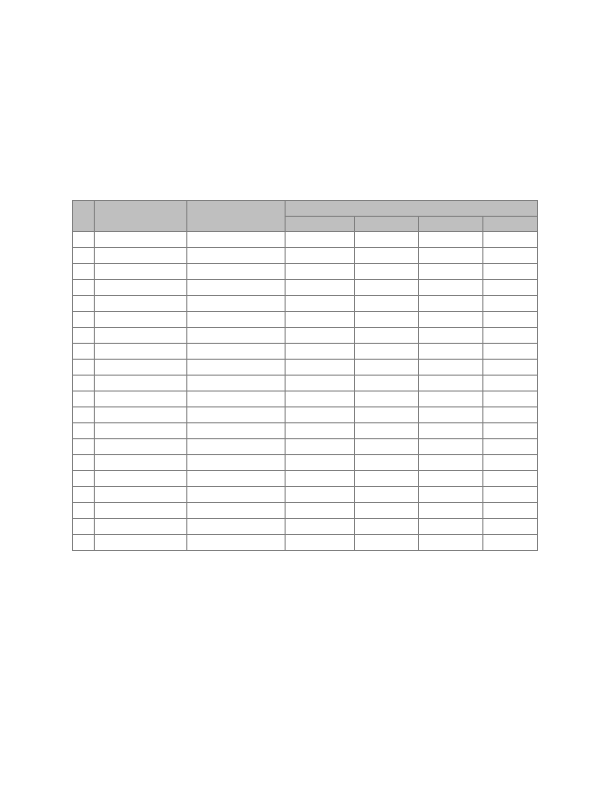
Aperture 3 (ISEA3H)
res
Number of Cells*
Hex Area** (km2)
Internode Spacing (km)
min
max
mean
std.dev.
1
32
17,002,187.39080
4,156.18000
4,649.10000
4,320.49000
233.01400
2
92
5,667,395.79693
2,324.81000
2,692.72000
2,539.69000
139.33400
3
272
1,889,131.93231
1,363.56000
1,652.27000
1,480.02000
89.39030
4
812
629,710.64410
756.96100
914.27200
855.41900
52.14810
5
2,432
209,903.54803
453.74800
559.23900
494.95900
29.81910
6
7,292
69,967.84934
248.80400
310.69300
285.65200
17.84470
7
21,872
23,322.61645
151.22100
187.55000
165.05800
9.98178
8
65,612
7,774.20548
82.31100
104.47000
95.26360
6.00035
9
196,832
2,591.40183
50.40600
63.00970
55.02260
3.33072
10
590,492
863.80061
27.33230
35.01970
31.75960
2.00618
11
1,771,472
287.93354
16.80190
21.09020
18.34100
1.11045
12
5,314,412
95.97785
9.09368
11.70610
10.58710
0.66942
13
15,943,232
31.99262
5.60065
7.04462
6.11367
0.37016
14
47,829,692
10.66421
3.02847
3.90742
3.52911
0.22322
15
143,489,072
3.55473
1.86688
2.35058
2.03789
0.12339
16
430,467,212
1.18491
1.00904
1.30335
1.17638
0.07442
17
1,291,401,632
0.39497
0.62229
0.78391
0.67930
0.04113
18
3,874,204,892
0.13166
0.33628
0.43459
0.39213
0.02481
19
11,622,614,672
0.04389
0.20743
0.26137
0.22643
0.01371
20
34,867,844,012
0.01463
0.11208
0.14489
0.13071
0.00827
page of 26 38
User Documentation for DGGRID version 6.4
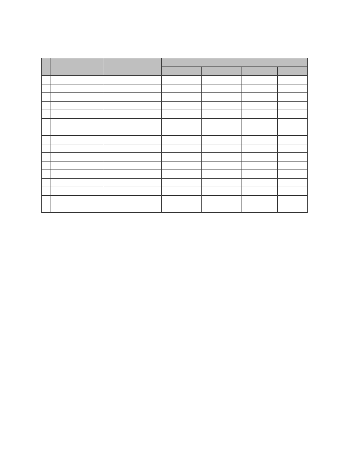
Aperture 4 (ISEA4H)
res
Number of Cells*
Hex Area** (km2)
Internode Spacing (km)
min
max
mean
std.dev.
1
42
12,751,640.54310
3,526.83000
4,003.02000
3,764.92000
238.59500
2
162
3,187,910.13578
1,730.20000
2,017.48000
1,913.88000
116.98200
3
642
796,977.53394
853.05600
1,024.99000
961.97800
58.98050
4
2,562
199,244.38349
422.25300
520.74600
481.77100
29.93870
5
10,242
49,811.09587
209.61200
262.55900
241.04700
15.09590
6
40,962
12,452.77397
104.30400
131.99100
120.56000
7.58663
7
163,842
3,113.19349
51.98740
66.29560
60.28930
3.80352
8
655,362
778.29837
25.94120
33.24750
30.14700
1.90448
9
2,621,442
194.57459
12.95380
16.65580
15.07410
0.95293
10
10,485,762
48.64365
6.47162
8.33821
7.53719
0.47664
11
41,943,042
12.16091
3.23413
4.17238
3.76863
0.23837
12
167,772,162
3.04023
1.61654
2.08723
1.88432
0.11919
13
671,088,642
0.76006
0.80810
1.04394
0.94217
0.05960
14
2,684,354,562
0.19001
0.40400
0.52208
0.47108
0.02980
15
10,737,418,242
0.04750
0.20198
0.26107
0.23554
0.01490
16
42,949,672,962
0.01188
0.10099
0.13055
0.11777
0.00745
page of 27 38
User Documentation for DGGRID version 6.4
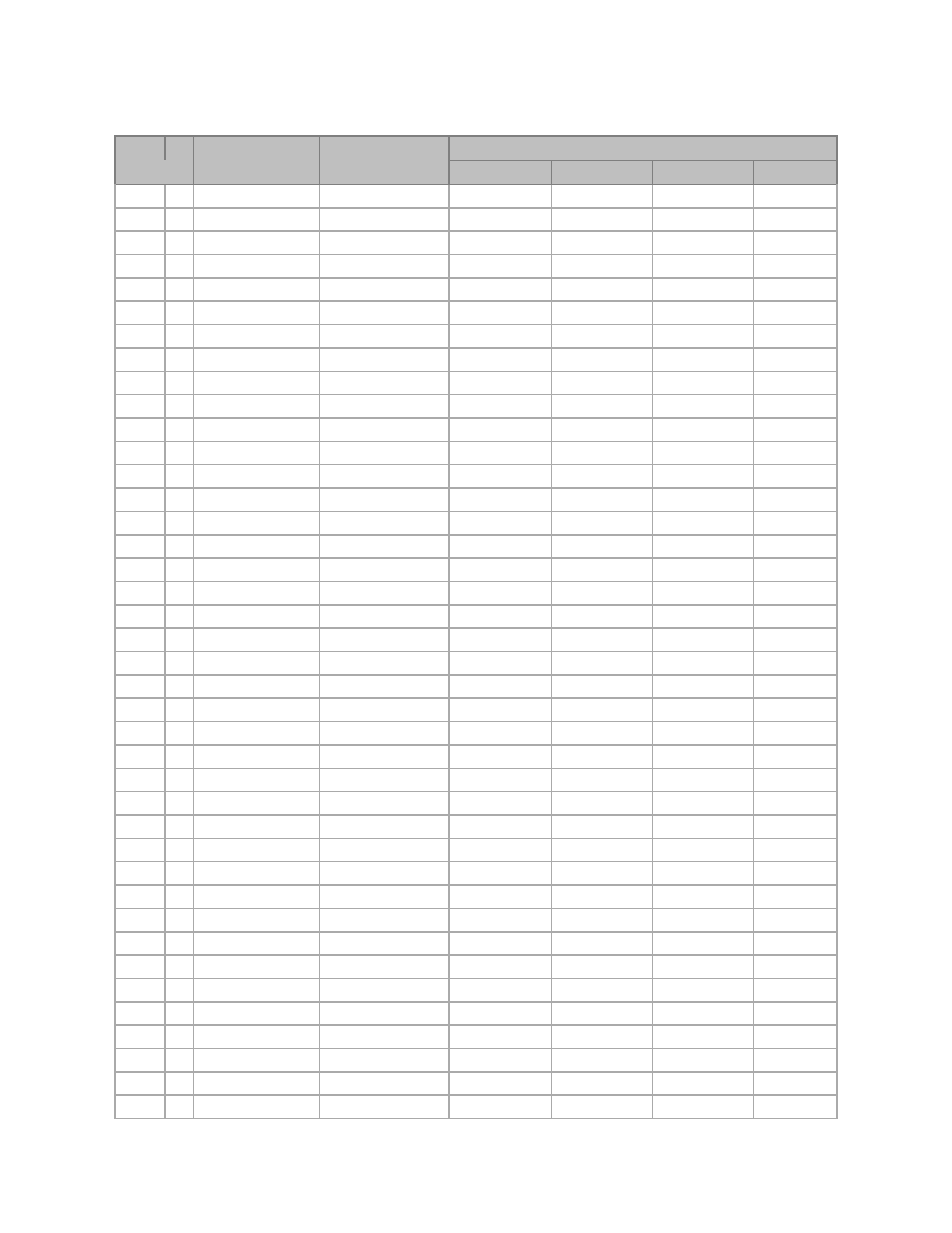
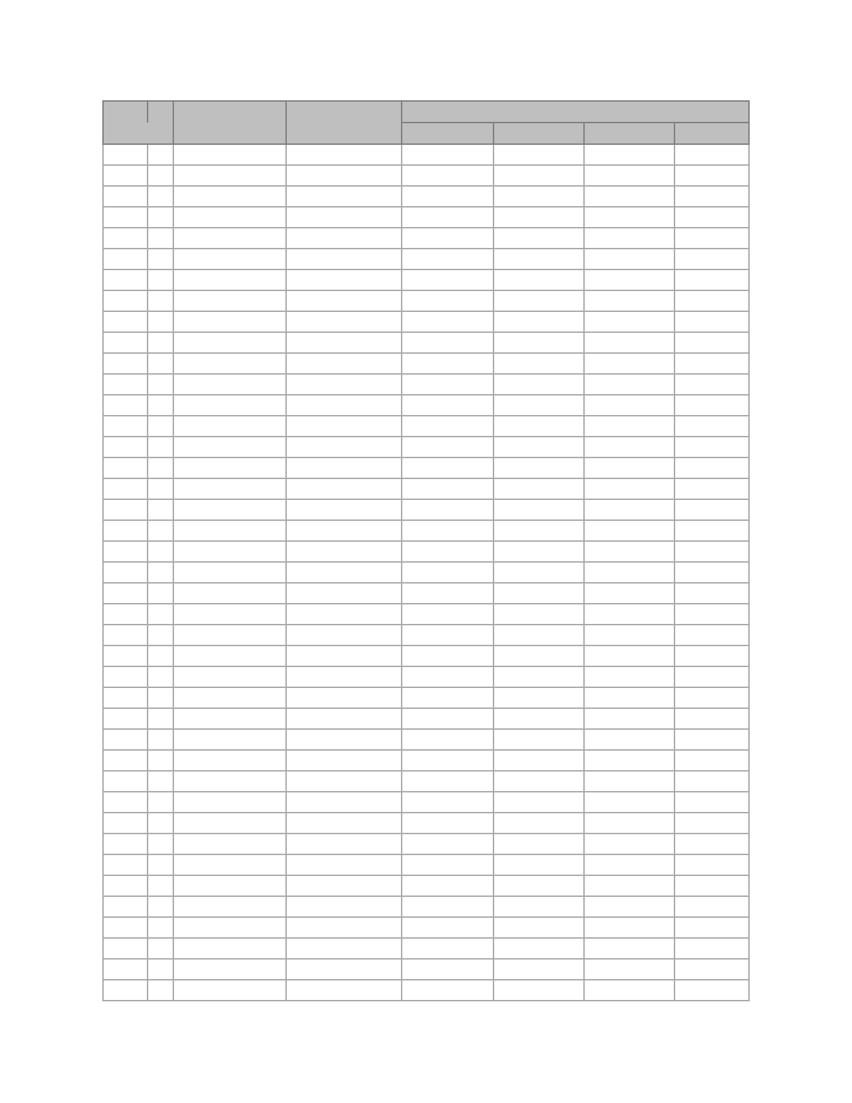
Mixed Aperture 4 and 3 (ISEA43H)
# Ap 4
Res
Number of Cells*
Hex Area** (km2)
Internode Spacing (km)
Res***
min
max
mean
std.dev.
1
2
122
4,250,546.84770
2,050.27000
2,445.80000
2,210.50000
134.60200
1
3
362
1,416,848.94923
1,143.10000
1,360.38000
1,280.77000
76.55180
2
3
482
1,062,636.71193
1,021.81000
1,246.71000
1,111.74000
66.88040
1
4
1,082
472,282.98308
680.80200
835.86200
742.02700
44.62200
2
4
1,442
354,212.23731
565.39700
690.57000
642.04700
39.50560
3
4
1,922
265,659.17798
510.49600
628.59000
556.76100
33.52270
1
5
3,242
157,427.66103
374.89400
463.73500
428.31100
26.59520
2
5
4,322
118,070.74577
340.28000
420.15500
371.29600
22.39940
3
5
5,762
88,553.05933
280.26400
349.09400
321.32800
20.04290
4
5
7,682
66,414.79450
255.19700
315.51700
278.50600
16.82030
1
6
9,722
52,475.88701
226.83800
280.57700
247.56900
14.95740
2
6
12,962
39,356.91526
186.14700
233.60700
214.27900
13.42690
3
6
17,282
29,517.68644
170.12500
210.75100
185.68800
11.22680
4
6
23,042
22,138.26483
139.31500
175.54900
160.73100
10.09490
1
7
29,162
17,491.96234
123.74300
156.19900
142.87800
8.98060
5
6
30,722
16,603.69862
127.59200
158.48900
139.27000
8.42455
2
7
38,882
13,118.97175
113.41500
141.01800
123.79700
7.48970
3
7
51,842
9,839.22881
92.65450
117.43200
107.16800
6.74663
4
7
69,122
7,379.42161
85.06050
105.99400
92.84930
5.61894
1
8
87,482
5,830.65411
75.60920
94.29160
82.53310
4.99505
5
7
92,162
5,534.56621
69.39600
88.24730
80.38160
5.06634
2
8
116,642
4,372.99058
61.65500
78.49940
71.45200
4.50532
6
7
122,882
4,150.92466
63.79510
79.64280
69.63760
4.21501
3
8
155,522
3,279.74294
56.70670
70.84140
61.90030
3.74689
4
8
207,362
2,459.80720
46.19200
58.96580
53.59140
3.38187
1
9
262,442
1,943.55137
41.04410
52.44340
47.63750
3.00696
5
8
276,482
1,844.85540
42.53000
53.20880
46.42540
2.81045
2
9
349,922
1,457.66353
37.80440
47.32180
41.26710
2.49825
6
8
368,642
1,383.64155
34.61350
44.28150
40.19490
2.53804
3
9
466,562
1,093.24765
30.75780
39.38000
35.72920
2.25652
7
8
491,522
1,037.73116
31.89750
39.95570
34.81920
2.10797
4
9
622,082
819.93573
28.35330
35.53200
30.95040
1.87379
1
10
787,322
647.85046
25.20290
31.59700
27.51150
1.66561
5
9
829,442
614.95180
23.05280
29.56480
26.79750
1.69313
2
10
1,049,762
485.88784
20.48640
26.28940
23.82020
1.50522
6
9
1,105,922
461.21385
21.26500
26.67450
23.21280
1.40539
3
10
1,399,682
364.41588
18.90220
23.71890
20.63360
1.24924
7
9
1,474,562
345.91039
17.27980
22.19230
20.09850
1.27026
4
10
1,866,242
273.31191
15.35680
19.73240
17.86540
1.12925
8
9
1,966,082
259.43279
15.94870
20.02190
17.40960
1.05406
page of 28 38
User Documentation for DGGRID version 6.4
1
11
2,361,962
215.95015
13.64790
17.54480
15.88050
1.00387
5
10
2,488,322
204.98393
14.17660
17.80240
15.47520
0.93695
2
11
3,149,282
161.96261
12.60150
15.82860
13.75580
0.83285
6
10
3,317,762
153.73795
11.51260
14.80890
13.39920
0.84712
3
11
4,199,042
121.47196
10.23190
13.16650
11.91050
0.75305
7
10
4,423,682
115.30346
10.63250
13.36000
11.60640
0.70272
4
11
5,598,722
91.10397
9.45109
11.87820
10.31680
0.62464
8
10
5,898,242
86.47760
8.63138
11.11270
10.04950
0.63545
1
12
7,085,882
71.98338
8.40097
10.56060
9.17051
0.55524
5
11
7,464,962
68.32798
7.67135
9.87982
8.93293
0.56487
9
10
7,864,322
64.85820
7.97436
10.02520
8.70482
0.52704
2
12
9,447,842
53.98754
6.81818
8.78363
7.94040
0.50213
6
11
9,953,282
51.24598
7.08832
8.91291
7.73762
0.46848
3
12
12,597,122
40.49065
6.30073
7.92394
6.87788
0.41643
7
11
13,271,042
38.43449
5.75194
7.41293
6.69974
0.42370
4
12
16,796,162
30.36799
5.11234
6.59024
5.95533
0.37664
8
11
17,694,722
28.82587
5.31624
6.68732
5.80321
0.35136
1
13
21,257,642
23.99446
4.54389
5.85880
5.29364
0.33480
5
12
22,394,882
22.77599
4.72555
5.94513
5.15841
0.31232
9
11
23,592,962
21.61940
4.31298
5.56160
5.02482
0.31780
2
13
28,343,522
17.99585
4.20049
5.28525
4.58526
0.27762
6
12
29,859,842
17.08199
3.83345
4.94425
4.46652
0.28250
10
11
31,457,282
16.21455
3.98718
5.01714
4.35241
0.26352
3
13
37,791,362
13.49688
3.40726
4.39539
3.97024
0.25112
7
12
39,813,122
12.81150
3.54416
4.46020
3.86881
0.23424
4
13
50,388,482
10.12266
3.15036
3.96505
3.43894
0.20822
8
12
53,084,162
9.60862
2.87459
3.70916
3.34990
0.21189
1
14
63,772,922
7.99815
2.80032
3.52485
3.05684
0.18508
5
13
67,184,642
7.59200
2.55504
3.29734
2.97769
0.18835
9
12
70,778,882
7.20647
2.65812
3.34599
2.90161
0.17568
2
14
85,030,562
5.99862
2.27101
2.93122
2.64684
0.16742
6
13
89,579,522
5.69400
2.36277
2.97448
2.57921
0.15616
10
12
94,371,842
5.40485
2.15564
2.78247
2.51243
0.15892
3
14
113,374,082
4.49896
2.10024
2.64420
2.29263
0.13881
7
13
119,439,362
4.27050
1.91602
2.47350
2.23327
0.14127
11
12
125,829,122
4.05364
1.99359
2.51002
2.17621
0.13176
4
14
151,165,442
3.37422
1.70305
2.19883
1.98513
0.12557
8
13
159,252,482
3.20287
1.77208
2.23129
1.93441
0.11712
1
15
191,318,762
2.66605
1.51376
1.95464
1.76456
0.11162
5
14
201,553,922
2.53067
1.57518
1.98351
1.71947
0.10411
9
13
212,336,642
2.40216
1.43686
1.85544
1.67496
0.10595
# Ap 4
Res
Number of Cells*
Hex Area** (km2)
Internode Spacing (km)
Res***
min
max
mean
std.dev.
page of 29 38
User Documentation for DGGRID version 6.4
2
15
255,091,682
1.99954
1.40016
1.76323
1.52842
0.09254
6
14
268,738,562
1.89800
1.27716
1.64937
1.48885
0.09418
10
13
283,115,522
1.80162
1.32906
1.67373
1.45080
0.08784
3
15
340,122,242
1.49965
1.13521
1.46619
1.32342
0.08372
7
14
358,318,082
1.42350
1.18139
1.48785
1.28960
0.07808
11
13
377,487,362
1.35121
1.07755
1.39177
1.25622
0.07947
4
15
453,496,322
1.12474
1.05012
1.32260
1.14631
0.06941
8
14
477,757,442
1.06762
0.95779
1.23719
1.11664
0.07064
12
13
503,316,482
1.01341
0.99679
1.25547
1.08810
0.06588
1
16
573,956,282
0.88868
0.93344
1.17570
1.01895
0.06169
5
15
604,661,762
0.84356
0.85134
1.09977
0.99257
0.06279
9
14
637,009,922
0.80072
0.88604
1.11602
0.96720
0.05856
2
16
765,275,042
0.66651
0.75673
0.97762
0.88228
0.05581
6
15
806,215,682
0.63267
0.78759
0.99206
0.85974
0.05205
10
14
849,346,562
0.60054
0.71829
0.92799
0.83748
0.05298
3
16
1,020,366,722
0.49988
0.70008
0.88187
0.76421
0.04627
7
15
1,074,954,242
0.47450
0.63847
0.82491
0.74443
0.04709
11
14
1,132,462,082
0.45040
0.66453
0.83710
0.72540
0.04392
4
16
1,360,488,962
0.37491
0.56751
0.73328
0.66171
0.04186
8
15
1,433,272,322
0.35587
0.59069
0.74412
0.64480
0.03904
12
14
1,509,949,442
0.33780
0.53869
0.69605
0.62811
0.03973
1
17
1,721,868,842
0.29623
0.50445
0.65182
0.58819
0.03721
5
16
1,813,985,282
0.28119
0.52506
0.66146
0.57316
0.03470
9
15
1,911,029,762
0.26691
0.47883
0.61873
0.55832
0.03532
13
14
2,013,265,922
0.25335
0.49840
0.62788
0.54405
0.03294
2
17
2,295,825,122
0.22217
0.46672
0.58798
0.50947
0.03085
6
16
2,418,647,042
0.21089
0.42562
0.55000
0.49628
0.03140
10
15
2,548,039,682
0.20018
0.44302
0.55813
0.48360
0.02928
3
17
3,061,100,162
0.16663
0.37832
0.48890
0.44114
0.02791
7
16
3,224,862,722
0.15817
0.39380
0.49613
0.42987
0.02603
11
15
3,397,386,242
0.15013
0.35910
0.46408
0.41874
0.02649
4
17
4,081,466,882
0.12497
0.35004
0.44101
0.38210
0.02314
8
16
4,299,816,962
0.11862
0.31920
0.41252
0.37221
0.02355
12
15
4,529,848,322
0.11260
0.33226
0.41862
0.36270
0.02196
1
18
5,165,606,522
0.09874
0.31115
0.39202
0.33965
0.02056
5
17
5,441,955,842
0.09373
0.28373
0.36670
0.33086
0.02093
13
15
6,039,797,762
0.08445
0.26932
0.34808
0.31405
0.01987
2
18
6,887,475,362
0.07406
0.25220
0.32596
0.29409
0.01860
# Ap 4
Res
Number of Cells*
Hex Area** (km2)
Internode Spacing (km)
Res***
min
max
mean
std.dev.
page of 30 38

User Documentation for DGGRID version 6.4
Notes
* At every resolution 12 of the cells are pentagons and the remainder are hexagons.
** The 12 pentagons at each resolution have an area exactly 5/6 the area of a hexagon.
*** Specified in a metafile using parameter dggs_num_aperture_4_res.
page of 31 38

User Documentation for DGGRID version 6.4
Appendix E. The Superfund_500m DGG
Kevin Sahr
Department of Computer Science, Southern Oregon University, Ashland, OR 9752
email: sahrk@sou.edu
Denis White
US Environmental Protection Agency (retired)
email: whitede@onid.orst.edu
Introduction
The Superfund_500m grid was commissioned by the US Environmental Protection agency for
use in developing its Superfund Emergency Response Atlas. The grid is a hierarchically indexed
icosahedral hexagonal discrete global grid (DGG) (Sahr et al. 2003) consisting of approximately
22 hectare hexagons, with approximately 500 meter distance between hexagon centers. This cell
size is generated geometrically by creating a mixed aperture sequence of two aperture 4
subdivisions followed by 15 aperture 3 subdivisions.
It is not possible to create a network of equal area, equal shape, and equally spaced grid cells
greater than twenty in number on the surface of a sphere. Thus one or more, often two or all
three, of these characteristics are distorted to varying degrees across the surface. The approach
used here starts with the twenty triangular faces of the icosahedron, creates a regular, equal area,
equal shape, and equally spaced network of hexagons of the desired size on one or more of the
planar triangles and then projects these cells to the surface of the globe. The distortion
characteristics of this approach have been investigated by Kimerling et al. (1999) and Gregory et
al. (2008).
Grid characteristics for the 10 addressable Superfund_500m resolutions are given in Table 1.
Grid Construction
The cells are generated as regular hexagons (and pentagons) on the surface of an icosahedron,
oriented relative to the globe so as to be symmetrical about the equator. The cells are projected to
longitude and latitude on a sphere with the authalic WGS84 radius (NAD 83 datum) using the
inverse icosahedral projection of R. Buckminster Fuller (1975) as developed analytically by
Robert Gray (1995) and John Crider (2008).
The Superfund_500m cell identifiers are an instance of Central Place Indexing (CPI). CPI
(Sahr, 2011; Sahr & White, in preparation) is a class of hierarchical indexing systems for pure
and mixed aperture hexagonal DGGs, where the linear index assigned to each cell is constructed
as a path address (Sahr 2008) on a multi-resolution discrete global grid system with the specified
aperture sequence. A CPI addressing system was used in the initial design for a sampling system
for the EPA’s Environmental Monitoring and Assessment Program (White et al. 1992).
page of 32 38
User Documentation for DGGRID version 6.4
Table 1. Superfund_500m DGG Resolutions (see notes after table).
Table 1 Notes:
1At every resolution 12 of the cells are pentagons and the remainder are hexagons.
2The 12 pentagons have an area exactly 5/6 the area of a hexagon.
3Measured in the plane of the Fuller projection space.
4Characteristic Length Scale (CLS): the diameter of a spherical cap of the same area as a cell of the specified
resolution. This metric was suggested by Ralph Kahn.
The Superfund_500m CPI system was designed to meet two design goals. First, the CPI
approach allows the grid to have an intercell spacing of approximately 500 meters, which cannot
be achieved with sufficient accuracy using a pure aperture grid system. Second, in order to take
advantage of the pre-existing discrete global grid software tool DGGRID the cells needed to be
hierarchically indexed in such a manner that the Christaller sets of each base cell are each
restricted to a single ij coordinate system whose axes form two of the edges of a spherical
quadrilateral formed by a pair of adjacent icosahedral faces.
These design goals were met by constructing a grid with base cells of valence 5 (i.e., with
pentagonal voronoi areas) centered on each of the 12 vertices of an icosahedron and then
applying the following aperture sequence:
4, 4, 3ccw, 3cw, 3ccw, 3cw, 3ccw, 3cw, 3ccw, 3cw, 3ccw, 3cw, 3ccw, 3cw, 3ccw, 3cw, 3ccw
To assign a unique hierarchical index to each cell, as well as to achieve the remaining grid design
goals, the generator types A-K were defined with the following generator string representations:
A: A123456
B: C123CCC
C: D123EED
D: F123IK6
E: J123GH6
F: D123EE6
G: DD234E6
Resolution
# Cells1
Hex Area2
(sq. km)
Intercell Distance3
(km)
CLS4
(km)
0
42
12,751,640.5431
3,526.8262
4,046.3596
1
162
3,187,910.1358
1,763.4131
2,016.7939
2
1,442
354,212.2373
587.8044
671.6409
3
12,962
39,356.9153
195.9348
223.8573
4
116,642
4,372.9906
65.3116
74.6182
5
1,049,762
485.8878
21.7705
24.8727
6
9,447,842
53.9875
7.2568
8.2909
7
85,030,562
5.9986
2.4189
2.7636
8
765,275,042
0.6665
0.8063
0.9212
9
2,295,825,122
0.2222
0.4655
0.5319
page of 33 38

User Documentation for DGGRID version 6.4
H: EE2D456
I: E1DD456
J: E1D345E
K: D123E5D
Two of the base cells on opposing sides of the icosahedron are assigned generator type A, while
the remaining 10 base cells (centered on the remaining 10 icosahedral vertices) are assigned
generator type B. Figures 1-3 illustrate the resolution 17 regions corresponding to the resolution
1 grid cells, numbered 10-51 (to avoid leading zeros in indexes). The resolution 0 base tiles
centered on the resolution 1 cells labeled 10 and 51 are the two base cells that were assigned
generator type A, which generates a single pentagonal cell at all resolutions.
Index Form
The base tiles of the Superfund_500m CPI indexes correspond to resolution 1 DGG cells, as
illustrated in Figure 1. Base tiles 11-50 each have four hierarchical children at the aperture 4
resolution 2, which are assigned the additional digits 1-4. These resolution 2 cells each have
three children at resolution 3, which are assigned the additional digits 1-3; this assignment
continues recursively through the aperture 3 resolutions 3-17. The special base tiles 10 and 51
have a single hierarchical child at all resolutions, which is assigned the additional digit 1 at each
resolution. In order to reduce the length of indexes, a first order compression is performed by
grouping the aperture 3 resolution 3-16 digits into pairs and replacing each pair of digits with a
digit value of 1-9.
The assignment of digits has been chosen so that all indexes form integers with the same number
of digits, and so that possibly troublesome leading zeros can be avoided, even if redundant
leading digits are removed from indexes when working in regions where this is possible.
Thus the full resolution 17 Superfund_500m CPI indexes are condensed into indexes with 11
digits, resulting in 10 addressable grid resolutions (see Table 1).
A Superfund_500m index at full resolution (resolution 9) has the 11-digit form:
BB499999993
where:
- BB is the 2-digit resolution 1 base tile cell with values 10-51,
- 4 is the resolution 2 aperture 4 digit with values 1-4,
- each 9 represent two successive combined aperture 3 digits for resolutions 3-16, with values
1-9 each, and
- the final 3 represents the extra aperture 3 at resolution 17, with values 1-3
page of 34 38
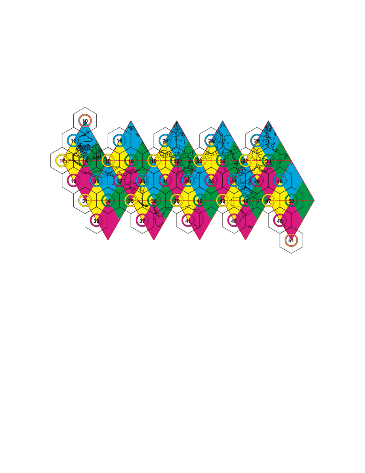
User Documentation for DGGRID version 6.4
Note that the resolution 9 footprint of base tiles 11-50 form approximate spherical diamonds on
the surface of the globe, as illustrated in Figure 1. Figures 2 and 3 illustrate the resolution 9
indexing footprints of base tiles adjacent to base tiles 10 and 15 respectively. The hierarchical
children at each aperture 3 resolution form a compact triangle; Figure 4 illustrates the pattern
formed at resolution 9.
Figure 1. Superfund_500m base tiles on an unfolded icosahedron with corresponding resolution
9 indexing footprints. Cells within the footprint region of a base tile will have that base tile’s
index as the first two digits of the cell’s index. Tiles 10 and 51 index only a single cell at all
resolutions, centered on the corresponding base tile. Note that all tiles that are centered on a
triangle vertex are actually pentagons on the sphere.
page of 35 38
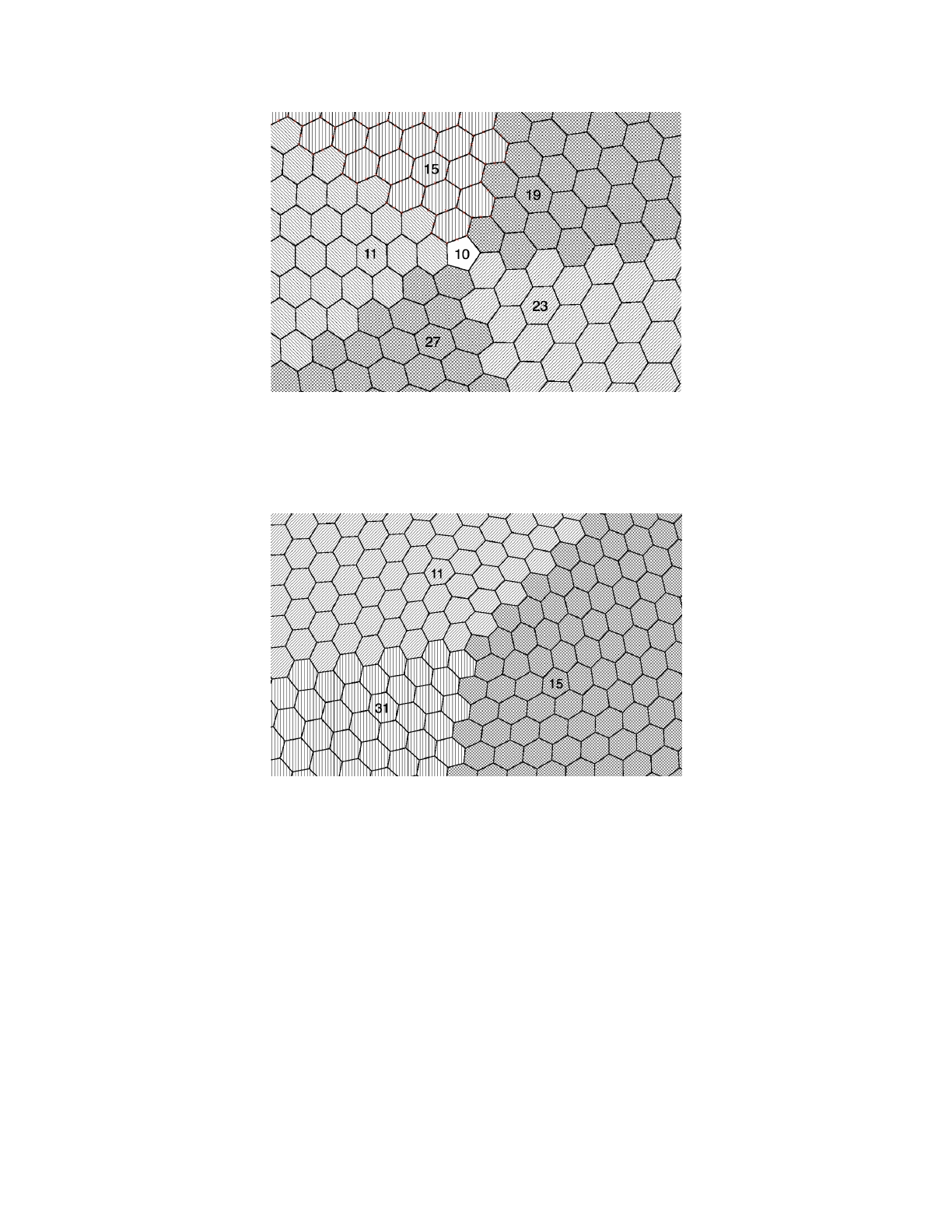
User Documentation for DGGRID version 6.4
Figure 2. Region around base tile 10 at resolution 9.
Figure 3. Region around base tile 15 at resolution 9.
page of 36 38
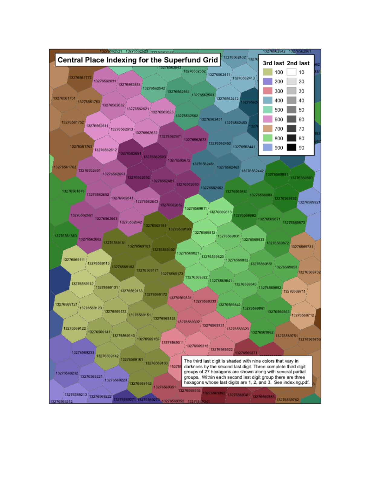
User Documentation for DGGRID version 6.4
Figure 4. Superfund_500m resolution 9 tiling pattern."
page of 37 38

User Documentation for DGGRID version 6.4
Appendix F. References
Crider JE. 2008. Exact equations for Fuller's map projection and inverse. Cartographica 43(1):
67-72.
Fuller RB. 1975. Synergetics. New York: MacMillan.
Gray RW. 1995. Exact transformation equations for Fuller's world map. Cartography and
Geographic Information Systems 32:243-246.
Gregory MJ, Kimerling AJ, White D, Sahr K. 2008. A comparison of intercell metrics on discrete
global grid systems. Computers, Environment and Urban Systems 32(3):188-203.
Kimerling AJ, Sahr K, White D, Song L. 1999. Comparing geometrical properties of discrete
global grids. Cartography and Geographic Information Science 26(4):271-287.
Sahr K, White D, Kimerling AJ. 2003. Geodesic discrete global grid systems. Cartography and
Geographic Information Science 30(2):121-134.
Sahr K. 2008. Location coding on icosahedral aperture 3 hexagon discrete global grids.
Computers, Environment and Urban Systems 32(3):174-187.
Sahr, K. 2011. Hexagonal discrete global grid systems for geospatial computing. Archives of
Photogrammetry, Cartography and Remote Sensing, 22:363-376.
Sahr, K. and D. White. In preparation. Hierarchical spatial indexing of pure and mixed aperture
hexagonal discrete global grid systems.
White D, Kimerling AJ, Overton WS. 1992. Cartographic and geometric components of a global
sampling design for environmental monitoring. Cartography and Geographic Information
Systems 19(1):5-22.
page of 38 38
