13524 XL650 Man. V 6.1 PDF Dillon V6 1
XL 650 User Manual XL 650 User Manual
User Manual: PDF T E X T F I L E S
Open the PDF directly: View PDF ![]() .
.
Page Count: 59
illon
recision
Products, Inc.
Manufacturers of
The World's Finest
Loading Equipment
XL 650
Instruction Manual
Version 6.1

Dillon Precision Products, Inc.
8009 E. Dillon’s Way
Scottsdale, AZ 85260
(480) 948-8009
FAX (480) 998-2786
Web Site: www.dillonprecision.com
E-mail: dillon@dillonprecision.com
Technical Support & Customer Service
(800) 223-4570
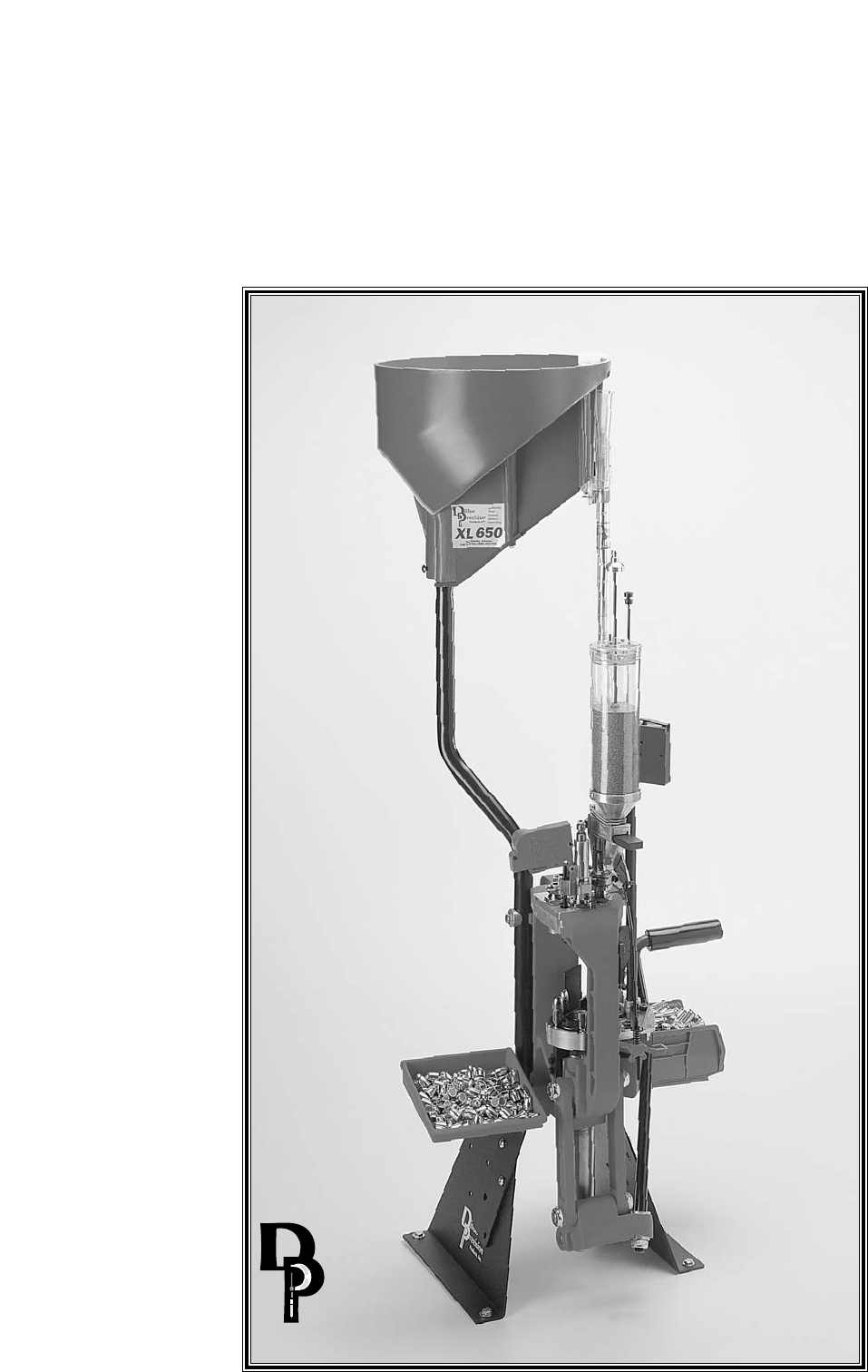
On the cover…
The XL 650 is pictured with optional accessories:
Strong Mount (550/650) #22051
Strong Mount (650 only) #22052
Aluminum Roller Handle #17950
Low Powder Sensor #16306
Bullet Tray #22214
Powdercheck System #21044
Electric Casefeeder (four sizes available)
Other accessories available for the XL 650 include:
Video Instruction Manual #15064
Machine Cover #10443
Maintenance Kit & Spare Parts Kit #97017
The Blue Press, Dillon’s monthly catalog, has a complete listing
of accessories available for all machines.
Part #13524 Spot Manuals XL 650 Folder XL 650 Man. 6.1 9/01 WJC

Page #
Mandatory Safety Measures 5
Getting Started 6
1. Unboxing your machine 6
2. Mounting your XL 650 7
3. Initial Set-Up 7
A. Installation of Handle 7
B. Installation of the Spent Primer Cup and Cartridge Bin 8
C. Installation of the Casefeed Post 8
D. Installation of the Casefeed Tube Bracket 8
E. Installation of the Optional Casefeeder 9
4. Toolhead Overview 11
Lubricating Brass 11
Pistol Section – Toolhead Set Up 12
A. Station One – Installation of the Sizing/Decapping Die 12
B. Station One – The Decapping assembly 12
C. Station Two – Installation of the Powder Measure Assembly 12
D. Station Two – About Powder Bars 13
E. Station Two – Adjustment of the Powder Die/Powder Funnel 14
F. Station Two – Installation of the Failsafe Rod Assembly 15
G. Station Three – Installation of the Powder Check System 16
H. Station Four – General Information on Bullet Seating 17
I. Station Four – Seating Stems 18
J. Station Four – Installation and Adjustment of the Seating Die 18
K. Station Five – Installation and Adjustment of the Crimp Die 18
Rifle Section – Toolhead Set Up 20
A. Station One – About the Case Gage 20
B. How to Use the Case Gage 20
C. Station One – Installation of the Sizing/Decapping Die 21
D. Station One – The Decapping assembly 22
E. Station Two – Installation of the Powder Measure Assembly 22
F. Station Two – About Powder Bars 23
G. Station Two – Adjustment of the Powder Die/Powder Funnel 23
H. Station Two – Installation of the Failsafe Rod Assembly 25
I. Station Three – Installation of the Powder Check System 25
J. Station Four – How to Determine the Proper Seating Depth 26
K. Station Four – Seating Stems 27
L. Station Four – Installation and Adjustment of the Seating Die 27
M. Station Five – Installation and Adjustment of the Crimp Die 28
Final Assembly 29
1. The Primer Magazine 29
2. Installation of the Primer Early Warning System 29
3. Installation of the Locator Buttons 30
Loading Components Section
1. Primer System Overview (how it works) 30
2. Powder Bar Adjustment 30
3. Powder Check System Adjustment 31
A. Installation and Adjustment of the Powder Check Rods 31
B. Powder Check System demonstration 32
4. Filling the Primer System 32
Station Orientation and Loading Funtions 34
Caliber Conversion Section 35-42
Trouble Shooting 43-45
Caliber Conversion Chart 46-48
Schematics 49-58
Table of Contents

Reloading small arms ammuni-
tion involves the use of highly
explosive primers and powder.
Handling these materials is inher-
ently dangerous. You should rec-
ognize this danger and take certain
minimum precautions to lessen
your exposure to injury.
Never operate the machine
without ear and eye protection on.
Call our customer service depart-
ment at (800) 223-4570 for informa-
tion on the wide variety of shoot-
ing/safety glasses and hearing
protection that Dillon has to offer.
• PAY ATTENTION: Load only
when you can give your com-
plete attention to the loading
process. Don’t watch television
or try to carry on a conversation
and load at the same time. Watch
the automatic systems operate
and make sure they are function-
ing properly. If you are interrupt-
ed or must leave and come back
to your loading, always inspect
the cases at every station to
insure that the proper operations
have been accomplished.
• SMOKING: Do not smoke
while reloading or allow anyone
else to smoke in your reloading
area. Do not allow open flames
in reloading area.
• SAFETY DEVICES: Do not
remove any safety devices from
your machine or modify your
machine in any way.
• LEAD WARNING: Be sure to
have proper ventilation while han-
dling lead components or when
shooting lead bullets. Lead is
known to cause birth defects, other
reproductive harm and cancer.
Wash your hands thoroughly after
handling anything made of lead.
• LOADS AND LENGTHS:
Avoid maximum loads and pres-
sures at all times. Use only rec-
ommended loads from manuals
and information supplied by reli-
able component manufacturers
and suppliers. Since Dillon
Precision has no control over the
components which may be used
on their equipment, no responsi-
bility is implied or assumed for
results obtained through the use
of any such components.
Seat bullets as close to maxi-
mum cartridge length as possible.
Under some conditions, seating
bullets excessively deep can raise
pressures to unsafe levels. Refer to
a reliable loading manual for over-
all length (OAL).
• QUALITY CHECKS: Every 50-
100 rounds, perform periodic qual-
ity control checks on the ammuni-
tion being produced. Check the
amount of powder being dropped
and primer supply.
• RELOADING AREA: Keep your
components safely stored. Clear
your work area of loose powder,
primers and other flammables
before loading.
• COMPONENTS: Never have
more than one type of powder in
your reloading area at a time. The
risk of a mix-up is too great. Keep
powder containers closed.
Be sure to inspect brass prior to
reloading for flaws, cracks, splits
or defects. Throw these cases away.
Keep components and ammuni-
tion out of reach of children.
• BLACK POWDER: Do not use
black powder or black powder
substitutes in any Dillon powder
measure. Loading black powder
cartridges requires specialized
loading equipment and tech-
niques. Failure to do so can result
in severe injury or death.
• PRIMERS: Never force primers.
If they get stuck in the operation of
the machine, disassemble it and
gently remove the obstruction.
Never attempt to clear primers
that are stuck in either the primer
pickup tube or the primer maga-
zine tube. Never, under any cir-
cumstances, insert any type of rod
to attempt to force stuck primers
out of these tubes. Trying to force
primers out of the tube will cause
the primers to explode causing
serious injury or even death.
If primers get stuck in a primer
magazine or pickup tube flood the
tube with a penetrating oil (WD-
40), throw the tube in the garbage
and call us for a free replacement.
Never attempt to deprime live
primers – eventually one will go
off. When it does it will detonate
the others in the spent primer cup.
Depriming live primers is the sin-
gle most dangerous thing you can
do in reloading and can cause
grave injury or death.
• LOADED AMMUNITION:
Properly label all of your loaded
ammunition (Date, Type of
Bullet, Primer, Powder, Powder
Charge, etc.).
• BE PATIENT: Our loading
equipment is conservatively rated
and you should have no trouble
achieving the published rates with
a smooth, steady hand. If some-
thing doesn’t seem right, stop,
look and listen. If the problem or
the solution isn’t obvious, call us.
The reloading bench is no place
to get into a hurry.
We have done everything we
know how to make your machine
as safe as possible. We cannot,
however, guarantee your complete
safety. To minimize your risk, use
common sense when reloading
and follow these basic rules.
• REMEMBER: If your machine
does not perform to your expecta-
tions, or if you are having technical
difficulties, give us a call.
Technical Support (800) 223-4570
ALL ELECTRICAL/ELECTRONIC COM-
PONENTS IN DILLON EQUIPMENT ARE
COVERED BY A ONE-YEAR WARRANTY.
5
MANDATORY SAFETY MEASURES
6
GETTING STARTED
1.Unboxing Your
Machine:
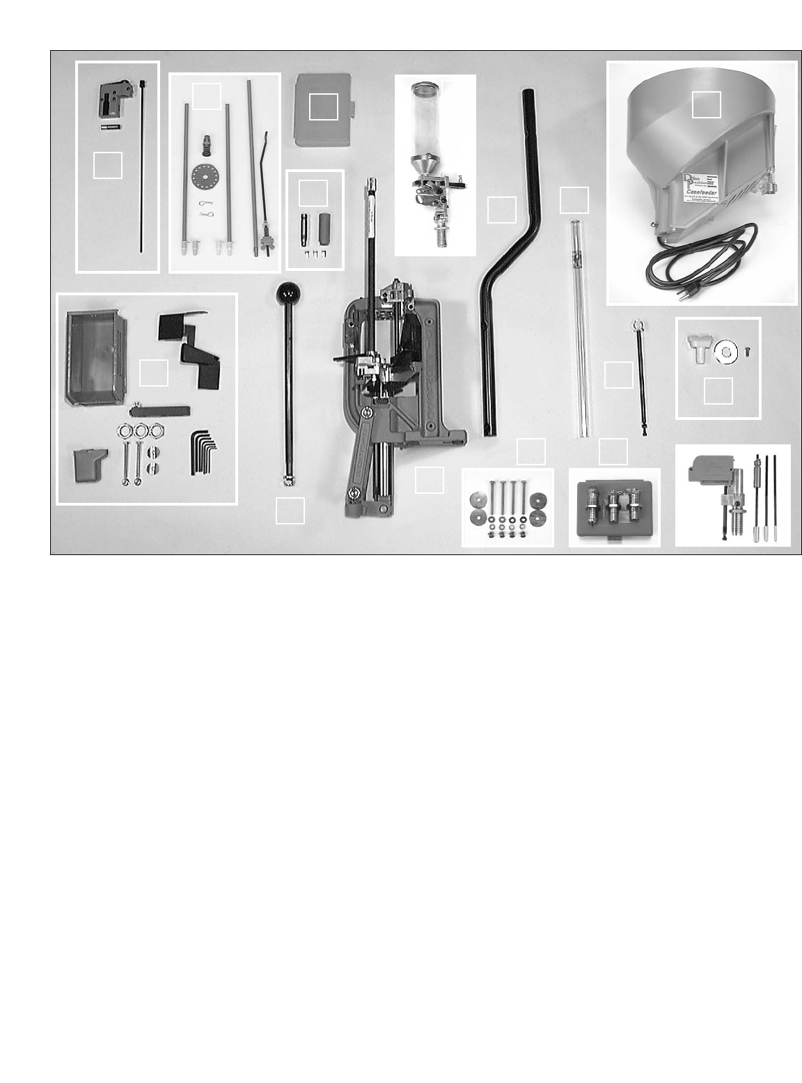
After opening the box, check the con-
tents against the list below. If any items are
missing or damaged, call us right away so
we can send out a replacement at no
charge.
You should have the following:
1. Machine with toolhead and toolhead
retaining pins installed
2. Operating handle assembly with washer
and lock nut
3. Casefeed mounting post
4. Casefeed tube
5. Casefeed support bracket
6. Primer Early Warning System bag
containing:
a. Primer Early Warning System (with
AAA battery included)
b. Primer follower rod (16” black plastic
rod)
7. Primer system parts bag containing:
a. Powder Measure Failsafe assem-
bly (10” black metal rod w/ hardware)
b. One small and one large primer pickup
tube – 12” aluminum tube each with
plastic tip - green tip (large), yellow tip
(small)
c. One large and one small plastic tip,
(spares)
d. Primer feed disk (2” diameter metal
disk w/16 small holes)
e. Primer magazine (15” aluminum tube
w/ brass tip)
f. Primer punch assembly. (metal
w/spring, approximately 2 x 1/2”)
g. Two steel hitchpins
8. Conversion kit box (empty)
9. Conversion kit includes caliber specific:
a. Powder funnel
b. Casefeed adapter
c. Three locator buttons
d. Shellplate (installed)
e. Station 1 locator (installed)
f. Casefeed arm bushing (installed)
g. Body bushing (installed)
10. Powder system with powder die
11. Accessory box containing:
a. Cartridge bin (blue plastic,
approximately 3 x 4 x7”)
b. Ejected cartridge chute (black
metal, wrapped in bubble pack)
c. Two 1/4” x 20 x 3”: hex bolts and two
1/4” x 20 nuts
d. Two Aluminum tube clamps
e. Spent primer cup (blue plastic)
f. Extra powder bar
g. Three die lockrings (7/8 x 14” thread)
h. Seven Allen wrenches (1/4”, 3/16”,
5/32”, 9/64”, 1/8”, 3/32”, 5/64”)
12. Casefeed assembly (optional)
13. Casefeed accessory bag containing:
a. Casefeed funnel adapter (white)
b. Spacer washer
c. Casefeed mounting post set screw
14. Mounting hardware kit (optional)
15. Three die set (optional)
16. Powder check system (optional)
11
1
16
4
5
3
8
6
7
2
9
13
14 15
12
10
7
2.Mounting your XL 650:
A. Locate a sturdy bench at least
24” wide and 14” deep, with 44” of
overhead clearance. We suggest a
minimum of 1” plywood or equivalent,
secured to the back wall. The work-
bench should be tall enough to place
your eye level about 18” above the
bench.
Note:It is important that the leading edge
of the bench has an overhang of at
least 3/4”. If the overhang is less
than 3/4”, the crank will interfere
with the front of the bench when the
operating handle is lowered. Unless
you have Strong Mounts, then none
of this is necessary.
B. Tools Needed:
You will need the following to mount and
set up your machine:
1. Electric drill
2. 17/64” drill bit preferred, 1/4” – 9/32” OK
3. Mounting Hardware Kit (#14355) or
four 1/4” through bolts with nuts and
washers
Note: The bolts should be at least 1 1/2”
longer than the thickness of the
mounting surface.
4. Two 7/16” wrenches if using kit
FIG 1
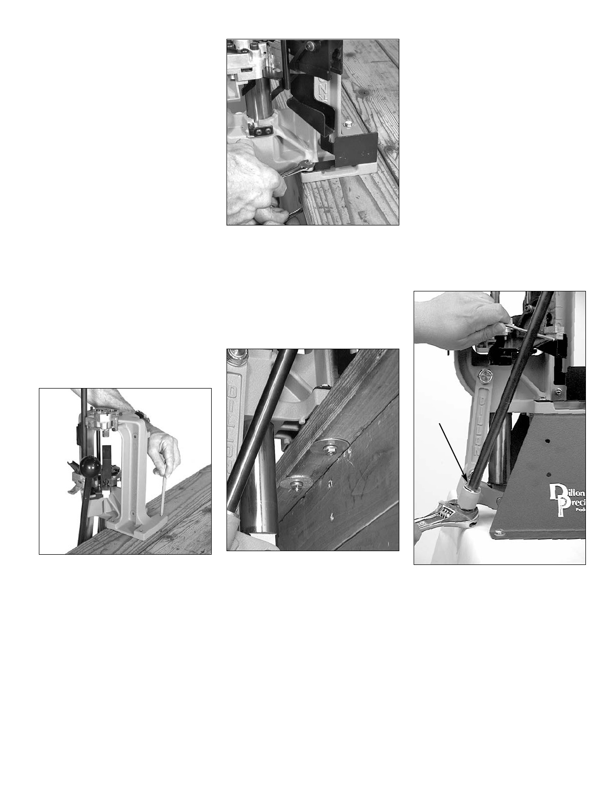
C. Drill the mounting holes FIG 1:
1. Using the machine as a template, mark
the four holes.
2. Using a 1/4” bit, drill the holes.
FIG 2
D. Bolting the machine to the
bench FIG 2:
Note: If you do not have a Mounting Hard-
ware Kit, ensure that you use 1/4”
or equivalent through bolts (with
large area washers if mounting to
wood). Do not use lag bolts or wood
screws!
FIG 3
1. Mount the left side of the machine with
the small washers on top and the large
washers on the bottom FIG 3. Run
the two left side nuts down finger tight.
2. Place the chute/bin bracket FIG 2 on
the right side of the machine. As
before, place the small washer on top
and the large washers on the bottom
and thread the nuts.
Note: The chute/bin mount goes under
the two right hand mounting bolts so
it must be installed as you are
mounting the machine FIG 2.
Check the fit of the chute/bin
mount. The chute/bin mount
should rest snugly against the
frame. Also, make sure that the
walls of the chute are parallel and
have not been bent during ship-
ping or installation.
3. Using two 7/16” wrenches, tighten all
four bolts down.
3.Initial Set Up
If you ordered your XL 650 for a specific
caliber, it comes factory adjusted for that
caliber (minus dies) with the appropriate
“caliber specific” parts included. In fact, a
Dillon technician runs casings and primers
through the machine to check its function.
Note: As you assemble your machine,
we recommend that you cross
check caliber specific parts, includ-
ed with your machine, with those
specified in the caliber conversion
chart (pages 42-44). The
point being – if we sent you the
wrong part, you’ll want to know it
before getting started. Reference
page 35 for instructions on how to
use the caliber conversion chart.
FIG 4
A. Installation of the handle FIG 4:
1. Hold the washer (see arrow FIG 4)
over the hole on the right side of the
crank and insert the handle.
2. Place a 5/32” Allen wrench or screw
driver through the hole in the handle to
help your grip.
3. Tighten the nut using a 7/8” wrench.
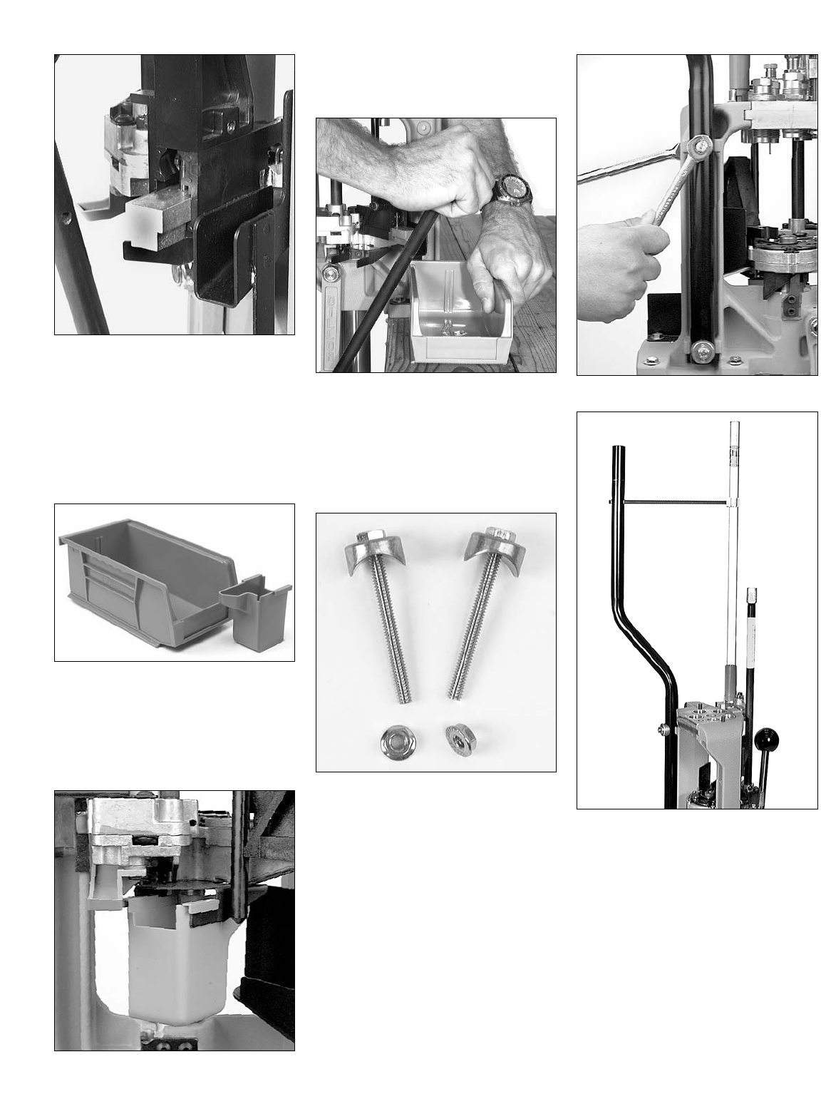
FIG 5
Operate the handle slowly to ensure that
the machine operates smoothly. Make sure
that the handle and the crank completely
clear the bench. Contact with the bench may
hinder its range of movement. Observe the
movement of the shellplate platform and veri-
fy that there is no interference or contact of
the case insert slide and the chute/bin mount
FIG 5.
FIG 6
B. Installation of the Spent
Primer Cup FIG 7 and
Cartridge Bin FIG 6:
1. Raise the platform (i.e., lower the
handle all the way).
FIG 7
2. Slide the spent primer cup onto the
rails as shown. Make sure when
installing the cup that it is on both
rails.
FIG 8
3. Place the cartridge bin on the
chute/bin bracket. Push the handle aft
FIG 8 while sliding the bin toward
the handle as shown. With the handle
pushed to its full aft position, there
should be a space between the han-
dle and bin.
FIG 9
C. Installation of the Casefeed
Post
1. Remove the bolts, nuts and clamp
from the spacer kit and assemble
them as shown in FIG 9.
FIG 10
FIG 11
2. Install the casefeed post as shown in
FIG 10. Make sure the bend in the
post is facing away from you FIG 11.
3. Using two 7/16” wrenches, tighten
the bolts.
D. Installation of the Casefeed
Tube Bracket FIG 11.
Install as shown in FIG11.
Note: If you ordered your machine with
the optional casefeed assembly,
you won’t need to use the casefeed
tube bracket. This is because the
upper end of the casefeed tube is
supported by the casefeed bowl.
8
9
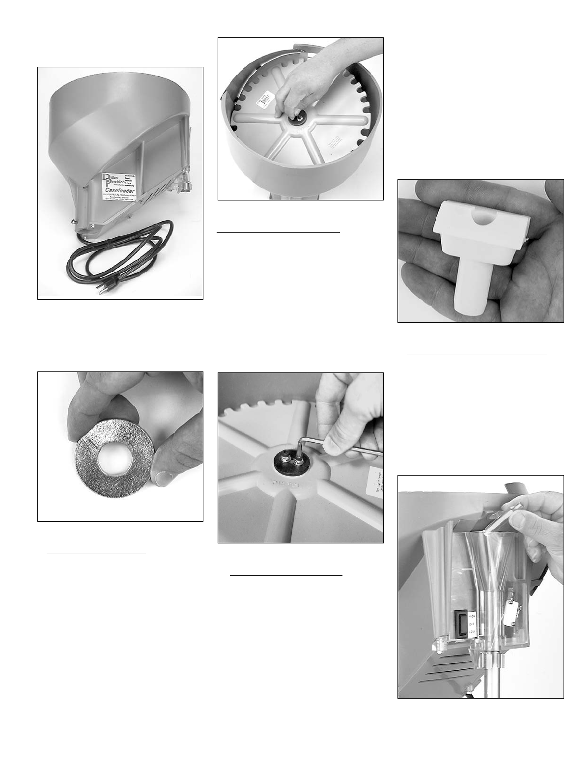
E. Installation of the Optional
Casefeeder FIG 12:
FIG 12
1. Remove the casefeed parts bag
from the casefeed bowl and remove
the casefeed assembly from the box
FIG 12.
FIG 13
a. Spacer Washer FIG 13:(see casefeed-
er schematic page 57)
Some calibers call for a spacer washer to
be used under the casefeed plate.
Installation of this washer raises the plate up
a bit to make the feeder function properly
with longer pistol cases (such as .357
Magnum, .44 Magnum and .30 M1 – this
listing of calibers requiring the spacer is
repeated in the caliber conversion chart on
pages 46-48 of this manual).
Note: The spacer washer does not come
factory installed.
FIG 14
To Install the Spacer Washer:
a.1. FIG 14 Remove the casefeed plate.
a.2. With the casefeed plate removed, dis-
assemble the clutch drive. To do so
unscrew the two clutch screws.
a.3. Install the spacer washer as illustrated
in the casefeed schematic (page 57).
IMPORTANT: The spacer washer goes
between the lower clutch and the case-
feed plate.
a.4. Reassemble the clutch drive and rein-
stall the casefeed plate. (Note how the
clutch drive engages the drive pin).
FIG 15
b. Clutch Adjustment FIG 15:
Note: The clutch comes factory adjusted
(if you don’t have to install the
spacer washer you shouldn’t have
to adjust the clutch drive).
The two socket-head machine screws (pt#
13732) should be just tight enough for the
clutch to drive the casefeed plate under a
normal load of brass. To check this, place
the casefeed assembly in front of you on the
bench. With the switch off, plug the case-
feeder in. Turn the switch to the down (low)
position and observe the movement of the
plate. You should be able to cause the
clutch to slip, using moderate finger pres-
sure, without stalling the motor. Alternately
tighten and loosen the two machine screws
evenly, observing the effect on the holding
power of the clutch. The correct setting
will stall the plate before stalling the motor,
yet not slip when the casefeed bowl is
about half full of brass.
Note: The casefeed bowl is not designed
to be completely filled with brass. If
it is fully loaded it will not function
reliably. The rated capacity of the
casefeeder is about 1/2 of the
bowl’s physical capacity.
FIG 16
c. Casefeed Funnel Adapter FIG 16:
Some calibers call for the white plastic
funnel adapter to be used, located in the
casefeed accessory bag FIG 16. It is used
for feeding 9mm, .38 Super, .32 H&R, and
.380 ACP. (This listing of calibers is repeat-
ed in the caliber conversion chart on pages
46-48). Without this funnel adapter these
calibers will occasionally hang up in the
clear plastic funnel FIG 17 at the top of the
casefeed tube.
FIG 17
Note: The casefeed funnel adapter does
not come factory installed.
10
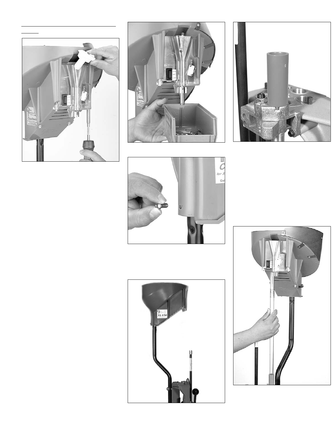
To Install the casefeed funnel adapter
FIG 18:
FIG 18
Remove the screws that attach the clear
casefeed funnel. Slide the front cover down
a bit, and slip the white plastic funnel
adapter into the funnel FIG 18. Reassemble.
Note: Do not loosen the two screws that
are holding the microswitch (pt#
13779).
Note: Occasional jams will occur. To
keep them to a minimum, be sure
to use the spacer washer FIG 13
or white casefeed funnel adapter
FIG 16 when called for. Use the
low setting if it will keep up with
your loading pace, and do not over-
load the casefeed bowl. The rated
capacity of the casefeeder is about
1/2 of the bowl’s physical capacity.
Before placing the casefeed bowl on the
casefeed post, take a moment to look over
and understand the casefeed assembly and
how it works. If you like, you can run the
casefeeder before placing it on top of the
casefeed post. This will allow you to get a
better idea of how it works. To do so, plug
in the casefeeder and fill it with about 50
cases. Hold the casefeeder FIG 19 so the
funnel is vertical. Place the cartridge bin
under the funnel and turn it on. Experi-ment
using both the high and low settings.
FIG 19
FIG 20
2. Remove the set screw from the acces-
sory bag and thread it into the case-
feed assembly FIG 20.
FIG 21
3. Place the casefeed bowl onto the
casefeed post FIG 21.
FIG 22
4. Place the casefeed adapter on the case-
feed body FIG 22. Note how the key
fits into the notch on the casefeed
body.
Note: Casefeed adapters are caliber spe-
cific. Crosscheck your casefeed
adapter with the one listed in the
caliber conversion chart (for the cal-
iber you’re loading) to ensure that
you have the correct one installed in
your machine.
FIG 23
5. Align the casefeed bowl so the spring
clamp is directly over the casefeed
adapter. Place the casefeed tube into
the casefeed adapter then snap the
tube into the clamp FIG 23.
11
Note: One end of the casefeed tube is
beveled and one end is squared off.
Insert the squared end of the tube
(down) into the top of the casefeed
adapter.
FIG 24
6. Using A 5/32” Allen wrench, snug
the machine screw against the case-
feed mounting post FIG 24 to pre-
vent the casefeed bowl from rotat-
ing.
4.Toolhead Overview
You’re now ready to install the toolhead
and adjust the dies. But first, we’ll give a
brief overview of the location and function
of each station, we’ll then follow up with a
detailed illustration.
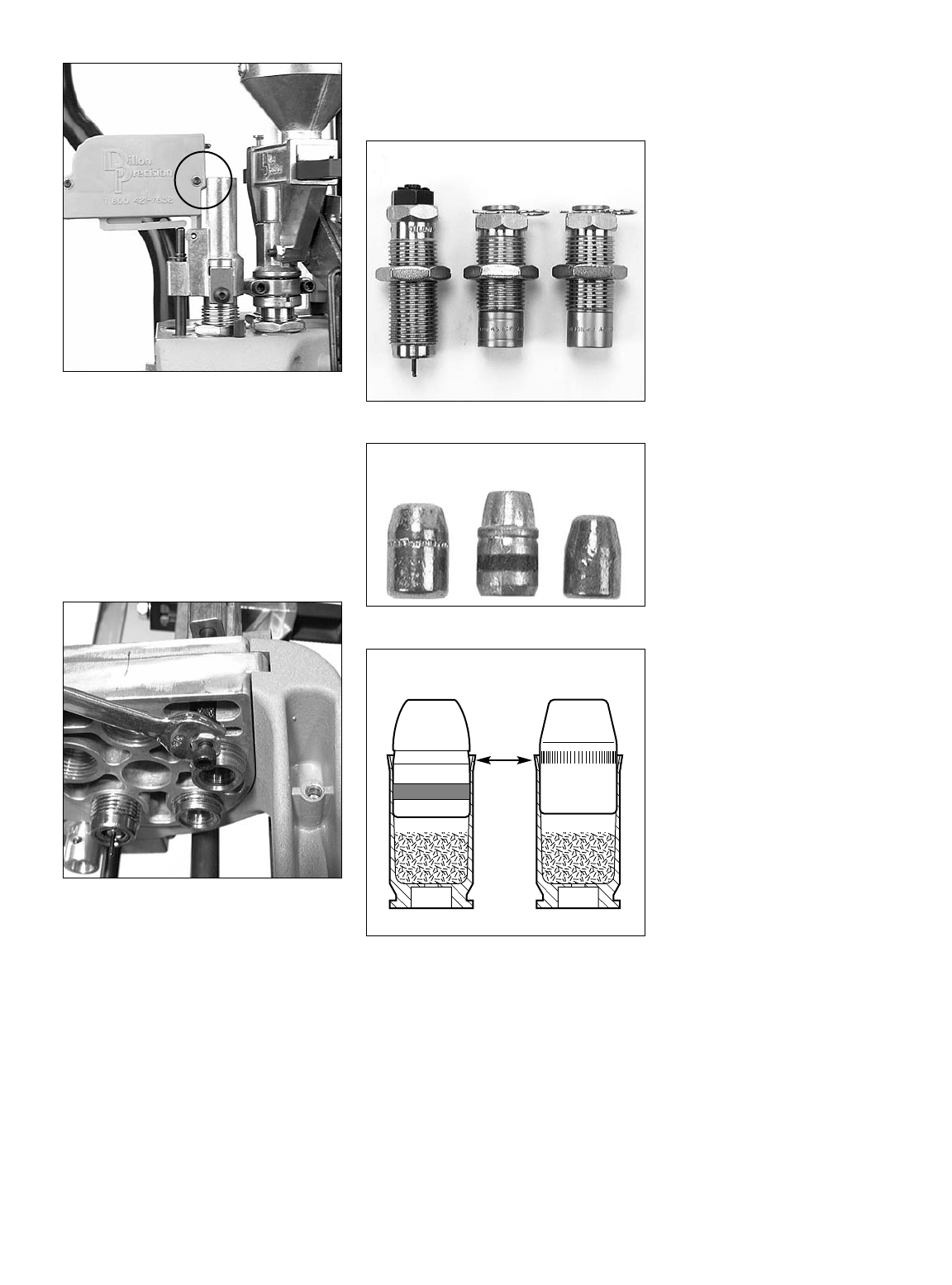
FIG 25
Station 1 - Sizing/Decapping
The stations on the toolhead are num-
bered 1-5. Station 1 is for the sizing/decap-
ping die FIG 25. This die can be easily
identified by the decapping pin sticking out
the bottom as well as by its label. This die
removes or “decaps” the old primer and
resizes the case.
Warning: Never decap live primers! (See
mandatory safety procedures.)
Station 2 - Powder Measure
FIG 26
Station 2 is for the powder die, which
comes attached to the powder measure
FIG 26. Here several operations are con-
ducted. The case is primed, straightwalled
pistol cases are belled, and powder is
dropped. The purpose of the bell at the
mouth of the case is simply to help align
the bullet and to keep the case from shav-
ing lead during the seating process. Note:
Only straight-walled cases receive a bell,
bottle-necked cases (rifle cartridges) are
not belled.
FIG 27
Station 3 - Powder Check
Station 3 is used for the optional powder
check system FIG 27. This system is located
in a separate package and can be identified
by the blue warning buzzer attached to a
die. This system is designed to detect gross
deviations in the powder charge, i.e. a dou-
ble charge of powder or no powder at all.
Station 4 - Bullet Seating
Station 4 is for the seating die FIG 25.
This is where the bullet is pushed into the
case.
Station 5 - Crimp
Station 5 is for the crimp die FIG 25. This
die not only removes the bell created at
Station 2, but rolls the mouth of the case
inward to insure proper feeding and to
secure the bullet.
LUBRICATING BRASS
To lubricate brass, use “Dillon Case
Lubricant” (item# 13733).
Pistol – If you’re using a carbide sizing
die, you will not need to lubricate your
cases (before sizing) when loading straight-
walled cases. If you’re not using a carbide
sizing die, you must lube the brass before
sizing. We do, however, recommend lubri-
cating all brass.
Rifle – Lubricate all bottle-necked cases,
even if you’re using a carbide sizing die.
To lubricate your cases, start by ensur-
ing that they are clean. Place your clean
brass in a shallow box so the cases are lay-
ing on their side. Pump a couple of sprays
of Dillon Case Lubricant over the cases.
Shake the box so the cases will tumble and
roll. Repeat this process again making sure
that the lubricant is well distributed over the
cases.
Note: When loading rifle cartridges, if your
sizing die doesn’t have a carbide
case mouth expander, you may
want to allow a little bit of lube to get
inside the case mouth.
Note: When loading bottle-necked
cartridges, if you get an excessive
amount of lube on the shoulder of
the case, it will leave oil dents.
Regardless of whether you’re lubri
cating pistol or rifle cases – do not
drench the cases in lubricant. A light
film of lubricant is sufficient.
Toolhead Head Setup:
Pistol – go to page 12
Rifle – go to page 20
12
PISTOL SECTION –
Toolhead Set Up
To set up the toolhead you’ll need to have
empty brass, bullets, primers and powder
on hand. (For your convenience Dillon
Precision offers a wide variety of new
primed and unprimed brass, bullets, primers
and powder.) For easy access, place your
brass in an open container. Dillon Precision
also offers a variety of blue bin boxes which
come in handy for this purpose.
A. Station 1 – To install the
size/decap die FIG 25:
Warning: Never attempt to de-prime live
primers, an explosion may result in
serious injury or even death.
1. Raise the platform, by lowering the
handle all the way down.
2. Screw the sizing die into Station 1.
Continue to screw the die down until
it just touches the shellplate. Tighten
the die lockring finger tight Now
lower the platform by raising the han-
dle to its upright position.
3. Place a case in the casefeed funnel.
Here, the case drops to the casefeed
arm bushing.
4. Raise the platform. The inserter cam
pushes the feed arm bushing over the
body, dropping the case onto the
Station 1 locator.
5. Lower the platform. The case is insert-
ed into Station 1.
FIG 28
Note: After raising the handle, insure that
you push the handle against its full aft
stop FIG 28. This will insure
that the case is fully inserted into
Station 1.
Note: Also, when priming, pushing the
handle against its full aft stop, FIG
28, will insure that the primer is
fully seated.
6. Again, raise the platform. The case is
now sized. If the case has a spent
primer, it will be deprimed. Leave
the platform in the raised position
with the case fully inserted in the
die. This will ensure that the die
remains in alignment when tighten-
ing the lockring.
FIG 29
7. Using a 1-1/8” wrench to turn the
lockring and a 7/8” wrench to hold
the die body, tighten the lockring
FIG 29.
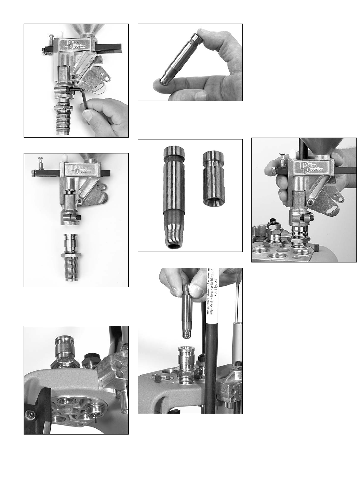
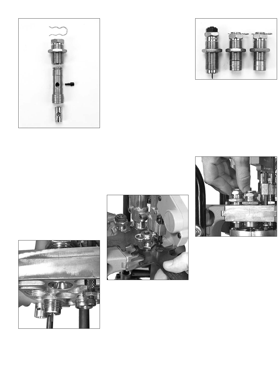
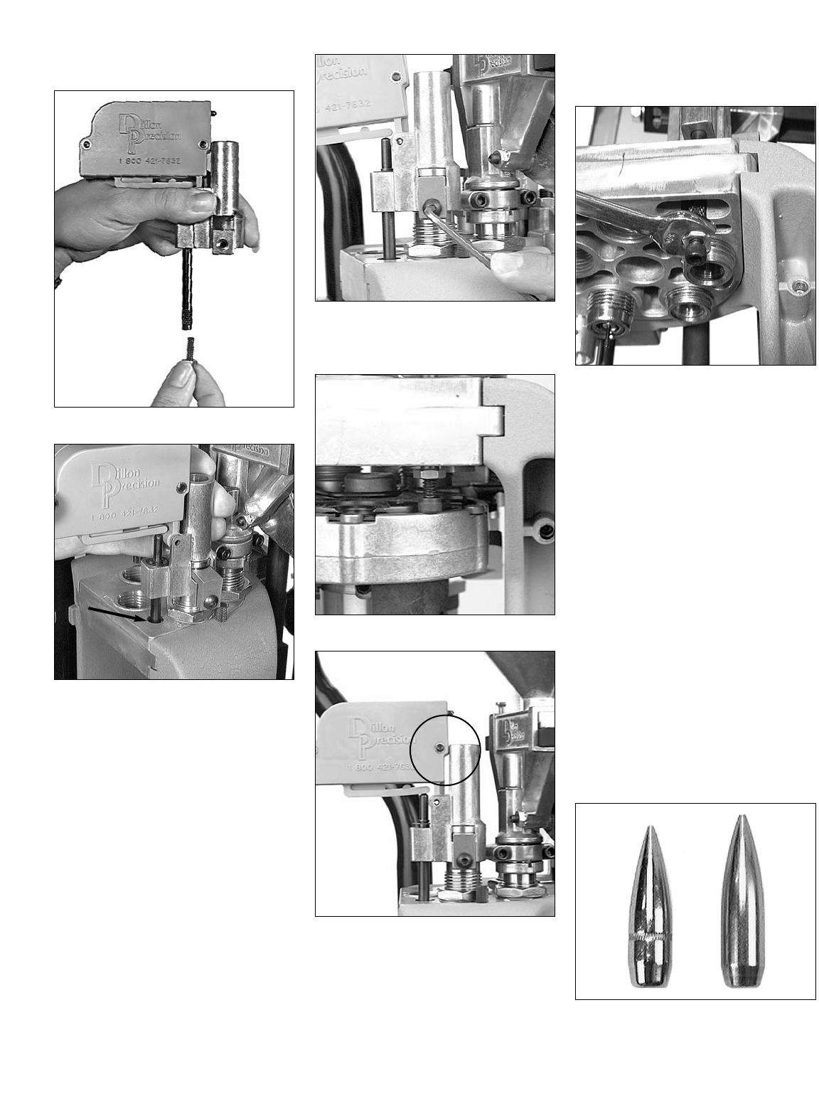
FIG 30
B. Station 1 – The decap-
ping assembly FIG 30:
Dillon decapping assemblies are made
with replaceable decap pins. One extra pin
is included with each sizing die. To replace
a bent or broken pin, simply:
1. Unscrew the decapping assembly
from the top of the die FIG 30.
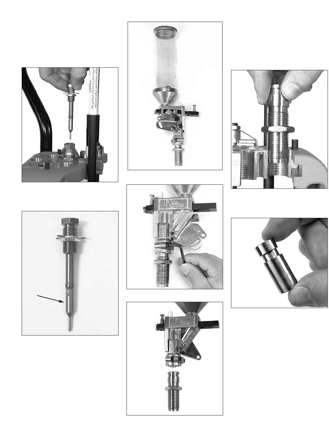
FIG 31
2. Unscrew the knurled retaining nut,
see “A” FIG 31, remove the old pin
and replace it with a new one, see
“B” FIG 31.
3. Screw the decapping assembly back
into the sizing die.
Note: The decapping assembly can be
removed from the sizing die without
affecting the adjustment of the siz-
ing die or sizing operation.
Note: The decapping assembly must be
removed when loading primed
cases. (Tip: Check prices of
components. You can often pur-
chase primed cases for the price
of the primers and new empty
cases. Obviously, this is a good
deal since you pay the same price
and save time.)
FIG 32
C. Station 2 – Installation of
powder measure assembly
FIG 32:
A
B
13
FIG 33
FIG 34
1. Use a 5/32” Allen wrench to loosen
the two collar clamp screws and
remove the powder die FIG 33 & 34.
FIG 35
2. Screw the powder die into Station 2.
Stop when the die is flush with the
bottom of the toolhead FIG 35.
FIG 36
3. Remove the powder funnel FIG 36
from the bag containing the locator
buttons.
FIG 37
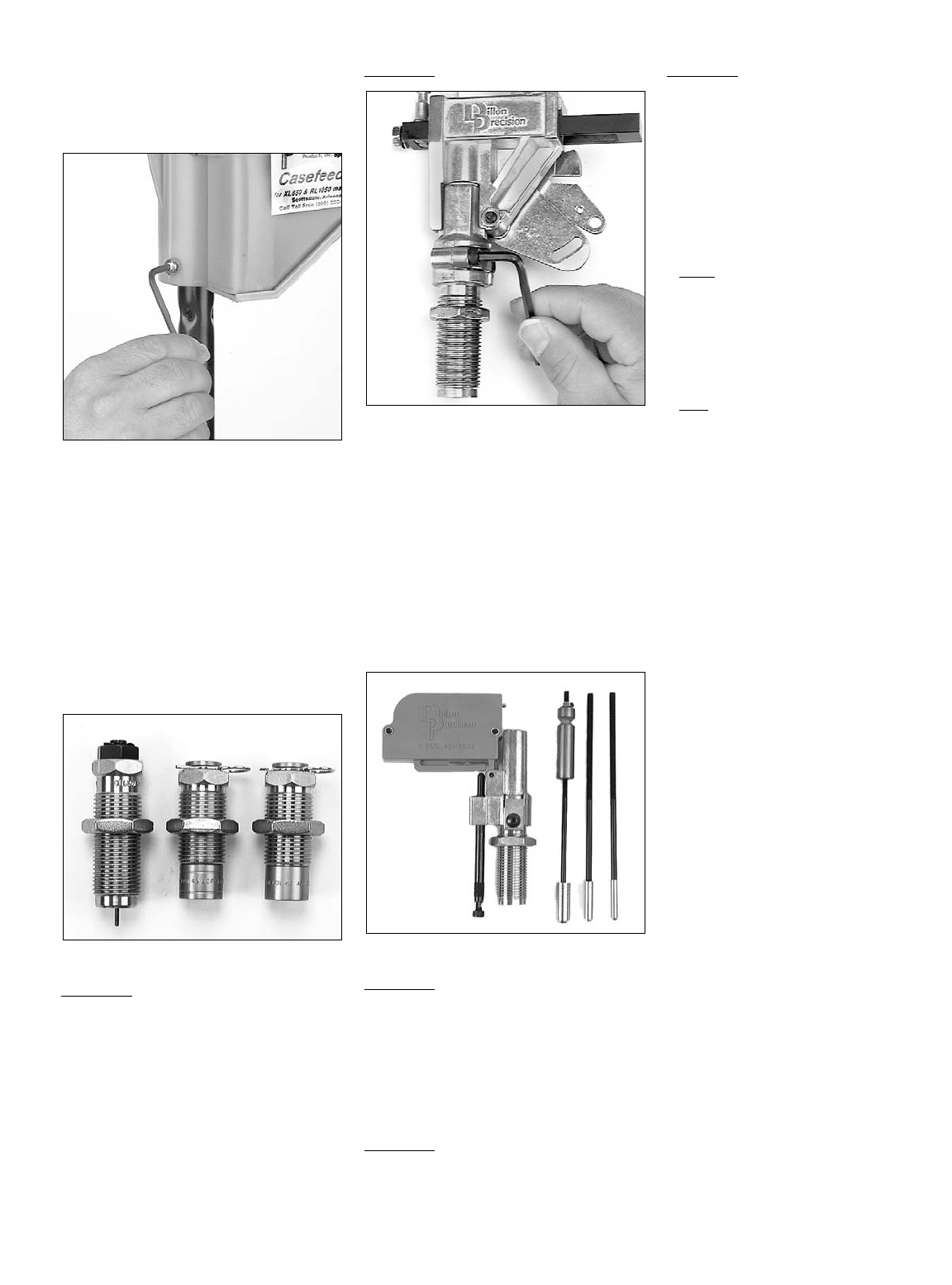
FIG 38
About Powder Funnels:
In FIG 37 are two examples of the many
powder funnels available for the XL 650.
On the left is a typical pistol caliber fun-
nel. On the right, a rifle or bottle-necked
type. The bottom of the rifle-style funnel
fits snugly over the neck of the case,
allowing powder to drop in without
spilling (the rifle-style powder funnel does
not bell the mouth of the case). The bot-
tom of the pistol funnel, on the other hand,
fits inside and actually expands and bells
as it guides the powder into the case.
Powder funnels are caliber specific, so be
sure you have the correct funnel by refer-
ring to the caliber conversion chart.
4. Insert the funnel into the die FIG 38.
Make sure that you insert the funnel
into the die with the grooved end up.
The funnel should move up and
down freely.
FIG 39
5. Remove the lid and the protective
cardboard tube from the powder
measure and place it onto the pow-
der die FIG 39. Turn down the two
clamp screws until they are snug.
Then loosen them slightly. The mea-
sure should move freely atop the die.
D. Station 2: About Powder
Bars
Dillon Precision manufactures four types
of powder bars for the XL 650:
1. Extra Small – use for dropping less
than 3 grains of powder.
2. Small – use for dropping 3 to 20
grains of powder.
3. Large – use for dropping 20 to approx.
45-50 grains of powder.
4. Magnum – use for dropping more
than approx. 45-50 grains of powder.
The extra small powder bar is used when
loading .32 Auto, .32 S&W and .32 SWL.
Both the extra small powder bar and the
magnum powder bar are non-standard
items and are ordered separately. The large
and small powder bar, on the other hand,
14
are standard equipment and are included
with every XL 650. If you ordered your
machine set up for a specific caliber, the
proper size powder bar should already be
installed. If you need to change the pow-
der bar – refer to “Powder Bar Adjust-
ment” in the Caliber Conversion Section
on page 30.
E. Station 2 – Adjustment
of Powder Die & Powder
Funnel:
Note: Adjusting the powder die for a
straight wall case is not the same
as adjusting a powder die for a
bottle-necked case. This is
because straight wall cases are
given a bell and bottle-necked
cases are not given a bell.
Adjusting the powder die for a
bottle-necked case is covered in
the rifle section.
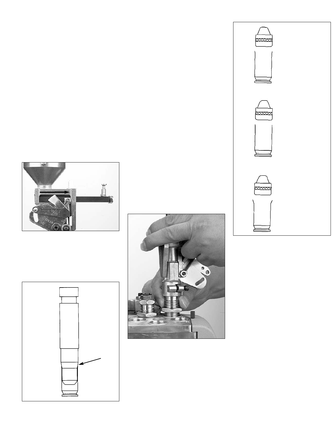
FIG 40
For the powder bar to properly dispense a
measured powder charge the powder bar
must travel its full distance. To travel its full
distance, the white cube must contact the
powder measure body (see arrow FIG 40).
FIG 41
Also the belling process does not begin until
after the powder bar has traveled its full dis-
tance. The angled portion on the bottom of
the powder funnel (see arrow FIG 41) is
what bells the cartridge. Once the white
cube has contacted the powder measure
body the case is forced upward against the
tapered portion of the powder funnel pro-
ducing a bell. The more the powder die is
adjusted down (clockwise) the more the
case will be belled.
Note: If the powder die is not adjusted
down far enough to cause the
powder bar to travel its full dis-
tance the powder charge will be
erratic and the case will not
receive enough bell.
To adjust the powder die/powder
funnel:
1. Drop a case into the casefeed funnel
and cycle the handle. The case
should now be in the shellplate at
Station 1.
2. Raise the platform. Notice the resis-
tance at the end of the downstroke.
This is the resistance of the case in
the sizing die. Lower the platform.
The case will index to Station 2.
3. Raise the platform. Check to see
how far the powder bar has traveled
FIG 40.
FIG 42
4. If the white cube has not traveled its
full distance, lower the platform just
enough to pull the case off of the
powder funnel (this will prevent the
shellplate from indexing while you
adjust the powder die). While holding
the powder measure, turn the die
down 1/8 of a turn FIG 42. Again
raise the platform and observe the
travel of the powder bar.
5. Repeat step four until the powder bar
travels its full distance FIG 40.
FIG 43
Once the powder bar travels fully across
you should continue to adjust the powder
die for the desired amount of bell (turn the
powder die 1/8 of a turn at a time). The
desired amount bell is just enough to allow
the bullet to sit on the case mouth without
falling off and to keep the case from shaving
lead during the seating process (see “A”
FIG 43).
Note: If you screw the die down too far,
the case will look like example “C”
FIG 43. You must then discard
this case, back the powder die off,
by turning it counter-clockwise, and
continue with a new sized case.
You’ll soon learn to judge the correct
amount of bell by simply looking at it. In
the meantime, you might want to use your
dial calipers to check it. Twenty thou-
sandths of an inch greater (at the mouth of
the case) than its original diameter, should
about do it.
A
Correct amount of
bell.
B
Not enough bell.
C
Too much bell.
15
FIG 44
6. Once you’ve achieved the desired
amount of bell – with the case in
Station 2, raise the platform. Run the
lockring down hand tight FIG 44.
FIG 45
FIG 46
7. Insure the bellcrank and the failsafe
bracket FIG 45 are aligned. Using a
5/32” Allen wrench, snug the collar
clamp screws FIG 46.
FIG 47
8. While holding the powder mea-
sure, snug the lockring using a 1
1/8 wrench FIG 47. Now lower the
platform.
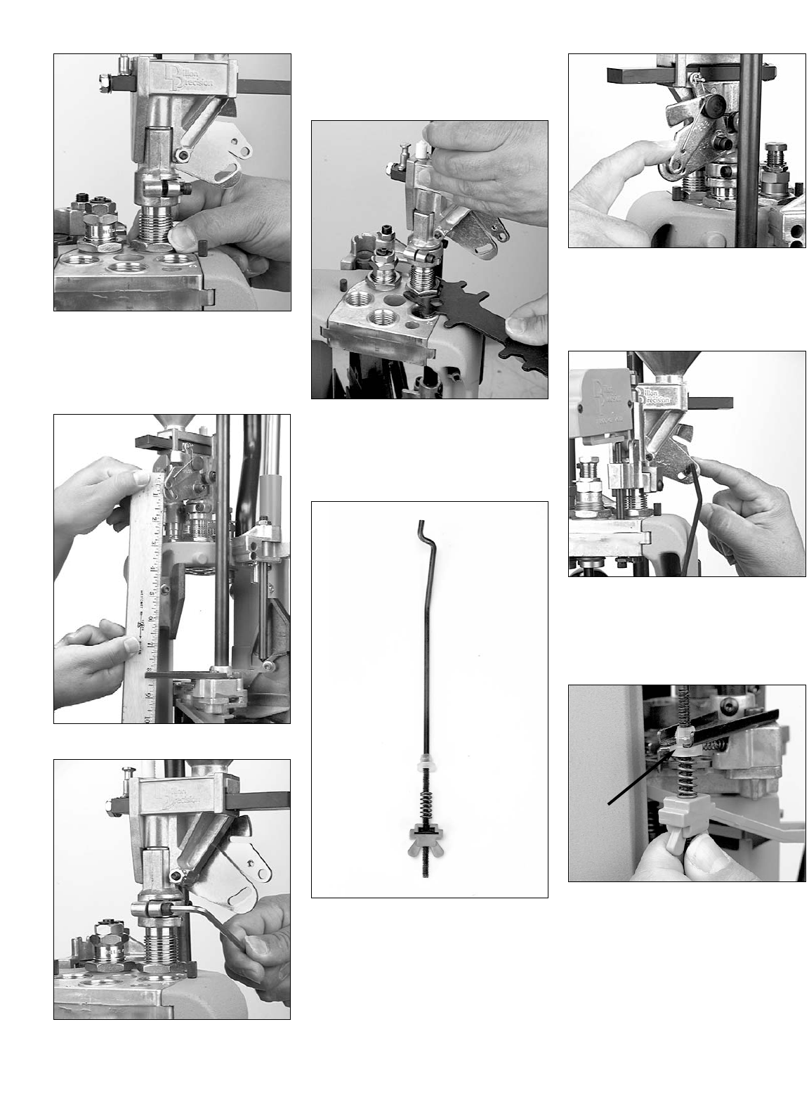
FIG 48
F. Station 2 – Installation of
the failsafe rod assembly
FIG 48:
The purpose of the powder measure fail-
safe rod is to return the powder bar to its re-
charge position.
FIG 49
1. Using your forefinger, move the lock-
link (#17838) down to align the hole
with the slot on the Powder Measure
bellcrank (#97034) FIG 49.
FIG 50
2. Insert the rod (#13629) through the
holes FIG 50.
3. Loosen the blue plastic wing nut
(#13799).
FIG 51
4. Slide the failsafe rod into the failsafe
return bracket. Push the shoulder
washer up into place (see arrow FIG
51) and tighten the blue plastic wing
nut until the spring just touches the
underside of the bracket.
Note: Do not fill the powder measure or
adjust the powder bar until the rest
of the dies are installed and adjusted.
16
FIG 52
G. Station 3 – Installation of
the Powder Check System
FIG 52:
Note: The powder check system does not
guarantee the accuracy of the pow-
der charge. It is designed to warn
you if the powder charge is grossly
out of tolerance, i.e., no powder or a
double charge.
Warning: A double-charged round (a
loaded round with twice as much
powder as it should have) can dam-
age your gun as well as cause bodi-
ly injury.
Warning: A round loaded without powder
can also damage your gun as well
as cause bodily injury. If a round
without powder is fired in your gun,
the detonation of the primer will
push the bullet part way down the
barrel. If the lodged bullet is not
removed before another round is
fired, the gun will be damaged
and bodily injury may occur.
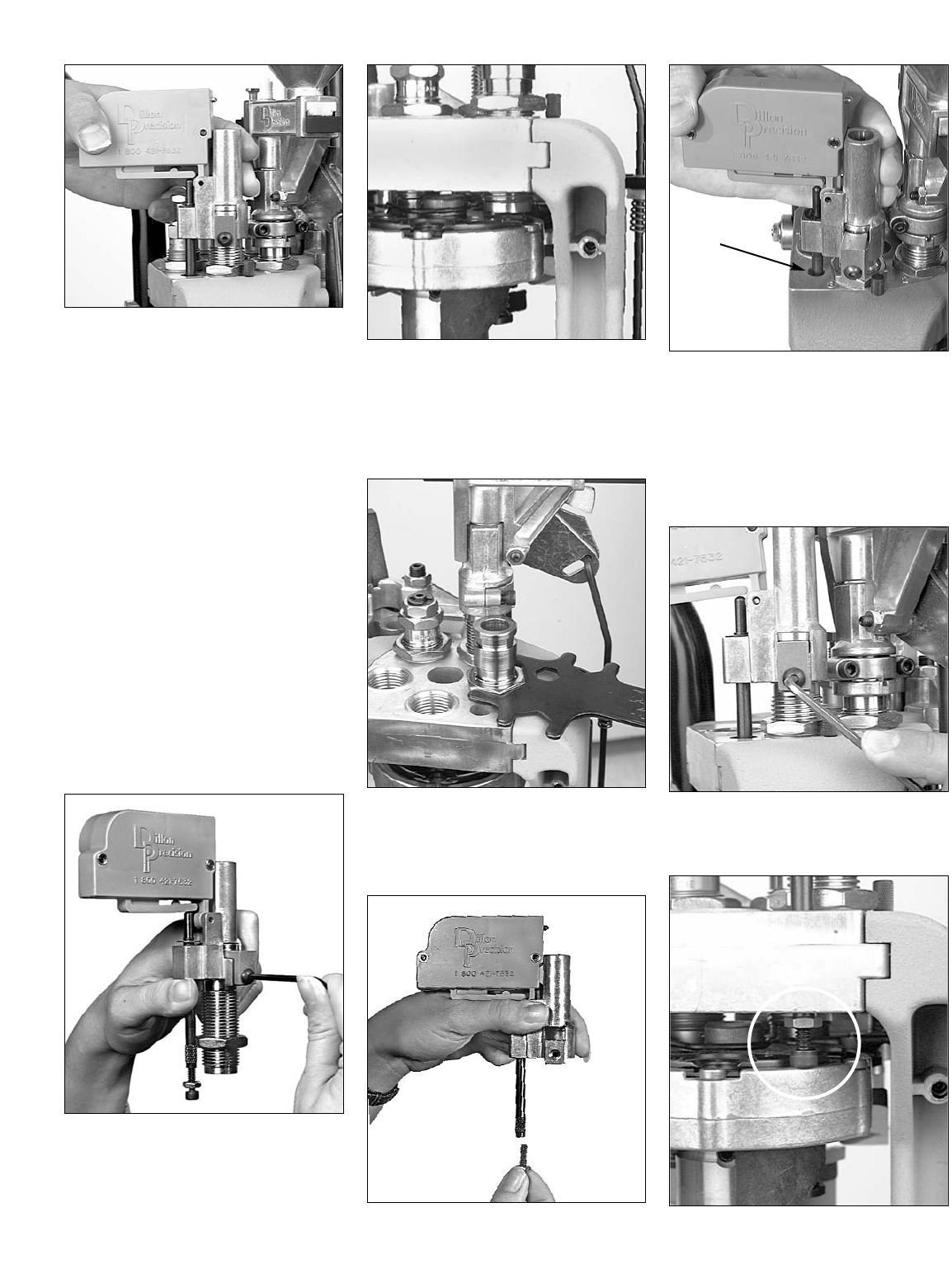
FIG 53
1. Loosen the die clamp screw FIG 53
and remove the die.
FIG 54
2. Raise the platform and screw the pow-
der check die into Station 3. There
should be a 1/8 to 1/4 inch space
between the shellplate and the bottom
of the die FIG 54.
FIG 55
3. Run the lockring down. Using a
1 1/8” wrench snug the lockring
FIG 55.
FIG 56
FIG 57
4. Remove the 10-24 screw and nut
from the black push rod FIG 56 and
place the powder check system on
the powder check die FIG 57.
Center the black push rod (see arrow
FIG 57) in the hole that is to the left
of the die.
FIG 58
5. Reinstall and snug the die clamp screw
FIG 58.
FIG 59
17
FIG 60
6. FIG 59 Screw the 10-24 screw and
nut fully into the rod. Raise the plat-
form. Unscrew the 10-24 screw until
it contacts the edge of the platform
FIG 59. Lower the platform part way
and unscrew the screw (counter-
clockwise) until raising the platform
causes the buzzer housing to gently
rock into the side of the die collar
FIG 60.
FIG 61
7. Secure the jam nut by holding the
black push rod while tightening it
using a 3/8” wrench FIG 61.
Note: Once you’ve adjusted the powder
bar for the desired powder charge,
adjustment of the powder check
system can be completed.
H. Station 4 – General
Information on Bullet
Seating
FIG 62
FIG 63
FIG 64
The purpose of the seating die FIG 62 is
to insert the bullet into the case and to push
it down into the case the proper amount.
How far the bullet is pushed into the case
will determine the overall length (OAL).
Several factors go into determining the
proper OAL – such as, the maximum rec-
ommended OAL, listed in the reloading
manual, and the type of bullet being
loaded. The type of bullet can determine
the OAL in one of two ways. If the bullet
has what is called a cannelure, or crimping
groove (items A&B in FIG 63), this will
determine the proper OAL. If the bullet
you’re using doesn’t have a cannelure or a
crimping groove (item C in FIG 63), then
you’ll need to refer to your reloading manu-
al for the suggested OAL. The purpose of
the cannelure and crimping groove is to
secure the bullet by giving the mouth of the
case a place to go (without deforming the
bullet) when being crimped. When the bul-
let is properly seated, the mouth of the car-
tridge case should be near the top of the
cannelure/crimping groove FIG 64.
Refer to your reloading manual. Under
the section specified for the caliber you’re
loading, you’ll find a schematic of the car-
tridge. For example, .38 Special lists a max-
imum OAL of 1.55” (Lyman Reloading
Handbook). If you’re seating the bullet to
the cannelure/crimping groove, the OAL
should be well within the maximum OAL
listed, however, use a set of dial calipers to
check it. (Dial calipers are available from
Dillon Precision). If the bullet you’re using
doesn’t have a cannelure/crimping groove,
refer to the specific type of bullet you’re
using in the reloading manual. For example
– if you’re loading a 158gr 38sp JHP and it
doesn’t have a cannelure/ crimping groove,
use the suggested OAL of 1.480 (Lyman
Reloading Handbook).
A
Sizing/Decapping Die
Seating Die Crimp Die
BC
18
FIG 65
I. Station 4 – Seating Stems
for pistol FIG 65
All pistol seating dies come with inter-
changeable seating stems. The seating stem
you should use will depend on the shape of
the bullet you’re loading. Three different
types of seating stems may be available –
wadcutter, semi-wadcutter and round nose.
Check to make sure that the seating stem
installed in your seating die matches the
bullet you are loading.
Dillon seating dies, which are being used
in this manual, are easily disassembled.
Simply remove the hitch pin from the top
and slide the seating stem out FIG 65.
Replace the seating stem and reassemble
the die.
FIG 66
J. Station 4 – Installation and
Adjustment of the
Seating Die:
1. Take the seating die from the die box
and screw it into Station 4. Screw
the die down until the bottom of the
die is flush with the bottom of the
toolhead FIG 66. Note: At this point
the die will not be screwed down far
enough to begin seating the bullet,
but it will give you a place to start.
2. Place a case (with a belled case
mouth) into Station 4.
3. Place a bullet on the belled case
mouth and raise the platform. Then,
lower the platform just enough to
inspect the bullet without indexing the
shellplate. If the bullet is not seated
deep enough, screw the seating die
down 1/2 turn at a time. As a guide,
one full turn moves the die down
about 70 thousandths of an inch,
about the thickness of a nickel.
Again, cycle the machine and inspect
the seating depth. Repeat these steps
as necessary until the correct overall
length is achieved. Use a dial caliper
or equivalent to measure the overall
length of the cartridge. Check the
overall length of the round against the
information in your reloading manual.
FIG 67
4. Once you have obtained the proper
OAL, replace the cartridge into
Station 4 and raise the platform.
Using a 1-1/8” wrench to turn the
lockring and a 7/8” wrench to hold
the die body, snug the lockring
FIG 67.
Note: If you should happen to seat the
bullet too deep, you can use a
Dillon bullet puller to reclaim your
components.
FIG 68
K. Station 5 – Installation and
adjustment of the Crimp
Die FIG 68:
1. Screw the crimp die into Station 5.
Screw it down until it is flush with the
bottom of the toolhead. This is a good
starting point for the crimp adjust-
ment.
2. Place a cartridge with a properly seat-
ed bullet into Station 5.
FIG 69
3. Raise the platform and continue to
screw the die down until it touches
the cartridge FIG 69.
4. Lower the platform and give the die
an 1/8 turn down, again raise the
platform.
5. Lower the platform halfway and
inspect the cartridge. If the bell is still
present, or the desired amount of
crimp has not been achieved, give
the die a 1/8 turn down and try again.
Continue making small adjustments
to your crimp die until the desired
amount of crimp has been achieved.
6. Once the adjustment is complete,
place the case back into Station 5 and
raise the platform. Using a 1-1/8”
wrench to turn the lockring and a
7/8” wrench to hold the die body,
snug the lockring.
Sizing/Decapping Die
Seating Die Crimp Die

FIG 70
Note: FIG 70 When adjusting the crimp
die it is important to know what to
look for. Check that the crimp: Looks
OK, allows your firearm to function
consistently and the bullet feels tight
in the case.
The drawing of case #3 FIG 70 is a
depiction of a case that has been over
crimped by adjusting the crimp die down
(clockwise) too far. Note the defined line
below the mouth of the case and the bulge
below the line. This is not a proper crimp.
This line is the direct result of the cartridge
being over crimped. A line like this will
only appear if the crimp die is adjusted
down too far. Warning: Over crimping
.45ACP, .38 Super, 9mm, etc., can actually
cause the bullet to be loose in the case.
Go to Loading Components
Section – Page 30
19
123
RIFLE SECTION –
Toolhead Set Up
To set up the toolhead you’ll need to
have your empty brass on hand. For your
convenience Dillon Precision offers a wide
variety of new primed and unprimed brass.
For easy access, place your brass in an
open container. Dillon Precision also offers
a variety of blue bin boxes which come in
handy for things like this.
FIG 71
A. Station 1 – About the Case
Gage FIG 71:
To install and adjust a sizing/decapping
die you must have a case gage and know
how to use it. The sizing die shapes the
case. If the case doesn’t have the proper
shape it won’t fit properly in the chamber of
the rifle. The purpose of the case gage is to
determine whether or not the case has the
proper shape, which in turn will tell you if
your sizing die is properly adjusted.
Note: Case gages are caliber specific.
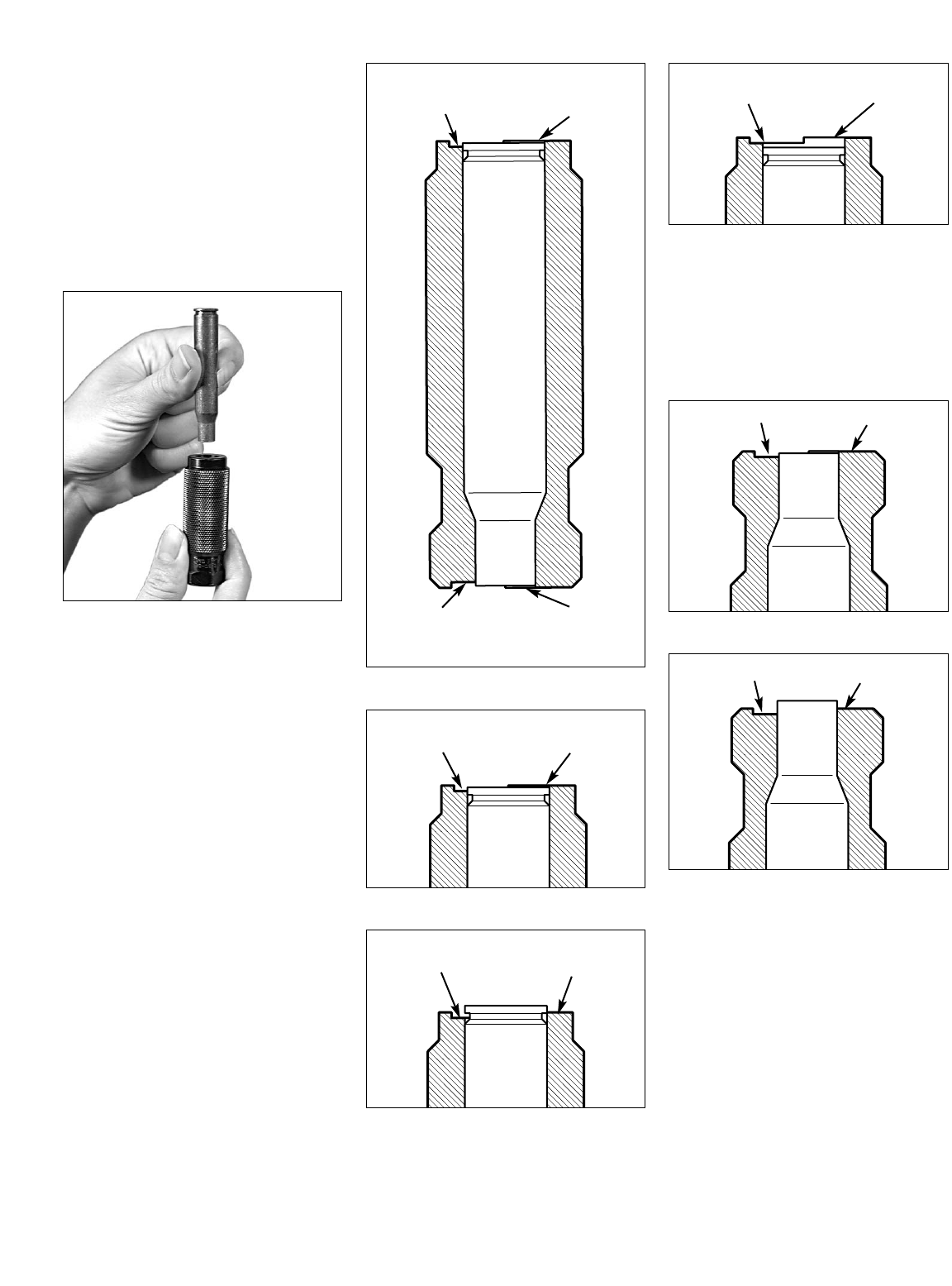
B. Station 1 – How to use the
Case Gage:
The way the case gage works is this:
Once you’ve made a preliminary adjust-
ment to your sizing die drop the sized case
all the way into the case gage FIG 72. Look
at the base of the case.
FIG 72
FIG 73
FIG 74
FIG 75
If the base of the case is below the high step
(see “B” FIG 73) and above the low step
(see “A” FIG 73) then the sizing die is prop-
erly adjusted. If the base of the case is
above the high step FIG 74 then you will
need to adjust the sizing die down by turn-
ing it clockwise.
FIG 76
FIG 77
If the base at the case is below low step
FIG 75 then the sizing die is adjusted
down too far and needs to be backed out
by turning it counter-clockwise (Note: this
case should be thrown away). Once the
sizing die is properly adjusted, drop the
properly sized case back into the case
gage and look at the mouth of the case FIG
76. If the case mouth is below the high
step (see “C” FIG 76) and above the low
step (see “D” FIG 76) then the case is the
proper length and will not need to be
trimmed. If the case mouth is above the
high step FIG 77 then the case mouth
needs to be trimmed in order to reduce the
overall length of the case. If you find that
your cases need to be trimmed, Dillon
Precision offers two types of case trimmers.
Figs 72 &
7
3
20
A
Low Step
B
High Step
C
Low Step
D
High Step
AB
AB
CD
AB
CD
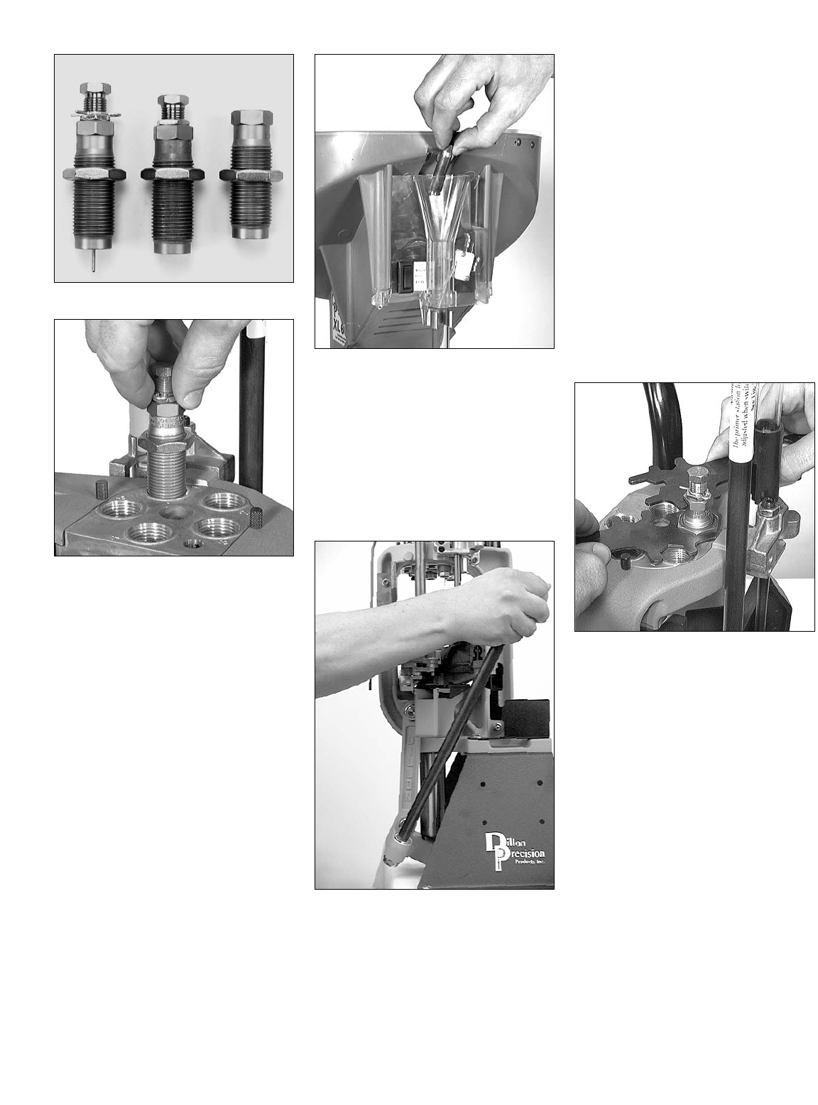
FIG 78
FIG 79
C. Station 1 – Installation
and adjustment of the siz-
ing/decapping die FIG 78:
Warning: Never attempt to de-prime a live
primer, an explosion may result
causing serious injury or even
death.
Note: Whenever sizing a bottle-necked
case you must lubricate the case
first, otherwise you will stick the
case inside the sizing die. For
more information refer to the section
“Lubricating Your Brass” (page 11).
1. Raise the platform, by lowering the
handle all the way.
2. Install the sizing die by screwing it
into Station 1 FIG 79. Continue to
screw the die down until the mouth
of the die is about the thickness of a
dime away from the shellplate. Lower
the platform by raising the handle to
its upright position.
FIG 80
3. Drop a lubricated case into the case-
feed funnel FIG 80. Here the case
drops to the casefeed arm bushing.
4. Raise the platform. The inserter cam
pushes the feed arm bushing over the
body, dropping the case onto the
Station 1 locator.
5. Lower the platform. The case is
inserted into Station 1.
FIG 81
Note: After raising the handle, insure that
you push the handle against its full
aft stop FIG 81. This will insure
that the case is fully inserted into
Station 1.
Note: When priming, pushing the handle
against its full aft stop will insure
that the primer is fully seated.
6. Again raise the platform. The case is
now sized. If the case has a spent
primer, it will be deprimed. Notice
the resistance at the end of the
downstroke. This is the resistance of
the case in the sizing die. Lower the
platform. The case will index to
Station 2.
7. Remove the case from Station 2 and
place it in the case gage. From this
point – follow the instructions provid-
ed under “Rifle Section B. Station 1 –
How to use the Case Gage.”
8. Once the sizing die is properly
adjusted, replace the case into Station
1 and raise the platform. Leave the
platform in the raised position with
the case fully inserted in the die. This
will ensure that the die remains in
position when tightening the lockring.
FIG 82
9. Run the lockring down until it con-
tacts the toolhead. Using a 1 1/8”
wrench to turn the lockring and a
3/4” wrench to hold the die body,
snug the lockring FIG 82.
21
Sizing/Decapping Die
Seating Die Crimp Die
D. Station 1 – The decapping
assembly FIG 78:
Dillon decapping assemblies are made
with replaceable decap pins. One extra pin
is included with each sizing die. To replace
a bent or broken pin, simply:
FIG 83
1. Unscrew the decapping assembly
from the top of the die FIG 83.
FIG 84
2. Unscrew the decapping pin (see
arrow FIG 84), and replace it with a
new one.
3. Screw the decapping assembly back
into the sizing die.
Note: The decapping assembly can be
removed from the sizing die without
affecting the adjustment of the siz-
ing die or sizing operation.
Note: The decapping assembly must be
removed when loading primed
cases.
FIG 85
FIG 86
FIG 87
E. Station 2 – Installation
of powder measure assem-
bly FIG 85:
1. Using a 5/32” Allen wrench, loosen
the two collar clamp screws and
remove the powder die FIG 86 & 87.
FIG 88
2. Thread the powder die into Station 2.
Screw it down about halfway FIG 88.
FIG 89
3. Remove the powder funnel from the
bag containing the brass locator but-
tons FIG 89.
22
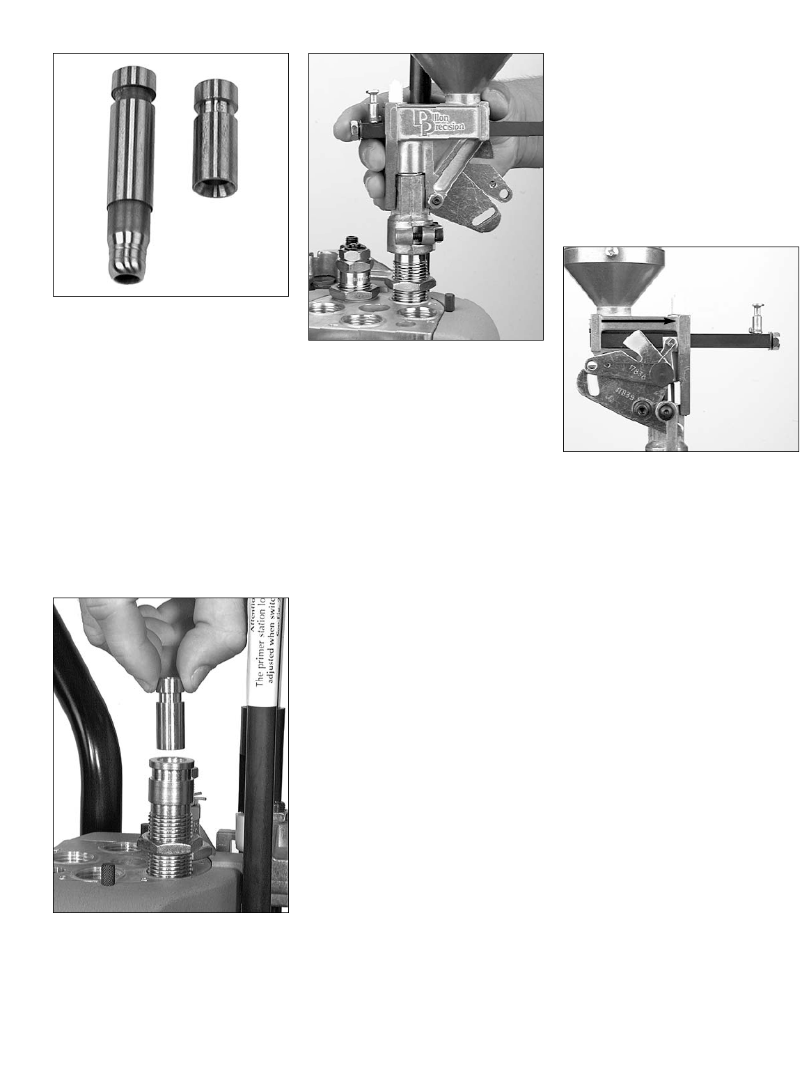
FIG 90
In FIG 90 are two examples of the many
powder funnels available for the XL 650.
On the left is a typical pistol caliber fun-
nel. On the right, a rifle or bottle-necked
type. The bottom of the rifle style funnel
fits snugly over the neck of the case allow-
ing powder to drop in without spilling (the
rifle style powder funnel does not bell the
mouth of the case). The bottom of the pis-
tol funnel, on the other hand, fits inside
and actually expands the case mouth as it
guides the powder into the case (the
expansion of the case mouth is where the
mouth of the case gets its bell). Powder
funnels are caliber specific so be sure you
have the correct funnel by referring to the
caliber conversion chart.
FIG 91
4. Insert the funnel into the die FIG 91.
Regardless of whether you’re using a
rifle or pistol powder funnel, make
sure that you insert the funnel into the
die with the grooved end up. It
should move up and down freely.
FIG 92
5. Remove the lid and the protective
cardboard tube from the powder mea-
sure and place it onto the powder die
FIG 92. Turn down the two clamp
screws until they are snug. Then
loosen them slightly. The measure
should move freely atop the die.
F. Station 2 – About powder
bars:
Dillon Precision manufactures four types
of powder bars for the XL 650:
1. Extra Small – use for dropping less
than 3 grains of powder.
2. Small – use for dropping 3 to 10
grains of powder.
3. Large – use for dropping 10 to
approx. 45-50 grains of powder.
4. Magnum – use for dropping more
than approx. 45-50 grains of powder.
The extra small powder bar is used when
loading .32 Auto, .32 S&W and .32 SWL.
Both the extra small powder bar and the
magnum powder bar are non-standard
items and are ordered separately. The large
and small powder bar, on the other hand,
are standard equipment and are included
with every XL 650. If you ordered your
machine set up for a specific caliber, the
proper size powder bar should already be
installed. If you need to change out the
powder bar – refer to “Powder Bar
Adjustment” in the Caliber Conversion
Section on page 30.
G. Station 2 – Adjustment
of Powder Die/Powder
Funnel
Important: Adjusting the powder die for a
bottle-necked case is not the same
as adjusting the powder die for
straight-walled cases. This is
because bottle-necked cartridges
are not given a bell – straight-
walled cases are given a bell. For
straight-walled cartridges refer to
the pistol section.
FIG 93
For the powder bar to properly dispense a
measured powder charge, the powder bar
must travel its full distance. To travel its full
distance, the white cube must contact the
powder measure body (see arrow FIG 93).
When adjusting the powder die for a
bottle-necked cartridge, the objective is to
adjust the powder die so that the powder
bar just travels the full distance and no
further (see arrow FIG 93). If you try to
apply the procedures used for belling a
straight walled case, as when loading pis-
tol cartridges, you will crush the bottle-
necked case and possibly damage the
powder measure.
Note: If the powder die is not adjusted
down far enough to cause the pow-
der bar to travel its full distance the
powder charge will be erratic.
Note: Whenever sizing a bottle-necked
case you must lubricate the case
first, otherwise you will stick the
case inside the sizing die. For
more information refer to the section
“Lubricating Your Brass” (page 11).
23
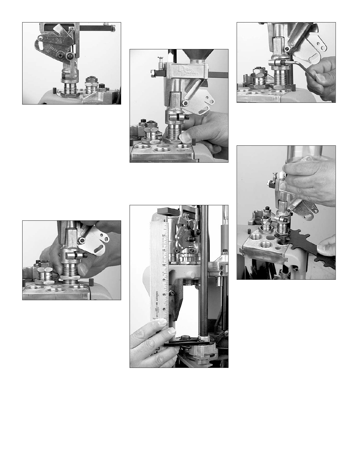
FIG 94
To adjust the powder die/powder
funnel:
1. Drop a lubricated case into the case-
feed funnel and cycle the handle. The
case should now be in the shellplate
at Station 1.
2. Raise the platform. Notice the resis-
tance at the end of the downstroke.
This is the resistance of the case in
the sizing die. Lower the platform.
The case will index to Station 2.
3. Raise the platform. Check to see
how far the powder bar has traveled
FIG 94.
FIG 95
4. If the white cube has not traveled its
full distance, lower the platform just
enough to pull the case off of the
powder funnel (this will prevent the
shellplate from indexing while you
adjust the powder die). While holding
the powder measure, turn the die
down 1/8 of a turn FIG 95. Again
raise the platform and observe the
travel of the powder bar.
5. Repeat step four until the powder bar
travels its full distance FIG 94.
Note: If you screw the powder die down
too far, the powder bar will travel its
full distance before the handle is all
the way down. If this happens – DO
NOT FORCE THE HANDLE
DOWN. Instead lower the platform
and back the powder die out by
turning it counter-clockwise. If you
force the handle, you will crush the
case and possibly damage the pow-
der measure.
FIG 96
6. Once the powder bar is traveling its
full distance – with the case in Station
2 – raise the platform. Run the lock-
ring down hand tight FIG 96.
FIG 97
FIG 98
7. Insure the bellcrank and the failsafe
bracket are aligned, FIG 97. Using a
5/32” Allen wrench snug the collar
clamp screws, FIG 98.
FIG 99
8. While holding the powder measure,
snug the lockring using a 1 1/8”
wrench FIG 99. Now lower the plat-
form.
24
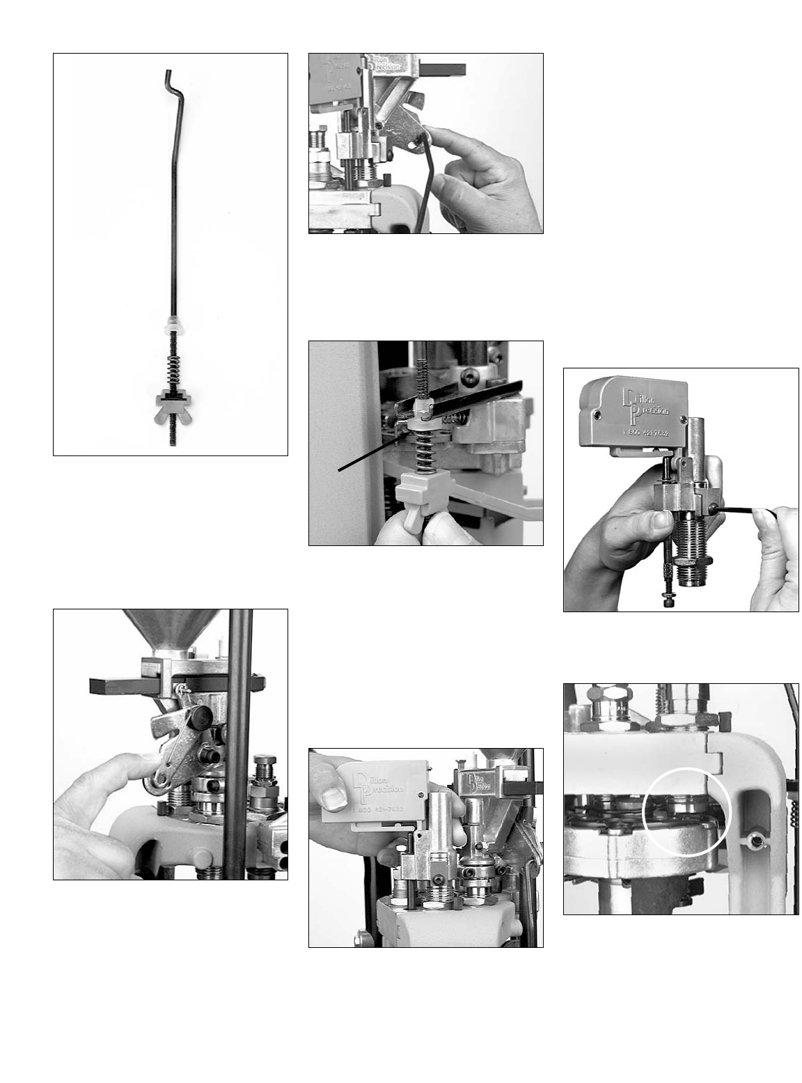
FIG 100
H. Station 2 – Installation of
the failsafe rod assembly
FIG 100:
The purpose of the powder measure fail-
safe rod is to return the powder bar to its re-
charge position.
FIG 101
1. Using your forefinger, move the lock-
link down to align the hole with the
slot on the Powder Measure bellcrank
FIG 101.
FIG 102
2. Insert the rod (#13629) through the
holes FIG 102.
3. Loosen the blue plastic wing nut
(#13799) FIG 102.
FIG 103
4. Slide the failsafe rod into the failsafe
return bracket. Push the shoulder
washer up into place (see arrow FIG
103) and tighten the blue plastic wing
nut until the spring just touches the
underside of the bracket.
Note: The powder measure is filled and
the powder bar is adjusted after
installing and adjusting the rest of
the dies.
FIG 104
I. Station 3 – Installation of
the Powder Check System
FIG 104:
Note: The powder check system does not
guarantee the accuracy of the pow-
der charge. It is designed to warn
you if the powder charge is grossly
out of tolerance, i.e., no powder or a
double charge.
Warning: A double-charged round (a
loaded round with twice as much
powder as it should have) can dam-
age your gun as well as cause bodi-
ly injury.
Warning: A round loaded without powder
can also damage your gun as well
as cause bodily injury. If a round
without powder is fired in your gun,
the detonation of the primer will
push the bullet part way down the
barrel. If the lodged bullet is not
removed before another round is
fired, the gun will be damaged.
FIG 105
1. Loosen the die clamp screw FIG 105
and remove the die.
FIG 106
2. Raise the platform and screw the
powder check die into Station 3 and
raise the platform. There should be a
1/8 to 1/4 inch space between the
shellplate and the bottom of the die
FIG 106.
25
3. Run the lockring down. Using a 1-
1/8” wrench snug the lockring.
FIG 107
FIG 108
4. Remove the 10-24 screw and nut
from the black push rod FIG 107 and
place the powder check system on
the powder check die FIG 108.
Center the black push rod (see arrow
FIG 108) in the hole that is to the left
of the die.
FIG 109
5. Reinstall and snug the die clamp
screw FIG 109.
FIG 110
FIG 111
6. FIG 110 Screw the 10-24 screw and
nut fully into the rod. Raise the plat-
form. Unscrew the 10-24 screw
until it contacts the edge of the plat-
form FIG 110. Lower the platform
part way and unscrew the screw
(counter-clockwise) until raising the
platform causes the buzzer housing
to rock into the side of the die collar
FIG 111.
FIG 112
7. Secure the jam nut by holding the
black push rod while tightening it
using a 3/8” wrench FIG 112.
Note: Once you’ve adjusted the powder
bar for the desired powder charge –
installation and adjustment of the
powder check system can be com-
pleted.
J. Station 4 – How to deter-
mine the proper seating
depth:
Before installing and adjusting the seating
die you’ll need to know how to determine
the proper seating depth. How far the bullet
is seated into the case will determine the
overall length (OAL). Several factors go into
determining the proper OAL – such as, the
maximum recommended OAL, listed in the
reloading manual, and the type of bullet
being loaded. The type of bullet can deter-
mine the OAL by one of two ways. If the
bullet has what is called a cannelure, FIG
113, this will determine the proper OAL.
FIG 113
26
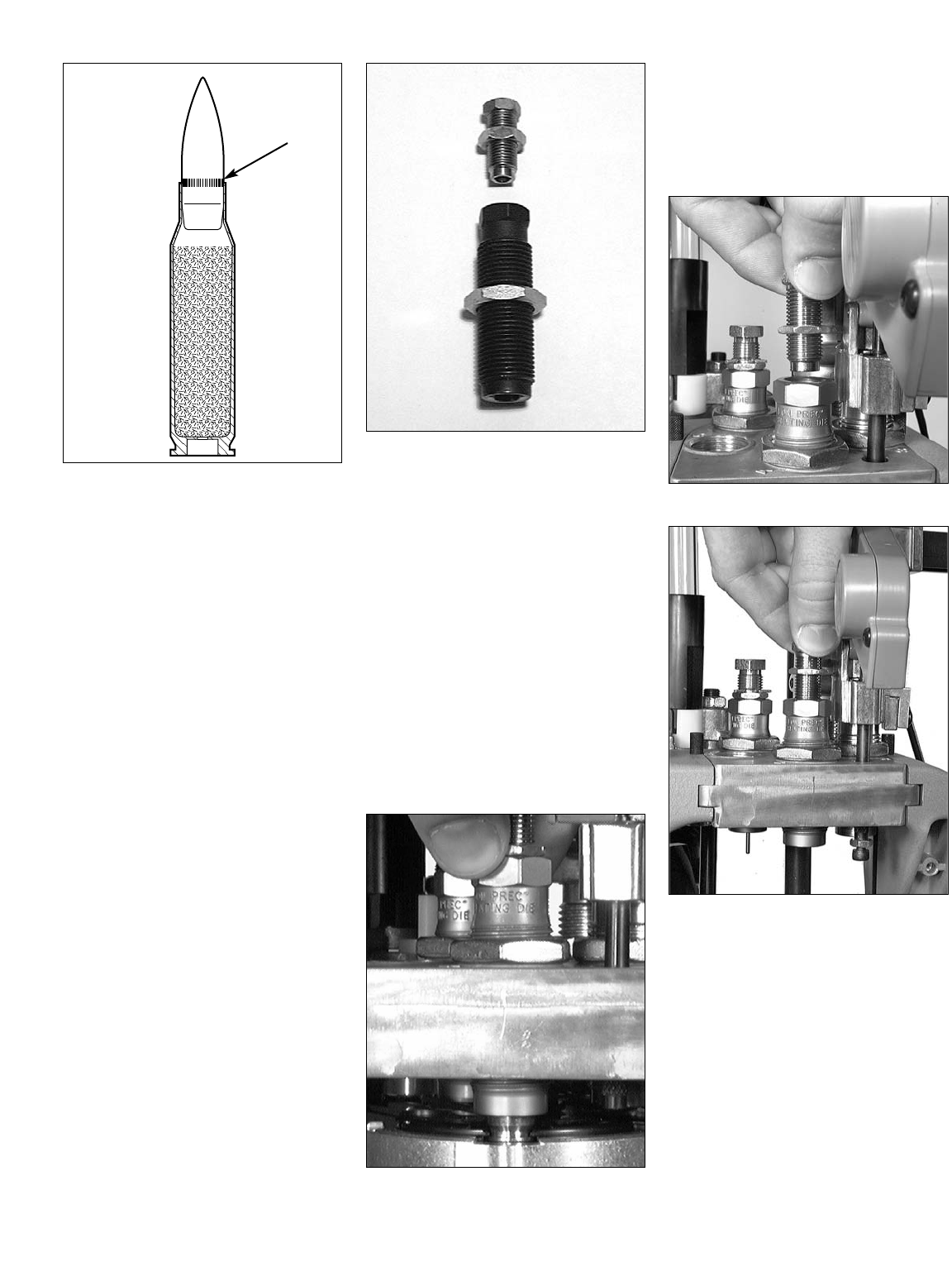
FIG 114
If the bullet you’re using doesn’t have a
cannelure, then you’ll need to refer to
your reloading manual for the suggested
OAL. The purpose of the cannelure is to
secure the bullet by giving the mouth of
the case something to dig into when being
crimped. When the bullet is properly
seated, the mouth of the cartridge case
should be in the middle of the cannelure,
see arrow FIG 114.
Refer to your reloading manual. Under
the section specified for the caliber you’re
loading, you’ll find a schematic of the car-
tridge. For example, .30-06 lists a maximum
OAL of 3.340” (Lyman Reloading
Handbook). If you’re seating the bullet to
the cannelure, the OAL should be well
within the maximum OAL listed, however,
use a set of dial calipers to check it. (Dial
calipers are available from Dillon
Precision). If the bullet you’re using doesn’t
have a cannelure, refer to its specific type in
the reloading manual. For example – if
you’re loading a .30-06 180 gr. JHPBT, and
it doesn’t have a cannelure, use the suggest-
ed OAL of 3.280 (Lyman Reloading
Handbook).
FIG 115
K. Station 4 – Seating Stem
for rifle FIG 115:
Unlike pistol seating dies, rifle seating dies
come with only one type of seating stem.
Dillon seating dies, which are being
used in this manual, are easily disassem-
bled. Should you need to disassemble the
rifle seating die – simply unscrew the seat-
ing stem from the top of the seating die
FIG 115.
L. Station 4 – Installation and
Adjustment of the
Seating Die
1. Place a lubricated sized case into
Station 4 and raise the platform.
FIG 116
2. Thread the seating die into Station 4.
Continue to screw it down until it
contacts the case FIG 116. Once the
die is in contact with the case back
the die off (counter-clockwise) 1/4 of
a turn. Using a 1 1/8” wrench snug
the lockring on the seating die.
FIG 117
FIG 118
3. Lower the platform.
4. FIG 117 Back the seating stem all the
way out of the seating die. Now
screw the seating stem back into the
seating die two full turns FIG 118.
5. Place a bullet on the case mouth and
raise the platform – then lower the
platform just enough to inspect the
bullet without indexing the shellplate.
a. If the bullet is not pushed down far
enough – go to step 6.
b. If the bullet is pushed down too far:
b.1. Pull the bullet from the case
using a Dillon bullet puller.
b.2. Back the seating stem out by
27
turning it counter clockwise and try
again.
6. Screw the seating stem down 1/2 turn
at a time FIG 118.
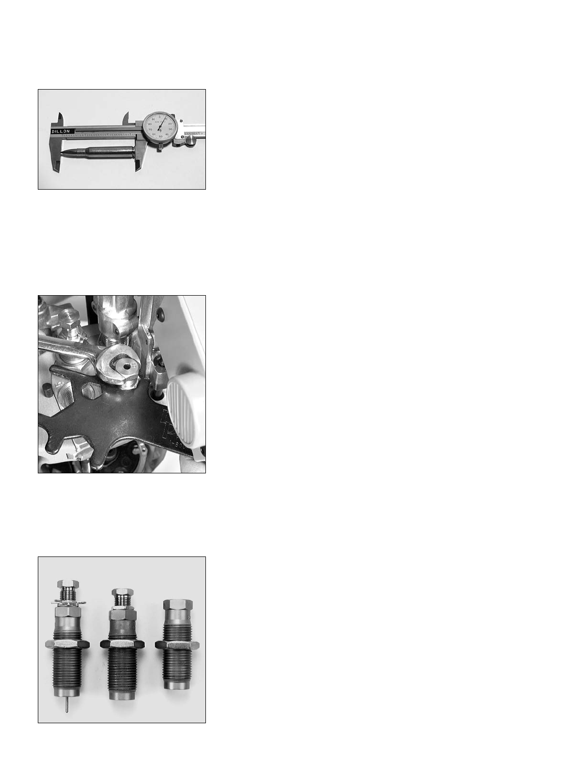
FIG 119
7. Repeat as necessary until the correct
overall length is achieved. Use a dial
caliper or equivalent to measure the
overall length of the cartridge FIG
119. Check the overall length of the
round against the information in your
reloading manual.
FIG 120
8. Once you have obtained the proper
OAL, replace the cartridge into
Station 4, raise the platform and
snug the lockring on the seating stem
FIG 120.
FIG 121
M.Station 5 – Installation and
adjustment of the Crimp
Die FIG 121:
1. Screw the crimp die into Station 5.
Screw it down until it is flush with the
bottom of the toolhead. This is a good
starting point for the crimp adjust-
ment.
2. Place a lubricated cartridge with a
properly seated bullet into Station 5.
3. Raise the platform and continue to
screw the die down until it stops.
4. Lower the platform and give the die a
half turn down; again, raise the plat-
form.
5. Lower the platform halfway and
inspect the cartridge. If the desired
amount of crimp has not been
achieved, give the die a 1/4 turn
down and try again. Continue making
small adjustments to your crimp die
until the desired amount of crimp has
been achieved.
6. Once the adjustment is complete,
place the case back into Station 5 and
raise the platform. Using a 1 1/8”
wrench to turn the lockring and a
7/8” wrench to hold the die body,
snug the lockring.
Go to Loading Components
Section - Page 30
28
Sizing/Decapping Die
Seating Die Crimp Die
Final Assembly
FIG 122
FIG 123
1. The Primer Magazine
The XL 650 comes equipped with an
automatic primer system.The XL 650’s auto-
matic primer system is protected by a steel
shield which is permanently secured to the
primer feed body and must never be
removed. The primer magazine is located
inside of a steel shield FIG 122. Primer
magazines come in two different sizes –
large and small FIG 123. Your machine
comes with both. One comes installed in
the machine, the other is located in the
primer accessory package. If you ordered
your machine set up in a particular caliber,
the magazine installed should be the proper
one for the caliber you selected. However,
you should check to make sure. By compar-
ing the two magazines FIG 123 you will be
able to determine which is large and which
is small.
FIG 124
To change the primer magazine:
1. Remove the primer shield cap FIG
124.
2. Remove the primer magazine by
pulling it straight up FIG 122.
3. Insert the new primer magazine FIG
125 and replace the primer shield
cap.
FIG 125
FIG 126
2. Installation of the Primer
Early Warning System:
FIG 126 The purpose of the Primer Early
Warning system is to warn you when the
primer magazine is low on primers. When
you hear the buzzer, it’s time to reload the
primer magazine tube.
FIG 127
1. Insert the battery into its receptacle
FIG 127 and push the black switch
lever to insure the device is working
properly.
2. Install the Primer Early Warning sys-
tem on top of the primer magazine
shield FIG 126. Lightly tighten the
clamp screw with a 3/32” Allen
wrench.
29
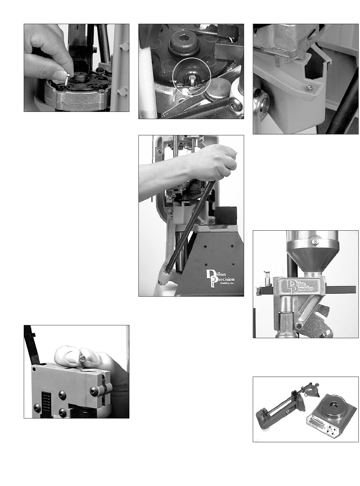
FIG 128
3. Installation of the Locator
Buttons FIG 128:
Install the three brass locator pins in the
shell platform at stations 3, 4 and 5. These
pins retain the cases during loading while
providing an easy way to remove a case
from the shellplate at any stage without dis-
turbing the other rounds. Note: The locator
buttons are caliber specific and can be
properly identified by referencing the cal-
iber conversion chart on pages 42-44.
LOADING COMPONENTS
SECTION
1. The Rotary Primer System
(how it works):
Warning: Wear safety glasses whenever
working with live primers. Safety
glasses are available from Dillon
Precision Products.
Observe how the rotary primer system
works, how to charge it and how to seat a
primer. To do so:
1. Put on your safety glasses.
FIG 129
2. Place five or six primers into the
primer magazine shiny side down
FIG 129.
3. Cycle the machine until a primer
appears in Station 2.
FIG 130
FIG 131
When you cycle the machine, the rotary
primer disc rotates one notch, advancing
another primer into position. When the
handle is pushed to its full aft stop FIG 131,
the primer seating punch pushes the primer
up through the rotary primer disc FIG 130,
fully inserting it onto the primer pocket of
the case. If there is no case in Station 2 to
receive the primer, the primer will return to
the rotary disc and continue around until
being dropped down a chute FIG 132
where it can be retrieved.
FIG 132
4. Drop an unprimed case into the case-
feed funnel and cycle the machine
twice. As the case is rotated into
Station 2, complete the downstroke of
the platform by firmly pushing the
handle to its full aft stop FIG 131 –
this will ensure that the primer is fully
seated.
5. Set aside the primed case, it will be
used later for adjusting the powder
measure.
FIG 133
2. Powder Bar Adjustment
FIG 133:
FIG 134
Note: Although a scale is not included with
the machine, you’ll need one to
30
31
properly adjust the powder bar.
Dillon Precision Products offers two
types of scales FIG 134. On the
right, and electronic scale, and on
the left, a balance beam scale.
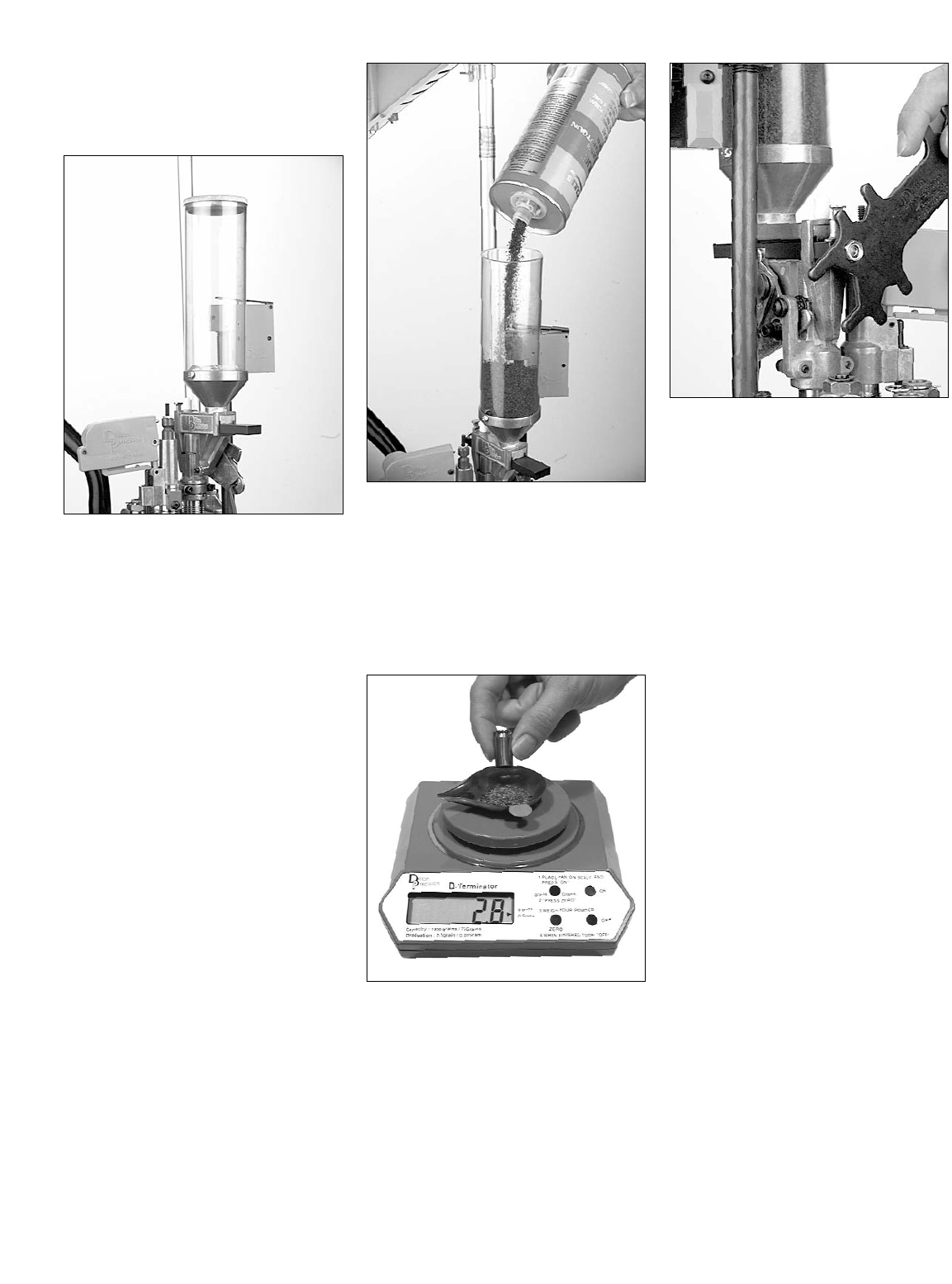
FIG 135
You are now ready to fill the powder
measure FIG 135, but first you’ll need to
refer to your reloading handbook. Under
the section specified for the caliber you’re
loading you’ll see a number of suitable
powders. Also given are “suggested starting
loads” and “maximum loads” (Lyman
Reloading Handbook).
Note: We do not recommend using IMR
stick powders (looks like pencil
lead) when loading a caliber size
less than 25 caliber. We do not
recommend using maximum loads
of powder.
Warning: Wear safety glasses whenever
working with live primers. Safety
glasses are available from Dillon
Precision Products.
Note: Insure that you have the proper
powder bar installed. To do so refer
to “About Powder Bars” on page 13.
For instructions on how to change
the powder bar, refer to Step 19 in
the Caliber Conversion Section,
page 41.
1. Put on your safety glasses.
FIG 136
2. Fill the powder measure and replace
the cap on both the powder measure
and the powder container FIG 136.
3. Place a primed case into Station 2.
Note: Using a case with a primer in it will
keep the powder from leaking out
through the primer flash hole.
FIG 137
4. Cycle the machine to charge the
case. Using your powder scale, weigh
the powder charge FIG 137. (From
this initial measurement, you will be
able to determine whether you’ll
need to increase or decrease the
powder charge.)
FIG 138
5. Using a 7/16” wrench, give the pow-
der bar bolt a quarter of a turn clock-
wise or counter-clockwise as neces-
sary to adjust the powder charge FIG
138. Clockwise will increase the
powder charge and vice versa.
Warning: As always, be sure to replace
the lid on the powder measure.
6. IMPORTANT! Before measuring the
next load, charge the case then empty
the powder back into the powder
measure. This will allow the powder
in the newly adjusted powder bar to
settle and give an accurate reading.
7. Replace the cartridge into Station 2
and charge the case. Continue this
process until the charge is reading
correctly. Once you have achieved
the desired powder charge weigh two
more charges to insure the powder
bar is throwing a consistent charge.
3. Powder Check System
Adjustment:
Once the powder bar is throwing the
desired charge, the powder check rod can
be installed and adjusted.
Warning: A double-charged round (a
loaded round with twice as much
powder as it should have) can dam-
age your gun as well as cause bodi-
ly injury.
Warning: A round loaded without powder
can also damage your gun as well
as cause bodily injury. If a round
without powder is fired in your gun,
the detonation of the primer will
push the bullet part way down the
barrel. If the lodged bullet is not
removed before another round is
fired, the gun will be damaged.
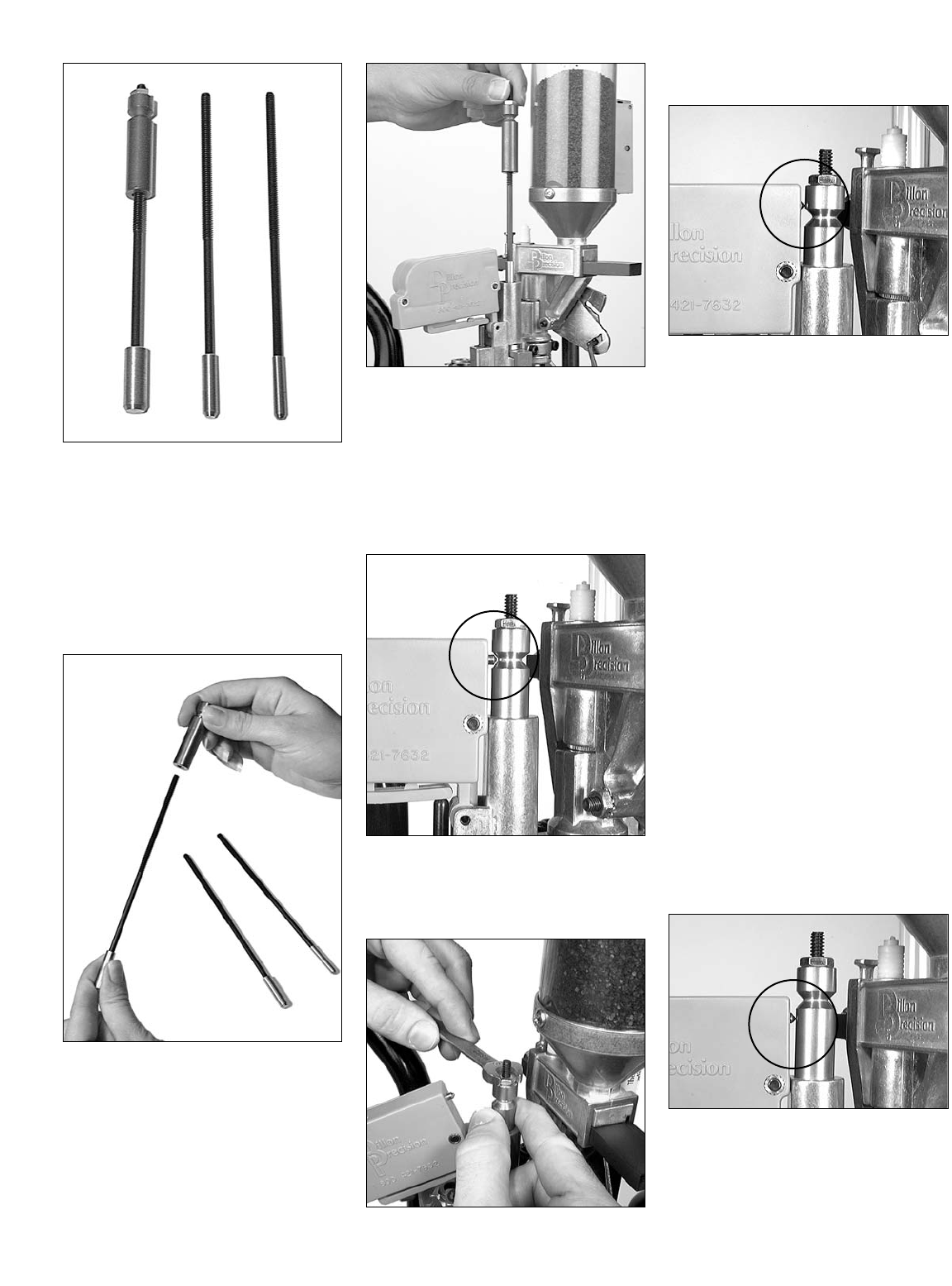
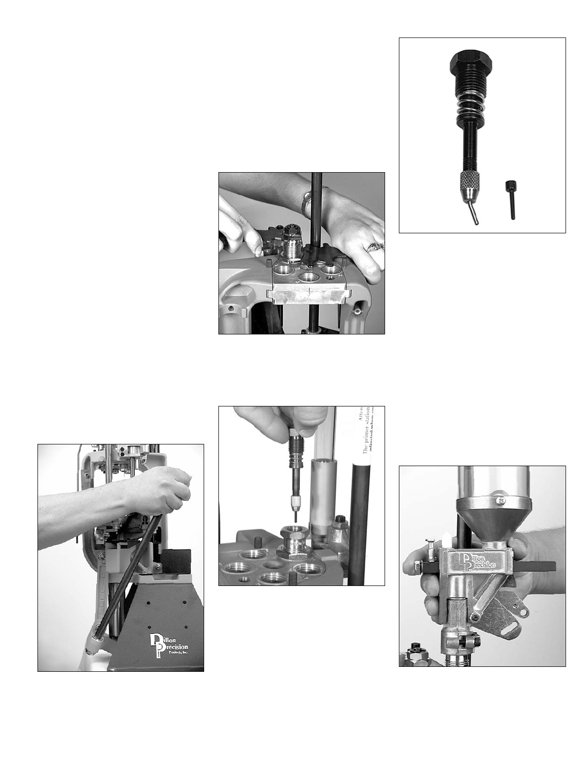
FIG 139
A. Installation and adjustment of
the powder check rods
FIG 139:
1. Remove the powder check rods from
the bag FIG 139. The three rods fit
different calibers. On the left .44-.45
caliber, center .30-.41 caliber and on
the right .22-.29 caliber.
FIG 140
2. Choose the correct rod for the caliber
you’re loading. For example – if
you’re loading .38 Spl. you would
use the .30-.41 caliber rod. If the rod
you’re using doesn’t have the
grooved sleeve on it, remove the
grooved sleeve from the one you’re
not using and thread it onto the cor-
rect rod FIG 140.
FIG 141
3. Insert the rod into the powder check
die FIG 141.
4. Put on your safety glasses.
5. Place a case with the proper powder
charge into Station 3 and raise the
platform. Leave the platform in the
raised position.
FIG 142
6. Thread the grooved sleeve down so
that the contact pin fits inside the
groove as seen in FIG 142.
FIG 143
7. Snug the lock nut with a 3/8” wrench
FIG 143.
FIG 144
B. Powder Check System
Demonstration:
1. Place a primed but empty case (case
with no powder) into Station 3 and
raise the platform. The contact pin is
above the groove FIG 144 (the alarm
sounds) indicating that the case has a
low or no charge.
2. Lower the platform. Remove the
empty case from Station 4 and place
it in Station 2.
3. With the empty case in Station 2 give
it a double charge.
To do so:
a. Raise the platform all the way to
charge the case.
b. Lower the platform halfway (enough
for the powder bar to return to its start-
ing point without indexing the case to
Station 3 and releasing the locklink).
c. Again, raise the platform to give the
case a second charge of powder.
d. Index the case to Station 3 by lower-
ing the platform all the way. (The case
is now double charged and ready to be
checked by the Powder Check System.)
FIG 145
4. Raise the platform FIG 145. The con-
tact pin is below the groove (the
alarm sounds) indicating that the
powder charge is double or more.
32
Note: If the buzzer to the powder check
system goes off, stop loading and
check the powders weight with the
scale. The primer warning buzzer
and the powder check system have
different pitch buzzers to distinguish
the two. The primer system is a
deep buzz and the powder check is
a high pitched tone.
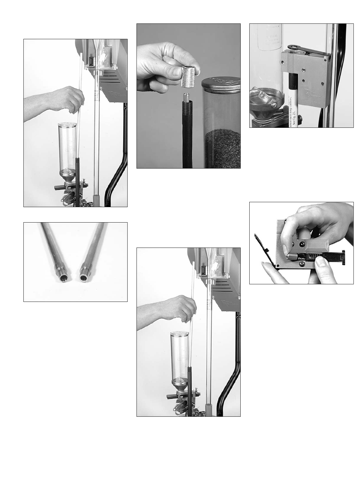
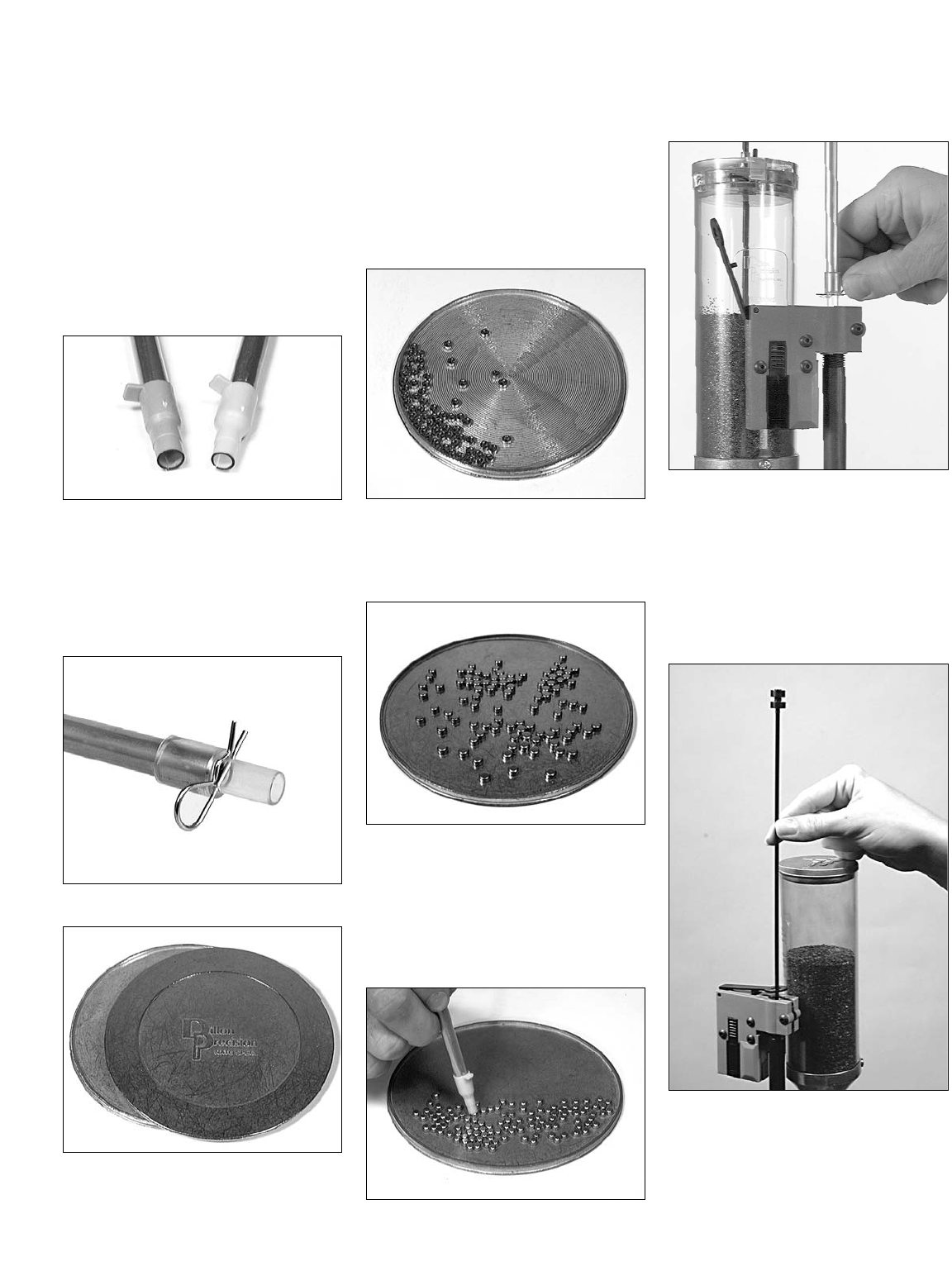
4. Filling the Primer System:
Warning: Wear safety glasses whenever
working with live primers. Safety
glasses are available from Dillon
Precision Products.
FIG 146
Now it’s time to fill the primer maga-
zine. To begin, you’ll need the proper size
primer pickup tube. Primer pickup tubes
come in either large or small. In FIG 146
are the two primer pickup tubes included
with your XL 650.
FIG 147
FIG 148
On the left is the large pickup tube (with
a green tip), on the right is the small pickup
tube (with a yellow tip). Make sure the
retaining clip FIG 147 is always in place
before using either tube. You’ll need the
proper size primers and we suggest using this
optional Dillon Primer Flip Tray FIG 148. It
will make this task quite a bit easier.
1. Put on your safety glasses.
2. Separate the two halves of the primer
flip tray.
3. Place the primers onto the grooved
surface of the primer flip tray.
FIG 149
4. Slowly shake the flip tray until all
the primers rest shiny side down
FIG 149.
FIG 150
5. Place the smooth lid on top, and
flip the entire tray. Remove the
grooved lid.
Now all the primers should be shiny side
up on the smooth side of the primer flip
tray. FIG 150.
FIG 151
6. FIG 151 Collect the primers using the
plastic tip end of the primer pickup
tube. Make sure all primers are shiny
side up, and fill the tube.
FIG 152
7. When the primer pickup tube is full,
pivot the black switch lever away
from the primer magazine shield.
Rotate the tube upside down over the
primer magazine shield and remove
the retaining clip FIG 152. After fill-
ing the primer magazine return the
switch lever to its normal position.
FIG 153
8. Slide the follower rod through the
hole in the switch lever until it touch-
es the primers FIG 153. When the
machine is nearly out of primers the
rod will activate the buzzer.
33
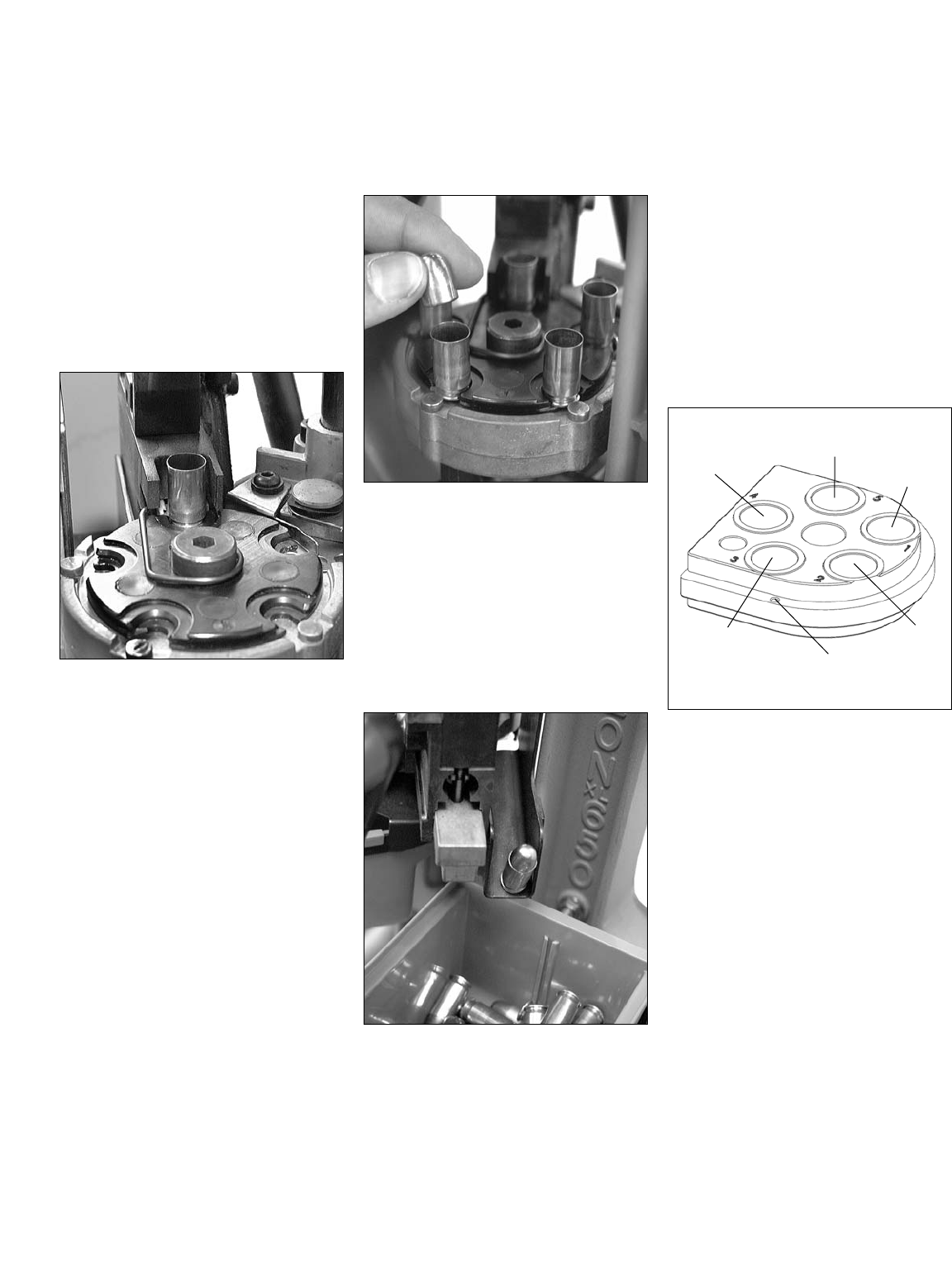
Add some empty cases to your casefeeder
and turn the unit “on”. The motor will run
until the clear casefeed tube fills and then it
will automatically shut off.
The reloading process on an XL 650
begins with one complete stroke or cycle of
the handle, which causes the first case to be
cycled through the casefeed system and fed
into the shellplate.
Station One
The first case is at station one of the
machine and a new primer is ready at sta-
tion 2. Move the handle down, the sizing
die reforms and also deprimes the first case.
Return the handle to its rest position. Using
a smooth, fluid motion, move the handle up
to its full aft stop to seat the new primer into
the case and release the handle. At the
same time, another case has been fed into
the shellplate.
Station Two
Again, cycle the handle completely. The
first case now gets a charge of powder, the
second case is resized and deprimed, then
they both advance to the next stations.
Using a smooth, fluid motion, move the
handle up to its full aft stop to seat the
new primer into the case. Return the han-
dle to its rest position. Now three cases
are in the shellplate.
Station Three
Cycle the handle. The first case enters the
powder checker, the second case is charged
with powder and the third case is resized
and deprimed. Again, return the handle to
its rest position and all the cases advance to
their next stations and the fourth case is
inserted into the shellplate.
Station Four
It is now time to begin placing a bullet on
the case at station four. Cycle the handle
down and then back up to its rest position.
The first case now has a bullet seated into it
and has advanced to station five. At this
point the shellplate is full.
Seat a primer into a case at the full aft
stroke of the handle and a case is inserted
into the shellplate automatically.
Station Five
Using your left hand, place a bullet on the
case at station four. Cycle the handle and
the first case is crimped at station five and
then ejected out at the right rear of the
machine into the collection bin. Repeat the
process by placing a bullet into the case at
station four and seating the primer into the
case at station two.
At this point a completed round is ejected
from the machine with every complete
stroke of the handle.
When operating the handle, pay close
attention to the cases, noting the changes
that take place as they go through the
machine.
Pace yourself when operating the
machine. Do not crash the handle down
against its stop and do not snatch the han-
dle upward. It should take two or more
seconds to move the handle from its rest
position, down and then back up to its
rest position.
Station/Toolhead Orientation
34
Now its Time to Start Loading
Station Orientation and Loading Functions
Sta. 4
Seat Die
Sta. 5
Crimp Die
Sta. 1
Sizing Die
Sta. 2
Powder
Measure
Toolhead
Pin (2)
Sta. 3
Powder Check
System (optional)
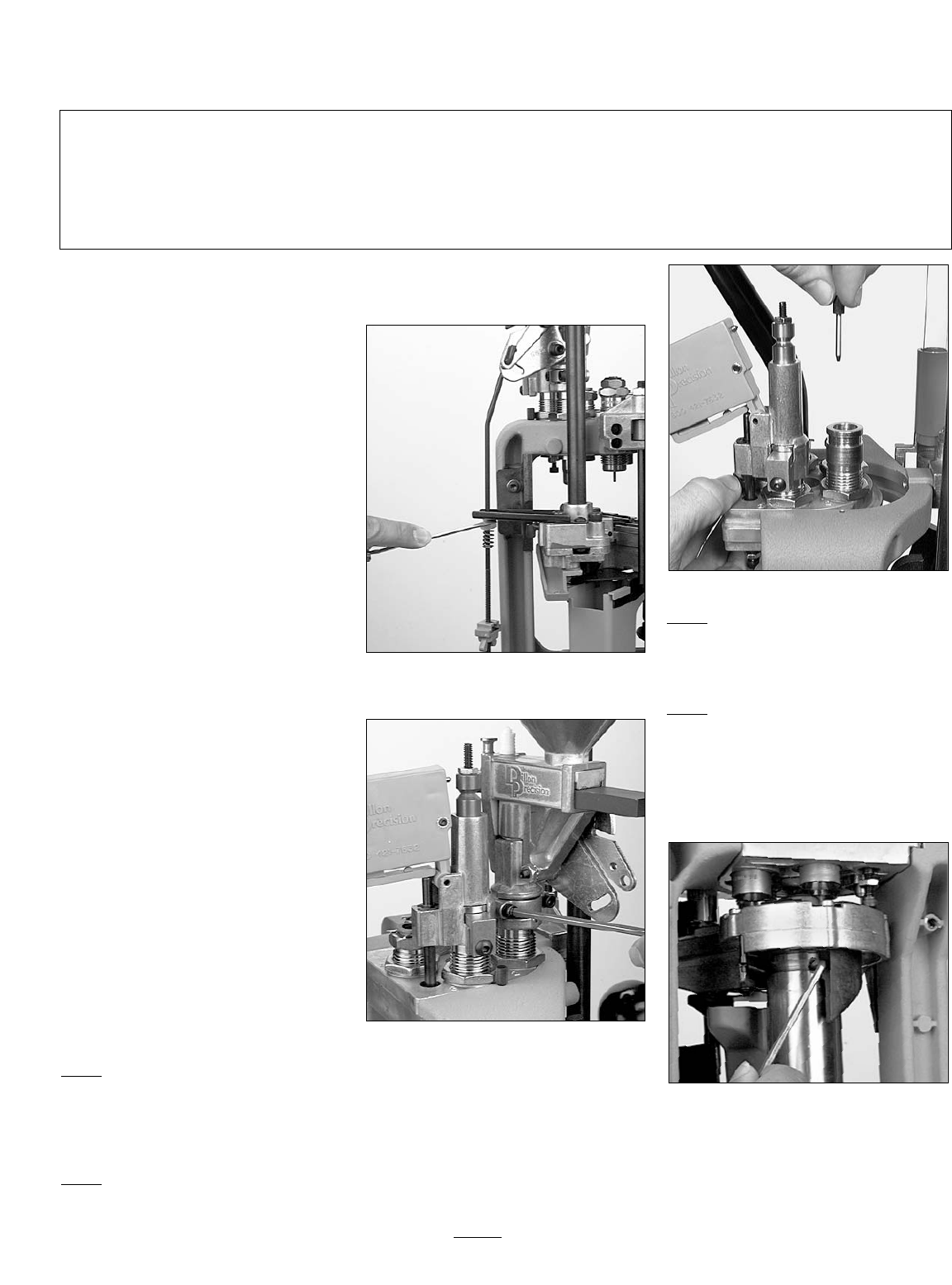
1. How to use the Caliber
Conversion Chart:
To explain the Caliber Conversion
Chart we are going to compare the pistol
caliber of .38 Spl. to the rifle caliber of
.30-06 FIG 154.
By comparing the two columns, you can
see which parts need to be changed. In this
comparison, .38 Spl. vs. .30-06, you can
see that none of the part numbers match up,
therefore, all of the those parts would need
to be changed. This, however, is not always
the case. If you compare .30-06 to
.308/7.62 Nato, you’ll find that they are
exactly the same. Another example would
be .38 Spl. vs. .357 Magnum. As you can
see, they too are identical. Some caliber
comparisons will show that only a couple
of parts are different – in this case, instead
of ordering an entirely new caliber conver-
sion kit, you have the option of ordering
only those parts needed to complete your
caliber conversion.
2. Conducting the Caliber
Conversion
(The following steps are in the sequential
order in which the caliber conversion is to
be conducted):
Note: Included in the following is a com-
plete list of all the items that need to
be considered when conducting a
caliber conversion. This is not a list
of all the items that will need to
changed or readjusted – this is a
complete list of all the items that
may need to be changed or re-
adjusted. The items that need to be
changed or readjusted will depend
on the caliber your XL 650 is cur-
rently set up to load and the caliber
you’re changing to.
Step 1)Remove the cases from the
machine:
1. Turn off the casefeed system
2. Remove the remaining cases from the
casefeed tube and the casefeed bowl.
Step 2)Remove the powder from the
powder measure:
Depending on the caliber change, you
may have to change powders and/or the
powder bar. If so, you’ll need to empty the
powder from the powder measure.
FIG 155
1. Disconnect the failsafe rod FIG 155.
FIG 156
2. Loosen the two powder measure
clamp screws FIG 156.
3. Remove the powder measure and
empty the powder back into the pow-
der can.
4. Manually cycle the powder bar to
ensure the powder measure is empty.
5. If you need to change powder bars
refer to Step 19.
FIG 157
Step 3)Remove the toolhead FIG 157:
1. Disconnect the failsafe rod FIG 155.
2. Remove the toolhead pins and slide
the toolhead out.
Step 4) Remove the shellplate:
Remove the shellplate only if you need
to either, change the shellplate for a differ-
ent caliber shellplate, or if you need to
remove the primer system (such as when
emptying the primers from the primer sys-
tem).
FIG 158
1. Using a 1/8” Allen wrench loosen the
shellplate set screw FIG 158. The
shellplate set screw is located on the
left side of the mainshaft just below
the shellplate platform. Do not
remove the screw, just loosen it about
a half turn.
35
Caliber Conversion Section
FIG 154 – Caliber Conversion Chart Sample
Caliber Complete Shellplate Locator Funnel Station 1 Casefeed Arm Body Casefeed Primer Powder
Conversion Number Button Locator Adapter Bushing Bushing Disc System Check Rod
38 Spl 21098 (2) 13430 (2) 14062 (D) 13599 13563 (Orange) 13386 (Red) 13403 (Sm38) 13384 (LP) 21072 Sm Med
.30-06 21094 (1) 13204 (1) 13930 (B) 13587 (1) 13595 (Black) 13541 (White) 13661 (Med) 13604 (LR) 21075 Lg Med
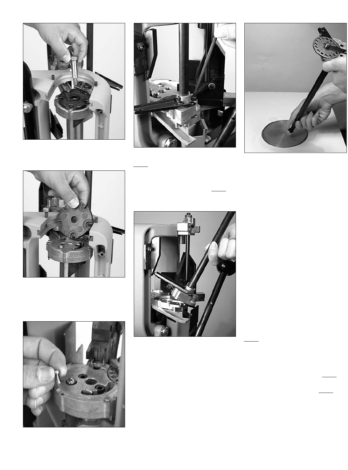
FIG 159
2. Using a 1/4” Allen wrench remove
the shellplate bolt FIG 159.
FIG 160
3. Swing the ejector wire out of the way
and remove the shellplate. Be sure
that index ball and index pawl
remain in place FIG 160.
FIG 161
4. Remove the locator buttons FIG 161.
FIG 162
Step 5)Remove the primers:
Remove the primers only if you need to
change to a different size or type of primer.
1. Remove the shellplate (ref. Step 4).
2. Loosen and remove the two primer
system bolts FIG 162.
FIG 163
3. Carefully lift the primer assembly
away from the machine FIG 163.
FIG 164
4. FIG 164 Empty the remaining
primers by placing a finger over the
primer shield cap, inverting the
magazine and carefully pouring the
primers onto the primer flip tray. Put
the primers back into their original
box.
5. If any primers remain in the primer
area (on the machine) carefully
remove them.
6. If you need to change the rotary
primer disc go to Step 6. If you only
to need empty the primer magazine,
reinstall the primer system at this
time.
Note: About Steps 6, 7 and 8. If you’re
changing from a large rifle/pistol
primer to a small rifle/pistol primer
or vice versa, the rotary primer disc,
primer magazine, and primer punch
will have to be changed. This is
because each of these three items
are designed specifically for either
large rifle/pistol primers or small
rifle/pistol primers.
Step 6)Change the rotary primer disc
(see note above):
Note: The two different size rotary primer
discs are labeled L (large) and S
(small).
1. Remove the shellplate (ref. Step 4).
2. Remove the primer system and empty
the primer magazine (ref. Step 5).
36
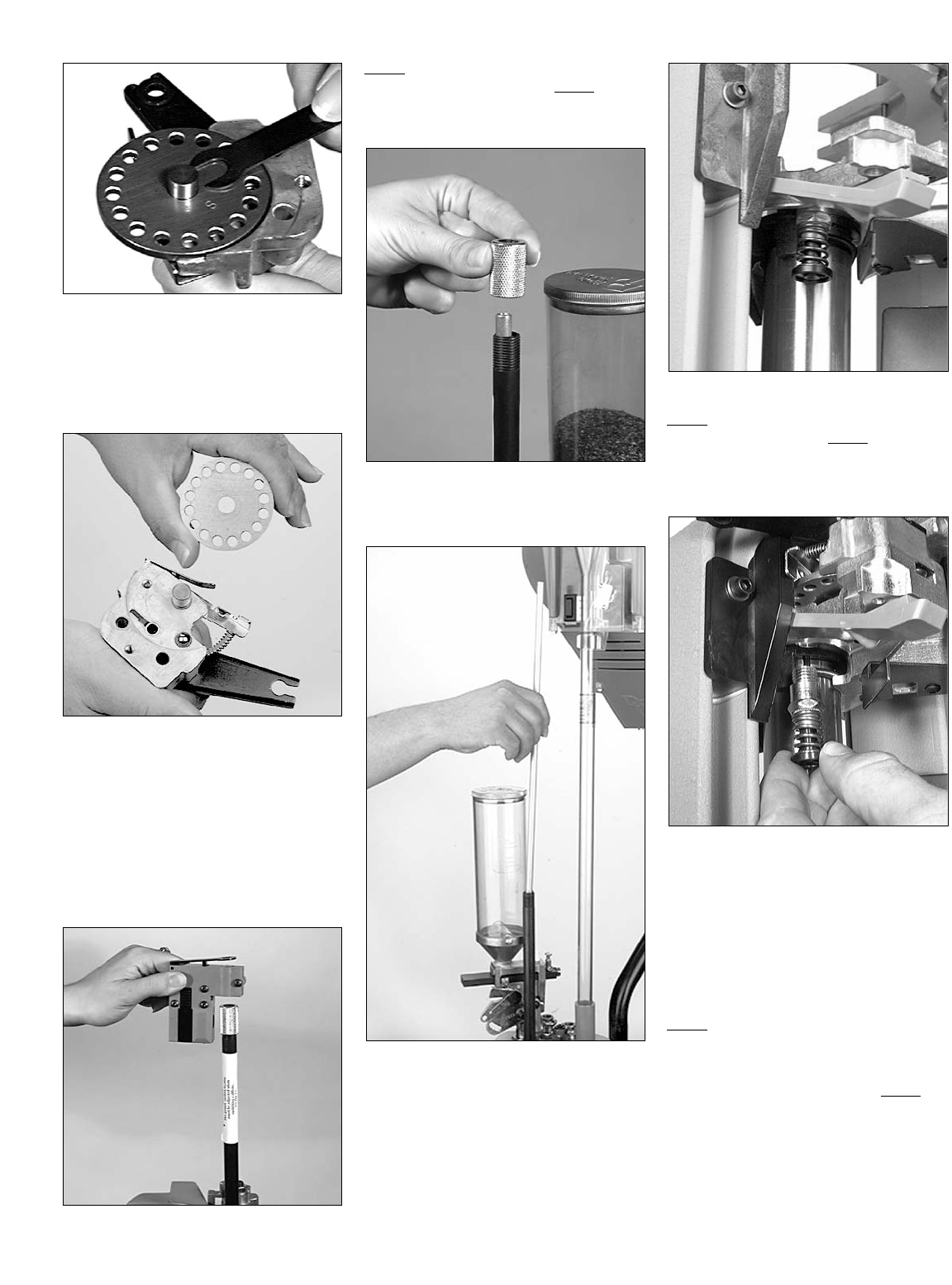
FIG 165
3. Rotate the primer system upside
down. Using an 1/8” Allen wrench
unscrew the primer support shim
screw and remove the primer support
shim FIG 165.
FIG 166
4. Remove the rotary primer disc FIG
166. Make sure the detent ball
remains in place.
5. Place the other rotary primer disc
onto the disc pin.
6. Slip the primer support shim back
into place and snug the screw.
7. Reinstall the primer system.
FIG 167
Step 7)Change the primer magazine
(see note just above Step 6):
1. Remove the Primer Early Warning
System FIG 167.
FIG 168
2. Remove the primer shield cap FIG
168.
FIG 169
3. Remove the primer magazine by
pulling it straight up FIG 169.
4. Insert the new primer magazine.
5. Replace the primer shield cap and
Primer Early Warning System.
FIG 170
Step 8)Change the primer punch (see
note just above Step 6):
The primer punch is attached to the
underside of the platform on the right side
FIG 170.
FIG 171
1. Raise the platform.
2. Using a 9/16” wrench loosen and
remove the primer punch FIG 171.
3. Remove the other size primer punch
from the primer accessory package.
Screw it in and snug it down.
4. Lower the platform.
Step 9)Install the new shellplate:
This is located in your caliber conver-
sion kit.
1. Remove the shellplate (ref. Step 4).
2. Place the new shellplate onto the
shellplate platform. The number side
of the shellplate should be face up.
Rotate the shellplate until it seats
itself on the index ball.
37
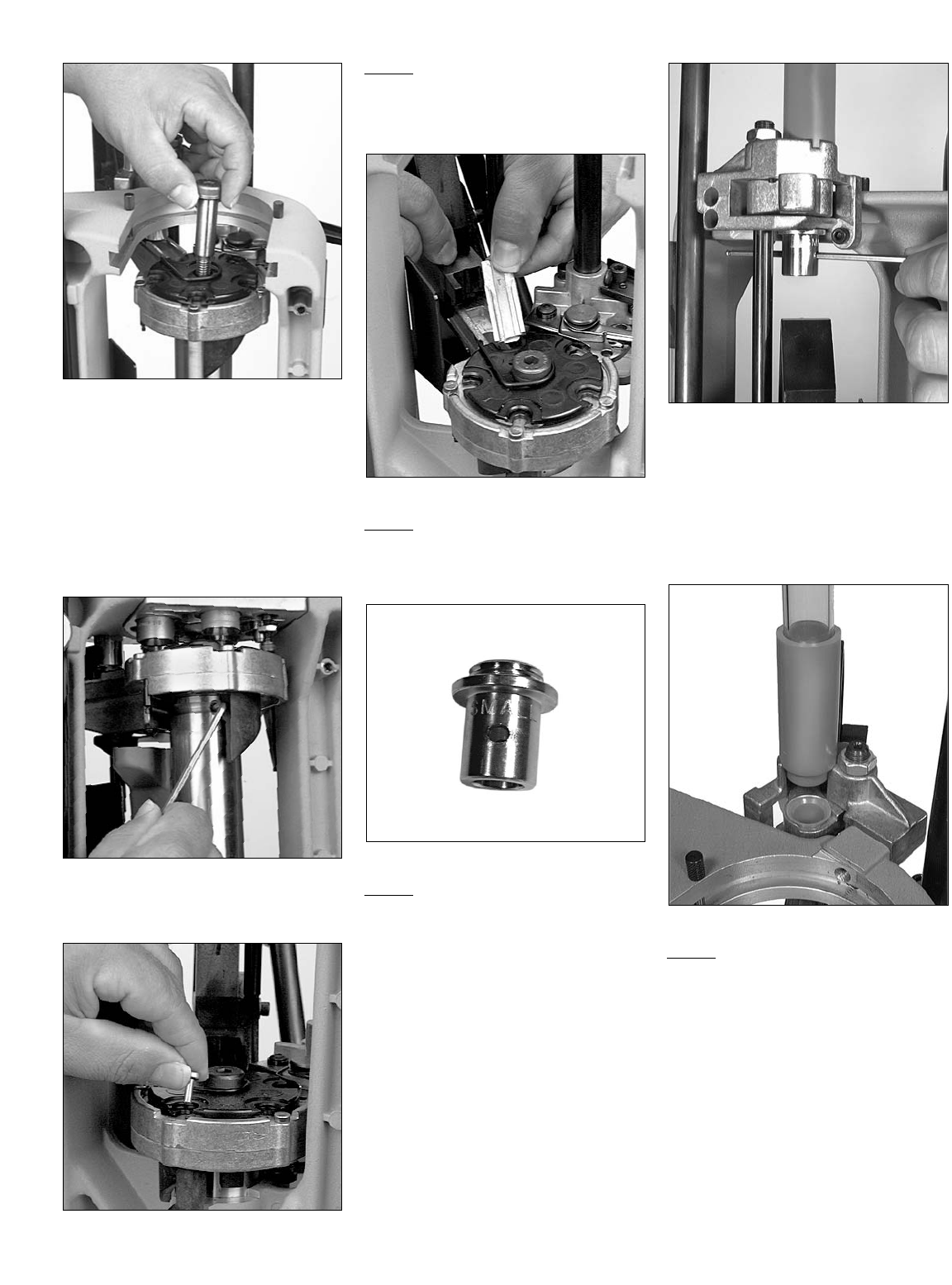
FIG 172
3. Swing the ejector wire back to its
original position over the shell-
plate and insert the shellplate bolt
FIG 172.
4. Using a 1/4” Allen wrench run the
shellplate bolt down until it stops
then loosen it slightly. Loosen it just
enough to allow the shellplate to
index freely.
FIG 173
5. Snug the shellplate set screw FIG
173.
FIG 174
Step 10)Install new locator pins FIG 174:
The new locator pins are located in your
caliber conversion kit.
1. Install as depicted
FIG 175
Step 11)Install the new Station 1 loca-
tor FIG 175:
The Station 1 locator is located in your
caliber conversion kit.
FIG 176
Step 12)Change the Body Bushing FIG
176:
The new body bushing is located in the
caliber conversion kit.
FIG 177
1. The body bushing is located on the
right side just above Station 1 FIG
177. Remove the body bushing by
slipping an Allen wrench through the
cross hole and twisting it counter-
clockwise.
2. Install the new body bushing.
FIG 178
Step 13)Replace the casefeed arm
bushing and casefeed
adapter FIG 178:
The new casefeed adapter and casefeed
arm bushing are located in your caliber
conversion kit.
38
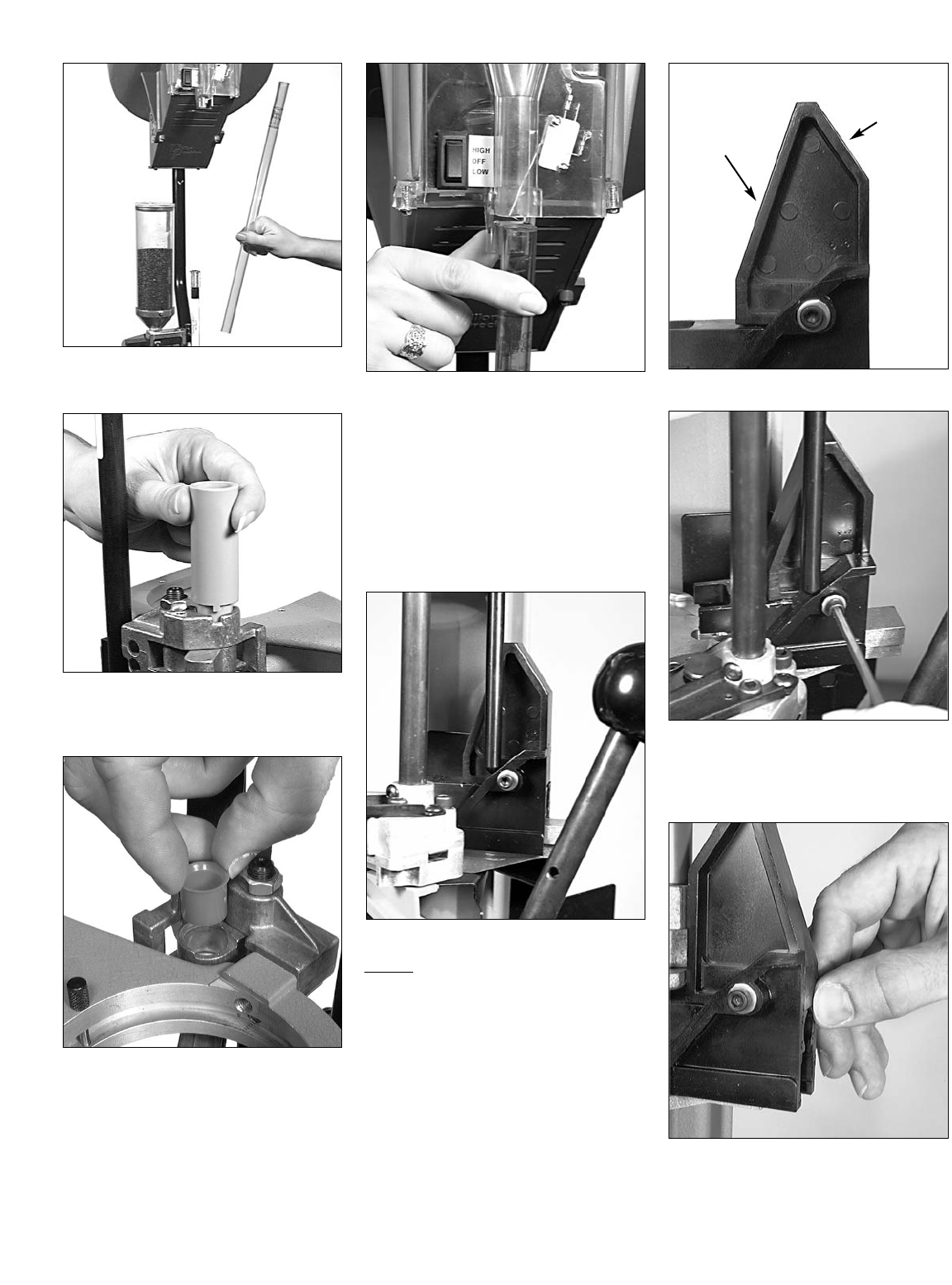
FIG 179
1. Remove the casefeed tube FIG 179.
FIG 180
2. Remove the casefeed adapter FIG
180.
FIG 181
3. To replace the casefeed arm bushing
first raise the platform. Remove the
casefeed arm bushing (currently
installed in your machine) and
replace it with the new one FIG 181.
4. After installing the new casefeed arm
bushing, install the new casefeed
adapter.
FIG 182
5. Reinstall the casefeed tube by placing
the casefeed tube into the casefeed
adapter and snapping it into the metal
clamp FIG 182.
Note: One end of the casefeed tube is
beveled and one end is squared off.
Insert the squared end of the tube
(down) into the top of the casefeed
adapter.
FIG 183
Step 14)Case insert slide cam – turn
around FIG 183:
The case insert slide is reversible. The
long side of the cam (see arrow “A” FIG
184) is for pistol and the short side of the
cam (see arrow “B” FIG 184) is for rifle. As
a reference, any case as long or longer than
.223 Rem. will require that the short (rifle)
side of the cam be used. Reverse the case
insert slide cam only if your caliber conver-
sion requires it.
FIG 184
FIG 185
1. Using a 5/32” Allen wrench, remove
the cam screw FIG 185 and reverse
the case insert slide.
FIG 186
2. FIG 186 Insure that the back side of
the cam is flush with the cam slide.
3. Replace the cam screw and snug it.
39
B
A
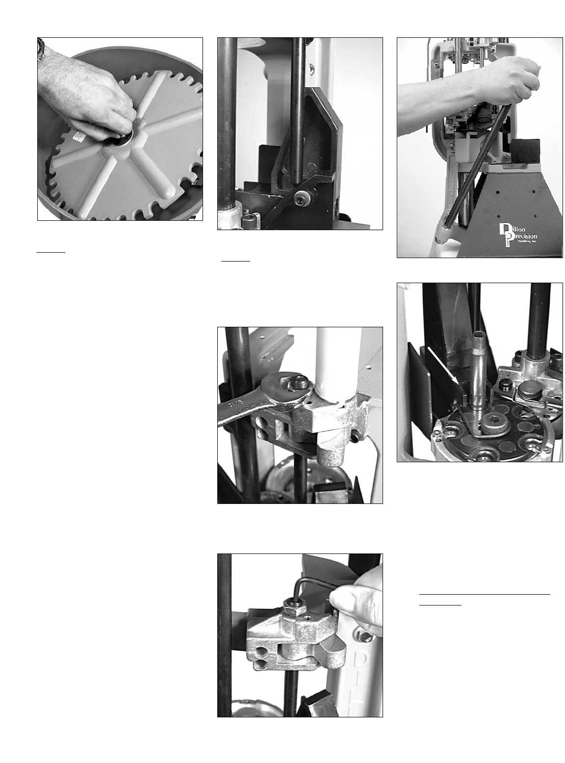
FIG 187
Step 15)Change out the casefeed disc
FIG 187:
Change the casefeed disc only if your cal-
iber conversion requires it.
1. Grip the casefeed plate clutch drive
FIG 187 and pull upward. The case-
feed disc will slip off the motor drive
shaft.
2. To install the new casefeed plate –
place the casefeed plate clutch drive
on the motor driveshaft. Slowly rotate
the disc until the groove on the drive
shaft aligns with the notch in the
plate. The casefeed plate will then
slip down onto the motor shaft and
into place.
Note: About Steps 16 and 17. Both the
camming pin and Station 2 locator
tab do not require removal or
replacement. Instead, depending
on the caliber change, they may
need to be readjusted. Whether or
not these two items need to be
adjusted depends on the diameter
of the base of the case and noth
ing else. If, for example, you are
converting from 9mm to .45 ACP,
because the diameter of the two
cases are different, both the cam
ming pin and Station 2 locator
will need to be read justed. If, on
the other hand, you are converting
from, say, .45 ACP to .30-06 or
.308, you will not have to readjust
these two items – the diameters at
the base of these cases are the
same.
FIG 188
Step 16)Adjusting the camming pin FIG
188 (see previous note):
1. Place a case in both Station 1 and
Station 2. The case in Station 2 must
have a primer – the primer can be
spent or new.
FIG 189
2. Using a 9/16” wrench, loosen the lock
nut FIG 189 on the camming pin.
FIG 190
FIG 191
FIG 192
3.Using a 1/8” Allen wrench, turn the
camming pin clockwise FIG 190 four
or five turns – or enough so that when
you push the handle to the full aft
stop FIG 191, the case insert slide
(see arrow FIG 192) does not push
the case fully into Station 1 FIG 192 –
this will give you a place to start the
adjustment.
4. With the handle pushed against its
full aft stop, start backing the cam-
ming pin out by turning it counter
clockwise FIG 190. Continue to back
the camming out until the case stops
its forward movement into the
shellplate. Once the case becomes
fully inserted into Station 1, stop turn-
ing the camming pin.
40

FIG 193
Note: The objective here is that – at the
point the case becomes fully insert-
ed into shellplate (with the handle
against its full aft stop) – the cam-
ming pin is still in contact with the
case insert slide cam – or at least
within a 1/16” of the case insert
slide cam (see arrow FIG 193).
5. Once properly adjusted, tighten the
lock nut.
Step 17)Adjusting the Station 2
Locator Tab (see note just
above Step 16):
The adjustment of the Station 2 locator
tab is best accomplished with the toolhead
removed.
1. Place a case in Station 2.
FIG 194
2. Using a 5/64” Allen wrench, insert it
into the side of the primer feed body
FIG 194. Turn the screw to adjust the
locator tab. A turn clockwise will
move the tab back away from the
shellplate and a turn counter clock-
wise will adjust it closer to the
shellplate.
FIG 195
3. Adjust the locator tab so that the tab
just clears the case FIG 195. The
objective here is, with the case fully
inserted into the shellplate, the loca-
tor tab should not come into contact
with the case. However, the tab
should be close enough so as to not
allow the case to lose its position in
the shellplate. The distance between
the locator tab and the case should
be about .010” or about the thickness
of a business card.
Step 18)Refer to the Rifle Section or
Pistol Section to set up the tool
head.
Step 19)Station 2 – Changing out the
powder bar:
Refer to “About Powder Bars” under the
Rifle or Pistol Section or refer to the Caliber
Conversion Chart (pages 46-48) to deter-
mine whether or not you’ll need to change
the powder bar.
To change the powder bar:
1. Remove the powder from the powder
measure (ref. Step 2).
2. Hold the powder measure over a
powder container and cycle the
powder bar with your thumb to
empty all remaining powder.
FIG 196
3. Using a 5/32” Allen wrench, loosen
the bellcrank screw just enough to
remove the white cube from the side
of the powder bar FIG 196.
FIG 197
4. Remove the white plastic retaining
plug. (FIG 197)
FIG 198
5. a) If the large powder bar is current-
ly installed – remove the large pow-
der bar.
b) If the small powder bar is currently
installed – remove both the small
powder bar and small powder bar
spacer FIG 198. Note: The purpose of
the spacer is simply to make up for
the room allowed for the large pow-
der bar.
41
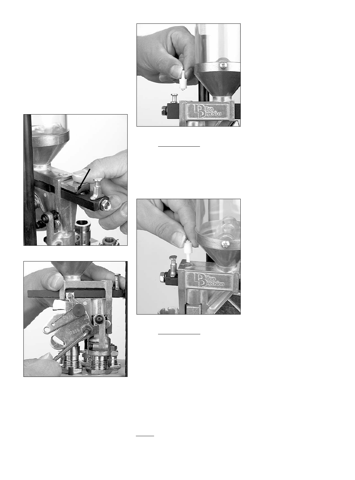
6. a) Installation of the large powder
bar – slide the large powder bar into
the powder measure body.
b) Installation of the small powder
bar – slide both the small powder bar
and small powder bar spacer into the
powder measure body FIG 199.
Note: The groove along the edge of
the spacer (see arrow FIG 199) is to
be installed face down. The hole in
the spacer is to be aligned with the
hole in the top of the powder mea-
sure body FIG 199.
FIG 199
FIG 200
7. Seat the white bellcrank cube into the
notch on the side of the powder bar.
Using a 5/32” Allen wrench snug the
bellcrank screw FIG 200.
8. Re-install the white plastic retaining
plug FIG 201:
FIG 201
a) Large powder bar – FIG 201 The
retaining plug has a short end and a
long end. If the large powder bar is
installed, insert the short end of the
retaining plug into the hole in the top
of the powder measure body. Note:
The short end is used to hold the plug
for safe keeping.
FIG 202
b) Small powder bar – FIG 202 The
retaining plug has a short end and a
long end. If the small powder bar is
installed:
1) Align the hole in the powder bar
spacer with the hole in the top of
powder measure body.
2) Insert the long end of the retaining
plug into both the top of the powder
measure body and the powder bar
spacer. Note: The long end of the
retaining plug is designed to anchor
the spacer that accompanies the
small powder bar.
Step 20)Load the components.
42

Trouble Shooting
Dies Too Short
A. Need Dillon die lockrings (14067).
1. Three extra come with the machine.
2. Threadaphobia (fear of too few
threads) can strike anyone-anytime.
It is a common but curable disease.
You only need one thread showing
above the toolhead to hold the die
lockring.
Cartridge won’t feed into chamber
1. Overall length too long. See loading
manual for dimensions.
2. Improper headspace. See loading
manual for dimensions. Use head-
space case gage.
3. Too much bell left on case. (Not
enough crimp.)
4. Case buckled.
a. Too much crimp.
5. Using brass that you picked-up at the
range that has been fired in an over-
size chamber.
6. Gun operation problems.
Hard or Incomplete Indexing
A. Shellplate not indexing smoothly.
1. Shellplate bolt adjusted too tight.
Readjust 1/8 turn maximum.
2. Shellplate bolt tightens when
shellplate turns.
a. Brass tipped set screw loose or
missing.
3. Wrong size locator buttons.
4. Index pawl bent, worn or in back-
wards.
5. Dirt under shellplate.
a. Keep shellplate clean.
b. When replacing shellplate, bolt
(13418) must be lubed with a little
all purpose grease.
6. Bent or broken shellplate.
7. Index ball (13891) and/or spring
(14118) stuck, missing or broken.
Can also cause shellplate to turn
backwards after indexing.
8. Not taking full stroke on the handle.
9. Ring indexer (13677) worn or indexer
block (16671) needs adjusted. Return
spring damaged or missing.
10. Improper type of locator button for
caliber.
B. Handle movement difficult
1. Powder or other debris causing jam-
ming of moving parts.
2. Link arm pins (13700) galled.
3. Main shaft (13485) dirty or dry.
a. Clean and lubricate with 30 wt oil.
4. Camming pin on black casefeed slide
not lubed.
5. Primer cam worn causing primer
indexing arm to drag and stick.
6. Incorrect lubricant used. Do not use
solvent blended lubes.
Casefeeding
A. Casefeeder is on but will not rotate.
1. Brass caught under casefeed plate.
2. Casefeed is too full.
3. Bad micro-switch.
B. Cases are falling down tube upside
down jamming in the top tube, etc.
1. Using the wrong casefeed plate for
that caliber.
2. Casefeed baffle (13688) not in place
(see conversion chart for which cal.
require use of the casefeed baffle)
3. Casefeed is too full.
4. The machine is not secured to a stur-
dy enough bench.
C. Casefeed tube (13099 or 13101)
appears too short.
1. Casefeed is not pushed down all the
way on the casefeed mounting post
(17123).
D. Cases hanging up at micro-switch or
micro-switch inoperative.
1. Check the angle of the switch lever
and adjust as necessary.
a. Too sharp an angle will cause
cases to hang up.
b. Too shallow an angle will cause
incomplete shutoff.
E. Cases jamming at the casefeed arm
(13716).
1. Wrong size or loose body bushing for
caliber being loaded.
2. Operating machine too fast.
3. Short stroking the machine.
4. Dented or squashed cases.
Case Insertion
A. Case not getting to shellplate.
1. Wrong size Station 1 locator.
2. Wrong size casefeed adapter.
3. Shellplate bolt is too loose.
4. Dirt in shellplate pockets or damaged
shellplate.
5. Handle being moved too rapidly on
upstroke.
6. Dirt or media in casefeed track.
B. Case doesn’t drop onto platform.
1. Using the wrong arm or body bushing.
C. Cases not fitting in shellplate or staying
centered.
1. Locator buttons missing or wrong
size for that caliber.
2. Primer Station locator tab (13242)
needs to be readjusted.
3. Wrong shellplate caliber being
loaded.
4. Wrong cases for caliber being
loaded.
5. Debris in pockets of shellplate.
6. Rim of case damaged or shot in open
bolt gun. i.e. 9mm sub gun.
7. Cases out of spec.
8. Worn out brass from over use or hot
loads.
9. Shellplate damaged from decap pin.
Station 1 - Resizing and Decapping
A. Crushing cases.
1. Incomplete case insertion.
2. Not enough radius on die. Use Dillon
dies where available.
3. Unstable bench causes case to move
and hit edge of die.
B. Bending or breaking decapping pins.
1. Smaller caliber brass stuck inside of
case or on decapping stem.
2. Berdan primed cases.
3. Media and polish has formed a hard
mix in bottom of case.
4. Handle being moved too rapidly on
the down stroke.
5. Rocks or other foreign objects in
cases.
C. Cases are not being pushed all the way
into the shellplate by the case insert
slide (97082).
1. Not pushing forward enough (or at
all) on the handle.
2. Camming pin (13371) needs to be
adjusted.
3. Debris or media in shellplate or under
Station 1 locator.
4. Bent rail on Station 1 locator.
D. Case insert slide (97082) jams on sta-
tion 1 locator.
1. Be sure there is lubrication on the
case insert slide.
2. Debris under Station 1 locator.
E. Sizing die marking cases.
1. Wrong sizing die for that caliber.
2. Dirty brass.
3. Scratched die.
4. Case shot in large chamber and base
is excessively expanded.
5. Brass/nickel adhering to carbide
insert.
a. Lube cases properly to prevent
this.
b. Clean insert with 600 grit to
remove build up.
c. Use Sweets 7.62 Solvent to clean
insert.
6. New brass (Sharp edges at case
mouth.)
7. Die lockring not tightened with a
case in the die.
F. Oil dent in shoulder of case or neck
appears wrinkled.
1. Using too much case lubricant.
G. Case sticking in sizing die.
1. Insufficient case lube.
2. Alcohol not yet evaporated from
spray-on case lube.
a. Allow five minutes for alcohol to
evaporate before sizing cases.
H. Decap pin not decapping.
1. Sizing die not screwed down far
enough.
2. Decapping assembly not screwed
down all the way.
3. Decapping pin bent, broken or missing.
43

4. Point of decap pin is squared off not
rounded (pin gets stuck in anvil and
pulls primer back into primer pocket).
5. Berdan primed brass.
a. Berdan primed brass has two flash
holes and should not be reloaded.
I. Case not properly sized.
1. Size die not properly adjusted.
2. Handle not cycled all the way down
to stops.
3. Case was shot in an unsupported
chamber and base is excessively
expanded.
a. Hot loads.
b. Consult a gunsmith about chamber.
J. Spent primers dropping on floor.
1. Spent primer cup bracket (16209)
broken or missing.
2. Spent primer cup (16211) broken or
missing.
K. Spent primers bouncing out of empty
spent primer cup.
1. Place a piece of thin foam to the
bottom of the spent primer cup.
Station 2 - Priming
A. Primers not feeding properly.
1. Magazine tube is empty.
2. Stuck primer in tube.
a. Tube must be thrown away.
3. Damaged brass tip or tube.
a. Tube must be thrown away.
B. Crushed primers.
1. Dirt or debris in shellplate pockets.
2. Ringed primer. When a spent primer
has been pierced by the decapping
pin leaving a ring of metal from the
primer in the pocket.
3. Chipped or worn primer punch.
4. Hot loaded ammo that has been fired
several times and the base of the
case has been flattened. Such cases
being reloaded need primer pockets
swaged – i.e., radiused edges on the
primer pocket.
5. Be sure the loading bench is not
shaking or rocking. To keep the
bench from moving bolt it to the wall.
If the bench is not solid the primers
will tip and jam.
6. Be sure the primer Station locator tab
is adjusted correctly. It should be
adjusted so it is approximately 10
thousandths from the case rim (the
thickness of a business card).
7. Wrong size/type primer for that cal-
iber.
8. Pushing forward on the handle too
hard.
9. Cycle the machine using a smooth
continuous motion. Do not make
erratic movements.
C. High Primers.
1. Shellplate too loose. Be sure the
shellplate is tightened down correctly.
This is done by turning the shellplate
bolt down until it is tight, then backing
it off 1/8 of a turn. Don’t forget to
loosen the shellplate bolt set screw,
on the left side of the mainshaft,
before adjusting the shellplate bolt.
Tighten the set screw when finished.
2. Erratic handle motion.
3. Push handle forward fully to seat the
primer.
4. Handle crank broken or cracked.
a. Push forward on the handle and
look for hairline cracks.
D. Primer early warning system inoperative.
1. Battery dead, missing or backwards.
2. Follower rod (13707) not in or
warped.
3. Buzzer defective.
4. Primers stuck in magazine tube.
E. Rotary primer disc not indexing/jammed.
1. Check indexing lever and replace if
bent.
2. Inspect primer cam (13670).
a. Missing.
b. Worn camming surface.
3. Powder debris on platform.
4. Stuck primer catching on shim
(14117) and platform body.
F. Primers going in upside down.
1. Primer punch is not properly aligned
with the indexing shellplate.
a. Using old index cam (if purchased
machine prior to March 95).
Station 2 - Powder Charging and Case
Mouth Belling
A. Crushing cases.
1. Locator tab is misadjusted. Adjust tab
until there is a small amount of light
showing between the case and the
locator tab. Approximately 10 thou-
sandths of an inch.
B. Spilling powder.
1. Slamming or going too fast with the
operating handle. Common with .380
and 9mm cases which are filled to
the top of the case. Slow down and
pace yourself.
2. Stick or pencil lead type powders
bridging on the case mouth in the
powder funnel.
3. Check powder bar adjustment.
4. Machine not secured properly or
bench not stable.
5. Small powder bar spacer plug
(13921) missing.
6. No primer in case.
C. Erratic belling (too much or too little).
1. Variation in case length. Note: sepa-
rate cases by brand.
2. Handle not moving all the way down
on each cycle.
3. No funnel.
4. Wrong funnel for that caliber.
5. Improper powder die adjustment.
6. Powder measure loose on powder
die (screws not tightened down).
D. Erratic powder charges.
1. Powder bar not moving the full length
of its travel. Turn the powder die
down until it does.
2. Failsafe rod missing.
3. Powder not settled in hopper.
a. After a powder bar has been re-
adjusted – cycle five cases through
the machine dropping powder in
each one. Check the powder
weight of the fifth case.
4. Not cycling the handle through its full
travel.
5. Machine not secured properly or
bench not stable.
6. Wrong size bar for requirements.
a. Switch to the large bar over 7
grains.
7. Powder funnel or drop tube dirty or
clogged.
8. Crack in powder measure body.
a. Usually present where bellcrank
bolt (13904) enters powder mea-
sure body (21274).
9. Small powder bar spacer plug
(13921) missing.
10. Erratic handle movement.
11. Using pencil lead/stick type powder.
E. Powder bar sticking
1. Powder bar dirty.
a. Clean with acetone or finger nail
polish remover. Keep very clean.
Do not lubricate.
b. Do not use sandpaper, file or any-
thing abrasive.
2. Powder bar, powder bar spacer or
powder measure body galled.
Appearance of a long streak of metal
on the bar or spacer.
a. Wipe off with soft cloth soaked in
acetone, lighter fluid or rubbing
alcohol.
3. Failsafe assembly not installed or
broken.
4. Using fine-grained spherical powder.
a. Win 296, H110 and Accurate Arms
powder have been known to get
between the powder bar, spacer
and/or the powder measure body
and bind movement.
5. Powder bar insert/powder bar adjust-
ment bolt adjusted full open against
the stop.
a. This can bind the powder bar
insert causing the powder bar to
drag.
F. Case sticking to powder funnel.
1. New, extremely clean or liquid
cleaned brass.
a. Do not clean cases more than 1
1/2 hours.
b. Worn powder funnel. Streaks on
funnel tip. Repolish to high luster.
Station 3 - Powder Check
A. Powder check die inoperative.
1. Check battery.
2. Check adjustments.
44

Station 4 - Bullet Seating
A. Erratic seating depth of the bullet.
1. Variations of less than 20 thou-
sandths of an inch are due to varia-
tions in cases and bullets. This is not
a problem.
2. Build up of lead shavings and/or lube
in the seater or crimp dies.
3. Bullets having erratic dimension
(length and/or the ogive).
4. Use of improper seating plug for the
type of bullet being used.
5. Variations in case types and/or lots
(sort your brass).
6. Refer to loading manual for dimen-
sions.
B. Shaving brass when bullet is seated or
crescent shaped brass falling on
shellplate.
1. New brass.
2. Too much flare.
C. Shaving lead/lube when bullet is seated.
1. Case not belled enough with funnel.
2. Case was cleaned too long. Case
mouth must be deburred.
3. Wrong bullet diameter for caliber.
D. Bullet loose in brass.
1. Bullet is under sized.
a. Measure diameter of bullets.
2. Incorrect powder funnel, i.e., if the
funnel is too big it will make the
mouth of the case oversized.
E. Bullet tilted after seating.
1. Case not belled enough.
2. Wrong seating stem or die for bullet
style or caliber.
3. Missing or wrong locator buttons, i.e.,
case not centered below the die.
4. Uneven casemouth opening.
5. Using a nominally incorrect bullet.
i.e., .38/357 bullet in .38 Super.
6. Die and stem not square to shellplate.
a. Snug lockring with case and bul-
let in die.
F. Seating die deforming top of bullet.
1. Seating stem not matching that style
of bullet.
2. Soft lead.
3. Lead and/or wax build-up in die.
4. Case not belled enough.
Station 5 - Crimp
A. Erratic crimping.
1. Variation in case length. Probably
due to mixed brands of brass.
2. Dirty or worn out crimp die. Use
Dillon dies where available.
B. Loose bullet.
1. Too much taper crimp. This condition
can also affect accuracy.
2. Wrong expander.
3. Thin cases. (Use Dillon dies and this
won’t be a problem.)
4. Wrong crimp die.
C. Too much or too little crimp on complet-
ed round.
1. Crimp die adjusted too low or too
high. See manual for maximum crimp
dimensions. If not available, crimp to
20 thousandths below case diameter.
2. Using wrong crimp die for that case.
3. Not using full stroke of handle.
4. Over flared case.
5. Variations in case length.
Ejecting Finished Cartridges
A. Rounds not ejecting after Station 5.
1. Ejector wire (13298) bent, broken or
missing.
2. Wrong locator buttons.
3. Shellplate damaged from decap pin.
B. Finished cartridges do not make it into
the catch bin.
1. Operating handle too fast.
2. Chute/bin mount is bent.
3. Bin is missing or improperly located.
Maintenance
Lubrication: Operating circumstances will
dictate the frequency of required lubrica-
tion. It is highly recommended that the XL
650 be cleaned and lubed after every 3000
rounds of operation. Use oil or wheel bear-
ing grease. Never use penetrating lubri-
cants, aerosol sprays, or solvent type lubes,
such as WD-40 or Break Free.
Lubrication Points:
Shellplate bolt – Grease.
Main Shaft Lubrication –
Use only 30 wt. motor oil. Once again, do
not use penetrating lubricants, aerosol
sprays, or solvent type lubricants.
45

46
650 Caliber Conversion Chart - Pistol
To order a complete conversion use the 5 digit number to the right of the caliber listing.
To order individual parts use the 5 digit number below the description.
Casefeed discs arenot included in caliber conversion kits.
Caliber Complete Shellplate Locator Funnel Station 1 Casefeed Arm Body Casefeed Primer Powder
Conversion Number Button Locator Adapter Bushing Bushing Disc System Check Rod
7TCU 21103 (3) 13345 (3) 14060 (N) 13014 13614 (White) 13575 (Green) 13412 (Sm) 13513 (SR) 21074 Sm Sm
(1) .30 Luger 21107 (5) 13509 (3) 14060 (C) 13564 13546 (Green) 13450 (Green) 13412 (Sm) 13513 (SP) 21073 Sm Med
(1) .30 Mauser 21107 (5) 13509 (3) 14060 (C) 13564 13546 (Red) 13143 (Green) 13412 (Sm) 13513 (SP) 21073 Sm Med
(1) .32 ACP (7.65MM) 21114 (8) 12779 (8) 14048 (S) 12845 11936 (Green) 13450 (Green) 13412 (Sm) 13513 (SP) 21073 Sm Med
(1) .32 Colt Short 21114 (8) 12779 (8) 14048 (S) 12845 11936 (Green) 13450 (Green) 13412 (Sm) 13513 (SP) 21073 Sm Med
(1) .32 S&W Long 21122 (D) 12879 (3) 14060 (SW) 13171 11619 (Green) 13450 (Green) 13412 (Sm) 13513 (SP) 21073 Sm Med
(1) .32 H&R Mag 21122 (D) 12879 (3) 14060 (SW) 13171 11619 (Blue) 13075 (Green) 13412 (Sm) 13513 (SP) 21073 Sm Med
(1) 9MM/9 X 21 21109 (5) 13509 (3) 14060 (F) 13806 13546 (Green) 13450 (Green) 13412 (Sm) 13513 (SP) 21073 Sm Med
.38 Super
(1) 9 X 25 21527 (W) 13310 (2) 14062 (F) 13806 13267 (Red) 13143 (Red) 13403 (Med) 13604 (LP) 21072 Sm Med
(1) .380 Auto 21104 (3) 13345 (3) 14060 (F) 13806 13614 (Green) 13450 (Green) 13412 (Sm) 13513 (SP) 21073 Sm Med
.38 21098 (2) 13430 (2) 14062 (D) 13599 13563 (Orange) 13386 (Red) 13403 (Sm38) 13384 (LP) 21072 Sm Med
(2) .357 21098 (2) 13430 (2) 14062 (D) 13599 13563 (Orange) 13386 (Red) 13403 (Sm38) 13384 (LP) 21072 Sm Med
10MM 21120 (W) 13310 (2) 14062 (W) 13600 13267 (Red) 13143 (Red) 13403 (Med) 13604 (LP) 21072 Lg Med
.40 S&W 21120 (W) 13310 (2) 14062 (W) 13600 13267 (Purple) 18076 (Red) 13403 (Med) 13604 (LP) 21072 Sm Med
(2) .41 Mag 21111 (6) 13121 (1) 13930 (H) 13240 13118 (Yellow) 13442 (Red) 13403 (Med) 13604 (LP) 21072 Lg Med
(2) .44 Spl/Mag 21105 (4) 13185 (4) 14047 (G) 13427 13340 (Yellow) 13442 (Yellow) 13619 (Lg) 13639 (LP) 21072 Lg Lg
.45 ACP 21071 (1) 13204 (1) 13930 (E) 13782 13595 (Red) 13143 (Red) 13403 (Med) 13604 (LP) 21072 Lg Lg
.45 Auto Rim 21445 (H) 10297 (4) 14047 (E) 13782 16263 (Red) 13143 (Red) 13403 (Lg) 13639 (LP) 21072 Lg Lg
(2) .45 Long Colt 21118 (C) 12986 (4) 14047 (E) 13782 12817 (Yellow) 13442 (Yellow) 13619 (Lg) 13639 (LP) 21072 Lg Lg
.454 Casull 21118 (C) 12986 (4) 14047 (E) 13782 12817 (Yellow) 13442 (Yellow) 13619 (Lg) 13639 (LP) 21072 Sm Lg
.45 Win Mag 21423 (L) 10295 (1) 13930 (E) 13782 13595 (Yellow) 13442 (Yellow) 13619 (Lg) 13639 (LP) 21072 Lg Lg
9x18 Makarov 21657 (5) 13509 (3) 14060 (9) 14980 13614 (Green) 13450 (Green) 13412 (Sm) 13513 (SP) 21073 Sm Med
(1) Requires casefeed adapter funnel (#13688), see manual for installation instructions.
(2) Requires casefeed spacer washer, see manual for installation instructions.
About Powder Bars: Dillon Precision manufactures four types of powder bars for the XL 650:
1. Extra Small – use for dropping less than 3 grains of powder
2. Small – use for dropping 3 to 20 grains of powder
3. Large – use for dropping 20 to approximately 45 to 50 grains of powder
4. Magnum – use for dropping 50 or more grains of powder
The extra small powder bar is used when loading 32 Auto, 32 S&W and 32 SWL. Both the extra small powder bar and the magnum powder bar
are non-standard items and are ordered separately. The large and small powder bar, on the other hand, are standard equipment and are included
with every XL 650.

47
650 Caliber Conversion Chart - Rifle
To order a complete conversion use the 5 digit number to the right of the caliber listing.
To order individual parts use the 5 digit number below the description.
Casefeed discs arenot included in caliber conversion kits.
Caliber Complete Shellplate Locator Funnel Station 1 Casefeed Arm Body Casefeed Primer Powder
Conversion Number Button Locator Adapter Bushing Bushing Disc System Check Rod
.17 Rem 21099 (3) 13345 (3) 14060 (O) 12921 (3) 13614 (White) 13575 (Green) 13412 (Sm) 13513 (SR) 21074 Sm Sm
.22 Hornet 21697 (E) 10300 (8) 14048 (A) 13426 (E) 14859 (BlueMod) 15186 (Green) 13412 (Sm) 13513 (SP) 21073 Sm Sm
.22 Rem Jet 21096 (2) 13430 (2) 14062 (A) 13426 13563 (Orange) 13386 (Red) 13403 (Sm38) 13384(LP) 21072 Sm Sm
.218 Bee 21618 (O) 10294 (3) 14060 (A) 13426 (W) 13600 (White) 13575 (Green) 13412 (Sm) 13513 (SR) 21074 Sm Sm
.220 Swift 21429 (L) 10295 (1) 13930 (A) 13426 (6) 13118 (Orange220) 14851 (White) 13661 (Med) 13604 (LR) 21075 Lg Sm
.221 Rem Fire Ball 21102 (3) 13345 (3) 14060 (A) 13426 (3) 13614 (White) 13575 (Green) 13412 (Sm) 13513 (SR) 21074 Sm Sm
.222 Rem/Rem Mag 21101 (3) 13345 (3) 14060 (A) 13426 (3) 13614 (White) 13575 (Green) 13412 (Sm) 13513 (SR) 21074 Sm Sm
.223 (5.56MM) 21101 (3) 13345 (3) 14060 (A) 13426 (3) 13614 (White) 13575 (Green) 13412 (Sm) 13513 (SR) 21074 Sm Sm
.224 Wby Mag 21116 (A) 12529 (2) 14062 (A) 13426 (A) 12339 (Black) 13541 (White) 13661 (Med) 13604 (LR) 21075 Lg Sm
.22-250 21088 (1) 13204 (1) 13930 (A) 13426 (1) 13595 (OrangeMod) 14313 (White) 13661 (Lg) 13639 (LR) 21075 Lg Sm
.243 Win/6mm Rem 21089 (1) 13204 (1) 13930 (I) 13305 (1) 13595 (Black) 13541 (White) 13661 (Lg) 13639 (LR) 21075 Lg Sm
.25-20 21619 (O) 10294 (3) 14060 (R) 13243 (W) 13600 (Blue) 13075 (Green) 13412 (Sm) 13513 (SP) 21073 Sm Sm
.25-06 21090 (1) 13204 (1) 13930 (K) 13216 (1) 13595 (Black) 13541 (White) 13661 (Lg) 13639 (LR) 21075 Lg Sm
.256 Win Mag 21097 (2) 13430 (2) 14062 (R) 13243 13563 (Orange) 13386 (Red) 13403 (Sm38) 13384(LP) 21072 Sm Sm
.257 Roberts 21090 (1) 13204 (1) 13930 (K) 13216 (1) 13595 (Black) 13541 (White) 13661 (Lg) 13639 (LR) 21075 Lg Sm
.257 Ack Imp 21090 (1) 13204 (1) 13930 (K) 13216 (1) 13595 (Black) 13541 (White) 13661 (Lg) 13639 (LR) 21075 Lg Sm
.257 WBY Mag 21431 (B) 12903 (4) 14047 (K) 13216 (B) 13156 (BlackModS) 14395 (Yellow) 13619 (Lg) 13639 (LR) 21075 Lg Sm
6.5 Rem Mag 21437 (B) 12903 (4) 14047 (Y) 12870 (B) 13156 (BlackModS) 14395 (Yellow) 13619 (Lg) 13639 (LR) 21075 Lg Sm
6.5 x 55 Mauser 21476 16545 (1) 13930 (Y) 12870 (1) 13595 (Black) 13541 (White) 13661 (Lg) 13639 (LR) 21075 Lg Sm
.264 Win Mag 21437 (B) 12903 (4) 14047 (Y) 12870 (B) 13156 (BlackModS) 14395 (Yellow) 13619 (Lg) 13639 (LR) 21075 Lg Sm
.270 WBY Mag 21438 (B) 12903 (4) 14047 (J) 13456 (B) 13156 (BlackModS) 14395 (Yellow) 13619 (Lg) 13639 (LR) 21075 Lg Sm
.270 Win 21093 (1) 13204 (1) 13930 (J) 13456 (1) 13595 (Black) 13541 (White) 13661 (Lg) 13639 (LR) 21075 Lg Sm
7mm Rem Mag 21438 (B) 12903 (4) 14047 (J) 13456 (B) 13156 (BlackModS) 14395 (Yellow) 13619 (Lg) 13639 (LR) 21075 Lg Sm
7mm Wby Mag 21438 (B) 12903 (4) 14047 (J) 13456 (B) 13156 (BlackModS) 14395 (Yellow) 13619 (Lg) 13639 (LR) 21075 Lg Sm
(3) 7.62x54 21699 (G) 10298 (7) 13436 (B) 13587 (G) 14331 (BlackModS) 14395 (Nickel) 14397 (XL) 14396 (LR) 21075 Lg Med
.30-338 Win Mag 21439 (B) 12903 (4) 14047 (B) 13587 (B) 13156 (BlackModT) 14394 (Yellow) 13619 (Lg) 13639 (LR) 21075 Lg Med
.300 H&H Mag 21439 (B) 12903 (4) 14047 (B) 13587 (B) 13156 (BlackModT) 14394 (Yellow) 13619 (Lg) 13639 (LR) 21075 Lg Med
.300 Win Mag 21439 (B) 12903 (4) 14047 (B) 13587 (B) 13156 (BlackModT) 14394 (Yellow) 13619 (Lg) 13639 (LR) 21075 Lg Med
.300 WBY Mag 21439 (B) 12903 (4) 14047 (B) 13587 (B) 13156 (BlackModT) 14394 (Yellow) 13619 (Lg) 13639 (LR) 21075 Lg Med
(2) .30 M1 Carbine 21113 (8) 12779 (8) 14048 (C) 13564 (8) 11936 (Blue) 13075 (Green) 13412 (Sm) 13513 (SP) 21073 Sm Med
.308 Norma Mag 21439 (B) 12903 (4) 14047 (B) 13587 (B) 13156 (BlackModT) 14394 (Yellow) 13619 (Lg) 13639 (LR) 21075 Lg Med
.308 Win (7.62mm)
.30-06 21094 (1) 13204 (1) 13930 (B) 13587 (1) 13595 (Black) 13541 (White) 13661 (Med) 13604 (LR) 21075 Lg Med
.303 British 21106 (N) 10296 (4) 14047 (B) 13587 (N) 14237 (Black) 13541 (Yellow) 13619 (Lg) 13639 (LR) 21075 Lg Med

48
650 Caliber Conversion Chart - Rifle
To order a complete conversion use the 5 digit number to the right of the caliber listing.
To order individual parts use the 5 digit number below the description.
Casefeed discs arenot included in caliber conversion kits.
Caliber Complete Shellplate Locator Funnel Station 1 Casefeed Arm Body Casefeed Primer Powder
Conversion Number Button Locator Adapter Bushing Bushing Disc System Check Rod
.30-30 Win 21112 (7) 13300 (4) 14047 (B) 13587 (7) 13176 (Orange220) 14851 (White) 13661 (Med) 13604 (LR) 21075 Lg Med
(4) 7.62 X 39 Russian 21117 (A) 12529 (2) 14062 (AK)13015 (A) 12339 (OrangeMod) 14313 (Red) 13403 (Med) 13604 (LP) 21072 ** Med
.32-20 21620 (O) 10294 (3) 14060 (S) 12845 (W) 13600 (Blue) 13075 (Green) 13412 (Sm) 13513 (SP) 21073 Sm Med
.338 Win Mag 21441 (B) 12903 (4) 14047 (Q) 13406 (B) 13156 (BlackModS) 14395 (Yellow) 13619 (Lg) 13639 (LR) 21075 Lg Med
.340 WBY Mag 21442 (B) 12903 (4) 14047 (P) 13187 (B) 13156 (BlackModT) 14394 (White) 13661 (Lg) 13639 (LR) 21075 Lg Med
.350 Rem Mag 21442 (B) 12903 (4) 14047 (P) 13187 (B) 13156 (BlackModS) 14395 (White) 13661 (Lg) 13639 (LR) 21075 Lg Med
.38-40 Win 21492 (N) 10296 (4) 14047 (W) 13600 (N) 14237 (Yellow) 13442 (Yellow) 13619 (Lg) 13639 (LP) 21072 Lg Med
.375 H&H Mag 21443 (B) 12903 (4) 14047 (R) 13531 (B) 13156 (BlackModT) 14394 (Yellow) 13619 (Lg) 13639 (LR) 21075 Lg Med
8MM REM MAG 21442 (B) 12903 (4) 14047 (P) 13187 (B) 13156 (BlackModT) 14394 (White) 13661 (Lg) 13639 (LR) 21075 Lg Med
.44-40 Win 21493 (N) 10296 (4) 14047 (4) 13474 (N) 14237 (Yellow) 13442 (Yellow) 13619 (Lg) 13639 (LP) 21072 Lg Lg
.444 Marlin 21491 (N) 10296 (4) 14047 (X) 12920 (N) 14237 (Black) 13541 (Yellow) 13619 (Lg)13639 (LR) 21075 Lg Lg
(3) .45-70 Gov't 21422 (G) 10298 (7) 13436 (T) 13407 (G) 14331 (BlackModS) 14395 (Nickel) 14397 (XL) 14396 (LR) 21075 Lg Lg
.458 Win Mag 21444 (B) 12903 (4) 14047 (T) 13407 (B) 13156 (BlackModS) 14395 (Yellow) 13619 (Lg) 13639 (LR) 21075 Lg Lg
(3) These caliber conversions come with an oversized casefeed tube, casefeed funnel, and complete casefeed body assembly.
(4) For 7.62x39 primer systems, Remington made brass requires the small primer system, all others require the large primer system.
About Powder Bars: Dillon Precision manufactures four types of powder bars for the XL 650:
1. Extra Small – use for dropping less than 3 grains of powder
2. Small – use for dropping 3 to 20 grains of powder
3. Large – use for dropping 20 to approximately 45 to 50 grains of powder
4. Magnum – use for dropping 50 or more grains of powder
The extra small powder bar is used when loading 32 Auto, 32 S&W and 32 SWL. Both the extra small powder bar and the magnum powder bar
are non-standard items and are ordered separately. The large and small powder bar, on the other hand, are standard equipment and are included
with every XL 650.
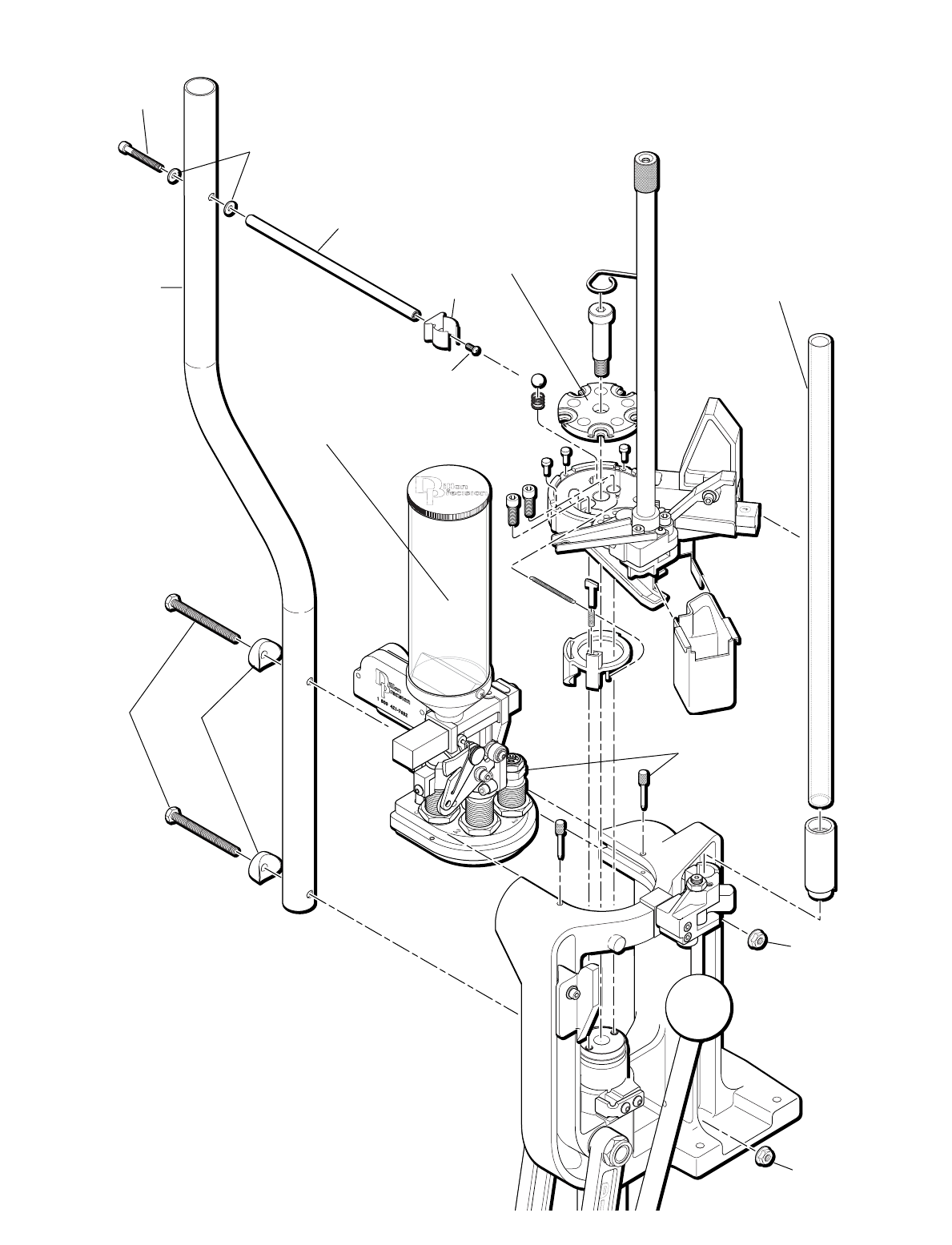
49
1
2
3
4
6
5
7
8
10
10
9
Complete
Powder Measure
Assembly
see page 56 for
more details
Toolhead
Assembly
see page 53
for more details
Platform Assembly
see page 54
for more details
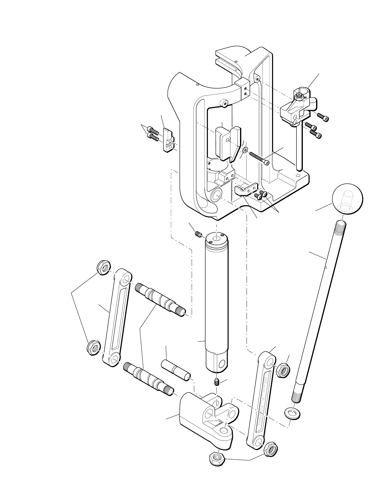
50
23
15
16
24
17
18
14
14
14
13
11
12
21
25
26
27
22
19
19
20
Casefeed Body Assembly
see page 52 for more details
Machine Assembly
21326 No feed Mounting Kit includes
items 1, 2, 3, 4, and 5
113905 Cam Screw 10-24x1 1/2
213738 #10 Rod Washer
312831 No Feed Mount Tube
413859 Casefeed Tube Clip
513895 10-24x3/8 Bolt
617123 Casefeed Mount Post
713099 Casefeed Feed Tube
13101 Casefeed Feed Tube, Large
813911 1/4-20x2 3/4 Bolt
913613 Clamp
10 13988 Casefeed Post Nut
11 13830 Mainshaft Pivot Pin
12 13789 Mainshaft Set Screw 1/4-28
13 13674 Crank
14 13841 Nylock Nut
15 13850 Handle Knob
16 13855 Handle Shaft
20636 Complete Handle Assembly
(shaft, knob, washer and nut)
17 13989 10-24x5/8 SHCS
18 16671 Indexer Block
19 14922 650 Link Arm
20 13700 650 Link Arm Pin
21 13923 Brass Tip Set Screw
22 13485 Mainshaft
23 13488 Punch Support Bracket
24 13895 10-24x3/8 BH Screw
25 13670 Primer Cam
26 14037 Cam Screw
27 13738 Stainless Flat Washer
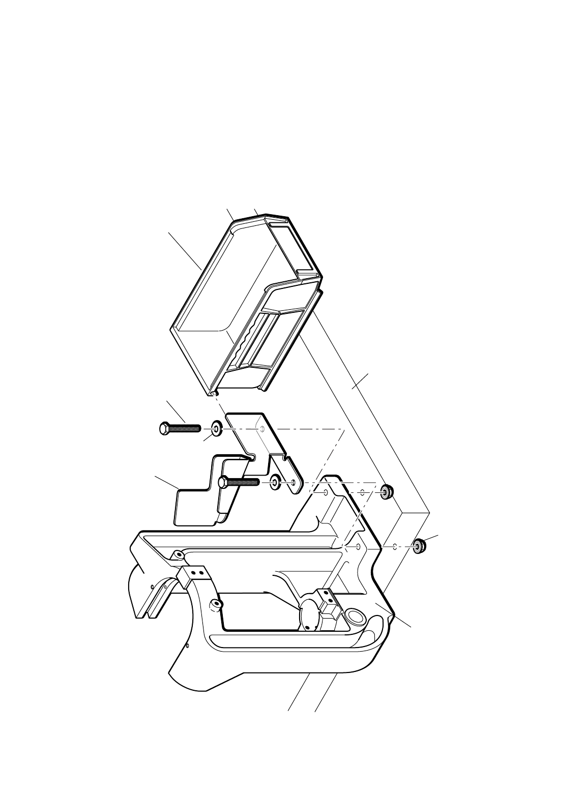
51
Lower Machine Assembly
113470 Chute/Bin Mount
213839 Blue Cartridge Bin
Items A, B, and C included in optional
Hardware Mounting Kit, #16600.
2
1
A
B
C
Frame
Bench
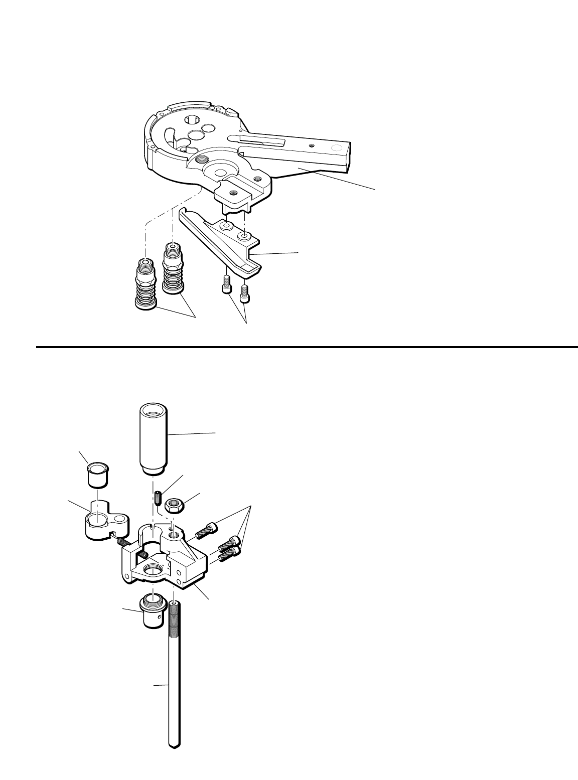
52
116652 Platform
214013 8-32x3/8 Cap Screw
316210 Primer Chute
4L 21380 Rev B Seater Assembly, Large
4S 21381 Rev B Seater Assembly, Small
Casefeed Body Assembly
Primer Punch
Assembly
1
3
1
2
4
5
6
7
8
9
3 (3 ea)
42
*1 13541 Casefeed Adapter (Black)
14394 Casefeed Adapter (BlackModT)
14395 Casefeed Adapter (BlackModS)
13450 Casefeed Adapter (Green)
13386 Casefeed Adapter (Orange)
14313 Casefeed Adapter (OrangeMod)
14851 Casefeed Adapter (Orange220)
13143 Casefeed Adapter (Red)
13575 Casefeed Adapter (White)
13442 Casefeed Adapter (Yellow)
13075 Casefeed Adapter (Blue)
15186 Casefeed Adapter (BlueMod)
214326 Casefeed Arm Stop Pin
313989 Casefeed Body Screws
413901 Cam Pin Jam Nut 3/8-24
*5 13412 Casefeed Arm Bushing (Green) Small Pistol
13403 Casefeed Arm Bushing (Red) Medium Pistol
13661 Casefeed Arm Bushing (White) Rifle
13619 Casefeed Arm Bushing (Yellow) Large Pistol
14397 Casefeed Arm Bushing (Nickel) Large
Magnum Calibers
613716 Casefeed Arm
713558 Casefeed Body (Standard)
14979 Casefeed Body (Extra Large/Magnum)
*8 13639 Casefeed Body Bushing, Large
13604 Casefeed Body Bushing, Medium
13513 Casefeed Body Bushing, Small
13384 Casefeed Body Bushing, 38
913371 Camming Pin
10 13936 Casefeed Arm Return Spring
* Indicates items included in caliber conversion kits.
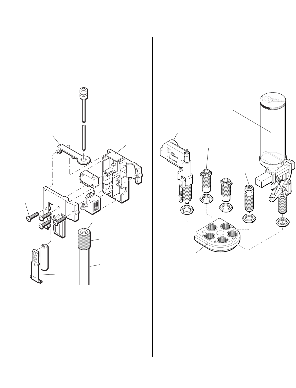
53
Primer Early Warning
Buzzer Assembly
#20302
Toolhead Assembly &
Orientation
#13863 - XL650 Toolhead
113957 Magazine Shield Cap
2L 22033 Primer Magazine, Large
2S 22032 Primer Magazine, Small
321279 Primer Feed Body Housing
420302 Early Warning Buzzer
513857 Battery Cover
613864 Switch Lever
714023 Buzzer Housing Screw
813707 Follower Rod
Station 1 Sizing Die
Station 2 Powder Measure System
Station 3 Powder Check System
Station 4 Seat Die
Station 5 Crimp Die
1 - Sizing Die
2 - Powder Measure
Toolhead Pin (2)
4 - Seat Die
4
Sold as an
assembly
8
6
5
1
2
3
7 (4 ea)
5 - Crimp Die
3 - Powder Check
System(optional)
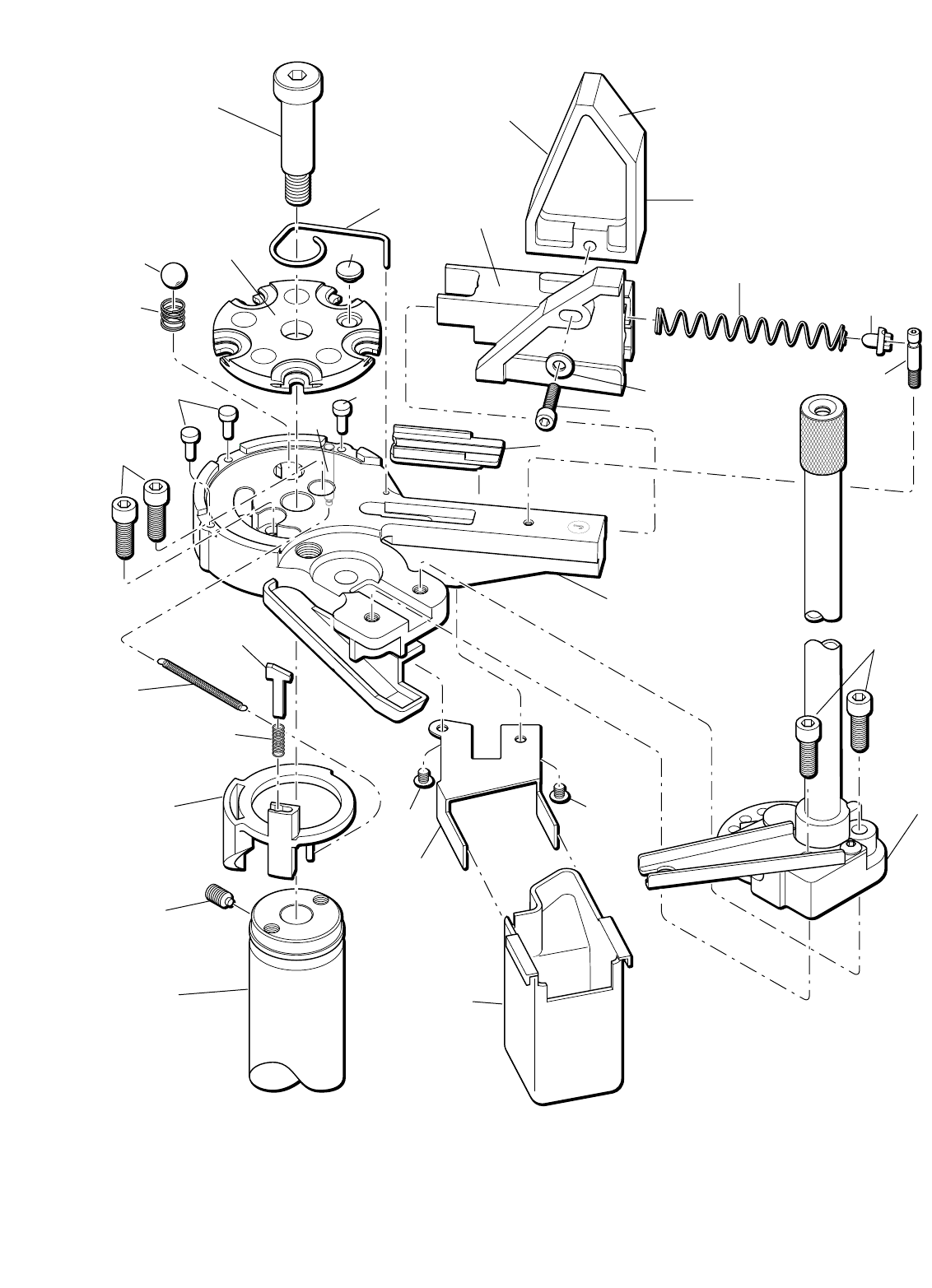
3
4
pistol
side
rifle
side
6
16
17
11
10
22
18
19
20
23
24
26
21
11
1
13
14
15
2
5
9
8
7
25
27
29
30
28 28
1, 2 97082 Case Insert Slide & Slide Cam (1)
313418 Shellplate Bolt
413298 Ejector Wire
513738 Stainless Flat Washer
6Shellplate - caliber specific
714050 Shellplate Cap
8Station 1 Locator - caliber specific
914037 Cam Screw
10 13966 Platform Mount Bolt
11 Locator Pins - caliber specific
12 13874 Station 1 Locator Tab Spring
13 13937 Case Insert Slide Spring
14 14574 Insert Slide Spring Cap
15 13311 Slide Spring Pin
16 13891 Index Ball
17 14118 Index Ball Spring
18 13667 Index Pawl
19 13938 Pawl Spring
20 13677 Ring Indexer
21 13790 Indexer Spring Pin
22 13791 Indexer Return Spring
23 13923 Brass Tip Set Screw
24 13485 Mainshaft
25 14138 Primer System Mounting Bolts
26 22060 Platform
27 21279 Primer Feedbody Housing
28 14689 Primer Cup Bracket Screw
29 16209 Spent Primer Cup Bracket
30 16211 Spent Primer Cup
Platform Assembly
54
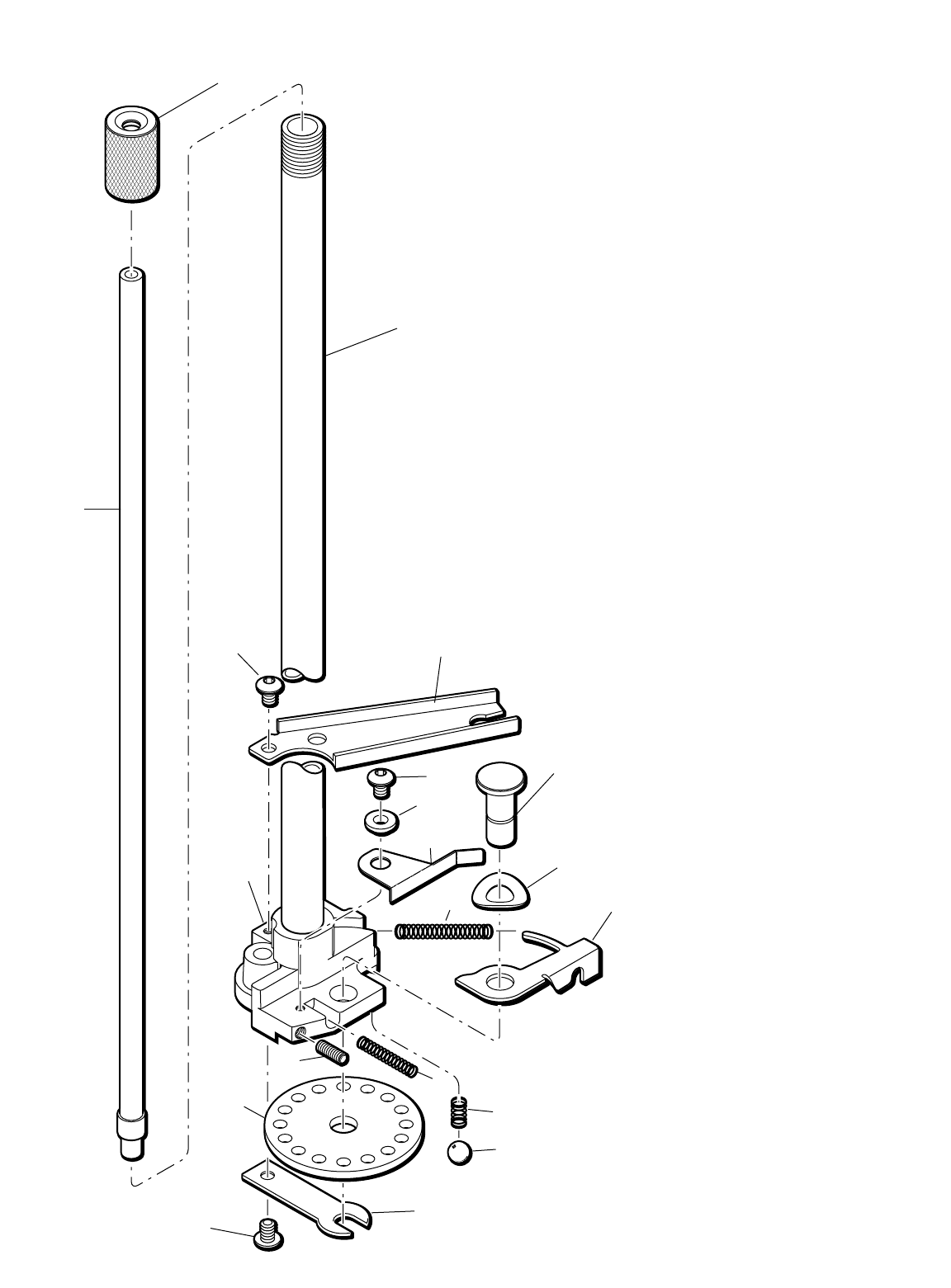
Primer System Assembly
#20982 Large, #21065 Small
113957 Magazine Shield Cap
213964 10/24x1/4 BH Screw
313367 Failsafe Bracket
413862 Primer Disc Pin
513832 Index Arm Bowed Washer
613662 Primer Indexing Arm
713964 10/24x1/4 BH Screw
813242 Primer Station Locator Tab
913820 Primer Station Locator Tab Set Screw 8-32 Thd.
10 13624 Locator Tab Spring
11 13965 Indexing Arm Spring
12 21279 Primer Feedbody Housing
13 13844 Disc Detent Spring
14 13932 Disc Detent Ball
15L 13431 Rotary Primer Disc, Large
15S 13499 Rotary Primer Disc, Small
16 14117 Primer Support Shim
17 Magazine Shield (not sold separately)
18L 22033 Primer Magazine, Large
18S 22032 Primer Magazine, Small
19 15062 Station 2 Locator Tab Bushing
1
17
18L
or
18S
3
2
12
716
14
13
10
6
11
5
4
7
19
9
15L
or
15S
8
55
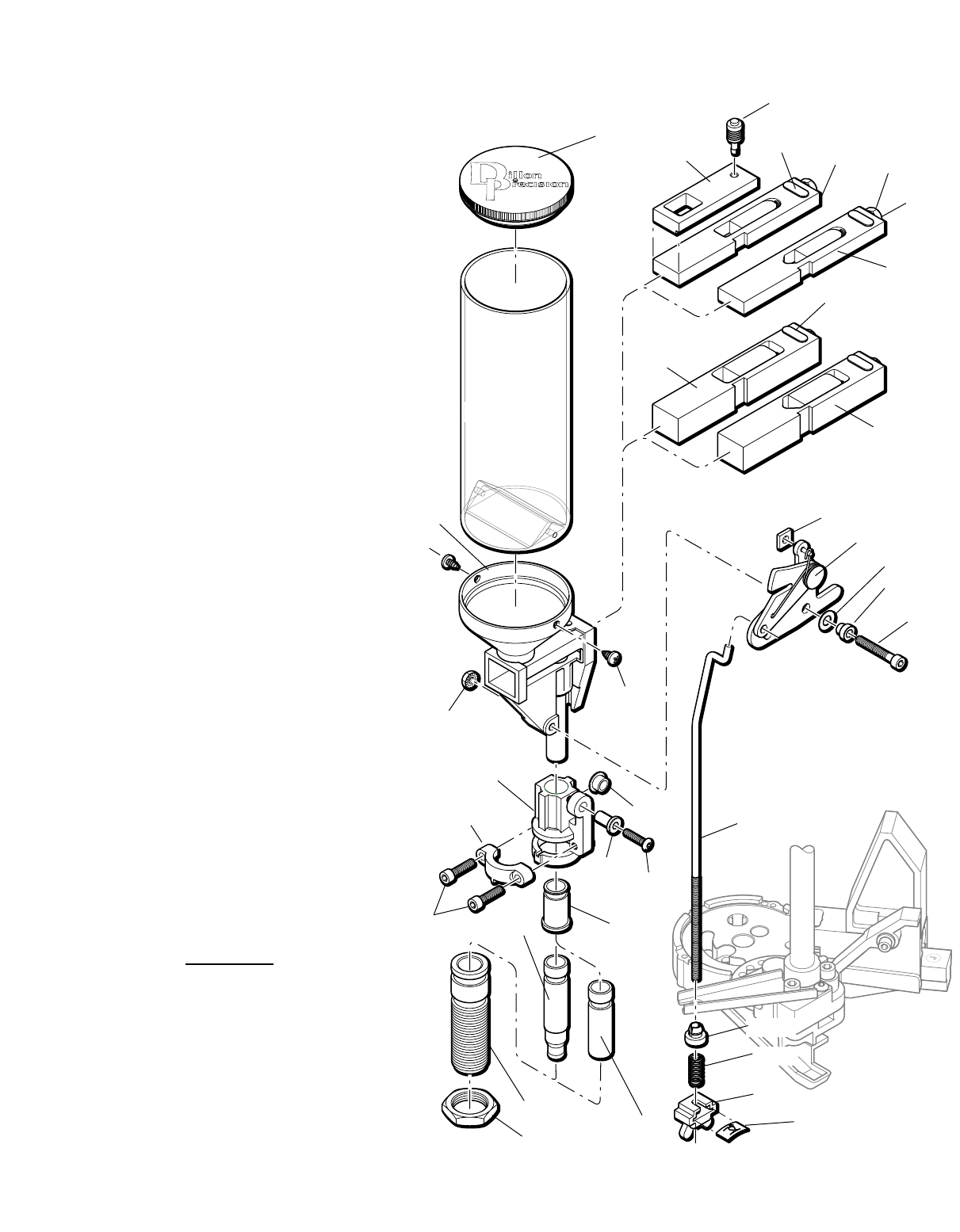
56
13882
22273
13691
13793
14808
13940
13845
13871
97034
14041
13904
13939
14037
14067
20064
*13782
16340
14202
13848
13893
20062
21353
20063
13426 * Powder Funnel, .22 cal rifle
13644 Powder Bar Spacer
13691 Powder Measure Tube Only
13782 * Powder Funnel, .45 cal pistol
13793 Roller
13845 Collar Sleeve
13848 Bellcrank Bushing
13871 Bellcrank Cube
13882 Powder Measure Lid
13893 Powder Bar Post, Large
13904 Bellcrank Screw
13921 Plastic Plug
13939 Body Collar Clamp
13940 Body Collar - Part
13943 Powder Bar Bolt
13951 Powder Bar Post, Small
13958 Powder Bar Bolt Washer
14023 8-32 x 3/4 BH Screw
14037 Clamp/Bracket Screw
14041 Bowed Washer
14067 Die Lock Ring
14202 Powder Measure Tube Screws
14808 Collar Roller Bushing
16340 10-32 Nylon Lock Nut
20062 Powder Bar Assembly, Small
20063 Powder Bar Assembly, Large
20064 Powder Die
20780 Powder Bar Assembly, Extra Small
21275 Connector Body Collar - Complete
21353 Powder Bar Assembly, Extra Large
22273 Powder Measure, Part
97034 Slotted Bellcrank
22172 Powder Measure Failsafe Kit
13629 Failsafe Rod
13799 Stripper Wing Nut
13801 Tinnerman Nut Insert
14033 Rod Spring
18086 Shoulder Washer
NOTE: * Indicates caliber specific parts –
see the caliber conversion chart for the
correct part number for the caliber you are
loading for.
WARNING
This powder measure drops a full charge of
powder each time the operating handle is
cycled. If, for any reason, you believe that
more than a single measure of powder was
dropped or you think that you may have
cycled the handle more than once on a sin-
gle case, you need to empty the case and
start over.
A double charged case can result in bodily
injury or a damaged firearm.
14202
13951 20780 13943
13958
13644
14023
Complete Powder Measure Assembly
#20785 13921
13629
18086
14033
13801
13799
*13426
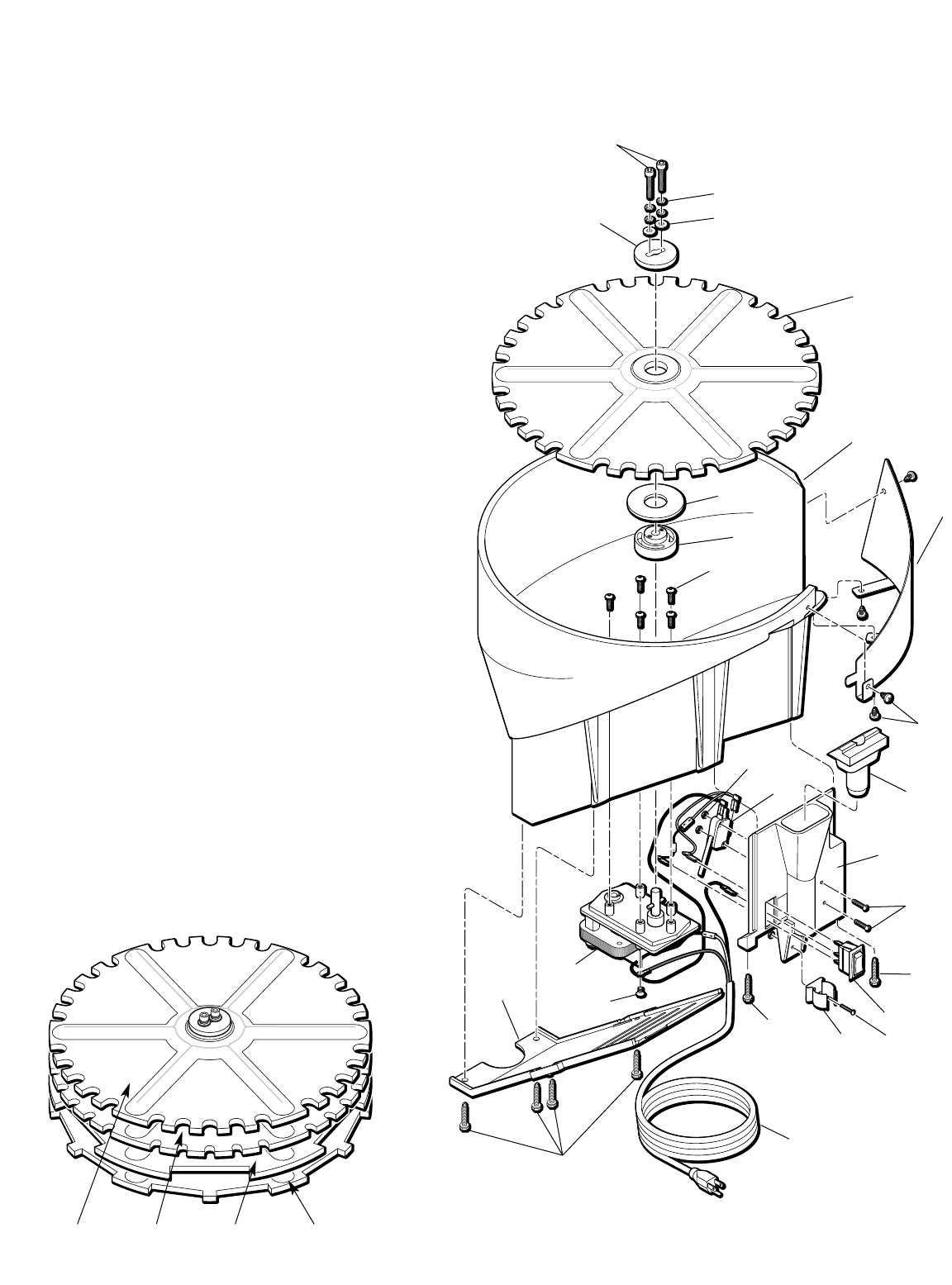
57
HIGH
OFF
LOW
13400 Casefeed Bowl
13473 Motor
13494 Casefeed Funnel, Small
13539 Power Cord
13540 Motor Cover
13623 1/4-20x5/8 Casefeed
Post Set Screw
13632 Upper Clutch
13688 Adapter Funnel
13703 Washer
13732 Clutch Screws (2)
13736 Lower Clutch
13738 Flat Washer
(2 - #10 Stainless Washers)
13779 Micro Switch
13813 Lock Washer (4)
13859 Tube Spring Clamp
13602 Zener Diode (not shown)
13912 Cover Screw
13954 Micro Switch Screws (2)
14025 Drive Pin (1/8 Roll Pin)
Not Shown
14026 Motor Mount Screw (5)
14038 Micro Switch & Bracket Nut
14137 8 x 1 Cover Screw (4) (not shown)
14393 Casefeed Funnel, Large
15433 Casefeed Port Cuff (not shown)
13812 Lighted Rocker Switch
17808 Casefeed Bowl Insert
17586 8 x 1 1/4 Funnel Screw (2)
17587 8 x 1/4 Phl. Pn. Screw (4)
21072 Large Pistol Plate
21073 Small Pistol Plate
21074 Small Rifle Plate
21075 Large Rifle Plate
29 31 32 30
10
7
29
1
11
9
28
3
8
13
21
18
27
27
4
517
2
2
25
15 6
26
20
14
12
Casefeed Assembly
1
2
3
4
5
6
7
8
9
10
11
12
13
14
15
16
17
18
19
20
21
22
23
24
25
26
27
28
29
30
31
32
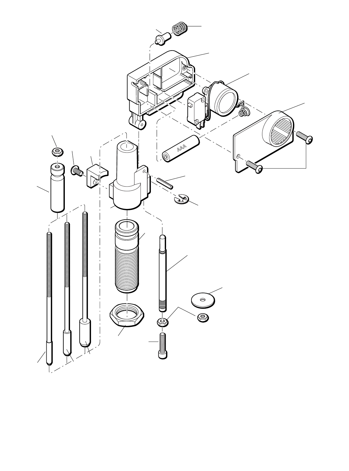
58
1513
9
21
10
19
17
7
AAA Battery
Included
16
14
20
18
2
1
8
14
6
12 11
5
4
3
Powder Check
System Assembly
#21044
114067 Die lockring
213990 Powder Die
321372 Powder Check Rod .22-.29 Cal.
421373 Powder Check Rod .30-.41 Cal.
521374 Powder Check Rod .44-.45 Cal.
610552 Die Collar
714025 Collar Roll Pin
812685 Check Rod Sleeve
913538 Buzzer Housing
10 13537 Buzzer Housing Cover
11 13986 Die Clamp
12 13895 Die Clamp Screw
13 13602 Contact Pin
14 13898 Jam Nut 10-24
15 13956 Spring
16 13603 Die Push Rod
17 13837 Die E Clip
18 14037 Push Rod Screw (10-24x3/4)
19 13983 Cover Screw (8/32x5/8)
20 14157 Washer
21 21382 Includes Housing (#13538), Buzzer,
Microswitch and Pin
Extra Powder Check Rods can be purchased
complete with sleeve (12685) and jam nut (13898).
21372 Powder Check Rod Assembly .22-.29 Cal.
21373 Powder Check Rod Assembly .30-.41 Cal.
21374 Powder Check Rod Assembly .44-.45 Cal.

59
NOTES: