R 302 Doc MG10R302
User Manual: R-302
Open the PDF directly: View PDF ![]() .
.
Page Count: 105 [warning: Documents this large are best viewed by clicking the View PDF Link!]

Contents
1 Safety Precautions
5
2 Introduction
9
About this Manual 9
What is MCT 10 Setup Software? 9
The MCT 10 Setup Software Modules 10
Two Versions 10
System Requirements 11
Background Knowledge 11
Related Literature 11
3 Installation and De-installation
13
Installation and De-installation 13
How to Start the Installation Program 13
How to Change Language after Installation 13
4 Introduction to User Interface
15
MCT 10 Features 15
5 Set-up of Communication
19
Serial Configuration 21
Profibus DPv1 Data Communication 23
Profibus DPv1 Data Communication 23
Profibus DPv1 configuration 24
USB Data Communication 25
USB Data Communication 25
Ethernet-TSC Data Communication 26
Ethernet-TSC Data Communication 26
Ethernet-TSC Configuration 26
6 Parameter Handling
27
Set-up 27
Parameter View Settings 31
Filters 32
Parameter Filters 33
Special Parameters 37
Parameter Edit 38
Inline Edit 38
Dialog Based Edit 38
Comparison of Parameters 39
Read Frequency Converter Database 40
MCT 10 Setup Software Contents
MG10R302 - VLT is a registred Danfoss trademark
1

7 Read/Write between MCT 10 and Frequency Converter
45
Reading and Writing Parameters 45
Read/Write Settings 45
Read From Drive 47
Write to Drive 49
Views 49
Scan 49
Scan Configuration 49
Scan Network 50
Poll 51
8 Saving Data
53
Network and Project Folders 53
Changing the Set-up of a Device in the Field 53
How to Save Data 53
Save Changes to a Hard Disk 53
Save a Project 53
9 SyncPos
55
SyncPos Handling 55
Programs and Configuration File 55
Import and Export of a Configuration File 56
Edit and Save Configuration File 57
Import and Export of Programs 58
Autostart 59
Source Code 59
Edit Source Code 59
Save and Exit Program 60
SyncPos Read From Drive 61
SyncPos Write to Drive 62
10 Import of Files
63
Import of Older Dialog Files 63
11 Printing
65
12 Alarm, Warning and Fault Log Readout
67
Localisation of Alarms and Warning 67
Handling Alarms/Warnings in Project Files 69
Handling the Alarms and Warning Loggings 69
13 Smart Logic Controller Plug-in
71
Smart Logic Controller Plug-in 71
Contents MCT 10 Setup Software
2
MG10R302 - VLT is a registred Danfoss trademark

Components simple to learn 72
14 Scope Function
73
Introduction to the Scope Function 73
Activating the Scope 73
Channel Types 73
Initial "Add Channel" (PC Polling Channel) 74
Initial "Add Channel" (Drive Real Time Channel) 77
Using Advanced Triggers in a "Drive Real 78
Communication Control 79
Additional Settings 80
Triggers 82
Trigger Position 82
Cursors 83
15 Update Drives Firmware Support in MCT 10
85
Background Details 85
How to Find Out if MCT 10 Has Been Updated 86
16 Guide to DP V1 Connection and Simatic Manager
87
17 FC 102 and FC 202 Series Functions
97
New Features 97
Clock Features 97
Date and Time 97
Working Days 98
Preventive Maintenance 99
Times Actions 99
Quick Menus 100
18 VLT to FC Series Converter Function
101
Import Drive from Excel 102
19 Troubleshooting
103
Save Error Dialog 103
Common Problems and Solutions 104
Changes Are Not Saved to PC 104
Error Message Whilst Installing MCT 10 Setup Software 104
Error Message Communication Failed 104
MCT 10 Setup Software Contents
MG10R302 - VLT is a registred Danfoss trademark
3

1 Safety Precautions MCT 10 Setup Software
4
MG10R302 - VLT is a registred Danfoss trademark
1
1 Safety Precautions
1.1.1 Copyright, Limitation of Liability and Revision Rights
This publication contains information proprietary to Danfoss. By accepting and using this manual the user agrees that the information contained herein
will be used solely for operating equipment from Danfoss or equipment from other vendors provided that such equipment is intended for communication
with Danfoss equipment over a PROFIBUS serial communication link. This publication is protected under the Copyright laws of Denmark and most other
countries.
Danfoss does not warrant that a software program produced according to the guidelines provided in this manual will function properly in every physical,
hardware or software environment.
Although Danfoss has tested and reviewed the documentation within this manual, Danfoss makes no warranty or representation, either express or implied,
with respect to this documentation, including its quality, performance, or fitness for a particular purpose.
In no event shall Danfoss be liable for direct, indirect, special, incidental, or consequential damages arising out of the use, or the inability to use information
contained in this manual, even if advised of the possibility of such damages. In particular, Danfoss is not responsible for any costs including but not limited
to those incurred as a result of lost profits or revenue, loss or damage of equipment, loss of computer programs, loss of data, the costs to substitute
these, or any claims by third parties.
Danfoss reserves the right to revise this publication at any time and to make changes in its contents without prior notice or any obligation to notify
previous users of such revisions or changes.
With this software package you can remote-control the frequency converter, thereby starting an electric motor which may act as a
drive for dangerous machinery.
Therefore the necessary caution must always be observed when using the software, and suitable measures should be taken to prevent
injury and damage to machinery and equipment.
MCT 10 Setup Software 1 Safety Precautions
MG10R302 - VLT is a registred Danfoss trademark
5
1
1.2 Safety Precautions
1.2.1 Safety Precautions
The voltage of the frequency converter is dangerous whenever connected to mains. Incorrect installation of the motor, frequency
converter or fieldbus may cause damage to the equipment, serious personal injury or death. Consequently, the instructions in this
manual, as well as national and local rules and safety regulations, must be complied with.
Safety Regulations
1. The mains supply to the frequency converter must be disconnected whenever repair work is to be carried out. Check that the mains supply has
been disconnected and that the necessary time has elapsed before removing motor and mains supply plugs.
2. The [OFF] button on the control panel of the frequency converterr does not disconnect the mains supply and consequently it must not be used
as a safety switch.
3. The equipment must be properly earthed, the user must be protected against supply voltage and the motor must be protected against overload
in accordance with applicable national and local regulations.
4. The earth leakage current exceeds 3.5 mA.
5. Protection against motor overload is not included in the factory setting. If this function is desired, set par. 1-90
Motor Thermal Protection
to
data value ETR trip 1 [4] or data value ETR warning 1 [3].
6. Do not remove the plugs for the motor and mains supply while the frequency converter is connected to mains. Check that the mains supply has
been disconnected and that the necessary time has elapsed before removing motor and mains plugs.
7. Please note that the frequency converter has more voltage sources than L1, L2 and L3, when load sharing (linking of DC intermediate circuit)
or external 24 V DC are installed. Check that all voltage sources have been disconnected and that the necessary time has elapsed before
commencing repair work.
Warning against unintended start
1. The motor can be brought to a stop by means of digital commands, bus commands, references or a local stop, while the frequency converter
is connected to mains. If personal safety considerations (e.g. risk of personal injury caused by contact with moving machine parts following an
unintentional start) make it necessary to ensure that no unintended start occurs, these stop functions are not sufficient. In such cases the mains
supply must be disconnected or the
Safe Stop
function must be activated.
2. The motor may start while setting the parameters. If this means that personal safety may be compromised (e.g. personal injury caused by
contact with moving machine parts), motor starting must be prevented, for instance by use of the
Safe Stop
function or secure disconnection
of the motor connection.
3. A motor that has been stopped with the mains supply connected, may start if faults occur in the electronics of the frequency converter, through
temporary overload or if a fault in the power supply grid or motor connection is remedied. If unintended start must be prevented for personal
safety reasons (e.g. risk of injury caused by contact with moving machine parts), the normal stop functions of the frequency converter are not
sufficient. In such cases the mains supply must be disconnected or the
Safe Stop
function must be activated.
NB!
When using the
Safe Stop
function, always follow the instructions in the
Safe Stop
section of the Design Guide.
4. Control signals from, or internally within, the frequency converter may in rare cases be activated in error, be delayed or fail to occur entirely.
When used in situations where safety is critical, e.g. when controlling the electromagnetic brake function of a hoist application, these control
signals must not be relied on exclusively.
Touching the electrical parts may be fatal - even after the equipment has been disconnected from mains.
Also make sure that other voltage inputs have been disconnected, such as external 24 V DC, load sharing (linkage of DC intermediate circuit), as well as
the motor connection for kinetic back up.
1 Safety Precautions MCT 10 Setup Software
6
MG10R302 - VLT is a registred Danfoss trademark
1
Systems where frequency converters are installed must, if necessary, be equipped with additional monitoring and protective devices according to the
valid safety regulations, e.g law on mechanical tools, regulations for the prevention of accidents etc. Modifications on the frequency converters by means
of the operating software are allowed.
Hoisting applications:
The frequency converter functions for controlling mechanical brakes cannot be considered as a primary safety circuit. There must always be a redundancy
for controlling external brakes.
Protection Mode
Once a hardware limit on motor current or dc-link voltage is exceeded the drive will enter “Protection mode”. “Protection mode” means a change of the
PWM modulation strategy and a low switching frequency to minimize losses. This continues 10 sec after the last fault and increases the reliability and
the robustness of the drive while re-establishing full control of the motor.
In hoist applications “Protection mode” is not usable because the drive will usually not be able to leave this mode again and therefore it will extend the
time before activating the brake – which is not recommendable.
The “Protection mode” can be disabled by setting par. 14-26
Trip Delay at Inverter Fault
to zero which means that the drive will trip immediately if one
of the hardware limits is exceeded.
NB!
It is recommended to disable protection mode in hoisting applications (par. 14-26
Trip Delay at Inverter Fault
= 0)
The DC link capacitors remain charged after power has been disconnected. To avoid electrical shock hazard, disconnect the frequency
converter from mains before carrying out maintenance. When using a PM-motor, make sure it is disconnected. Before doing service
on the frequency converter wait at least the amount of time indicated below:
Voltage Power Waiting Time
380 - 500 V 0.25 - 7.5 kW 4 minutes
11 - 75 kW 15 minutes
90 - 200 kW 20 minutes
250 - 800 kW 40 minutes
525 - 690 V 37 - 315 kW 20 minutes
355 - 1000 kW 30 minutes
For further information, please see
http://www.danfoss.com/BusinessAreas/DrivesSolutions/Documentations/Technical+Documentation.htm
MCT 10 Setup Software 1 Safety Precautions
MG10R302 - VLT is a registred Danfoss trademark
7
1

2 Introduction MCT 10 Setup Software
8
MG10R302 - VLT is a registred Danfoss trademark
2
2Introduction
2.1 About this Manual
This manual provides the user with the basic knowledge required to use the MCT 10 Setup Software with Danfoss Drives VLT frequency converters.
Familiarity with the following is assumed:
•MS®-WindowsTM at user level
• Set-up and operation of frequency converters, including knowledge of processes of which the drives forms part
• Use of and linkage with communication equipment
The manual does not provide any detailed information regarding specific applications or possible solutions and related parameter combinations in the
set-up and use of a frequency converter. Instead, please refer to the Operating Instructions and Design Guide of the frequency converter. An update of
the manual and instructions related to the MCT 10 Setup Software are available on the Danfoss Drives Homepage:
http://drives.danfoss.com
2.2 What is MCT 10 Setup Software?
MCT 10 Setup Software is designed as an interactive commissioning tool for quick and easy commissioning. The MCT 10 Setup Software can be used as
follows:
• For planning a new communication network off- line. The MCT 10 Setup Software contains a complete database with all Danfoss Drives products.
• For commissioning VLT frequency converters online.
• If a VLT frequency converter requires replacement.
• If a communication network is to be expanded with more frequency converters.
• For back-up of all parameter settings of frequency converters in a communication network.
• The MCT 10 Setup Software supports Profibus DP V1 communication via a Master class 2 connection, which makes it possible to go online on a
Profibus network and read from/write to parameters. This will eliminate the need for an extra communication network.
• The MCT 10 Setup Software supports VLT 2800, VLT 4000, VLT 5000, VLT 6000, VLT 8000, FCD 300, FC 100, FC 200, FC 300 and FCM 300
series frequency converters from Danfoss Drives.
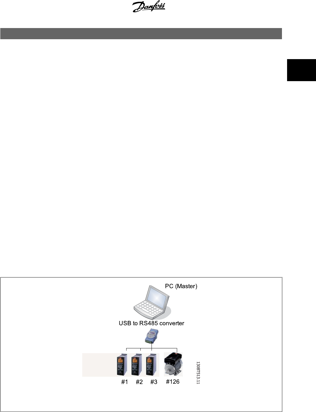
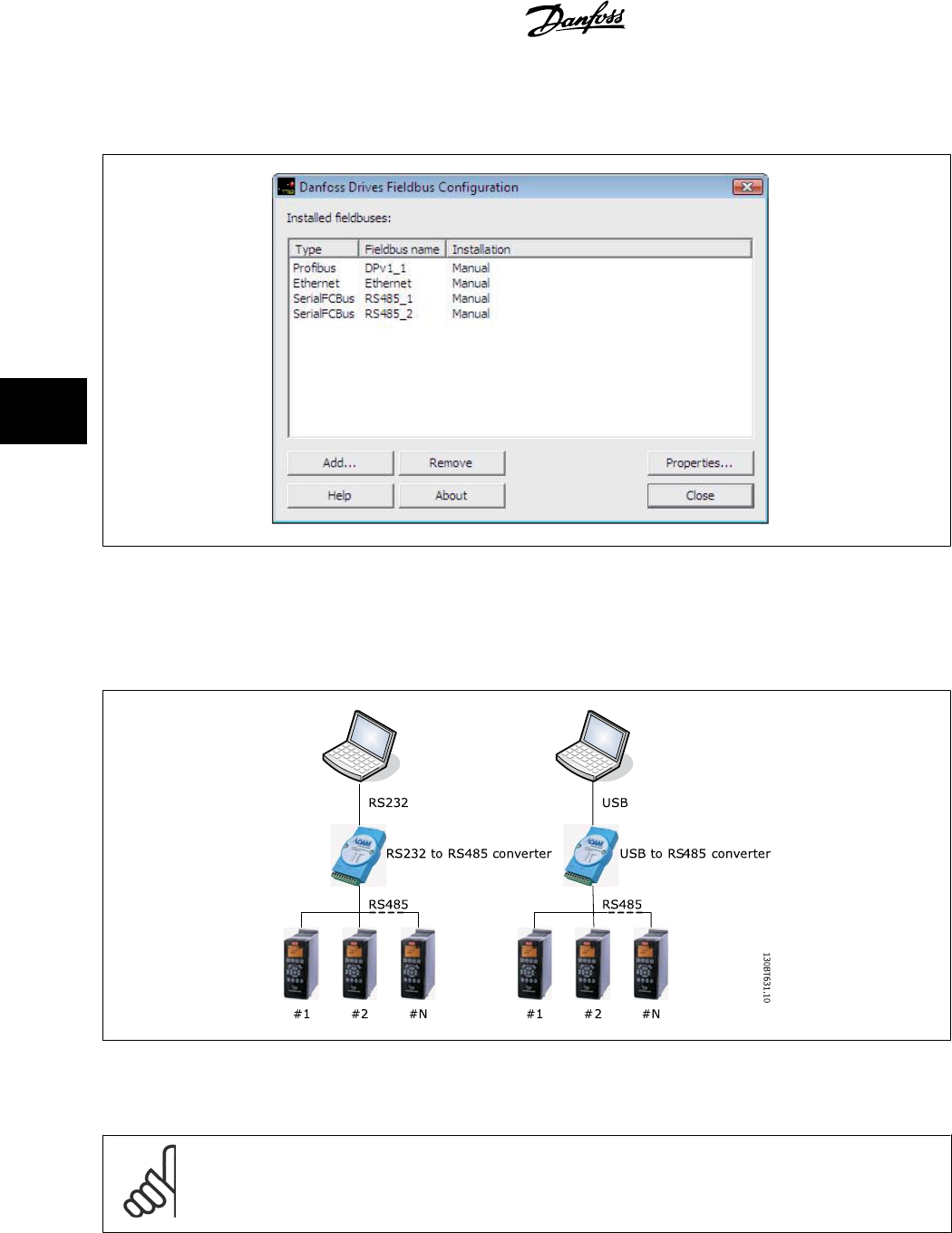
Illustration 2.1: With for example an Advantech ADAM 4510 repeater you can connect up to 126 nodes. Without a repeater you can connect
up to 31 nodes.
With the MCT 10 PC software tool you can control and configure your system simultaneously, and monitor the entire system more effectively for faster
diagnosis, and better preventive maintenance. Simplify commissioning, maintenance and documentation using MCT 10.
MCT 10 Setup Software 2 Introduction
MG10R302 - VLT is a registred Danfoss trademark
9
2
2.2.1 Features of MCT 10:
• Project-oriented PC tool, one tool for all VLT series
• Links to all Windows applications possible
• Supports Siemens CP PCMCIA- and PCI cards, for Profibus DP V1 Master Class 2 connection
• Support of standard interfaces: COMx, USB, RS 232 (Flux)
• Siemens PG / Field PGs already have the necessary hardware
• View is highly individually configurable
• Downwards compatibility with Dos-Dialog (*.mnu) and WinDialog (*.vlt)
2.2.2 Help
The Help feature is located in the main menu, at the far right. Select Help from the main menu, then Help again, and a Help file will be opened, displaying
the MCT 10 Setup Software manual in .pdf format. To open the Help file you will require Acrobat Reader software. If you do not have this software
installed, it can be downloaded free of charge at www.adobe.com.
2.3 The MCT 10 Setup Software Modules
The MCT 10 Setup Software is supplied in two modules:
MCT 10 Setup Software for
• setting of the frequency converter parameters
• copying of parameter sets to and from a frequency converter
• documentation/print-out of set-up, including diagrams
• servicing and fault analysis
SyncPos program for
• creating SyncPos programs.
2.4 Two Versions
MCT 10 Setup Software is available in two versions: Basic and Advanced.
MCT 10 Basic is available free of charge, downloadable from http://www.vlt-software.com.
MCT 10 Advanced can be purchased under the order-number 130B1000.
The features of each version are listed in the table below.
2 Introduction MCT 10 Setup Software
10
MG10R302 - VLT is a registred Danfoss trademark
2
Version supports: MCT 10 Advanced MCT 10 Basic
Frequency converters per project Unlimited Four
FC protocol Yes Yes
USB Yes Yes
Profibus DP V1 Yes Yes
Profibus DP V1
Handling Multiple Danfoss Nodes Concurrently Yes (improved performance) N/A
Ethernet-TSC Yes N/A
Logging and Scope function 8 Channels 2 Channels
Real Time Logging from Drive 4 Channels N/A
Alarm display Yes View only
MCO 305 Yes Yes
Graphical Smart Logic Contr. Yes Yes
VLT5000 to FC302 Wizard Yes Yes
Import 3000.XLS to FC302 Yes N/A
Motor Database Yes N/A
2.5 System Requirements
In order to use the MCT 10 Setup Software, your IBM-compatible personal computer must meet the following minimum system requirements:
• a Pentium PIII 350Mhz or compatible microprocessor
• 256 MB of RAM (512 MB of RAM Recommended)
•a CD-ROM drive
• 200 MB of available space on the hard drive;
Recommended system:
• a Pentium PIII 450Mhz microprocessor
• 256 MB of RAM (512 MB of RAM Recommended)
•a CD-ROM drive
• 200 MB of available space on the hard drive;
MCT 10 Setup Software runs under MS Windows versions:
WindowsTM 2000 (with service pack 3 or higher)
WindowsTM XP (Professional when using Siemens Profibus CP Cards).
2.6 Background Knowledge
Familiarity with the PC or PLC you intend to use as a master in your system is assumed. Issues regarding hardware or software produced by other
manufacturers are beyond the scope of this manual, and are not the responsibility of Danfoss.
If you have questions regarding set-up of master-to-master communication, or communication to a non-Danfoss slave, please consult the appropriate
manuals.
2.7 Related Literature
The following literature related to MCT 10 Setup Software is available.
Title Literature no.
SyncPos manual MN50V102
Profibus DP V1 MG90E102
Design Guide for the relevant frequency converter(s) -
Please also refer to drives.danfoss.com for frequently asked questions and additional information.
MCT 10 Setup Software 2 Introduction
MG10R302 - VLT is a registred Danfoss trademark
11
2

3 Installation and De-installation MCT 10 Setup Software
12
MG10R302 - VLT is a registred Danfoss trademark
3
3 Installation and De-installation
3.1 Installation and De-installation
The MCT 10 Setup Software and SyncPos modules are installed by means of a multilingual, self-explanatory installation program.
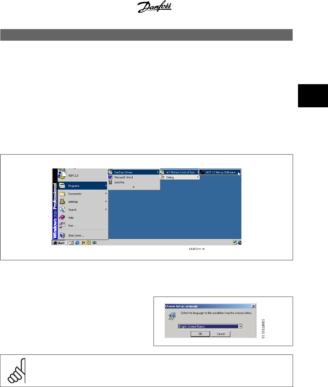
3.1.1 How to Start the Installation Program
1. Choose the sub-menu Run from File in Windows programming control.
2. In the command line you enter: [DRIVELETTER]:\SETUP and press the <Return> key.
3. Then you just follow the instructions of the installation program.
When the installation process is complete the MCT 10 Setup Software can be found on the following path:
3.1.2 How to Change Language after Installation
During installation, select the language version required in the installation
program. After installation, programs will start with the same language
version.
After installation you can change the menu texts of the programs to dif-
ferent languages.
NB!
The parameter language will also be changed. If an LCP display is connected to the frequency converter, the change of program
language version does not affect the display language.
MCT 10 Setup Software 3 Installation and De-installation
MG10R302 - VLT is a registred Danfoss trademark
13
3

3.1.3 De-installation of MCT 10 Setup Software under a Windows
®
Operating System
1. Click the Start button
2. Select Settings
3. Select Control Panel
4. Double-click on Remove/Add Programs icon
5. Select MCT 10 Setup Software
6. Choose the Remove option
3 Installation and De-installation MCT 10 Setup Software
14
MG10R302 - VLT is a registred Danfoss trademark
3
4 Introduction to User Interface
4.1 MCT 10 Features
4.1.1 MS
®
Windows™ Explorer-like interface
MCT 10 Setup Software has a familiar MS® Windows™ Explorer-like interface, to make it quick and easy for you to get started and find your way around
the software.
4.1.2 MCT 10 Language
The default language for the MCT 10 Setup Software is English. If desired, you can change the language of operation as follows.
Select the language you wish MCT 10 Setup Software to be displayed in, by selecting Options from the main menu, then Select Language…. Choose the
desired language from the scrollbar and close the window. The new language setting will be activated when MCT 10 is closed and restarted.
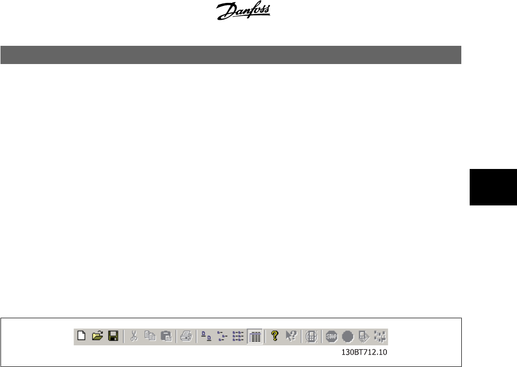
4.1.3 Toolbar
A toolbar displays icons for the most commonly used functions.
The toolbar can be activated by selecting
Toolbar
under
View
from the main menu bar, whereupon the Toolbar will be marked with a tick to show it is
active. To deactivate the Toolbar, again select
View
and then
Toolbar
, and after this the tick will be removed, indicating that the toolbar is no longer
active.
4.1.4 Display
The MCT 10 Setup Software is displayed in two parts, Left View and Right View.
4.1.5 Left View
The Left View shows the Network (real, online) and Project (simulated, offline) views of the frequency converter network. In the Left View new folders
and network elements can be added or existing folders and elements deleted.
It is also in the Left View that the user records changes made to the real online set-up into the Project folder, thus storing the changes in the simulated,
offline set-up for later use.
For more information on saving data, please refer to the chapter
Saving Data
.
MCT 10 Setup Software 4 Introduction to User Interface
MG10R302 - VLT is a registred Danfoss trademark
15
4
4.1.6 Right View
The Right View displays details of the element highlighted in the Left View. In the Right View the elements of the frequency converter network can be
programmed.
4.1.7 Tree View
The Left View can be expanded or compressed according to the level of detail the user wishes to view. The Left View has a tree structure, where folders
containing un-displayed content are marked with +. By clicking on the + with the mouse, the folder will open and its contents display in a tree structure.
Folders containing content which is on display in a tree structure are marked with -. By clicking on the - with the mouse, the folder will close and its
contents will be hidden.
4 Introduction to User Interface MCT 10 Setup Software
16
MG10R302 - VLT is a registred Danfoss trademark
4
4.1.8 Network Mode - Online
The Network folder displays details of the frequency converter network as it appears in reality, online. In Network mode the user can make changes to
parameters in the frequency converter(s) exactly as if operating the control panel on the frequency converter itself.
Data entered in Network mode will be stored in the frequency converter only, not on the hard disk. For information on saving data to the hard disk, please
refer to the chapter
Saving Data
.
4.1.9 Project Mode - Offline
The Project folder displays an offline view of the frequency converter network, as set up by the user. This is where the user can store a copy of those
parts of the online set-up he will use for later retrieval and use, perhaps remote to the physical site of the network. The Project folder is also where to
store other files related to the network project. These other files can be in any format, for example Word, .pdf, etc.
4.1.10 Folders
Insert a new frequency converter, folder or file folder by selecting the Project icon with a right-click on the mouse:
130BT516.11
MCT 10 Setup Software 4 Introduction to User Interface
MG10R302 - VLT is a registred Danfoss trademark
17
4
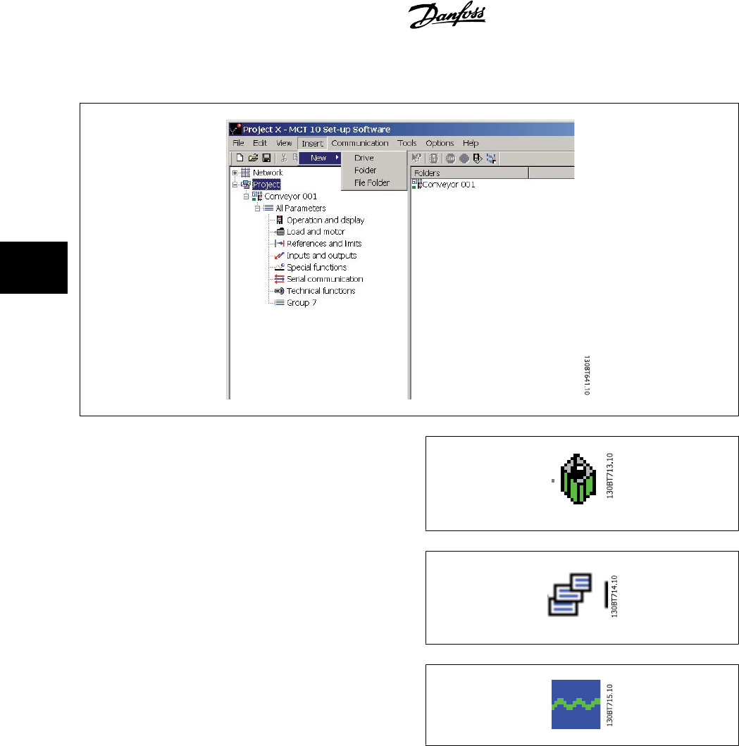
Alternatively, you can select Insert on the menu bar, then New, and then Drive, Folder or File Folder:
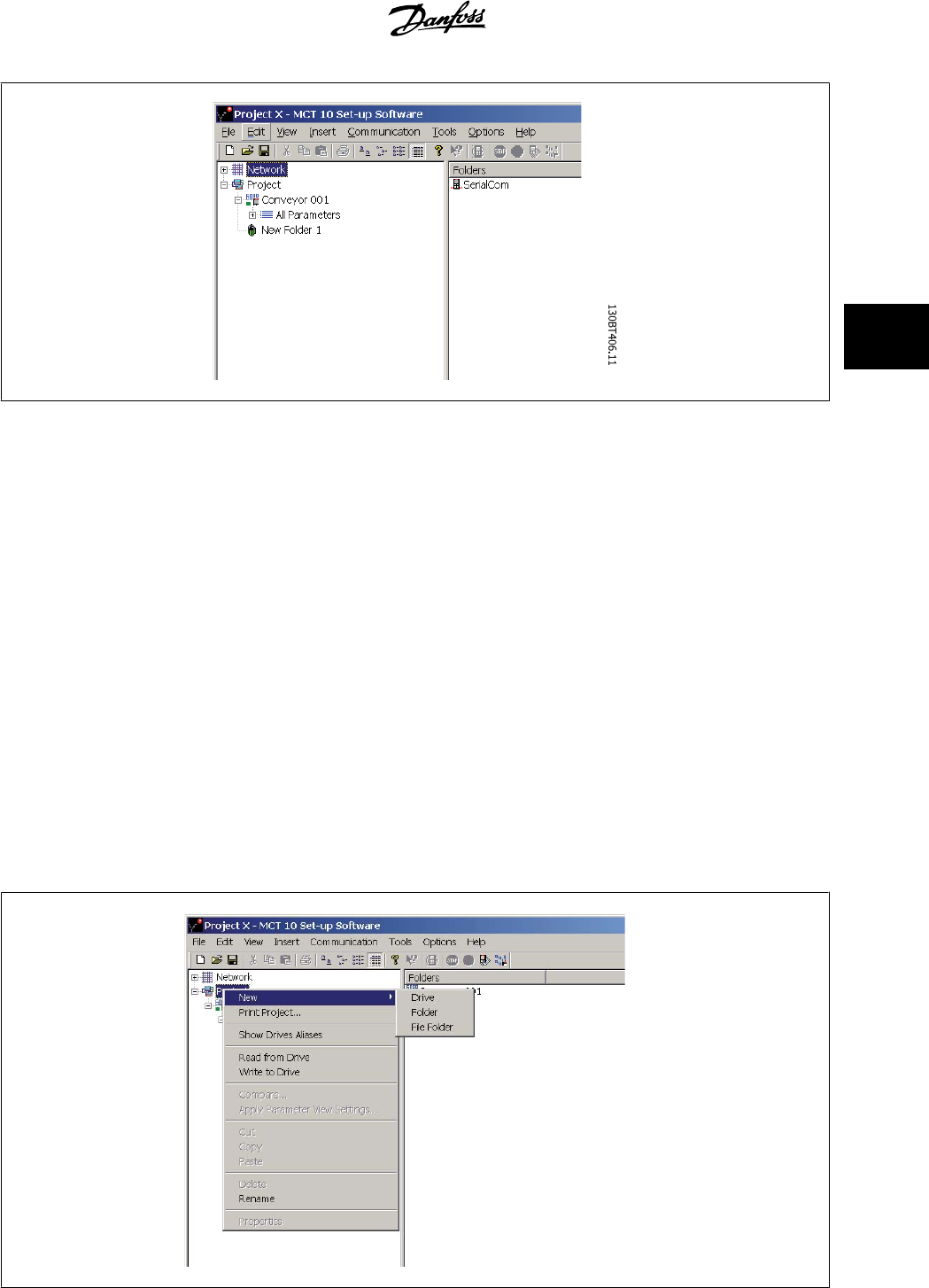
A Folder is a group of frequency converters forming part of a machine
or of a system. Folders are used for organising a large system into several
smaller systems.
A File Folderis a folder for storing files belonging to the Project. These
files can be in any format, Word documents, PDF files etc.
A Scope Folder is a folder for doing analysis on how selected parameters
behave. The selected parameters can be visualised as curves.
4 Introduction to User Interface MCT 10 Setup Software
18
MG10R302 - VLT is a registred Danfoss trademark
4
5 Set-up of Communication
5.1 How to Establish Communication
Data communication between a PC and the frequency converter(s) can be established via a hardwired connection. The hardwired connection can be via
the standard built-in RS 485 or USB port. If the MCA101 or MCA121 fieldbus option is mounted in the frequency converter(s), the connection can be
obtained via a Profibus Master Class 2 connection (MSAC 2) or an Ethernet based network.
The USB interface socket is controlled by the Microsoft operating system providing plug-and-play capabilities by allowing devices to be connected and
disconnected using hot swapping. Connecting a frequency converter using USB MCT10 will automatically add on to the bus list.
The communication framework part of MCT10 is handling the control of the fieldbusses. It provides enhanced capabilities allowing multiple concurrent
fieldbus communication. Several fieldbuses can be configured and combined in the same Network within MCT10. If several fieldbusses are created with
the same type, please make sure they are configured with different scan ranges.
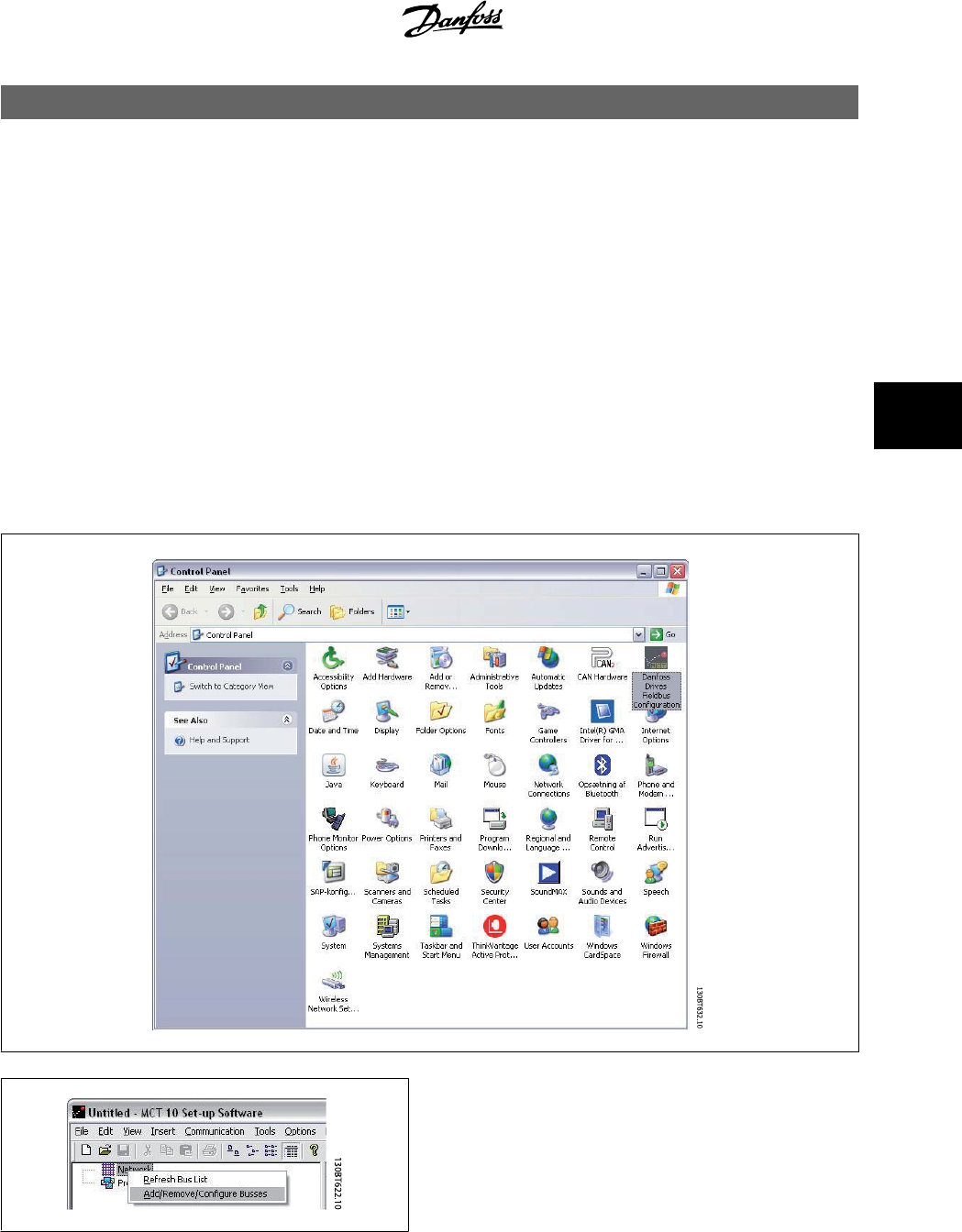
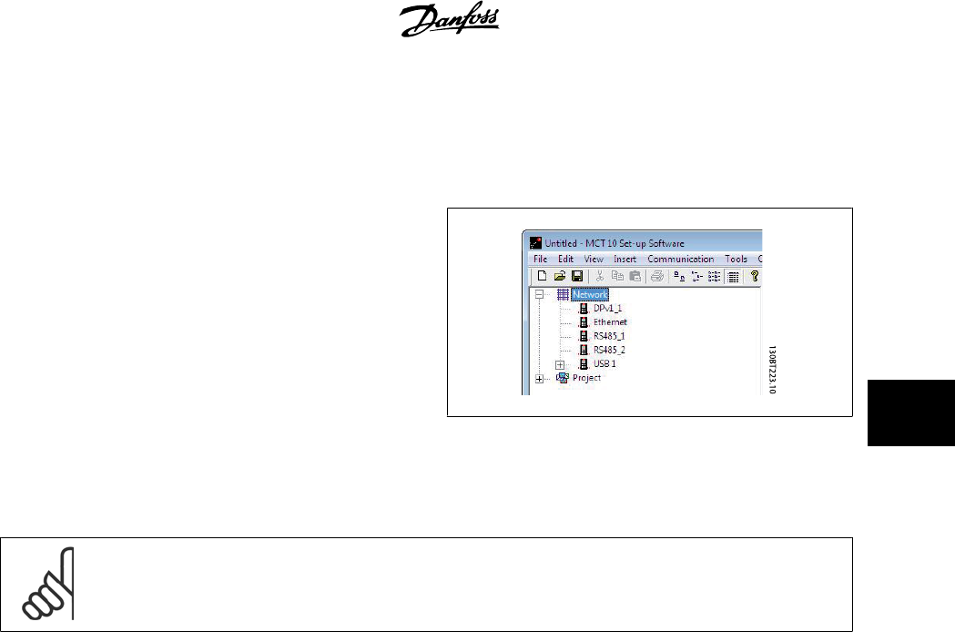
Starting MCT10 the first time after installation the non plug-and-play fieldbusses must be manually configured from the fieldbus configuration dialog. This
is available from the standard Windows Control Panel or from the MCT10 Network.
From the fieldbus configuration dialog non plug-and-play fieldbusses can be added, removed or reconfigured from the installed list.
If the installed fieldbus list is updated from the Windows Control Panel while MCT10 is running the user needs to refresh the bus list by right clicking on
Network
.
MCT 10 Setup Software 5 Set-up of Communication
MG10R302 - VLT is a registred Danfoss trademark
19
5
For MCT10 to indicate the available frequency converter(s) on the non plug-and-play fieldbusses the user manually has to scan the network for active
drives. The scanning is available from a right click on the appropriate fieldbus.
130BT630.10
5.2 RS 485 Data Communication
The majority of Danfoss Drives products have the FC protocol as standard RS 485 data communication. Communication from a PC can be established via
RS 232 to 485 converters or via USB to 485 converters.
All frequency converters are default set to 9600 baud, but can also be configured to 300, 1200, 4800, 19200, 38400, 57600 or 115200 baud. The serial
configuration is always configured with 8 data bits, 1 stop bit and even parity.
NB!
Choose a relevant scan range. It takes too much time to scan all available addresses (1-126).
Using the VLT FC 100, FC 200 and FC 300 series : FC MC Protocol (parameter 8-30 "FC MC") is required for correct functionality. The
parameter is only available from the LCP.
5 Set-up of Communication MCT 10 Setup Software
20
MG10R302 - VLT is a registred Danfoss trademark
5
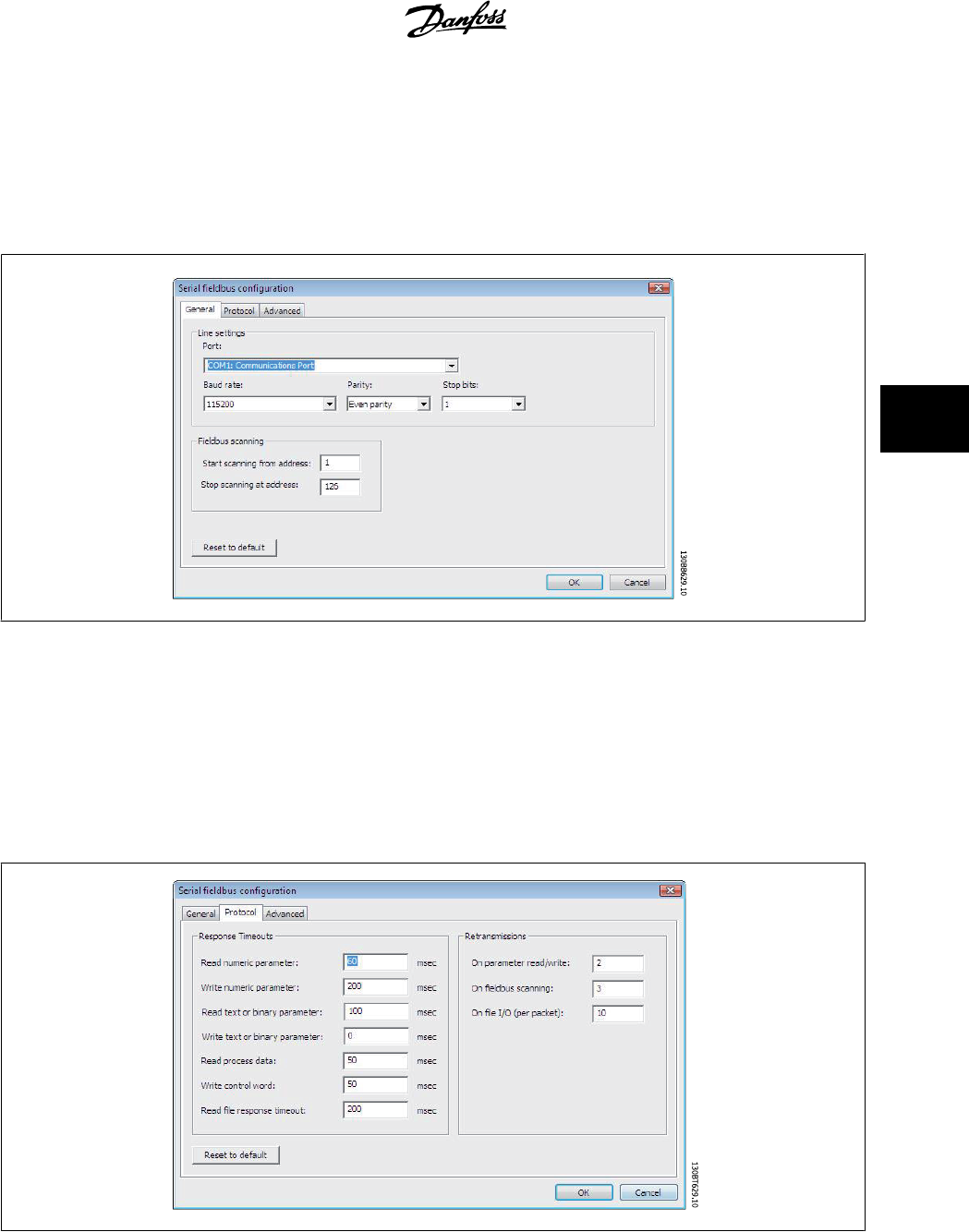
5.2.1 Serial Configuration
When using a RS485 converter as the Advantech ADAM converter, MCT10 will indicate online frequency converter(s) available on the serial bus after
scanning the bus.
The bus can be configured from the Fieldbus Configuration dialog or from
right-click
on the appropriate serial bus.
The COM port number must be set to the appropriate one used. When using USB to RS485 converters, the actual comport number can be identified from
the Device Manager part of the Windows Control Panel.
The Baud rate, Parity and the number of Stop bits must match the settings in the drive.
The Fieldbus scanning range should be set to the available addresses only to limit the time scanning for active drives.
Reset to default bottom restores the Line settings and Fieldbus scanning to factory configuration values.
The Response Timeouts and Retransmissions are settings editable for performance optimization, but should normally not be changed.
MCT 10 Setup Software 5 Set-up of Communication
MG10R302 - VLT is a registred Danfoss trademark
21
5
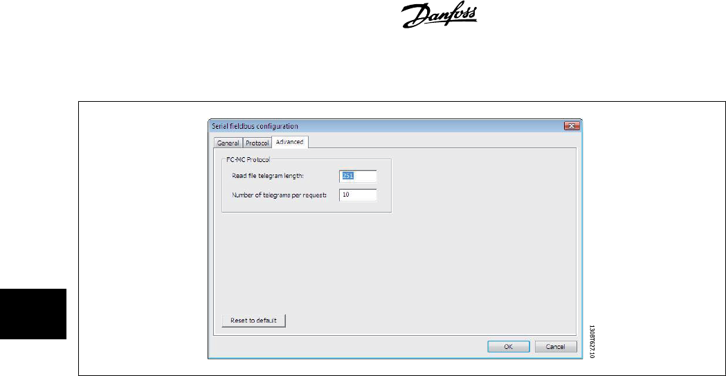
Reset to default bottom restores the Protocol settings to factory configuration values.
The FC-MC Protocol are settings editable for performance optimization, but should normally not be changed.
Reset to default bottom restores the Protocol settings to factory configuration values.
5 Set-up of Communication MCT 10 Setup Software
22
MG10R302 - VLT is a registred Danfoss trademark
5
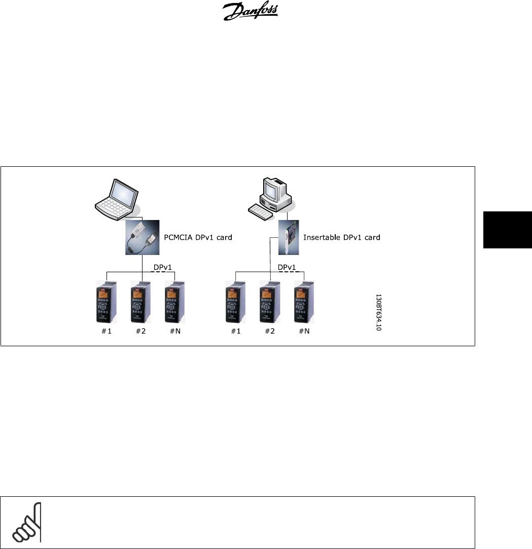
5.3 Profibus DPv1 Data Communication
5.3.1 Profibus DPv1 Data Communication
To setup a Profibus DPv1 communication, the MCA101 Profibus option module is required. Communication from a PC using Profibus DPv1 can be estab-
lished using a Profibus PCMCIA card or a card installed in the PC. The Profibus cable from the frequency converter is connected to the 9-pin sub D socket
connector located on the card.
The following Master class 2 cards are currently supported from Siemens:
• CP 5411
• CP 5511
• CP 5512
• CP 5611
• CP 5613
• CP 5614
(Please also consult the Siemens website for latest supported cards for PC’s.)
NB!
Please consult the chapter:
Guide to DPv1 connection and Simatic Manager
, covering more details about setting up the Simatic Manager.
MCT 10 Setup Software 5 Set-up of Communication
MG10R302 - VLT is a registred Danfoss trademark
23
5
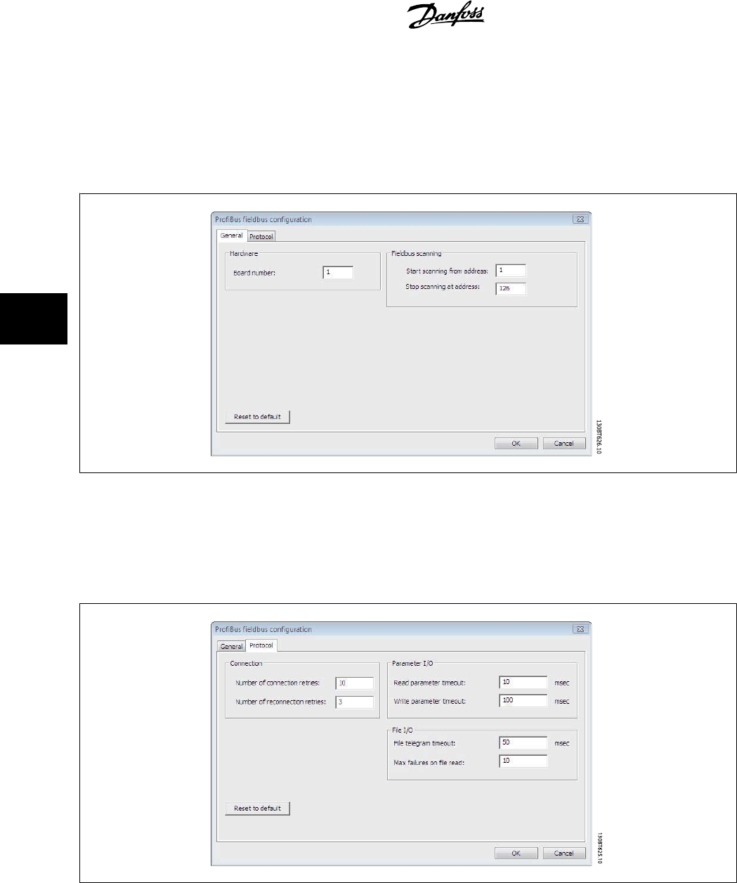
5.3.2 Profibus DPv1 configuration
When using a Profibus interface card with the associated driver installed, MCT10 will indicate online frequency converter(s) available on the specific
Profibus after scanning the bus for active drives.
The bus can be configured from the Fieldbus Configuration dialog or from right click on the appropriate Profibus bus.
The Board number must be set to the appropriate one used.
The Fieldbus scanning range should be set to the available addresses only to limit the time used for scanning active drives.
Reset to default bottom restores the Hardware settings and Fieldbus scanning to factory configuration values.
The Connection, Parameter I/O and File I/O are settings editable for performance optimization, but should normally not be changed.
Reset to default bottom restores the Protocol settings to factory configuration values.
5 Set-up of Communication MCT 10 Setup Software
24
MG10R302 - VLT is a registred Danfoss trademark
5
5.4 USB Data Communication
5.4.1 USB Data Communication
Danfoss frequency converters in the FC 100, FC 200 and FC 300 series
are standard equipped with a USB port. Communication from a PC can
be established using a standard A – B male to male USB cable connected
to the frequency converter. No extra hardware or bus configuration is
required. If the PC is equipped with more than one USB port several fre-
quency converters can be connected. The USB bus will in MCT10 auto-
matically be add on to the Network bus list.
When the USB cable is disconnected, the frequency converter connected via the USB port will be removed from the Network bus list.
When the USB cable is disconnected, the frequency converter connected via the USB port will be removed from the Network bus list.
NB!
A USB bus has no address-setting capacity and no bus name to configure. Connecting more than one frequency converter through
USB, the bus name will be auto incremented in the MCT10 Network bus list.
MCT 10 Setup Software 5 Set-up of Communication
MG10R302 - VLT is a registred Danfoss trademark
25
5
5.5 Ethernet-TSC Data Communication
5.5.1 Ethernet-TSC Data Communication
To setup an Ethernet-TSC (Transparent Socket Channel) communication, the MCA121 option module is required within the drive. Communication from
a PC can be established using a standard Ethernet cable connected to the drive.
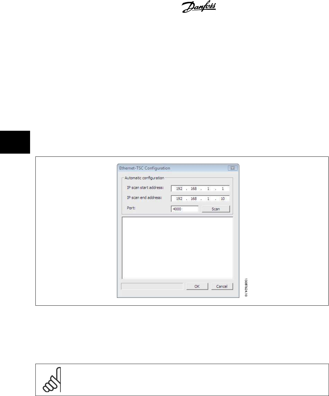
5.5.2 Ethernet-TSC Configuration
When using an Ethernet-TSC with the default installed Ethernet driver, MCT10 will indicate online frequency converter(s) available on the specific Ethernet
bus after scanning the bus for active drives.
The bus can be configured from the Fieldbus Configuration dialog or from
right-click
on the appropriate Ethernet bus.
The IP address scanning range should be set to the available addresses only, to limit the time used for scanning active drives.
IP port number 4000 is the default one used within the Ethernet option module for TSC. It should match the setting in parameter 12-89.
Scan bottom initiates a scanning for the active drives connected to the bus.
NB!
The PC must be in the same sub-net as the frequency converter(s) for scanning.
5 Set-up of Communication MCT 10 Setup Software
26
MG10R302 - VLT is a registred Danfoss trademark
5
6 Parameter Handling
6.1 Set-up
This chapter explains how to control a frequency converter using the MCT 10 Setup Software. After starting the MCT 10 Setup Software, the main window
looks like this:
Insert a new drive, folder or file folder by selecting the Project icon with a right-click on the mouse. Alternatively, you can select Insert on the menu bar,
then select New, then Drive, Folder or File Folder.
Drive refers to the type of frequency converter you wish to set up. Inserting a frequency converter will bring up the drive selector window.
MCT 10 Setup Software 6 Parameter Handling
MG10R302 - VLT is a registred Danfoss trademark
27
6
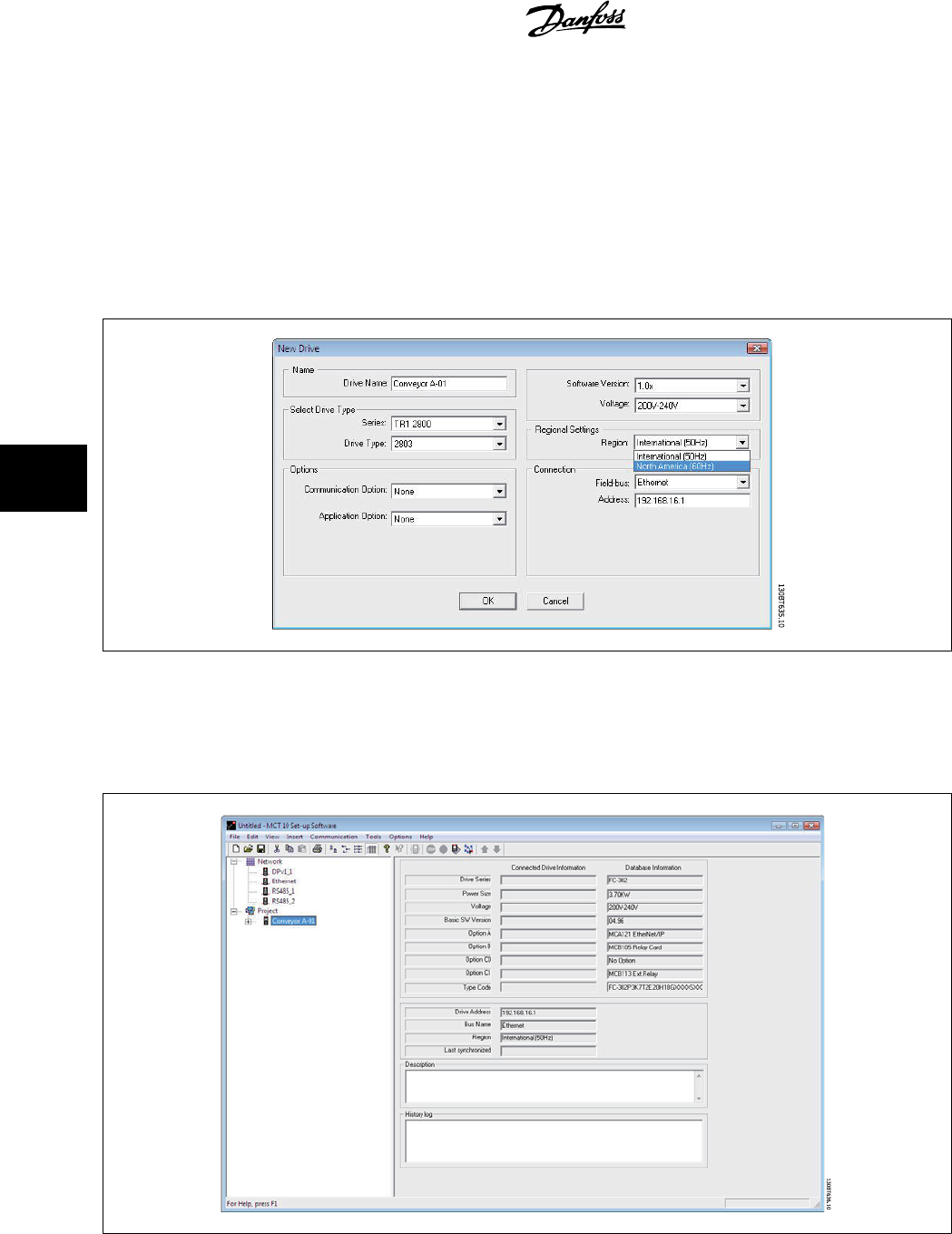
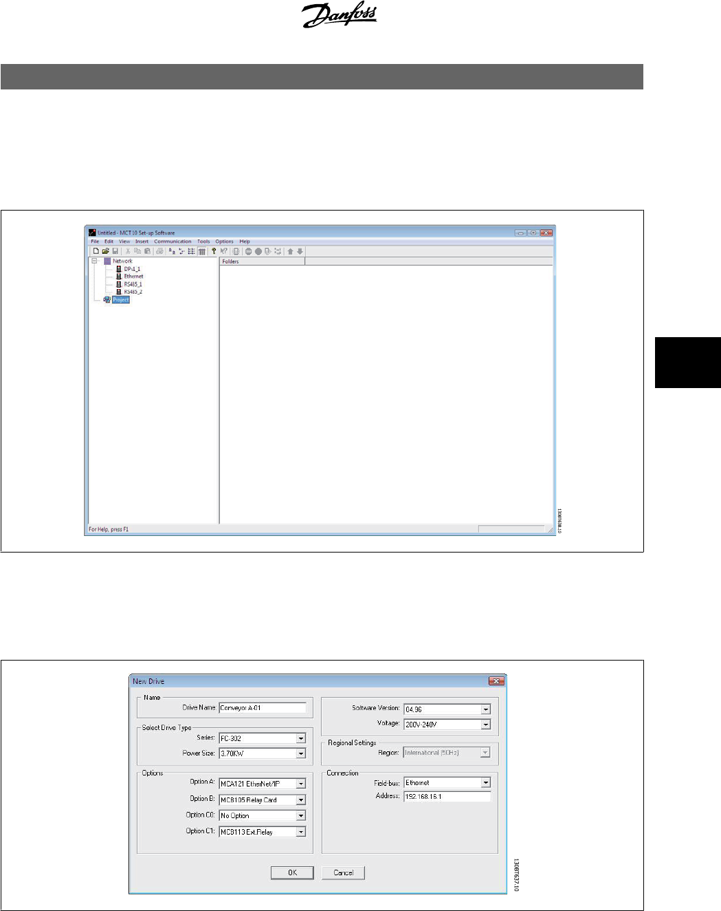
The New Drive window consists of four main parts; Name, Drive Identification, Regional Settings and Connection. All parts are mandatory to be Fill in:
Name is the name you want to identify the frequency converter with. This can be any text/number combination.
Drive Identification is the information regarding the frequency converter series, power size, options installed, software version and voltage level. The
different selections are available from the drop down menus.
Regional Settings is configurable for International 50Hz or North America 60Hz settings. These discriminate mainly between horse power, kW and
voltage level. The following screen shot shows an example of regional settings for a VLT 2800 frequency converter.
Connection means the fieldbus used between the PC and the frequency converter associated with the address to communicate. The specific fieldbus
type is available from the drop down menu.
Once the new frequency converter is added in the Project folder, the drive icon is selectable to display the database information as entered above:
6 Parameter Handling MCT 10 Setup Software
28
MG10R302 - VLT is a registred Danfoss trademark
6
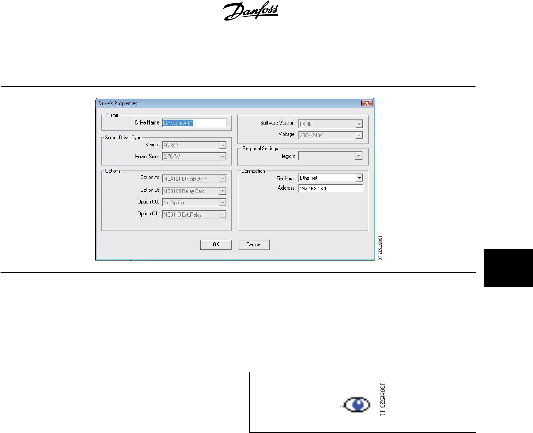
The frequency converter(s) located in the offline project folder are reconfigurable right click on the specific drive icon and choose Properties. The Drive’s
Properties dialog appears providing the possibility to rename the drive Name and reconfiguring the Connection setup.
Note that the Connected Drive Information fields are empty. This is because at this point, you have not yet accessed the online frequency converter
represented by the new frequency converter created offline. To view information from the online frequency converter, please refer to the Read From
Drive feature.
6.1.1 Parameter Folders
When you have set up a drive within the Project folder, you can create
new parameter folders within that drive. Create a new Parameter Folder
by right-clicking on the Drive icon, then selecting New, then Parameter
Folder. The default name for the new parameter folder will be New Folder
1, New Folder 2, etc.
6.1.2 Custom Parameter Folders
You can give the new parameter folder the desired identity using the Rename function, accessible by right-clicking on the New Folder icon.
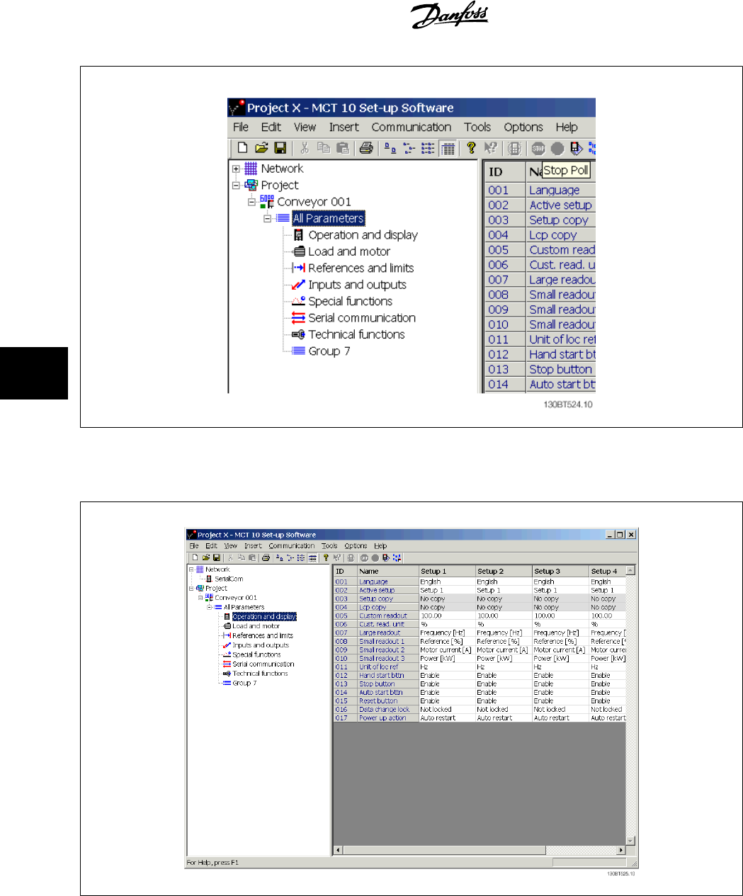
6.1.3 Generic Folders
When a new drive is set up according to drive, it will take the form of a folder named by the user, containing an All Parameters folder, which comprises
a series of inner folders with generic names. These generic names cannot be changed or personalised, i.e. there is no rename function for these folders.
The generic folders within most frequency converters are as follows:
•Operation and Display
•Load and Motor
• References and Limits
• Inputs and outputs
•Special functions
• Serial communication
• Technical functions
The generic folders can vary according to the type of frequency converter selected.
MCT 10 Setup Software 6 Parameter Handling
MG10R302 - VLT is a registred Danfoss trademark
29
6
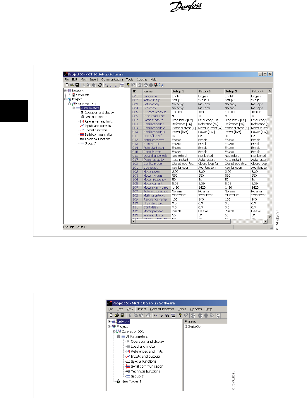
The contents of the generic folders are fixed, and comprise the parameters relevant to the frequency converter type selected. The ID, name and settings
of these parameters become visible in the Right View, with a left-click on the generic folder icon or name in the Left View.
6 Parameter Handling MCT 10 Setup Software
30
MG10R302 - VLT is a registred Danfoss trademark
6
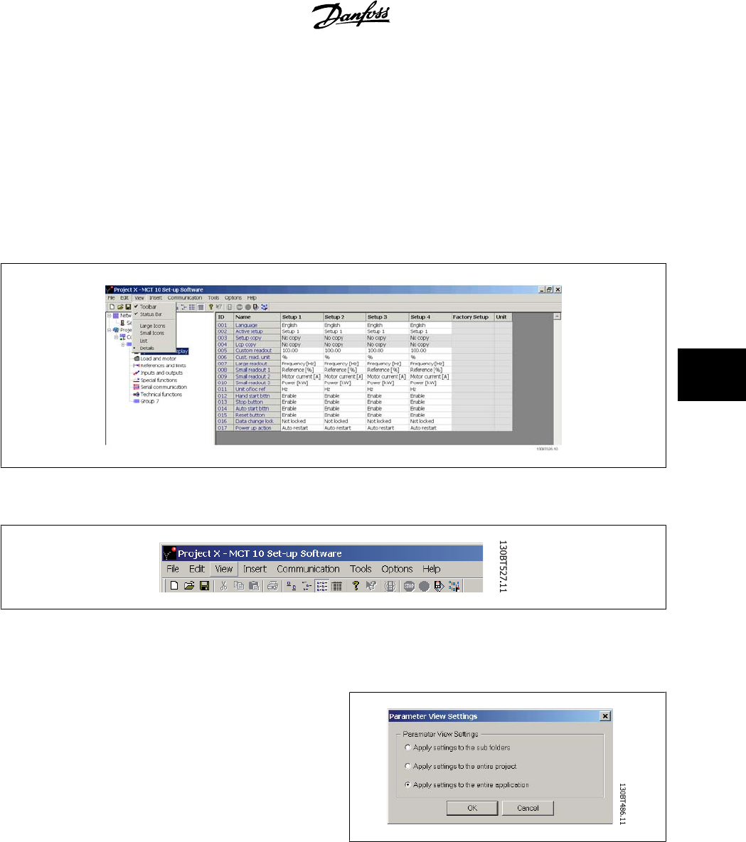
6.1.4 Display Options
Display Options By selecting View in the main menu bar, a range of display options are presented. The user can choose to display or hide the Toolbar
and the Status Bar.
The user can also select the desired form of the Right View:
•Large icons
•Small icons
• The Right View display can be presented in the form of a List of folders and elements
• The Right View display can present Details of Network and Project elements
The final four display options (Large icons, Small icons, List and Details) are also accessible by clicking on the toolbar, options 8 through 11 from the left.
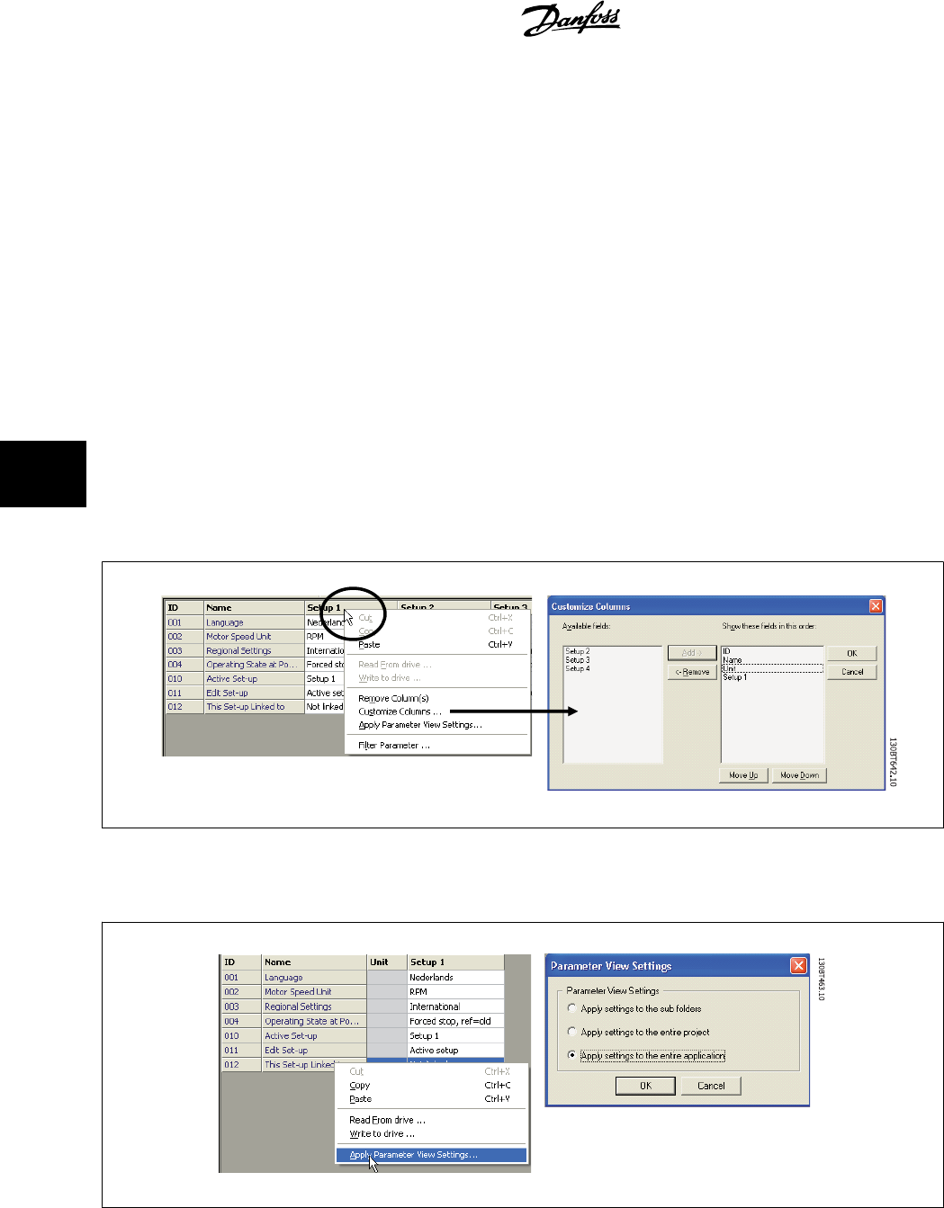
6.1.5 Parameter View Settings
You can apply the chosen parameter view settings described above to
subfolders, to an entire project, or to the entire application, i.e. all MCT
10 folders in Network or Project mode.
Right-click on the parameter cell or set-up column then select Apply Pa-
rameter View Settings. Alternatively, select Apply Parameter View Set-
tings under Tools on the main menu bar. The following pop-up will
appear:
Select the option you wish to apply then click OK to activate that option.
MCT 10 Setup Software 6 Parameter Handling
MG10R302 - VLT is a registred Danfoss trademark
31
6
6.2 Filters
The MCT 10 Setup Software can be configured by view filters to display parameters in a special way or to display parameters of interest. This is a powerful
tool in maintaining an overview of the drive, without becoming confused by irrelevant parameters.
Filters can be applied to the parameter set-ups, which are displayed in the Right View when highlighting a generic folder in the Left View, i.e. one of
• Operation and Display
•Load and Motor
• References and Limits
• Inputs and outputs
• Special functions
• Serial communication
• Technical functions
The parameters displayed in the Right View are presented in a series of columns, containing ID, parameter name, four set-ups, units and factory set-up.
Each set-up can be hidden by removing it. This is done by selecting the set-up in the parameter view and then selecting the remove menu. Changes
made to the removed set-up are still stored inside the MCT 10 Setup Software and can be displayed again by selecting Customize Columns.
By adding or removing columns the user can decide which information he wants to view.
The actual view can also be made valid for the complete Project or for the Folder only. This allows the user to adjust his view setting quickly for parts or
the complete Project.
6 Parameter Handling MCT 10 Setup Software
32
MG10R302 - VLT is a registred Danfoss trademark
6
Another flexible way to adjust the display is via the Filter function.
Just by selecting Change Parameters, the number of Parameters displayed is reduced to 5 Parameters in this example.
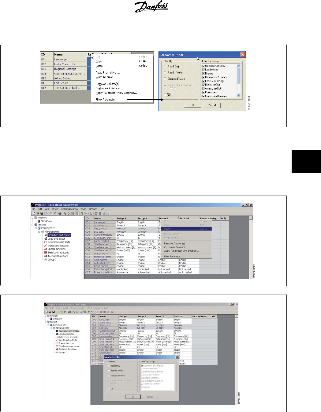
6.2.1 Parameter Filters
To find the Parameter Filter dialog:
Right-click on any column in Right View, then select Filter Parameter.
MCT 10 Setup Software 6 Parameter Handling
MG10R302 - VLT is a registred Danfoss trademark
33
6
6.2.2 Read Only
In the Right View showing details of parameter set-ups, the user can select the Read Only filter to display those parameters which are read only and
cannot be changed by the user. Right-click on any parameter column in the Right View, and then select the Filter Parameter option. Under Filter By, the
user can then mark Read Only, and the display will show only those parameters which are read only.
6.2.3 Read & Write
In the Right View showing details of parameter set-ups, the user can select the Read & Write filter to display those parameters which are read/write and
can thus be changed by the user. Right-click on any parameter column in the Right View, then select the Filter Parameter option. Under Filter By the user
can then mark Read & Write, and the display will show only those parameters which are read/write, i.e. can be changed by the user.
6.2.4 Changed
In the Right View showing details of parameter set-ups, the user can select the Changed Value filter to display those parameters which have been changed
by the user in the current session. Right-click on any parameter column in the Right View, and then select the Filter Parameter option. Under Filter By,
the user can then mark Changed Value and the display will show only those parameters which have been changed during the current session.
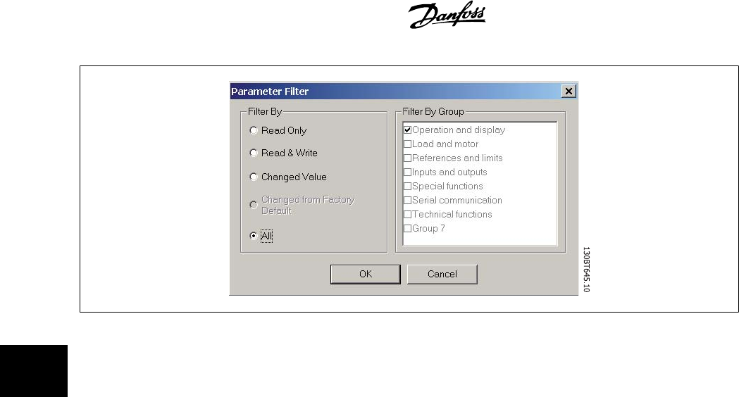
6.2.5 All
To display all parameters in the Right View, following a filtering which has hidden some of the parameters, right-click on any parameter column in the
Right View, and then select the Filter Parameter option. Under Filter By, the user can then mark All, and the display will show all parameters.
6.2.6 Filter By Group
To display only parameters from a particular group or groups in the Right View, the user can right-click on any parameter column in the Right View, and
then select the Filter Parameter option. Under Filter By Group, the user can then mark the desired group or groups to be displayed and the Right View
display will show only those group(s).
6.2.7 Column Select
Select a column in the Right View by left-clicking on the column title cell.
6 Parameter Handling MCT 10 Setup Software
34
MG10R302 - VLT is a registred Danfoss trademark
6
6.2.8 Folder Select
Select a folder in the Left View by left-clicking on the folder name or folder icon.
6.2.9 Parameter Display
By selecting a parameter folder in the Left View you can view the parameters in the Right View, including their ID code, name and configuration details.
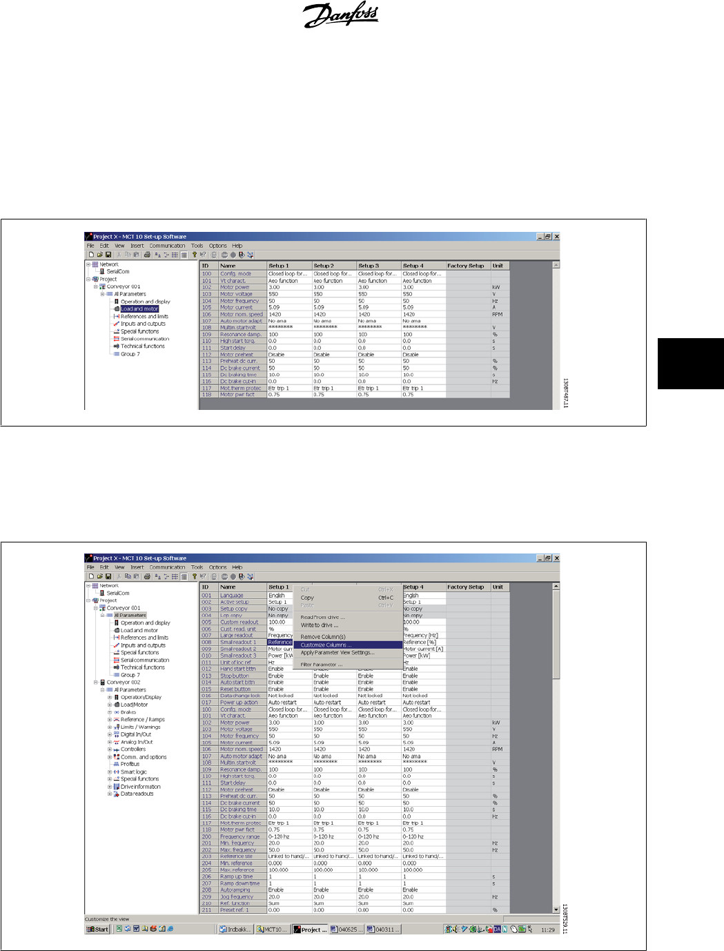
6.2.10 Customize Columns
The user can rearrange the display of columns in the Right View display by right-clicking on any column title, then selecting Customize Columns.
MCT 10 Setup Software 6 Parameter Handling
MG10R302 - VLT is a registred Danfoss trademark
35
6
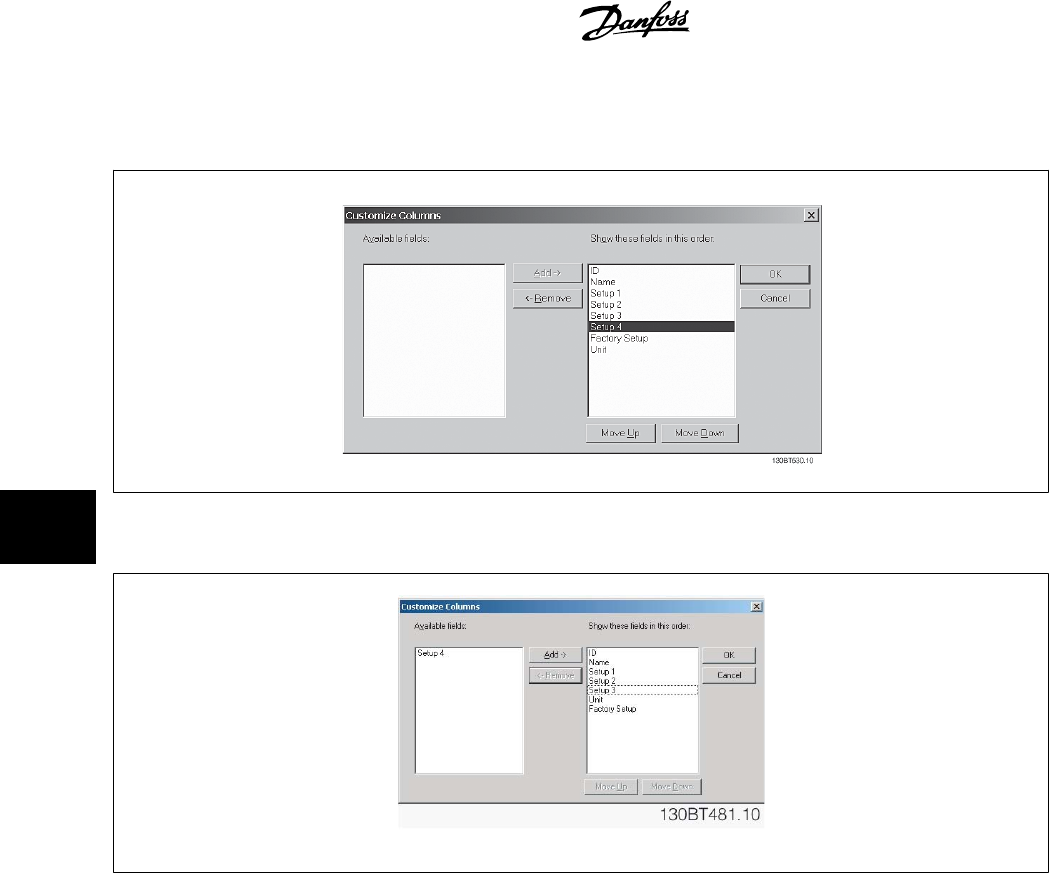
The Customize Columns window will be displayed and there, the user can change the order of fields in the display by highlighting a field, then selecting
Move Up, Move Down or Remove.
Removed columns are still stored in memory and can be retrieved into the Right View by highlighting the relevant field name and selecting Add.
6.2.11 Read/Write Parameters
The majority of parameters are read/write, i.e. they can be configured by the user. Use the Filter function to view which parameters are read/write.
6.2.12 Read Only Parameters
A few parameters are read only, i.e. they provide data only and cannot be configured by the user. Use the Filter function to view which parameters are
read only.
6.2.13 Factory Defaults
The parameter factory defaults are viewable by highlighting the parameter folder in the Left View, whereupon the parameter details will be displayed in
the Right View. The factory defaults will be displayed in the Set-up columns unless a user has changed the parameter configuration. If the parameter
configuration has been changed since factory supply, the factory defaults are displayed in the Factory Set-up column.
6 Parameter Handling MCT 10 Setup Software
36
MG10R302 - VLT is a registred Danfoss trademark
6
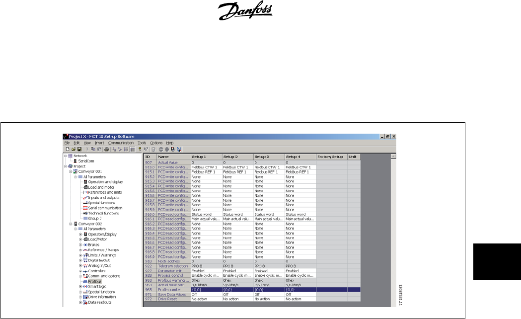
6.2.14 Array Parameters - MCT 10
Parameters containing data in the form of an array are displayed as a matrix in the Right View, where the rows of the matrix are identified as ID.1, ID.
2, etc. For example, in the view below, array parameters 9-15 and 9-16 are displayed over several entries as 915.1, 915.2, 915.3, and 916.1, 916.2,
916.3,. in the Right View below.
6.3 Special Parameters
6.3.1 Edit Set-up
The user can change parameter set-up by manually entering new value(s) into the cells in the Right View.
Alternatively, the parameter set-up can be altered by importing values from an active drive, using the Read From Drive function.
MCT 10 Setup Software 6 Parameter Handling
MG10R302 - VLT is a registred Danfoss trademark
37
6
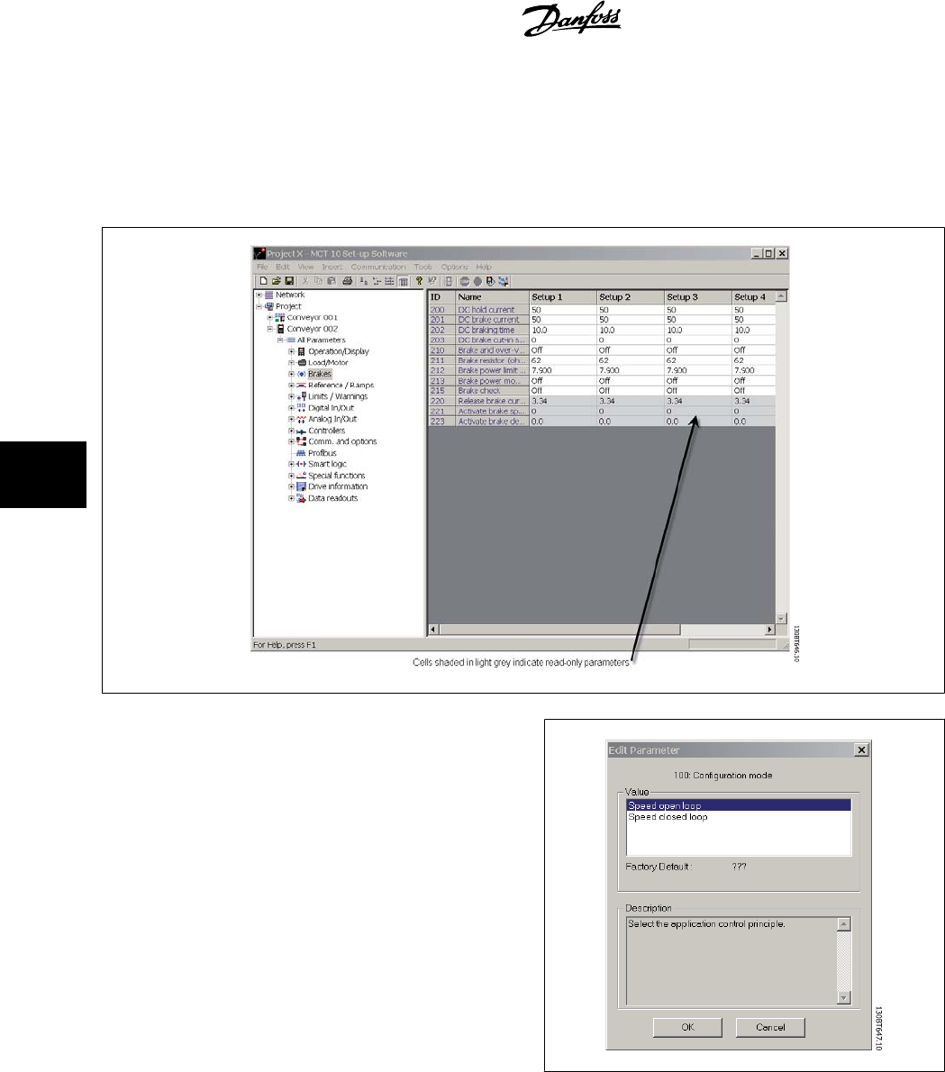
6.4 Parameter Edit
Parameters are organized into the same groups found on the LCP of the drive. A parameter can easily be modified by simply double-clicking on the desired
parameter entry. If an entry cell is shaded in light grey it means that it is read only, and cannot be modified.
The settings of a parameter are checked for correct value upon their en-
try. If a parameter value is set to an illegal value the MCT 10 Setup
Software displays an error. Parameters can be edited in two different
modes, dialog-based and inline. In dialog-based edit mode MCT 10 will
make a window pop up explaining the usages of the parameter.
6.4.1 Inline Edit
In inline edit mode, MCT 10 displays only the setting options available for a parameter. This works faster but is recommended only for the experienced
user, since each possible setting is not followed by a detailed description of the setting.
6.4.2 Dialog Based Edit
If you would prefer to have details of parameters available whilst editing, use Dialog Based Edit. Parameter options, ranges and functions will be displayed
whilst you edit the parameters. You will automatically enter Dialog Based Edit if you de-select Inline Edit.
6 Parameter Handling MCT 10 Setup Software
38
MG10R302 - VLT is a registred Danfoss trademark
6
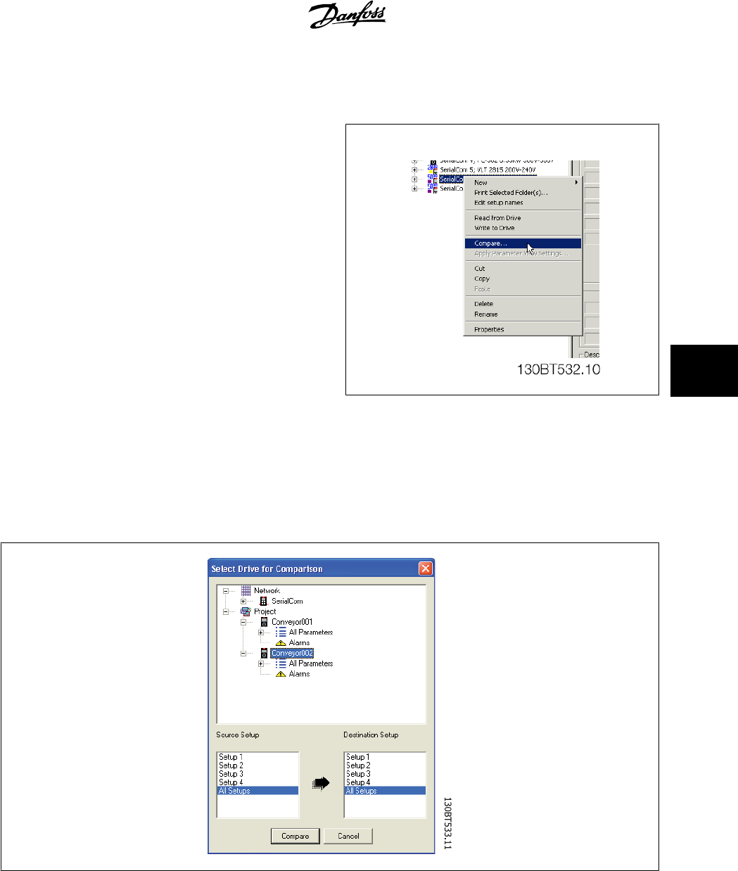
6.5 Comparison of Parameters
Parameter settings can be compared to the parameter settings in another
drive. Comparisons can be made either to another drive inside the project
or to an online drive. The comparison function is a powerful tool that
evaluates whether settings inside the drive have been changed, or checks
if two or more drives have the same settings. The compare function is
activated by highlighting the desired drive and selecting Compare.
The compare window asks the user for a drive with which to make the comparison. This can be an online drive from the network, or it can be a drive in
the offline folder (Project folder).
The result of a comparison can be stored in an ASCII text file for documentation or for subsequent import into a spreadsheet.
It is possible to compare all set-ups, or to compare one set-up against another. The result of a comparison could look like this:
MCT 10 Setup Software 6 Parameter Handling
MG10R302 - VLT is a registred Danfoss trademark
39
6
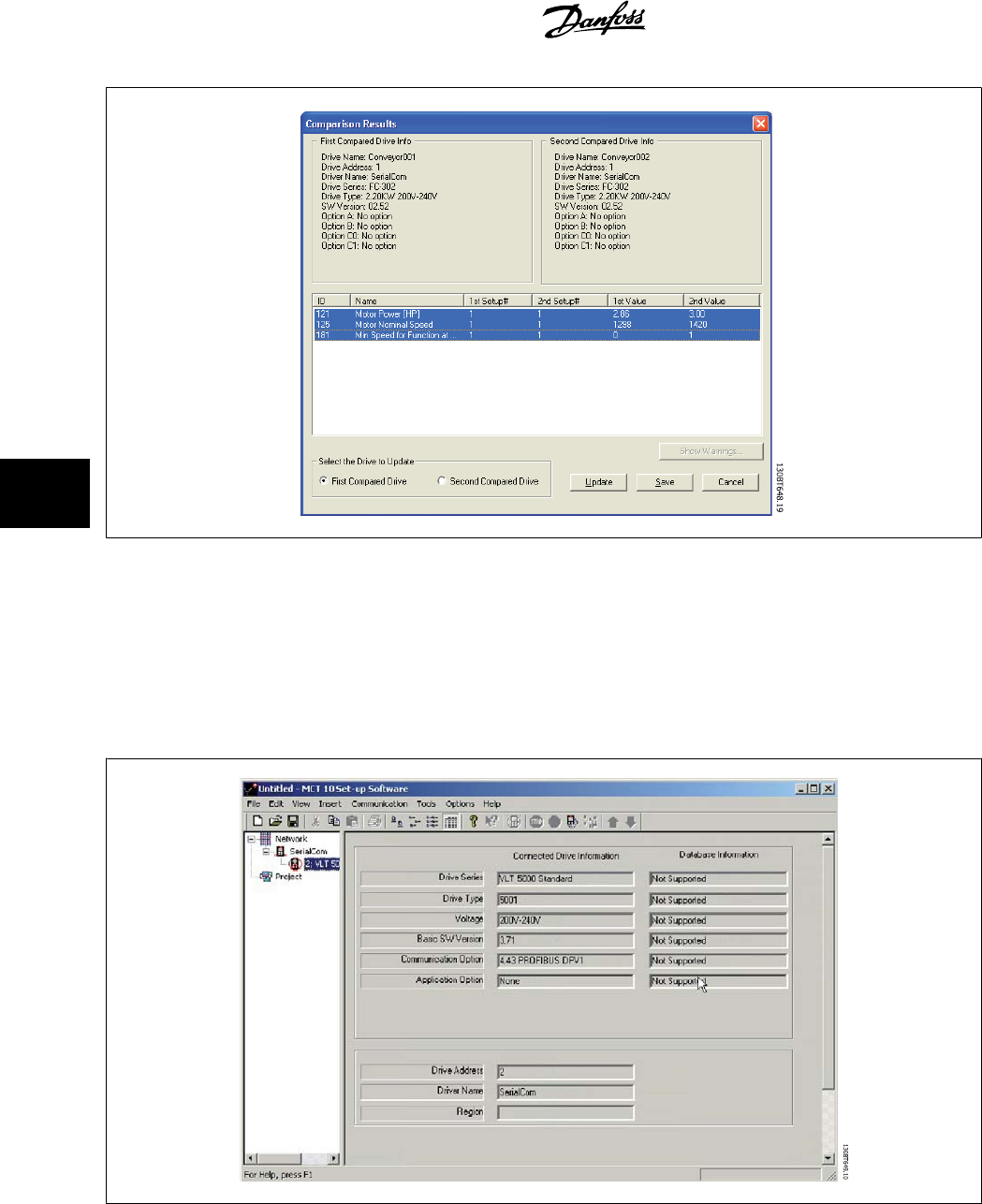
6.6 Read Frequency Converter Database
In the event that the MCT 10 database information is outdated, for example when a drive newer than the software version is introduced to the network,
the MCT 10 database can be updated either by download from Internet or when this is not possible, by reading from the frequency converter itself.
When the MCT 10 database for a frequency converter is outdated, the frequency converter icon will be displayed with a red line through it and the
Database Information cells will display the message Not supported, as shown:
6 Parameter Handling MCT 10 Setup Software
40
MG10R302 - VLT is a registred Danfoss trademark
6
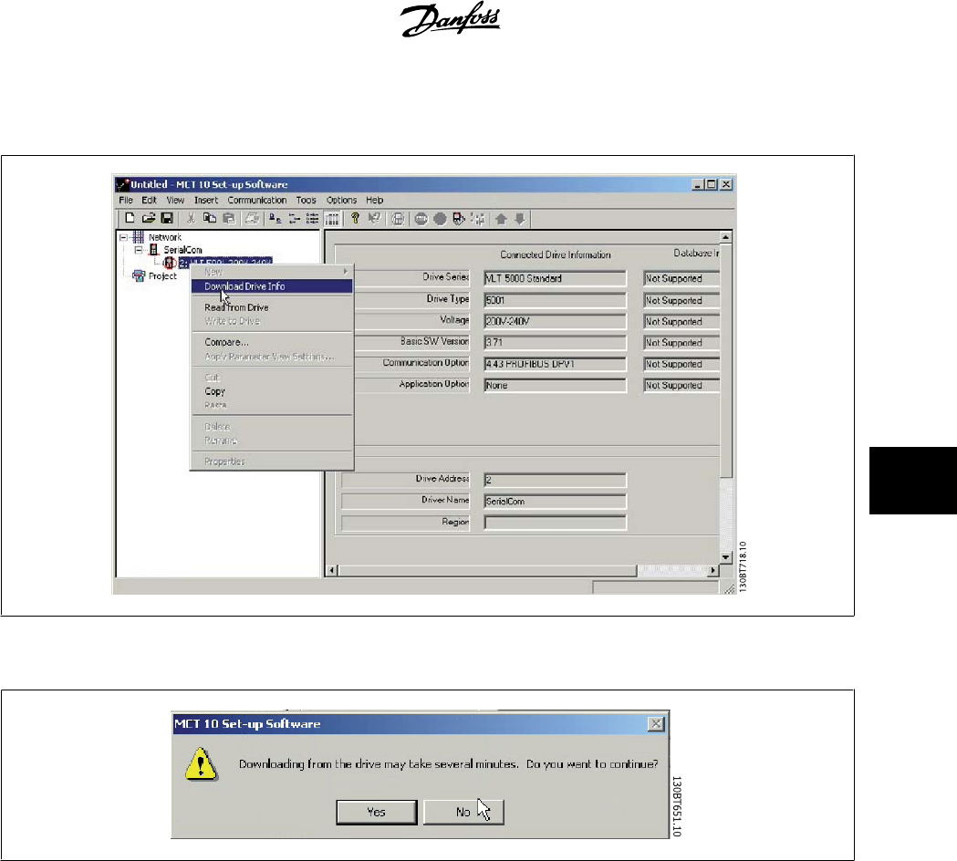
Update the database by uploading the DLL file as follows:
Right-click on the frequency converter icon and select Download Drive Info.
The following message will appear. To read from the frequency converter select Yes and reading from the frequency converter will commence.
When reading from the frequency converter is complete, the frequency converter icon will no longer have a red line through it and the Database Infor-
mation in the Right View will display settings identical to the Connected Drive Information.
MCT 10 Setup Software 6 Parameter Handling
MG10R302 - VLT is a registred Danfoss trademark
41
6
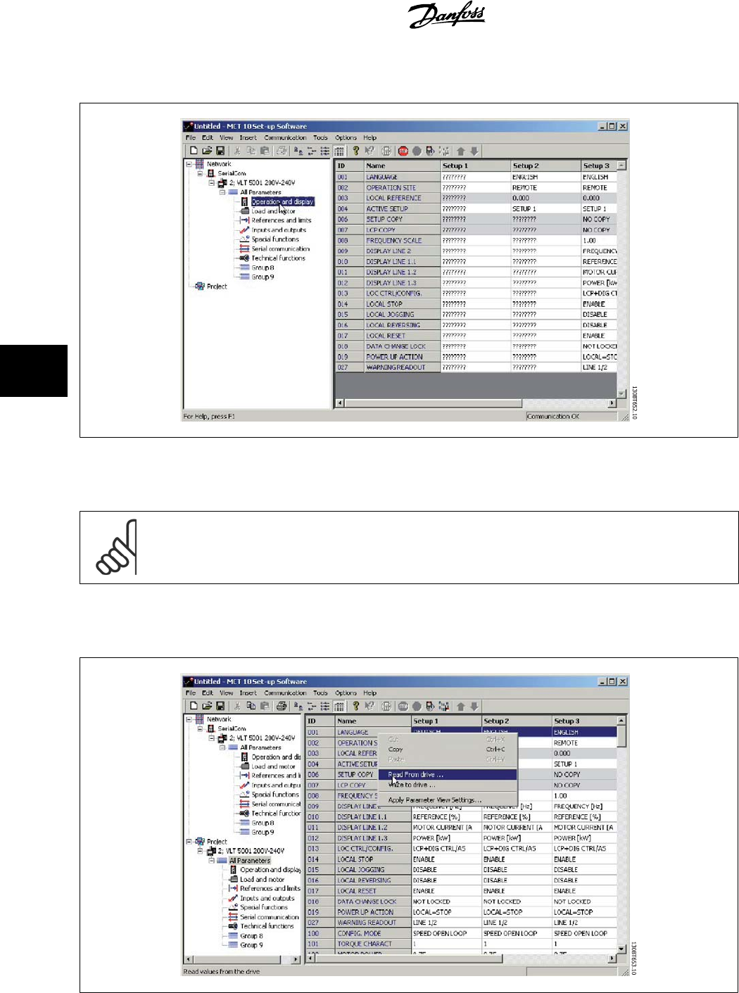
In addition, the parameter settings will be displayed in capital letters.
The capital letters indicate data which has been read directly from the frequency converter. Copy the frequency converter from the Network folder and
paste into the Project folder to save the data.
NB!
When the data is displayed in capital letters, a change of parameter settings in one set-up will not automatically be transferred to the
other set-ups:
In order to ensure that changes in settings are transferred to all set-ups, perform a Write to drive then Read From drive as the final step in updating
parameter settings.
6 Parameter Handling MCT 10 Setup Software
42
MG10R302 - VLT is a registred Danfoss trademark
6
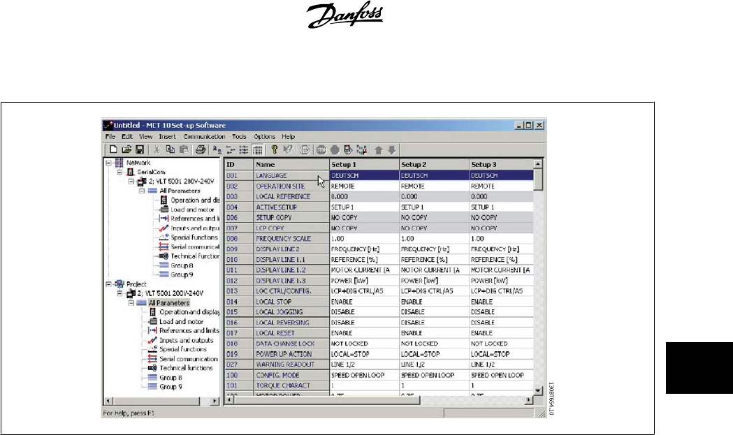
The change(s) in setting will then be transferred and displayed in all set-ups.
MCT 10 Setup Software 6 Parameter Handling
MG10R302 - VLT is a registred Danfoss trademark
43
6

7 Read/Write between MCT 10 and Frequency
Converter MCT 10 Setup Software
44
MG10R302 - VLT is a registred Danfoss trademark
7
7 Read/Write between MCT 10 and Frequency Converter
7.1 Reading and Writing Parameters
Parameter settings can be read from or written to an online connected frequency converter. The options for reading from or writing to parameters are
manifold.
One single set-up value can be read/written.
All four set-ups of a parameter can be read/written.
A group of parameters can be read/written and so on.
The user performs reading or writing by selecting the value(s) to be read/written and then selecting the
Read From drive or Write to drive
menu.
You can select
• A single parameter in the Right View
• All Parameters in the Left View
• One group of parameters in the Left View, e.g. Load and Motor group
and the Read From drive and Write to drive functions will apply to the whole selection.
7.2 Read/Write Settings
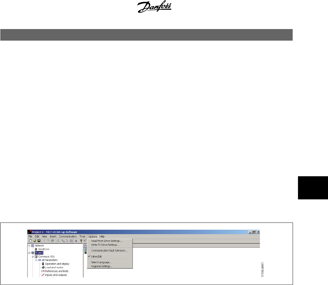
Access a range of functions by selecting Options on the main menu bar:
MCT 10 Setup Software 7 Read/Write between MCT 10 and Frequency
Converter
MG10R302 - VLT is a registred Danfoss trademark
45
7
7.2.1 Read From Drive Settings
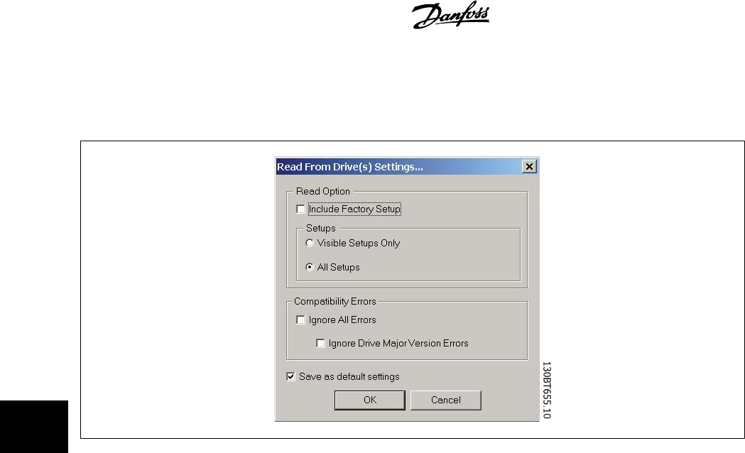
Select the desired options for reading from an active frequency converter, which will then become applicable for all reading from frequency converter(s).
Include Factory Set-up
If this option is selected, the factory set-up data (i.e. default values) will be included in the data read from the frequency converter. The factory set-up
is not always standard, it can be changed, and therefore this can be a useful option when needing to check the actual default values.
Set-ups
Select whether you wish to read only visible set-ups or wish to read all set-ups.
Compatibility Errors
If the field device software is not exactly identical with the MCT 10 version of the device, this is where you can specify what level of compatibility is
acceptable. You can choose to
Ignore All Errors
, i.e. ignore all compatibility errors.
Alternatively, if this is unacceptably broad, you can choose
Ignore Drive Major Version Errors
to restrict the acceptable compatibility errors to those
occurring in a major software version. Minor version differences such as v3.1 to v3.4 will be ignored, but major version differences such as v3.1 to v4.1
will not be accepted.
Save as Default Settings
Selecting this option will activate the above settings for all reads from drive.
7 Read/Write between MCT 10 and Frequency
Converter MCT 10 Setup Software
46
MG10R302 - VLT is a registred Danfoss trademark
7
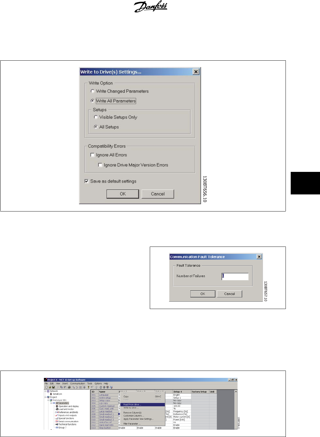
7.2.2 Write to Drive Settings
Select the desired options for writing to an active drive, which will then become applicable for all writing to drive(s).
7.2.3 Communication Fault Tolerance
Here you can set up the number of communication faults tolerable before
breaking off the connection. The default Number of Failures value is 0 or
1, which in practice is usually too low a fault tolerance for smooth com-
munications, i.e. the connection will constantly be cut off.
For normal operating conditions, set Number of Failures to 3 to achieve
reasonably smooth communications. For operating conditions where the
electrical noise level is high, or where the standard of the installation is
low, set Number of Failures to 5.
7.3 Read From Drive
Values can be read from an active frequency converter by right-clicking on the desired selection (in this example a parameter column title in the Right
View), then selecting Read From Drive.
MCT 10 Setup Software 7 Read/Write between MCT 10 and Frequency
Converter
MG10R302 - VLT is a registred Danfoss trademark
47
7
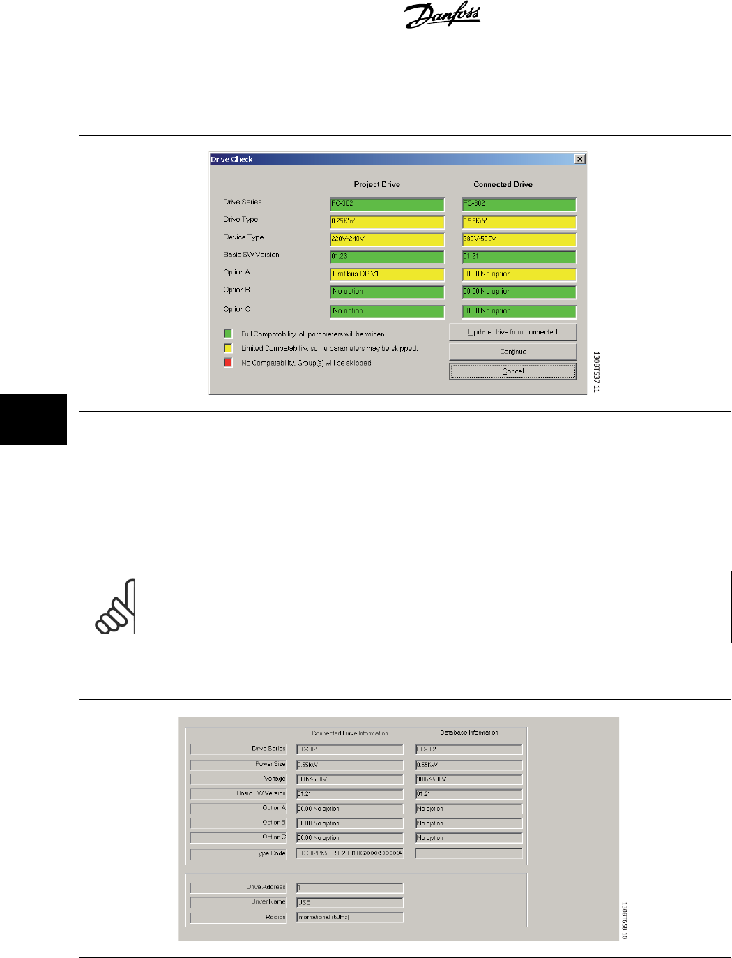
Once Read From Drive is selected, the software accesses the online device and the Drive Check window pops up, showing the compatibility of the
properties of the offline Project drive (where the properties are based on database information) with the online device, i.e. Connected Drive, as in the
following example:
The colour codes indicate the level of compatibility between the theoretical Project Drive and the actual Connected Drive, for each property.
In the Drive Check pop-up you can select one of three options: Cancel, Continue, or Update drive from connected.
Cancel
will stop the Read From Drive process, for example if the level of compatibility between Project drive and Connected drive is unacceptably low.
Continue
will activate the Read From Drive process to show the properties of the connected drive.
Update drive from connected
will activate the Read From Drive process, deleting the data in the Project drive and replacing it with the data from the
Connected drive.
NB!
The Update
drive from connected
selection will cause all information stored in the Project Drive to be deleted and then replaced in the
Read From Drive process. If you wish to retain the information entered into the Project Drive,
Continue
is the appropriate selection.
Once the Read From Drive process is completed, the display shows details of both the Connected Drive Information and the Database Information.
7 Read/Write between MCT 10 and Frequency
Converter MCT 10 Setup Software
48
MG10R302 - VLT is a registred Danfoss trademark
7
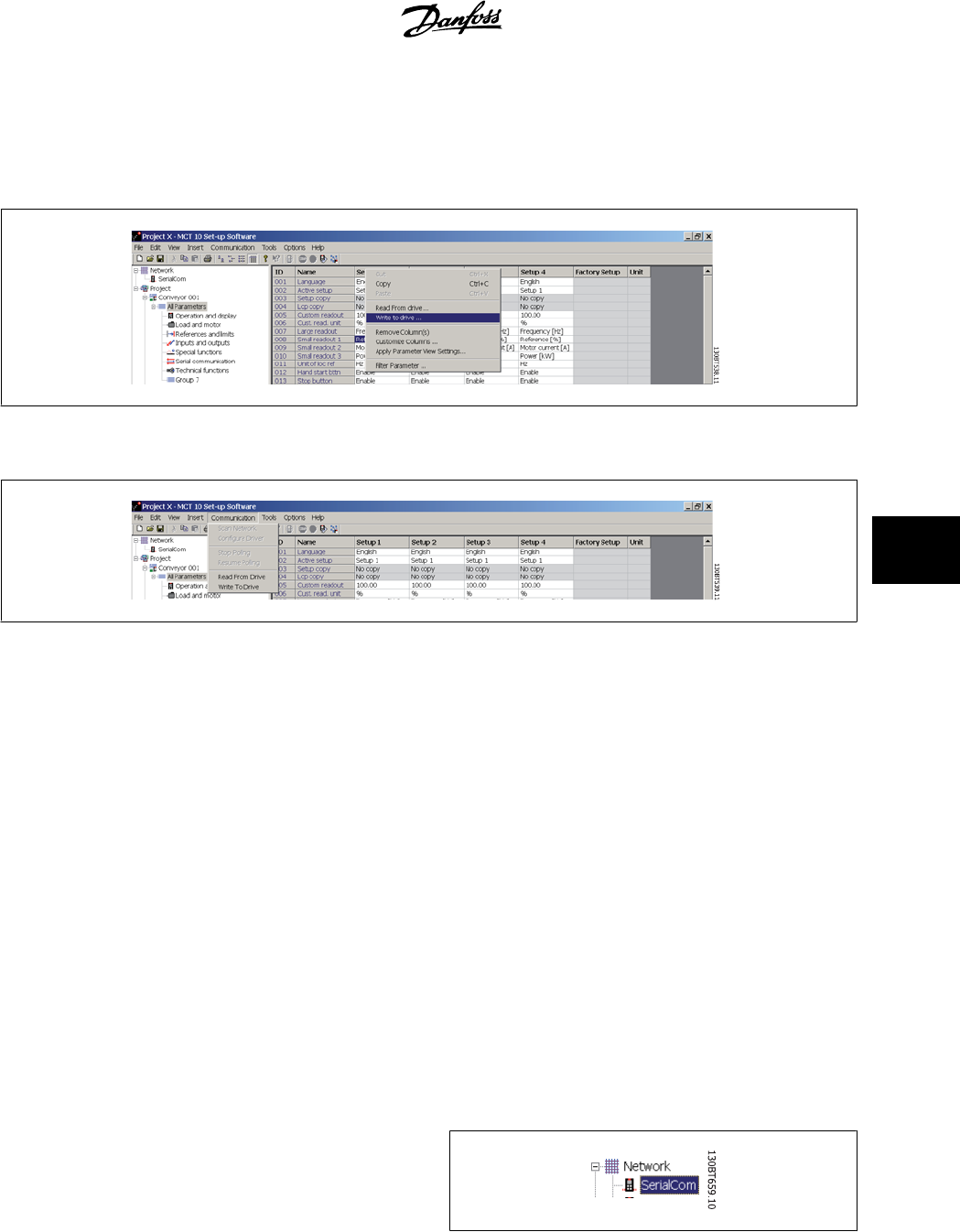
7.4 Write to Drive
Values can be written to an active frequency converter by right-clicking on a parameter column title in the Right View and then selecting Write To Drive.
Alternatively, access Read From Drive and Write To Drive by selecting Communication in the main menu:
7.5 Views
The MCT 10 Setup Software can be configured by view filters to display parameters in a special way or to display parameters of interest. This is a powerful
tool when wanting to maintain an overview of the frequency converter, without becoming confused by irrelevant parameters.
Each set-up can be hidden by removing it. This is done by selecting the set-up in the parameter view and then selecting the remove menu. Changes
made to the removed set-up are still stored inside the MCT 10 Setup Software and can be displayed again by selecting "Customize Columns".
By adding or removing columns the user can decide which information he wants to view.
The actual view can also be made valid for the complete Project or for the Folder only. This allows the user to adjust his view setting quickly for parts or
the complete Project.
Another flexible way to adjust the display is via the Filter function.
Just by selecting Change Parameters, the number of parameters displayed is reduced to 5 in this example.
7.6 Scan
Before starting to work in Network mode, perform a scan of the network to detect all the active frequency converters on the network.
7.6.1 Scan Configuration
You can enter your preferred scan settings by right-clicking on SerialCom
and then selecting Configure Driver.
MCT 10 Setup Software 7 Read/Write between MCT 10 and Frequency
Converter
MG10R302 - VLT is a registred Danfoss trademark
49
7
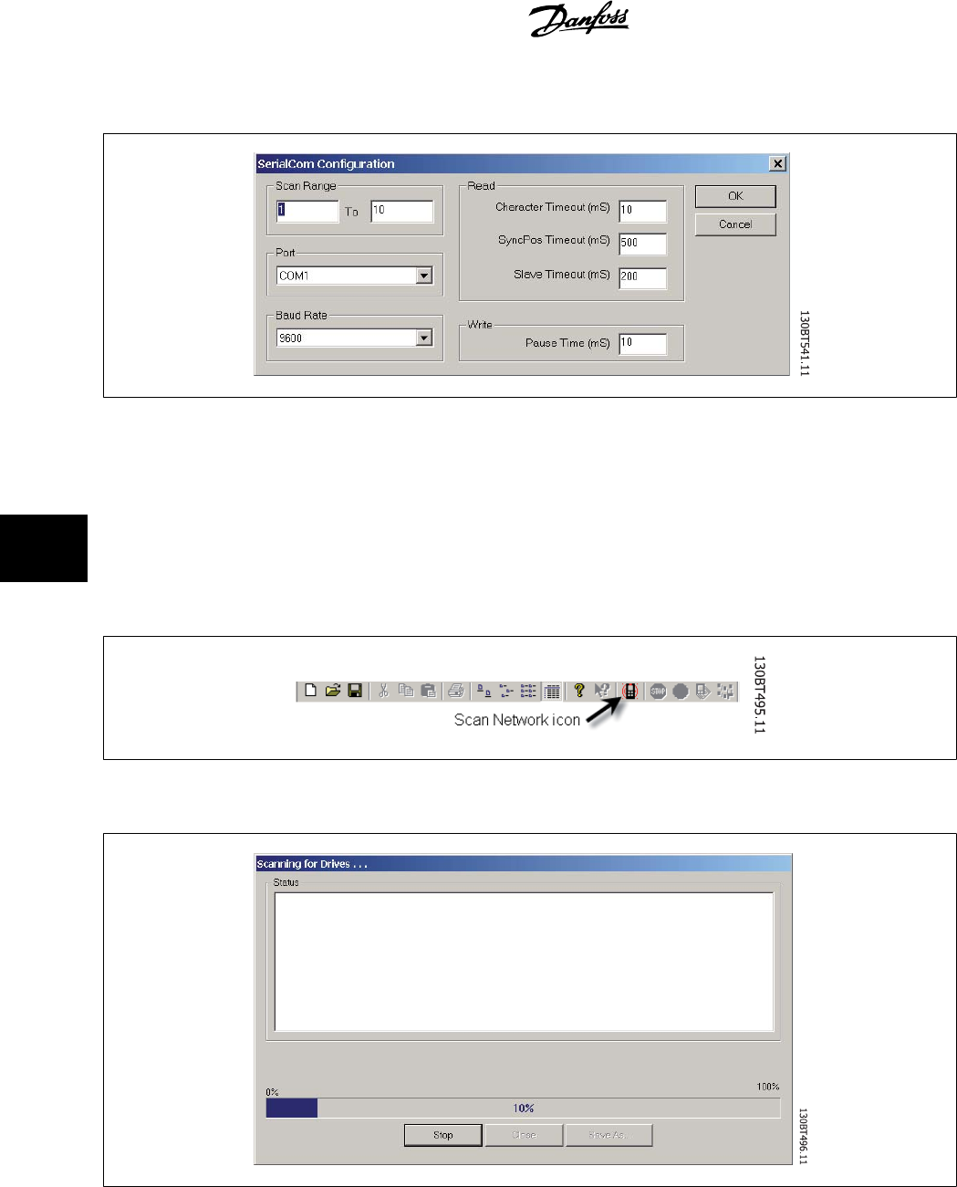
The following configuration window will pop up:
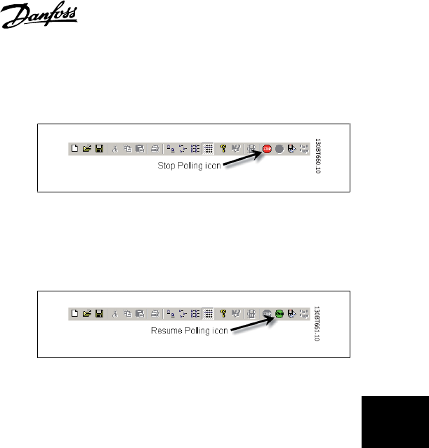
7.6.2 Scan Network
You can scan the network in three ways:
1. Right-click on the SerialCom icon in the Left View and then select Scan Network.
2. Select Scan Network under Communication on the main menu bar.
3. Select the Scan Network icon on the toolbar:
The Scanning for Drives window will pop up, and will indicate the progress of the scan:
7 Read/Write between MCT 10 and Frequency
Converter MCT 10 Setup Software
50
MG10R302 - VLT is a registred Danfoss trademark
7
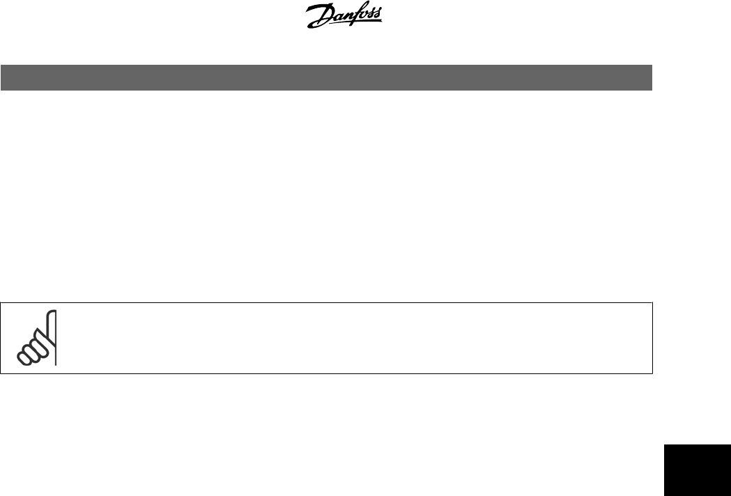
7.7 Poll
When in Network mode, MCT 10 Setup Software will automatically poll
the parameters in the Right View to continuously update their status to
reflect live operation.
However, if you wish to stop polling, for example to freeze and analyse
a particular moment, you can do this in two ways:
1. Select Stop Polling under Communication on the main menu bar
2. Select Stop Polling from the toolbar
You can also resume polling in two ways:
1. Select Resume Polling under Communication on the main menu
bar.
2. Select Resume Polling from the toolbar:
MCT 10 Setup Software 7 Read/Write between MCT 10 and Frequency
Converter
MG10R302 - VLT is a registred Danfoss trademark
51
7

8 Saving Data MCT 10 Setup Software
52
MG10R302 - VLT is a registred Danfoss trademark
8
8Saving Data
8.1 Network and Project Folders
It is important to note the difference between Network and Project folders in the Left View.
Through the Network folder the user gains access to physical devices operating in the field. Here the user can configure the physical frequency converters
just as if he were configuring them on the LCD panel of the device. Configuration changes made in the Network folder are therefore saved only in the
physical device in the field. The Network folder contains online data.
The Project folder contains those data saved to the user’s hard disk, remote from the field. The Project folder therefore contains offline data.
NB!
Changes made in the Network folder are not automatically saved to the Project folder. That is, the user must actively save changes to
his hard disk.
8.2 Changing the Set-up of a Device in the Field
In order to change settings for a field device, the user opens the Network folder and selects the relevant device. The configuration window will pop up,
showing where the user sets the scan range, scans for frequency converters and finds the device he is seeking.
The user can stop polling by selecting the stop icon on the tool bar, and then make changes to settings directly in the set-up columns in the Right View.
At this point the changes will be implemented online in the field device, but are not recorded elsewhere.
8.3 How to Save Data
8.3.1 Save Changes to a Hard Disk
To record online changes to a hard disk, select the relevant device in the Network folder. Right-click on the device and select
Copy
.
Select the Project folder, right-click and select
Paste
.
Then select
File
from the main menu bar, and select
Save As
.
The user can then save the device file under the desired title into a directory on his hard disk.
8.3.2 Save a Project
Save a project by selecting
File
from the main menu bar, then
Save
. Alternatively, select the
Save icon
on the toolbar, the third icon from the left.
8.3.3 Archive / Unarchive
Projects that include links to other documents, can store not only the drives but also the linked files.
By selecting the
Archive
function the MCT 10 generates a file that contains all drives and the linked files into a *.ssa File. If this file is sent to other
computers the user will get a copy of the linked files on his computer.
MCT 10 Setup Software 8 Saving Data
MG10R302 - VLT is a registred Danfoss trademark
53
8

9 SyncPos MCT 10 Setup Software
54
MG10R302 - VLT is a registred Danfoss trademark
9
9SyncPos
9.1 SyncPos Handling
The VLT 5000 and VLT 5000 FLUX series have a SyncPos application option, which consists of a print card with processor. This manual does not describe
the SyncPos functionality in detail. For detailed information please consult the separate SyncPos program manual.
The MCT 10 Setup Software can directly modify, read from and write to SyncPos files. SyncPos Files are stored within the MCT 10 files, and do therefore
not require separate handling.
When a VLT 5000 has a SyncPos option installed, the MCT 10 will display two icons upon selection of the frequency converter: an All Parameters folder
icon and a separate icon for the SyncPos option. A group 7 series of parameters is incorporated under All Parameters. The group 7 parameters apply to
SyncPos.
NB!
MCT10 has not true support for SyncPos application options ver 1.xx and 2.xx. The Syncpos folder will be available due to the lag of
functionality in these initial versions.
9.2 Programs and Configuration File
Select the SyncPos icon and two more folders will become visible. The SyncPos program consists of two main parts: Configuration file (*.cnf) and Program
Files(s) (*.m). A configuration file consists of a series of SyncPos parameters which can be programmed. MCT 10 can import or export SyncPos Config-
uration files. If no Configuration file exists it can be set up.
9.2.1 Programs
Programs can be inserted in the MCT 10 Project folder. When a new SyncPos program is selected, an untitled program
is inserted in the SyncPos folder. The program can be edited, written and exported just as in the stand alone SyncPos
program. If a SyncPos program already exists it can be imported into the MCT 10 project.
9.2.2 Configuration
Select the Configuration icon to view the available frequency converter configuration file in the Right View. Select the
icon for the relevant frequency converter in the Right View to open a new editor (Cam Editor), which is used to change
the SyncPos settings. Details of how to use the editor are dealt with in the separate SyncPos manual.
Once the desired settings are made, you can either Compile (under Settings in the main menu) or Exit Program (under File in the main menu).
Upon selecting Exit Program, a window will pop up: SyncPos Application Closed, providing you with two options for how to save and exit, including an
explanation. Select Read or Write. A Confirm SyncPos Write (or Read) window will pop up, with two options for saving to the SyncPos card. Mark the
desired selection and select Yes or No. Upon selecting Yes, the information will be written to the frequency converter.
If Write to Drive is selected at the root of a frequency converter, the MCT 10 also writes the SyncPos Files to the SyncPos options. If this function is
called, the MCT 10 warns the user for unattended stop of the SyncPos Card.
MCT 10 Setup Software 9 SyncPos
MG10R302 - VLT is a registred Danfoss trademark
55
9
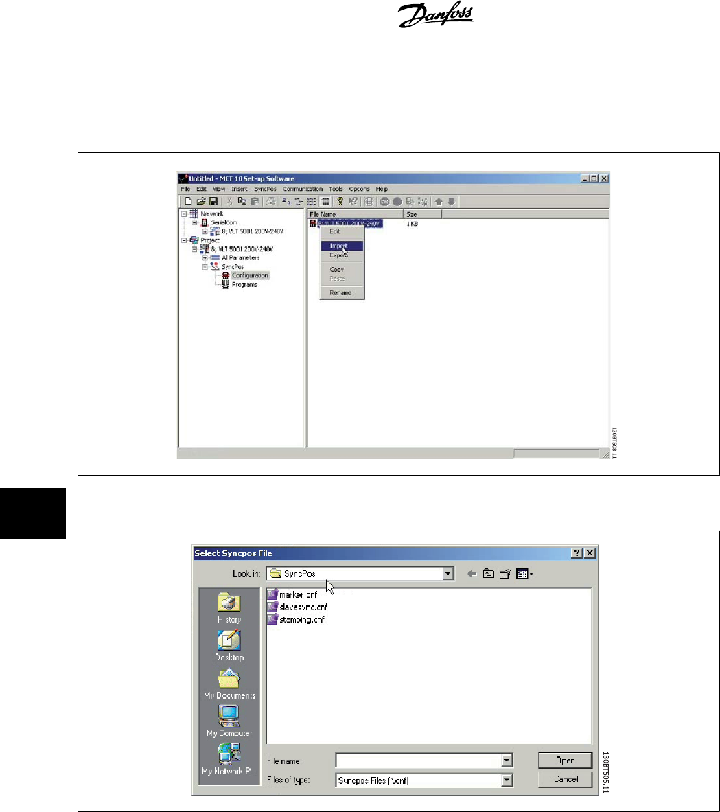
9.2.3 Import and Export of a Configuration File
To import a configuration file saved elsewhere, for example in another project, to the SyncPos card, left-click on the configuration file displayed in the
Right View as shown below.
A window will pop up enabling you to select a configuration file for import from your computer directory:
9 SyncPos MCT 10 Setup Software
56
MG10R302 - VLT is a registred Danfoss trademark
9
Select the desired file, click Open, and the file will be imported to the Configuration folder.
Export of configuration files is performed in the same manner.
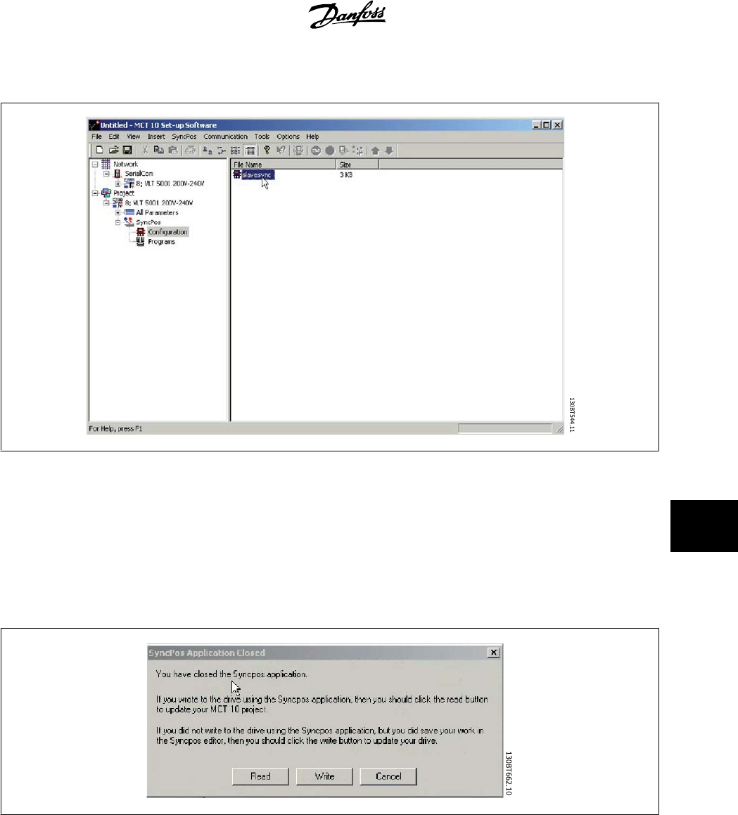
9.2.4 Edit and Save Configuration File
View and edit the content of the configuration file by selecting it, whereupon the configuration editor will open.
After editing is complete, close the SyncPos application and the following window will pop up:
To save your changes, select Read or Write to save changes to the MCT 10 project or to the frequency converter, respectively. Reading or Writing can
take some time.
MCT 10 Setup Software 9 SyncPos
MG10R302 - VLT is a registred Danfoss trademark
57
9
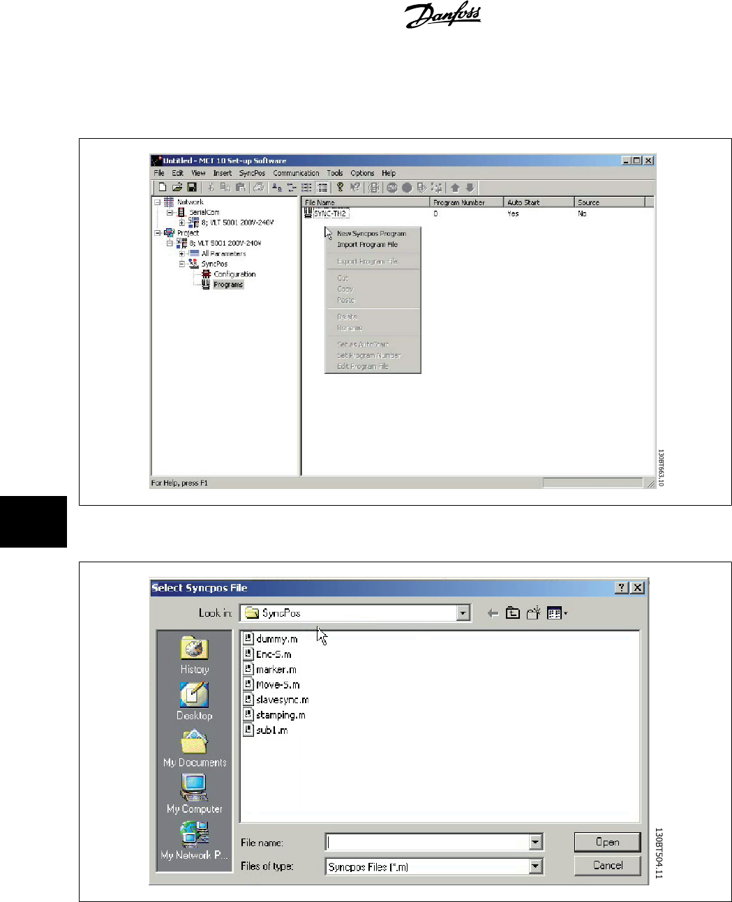
9.2.5 Import and Export of Programs
To import a program to the SyncPos card, left-click on a program displayed in the Right View as shown below.
A window will pop up enabling you to find the desired program for import in the computer directory.
Select the desired program, click Open, and the program will be imported to the Programs folder. The import is now complete.
9 SyncPos MCT 10 Setup Software
58
MG10R302 - VLT is a registred Danfoss trademark
9
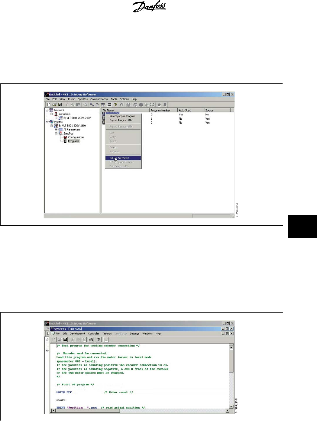
9.2.6 Autostart
If more than one program is stored in the Programs folder, you can set one of them to start automatically when the device is turned on.
In the Right View, select the program you wish to be the start-up program, and then right-click to select Set As Autostart. The program selected is
thereafter indicated with Yes in the Autostart column.
9.2.7 Source Code
Refer to SyncPos manual.
9.2.8 Edit Source Code
Double-click on the program icon in the Right View to view and edit the source code.
A range of editing operations are possible, described in detail in the SyncPos manual.
MCT 10 Setup Software 9 SyncPos
MG10R302 - VLT is a registred Danfoss trademark
59
9
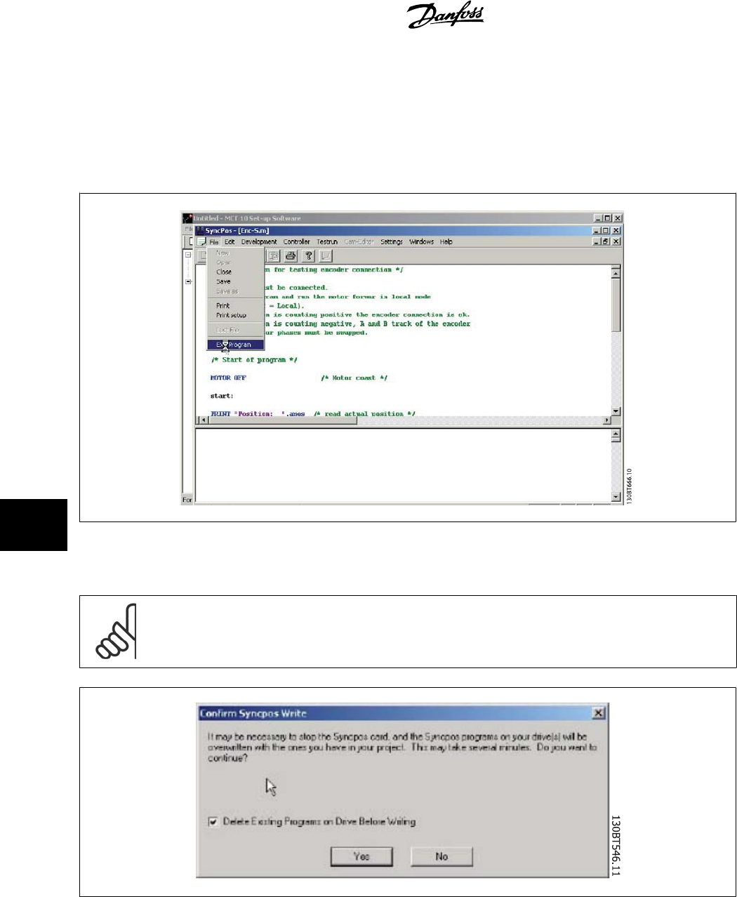
9.2.9 Save and Exit Program
If you wish to save your work when editing is complete, select Save under File in the menu bar. This will save the changes to the program file opened
from the MCT 10 project.
To leave SyncPos, select Exit Program under File in the menu bar:
As for editing of a configuration file, a SyncPos Application Closed dialog box will pop up and you should select Read or Write according to the instructions
in the box.
NB!
If there are programs in the SyncPos card they will be deleted without further warning.
9 SyncPos MCT 10 Setup Software
60
MG10R302 - VLT is a registred Danfoss trademark
9
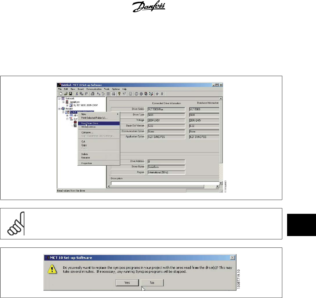
9.3 SyncPos Read From Drive
Read all parameters and SyncPos files from a frequency converter to a project in one step by selecting Read from Drive. Select the root drive and then
right-click to find Read from Drive:
NB!
Use this feature with caution. Files in the project can be permanently lost. The following warning will appear, explaining that files of
the same name will be permanently overwritten:
If you select Yes, reading from the frequency converter will commence, and Configuration Files and Programs from the frequency converter will be saved
to the Project.
MCT 10 Setup Software 9 SyncPos
MG10R302 - VLT is a registred Danfoss trademark
61
9
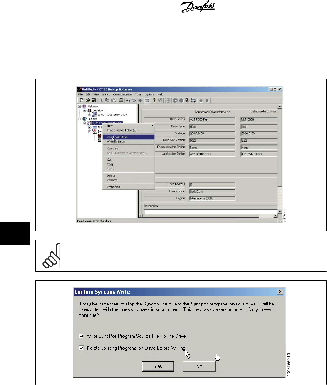
9.4 SyncPos Write to Drive
Write all parameters and SyncPos files from a project to a frequency converter in one step by selecting Write to Drive. Select the root drive and then
right-click to find Write to Drive:
NB!
Use this feature with caution. If incorrectly used, files on the drive can be permanently lost. The following warning will appear, explaining
that files of the same name can be permanently overwritten:
Choose the settings you require. Then to write, select Yes. For the above settings, the existing programs will first be deleted, and then the SyncPos
Program Source Files will be written to the frequency converter. Once the write is complete, you can check the contents for the Network folder to confirm
that the Write to Drive was successful.
9 SyncPos MCT 10 Setup Software
62
MG10R302 - VLT is a registred Danfoss trademark
9
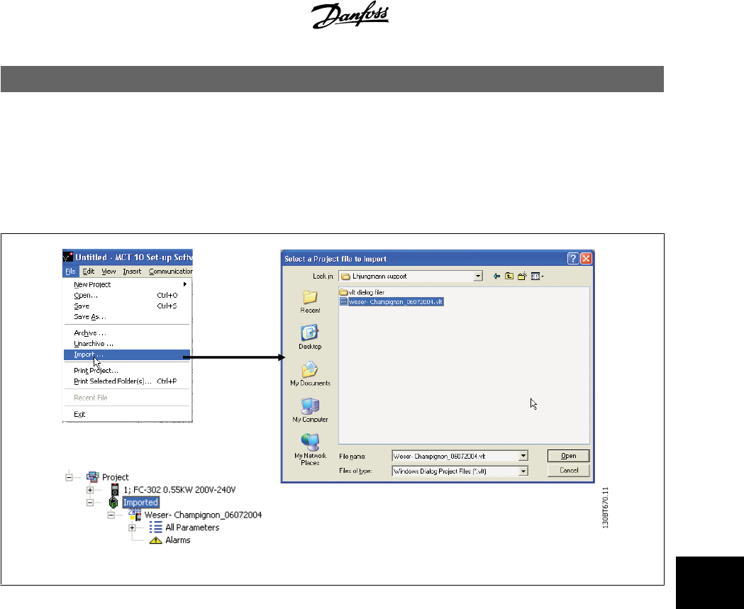
10 Import of Files
10.1 Import of Older Dialog Files
For users working with VLT set-up software dialog, the files generated under these software packages can be imported into the MCT 10.
Files from DOS versions as well as Windows versions can be imported to the MCT 10. Following a successful import, the MCT 10 places the imported files
in an imported files folder.
Due to limitations in some of the former PC tools some functionality is not importable. Functions such as displaying changed values only, are not available
in MCT 10.
MCT 10 Setup Software 10 Import of Files
MG10R302 - VLT is a registred Danfoss trademark
63
10

11 Printing MCT 10 Setup Software
64
MG10R302 - VLT is a registred Danfoss trademark
11
11 Printing
There are two options for printing from MCT 10: Print Project or Print Selected Folders.
Both options are located under File in the main menu bar.
Alternatively, Print Project can be selected by right-clicking on the Project icon. Print Selected Folders can be selected by right-clicking on the icon for a
folder within the Project.
If you wish to print parameter settings for an entire project, select Print Project.
If you wish to print parameter settings for part of a project, select Print Selected Folders
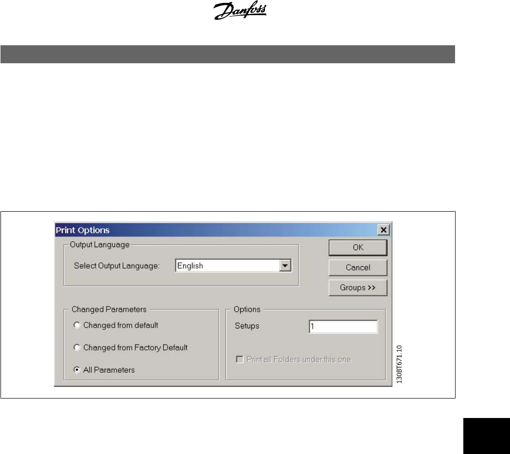
The following dialog box will pop up:
In this box you can set the options as follows.
11.1.1 Output Language
Select the desired print language from the list, which appears by left-clicking on the default language displayed.
11.1.2 Changed Parameters
Select this option to print all parameters, or if you only wish to print the parameters which have changed. Select between parameters
• Changed from default
• Change from factory default
• All parameters
Make your selection, and then press ok for printing to begin.
11.1.3 Options
Specify which set-up you wish to print.
MCT 10 Setup Software 11 Printing
MG10R302 - VLT is a registred Danfoss trademark
65
11
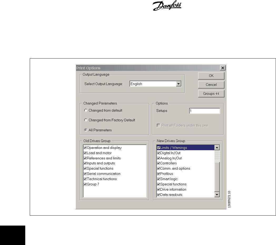
11.1.4 Groups
You can choose to print only selected parameter groups.
If you select Groups >> the Print dialog box will expand to look like this:
Make your selection of which parameter groups to print.
To return to the original unexpanded Print dialog box, select Groups <<.
To print, select OK.
11 Printing MCT 10 Setup Software
66
MG10R302 - VLT is a registred Danfoss trademark
11
12 Alarm, Warning and Fault Log Readout
From Version 2.0, MCT 10 supports the feature of reading out the alarms, warnings and fault logs of the online frequency converters. This allows the
user to quickly locate alarms and warnings in the connected drive system, and investigate the fault log for previous trips. This feature also allows the
user to gather and store events in the project file for later evaluation or the project file can be sent to a remote specialist for further investigation.
12.2 Localisation of Alarms and Warning
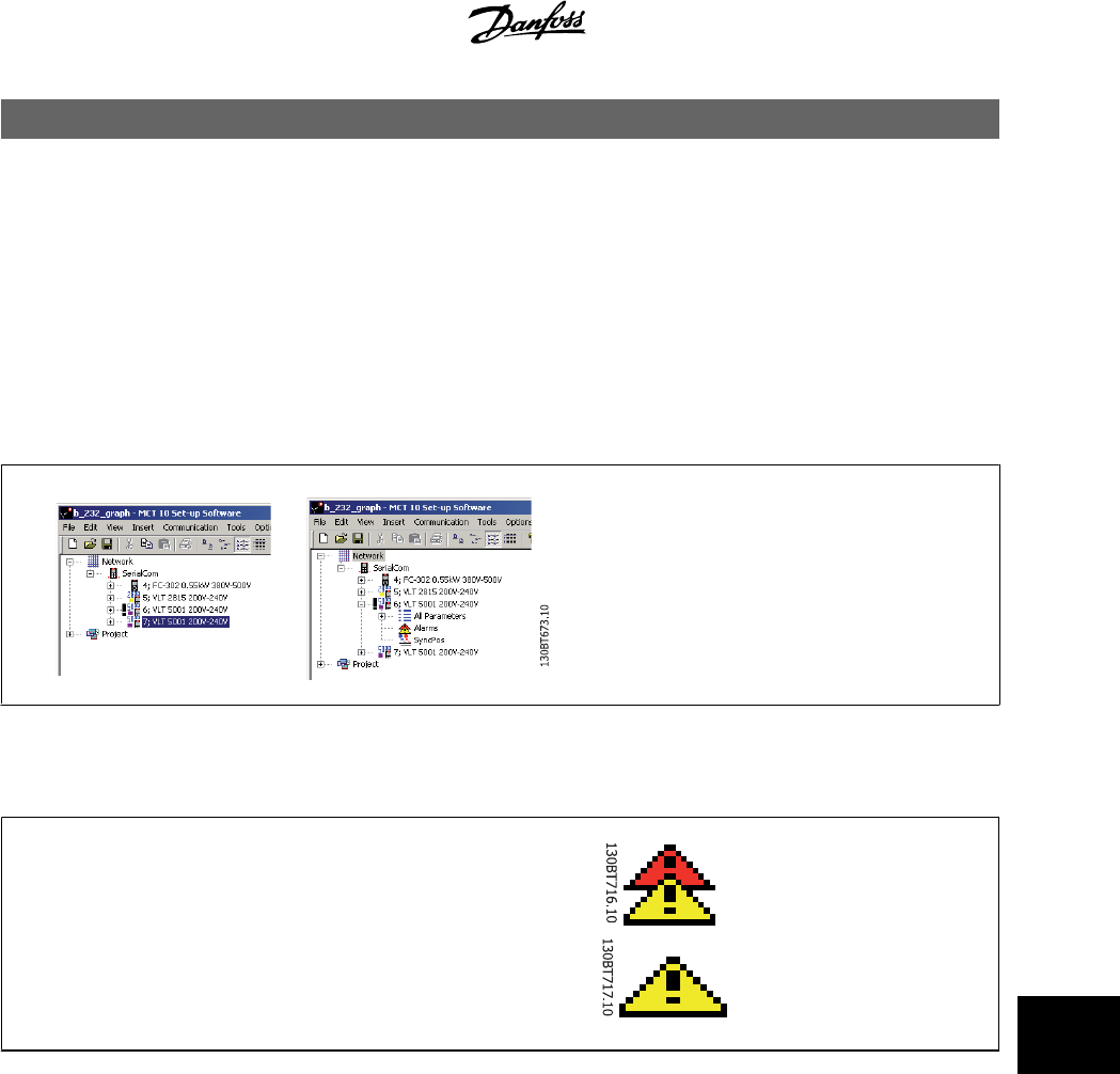
After a complete scanning of a Drive Network, the MCT 10 indicates if the connected drives have active warnings or alarms. Both warnings and alarms
are indicated by a ! sign in front of the drive icon. A missing ! indicates that no alarms or warnings are present at the time the Network was scanned.
The picture below shows a small network with four drives, where the VLT 5000 at address 6 has an active Alarm or Warning.
By selecting the + sign the view of the VLT 5000 is expanded. In this view the user has the active alarm/warning icon, which is represented by the double
triangle icon. The single triangle icon indicates no warning/alarms.
Active Alarms/Warnings
No Active Alarms/Warnings
MCT 10 Setup Software 12 Alarm, Warning and Fault Log Readout
MG10R302 - VLT is a registred Danfoss trademark
67
12
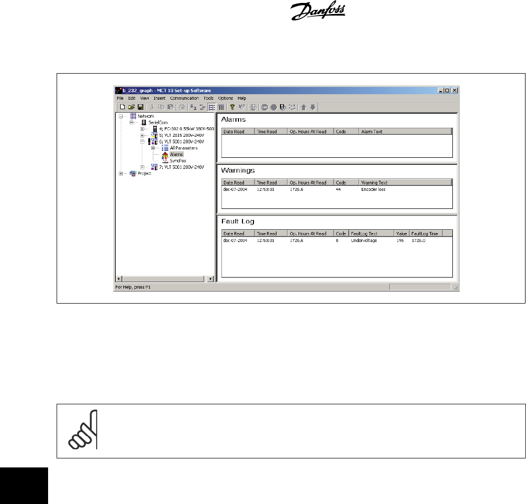
Selecting the active alarm/warning icon will split the right view into three main areas:
130BT674.10
The alarms and warnings are displayed at the top of the Right View. Both views consist of five columns. The first two columns are the date and time of
the PC at the time the information was read from the drive. The third column is the Drives Operating Hours counter. Column for is the code for the
warning/alarm. For a more detailed description of the code, please consult your Operating Instructions for the particular drive. The last column is the
warning in clear text.
In case of a trip the drive stores the reason for the trip in a fault log buffer. The log consist of three values; code, value and time. When MCT 10 reads
the fault log it displays the PCs time and date at the time where the log was read.
NB!
Since the drives do not have a built-in real time clock, the actual time of when a fault occurs can only be estimated. This requires that
the user knows exactly the total amount of time in which the drive has been disconnected, between the time the fault occurred and
the time the loggings were read.
12 Alarm, Warning and Fault Log Readout MCT 10 Setup Software
68
MG10R302 - VLT is a registred Danfoss trademark
12
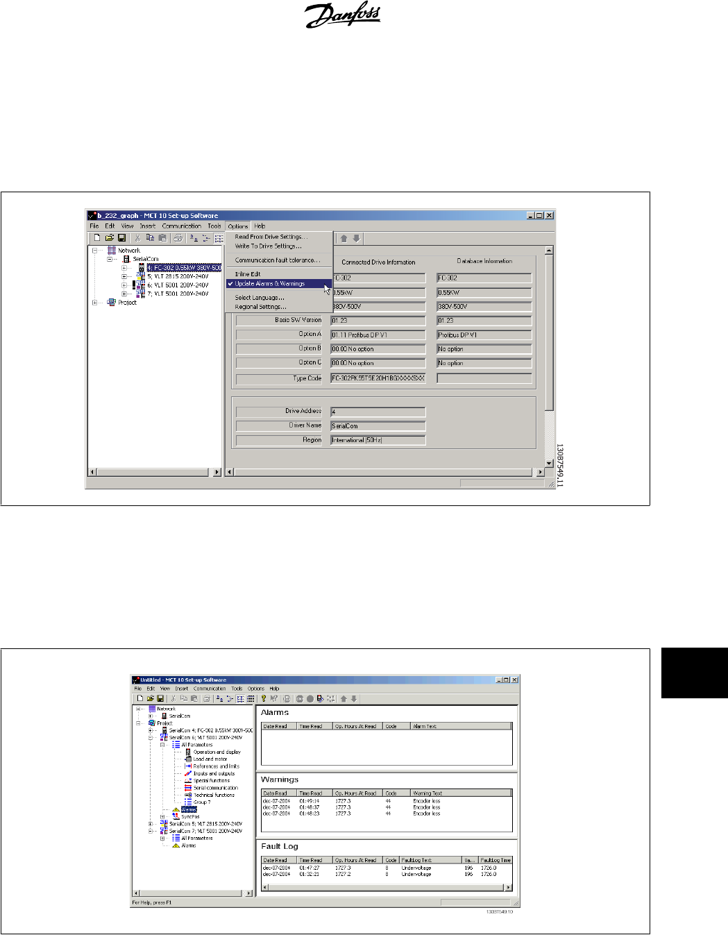
12.3 Handling Alarms/Warnings in Project Files
Before alarms/warnings and the fault loggings are stored into the Project File, the user has to enable this function in MCT 10. This is done under the
main menu Options Updating Alarms and Warnings. By simply adding the checkmark, the MCT 10 now automatically reads the alarms, warnings and
fault loggings at every read from/write to the drive.
12.4 Handling the Alarms and Warning Loggings
Every time the MCT 10 reads from or writes data to a connected drive the loggings are updated. Since the drive has no real time clock built-in there is
no way to evaluate if a fault has occurred only once or if it has occurred twice or more. Due to this behaviour in the drive, MCT 10 consequently stores
active alarms and warnings in the project file at each read/write command. These functions ensure that no alarm is lost, but can lead to a situation where
one alarm has multiple entries in the log.
MCT 10 Setup Software 12 Alarm, Warning and Fault Log Readout
MG10R302 - VLT is a registred Danfoss trademark
69
12
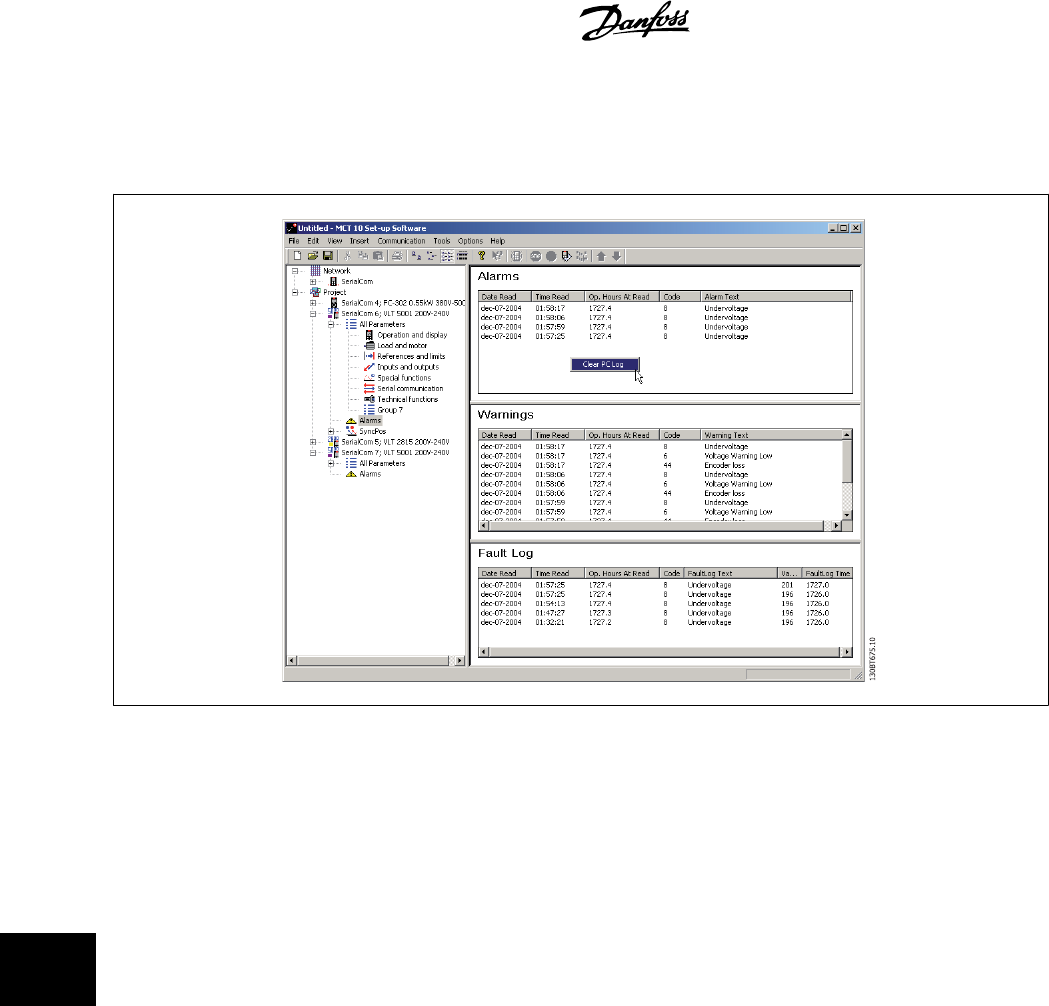
MCT 10 stores space for more than 200 alarms and warnings for each drive in the project. The loggings can be individual cleared. This is done by entering
the loggings you wish to clear, and right-click with the mouse. Clearing the log only clears the PC log, the drives onboard information is unaffected by
this handling.
12 Alarm, Warning and Fault Log Readout MCT 10 Setup Software
70
MG10R302 - VLT is a registred Danfoss trademark
12
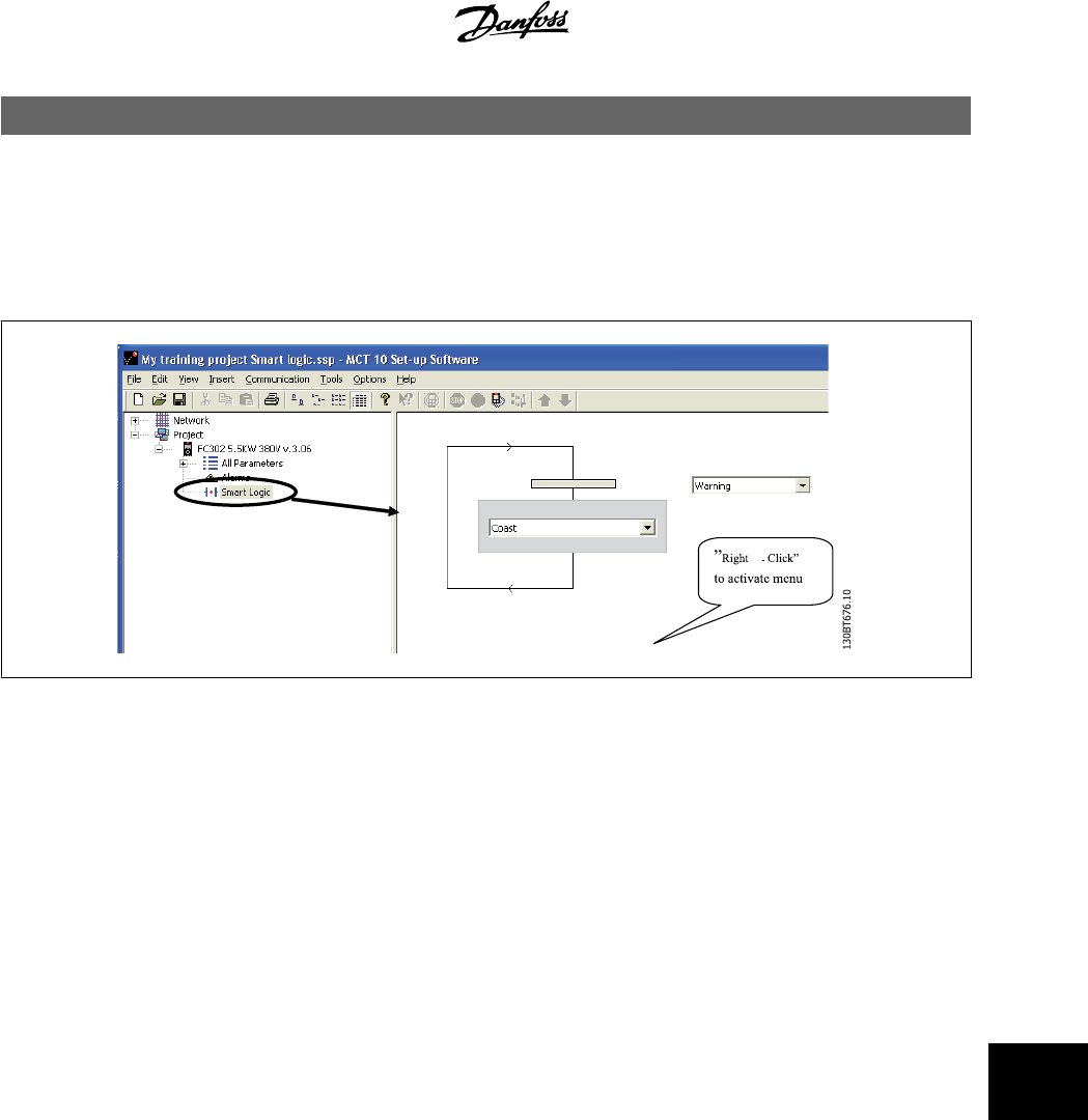
13 Smart Logic Controller Plug-in
13.1.1 Smart Logic Controller Plug-in
From Version 2.13, MCT 10 supports the Smart Logic Controller Plug-in for the Automation Drive series. This feature enables the user to do very quick
set-up of logical sequence programs by means of a graphical user interface, instead of setting up each single parameter by hand.
This plug-in is easy to use, and items can be added, just by performing a right-click in the sequence tree area.
It is recommended to consult the Automation Drive’s Design guide to get a full overview of the Smart Logic Controller features.
One of the great advantages of the built-in Logic Condition Controller is its easy-to-use programmability. You can easily configure it without previous
training and it enables a host of advanced functionalities.
The condition controller is a simple, but at the same time very clever way to have your drive, motor and application work together. The principle is this:
The controller monitors a pre-determined event. When the specified event occurs, it performs a pre-determined act and starts monitoring the next
predetermined event – and continues that way in up to twenty different steps until it returns to step one – monitoring the first specified event.
The logic controller is able to monitor any parameter that can be characterised as “true” or “false”. This includes digital commands and also logic
expressions, which allows sensor outputs to determine the operation. Temperature, pressure, flow, time, load, frequency, voltage and other parameters
combined with the operators “>”, “<”, “=”, “and” and “or” forms logic expressions that controls the drive logically in any application. That is why Danfoss
calls it a “logic” controller.
• Makes the drive act according to your specific application
• Standard feature
• Simple to programme
• Easy to correct
• Program via MCT 10 or LCP
MCT 10 Setup Software 13 Smart Logic Controller Plug-in
MG10R302 - VLT is a registred Danfoss trademark
71
13
13.1.2 Components simple to learn
• Comparators
•Logic rules
•Events
•Actions
•Done!
13 Smart Logic Controller Plug-in MCT 10 Setup Software
72
MG10R302 - VLT is a registred Danfoss trademark
13
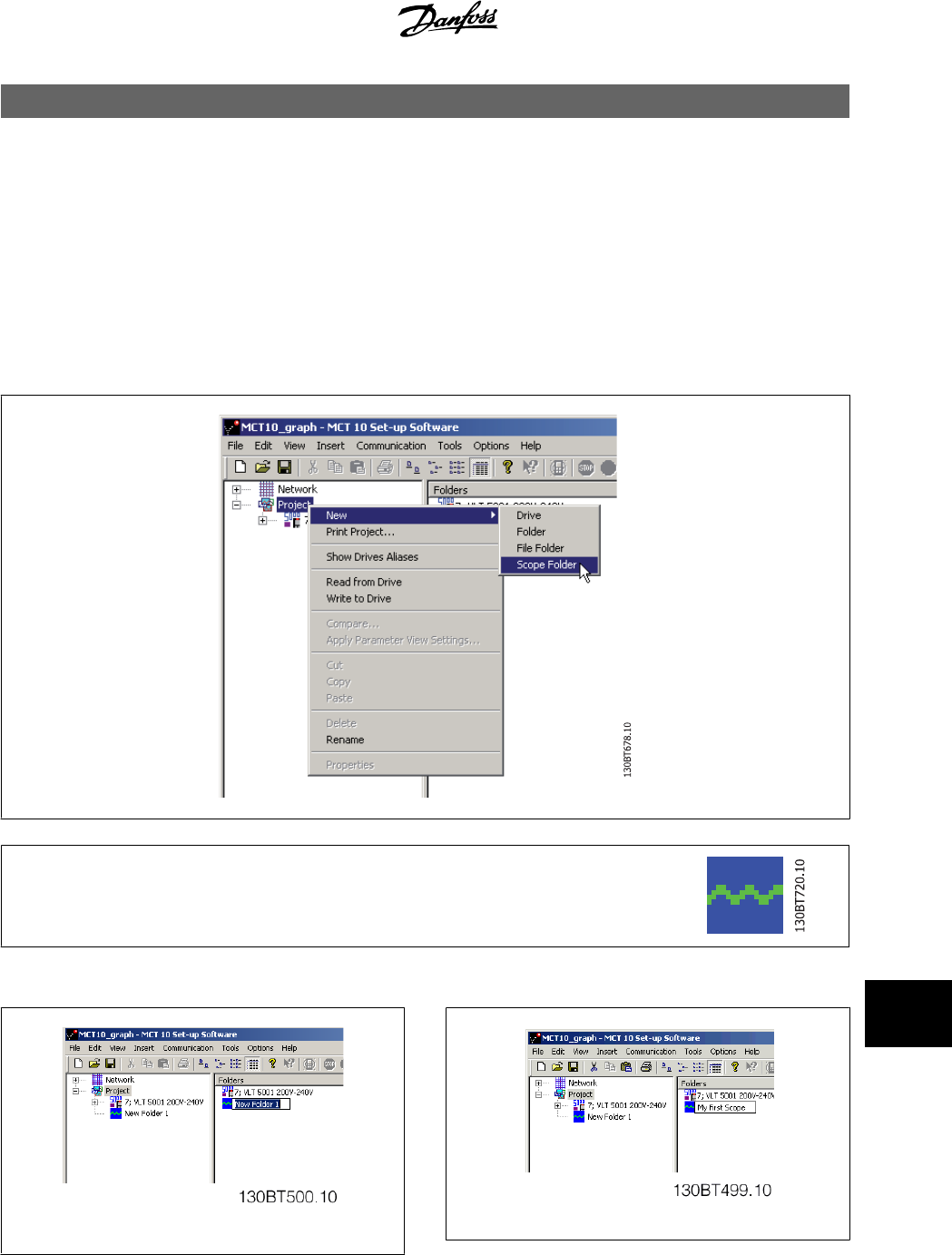
14 Scope Function
14.1 Introduction to the Scope Function
In many situations the use of viewing a variable as a curve provides a better and faster way to understanding your system. Curves also give you the
possibility to graphically evaluate if a system is unstable e.g. PID loops.
Many faults that exist in a very short time (e.g. over current) can also be traced by this function, and thus be a valuable feature to the user.
14.2 Activating the Scope
The Scope is inserted like a new File folder or a new Parameter Folder, by right-clicking the mouse cursor over the Project Folder, Drive Folder or a drive.
The Scope folder can be inserted at any place, under the Project, under a Drive folder or under a drive. There are no
limitations related to the place where a Scope is inserted. As soon as the Insert new Scope folder has been selected, the
icon is inserted.
The default name of the Scope folder can be renamed.
MCT 10 Setup Software 14 Scope Function
MG10R302 - VLT is a registred Danfoss trademark
73
14
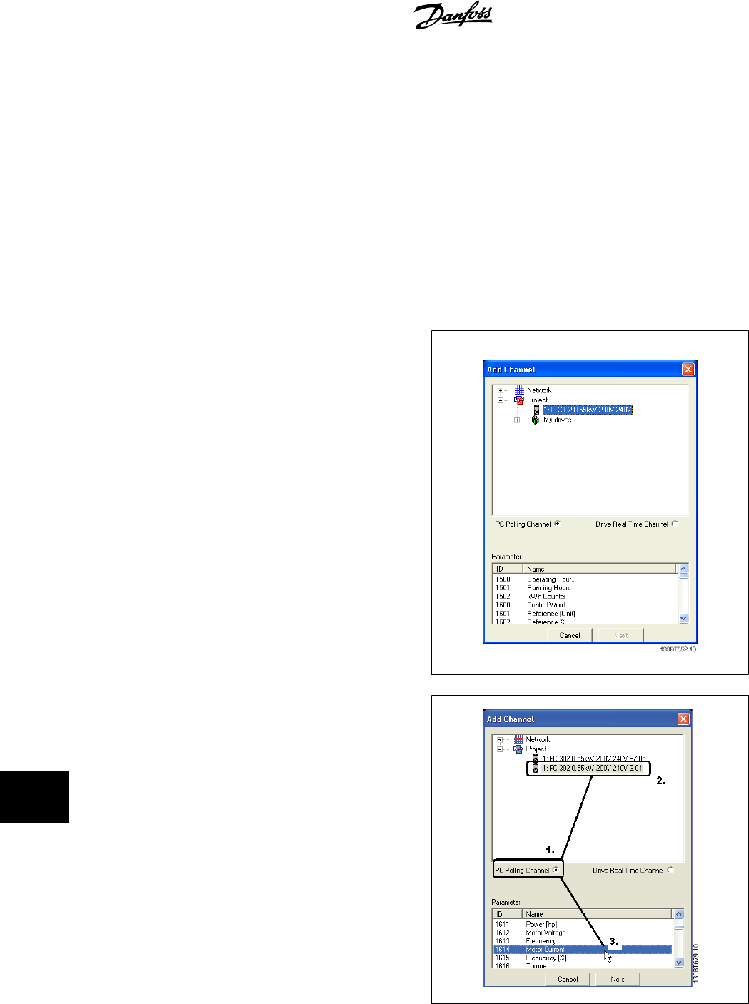
14.3 Channel Types
Using the scope function in MCT 10 gives by default the possibility to use two different channel types, depending on what the actual drive supports.
The normal channel is selected as a PC polling channel, a channel where the PC-SW itself request values from the drive to, through this channel.
The second channel type, which for instance is available in specific FC30x drives, is called Drive Real Time Channel. This channel is started when filling
up a buffer in drive, the data here can be set up with a very precise sample-rate. The rate is depending on what the single drive supports.
14.4 Initial "Add Channel" (PC Polling Channel)
The first time you select the Scope Folder, MCT 10 will pop-up with the Add new Channel Box.
In this Box you will be able to browse your Network for the drives and
signal that you want to add to your Scope view. The first task is to select
the channel type and to locate the drive that you want to monitor. The
default channel type is PC Polling Channel.
By selecting the drive (2) the available Signals will be shown in the box
with Parameter ID number and the parameter name (3). Selecting the
Signal and pressing OK brings up the add channel box again, and the
setting for value/divisions (in this case Amps/Div) can be set. Setting a
wrong value is not critical. MCT 10 stores the values, but the value may
not be shown within the visible area. You can adjust the Amps/Div later
to fit the level inside the visible area without losing information.
14 Scope Function MCT 10 Setup Software
74
MG10R302 - VLT is a registred Danfoss trademark
14
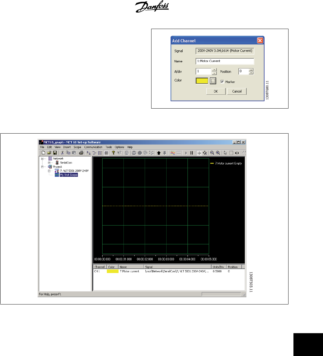
The position number is vertical Zero line (on the Y Axis). If you have many
signals on top of each other it is useful to have them plotted apart. The
marker allows you to differentiate the different curves in a black and white
printout. Each curve gets a marker as box, triangle, cross etc. Colour sets
the colour of the curve.
The selection done by now, gives the following graph window:
If more channels are needed, the user can insert more channels by right-clicking the mouse cursor in the channel box:
MCT 10 Setup Software 14 Scope Function
MG10R302 - VLT is a registred Danfoss trademark
75
14
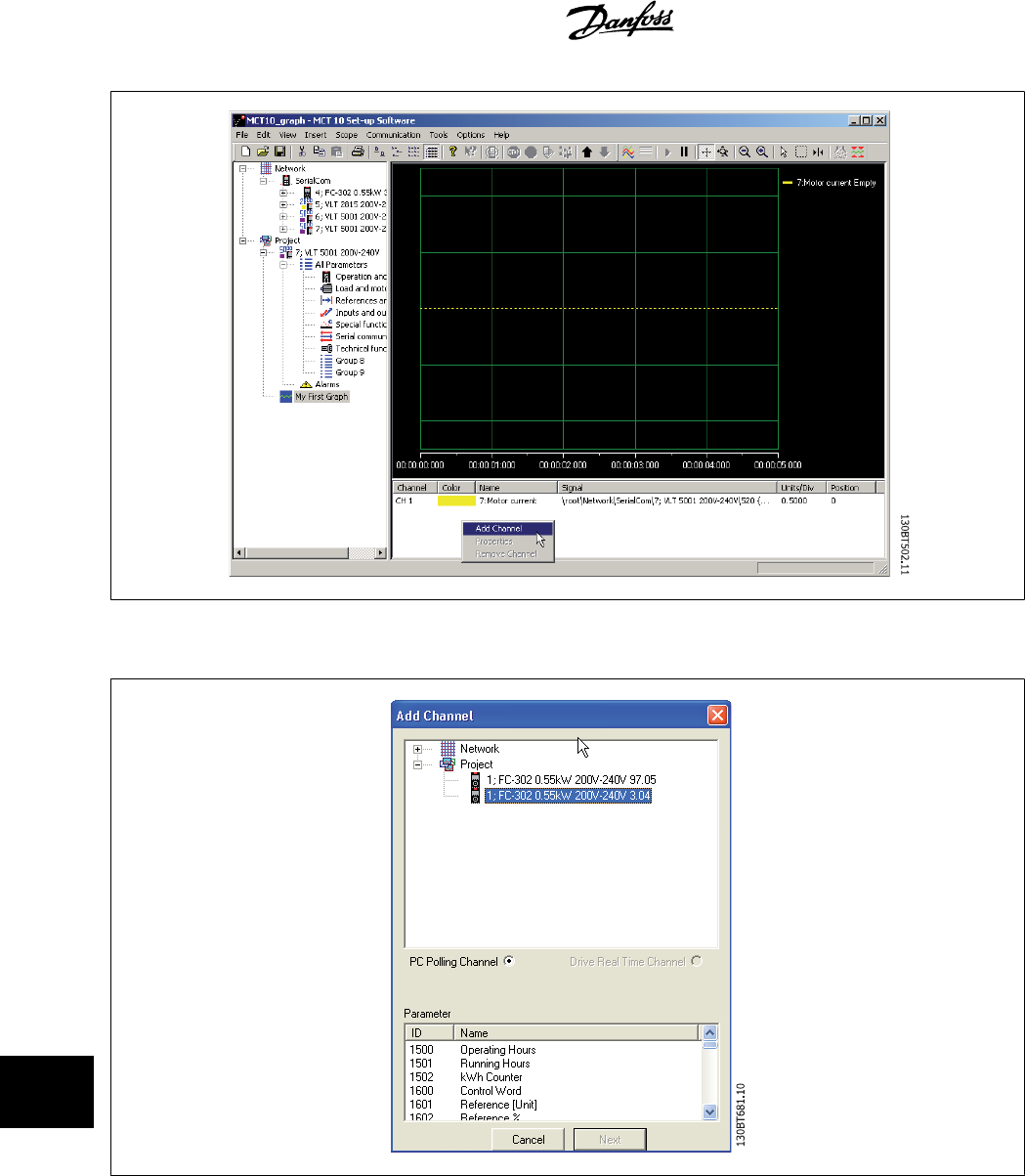
This will activate a new Add Channel Box, which will be handled like the first channel insert.
14 Scope Function MCT 10 Setup Software
76
MG10R302 - VLT is a registred Danfoss trademark
14
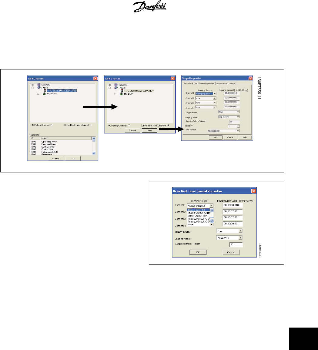
14.5 Initial "Add Channel" (Drive Real Time Channel)
The first time you select the Scope Folder, MCT 10 will pop up with the Add new Channel Box.
In this box you will be able to browse your Network for the drives and
signal that you want to add to your Scope view.
The first task is to select the channel type and to locate the drive that you
want to monitor. The default channel type is PC Polling Channel, which
must be set to Drive Real Time Channel.
By selecting the drive and Drive Real Time Channel, the scope properties
dialog will be shown. In this dialog it is possible to set up a specific num-
ber of channels, depending on what the actual drive supports.
In this example four channels can be configured. In the selection lists
under the Logging source column, the available signals will be shown by
parameter name. In the logging interval column, the sample rate for the
channel can be set.
The trigger set-up is in this example set up to be in continuous mode,
which will have the drive to read data into its internal buffer continuously.
The Samples before Trigger can in this example be ignored.
MCT 10 Setup Software 14 Scope Function
MG10R302 - VLT is a registred Danfoss trademark
77
14
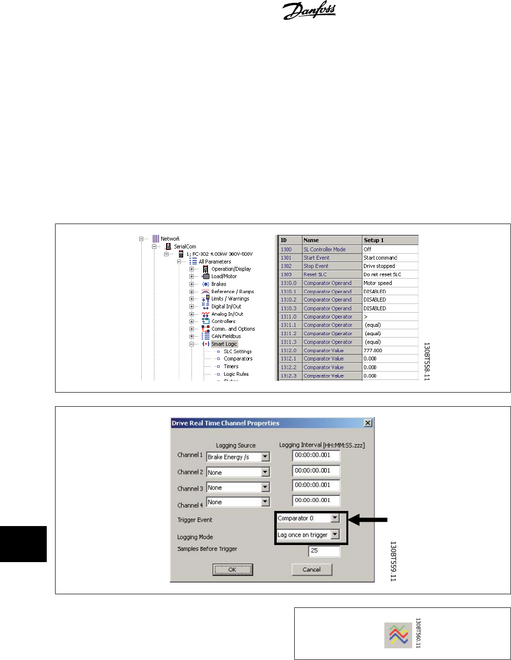
14.6 Using Advanced Triggers in a "Drive Real
The following example explains the set-up of a trigger, which triggers the collection of data in the drive when the motor speed exceeds a certain limit.
First we need to set up a comparator in the Smart Logic Control in order to be able to have a trigger signal when the motor speed exceeds a certain limit.
1. Select the Smart Logic group
2. Select a free available comparator not in use, 1310.0, and set it up to motor speed
3. Select Comparator operate 1311.0 to greater than >.
4. Select Comparator Value 1312.0 to the needed value.
5. Set up the trigger event in the Drive Real Time Channel Properties dialog to Comparator 0, and set the Logging mode to log once on trigger.
Press OK to enable the set-up.
Now the MCT 10 logging can be started by pressing Start (resume) Poll:
14 Scope Function MCT 10 Setup Software
78
MG10R302 - VLT is a registred Danfoss trademark
14
14.7 Communication Control
14.7.1 Communication Control
By now we have pointed out the variable that will be shown. The next vital part of MCT 10 Scope is the control of the Communication Driver. The toolbar
of the Scope has four main buttons for the communication.
Start (Data Acquisition):
This icon controls the driver of MCT 10. By pressing this button the driver of MCT 10 starts collecting the requested
data from the drive network.
Stop (Data Acquisition):
The driver of MCT 10 is stopped no communication to the drive network while the Scope part is active on the screen.
Start (resume) all tracking:
Activating the tracking mechanism of MCT 10 starts the readout of variables to the screen and to the buffer
of MCT 10. Variables are checked up against the trigger settings. If the buffer has been partially filled (use
of the Pause All Tracking button), MCT 10 will continue to fill data into the buffer.
Pause All Tracking:
Deactivates the tracking. Buffer remains at its current state, no new data is entered into the buffer. The buffer pointer
keeps its current value. The screen remains at its current state, no new data is visualised.
MCT 10 Setup Software 14 Scope Function
MG10R302 - VLT is a registred Danfoss trademark
79
14
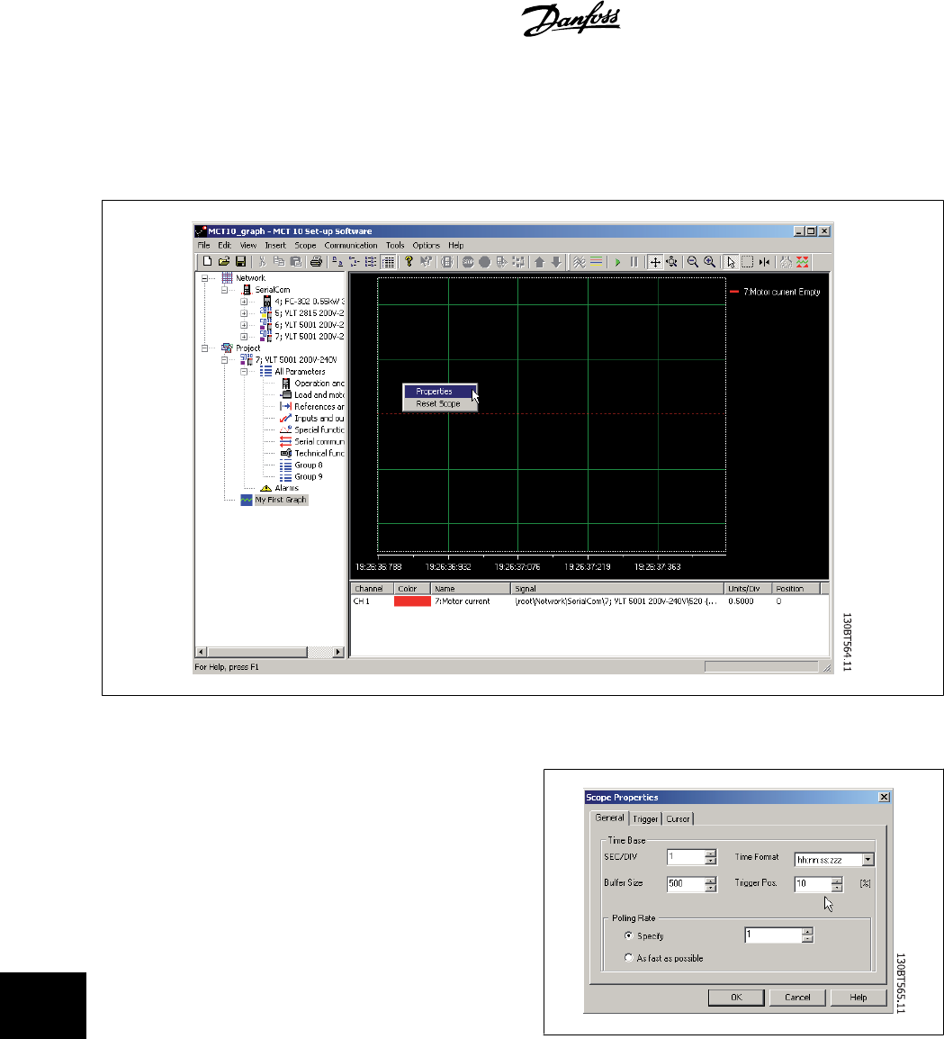
14.7.2 Additional Settings
The Scope tool has more settings, which can be adjusted by right-clicking on the Scope window, and selecting Properties (depending on channel type
the scope properties dialog will differ):
The General tab holds four basic settings for the Scope, seconds per division (SEC/DIV), Time Format, Buffer Size and Polling Rate.
The SEC/DIV sets the time base on the X-axis. The number can be set
between 0.01 sec and 100000 sec. Time format can be set to contain
year, month, date, hour, seconds and milliseconds in eight different for-
mats. The buffer size is the number of data sets in the buffer. The number
can be set to a number between 0 and 1 .000.000
The last of the General setting for the Scope is the Polling Rate. Polling
rate is time in milliseconds between two samples.
For systems with large inertia a high time may be used, since the value
changes slowly. For systems with low inertia a high polling rate (low time
between the samples) is needed. Setting the polling rate to As fast as
possible, lets MCT 10 run without a fixed sample time between each
sample. By doing so, MCT 10 does not control the actual time between
each sample and this can lead to a high jitter between two samples.
14 Scope Function MCT 10 Setup Software
80
MG10R302 - VLT is a registred Danfoss trademark
14
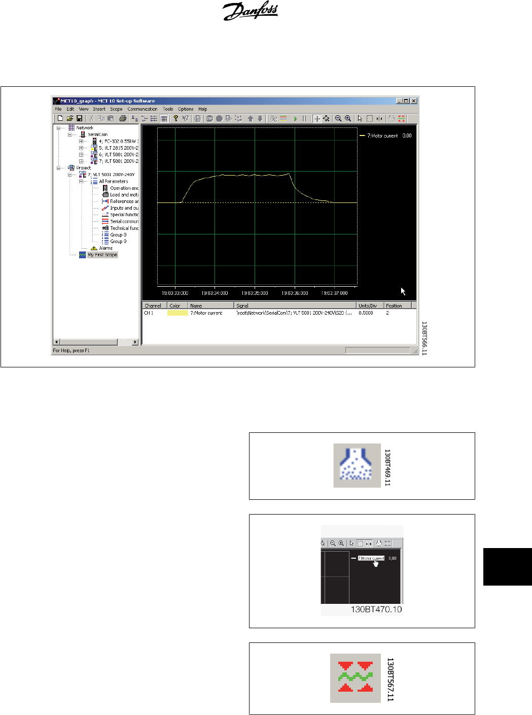
Knowing the first four buttons allows the user to generate a graph out of one drive variable. By selecting the Resume Poll button, MCT 10 starts tracing
the motor current, which based on the motor load can generate a current curve like this:
To stop the tracing press the Stop Poll button or Pause All Tracking. The tracking will continue until the buffer is filled (default 1000 samples). If the
tracing stops due to a filled buffer, the buffer has to be emptied before a new trace can be activated. To clear the buffer and to reset the Scope, the
following two buttons are defined:
Clear all buffer for the channel:
By selecting the trace with:
The buffer for this channel can be individually emptied.
Reset Scope
The reset Scope works in the same way in that it clears all buffers for the
channel. The difference is that it clears all buffers at once. This is more
convenient if many channels are activated at the same time, or if a new
channel is added to an existing track. Before new values can be added to
a track all channel buffers must be emptied, since MCT 10 requires that
all buffers have the same amount of data.
MCT 10 Setup Software 14 Scope Function
MG10R302 - VLT is a registred Danfoss trademark
81
14
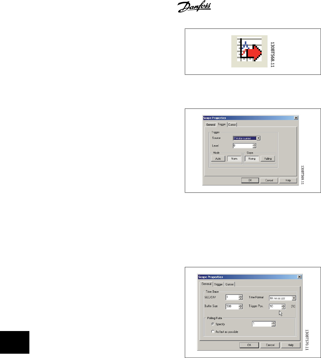
Export to Excel
The export to Excel enables the user to have the scope data stored in a
file which Microsoft Excel can open.
A save file dialog will appear, so the user can store the file in an appro-
priate place.
14.8 Triggers
A trigger is a tool that allows only starting the sampling of values when
a certain value is reached. This will reduce the need for large buffer sizes.
A trigger is also a valuable tool to see if values cross border where the
drive does not store any warnings.
Setting up Trigger:
By right-clicking on the Scope window and selecting Properties (See un-
der Polling Rate) the property for the Scope is brought up.
Under the Trigger tab the Source for triggering, the level for activating,
Mode and Slope for the trigger can be set.
The source is selected out of the channels that are currently active. The level is the level for the source where the Trigger has to be activated. For Mode,
there are two different modes, Auto and Normal. With Auto the user will trigger the trigger automatically by pressing the Resume All button. This means
that the trigger line will be set to the time when the user pressed the Resume button. Selecting Normal (Norm) the trigger is activated when the level
and the slope settings are fulfilled. The slope sets if the value has to be rising (source value goes from low values to higher values) or the slope has to
be falling (source value goes from high values to low values).
14.8.1 Trigger Position
In many cases it is worth knowing what happens before the trigger is
activated. This can be achieved by setting the trigger position value to a
value different from the default, which is 0%. If the buffer has a size of
1000 samples and the trigger position is set to 10%, the buffer will con-
tain 100 samples before the triggering point and 900 after the triggering
point.
14 Scope Function MCT 10 Setup Software
82
MG10R302 - VLT is a registred Danfoss trademark
14
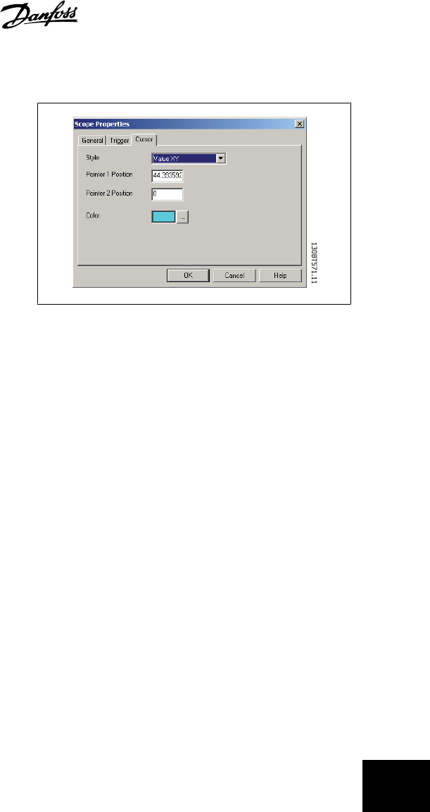
14.8.2 Cursors
To evaluate a trace or show the actual values of the buffer, the cursor is
used to point out the data. The Cursor tab contains four different settings:
The style contains six different possibilities:
Value XY
Value X
Value Y
Delta X
Delta Y
Inverse Delta X
Value XY shows the time and value of each signal at the cursor location,
Value X the time alone. Value Y the value alone. Delta X shows two cur-
sors, and the time between the two cursors are calculated. Delta Y works
like Delta X, but this time the difference between two levels is calculated.
MCT 10 Setup Software 14 Scope Function
MG10R302 - VLT is a registred Danfoss trademark
83
14

15 Update Drives Firmware Support in MCT 10 MCT 10 Setup Software
84
MG10R302 - VLT is a registred Danfoss trademark
15
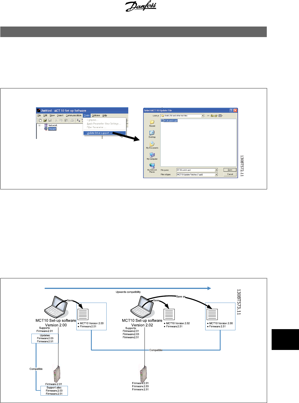
15 Update Drives Firmware Support in MCT 10
MCT 10 can be updated, regarding what firmware versions of drives are supported.
The updates must manually be downloaded from the Danfoss Drives web-site http://www.vlt-software.com for storage on local disk drive. It is also
possible to find video training material on this site for operating MCT10.
The update files can be installed without the user having administrator rights in Microsoft operating systems, which has been a major disadvantage for
standard users which were not allowed to install software on their computers (laptops).
15.2 Background Details
MCT 10 project files are in principle having the same features as Microsoft Office Word. Newer versions of MCT 10 can open legacy version project files.
The example in the illustration below visualises a version 2.00 of MCT 10 supporting offline the firmware version 2.01 of FC 302. This file can be used by
the newer version 2.02 of MCT 10. However, if a project file from the newer version 2.02 of MCT 10 containing firmware version 2.51 of FC 302 cannot
be opened or used offline by the legacy version 2.00 of MCT 10, since the firmware is unknown.
MCT 10 Setup Software 15 Update Drives Firmware Support in MCT 10
MG10R302 - VLT is a registred Danfoss trademark
85
15
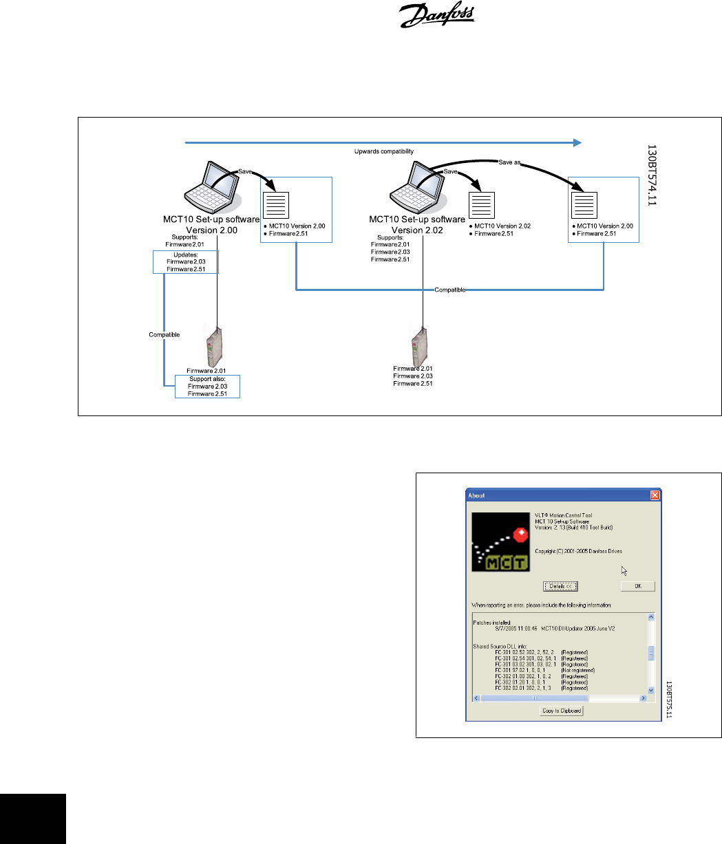
When MCT 10 has been updated, project-files saved as with newer version firmware can be opened and used. This scenario is shown in the below
example.
15.3 How to Find Out if MCT 10 Has Been Updated
Finally MCT 10 can be checked in the About box, regarding what updates
the user has installed.
Also when contacting the hot-line support, system information can be
copied directly to the Windows Clipboard.
15 Update Drives Firmware Support in MCT 10 MCT 10 Setup Software
86
MG10R302 - VLT is a registred Danfoss trademark
15
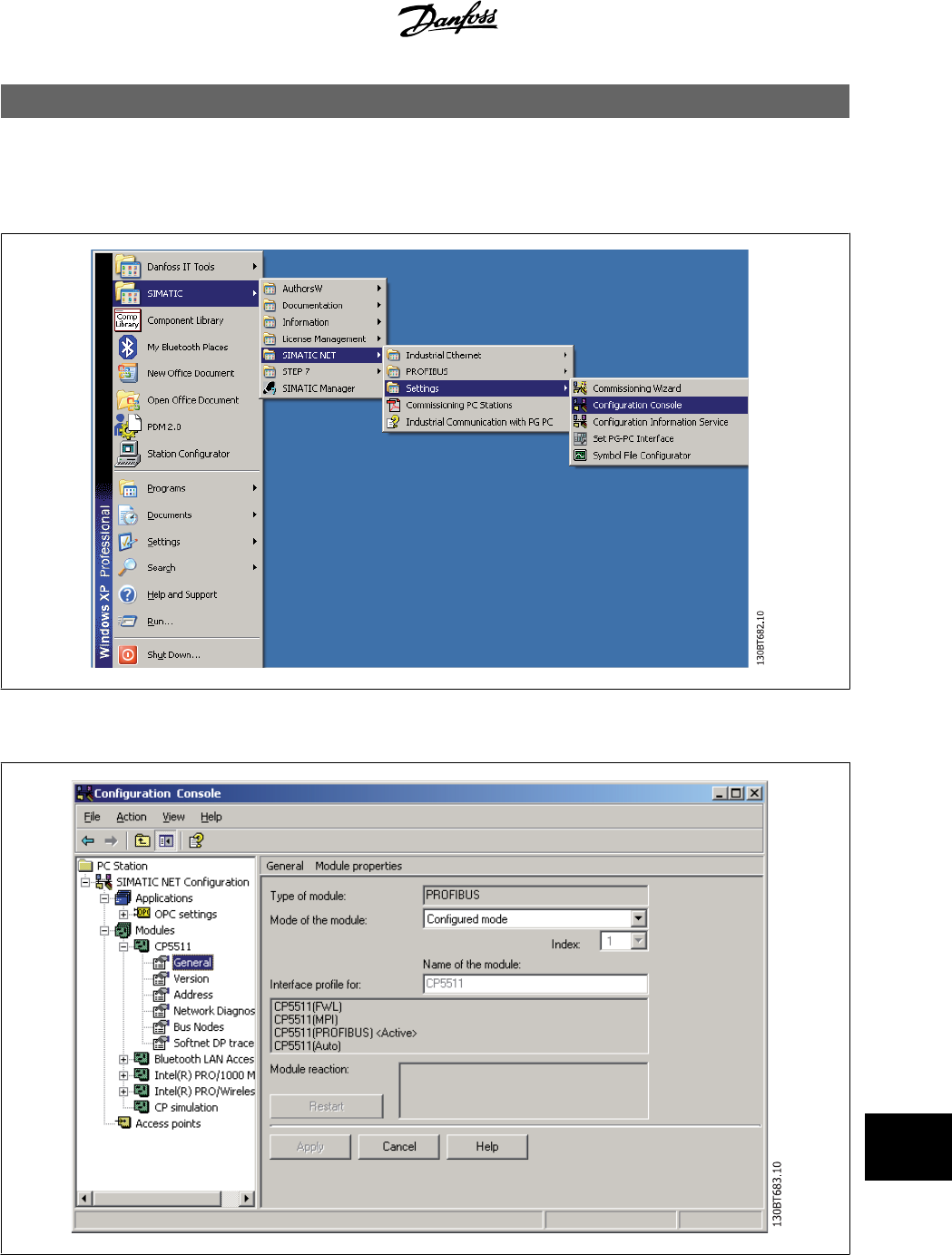
16 Guide to DP V1 Connection and Simatic Manager
The following guide explains how set-up SIMATIC NET to work together with MCT10.
Start Configuration Console:
Set the Mode of the module to Configure mode and press apply:
Close the Configuration Console.
MCT 10 Setup Software 16 Guide to DP V1 Connection and Simatic
Manager
MG10R302 - VLT is a registred Danfoss trademark
87
16
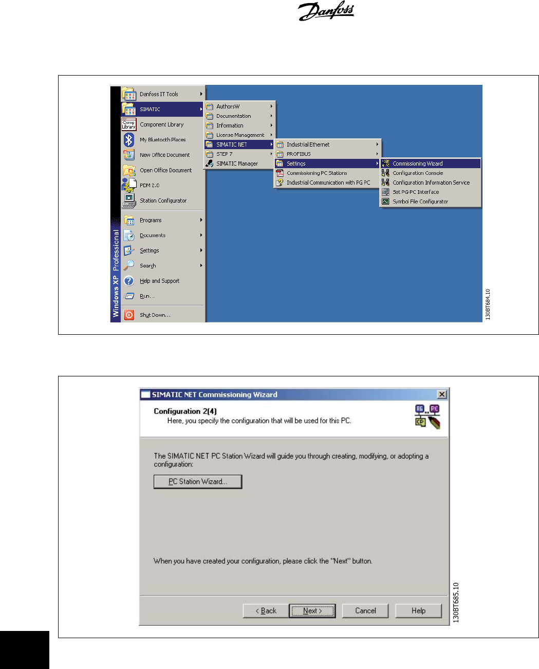
Start
Commissioning Wizard
:
Press
Next
and the following screen is shown:
16 Guide to DP V1 Connection and Simatic
Manager MCT 10 Setup Software
88
MG10R302 - VLT is a registred Danfoss trademark
16
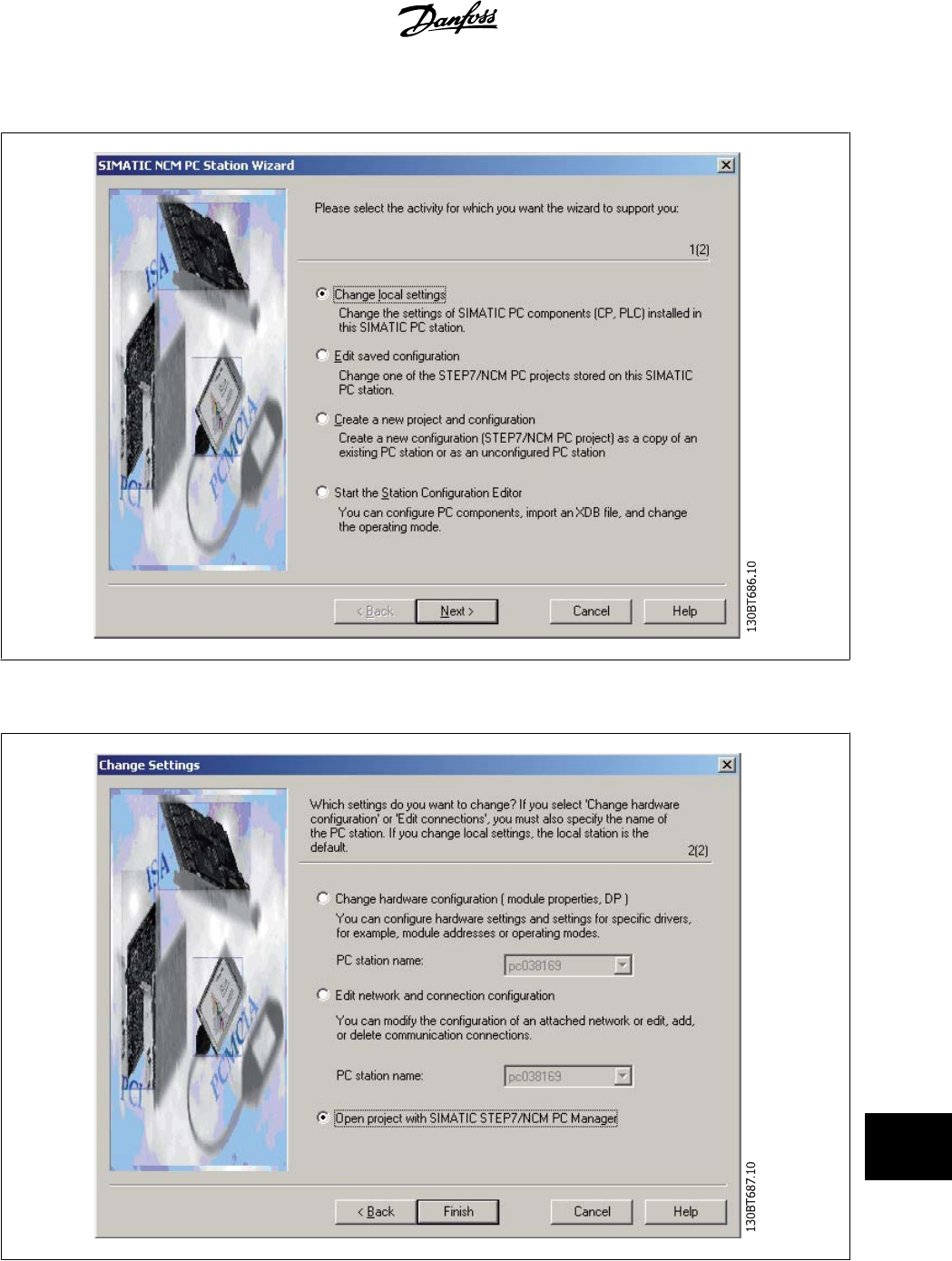
Press on
PC Station Wizard
and
Change local setting
and then on
Next
:
Choose
Open project with Simatic Step7/NCM PC Manager
:
Simatic Manager is now opening a new project.
MCT 10 Setup Software 16 Guide to DP V1 Connection and Simatic
Manager
MG10R302 - VLT is a registred Danfoss trademark
89
16
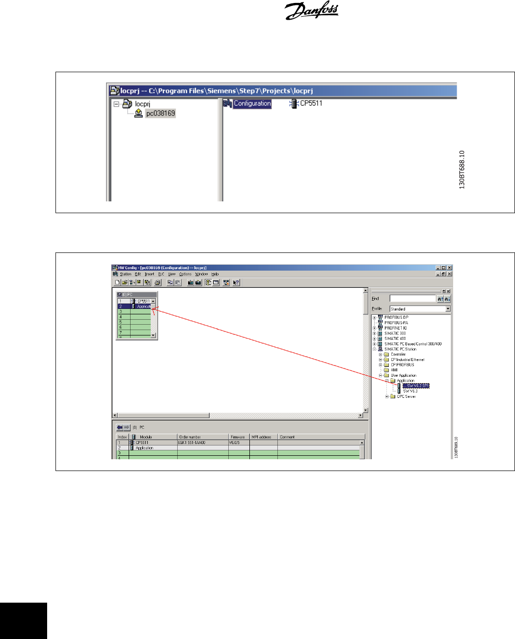
Open
Configuration
:
Drag and Drop a Application to the PC index 2.
16 Guide to DP V1 Connection and Simatic
Manager MCT 10 Setup Software
90
MG10R302 - VLT is a registred Danfoss trademark
16
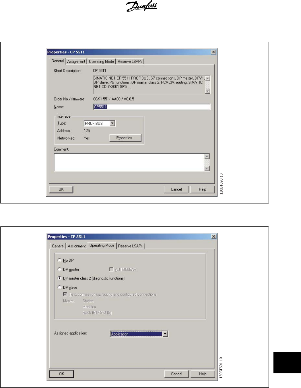
Open the properties on your Master Class 2 card (here shown as a CP5511 card).
Press on
Operating Mode
and select
DP master class 2
and assign an Application. Press on
OK
and on
Save and Compile
.
MCT 10 Setup Software 16 Guide to DP V1 Connection and Simatic
Manager
MG10R302 - VLT is a registred Danfoss trademark
91
16
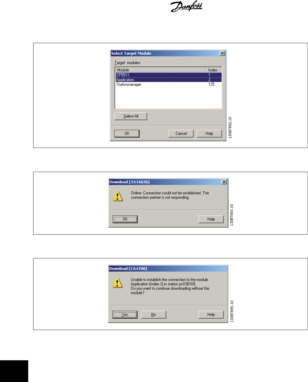
Press on Download and select to download CP5511 (index 1) and the Application (index 2).
Press OK and also OK to the Warning:
Press Yes to this Warning:
Press OK to Stop Target Modules and the download and setup of the CP5511 card is completed. Close Simatic Manager.
16 Guide to DP V1 Connection and Simatic
Manager MCT 10 Setup Software
92
MG10R302 - VLT is a registred Danfoss trademark
16
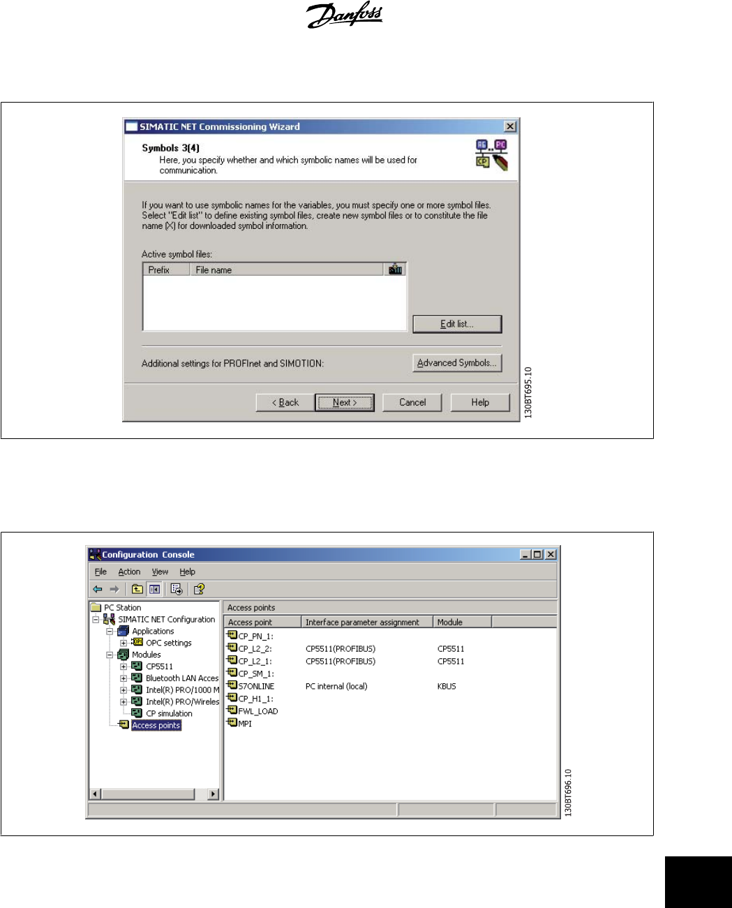
Click on Simatic Net Commissioning Wizard and on
Next
.
Click on Next again and click on finished.
By Configuration Console and by
Access points
set the CP_L2_1 and CP_L2_2 Interface parameter assignment to
CP5511(PROFIBUS)
.
Set the Mode of the module from
Configure mode
to
PG Operation
and press apply and OK.
Close the program.
MCT 10 Setup Software 16 Guide to DP V1 Connection and Simatic
Manager
MG10R302 - VLT is a registred Danfoss trademark
93
16
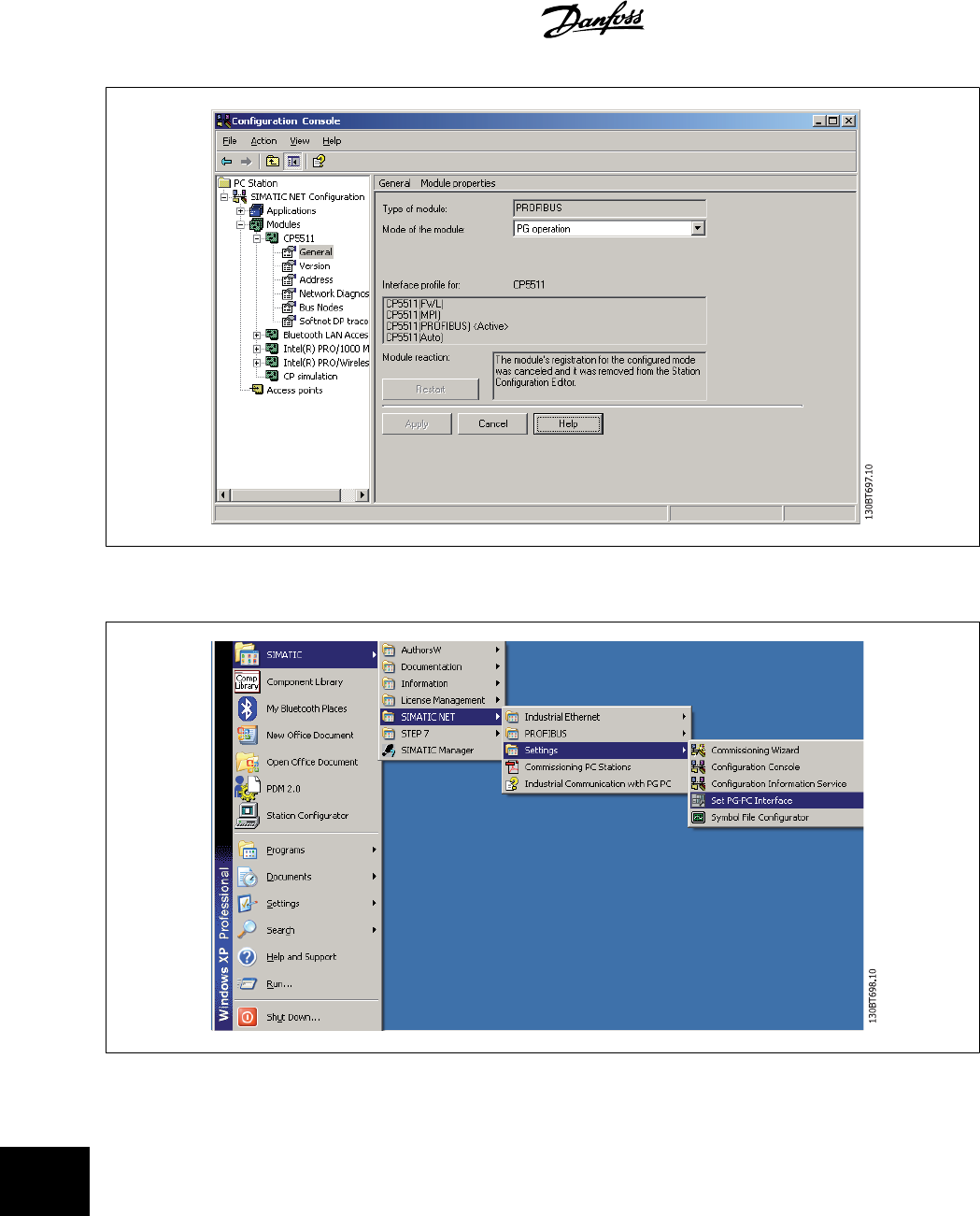
Open the
Set PG-PC Interface
:
16 Guide to DP V1 Connection and Simatic
Manager MCT 10 Setup Software
94
MG10R302 - VLT is a registred Danfoss trademark
16
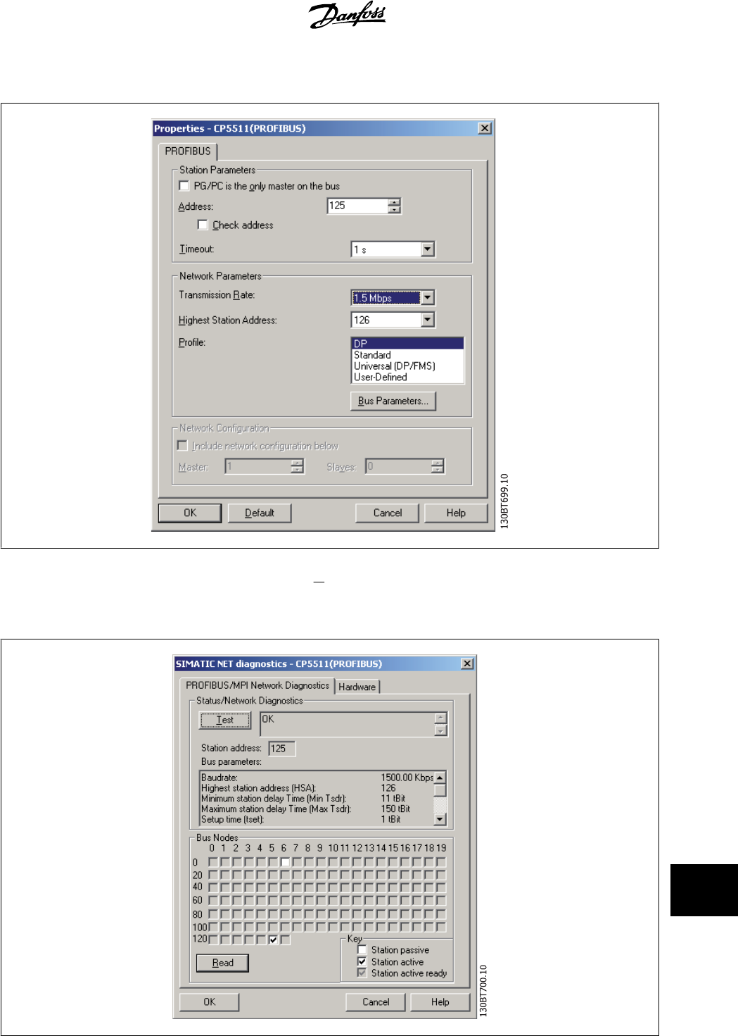
Set
Interface Parameter Assignment Used
to CP5511(Profibus) and click on Properties:
The tag
PG/PC is the only master on the bus
should only be set active if no PLC is active on the bus. Set the Transmission Rate (Baud Rate) to the same
baud rate as the PLC and click on OK. Click on
Diagnostic
and on
Test
and
Read
and the CP5511 card will read all nodes on the Profibus network. In this
example it finds a Slave on address 6.
MCT 10 Setup Software 16 Guide to DP V1 Connection and Simatic
Manager
MG10R302 - VLT is a registred Danfoss trademark
95
16
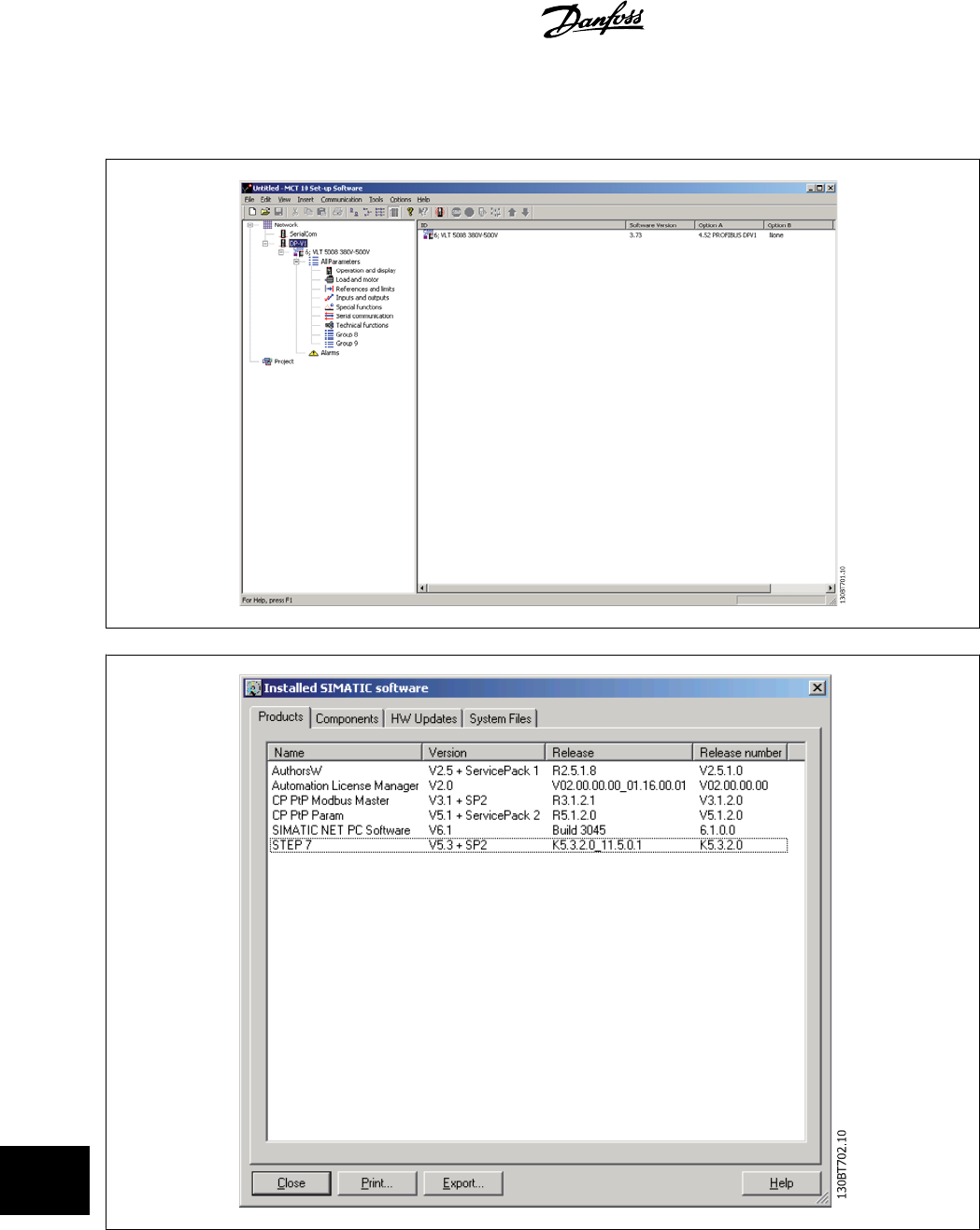
Open MCT 10 and a DPV1 connection should be detected by
Network
.
In this example a VLT 5000 is found at address 6.
16 Guide to DP V1 Connection and Simatic
Manager MCT 10 Setup Software
96
MG10R302 - VLT is a registred Danfoss trademark
16
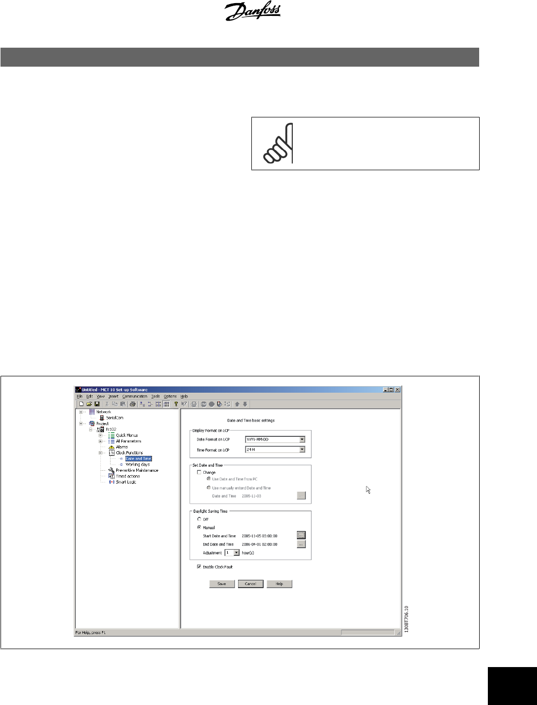
17 FC 102 and FC 202 Series Functions
17.1 New Features
In MCT 10 there is added special support for some new features in the
FC 10x series of frequency converters.The following section describes
how to access and set these new features.
NB!
Consult the FC 102 and FC 202 design guide for de-
tailed functionality of the frequency converters.
17.1.1 Clock Features
MCT 10 supports the clock features in FC102, by means of intuitive dialogs, enabling the user to set-up the clock features
The Clock Features are grouped in two sub-levels:
1. Date and Time
2. Working days
17.1.2 Date and Time
In the Date and Time dialog, the user can see three groups of settings:
Display format on LCP:
In this group the user can select how to get date and time presented on the local control panel on the FC102. In MCT10 parameters Date and Time
format depends on PC Regional Options (Date and Time format).
MCT 10 Setup Software 17 FC 102 and FC 202 Series Functions
MG10R302 - VLT is a registred Danfoss trademark
97
17
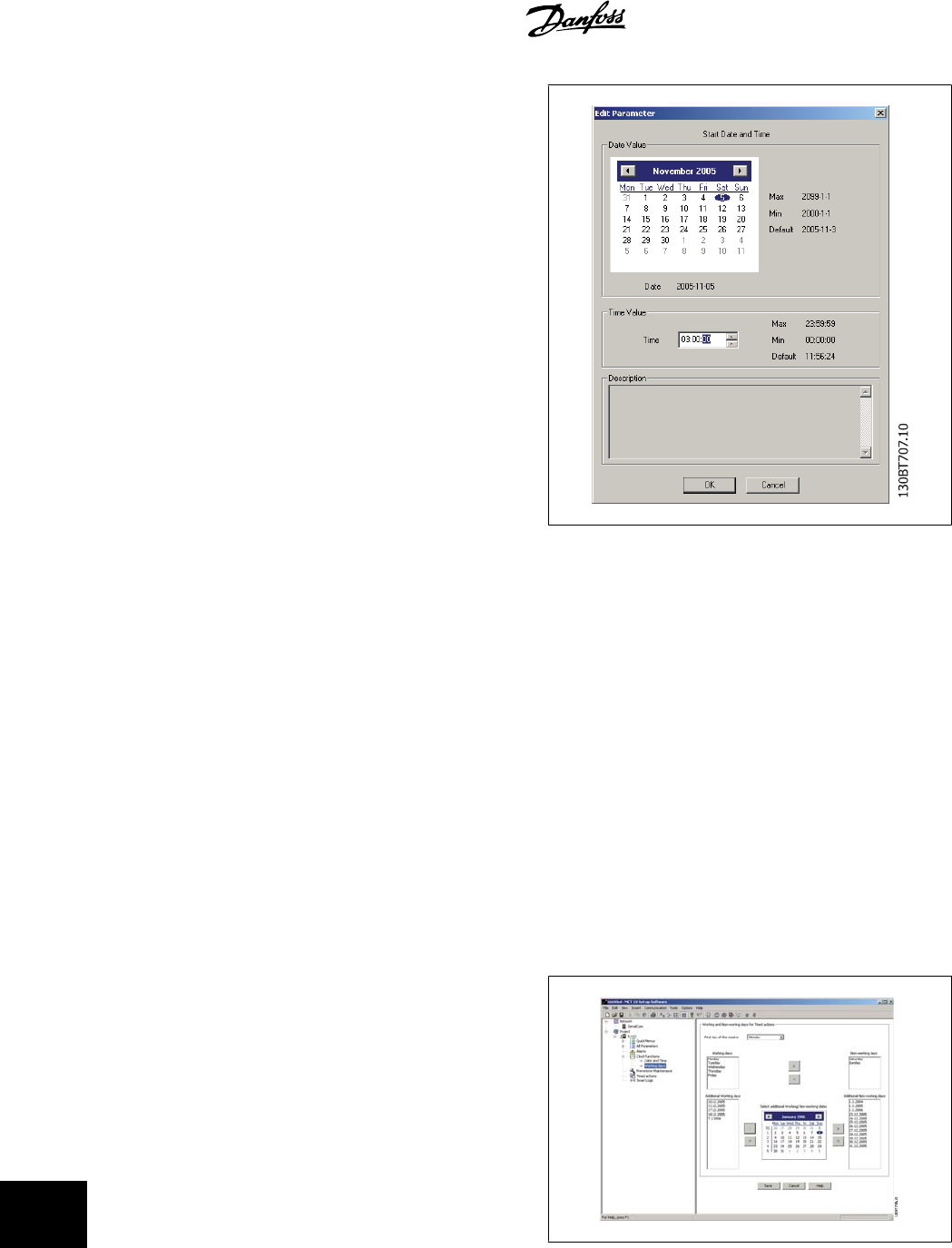
Set Date and Time:
In this group the user can actively select to change the date and time in
the FC102 from the PC. Normally it should be set to use the local PC’s
date and time, connected. When the connected PC’s time is in another
time zone, then it can be beneficial to set the date and time manually.
Date and time will be changed in MCT10 project file or in drive only when
"Change" check box is checked.
Setting the date and time manually, this dialog appears.
Daylight Saving Time:
In this group the user can set the date and time for daylight saving.
Daylight Saving Time begins for most of the United States at 2:00 a.m. on the first Sunday of April. Time reverts to standard time at 2:00 a.m. on the
last Sunday of October. In the U.S., each time zone switches at a different time. In the European Union, Summer Time begins and ends at 1:00 a.m.
Universal Time (Greenwich Mean Time). It begins the last Sunday in March and ends the last Sunday in October. In the EU, all time zones change at the
same moment.
Enable Clock Fault:
If the clock is not set up, then the drive shows a specific warning. (Also MCT10 shows warning in Warnings folder). If the user does not want to set up
clock or can not set up clock then he probably also does not want to see this warning all the time. For that case is the parameter Clock Fault. If Clock
fault is enabled, the user can see this specific warning and if clock fault is disabled then user can not see the warning.
Enable Clock Fault is checked - drive is showing warning.
Enable Clock Fault is unchecked - drive is not showing warning.
17.1.3 Working Days
In the Working days dialog, the user can easily define the working days
for time based actions.
Start of the week can be Monday or Sunday. The visual Calendar will
change.
Only 5 additional working days (dates) are allowed.
Only 15 additional non-working days (dates) are allowed.
Please notice Additional working dates and non-working dates have year and must be updated every year.
17 FC 102 and FC 202 Series Functions MCT 10 Setup Software
98
MG10R302 - VLT is a registred Danfoss trademark
17
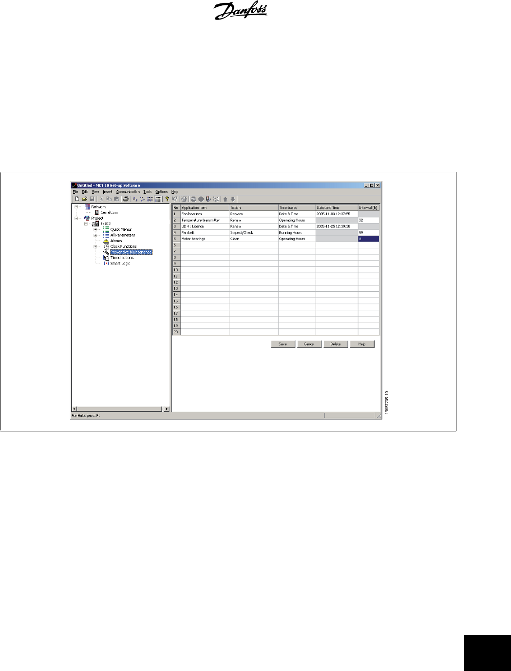
17.2 Preventive Maintenance
The intension of the “preventive maintenance” feature is to provide the user’s with the capability to plan periodic maintenance of both the drive and other
technical equipment within the same plant. Preventive maintenance should be seen as time based scheduling of periodic checks that manually should be
done.
In the right view grid, it is possible by means of double clicking in the cells to activate dialogs to enter application item, action and how the interval must
be defined.
The clock parameters (parameters in the Clock Functions folder) must be correctly programmed for Preventive Maintenance to function correctly.
If Preventive Maintenance item Date and Time is passed then the line is marked as red.
Before writing new Preventive items to FC102 do not forgot to reset Maintenance Word (par 23-15).
17.3 Times Actions
MCT 10 can by means of an intuitive user interface, easily setup the possible “time based actions” supported in the FC102.
The purpose of “Time-based Actions” is to automate the drive by giving the user the possibility to define real-time controlled events. The basic idea is to
have a possibility to define time of day and which day(s) of the week, when the drive automatically must perform a selected action.
In this way the user doesn’t have to execute the actions defined manually, instead the drive automatically does the job on the days needed.
The programmed actions will be repeated on a weekly basis. Additional working days and additional non-working days can be programmed.
The clock parameters (parameters in the Clock Functions folder) must be correctly programmed for Timed Actions to function correctly.
Actions, which can be programmed, are the same as known from the SLC (Smart Logic Controller).
MCT 10 Setup Software 17 FC 102 and FC 202 Series Functions
MG10R302 - VLT is a registred Danfoss trademark
99
17
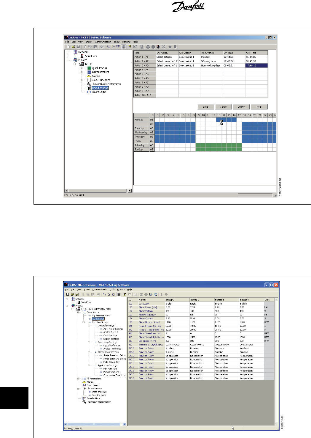
It is easy to by means of double clicking in the cells to activate dialogs to enter the required data.
17.4.1 Quick Menus
The quick menus can be viewed in MCT 10.
The quick menus allow easy access to the relevant parameters for specific application setup. The user should just follow the steps through the tree-view
in MCT10 as on the LCP on the drive.
17 FC 102 and FC 202 Series Functions MCT 10 Setup Software
100
MG10R302 - VLT is a registred Danfoss trademark
17
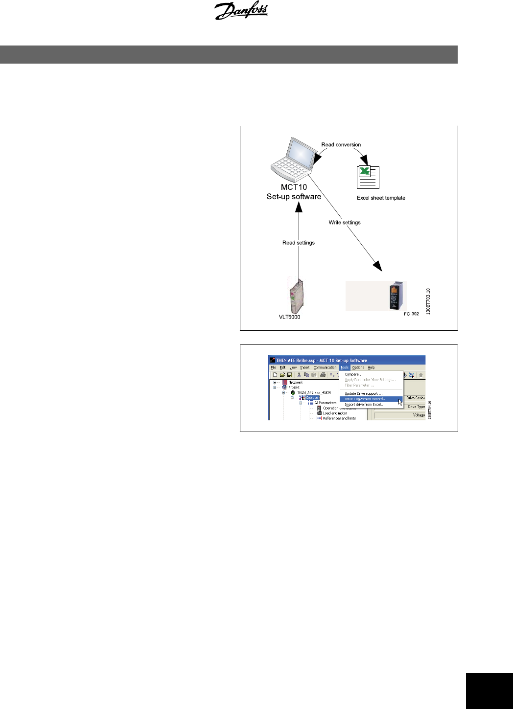
18 VLT to FC Series Converter Function
In MCT10 it is possible to have a VLT5000 drive in the project folder converted to a FC302 Automation Drive. This is easy done by means of a build in
function in MCT10.
Easy converting in MCT10:
The conversion matrix (Excel sheet) can be edited by the Advanced user,
when necessary.
Easy conversion of multiple drives:
• Select the Tools menu and activate the “Drive Conversion Wiz-
ard” item
• In the following dialogs select the drives for conversion.
• When converted a new FC302 drives will be created in the
project folder.
MCT 10 Setup Software 18 VLT to FC Series Converter Function
MG10R302 - VLT is a registred Danfoss trademark
101
18
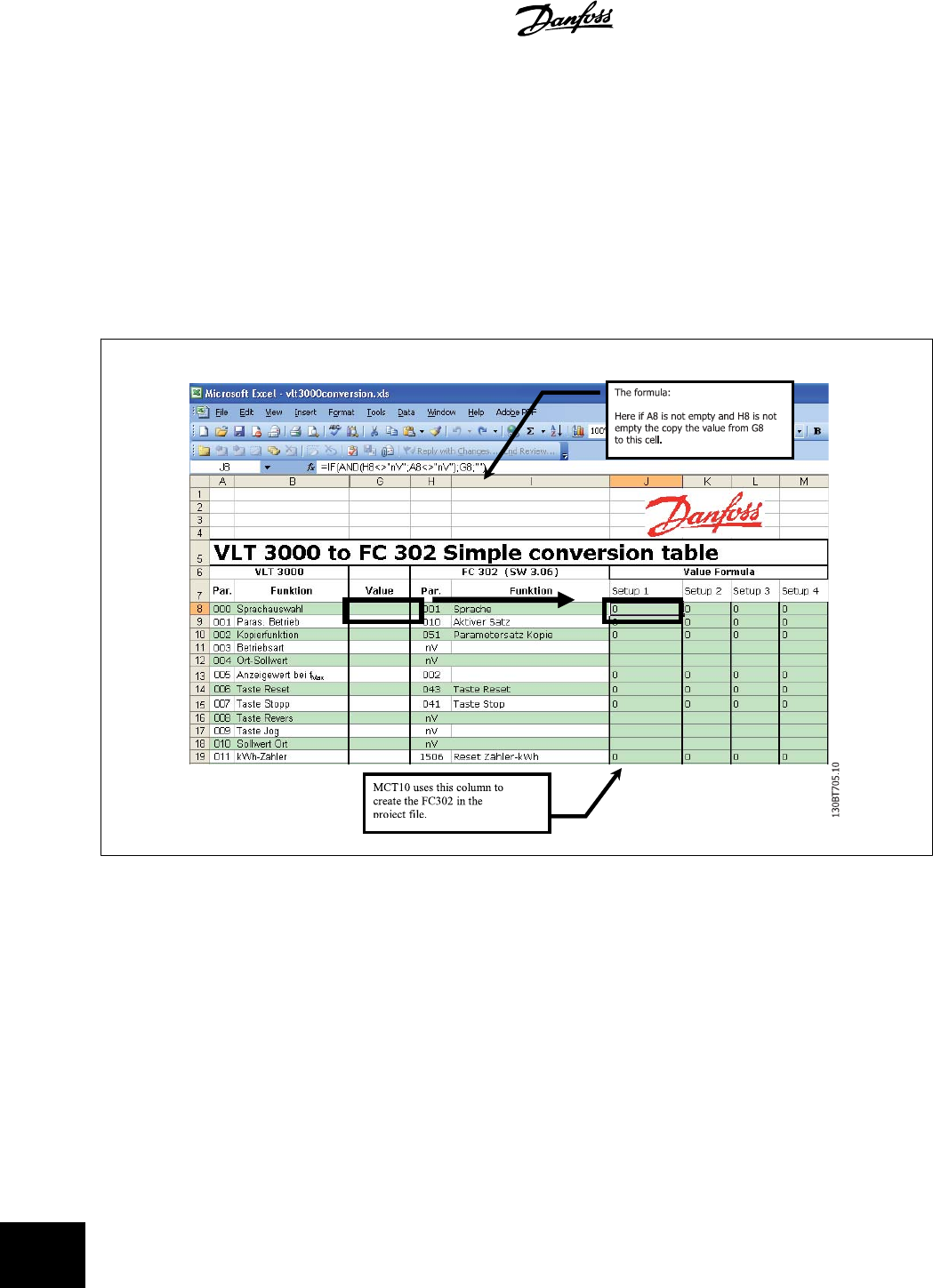
18.2 Import Drive from Excel
This function can create an FC30x drive out from an Excel sheet. The objective with this function is that the user himself can import VLT3000 settings,
from settings copied into an excel sheet and have these settings copied into the selected parameter numbers into a new FC302.
An example file is attached in MCT10 (vlt3000conversion.xls), this example file can be edited by the user and be used for converting from vlt3000 to
FC302. This requires however that the user must have detailed knowledge of Microsoft Excel formula editing.
The user must enter VLT3000 settings into column G8 !
18 VLT to FC Series Converter Function MCT 10 Setup Software
102
MG10R302 - VLT is a registred Danfoss trademark
18
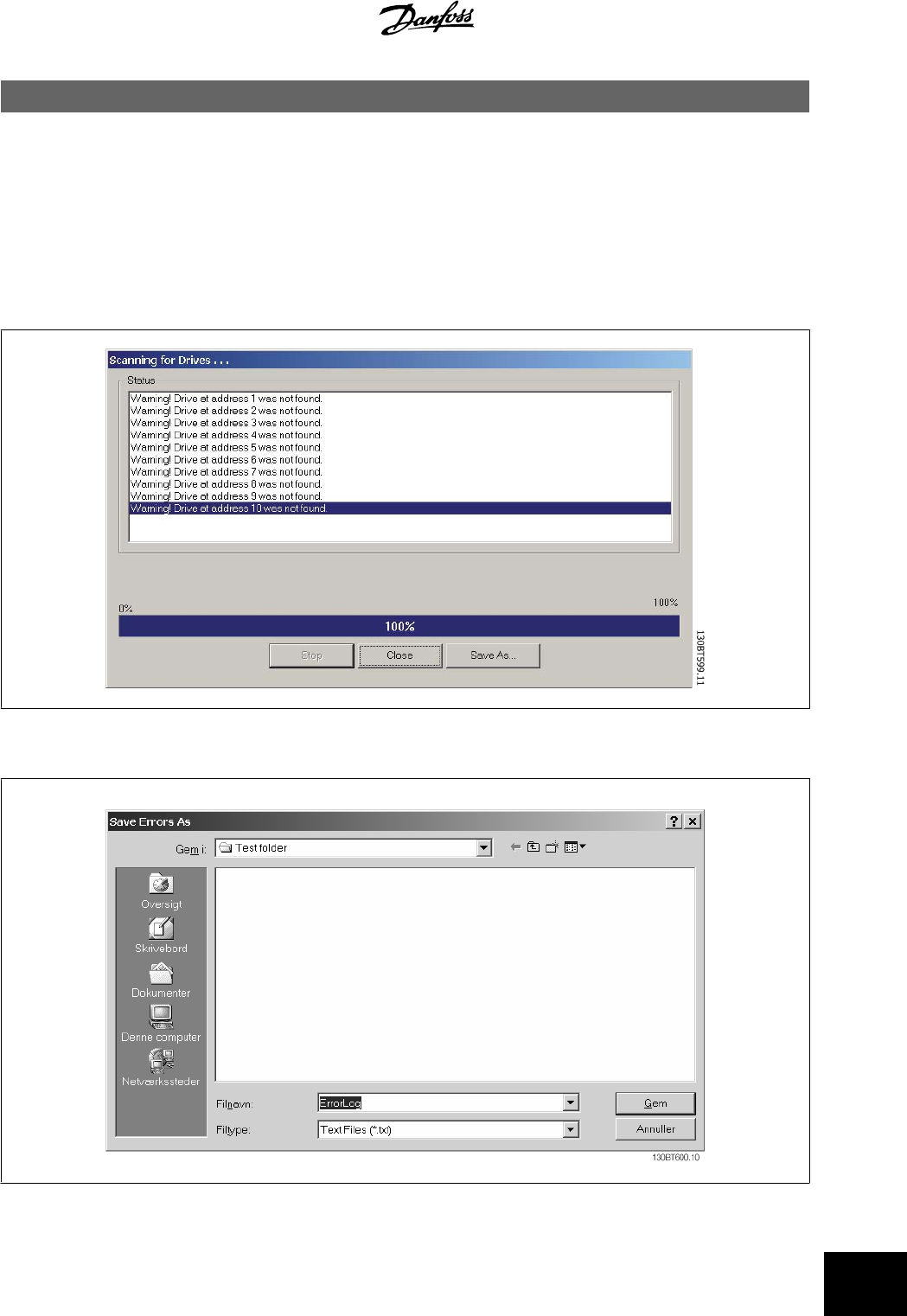
19 Troubleshooting
19.1 Save Error Dialog
When an error dialog appears on the screen MCT 10 has a facility for saving to a text file to record the error message for later reference, for example to
obtain help from Support. Within the error dialog window, select the option Save As and you will be able to record the error message as a text file with
free choice of file name and location.
For example, when scanning the network for frequency converters, an error dialog will appear showing the frequency converters not detected:
Select Save As.. to store the error log and the following dialog will appear:
MCT 10 Setup Software 19 Troubleshooting
MG10R302 - VLT is a registred Danfoss trademark
103
19
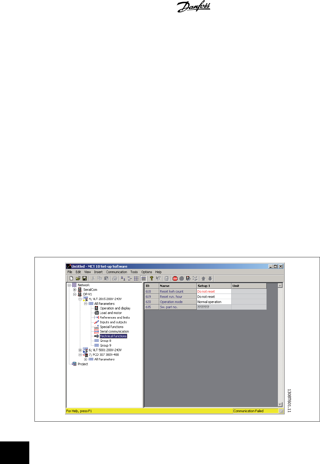
19.2 Common Problems and Solutions
19.2.1 Changes Are Not Saved to PC
Checks that changes made in the Network folder have been copied over to the Project folder, and then saved to a directory on the users hard disk.
Changes made in the Network folder are implemented in the field device only, and are not automatically saved to a PC.
19.2.2 Error Message Whilst Installing MCT 10 Setup Software
Message such as "MCT-10 SET UP SOFTWARE ERROR OPENING FC DRIVER" This error may occur if there is a second PC program installed, using the
same COM port of the PC. Such a program could be a PLC programming tool, Palm pilot driver or Cellular Phone driver etc. Investigate whether other
programs use the same COM port. If this is the case make sure that the other PC tool does not lock or reserve the COM port.
Error message whilst storing parameter settings and reading / writing via Profibus DP V1 using the function Database readout from the Drive.
19.2.3 Error Message Communication Failed
The communications error comes and goes sporadically:
This type of communications error typically occurs when cables are inadequately screened, in which case EMC noise can affect the communications. Check
that the cables are installed according to the guidelines in the Operating Instructions for the frequency converter.
The communications error is permanent:
This type of communications error is typically due to an error in network configuration. Check that the network configuration is in accordance with the
frequency converter Operating Instructions guidelines.
The Communication Failed error message appears in the status bar as shown:
19 Troubleshooting MCT 10 Setup Software
104
MG10R302 - VLT is a registred Danfoss trademark
19
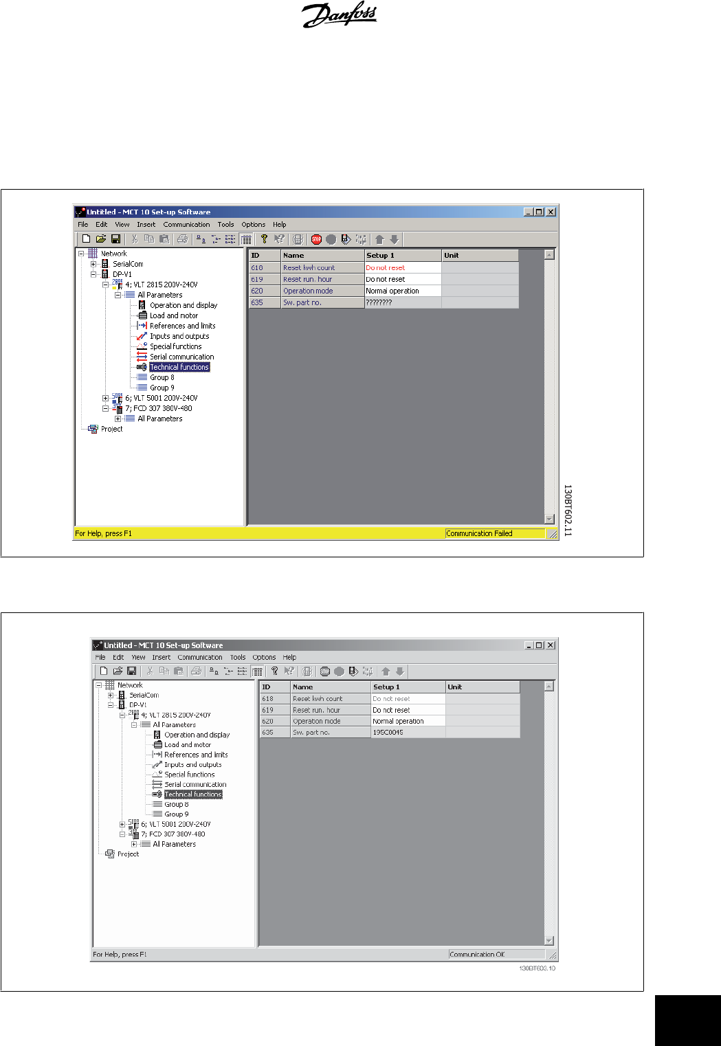
19.2.4 Communication Errors
If an erroneous/illegal action has been attempted, an error highlight will appear in the status bar at the bottom of the MCT 10 window.
When a communications error arises, the status bar at the bottom of the MCT 10 window will be highlighted and display a
Communications Failed
error
message, as shown in the following example:
When no communications error has occurred the same window will appear as:
Communications errors typically occur due to inadequate screening of cables, i.e. cable is not installed in accordance with installation instructions.
MCT 10 Setup Software 19 Troubleshooting
MG10R302 - VLT is a registred Danfoss trademark
105
19
