Cameron Drilling Products Equipment And Services Overview Catalog
User Manual: Drilling Products Overview Catalog Resource Library
Open the PDF directly: View PDF ![]() .
.
Page Count: 84
Drilling Products Overview
Total rig package solutions for your drilling needs

2

Content
Total rig packages solutions . . . . . . . . . . . . . . . . . . . . . . . . . . . . . . . 4
Drilling pressure control equipment
Blowout preventers (BOPs) . . . . . . . . . . . . . . . . . . . . . . . . . . . . . . . . 6
Rams and ram packers . . . . . . . . . . . . . . . . . . . . . . . . . . . . . . . . . . . . . . 8
Connectors . . . . . . . . . . . . . . . . . . . . . . . . . . . . . . . . . . . . . . . . . . . . . . . . . . . 10
ESG system . . . . . . . . . . . . . . . . . . . . . . . . . . . . . . . . . . . . . . . . . . . . . . . . . . 11
Capping stack . . . . . . . . . . . . . . . . . . . . . . . . . . . . . . . . . . . . . . . . . . . . . . . 12
Riser systems . . . . . . . . . . . . . . . . . . . . . . . . . . . . . . . . . . . . . . . . . . . . . . . 14
Diverters . . . . . . . . . . . . . . . . . . . . . . . . . . . . . . . . . . . . . . . . . . . . . . . . . . . . . . 17
BOP controls and monitoring systems . . . . . . . . . . . . . . . . 18
Manifold systems . . . . . . . . . . . . . . . . . . . . . . . . . . . . . . . . . . . . . . . . . . 22
Valves . . . . . . . . . . . . . . . . . . . . . . . . . . . . . . . . . . . . . . . . . . . . . . . . . . . . . . . . . 27
Drilling equipment
HMI and controls systems . . . . . . . . . . . . . . . . . . . . . . . . . . . . . . . 30
OnTrack system . . . . . . . . . . . . . . . . . . . . . . . . . . . . . . . . . . . . . . . . . . . . . 32
Drawworks . . . . . . . . . . . . . . . . . . . . . . . . . . . . . . . . . . . . . . . . . . . . . . . . . . . 36
Equipment . . . . . . . . . . . . . . . . . . . . . . . . . . . . . . . . . . . . . . . . . . . . . . . . . . . 39
Top drive systems . . . . . . . . . . . . . . . . . . . . . . . . . . . . . . . . . . . . . . . . . . 41
Vertical pipe handling systems . . . . . . . . . . . . . . . . . . . . . . . . . 43
Horizontal pipe handling systems . . . . . . . . . . . . . . . . . . . . . . 45
Pipe deck crane . . . . . . . . . . . . . . . . . . . . . . . . . . . . . . . . . . . . . . . . . . . . . 47
Drillfloor pipe handling equipment . . . . . . . . . . . . . . . . . . . . 48
Hydraulic roughnecks . . . . . . . . . . . . . . . . . . . . . . . . . . . . . . . . . . . . . 49
Drillfloor tools . . . . . . . . . . . . . . . . . . . . . . . . . . . . . . . . . . . . . . . . . . . . . . . 52
Cellar deck equipment . . . . . . . . . . . . . . . . . . . . . . . . . . . . . . . . . . . . 53
Stab-in connection system . . . . . . . . . . . . . . . . . . . . . . . . . . . . . . . 55
Hydraulic power units . . . . . . . . . . . . . . . . . . . . . . . . . . . . . . . . . . . . . 56
Motion compensation equipment . . . . . . . . . . . . . . . . . . . . . . 57
Drilling derricks . . . . . . . . . . . . . . . . . . . . . . . . . . . . . . . . . . . . . . . . . . . . . 61
Well intervention packages . . . . . . . . . . . . . . . . . . . . . . . . . . . . . . 62
Total drilling fluid solutions
Mud control system . . . . . . . . . . . . . . . . . . . . . . . . . . . . . . . . . . . . . . . 66
Mud mixing system . . . . . . . . . . . . . . . . . . . . . . . . . . . . . . . . . . . . . . . . 68
Bulk storage and transfer system . . . . . . . . . . . . . . . . . . . . . . 70
Mud treatment system . . . . . . . . . . . . . . . . . . . . . . . . . . . . . . . . . . . . 72
Low-pressure system . . . . . . . . . . . . . . . . . . . . . . . . . . . . . . . . . . . . . . 73
High-pressure system . . . . . . . . . . . . . . . . . . . . . . . . . . . . . . . . . . . . . 74
Mud modules . . . . . . . . . . . . . . . . . . . . . . . . . . . . . . . . . . . . . . . . . . . . . . . 75
Containerized solutions . . . . . . . . . . . . . . . . . . . . . . . . . . . . . . . . . . . 75
Surveys and upgrades . . . . . . . . . . . . . . . . . . . . . . . . . . . . . . . . . . . . 76
Services
Services . . . . . . . . . . . . . . . . . . . . . . . . . . . . . . . . . . . . . . . . . . . . . . . . . . . . . . . 78
Global network . . . . . . . . . . . . . . . . . . . . . . . . . . . . . . . . . . . . . . . . . . . . . . 82
3
Total Rig Package Solutions
Cameron Total Rig Package Solutions
bring the Cameron reputation for safety
and reliability to all your equipment
and service needs. This complete suite
combines our best-in-class equipment
and comprehensive services, providing
customers with a lower total cost of
ownership. Through our worldwide
network of resources, we present full life
cycle support, from conceptual design to
a full range of services. And our global
infrastructure provides service and support
wherever and whenever needed. For
reliable rig equipment and far-reaching
service, the clear choice is Cameron.
Cameron understands that maximizing uptime means lower total cost of
ownership and greater returns for our customers. With growing demands
for rig efficiency, the value of safety and reliability cannot be overstated.
Through a comprehensive approach that impacts every aspect of our
business, Cameron is dedicated to ever-increasing rig efficiency.
Quality and performance
Cameron invests in state-of-the-art engineering and unrelenting
quality control processes throughout the design, engineering, project
management, and manufacturing of your equipment. This has garnered a
reputation in the industry for high-performance, quality products.
Service and support
Providing technical expertise and extensive training programs, Cameron
services are available to help you meet your objectives throughout the life
cycle of your project. With your return on investment in mind, our network
of technical specialists spans the globe so there’s no waiting for support.
Integrated solutions
Cameron Total Rig Package Solutions ensure your entire system
incorporates a high level of product integrity. By leveraging a cohesive
package that’s built to withstand the specific challenges of your project,
you assure more reliable long-term performance and lower costs.
4

DRILLING PRESSURE CONTROL EQUIPMENT
5
Focused on reliability and safety, Cameron continues to innovate in response to
your drilling BOP needs. With the world’s largest installed base of BOPs, Cameron
has provided a legacy of technology leadership, from the industry’s first BOP in
1922 to the world’s first 13-⁄in 25,000 psi BOP. With Cameron, reliability begins in
the design phase and continues through the use of proprietary products, including
high-performance elastomers.
Ram-Type BOPs
Cameron offers an extensive product line of ram-type BOPs with features that help to reduce rig maintenance and downtime.
Blowout Preventers (BOPs)
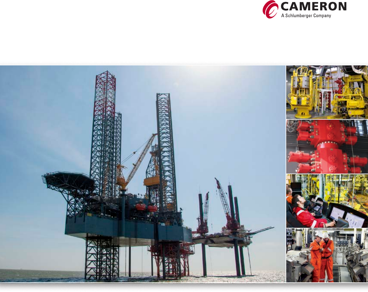
EVO* Compact Offshore BOP
Application Offshore (subsea and surface) and onshore
Bore sizes and working pressures 18-⁄in 15,000, 20,000 psi
Body styles Single, double, triple
Pressure-energized rams Yes
Lock type(s) Hydraulic; EVO-Loc* BOP locking system and motors
Bonnet studs instead of bolts: Yes
Tandem booster bonnets available for increased shearing and sealing capabilities. Super shear bonnets available for shearing casing.
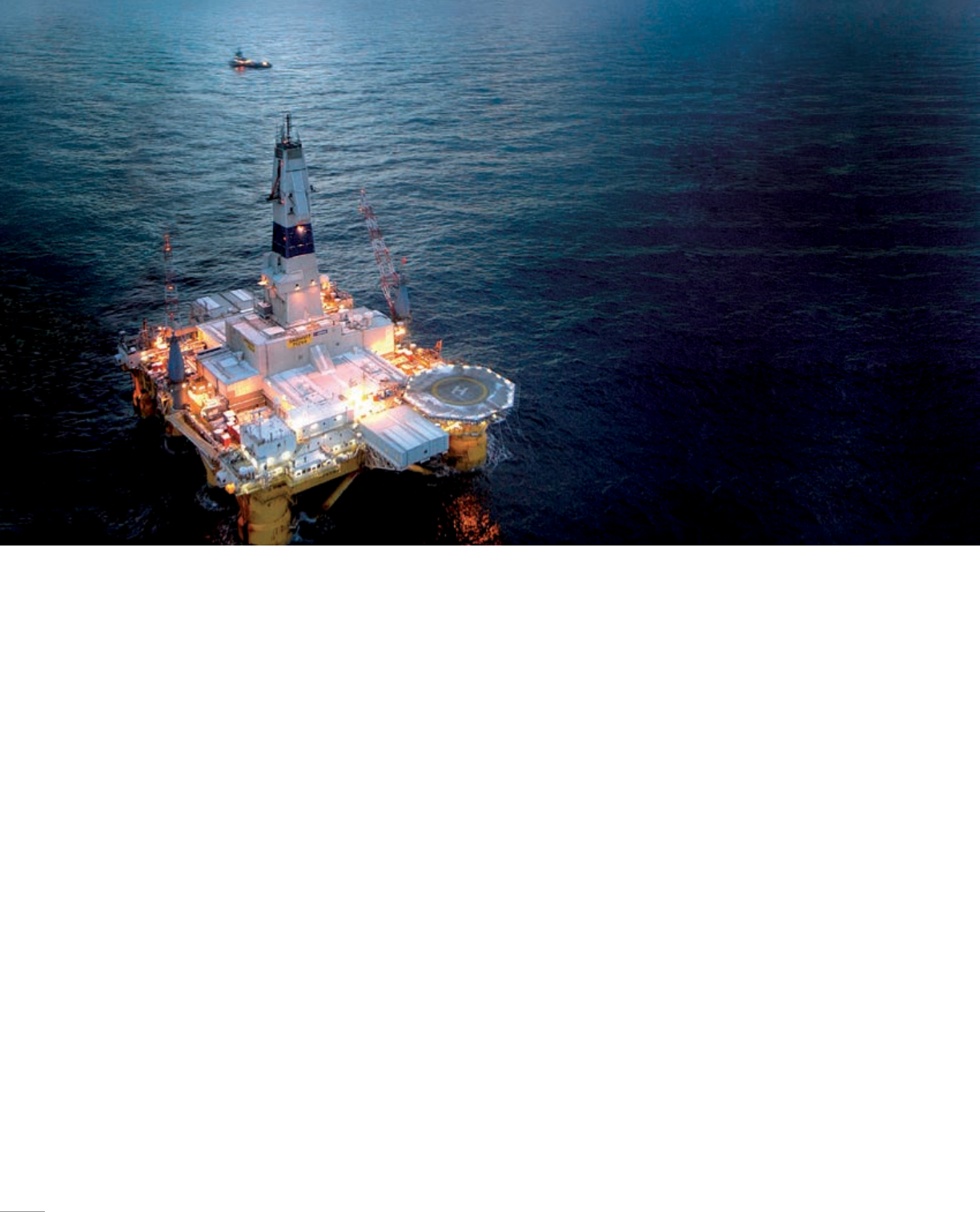
TL* Offshore Ram-Type BOP
Application Offshore (subsea and surface) and onshore
Bore sizes and working pressures 18-⁄in 5,000, 10,000, 15,000, 20,000 psi
Body styles Single, double, triple
Pressure-energized rams Yes
Lock type(s) Hydraulic; RamLocks (5,000, 10,000, 15,000 psi working pressure),
ST lock (10,000, 15,000, 20,000, 25,000 psi working pressure),
Wedgelocks (5,000 psi working pressure)
Bonnet studs instead of bolts Yes
Tandem booster bonnets available for increased shearing and sealing capabilities. Super shear bonnets available for shearing casing.
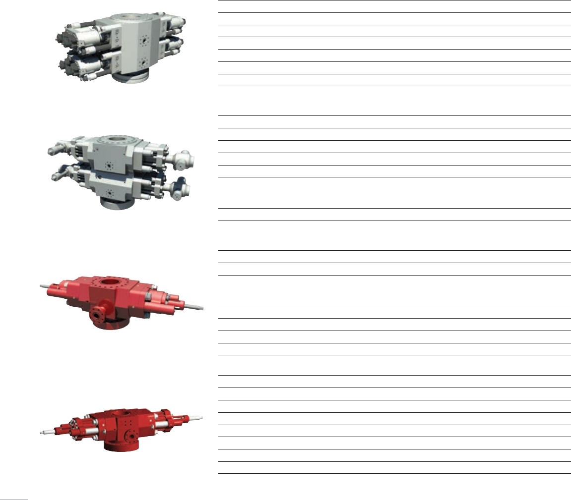
U* Onshore Ram-Type BOP
Application Offshore (surface) and onshore
Bore sizes and working pressures 7-⁄in, 11in, 13-⁄in 3,000 to 15,000 psi; 16-⁄in 3,000 to
10,000 psi; 20-⁄in 3,000 psi; 21-⁄in 2,000, 5,000, 10,000 psi;
26-⁄in 3,000 psi
Body styles Single, double, triple, quad
Pressure-energized rams Yes
Lock type(s) Manual locks standard; hydraulic locks optional
Hydraulically opening bonnets Yes
Large bore bonnets and FXT bonnets available for increased shearing and sealing capabilities.
UM* Convertible-Bonnet Ram-Type BOP
Application Offshore (subsea and surface) and onshore
Bore sizes and working pressures 7-⁄in and 11in 3,000 to 15,000 psi; 13-⁄in 10,000 psi
Body styles Single, double, triple, quad
Pressure-energized rams Yes
Lock type(s) Manual locks standard; hydraulic locks optional
Hydraulically opening bonnets Yes
Bonnet studs instead of bolts Yes
Large bore bonnets and FXT bonnets available for increased shearing and sealing capabilities.
6
Annular BOPs
Cameron offers a variety of field-proven annular BOPs to fit your desired drilling applications. Our portfolio includes models that feature a quick-release top
for prompt packer changeout and, when vertical space is limited, reliable solutions in a compact design.
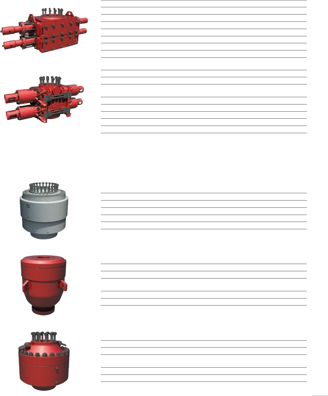
T-81 Small-Bore Compact Ram-Type BOP
Application Onshore
Bore sizes and working pressures 7-⁄in 3,000, 5,000 psi; 9in 3,000, 5,000 psi
Body styles Single, double, triple
Pressure-energized rams Yes
Lock type(s) Manual locks only
Hydraulically opening bonnets Yes
Bonnet studs instead of bolts Yes; also studs on the door
T-82 Compact Ram-Type BOP
Application Onshore
Bore sizes and working pressures 7-⁄in 3,000, 5,000 psi; 11in 3,000, 5,000 psi; 13-⁄in 3,000,
5,000 psi
Body styles Single, double
Pressure-energized rams Yes
Lock type(s) Manual locks only
Hydraulically opening bonnets Yes
Bonnet studs instead of bolts No
DL High-Pressure Annular BOP
Application Offshore (subsea and surface) and onshore
Bore sizes and working pressures 7-⁄in to 21-⁄in and 2,000 to 10,000 psi
Body styles Single, dual configurations available for certain sizes
Packer High-performance CAMULAR* annular elastomer technology
T-84 Low-Pressure Annular BOP
Application Onshore
Bore sizes and working pressures 7-⁄in 3,000, 5,000 psi; 9in 3,000 psi; 11in 3,000, 5,000 psi;
13-⁄in 3,000 psi
Body styles Single
Packer Synthetic rubber
T-90 Short-Body Annular BOP
Application Onshore
Bore sizes and working pressures 7-⁄in 3,000, 5,000, 10,000 psi; 9in 3,000 psi; 11in 3,000, 5,000
psi; 13-⁄in 3,000, 5,000 psi
Body styles Single
Packer Synthetic rubber
7
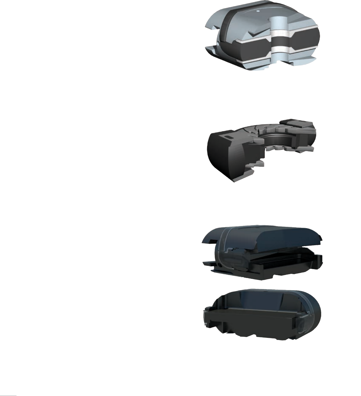
Rams and Ram Packers
Cameron offers the most comprehensive
line of rams and ram packers in the
industry. Our rams cover a wide range of
drilling requirements, including shearing
high-strength casing and drill collars.
Cameron also offers a choice of rams for
variable bore sealing and high-temperature
applications.
Cameron is known as a pioneer in variable
bore sealing technology. The name variable
bore ram (VBR) is synonymous with the
CAMERON* VBR*. In addition, Cameron
offers FLEXPACKER* ram technology,
FLEXPACKER NR* narrow-range ram
packer, and dual bore FLEXPACKER
technology, which provide sealing on
specific bore sizes. VBR
Pipe ram
CDVS cable double-v shear ram
8

Elastomer Technology
One of the many ways to differentiate Cameron drilling products from those
of other manufacturers is the elastomers used in critical sealing areas, such
as ram packers and top seals.
Cameron drilling products exclusively feature proprietary elastomers
designed and manufactured by our facility in Katy, Texas. Cameron provides
engineered solutions to elastomeric material problems, and for drilling
applications, we have developed CAMRAM*, CAMRAM 350*, CAMULAR,
CAMLAST* and DUROCAM* elastomer technology to meet the rigorous
demands of the oil field. This technology, when used in Cameron ram-type
BOPs and annular BOPs, help to improve performance, extend service life,
reduce downtime, and lower operating costs. Elastomer components are
in-house engineered technology with required API testing as with all other
pressure control equipment.
RAM SELECTION CHART
Ram description Ram-type BOP models
EVO TL U UM T-81 T-82
Shearing SBR shearing blind ram ●● †† ● ● – –
DVS double ‘v’ shear ram ●● †† ● †† ● †† – –
SSR super shear ram†●●●● †† – –
HS SBR shearing blind ram ●●●●– –
DS dual string shear ram – – ● †† ● †† – –
ISR interlocking shear ram – – ● †† ● †† – –
DSI dual string interlocking shear ram – – ● †† ●– –
CDVS cable double v shear ram ● ● ––––
Variable bore VBR-II* variable bore ram ● †† ● †† ● †† ● †† – –
FLEXPACKER ● †† ● †† ● †† ● †† – –
FLEXPACKER-NR ● †† ● †† ● †† ● †† ● †† –
Dual bore FLEXPACKER ● †† ● †† ● †† ● †† – –
Pipe Standard service ●●●●●●
High temp service ●●●●●–
† Non-sealing ram; does not contain elastomeric material.
†† Contact your local Cameron representative to learn more about specific sizes.
9
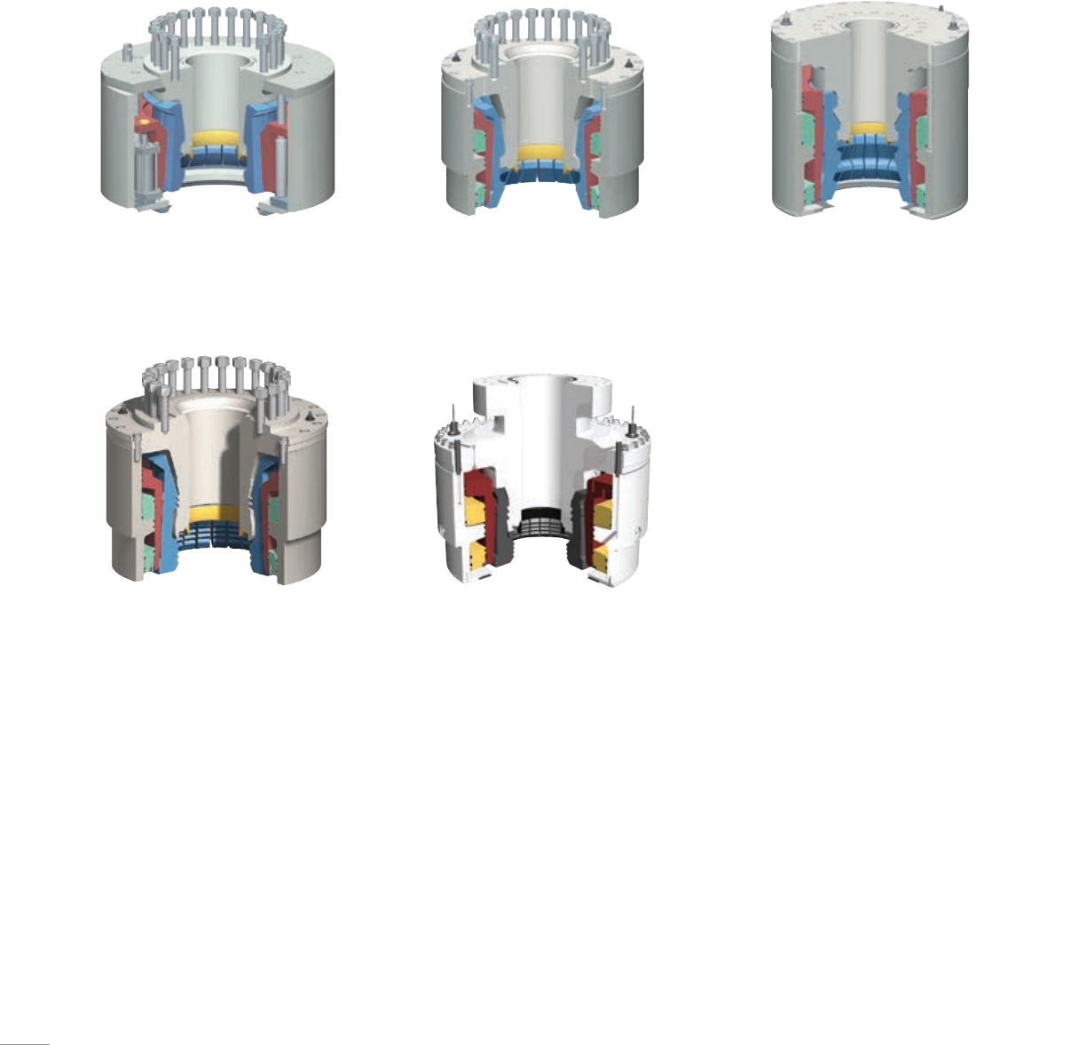
Connectors
As drilling depths have increased, Cameron has expanded its product offerings
to include a full range of collet connectors able to secure your subsea BOP stack
connections from shallow to ultra-deepwater environments.
Model 70 connector
The Model 70 collet connector is offered in sizes and
pressure ratings for a wide variety of applications.
HC connector
The HC high-capacity collet connector is similar to the
Model 70 connector, but is designed to provide greater
preload to withstand higher separating forces.
DWHC connector
The DWHC deepwater, high-capacity collet connector
is a high-strength drilling and completion collet
connector, engineered for the high loads encountered in
ultra-deepwater applications.
HCH4 connector
The HCH4 connector locks onto an H4 wellhead.
EVO-Con connector
The EVO-Con* adaptable collet connector works on various
wellheads, giving you increased versatility and capacity,
and is made with only one hydraulic unit.
10
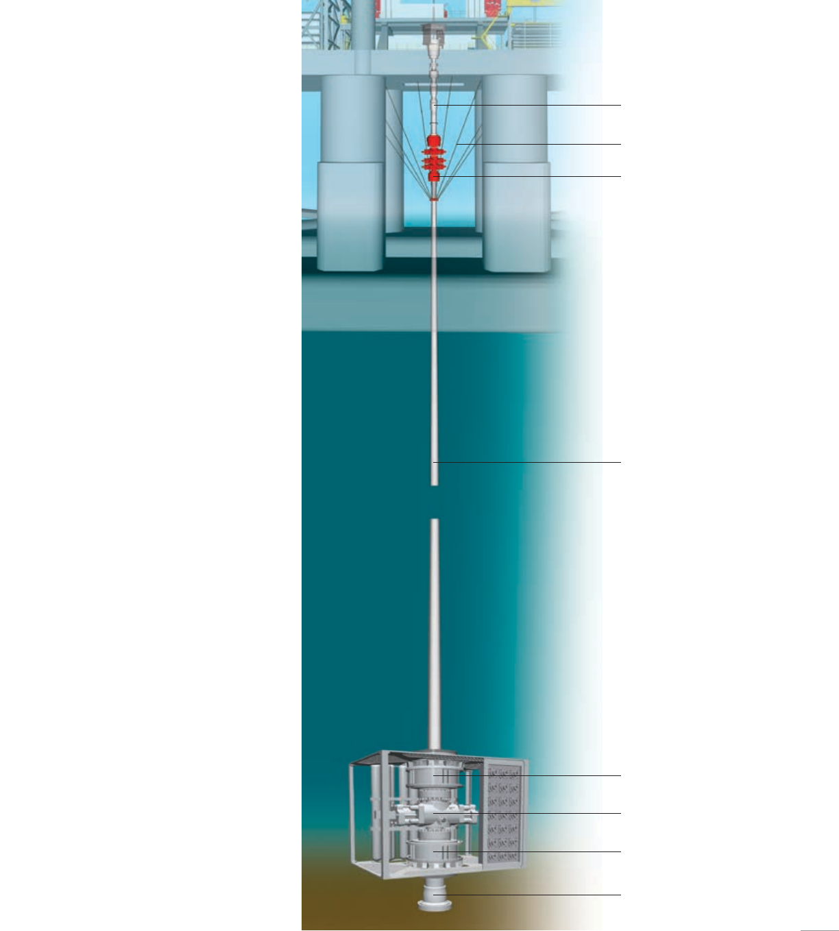
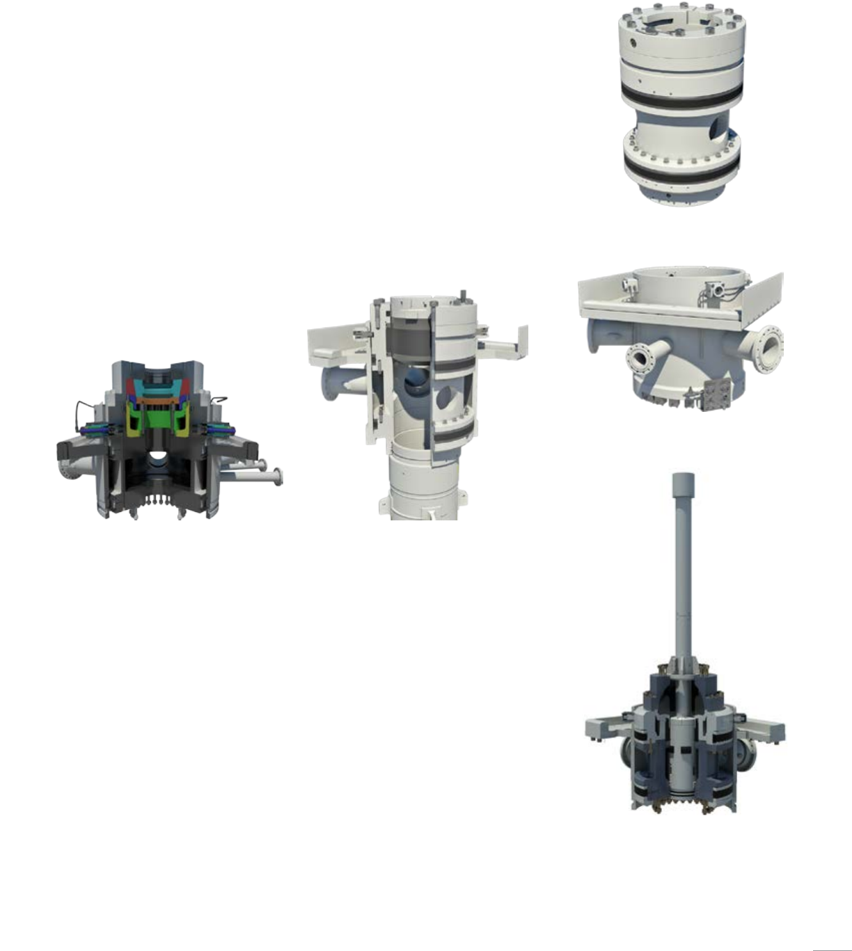
ESG System
The Cameron ESG*
environmental safeguard
BOP control system is a
safe, reliable and cost-
effective alternative to
traditional subsea drilling
practices, combining field-
proven equipment into an
evolutionary new system.
Evolving traditional methods one step further,
the Cameron ESG system utilizes a floating
vessel equipped with a combination of subsea
and surface modules. The subsea portion,
at only a fraction of the size and weight of a
traditional subsea stack, is used to shear, seal
and disconnect from the seabed while the
traditional surface BOP stack handles all the well
control functions.
The subsea stack consists of upper and lower
wellhead connectors, a ram-type BOP with
shearing blind rams and a mini (acoustic,
electric, ROV-actuated or hydraulic) control
system. The subsea portion is connected to
a traditional surface BOP stack via a high-
pressure riser system, Cameron exclusive
triple-barrel telescoping joint and a motion
compensation system.
In the event of an emergency, the control system
is used to signal the subsea BOP to shear the
pipe. Once the shearing blind rams shear and
seal off the bore, the control system is used
to signal the upper connector to disconnect,
allowing the rig to be moved safely off location
with minimal loss of drilling or well fluids.
Three-barrel telescoping joint
Tensioning system
Surface BOP stack
Casing/riser
Wellhead
Collet connector
Collet connector
BOP with shearing blind rams
11
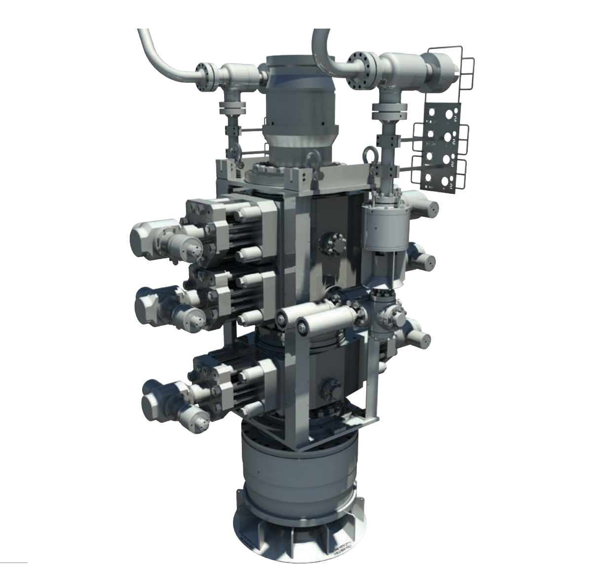
Capping Stack
Building on a legacy of innovative BOP products, Cameron now designs and
manufactures capping stacks. These stacks provide an additional method for safely
shutting in a well or diverting the flow to a containment system. These small,
lightweight stacks, varying in size and working pressure, are designed to fit on top of a
subsea BOP stack or wellhead and can be configured per customer’s request.
12
13
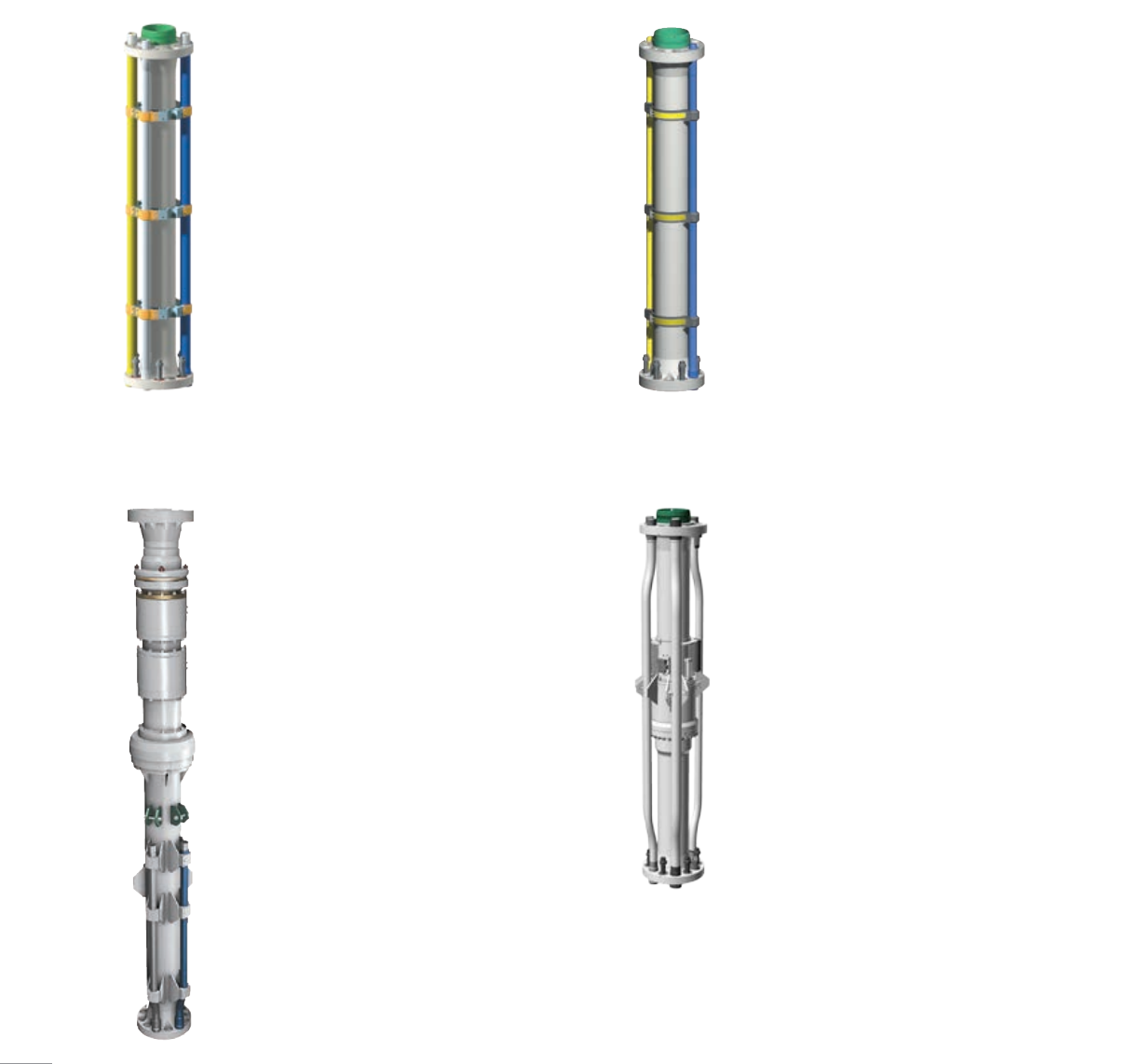
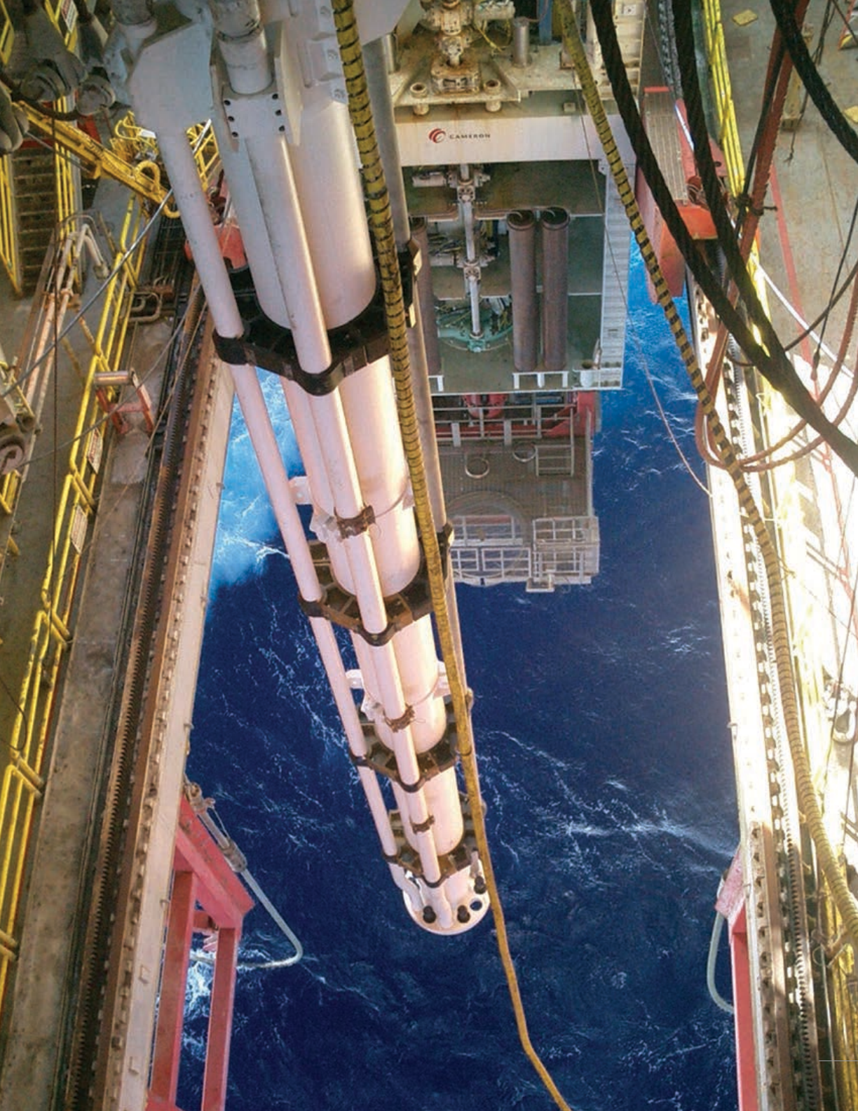
Riser Systems
Cameron offers drilling riser systems that accommodate the stringent conditions
encountered in ultra-deepwater drilling, including high-tension loads, multiple control
lines and the need to respond to changes in surface weather conditions. Riser sections
are available in varying lengths, wall thicknesses and with preps for buoyancy materials
as required.
LoadKing riser system
Cameron LoadKing* ultradeepwater riser
systems is designed to meet the demands of
ultra-deepwater drilling in water depths of
7,000ft (2,133.60 m) or more. LoadKing riser
system are available with tension ratings up to 4
MMlb. LoadKing riser systems incorporate many
of the features of the RF riser system while
holding the weight of the riser joints to less
than 2% heavier than a comparably equipped
RFriser system.
Riser fill up valve
The Cameron riser fill up valve is a special riser
joint with an automatic or hydraulically operated
actuator designed to prevent riser collapse
should drilling fluid levels drop within the riser.
Riser running tools
Cameron riser running tools feature integrated
running and testing functionality. The devices
handle risers for lifting and assembling the riser
into the riser string and pressure testing the
lines. Cameron running tools are qualified up to
2.75 MMlb. Removable test plugs eliminate the
need to stab a test sub for every joint. Hydraulic
and manual tools are available.
Telescoping joint
The Cameron Telescopic Joint (TJ) compensates
for rig heave. It is a riser joint consisting of an
inner and outer barrel with a sealing element.
Cameron offers a dual seal assembly (DSA) for
sealing between the inner and outer barrel. The
autolock feature secures the inner and outer
barrel to ensure the telescopic joint can safely
run and land the BOP. The Cameron TJ can be
provided as MPD ready, with an inner barrel
sized to accommodate passing a rotating control
device and associated deployment tooling.
RF riser system
The Cameron RF* riser system is designed to
meet the drilling industry’s needs for a midwater
riser system. Less costly and quicker to operate
than conventional systems, RF riser systems are
available with tension ratings up to 2 MMlb.
14
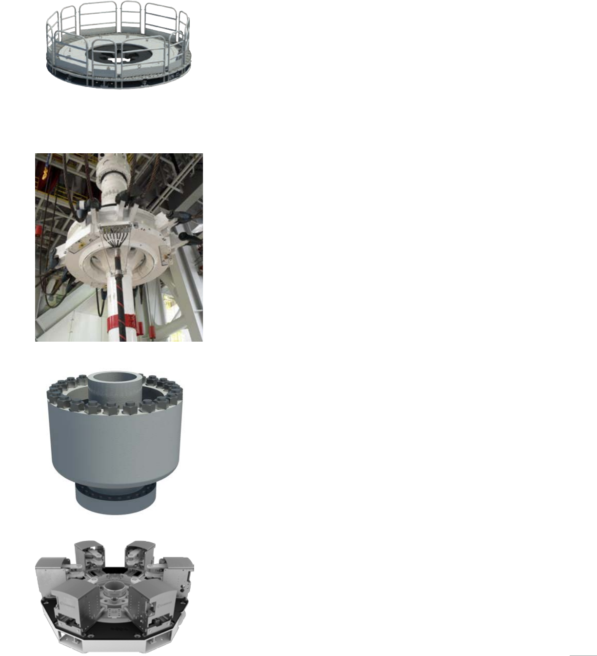
Spider and gimbal
The Cameron spider serves as a hang off point for the riser during BOP
running. Cameron offers split spiders and gimbals to accommodate rotary
tables of 49.5in (1,257.3 mm), 60.5in (1,536.7 mm), and 75.5in (1,917.7
mm) in diameter and are qualified up to 2.5 MMlb hang off capacity.
Cameron spiders are designed so that the only moving parts are the spider
dogs. For improved safety, the 75.5in (1,917.7 mm) spider dogs completely
cover the open hole when hanging off a riser joint. The shock mount
gimbal allows up to a 5-degree movement in all directions. The Cameron
spider design can be configured to readily accommodate the Robo-Spider*
automated riser-flange-bolt torque system.
Tension ring
The Cameron tension ring secures the tensioning lines to the telescopic
joint. Cameron offers solid body and split tension rings to accommodate
both wireline and direct acting tensioning systems. Cameron tension rings
are qualified up to the same capacity as the riser system with which they
are coupled.
FlexKing subsea flex joint
Cameron FlexKing subsea flex joints permit angular displacement up to ±10
degree. They are rated up to 6,000 psi and are certified to water depths up
to 12,000 ft (3,657.6 m).
BOP landing assist tool
The Cameron BOP Landing Assist Tool (BLAT) locks into the riser string
below the telescopic joint inner barrel to allow hang off to be supported by
the derrick instead of the tensioning system. The BLAT can support up to
2.5 MMlb and interfaces with either the outer barrel of the telescopic joint
or a modified pup joint.
Robo-Spider system
The Cameron Robo-Spider system is an automated riser flange bolt torque
system capable of reducing riser flange bolt torque time by up to 70%,
while increasing rig floor safety.
15
Riser gas handling system
The Cameron RGH riser gas handling system utilizes a subsea diverter
to permit the safe handling of gas in the riser. The system includes an
annular for sealing the riser annulus and a gas bleed spool to safely
bleed off gas and mud to a choke manifold. Standard configurations are
available to accommodate an HSE system or a Managed Pressure Drilling
(MPD)-ready system.
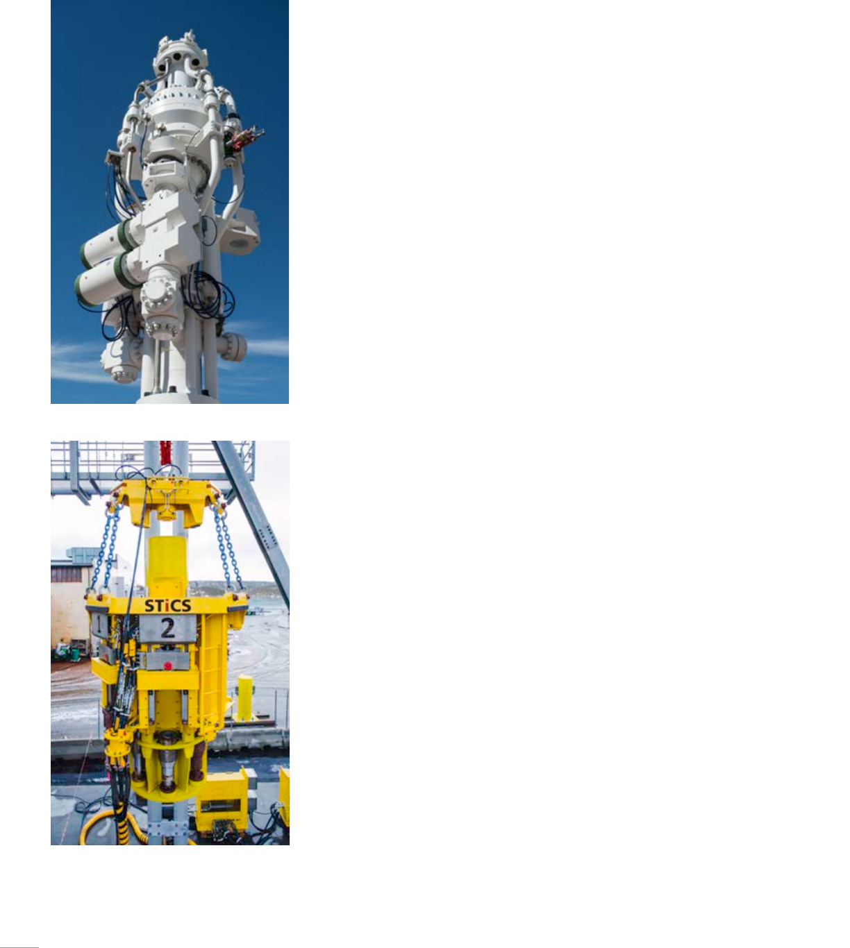
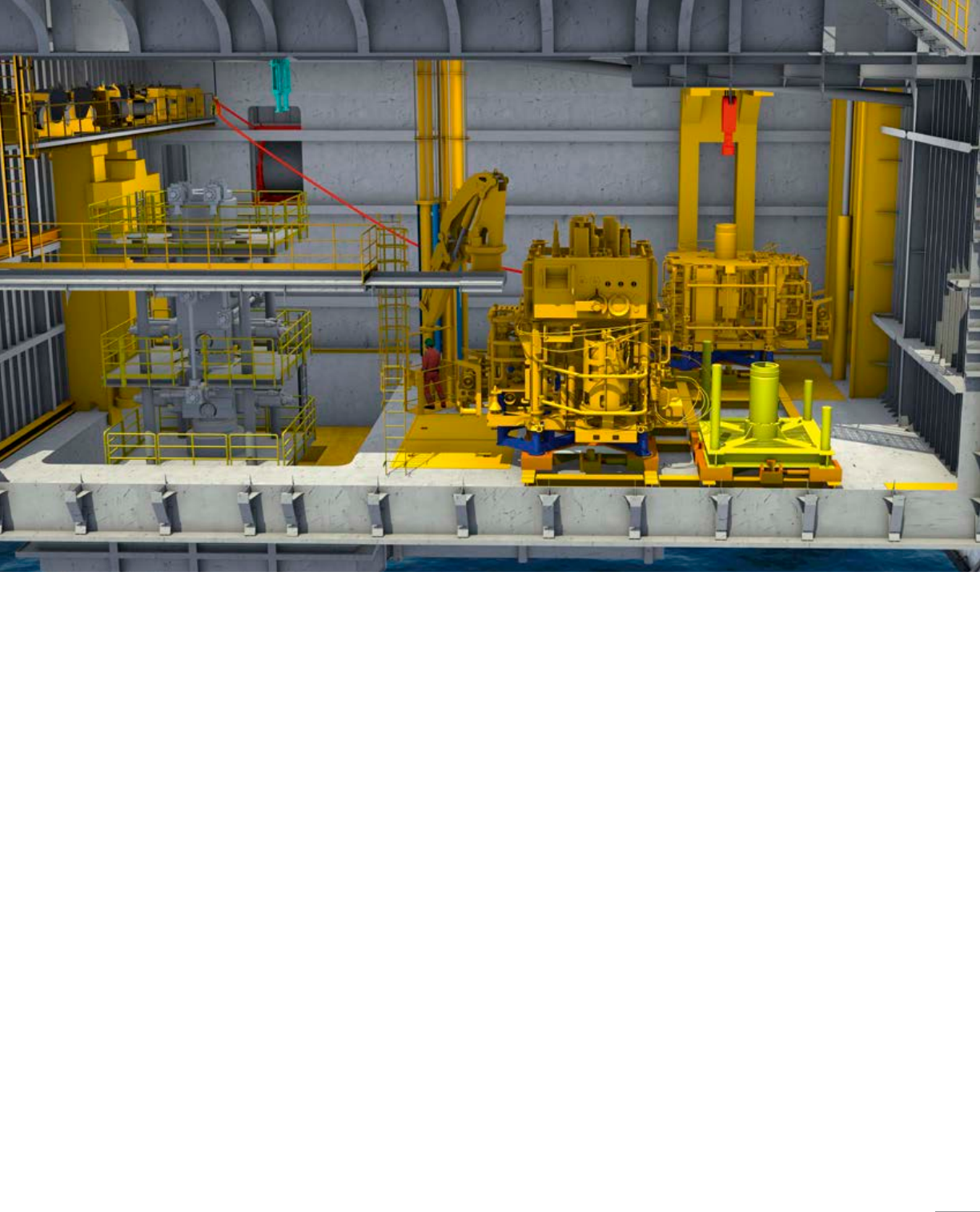
Stab-in connection system
The STiCS stab-in connection system provides hands-free remote operation
for installation of goosenecks on the telescopic joint, reducing time and
potential hazards that can occur during the connection of the choke, kill,
and other auxiliary lines.
For more information on the STiCS system, refer to page 61.
16
Diverters
CF-B diverter
Diverter housing
CF-A diverter and running tool
CF-A diverter
The Cameron CF-A diverter is fully customizable
for customer-specific floater operations and
is designed for reliable, efficient use. The
system consists of a diverter housing, outlet
valves, running tools, controls system, diverter
assembly, and storage skid.
The CF-A diverter supports up to 75.5in rotary
tables and has a hang off capacity of up to 2.5
MMlb. It is a single annular packing element
with a pressure rating up to 500 psi. The CF-A
model features four hydraulic locking dogs
that also provide hydraulic functionality, thus
reducing hosing and providing a simplified
running and retrieval of the diverter assembly. It
also eliminates the need to secure hoses to the
diverter assembly while providing hydraulic fluid
for the operations.
CF-B diverter
The Cameron CF-B diverter is fully customizable
for customer-specific jack-up rig operations
and is designed for reliable, efficient use. The
system consists of a diverter housing, outlet
valves, running tools, controls system, diverter
assembly, overshot packers, and storage skids.
The CF-B diverter supports up to 49in rotary
tables and is qualified up to 1,000 psi. Packers
can be split and hinged to allow them to be
changed out with pipe in the hole. J-slot type
running tools are entirely mechanical and require
no hydraulics. The bolt-on hydraulic stabs
automatically engage receptacles in the diverter
housing during deployment, thus eliminating
the need to make/break hydraulic connections
during running and retrieval.
Cameron diverter solutions provide low-pressure
flow control to direct wellbore fluids away from the
immediate drilling area to maximize safety of personnel
and equipment. These diverters are used primarily to
divert drilling fluids to mud systems in shallow fluid and
gas flows, drilling with a rotating head, or drilling with
a marine riser. Cameron offers the CF-A low-pressure
flow control floater diverter for floaters and the CF-B low-
pressure flow control jackup diverter for jack-up rigs.
17
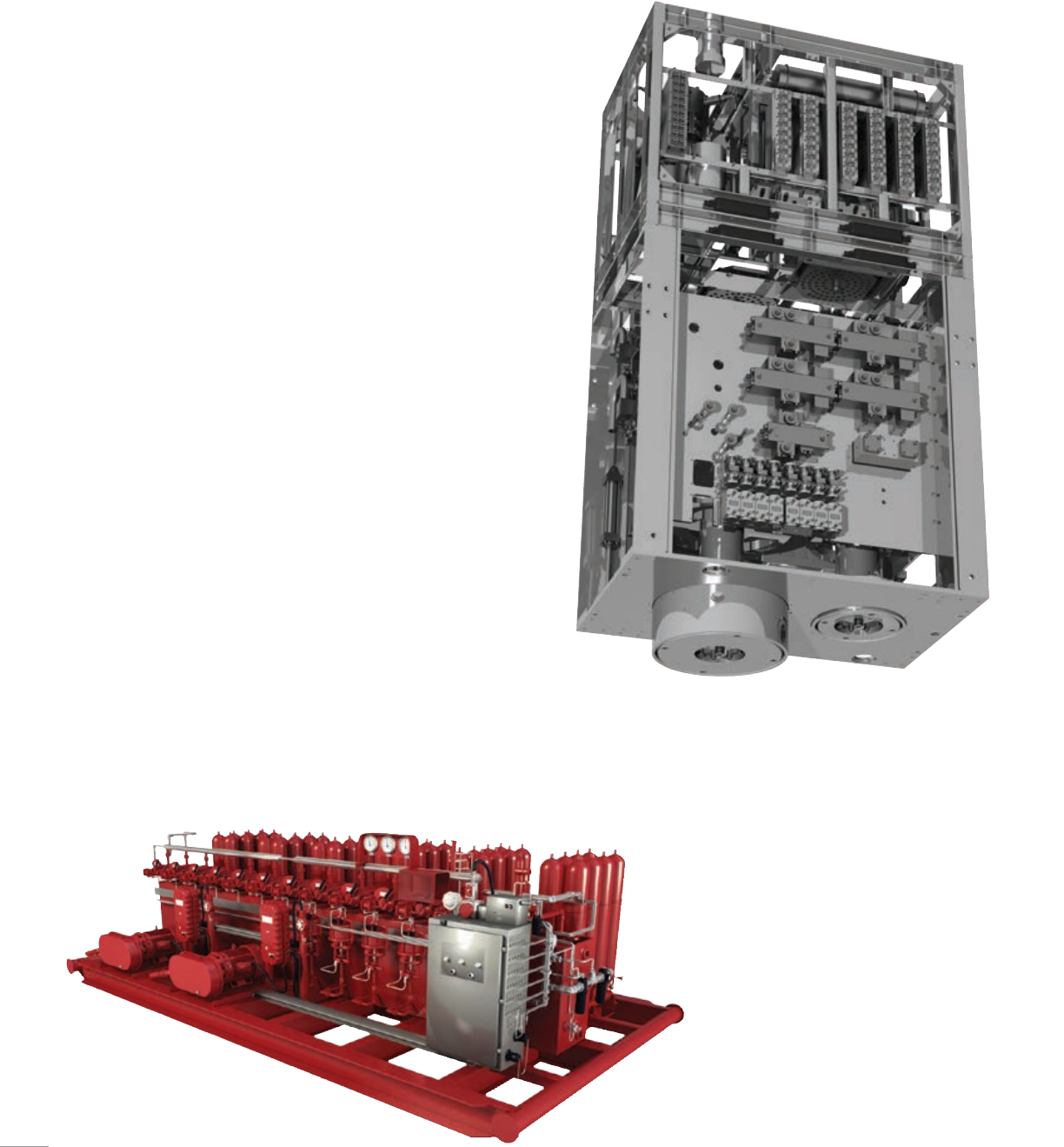
Land and platform hydraulic
Cameron hydraulic control systems for land and
platform BOPs supply hydraulic fluid used to
operate the stack and associated equipment.
These systems feature field-proven and reliable
components designed for dependability and field
serviceability. The valves use sliding CAMERON
metal-to-metal shear seals for maximum
tolerance of fluid contamination.
As a leading supplier of BOPs, Cameron is
uniquely qualified to design, manufacture,
install and service drilling control systems
tailored to the specific requirements of
Cameron BOPs. By providing superior
design, dependable performance and
excellent field service, Cameron is an
industry leader in the supply of drilling
control systems for land, platform
and subsea applications. Available
controls range from simple-hydraulic to
all-electric systems.
BOP control systems from Cameron feature
a modular design using pre-engineered,
field-proven components. The unique
modular design allows simple installation
and retrieval of the control pod utilized
in our multiplex (MUX) systems, which
leads to reduced maintenance time and
costs. Cameron control systems feature
the latest technology with new advances
in safety and functionality, providing for
operational efficiency.
BOP Controls and Monitoring Systems
18
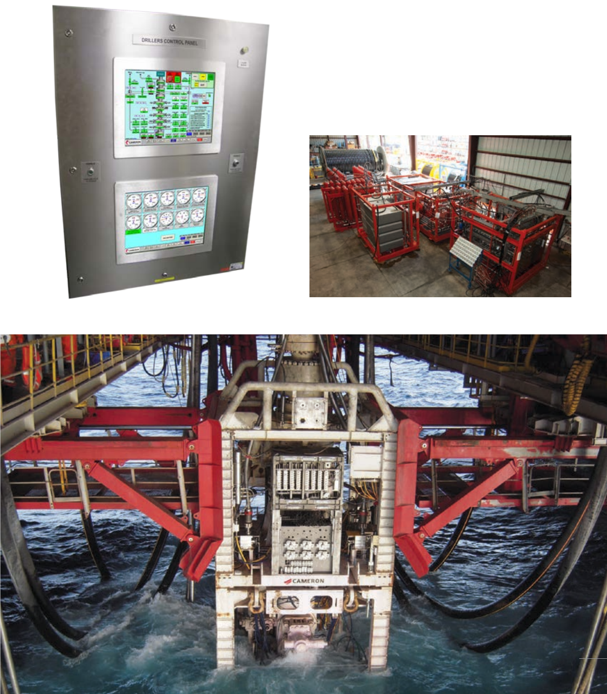
EH MUX subsea electro-hydraulic multiplex systems
Cameron compact, lightweight EH MUX systems combine modular,
field-proven components with dual-redundant electronics to provide
the rapid actuation required of BOPs operating in deep water.
For operating equipment in shallower water depths, Cameron offers
direct-hydraulic and piloted-hydraulic drilling control systems to deliver
superior BOP control at an economical cost. Like the EH MUX systems,
the piloted systems offer robust, field-proven components, but are
controlled via electric connections between the surface controls and
subsea control pod.
19
Cognition subsea BOP monitoring system
The Cameron Cognition* monitoring system is a network of sensors,
data recorders, and communications fitted to the subsea stack of
new or existing BOP assemblies, that administers mission critical
information for real-time monitoring, condition based maintenance, and
emergency mitigation.
Monitoring the parameters of condition in BOP equipment provides
access to crucial details about performance and reliability. This presents
drillers with new insight to proactively manage maintenance which
is essential to maximizing operational uptime. Also, this progressive
set of statistics contributes vital intelligence to identify and respond
in well control emergencies. Redundant “black box” recorders
store several weeks of data enabling ROV recoverable forensics of
time-stamped information.
The Cognition monitoring system has the flexibility to incorporate a
wide range of installer selected sensors, including but not limited to
BOP ram position, hydraulic fluid condition, stack accumulator bottle
volume, and solenoid performance. Four redundantly accessible data
transmission paths are designed to increase availability, which includes
the main umbilicals, ROV stab access points, ROV inductive high-capacity
connectivity, and an acoustic system that also facilitates local power.
Each connection is capable of energizing sensors and reading data
from subsea historians independently of the native BOP control system.
All measurements are accessible from any single connection point,
implementing an unprecedented level of redundancy.
Additionally, the Cognition Knowledge Base* software provides advanced
analytics, alerts, alarms, and reports that synthesize both real-time and
historical data into advantageous information. The complete package
solution offers the most value to aid in preventing failures, reducing
downtime, and extending the operational life of subsea BOP equipment.
LMRP ROV wireless data and power connection point and ROV retrievable black
box recorder
Lower Stack ROV wireless data and power connection point and ROV retrievable black
box recorder
20
21
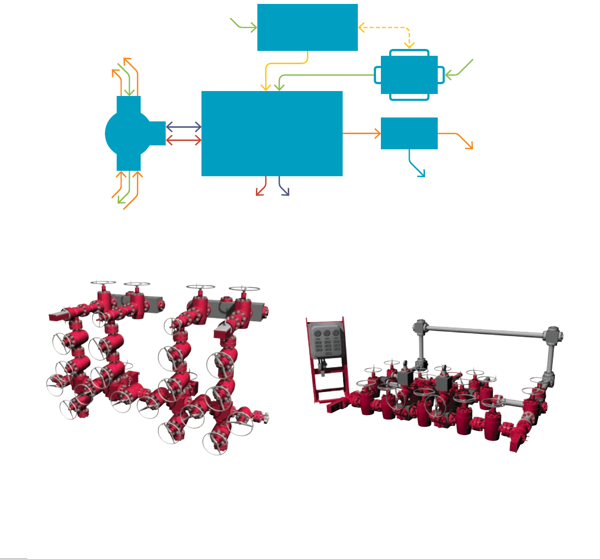
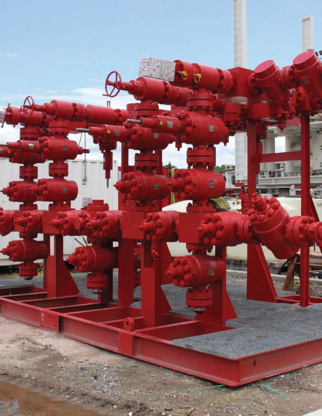
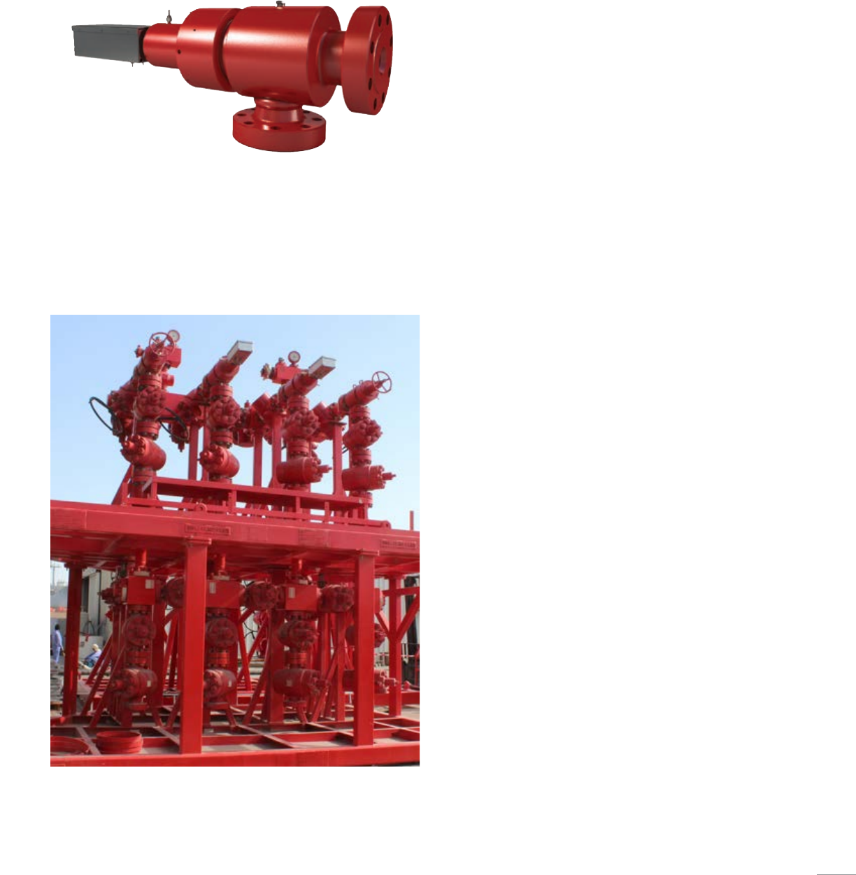
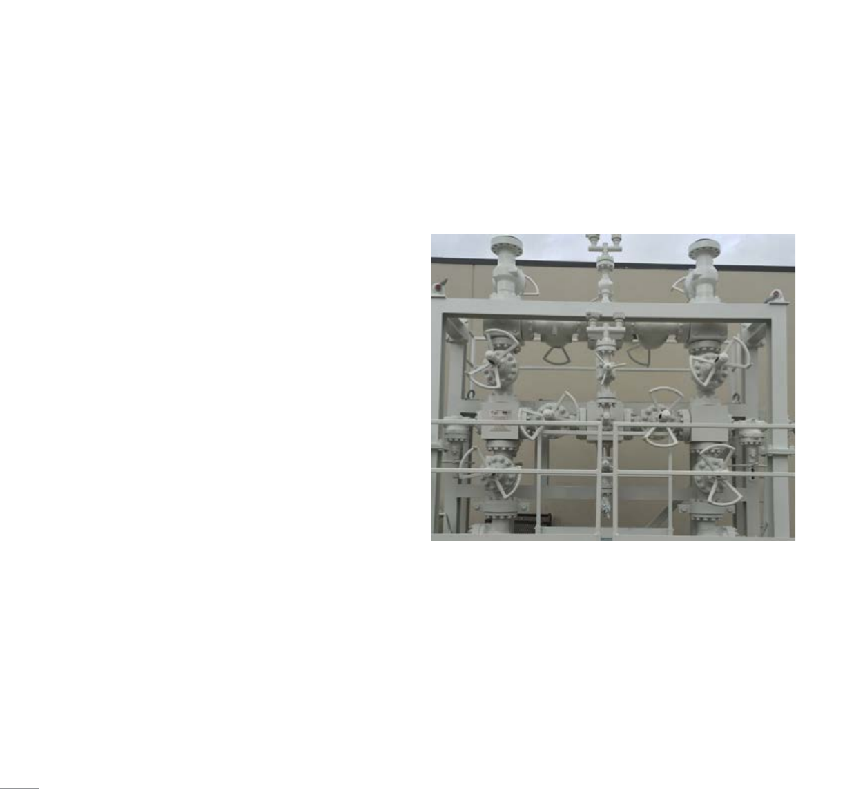
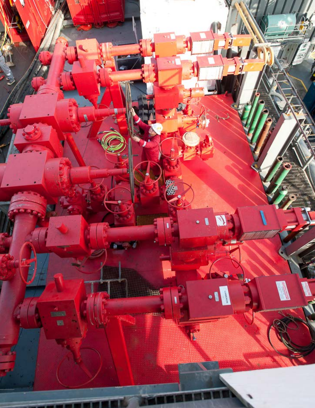
Cameron offers manifold systems including choke and kill manifolds, drilling chokes,
mud standpipe manifolds, cement manifolds, mud gas separators, glycol injection units,
and manifold control systems for improved pressure and flow control in onshore and
offshore applications.
Manifold Systems
Offshore manifold Onshore manifold
Choke and kill manifold
Cement manifold
MCG
Vent
Overboard starboardOverboard port
To mud treatment
From HP system
From HP cement system
From HP system
To well
Mud
standpipe
BOP
stack
22
Choke and kill manifolds
The Cameron choke and kill manifold provides control of flowback or
treatment fluids. With a commitment to offer the highest quality, safest,
and most reliable products on the market, Cameron choke and kill
manifolds undergo design, development, and production processes that
adhere to our rigorous OEM protocol. Every element of the choke and
kill manifold, from gate valves to chokes, must meet meticulous design
standards, qualification testing, and material selection. The manufacturing
of each manifold system is done in-house by our trained employees. This
attention to detail is what you can expect from the best-in-class pressure-
control equipment provider.
■ Compliance with API standard 53 and API spec 16C
■ ABS and DNV certification
■ API 6A monogrammed components
■ Material class DD-0.5 to EE-NL
■ Temperature class L to X (-50 to 350 degF [-45 to 176 degC])
■ Product specification level: PSL 2 or 3
■ Inconel* 625 inlay available
■ Hydraulically actuated components to allow for remote operation
Options include: standard or custom configurations, instrumentation for
pressure readings, ports for glycol injections, various structural components
to operate chokes and valves, etc.
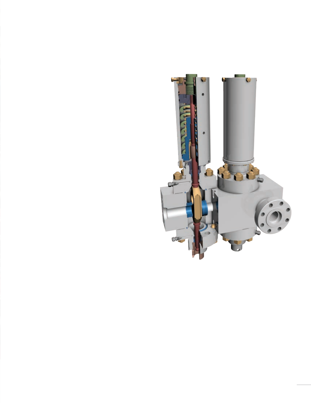
Drilling chokes
The Cameron drilling choke product range consists of two main
choke types: the CAMERON* DR gate and seat type and the WILLIS*
Multiple Orifice Valve (MOV) rotating disc type. These chokes control
the pressure in the well bore during drilling, circulate out any kicks of
gas encountered during drilling, and prevent loss of well control by
maintaining a satisfactory column of drilling mud. With several options and
configurations, Cameron drilling chokes offer proven performance within
diverse drilling applications on a global scale.
■ Controlling components (gate and seat) of DR Type gate-and-seat
drilling choke valves as well as the disc components of WILLIS MOV-
type drilling chokes are made from solid tungsten carbide for maximum
durability and increased service life
■ Available in manual and hydraulically actuated configurations
■ Actuated configuration with a pneumatic pressure-type position
indicator is standard (digital position sensor is optional)
Drilling choke
23
Mud standpipe manifolds
Cameron mud standpipe manifolds are designed and manufactured to
customer requirements and are fully certified in accordance with the
recognized oilfield equipment standards.
The mud standpipe manifold is installed downstream of the mud pumps
with the purpose of diverting the flow of drilling fluids towards the drill
line or drill string. An adjustable choke can be installed to bleed pressure
off the drillpipe, to reduce shock when breaking circulation in wells
where loss of circulation is a problem, and to bleed-off pressure between
BOPs during stripping operations. Pressure ratings up to 7,500psi
are available.
■ Diverts flow of drilling fluids
■ Provided with pressure indicator/sensor and/or
temperature indicator/sensor
■ Supplied free-standing or with support frame
■ Range of configurations/capacities/specifications available
■ Custom single or dual designs
Cement manifolds
Cameron cement manifolds are designed and manufactured to customer
requirements and are fully certified in accordance with the recognized
oilfield equipment standards.
The cement manifold is installed downstream of the cement unit with
the purpose of diverting the flow of cement slurry during cementing
operations. Pressure ratings up to 20,000 psi are available.
■ Diverts flow cement
■ Installed downstream of cement unit
■ Provided with pressure indicator/sensor and/or
temperature indicator/sensor
■ Supplied free-standing or with support frame
■ Hammer union or flanged connections
■ Range of configurations/capacities/specifications available
24
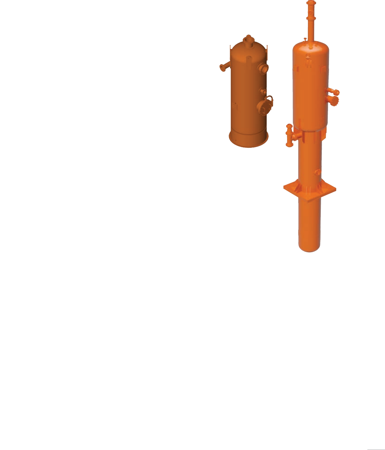
Mud gas separator (MGS)
Cameron mud gas separators are designed and manufactured to customer
requirements and are fully certified in accordance with the recognized
oilfield equipment standards.
Mud gas separators are installed and used to separate and safely vent
large pockets of gas from the active drilling mud system. The mud is routed
to solids control equipment for further processing while the free gas is
discharged through the gas exhaust pipe and travels through the flare line
to be safely vented.
■ Separate gas from drilling fluid
■ Install downstream of well control choke
■ Install in flow line if high-gas concentrations
■ Excellent for underbalanced drilling
■ Range of configurations/capacities available
■ Custom design with capacity calculations
Glycol injection unit
Cameron glycol injection units are designed and manufactured to customer
requirements and are fully certified in accordance with the recognized
oilfield equipment standards.
The glycol injection unit works by pumping glycol into the manifold in
order to prevent the formation of hydrates that can block flow lines.
Injection occurs upstream of the manifold chokes. Current available sizes
are 198.13gallons (750 liters) or 264.17 gallons (1,000 liters) with outputs
greater than 0.26 gal/min (1 L/min).
■ Stainless steel enclosure
■ Range of capacities and specifications available
■ Easily integrated with control equipment
■ Maintenance friendly
Manifold control system
Cameron manifold control systems are designed and manufactured to
customer requirements and are fully certified in accordance with the
recognized oilfield equipment standards.
Cameron manifold controls range from a simple single or dual choke control
panel to custom design control systems. Custom designs include control of
chokes, valves, and position indication with readout for choke upstream,
choke downstream, standpipe and cement pressures/temperatures and
pump stroke counter display. Handoff to DCS is often a desired feature that
Cameron incorporates into its custom panels. PLC/HMI is also available.
■ Reliable, economical, onshore or offshore application
■ Range of instrumentation packages
■ Design to fit in drillers cabin or on rig floor
■ Range of configurations/capacities/specifications available
Mud gas separators
25
26
Cameron offers a wide range of valves to control and direct
the flow of oil and gas from the drillfloor to the end user.
Valves
MCS gate valves
The Cameron MCS subsea gate valve is a compact valve suited for the
rugged requirements of subsea choke-and-kill lines in water depths up
to 10,000 ft (3,048 m).
The valve is hydraulically actuated. The detachable actuator requires
only 6in of clearance for removal without requiring removal of the valve
from the line. The bonnet, packings, and stem remain in the valve when
the actuator is removed.
Balanced stem prevents fluid displacement and prevents opening when
line pressure is less than sea pressure. The exposed balancing stem
allows visual indication of gate position. Bi-directional sealing allows
valves to be spaced closely without liquid lock.
The one-piece seats and slab gate minimize cavity parts which
simplifies maintenance.
■ Size: 3-⁄in (other sizes available upon request)
■ Working pressure: 15,000 psi (other pressures available
upon request)
■ Operating temperatures: 0 to 350 degF (-18 to 176 degC)
■ Operating pressure: 1,500 to 3,000 psi
■ Variety of trims available
■ Metal-to-metal sealing
■ Compliant with API 6A, DNV, ABS, etc.
■ Locking screw option available
27
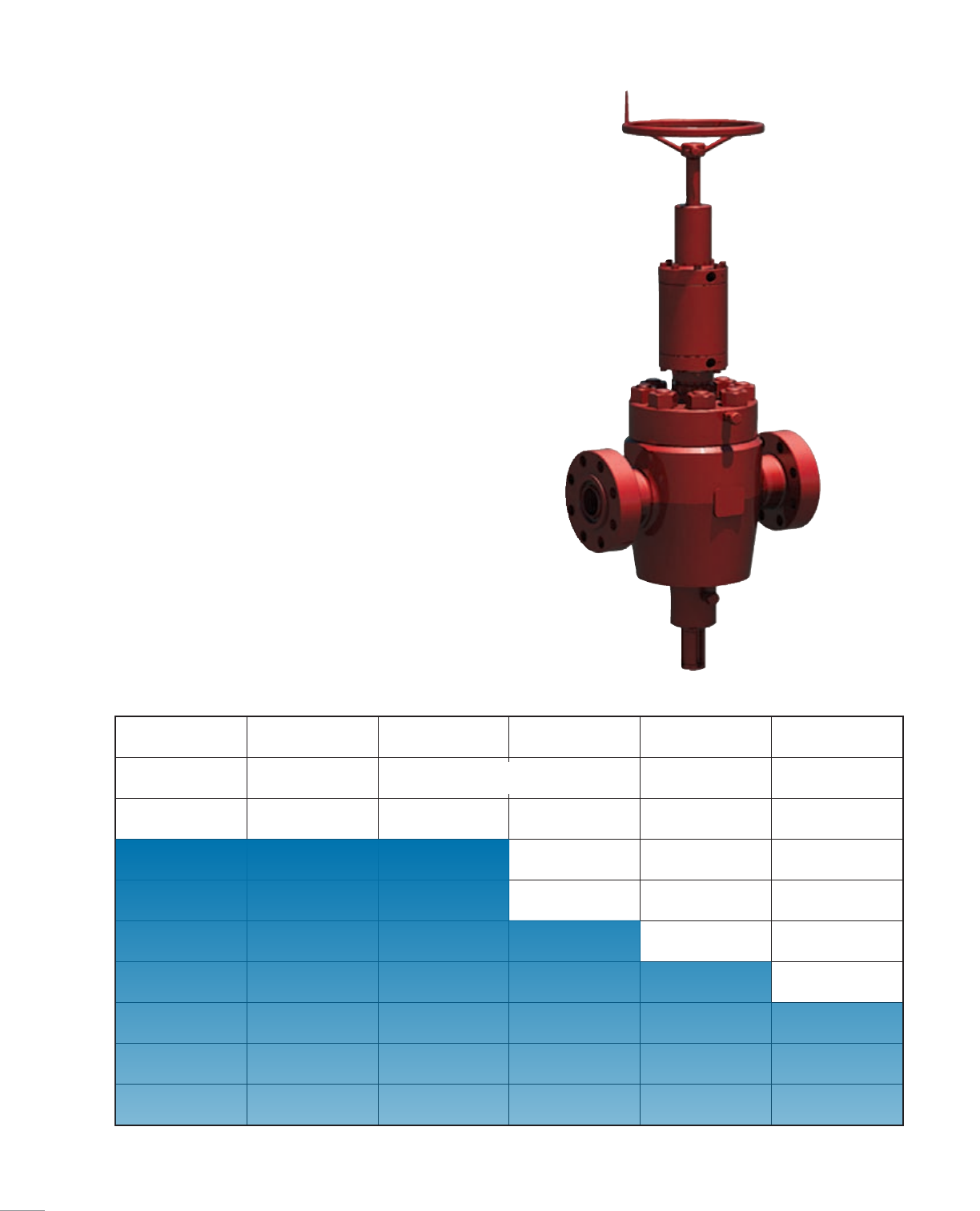
FLS gate valves
The Cameron FLS* gate valve is a full-bore, through-conduit valve
available in standard double-flange, threaded-end and special block body
configurations. It is a forged valve available in pressure ratings from
2,000 psi to 20,000 psi and bore sizes from 1-⁄in to 11in. As Cameron
standard valve, the FLS gate valve can be fitted with a wide range of
Cameron actuators.
The FLS gate valve’s bi-directional design provides flow direction
versatility and maximum service life. Featuring metal-to-metal sealing
(gate-to-seat and seat-to-body), the valve’s simple, reliable gate and seat
design promotes ease of field service and minimal spare parts inventory.
Two spring-loaded, pressure energized, non-elastomeric lip-seals
between each seat and body assist in low-pressure sealing. They also
protect against intrusion of particle contaminants into the body cavity
and seal areas.
The valve’s stem seal design covers a full range of pressures,
temperatures and fluids encountered in wellhead and manifold service.
The stem can be back seated to allow stem seal replacement with the
valve under pressure.
For more information on Cameron gate valves, please reference API 6A Gate
Valves brochure (SUR-1024).
Gate valve application guide
Bore size, in
11
9
7-⁄
6-⁄
5-⁄
4-⁄
3-⁄
2-⁄
2-⁄
1-⁄
0
Working pressure, psi
02,000 3,000 5,000 10,000 15,000 20,000
FLS
FLS-R*, FLS actuated
28
DRILLING EQUIPMENT
29
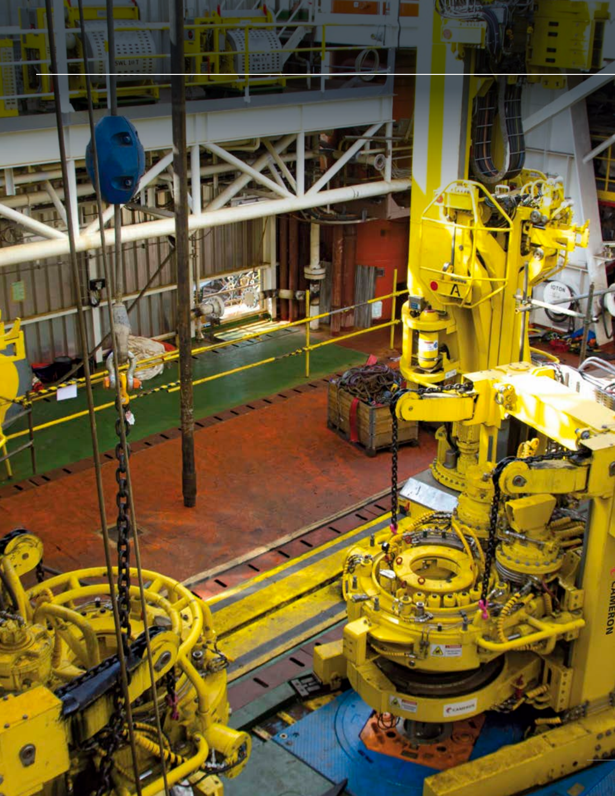
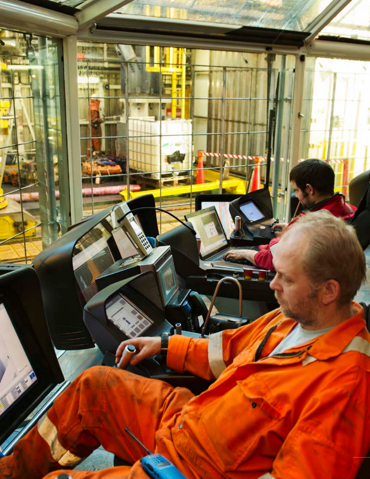
Cameron delivers a complete range of drilling control rooms, advanced X-COM*
operator chairs, drilling instrumentation systems, and monitoring systems for multiple
types of offshore drilling applications. All software, inclusive of our HMI, machine
controls, and integration functions for the zone management and tubular interlock
systems are tested in a 3D simulation environment before installation on the rig. Our
systems feature high-quality software and easy-to-use screen graphics, and our secure
and efficient network is capable of interfacing with equipment from third-party vendors.
HMI and Controls Systems
Drilling control room
Cameron delivers a range of drilling control rooms (DCRs) to the drilling
industry. Our product offerings range from compact one-seater cabins to
large well-construction centers, able to house essential drilling control
and monitoring equipment, as well as several operators and any additional
auxiliary equipment and personnel.
■ Self-supporting carbon steel unit (optional stainless steel)
■ Integrated X-COM designed for 1 to 5 X-COM operator chairs
■ Large windows with fully-automatic window-cleaning system
programmed for different weather conditions
■ Removable, easy-to-clean, non-slip floor tiles
■ Recessed ceiling with noise dampening
■ Two safety/emergency exits
■ Sun-filtered safety windows with protection bars and grids to protect
the top windows from falling objects and the front windows and DCR
from moving objects
■ Tailored to drillfloor layout
■ Ergonomically designed to meet the highest standards
■ Wall space for BOP/auxiliary panels
■ HVAC systems
■ Range of additional options to meet customer specifications
30
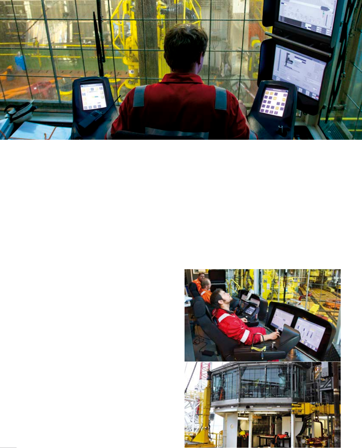
X-COM operator chair
■ Simple and intuitive user interface
■ Sunlight readable and dimming in all conditions
■ Designed in accordance with NORSOK and international standards
■ Outstanding ergonomic adjustments for maximized comfort
and efficiency
■ Slim and robust industrial design
■ Safe technical components and internal redundancy
■ Rapid placement of pluggable components allows for stress-free
service and maintenance
■ Includes 3 HMI front screens for closed circuit television (CCTV)
and HMI
■ Integrated CCTV and talkback system interface
■ Excellent line of sight due to the chair’s slim design
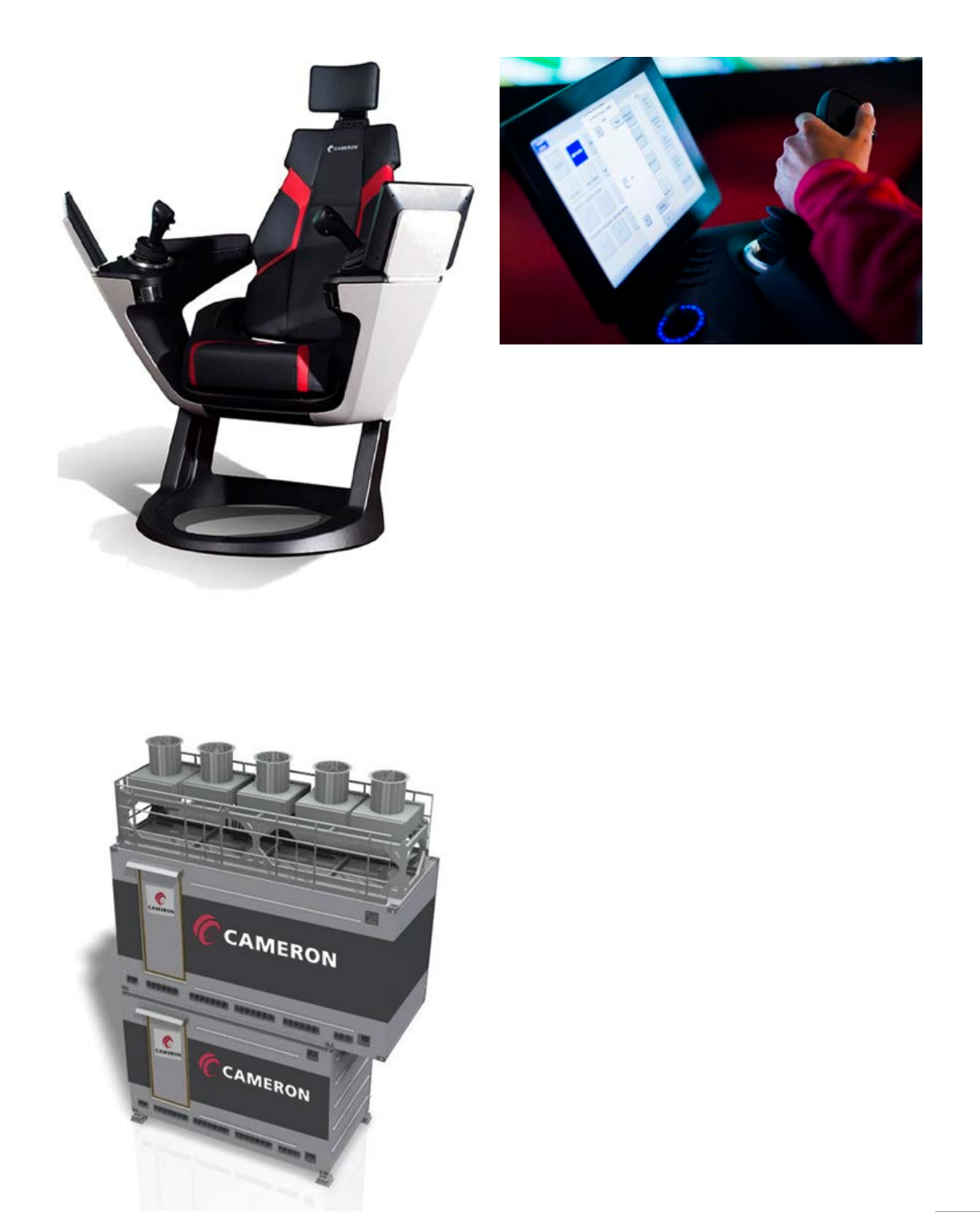
Local equipment room/local instrument room
■ Self-supporting steel structure, with insulation and entrance door
■ Rated for installation in Hazardous area Zone II (safe by ventilation)
■ Removable antistatic floor tiles
■ Complete delivery (including control system components, power
distribution and lighting)
■ HVAC system with heating/cooling units for temperature control
■ Air handling unit with fire dampers and overpressure control
■ Prepared interface for external systems (fire and gas system, HVAC,
and rig control system)
31
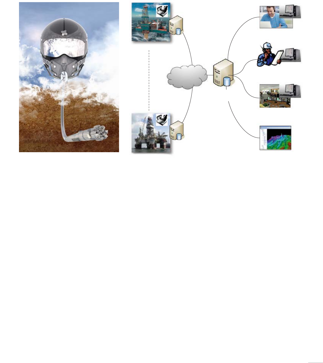
With the Cameron OnTrack* integrated drilling controls system, various types of
drilling equipment and processes can be integrated into one system. This provides
the driller and assistant driller with optimal monitoring and controls, along with key
decision-making information.
OnTrack System
OnTrack System integration
Cameron OnTrack system integration ensures that all control systems from
other suppliers fit together correctly and are integrated properly.
■ Open interfaces which allow real-time parameter settings from drilling
optimization/reservoir models
■ Capable of being interfaced with virtually any third-party system on
the market
■ Executes and documents signal tests before installation
■ Plug-and-play connection and start up of the drilling control system at
the yard
OnTrack C-Net and I-Net
The Cameron C-Net and I-Net consist of high-speed communications
networks exchanging data points at high rates. The network is segregated
into two segments in order to ensure that control signals are given priority.
OnTrack MI interface
The Cameron OnTrack MI machinery interface ensures inter-faceability with
virtually any third-party system on the market.
OnTrack Explorer workstation
The Cameron OnTrack Explorer* drilling analysis workstation consists of an
analysis application that is used to access real-time and historical data from
the OnTrack Server.
OnTrack tubular interlock system
The Cameron OnTrack tubular interlock system evaluates the status
of interacting equipment, generates a tubular interlock situation, and
executes the following interlock actions: inhibits control function in control
logic, inhibits notification to HMI system, and provides interlock message
notification to the HMI system.
■ Increases personnel safety and uptime
■ Prevents unintentional drop of tubular
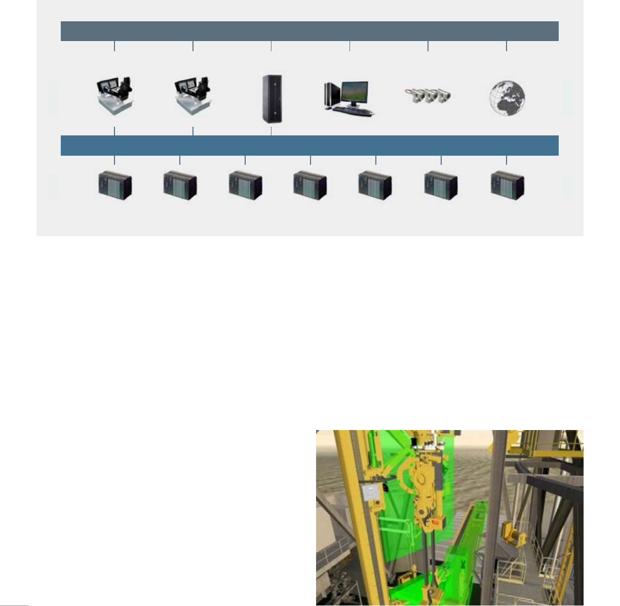
OnTrack ZMS system
The Cameron OnTrack ZMS zone management system enables
communication with other systems to help detect and avoid collisions
between drillfloor equipment.
OnTrack AWD Top driveDrawworks Mud pumps Pipe handling Roughneck OnTrack MI
C-NET
X-COM
operator chair
X-COM
operator chair
OnTrack Server OnTrack Explorer
workstation
CCTV system OnTrack DMS
I-NET
32
OnTrack DrillPilot
The Cameron OnTrack DrillPilot enables multiple drilling machines to be
controlled by a single operator. With DrillPilot, the entire drilling operation
acts as a complete system, rather than several individual machines. This
simplifies operation and preparation for the operator compared with other
conventional control systems.
■ Reduces complexity for the operator
■ All machines controlled by a single joystick
■ Increases operational efficiency by reducing pipe handshake-time and
providing more consistent tripping speeds
■ Activates next step in operational sequences automatically, at the
correct time
■ Integrated setup wizards feature allows for faster setup and line-up of
equipment for each type of operation (i.e., tripping or standbuilding)
Drilling parameter sensors
Cameron drilling parameter sensors allow for any type of sensor to be
supplied as part of our package.
OnTrack SoftTorque
The Cameron OnTrack SoftTorque consists of anti-stick-slip software
for the top drive.
■ Eliminates stick-slip
■ Improves well bore
■ Reduces torque vibrations
■ Reduces wear and tear on downhole tools
■ Improves steerable system performance
■ Reduced bit damage, longer bit runs
OnTrack DMS drilling management system
■ Makes drilling data generated on the rig available anywhere
■ Offers secure replication to onshore server
■ Can be used with any internet location
■ Can be fully interfaced on multiple rigs
■ Incorporates the OnTrack Explorer workstation for operation and
maintenance support
■ Enables drilling data to be fed into other applications (i.e., maintenance
system, reservoir model, etc.)
■ Ultimately allows for "drill from the beach" capability
Rig 1
OnTrack
Historian
OnTrack Historian
replication server
OnTrack Explorer workstation
in city offices
OnTrack Explorer workstation
alerts experts anywhere
OnTrack Explorer workstation
in drilling center
Feeding 3rd party applications
OnTrack
Historian
Rig N
33
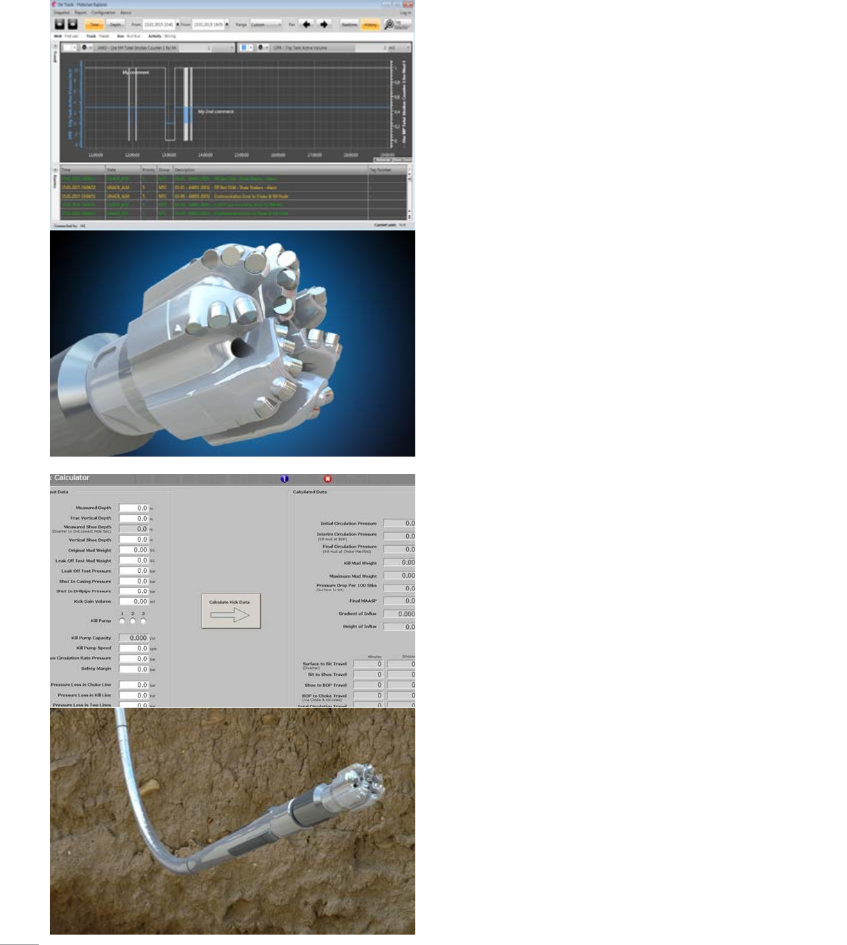
OnTrack Historian
The Cameron OnTrack Historian records all drilling activity, equipment,
alarms, and events data generated on the rig in real-time to a time and
depth series database. Historian components are integrated into the
HMI for simple accessibility.
■ Innovative method for storing all drilling data generated on the rig
■ Records data based on the depth of the drilled hole
■ Includes redundant data collectors on two physical servers to
prevent loss of data in case of component failures
■ Enables drilling data to be fed into other applications (i.e.,
maintenance system, performance logging, etc.)
■ Allows user comments to be added to relevant alarm(s)
and/or event(s)
■ Allows for data retrieval from virtually anywhere via open protocols
■ Optional secure replication of data to onshore server
OnTrack AWD analysis while drilling
The Cameron OnTrack AWD analysis while drilling consists of several
real-time algorithms used to assist and guide the driller during
drilling operations.
■ Advanced drilling software that calculates numerous parameters
such as:
● Auto driller functions (i.e., weight on bit (WOB) and ROP)
● Stands in hole
● Bit runtime and depth
● Hole depth
● Drill string configuration
● Mud tank volumes, mud flow and mud displacement
● Kick calculator, kill sheet, annular mud velocity, etc.
■ Integrated mud process control system and HMI
● Provides mud control of tanks, pits, pumps, etc.
■ Facilitates data transmission of AWD information to other consumers
via standard protocols
34
35
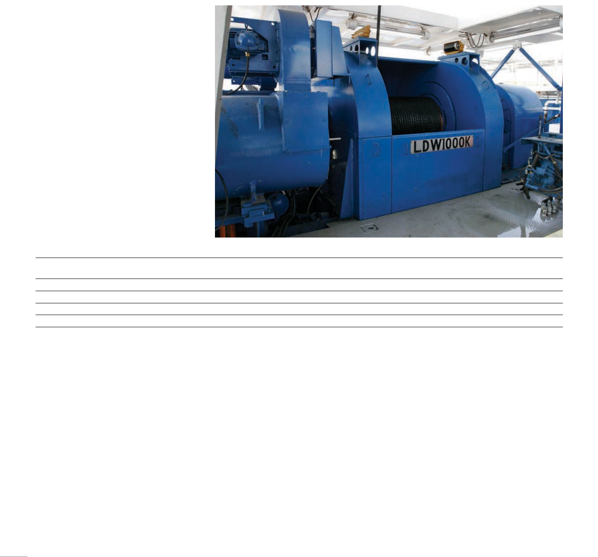
Cameron offers AC gear-driven drawworks concepts for onshore and offshore
applications. A wide range of models are available in single-speed or three-speed
designs with up to 6,000-hp ratings. Cameron offers technically advanced gear-driven,
active-heave drawworks systems with up to 11,200-hp ratings that are capable of
compensating movements on large floaters and drillships.
Drawworks
LDW series
Cameron LEWCO* AC gear-driven drawworks
offer technically advanced features to increase
drilling performance, safety and reliability.
The combination of both cost and operational
efficiency with small footprints, less weight and
reduced noise and vibration further adds to the
advantages provided by these solid machines.
■ Offered in 500/550K, 750K, 1000K, 1500K and
2000K hook load models
■ Feature an engineered braking system for
increased safety
■ Achieve higher operational speeds (in all
models) through the use of variable frequency
drive (VFD) AC motors
■ Require fewer utilities for installation and
fewer spare parts
Model Power rating DW duty,
hp [kW]
Load,
ton [tonne]
Block speed,
ft/min [m/sec]
Gears Motors Lines
LDW 550K 1,500.00 [1,103.25] 275.00 [249.48] 238.19 [1.21] 1 1 10
LDW 750K 2,300.00 [1,691.65] 375.00 [340.19] 214.57 [1.09] 1 2 12
LDW 1000K 3,000.00 [2,206.50] 500.00 [453.59] 307.09 [1.56] 1 2 12
LDW 1500K 4,500.00 [3,309.74] 750.00 [680.39] 240.16 [1.22] 1 3 14
36
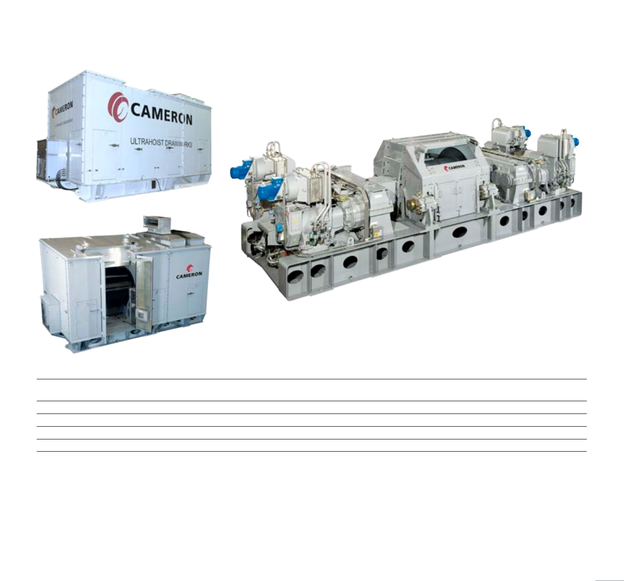
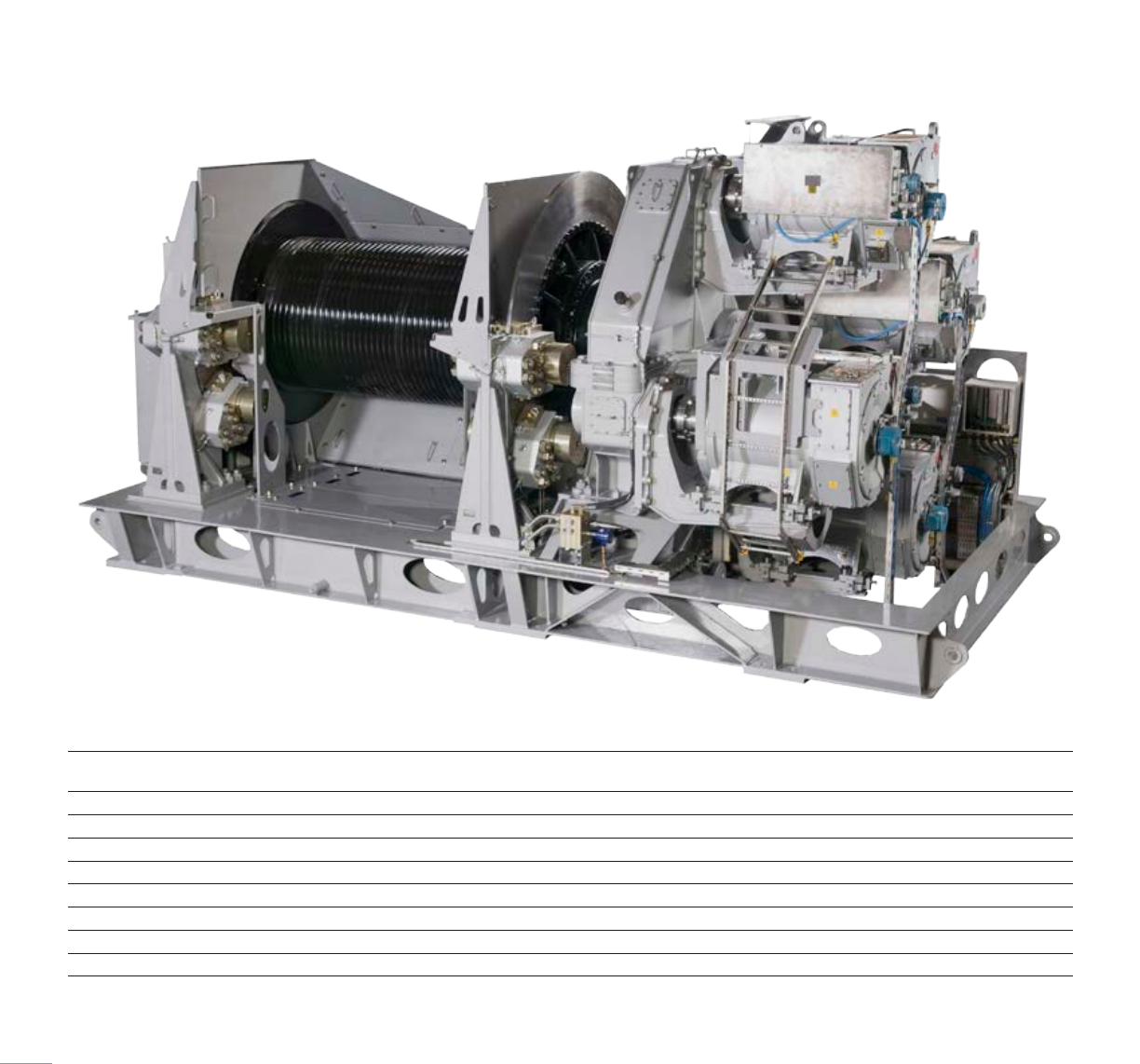
UltraHoist AHC series
The Cameron UltraHoist active-heave
compensated (AHC) drawworks delivers safe
and efficient hoisting and lowering during
traditional drilling, tripping and handling
operations, as well as accurate heave
compensation during drilling or landing of
the BOP to the seafloor. All UltraHoist AHC
drawworks are gear-driven and available in
three-speed or single-speed versions with power
input from 4.5 hp to 9 hp and a load handling
capacity of up to 1,250 ton (1,133.98 tonne).
■ Lebus grooved drum for 2in (50.8 mm) drill
line—complete with kickback rollers and
easily removable guards
■ Easily removable cable anchor
■ Control system interfaces with the Zone
Management System via the C-NET network
to enable communication with other system
PLC, such as the anti-collision system
■ Custom PLC software ensures smooth and
natural operations for the driller
■ Built-in, self-diagnostic functions
automatically warn for service and overhaul of
main components
■ Onboard HPU systems for brakes and
lubrications fitted with dual pumps
and motors
■ Internal gearboxes use a keyless design to
avoid stress configurations
■ Fail-safe braking system comprised of two
brake discs, one at each side of the drum,
and two calipers with brake pads acting on
each disc
■ Braking capacity of the emergency brakes
equal to 200% of maximum line pull
■ Automatic brake monitoring system,
includingbrake slip detection, drum creep
detection and drum response detection
■ Integrated crown and floor saver provides full
control of the various braking systems
Model Power rating DW duty,
hp [kW]
Load,
ton [tonne]
Block speed,
ft/min [m/sec]
Gears Motors Lines
UH SG 750-5600—AHC 5,600.00 [4,118.79] 750.00 [680.39] 326.77 [1.66] 1 4 14
UH SG 1250-11200—AHC 11,200.00 [8,237.59] 1,250.00 [1,133.98] 344.49 [1.75] 1 8 16
UH 3G 750-7300—AHC 7,300.00 [5,369.14] 750.00 [680.39] 393.70 [2.00] 3 4 14
UH SG 1000-8400—AHC 8,400.00 [6,178.19] 1,000.00 [907.18] 344.49 [1.75] 1 6 16
37
Model Power rating DW duty,
hp [kW]
Load,
ton [tonne]
Block speed,
ft/min [m/sec]
Gears Motors Lines
UH 3G 500-3000 3,000.00 [2,206.50] 500.00 [453.59] 393.70 [2.00 ] 3 2 12
UH 3G 650-3000 3,000.00 [2,206.50] 650.00 [589.67] 393.70 [2.00 ] 3 2 12
UH 3G 750-3660 3,660.00 [2,691.93] 750.00 [680.39] 393.70 [2.00 ] 3 2 14
UH 3G 1000-5600 5,600.00 [4,118.79] 1,000.00 [907.19] 393.70 [2.00 ] 3 4 16
UH 3G 1250-5600 5,600.00 [4,118.79] 1,250.00 [1,133.98] 393.70 [2.00 ] 3 4 16
UH SG 750-4500 4,500.00 [3,309.74] 750.00 [680.39] 275.59 [1.40 ] 1 3 14
UH SG 1000-6000 6,000.00 [4,412.99] 1,000.00 [907.19] 236.22 [1.20 ] 1 4 16
UH SG 1250-7300 7,300.00 [5,369.14] 1,250.00 [1,133.98] 236.22 [1.20 ] 1 4 16
Note: DW pull force to be limited to drill line size/type used
UltraHoist drawworks
The Cameron UltraHoist* offshore drawworks
delivers efficient hoisting and lowering during
drilling, tripping and handling operations. All
UltraHoist drawworks are AC and gear-driven.
The three-speed version offers operational
flexibility, both at high speeds and high loads.
The Cameron UltraHoist drawworks is also
simpler to use, and integrates many safety
features that are not currently offered by
other models.
■ Three-speed transmissions used between
AC motors and fixed speed gearbox provide
unique, fast line speed and pull characteristics
■ Lebus grooved drum for 1-⁄in (38.1 mm) (or
1-⁄in (41.28 mm)) drill line—complete with
kickback rollers and easily removable guards
■ Easily removable cable anchor
■ Control system interfaces with the Zone
Management System via the C-NET network
to enable communication with other system
PLC, such as the anti-collision system
■ Custom PLC software ensures smooth and
natural operation for the driller
■ Built-in, self-diagnostic functions with
automatic warning system for service and
overhaul of main components
■ Onboard HPU systems for brakes and
lubrications fitted with dual pumps
and motors
38
Traveling block
■ 500-, 650-, 750-, 1,000- and 1,250-ton
(453.59-, 589.67-, 680.39-, 907.19- and
1,133.98-tonne) models available
■ Simple and sturdy design
■ Easy access to lubrication and
greasing points
■ High-quality, durable components
■ Bondura bolts as clevis pins
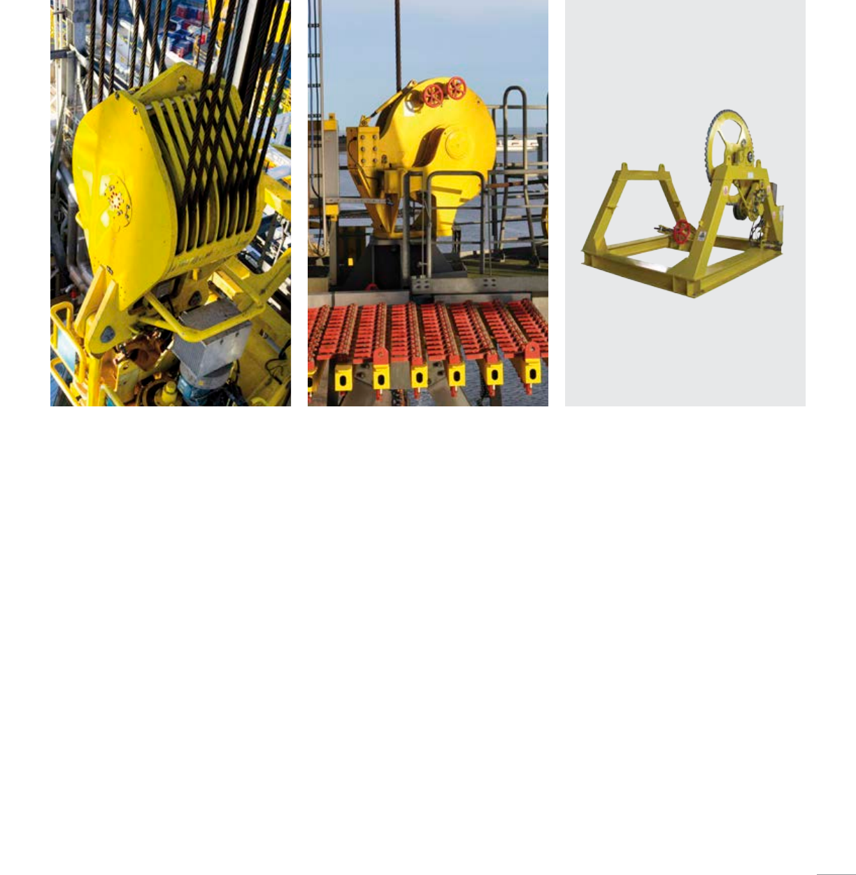
Deadline anchor
■ Designed for ease of service
and maintenance
■ Drum design enables easy slip-and-cut
■ Adjustable wire outlet direction allows for
both floor and derrick leg mounting
■ Dual strain gauge in load cell
■ Handy service pocket
Drill line storage reel
■ Robust frame/skid for drum carriage
■ Quick change of drum
■ Robust pinion/cog wheel transmission
for drilling line spooling
■ Hydraulic drive to ease slip-and-cut
operations; hydraulic drive also serves
as brake when not in operation
Cameron provides a range of high-performance hoisting equipment designed to
enhance safety and reduce maintenance.
Hoisting Equipment
39
40
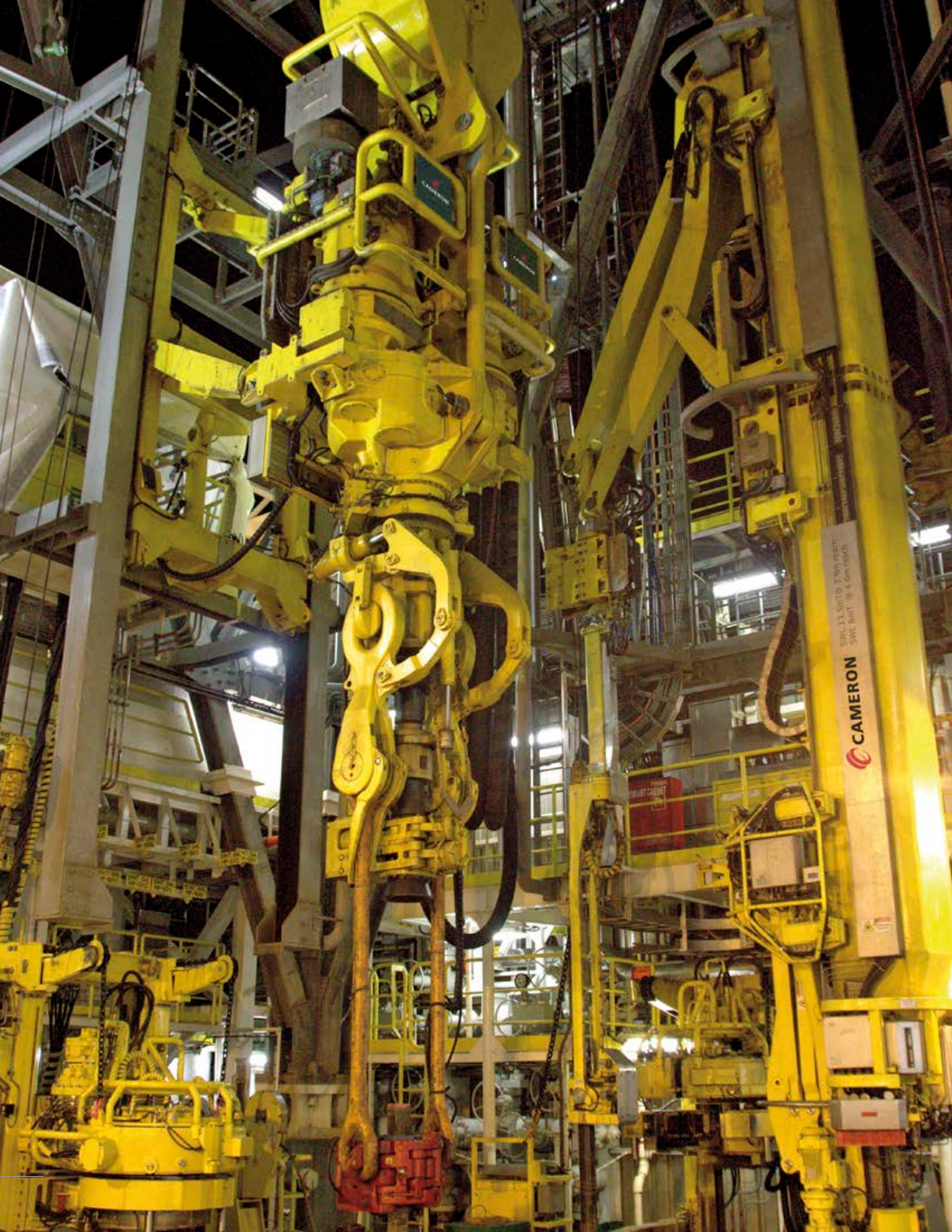
Cameron offers a range of 500-ton (453.59-tonne) to 1,250-ton (1,133.98-tonne)
AC-driven top drive systems for demanding drilling applications. All of our top drives
come with several accessories that have been tailor-made to meet rig requirements.
High quality components, modularity to reduce maintenance and down time, as well
as reliable gearboxes, controls, and automation make Cameron top drives the preferred
choice for any drilling crew.
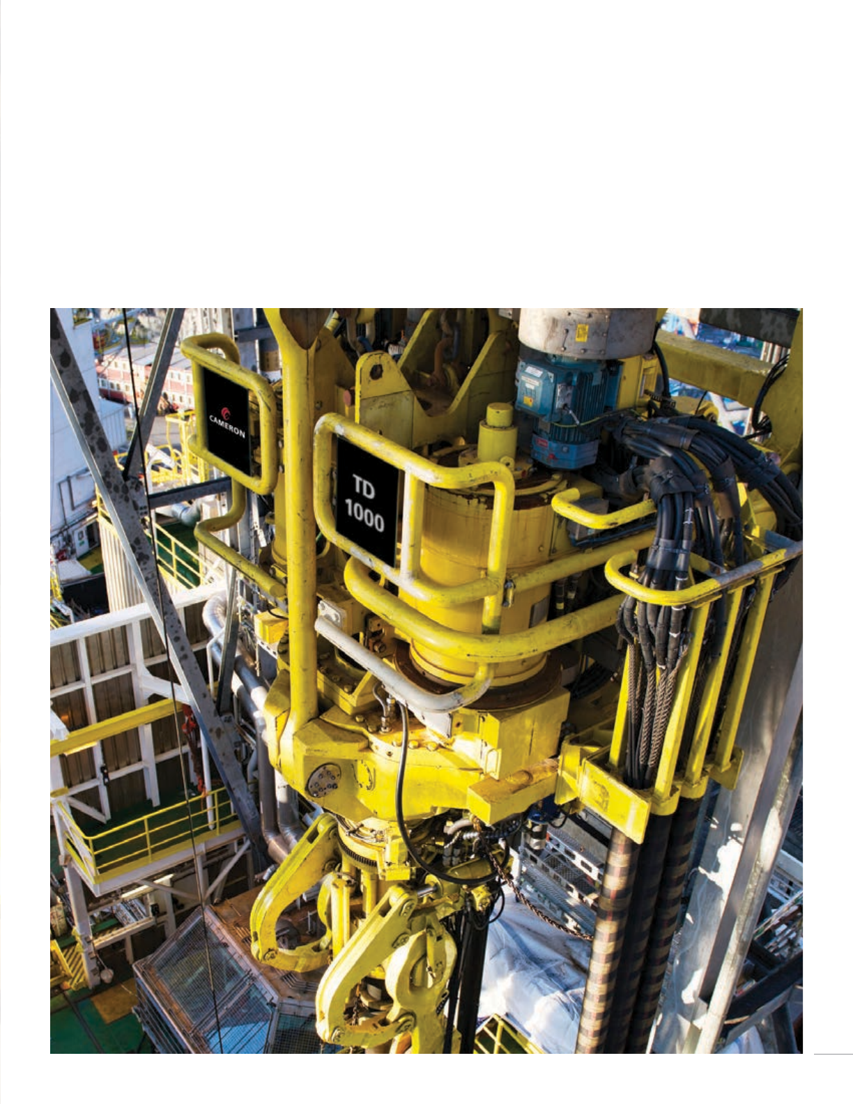
Top Drive Systems
41
TD 1500-AC-2M TD 1250-AC-2M TD 1000-AC-2M TD 500/650/750-AC-1M TD 750-AC-1M-C
Drive type AC AC AC AC AC
Capacity in elevator 1,500.00 ton
[1,360.78 tonne]
1,250.00 ton
[1,133.98 tonne]
1,000.00 ton
[907.19 tonne]
500.00 ton/650.00 ton/700.00 ton
(453.59 tonne/589.67 tonne/
635.03 tonne)
750.00 ton
[680.39 tonne]
Power rating 2,300.00 hp/3,000.00 hp
[1,691.65 kW/2,206.50 kW]
2,300.00 hp
[1,691.65 kW]
2,300.00 hp
[1,691.65 kW]
1,150.00 hp
[845.82 kW]
1,150.00 hp
[845.82 kW]
Motors 2 2 2 1 1
Continuous torque 120,000.00 ft-lb/157,000 ft-lb
[162,698.15 N·m/212,863.42 N·m]
98,000.00 ft-lb
[132,870.16 N·m]
98,000.00 ft-lb
[132,870.16 N·m]
66,000.00 ft-lb
[89,483.98 N·m]
66,000.00 ft-lb
[89,483.98 N·m]
Maximum speed 250 rpm 274 rpm 274 rpm 263 rpm 263 rpm
Torque at
maximum speed
40,000.00 ft-lb
[54,232.72 N·m]
43,900.00 ft-lb
[59,520.40 N·m]
43,900.00 ft-lb
[59,520.40 N·m]
17,500.00 ft-lb
[23,726.81 N·m]
17,500.00 ft-lb
[23,726.81 N·m]
Speed at
maximum torque
100 rpm 123 rpm 123 rpm 91 rpm 91 rpm
Maximum
breakout torque
147,000.00 ft-lb/220,000 ft-lb
[199,305.24 N·m/298,279.95 N·m]
125,000.00 ft-lb
[169,477.24 N·m]
125,000.00 ft-lb
[169,477.24 N·m]
115,000.00 ft-lb
[155,919.06 N·m]
99,000 ft-lb
[134,225.98 N·m]
Mud line path 4.00in
[101.60 mm]
3.25in
[82.55 mm]
3.25in
[82.55 mm]
3.25in
[82.55 mm]
3.25in
[82.55 mm]
Water course
pressure rating
7,500.00 psi
[517.11 bar]
7,500.00 psi
[517.11 bar]
7,500.00 psi
[517.11 bar]
7,500.00 psi
[517.11 bar]
7,500.00 psi
[517.11 bar]
IBOP standard 20,000.00 psi
[1,378.95 bar]
15,000.00 psi
[1,034.21 bar]
15,000.00 psi
[1,034.21 bar]
15,000.00 psi
[1,034.21 bar]
15,000.00 psi
[1,034.21 bar]
Features
■ High-capacity thrust bearing
■ Helical-cut gear teeth (carburized and
grinded) increase service life and reduce noise
level and maintenance
■ Gearbox lubrication ensures optimal
conditions for gears and bearings under all
environmental conditions
■ Self-calibrating thread compensation
system uses analogue stroke sensor to
optimize performance
■ Bell housings between AC motors and
gearbox provide precise alignment as well as
protect the flexible coupling between motor
output shaft and gearbox pinion shaft
■ High-capacity knuckle link tilt system
allows handling of latest model of «fail-
safe» elevator—from drilling to maximum
kickout mode
■ Wash pipe can be replaced within minutes
■ Rotary head with 18 ports
■ Programmable arbitrary stop positions for
the pipehandler rotate function allow the
driller to set a number of predefined elevator
open positions
■ Customized PLC software provides easy,
accurate and natural operator controls from a
single point
■ Noise reduction
■ Dual retention of all fasteners
■ Torque wrench design eliminates risk of
accidental break out of drillstem subs
TD 1500-AC-2M, TD 1250-AC-2M, TD 1000-AC-2M TD 750-AC-1M, TD 650-AC-1M, TD 500-AC-1M 750-AC-1M-C
42
SR IV-P SR III-P SR III-XY
Racking arrangement Parallel Parallel Parallel
Stand type Quad Triple Triple
Tubular maximum length 135.00 ft [41.15 m] 96.00 ft [29.26 m] 96.00 ft [29.26 m]
Number of arms (guide/lift) 2G/1L 1G/1L 1G/1L
Guide arms vertical movement 6.56 ft [2.00 m] 6.56 ft [2.00 m] —
Lower guide arm vertical movement 11.48 ft [3.50 m] 11.48 ft [3.50 m] —
Upper guide arm vertical movement 29.53 ft [9.00 m] 29.53 ft [9.00 m] —
Drive type (lift/turn/sideways) AC AC Hydraulic
Lifting capacity 16.53 ton [15.00 tonne] 11.02 ton [10.00 tonne] 11.02 ton [10.00 tonne]
Maximum reach 16.90 ft [5.15 m] 16.90 ft [5.15 m] 15.09 ft [4.60 m]
Rotation 360 degree 360 degree 225 degree
Gripper head pipe range 3.50–14.00in
[88.90–355.60 mm]
3.50–14.00in
[88.90–355.60 mm]
3.50–9.75in
[88.90–247.65 mm]
Pick up elevator pipe 2.88–14.00in
[73.15–355.60 mm]
2.88–14.00in
[73.15–355.60 mm]
2.88–75in
[73.15–247.65 mm]
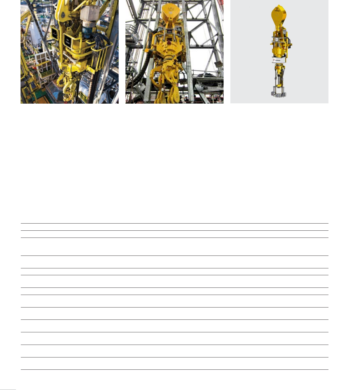
Cameron delivers a full range of high-performance vertical pipe handling solutions
for a variety of offshore applications. Our product offering includes triple and quad
SmartRacker vertical pipe-handling systems, two-arm systems, double and triple
X-Rackers and fingerboards, handling everything from singles to quadruple stands in a
safe and efficient manner.
Vertical Pipe Handling Systems
SmartRacker IV-P and SmartRacker III-P systems
Cameron SmartRacker* systems fulfill any pipe handling functions on a modern drillfloor. With their main functions driven by AC technology, our
SmartRacker systems perform tripping and standbuilding safely and efficiently. The design includes advanced features, but is simple to use and produces
smooth and accurate movements.
43
SmartRacker XY system
■ Versatile for handling of triple stands, horizontal-to vertical, as well
as assistance in handling smaller bits, subs and objects
■ Fully-automated functions with focus on extremely simple use
■ All main functions driven by hydraulic motors
■ One gripper head handles all drillpipe, casing and drill collar from
3-⁄ to 9-⁄in (88.9 to 247.65 mm) (2-⁄in (73.03 mm) optional)
■ Accurate soft stabbing function saves threads on drillpipes
■ Works in concert with the SmartCat* catwalk machine for horizontal-
to-vertical operations; no need for overhead v-door machines
■ Pickup elevator with fail-safe mechanical lock range from 2-⁄ to
9-⁄in (73.03 to 247.65 mm) pipe size
■ Robust design with few well-protected sensors
■ User-friendly HMI with onscreen operator guidance
BridgeRacker*
■ Suitable for drillships or jack-ups
■ Extremely compact design
■ 11.02 ton (10 tonne) lifting capacity
■ 9.84 ft (3 m) lifting height
■ Handles pipe from 3-⁄ to 14in (88.9 to 355.6 mm)in size
■ Easily retrofittable, due to limited integration needed with derrick and
control system
■ Can be controlled from portable operator panel
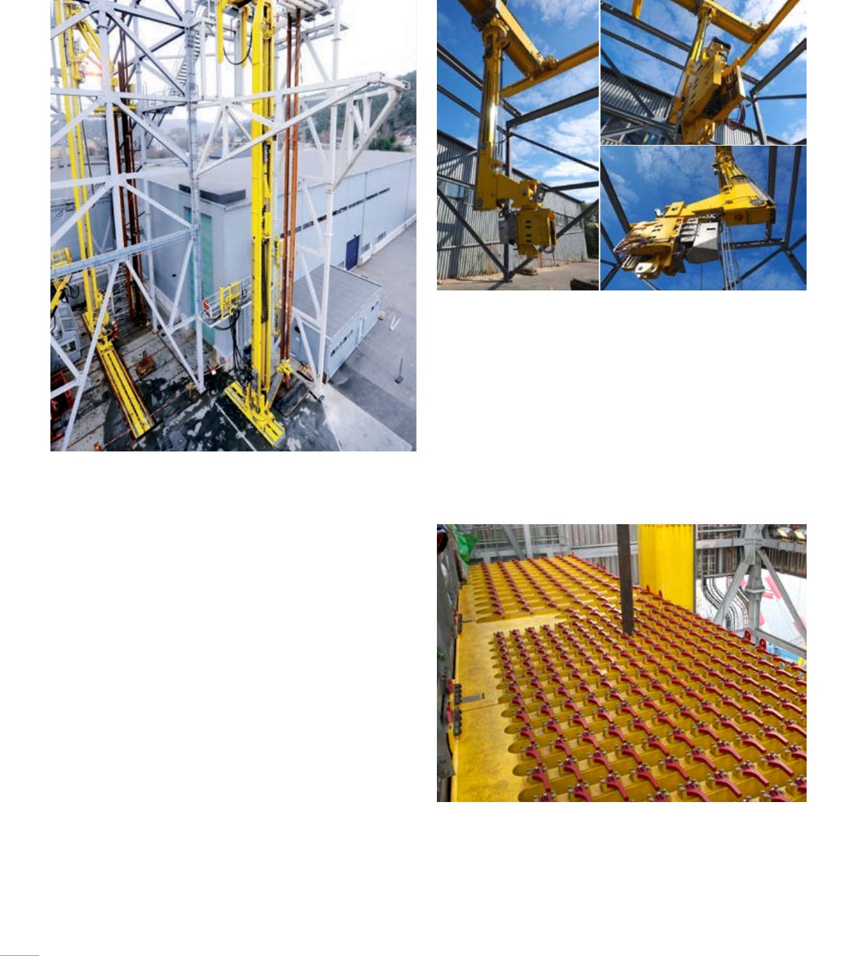
Fingerboards
Cameron delivers various types of fingerboards. All fingerboards are tailor-
made with respect to storage capacity, dynamic considerations, interfaces,
options and choice of remote control or automated functionality.
44
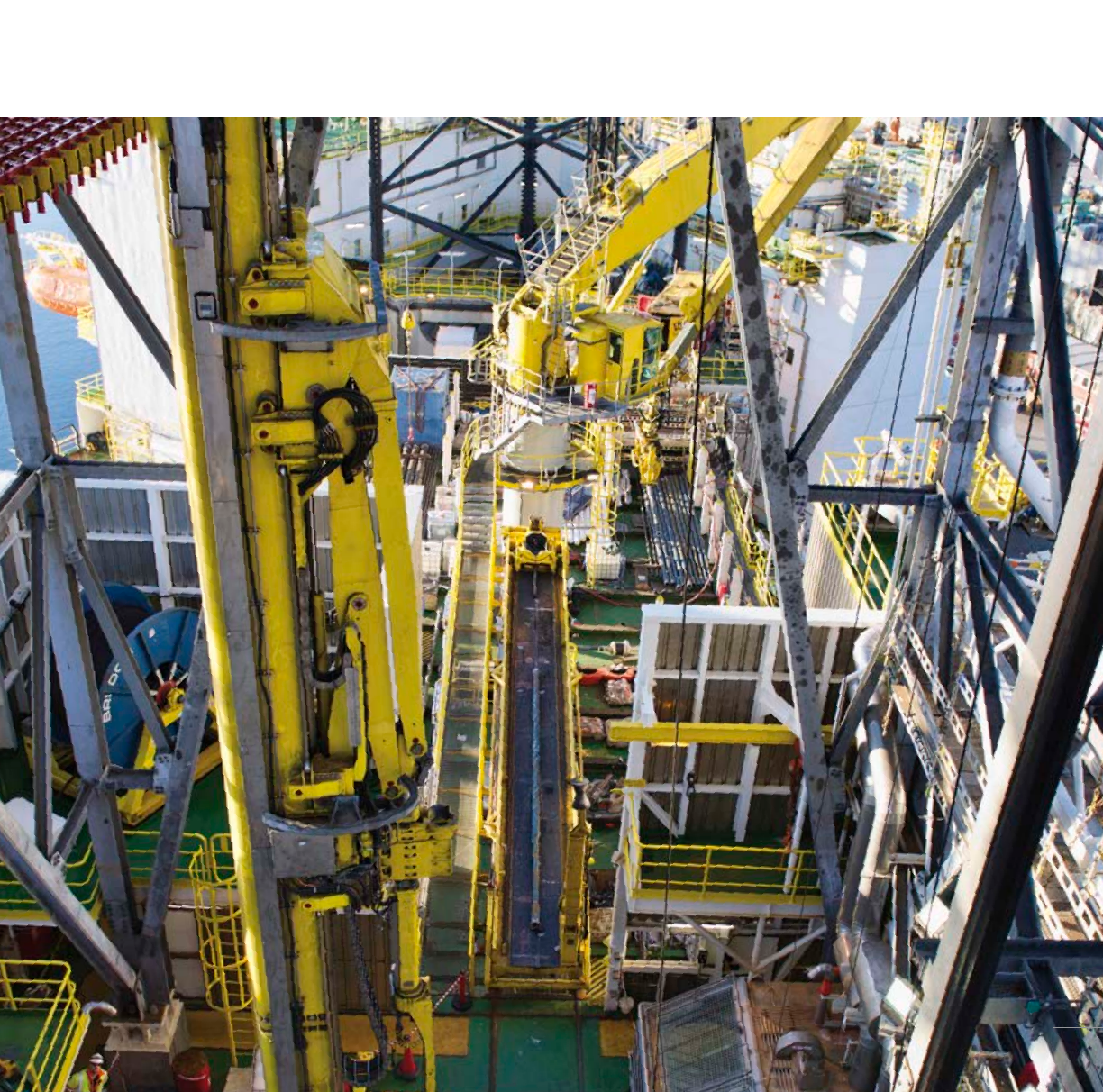
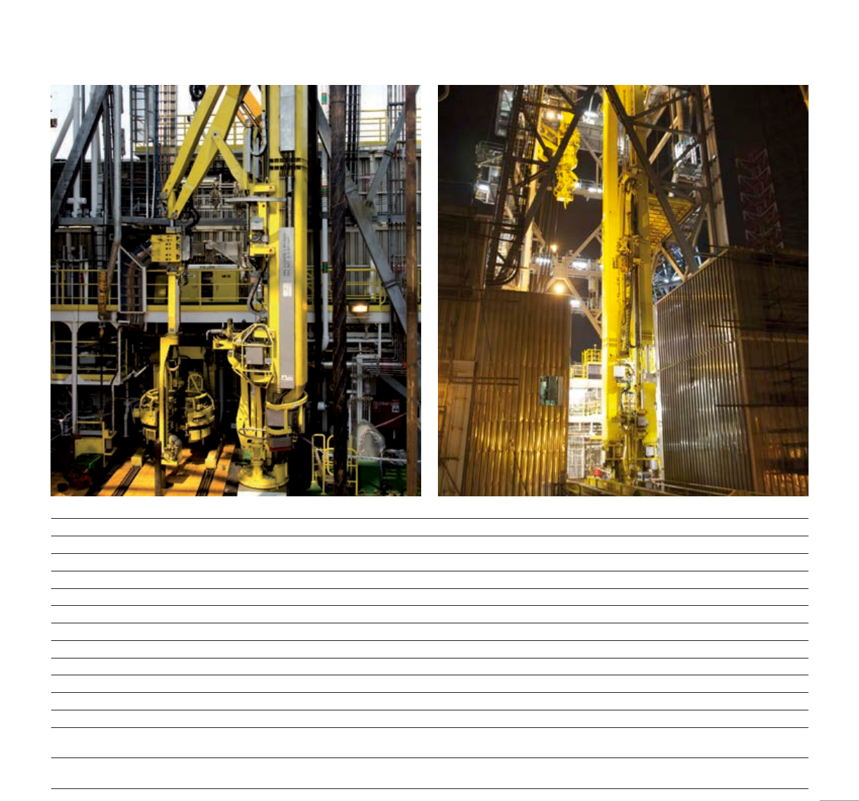
Cameron delivers a full range of high-performance horizontal pipe handling solutions
for a variety of offshore applications. Our product offerings include catwalk machines,
conveyers, feeding tables, pipe deck cranes and tail-in arms that handle everything
from drillpipe to casing and marine risers in a safe and efficient manner. Cameron
delivers both tailor-made, standalone equipment and complete systems designed for
tripping and offline standbuilding of casing and drillpipe while drilling. Cameron has a
range of products that can be used to optimize pipe handling through rig upgrades as
well as new builds.
Horizontal Pipe Handling Systems
45
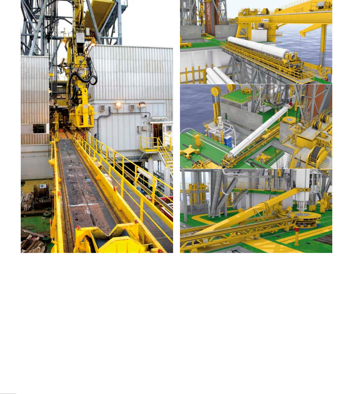
Catwalk
The Cameron catwalk machine runs horizontal from the pipe rack area
onto the drillfloor to deliver and pick up singles of drillpipe, drill collars,
and casing as well as smaller items such as subs, bits, and pumps.
■ Horizontal handling of all drillpipe improves overall safety and ease
of operation
■ Tail-in-arm for guiding pipe to and from vertical position
■ Fully-automated system that can be interfaced with other machines
on the drillfloor
■ Twin skate travel motors, gears, and brakes
■ Fail-safe design philosophy
■ Transport frame with 33.07 ton (30 tonne) capacity
Riser catwalk
The riser catwalk machine runs horizontal from the riser rack area onto the
drillfloor to deliver and pick up risers.
■ Versatile to accommodate various drillfloor layouts, with a skate capable
of up to 131 ft (39.93 m) of horizontal travel
■ Uplift unit designed to lift the front end of the risers in order to
accommodate for various riser gimbal heights
■ Tail in unit, for tail-in of risers, built into the skate
■ Includes transport frame with 55.12 ton (50 tonne) lifting capacity,
which allows for of various pieces of equipment (i.e., spider, gimbal,
etc.) to and from the drillfloor
■ Fully-automated system that can be interfaced with other machines on
the drillfloor
46
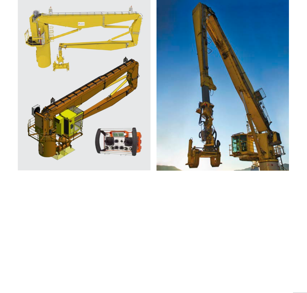
Pipe deck crane, knuckle boom with «JibLink»
■ Knuckle boom for direct connection with the load
■ Lightweight and cost-efficient «JibLink» design provides wider operating
envelope without the need for any telescope in the jib
■ Lifting capacity of 5.51 ton (5tonne)
■ Wide operating radius: 8.2 ft to 85.3 ft (2.5 m to 26 m) reach
■ Handles pipe with up to 20in (508mm) diameter and 45 ft
(13.72m) length
■ Simple, low-maintenance gripper yoke
■ LED floodlights
■ Onboard HPU
Optional:
■ Operator cabin with HVAC
■ CCTV in gripper head
■ Winch
Pipe deck crane, knuckle boom
■ Knuckle boom for direct connection with the load (no wires or
swinging load)
■ Lifting capacity range of 5.51 ton to 38.58 ton (5 tonne to 35 tonne)
■ Operator-friendly cabin
■ Onboard HPU
Optional:
■ Telescopic jib
■ Winch
■ Various gripper yoke designs available
The Cameron pipe deck crane is designed as an advanced stand-alone system
for horizontal handling of tubular between the pipe deck and the tubular catwalk
machine. The crane is a knuckle-boom type crane with a circular pedestal, specially
designed to have a simple interface and large operating envelope.
Pipe Deck Crane
47
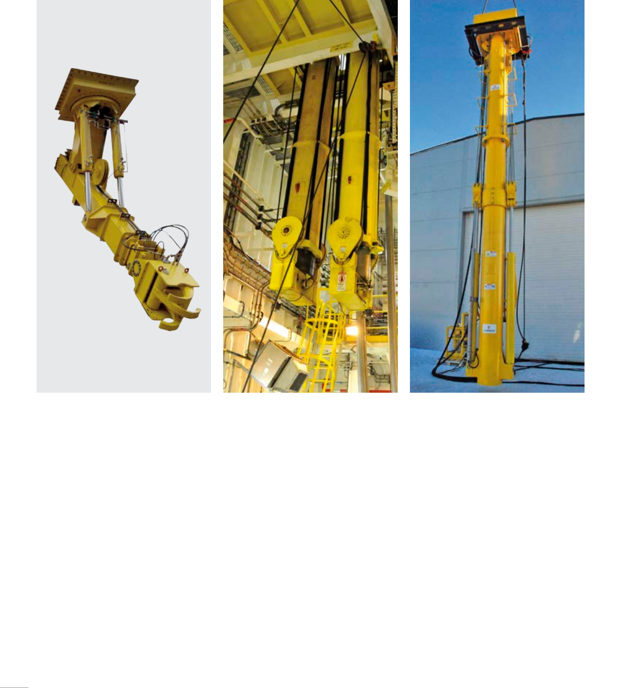
Drillfloor Pipe Handling Equipment
Drillfloor manipulator arm
■ Versatile arm installed under guide rails or
other suitable locations
■ Accommodates tubular ranging from 2.88 to
47in (73.15 to 1,193.8 mm)
■ Telescoping range of 17.06 ft (5.2 m)
■ 180-degree swing
■ 1,322.77 lb (600 kg) extended lifting capacity
Floor handling arm
■ Versatile handling arm can be placed on
drillfloor or cellar deck
■ Adapter for gripper or work basket
■ Lifting capacity of up to 6.61 ton (6 tonne) at
8.2 ft (2.5 m)
■ Maximum reach for guiding of 28.54 ft (8.7 m)
■ 360-degree swing
Mouseholes
The main function of the mousehole is to
hold tubulars during standbuilding or stand
breakdown. Mouseholes are designed to utilize
the area below drilling, and are flush-mounted
with the drillfloor upon installation.
Available in various designs:
■ Fixed
■ Telescopic
■ Rotating
■ Colt
■ Rabbit
■ Rotary-mounted fixed
All types can be equipped with the following:
■ Hydraulic or spring-powered centralizer
■ Patented shock absorbing system
■ Mud drain system
48
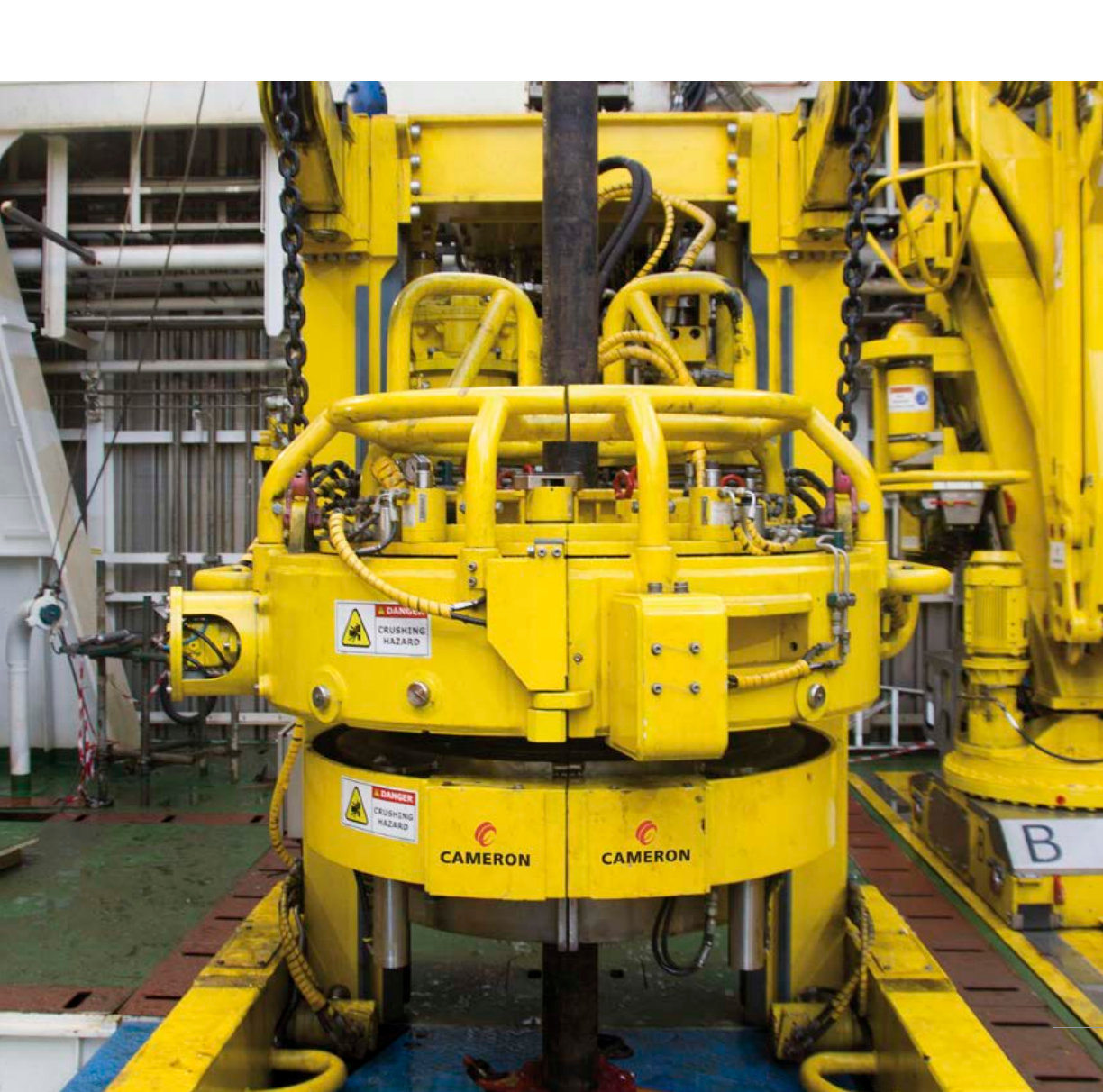
Cameron delivers high-performance hydraulic roughnecks including the patented
JiM20 large-tubular hydraulic roughneck, one of the most advanced hydraulic
roughnecks on the market, capable of handling tubulars from 2-⁄ to 20in (73.15 to
508mm). The JiM 20 hydraulic roughneck features a six-grip drive ring that transmits
torque accurately onto the tool joint with a built-in pipe doper and mud bucket. The
JiM 20 hydraulic roughneck is fully automated and can transmit torque/turn data
directly to «the beach» in real time.
Hydraulic Roughnecks
49
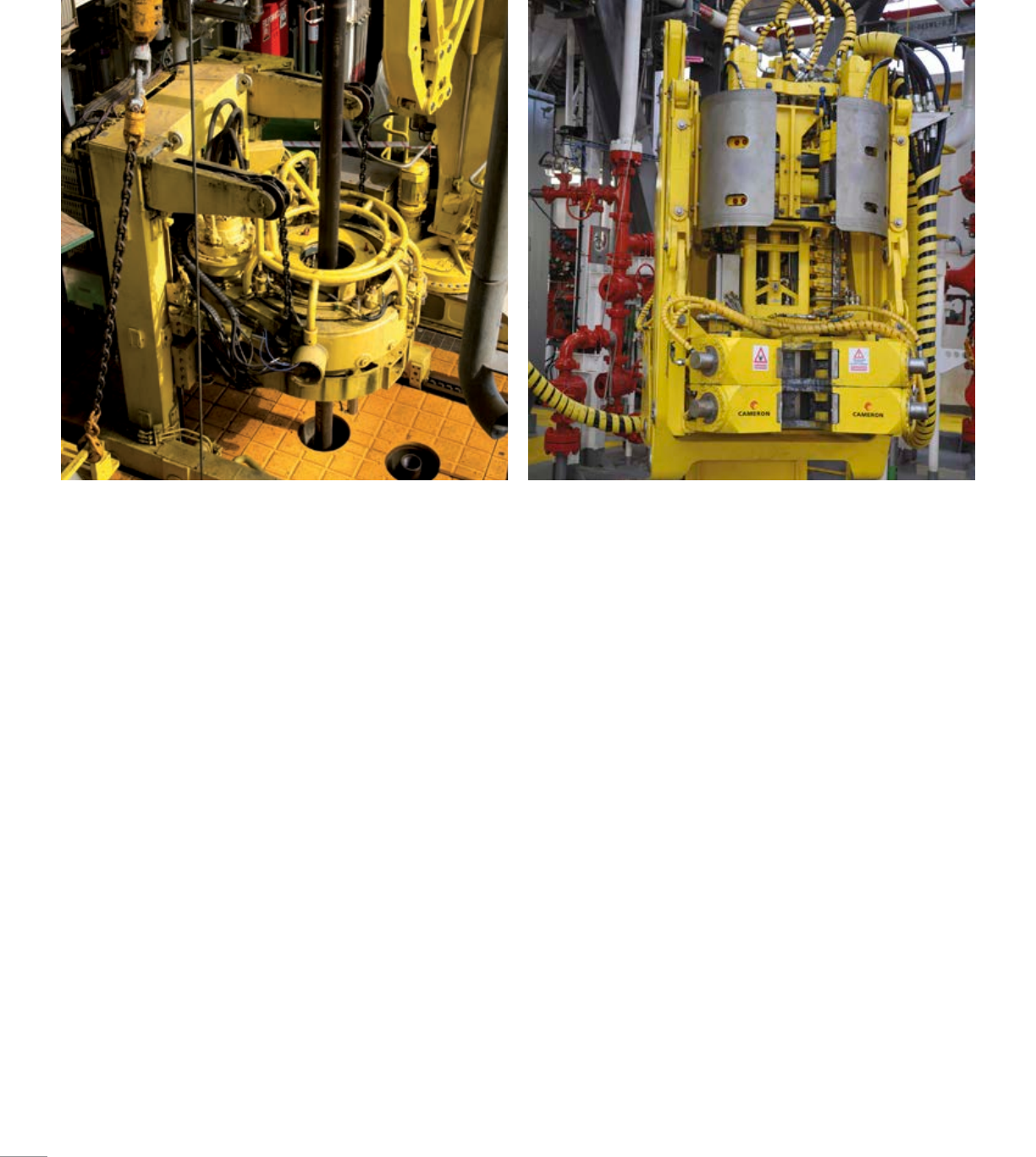
JiM 20
The Cameron JiM 20 hydraulic roughneck embraces a complete
equipment package to perform jointing operations on all tubular pipes
used for drilling, casing, and completing the well.
The JiM 20 hydraulic roughneck handles spinning, make up and break
out of all drillpipes, drill collars, casing and tubing—from 2-⁄in
(60.45mm) drillpipe to 20in (508 mm) casings—by changing jaw inserts.
Roughneck tubing tongs and casing tongs are replaced with the JiM 20
hydraulic roughneck.
■ Unique split driving design for continuous rotation
■ Six mechanically-synchronized dies in each jaw
■ Extreme torque capability of up to 184,390.54 ft-lb (250 kN·m)
● Bit breaking at full torque
● Top drive backup at full torque
■ Integrated cleaning and doping system
■ Integrated mud bucket
■ Allows for quick changes between drillpipe and casing modes
(approximately 14 minutes)
JiM 10
The design of the Cameron JiM 10 hydraulic roughneck delivers a cost-
effective, modern hydraulic roughneck in a compact format. Featuring an
advanced control system, the JiM 10 hydraulic roughneck keeps safety in
mind and is a sensible choice for today’s demanding drilling needs.
The Cameron JiM 10 hydraulic roughneck is an advanced system for
make up and break out of drillpipe and drill collars, engineered for a
tubular range of 3-⁄ to 10in (88.9 to 254 mm). The JiM 10 hydraulic
roughneck features a torque wrench in an articulated arm, allowing
the torque wrench and spinner assembly to travel from parked position
to well center. The elevation system ensures that the JiM 10 hydraulic
roughneck is capable of handling a wide range of stick ups with ease and
high precision. Additionally, casing modems are available for the JiM 10
hydraulic roughneck.
■ Compact design
■ Triple-grip torque wrench with integrated clamp cylinders
■ Powerful spinner (3,466.54 ft-lb (4.7 kN·m)) with high-grip rollers
■ Synchronized clamps
■ Smart clamp system with adjustable clamp pressure
■ Short (T-P) or long (T-P-L) reach models available
■ High make up and breakout torque of 103,258.7 ft-lb to
147,512.43ft-lb (140 kN·m to 200 kN·m)
50
Model code GR01 GR02 GR03
Product model JiM 10 T-P JiM 10 T-P-L JiM 10 T-R
Diameter range, drilling tubular 3-⁄–10in
[88.90–254.00 mm]
3-⁄–10in
[88.90–254.00 mm]
3-⁄–10in
[88.90–254.00 mm]
Diameter range, casing and tubing ———
Torque capacity, make up 103,258.70 ft-lb [140.00 kN·m] 103,258.70 ft-lb [140.00 kN·m] 103,258.70 ft-lb [140.00 kN·m]
Torque capacity, break out 103,258.70 ft-lb [140.00 kN·m] 147,512.42 ft-lb [200.00 kN·m] 147,512.42 ft-lb [200.00 kN·m]
Torque capacity, back up ——103,258.70 ft-lb [140.00 kN·m]
Torque capacity, bit breaking ——103,258.70 ft-lb [140.00 kN·m]
Spinner torque 3,466.54 ft-lb [4.70 kN·m] 3,466.54 ft-lb [4.70 kN·m] 3,466.54 ft-lb [4.70 kN·m]
Travel/extend range 75.59in/94.69in
[1,920.00 mm/2,405.00 mm]
153.54in/193.39in
[3,900.00 mm/4,912.00 mm]
275.59in
[7,000.00 mm]
Parked size (l × w × h) 4.62 ft × 4.43 ft × 8.50 ft
[1.41 m × 1.35m × 2.59 m]
7.41 ft × 5.12 ft × 8.96 ft
[2.26 m × 1.56 m × 2.73 m]
6.30 ft × 6.30 ft × 8.30 ft
[1.92 m × 1.92 m × 2.53 m]
Integrated mud bucket No No No
Weight 5.40 ton [4.90 tonne] 8.71 ton [7.90 tonne] 8.71 ton [7.90 tonne]
Hazardous area classification ATEX Zone 1 ATEX Zone 1 ATEX Zone 1
Class ABS / DNV Class II ABS / DNV Class II ABS / DNV Class II
Model code GR12 GR20
Product model JiM 10 M-P-L JiM 20
Configuration CDT10 CCT9 CCT22
Diameter range, drilling tubular 3-⁄–10in
[88.90–254.00 mm]
— — 2-⁄–9-⁄in
[73.15–241.30 mm]
Diameter range, casing and tubing — 2-⁄–9in
[60.45–228.60 mm]
9–22in
[228.60–558.80 mm]
5–22in
[127.00–558.80 mm]
Torque capacity, make up 103,258.70 ft-lb
[140.00 kN·m]
25,077.11 ft-lb
[34.00 kN·m]
81,131.84 ft-lb
[110.00 kN·m]
184,390.54 ft-lb
[250.00 kN·m]
Torque capacity, break out 147,512.42 ft-lb
[200.00 kN·m]
25,077.11 ft-lb
[34.00 kN·m]
81,131.84 ft-lb
[110.00 kN·m]
184,390.54 ft-lb
[250.00 kN·m]
Torque capacity, back up ———184,390.54 ft-lb
[250.00 kN·m]
Torque capacity, bit breaking ———184,390.54 ft-lb
[250.00 kN·m]
Spinner torque 3,466.54 ft-lb
[4.70 kN·m]
Variable motor displacement Variable motor displacement 8,850.75 ft-lb
[12.00 kN·m]
Travel/extend range 157.48in/208.66in
[4,000.00 mm/5,300.00 mm]
157.48in/208.66in
[4,000.00 mm/5,300.00 mm]
157.48in/208.66in
[4,000.00 mm/5,300.00 mm]
275.59in
[7,000.00 mm]
Parked size (l × w × h) 7.61 ft × 5.12 ft × 8.96 ft
[2.32 m × 1.56 m × 2.73 m]
7.91 ft × 5.25 ft × 8.96 ft
[2.41 m × 1.60 m × 2.73 m]
9.32 ft × 6.20 ft × 8.96 ft
[2.84 m × 1.89 m × 2.73 m]
9.38 ft × 7.25 ft × 9.84 ft
[2.86 m × 2.21 m × 3.00 m]
Integrated mud bucket No No No Yes
Weight 10.91 ton [9.90 tonne] 8.71 ton [7.90 tonne] 10.25 ton [9.30 tonne] 13.78 ton [12.50 tonne]
Hazardous area classification ATEX Zone 1 ATEX Zone 1 ATEX Zone 1 ATEX Zone 1
Class ABS / DNV Class II ABS / DNV Class II ABS / DNV Class II ABS / DNV Class II
51
Cameron delivers a range of innovative drillfloor tools for a variety of offshore applications.
Drillfloor Tools
Hydraulic cathead
■ Designed for easy service
and maintenance
■ Remote operation
■ Pad eyes for backup tongs on
swing sheave
■ Valve cabinet for
drillfloor installation
■ Remote operation; no crew
needed on floor during operation
■ Fail-safe isolation valve
Utility winch
■ Lifting capacity ranging from 1.1 ton to
16.53 ton (1 tonne to 15 tonne)
■ Controlled from winch or optional
remote control
■ Certified to DNV Drilling Plant and
ABS+CDS (other requirements available
upon request)
Man-rider winch
■ Compact and versatile man rider
■ Controlled from winch or optional
remote control
■ Delivered in accordance with any approval
and certificate requirement(s)
■ Certified to DNV Drilling Plant and
ABS+CDS (other requirements available
upon request)
Back-up stabber
■ Offers backup when making connections
with high stick up
■ Easily installed behind top drive guide rails
■ Torque capacity of up to 88,500 ft-lb
(119.99 kN·m)
Work basket
■ 551.16 lb (250 kg)
basket capacity
■ ±45-degree boom swing
■ Hydraulic unit rated for
ZoneII operation
■ Double-telescopic boom can be
tilted or slewed
■ Emergency stop on local and
remote control panels
Mud bucket
■ Long reach
■ Handles wide range of stick ups
■ Quick replacement of mud seal
■ Quick connections on mud hose
■ Emergency stop located in
control stand
Rotary table
■ Supplied with spiral-bevel,
induction-hardened gears
■ Include a forged-steel fabricated
housing and a heat-treated
forged-steel turntable
■ Lever access from the top to lock
the table in position
52
Cameron delivers a complete range of BOP handling systems for semisubmersibles,
drillships, platforms, and jack-ups. Our systems are designed and built with focus on easy
maintenance, durability, and the ability to withstand even the harshest environments.
Cameron provides solutions to meet our customer’s requirements and specifications.
Cellar Deck Equipment
BOP handling equipment for platforms
and jack-ups:
■ BOP monorail hoists up to 137.79 ton
(125tonne)
■ BOP overhead cranes up to 248.02 ton
(225tonne)
■ BOP service cranes up to 38.58 ton (35 tonne)
■ BOP fork cranes up to 137.79 ton (125 tonne)
■ BOP trolleys (of various designs)
■ BOP skids up to 248.02 ton (225 tonne)
■ BOP tensioner cylinders
■ X-mas tree skids up to 165.35 ton (150 tonne)
■ X-mas tree skids with turn-table
BOP handling equipment for
semisubmersibles and drillships:
■ BOP/LMRP cranes up to 661.38 ton
(600tonne) (with or without BOP/LMRP
guiding on pinned leg)
■ AC BOP cranes with variable frequency
drives (VFDs)
■ BOP service cranes (of various designs)
■ BOP forklift carriers up to 716.5 ton
(650 tonne)
■ BOP moonpool trolleys up to 1,102.31 ton
(1,000 tonne)
■ BOP skids (of various designs) up to
661.38ton (600 tonne)
■ BOP underhull guiding
■ BOP/LMRP bulkhead guiding
■ BOP/LMRP seafixing
Various cellar deck handling equipment:
■ X-mas tree handling cranes up to 165.35 ton
(150 tonne)
■ X-mas tree skids up to 165.35 ton (150 tonne)
■ X-mas tree stack-up guide
■ X-mas tree guide arms
■ Trip saver trolleys up to 1,102.31 ton
(1,000 tonne)
■ Test stump retraction unit
■ Connector removal skid
■ STiCS stab-in connection system
■ MUX cable tensioning system
53
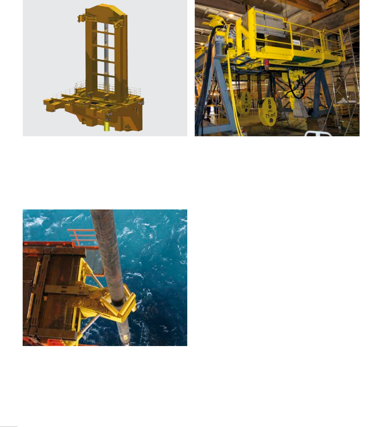
BOP handling equipment
■ Skidding of BOP directly on to forklift
■ Fully-guided BOP
■ Integrated test stump retraction unit
BOP crane
■ VFD-driven AC crane with pneumatic auxiliary hoists
■ Emergency caliper brakes with 220% safe working load (SWL)
brakingforce
■ API 7K and DNV compliant
Casing guide
■ Guides casing through the splash zone
■ Eliminates casing stickup movement
■ Increases casing running speed
54
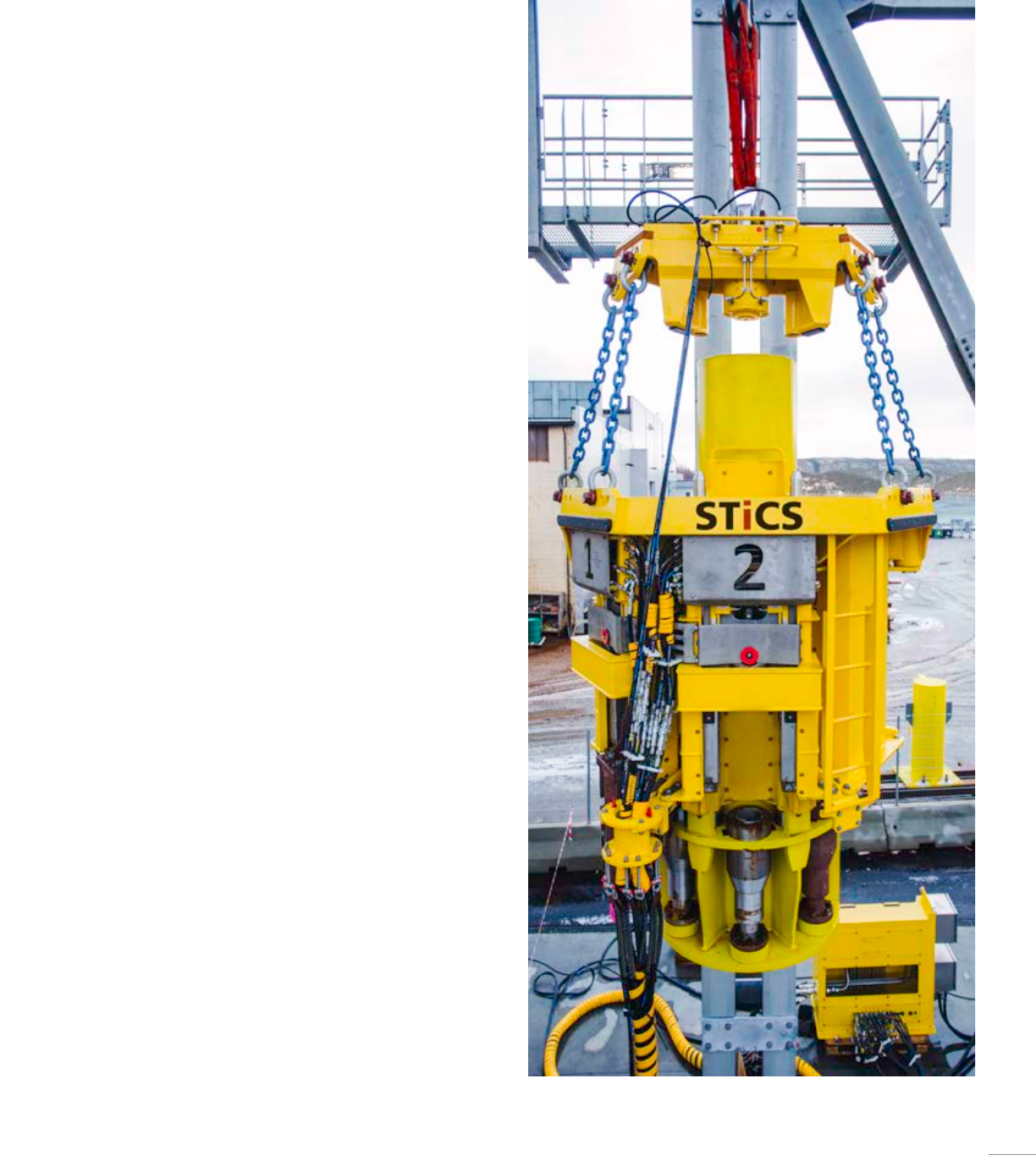
■ Eliminates hazardous work above open water by allowing the
operator to safely connect or disconnect the goosenecks to/from
the telescopic joint via a remote operated panel
■ All hydraulic connections are located on the STiCS system executer
assembly, no onboad hydraulics stay on the telescopic joint
The STiCS stab-in connection system
safely and quickly connects heavy choke
and kill hoses to the riser slip joint to
save hours of rig time while reducing
hazardous work above water. The
operator remotely stabs and makes up
all riser hose connections then stores
and hides the hydraulic handling arms
and actuators. Corrosion-resistant
gooseneck connections remain fail-safe
locked onto the riser.
For easy maintenance access,
disconnection is done in reverse
order by parking the hose/gooseneck
assemblies at the side of the moon pool.
Handling arms are mounted on the BOP
trolley or moon pool structure. STiCS
systems can be used with both in-line
and wireline tensioners. The termination
receptacles may be welded or clamped
onto any telescopic joint.
Stab-in Connection System
STiCS system
55
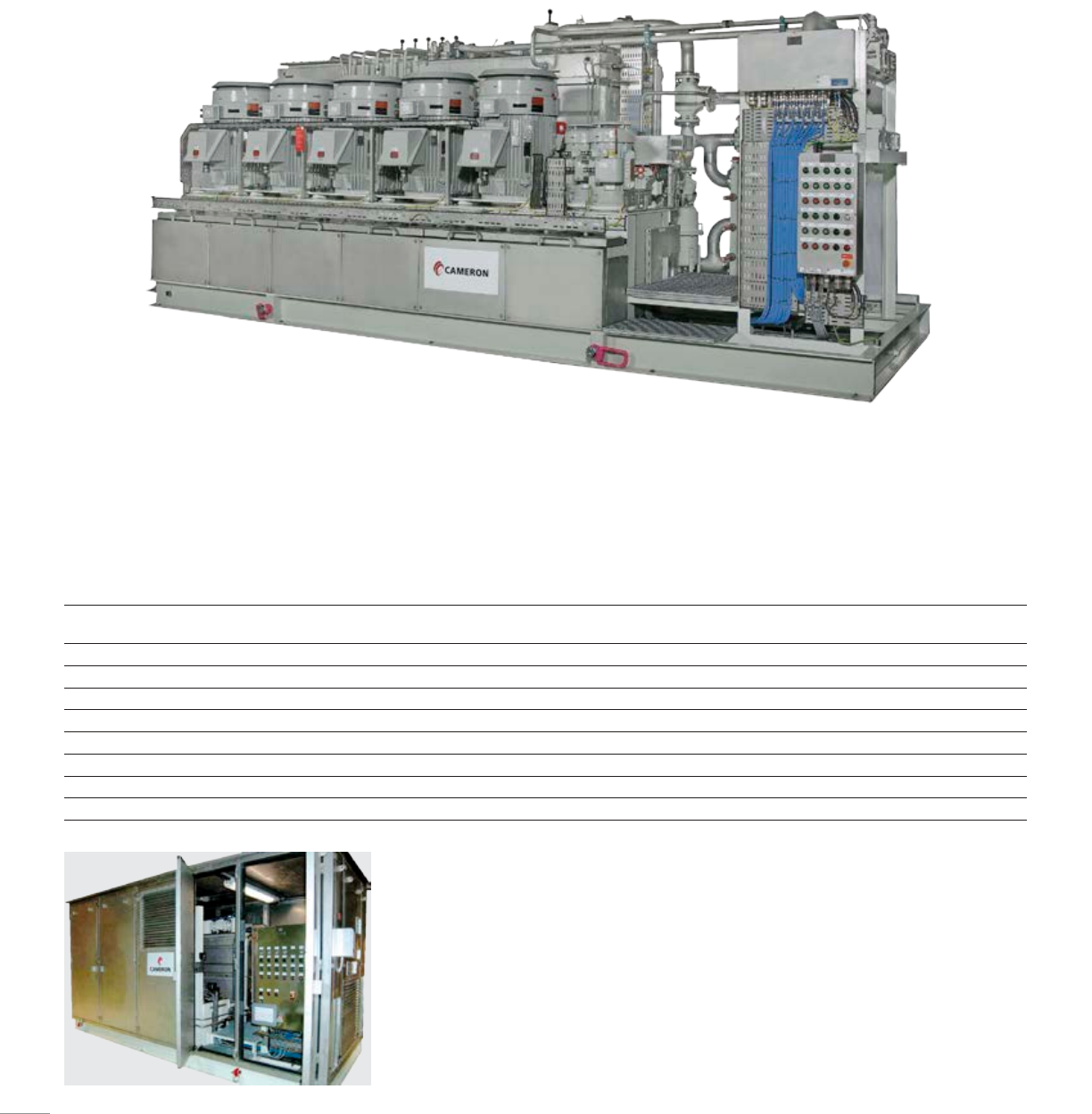
■ Stainless steel hydraulic fluid tank
■ HPU skid supplied with vibration dampeners
■ Continuous oil circulation system
■ Offline fine-filter system
■ Duplex main return and drain filter
■ Individual pressure filter for main pumps
■ Distribution manifold in the supply line
■ Low and low-low level tank alarms
■ High and high-high fluid temperature alarms
■ Local operator panel provides start/stop
control and running indications on all motors
■ HPU skid equipped with four certified
lifting eyes
■ Pressure relief valve mounted in each main
supply line
■ Hydraulic soft start-up system
Noise hood
■ Access doors for easy maintenance
■ Removable
■ Entire HPU can be lifted (including noise hood)
■ Stainless steel construction
Cameron offers a line of hydraulic power units (HPUs), available in three-, four- and
five-pump models, designed to the highest standard, with a focus on low noise, easy
maintenance, and low life cycle cost.
Hydraulic Power Units
Model Number
of pumps
Operating pressure,
psi [bar]
Required electric input
power per pump, hp [kW]
Output flow per pump,
gal/min [L/min]
Total output flow,
gal/min [L/min]
HPU 1-210-94-240-240 13,000.00 [206.84] 126.00 [92.67] 63.40 [240.00] 63.40 [240.00]
HPU 2-210-94-240-480 23,000.00 [206.84] 126.00 [92.67] 63.40 [240.00] 126.80 [480.00]
HPU 3-210-94-240-720 33,000.00 [206.84] 126.00 [92.67] 63.40 [240.00] 190.20 [720.00]
HPU 4-210-94-240-960 43,000.00 [206.84] 126.00 [92.67] 63.40 [240.00] 253.61 [960.00]
HPU 5-210-94-240-1200 53,000.00 [206.84] 126.00 [92.67] 63.40 [240.00] 317.00 [1,200.00]
HPU 6-210-94-240-1440 63,000.00 [206.84] 126.00 [92.67] 63.40 [240.00] 380.41 [1,440.00]
HPU 7-210-94-240-1680 73,000.00 [206.84] 126.00 [92.67] 63.40 [240.00] 443.81 [1,680.00]
HPU 8-210-94-240-1920 83,000.00 [206.84] 126.00 [92.67] 63.40 [240.00] 507.21 [1,920.00]
56
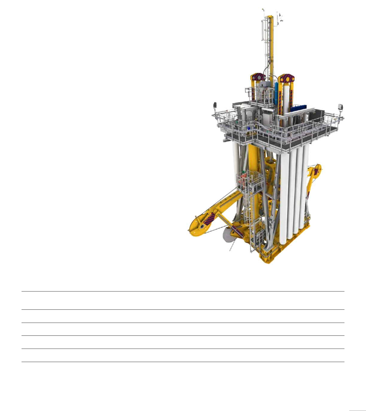
Cameron delivers motion compensation
equipment for the drillstring and riser,
enabling floaters to operate in the harshest
environments. Our equipment is designed and
fabricated to the highest quality standards to
offer years of accurate and reliable operation.
We have incorporated many novel ideas
to achieve easier operation and reduce
maintenance than competing products.
Motion Compensation Equipment
Model Dynamic
capacity†,
kip [tonne]
Stroke,
ft [m]
Static capacity,
kip [tonne]
Sheave diameter,
in [mm]
Wire diameter,
in [mm]
Maximum
speed,
mph [m/sec]
Dry weight
(approximate)††,
lb [tonne]
TMC 1000-25-2000 1,000.00 [453.59] 25.00 [7.62] 2,000.00 [907.18] 60.00 [1,524.00]
72.00 [1,828.80]
1.75 [44.45]
2.00 [50.80]
2.93 [1.31] 396,000.00 [179.62]
TMC 1000-25-2650 1,000.00 [453.59] 25.00 [7.62] 2,650.00 [1,202.02] 60.00 [1,524.00]
72.00 [1,828.80]
1.75 [44.45]
2.00 [50.80]
2.93 [1.31] 396,000.00 [179.62]
TMC 1500-25-2000 1,500.00 [680.39] 25.00 [7.62] 2,000.00 [907.18] 72.00 [1,828.80]
78.00 [1,981.20]
2.00 [50.80]
2.13 [53.98]
2.93 [1.31] 440,000.00 [199.58]
TMC 1500-25-2650 1,500.00 [680.39] 25.00 [7.62] 2,650.00 [1,202.02] 72.00 [1,828.80]
78.00 [1,981.20]
2.00 [50.80]
2.13 [53.98]
2.93 [1.31] 440,000.00 [199.58]
† Capacity at top drive elevator
†† Including steel APVs
Top mounted compensator
■ Top-mounting installation reduces weight on bit (WOB) fluctuations
■ Cylinder placement designed to allow standard top drives to be lifted
between compensation cylinders
■ Low weight of compensator module is due to vertical forces
■ Compensator can be locked in any position
■ High static force rating
■ Unit ready for easy installation on top of the derrick at delivery
■ Active-heave compensator can be easily added
■ Low-friction seals are used in the cylinders and accumulator
■ Geometry of the rocker arms in combination with how the wire is
reeved over the guide sheaves reduces the effect of compression/
decompression of the air volume due to cylinder movements
■ Flow shut-off valve protects the system against uncontrolled movement
if a drillstring failure occurs
■ Position measuring system for the crown block
■ Only hard piping between the main components (i.e., no flexible hoses)
■ Customized PLC software provides simple and natural operator controls
from a single point
57
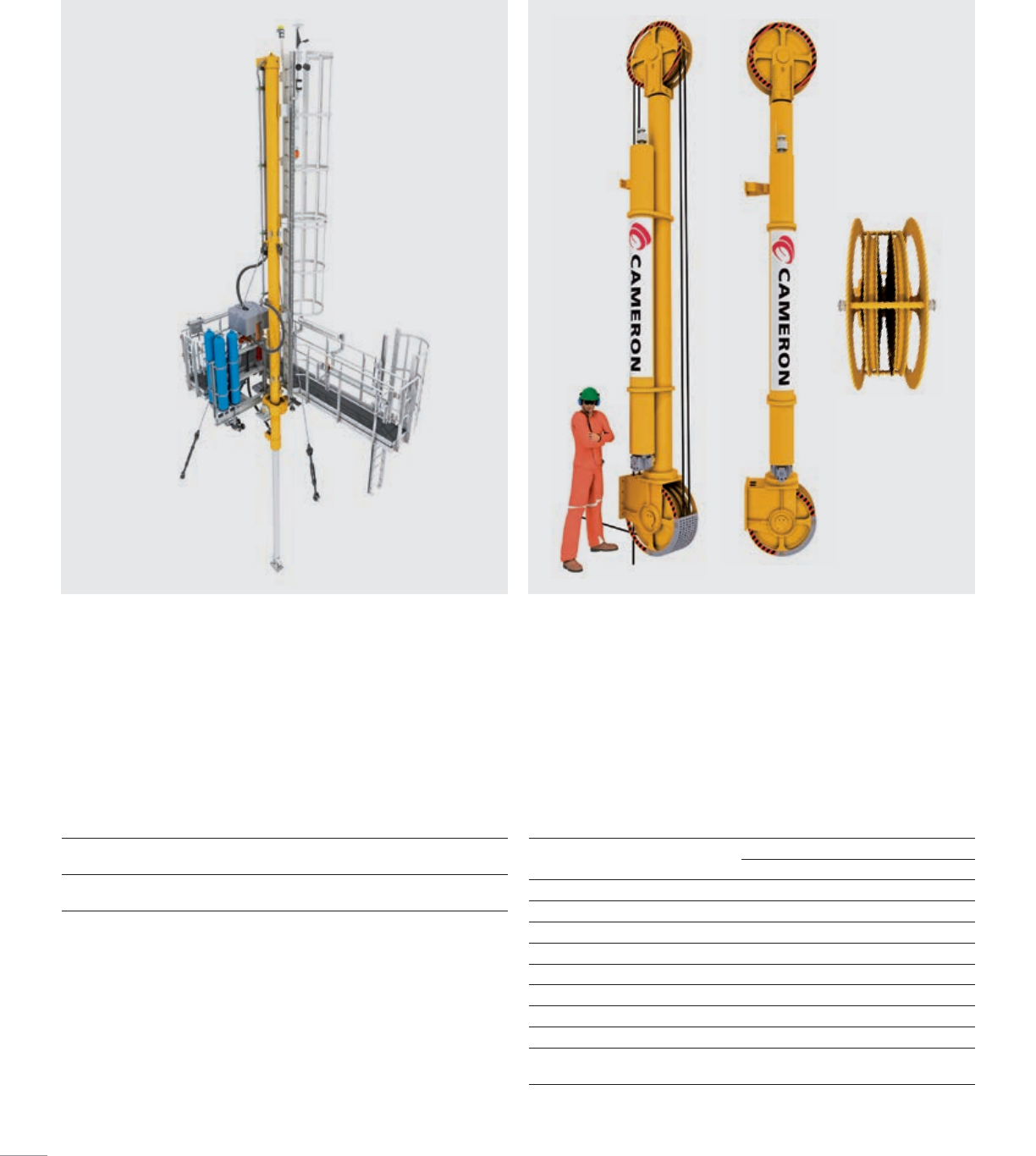
Active-heave compensator
■ Compact
■ Lightweight
■ Easy to lift/handle, access, and maintain
■ Independent modules for easy disconnection
■ Simple operation and full integration with top-mounted
compensator (TMC)
■ Operational media: mineral oil
Guideline and podline tensioners
■ Reliable and low-maintenance design
■ Automatic flow shut-off function included in case of wire rope failure
■ Easy maintenance at defined locations
Capacity
(push/pull)
Stroke Maximum
speed
Dry weight
(approximate)
61.80 kip
(28.00 tonne)
25.00 ft
(7.62 m)
2.93 mph
(1.31 m/sec)
9,920.00 lb
(4.50 tonne)
16 kip
Imperial (US) SI
Tensioner capacity 16.09 kip 7.30 tonne
Wire line travel 50.00 ft 15.24 m
Maximum line speed 354.33 ft/min 1.80 m/sec
Tensioner cylinder stroke 12.50 ft 3.81 m
Wire sheave diameter 27.95in 711.20 mm
Wire rope diameter 0.75in 19.00 mm
Hydraulic fluid type — Water glycol based
Maximum fluid pressure 3,002.28 psi 207.00 bar
Maximum pressure in working
air pressure vessels
3,002.28 psi 207.00 bar
58
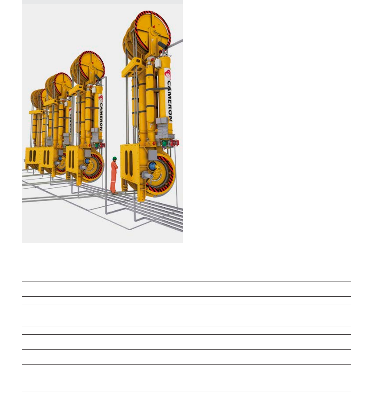
Wireline riser tensioners
Cameron wireline riser tensioners are designed to maintain the riser string
in tension on floating vessels.
Three versions currently are available. The 160-, 200-, or 250-kip double-
wire rope tensioners include idler sheaves, wire, rotating deadline
drum, valve block skids, APVs, control system, anti-recoil, and optional
air compressors.
■ Compact and robust mechanical design
■ Easy maintenance at defined points
■ Hydraulically driven deadline drum simplifies wire replacement
■ Manifold valve blocks used to reduce the amount of piping and number
of leakage points
■ State-of-the-art anti-recoil valve with flow shut-off function allows for
safe normal operation and disconnect operation
■ State-of-the-art tensioner cylinder rod coating for harsh
marine environment
■ High degree of redundancy in the system
■ State-of-the-art redundant control system ensures an efficient, safe, and
smooth operation
■ Separate filling and draining unit provides easy and safe filling and
draining of compensation fluid
■ System operation is conducted from the drilling control room (DCR) and
a local operator panel in the moonpool area
160 kip 200 kip 250 kip
Imperial (US) SI Imperial (US) SI Imperial (US) SI
Dual tensioner capacity 2.00 × 160.00 kip 2.00 × 72.57 tonne 2.00 × 200.00 kip 2.00 × 90.72 tonne 2.00 × 250.00 kip 2.00 × 113.40 tonne
Single tensioner capacity 160.00 kip 72.57 tonne 200.00 kip 90.72 tonne 250.00 kip 113.40 tonne
Wire line travel 50.00 ft 15.24 m 50.00 ft 15.24 m 50.00 ft 15.24 m
Maximum line speed 330.71 ft/min 1.68 m/sec 330.71 ft/min 1.68 m/sec 330.71 ft/min 1.68 m/sec
Tensioner cylinder stroke 12.50 ft 3.81 m 12.50 ft 3.81 m 12.50 ft 3.81 m
Wire sheave diameter 64.00in 1.63 m 78.00in 1.98 m 90.00in 2.29 m
Wire rope diameter 2.13in 54.10 mm 2.50in 63.50 mm 2.75in 69.85 mm
Hydraulic fluid type — Water glycol based ————
Maximum fluid pressure 3,000.00 psi 206.84 bar ————
Maximum pressure in working
air pressure vessels
3,000.00 psi 206.84 bar ————
Maximum pressure in standby
air pressure vessels
4,350.00 psi 299.92 bar ————
59
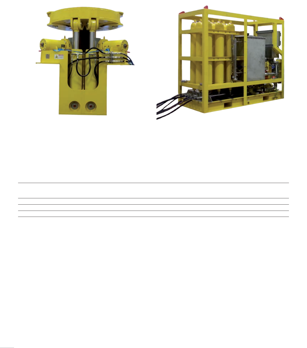
Conductor tensioner systems
■ Maintain the conductor system in tension to prevent buckling under
compressive load from the BOP or self-weight
■ Simple adjustment of tension load
■ Redundancy if one cylinder fails
■ Easy manual adjustable lateral supports
■ Compact and reliable design
■ Splitable CTU design is standard
■ Remote monitoring of the cylinder tension force from the Drilling Control
Room (DCR)
■ Available for operation with water/glycol based fluid
■ Suitable for hazardous area operation
Model Tension
load capacity,
kip [tonne]
Horizontal
load capacity,
kip [tonne]
Conductor
size range,
in [mm]
Number of
cylinders
Cylinder
stroke,
in [mm]
Maximum
operating pressure,
psi [bar]
CTU 272 600.00 [272.16] 77.00 [34.93] 9.63–36.00 [244.60–914.40] 413.80 [350.52] 3,000.00 [206.84]
CTU 400 882.00 [400.07] 77.00 [34.93] 9.63–36.00 [244.60–914.40] 413.80 [350.52] 3,000.00 [206.84]
CTU 500 1,100.00 [498.95] 265.00 [120.20] 9.63–36.00 [244.60–914.40] 439.40 [1,000.76] 3,000.00 [206.84]
60
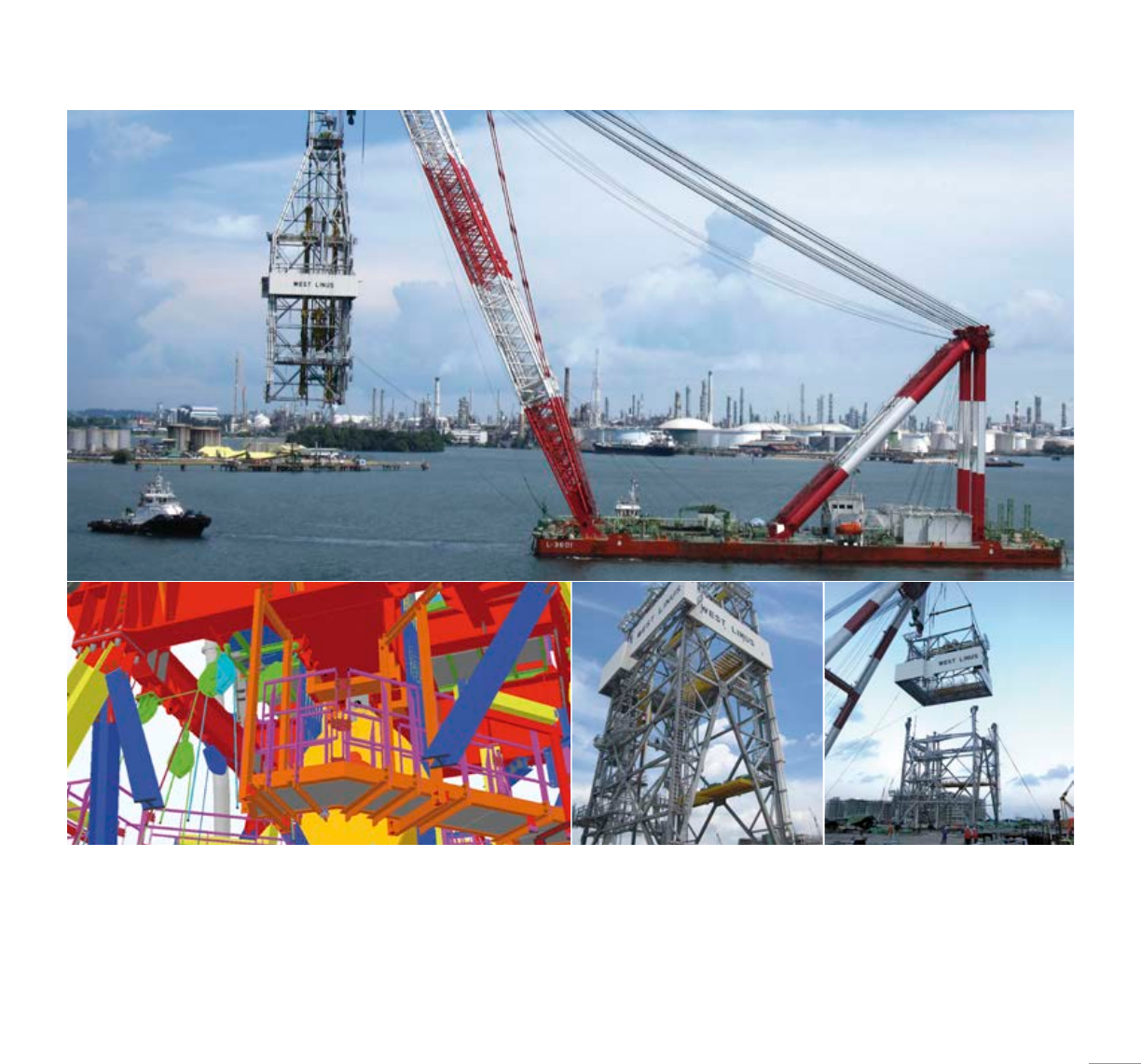
■ Designed and fabricated according to the
latest edition of API 4F model specifications
■ ABS/DNV certified
■ Area of operation according to customer’s
requirement(s), generally API Bull 2INT-MET
(Gulf of Mexico)
■ Weight-efficient structural design
■ Designed for safe operation, in compliance
with North Sea safety requirement as
a standard
■ Designed for timely assembly on erection site
■ Small quantity of loose parts, assembly in
smaller sections
■ 3D design for optimal layout, interface control
and clash prevention
■ Corrosion resistant hot-dip
galvanized structure
■ Generally designed for single lift onboard
Cameron delivers a variety of drilling derricks, purpose-built to meet our customers’
preferences with respect to loading and operational conditions. We design and
fabricate to comply with all industry standards using the latest 3D design tools,
focusing on low weight and life cycle cost, easy fabrication, quick quayside erection
and complete interfaces with drilling and third-party equipment. Derrick structures
are available in various configurations for fixed or floating platforms, to handle triples
and quads, and ratings up to 1,250 ton (1,133.98 tonne) at the top drive stem, and are
supplied to a number of vessel specifications. API monogramming is also available.
Drilling Derricks
61
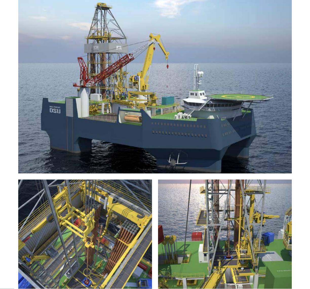
Cameron combines an extensive knowledge in drilling, subsea handling and active-
heave compensation equipment to deliver efficient Well Intervention Systems. Together
with our clients we develop well intervention packages that can be optimized for special
tasks, or designed as multi-purpose solutions making the vessels attractive in many
segments of the market.
Well Intervention Packages
62
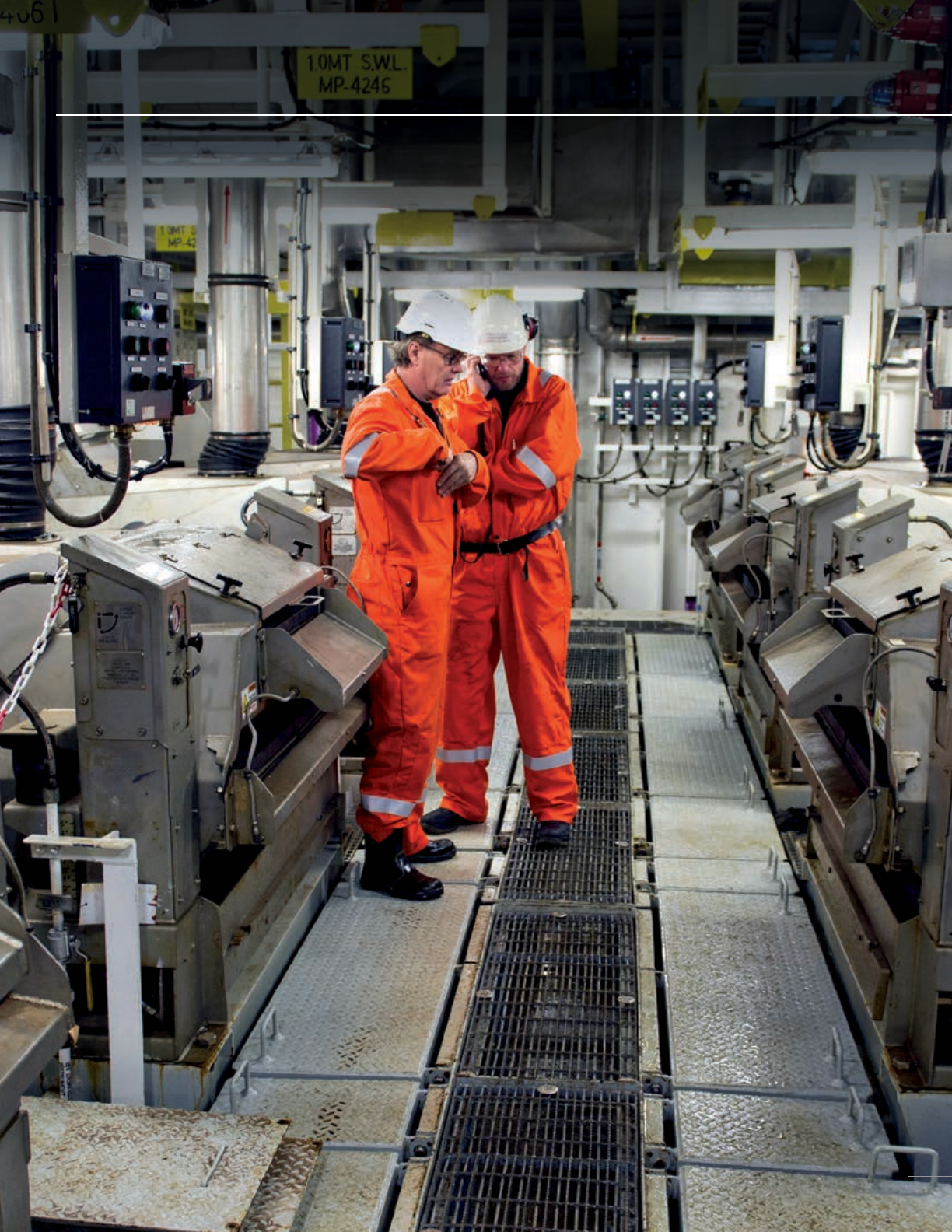
TOTAL DRILLING FLUID SOLUTIONS
63
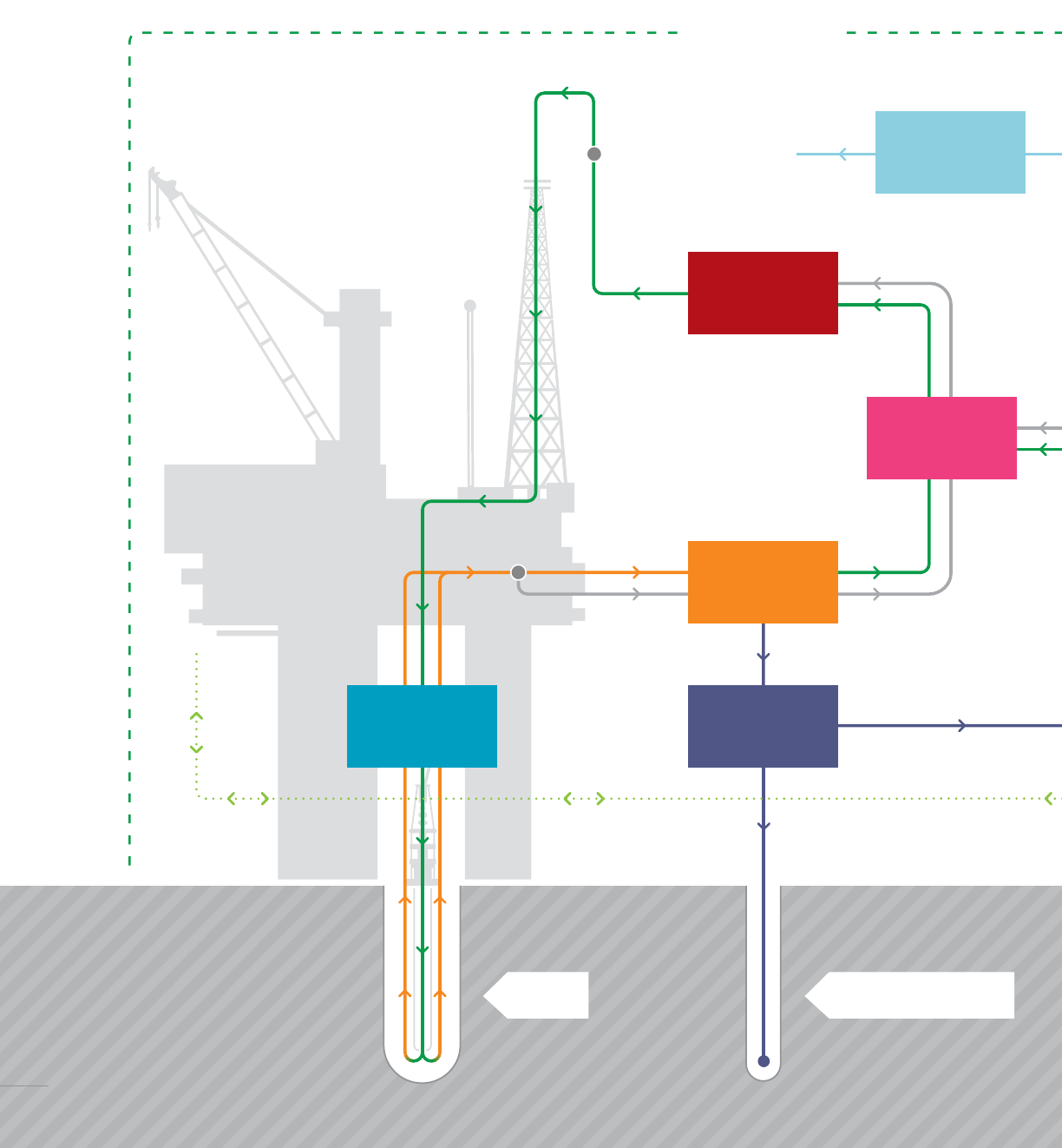
HP system
Cementing
unit
Standpipe manifold
Active system
Active
tanks
Mud
treatment
Injection well
Well
Cuttings
handling
Well
control
Cameron offers a comprehensive range of complete drilling fluid packages and
standalone equipment. Our products are designed to streamline many essential, yet
time-consuming operation and maintenance procedures, improve operator safety and
productivity, and reduce costly system downtime.
64
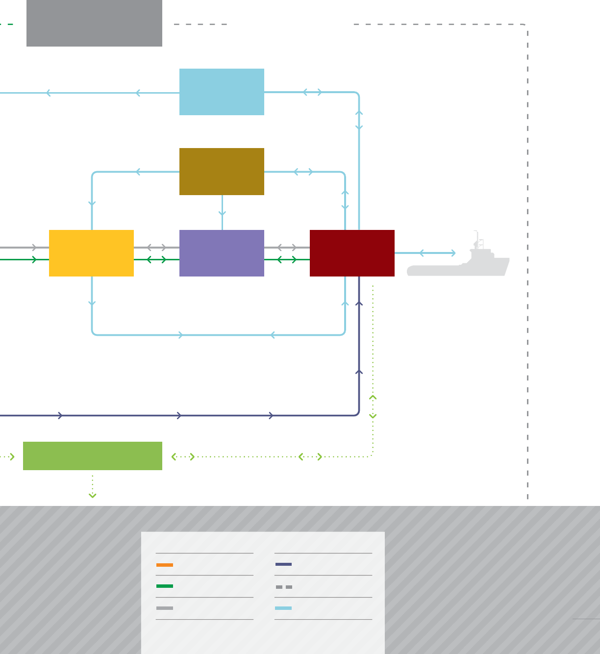
Reserve/mix system
Bulk
(cement)
Bulk
(barite)
Mix
system
Loading
station
LP
system
Mud control
system
Slop system
From well (mud)
Cuttings
Mud system 1
Slops
Mud system 2
Bulk system
65
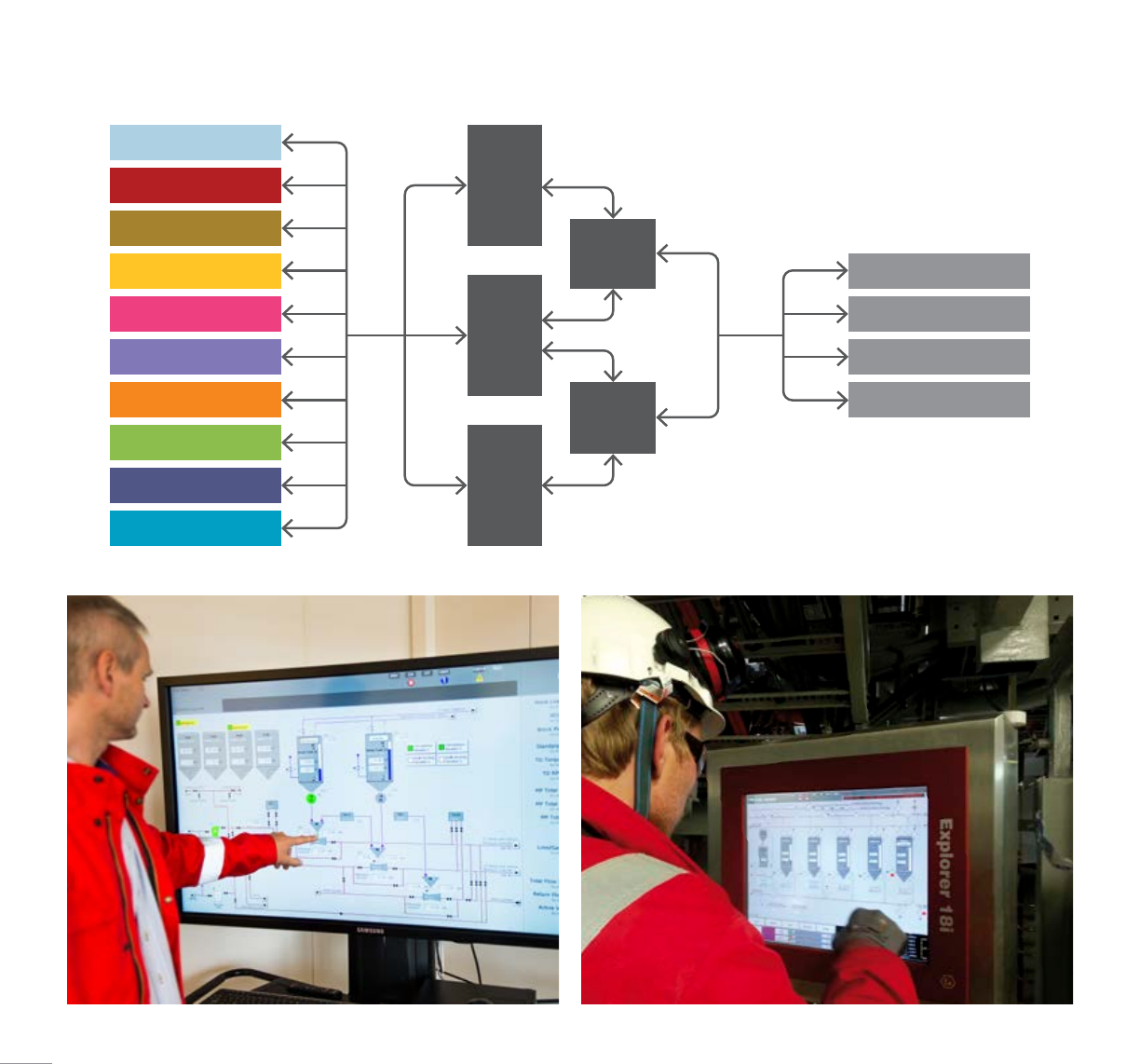
The Cameron mud control system is a custom-designed control system for drilling fluids
systems and processes. Offering increased product automation and system integration,
the mud control system provides operators with more information and advanced control
capabilities, making their jobs safer and more effective. Its purpose-designed software
also enables closer monitoring and better reporting abilities that can reduce equipment
downtime and improve system/production planning. Our mud control system hardware
and software is engineered to ensure a flexible control system that can be upgraded as
operational needs change.
Mud Control System
Real-time monitoring and logical control of drilling fluids equipment and complete systems
from local and remote locations.
User interface and control panel engineered for optimal overview and ergonomic safety.
Bulk (barite)
Bulk (cement)
HP system RIO
cabinet
PLC 1
PLC 2
RIO
cabinet
VFD
cabinet
Mix system
Active tanks
LP system
Mud treatment
Slop system
Cuttings handling
Well control
Drilling control system
HMI operator stations
Remote services
Third party
66
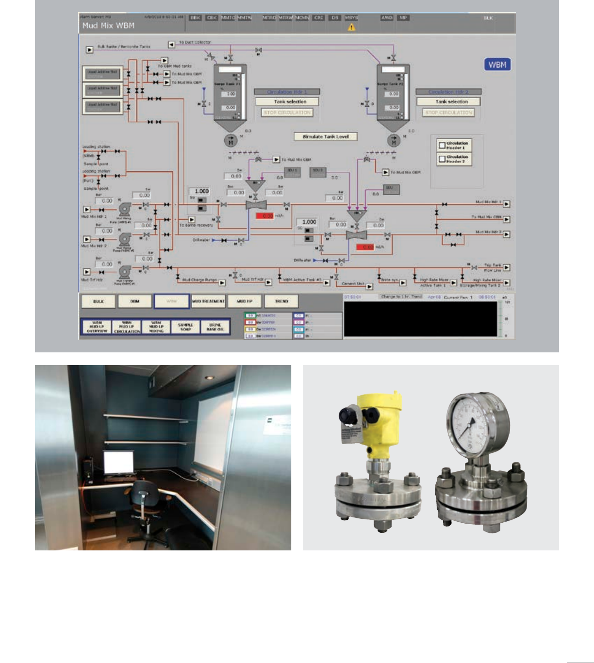
Complete control cabins
■ Tailored to installation area layout
■ Integrated control system equipment for handsoff mixing, dosing, and
transfer operations
■ Noise- and vibration-insulated housing
■ Complete with windows, lights, and HVAC
Field instrumentation
■ A range of field instrumentation packages are available to enhance
and support the control experience
■ Level indicators, pressure transmitters, density transmitters with
precise degree of measurement/indication
67
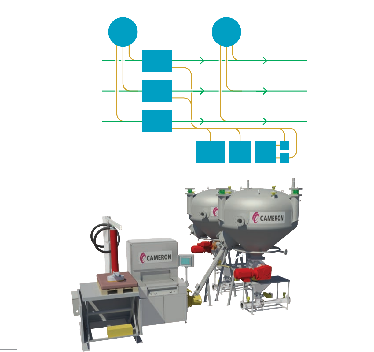
Cameron mud mixing and additive equipment makes drilling fluid mixing operations
smarter, safer and more accurate. With our proven technology, hands-on experience
and innovative thinking, Cameron has engineered a product portfolio that improves
drilling fluid system operations from both production and operator standpoints. Whether
you need a full system design or standalone equipment, Cameron has mud mixing and
additive solutions that help improve your operations.
Mud Mixing System
Density LAS
Barite/
bent BBU
Hopper 1
Hopper 2
Hopper 3
SDU
R1
R2
From mud mix pump 1 To mud LP
To mud LP
To mud LP
From mud mix pump 2
From mud mix pump 3
68
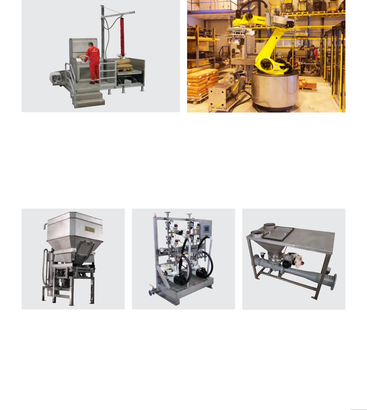
Sack dosing unit (SDU)
■ Standalone unit with integrated control system
■ Market’s most compact footprint
■ Dust-free in operation
■ Integrated waste compactor
■ Can be assembled on a skid for easy installation
■ Accompanied with a vacuum lifter and electro-hydraulic lifting table
Big bag unit (BBU)
■ Cuts and doses big bags up to 1 ton
(0.91 tonne)
■ Removable discharge hopper designed to
prevent wastage and material clogging
■ Integrated dust filter and vibration unit
■ Automatic dosing screw conveyor to hopper
■ Weight control system
Liquid additive skid (LAS)
■ Easy and accurate/reliable dosing of
liquid chemicals
■ Compact footprint
■ VFD-controlled hose pumps
■ Easy cleaning and maintenance
■ Integrated control system with local control
panel for real-time monitoring and control
Mixing hopper
■ Skid-mounted for ease of installation
■ Venturi-type mud mixer
■ Low-maintenance requirements
■ Suitable for powder and liquid mixing
■ Direct discharge into mixing lines
SHR sack-handling robot technology
■ Customized and highly flexible layout
■ Scalable system for multiple pallets/chemicals
■ Depalletizing robot
■ Intelligent vision system
■ Minimized exposure to chemicals for operators
■ Reduced manual handling
■ Increased automation
69

The Cameron bulk storage and transfer system is a complete solution for bulk
barite, bentonite, and cement storage. Each system is custom-engineered to meet
your production requirements and offers efficiency enhancing options such as full
instrumentation packages, remote valves, product automation, and remote system
control capabilities.
Bulk Storage And Transfer System
Bulk mud/cement storage and surge tanks
■ Tank design minimizes potential wastage,
clogging, and maintenance downtime
■ Three-legged or skirt-support design provides
superior stability
■ Aeration panels in cone and base ensure
optimal flow during pressurization and discharge
processes and minimize the amount of material
left in the tank after emptying
■ Full instrumentation package
■ Remote, real-time monitoring, and control
capabilities for repetitive tasks
■ Meets ASME standards
■ ABS/DNV certification
123 4
Loading station
Mixing system
Dust
collector/
cyclone
Overboard vent
70
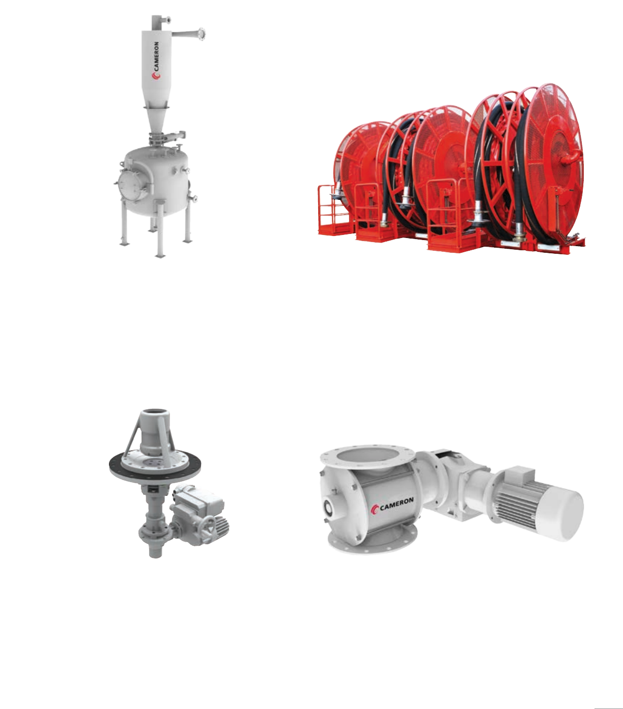
Dust cyclone and collector unit
■ Reclaims and recycles costly powder dust into the bulk storage system
■ Automatic filling, separation, and discharge
■ Proven effective operation in any climate condition
■ Single cyclone-type separator delivers ongoing high
operational efficiency
Cement discharge valve
■ Optimizes the fluidization process within the silo tank
■ Provides high levels of precision, easier control, and better results
during bulk cement transfer
■ Low maintenance
■ Electrically-actuated control valve
Loading stations
■ Self-supporting frame with internal piping, couplings, and lifting legs
■ Hydraulic-driven reels
■ Loading hoses
■ Portable remote control
Cell feeder
■ Enables automatic dosing of bulk material from surge tank into
mixing hoppers
■ Improves dosing accuracy
■ VFD-controlled
71
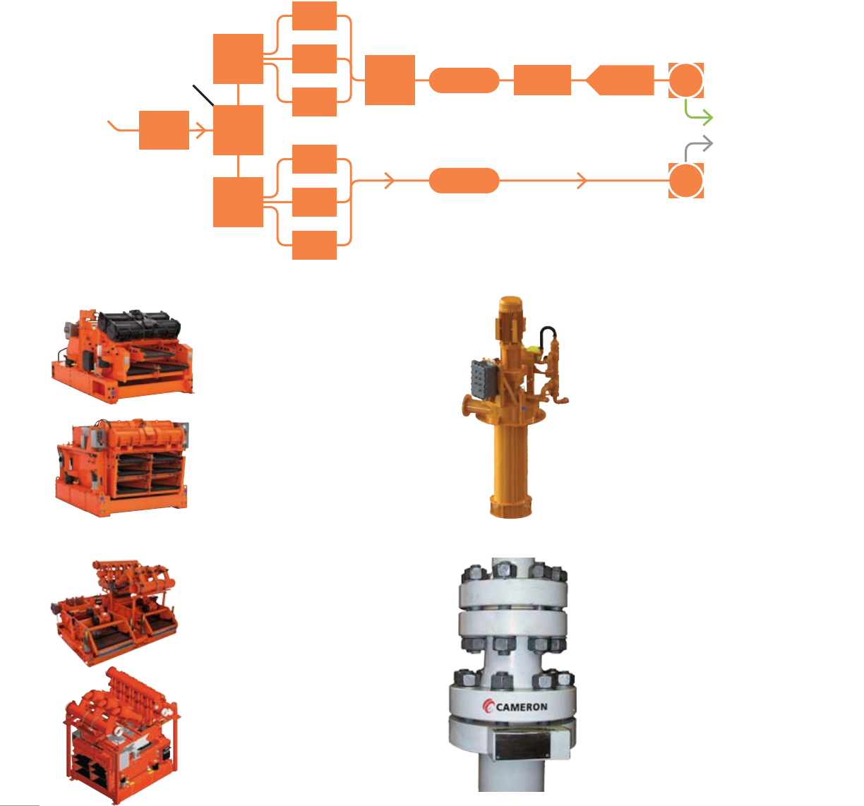
Together with M-I SWACO, a Schlumberger company, we are able to provide our
customers with custom-engineered and industry-proven cuttings, solids, and treatment
equipment. M-I SWACO is one of the world’s leading manufacturers and suppliers of
mud treatment systems.
Mud Treatment System
Shale shakers
■ Single/dual/triple deck
■ Single/dual motion
■ Small footprint
■ Modular platform
■ Deck adjustment
■ Maximized fluid distribution
onscreen area
■ Ventilation hood with front
hood available
Mud cleaners
■ Field-proven cone design
■ 12in (304.8 mm) desander cones,
4in(101.6 mm) desilter cones
■ High-processing rate
■ Slant-mount or vertical-mount
■ Ventilation hoods available
■ Replaceable, wear-resistant,
polyurethane hydrocyclones come
with quick-release clamps
Degasser
■ Centrifugal and vacuum degassers
■ Small footprint and compact design
■ High-capacity and high-efficiency
■ Robust design with
minimal maintenance
■ Remote operation available
High-pressure shear unit
■ Effective shearing of drilling fluid
■ Pressure up to 10,000 psi
■ Easy installation
■ Straight or angle top connection
From well
From swarf
To mud system 1
To mud system 2
Diverter Splitter
box
Flow
divider
Flow
divider Sand
trap Degasser
CF degasser
Shaker
Shaker
Shaker
Shaker
Shaker
Shaker
Desander Centrifuge Clean
CF
clean
72
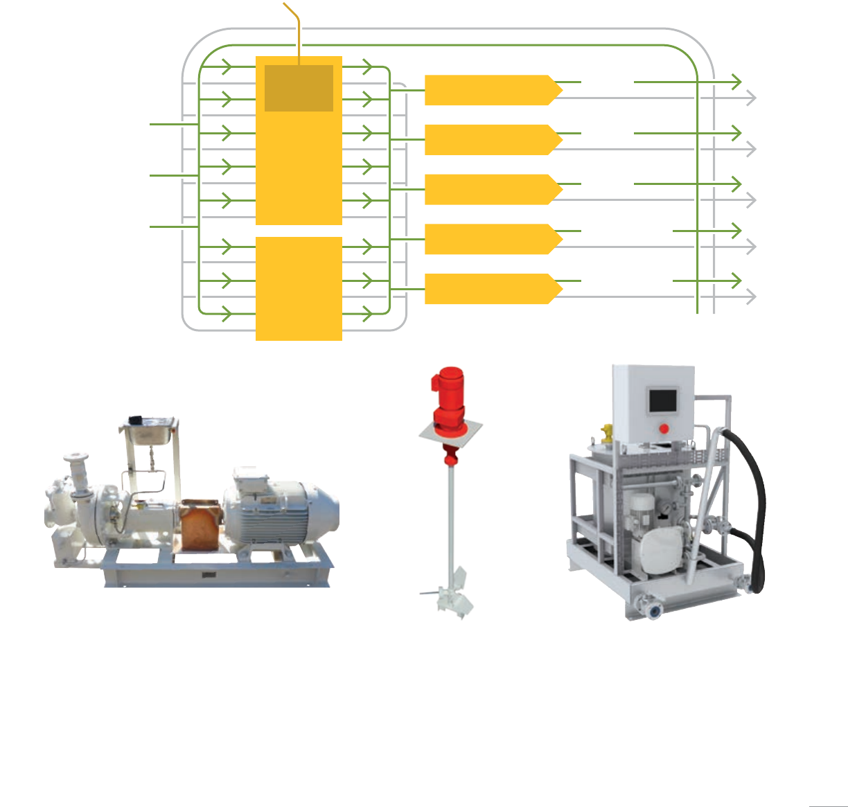
Cameron engineers works with you to assess, calculate and design your low-pressure
mud system or equipment. We work with some of the world’s leading suppliers
of LP equipment to offer low-pressure pump packages and agitating units to suit
every operation.
Low-Pressure System
Low-pressure pumps
■ DNV type certified
■ Semi-open special impellers
■ High-quality bearings and mechanical seals
■ Concentric casing design with heavier frames
Agitating equipment
■ Shaft type or submersible
high-performance agitators
■ Durable design
■ Minimal energy consumption
■ Minimal maintenance
■ Space-saving and easy installation
■ Functions according to ATEX and CE directive
Tank washing equipment
■ Streamlines process of mud pit cleaning
and reduces personnel exposure to
hazardous chemicals
■ Designed for robust and reliable operation
■ Constructed from highly
corrosion-resistant materials
■ Custom-engineered
High rate
mixer
Mud
pits
Mud mix pump
Mud mix pump
Mud mix pump
Active transfer pump
Active transfer pump
CF
pits
Bulk system
Mud mix
Mud mix
Mud mix
To active system
To active system
Mud mix 1
Mud mix 2
Mud mix 3
73
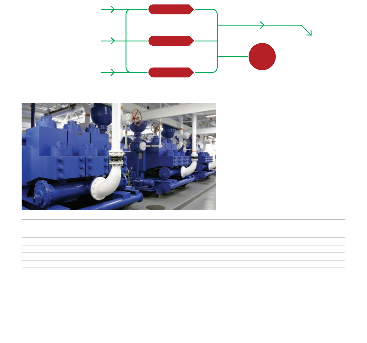
Cameron offers a range of integrated pump packages, including top- or rear-mount
AC- or DC- electric drives, controls, manifolds, piping, and accessories for onshore and
offshore applications. All equipment is designed and manufactured in accordance with
specific project requirements, with local and remote control available.
High-Pressure System
High pressure pumps
■ 1,300 to 2,200 hp (969.41 to 1,640.54kW)
■ High-discharge flow rates
■ Impressive power-to-weight ratios
■ One-piece, forged and fabricated alloy-steel crankshaft
for smooth operation and enhanced longevity
■ High-performance steel connecting rods
■ Forged alloy-steel pinions and gears
■ Triple-redundant power-end lubrication
■ Installed on a heavy-duty oilfield skid for added
strength and durability
Model Maximum input
horsepower (kW rating)1,
hp [kW]
Stroke,
in [mm]
Maximum
pump speed,
Spm
Maximum
liner size,
in [mm]
Maximum
flowrate,
gal/min [L/min]
Maximum
discharge pressure3,
psi [kg/cm2]
WH-1312 1,300.00 [969.41] 12.00 [304.80] 130 6.75 [171.45] 725.00 [2,744.42] 5,000.00 [351.55]
WH-1612 1,600.00 [1,193.12] 12.00 [304.80] 120 7.50 [190.50]4 826.00 [3,126.75] 7,500.00 [527.32]
W-1712 1,700.00 [1,267.69] 12.00 [304.80] 120 7.50 [190.50]4 826.00 [3,126.75] 7,500.00 [527.32]
W-2214 2,200.00 [1,640.54] 14.00 [355.60] 110 9.00 [228.60]51,272.00 [4,815.04] 7,500.00 [527.32]
W-2215 2,200.00 [1,640.54] 15.00 [381.00] 110 9.00 [228.60]51,363.00 [5,159.52] 7,500.00 [527.32]
1 Based on 90% mechanical efficiency
2 Based on 100% volumetric efficiency
3 Pressures greater than 5,000 psi require high-pressure fluid ends
4 Liner is induction-hardened, therefore liner life is reduced
5 Requires special retention system; liner is induction-hardened, therefore liner life is reduced
All specifications are subject to change. Information important to a particular application should be verified by Cameron.
Hp
shear
unit
Hp pump 1
Hp pump 2
Hp pump 3
From charge pump 1 Mud manifold
To well
From charge pump 2
From charge pump 3
74
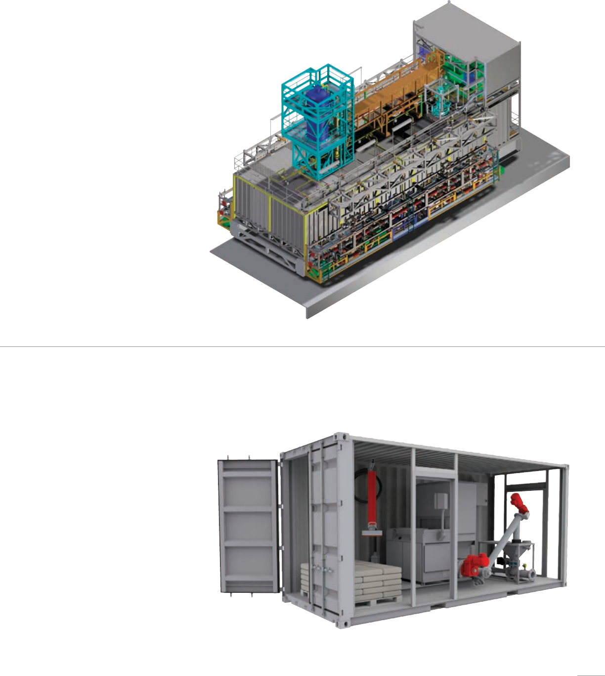
Mud Modules
Containerized Solutions
Cameron delivers a new generation of mud
modules that are more compact, efficient,
and reliable.
■ Reduce, and where possible, prevent human
exposure to dangerous materials
■ Develop a more efficient treatment and mixing
system for drilling fluids
■ Improve mud logistics, pre-mix, and
cuttings handling
■ Employ technology and equipment that
minimize the industry footprint on local and
global environments
■ Maximize available installation area
A range of flexible containerized solutions are
offered at Cameron for a variety of applications
anytime and anywhere.
■ Streamline and optimize transport and
installation procedures
■ Standalone system/plug-and-play
■ Customized solutions
■ Compact designs
■ Factory tested
75
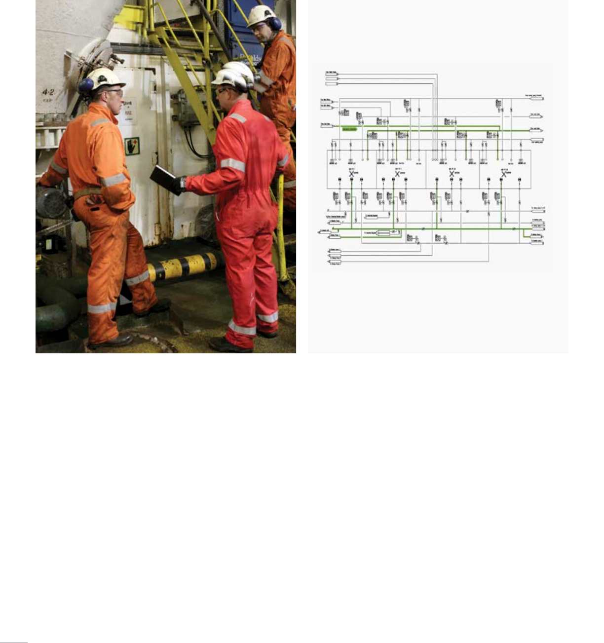
Surveys and Upgrades
Engineering services
■ Process and instrumentation diagram (P&ID) design for complete
mud systems
■ Flow calculations
Comprehensive services expertly delivered
■ Offshore surveys to advise mud system upgrades
■ Planning, engineering, onshore fabrication, offshore installation, and
commissioning of complete system upgrades
■ System documentation and training for offshore personnel
■ System certifications
76
SERVICES
77
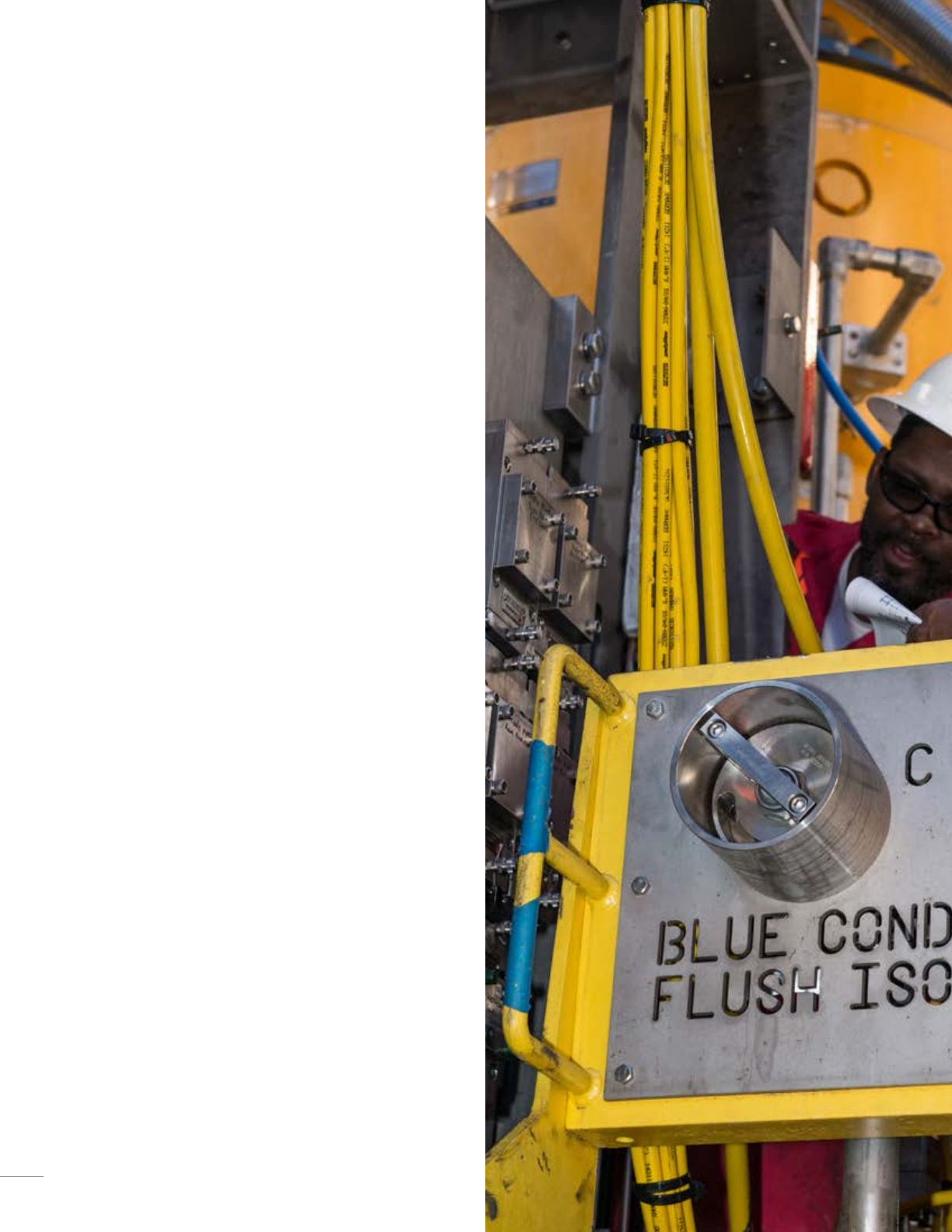
With Cameron Services, you have a world
of resources at your command—around
the clock and around the globe. Dedicated
to optimizing your operations and reducing
your total cost of ownership, we have the
most locations worldwide, staffed with
qualified people who are accessible 24/7,
so you are never without service when
you need it. What’s more, our integrated
systems and advanced processes enable
us to provide faster turnaround. And, as
the OEM, we know our products better
than anyone and know how to best
service them.
Comprehensive services expertly delivered
As the market leader in services, we provide flexible solutions through
five main areas that lower the total cost of ownership of your equipment:
■ Parts—Immediate delivery of genuine OEM replacement parts for
many Cameron products.
■ Life of field services—Field service technicians are available around
the world 24/7 to provide a wide variety of services that range
from field repairs to preventive maintenance, technical support,
and training.
■ Repairs—Service centers offer a full range of equipment repair
services, including disassembly, inspection, reassembly, testing, and
parts replacement.
■ Remanufacturing—Provides remanufacturing of oilfield equipment
to return products to first-class, fit-for-function or working-condition
performance standards.
■ Asset management—Provides a range of asset management services,
including storage/warehousing, utilization, brokering, buy-back,
and exchange.
78
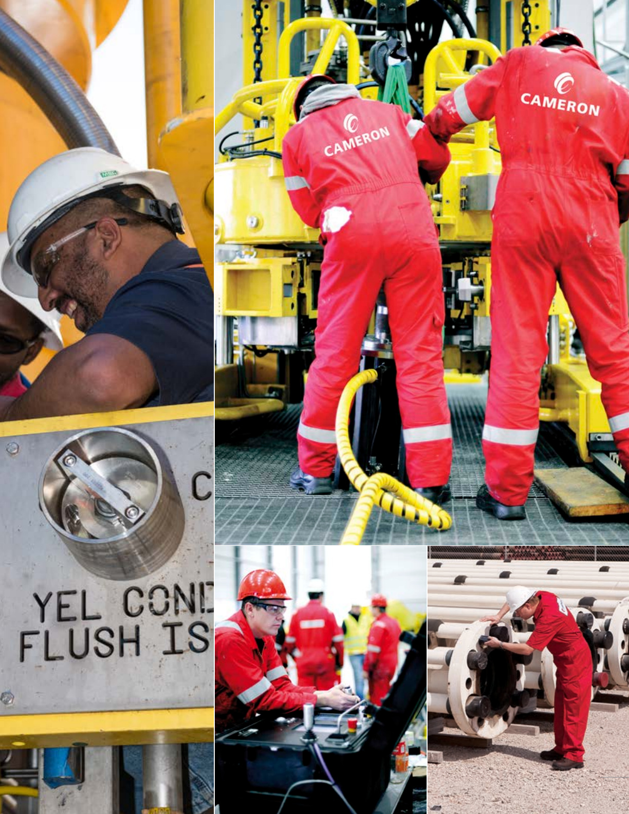
79
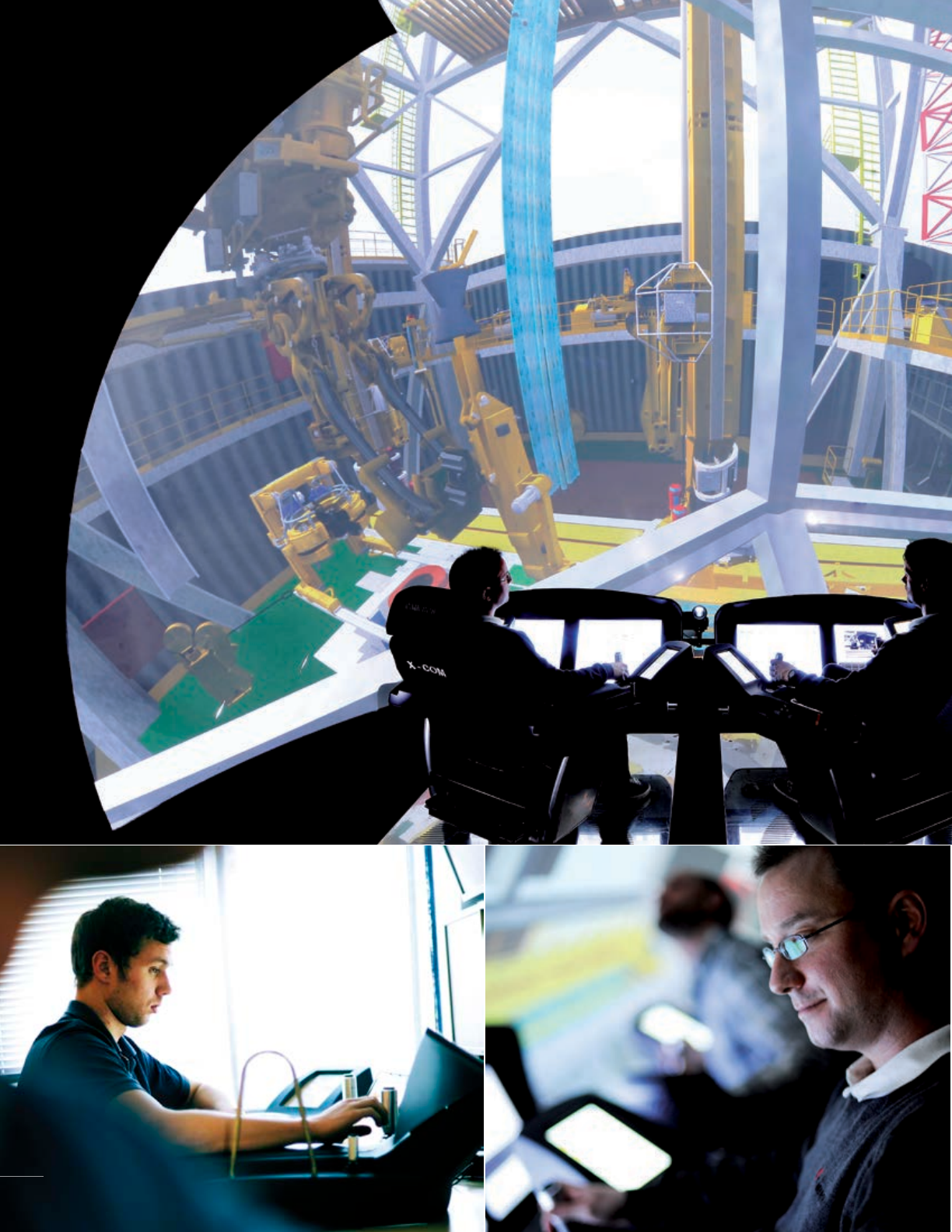
80
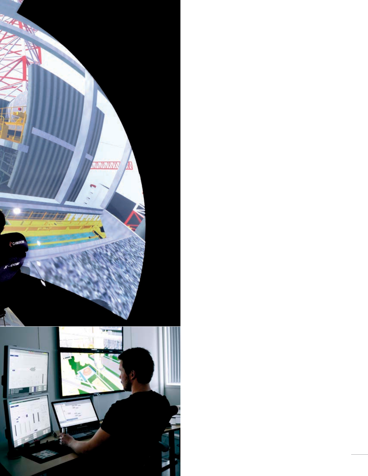
Remote access center
To help better support our customers, Cameron control systems are
designed to enable remote access. A VPN router for secure authorization
and a Cameron support PC are the only two components needed to enable
a gateway to all of Cameron PLCs.
Rig efficiencies
The Cameron support center is able to remotely access each
computer and PLC just as if our support team was on the rig or vessel
themselves. Having the capability to remotely locate and correct
issues in cooperation with the rig maintenance crew provides the
customer with timely support and efficiencies in rig operations.
Cameron software engineers are also available to provide customers
with troubleshooting assistance which can reduce the need for
the rig or vessel’s maintenance crew to access the advanced
software themselves.
Cost savings
Cameron OnTrack24 Remote Access can reduce the need for costly
service interventions by allowing software issues to be resolved and
software updates to be implemented remotely, without the need for
Cameron field service technicians onboard the rig.
Simple upgradability
Updates to PLC software for controlling drilling equipment as well as
HMI updates to the Cameron X-COM operator chair, OnTrack servers
and workstations can be seamlessly implemented and tested from the
Cameron remote access system.
Laboratory
Cameron software is developed in a dynamic 3D HIL test simulator
environment. Furthermore, test activities normally carried out during
commissioning are verified at equipment delivery. All software is
developed in accordance with DNV-RP-D201.
Simulation
The Cameron drilling simulator is used to train the rig’s operational
and maintenance crews by providing familiarization of the machinery
and control stations, sequences collaboration, manual operation and
unexpected scenarios. In addition, the simulator also aids in internal
training to ensure that our service personnel are continually updated with
the latest features and equipment.
Utilizing 3D models, the Cameron drilling simulator is based on the
equipment and machine software that is used on the rig, which reduces
variability between real life and simulator operations. The operator is
able to reverse, stop, or change the operation at any time. The simulator
training is suitable for those participants who have previously taken
Cameron operational training. The Cameron drilling simulator has the
following main components:
■ X-COM operator chairs
■ Instruction station computer
■ PLC simulator computer
■ 3D model simulator computer
■ 3D visualization system
■ Audio system
81
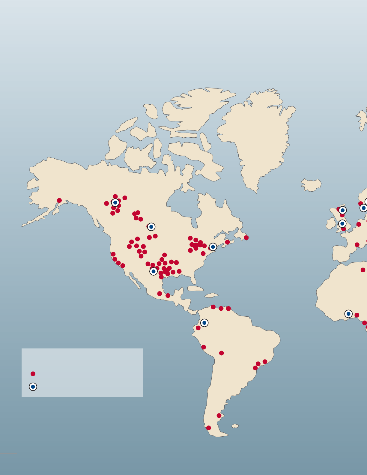
GRANDE PRAIRIE, ALBERTA
MINOT, NORTH DAKOTA
ODESSA, TEXAS
BASRA, IRAQ
GAOMI, CHINA
ABERDEEN, SCOTLAND
LUANDA, ANGOLA
YUZHNO-SAKHALINSK, RUSSIA
OSLO, NORWAY
TAKORADI, GHANA
MARCELLUS SHALE
RUGBY, ENGLAND
BOGOTÁ, COLOMBIA
KRISTIANSAND, NORWAY
PERTH, AUSTRALIA
SINGAPORE
Global Network
LEGEND
Current locations
New and expanding locations
82

GRANDE PRAIRIE, ALBERTA
MINOT, NORTH DAKOTA
ODESSA, TEXAS
BASRA, IRAQ
GAOMI, CHINA
ABERDEEN, SCOTLAND
LUANDA, ANGOLA
YUZHNO-SAKHALINSK, RUSSIA
OSLO, NORWAY
TAKORADI, GHANA
MARCELLUS SHALE
RUGBY, ENGLAND
BOGOTÁ, COLOMBIA
KRISTIANSAND, NORWAY
PERTH, AUSTRALIA
SINGAPORE
Cameron operates around the world from more than 300 locations that reach virtually
all of the world’s oil and gas operating basins. Our global network of sales, service, and
strategically located in-house manufacturing centers means customers benefit from
faster ordering times, quicker deliveries and easier access to Cameron professionals,
no matter where your operations are located. Count on Cameron to be there,
anywhere we are needed.
83

Drilling Products Overview
*Mark of Schlumberger
Other company, product, and service names are the properties of their respective owners.
Copyright © 2017 Schlumberger. All rights reserved. 17-DRL-243727
Chart design: Tress Design – www.tressdesign.no – pages: 64 and 65
Photos: Allan Klo, Statoil, page: 4 | Anders Martinsen, pages: 2, 30, 42, 43, 45, 46 and 47
Anne Lise Norheim, pages: 33, 44, 77, 79, 80 and 81 | M-I SWACO, page: 72
cameron.slb.com/drilling
