DS700 SM SELPHY Ds700sm
User Manual: SELPHY DS700
Open the PDF directly: View PDF ![]() .
.
Page Count: 72
- Part 1: Maintenance
- Part 2: Technical Reference
- 1. New Technologies
- 2. Cleaning Mode and Amount of Ink Purged
- 3. Print Mode
- 4. Photo Direct Print Function
- 4.1 Host PC Memory Card Access Function
- 4.2 Memory Card Direct Printing Function
- 4.3 File Search
- 4.4 File Sort
- 4.5 Date Print
- 4.6 Canon Bubble Jet Direct Function
- 4.7 PictBridge Function
- 4.8 Exclusive Processes
- 4.9 Display
- 4.10 Card Slot-related Operations and Display
- 4.11 DPOF Settings in the Memory Card Direct Printing Function
- 4.12 Print Layout
- 4.13 Date Print Specifications
- 4.14 Photo Number Printing Specifications
- 5. FAQs
- Part 3: Appendix
- Service Manual Menu
- Main Menu

SELPHY DS700
SERVICE
MANUAL
Canon
Copyright 2004, Canon U.S.A. This technical publication is the proprietary and confidential information of Canon U.S.A. which
shall be retained for reference purposes by Authorized Service Facilities of Canon U.S.A. Its unauthorized use is prohibited.

Scope
This manual has been issued by Canon Inc., to provide the service technicians of this product with the information necessary for
qualified persons to learn technical theory, installation, maintenance, and repair of products. The manual covers information
applicable in all regions where the product is sold. For this reason, it may contain information that is not applicable to your region.
Revision
This manual could include technical inaccuracies or typographical errors due to improvements or changes made to the product. When
changes are made to the contents of the manual, Canon will release technical information when necessary. When substantial changes
are made to the contents of the manual, Canon will issue a revised edition.
The following do not apply if they do not conform to the laws and regulations of the region where the manual or product is used:
Trademarks
Product and brand names appearing in this manual are registered trademarks or trademarks of the respective holders.
Copyright
All rights reserved. No parts of this manual may be reproduced in any form or by any means or translated into another language
without the written permission of Canon Inc., except in the case of internal business use.
Copyright © 2004 by Canon Inc.
CANON INC.
Inkjet SFP Quality Assurance Div.
16-1, Shimonoge 3-chome, Takatsu-ku, Kawasaki, Kanagawa 213-8512, Japan

I. MANUAL OUTLINE
This manual consists of the following three parts to provide information necessary to service the SELPHY DS700:
Part 1: Maintenance
Information on maintenance and troubleshooting of the SELPHY DS700
Part 2: Technical Reference
N
ew technology and technical information such as FAQ's (Frequently Asked Questions) of the SELPHY DS700
Part 3: Appendix
Block diagrams and pin layouts of the SELPHY DS700
Reference:
This manual does not provide sufficient information for disassembly and reassembly procedures. Refer to the graphics in the separate
Parts Catalog.

II. TABLE OF CONTENTS
Part 1: MAINTENANCE
1. MAINTENANCE
1-1. Adjustment, Periodic Maintenance, Periodic Replacement Parts, and Replacement Consumables by Service
Engineer
(1) Adjustment
(2) Periodic maintenance
(3) Periodic replacement parts
(4) Replacement consumables
(5) Replacement of the print head
1-2. Customer Maintenance
1-3. Product Life
(1) Printer
(2) Print head
(3) Ink tank
1-4. Special Tools
1-5. Serial Number Location
2. LIST OF ERROR DISPLAY / INDICATIONS
2-1. Operator Call Errors
2-2. Service Call Errors
2-3. Warnings
2-4. Troubleshooting by Symptom
3. REPAIR
3-1. Notes on Service Part Replacement
3-2. Special Notes on Repair Servicing
(1) Flexible cable and harness wiring, connection
(2) Notes on disassembly and re-assembly
3-3. Adjustment / Settings
(1) Paper feed motor adjustment
(2) Access cover gear phase adjustment
(3) Pump unit adjustment
(4) Grease application
(5) Waste ink counter setting
(6) User mode
(7) Service mode
3-4. Verification Items
(1) Service test print
(2) EEPROM information print
4. PRINTER TRANSPORTATION
Part 2: TECHNICAL REFERENCE
1. NEW TECHNOLOGIES
(1) Robust direct printing
(2) Card direct printing
(3) PictBridge / Canon Bubble Jet Direct supporting
(4) Infrared printing
(5) New design
(6) New print head and ink tank
(7) Memory card access functionality
2. CLEANING MODE AND AMOUNT OF INK PURGED
3. PRINT MODE
3-1. Resolution during Printing via Computer
3-2. Resolution in Card Direct / Camera Direct / Infrared Printing
4. PHOTO DIRECT PRINT FUNCTION
4-1. Host PC Memory Card Access Function
(1) Supported memory cards
(2) Mounting the drive
(3) Arrangement of image files
(4) Data access
(5) Card slot attribute
4-2. Memory Card Direct Printing Function
(1) Slide show

(2) Print mode
(3) Print quality
(4) Supported image formats
(5) Supported file names
4-3. File Search
4-4. File Sort
4-5. Date Print
4-6. Canon Bubble Jet Direct Function
(1) Print mode
(2) Media type
(3) Print layout
(4) Print quality
(5) Image correction function
(6) Maintenance
(7) Print date
(8) Copies
4-7. PictBridge Function
(1) Print mode
(2) Media type
(3) Print layout
(4) Print quality
(5) Image correction function
(6) Image adjustment
(7) Image processing
(8) Maintenance
(9) Print date
(10) Copies
(11) Digital camera's standard setting
4-8. Exclusive Processes
(1) Exclusive processes in Memory Card Direct Printing and Digital Camera Direct Printing
(2) Exclusive process control between Direct Printing and printing from the host computer
(3) Exclusive processes in host computer memory card access and Memory Card Direct Printing
(4) Exclusive processes between the memory card and memory card
4-9. Display
4-10. Card Slot-related Operations and Display
(1) Timing and precautions when removing the memory card
(2) Power supply/cut to the memory card
(3) Memory card removal command from the host computer
4-11. DPOF Settings in the Memory Card Direct Printing Function
(1) Supported DPOF functions
(2) Print specifications in DPOF print mode
4-12. Print Layout (Details)
(1) Selectable layout in Memory Card Direct Printing
(2) Selectable layout in Digital Camera Direct Printing
(3) Selectable layout in Infrared Printing (Direct Printing from a Mobile Phone via Infrared Communication)
(4) Layout in Memory Card Direct Printing
(5) Layout and image size
4-13. Date Print Specifications
(1) Date print in Memory Card Direct Printing
(2) Date print in Digital Camera Direct Printing
(3) Date print in Infrared Printing
4-14. Photo Number Printing Specifications
(1) Photo number printing in Memory Card Direct Printing
(2) Photo number printing in Digital Camera Direct Printing
(3) Photo number printing in Infrared Printing
5. FAQ (Problems Specific to the SELPHY DS700 and Corrective Actions)
Part 3: APPENDIX
1. BLOCK DIAGRAM
2. CONNECTOR LOCATION AND PIN LAYOUT
2-1. Main Board
2-2. Panel Board
2-3. Front I/F Board
2-4. Rear I/F Board
3. SPECIFICATIONS

P
art 1
MAINTENANCE

1. MAINTENANCE
1-1. Adjustment, Periodic Maintenance, Periodic Replacement Parts, and Replacement
Consumables by Service Engineer
(1) Adjustment
Note: DO NOT loosen the 2 red screws on both front sides of the main chassis, adjusting the head-to-paper distance.
The red screws securing the paper feed motor ass'y may be loosened only at replacement of the paper feed motor ass'y.
(2) Periodic maintenance
No periodic maintenance is necessary.
(3) Periodic replacement parts
There are no parts in this printer that require periodic replacement by a service engineer.
(4) Replacement consumables
There are no consumables that require replacement by a service engineer.
(5) Replacement of the print head
Procedures:
1) Press the Power button to turn on the printer.
2) Open the access cover.
=> The print head holder will move to the ink tank replacement position (to the left), and the LED blinks in green.
3) Press and hold the Resume/Cancel button for 2 seconds or longer.
=> The print head holder will move to the print head replacement position (to the right), and the LED blinks in green.
4) Raise the print head lock lever.
=> The print head can be removed from the holder.
5) Replace the print head, following the instructions in the user's guide.
Adjustment Timing Purpose Tool Approx.
time
Destination
settings
(EEPROM
settings)
At logic board ass'y replacement To set the destination. None. 1 min.
Language settings At logic board ass'y replacement To set the language to be displayed on
the TV.
TV (in the user
mode)
1 min.
Waste ink counter
resetting
(EEPROM
settings)
- At logic board ass'y replacement
- At waste ink absorber
replacement
To reset the waste ink counter. None. 1 min.
Paper feed motor
ass'y position
adjustment
- At paper feed motor ass'y
replacement
To adjust the belt tension. (Position the
paper feed motor so that the belt is
stretched tight.)
None. 2 min.
Access cover gear
phase adjustment
- At access cover unit
replacement
- At main cover unit replacement
To adjust the access cover damper. None. 1 min.
Pump unit
adjustment
- At pump unit replacement
- At purge tube replacement
- At pump drive gear replacement
To set an accurate ink absorption
function. None. 2 min.
Grease
application
- At carriage unit / carriage shaft
replacement
- At access cover unit
replacement
- At feed roller ass'y replacement
To maintain sliding properties of the:
- carriage oil pad / carriage shaft,
carriage rail.
- access cover, and
- feed roller ass'y.
- GREASE EU-1
- MOLYKOTE
PG641
- FLOIL KG-107A
1 min.
1 - 1

1-2. Customer Maintenance
1-3. Product Life
(1) Printer
Specified print volume (I) or the years of use (II), whichever comes first.
(I) Print volume: 2,000 pages (4" x 6", borderless printing, standard photo)
(II) Years of use: 5 years
(2) Print head
Print volume: 2,000 pages (4" x 6", borderless printing, standard photo)
(3) Ink tank
BCI-16 Color: Approx. 75 pages (4" x 6", borderless printing, PP-101, standard mode printing from a computer)
Adjustment Timing Purpose Tool Approx. time
Print head cleaning When print quality
is not satisfying.
To improve nozzle
conditions.
- Remote control and connection to a
TV
- Printer button
- Computer (settings via the printer
driver)
42 sec.
Print head deep cleaning When print quality
is not satisfying,
and not improved
by print head
cleaning.
To improve nozzle
conditions.
- Remote control and connection to a
TV
- Computer (settings via the printer
driver)
82 sec.
Ink tank replacement When the ink tank
becomes empty.
(No ink error)
--- ---
2 min.
Print head alignment When print quality
is not satisfying.
To ensure accurate dot
placement.
- Remote control and connection to a
TV
- Computer (settings via the printer
driver)
1 min.
Print head alignment value
printing
When confirming
the print head
alignment values set
in the printer.
To confirm the current
print head alignment
values.
- Remote control and connection to a
TV
25 sec.
Language selection When necessary. To select the TV display
language.
- Remote control and connection to a
TV
10 sec.
Paper feed roller cleaning When paper does
not feed properly,
or the paper feed
roller is soiled.
To clean the paper feed
roller.
- Printer button 2 min.
Bottom plate cleaning After printing is
performed on the
wrong side of
paper, or rollers
inside the printer
are extremely
soiled.
To cleaning the bottom
plate and platen ribs.
- Printer button 40 sec.
1 - 2
1-4. Special Tools
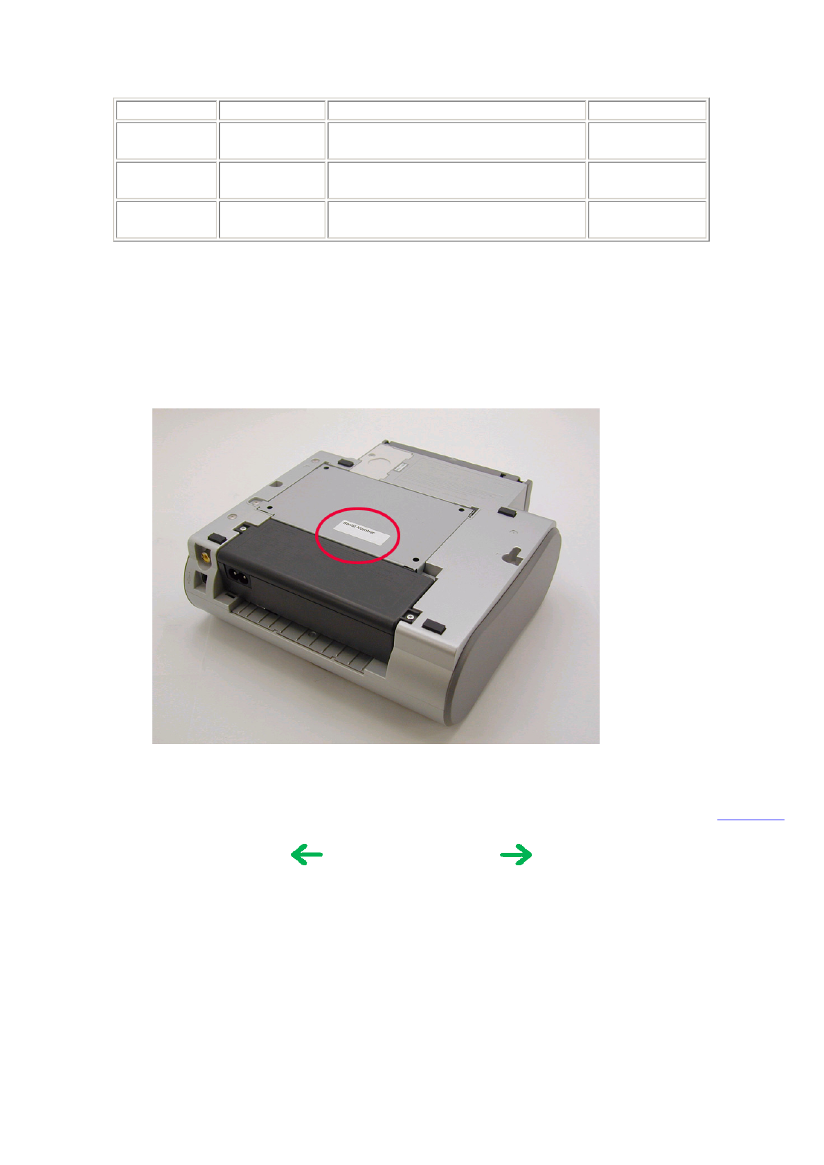
1-5. Serial Number Location
On the bottom shield plate.
To the top
Name Tool no. Application Remarks
MOLYKOTE
PG641
CK-0562-000 To be applied to the sliding portion of the
access cover arm, and feed roller ass'y.
In common with
other models.
FLOIL KG-
107A
QY9-0057-000 To be applied to the sliding portion of the
carriage guide rail.
In common with
other models.
EU-1 QY9-0037-000 To be applied to the carriage oil pad, and the
sliding portion of the carriage shaft.
In common with
other models.
<Part 1: MAINTENANCE>
1 - 3
2. LIST OF ERROR DISPLAY / INDICATIONS
Errors and warnings are displayed by the following ways:
1) Errors are indicated by the number of times the LED blinks.
2) Errors and warnings are displayed on the TV.
3) Errors and warnings are displayed on the printer driver's Status Monitor.
2-1. Operator Call Errors
(by LED Blinking in Orange)
2-2. Service Call Errors
(by LED Blinking in Orange and Green Alternately, or Lit in Orange)
LED
blinking
in orange
Error [Error code] Solution Remarks
2 times No paper. (ASF) [1000] Set the paper in the ASF, and press the
Resume/Cancel button.
3 times Paper jam. [1300] Remove the jammed paper, and press the
Resume/Cancel button.
4 times No ink tank. [1662] Install an ink tank, and press the
Resume/Cancel button.
5 times - The print head is not
installed, or it is not
properly installed. [1401]
- EEPROM data of the print
head is faulty. [1403 /
1405].
- Install the print head properly, and close
the access cover, or, with the print head
installed, turn the printer off and on.
- If the error is still not resolved, the print
head may be defective. Replace the print
head.
8 times Warning: The waste ink
absorber is almost full
(approx. 95% of the
maximum capacity). [1700]
Pressing the Resume/Cancel button will
exit the error, and enable printing.
In repair servicing, replace the ink
absorbers.
The service call error, indicating the
waste ink absorber is full, is likely to
occur soon.
9 times The connected digital camera
or digital video camera does
not support Camera Direct
Printing. [2001]
After removing the cable between the
camera and the printer, press the
Resume/Cancel button, and re-connect the
cable. If the error is still not resolved, a
non-supported camera may be connected.
Connect a supported camera.
Access cover open. [1200] Close the access cover.
LED alternate
blinking in orange
and green
Error [Error code] Solution
(Replacement of listed parts, which are likely to be faulty)
2 times Carriage error [5100] - Carriage unit (QM2-1974)
- Timing slit strip film (QC1-5153)
- Logic board ass'y (QM2-1961)*1
- Carriage motor ass'y (QM2-1744)
1 - 4
*1: Before replacement of the logic board ass'y, check the waste ink amount (by service test print or EEPROM information
print). If the waste ink amount is 7% or more, also replace the ink absorbers (QC1-5195 / 5196 / 5566 / 5567 / 5568 ) when
replacing the logic board ass'y.
[See Section 3-3. Adjustment / Settings, (7) Service mode, for details.]
2-3. Warnings
Printer (displayed via the Status Monitor or on the TV, no LED indication):
*1: If the warning is displayed, the carriage does not move to the ink tank replacement position when the access cover is
opened.
3 times Paper feed error [6000] - Timing sensor unit (QM2-1759)
- Timing slit disk ass'y (QL2-0843)
- Paper feed motor ass'y (QM2-1746)
- Feed roller ass'y (QM2-1970)
- Platen (QC1-5176/5177)
- Logic board ass'y (QM2-1961)*1
4 times Purge unit error [5C00] - Purge unit (QM2-1975)
- Logic board ass'y (QM2-1961)*1
5 times ASF cam sensor error [5700] - Sheet feed unit (QM2-1964)
6 times Internal temperature error [5400] - Logic board ass'y (QM2-1961)*1
7 times Waste ink absorber full [5B00] - Ink absorber (QC1-5195 / 5196 / 5566 / 5567 / 5568)
- After replacement of the ink absorber, reset the EEPROM
(waste ink amount value) on the logic board ass'y.
8 times Print head temperature rise error
[5200]
- Print head (QY6-0056)
- Logic board ass'y (QM2-1961)*1
9 times EEPROM error [6800] - Logic board ass'y (QM2-1961)*1
Continuous
alternate blinking
ROM error - Logic board ass'y (QM2-1961)*1
Lights in orange RAM error - Logic board ass'y (QM2-1961)*1
Displayed warning Remarks
Ink low warning 1 (approx. half level) The warning is displayed only when printer driver's Low Ink
Warning Setting is enabled.
Ink low warning 2 (low remaining ink, display of "!" in the
warning)
The warning is displayed only when printer driver's Low Ink
Warning Setting is enabled.
Ink low warning 3 (ink level unknown, display of "?" in the
warning)
The warning is displayed only when printer driver's Low Ink
Warning Setting is enabled.
Print head temperature rise If the print head temperature is high when the access cover is
opened, the warning is displayed.*1
When the print head temperature falls below the specified
temperature, the warning is released.
Protection against excess rise of the print head temperature If the print head temperature exceeds the specified limit, a
Wait is inserted during printing,
When the print head temperature falls below the specified
temperature, the warning is released.
1 - 5
2-4. Troubleshooting by Symptom
Symptom Solution
Faulty operation
The power does not turn on.
The power turns off immediately after power-on.
Replace the
- AC adapter, or
- logic board ass'y*1.
The print head is not recognized.
The print head does not return to the home position.
Remove and re-install the print
head, or replace the
- print head, or
- logic board ass'y*1.
Strange noise. Remove foreign material, or
attach a removed part if any.
Printing stops mid-way. Replace the logic board ass'y*1.
Paper feed problems
Multiple sheets feed. Replace the
- sheet feed unit, or
- output tray unit.
Paper does not feed. Remove foreign material, or
replace the
- sheet feed unit, or
- output tray unit.
Paper feeds at an angle. Remove foreign material, or
adjust the paper guide, or
replace the
- sheet feed unit, or
- output tray unit.
Unsatisfactory print
quality
No printing, or no color ejected. Replace the
- ink tank,
- print head*2,
- logic board ass'y*1, or
- purge unit.
Printing is faint, or white lines appear on printouts even after print
head cleaning.
Line(s) not included in the print data appears on printouts.
Remove and re-install the print
head, or replace the
- ink tank,
- print head*2,
- purge unit, or
- logic board ass'y*1.
Paper gets smeared. Feed several sheets of paper,
perform bottom plate
cleaning*3, or
clean the paper path with
cotton swab or cloth.
A part of a line is missing on printouts. Replace the
- ink tank, or
- print head*2.
Color hue is incorrect. Replace the
- ink tank, or
- print head*2, or
perform print head alignment.
Printing is incorrect. Replace the logic board ass'y*1.
Non-ejection of ink. Replace the
1 - 6
*1: Before replacement of the logic board ass'y, check the waste ink amount (by service test print or EEPROM information
print). If the waste ink amount is 7% or more, also replace the ink absorbers (QC1-5195 / 5196 / 5566 / 5567 / 5568 ) when
replacing the logic board ass'y.
[See Section 3-3. Adjustment / Settings, (7) Service mode, for details.]
*2: Replace the print head only after the print head deep cleaning is performed 2 times, and when the problem persists.
*3: To perform bottom plate cleaning, with the printer power turned on, press and hold the Resume/Cancel button until the
Power lamp blinks 5 times, then release the button. For details, see Section 3-3. Adjustment / Settings, (6) User mode.
To the top
- ink tank, or
- print head*2.
Graphic or text is enlarged on printouts. When enlarged in the carriage
movement direction, clean
grease or oil off the timing slit
strip film, or replace the
- timing slit strip film,
- carriage unit, or
- logic board ass'y*1.
When enlarged in the paper
feed direction, clean grease or
oil off the timing slit disk ass'y,
or replace the
- timing slit disk ass'y,
- timing sensor unit, or
- logic board ass'y*1.
<Part 1: 2. LIST OF ERROR DISPLAY / INDICATION>
1 - 7
3. REPAIR
3-1. Notes on Service Part Replacement
Service part Notes on replacement*1 Adjustment / settings Operation check
Logic board ass'y
(QM2-1961)
- Before removal of the logic board
ass'y, remove the power cord, and
allow for to sit approx. 1 minute
(for discharge of capacitor's
accumulated charges), to prevent
damage to the logic board ass'y.
- Before replacement, check the
waste ink amount (by service test
print or EEPROM information
print). If the waste ink amount is
7% or more, also replace the ink
absorbers when replacing the logic
board ass'y.
[See 3-3. Adjustment / Settings, (7)
Service mode, for details.]
After replacement:
1. Initialize the EEPROM.
2. Reset the waste ink counter.
3. Set the destination in the
EEPROM.
[See 3-3. Adjustment / Settings,
(7) Service mode, for details of 1
to 3]
4. Set the TV display language in
the user mode.
5. Perform the print head
alignment in the user mode.
- Service test print
- EEPROM
information print
- Printing via USB
connection
- Digital Camera
Direct Printing
- Memory Card
Direct Printing
- Infrared Printing
- Connection to the
TV
Ink absorber
(QC1-5195 / 5196 / 5566 /
5567 / 5568)
After replacement:
1. Reset the waste ink counter.
[See 3-3. Adjustment / Settings,
(7) Service mode.]
- Service test print
- EEPROM
information print
Carriage unit
(QM2-1974)
At replacement:
1. Apply grease to the entire
surface of the carriage oil
pads (2 pcs.).
2. Apply grease to the sliding
portions.
[See 3-3. Adjustment / Settings,
(4) Grease application.]
After replacement:
1. Perform the print head
alignment in the user mode.
- Service test print
Paper feed motor ass'y
(QM2-1746)
- The red screws securing the paper
feed motor are allowed to be
loosened. (For any purposes other
than paper feed motor replacement,
DO NOT loosen them.)
After replacement:
1. Adjust the paper feed motor.
[See 3-3. Adjustment / Settings,
(1) Paper feed motor adjustment.]
- Service test print
Access cover unit
(QM2-1982)
Main cover unit
(QM2-1955)
After replacement:
Adjust the phase of the access
cover arm and access cover gear.
[See 3-3. Adjustment / Settings,
(2) Access cover gear phase
adjustment.]
- Opening and
closing of the
access cover
Pump unit (QM2-1979),
Purge Tube (QC1-5555),
Pump Drive Gear (QC1-5253)
After replacement:
Perform the pump unit
adjustment.
[See 3-3. Adjustment / Settings,
(3) Pump unit adjustment.]
- Service test print
Carriage shaft
(QC1-5150)
At replacement:
1. Apply grease to the sliding
portions.
[See 3-3. Adjustment / Settings,
(4) Grease application.]
- Service test print
1 - 8
*1: General notes:
- Make sure that the flexible cables and wires in the harness are in the proper position and connected correctly.
[See 3-2. Special Notes on Repair Servicing, (1) Flexible cable and harness wiring, connection, for details.]
- Do not drop the ferrite core, as it may damage the core.
- Protect electrical parts from damage due to static electricity.
- Before removing a unit, after removing the power cord, allow the printer to sit for approx. 1 minute (for capacitor
discharging to protect the logic board ass'y from damages).
- Do not touch the timing slit strip film and timing slit disk ass'y. No grease or abrasion is allowed.
- Protect the units from becoming soiled with ink.
- Protect the housing from scratches.
- Exercise caution with the red screws, as follows:
i. The red screws of the paper feed motor may be loosened only at replacement of the paper feed motor ass'y (DO
NOT loosen them in other cases).
ii. DO NOT loosen the red screws on both front sides of the main chassis, securing the carriage guide rail positioning
(they are not adjustable in servicing).
To the top
Timing slit strip film
(QC1-5153)
- Upon contact with the film, wipe the
film with ethanol.
- Confirm no grease is on the film.
(Wipe off any grease thoroughly
with ethanol.)
- Do not bend the film.
After replacement:
1. Perform the print head
alignment in the user mode.
- Service test print
Timing slit disk ass'y
(QL2-0843)
Print head
(QY6-0056)
After replacement:
1. Perform the print head
alignment in the user mode.
- Service test print
<Part 1: 3. REPAIR, 3-1>
1 - 9
3-2. Special Notes on Repair Servicing
(1) Flexible cable and harness wiring, connection
Exercise care when handling the flexible cables and harness wiring. Improper wiring or connection may cause a short-circuit,
and may lead to ignition or emission of smoke.
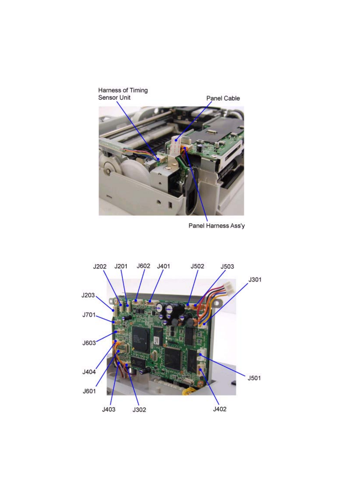
(I) Panel board ass'y and front I/F unit wiring
(II) Logic board ass'y wiring
J201, J202, J203: Carriage FCC cable connectors
J301: DC Harness ass'y connector
J302: Battery holder ass'y harness connector
J401: PE sensor and PG sensor connector
J402: Connected to the PF/ASF sensor inside the sheet feed uni
t
1 - 10
J403: Panel cable connector
J404: Panel harness ass'y connector
J501: Connected to the AP motor harness inside the sheet feed unit
J502: Paper feed motor ass'y connector
J503: Carriage motor ass'y connector
J601: IR cable connector
J602: USB harness ass'y connector
J603: DSC harness ass'y connector
J701: Video harness ass'y connector
(III) Printer unit wiring
<Enlarged View>
1 - 11
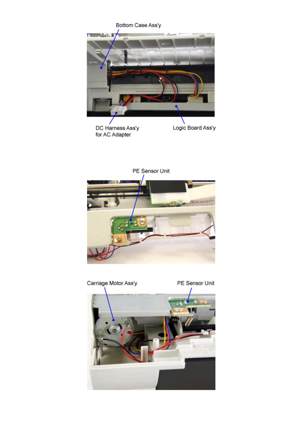
<Wiring of Logic Board Ass'y assembled in Bottom Case Ass'y>
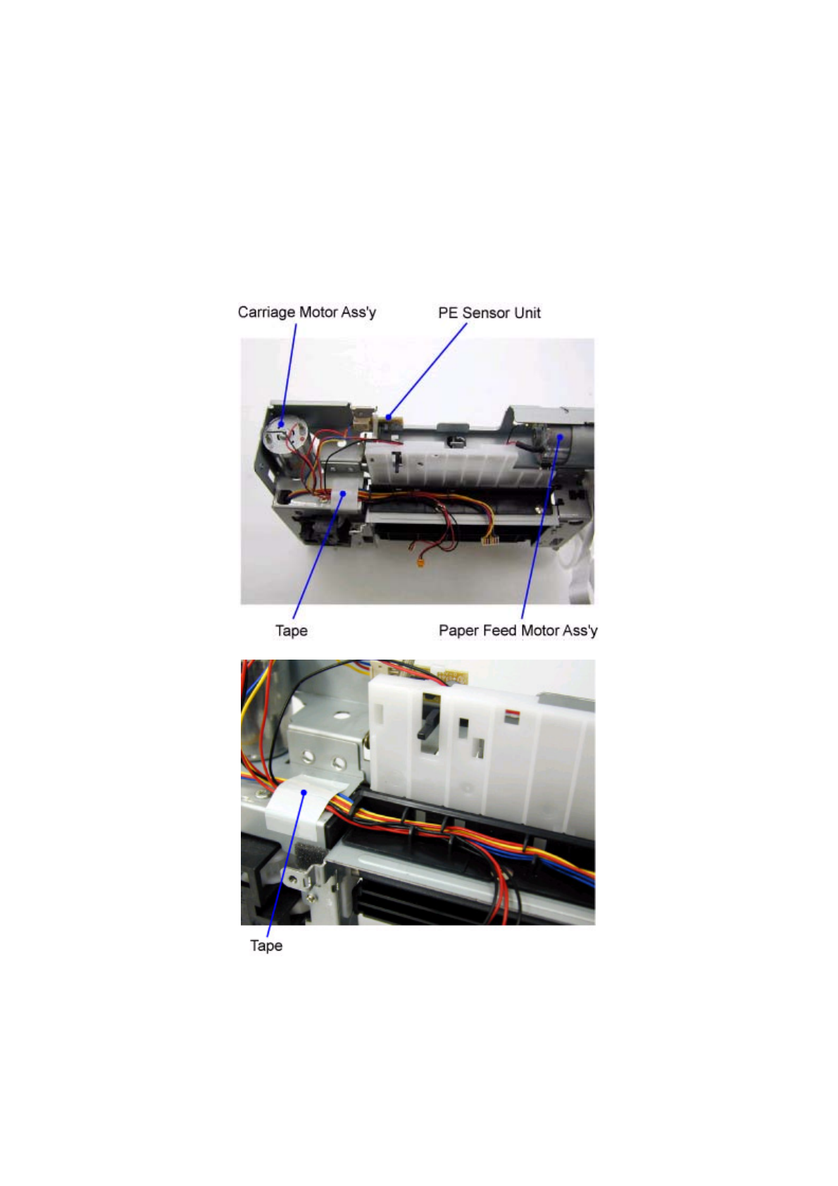
(IV) Paper feed motor ass'y wiring
(V) Carriage motor ass'y and PE sensor harness wiring
1 - 12
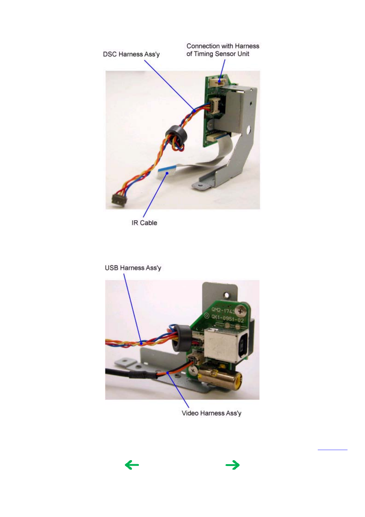
(VI) Front I/F unit wiring
(VII) Rear I/F unit wiring
To the top
<Part 1: 3. REPAIR, 3-2, (1)>
1 - 13
(2) Notes on disassembly and re-assembly
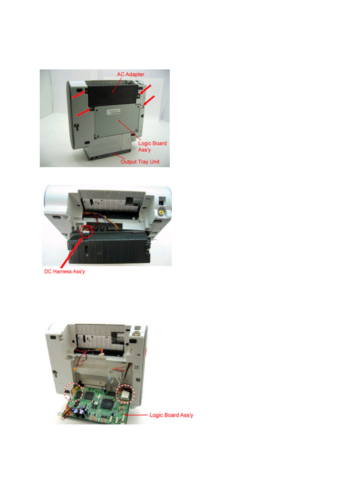
zAC adapter and logic board ass'y removal
1) Remove the 4 screws indicated by the arrow in the figure below. Position the DS700 so that it stands on the output tray
unit, as shown below, to facilitate servicing.
2) Remove the DC harness ass'y, and AC adapter.
3) Remove the harnesses and cables from the logic board ass'y, leaving J402 and J501 on the left side and J601, J403, and
J302 on the right side connected so that further work can be done easily.
Note: For removal of harnesses or cables with few pins, use a pair of tweezers to avoid damaging the connectors.
1 - 14
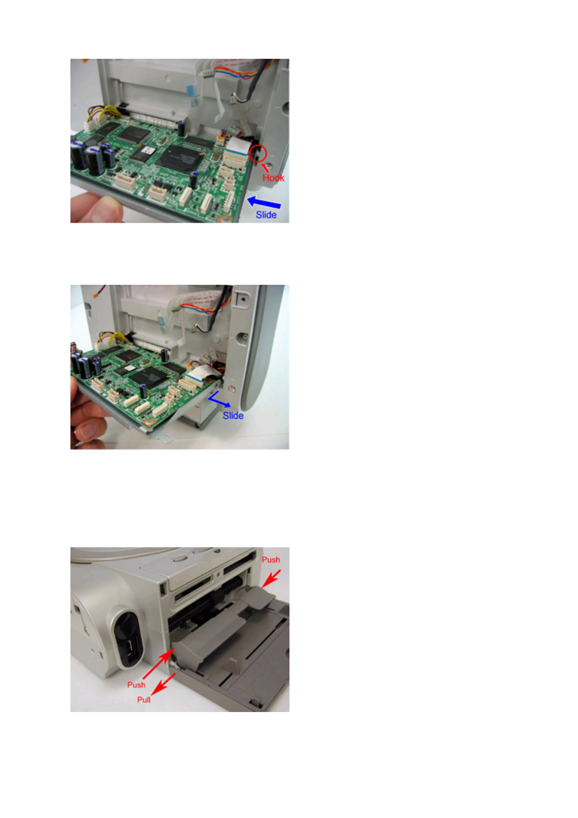
4) Hold the logic board ass'y in a horizontal position, and slide it to the left to release the hook on the right side.
5) Pull and slide the right side of the logic board ass'y to the right, to release the hook on the left side.
Then, remove the remaining harnesses and cables from the logic board ass'y.
Note: For removal of harnesses or cables with few pins, use a pair of tweezers to avoid damaging the connectors.
zOutput tray unit removal
1) Push the left and right sides of the paper output tray inward to release the hooks.
2) Pull the left side of the paper support outward to release the hook.
1 - 15
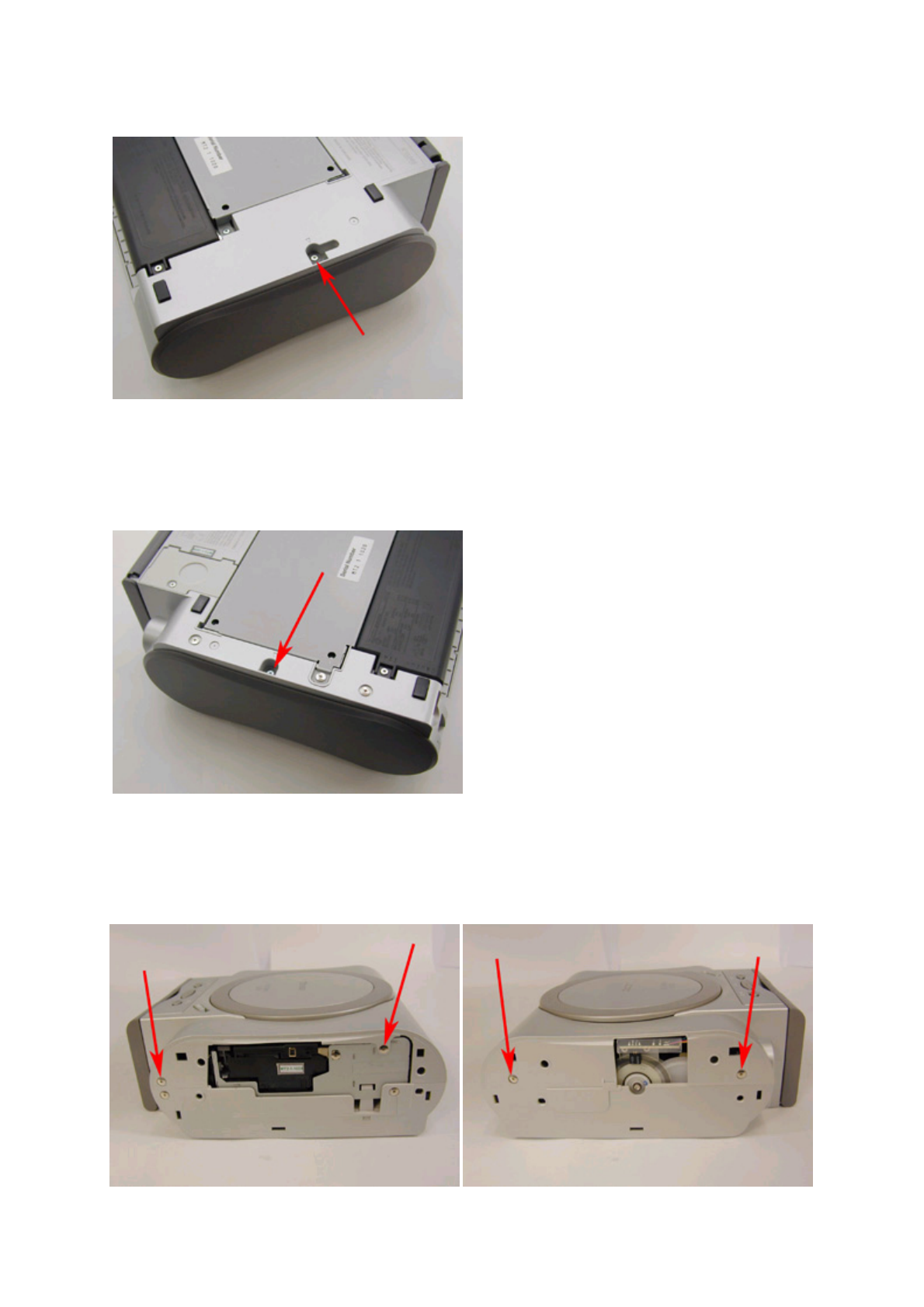
zSide cover R ass'y removal
Remove the screw from the bottom case.
zSide cover L removal
Remove the screw from the bottom case.
zMain cover unit removal
Remove 2 screws from the left side and 2 screws from the right side.
<Right Side> <Left Side>
1 - 16
zTorsion spring and grounding panel board plate positions
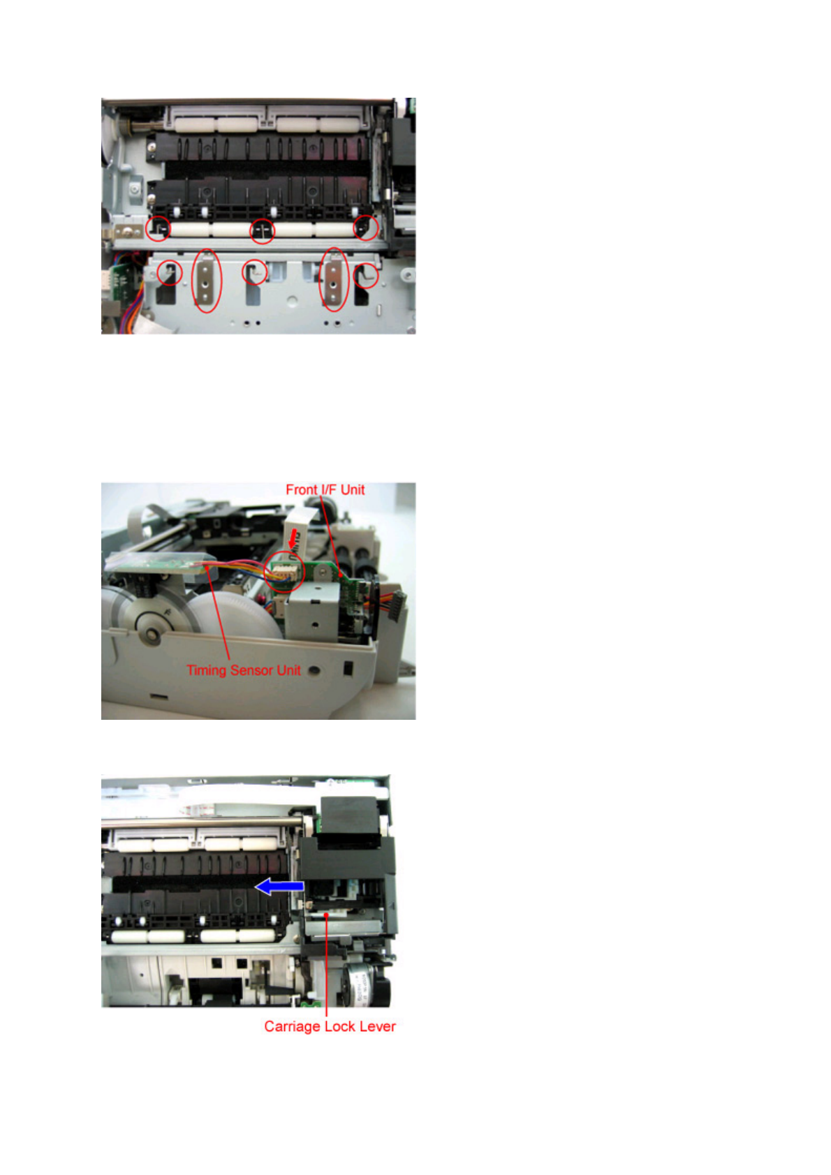
zPrinter unit removal
1) Remove the motor and sensor harnesses from the logic board ass'y, and the timing sensor unit harness from the front I/F
unit.
2) While pressing the carriage lock lever to release the lock, move the carriage to the left.
1 - 17
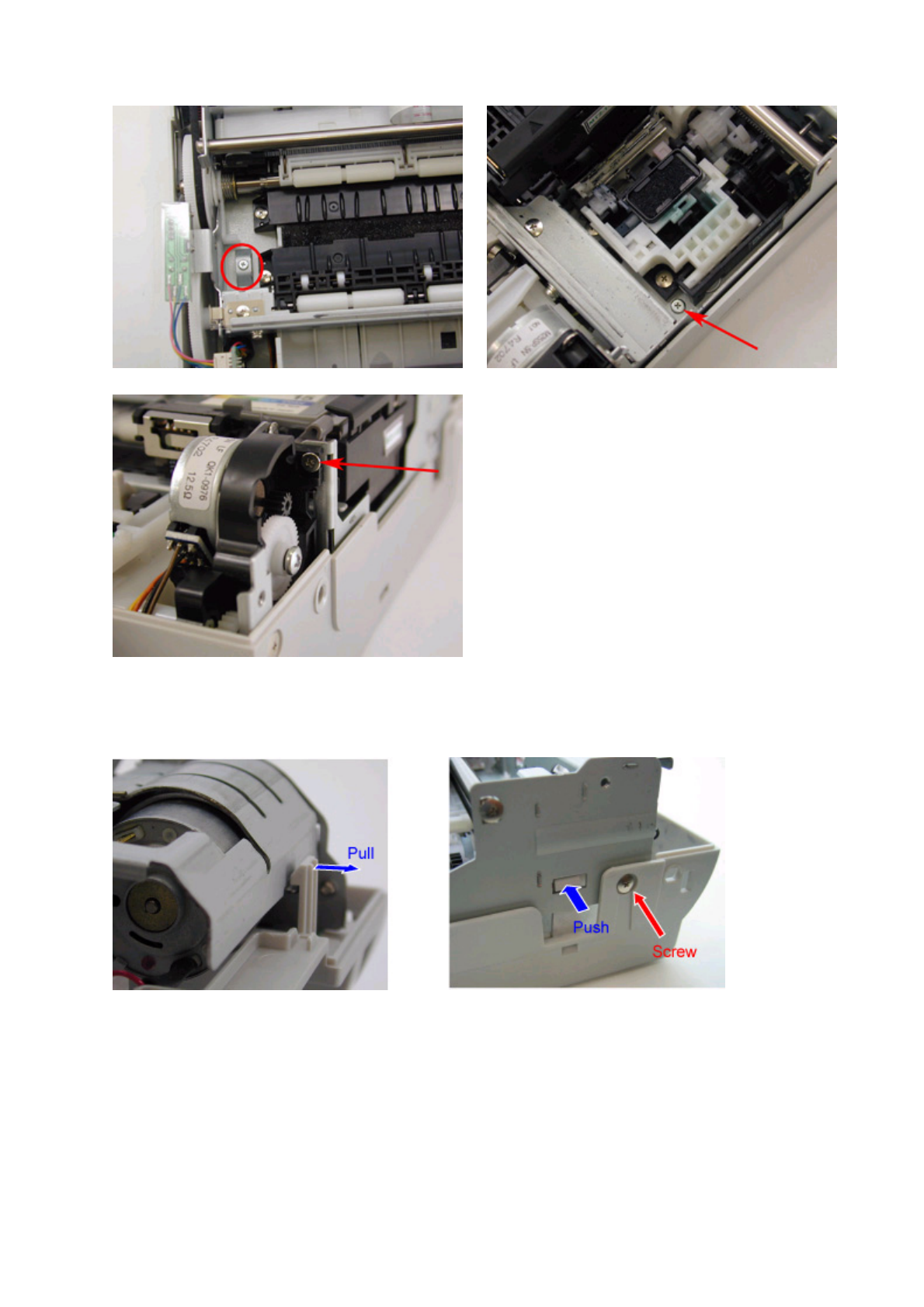
3) Remove the 3 screws shown in the figures below.
4) Remove 1 screw, and release the hooks at 2 locations.
5) While lifting the back side portion of the printer chassis, slide the printer unit backward and remove from the bottom case
ass'y.
Note:
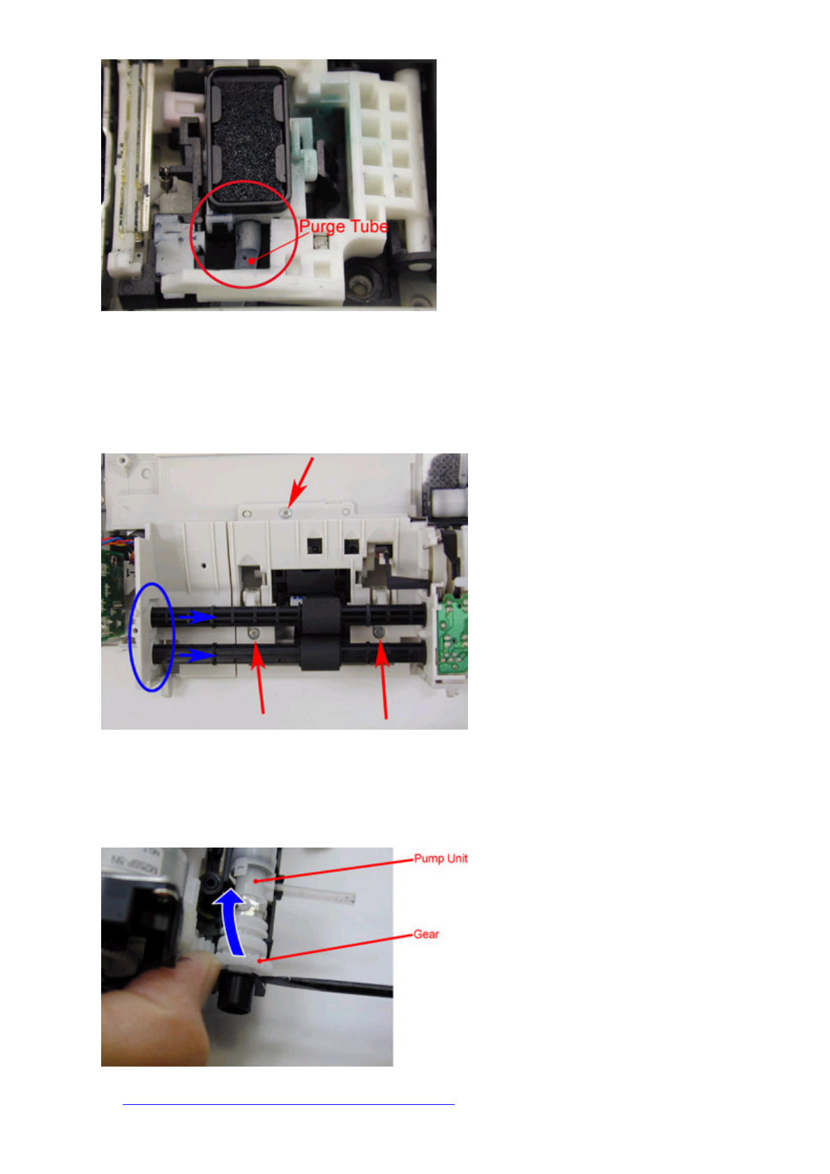
- The printer unit is connected via the purge tube to the sheet feed unit. When removing the printer unit from the purge
tube, use a pair of tweezers to protect the tube from damage.
When re-assembling the printer unit, securely connect the purge tube to the end, while being careful not to damage the
p
urge tube.
1 - 18
- DO NOT touch or scratch the timing slit strip film and the timing slit disk ass'y, and keep them free from any grease.
zSheet feed unit removal
Remove 3 screws, and slide the 2 shafts to the right to remove the sheet feed unit.
zPump unit removal
While creating space with a flat-blade screwdriver, etc., slide the gear portion upward to release it, and remove the pump unit.
Note: In re-assembling the pump unit, adjustment is required.
See [3-3. Adjustment / Settings, (3) Pump unit adjustment], for details.
1 - 19
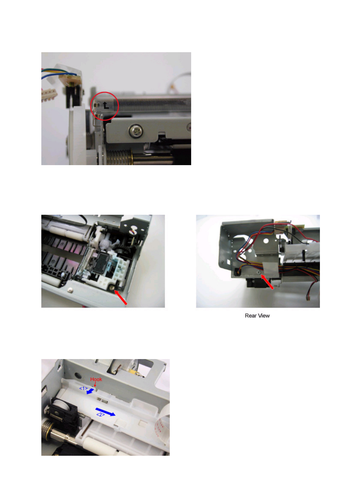
zTiming slit strip film attachment
Attach the film so that the arrow on the left end faces upward, as shown in the figure below.
zPurge unit removal
1) Remove the carriage shaft and the carriage motor ass'y.
2) Remove the harness from the PE sensor unit.
3) Remove the 2 screws shown in the figures below.
zCarriage unit cable holder removal
1) Release the hook by pulling it in the direction <1> in the figure below.
2) Slide the cable holder in the direction <2> in the figure below.
1 - 20
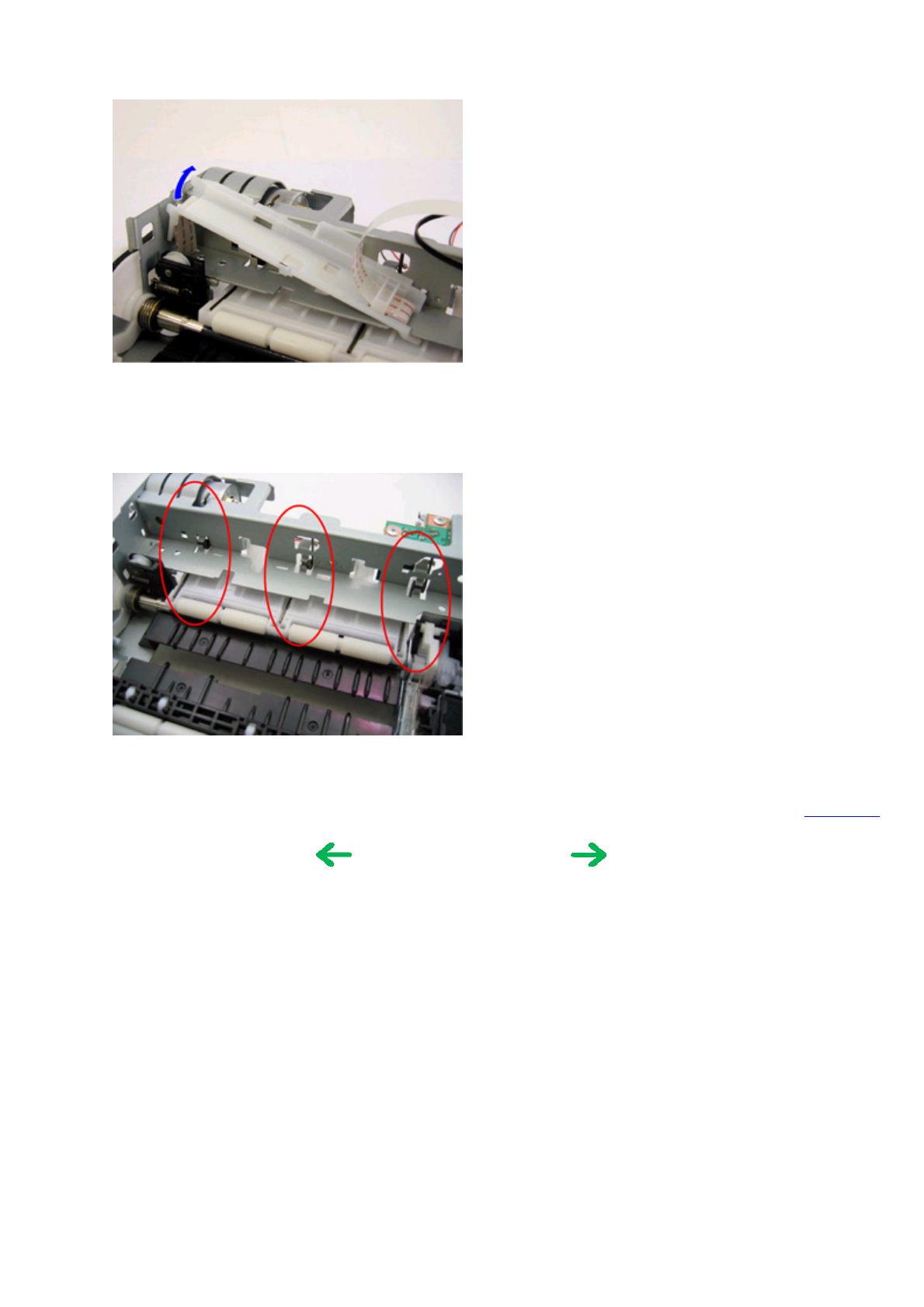
3) Lift the cable holder's left side upward, and remove the flat cable.
zTension spring position
To the top
<Part 1: 3. REPAIR, 3-2, (2)>
1 - 21
3-3. Adjustment / Settings
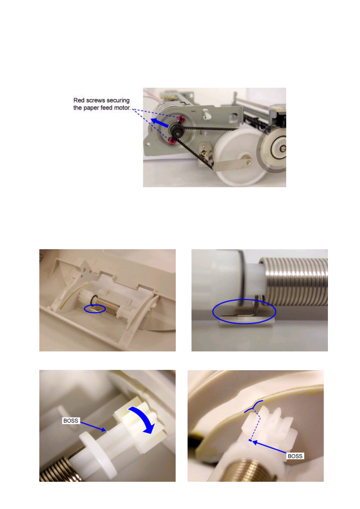
(1) Paper feed motor adjustment
Perform the following adjustments when the paper feed motor ass'y is replaced:
1) When attaching the motor, fasten the screws so that the belt is properly stretched (in the direction indicated by the blue arrow
in the figure below).
2) After replacement, be sure to perform the service test print, and confirm that no strange noise or faulty print operation (due to
dislocation of the belt or gear, or out-of-phase motor, etc.) occurs.
Note: The red screws securing the paper feed motor may be loosened only at replacement of the paper feed motor ass'y. DO
NOT loosen them in other cases.
(2) Access cover gear phase adjustment
After replacement or re-assembly of the access cover unit (QM2-1982) or main cover unit (QM2-1955), adjust the gear phase.
If the main cover unit is replaced with a new unit, apply grease to the locations specified in (4), Grease application, below.
1) Inside the main cover unit, confirm that the access cover spring end fits in the groove of the main cover.
2) Rotate the gear in the direction indicated by the blue arrow, and hold it so that the boss position matches the recess of the
access cover arm sliding portion.
1 - 22
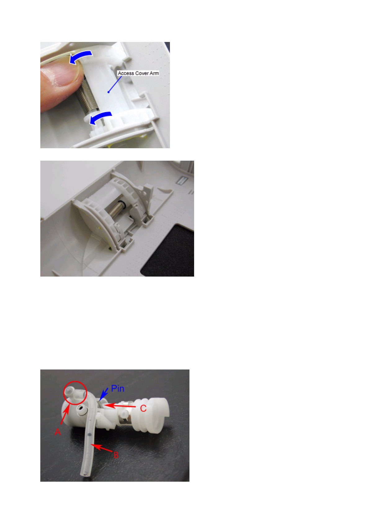
3) While holding the gear position in step 2), slide the access cover arm through the main cover's slot (in the direction indicated
by the blue arrows) into place.
4) Check that the access cover arm fits in place, as shown below.
5) After adjustment of the gear phase, attach the main and access cover units to the printer, and confirm the cover operation.
The cover should open properly by the cover open switch, and close and lock manually.
(3) Pump unit adjustment
zWhen attaching the purge tube to the pump unit
- The purge tube must securely fit in the pump unit hole without any gaps. Any space or crack in location "A" in the figure
below prevents ink from being drawn properly.
- The purge tube will curve, as shown in "B" in the figure below, when assembled in the sheet feed unit.
- Align the pin to the left, as shown in "C" in the figure below.
1 - 23
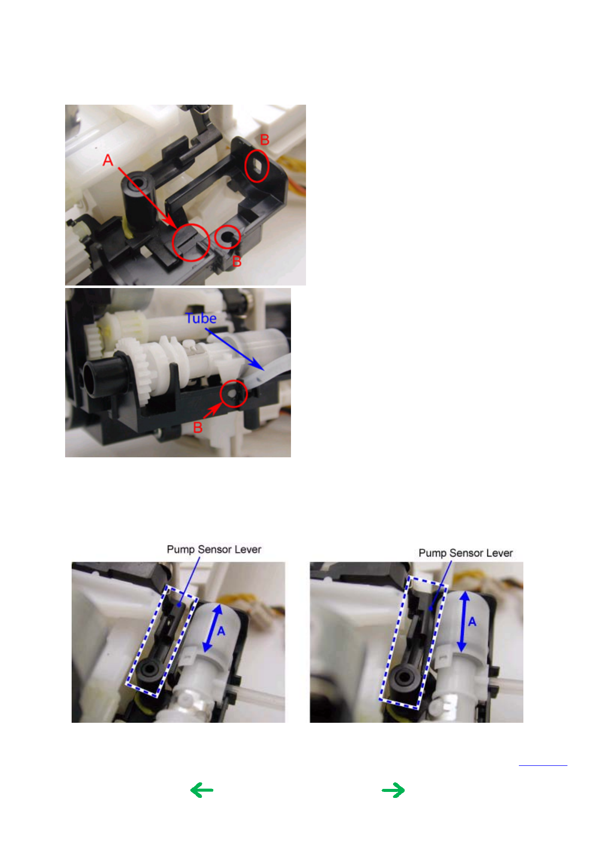
zWhen assembling the pump unit in the sheet feed unit
- Position the pump unit so that the pump unit's pin fits in the groove "A" in the figure below.
- Confirm that the pump unit's bosses fit in the holes "B" in the figure below.
- Set the purge tube in place.
zCheck items after pump unit assembly in the sheet feed unit
Rotate the pump drive gear clockwise and counterclockwise, and confirm the following:
- The pump makes piston action properly at "A" in the figure below.
- The pump sensor lever operates properly (repeats movement shown in figures "Standby" and "Sensor ON" ).
To the top
<Standby> <Sensor ON>
<Part 1: 3. REPAIR, 3-3, (1) to (3)>
1 - 24
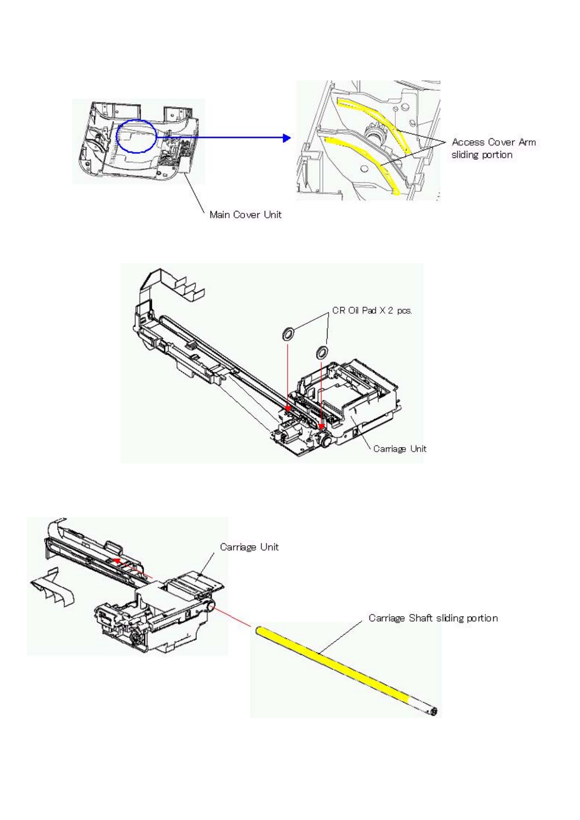
(4) Grease application
1.
2.
3.
1 - 25
4.
5.
6.
1 - 26
Note: 1 drop = 9 to 18 mg
To the top
Part name Where to apply grease / oil Grease / oil name Grease / oil
amount
Main cover unit 1 Access cover arm sliding portion (2 locations) MOLYKOTE PG641 1 drop x 2
locations
Carriage unit 2 Entire surface of the carriage oil pad (2 pcs.) GREASE EU-1 30 +/-5mg x 2
locations
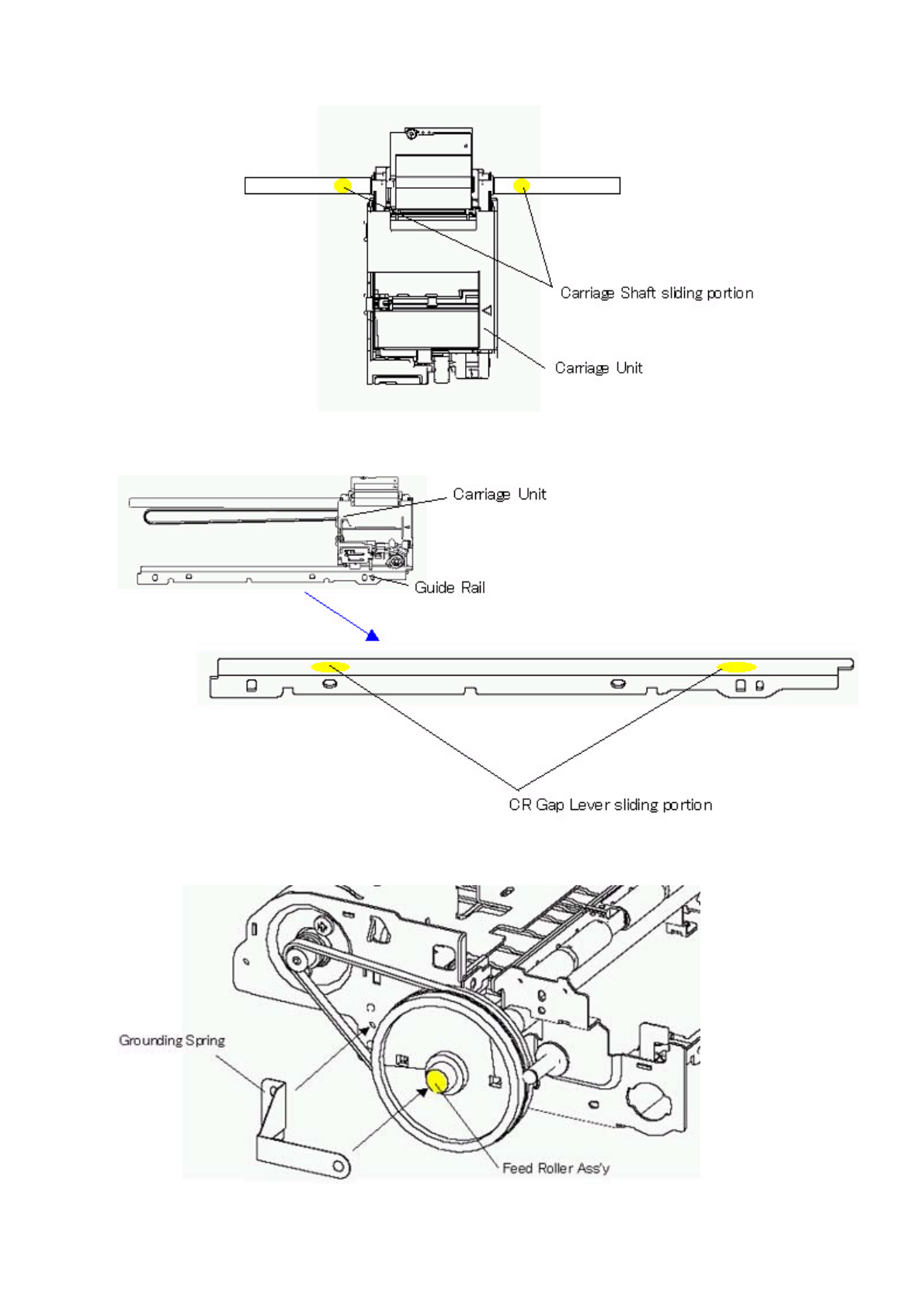
Carriage shaft 3 Carriage shaft sliding portion GREASE EU-1 20 +/-10mg
Carriage shaft 4 Carriage shaft sliding portion (2 times at 2
locations after assembled in the carriage unit)
GREASE EU-1 5 to 8mg x 2
times x 2
locations
Guide rail 5 Carriage gap lever sliding portion (2 locations) FLOIL KG107A Half drop x 2
locations
Grounding spring 6 Feed roller ass'y sliding portion GREASE,
ELECTRICITY IF-20
1 drop
<Part 1: 3. REPAIR, 3-3, (4)>
1 - 27
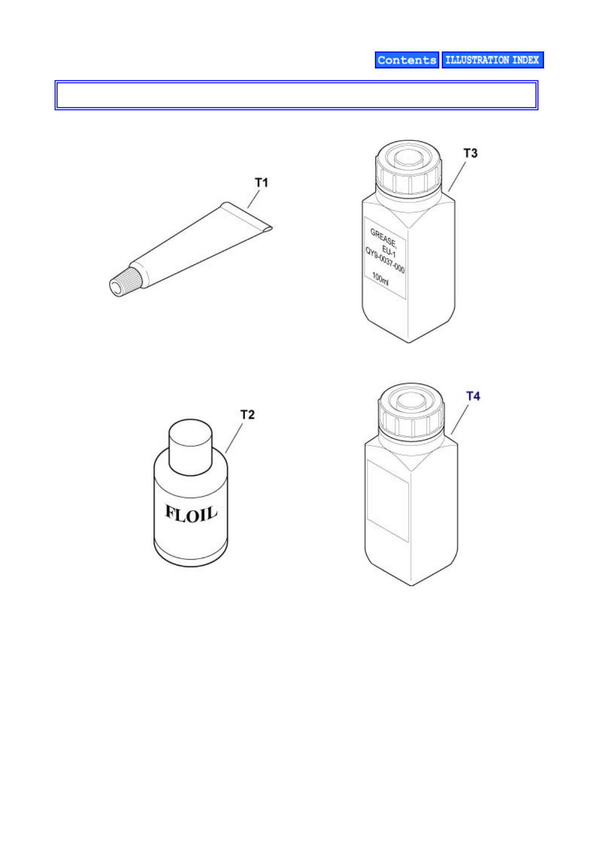
E. TOOL
FIGURE 10 TOOL
E - 1

FIGURE &
KEY No. PART NUMBER RANK QTY DESCRIPTION REMARKS
T - 1CK-0562-000 1 GREASE, MOLYKOTE PG-641
2 QY9-0057-000 1 LUBE, FLOIL KG107A, OIL
3 QY9-0037-000 1 GREASE EU-1
4CK-8006-000 1GREASE, ELECTRICITY IF-20
E - 2
(5) Waste ink counter setting
When the logic board ass'y is replaced, reset the waste ink counter. In addition, according to the waste ink amount, replace the
waste ink absorber. The standard amount for waste ink absorber replacement is given in the table below.
*1: Check the waste ink amount by service test print or EEPROM information print.
[See 3-3. Adjustment / Settings, (7) Service mode.]
(6) User mode
*1: Selectable from among the following 11 languages in the user mode (via TV connection and remote control operation):
LG = 01 Japanese
LG = 02 English 1 (mm)
LG = 03 English 2 (inch)
LG = 04 German
LG = 05 French
LG = 06 Dutch
LG = 07 Spanish
LG = 08 Portuguese
LG = 09 Italian
LG = 0A Swedish
LG = 0B Chinese
<Standalone printer operation>
1) Turn on the printer.
2) Press and hold the Resume/Cancel button until the LED blinks the specified number of times listed in the table below, and
release it. The operation starts.
Waste ink amount*1 Ink absorber replacement
Less than 7% Not required.
7% or more Required.
Function Procedures Remarks
Nozzle check pattern
printing
For procedures on standalone printers,
see "Standalone printer operation" below.
Available from "Standalone printer operation,"
the printer driver, or connection to a TV.
Print head cleaning For procedures on standalone printers,
see "Standalone printer operation" below.
Available from "Standalone printer operation,"
the printer driver, or connection to a TV.
Print head deep cleaning Available from the printer driver, or
connection to a TV.
Available from the printer driver, or
connection to a TV.
Print head alignment Available from the printer driver, or
connection to a TV.
Available from the printer driver, or
connection to a TV.
Print head alignment
values printing
Via TV connection, select Tool Box, and
Head alignment print.
Available only from connection to a TV.
Language selection*1 Via TV connection, select Tool Box, and
Languages.
Available only from connection to a TV.
Paper feed roller cleaning For procedures on standalone printers,
see "Standalone printer operation" below.
Available only from "Standalone printer
operation."
Bottom plate cleaning For procedures on standalone printers,
see "Standalone printer operation" below.
Available only from "Standalone printer
operation."
LED blinking Operation Remarks
1 time Print head cleaning
2 times Nozzle check pattern printing Set a sheet of 4" x 6"-sized paper in the ASF.
3 times Paper feed roller cleaning Set several sheets of Canon 4" x 6"-sized paper with the back
side facing up.
1 - 28
(7) Service mode
<Service mode operation procedures>
1) With the printer power turned off, while pressing the Resume/Cancel button, press and hold the Power button. (DO NOT
release the buttons. The LED lights in green to indicate that a function is selectable.)
2) While holding the Power button, release the Resume/Cancel button. (DO NOT release the Power button.)
3) While holding the Power button, press the Resume/Cancel button 2 times, and then release both the Power and
Resume/Cancel buttons. (Each time the Resume/Cancel button is pressed, the LED lights alternately in orange and green,
starting with orange.)
4) When the LED lights in green, press the Resume/Cancel button the specified number of time(s) according to the function
listed in the table below. (Each time the Resume/Cancel button is pressed, the LED lights alternately in orange and green,
starting with orange.)
5 times Bottom plate cleaning Set Canon MP-101 (4" x 6") or GP-401 (4" x 6") in the ASF.
Function Procedures Remarks
Service test print See "Service mode operation procedures"
below.
Set a sheet of 4" x 6"(101.6 mm x 152.4
mm)-sized paper.
For a print sample, see 3-4. Verification
Items, (1) Service test print.
EEPROM information print See "Service mode operation procedures"
below.
Set a sheet of 4" x 6"(101.6 mm x 152.4
mm)-sized paper.
For a print sample, 3-4. Verification
Items, (2) EEPROM information print.
EEPROM initialization See "Service mode operation procedures"
below.
The following item is NOT initialized:
- Waste ink counter
Waste ink counter reset See "Service mode operation procedures"
below.
If the waste ink amount is 7% or more,
replace the ink absorbers.
Destination settings See "Service mode operation procedures"
below.
The TV display language is set to the
default language for the set destination.
Print head deep cleaning See "Service mode operation procedures"
below.
Cleaning of all colors at the same time.
Time(s) LED Function Remarks
0 times Green Power off Even when the print head is not installed, the
carriage returns and locks in the home position.
1 time Orange Service test print See 3-4. Verification Items, (1) Service test print.
2 times Green EEPROM information
print
See 3-4. Verification Items, (2) EEPROM
information print.
3 times Orange EEPROM initialization The waste ink counter value is not reset.
4 times Green Waste ink counter
resetting
5 times Orange Destination settings Proceed to the following step 5), and follow the
Destination settings procedures.
6 times Green Print head deep cleaning
7 times Orange EEPROM dump print
8 times Green NTSC / PAL signal
switching
Proceed to the following step 5), and follow the
NTSC / PAL signal switching procedures.
9 times Orange Return to the menu
selection
1 - 29
5) After the function (menu) is selected, press the Power button. The LED lights in green, and the selected function is
performed. (When the operation completes, the printer returns to the menu selection mode automatically.)
Note: To exit the service mode, press the Power button.
<Destination settings procedures>
In the destination settings mode, press the Resume/Cancel button the specified number of time(s) according to the destination
listed in the table below, and press the Power button.
Note: After setting the destination, confirm the settings in the service test print or EEPROM information print.
[See 3-4. Verification Items, (1) Service test print, or (2) EEPROM information print.]
<NTSC / PAL signal switching procedures>
In the NTSC / PAL signal settings mode, press the Resume/Cancel button the specified number of time(s) according to the TV
mode listed in the table below, and press the Power button.
Note: After setting the TV mode, confirm the settings in the service test print or EEPROM information print.
[See 3-4. Verification Items, (1) Service test print, or (2) EEPROM information print.]
To the top
Time(s) LED Destination Paper size Language TV
0 times Green No destination change - - -
1 time Orange JPN 01 (L) LG = 01 Japanese NTSC
2 times Green US / CA / LAM LVT / TW 02 (4x6) LG = 03 English 2 (inch) NTSC
3 times Orange EUR / GB / EUM 02 (4x6) LG = 02 English 1 (mm) PAL
4 times Green CN 02 (4x6) LG = 0B Chinese PAL
5 times Orange ASA HVT / AU / HK 02 (4x6) LG = 03 English 2 (inch) PAL
6 times or
more Green Return to the destination
settings mode - - -
Time(s) LED TV mode
0 times Green No TV mode change
1 time Orange NTSC
2 times Green PAL
3 times Orange Return to the NTSC/PAL signal settings mode
<Part 1: 3. REPAIR, 3-3, (5) to (7)>
1 - 30
3-4. Verification Items
(1) Service test print
After repair, perform service test print, and confirm the items below.
Note: Use a sheet of 4" x 6" (101.6 mm x 152.4 mm)-sized paper.
<Print check items>
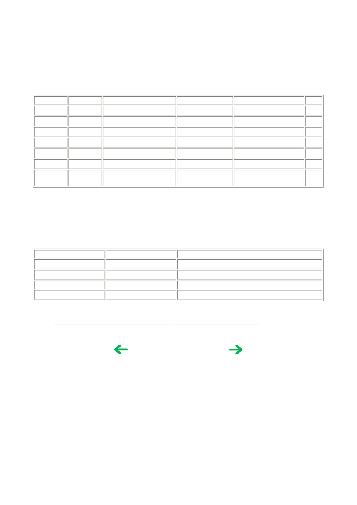
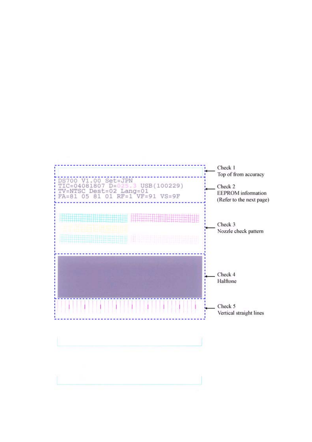
On the service test print (sample below), confirm the following items:
- Check 1, top of form accuracy: The line shall not extend off the paper.
- Check 2, EEPROM information: Destination settings, waste ink amount, etc.
- Check 3, nozzle check pattern: Ink shall be ejected from all nozzles.
- Check 4, halftone: There shall be no remarkable streaks or unevenness.
- Check 5, vertical straight lines: The line shall not be broken.
<Service test print sample>
1 - 31

<Check 2, EEPROM information>
On the service test print, confirm the following EEPROM information:
DS700: Model name (same for all destinations).
Vx.xx: ROM version.
Set = xxx: Destination settings at shipment from the plant (not used in field service).
(Destination setting in the service mode is not reflected to this value. Settings in the service mode are reflected in
EEPROM's TV, Dest, and Lang values, however, the Set value remains unchanged from the original setting at
shipment from the plant.)
TIC = xxxxxxxx: Timer IC data. Year, month, day, and time are printed.
D = xxx.x: Waste ink amount (%). (The values 3.5% or less are printed in black, and 3.6% or more are printed in magenta.)
USB (xxxxxx): USB serial number.
TV = xxxx: TV signal information (NTSC or PAL).
Dest = xx: Destination setting. (01 for standard model supporting L-sized paper, 02 for standard model supporting 4" x 6"-sized
paper)
Lang = xx: Number corresponding to the selected language.
01 Japanese
02 English 1 (mm)
03 English 2 (inch)
04 German
05 French
06 Dutch
07 Spanish
08 Portuguese
09 Italian
0A Swedish
0B Chinese
FA = xx xx xx xx: Line inspection information (not used in field service).
RF = x: Remote control operation flag (not used in field service).
VF = xx: Video frequency adjustment value (not used in field service).
VS = xx: Video signal output adjustment value (not used in field service).
(2) EEPROM information print
<How to read the EEPROM information print>
Print sample:
1:01 2:DS700 3:V1.00 4:IF(USB=1) 5:D=014.7 6:ST=2004/08/14-08:21
7:ER(ER0=1000 ER1=5C00) 8: LPT=2004/08/14-11:020
9:PC(M=004 R=001 T=001 D=002 H=003) 10:CLT(2004/08/03-06:58)
11:CH=00001 12:CT=00003
13:IS( C=1 M=0 Y=2) 14:IC(C=00924 M=01170 Y=01107)
15:Power(SON=00029 SOFF=00018 HON=00008 RON=00000 ROFF=00000)
16:REG=1 17:UR(A(Coe)=-02 B(SCoe)=+02 C(CLbi)=000 D(SCLbi)=+01)
18:LG=01 Japanese 19:TV=NTSC 20:CDIN(LG=000 PB=000 OPB=000) 21:MSD(020)
22:PAGE(All=00151 PP=00000 HR=00000 MP=00021 PR=00018 SP+SG=00108
GP=00004 PC=00000 ENV=00000) 23:KP=00027
24:CDPAGE
(
All=001
)
25:EDGE=00096 26:L=00066
1 - 32

27:DCR=001 28:DCRC=00000 29:Head Temp=26.5 30:WP=0193
31: Env Temp=27.5 32:FF(81 05 81) 33:OPP=00000 34:PrnB=00025 35:Seal=00003
36:CardPaper=00039 37:CardIns(0063) 38:CardPrn(0077)
39:CardD-PR( L/4x6=0002 JPC=0001)
40:CardD-SP( L/4x6=0021 JPC=0003)
41:CardD-MP( L/4x6=0008 JPC=0000)
42:CameraD-Photo P( L/4x6=0001 JPC=0000)
43:CameraD-Fast Photo P( L/4x6=0002 JPC=0000)
44:CameraD-Matte Photo P( L/4x6=0003 JPC=0000)
HDEEPROM
45:V0001 46:SN=0000-0154 47:LN(00 00 00 03 13 17 15) 48:ID=05
49:IL=(C=000 M=000 Y=000)
Printed items:
1: Destination setting (01 for standard model supporting L-sized paper, 02 for standard model supporting 4x6-sized paper)
2: Model name (same for the all destinations)
3: ROM version
4: USB I/F connection
Once the printer is connected via USB, "IF(USB=1)" is printed.
5: Waste ink amount (%) (D: Drain)
6: Installation date and time (ST: Set Time)
7: Operator call / service call error record (ER0 = latest error, ER1 = previous error)
8: Last printing time (last time before an error) (LPT: Last Print Time)
9: Purging count (PC: Purge Count) (M = manual cleaning, R = deep cleaning, T = timer cleaning, D = cleaning by dot count,
H = cleaning at ink tank / print head replacement)
10: Last cleaning time (CLT: Cleaning Time)
11: Print head replacement count (CH: Change Head)
12: Ink tank replacement count (CT: Change Tank)
13: Ink status (IS: Ink Status)
The number 0, 1, 2, or 3, corresponding to the Low Ink Warning level is printed.
14: Total ink consumption (IC: Ink Consumption) in mg
15: Power-on / -off count (SON = soft-power-on, SOFF = soft-power-off, HON = hard-power-on, RON = power-on via remote
control, ROFF = power-off via remote control)
16: Manual print head alignment by user (1 for performed, 0 for not performed)
17: User print head alignment value (UR: User Registration)
18: Language setting (LG: Language)
The specified language is printed.
LG = 01 Japanese
LG = 02 English1 (mm)
LG = 03 English2 (inch)
LG = 04 German
LG=05 French
LG=06 Dutch
LG=07 Spanish
LG=08 Portuguese
LG=09 Italian
LG=0A Swedish
LG=0B Chinese
1 - 33

19: TV signal (NTSC or PAL)
20: Camera Direct Print-supported device connection record (CDIN: Camera Direct Insert)
LG = Legacy (Canon Bubble Jet Direct), PB = Canon PictBridge, OPB = Other PictBridge
21: Longest period of non-printing (MSD: Maximum Stop Date)
22: Number of pages fed (total, plain paper, High Resolution Paper, Matte Photo Paper, Photo Paper Pro, Photo Paper Plus
Glossy & Photo Paper Plus Semi-gloss, Glossy Photo Paper, postcard, envelope)
23: Print count by the Print All button (KP: Key Print)
24: Camera Direct print pages in total (CDPAGE: Camera Direct PAGE)
25: Borderless print pages
26: L & 4x6 print pages
27: Number of times dot count is reset (DCR: Dot Count Reset)
The number of times ink counter reset is performed (OK is clicked) at Ink Low Warning 2 or 3.
28: Number of times dot count reset is cancelled (DCRC: Dot Count Reset Cancel)
The number of times ink counter reset is cancelled at Ink Low Warning 2 or 3.
29: Print head temperature
30: Wiping count (WP: Wiping)
31: Inside temperature
32: Line inspection information (FF: Factory Function) (Not used in field service)
33: Other Photo Paper pages fed (Not used in field service, as the DS700 does not support Other Photo Paper.)
34: Infrared printing pages fed (PrnB: Print Beam)
35: Photo Sticker pages fed
36: Name card- / Credit Card-sized paper pages fed
37: Number of times a memory card is used
38: Memory Card Direct print pages in total
39: Memory Card Direct print pages: Photo Paper Pro (L/4x6, Japanese postcard)
40: Memory Card Direct print pages: Photo Paper Plus Glossy (L/4x6, Japanese postcard)
41: Memory Card Direct print pages: Matte Photo Paper (L/4x6, Japanese postcard)
42: Camera Direct print pages: Photo Paper (L/4x6, Japanese postcard)
43: Camera Direct print pages: Fast Photo Paper (L/4x6, Japanese postcard)
44: Camera Direct print pages: Matte Photo Paper (L/4x6, Japanese postcard)
HDEEPROM
45: Version
46: Serial number
47: Lot number
48: Print head ID
49: Ink ejection level (C/M/Y)
To the top
<Part 1: 3. REPAIR, 3-4>
1 - 34
4. PRINTER TRANSPORTATION
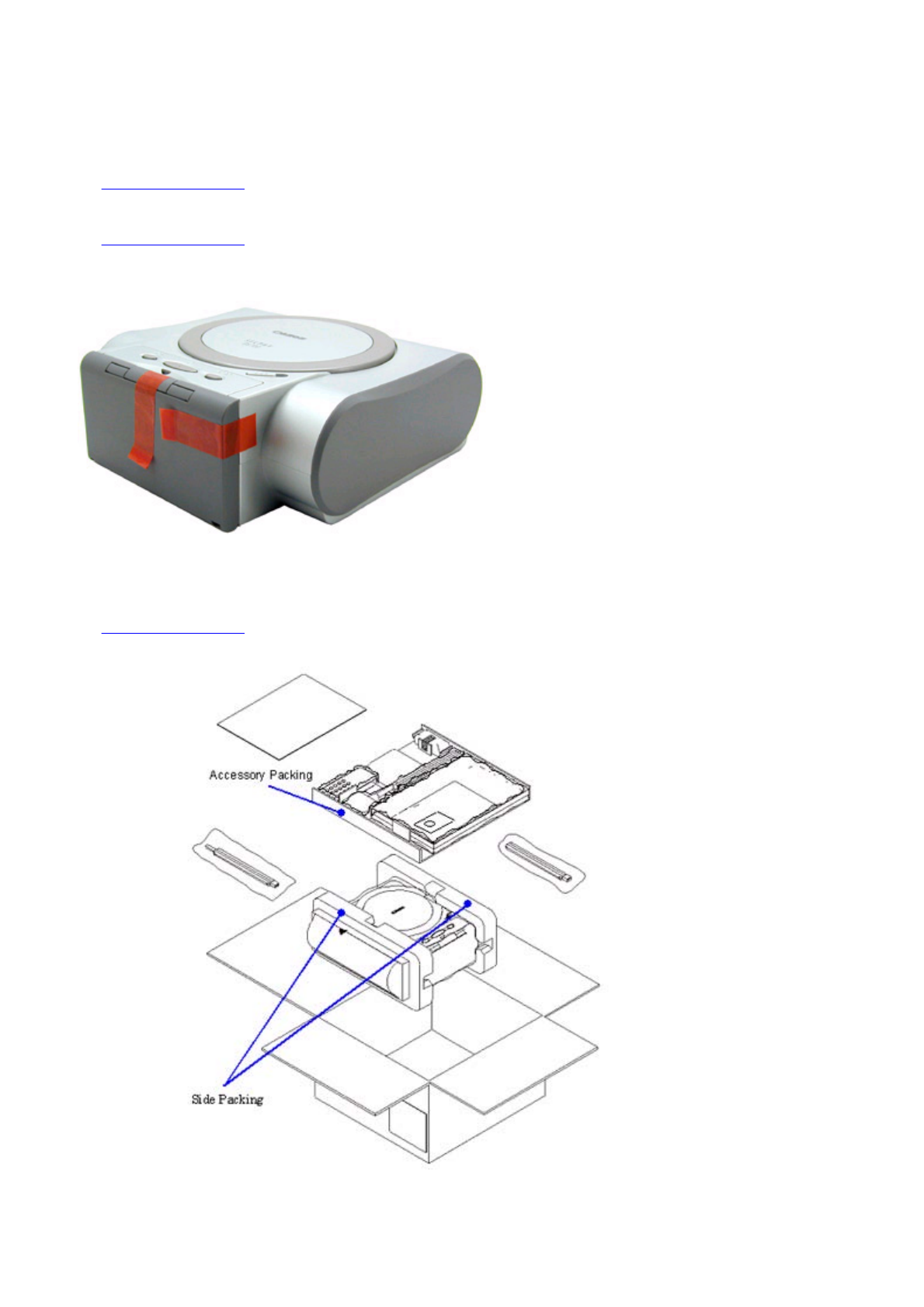
This section describes the procedures for transporting the printer for returning after repair, etc.
1) Keep the print head and ink tank installed in the carriage.
[See Caution 1 below.]
2) Turn off the printer to securely lock the carriage in the home position. (When the printer is turned off, the carriage is
automatically locked in place.)
[See Caution 2 below.]
3) Attach the tape in 2 locations, as shown below, to fix the output tray unit.
4) Attach the left / right side packing and accessory packing to protect the printer, and set in the packing box.
Note: If the packing used when the box was opened is not available, use packing of the same grade.
[See Caution 3 below.]
1 - 35

Caution:
(1) If the print head is removed from the printer and left alone by itself, ink is likely to dry. For this reason, keep the print
head installed in the printer even during transportation.
(2) Securely lock the carriage in the home position, to prevent the carriage from moving and applying stress to the carriage
flexible cable or causing ink leakage during transportation.
(3) Attach the accessory and side packing to the printer when transporting it, to prevent the print head face surface from
contacting the purge base, and from scratching the nozzles.
Memo:
If the print head must be removed from the printer and transported alone, perform the following:
(1) Install the ink tank (to prevent the nozzles from drying).
(2) Attach the protective cap (used when the packing was opened) to the print head (to protect the print head face from
damage due to shocks).
To the top
<Part 1: 4. PRINTER TRANSPORTATION>
1 - 36

P
art 2
TECHNICAL REFERENCE

1. NEW TECHNOLOGIES
(1) Robust direct printing
The SELPHY DS700 is a compact photo printer equipped with a wide array of inputs (by memory card, digital camera, and
camera-equipped mobile phone), TV outputs, easy-to-use remote control and UI, realizing fast and high-quality photo printing
with ease and wide range, without using a computer.
(2) Card direct printing
By using the TV display function, viewing images from the memory card on the TV and printing them are possible.
<Main menu>
- Photo Gallery:
Display photos saved in the memory card on the TV one by one, and print a desired photo. In Slide Show, photos are
displayed in series automatically on the TV.
- Photo Print:
Display 9 photos on the TV at one time, specify a desired number of print copies for each photo respectively, and print
them.
- Print Studio:
Make various prints such as Layout print and Sticker print.
- Tool Box:
Perform print head cleaning / alignment, set default paper for infrared printing, and select a language, etc.
(3) PictBridge / Canon Bubble Jet Direct supporting
The SELPHY DS700 supports PictBridge and Canon Bubble Jet Direct, which are direct print standards for the digital camera
and printer. By using a digital camera/video camera which supports either of these standards, direct printing via cable, without
using a computer, can be easily performed.
(4) Infrared printing
Direct printing of photos from a camera-equipped mobile phone can be performed via infrared communication. (Text printing
from a camera-equipped mobile phone or printing from a computer / PDA via infrared communication is not available.)
(5) New design
A new design more suitable for the living room environment. By adopting switchback feeding, feeding from the front side is
available.
(6) New print head and ink tank
A new print head with 3 colors (C / M / Y) with miniscule 2 pl ink drops in addition to 5 pl, and a new ink tank, BCI-16 Color,
with enhanced weather resistance and storage stability, are adopted.
(7) Memory card access functionality
From a computer, read or write of image files in a memory card inserted in the printer can be performed. By using the memory
card utility, provided with the printer, cancellation of write-protect or memory card ejection can be safely performed.
To the top
<Part 2: 1. NEW TECHNOLOGIES>
2 - 1
2. CLEANING MODE AND AMOUNT OF INK PURGED
To prevent printing problems due to bubbles, dust, or ink clogging, print head cleaning is performed before the start of printing,
except in the following cases:
- Cleaning on arrival: Performed when the access cover is closed.
- Cleaning by dot count: Performed after ejection of paper.
- Manual cleaning / deep cleaning: Performed manually.
<Cleaning mode list>
Color: C / M / Y
To the top
Condition Details Est. amount of ink used (g) Est. required
time (sec.)
On arrival of the
printer
First cleaning after shipped from the
plant.
0.48 82
Dot count cleaning When the specified number of dots are
printed since the previous cleaning.
0.16 42
Timer cleaning - 1 If 504 to 720 hours have elapsed since
the previous cleaning till the start of the
next printing.
0.16 42
Timer cleaning - 2 If more than 720 hours have elapsed
since the previous cleaning till the start
of the next printing.
0.32 62
At print head
replacement
When the print head is removed and
installed.
0.48 82
At ink tank
replacement
0.32 62
Head cleaning - Via the printer button
- Via the printer driver
- Via connection to a TV (remote
control)
0.16 42
Deep cleaning - Via the printer driver
- Via connection to a TV (remote
control)
0.48 82
If the print head has not
been capped for more
than 1 hour before
power-on
0.32 62
<Part 2: 2. CLEANING MODE>
2 - 2
3. PRINT MODE
3-1. Resolution during Printing via Computer
3-2. Resolution in Card Direct / Camera Direct / Infrared Printing
Paper type
Print direction, ink used, and resolution (dpi)
Quality 1 Quality 2 (High) Quality 3
(Standard) Quality 4 (Draft) Quality 5
Photo Paper Pro
(PR-101 4x6)
16 pass-
bidirectional
4800x1200
2pl
12 pass-
bidirectional
1200x600
2pl
6 pass-
bidirectional
1200x600
2pl/5pl
Photo Paper Plus Glossy
(PP-101 4x6)
Photo Paper Plus Semi-gloss
(SG-101 4x6)
12 pass-
bidirectional
1200x600
2pl
6 pass-
bidirectional
1200x600
2pl/5pl
4 pass-
bidirectional
600x600
5pl
Matte Photo Paper
(MP-101 4x6)
12 pass-
bidirectional
1200x600
2pl
6 pass-
bidirectional
1200x600
2pl/5pl
Glossy Photo Paper
(GP-401 4x6/Credit Card)
12 pass-
bidirectional
1200x600
2pl/5pl
6 pass-
bidirectional
1200x600
2pl/5pl
Ink Jet Hagaki
12 pass-
bidirectional
1200x600
2pl
6 pass-
bidirectional
1200x600
2pl/5pl
Hagaki
6 pass-
bidirectional
1200x600
2pl/5pl
4 pass-
bidirectional
1200x600
5pl
Paper type
Print direction, ink used, and resolution (dpi)
Quality 1 Quality 2 (High) Quality 3
(Standard) Quality 4 (Draft) Quality 5
Photo Paper Pro
(PR-101 4x6)
6 pass-
bidirectional
1200x600
2pl/5pl
Photo Paper Plus Glossy
(PP-101 4x6)
Photo Paper Plus Semi-gloss
(SG-101 4x6)
Photo Stickers
(PS-101)*2
6 pass-
bidirectional
1200x600
2pl/5pl
Matte Photo Paper
(MP-101 4x6)*1
6 pass-
bidirectional
1200x600
2pl/5pl
Glossy Photo Paper
(GP-401 4x6/Credit Card)
6 pass-
bidirectional
1200x600
2pl/5pl
2 - 3

*1: Camera Direct Printing not supported.
*2: In Print Studio, select Sticker print.
Notes on PictBridge supported digital camera:
1. Paper size and type settings on the camera
When Default is selected for the paper size and paper type on the camera, printing is performed according to the printer's paper
size and paper type settings.
2. When paper type (other than default) is set on the camera
Printing is performed in the following print mode:
- Fast Photo: Photo Paper Pro (PR-101 4x6)
- Photo: Photo Paper Plus Glossy (PP-101 4x6), Photo Paper Plus Semi-gloss (SG-101 4x6)
To the top
<Part 2: 3. PRINT MODE>
2 - 4

4. PHOTO DIRECT PRINT FUNCTION
4-1. Host PC Memory Card Access Function
(1) Supported memory cards
Media types compatible with the host computer memory card access function and Memory Card Direct Printing function are as
follows:
- Compact Flash Card (CF1, CF2 [micro drive]) (However, 5V is not supported.)
- Smart Media Card (5V, 1M and 2M are not supported.)*1
- Memory Stick / Memory Stick PRO / MagicGate Memory Stick (For Memory Stick Duo / Memory Stick PRO Duo /
MagicGate Memory Stick Duo, an excusive adapter is necessary.)* 1
- SD Memory Card (For the miniSD memory card, an exclusive adapter is necessary.)* 1
- Multimedia Card
- xD-Picture Card (An exclusive adapter is necessary.)
*1: In the Memory Card Utility, if Read/Write mode is selected, the use of memory cards where the write protection is set to
Read-only mode is prohibited, and the operations are not assured.
(2) Mounting the drive
Windows:
When the SELPHY DS700 is connected by USB cable to a host computer with the Memory Card Utility installed, and the
printer is powered on via the Power button, the card slot on the SELPHY DS700 is mounted in My Computer as a removable
drive.
Macintosh:
When the SELPHY DS700 is connected by USB cable to a host computer with the Memory Card Utility installed, and the
printer is powered on via the Power button, and then a supported memory card is inserted, the card slot on the SELPHY
DS700 is mounted on the desktop as a removable drive.
(3) Arrangement of image files
Photo numbers are generally assigned in the order of exposure by the digital camera, and, in Index printing or with the TV View
function, photos are displayed in the order of those photo numbers.
In a folder, a higher priority is placed on a file when the file name, not counting the file extension, consists of 8 characters with
the latter 4 being numeric, in compliance with the DCF (Design rule for Camera File system). Files are sorted in ascending order
of those 4 numeric figures.
(4) Data access
For mounted cards in the SELPHY DS700, data access to the memory card is possible by performing the usual file operations
through the OS’s standard file control software (such as Explorer and Finder) and general software applications. (The same
operations as with standard removable drives are possible: file reading, writing, deletion, media formatting, properties, etc.)
Note: In the Memory Card Utility, when “Read-only” is selected in "Read/Write attribute settings," it is not possible to write,
delete, and format the data. When Read/Write mode is selected in “Read/Write attribute settings," the use of memory
cards where the write protection switch is set to Read-only is prohibited.
- Memory card-supported file format: FAT16 only
(It may be possible to read/write with memory cards formatted using FAT32, NTFS, Macintosh, etc., however they are out of
specifications.)
- Change of the number of files displayed on the TV:
When files have been added or deleted via the computer to the memory card, or the card has been formatted, the number of
files displayed on the TV is not updated until the memory card is removed and re-inserted.
(5) Card slot attribute
The card slot attributes can be changed by operating the Memory Card Utility on the host computer.
Card slot attribute State
Read-only mode To protect the data on the memory card, writing to the memory card inserted
in the card slot is prohibited. (Default setting)
2 - 5

Note: When the memory card is inserted to the printer and the printer power is turned on, the card slot attribute cannot be
changed. The card slot attribute resets to Read-only by soft power-off and on.
4-2. Memory Card Direct Printing Function
(1) Slide show
The slide show function is selectable in Photo Gallery. In Slide Show, photos in a memory card are displayed one by one in
sequence to the full TV screen at a certain interval (5 seconds or longer).
(2) Print mode
Displayed image print (Photo Gallery):
Images in the memory card can easily be viewed on the TV and printed, one by one.
In the print confirmation screen, the number of copies to print can be specified.
Specify images (Photo Print):
Specify the number of copies to print per image. It is not possible to specify the layout such that multiple images are
included in one page.
As the number of copies to print per image is specified, the number of copies in all cannot be specified.
Print all (Print Studio):
Prints all images in the memory card. In the print confirmation screen, the number of copies to print can be specified.
Print index (Print Studio):
Prints a list of all photos using thumbnail images. For photos without thumbnails, main images are used in printing.
In the print confirmation screen, the number of copies to print can be specified.
Layout print (Print Studio):
Select a layout (containing multiple images in one page), and specify image(s) to print in the layout.
In the print confirmation screen, the number of copies to print can be specified.
Sticker print (Print Studio):
Select a layout (containing multiple copies of one image), and specify the image to print in the layout.
In the print confirmation screen, the number of copies to print can be specified.
DPOF print (Print Studio):
Performs printing according to the DPOF settings in the memory card.
It is not possible to specify the number of copies to print.
(3) Print quality
In the Memory Card Direct Printing, the print quality is fixed and is not selectable.
(4) Supported image formats
Images in the following formats can be selected when using direct printing:
DCF, CIFF, EXIF (JPEG, TIFF), EXIF-R98, JFIF, JPEG image:
Format: Baseline DCT
Pixel sampling: 4:4:4, 4:2:2, 4:2:0
Samples per pixel: 1 or 3
Maximum pixel size: Approx. 6,400 (H) x 6,400 (V)
TIFF image:
Format: RGB uncompressed or YCC uncompressed
Pixel composition: 8 bits each (for RGB and YCC)
Note:
- Non-supported images will be skipped (not printed).
Read/Write mode
Writing data to the memory card inserted in the card slot is allowed. (Use of
memory cards where the write protection switch is set to Read Only is
prohibited.) In this attribute, printing from the memory card cannot be
performed.
2 - 6

If all images are of a non-supported type, they will not be printed and blank paper is ejected.
- When non-supported images are detected, “No photos stored in memory card” is displayed on the TV.
- Examples of non-supported files (note: some files may be printed even out of the specifications):
TIFF (CMYK)
JPEG (CMYK)
TIFF (LZW compressed)
TIFF (JPEG compressed)
TIFF (ZIP compressed)
TIFF (over 5,000 pixels)
JPEG (over 5,000 pixels)
JPEG (Progressive)
JPEG (sampling ratio: 4:4:4)
TIFF (16 bit channel)
- If certain images cannot be printed although they are within image format specifications:
For an unknown reason, when a memory card containing partially-damaged data (detected by software such as ScanDisk as a
“Bad Block”) is inserted, and printing is attempted, there is a possibility that printing as well as some button operations may
not be possible. Rectifying the Bad Block in the applicable image files through file recovery software such as ScanDisk may
correct the problem.
- When data in digital camera is processed on Photoshop 6:
When the original image file taken by the digital camera is processed on Photoshop 6, as Photoshop 6 leaves the thumbnail
image in the original image file without deleting it, the following phenomena occur:
->Pre-processed data is displayed on the TV for a moment. (In the TV View function specifications, if the thumbnail image
exists in the image file, the thumbnail image is displayed, and then full resolution image is displayed.)
->In Plain paper / Standard mode in Index printing, as printing is conducted using the thumbnail image, processed images
are not printed. (In High quality mode, full resolution images are printed even the thumbnail images exist, therefore
processed images are printed.) In Photoshop 5.5, as the thumbnail image is deleted after processing, the above
phenomenon does not occur.
(5) Supported file names
DOS Ver.6.2 compliance
Hierarchies up to 4 layers; ex. \aaa\bbb\ccc\img.jpg, \aaa\bbb\ccc\img.tif
- Length limitation: Up to 60 characters for the file and directory names
- Text type: If a double-byte character is used for a file or directory name, the file may not be recognized. In such case, rename
the file using only single-byte alphanumeric characters.
- Extension: 3 digits (4-digit extensions, such as JPEG or TIFF, are not supported.)
4-3. File Search
In the following explanation, “O” indicates files and directories to be searched for, and “X” indicates files and directories
excluded from searching.
Images to be searched for are .jpg and .tif files within the 4th layer directories, including root.
O /xxx.jpg
O /DCIM/110CANON/xxx.jpg
O /ABCD/EFGH/IJKL/xxx.jpg
X /ABCD/EFGH/IJKL/MNOP/xxx.jpg
However, the following files are excluded from searching.
(1) Hidden files, and files under hidden directories
(2) Files and sub-directories with THM as the first three characters, within PWRSHOT, DCIM, or DC97 directories
(To avoid duplication of thumbnail images taken by Canon digital cameras)
X /PWRSHOT/THM00001.jpg
X /DCIM/THM00002.tif
X /DC97/THM00003.jpg
2 - 7

X /DCIM/ABCD/THM00004.tif
X /ABCD/DCIM/THM00005.jpg
X /ABCD/DCIM/EFGH/THM00006.jpg
X /ABCD/DCIM/THMA/IMG00006.jpg
(3) RECYCLED directory (Windows)
X /RECYCLED
X /ABCD/RECYCLED
(4) TRASH directory (Mac OS)
X /TRASH
X /ABCD/TRASH
(5) RESOURCE.FRK directory (Mac OS)
X /RESOURCE.FRK
X /ABCD/RESOURCE.FRK
(6) Other directories (including sub-directories)
X _MOVE&RENAME
X THEVOLUMESETTINGSFOLDER
To the top
<Part 2: 4. PHOTO DIRECT PRINT FUNCTION, 4-1 to 4-3>
2 - 8

4-4. File Sort
Full pathnames ("/DCIM/100CANON") are sorted in alphabetical order.
If there are six directories; "/"; "/CUSTOM"; "/FREE"; "/DCIM/100CANON"; "/DCIM/101CANON"; "/DC97/CTG_0020",
they are sorted in the following order: "/" -> "/CUSTOM" -> "/DC97/CTG_0020" -> "/DCIM/100CANON" ->
"/DCIM/101CANON" -> "/FREE"
<File name sorting specifications>
Files specified in the DCF (Design rule for Camera File system) standards (the file name with 8 characters excluding the
extensions, and with the latter 4-digit figures) are sorted to the top of the list by priority.
Also, DCF files are sorted using the last 4-digits, which are recognized as a number, and sorted in ascending order. For non-
DCF files, if the file name includes numbers, they are recognized as numbers, and are sorted in ascending order also.
Sorting is performed for each directory.
As the SELPHY DS700 can work with up to 999 files, the 1,000th file and later are not sorted.
Detailed sorting specifications are as follows:
File order is determined using the rules in the following order to sort from Low to High in ascending order:
A. When one is a DCF file, and the other is a non-DCF file, the DCF file is low.
eg. IMG_0001.JPG < IMG_FILE.JPG
B. When both files are DCF files,
B-1. The last 4-digits (numbers) of each file name are recognized as a number, with the smaller number low.
eg. IMG_0001.JPG < IMG_0002.JPG,
eg. IMG_0005.JPG < 07240010.JPG (The latter figures are 0005 and 0010.)
B-2. When the result of the comparison in B-1 above is the same, the files are then sorted in alphabetical order.
eg. ABC_0001.JPG < ABD_0001.JPG
eg. IMG_0001.JPG < IMG_0001.TIF (J is "lower" than T.)
C. When both files are non-DCF files,
C-1. From the beginning of the file name, the position of first number is detected, sorting by distance in ascending
order.
eg. IMG001.JPG < IMG_001.JPG
C-2. When the result of the comparison in C-1 above is the same, numbers are sorted in ascending order.
eg. IMG001.JPG < ABC002.JPG
C-3. When the result of the comparison in C-2 above is the same, the length of the numerical string is sorted in
ascending order.
eg. IMG001.JPG < ABC0001.JPG (The length of the former is 3, and the latter is 4.)
C-4. When the result of the comparison in C-3 above is the same, the next character is recognized as the top of the file
name,
and the process returns to C-1.
eg. A_1_2_.JPG < A_1_2_3.JPG (as the results of the comparison in the first (1) and second (2) loops are the
same, in the third loop,
the distance to the next number of the former is 0.)
C-5. When the result of repetition from C1 to C4 is the same, the files are sorted in alphabetical order, as in B-2.
eg. A_1_2.JPG < A_1_2.TIF
4-5. Date Print
It is possible to print the date in the following three patterns, or to not print the date.
MM/DD/YYYY
DD/MM/YYYY
YYYY/MM/DD
2 - 9
However, in DPOF mode, the DPOF setting is used. For the date layout and size, refer to 4-13, Date Print Specifications. The date
data to be used in date print are as follows:
4-6. Canon Bubble Jet Direct Function
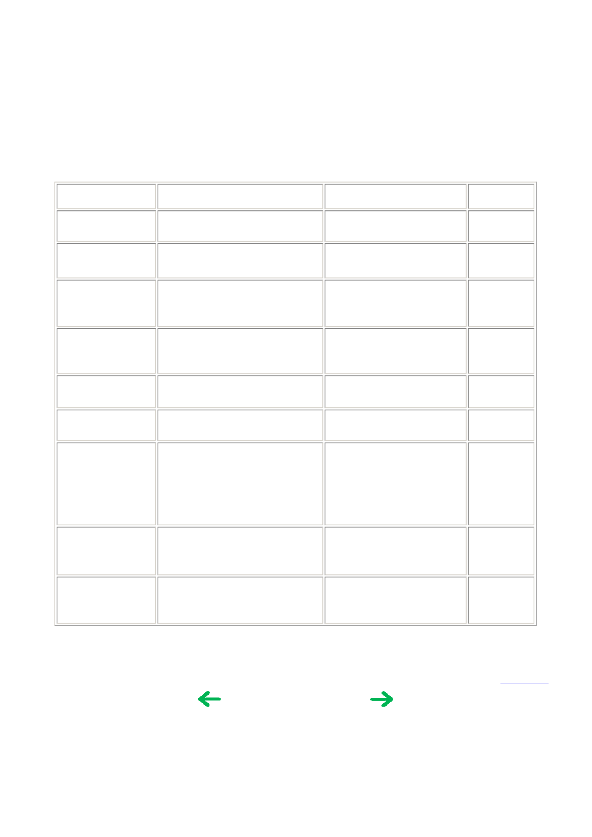
The following applies when the printer is connected to a Canon Bubble Jet Direct-supported digital camera. For PictBridge
functionality, refer to 4-7, PictBridge Function.
(1) Print mode
In Canon Bubble Jet Direct, the following print modes are selectable:
- Standard print: Printing of images during reproduction of single frame or index. Standard printing (1 image per page) only.
- DPOF print: Printing with DPOF printing settings. Standard and index printing can be performed.
(2) Media type
Media types that can be printed in the Digital Camera Direct Printing are as follows:
- When the language setting on the digital camera is not set to Japanese:
(Media types for destinations other than Japan are identical, however, the digital camera's panel display differs depending on
the languages. The following is the display of English.)
- When the language setting on the digital camera is set to Japanese.
Print mode Exif file or non-Exif file Date data to be printed
DPOF mode --- Date in the DPOF file
Non-DPOF mode Exif files with the creation date of the image data Date when the Exif file was created
Non-Exif file Updated date of the file system
Paper setting in digital camera operation panel SELPHY DS700 paper
Card#1 Photo Paper Pro 4"x6" (PR-101 4"x6")
Card#2 Photo Paper Plus Glossy 4"x6" (PP-101 4"x6")
Photo Paper Plus Semi-gloss 4"x6" (SG-101 4"x6")
Glossy Photo Paper 4"x6" (GP-401 4"x6")
Card#3 Not supported
LTR Not supported
A4 Not supported
(3) Print layout
Print layout can be set to Border or Borderless in the digital camera operation panel.
Standard print:
- Borderless: 1 photo per page
- Border: 1 photo per page
Paper setting in digital camera operation panel SELPHY DS700 paper
L Photo Paper Plus Glossy (SP-101 L)
Photo Paper Pro (PR-101 L)
Photo Paper Plus Semi-gloss( SG-101 L)
Glossy Photo Paper (EC-101 L)
2L Not supported
Postcard Photo Paper Pro Postcard (PH-101)
A4 Not supported
Card Glossy Photo Paper (EC-101 Card)
2 - 10

DPOF print:
- Standard:
-- Borderless: 1 photo per page
-- Border: 1 photo per page
- Index print:
-- Same as Index mode of Memory Card Direct Printing.
(4) Print quality
No. of passes: 6 passes
Resolution: 1200 dpi x 600 dpi
Y/M/C: 5 pl / 2 pl (mixed)
(5) Image correction function
Exif 2.2 files are processed with Photo Optimizer PRO, and for other files, image correction is not implemented. Not selectable
by users.
(6) Maintenance
Even with a digital camera connected to the printer, Tool Box can be selected on the TV by pressing the Menu button on the
remote control, then selecting Tool Box from the menu. Tool Box cannot be selected from the digital camera.
(7) Print date
Dates can be printed by switching the date setting on the digital camera's operation panel to "ON".
Dates cannot be printed in index printing of DPOF print mode.
(8) Copies
The number of prints can be specified in both standard and DPOF print modes via the digital camera's operation panel.
To the top
<Part 2: 4. PHOTO DIRECT PRINT FUNCTION, 4-4 to 4-6>
2 - 11
4-7. PictBridge Function
The following applies when the printer is connected to a Canon PictBridge-supported digital camera.
(As PictBridge is enabled when both the printer and digital camera have shared functionality, some functions may not be selectable,
depending on the combination of the printer and digital camera.)
For Canon Bubble Jet Direct functionality, refer to 4-6, Canon Bubble Jet Direct Function.
For other companies' digital cameras, refer to the camera's manual.
(1) Print mode
In a PictBridge-supported digital camera, only the single frame reproduction print mode is selectable.
(2) Media type
Media types that can be printed in the Digital Camera Direct Printing are as follows:
(3) Print layout
Print layout can be set to Border or Borderless in the digital camera operation panel.
(4) Print quality
Print quality is fixed to Standard.
(5) Image correction function
The following 3 correction functions may not be selectable by users, in some cases:
POP: ON/OFF/Face brightener
VIVID Photo: ON/OFF
Noise reduction: ON/OFF
(6) Image adjustment
Brightness: -2, -1, Standard, +1, +2
Contrast: -2, -1, Standard, +1, +2
Color hue: red+2, red+1, Original, yellow+1, yellow+2
(7) Image processing
Non-processing
(8) Maintenance
Maintenance operation of the SELPHY DS700 via the digital camera's operation panel is not possible.
Maintenance operations are possible through the TV View function, even when connected to the digital camera.
(9) Print date
Dates can be printed by switching the date setting on the digital camera's operation panel to "ON."
(10) Copies
The number of prints can be specified via the digital camera's operation panel.
(
11
)
Di
g
ital camera's standard settin
g
Paper setting in digital camera operation panel SELPHY DS700 paper
Default Depending to the printer setting
Photo Photo Paper Plus Glossy PP-101 4"x6"
Photo Paper Plus Semi-gloss SG-101 4"x6"
Glossy Photo Paper GP-401 4"x6"/Credit Card
Photo Stickers PS-101
Fast Photo Photo Paper Pro PR-101 4"x6"
2 - 12

In PictBridge-supported digital cameras, Default (standard) is selectable for the items below.
When Default is selected, printing will be performed using the printer's settings.
4-8. Exclusive Processes
(1) Exclusive processes in Memory Card Direct Printing and Digital Camera Direct Printing
As it is impossible to simultaneously process Memory Card Direct Printing and Digital Camera Direct Printing, the following
actions are taken:
When the digital camera is connected via the digital camera connection cable:
Memory Card Direct Printing settings and operation are not possible.
Setting items are not displayed on the TV, and the Print button is invalid.
"Digital camera connected." is displayed on the TV.
During Memory Card Direct Printing:
Digital Camera Direct Printing is impossible. (Settings in the digital camera are possible.)
If Digital Camera Direct Printing print operations are attempted, an error is displayed in the digital camera.
(2) Exclusive process control between Direct Printing and printing from the host computer
As it is impossible to simultaneously process direct printing from memory cards or digital cameras and printing from the host
computer, the following actions are taken:
When printing from the host computer:
Memory Card Direct Printing and Digital Camera Direct Printing are impossible.
During Memory Card or Digital Camera Direct Printing:
Printing from the host computer is impossible.
(3) Exclusive processes in host computer memory card access and Memory Card Direct Printing
Writing of data from the host computer to the memory card, while reading image data from the memory card for direct printing
is conducted as follows in order to avoid overwriting the image being printed in Memory Card Direct Printing, via the host
computer.
During Memory Card Direct Printing:
Writing data from the host computer to the memory card is not possible. (Reading of data is possible.)
An error is displayed in the host computer at the start of data writing operations.
When writing data from the host computer to the memory card*:
Memory Card Direct Printing is not possible.
Even if the Print button is pressed, printing will not start.
* To write data from the host computer to the memory card, the mode needs to be changed to the Read/write mode, using the
Memory Card Utility.
(4) Exclusive processes between the memory card and memory card
There are 2 slots available, a slot for SM, MS/ MS PRO/MG-MS, and SD/MMC (used in common, however, multiple cards
Item Dependency on the printer Printer setting at shipment
Paper size Depending on the printer setting 4" x 6"
Paper type Depending on the printer setting Photo Paper Plus Glossy
Layout Depending on the printer setting Borderless
Image correction Depending on the printer setting Exif Print
Date print Depending on the digital camera Date not printed
2 - 13

cannot be inserted simultaneously), and another slot for CF/MD.
However, even though 2 cards may physically be inserted in both slot simultaneously, as one drive only is always valid, control
is performed as follows:
- The card inserted first has priority. Even if a card is inserted into a drive other than the current drive, this action is ignored.
- When the card in the current drive is removed, the other drive is checked. If a card is detected, the same control as when the
former card is removed and a new card is inserted, is performed.
- When multiple cards are inserted when the printer is powered on, the drive is checked in the order of CF, SM, MS, and
SD/MMC, and the drive in which a valid card is detected becomes the current drive.
- When the memory card is uninstalled from a computer, the power supply for the card with the current drive is halted, and the
no card inserted status is valid. However, as long as the card itself is not removed from the current drive, even though another
card is inserted into another drive, this action is ignored.
4-9. Display
The SELPHY DS700 can be connected to a TV, realizing two functions, image display and operation display. Operations are
carried out by the user selecting the desired menu item from within a nested menu displayed on the TV, and by pressing the OK
b
utton on the remote control, proceeding with the next step. During the process, if an image needs to be selected, it can be displayed
on the TV, and images can be browsed by using the left and right cursor buttons on the remote control.
4-10. Card Slot-related Operations and Display
(1) Timing and precautions when removing the memory card
The following timing and precautions are suggested to protect the memory card data:
- Remove the memory card while the indicator lamp is not lit. (If the memory card is removed while the Access lamp is blinking
or on, the data on the card is not assured.)
- When the printer is not connected to a host computer, power off the printer with the Power button, and after the indicator lamp
is extinguished, remove the memory card.
- Remove the memory card together with the adapter, not the memory card only.
- When the printer is connected to the host computer, from the host computer, select "Eject the Memory Card" to turn the
indicator lamp off, and then remove the memory card. (Turning off the printer also turns off the indicator lamp, however, the
incorrect disk removal warning message may be displayed in the connected host computer.)
- When using Windows, and the memory card drive is displayed in Explorer, close the window prior to removing the memory
card.
(2) Power supply/cut to the memory card
1) Power supply to the memory card
When any of the following events occurs, the memory card detection process starts, and if an accessible memory card is
recognized, power supply to the memory card starts. (The indicator lamp lights.)
a. When a memory card is inserted into the card slot while the printer is on.
b. When the printer is powered on while a memory card is in the card slot.
c. When the USB bus is reset while the printer is on with a memory card in the card slot. (When the host computer is already
on, and is connected to the printer via USB, or when the host computer is restarted.)
2) Power cut to the memory card
When any of the following events occurs, power supply to the memory card is cut. (The indicator lamp turns off.)
a. When the printer is turned off by pressing the Power button.
However, power is supplied in the following instances even if the printer is not on:
- From the time that a memory card not-removable command is received from the host computer until a removal permission
command is received, or the USB cable is disconnected.
- From the time that a writing command is received from the host computer to the memory card until writing is completed.
b. When the memory card is removed from the card slot by pressing the Eject button / or by hand.
c. When the "Eject" function is implemented on the connected host computer.
2 - 14

(3) Memory card removal command from the host computer
When the following operation is performed on the host computer, it is detected that the memory card removal command has
been implemented, and power supply to the memory card is cut.
Select "Eject the memory card" in the Memory Card Utility.
To the top
<Part 2: 4. PHOTO DIRECT PRINT FUNCTION, 4-7 to 4-10>
2 - 15

4-11. DPOF Settings in the Memory Card Direct Printing Function
(1) Supported DPOF functions
DPOF Ver. 1.0 is supported.
The following essential functions as a DPOF printer are supported:
- Standard printing
- No. of copies to be printed (1 page)
- Image format (CIFF, EXIF (JPEG), JFIF)
- Designation of images to be printed (relative path name)
The following optional functions as a DPOF printer are supported:
- Index printing
- No. of copies to be printed (2 pages or more)
- Image format (EXIF (TIFF))
- Printing of designated characters (dates, photo numbers)
If both dates and photo numbers are selected, one of the two will be printed.
Note: The CMT value indicating the comment and image title is not supported.
The following optional functions as a DPOF printer are not supported:
- Image format (FlashPix)
- Designation of paper types
- Trimming
- Rotation of images
(2) Print specifications in DPOF print mode
Photo number designation:
Only photos designated in the DPOF file can be printed, and designation via the TV is impossible.
Paper type:
The paper type can be selected via the TV.
Layout:
Images designated for Standard printing in the DPOF file are printed in the designated order in the layout selected via the
TV.
Images designated for Index printing will be printed using the printer's index layout, regardless of the specified layout.
No. of copies to be printed:
The number of copies cannot be designated via the TV. Only the number of copies specified in the DPOF file is printed.
Image correction:
Image correction can be designated via the TV.
Print quality:
The print quality cannot be specified.
Date print:
Date print cannot be designated via the TV in DPOF mode, and printing is implemented using the file's DPOF settings.
Date formats are dependent on the digital camera.
4-12. Print Layout (Details)
(1) Selectable layout in Memory Card Direct Printing
<Other than Japan model>
- Index printing:
4" x 6": 24 photos, Credit Card: 6 photos
2 - 16

- Layout printing:
2/4/8 photos per page with borderless/bordered (4" x 6", Credit Card)
Half with borderless/bordered (4" x 6", Credit Card)
- Sticker printing:
16 seals per page
- Single frame printing (= single image per page):
4" x 6" with borderless/bordered, Credit Card with borderless/bordered
<Japan model>
- Index printing:
L: 15 photos, Postcard: 24 photos, Name Card / Credit Card: 6 photos
- Layout printing:
2/4/8 photos with borderless/bordered (L, Postcard, Name Card / Credit Card)
Postcard (with ruled line) with borderless/bordered (L, Postcard, Name Card / Credit Card)
- Sticker printing:
2/4/9/16 seals per page
1/5/6/7 seals per page (for free-cut)
- Single frame printing (= single image per page):
L with borderless/bordered, Postcard with borderless/bordered, Name Card / Credit Card with borderless/bordered
(2) Selectable layout in Digital Camera Direct Printing
In Digital Camera Direct Printing, Index printing and single frame printing are available.
When the language setting on the digital camera is set to other than Japanese:
(Media types for non-Japanese models are common for all markets, however, the panel display differs depending on the
languages. )
- Index printing:
4" x 6": 24 photos, Credit Card: 6 photos
- Single frame printing:
4" x 6" with borderless/bordered, Credit Card with borderless/bordered
When the language setting on the digital camera is set to Japanese:
- Index printing:
L: 15 photos, Postcard: 24 photos, Name Card / Credit Card: 6 photos
- Single frame printing:
L with borderless/bordered, Postcard with borderless/bordered, Name Card / Credit Card with borderless/bordered
(3) Selectable layout in Infrared Printing (Direct Printing from a Mobile Phone via Infrared Communication)
<Other than Japan model>
- Layout printing:
1/2/4/8 photos per page (4" x 6", Credit Card)
- Sticker printing:
16 seals per page
<Japan model>
- Layout printing:
1/2/4/8 photos per page (L, Postcard, Name Card / Credit Card)
- Sticker printing:
2/4/9/16 seals per page
1/5/6/7 seals per page (for free-cut)
(4) Layout in Memory Card Direct Printing
Layout of multiple images is arranged as shown below.
2 - 17
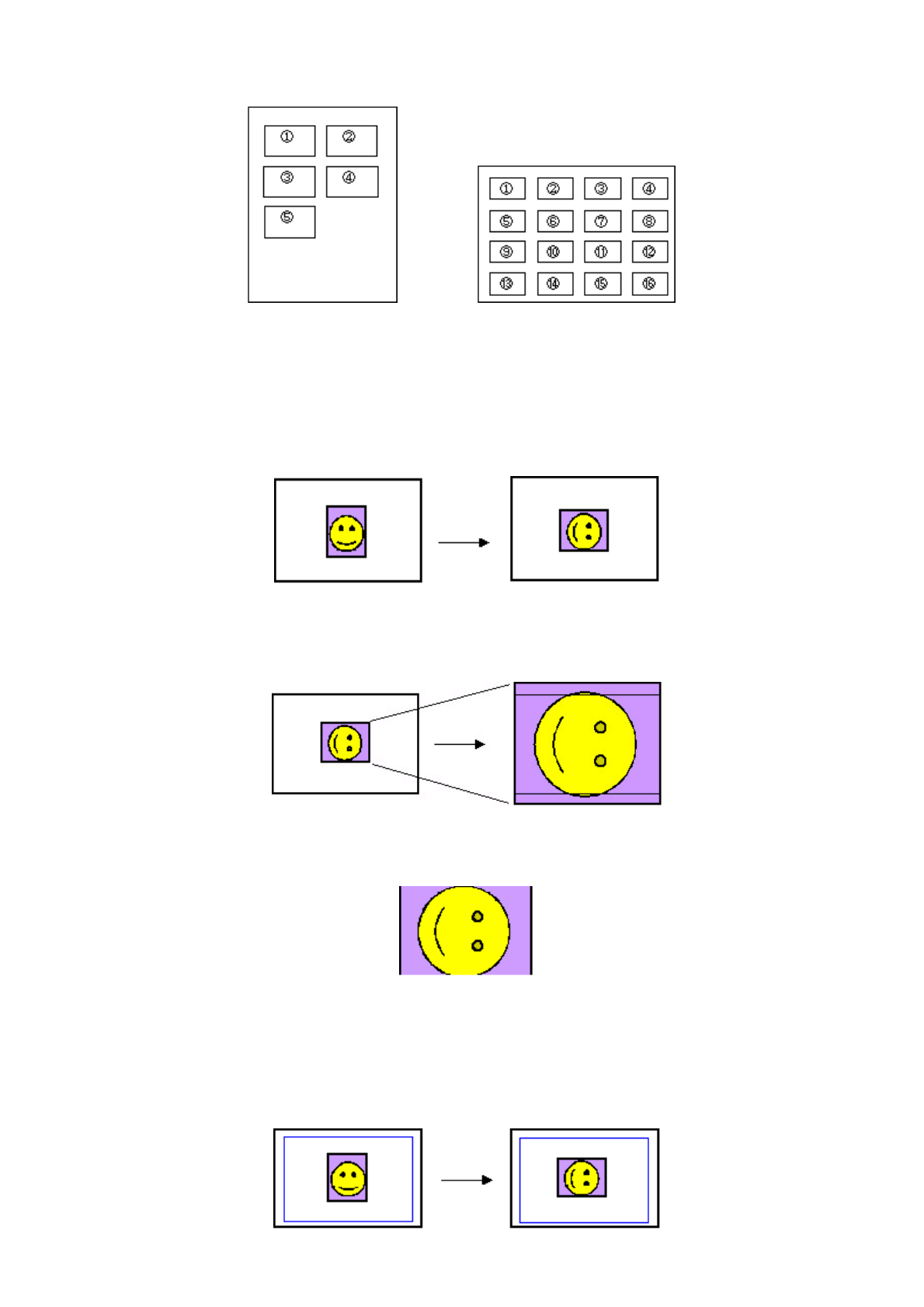
- Images are arranged horizontally, from left to right, top to bottom.
- When the number of photos designated requires less space than the layout provides, nothing is printed in the remaining spaces.
(5) Layout and image size
Processing in borderless printing (including 2/4/8 photos per page with borderless, and postcard with borderless):
1) Rotate the image data by 90 degrees (if necessary) to align the long edges of the image with those of the paper.
2) Enlarge (or reduce) the image data while maintaining the image's proportions so as to align either the long or short edges of
the image with those of the paper , so that blank space in the paper is completely eliminated.
3) Any image data extending beyond the printing area will be cut off and not printed. (The discarded image data will be equally
divided between top and bottom, or left and right.)
Note: As printing of the image is performed to an area 5 mm larger than that of the paper size, the perimeter of the image is
further trimmed by a few millimeters.
Processing in printing in print area without image trimming
1) Rotate the image data by 90 degrees (if necessary) to align the long/short edge of the image data with that of the print area
(blue line).
2 - 18
2) Enlarge (or reduce) the image data while maintaining the image's proportions so as to align either the long or short edges of
the image with those of the print area (blue line), so that no image data is discarded.
3) The area without any image data will be blank. (Empty areas will be equally divided between left and right, or top and
bottom.)
To the top
<Part 2: 4. PHOTO DIRECT PRINT FUNCTION, 4-11 and 4-12>
2 - 19
4-13. Date Print Specifications
(1) Date print in Memory Card Direct Printing
1) Settings and data format
Printing in DPOF (Index and Standard) mode:
When date print is set to ON in the DPOF settings, the date is printed using the character strings in the DPOF settings,
regardless of the date setting via the TV.
The number of characters printable is up to 24 for Standard, and up to 12 for Index.
Printing in other modes:
When date print is set to ON in settings options via the TV, the Exif tag information in the file is printed in the following
order:
Year (four digits), month (two digits), and date (two digits), with date elements separated by "/".
If the Exif tag information does not exit, or does not have correct information, the date when the file was updated is
printed.
Ex. 2002/10/25, 10/25/2002
2) Print location, color, and size
DPOF mode Standard printing and printing in other modes:
Location: Lower right, in the image (In images with an aspect ratio other than 4:3, the date is moved such that the
relative distance from the lower right of the image to the date is the same as when a 4:3 ratio is used.)
Color: Orange
Size: According to the layout
(2) Date print in Digital Camera Direct Printing
1) Settings and data format
When date print is set in the digital camera, the date is printed using the character strings sent by the digital camera. However,
in Canon Bubble Jet Direct index printing using the digital camera, the date will not be printed, regardless of the settings.
2) Print location, color, and size
Standard printing and DPOF mode Standard printing:
Location: Lower right, in the image (In images with an aspect ratio other than 4:3, the date is moved such that the
Index mode printing:
Location: Below the image (under the
photo number)
Color: Black
Size: Fixed size
Index mode print sample:
001 100-0001
1999/06/30
DPOF mode Index printing:
Location: Below the image
Color: Black
Size: Fixed size
DPOF mode Index print sample:
1999/06/30
Print sample 1: Print sample 2:
2 - 20

relative distance from the lower right to the image date is the same as when a 4:3 ratio is used.)
Color: Orange
Size: According to the layout
DPOF mode Index printing:
Date is not printed, even when set in the digital camera's DPOF settings.
(3) Date print in Infrared Printing
In Infrared Printing, date print setting is not available, and so the date is not printed.
4-14. Photo Number Printing Specifications
(1) Photo number printing in Memory Card Direct Printing
1) Data format
Printing in Index mode:
Photo number (3-digit number) and DCF number (8-character number (***-****) displayed on the TV) are printed
(without exception). Printed characters consist of 3 characters + space + 8 characters.
Printing in DPOF (Index and Standard) mode:
When the file number print is set to ON in the DPOF settings, the file number character string set in the DPOF settings is
printed, as is. (However, when date print is selected, the file number will not be printed.)
The number of characters printable is up to 24 for Standard, and up to 12 for Index.
Printing in other modes:
The photo number will not be printed.
2) Print location, color, and size
Print sample:
Index mode printing:
Location: Below the image
(above the date)
Color: Black
Size: Fixed size
Index mode print sample:
001 100-0001
1999/06/30
DPOF mode Index printing:
Location: Below the image
Color: Black
Size: Fixed size
DPOF mode Index print sample:
100-0001
DPOF mode Standard printing:
Location: Lower right in the image (In images with an aspect ratio other than 4:3, the photo number is moved such that t
h
image to the photo number is the same as when a 4:3 ratio is used.)
2 - 21
Printing in other modes:
The photo number will not be printed.
(2) Photo number printing in Digital Camera Direct Printing
The photo number will not be printed regardless of data formats.
(3) Photo number printing in Infrared Printing
The photo number will not be printed.
To the top
<Part 2: 4. PHOTO DIRECT PRINT FUNCTION, 4-13 and 4-14>
Color: Orange
Size: According to the layout
DPOF mode Standard print sample:
2 - 22
5. FAQ (Problems Specific to the SELPHY DS700 and Corrective Actions)
No. * Function Phenomenon Condition Cause Corrective Action Possible call
or complaint
1 C
Safety
during
transportation
Non-ejection of
ink
- Transportation of
the printer with the
print head and ink
tank installed
- Phenomenon
confirmed in the
transportation test
If the printer is
transported without
the accessory and
side packing, the
print head face can
contact the purge
base, scratching the
nozzles.
Properly package the printer.
For details, see Part1, 4.
PRINTER
TRANSPORTATION.
Ink is not
ejected in the
printer
returned from
repair.
2 A Print
results
Soiling on the
back side of
paper (lines or
streaks parallel
to the paper feed
direction)
After continuous
borderless printing
of small sized paper
(such as Credit
Card), when a larger
sized paper (such as
4x6) is printed
In borderless
printing, printing is
performed to the
size slightly larger
than the paper size,
and ink off the
paper is absorbed
by the platen's ink
absorber. Absorbed
ink may attach to
the platen rib(s)
after several dozen
sheets are printed,
causing soiling at
the leading edge of
p
aper or on the back
side of paper.
1. Perform Bottom plate
cleaning (press and hold
the Resume/Cancel button
until the power lamp
blinks 5 times, then
release the button) up to 3
times. For details, please
refer to the user's guide.
2. If soiling on the paper still
remains after 3 times of
Bottom plate cleaning,
wipe the platen rib(s) and
their surroundings with a
cotton swab. For details,
please refer to the user's
guide.
- Paper gets
smeared.
- The back
side of paper
gets
smeared.
3 -
Paper
feeding
(specifications)
Paper is not fed
properly.
Due to dirty paper
feed roller.
Perform Paper feed roller
cleaning (press and hold the
Resume/Cancel button until
the power lamp blinks 3
times, then release the
button). For details, please
refer to the user's guide.
Paper is not
ejected.
4 -
Print
results
(specifications)
Would like to
change color
hue in Direct
Printing (as
color hue is red-
tinged).
In Direct Printing Color hue is
different from the
desired colors.
Via the TV, select Tool Box,
and Color adjust, and adjust
colors.
- Color hue is
improper.
- Color hue
differs from
that
displayed on
the TV.
5 B Paper
feeding
Skewed paper
feeding with
Credit Card-
sized paper
- In the high
temperature and
high humidity
environment
- In the low
temperature and
low humidity
environment
- With the maximum
20 sheets loaded
As the paper may be
caught by the ASF
base corner, and
creased and rotated.
Reduce the number of sheets
loaded (from 20 to 10, for
example).
Paper feeds at
an angle.
6 B Print
results
With GP-401
4x6 paper, the
leading edge of
paper contacts
the print head.
In the high
temperature and
high humidity
environment
Due to paper
swelling in the high
temperature and
high humidity
environment.
- Increase the head-to-paper
distance by setting the
paper thickness lever to the
left.
- Perform print head
alignment.
Printing is
scratched.
2 - 23
* Occurrence level:
A: The symptom is likely to occur frequently. (Caution required)
B: The symptom may occur under certain conditions, but likeliness is assumed very low in practical usage.
C: The symptom is unlikely to be recognized by the user, and no practical issues are assumed.
To the top
7 - Operability
Remote control
not operated
In particular usage - The printer's
remote control
receiver is
exposed to the
direct sunlight or
intense light of an
inverter
fluorescent light,
etc.
- The remote
control is not
within the
allowable range.
- The battery is
empty.
- Avoid direct sunlight, and
leave the printer 50cm or
more away from intense
light such as that from an
inverter fluorescent light.
- Use the remote control
within 4 meters from the
printer, and less than 30
degrees away from the
optical axis.
- Replace the CR2025
battery.
The remote
control does
not work.
8 - Specifications
The bottom of
the printer gets
hot.
When continuously
printing
Per the
specifications.
In continuous
printing, the bottom
of the printer
becomes hot, but
maintained within
the specified range.
No specific solution. The bottom of
the printer
gets hot.
9 -
Print
results
(specifications)
Improper color
hue in printing
using the Print
All button
When the Print All
button is pressed,
printing for Photo
Paper Plus Glossy is
performed. So PP-
101 or SG-101 is
suitable for printing.
With other type(s)
of paper, color hue
may be improper.
Use recommended paper type
(s).
Color hue is
not proper.
<Part 2: 5. FAQ>
2 - 24

P
art 3
APPENDIX
<Direct Printing Specifications>
Memory card drive Supported memory
card
Compact Flash TYPE I/II, Microdrive, SmartMedia Card, Memory Stick,
Memory Stick PRO, MagicGate Memory Stick, SD Memory Card,
MultiMediaCard, xD-Picture Card*, miniSD Memory Card*, Memory Stick
Duo*, Memory Stick PRO Duo*, MagicGate Memory Stick Duo*
* Adapter required
Storage function
Supported OS Windows 2000 / XP, Mac OS X 10.2.1 or later
Utility - Memory Card Utility packaged with the printer (Read/Write function)
Memory Card Direct
Print function
Operation panel 3 buttons, 1 LED (2 colors), memory card access LED
Supported file format JPEG (DCF, CIFF, Exif 2.21 or prior, JFIF), TIFF (Exif complaint), DPOF
(Ver. 1.00 compliant)
Print quality Fixed (Standard)
Image correction
function
POP (Photo Optimizer PRO) with face brightener, VIVID Photo, noise
reduction
Image color
adjustment function Brightness, Contrast, Color hue
Image processing
function Not available
Image search
function Available (by exposure date)
DPOF Ver. 1.00 compliant
Print layout
One-by-one printing / image specification printing: 1 image per page
(bordered / borderless)
DPOF printing: 1 image per page (bordered / borderless), 24 images per page
Credit Card size: 6 images per page
Layout printing: 2, 4, and 8 images per page (bordered / borderless)
Sticker printing: 16 seals
Resolution Max. 1200 x 600dpi
Throughput Photo Paper Plus Glossy 4x6, borderless, standard photo: Approx. 85 sec.
Camera Direct Print
function
Supported digital
cameras
Digital cameras and digital video cameras supporting Canon Bubble Jet Direct
or PictBridge
Supported print
layout
- 1 image per page (bordered / borderless)
- Index printing
- 2, 4, 9, and 16 images with bordered per page (only when 4" x 6" paper size
is selected)
Resolution Max. 1200 x 600dpi
Throughput PP-101 4x6, borderless, standard photo: Approx. 85 sec.
Infrared printing
function
Supported mobile
phones Mobile phone equipped with IrDA 1.2 port, compliant with IrMC version 1.1
Printable data Image (JPEG only)
Print layout
- Paper other than Photo Stickers: 1, 2, 4, and 8 images per page (bordered /
borderless)
- Photo Stickers: 16 image per page (bordered)
3 - 13

<Print Head Specifications>
To the top
Type Single head with 3 colors (C/M/Y)
Print head Each color: 256 nozzles (128 nozzles each for 2pl and 5pl)
Total: 768 nozzles (600dpi)
Ink color Cyan, magenta, yellow
Applicable ink tank BCI-16 Color (dye-based), single tank with 3 colors (C/M/Y)
Weight (Net) Approx. 27g (not including the ink tank, protective materials, and packing material)
Supply method As a service part (not including the ink tank)
Part number QY6-0056-000
<Part 3: 3. SPECIFICATIONS>
3 - 14
