Dsc Powerseries Neo Hs2016 Hs2032 Hs2064 Hs2128 Host Architecture And Engineering Specification R001
User Manual: dsc-powerseries-neo-hs2016-hs2032-hs2064-hs2128-host-architecture-and-engineering-specification-r001
Open the PDF directly: View PDF ![]() .
.
Page Count: 26

i
Architecture and
Engineering
Specification
Table of Contents
Introduction and System Overview ............................................................. 1
Introduction ........................................................................................ 1
System Overview ................................................................................. 1
Regulatory Requirements ........................................................................... 2
Regulatory Compliance Standards ........................................................... 2
US Approvals ............................................................................. 2
Canadian Approvals .................................................................... 2
European Approvals .................................................................... 3
South America ........................................................................... 4
Oceania .................................................................................... 4
Asia .......................................................................................... 4
Africa ........................................................................................ 5
Model Feature Overview ............................................................................. 6
Model ................................................................................................. 6
HS2016 .................................................................................... 6
HS2032 .................................................................................... 7
HS2064 .................................................................................... 7
HS2128 .................................................................................... 8
Corbus ................................................................................................ 9
System Performance ................................................................................. 10
Model ................................................................................................ 10
HS2016 ................................................................................... 10
HS2032 ................................................................................... 10
HS2064/HS2128 ....................................................................... 10
Zone Expansion .................................................................................. 11
HS2016 ................................................................................... 11
HS2032 ................................................................................... 11
HS2064 ................................................................................... 11
HS2128 ................................................................................... 11
System Keypads ................................................................................. 11
HS2016/ HS2032/ HS2064 ......................................................... 11
HS2128 ................................................................................... 12
ULC Fire Monitoring and Reporting ......................................................... 12
Alternate Reporting Methods ................................................................. 12

Table of Contents
ii
Central Station Reporting ..................................................................... 12
Programmable Outputs ........................................................................ 12
HS2016 ................................................................................... 12
HS2032 ................................................................................... 13
HS2064 ................................................................................... 13
HS2128 ................................................................................... 13
System Software ................................................................................. 13
System Programming .......................................................................... 13
User Codes ......................................................................................... 14
HS2016 ................................................................................... 14
HS2032 ................................................................................... 14
HS2064/HS2128 ....................................................................... 14
Partitions ........................................................................................... 14
HS2016 ................................................................................... 14
HS2032 ................................................................................... 14
HS2064/HS2128 ....................................................................... 15
Supervision ........................................................................................ 15
False Alarm Prevention ......................................................................... 15
Automatic Arming/Disarming ................................................................ 16
Temporary Zone Disabling/Bypassing ..................................................... 16
Network Communications ..................................................................... 16
Mechanical, Electrical, and Environmental Specifications .......................... 17
Mechanical Specifications ..................................................................... 17
Electrical Operating Voltages ....................................................... 18
Communicator ................................................................ 18
Hardwired Keypads .......................................................... 18
Hardwired RF Keypads ..................................................... 18
Zone Expanders .............................................................. 18
Output Module ................................................................ 18
Power Supply/High-Current Output Expander ...................... 19
Electrical Specifications (base panel) ...................................................... 19
Bell Output ............................................................................... 19
AUX Output .............................................................................. 19
PGM Outputs ............................................................................ 19
Corbus ..................................................................................... 19
Battery Charger ........................................................................ 20
Input Power .............................................................................. 20
Environmental Specifications ................................................................. 20
Operating Environment .............................................................. 20
Wiring Diagram (HS2016/2032/2064/2128) ............................................ 21
Execution .................................................................................................. 22
Installation ......................................................................................... 22
System Testing and Certification ........................................................... 22

1
1
Introduction and System
Overview
Introduction
The purpose of this document is to introduce you to the PowerSeries Neo alarm
panel and to provide you with detailed information on its specifications and
features. The following areas are covered in this document:
Regulatory requirements
Model features
System performance
Mechanical, electrical, and environmental specifications
Important: For detailed information about the PowerSeries Neo alarm panel
“wireless” component, refer to the document: PowerSeries Neo 1.0 Wireless Host
Architecture and Engineering Specification.
System Overview
The PowerSeries Neo alarm panel is a feature-rich, scalable system designed for
residential and commercial use. The alarm panel supports both hardwired and
wireless devices.
The following alarm controller models are available:
HS2016
HS2032
HS2064
HS2128

2
2
Regulatory Requirements
This chapter identifies all regulatory system requirements for the PowerSeries Neo
alarm panel.
Regulatory Compliance Standards
US Approvals
a) UL
i. UL1023 Standard for Household Burglar Alarm System Units (4h
Battery Standby required)
ii. UL985 Standard for Household Fire Warning System Units (24h Battery
Standby required)
iii. UL1635 Standard for Digital Alarm Communicator System Units
iv. UL1610 Standard for Central Station Burglar Alarm Units
v. UL365 Standard for Police Station Connected Burglar Alarm Units and
Systems
b) SIA
i. ANSI/SIA CP-01-2010 Control Panel Standard – Features for False
Alarm Reduction
c) FCC
i. TIA-968-B Technical Requirements for Connection of Terminal
Equipment to the Telephone Network (USA)
ii. CISPR22 Class B Information Technology Equipment – Radio
Disturbance Characteristics – Limits and Methods of Measurement
Canadian Approvals
a) ULC
i. ULC-S545-2002 Standard for Residential Fire Warning System Control
Units

Regulatory Requirements
3
ii. ORD-C1023-1974 Standard for Household Burglar Alarm System Units
iii. CAN/ULC-S304-2006 Standard for Central & Monitoring Station Burglar
Alarm Systems
iv. CAN/ULC-S559-2004 Standard for Equipment for Fire Signal Receiving
Centers and Systems
b) IC
i. ICES-003 (CISPR22 Class B) Standard for Interference Causing
Equipment, Digital Apparatus
ii. IC-CS03 Issue 9, Industry Canada Terminal Equipment Technical
Specifications
European Approvals
a) CE
i. TS 203 021 Parts 1, 2, 3 European Telecommunication Specifications
ii. CISPR22 Class B Information Technology Equipment – Radio
Disturbance Characteristics – Limits
iii. EN50130-4:2011 Immunity Requirements for Components of Fire,
Intruder, and Social Alarm Systems
iv. EN60950-1:2006 ITE. Safety. General Requirements
b) EN
i. EN50131-1:2006+A1:2009 Intrusion Systems General Requirements,
Grade 2, Class II
ii. EN50131-3:2009 Control and Indicating Equipment , Grade 2, Class II
iii. EN50131-6:2008 Power Supplies, Grade 2, Type A (12h standby time
with AC trouble transmitted)
iv. EN50130-5:2011 Environmental Test Methods for Alarm Systems,
Class II
v. EN50136-2-1:1998 Alarm Systems – Alarm Transmission Systems and
Equipment Part 2-1: General Requirements for alarm transmission
equipment
c) INCERT Certification
i. T-014:2012 General Requirements for Testing the Alarm Systems (24h
standby time mandated)
d) NFA2P Certification
i. RT50131-3: 2009 – Control Units French Deviations from EN50131-3
ii. RT50131-6: 2009 – Power Supply French Deviations from EN50131-6

Regulatory Requirements
4
e) SBSC Certification
i. SSF 1014-3 Intrusion Alarm System Requirements
ii. SSF 114 – Alarm Transmission Systems
f) UK
i. BS8243:2010
ii. PD6662:2010
South America
a) Anatel
i. NET 001/92, Resolution 392, 237, 442 and 529 Brazilian Telecom
Standards
ii. EN60950-1:2006 ITE. Safety. General Requirements
iii. CISPR22 Class B Information Technology Equipment – Radio
Disturbance Characteristics – Limits and Methods of Measurement
Oceania
a) A-Tick
i. CISPR22 Class B Information Technology Equipment – Radio
Disturbance Characteristics – Limits and Methods of Measurement
ii. AS/ACIF S002:2005 Australian Telecom Standard – Analog
interworking and non-interference requirements for Customer
Equipment for connection to the PSTN
iii. AS/NZ 60950.1:2003/Amdt 1:2006 – Information Technology
Equipment – Safety – General Requirements
b) Telepermit
i. PTC200 Requirements for Analog Telecommunications Equipment
ii. AS/NZ 60950.1:2003/Amdt 1:2006 – Information Technology
Equipment – Safety – General Requirements
c) C-Tick
i. CISPR22 Class B Information Technology Equipment – Radio
Disturbance Characteristics – Limits and Methods of Measurement
Asia
a) CCC Certification
i. GB 12663-2001 General Requirements for Burglar Alarm Systems

Regulatory Requirements
5
b) MII Telecom
i. YD/T868 – 1996 China Telecom Requirements for Alarm Panels and
MII Certification
ii. YD/T993 – 1998
iii. YD/T965 – 1998
iv. YD/T968 – 2002
v. YD/T1277.1 – 2003
vi. GB/T 15279 – 2002 (Environmental Requirements, DTMF levels, etc.)
c) IDA Registration
i. IDS TS PSTN Requirements for Terminal Equipment connected to PSTN
d) India Telecom Registration TAC
i. TEC/EMI/TEL-001/01/FEB-09 Class B Digital Emissions Test
ii. IR/PST/01-01 SEP 2005 Terminal for connecting to PSTN
Africa
a) South Africa
i. TEC/EMI/TEL-001/01/FEB-09 Class B Digital Emissions Test
ii. ICASA Approval for Telecom Devices

6
3
Model Feature Overview
This chapter lists the features of each PowerSeries Neo alarm controller model.
Model
HS2016
6 on-board zones, expandable to 16 zones, using HSM2108 hardwired
zone expanders
2 partitions
47 user codes + master code
47 proximity tags
16 wireless keys or panic pendants
500 event buffer
39 programmable zone types
46 programmable output options
4 holiday groups with 99 programmable schedules in each
Expandable to 8 keypads
Expandable to 16 wireless zones
Expandable to 4 wireless sirens
Expandable to 4 wireless repeaters
2 on-board programmable outputs
Expandable to (4) 500mA programmable outputs using the HSM2204
high current expander
Expandable to (16) 50mA programmable outputs using 2 HSM2208
output expanders
Expandable to 3 power supply modules using the HSM2300

Model Feature Overview
7
HS2032
8 on-board zones, expandable to 32 zones using 3 HSM2108
hardwired zone expanders
4 partitions
71 user codes + master code
71 proximity tags
32 wireless keys or panic pendants
500 event buffer
39 programmable zone types
46 programmable output options
4 holiday groups with 99 programmable schedules in each
Expandable to 8 keypads
Expandable to 32 wireless zones
Expandable to 8 wireless sirens
Expandable to 8 wireless repeaters
2 on-board programmable outputs
Expandable to (4) 500mA programmable outputs using HSM2204 high
current expanders
Expandable to (32) 50mA programmable outputs using 4 HSM2208
output expanders
Expandable to 3 power supply modules using HSM2300
HS2064
8 on-board zones, expandable to 64 zones using 7 HSM2108
hardwired zone expanders
8 partitions
94 user codes + master code
94 proximity tags
32 Wireless keys or panic pendants
500 event buffer
39 programmable zone types

Model Feature Overview
8
46 programmable output options
4 holiday groups with 99 programmable schedules in each
Expandable to 8 keypads
Expandable to 64 wireless zones
Expandable to 8 wireless sirens
Expandable to 8 wireless repeaters
4 on-board programmable outputs
Expandable to (12) 500mA programmable outputs using HSM2204
high current expanders
Expandable to (64) 50mA programmable outputs using 8 HSM2208
output expanders
Expandable to 3 power supply modules using HSM2300
HS2128
8 on-board zones, expandable to 64 zones using 15 HSM2108
hardwired zone expanders
8 partitions
94 user codes + master code
94 proximity tags
32 Wireless keys
1000 event buffer
39 programmable zone types
46 programmable output options
4 holiday groups with 99 programmable schedules in each
Expandable to 16 keypads
Expandable to 128 wireless zones
Expandable to 16 wireless sirens
Expandable to 8 wireless repeaters
4 on-board programmable outputs
Expandable to (16) 500mA programmable outputs using 4 HSM2204
high current expanders

Model Feature Overview
9
Expandable to (128) 50mA programmable outputs using 16 HSM2208
output expanders
Expandable to 4 power supply modules using HSM2300
Corbus
The Corbus uses an RS-485 serial cable, without requiring termination, and can
support: “Home Run”, “Star”, and “Daisy Chain” wiring types. It is also capable of
supporting the transmission of visual verification frames to the control panel.

10
4
System Performance
This chapter identifies the system performance for each of the PowerSeries Neo
alarm controller models: HS2016/ HS2032/ HS2064/ HS2128.
Model
HS2016
This model supports six onboard, fully supervised programmable zones. It has an
integrated power supply and a supervised digital alarm communicator, and
includes auxiliary power for powering security detection devices. A programmable
switch auxiliary output is used for 2 and 4-wire smoke detectors. The controller
supports two programmable outputs, which can be programmed as general
purpose outputs.
HS2032
This model supports eight onboard, fully supervised programmable zones. It has
an integrated power supply and a supervised digital alarm communicator, and
includes auxiliary power for powering security detection devices. A programmable
switch auxiliary output is used for 2 and 4-wire smoke detectors. The controller
supports two programmable outputs, which can be programmed as general
purpose outputs.
HS2064/HS2128
These models support eight onboard, fully supervised programmable zones. They
have an integrated power supply and a supervised digital alarm communicator,
and include auxiliary power for powering security detection devices. A
programmable switch auxiliary output is used for 2 and 4-wire smoke detectors.
The controller supports four programmable outputs, which can be programmed as
general purpose outputs.

System Performance
11
Zone Expansion
HS2016
This model supports 16 hardwired or wireless zones. The controller is expandable
to a maximum of 16 zones, by adding 1 HSM2108 hardwired 8 zone expansion
module, or an HSM2HOST wireless expansion module. They are connected to the
controller via a supervised 4-wire power/communication bus.
HS2032
This model supports 32 hardwired or wireless zones. The controller is expandable
to a maximum of 32 zones, by adding 3 HSM2108 hardwired 8 zone expansion
modules, or an HSM2HOST wireless expansion module. They are connected to the
controller via a supervised 4-wire power/communication bus.
HS2064
This model supports 64 hardwired or wireless zones. The controller is expandable
to a maximum of 64 zones, by adding 7 HSM2108 hardwired 8 zone expansion
modules, or an HSM2HOST wireless expansion module. They are connected to the
controller via a supervised 4-wire power/communication bus.
HS2128
This model supports 128 hardwired or wireless zones. The controller is expandable
to a maximum of 128 zones, by adding 15 HSM2108 hardwired 8 zone expansion
modules, or an HSM2HOST wireless expansion module. They are connected to the
controller via a supervised 4-wire power/communication bus.
System Keypads
HS2016/ HS2032/ HS2064
These models support up to eight hardwired or wireless keypads. LED,
alphanumeric LCD or fixed ICON LCD keypads are supported in any combination.
LCD and ICON keypads with integrated proximity tag support are also available.
The keypads include “Armed”, “Ready”, “Trouble” and “AC” indication LEDs, as
well as five programmable function keys and three keypad activated alarm
buttons. Keypads can operate in Power Save mode in the event of a power failure.

System Performance
12
HS2128
This model supports up to 16 hardwired or wireless keypads. The system supports
LED, alphanumeric LCD or fixed ICON LCD keypads in any combination. LCD and
ICON keypads with integrated proximity tag support are also available. The
keypads include “Armed”, “Ready”, “Trouble” and “AC” indication LEDs, as well as
five programmable function keys and three keypad activated alarm buttons.
Keypads can operate in Power Save mode in the event of a power failure.
ULC Fire Monitoring and Reporting
The system can be expanded to provide remote reporting of fire alarm system
status, simultaneously over two paths. It does this using either a dual digital
dialer (subject to approval by the local authority having jurisdiction), a
combination of digital dialer and cellular, digital dialer and IP, or cellular and IP
communication paths. The alarm communicators are fully supervised and
automatically report troubles and alarm signals to the signal receiving center.
Alternate Reporting Methods
The system is capable of reporting all alarms, as well as trouble and system status
information, using one of the following options: dual digital alarm communicators
(Cellular and IP), a cellular transmitter, or an internet (IP) communicator.
Central Station Reporting
The system provides Contact ID and SIA reporting formats, and is capable of
being programmed to call up to four telephone numbers. The system is
programmable for split reporting, so that alarms/restorals, openings/closings, and
miscellaneous events can be sent to different telephone numbers or
communication paths. The system can report an account code for each partition
and a separate account code for non-partition (system) events.
Programmable Outputs
HS2016
This model is capable of including up to 22 programmable outputs. Using the high
current output module, (4) 500mA programmable outputs may be added, and
using two low current output modules, (16) 50mA programmable outputs can be
added. These modules can be located anywhere on the 4-wire communication

System Performance
13
bus. The high current output module includes an integrated power supply, battery
charger and supply, and up to 1.0A of auxiliary power at 12VDC.
HS2032
This model is capable of including up to 38 programmable outputs. Using the high
current output module, (4) 500mA programmable outputs may be added, and
using four low current output modules, (32) 50mA programmable outputs can be
added. These modules can be located anywhere on the 4-wire communication
bus. The high current output module includes an integrated power supply, battery
charger and supply, and up to 1.0A of auxiliary power at 12VDC.
HS2064
This model is capable of including up to 80 programmable outputs. Using three
high current output modules, (12) 500mA programmable outputs can be added,
and using eight low current output modules, (64) 50mA programmable outputs
can be added. These modules can be located anywhere on the 4-wire
communication bus. The high current output module includes an integrated power
supply, battery charger and supply, and up to 1.0A of auxiliary power at 12VDC.
HS2128
This model is capable of including up to 148 programmable outputs. Using four
high current output modules, (16) 500mA programmable outputs can be added,
and using 16 low current output modules, (128) 50mA programmable outputs can
be added. These modules can be located anywhere on the 4-wire communication
bus. The high current output module includes an integrated power supply, battery
charger and supply, and up to 1.0A of auxiliary power at 12VDC.
System Software
The base panel comes complete with all of the software to implement every
system feature and to allow for the addition of every expansion or functional
module without changes or additions to the basic software.
System Programming
The system is fully programmable, via the keypads, and also allows event buffer
viewing, via the alphanumeric LCD keypads.
Separate PC based upload/download software provides the ability to fully program
the system and to read all current system programming, including the event

System Performance
14
buffer. The system provides a connector (PC-link 1) on the base panel to allow for
local upload/download operations and is capable of being used remotely, over
telephone lines or the Internet (IP network). The system provides a separate
telephone number that can be used for this remote upload/download operation.
Remote upload/download access is controllable by the user to prevent
unauthorized access.
All system programming is maintained in non-volatile memory, so that program
information is maintained, even if all AC and battery power is off.
User Codes
HS2016
This model provides up to 47 user codes, plus a master code, which is selectable
as either four or six digits. User codes are assignable to one or multiple partitions.
HS2032
This model provides up to 71 user codes, plus a master code, which is selectable
as either four or six digits. User codes are assignable to one or multiple partitions.
HS2064/HS2128
These models provide up to 94 user codes, plus a master code, which is selectable
as either four or six digits. User codes are assignable to one or multiple partitions.
Partitions
HS2016
This model is programmable for up to two fully independent partitions, each of
which has its own account code. Keypads are assignable as “partition” keypads or
as “global” keypads. Each zone in the system is assignable to one or more
partitions.
HS2032
This model is programmable for up to four fully independent partitions, each of
which has its own account code. Keypads are assignable as “partition” keypads or
as “global” keypads. Each zone in the system is assignable to one or more
partitions.

System Performance
15
HS2064/HS2128
These models are programmable for up to eight fully independent partitions, each
of which has its own account code. Keypads are assignable as “partition” keypads
or as “global” keypads. Each zone in the system is assignable to one or more
partitions.
Supervision
Each zone in the system is supervised, using single EOL or DEOL resistors of 5.6K.
General system supervision includes loss of AC for the base panel and any remote
module with its own AC input. Batteries for the base panel and all remote
functional panels are supervised and short circuit protected. Each wireless input
device is supervised, and the 4-wire communication bus is supervised for low
voltage and the presence of each enrolled module and keypad. Digital alarm
communicators are supervised for telephone line trouble and failures to
communicate, and the system will report any cellular or IP network
communication panel trouble.
Note: The Bell output is fully supervised.
False Alarm Prevention
The system includes the following false alarm prevention features:
Silent exit delay
Audible exit delay
Arm/disarm bell squawk
Audible exit fault
Urgency on entry delay
Swinger shutdown—programmable by zone
Transmission delay by zone
Rotating key press buffer for disarming
Recent close code transmission
Police code (cross zone) transmission
Opening after alarm transmission

System Performance
16
Automatic Arming/Disarming
The system allows for the automatic arming and disarming of partition(s)
according to a programmable schedule. The system includes a method to
automatically arm a partition, after there has been no activity for a predetermined
period of time.
Temporary Zone Disabling/Bypassing
The system includes the following temporary zone disabling/bypassing features:
Arm partition with zone violated and arm zone upon restore
Manual bypass by user
Network Communications
The system is capable of network (LAN/WAN) and Internet communications. This
is according to UL standards and encrypted line security, ULC A1-A4
communication line security levels for active systems, or P1-P3 for passive
communication systems. The network communicator utilizes 128-bit AES
encryption over 10/100 base-T networks and supports static or dynamic IP
addressing. The IP communicator is capable of sending alarm events to a primary
and backup IP receiver address. The Internet communicator performs full alarm
reporting directly to the central monitoring station. It also performs full system
configuration programming and the viewing of system statuses, using remote
upload/download software, over an encrypted connection. For security purposes,
the Internet communicator is capable of end-to-end supervision and hardwire
substitution detection.

17
5
Mechanical, Electrical, and
Environmental
Specifications
This chapter identifies all mechanical, electrical (base panel), and environmental
specifications.
Mechanical Specifications
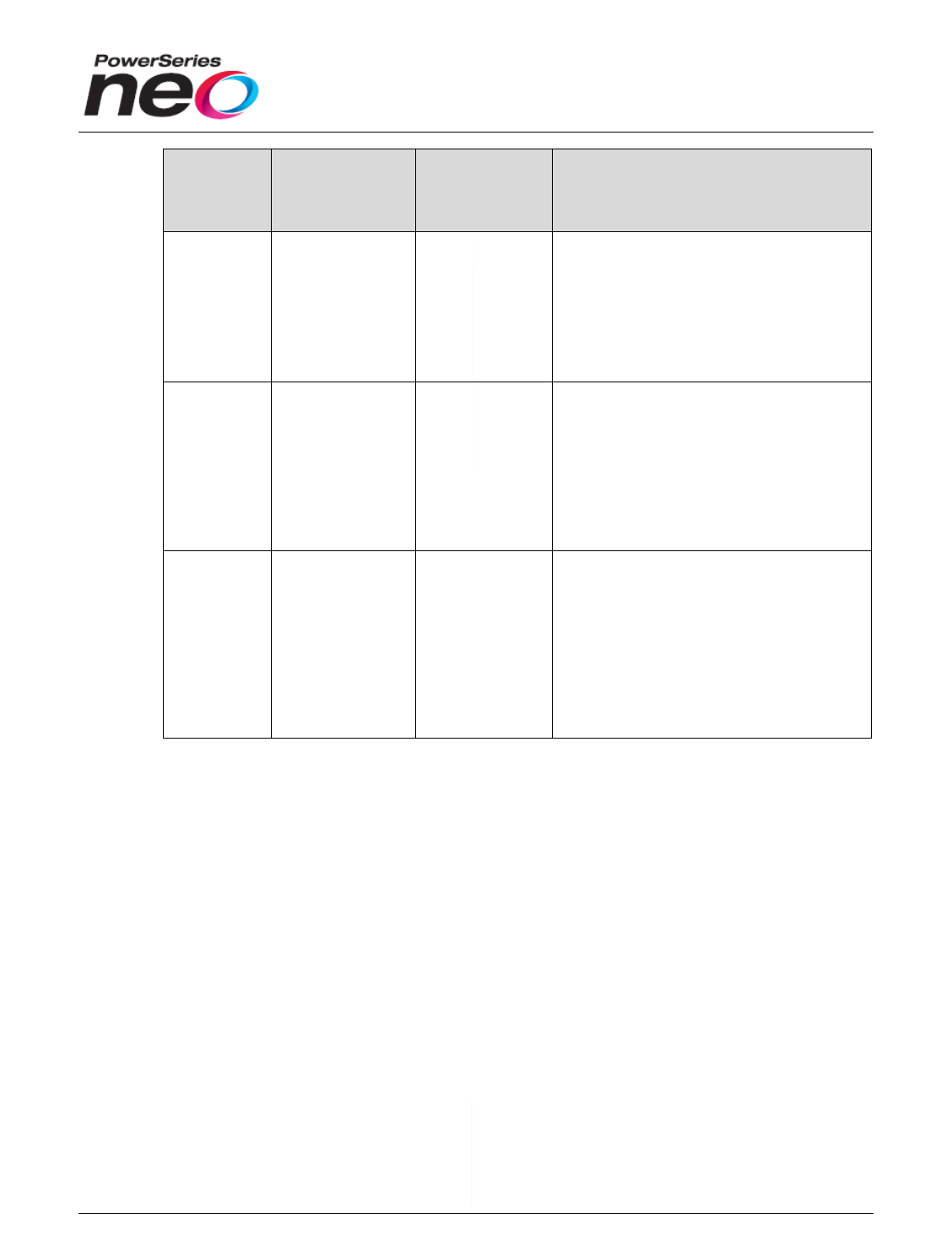
Table 1 Cabinets
Cabinet
DSC Part
Number
Dimensions
Description
PC5003C
31000104
L=279mm
H=293 mm
D=77mm
Removable door. Compatible with
HS2016/2032/2064/2128 panels.
Supports up to (3) HS2108 or (3)
HS2208 modules. Supports (1) 7AH
battery.
PC5001C
31000075 - Top
31000076 -
Bottom
L=150mm
H=121mm
D=37mm
Suitable for use with (1) HSM2208 or
(1) HSM2108 module. Does not
support DSC sealed lead acid
batteries.
PC4003CS
31000084
L=218mm
H=170mm
D=64mm
Hinged door. Suitable for use with (2)
HSM2208 and/or HSM2108 modules or
(1) HS2204/HS2300 module. Supports
1.2AH batteries only.
PC500C
31000195
L=205mm
H=229mm
D=76mm
Removable door. Suitable for use with
HS2016/2032/2064/2128 control
panels, or HSM2204 modules. Not
compatible with HSM2208 or HSM2108
modules. Supports (1) 7AH battery.
Specifications
18
Cabinet
DSC Part
Number
Dimensions
Description
PC4050C
31000166
L=294mm
H=367 mm
D=120mm
Beige in color. Hinged door. Suitable
for use with HS2016/2032/2064/2128
panels and up to (3) HSM2204 or (3)
HSM2300 modules in addition to the
panel. Includes mounting holes for
one 240V 50Hz AC transformer.
Supports (2) 7AH batteries.
PC4050CR
31000128
L=294mm
H=367 mm
D=120mm
Red in color. Hinged door. Suitable for
use with HS2016/2032/2064/2128
control panels and up to (3) HSM2204
or (3) HSM2300 modules in addition to
the panel. Suitable for North American
use only. 240V 50Hz AC transformers
cannot be mounted inside this cabinet.
Supports (2) 7AH batteries.
PC4050CAR
31000196
L=294mm
H=367 mm
D=120mm
Beige in color. Hinged door. Suitable
for use with HS2016/2032/2064/2128
control panels and up to (3) HSM2204
or (3) HSM2300 modules. This cabinet
includes an attack resistant door for
Europe, secured using 17 screws, and
has mounting holes for (1) 240V 50Hz
AC transformer. Supports (2) 7AH
batteries.
Electrical Operating Voltages
Communicator
9VDC to 14VDC
Hardwired Keypads
9VDC to 14VDC
Hardwired RF Keypads
9VDC to 14VDC
Zone Expanders
9VDC to 14VDC
o Loop response timing as fast as 40ms or as slow as 500ms. By
default, the loop response time for each zone is 250ms.
Output Module
9VDC to 14VDC

Specifications
19
Power Supply/High-Current Output Expander
9VDC to 14VDC
Electrical Specifications (base panel)
Bell Output
a) 12VDC 700mA max. continuous rating (currently limited at 2 amps).
Available only with standby battery connected.
b) PTC over current protected – self restoring
c) Steady, Pulsed, Temporal 3 fire, CO alarm cadences
d) Bell short detection (software + hardware)
AUX Output
a) 9.6VDC – 13.8VDC 700mA max. (North American version) or 500mA
(International version)
b) Communications bus and on-board PGM outputs
PGM Outputs
a) All PGM outputs are open collector type outputs, and the PGM terminal will
switch to ground (-) upon activation.
i. HS2016, HS2032
1. PGM 1 – 12VDC 50mA
2. PGM 2 – 12VDC 300mA
ii. HS2064, HS2128
1. PGM 1 – 12VDC 50mA
2. PGM 2 – 12VDC 300mA
3. PGM 3 – 12 VDC 50mA
4. PGM 4 – 12VDC 50mA
Corbus
a) 500/700mA max. (depending on the version) provided from the HS2016,
HS2032, HS2064, and HS2128 main panel
b) Additional power is provided by the HSM2204 and HSM2300 modules
c) Minimum 22AWG non-shielded wire can be used
d) No wire run can exceed 1000 feet (305m) from the panel

Specifications
20
e) No more than 3000 feet (915m) of wire may be used in total
Battery Charger
a) Selectable battery charging current (400/700mA) to charge 12V lead-acid
batteries up to 14Ah capacity (compatible with 4Ah, 7Ah, and 14Ah
batteries)
b) Standby battery capacity able to cover 4h, 12h, 24h
c) Battery charger is supervised for opens and is protected by a PTC over
current device, which is self-restoring
Input Power
a) 16VAC, 40VA 50/60Hz
Environmental Specifications
Operating Environment
a) -10 ºC to 55 ºC
b) Max 93% relative humidity non-condensing
c) To be installed and used in non-hazardous locations only
Specifications
21
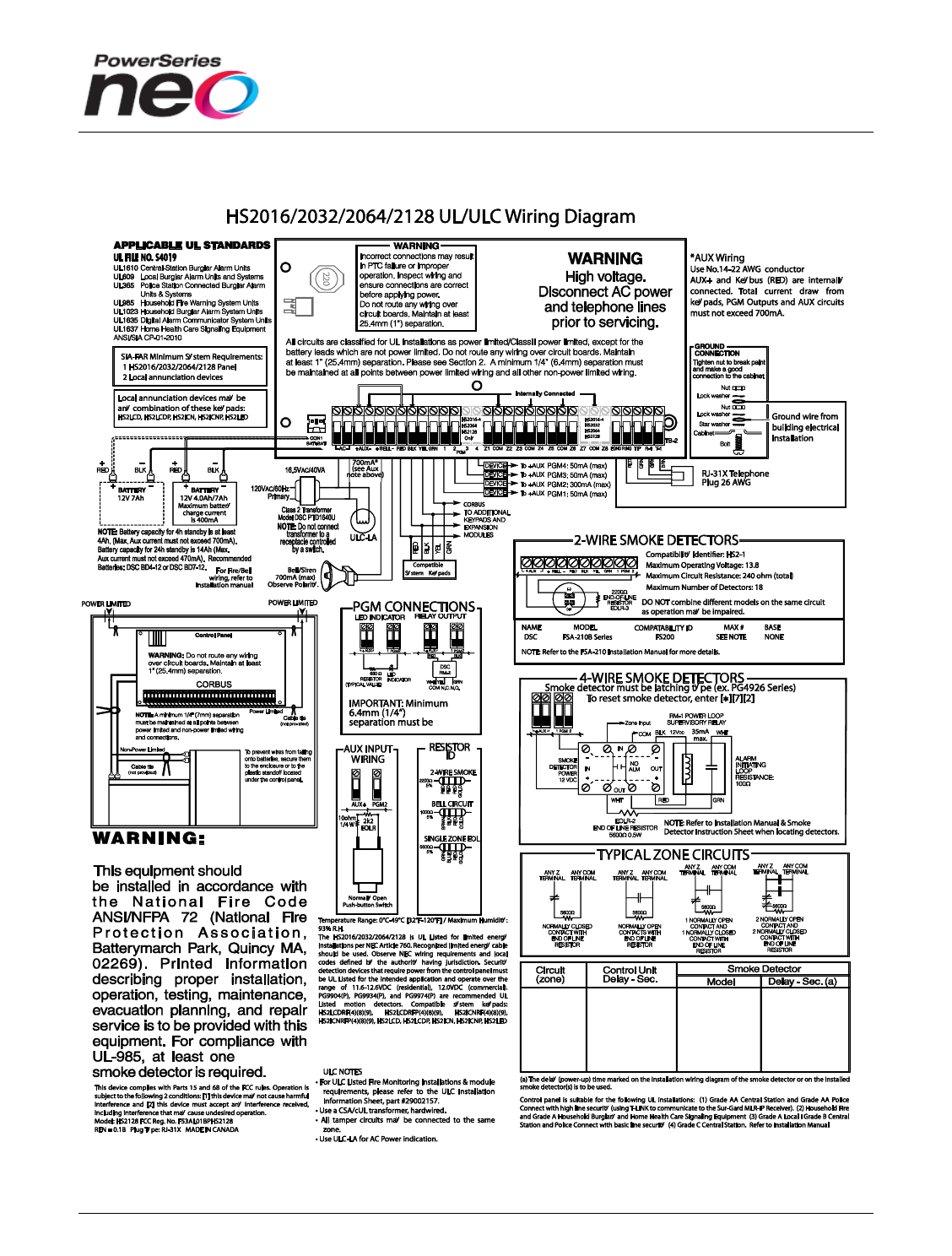
Wiring Diagram (HS2016/2032/2064/2128)

22
6
Execution
This chapter identifies the execution process, including installation, testing, and
certification.
Installation
The system is installed according to the manufacturer’s installation instructions
and recommendations.
System Testing and Certification
The system is tested in accordance with the manufacturer’s recommendations and
industry standard practices.
This completes the Architecture and Engineering specification for the PowerSeries Neo Alarm
Controller.
Again, for detailed information about the PowerSeries Neo Alarm Controller “wireless”
component, refer to the document: PowerSeries Neo 1.0 Wireless Host Architecture and
Engineering Specification.