E KAM DATA SHEET ISA
User Manual: e-KAM-DATA-SHEET-ISA-
Open the PDF directly: View PDF ![]() .
.
Page Count: 8


• Fully automatic primary injection test system
• CT ratio, burden and polarity test
• Circuit breaker testing
• Two portable units: control and current units
• High current output: up to 2000 A, 3000 A
and 5000 A and AC voltage output up to 220 V
• Variable output frequency: 15÷500 Hz
• Large graphic display
• Advanced Test & Data Management
Software for test set control, results storage
and analysis
• Step & Touch plus ground resistance tests
with STLG option, according to EN50522 and
EN61936-1 standards
• Line impedance test with STLG option
• Reduced timing test
• USB interface and Ethernet interface for PC
connection
• IEC 61850-9-2 sample values protocol
interface
• Compact and lightweight:
Control unit: 17 kg
Current unit: 16/20 kg according to the
model
Func on keys
Multifunction
function knob
eKAM- FRONT PANEL
Keyboard
Display
Start/Stop Emergency
push-bu on
Digital
input
Current
input
Voltage
input
Voltage
input

BUX 2000 - BUX 3000 - BUX 5000
eKAM - SIDE PANEL
InterfacesRemote start
Safety warnings
External booster
output / AC voltage
output
STLG
Line impedance and Step & Touch tes ng kit
STSGGROUND GRID TEST ACCESSORIES KIT

eKAM test system includes two portable units: one control unit
with a large graphical display that adjusts the AC voltage output
(up to 220 V) and one current unit (up to 2000, 3000, 5000A).
BUX 2000 (2000 A) - BUX 3000 (3000 A) - BUX 5000 (5000 A):
one or more BUX current unit can be connected to eKAM (not
simultaneously), they can be ordered separately when the order
is placed or at a later moment.
With the control knob and the LCD display, it is possible to en-
ter the MENU mode, that allows to set many functions, making
eKAM a very powerful testing device, with manual and auto-
matic testing capabilities and with the possibility to transfer test
results to a PC via ETHERNET or Pen Drive.
The TDMS software, which comes with the test set, allows to
download, display and analyze test results obtained in local
mode. Remote maintenance and diagnostic of the instrument
are available via Ethernet. TDMS software operates with all Win-
dows® versions. The ease of operation has been the first goal of
eKAM. This is why the LCD display is so large and the dialogue in
the MENU mode is made easy.
eKAM includes three measurement inputs:
. DC voltage (10 V DC).
. AC voltage:
.. High range (300 V AC)
.. Medium range (10 V AC)
.. Low range (3 V AC)
. Current (10 A AC or DC).
All these inputs are independent among them (unless 3V and
300V) and allow the measurement of CT outputs or of another
source. In addition, a digital input (up to 300 V) is available: it
can measure the timing of a wet or dry contact. The instrument
is housed in a transportable aluminium box, which is provided
with a cover and handles for ease of transportation. A transport
case can also be supplied upon request.
IEC 61850-9-2 Sampled Values
eKAM has the facility to test CT, both conventional and non
conventional, Merging Unit (MU) using the IEC 61850-9-2 (SV)
protocol. eKAM generates current signal and injects these quan-
tities into the CT under test. eKAM then reads the data from
the network (Sample Values) in order to perform a variety of
different tests.
. Possibility to test CT ratio and polarity check up to 2000 A,
3000A and 5000A. Test of MU.
TDMS – Test & Data Management Software
TDMS, Test & Data Management Software, is a powerful soft-
ware package providing data management for acceptance and
maintenance testing activities. Electrical apparatus data and
test results are saved in the TDMS database for historical results
analysis.
The TDMS database organizes test data and results for the ma-
jority of electrical apparatus tested with ISA test sets and related
software.
PADS - Power Apparatus Diagnostic Software
PADS - Power Apparatus Diagnostic Software is a powerful soft-
ware application, included in TDMS software, that optionally al-
lows the remote control of the eKAM and STS family: STS 5000,
STS 4000, STS 3000 light and TDX 5000. The software performs
various tasks, such as:
. Controls eKAM from PC
. Create test plan
. Download stored test results via Ethernet cable
. Create and customize test reports
. Print test results
This program runs under Windows© environment.
Note: Windows is trademark of Microsoft Corporation.
TEST PLAN EDITOR is an innovative and advanced software
module allowing the operator to define and plan a sequence of
tests. The operator defines the desired sequence of tests and
sets the parameters of each test. TEST PLAN EDITOR creates a
sequence of tests to be performed automatically. This feature is
available for the test of current transformer. It is also possible to
create a test sequence for primary injection.
At the end of the programming, starting the first test will ex-
ecute the complete sequence. During the test, test results are
stored in the memory. The test set minimizes the test Test plans
can be saved or recalled, like test results. Up to 64 settings can
be stored and recalled. Settings are permanently stored in the
memory and new settings can be written to the same address
after confirmation. During the test, test results can be stored in
the memory. At the end of test, settings and test results can be
transmitted to a PC provided with TDMS. The software allows
saving, exporting and analysing test results

• CT RATIO, POLARITY AND BURDEN
The ratio measurement is performed applying high current, coming
from one of the BUX modules, to the CT primary and measuring the CT
secondary current. The burden can be by-passed, or left in series for the
measurement. In this instance, the voltage drop is measured. The secon-
dary current can be measured by a clamp. Input parameters are: the
nominal primary and secondary current, from which the program com-
putes the nominal ratio and the nominal test current. The display shows:
• The actual primary current
• The corresponding secondary current
• The value of the secondary current with the nominal primary current
• Actual ratio and ratio error
• Phase shift and polarity.
When the burden is tested, the following parameters are displayed:
• The voltage drop across the burden;
• For the burden: VA rating at the nominal current, angle and power
factor.
• CB; PRIMARY AND SECONDARY RELAY TESTS
The selection allows injecting the test parameter and measuring the
relay threshold and trip delay of a MV CB or of a relay. It is also possible
to measure external voltages and currents. Accordingly with the BUX
model, it is possible to perform high current tests, up to 5000 A. Input
parameters are:
• current range
• output current
• frequency.
It is possible to enable the time measurement on the digi-
tal input and to set the type of digital input (wet or dry).
The display shows the following data:
• Test current or test voltage • Trip time • Closing time • External volta-
ge and current measurements.
GENERATOR OUTPUT
The internal generator has one high power - AC voltage output, not
insulated from the mains. The adjustment is performed by the local
control.
The generated frequency can be userdefined or synchronized to the
supply frequency (with optional power line synchronizer). The following
specification applies to the output.
NOTE:
. Output power is reduced with the supply of 110 V.
. Output amplitude may decrease for frequency below 50 Hz and above 60 Hz.
Output frequency
. AC output frequency range: 15÷500 Hz.
. Frequency resolution : 10 mHz.
220 1500 Steady 15 to 500
220 4000 300 15 to 500
220 5000 25 15 to 50
MAX VOLTAGE OUTPUT OUTPUT POWER MAX TEST DURATION FRECUENCY
V VA s Hz
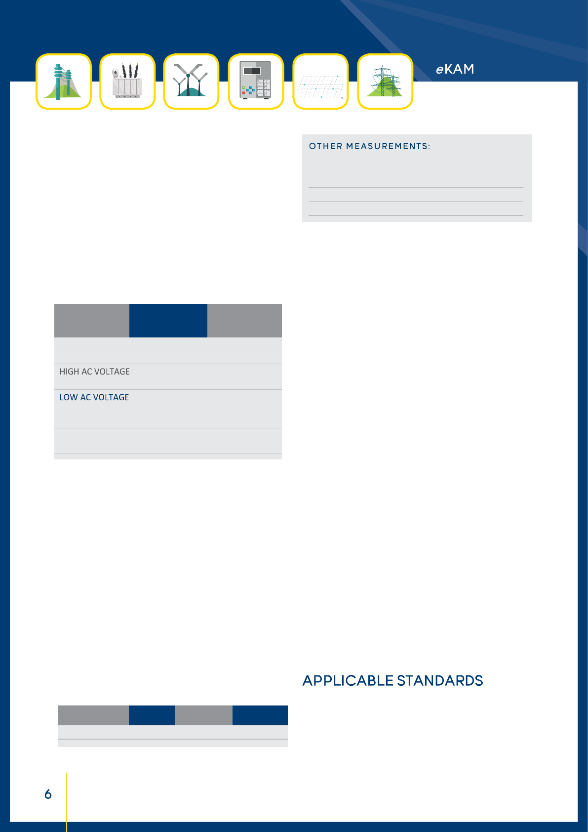
INPUT MEASUREMENTS
Current and Voltage
It is possible to meter the current and the voltage of an external
input. Three metering groups are available:
. AC or DC current, up to 10 A
. AC voltage, with two connections:
o High range, up to 300 V AC.
o Low range, up to 3 V AC.
. AC/DC voltage up to 10 V DC.
Resolu on and accuracy
Binary Input - Timer
The test set allows tes ng protec on relays. The test current
or voltage can be ramped or stepped. As the output changes, a
mer is started; the mer stops as the Digital input senses that
the relay has tripped or the output cut is cut. Characteris cs of
the Digital input:
• The input may be selected as Normal Open, Normal Closed
• The mer can start from an analog input ( current or voltage)
• The mer can start and stop at the changing of the digital
input, both dry or wet contact
• Type of input: either dry or under voltage. Maximum input:
300 V AC or DC
• Voltage thresholds: 5 V, 24 V, 48 V or > 80 V
• Timer resolu on: 1 ms
Phase angle measurement
The test set measures the phase angle between the two AC
selected parameters which are used during the test.
AC CURRENT 1 A; 10 A <%0.05 <%0.05
DC CURRENT 1 A; 10 A <%0.03 <% 0.08
300 mV; 3 V; <%0.15 <%0.05
30 V; 300 V <%0.05 <%0.05
30 mV <%0.1 <%0.25
300 mV <%0.08 <%0.08
3 V <%0.03 <%0.08
DC VOLTAGE 10 mV; 100 mV <%0.05 <%0.15
1 V; 10 V <%0.03 <%0.08
INPUT RANGE ACCURACY
reading & range
PHASE 0 - 360 0.01° < 0.15°
MEASUREMENT RANGE RESOLUTION ACCURACY
Star ng from the internal and external measurements, the
test set computes the following parameters:
CT RATIO
CT POLARITY
CT BURDEN
Other measurement:
Z, P, R, X, S, Q, cos(φ)
For the CT ra o measurement, the following applies:
. Range: 0÷9.999
. Resolu on: 1
. Accuracy: ±0.15% of the reading ± 0.15% of the range
DISPLAY
The large graphic display has the following characteris cs:
. Pixels: 640 x 480, coloured
. LCD type: TFT
. View area: 132 x 99 mm
. Backlight
LOCAL TEST CONTROL
Local test control: by the START/STOP pushbu on. A er test
selec on, pressing it, the output is generated, according to the
type of test. During ON, if a manual control test is selected, the
operator adjusts the output at the desired value. Test saving:
. Automa c save.
. A er operator confi rma on.
OTHER CHARACTERISTICS
Communica on interfaces:
. ETHERNET for the PC connec on
. USB port for the USB key.
Interfaces to external modules:
. Alarms to a fl ashing light
. Remote start input.
Mains supply
100-230 V ± 15%; 50-60 Hz. Maximum supply current: 16 A.
Dimensions: 450 (W) x 400 (H) x 230 (D) mm.
Weight: 17 kg.
The test set conforms to the EEC directives regarding
Electromagnetic Compatibility and Low-Voltage instruments.
. Electromagnetic Compatibility: Directive no. 2014/30/UE.
Applicable Standard: EN61326-1:2013
. Low Voltage Directive: Directive n. 2014/35/UE. Applicable
standards: CEI EN61010-1:2010. In particular:
. Input/output protection: IP 2X - IEC69529.
. Operating temperature: -10° to 55 °C; storage: -20 °C÷70 °C
. Relative humidity: 5-95% without condensing.

BUX 2000, BUX 3000 and BUX 5000 - VERY HIGH
CURRENT BOOSTER
The current boosters allows performing tests up to 2000A,
3000 A and 5000A.
The op on is made of a module, which incorporates:
• A power transformer, which generates a low-voltage, high cur-
rent output.
•A metering CT, which measures the output current and sends
the metering to eKAM.
BUX 2000
BUX 3000
BUX 5000
• Frequency: 15 Hz ÷ 500 Hz.*
• Weight: BUX 3000 15 kg, BUX 2000 18 kg, BUX 5000 19 kg
without current cables and clamps.
• Dimensions for models BUX 2000 and BUX 3000: external
diameter 190 mm; height 120 mm.
• Dimensions for model BUX 5000: external diameter 200 mm;
height 170 mm.
500 700 INFINITE
1000 1500 60
2000 5000 25
TEST CURRENT OUTPUT POWER TEST DURATION
A VA s
1000 900 INFINITE
2000 2400 300
3000 4800 60
TEST CURRENT OUTPUT POWER TEST DURATION
A VA s
1000 700 INFINITE
2000 1500 300
3000 2700 30
4000 4200 20
5000 5500 10
TEST CURRENT OUTPUT POWER TEST DURATION
A VA s
All high current boosters are supplied with:
. high current cable, made of 4 cables, 95 sq. mm, 1.2 m long,
with 2 high current clamps for BUX3000
. 4 cables, 95 sq. mm, 2 m long, with 2 high current clamps for
BUX 2000
. 12 cables, 95 sq. mm, 0.8 m long, with 4 high current clamps
for BUX 5000
. one power supply cable , 20 m long
. one measurement cable, 20 m long, with the output current
measurement.
* The output amplitude may decrease for frequency below 50 Hz and
above 60 Hz.
STANDARD CONNECTION CABLES
NOTE: standard cables can also be ordered separately.
. One mains supply cable, 2 m long.
. One grounding cable, 6 m long.
. One interface cable for the USB port.
. One ETHERNET interface cable.
. One USB pen drive.
. One cable for the 10A measurement to be connected to the
secondary of the CT 2.5 sq. mm, 10 m long .
. Four crocodiles for measurements connec ons (two red and
two black).
. One cable for voltage measurements 1 sq. mm, 10 m long .
. two short cables, 2m long (red and black), for other measure-
ments.
. One adaptor for 10V input - measuring BUX cable.
TRANSPORT CASES
Transport cases for eKAM and BUX units are available; all
of them allow transporting the device with no concern about
shocks or falls up to 1 m. The case is supplied with handles and
wheels. eKAM transport case protection degree: IP IEC 60529.
TROLLEY
The trolley eases the transport of eKAM.
eKAM transport case and trolley
The document is subject to change without notice.
Always refer to our technical specification for more detailed
information and as formal contract document.
STEP & TOUCH TESTING KIT
STLG MODULE FOR GROUND TESTING AND LINE
IMPEDANCE MEASUREMENT
The option allows performing both the measurement of: ground
grid resistance, step and touch tests, overhead lines zero
sequence and mutual coupling coefficients.
STLG is a high power transformer, which increases the output
current. A high current switch allows selecting the desired
current range. A voltage meter displays the generated voltage.
The option takes its power from the EXT. BOOSTER connector of
eKAM. Output current and voltage are metered and sent back
to eKAM measuring inputs; a third output allows eKAM to know
the selected range. Device characteristics are the followings.
. Input: from eKAM, via the booster connector
. Output current ranges: 11, 22, 35, 55, 105 A AC
. Output power: 1800 VA steady; 5200 VA peak for 10 s
. High current range selector switch
. Analogue output voltage meter. Meter range: 600 V AC
. Outputs to eKAM: selected current output range, output cur-
rent and output voltage.
All necessary connection cables are included in the option.
Current clamp provided: 400 A range.
Weight: 25 kg. Dimensions: 23 x 33 x 44 cm.
STSG SAFETY GROUNDING MODULE
During tests, STLG is connected to the overhead line to be
tested. The purpose of the STSG optional device is to pro-
tect the operator against possible high voltage spikes.
STSG incorporates three voltage suppressors and one high
current switch, to connect three lines in parallel. This option
applies in conjunction with STLG. Option characteristics:
. Nominal AC spark-over voltage: 1000 V rms
. Impulse spark-over voltage: 2000 V peak
. Short-circuit proof with 25 kAeff / 100 ms; 36 kAeff / 75 ms
. Connection via three cylindrical ball studs 16, 20 or 25 mm
diameter. The ball diameter must be specified at order.
. Weight: 9.1 kg. Dimensions: 41 x 21 x 13.5 cm
. Grounding cable included: 95sq.mm, 2m.
GROUND GRID TEST ACCESSORIES KIT
The option is the kit of connection cables, auxiliary spikes and
other accessories that allows connecting eKAM or STLG to the
testing devices and performing all types of tests. The kit includes:
. Four earth spikes for the soil resistivity test and for the earth
resistance test.
. Two auxiliary earth spikes, for tests in small sites.
. Three cables, wound on wheels, 200 m long.
. One mains synchronizer device, to synchronize the eKAM ge-
neration to the mains.
. Two test probes for the step and touch test.
. One voltage meter, digital, type true RMS, for the earth resi-
stance and step and touch tests.
. One resistor box for the step and touch test.
LINE IMPEDANCE TESTING KIT
The kit is made of STLG - Line and Grid module and STSG - safety
grounding module, without the line and grid accessories.
OPTIONAL SOFTWARE
PADS - POWER APPARATUS DIAGNOSTIC SOFTWARE
PADS - Power Apparatus Diagnostic Software is a powerful
software application, included in TDMS software, that allow the
remote control of the eKAM.
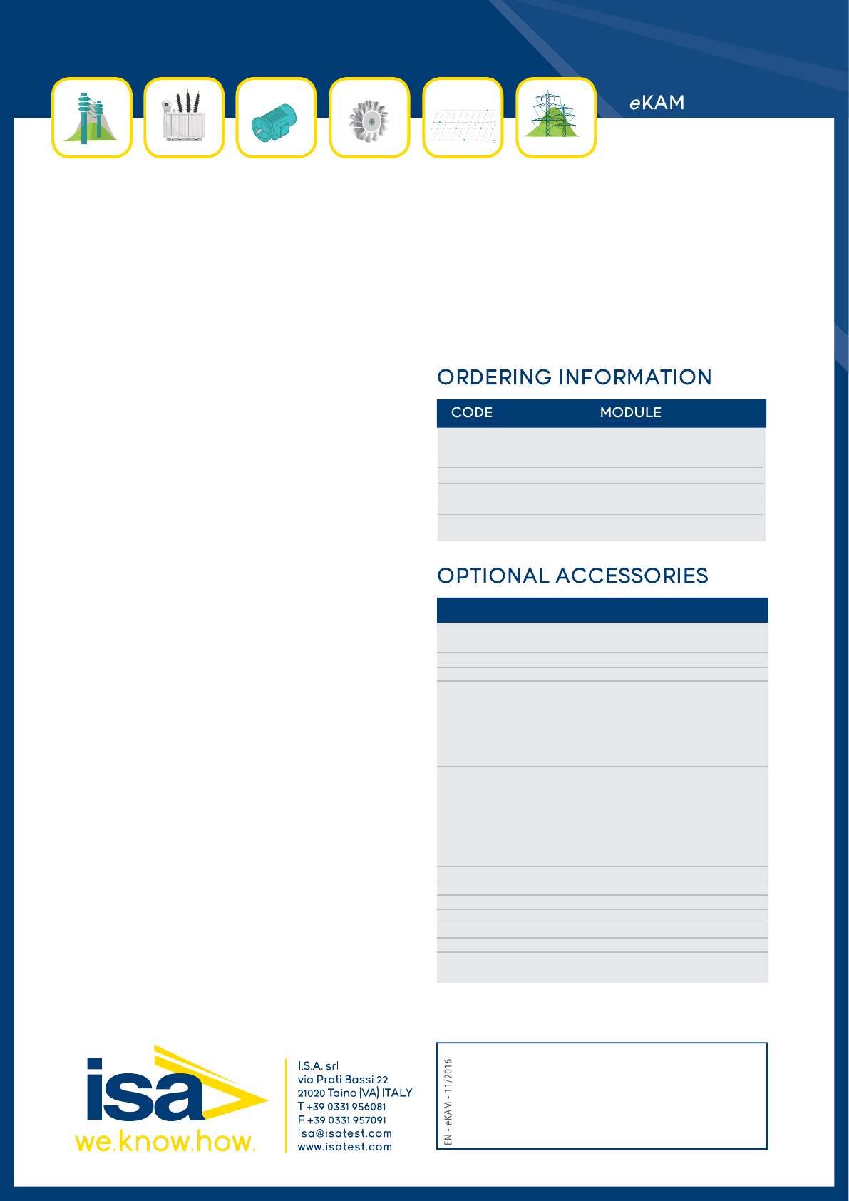
49175 eKAM control unit supplied with connection
cables, transport case and TDMS software
56175 BUX 2000 Current unit with transport case
50175 BUX 3000 Current unit with transport case
63175 BUX 5000 Current unit with transport case
CODE MODULE
10176P PADS software (primary)- Primary, CTs, VTs
test module*
37175 Transport case for eKAM
51175 Transport case of BUX unit
84175 Line impedance testing kit:
. STLG Line & ground grid module (100 A booster)
. Cables set for STLG
. Heavy duty plastic transport case for STLG
. STSG Safety grounding module
. Heavy duty plastic transport case for STSG
81175 Step & Touch testing kit:
. ST-LG Line & ground grid module (100 A booster).
. Cables set for STLG
. Heavy duty plastic transport case for STLG
. ST-SG Safety grounding module
. Heavy duty plastic transport case for STSG
. Step & touch, earth resistance/resistivity accessories.
72175 Stud 20 mm for Step & Touch testing kit
73175 Stud 25 mm for Step & Touch testing kit
74175 Stud 16 mm for Step & Touch testing kit
18175 Trolley for eKAM
42175 Remote safety switch
43175 Warning strobe light
*PADS - Power Apparatus Diagnos c So ware is NOT included into basic
unit price. It should be expressely ordered.
