E MG_UCP A&P Manual_1.6_sw2.1 MG UCP Manual 1.6 Sw2.1
User Manual: eMG_UCP-A&P manual_1.6_sw2.1
Open the PDF directly: View PDF ![]() .
.
Page Count: 689 [warning: Documents this large are best viewed by clicking the View PDF Link!]
- iPECS eMG80 & eMG800 & UCP Administration & Programming Manual
- 1. Introduction
- 2. System & admin information
- 3. STATION ADMIN PROGRAMMING for eMG
- 3.1 General
- 3.2 Data Entry Mode
- 3.3 Procedure for Data Entry
- 3.3.1 System ID — PGM 100
- 3.3.2 NUMBERING PLANS DATA — PGM 102 to 109
- 3.3.3 Station Data –PGM 110-125
- 3.3.3.1 Station Type -PGM 110
- 3.3.3.2 Station Attributes I to III - PGM 111-113
- 3.3.3.3 Station Attributes IV -PGM 114
- 3.3.3.4 Flexible button Assignment -PGM 115
- 3.3.3.5 Station Class-of-Service – PGM 116
- 3.3.3.6 CO/IP Group Access – PGM 117
- 3.3.3.7 Internal Page Zone Access – PGM 118
- 3.3.3.8 PTT (Push-To-Talk) Group Access – PGM 119
- 3.3.3.9 Preset Call Forward – PGM 120
- 3.3.3.10 Idle Line Selection – PGM 121
- 3.3.3.11 Station IP Attributes – PGM 122
- 3.3.3.12 Station Timers – PGM 123
- 3.3.3.13 Linked Station Table – PGM 124
- 3.3.3.14 ICM Tenancy Group – PGM 125
- 3.3.3.15 Station VM Attributes – PGM 127
- 3.3.3.16 Station CCR Table – PGM 128
- 3.3.3.17 LSS Label Edit – PGM 129
- 3.3.4 BOARD DATA – PGM 130 to 132
- 3.3.5 CO LINE DATA – PGM 140 to 151
- 3.3.5.1 CO Service Type – PGM 140
- 3.3.5.2 CO/IP Attributes I ~ III - PGM 141~143
- 3.3.5.3 CO/IP Ring Assignment – PGM 144
- 3.3.5.4 DID Service Attributes – PGM 145
- 3.3.5.5 DISA Service – PGM 146
- 3.3.5.6 CO Line Preset Forward Attributes – PGM 147
- 3.3.5.7 CO Additional Attributes – PGM 148
- 3.3.5.8 NA ISDN Line Attributes – PGM 150
- 3.3.5.9 ISDN CO Line Attributes – PGM 151
- 3.3.5.10 T1 Line Timers – PGM 152
- 3.3.5.11 DCOB CO Attribute – PGM 153
- 3.3.6 SYSTEM DATA –PGM 160 to 182
- 3.3.6.1 System Attributes I & II – PGM 160 to 161
- 3.3.6.2 System Password – PGM 162
- 3.3.6.3 Alarm Attributes – PGM 163
- 3.3.6.4 Attendant Assignment – PGM 164
- 3.3.6.5 Multi-cast RTP/RTCP Ports – PGM 165
- 3.3.6.6 DISA COS – PGM 166
- 3.3.6.7 DID/DISA Destination – PGM 167
- 3.3.6.8 External Control Contacts – PGM 168
- 3.3.6.9 LCD Display Mode -PGM 169
- 3.3.6.10 Button LED Flash Rate – PGM 170
- 3.3.6.11 Music Sources – PGM 171
- 3.3.6.12 PABX Access Codes – PGM 172
- 3.3.6.13 Ringing Line Preference Priority – PGM 173
- 3.3.6.14 RS-232 Port Settings – PGM 174
- 3.3.6.15 Serial Port Function Selections – PGM 175
- 3.3.6.16 Break/Make Ratio – PGM 176
- 3.3.6.17 SMDR Attributes – PGM 177
- 3.3.6.18 System Date, Time and Daylight Saving Time (DST) – PGM 178
- 3.3.6.19 Multi Language – PGM 179
- 3.3.6.20 System Timers I to III - PGMs 180-182
- 3.3.6.21 In-Room Indication – PGM 183
- 3.3.6.22 DCOB SYS Timers – PGM 186
- 3.3.6.23 NTP Attributes – PGM 195
- 3.3.6.24 CRR Attributes – PGM 252
- 3.3.6.25 VM COS Attributes – PGM 253
- 3.3.6.26 Personal Group – PGM 260
- 3.3.6.27 Personal Group Attribute – PGM 261
- 3.3.7 STATION GROUP DATA – PGM 190 & 192
- 3.3.8 ISDN LINE & ICLID ROUTING DATA – PGM 200-206
- 3.3.9 TABLES DATA – PGM 220 to 235
- 3.3.9.1 LCR Assignment Tables - PGM 220 to 223
- 3.3.9.2 Toll Tables – PGM 224
- 3.3.9.3 Emergency Code Table – PGM 226
- 3.3.9.4 Authorization Codes Table – PGM 227
- 3.3.9.5 Customer Call Routing/VSF AA Table – PGM 228
- 3.3.9.6 Executive/Secretary Table – PGM 229
- 3.3.9.7 Flexible DID Conversion Table – PGM 231
- 3.3.9.8 System Speed Zone Table – PGM 232
- 3.3.9.9 Auto Ring Mode – PGM 233
- 3.3.9.10 Voice Mail Dialing Table – PGM 234
- 3.3.9.11 Registration & Fractional Module Table – PGM 235
- 3.3.9.12 Mobile Extension Table – PGM 236
- 3.3.9.13 Hot Desk Attributes – PGM 250
- 3.3.9.14 CO Call Rerouting – PGM 252
- 3.3.9.15 Digit Conversion Tables – PGM 270
- 3.3.10 NETWORKING DATA – PGM 320 to 324
- 3.3.11 TNET (Centralized Networking) – PGM 330 ~ 336
- 3.3.12 Zone Data – PGM 436 - 441, 444
- 3.3.13 GREEN MODE
- 3.3.14 INITIALIZATION — PGM 450
- 3.3.15 PRINT-OUT DATABASE — PGM 451
- 3.3.16 VIRTUAL TRACE DIP-SWITCH — PGM 452
- 3.3.17 VIRTUAL DIP-SWITCH — PGM 453
- 3.3.18 DECT ATTRIBUTES — PGM 491
- 4. WEB SERVICE
- 4.1 General
- 4.2 iPECS system Web Access & Login
- 4.3 Web Admin & Maintenance Main Page Overview
- 4.4 Web Admin Programming
- 4.4.1 System ID & Numbering Plans
- 4.4.1.1 System ID – PGM 100
- 4.4.1.2 System Overview
- 4.4.1.3 Device Port Number Change – PGM 101
- 4.4.1.4 System IP Plan - PGM 102
- 4.4.1.5 Device IP Plan - PGM 103
- 4.4.1.6 CO Device Sequence Number - PGM 104
- 4.4.1.7 Flexible Station Numbering Plan - PGM 105
- 4.4.1.8 Flexible Numbering Plan - PGM 106 ~ 109
- 4.4.1.9 8 Digit Extension Table - PGM 238
- 4.4.2 Station Data
- 4.4.2.1 Station Type - PGM 110
- 4.4.2.2 Common Attributes - PGM 111
- 4.4.2.3 Terminal Attributes - PGM 112
- 4.4.2.4 CLI Attributes - PGM 113
- 4.4.2.5 Flexible Buttons - PGM 115/129
- 4.4.2.6 Station COS - PGM 116
- 4.4.2.7 CO/IP Group Access - PGM 117
- 4.4.2.8 Internal Page Zone Access - PGM 118
- 4.4.2.9 PTT Group Access - PGM 119
- 4.4.2.10 Preset Call Forward - PGM 120
- 4.4.2.11 Station ICR Scenario - PGM 1201
- 4.4.2.12 Idle Line Selection - PGM 121
- 4.4.2.13 Station IP Attributes - PGM 122
- 4.4.2.14 Station Timers - PGM 123
- 4.4.2.15 Linked Station - PGM 124
- 4.4.2.16 Station ICM Group - PGM 125
- 4.4.2.17 Station Voice Mail Attributes – PGM 127
- 4.4.2.18 Station Personal CCR Table – PGM 128
- 4.4.2.19 Station Name Overview & Display
- 4.4.2.20 Station User Greeting
- 4.4.2.21 Station Data Copy
- 4.4.2.22 Station CTI IP Address (1st Party TAPI)
- 4.4.2.23 Station Recording Information
- 4.4.3 Board Based Data
- 4.4.4 CO Line Data
- 4.4.4.1 Common Attributes - PGM 140
- 4.4.4.2 Analog Attributes - PGM 141
- 4.4.4.3 VoIP Attributes - PGM 142
- 4.4.4.4 ISDN Attributes - PGM 143
- 4.4.4.5 CO/IP Ring Assignment - PGM 144
- 4.4.4.6 DID Service Attributes - PGM 145
- 4.4.4.7 DISA Service Attributes - PGM 146
- 4.4.4.8 CO/IP Preset Forward Attributes - PGM 147
- 4.4.4.9 MATM Attributes - PGM 149
- 4.4.4.10 NA ISDN Line Attributes - PGM 150
- 4.4.4.11 CID/CPN Attributes - PGM 151
- 4.4.4.12 T1 CO Line Attributes - PGM 152
- 4.4.4.13 DCOB CO Line Attributes - PGM 153
- 4.4.5 System Data
- 4.4.5.1 System Attributes - PGM 160 & 161
- 4.4.5.2 System Password - PGM 162
- 4.4.5.3 Alarm Attributes - PGM 163
- 4.4.5.4 Attendant Assignment - PGM 164
- 4.4.5.5 Multi-cast IP/Port - PGM 165
- 4.4.5.6 DISA COS - PGM 166
- 4.4.5.7 DID/DISA Destination - PGM 167
- 4.4.5.8 External Control Contacts - PGM 168
- 4.4.5.9 LCD Display Mode - PGM 169
- 4.4.5.10 LED Flashing Rate - PGM 170
- 4.4.5.11 Music Sources - PGM 171
- 4.4.5.12 PBX Access Codes - PGM 172
- 4.4.5.13 Ringing Line Preference Priority - PGM 173
- 4.4.5.14 RS-232 Port Settings - PGM 174
- 4.4.5.15 Serial Port Selections - PGM 175
- 4.4.5.16 Pulse Dial (Break/Make) Ratio - PGM 176
- 4.4.5.17 SMDR Attributes - PGM 177
- 4.4.5.18 System Date & Time - PGM 178
- 4.4.5.19 System Multi Language - PGM 179
- 4.4.5.20 System Timers - PGM 180 ~ 182 & 186
- 4.4.5.21 In-Room Indication - PGM 183
- 4.4.5.22 Web Access Authorization
- 4.4.5.23 Station Web Access Authorization
- 4.4.5.24 NTP Attributes - PGM 195
- 4.4.5.25 SNMP Attribute - PGM 196
- 4.4.5.26 Cabinet Attribute for UCP - PGM 197
- 4.4.5.27 Hot Desk Attributes - PGM 250
- 4.4.5.28 System Call Routing - PGM 251
- 4.4.5.29 CO Call Rerouting - PGM 252
- 4.4.5.30 VM COS Attributes – PGM 253
- 4.4.5.31 Static Route Attributes – PGM 254
- 4.4.5.32 Access Control List – PGM 255
- 4.4.5.33 Attendant Ring Mode – PGM 257
- 4.4.5.34 System Speed Dial
- 4.4.5.35 Custom Messages
- 4.4.5.36 PPTP Attributes
- 4.4.5.37 PPP Attributes for eMG – PGM 205
- 4.4.6 Station Group Data
- 4.4.7 ISDN Line Data
- 4.4.8 SIP Data
- 4.4.8.1 SIP Common (System based) Attributes - PGM 210
- 4.4.8.2 SIP Trunk Status Overview
- 4.4.8.3 SIP CO Attributes - PGM 133
- 4.4.8.4 SIP Registration Status Overview
- 4.4.8.5 SIP UID Allocation Status Overview
- 4.4.8.6 SIP User ID Attributes – PGM 126
- 4.4.8.7 SIP Phone Attributes - PGM 211
- 4.4.8.8 SIP Phone Provisioning - PGM 212
- 4.4.8.9 Provisioning File View & Delete
- 4.4.8.10 VMEX Station Data - PGM 215
- 4.4.8.11 VMEX Connection table - PGM 216
- 4.4.9 Tables Data
- 4.4.9.1 LCR Control Attributes - PGM 220
- 4.4.9.2 LCR LDT (Leading Digit Table) - PGM 221
- 4.4.9.3 LCR DMT (Digit Modification Table) - PGM 222
- 4.4.9.4 LCR Table Initialization - PGM 223
- 4.4.9.5 Digit Conversion Table - PGM 270
- 4.4.9.6 Toll Exception Table - PGM 224
- 4.4.9.7 Emergency Code Table - PGM 226
- 4.4.9.8 COS Table
- 4.4.9.9 Authorization Codes Table - PGM 227
- 4.4.9.10 Customer Call Routing Table - PGM 228
- 4.4.9.11 Executive/Secretary Table - PGM 229
- 4.4.9.12 Flexible DID Conversion Table - PGM 231
- 4.4.9.13 System Speed Zone Table - PGM 232
- 4.4.9.14 Auto Ring Mode Table - PGM 233
- 4.4.9.15 Voice Mail Dialing Table - PGM 234
- 4.4.9.16 Registration Table - PGM 235
- 4.4.9.17 Mobile Extension Table - PGM 236
- 4.4.9.18 IPCR Agent Table - PGM 237
- 4.4.9.19 Dummy Dial-Tone Digit Table
- 4.4.9.20 Flexible Button Default Table – PGM 239
- 4.4.9.21 Preset Flexible Button Default – PGM 240
- 4.4.10 Networking Data
- 4.4.10.1 Network Basic Attributes - PGM 320
- 4.4.10.2 Network Supplementary Attributes - PGM 321
- 4.4.10.3 Net CO Line Overview
- 4.4.10.4 Network CO Line Attributes - PGM 322
- 4.4.10.5 Network Numbering Plan Table Overview
- 4.4.10.6 Network Numbering Plan - PGM 324
- 4.4.10.7 Network Feature Code Table - PGM 325
- 4.4.11 H.323 Routing Table
- 4.4.12 T-NET Data
- 4.4.13 Zone Data
- 4.4.13.1 Zone Number Overview
- 4.4.13.2 Device Zone Number – PGM 436
- 4.4.13.3 Device Zone Attributes – PGM 437
- 4.4.13.4 Access & Page Relay – PGM 438
- 4.4.13.5 Inside Zone Attributes Overview
- 4.4.13.6 Zone Attribute – PGM 439
- 4.4.13.7 Zone RTP Relay Group – PGM 440
- 4.4.13.8 Inter Zone Attribute – PGM 441
- 4.4.13.9 Zone Holiday Assignment - PGM 444
- 4.4.14 Device Login
- 4.4.15 UCS Data
- 4.4.16 DECT Data
- 4.4.17 Hotel Data
- 4.4.18 Green Mode for eMG - PGM 500
- 4.4.19 Redundancy Data for UCP600 & 2400
- 4.4.20 Initialization - PGM 450
- 4.4.1 System ID & Numbering Plans
- 4.5 Maintenance
- 4.5.1 S/W Upgrade
- 4.5.2 Database
- 4.5.3 Multi Language
- 4.5.4 SMDR
- 4.5.5 File System
- 4.5.6 MOH (Music On-Hold) Management
- 4.5.7 License Install
- 4.5.8 DECT Statistics Feature
- 4.5.9 VSF Prompt Upload
- 4.5.10 VSF System Greeting
- 4.5.11 User Greeting
- 4.5.12 Company Directory
- 4.5.13 Voice Mail Management
- 4.5.14 Function program
- 4.5.15 User Management
- 4.5.16 Trace
- 4.5.17 TDM Gain Control
- 4.5.18 IP Gain Control
- 4.5.19 Tone/ Ring Gain & Cadence Control
- 4.5.20 Appliances Control
- 4.5.21 Web Certificate
- 4.6 On-Line web user guide
- Appendix A Program Codes
- Appendix B Flexible Numbering Plan (Web based)
- Appendix C Database Details & Default for Station Administration for eMG

iPECS eMG80 & eMG800 & UCP
Administration & Programming
Manual
Please read this manual carefully before operating System.
Retain it for future reference.

iPECS eMG80 & eMG800 & UCP
Administration and Programming Manual Issue 1.6
Revision History
SW version ISSUE DATE DESCRIPTION OF CHANGES
1.0
Sep., 2013
Initial Release
1.1
Dec., 2013
Changed Ericsson-LG to Ericsson-LG Enterprise
1.1.x
1.2
Feb., 2015
Update contents according to S/W integration for both eMG80 & eMG800
1.2.x 1.3 May, 2015 We updated the following features:
- On-line user guide
- Terminal attributes (Small popup use, large popup timer, SLT open
loop time)
- Web Access Authorization
- NTP attributes
- Digit Conversion Table
- System attributes
- U-LOOP, PBX code insertion for emergency call
- Disconnect with Inband information
- Temp License expiration notify
- Trace Log via Web
- Add System Date and Time to Installation wizard
2.0.x 1.4 Jan., 2016 - Added Speed code number plan in PGM100.
- IPCR announce only for incoming call.
- Updated Strong password in PGM 160/161.
- Updated ‘Do not overwrite station name in PGM 211.
- Added Attendant ring mode in PGM 257.
- Added the more item for Alarm in PGM 163.
- Added Flexible button default table (PGM 239)
- Added Preset flexible button default (PGM 240)
- Added System DST mode in PGM 439.
- Added LDAP server setting in PGM 160/161.
- Added Arabic language.
- Updated Message wait indication LED in PGM 112.
- Updated Company directory in Station Name Display.
- Added Station User Greeting in Station Data.
- Added the search box in Maintenance.
- Added MOH Management in Maintenance.
- Updated DB management by adding Comment field.
- Updated Install wizard
- DTMF repeat tone does not have nothing to do with PSTN in
PGM160-15
- Added Call wait signal and duration in PGM 113.
- Added some admin (Alternate/Secondary signal port, Local route ID,
Remote route ID, Sending Name option) in PGM 324.
- Added SLT Pulse and SLT pulse-MW type in PGM 110.
- Added Lift Handset for Page & Privacy in PGM 111.
- Added Short Modem in PGM 112.
- Added NFC Authorization Code use in PGM 112.
- Added rel 180 after 183 and “Add ‘user=phone’ param” in PGM 133.
- Added Short Modem Timer in PGM 182~182, 186
- Added Alarm mode to send email to the address in PGM 163.

iPECS eMG80 & eMG800 & UCP
Administration and Programming Manual Issue 1.6
- Added the special character to DB management.
- Added Ring detection register setting in Analog parameter.
- Added LCD Dimming for LIP-9000 Series & LDP-9240D in PGM 112.
- ‘Go to assignment’ function added to Personal group overview and
can check the master & member list at a glance.
- Added Station ICR scenario (1201) to Station Data.
- Changed the name from UCS Standard to UCS data.
- Added MOH management in Maintenance.
- Added Keyset admin password to Install Wizard.
2.0.x
1.5
April, 2016
- ‘Unified SMB A&P manual’ by integrating eMG and UCP.
2.1.x 1.6 August, 2016 - The type of Speed numbering is added more in PGM 100.
- ‘DDNS usage of Firewall’ & ‘Domain name of Firewall’ is added in
PGM 102.
- The LCD LED is changed to the option ‘MWI/Ring’ or ‘Ring’.
- The ACD & CRM function is added for UCS Client: CRM function
and ACD login/out & ACD On/Off duty in PGM 112.
- UCS Dialing Rule Use for Standard UCS in PGM 112.
- UCS Mobile Dial Use (Android) for Standard UCS in PGM 112.
- The description of CLI Name Display is changed, refer to PGM 113.
- Display full CLI function is added in PGM 113.
- SMTP Server Address fills out up to 64 characters in PGM 127.
- Proxy Server Address fills out up to 64 characters in PGM 133.
- The range for ICLID Usage is changed to Disable, CLI, Name/CLI in
PGM 140.
- Web hacking block is added in PGM 160; Web admin login failure
count to block, Web admin hacking block period, Wed admin
hacking Email notification.
- UCS Ring ACK count is added in PGM 160 and UCS Ring ACK
timer is added in PGM 180.
- SLT Line monitor and SLT Line Monitor time is added in PGM 160.
- Dial Back to Caller from Remote VM Access is added in PGM 160.
- Alarm Display is added in PGM 163.
- The range about Alarm is changed to Off, On, Alarm only,
Alarm/Email. Especially, the default of Maintenance Expire Notify is
Email only.
- Message wait (Call back) for LED flash is added in PGM 170.
- Outgoing Call type is added for All call or Answered call in PGM 177.
- Call log/Directory Auto Idle Timer is added in PGM 180.
- The range of Hot Desk for eMG and UCP is changed in PGM 250:
eMG80 (100), eMG800 (300), UCP (1200).
- Advice of Charge is added in PGM 133.
- SIP Profile is added in PGM 211.
- Signaling port, TLS Version, First & Second TLS crypto, SRTP
usage, First & Second SRTP crypto are added in PGM 212.
- Interworking system is added in PGM 322.
- Name option is deleted in PGM 327.
- Alarm display is added in PGM 335.
- Firewall IP is added in PGM 441.
- MS Excel-like table data management (copy/paste from/to the excel
file, Input/Edit) is to be extended to the following tables.
- PGM 105 : Flexible Station Number
- PGM 115/129 : Flexible Buttons

iPECS eMG80 & eMG800 & UCP
Administration and Programming Manual Issue 1.6
Copyright© 2013 Ericsson-LG Enterprise Co., Ltd. All Rights Reserved
This material is copyrighted by Ericsson-LG Enterprise Co., Ltd. (Ericsson-LG Enterprise). Any
unauthorized reproductions, use or disclosure of this material, or any part thereof, is strictly prohibited
and is a violation of Copyright Laws. Ericsson-LG Enterprise reserves the right to make changes in
specifications at any time without notice. The information furnished by Ericsson-LG Enterprise in this
material is believed to be accurate and reliable, but is not warranted to be true in all cases. If you are not
the intended recipient, you should destroy or retrieve this material to Ericsson-LG Enterprise.
iPECS is trademark of Ericsson-LG Enterprise Co., Ltd.
All other brand and product names are trademarks or registered trademarks of their respective
companies.
- PGM 202 : MSN Table
- PGM 206 : Prefix Dialing Table
- PGM 443 : Station User Login
- PGM 231 : Flexible DID Conversion
- PGM 262 : System Speed Dial
- PGM 3241 : Net Numbering Plan Table
- PGM 227 : Station/System Authorization Code Table
- PGM 442 : Remote Device Registration
- Station Name Display
- User Greeting is added to Maintenance.
- Company Directory is added to Maintenance.
- Web Certificate is added to Maintenance.
- Custom 1 and Custom 2 are added in Web Access Authorization and
User management.
- Line Echo added to SLT attributes in PGM 112.
- DSS in use added to LED Flashing Rates in PGM 170.
- Multiple Announcement (1~9) is added to IPCR Agent table in PGM
237.

iPECS eMG80 & eMG800 & UCP
Administration and Programming Manual Issue 1.6
i
Table of Contents
1. Introduction ................................................................... 1
1.1 Manual Application .............................................................. 1
1.2 Manual Organization ........................................................... 1
2. System & admin information ...................................... 3
2.1 System capacities for eMG and UCP ................................ 3
2.2 Slot configuration for eMG80 ............................................. 9
2.3 Initialization ........................................................................ 11
2.3.1 eMG Initialization ........................................................................ 11
2.3.2 UCP Initialization ........................................................................ 13
2.3.2.1 Normal Registration Process .............................................................. 13
2.3.2.2 Replacement Module Registration ..................................................... 15
2.4 General Admin and Menu Structure ................................ 16
3. STATION ADMIN PROGRAMMING for eMG ............ 17
3.1 General ................................................................................ 17
3.1.1 LCD & Button Functions ............................................................ 17
3.1.2 Alphanumeric Data Entries ....................................................... 17
3.2 Data Entry Mode ................................................................ 18
3.3 Procedure for Data Entry .................................................. 19
3.3.1 System ID — PGM 100 ............................................................... 19
3.3.2 NUMBERING PLANS DATA — PGM 102 to 109 ...................... 21
3.3.2.1 System IP Address Plan — PGM 102 ................................................ 21
3.3.2.2 Device IP Address Plan -PGM 103 .................................................... 23
3.3.2.3 CO Device Sequence Number -PGM 104 ......................................... 27
3.3.2.4 Flexible Station Numbering Plan -PGM 105 ...................................... 28
3.3.2.5 Flexible Numbering Plan part A to D - PGM 106 to 109 .................... 29
3.3.2.6 8-Digit Table ....................................................................................... 35
3.3.3 Station Data –PGM 110-125 ....................................................... 36
3.3.3.1 Station Type -PGM 110 ...................................................................... 36
3.3.3.2 Station Attributes I to III - PGM 111-113 ............................................ 37
3.3.3.3 Station Attributes IV -PGM 114 .......................................................... 47
3.3.3.4 Flexible button Assignment -PGM 115 ............................................... 52
3.3.3.5 Station Class-of-Service – PGM 116 ................................................. 56
3.3.3.6 CO/IP Group Access – PGM 117 ....................................................... 58

iPECS eMG80 & eMG800 & UCP
Administration and Programming Manual Issue 1.6
ii
3.3.3.7 Internal Page Zone Access – PGM 118 ............................................. 58
3.3.3.8 PTT (Push-To-Talk) Group Access – PGM 119 ................................ 59
3.3.3.9 Preset Call Forward – PGM 120 ........................................................ 59
3.3.3.10 Idle Line Selection – PGM 121 ......................................................... 60
3.3.3.11 Station IP Attributes – PGM 122 ...................................................... 61
3.3.3.12 Station Timers – PGM 123 ............................................................... 62
3.3.3.13 Linked Station Table – PGM 124 ..................................................... 63
3.3.3.14 ICM Tenancy Group – PGM 125 ...................................................... 64
3.3.3.15 Station VM Attributes – PGM 127 .................................................... 65
3.3.3.16 Station CCR Table – PGM 128 ........................................................ 67
3.3.3.17 LSS Label Edit – PGM 129 .............................................................. 68
3.3.4 BOARD DATA – PGM 130 to 132 .............................................. 69
3.3.4.1 H.323 VoIP Attributes – PGM 130 ..................................................... 69
3.3.4.2 T1/E1/PRI Attributes – PGM 131 ....................................................... 72
3.3.4.3 Board Base Attributes – PGM 132 ..................................................... 73
3.3.5 CO LINE DATA – PGM 140 to 151 ............................................. 75
3.3.5.1 CO Service Type – PGM 140 ............................................................. 75
3.3.5.2 CO/IP Attributes I ~ III - PGM 141~143 .............................................. 75
3.3.5.3 CO/IP Ring Assignment – PGM 144 .................................................. 86
3.3.5.4 DID Service Attributes – PGM 145 ..................................................... 87
3.3.5.5 DISA Service – PGM 146 ................................................................... 88
3.3.5.6 CO Line Preset Forward Attributes – PGM 147 ................................. 89
3.3.5.7 CO Additional Attributes – PGM 148 .................................................. 90
3.3.5.8 NA ISDN Line Attributes – PGM 150 ................................................. 91
3.3.5.9 ISDN CO Line Attributes – PGM 151 ................................................. 93
3.3.5.10 T1 Line Timers – PGM 152 .............................................................. 95
3.3.5.11 DCOB CO Attribute – PGM 153 ....................................................... 97
3.3.6 SYSTEM DATA –PGM 160 to 182 .............................................. 98
3.3.6.1 System Attributes I & II – PGM 160 to 161 ........................................ 98
3.3.6.2 System Password – PGM 162 ......................................................... 108
3.3.6.3 Alarm Attributes – PGM 163 ............................................................. 109
3.3.6.4 Attendant Assignment – PGM 164 ................................................... 110
3.3.6.5 Multi-cast RTP/RTCP Ports – PGM 165 .......................................... 110
3.3.6.6 DISA COS – PGM 166 ..................................................................... 115
3.3.6.7 DID/DISA Destination – PGM 167 ................................................... 116
3.3.6.8 External Control Contacts – PGM 168 ............................................. 117
3.3.6.9 LCD Display Mode -PGM 169 .......................................................... 117
3.3.6.10 Button LED Flash Rate – PGM 170 ............................................... 119
3.3.6.11 Music Sources – PGM 171 ............................................................. 122
3.3.6.12 PABX Access Codes – PGM 172 .................................................. 123
3.3.6.13 Ringing Line Preference Priority – PGM 173 ................................. 123
3.3.6.14 RS-232 Port Settings – PGM 174 .................................................. 124

iPECS eMG80 & eMG800 & UCP
Administration and Programming Manual Issue 1.6
iii
3.3.6.15 Serial Port Function Selections – PGM 175 ................................... 125
3.3.6.16 Break/Make Ratio – PGM 176 ....................................................... 127
3.3.6.17 SMDR Attributes – PGM 177 ......................................................... 127
3.3.6.18 System Date, Time and Daylight Saving Time (DST) – PGM 178 132
3.3.6.19 Multi Language – PGM 179 ............................................................ 133
3.3.6.20 System Timers I to III - PGMs 180-182 .......................................... 133
3.3.6.21 In-Room Indication – PGM 183 ...................................................... 138
3.3.6.22 DCOB SYS Timers – PGM 186 ..................................................... 139
3.3.6.23 NTP Attributes – PGM 195 ............................................................. 140
3.3.6.24 CRR Attributes – PGM 252 ............................................................ 141
3.3.6.25 VM COS Attributes – PGM 253 ...................................................... 142
3.3.6.26 Personal Group – PGM 260 ........................................................... 143
3.3.6.27 Personal Group Attribute – PGM 261 ............................................ 144
3.3.7 STATION GROUP DATA – PGM 190 & 192 ............................ 145
3.3.7.1 Station Group Assignment -PGM 190 .............................................. 146
3.3.7.2 Station Group Attributes – PGM 191 ................................................ 147
3.3.7.3 Pick Up Group Assignment – PGM 192 ........................................... 162
3.3.8 ISDN LINE & ICLID ROUTING DATA – PGM 200-206 ............ 163
3.3.8.1 ISDN Attributes – PGM 200 ............................................................. 163
3.3.8.2 CLIP/COLP Table – PGM 201 ......................................................... 164
3.3.8.3 MSN Table – PGM 202 .................................................................... 165
3.3.8.4 ICLID Route Table – PGM 203 ........................................................ 166
3.3.8.5 ICLID Ring Assignment – PGM 204 ................................................. 167
3.3.8.6 PPP Attributes – PGM 205 ............................................................... 168
3.3.8.7 Prefix Dialing Table – PGM 206 ....................................................... 169
3.3.9 TABLES DATA – PGM 220 to 235 ........................................... 171
3.3.9.1 LCR Assignment Tables - PGM 220 to 223 ..................................... 171
3.3.9.2 Toll Tables – PGM 224 ..................................................................... 177
3.3.9.3 Emergency Code Table – PGM 226 ................................................ 178
3.3.9.4 Authorization Codes Table – PGM 227 ............................................ 178
3.3.9.5 Customer Call Routing/VSF AA Table – PGM 228 .......................... 179
3.3.9.6 Executive/Secretary Table – PGM 229 ............................................ 181
3.3.9.7 Flexible DID Conversion Table – PGM 231 ..................................... 182
3.3.9.8 System Speed Zone Table – PGM 232 ........................................... 184
3.3.9.9 Auto Ring Mode – PGM 233 ............................................................ 185
3.3.9.10 Voice Mail Dialing Table – PGM 234 ............................................. 186
3.3.9.11 Registration & Fractional Module Table – PGM 235 ...................... 187
3.3.9.12 Mobile Extension Table – PGM 236 ............................................... 188
3.3.9.13 Hot Desk Attributes – PGM 250 ..................................................... 190
3.3.9.14 CO Call Rerouting – PGM 252 ....................................................... 191
3.3.9.15 Digit Conversion Tables – PGM 270 .............................................. 192
3.3.10 NETWORKING DATA – PGM 320 to 324 .............................. 194

iPECS eMG80 & eMG800 & UCP
Administration and Programming Manual Issue 1.6
iv
3.3.10.1 Network Basic Attribute – PGM 320 ............................................... 194
3.3.10.2 Network Supplementary Attribute – PGM 321 ............................... 195
3.3.10.3 Network CO LINE Attribute – PGM 322 ......................................... 196
3.3.10.4 NET Numbering Plan Table – PGM 324 ........................................ 197
3.3.10.5 Network Feature Code Table – PGM 325 ...................................... 199
3.3.11 TNET (Centralized Networking) – PGM 330 ~ 336 ............... 200
3.3.11.1 TNET Basic Attributes – PGM 330 ................................................. 200
3.3.11.2 TNET CM Attributes – PGM 331 .................................................... 201
3.3.11.3 TNET LM ATTRIBUTES – PGM 332 ............................................. 202
3.3.11.4 FoPSTN Attributes – PGM 333 ...................................................... 203
3.3.11.5 TNET LM External Contact Attributes – PGM 334 ......................... 204
3.3.11.6 TNET LM Music Attributes – PGM 335 .......................................... 205
3.3.11.7 TNET LM Alarm Attributes – PGM 336 .......................................... 206
3.3.12 Zone Data – PGM 436 - 441, 444 ........................................... 207
3.3.12.1 Zone Holiday Assignment – PGM 444 ........................................... 208
3.3.13 GREEN MODE ......................................................................... 209
3.3.13.1 Green mode activation – PGM 500 ................................................ 209
3.3.13.2 Green mode time setting – PGM 501 ............................................. 210
3.3.14 INITIALIZATION — PGM 450 .................................................. 211
3.3.15 PRINT-OUT DATABASE — PGM 451 .................................... 213
3.3.16 VIRTUAL TRACE DIP-SWITCH — PGM 452 ......................... 215
3.3.17 VIRTUAL DIP-SWITCH — PGM 453 ...................................... 217
3.3.18 DECT ATTRIBUTES — PGM 491 ........................................... 218
4. WEB SERVICE .......................................................... 219
4.1 General .............................................................................. 219
4.1.1 PC/Browser ............................................................................... 219
4.1.2 Environment for LAN connection ........................................... 219
4.1.3 Web Browser setting ................................................................ 220
4.1.4 Password Encryption ............................................................... 220
4.2 iPECS system Web Access & Login ............................. 221
4.3 Web Admin & Maintenance Main Page Overview ........ 223
4.3.1 Favorite Program Groups ........................................................ 227
4.3.2 Using Function Base ................................................................ 229
4.3.3 iPECS Web Page Navigation ................................................... 233
4.3.4 General Web Page Features .................................................... 233
4.3.4.1 Web Page Range Entries ................................................................. 233
4.3.4.2 Table Check Boxes .......................................................................... 233
4.3.4.3 Sorting Displayed Data ..................................................................... 233

iPECS eMG80 & eMG800 & UCP
Administration and Programming Manual Issue 1.6
v
4.3.5 Install wizard ............................................................................. 234
4.3.5.1 System Upgrade ............................................................................... 234
4.3.5.2 Nation Code ...................................................................................... 235
4.3.5.3 Set System Time and Date .............................................................. 235
4.3.5.4 Set Station Number .......................................................................... 236
4.3.5.5 Set Flexible Numbering Plan ............................................................ 236
4.3.5.6 Set CO Ring Assignment ................................................................. 237
4.3.5.7 Set License Upload .......................................................................... 237
4.3.5.8 Set Maintenance ID & Password ..................................................... 238
4.3.5.9 Set IP Information ............................................................................. 239
4.4 Web Admin Programming .............................................. 240
4.4.1 System ID & Numbering Plans ................................................ 240
4.4.1.1 System ID – PGM 100 ...................................................................... 241
4.4.1.2 System Overview .............................................................................. 245
4.4.1.3 Device Port Number Change – PGM 101 ........................................ 248
4.4.1.4 System IP Plan - PGM 102 .............................................................. 250
4.4.1.5 Device IP Plan - PGM 103 ............................................................... 253
4.4.1.6 CO Device Sequence Number - PGM 104 ...................................... 255
4.4.1.7 Flexible Station Numbering Plan - PGM 105 ................................... 256
4.4.1.8 Flexible Numbering Plan - PGM 106 ~ 109 ..................................... 258
4.4.1.9 8 Digit Extension Table - PGM 238 .................................................. 262
4.4.2 Station Data ............................................................................... 263
4.4.2.1 Station Type - PGM 110 ................................................................... 264
4.4.2.2 Common Attributes - PGM 111 ........................................................ 265
4.4.2.3 Terminal Attributes - PGM 112 ......................................................... 272
4.4.2.4 CLI Attributes - PGM 113 ................................................................. 276
4.4.2.5 Flexible Buttons - PGM 115/129 ...................................................... 279
4.4.2.6 Station COS - PGM 116 ................................................................... 281
4.4.2.7 CO/IP Group Access - PGM 117 ..................................................... 283
4.4.2.8 Internal Page Zone Access - PGM 118 ............................................ 284
4.4.2.9 PTT Group Access - PGM 119 ........................................................ 286
4.4.2.10 Preset Call Forward - PGM 120 ..................................................... 287
4.4.2.11 Station ICR Scenario - PGM 1201 ................................................. 288
4.4.2.12 Idle Line Selection - PGM 121 ........................................................ 289
4.4.2.13 Station IP Attributes - PGM 122 ..................................................... 290
4.4.2.14 Station Timers - PGM 123 .............................................................. 291
4.4.2.15 Linked Station - PGM 124 .............................................................. 292
4.4.2.16 Station ICM Group - PGM 125 ....................................................... 294
4.4.2.17 Station Voice Mail Attributes – PGM 127 ....................................... 295
4.4.2.18 Station Personal CCR Table – PGM 128 ....................................... 299
4.4.2.19 Station Name Overview & Display ................................................. 301
4.4.2.20 Station User Greeting ..................................................................... 303

iPECS eMG80 & eMG800 & UCP
Administration and Programming Manual Issue 1.6
vi
4.4.2.21 Station Data Copy .......................................................................... 304
4.4.2.22 Station CTI IP Address (1st Party TAPI) ......................................... 305
4.4.2.23 Station Recording Information ........................................................ 306
4.4.3 Board Based Data ..................................................................... 307
4.4.3.1 H.323 VoIP Attributes - PGM 130 .................................................... 308
4.4.3.2 T1/E1/PRI Attributes - PGM 131 ...................................................... 311
4.4.3.3 Board Base Attributes - PGM 132 .................................................... 312
4.4.4 CO Line Data ............................................................................. 314
4.4.4.1 Common Attributes - PGM 140 ........................................................ 316
4.4.4.2 Analog Attributes - PGM 141 ............................................................ 321
4.4.4.3 VoIP Attributes - PGM 142 ............................................................... 323
4.4.4.4 ISDN Attributes - PGM 143 .............................................................. 324
4.4.4.5 CO/IP Ring Assignment - PGM 144 ................................................. 326
4.4.4.6 DID Service Attributes - PGM 145 .................................................... 327
4.4.4.7 DISA Service Attributes - PGM 146 ................................................. 328
4.4.4.8 CO/IP Preset Forward Attributes - PGM 147 ................................... 329
4.4.4.9 MATM Attributes - PGM 149 ............................................................ 330
4.4.4.10 NA ISDN Line Attributes - PGM 150 .............................................. 332
4.4.4.11 CID/CPN Attributes - PGM 151 ...................................................... 334
4.4.4.12 T1 CO Line Attributes - PGM 152 .................................................. 337
4.4.4.13 DCOB CO Line Attributes - PGM 153 ............................................ 339
4.4.5 System Data .............................................................................. 340
4.4.5.1 System Attributes - PGM 160 & 161 ................................................ 341
4.4.5.2 System Password - PGM 162 .......................................................... 352
4.4.5.3 Alarm Attributes - PGM 163 ............................................................. 353
4.4.5.4 Attendant Assignment - PGM 164 .................................................... 355
4.4.5.5 Multi-cast IP/Port - PGM 165 ............................................................ 356
4.4.5.6 DISA COS - PGM 166 ...................................................................... 362
4.4.5.7 DID/DISA Destination - PGM 167 .................................................... 363
4.4.5.8 External Control Contacts - PGM 168 .............................................. 364
4.4.5.9 LCD Display Mode - PGM 169 ......................................................... 365
4.4.5.10 LED Flashing Rate - PGM 170 ....................................................... 367
4.4.5.11 Music Sources - PGM 171 ............................................................. 370
4.4.5.12 PBX Access Codes - PGM 172 ...................................................... 371
4.4.5.13 Ringing Line Preference Priority - PGM 173 .................................. 372
4.4.5.14 RS-232 Port Settings - PGM 174 ................................................... 373
4.4.5.15 Serial Port Selections - PGM 175 ................................................... 374
4.4.5.16 Pulse Dial (Break/Make) Ratio - PGM 176 ..................................... 375
4.4.5.17 SMDR Attributes - PGM 177 .......................................................... 376
4.4.5.18 System Date & Time - PGM 178 .................................................... 379
4.4.5.19 System Multi Language - PGM 179 ............................................... 380
4.4.5.20 System Timers - PGM 180 ~ 182 & 186 ........................................ 381

iPECS eMG80 & eMG800 & UCP
Administration and Programming Manual Issue 1.6
vii
4.4.5.21 In-Room Indication - PGM 183 ....................................................... 386
4.4.5.22 Web Access Authorization ............................................................. 387
4.4.5.23 Station Web Access Authorization ................................................. 388
4.4.5.24 NTP Attributes - PGM 195 .............................................................. 389
4.4.5.25 SNMP Attribute - PGM 196 ............................................................ 390
4.4.5.26 Cabinet Attribute for UCP - PGM 197 ............................................ 392
4.4.5.27 Hot Desk Attributes - PGM 250 ...................................................... 393
4.4.5.28 System Call Routing - PGM 251 .................................................... 394
4.4.5.29 CO Call Rerouting - PGM 252 ........................................................ 396
4.4.5.30 VM COS Attributes – PGM 253 ...................................................... 398
4.4.5.31 Static Route Attributes – PGM 254 ................................................ 399
4.4.5.32 Access Control List – PGM 255 ..................................................... 400
4.4.5.33 Attendant Ring Mode – PGM 257 .................................................. 401
4.4.5.34 System Speed Dial ......................................................................... 402
4.4.5.35 Custom Messages .......................................................................... 403
4.4.5.36 PPTP Attributes .............................................................................. 404
4.4.5.37 PPP Attributes for eMG – PGM 205 ............................................... 405
4.4.6 Station Group Data ................................................................... 406
4.4.6.1 Station Group Overview ................................................................... 407
4.4.6.2 Station Group Assignment - PGM 190 ............................................. 408
4.4.6.3 Station Group Attributes - PGM 191 ................................................ 409
4.4.6.4 Pick Up Group Overview .................................................................. 426
4.4.6.5 Pick Up Group - PGM 192 ................................................................ 427
4.4.6.6 Personal Group Overview ................................................................ 428
4.4.6.7 Personal Group - PGM 260 .............................................................. 429
4.4.6.8 Personal Group Attribute - PGM 261 ............................................... 430
4.4.7 ISDN Line Data .......................................................................... 431
4.4.7.1 ISDN Attributes - PGM 200 .............................................................. 432
4.4.7.2 CLIP/COLP Table - PGM 201 .......................................................... 433
4.4.7.3 MSN Table - PGM 202 ..................................................................... 434
4.4.7.4 ICLID Route Table - PGM 203 ......................................................... 435
4.4.7.5 ICLID Ring Assignment Table - PGM 204 ....................................... 436
4.4.7.6 PPP Attributes for UCP - PGM 205 .................................................. 437
4.4.7.7 Prefix Dialing Table - PGM 206 ........................................................ 438
4.4.7.8 ISDN Clock Priority for eMG800 - PGM 207 .................................... 440
4.4.8 SIP Data ..................................................................................... 441
4.4.8.1 SIP Common (System based) Attributes - PGM 210 ....................... 442
4.4.8.2 SIP Trunk Status Overview .............................................................. 446
4.4.8.3 SIP CO Attributes - PGM 133 ........................................................... 447
4.4.8.4 SIP Registration Status Overview .................................................... 460
4.4.8.5 SIP UID Allocation Status Overview ................................................ 461
4.4.8.6 SIP User ID Attributes – PGM 126 ................................................... 462

iPECS eMG80 & eMG800 & UCP
Administration and Programming Manual Issue 1.6
viii
4.4.8.7 SIP Phone Attributes - PGM 211 ...................................................... 464
4.4.8.8 SIP Phone Provisioning - PGM 212 ................................................. 470
4.4.8.9 Provisioning File View & Delete ....................................................... 474
4.4.8.10 VMEX Station Data - PGM 215 ...................................................... 475
4.4.8.11 VMEX Connection table - PGM 216 ............................................... 476
4.4.9 Tables Data ................................................................................ 477
4.4.9.1 LCR Control Attributes - PGM 220 ................................................... 478
4.4.9.2 LCR LDT (Leading Digit Table) - PGM 221 ..................................... 480
4.4.9.3 LCR DMT (Digit Modification Table) - PGM 222 .............................. 482
4.4.9.4 LCR Table Initialization - PGM 223 .................................................. 484
4.4.9.5 Digit Conversion Table - PGM 270 .................................................. 485
4.4.9.6 Toll Exception Table - PGM 224 ...................................................... 486
4.4.9.7 Emergency Code Table - PGM 226 ................................................. 487
4.4.9.8 COS Table ........................................................................................ 488
4.4.9.9 Authorization Codes Table - PGM 227 ............................................ 489
4.4.9.10 Customer Call Routing Table - PGM 228 ....................................... 493
4.4.9.11 Executive/Secretary Table - PGM 229 ........................................... 495
4.4.9.12 Flexible DID Conversion Table - PGM 231 .................................... 497
4.4.9.13 System Speed Zone Table - PGM 232 .......................................... 499
4.4.9.14 Auto Ring Mode Table - PGM 233 ................................................. 500
4.4.9.15 Voice Mail Dialing Table - PGM 234 .............................................. 501
4.4.9.16 Registration Table - PGM 235 ........................................................ 503
4.4.9.17 Mobile Extension Table - PGM 236 ............................................... 504
4.4.9.18 IPCR Agent Table - PGM 237 ........................................................ 506
4.4.9.19 Dummy Dial-Tone Digit Table ........................................................ 507
4.4.9.20 Flexible Button Default Table – PGM 239 ...................................... 508
4.4.9.21 Preset Flexible Button Default – PGM 240 .................................... 509
4.4.10 Networking Data ..................................................................... 510
4.4.10.1 Network Basic Attributes - PGM 320 .............................................. 511
4.4.10.2 Network Supplementary Attributes - PGM 321 .............................. 512
4.4.10.3 Net CO Line Overview .................................................................... 513
4.4.10.4 Network CO Line Attributes - PGM 322 ......................................... 514
4.4.10.5 Network Numbering Plan Table Overview ..................................... 515
4.4.10.6 Network Numbering Plan - PGM 324 ............................................. 516
4.4.10.7 Network Feature Code Table - PGM 325 ...................................... 519
4.4.11 H.323 Routing Table ............................................................... 520
4.4.11.1 H.323 Basic Attributes -PGM 326 .................................................. 521
4.4.11.2 H.323 CO Group Attributes -PGM 327 ........................................... 522
4.4.11.3 H.323 Incoming Route table -PGM 328 ......................................... 524
4.4.12 T-NET Data .............................................................................. 525
4.4.12.1 T-NET Basic Attributes -PGM 330 ................................................. 526
4.4.12.2 T-NET CM Attributes -PGM 331 .................................................... 527

iPECS eMG80 & eMG800 & UCP
Administration and Programming Manual Issue 1.6
ix
4.4.12.3 T-NET LM Attributes -PGM 332 ..................................................... 528
4.4.12.4 T-NET FoPSTN table -PGM 333 .................................................... 529
4.4.12.5 T-NET Control Contact -PGM 334 ................................................. 530
4.4.12.6 T-NET Music/Alarm -PGM 335 ~ 336 ............................................ 531
4.4.12.7 T-NET ISDN Clock Priority for eMG800 - PGM 337 ...................... 532
4.4.13 Zone Data ................................................................................ 533
4.4.13.1 Zone Number Overview ................................................................. 534
4.4.13.2 Device Zone Number – PGM 436 .................................................. 535
4.4.13.3 Device Zone Attributes – PGM 437 ................................................ 536
4.4.13.4 Access & Page Relay – PGM 438 ................................................. 538
4.4.13.5 Inside Zone Attributes Overview .................................................... 539
4.4.13.6 Zone Attribute – PGM 439 .............................................................. 540
4.4.13.7 Zone RTP Relay Group – PGM 440 .............................................. 543
4.4.13.8 Inter Zone Attribute – PGM 441 ..................................................... 544
4.4.13.9 Zone Holiday Assignment - PGM 444 ............................................ 546
4.4.14 Device Login ........................................................................... 547
4.4.14.1 Remote Device Registration – PGM 442 ....................................... 548
4.4.14.2 Station User Login – PGM 443 ...................................................... 549
4.4.15 UCS Data ................................................................................. 551
4.4.15.1 Common Attributes – PGM 445 ..................................................... 552
4.4.15.2 UCS Standard Client Login – PGM 446 ......................................... 554
4.4.15.3 UCS Premium Client Login – PGM 446 ......................................... 556
4.4.15.4 UCS Standard Client Attributes – PGM 447 .................................. 558
4.4.15.5 Administrative Message – PGM 448 .............................................. 559
4.4.15.6 UCS Standard Client Audio Setting – PGM 449 ............................ 560
4.4.16 DECT Data ............................................................................... 562
4.4.16.1 DECT Registration (0#) .................................................................. 563
4.4.16.2 DECT ATTRIBUTES - PGM 491 .................................................... 565
4.4.16.3 DECT Multi-zone support ............................................................... 566
4.4.17 Hotel Data ................................................................................ 567
4.4.18 Green Mode for eMG - PGM 500 ........................................... 568
4.4.18.1 Green mode activation ................................................................... 569
4.4.18.2 Green Mode Time Setting .............................................................. 570
4.4.19 Redundancy Data for UCP600 & 2400 .................................. 571
4.4.19.1 Redundancy Attributes – PGM 502 ................................................ 572
4.4.19.2 Redundancy IP Address – PGM 503 ............................................. 573
4.4.20 Initialization - PGM 450 .......................................................... 574
4.4.20.1 Initialization Table - PGM 450 ........................................................ 575
4.5 Maintenance ..................................................................... 576
4.5.1 S/W Upgrade ............................................................................. 578
4.5.1.1 File Upload ....................................................................................... 579

iPECS eMG80 & eMG800 & UCP
Administration and Programming Manual Issue 1.6
x
4.5.1.2 Upgrade Process .............................................................................. 580
4.5.1.3 Upgrade HTML Files ........................................................................ 582
4.5.1.4 WTIB Base upgrade Process for eMG800 ....................................... 583
4.5.2 Database .................................................................................... 584
4.5.2.1 Database Upload .............................................................................. 584
4.5.2.2 Database management .................................................................... 584
4.5.3 Multi Language ......................................................................... 585
4.5.3.1 Multi Language File Upload .............................................................. 585
4.5.3.2 Multi Language File Download ......................................................... 585
4.5.4 SMDR ......................................................................................... 586
4.5.5 File System ................................................................................ 587
4.5.5.1 File View & Delete ............................................................................ 587
4.5.5.2 File System Information .................................................................... 587
4.5.6 MOH (Music On-Hold) Management ....................................... 588
4.5.6.1 MOH Delete & Download ................................................................. 588
4.5.6.2 MOH Upload ..................................................................................... 588
4.5.7 License Install ........................................................................... 589
4.5.7.1 License upload ................................................................................. 590
4.5.7.2 Gateway License for UCP ................................................................ 590
4.5.7.3 Temp License Activation .................................................................. 591
4.5.8 DECT Statistics Feature ........................................................... 592
4.5.9 VSF Prompt Upload .................................................................. 593
4.5.9.1 Prompt selection ............................................................................... 593
4.5.9.2 Prompt Upload/Delete ...................................................................... 594
4.5.9.3 Individual Upload .............................................................................. 595
4.5.10 VSF System Greeting ............................................................. 596
4.5.10.1 Individual Upload ............................................................................ 596
4.5.10.2 Individual download ........................................................................ 597
4.5.10.3 System greeting Upload ................................................................. 597
4.5.10.4 System greeting Download ............................................................ 598
4.5.11 User Greeting .......................................................................... 599
4.5.11.1 User Greeting Upload ..................................................................... 599
4.5.11.2 User Greeting Download ................................................................ 600
4.5.12 Company Directory ................................................................ 601
4.5.12.1 CDN Upload ................................................................................... 601
4.5.12.2 CDN Download ............................................................................... 602
4.5.13 Voice Mail Management ......................................................... 603
4.5.13.1 Voice Mail Delete ............................................................................ 603
4.5.13.2 Voice Mail USB Backup ................................................................. 604
4.5.14 Function program ................................................................... 605

iPECS eMG80 & eMG800 & UCP
Administration and Programming Manual Issue 1.6
xi
4.5.14.1 User Function Management Page ................................................. 605
4.5.15 User Management ................................................................... 609
4.5.15.1 Company (Tenant group) Administrator Account ........................... 609
4.5.16 Trace ........................................................................................ 611
4.5.17 TDM Gain Control ................................................................... 612
4.5.18 IP Gain Control ....................................................................... 613
4.5.19 Tone/ Ring Gain & Cadence Control .................................... 613
4.5.20 Appliances Control ................................................................. 614
4.5.21 Web Certificate ....................................................................... 614
4.6 On-Line web user guide .................................................. 617
Appendix A Program Codes ....................................... 618
Appendix B Flexible Numbering Plan (Web based) . 620
Appendix C Database Details & Default for Station
Administration for eMG ............................................... 630

iPECS eMG80 & eMG800 & UCP
Administration and Programming Manual Issue 1.6
1
1. INTRODUCTION
1.1 Manual Application
This document provides detailed information covering the configuration of the eMG/UCP
database and maintenance of the eMG/UCP. The manual also details the power-up and
initialization routines and the Station Web Portal.
The manual is written for the experienced installer with knowledge of telephony terms, and
functions of small and mid-sized business telecommunications systems.
1.2 Manual Organization
This manual is organized in ten (10) major sections including:
Section 1 Introduction: This section introduces the content and organization of the
manual.
Section 2 System & Admin Information: In this section general information on
System capacities, power-up routines and the system initialization process are detailed.
Also, this section discusses the process for registration of IP and softphones with the
system.
Section 3 Station Administration for eMG: This section provides details on
configuring the eMG system employing a station allowed administrative access. Step
by step procedures are given along with brief but concise descriptions of the various
configuration parameters and available settings. We recommend that you use Section
4 Web administration.
Section 4 Web Administration: Similar to the Station Administration section, the Web
Administration section gives step by step procedures and descriptions for the
configuration parameters and settings available using a Web browser.
- Section 4.5 Maintenance: The Maintenance section provides details on managing
the eMG including database upload and download, software upgrade, and user
access management using the Web browser interface.
- Section 4.6 Station Program: This section discusses the configuration of the
features and functions available in the portal.
- Section 4.7 On-line web user guide: This section explains the frequent use of
features to a user. We didn’t describe this section because you can easily get the
information on the web by clicking [User’s guide] of login page.
Appendix A: The Station and Attendant Station User Program codes are listed with the
associated function. These fixed codes are available at the iPECS IP or LDP phones to
configure basic functions such as ring tones, activate features and assign features and
functions to Flex buttons.
Appendix B: A complete listing of the nine basic Flexible Numbering Plans. One is

iPECS eMG80 & eMG800 & UCP
Administration and Programming Manual Issue 1.6
2
selected as the system’s Flexible Numbering Plan. Each of the basic Numbering Plans
includes all feature and resource access codes, and any individual code can be
changed.
Appendix C: This Appendix includes a detailed listing of all the configurable
parameters by Program group and includes the default values for each parameter. It is
only for eMG Station Administration.

iPECS eMG80 & eMG800 & UCP
Administration and Programming Manual Issue 1.6
3
2. SYSTEM & ADMIN INFORMATION
2.1 System capacities for eMG and UCP
iPECS eMG is available in several hardware configurations based on the Main board of the KSU.
Upon initialization, the software will structure a database for the maximum possible station and
CO/IP Line configurations. Thus, the software port count capacities will differ from the hardware
count however, the hardware limitations always apply. The total System ports supported by the
software include the Station ports, CO/IP Line ports and ports for various options including the
integrated AA/VM, Miscellaneous ports, etc. Other than the Station and CO/IP Line ports, the
hardware and software capacities are the same. The capacities relative to the software are
provided in the table below.
Table 2.1-1 eMG80 Software Capacities
Item Capacity
CO/Trunk lines Max. 74
Stations
Max. 140
Attendants 4
LAN port
2 (1 each, KSU and VVMU)
Modem Channel
1 (MODU)
Serial Port(RS-232C)
1
USB(2.0) Host port 1
Alarm/Doorbell input
2 (1 per KSU)
External Control Relays 2 (1 per KSU)
Music Source Inputs
1 Internal: select one of 13 melodies
1 External source input
5 SLT ports
3 VSF announcements
Power Fail Circuit
Max. 6 (1 per KSU, EKSU, CH204, CH408, CS416)
VSF Device 1: Built-in AA/VM
w/MEMU
w/MEMU2
VSF Device 2 (VVMU)
8 channels(2 Chan. by default, 1 Channel by license), 1 hour
15 hours(no license needed)
60 hours(no license needed)
8 channels (by license) & 15 hours(by license), 1 hour(by default)
Conference channels 148 channels/13 party per group
WTIB
1
DECT Phones 48
Built-in VoIP channels
8 (2 channels by default, 6 channels by license)
VVMU VoIP channels 8 (by license)
IP Stations and SIP Trunks
48 port (32 Stations+16 SIP Trunks)
External Page 1 port
Internal Page
35 zones
System Speed Dial 3000 numbers, 25 digits each

iPECS eMG80 & eMG800 & UCP
Administration and Programming Manual Issue 1.6
4
Item Capacity
System Speed Dial Zones (Groups)
10 zones
Station Speed Dial
100 per station, 25 digits each (Max. 4000 numbers)
Last Number Redial
10 numbers
Save Number Redial
1 number
DSS Consoles per Station
3
Serial DSS - System
100
Serial DSS – Station (LIP-8000)
4
Serial DSS – Station (LIP-9000)
1
SMDR buffer
5000
CO Line Groups
20
Station & Station Groups
40
Station & Station Group Members
70
Pickup Group
50
Pickup Group Member
140
Conference Groups - System
40
Conference Groups - Station
20 per station
Executive/Secretary pairs
36
Authorization Codes
500 (Station: 140, System: 360)
Transparent Networking Table
15
ICLID Routing table
250
Tenancy (ICM) Group
15
Attendant Station
4
DID Digits Analysis
4
MSN Table
500
Table 2.1-2 eMG800 Software Capacities
Item Capacity
CO/Trunk lines
Max. 600
Stations
Max. 1200
Attendants
5
LAN port
MPB(1), VOIB(1), VMIB(1)
Modem Channel
1(MODU)
Serial Port(RS-232C)
1
USB(3.0) Host port
1
Alarm/Doorbell input
1
External Control Relays
2 (1 per KSU)
Music Source Inputs
1 Internal: select one of 13 melodies
1 External source input
5 SLT ports
3 VSF announcements
Power Fail Circuit
1 port / 1 LCOB
VSF Device
VMIU
VMIB
4ch, 1 hours
8ch, 100 hours

iPECS eMG80 & eMG800 & UCP
Administration and Programming Manual Issue 1.6
5
Item Capacity
Conference channels
148 channels/13 party per group
WTIB
3
DECT Phones
192
Built-in VoIP channels
8 (4 channel by default)
VOIB128 channels
128 (32 channel by default)
IP Stations and SIP Trunks
600
External Page
1 port
Internal Page
100 zones
System Speed Dial
8000 numbers, 25 digits each
System Speed Dial Zones (Groups)
10 zones
Station Speed Dial
100 per station, 25 digits each (Max. 12,000 numbers)
Last Number Redial
10 numbers
Save Number Redial
1 number
DSS Consoles per Station
3
Serial DSS - System
500
Serial DSS – Station (LIP-8000)
4
Serial DSS – Station (LIP-9000)
1
SMDR buffer
30,000
CO Line Groups
200
Station & Station Groups
200
Station & Station Group Members
200
Pickup Group
200
Pickup Group Member
12,000
Conference Groups - System
160
Conference Groups - Station
100 per station
Executive/Secretary pairs
100
Authorization Codes
2,400 (Station: 1,200/System: 1,200)
Transparent Networking Table
32
ICLID Routing table
250
Tenancy (ICM) Group
32
Attendant Station
5
DID Digits Analysis
4
MSN Table
1,500

iPECS eMG80 & eMG800 & UCP
Administration and Programming Manual Issue 1.6
6
Table 2.1-3 UCP System Capacities
ITEM
UCP100
UCP600
UCP2400
Remark
Main Cabinet
10 Slots 1 slot used by the PSU
System channels, basic
maximum
50 100 600
199 600 2400 w/License
Stations 199 600 2400 Total stations and Lines
cannot exceed the available
System channels
CO/IP Lines (external network
channels incl. VoIP)
199 600 998
UCS Standard Clients
Registrations
Simultaneous
UCS Premium Clients
Registrations
100
100
199
200
200
600
400
400
2400
Server Redundancy No Yes Yes Supports local and remote
redundancy
Cabinet Power Redundancy Yes
Integrated Telephony ports*1
None None
Two FXS ports are equipped
as standard in the UCP100
module; an optional CO/BRI
line unit may be equipped or
installed.
2 FXS (SLT)
standard
optional 4 CO, or 2 BRI
or 4 BRI Lines
WTIM4/8 modules (Max.)
132
Max DECT phones
100 255 255
VoIP Switch channels, *2&3
Built-in basic
Built-in maximum
System Maximum
2-6
16
199
6
24
600
0
0
998
w/License (8ch increment)
w/VOIM and VCIM
VoIP DSP channels,
Built-in max
6
6
0
VoIP DSP channels can be
assigned to the MCIU, 2
VoIP = 4 Conf channels.
For UCP100 see Note 1.
Multi-party Conference Unit
(MCIU) channels
6/10/14/18 6/18 0
Maximum MCIMs 30
Max SIP channels 100 600 1200
VSF*4 8-Ch./4 Hrs. 8-Ch./6Hrs. NA
14 Hours 16 Hours NA w/License
UVM capacity, basic
maximum
8 Channels at 50 hours
16 Channels at 200 hours
w/License
UVM per system
30
Attendants
50
Serial Port (RS-232C)
1
USB Host port
1
Alarm/Doorbell input
1 2
External Control Relays
1 4
Music Source Inputs (Ext)
1 2
Power Fail Circuit
1 4
External Page zones
1 2
Internal Page Zones
100
System Speed Dial
12,000
System Speed Dial Zones
50

iPECS eMG80 & eMG800 & UCP
Administration and Programming Manual Issue 1.6
7
Table 2.1-3 UCP System Capacities
ITEM
UCP100
UCP600
UCP2400
Remark
(Groups)
Station Speed Dial, per Station
100
Total Station Speed Dial
24,000
Call park
200
Last Number Redial
10 (23 digits)
Save Number Redial
1 (23 digits)
Standard DSS Consoles/Station
9
Serial DSS - System
500
Serial DSS - Station (LIP-8000)
4
Serial DSS – Station (LIP-9000)
1
SMDR buffer
30,000
CO Line Groups
200
Station & Station Groups
200
Station & Station Group Members
200
Pickup Groups
200
Pickup Group Member
2,4000
Personal Groups
1200
Conference Group - System
160
Conference Group - Station
100
Executive/Secretary pairs
100
Authorization Codes
5200 (Station:2400/System:2800)
Transparent Networking Table
100
CLI Msg Wait (Missed calls)
4,000
Redundancy
N/A Yes
Flex DID Table
10,000
MSN table
2,400
DID Digits Analysis
4
Tenancy (ICM) Groups
100
ICLID table
500
NOTE
1. iPECS UCP-100 is equipped with two (2) FXS ports, and one of several built-in CO
Line units may be factory or field installed.
4 analog CO Lines (UCP-COIU4), uses two (2) VoIP DSP channels
2 BRI Lines, 2B+D each, (UCP-BRIU2) , uses two (2) VoIP DSP channels
4 BRI Lines, each 2B+D, (UCP-BRIU4) , uses four (4) VoIP DSP channels
Note the built-in PSTN interfaces require dedicated DSP resources. These DSP
resources reduce the maximum VoIP DSP resources available shown in the above
chart.
2. The built-in VoIP Switching channels implement agent and packet relay functions.
Remote device and network interfaces send RTP traffic to the VoIP channel, which
forwards traffic to the appropriate local iPECS device. The VoIP Switching channel
also forwards multi-cast packets to the remote end-points and local non-iPECS
devices. Only the g.711 codec is allowed unless there is an available VoIP DSP
channel.

iPECS eMG80 & eMG800 & UCP
Administration and Programming Manual Issue 1.6
8
3. The number of VoIP Switching channels can be increased to the maximum with
license installation.
4. Approximately 35 minutes (16 Mbytes) of the VSF and UVM memories are used to
provide basic system prompts, the remaining memory can be used for
announcements and voice message storage. Note the built-in VSF supports the
g.711 Codec only; the UVM supports g.711, g.729, g.723, and g.722 Codecs.
iPECS eMG80 & eMG800 & UCP
Administration and Programming Manual Issue 1.6
9
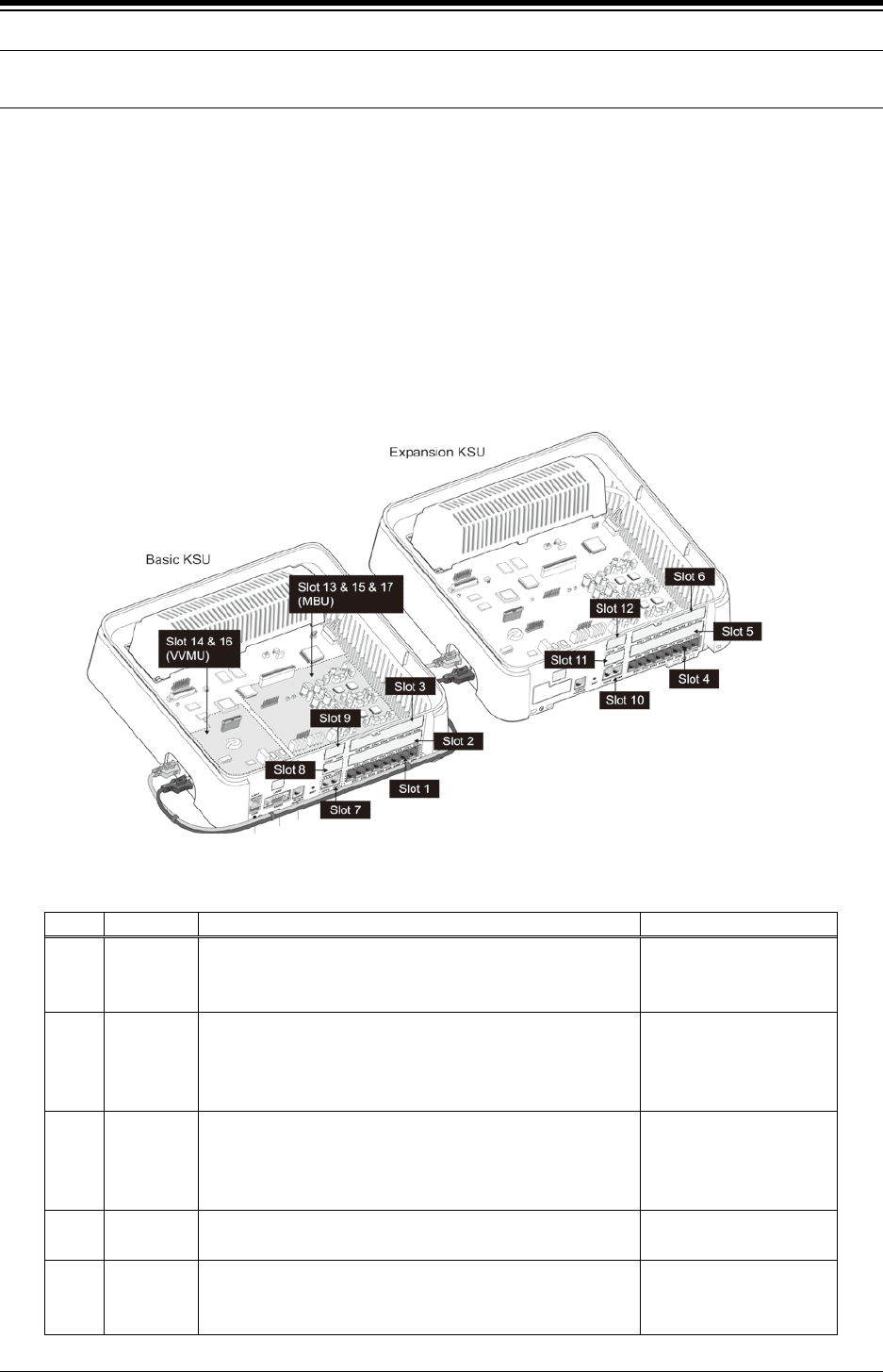
2.2 Slot configuration for eMG80
The built-in interface ports, ports of the optional Interface boards and the optional Function
boards are organized into Slots. For the built-in and optional board interfaces two Slots are
defined, a Slot for the Stations and a Slot for the CO/IP Lines. The Function boards use a single
Slot to identify the board location. The Slots are used during the initialization routines, refer to
section 2.3, to identify the installed equipment and establish the numbering for the Stations,
CO/IP lines, and Function board channels. An additional Slot (Slot 18) is used by the software
to identify the Conferencing channels as a virtual board.
The figure below depicts the Slot locations and Table 2.2-1 lists the Slots, the hardware
designation for boards applicable for the Slot and the software reference for the type of
interfaces.
Table 2.2-1 eMG80 Slot Configuration (Standard)
Slot
KSU
H/W Reference
S/W Reference
1 KSU
Built-in KSU Station interface group
KSUA and KSUI: 1-DKT & 7-Hybrid
KSUAD & KSUID: 8-DKT &-4 SLT
HYIB8
DSIB12
2 KSU
CH204 or BH104
CH408, BH208 or HYB8
CS416 or SLIB16
WTIB4
HYIB4
HYIB8
SLIB16
WTIB4
3 KSU
CH204 or BH104
CH408, BH208 or HYB8
CS416 or SLIB16
WTIB4
HYIB4
HYIB8
SLIB16
WTIB4
4 EKSU Built-in EKSU Station interface group
8-Hybrid
HYIB8
5 EKSU
CH204
CH408 or HYB8
CS416 or SLIB16
HYIB4
HYIB8
SLIB16

iPECS eMG80 & eMG800 & UCP
Administration and Programming Manual Issue 1.6
10
Slot
KSU
H/W Reference
S/W Reference
6 EKSU
CH204
CH408 or HYB8
CS416 or SLIB16
HYIB4
HYIB8
SLIB16
7 KSU
Built-in KSU Station interface group
KSUA and KSUAD: 4-CO Line
KSUI & KSUID w/PRIU:
KSUI & KSUID w/BRIU2
LCOB4
PRIB
BRIB2
8 KSU
CH204
CH408 or CS416
BH104
BH208
LCOB2
LCOB4
BRIB1
BRIB2
9 KSU
CH204
CH408 or CS416
BH104
BH208
LCOB2
LCOB4
BRIB1
BRIB2
10 EKSU Built-in EKSU Station interface group
4-CO Line
LCOB4
11 EKSU CH204
CH409 or CS416
LCOB2
LCOB4
12 EKSU CH204
CH408 or CS416
LCOB2
LCOB4
13
KSU
Built-in KSU VoIP channels
VOIU
14
KSU
VVMU VoIP channels
VOIB
15
KSU
Built-in 4-port 1-Hour AA/VM
VMIU
16
KSU
VVMU 4-port, 15-hour AA/VM
VMIB
17
Miscellaneous connections
MISU
18
KSU
Virtual Slot for Conferencing channels

iPECS eMG80 & eMG800 & UCP
Administration and Programming Manual Issue 1.6
11
2.3 Initialization
2.3.1 eMG Initialization
The system should be initialized before starting the configuration to assure a known starting point
and automatically register installed boards. Also, if the Nation Code requires modification, the
system will be initialized in the process so as to establish tones and gains appropriate for the
region. You can initialize the system using the Initialization switch (Dip-switch SW1, pole-2) in the
KSU or using the software Initialization PGM 450. Note the former must be used to change the
Nation Code as detailed section 3.3.1.
Basic Power-Up Routine
When the KSU power switch is turned On or the KSU Reset button is pressed with power ON, the
system will initiate the “Power-up” routine. During the Power-Up routine the system checks the
Initialization switch and, if the switch is in the Off position, the system will perform the basic
Power-up routine; clear all scratch-pad memory, load run-time programs, establish
communications with each registered Interface board, Function board, iPECS IP Phone and LDP
Phone, send Restart commands and load appropriate settings to the boards and terminals. The
KSU also will attempt to communicate and register the EKSU. If a registered board or terminal
does not respond after several attempts, the system places the device in an out-of-service mode
but maintains the configuration of the device. Once the Power-up routine is complete, the system
will conduct normal operations.
Registration of Boards
If the Initialization switch is in the ON position, in addition to the Power-Up routine, the system will
perform the full Initialization procedure. During initialization, the system attempts to communicate
with the board in each Slot, starting with Slot 1 and progressing sequentially through the slots, to
determine the installed equipment. If the board is installed, the Slot number (“Sequence Number”)
is registered, an “Order number” is determined and the MPB MAC and IP address are assigned.
Using “Order number”, which is the order that devices of the same type (CO/IP Line, Station, VSF
device, etc.) register, the system assigns the Station numbers and CO/IP Line numbers.
An exception to the above is the MAC and IP address of the VOIB which covers the VoIP
channels on the VVMU. The VOIB has a separate MAC address and the IP address is assigned
from the system. Note this IP address can be modified at a later time.
Once the system is operational and the database configured, the system can be expanded
manually by registering the optional boards as detailed in PGM 235, Registration Table.

iPECS eMG80 & eMG800 & UCP
Administration and Programming Manual Issue 1.6
12
Initial Station and CO Numbering
The default Station Numbering Plan assigns a Three-digit number to each station port. Starting at
the first (left) port of Slot 1, the system assigns the Station Numbers beginning at “100 (eMG80)
or 1000 (eMG800)”. The Station number increments for each port in the slot, moving to the right
until reaching the last port. The process is repeated for each Station slot (1 to 6) in sequence
assigning consecutive Station Numbers.
Note the Station Number Plan can be two to four digits and the Station Number for each port can
be modified individually.
Slots 7 to 14 are then registered and, since they are CO/IP Lines, the Order numbers 1 to 8 are
used to number the CO/IP Lines. The process is repeated for each device type.
IP Phone Registration
Unregistered iPECS IP Phones attempt to discover and register with a local (on the same LAN)
iPECS system, in this case the eMG. The phone will send a registration request to the MPB IP
address. If no response is received, the phone will send a multi-cast request. With the request,
the phone will send the MAC address. This address must be assigned in the PGM 235.
When the system receives the request, the MAC address received is compared to the
Registration table and, if matched, the phone is registered, it is given the next available sequence
number starting at “19”, and assigned the next available Station Number.
If the iPECS IP Phone is configured as a remote device, it will send a registration request to the
iPECS system at the configured IP address. When the system receives the request, it is
processed normally except the MAC address must be assigned in PGM 442 Remote Device
Register.
Default Database
Based on the installed equipment, the system populates the database with the default values,
refer to Appendix C based on Keyset administration as numbering plan 1. Once the database is
set to default, the system will conduct normal operations.

iPECS eMG80 & eMG800 & UCP
Administration and Programming Manual Issue 1.6
13
2.3.2 UCP Initialization
When power is applied to the UCP or the UCP Reset button is pressed, the system will initiate the
“Power-up” routine. During the Power-Up routine, the system will check the Initialization switch
(pole 4th of UCP Mode Dip Switch). If the switch is in the OFF position, the system will perform a
simple Power-Up routine; clear all scratch-pad memory, load run-time programs, establish
communications with each registered gateway Module and iPECS terminal, send RESTART
commands and load appropriate settings to the Modules and terminals. If a Module or terminal
does not respond after several attempts, the system places the device in an out-of-service mode
but maintains the database settings. Once the Power-up routine is complete, the system will
conduct normal operations.
If the Initialization switch is in the ON position, in place of the Power-Up routine, the system will
perform the full Initialization procedure. The initialization procedure will set the system database
to default values. Further, during the full initialization procedure, the system will establish
communications with each gateway Module and iPECS terminal for registration. This
communication will use the default device IP address and the UCP MAC address for system
identification. The system will maintain IP addresses and Sequence Numbers for previously
registered gateway Modules and iPECS terminals. These values are employed for subsequent
communication and logical assignments of numbering plans, respectively. In addition, the system
sends commands to modify all settings to the default values, including IP addresses but
maintains the existing Sequence Numbers.
After successful initialization, should a device not respond to several attempts by the system to
communicate, the system places the device in an out-of-service mode but maintains the
database. Once initialization is complete, set the initialization switch to the OFF position to protect
the database. The system must be restarted to complete the initialization.
2.3.2.1 Normal Registration Process
Module & Terminal
When power is applied and an Ethernet link is established, an unregistered device will attempt to
discover and register with a local (on the same LAN) iPECS system. The Module or terminal will
send a registration request to the assigned iPECS system (UCP) IP address. If no response is
received, the device will generate a Multi-cast discovery request for registration.
Remote iPECS Phone & Remote Services Module
A remote device, iPECS Phone or gateway Module, registers with the system using the MAC
address of the device. The MAC address must be assigned in the system database and the IP
address of the system must be assigned in the remote device. Using this address, the remote
device will attempt to register with the assigned iPECS system. When the system receives the
registration request, the MAC address is compared with the database to authenticate the remote
device. With a matching MAC, the system will accept the registration request and provide the
remote device with the appropriate settings. Note that the position of the UCP Registration switch
does not affect remote registration.

iPECS eMG80 & eMG800 & UCP
Administration and Programming Manual Issue 1.6
14
iPECS Softphone or SIP Phone
iPECS softphones (iPECS UCS Client) and SIP phones register with the system employing the
User Id and Password. When the system receives the registration request, the Id and password
are compared to the Station Login parameters. If a match is found in the Station Login Table, the
system registers the device and assigns the phone the Station Number requested (Desired
number), if available. As with remote registration, the position of the UCP Registration switch will
not affect Softphone or SIP Phone registration.
iPECS system
When power is applied, an Ethernet link is established, and the Registration switch (UCP DIP
Switch position 3) is in the ON position, the UCP will send a Multi-cast request to unregistered
gateway Modules and iPECS terminals for registration.
When the system receives a valid registration or discovery request, and the Registration switch
(UCP DIP Switch position 3) is in the ON position, the system will respond to the gateway Module
or terminal with a Registration command including the system IP and MAC address. During the
registration process, the Module or terminal will receive data from the system including a
Sequence Number, IP address, RTP characteristics, etc., as well as default settings appropriate
to the type of Module or terminal. Once registered, the Module or terminal will maintain the
system IP and MAC address in non-volatile memory and will not attempt further registrations.
If the Registration switch is in the OFF position, the system will not respond to normal registration
requests from a local device.
Sequence Number
Sequence numbers are allocated to the different device types and are assigned sequentially to
devices of the same type as shown in the Table 2.3.1 below.
Table 2.3.1 Sequence Number Allocation
Device Type Start Sequence Number End Sequence Number
Station 1 2400
CO line 2401 3000
VSF 3001 3100
MISC 3101 3200
MCIM 3201 3230
UCS server 3231 3246
IPCR and 3
rd
party server 3247 3256
WTIM 3257 3388

iPECS eMG80 & eMG800 & UCP
Administration and Programming Manual Issue 1.6
15
2.3.2.2 Replacement Module Registration
Under certain situations, it is necessary to force the registration of gateway modules and
terminals specifically when an UCP, gateway Module or iPECS Terminal is replaced. When
replacing a UCP module, gateway Modules and iPECS terminals must be forced to register with
the new system. With Module or terminal replacement, the system must recognize the
“replacement” status to transfer the existing database values.
When replacing a UCP, the local Web interface is used to access the system. The user may
update the system database using the database downloaded from the previous UCP memory.
Using the Terminal mode Command Line interface (“maint > reset ip”), the user provides the new
UCP with the IP address of the previous UCP, and issues the Register command. The new
system will then send a Uni-cast Register command to each gateway Module and iPECS terminal
registered to the previous system. This Register command will include the previous system IP
address. These commands are repeated several times only. As communication is established,
the new UCP will update the settings of the gateway Modules and iPECS terminals appropriately.
When the gateway Modules and terminals respond, they are registered to the new system.
When replacing a gateway Module, use PGM 103 “Device IP Plan” in Web admin to change the
service mode to “Out of Service”, change the MAC information for the new module, change the
service mode to in-service and install the new gateway Module.
When replacing an iPECS terminal, using PGM 103 “Device IP Plan” in Web admin change the
service mode to “Out of Service” change the MAC information for the new iPECS terminal,
change the service state to in-service, and install the new terminal.

iPECS eMG80 & eMG800 & UCP
Administration and Programming Manual Issue 1.6
16
2.4 General Admin and Menu Structure
The iPECS system can be configured to meet each customer's individual needs. System
configuration may be accomplished by entering the “Program mode” at an assigned Admin
Station or by pointing a Web Browser at the IP address of the MPB/UCP. Section 3 provides a
description of eMG system for data entry using the Admin Station. Section 4 discusses
configuration employing the Web browser. Note that some parameters are available through Web
Admin and not the Keyset Admin.
Configurable items are organized as “Data” groups with a common affect, i.e. station, system,
numbering plan, etc. Items are further grouped into “Programs” forming a multi-layered menu
structure as the following list. Each of the Program groups is assigned a three digit “Program”
(PGM) code used to access the group. The top level Data groups include:
- System ID & Numbering Plans
- Station Data
- Board Based Data
- CO Line Data
- System Data
- Station Group Data
- ISDN Line Data
- SIP Data
- Tables Data
- Networking Data
- H.323 Routing Table
- T-NET Data
- Zone Data
- Device Login
- UCS Data
- DECT Data
- Redundancy Data (for UCP600 & UCP2400)
- Hotel Data
- Green Mode for eMG
- Initialization
The default and range of values for each configurable parameter are provided in Section Web
admin programming. The index and charts are helpful references when entering data into the
system‘s database.

iPECS eMG80 & eMG800 & UCP
Administration and Programming Manual Issue 1.6
17
3. STATION ADMIN PROGRAMMING
FOR EMG
3.1 General
3.1.1 LCD & Button Functions
While in the Program mode, the Liquid Crystal Display (LCD) and Flex button LEDs of an Admin
Station are used to guide and indicate status of the feature. The dial-pad is most often used to
enter data after selecting a data item using the Flex buttons. In some cases, pressing a Flex
button will toggle the entry with the Flex button LED indicating the status (On/Off).
For Programs with multiple Flex button selections, the volume controls ([VOL UP] and [VOL
DOWN] buttons) may be used to select the next or previous item. The [SPEED] button is
generally employed as a delete button to erase existing entries. However, where noted, it may be
used to confirm a range input. Pressing the [CONF] button, returns to the 1st step of the data
entry procedure for the Program without storing unsaved entries.
The [Save] button is used to store data after entry. If there are no conflicts in the entered data,
confirmation tone will be received and the data stored. If a conflict exists, error tone is provided
and newly entered data are not saved. Generally, corrected data may be entered and stored
without restarting the entry procedure from the 1st step.
3.1.2 Alphanumeric Data Entries
In some cases, an alphanumeric entry is required. Two (2) dial-pad digits represent each
character of an alphanumeric entry, as shown in Table 3.1.2–1 below. Use the Table to
determine the two digits that must be entered from the dial-pad for each character.
Table 3.1.2-1 ALPHANUMERIC DIAL-PAD ENTRIES
1
Q – 11
Z – 12
. – 13
1 – 10
2
A - 21
B - 22
C - 23
2 - 20
3
D - 31
E - 32
F - 33
3 - 30
4
G – 41
H - 42
I - 43
4 - 40
5
J - 51
K - 52
L - 53
5 - 50
6
M - 61
N - 62
O - 63
6 - 60
7
P - 71
R - 72
S - 73
Q - 7*
7 - 70
8
T - 81
U - 82
V - 83
8 - 80
9
W - 91
X - 92
Y - 93
Z - 9#
9 - 90
*
Blank - *1
: - *2
, - *3
0
0-00
#
#
iPECS eMG80 & eMG800 & UCP
Administration and Programming Manual Issue 1.6
18
3.2 Data Entry Mode
Limited data entry can be accomplished from an Admin Station or station assigned for data entry
(Station Attributes III PGM 113, Flex button 1). After initialization and registration, any enabled
iPECS IP or LDP Phone may access the system database. In addition, as default, there is no
Station Admin password defined. To enter the Program mode from the Admin Station follow the
procedure below. In the left column of the chart are the LCD displays and in the right column are
step-by-step instructions to modify database items.
PROCEDURE:
STATION 100 (T)
04 SEP 01 02:49 PM
1. Press the [PGM] button.
Dial ‘*‘ and ‘#’.
ENTER ADMIN PASSWORD
Enter the Admin password. Confirmation tone is received. As
a default there is no password and this step is skipped.
ADMIN PROGRAM START
ENTER PGM NUMBER
To select a program, use the instructions in the following
sections, starting with “Press the [PGM] button” and dial the
specified Admin Program code.

iPECS eMG80 & eMG800 & UCP
Administration and Programming Manual Issue 1.6
19
3.3 Procedure for Data Entry
The following sections provide specific instructions for entering data from the Admin Station once
in the Program mode. Each section provides descriptive information, step-by-step instructions
and Tables for determining appropriate entries.
3.3.1 System ID — PGM 100
Under System ID, the country is identified using the international dial codes (NATION CODE). If
the NATION code requires changing, the system must be initialized to restructure memory and
create the country specific defaults, gain, frequencies and other system characteristics specific to
the country and regional regulatory requirements.
To change the NATION Code on eMG:
Set the MPB Dip-switch 1 pole 2 to the ON position,
Follow the procedure below to modify the NATION code
Press the reset button on the KSU, power the system Off and On, or use PGM 450 to
initialize the system.
After initialization, reset switches as needed, Dip-switch 1 pole 2 should be OFF.
A twenty-four (24) character SITE NAME and the local Area Code are also defined in this
program. The SITE NAME is primarily useful for the installer/programmer as a reference to the
customer.
In addition, under this program the system can be programmed to select one of eight (8) Flexible
Number Plans, refer to Appendix B. Individual items from the selected Numbering Plan can be
changed under Flexible Numbering Plan part A to D – PGM 106 to 109- in section 3.3.2.5.
PROCEDURE:
SYSTEM ID
PRESS FLEX KEY (1-6)
1. Press the [PGM] button and dial 100.
Select the desired Flex button (1~5), refer to Table 3.3.1-1.
For COUNTRY CODE, refer to Table 3.3.1-2 for appropriate
entries.
Use the dial-pad to enter desired System Id data. For
System Reset, button 5, press [Save] to reset the System Id
to default.
To store the System Id data press the [Save] button.
Table 3.3.1-1 SYSTEM ID (PGM 100)
BTN − DISPLAY REMARK RANGE DEFAULT
1 COUNTRY CODE
1
Refer to Table 3.3.1-2 below.
Note system must be re-initialized if
changed.
4 digits 1

iPECS eMG80 & eMG800 & UCP
Administration and Programming Manual Issue 1.6
20
Table 3.3.1-1 SYSTEM ID (PGM 100)
BTN − DISPLAY REMARK RANGE DEFAULT
2 CUSTOMER SITE NAME
………………………………….
Refer to Table 3.1.2-1 for alphanumeric
dial-pad entries.
24
character
3 MY MULTI AREA CODE
ENTER TABLE NO(00-40)
Enter the area code of the installed site. 6 digits
4 NUMBERING PLAN (1-9)
1
Refer to Appendix B for details of
Numbering Plan selection.
1-9 1
5 PREFIX USAGE
(1:ON/0:OFF) : OFF
Enable/Disable 8-digit Station Numbering
Plan. Assign the Prefix codes in the 8-
Digit Numbering Table (PGM238).
0: OFF
1: ON
OFF
6 SYSTEM ID
SYSTEM RESET
Returns the System Id to default.
Table 3.3.1-2 COUNTRY CODES
COUNTRY CODE COUNTRY CODE COUNTRY CODE
America
1
Argentina
54
Australia
61
Bahrain
973
Bangladesh
880
Belgium
32
Bolivia
591
Brazil
55
Brunei
673
Burma
95
Cameroon
237
Chile
56
China (Taiwan)
886
CIS
7
Colombia
57
Costa Rica
506
Cyprus
357
Czech
42
Denmark
45
Ecuador
593
Egypt
20
El Salvador
503
Ethiopia
251
Fiji
679
Finland
358
France
33
Gabon
241
Germany
49
Ghana
233
Greece
30
Guam
671
Guatemala
502
Guyana
592
Haiti
509
Honduras
504
Hong Kong
852
India
91
Indonesia
62
Iran
98
Iraq
964
Ireland
353
Israel
972
Italy
39
Japan
81
Jordan
962
Kenya
254
Korea
82
Kuwait
965
Liberia
231
Libya
218
Malta
356
Luxembourg
352
Malaysia
60
Morocco
212
Mexico
52
Monaco
377
Nigeria
234
Netherlands
31
New Zealand
64
Pakistan
92
Norway
47
Oman
968
Paraguay
595
Panama
507
P.N.G
675
Portugal
351
Peru
51
Philippines
63
Senegal
221
Qatar
974
Saudi Arabia
966
Spain
34
Singapore
65
South Africa
27
Sweden
46
Sri Lanka
94
Swaziland
268
Tunisia
216
Switzerland
41
Thailand
66
United Kingdom
44
Turkey
90
U.A.E.
971
Y.A.R.
967
Uruguay
598
Venezuela
58
iPECS eMG80 & eMG800 & UCP
Administration and Programming Manual Issue 1.6
21
3.3.2 NUMBERING PLANS DATA — PGM 102 to 109
3.3.2.1 System IP Address Plan — PGM 102
The System IP Address Plan sets several IP addresses including the KSU LAN port IP address
(MPB IP Address) required for external VoIP calls, the IP address for the router, and the system‘s
internal private IP address Plan. Note that the MPB and Router addresses and sub-net mask
must be a routable IP address for access to an external VoIP network, remote access by a
gateway/board or terminal and remote Web access. The VOIB must also have a routable IP
address for access to/from an external VoIP network or remote user.
When Automatic IP Assignment, button 7, is enabled, the system will assign IP addresses to
each local terminal and the VOIB using the assigned System IP address range. These addresses
are used for communications between the system and the VOIB and terminals.
The system may be connected to a LAN that is segmented by two separate private IP address
schemes. This segmenting technique is often used to separate voice and data devices.
However, with this segmenting technique, the system would normally treat the segmented
Terminals such as iPECS Soft Phones, as remote devices, using valuable WAN bandwidth.
Assigning the “Second Sys IP address” with valid IP address from the second segment permits
the system to communicate with the devices directly over the LAN.
iPECS can be installed behind a NAPT server, if the NAPT server provides fixed address
translation and port forwarding to the system. In this case, the system will employ the “Firewall IP
address”, button 10, as the fixed public IP address for communication with remote devices. This
address must be assigned as the “MPB” address in the remote device.
PROCEDURE:
SYSTEM IP ADDRESS PLAN
PRESS FLEX KEY (01-17)
1. Press the [PGM] button and dial 102.
Select the desired button 1~19, refer to Table 3.3.2.1-1.
Use the dial-pad to enter desired IP addresses. Use an “*” to
enter a dot (“.”)
Press the [Save] button to store IP address entries.
Table 3.3.2.1-1 SYSTEM IP ADDRESS PLAN (PGM 102)
BTN DISPLAY DEFAULT REMARK
1 MPB IP ADDRESS
10 . 10 . 10 . 2
10.10.10.2 This is the IP address of the KSU LAN port A. A
Public IP Address is required for remote user and
external VoIP network access. IPv4 format.
2 MPB SUB NET MASK
255.255.255.0
255.255.0.0
3 ROUTER IP ADDRESS
10 . 10 . 10 . 1
10.10.10.1 IP Address of router for external network (WAN)
access. Required for shared voice and data LAN,
external VoIP and remote Web access.
4 SYSTEM START IP ADDRESS
10.10.10.10
10.10.10.10 Start of range for private IP addresses assigned by
the system to Modules/Terminals.
iPECS eMG80 & eMG800 & UCP
Administration and Programming Manual Issue 1.6
22
Table 3.3.2.1-1 SYSTEM IP ADDRESS PLAN (PGM 102)
BTN DISPLAY DEFAULT REMARK
5 SYSTEM END IP ADDRESS
10.10.10.254
10.10.10.254 End of range for private IP addresses assigned by
the system to Modules/Terminals.
6 SYSTEM SUB NET MASK
255.255.255.0
255.255.0.0
7 AUTOMATIC IP ASSIGN
(1:ON/0:OFF): ON
ON The system will automatically assign IP addresses
to modules and terminals (ON) or, when OFF, IP
addresses are assigned manually in PGM 103
Device IP Address Plan.
8 SECOND SYS IP ADDRESS
0 . 0 . 0 .0
0.0.0.0 When devices are located on a different private
address on the same net, enter the MPB IP
address for the second LAN.
9 SECOND SYS SUB NET MASK
255.255.255 .0
255.255.255.0
10 FIREWALL IP ADDRESS
0 . 0 . 0 .0
0.0.0.0 When the system is installed behind a NAPT
server, the fixed IP Address provided by the NAPT
server must be assigned in this field.
Also, use this IP address for the MPB address in
remote devices.
11 FIRST START MAC ADDR
000000000000
00.00.00.0
0.00.00
A range of MAC addresses can be entered to
register devices. This entry is the start address of
the first range.
12 FIRST END MAC ADDR
000000000000
00.00.00.0
0.00.00
A range of MAC addresses can be entered to
register devices. This entry is the end address of
the first range.
13 SECOND START MAC ADDR
000000000000
00.00.00.0
0.00.00
A range of MAC addresses can be entered to
register devices. This entry is the start address of
the second range.
14 SECOND END MAC ADDR
000000000000
00.00.00.0
0.00.00
A range of MAC addresses can be entered to
register devices. This entry is the end address of
the second range.
15 SYSTEM IP ADDRESS PLAN
SYSTEM RESET
Returns System IP Address Plan to default values.
16 MPB DNS IP ADDR
0 . 0 . 0 .0
0.0.0.0 IP Address of Domain Name Server, which iPECS
will use to resolve URL to an IP address. The DNS
provides the resolution after receiving the name
from iPECS.
17 MPB DHCP
(1:ON/0:OFF) : OFF
OFF Enable/Disable DHCP client function for the MPB.

iPECS eMG80 & eMG800 & UCP
Administration and Programming Manual Issue 1.6
23
3.3.2.2 Device IP Address Plan -PGM 103
TDM board is registered with own slot number. It is registered automatically without any
configuration.
To register an IP device:
As IP gateway/board and terminals register to the iPECS, a logical slot number is assigned,
which indicates the order of registration. Also, based on the type of device (CO/IP gateway/board,
Terminal) the system assigns a logical Sequence Number. Thus, Sequence Numbers for CO
gateway/board, Terminals are independently assigned based on the type of gateway/board.
These Sequence Numbers are employed to provide a relationship between the physical MAC
address and the logical port numbers of the device.
The system may assign a default private IP address to each Sequence Number. If desired, this
program may be used to modify the assigned IP address for each gateway/board and iPECS
Phone.
Each local gateway/board and terminal can be assigned for “Direct Send”. With Direct Send
enabled, the system will employ the Ethernet MAC address, layer 2 switching to eliminate the
need for IP traffic overhead, reducing overall LAN traffic.
The system normally employs IP multi-cast protocol to respond to a registration request from a
gateway/board or terminal. When the device is separated from the system by a router, the system
must use the IP uni-cast protocol. This is established by the “Local Device” assignment.
When disabled (Off), the system will send an IP uni-cast message to the device in response to a
registration request.
PROCEDURE:
DEVICE IP ADDRESS PLAN
PRESS FLEX KEY (1-7)
1. Press the [PGM] button and dial 103.
Select the desired Flex button.
Button 1: CO & VOIP Gateway/Board
Button 2: Stations
Button 3: MISU
Button 4: VMIU, VMIB
Button 5: MCIB
Button 6: SYSTEM RESET
Button 7: WTIB
Use the [VOL UP] and [VOL DOWN] buttons to see next/
previous IP Address. Refer to Table 3.3.2.2-1 for display
information.
iPECS eMG80 & eMG800 & UCP
Administration and Programming Manual Issue 1.6
24
PROCEDURE:
Press Flex 1~6 to select the Sub-menu item desired. See
Table 3.3.2.2-1.
Button 1: IP address
Button 2: MAC address
Button 3: ARP
Button 4: REGISTRATION
Button 5: CPU Type
Button 6: Device (Board) ID
Use the dial-pad to enter desired data. For IP and MAC
addresses, an “*” is used to enter a dot (“.”)
Press the [Save] button to store the data entry.
Table 3.3.2.2-1 DEVICE & STATION ADDRESS PLAN (PGM 103)
BTN DISPLAY FEATURE DEFAULT
1 001-001 :B40EDCBF5606
VOIP 1 :10 .10 .10 .2
LCD shows:
Line 1 Sequence Number, 2 or 3 digits MAC
Address, 12 digits
Line 2 Module Type, 4 characters First Logical
port number IP Address, 7~12 digits
CO & VoIP
board IP
address set
sequentially,
from the range
in PGM 102.
1–1 SET IP ADDRESS
VOIP 1 : 10.10.10.2
Use Flex button 1 to set the device‘s IP address
in IP v4 format.
10.10.10.10~254
1–2 SET MAC ADDRESS
001-001 : B40EDCBF5606
Use Flex button 2 to enter the device‘s MAC
address in the system memory.
None
1–3 ARP
(1:ON/0:OFF): OFF
Use Flex button 3 to enable/disable Direct Send
mode, which employs layer 2 switching to local
devices.
OFF
1–4 REGISTRATION
(0:UCAST/1:MCAST): MCAST
Use Flex button 4 to enable/disable Local
Device Mode, which defines the device as on a
common LAN with the MPB.
MCAST
1–5 CPU TYPE
MSC1K
Flex button 5 displays the type of CPU
employed in the device.
1–6 DEVICE(BOARD) ID
PRIB
Flex button 6 displays the Board type
designation.
2 001-001 : B40EDCBF5606
KTU 100 :10.10.10.10
LCD shows:
Line 1 Sequence Number, 3 digits MAC
Address, 12 digits
Line 2 Station Type, 3 characters Station
Number, 2~4 digits IP Address, 7~12 digits
Station IP
address set
sequentially,
from the range
in PGM 102.
2–1 SET IP ADDRESS
KTU 100 :10.10.10.10
Use Flex button 1 to set the device‘s IP address
in IP v4 format.
10.10.10.10~254
iPECS eMG80 & eMG800 & UCP
Administration and Programming Manual Issue 1.6
25
Table 3.3.2.2-1 DEVICE & STATION ADDRESS PLAN (PGM 103)
BTN DISPLAY FEATURE DEFAULT
2–2 SET MAC ADDRESS
001-001 : B40EDCBF5606
Use Flex 2 button to enter the device‘s MAC
address into system memory.
None
2–3 ARP
(1:ON/0:OFF): OFF
Use Flex button 3 to enable/disable Direct Send
mode, which employs layer 2 switching to local
devices.
OFF
2–4 REGISTRATION
(0:UCAST/1:MCAST): MCAST
Use Flex button 4 to enable/disable Local
Device Mode, which defines the device as on a
common LAN with the MPB.
MCAST
2–5 CPU TYPE
MSC1K
Flex button 5 displays the type of CPU
employed in the device.
2–6 DEVICE(BOARD) ID
HYIB
Flex button 6 displays the terminal type
designation.
3 001-017 : B40EDCBF5606
MISU :10.10.10.2
LCD shows:
Line 1 Sequence Number, 2 digits MAC
Address, 12 digits Line 2 “MISU” IP Address,
7~12 digits.
IP address of
MISU.
Functions in the
system‘s MPB
set
automatically,
3–1 SET IP ADDRESS
MISU :10.10.10.2
Use Flex button 1 to set the device‘s IP address
in IP v4 format.
10.10.10.10~254
3–2 SET MAC ADDRESS
001-003 : B40EDCBF5606
Use Flex button 2 to enter the device‘s MAC
address into system memory.
None
3–3 ARP
(1:ON/0:OFF): OFF
Use Flex button 3 to enable/disable Direct Send
mode, which employs layer 2 switching to local
devices.
OFF
3–4 REGISTRATION
(0:UCAST/1:MCAST): MCAST
Use Flex button 4 to enable/disable Local
Device Mode, which defines the device as on a
common LAN with the MPB.
MCAST
3–5 CPU TYPE
MSC1K
Flex button 5 displays the type of CPU
employed in the device.
3–6 DEVICE(BOARD) ID
MISU
Flex button 6 displays the MISU type
designation.
4 001-015 : B40EDCBF5606
VMIU :10.10.10.2
LCD shows:
Line 1 Sequence Number, 2 digits MAC
Address, 12 digits Line 2 device type and IP
address.
.
4–1 SET IP ADDRESS
VMIU :10.10.10.2
Use Flex button 1 to set the device‘s IP address
in IP v4 format.
10.10.10.10~254
iPECS eMG80 & eMG800 & UCP
Administration and Programming Manual Issue 1.6
26
Table 3.3.2.2-1 DEVICE & STATION ADDRESS PLAN (PGM 103)
BTN DISPLAY FEATURE DEFAULT
4–2 SET MAC ADDRESS
001-015 : B40EDCBF5606
Use Flex button 2 to enter the device‘s MAC
address into system memory.
None
4–3 ARP
(1:ON/0:OFF): OFF
Use Flex button 3 to enable/disable Direct Send
mode, which employs layer 2 switching to local
devices.
OFF
4–4 REGISTRATION
(0:UCAST/1:MCAST): MCAST
Use Flex button 4 to enable/disable Local
Device Mode, which defines the device as on a
common LAN with the MPB.
MCAST
4–5 CPU TYPE
MSC1K
Flex button 5 displays the type of CPU
employed in the device.
4–6 DEVICE(BOARD) ID
VMIU
Flex button 6 displays the type designation.
5 001-018 : FFFF0000FFFF
MCIB : 10 .10 .10 .2
LCD shows:
Line 1 Sequence Number, 2 digits MAC
Address, 12 digits Line 2 device type and IP
address.
5–1 SET IP ADDRESS
MCIB :10.10.10.2
Use Flex button 1 to set the device‘s IP address
in IP v4 format.
10.10.10.10~254
5–2 SET MAC ADDRESS
001-018 : FFFF0000FFFF
Use Flex button 2 to enter the device‘s MAC
address into system memory.
None
5–3 ARP
(1:ON/0:OFF): OFF
Use Flex button 3 to enable/disable Direct Send
mode, which employs layer 2 switching to local
devices.
OFF
5–4 REGISTRATION
(0:UCAST/1:MCAST): MCAST
Use Flex button 4 to enable/disable Local
Device Mode, which defines the device as on a
common LAN with the MPB.
MCAST
5–5 CPU TYPE
MS828
Flex button 5 displays the type of CPU
employed in the device.
5–6 DEVICE(BOARD) ID
MCIB_V
Flex button 6 displays the type designation,
MCIB_V.
6 DEVICE IP ADDRESS PLAN
SYSTEM RESET
If the [Save] button is pressed, the system will
reset and restart.
7 001-003 : 00405A142C67
WTIB : 10:10:10:14
LCD shows:
Line 1 Sequence Number, 2 digits MAC
Address, 12 digits Line 2 “WTI4” and IP
Address, 7~12 digits.
7–1 SET IP ADDRESS
WTIB :10.10.10.14
Use Flex button 1 to set the device‘s IP address
in IP v4 format.
10.10.10.10~254
iPECS eMG80 & eMG800 & UCP
Administration and Programming Manual Issue 1.6
27
Table 3.3.2.2-1 DEVICE & STATION ADDRESS PLAN (PGM 103)
BTN DISPLAY FEATURE DEFAULT
7–2 SET MAC ADDRESS
001-003 : 00405A142C67
Use Flex button 2 to enter the device‘s MAC
address into system memory.
None
7–3 ARP
(0:ON/1:OFF): OFF
Use Flex button 3 to enable/disable ARP, ARP
OFF enables Direct Send, which employs layer
2 switching to local devices.
OFF
7–4 REGISTRATION
(0:UCAST/1:MCAST):MCAST
Use Flex button 4 to disable/enable Local
Device Mode, which defines the device as on a
common LAN with the system. MCAST enables
Local Device Mode.
MCAST
7–5 CPU TYPE
MS828
Flex button 5 displays the type of CPU
employed in the device.
7–6 DEVICE(BOARD) ID
WTIB
Flex button 6 displays the type designation,
WTIB.
3.3.2.3 CO Device Sequence Number -PGM 104
The system uses the Sequence Number to assign logical (software) port numbers. This
Sequence Number relates the hardware and software port numbers for each device.
PROCEDURE:
001 002 003 004 005 006
009 007 008 013 014 . . .
1. Press the [PGM] button and dial 104.
001 002 003 004 005 006
009 007 008 013 014 . . .
Press the Flex button (1~6) for the desired Sequence
Number, use the [VOL UP] and [VOL DOWN] buttons for
the next/previous set of six Sequence Numbers.
001 002 003 004 005 006
009 007 008 013 014 . . .
Using the dial pad, enter new slot numbers. Note slot
numbers cannot be duplicated and duplicates will cause an
error. The [SPEED] button may be used to erase the slot
number associated with the selected Sequence Number.
Press the
[Save]
button to store the new Slot data.

iPECS eMG80 & eMG800 & UCP
Administration and Programming Manual Issue 1.6
28
3.3.2.4 Flexible Station Numbering Plan -PGM 105
Each LDP Phone, iPECS IP Phone and SLT is assigned a Sequence Number during the
registration process. The station Sequence Number is a 3-digit number starting at 001, which is
incremented as each terminal device is registered. At registration, station numbers increment
sequentially with the Sequence Number and are assigned starting at station 100 for Sequence
Number 001. The Station Numbering Plan allows the station numbers to be Three (3) to eight (8)
digits in length.
PROCEDURE:
001 002 003 004
100 101 102 103
1. Press the [PGM] button and dial 105.
001 002 003 004
… … … …
Use either of the two methods below to change the station
number associated with a Sequence Number. Note pressing
the [SPEED] button twice clears all station number
assignments.
The [VOL UP] / [VOL DOWN] buttons are used to view
the next/previous 2 station Sequence Numbers.
Range entry:
Using the dial-pad, enter a station number range (first &
last station number). The two station numbers must be of
the same length, 2~8 digits. The range assignment
begins with the first station number shown by the LCD
and continues to the end of the entered range.
Single entry:
4.1 Press Flex button 1~4 to select the desired Sequence
Number from the two shown by the LCD.
4.2 Dial new station number.
Press the
[Save]
button to store the new station numbers.
iPECS eMG80 & eMG800 & UCP
Administration and Programming Manual Issue 1.6
29
3.3.2.5 Flexible Numbering Plan part A to D - PGM 106 to 109
Feature dial codes for the system can be assigned using the system‘s Flexible Numbering Plan.
Feature codes should be one (1) to four (4) digits in length and must not conflict. For example,
Feature dial codes 53 and 536 represent a conflict. The system will generate error tone and will
not update the database. Table 3.3.2.5-1 to Table 3.3.2.5-4 below show the defaults for the 1st
base Numbering Plan. Appendix B provides the default values for each of the 9 basic Numbering
Plans, select the base Numbering Plan in PGM 100. The default is based on Numbering plan 1.
PROCEDURE:
FLEX NUMBERING PLAN A
PRESS FLEX KEY (01-24)
1. Press the [PGM] button and dial:
106 for part A
107 for part B
108 for part C
109 for part D.
Select the desired button (01~24); refer to Table 3.3.2.5-1 to
Table 3.3.2.5-4 for
PGM
106 to 109 respectively.
Use the dial-pad to enter desired data. Where a range is
required, input the first and last numbers in the range.
Press the [Save] button to store the new Numbering Plan
data.
Table 3.3.2.5-1 FLEXIBLE NUMBERING PLAN PART A (PGM 106)
BTN DISPLAY FEATURE DEFAULT
1 INT PAGE ZONES
START& END:301-335
Internal Page Zone access codes. eMG80:301~335
eMG800:301~400
2 INT ALL CALL
ENTER NEW #:543
Internal All Call Page access code. 543
3 MEET ME PAGE
ENTER NEW #:544
Meet-Me-Page answer code. 544
4 EXT PAGE ZONE 1
ENTER NEW #:545
External Page Zone 1 access code. 545
5 UNUSED
6 EXT ALL CALL
ENTER NEW #:548
External All Call Page access code. 548
7 ALL CALL PAGE
ENTER NEW #:549
All Call Page access code. 549
iPECS eMG80 & eMG800 & UCP
Administration and Programming Manual Issue 1.6
30
Table 3.3.2.5-1 FLEXIBLE NUMBERING PLAN PART A (PGM 106)
BTN DISPLAY FEATURE DEFAULT
8 SMDR ACT CODE ENTER
ENTER NEW #:550
Dial code to signify the start of an SMDR
Account Code.
550
9 FLASH CMD TO CO
ENTER NEW #:551
Dial code to generate a Flash on the
active CO Line.
551
10 SLT LAST SPD DIAL
ENTER NEW #:552
SLT Last Number Redial feature access
code.
552
11 DND
ENTER NEW #:553
Dial code to activate Do-Not-Disturb. 553
12 CALL FWD
ENTER NEW #:554
Dial code to activate Call Forward. 554
13 SPD DIAL PGM
ENTER NEW #:555
Speed Dial programming access dial
code for SLTs.
555
14 MSG WAIT ENABLE
ENTER NEW #:556
Dial code to activate a Message
Wait/Call Back.
556
15 MSG WAIT RETURN
ENTER NEW #:557
Dial code to return a Message Wait/Call
Back.
557
16 SPD DIAL ACCESS
ENTER NEW #:558
SLT Speed Dial access code. 558
17 DND/FWD CANCEL
ENTER NEW #:559
Dial code to cancel DND/FWD/MSG
Wait.
559
18 CO SYS HOLD
ENTER NEW #:560
Dial code to place a CO call on System
Hold.
560
19 SLT PGM MODE ENTER
ENTER NEW #:561
User program mode entry dial code for
SLTs.
561
20 ATTD UNAVAILABLE
ENTER NEW #:562
Dial code to place attendant in the
“unavailable” mode, attendant only.
562
21 ALARM RESET
ENTER NEW #:565
Dial code to terminate Alarm contact
signal.
565
22 GROUP CALL PICK-UP
ENTER NEW #:566
Group Call Pick-up dial code. 566
23 UNIVERSAL ANSWER
ENTER NEW #:567
Universal Night Answer dial code. 567
iPECS eMG80 & eMG800 & UCP
Administration and Programming Manual Issue 1.6
31
Table 3.3.2.5-1 FLEXIBLE NUMBERING PLAN PART A (PGM 106)
BTN DISPLAY FEATURE DEFAULT
24 ACCNT CODE WITH BIN
ENTER NEW #:568
Dial code for entering an Account code. 568
Table 3.3.2.5-2 FLEXIBLE NUMBERING PLAN PART B (PGM 107)
BTN DISPLAY FEATURE DEFAULT
1 WALKING COS
ENTER NEW #:569
Dial code to activate Walking Class-of-
Service.
569
2 ACD AGENT ON/OFF DUTY
ENTER NEW #:571
Dial code to toggle ACD Agent or
Supervisor ON and OFF duty.
571
3 ACD SUPERVISOR LOGIN
ENTER NEW #:572
Supervisor login dial code. 572
4 ACD SUPERVISOR LOGOUT
ENTER NEW #:573
Supervisor logout dial code. 573
5 ACD HELP CODE
ENTER NEW #:574
Agent code requesting Supervisor help
and Supervisor Help request Response
code.
574
6 ACD CALLS IN QUEUE
ENTER NEW #:575
Dial code to display calls in queue. 575
7 ACD SUPERVISOR STATUS
ENTER NEW #:576
Dial code to display group status. 576
8 ACD SUPERVISOR MONITOR
ENTER NEW #:577
Dial code to activate Supervisor monitor. 577
9 ACD REROUTE QCALL ANS
ENTER NEW #:578
Dial code to reroute call after answer. 578
10 ACD REROUTE QCALL NO AN
ENTER NEW #:579
Dial code to reroute call prior to answer. 579
11 CAMP-ON ANSWER
ENTER NEW #:621
Dial code to answer a Camped On call. 621
12 CALL PARK LOCATIONS
START#:#601-#619
Dial code to place/retrieve a call in a
Park location.
eMG80:#601~#619
eMG800:#601~#800
13 STA GRP PILOT NUMBER
START #:401-440
Station group pilot numbers. eMG80:401~440
eMG800:401~500
iPECS eMG80 & eMG800 & UCP
Administration and Programming Manual Issue 1.6
32
Table 3.3.2.5-2 FLEXIBLE NUMBERING PLAN PART B (PGM 107)
BTN DISPLAY FEATURE DEFAULT
14 STA USER VSF FEATURES
ENTER NEW #:*66
VSF feature access code. *66
15 CALL COVERAGE RING
ENTER NEW #:76
Code for Call Coverage button. 76
16 DIRECT CALL PICK-UP
ENTER NEW #:*77
Dial code to activate Directed Call Pick-
up.
*77
17 ACCESS CO GROUP FEAT
ENTER NEW #:89
Dial code to access a CO Line or IP
channel from a CO/IP group.
89
18 ACCESS IND CO/IP FEAT
ENTER NEW #:88
Dial code to access a specific CO Line. 88
19 ACCESS HELD CO/IP FEAT
ENTER NEW #:8*
Dial code to access last held CO Line or
IP channel from Hold.
8*
20 ACCESS HELD IND CO/IP
ENTER NEW #:8#
Dial code to access a specific CO Line/IP
channel from Hold.
8#
21 ACCESS CO IN 1ST CO GRP
ENTER NEW #:9
Dial code to access the 1st available CO
Line in any accessible group.
9
22 ATTENDANT CALL
ENTER NEW #:0
Dial code to call an Attendant. 0
23 VM MSG WAIT ENABLE
ENTER NEW #:*8
Dial code for external Voice mail to
activate Message Wait indication.
*8
24 VM MSG WAIT CANCEL
ENTER NEW #:*9
Dial code for external Voice Mail to
deactivate Message Wait indications.
*9
Table 3.3.2.5-3 FLEXIBLE NUMBERING PLAN PART C (PGM 108)
BTN DISPLAY FEATURE DEFAULT
1 DOOR OPEN 1
ENTER NEW #:#*1
Dial code to activate Door 1 contact
(open door 1)
#*1
2 DOOR OPEN 2
ENTER NEW #:#*2
Dial code to activate Door 2 contact
(open door 2).
#*2

iPECS eMG80 & eMG800 & UCP
Administration and Programming Manual Issue 1.6
33
Table 3.3.2.5-4 FLEXIBLE NUMBERING PLAN PART D (PGM 109)
BTN DISPLAY FEATURE DEFAULT
1 MCID REQUEST
ENTER NEW #:*0
Dial code to activate Malicious Call ID
Request in ISDN Supplementary service.
Not available in USA version.
*0
2 AME FEATURE
ENTER NEW #: 564
Dial code to assign an Answering
Machine Emulation Flex button.
564
3 US-CONF TMR EXTENSION
ENTER NEW #:##
Dial code to extend Unsupervised
conference time.
##
4 PTT GROUP LOGIN/OUT
ENTER NEW #:#0
Push-To-Talk group login and logout dial
code. The station must have a PTT
button for proper operation.
#0
5 ACD AGENT P LOGIN
ENTER NEW #:581
ACD Agent Primary Login code. 581
6 ACD AGENT P LOGOUT
ENTER NEW #:582
ACD Agent Primary Logout code. 582
7 ACD AGENT S LOGIN
ENTER NEW #:583
ACD Agent Secondary Login code. 583
8 ACD AGENT S LOGOUT
ENTER NEW #:584
ACD Agent Secondary Logout code. 584
9 ACD AGENT WRAPUP END
ENTER NEW #:585
ACD Agent wrap-up end code. 585
10 TNET CM LOGIN/OUT
ENTER NEW #:586
When Central Control networking (TNET)
is employed, a station can be manually
logged in or out of the Central system
using this code.
586
11 ENTER INTO CONF-ROOM
ENTER NEW #:59
Code for a station to enter a conference
room.
59
12 ENTER INTO CONF-GROUP
ENTER NEW #:68
Code to open a conference group. 68
13 STATION ICR
ENTER NEW #:587
Code to activate Station ICR. 587
14 PICK UP GROUP PICK-UP
ENTER NEW #:588
Pick Up Group Call Pick-up dials code. 588
15 EMERGENCY PAGE
ENTER NEW #:589
Code for emergency page. 589
16 REMOTE MEX CONTROL
ENTER NEW #:580
Code to control the mobile extension
settings remotely.
580

iPECS eMG80 & eMG800 & UCP
Administration and Programming Manual Issue 1.6
34
Table 3.3.2.5-4 FLEXIBLE NUMBERING PLAN PART D (PGM 109)
BTN DISPLAY FEATURE DEFAULT
17 ALL GR AGENT ON/OFF DUT
ENTER NEW #:58*
Code to change the state of the Agent
ON/Off duty in all hunt groups.
58*
18 SLT ACNR CODE
ENTER NEW #:58#
In SLT, user can ACNR feature by using
this numbering plan.
58#
19 ACD SUPERVISOR RING MODE
ENTER NEW #:570
Code to check and change ACD group
Ring mode by ACD group supervisor.
570
20 COMPANY DIRECTORY NAME
ENTER NEW #:563
Code to check and change recording
station subscribe name of Company
Directory feature. (USA Only)
563
21 ISDN SUPP HOLD
ENTER NEW #:57*
ISDN Supplementary Service for HOLD. 57*
22 ISDN SUPP CONF
ENTER NEW #:57#
ISND Supplementary Service for
Conference (Not supported).
57#
23 FORCED SEIZE BUSY STN/CO
ENTER NEW #:56*
Busy Station / CO can be connected with
entering this Code.
56*
24 ADDED FLEX NUMBER PLAN
PRESS FLEX KEY (1-5)
24-1
OVERRIDE DND/CFW
ENTER NEW #:56#
[56#] + Station number, then the station’s
DND or CFW setting will be overridden.
56#
24-2
CANCEL CALL BACK
ENTER NEW #:….
It is used to cancel call back.
24-3
XFER TO VSF ANNC NO
ENTER NEW #:55*
When a station is talking over a CO line
User, [Transfer] + [55*] + Valid system
announcement (01-70), then Outside
user can hear system announcement,
and system starts DISA service.
55*
24-4 CCR
ENTER NEW #:#2
It is used in digit conversion. #2
24-5 UCS SYS CONF GRP JOIN
ENTER NEW #:5*0
It is used to join UCS conference group
by entering the code.
5*0
iPECS eMG80 & eMG800 & UCP
Administration and Programming Manual Issue 1.6
35
3.3.2.6 8-Digit Table
We can support it more 4 digits for station number. Station numbering should not conflict with
numbering plan. It is consist of prefix digits and add digits. Prefix digits can have up to 4 digits
and Add digits can have up to 4 digits.
PROCEDURE:
DIGIT 8 TBL
ENTER TBL NO(01-10)
1. Press the [PGM] button and dial 238.
Digit 8 TBL 1 : Empty
Use the dial-pad to enter the desired table number.
Press the desired Flex button; refer to Table 3.3.2.6-1.
Use the dial-pad to enter the required data.
Press the
[Save]
button to store the data entry.
Table 3.3.2.6-1 8-Digit Table (PGM 238)
BTN ATTRIBUTE/DISPLAY DESCRIPTION RANGE DEFAULT
1 TBL 1 : SET 8 digit
8 Digit 1 : …....
The user may be allowed to enter
the prefix digits using character
assign method. (ex : 4+0 → 4)
Up to 4 digits N/A
2 TBL 1: SET ADD DIGIT
ADD DIGIT : 0
The user can be allowed to add
digits. (ex: if it’s set 3, prefix digits +
xxx)
Up to 4 digits 0
iPECS eMG80 & eMG800 & UCP
Administration and Programming Manual Issue 1.6
36
3.3.3 Station Data –PGM 110-125
3.3.3.1 Station Type -PGM 110
Each station is assigned a type, which is used by the system to recognize the station‘s
capabilities and default Flex button configuration. In addition, for the iPECS DSS/BLF Consoles,
the associated station number is identified here. Note that the maximum of three (3) DSS
Consoles(LIP DSS & LDP DSS) can be associated and connected to a station.
PROCEDURE:
STATION TYPE ASSIGN
ENTER STA RANGE
1. Press the [PGM] button and dial 110.
100-110 F1:TY F2:ASC
IPKTU
Use the dial-pad to enter a station range (Ex 100~110). For
a single station, enter the same number twice; use this
procedure for an iPECS DSS Console.
Select Flex button 1, to set the station type and, for iPECS
DSS Consoles (types 2~4), Flex button 2 assigns the
associated station.
100-110 F1:TY F2:ASC
IPKTU
Use the dial-pad to enter desired data:
4-1. For Flex button 1 (TYPE), enter the station TYPE;
refer to Table 3.3.3.1–1.
111-111 F1:TYPE F2 :ASC
DSS MAP2 : STA . . . .
4-2. For Flex button 2 (Associated station), enter the
number of the station used with the console. Flex button
2 is only available for iPECS DSS Consoles (Types 2~4),
see Table 3.3.3.1-2 for default configurations.
Press the [Save] button to store the data entries.
Table 3.3.3.1-1 STATION TYPE ASSIGNMENT — (PGM 110)
TYPE DESCRIPTION
1
IP KEYSET
2
DSS MAP 1
3
DSS MAP 2
4
DSS MAP 3
5
SLT (DTMF)
6
SLT (DTMF) – Voltage Message lamp
7
SLT (DTMF) – FSK Message lamp
8
SLT (DTMF) – Polarity Reversal Message lamp
iPECS eMG80 & eMG800 & UCP
Administration and Programming Manual Issue 1.6
37
Table 3.3.3.1-2 CONSOLE BUTTON CONFIGURATION (PGM 110)
MAP DEFAULT CONSOLE BUTTON CONFIGURATION
MAP 1
Button 1: Intrusion
Button 2: All Call Page
Button 3: Call Park 1
Button 4: Station Group 1
Button 5: Camp-On
Button 6: Internal All Call Page
Button 7: Call Park 2
Button 8: Station Group 2
Button 9: [Release]
Button 10: Ext. All Call Page
Button 11: Call Park 3
Button 12: Station Group 3
Buttons 13 ~ 48: Station Ports 100 ~ 135
MAP 2
Station Ports 136 ~ 183
MAP 3
Station Ports 184 ~ 231
3.3.3.2 Station Attributes I to III - PGM 111-113
Station Attributes define features and functions available to the station. Generally, the entry will
turn the feature ON (enable) or OFF (disable). Refer to Table 3.3.3.2-1 to Table 3.3.3.2-3 for a
description of the features and the input required.
PROCEDURE:
STATION ATT 1
ENTER STA RANGE
1. Press the [PGM] button and dial:
111 for Station Attributes I
112 for Station Attributes II
113 for Station Attributes III
100-110 S TATION ATT 1
PRESS FLEX_KEY (01-24)
Use the dial-pad to enter a station range (Ex. 100~110). For
a single station, enter the same number twice.
Press the desired Flex button; refer to Table 3.3.3.2-1 to
Table 3.3.3.2-3.
Use the dial-pad to enter desired data for the attribute
setting, refer to Table 3.3.3.2-1 to Table 3.3.3.2-3.
Press the [Save] button to store the data entry.
Table 3.3.3.2-1 STATION ATTRIBUTES I (PGM 111)
BTN ATTRIBUTE/DISPLAY DESCRIPTION RANGE DEFAULT
1 100-110 AUTO SPKR
(1:ON/0:OFF) : ON
Enables [SPEAKER] activation when
a CO/IP, DSS or other feature button
is pressed, no need to lift handset.
0: OFF
1: ON
ON
2 100-110 CALL FWD
(1:ON/0:OFF) : OFF
Enables Call Forward activation by the
station.
0: OFF
1: ON
OFF
iPECS eMG80 & eMG800 & UCP
Administration and Programming Manual Issue 1.6
38
Table 3.3.3.2-1 STATION ATTRIBUTES I (PGM 111)
BTN ATTRIBUTE/DISPLAY DESCRIPTION RANGE DEFAULT
3 100-110 DND
(0-3) : 0(OFF)
Enables DND activation by the station. 0: OFF
1: ALL
2:ICM call only
3:CO call only
OFF
4 100-110 DATA SECURITY
(1:ON/0:OFF) : OFF
Disables override and camp-on tones
to the station when busy.
0: OFF
1: ON
OFF
5 100-110 HOWLING TONE
(1:ON/0:OFF) : ON
Permits Howler tone to be sent to a
SLT when left off-hook.
0: OFF
1: ON
ON
6 100-110 NO TCH ANS
(1:ON/0:OFF) : OFF
Enables No-touch answer; this will
automatically connect transferred calls
to the station‘s speakerphone.
0: OFF
1: ON
OFF
7 100-110 PAGE ACCESS
(1:ON/0:OFF) : OFF
Allows station to access paging. 0: OFF
1: ON
OFF
8 100-110 HEADSET RING
(1:S/2:H/3:BOTH) : SPKR
This item selects device to receive
incoming ring signals, Speaker,
Headset or Both.
1: Speaker
2: Headset
3: Both
SPKR
9 100-110 SPKR/HEAD
(1:SPKR/0:HEAD): SPKR
Selects Speakerphone mode or
Headset mode
0: Headset
1: Speaker
SPKR
10 100-110 LCD DISP LED
(1:RING/0:MWI): MWI
The LCD LED, upper left of LCD, may
be used for Intercom Call ring
Indication or Message Wait Indication.
0: MWI
1: Ring
MWI
11 100-110 LOOP LCR ACCT
(1:ON/0:OFF) : OFF
Station based LOOP LCR
authorization; this is used for LOOP
LCR operation.
0: OFF
1: ON
OFF
12 100-110 CALL COVERAGE
(1:ON/0:OFF) : OFF
The Call Coverage feature permits an
iPECS Phone user to receive ring and
answer calls to other stations.
0: OFF
1: ON
OFF
13 100-110 CALL COVERAGE
DELAY RING: 0
When a covered station rings, the
{CALL COVERAGE} button LED will
flash at the covering station and will
receive ring (immediate or delayed, 0
to 9 ring cycles).
0~9 0
14 100-110 OFFNET FWD
(1:DIS/0:EN):ENABLE
A station must be allowed Off Net Fwd
to forward external incoming calls
outside the system or otherwise
establish a CO-to-CO connection
(Unsupervised Conference). (Except
USA version)
0: Enable
1: Disable
Enable
15 100-110 FORCED ICM
(1:ON/0:OFF) : OFF
When placing an intercom call, a user
can change the ICM signaling mode,
Tone Ring to Hands free answer mode
or HF Answer to Tone Ring.
0: OFF
1: ON
OFF
iPECS eMG80 & eMG800 & UCP
Administration and Programming Manual Issue 1.6
39
Table 3.3.3.2-1 STATION ATTRIBUTES I (PGM 111)
BTN ATTRIBUTE/DISPLAY DESCRIPTION RANGE DEFAULT
16 100-110 ACT PTT GRP
ACTIVE PTT GROUP: .
A station can be assigned to a PTT
group and the group enabled so the
station can place and receive PTT
announcements for the group.
0~9 .
17 100-110 ICM GROUP
(01-15): 01
Assigns station to an ICM Tenancy
Group, refer to PGM 125.
eMG80:1~15
eMG800:0~32
1
18 100-100 VMIU/VMIB BOARD
USE 1ST VMIU/VMIB
Assigns the VMIU or VMIB where
messages for the station are stored.
Sequence no
19 100-110 SIP UID TBL
(000-140) : 000
Index to SIP User ID table, PGM 126,
for the station. Note PGM 126 is
accessible by Web only.
000-140 000
20 100-110 CAMP ON TONE
(1:ON/0:OFF) : ON
Permits camp on tone to be sent to a
station when the station receives
camp-on request.
0: OFF
1: ON
ON
21 100-110 SERIAL DSS
(1:EN/0:DIS):ENABLE
Assigns Serial DSS usage authority. 0: Disable
1: Enable
Enable
22 100-110 DLTN (00-10)
DIAL TONE (00)
Each station can choose one of eleven
dial tone sources
00: dial tone
01: INT music
02: EXT music
03: VSF MOH
04: SLT MOH1
05: SLT MOH2
06: SLT MOH3
07: SLT MOH4
08: SLT MOH5
09: VSF MOH2
10:VSF MOH3
dial tone
23 100-110 RBTN (00-10)
RING BACK TONE (00)
Each station can choose one of eleven
ring back tone sources
00: ring back
tone
01: INT music
02: EXT music
03: VSF MOH
04: SLT MOH1
05: SLT MOH2
06: SLT MOH3
07: SLT MOH4
08: SLT MOH5
09: VSF MOH2
10:VSF MOH3
ring back
tone
24 100-110 ATTACH MSG
(1:ON/0:OFF) : ON
When e-mail notification of a new VSF
message is enabled, (PGM 236-button
7) the e-mail may include the voice
mail as a wav file attachment. VSF
mail server IP (PGM 113-button18) &
VSF Mail Address (PGM 113-
button19) are required for proper
operation.
0: OFF
1: ON
ON

iPECS eMG80 & eMG800 & UCP
Administration and Programming Manual Issue 1.6
40
Table 3.3.3.2-2 STATION ATTRIBUTES II (PGM 112)
BTN ATTRIBUTE/DISPLAY DESCRIPTION RANGE DEFAULT
1 100-110 CALL TIME TN
(1:ON/0:OFF) : OFF
A tone can be sent periodically
indicating the elapsed time of an
outgoing CO/IP call. The Elapsed Call
Timer (PGM 180-button 19)
determines the period between tones.
0: OFF
1: ON
OFF
2 100-110 AUTO HOLD
(1:ON/0:OFF) : OFF
Enables Auto Hold for the station. With
Auto Hold enabled, the system will
place an active external call on hold if
the user presses a CO/IP or DSS
button.
0:
OFF(Others)
1: ON(ATD)
OFF
3 100-110 TIME RESTRICT
(1:ON/0:OFF) : OFF
The system can automatically
disconnect outgoing calls at expiration
of the Call Restrict timer (PGM 180-
button 14).
0: OFF
1: ON
OFF
4 100-110 IND CO ACCESS
(1:EN/0:DIS) : ENABLE
Permits stations to use dial codes to
access individual CO Lines.
0: Disable
1: Enable
Enable
5 100-110 CO/IP QUEUING
(1:EN/0:DIS): ENABLE
Permits the station to queue for the
next available Line when an All Lines
Busy signal is received.
0: Disable
1: Enable
Enable
6 100-110 CO PGM
(1:EN/0:DIS): DISABLE
A station can be permitted to change
the CO Line numbers (ports)
associated with a CO Line button.
0: Disable
1: Enable
Disable
7 100-110 RING LINE PRE
(1:EN/0:DIS) : ENABLE
Enables Ringing Line Preference for
the station. Calls that ring the
telephone are answered by going off-
hook.
0: Disable
1: Enable
Enable
8 100-110 SPD ACCESS
(1:EN/0:DIS) : ENABLE
Allows the station access to System
Speed Dial bins.
0: Disable
1: Enable
Enable
9 100-110 UCD GRP SVC
(1:ON/0:OFF) : OFF
When unavailable, DID/DISA calls to
the station can be routed to the ACD
Group to which the station is a
member.
0: OFF
1: ON
OFF
10 100-110 RING GRP SVC
(1:ON/0:OFF) : OFF
When unavailable, DID/DISA calls to
the station can be routed to the Ring
Group to which the station is a
member.
0: OFF
1: ON
OFF
11 100-110 TWO WAY RECD
(1:ON/0:OFF) : OFF
When allowed, the station can activate
the Two-way record feature to record a
conversation.
0: OFF
1: ON
OFF
12 100-110 MSG SCRL SPD
(0 - 7) : 3
Select message scroll speed for IP
phone (Not presently used).
0 ~ 7 3
13 100-110 HOT DESK STA
(1:ON/0:OFF) : OFF
A station can be assigned as a Hot
Desk phone. Users and agents can
login and use resources of the system
through the Hot Desk phone.
0: OFF
1: ON
OFF
iPECS eMG80 & eMG800 & UCP
Administration and Programming Manual Issue 1.6
41
Table 3.3.3.2-2 STATION ATTRIBUTES II (PGM 112)
BTN ATTRIBUTE/DISPLAY DESCRIPTION RANGE DEFAULT
14 100-110 PREFER CO/GRP
…..
The system will seize this CO Line or
CO group number when the station
dials ‘9’ (First available CO access
code).
CO # or
CO Group #
..
15 100-110 SEND SLT CLI
(1:ON/0:OFF) : ON
When allowed, system will send CLI
information to the SLT.
0: OFF
1: ON
ON
16 100-110 UCD PRIORITY
(0-9) : 0
ACD Group members may be
assigned a priority, 0-9. Members with
the highest priority are sent calls
ahead of lower priority members. This
field is the same as PGM 191-button
19 for ACD Groups.
0 ~ 9 0
17 100-110 EZ PWD LOGIN
(1:ON/0:OFF
For ez ATD. Enables/disables required
Auth code use.
0: OFF
1: ON
OFF
18 100-110 EMERGENCY CO
…..
This field defines the CO Line or Group
employed by the system to place
Emergency Assistance calls.
CO #,
CO Group #,
Transit-out
Any CO
19 100-110 STA ACCOUNT
(1:ON/O:OFF) : OFF
When ON, the station user must enter
an authorization code to access CO
Lines.
0: OFF
1: ON
OFF
20 100-110 AUTO CALL REC
(0:OFF/1:ALL/2:CO): OFF
This field enables unconditional
recording of all calls placed/received
by the station.
Recordings, in .wav format, are stored
at the UCS Client or Recording Server
(IPCR or 3rd party) defined under
button 21. Station and CO calls are
recorded with ALL. Only CO calls are
recorded with CO.
0: OFF
1: ALL
2: CO
OFF
21 100-110 CALL REC DEST
……..
When Unconditional Call recording is
enabled as above, the recording UCS
Client station number is defined here.
station
22 100-110 VSF BK DEL
(1:ON/0:OFF) : OFF
UCS Client may monitor voice
messages for another station as a
backup.
The UCS Client will include the
message count for the station in the
Voice message count. When enabled
here, the UCS Client may delete
messages for the station.
0: OFF
1: ON
OFF
iPECS eMG80 & eMG800 & UCP
Administration and Programming Manual Issue 1.6
42
Table 3.3.3.2-2 STATION ATTRIBUTES II (PGM 112)
BTN ATTRIBUTE/DISPLAY DESCRIPTION RANGE DEFAULT
23 100-110 VSF BK STA
……..
UCS Client may monitor voice
messages for another station as a
backup.
UCS Client will include the message
count for the station in the Voice
message count. This field defines the
UCS Client station number that will be
used as the VMIU/VMIB back up.
station
24 100-110 VSF BK PROM
(1:ON/0:OFF) : OFF
Enables UCS Client to backup VSF
Prompts.
0: OFF
1: ON
OFF
Table 3.3.3.2-3 STATION ATTRIBUTES III (PGM 113)
BTN ATTRIBUTE/DISPLAY DESCRIPTION RANGE DEFAULT
1 100-110 ADMIN
(1:EN/0:DIS) : ENABLE
Enables station access to the
System Database.
0: Disable
1: Enable
Enable
2 100-110 VSF ACCESS
(1:EN/0:DIS) : ENABLE
Permits station access to the built-in
AA/VM.
0: Disable
1: Enable
Enable
3 100-110 GROUP LISTEN
(1:EN/0:DIS) : DISABLE
Enables Group Listen feature, audio
is sent to both the handset and
speaker with the handset
microphone active and
speakerphone microphone OFF.
0: Disable
1: Enable
Disable
4 100-110 OVERRIDE
(1:EN/0:DIS) : DISABLE
Enables intrusion to gain access to
an active CO/IP call.
0: Disable
1: Enable
Disable
5 100-110 SMDR HIDE
(1:EN/0:DIS) : DISABLE
Enables hiding dialed digits in
SMDR output.
0: Disable
1: Enable
Disable
6 100-110 VOICE OVER
(1:EN/0:DIS) : ENABLE
Enables use of Voice Over by
station.
0: Disable
1: Enable
Enable
7 100-110 PRIME LINE
(1:HOT/0:WARM) : WARM
Enables Delayed Prime Line (Idle
Line) activation, see PGM 121, Idle
Line Selection and PGM 182-button
6 for Prime Line timer.
0: WARM
1: HOT
WARM
8 100-110 ALARM/DOORBEL
(1:EN/0:DIS) : DISABLE
Assigns station to receive
Alarm/Doorbell signal.
0: Disable
1: Enable
Disable
iPECS eMG80 & eMG800 & UCP
Administration and Programming Manual Issue 1.6
43
Table 3.3.3.2-3 STATION ATTRIBUTES III (PGM 113)
BTN ATTRIBUTE/DISPLAY DESCRIPTION RANGE DEFAULT
9 100-110 CALL WAIT
(0-3) : For Ext/Int
When a busy station receives a call,
the call may queue to the station
instead of receiving busy tone. With
Call Wait, the caller will hear Ring-
back and the user sees the CO line
LED flash.
If this option is set to a station, and a
co-line is ring assigned to the
station, second ring assigned call
CLI will show in the station’s LCD.
0: OFF,
1: For
External/Internal
2:For External,
3: For Internal
For
External/Internal
10 100-110 LEFT MSG EXEC
(1:ON/0:OFF ) : ON
When a call is forward to the
Secretary of an Executive/Secretary
pair, messages can be left for the
Executive (ON) or Secretary (OFF).
0: OFF
1: ON
ON
11 100-110 E&MIC HEADSET
(1:ON/0:OFF ) : OFF
Select E&MIC Headset mode. 0: OFF
1: ON
OFF
12 100-110 ENBLOCK MODE
(1:ON/0:OFF ) : OFF
When On, the user-dialed digits are
stored at iPECS IP or LDP Phones
until explicitly sent by the user.
When sent, all dialed digits are sent
to the system in a block. En-block
mode is only available to iPECS IP
and LDP Phones with 3-Soft keys.
0: OFF
1: ON
OFF
13 100-110 MSG RETRIEVE
(1:FIFO/0:LIFO ) : LIFO
Messages stored in the VSF may be
retrieved in either a FIFO (first-in-
first-out) or LIFO (last-in-first-out)
order based on this entry.
1: FIFO
0: LIFO
LIFO
14 100-110 VMID NUMBER
100
When using an adjunct VM, the
system can translate the Mailbox
number from the user’s station
number to the assigned VMID. The
system sends the station number or
VMID to the VM (in-band or SMDI) in
order to identify the appropriate
Voice Mailbox.
0000-9999 Station #
15 100-110 AUTO ACD-DND
([SPD],0-9,*,#): ..
If an Agent does not answer an ACD
call in the ACD No Answer timer, the
Agent enters an Unavailable state
with the Reason code entered here.
The reason code is sent in the ACD
Event message.
0: None
#, *
1 ~ 9
None
16 100-110 FWD IF OOS
(1:ON/0:OFF) : OFF
If a station is Out-of-Service and has
previously forwarded calls, the
system will forward the calls, if
enabled here.
0: OFF
1: ON
OFF
17 100-110 BACK LIGHT
(O:OFF/1:BUSY/2:ON): 1
The backlight of the LIP phones is
assigned to stay off, light only when
the station is busy, or light
constantly.
0: OFF
1: Busy
2: ON
Busy
iPECS eMG80 & eMG800 & UCP
Administration and Programming Manual Issue 1.6
44
Table 3.3.3.2-3 STATION ATTRIBUTES III (PGM 113)
BTN ATTRIBUTE/DISPLAY DESCRIPTION RANGE DEFAULT
18 100-110 VSF MailSvrIP
……………………………..
The VMIB includes notification of
new messages to the user’s e-mail.
This field displays the user’s e-mail
mail server for the notification. Use
Web Admin PGM 132 to modify this
value.
IP v4 address
Or Mail server
name
19 100-110 VSF Mail Addr
…………………………..
The VMIB includes notification of
new messages to the user’s e-mail.
This field displays the e-mail
address to notify when a new
message is received at the VMIB.
Use Web Admin to modify this value.
e-mail address
20 100-110 BLOCK B-CALL
(1:ON/0:OFF) : OFF
When an SLT extension tries to
transfer a CO call to a CO line it is
blocked and the call is released.
0 : OFF
1 : ON
OFF
21 100-110 BY PASS DTMF
(1:ON/0:OFF) : OFF
When detected, DTMF from an SLT
may be regenerated by the analog
CO line ports, the SLT port can by-
pass detection so DTMF is not
detected.
0 : OFF
1 : ON
OFF
22 100-110 PROCTOR MONIT
(1:ON/0:OFF) : OFF
Enables use of PABX ANI Link
device for E-911 support, Only an
SLT can be used for this feature.
0 : OFF
1 : ON
OFF
23 100-110 VSF MailSvrID
………………………
The VMIU and VMIB include
notification of new messages to the
user’s voice mail. This field defines
the user’s ID to notify when a new
message is received at the VMIU or
VMIB.
24 ADDED STATION ATT3
PRESS FLEX KEY (01-24)
01-24
24-1 100-110 VSF MailSvrPW
………………………
Unified Mail server password
24-2 100-110 DOOR OPEN
(1:EN/0:DIS) : ENABLE
Enables use of Door open feature by
station - Default value :
Australia : Disable except for port
1or2
Otherwise : Enable
0: Disable
1: Enable
Enable
24-3 100-110 VSF MSG DD/TM
(1:ON/0:OFF) : ON
When ON, play the date/time stamp
of VSF message.
0 : OFF
1 : ON
ON
24-4 100-110 OGM DEST
NOT ASSIGNED
Assign Mail box destination. When a
user dial attendant code (‘0’ or ‘9’), if
it is assigned then the call will be
delivered to assigned mail box
destination instead of attendant. If it
is not assigned then the call will be
delivered to attendant.
NOT
ASSIGNED

iPECS eMG80 & eMG800 & UCP
Administration and Programming Manual Issue 1.6
45
Table 3.3.3.2-3 STATION ATTRIBUTES III (PGM 113)
BTN ATTRIBUTE/DISPLAY DESCRIPTION RANGE DEFAULT
24-5 100-110 VSF DEL MSG
(1:ON/0:OFF) : OFF
When ON, delete VSF messages
when send UMS e-mail notification.
0 : OFF
1 : ON
OFF
24-6 100-110 VM PWD CHECK
(0-2) : STN&PWD
When ON, check password when a
user access to the VSF messages.
0 : No
Password
1 : PWD only
2: station
number and
Password
2: station
number and
Password
24-7 100-110 BARGE IN MODE
(0-2) : DISABLE
Barge in permits an authorized
extension to intrude into other
existing outside/internal calls or to
disconnect existing call forcedly.
If 0, Barge In is disabled.
If 1, Barge In monitors other
conversation.
If 2, Barge In monitor join and
Forced Disconnect.
0: Disable
1: Monitor
2:Monitor&Join
& Disconnect
Disable
24-8 100 – 110 SLT FLASH
MODE
(0-3) : FLASH TRANSFER
SLT Flash works as following option.
0: Flash Transfer – Flash detected,
then the line is held and the line
goes to waiting state.
1: Flash Drop - Flash detected and
Line is disconnected.
2: Flash Ignore – Flash detected, but
Ignored.
3: Hold Release – Flash detected,
then the line is held and the line
goes to waiting state.
And the SLT user goes on-hook,
then the held line is disconnected,
not recalling.
0: Transfer
1: Drop
2: Ignore
3: Hold Release
Transfer
24-9 100 – 110 RLS COST DISP
(1:ON/0:OFF) : OFF
When CO line is released, according
to admin option, call-cost or
disconnection-cause can be
displayed to user LCD.
0 : OFF
1 : ON
OFF
24-10
100 – 110 LDT TBL INDEX
(00-10) : 01
LCR will be operated with this LDT
table index
No. of LDT
Table
1
24-11 100 – 110 WEB CALL BACK
(1:EN/0:DIS) : DISABLE
Enable Web call back service. When
enabled, call back service on station
web admin could be used.
0: Disable
1: Enable
Disable
24-12
100 – 110 VSF SMTP SECU
(0-2) : NO SECUTIRY
Security for VSF mail sending can
be chosen.
0: No Security
1: SSL
2: TSL
No Security
24-13
100 – 110 VSF SMTP PORT
(00001-65535) : 00025
When VSF mail sending, SMTP port
can be program.
00001 – 65535 25
iPECS eMG80 & eMG800 & UCP
Administration and Programming Manual Issue 1.6
46
Table 3.3.3.2-3 STATION ATTRIBUTES III (PGM 113)
BTN ATTRIBUTE/DISPLAY DESCRIPTION RANGE DEFAULT
24-14
100 – 110 VSF S-
MAILADDR
…………………………
When VSF mail sending, Sender
Mail Address can be program.
24-15
100 – 110 PREPAID CALL
(1:ON/0:OFF) : OFF
Enable prepaid call service. 0: OFF
1: ON
OFF
24-16
100 – 110 PREPAID
MONEY
000000
Prepaid Money can be entered.
By Call Metering signal, pre-paid
money can be calculated.
000000 -
999999
0
24-17
100 – 110 DEFAULT VM NO
….
Default VM group number used
when users press the [Msg/Call
Back] button and there is no
message.
24-18
100 – 110 SLT MODE
(0-3) : DEFAULT
SLT configuration mode.
It is used only for South Africa.
SLT gain is changed cording to this
configuration.
0: Default
1: Short
2: Long
3: Far
Default (0)
24-19
100 – 110 OFF HOOK RING
(0-3) : REFER TO SYS
Off hook ring type could be selected
by station base.
0: BURST
1: MUTE
2: SYSTEM
3:SILENCE
Refer to System
(2)
24-20
100 – 110 SIP COLOR
RING
…..
Color ring is provided from assigned
SIP VM (UMS).
SIP extension number that is
connected to SIP VM (UMS) server
should be assigned.
24-21
100 – 110 FORCED ACNT
(1:ON/0:OFF) : OFF
User should enter an Account Code
prior to placing an outgoing call
when this value has “ON”.
0: OFF
1: ON
OFF
24-22
100 – 110 FLEX BTN PGM
(1:ON/0:OFF) : ON
A user can program Flex buttons at
station.
0: OFF
1: ON
ON
24-23
100 – 110 STNWEB_LEVEL
(1-3) : LEVEL 1
There are 3 access levels that can
be assigned to station.
The station with level 1 can
view/access all programs in station
web.
The station with level 2/3 follows
Station Web Authorization menu
(System Data -> Station Web
Authorization).
LEVEL 1 ~
LEVEL 3
LEVEL 1
24-24
100 – 110 HEADSET PAGE
(1:S/2:H/3:BOTH): SPKR
Paging is provided on selected
device (SPEAKER/HEADSET/Both)
while in the headset mode.
1~3
(SPKR/
HEADSET/
Both)
1: SPKR
iPECS eMG80 & eMG800 & UCP
Administration and Programming Manual Issue 1.6
47
3.3.3.3 Station Attributes IV -PGM 114
When a station uses an ISDN Line, various parameters relating to ISDN Calling Line Identification
and Connected Line Identification can be assigned for each station. In addition, when the station
is an SLT, several parameters must be set to indicate the capabilities related to the station, such
as 3.1 KHz audio for ISDN use. Refer to Table 3.3.3.3-1 for a description of the attributes and the
inputs available.
PROCEDURE:
STATION ATT 4
ENTER STA RANGE
1. Press the [PGM] button and dial 114.
100-110 STATION ATT4
PRESS FLEX_KEY (01-24)
Use the dial-pad to enter a station range (Ex. 100~110). For
a single station, enter the same number twice.
Press the desired Flex button; refer to Table 3.3.3.3-1.
Use the dial-pad to enter desired data for the attribute, refer
to Table 3.3.3.3-1.
Press the
[Save]
button to store the data entry.
Table 3.3.3.3-1 STATION ISDN ATTRIBUTES (PGM 114)
BTN ATTRIBUTE/DISPLAY DESCRIPTION RANGE DEFAULT
1 100-110 CLIP DISPLAY
(1:ON/0:OFF ) : OFF
CLIP (Calling Line Identification
Presentation), an ISDN service, sends
the number of the calling party to the
system in the call SETUP message. If
enabled here, the number will be shown
in the iPECS Phone LCD.
0: OFF
1: ON
OFF
2 100-110 COLP DISPLAY
(1:ON/0:OFF ) : OFF
COLP (Connected Line Id Presentation),
an ISDN service, sends the number of
the answering party to the system in the
call CONNECT message. If enabled
here, the number will be shown in the
iPECS Phone LCD.
0: OFF
1: ON
OFF
3 100-110 PROGRESS IND
(1:ON/0:OFF ) : OFF
When employing a non-ISDN terminal,
specifically a modem or analog FAX, the
ISDN call SETUP message must include
this message and the Progress
Indication
parameter should be set to “ON”.
0: OFF
1: ON
OFF
4 100-11- CLIR SERVICE
(1:ON/0:OFF ) : OFF
CLIR (Calling Line Identification
Restriction), an ISDN service, removes
calling party Id sent from the PSTN to the
called party with a RESTRICT instruction
in the SETUP message.
If enabled here, the system will send the
RESTRICT instruction to the PSTN when
an outgoing ISDN call is placed.
0: OFF
1: ON
OFF

iPECS eMG80 & eMG800 & UCP
Administration and Programming Manual Issue 1.6
48
Table 3.3.3.3-1 STATION ISDN ATTRIBUTES (PGM 114)
BTN ATTRIBUTE/DISPLAY DESCRIPTION RANGE DEFAULT
5 100-110 COLR SERVICE
(1:ON/0:OFF ) : OFF
COLR (Connected Line Id Restriction),
an ISDN service, removes connected
party Id sent from the PSTN to the calling
party with a RESTRICT instruction in the
CONNECT message.
If enabled here, the system will send the
restrict instruction to the PSTN when the
station answers an ISDN call.
0: OFF
1: ON
OFF
6 100-110 STN CLI 1
100
When not restricted (button 4 & 5 above)
and entry 00 of the CLIP/CLOP Table is
selected in PGM 143-button 1& 2, this
entry is added to the number sent in the
ISDN call SETUP or CONNECT
message in place of the station number.
12 digits Station
number
7 100-110 3.1 kHz AUDIO
(1:ON/0:OFF ) : OFF
When an analog device (SLT or FAX)
uses an ISDN Line in the system, the
Information Element of the ISDN SETUP
message must indicate it only has 3.1
KHz audio capabilities. If a SLT or analog
FAX will be allowed access to the ISDN
Lines, this parameter must be “ON”.
0: OFF
1: ON
OFF
8 100-110 CLI NAME DISP
(1:ON/0:OFF ) : OFF
When the CLI data from the PSTN in the
call SETUP message matches a number
in Speed Dial, the system can display the
name associated
with the Speed Dial bin,
if set to ON.
0: OFF
1: ON
OFF
9 100-110 CLI/REDIRECT
(1:RED/0:CLI) : CLI
When an incoming ISDN call is
Redirected by the ISDN, the call SETUP
message will contain an original and
redirected CLI. This selection determines
if the iPECS Phone will display the
original or redirected number.
0: CLI
1: Redirect
CLI
10 100-110 CLI MSG-WAIT
(1:ON/0:OFF ) : OFF
A log of caller identification can be
maintained for the user, permitting the
user to call back the identified party.
System-wide, up to 1000 entries can be
maintained in the log.
0: OFF
1: ON
OFF
11 100-110 EXT OR ATD
(1:ATD/0:EXT ) : EXT
When the system sends a station
number with CLIP or COLP, the number
can be either the Attendant number or
the number of the station.
0: EXT
1: ATD
EXT
iPECS eMG80 & eMG800 & UCP
Administration and Programming Manual Issue 1.6
49
Table 3.3.3.3-1 STATION ISDN ATTRIBUTES (PGM 114)
BTN ATTRIBUTE/DISPLAY DESCRIPTION RANGE DEFAULT
12 100-110 MSN WAIT
(1:ON/0:OFF ) : OFF
When a call that is corresponding to a
MSN Telephone Number comes in to
system, the call is basically routed to idle
stations that have free MSN button that is
assigned for the corresponding
Telephone Number. And also the call can
be routed to busy stations in the following
condition.
OFF : if a keyset is in a busy status,
cannot receive incoming MSN Telephone
Number corresponding call even though
it has a free(idle) corresponding MSN
LOOP Button
ON : if a keyset is in a busy status, can
receive incoming MSN Telephone
Number corresponding call if it has a
free(idle) corresponding MSN LOOP
Button
0: OFF
1: ON
OFF
13
14 100-110 DID RESTRICT
(1:ON/0:OFF ) : OFF
Enable station receive DID call. 0: OFF
1: ON
OFF
15 100-110 DISA RESTRICT
(1:ON/0:OFF ) : OFF
Enable station receive DISA call. 0: OFF
1: ON
OFF
16
17 100-110 MODEM ENABLE
(1:ON/0:OFF ) : OFF
It is used to set modem attributes. 0: OFF
1: ON
OFF
18 100-110 FAST XFER CLI
(1:ORI/0:TRN ) : TRN
If a user transfers a CO call with CLI to
SLT or DECT, CO CLI can be seen
instead of station number when this
option is set to ORI.
0: TRN
1: ORI
TRN
19
20 100-110 PICKUP BY BTN
(1:ON/0:OFF ) : ON
It is used to set pick up by flex button. 0: OFF
1: ON
ON
21 100-110 MULTI LANG
(1-6):PROMPT1 A.AMERICA
Selected language prompt is played to
the user when accessing the VMIU or
VMIB.
1~6
(1:
N.AMERICA
2:KOREA
3:TURKIYE
4:RUSSIA
5:AUTRALIA
6:GERMANY)
1
iPECS eMG80 & eMG800 & UCP
Administration and Programming Manual Issue 1.6
50
Table 3.3.3.3-1 STATION ISDN ATTRIBUTES (PGM 114)
BTN ATTRIBUTE/DISPLAY DESCRIPTION RANGE DEFAULT
22 100-110 P-MSG DND
(1:ON/0:OFF) : OFF
If it is ON, the pre-selected station
doesn’t receive the ring and the caller
hears DND tone.
0: OFF
1: ON
OFF
23 100-110 P-MSG LANG
(1-6):PROMPT1 U.S
Select voice enabled preselected
message for a station playing toward an
incoming CO call
1~6
(1: US
2:KOREA
3:TURKIYE
4:RUSSIA
5:AUTRALIA
6:GERMANY)
1
24 ADDED STATION ATT4
PRESS FLEX KEY (01-23)
24-1 100-110 STN CLI 2
…………....
Station CLI 2 can be programmed. If a
CO line is set to Station CLI 2, then this
CLI is used for outgoing CLI.
16 Chars None
24-2 100-110 STN CLI 3
…………....
Station CLI 3 can be programmed. If a
CO line is set to Station CLI 3, then this
CLI is used for outgoing CLI.
16 Chars None
24-3 100-110 STN CLI 4
…………....
Station CLI 4 can be programmed. If a
CO line is set to Station CLI 4, then this
CLI is used for outgoing CLI.
16 Chars None
24-4 100-110 STN CLI 5
…………....
Station CLI 5 can be programmed. If a
CO line is set to Station CLI 5, then this
CLI is used for outgoing CLI.
16 Chars None
24-5 100-110 SLT CID TYPE
(0:FSK./1:DTMF) : FSK
SLT can send CID by programming
options.
(0:FSK./1:DT
MF)
FSK
24-6 100-110 WAKEUP ANNC
00
Wakeup Announce can be programmed. 0-200 0
24-7 100-110 CAMP ON ENABLE
(1:ON/0:OFF ) : ON
If it is ON (enabled) then this station will
receive camp on. But if it is OFF
(Disabled) then this station will not
receive camp on by other person.
0: OFF
1: ON
ON
24-8 100-110 GAIN TBL
(1-3) : 1
TDM gain table can be programmed. 1-3 1
24-9 100-110 TONE TBL
(1-5) : 1
Tone table can be programmed. 1-5 1
24-10 100-110 DGT CONV TBL
(01-15) : 00
Set the digit conversion table. eMG80:1-15
eMG800:1-32
0
24-11 100-110 VIDEO ON CALLING
(1:ON/0:OFF ) : OFF
Video show to called party when calling
(ex. IP Video Door Phone)
0: OFF
1: ON
OFF
iPECS eMG80 & eMG800 & UCP
Administration and Programming Manual Issue 1.6
51
Table 3.3.3.3-1 STATION ISDN ATTRIBUTES (PGM 114)
BTN ATTRIBUTE/DISPLAY DESCRIPTION RANGE DEFAULT
24-12 100-110 E.164 CLI TO
(1:ON/0:OFF ) : OFF
Send CLI with E.164 format if it is ON. 0: OFF
1: ON
OFF
24-13 100-110 FLEX PAGE
(1-3 ) : 3 PAGE
The iPECS LIP-9030 and 9040 have 8
and 12 Flexible buttons, respectively.
Additional Flex buttons are available
using Flex button pages. The phone can
have up to 3 pages each with the 8 or 12
Flex buttons. Thus, an LIP-9030 can
have 24 Flex buttons and the LIP-9040
can have 36 Flex buttons.
The Navigation Up/Down button is used
to scroll through the Flex buttons pages
assigned.
1-3 3 PAGE
24-14 100-110 ALIGN LCD
(0-2) : NOT ALIGN
For the iPECS LIP-9010/20/30/40,
character alignment for messages to the
phone can be right or left aligned by the
system, or alignment controlled by the
phone (“Not Align”).
0: Not align
1: Left
2: Right
Not Align
24-15 100-110 TWOWA REC AN
00
The two way record announcement can
be recorded to play to the station as
Announcement.
0-200 00
24-16 100-110 LDT ZONE
(001-100 ) : 001
If the LDT Zone Number of a LDT table
(LCR LDT(221)) is equal to this value,
the LDT table is available to this CO
Line.
001-100 001
24-17 100-110 ECM FAX(T.38)
(1:ON/0:OFF ) : ON
ECM stands for Error Correction Mode. If
you failed to send something via Faxes,
you can send it again until it is
successful.
0: OFF
1: ON
ON
24-18 100-110 DISP RESTRICT
(1:ON/0:OFF ) : OFF
When {Display Restricted Caller Number}
in CLI Attributes(113) of a station is ON,
Although the caller number is restricted
in ISDN message, the ringing station
displays the caller number.
0: OFF
1: ON
OFF
24-19 100-110 SMALL WIN USE
(1:ON/0:OFF ) : OFF
If this option is set to ON, small popup is
displayed on the LCD of LIP-9030/9040.
If it is set to OFF, top bar is displayed
instead of small popup.
0: OFF
1: ON
OFF
24-20 100-110 LARGE WIN TMR
(0-5) : 0
When Large popup timer is set to any
value from 1 to 5 except 0, the display of
large popup is disappeared after the
timer expired and then the large popup
information is displayed at top bar.
0-5 0
24-21 100-110 MWI LED
(0-4) : ALL MWI User can program Message wait lamp for
each type, refer to the range.
0: All MWI
1: VM MWI
2: CLI MWI
3: SMS MW
4: ICM MWI
ALL MWI
iPECS eMG80 & eMG800 & UCP
Administration and Programming Manual Issue 1.6
52
Table 3.3.3.3-1 STATION ISDN ATTRIBUTES (PGM 114)
BTN ATTRIBUTE/DISPLAY DESCRIPTION RANGE DEFAULT
24-22 100-110 NFC AUTH USE
(1:ON/0:OFF ) : ON
If this option is ON, User enters
Authorization code to use NFC function
only for LIP-9071.
0: OFF
1: ON
ON
24-23 100-110 SHORT MODEM
(1:ON/0:OFF ) : OFF
If this value of SLT is ON, SLT is the
modem mode in seizing a co line.
When the CO line is CO Board, the
{short modem timer} is starting when the
SLT seizes the CO line. And if the {short
modem timer} is expired, the SLT goe
s to
the original mode.
When the CO line is ISDN, the {short
modem timer} is starting after receiving
the ISDN connect message. And if the
{short modem timer} is expired, the SLT
goes to the original mode.
0: OFF
1: ON
OFF
3.3.3.4 Flexible button Assignment -PGM 115
Each Flex button for each iPECS IP and LDP Phone, and DSS Console is assigned a function
(Type) and an associated Value as shown in Table 3.3.3.4-1.
For assignments to an DSS Console, the [VOL UP]/[VOL DOWN] buttons shift the Flex button
appearance on the Admin station to the next or previous group of 24 buttons as they appear on
the iPECS DSS Console. When multiple DSS Consoles are associated with a station, [VOL
UP]/[VOL DOWN] are used to access and assign a function to the console buttons. Each
console contains entries for 48 buttons even though the console may only have 12 buttons. In this
case, assignments for buttons 13 to 48 are ignored.
Table 3.3.3.4-2 shows the default button assignments for the iPECS IP and LDP Phones and
Table 3.3.3.4-3 and Table 3.3.3.4-6 provides default assignment for the various DSS Console
button maps.
PROCEDURE:
FLEX BUTTON ASSIGN
ENTER STA RANGE
1. Press the [PGM] button and dial 115.
100-110 BTN ASSIGN
PRESS FLEX_KEY (1-24)
Use the dial-pad to enter a station range (Ex. 100~110). For
a single station, enter the same number twice.
Press the desired Flex button (1~24).

iPECS eMG80 & eMG800 & UCP
Administration and Programming Manual Issue 1.6
53
Use the dial-pad to enter the desired button TYPE (1~6) and
value, if required. Refer to Table 3.3.3.4-1 for types and
value range. Defaults for the iPECS IP and LDP Phones are
shown in Table 3.3.3.4-2, for DSS Console defaults refer to
Table 3.3.3.4-3. In addition, for the DSS Console, use [VOL
UP]/[VOL DOWN] buttons to access the next/previous 24
flex buttons.
Press the [Save] button to store the Flex button data entry.
Table 3.3.3.4-1 FLEX BUTTON TYPE & VALUE CODES (PGM 115)
TYPE DESCRIPTION Remarks
1
Empty Button
Empty (unassigned) button, may be defined by the user.
2 User Program Fixed Numbering Plan Assigns button to perform a User Program function from the Fixed
Numbering Plan, Appendix A.
3
{[SPEED] XXX}
Station or System Speed Dial bin.
4 Flexible Numbering Plan Code Assigns button to dial a code from the Flexible Numbering Plan,
see Appendix B.
5
Station or Network Station
Assign network station number from network table.
6
MSN
Enter desired MSN Table index.
7
U-LOOP
U-Loop button for call wait of internal & external call
Table 3.3.3.4-2 iPECS IP & LDP PHONE BUTTON DEFAULT CONFIGURATION (PGM 115)
BTN iPECS LDP Phone
9030 9008 7004 7008 7016 7024
1 {CO 1} {CO 1} Trans/
PGM*
DND {CO 1} {CO 1}
2
{CO 2}
{CO 2}
Speed*
Call Back
{CO 2}
{CO 2}
3
{CO 3}
{CO 3}
{LOOP}
{LOOP}
{CO 3}
{CO 3}
4
{CO 4}
{CO 4}
{LOOP}
{LOOP}
{CO 4}
{CO 4}
5
{CO 5}
{CO 5}
empty
{CO 5}
{CO 5}
6
{CO 6}
{CO 6}
empty
{CO 6}
{CO 6}
7
{CO 7}
{CO 7}
empty
{CO 7}
{CO 7}
8
{CO 8}
{LOOP}
empty
{CO 8}
{CO 8}
9
{CO 9}
empty
{CO 9}
{CO 9}
10
{CO 10}
empty
{CO 10}
{CO 10}
11
{LOOP}
{LOOP}
{LOOP}
12
{LOOP}
{LOOP}
{LOOP}
13
empty
empty
empty
14
empty
empty
empty
15
empty
empty
empty
16
empty
empty
empty
17
empty
empty
18
empty
empty
19
empty
empty
20
empty
empty

iPECS eMG80 & eMG800 & UCP
Administration and Programming Manual Issue 1.6
54
BTN iPECS LDP Phone
9030 9008 7004 7008 7016 7024
21
empty
empty
22
empty
empty
23
empty
empty
24
empty
empty
BTN iPECS IP Phone (7000/8000/8000E series)
8004 8008 8012 8024 8040 7004 7008 7016 7024
1 {CO 1} {CO 1} {CO 1} {CO 1} {CO 1} Trans/
PGM*
DND {LOOP} {CO 1}
2
{CO 2}
{CO 2}
{CO 2}
{CO 2}
{CO 2}
{LOOP}
{LOOP}
empty
{CO 2}
3 {CO 3} {CO 3} {CO 3} {CO 3} {CO 3} {LOOP} {LOOP} empty {CO 3}
4
{CO 4}
{CO 4}
{CO 4}
{CO 4}
{CO 4}
empty
empty
{CO 4}
5 {CO 5} {CO 5} {CO 5} {CO 5} empty empty {CO 5}
6
{CO 6}
{CO 6}
{CO 6}
{CO 6}
empty
empty
{CO 6}
7 {CO 7} {CO 7} {CO 7} {CO 7} empty empty {CO 7}
8
{LOOP}
{CO 8}
{CO 8}
{CO 8}
empty
{CO 8}
9 {CO 9} {CO 9} {LOOP} empty {CO 9}
10
{CO 10}
{CO 10}
{LOOP}
empty
{CO 10}
11 {LOOP} {LOOP} empty {LOOP}
12
{LOOP}
{LOOP}
empty
{LOOP}
13 empty empty empty
14
empty
empty
empty
15 empty empty empty
16
empty
empty
empty
17 empty empty
18
empty
empty
19 empty empty
20
empty
empty
21 empty empty
22
empty
empty
23 empty empty
24
empty
empty
BTN
iPECS IP Phone (9000 series)
9002 9010 9020 9030
(8/24)
9040
(12/36)
9070
(48)
1 {LOOP} {CO 1} {CO 1} {CO 1} {CO 1} {CO 1}
2
{LOOP}
{CO 2}
{CO 2}
{CO 2}
{CO 2}
{CO 2}
3 {CO 3} {CO 3} {CO 3} {CO 3} {CO 3}
4
{CO 4}
{CO 4}
{CO 4}
{CO 4}
{CO 4}
5 {LOOP} {CO 5} {CO 5} {CO 5} {CO 5}
6
{CO 6}
{CO 6}
{CO 6}
{CO 6}
7 {CO 7} {CO 7} {CO 7} {CO 7}
8
{CO 8}
{CO 8}
{CO 8}
{CO 8}
9 {LOOP} {CO 9} {CO 9} {CO 9}
10
{LOOP}
{CO 10}
{CO 10}
{CO 10}
11 {LOOP} {LOOP} {LOOP}
12
{LOOP}
{LOOP}
{LOOP}

iPECS eMG80 & eMG800 & UCP
Administration and Programming Manual Issue 1.6
55
NOTE:
These button definitions cannot be changed.
Table 3.3.3.4-3 IP CONSOLE BUTTON CONFIGURATION
MAP DEFAULT CONSOLE BUTTON CONFIGURATION
MAP 1
Button 1: Intrusion
Button 2: All Call Page
Button 3: Call Park 1
Button 4: Station Group 1
Button 5: Camp-On
Button 6: Internal All Call Page
Button 7: Call Park 2
Button 8: Station Group 2
Button 9: [Release]
Button 10: Ext. All Call Page
Button 11: Call Park 3
Button 12: Station Group 3
Buttons 13 ~ 48: Station Ports 100 ~ 135
MAP 2
Station Ports 136 ~ 183
MAP 3
Station Ports 184 ~ 231

iPECS eMG80 & eMG800 & UCP
Administration and Programming Manual Issue 1.6
56
3.3.3.5 Station Class-of-Service – PGM 116
All stations are assigned a Class-of-Service (COS), which determines the ability of the user to dial
certain types of calls, refer to Table 3.3.3.5-1. Separate COS assignments are made for Day,
Timed and Night Mode system operation. As a default, all stations are assigned with a Station
COS of 1, no restrictions for all three modes.
The station COS interacts with the CO Line COS to establish overall dialing or Toll restrictions.
This interaction and the resulting restrictions are given in Table 3.3.3.5-2.
Long distance calls are determined by the 1st dialed digit (“0”) and/or the number of digits dialed.
If the 1st digit dialed is an LD code, default “0”, or, if the number of digits dialed exceeds the
assigned LD digit counter (SMDR Attributes PGM 177 button 4), the call is consider a Long
Distance call and appropriate restrictions are applied.
PROCEDURE:
STATION COS
ENTER STA RANGE
1. Press the [PGM] button and dial 116.
100-110 STATION COS
DAY=01 NIGHT=01 TIMED=01
Use the dial-pad to enter a station range (Ex. 100~110). For
a single station, enter the same number twice.
Press desired Flex button,
1: Day mode COS
2: Night mode COS
3: Timed mode COS
Use the dial-pad to enter desired data for the Station COS,
refer to Table 3.3.3.5-1 & Table 3.3.3.5-2.
Press the
[Save]
button to store the data entry.
Table 3.3.3.5-1 STATION CLASS-OF-SERVICE (PGM 116)
STATION
COS RESTRICTIONS
1
No restrictions are placed on dialing from the station.
2
The assignments in Exception Table A are monitored for allow and deny numbers.
3
The assignments in Exception Table B are monitored for allow and deny numbers.
4
The assignments in both Exception Tables A & B are monitored for allow and deny numbers.
5 The leading digit dialed cannot be a Long Distance code, default “0”, and further
denied/allowed based on Exception Table C.
6 The leading digits dialed cannot be a Long Distance code & digit count cannot exceed the LD
digit counter, default 8 digits, and further denied/allowed based on Exception Table C.
7 Intercom and paging calls are allowed. No outgoing dialing except for emergency calls is
allowed on CO Lines.
8
The assignments in the Exception Table D are monitored for allow and deny numbers.
9
The assignments in the Exception Table E are monitored for allow and deny numbers.
10
The assignments in the Exception Table D & E are monitored for allow and deny numbers.
11 The assignments in the Exception Table A & B and D & E are monitored for allow and deny
numbers.

iPECS eMG80 & eMG800 & UCP
Administration and Programming Manual Issue 1.6
57
Table 3.3.3.5-2 STATION/CO LINE COS TOLL RESTRICTIONS (PGM 116)
CO COS 1 CO COS 2 CO COS 3 CO COS 4 CO COS 5
STA COS 1 No Restriction No Restriction No Restriction Only Local
Call(LD
code/counter)
and Table C
No Restriction
STA COS 2 Exception Table
A governs the
dialing
Exception Table
A governs the
dialing
No Restriction Only Local
Call(LD
code/counter)
and Table C
No Restriction
STA COS 3 Exception Table
B governs the
dialing
No Restriction Exception Table
B governs the
dialing
Only Local
Call(LD
code/counter)
and Table C
No Restriction
STA COS 4 Exception Table
A & B governs
the dialing
Exception Table
A governs the
dialing
Exception Table
B governs the
dialing
Only Local
Call(LD
code/counter)
and Table C
No Restriction
STA COS 5 Local Call only
(LD Code, “1” or
“0”) and Table C
Local Call only
(LD Code, “1” or
“0”) and Table C
Local Call only
(LD Code, “1” or
“0”) and Table C
Only Local
Call(LD
code/counter)
and Table C
No Restriction
STA COS 6 Only Local Call
(LD code/counter)
and Table C
Only Local Call
(LD
code/counter)
and Table C
Only Local Call
(LD
code/counter)
and Table C
Only Local
Call(LD
code/counter)
and Table C
No Restriction
STA COS 7 In-house dialing
only
In-house dialing
only
In-house dialing
only
In-house dialing
only
In-house dialing
only
STA COS 8 Exception Table
D governs the
dialing
Exception Table
D governs the
dialing
No Restriction Only Local
Call(LD
code/counter)
and Table C
No Restriction
STA COS 9 Exception Table
E governs the
dialing
Exception Table
E governs the
dialing
No Restriction Only Local
Call(LD
code/counter)
and Table C
No Restriction
STA COS 10 Exception Table
D & E governs
the dialing
Exception Table
D & E governs
the dialing
No Restriction Only Local
Call(LD
code/counter)
and Table C
No Restriction
STA COS 11 Exception Table
A & B and D & E
governs the
dialing
Exception Table
A & B and D & E
governs the
dialing
No Restriction Only Local
Call(LD
code/counter)
and Table C
No Restriction
iPECS eMG80 & eMG800 & UCP
Administration and Programming Manual Issue 1.6
58
3.3.3.6 CO/IP Group Access – PGM 117
Stations can be allowed or denied access to CO Lines and IP Channels by group (eMG80: 20
/eMG800:200), refer to CO Line Attributes, PGM 141, button 1. As a default, all stations are
allowed access to all groups except Private Lines (group 00) and unused CO Lines. The CO Line
of an RSGM is assigned as a Private Line by default.
PROCEDURE:
CO/IP GROUP ACCESS
ENTER STA RANGE
1. Press the [PGM] button and dial 117.
100 – 110 CO/IP GRP
PRESS FLEX KEY (01-20)
Use the dial-pad to enter a station range (Ex. 100~110). For
a single station, enter the same number twice.
The first 20 Flex button LEDs indicate group access for
eMG.
Press the desired Flex button to toggle CO/IP Group
access,
LED on: group access allowed
LED off: group access not allowed
Press the [Save] button to store the data entry.
3.3.3.7 Internal Page Zone Access – PGM 118
Each iPECS IP and LDP Phone is assigned to receive announcements from each Internal Page
Zone. A station can be assigned to any, all or no zones. Note a remote station or a station not
assigned to any Internal Zone will not receive any page announcements including Internal All Call.
As a default, all stations except remote stations are assigned to zone 1.
PROCEDURE:
INTERNAL PAGE ZONE
ENTER STA NUMBER
1. Press the [PGM] button and dial 118.
100-110 I-PAGE ZONE
PRESS FLEX KEY (001-024)
Use the dial-pad to enter a station range (Ex. 100~110). For
a single station, enter the same number twice.
The LEDs indicate the status for Page Zones 1 to 24, Use
the [VOL UP]/[VOL DOWN] button to display Page Zones
25 to 35.
Press the desired Flex button to toggle Internal Page
Zone assignments,
LED On: station receives announcement
LED Off: station does not receive announcement.
Press the [Save] button to store the Page Zone data.
iPECS eMG80 & eMG800 & UCP
Administration and Programming Manual Issue 1.6
59
3.3.3.8 PTT (Push-To-Talk) Group Access – PGM 119
Each iPECS Phone is assigned to receive PTT announcements from any combination of the nine
PTT groups. Note remote stations and stations not assigned to a group will not receive PTT page
announcements including All PTT group page. As a default, all stations except remote stations
are assigned to group 1.
PROCEDURE:
PTT GROUP ACCESS
ENTER STA NUMBER
1. Press the [PGM] button and dial 119.
100-110 PTT GRP ACC
PRESS FLEX_KEY (01-10)
Use the dial-pad to enter a station range (Ex. 100~110). For
a single station, enter the same number twice.
The first 10 Flex button LEDs indicate assigned zones.
Press the desired Flex button to toggle Push-To-Talk group
assignments,
LED On: station receives announcement
LED Off: station does not receive PTT announcement
Flex button 10 assigns group 0, all groups.
Press the [Save] button to store the PTT group data.
3.3.3.9 Preset Call Forward – PGM 120
This assignment allows an external or internal call to initially ring at a station and forward to a pre-
determined destination. Preset Call Forward can be assigned separately for internal and external
calls forwarding for all calls (Unconditional), Internal Busy, No-Answer or DND, or External Busy,
No-Answer or DND. Calls can set as Preset Forward to a Station, Hunt group, System Speed dial
for Off-net, or Station ICR.
For the “Transfer to Mail-Box” enter the Station Group number of the Voice Mail group (external
VM, VSF or Feature Server Voice Mail group). This will permit other iPECS IP Phone and LDP
users to transfer a call directly to the desired user‘s Voice Mail-Box.
PROCEDURE:
CALL FWD PRESET
ENTER STA RANGE
1. Press the [PGM] button and dial 120.
100 – 110 STA PRES FWD
CONDITION CHOICE (F1 –F8)
Use the dial-pad to enter a station range (Ex. 100~110). For
a single station, enter the same number twice.

iPECS eMG80 & eMG800 & UCP
Administration and Programming Manual Issue 1.6
60
PROCEDURE:
F1:S F2:H F3:SPD F4:ICR
UNCONDITION : ….
Press Flex Button for the desired type of forward:
1. Unconditional
2. Internal Busy
3. Internal No Answer
4. External Busy
5. External No Answer
6. Transfer to Mailbox (destination must the VM Group).
7. Internal DND
8. External DND
ENTER FWD STA NO.
UNCONDITION : STA ….
Select Flex button for the Destination type:
1. Station
2. Hunt Group
3. System Speed Bin for Off-net
4. Station ICR
Use the dial pad to enter the value associated with the
selected type:
For Station & Net Station, enter station number,
For Hunt Group, enter Station Group Number,
For System Speed Bin for Off-Net enter Speed bin
number.
Press the
[Save]
button to store the data entry.
3.3.3.10 Idle Line Selection – PGM 121
When a station goes to an off-hook condition (lifts handset or presses [SPEAKER] button), the
system normally provides intercom dial tone. In place of the dial tone, the station can be
programmed to access a CO Line, CO/IP Group or call a Station or Station Group as described in
Table 3.3.3.10-1. The Idle Line Selection (Prime Line) can be either immediate or delayed after
going off-hook. The immediate/delay selection is based on the Hot/Warm assignment in Station
Attributes III Prime Line PGM 113, button 7 and System timers PGM 182, button 6.
PROCEDURE:
IDLE LINE SELECTION
ENTER STA RANGE
1. Press the [PGM] button and dial 121.
100-110 IDLE LINE
NOT ASSIGNED (1-7)
Use the dial-pad to enter a station range (Ex. 100~110). For
a single station, enter the same number twice.
iPECS eMG80 & eMG800 & UCP
Administration and Programming Manual Issue 1.6
61
Use the dial-pad to enter the type and value for the desired
Idle Line selection, refer to Table 3.3.3.10-1.
Press the [Save] button to store the data entry.
Table 3.3.3.10-1 IDLE LINE SELECTION TYPE & VALUE (PGM 121)
TYPE
VALUE
DESCRIPTION
1
Flex button
Flex button, activates Flex Number as if dialed.
2
CO line
CO/IP path seizes CO line.
3
CO group
CO/IP Group seizes CO line from the CO/IP Group.
4
Station
Station, calls the assigned station
5
Hunt Group
Call to Hunt Group
6
Station Speed
Call to Station Speed
7
System Speed
Call to System Speed
3.3.3.11 Station IP Attributes – PGM 122
Stations are allowed access to the systems H.323 VoIP resources based on the Station IP
Attributes. Refer to Table 3.3.3.11-1 for a description of the attributes and the inputs available.
PROCEDURE:
STATION IP ATTRIBUTE
ENTER STA RANGE
1. Press the [PGM] button and dial 122.
100-110 STA IP ATT
PRESS FLEX KEY (1)
Use the dial-pad to enter a station range (Ex. 100~110). For
a single station, enter the same number twice.
Press the desired Flex button; refer to Table 3.3.3.11-1.
Use the dial-pad to enter desired data for the Station IP
Attribute, refer to Table 3.3.3.11-1.
Press the
[Save]
button to store the data entry.
Table 3.3.3.11-1 STATION IP ATTRIBUTES (PGM 122)
BTN ATTRIBUTE/DISPLAY DESCRIPTION RANGE DEFAULT
1 100-110 DTR IP CALL
(1:EN/0:DIS) : ENABLE
Enables station to access an IP
channel directly by dialing the IP
Group access code to place
H.323 or SIP VoIP calls.
0: Disable
1: Enable
Enable
iPECS eMG80 & eMG800 & UCP
Administration and Programming Manual Issue 1.6
62
3.3.3.12 Station Timers – PGM 123
Certain timers can be assigned on a station basis. Available timers, description and valid inputs
are given in Table 3.3.3.12-1.
PROCEDURE:
STATION TIMERS
ENTER STA RANGE
1. Press the [PGM] button and dial 123.
100-110 STATION RANGE
PRESS FLEX KEY (1-2)
Use the dial-pad to enter a station range (Ex. 100~110). For
a single station, enter the same number twice.
Press the desired Flex button.
Use the dial-pad to enter desired data for the Station IP
Attribute, refer to Table 3.3.3.12-1.
Press the
[Save]
button to store the data entry.
Table 3.3.3.12-1 STATION TIMERS (PGM 123)
BTN ATTRIBUTE/DISPLAY DESCRIPTION RANGE DEFAULT
1 STA FWD NO ANS TMR (sec)
(000-600) : 000
This timer determines the
duration the station will ring prior
to Ring-No-Answer Forward.
This setting affects both manual
and Preset Call Forward and
overrides the System Ring No
Answer timer PGM 181-button
1.
000-600
seconds
000
2 CUT OFF (Min)
(00-99) : 00
Allowed length of CO/IP calls
when station is assigned Call
Time restriction in Station
Attributes II, PGM 112, button 3
00-99
minutes
00
iPECS eMG80 & eMG800 & UCP
Administration and Programming Manual Issue 1.6
63
3.3.3.13 Linked Station Table – PGM 124
A station can be linked to another station so that the two stations effectively act as a single station
with the attributes of the primary station number. An unregistered or registered station may be
linked to a primary station. When unregistered station linking is used, the linked station does not
reduce the system’s capacity.
PROCEDURE:
LINKED STA TABLE
ENTER STA NUMBER
1. Press the [PGM] button and dial 124.
STA 110 IS LINKED PAIR
PRESS FLEX KEY (1-3)
Use the dial-pad to enter primary station number for the
Linked pair (Ex. 110).
Press the desired Flex button.
Use the dial-pad to enter desired data, refer to Table
3.3.3.13-1.
Press the [Save] button to store the data entry.
Table 3.3.3.13-1 LINKED STATION ATTRIBUTES (PGM 124)
BTN ATTRIBUTE/DISPLAY DESCRIPTION RANGE DEFAULT
1 SET IP ADDRESS
IP: IP NOT ASSIGNED
IP Address of the linked station not
required.
2 ROUTER IP ADDRESS
IP: ROUTER IP NOT ASSIGN
Set Router IP address associated with
linked station.
3 STA 110 : SET MAC ADDR
MAC: NOT ASSIGNED
Set MAC address of linked un-registered
station, required data. Note the
secondary station must not be registered
in the system prior to linking. If needed,
delete the device from the system.
iPECS eMG80 & eMG800 & UCP
Administration and Programming Manual Issue 1.6
64
3.3.3.14 ICM Tenancy Group – PGM 125
Stations can be assigned to an ICM Tenancy group under Station Attributes II PGM 111, button
17. Up to 15 Tenant groups for eMG80 and up to 32 for eMG800 can be defined. Each group is
configured to allow or deny placing intercom calls to stations in other groups and an Attendant
station can be defined for each group. The Attendant will receive “dial 0” calls and controls
Day/Night mode for the Group.
PROCEDURE:
ICM TENANCY GROUP
ENTER GRP NUMBER (01-15)
1. Press the [PGM] button and dial 125.
ICM TENANCY GRP 01
F1:ATD F2:ACCESS
Use the dial-pad to enter the group number (Ex. 01)
Press the desired Flex button; refer to Table 3.3.3.14-1.
For Attendant assignment, use the dial-pad to enter the
station number of the Group Attendant.
To assign accessible ICM Tenancy groups for the group, the
Flex button indicates the current Tenant group access.
Press the Flex.
Buttons to toggle Group access settings.
LED ON: group access allowed
LED OFF: group access denied
Press the [Save] button to store the data entry.
Table 3.3.3.14-1 ICM TENANCY GROUP ATTRIBUTES (PGM 125)
BTN ATTRIBUTE/DISPLAY DESCRIPTION RANGE DEFAULT
1 ICM TENANCY GRP 01
ATD: . . . .
Attendant station for the ICM
tenancy group. ATD. Receives dial
‘0’ calls and controls Day/Night
mode.
STA No -
2 ICM TENANCY GRP 01
PRESS ACCESS GRP(1-15)
ICM Tenancy groups allowed
access to the selected group.
eMG80:01-15
eMG800:01-32
GROUP 1
iPECS eMG80 & eMG800 & UCP
Administration and Programming Manual Issue 1.6
65
3.3.3.15 Station VM Attributes – PGM 127
Voice Mail attributes can be assigned on a station basis. The description and valid inputs are
given in Table 3.3.3.15-1.
PROCEDURE:
ENTER PGM NUMBER
1. Press the [PGM] button and dial 127.
STATION VM ATT
ENTER STA RANGE
Enter Station Range.
100-110 STA VM ATT
PRESS FLEX KEY (01-20)
Press the desired Flex button.
Use the dial-pad to enter desired data, refer to Table
3.3.3.15-1.
Press the [Save] button to store the data entry.
Table 3.3.3.15-1 STATION VM Attributes (PGM 127)
BTN − ATTRIBUTE/DISPLAY DESCRIPTION RANGE DEFAULT
1 VM COS
(1-5) : 1
Voice Mail COS (Grade) can be set on
each station. Each COS attributes can
be set at PGM 253.
1-5 1
2 ADMINISTRATOR MAILBOX
(1:EN/0:DIS):DISABLE
If this option is set to ON, Administrator
Voice Mail feature can be accessed.
0: Disable
1: Enable
Disable
3 ANNC. ONLY MAILBOX
(1 :EN/0 :DIS) :DISABLE
If this option is set to ON, no message
can be left and only the greeting is
played.
0: Disable
1: Enable
Disable
4 ANNC. ONLY OPTION
(0-1):PREVIOUS MENU
This option is available only ANNC.
ONLY MAIL BOX is set to ON.
If Previous Menu, after greeting
message is played, go to previous
menu.
If Hang Up, after greeting message is
played, call is hanged up.
0: Previous
1: Hang Up
Previous
menu
5 COMPANY DIR FIRST NAME
…............
This field is first name of a station for
Company Directory feature.
Max 12 Char N/A
6 COMPANY DIR LAST NAME
…............
This field is last name of a station for
Company Directory feature.
Max 12 Char N/A
7 USER-MSG RW/FF TIME
(03-99):04 Sec
User Message Rewind / Fast Forward
are supported by this time.
03-99 04
8 NOTIFY REPEAT COUNT
(00-99) : 03
It is used to transfer call to attendant if
retry count is over this for VM
notification.
00-99 03
iPECS eMG80 & eMG800 & UCP
Administration and Programming Manual Issue 1.6
66
Table 3.3.3.15-1 STATION VM Attributes (PGM 127)
BTN − ATTRIBUTE/DISPLAY DESCRIPTION RANGE DEFAULT
9 NOTIFY DIAL TIME
(00-99) : 15 Sec
It is dial waiting time after provide
VMIU/VMIB announcement for VM
notification.
00-99
(seconds)
15
10 FORWARD OPTION
(0-1) : MOVE
When a left message is forwarded, this
option is applied.
0:Move
1: Copy Move
11 CASCADE MAILBOX1
….
Message ca scading i s a f eature
that
copies messages left for the
originating
mailbox to another
mailbox. This field is
destination mail box station.
Station No. N/A
12 CASCADE MAILBOX2
….
13 CASCADE MAILBOX3
….
14 CASCADE MAILBOX4
….
15 CASCADE MAILBOX5
….
16 CASCADE METHOD
(0-2) : DISABLE Cascade method is determined.
0:Disable
1: Copy
2: Move
Disable
17 CASCADE MESG TYPE
(0-2) : NORMAL ONLY Cascade Message Type is determined.
0:Normal Only
1: Urgent Only
2:All
Normal
only
18 CASCADE APPLY TYPE
(0-2) : IMMEDIATE
Cascade Apply Type is determined.
Immediate: Cascade is done as soon
as a message is left.
After Notify Retry Count: After Notify
Retry Count is over, cascade is done.
After Cascade Timer: Cascade is done
after cascade timer.
0:Immediate
1: After Notify
Retry Count
2: After
Cascade
Timer
Immediate
19 CASCADE TMR(min)
(000-250) : 000 Cascade Apply Timer is set. 000 ~250
(min) 0
20 MSG WAIT NOTICE
(0-2) : TONE
When a user has voice mail, system
can provides this as voice prompt
instead of dial tone according to option
based on station.
Disable: System provides normal dial
tone when a user goes to off hook
status.
Tone: System provides warning tone
instead of dial tone to give indication
when a user goes to off hook status.
Prompt: System provides message
indication as voice prompt when a user
goes to off hook status.
0: OFF
1:Tone
2:Prompt
Tone
iPECS eMG80 & eMG800 & UCP
Administration and Programming Manual Issue 1.6
67
3.3.3.16 Station CCR Table – PGM 128
CCR Table can be assigned on a station basis. The description and valid inputs are given in
Table 3.3.3.16-1.
PROCEDURE:
ENTER PGM NUMBER
1. Press the [PGM] button and dial 128.
STATION CCR
ENTER STA RANGE
Enter Station Range (Ex. 100~110).
100-110 STA CCR
PRESS FLEX KEY (01-14)
Press the desired Flex button.
Press the desired Flex button; refer to Table 3.3.3.16-1.
Table 3.3.3.16-1 STATION CCR Table (PGM 128)
BTN ATTRIBUTE/DISPLAY DESCRIPTION RANGE DEFAULT
1-10 101 – 110 STA CCR
INPUT 0 : NOT ASSIGNED
Button 1 to 10 means outside user
press 1 to 0. This dialing is matched
with this table destination.
The destination is 14 kinds.
NA
11 101 – 110 CCR TBLUSAGE
(1:ON/0:OFF) : OFF
If this option is set to ON, this CCR
table is worked.
If this option is set to OFF, this CCR
table is not worked, instead of that,
outside caller’s dialed digit can be
regarded as DISA dialing.
OFF
ON
OFF
12 101 – 101 CCR 1 DGT ONLY
(1:ON/0:OFF) : OFF
If this option is set to ON, Only the
first digit that is user entered is
affected to the CCR routing.
If this option is set to OFF, the
following next digits are also
affected to the DISA routing.
ON/OFF OFF
13 101 – 101 * USED AS
(0-3): NUMBERING PLAN
While listening User Greeting, *
button working is followed by this
attribute.
0 : Numbering
Plan
1 : Replay
Greeting
2 : Access
Mail Box
3 : Leave
Message
Numbering
Plan
14 101 – 101 # USED AS
(0-3): ACCESS MAILBOX
While listening User Greeting, #
button working is followed by this
attribute.
0 : Numbering
Plan
1 : Replay
Greeting
2 : Access
Mail Box
3 : Leave
Message
Access
Mailbox
iPECS eMG80 & eMG800 & UCP
Administration and Programming Manual Issue 1.6
68
Table 3.3.3.16-1 CCR DESTINATIONS (PGM 128)
TYPE
DESCRIPTION
1
Route to a Station
2
Route to a Hunt Group
3
Route with System Speed Dial
4
Route as PBX Transfer with System Speed Dial (Flash then dial speed dial digits)
5
Route to VSF Announcement
6
Route to VSF Announcement and disconnect
7
Route to Networked Station
8
Conference Room
9
Internal Page
10
External page
11
All Call Page
12
Route to voice mail (Hunt group/station number)
13
Company Directory (USA Only)
14
Record VM Greeting (USA Only)
3.3.3.17 LSS Label Edit – PGM 129
The LIP-8012 LSS 12 button DSS Console incorporates an LCD used to label the function of
each button. The label, which can be up to 12 characters, is assigned in this program.
PROCEDURE:
LSS LABEL EDIT
ENTER STA NUMBER
1. Press the [PGM] button and dial 129.
STA 100 LSS LABEL
ENTER LSS IDX(1-4)
Use the dial-pad to enter the station number associated with
the console (Ex. 100).
STA 100 LSS 1
ENTER BTN NO (01 – 12)
Consoles are indexed, allowing multiple consoles to be
associated with a station. Use the dial-pad to enter the index
of the LSS console (1 ~ 4).
STA 100 LSS 1 BTN 1
LABEL IS EMPTY
Use the dial-pad to enter the desired LSS console button
number (1 ~ 12).
Edit the label referring to Table 2.1.2-1 Alpha-numeric Entry
Chart.
Press the
[Save]
button to store the data entry.
iPECS eMG80 & eMG800 & UCP
Administration and Programming Manual Issue 1.6
69
3.3.4 BOARD DATA – PGM 130 to 132
3.3.4.1 H.323 VoIP Attributes – PGM 130
The VOIP channels are used for Distributed Networking, access to SIP or H.323 networks and for
remote iPECS devices. When the standard H.323 VoIP protocol is employed for an external VoIP
call, several attributes of these channels can be assigned. The H.323 call set-up mode and
tunneling (H.245 Encapsulation) can be established.
Also for H.323 support, a RAS (Registration, Admissions and Status) channel can be defined.
The RAS channel IP addresses (uni-cast and multi-cast) as well as the IP port Numbering Plan
and other H.323 set-up characteristics are defined.
This PGM also allows setting the IP TOS bit for Diffserv, a commonly recognized packet
prioritization protocol. Higher priority packets are given priority in the Router or Layer 3 Switch
queue. However, they are the first to be discarded in the event of long queue delays, which may
cause excess packet loss and poor voice quality.
Refer to Table 3.3.4.1-1 for a description of the features and the input required.
PROCEDURE:
H323 VOIP ATTRIBUTE
ENTER SEQ NO(001-300)
1. Press the [PGM] button and dial 130. eMG800 range is
0001-2890.
001 H323 VOIP ATTR
PRESS FLEX KEY (01-24)
Use the dial pad to enter the VoIP board sequence number.
Press the desired Flex button; refer to Table 3.3.4.1-1.
Use the dial pad to enter the desired data, refer to Table
3.3.4.1-1.
Press the
[Save]
button to store the data entry.
Table 3.3.4.1-1 H.323 VOIP ATTRIBUTES (PGM 130)
BTN ATTRIBUTE/DISPLAY DESCRIPTION RANGE DEFAULT
1 H.323 SETUP MODE
(1:FAST/0:NORM): FAST
H.323 IP calls can be set-up
using the H.323 normal or Fast
Start mode.
0: Fast
1: Norm
Fast
2 H.323 TUNNEL MODE
(1:ON/0:OFF) : ON
H.323 IP calls can be set-up
using the H.245 encapsulation
(Tunneling).
0: OFF
1: ON
ON
3 H.323 DTMF PATH
(0:IN/1:OUT/2:2833): 0
During a connection, DTMF Digits
can be sent in-band or out of
band (H.245).
0: In band
1: Out band
2: 2833
0
4 DIFFSERV PRETAG
TAG (00-63) : 04
Diffserv pre-tagging for Voice
packet. Note high values may
cause high packet discard levels.
0~63 4
iPECS eMG80 & eMG800 & UCP
Administration and Programming Manual Issue 1.6
70
Table 3.3.4.1-1 H.323 VOIP ATTRIBUTES (PGM 130)
BTN ATTRIBUTE/DISPLAY DESCRIPTION RANGE DEFAULT
5 RAS USAGE
(1:ON/0:OFF) : OFF
Determine whether VOIU/VOIB
Board will be used as a
Gatekeeper.
0: OFF
1: ON
OFF
6 RAS MULTICAST IP
224.0.1.41
Multi-cast IP address for RAS
Information of Gatekeeper.
IP Address 224.0.1.41
7 RAS MULTICAST PORT
(00001-65535): 01718
Multi-cast IP Port for RAS
Information of Gatekeeper.
IP Port # 1718
8 RAS UNICAST IP
82.134.80.2
Uni-cast IP address for RAS
Information of Gatekeeper.
IP Address 82.134.80.2
9 RAS UNICAST PORT
(00001-65535): 01719
Uni-cast IP Port for RAS
Information of Gatekeeper.
IP Port # 1719
10 RAS KEEP_ALIVE TM
(001-999) : 120 (sec)
The time between exchange of
RAS Information between GK
and VOIB/VOIU.
001-999
(SEC)
120
11 RAS NUM PLAN PREFIX
9
The numbering plan for Calling
Number in RAS Setup.
Number
(24 digits)
9
12 RAS GATEWAY ID
ONLY POSSIBLE BY WEB ADM
The Gatekeeper ID (This can be
programmed only via WEB
Admin).
128 Character
13 RAS LIGHT RRQ
(1:ON/0:OFF) : OFF
The system can be assigned to
use the simple RRQ (Registration
Request) message (ON) or the
full RRQ message (OFF).
0: OFF
1: ON
OFF
14 TCP KEEP ALIVE
(1:ON/0:OFF) : ON
The system will send a polling
message every 75 seconds to
assure the status of the TCP
connection.
0: OFF
1: ON
ON
15 FAIL OVER USAGE
(1:ON/0:OFF) : OFF
The H.323 call will be failover to
another line (FAIL OVER USAG:
ON).
0: OFF
1: ON
OFF
16 FAIL OVER TIME(sec)
(03-10) : 05
The H.323 call will be failover.
The time will be set.
03-10
(Sec.)
5
17 FAIL OVER CO GRP
(01-21) : . .
If the H.323 call will be failover,
assign another CO group.
01-21
18 Q931 START PORT
(00001-65535) : 02048
IP-Binding H.323 signaling
option: Q.931 TCP Start Port in
case of outgoing call.
00001-65535 2048
19 Q931 END PORT
(00001-65535) : 02559
IP-Binding H.323 signaling
option: Q.931 TCP End port in
case of outgoing call.
00001-65535 2559
iPECS eMG80 & eMG800 & UCP
Administration and Programming Manual Issue 1.6
71
Table 3.3.4.1-1 H.323 VOIP ATTRIBUTES (PGM 130)
BTN ATTRIBUTE/DISPLAY DESCRIPTION RANGE DEFAULT
20 H245 START PORT
(00001-65535) : 02560
P-Binding H.323 signaling option:
H.245 TCP Start Port.
00001-65535 2560
21 H245 END PORT
(00001-65535) : 03071
IP-Binding H.323 signaling
option: H.245 TCP End Port.
00001-65535 3071
22 RAS START PORT
(00001-65535) : 02048
IP-Binding H.323 signaling
option: RAS UDP Start Port.
00001-65535 2048
23 RAS END PORT
(00001-65535) : 03071
IP-Binding H.323 signaling
option: RAS UDP End Port.
00001-65535 3071
24 001 H323 VOIP ATTR (2ND)
PRESS FLEX KEY (1-4)
24-1 MEDIA START PORT
(00001-65535) : 06000
IP-Binding media option: Media
UDP Start Port.
00001-65535 6000
24-2 MEDIA END PORT
(00001-65535) : 07036
IP-Binding media option: Media
UDP End Port.
00001-65535 7036
24-3 DATA START PORT
(00001-65535) : 08500
IP-Binding option: Data Sharing
TCP Start Port.
00001-65535 8500
24-4 DATA END PORT
(00001-65535) : 08548
IP-Binding option: Data Sharing
TCP End Port.
00001-65535 8548
24-5 H.245 SETUP
(1:ON/0:OFF) : OFF
This feature is the ability of two
user endpoints to communicate
before call is actually established
in normal call mode. This feature
is not used when 'H323 Setup
Mode' is 'Fast'.
* Setup: Caller party tries to open
early media on receiving the
Setup message.
* Proceeding: Calling party tries
to open early media on receiving
the Proceeding message.
* Alerting: Calling party tries to
open early
media on receiving the
Alerting message.
0: OFF
1: ON
OFF
24-6 H.245 PROCEEDING
(1:ON/0:OFF) : OFF
0: OFF
1: ON
OFF
24-7 H.245 ALERTING
(1:ON/0:OFF) : OFF
0: OFF
1: ON
OFF
iPECS eMG80 & eMG800 & UCP
Administration and Programming Manual Issue 1.6
72
3.3.4.2 T1/E1/PRI Attributes – PGM 131
Each T1/PRI module can be assigned for various attributes of the interface. The T1 interface
framing and line coding can be selected and, for the PRI, TE or NT operation and CRC check can
be selected. Refer to Table 3.3.4.2-1 for a description of the features and the input required. Note
that the Sequence Number can be determined in PGM 103, Button 1.
PROCEDURE:
T1 /E1/PRI ATTRIBUTE
ENTER SEQ NO ( 001 –300 )
1. Press the [PGM] button and dial 131 and enter sequence
number (Ex. 001). eMG800 range is 0001-2890.
001 T1 /PRI ATTR
PRESS FLEX KEY ( 1 – 7 )
Use the dial pad to enter the Sequence Number of the
desired T1/PRI module. Use PGM 103 to determine
Sequence Numbers. (e.g. enter the sequence number
Press the desired Flex button; refer to Table 3.3.4.2-1.
Use the dial pad to enter the desired data, refer to Table
3.3.4.2-1.
Press the
[Save]
button to store the Table data entry.
Table 3.3.4.2-1 T1/PRI MODE (PGM 131)
BTN ATTRIBUTE/DISPLAY DESCRIPTION RANGE DEFAULT
1 T1 SETUP MODE
(1:ESF/0:D4) : D4
Select T1 Setup mode.
D4 frame: Use In-Band Control
Protocol.
ESF: Use Data link Message.
0: D4
1: ESF
D4
2 T1 LINE MODE
(1:AMI/0:B8ZS) : B8ZS
Select T1 line mode (AMI/B8ZS). 0: B8ZS
1: AMI
B8ZS
3 PRI LINE MODE
(1:TE/0:NT): TE
Select TE/NT mode. 0: NT
1: TE
TE
4 PRI/E1 CRC CHECK
(1:ON/0:OFF): OFF
For PRI lines the CRC (Cyclical
Redundancy Check) can be
disabled (OFF).
0: OFF
1: ON
OFF
5 E1 R2DSP CHECK
(1:ON/0:OFF): OFF
Used for R2-El board or E1 board. 0: OFF
1: ON
OFF
6 DCO PX TYPE
(0-3): STANDARD (2)
Reserved for future use with R2 E1
board.
0: S1240
1: TDX1B
2: STANDARD
3:CONGES_DIS
STANDARD
7 CALLER NAME TYPE
(1:DISP/0:FAC) : FACILIT
If the caller has a name, the Caller
Name is sent to the network
according to the option (FACILITY,
DISPLAY). (USA only)
0:FACILITY
1:DISPLAY FACILITY
iPECS eMG80 & eMG800 & UCP
Administration and Programming Manual Issue 1.6
73
3.3.4.3 Board Base Attributes – PGM 132
Appliances (Boards and IP Phones) can be connected to the iPECS over a managed WAN
without the need to employ a VoIP channel. In this case, the system does not implement security
(IPSec) or QoS treatment over the link. To implement the managed WAN connectivity, the iPECS
must be assigned with the IP address of the router for all appliances that may attempt a point-to-
point connection over the managed WAN, including devices on the iPECS LAN. Note that if the
device’s Router IP address is not defined, the system will use the Router IP address defined in
PGM 102.
The default codec employed by each device can be specifically defined as G.711, G.723, G.729,
G.722 or the system default codec PGM 161 can be defined.
Note that the Sequence Number can be determined in PGM 103, Button 1.
PROCEDURE:
BOARD BASE ATTRIBUTE
ENTER RANGE (001–300 )
1. Press the [PGM] button and dial 132 and enter Range
(Ex. 001~002). eMG800 range is 0001-2890.
001-002 BOARD ATTRIBUTE
PRESS FLEX KEY (01–13)
Use the dial pad to enter the Sequence Number range of the
desired module. Use PGM 103 to determine Sequence
Numbers.
Press the desired Flex button; refer to Table 3.3.4.3-1.
Use the dial pad to enter the desired data, refer to Table
3.3.4.3-1.
Press the
[Save]
button to store the Table data entry.
Table 3.3.4.3-1 BOARD ATTRIBUTES (PGM 132)
BTN ATTRIBUTE/DISPLAY DESCRIPTION RANGE DEFAULT
1 001-002 ROUTER IP ADDR
0 .0 .0 .0
Enter the default Router IP address
associated with the selected
devices.
0.0.0.0
2 001-002 DEV CODEC TYPE
(0-4): SYSTEM CODEC
Select the CODEC type for the
selected devices:
0: G.711,
1: G.723.1,
2: G.729,
3: G.722
4: System Codec refer to
PGM 161-button 9.
0-4 4
3 001-002 FIRWALL IP ADDR
0 .0 .0 .0
Enter the Firewall IP address
associated with the selected
devices.
0.0.0.0
4 001-002 RTP SECURITY
(1:ON/0:OFF) : ON
Remote iPECS IP & LDP phones
use IPSec to assure a secure
connection. To reduce bandwidth
use, IPSec may be disabled.
0: OFF
1: ON
ON
iPECS eMG80 & eMG800 & UCP
Administration and Programming Manual Issue 1.6
74
Table 3.3.4.3-1 BOARD ATTRIBUTES (PGM 132)
BTN ATTRIBUTE/DISPLAY DESCRIPTION RANGE DEFAULT
5 001-002 TNET ENABLE
(0:ON/0:OFF) : OFF
When a module or station is to
be connected in a Centralized
Control network (TNET), the
device must be enabled for
TNET operation.
0: OFF
1: ON
OFF
6 001-002 VSF SENDER MAIL
. . . . . . . . . . . .
VMIU/VMIB e-mail address for
Mailbox Mail Sending.
NULL
7 001-002 T38 ENABLE
(1:ON/0:OFF) : OFF
T38 mode ON/OFF for FAX data
transfer.
0: OFF
1: ON
OFF
8 001-002 USE BRD IP FWIP
(1:ON/0:OFF) : OFF
VOIB IP will be used for SIP
signaling in Multi NAT
circumstance.
0: OFF
1: ON
OFF
9 001-002 RTP FIRWALL IP
0 .0 .0 .0
Enter the Firewall IP address
associated with the Remote Phone
or Gateway/board if there needs
Dual Broadband connection for SIP
trunks and Remote phones (using a
VOIB).
0.0.0.0
10 001-002 T38 PORT USAGE
(0:D/1:S/2:T) : 0
T38 Port can be different with
Voice Port. Or, be same or be
triggered.
0: D
1: S
2: T
0
11 001-002 2833 PAYLOAD
(000-127) : 000
RFC 2833 Payload is
programmable.
000-127 000
12 001-002 2833 VOLUME
(00-36) : 00
RFC 2833 packet volume. 00-36 00
13 001-002 2833 REDUNDANCY
(1-8) : 0
RFC2833 Packet Redundancy. 1-8 0
iPECS eMG80 & eMG800 & UCP
Administration and Programming Manual Issue 1.6
75
3.3.5 CO LINE DATA – PGM 140 to 151
3.3.5.1 CO Service Type – PGM 140
Each CO Line is assigned a type, Normal or DID. Normal CO Lines can be employed for DISA
Service PGM 146. DID lines are for incoming only operation and provide call routing based on
signaling from the carrier, refer to section 3.3.5.4 DID Service Attributes - PGM 145.
PROCEDURE:
COL SERVICE ATT
ENTER COL RANGE
1. Press the [PGM] button and dial 140 and enter the range
(Ex. 0102).
01-02 SVC TYPE
PRESS FLEX KEY (1-1)
2. Press the desired Flex button.
01-02 SVC TYPE (1-4)
NORMAL CO (1)
Use the dial pad to enter a CO Line range. For a single CO
Line, enter the same number twice.
Use the dial pad to enter the desired service type:
1. Normal CO line
2. DID line
3. TIE line
4. Unused
Press the [Save] button to store the data entry.
3.3.5.2 CO/IP Attributes I ~ III - PGM 141~143
CO/IP Attributes define various characteristics of the CO lines and IP facilities under control of the
system. Most require a dial pad input of 1 or 0 to set the characteristic, refer to Table 3.3.5.2-1 to
Table 3.3.5.2-3. Specific descriptions for Class-of-Service and CO line Call Metering tones are
provided in Table 3.3.5.2-4 and Table 3.3.5.2-5 respectively.
PROCEDURE:
CO/IP ATTRIBUTE 1
ENTER COL RANGE
1. Press the [PGM] button and dial:
141 for CO/IP Attributes I
142 for CO/IP Attributes II
143 for CO/IP Attributes III.
01-02 CO/IP ATT 1
PRESS FLEX KEY (01-24)
Use the dial-pad to enter a CO/IP line range. For a single
CO/IP Line, enter the same number twice.
Press the desired Flex button; refer to Table 3.3.5.2-1 to
Table 3.3.5.2-3.
iPECS eMG80 & eMG800 & UCP
Administration and Programming Manual Issue 1.6
76
PROCEDURE:
Use the dial-pad to enter desired data for the Attribute, refer
to Table 3.3.5.2-1 through Table 3.3.5.2-5.
Press the
[Save]
button to store the data entry.
Table 3.3.5.2-1 CO/IP ATTRIBUTES I (PGM 141)
BTN ATTRIBUTE/DISPLAY DESCRIPTION DEFAULT
1 01-02 CO/IP GROUP
GRP NO (01-20) : 01
Each CO Line is assigned to a group;
grouping should be based on the Line type
and COS.
01
2 01-02 CO LINE COS
COS (1–5) : 1
Each CO Line is assigned a Class-of-Service
which will interact with the Station COS, refer
to section 3.3.5.2.
CO COS 1: Station COS applies
CO COS 2: Exception Table A governs
CO COS 3: Exception Table B governs
CO COS 4: Restricts LD calls and Exception
Table C
CO COS 5: Overrides Station COS 2~6 with
no restrictions.
1
3 01-02 CO START SIGNAL
(1:GND/0:LOOP) : LOOP
The system can recognize a loop closure or a
ground as the “connect” (start) signal on an
analogue CO Line.
LOOP
4 01-02 CO LINE TYPE
(1:PBX/0:CO) : CO
Each CO Line can be assigned as connected
to a CO Line or a PBX/CTX Line.
CO
5 01-02 CO LINE SIGNAL
(1:DTMF/0:PULSE):DTMF
Each analogue CO Line can be assigned to
send either DTMF or Pulses for dialed digits
to the PSTN.
DTMF
6 01-02 UNSED
7 01-02 UNIVERSAL ANS
(1:ON/0:OFF) : OFF
Universal Night Answer (UNA) allows any
station to answer a call on the CO Line by
dialing the UNA code.
OFF
8 01-02 CO/IP GRP AUTH
(1:ON/0:OFF) : OFF
Each CO/IP Group can be assigned to require
the user enter an Authorization Code for
access.
OFF
9 01-02 DATA STATION NO
FAX : ….
Each CO/IP line can be assigned to recognize
a FAX call when a specified station answers.
….
10 01-02 TENANCY GROUP
(00-15) : 00
Only stations in the assigned Tenancy group
are permitted access to the defined CO Line.
00
iPECS eMG80 & eMG800 & UCP
Administration and Programming Manual Issue 1.6
77
Table 3.3.5.2-1 CO/IP ATTRIBUTES I (PGM 141)
BTN ATTRIBUTE/DISPLAY DESCRIPTION DEFAULT
11 01-02 CO VOIP MODE
VOIP MODE(1-6) : COMMON
The VOIB channels can support iPECS,
H.323 or SIP protocols. This field defines the
protocol for the VoIP channel(s).
1: COMMON
2:H.323 ONLY
3: SIP ONLY
4:RTP RLY
5:H.323/RTP RLY
6:SIP/RTP RLY
COMMON
12 01-02 PROCTOR ON/OFF
(1:ON/0:OFF) : OFF
Each analogue CO line can be assigned to
send the station number as DTMF digits for
Proctor service.
OFF
13 01-02 WAIT IF VSF BUSY
(1:ON/0:OFF) : ON
When a DID/DISA call assigned to receive a
VMIU/VMIB announcement arrives and all
channels are busy, the call may wait with Ring
back until a channel is available (ON) or route
to the DID/DISA Destination - PGM 167.
ON
14 01-02 UNUSED
15 01-02 UNUSED
16 01-02 RING TONE
(00-12, 0:N/A) : 00
Ring Tone can be programmable by CO-line
base admin.
00
17 01-02 UNUSED
18 01-02 GAIN TABLE
(1-3) : 1
TDM gain table can be programmed. 1
19 01-02 TONE TBL
(1-5) : 1
Tone table can be programmed. 1
20 01-02 DGT CONV. TBL
(01-15) : 01
Select digit conversion table. 01
21 01-02 PREPAID CALL
(1:ON/0:OFF) : OFF
Enables Pre-paid Call feature. OFF
iPECS eMG80 & eMG800 & UCP
Administration and Programming Manual Issue 1.6
78
Table 3.3.5.2-1 CO/IP ATTRIBUTES I (PGM 141)
BTN ATTRIBUTE/DISPLAY DESCRIPTION DEFAULT
22 01-02 PREPAID MONEY
0 (USED:0)
An amount can be associated with the station
as prepayment for outgoing calls. The
assigned “Pre-paid Money” is reduced by the
calculated call cost (Call Metering or
cost/minute). This parameter displays the
remaining funds for outgoing calls. Prepaid
Money is often used in small hospitality
businesses.
The “Used Pre-paid Money” displays the
money that has been used.
23 01-02 LDT ZONE
(001-100) : 001
If the LDT Zone Number of a station/co line is
equal to this value, this LDT table is available
to the station/co line.
001
24 ADDED CO/IP ATTRIBUTE 1
PRESS FLEX KEY (1-2)
24-1 01-02 ICLID USAGE
(0-2) : CLI
An incoming call can be routed to the
destination based on Calling Name.
Disable - ICLID feature is disabled
CLI - ICLID feature is operated with CLI
Name - ICLID feature is operated with Name
CLI
24-2 01-02 EMERGENCY PBX C
(0-4) : DISABLE
System can insert PBX code automatically if
pre-configured when a user make an
emergency call.
Disable
Table 3.3.5.2-2 CO/IP ATTRIBUTES II (PGM 142)
BTN ATTRIBUTE/DISPLAY DESCRIPTION DEFAULT
1 01-02 CO NAME DISPLAY
(1:ON/0:OFF) : OFF
The IP Phone display can indicate the CO
Line/IP channel number or a twelve (12)-
character name, if assigned.
OFF
2 01-02 CO NAME ASSIGN
…………
Each CO Line and the IP group can be
assigned a twelve (12) character name for
display purposes, see Table 3.1.2-1 for
character entry sequence.
3 01-02 METERING UNIT
00:NONE (0-6)
Selects the call-metering signal from the
PSTN to indicate call cost, refer to Table
3.3.5.2-5.
00
4 01-02 LINE DROP(CPT)
(1:ON/0:OFF) : OFF
Each CO Line can be programmed to
disconnect if an error tone is detected.
OFF
5 01-02 DISA ACCT CODE
(1:ON/0:OFF) : ON
With DISA ACCT CODE “ON”, users will be
required to enter an Authorization code. Enter
codes in Authorization Codes Table - PGM
227.
ON
iPECS eMG80 & eMG800 & UCP
Administration and Programming Manual Issue 1.6
79
Table 3.3.5.2-2 CO/IP ATTRIBUTES II (PGM 142)
BTN ATTRIBUTE/DISPLAY DESCRIPTION DEFAULT
6 01-02 MOH: (00-10)
MUSIC 1 (01)
A held call can be connected to one (1) of
three (3) possible audio sources while on Hold
as Music-on-Hold (MOH).
00:REFER TO SYS HOLD
01: INT music
02: EXT music
03: VSF MOH
04: SLT MOH1
05: SLT MOH2
06: SLT MOH3
07: SLT MOH4
08: SLT MOH5
09: VSF MOH2
10:VSF MOH3
01
7 01-02 CO DIAL TONE
(1:ON/0:OFF) : ON
ISDN Lines may provide a digital signal rather
than actual tones.
If the ISDN tone is set to “OFF”, iPECS can
provide the tones.
ON
8 01-02 CO RBACK TONE
(1:ON/0:OFF) : OFF
OFF
9 01-02 CO ERROR TONE
(1:ON/0:OFF) : OFF
OFF
10 01-02 CO BUSY TONE
(1:ON/0:OFF) : OFF
OFF
11 01-02 DISA CO ACCESS
(1:ON/0:OFF) : OFF
Permits DISA users access to the VoIP
facilities of the system.
OFF
12 01-02 FLASH TMR
(000-300 10 ms) : 050
This entry sets the duration of a Flash on the
CO Line.
050
500 msec
13 01-02 OPEN LOOP
(00-20 100ms) : 04
This entry sets the duration of open loop that
will be recognized as a “Disconnect Signal”.
04
14 01-02 ICLI DT TMR
(00-20 SEC) : 00
When a call is received, the system may use
the ICLID (Incoming Caller ID) to route the
call. The system will delay routing a call for
this timer while awaiting ICLID. Enter a 00 to
disable ICLID routing.
00
15 01-02 SMS OUTGOING
(1:EN/0:DIS) : DISABLE
Each CO line can be assigned to support
PSTN SMS.
Disable
16 01-02 SMS RCV STATION
STA : ….
When a PSTN SMS is received, the system
delivers the message to the assigned station.
….
iPECS eMG80 & eMG800 & UCP
Administration and Programming Manual Issue 1.6
80
Table 3.3.5.2-2 CO/IP ATTRIBUTES II (PGM 142)
BTN ATTRIBUTE/DISPLAY DESCRIPTION DEFAULT
17 01-02 DL TN:(00-10)
DIAL TONE (00)
One of eleven dial tones can be used by the
CO line.
00:DIAL TONE
01:INT MUSIC
02:EXT MUSIC
03:VSF MOH
04:SLT MOH1
05:SLT MOH2
06:SLT MOH3
07:SLT MOH4
08:SLT MOH5
09:VSF MOH2
10:VSF MOH3
dial tone
18 01-02 RB TN: (00-10)
RING BACK TONE (00)
One of eleven ring back tones can be used by
the CO line.
Ring back tone
19 01-02 REJECT ANONYMOUS
(1:ON/0:OFF) : OFF
When REJECT ANONYMOUS “ON”,
incoming call without Caller ID will be
rejected.
OFF
20 01-02 PREFIX TABLE ID
(0-6) : 0
If prefix table ID is set to 0, then prefix dialing
call cannot be applied.
If prefix table ID is set to (1-6), then prefix
dialing call can be applied with PREFIX
DIALING TABLE (PGM 206)
0
21 01-02 CO CUT OFF TMR
(00-99 MIN) : 00
Co base call cut off timer can be set at this
field.
00
22 01-02 DISA DELAY TMR
(0-9 SEC): 0
It is only used for Russia.
System is connected to DISA call
immediately, and DISA announcement is
played after this timer.
0
23 01-02 LDT TBT INDEX
(00-10) : 01
LCR will be operated with LDT table index. 1
24 01-02 DISA ANS TMR
(0-9 SEC) : 0
It is only used for Russia.
When DISA incoming call, System is
connected after DISA Answer Timer.
0
Table 3.3.5.2-3 CO/IP ATTRIBUTES III (PGM 143)
BTN ATTRIBUTE/DISPLAY DESCRIPTION DEFAULT
1 01-02 COLP TABLE IDX
INDEX : NOT ASSIGNED
When an incoming call on an ISDN Line is
answered, the system will send caller id using
the number from the CLIP/COLP Table –PGM
201- entry defined by this parameter.
None
iPECS eMG80 & eMG800 & UCP
Administration and Programming Manual Issue 1.6
81
Table 3.3.5.2-3 CO/IP ATTRIBUTES III (PGM 143)
BTN ATTRIBUTE/DISPLAY DESCRIPTION DEFAULT
2 01-02 CLIP TABLE IDX
INDEX : NOT ASSIGNED
When a call is placed on an ISDN Line, the
system will send caller id using the number
from the CLIP/COLP Table –PGM 201- entry
defined by this parameter. For entry 00, the
CLI STA NO entered in PGM 114-button 6 will
be used in place of the station number. For
other entries, the station number is added as
a suffix to the entry in PGM 201.
None
3 01-02 ENBLOCK SENDING
(1:ON/0:OFF) : OFF
This entry determines if the system sends
dialed digits to the ISDN line as they are
received (Overlap) or collects all digits and
forwards them in a block, ENBLOCK.
eMG80 : OFF,
eMG800: ON
4 01-02 TYPE OF NO(0-4)
NATIONAL (2)
For outgoing calls on the ISDN Line, this
parameter defines the “Type of Number Plan”
provided in Calling Party Information Element
of the ISDN call SETUP message.
0: UNKNOWN
1: INTERNATIONAL
2: NATIONAL
3: Unused
4: SUBSCRIBER
2
5 01-02 DID REMOVE NO
(00-99) : 00
When a DID call is received on an ISDN Line,
this entry determines the number of digits that
will be removed starting with the first received
digit.
00
6 02 TEI TYPE
(1:AUTO/0:FIX) : AUTO
The TEI (Terminal Endpoint Identifier) is a
unique identifier for each device attached to
the ISDN line. When the system shares an
ISDN connection with other devices, the TEI
should be automatic to assure no conflict with
other attached devices.
When the ISDN connection is not shared, the
Fixed identifier option should be employed.
AUTO
7 02 ISDN-SS CD/CR
(1:EN/0:DIS) : DISABLE
Permits a user access to ISDN
Supplementary Call Deflection or Call Re-
route Service.
(Except USA version)
Disable
8 02 ISDN 1 DGT RM
(1:ON/0:OFF) : OFF
Select one digit remove mode in ISDN Called
Digits (for Italy).
OFF
9 001-002 AOC TYPE (0-5)
NO SERVICE (0)
When assigned, the system will analyze the
Advice of Charge information in the Facility
Message according to the ETSI specifications
with appropriate regional protocol support.
No Service
10 001-002 ISDN LINE TYPE
(1:U/0:A): U_LAW
The system will encode voice using the A-law
or u-law PCM format and should be set to
match the ISDN Back bone type.
u-Law
11 01-02 CALLING SUBADDR
(1:ON/0:OFF) : OFF
For outgoing calls, the user’s station number
may be included in the ISDN call SETUP
message Sub-address field.
OFF
iPECS eMG80 & eMG800 & UCP
Administration and Programming Manual Issue 1.6
82
Table 3.3.5.2-3 CO/IP ATTRIBUTES III (PGM 143)
BTN ATTRIBUTE/DISPLAY DESCRIPTION DEFAULT
12 01-02 IN PREFIX INS
(1:ON/0:OFF) : OFF
Regional ISDN providers may use the Local
Area Prefix code for special services. In cases
where the code is not provided in the
incoming call SETUP message, the system
can insert the Local Prefix and Area code in
SMDR, LNR, displays, etc.
OFF
13 01-02 OUT PREFIX INS
(1:ON/0:OFF) : ON
Regional ISDN providers may use the Local
Area Prefix code for special services. The
system can insert the Local Prefix in the
outgoing call SETUP message.
ON
14 01-02 INT ACCESS CODE
….
When an incoming call includes the
international Country code in the ISDN call
SETUP message, the Country code will be
included in the station display.
To include the Country code, Incoming Prefix
insertion (button 12 above) and CLI Display
for the station (PGM 114-button 1) must be
On.
15 01-02 AREA CODE
……
Regional ISDN providers may use the Local
Prefix and Area codes for special services.
The system will insert this Local Area Code in
the call SETUP messages defined under
button 13 above.
-
16 01-02 PREFIX CODE
….
Regional ISDN providers may use the Local
Prefix and Area codes for special services.
The system will insert this Local Prefix Code
in the call SETUP messages defined under
button 13 above.
-
17 01-02 CLI TRANSIT
(1:ORI/0:CFW):CFW
When the system must send CLI to the ISDN
for an off-net call, the CLI can be either the
original caller’s CLI or the CLI of the Off-net
forwarding/transferring station.
CFW
18 01-02 PRESERVE NAME
(1:ON/0:OFF) : OFF
For DID lines, the CLI is normally displayed
only during ringing. If enabled here, the CLI
will be displayed for the entire call duration.
OFF
19 01-02 REDIRECT INFO
NO SERVICE (0)
When the system needs to send Redirecting
number to the ISDN for an off-net call, the
Redirecting number can be either the original
caller’s CLI or the CLI of the Off-net
forwarding/transferring station.
If it is no service then system will not send this
information.
If it is OGR CLI (original CLI) then system will
send original CLI that is received from
incoming CO line.
If it is CFW CLI then system will send
redirecting CLI that is CLI for call off-net call
forwarded station.
NO
SERVICE
iPECS eMG80 & eMG800 & UCP
Administration and Programming Manual Issue 1.6
83
Table 3.3.5.2-3 CO/IP ATTRIBUTES III (PGM 143)
BTN ATTRIBUTE/DISPLAY DESCRIPTION DEFAULT
20 01-02 INC CLI CHOICE
(1:ORI/0:TRANSIT):TRS
Incoming CLI Choice – When ISDN setup
message have two CLI (Transit Point CLI /
Original CLI), by using this option, CLI can be
chosen.
Transit
21 01-02 CALLING NUM PLAN
(0-6):ISDN/TELEPHONY (1)
ISDN Calling Party Numbering Plan can be
programmable.
0: Unknown.
1: ISDN / Telephony.
2: Data / Numbering.
3: Telex.
4: National Standard.
5: Private.
6: Reserved.
ISDN/
Telephony
22 01-02 CALLED NUM PLAN
(0-6) : UNKNOWN (0)
ISDN Called Party Numbering Plan can be
programmable.
0: Unknown.
1: ISDN / Telephony.
2: Data / Numbering.
3: Telex.
4: National Standard.
5: Private.
6: Reserved.
Unknown
23 01-02 SCREENING (0-3)
USER PROVIDED, NO S (0)
ISDN Screening Indicator can be
programmable.
0: User Provided, No Service.
1: User Provided, Pass.
2: User Provided, Fail.
3: Network Provided.
0
24 ADDED CO LINE ATT3
PRESS FLEX KEY (1-6)
24-1 01-02 CLI TYPE (1-5)
STN CLI 1 (1)
Outgoing CLI can be chosen from CLI 1 to
CLI 5. This program is combined with PGM
114 – Station CLI 1 to Station CLI 5.
1 (Station CLI 1)
24-2 01-02 ISDN PLUSE CODE
….
When incoming CLI start with “+” code, this
Plus code can be translated as this program.
-
24-3 01-02 CP/ALERT INBAND
(1:ON/0:OFF):OFF
Send progress indication with in-band
information in call proceeding and alerting
message.
OFF
24-4 01-02 DISCONNECT INBAND
(1:ON/0:OFF):OFF
Send progress indication with in-band
information in disconnect message.
OFF
24-5 01-02 BURSTTN TO CALLER
(1:ON/0:OFF):OFF
Send to burst tone to caller if it’s set ON. OFF

iPECS eMG80 & eMG800 & UCP
Administration and Programming Manual Issue 1.6
84
Table 3.3.5.2-3 CO/IP ATTRIBUTES III (PGM 143)
BTN ATTRIBUTE/DISPLAY DESCRIPTION DEFAULT
24-6 01-02 DISCONN. (INBAND)
IGMORE (0)
When system receives DISCONNECT
message with Inband information from PSTN,
the following option can be applied:
-. Ignore Inband information: Line is
disconnected
-. Bypass Inband information: Progress
Information is transferred
-. Wait Release: System wait to send Release
message till the other party is disconnected
Ignore
Table 3.3.5.2-4 STATION/CO LINE COS TOLL RESTRICTIONS
CO COS 1 CO COS 2 CO COS 3 CO COS 4 CO COS 5
STA COS 1 No Restriction No Restriction No Restriction Only Local Call
(LD Code /
Counter) and
Table C
No Restriction
STA COS 2 Exception Table
A governs the
dialing
Exception Table
A governs the
dialing
No Restriction Only Local Call
(LD Code /
Counter) and
Table C
No Restriction
STA COS 3 Exception Table
B governs the
dialing
No Restriction Exception Table
B governs the
dialing
Only Local Call
(LD Code /
Counter) and
Table C
No Restriction
STA COS 4 Exception Table
A & B governs
the dialing
Exception Table
A governs the
dialing
Exception Table
B governs the
dialing
Only Local Call
(LD Code /
Counter) and
Table C
No Restriction
STA COS 5 Local Call only
(LD Code, 1st
digit “0” or “1”)
and Table C
Local Call only
(LD Code, 1st
digit “0” or “1”)
and Table C
Local Call only
(LD Code, 1st
digit “0” or “1”)
and Table C
Only Local Call
(LD Code /
Counter) and
Table C
No Restriction
STA COS 6 Only Local Call
(LD
code/counter)
and Table C
Only Local Call
(LD
code/counter)
and Table C
Only Local Call
(LD
code/counter)
and Table C
Only Local Call
(LD Code /
Counter) and
Table C
No Restriction
STA COS 7 In-house dialing
only
In-house dialing
only
In-house dialing
only
In-house dialing
only
In-house dialing
only
STA COS 8 Exception Table
D governs the
dialing
Exception Table
D governs the
dialing
No Restriction Only Local Call
(LD Code /
Counter) and
Table C
No Restriction

iPECS eMG80 & eMG800 & UCP
Administration and Programming Manual Issue 1.6
85
Table 3.3.5.2-4 STATION/CO LINE COS TOLL RESTRICTIONS
CO COS 1 CO COS 2 CO COS 3 CO COS 4 CO COS 5
STA COS 9 Exception Table
E governs the
dialing
Exception Table
E governs the
dialing
No Restriction Only Local Call
(LD Code /
Counter) and
Table C
No Restriction
STA COS 10 Exception Table
D & E governs
the dialing
Exception Table
D & E governs
the dialing
No Restriction Only Local Call
(LD Code /
Counter) and
Table C
No Restriction
STA COS 11 Exception Table
A & B and D & E
governs the
dialing
Exception Table
A & B and D & E
governs the
dialing
No Restriction Only Local Call
(LD Code /
Counter) and
Table C
No Restriction
Table 3.3.5.2-5 CALL METERING FUNCTION
ENTRY CALL METERING TYPE
00
- None
01
- 50 Hz
02
- 12 KHz
03
- 16 KHz
04
- Singular Polarity Reverse (SPR)
05
- Plural Polarity Reverse (PPR)
06
- No Polarity Reverse (NPR)

iPECS eMG80 & eMG800 & UCP
Administration and Programming Manual Issue 1.6
86
3.3.5.3 CO/IP Ring Assignment – PGM 144
Each CO/IP line is assigned to signal a station or group for an incoming call (Ring). Separate ring
assignments are made for Day, Night, and Timed Ring modes. When assigned to ring to a VSF
announcement, the call can be dropped automatically after the assigned announcement by
entering ‘#’ after the VSF announcement number.
When CO Lines are programmed to Ring an external AA/VM or Feature Server Group as an
Automated Attendant, the Ring signal can be on an immediate or delayed basis allowing other
stations/groups to be assigned Ring and answer prior to signaling the AA. The delay is defined in
seconds from 00 to 30.
PROCEDURE:
CO RING ASSIGNMENT
ENTER COL RANGE
1. Press the [PGM] button and dial 144.
01-02 PRESS KEY
DAY NIGHT TIMED-R
Use the dial-pad to enter a CO Line range. For a single CO
Line, enter the same number twice.
Press the desired Flex button:
Button 1: Day Ring
Button 2: Night Ring
Button 3: Timed Ring
Use the dial pad to select the destination type:
Dial 1: Station
Dial 2: Hunt Group
Dial 3: VSF
Dial 4: AA Ring Time
Dial 5: Net number
Use the dial pad to enter a value for the selected destination
type. For:
Dial 1: Enter a station range (enter the same station
number twice to assign a single station) and the ring
delay if any, in ring cycles (0~9).
Dial 2: Enter a hunt group number.
Dial 3: Enter the VSF announcement number and, if
desired ‘#’ to drop the call after the announcement.
Dial 4: For AA Ring Time, enter the desired delay from 00
to 30 seconds.
Press the [Save] button to store the data entry.
iPECS eMG80 & eMG800 & UCP
Administration and Programming Manual Issue 1.6
87
3.3.5.4 DID Service Attributes – PGM 145
PSTN DID lines can be assigned the type of “Start” signaling and treatment of any received digits.
Digits can be used “as is” to route the call within the system, digits can be converted and used to
route the call, or digits can be converted to a Table index to determine the call routing based on
the assigned conversion method, see Table 3.3.9.7-1 (PGM 231).
PROCEDURE:
DID ATTRIBUTES
ENTER COL RANGE
1. Press the [PGM] button and dial 145.
01-02 DID ATTRIBUTES
PRESS FLEX KEY(1–4)
Use the dial-pad to enter the DID Line range. For a single
DID Line, enter the same number twice.
Select the desired Flex button; refer to Table 3.3.5.4-1.
Use the dial-pad to enter the desired value for the selected
Attribute, refer to Table 3.3.5.4-1.
Press the [Save] button to store the data entry.
Table 3.3.5.4-1 DID LINE ATTRIBUTES (PGM 145)
BTN ATTRIBUTE/DISPLAY DESCRIPTION RANGE DEFAULT
1 01-02 SIG. TYPE: 1-3
WINK (2)
Assigns the type of DID start
signaling, Immediate, Wink or
Delayed.
1: Immediate
2: Wink
3: Delayed
Wink
2 01-02 DID CONV TYPE
(0 – 2) : 1
The received DID digits can be
treated to determine call routing,
simple conversion (PGM 230), “use
as is” (no treatment), or modify
using look-up Table (PGM 231).
0: Convert
1: Use as is
2: Look-up
Use as is
3 01-02 DID DGT RCV NO
3 (2 – 4)
Number of digits expected from the
PSTN DID circuit.
2~4 eMG80:3
eMG800:4
4 01-02 DID DGT MASK
#***
DID digit modification sequence: “#”
deletes the digit, “*” accepts the
digit as is, a digit (0~9) replaces the
digit. The modification is based on
the position of the digit (1~4) in the
received number.
(0~9, *, #) #***

iPECS eMG80 & eMG800 & UCP
Administration and Programming Manual Issue 1.6
88
3.3.5.5 DISA Service – PGM 146
DISA Service can be enabled on CO lines based on the system operation mode (Day, Night, and
Timed). DISA calls may be routed to dial tone and await user dialing (simple routing) or through a
multi-layered Audio Text menu assigning a VSF Announcement/Customer Call Route (CCR)
Table Index. The system can be instructed to disconnect after the announcement or follow the
CCR Table routing with a user-recorded announcement requesting specific inputs from the user.
PROCEDURE:
DISA ATTRIBUTES
ENTER COL RANGE
1. Press the [PGM] button and dial 146.
01-02 DISA ATTRIBUTE
F1:DAY F2:NIGHT F3:TIME
Use the dial-pad to enter the CO Line range. For a single
CO Line, enter the same number twice.
001-002 DISA ATTRIBUTE
DAY SERVICE 00 (00 – 71)
Select the desired Flex button:
Button 1: Day
Button 2: Night
Button 3: Timed
Use the dial-pad to enter the desired VSF AA
Announcement, (00: disabled, 01~70 CCR Table index PGM
228, or 71: await user digits). Enter ‘#’ after the entry to
include a “drop after announcement instruction”.
Press the [Save] button to store the data entry.
iPECS eMG80 & eMG800 & UCP
Administration and Programming Manual Issue 1.6
89
3.3.5.6 CO Line Preset Forward Attributes – PGM 147
The CO Line Preset Forward feature enables a CO line to initially ring at multiple stations and
forward to a pre-determined destination (PGM 204). The destination can be a station, Voice
Mailbox, ACD group, or Hunt group. Each CO line has a Preset Forward Timer. Each CO line
also can be assigned a VMID (Voice Mail Id) to allow sending specific VM digits when a CO line
forwards to an external VM group.
PROCEDURE:
CO PRESET FWD ATT
ENTER COL RANGE
1. Press the [PGM] button and dial 147.
01-02 CO PRE-FWD
PRESS FLEX KEY(1–3)
Use the dial-pad to enter the CO Line range. For a single
CO Line, enter the same number twice.
Select the desired Flex button; refer to Table 3.3.5.6-1.
Use the dial-pad to enter the desired value for the selected
Attribute, refer to Table 3.3.5.6-1.
Press the
[Save]
button to store the data entry.
Table 3.3.5.6-1 CO LINE PRESET FORWARD ATTRIBUTES (PGM 147)
BTN ATTRIBUTE/DISPLAY DESCRIPTION RANGE DEFAULT
1 01-02 PRESET FWD TMR
(00-99 SEC) : 00
An incoming call, which remains
unanswered for this timer, is routed
to the pre-determined Ring Table
Index, PGM 147-button 2.
00-99 Sec 00
2 01-02 RING TBL INDEX
INDEX : NOT ASSIGNED
If an incoming call remains
unanswered after the Preset Fwd
time the call is routed as defined in
the ICLID Ring Assignment table
bin entered here, refer to PGM 204.
001-250 …
3 01-02 VMID NUMBER
….
Each CO/IP line can be assigned a
VMID (Voice Mail Id) that is sent to
the VM group to identify the desired
Mailbox for the CO/IP line.
0000~9999 …
iPECS eMG80 & eMG800 & UCP
Administration and Programming Manual Issue 1.6
90
3.3.5.7 CO Additional Attributes – PGM 148
CID Attributes are assigned for Analog CO Line Caller Id services.
PROCEDURE:
CO ADDITIONAL ATTR
ENTER COL RANGE
1. Press the [PGM] button and dial 163.
01–02 CID SETTING
PRESS FLEX_KEY (01–13)
Use the dial–pad to enter a CO line range. For a single
CO Line, enter the same number twice.
Press the desired Flex button; refer to Table 3.3.5.7-1.
Use the dial–pad to enter desired data for the Attribute.
Press the [Save] button to store the data entry.
Table 3.3.5.7-1 CO Additional Attributes (PGM 148)
BTN ATTRIBUTE/DISPLAY DESCRIPTION RANGE DEFAULT
1 01–02 CID MODE SELECT
(0–4) : FSK
CID signal type can be
assigned according to the
CID type PSTN provides.
0: Disabled
1: FSK
2 : DTAS FSK
3: DTMF
4: Russia CID
FSK
2 01-02 RCID DETECT
(1: ALL/0: LOCAL) : ALL
Russia CID Detect Mode. 0: LOCAL
1: ALL
ALL
3 01-02 RCID REQUEST
(1: AUTO/0: USER) : AUTO
Russia CID Request Mode. 0: USER
1: AUTO
AUTO
4 01-02 RCID REQ TMR(10ms)
(010–150) : 030
Russia CID First Delay
Timer.
010–150
(10msec)
030
5 01-02 RCID NOANS TMR(s)
(001–300) : 020
Russia CID NO–Answer
Timer.
001–300 (sec) 020
6 01-02 RCID DGT NUMBER
(04–10) : 07
Russia CID Digit Number. 04–10 07
7 01-02 RCID REQ COUNT
(1–3) : 1
Russia CID Request Count. 1–3 1
8 01-02 RCID REQ DELAY
(10–30) : 10 (10ms)
Russia CID Retry Delay
Timer.
10–30
(10msec)
10
9 01-02 CC BLOCKING
(0-2): DISABLED
It’s for only Brazil R2, it
blocks for collect call if
double answer or with
indication is selected.
0: Disabled
1: Double
Answer
2: With
Indicator
Disabled
iPECS eMG80 & eMG800 & UCP
Administration and Programming Manual Issue 1.6
91
Table 3.3.5.7-1 CO Additional Attributes (PGM 148)
BTN ATTRIBUTE/DISPLAY DESCRIPTION RANGE DEFAULT
10 01-02 CC ANS TMR
(001-250): 010 (100ms)
If it is set to Double Answer
for collect call blocking, this
timer is sending dummy
answer signal.
1-250 (100ms) 10
11 01-02 CC IDLE TMR
(001-250): 020 (100ms)
If it is set to Double Answer
for collect call blocking, this
timer is sending dummy idle
signal.
1-250 (100ms) 20
12 01-02 LINE MONITORING
(1: ON / 0: OFF): ON
This determines that detect
line fault or not.
0: OFF
1: ON
ON
13 01-02 RING DETECT REG
(000-255) : 015
In the web admin, it is
located in the Maintenance
page [Appliances Control] >
[Analog CO Param Set].
000-255 015
3.3.5.8 NA ISDN Line Attributes – PGM 150
To comply with the North American ISDN standards, certain attributes must be defined for the
system. These include Directory (telephone) Number and Service Profile (SPID) for the device.
Note that this programming is required only for “Country Code” 1, USA installations.
PROCEDURE:
COL NA ISDN ATT
ENTER CO RANGE
1. Press the [PGM] button and dial 150.
01-02 COL NA ISDN ATT
PRESS FLEX KEY (1-8)
Use the dial-pad to enter a CO Line range. For a single CO
Line, enter the same number twice.
Press the desired Flex button; refer to Table 3.3.5.8-1.
Use the dial-pad to enter desired data for the Attribute, refer
to Table 3.3.5.8-1.
Press the [Save] button to store the data entry.
Table 3.3.5.8-1 NA ISDN ATTRIBUTES (PGM 150)
BTN ATTRIBUTE/DISPLAY DESCRIPTION RANGE DEFAULT
1 01-02 TYPE OF PX(1-4)
NI1 (1)
The type of PSTN determines several
specifics of the protocol
and is required
for proper operation.
1: NI 1
2: NI 2
3: 5 ESS
4: NORTEL
NI 1

iPECS eMG80 & eMG800 & UCP
Administration and Programming Manual Issue 1.6
92
Table 3.3.5.8-1 NA ISDN ATTRIBUTES (PGM 150)
BTN ATTRIBUTE/DISPLAY DESCRIPTION RANGE DEFAULT
2 01-02 SPID NUMBER
……………………..…….
The Service Profile Identifier (SPID) is
a number assigned to a fully initializing
ISDN terminal and enables the Stored
Program Control switching System
(SPCS) to identify the ISDN terminal at
layer 3 of the D-channel signaling
protocol.
The SPID is a free-formatted numeric
string composed of 9 to 23 numeric {0-
9} and International Alphabet (IA5)
characters. The SPID uniquely
identifies a particular set of
subscription parameters assigned to a
TSP.
9~23 digits
3 01-02 DN NUMBER
………………………….
Initializing terminals are required to
store a 7-digit DN in order to perform
the compatibility checking procedures
that are part of call termination.
23 digits -
4 01-02 EKTS MODE
(1:EKTS/0:NONE) : NONE
The EKTS (Electronic Key Telephone
Service) terminal permits a user to
operate those features that are specific
to EKTS, as well as voice features that
may function distinctly in the EKTS
environment. EKTS allows a DN to be
shared by more than one terminal, on
the same or on different interfaces.
0: None
1: EKTS
NONE
5 01-02 TYPE FOR 1/2/3
UNKNOWN (0)
ISDN CALLED NO is made with the
International format, National format,
Network format, Subscriber format, or
Abbreviated format when user dials
1~3 digits.
0: Unknown
1: International
2: National
3: Network
4: Subscriber
5: Abbreviated
Unknown
6 01-02 TYPE FOR 4/5/6
UNKNOWN (0)
ISDN CALLED NO is made with the
International format, National format,
Network format, Subscriber format, or
Abbreviated format when user dials
4~6 digits.
0: Unknown
1: International
2: National
3: Network
4: Subscriber
5: Abbreviated
Unknown
7 01-02 TYPE FOR 7/8/9
UNKNOWN (0)
ISDN CALLED NO is constructed with
the International format, National
format, Network format, Subscriber
format, or Abbreviated format when
user the dials 7~9 digits.
0: Unknown
1: International
2: National
3: Network
4: Subscriber
5: Abbreviated
Unknown
8 01-02 TYPE FOR 10/11
UNKNOWN (0)
ISDN CALLED NO is constructed with
the International format, National
format, Network format, Subscriber
format, or Abbreviated format when
user the dials more than 10 digits.
0: Unknown
1: International
2: National
3: Network
4: Subscriber
5: Abbreviated
Unknown
iPECS eMG80 & eMG800 & UCP
Administration and Programming Manual Issue 1.6
93
3.3.5.9 ISDN CO Line Attributes – PGM 151
ISDN standards require that the ISDN terminating device, in this case the iPECS eMG, include
various “adjustable” timers and counters as described below.
PROCEDURE:
COL ISDN ATT
ENTER CO RANGE
1. Press the [PGM] button and dial 151.
01-02 COL ISDN ATT
PRESS FLEX KEY (01-16)
Use the dial-pad to enter a CO Line range (Ex. 01-02). For a
single CO Line, enter the same number twice.
Press the desired Flex button; refer to Table 3.3.5.9-1.
Use the dial-pad to enter desired data for the Attribute, refer
to Table 3.3.5.9-1.
Press the
[Save]
button to store the data entry.
Table 3.3.5.9-1 ISDN CO LINE ATTRIBUTES (PGM 151)
BTN ATTRIBUTE/DISPLAY DESCRIPTION RANGE DEFAULT
1 01-02 T200 (1- 5)
(1-5) : 1 (sec)
The terminal must support one
T200 timer for each data link
supported.
1~5 (seconds) 1
2 01-02 T201 (1- 5)
(1-5) : 1 (sec)
The minimum time between TEI ID
check messages.
1~5 (seconds) 1
3 01-02 T202(1-5)
(1-5) : 2 (sec)
When the terminal transmits a TEI
Identify Request message, it must
provide one T202 timer for each
logical link supported.
1~5 (seconds) 2
4 01-02 T203 (05 – 15)
(05-15) : 10 (sec)
If the terminal initiates the link
monitoring function, it must provide
one T203 timer for each logical link
supported.
T203 defines the maximum time
between message exchanges.
5~15
(seconds)
10
5 01-02 T204 (05 – 15)
(05-15) : 10 (sec)
The T204 timer defines the
minimum time between
transmissions of XID messages.
5~15
(seconds)
10
6 01-02 T302 (10 – 30)
(10-30) : 15 (sec)
In the Overlap dial mode, when the
system receives incomplete dialing
information from the ISDN, the
system will wait the T302 timer
duration for the additional digits. At
time-out of this timer, the call will be
disconnected.
10~30
(seconds)
15
7 01-02 T303 (01 – 10)
(01-10) : 04 (sec)
T303 establishes the time Interval
for a response after sending a call
setup message.
1~10
(seconds)
4
iPECS eMG80 & eMG800 & UCP
Administration and Programming Manual Issue 1.6
94
Table 3.3.5.9-1 ISDN CO LINE ATTRIBUTES (PGM 151)
BTN ATTRIBUTE/DISPLAY DESCRIPTION RANGE DEFAULT
8 01-02 T305 (10 – 60)
(10-60) : 30 (sec)
T305 establishes the Interval for a
Released signal after receiving a
Disconnect message.
10~60
(seconds)
30
9 01-02 T308 (01 – 10)
(01-10) : 04 (sec)
T308 establishes the Interval for a
Released ACK signal after sending
a release message.
1~10
(seconds)
4
10 01-02 T309 (001 – 100)
(001-100) : 090 (sec)
Optional state timer. 1~100
(seconds)
90
11 01-02 T310 (10 – 60)
(10-60) : 40 (sec)
Timer used in accepting Received
signal.
10~60
(seconds)
40
12 01-02 N200 (1 – 5)
(1-5) : 3
The terminal shall provide one
N200 counter for each logical link
supported. The default value of this
counter shall be 3.
1~5 3
13 01-02 N201 (250 – 300 )
(250~300) : 260 (byte)
The N201 counter sets the
maximum number of Octets in the
ISDN information field.
250~300
(bytes)
260
14 01-02 N202 (1 – 5)
(1-5) :3
If the terminal transmits a TEI
Identify Request message (to
request assignment of a TEI), the
terminal shall provide one N202
counter for each logical link that it
supports.
1~5 3
15 01-02 N204 ( 1 – 5)
(1-5) : 1
The N204 counter establishes the
maximum number of XID re-
transmissions from the terminal.
1~5 1
16 01-02 K_VALUE
(1-5) : 1
The terminal shall provide one K
counter for each logical link
supported.
1~5 1
iPECS eMG80 & eMG800 & UCP
Administration and Programming Manual Issue 1.6
95
3.3.5.10 T1 Line Timers – PGM 152
North American T1 standards require that the T1 terminating device, in this case the iPECS eMG,
include various “adjustable” timers and counters as described below.
PROCEDURE:
COL T1 ATT
ENTER CO RANGE
1. Press the [PGM] button and dial 152.
01-02 COL T1 ATT
PRESS FLEX KEY (01-13)
Use the dial-pad to enter a CO Line range (Ex. 01-02). For a
single CO Line, enter the same number twice.
Press the desired Flex button; refer to Table 3.3.5.10-1.
Use the dial-pad to enter desired data for the Attribute, refer
to Table 3.3.5.10-1.
Press the
[Save]
button to store the data entry.
Table 3.3.5.10-1 T1 LINE TIMERS (PGM 152)
BTN ATTRIBUTE/DISPLAY DESCRIPTION RANGE DEFAULT
1 01-02 PAUSE
(1-9) : 2 (sec)
A timed pause may be included in a
Speed Dial number, in which case,
the pause time is defined by this
entry.
Not currently implemented.
1~9 (seconds) 2
2 01-02 RLS GRD
(01-60) : 20 (100ms)
The release guard timer defines the
length of time the system will
maintain a Line as busy after the
call has been terminated to assure
the PSTN has sufficient time to
‘clear down’ the circuit. Not
currently implemented.
01~60
(100 ms)
20
3 01-02 DT DELAY
(02-50) : 10 (100ms)
The DT (Dial tone) Delay timer
defines the duration that dial tone
must be received for DT
recognition.
Not currently implemented.
02~50
(100 ms)
10
4 01-02 INTER DGT
(15-30) : 15 (20ms)
The Inter Digit timer defines the
duration between digit
transmissions.
Not currently implemented.
15~30
(20 ms)
15
5 01-02 WINK
(07-15) : 10 (20ms)
For TIE or DID Lines the Wink timer
defines the length of time the ‘wink’
(T1 TIE line circuit reversal) will last.
7~15
(20 ms)
10
iPECS eMG80 & eMG800 & UCP
Administration and Programming Manual Issue 1.6
96
Table 3.3.5.10-1 T1 LINE TIMERS (PGM 152)
BTN ATTRIBUTE/DISPLAY DESCRIPTION RANGE DEFAULT
6 01-02 OP RATE ( 0- 3)
60-40 (10pps) (0)
For Pulse signaling, defines the
duration and make/break ratio of
each pulse.
0: 60-40
(10pps)
1: 66-33
(10pps)
2: 60-40
(20pps)
3: 66-33
(20pps)
60-40
(10pps)
7 01-02 SEZ DTC
(000-127) : 003 (20ms)
This timer defines the length of a
valid ‘line seizure’ signal.
0~127
(20 ms)
3
8 01-02 RELEASE
(000-127) : 007 (20ms)
For Ground Start Lines, defines the
minimum length of time ground will
not be applied to the TIP side from
the PSTN.
0~127
(20 ms)
7
9 01-02 IASG TY
(1:DTMF/0:PULSE) : DTMF
Incoming Address Signaling Type
defines the type of signaling (DTMF
or Pulse) expected.
0~1 DTMF
10 01-02 RING DTC
(2-9) : 2 (100ms)
The Ring DTC (detect) timer
defines the minimum acceptable
length of the Ring-on time during a
ring cycle.
2~9
(100 ms)
2
11 01-02 RING STOP
(10-60) : 60 (100ms)
The Ring Stop timer defines the
maximum Ring-off time during a
ring cycle.
10~60
(100 ms)
60
12 01-02 COLLECT DGT
(1-6) : 3
Collect DGT (digits) defines the
number of digits expected on a DID
line.
1~6 3
13 01-02 STORE TIME
(01~15) : 15 (1sec)
For DID lines, this timer defines the
maximum delay between incoming
DID digits.
1~15
(second)
15
iPECS eMG80 & eMG800 & UCP
Administration and Programming Manual Issue 1.6
97
3.3.5.11 DCOB CO Attribute – PGM 153
The DCOB Attributes defines various characteristics of the E1/PRI module when employing R2
signaling.
PROCEDURE:
DCOB COLINE ATT
ENTER CO RANGE
1. Press the [PGM] button and dial 153.
01-02 DCOB CO ATT
PRESS FLEX KEY (1-6)
Use the dial-pad to enter a CO Line range (Ex. 01-02). For a
single CO Line, enter the same number twice.
Press the desired Flex button; refer to Table 3.3.5.11-1.
Use the dial-pad to enter desired data for the Attribute, refer
to Table 3.3.5.11-1.
Press the
[Save]
button to store the data entry.
Table 3.3.5.11-1 DCOB CO ATTRIBUTE (PGM 153)
BTN ATTRIBUTE/DISPLAY DESCRIPTION RANGE DEFAULT
1 01-02 LINE STATUS
(1-9) : 6
Send Line status information to PX
when a call routed to subscriber
before the called party is ringing.
1~9 6
2 01-02 DNIS SERVICE
(1:ON/0:OFF) : OFF
In R2, determine whether system
will send caller information to PX or
not.
0: OFF
1: ON
OFF
3 01-02 NO OF CLI DGTS
(01-15) : 10
In R2, board request CLI Digit to
PX.
01~15 10
4 01-02 DCOB TYPE(0-2)
DID (2)
According to this type, the line can
be restricted to seize CO line for
outgoing call.
0~2
(0: DID/DOD
1:DOD
2:DID)
2
5 01-02 CALL CATEGORY
(1-9) : 1
In R2 signaling, the category signal
used by the iPECS is defined here.
1~9 1
6 01-02 DID DGT NUM
(00-32) : 00
Maximum number of DID digits if
line is E1/R2
(if it is N/A then it will follow PGM
145 3
rd
.)
00~32 0
iPECS eMG80 & eMG800 & UCP
Administration and Programming Manual Issue 1.6
98
3.3.6 SYSTEM DATA –PGM 160 to 182
3.3.6.1 System Attributes I & II – PGM 160 to 161
There are two (2) System Attributes programs to define settings that affect system-wide features
and functions. Generally, the entry will turn the feature ON (enable) or OFF (disable).
Refer to Table 3.3.6.1-1 and Table 3.3.6.1-2 for a description of the Attributes, LCD displays and
the data entries required.
PROCEDURE:
SYSTEM ATTRIBUTES 1
PRESS FLEX KEY (01-24)
1. Press the [PGM] button and dial:
160 for System Attributes I
161 for System Attributes II.
Press the Flex button for the desired Attribute, refer to Table
3.3.6.1-1 & Table 3.3.6.1-2.
Use the dial-pad to enter desired data for the Attribute, refer
to Table 3.3.6.1-1 to Table 3.3.6.1-2.
Press the
[Save]
button to store the data entry.
Table 3.3.6.1-1 SYSTEM ATTRIBUTES I (PGM 160)
BTN ATTRIBUTE/DISPLAY DESCRIPTION RANGE DEFAULT
1 ATD CALL QUE RB TONE
(1:RBT/0:MOH): MOH
When calling a busy attendant, the
system will provide either ring-back
tone or MOH. If MOH is selected,
the source must be defined in PGM
171.
0: MOH
1: RB tone
MOH
2 CAMP-ON RBT/MOH
(1:RBT/0:MOH) : MOH
When Camp-On is used, the calling
station will receive either ring-back
tone or MOH. If MOH is selected,
the source must be defined in PGM
171.
0: MOH
1: RB tone
MOH
3 CO DIAL TONE DETECT
(1 : ON/ 0 : OFF) : OFF
The system can use dial-tone
detection or a timed pause for
Speed Dial numbers that contain a
Pause.
0: OFF
1: ON
OFF
4 CO LINE CHOICE
(0:RR/1:LAST/2:FIRST): 1
CO Lines are selected by the
system from groups using either the
LAST used, ROUND robin method
or FIRST line in the group.
0: ROUND
1: LAST
2: FIRST
LAST
5 DISA RETRY COUNT
(1 –9): 3
A DISA user is allowed to retry
erroneous authentication code
entries. This entry sets the number
of retries before the system
disconnects.
1~9 3
iPECS eMG80 & eMG800 & UCP
Administration and Programming Manual Issue 1.6
99
Table 3.3.6.1-1 SYSTEM ATTRIBUTES I (PGM 160)
BTN ATTRIBUTE/DISPLAY DESCRIPTION RANGE DEFAULT
6 EXTERNAL NIGHT RING
(1 : ON/ 0 : OFF) : OFF
CO/IP calls, which are assigned
UNA, can activate the Loud Bell
Contact. An incoming call, received
while in Night, will activate the
contact.
0: OFF
1: ON
OFF
7 HOLD PREFERENCE
(1: SYS/ 0: EXC) : SYS
A single depression of the [HOLD]
button places the call on the
preferred hold, System or
Exclusive.
0: Excl
1: System
System
8 PRINT LCR CONV DIGIT
(1 : LCR/ 0 : USER) : LCR
SMDR will output the number dialed
by either the system’s LCR or the
user.
0: User
1: LCR
LCR
9 ATD CALL QUE AVAILABLE
(1:ON/0:OFF) : OFF
The system can be configured to
queue incoming calls to a busy
Attendant.
0: OFF
1: ON
OFF
10 USE PGM_0 IN ALL ATTD
(1 : ON/ 0 : OFF) : OFF
This field allows Main attendants
access to all Attendant functions
including System Attendant features
and programming.
(Except PGM 06 – Record system
announcement)
0: OFF
1: ON
OFF
11 OFFNET PROMPT USAGE
(1 : ON/ 0 : OFF) : OFF
When a call is routed to a
destination external to the iPECS,
the Off Net routing prompt can be
played. Not available in US version.
0: OFF
1: ON
OFF
12 CO-TO-CO UC TMR EXTEND
(1:ON/0:OFF) : OFF
When an Unsupervised Conference
is established with DISA, Off-Net
Fwd, etc., the Unsupervised
Conference timer (PGM 182-button
5 determines the allowed duration
of the call. If enabled here, the user
may dial ‘#’ to extend the allowed
duration.
0: OFF
1: ON
OFF
13 ACD MANAGER PRINT
(1:ON/0:OFF) : OFF
When the optional ACD Message
events are desired, the system
must be enabled to send ACD
event messages.
0: OFF
1: ON
OFF
14 CALL LOG LIST NUM
(15-50) : 15
The Call Log that saves the
Outgoing call, Received call, or Lost
call information can be displayed by
pressing Call Log Display Button.
The maximum size of the Call Log
per station is defined here.
15~50 15
15 REPEAT DTMF TONE
(1:ON/0:OFF) : OFF
When enabled, the system will
provide DTMF repeat tone to the
caller’s station. It’s nothing to do
with PSTN.
0: OFF
1: ON
OFF
iPECS eMG80 & eMG800 & UCP
Administration and Programming Manual Issue 1.6
100
Table 3.3.6.1-1 SYSTEM ATTRIBUTES I (PGM 160)
BTN ATTRIBUTE/DISPLAY DESCRIPTION RANGE DEFAULT
16 AUTH RETRY COUNT
(1-9) : 3
If a CO’s have “CO/IP group
Authorization” set to ON in
PGM141, 8th or the Stations have
“Station Account” set to ON in
PGM112, 19th then a valid
authorization code must be entered
to make an external CO call.
When user fails to enter a valid
Authorization code in the number of
attempts assigned in this field, the
station is disconnected or the
Station COS is changed to COS 7.
If the COS 7 WHEN AUTH FAIL,
PGM 161, 17th is on then the station
COS is changed to COS 7
otherwise the station is
disconnected. When the station
COS is changed COS 7, the user
must employ COS Restore in
Station User PGM 2 to return the
station to the normal COS.
1 ~ 9 3
17 CONFROOM CO TEL NUMBER
CO TEL:..
ISDN DID number an external party
must dial to enter a Conference
room. UCS Client must pre-
establish the Conf Room.
8 digits
18 MPB DIFFSERV
TAG(00-63): 04
MPB Diff-Serv pre-tag value. 00-63 04
19 UPGRADE MODE
(1:FTP/0:TFTP): FTP
Upgrade transfer mode from MPB
to IP devices.
1: FTP
0: TFTP
FTP
20 TRANSFER TONE
(1:RBT/0:MOH): RBT
When a CO call is transferred to a
busy extension, Ring Back Tone or
Music On Hold will be played to the
CO Line.
0: MOH
1: RBT
RBT
21 CONF WARN TONE
(1:ON/0:OFF) : ON
As new members join a conference
room, the system provides warning
tone to conference members.
0: OFF
1: ON
ON
22 TLS for WEB
(1:ON/0:OFF) : OFF
Enables Transport Layer Security
TLS for Web access.
0: OFF
1: ON
OFF
23 DUMMY DIAL TONE
(1:ON/0:OFF) : OFF
When a CO/IP line does not provide
dial tone, the system can provide
dummy dial tone to the user.
0: OFF
1: ON
OFF
24 SYSTEM 2 ADDED ATTR
PRESS FLEX KEY (01-23)
Select button 24 to access added
attributes 1~23.
FLEX 1 ~
FLEX 23

iPECS eMG80 & eMG800 & UCP
Administration and Programming Manual Issue 1.6
101
Table 3.3.6.1-1 SYSTEM ATTRIBUTES I (PGM 160)
BTN ATTRIBUTE/DISPLAY DESCRIPTION RANGE DEFAULT
24-1 SIP STA MODE
(1:PTP/0:RTD): RTD
SIP phones may set-up a point-to-
point RTP connection (PTP) or to
assure a controlled connection,
RTP can be routed via a VoIP
channel (RTD).
0: RTD
1: PTP
ROUTED
24-2 SYS AUTH END CODE(#)
(1:ON/0:OFF) : OFF
If this value is set to ON, the end
dialing digit (#) must be entered
when system Auth code is entered.
0: OFF
1: ON
OFF
24-3 STN VM FEATURE USAGE
(1:ON/0:OFF) : ON
If this value is set to ON, Station VM
feature (PGM 127) can be used.
0: OFF
1: ON
ON
24-4 REMOTE VM ACCESS
(1:ON/0:OFF) : ON
If this value is OFF, the user cannot
access their VSF mailbox via DID,
DISA CO call and so on (i.e.
through CO line channel).
0: OFF
1: ON
ON
24-5 TRANSFER TONE USAGE
(1:ON/0:OFF) : OFF
If this value is ON, Warning tone is
served to the [transfer to] station.
This is only applied to screened
transfer case.
0: OFF
1: ON
OFF
24-6 LCR DIAL TONE DETECT
(1:ON/0:OFF) : OFF
If this value is set to ON, system
first checks if the CO provides dial
tone in case if analog CO is seized
for LCR dialing.
If there’s no dial tone, the call is
rerouted to Alternate DMT Index.
If LCR type is set to M13, LCR dial
tone detect option is not applied.
0: OFF
1: ON
OFF
24-7 ICM CALL LOG
(1:ON/0:OFF) : OFF
If this value is set to ON, system
save and provide ICM call log for IP
and LDP phone.
0: OFF
1: ON
OFF
24-8 ATD PWORD USAGE
(1:ON/0:OFF) : OFF
If this value is set to ON, system
requests password below cases.
When a user enters attendant
program([PGM] + 0) in attendant
keyset,
When a user enters speed program
in attendant keyset,
When a user assigns attendant
program code([PGM] + 0) to flexible
button in attendant keyset,
0: OFF
1: ON
OFF
24-9 PICKUP STA NAME USAGE
(1:ON/0:OFF) : OFF
Name of picked up station is display
when pickup internal call.
0: OFF
1: ON
OFF
24-10 DISPLAY LCR MODE
(1:ON/0:OFF) : ON
Display “LCR MODE” when LCR is
activated.
0: OFF
1: ON
ON
iPECS eMG80 & eMG800 & UCP
Administration and Programming Manual Issue 1.6
102
Table 3.3.6.1-1 SYSTEM ATTRIBUTES I (PGM 160)
BTN ATTRIBUTE/DISPLAY DESCRIPTION RANGE DEFAULT
24-11 EASY 5 WAKE UP USAGE
(1:ON/0:OFF) : OFF
If this value is set to ON, and PGM
161 – 5-Wake Up Usage is also set
to ON, each station user can enter
his wake up time, without entering
wake up type, wake up index.
0: OFF
1: ON
OFF
24-12 WEB LOGIN ID USAGE
(1:ON/0:OFF) : OFF
If this value is set to ON, Login ID
should be entered to login the web
admin.
0: OFF
1: ON
OFF
24-13 VM MEX NOTIFY OVER LCO
(1:EN/0:DIS) : DISABLE
If this value is set to ON, LCO can
be used for the VM notification call
to MEX.
0: DISABLE
1: ENABLE
DISABLE
24-14 MODEM ASC CO LINE
(00-74) : 00
Call is delivered to built-in modem if
calls come in from assigned CO
line.
00-74 0
24-15 MEET ME SOFT DISPLAY
(1:ON/0:OFF) : ON
If this value is set to OFF, {MEET
ME} soft button is not displayed in
being paged.
0: OFF
1: ON
ON
24-16 DEV INFO REQ INTERVAL
(015-255) : 015
System checks each device by
polling message periodically using
this timer.
015-255 015
24-17 NUM OF CLI WAIT LIST
(000-255) : 000
The number of CLI wait list can be
the available number.
000-255 000
24-18 EMER MAIL STA
. . .
When an Emergency Mailbox
Station is assigned, an emergency
call placed by a station is recorded
automatically to the assigned
mailbox.
24-19 MSVC XML PORT
(00001-65535) : 07878
The XML port used to support Web
callback, call-through and iPECS
ClickCall application for MSVC
(Mobile Service) must be defined.
00001~65535 7878
24-20 MEXT CO PASSWD
(1:ON/0:OFF) : OFF
When a mobile extension places an
external call using an iPECS CO/IP
Line, the user may be required to
enter a valid Authorization code to
place the call.
OFF
ON
OFF
24-21 DIAL BY NAME LIST
(0:ALL/1:GRP) : OFF
The Dial by Name feature can allow
stations in any ICM tenancy groups
to call a station any in ICM Tenancy
group. When desired, Dial by Name
can be limited to function within
allowed Tenancy calling groups,
PGM 125.
All
Accessible
ICM Group
only
ALL
iPECS eMG80 & eMG800 & UCP
Administration and Programming Manual Issue 1.6
103
Table 3.3.6.1-1 SYSTEM ATTRIBUTES I (PGM 160)
BTN ATTRIBUTE/DISPLAY DESCRIPTION RANGE DEFAULT
24-22 DIAL BY SYSNAME LIST
(0:ALL/1:ZONE) : OFF
If this value is set to "Accessible
System Speed Zone Only", the
system speed dial number of
Accessible system speed zone
(System Speed Zone(232)) is
displayed in {Dial by Name}.
All,
Accessible
System
Speed Zone
Only
ALL
24-23 NO CLI CALL LOG
(1:ON/0:OFF) : OFF
Leave system Call log even though
there is no CLI information if it is
ON. Otherwise Call log is not
leaved.
OFF
ON OFF
Table 3.3.6.1-2 SYSTEM ATTRIBUTES II (PGM 161)
BTN ATTRIBUTE/DISPLAY DESCRIPTION RANGE DEFAULT
1 OFF-HOOK RING TYPE
(1:MUTE/0:BURST) : MUTE
Off-hook ring can be a single tone
burst or muted normal ring.
0:BURST
1:MUTE
MUTE
2 PAGE WARN TONE
(1 : ON/ 0: OFF) : ON
A warning tone can be sent prior to
a page announcement.
0: OFF
1: ON
ON
3 AUTOMATIC PRIVACY
(1 : ON/ 0: OFF) : ON
Automatic Privacy can be disabled,
allowing stations to join an active
CO/IP call. A warning tone can be
provided, see button 4 below.
0: OFF
1: ON
ON
4 PRIVACY WARN TONE
(1 : ON/ 0: OFF) : ON
If desired, warning tone can be
provided when privacy is overridden.
0: OFF
1: ON
ON
5 ACD PRINT ENABLE
(1 : ON/ 0: OFF) : OFF
ACD statistics can be periodically
sent to the assigned serial port. To
provide periodic reports, this entry
must be ON.
0: OFF
1: ON
OFF
6 ACD PRINT TIMER(1sec)
(001 –255) : 001
This entry defines the time, in 10-
second increments, between the
periodic ACD reports.
001~255
(10 sec)
010
7 CLEAR ACD DATABASE
(1 : ON/ 0: OFF) : OFF
When a periodic report is sent, the
ACD database can be cleared
automatically, if “ON”.
0: OFF
1: ON
OFF
8 OVERRIDE 1ST CO GRP
(1: ON/0: OFF) : ON
When a user dials ‘9’, the system
can search all CO/IP Groups for the
first available CO/IP line.
0: OFF
1: ON
ON
9 BASE CODEC TYPE
(0-3): G.711(0)
The default codec can be defined as
G.711 or G.723.1 for decreased
bandwidth needs.
The selected codec will be used on
all internal communications as well
as for remote iPECS devices.
0: G.711
1: G.723.1
2:G.729
3:G.722
G.711

iPECS eMG80 & eMG800 & UCP
Administration and Programming Manual Issue 1.6
104
Table 3.3.6.1-2 SYSTEM ATTRIBUTES II (PGM 161)
BTN ATTRIBUTE/DISPLAY DESCRIPTION RANGE DEFAULT
10 G711 PACKETIZATION(1ms)
(10/20/30) : 20
The G.711 voice frame packetization
time determines the interval at which
voice samples are packetized and
sent when the G.711 codec is used.
10/20/30 20
11 G723 PACKETIZATION(1ms)
(30/60) : 030
The G.723.1 voice frame
packetization time determines the
interval at which voice samples are
packetized and sent when the
G.723.1 codec is used.
30/60 030
12 NETWORK TIME/DATE
(0-2) : DISABLE
The system can use ISDN Network
time or NTP to synchronize time with
the ISDN or data network. To
disable time sync, use OFF. ISDN
sync is not available in USA version.
0~2 DISABLE
13 INCOMING TOLL CHK
(1:ON/0:OFF) : ON
The system can invoke COS dialing
restrictions when a user dials while
connected to incoming call.
0: OFF
1: ON
ON
14 WEB SERVER PORT
(00001-65535) : 00080
This field determines the TCP port
employed to access the system
WEB server.
00001~
65535
00080
15 UNUSED
16 OLD AUTH CODE USAGE
(1:ON/0:OFF) : ON
System Authorization codes are
entered by the user as “*” and the
code (ON) or “*”+ the Auth code
index and the code (OFF).
0: OFF
1: ON
ON
17 COS 7 WHEN AUTH FAIL
(1:ON/0:OFF) : OFF
If user fails to enter a valid
Authorization code in the number of
attempts assigned in FAC RETRY
COUNT, PGM 160-button 16, the
station is disconnected or the
Station COS is changed to COS 7.
In the latter case, the user must
employ COS Restore in Station User
PGM 2 to return the station to the
normal COS.
0: OFF
1: ON
OFF
18 UNIFIED MESSAGE FORMAT
(1:ON/0:OFF) : OFF
System Integration Messages are
sent out the defined serial or TCP
channel.
0: OFF
1: ON
OFF
19 RECORD WARNING TONE
(1:ON/0:OFF) : ON
When call recording is active, a tone
can be sent to all connected parties
to indicate the conversation is being
recorded.
0: OFF
1: ON
ON
20 UNUSED
Unused. 0: OFF
1: ON
OFF

iPECS eMG80 & eMG800 & UCP
Administration and Programming Manual Issue 1.6
105
Table 3.3.6.1-2 SYSTEM ATTRIBUTES II (PGM 161)
BTN ATTRIBUTE/DISPLAY DESCRIPTION RANGE DEFAULT
21 UNUSED
Unused. 0: OFF
1: ON
OFF
22 SMS CENTER NUMBER
.......................
When the PSTN will be used to send
SMS, the phone number of the Short
Message Service Center must be
entered.
23 digits
23 SMS PROTOCOL
(0-8) : NONE (0)
The Short Message Service Protocol
must be selected to support SMS:
0: No PSTN SMS support,
1: ETSI-P1
2: ETSI-P2
3: KT-LivingNet
4: SIP-Text
5: SIP-XML
6: KT-IP-PBX
7: SKN-IP-PBX
8: KT XML
0 ~ 8 NONE
24 SYSTEM 2 ADDED ATTR
PRESS FLEX KEY (1-23)
Select button 24 to access added
attributes 1~23.
FLEX 1 ~
FLEX 23
24-1 G722 PACKETIZATION(1ms)
(10/20/ 30) : 20
The G.722 voice frame packetization
time determines the interval at which
voice samples are packetized and
sent when the G.722 codec is used.
10/20/30msec
20
24-2 UNUSED
This filed is used only for KOREA.
24-3 SMS CENTER CLI
.......................
When the CO/IP will be used to
receive SMS, the Caller Id expected
from the Short MSG Service Center
must be defined.
23 digits
24-4 TRANSIT-OUT SECURITY
(1:ON/0:OFF) : ON
Check IP address for transit-out in
the master system, if it is not valid IP
address then it will be denied.
0: OFF
1: ON
ON
24-5 EMR CALL ATD NOTIFY
(1:ON/0:OFF) : ON
Provide notification to attendant
when user dials emergency number.
0: OFF
1: ON
ON
24-6 UNUSED
Unused. 0: LOCAL
1: MCIB_V
MCIB_V
24-7 FIRST DIGIT * IN SPD
DISPLAY SECURITY (0)
If it is ‘0’ then the first ‘*’ in speed will
be used for display security
otherwise DTMF ‘*’ will be send.
0: DISPLAY
SECURITY
1: DIGIT *
DISPLAY
SECURITY
24-8 STRONG PASSWORD
(1:ON/0:OFF) :OFF
ON: Password in PGM162 must be
longer than 8 and made by
Numbers, Characters.
0: OFF
1: ON
ON

iPECS eMG80 & eMG800 & UCP
Administration and Programming Manual Issue 1.6
106
Table 3.3.6.1-2 SYSTEM ATTRIBUTES II (PGM 161)
BTN ATTRIBUTE/DISPLAY DESCRIPTION RANGE DEFAULT
24-9 VSF SMTP PORT
(00001~65535) : 00025
SMTP port of VMIU/VMIB 00001~65535 00025
24-10 ICM BUSY SVC
(1:INTR/0:OHVO): OHVO
If ICM busy, choice OHVO or
Intrusion.
0: OHVO
1: INTR
OHVO
24-11 AUTO SAVE NEW MEG
(1:ON/0:OFF) : OFF
If it’s ON, Move current (new)
message to saved message
category.
If it is OFF, leave it in new message
category.
0: OFF
1: ON
OFF
24-12 IGMP QUERY USAGE
(1:ON/0:OFF) : OFF
Regarding PGM161 (Flex 24-12 to
15) are used when there are some
problems in multicast packet
forwarding like as registering
devices or multicast MOH. With
some multicast snoop enabled
switch devices, they do not forward
multicast packets if there is no IGMP
query device in the network.
This entity enables the IGMP query
option and MPB sends IGMP query
message with periodic to avoid
multicast related problem.
0: OFF
1: ON
OFF
24-13 IGMP INTV_TMR(1sec)
(0000~3600) : 0180
This timer defines the interval time
of each IGMP query messages. With
some special switches, this timer
value should be modified.
(0~3600) sec 180
24-14 IGMP QUERY ALL HOSTS
(1:ON/0:OFF) : ON
This entity defines which destination
address is used when IGMP query is
sent to. If ON is selected, query
message is sent to ALL HOST group
by using address 224.0.0.1. And
OFF is selected, query is sent to
iPECS specific address by using
address 239.20.19.50. This should
be ON when there is a MOH
problem.
0: OFF
1: ON
ON
24-15 IGMP QUERY GENERIC
(1:ON/0:OFF) : OFF
This entity specifies a group address
being queried. If ON is selected, all
multicast group are queried. If OFF
is selected, iPECS registering
device group (239.20.19.50) is only
queried. This should be ON when
there is a MOH problem.
0: OFF
1: ON
OFF
24-16 UNUSED
iPECS eMG80 & eMG800 & UCP
Administration and Programming Manual Issue 1.6
107
Table 3.3.6.1-2 SYSTEM ATTRIBUTES II (PGM 161)
BTN ATTRIBUTE/DISPLAY DESCRIPTION RANGE DEFAULT
24-17 RESTRICT * AND #
(1:ON/0:OFF) : OFF
If it’s ON, if the first digit is * or #
then the call will be prohibited.
0: OFF
1: ON
OFF
24-18 RESTRICT ANS DGT DISP
(1:ON/0:OFF) : ON
If it’s OFF, SMDR print digits after
answer.
0: OFF
1: ON
ON
24-19 IP BIND USAGE
(1:ON/0:OFF) : OFF
If It’s ON, VOIU/VOIB will apply IP-
Binding with information in PGM130
(Flex 18 – Flex 24-3) / PGM133
(Media port)
0: OFF
1: ON
OFF
24-20 ACD MAILSEND WEEKLY SET
N/A (0-7)
Sets day of week to send ACD
statistic data weekly. (0 for no
weekly data, 1-7 for Monday through
Sunday)
0-7 0
24-21 ACD MAILSEND DAILY SET
..(00-23)
Sets time-of-day for ACD statistic
data to be sent on a daily basis. (00
for no daily records, 01-23 for hour
of the day)
00-23 ..
24-22 ACD DEL AFTER MAILSEND
(1 : ON/ 0: OFF) : OFF
Delete ACD statistic data after
sending e-mail.
0: OFF
1: ON
OFF
24-23 NEW 5 WAKE UP USAGE
(1:ON/0:OFF) : OFF
New Wake-Up function usage
option.
0: OFF
1: ON
OFF
iPECS eMG80 & eMG800 & UCP
Administration and Programming Manual Issue 1.6
108
3.3.6.2 System Password – PGM 162
Access to the system database and maintenance functions can be protected by passwords up to
twelve (12) digits. Three passwords can be defined, Keyset Admin, Remote access, and CID.
The Maintenance password has full and unlimited access to the database and maintenance
functions of the system. The User and Admin password have access to database items defined in
Web Admin. Note there are no default passwords.
PROCEDURE:
SYSTEM PASSWORD
PRESS FLEX KEY (1-3)
1. Press the [PGM] button and dial 162.
KEYSET ADMIN PASSWORD
@@@@@@@@@@@@
Press the Flex button for the desired password:
For the Keyset Admin password press Flex button 1.
For the Remote access password press Flex button 2.
For the CID password press Flex button 3.
REMOTE ACCESS PASSWORD
@@@@@@@@@@@@
Enter the desired password, up to 12 digits. To erase a
password press the [SPEED] button.
CID PASSWORD
@@@@@@@@@@@@
Enter the desired password, up to 12 digits. To erase a
password press the [SPEED] button.
Press the [Save] button to store the password entry.
Table 3.3.6.2-1 System Passwords
BTN ATTRIBUTE/DISPLAY DESCRIPTION RANGE DEFAULT
1 KEYSET ADMIN PASSWORD
@@@@@@@@@@@@
Admin password, configurable
database access in Keyset
Admin.
12 digits none
2 REMOTE ACCESS PASSWORD
@@@@@@@@@@@@
Remote access password, full
and unlimited access to database
and maintenance functions.
12 digits none
3 CID PASSWORD
@@@@@@@@@@@@
CID password. 12 digits none
iPECS eMG80 & eMG800 & UCP
Administration and Programming Manual Issue 1.6
109
3.3.6.3 Alarm Attributes – PGM 163
The system can monitor an external contact. This contact is most often employed as an Alarm
indicator or Doorbell. The Alarm attributes define the operation of the external contact. The Alarm
Signal sent to assigned stations can be repeating or a single burst, the former is often desired.
For the Doorbell, a single tone is sent each time the contact activates. Refer to Table 3.3.6.3-1 for
a description of the features, the data entries required and LCD displays for each attribute.
PROCEDURE:
SYSTEM ALARM ATT
PRESS FLEX KEY (1-8)
1. Press the [PGM] button and dial 163.
Press the desired Flex button; refer to Table 3.3.6.3-1.
Use the dial-pad to enter desired data for the attribute, refer
to Table 3.3.6.3-1.
Press the [Save] button to store the data entry.
Table 3.3.6.3-1 ALARM ATTRIBUTES (PGM 163)
BTN ATTRIBUTE/DISPLAY DESCRIPTION RANGE DEFAULT
1 ALARM ENABLE
(1:ON/0:OFF) : OFF
This parameter enables the
external
contact monitoring circuitry.
0: OFF
1: ON
OFF
2 ALARM CONTACT TYPE
(1:CLOSE/0:OPEN) : CLOSE
This parameter establishes the
contact state that will activate the
Alarm, close or open.
0: Open
1: Close
CLOSE
3 ALARM/DOORBELL MODE
(1:ALARM/0:BELL): ALARM
The contact can be treated to
function as a doorbell instead of an
alarm.
0: Bell
1: Alarm
ALARM
4 ALARM SIGNAL MODE
(1:RPT/0:ONCE) : RPT
The assigned stations will receive a
Repeating signal or single burst
(ONCE) of alarm tone.
0: Once
1: Repeat
RPT
5 EMER CALL NOTIFY
(1:ON/0:FF) : ON
This parameter enables/disables
the emergency call notification.
0: OFF
1: ON
ON
6 DCOB FAULT NOTIFY
(1:ON/0:FF) : ON
This parameter enables/disables
the DCOB Fault notification.
0: OFF
1: ON
ON
7 SIP REG FAULT NOTIFY
(1:ON/0:FF) : ON
This parameter enables/disables
the SIP Registration Fault
notification.
0: OFF
1: ON
ON
8 TEMP LICENSE NOTIFY
(1:ON/0:OFF) : ON
This entry enables user to get the
notification before expiring Temp
license.
0: OFF
1: ON
ON
iPECS eMG80 & eMG800 & UCP
Administration and Programming Manual Issue 1.6
110
3.3.6.4 Attendant Assignment – PGM 164
eMG80 is consist of 1 System attendant and 3 Main attendant. eMG800 is consist of 1 System
attendant and 4 Main attendant. The System Attendant has higher priority in call handling and
system management functions with access to PGM 0. As a default, the System Attendant is
assigned Station 100 for eMG80 and Station 1000 for eMG800. Main Attendants are not
assigned by default.
PROCEDURE:
ATTENDANT ASSIGNMENT
100 . . . . . .
1. Press the [PGM] button and dial 164.
ATTENDANT ASSIGNMENT
100 . . . . . .
2. Select the desired button:
Button 1: System Attendant
Button 2: Main Attendants
3. Use the dial-pad to enter desired station numbers for the
System and Main Attendants. Use the [SPEED] button to
erase an entry and the [VOL UP]/[VOL DOWN] button to
scroll through the Main Attendants.
4. Press the [Save] button to store the Attendant
assignment entry.
3.3.6.5 Multi-cast RTP/RTCP Ports – PGM 165
Multi-cast is employed by the system to send BGM, MOH, paging and Push-To-Talk packets.
Employing a single multi-cast packet reduces the overall LAN traffic. In some cases, specifically
when multiple systems are connected to the same default router it may be advantageous to
define different ports for each system.
PROCEDURE:
MULTICAST RTP/RTCP
PRESS FLEX KEY (1-2)
1. Press the [PGM] button and dial 165.
MULTICAST RTP
PRESS FLEX_KEY (01-24)
Press Flex button 1 for RTP ports or Flex button 2 for RTCP
ports.
Press the desired Flex button; refer to Table 3.3.6.5-1. The
24 Flex buttons are used to assign ports for the first 24
RTP/RTCP functions. To assign port numbers for additional
RTP/RTCP functions, use the [VOL UP]/[VOL DOWN]
buttons.
Use the dial-pad to enter desired data for the port, refer to
Table 3.3.6.5-1.

iPECS eMG80 & eMG800 & UCP
Administration and Programming Manual Issue 1.6
111
Table 3.3.6.5-1 MULTI-CAST RTP/RTCP PORTS — (PGM 165)
BTN ATTRIBUTE/DISPLAY DESCRIPTION RANGE DEFAULT
1 M-CAST RTP BGM INT
8100 (8101)
RTP and RTCP ports for internal
BGM.
0000-9999 8100
(8101)
2 M-CAST RTP BGM EXT 1
8102 (8103)
RTP and RTCP ports for external
BGM 1.
0000-9999 8102
(8103)
3 M-CAST RTP BGM EXT 2
8104 (8105)
RTP and RTCP ports for external
BGM 2.
0000-9999 8104
(8105)
4 M-CAST RTP I-PAGE 1
8106 (8107)
RTP and RTCP ports for Internal
Page 1.
0000-9999 8106
(8107)
5 M-CAST RTP I-PAGE 2
8108 (8109)
RTP and RTCP ports for Internal
Page 2.
0000-9999 8108
(8109)
6 M-CAST RTP I-PAGE 3
8110 (8111)
RTP and RTCP ports for Internal
Page 3.
0000-9999 8110
(8111)
7 M-CAST RTP I-PAGE 4
8112 (8113)
RTP and RTCP ports for Internal
Page 4.
0000-9999 8112
(8113)
8 M-CAST RTP I-PAGE 5
8114 (8115)
RTP and RTCP ports for Internal
Page 5.
0000-9999 8114
(8115)
9 M-CAST RTP I-PAGE 6
8116 (8117)
RTP and RTCP ports for Internal
Page 6.
0000-9999 8116
(8117)
10 M-CAST RTP(RTCP) I-PAGE 7
8118 (8119)
RTP and RTCP ports for Internal
Page 7.
0000-9999 8118
(8119)
11 M-CAST RTP I-PAGE 8
8120 (8121)
RTP and RTCP ports for Internal
Page 8.
0000-9999 8120
(8121)
12 M-CAST RTP I-PAGE 9
8122 (8123)
RTP and RTCP ports for Internal
Page 9.
0000-9999 8122
(8123)
13 M-CAST RTP I-PAGE 10
8124 (8125)
RTP and RTCP ports for Internal
Page 10.
0000-9999 8124
(8125)
14 M-CAST RTP I-PAGE 11
8126 (8127)
RTP and RTCP ports for Internal
Page 11.
0000-9999 8126
(8127)
15 M-CAST RTP I-PAGE 12
8128 (8129)
RTP and RTCP ports for Internal
Page 12.
0000-9999 8128
(8129)

iPECS eMG80 & eMG800 & UCP
Administration and Programming Manual Issue 1.6
112
Table 3.3.6.5-1 MULTI-CAST RTP/RTCP PORTS — (PGM 165)
BTN ATTRIBUTE/DISPLAY DESCRIPTION RANGE DEFAULT
16 M-CAST RTP I-PAGE 13
8130 (8131)
RTP and RTCP ports for Internal
Page 13.
0000-9999 8130
(8131)
17 M-CAST RTP I-PAGE 14
8132 (8133)
RTP and RTCP ports for Internal
Page 14.
0000-9999 8132
(8133)
18 M-CAST RTP I-PAGE 15
8134 (8135)
RTP and RTCP ports for Internal
Page 15.
0000-9999 8134
(8135)
19 M-CAST RTP I-PAGE 16
8136 (8137)
RTP and RTCP ports for Internal
Page 16.
0000-9999 8136
(8137)
20 M-CAST RTP I-PAGE 17
8138 (8139)
RTP and RTCP ports for Internal
Page 17.
0000-9999 8138
(8139)
21 M-CAST RTP I-PAGE 18
8140 (8141)
RTP and RTCP ports for Internal
Page 18.
0000-9999 8140
(8141)
22 M-CAST RTP I-PAGE 19
8142 (8143)
RTP and RTCP ports for Internal
Page 19.
0000-9999 8142
(8143)
23 M-CAST RTP I-PAGE 20
8144 (8145)
RTP and RTCP ports for Internal
Page 20.
0000-9999 8144
(8145)
24 M-CAST RTP I-PAGE 21
8146 (8147)
RTP and RTCP ports for Internal
Page 21.
0000-9999 8146
(8147)
25 M-CAST RTP I-PAGE 22
8148 (8149)
RTP and RTCP ports for Internal
Page 22.
0000-9999 8148
(8149)
26 M-CAST RTP I-PAGE 23
8150 (8151)
RTP and RTCP ports for Internal
Page 23.
0000-9999 8150
(8151)
27 M-CAST RTP I-PAGE 24
8152 (8153)
RTP and RTCP ports for Internal
Page 24.
0000-9999 8152
(8153)
28 M-CAST RTP I-PAGE 25
8154 (8155)
RTP and RTCP ports for Internal
Page 25.
0000-9999 8154
(8155)
29 M-CAST RTP I-PAGE 26
8156 (8157)
RTP and RTCP ports for Internal
Page 26.
0000-9999 8156
(8157)
30 M-CAST RTP I-PAGE 27
8158 (8159)
RTP and RTCP ports for Internal
Page 27.
0000-9999 8158
(8159)
31 M-CAST RTP I-PAGE 28
8160 (8161)
RTP and RTCP ports for Internal
Page 28.
0000-9999 8160
(8161)

iPECS eMG80 & eMG800 & UCP
Administration and Programming Manual Issue 1.6
113
Table 3.3.6.5-1 MULTI-CAST RTP/RTCP PORTS — (PGM 165)
BTN ATTRIBUTE/DISPLAY DESCRIPTION RANGE DEFAULT
32 M-CAST RTP I-PAGE 29
8162 (8163)
RTP and RTCP ports for Internal
Page 29.
0000-9999 8162
(8163)
33 M-CAST RTP I-PAGE 30
8164 (8165)
RTP and RTCP ports for Internal
Page 30.
0000-9999 8164
(8165)
34 M-CAST RTP I-PAGE 31
8166 (8167)
RTP and RTCP ports for Internal
Page 31.
0000-9999 8166
(8167)
35 M-CAST RTP I-PAGE 32
8168 (8169)
RTP and RTCP ports for Internal
Page 32.
0000-9999 8168
(8169)
36 M-CAST RTP I-PAGE 33
8170 (8171)
RTP and RTCP ports for Internal
Page 33.
0000-9999 8170
(8171)
37 M-CAST RTP I-PAGE 34
8172 (8173)
RTP and RTCP ports for Internal
Page 34.
0000-9999 8172
(8173)
38 M-CAST RTP I-PAGE 35
8174 (8175)
RTP and RTCP ports for Internal
Page 35.
0000-9999 8174
(8175)
39 M-CAST RTP I-PAGE ALL
8176 (8177)
RTP and RTCP ports for Internal
All Call Page.
0000-9999 8176
(8177)
40 M-CAST RTP E-PAGE 1
8178 (8179)
RTP and RTCP ports for External
Page 1.
0000-9999 8178
(8179)
41 MULTICAST RTP E-PAGE 2
8180 (8181)
RTP and RTCP ports for External
Page 2.
0000-9999 8180
(8181)
42 M-CAST RTP E-PAGE ALL
8182 (8183)
RTP and RTCP ports for External
All Call Page.
0000-9999 8182
(8183)
43 M-CAST RTP PAGE ALL
8184 (8185)
RTP and RTCP ports for All Call
Page.
0000-9999 8184
(8185)
44 M-CAST RTP PTT 1
8186 (8187)
RTP and RTCP ports for PTT group
1.
0000-9999 8186
(8187)
45 M-CAST RTP PTT 2
8188 (8189)
RTP and RTCP ports for PTT group
2.
0000-9999 8188
(8189)
46 M-CAST RTP PTT 3
8190 (8191)
RTP and RTCP ports for PTT group
3.
0000-9999 8190
(8191)
47 M-CAST RTP PTT 4
8192 (8193)
RTP and RTCP ports for PTT group
4.
0000-9999 8192
(8193)
iPECS eMG80 & eMG800 & UCP
Administration and Programming Manual Issue 1.6
114
Table 3.3.6.5-1 MULTI-CAST RTP/RTCP PORTS — (PGM 165)
BTN ATTRIBUTE/DISPLAY DESCRIPTION RANGE DEFAULT
48 M-CAST RTP PTT 5
8194 (8195)
RTP and RTCP ports for PTT group
5.
0000-9999 8194
(8195)
49 M-CAST RTP PTT 6
8196 (8197)
RTP and RTCP ports for PTT group
6.
0000-9999 8196
(8197)
50 M-CAST RTP PTT 7
8198 (8199)
RTP and RTCP ports for PTT group
7.
0000-9999 8198
(8199)
51 M-CAST RTP PTT 8
8200 (8201)
RTP and RTCP ports for PTT group
8.
0000-9999 8200
(8201)
52 M-CAST RTP PTT 9
8202 (8203)
RTP and RTCP ports for PTT group
9.
0000-9999 8202
(8203)
53 M-CAST RTP PTT ALL
8204 (8205)
RTP and RTCP ports for PTT group
ALL.
0000-9999 8204
(8205)
54 M-CAST RTP BGM VSF 1
8206 (8207)
RTP and RTCP ports for VSF/VMIB
BGM use.
0000-9999 8206
(8207)
55 M-CAST RTP SLT MOH 1
8208 (8209)
RTP and RTCP ports for SLT MOH
1 use.
0000-9999 8208
(8209)
56 M-CAST RTP SLT MOH 2
8210 (8211)
RTP and RTCP ports for SLT MOH
2 use.
0000-9999 8210
(8211)
57 M-CAST RTP SLT MOH 3
8212 (8213)
RTP and RTCP ports for SLT MOH
3 use.
0000-9999 8212
(8213)
58 M-CAST RTP SLT MOH 4
8214 (8215)
RTP and RTCP ports for SLT MOH
4 use.
0000-9999 8214
(8215)
59 M-CAST RTP SLT MOH 5
8216 (8217)
RTP and RTCP ports for SLT MOH
5 use.
0000-9999 8216
(8217)
60 M-CAST RTP VSF MOH 2
8218 (8219)
RTP and RTCP ports for VSF/VMIB
MOH 2 use.
0000-9999 8218
(8219)
61 M-CAST RTP VSF MOH 3
8220 (8221)
RTP and RTCP ports for VSF/VMIB
MOH 3 use.
0000-9999 8220
(8221)

iPECS eMG80 & eMG800 & UCP
Administration and Programming Manual Issue 1.6
115
3.3.6.6 DISA COS – PGM 166
A DISA user is subject to the dialing restrictions assigned in the DISA Class-of-Service (COS).
The restrictions applied are the same as with the corresponding Station COS levels 1~11 and
interact with the CO COS in the same manner. Assignments for DISA COS are made for the Day,
Timed and Night mode of system operation. The default for all three DISA COS modes is 1, no
restrictions.
PROCEDURE:
DISA COS (1 – 11)
DAY: 07 NIGHT: 07 TIMED:07
1. Press the [PGM] button and dial 166.
Select the desired button;
Button 1: Day mode COS
Button 2: Night mode COS
Button 3: Timed mode COS
Use the dial-pad to enter desired DISA COS (1~11).
Press the [Save] button to store the DISA COS data entry.

iPECS eMG80 & eMG800 & UCP
Administration and Programming Manual Issue 1.6
116
3.3.6.7 DID/DISA Destination – PGM 167
When a DID line or DISA user dials an invalid/vacant or busy station number the caller will be
sent to the assigned destination that is selected according to the CO tenancy group of the
DID/DISA line.
The destination is separately defined for invalid, busy, no answer and DND conditions and can be
defined as the Attendant, busy tone, Station Group or VSF System Announcement.
Note that for calls on a DID line to a busy station, Call Wait can be assigned, refer to PGM 113,
Station Attributes III, button 9.
Also, for DID calls only, announcements (prompts) can be sent from the VSF to the caller for
various conditions, busy, error, DND, No Answer, reroute busy, reroute error, reroute no answer,
or Attendant Transfer.
PROCEDURE:
DID/DISA DESTINATION
ENTER ICM GROUP (00-15)
1. Press the [PGM] button and dial 167.
Select ICM tenancy group (eMG80:0~15 / eMG800:0~32)
DID/DISA DESTINATION :0
PRESS FLEX KEY (1-9)
Press the [PGM] button and dial 167 and press Flexible
button (Ex.1).
BUSY DESTINATION
TONE (F1-F4)
Select the desired Flex button,
Button 1: Busy Destination (F1-F4)
Button 2: Error Destination (F1-F4)
Button 3: No Answer Destination (F1-F4)
Button 4: VSF Prompt Usage (F1-F5)
Button 5: Reroute Busy Destination (F1-F3)
Button 6: Reroute Error Destination (F1-F3)
Button 7: Reroute No answer Destination (F1-F3)
Button 8: DND destination (F1-F3)
Button 9: Reroute NET CO BUSY Destination (F1-F3)
For Flex button 1~3 or 1~4, use the dial-pad to enter 1:
ON or 0: OFF for the following VSF prompts.
1: Tone
2: Attendant
3: Station Group number
4: VSF Announcement
For Flex button 4, select Flex button 1~5 for the desired
VSF prompt and use the dial-pad to enter 1: ON or 0:
OFF:
Button 1: Busy Prompt
Button 2: Error Prompt
Button 3: DND Prompt
Button 4: No Answer Prompt
Button 5: Attendant Transfer Prompt
Press the
[Save]
button to store the destination data entry.
iPECS eMG80 & eMG800 & UCP
Administration and Programming Manual Issue 1.6
117
3.3.6.8 External Control Contacts – PGM 168
The MPBs include programmable contacts, which can be used to control external devices. Refer
to Table 1.1-1 System Capacity Chart for number of available contacts. Each contact is assigned
to activate under one of several conditions. As a Loud Bell Contact (LBC), the contact will activate
when the assigned station or group receives an external call. Note for LBC, when the system is in
the Night or Timed Ring mode, the contact will activate for incoming UNA calls and will ignore any
station assignment. The contact may alternatively activate as a Door open contact, when External
Page Zone 1 is accessed.
PROCEDURE:
EXT CONTROL CONTACT
PRESS FLEX KEY (1-2 )
1. Press the [PGM] button and dial 168.
EXT CONTROL CONTACT
NO 1 : . . . (1-3)
Select Flex button 1~2 for the desired External Control
contact.
Use the dial-pad to enter desired data.
1: LBC + station number
2: Door open
3: External Page 1 access
Press the [Save] button to store the External Contact data
entry.
3.3.6.9 LCD Display Mode -PGM 169
The LCD display mode sets the time (12/24 hr.), date (day/month order), language and day-of-
week display. Refer to Table 3.3.6.9-1 and Table 3.3.6.9-2 for a description of the modes, the
data entries required and LCD displays for each attribute.
PROCEDURE:
LCD DISPLAY MODE
PRESS FLEX KEY (1-4)
1. Press the [PGM] button and dial 169.
Select the desired Flex button; refer to Table 3.3.6.9-1.
Use the dial-pad to enter the desired mode and language,
refer to Table 3.3.6.9-1 and Table 3.3.6.9-2.
Press the [Save] button to store the LCD Display mode data
entry.
iPECS eMG80 & eMG800 & UCP
Administration and Programming Manual Issue 1.6
118
Table 3.3.6.9-1 LCD DISPLAY MODE (PGM 169)
BTN ATTRIBUTE/DISPLAY DESCRIPTION RANGE DEFAULT
1 LCD DATE MODE
(1:MMDD/0:DDMM): MMDDYY
Sets the Date display as month/day
or day/month.
0: DD-MM-YY
1: MM-DD-YY
MMDDYY
2 LCD TIME MODE
(1:12H/0:24H):12H
Sets the Time display mode as 12
hour or 24-hour (military) time.
0: 24 Hour
Mode
1: 12 Hour
Mode
12 Hour
3 LCD LANGUAGE (00-18)
ENGLISH (00)
Sets the Language used in the LCD;
Refer to Table 3.3.6.9-2 below.
00~18 00
(English)
4 LCD WEEKDAY MODE (0-2)
PGM 169 BTN 1 (0)
Sets the Day-of-Week (DoW)
display mode:
0: no DoW, see PGM 169-BTN1...
1: display MM/DD WDY, (alpha
month display, overrides button 1.
2: display MM DD WDY, numeric
month display, overrides button 1.
0: use button 1
1: MM/DD WDY
2: MM DD WDY
Use button
1
Table 3.3.6.9-2 LCD LANGUAGE SELECTION
ENTRY
LANGUAGE
00 English
01
Italian
02 Finnish
03
Dutch
04 Swedish
05
Danish
06 Norwegian
07
Hebrew
08 German
09
French
10 Portuguese
11
Spanish
12 Korean
13
Estonian
14 Russian
15
Turkish
16 Polish
17
Greek
18 Arabic
iPECS eMG80 & eMG800 & UCP
Administration and Programming Manual Issue 1.6
119
3.3.6.10 Button LED Flash Rate – PGM 170
The LED flash rate for various functions and states can be assigned any one of the system’s 15
signals. The various functions and states are shown in Table 3.3.6.10-1. The 15 flash signals
available in the system are shown in Table 3.3.6.10-2.
PROCEDURE:
LED FLASHING RATE
PRESS FLEX_KEY (1-24)
1. Press the [PGM] button and dial 170.
LED FLASHING RATE
PRESS FLEX KEY (25-35)
There are 35 Flash rate entries represented by Flex buttons.
To access entries 25 to 35, use the [VOL UP]/[VOL DOWN]
buttons. Press the desired Flex button; refer to Table
3.3.6.10-1.
Use the dial-pad to enter desired data for the flash rate, refer
to Table 3.3.6.10-1 and Table 3.3.6.10-2.
Press the [Save] button to store the Flash Rate data entry.
Table 3.3.6.10-1 BUTTON LED FLASH RATE (PGM 170)
BTN ATTRIBUTE/DISPLAY DESCRIPTION RANGE DEFAULT
1 COL IN RING
FLASH 30 IPM
CO button Incoming ring flashing
rate.
00-14 FLASH 30
IPM (2)
2 COL XFER RING
FLASH 120 IPM
CO button transfer ring flashing
rate.
00-14 FLASH
120 IPM(10)
3 COL QUE RING
FLASH 240 IPM FLUTTER
CO button queue call back ring
flashing rate.
00-14 FLASH
240 IPM
FLUTTER(6)
4 COL RCL RING
FLASH 480 IPM FLUTTER
CO button recall ring flashing rate. 00-14 FLASH
480 IPM
FLUTTER(8)
5 COL I HOLD RING
FLASH 30 IPM WINK
CO button I hold flashing rate. 00-14 FLASH 30
IPM WINK(12)
6 COL SYS HOLD RING
FLASH 60 IPM
CO button system hold flashing
rate.
00-14 FLASH 60
IPM (3)
7 COL EXC HOLD RING
FLASH 120 IPM
CO button exclusive hold flashing
rate.
00-14 FLASH
120 IPM(10)
8 COL OUT DISABLED
FLASH 240 IPM FLUTTER
CO button out going disabled
flashing rate.
00-14 FLASH
240 IPM
FLUTTER(6)
9 COL IN OFFNET CFW
FLASH 240 IPM FLUTTER
CO button incoming off-net call
forward flashing rate.
00-14 FLASH
240 IPM
FLUTTER(6)
10 COL DISA IND
FLASH 240 IPM
CO button DISA indication flashing
rate.
00-14 FLASH
240 IPM(5)
iPECS eMG80 & eMG800 & UCP
Administration and Programming Manual Issue 1.6
120
Table 3.3.6.10-1 BUTTON LED FLASH RATE (PGM 170)
BTN ATTRIBUTE/DISPLAY DESCRIPTION RANGE DEFAULT
11 COL SUPP CW
FLASH 240 IPM FLUTTER
CO button supplementary call
waiting flashing rate.
00-14 FLASH
240 IPM
FLUTTER(6)
12 COL SUPP HOLD
FLASH 480 IPM
CO button supplementary hold
flashing rate.
00-14 FLASH
480 IPM(7)
13 DSS CO RING
FLASH 30 IPM
DSS button CO ring flashing rate. 00-14 FLASH 30
IPM (2)
14 DSS ALL RING
FLASH 60 IPM
DSS button ICM ALL ring flashing
rate.
00-14 FLASH 60
IPM (3)
15 DSS ASC RING
FLASH 120 IPM
DSS button ICM ring associate
device flashing rate.
00-14 FLASH
120 IPM(10)
16 DSS IN DND
FLASH 60 IPM
DSS button station in DND. 00-14 FLASH 60
IPM (3)
17 DSS LOCK OUT
FLASH 480 IPM FLUTTER
DSS button station in lockout. 00-14 FLASH
480 IPM
FLUTTER(8)
18 DSS PRESEL MSG
FLASH 30 IPM
DSS button station in pre-selected
message.
00-14 FLASH 30
IPM (2)
19 DSS ICM HOLD
FLASH 60 IPM
DSS button station on ICM hold. 00-14 FLASH 60
IPM (3)
20 DSS OTHER
FLASH 120 IPM
DSS button station in other state. 00-14 FLASH
120 IPM(10)
21 UCD QUE RING 2
FLASH 60 IPM
CIQ Threshold # 1. 00-14 FLASH 60
IPM (3)
22 UCD QUE RING 6
FLASH 120 IPM
CIQ Threshold # 2. 00-14 FLASH
120 IPM(10)
23 UCD QUE RING 7-X
FLASH 240 IPM
CIQ Threshold # 3. 00-14 FLASH
240 IPM(5)
24 UCD DND(OFF DUTY)
FLASH 120 IPM
UCD agent is off duty (UCD DND). 00-14 FLASH
120 IPM(10)
25 UCD WARNING
FLASH 120 IPM
UCD warning tone. 00-14 FLASH
120 IPM(10)
26 UCD HELP
FLASH 120 IPM
UCD help request/response. 00-14 FLASH
120 IPM(10)
iPECS eMG80 & eMG800 & UCP
Administration and Programming Manual Issue 1.6
121
Table 3.3.6.10-1 BUTTON LED FLASH RATE (PGM 170)
BTN ATTRIBUTE/DISPLAY DESCRIPTION RANGE DEFAULT
27 FEATURE RECORD
FLASH 240 IPM
FEATURE voice record button. 00-14 FLASH
240 IPM(5)
28 FEATURE MSG WAIT
FLASH 30 IPM
FEATURE message wait. 00-14 FLASH 30
IPM (2)
29 DSS OUT OF SERVICE
FLASH OFF
Station in out-of-service state. 00-14 FLASH
OFF (00)
30 ON DEMAND RING MODE
FLASH 60 IPM
DND LED of attendant for ring
mode indication (On-demand).
00-14 FLASH 60
IPM (3)
31 NIGHT RING MODE
FLASH STEADY
DND LED of attendant for ring
mode indication (Night).
00-14 FLASH
STEADY(01)
32 TIMED RING MODE
FLASH 240 IPM
DND LED of attendant for ring
mode indication (TIMED).
00-14 FLASH
240 IPM(5)
33 AUTO RING MODE
FLASH 480 IPM
DND LED of attendant for ring
mode indication (AUTO).
00-14 FLASH
480 IPM(7)
34 PAGE HOLD BUTTON
FLASH 60 IPM
HOLD LED for paging. 00-14 FLASH 60
IPM (3)
35 DSS OFF DUTY
FLASH 120 IPM
DSS button station in Hunt DND. 00-14 FLASH 120
IPM (10)
36 CALLBK
FLASH OFF
Message wait (call back). 00-14 FLASH OFF
Table 3.3.6.10-2 FLASH RATE TABLE (PGM 170)
Flash Rate DESCRIPTION
00
Flash OFF
01
Steady On
02
30 ipm flash (30% On)
03
60 ipm flash (30% On)
04
60 ipm double wink (30% On-Off-On-Off & 70% On)
05
240 ipm flash (30% On)
06
240 ipm flutter (30% On-Off-On-Off-On & 70% Off)
07
480 ipm flash (30% On)
08
480 ipm flutter (30% On-Off-On-Off-On & 70% Off)
09
15 ipm flash (30% On)
10
120 ipm flash (30% On)
11
120 ipm flutter (30% On-Off-On-Off-On & 70% Off)
12
30 ipm double flash (30% On-Off-On & 70% Off)
13
480 ipm double wink (30% On-Off-On-Off & 70% On)
14
480 ipm double flash (30% On-Off-On & 70% Off)
iPECS eMG80 & eMG800 & UCP
Administration and Programming Manual Issue 1.6
122
3.3.6.11 Music Sources – PGM 171
Music inputs are provided for use as the Background Music and/or Music-On-Hold source inputs.
MPBs provide for two (2) music inputs. The first input is the internal source and the second is
external. In addition, a VMIU or VMIB announcement may be recorded and played as MOH to a
holding caller. And SLIB port is used as MOH to a holding caller.
PROCEDURE:
MUSIC ASSIGN
PRESS FLEX KEY (1-6)
1. Press the [PGM] button and dial 171.
Select the desired Flex button; refer to Table 3.3.6.11-1.
Use the dial-pad to select the desired Music Source, refer to
Table 3.3.6.11-1.
To save the Music Source, press the [Save] button.
Table 3.3.6.11-1 MUSIC SOURCES FOR MOH & BGM (PGM 171)
BTN ATTRIBUTE/DISPLAY DESCRIPTION RANGE DEFAULT
1 BGM TYPE (00-10)
MUSIC 1 (01)
Assigns the source for
BGM.
00: No BGM
01: INT Music
02: EXT Music
03: VSF MOH
04-08: SLT MOH1-5
09: VSF MOH2
10: VSF MOH3
Music 1
2 MOH TYPE (00-10)
MUSIC 1 (01)
Assigns the source for
MOH
00: Hold tone
01: INT Music
02: EXT Music
03: VSF MOH
04-08: SLT MOH1-5
09: VSF MOH2
10: VSF MOH3
Music 1
3 INT MOH TYPE (00-12)
ROMANCE (00)
Assigns the input for
source 1
00: ROMANCE
01: TURKISH MARCH
02: GREEN SLEEVE
03: FUR ELISE
04: CARMEN / 05: WALTZ
06: PAVANE
07: SICHILIANO
08: SONATA
09: SPRING
10: CAMPANELLA
11: BADINERIE
12: BLUE DANUBE
ROMANCE
4 ASGN SLT MOH (F1-F5)
…. …. …. …. ….
Assign the SLIB port as a
SLT MOH.
F1-F5:SLTMOH1-5
5 VSF MOH2 (01-70)
VSF NO (..)
A system announcement
could be used for VSF
MOH 2
01-70 N/A
6 VSF MOH3 (01-70)
VSF NO (..)
A system announcement
could be used for VSF
MOH 3
01-70 N/A
iPECS eMG80 & eMG800 & UCP
Administration and Programming Manual Issue 1.6
123
3.3.6.12 PABX Access Codes – PGM 172
When the system is used “behind” a PBX/CTX, the system needs to recognize the PBX/CTX
Trunk access codes to implement dialing restriction, tone detection sequences and Flash timing.
A maximum of four (4) Trunk Access Codes of one (1) or two (2) digits can be entered.
PROCEDURE:
PABX ACCESS CODE
PRESS FLEX KEY (1-4)
1. Press the [PGM] button and dial 172.
PABX ACCESS CODE 1
..
Select the Flex button for the desired Access Code (button
1~4).
Use the dial-pad to enter the PABX Trunk Access Code, two
(2) digits 0~9, Use “*” as a wild card (any digit) entry.
Press the [Save] button to store the access code data entry.
3.3.6.13 Ringing Line Preference Priority – PGM 173
When multiple calls are ringing at a station assigned Ringing Line Preference, the order of
preference can be assigned based on the type of call; CO/IP Transfer (XFR), CO/IP Recall (REC),
Incoming call (INC), or CO/IP Queue (QUE). ICM calls are always assigned the lowest priority.
PROCEDURE:
XFR REC INC QUE
1 2 3 4
1. Press the [PGM] button and dial 173.
Select the Flex button for the desired Call Type; refer to
Table 3.3.6.13-1.
Use the dial-pad to enter the priority 1~4.
Press the
[Save]
button to store the RLP Priority data entry.
Table 3.3.6.13-1 RLP PRIORITY (PGM 173)
BTN DESCRIPTION RANGE DEFAULT
1
CO/IP Transferred call
1~4
1
2
CO/IP Recall
1~4
2
3
COIP Incoming call
1~4
3
4
Queued CO/IP recall
1~4
4
iPECS eMG80 & eMG800 & UCP
Administration and Programming Manual Issue 1.6
124
3.3.6.14 RS-232 Port Settings – PGM 174
The system has an RS–232 serial port located on the MPB; refer to the iPECS eMG Hardware
Description and Installation Manual. Certain characteristics of each port are programmable:
baud rate, RS–232 control, and page settings. Refer to Table 3.3.6.14-1 for a description of the
settings, the data entries required and LCD displays.
PROCEDURE:
RS232 PORT SETTING
PRESS FLEX KEY (1-3)
1. Press the [PGM] button and dial 174.
Press Flex button 1 for Serial port 1 or Flex button 2 for USB
COM1 port or Flex button 3 for USB COM2 port, then select
a Flex button for the desired attribute (e.g. Flex button 1),
refer to Table 3.3.6.14-1.
Use the dial-pad to enter the desired Port data, refer to
Table 3.3.6.14-1.
Press the [Save] button to store the Port Data entry.
Table 3.3.6.14-1 RS–232 PORT SETTINGS (PGM 174)
BTN ATTRIBUTE/DISPLAY DESCRIPTION RANGE DEFAULT
1 SERIAL1 PORT SETTING
PRESS (F1-F5)
Select a Flex button for the desired
attribute.
F1-F5
1-1 SERIAL1 BAUD RATE
BAUDRATE: 115200
This entry establishes the BAUD
rate for the RS-232 serial port.
1: Unused
2: 9600
3: 19200
4: 38400
5: 57600
6: 115200
115200
1-2 SERIAL1 CTS/RTS
(1:ON/0:OFF):OFF
The system’s RS-232 port can
support Clear-to-Send (CTS) and
Ready-to-Send (RTS), control
leads.
0: OFF
1: ON
OFF
1-3 SERIAL1 PAGE BREAK
(1:ON/0:OFF):OFF
The system can send a page break
command over the serial port at the
end of each page. See button 4 for
page length set-up.
0: OFF
1: ON
OFF
1-4 SERIAL1 LINE PAGE
(001-199) : 066
This entry is used to set the page
length, the number of lines the
system will send before sending the
page break, see button 3 above.
001~199 66
1-5 SERIAL 1 XON/XOFF
(1:ON /0:OFF):XOFF
This entry enables XON/XOFF
protocol. (It is not supported)
0: OFF
1: ON
XOFF
iPECS eMG80 & eMG800 & UCP
Administration and Programming Manual Issue 1.6
125
3.3.6.15 Serial Port Function Selections – PGM 175
The system has an RS-232 serial port located on the MPB; Also, the system can employ IP over
three (3) TCP channels for the output of various system information.
Each output function is assigned a Serial port or TCP channel that is used to output the
information. In addition, a TCP port must be assigned when a function is defined to use a TCP
channel. The Serial port is located on the MPB; refer to the iPECS eMG Hardware Description
and Installation Manual. Note each function can be defined to use only one output. Refer to
Table 3.3.6.15-1 and Table 3.3.6.15-2 for a description of the selections, the data entries
required and LCD displays.
PROCEDURE:
PRINT PORT SELECTION
PRESS FLEX_KEY (1-2)
1. Press the [PGM] button and dial 175.
SELECT TCP NO
PRESS FLEX_KEY (1-9)
Press Flex button 1 to assign the output type for each
function or Flex button 2 to assign the TCP port for the
function when a TCP channel is selected for the function.
Select the Flex button for the desired function, refer to Table
3.3.6.15-1 or Table 3.3.6.15-2.
Use the dial pad to enter the output type (Flex button 1) or
TCP port (Flex button 2). For Flex button 1 the entries
available are:
1: Serial port 1
2: Serial port 2
3: TCP channel 1
4: TCP channel 2
5: TCP channel 3
6: USB COM1 (6)
7: USB COM2 (7)
Press the
[Save]
button to store the data entry.
Table 3.3.6.15-1 FUNCTION OUTPUT TYPE (PGM 175)
BTN ATTRIBUTE/DISPLAY DESCRIPTION RANGE DEFAULT
1 OFF LINE SMDR (1-7)
SERIAL1 (1)
Defines the serial port or TCP
channel used for Off-line
SMDR/Statistics output.
1 ~ 7 SERIAL1
2 ADMIN DATA (1-7)
SERIAL1 (1)
Defines the serial port or TCP
channel used for the ADMIN Report
output.
1 ~ 7 SERIAL1
3 TRAFFIC (1-7)
SERIAL1 (1)
Defines the serial port or TCP
channel used for the TRAFFIC
report output.
1 ~ 7 SERIAL1
4 SMDI (1-7)
SERIAL1 (1)
Defines the serial port or TCP
channel used for the SMDI output.
1 ~ 7 SERIAL1
iPECS eMG80 & eMG800 & UCP
Administration and Programming Manual Issue 1.6
126
Table 3.3.6.15-1 FUNCTION OUTPUT TYPE (PGM 175)
BTN ATTRIBUTE/DISPLAY DESCRIPTION RANGE DEFAULT
5 CALL INFO (1-7)
SERIAL1 (1)
Defines the serial port or TCP
channel used to receive Call
Information output.
1 ~ 7 SERIAL1
6 ON-LINE SMDR (1-7)
SERIAL1 (1)
Defines the serial port or TCP
channel used for the On-line
SMDR.
1 ~ 7 SERIAL1
7 TRACE (1-7)
SERIAL1 (1)
Defines the serial port or TCP
channel used for the Trace output.
1 ~ 7 SERIAL1
8 DEBUG (1-7)
SERIAL1 (1)
Defines the serial port or TCP
channel used for the Debug output.
1 ~ 7 SERIAL1
9 ACD PACK (1-7)
SERIAL 1 (1)
Defines the serial port or TCP
channel used for the Unified
Messages.
1 ~ 7 SERIAL1
Table 3.3.6.15-2 OUTPUT FUNCTION TCP PORT (PGM 175)
BTN ATTRIBUTE/DISPLAY DESCRIPTION RANGE DEFAULT
1 OFF-LINE SMDR (1-9999)
TCP PORT(NULL)
Defines the TCP port used for Off-
line SMDR/ Statistics output.
1 ~ 9999 NULL
2 ADMIN DATA (1-9999)
TCP PORT(NULL)
Defines the TCP port used for the
ADMIN Report output.
1 ~ 9999 NULL
3 TRAFFIC (1-9999)
TCP PORT(NULL)
Defines the TCP port used for the
TRAFFIC report output.
1 ~ 9999 NULL
4 SMDI (1-9999)
TCP PORT(NULL)
Defines the TCP port used for the
SMDI output.
1 ~ 9999 NULL
5 CALL INFO (1-9999)
TCP PORT(NULL)
Defines the TCP port used to
receive Call Information output.
1 ~ 9999 NULL
6 ON-LINE SMDR (1-9999)
TCP PORT(NULL)
Defines the TCP port used for the
On-line SMDR.
1 ~ 9999 NULL
7 TRACE (1-9999)
TCP PORT(NULL)
Defines the TCP port used for the
Trace output.
1 ~ 9999 NULL
8 DEBUG (1-9999)
TCP PORT(NULL)
Defines the TCP port used for the
Debug output.
1 ~ 9999 NULL
9 ACD PACK (1-9999)
TCP PORT(NULL)
Defines the TCP port used for
Unified Messages.
1 ~ 9999 NULL
10 I-SMDR (1-9999)
TCP PORT(NULL)
Defines the TCP port used for I-
SMDR(Interactive-SMDR)
1 ~ 9999 NULL
iPECS eMG80 & eMG800 & UCP
Administration and Programming Manual Issue 1.6
127
3.3.6.16 Break/Make Ratio – PGM 176
For Pulse dial CO Lines, the system supports 10pps and the percent break/make ratios of 66/33
or 60/40.
PROCEDURE:
BREAK/MAKE RATIO
(1:66/33 / 0: 60/40): 60/40
1. Press the [PGM] button and dial 176.
Dial the digit (1 or 0) for the desired Break/Make ratio:
1: 66/33
0: 60/40
To save Break/Make ratio data, press the
[Save]
button.
3.3.6.17 SMDR Attributes – PGM 177
Station Message Detail Recording (SMDR) is an ASCII output of details on both incoming and
outgoing calls. Various SMDR attributes can be assigned including; output records for all calls or
LD only, call cost per pulse when using call metering, etc. Refer to Table 3.3.6.17-1 for a
description of each Attribute, LCD displays and the data entries required.
PROCEDURE:
SMDR ATTRIBUTES
PRESS FLEX KEY (01-24)
1. Press the [PGM] button and dial 177.
Press the desired Flex button; refer to Table 3.3.6.17-1.
Use the dial-pad to enter the desired data, refer to Table
3.3.6.17-1.
To save SMDR Attribute data, press the
[Save]
button.
Table 3.3.6.17-1 SMDR ATTRIBUTES (PGM 177)
BTN ATTRIBUTE/DISPLAY DESCRIPTION RANGE DEFAULT
1 SMDR SAVE
(1:ON/0:OFF) : OFF
The system can store all outgoing calls
(ON) or only calls that exceed the SMDR
Timer (OFF).
The later allows PSTN call set-up times
to be removed from the recorded call
time. For SMDR Timer settings refer to
button 12 below.
0: OFF
1: ON
OFF
2 SMDR PRINT
(1 : ON/ 0: OFF) : ON
The system can output SMDR records
automatically as they occur (real-time) or
only when requested. When this attribute
is ON, SMDR output is automatic at call
completion.
0: OFF
1: ON
ON

iPECS eMG80 & eMG800 & UCP
Administration and Programming Manual Issue 1.6
128
Table 3.3.6.17-1 SMDR ATTRIBUTES (PGM 177)
BTN ATTRIBUTE/DISPLAY DESCRIPTION RANGE DEFAULT
3 RECORD TYPE
(1 : LD/ 0: ALL) : LD
The system can record all outgoing calls
or only long distance calls. Long
distance calls are identified by the LD
digit count and LD codes assigned in
Flex button 4 and 19, respectively.
0: ALL calls
1: LD
LD
4 LD CALL DIGIT COUNT
(07-15) : 07
Dialed numbers, which exceed the
assigned LD digit count, are considered
long distance calls for SMDR and COS
purposes.
07-15 07
5 PRINT INCOMING CALL
(1 : ON/ 0: OFF) : OFF
The system can output records for
incoming calls as well as outgoing calls.
If enabled, incoming calls are recorded
as well as outgoing calls.
0: OFF
1: ON
OFF
6 PRINT LOST CALL
(1 : ON/ 0: OFF) : ON
The system can provide lost call records,
records for unanswered incoming
(abandoned) calls.
0: OFF
1: ON
ON
7 RECORD IN DETAIL
(1 : ON/ 0: OFF) : ON
The system can output detailed call
records (ON) or summary information
(total number of calls, cost and cost for
each station).
0: OFF
1: ON
ON
8 HIDDEN DIALED DIGIT
( 0 – 9 ) : 0
For security purposes, digits dialed for
an outgoing call can be hidden and
replaced with “*”. This field defines the
number of digits to hide.
Button 24 below defines whether leading
or trailing digits are hidden. In addition,
the station must be assigned for SMDR
HIDE, PGM 113 button 5.
0~9 0
9 SMDR CURRENCY UNIT
…
The unit of currency used for call cost
can be identified with 3 alpha characters
for easy reference, refer to Table 2.1.2-
1.
-
10 COST PER PULSE
000000
When metering is provided by the PSTN,
the cost per metering pulse can be
assigned.
6 digits 000000
11 SMDR DECIMAL LOCATION
(0-5) : 0
This value determines the position of the
decimal in the Cost per Pulse, button 10,
starting from the right most digits.
0~5 0
12 SMDR START TIMER (1sec)
(000 – 250) : 000
To allow for call set-up times through the
PSTN, a “Valid call timer” can be set. A
call must be longer than the SMDR Start
Timer for a call record to be generated if
enabled under button 1 above.
000~250
seconds
000
13 SMTP IP ADDR (WEB)
0 . 0 . 0 . 0
SMTP Mail server IPv4 address to
receive the SMDR e-mail reports.
12-digits
14 USER MAIL ADDR (WEB)
…………………………
User e-mail address to receive the
SMDR e-mail reports, display only. To
change data, use Web Admin.
iPECS eMG80 & eMG800 & UCP
Administration and Programming Manual Issue 1.6
129
Table 3.3.6.17-1 SMDR ATTRIBUTES (PGM 177)
BTN ATTRIBUTE/DISPLAY DESCRIPTION RANGE DEFAULT
15 MAIL SEND WEEKLY SET
N/A (0-7)
Sets day of week to send SMDR data
weekly (0 for no weekly data, 1-7 for
Monday through Sunday)
0-7 0
16 MAIL SEND DAILY SET
00(00-23)
Sets time-of-day for SMDR data to be
sent on a daily basis (00 for no daily
records, 01-23 for hour of the day).
00-23 00
17 AUTO SEND MODE
(1 : ON/ 0: OFF) : OFF
If the SMDR buffer is full, the system can
automatically send a notification by e-
mail.
0: OFF
1: ON
OFF
18 AUTO DELETE MODE
(1 : ON/ 0: OFF) : OFF
Delete SMDR records after sending e-
mail.
0: OFF
1: ON
OFF
19 LONG DISTANCE CODE
0 .. .. .. ..
For SMDR and COS purposes, five (5)
Long Distance codes of up to two (2)
digits each can be assigned. If dialed as
the 1st digits, the call is considered an LD
call.
Flex button
1~5 +
digits 0~9
& ‘*’ as a
wild card
BTN 1: 0
20 SMDR RIN/CLI/CPN SVC_I
(0:RIN/1:CLI/2:CPN):0
For incoming calls, the system will send
the defined data item for “Field I”. The
data item may be CLI, CPN or Ring
Service Time. Note the User dialed
number is always provided for an
outgoing call.
0: RING
1: CLI
2: CPN
RING time
21 MSN PRINT ON SMDR
(1:ON/0:OFF) : OFF
Print MSN number Information in SMDR
Record.
0: OFF
1: ON
OFF
22 SMDR RIN/CLI/CPN SVC_II
(0:RN/1:CL/2:CP/3:NO):2
For incoming calls, the system will send
the defined data item for “Field II”. The
data item may be CLI, CPN or Ring
Service Time.
0: RING
1: CLI
2: CPN
3: None
CPN
23 PRINT SERIAL NO
(1 : ON/0:OFF) : OFF
Print record number as part of SMDR
output, will reset to 1 when SMDR
capacity is reached or SMDR records
are deleted, see button 18.
0: OFF
1: ON
OFF
24 SMDR ATTRIBUTRS(2ND)
PRESS FELX KEY (01-19)
01-19
24-1 SMDR HIDE DGT
1:RIGHT/0:LEFT) : RIGHT
When “HIDDEN DIALED DIGIT” is
enabled, button 8 above, this field
determines if leading or trailing digits are
hidden.
0: Left
1: Right
Right
24-2 SMDR INTERFACE SVC
(0 : OFF/1:CO/2:CO&ICM) : 0
When enabled, the system stores SMDR
data to send to applications including
NMS upon request.
0: OFF
1: CO
2:CO&ICM
OFF
24-3 SMDR ICM SAVE
(1:ON/0:OFF) : OFF
When enabled, intercom call data is
stored as part of the SMDR data.
0: OFF
1: ON
OFF
iPECS eMG80 & eMG800 & UCP
Administration and Programming Manual Issue 1.6
130
Table 3.3.6.17-1 SMDR ATTRIBUTES (PGM 177)
BTN ATTRIBUTE/DISPLAY DESCRIPTION RANGE DEFAULT
24-4 SMDR ICM PRINT
(1:ON/0:OFF) : OFF
When enabled, intercom call data is
printed as part of the On-line SMDR.
0: OFF
1: ON
OFF
24-5 SMDR DISC CAUSE
(1:ON/0:OFF) : OFF
When enabled, the disconnect cause is
stored in Off-line SMDR data and printed
as parted of the On-line SMDR.
0: OFF
1: ON
OFF
24-6 LONG TIME CALL (10min)
(000-144) : 000
To monitor long time CO call, a “Long
Time Call” can be set. 0 means no
monitoring. If CO call duration exceeds
this value, a notification will be sent to
NMS server and alarm will be displayed.
000 ~ 144 000
24-7 PRT LIMIT TO NET CALL
(1:ON/0:OFF) : OFF
When CO call is transferred to Net
transit out CO, it’s automatically deleted
from SMDR.
0: OFF
1: ON
OFF
24-8 INTERNATIONAL CODE
….
It is used to distinguish international call
for SMDR.
4 digit ….
24-9 MOBILE PHONE CODE
….
It is used to distinguish mobile call for
SMDR.
4 digit ….
24-10 SMTP MAIL SERVER ID
……………………………
This field defines the user’s ID for SMTP
Mail server. If user’s ID and password is
assigned, SMTP Mail server will check
the validation of user ID and password.
Max 40
Chars
24-11 SMTP MAIL SERVER PWD
……………………………
This field defines the user‘s password for
SMTP Mail server. If user‘s ID and
password is assigned, SMTP Mail server
will check the validation of user ID and
password.
Max 20
Chars
24-12 TRANSFER CHARGE RATE
(0-2): INDIVIDUAL
1. INDIVIDUAL: When a call is
transferred to another station, the
transferred call is charged to two stations
respectively.
2. INTEGRATE XFERING: When a call
is transferred to another station, the call
is charged to the transferring station.
3. INTEGRATE XFERED: When a call is
transferred to another station, the call is
charged to the transferred station.
0:
INDIVIDUAL
1:
INTEGRATE
XFERING
2:
INTEGRATE
XFERED
INDIVIDUAL
iPECS eMG80 & eMG800 & UCP
Administration and Programming Manual Issue 1.6
131
Table 3.3.6.17-1 SMDR ATTRIBUTES (PGM 177)
BTN ATTRIBUTE/DISPLAY DESCRIPTION RANGE DEFAULT
24-13 ATD XSFER CHARGE RATE
(0-2):INDIVIDUAL
1. INDIVIDUAL: When Attendant make
outgoing call and transfer this call to
another station, the transferred will follow
the Transfer Charge Mode.
2. ATD CHARGING: When Attendant
makes outgoing call and transfers this
call to another station, the call is charged
to the Attendant.
3. XFERED CHARGING: When
Attendant makes outgoing call and
transfers this call to another station, the
call is charged to the transferred station.
0:
INDIVIDUAL
1: ATD
CHARGING
2: XFERED
CHARGING
INDIVIDUAL
24-14 SMTP DNS ADDR (WEB)
. . . . . . . . . . .
SMTP Mail server Domain address to
receive the SMDR e-mail reports.
Max 100
Chars
-
24-15 SMTP SENDER MAIL (WEB)
. . . . . . . . . . .
Program VSF mail Sender mail Address
(It is moved to web admin PGM 160-
161)
Max 40
Characters
-
24-16 SMTP SECURITY
(0-2) : NO SECURITY
Choose SMTP Security (It is moved to
web admin PGM 160-161)
0-2
(0:No
security
1:SSL
2:TLS)
0
24-17 SMTP PORT
(00001-65535) : 00025
Choose SMTP Port (It is moved to web
admin PGM 160-161)
1-65535 25
24-18 VSF VM DISPLAY
(0:’I’, 1:’V’)
If the value is ‘I’, the call to “VSF voice
mail” is displayed as ‘I’ in SMDR.
But if the value is ‘V’, the call to “VSF
voice mail” is displayed as ‘V’ in SMDR.
‘I’ means “incoming call”.
‘V’ is new indication for “VSF voice mail”.
0:’I’
1:’V’
0:’I’
24-19 DISPLAY N TYPE
(1:ON/0:OFF) : OFF
Display ‘N’ in SMDR to distinguish and
it is network call.
1:ON
2:OFF
OFF
iPECS eMG80 & eMG800 & UCP
Administration and Programming Manual Issue 1.6
132
3.3.6.18 System Date, Time and Daylight Saving Time (DST) – PGM 178
The system Date, Time and DST feature are established by this entry. The date and time are
employed for several features and functions including; LCR, LCD displays, SMDR outputs, Auto
Ring Mode Selection, Wake-Up Alarm, etc. If DST is enabled the system time will be adjust one-
hour forward and back at the DST start and end times, respectively.
PROCEDURE:
SET TIME/DATE & DST
PRESS FLEX_KEY (1 - 5)
1. Press the [PGM] button and dial 178.
Press the Flex button for the desired Attribute; refer to Table
3.3.6.18-1.
Button 1: Time
Button 2: Date
Button 3: DST enable mode
Button 4: DST start time
Button5 : DST end time
Use the dial-pad to enter desired data for the Attribute, refer
to Table 3.3.6.18-1.
Press the [Save] button to store the data entry.
Table 3.3.6.18-1 SYSTEM TIME, DATE & DST (PGM 178)
BTN ATTRIBUTE/DISPLAY DESCRIPTION RANGE DEFAULT
1 SET TIME
TIME 00:22(HH:MM)
Sets the system time. HH:MM
2 SET DATE
DATE : 07/24/13(MMDDYY)
Sets the system date. MMDDYY
3 DST ENABLE MODE
(1:ON/0:OFF) : OFF
Enables DST feature for
System Time.
0: OFF
1: ON
OFF
4 DST START TIME
ONLY POSSIBLE BY WEBADM
The DST start time.
This can be set only via WEB
Admin.
See DST Table 2
nd
Sunday of March
at 2:00 AM
5 DST END TIME
ONLY POSSIBLE BY WEBADM
The DST end time.
This can be set only via WEB
Admin.
See DST Table 1
st
Sunday in
Nov., at
2:00 AM
iPECS eMG80 & eMG800 & UCP
Administration and Programming Manual Issue 1.6
133
3.3.6.19 Multi Language – PGM 179
The VMIU and VMIB support multiple languages; up to six languages may be supported
simultaneously. Once the prompts are downloaded to the VMIU/VMIB, the caller receives the
Language selection announcement for DISA and CCR calls as well as proceeding a Hunt Group
guaranteed announcement or DID error announcement. The language selection announcement
will only affect the language prompts enabled for use.
PROCEDURE:
SET SYSTEM MULTI LANG
ENTER SEQ NO (001 -300)
1. Press the [PGM] button and dial 179 (e.g. enter 015).
eMG800 sequence number range is 0001-2890.
SET 015 SYS MULTI LANG
PRESS FLEX KEY (1-6)
Select Flex button,
Button 1: N. AMERICA Prompt Usage
Button 2: UNKNOWN Prompt Usage
Button 3: UNKNOWN Prompt Usage
Button 4: UNKNOWN Prompt Usage
Button 5: UNKNOWN Prompt Usage
Button 6: UNKNOWN Prompt Usage
N.AMERICA Prompt Usage
(1:ON/0:OFF) : OFF
Us the dial pad to enable or disable the desired language
prompts.
Press the [Save] button to store the data entry.
3.3.6.20 System Timers I to III - PGMs 180-182
A number of timers can be assigned to control and affect many features and functions of the
system. Refer to Table 3.3.6.20-1 to Table 3.3.6.20-3 for a description of the timers and the input
required.
PROCEDURE:
SYSTEM TIMER 1
PRESS FLEX KEY (01-22)
1. Press the [PGM] button and dial:
180 for System Timers I
181 for System Timers II
182 for System Timers III
Press the Flex button for the desired Timer; refer to Table
3.3.6.20-1 to Table 3.3.6.20-3.
Us the dial pad to enable or disable the desired language
prompts.
Press the [Save] button to store the data entry.
Use the dial-pad to enter the desired Timer data, refer to
Table 3.3.6.20-1 to Table 3.3.6.20-3.
Press the [Save] button to store the Timer data entry.
iPECS eMG80 & eMG800 & UCP
Administration and Programming Manual Issue 1.6
134
Table 3.3.6.20-1 SYSTEM TIMERS I (PGM 180)
BTN ATTRIBUTE/DISPLAY DESCRIPTION RANGE DEFAULT
1 ATD RECALL TMR(min)
(00-60) : 01
Determines the amount of time the
attendant receives recall after which
the system will disconnect the call.
00~60
(minutes)
01
2 CALL PARK TMR(sec)
(000-600) : 120
Determines the amount of time before
a parked call will recall the station that
parked the call.
000~600
(seconds)
120
3 CAMP-ON RECALL TMR(sec)
(000-600) : 030
When a call transfer is camped-on,
this timer determines the amount of
time before the station receives recall.
000~600
(seconds)
030
4 EX-HOLD RECALL TMR(sec)
(000-600) : 060
Determines the amount of time before
a call placed on exclusive hold will
recall the station.
000~600
(seconds)
060
5 I-HOLD RECALL TMR(sec)
(000-600) : 030
Determines the amount of time before
a call that is recalling the station will
recall before also recalling the
attendant.
000~600
(seconds)
030
6 S-HOLD RECALL TMR(sec)
(000-600) : 030
Determines the amount of time before
a call placed on system hold will recall
the station.
000~600
(seconds)
030
7 TRANS RECALL TMR(sec)
(000-600) : 030
Determines the amount of time a
transferred call will ring at the
receiving station before recalling the
station that transferred the call.
000~600
(seconds)
030
8 ACNR DELAY TMR(sec)
(000-300) : 030
If the ACNR Pause Timer expires and
no CO Line is available for ACNR
recall, the delay timer sets the delay
before ACNR attempts to access a
CO line. The retry counter is not
decremented by this action.
000~300
(seconds)
030
9 ACNR PAUSE TMR(sec)
(000-300) : 030
This timer establishes the time
between ACNR recall attempts.
000~300
(seconds)
030
10 ACNR RETRY COUNT
(01-13) : 03
This counter sets the number of recall
attempts for ACNR before ACNR is
abandoned. (For CIS : 1-9).
1~13 03
11 ACNR TONE DTC TMR(sec)
(001-300) : 030
If call progress tones are not available
for ACNR, the system will wait this
duration after dialing before
considering the called party as
busy/no answer.
001~300
(seconds)
030
12 AUTO RELEASE TMR(sec)
(000-300) : 030
If a user accesses a CO/IP path and
does not take any action, the system
will automatically release the CO/IP
path when this timer expires.
000~300
(seconds)
030
13 CCR INT DGT TMR(100ms)
(000-300) : 030
Inter-digit timer used with Customer
Call Routing function.
000~300
(100msec)
030
iPECS eMG80 & eMG800 & UCP
Administration and Programming Manual Issue 1.6
135
Table 3.3.6.20-1 SYSTEM TIMERS I (PGM 180)
BTN ATTRIBUTE/DISPLAY DESCRIPTION RANGE DEFAULT
14 CALL RESTRICT TMR(min)
CHECK PGM 123-F2
Not used. Check PGM123-BTN2 00~99
(minutes)
00
15 CO DIAL DLY TMR(100ms)
(00-99) : 05
Delay for through connection to
prevent illegal dialing when CO/PBX
has slow response.
00~99
(100msec)
05
16 RLS GUARD TMR(100ms)
(010-150) : 020
When a CO Line is returned to idle,
the system will deny access for this
time to assure the PSTN returns the
CO circuitry to idle.
010~150
(100msec)
020
17 CO RING OFF TMR(100ms)
(010-150) : 060
This timer sets the maximum ‘OFF’
duration of the incoming ring cycle to
determine when a call has been
abandoned.
010~150
(100msec)
060
18 CO RING ON TMR(100ms)
(1-9) : 2
This timer sets the ‘ON’ time of the
incoming ring cycle for the Ring
Detect circuitry of the system to
recognize an incoming call.
1~9
(100msec.)
2
19 ELAPSED CALL TMR(sec)
(005-900) : 180
Users can receive a periodic tone
indicating the length of an outgoing
call. This timer sets the time before
and between the tones. Note Call
Time Tone must be enabled in PGM
112-button 1.
005~900
(seconds)
180
20 WEB PWD GUARD TMR (min)
(001-999) : 005
If no data packets are received during
a Web Admin connection for the
Guard time, a password check will be
initiated by the system.
001~999
(minutes)
5
21 ON HOOK IDLE TMR (sec)
(00-99) : 00
Phone (IP/DKTU) goes to idle after
this timer when the phone receives
disconnect message or signal from
CO line.
00~99
(seconds)
0
22 CALL REC REPEAT TMR(sec)
(000-999) : 000
If record warning tone is set and this
timer is set greater than 1, it works
periodically when it’s recorded.
000~999
(seconds)
0
Table 3.3.6.20-2 SYSTEM TIMERS II (PGM 181)
BTN ATTRIBUTE/DISPLAY DESCRIPTION RANGE DEFAULT
1 FWD NO ANS TMR(sec)
(000-600) : 015
When a user activates No-Answer
Forward, calls will ring for this
duration before the calls are forward.
The Station No-Answer Forward timer
PGM 123 will take precedence.
000~600
(seconds)
015
2 DID/DISA NO ANS(sec)
(000-255) : 000
A DID/DISA call to a station will
forward to the DID/DISA Destination
assigned in PGM 167 should this
timer expire before the call is
answered.
000~255
(seconds)
000

iPECS eMG80 & eMG800 & UCP
Administration and Programming Manual Issue 1.6
136
Table 3.3.6.20-2 SYSTEM TIMERS II (PGM 181)
BTN ATTRIBUTE/DISPLAY DESCRIPTION RANGE DEFAULT
3 VSF USR RECORD(sec)
(000-999) : 060
This timer sets the maximum duration
allowed for the User Greeting in the
system’s basic Voice Mail.
000~999
(seconds)
60
4 VSF VALID USER MSG(sec)
(0-9) : 4
This timer sets the minimum duration
allowed for a voice mail message in
the system’s basic VSF Voice Mail.
Messages shorter than this period are
not stored.
0~9
(seconds)
4
5 DOOR OPEN TMR(100ms)
(00-99) : 20
This timer sets the minimum contact
closure time required to activate the
contact assigned as a door open
contact.
00~99
(100msec.)
20
6 ICM DIAL TONE TMR(sec)
(001-255) : 010
If a user goes off-hook on the
Intercom and takes no action for this
timer, the user will receive error tone.
001~255
(seconds)
10
7 INTER DIGIT TMR(sec)
(01-20) : 05
This timer sets the maximum allowed
time between user dialed digits. At
expiration, the user will receive error-
tone.
01~20
(seconds)
05
8 MSG REMINDER TONE(min)
(00-60) : 00
An iPECS Phone user will receive
periodic reminder tones of a message
waiting at intervals based on this
timer.
00~60
(minutes)
00
9 PAGE TIME OUT TMR(sec)
(000-255) : 015
Determines the maximum duration of
a page after which the caller and
Page Zone are released.
000~255
(seconds)
15
10 PAUSE TMR(sec)
(1-9) : 3
A Timed pause of this duration is
used in Speed Dial and during other
automatically dialed digits sent to the
PSTN.
1~9
(seconds)
3
11 SOFT AUTO RLS TMR(sec)
(01-30) : 10
When a Soft Key is used on the
iPECS Phone, after expiration of this
timer, the display will return to the
previous display.
1~30
(seconds)
10
12 VM PAUSE TMR(100 msec)
(01-90) : 30
When the system sends a “Pause” to
Voice Mail using In-band signals, the
Pause interval is defined by this timer.
Not available in the USA.
1~90
(100msec.)
30
13 VSF CUT ERR TMR(1 SEC)
(01-90) : 00
To cut error tone in VSF message
that is leaved in a station.
1~90
(1 sec.)
00
14 UNUSED
Unused.
15 EMERGENCY RETRY TMR
(00-99) : 00 SEC
System try to make emergency call
according to the CO access
rule/Prefer CO/CO group if system
could not seize predefined emergency
Co line within this timer.
00~99
(1 sec.)
00
iPECS eMG80 & eMG800 & UCP
Administration and Programming Manual Issue 1.6
137
Table 3.3.6.20-2 SYSTEM TIMERS II (PGM 181)
BTN ATTRIBUTE/DISPLAY DESCRIPTION RANGE DEFAULT
16 ERROR TONE TMR(1sec)
(005-180) : 030
Error Tone Timer 005~180
(1 sec.)
30
17 HOWLING TONE TMR(1sec)
(000-180) : 030
Howling Tone Timer 000~180
(1 sec.)
30
18 NOTIFY PLAY DELAY(1sec)
(01-99) : 10
When VM notification call uses LCO,
system will treat the call as the
answered after this timer and play the
new message prompt.
1~99
(1 sec.)
10
19 SHORT MODEM TMR(1sec)
(01-60) : 10
If {Short modem} of a SLT is ON, the
SLT maintains the modem mode for
this time.
01~60
(1 sec.)
10
Table 3.3.6.20-3 SYSTEM TIMERS III (PGM 182)
BTN ATTRIBUTE/DISPLAY DESCRIPTION RANGE DEFAULT
1 SLT HOOK BOUNCE(100ms)
(01-25) : 01
This timer determines the duration the
system considers an actual state
change in the hook-switch and not a
spurious contact bounce.
01~25
(100msec.)
01
2 SLT MAX H_FLASH(100ms)
(01-25) : 07
This timer sets the maximum time an
SLT user can depress the hook-
switch for a Flash signal.
01~25
(100msec.)
07
3 SLT MIN H_FLASH(10ms)
(000-250) : 010
This time sets the minimum time an
SLT user must depress the hook-
switch for a Flash signal.
000~250
(10 msec.)
010
4 STA AUTO RLS TMR(sec)
(000-300) : 060
For an internal call, the system will
return a station to idle if the call
remains unanswered for this duration.
000~300
(seconds)
060
5 UNSUPER CONF TMR(min)
(00-99) : 10
This timer determines the duration of
an “Unsupervised conference” before
the station is recalled or the
conference is dropped.
00~99
(minutes)
10
6 PRIME LINE TMR(sec)
(01-20) : 05
This timer sets the delay (no action
duration) for delayed Prime Line
operation.
01~20
(seconds)
05
7 WINK SIGNAL TMR(10ms)
(010-200) : 010
This timer sets the duration of the
“Seize Acknowledge Signal” (Wink)
sent to the PSTN on a DID line.
010~200
(10 msec.)
010
8 EN-BLOC I_DGT TMR(sec)
(01-20) : 05
When an ISDN Line is assigned to
send digits En-block, PGM 143-button
3, the system will send a dialed digit if
the user dials “#” or this timer is
expired.
01~20
(seconds)
05
9 DTMF DURATION TMR(10ms)
(04-99) : 10
This timer establishes the duration of
the DTMF tone sent on an analog CO
Line.
04~99
(10 msec.)
10

iPECS eMG80 & eMG800 & UCP
Administration and Programming Manual Issue 1.6
138
Table 3.3.6.20-3 SYSTEM TIMERS III (PGM 182)
BTN ATTRIBUTE/DISPLAY DESCRIPTION RANGE DEFAULT
10 FLEX DID TMR(100ms)
(01-99): 30
The system will receive DID digits for
this timer. After the timer expires, the
system will use the last 2 to 4 digits
received as DID digits.
01~99
(100msec.)
30
11 WAKE UP FAIL TMR (sec)
(00-99): 20
Provide wake up fail indication to
attendant according to this timer.
00~99
(1 sec.)
20
12 PREPAID WARN TMR (sec)
(00-99): 00
Prove warning tone when run out of
prepaid money if this timer is not zero.
00~99
(1 sec.)
00
13 FAX DETECT TMR (sec)
(01-20): 10
It is maximum fax tone detection time
to deliver FAX call to fax destination.
1~20
(1 sec.) 10
14 AUTO PAUSE TMR (sec)
(000-255): 000
IPCR Mute function will be released
by this auto pause released timer.
0~255
(1 sec.) 0
3.3.6.21 In-Room Indication – PGM 183
The Supervisor Station can set the In-Room Indication to all members in the same Group up to
10 bins can be programmed, and each bin has (at most) 20 members excluding the Supervisor.
PROCEDURE:
IN ROOM INDICATION
ENTER BIN NO (01-10)
1. Press the [PGM] button and dial 183.
IN ROOM INDICATION
F1:SUPERVISOR F2:MEM
Use the dial-pad to enter the desired bin number.
Press the desired Flex button; refer to Table 3.3.9.6-1.
Press the [Save] button to store the data entry.
Table 3.3.6.21-1 In-Room Indication (PGM 183)
BTN ATTRIBUTE/DISPLAY DESCRIPTION RANGE DEFAULT
1 IN ROOM INDICATION
SURERVISOR : STA 100
Assigns Supervisor station.
2 STA 100 MEM
101 …. …. ….
This entry assigns stations as
members.
iPECS eMG80 & eMG800 & UCP
Administration and Programming Manual Issue 1.6
139
3.3.6.22 DCOB SYS Timers – PGM 186
A number of timers can be assigned to control and affect operation of E1 lines using R2 signaling.
Refer to Table 3.3.6.22-1 for the timer descriptions and inputs required.
PROCEDURE:
DCOB SYS ATTRIBUTES
PRESS FLEX KEY (1-6)
1. Press the [PGM] button and dial 186.
Press the Flex button for the desired Timer; refer to Table
3.3.6.22-1.
Use the dial-pad to enter the desired Timer data, refer to
Table 3.3.6.22-1.
Press the [Save] button to store the Timer data entry.
Table 3.3.6.22-1 DCOB SYSTEM TIMERS (PGM 186)
BTN ATTRIBUTE/DISPLAY DESCRIPTION RANGE DEFAULT
1 R2 OUT MANAG TMR(sec)
(01-50) : 14
In R2 signaling, maximum time for
waiting for forward signal from PBX.
01~50
(seconds)
14
2 R2 IN MANAG TMR(sec)
(01-50) : 14
In R2 signaling, maximum time for
waiting for forward signal from PBX.
01~50
(seconds)
14
3 R2 DISAPPEAR TMR(sec)
(01-50) : 14
In R2 signaling, maximum time for
waiting for the acknowledge of R2
signal.
01~50
(seconds)
14
4 R2 PULSE TMR(20msec)
(01-30) : 07
In R2 signaling, time duration to
send pulse typed R2 signal.
01~30
(20 msec)
07
5 R2 READY TMR (20msec)
(000-500) : 007
Reserved for future usage for R2
timers.
000~500
(20 msec)
07
6 DIAL TONE DELAY (20msec)
(01-30) : 20
Reserved for future usage for R2
timers.
01~30
(20 msec)
20
iPECS eMG80 & eMG800 & UCP
Administration and Programming Manual Issue 1.6
140
3.3.6.23 NTP Attributes – PGM 195
The system can employ the Network Time Protocol (NTP) or ISDN clock to synchronize the
system time with the NTP time server or ISDN clock. The system requests the time from the NTP
server at 10-minute intervals and then determines the time differential. If the system time is more
2 seconds off the NTP time, the system time is adjusted to synchronize with the NTP server time.
PROCEDURE:
NTP ATTRIBUTES
PRESS FLEX KEY (1-1)
1. Press the [PGM] button and dial 195.
Press the Flex button for the desired NTP Attribute; refer to
Table 3.3.6.23-1.
Use the dial-pad to enter the desired data, refer to Table
3.3.6.23-1.
Press the [Save] button to store the data entry.
Table 3.3.6.23-1 NTP ATTRIBUTES
BTN ATTRIBUTE/DISPLAY DESCRIPTION RANGE DEFAULT
1 NETWORK TIME/DATE
(0-2): DISABLE(0)
Sets time synchronization for the
system as :
Disable
ISDN clock
NTP, NTP Attributes are set only
via the Web.
0: DISABLE
1: ISDN
2: NTP
DISABLE
iPECS eMG80 & eMG800 & UCP
Administration and Programming Manual Issue 1.6
141
3.3.6.24 CRR Attributes – PGM 252
System can reroute incoming call to CO. If called number matched with compare digits of Table
252, the call are routed to Rerouting number.
PROCEDURE:
CRR ATTRIBUTES
PRESS FLEX KEY (1–3)
1. Press the [PGM] button and dial 252.
Press the Flex button 1~3 for the desired setting, refer to
Table 3.3.6.24-1.
For Flex button 1 enable or disable CRR. For Flex button 2,
press the [Save] button to reset the CRR table. For Flex
button 3, dial the table bin number to input data.
For Flex button 3, Enter the bin number, refer to Table
3.3.6.24-1.
Table 3.3.6.24-1 CRR ATTRIBUTES (PGM 252)
BTN ATTRIBUTE/DISPLAY DESCRIPTION RANGE DEFAULT
1 ENABLE CRR
(1:ON/0:OFF) : OFF
This field is used to enable or
disable CO Call Rerouting.
0: OFF
1: ON
OFF
2 INIT CRR
PRESS [Save] KEY
This field is used to initialize the
CRR table.
3 CRR ATTRIBUTES
ENTER BIN NO(000-169)
000-169
3-1 CRR 001 COMPARE CO GRP
GRP NO (01-20) : 01
Compared Co group should be
matched with incoming CO group.
01-20
Max 2 digits
01
3-2 CRR 001 RECEIVE DGTS
. . . . . . . . . . . .
Incoming digit numbers should be
matched with these digits. An “*”
may be entered as a wild-card to
indicate insertion of the compared
number.
Max 12 digits
3-3 CRR 001 CO+TEL NUMBER
. . . . . . . . . . . . . . . . . . . . . . . . .
This field defines the CO line, CO
group or CO access code plus
telephone number.
Max 20 digits
3-4 CRR 001 TYPE
. . . . . . .
If you chose ‘1’ for NET type, you
can use transit out code for CO to
CO rerouting. If you chose ‘2’ for
DISA type, you can access the
station number as DISA mode.
Other case, you should not use this
type.
N/A
iPECS eMG80 & eMG800 & UCP
Administration and Programming Manual Issue 1.6
142
3.3.6.25 VM COS Attributes – PGM 253
Each Station is assigned one of the five Voice Mail Classes of Service. The VM COS attributes
include user greeting length, E-Mail notifications, message retention and optional message
marking.
PROCEDURE:
ENTER PGM NUMBER
1. Press the [PGM] button and dial 253.
VM COS ATTRIBUTE
ENTER COS RANGE (1-5)
Enter COS range from 1 to 5.
1-2 VM COS ATT
PRESS FLEX KEY (1-8)
Press flex button 1-8 for the desired setting, refer to Table
3.3.6.25-1.
Use the dial-pad to enter the desired data, refer to Table
3.3.6.25-1.
Press the [Save] button to store the data entry.
Table 3.3.6.25-1 VM COS ATTRIBUTES (PGM 253)
BTN ATTRIBUTE/DISPLAY DESCRIPTION RANGE DEFAULT
1 GREETING LENGTH
(00-99) : 60
This defines maximum user
greeting length.
00-99 60
2 MESSAGE LENGTH
(000-600) : 000
This defines maximum user
message recording time.
000-600 000
3 NUMBER OF MESSAGE
(000-250) : 000
This defines maximum number of
voice mail message.
000-250 000
4 RETENTION TIME
(00-99) : 00 (DAYS)
Voice mail messages will be
automatically deleted after this
amount of days.
00-99 00
5 E-MAIL NOTIFICATION
(0-2) : NOTI. DELETE
E-mail notification can be enabled
or disabled.
0: OFF
1: Notification
2: Notification
& Delete
Notification &
Delete
6 FUTURE DELEVERY MSG
(1 :ON /0 :OFF) : OFF
Future Delivery message can be
enabled or disabled.
0: OFF
1: ON
OFF
7 CONFIRM MSG RECEIPT
(1 :ON/0 :OFF) : OFF
Confirm message receipt can be
enabled or disabled.
0: OFF
1: ON
OFF
8 PRIVATE MSG MARK
(1 :ON/0 :OFF) : OFF
Private message mark can be
enabled or disabled.
0: OFF
1: ON
OFF

iPECS eMG80 & eMG800 & UCP
Administration and Programming Manual Issue 1.6
143
3.3.6.26 Personal Group – PGM 260
Several stations can share same station number. That means Personal Group is extended
feature of Linked Pair.
A Personal Group is composed with a master station and several member stations.
A master station and all member stations share master station‘s number.
By using this shared number, almost features (Call To xxx / Call From xxx / SMDR / Message
Wait…) can be activated.
But, some features can be chosen by PGM 261 attribute about all station activating or individual
station working.
In PGM 260, Personal group master and member can be assigned.
In PGM 261, Personal group attribute can be set.
PROCEDURE:
PERSONAL GRP ASSIGN
ENTER GRP NUM (01–70)
1. Press the [PGM] button and dial 260.
And Enter Group number (eMG80:1~7 /eMG800:1~600)
PERSONAL GRP 01
F1 : MASTER STA F2 : MEM
Press Flex button 1, register Master station.
Press Flex button 2, register member stations.
Use the dial-pad to enter the desired data.
Press the [Save] button to store the data entry.
iPECS eMG80 & eMG800 & UCP
Administration and Programming Manual Issue 1.6
144
3.3.6.27 Personal Group Attribute – PGM 261
In PGM 261, Personal group attribute can be set.
PROCEDURE:
PERSONAL ATTRIBUTE
ENTER GRP NUM (01–70)
1. Press the [PGM] button and dial 261.
And Enter Group number.(eMG80:1~70 /eMG800:1~600)
PERSONAL GRP 01
PRESS FLEX KEY (1-3)
2. Press the Flex button 1~4 for the desired setting, refer to
Table 3.3.6.27-1.
Use the dial-pad to enter the desired data, refer to Table
3.3.6.27-1.
Press the [Save] button to store the data entry.
Table 3.3.6.27-1 PERSONAL GROUP ATTRIBUTES (PGM 261)
BTN ATTRIBUTE/DISPLAY DESCRIPTION RANGE DEFAULT
1 01 USE MASTER WAKEUP
(1:ON/0:OFF) : OFF
If this value is set to ON, all
member wake-up follow by master
wake up.
If this value is set to OFF, individual
wake-up is worked by each station.
0: OFF
1: ON
OFF
2 01 USE MASTER DND
(1:ON/0:OFF) : OFF
If this value is set to ON, DND
setting affect to Master and all
member.
If this value is set to OFF, individual
DND is worked by each station.
0: OFF
1: ON
OFF
3 01 SET LINKED PAIR
(1:ON/0:OFF) : OFF
If this value is set to ON, Master
and Member Stations are linked
and only one station can be
activated.
0: OFF
1: ON
OFF

iPECS eMG80 & eMG800 & UCP
Administration and Programming Manual Issue 1.6
145
3.3.7 STATION GROUP DATA – PGM 190 & 192
Stations can be grouped so that incoming calls will search (hunt) for an idle station in the group.
The system allows assignment of three hunt processes, Circular, Terminal and UCD. In addition,
there are eight (8) functional groups available: ACD (Automatic Call Distribution) based on UCD
hunt, Ring, Call Pick-Up, External Voice Mail (SLT connected), VSF-Voice Mail, iPECS Feature
Server Voice Mail, Network Voice Mail and UCS Groups.
Certain types of groups can incorporate announcements, which are given to the calling party. The
system’s VMIU or VMIB can store up to seventy (70) announcements for use with Station Groups.
Note that a station can belong to multiple groups if the groups are all of the same type. Also note
that when a station group is assigned to a group type (Station, ACD, VM, FS VM, VSF-VM, Net
VM, UCS and Ring), the group attributes are initialized to the default values.
iPECS eMG80 & eMG800 & UCP
Administration and Programming Manual Issue 1.6
146
3.3.7.1 Station Group Assignment -PGM 190
Under Station Group Assignments the type, members and Pick-Up attribute are assigned to the
Station Group. Note for the Net VM group, the network number must be assigned as the Net VM
group member station. Refer to Table 3.3.7.1-1 for a description of the functions, the LCD
displays and data entries required.
PROCEDURE:
STATION GRP ASSIGN
ENTER GRP NO(401-440)
1. Press the [PGM] button and dial 190.
STATION GRP 401
F1:TYPE F2:PKUP F3:MEM
Use the dial pad to enter the desired Station Group number.
Press the Flex button for the desired setting; refer to Table
3.3.7.1-1.
Use the dial pad to enter the desired Station Group data.
Note for group members, enter a station or station range.
For an individual station press the desired Flex button for the
position of the station in the group and dial the station
number. For a range, enter the first and last station number
in the range.
Press the [Save] button to store the data entry.
Table 3.3.7.1-1 STATION GROUP ASSIGNMENT (PGM 190)
BTN ATTRIBUTE/DISPLAY DESCRIPTION RANGE DEFAULT
1 STATION GRP 401
CIRCULAR GROUP (00-10)
This entry defines the type of
station group.
00: Not Assign
01: Circular
02: Terminal
03: UCD/ACD
04: RING
05: Ext VM
06: PICK-UP
07: VSF-VM
08: UMS
09: NET-VM
10:UCS Server
Not Assign
2 GROUP 401 PICK-UP
(1:ON/0:OFF) : OFF
Stations can pick-up group calls
ringing at other stations in the
group. This does not apply to
VSF groups.
0: OFF
1: ON
OFF
3 CIRCULAR GROUP 401
. . . . . . . . . . . .
This entry assigns stations as
members of a station group, or
for Net VM, the Network number.
iPECS eMG80 & eMG800 & UCP
Administration and Programming Manual Issue 1.6
147
3.3.7.2 Station Group Attributes – PGM 191
Each type of group has a different set of available attributes relating to announcements, timers,
overflow, etc. Table 3.3.7.2-1 through Table 3.3.7.2-8 provides descriptions for the attributes,
LCD displays and data entries required. The attributes for the Circular and Terminal Hunt groups
are given in Table 3.3.7.2-1 and the UCD attributes include the ACD functions Table 3.3.7.2-2. In
addition, there are no attributes for a group assigned as a Net VM group in PGM 190.
PROCEDURE:
STATION GRP ATT
ENTER GRP NO(401-440)
1. Press the [PGM] button and dial 191.
CIRC GRP 401
PRESS FLEX KEY (01-21)
Use the dial pad to enter the desired Station Group. The
system will display the type of group from the Station Group
Assignment PGM 190 data (Ex. 01 Circular).
Press the Flex button for the desired attribute; refer to Table
3.3.7.2-1 to Table 3.3.7.2-8.
Use the dial pad to enter the desired Group Attributes data,
refer to Table 3.3.7.2-1 to Table 3.3.7.2-8.
Press the
[Save]
button to store the data entry.
Table 3.3.7.2-1 STATION GROUP ATTRIBUTES — CIRCULAR & TERMINAL GROUPS
(PGM 191)
BTN ATTRIBUTE/DISPLAY DESCRIPTION RANGE DEFAULT
1 CIRC 401 ANNC 1 TMR(1s)
(000 - 999) : 015
If all stations in the group are busy
when a call is offered, the call may
continue to wait (queue) for an
available station.
If the queue period exceeds 1st
Announcement Timer, the call may
be sent to a VSF announcement.
If the timer is set to 000, the call will
receive the first announcement, in
full, prior to the hunt process
(guaranteed announcement).
000~999
(seconds)
015
2 CIRC 401 ANNC 2 TMR(1s)
(000 - 999) : 000
After the 1
st
announcement, the 2
nd
ANNC TMR is activated. At
expiration, if the call remains
queued to the group, the call is
sent to the assigned 2nd VSF
announcement.
000~999
(seconds)
000

iPECS eMG80 & eMG800 & UCP
Administration and Programming Manual Issue 1.6
148
Table 3.3.7.2-1 STATION GROUP ATTRIBUTES — CIRCULAR & TERMINAL GROUPS
(PGM 191)
BTN ATTRIBUTE/DISPLAY DESCRIPTION RANGE DEFAULT
3 CIRC 401 ANNC1 LOC
VSF ANNC .. (01 – 70)
The Station Group can be assigned
an announcement, which is played
if the call remains queued beyond
the ANNC 1 TMR duration. The
announcement location is the VSF
ANNC1 number. An entry of 00
indicates no announcement.
Including ‘#’ at the end of an entry
instructs the system to disconnect
after the announcement.
01~70 00: none
4 CIRC 401 ANNC2 LOC
VSF ANNC .. (01 – 70)
The Station Hunt Group can be
assigned a 2nd announcement,
which is played if the call remains
queued beyond the ANNC 2 TMR
duration. The announcement
location is the VSF ANNC2
number. An entry of 00 indicates no
announcement. Including ‘#’ at the
end of an entry instructs the system
to disconnect after the
announcement.
01~70 00: none
5 CIRC 401 ANNC2 RPT TMR
(000 - 999) : 000.
The 2
nd
announcement can be
repeated to calls that remain in
queue at intervals of the
Announcement 2 Repeat Timer.
NOTE
Repeating must be “ON” under
button 6 below.
000~999
(seconds)
000
6 CIRC 401 ANNC 2 RPT
(1: ON / 0: OFF): OFF
After the 2
nd
announcement, if the
call remains queued to the group,
the 2nd VSF announcement can be
repeated at the Announcement
Repeat Timer interval.
0: OFF
1: ON
OFF
7 CIRC 401 OVERFLOW DEST
S/H/V/SPD (Dial 1-4)
A call to the group will continue to
route through the group until
answered or all group members
have been tried. The call will
remain at the last station or will
pass to the assigned Overflow
Destination.
1-4
(1:Station
2:Station group
3:VSF Announce
4:System speed)
8 CIRC 401 OVERFLOW TMR
(000 - 600) : 180
A call to a group will remain at the
last station in the group or can be
sent to the assigned Overflow
Destination after expiration of the
OVERFLOW Timer.
000~600
(seconds)
180

iPECS eMG80 & eMG800 & UCP
Administration and Programming Manual Issue 1.6
149
Table 3.3.7.2-1 STATION GROUP ATTRIBUTES — CIRCULAR & TERMINAL GROUPS
(PGM 191)
BTN ATTRIBUTE/DISPLAY DESCRIPTION RANGE DEFAULT
9 CIRC 401 WRAP-UP TMR
(000 - 999) : 002
After terminating any call, a Group
member will be maintained in a
busy state for the duration of the
WRAP-UP Timer.
000~999
(seconds)
002
10 CIRC 401 NO ANS TMR(1s)
(00 – 99) : 15
Calls to a station in the group are
directed to the station, if
unavailable or unanswered in the
NO Answer Timer, the call can be
routed based on the assigned hunt
process.
00~99
(seconds)
15
11 CIRC 401 PILOT HUNT
(1 : ON/ 0: OFF) : ON
A circular/terminal hunt group can
be set so that only calls to the pilot
number (Station Group number)
will hunt.
0: OFF
1: ON
ON
12 CIRC 401 RPT NO MEMBER
(1 : ON/ 0: OFF) : OFF
If a call is received and no
members are on-duty, an ICM call
will return re-order tone, while a
CO/IP call will be routed to the
overflow destination.
0: OFF
1: ON
OFF
13 CIRC 401 MUSIC SRC
(00–10) : 01
A Music source is assigned so that
calls to the group receive audio
from the source in place of ring-
back tone.
00: Ring-back
01: INT Music
02: EXT Music
03: VSF MOH
04: SLT MOH1
05: SLT MOH2
06: SLT MOH3
07: SLT MOH4
08: SLT MOH5
09: VSF MOH2
10: VSF MOH3
01
14 CIRC 401 MBR FORWARD
(1 : ON/ 0: OFF) : ON
A member activating Call forward
may be placed in an unavailable
state for hunt group calls (ON).
When OFF, group calls are sent to
the member as normal.
0: OFF
1: ON
ON
15 MAILBOX MSG WAIT STA
. . . .
When a group calls overflows or
routes to the VM group, a station
number is used to identify the
Mailbox for the Circular group
messages.
Station ….
16 MAILBOX PASSWORD
…………
The password associated with a
group Mailbox is defined here.
The password is used in
conjunction with the Circular group
as with a normal station.
12 digits ….
iPECS eMG80 & eMG800 & UCP
Administration and Programming Manual Issue 1.6
150
Table 3.3.7.2-1 STATION GROUP ATTRIBUTES — CIRCULAR & TERMINAL GROUPS
(PGM 191)
BTN ATTRIBUTE/DISPLAY DESCRIPTION RANGE DEFAULT
17 CIRC 401 FORCED DEST
S/H/V/SPD (DIAL 1-4)
When a call is delivered to the
group the system can redirect the
call to the Forced destination if
enabled under button 18 below.
1-4
(1:Station
2:Station group
3:VSF Announce
4:System speed)
-
18 FORCED FWD DEST USAGE
(1:ON/0:OFF): OFF
Enables the system to redirect
group calls to the Forced
destination defined under button 17
above.
0: OFF
1: ON
OFF
19 WAIT IF 1ST ANNC BUSY
(1:ON/0:OFF): ON
When a call assigned to receive an
announcement arrives and all
channels are busy, the call may
wait with Ring back until a channel
is available (ON) or bypass the
announcement.
0: OFF
1: ON
ON
20 GROUP NAME
……………………………….
A hunt group name can be
designated.
20 character ….
21 CIRC 401 MAX QUE C-CNT
(00-99) : 99
When the number of calls queued
to the group match this parameter,
new calls will receive error tone
and be disconnected after the VSF
AA announcement, if assigned, is
played.
00-99 99
Table 3.3.7.2-2 STATION GROUP ATTRIBUTES — UCD/ACD GROUPS (PGM 191)
BTN − ATTRIBUTE/DISPLAY DESCRIPTION RANGE DEFAULT
1 ACD 403 ANNC 1 TMR(1s)
(000 – 999) : 015
If all stations in the group are busy
when a call is offered, the call may
continue to wait (queue) for an
available station.
If the queue period exceeds this 1st
Announcement Timer, the call may be
sent to a VSF announcement.
If the timer is set to 000, the call will
receive the first announcement, in full,
prior to the hunt process (guaranteed
announcement).
000~999
(seconds)
015
2 ACD 403 ANNC 2 TMR(1s)
(000 – 999) : 000
After the 1st announcement, a 2nd
ANNC TMR is activated. At expiration,
if the call remains queued to the group,
the call is sent to the assigned 2nd VSF
announcement.
000~999
(seconds)
000

iPECS eMG80 & eMG800 & UCP
Administration and Programming Manual Issue 1.6
151
Table 3.3.7.2-2 STATION GROUP ATTRIBUTES — UCD/ACD GROUPS (PGM 191)
BTN − ATTRIBUTE/DISPLAY DESCRIPTION RANGE DEFAULT
3 ACD 403 ANNC1 LOC
VSF ANNC .. (01–70)
Each Station Hunt Group can be
assigned an announcement, which is
played if the call remains queued
beyond the ANNC 1 TMR duration.
The announcement location is a VSF
ANNC1 number. An entry of 00
indicates no announcement. Including
‘#’ at the end of an entry instructs the
system to disconnect after the
announcement.
01~70 00: none
4 ACD 403 ANNC2 LOC
VSF ANNC .. (01–70)
The Station Hunt Group can be
assigned a 2nd announcement, which is
played if the call remains queued
beyond the ANNC 2 TMR duration.
The announcement location is a VSF
ANNC2 number. An entry of 00
indicates no announcement. Including
‘#’ at the end of an entry instructs the
system to disconnect after the
announcement.
01~70 00: none
5 ACD 403 ANNC2 RPT TMR
(000 – 999) : 000
The 2nd announcement can be
repeated to calls that remain in queue
at intervals of the Announcement 2
Repeat Timer. Note repeating must be
“ON” under button 6 below.
000~999
(seconds)
000
6 ACD 403 ANNC2 RPT
(1: ON / 0: OFF): OFF
After the 2nd announcement, if the call
remains queued to the group, the 2nd
VSF
Announcement can be repeated at the
Announcement Repeat Timer interval.
0: OFF
1: ON
OFF
7 ACD 403 OVERFLOW DEST
S/H/V/SPD (Dial 1-4)
A call to the group will continue to
route through the group until answered
or all group members have been tried.
The call will then queue to the group or
route to the assigned Overflow
Destination.
1-4
(1:Station
2:Station group
3:VSF
Announce
4:System
speed)
8 ACD 403 OVERFLOW TMR
(000 - 600) : 180
A call to a group will remain queued to
the group or be sent to the assigned
Overflow Destination after expiration of
the OVERFLOW Timer.
000~600
(seconds)
180
9 ACD 403 WRAP-UP TMR
(000 - 999) : 002
After terminating any call, a Hunt
Group member will be maintained in a
busy state for the duration of the
WRAP-UP Timer.
000~999
(seconds)
002

iPECS eMG80 & eMG800 & UCP
Administration and Programming Manual Issue 1.6
152
Table 3.3.7.2-2 STATION GROUP ATTRIBUTES — UCD/ACD GROUPS (PGM 191)
BTN − ATTRIBUTE/DISPLAY DESCRIPTION RANGE DEFAULT
10 ACD 403 RPT NO MEMBER
(1 : ON/ 0: OFF) : OFF
If a call is received and no members
are on-duty, an ICM call will return re-
order tone, while a CO/IP call will be
routed to overflow destination.
0: OFF
1: ON
OFF
11 ACD 403 MUSIC SRC
(00– 10) : 01
A Music source can be assigned so
that calls to the group will receive
audio from the assigned source in
place of ring-back tone while in Queue.
00: Ring-back
01: INT Music
02: EXT Music
03: VSF MOH
04: SLT MOH1
05: SLT MOH2
06: SLT MOH3
07: SLT MOH4
08: SLT MOH5
09: VSF MOH2
10: VSF MOH3
01
12 ACD 403 ACD WARN TONE
(1 : ON/ 0: OFF) : OFF
An ACD supervisor can monitor agent
conversations. A warning tone can be
provided to the agent and connected
party when the supervisor activates the
monitor feature.
0: OFF
1: ON
OFF
13 ACD 403 ALTER DEST
S/H/SPD (Dial 1-3)
When a call comes into the group and
there are no group members available,
the call will be routed to the assigned
alternate destination.
1-3
(1:Station
2:Station group
3:System
speed)
....
14 ACD 403 SP-VISOR TMR
(000-999) : 030
When calls have been in queue longer
than the Supervisor Timer, the ACD
supervisor is notified by a display of
the longest queue time.
000~999
(seconds)
030
15 ACD 403 SP-VISOR C-CNT
(00-99) : 00
When the number of calls in queue
exceeds the Supervisor Call Counts,
the ACD Supervisor is notified by a
display of queued calls count.
00~99 00
16 WAIT IF 1ST ANNC BUSY
(1:ON/0:OFF): ON
When a call assigned to receive an
announcement arrives and all channels
are busy, the call may wait with Ring
back until a channel is available (ON)
or bypass the announcement.
0: OFF
1: ON
ON
17 ACD 403 MAX QUE C-CNT
(00-99) : 99
When the number of calls queued to
the group match this parameter, new
calls will receive error tone and be
disconnected after the VSF AA
announcement, if assigned, is played.
00-99 99
18 ACD 403 SUPERVISOR
…. …. …. ….
Any valid IP Phone can be assigned as
a Supervisor, max. 5 ACD Supervisors.
Station ....
iPECS eMG80 & eMG800 & UCP
Administration and Programming Manual Issue 1.6
153
Table 3.3.7.2-2 STATION GROUP ATTRIBUTES — UCD/ACD GROUPS (PGM 191)
BTN − ATTRIBUTE/DISPLAY DESCRIPTION RANGE DEFAULT
19 100 110 123 124
0 0 0 0
ACD Group members may be
assigned a priority, 0-9.
Members with the highest priority are
sent calls ahead of lower priority
members. This field is the same as
PGM 112-button 16.
0~9 0
20 ACD 403 ACD_DND W_TMR
(002-200) : 010
ACD agents are placed in the Wrap-up
mode for the Wrap-up timer duration
after call completion.
002~200
sec
010
21 ACD 403 ICLID USAGE
(1:ON/0:OFF) : OFF
Within 5 seconds of a guaranteed
announcement, the caller may dial
digits as an ICLID. The User dialed
digits are compared to the ICLID Table
entries, PGM 203 for routing or, for a
single dialed digit, to the ACD CCR
table PGM 191 BTN 23.
0: OFF
1: ON
OFF
22 GROUP NAME
………. . . . . . . . . . . . . . ……
An ACD group name can be
designated.
20 character ..
23 ACD 403 CIQ ROUTE
PRESS FLEX KEY (01-10)
CCR for ACD Calls-in-queue permits
caller to re-route the call by dialing a
single digit. The destination is assigned
to Flex button 1 ~ 10 for digits 1 ~ 9 &
0.
FLEX 1 ~ FLEX
10
23-
1~23-
10
ACD 403 CIQ ROUTE
INPUT 1 : NOT ASSIGNED
When an ACD call is queued and the
caller may exit this queue by entering
one digit. The queued call can be
routed to station, hunt, system-speed
bin, or network station.
Dial 1: Enter a station number.
Dial 2: Enter a hunt group number.
Dial 3: Enter a system speed bin.
Dial 4: Enter a network station number.
- -
24 ACD 403 ADDED ATTR
PRESS FLEX KEY (01-24)
To select an ACD group “Added
Attribute”, press flex button 24, then
select button 1~24 for the attribute
desired.
FLEX 1 ~ FLEX
24
24-1 ZAP TONE
(1:ON/0:OFF) : OFF
Agents, using a headset can have
ACD calls connected to them
automatically preceded by a tone (Zap
tone).
0: OFF
1: ON
OFF
24-2 MAILBOX MSG WAIT STN
….
When an ACD call overflows or routes
to the VM group, a station number is
used to identify the Mailbox for the
ACD group messages.
Station ….
24-3 MAILBOX PASSWORD
…………
The password associated with an ACD
group Mailbox is defined here. The
password is used in conjunction with
the ACD group as with a normal
station.
12 digits ….
iPECS eMG80 & eMG800 & UCP
Administration and Programming Manual Issue 1.6
154
Table 3.3.7.2-2 STATION GROUP ATTRIBUTES — UCD/ACD GROUPS (PGM 191)
BTN − ATTRIBUTE/DISPLAY DESCRIPTION RANGE DEFAULT
24-4 CIQ AGENT DISPLAY
(1:ON/0:OFF) : OFF
When an ACD call is in queue, the Call
in queue information can be displayed
on LCD of agent and supervisor
telephones.
0: OFF
1: ON
OFF
24-5 FORCED FWD DEST USAGE
(1:ON/0:OFF): OFF
Enables the system to redirect group
calls to the Forced destination defined
under button 24-24 below.
0: OFF
1: ON
OFF
24-6 CIQ #1 THRESHOLD
(00-99) : 10
If the queued call count exceeds the
threshold, the system plays the CIQ #1
Announcement (button 7 below) to the
CIQ #1 Page Zone (button 8 below)
after the CIQ #1 Announcement Delay
Timer (button 9 below).
Announcements are repeated at
intervals of the CIQ #1 Announcement
Repeat Timer (button 10 below).
00-99 10
24-7 CIQ #1 ANNC LOC
VSF ANNC .. (00-200)
VSF announcement number for the
CIQ #1 Announcement.
00-200 …
24-8 CIQ #1 PAGE ZONE
(00-40) : 00
Page Zone to receive CIQ #1
Announcement.
eMG80:00~15
or 00~40,
eMG800:0~105
00
24-9 CIQ #1 ANNC DELAY TMR
(000-180) : 015
Delay timer for CIQ #1 Announcement. 000-180 015
24-10 CIQ #1 ANNC REPEAT TMR
(000-180) : 045
Interval for repeating the CIQ #1
Announcement.
000-180 045
24-11 CIQ #2 THRESHOLD
(00-99) : 20
If the queued call count exceeds the
threshold, the system plays the CIQ #2
Announcement (button 12 below) to
the CIQ #2 Page Zone (button 13
below) after the CIQ #2 Announcement
Delay Timer (button 14 below).
Announcements are repeated at
intervals of the CIQ #2 Announcement
Repeat Timer (button 15 below).
00-99 20
24-12 CIQ #2 ANNC LOC
VSF ANNC .. (00-200)
VSF announcement number for the
CIQ #2 Announcement.
00-200 …
24-13 CIQ #2 PAGE ZONE
(00-40) : 00
Page Zone to receive CIQ #2
Announcement.
eMG80:00~15
or 00~40,
eMG800:0~105
00
24-14 CIQ #2 ANNC DELAY TMR
(000-180) : 015
Delay timer for CIQ #2 Announcement. 000-180 015
24-15 CIQ #2 ANNC REPEAT TMR
(000-180) : 025
Interval for repeating the CIQ #2
Announcement.
000-180 025
iPECS eMG80 & eMG800 & UCP
Administration and Programming Manual Issue 1.6
155
Table 3.3.7.2-2 STATION GROUP ATTRIBUTES — UCD/ACD GROUPS (PGM 191)
BTN − ATTRIBUTE/DISPLAY DESCRIPTION RANGE DEFAULT
24-16 CIQ #3 THRESHOLD
(00-99) : 30
If the queued call count exceeds the
threshold, the system plays the CIQ #3
Announcement (button 17 below) to
the CIQ #3 Page Zone (button 18
below) after the CIQ #3 Announcement
Delay Timer (button 19 below).
Announcements are repeated at
intervals of the CIQ #3 Announcement
Repeat Timer (button 20 below).
00-99 30
24-17 CIQ #3 ANNC LOC
VSF ANNC .. (00-200)
VSF announcement number for the
CIQ #3 Announcement.
00-200 …
24-18 CIQ #3 PAGE ZONE
(00-40) : 00
Page Zone to receive CIQ #3
Announcement.
eMG80:00~15
or 00~40,
eMG800:0~105
00
24-19 CIQ #3 ANNC DELAY TMR
(000-180) : 015
Delay timer for CIQ #3 Announcement. 000-180 015
24-20 CIQ #3 ANNC REPEAT TMR
(000-180) : 005
Interval for repeating the CIQ #3
Announcement.
000-180 005
24-21 CIQ MENT ON/OFF
(1:ON/0:OFF) : OFF
If enabled, queued callers receive the
CIQ message (You are # in queue)
after the 1st and 2nd announcement.
0: OFF
1: ON
OFF
24-22 ACD NO ANS TMR
(000-180) : 000
Calls to an agent in the group are
directed to the station, if unanswered in
the NO ANSWER TIMER, the call is
routed to another agent.
000-180 000
24-23 ACD 403 MBR FORWARD
(1 : ON/ 0: OFF) : ON
A member activating Call Forward may
be placed in an unavailable state for
hunt group calls (ON). When OFF,
group calls are sent to the member as
normal.
0: OFF
1: ON
ON
24-24-
1 ACD 403 FORCED DEST
S/H/V/SPD (DIAL 1-4)
When a call is delivered to the group
the system can redirect the call to the
Forced destination, if enabled under
button 24-5 above.
1-4
(1:Station
2:Station group
3:VSF
Announce
4:System
speed)
-
24-24-
2 ACD Q CALL INDI
0(OFF)1(R/LED)2(LED):0
If there are queued group calls, the
queuing indication can be served to
group members by Mute Ring and LED
button flashing.
0:OFF
1:RING& LED
2: LED only
OFF

iPECS eMG80 & eMG800 & UCP
Administration and Programming Manual Issue 1.6
156
Table 3.3.7.2-3 STATION GROUP ATTRIBUTES — RING GROUPS (PGM 191)
BTN ATTRIBUTE/DISPLAY DESCRIPTION RANGE DEFAULT
1 RING 405 ANNC1 TMR(1s)
(000 – 999) : 015
If all stations in the group are busy
when a call is offered, the call may
continue to wait (queue) for an
available station.
If the queue period exceeds this 1st
Announcement Timer, the call may
be sent to a VSF announcement.
If the timer is set to 000, the call will
receive the first announcement, in
full, prior to the hunt process
(guaranteed announcement).
000~999
(seconds)
015
2 RING 405 ANNC 2 TMR(1s)
(000 – 999) : 000
After the 1st announcement, a 2nd
ANNC TMR is activated. At
expiration, if the call remains
queued to the group, the call is sent
to the assigned 2nd VSF
announcement.
000~999
(seconds)
000
3 RING 405 ANNC1 LOC
VSF ANNC .. ( 01–70 )
Each Ring Group can be assigned
an announcement, which is played if
the call remains queued beyond the
ANNC 1 TMR duration.
The announcement location is a
VSF ANNC1 number. An entry of 00
indicates no announcement.
Including ‘#’ at the end of an entry
instructs the system to disconnect
after the announcement.
01~70 00: none
4 RING 405 ANNC2 LOC
VSF ANNC .. ( 01–70 )
The Ring Group can be assigned a
2nd announcement, which is played
if the call remains queued beyond
the ANNC 2 TMR duration.
The announcement location is a
VSF ANNC2 number. An entry of 00
indicates no announcement.
Including ‘#’ at the end of an entry
instructs the system to disconnect
after the announcement.
01~70 00: none
5 RING 405 ANNC2 RPT TMR
(000 – 999) : 000
The 2nd announcement can be
repeated to calls that remain in
queue at intervals of the
Announcement 2 Repeat Timer.
Note repeating must be “ON” under
button 6 below.
000~999
(seconds)
000
6 RING 405 ANNC2 RPT
(1: ON / 0: OFF): OFF
After the 2nd announcement, if the
call remains queued to the group,
the 2nd VSF announcement can be
repeated at the Announcement
Repeat Timer interval.
0: OFF
1: ON
OFF

iPECS eMG80 & eMG800 & UCP
Administration and Programming Manual Issue 1.6
157
Table 3.3.7.2-3 STATION GROUP ATTRIBUTES — RING GROUPS (PGM 191)
BTN ATTRIBUTE/DISPLAY DESCRIPTION RANGE DEFAULT
7 RING 405 OVERFLOW DEST
S/H/V/SPD (Dial 1-4)
A call to the group rings at member
stations until the Overflow timer
expires then the call passes to the
assigned Overflow Destination.
1-4
(1:Station
2:Station group
3:VSF Announce
4:System speed)
8 RING 405 OVERFLOW TMR
(000 - 600) : 180
A call to a ring group will continue to
ring stations in the group or be sent
to the assigned Overflow
Destination after expiration of the
OVERFLOW Timer.
000~600
(seconds)
180
9 RING 405 WRAP-UP TMR
(000 - 999) : 002
After terminating any call, a Ring
Group member will be maintained in
a busy state for the duration of the
WRAP-UP Timer.
000~999
(seconds)
002
10 RING 405 MUSIC SRC
(00–10) : 01
A Music source is assigned so that
calls to the group will receive audio
from the assigned source in place of
ring-back tone.
00: Ring-back
01: Int music
02: Ext music
03: VSF MOH
04: SLTMOH1
05: SLTMOH2
06: SLTMOH3
07: SLTMOH4
08: SLTMOH5
09: VSFMOH2
10: VSFMOH3
01
11 RING 405 MAX QUE C-CNT
(00-99) : 99
When the number of calls queued is
reached, new calls will receive error
tone and be disconnected after the
VSF AA announcement, if assigned,
is played.
00-99 99
12 RING 405 MBR FORWARD
(1 : ON/ 0: OFF) : ON
A member activating Call Forward
may be placed in an unavailable
state for hunt group calls (ON).
When OFF, group calls are sent to
the member as normal.
0: OFF
1: ON
ON
13 MAILBOX MSG WAIT STA
. . . .
When a group calls overflows or
routes to the VM group, a station
number is used to identify the
Mailbox for the Ring group
messages.
Station ….
14 MAILBOX PASSWORD
…………
The password associated with a
group Mailbox is defined here. The
password is used in conjunction with
the Ring group as with a normal
station.
12 digits ….
15 RING 405 FORCED DEST
S/H/V/SPD (DIAL 1-4)
When a call is delivered to the group
the system can redirect the call to
the Forced destination if enabled
under button 16 below.
1-4
(1:Station
2:Station group
3:VSF Announce
4:System speed)
-
iPECS eMG80 & eMG800 & UCP
Administration and Programming Manual Issue 1.6
158
Table 3.3.7.2-3 STATION GROUP ATTRIBUTES — RING GROUPS (PGM 191)
BTN ATTRIBUTE/DISPLAY DESCRIPTION RANGE DEFAULT
16 FORCED FWD DEST USAGE
(1:ON/0:OFF): OFF
Enables the system to redirect
group calls to the Forced destination
defined under button 15 above.
0: OFF
1: ON
OFF
17 WAIT IF 1ST ANNC BUSY
(1:ON/0:OFF): ON
When a call assigned to receive an
announcement arrives and all
channels are busy, the call may wait
with Ring back until a channel is
available (ON) or bypass the
announcement.
0: OFF
1: ON
ON
18 GROUP NAME
……………………………….
A Ring group name can be
designated.
20 character ….
19 RING Q CALL INDI
0(OFF)1(MUTE)2(BURST):1
When a station calls a Ring Group,
DSS/BLF buttons assigned for the
calling station will flash and muted
ring is received.
0:OFF
1: Mute
2: Burst
Mute
Table 3.3.7.2-4 STATION GROUP ATTRIBUTES — EXTERNAL VM GROUPS (PGM 191)
BTN ATTRIBUTE/DISPLAY DESCRIPTION RANGE DEFAULT
1 VM 407 WRAP-UP TMR
(000 – 999) : 002
After terminating any call, the VM
port will be maintained in a busy
state for the duration of the WRAP-
UP Timer.
000~999
(seconds)
002
2 VM 407 PUT MAIL INDEX
(1 – 4) : 1
For external analog Voice Mail
groups, an index to the Voice Mail
Dial Table, this contains the “Put
Mail” dial code.
1~4 1
3 VM 407 GET MAIL INDEX
(1 – 4) : 2
For external analog Voice Mail
groups, an index to the Voice Mail
Dial Table, which contains the “Get
Mail” dial code?
1~4 2
4 VM 407 HUNT TYPE
(1 : CIR/ 0 : TERM): TERM
The type of Hunt process applied to
the SLT ports connected to the VM
can be assigned as Circular or
Terminal.
0: TERM
1: CIRC
TERM
5 VM 407 OVERFLOW TMR
(000 - 600) : 180
A call to a group will remain queued
to the group or be sent to the
assigned OVERFLOW DEST after
expiration of the OVERFLOW TMR.
000~600
(seconds)
180
6 VM 407 OVERFLOW DEST
S/H/V/SPD (Dial 1-4)
A call to the group will continue to
route through the group until
answered or all group members
have been tried. The call will remain
at the last station or routes to the
assigned OVERFLOW DEST.
1-4
(1:Station
2:Station group
3:VSF Announce
4:System speed)
-
iPECS eMG80 & eMG800 & UCP
Administration and Programming Manual Issue 1.6
159
Table 3.3.7.2-4 STATION GROUP ATTRIBUTES — EXTERNAL VM GROUPS (PGM 191)
BTN ATTRIBUTE/DISPLAY DESCRIPTION RANGE DEFAULT
7 FORCED FWD DEST USAGE
(1:ON/0:OFF): OFF
When a call is delivered to the group
the system can redirect the call to
the Forced destination if enabled
under button 8 below.
0: OFF
1: ON
OFF
8 VM 407 FORCED DEST
S/H/V/SPD (DIAL 1-4)
Enables the system to redirect
group calls to the Forced destination
defined under button 7 above.
1-4
(1:Station
2:Station group
3:VSF Announce
4:System speed)
-
9 GROUP NAME
……………………………….
A hunt group name can be
designated.
20 character ….
10 VM 407 SERVER TYPE
(0:IPCR/1:3RD) : 3RD
Server Type can set 3
rd
or IPCR.
0: IPCR
1: 3RD
3RD
11 VM 407 SERVER NUMBER
(01-10) : . .
Sever Number can set 01 ~ 10 for
237 table.
01-10 ..
12 VM 407 MEMBER TYPE
(0:SIP/1:SLT) : SLT
Server Member can set SIP or SLT. 0: SIP
1: SLT
SLT
13 VM 407 SERVER CAPACITY
(001-140) : 000
Maximum number of channels of
SIP VM (UMS).
eMG80:00~140,
eMG800:0~1200
0
Table 3.3.7.2-5 STATION GROUP ATTRIBUTES — PICK-UP GROUPS (PGM 191)
BTN ATTRIBUTE/DISPLAY DESCRIPTION RANGE DEFAULT
1 PICK UP 408 AUTO PICKUP
(1 : ON/ 0: OFF) : OFF
If a Pick-Up Group member is
ringing, another member of the
Pick-Up Group can Pick-Up a call
ringing at another member by
simply going “off-hook”.
0: OFF
1: ON
OFF
2 PICK UP 408 ALL RING
(1 : ON/ 0: OFF) : OFF
When a call is offered to a member
of the Pick-Up Group in the Tone
Ring mode, all members will ring.
NOTE
Auto Pickup, Button 1 must be
“ON”.
0: OFF
1: ON
OFF

iPECS eMG80 & eMG800 & UCP
Administration and Programming Manual Issue 1.6
160
Table 3.3.7.2-6 STATION GROUP ATTRIBUTES — VSF-VM GROUP (PGM 191)
BTN ATTRIBUTE/DISPLAY DESCRIPTION RANGE DEFAULT
1 VSF-VM 409 RETENSION (1d)
(00 – 99) : 00
When voice messages are stored in
the VSF, the system will maintain
(store) the message for the
maximum number of days set in this
program (1 to 99 days). (Not used
currently)
00-99
(day)
00
2 VSF-VM 409 DIAL TIME (1s)
(00 – 99) : 15
This timer determines the inter-digit
time employed during a VSF-VM
session. If this timer expires while
the VSF-VM is awaiting user input,
the system will assume the remote
party has disconnected and will
return the channel to idle.
00-99
(seconds)
15
3 VSF-VM GROUP NAME
……………………………….
A VSF-VM group name can be
designated.
20 character ….
Table 3.3.7.2-7 STATION GROUP ATTRIBUTES — UMS GROUP (PGM 191)
BTN ATTRIBUTE/DISPLAY DESCRIPTION RANGE DEFAULT
1 UMS 410 ANNC 1 TMR(1s)
(000 - 999) : 015
If all stations in the group are
busy when a call is offered, the
call may continue to wait (queue)
for an available station.
If the queue period exceeds this
1st Announcement Timer, the call
may be sent to a VSF
announcement. If the timer is set
to 000, the call will receive the
first announcement, in full, prior to
the hunt process (guaranteed
announcement).
000~999
(seconds)
015
2 UMS 410 ANNC 2 TMR(1s)
(000 - 999) : 000
After the 1
st
announcement, the
2nd ANNC TMR is activated. At
expiration, if the call remains
queued to the group, the call is
sent to the assigned 2nd VSF
announcement.
000-999
(seconds)
000
3 UMS 410 ANNC1 LOC
VSF ANNC .. (01 – 70)
The Station Group can be
assigned an announcement,
which is played if the call remains
queued beyond the ANNC 1 TMR
duration. The announcement
location is the VSF ANNC1
number. An entry of 00 indicates
no announcement. Including ‘#’ at
the end of an entry instructs the
system to disconnect after the
announcement.
01~70 00: none

iPECS eMG80 & eMG800 & UCP
Administration and Programming Manual Issue 1.6
161
Table 3.3.7.2-7 STATION GROUP ATTRIBUTES — UMS GROUP (PGM 191)
BTN ATTRIBUTE/DISPLAY DESCRIPTION RANGE DEFAULT
4 UMS 410 ANNC2 LOC
VSF ANNC .. (01 – 70)
The Station Hunt Group can be
assigned a 2nd announcement,
which is played if the call remains
queued beyond the ANNC 2 TMR
duration. The announcement
location is the VSF ANNC2
number. An entry of 00 indicates
no announcement. Including ‘#’ at
the end of an entry instructs the
system to disconnect after the
announcement.
01~70 00: none
5 UMS 410 ANNC2 RPT TMR
(000 - 999) : 000.
The 2
nd
announcement can be
repeated to calls that remain in
queue at intervals of the
Announcement 2 Repeat Timer.
Note; repeating must be “ON”
under button 6 below.
000~999
(seconds)
000
6 UMS 410 ANNC 2 RPT
(1: ON / 0: OFF): OFF
After the 2
nd
announcement, if the
call remains queued to the group,
the 2nd VSF announcement can
be repeated at the Announcement
Repeat Timer interval.
0: OFF
1: ON
OFF
7 UMS 410 OVERFLOW DEST
S/H/V/SPD (Dial 1-4)
A call to the group will continue to
route through the group until
answered or all group members
have been tried. The call will
remain at the last station or routes
to the assigned Overflow
Destination.
1-4
(1:Station
2:Station group
3:VSF Announce
4:System speed)
8 UMS 410 OVERFLOW TMR
(000 - 600) : 180
A call to a group will remain at the
last station in the group or can be
sent to the assigned Overflow
Destination after expiration of the
OVERFLOW Timer.
000~600
(seconds)
180
9 UMS 410 NANS TMR(1s)
(00 – 99) : 15
Calls to a station in the group are
directed to the station, if
unavailable or unanswered in the
NO Answer Timer, the call can be
routed based on the assigned
hunt process.
00~99
(seconds)
15
10 UMS 410 PILOT HUNT
(1 : ON/ 0: OFF) : ON
A FS VM group can be set so that
only calls to the pilot number
(station group number) will hunt.
0: OFF
1: ON
ON
11 UMS 410 ALTER DEST
STA/HUNT
When a call comes into the group
and there are no group members
available, the call will be routed to
the assigned Alternate
Destination.
Station or Group
Number
....
iPECS eMG80 & eMG800 & UCP
Administration and Programming Manual Issue 1.6
162
Table 3.3.7.2-7 STATION GROUP ATTRIBUTES — UMS GROUP (PGM 191)
BTN ATTRIBUTE/DISPLAY DESCRIPTION RANGE DEFAULT
12 UMS 410 HUNT TYPE
(1 : CIRC/ 0 : TERM): CIR
When a call is offered to the
group, the Hunt process can be
defined for Circular or Terminal
hunt group.
0: TERM
1: CIR
CIR
13 UMS 410 WRAP-UP TMR
(002 – 999) : 002
After terminating any call, the VM
port will be maintained in a busy
state for the duration of the
WRAP-UP Timer.
002~999
(seconds)
002
14 FORCED FWD DEST USAGE
(1:ON/0:OFF): OFF
Enables the system to redirect
group calls to the Forced
destination defined under button
15 below.
0: OFF
1: ON
OFF
15 UMS 410 FORCED DEST
S/H/V/SPD (DIAL 1-4)
When a call is delivered to the
group the system can redirect the
call to the Forced destination if
enabled under button 14 above.
1-4
(1:Station
2:Station group
3:VSF Announce
4:System speed)
-
16 GROUP NAME
……………………………….
A hunt group name can be
designated.
20 character ….
Table 3.3.7.2-8 STATION GROUP ATTRIBUTES — UCS SERVER GROUP (PGM 191)
BTN ATTRIBUTE/DISPLAY DESCRIPTION RANGE DEFAULT
1 UCS SVR [411] ASSIGNED
UC Server 1 (01–16)
UCS Server number, this value
must be set to 1.
01-16 1
3.3.7.3 Pick Up Group Assignment – PGM 192
Under Pick-Up Group Assignments members are assigned to the Station Pick Up Group.
PROCEDURE:
PICKUP GRP ASSIGN
ENTER GRP NUM(00-49)
1. Press the [PGM] button and dial 192 and enter group
number (Ex. 00). (eMG80:00~49/ eMG800:0~199)
PICKUP GRP 00
…. …. ….
Use the dial pad to enter the desired Pickup Group.
The system will display the member of pickup group.
PICKUP GRP 00
…. …. ….
Note for group members, enter a station or station range.
For an individual station press the desired Flex button for the
position of the station in the group and dial the station
number. For a range, enter the first and last station number
in the range.
Press the [Save] button to store the data entry.
iPECS eMG80 & eMG800 & UCP
Administration and Programming Manual Issue 1.6
163
3.3.8 ISDN LINE & ICLID ROUTING DATA – PGM 200-206
Each ISDN (Integrated Services Digital Network) Line provides digital services to the end-user.
Basic Rate Lines have three (3) channels, 2 B channels and a D channel. The 2 B channels
provide 64 Kbps each, a total of 128 Kbps for “Bearer” or voice channels. The D channel provides
a 16 Kbps signaling channel. Primary Rate Lines have 23/30 64 Kbps ‘B’ channels and 1/2 64
Kbps signaling channels. For proper operation, entries are required for various attributes in PGM
200 ~ 202 to match the ISDN circuit and services from the PSTN.
3.3.8.1 ISDN Attributes – PGM 200
ISDN attributes define several characteristics of the ISDN interface. ISDN call cost services
(Advice of Charge), CLI modification, voice encoding, and other characteristics of the interface
are defined.
PROCEDURE:
SYSTEM ISDN ATT
PRESS FLEX KEY (1-3)
1. Press the [PGM] button and dial 200.
Press the Flex button for the desired Attribute; refer to Table
3.3.8.1-1.
Use the dial pad to enter the desired Attribute data.
Press the [Save] button to store the Attribute data entry.
Table 3.3.8.1-1 ISDN LINE ATTRIBUTES (PGM 200)
BTN ATTRIBUTE/DISPLAY DESCRIPTION RANGE DEFAULT
1 CO ATD CODE (2DGT)
..
When the system is set to send the
station number with ISDN CLIP or
COLP, either the station number or
this ATD code will be sent based on
PGM 114 button 11.
1~2 digits
2 CLI PRINT TO SERIAL
(1:ON/0:OFF) : OFF
The ISDN Calling Line Id may be
included in call records output over
the serial port assigned for “Call
Information”, PGM 175 button 5.
0: OFF
1: ON
OFF
3 DISPLAY DID INFO
(1:ON/0:OFF) : OFF
Display DID digit information on
LCD and print it to serial port.
0: OFF
1: ON
OFF
iPECS eMG80 & eMG800 & UCP
Administration and Programming Manual Issue 1.6
164
3.3.8.2 CLIP/COLP Table – PGM 201
Normally, the system will send the primary Directory Number of the ISDN Line in the ISDN call
SETUP and CONNECT messages to identify the caller (CLIP) or the answering (COLP) party
respectively. Under certain circumstances, it may be desirable to provide a secondary or DID
number for the ISDN Line. In these cases, the CLIP/COLP Table may be used to define the digits
sent. The number sent is selected based on the index assigned for the ISDN Line under CO/IP
Attributes III (PGM 143).
For the CLIP/COLP Table entry, the CLI Station Number (PGM 114) is sent in place of the station
number. For all other CLIP/COLP Table entries, the station number is sent as a suffix to the
number in the Table. Note that this number is sent only if CLIR and COLR are disabled under the
CLIR Service and COLR Service assignments in the Station ISDN Attributes (PGM 114).
PROCEDURE:
CLIP/COLP TABLE ENTRY
ENTER BIN NO ( 00 –4 9 )
1. Press the [PGM] button and dial 201 and enter the bin
number (Ex.00).
CLIP/COLP TABLE 00
……….
Use the dial pad to enter the desired Bin number (00-49)
Use the dial pad to enter the desired CLIP/COLP data,
maximum 10 digits.
Press the [Save] button to store the CLIP/COLP data entry.
iPECS eMG80 & eMG800 & UCP
Administration and Programming Manual Issue 1.6
165
3.3.8.3 MSN Table – PGM 202
When an ISDN Line assigned for DID operation, receives an incoming call, the call will be routed
to a station based on the Flexible DID Table Index in the MSN Table.
PROCEDURE:
MSN TABLE ATT
ENTER BIN NO ( 001 – 500 )
1. Press the [PGM] button and dial 202 and enter the bin
number (Ex.121). (eMG80:001~500/ eMG800:1~1500)
MSN TABLE 121
PRESS FLEX KEY ( 1 – 3 )
Use the dial pad to enter a MSN Table index number.
Press the Flex button for the desired MSN Table entry; refer
to Table 3.3.8.3-1.
Use the dial pad to enter the desired Table data.
Press the
[Save]
button to store the Table data entry.
Table 3.3.8.3-1 MSN ATTRIBUTES (PGM 202)
BTN ATTRIBUTE/DISPLAY DESCRIPTION RANGE DEFAULT
1 MSN TABLE 121 CO RANGE
… - …
CO Line number associated with
the MSN.
None
2 MSN TABLE 121
INDEX : NOT ASSIGNED
Index to the Flexible DID Table,
PGM 231.
000~999 None
3 TABLE 121 TEL NUMBER
……………………..
Telephone Number (called number) 23 Digits None
iPECS eMG80 & eMG800 & UCP
Administration and Programming Manual Issue 1.6
166
3.3.8.4 ICLID Route Table – PGM 203
The system can employ ICLID (Incoming Calling Line Id) to determine the routing of incoming
external calls. Each CO/IP Line and ACD group may be assigned to employ ICLID routing. The
system will compare the received ICLID to entries in the ICLID Route Table and, if a match is
found, will route the call to the destination indicated by the index (bin) number of PGM 204.
PROCEDURE:
ICLID ROUTE TABLE ATT
ENTER BIN NO (001-250)
1. Press the [PGM] button and dial 203 and enter the bin
number (Ex.001).
ICLID ROUTE TABLE 001
PRESS FLEX KEY (1-4)
To program ICLID Route table, dial Bin No (001 – 250).
Press the Flex button for the desired ICLID Table entry; refer
to Table 3.3.8.4-1.
Use the dial pad to enter the desired Table data
Press the [Save] button to store the Table data entry.
Table 3.3.8.4-1 ICLID ROUTE INDEX (PGM 203)
BTN ATTRIBUTE/DISPLAY DESCRIPTION RANGE DEFAULT
1 ROUTE TABLE 001
INDEX : NOT ASSIGNED
Index to the ICLID Ring Assignment
Table PGM 204 that determines the
call routing.
001~250 Not assigned
2 TABLE 001 ICLID NUMBER
…………………….
ICLID (Incoming Caller Id) to match
for the index. If the Caller Id
matches the Table entry, the index
is used to select the route from
PGM 204.
24-digits 0 ~ 9
& ‛*’ and ‛#’ as
a wild-card.
None
3 TABLE 001 ICLID NAME
……………………..
ICLID name that is sent by the
system to the destination for the
ICLID routed call.
12.Character None
4 TABLE 001 ICLID TONE
..
If the ICLID Number is matched
with CID of caller, the Ring tone is
followed this ICLID Tone.
2 digits.01~12 None

iPECS eMG80 & eMG800 & UCP
Administration and Programming Manual Issue 1.6
167
3.3.8.5 ICLID Ring Assignment – PGM 204
If the Incoming Caller ID matches an entry in the ICLID Route Table, the index from the Table is
used to determine the call routing from the ICLID Ring Assignment Table. Separate ring
assignments are made for Day, Night, and Timed Ring mode for each index, 001 to 250, in this
table. When assigned to ring to a VSF announcement, the call can be automatically dropped after
the announcement by entering ‘#’ after the announcement number.
When CO Lines are programmed to Ring an external AA/VM, VSF or Feature Server Group as
an Automated Attendant, the Ring signal can be on an immediate or delayed basis allowing other
stations/groups to be assigned Ring and answer prior to signaling the AA. The delay is defined in
seconds from 00 to 30.
PROCEDURE:
ICLID RING ASN TBL ATT
ENTER BIN NO (001-250)
1. Press the [PGM] button and dial 204 and enter the bin
number (Ex.001).
PRESS KEY
DAY NIGHT TIMED-R
Use the dial pad to enter the Index or Bin number (001 –
250).
Press the desired Flex button:
Button 1: Day Ring
Button 2: Night Ring
Button 3: Timed Ring
Use the dial pad to select the destination type:
Dial 1: Station
Dial 2: Hunt Group
Dial 3: VSF Announcement
Dial 4: AA Ring Time
Dial 5 : Net number
Use the dial pad to enter a value for the selected destination
type.
Press the [Save] button to store the data entry.
iPECS eMG80 & eMG800 & UCP
Administration and Programming Manual Issue 1.6
168
3.3.8.6 PPP Attributes – PGM 205
In addition to remote access via an IP network connection, the system database may be
accessed remotely via MODU. The system will request a user id and password, which must
match one of the User Ids and passwords assigned. After matching id and password are entered,
the iPECS Home page is provided and Web Admin is available as explained in section 4.
PROCEDURE:
PPP ATTRIBUTES
PRESS FLEX KEY (1-7)
1. Press the [PGM] button and dial 205.
Press the desired Flex button; refer to Table 3.3.8.6-1.
Used the dial pad to enter desired data, refer to Table
3.3.8.6-1 for appropriate entries.
Press the [Save] button to store the data entry.
Table 3.3.8.6-1 PPP ATTRIBUTES (PGM 205)
BTN ATTRIBUTE/DISPLAY DESCRIPTION RANGE DEFAULT
1 PPP DEST STA
….
If the incoming capability is 64 Kbps
unrestricted digital and the called
party number matches the PPP
destination, the system will
automatically answer the call and
request PPP ID and password.
Station
number
None
2 PPP USER ID 1
likppp01
System accepts this PPP ID 1. 12 Character likppp01
3 PPP PASSWORD 1
Ipkts01
The password entered is used to
authorize PPP ID 1.
12 Character Ipkts01
4 PPP USER ID 2
likppp02
System accepts this PPP ID 2. 12 Character likppp02
5 PPP PASSWORD 2
Ipkts02
The password entered is used to
authorize PPP ID 2.
12 Character Ipkts02
6 PPP SERVER IP ADDR
10 . 0 . 0 . 3
Operator can configure PPP Server
IP Address with this option. To
apply this option, system must be
restarted.
10.0.0.3
7 PPP CLIENT IP ADDR
10 . 0 . 0 . 2
Operator can configure PPP Client
IP Address with this option. To
apply this option, system must be
restarted.
10.0.0.2
iPECS eMG80 & eMG800 & UCP
Administration and Programming Manual Issue 1.6
169
3.3.8.7 Prefix Dialing Table – PGM 206
With this table, three features can be supported.
1. Analog CO Call Charge with NPR metering.
2. SIP direct dialing with no wait inter-digit timer.
3. ISDN Prefix Call – ISDN en-block Dialing with Prefix Call Setup.
If first some digits (up to 8 digits) of outgoing dial number are matched with Prefix Code of each
table, this table can start work. By each CO-line (PGM 142 – F20), Table ID (0-6) can be set. This
table ID (PGM 142 – F20) is associated with PGM 206 – each table ID.
PROCEDURE:
PREFIX DIALING TABLES
ENTER BIN NO (001-500)
1. Press the [PGM] button and dial 206 and enter the bin
number (Ex.001).
PREFIX TABLE 001
PRESS FLEX KEY(01-10)
Use the dial-pad to enter the Table index number (bin).
Refer to Table 3.3.8.7-1
DISPLAY
2. Press the desired Flex button, refer to Table 3.3.8.7-1
Use the dial pad to enter desired data, refer to Table 3.3.8.7-
1...
Press the [Save] button to store the data entry.
Table 3.3.8.7-1 Prefix Dialing Table (PGM 206)
BTN ATTRIBUTE/DISPLAY DESCRIPTION RANGE DEFAULT
1 001 PREFIX CODE
........
Enter the Prefix code. (Max 8
digits)
2 001 TABLE ID
(0 – 6) : 0
Enter Table ID (0-6). 0 means NOT
used.
0-6 0
3 001 MIN DIGIT
(00 – 30) : 00
Select the minimum dial digits (00-
30)
00-30 00
4 001 MAX DIGIT
(00 – 30) : 00
Select the minimum dial digits (00-
30)
00-30 00
5 001 NUM OF TYPE(0-6)
UNKNOWN(0)
Select Number of Type (0~6).
Unknown/International/National/
Network Spec/Subscriber/
Abbreviated /Reserved
0-6
(0:Unknown
1:International
2:National
3:Network Spec.
4:Subscriber
5:Abbreviated
6:Reserved)
UNKNOWN(0)

iPECS eMG80 & eMG800 & UCP
Administration and Programming Manual Issue 1.6
170
Table 3.3.8.7-1 Prefix Dialing Table (PGM 206)
BTN ATTRIBUTE/DISPLAY DESCRIPTION RANGE DEFAULT
6 001 NUM PLAN(0-6)
UNKNOWN(0)
Select Numbering Plan (0~6).
Unknown/ISDN/Data
Numbering/Telex/National
Standard/Private /Reserved
0-6
(0:Unknonw
1:ISDN/Telephony
2:Data numbering
3:Telex
4:National
standard
5:Private
6:Reserved)
UNKNOWN(0)
7 001 SENDING COMPLETE
(1:ON/0:OFF) : OFF
Select Sending Complete option.
(On/Off)
0-1 OFF
8 001 CALL TYPE (0-5)
UNKNOWN(0)
Call Charge Type (0~5).
Unknown/Local/Long Distance/
International/Mobile/reserved
0-5
(0:Unknown
1:Local
2:Long Distance
3:International
4:Mobile
5:reserved)
UNKNOWN(0)
9 001 CALL TIMER(sec)
(000 – 999) : 000
Call Charge Timer can be
assigned. By this timer value Call
Metering can be established.
000-999 000
10 001 CALL COST
000000
Call Cost is calculated by CALL
TIMER. (ex : timer is 1 min, cost is
000020, then after 3 minute call,
total call cost is calculated to
000060)
000000-999999 000000
11 001 FLAT RATE
(1:ON/0:OFF) : OFF
If Flat Rate is ON, Flat Rate is
applied by CALL COST per a call
0-1 OFF
12 PREFIX TABLE INIT
PRESS [HOLD] TO INIT
Initialize Prefix table.

iPECS eMG80 & eMG800 & UCP
Administration and Programming Manual Issue 1.6
171
3.3.9 TABLES DATA – PGM 220 to 235
3.3.9.1 LCR Assignment Tables - PGM 220 to 223
The LCR Tables provide a mechanism to define the database, which will route outgoing calls,
particularly long distance, using the most cost effective route. User dialed digits are compared to
table entries and modified appropriately based on time of day, day of week, and assigned routes.
There are four LCR Tables, LCR Control Attributes, LCR Leading Digit Table, LCR Digit
Modification Table, and LCR Initialization Table.
3.3.9.1.1 LCR Control Attributes - PGM 220
The LCR Control Attributes, among others items, allows access to the LCR Access Mode
assignments. The LCR Access Modes define the user operations that will access the LCR feature.
The LCR Access Modes are:
Mode 00:
LCR Disabled
Mode 01:
Loop (user dials ‛9’ or CO/IP Group code (8xx) or presses a Loop button)
Mode 02:
Loop and Internal (user dials digits without a CO/IP Access Code prefix)
Mode 11:
Loop and Direct CO Line (user dialed CO Line Access Code, or presses {CO} button).
Mode 12:
Loop, Direct CO Line, and Internal
Mode 13:
Loop, Direct CO Line, Internal and Direct
In addition, days of the week are grouped into zones (Day Zones) and the time of day can be set
into three groups (Time Zones). Table 3.3.9.1.1-1 provides general descriptive information and
input ranges.
− PROCEDURE:
LCR CONTROL ATTRIBUTES
PRESS FLEX KEY (1-5)
1. Press the [PGM] button and dial 220.
Press Flex button 1~5, refer to Table 3.3.9.1.1-1.
For LCR Access Mode and Time Zones, use the dial-pad to
enter desired data and proceed to step 5). Refer to Table
3.3.9.1.1-1 for input ranges. For Day Zones press the Flex
button 1~7 to select the day of week, Monday: Flex button 1
to Sunday: Flex button 7.
For Day Zones, after selecting the desired day of week Flex
button, use the dial pad to enter the desired zone, 1~3.
Press the
[Save]
button to store the data entry.
iPECS eMG80 & eMG800 & UCP
Administration and Programming Manual Issue 1.6
172
Table 3.3.9.1.1-1 LCR CONTROL ATTRIBUTES (PGM 220)
BTN ATTRIBUTE/DISPLAY DESCRIPTION RANGE DEFAULT
1 LCR ACCESS MODE (1-6)
(M00) DISABLE LCR
This entry defines the effective LCR
modes, the modes by which the
user can access LCR.
M00: 1
M01: 2
M02: 3
M11: 4
M12: 5
M13: 6
1
2 DAY ZN 1:1234567 2: 3:
M1 T2 W3 T4 F5 SA6 SU7
For each day of the week, a Day
Zone (1 to 3) is assigned. The
active Day Zone is the Zone
assigned to the current day of the
week (Flex button 1~7).
Flex 1~7 +
1~3
Zone 1: all
days of
the week
3 TIME ZONE 1
1:00-24 2: . .-. . 3:. .- . .
This entry defines the hours of the
day during which Time Zone 1 is
active. Note hours not defined in
Time Zone 2 and 3 are
automatically part of Time Zone 1.
00~24 00~24
4 TIME ZONE 2
1:00-24 2: . .-. . 3:. .- . .
This entry defines the hours of the
day during which Time Zone 2 is
active.
00~24 00~24
5 TIME ZONE 3
1:00-24 2: . .-. . 3 :. .- . .
This entry defines the hours of the
day during which Time Zone 3 is
active.
00~24 00~24
iPECS eMG80 & eMG800 & UCP
Administration and Programming Manual Issue 1.6
173
3.3.9.1.2 LCR Leading Digit Table — PGM 221
The Leading Digit Table is used to analyze the user-dialed digits to determine an appropriate
Digit Modification Table Index. LDT Tables are provided for 32 LDT Table for iPECS-1200, 10 for
the other systems. The Table is divided into bins. The applicable LCR Access Modes (LCR Type)
and the digits (up to the first 12) to be compared with the number dialed by the user are entered
in the Leading Digit Table bin. In addition, indices to the Digit Modification Table are defined for
each Time Zone of each Day Zone; refer to LCR Control Attributes PGM 220.
Note the mode used to access LCR must match the LCR Type and must be within the effective
LCR Access Mode assigned in PGM 220 to access the Digit Modification Table index. The
allowed LCR Types are:
1. CO Line or Loop access: User dials CO Line Access Code, CO/IP Group Access Code
(8xx), Any CO Line Access Code ‛9’, or presses a CO Line, CO/IP Group or Loop button.
2. Internal: User dials outgoing call while receiving Intercom dial tone with no CO/IP
access code.
3. Both: Both COL and Internal.
In addition, each Leading Digit Table bin has the option to require an authorization code entry.
When the user-dialed digits match an entry in the LCR Leading Digit Table, the system will check
the Authorization option for the LDT Table bin. If the Authorization option is enabled, the user
must enter a valid Authorization code to place the call.
PROCEDURE:
LDT TABLE
ENTER LDT TBL NO (01-10)
1. Press the [PGM] button and dial 221 and enter LDT
Table number (Ex.01).(eMG80:01~10/eMG800:1~32)
LDT 01 TABLE
ENTER LDT BIN (000)
Enter the LDT Table number (Ex.000).
000 BOTH CD: . . . . . . . .
DMT: . . . . . . . . . . . . . . .
The system displays the first available bin (000~249) of the
Leading Digits Table. To select a different bin, use the dial
pad to enter the desired bin number.
Press the desired Flex button (1~6), refer to Table 3.3.9.1.2-
1.
Use the dial pad to enter the desired Leading Digit Table
data, refer to Table 3.3.9.1.2-1.
Press the [Save] button to store the data entry. Note, as the
data is stored, the system sorts the LDT bins in ascending
order to allow rapid “look-up” of data. Thus, the bin number
will be changed appropriately.
iPECS eMG80 & eMG800 & UCP
Administration and Programming Manual Issue 1.6
174
Table 3.3.9.1.2-1 LCR LEADING DIGITS (PGM 221)
BTN ATTRIBUTE/DISPLAY DESCRIPTION RANGE DEFAULT
1 LDT 01/000 : LCR TYPE
LCR MODE : BOTH (3)
This entry defines the LCR modes that
will apply to this Leading Digit Table bin.
To apply the DMT index, the LCR Type
must be part of the LCR Mode defined
in PGM 220.
1: Internal
2: CO Line
3: Both
Both
2 LDT 01/000 : LCR CODE
. . . . . . . . . . . .
Up to 12 digits that, if matched by the
user dialed digits, will access the DMT
entry for the index assigned for the Day
and Time zone below.
12 digits
0 ~ 9 and
‘*’ as a
wildcard
3 LDT 01/000 : DAY 1 DMT
INDEX(6DGT): . . . . . .
This entry defines the Digit Modification
Table index (00~99) for each Time
Zone for Day Zone 1. The appropriate
index will be selected for the current
Day and Time Zone. An entry of 6 digits
(2 per Time Zone) must be entered.
00~99
3 DMT
indices
4 LDT 01/000: DAY 2 DMT
INDEX(6DGT): . . . . . .
This entry defines the Digit Modification
Table index (00~99) for each Time
Zone for Day Zone 2. The appropriate
index will be selected for the current
Day and Time Zone. An entry of 6 digits
(2 per Time Zone) must be entered.
00~99
3 DMT
indices
5 LDT 01/000: DAY 3 DMT
INDEX(6DGT): . . . . . .
This entry defines the Digit Modification
Table index (00~99) for each Time
Zone for Day Zone 3. The appropriate
index will be selected for the current
Day and Time Zone. An entry of 6 digits
(2 per Time Zone) must be entered.
00~99
3 DMT
indices
6 LDT 01/000: CHK PASSWORD
(1:ON / 0:OFF) : OFF
If enabled (ON), when the dialed digits
match the LDT table digits, the system
will send second dial tone to request the
user input a valid Authorization code.
0: OFF
1: ON
OFF
7 LDT 01/000: ZONE NO
(001-100) : 001
If the LDT Zone Number of a station/co
line is equal to this value, this LDT table
is available to the station/co line.
001-100 001
iPECS eMG80 & eMG800 & UCP
Administration and Programming Manual Issue 1.6
175
3.3.9.1.3 LCR Digit Modification Table — PGM 222
Using the index determined from the analysis of the LCR Leading Digits Table PGM 221, the
dialed number is modified in accordance with the Digit Modification Table and sent over the
CO/IP group assigned for the index.
Digits of the dialed number can be deleted based on the “Removal Position (RP)” and “Number of
Remove digits (NR)” and a digit stream can be inserted in the resulting number. Counting from
the first dialed digit, the Removal Position defines the location of the digit where removal begins
and, NR defines the number of digits to remove. The “Add Digit Stream” is then inserted in the
resulting number at the digit position assigned by the Add Position entry. The resulting number is
then dialed over the CO/IP path assigned. If the assigned path is not available, the “Alternate
DMT index” is used to determine the number and CO/IP path to be used.
Table 3.3.9.1.3-1 provides the displays, descriptions and entry ranges for the Digit Modification
Table.
PROCEDURE:
DMT TABLE
ENTER DMT BIN (00-99)
1. Press the [PGM] button and dial 222 and enter DMT bin
number (Ex.55).
55 A: . . . . . . . . . . . . . . . . . . . .
RP01 NR00 AP01 CG01 AD ..
Using the dial pad enter the desired Digit Modification Table
index.
Press the Flex button (1~6) for the desired Table entry, refer
to Table 3.3.9.1.3-1.
Use the dial pad to enter the desired Digit Modification Table
data, refer to Table 3.3.9.1.3-1.
Press the [Save] button to store the data entry.
Table 3.3.9.1.3-1 LCR DIGIT MODIFICATION (PGM 222)
BTN ATTRIBUTE/DISPLAY DESCRIPTION RANGE DEFAULT
1 DMT 55 ADDED DGT
. . . . . . . . . . . . . . . . . . . . . . . . . .
This entry defines the digit stream to insert in
the number after digits are removed. Digits
0~9, ‛*’, ‛#’, and special characters:
[HOLD]: timed Pause
[DND]: Dial tone detect
[FLASH]: Billing station number
25 digits
2 DMT 55 REMOVAL POSITION
(01-12) : 01
This entry defines the position of the digit
where removal is to begin, starting with the
1st dialed digit (01).
01~12 01
3 DMT 55 NUM OF REMOVE
DIGITS (00-12) : 00
This entry defines the number of digits to
remove starting at the “Removal Position”.
00~12 00
4 DMT 55 ADD POSITION
(01-13) : 01
This entry defines the position in the number
(after digits are removed) where the Add
Digits are inserted.
01~13 01
5 DMT 55 CO/IP GROUP
(01-21) : 01
This entry defines the CO/IP Group that the
system will attempt to use for the call.
01~21 01
6 DMT 55 ALT INDEX
(00-99) : . .
This entry defines an Alternate Digit
Modification Table Index to use if no path is
available in the assigned CO/IP Group.
00~99
iPECS eMG80 & eMG800 & UCP
Administration and Programming Manual Issue 1.6
176
Table 3.3.9.1.3-1 LCR DIGIT MODIFICATION (PGM 222)
BTN ATTRIBUTE/DISPLAY DESCRIPTION RANGE DEFAULT
7 DMT 55 NET NUM PLAN BIN
(000-251) : . . .
This entry defines the Net Number Plan
Table bin that the system will attempt to use
for the transit out call.
000~251
8 DMT 55 SMDR CODE
....
This only used for TNET with CM. This code
will be send to CM when the TNET status is
changed from Local survival mode to bypass
mode.
4 digit
3.3.9.1.4 LCR Table Initialize — PGM 223
The LCR Table Initialize allows global values to be assigned to the various Digit Modification
Table entries. In addition, the LCR Leading Digits and LCR Digit Modification Tables can be
initialized, no entries state.
PROCEDURE:
INITIALIZE LCR DB
PRESS FLEX KEY (1-6)
1. Press the [PGM] button and dial 223.
Press the Flex button (1~6) for the desired Table entry, refer
to Table 3.3.9.1.4-1.
Use the dial pad to enter the desired LCR data, refer to
Table 3.3.9.1.4-1.
Press the [Save] button to store the data entry.
Table 3.3.9.1.4-1 LCR TABLE INITIALIZE (PGM 223)
BTN ATTRIBUTE/DISPLAY DESCRIPTION RANGE DEFAULT
1 ENTER DMT INIT VAL(DAY1)
. . . . . .
This entry permits the global setting of the
Digit Modification Table Time Zone 1 to 3
indices for Day Zone 1.
00~99 3 DMT
indices
2 ENTER DMT INIT VAL(DAY2)
. . . . . .
This entry permits the global setting of the
Digit Modification Table Time Zone 1 to 3
indices for Day Zone 2.
00~99 3 DMT
indices
3 ENTER DMT INIT VAL(DAY3)
. . . . . .
This entry permits the global setting of the
Digit Modification Table Time Zone 1 to 3
indices for Day Zone 3.
00~99 3 DMT
indices
4 ENTER CO GRP INIT VAL
. .
This entry permits the global setting of the
CO/IP Group to be used for LCR calls.
01~21
5 ENTER ALT INDEX INIT VA
. .
This entry permits the global setting of the
Digit Modification Alternate Index.
00~99
6 INITIALIZE ALL LCR ?
Pressing [Save] will return the LCR LDT
and DMT tables to the default (no entries)
setting.
iPECS eMG80 & eMG800 & UCP
Administration and Programming Manual Issue 1.6
177
3.3.9.2 Toll Tables – PGM 224
There are five Toll restriction Tables and each has a pair of Table entries. Each pair consists of
an Allow and a Deny entry. Allow and Deny entries for Table ‛A’ apply to Station and DISA Class
of Service 2, 4 and 11. Allow and Deny entries for Table ‛B’ apply to Station and DISA Class of
Service 3, 4 and 11. Allow and Deny entries for Table ‛C’ apply to Station and DISA Class of
Service 5 and 6. Allow and Deny entries for Table ‛D’ apply to Station and DISA Class of Service
8, 10 and 11. Allow and Deny entries for Table ‛E’ apply to Station and DISA Class of Service 9,
10 and 11.
For each Table, there can be up to 50 separate Allow and Deny entries (total of 100) of up to 20
digits. Entries in the Tables can be any digit (0-9), “#” as a wild card (don’t care) digit, or “*” as an
end of entry digit.
Based on Table entries, stations or DISA users are allowed or denied dialing specified numbers.
The following rules apply to establishing restrictions based on the Table entries:
- If the appropriate Allow/Deny Table pair has no entries and COS is 2 to 4, or 8 to 9, no
restrictions are applied. If the COS is 5 or 6, no Long Distance dialing is allowed.
- If entries are only made in the Allow Table, only those numbers entered can be dialed,
all other dialed numbers will be restricted.
- If entries are only made in the Deny Table, only those numbers entered will be
restricted and all other numbers can be dialed.
- When there are entries in both the Allow and Deny Table pair, if the number is in the
Deny Table, the number will be restricted otherwise the number can be dialed without
restriction.
PROCEDURE:
TOLL EXCEPTION TABLES
PRESS FLEX KEY (01-10)
1. Press the [PGM] button and dial 224.
ALLOW TABLE A
ENTER BIN NO (01-50)
Press Flex button 1~10:
Button 1: Allow Table A
Button 2: Deny Table A
Button 3: Allow Table B
Button 4: Deny Table B
Button 5: Allow Table C
Button 6: Deny Table C
Button 7: Allow Table D
Button 8: Deny Table D
Button 9: Allow Table E
Button 10: Deny Table E
Use the dial-pad to select a bin number (01~50).
Use the dial-pad to enter the dialed number desired (up to
20 digits). Use “#” as a wild card to represent any digit and,
at the end of an entry, dial “*” to end the entry. To delete a
Toll Table entry, press the [SPEED] button.
Press the
[Save]
button to store the data entry.

iPECS eMG80 & eMG800 & UCP
Administration and Programming Manual Issue 1.6
178
3.3.9.3 Emergency Code Table – PGM 226
The Emergency Code Table is used to identify emergency numbers which, when dialed, will
override all COS dialing restrictions. An Emergency Code number may be up to fifteen (15) digits
in length.
PROCEDURE:
EMERGENCY SVC CALL
ENTER BIN NO (01 - 10)
1. Press the [PGM] button and dial 226 and enter the bin
number (Ex.01).
EMERGENCY SVC CALL
BIN 01: 911
Use the dial-pad for the desired Emergency code entry, 01 ~
10.
Use the dial-pad to enter the Emergency code number. After
entering the number dial “*”, the number is displayed with an
“E” indicating END of entry.
Press the [Save] button to store the data entry.
3.3.9.4 Authorization Codes Table – PGM 227
Authorization codes are employed to control access to the system resources and facilities.
Walking COS, CO/IP Group access, DISA callers, and certain Call Forward types may require
input of a valid Authorization code. Codes up to 12 digits may be entered into the system
database. The station has an associated Station Authorization bin, which can be assigned by the
user from the user‘s telephone. The System Authorization codes are stored in System bins and
are entered or deleted only through Admin.
PROCEDURE:
AUTHORIZATION CODE
F1:STA_AUTH F2:SYS_AUTH
1. Press the [PGM] button and dial 227.
Press Flex button 1 or 2 to select the desired entry:
Flex button 1 - Station authorization code
Flex button 2 - System Authorization code
For Flex button 1 enter a station range, enter the same
station number twice for a single station entry.
Then press Flex button 1 to set the password and Flex
button 2 to set the COS (Day, Night and Timed).
Use the dial-pad to enter the Authorization code or COS.
Press the [Save] button to store the data entry.
iPECS eMG80 & eMG800 & UCP
Administration and Programming Manual Issue 1.6
179
Table 3.3.9.4-1 AUTHORIZATION CODES (PGM 227)
BTN ATTRIBUTE/DISPLAY DESCRIPTION RANGE DEFAULT
1 AUTHORIZATION CODE
ENTER STA RANGE
Authorization code for each station
can be assigned up to 12 digits in
length (enter STA range (Ex.
100110)).
1-1 STATION AUTHORIZATION
100-110 : . . . . . . . . . . . . . .
Authorization codes for system-wide
use can be assigned up to 12 digits in
length.
100-239
2 AUTHORIZATION CODE
ENTER BIN NO(001-360)
Selects attribute, code or Class of
Service.
eMG80:001~360,
eMG800:1~1200
SYSTEM AUTHORIZATION
F1:SET_PWD F 2:SET_COS
Press Flex button 1 or 2 to select the
desired entry:
Flex button 1 – Set Password
Flex button 2 – Set class of service
Flex button1-2
2-1 SYSTEM AUTHORIZATION
001: . . . . . . . . . . . . . . . . .
A password of up to 12 digits is
defined.
2-2 SET COS :
F1:DAY F2 :NIGHT F3 :TIME
Establishes the COS associated with
the System Authorization code during
Day, Night and Timed Service modes.
Flex button1-3
3.3.9.5 Customer Call Routing/VSF AA Table – PGM 228
The system incorporates IVR (Integrated Voice Response) capabilities called CCR (Customer
Call Routing). After or during a VSF AA Announcement, a caller may dial a digit to select a
destination or route for the call. The CCR/VSF-AA Routing Audio Text Table defines the
destination associated with digits dialed by the caller in response to the VSF AA Announcement
(01-70). Up to 70 single-level Audio Text menus may be assigned or, multi-level menu structures
(maximum 70 levels) can be established using one menu as a destination for the previous level.
PROCEDURE:
CUSTOM CALL ROUTING
SELECT CCR TABLE (01-70)
1. Press the [PGM] button and dial 228 and select CCR
table (Ex.01).
CCR TABLE 01
PRESS FLEX KEY (01-14)
Use the dial-pad to select a CCR Table index, 01~70. The
index number 01-70 is the VSF Announcement number.
iPECS eMG80 & eMG800 & UCP
Administration and Programming Manual Issue 1.6
180
PROCEDURE:
CCR TABLE 01
INPUT 1 : NOT ASSIGNED
2. Press a Flex button (1~13, 10=0) to assign a route for the
associated CCR dialed digit. (11~13 is assigned to busy,
no answer, error destinations)
− Flex button 01-10 is matched with input dial digit from
outside user. The flex key number 10 is matched with dial
digit 0.
− Flex button 11-13 is related with CCR re-route Busy / Error /
No Answer destination – The destination type is Tone /
Attendant / Hunt Group / VSF Announcement.
Flex button 14 is CCR One Digit Only option. If this option is
set to ON, user can dial only one digit. If this option is set to
OFF, user can dial more than one digit. That means CCR or
DISA service can be possible.
CCR TABLE 01
INPUT 1 : ...
Use the dial-pad to enter the Type and Value for Destination,
refer to Table 3.3.9.5-1 for Type and value codes.
Press the
[Save]
button to store the data entry.
Table 3.3.9.5-1 CCR DESTINATIONS (PGM 228)
TYPE DESCRIPTION
01
Route to a Station
02
Route to a Hunt Group
03
Route with System Speed Dial
04
Route as PBX Transfer with System Speed Dial (Flash then dial speed dial digits)
05
Route to VSF Announcement
06
Route to VSF Announcement and disconnect
07
Route to Networked Station
08
Conference Room
09
Internal Page (eMG80:1~35 / eMG800:1~100)
10
External page
11
All Call Page
12
Route to voice mail (station group/station number)
13
Company Directory (USA Only)
14
Record VM Greeting (USA Only)
15
UCS system conference group (eMG80:100~139 / eMG800:100~259)
iPECS eMG80 & eMG800 & UCP
Administration and Programming Manual Issue 1.6
181
3.3.9.6 Executive/Secretary Table – PGM 229
Stations can be paired as Executive/Secretary pairs so that when the Executive enters DND,
intercom and transferred calls are automatically routed to the Secretary. An Executive may have
only one Secretary however, a Secretary can be assigned to multiple Executives. A Secretary of
one pair may be the Executive of another however, assignments that form a loop-back are not
allowed. In addition, when active, the Secretary can be assigned to receive the Executive‘s voice
messages, refer to Station Attributes III PGM 113 button 10.
PROCEDURE:
EXEC/SEC PAIRS
ENTER BIN NO (01-36)
1. Press the [PGM] button and dial 229 and enter the bin
number (Ex.01).
EXEC/SEC PAIR 01
PRESS FLEX KEY(1-7)
Use the dial-pad to enter the desired Executive/Secretary
pair bin.
Press the desired Flex button; refer to Table 3.3.9.6-1.
Press the [Save] button to store the data entry.
Table 3.3.9.6-1 EXECUTIVE/SECRETARY PAIRS (PGM 229)
BTN ATTRIBUTE/DISPLAY DESCRIPTION RANGE DEFAULT
1 EXEC/SEC PAIR 01
PAIR 1 : . . . /. . .
Assigns Executive/Secretary pair stations.
2 CO CALL TO SEC
(1:ON/0:OFF) : OFF
If desired, all incoming CO calls to the Exec.
The call is routed to the Secretary’s station
regardless of the Executive’s status.
0: OFF
1: ON
OFF
3 CALL EXEC IF SEC DND
(1:ON/0:OFF) : OFF
If the Secretary is in DND, Executive calls
can be routed back to the Executive.
0: OFF
1: ON
OFF
4 EXEC GRADE
(01-12): 12
Higher (or equal) grade Executives can
override the Executive/Secretary Forward
feature (5th: ICM call to SEC) to call a lower
grade Executive. Highest grade: 01, Lowest
grade: 12.
01~12 12
5 ICM CALL TO SEC
(1:ON/0:OFF) : OFF
If this option is ON, all internal calls to the
executive station (except for calls from
higher or same grade executive) are routed
to the Secretary’s station regardless of the
Executive’s status.
8801 Default value
Korea, India, Israel, Turkey,
Thailand : ON / Otherwise : OFF
0: OFF
1: ON
OFF
6 SEC. AUTO ANS
(1:ON/0:OFF) : OFF
When executive call to the secretary who is
in ‘T’ mode. The call will be answered by
hands free mode if it is ON.
0: OFF
1: ON
OFF
7 EXEC GROUP
(00-50) : 00
If Group is greater than 1, it works that lower
grade executive can call to higher grade
executive directly when they are same
group.
00-50 00
iPECS eMG80 & eMG800 & UCP
Administration and Programming Manual Issue 1.6
182
3.3.9.7 Flexible DID Conversion Table – PGM 231
When the received DID digits are converted as in PGM 230, the resulting 4 digit number may be
used as an index to the Flexible DID Conversion Table. The Flexible DID Table index is used
when DID Line is assigned a Conversion type 2; refer to PGM 145 Flex button 2. Based on the
index from PGM 230 and the system mode (Day, Night or Timed) a destination for the DID call is
determined. The destination can be a VSF AA Announcement with CCR assigned allowing
further routing of the call or can route using the ICLID routing tables.
PROCEDURE:
FLEX DID CONV TABLE
F1:INPUT F2:INIT F3:DEL
1. Press the [PGM] button and dial 231.
FLEX DID CONV TBL INPUT
ENTER BIN NO (0000-9999)
Select Flex button 1~3:
Flex button 1: Input new data
Flex button 2: Initialize Table
Flex button 3: Delete entry
Enter the bin number (Ex.0001)
TABLE BIN 001
PRESS FLEX KEY (1-9)
Use the dial pad to enter a Table index (0000~9999).
Press Flex button 1~9 to select the desired destination, refer
to Table 3.3.9.7-1.
Use the dial pad to enter the desired type and value for the
destination, refer to Table 3.3.9.7-2.
Press the [Save] button to store the data entry.
Table 3.3.9.7-1 FLEXIBLE DID CONVERSION (PGM 231)
BTN ATTRIBUTE/DISPLAY DESCRIPTION RANGE DEFAULT
1 TABLE 001 NAME
………...
Name associated with the
destination.
11 characters
2 TABLE 001 DAY DEST
NONE (01-15)
Destination setting for Day Ring
mode.
01-15
3 TABLE 001 NIGHT DEST
NONE (01-15)
Destination setting for Night Ring
mode. Table 3.3.9.7-2.
01-15
4 TABLE 001 TIMED_R DEST
NONE (01-15)
Destination setting for Timed Ring
mode. Table 3.3.9.7-2.
01-15
5 TABLE 001 REROUTE DEST
NONE (01-15)
Destination setting for Reroute Dest
mode. Table 3.3.9.7-2.
01-15
iPECS eMG80 & eMG800 & UCP
Administration and Programming Manual Issue 1.6
183
Table 3.3.9.7-1 FLEXIBLE DID CONVERSION (PGM 231)
BTN ATTRIBUTE/DISPLAY DESCRIPTION RANGE DEFAULT
6 TABLE 001 USE ICLID
(1:ON/O:OFF) : OFF
A DID Conversion Table index can
be assigned to employ ICLID
routing, section 3.3.8.4.
0: OFF
1: ON
OFF
7 TABLE 001 AUTO RING TBL
(00-16),16:N/A) : 00
A DID Conversion Table Index can
be assigned to employ an Auto ring
mode table, section 3.3.9.9.
00-16 00
8 TABLE 001 MOH : (00-10)
REFER TO CO HOLD(00)
A Music source is assigned so that
calls to the destination receive
audio from the source in place of
ring-back tone.
00-10
(00:
Refer to CO
Hold
01: INT Music
02: EXT Music
03: VSF MOH
04: SLT MOH1
05: SLT MOH2
06: SLT MOH3
07: SLT MOH4
08: SLT MOH5
09: VSF MOH2
10: VSF MOH3
Refer to CO
Hold
9 TABLE 001 RING TONE
(00-16, 0:N/A) : 00
Ring tone of destination is followed
this ring tone value.
2 digits.
00~16
00
Table 3.3.9.7-2 FLEXIBLE DID DESTINATION (PGM 231)
TYPE DESCRIPTION
01
Route to a Station
02
Route to a Hunt Group
03
Route with System Speed Dial
04 Route as PBX Transfer with System Speed Dial
(Flash then dial speed dial digits)
05
Route to VSF AA Announcement
06
Route to VSF AA Announcement and disconnect
07
Route to a Networking Station
08
Conference Room
09
Internal Page
10
External page
11
All Call Page
12
Voice Mail Box Group
Voice Mail Box Station
13
ICLID Ring Assignment Table
14 Company Directory
(USA Only)
15 Record VM Greeting
(USA Only)
iPECS eMG80 & eMG800 & UCP
Administration and Programming Manual Issue 1.6
184
3.3.9.8 System Speed Zone Table – PGM 232
The System Speed Dial numbers can be grouped into zones. Only stations allowed can access
numbers within a zone, allowing System Speed Dials to be partitioned. Each zone can be
assigned to apply the appropriate Station and CO Line COS for the Speed Dial number prior to
dialing.
PROCEDURE:
SYSTEM SPEED ZONE PGM
ENTER BIN NO (01-10)
1. Press the [PGM] button and dial 232 and enter the bin
number (Ex.01).
SYSTEM SPEED ZONE 1
F1:ZN F 2:ST F3:TK F4:AK
Using the dial-pad, enter the zone number, 01~10.
Press Flex button 1~3 for the desired zone characteristic,
refer to Table 3.3.9.8-1.
Using the dial pad, enter the desired data as indicated in
Table 3.3.9.8-1.
Press the
[Save]
button to store the data entry.
Table 3.3.9.8-1 SPEED ZONE (PGM 232)
BTN ATTRIBUTE/DISPLAY DESCRIPTION RANGE DEFAULT
1 ENTER NEW ZONE RANGE
ZONE 1 : 2200- 4999
Speed Dial Bin range for zone. 2200-4999 eMG80:2200~4999,
eMG800:2200~9999
2 ENTER STA RANGE
ZONE 1 : 100 – 239
Station range for zone. 100-239 eMG80:100~239,
eMG800:1000~2199
3 SPEED ZONE 1 TOLL CHK
(1:ON/0:OFF) : ON
Assignment to apply toll
restriction.
0: OFF
1: ON
ON
4 SPEED ZONE 1 AUTH CHK
(1:ON/0:OFF) : ON
Speed Dial Authorization Check
for zone.
0: OFF
1: ON
ON
iPECS eMG80 & eMG800 & UCP
Administration and Programming Manual Issue 1.6
185
3.3.9.9 Auto Ring Mode – PGM 233
The system can automatically select the Ring and COS Mode based on time of day and day of
week. Three Ring and COS modes are supported, Day, Night, and Timed modes. The ring
assignments are as defined in CO/IP Ring Assignment - PGMs 144. The COS assignments are
defined in the DISA COS - PGM 166.
The start times for Day, Night and start and end times for timed modes are entered for each day
of week. When the Timed mode ends, the system reverts to the appropriate mode based on the
Day/Night settings and the time-of-day. The Attendant can override the automatic selection and
select the desired system Mode (Day, Night, and Timed). A separate Auto Ring Table can be
established for each ICM Tenancy Group - PGM 125 (indices 1 ~ 15) and for the system (index
00).
PROCEDURE:
WEEKLY TIME TABLE
DIAL DIGIT (00-15)
1. Press the [PGM] button and dial 233 and enter Dial digit
(Ex.00).(eMG80:00~15/eMG800:00~32)
WEEKLY TIME TBL 0
PRESS FLEX KEY (1-7)
Use the dial-pad to enter a tenant Table index or 00 for the
system (00~15).
Press the Flex button 1~7 for the desired day of week
(Monday ~Sunday) followed by Flex button 1~3 for the
desired ring mode (Day, Night, Timed), refer to Table
3.3.9.9-1.
Use the dial-pad to enter a time (military time), 0000 to 2359.
Press the [Save] button to store the data entry.
Table 3.3.9.9-1 AUTO RING MODE ASSIGNMENT (PGM 233)
BTN ATTRIBUTE/DISPLAY DESCRIPTION RANGE DEFAULT
1 MON DAY-09:00 NITE-18:00
TDS-..:.. TDE-..:..
Monday DAY/NIGHT/TIMED ring
mode start times and TIMED mode
end times.
0000~2359 DAY: 9:00
NITE: 18:00
TDS: ..:..
TDE: ..:..
2 TUE DAY-09:00 NITE-18:00
TDS-..:.. TDE-..:..
Tuesday DAY/NIGHT/TIMED ring
mode start times and TIMED mode
end times.
0000~2359 DAY: 9:00
NITE: 18:00
TDS: ..:..
TDE: ..:..
3 WED DAY-09:00 NITE-18:00
TDS-..:.. TDE-..:..
Wednesday DAY/NIGHT/TIMED
ring mode start times and TIMED
mode end times.
0000~2359 DAY: 9:00
NITE: 18:00
TDS: ..:..
TDE: ..:..
4 THU DAY-09:00 NITE-18:00
TDS-..:.. TDE-..:..
Thursday DAY/NIGHT/TIMED ring
mode start times and TIMED mode
end times.
0000~2359 DAY: 9:00
NITE: 18:00
TDS: ..:..
TDE: ..:..
5 FRI DAY-09:00 NITE-18:00
TDS-..:.. TDE-..:..
Friday DAY/NIGHT/TIMED ring
mode start times and TIMED mode
end times.
0000~2359 DAY: 9:00
NITE: 18:00
TDS: ..:..
TDE: ..:..
iPECS eMG80 & eMG800 & UCP
Administration and Programming Manual Issue 1.6
186
Table 3.3.9.9-1 AUTO RING MODE ASSIGNMENT (PGM 233)
BTN ATTRIBUTE/DISPLAY DESCRIPTION RANGE DEFAULT
6 SAT DAY-09:00 NITE-18:00
TDS-..:.. TDE-..:..
Saturday DAY/NIGHT/TIMED ring
mode start times and TIMED mode
end times.
0000~2359 DAY: 9:00
NITE: 18:00
TDS: ..:..
TDE: ..:..
7 SUN DAY-09:00 NITE-18:00
TDS-..:.. TDE-..:..
Sunday DAY/NIGHT/TIMED ring
mode start times and TIMED mode
end times.
0000~2359 DAY: 9:00
NITE: 18:00
TDS: ..:..
TDE: ..:..
3.3.9.10 Voice Mail Dialing Table – PGM 234
When an external Voice Mail system is used that employs in-band signaling, a digit sequence
must be defined for the system to signal various call characteristics to the Voice Mail system. The
voice mail uses the sequences to determine appropriate announcements or further call routing.
The Table permits the definition of digits as either a prefix or suffix to other digits (station number
for mailbox identification). Sequences are defined for such call characteristics as Put Mail, Get
Mail, No Answer call, etc.
PROCEDURE:
VOICE MAIL DIALING TBL
DIAL DIGIT (1-9)
1. Press the [PGM] button and dial 234.
Use the dial-pad to enter a table entry (1~9), refer to Table
3.3.9.10-1.
Use the dial-pad to select Prefix or Suffix and the digit
sequence, use the [MSG/CALLBK] button to enter a Pause,
refer to Table 3.3.9.10-1.
Press the [Save] button to store the data entry.
Table 3.3.9.10-1 VOICE MAIL DIAL (PGM 234)
BTN ATTRIBUTE/DISPLAY DESCRIPTION RANGE DEFAULT
1 VOICE MAIL 1
PREFIX OR SUFFIX (1-2)
Code sent when the voice mail is to
receive call to record a message.
Put Mail
1: Prefix
2: Suffix
Any digits
P#
2 VOICE MAIL 2
PREFIX OR SUFFIX (1-2)
Code sent when the voice mail is to
playback recorded messages.
Get Mail
1: Prefix
2: Suffix
Any digits
P##
3 VOICE MAIL 3
PREFIX OR SUFFIX (1-2)
Code sent when the voice mail is to
receive a call while the user is busy.
Busy Mail
1: Prefix
2: Suffix
Any digits
P#*3P
4 VOICE MAIL 4
PREFIX OR SUFFIX (1-2)
Code sent when the voice mail is to
receive a call while the user is in
DND.
DND Mail
1: Prefix
2: Suffix
Any digits
P#*4P
iPECS eMG80 & eMG800 & UCP
Administration and Programming Manual Issue 1.6
187
Table 3.3.9.10-1 VOICE MAIL DIAL (PGM 234)
BTN ATTRIBUTE/DISPLAY DESCRIPTION RANGE DEFAULT
5 VOICE MAIL 5
PREFIX OR SUFFIX (1-2)
Code sent when the voice mail is to
receive a call when the user did not
answer.
No Answer Mail
1: Prefix
2: Suffix
Any digits
P#*5P
6 VOICE MAIL 6
PREFIX OR SUFFIX (1-2)
Code sent when the voice mail is to
receive a call when a dialing error
exists.
Error Mail
1: Prefix
2: Suffix
Any digits
P#*6P
7 VOICE MAIL 7
PREFIX OR SUFFIX (1-2)
It is reserved. 1: Prefix
2: Suffix
Any digits
8 VOICE MAIL 8
PREFIX OR SUFFIX (1-2)
It is reserved. 1: Prefix
2: Suffix
Any digits
9 VOICE MAIL 9
DISCONNECT [DIAL DGT_1]
Code sent when the voice mail is to
disconnect a call.
Disconnect Mail
1: Prefix
2: Suffix
Any digits
*****
3.3.9.11 Registration & Fractional Module Table – PGM 235
When multiple iPECS eMG are located on the same LAN, it may be desirable to register add-on
devices employing the Registration Table.
PROCEDURE:
REGISTRATION TBL
ENTER TBL NO(1-5)
1. Press the [PGM] button and dial 235 and enter Table
number (Ex.1).
REG TBL 1: NO MAC INFO
MAX PORT : 00, DEV ID: . . . .
Use the dial-pad to select a Table entry (1~5).
Press the desired Flex button; refer to Table 3.3.9.11-1.
Use the dial-pad to enter the desired data, refer to Table
3.3.9.11-1.
Press the [Save] button to store the data entry.
Table 3.3.9.11-1 MAC REGISTRATION (PGM 235)
BTN ATTRIBUTE/DISPLAY DESCRIPTION RANGE DEFAULT
1 TBL 1: SET MAC ADDR
MAC 1: . . . . . . . . . . . . . . . .
Enter the MAC address of the
device to register.
2 TBL 1: SET MAX PORT
NO OF PORT : 00
Enter maximum number of ports
(channels) for the device. For a 00
entry the system will accept
physical port number.
00-99 00
iPECS eMG80 & eMG800 & UCP
Administration and Programming Manual Issue 1.6
188
Table 3.3.9.11-1 MAC REGISTRATION (PGM 235)
BTN ATTRIBUTE/DISPLAY DESCRIPTION RANGE DEFAULT
3 TBL 1: DEVICE ID
DEVICE ID : ....
Enter device ID when it has multiple
device ID in Board/Gateway.
0-255 0 (N/A)
3.3.9.12 Mobile Extension Table – PGM 236
A mobile phone can be used in conjunction with an iPECS Phone. The Mobile phone can access
system resources available to the user‘s wired phone and will receive ring for incoming iPECS
calls. The user may be allowed to enable the Mobile extension and define the mobile number.
The system can be defined to employ a specific CO/IP Line Group to place calls to the Mobile
phone.
The Mobile Extension Table also defines Notification of new VSF messages. When a new
message is received for a user in the VSF, the system will call the assigned ‘Tel Number’
notifying the user of the new message.
PROCEDURE:
MOBILE EXTENSION TABLE
ENTER STA NUMBER
1. Press the [PGM] button and dial 236 and enter STA
number (Ex.100).
100 : MOBIL EXT ATTR
PRESS FLEX KEY (01-14)
Use the dial-pad to enter the desired station number.
Press the Flex button for the desired item; refer to Table
3.3.9.12-1.
Use the dial-pad to enter the required data.
Press the [Save] button to store the data entry.
Table 3.3.9.12-1 MOBILE EXTENSION (PGM 236)
BTN ATTRIBUTE/DISPLAY DESCRIPTION RANGE DEFAULT
1 100 : PGM AUTHORITY
(1:ON/0:OFF) : OFF
The user may be allowed to activate
the mobile extension feature.
0: OFF
1: ON
OFF
2 100 : USAGE
DISABLE (0 -2)
Mobile extension feature can be
enabled and Fail Over to Mobile
extension can be included
0: DISABLE
1: MOBILE
EXT
2: FAIL OVER
DISABLE
3 100 : ACCESS CO GRP
CO GRP : 01
CO group used to call (ring) the
mobile extension.
eMG80:1-21
eMG800:1~201
01
iPECS eMG80 & eMG800 & UCP
Administration and Programming Manual Issue 1.6
189
Table 3.3.9.12-1 MOBILE EXTENSION (PGM 236)
BTN ATTRIBUTE/DISPLAY DESCRIPTION RANGE DEFAULT
4 100 : TEL NUMBER
………………………..
Telephone number of the Mobile
extension.
Not assigned
5 TABLE 001 CLI
………………………
When the mobile Telephone
number and CLI do not match, the
CLI entered here is used to
authorize incoming calls from the
mobile.
Not assigned
6 100 : HUNT CALL ENABLE
(1:ON/0:OFF) : OFF
When the paired station is a
member of a hunt group (ACD,
Circular or Terminal), group calls
can be sent to the active mobile
extension.
0: OFF
1: ON
OFF
7 100 : VSF NOTIFY
(1:ON/0:OFF) : OFF
Enables outbound notification by
the system when the VSF has
unheard messages.
0: OFF
1: ON
OFF
8 100 : NOTIFY RETRY CNT
(1~9) : 3
Defines the number of attempts the
system will make to complete a
notification when receiving busy/no-
answer.
1~9 3
9 100 : NOTIFY RETRY INT
(1~3) : 3
Defines the time between
notification attempts. If a notification
fails, the system will retry after the
timer expires.
1~3
(Minutes)
3
10 100 : NOTIFY BY MY CLI
(1:ON/0:OFF) : OFF
When the system sends CLI to the
mobile extension, the CLI can be
either the original caller’s CLI or the
CLI of station.
0: OFF
1: ON
OFF
11 100 : CALL BACK
(1:ON/0:OFF) : OFF
If it is set to “ON”, incoming mobile
extension call will be released
before answered and system places
a call to mobile extension. After
mobile extension answers, the dial
tone is provided and mobile
extension can make internal or
external call.
0: OFF
1: ON
OFF
12 100 : DELAY TIMER
(000-255) : 000
Mobile extension call will be placed
after delay time.
000~255 0
13 100 : ANNOUNCE
(00-200) : 00
It can be announced for remote
control.
0~200 0
14 100 : SUFFIX DID TBL T
(1:ON/0:OFF) : OFF
It provide flexible DID table index
when DID type 2 is used.
0: OFF
1: ON
OFF
iPECS eMG80 & eMG800 & UCP
Administration and Programming Manual Issue 1.6
190
3.3.9.13 Hot Desk Attributes – PGM 250
A Hot Desk station allows a user to login for access to the system features and resources. Once
logged in, the user is provided access to system features and resources employing the database
for the user‘s assigned station.
PROCEDURE:
HOTDESK ATTRIBUTE
PRESS FLEX KEY (1-3)
1. Press the [PGM] button and dial 250.
Press the desired Flex button; refer to Table 3.3.9.13-1.
Use the dial-pad to enter the appropriate data.
Press the [Save] button to store the data entry.
Table 3.3.9.13-1 HOT DESK ATTRIBUTES (PGM 250)
BTN ATTRIBUTE/DISPLAY DESCRIPTION RANGE DEFAULT
1 NO OF AGENT (000-140)
000
Assign number of hot desk
agents.
0-140 000
2 VIEW AGENT RANGE
N/A
View the assigned station
number for agents.
3 AUTO LOGOUT TMR (hour)
(00-24) : 00
A Hot desk station will
return to inactive if the
logged in user takes no
action for the Auto Logout
timer.
0~24 Hrs. 00
iPECS eMG80 & eMG800 & UCP
Administration and Programming Manual Issue 1.6
191
3.3.9.14 CO Call Rerouting – PGM 252
System can reroute incoming call to CO. If called number matched with compare digits of Table
252, the call are routed to Rerouting number.
PROCEDURE:
CRR ATTRIBUTE
PRESS FLEX KEY (1-3)
1. Press the [PGM] button and dial 252.
Press the desired Flex button; refer to Table 3.3.9.14-1.
Use the dial-pad to enter the appropriate data.
Press the
[Save]
button to store the data entry.
Table 3.3.9.14-1 CALL REROUTING ATTRIBUTES (PGM 252)
BTN ATTRIBUTE/DISPLAY DESCRIPTION RANGE DEFAULT
1 ENABLE CRR
(1:ON/0:OFF) : OFF
Enable CRR 0: OFF
1: ON
OFF
2 INIT CRR
PRESS [Save] KEY
Initialize all data
3 CRR ATTRIBUTES
ENTER BIN NO (000-169)
If PGM 252-BTN1 is set ‘ON’,
BTN3 is available.
(Ex. enter the bin number 000)
000-169
CRR TABLE 000
PRESS FLEX KEY (1-4)
Press the desired Flex button,
refer to Table 3.3.9.14-2
Flex button 1-4
Table 3.3.9.14-2 CRR TABLE ATTRIBUTES (PGM 252)
BTN ATTRIBUTE/DISPLAY DESCRIPTION RANGE DEFAULT
1 CRR 000 COMPARE CO GRP
GRP NO (01-20) : 01
Enter group number for compare
digits in incoming.
01-20 01
2 CRR 000 RECEIVE DGTS
. . . . . .
Enter receive digits. ..
3 CRR 000 CO+TEL NUMBER
. . . . . . . . . . . . . . . . . . . . . . . . . .
Enter co group (or individual co,
access co) plus telephone number.
..
4 CRR 000 TYPE
...
N/A : press digit ‘0’
NET TYPE : ‘1’ for transit out
DISA TYPE : ‘2’ for using DISA
0-2 N/A
iPECS eMG80 & eMG800 & UCP
Administration and Programming Manual Issue 1.6
192
3.3.9.15 Digit Conversion Tables – PGM 270
The Digit Conversion Table index is assigned to the Station and CO line. And the digit conversion
can be applied according to the Apply Time Type (Unconditional, Day/Night/Timed or LCR
Day/Time) differently.
Each Table includes 200 entries of up to 16 digits; entries in the Tables can be any digit (01–15),
or “*”, “#”. Each Index can be applied by Apply Option. (All/Station/CO line/Disable)
PROCEDURE:
DIGIT CONVERSION TABLE
ENTER TABLE NO (01–15)
1. Press the [PGM] button and dial 270 and enter the table
number (Ex. 01).(eMG80 : 1-15 / eMG800:1-32)
01 DIGIT CONVERSION
ENTER BIN NO (001–200)
2. Dial Digit Conversion Table Number (01–15) and enter
the bin umber (Ex.001).
01/001 DIGIT CONV.
PRESS FLEX KEY (01–18)
3. Dial conversion Bin No (001–200).
− Flex 1: Apply Time Type
− Flex 2: Dialed Digit
− Flex 3: Unconditional Changed Digit
− Flex 4−6: Day/Night Timed Changed Digit
− Flex 7−15: LCR Time (Day/Time Zone Changed Digit)
− Flex 16 : Ring mode table
− Flex 17 : Apply Option
− Flex 18: ARS CO Access CO
4. Use the dial–pad to enter the dialed number.
5. Press the [Save] button to store the data entry.
Table 3.3.9.15-1 DIGIT CONVERSION TABLE ATTRIBUTES (PGM 270)
BTN
ATTRIBUTE/DISPLAY DESCRIPTION RANGE DEFAULT
1 01/001 APPLY T–TYPE
(0–2): UNCONDITIONAL
The Apply time type to be applied
when the dialed digit is dialed.
0: Unconditional
1: Follow DNT
2: Follow LCR
Unconditional
2 01/001 DIALED DIGIT
…………………..
The dialed digits Max. 24 digits
3 01/001 UNCOND CHANGED
…………………..
The dialed digits are converted to this
digit stream unconditionally.
Max. 24 digits
4 01/001 DAY CHANGED
…………………..
The dialed digits are converted to this
digit stream when Apply Time type is
‘FOLLOW DNT’ and current ring mode
is DAY.
Max. 24 digits
5 01/001 NIGHT CHANGED
…………………..
The dialed digits are converted to this
digit stream when Apply Time type is
‘FOLLOW DNT’ and current ring mode
is NIGHT.
Max. 24 digits
6 01/001 TIMED CHANGED
…………………..
The dialed digits are converted to this
digit stream when Apply Time type is
‘FOLLOW DNT’ and current ring mode
is TIMED.
Max. 24 digits
iPECS eMG80 & eMG800 & UCP
Administration and Programming Manual Issue 1.6
193
Table 3.3.9.15-1 DIGIT CONVERSION TABLE ATTRIBUTES (PGM 270)
BTN
ATTRIBUTE/DISPLAY DESCRIPTION RANGE DEFAULT
7 01/001 D1/T1 CHANGED
…………………..
The dialed digits are converted to this
digit stream when Apply Time type is
‘FOLLOW LCR’ and day zone is 1 and
time zone is 1.
Max. 24 digits
8 01/001 D1/T2 CHANGED
…………………..
The dialed digits are converted to this
digit stream when Apply Time type is
‘FOLLOW LCR’ and day zone is 1 and
time zone is 2.
Max. 24 digits
9 01/001 D1/T3 CHANGED
…………………..
The dialed digits are converted to this
digit stream when Apply Time type is
‘FOLLOW LCR’ and day zone is 1 and
time zone is 3.
Max. 24 digits
10 01/001 D2/T1 CHANGED
…………………..
The dialed digits are converted to this
digit stream when Apply Time type is
‘FOLLOW LCR’ and day zone is 2 and
time zone is 1.
Max. 24 digits
11 01/001 D2/T2 CHANGED
…………………..
The dialed digits are converted to this
digit stream when Apply Time type is
‘FOLLOW LCR’ and day zone is 2 and
time zone is 2.
Max. 24 digits
12 01/001 D2/T3 CHANGED
…………………..
The dialed digits are converted to this
digit stream when Apply Time type is
‘FOLLOW LCR’ and day zone is 2 and
time zone is 3.
Max. 24 digits
13 01/001 D3/T1 CHANGED
…………………..
The dialed digits are converted to this
digit stream when Apply Time type is
‘FOLLOW LCR’ and day zone is 3 and
time zone is 1.
Max. 24 digits
14 01/001 D3/T2 CHANGED
…………………..
The dialed digits are converted to this
digit stream when Apply Time type is
‘FOLLOW LCR’ and day zone is 3 and
time zone is 2.
Max. 24 digits
15 01/001 D3/T3 CHANGED
…………………..
The dialed digits are converted to this
digit stream when Apply Time type is
‘FOLLOW LCR’ and day zone is 3 and
time zone is 3.
Max. 24 digits
16 01/001 RING MODE TBL
(00–15) : 0
The dialed digits are converted
according to the auto ring mode time.
00-15 0
17 01/001 APPLY OPTION
(0–3): ALL
The Apply Option can be applied
according to the caller.
0. All
1. Reserved
2. CO Line
3. Disable
All
18 01/001 ARS CO ACCESS CO
. . . . . . . .
If a selected path is not available for
some reason (All Busy, Line Fault etc.
)
after digit conversion, Alternative
Route Selection (ARS) will connect
calls usi
ng predefined designated ARS
digit in digit conversion table.
Max. 8 Digits
iPECS eMG80 & eMG800 & UCP
Administration and Programming Manual Issue 1.6
194
3.3.10 NETWORKING DATA – PGM 320 to 324
3.3.10.1 Network Basic Attribute – PGM 320
PROCEDURE:
NET BASIC ATTRIBUTE
PRESS FLEX KEY (1-8)
1. Press the [PGM] button and dial 320.
Press the Flex button 1~8 for the desired setting, refer to
Table 3.3.10.1-1.
Use the dial-pad to enter the required data.
Press the [Save] button to store the new data.
Table 3.3.10.1-1 NETWORK BASIC ATTRIBUTE (PGM 320)
BTN ATTRIBUTE/DISPLAY DESCRIPTION RANGE DEFAULT
1 NET ENABLE
(1:ON/:OFF) :OFF
Enable Networking function 0: OFF
1: ON
OFF
2 NET RETRY COUNT
(00-99) :00
Not used. 00-99 00
3 NET CNIP ENABLE
(1:ON/:OFF) :ON
The name of calling station is sent
to the called system between
iPECS eMG. CNIP is displayed at
called party stations display based
on the programming.
0: OFF
1: ON
ON
4 NET CONP ENABLE
(1:ON/:OFF) :OFF
Reserved for future usage. 0: OFF
1: ON
OFF
5 NET SIGNAL METHOD
(1:FAC/:UUS) :FAC
Select the information element type
for QSIG supplementary service
message.
0: UUS
1: FAC
FAC
6 NET CAS ENABLE
(1:ON/:OFF) :OFF
Not used. 0: OFF
1: ON
OFF
7 NET VPN ENABLE
(1:ON/:OFF) :OFF
Not used. 0: OFF
1: ON
OFF
8 NET CC RETAIN MODE
(1:ON/:OFF) :OFF
Not used. 0: OFF
1: ON
OFF
iPECS eMG80 & eMG800 & UCP
Administration and Programming Manual Issue 1.6
195
3.3.10.2 Network Supplementary Attribute – PGM 321
PROCEDURE:
NET SUPPLEMENTARY ATTR
PRESS FLEX KEY (1-9)
1. Press the [PGM] button and dial 321.
Press Flex button 1~9 for the desired setting, refer to Table
3.3.10.2-1.
Use the dial-pad to enter the required data, refer to Table
3.3.10.2-1.
Press the [Save] button to store the new data.
Table 3.3.10.2-1 NETWORK SUPPLEMENTARY ATTRIBUTE (PGM 321)
BTN ATTRIBUTE/DISPLAY DESCRIPTION RANGE DEFAULT
1 NET TRANSFER MODE
(1:RERT/0:JOIN) :REROUT
Select type for Transfer and Call
forward – Rerouting or Join
1: RERT
0: JOIN
REROUT
2 TCP PORT FOR BLF
(9500-9999) :9500
TCP port for sending BLF message
to BLF Manager
0000-9999 9500
3 UDP PORT FOR BLF
(9500-9999) :9501
UDP port for sending BLF message
to BLF Manager
0000-9999 9501
4 BLF MANAGER IP
0 . 0 . 0 . 0
IP Address of BLF Server used only
when iPECS is configured with LDK
systems for Voice Networking
0.0.0.0
5 DURATION OF BLF STS
(01-99) 100 mm sec : 10
Duration of BLF status message
sending to BLF Server.
01-99
(msec)
10
6 MULTI CAST IP
0 . 0 . 0 . 0
IP address of Multicast for BLF
service.
0.0.0.0
7 NET TRANS FAULT RCL TMR
(001-300)sec : 010
Network transfer fault recall timer to
be used when no responses from
other systems.
001-300
(seconds)
10
8 VOIP CALL REROUTE CO GR
(00-20) : 00
SIP outgoing call is rerouted via
alternative backup CO line when
call is failed or there is no answer
during 3 seconds.
eMG80:1-20
eMG800:1~200
00
9 BLF SERVICE USAGE
(1:ON/:OFF) :ON
Enable/disable for BLF manager
function.
0: OFF
1: ON
ON
iPECS eMG80 & eMG800 & UCP
Administration and Programming Manual Issue 1.6
196
3.3.10.3 Network CO LINE Attribute – PGM 322
PROCEDURE:
NET COL ATTRIBUTE
ENTER CO RANGE
1. Press the [PGM] button and dial 322 and enter CO range
(Ex. 0101).(eMG80 : 1-74 / eMG800: 1-600)
01-01 NET COL PGM
PRESS FLEX KEY (1-2)
Use the dial-pad to enter the CO Range.
Press the Flex button 1~2 for the desired setting, refer to
Table 3.3.10.3-1.
Use the dial-pad to enter the required data, refer to Table
3.3.10.3-1.
Press the
[Save]
button to store the new data.
Table 3.3.10.3-1 NETWORK BASIC ATTRIBUTE (PGM 322)
BTN ATTRIBUTE/DISPLAY DESCRIPTION RANGE DEFAULT
1 01-01 NET CO GRP
( 00 – 24 ) : 00
Networking CO group programming
for Networking call.
00-24 00
2 01-01 NET CO TYPE
(0:PSTN/1:NET) : PSTN
Select network CO Line Type 0: PSTN
1: NET
PSTN
iPECS eMG80 & eMG800 & UCP
Administration and Programming Manual Issue 1.6
197
3.3.10.4 NET Numbering Plan Table – PGM 324
PROCEDURE:
NET NUM PLAN TABLE
ENTER BIN NO (000-251)
1. Press the [PGM] button and dial 324 and enter bin
number (Ex.001).
001 NET NUM PLAN TBL
PRESS FLEX KEY (01 – 16)
Use the dial-pad to enter the 3-digit Table index (bin)
number, 000 ~ 251.
Press the Flex button, 1~16 for the desired setting, refer to
Table 3.3.10.4-1.
Use the dial-pad to enter the required data, refer to Table
3.3.10.4-1.
Press the
[Save]
button to store the new data.
Table 3.3.10.4-1 NETWORK NUMBERING PLAN (PGM 324)
BTN ATTRIBUTE/DISPLAY DESCRIPTION RANGE DEFAULT
1 001 SYSTEM USAGE
(0:NET/1:PSTN) : NET
Select system usage 0: NET
1: PSTN
NET
2 001 NUM PLAN CODE
. . . . . . . . . . . .. .
‘*’ means any digits can be
inserted between 0 ~ 9.
The digits followed by ‘#’ are an
internal station number.
16 digits
3 001 NUM PLAN CO GRP
(00 - 24) : . .
‘00’ means an internal net station
number
00-24 ..
4 001 CPN INFORMATION
PRESS FLEX KY (1-4)
Flex 1: ISDN CPN
INFORMATION
Flex 2: ( Flex button 1- 4 )
1: 00 CPN INFORMATION 01
2: 00 CPN INFORMATION 02
3: 00 CPN INFORMATION 03
4: 00 CPN INFORMATION 04
16 digits
5 001 ALT SPD BIN
(2000-4999) : . . . .
Alternative Dial Number (System
SPD Bin) when the networking
path has a fatal problem.
eMG80:2000~4999
eMG800:2000~9999
6 DEST SYSTEM IP ADDR
0 . 0 . 0 . 0
IP Address of destination MPB
system only when iPECS eMG is
configured for Voice Networking.
0.0.0.0
7 DEST SYSTEM PORT NO
(0000-9999) : 5588
Port Number of destination
system for Networking.
0000-9999 5588
8 001 DIGIT REPEAT
(0:NO/1:YES): NO
When the number plan code (Flex
2) is for PSTN call or transit-call,
this number code can be
enveloped in SETUP message or
not whether if this field is set or
not.
0: NO
1: YES
NO
iPECS eMG80 & eMG800 & UCP
Administration and Programming Manual Issue 1.6
198
Table 3.3.10.4-1 NETWORK NUMBERING PLAN (PGM 324)
BTN ATTRIBUTE/DISPLAY DESCRIPTION RANGE DEFAULT
9 001 NET PSTN ENBLOCK
(0:NO/1:YES) : NO
Choose “Transit-out Public Line”
to En-block or Over-lap.
0: NO
1: YES
NO
10 001 CO ATD CODE CLI
(1:ON/0:OFF) : OFF
Determine whether if Centralized
ATD CLI is sent or not when slave
system makes transit call.
0: OFF
1: ON
OFF
11 001 FIREWALL ROUTING
(1:ON/0:OFF) : ON
Select IP address (Firewall IP
address or Non-firewall IP
address).
If the destination system (VOIB) is
in same VPN then Non-firewall IP
address should be sent.
Otherwise the firewall IP address
should be sent.
ON : Send firewall IP address
OFF : Send Non-firewall (Internal)
IP address
0: OFF
1: ON
ON
12 001 AUTHO CODE COS USE
(0:NO/1:YES): NO
When there‘s a transit out call
request from user of slave system
by seizing CO line, apply COS
according to the authorization
code.
0: NO
1: YES
NO
13 001 SMDR DIAL HIDDEN
(0:NO/1:YES): NO
Determine to display dialed digit of
transit out call or not at the slave
system; it can contain
authorization code.
0: NO
1: YES
NO
14 001 NET PSTN CLI
(0:NET/1:PSTN): NET
NET: Send network station
number for CLI PSTN: Send full
CLI (e.g., 02-450-1000)
0: NET
1: PSTN
NET
15 001 SITE NAME
.............
It is comment field to set name of
network site.
Max. 12 characters
16 001 EMERGENCY RERTE
TMR
(00-10) : 00
When timer is ‘0’: The reroute
emergency call is not work. When
timer is set ‘1’~’10’: The reroute
emergency call is activated after
this timer. This is only work when
PGM 112-18th is transit-out CO
group.
00-10 00
iPECS eMG80 & eMG800 & UCP
Administration and Programming Manual Issue 1.6
199
3.3.10.5 Network Feature Code Table – PGM 325
PROCEDURE:
NET FEATURE CODE TBL
ENTER BIN NO (01-20)
1. Press the [PGM] button and dial 325 and enter the bin
number (Ex.01).
01 NET FEATURE CODE TBL
PRESS FLEX KEY (1-2)
Use the dial-pad to enter the bin no.
Press the Flex button 1~2 for the desired setting, refer to
Table 3.3.10.5-1.
Use the dial-pad to enter the required data, refer to Table
3.3.10.5-1.
Press the
[Save]
button to store the new data.
Table 3.3.10.5-1 NETWORK FEATURE CODE TABLE (PGM 325)
BTN ATTRIBUTE/DISPLAY DESCRIPTION RANGE DEFAULT
1 01 NET FEATURE CODE
...............
Networking Feature Code
programming for Networking paging
call.
16 digits
2 01 NET DEST
NONE (1-6)
Select network feature type (1-6)
and dial associated number.
INT PAGE ZONE (eMG80:01-
35/eMG800:1-100)
EXT PAGE ZONE : (1-1)
ALL CALL PAGE ZONE : (1-3 :
1(INT), 2(EXT), 3(ALL))
DOOR OPEN : 1~2
Conference Room (1-9)
Call park (eMG80:01-
19/eMG800:1-200)
1 : INT PAGE
2 : EXT PAGE
3 : ALL CALL
PAGE
4: DOOR OPEN
5:Conference
Room (1-9)
6:Call park (01-
19)
N/A
iPECS eMG80 & eMG800 & UCP
Administration and Programming Manual Issue 1.6
200
3.3.11 TNET (Centralized Networking) – PGM 330 ~ 336
In a Centralized Control TNET (Transparent Networking), remote devices may be registered to a
Central MPB/MPB (CM) and to a Local MPB/MPB (LM). In this way, the CM maintains control of
the remote device. Should the WAN connection between an LM and CM fail (2 second polling
error), the LM will initiate operational control of the locally registered devices. Calls between the
systems (CM & LM) can automatically shift to PSTN Modules registered with the LM for Fail-over
operation. The configuration and characteristics of LMs and CM are configurable as is Fail-over
operation.
3.3.11.1 TNET Basic Attributes – PGM 330
Each MPB in a Central Control network environment must be enabled for TNET operation in
order to function as part of the network.
PROCEDURE:
TNET BASIC ATTRIBUTES
PRESS FLEX KEY (1 – 1)
1. Press the [PGM] button and dial 330.
TNET ENABLE
(1:ON/0:OFF) : OFF
Press Flex button 1.
Use the dial-pad to enable or disable TNET, Central Control
networking.
Press the [Save] button to store the new data.
iPECS eMG80 & eMG800 & UCP
Administration and Programming Manual Issue 1.6
201
3.3.11.2 TNET CM Attributes – PGM 331
Each LM (Local MPB), which is part of a Central Control Network, must be defined with the IP
Address of the CM (Central MPB) as well as the LM configuration data that will be sent to the CM
at the time the LM registers with the CM. The port counts define the ports, which are allocated in
the CM database for use by devices registered to the LM. The number of ports defined in the
database of each LM must be equal or less than the ports defined in the CM for the LM, see PGM
332, in order to register properly.
PROCEDURE:
TNET CM ATTRIBUTES
PRESS FLEX KEY (1 – 10 )
1. Press the [PGM] button and dial 331.
Press the Flex button, 1~6 for the desired setting, refer to
Table 3.3.11.2-1.
Use the dial-pad to enter the required data, refer to Table
3.3.11.2-1.
Press the [Save] button to store the new data.
Table 3.3.11.2-1 TNET CM ATTRIBUTES (PGM 331)
BTN
ATTRIBUTE/DISPLAY
DESCRIPTION
RANGE
DEFAULT
1 CM REGISTER REQ
(1:ON/0:OFF) : ON
This field informs the LM to attempt
registration with the CM. This field must
be set to ON for proper registration.
0: OFF
1: ON
OFF
2 CM SERVER TYPE
0:LIK / 1:CM : LIK(0)
This field defines Central Call Manager
type. The LIK is eMG/UCP even though
the display is LIK.
0:LIK
1: CM
LIK
3 CM1 IP ADDRESS
0 .0 .0 .0
This field defines the IP address of the
CM1 that will be used by the LM.
IPv4
address
4 CM2 IP ADDRESS
0 .0 .0 .0
This field defines the IP address of the
CM2 that will be used by the LM.
IPv4
address
5 CM1 MAC ADDRESS
000000000000
This field defines the MAC address of
the CM1 that will be used by the LM.
6 CM2 MAC ADDRESS
000000000000
This field defines the MAC address of
the CM2 that will be used by the LM.
7 CM IPKTS PORT
(0001 - 9999) :5588
In the TNET environment, the IP KTS
protocol signaling UDP port is defined.
At present this field is not used, do not
change this port number.
0000-9999 5588
iPECS eMG80 & eMG800 & UCP
Administration and Programming Manual Issue 1.6
202
Table 3.3.11.2-1 TNET CM ATTRIBUTES (PGM 331)
BTN
ATTRIBUTE/DISPLAY
DESCRIPTION
RANGE
DEFAULT
8 CM TOTAL PORT
(000 – 999) : 011
This field defines the total number of
ports the LM will request be allocated
by the CM for devices attached to the
LM.
This value must be equal to or less than
the port count in the CM for the LM
devices.
000-999 000
9 POLLING COUNT
(00 – 99) : 05
This field defines the maximum polling
failures an LM considers a WAN fault.
00-99 05
10 POLLING INTERVAL
(00 – 99) : 02
This field defines the interval time
between LM to CM polling attempts.
00-99 02
3.3.11.3 TNET LM ATTRIBUTES – PGM 332
The CM (Central MPB/MPB) must be programmed with the MAC and IP address of each LM
(Local MPB) in the Centralized Control network as well as the maximum configuration of each LM.
The port counts define the ports, which are allocated in the CM database for use by devices
registered to the LM. The number of ports defined in the database of each LM, sees PGM 331,
must be equal to or less than the ports defined in the CM for the LM, in order to register properly.
VoIP channels are needed to support RTP Packet relay or codec translation between other
devices. The CO port count must include any VoIP channels required.
PROCEDURE:
TNET LM ATTRIBUTES
ENTER BIN NO(01-15)
1. Press the [PGM] button and dial 332.
TNET LM(01) ATTRIBUTES
PRESS FLEX KEY (1- 4)
Use the dial pad to enter the bin number associated with the
LM.
Press the Flex button, 1~4 for the desired setting, refer to
Table 3.3.11.3-1.
Use the dial-pad to enter the required data, refer to Table
3.3.11.3-1.
Press the [Save] button to store the new data.
Table 3.3.11.3-1 TNET LM ATTRIBUTES (PGM 332)
BTN ATTRIBUTE/DISPLAY DESCRIPTION RANGE DEFAULT
1 LM(01) MAC ADDRESS
0000000000000
This field defines the MAC address of the
LM that will be part of the TNET
environment and is used by the CM for
authorization.
MAC
address
iPECS eMG80 & eMG800 & UCP
Administration and Programming Manual Issue 1.6
203
Table 3.3.11.3-1 TNET LM ATTRIBUTES (PGM 332)
BTN ATTRIBUTE/DISPLAY DESCRIPTION RANGE DEFAULT
2 LM(01) IP ADDRESS
0 .0 .0 .0
This field displays the IP address of the
LM.
IPv4
address
3 LM(01) IPKTS PORT
(0001 - 9999) :5588
In the TNET environment, the IP KTS
protocol signaling UDP port is defined. At
present this field is not used, do not
change this port number.
0000-9999 5588
4 LM (01) TOTAL PORT
(000 – 999) : 000
This field defines the total number of ports
the LM will request be allocated by the CM
for devices attached to the LM.
This value must be equal to or more than
the available port count in the LM.
000-999 000
5 LM (01) MULTICAST IP
239.20.19.1
This field defines the multicast IP address
that could be used in TNET branch site.
IPv4
address
3.3.11.4 FoPSTN Attributes – PGM 333
The Fail-over function allows the systems in a Centralized Control network (TNET) environment
to complete calls from system to system over a PSTN (analog or digital) line should the WAN
connection to the CM fail. A CO Gateway/Board must be registered to the LM for local control and
access CO services. Users may call others in the normal manner and the call is routed over CO
facilities to the remote CM. When calls are directed to a DID line at the receiving system, the
system will select a line from the assigned CO Group and dial the Tel Number with the station
number dialed as the trailing digits.
PROCEDURE:
FoPSTN ATTRIBUTES
PRESS FLEX KEY (1–3)
1. Press the [PGM] button and dial 333.
Press the Flex button 1~3 for the desired setting, refer to
Table 3.3.11.4-1.
For Flex button 1 enable or disable FO. For Flex button 2,
press the [Save] button to reset the FO table. For Flex
button 3, dial the table bin number to input data.
For Flex button 3, use the dial-pad to enter the required
data, refer to Table 3.3.11.4-1.
Press the [Save] button to store the new data.
Table 3.3.11.4-1 FAIL-OVER ATTRIBUTES (PGM 333)
BTN ATTRIBUTE/DISPLAY DESCRIPTION RANGE DEFAULT
1 ENABLE FoPSTN
(1:ON/0:OFF) : ON
This field is used to enable or disable
Fail-over operation from the CM or LM.
0: OFF
1: ON
OFF
iPECS eMG80 & eMG800 & UCP
Administration and Programming Manual Issue 1.6
204
Table 3.3.11.4-1 FAIL-OVER ATTRIBUTES (PGM 333)
BTN ATTRIBUTE/DISPLAY DESCRIPTION RANGE DEFAULT
2 INIT FoPSTN TABLE
PRESS [Save] KEY
This field is used to initialize the FO table.
3 FoPSTN ATTRIBUTES
ENTER BIN NO(000-199)
3-1 FoPSTN 001 NUM PLAN
xxxxxxxx
Station numbers associated with the
remote system. A range can be indicated
by using “*” to indicate the range.
Max 8 digits
3-2 FoPSTN 001 CO GROUP
GRP NO (00-21) : 01
This field defines the CO Group of the
local system that will be used to place
calls to the stations entered in the FO
Numbering Plan, should WAN failure
occur.
eMG80:1~20
eMG800:1~200
3-3 FoPSTN 001 TEL NUMBER
xxxxxxxxxxxxxxxxxxx
This field defines the telephone number
the system should dial to place a call to
the stations entered in the FO Numbering
Plan, should Wan failure occur. An “*”
may be entered as a wild-card to indicate
insertion of the dialed station number.
3.3.11.5 TNET LM External Contact Attributes – PGM 334
Each LM incorporates relay contacts, which can be employed as a Door Lock Release. The
contact activates a 3rd party Door Lock Release mechanism activated by dialing the Door Unlock
code at a local station. Note assigning other functions to the contact may cause unexpected
operation.
PROCEDURE:
TNET LM EXT CONTACT
ENTER BIN NO (01-15)
1. Press the [PGM] button and dial 334.
The range is : eMG80 : 1-15 / eMG800: 1-32
LM(01) EXT CONTACT
PRESS FLEX_KEY (1-4)
Select LM number
Select Flex button 1~4 for the desired External Control
contact.
Use the dial-pad to enter desired data.
1. LBC + station number, (ex. 150)
2. Door Lock Release
3. External Page 1 access
4. External Page 2 access
Press the [Save] button to store the External Contact data
entry.
iPECS eMG80 & eMG800 & UCP
Administration and Programming Manual Issue 1.6
205
3.3.11.6 TNET LM Music Attributes – PGM 335
The CM does not provide BGM/MOH to an LM. The LM employs local BGM and MOH facilities,
which reduces traffic load on the WAN and IP channel processors. The LM uses IP Multicast for
local BGM and MOH transport.
PROCEDURE:
TNET LM MUSIC ATTR
ENTER BIN NO (01-15)
1. Press the [PGM] button and dial 335
MUSIC ASSIGN
PRESS FLEX_KEY (1-3)
Select LM number
Refer to Table 3.3.11.6-1
DISPLAY
Select the desired Flex button; refer to Table 3.3.11.6-1.
Use the dial-pad to select the desired Music Source, refer to
Table 3.3.11.6-1.
To save the Music Source, press the [Save] button.
Table 3.3.11.6-1 MUSIC SOURCES FOR MOH & BGM (PGM 335)
BTN ATTRIBUTE/DISPLAY DESCRIPTION RANGE DEFAULT
1 BGM TYPE (0-3)
MUSIC 1 (1)
Assigns the source for
BGM.
00: Ring-back
01: Int music
02: Ext music
03: VSF MOH
04: SLTMOH1
05: SLTMOH2
06: SLTMOH3
07: SLTMOH4
08: SLTMOH5
09: VSFMOH2
10: VSFMOH3
Music 1
2 MOH TYPE (0-3)
MUSIC 1 (1)
Assign the source for
MOH.
00: Ring-back
01: Int music
02: Ext music
03: VSF MOH
04: SLTMOH1
05: SLTMOH2
06: SLTMOH3
07: SLTMOH4
08: SLTMOH5
09: VSFMOH2
10: VSFMOH3
Music 1
3 INT/EXT1 MUSIC
(0:INT/1:EXT1): INT
Assigns the input for
source 1 (Internal or
External)
0: Internal
1: Ext. Music 1
Internal
iPECS eMG80 & eMG800 & UCP
Administration and Programming Manual Issue 1.6
206
3.3.11.7 TNET LM Alarm Attributes – PGM 336
The LM incorporates circuitry to monitor an external contact. This contact is most often employed
as an Alarm indicator or Doorbell. The Alarm attributes define the operation of the monitoring
circuitry. For the Alarm, the signal to the LM stations can be repeating or a single burst, the
former is often desired. For the Doorbell, a single tone is sent each time the contact activates.
PROCEDURE:
TNET LM ALARM ATTR
ENTER BIN NO (01-15)
1. Press the [PGM] button and dial 336.
LM(01) ALARM ATTR
PRESS FLEX KEY (1-4)
Select LM number
Press the desired Flex button; refer to Table 3.3.11.7-1.
Use the dial-pad to enter desired data for the attribute, refer
to Table 3.3.11.7-1.
Press the [Save] button to store the data entry.
Table 3.3.11.7-1 ALARM ATTRIBUTES (PGM 336)
BTN ATTRIBUTE/DISPLAY DESCRIPTION RANGE DEFAULT
1 ALARM ENABLE
(1:ON/0:OFF) : OFF
This parameter enables the external
contact monitoring circuitry.
0: OFF
1: ON
OFF
2 ALARM CONTACT TYPE
(1:CLOSE/0:OPEN) : CLOSE
This parameter establishes the
contact state that will activate the
Alarm, close or open.
0: Open
1: Close
CLOSE
3 ALARM/DOORBELL MODE
(1:ALARM/0:BELL): ALARM
The contact can be treated to
function as a doorbell instead of an
alarm.
0: Bell
1: Alarm
ALARM
4 ALARM SIGNAL MODE
(1:RPT/0:ONCE) : RPT
The assigned stations will receive a
Repeating signal or single burst
(ONCE) of alarm tone.
0: Once
1: Repeat
RPT

iPECS eMG80 & eMG800 & UCP
Administration and Programming Manual Issue 1.6
207
3.3.12 Zone Data – PGM 436 - 441, 444
Zone data is a tool employed to easily manage the characteristics of groups of devices under the
control of an MPB. Often, devices are installed in groups with common characteristics. Such
devices can be grouped to a Zone to define common characteristics including Country Code,
DSCP, RTP packet handling, etc. Common attributes are defined at the device, Zone and Inter-
zone level. Device settings have priority over Zone settings, while Zone settings have priority over
system settings.
Generally, transport of RTP packets should be a peer-to-peer communication over either a LAN
or VPN. If iPECS devices are separated by a NAPT server or direct peer-to-peer communications
is not available, packet relay must be employed to assure communication. In packet relay, RTP
packets are received by a local VoIP channel (MPB or VOIB), which is under control of the MPB,
and the IP address is translated from a public to the device’s private address. The VoIP channels
implement a secure channel using IPSec protocol. Devices can be assigned as part of an “RTP
Relay group” to use the same VoIP channels to implement relay of RTP packets. Packet relay
groups also provide for conversion of multi-cast packets from the MPB to uni-cast and back again
at the group level to multi-cast. Note packet relay requires an MPB or VoIP channel be available
locally for each simultaneous call that requires packet relay. Programs 436 to 441 define device
zone assignments and zone configurations. These programs are available only in Web admin.
Holiday and Vacation assignments for each zone are defined in Program 444.
iPECS eMG80 & eMG800 & UCP
Administration and Programming Manual Issue 1.6
208
3.3.12.1 Zone Holiday Assignment – PGM 444
Holidays and vacation day intervals for each zone can be established to define a specified
Service mode (Day, Night, and Timed) Up to 40 holidays and 5 vacation intervals can be defined.
PROCEDURE:
ZONE HOLIDAY ASSIGNMENT
ENTER BIN (01-32)
1. Press the [PGM] button and dial 444 and enter the bin
number (Ex.01).
ZONE(01) HOLIDAY ATTR
PRESS FLEX KEY (1-3)
Use the dial-pad to enter the bin (Zone) number (01~32).
Press the Flex button, 1 ~ 3, for the desired setting, refer to
Table 3.3.12.1-1.
Use the dial pad to enter the required data, refer to Table
3.3.12.1-1.
Press the [Save] button to save any changes.
Table 3.3.12.1-1 ZONE HOLIDAY ASSIGNMENT (PGM 444)
BTN ATTRIBUTE/DISPLAY DESCRIPTION RANGE DEFAULT
1 ZONE(01) RING MODE(0-3)
TIMED-R
Enter the desired Service mode for
the Holiday or Vacation.
0 -3
0: DAY
1: NIGHT
2: TIMED
3: N/A
TIMED
2 ZONE(01) VACATION
ENTER BIN NO(1-5)
Assign a date range for the vacation
entering the start and end dates as
yymmdd - yymmdd.
12 digits None
3 ZONE(01) HOLIDAY
ENTER BIN NO(01-40)
Assign a date for the holiday for the
Zone as MMDD.
None
iPECS eMG80 & eMG800 & UCP
Administration and Programming Manual Issue 1.6
209
3.3.13 GREEN MODE
The system can disable the power of a Digital Phone or SLT (Single Line Telephone) installed in
the system at night or during holiday mode. The power On/Off can be controlled by Web Admin
manually or automatically according to the assigned power On/Off time.
3.3.13.1 Green mode activation – PGM 500
It is applied for SLIB, DSIB and HYIB. Regarding the exact board related to terminal, refer to
iPECS eMG Hardware Description and Installation Manual.
PROCEDURE:
GREEN MODE ACTIVATION
PRESS FLEX KEY (1-4)
1. Press the [PGM] button and dial 500.
Press the Flex button, 1 ~ 4, for the desired setting, refer to
Table 3.3.13.1-1.
Use the dial pad to enter the required data, refer to Table
3.3.13.1-1.
Press the [Save] button to save any changes.
Table 3.3.13.1-1 GREEN MODE ACTIVATION (PGM 500)
BTN ATTRIBUTE/DISPLAY DESCRIPTION RANGE DEFAULT
1 POWER SAVE USAGE
(1:EN/0:DIS) : DISABLE
Enable or Disable power usage. 0: Disable
1: Enable
DISABLE
2 POWER ON/OFF
(1:ON/0:OFF) : ON
Power ON/OFF manually all of
stations in Power Save used board.
0: OFF
1: ON
ON
3 POWER SAVE MODE
PRESS SLOT BTN (F1-F6)
Enables or Disables Power Save
Usage Mode of each board.
Flex button1-6
4 POWER CURRENT STATE
CHECK SLOT BTN (F1-F6)
Displays the current status of board
power ON/OFF.
Flex button1-6
iPECS eMG80 & eMG800 & UCP
Administration and Programming Manual Issue 1.6
210
3.3.13.2 Green mode time setting – PGM 501
It is applied for SLIB, DSIB and HYIB. Regarding the exact board related to terminal, refer to
iPECS eMG Hardware Description and Installation Manual.
PROCEDURE:
GREEN MODE TIME
ENTER WEEK DAY NO (1-7)
1. Press the [PGM] button and dial 501 and enter the day
from 1 to 7 by dial pad (Ex.1).
(MON) GREEN MODE TIME
F1:ON TIME F2:OFF TIME
Press the desired Flex button 1 or 2.
Press the Flex button, 1 ~ 2, for the desired setting, refer to
Table 3.3.13.2-1.
Use the dial pad to enter the required data, refer to Table
3.3.13.2-1.
Press the [Save] button to save any changes.
Table 3.3.13.2-1 GREEN MODE TIME (PGM 501)
BTN ATTRIBUTE/DISPLAY DESCRIPTION RANGE DEFAULT
1 POWER ON TIME (HH:MM)
NOT ASSIGNED
Enable power on time Not assigned
2 POWER OFFIME (HH:MM)
NOT ASSIGNED
Enable power off time Not assigned
iPECS eMG80 & eMG800 & UCP
Administration and Programming Manual Issue 1.6
211
3.3.14 INITIALIZATION — PGM 450
The system has been pre-programmed with certain features, which are based on the default
database. The defaults are loaded into memory when the system is initialized. The system should
always be initialized when installed or the database is suspected of being corrupt. The system
can be initialized manually during installation, refer to the iPECS eMG Hardware Description &
Installation Manual.
This program allows all or any of several distinct portions or the database to be initialized,
returned to default.
PROCEDURE:
INITIALIZATION
PRESS FLEX KEY (01-17)
1. Press the [PGM] button and dial 450.
Select a Flex button to initialize the desired data, refer to
Table 3.3.14-1.
Press the [Save] button, the selected data is initialized and
confirmation tone is received.
Table 3.3.14-1 INITIALIZATION DATA (PGM 450)
BTN DISPLAY REMARK
1 INITIALIZATION
FLEX NUM PLAN
It will initialize numbering plan.
2 INIT STATION DATA
STATION DATA(ENT STA RNG)
It will initialize station attributes for selected stations.
3 INIT COL DATA
COL DATA(ENT COL RNG)
It will initialize CO line attributes for selected CO lines.
4 INIT COL DATA
SYSTEM DATA
It will initialize system attributes.
5 INITIALIZATION
STATION GROUP
It will initialize hunt attributes.
6 INITIALIZATION
ISDN TABLES
It will initialize ISDN related attributes.
(MSN/Flexible DID, COLP, DID conversion)
7 INITIALIZATION
SYSTEM TIMER
It will initialize system timer attributes.
8 INITIALIZATION
TOLL TABLES
It will initialize toll tables.
iPECS eMG80 & eMG800 & UCP
Administration and Programming Manual Issue 1.6
212
Table 3.3.14-1 INITIALIZATION DATA (PGM 450)
BTN DISPLAY REMARK
9 INITIALIZATION
LCR DATA
It will initialize LCR attributes.
10 INITIALIZATION
OTHER TABLES
It will initialize miscellaneous tables.
(Exec/Sec, CCR, Prefix, Authorization code, Auto ring mode, VM
prefix, System SPD Zone, Multicast table, Mobile Extension)
11 INITIALIZATION
FLEX BUTTON
It will initialize flexible button and DSS/LSS.
12 INITIALIZATION
NET DATA
It will initialize networking attributes.
13 INITIALIZATION
ALL DATA
It will initialize all programs.
14 SYSTEM RESTART
RESTART NOW
It will restart the MPB.
15 UNUSED
16 INITIALIZATION
PERSONAL GROUP
It will initialize Personal Group.
17 INITIALIZATION
Default password *
It will initialize(remove) password if it is *
18 INITIALIZATION
HOTEL DATA
iPECS eMG80 & eMG800 & UCP
Administration and Programming Manual Issue 1.6
213
3.3.15 PRINT-OUT DATABASE — PGM 451
The system can output all or portions of the system database in order to provide a ‘hard-copy’.
The data is output over the appropriate Serial port (Serial 1 or Serial 2).
PROCEDURE:
DATABASE PRINT OUT
PRESS FLEX KEY (01-22)
1. Press the [PGM] button and dial 451.
Select Flex button 1~22 to output the desired data, refer to
Table 3.3.15-1.
For Station, Station Flex buttons, and CO/IP line data, use
the dial pad to enter the desired range for stations or CO/IP
lines, or for all skip this step.
Press the [Save] button, after output, confirmation tone is
heard.
Table 3.3.15-1 DATABASE PRINT OUT (PGM 451)
BTN DISPLAY REMARK
1 DATABASE PRINT OUT
FLEX NUM PLAN
2 DATABASE PRINT OUT
IP SETTING PLAN
3 DATABASE PRINT OUT
STA DATA(ENT STA RNG)
A station range must be entered to output the Station data.
4 DATABASE PRINT OUT
COL DATA(ENT COL RNG)
A CO/IP line range (01~21) must be entered to output CO/IP
data.
5 DATABASE PRINT OUT
SYSTEM DATA
6 DATABASE PRINT OUT
STATION GROUP
7 DATABASE PRINT OUT
ISDN TABLES
8 DATABASE PRINT OUT
SYSTEM TIMER
9 DATABASE PRINT OUT
TOLL TABLES
iPECS eMG80 & eMG800 & UCP
Administration and Programming Manual Issue 1.6
214
Table 3.3.15-1 DATABASE PRINT OUT (PGM 451)
BTN DISPLAY REMARK
10 DATABASE PRINT OUT
LCR DATA
11 DATABASE PRINT OUT
OTHER TABLES
12 DATABASE PRINT OUT
NATION SPECIFIC
13 DATABASE PRINT OUT
FLX BTN(ENT STA RNG)
A station range must be entered to output the Station Flex button
data. Data may be output in 20 or 10 character format, see Flex
button 17 below.
14 DATABASE PRINT OUT
ALL DATA
15 DATABASE PRINT OUT
LCD PRINT(0-2):NORMAL 24
16 DATABASE PRINT OUT
TO QUIT PRESS [Save]
17 STRING LENGTH
(1:20/0:10): 20(CHAR)
The Station Flex button print out can be provide in a 20 or 10
character format, default is 20 characters.
18 DATABASE PRINT OUT
BOARD ATTRIBUTES
19 DATABASE PRINT OUT
NETWORKING TABLE
20 DATABASE PRINT OUT
HOTEL DATA
21 FLEX BTN LCD PRINT
STR LEN(0-1): 20
Print out strings those are used in flexible button to display the
content.
22 WORKING LCD PRINT
Print out strings those are used to activate some features.
iPECS eMG80 & eMG800 & UCP
Administration and Programming Manual Issue 1.6
215
3.3.16 VIRTUAL TRACE DIP-SWITCH — PGM 452
The Virtual Trace Dip-switch is used to enable and disable traces for various functions as
defined in Table 3.3.16-1.
PROCEDURE:
VIRTUAL TRACE DIP SW
PRESS FLEX KEY (01-22)
1. Press the [PGM] button and dial 452.
To enable trace, press the desired trace button 1-9. The Flex
button LEDs indicate trace setting, On/Off, press the desired
Flex button to toggle Trace Enable,
LED on: trace enable
LED off: trace disabled.
To enable selected trace settings, press the [Save] button.
Table 3.3.16-1 VIRTUAL TRACE DIP-SWITCH (PGM 452)
BTN ATTRIBUTE/DISPLAY DESCRIPTION RANGE DEFAULT
1 VIRTUAL TRACE DIP SW
CALL TRACE : (OFF)
‘Call Trace’ is enabled for output. 0: OFF
1: ON
OFF
2 VIRTUAL TRACE DIP SW
VOIP TRACE : (OFF)
VoIP Trace is enabled for output. 0: OFF
1: ON
OFF
3 VIRTUAL TRACE DIP SW
HTTP TRACE : (OFF)
HTTP Trace is enabled for output. 0: OFF
1: ON
OFF
4 VIRTUAL TRACE DIP SW
MULTICAST TRACE : (OFF)
Multicast Data (normally registration
data between MPB and local mode
device) Trace is enabled for output.
0: OFF
1: ON
OFF
5 VIRTUAL TRACE DIP SW
CTI TRACE : (OFF)
CTI Device Trace is enabled for
output.
0: OFF
1: ON
OFF
6 VIRTUAL TRACE DIP SW
RAW DATA TRACE : (OFF)
Detailed Data Trace is enabled. 0: OFF
1: ON
OFF
7 VIRTUAL TRACE DIP SW
MPMP TRACE: (OFF)
MPB to MPB Data Trace is enabled
for output.
0: OFF
1: ON
OFF
8 VIRTUAL TRACE DIP SW
CPU RE TRACE: (OFF)
CPU Redundancy Data Trace is
enabled for output. It is not used.
0: OFF
1: ON
OFF
9 VIRTUAL TRACE DIP SW
MISU/VMIU TRACE:( OFF)
MISU/VMIU Trace is enabled for
output.
0: OFF
1: ON
OFF
10 VIRTUAL TRACE DIP SW
DSP TRACE (OFF)
DSP Trace is enabled for output. 0: OFF
1: ON
OFF
iPECS eMG80 & eMG800 & UCP
Administration and Programming Manual Issue 1.6
216
Table 3.3.16-1 VIRTUAL TRACE DIP-SWITCH (PGM 452)
BTN ATTRIBUTE/DISPLAY DESCRIPTION RANGE DEFAULT
11 VIRTUAL TRACE DIP SW
SIP TRACE (OFF)
SIP Trace is enabled for output. 0: OFF
1: ON
OFF
12 VIRTUAL TRACE DIP SW
ISDMR TRACE (OFF)
ISMDR Trace is enabled for output. 0: OFF
1: ON
OFF
13 VIRTUAL TRACE DIP SW
SIP MSG TRACE (OFF)
SIP MSG Trace is enabled for
output.
0: OFF
1: ON
OFF
14 VIRTUAL TRACE DIP SW
FULL SIP TRACE (OFF)
FULL SIP Trace is enabled for
output.
0: OFF
1: ON
OFF
15 VIRTUAL TRACE DIP SW
HOTEL TRACE (OFF)
Hotel trace is enabled for output. 0: OFF
1: ON
OFF
16 VIRTUAL TRACE DIP SW
SIP EXT TRACE (OFF)
SIP EXT Trace is enabled for
output.
0: OFF
1: ON
OFF
17 VIRTUAL TRACE DIP SW
DEBUG TRACE (OFF)
DEBUG Trace is enabled for output.
0: OFF
1: ON
OFF
18 VIRTUAL TRACE DIP SW
IPATD TRACE (OFF)
IPATD Trace is enabled for output. 0: OFF
1: ON
OFF
19 VIRTUAL TRACE DIP SW
ISDN TRACE (OFF)
ISDN Trace is enabled for output. 0: OFF
1: ON
OFF
20 VIRTUAL TRACE DIP SW
SPI TRACE (OFF)
SPI Trace is enabled for output. 0: OFF
1: ON
OFF
21 VIRTUAL TRACE DIP SW
DECT TRACE (OFF)
DECT Trace is enabled for output. 0: OFF
1: ON
OFF
22 VIRTUAL TRACE DIP SW
HTTPXML T RACE (OFF)
HTTPXML Trace is enabled for
output.
0: OFF
1: ON
OFF
iPECS eMG80 & eMG800 & UCP
Administration and Programming Manual Issue 1.6
217
3.3.17 VIRTUAL DIP-SWITCH — PGM 453
The Virtual Dip Switch is employed to change from in-band to SMDI for External Voice Mail
communications and manually poll each IP KTS device.
PROCEDURE:
VIRTUAL DIP SWITCH
PRESS FLEX KEY (1-6)
1. Press the [PGM] button and dial 453.
To enable trace, press desired Flex button 1~6. The Flex
button LEDs indicates Dip switch setting, On/Off. Press the
desired Flex button to toggle setting,
LED On: enabled
LED Off: disabled
To enable call trace, press the
[Save]
button.
Table 3.3.17-1 VIRTUAL DIP-SWITCH (PGM 453)
BTN ATTRIBUTE/DISPLAY DESCRIPTION RANGE DEFAULT
1 VIRTUAL DIP SWITCH
DEVICE POLLING: (ON)
‘Device polling’. If enabled (On), the
system will check each registered
device, Gateway/Board and iPECS
Phone to determine if the device is
alive or not.
0: OFF
1: ON
ON
2 VIRTUAL DIP SWITCH
SMDI SETTING: (OFF)
SMDI setting is enabled for output. 0: OFF
1: ON
OFF
3 VIRTUAL DIP SWITCH
MULTICAST LED: (OFF)
If this value is set, the LED
commands from MPB will be sent to
Gateway/boards and terminals in
the multi-cast mode.
0: OFF
1: ON
OFF
4 VIRTUAL DIP SWITCH
AUTO NEGO: (MANUAL)
This field enables negotiation of
speed between the LAN switch port
and the system.
0: AUTO
1: MANUAL
MANUAL
5 VIRTUAL DIP SWITCH
FULL-HALF: (FULL)
The duplex mode of LAN
connections can be set according to
this field.
0: FULL
1: HALF
FULL
6 VIRTUAL DIP SWITCH
10-100 TX: (100)
The speed of the Ethernet interface
is established based on this field,
10 Base T or 10/ 100 Base T.
0: 100
1: 10
100
iPECS eMG80 & eMG800 & UCP
Administration and Programming Manual Issue 1.6
218
3.3.18 DECT ATTRIBUTES — PGM 491
DECT Attributes define functions associated with the DECT equipment and operation. Generally,
the entry will turn the feature ON (enable) or OFF (disable).
PROCEDURE:
DECT ATTRIBUTES
PRESS FLEX KEY (1-4)
1. Press the [PGM] button and dial 491.
Press the Flex button for the desired Attribute; refer to Table
3.3.18-1.
Use the dial pad to enter the required data.
Press the [Save] button to store the data entry.
Table 3.3.18-1 DECT ATTRIBUTES (PGM 491)
BTN ATTRIBUTE/DISPLAY DESCRIPTION RANGE DEFAULT
1 AUTO CALL RLS
(1:ON/0:OFF) : OFF
If enabled, when the other party of
an active internal call disconnects,
GDC-450H/480H/500H returns to
idle.
0: OFF
1: ON
OFF
2 BASE FAULT ALARM
(1:EN/0:DIS) : DISABLE
If enabled, DECT Base station
(GDC-600BE) alarms are sent to
the Attendant.
0: Disable
1: Enable
Disable
3 CHAIN FAULT ALARM
(1:EN/0:DIS) : DISABLE
Not used. 0: Disable
1: Enable
Disable

iPECS eMG80 & eMG800 & UCP
Administration and Programming Manual Issue 1.6
219
4. WEB SERVICE
4.1 General
The iPECS system incorporates a Web Server, which is employed by the system’s Web Service.
Using a Web browser the system’s Web Server can be accessed and the database managed in a
user-friendly environment. In addition to modifying the system database, Web Admin provides for
Maintenance such as system file upload, remote upgrade, database download and maintenance
functions.
We provide On-line web user guide to a user. You can get the information about the frequent use
of features by clicking [User’s guide] in the login page.
The default database includes assignment of a private IP address to the system. This address
(10.10.10.2) may be used to access the system from the LAN. However, a routable IP address
must be assigned for access from a remote location.
To access the iPECS Web Server requires:
1) Operating iPECS series system
2) IP address assigned in the system and is known
3) TCP port assigned for the KSU LAN port and is known
4) iPECS system connected to an accessible LAN
5) iPECS system password (Keyset Admin, Remote access, and CID) if any, is known
4.1.1 PC/Browser
MS Explore 10.0, Chrome 24.0, Firefox 18.0 or higher version is recommended
(HTML5 support required)
Windows PC, at least 32MB RAM (64MB or more RAM is recommended)
NIC (Network Interface Card)
4.1.2 Environment for LAN connection
IEEE 802.3, 10/100 Base T
Static/DHCP addressing
Firewall, requires Network Administrator to allow access.
Remote access requires a routable IP address for the iPECS system Web Server. This
must be assigned to the system prior to access.
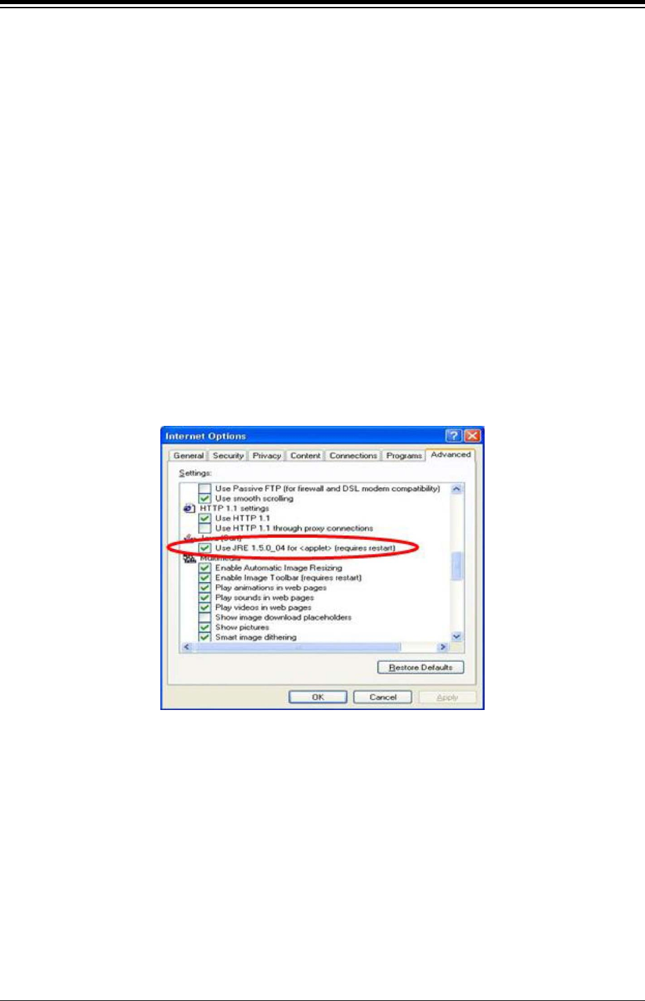
iPECS eMG80 & eMG800 & UCP
Administration and Programming Manual Issue 1.6
220
4.1.3 Web Browser setting
Web browsers may store (cache) a copy of the iPECS Web pages in a cache memory. The Web
browser may use these copies to provide a “quick view”. If the Web page has been altered by
data entered in Station Admin or a file upgrade, the cached copy will be out-of-date and could
cause unexpected system operation. To assure proper page views and data entry, the browser
should be set to eliminate the use of the cached pages. For Explorer, in “Internet Options”, enable
refresh on “Every visit to the page”, for other browser, the procedure may be different.
4.1.4 Password Encryption
When enabled in PGM 162, iPECS system implements decryption of the password employing
RC-6 block encryption. iPECS system employs a Sun Java Virtual Machine applet to implement
AES encryption. The PC entering the Password must have a JAVA Virtual Machine and the JRE
(Java Runtime Environment) Explorer option enabled to properly handle encrypted passwords.
The Sun JVM is downloaded from the Java home page (www.java.com). Once downloaded,
execute the downloaded file. To enable the Explorer JRE option,
1. From the Explorer menu select Internet Options-Advanced.
2. From the Advanced Internet Options check the [Use JRE….] Option.
3. After restarting the computer, access iPECS system Web Manager, section 4.2.
“Applet iPECSPwd started” will display in the bottom left corner to indicate password
encryption is active.
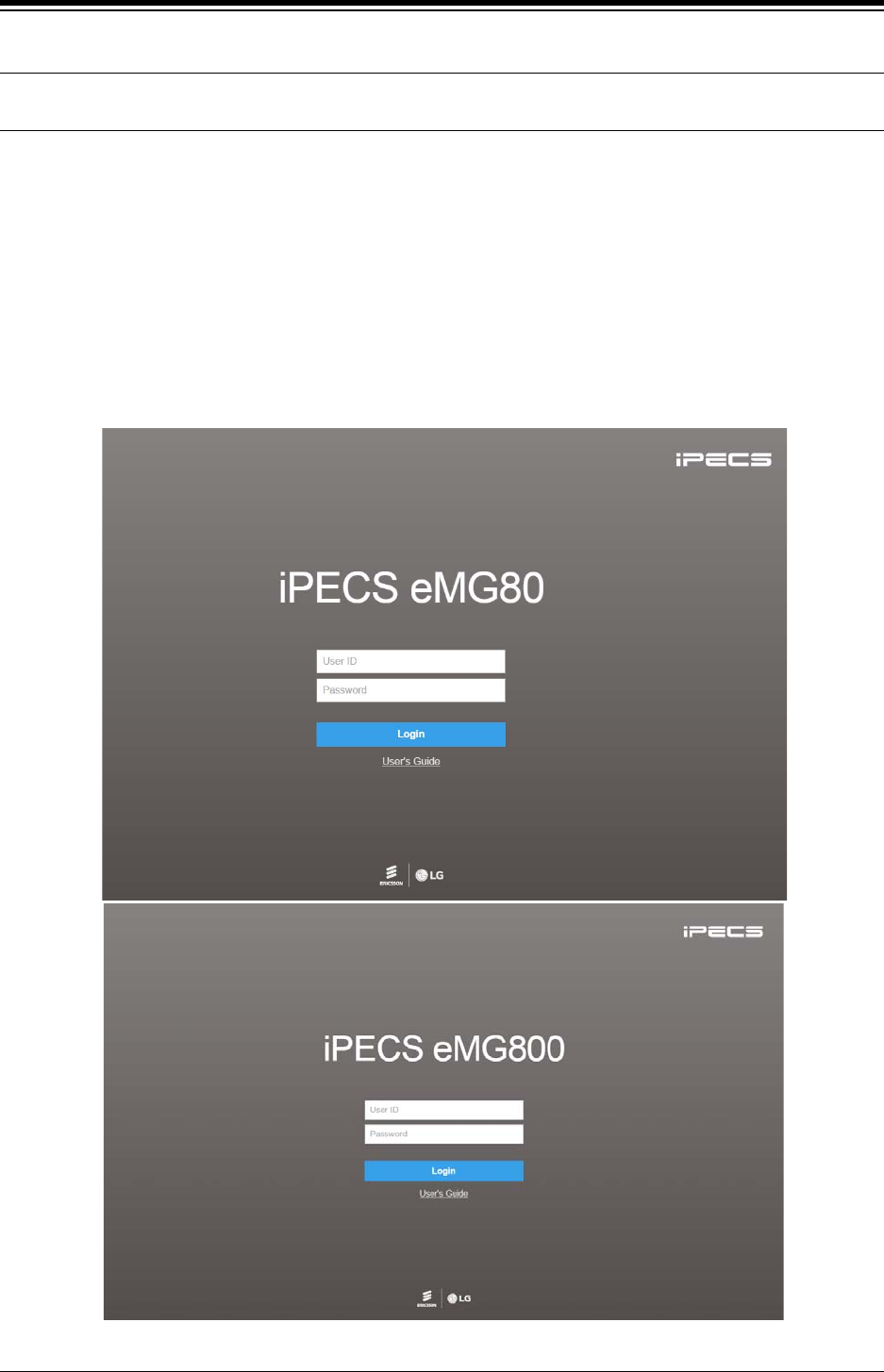
iPECS eMG80 & eMG800 & UCP
Administration and Programming Manual Issue 1.6
221
4.2 iPECS system Web Access & Login
In the browser ‘ADDRESS’ field, enter the MPB or UCP IP address (default is 10.10.10.2) and
TCP port. Select GO; the Web server returns iPECS system Web Services Login page, Figure
4.2.1-1. The Web services include the Admin and Maintenance functions and the Station
Program User Portal. To access the Admin and Maintenance function, User ID and Password
should be matched with the assignments in the User Management. The default Maintenance
User ID is ‘admin’ and the password is ‘1234’. The system will return the Admin & Maintenance
Main page, section 4.3.
To access the Station program, the user must enter their Station number and full Authorization
code (station number and Auth code) in Tables Data – Station Authorization Code (PGM 227).
The system will return the Station Program Main page as shown in section 4.6.
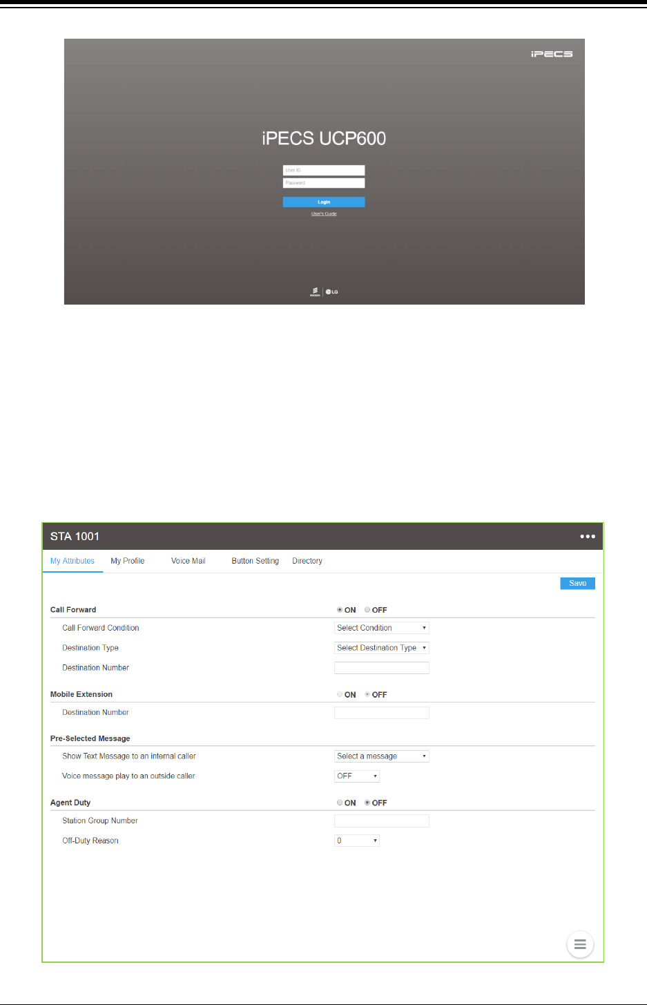
iPECS eMG80 & eMG800 & UCP
Administration and Programming Manual Issue 1.6
222
Figure 4.2-1 iPECS eMG80 & eMG800 & UCP600 Home page
For reference, we explain Admin and Maintenance based on UCP600. The home page is
displayed according to eMG80, eMG800 & UCP type (UCP100, UCP600, UCP2400).
To access User portal, the user must enter Station number and full Authorization code
(station number and Auth code) as defined in Tables Data – Station Authorization Codes (PGM
227). The system will go to the user portal Main page as below. For detail information, refer to
“User Portal User Guide” provided.
Figure 4.2-2 iPECS User Portal main page
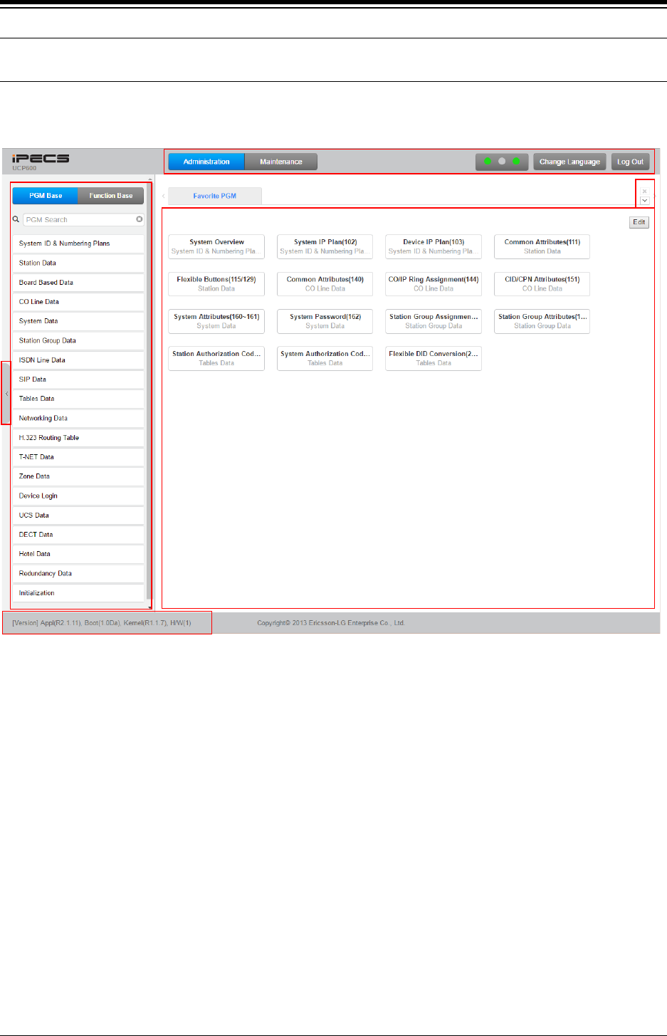
iPECS eMG80 & eMG800 & UCP
Administration and Programming Manual Issue 1.6
223
4.3 Web Admin & Maintenance Main Page Overview
In the Web Admin Login screen (see section 4.2), enter the User ID and Password then click the
[Login] button to access the iPECS Admin & Maintenance Main Page as shown in Figure 4.3-1.
Figure 4.3-1 iPECS UCP Admin & Maintenance Main Page
The Admin & Maintenance Main Page has three sections,
Menu bar – Upper frame
Directory & Navigation section – Left frame
Favorite Programs and Entry section – Central frame
Items in the Menu bar are mouse-clickable for selections of:
Administration – accesses the system database.
Maintenance – SW upgrade, Database, Multi Language, SMDR, VSF, Voice Mail, Trace, etc.
Change Language – change the desired language.
Log out – log out the web server
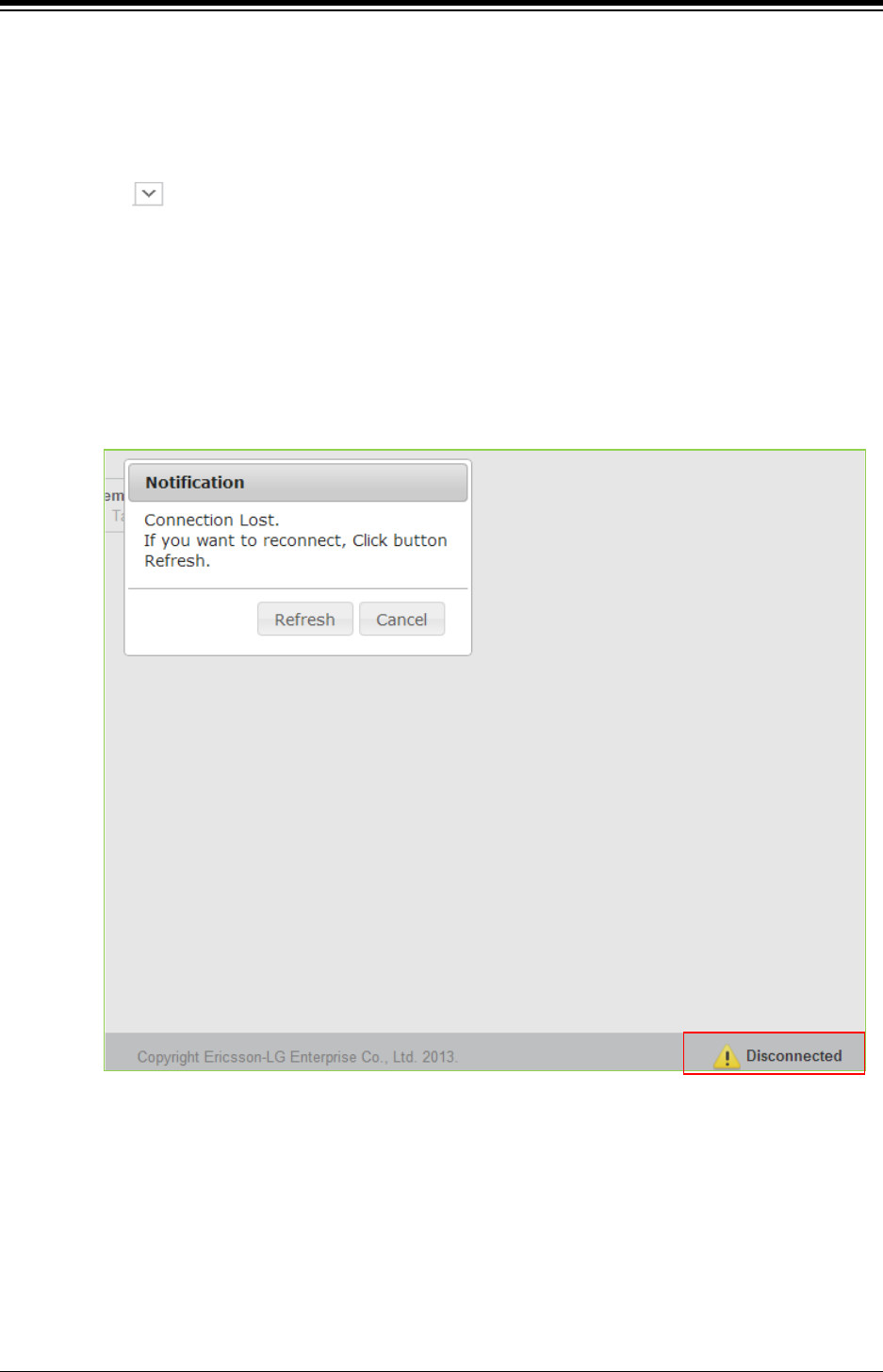
iPECS eMG80 & eMG800 & UCP
Administration and Programming Manual Issue 1.6
224
What is the meaning about Buttons and Text on page?
1) Hide menu by clicking the left arrow in the middle of window on left side.
2) X button at the top of the page on the right side functions whether the current tab or
all tabs are closed or not.
3) button will display all PGM by click and check which PGM is using.
4) The Application, Boot, and Kernel version can find at the left side of bottom.
5) User can check the status indicator at the bottom on the right side of page by
displaying the text such Disconnected or Read Only User.
Disconnected: discconected to Web Admin Server without working for a long
time. User can connect to Web Admin Server by clicking Refresh button.
Read Only User: User who access to Web Admin Sever has no authority to set
the function as the maintenance user and just is only for read.
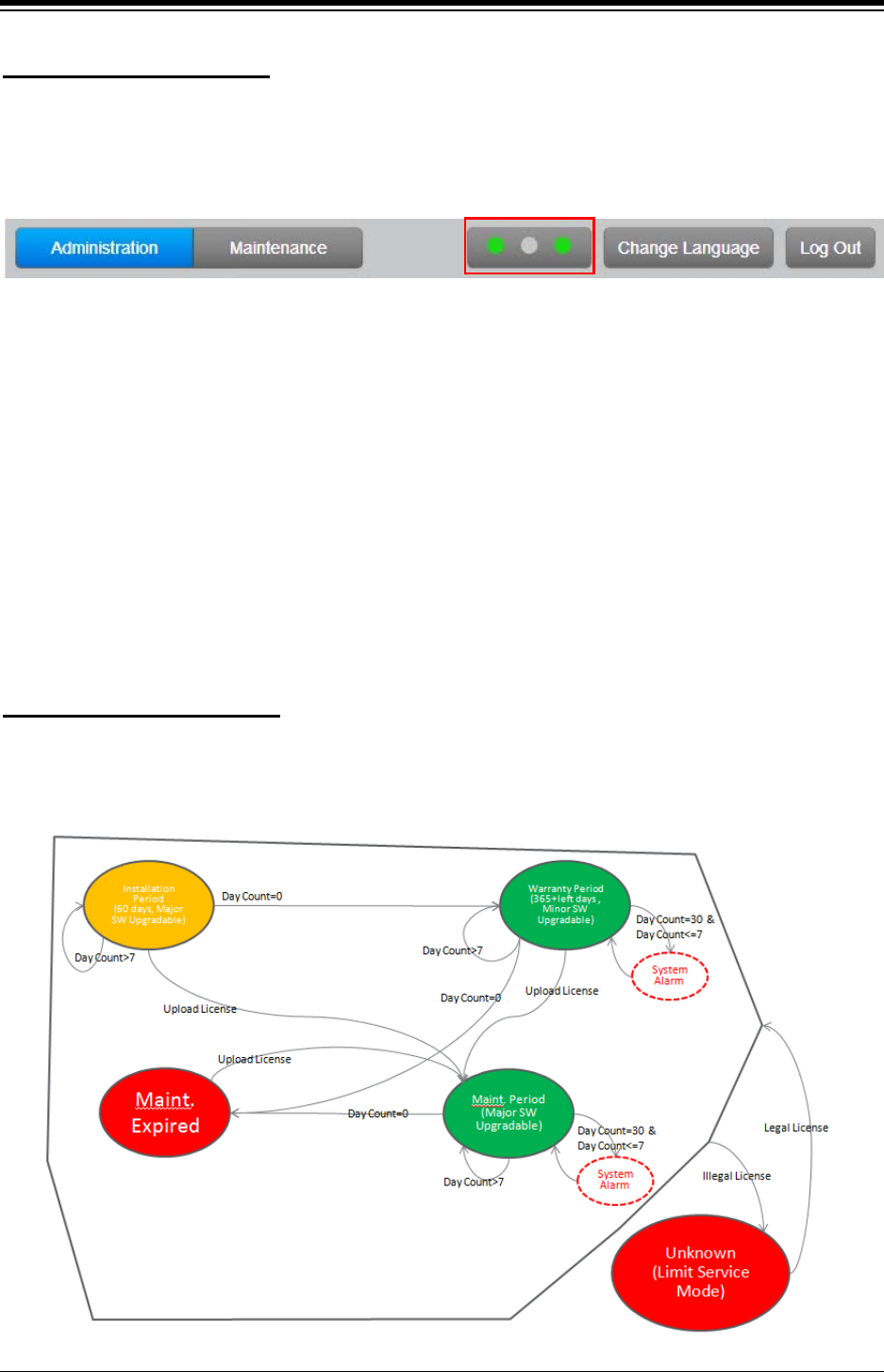
iPECS eMG80 & eMG800 & UCP
Administration and Programming Manual Issue 1.6
225
If “Installation Period” or the color of SW Maint. is GREEN, system software can be upgraded.
Major version upgrade is possible in “Installation” or “Maintenance” Period but Minor version
upgrade is possible in “Warranty” Period. In other states, both upgrade and downgrade are not
allowed.
License State Display
First LED : SW maintenance
Second LED: Temporary License
Third LED: T-Net (eMG & UCP) / Redundancy (UCP only)
Note)
1) To turn off the alarm, Administrator can set ‘Alarm Enable’ to OFF in System Data >
Alarm Attributes (163) > Alarm enable: OFF. For more information, refer to Alarm
Attributes.
2) To turn off the alarm on Phone, press ‘Alarm reset’ PGM code *565 to stop. It’s a one-
time thing. Please check the exact alarm reset code in Flexible Numbering Plan
(106~109) because the code is different according to the numbering plan.
The following figure is SW Maintenance state for SMB. System Alarm (Attenant alarm & E-mail
notification) occurs once 30 days before expiration and daily during 7 days before expiration.
SW Maintenance State
If the system goes to the limited service mode, the station COS is changed to 7.
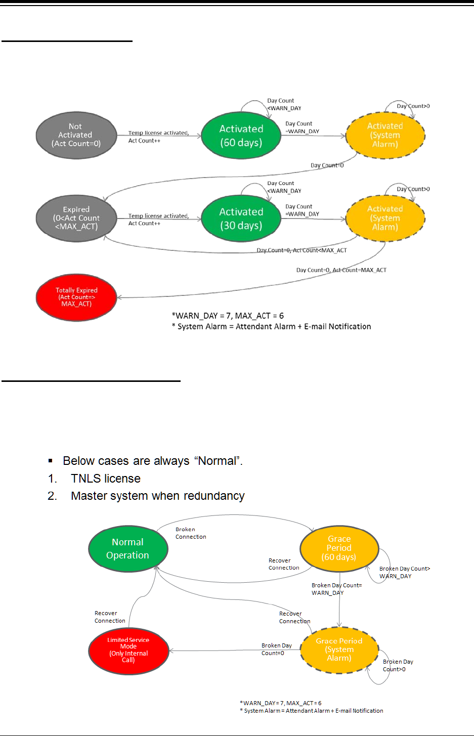
iPECS eMG80 & eMG800 & UCP
Administration and Programming Manual Issue 1.6
226
Temp License can be activated totally 6 times. It is valid for 60 days at first activation and is valid
30 days from second activation to the last. System Alarm occurs daily during 7 days before
expiration.
Temp License State
T-Net LCM license is valid for 60 days if the connection is broken. And Redundancy for UCP
system is valid for 60 days if System is slave, active state, and the connection is broken. But the
limitation is not applied in Master system. System Alarm occurs daily whenever the broken day
coutner is smaller than 7 and the alarm will be stopped if the connection is restored.
T-Net or Redundancy State
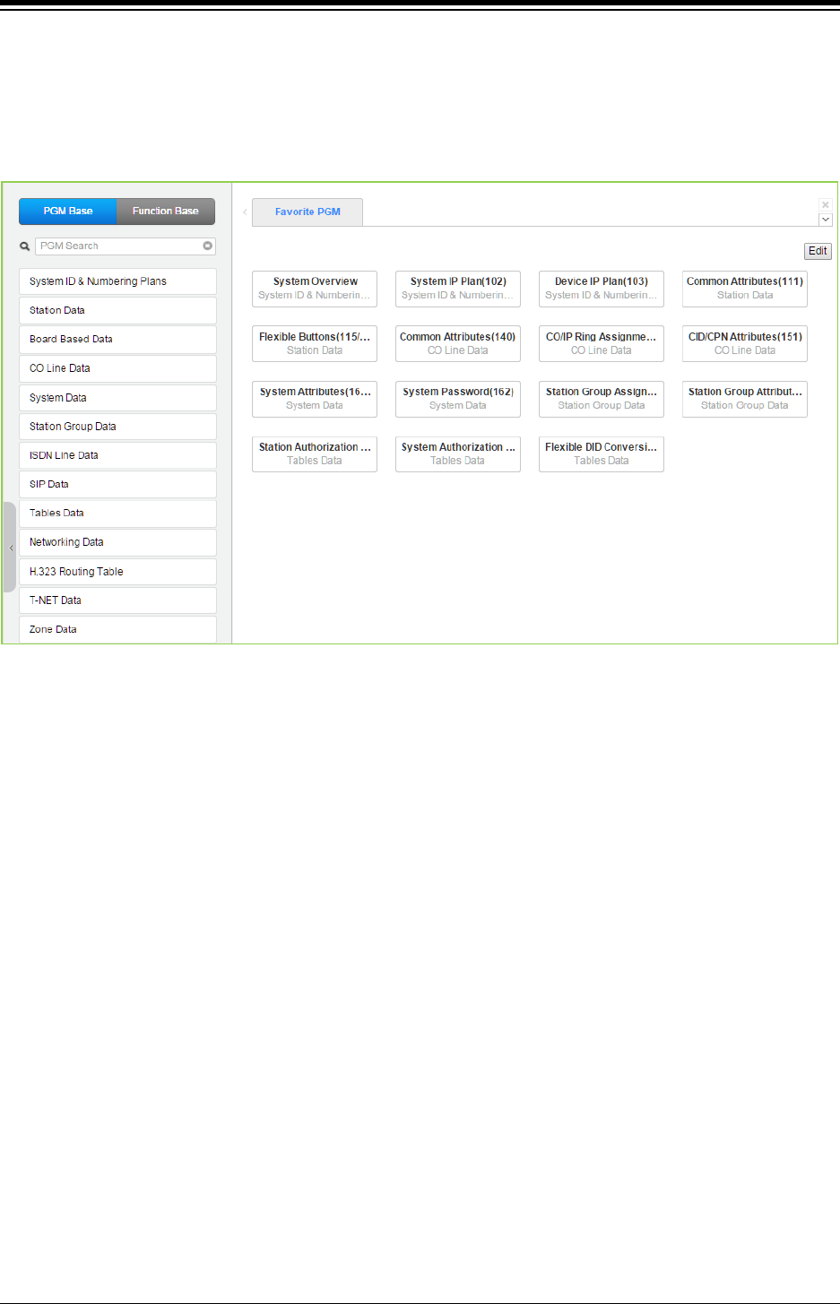
iPECS eMG80 & eMG800 & UCP
Administration and Programming Manual Issue 1.6
227
4.3.1 Favorite Program Groups
To ease access to frequently used program, the iPECS Admin Main Page displays a Favorite
PGM list. The Favorite PGM list buttons, when selected, return the associated Web page. Up to
20 favorites are configured using the Edit button in the upper right of the page.
Figure 4.3.1-1 Favorite Program
To register a Favorite program, click Edit button. The following page will be displayed.
Clear button: Clears the check box for all programs.
Save button: Saves the Web page, PGMs with checked boxes are stored as Favorites,
up to 20.
Back button: Returns to the previous page.
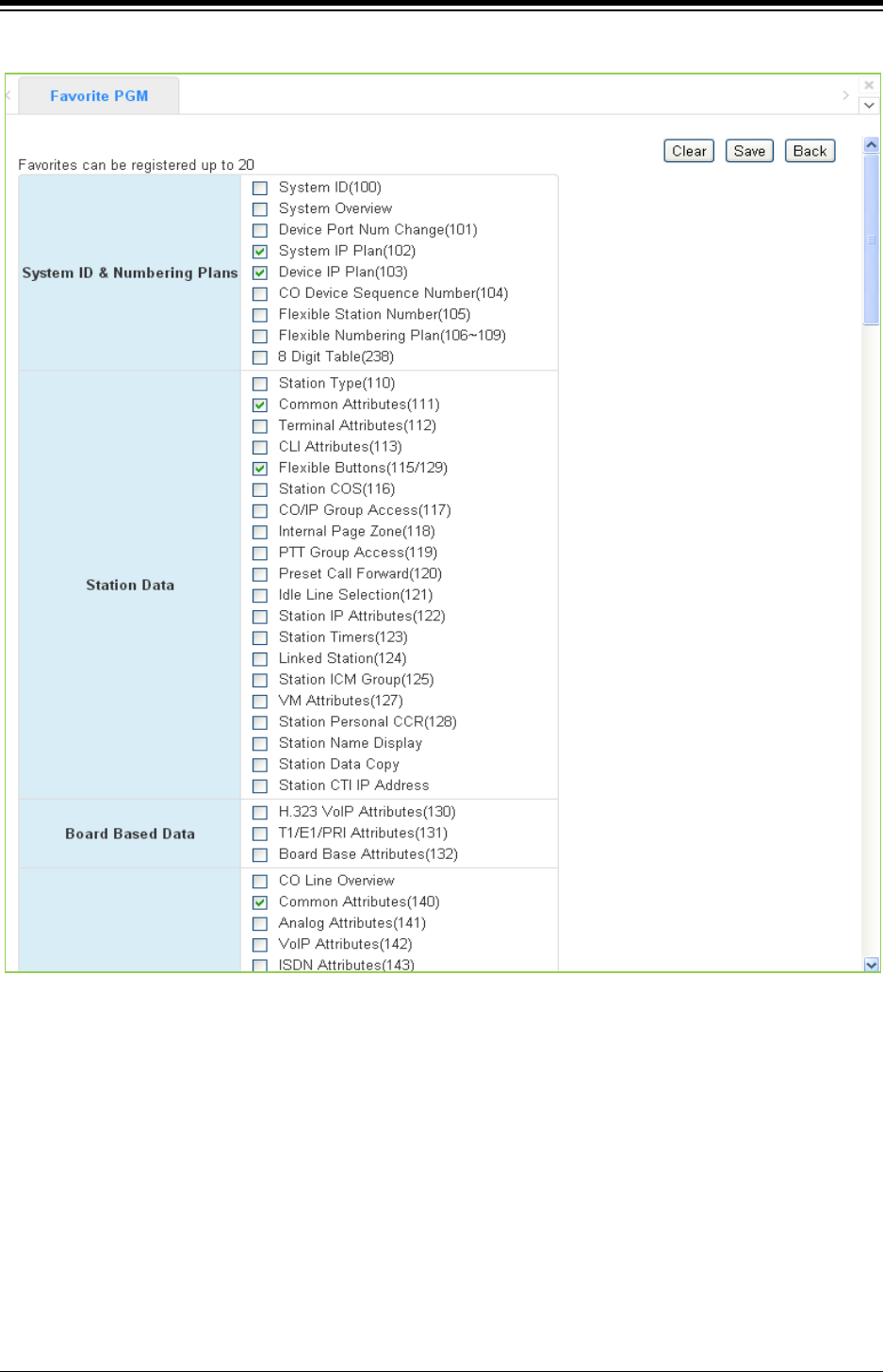
iPECS eMG80 & eMG800 & UCP
Administration and Programming Manual Issue 1.6
228
Figure 4.3.1-2 Favorite Program Groups for edit
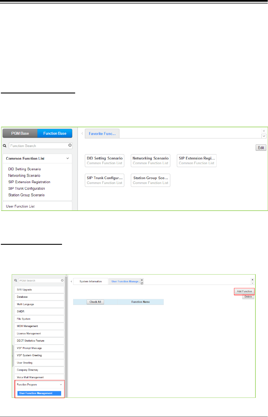
iPECS eMG80 & eMG800 & UCP
Administration and Programming Manual Issue 1.6
229
4.3.2 Using Function Base
Function Base is designed to customize the feature or PGM by configuring the Function base so
that customer can be easy to use the desired and frequent feature.
There are two buttons: Common Function List and User Function List. The feature or PGM can
register up to 20 as Favorite function.
Generally, iPECS system supports the basic function list as default. The available function is 5
(DID Setting Scenario, Network Scenario, SIP Extension Registration, SIP Trunk Configuration,
Station Group Scenario). The 5 functions can’t be deleted or editable.
1) Common Function List
Figure 4.3.2-1 Common Function List
To configure the user function list, click Maintenance button and then you can see the Function
Program in the left frame and click the sub menu ‘User Function Management’ as the following
figure. On this web page, you can add or delete the function.
2) User Function List
Figure 4.3.2-2 User Function Management
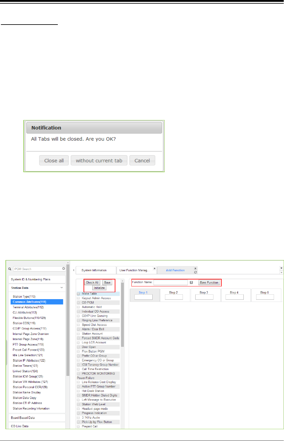
iPECS eMG80 & eMG800 & UCP
Administration and Programming Manual Issue 1.6
230
This step is divided into 5 steps and you can make the desired function each step. The following
is the guide to make Name and add the function on each step:
Adding Function
1) To enter the function name, English, Numbering, Underscore (_) and Parentheses are
available. Function name has to be filled out.
2) To enter the step name, English, Numbering, and Special letters except Double
quotation marks are available.
3) The step name doesn’t need to be filled out, but the function has to be configured each
step.
4) To cancel or close this tab, click the close button (X) and pop up the blow;
1. Click the Add Function button.
2. On the below window, click the desired PGM in the left frame. First fill out the function
name and step name. To configure the step 1, click the Make table to check the desired
function and then click [Save] button.
Check All: check all functions
Save: Save the checked functions
Initialize: Initialize the checked functions

iPECS eMG80 & eMG800 & UCP
Administration and Programming Manual Issue 1.6
231
3. The selected functions are displayed and click [Save] button after checking each
functions. The rest steps are the same as the step 1.
4. Finally, click [Save] Function to save and then click [OK] button.
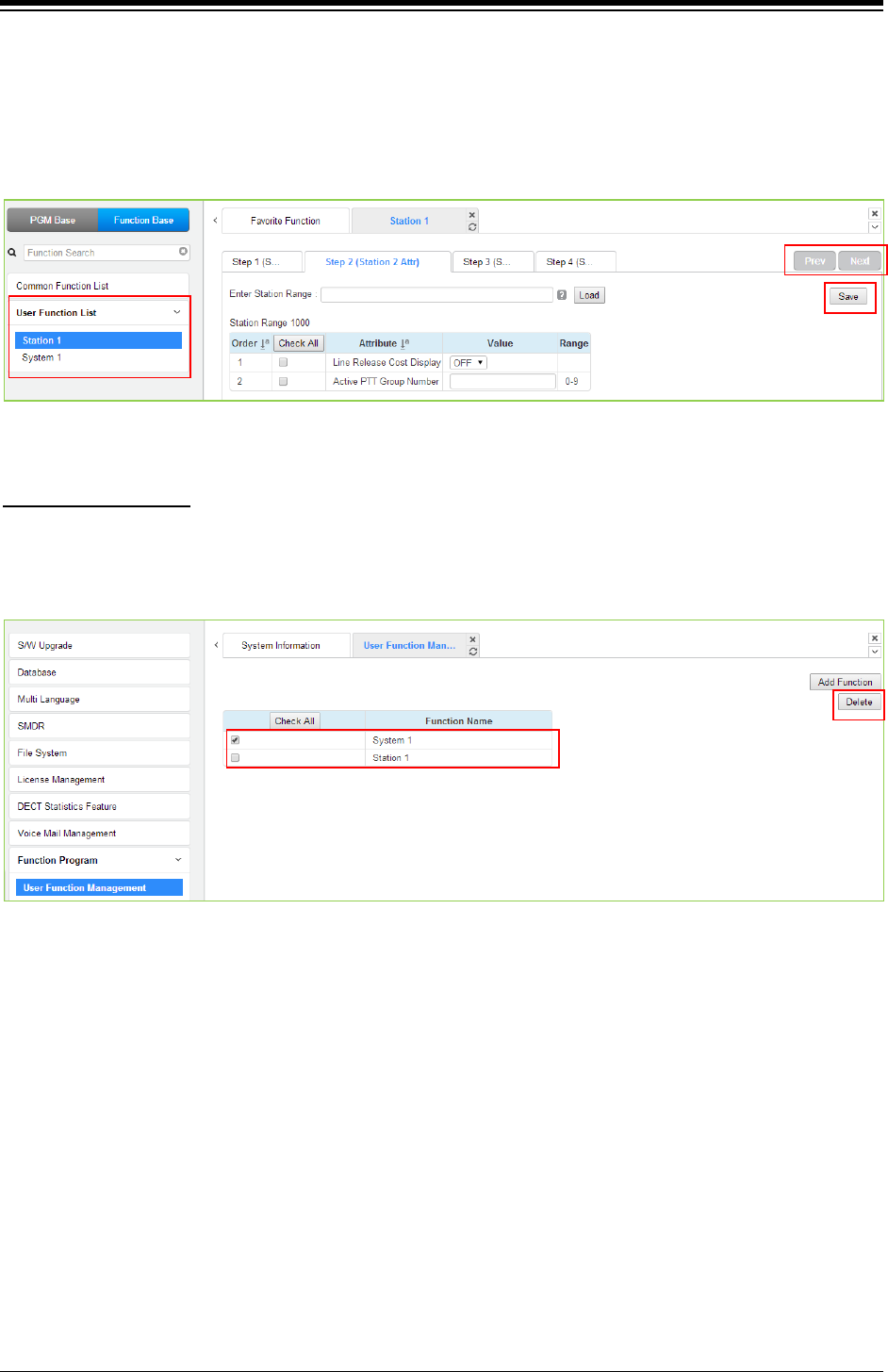
iPECS eMG80 & eMG800 & UCP
Administration and Programming Manual Issue 1.6
232
5. To check the function, click Function Base button in the left frame and User Function List
and you will see the following figure.
You can enable or disable the function by checking each function and then click the save
after setting Value. Also move to each step by clicking [Next] button or [Previous] button.
To delete the user function, click Maintenance at the top of window and then click the Function
Program -> User Function Management. Check the desired function to delete and click [Delete]
button.
Deleting Function

iPECS eMG80 & eMG800 & UCP
Administration and Programming Manual Issue 1.6
233
4.3.3 iPECS Web Page Navigation
The Navigation frame appears in the left after login; refer to Figure 4.3-1. Selecting a Program
group from either the Navigation pane or the Favorites list will display the selected Web entry
page.
Each of the system‘s data entry Web pages includes a frame for data display and modification.
To modify data, click in the data field, either a drop-down menu will appear for entry selection or a
cursor will appear in the field and the user may type in the data required. Once all new data for a
Web page has been entered, the [Save] button must be clicked to send the new page to the
system and save the modified data.
In some cases, where mentioned, it may be necessary to reset the system. The system can be
reset manually as described in the iPECS Hardware Description and Installation Manual by
selecting the Reset System button on the Initialization Web page or using the reset button.
4.3.4 General Web Page Features
4.3.4.1 Web Page Range Entries
On many of the Web pages for Station, CO Line and Tables Data a range of station, lines or table
indices must be entered to display the appropriate data entry page. In this case, a range of
devices or indices can be selected by entering the lowest and highest device number separated
by a dash. In addition, a comma can be used to enter non-sequential numbers. Note no space
characters should be entered before or after the dash or comma. Note the data entry page
displays the data for the lowest device or table index entered.
4.3.4.2 Table Check Boxes
Data entry pages that require a range entry, only display the data for the lowest device number or
Table index entered in the range. To assure that only the appropriate data is changed for all
entries in the range, a check box is located in front of each attribute. When the page is saved,
only data for attributes with the box checked are saved for the range while data for unchecked
attributes are not modified.
4.3.4.3 Sorting Displayed Data
Charts in the data pages typically allow the data to be sorted based on a given column in either
ascending or descending order. In the column header, the sorting symbol displays to indicate the
sorting function is available for the column.
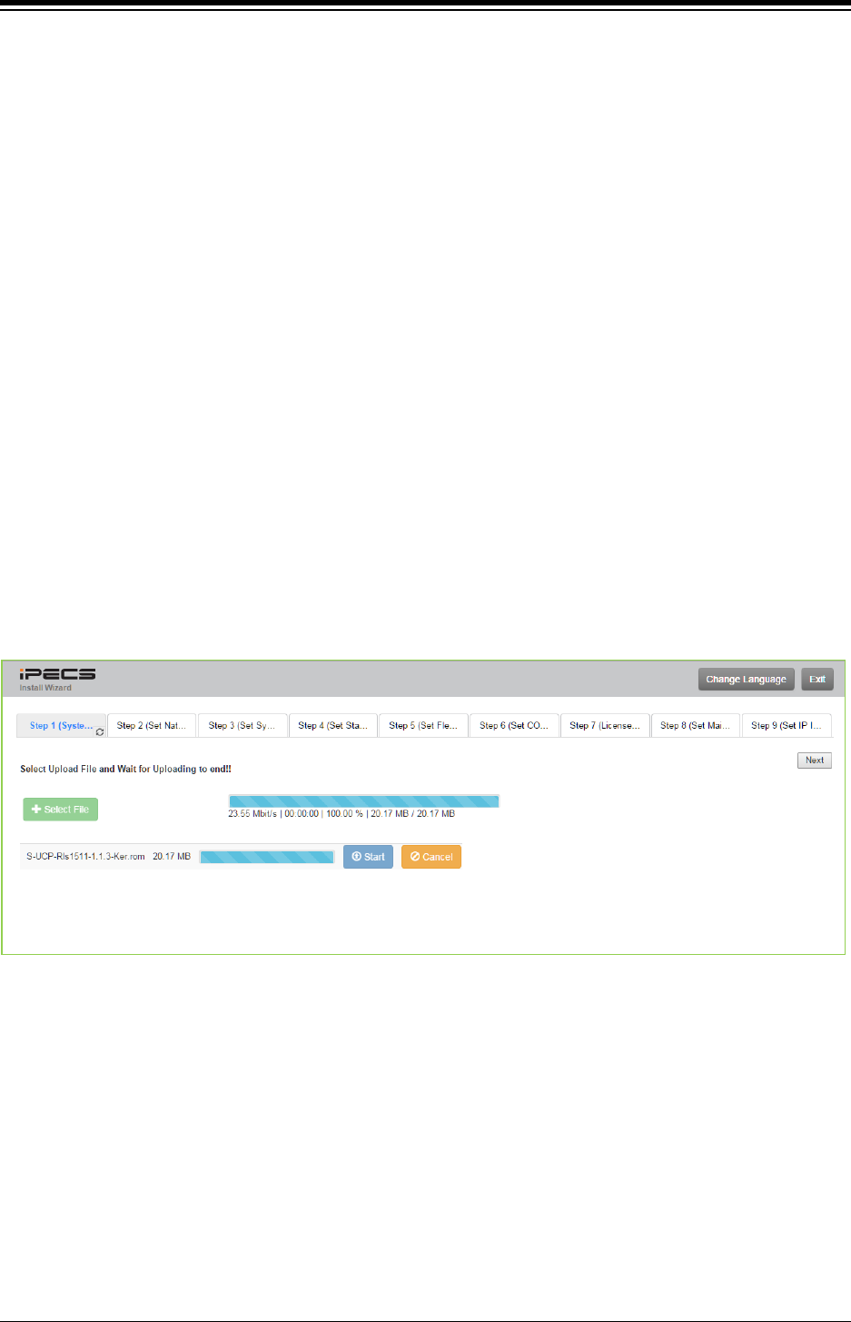
iPECS eMG80 & eMG800 & UCP
Administration and Programming Manual Issue 1.6
234
4.3.5 Install wizard
After the system is initialized, the first time Web Admin is accessed, the Install Wizard is
displayed. The Wizard presents 9 pages in sequence with parameters that should be verified or
commonly need modification prior to operation of the system including:
1) System Upgrade
2) Nation Code
3) System Time & Date
4) Station Number
5) Flexible Numbering Plan
6) CO Ring Assignment
7) License Upload
8) Maintenance ID & Password
9) IP Information
4.3.5.1 System Upgrade
Click the Select files button and then open the pop-up folder. Select the desired file to upload to
the system’s memory and click the [Start] button. The file is sent to the system’s memory, saved
and automatically loaded upon a system reset or restart.
Figure 4.3.5.1-1 System upgrade
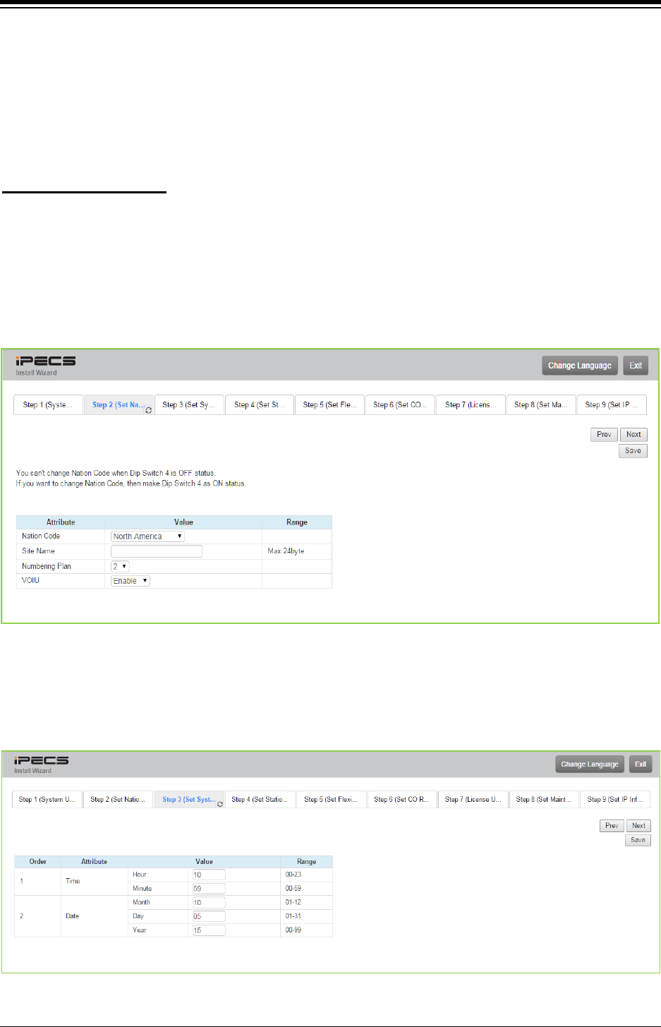
iPECS eMG80 & eMG800 & UCP
Administration and Programming Manual Issue 1.6
235
4.3.5.2 Nation Code
During initialization, the system employs the Nation Code to establish the default gains and tones
for the various interfaces (analog CO Lines, ISDN lines, etc.), as well as the numbering plans for
the specific country. The gains, in particular must be set to comply with the local regulatory
requirements. Normally, the Nation Code will be set at the factory, however, assure the Nation
code matches the system location.
1) Dip Switch pole 4 of UCP100 (or UCP600, UCP2400) moves to ON. Dip Switch pole 2 of
KSU (eMG) moves to ON.
Changing Nation Code
2) Change Nation Code by clicking in the combo box.
3) Click [Save] button and then the system start resetting to apply.
In addition, all other data will be initialized, so the Nation Code should be properly set prior to
other programming. You can change the numbering plan for your situation.
Figure 4.3.5.2-1 Set Nation Code Wizard
4.3.5.3 Set System Time and Date
You can set System time and date in this page.
Figure 4.3.5.3-1 Set system time and date
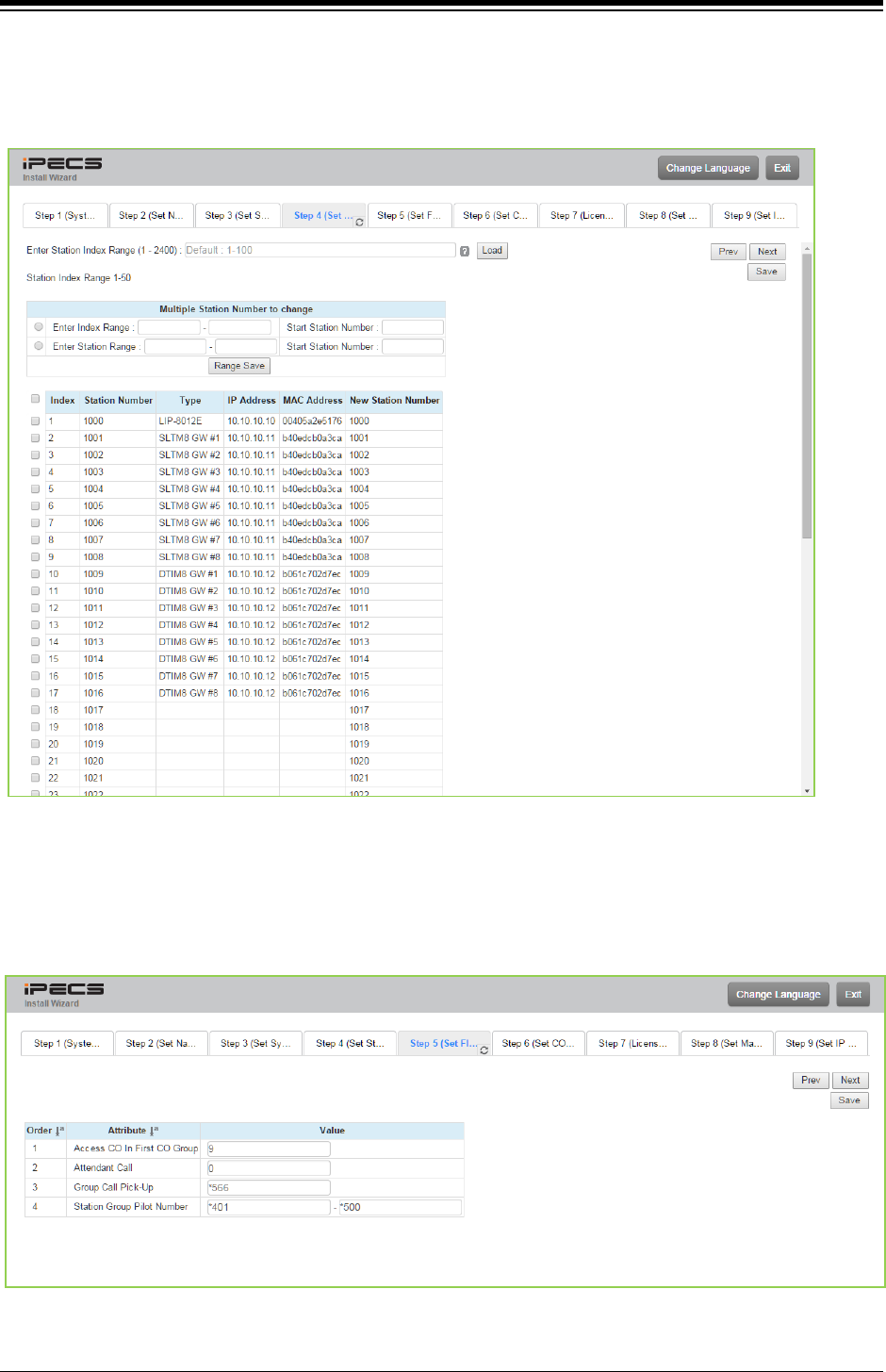
iPECS eMG80 & eMG800 & UCP
Administration and Programming Manual Issue 1.6
236
4.3.5.4 Set Station Number
You want to change the current station number to New station number. In this page, you can
change the station number.
Figure 4.3.5.4-1 Set Station Number
4.3.5.5 Set Flexible Numbering Plan
The Flexible Numbering Plan defines the various digit strings (codes) users may dial to access
system resources (outside lines, page zones, etc.) and features. In the wizard, codes for features
that commonly may require modification are displayed.
Figure 4.3.5.5-1 Set Flexible Numbering plan
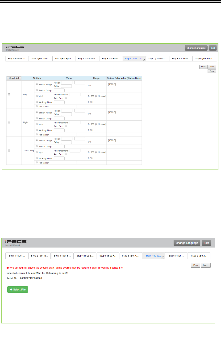
iPECS eMG80 & eMG800 & UCP
Administration and Programming Manual Issue 1.6
237
4.3.5.6 Set CO Ring Assignment
CO Ring Assignment establishes how the system will route incoming calls. The wizard
assignments cover all CO/IP Lines in the system and the Ring assignments for Day, Night and
Timed Ring modes can be established.
Figure 4.3.5.6-1 Set CO Ring Assignment
4.3.5.7 Set License Upload
Before License upload, make sure that the date of system is set correctly. Click [Select files]
button and then open the pop-up folder. Select a valid license file to upload to the system and
click the [Start] button. If the file which is sent to the system is “System License File”, it will be
saved and automatically applied without restart. The enabled features by uploading license file
can be shown in “System Overview” page.
Figure 4.3.5.7-1 Set License Upload
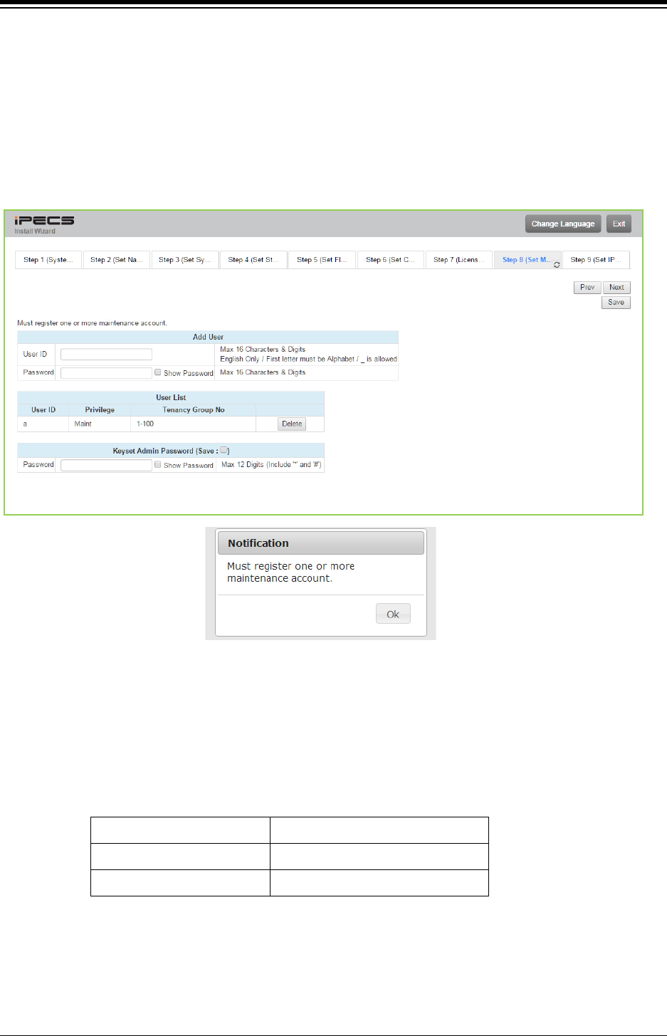
iPECS eMG80 & eMG800 & UCP
Administration and Programming Manual Issue 1.6
238
4.3.5.8 Set Maintenance ID & Password
The Wizard includes a password entry page. It is strongly recommended that a unique User
ID and strong password be entered to minimize the risk of admin and maintenance access
by unauthorized personnel.
In order to finish the final step, you should register at least a maintenance ID. If not so, the Wizard
can’t go on to the next.
Also, Keyset admin password can be registered in this page.
Figure 4.3.5.6-1 Set Maintenance Password
NOTE
1. The new information will be in effect immediately upon saving the information. When
a new Admin User ID and Password are saved, the Web login screen appears. A
new Admin session will be required using the new login credentials.
2. The number of Tenancy group for each system is as below:
UCP100/600/2400 100 groups
eMG800
32 groups
eMG80 15 groups
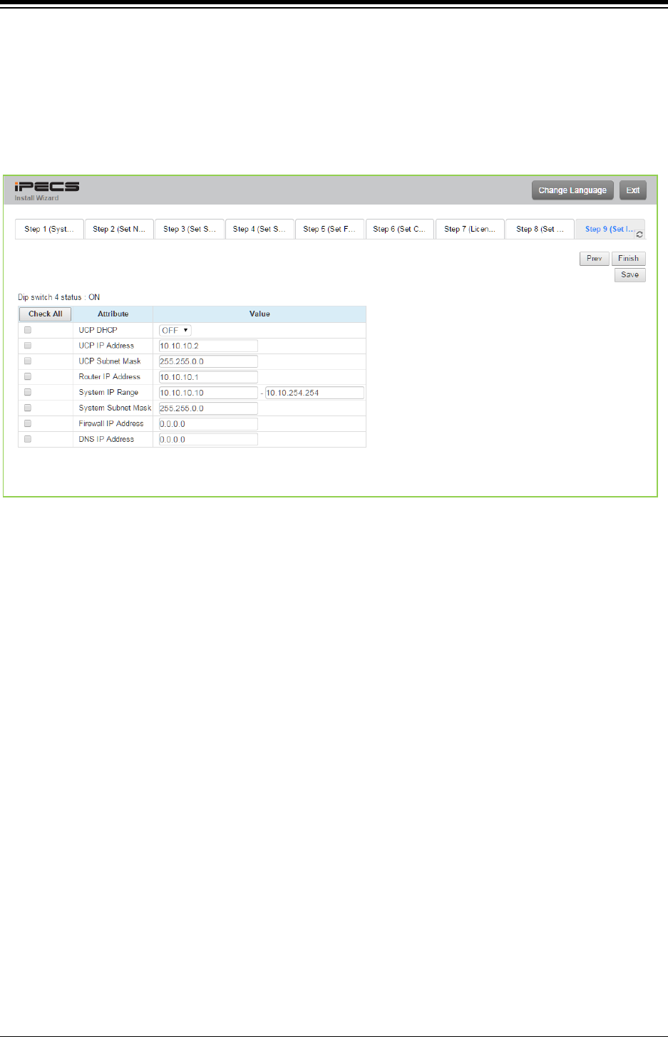
iPECS eMG80 & eMG800 & UCP
Administration and Programming Manual Issue 1.6
239
4.3.5.9 Set IP Information
The IP Information page establishes the IP address scheme. DHCP can be enabled or static
addressing can be configured. When the system is behind a firewall, the Firewall address must
be entered allowing proper operation with remote users, devise and SIP trunks. A DNS (Directory
Name Server) for Domain Name resolution should also be entered on this page. Note that
changing any IP address in the system requires a system reset; the reset does not initialize data.
Figure 4.3.5.2-1 Set IP Information
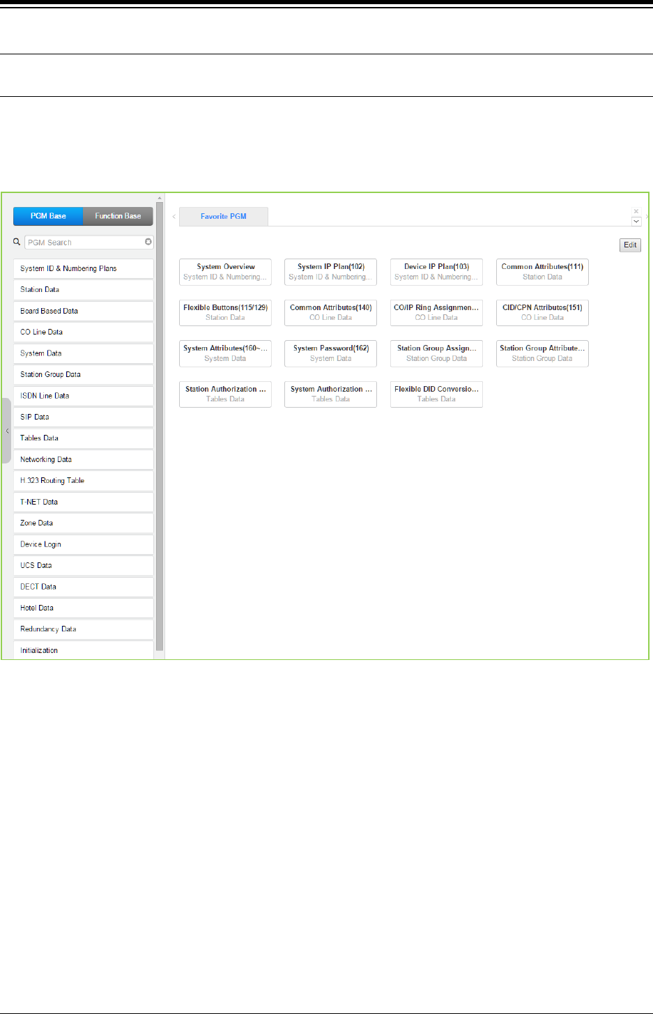
iPECS eMG80 & eMG800 & UCP
Administration and Programming Manual Issue 1.6
240
4.4 Web Admin Programming
4.4.1 System ID & Numbering Plans
Selecting the System ID & Numbering Plans expands the Navigation frame to display the
available Program groups as shown in the below figure.
Figure 4.4.1-1 System ID & Numbering Plans sub-menu
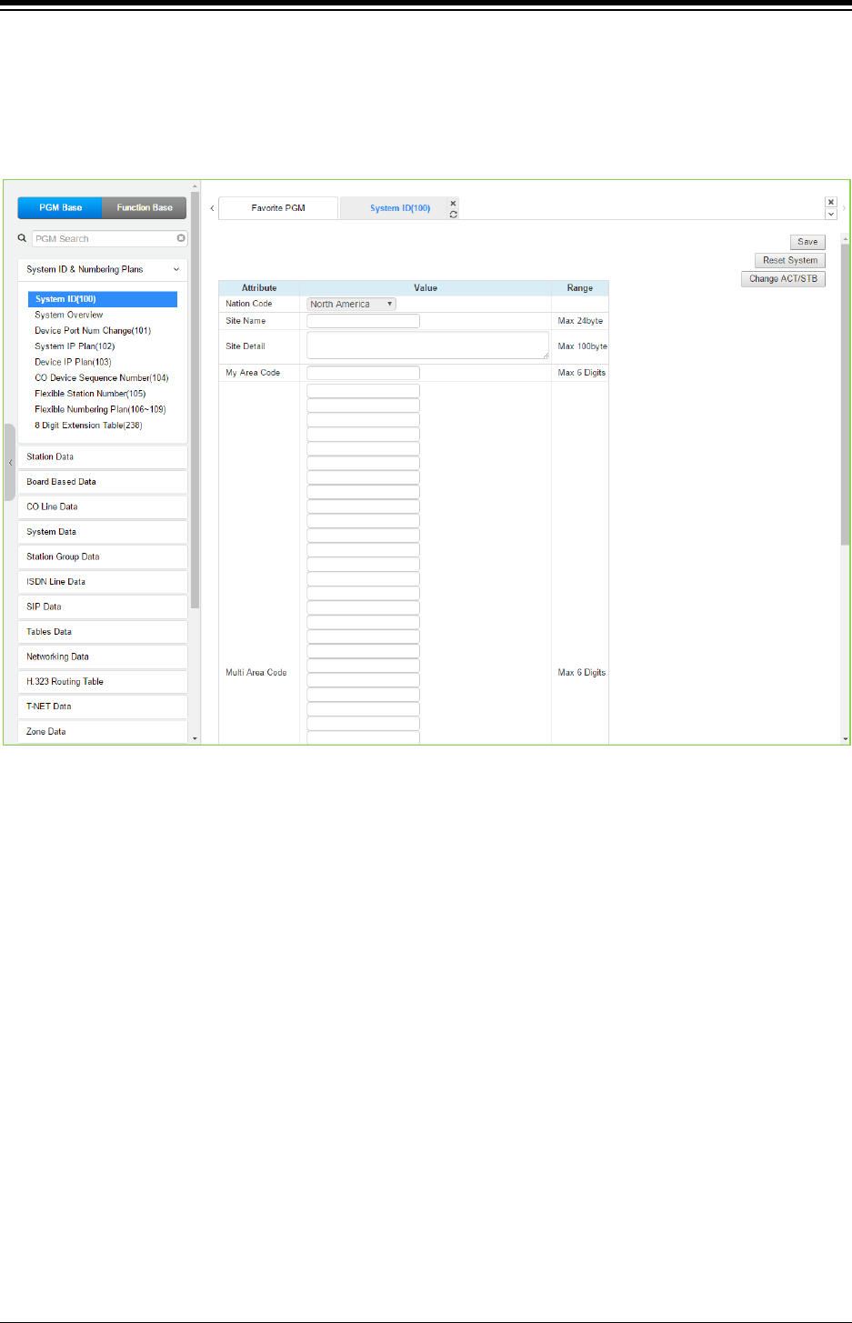
iPECS eMG80 & eMG800 & UCP
Administration and Programming Manual Issue 1.6
241
4.4.1.1 System ID – PGM 100
Selecting System ID will display the following Input Entry page. Click [Reset System] to restart
the system after changing Nation code, Site name, Site detail, My area code, Multi area code,
Numbering Plan, etc.
Figure 4.4.1.1-1 System ID
Under System ID, the country is identified using the international dial codes (Nation Code). A
twenty-four (24) character Site Name, Site detail and the local My Area Code maybe defined.
This information is used to set gain, frequencies and other system characteristics specific to the
country and regional regulatory requirements. The Site Name is primarily useful for the
installer/programmer as a reference to customer.
Note
1) In case of eMG, to change Nation code, Dip-switch 1 pole # 2 is ON; you cannot change the
Nation code while the switch is OFF.
2) In case of UCP, to change the Nation Code or disable the VOIU, the UCP Module “Mode”
dip switch pole 4 must be ON; you cannot change the Nation code while the switch is OFF.
3) The rest attributes are additional options for Customer’s convenience.
4) In case of UCP, the built-in VoIP DSP channels (VOIU) can be disabled allowing use of the
DSPs for the Multi-party Conference function. Note the capability to disable the VOIU is only
available when dip switch 4 of the UCP module is in the ON position.
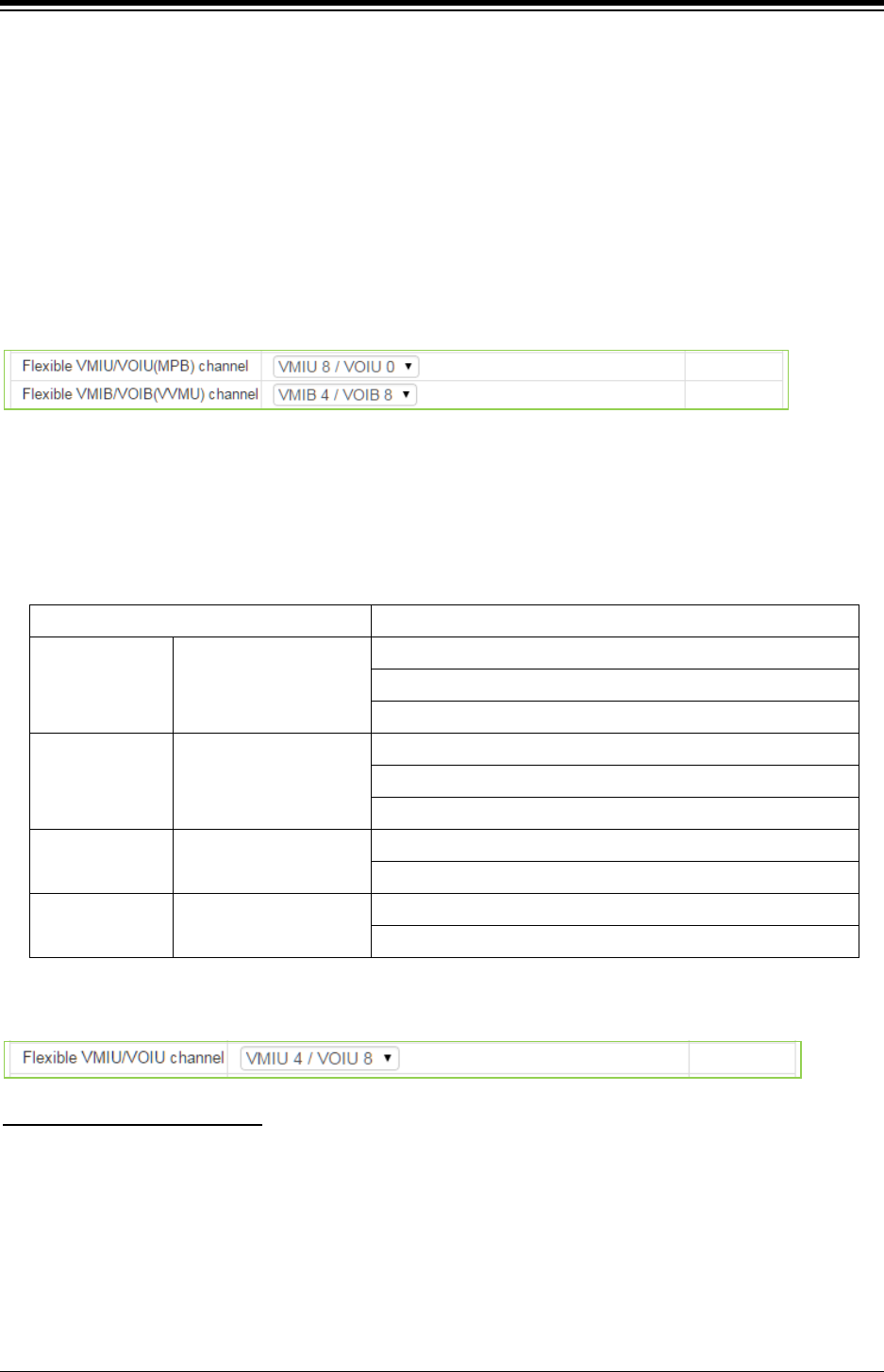
iPECS eMG80 & eMG800 & UCP
Administration and Programming Manual Issue 1.6
242
Numbering Plan
The system employs one of the nine (9) basic Flexible Number Plans as detailed in Appendix B.
Individual items from the selected Numbering Plan can be changed under Flexible Numbering
Plan in section 4.4.1.7.
Note
The numbering plan on this manual is based on Numbering plan 2. The value (or feature code)
may be different according to Numbering plan.
In case of eMG80
1. Administrator can select the channel capacity of VoIP and Voice Mail in this filed.
- In case of VMIU8/VOIU0, the default 2 channel of VoIP can't be used.
2. VVMU channel field can't be available if VVMU is not installed.
3. Select VoIP and Voice mail channel for Built-in (MPB) and VVMU by referring the below chart.
Item Specification
VOIU(MPB) Built-in VoIP
Max. 8 Channels
- 2 Channels (by default)
- 6 Channels (1 Channel increment by license)
VMIU(MPB) Built-in Voice Mail
Max. 8 Channels
- 2 Channels (by default)
- 6 Channels (1 Channel increment by license)
VOIB(VVMU) VoIP Max. 8 Channels
- 8 Channels (1 Channel increment by license)
VMIB(VVMU) Voice Mail Max. 8 Channels
- 8 Channels (1 Channel increment by license)
In case of eMG800
You can select one of the following types according to the current configuration using Voice mail
and VoIP channel:
Flexible VMIU/VOIU channel
1) VMIU8 / VOIU0
2) VMIU8 / VOIU2
3) VMIU8 / VOIU4
4) VMIU4 / VOIU8
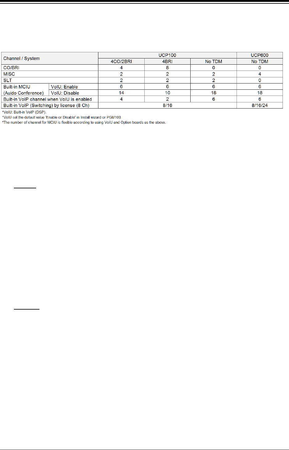
iPECS eMG80 & eMG800 & UCP
Administration and Programming Manual Issue 1.6
243
In case of UCP
You can set VOIU in this page. The MCIU (Audio Conference) channel is flexible according to
VoIU ‘Enable or Disable’ and installing the related module as below:
eMG ‘Speed Numbering’
You can easily memory the system speed dial code and station dial code by selecting the desired
type depending on the situation among the following types:
1) Type (0): System speed (2000~4999), Station speed (000~099)
eMG80
2) Type (1): System speed (200~999), Station speed (000~099)
3) Type (2): System speed (200~999), Station speed (00~19)
4) Type (3): System speed (20~99), Station speed (00~19)
5) Type (4): System speed (1000~3999), Station speed (000~099)
6) Type (5): System speed (100~999), Station speed (000~099)
7) Type (6): System speed (100~999), Station speed (00~09)
8) Type (7): System speed (10~99), Station speed (00~09)
9) Type (8): System speed (1~9), Station speed (0~0)
eMG800
1) Type (0): System speed (2000~9999), Station speed (000~099)
2) Type (1): System speed (200~999), Station speed (000~099)
3) Type (2): System speed (200~999), Station speed (00~19)
4) Type (3): System speed (20~99), Station speed (00~19)
5) Type (4): System speed (1000~8999), Station speed (000~099)
6) Type (5): System speed (100~999), Station speed (000~099)
7) Type (6): System speed (100~999), Station speed (00~09)
8) Type (7): System speed (10~99), Station speed (00~09)
9) Type (8): System speed (1~9), Station speed (0~0)

iPECS eMG80 & eMG800 & UCP
Administration and Programming Manual Issue 1.6
244
UCP ‘Speed Numbering’
You can easily memory the system speed dial code and station dial code by selecting the desired
type depending on the situation among the following types:
1) Type (0): System speed (20000~31999), Station speed (000~099)
2) Type (1): System speed (2000~9999), Station speed (000~099)
3) Type (2): System speed (200~999), Station speed (000~099)
4) Type (3): System speed (200~999), Station speed (00~19)
5) Type (4): System speed (20~99), Station speed (00~19)
6) Type (5): System speed (1000~9999), Station speed (000~099)
7) Type (6): System speed (100~999), Station speed (000~099)
8) Type (7): System speed (100~999), Station speed (00~09)
9) Type (8): System speed (10~99), Station speed (00~09)
10) Type (9): System speed (1~9), Station speed (0~0)
The notifications is displayed ‘Speed Numbering type is successfully changed. Please refresh this
page to reload Speed numbering data.” According to selecting Speed numbering type, the range
of System speed dial and Station speed dial is changed over the related PGM.
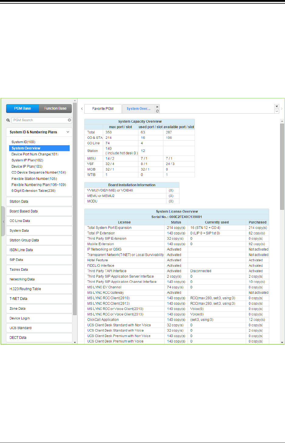
iPECS eMG80 & eMG800 & UCP
Administration and Programming Manual Issue 1.6
245
4.4.1.2 System Overview
Selecting System Overview will display the System Overview page. This page displays the
system capacity, the system license overview related to Application, Device ID list, and Gateway
list. Note that data cannot be entered on this page. Especially, you can check the status of
software license and Temp license.
Note
System overview may show different figure between the below and yours according to installing
Module, Device, etc.
Figure 4.4.1.2-1 eMG80 System Overview
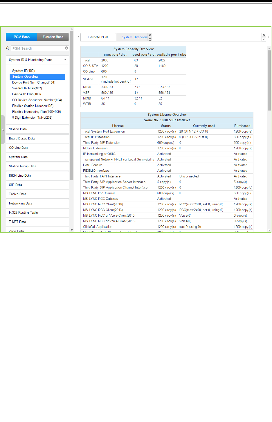
iPECS eMG80 & eMG800 & UCP
Administration and Programming Manual Issue 1.6
246
Figure 4.4.1.2-2 eMG800 System Overview
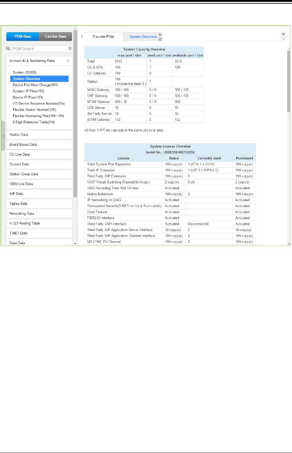
iPECS eMG80 & eMG800 & UCP
Administration and Programming Manual Issue 1.6
247
Figure 4.4.1.2-3 UCP System Overview
The above information may be different according to installing the related board and license.
Especially UCP is different according to UCP type (UCP100, UCP600, UCP2400).
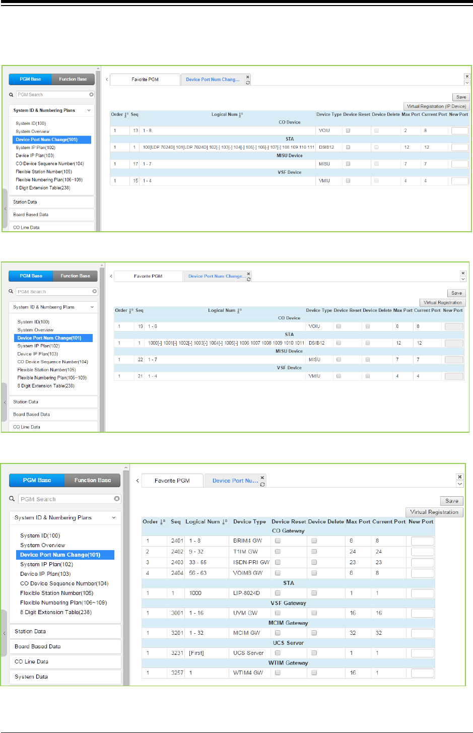
iPECS eMG80 & eMG800 & UCP
Administration and Programming Manual Issue 1.6
248
4.4.1.3 Device Port Number Change – PGM 101
Selecting Device Port Num Change (101) will display the input entry page.
Figure 4.4.1.3-1 eMG80 Device Port Num Change
Figure 4.4.1.3-2 eMG800 Device Port Num Change
Figure 4.4.1.3-3 UCP Device Port Num Change
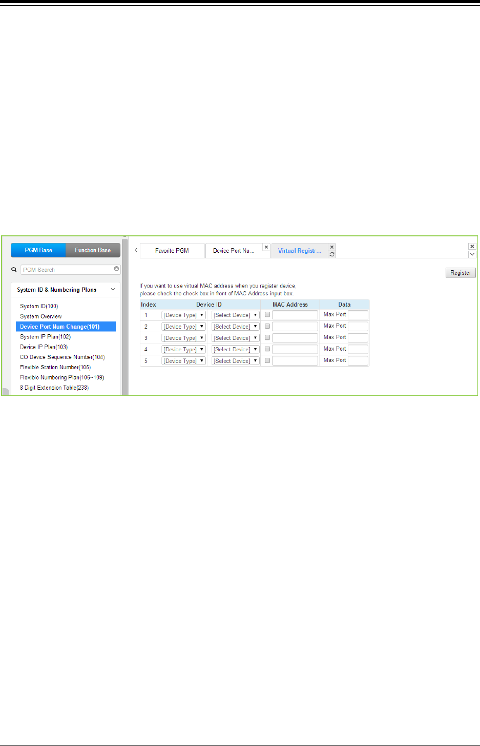
iPECS eMG80 & eMG800 & UCP
Administration and Programming Manual Issue 1.6
249
The system supports changing port count of a device or deleting devices. In this window, the
Device ID, Mac address, IP address and port count of the device can be modified. Also checking
the [Device Delete] check box will delete the device.
Devices may be registered through the Virtual Registration page by accessing to “Device Port
Number Change” page. Devices can be registered with or without a MAC address and the
number of ports associated with the device may be limited. This may be useful for example to
implement a “partial T1” gateway where only some of the T1 channels are available. Note to
virtually register a SIP trunk, use the Device Type of CO and device as VOIM, enter the desired
number of channels. If you want to use virtual MAC address when you register Device, please
check the check box in front of MAC address input field. Click [Register] button after finishing
the desired value.
Figure 4.4.1.3-2 Virtual Registration
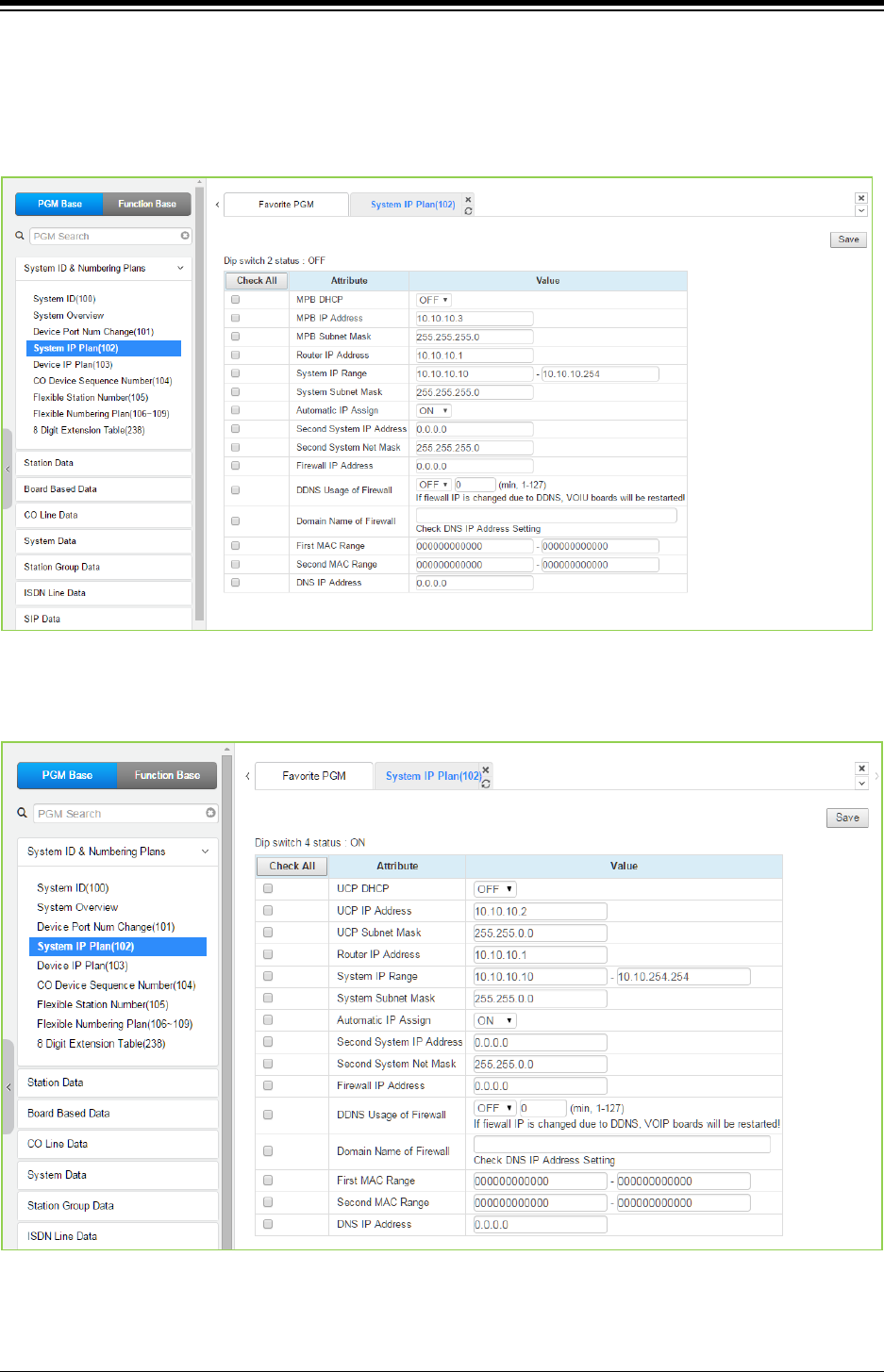
iPECS eMG80 & eMG800 & UCP
Administration and Programming Manual Issue 1.6
250
4.4.1.4 System IP Plan - PGM 102
Selecting System IP Plan will display the following input entry page. Use the check boxes to
indicate which attributes to modify and the data for checked attributes is stored for the entire
range of stations when saved.
Figure 4.4.1.4-1 eMG System IP Plan
Figure 4.4.1.4-2 UCP System IP Plan

iPECS eMG80 & eMG800 & UCP
Administration and Programming Manual Issue 1.6
251
The System IP Plan sets several IP addresses including MPB (UCP) IP address that is required
for external VoIP calls, the IP address for the router, and the system‘s internal private IP address
Plan. Note that the LAN and Router addresses must be routable IP addresses for access to an
external VoIP network, remote access by an iPECS Phone or remote Web access. When used,
the LAN port of the VVMU(eMG80), VOIB(eMG800) or VOIM (Voice over IP device unit) must
also have a routable IP address for access to/from an external VoIP network and a remote iPECS
device.
When “Automatic IP Assign” is enabled, the system will assign IP addresses to each iPECS IP
terminal and gateway Modules including any VOIM using the System IP address range defined.
These addresses are used for communications between the system and other VOIMs and
terminals.
When “Automatic IP Assign” is enabled, the system will assign IP addresses to each iPECS IP
terminal and Board (Gateway Modules) including any VVMU, VOIB or VOIM using the System IP
address range defined. These addresses are used for communications between the system and
other VVMU (VOIB, VOIM) and terminals.
The system may be connected to a LAN that is segmented by two separate private IP address
schemes. This segmenting technique is often used to separate voice and data devices. However,
with this segmenting technique, the system will normally treat the segmented devices such as IP
soft phones, as remote devices, using valuable WAN bandwidth. Assigning the “Second Sys IP
address” with a valid IP address from the second segment permits the system to communicate
directly with the devices over the LAN.
iPECS can be installed behind a NAPT server, if the NAPT server provides fixed address
translation and port forwarding to the system. In this case, the system will employ the “Firewall IP
address” as the fixed IP address for communication with remote devices. This address must be
assigned as the “MPB (UCP)” address in the remote device.
Table 4.4.1.4-1 SYSTEM IP ADDRESS PLAN
ATTRIBUTE DESCRIPTION DEFAULT
MPB (UCP) DHCP Controls the DHCP client function for MPB in the KSU or UCP. OFF
MPB (UCP) IP Address Public IP Address of the KSU (UCP) LAN port that required for
remote user and external VoIP network access. IPv4 format.
10.10.10.2
MPB (UCP) Subnet Mask Defines the system subnet for MPB (UCP) IP addresses. 255.255.255.0
Router IP Address
IP Address of router for external network (WAN) access. Required
for shared voice and data LAN, external VoIP and remote Web
access.
10.10.10.1
System IP Range Range for private IP addresses of Modules/Terminals.
System Subnet Mask Define the system subnet for private IP addresses. 255.255.255.0
Automatic IP Assign
The system automatically assigns IP addresses to modules and
terminals (ON) or, when OFF, IP addresses are assigned
manually in Device IP Address Table or from the DHCP address
assigned to the device.
ON
Second System IP
Address
When devices have different address schemes on the same LAN,
enter an IP address from the second LAN for use by the system. 0.0.0.0

iPECS eMG80 & eMG800 & UCP
Administration and Programming Manual Issue 1.6
252
Table 4.4.1.4-1 SYSTEM IP ADDRESS PLAN
ATTRIBUTE DESCRIPTION DEFAULT
Second System Net Mask Net mask of the second private IP addresses 255.255.255.0
Firewall IP Address
When the system is installed behind a NAPT server, the fixed IP
Address provided by the NAPT server must be assigned here.
Also, use this IP address to identify the MPB in remote devices.
0.0.0.0
DDNS Usage of Firewall If the firewall of system has a dynamic IP address, you can use
Dynamic DNS by setting 'DDNS Usage of Firewall' and 'Domain
Name of Firewall'. Note that after IP address of firewall is
changed, VOIP (UCP) / VOIU (eMG) board will be restarted.
ON/OFF,
1-127 (Min.)
Domain Name of Firewall
First MAC Range MAC Address Range to register a device if device MAC address
is included in range.
000000000000~
000000000000
Second MAC
Range
MAC Address Range to register a device if device MAC address
is included in range.
000000000000~
000000000000
DNS IP Address
IP Address of Domain Name Server, which iPECS system will use
to resolve a URL to an IP address. The DNS provides the
resolution after receiving the name from iPECS.
0.0.0.0
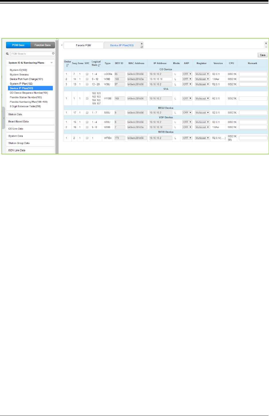
iPECS eMG80 & eMG800 & UCP
Administration and Programming Manual Issue 1.6
253
4.4.1.5 Device IP Plan - PGM 103
Selecting Device IP Plan will display the input entry page.
Figure 4.4.1.5-1 eMG Device IP Plan
TDM board is registered with own slot number. It is registered automatically without any
configuration.
If the station is assigned to Master or Slave by linked station, the bracket ‘[M] or [S]’ will be
displayed by the station number in PGM 101, 103, 105, 124 of Web page.
To register IP device:
As Gateway/board and terminals are registered to the iPECS, a slot number is assigned, which
indicates the order of registration. Also, based on the type of device (CO Gateway/board,
Terminal or Station board) the system assigns a logical Sequence Number. Thus, Sequence
Numbers for CO Gateway/board, Terminals are independently assigned based on the type of
Gateway/board. These Sequence Numbers are employed to provide a relationship between the
physical MAC address and the logical port numbers of the device.
The system may assign a default private IP address to each Sequence Number. If desired, this
program may be used to modify the assigned IP address for each Gateway/board and iPECS
Phone.
Each Gateway/board and terminal can be assigned for “Direct Send”. With Direct Send enabled,
the system will employ the Ethernet MAC address of the device to send iPECS protocol
messages to the device. This reduces the overall LAN traffic by eliminating the need for IP
address headers in the messages.
The system normally employs IP multi-cast protocol to respond to a registration request from a
Gateway/board or terminal. When the device is separated from the system by a router, the
system must use the IP uni-cast protocol. This is established by the “Local Device” assignment.
When disabled (Off), the system will send an IP uni-cast message to the device in response to a
registration request.
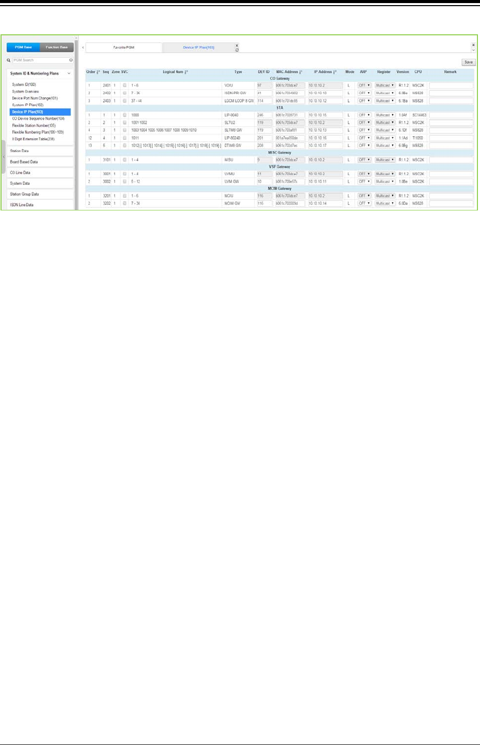
iPECS eMG80 & eMG800 & UCP
Administration and Programming Manual Issue 1.6
254
Figure 4.4.1.5-2 UCP Device IP Plan
This page displays all of the devices registered to the iPECS UCP by grouping into the type of
device (CO, STA, etc.).
If the station is assigned to Master or Slave by linked station, the bracket ‘[M] or [S]’ will be
displayed by the station number in PGM 101, 103, 105, 124 of Web page.
Selecting the SVC button for a device will toggle the service mode between in and out-of-service.
The device type can be modified as well as the MAC and IP address. Using the SVC check box
to place a device out of service, an errant device can be replaced without affecting the database.
After placing the device out-of-service, it can be removed, replaced and the MAC address of the
new device entered. The SVC check box is used to bring the new device into service employing
the database from the replaced device.
The system may assign a default private IP address to each device. If desired, this program may
be used to modify the assigned IP address for each Gateway/board and iPECS Phone.
The device mode, connected to a local or remote LAN, is displayed. Each Gateway/board and
terminal can be assigned for “ARP”. With ARP disabled, the system will employ the Ethernet
MAC address of the device to send iPECS protocol messages to the device. This reduces the
overall LAN traffic by eliminating ARP messages and the need for IP address headers in the
messages.
The system normally employs IP multi-cast protocol to respond to a registration request from a
Gateway/board or terminal.
When the device is separated from the system by a router, the system must use the IP uni-cast
protocol. This is established by the “Local Device” assignment. When disabled (OFF), the system
will send an IP uni-cast message to the device in response to a registration request.
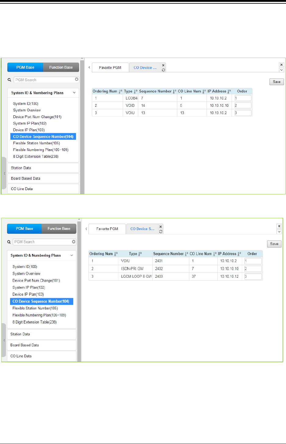
iPECS eMG80 & eMG800 & UCP
Administration and Programming Manual Issue 1.6
255
4.4.1.6 CO Device Sequence Number - PGM 104
Selecting CO Gateway/board Sequence Number will display the input entry page. Selecting the
blue colored text in the Table header will sort the table based on the selected column. Click [Save]
button after changing Value to apply.
Figure 4.4.1.6-1 eMG CO Device Sequence Number
Figure 4.4.1.6-1 UCP CO Device Sequence Number
The system configures the CO/IP Line numbers as discussed in section 2.3. In case of eMG,
each slot is assigned the starting CO/IP Line number based on the Order Numbering. With UCP,
each Module is assigned the starting CO/IP Line number based on the registration order. In
place of the default Order Numbering, the “Order” number assigned in this PGM can be used to
reorder the CO/IP numbering.
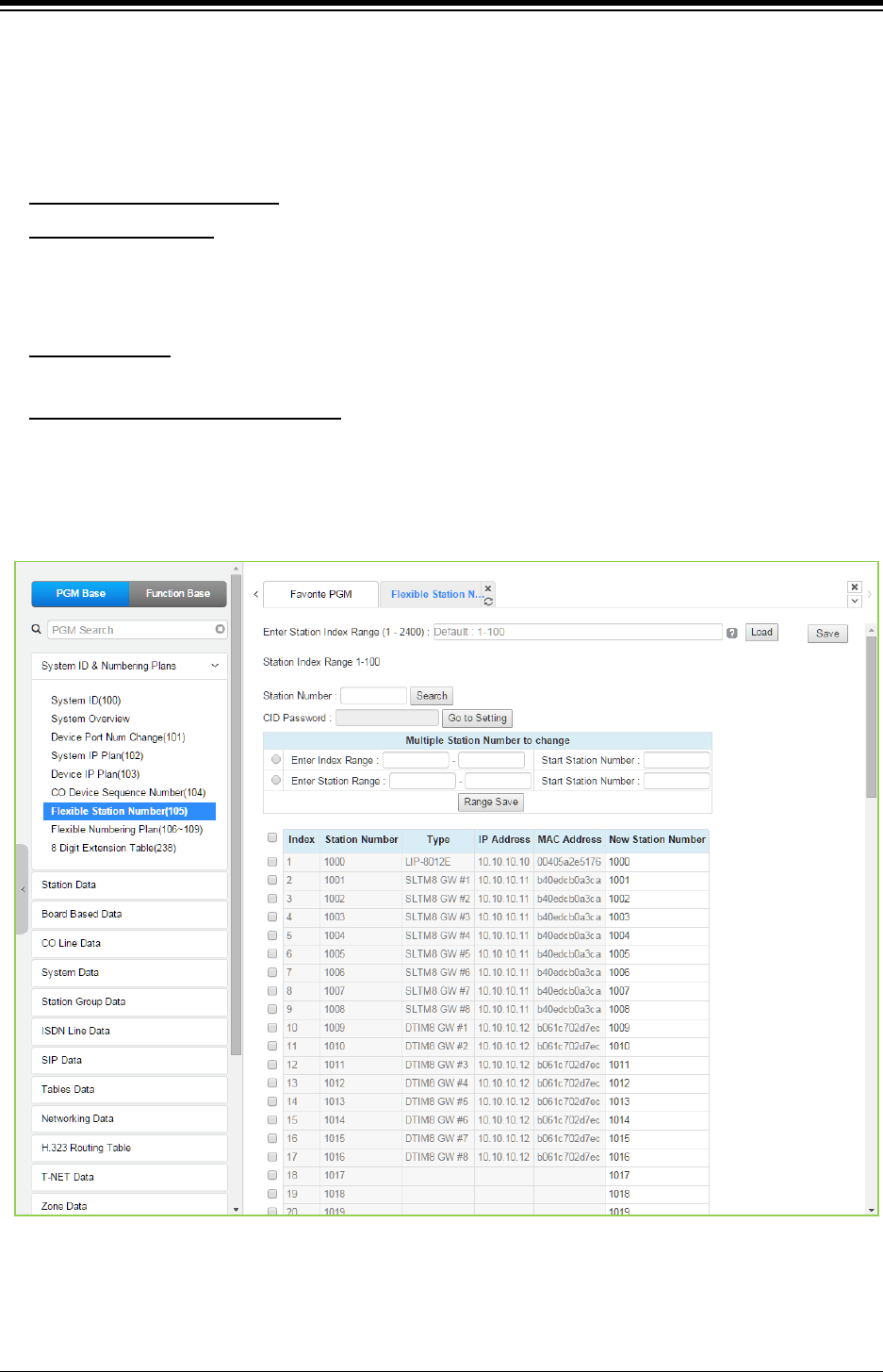
iPECS eMG80 & eMG800 & UCP
Administration and Programming Manual Issue 1.6
256
4.4.1.7 Flexible Station Numbering Plan - PGM 105
Selecting Flexible Station Number will return the data entry page. For convenience, the copy,
paste, and drag is available to enter or modify data.
This page permits changes in the Station Numbering Plan using one of three methods:
Enter Station Index Range: eMG80: 1-140 / eMG800: 1-1200 / UCP: 1-2400
Station Index Range: use to change the station numbers associated with a range of “Order
Numbers” (the indexes). The “Start Station Number” is assigned to the station with the first
index then the station number is incremented by one and assigned to the next station in the
range. The process is repeated until the station number with the last index is changed.
Station Number: enter the station number to search. The station number is displayed and then
you can change the new station number as you wish.
Multiple Station Number to change
You can change station numbers over a range of stations using the “Start Station Number” as
the first station number for the range. The station number is incremented by one for each
successive station in the range.
: there are two ways to search the station number for
change; Enter Index Range or Enter Station Range.
Figure 4.4.1.7-1 Flexible Station Number
Each iPECS IP and LDP Phone and SLT is assigned a logical order number, shown as the “Index”
number on the Web page, during the registration process. The station Index number is
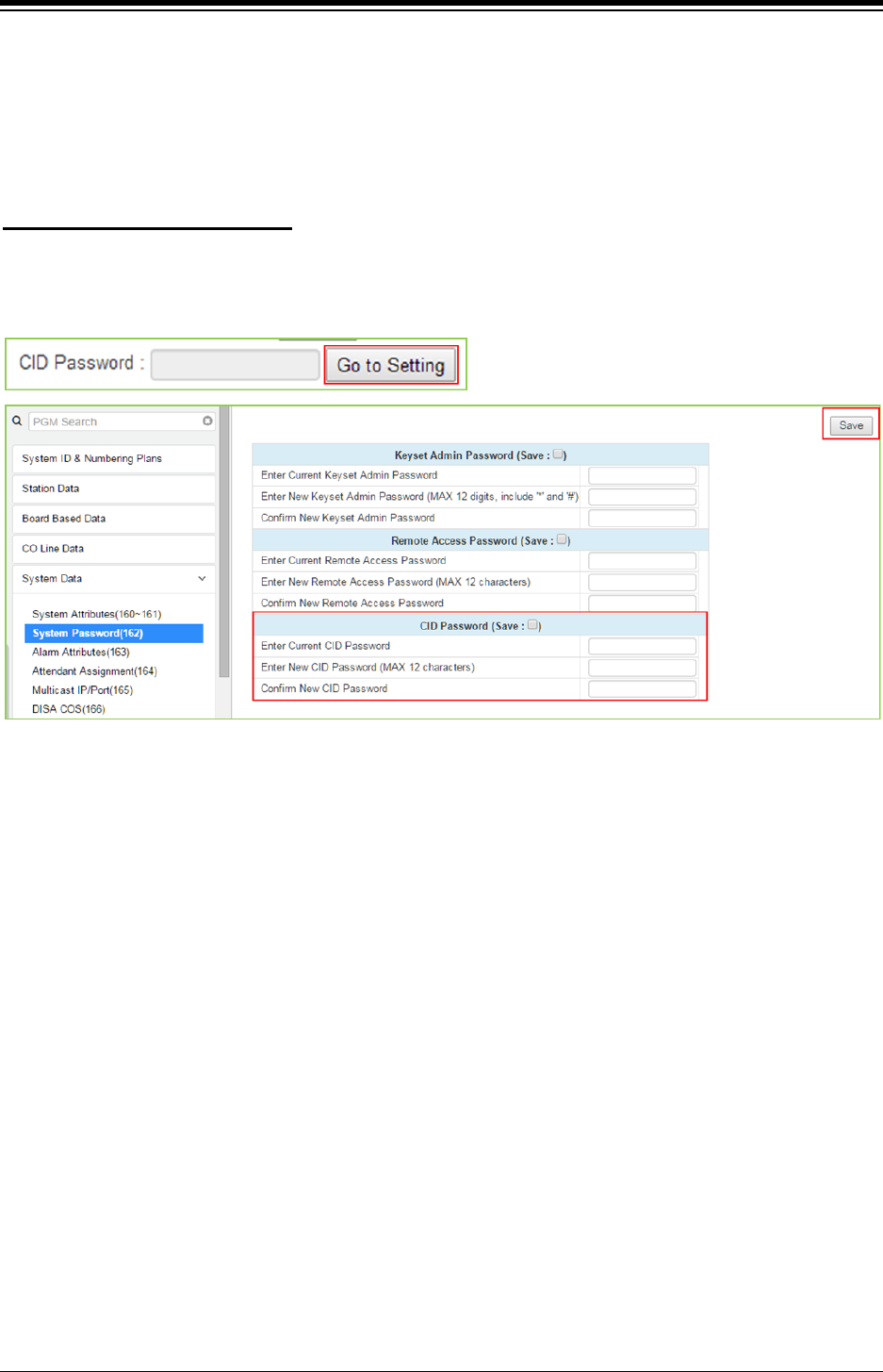
iPECS eMG80 & eMG800 & UCP
Administration and Programming Manual Issue 1.6
257
incremented from 1 as each terminal device is registered. At registration, station numbers
increment sequentially with the index and are assigned starting at Station 100 for eMG80 and at
Station 1000 for eMG800/UCP. The Station Numbering Plan allows the station numbers to be two
(2) to eight (8) digits in length as long as the number of digits in the Station numbers is the same.
You can set the CID password to click “Go to Setting” button. After clicking it, you will move to the
following PGM 162 and set the CID password, and then save CID password to mark tick on the
save box and click the [Save] button.
Setting CID Password directly
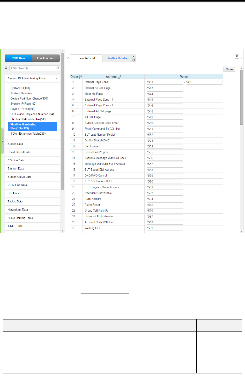
iPECS eMG80 & eMG800 & UCP
Administration and Programming Manual Issue 1.6
258
4.4.1.8 Flexible Numbering Plan - PGM 106 ~ 109
Selecting Flexible Numbering Plan will display the input entry page. Selecting the blue colored
text in the Table header will sort the table based on the selected column. Click [Save] button after
changing Value to apply.
Figure 4.4.1.8-1 Flexible Number Plan
Feature dial codes for the system can be assigned using the system‘s Flexible Number Plan.
Feature codes should be one (1) to four (4) digit in length and must not conflict. For example,
Feature codes 53 and 536 represent a conflict. The system will not update the database until
correct data is entered. Table 4.4.1.8-1 provides a brief description for each feature and the
default codes as they appear in Numbering Plan
2. The default values for other numbering plans,
which may be selected on the title “System ID (100)” and other numbering plan is described in
Appendix B.
Table 4.4.1.8-1 FLEXIBLE NUMBERING PLAN CODES
Order
ATTRIBUTE DESCRIPTION DEFAULT
1 Internal Page Zone Internal Page Zone access codes.
eMG80:301~335
eMG800:*301~*400
UCP:*301~*400
2
Internal All Call Page
Internal All Call Page access code.
*543
3
Meet Me Page
Meet-Me-Page answer code.
*544
4
External Page Zone – 1
External Page Zone 1 access code.
*545

iPECS eMG80 & eMG800 & UCP
Administration and Programming Manual Issue 1.6
259
Table 4.4.1.8-1 FLEXIBLE NUMBERING PLAN CODES
Order
ATTRIBUTE DESCRIPTION DEFAULT
5
External Page Zone – 2
External Page Zone 1 access code only for UCP.
*546
6
External All Call Page
External All Call Page access code.
*548
7
All Call Page
All Call Page access code.
*549
8 SMDR Account Code Enter Dial code to signify the start of an SMDR Account
Code.
*550
9 Flash Command To CO Line Dial code to generate a Flash on the active CO
Line.
*551
10
SLT Last Number Redial
SLT Last number redial feature access code.
*552
11
Do-Not-Disturb (DND)
Dial code to activate Do-Not-Disturb.
*553
12
Call Forward
Code to activate Call Forward.
*554
13
Speed Dial Program
SLT Speed Dial programming access code.
*555
14 Activate Message Wait/Call
Back
Code to activate Message Wait/Call Back. *556
15
Message Wait/Call-Back Answer
Code to return Message Wait/Call Back.
*557
16
SLT Speed Dial Access
SLT Speed Dial access code.
*558
17
DND/FWD Cancel
Code to cancel DND/FWD/MSG Wait.
*559
18
SLT CO System Hold
Code to place a CO Line call on System Hold.
*560
19
SLT Program Mode Access
SLT user program access code.
*561
20
Attendant Unavailable
Code to make attendant “unavailable”.
*562
21 AME Feature Dial code to assign an Answering Machine
Emulation Flex button.
*564
22
Alarm Reset
Code to terminate an Alarm signal.
*565
23
Group Call Pick-Up
Group Call Pick-up code.
*566
24
Universal Night Answer
Universal Night Answer code.
*567
25
Account Code With Bin
Dial code for entering an Account Code.
*568
26
Walking COS
Dial code to activate Walking Class-of-Service.
*569
27 ACD Agent ON/OFF Duty Code to toggle ACD Supervisor ON and OFF
duty.
*571
28
ACD Supervisor Login
Supervisor log-in code.
*572
29
ACD Supervisor Logout
Supervisor log-out code.
*573
30
ACD Help Code
Agent & Supervisor code for Supervisor help.
*574
31
ACD Call In Queue Display
Dial code to display calls in queue.
*575
32
ACD Supervisor Status
Dial code to display group status.
*576
33
ACD Supervisor Monitor
Dial code to activate Supervisor monitor.
*577
34 ACD Reroute Queued Call
Answer
Code to reroute call after answer. *578
35 ACD Reroute Queued Call No
Answer
Code to reroute call prior to answer. *579
36
Camp-On Answer
Dial code to answer a Camped On call.
*621
37 Call Park Locations Dial code to place/retrieve a call in a system Park
Orbit.
eMG80:#601~#619
eMG800:#601~#800
UCP:#601~#800
38 Station Group Pilot Number Station group pilot number.
eMG80: *401~*440
eMG800: *401~*500
UCP: *401~*500
39 Station User VSF Features
Access
VSF feature access code. 66
40
Call Coverage Ring
Code for Call Coverage button.
*76

iPECS eMG80 & eMG800 & UCP
Administration and Programming Manual Issue 1.6
260
Table 4.4.1.8-1 FLEXIBLE NUMBERING PLAN CODES
Order
ATTRIBUTE DESCRIPTION DEFAULT
41
Direct Call Pick-Up
Dial code to activate Directed Call Pick-up.
*77
42
Access CO Group
Dial code to access a CO Line from a group.
89
43
Access Individual CO/IP
Dial code to access a specific CO/IP Line.
88
44
Access Held CO/IP
Dial code to access the last CO/IP Line from Hold.
8*
45 Access Held Individual CO/IP Dial code to access a specific CO/IP Line from
Hold.
8#
46 Access CO In First CO Group Dial code to access the 1st available CO/IP Line in
any accessible group.
9
47
Attendant Call
Dial code to call Main Attendant.
0
48 VM MSG Wait Enable Dial code for external Voice mail to activate
Message Wait indication.
*8
49 VM MSG Wait Cancel Dial code for external Voice Mail to deactivate
Message Wait indication.
*9
50
Door Open
Dial code to activate Door 1 contact.
#*1
51
Door Open
Dial code to activate Door 2 contact.
#*2
52
Door Open
Dial code to activate Door 3 contact only for UCP.
#*3
53
Door Open
Dial code to activate Door 4 contact only for UCP.
#*4
54 MCID Request Dial code to activate Malicious Caller Id (Except
USA version).
*0
55 Unsupervised Conf Timer
Extend Code
Dial code to extend unsupervised conference
time.
##
56 PTT Group Logon/Logoff
Push-To-Talk group login and logout dial code.
The station must have a PTT button for proper
operation.
#0
57
ACD Agent Primary Login
ACD Agent Primary Login code.
*581
58
ACD Agent Primary Logout
ACD Agent Primary Logout code.
*582
59
ACD Agent Secondary Login
ACD Agent Secondary Login Code.
*583
60
ACD Agent Secondary Logout
ACD Agent Secondary Logout Code.
*584
61
Wrap-up End
ACD Agent Wrap-up end code.
*585
62 T-NET CM LOGIN/OUT T-NET CM Login/out code *586
63
ENTER INTO CONF ROOM
Code for a station to enter a conference room.
*59
64 ENTER INTO CONF-GROUP Code for a station to initiate a conference group. *68
65
STATION ICR
Code for a station to activate ICR forward.
*587
66 PICK UP GROUP PICK-UP Pick Up Group Call Pick-up dialing code. *588
67
EMERGENCY PAGE
Code for emergency page.
*589
68 REMOTE MEX CONTROL Code to control the mobile extension settings
remotely. *580
69 Agent ON/OFF Duty In ALL
GRP
Code to change the state of the Agent ON/Off
duty in all Station groups.
*58*
70 SLT ACNR Dial code for an SLT to activate ACNR *58#
71 ACD Supervisor Ring Mode Code to check and change ACD group Ring mode
by ACD group supervisor.
*570
72 Company Directory Name Code to check and record a user’s Name greeting
for the Company Directory feature. *563
73 ISDN Supplementary HOLD ISDN Supplementary HOLD Numbering Plan
Code.
*57*
74 ISDN Supplementary
Conference
ISDN Supplementary Conference Numbering Plan
Code (Not supported). *57#

iPECS eMG80 & eMG800 & UCP
Administration and Programming Manual Issue 1.6
261
Table 4.4.1.8-1 FLEXIBLE NUMBERING PLAN CODES
Order
ATTRIBUTE DESCRIPTION DEFAULT
75 Forced Channel Seize Code to disconnect an existing call and seize the
CO/IP Line or connect to the station.
*56*
76 Override DND/Forward Dial code to override DND or Call Forward
activated by a station.
*56#
77
Cancel call back
Code to cancel a Callback request.
78 Transfer to VSF Number
While on a CO/IP Line call, this code may be used
to transfer a call to a valid system announcement,
[Transfer] + [*55*] + valid system announcement
(01-200). The outside party receives the system
announcement and DISA service activates.
*55*
79
CCR
It is used in digit conversion.
#2
80 Room Type Conf Group Join
After a UCS client activates a UCS Conference
Group, other users may dial this code and the
group number to enter the Conference.
5*0
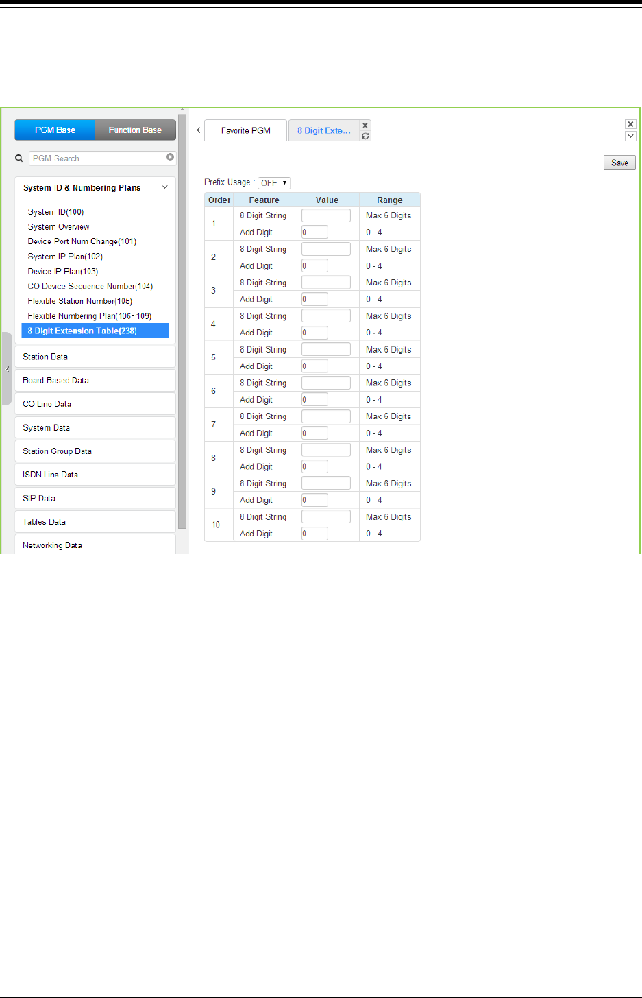
iPECS eMG80 & eMG800 & UCP
Administration and Programming Manual Issue 1.6
262
4.4.1.9 8 Digit Extension Table - PGM 238
Selecting 8 Digit Extension Table will display the input entry page. Click [Save] button after
changing Value to apply.
Figure 4.4.1.9-1 8 Digit Table
The iPECS system supports a Station Numbering Plan of up to eight digits. By combining a prefix
digit string (8 Digit String) of up to six (6) digits with the Add Digit count (digit count from the
Station Numbering assigned in PGM 105), Station Numbering can support up to eight digits. Note
that multiple prefixes (8 Digit Strings) with varying ADD Digit counts can be assigned. In addition,
in case of a conflict, the Prefix digit string will have priority over the Flexible Numbering Plan thus
disabling the feature associated with the digit string but allowing the station to receive calls.
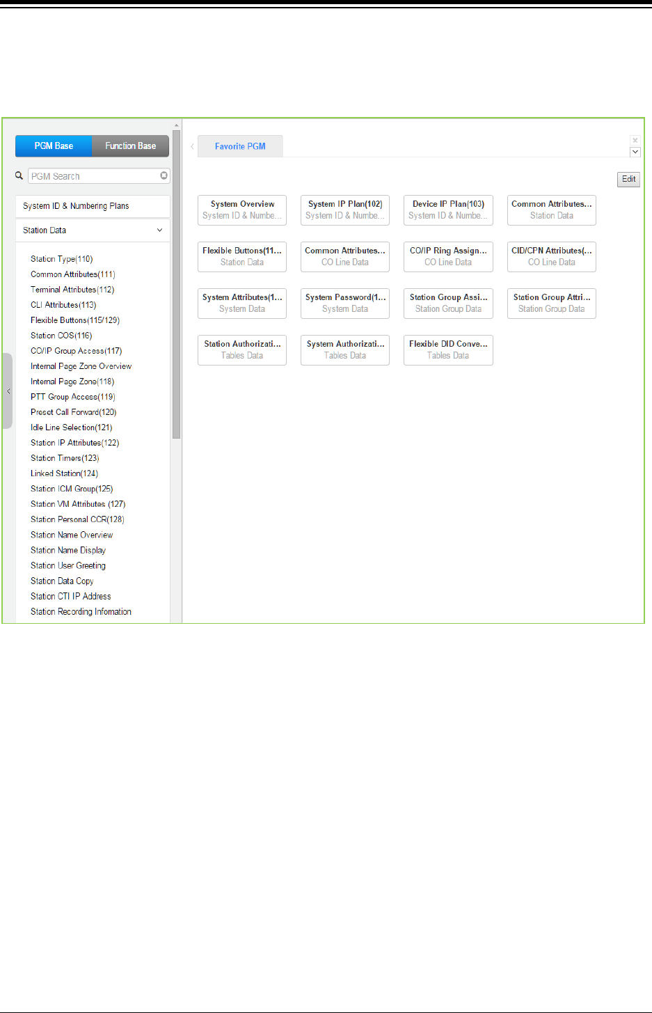
iPECS eMG80 & eMG800 & UCP
Administration and Programming Manual Issue 1.6
263
4.4.2 Station Data
Selecting the Station Data group will display the Station Data sub-menu displayed in the left
frame as the below figure.
Figure 4.4.2-1 Station Data Main Page
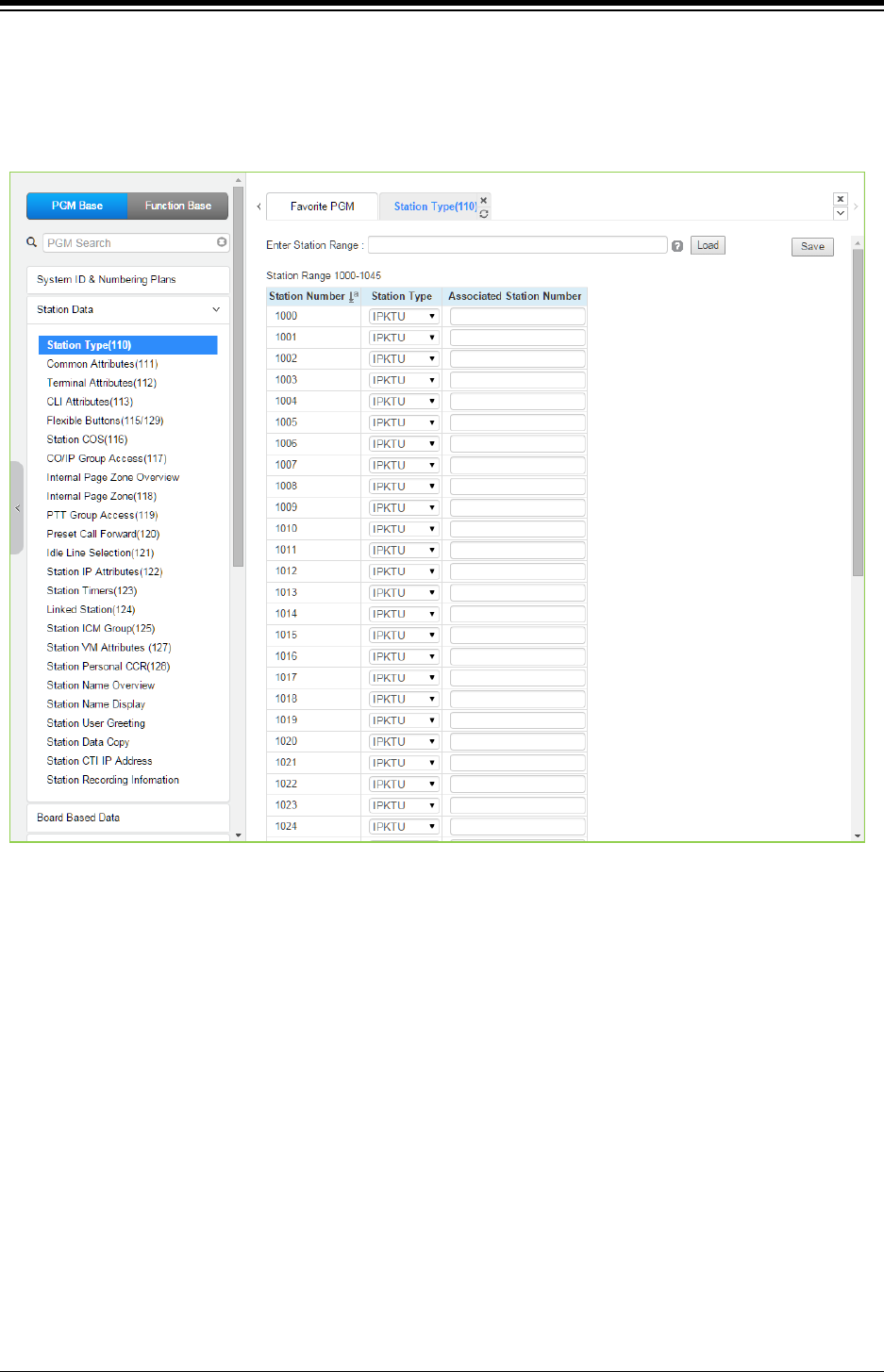
iPECS eMG80 & eMG800 & UCP
Administration and Programming Manual Issue 1.6
264
4.4.2.1 Station Type - PGM 110
Selecting Station Type will display the Station Type data input entry page. Enter a valid station
range and click [Load] to modify the Station Type data. Click [Save] button after changing Value
to apply.
Figure 4.4.2.1-1 Station Type
Each station is assigned a type selected from the “Station Type” drop-down menu. The type is
used by the system to recognize the station‘s capability and set default Flex button configurations.
In addition, for standard iPECS DSS/BLF consoles, the ‘Associated Station Number’ is required
so the system will recognize the station that is used with the console. Note this is not used with
the Serial DSS/BLF Consoles.
In case of selecting SLT type, there are 6 types as below:
SLT (DTMF)
SLT (Pulse)
SLT (DTMF VOL-MW)
SLT (Pulse-MW)
SLT (DTMF FSK-MW)
SLT (DTMF POL-MW)
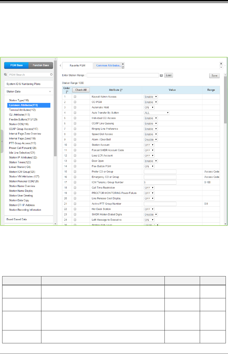
iPECS eMG80 & eMG800 & UCP
Administration and Programming Manual Issue 1.6
265
4.4.2.2 Common Attributes - PGM 111
Selecting Common Attributes will display the common attributes data input page. Enter a valid
station range and click the [Load] button to enter Common Attributes data.
Use the check boxes to indicate which attributes to define; data for checked attributes is stored
for the entire range of stations by clicking [Save] button after changing Value.
Figure 4.4.2.2-1 Common Attributes
Common Attributes define features and functions available to the station. Generally, the entry will
turn the feature ON (enable) or OFF (disable). Refer to the following table for a description of the
features and the input required.
Table 4.4.2.2-1 Common Attributes
ATTRIBUTE DESCRIPTION RANGE DEFAULT
Keyset Admin
Access
When enabled, the station can access the system Database. Disable
Enable
Enable
CO PGM A station can be permitted to change the CO/IP Line numbers
(ports) associated with a Flexible button.
Disable
Enable
Disable
Automatic Hold
Enables Auto Hold for the station. With Auto Hold enabled, the
system will place an active external call on hold if the user
presses a CO/IP Line or DSS button.
OFF
ON
ATD: ON
Others:
OFF
Auto Transfer By
Button
Transfer a talking call to a new making call by pressing Station
(DSS)/CO (Loop)/U-Loop flexible button.
OFF
ALL
ALL

iPECS eMG80 & eMG800 & UCP
Administration and Programming Manual Issue 1.6
266
Table 4.4.2.2-1 Common Attributes
ATTRIBUTE DESCRIPTION RANGE DEFAULT
Except CO
to CO
Individual CO
Access
Permits stations to use dial codes to access individual CO/IP
Lines.
Disable
Enable
Enable
CO/IP Line
Queuing
Permits the station to queue for the next available Line when
an All Lines Busy signal is received.
Disable
Enable
Enable
Ringing Line
Preference
Enables Ringing Line Preference for the station. Calls that ring
the telephone can be answered by going off-hook without
selecting the CO/IP Line button.
Disable
Enable Enable
Speed Dial
Access
Allows the station to access System Speed Dial bins. Disable
Enable
Enable
Alarm/Door Bell Assigns a station to receive Alarm/Door Bell signal. Disable
Enable
Disable
Station Account When ON, the station user must enter an authorization code
to access CO/IP Lines.
OFF
ON
OFF
Forced SMDR
Account Code
When On, the user must enter an Account code to place an
outgoing call.
OFF
ON
OFF
Loop LCR
Account
The Station may be required to enter a Station Authorization
code to access LOOP LCR operation.
OFF
ON
OFF
Door Open Enables use of Door open feature by station. Disable
Enable
Enable
Flex Button PGM
The ability to assign Flexible buttons of the iPECS IP and LDP
Phones can be controlled. When allowed here, the user may
assign features to Flexible buttons but requires special
assignments to configure CO/IP Line buttons.
OFF
ON ON
Prefer CO or
Group
The System will seize this CO/IP Line or a Line from the
CO/IP group number when the station dials “9” (First available
Co access code)
CO/IP Line/
CO Group
number
Access
code
Emergency CO or
Group
This field defines the CO/IP Line or Group employed by the
system to place Emergency Assistance calls.
CO # or CO
Group #
Any CO
ICM Tenancy
Group Assigns stations to an ICM Tenancy Group.
eMG80:1~15
eMG800:0~32
UCP:0~100
1
Call Time
Restriction
All outgoing calls will disconnect at expiration of the Call
Restrict Timer. The Cut-Off Timers can be set the time for
Station and CO Line. For cut off timer of Station, refer to the
title “Station Timers (123)”. For CO line, refer to the title “CO
Line data: Common Attributes (144)”.
OFF
ON OFF
Proctor Monitoring
Power-Fail
Enables use of PABX ANI Link device for E-911 support, Only
an SLT port can be used for this feature.
OFF
ON
OFF
Line Release Cost
Display
When a CO/IP line is released, the disconnect cause or call-
cost is displayed in the LCD of iPECS IP or LDP Phone.
OFF
ON
OFF
Active PTT Group
Number
A station can be assigned to a PTT (Push-to-Talk) group and
the group enabled so the station can place and receive PTT
announcements for the group.
0~9
Hot Desk Station
A station (only IP Phone) can be assigned as a Hot Desk
phone. Users and agents can login and use resources of the
system through the Hot Desk phone.
OFF
ON OFF
SMDR Hidden
If this feature enables, the dialed digit can be hided on SMDR
Disable
Disable

iPECS eMG80 & eMG800 & UCP
Administration and Programming Manual Issue 1.6
267
Table 4.4.2.2-1 Common Attributes
ATTRIBUTE DESCRIPTION RANGE DEFAULT
Dialed Digits
output.
Enable
Left Message to
Executive
When a call forwards to the Secretary of an
Executive/Secretary pair, messages can be left for the
Executive (ON) or Secretary (OFF).
OFF
ON ON
Station Web Level
Based on this level, the user will be able to view the specified
programs within the Station User Web portal. Level 1 can view
all programs, Levels 2 and 3 are configured in the title
“System data: Station Web Authorization”. This is a Web only
PGM.
LEVEL 1 ~
LEVEL 3 LEVEL 2
Headset page
mode
When a page announcement is received, it is normally played
over the Speaker of the iPECS IP or LDP Phone. For headset
users, the page can played to the headset or both the headset
and speaker.
SPKR/
HEADSET/
BOTH
Speaker
Progress
Indication
When employing a non-ISDN terminal, specifically a modem
or analog FAX, the ISDN call SETUP message must include
this message and “Progress Indication” should be set to “ON”.
OFF
ON OFF
3.1 KHz Audio
When an analog device (SLT or FAX) uses an ISDN Line in
the system, the Information Element of the ISDN SETUP
message must indicate the device only has 3.1 KHz audio
capabilities. If an SLT or analog FAX will be allowed access to
the ISDN Lines, this parameter must be “ON”
OFF
ON OFF
Pickup by flexible
button
When a station receives a call, the DSS/BLF button at other
stations will flash and, if allowed, other stations may use the
button to answer (pick-up) the call.
ON: User can pick up by DSS button.
OFF: User can’t pick up by DSS button.
OFF
ON ON
Prepaid Call
It is useful feature for user to pay the money within the budget
(Prepaid) for outgoing calls. For more information, refer to the
below feature “Prepaid money”.
OFF
ON OFF
Prepaid Money (0
- 999999)
&
Used Prepaid
Money
An amount can be associated with the station as prepayment
for outgoing calls. The assigned “Pre-paid Money” is reduced
by the calculated call cost (Call Metering or cost/minute). This
parameter displays the remaining funds for outgoing calls.
Prepaid Money is often used in small hospitality businesses.
The “Used Pre-paid Money” displays the money that has been
used.
000000 –
999999
000000 -
999999
0
0
SIP USER TABLE
INDEX
These fields reference the index to the SIP User ID Attributes
Table. The referenced SIP User ID may be employed for
several of the SIP headers for outgoing calls and may be
employed for incoming call routing as configured in the SIP
CO Attributes PGM 133, “ID Assigned Station”.
Up to three SIP User Id indices can be assigned to each
station to permit the use of up to three SIP Trunk service
providers.
eMG80:0~140
eMG800:0~1200
UCP:0~2400
0
SIP USER TABLE
INDEX2
0
SIP USER TABLE
INDEX3 0
Station Web
Language
User can select the desired language for Station Web. English/
Local language
English
Lift Handset for
page
If an iPECS IP or LDP Phone user attempts to page using the
speakerphone, pre-selection will be activated and the display
shows “Lift Handset for Page when Lift Handset for Page is
OFF
ON ON

iPECS eMG80 & eMG800 & UCP
Administration and Programming Manual Issue 1.6
268
Table 4.4.2.2-1 Common Attributes
ATTRIBUTE DESCRIPTION RANGE DEFAULT
ON”.
If Lift Handset for Page is OFF, then User can make page on
speakerphone without lift handset.
Privacy
If Privacy is ON, then any person could not barge-in to the
station and also Attendant can’t intrude to Station. Also, if
Privacy is ON, any person can’t forcefully disconnect the
station.
OFF
ON OFF
Call Coverage Attributes
Call Coverage
Mode
The Call Coverage feature permits an iPECS IP or LDP
Phone user to receive ring and answer calls for other stations.
OFF
ON
OFF
Call Coverage
Delay Ring
When a covered station rings, the {CALL COVERAGE}
button LED will flash at the covering station and the station will
receive ring (immediate or delayed by 0 to 15 ring cycles).
0~15 0
Call Coverage On
Busy
OFF: Call Coverage is implemented when a covered station is
in the idle state.
ON: Call Coverage is implemented when a covered station is
on idle or busy state.
OFF
ON ON
Call Coverage
Through Mobile
Extension
OFF: Call Coverage Ring is not delivered to Mobile Extension
ON: Call Coverage Ring is not delivered to Mobile Extension
OFF
ON ON
Call Coverage On
Busy Range
External Call Only: Call Coverage only for external calls when
the covered station is busy
External and Internal Call: Call Coverage both for external &
internal calls when the covered station is busy
External Call
Only/
External and
Internal Call
External
Call
Only
Call Coverage
Delay Ring
Method
by Originator: Call Coverage Delay is implemented by the
covered station’s “Call Cover Delay Ring” delay count’
by Member: Call Coverage Delay is implemented by covering
station’s “Call Cover Delay Ring” delay count’
by Originator/
by Member
by
Originator
Call Coverage For
Wakeup Ring
OFF: Wakeup Ring to covered station is not covered
ON: Wakeup Ring to covered station is covered
OFF
ON
OFF
Call Coverage
Ring Type on
Member
Silence: No audible ring is presented and the user must press
the flashing Call Coverage button to answer the call.
Normal Ring: Audible ring is presented and the call can be
answered by simply lifting the handset or pressing the
Speaker button.
Mute ring is only supported in LIP-8000E series.
Silence/
Normal Ring/
Muted(Continuo
us)-80XXE only/
Muted(One
Burst)-80XXE
only
Normal
Ring
Tone/Ring Attributes
Call Time Tone
A tone can be sent periodically with indicating the elapsed
time of an outgoing CO/IP call. The Elapsed Call Timer
determines the period between tones. For more information
about Elapsed Call timer, refer to the title “System data:
System timer (180~182, 186)”.
OFF
ON OFF
Camp-on Tone
When the Camp-on feature is enabled for the station, if the
station is busy and receives a Camp-on request, the LCD
indicates the camped on call. In addition, if Camp-on tone is
enabled, the Camp-On tone is sent to the station as an
audible signal for the camp-on.
OFF
ON ON
ICM Dial Tone
One of four dial tone sources can be selected for each station.
Dial Tone/
Dial Tone

iPECS eMG80 & eMG800 & UCP
Administration and Programming Manual Issue 1.6
269
Table 4.4.2.2-1 Common Attributes
ATTRIBUTE DESCRIPTION RANGE DEFAULT
Source Internal music/
External music/
VSF MOH/
SLT MOH1~5/
VSF MOH2/
VSF MOH3
ICM Ring Back
Tone Source One of four ring back tones can be selected for each station.
Ring Back Tone/
Internal music/
External music/
VSF MOH/
SLT MOH1~5/
VSF MOH2~3
Ring Back
Tone
Off hook ring type
While the station is Off hook ring, the type of ring can be
adjusted as a single burst, muted normal ring, system ring or
no audible ring signal.
BURST/
MUTE/
Refer to System
Attributes
SILENCE
Refer to
System
attributes
SIP color ring
With a SIP based AA/VM that supports color ring, color ring
may be provided to SIP pones. The group number associated
with the external AA/VM should be entered as the SIP Color
Ring source.
Station
number
Gain table index
Selects one of three Tables employ to set the gain from a
device to other device types. PGM 410 to 417 under the
Maintenance tab set the individual gains.
1-3 1
Tone table index
Selects one of five Tables to determine the tones sent to the
Station. The individual tones are configured in PGM 410 to
417 under the Maintenance.
1-5 1
Digit conversion
table
One of the Digit Conversion Tables can be configured for use
for this CO/IP Line.
eMG80:1-15
eMG800:1-32
UCP: 1-32
Routing Attributes
Call Forward When allowed, Call Forward can be activated by the station. OFF
ON
OFF
DND
Enables DND to be activated by the station. The station can
be limited to activate DND for outside calls (CO/IP Only) or for
internal calls (ICM only), if desired.
OFF/
ALL/
ICM call only/
CO call only
OFF
Off-net Forward
A station must be allowed Off-Net Fwd to forward external
incoming calls outside the system or otherwise establish a
CO-to-CO connection (Unsupervised Conference). (Except
USA version)
Disable
Enable Enable
ACD Group
Service
When unavailable, DID/DISA calls to the station can route to
the ACD Group to which the station is a member.
OFF
ON
OFF
Ring Group
Service
When unavailable, DID/DISA calls to the station can route to
the Ring Group to which the station is a member.
OFF
ON
OFF
ACD Login Priority
ACD Group members may be assigned a priority, 0-9.
Members with the highest priority are sent calls ahead of
lower priority members. This field is the same as PGM 191-
button 19.
0 ~ 9 0

iPECS eMG80 & eMG800 & UCP
Administration and Programming Manual Issue 1.6
270
Table 4.4.2.2-1 Common Attributes
ATTRIBUTE DESCRIPTION RANGE DEFAULT
Prime Line
This feature enables Delayed Prime Line (Idle Line) activation;
see the title “Idle Line Selection (121)” and “System data:
System timer: Prime Line Delay timer (180~182 & 186)”.
HOT
WARM WARM
Auto ACD DND
If an Agent does not answer an ACD call in the ACD No
Answer timer, the Agent enters an Unavailable state with the
Reason code entered here. The reason code is sent in ACD
Event messages.
None
#, *, 1~9 NONE
Forward if OOS
If a station is Out-of-Service and has previously forwarded
calls, the system will forward the calls to the previous
destination if enabled here.
OFF
ON OFF
LDT Table Index LCR operation for the station will employ the LDT Table index
defined by this entry.
eMG80: 1-10
eMG800:1-32
UCP:1-32
1
LDT Zone number If the LDT Zone Number of a LDT table (LCR LDT(221)) is
equal to this value, the LDT table is available to this station.
1-100 1
Mobile (Web)
Client Service
When enabled, the station can activate call back from the
Station Web portal.
Disable,
Enable
Disable
Click to call
service
To use click call application, it should be enabled. Disable,
Enable
Disable
MS Lync RCC
service
To use MS Lync RCC, it should be enabled. Disable,
Enable
Disable
MSN Wait
When a call that is corresponding to a MSN Telephone
Number comes in to system, the call is basically routed to idle
stations that have free MSN button that is assigned for the
corresponding Telephone Number. And also the call can be
routed to busy stations in the following condition.
OFF : if a keyset is in a busy status, cannot receive incoming
MSN Telephone Number corresponding call even though it
has a free(idle) corresponding MSN LOOP Button
ON : if a keyset is in a busy status, can receive incoming MSN
Telephone Number corresponding call if it has a free(idle)
corresponding MSN LOOP Button.
OFF
ON OFF
DID Restriction
A call routed using DID normally routes to the appropriate
station. If desired, a Station can be restricted from receiving
DID calls.
OFF
ON OFF
DISA Restriction
A call routed using DISA normally routes to the appropriate
station. If desired, a Station can be restricted from receiving
DISA calls.
OFF
ON OFF
Pre-Selected Msg
DND
When the user activates Pre-Selected or Custom Messages,
the system can automatically activate DND for the station so
that the station will not receive ring and the call is routed
based on the DND treatment.
OFF
ON OFF
Voice Attributes
Page Access Stations must be allowed Page access to send a page over
the system’s Paging facilities.
OFF
ON
OFF
Forced hands
Free Mode
When placing an intercom call, a user can change the ICM
signaling mode, Tone Ring to Hands free answer mode or HF
Answer to Tone Ring.
OFF
ON OFF
Group Listening
Enables Group Listen feature, audio is sent to both the
Disable
Enable

iPECS eMG80 & eMG800 & UCP
Administration and Programming Manual Issue 1.6
271
Table 4.4.2.2-1 Common Attributes
ATTRIBUTE DESCRIPTION RANGE DEFAULT
handset and speaker with the handset microphone active and
speakerphone microphone OFF.
Enable
Override Privilege Enables intrusion to gain access to an active CO/IP call. Disable
Enable
Disable
Voice Over Enables use of Voice Over by the station. Disable
Enable
Enable
Barge In Mode
Barge-in permits an authorized Station to intrude into other
existing outside/internal calls or to force disconnection existing
of an existing call.
Disable/
Only Monitor/
Monitor & Join &
Disconnect
Disable
Camp on enable
Station can receive a Camp-on while busy. If ‘Camp On Tone’
is enabled, the stations receive Camp-on tone, otherwise only
the LCD will indicate the camp on call. If the station is not
allowed to receive a Camp-On, the calling user receives error
tone.
OFF
ON ON
Video Show on
Calling (ex. IP
Video Door
Phone)
When VoIP video door phone rings to a video-enabled IPKTS
handset, the video streaming commences immediately while
the IPKTS handset is in the ringing and the video stream
continues when answered.
- OFF : normal implementation (video starts after answer)
- ON: video stream from this Video Door Phone to the ringing
video-enabled LIP Phone even though this is alerting stage.
- Condition: A VOIU/VOIB channel for RTP-Packet-Relay
purpose is required to serve ring-back-tone generation via a
DSP channel.
That is because system does pre-answer to the Video Door
Phone even though the receiving station is on alerting state.
OFF
ON OFF
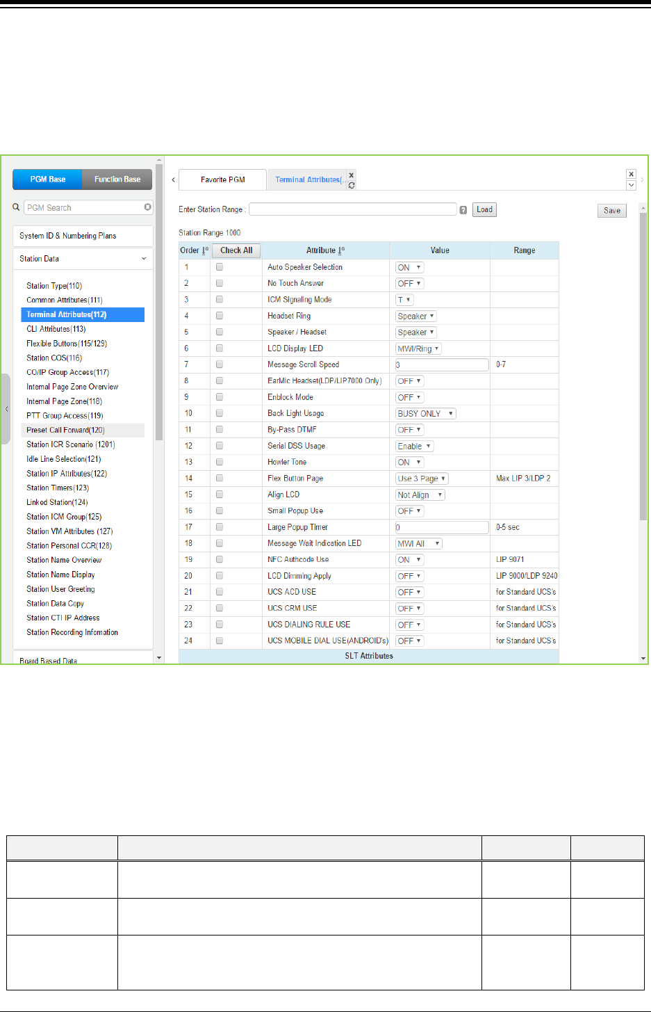
iPECS eMG80 & eMG800 & UCP
Administration and Programming Manual Issue 1.6
272
4.4.2.3 Terminal Attributes - PGM 112
Selecting Terminal Attributes will display the Terminal Attributes data input page. Enter a valid
station range and click [Load] to enter Terminal Attributes data. Use the check boxes to indicate
which attributes to define; data for checked attributes is stored for the entire range of stations
by clicking [Save] Button after changing Value.
Figure 4.4.2.3-1 Terminal Attributes (PGM 112)
Terminal Attributes define features and functions available to the terminal itself. Generally, the
entry will turn the feature ON (enable) or OFF (disable). Refer to the following table for a
description of the features and the input required.
Table 4.4.2.3-1 Terminal Attributes
ATTRIBUTE DESCRIPTION RANGE DEFAULT
Auto Speak
Selection
Enables [SPEAKER] activation when a CO/IP Line, DSS or
other feature button is pressed; there is no need to lift handset.
OFF
ON
ON
No-Touch Answer Enables No-touch answer, which automatically connects
transferred calls to the station’s speakerphone after a short tone.
OFF
ON
OFF
ICM signaling
Mode
The user may select Hands-free (H), Privacy (P) or Tone Ring
(T) for the ICM Signaling mode.
H,
T,
P
T

iPECS eMG80 & eMG800 & UCP
Administration and Programming Manual Issue 1.6
273
Table 4.4.2.3-1 Terminal Attributes
ATTRIBUTE DESCRIPTION RANGE DEFAULT
Headset Ring The user can select how to receive Incoming ring signals among
Speaker, Headset or Both.
Speaker/
Headset/
Both
Speaker
Speaker/Headset The user can select between Speaker and Headset for Call. Speaker/
Headset/
Speaker
LCD Display LED The LCD LED, upper left of LCD, may be used for Intercom Call
ring Indication or both Message Wait and ring Indication.
MWI/Ring,
Ring
MWI/Ring
Message Scroll
Speed
The user can adjust the scroll speed on message from 0 to 7. 0 ~7 3
Ear & Mic Headset
The user can use Ear Microphone Headset for Internal or
external calls if the phone has the Ear. Microphone headset
port.
OFF
ON OFF
Enblock mode
When On, the user-dialed digits are stored at the iPECS IP or
LDP Phone until explicitly sent by the user. When sent, all dialed
digits are sent to the system in a block.
Enblock mode is only available to iPECS IP or LDP Phones with
3-Soft keys.
OFF
ON OFF
Back Light Usage
The backlight of iPECS IP and LDP Phones is assigned to stay
off, light only when the station is busy, or light constantly. Please
check the phone if the feature is available before setting this
option.
Always Off/
Busy Only/
Always On
Busy Only
By Pass DTMF
When detected, DTMF from an SLT may be regenerated by
CO/IP Line interface circuitry, the SLT port can by-pass
detection so DTMF is not detected.
OFF
ON OFF
Serial DSS Usage Enables an LIP-8000/LIP-9000 station to have a Serial DSS
/BLF
Console attached.
Disable
Enable
Enable
Howler Tone Howler tone can be sent to a phone when left off-hook. OFF
ON
ON
Flex Button Page
The iPECS LIP-9030 and 9040 have 8 and 12 Flexible buttons,
respectively. Additional Flex buttons are available using Flex
button pages. The phone can have up to 3 pages each with the
8 or 12 Flex buttons. Thus, an LIP-9030 can have 24 Flex
buttons and the LIP-9040 can have 36 Flex buttons.
The Navigation Up/Down button is used to scroll through the
Flex buttons pages assigned.
Use 1 Page
Use 2 Page
Use 3 Page
Use 3 Page
Align LCD
For the iPECS LIP-9010/20/30/40, character alignment for
messages to the phone can be right or left aligned by the
system, or alignment controlled by the phone (“Not Align”).
For the other phone, please check if the feature is available
before using this option.
Not Align
Align Left
Align Right
Not Align
Small Popup Use
If this option is set to ON, small popup is displayed on the LCD
of LIP-9030/9040.
If it is set to OFF, top bar is displayed instead of small popup.
OFF
ON OFF
Large Popup
Timer
When Large popup timer is set to any value from 1 to 5 except
0, the display of large popup is disappeared after the timer
expired and then the large popup information is displayed at top
bar.
0~5
(Sec.) 0
Message Wait
Indication LED
User can program MWI (Message Wait Indication) LED
according to the following type:
MWI All,
VM MWI,
MWI ALL

iPECS eMG80 & eMG800 & UCP
Administration and Programming Manual Issue 1.6
274
Table 4.4.2.3-1 Terminal Attributes
ATTRIBUTE DESCRIPTION RANGE DEFAULT
1. MWI All: LED is blinking about all calls and Message
2. VM MWI: blinking in case of getting Voice mail
3. CLI MWI: blinking in case of Calling Line Identification
4. SMS MWI: blinking in case of getting Short message
5. ICM MWI: blinking in case of Incoming call
CLI MWI,:
SMS MWI,
ICM MW
NFC Authorization
code Use
If this option is ON, User enters Authorization code to use NFC
function for LIP-9071.
OFF
ON
ON
LCD Dimming
Apply
If this option is ON, LCD dimming is available only for LIP-9000
Series and LDP-9240D. LCD is dark when the phone is paused
so some light is needed. So we provide the dimmable lights.
OFF
ON OFF
UCS ACD Use
If the ACD (Automatic Call Distribution) option is set to ON, the
ACD menu is displayed on Tools of UCS. UCS can use ACD
login/logout and ACD On/Off Duty.
OFF
ON OFF
UCS CRM Use
If the CRM (Customer Relationship Management) option is set
to ON, the CRM menu is displayed and CRM installation tray
icon is displayed on Tools of UCS. UCS can use CRM function
after installation CRM integration.
OFF
ON OFF
UCS DIALING
RULE USE
UCS client user can use ‘Dialing Rule’ of UCS client such as CO
Access, PBX code, Country Code, Area code, International Call,
Long distance call, Add zero setting, etc. by setting ON. But, if
this option is OFF, UCS Client user follows ‘System Dialing
Rule’ such as Digit Conversion and LCR.
OFF
ON OFF
UCS MOBILE
DIAL USE
(ANDROID’S)
This option is only for Android UCS Client. If this option is ON,
UCS client user can place a call by using UCS client application.
But, if this option is OFF, UCS client user places a call by Mobile
Network (Commnuication network where the last link is
wireless).
OFF
ON OFF
SLT Attributes
Data Security
Disables override and camp-on tones to the station. This feature
is commonly used for an analog modem or FAX to assure tones
do not affect received information.
OFF
ON OFF
ECM Faxes in
T.38
ECM stands for Error Correction Mode. If you failed to send
something via Faxes, you can send it again until it is successful.
Allow,
Prevent
Allow
MODEM Enable
When an SLT port is connected to a Modem, the port can be
enabled for Modem operation. This will activate Echo
Cancellation and disregard any Camp-on/Call Wait to improve
modem performance.
OFF
ON OFF
SLT CID TYPE Caller ID can be sent to an SLT as FSK or DTMF signals. FSK
DTMF
FSK
Send SLT CLI Info When allowed, the system sends CLI (Calling Line Identification)
information to SLT.
OFF
ON
ON
SLT Flash Mode
When an SLT activates a Hook-flash the system will perform
one of the following operations:
Flash Transfer – the active call placed on hold and the dial
tone is returned.
Flash-Drop – the active call is dropped.
Flash-Ignore – the Hook-flash is ignored, no action is taken.
Hold Release – the active call is placed on hold and if the
SLT returns to idle the call is dropped.
Flash xfer/
Flash Drop/
Flash Ignore/
Hold Release
FlashTransf
er

iPECS eMG80 & eMG800 & UCP
Administration and Programming Manual Issue 1.6
275
Table 4.4.2.3-1 Terminal Attributes
ATTRIBUTE DESCRIPTION RANGE DEFAULT
SLT configuration
mode
For the South African region, the SLT gain is adjusted based on
the SLT Configuration Mode.
Default,
Short,
Long,
Far
Default
Block Back Call When an SLT attempts to transfer a CO/IP call to another CO/IP
Line, the transfer can be blocked and the call released.
OFF
ON
OFF
SLT Open Loop
Time
Send open loop signal to SLT port when counter party user
hangs up SLT.
0~9
(100ms)
0
Short Modem
If this value of a SLT is ON, the SLT is the modem mode in
seizing a CO line.
When the CO line is CO board, the {short modem timer} is
starting when the SLT seizes the co line. And if the {short
modem timer} is expired, the SLT goes to the original mode.
When the CO line is ISDN, the {short modem timer} is starting
after receiving the ISDN connect message. And if the {short
modem timer} is expired, the SLT goes to the original mode.
OFF
ON OFF
Line Echo When LKA-200 SLT is used, the echo may be hearing. If this
option is set to ON, the echo won’t be happen.
OFF
ON
OFF
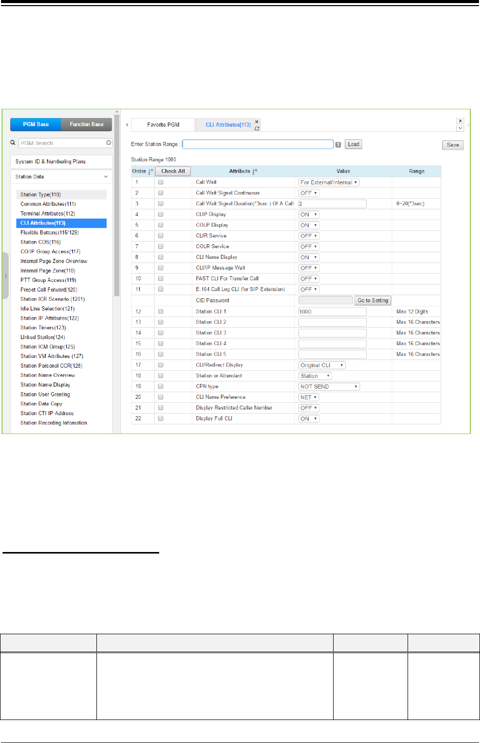
iPECS eMG80 & eMG800 & UCP
Administration and Programming Manual Issue 1.6
276
4.4.2.4 CLI Attributes - PGM 113
Selecting CLI Attributes will display the CLI Attributes data input page. Enter a valid station range
and click [Load] to enter CLI Attributes data. Use the check boxes to indicate which attributes to
define; data for checked attributes is stored for the entire range of stations by clicking [Save]
Button after changing Value.
Figure 4.4.2.4-1 CLI Attributes (PGM 113)
CLI Attributes define features and functions available to the station. Generally, the entry will turn
the feature ON (enable) or OFF (disable) or enter is made in the text box. Refer to the following
table for a description of the features and the input required.
You can set the CID password to click [Go to Setting] button. After clicking it, you will move to
the following PGM 162 and set the CID password, and then save CID password to mark tick on
the save box and click [Save] button.
Setting CID Password directly
Table 4.4.2.4-1 CLI Attributes
ATTRIBUTE DESCRIPTION RANGE DEFAULT
Call Wait
When a busy station receives a call, the call may queue
to the station instead of receiving busy treatment. With
Call Wait, the caller will hear Ring-back tone and the
CO/IP Line LED flashes. Also, the CLI for the new
incoming call displays.
OFF,
For
External/Internal,
For External,
For Internal
For
External/Internal

iPECS eMG80 & eMG800 & UCP
Administration and Programming Manual Issue 1.6
277
Table 4.4.2.4-1 CLI Attributes
ATTRIBUTE DESCRIPTION RANGE DEFAULT
Call wait signal
continuous
When this filed set On, you will get the indication of Call
wait signal continuously without returning to the current
conversation. In case of Off, you will return to the current
conversation after 1 cycle of Call wait signal indication.
ON,
OFF OFF
Call wait signal
duration (*3sec.) of a
call
You can set the call wait signal duration of a waiting call:
the default is 2 (2*3sec.) and the range is from 0 to 20.
0-20
(*3sec) 2
CLIP Display
CLIP (Calling Line Identification Presentation), a carrier
service, sends the number of the calling party to the
system in the call SETUP message. If enabled here, the
number will be shown in the iPECS Phone LCD.
OFF
ON ON
COLP Display
COLP (Connected Line Id Presentation), a carrier
service, sends the number of the answering party to the
system in the call CONNECT message. If enabled here,
the number will be shown in the iPECS Phone LCD.
OFF
ON ON
CLIR Service
CLIR (Calling Line Identification Restriction), a carrier
service, removes calling party ID sent from the ISDN to
the called party with a RESTRICT instruction in the
SETUP message. If enabled here, the system will send
the RESTRICT instruction to the PSTN when an
outgoing ISDN call is placed.
OFF
ON OFF
COLR Service
COLR (Connected Line Id Restriction), a carrier service,
removes connected party ID sent from the ISDN to the
calling party with a RESTRICT instruction in the
CONNECT message. If enabled here, the system will
send the restrict instruction to the PSTN when the station
answers an ISDN call.
OFF
ON OFF
CLI Name Display
When the Incoming CLI data from the carrier matches a
number in Speed Dial, or Outgoing dial data from a user
matches a number in Speed Dial, the system can display
the name associated with the Speed Dial bin, if set to
ON.
OFF
ON ON
CLI/IP Message Wait
A log of missed calls with caller identification can be
maintained for the user, permitting the user to call back
the identified party. Up to 1000 entries are maintained in
the log, system-wide.
OFF
ON OFF
FASTCLI For Transfer
Call
If this option is set to ON, when a transferred call is
routed to an SLT or DECT phone, the CLI for the CO/IP
call is sent to the SLT or DECT phone instead of
transferring station number.
OFF
ON OFF
E.164 Call Log CLI
(for SIP Extension)
When enabled, the E.164 format CLI is sent to SIP
Extensions for an incoming CO/IP call.
OFF
ON
OFF
Station CLI 1
When not restricted by CLIR or COLR, this entry is
added to the number in the selected COIP/CLIP Table
and sent in the ISDN call SETUP or CONNECT
message in place of the station number.
Max. 12 digits
eMG80:100
eMG800:1000
UCP:1000
Station CLI 2
When not restricted by CLIR or COLR, this entry is
added to the number in the selected COIP/CLIP Table
and sent in the ISDN call SETUP or CONNECT
Max. 16
characters
Related with
PGM 143 –
Station CLI
Station CLI 3
Station CLI 4

iPECS eMG80 & eMG800 & UCP
Administration and Programming Manual Issue 1.6
278
Table 4.4.2.4-1 CLI Attributes
ATTRIBUTE DESCRIPTION RANGE DEFAULT
Station CLI 5
message in place of the station number.
Type
CLI / Redirect Display
When an incoming call is Redirected in the carrier’s
network, the call SETUP message will contain an original
and redirected CLI. This selection determines if the
iPECS IP and LDP Phone will display the original or
redirected number.
Original CLI/
Redirect CLI Original CLI
Station or Attendant
When the system sends a station number with CLIP or
COLP, the number can be either the Attendant number
or the number of the station.
Station
Attendant Station
CPN Type
NOT SEND: CPN is not sent to S0 interface.
STATION NUMBER: Station number is sent as CPN to
S0 interface.
BYPASS FROM NET: Incoming CPN is sent as CPN to
S0 interface.
Not send,
Station number,
By pass from
NET
Not send
CLI Name Preference
NET: If CLI name is provided from network, then it is
displayed. If CLI name is not provided from network, the
matched Speed name is displayed.
SPD: If CLI is matched with Speed bin and it has name,
then the matched Speed name is displayed. If CLI is not
matched or matched Speed name is not configured, CLI
name from network is displayed.
NET,
SPD NET
Display Restricted
Caller Number
When {Display Restricted Caller Number} in CLI
Attributes (113) of a station is ON, although the caller
number is restricted in ISDN message, the ringing station
displays the caller number.
OFF
ON OFF
Display Full CLI
The system provides CLI information by displaying on
LCD. If this option is ON, the full CLI information is
displayed on the second line of LCD.
If this option is OFF, the CLI information is displayed
from the left to the center on the second line partially. It
means the CLI information is limited so that the full CLI
can’t be displayed.
OFF
ON ON
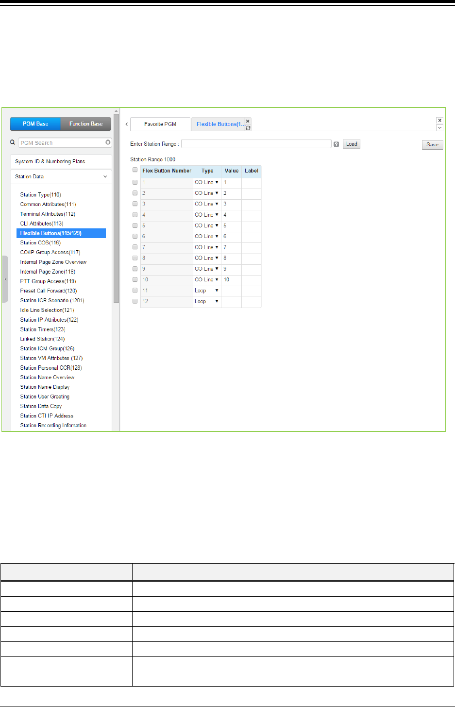
iPECS eMG80 & eMG800 & UCP
Administration and Programming Manual Issue 1.6
279
4.4.2.5 Flexible Buttons - PGM 115/129
Selecting Flex Buttons will display the Flex buttons data input page. Enter a valid Station range
and click [Load] to enter Flex button data. For convenience, the copy, paste, and drag is
available to enter or modify data. Please click [Save] button after entering or modifying data to
apply.
Figure 4.4.2.5-1 Flex Buttons Assignment
Each Flex button for each iPECS IP and LDP Phone and DSS Console can be assigned a
function (TYPE) as below. After selecting the Type for a button, enter the value, if required. The
types available from the drop-down menu are shown are shown in Table below. In addition, for
the LIP Phone models 8040, 8050, 9070, 9071 and the LSS Console models, a label can be
assigned that is used as the designation for the button in the LCD of the phone.
Table 4.4.2.5-1 FLEX BUTTON TYPE & VALUE
TYPE REMARK
N/A
Empty (unassigned), may be defined by the user.
CO Line
Assigns button to access a defined CO/IP line.
CO Group
Assigns button to access a free line in the CO/IP Group.
Loop
Assigns button to access a loop line.
Station Number
Assigns button as DSS/BLF for the assigned station number.
Programming (Numbering Plan) Assigns button to dial a code from the Flexible Numbering Plan, see Appendix
section.

iPECS eMG80 & eMG800 & UCP
Administration and Programming Manual Issue 1.6
280
Table 4.4.2.5-1 FLEX BUTTON TYPE & VALUE
TYPE REMARK
Programming (PGM) Assigns button to perform a User Program function from the Fixed Numbering
Plan, Appendix section.
Station Speed Bin
Station Speed Dial bin.
System Speed Bin
System Speed Dial bin.
Net Station Number
Refer to Network Numbering Plan Table - PGM 324.
U-Loop
U-Loop button for call wait of internal & external call
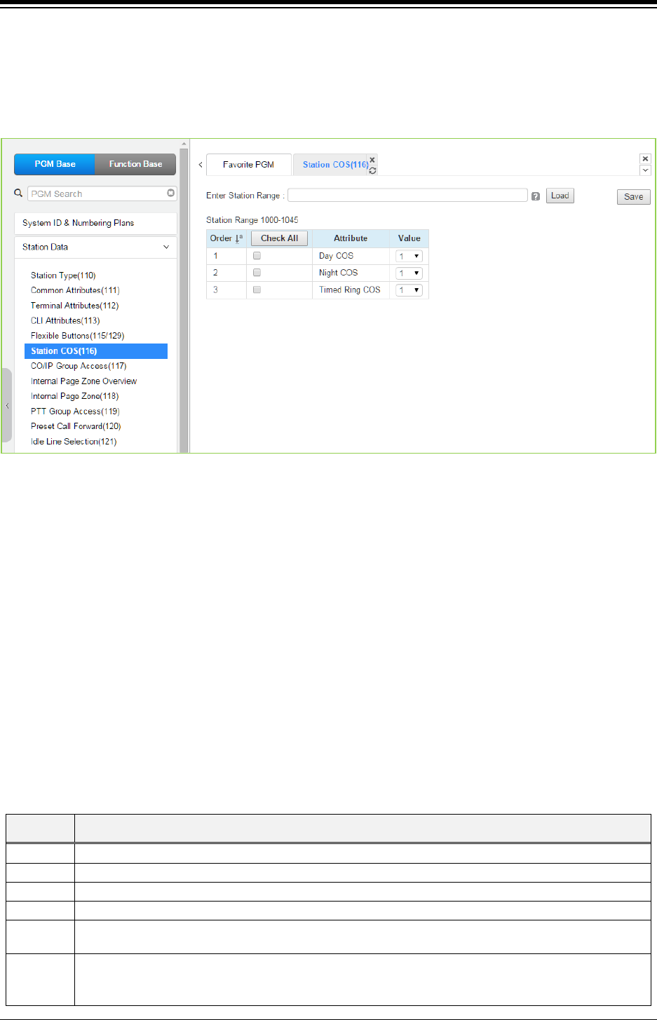
iPECS eMG80 & eMG800 & UCP
Administration and Programming Manual Issue 1.6
281
4.4.2.6 Station COS - PGM 116
Selecting Station COS will display the Station COS data input page. Enter a valid station range
and click [Load] to enter the Station COS data. Use the check mark to indicate which attributes
to modify; data for checked attributes is stored by clicking [Save] button.
Figure 4.4.2.6-1 Station COS
In case of PGM 116 is in condition of limited service mode due to License issue, the default value
is 7 for all COS type.
All stations are assigned a Class-of-Service (COS), which determines the ability of the user to dial
certain types of calls, refer to Table 4.4.2.6-1. Separate COS assignments are made for Day,
Timed and Night Mode operation. As a default all stations are assigned with a Station COS of 1
for all modes, no restrictions. The station COS interacts with the CO Line COS to establish overall
dialing or Toll restrictions. This interaction and the resulting restrictions are given in Table
‘Station/CO COS’.
Long distance calls are determined by the first dialed digit (“0” or “1”) and the number of digits
dialed. If the first digit dialed is a LD code, default “0” or “1”, or, if the number of digits dialed
exceeds the assigned LD digit counter in ‘System Data SMDR Attributes section’, the call is
considered a Long Distance call and appropriate restrictions applied.
Table 4.4.2.6-1 STATION COS
STATION RESTRICTIONS
1
No restrictions are placed on dialing from the station.
2
The assignments in Exception Table A are monitored for allow and deny numbers.
3
The assignments in Exception Table B are monitored for allow and deny numbers.
4
The assignments in both Exception Tables A & B are monitored for allow and deny numbers.
5 The leading digit dialed cannot be a Long Distance code, default “0” or “1”, and further denied/allowed
based on Exception Table C.
6
The leading digits dialed cannot be a Long Distance code & digit count cannot
exceed the LD digit counter, default 7 digits, and further denied/allowed based on
Exception Table C.

iPECS eMG80 & eMG800 & UCP
Administration and Programming Manual Issue 1.6
282
Table 4.4.2.6-1 STATION COS
STATION RESTRICTIONS
7 Intercom and paging calls are allowed. No outgoing dialing except for emergency calls is allowed on
CO Lines.
8
The assignments in the Exception Table D are monitored for allow and deny numbers.
9 The assignments in the Exception Table E are monitored for allow and deny
Numbers
10
The assignments in the Exception Table D & E are monitored for allow and deny numbers.
11
The assignments in the Exception Table A & B and D & E are monitored for allow and deny numbers.
Table 4.4.2.6-2 STATION/CO COS
CO COS 1 CO COS 2 CO COS 3 CO COS 4 CO COS 5
STA
COS
1
No Restriction No Restriction No Restriction Only Local Call (LD
code/counter) and
Table C
No Restriction
STA
COS
2
Exception Table A
governs the dialing
Exception Table A
governs the dialing
No Restriction Only Local Call (LD
code/counter) and
Table C
No Restriction
STA
COS
3
Exception Table B
governs the dialing
No Restriction Exception Table B
governs the
dialing
Only Local Call (LD
code/counter) and
Table C
No Restriction
STA
COS
4
Exception Table A &
B governs the dialing
Exception Table A
governs the dialing
Exception Table B
governs the
dialing
Only Local Call (LD
code/counter) and
Table C
No Restriction
STA COS
5
Local Call only (LD
Code, “1” or “0”) and
Table C
Local Call only (LD
Code, “1” or “0”)
and Table C
Local Call only
(LD Code, “1” or
“0”) and Table C
Only Local Call (LD
code/counter) and
Table C
No Restriction
STA
COS
6
Only Local Call (LD
code/counter) and
Table C
Only Local Call (LD
code/counter) and
Table C
Only Local Call
(LD code/counter)
and Table C
Only Local Call (LD
code/counter) and
Table C
No Restriction
STA C
OS
7
In-house dialing only In-house dialing
only
In-house dialing
only
In-house dialing only In-house
dialing only
STA
COS
8
Exception Table D
governs the dialing
Exception Table D
governs the dialing
No Restriction Only Local Call (LD
code/counter) and
Table C
No Restriction
STA
COS
9
Exception Table D
governs the dialing
Exception Table D
governs the dialing
No Restriction Only Local Call (LD
code/counter) and
Table C
No Restriction
STA
COS
10
Exception Table D &
E governs the dialing
Exception Table D
& E governs the
dialing
No Restriction Only Local Call (LD
code/counter) and
Table C
No Restriction
STA
COS
11
Exception Table A &
B and D & E governs
the dialing
Exception Table A
& B and D & E
governs the dialing
No Restriction Only Local Call (LD
code/counter) and
Table C
No Restriction
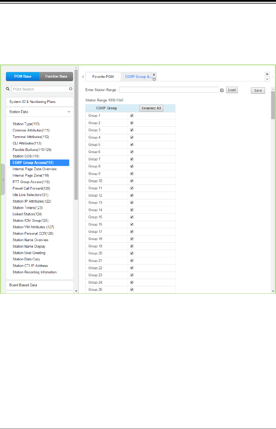
iPECS eMG80 & eMG800 & UCP
Administration and Programming Manual Issue 1.6
283
4.4.2.7 CO/IP Group Access - PGM 117
Selecting CO/IP Group Access will display the CO/IP Group Access data input page. Enter a
valid station range and click [Load] to enter CO/IP Group Access data. Check the appropriate
boxes to allow or delete access to each CO/IP Group. Click [Save] button after changing Value to
apply.
Figure 4.4.2.7-1 CO/IP Group Access
Stations can be allowed or denied access to CO Lines and IP Channels by group (eMG80: 20 &
eMG800/UCP: 200). As a default, all stations are allowed access to all groups except Private
Lines (group 00) and unused CO Lines. The CO Line is assigned as a Private Line by default.
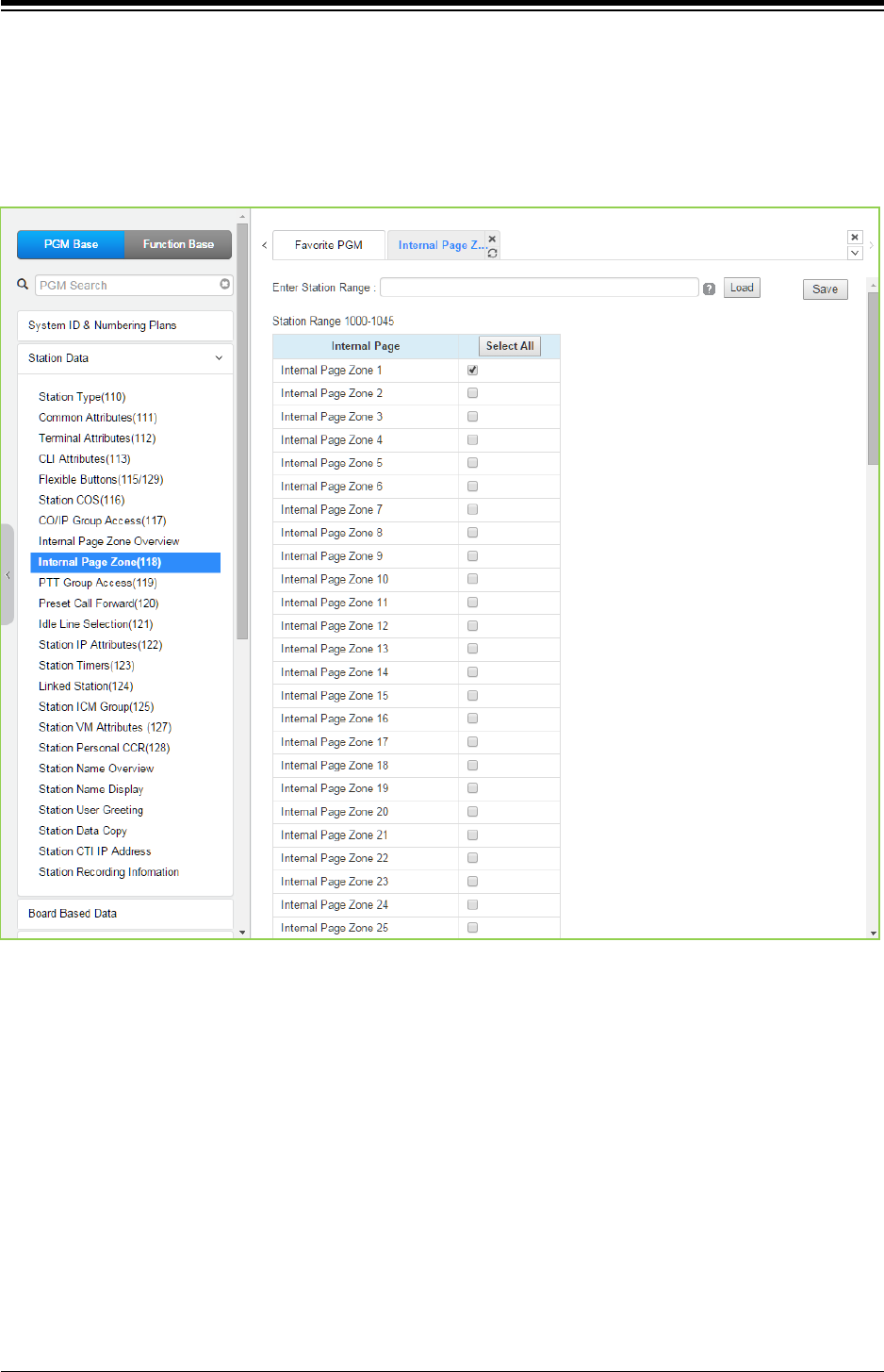
iPECS eMG80 & eMG800 & UCP
Administration and Programming Manual Issue 1.6
284
4.4.2.8 Internal Page Zone Access - PGM 118
Selecting Internal Page Zone will display the Internal Page Zone data input page. Enter a valid
station range and click [Load] to enter the Internal Page Zone Access data. Check the
appropriate boxes to allow or delete access to each Internal Page Zone. Click [Save] button after
changing Value to apply.
Figure 4.4.2.8-1 Internal Page Zone
Each iPECS IP and LDP Phone is assigned to receive announcements from each Internal Page
Zone. A station can be assigned to any, all or no zones. Note a remote station or a station not
assigned to any Internal Zone will not receive any page announcements including Internal All Call.
As a default, all stations except remote stations are assigned to zone 1.
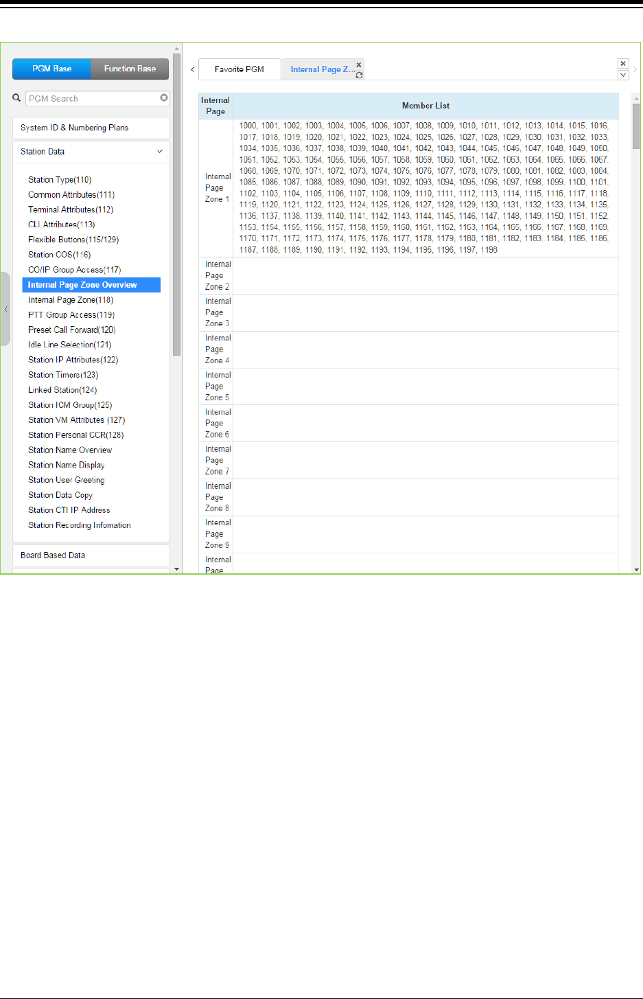
iPECS eMG80 & eMG800 & UCP
Administration and Programming Manual Issue 1.6
285
Figure 4.4.2.8-2 Internal Page Zone overview
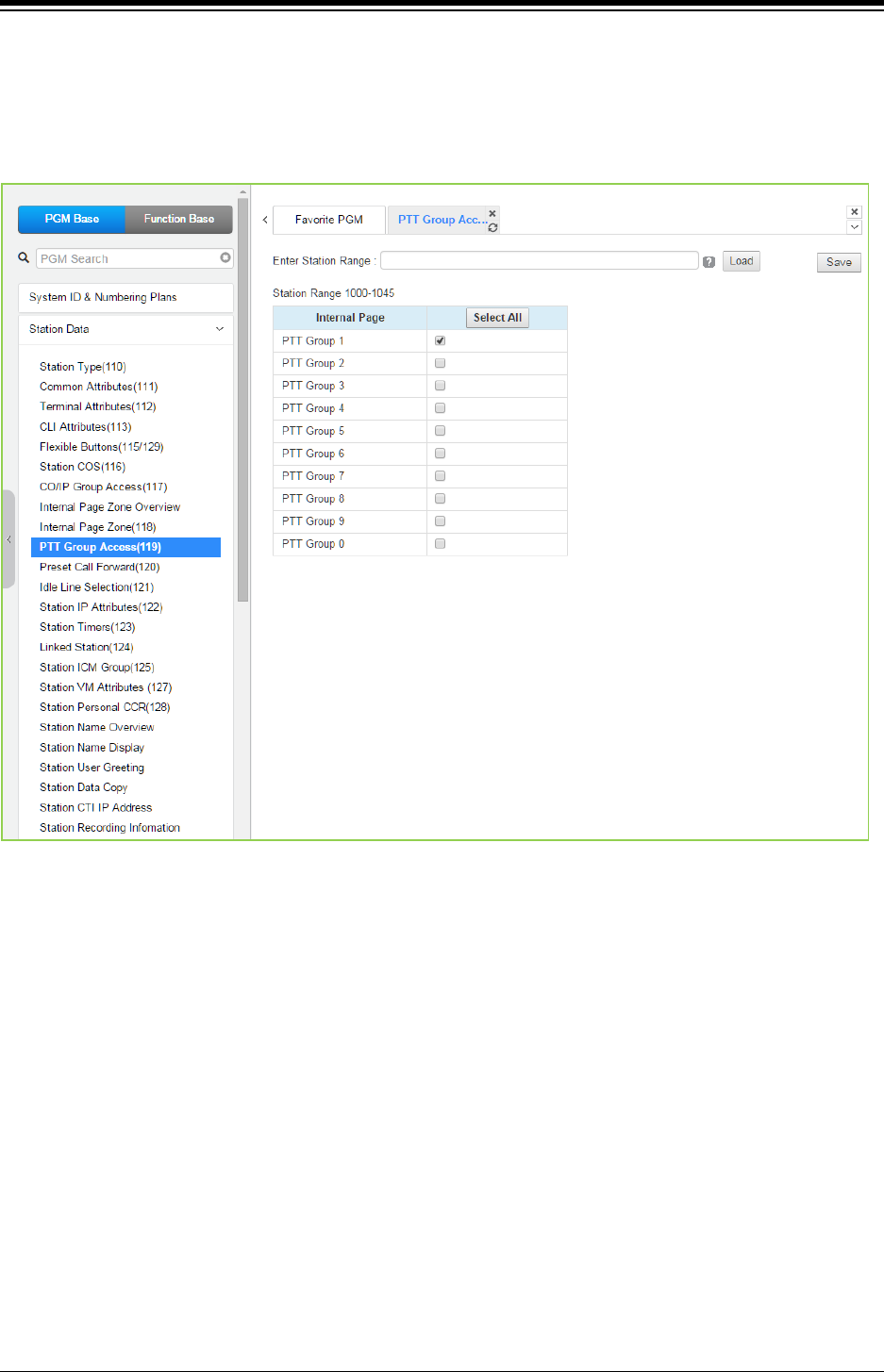
iPECS eMG80 & eMG800 & UCP
Administration and Programming Manual Issue 1.6
286
4.4.2.9 PTT Group Access - PGM 119
Selecting PTT Group Access will display the PTT Group Access data input page. Enter a valid
Station range and click [Load] to enter the PTT Group Access data. Check the appropriate boxes
to allow or delete access to each PTT Group. Click [Save] button after changing Value to apply.
Figure 4.4.2.9-1 PTT Group Access
Each iPECS IP or LDP Phone is assigned to receive PTT announcements from any combination
of the ten (10) PTT groups. Note a station not assigned to any group will not receive PTT page
announcements including Internal All PTT group page. As a default, all stations except remote
stations are assigned to group 1.
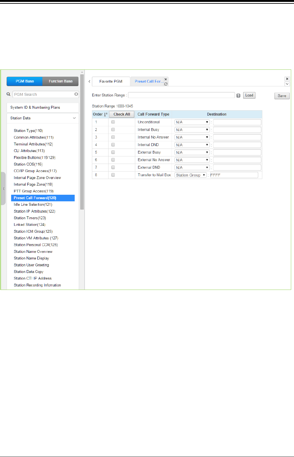
iPECS eMG80 & eMG800 & UCP
Administration and Programming Manual Issue 1.6
287
4.4.2.10 Preset Call Forward - PGM 120
Selecting Preset Call Forward will display the Preset Call Forward data input page. Enter a valid
station range and click [Load] to enter the Station Preset Call Forward data. Use the check mark
to indicate which attributes to modify; data for checked attributes is stored by clicking [Save]
button.
Figure 4.4.2.10-1 Preset Call Forward
Stations can be programmed so that incoming CO/IP and Intercom calls forward to a preset
station or station group. This allows an external or internal call to initially ring at a station and
forward to a pre-determined destination. Preset Forward can be separately assigned
Unconditional, Internal Busy, Internal No Answer, Internal DND, External Busy, External No
Answer, External DND preset forwarding to any station, Station group, system speed dial bin (off-
net) or Station ICR. As a default, no Preset Call Forward is assigned.
For “Transfer Mail-Box” enter the Station Group number of the Voice Mail group (external VM,
VSF or Feature Server Voice Mail group). This will permit other users to transfer calls directly to
the desired user‘s Voice Mailbox.
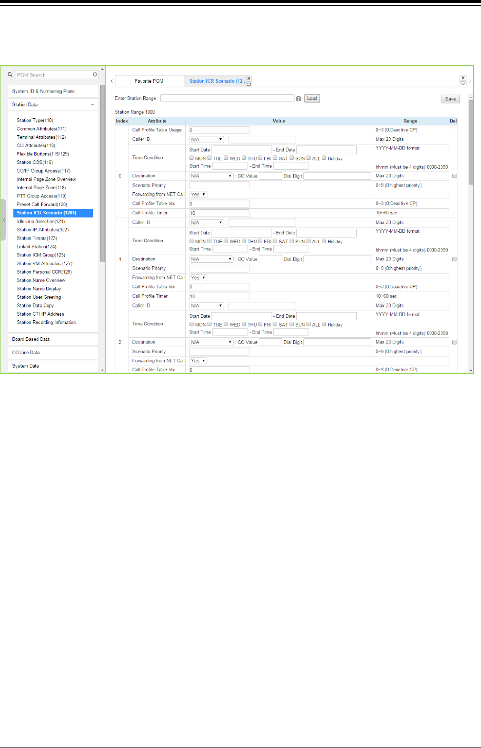
iPECS eMG80 & eMG800 & UCP
Administration and Programming Manual Issue 1.6
288
4.4.2.11 Station ICR Scenario - PGM 1201
Selecting Station ICR Scenario displays the input entry page.
Figure 4.4.2.11-1 Station ICR Scenario
Station ICR is an extension of call forward where the user enters scenarios to define the call
forward feature. Each station has ten (10) routing scenarios that define conditions for routing a
user’s incoming calls. Each scenario may define time of day, day of week, date, caller ID and
destination for incoming calls. In addition, the scenarios may be prioritized; calls are routed to the
destination with the highest priority-matching scenario.
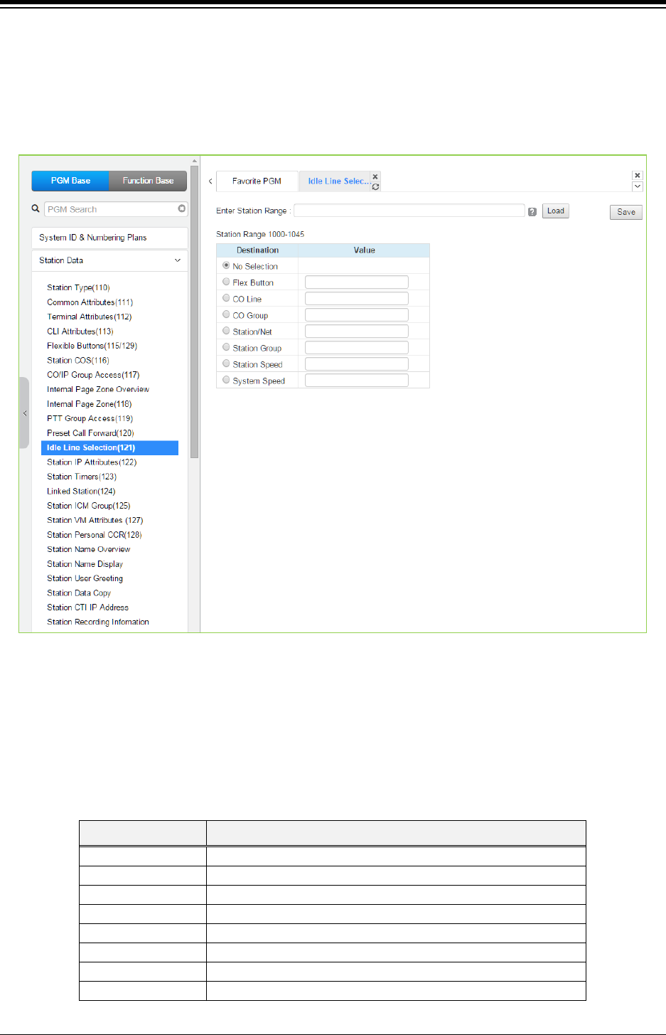
iPECS eMG80 & eMG800 & UCP
Administration and Programming Manual Issue 1.6
289
4.4.2.12 Idle Line Selection - PGM 121
Selecting Idle Line Selection will display the Idle Line Selection data input page. Enter a valid
Station range and click [Load] to enter the Idle Line Selection data. Check the appropriate radial
button and enter the value for the Idle Line Selection. Click [Save] button after changing Value to
apply.
Figure 4.4.2.12-1 Idle Line Selection
When a station goes to an off-hook condition (lifts handset or presses [SPEAKER] button), the
system normally provides intercom dial tone. In place of dial tone, the station can be programmed
to access a CO Line, CO/IP Group or call a Station or Station Group as described in Table
4.4.2.12-1 when the station goes off-hook. The Idle Line Selection (Prime Line) can be either
immediate or delayed after going off-hook. The immediate/delay selection is based on the
Hot/Warm assignment in ‘Common Attributes - Prime Line’.
Table 4.4.2.12-1 IDLE LINE SELECTION TYPE & VALUE
TYPE DESCRIPTION
No Selection
Returns Intercom dial tone.
Flex Button Flex button, activates Flex button as if pressed.
CO Line
CO/IP path seizes CO line.
CO/IP Group CO/IP Group, seizes CO line from the CO/IP Group.
Station/Net
Station, calls the assigned station.
Station group Station group, calls the assigned station group.
Station speed
Station speed, calls the assigned station speed.
System speed System speed, calls the assigned system speed.
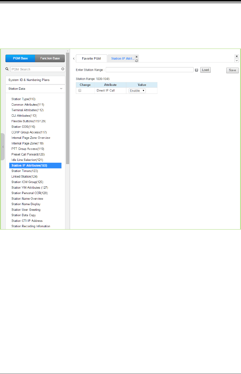
iPECS eMG80 & eMG800 & UCP
Administration and Programming Manual Issue 1.6
290
4.4.2.13 Station IP Attributes - PGM 122
Selecting Station IP Attributes will display the Station IP Attributes data input page. Enter a valid
Station range and click [Load] to enter the Station IP Attributes data. Use the check mark to
indicate which attributes to modify; data for checked attributes is stored by clicking [Save] button.
Figure 4.4.2.13-1 Station IP Attributes
Stations are allowed access to the systems VoIP resources based on the Station IP Attributes.
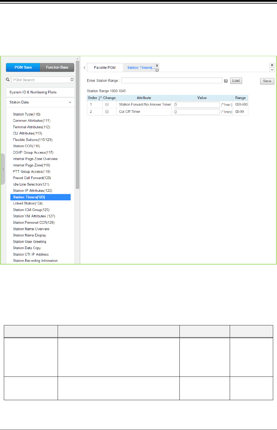
iPECS eMG80 & eMG800 & UCP
Administration and Programming Manual Issue 1.6
291
4.4.2.14 Station Timers - PGM 123
Selecting Station Timers will display the Station Timers input page. Enter a valid Station range
and click [Load] to enter the Station Timers data. Use the check mark to indicate which attributes
to modify; data for checked attributes is stored by clicking [Save] button.
Figure 4.4.2.14-1 Station Timers
Certain timers can be assigned on a station basis. Available timers, description and valid inputs
are given in the below table.
Table 4.4.2.14-1 STATION TIMERS (PGM 123)
ATTRIBUTE DESCRIPTION RANGE DEFAULT
Station Forward No
Answer Timer
This timer set the duration that the station will ring
prior to Ring-No-Answer Forward. This setting
affects both manual and ‘Preset Call Forward’ and
overrides ‘Call forward No Answer timer in System
timer of System data’.
000-600
(seconds) 000
Cut Off Timer
Allowed length of CO/IP calls when station is
assigned ‘Call Time restriction in Common
Attributes of Station data’.
00-99
(minutes) 00
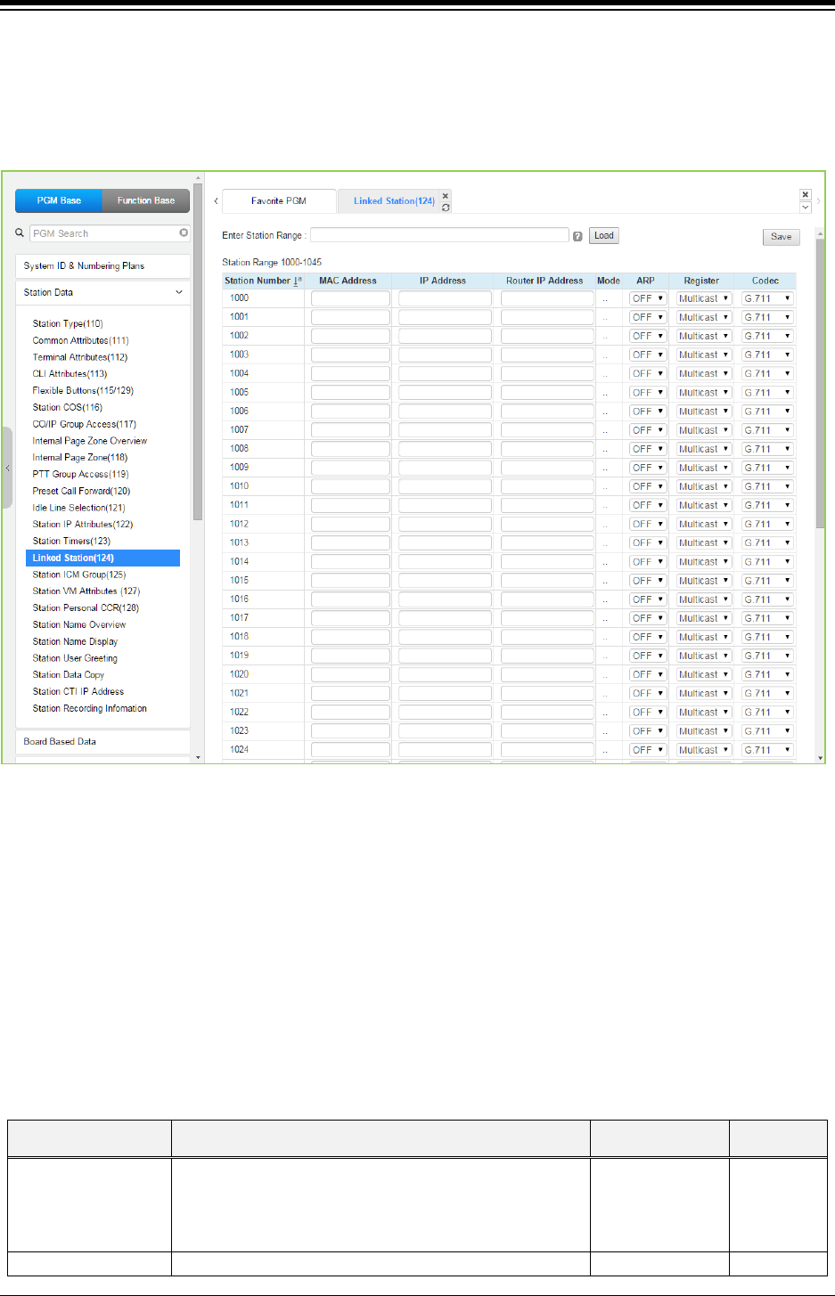
iPECS eMG80 & eMG800 & UCP
Administration and Programming Manual Issue 1.6
292
4.4.2.15 Linked Station - PGM 124
Selecting Linked Station will display the Linked Station input page. Enter a valid Station range
and click [Load] to enter the Linked Station data. Click [Save] button after changing Value to
apply.
Figure 4.4.2.15-1 Linked Station Pair
For UCS Client, it is recommended that PGM 443 be employed for an unregistered (MAC Linked
pair) station. When unregistered station linking is used, the linked station does not reduce the
system‘s capacity. However, in this case, the linked station must be an iPECS IP Phone.
Unregistered linking is allowed only to an iPECS IP Phone. Once UCS Client is linked, it will
display in this Web page as well as in PGM 103 and 443.
If the station is assigned to Master or Slave by linked station, the bracket ‘[M] or [S]’ will be
displayed by the station number in PGM 101, 103, 105, 124 of Web page.
To link registered stations, the Personal Group feature is used and configured in PGM 260 and
261.
Table 4.4.2.15-1 LINKED STATION TABLE
ATTRIBUTE DESCRIPTION RANGE DEFAULT
MAC Address
Set MAC address of linked un-registered station, required
data. Note the secondary station must not be registered
in the system prior to linking. If needed, delete the device
from the system prior to linking.
IP Address
The IP Address of the linked station.
IPv4 address

iPECS eMG80 & eMG800 & UCP
Administration and Programming Manual Issue 1.6
293
ATTRIBUTE DESCRIPTION RANGE DEFAULT
Router IP Address
Set the Router IP address for a linked station.
IPv4 address
Mode Display operating mode of the station, remote or local
and NAT or NAPT.
Remote:
-. R/NAPT
-. R/NAT
-. R/NAP
-. R
Local remote
-. LO/NAPT
-. LO/NAT
-. LO/NAP
-. LO Local
-. L/NAPT
-. L/NAT
-. L/NAP
-. L
L (Local)
ARP
If set OFF, the system will employ layer 2 switching over
the LAN to communicate with the linked station. If set
ON,
the system will employ ARP (Address Resolution
Protocol) to determine the IP address of the device, if
required, and communicate using IP.
OFF
ON
OFF
Register
Normally, iPECS IP devices register using multi-cast
packets. When separated from the system, that is when
the device is remote, unicast is used.
Multicast
Unicast
Multicast
Codec Type A specific Codec type can be configured for the station.
G.711/
G.723.1/
G.729/
System, use the
codec defined for
the system
G.711
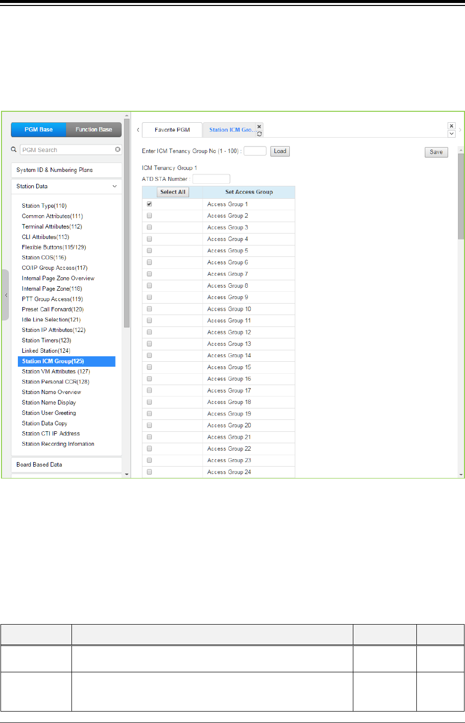
iPECS eMG80 & eMG800 & UCP
Administration and Programming Manual Issue 1.6
294
4.4.2.16 Station ICM Group - PGM 125
Selecting Station ICM Tenancy Group displays the Station ICM Tenancy Group input page.
Select ICM Tenancy Group and click [Load], the system will display the ICM Tenancy Group
Characteristics. Enter the Station number of the group Attendant and check the appropriate box
to allow calling to the group. Click [Save] button after changing Value to apply.
Figure 4.4.2.16-1 Station ICM Group
Stations can be assigned to an ICM group under ‘Common Attributes section’. Up to 15 Tenant
groups for eMG80 (up to 32 for eMG800 and up to 100 for UCP) can be defined. Each group is
configured to allow or deny placing intercom calls, including transfers, to stations in other groups
and an Attendant station can be defined for each group. The Attendant will receive “dial 0” calls
and controls Day/Night mode for the group.
Table 4.4.2.16-1 STATION ICM GROUP ATTRIBUTES
ATTRIBUTE DESCRIPTION RANGE DEFAULT
Tenancy ATD Attendant station for the ICM Tenant group. ATD receives dial ‘0’ calls
and controls Day/Night Service.
Station No.
Group Access ICM tenancy groups allowed access by stations of the selected group.
eMG80:1~15
eMG800:1~32
UCP:1~100
1
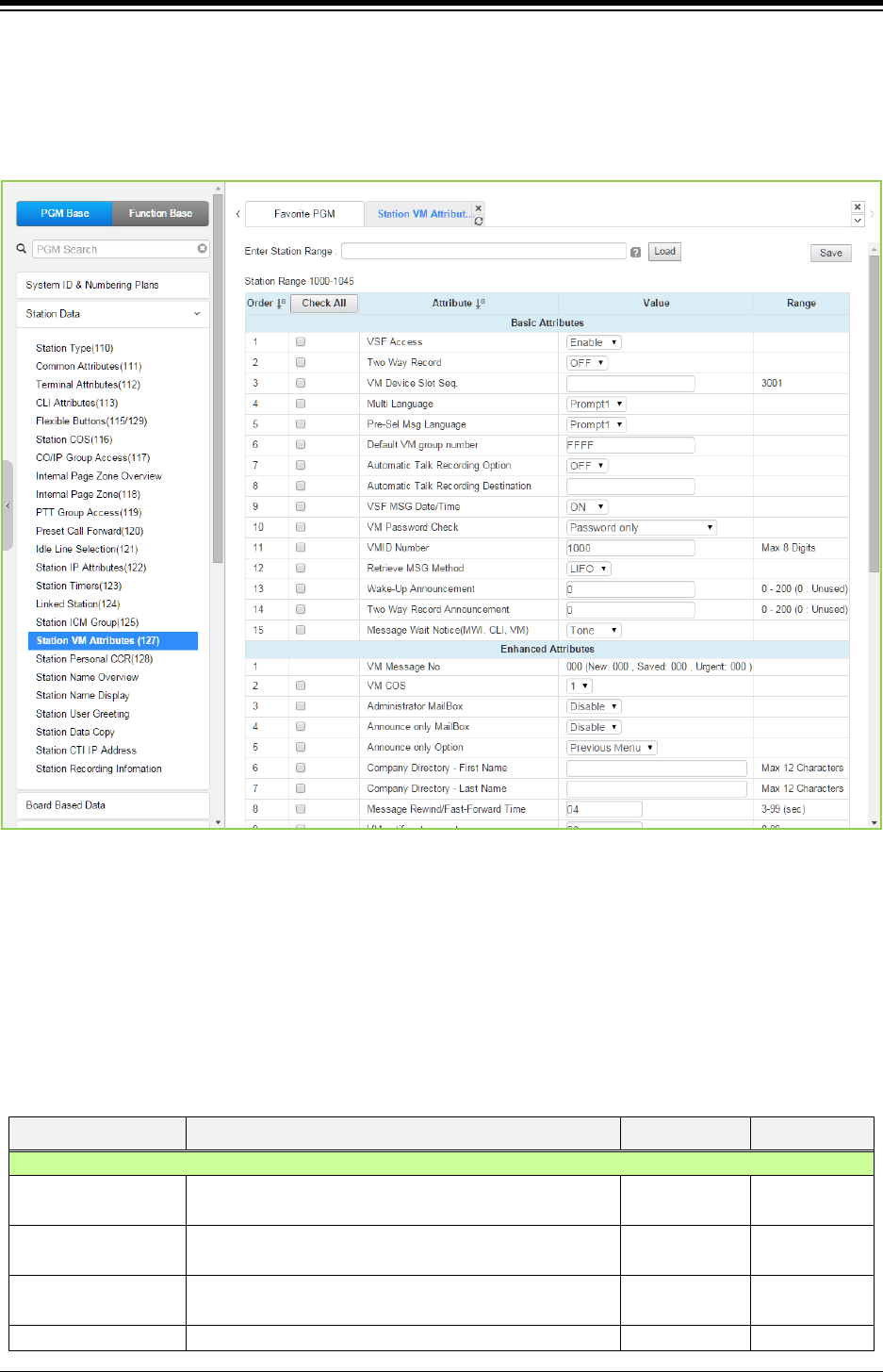
iPECS eMG80 & eMG800 & UCP
Administration and Programming Manual Issue 1.6
295
4.4.2.17 Station Voice Mail Attributes – PGM 127
Selecting VM Attributes displays the Station Voice Mail Attributes input page. Enter a valid Station
range and click [Load] to enter the Station Voice Mail Attributes data. Use the check mark to
indicate which attributes to modify; data for checked attributes is stored by clicking [Save] button.
Figure 4.4.2.17-1 Station VM Attributes
The Station VM Attributes are divided into three sub-sections. The Basic Attributes assign general
characteristics of the Station’s Voice Mail and announcements. Enhanced Attributes assign
characteristics including VM COS, notification, cascading and Company Directory Names. The E-
Mail Notification section defines various SMTP server data such as the Station and System E-
mail account data.
Table 4.4.2.17-1 STATION VM ATTRIBUTES
ATTRIBUTE DESCRIPTION RANGE DEFAULT
Basic Attributes
VSF Access The station must be permitted VSF access to access the
built-in Voice Mailbox.
Disable
Enable
Enable
Two way Record When allowed, the station can activate the Two-way
record feature to record a conversation.
OFF
ON
OFF
VM Device Slot Seq. The sequence number defines the VMIU or VMIB
where messages for the station are stored
Seq. No.
Multi Language
The selected language is employed for prompts played
Prompt 1~6
Prompt 2

iPECS eMG80 & eMG800 & UCP
Administration and Programming Manual Issue 1.6
296
Table 4.4.2.17-1 STATION VM ATTRIBUTES
ATTRIBUTE DESCRIPTION RANGE DEFAULT
to the user when accessing the VSF.
Pre-selected
Message Language
The selected language is employed for prompts played
to an external CO caller if the called station has
activated Pre-selected Message.
Prompt 1~6 Prompt 2
Default VM group
number
When the user has no Voice messages and selects the
[Call Back/Msg] button, the “Default VM group number”
is called.
Auto Talk Recording
Option
This field enables unconditional recording of all calls
placed/received by the station. Recordings, in .wav
format, are stored at the UCS Client defined as the Call
Recording Station below.
OFF,
ALL,
CO
OFF
Auto Talk Recording
Destination
When Auto Call Recording is defined for a station, the
destination for the recording is defined here. The UCS
Client Station number, or an IPCR or 3rd party SIP
recording server.
Station or
Group
VSF MSG Date/Time When ON, the data/time the message was received is
played to the user prior to the message.
OFF
ON ON
VM Password check
When ON, the user must enter their valid Authorization
code to access their VSF Voice Mailbox. The password
can be defined as none, the Authorization code only or
the normal Station Number and Authorization code.
No password/
Password only/
Station number
and password
Password only
VMID Number
When using an adjunct VM, the system can translate the
Mailbox number from the user’s station number to the
assigned VMID. The system sends the station number
or VMID, if assigned, to the VM (in-band or SMDI) in
order to identify the appropriate Voice Mailbox.
Max. 8 digit
eMG80:100
eMG800:1000
UCP:1000
Retrieve MSG Method
Messages stored in the VSF may be retrieved in either a
FIFO (first-in-first-out) or LIFO (last-in-first-out) order
based on this entry.
FIFO/
LIFO LIFO
Wake-Up
Announcement
A VSF system announcement can be recorded to play to
the station as a Wakeup Announcement. 0-200 0
Two way record
announcement
The two way record announcement can be recorded to
play to the station as Announcement. 0-200 0
Message Wait
Notice(MWI, CLI, VM)
When a user has voice mail, system can provides this
as voice prompt instead of dial tone according to option
based on station.
Disable: System provides normal dial tone when a user
goes to off hook status.
Tone: System provides warning tone instead of dial tone
to give indication when a user goes to off hook status.
Prompt: System provides message indication as voice
prompt when a user goes to off hook status.
DECT phone do not support this feature.
Disable,
Tone,
Prompt
Tone
Enhanced Attributes
VM Message No Number of Voice Messages in the user’s Mailbox. 000
VM COS
Each Voice Mailbox is assigned one of five VM Classes
of Service (COS) that determines basic characteristics
of the Mailbox such as message retention. The Voice
Mail COS attributes are set in PGM 253.
1-5 1

iPECS eMG80 & eMG800 & UCP
Administration and Programming Manual Issue 1.6
297
Table 4.4.2.17-1 STATION VM ATTRIBUTES
ATTRIBUTE DESCRIPTION RANGE DEFAULT
Administrator Mailbox
A Mailbox can be assigned as an Administrator Mailbox
permitting broadcast messaging and control of other
user mailboxes.
Disable
Enable Disable
Announce Only
Mailbox
A mailbox can be configured so that the connected party
will hear the greeting but cannot leave a message,
Announce Only. A fter the greeting, the call is routed
based on the Announce Only Option.
Disable
Enable Disable
Announce Only
Option
This option determines if the caller will be disconnected
or returned to the previous menu after hearing the
Announce Only Mailbox greeting.
Previous Menu/
Hang Up Previous menu
Company Directory –
First Name
This field is first name of a station for Company
Directory feature.
Max. 12
characters
N/A
Company Directory –
Last Name
This field is last name of a station for Company Directory
feature.
Max. 12
characters
N/A
Message
Rewind/Fast-Forward
Time
While listening to a message the user may rewind or
Fast forward. The Rewind and Fast Forward time are
determined by this field.
03 - 99 04
VM Notify retry count
If the notification to the user’s mobile repeatedly fails,
after the retry count, the system will send the call to the
Attendant to complete the notification.
00 - 99 03
VM Notify dial time
When the mobile notification call is placed, the system
will terminate the call, considering the call a failed
attempt, if no digits are received from the mobile phone
user before the timer expires.
00 - 99 15 sec
VM Forward Option
When a left message is forwarded, this option is applied.
Move / Copy
Move
Cascade Mailbox 1 A left message is copied or moved to 1’st mailbox
destination station.
Station No N/A
Cascade Mailbox 2 A left message is copied or moved to 2’nd mailbox
destination station.
Station No N/A
Cascade Mailbox 3 A left message is copied or moved to 3’rd mailbox
destination station.
Station No N/A
Cascade Mailbox 4 A left message is copied or moved to 4’th mailbox
destination station.
Station No N/A
Cascade Mailbox 5 A left message is copied or moved to 5’th mailbox
destination station.
Station No N/A
Cascade Method Cascade method is determined.
Disable /
Copy /
Move
Disable
Cascade Message
Type Cascade Message Type is determined.
Normal Only /
Urgent Only /
All
Normal only
Cascade Apply Timer
Cascade Apply Timer is set.
001 ~250 (min)
0
E-Mail notification
[Send Mail] button : click [Send mail] button to send mail for notification
E-Mail Notification
Enable
If this option is set ON, the system send Email as soon
as getting Voice mail.
OFF
ON
OFF
SMTP Server
Address (IP or
Domain Name)
This field defines the address or URL of the SMTP mail
server for the notification.
IP v4 addressor
Mail server
name
Max. 64
characters

iPECS eMG80 & eMG800 & UCP
Administration and Programming Manual Issue 1.6
298
Table 4.4.2.17-1 STATION VM ATTRIBUTES
ATTRIBUTE DESCRIPTION RANGE DEFAULT
SMTP Port This field defines the TCP/IP port the system will employ
when communicating with the SMTP E-mail server.
1 - 65535 25
SMTP Security
Connection
The system can support basic security policies when
communicating with the SMTP E-mail server. Note the
server must also be configured for the selected security
protocol.
No Security/
SSL/
TLS
No Security
E-Mail Account ID This field defines the account Identification for the
system configured in the SMTP server.
E-Mail Account
Password
This field defines the password for the system’s E-mail
account in the SMTP server.
Sender E-Mail
Address (From)
This field defines the E-mail address used to send the
new Voice Message notification via E-mail.
E-mail address
Receiver E-Mail
Address (To)
This field defines the E-mail address to notify when a
new VSF message is received for the station.
E-mail address
Attach Message
Option
When E-mail notification is enabled in the VM COS
(PGM 253), the E-mail may include the voice mail as a
wav file attachment. The proper information must be
assigned for the receiver mail and system mail account
information.
OFF
ON ON
Delete Message
Option
After sending an E-mail notification the system will
automatically delete the Voice message from the user’s
Voice Mailbox if this parameter is ON.
OFF
ON OFF
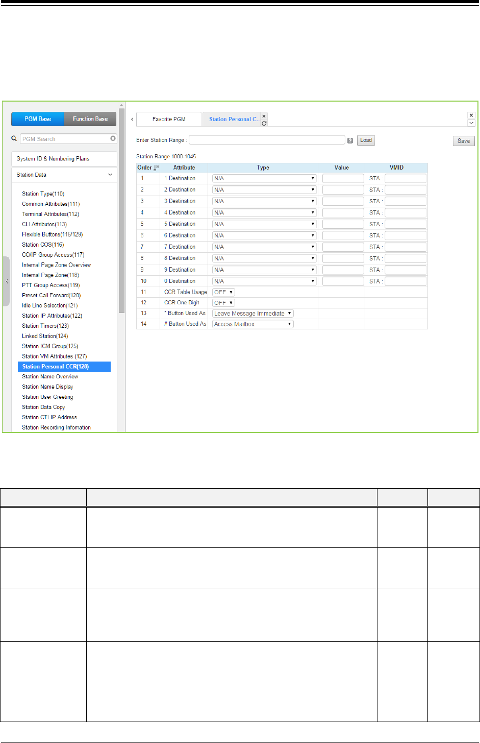
iPECS eMG80 & eMG800 & UCP
Administration and Programming Manual Issue 1.6
299
4.4.2.18 Station Personal CCR Table – PGM 128
Selecting Station Personal CCR displays the Station Personal CCR Table input page. Enter a
valid Station range and click [Load] to enter the Station Personal CCR Table data. Click [Save]
button after changing the type or value.
Figure 4.4.2.18-1 Station Personal CCR Table
Table 4.4.2.18-1 STATION CCR Table
ATTRIBUTE DESCRIPTION RANGE DEFAULT
1-0 Destination
Digit dialed by outside caller.
A destination type and value can be programmed by dialed digit. 14
kinds destination is available.
… NA
CCR One Digit
When ON, the system will analyze the first digit received only,
additional digits dialed by the caller are ignored.
OFF
ON OFF
CCR Table Usage
If this option is ON, CCR table can be activated.
If this option is OFF, CCR table is not available, instead of that, dialing
digits by outside caller can be recognized as DISA dialing.
ON
OFF OFF
*Button Used As
* can be used as the following:
System Numbering Plan
Replay Greeting
Access Mailbox
Leave Message Immediate
Refer to
Description
Leave
Message
Immediate

iPECS eMG80 & eMG800 & UCP
Administration and Programming Manual Issue 1.6
300
Table 4.4.2.18-1 STATION CCR Table
ATTRIBUTE DESCRIPTION RANGE DEFAULT
# Button Used As
# can be used as the following:
System Numbering Plan
Replay Greeting
Access Mailbox
Leave Message Immediate
System
Refer to
Description
Access
Mailbox
Table 4.4.2.18-2 STATION CCR DESTINATIONS
DESTINATION TYPES
Route to a Station
Route to a Station Group
Route with System Speed Dial
Route as PBX Transfer with System Speed Dial (Flash then dial speed dial digits)
Route to VSF Announcement
Route to VSF Announcement and disconnect
Route to Networked Station.
Conference Room
Internal Page
External page
All Call Page
Route to voice mail(station group/station number)
Company Directory
Record VM Greeting
Room type conference group join
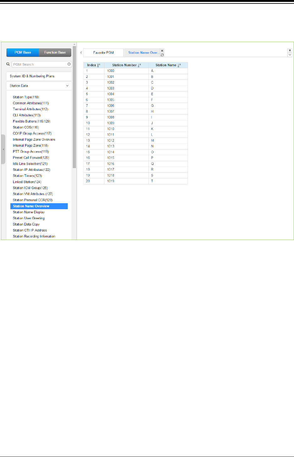
iPECS eMG80 & eMG800 & UCP
Administration and Programming Manual Issue 1.6
301
4.4.2.19 Station Name Overview & Display
Selecting Station Name Overview shows the current station name.
Figure 4.4.2.19-1 Station Name Overview
Each station name will be displayed if the each station has the name.
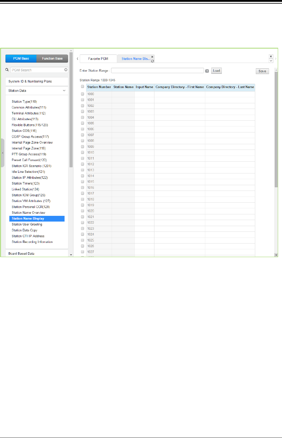
iPECS eMG80 & eMG800 & UCP
Administration and Programming Manual Issue 1.6
302
Selecting Station Name Display will display the Station Name input page. Enter a valid Station
range and click [Load] to enter the Station Name data. For convenience, the copy, paste, and
drag is available to enter or modify data. Click [Save] button after changing the type or value.
Figure 4.4.2.19-2 Station Name Display
You can fill out the Station name, Input name (up to 20 digits), company directory-First name &
Last name for customer’s convenience.
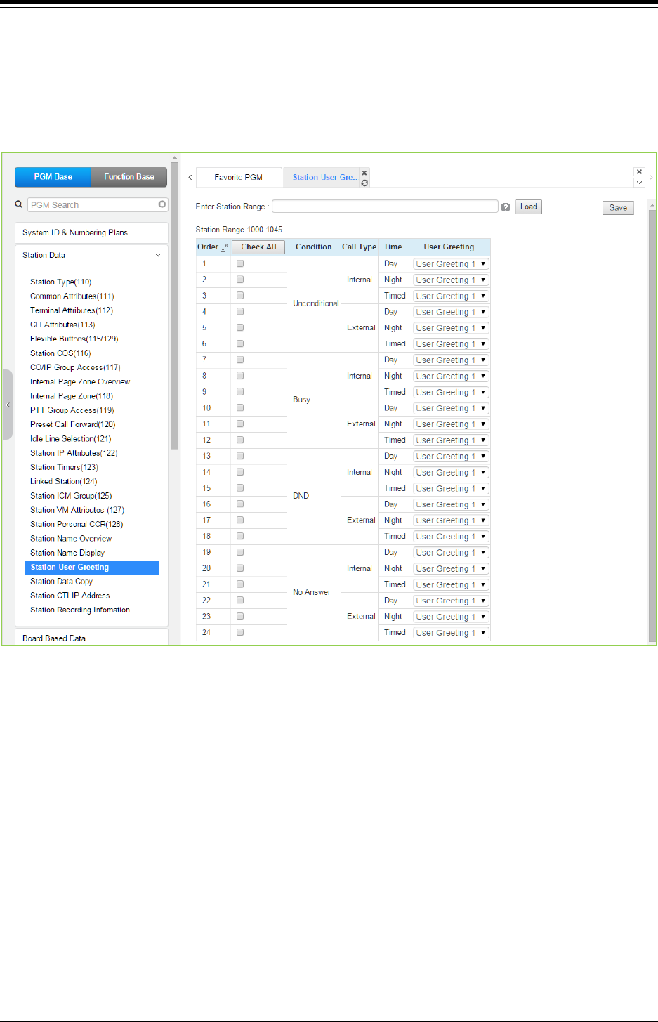
iPECS eMG80 & eMG800 & UCP
Administration and Programming Manual Issue 1.6
303
4.4.2.20 Station User Greeting
Selecting Station User Greeting will display the Station User Greeting data input page. Enter a
valid Station range and click [Load] to enter the Station Voice Mail Attributes data. Use the check
mark to indicate which attributes to modify; data for checked attributes is stored by clicking [Save]
button.
Figure 4.4.2.20-1 Station User Greeting
There are 4 User greeting for each station.
User can select multi user greeting depending on the condition, call type, and time.
-. Condition: unconditional, busy, DND, No answer
-. Call Type: Internal, External
-. Call Time: Day, Night, Timed
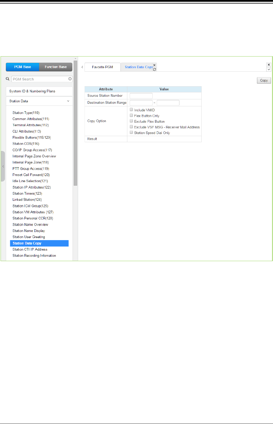
iPECS eMG80 & eMG800 & UCP
Administration and Programming Manual Issue 1.6
304
4.4.2.21 Station Data Copy
Selecting Station Data Copy will display the Station Data Copy data input page. Enter a valid
Source Station, Destination Station Range and click [Copy] to copy the station data. Note that
this function is not available for an Attendant station.
Figure 4.4.2.21-1 Station Data Copy
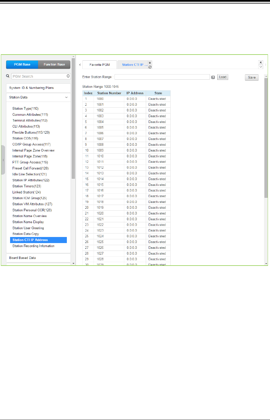
iPECS eMG80 & eMG800 & UCP
Administration and Programming Manual Issue 1.6
305
4.4.2.22 Station CTI IP Address (1st Party TAPI)
Selecting Station CTI IP Address displays the page shown in the following figure. Enter a Station
Range and click [Load] to display and modify the CTI IP address. Click [Save] button after
changing the type or value.
Figure 4.4.2.22-1 Station CTI IP Address
The system supports 1st party TAPI (Telephony Application Programming Interface) for CTI
(Computer Telephony Integration). The system will send specific TAPI information to the IP
address for activity by the associated Station.
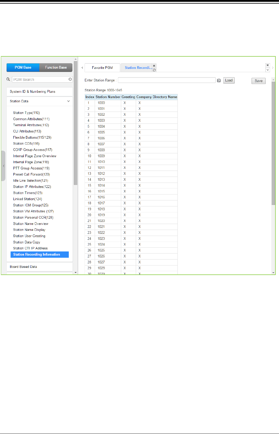
iPECS eMG80 & eMG800 & UCP
Administration and Programming Manual Issue 1.6
306
4.4.2.23 Station Recording Information
Selecting Station recording information displays the page shown in the following figure. Enter a
Station Range and click [Load] to display and check the current recording information on each
station.
Figure 4.4.2.23-1 Station Recording Information
The {Station Recording information} displays the recording state of voice mail greeting and
company directory name with O and X. (O: recorded, X: not recorded)
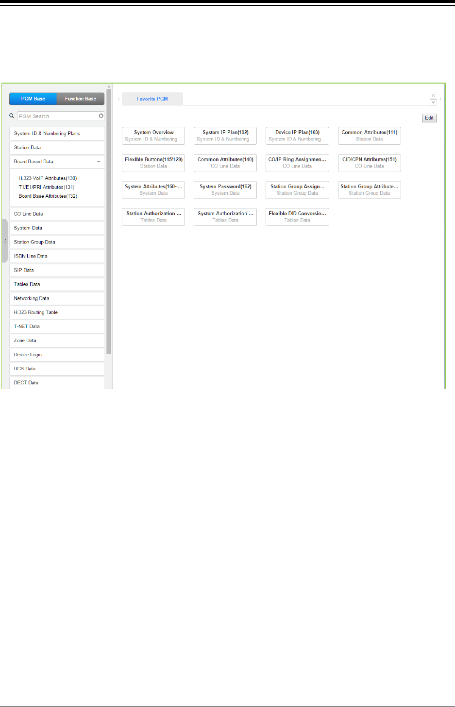
iPECS eMG80 & eMG800 & UCP
Administration and Programming Manual Issue 1.6
307
4.4.3 Board Based Data
Selecting the Board Based Data program group returns the sub-menu displayed in the left frame
as shown in the following figure.
Figure 4.4.3-1 Board Based Data Main Page
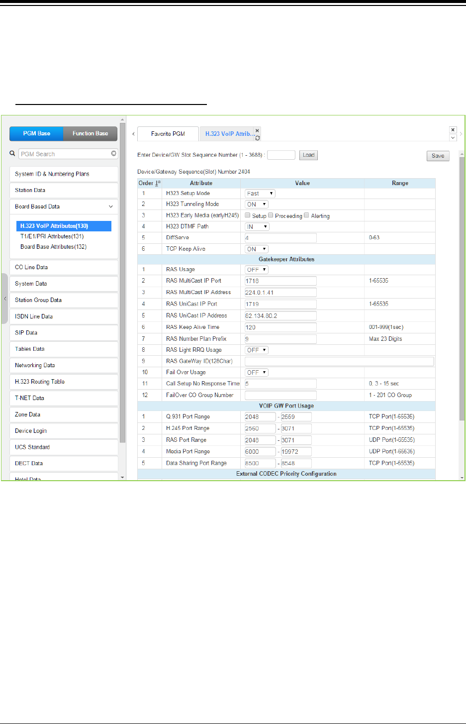
iPECS eMG80 & eMG800 & UCP
Administration and Programming Manual Issue 1.6
308
4.4.3.1 H.323 VoIP Attributes - PGM 130
Selecting H.323 VoIP Attributes returns the H.323 VoIP Attributes data input page. Enter the VoIP
gateway Sequence number (refer to ‘Device IP Plan’ if you want to find the sequence number)
and click [Load] to enter VoIP data. Click [Save] button after changing Value.
Enter Device/GW slot sequence number
: eMG80: 1-300 / eMG800: 1-2890 / UCP: 1-3688
Figure 4.4.3.1-1 H.323 VoIP Attributes
The VOIP channels may be used for Distributed Networking, access to SIP or H.323 networks
and for remote iPECS devices. When the standard H.323 VoIP protocol is employed for an
external VoIP call, several attributes of these channels can be assigned. The H.323 call set-up
mode and tunneling (H.245 Encapsulation) can be established.
Also for H.323 support, a RAS (Registration, Admissions and Status) channel can be defined.
The RAS channel IP addresses (uni-cast and multi-cast) as well as the IP port Numbering Plan
and other H.323 set-up characteristics are defined.
This page also allows setting the IP TOS bit for Diffserv, a commonly recognized packet
prioritization protocol. Higher priority packets are given priority in the Default gateway or Layer 3
Switch queue. However, they are the first to be discarded in the event of long queue delays,
which may cause excess packet loss and poor voice quality.
Refer to the following table for a description of the features and the input required.

iPECS eMG80 & eMG800 & UCP
Administration and Programming Manual Issue 1.6
309
Table 4.4.3.1-1 H.323 VOIP ATTRIBUTES
ATTRIBUTE DESCRIPTION RANGE DEFAULT
H323 Setup Mode IP calls can be set-up using the H.323 normal
or Fast Start mode.
Normal/
Fast
Fast
H323 Tunneling Mode IP calls can be set-up using the H.245
encapsulation (Tunneling).
OFF
ON
ON
H323 Early Media
(early H245)
This feature is the ability of two user endpoints
to communicate before call is actually
established in normal call mode. This feature is
not used when 'H323 Setup Mode' is 'Fast'.
* Setup: Caller party tries to open early media
on receiving the Setup message.
* Proceeding: Calling party tries to open early
media on receiving the Proceeding message.
* Alerting: Calling party tries to open early
media on receiving the Alerting message.
Setup,
Proceeding,
Alerting
H323 DTMF Path During a call, DTMF can be sent in-band or
out-of-band (H.245)
Out-band/
In-band/
2833
IN
DIFFSERV
This parameter sets DiffServ pre-tagging for
Voice packet.
Note high values may cause high packet
discard levels.
0~63 4
TCP Keep-Alive
The system will send a polling message every
75 seconds to assure the status of the TCP
connection.
OFF
ON ON
Gatekeeper Attributes
RAS Usage When this feature is ON, the VoIP channel is
used as the Gatekeeper.
OFF
ON
OFF
RAS Multicast IP Port This field defines the Multicast TCP/IP Port for
RAS Information of Gatekeeper.
TCP/IP Port 1718
RAS Multi-cast IP
Address
This field defines the Multicast IP address for
RAS Information of Gatekeeper.
IP Address 224.0.1.41
RAS Uni-cast IP Port This parameter defines the Unicast IP Port for
RAS Information of Gatekeeper.
TCP/IP Port 1719
RAS Uni-cast IP
Address
This parameter defines the Unicast IP address
for RAS Information of Gatekeeper.
IP Address 82.134.80.2
RAS Keep Alive Time
To maintain a connection, the system and
GateKeeper must exchange RAS Information
prior to expiration of this timer.
001-999
(seconds) 120
RAS Number Plan
Prefix
The numbering plan for Calling Number in RAS
Setup.
Max. 23 digit 9
RAS Light RRQ Usage
The system can be assigned to use the simple
RRQ (Registration Request) message (ON) or
the full RRQ message (OFF).
OFF
ON OFF
RAS Gateway ID The Gatekeeper ID. 128 characters
Fail Over Usage
If an H.323 call fails to set-up in the ‘Call Setup
No Response time’ below, the system will
attempt to place the call on the Failover CO/IP
group also defined below.
OFF
ON OFF

iPECS eMG80 & eMG800 & UCP
Administration and Programming Manual Issue 1.6
310
Table 4.4.3.1-1 H.323 VOIP ATTRIBUTES
ATTRIBUTE DESCRIPTION RANGE DEFAULT
Call Setup No
Response Time
When Failover is enabled, the system places
the fail-over call if this timer expires before the
system receives a response to setup
messages.
0, 3-10 Sec. 5
Failover CO Group
Number
The system will place the Fail-over call
employing a CO/IP line from the assigned
CO/IP Line Group.
eMG80:1-21
eMG800:1~201
UCP:1~201
VOIP(VOIU) GW Port Usage
Q.931 Port Range IP-Binding H.323 signaling option: Q.931 TCP
Port Range.
TCP port 2048-2559
H.245 Port Range IP-Binding H.323 signaling option:
H.245 TCP Port Range.
TCP port 2560-3071
RAS Port Range IP-Binding H.323 signaling option: RAS UDP
Port Range.
UDP port 2048-3071
Media Port Range IP-Binding media option: Media UDP Port
Range. UDP port
eMG80:6000-7036
eMG800:6000-14400
UCP:6000-19972
Data Sharing Port
Range
IP-Binding option: Data Sharing TCP Port
Range.
TCP port 8500-8548
External CODEC Priority Configuration
External CODEC
Priority Configuration
The system supports five Codecs and, for
negotiating purposes, the priority of each can
be defined. Codecs not assigned a consecutive
priority are not available during negotiations
with the host.
None/
g.711-u/
g.711-a/
g.723.1/
g.729/
g.729-a
none
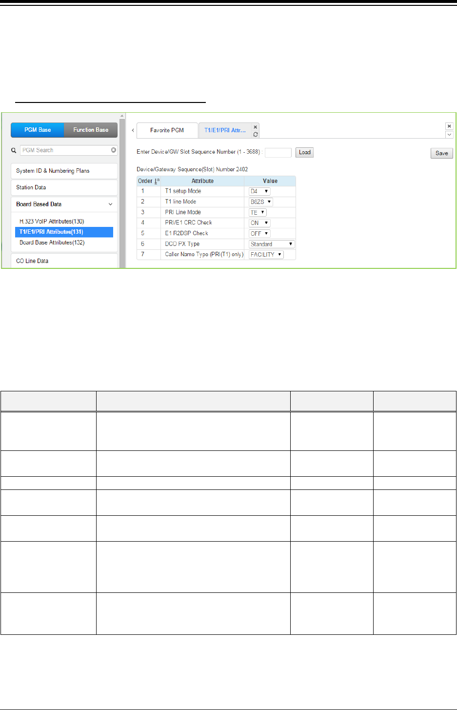
iPECS eMG80 & eMG800 & UCP
Administration and Programming Manual Issue 1.6
311
4.4.3.2 T1/E1/PRI Attributes - PGM 131
Selecting T1/E1/PRI Attributes returns the T1/E1/PRI Attributes data input page. Enter the Device
Sequence number (refer to ‘Device IP Plan’ if you want to find the sequence number) and click
[Load] to enter T1/E1/PRI data. Click [Save] button after changing Value.
Enter Device/GW slot sequence number
: eMG80: 1-300 / eMG800: 1-2890 / UCP: 1-3688
Figure 4.4.3.2-1 T1/E1/PRI Attributes
Each T1/E1/PRI module can be assigned for various attributes of the interface. The T1 interface
framing and line coding can be selected and, for the PRI, TE or NT operation can be selected.
Refer to the following table for a description of the features and the input required.
Table 4.4.3.2-1 T1/E1/PRI ATTRIBUTES
ATTRIBUTE DESCRIPTION RANGE DEFAULT
T1 Setup Mode
Select T1 Setup mode D4 frame: Using In-Band
Control Protocol.
ESF: Using Data link Message.
ESF/
D4 D4
T1 Line Mode Select T1 line coding (AMI/B8ZS). AMI/
B8ZS
B8ZS
PRI Line Mode
Select TE/NT Mode.
TE/NT
TE
PRI /E1 CRC Check Enable CRC (Cyclical Redundancy Check). OFF
ON
OFF
E1 R2DSP check Used for R2-E1 Device or E1 Device. OFF/
ON
OFF
DCO PX Type Reserved for future usage for R2 E1 Device.
S1240/
TDX1B/
STANDARD/
CONGES_DIS
STANDARD
Caller Name
Type(PRI(T1) only)
If the caller has a name, the Caller Name is sent
to the network according to the option
(FACILITY, DISPLAY). (USA only)
FACILITY,
DISPLAY FACILITY
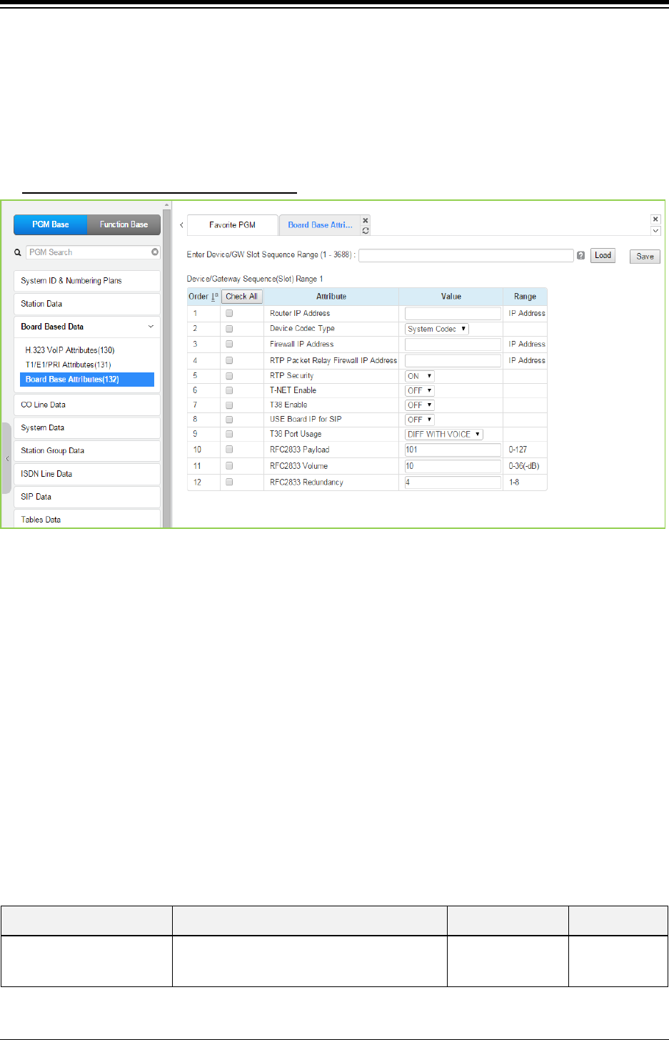
iPECS eMG80 & eMG800 & UCP
Administration and Programming Manual Issue 1.6
312
4.4.3.3 Board Base Attributes - PGM 132
Selecting Board Base Attributes will display the Board Base Attributes data input pag. Enter the
Sequence number (refer to ‘Device IP Plan’ if you want to find the sequence number) and click
[Load] to enter attribute values. Use the check boxes to indicate which attributes to modify; data
for checked attributes is stored for the entire range of devices when saved. Click [Save] button
after changing Value.
Enter Device/GW slot sequence number
: eMG80: 1-300 / eMG800: 1-2890 / UCP: 1-3688
Figure 4.4.3.3-1 Board Base Attributes
Appliances (Devices and IP Phones) can be connected to the iPECS over a managed WAN
without the need to employ a VoIP channel. In this case, the system does not implement security
(IPSec) or QoS treatment over the link. To implement the managed WAN connectivity, the iPECS
must be assigned with the IP address of the router for all appliances that may attempt a point-to-
point connection over the managed WAN, including devices on the iPECS LAN. Note that if the
device‘s Router IP address is not defined, the system will use the Router IP address defined in
System & Device IP Address Plan.
The default codec employed by each device can be specifically defined as G.711, G.729, G.723,
G.722, or the system default codec assigned.
Appliances include support for SRTP (Secure Real-Time Protocol), which employs Advanced
Encryption Standard (AES) to secure RTP packets. If RTP security is enabled then IPSEC or
SRTP is implemented for RTP packet.
Table 4.4.3.3-1 BOARD BASE ATTRIBUTES
ATTRIBUTE DESCRIPTION RANGE DEFAULT
Router IP Address Enter the Default gateway (Router) IP address
associated with the selected devices. IP Address

iPECS eMG80 & eMG800 & UCP
Administration and Programming Manual Issue 1.6
313
Table 4.4.3.3-1 BOARD BASE ATTRIBUTES
ATTRIBUTE DESCRIPTION RANGE DEFAULT
Device Codec Type Select the CODEC type for each device.
G.711, G.723.1,
G.729, G.722, or
SYSTEM CODEC
SYSTEM
CODEC
Firewall IP Address Enter the Firewall IP address of the selected
devices.
0.0.0.0
RTP Packet Relay Firewall
IP Address
Enter the Firewall IP address associated with
the Remote Phone or Gateway if there a dual
broadband connection for SIP trunks and
Remote phones (using a VOIB/VOIM).
0.0.0.0
RTP Security
SRTP implements AES (Advanced Encryption
Standard) for packets between other devices
with RTP Security enabled. To reduce
bandwidth use or to use an external VPN, this
parameter must be OFF.
OFF
ON ON
TNET Enable
When a module or station is to be connected in
a Centralized Control network (TNET), the
device must be enabled for TNET operation.
OFF
ON
eMG80:ON
eMG800:OFF
UCP: OFF
T38 Enable FAX over IP Lines is supported when T38
mode is ON.
OFF
ON OFF
USE Board IP for SIP
When the VoIP channels of a VOIB/VOIM are
used for SIP, such as a SIP Trunk, the IP
address of the VOIB/VOIM must be used for
the SIP messages (ON).
OFF
ON OFF
T38 Port Usage
The TCP/IP port employed for T38 packets is
negotiated and the system can allow the port
to be the same as or different from the
preceding Voice packets. The system can also
employ NAT to determine the port.
Different from Voice
Same as Voice
NAT Triggered
DIFF WITH
VOICE
RFC2833 Payload Payload value for RFC2833 0~127 101
RFC2833 Volume Volume(Gain) of RFC2833 payload 0~36(-dB) 10
RFC2833 Redundancy Sending time of end packet of RFC2833 1~8 4
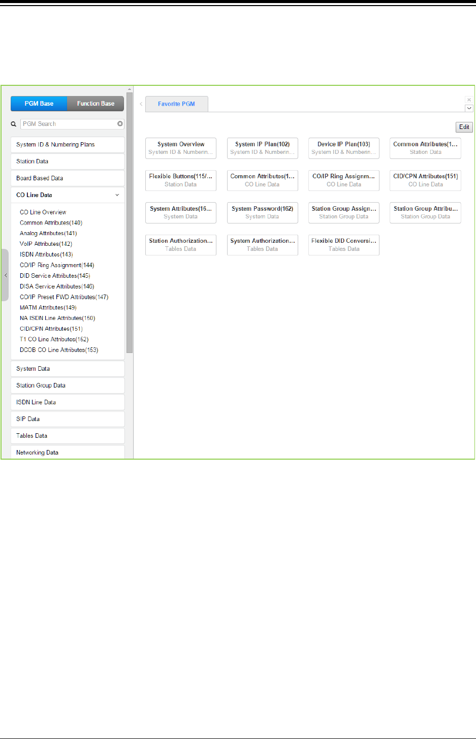
iPECS eMG80 & eMG800 & UCP
Administration and Programming Manual Issue 1.6
314
4.4.4 CO Line Data
Selecting the CO Line Data program group returns the sub-menu displayed in the left frame as
shown in the following figure.
Figure 4.4.4-1 CO Line Data Main Page
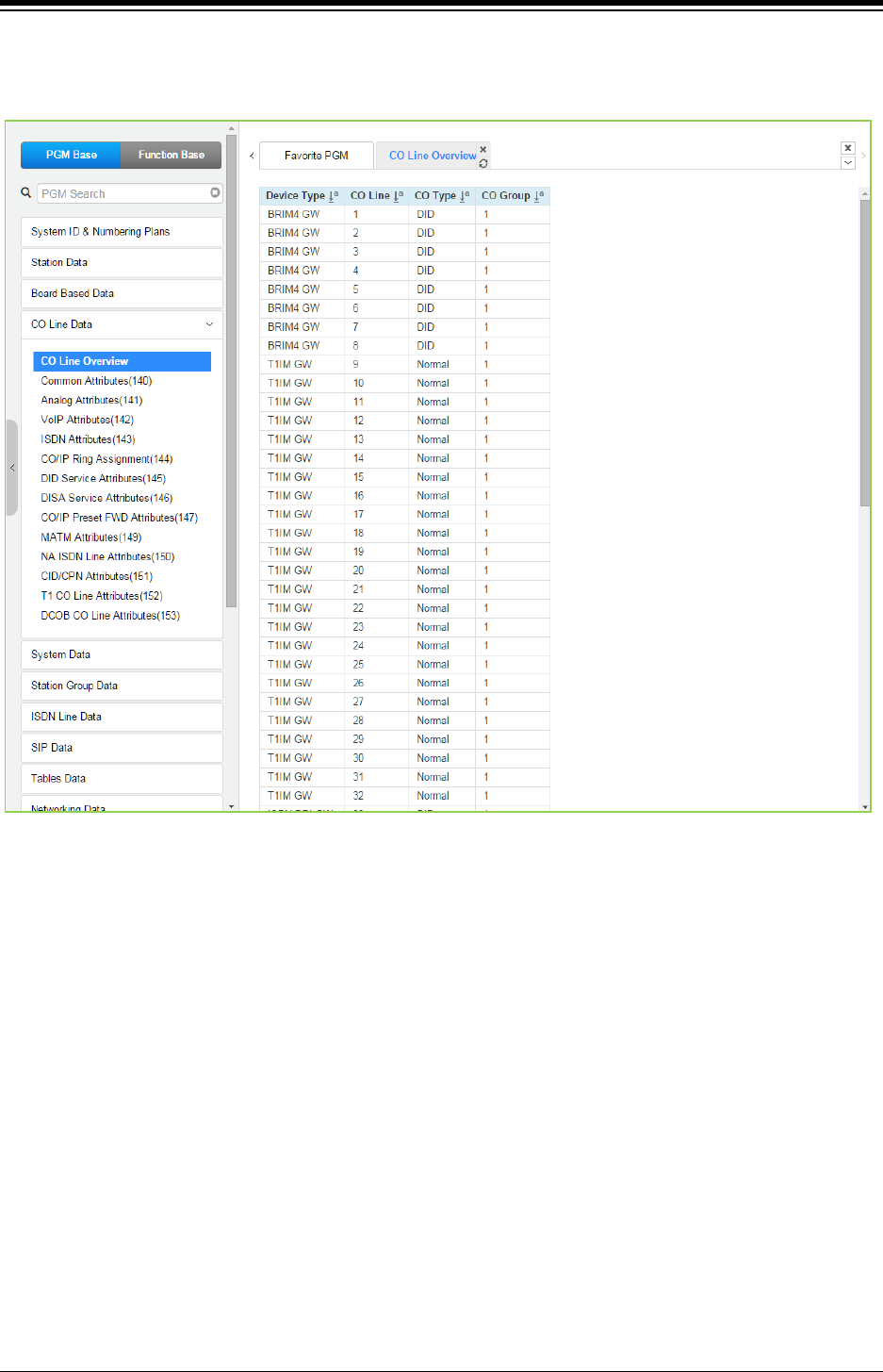
iPECS eMG80 & eMG800 & UCP
Administration and Programming Manual Issue 1.6
315
Selecting CO Line Overview will show the current overview of CO line. The information may vary
depending on installed modules.
Figure 4.4.4-2 CO Line Overview
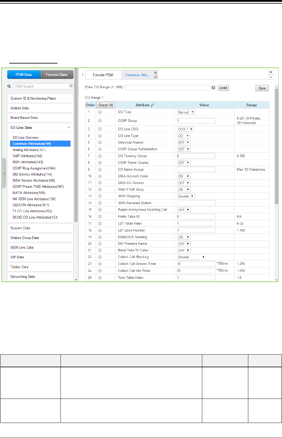
iPECS eMG80 & eMG800 & UCP
Administration and Programming Manual Issue 1.6
316
4.4.4.1 Common Attributes - PGM 140
Selecting Common Attributes will display the Common Attributes data input page. Enter a valid
CO range and click [Load] to enter the Common Attributes data. Use the check mark to indicate
which attributes to modify; data for checked attributes is stored by clicking [Save] button.
Enter CO Range
: eMG80: 1-74 / eMG800: 1-600 / UCP: 1-998
Figure 4.4.4.1-1 Common Attributes
Common Attributes define various characteristics of CO lines facilities under control of the system.
Most characteristics require an On/Off setting; refer to the following table. Specific descriptions for
Class-of-Service and CO line Call Metering tones are provided in Table 4.4.4.1-3.
Table 4.4.4.1-1 Common Attributes
ATTRIBUTE DESCRIPTION RANGE DEFAULT
CO Type Each CO Line is assigned a type, Normal, DID or TIE
Line.
Normal/
DID/
TIE/
Unused
Normal
CO/IP Group Each CO/IP Line is assigned to a group; grouping should
be based on the Line type, technology and COS.
eMG80:0-21
eMG800:0-201
UCP:0-201
1

iPECS eMG80 & eMG800 & UCP
Administration and Programming Manual Issue 1.6
317
Table 4.4.4.1-1 Common Attributes
ATTRIBUTE DESCRIPTION RANGE DEFAULT
CO Line COS
Each CO/IP Line is assigned a Class-of-Service that
interacts with the Station COS, refer to Table 4.4.4.1-2
CO COS 1: Station COS applies
CO COS 2: Exception Table A governs
CO COS 3: Exception Table B governs
CO COS 4: Restricts LD calls & Exception Table C
CO COS 5: Overrides Station COS 2~6 with no
restrictions.
COS 1~5 COS 1
CO Line Type Each CO/IP Line can be assigned as connected to a CO
Line or a PBX/CTX Line.
PBX
CO
CO
Universal Night Answer Universal Night Answer (UNA) allows any station user to
answer a call on the CO/IP line by dialing the UNA code.
OFF
ON
OFF
CO/IP Group
Authorization
Each CO/IP Group can be assigned to require the user
enter an Authorization Code.
OFF
ON
OFF
CO Tenancy Group Only stations in the assigned Tenancy group are
permitted access to the defined CO Line.
eMG80:00-15
eMG800:0-32
UCP:0-100
0
CO/IP Name Display
The IP Phone display can indicate the CO line/IP channel
number or the twelve (12) character name, if assigned
below.
OFF
ON OFF
CO Name Assign Each CO Line and IP group can be assigned a twelve
(12)-character name for display purposes.
Max. 12
characters
DISA Account Code
With DISA Account Code “ON”, users are required to
enter a DISA Authorization code. Codes are entered in
‘Authorization Code Table section’.
OFF
ON ON
DISA CO Access When enabled, DISA users may access the VoIP facilities
of the system.
OFF
ON
OFF
Wait If VSF Busy
When a DID/DISA call assigned to receive a VSF
announcement arrives and all channels are busy, the call
may wait with Ring back until a channel is available (ON)
or route to the DID/DISA Destination -PGM 167-.
OFF
ON ON
SMS Outgoing Each CO line can be assigned to support PSTN SMS. Disable
Enable
Disable
SMS Received Station When a PSTN SMS is received, the system delivers the
message to the assigned station.
Station ….
Reject Anonymous
Incoming Call
When REJECT ANONYMOUS is enabled, incoming calls
without Caller ID are rejected.
OFF
ON
OFF
Prefix Table ID
When the Prefix Dialing Table (PGM 206) feature is used,
this Prefix Table ID is employed. If this value is set to 0,
the Prefix Table feature is disabled.
0 – 6.
0 means disable 0
LDT Table Index When LCR is configured, this LDT Table index is
referenced for outgoing calls on this CO/IP Line.
0-10(eMG80),
0-32(eMG800)
0-32(UCP)
1
LDT Zone Number
If the LDT Zone Number of a LDT table (LCR LDT(221))
is equal to this value, the LDT table is available to this CO
Line.
1-100 1
ENBLOCK Sending
This entry determines if the system sends dialed digits to
the ISDN line as they are received (OFF), or collects all
digits and forwards them in a block. (ON).
OFF
ON ON

iPECS eMG80 & eMG800 & UCP
Administration and Programming Manual Issue 1.6
318
Table 4.4.4.1-1 Common Attributes
ATTRIBUTE DESCRIPTION RANGE DEFAULT
DID preserve Name
For DID lines, the CLI is normally displayed only during
ringing. If enabled here, the CLI will be displayed for the
entire call duration.
OFF
ON OFF
Burst Tone to Caller
When DID Call Wait is assigned for the station, the
system can send audible off-hook signals as a short burst
of tone for DID calls from this CO/IP Line.
OFF
ON OFF
Collect Call Blocking
This parameter defines the type of Collect Call Blocking
supported for E1 CO lines with R2 signaling. (Intended for
Brazil only)
Disable/
Double Answer/
Double Answer
w/Indication
Disable
Collect Call Answer
Timer
These parameters determine treatment of an incoming
call when Collect Call Blocking Double Answer is
assigned. In this case, the system answers the call and
maintains the connection for the Call Answer time then,
the system will disconnect for the Call Idle time before
finally reconnecting the call.
1-250 (100ms) 10
Collect Call Idle Timer 1-250 (100ms) 20
Gain table index One of three Gain tables can be configured for TDM
connections.
1-3 1
Tone table index One of the five Tone table can be configured for use with
the CO/IP Line.
1-5 1
Digit conversion table
index
One of the Digit Conversion Tables can be configured for
use for this CO/IP Line.
eMG80:1-15
eMG800:1-32
UCP:1-32
1
Prepaid Call
The Pre-paid Call feature must be enabled for use by a
station. User can set the budget for the station call charge
in advance.
OFF
ON OFF
Prepaid Money (0-
999999)
&
Used Prepaid Money
An amount can be associated with the station as
prepayment for outgoing calls. The assigned “Pre-paid
Money” is reduced by the calculated call cost (Call
Metering or cost/minute). This parameter displays the
remaining funds for outgoing calls. Prepaid Money is
often used in small hospitality businesses.
The “Used Pre-paid Money” displays the money that has
been used.
0-999999
0-999999
0
Automatic call
recording destination
When desired, the IP CR server can be used to record
calls on the CO/IP Line. This value defines the Station
Group of the IP CR server. The IP CR Agent object, see
PGM 237, must be assigned as CO Line for proper
operation.
ICLID Usage
An incoming call can be routed to the destination based
on Calling Name.
Disable - ICLID feature is disabled
CLI - ICLID feature is operated with CLI
Name, CLI - ICLID feature is operated with Name and CLI
Disable/
CLI/
Name, CLI
CLI
PBX Code Insertion for
Emergency call
System can insert PBX code automatically if pre-
configured when a user make an emergency call.
Disable,
PBX code1~4
Disable
Timer Attributes
CO CUT OFF TIMER When the Station is assigned Call Time restriction is 00-99 0

iPECS eMG80 & eMG800 & UCP
Administration and Programming Manual Issue 1.6
319
Table 4.4.4.1-1 Common Attributes
ATTRIBUTE DESCRIPTION RANGE DEFAULT
assigned, this timer defines the allowed call duration. 00 = disable
DISA Delay Timer
Once answered, the system attaches a DTMF receiver to
the DISA call to receive caller-dialed digits. This timer
introduces a delay before attaching the DTMF receiver to
the CO line. (Intended for Russia only)
0-9 seconds 0
DISA Answer Timer
When a call is received on a CO line with DISA service,
the system will answer the call when the DISA Answer
Timer expires. (Intended for Russia only)
0-9 seconds 0
Tone Attributes
CO Line MOH
A held call can be connected to one (1) of ten (10)
possible audio sources while on Hold as Music-on-Hold
(MOH).
Refer to Sys
Hold/
Internal Music/
External Music/
VSF MOH/
SLT MOH1~5/
VSF MOH2~3
Refer to Sys
Hold
CO Dial Tone
ISDN Lines may provide a digital signal rather than actual
tones. In this case, the iPECS can provide the tones. If
the ISDN provides the tone, the Tone is “ON”, for an
iPECS system-generated tone, the tone is set to “OFF”.
OFF
ON
ON
CO Ring Back Tone OFF
ON
OFF
CO Error Tone OFF
ON
OFF
CO Busy Tone OFF
ON
OFF
CO Line Dial Tone
Source
One of eleven sources can be defined as dial tone for use
by the CO line.
Dial Tone/
Internal Music/
External Music/
VSF MOH/
SLT MOH1~5/
VSF MOH2~3
Dial Tone
CO Ring Back Tone
Source
One of eleven sources can be defined as ring back tone
for use by the CO line.
Ring Back Tone/
Internal Music/
External Music/
VSF MOH/
SLT MOH1~5/
VSF MOH2~3
Ring Back
Tone
COL Ring Tone One of sixteen Ring Tones can be configure for use by
this CO Line.
00-16 0

iPECS eMG80 & eMG800 & UCP
Administration and Programming Manual Issue 1.6
320
Table 4.4.4.1-2 STATION/CO LINE TOLL RESTRICTIONS
CO COS 1 CO COS 2 CO COS 3 CO COS 4 CO COS 5
STA
COS 1
No Restriction No Restriction No Restriction Only Local Call (LD
code/counter) & Table C
No
Restriction
STA
COS 2
Exception Table A
governs the dialing
Exception Table A
governs the dialing
No Restriction Only Local Call (LD
code/counter) & Table C
No
Restriction
STA
COS 3
Exception Table B
governs the dialing
No Restriction Exception Table B
governs the
dialing
Only Local Call (LD
code/counter) & Table C
No
Restriction
STA
COS 4
Exception Table A &
B governs the dialing
Exception Table A
governs the dialing
Exception Table B
governs the
dialing
Only Local Call (LD
code/counter) & Table C
No
Restriction
STA
COS 5
Local Call only (LD
Code, “1” or “0”) and
Table C
Local Call only (LD
Code, “1” or “0”)
and Table C
Local Call only
(LD Code, “1” or
“0”) & Table C
Only Local Call (LD
code/counter) & Table C
No
Restriction
STA
COS 6
Only Local Call (LD
code/counter) &
Table C
Only Local Call (LD
code/counter) and
Table C
Only Local Call
(LD code/counter)
& Table C
Only Local Call (LD
code/counter) & Table C
No
Restriction
STA
COS 7
In-house dialing only In-house dialing
only
In-house dialing
only
In-house dialing only In-house
dialing only
STA
COS 8
Exception Table D
governs the dialing
Exception Table D
governs the dialing
No Restriction Only Local Call (LD
code/counter) & Table C
No
Restriction
STA
COS 9
Exception Table D
governs the dialing
Exception Table D
governs the dialing
No Restriction Only Local Call (LD
code/counter) & Table C
No
Restriction
STA
COS 10
Exception Table D &
E governs the dialing
Exception Table D
& E governs the
dialing
No Restriction Only Local Call (LD
code/counter) & Table C
No
Restriction
STA
COS 11
Exception Table A &
B and D & E governs
the dialing
Exception Table A
& B and D & E
governs the dialing
No Restriction Only Local Call (LD
code/counter) & Table C
No
Restriction
Table 4.4.4.1-3 CALL METERING FUNCTION
ENTRY CALL METERING TYPE
00
- None
01
- 50 Hz
02
- 12 KHz
03
- 16 KHz
04
- Singular Polarity Reverse (SPR)
05
- Plural Polarity Reverse (PPR)
06
- No Polarity Reverse (NPR)
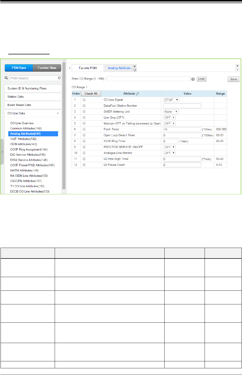
iPECS eMG80 & eMG800 & UCP
Administration and Programming Manual Issue 1.6
321
4.4.4.2 Analog Attributes - PGM 141
Selecting Analog Attributes will display the Analog Attributes data input page. Enter a valid CO
range and click [Load] to enter the Analog (PSTN) Attributes data. Use the check mark to
indicate which attributes to modify; data for checked attributes is stored by clicking [Save] button.
Enter CO Range
: eMG80: 1-74 / eMG800: 1-600 / UCP: 1-998
Figure 4.4.4.2-1 Analog Attributes
Analog Attributes define various characteristics of Analog CO Lines under control of the system.
Most characteristics require an On/Off setting; refer to the following table. Specific descriptions for
CO Line (SMDR) Call Metering tones are provided in Table 6.4.2-2.
Table 4.4.4.2-1 Analog ATTRIBUTES
ATTRIBUTE DESCRIPTION RANGE DEFAULT
CO Line Signal Each analog CO Line can be assigned to send
either DTMF or Pulses for dialed digits to the PSTN.
DTMF
Pulse DTMF
Data(Fax) Station
Number
Each CO line can be assigned to recognize a FAX
call when a specified station answers.
Station Number
SMDR Metering Unit This field selects the call-metering signal from the
PSTN to indicate call cost, refer to Table 4.4.4.1-2.
See
Table 4.4.4.1-2
None
Line Drop (CPT) Each CO Line can be programmed to disconnect if
error tone is detected.
OFF
ON OFF
Maintain CPT on talking
(Answer by User)
The system can continuously monitor the CO Line
during a call and, if error tone is detected, drop the
call.
OFF
ON OFF
Flash Timer This time sets the flash time. 000-300
(*10 msec) 50
Open Loop Detect timer
This entry sets the duration of open loop that will be
00-20
04

iPECS eMG80 & eMG800 & UCP
Administration and Programming Manual Issue 1.6
322
Table 4.4.4.2-1 Analog ATTRIBUTES
ATTRIBUTE DESCRIPTION RANGE DEFAULT
recognized as a “Disconnect Signal”.
(*100 msec)
ICLID Ring Timer
When a call is received, the system may use ICLID
(Incoming Caller ID) to route the call. The system
will delay routing a call for this duration while
awaiting ICLID. Enter a 00 to disable ICLID routing.
00-20
(*Sec) 4
Proctor Service Each analog CO line can be assigned to send the
station number as DTMF digits for Proctor service.
OFF
ON OFF
Analog Line monitor The system can monitor and report faults on an
analog CO Line.
OFF
ON
ON
LD Inter Digit Timer This time is for setting the duration between digits
for LD (Long Distance) call.
00-20 (*1sec) 0
LD Pause count This count sets the number of Pause for Long
distance call.
0-10 0
Table 4.4.4.2-2 CALL METERING FUNCTION
ENTRY SMDR METERING UNIT TYPE
00
- None
01
- 50 Hz
02
- 12 KHz
03
- 16 KHz
04
- Singular Polarity Reverse (SPR)
05
- Plural Polarity Reverse (PPR)
06
- No Polarity Reverse (NPR)
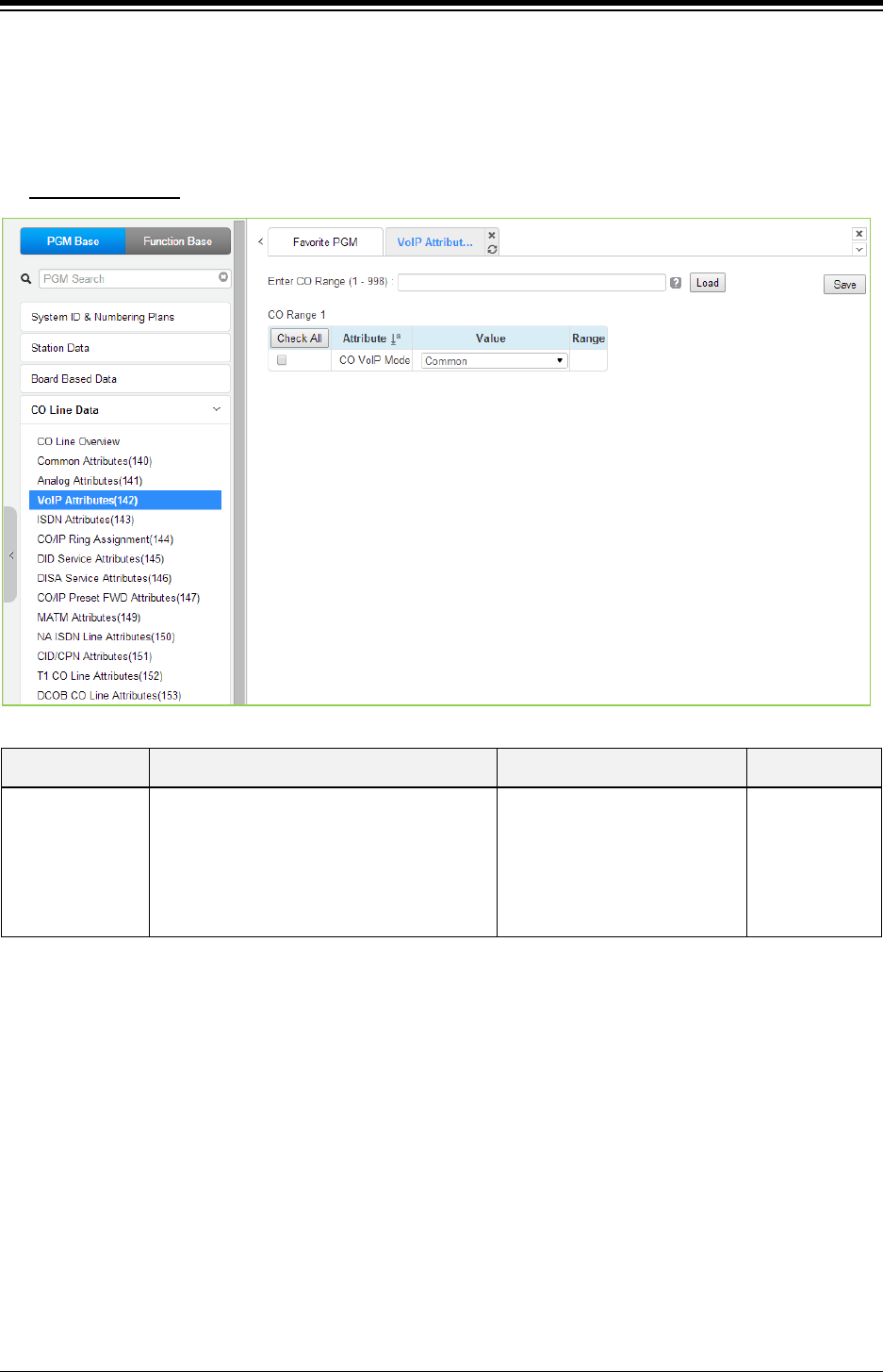
iPECS eMG80 & eMG800 & UCP
Administration and Programming Manual Issue 1.6
323
4.4.4.3 VoIP Attributes - PGM 142
Selecting VoIP Attributes will display the Analog Attributes data input page. Enter a valid CO
range and click [Load] to enter the VoIP Attributes data. Use the check mark to indicate which
attributes to modify; data for checked attributes is stored by clicking [Save] button.
Enter CO Range
: eMG80: 1-74 / eMG800: 1-600 / UCP: 1-998
Figure 4.4.4.3-1 VoIP Attributes
Table 4.4.4.3-1 VoIP ATTRIBUTES
ATTRIBUTE DESCRIPTION RANGE DEFAULT
CO VoIP Mode
The VoIP channels can support iPECS,
H.323 or SIP protocols. This field defines the
protocol for the VoIP channel(s).
COMMON/
H323 only/
SIP only/
RTP-Packet-Relay only/
H323 & RTP-Packet-Relay/
SIP & RTP-Packet-Relay
COMMON
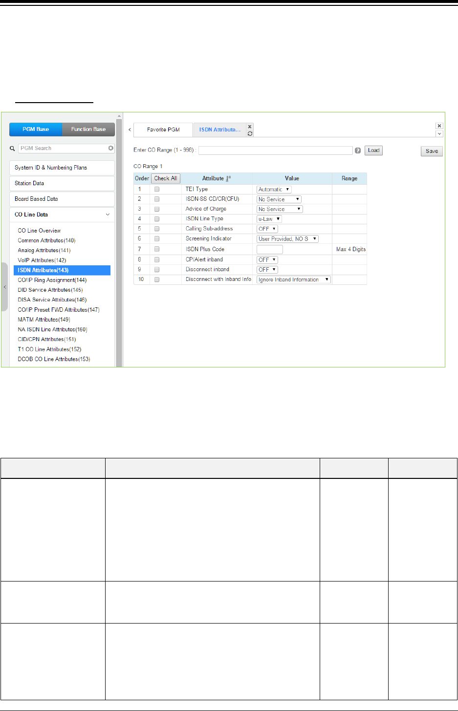
iPECS eMG80 & eMG800 & UCP
Administration and Programming Manual Issue 1.6
324
4.4.4.4 ISDN Attributes - PGM 143
Selecting ISDN Attributes will display the ISDN Attributes data input page. Enter a valid CO range
and click [Load] button to enter the ISDN Attributes data. Use the check mark to indicate which
attributes to modify; data for checked attributes is stored by clicking [Save] button.
Enter CO Range
: eMG80: 1-74 / eMG800: 1-600 / UCP: 1-998
Figure 4.4.4.4-1 ISDN Attributes
PGM 143 assigns attributes associated with ISDN lines in the entered range.
Table 4.4.4.4-1 ISDN ATTRIBUTES
ATTRIBUTE DESCRIPTION RANGE DEFAULT
TEI Type
The TEI (Terminal Endpoint Identifier) is a unique
identifier for each device attached to the ISDN line.
When the system shares an ISDN connection with
other devices, the TEI should be automatic to assure
no conflict with the other attached devices.
Otherwise, the Fixed identifier option should be
employed.
Fixed/
Automatic Automatic
ISDN – SS CD/CR(CFU) Permits a user to access to ISDN Supplementary Call
Deflection Service. (Except USA version).
No Service/
Call Deflection/
Call Rerouting
No Service
Advice of Charge
When assigned, the system will analyze the Advice of
Charge information in the Facility Message according
to the ETSI specifications with appropriate regional
protocol support.
No AOC/
Italy & Spain/
Finland/
Australia/
Belgium/
ETSI STD
No Service

iPECS eMG80 & eMG800 & UCP
Administration and Programming Manual Issue 1.6
325
Table 4.4.4.4-1 ISDN ATTRIBUTES
ATTRIBUTE DESCRIPTION RANGE DEFAULT
ISDN Line Type
The system will encode voice using the A-law or u-
law PCM format to match the installed ISDN back
bone.
μ-Law/
A-Law μ-Law
Calling Sub-address
For outgoing calls, the user’s station number may be
included in the ISDN call SETUP message Sub-
address field.
OFF
ON OFF
Screening indicator The ISDN Screening Indicator can be configured.
User Provided,
No Service/
User Provided,
Pass/
User Provided,
Fail/
Network
Provided.
User Provided,
No Service
ISDN PLUS Code When the incoming CLI starts with “+”, this value will
be inserted in place of the “+” sign.
0000-9999 -
CP/Alert inband Send progress indication with in-band information in
Call proceeding and Alerting messages.
OFF
ON
OFF
Disconnect inband Send progress indication with in-band information in
Disconnect message.
OFF
ON
OFF
Disconnect with Inband
Info
When system receives DISCONNECT message with
Inband information from PSTN, the following option
can be applied:
-. Ignore Inband information: Line is disconnected
-. Bypass Inband information: Progress Information is
transferred
-. Wait Release: System wait to send Release
message till the other party is disconnected
Ignore Inband
information,
Bypass Inband
information,
Wait Release
Ignore Inband
information
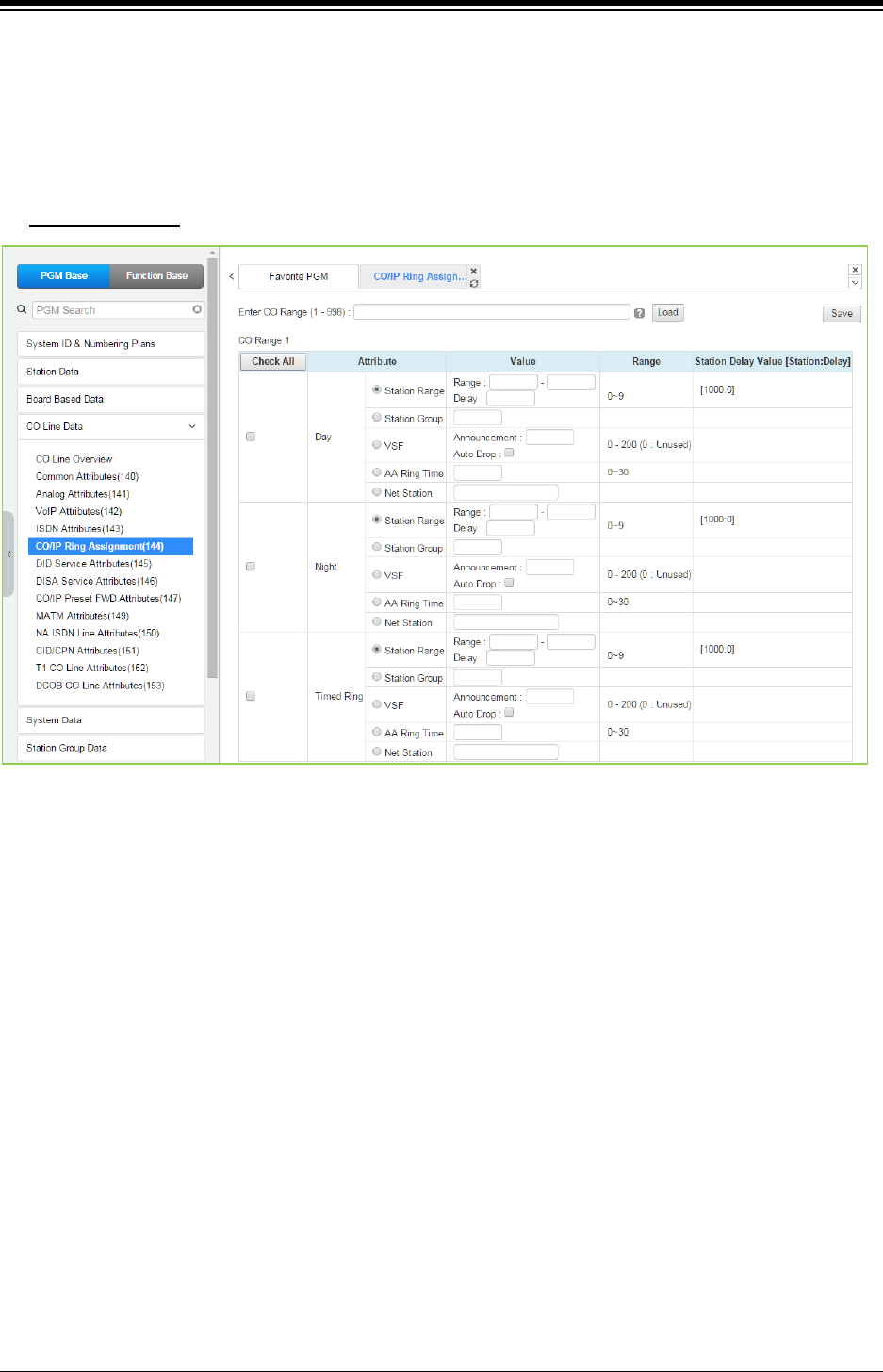
iPECS eMG80 & eMG800 & UCP
Administration and Programming Manual Issue 1.6
326
4.4.4.5 CO/IP Ring Assignment - PGM 144
Selecting CO/IP Ring Assignment will display the CO/IP Ring Assignment data input page. Enter
a valid CO range and click [Load] to enter the CO/IP Ring Assignment data. Use the check mark
to indicate which attributes to modify; data for checked attributes is stored by clicking [Save]
button.
Enter CO Range
: eMG80: 1-74 / eMG800: 1-600 / UCP: 1-998
Figure 4.4.4.2-1 CO/IP Ring Assignment
Each “Normal” CO/IP line is assigned to signal a station, station group or VSF Announcement for
an incoming call (Ring). Separate ring assignments are made for Day, Night, and Timed Ring
mode. A delay from 1 to 9 Ring cycles can also be assigned, based on this assignment, the
station/Station group will receive audible ring after a delay of the number of Ring cycles entered.
In addition, when assigned to ring a VSF Announcement, the system can be programmed to
disconnect after the announcement, ‘Auto Drop’.
When CO/IP Lines are programmed to ring the built-in Auto Attendant, a delay of 0 to 30 seconds
can be assigned as the AA Ring Time. The delay allows stations to be assigned Ring and to
answer prior to signaling the AA. At expiration of the AA Ring Time, the call is sent to the
assigned VSF announcement or announcement 1 when no VSF announcement is assigned.
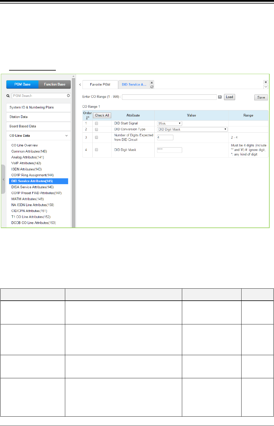
iPECS eMG80 & eMG800 & UCP
Administration and Programming Manual Issue 1.6
327
4.4.4.6 DID Service Attributes - PGM 145
Selecting DID Service Attributes will display the DID Service Attributes data input page. Enter a
valid CO range and click [Load] button to enter the DID Service Attributes data. Use the check
mark to indicate which attributes to modify; data for checked attributes is stored by clicking [Save]
button.
Enter CO Range
: eMG80: 1-74 / eMG800: 1-600 / UCP: 1-998
Figure 4.4.4.6-1 DID Service Attributes
DID lines can be assigned the type of “Start” signaling and treatment of received digits. Digits can
be used “as is” to route the call within the system, digits can be converted and used to route the
call, or digits can be converted to a Table index to determine the call routing from a Table look-up.
Refer to the following table for additional description of attributes and values.
Table 4.4.4.6-1 DID SERVICE ATTRIBUTES
ATTRIBUTE DESCRIPTION RANGE DEFAULT
DID Start Signal Assigns the type of DID start signaling,
Immediate, Wink or Delayed for the CO/IP Line.
Immediate/
Wink/
Delayed
Wink
DID Conversion Type
The received DID digits can be treated to
determine call routing, simple conversion
(Convert), use “as is” (no treatment), or modify
using Flexible DID Conversion Table (Look-up).
DID Digit Conversion/
Use ‘as is’/
Modify using Flexible
DID conversion table
Use ‘as is’
Number of Digits
Expected from DID Circuit
The number of digits expected from the PSTN
DID circuit. 2~4
eMG80:3
eMG800:4
UCP:4
DID Digit Mask
DID digit modification sequence: “#” deletes the
digit, “*” accepts the digit “as is”, a digit (0~9)
replaces the digit. The modification is based on
the position of the digit (1~4) in the received
number.
(0~9, *, #) #***
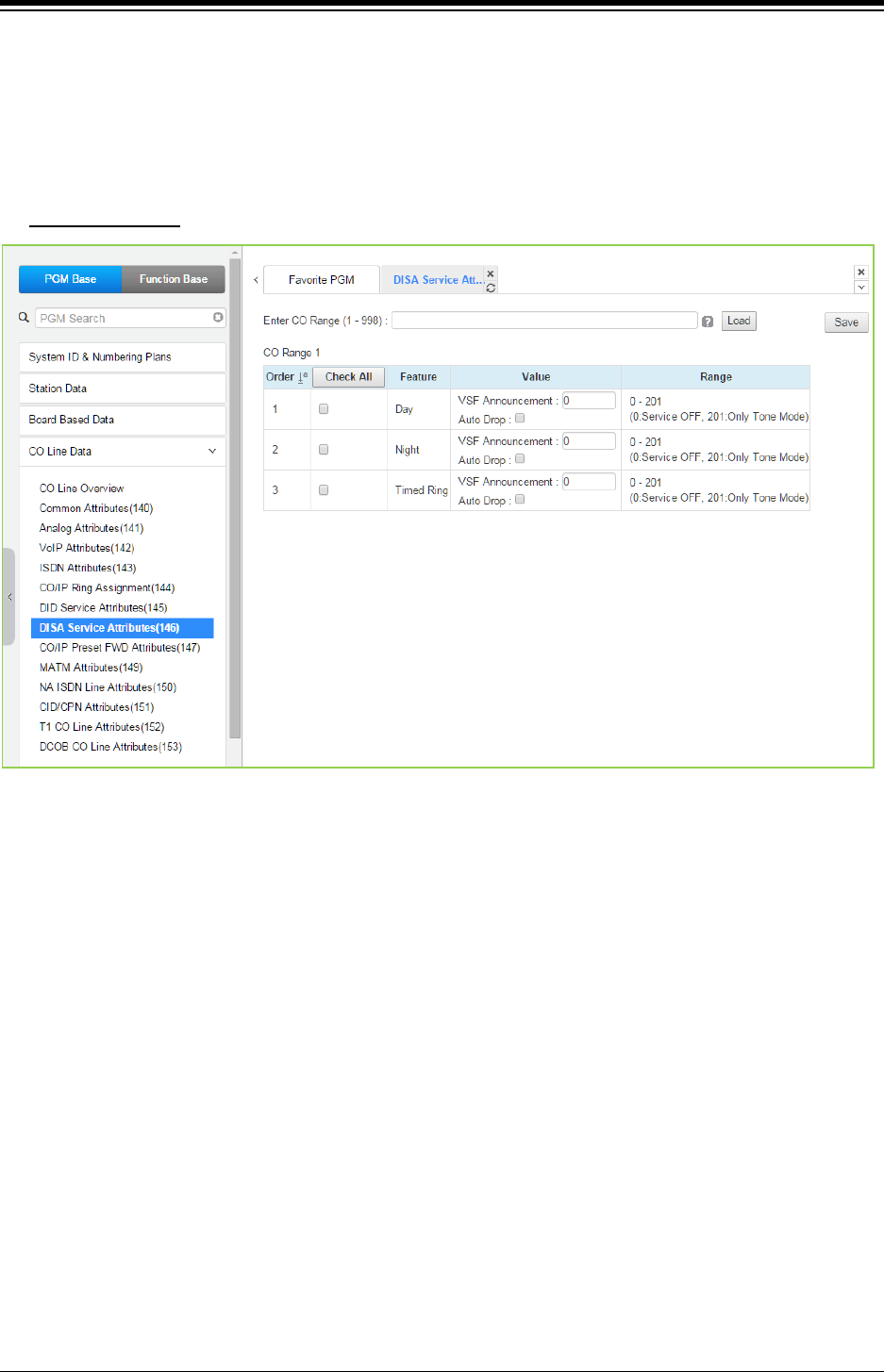
iPECS eMG80 & eMG800 & UCP
Administration and Programming Manual Issue 1.6
328
4.4.4.7 DISA Service Attributes - PGM 146
Selecting DISA Service Attributes will display the DISA Service Attributes data input page. Enter
a valid CO range and click [Load] to enter the DISA Service Attributes data. Use the check mark
to indicate which attributes to modify; data for checked attributes is stored by clicking [Save]
button.
Enter CO Range
: eMG80: 1-74 / eMG800: 1-600 / UCP: 1-998
Figure 4.4.4.7-1 DISA Service Attributes
DISA Service can be enabled on CO lines based on the system operation mode (Day, Night, and
Timed). DISA calls may be routed to dial tone and await user dialing (simple routing) or through a
multi-layered Audio Text menu assigning a VSF Announcement and a Customer Call Route
(CCR) Table Index. The system can be programmed to disconnect after the announcement, ‘Auto
Drop’, or follow the CCR Table routing with a user-recorded announcement requesting specific
inputs from the user.
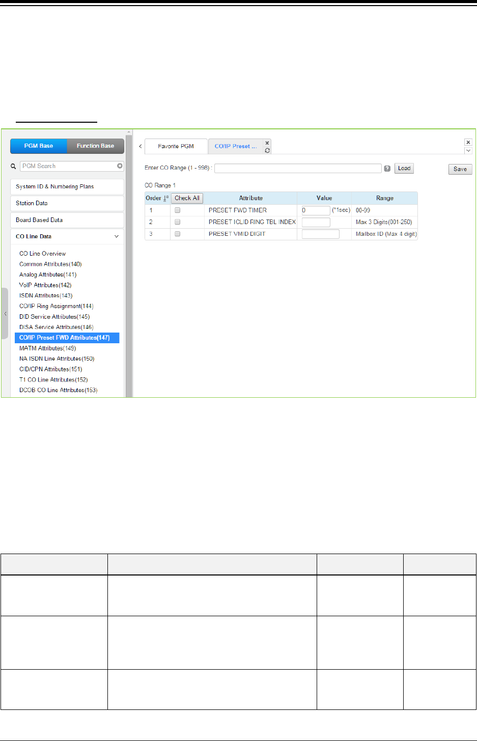
iPECS eMG80 & eMG800 & UCP
Administration and Programming Manual Issue 1.6
329
4.4.4.8 CO/IP Preset Forward Attributes - PGM 147
Selecting CO/IP Preset Forward Attributes will display the CO/IP Preset Forward Attributes data
input page. Enter a valid CO range and click [Load] to enter the CO/IP Preset Forward Attributes
data. Use the check mark to indicate which attributes to modify; data for checked attributes is
stored by clicking [Save] button.
Enter CO Range
: eMG80: 1-74 / eMG800: 1-600 / UCP: 1-998
Figure 4.4.4.8-1 CO/IP Preset Forward Attributes
The CO/IP Preset Call Forward feature enables a CO line to initially ring at multiple stations and
forward to a pre-determined destination. A separate timer can be defined for each CO/IP line for
no-answer. The destination can be any index to the ICLID Ring Table in section 4.4.7.5 or a
Voice Mailbox. The VMID field allows selecting a specific mailbox when the CO line call forwards
to an external VM group.
Table 4.4.4.8-1 CO/IP PRESET FORWARD ATTRIBUTES
ATTRIBUTE DESCRIPTION RANGE DEFAULT
Preset FWD Timer
An incoming call, which remains unanswered for
this timer, is routed as defined in the ‘ICLID Ring
Table Index section’.
00-99
(Sec.) 00
Preset ICLID Ring Table
Index
If an incoming call remains unanswered after the
Preset Fwd time above, the call is routed as
defined in the ‘ICLID Ring Table index’ defined
here.
001-250
Preset VMID Digit
Each CO/IP line can be assigned a VMID (Voice
Mail Id) that is sent to the external VM group to
identify the desired Mailbox for the call.
Mailbox ID
(Max. 4 digits)
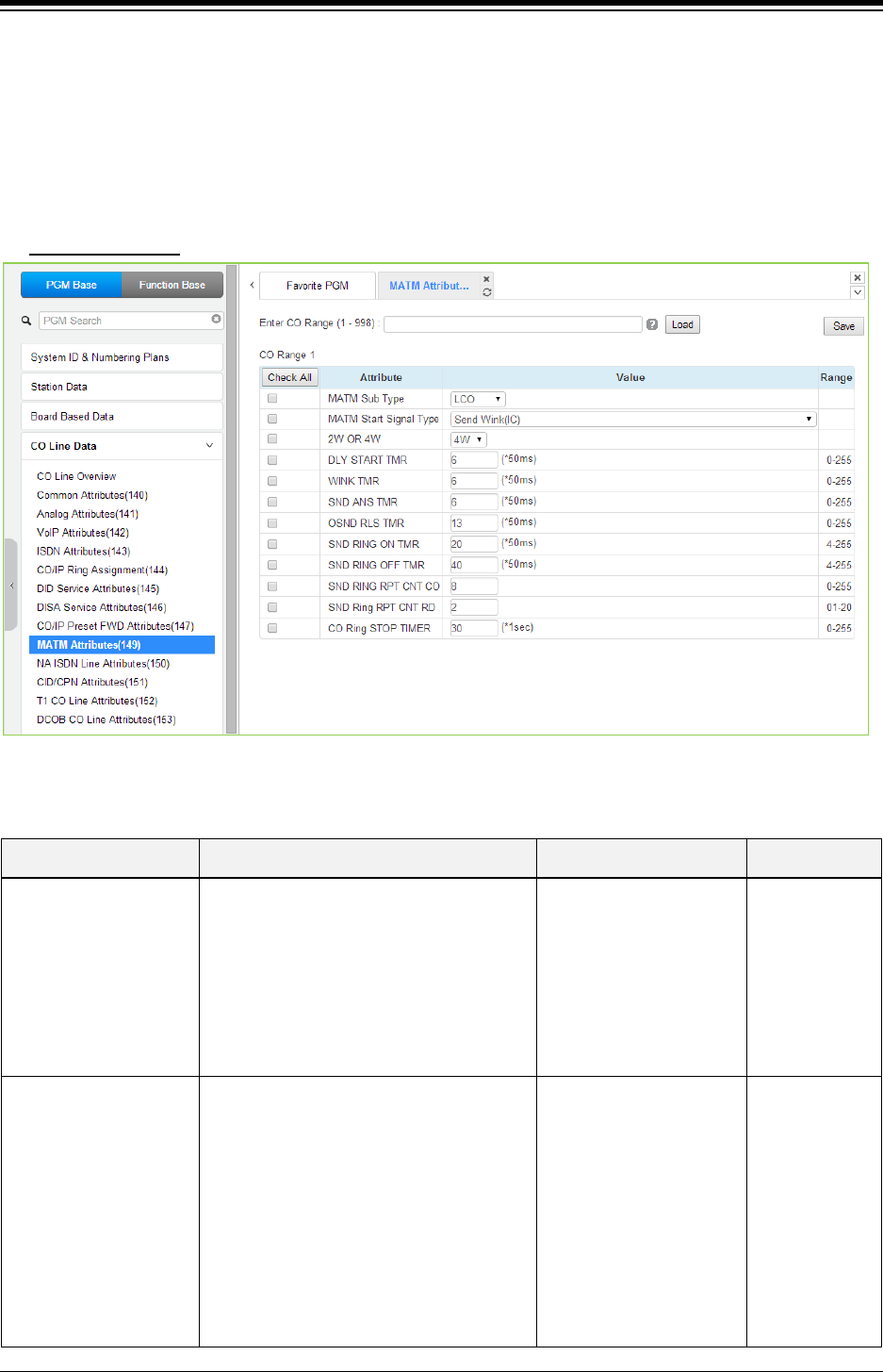
iPECS eMG80 & eMG800 & UCP
Administration and Programming Manual Issue 1.6
330
4.4.4.9 MATM Attributes - PGM 149
Selecting MATM Attributes will display the MATM Attributes data input page. Enter a valid CO
range and click [Load] to enter the MATM Attributes data. Use the check boxes to indicate which
attributes to modify; data for checked attributes is stored for the entire range of CO/IP Lines when
saved. Use the check mark to indicate which attributes to modify; data for checked attributes is
stored by clicking [Save] button. These attributes are available for Country code 82.
Enter CO Range
: eMG80: 1-74 / eMG800: 1-600 / UCP: 1-998
Figure 4.4.4.9-1 MATM Attributes
Table 4.4.9-1 MATM ATTRIBUTES
ATTRIBUTE DESCRIPTION RANGE DEFAULT
MATM Sub Type
This is the analog trunk type for the MATM
option board.
COIU : LCO
RDIU : RD (ring down, only for national
army)
LDIU : LD (loop dial, only for national army)
EMC = E&M continuous,
EMD = E&M discontinuous)
LCO,
RD,
LD,
EMC,
EMD,
Unused
LCO
MATM Start Signal Type
This is the signal type for the analog trunk.
This should be set with alternate trunk type.
These can be set by testing with available
values.
Send Wink (IC),
Wait Seize Ack(OG),
Send Wink (IC) and
Wait Seize Ack(OG),
Send Sub Answer (IC)
and Wait Sub
Answer(OG),
Send Wink and Send Sub
Answer(IC),
Wait Ack and Wait Sub
Answer(OG),
Send Wink (IC)

iPECS eMG80 & eMG800 & UCP
Administration and Programming Manual Issue 1.6
331
Table 4.4.9-1 MATM ATTRIBUTES
ATTRIBUTE DESCRIPTION RANGE DEFAULT
Send Wink and Send Sub
Answer(IC) & Wait Wink
and wait sub answer(OG),
Unused Type
2W or 4W For E&M Lines, this value should be set as
2 wire or 4wire to match the line.
2W/
4W
4W
DLY Start Timer
This is timer value for analog signaling.
0~255
6
Wink Timer
This is timer value for analog signaling.
0~255
6
SND ANS Timer
This is timer value for analog signaling.
0~255
6
OSND RLS Timer
This is timer value for analog signaling.
0~255
13
SND RING ON Timer
This is timer value for analog signaling.
4~255
20
SND RING OFF Timer
This is timer value for analog signaling.
4~255
40
SND RING RPT CNT
CO
This is timer value for analog signaling. 0~255 8
SND RING RPT CNT
RD
This is timer value for analog signaling. 01~20 2
CO Ring STOP Timer
This is timer value for analog signaling.
0~255
30
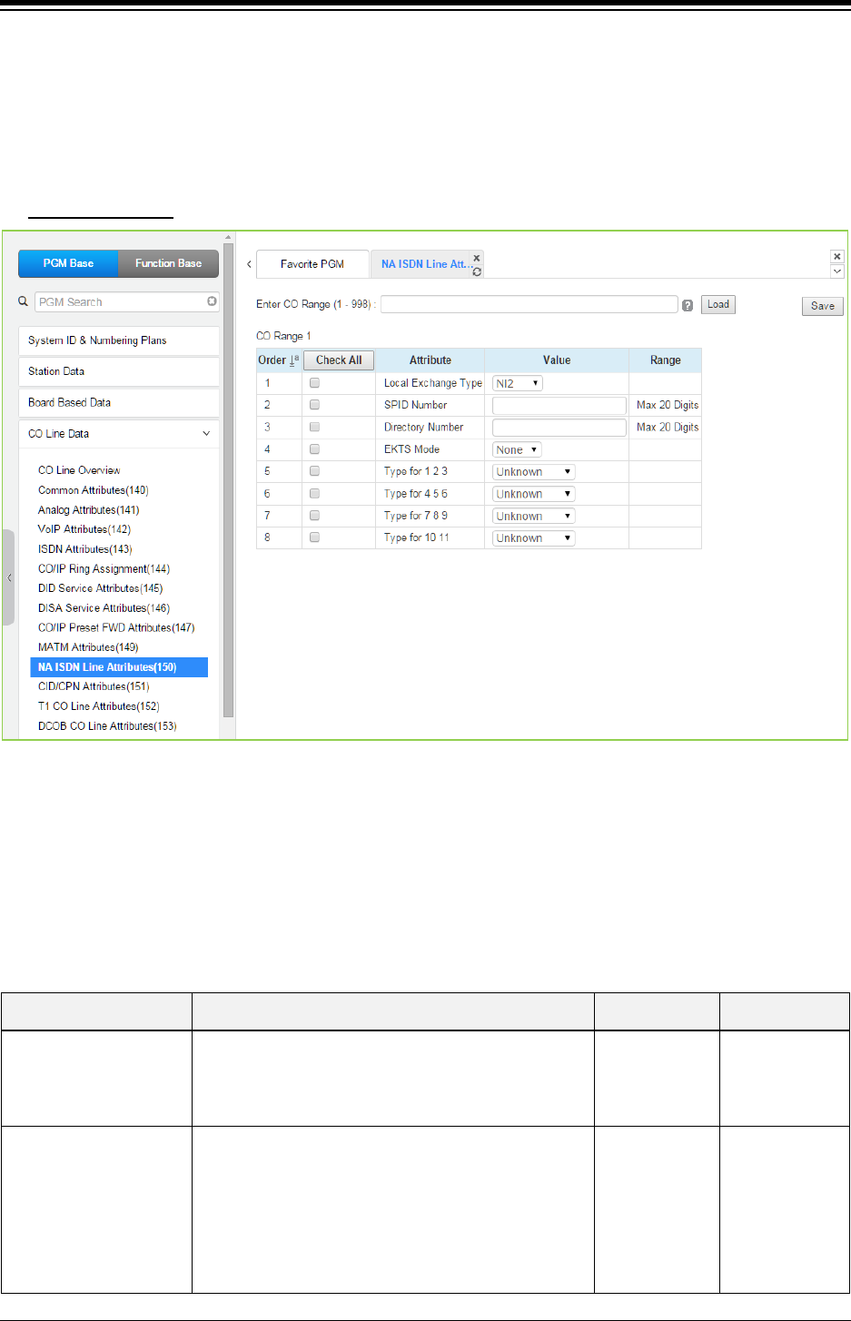
iPECS eMG80 & eMG800 & UCP
Administration and Programming Manual Issue 1.6
332
4.4.4.10 NA ISDN Line Attributes - PGM 150
Selecting NA (North America) ISDN Line Attributes will display the NA ISDN Line Attributes data
input page. Enter a valid CO range and click [Load] to enter the NA ISDN Line Attributes data.
Use the check mark to indicate which attributes to modify; data for checked attributes is stored by
clicking [Save] button.
Enter CO Range
: eMG80: 1-74 / eMG800: 1-600 / UCP: 1-998
Figure 4.4.4.10-1 NA ISDN Line Attributes
To comply with the North American ISDN standards, certain attributes must be defined for the
system. These include Directory (telephone) Number and Service Profile Id (SPID) for the device.
Note that this programming is required only for “Country Code” 1, USA installations. Refer to
Table 4.4.4.10-1 for information on individual attributes.
Table 4.4.4.10-1 NA ISDN LINE ATTRIBUTES
ATTRIBUTE DESCRIPTION RANGE DEFAULT
Local Exchange Type The type of ISDN determines several specifics of the
protocol and is required for proper operation.
NI 1/
NI 2/
5 ESS/
Nortel
NI 2
SPID Number
The Service Profile Identifier (SPID) is a number
assigned to a fully initializing ISDN terminal and
enables the Stored Program Control switching System
(SPCS) to identify the ISDN terminal at layer 3 of the
D-channel signaling protocol. The SPID is a free-
formatted numeric string composed of 9 to 20 numeric
{0-9} and International Alphabet (IA5) characters. The
20 digits

iPECS eMG80 & eMG800 & UCP
Administration and Programming Manual Issue 1.6
333
Table 4.4.4.10-1 NA ISDN LINE ATTRIBUTES
ATTRIBUTE DESCRIPTION RANGE DEFAULT
SPID uniquely identifies a particular set of
subscription parameters assigned to a TSP.
Directory Number
Initializing terminals are required to store a 7-digit DN
in order to perform the compatibility checking
procedures that are part of call termination.
20 digits
EKTS Mode
The EKTS (Electronic Key Telephone Service)
terminal permits a user to operate those features that
are specific to EKTS, as well as voice features that
may function distinctly in the EKTS environment.
EKTS allows a DN to be shared by more than one
terminal, on the same or on different interfaces.
NONE/
EKTS NONE
Type for 1/2/3
ISDN CALLED NO uses the International format,
National format, Network format, Subscriber format, or
Abbreviated format when the user dials 1~3digits.
Unknown/
International/
National/
Network/
Subscriber/
Abbreviated
Unknown
Type for 4/5/6
ISDN CALLED NO is constructed with International
format, National format, Network format, Subscriber
format, or Abbreviated format when the user dials 4~6
digits.
Unknown/
International/
National/
Network/
Subscriber/
Abbreviated
Unknown
Type for 7/8/9
ISDN CALLED NO is constructed with International
format, National format, Network format, Subscriber
format, or Abbreviated format when the user dials 7~9
digits.
Unknown/
International/
National/
Network/
Subscriber/
Abbreviated
Unknown
Type for 10/11
ISDN CALLED NO is constructed with International
format, National format, Network format, Subscriber
format, or Abbreviated format when the user dials
more than 10 digits.
Unknown/
International/
National/
Network/
Subscriber/
Abbreviated
Unknown
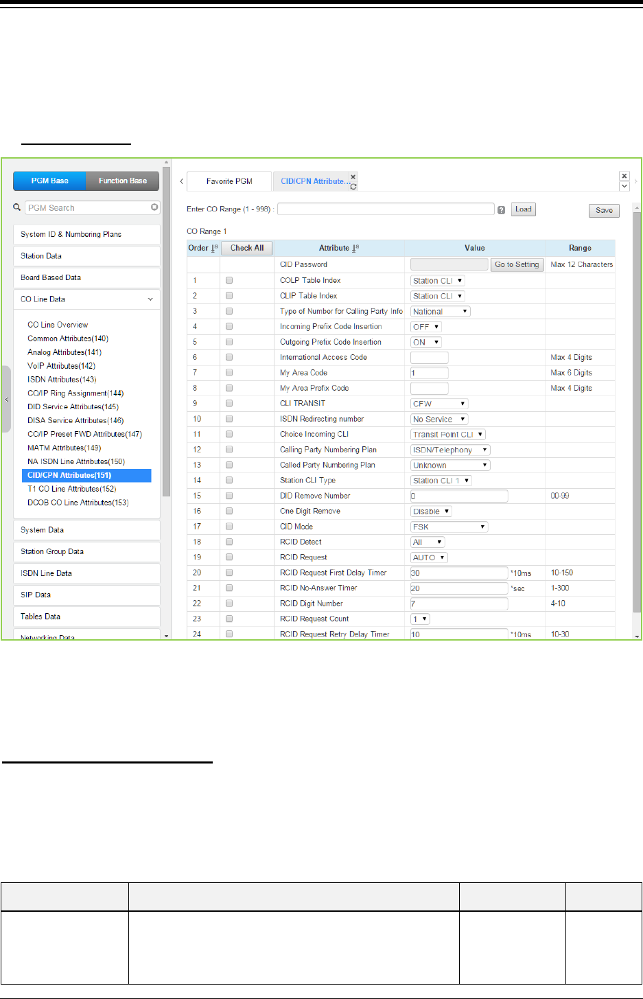
iPECS eMG80 & eMG800 & UCP
Administration and Programming Manual Issue 1.6
334
4.4.4.11 CID/CPN Attributes - PGM 151
Selecting CID/CPN Attributes will display the CID/CPN Attributes data input page. Enter a valid
CO range and click [Load] to enter the CID/CPN Attributes data. Use the check mark to indicate
which attributes to modify; data for checked attributes is stored by clicking [Save] button.
Enter CO Range
: eMG80: 1-74 / eMG800: 1-600 / UCP: 1-998
Figure 4.4.4.11-1 CID/CPN Attributes
COLP: Connected Line Presentation / CLIP: Calling Line Identification Presentation
You can set the CID password to click “Go to Setting” button. After clicking it, you will move to the
following PGM 162 and set the CID password, and then save CID password to mark tick on the
save box and click the Save button.
Setting CID Password directly
Refer to Table 4.4.4.11-1 for information on individual attributes.
Table 4.4.4.11-1 CID/CPN ATTRIBUTES
ATTRIBUTE DESCRIPTION RANGE DEFAULT
COLP Table Index
When an incoming call on an ISDN Line is answered, the
system will send caller id using the number from the
CLIP/COLP Table (section 4.4.7.2) entry defined by this
parameter. The station number is included as a suffix of
N/A
0-49
Station CLI
Station CLI

iPECS eMG80 & eMG800 & UCP
Administration and Programming Manual Issue 1.6
335
Table 4.4.4.11-1 CID/CPN ATTRIBUTES
ATTRIBUTE DESCRIPTION RANGE DEFAULT
the caller id. For “Using Station’s COLP Attribute”, the
Station CLI type entered below will be used in place of the
station number.
CLIP Table Index
When a call is placed on an ISDN Line, the system will
send caller id using the number from the CLIP/COLP Table
entry defined by this parameter. The station number is
included as a suffix of the caller id. For “Using Station’s
CLIP Attribute”, the Station CLI Type entered below will be
used in place of the station number.
N/A
0-49
Station CLI
Station CLI
Type of Number for
Calling Party Info
For outgoing calls on an ISDN Line, this parameter defines
the “Type of Number Plan” provided in Calling Party
Information Element of the ISDN call SETUP message.
Unknown/
International/
National/
Unused/
Subscriber
National
Incoming Prefix Code
Insertion
Regional ISDN providers may use the Local Area Prefix
code for special services. In cases where the code is not
provided in the incoming call SETUP message, the system
can insert the My Local Prefix and My Area Code below in
SMDR, LNR, displays, etc.
OFF
ON OFF
Outgoing Prefix Code
Insertion
Regional ISDN providers may use the Local Area Prefix
code for special services. The system can insert the “My
Area Code” and “My Local Prefix Code” in the Connect
message as defined in those items below.
OFF
ON ON
International Access
Code
When an incoming call includes the international Country
code in the ISDN call SETUP message, the Country code
can be included in the station display. To include the
Country code, Incoming Prefix insertion, and CLI display in
Station Data must be ON.
Max. 4 digits -
My Area Code
Regional ISDN providers may use the Local Prefix and
Area codes for special services. The system will insert this
Local Area Code in the call SETUP messages defined
under the Incoming/Outgoing Prefix Code Insertion entries
above.
Max. 6 digits -
My Area Prefix Code
Regional ISDN providers may use the Local Prefix and
Area codes for special services. The system will use this
code for insertion of the Local Prefix Code in the call
SETUP messages if Local Prefix Insertion is enabled
above.
Max. 4 digits -
CLI Transit
When the system must send CLI to the ISDN for an off-net
call, the CLI can be either the original caller’s CLI or the
CLI of the Off-net forwarding/transferring station.
ORI/
CFW CFW
ISDN Redirecting
Number
When the system needs to send a Redirecting number to
the ISDN for an off-net call, the Redirecting number can be
either the original caller’s CLI or the CLI of the Off-net
forwarding/transferring station. If it is no service then
system will not send this information. If it is configured for
OGR CLI (original CLI) then system will send original CLI
that is received from incoming CO line. If it is CFW CLI
then system will send the redirecting CLI that is the CLI of
the off-net call forwarding station.
NO SERVICE/
ORG CLI/
CFW CLI
NO
SERVICE

iPECS eMG80 & eMG800 & UCP
Administration and Programming Manual Issue 1.6
336
Table 4.4.4.11-1 CID/CPN ATTRIBUTES
ATTRIBUTE DESCRIPTION RANGE DEFAULT
Choice incoming CLI
Incoming CLI Choice – When ISDN setup message has
two CLIs (Transit Point CLI / Original CLI), this option
determines the CLI the system will recognize.
Original CLI/
Transit Point CLI
Transit point
CLI
Calling party
numbering Plan ISDN Calling Party Numbering Plan can be configured.
Unknown,
ISDN/Telephony,
Data/Numbering,
Telex,
National Std,
Private,
Reserved
ISDN/
Telephony
Called party
numbering Plan ISDN Calling Party Numbering Plan can be programmable.
Unknown,
ISDN/Telephony,
Data/Numbering,
Telex,
National Std,
Private,
Reserved
Unknown
Station CLI Type
When the Station CLI is used with the CLIP or CLOP, one
of five Station CLIs as defined in PGM 114 section 4.4.7.2
is used for this CO/IP Line as selected here.
Station CLI 1 –
Station CLI 5
Station CLI
1
DID Remove Number
When a DID call is received on an ISDN Line, this entry
determines the number of digits that will be removed
starting at the first received digit.
00~99 00
One Digit Remove Selects one digit remove mode in ISDN Called Digits for
Italy DID.
Enable
Disable
Disable
CID mode The type of CID signal can be assigned according to the
type of CID from the carrier.
Disabled/
FSK/
DT-AS(TAS) FSK/
DTMF/
RCID
FSK
RCID detect Russia CID Detect Mode. LOCAL/
ALL
ALL
RCID request Russia CID Request Mode. USER/
AUTO
AUTO
RCID Request First
Delay Timer
Russia CID First Delay Timer. 010–150
(10msec)
30
RCID No-Answer
Timer
Russia CID NO–Answer Timer. 001–300
(Sec.)
20
RCID Digit Number
Russia CID Digit Number.
04–10
07
RCID Request Count
Russia CID Request Count.
1–3
1
RCID Request Retry
Delay Timer
Russia CID Retry Delay Timer. 10–30
(10msec)
10
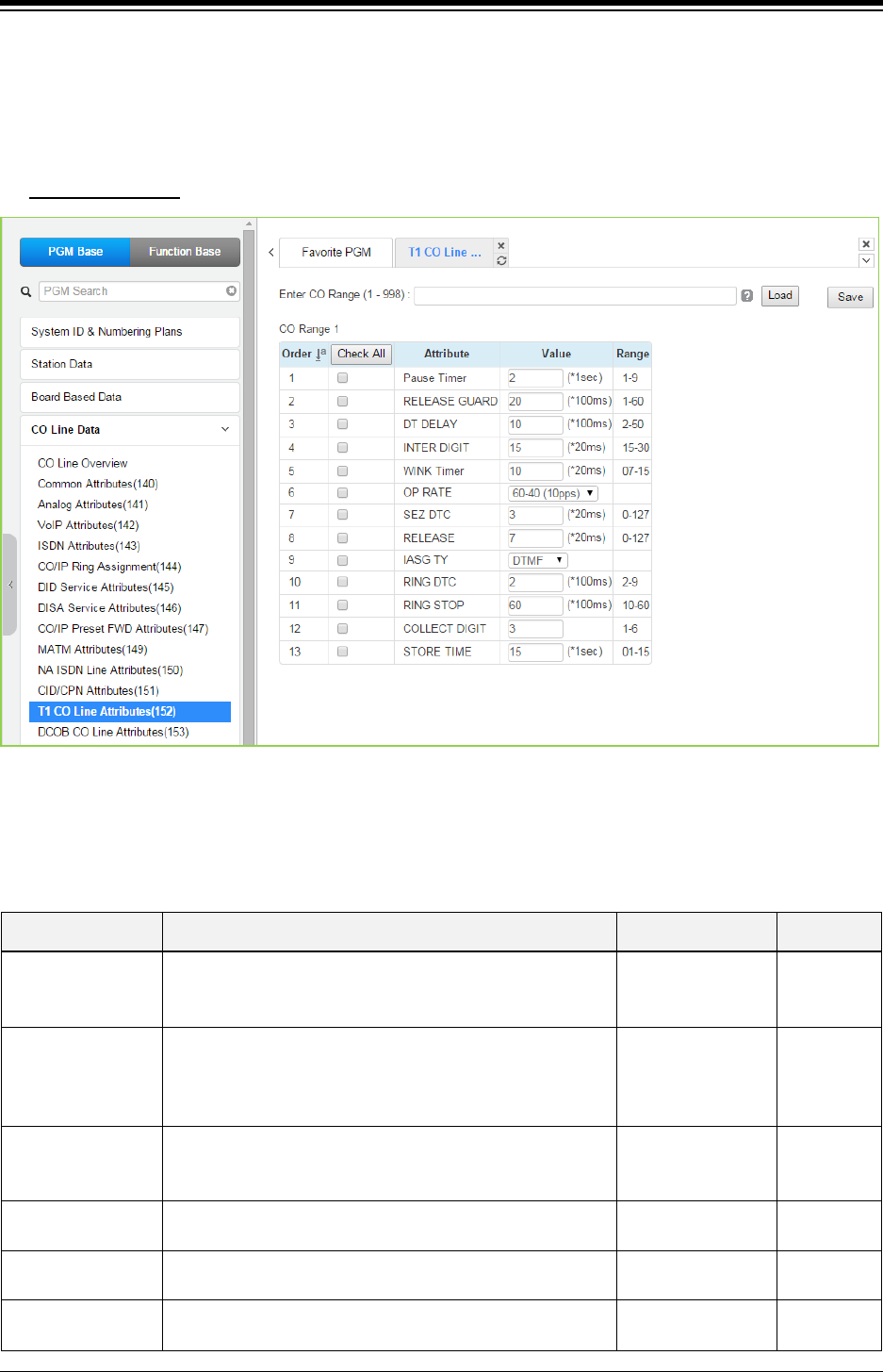
iPECS eMG80 & eMG800 & UCP
Administration and Programming Manual Issue 1.6
337
4.4.4.12 T1 CO Line Attributes - PGM 152
Selecting T1 CO Line Attributes will display the T1 Line Attributes data input page. Enter a valid
CO range and click [Load] to enter the T1 Line Attributes data. Use the check mark to indicate
which attributes to modify; data for checked attributes is stored by clicking [Save] button.
Enter CO Range
: eMG80: 1-74 / eMG800: 1-600 / UCP: 1-998
Figure 4.4.4.12-1 T1 CO Line Attributes
North American T1 standards require that the T1 terminating device, in this case iPECS system,
include various “adjustable” timers and counters as described below.
Table 4.4.4.12-1 T1 CO LINE ATTRIBUTES
ATTRIBUTE DESCRIPTION RANGE DEFAULT
Pause Timer
A timed pause may be included in a Speed Dial number, in
which case, the pause time is defined by this entry. Not
currently implemented.
1~9
(seconds) 2
RELEASE GUARD
The release guard timer defines the length of time the
system will maintain a Line as busy after the call has been
terminated to assure the PSTN has sufficient time to ‘clear
down’ the circuit. Not currently implemented.
01~60
(100 ms) 20
DT DELAY
The DT (Dial tone) Delay timer defines the duration dial
tone must be received for DT recognition.
Not currently implemented.
02~50
(100 ms) 10
INTER DIGIT The Inter Digit timer defines the duration between digit
transmissions. Not currently implemented.
15~30
(20 ms)
15
WINK Timer For TIE or DID Lines the Wink timer defines the length of
time the ‘wink’ (T1 TIE line circuit reversal) will last.
7~15
(20 ms)
10
OP RATE For Pulse signaling, defines the duration and make/break
ratio of each pulse.
60-40(10pps)
66-33(10pps)
60-40
(10pps)

iPECS eMG80 & eMG800 & UCP
Administration and Programming Manual Issue 1.6
338
Table 4.4.4.12-1 T1 CO LINE ATTRIBUTES
ATTRIBUTE DESCRIPTION RANGE DEFAULT
60-40(20pps)
66-33(20pps)
SEZ DTC This timer defines the length of a valid ‘line seizure’ signal. 0~127
(20 ms)
3
RELEASE
For Ground Start, this timer defines the minimum length of
time ground will not be applied to the TIP side from the
PSTN.
0~127
(20 ms) 7
IASG TY Incoming Address Signaling Type defines the type of
signaling (DTMF or Pulse) expected.
PULSE/
DTMF
DTMF
RING DTC The Ring DTC (detect) timer defines the minimum
acceptable length of the Ring-on time during a ring cycle.
2~9
(100 ms)
2
RING STOP The Ring Stop timer defines the maximum Ring-off time
during a ring cycle.
10~60
(100 ms)
60
COLLECT DGT Collect DGT (digits) defines the number of digits expected
on a DID line.
1~6 3
STORE TIME For DID lines, this timer defines the maximum delay
between incoming DID digits.
1~15
(second)
15
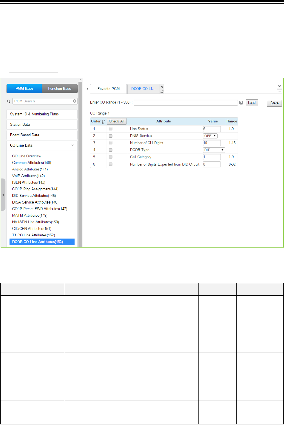
iPECS eMG80 & eMG800 & UCP
Administration and Programming Manual Issue 1.6
339
4.4.4.13 DCOB CO Line Attributes - PGM 153
Selecting DCOB CO Line Attributes will display the DCOB Line Attributes data input page. Enter
a valid CO range and click [Load] button to enter the DCOB Line Attributes data. Use the check
mark to indicate which attributes to modify; data for checked attributes is stored by clicking [Save]
button.
Enter CO Range
: eMG80: 1-74 / eMG800: 1-600 / UCP: 1-998
Figure 4.4.4.13-1 DCOB CO Line Attributes
Table 4.4.4.13-1 DCOB LINE ATTRIBUTES
ATTRIBUTE DESCRIPTION RANGE DEFAULT
Line Status
This parameter defines the code that the system will
send to indicate idle line status in accordance with
E1R2 specifications.
1~9 6
DNIS Service In R2, this field determines whether system will send
caller information to PX or not.
OFF
ON
OFF
Number of CLI Digits This parameter defines the number of digits expected
as the Calling Line Identification from digital CO lines.
01~15 10
DCOB Type
According to this type, the line can be restricted to the
type of service, incoming DID and outgoing calls
(DOD).
DID/DOD,
DOD,
DID
DID
Call Category
This parameter defines the code sent in response to a
call category request from the network in accordance
with E1R2 specifications.
1~9 1
Number of Digits
Expected from DID
circuit
This parameter defines the number of digits expected
as DID digits from digital CO lines. If set to “0”, the
number of digits defined in PGM 145 is used.
0~32 0
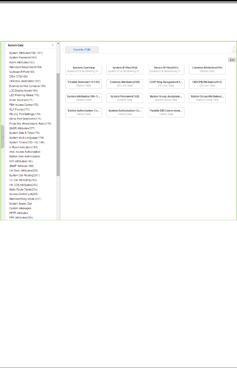
iPECS eMG80 & eMG800 & UCP
Administration and Programming Manual Issue 1.6
340
4.4.5 System Data
Selecting the System Data program group returns the sub-menu displayed in the left frame as
shown in the following figure.
Figure 4.4.5-1 System Data Main Page
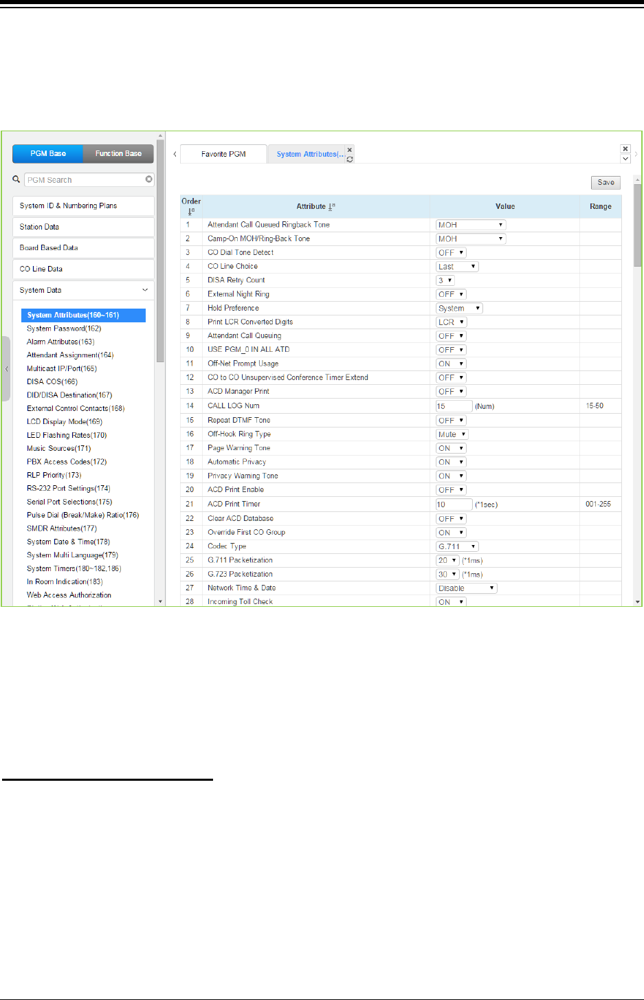
iPECS eMG80 & eMG800 & UCP
Administration and Programming Manual Issue 1.6
341
4.4.5.1 System Attributes - PGM 160 & 161
Selecting System Attributes will display the System Attributes data entry page. Selecting the blue
colored text in the Table header will sort the table based on the selected column. Click [Save]
button after changing Value.
Figure 4.4.5.1-1 System Attributes
System Attributes define settings that affect system wide features and functions. Generally, the
entry will turn the feature ON (enable) or OFF (disable). Refer to Table 4.4.5.1-1 for a description
of the Attributes and the data entries required.
You can set the CID password to click “Go to Setting” button. After clicking it, you will move to the
following PGM 162 and set the CID password, and then save CID password to mark tick on the
save box and click the Save button.
Setting CID Password directly

iPECS eMG80 & eMG800 & UCP
Administration and Programming Manual Issue 1.6
342
Table 4.4.5.1-1 SYSTEM ATTRIBUTES
ATTRIBUTE DESCRIPTION RANGE DEFAULT
Attendant Call Queued
Ring Back Tone
When Attendant is busy with receiving call, the
system will provide either Ring-back tone or
Background music (MOH). If MOH is selected, the
Music Source must be defined in ‘Music source –
PGM171’.
MOH/
Ring-Back Tone MOH
Camp-On MOH/Ring-
Back Tone
When Camp-On is used, the calling station will
receive either ring-back tone or MOH. If MOH is
selected, a source must be defined in ‘Music source –
PGM171’.
MOH/
Ring-Back Tone MOH
CO Dial Tone Detect The system can use dial-tone detection or a timed
pause for speed dial numbers that contain a Pause.
OFF
ON
OFF
CO Line Choice
CO Lines are selected by the system from groups
using either the LAST used, FIRST or ROUND robin
method.
LAST
FIRST
ROUND
LAST
DISA Retry Count
A DISA user is allowed to retry erroneous
authentication code entries. This entry sets the
number of retries before the system disconnects.
1~9 3
External Night Ring
CO/IP calls, which are assigned UNA, can activate
the Loud Bell Contact. While in the Night mode, an
incoming call will activate the contact.
OFF
ON OFF
Hold Preference A single depression of the [Hold] button places the
call on the preferred hold, System or Exclusive.
System/
Exclusive
System
Print LCR Converted
digits
SMDR will output the number dialed by either the
system’s LCR or the user.
LCR/
USER
LCR
Attendant Call Queuing
The system can be configured to queue incoming
calls to a busy Attendant.
OFF
ON
OFF
USE PGM_0 IN ALL
ATD
This field allows Main Attendants to activate
Day/Night mode and other System Attendant menus
except PGM 06 – Record system announcement.
(Not available in USA version.)
OFF
ON OFF
Off-net Prompt Usage
When a call is routed to a destination external to the
iPECS, the Off Net routing prompt can be played.
(Not available in US version)
OFF
ON ON
CO to CO
Unsupervised
Conference Timer
Extend
When an Unsupervised Conference is established
with DISA, Off-Net Fwd, etc., the Unsupervised
Conference timer determines the allowed duration of
the call. If enabled here, the user may extend the
allowed duration.
OFF
ON OFF
ACD Manager Print
When the optional ACD Event messages are
required, the system must be enabled here to send
the events.
OFF
ON OFF
CALL LOG Number
The Call Log saves the Outgoing call, Received call,
or Lost call information and can be displayed by
pressing Call Log Display Button. The maximum size
of the Call Log per station is defined here.
15~50 15
Repeat DTMF tone
If enabled, the system will repeat DTMF tones to the
caller’s station when the call is routed to an off-net
location.
OFF
ON OFF

iPECS eMG80 & eMG800 & UCP
Administration and Programming Manual Issue 1.6
343
Table 4.4.5.1-1 SYSTEM ATTRIBUTES
ATTRIBUTE DESCRIPTION RANGE DEFAULT
Off-Hook Ring Type Off-hook ring can be a single tone burst or muted
normal ring.
MUTE/
BURST
MUTE
Page Warning Tone A warning tone can be sent prior to a page
announcement.
OFF
ON
ON
Automatic Privacy
Automatic Privacy can be disabled, allowing stations
to join an active CO/IP call. A warning tone can be
provided, see Privacy Warning Tone below.
OFF
ON ON
Privacy Warning Tone If desired, a warning tone can be provided when
privacy is overridden.
OFF
ON
ON
ACD Print Enable
ACD statistics can be periodically sent to the
assigned serial port. To provide periodic reports, this
feature must be ON.
OFF
ON OFF
ACD Print Timer This entry defines the time, in 10-second increments,
between the periodic ACD reports assigned above.
001~255
(1 sec)
010
Clear ACD Database When a periodic report is sent, the ACD database can
be cleared automatically, if “ON”.
OFF
ON
OFF
Override 1st CO Group When a user dials ‘9’, the system can search all
CO/IP Groups for the first available CO/IP line.
OFF
ON
ON
Codec Type
The default codec can be defined as G.711, G.729,
G.722 or G.723.1 for decreased bandwidth needs.
The selected codec will be used on all internal
communications as well as for remote iPECS devices.
G.729/
G723.1/
G711/
G722
G711
G.711 Packetization
The G.711 voice frame packetization time determines
the interval at which voice samples are packetized
and sent when the G.711 codec is used.
10/20/30
(1 msec) 020
G.723 Packetization
The G.723.1 voice frame packetization time
determines the interval at which voice samples are
packetized and sent when the G.723.1 codec is used.
30/60
(1 msec) 030
Network Time/Date
The system can use ISDN Network time or NTP to
synchronize time with the ISDN or data network.
ISDN sync is not available in USA version.
Disable/
ISDN/
NTP
Disable
Incoming Toll Check The system can invoke COS dialing restrictions when
a user dials while connected to incoming call.
OFF
ON
ON
Web Server Port/TLS
for Web
This field determines the TCP port employed to
access the system WEB server. This field also
enables Transport Layer Security (TLS) for access to
Web Admin.
00001-65535/
Enable or Disable
80/
Disable
Auth Retry Count
When an Authorization code is required, the user may
attempt to enter a Valid code up to the maximum
value defined in this field.
1-9 3
Simple Auth Code
Usage
System Authorization codes are entered by the user
as “*” and the code (ON) or “*”+ the Auth code index
and the code (OFF).
OFF
ON ON
COS 7 when Auth Fail
If a user fails to enter a valid Authorization code in the
number of attempts assigned in Auth Retry Count
above, the station is disconnected or the Station COS
is changed to COS 7. In the latter case, the user must
employ COS Restore in Station User PGM 2 to return
the station to the normal COS.
OFF
ON OFF

iPECS eMG80 & eMG800 & UCP
Administration and Programming Manual Issue 1.6
344
Table 4.4.5.1-1 SYSTEM ATTRIBUTES
ATTRIBUTE DESCRIPTION RANGE DEFAULT
Unified Message
Format
System Integration Messages are sent out the defined
serial or TCP channel.
OFF
ON
OFF
Conference Room CO
Tel Number
ISDN DID number an external party must dial to enter
a Conference room.
Max. 15 digits
Record warning tone
When call recording is active, a tone can be sent to all
connected parties to indicate the conversation is
being recorded.
OFF
ON ON
UCP (MPB) DIFF
SERVE
Diff-Serv Code Point applied to packets from LAN port
of the UCP (iPECS eMG LAN port of the MPB).
00-63 46
Device Upgrade Mode Transfer mode for upgrades from MPB to an iPECS
device.
FTP
TFTP
FTP
CO Transfer Tone
When a CO call is transferred to a busy extension,
Ring Back Tone or Music On Hold will be played to
the CO Line.
MOH/
Ring-Back Tone Ring-Back Tone
Conference Warning
Tone
When a new member joins a conference room, the
system provides warning tone to conference
members.
OFF
ON ON
Dummy Dial Tone When a CO line does not provide dial tone, the
system can provide dummy dial tone.
Unused/
Use
Unused
SIP Station Mode
SIP phones may set-up a point-to-point RTP
connection (PTP) or to assure a controlled
connection, RTP can be routed via a VoIP channel
(RTD).
RTD/
PTP Routed
SMS Center Number
When the PSTN will be used to send SMS, the phone
number of the Short Message Service Center must be
entered.
Max. 23 digits
SMS Center CLI
When the CO/IP Line will be used to receive SMS, the
Caller Id expected from the Short MSG Service
Center must be defined.
Max. 23 digits
SMS Protocol The Short Message Service Protocol must be
selected to support SMS.
None/
ETSI-P1/
ETSI-P2/
KT-LivingNet/
SIP-Text/
SIP-XML/
KT IP-PBX/
SKN IP-PBX/
KT XML
NONE
G.722 Packetization
The G.722 voice frame packetization time determines
the interval at which voice samples are packetized
and sent when the G.722 codec is used.
10/20/30
(1 msec) 020
Transit-out security
The system will check the IP address for transit-out
calls in the master system. If not valid the transit-out
call is denied.
Unused/
Use Use
Emergency call
attendant Notify
The Attendant can be notified when another user in
the system dials emergency number.
Unused/
Use
Use
3-Way Conference
Preference
When 3-way conference calling, the system uses the
selected device to establish the conference mixing.
When “Local” is assigned, the device, such as a SIP
Local/
MCIM Local

iPECS eMG80 & eMG800 & UCP
Administration and Programming Manual Issue 1.6
345
Table 4.4.5.1-1 SYSTEM ATTRIBUTES
ATTRIBUTE DESCRIPTION RANGE DEFAULT
phone, must provide the mixing. This option is
available only for UCP.
First digit * in SPD
Normally, when “*” is the first digit in a Speed Dial
number, the Display Security feature is activated so
that the number is not shown in the LCD of iPECS IP
or LDP Phones. Otherwise, the “*” is sent as the first
digit to the carrier.
Display Security/
Digit * Display Security
Use Strong Password
When enabled, passwords in PGM 162 must be
longer than 10 digits and include both numbers and
characters.
OFF
ON ON
VSF SMTP port SMTP port used for the VSF and UVM gateway
(VMIU/VMIB).
00001~65535 25
CTI IP When assigned, the system will accept 3rd party TAPI
messages only from assigned IP address.
0.0.0.0
Intercom busy service
When busy, an intercom call may use Off-hook Voice-
Over or Intrusion to connect to the called intercom
party.
Voice-over/
Intrusion Voice over
Auto save new
message
After listening to a voice message, if the user takes no
action, the system can automatically save the
message or leave the message in the new message
category.
Unused/
Use Unused
IGMP query usage
The system employs multi-cast packets for
registration and certain general functions such as
MOH. With some multicast snoop enabled Layer 2
switches, multicast packets are not forward unless an
IGMP query device exists in the network. This entry
enables the IGMP query option and system sends
periodic IGMP query message to avoid multicast
blocking.
OFF
ON OFF
IGMP query interval
timer
This timer defines the interval for each IGMP query
message.
0~3600
(Sec.) 180
IGMP query all host
IGMP queries are sent to all IP hosts (ON) on the
network or to iPECS devices only. For All Hosts, IP
address 224.0.0.1 is used otherwise the iPECS
specific 239.20.19.50 IP address is used. If problems
occur with MOH, the “All Hosts” may correct the
issue.
OFF
ON ON
IGMP query generic
This entity specifies a group addresses being queried.
If ON is selected, all multicast group are queried. If
OFF is selected, iPECS registering device group
(239.20.19.50) is queried only. This should be ON
when there is a MOH problem.
OFF
ON OFF
Restrict star and pound
If enabled, calls using * or # as the first digit are
prohibited by the system.
OFF
ON
OFF
Restricted Dialing
Display After Answer
If a restricted number is called, the system will output
an SMDR record for the call after the call is answered.
OFF
ON
ON
IP BIND USAGE If It’s ON, VOIU/VOIB/VOIM will apply IP-Binding with
information in PGM130 / PGM133 (Media port).
OFF
ON OFF

iPECS eMG80 & eMG800 & UCP
Administration and Programming Manual Issue 1.6
346
Table 4.4.5.1-1 SYSTEM ATTRIBUTES
ATTRIBUTE DESCRIPTION RANGE DEFAULT
New 5 Wake Up
Usage
With the “New Wake-Up” option, the user can assign
five alarm notification times, otherwise only one
Wake-Up time can be set.
OFF
ON OFF
Easy 5 Wake Up
Usage
If this value is set to ON, and New 5 Wake Up Usage
is also set to ON, each station user can enter his/her
wake up time without entering wake up type and wake
up index.
OFF
ON OFF
Station VM Feature
Usage
If this option is set to ON, Station VM feature (PGM
127) can be used.
Enhanced features of the VSF/UVM can be disabled.
Features controlled by this setting include as below:
- Company Directory
- Remote Announcement Recording
- Administrator Mailbox
- Distribution List
- Mark a Message as Private, Urgent, or
Delivery Confirmation
- Record Greeting through CCR
- Voice Mail Class of Service
OFF
ON ON
End code(#) usage in
System Auth Code
If this option is set to ON, End code (#) must be
entered when system Auth code is entered.
OFF
ON
OFF
Remote VM Access
If this value is OFF, the user cannot access to VSF
mailbox via DID, DISA CO call and so on (i.e. through
CO line channel).
OFF
ON ON
Transfer Tone Usage
If this value is ON, Warning tone is served to the
[transfer to] station. This is only applied to screened
transfer case.
OFF
ON OFF
CID Password Usage If this value is ON, a user must enter the CID
password to modify an admin value about CID setting.
OFF
ON
OFF
LCR Dial Tone Detect
If this value is set to ON, the system first checks dial
tone in case on analog CO Lines then LCR dialing is
completed. If no dial tone is detected, the call is
rerouted to Alternate DMT Index.
If LCR type is set to M13, LCR dial tone detect option
is not applied.
OFF
ON OFF
ICM call log If this value is set to ON, the system provides an ICM
Call log for iPECS IP and LDP Phones.
OFF
ON
OFF
Mobile Phone
Presence Service port
This is for an interface between eMG and external
server that sends http/xml data. Currently the first
usage of this port is ‘mobile phone presence’ service.
If set to a valid port the presence service will be
implemented and the system will await messages for
presence from the external server.
00001~65535 00000
Mobile Phone
Presence State Sync
When the system receives presence information for a
mobile extension from external server, the system
synchronizes the station’s call state with this presence
information. A busy presence will set the station to
busy.
OFF/
DSS LED only/
Station Status
Station Status

iPECS eMG80 & eMG800 & UCP
Administration and Programming Manual Issue 1.6
347
Table 4.4.5.1-1 SYSTEM ATTRIBUTES
ATTRIBUTE DESCRIPTION RANGE DEFAULT
Mobile Phone
Presence Force Idle
Timer
The system will return a station’s state to idle if there
is no updated presence information from external
server for the duration of this timer.
0~3600
(Sec.) 0
Attendant Password
Usage
If this value is set to ON, system requests a
password:
When a user enters Attendant program ([PGM] + 0,
When an Attendant enters Speed program,
When a user assigns attendant program code ([PGM]
+ 0) to Flexible button,
OFF
ON OFF
Picked-up station
name usage
Name of picked up station is display when pickup
internal call.
OFF
ON
ON
Display LCR mode Display “LCR MODE” when LCR is activated. OFF
ON
ON
VM Notify to Mobile
Extension over CO
If this value is set to ON, an analog Loop Start CO
Line can be used for the VM notification call to the
Mobile Extension.
Disable
Enable Disable
MODEM Associated
Station/CO line
When a call is received by the assigned CO Line, the
call is routed to the system’s built-in modem. This
option is available only for eMG80 & eMG800.
CO/STA
eMG80:STA/
239
eMG800:STA/2
199
Display {MEET ME}
Soft button
If this value is set to OFF, {MEET ME} soft button is
not displayed during a paged.
OFF
ON
ON
Number of CLI Wait
List
The system check the status of each device with a
polling message periodically using this timer.
0-255 0
Emergency Mailbox
Station
When an Emergency Mailbox Station is assigned, an
emergency call placed by a station is recorded
automatically to the assigned mailbox.
MSVC XML Port
The XML port used to support Web callback, call-
through and iPECS ClickCall application for MSVC
(Mobile Service) must be defined.
00001~65535 7878
IPCR Announce for
recording warning
When ON, the IPCR server Call Recording notification
announcement is played to the caller in place of the
warning tone.
OFF
ON OFF
IPCR Announce for
only incoming
User can select IPCR Announce only when it’s
incoming by setting ON.
OFF
ON OFF
Mobile EXT CO
Access Password
Check
When a mobile extension places an external call
using an iPECS CO/IP Line, the user may be required
to enter a valid Authorization code to place the call.
OFF
ON OFF
Hold key usage on
paging
When ON, the Hold key is used for paging. OFF
ON
ON
Device Info Request
Interval
The system checks the status of each device with a
polling message at intervals of this timer.
15 ~ 255 seconds 15
Dial By Name List
The Dial by Name feature can allow stations in any
ICM tenancy groups to call a station any in ICM
Tenancy group. When desired, Dial by Name can be
limited to function within allowed Tenancy calling
groups, PGM 125.
All,
Accessible ICM
Group only
ALL
Dial By System Speed
If this value is set to "Accessible System Speed Zone
All,
ALL

iPECS eMG80 & eMG800 & UCP
Administration and Programming Manual Issue 1.6
348
Table 4.4.5.1-1 SYSTEM ATTRIBUTES
ATTRIBUTE DESCRIPTION RANGE DEFAULT
Name List Only", the system speed dial number of Accessible
system speed zone (System Speed Zone (232)) is
displayed in {Dial by Name}.
Accessible
System Speed
Zone Only
Default Web Language
The user can select the display language used in the
Web pages. Either English or the “Local” language
can be selected. Note the “Local Language” must be
entered in the Multi-Language file in Maintenance
section.
English/
Local language English
No Range Load Limit
on Web Admin
OFF: Limited index range will be accepted (e.g. 1-
100)
ON: No limitation of table index (e.g. 221, 222, 270,
etc)
OFF/ON ON
Forward limitation by
caller COS
Caller (internal station) call to a station offnet
forwarded. It can be forwarded by caller COS if it's
ON.
OFF/ON OFF
No CLI Call Log
Leave system Call log even though there is no CLI
information if it is ON. Otherwise Call log is not
leaved.
OFF
ON OFF
Remote VM Forward
Access
If the value is ON, Call Forwarding setting from
remote access is enabled. If the value is OFF, Call
Forwarding setting from remote access is disabled.
OFF
ON ON
DB Backup to USB
monthly
System downloads the database to USB periodically.
The user can access, copy and delete files in USB
drive via web admin. So you can back up DB by
choosing the specific date for Monthly or Weekly.
N/A,
1,
15
DB Backup to USB
weekly
N/A,
Mon ~ Sun.
SLT Line Monitor
SLT line supervision is to be supported to check the
line connection/disconnection periodically as
programmed - daily or programmed time. When the
line is disconnected, alarm call/message notification is
provided to pre-defined destinations like other alarms.
System will send e-mail notification according to
"Common SMTP Attributes" and "Alarm Attributes".
This is to provide more reliability for mission-critical
services for hospitality or health care solutions (i.e.
bath alarms using SLT line).
Conditions
- Normal SLT service is not available during detection
period since the detection takes several seconds.
- Ringer test determines the presence of appropriate
ringer terminations on the line. The measured
impedance must be within the defined limits: 1.4 kΩ
(5 REN) ~ 40 kΩ (0.175 REN). Otherwise the test
fails, which means that normal SLT device can be
detected, but if simple device which does not provide
the proper ringer impedance is connected, then we
cannot detect it properly.
- Supported system options: UCP/eMG80/800 with
Unified 2.1 software
OFF
ON OFF

iPECS eMG80 & eMG800 & UCP
Administration and Programming Manual Issue 1.6
349
Table 4.4.5.1-1 SYSTEM ATTRIBUTES
ATTRIBUTE DESCRIPTION RANGE DEFAULT
- Supported G/W & Boards: UCP-SLTM, UCP100
SLTU, eMG80/800 SLIB
SLT Line Monitor Time The system monitors if SLT Line functions correctly at
a preset time in this field.
0-23 0
UCS Ring ACK Count
UCS Client can be checked by Ring ACK Message. If
the Ring ACK message is sent and get no ACK
message, System set the state of UCS Client on OOS
(Out of service) after the set of Ring ACK count.
If the Ring ACK Count is 0, the UCS Client goes to
OOS (Out Of Service) after 1 time. If the count is 2,
UCS Client can go to OOS (Out Of Service) at 3
times.
UCS Client is ringing before expiring the Ring ACK
timer set on System Timers ‘UCS Ring ACK Timer’
and afterwards will hear Error tones.
0-9 0
Dial Back to Caller
from Remote VM
Access
A user accesses to voice mail from remote, the user
can make a call to the caller of the voice mail like
below.
If ‘Toll Free’ is selected, the user can make a call to
the caller of the voice mail.
If ‘toll check’ is selected, Station COS will be applied.
If ‘Rejected’ is selected, the user can’t make a call to
the caller of the voice mail.
Toll Free,
Toll Check,
Rejected
Toll Free
Web Admin Login
Failure count to block
For security, administrator can set the limited count to
log in Web admin from 5 to 99.
5-99, o: unused 5
Web Admin Hacking
Block Period
This setting time is the duration of blocking the access
to Web admin if Web admin login fails.
5-60 minutes 5
Web Admin Hacking
Block Email
Notification
If this option is Enable, System send the notification
by email about blocking the web admin. The email
address is following the below ‘Alarm Receiver E-Mail
Address(To) & Notification Receiver E-Mail
Address(To)’.
Disable,
Enable Disable
SMDR/ACD/Alarm Mail Attribute
Common SMTP Attributes
SMTP Server IP
Address
SMTP server IPv4 address to receive the SMDR E-
mail reports.
12-digits 0.0.0.0
SMTP Server Domain
Address
SMTP Mail server Domain address to receive the
SMDR e-mail reports. Check DNS IP address setting.
SMTP Port
This field defines the TCP/IP port that the system will
employ when communicating with the SMTP E-mail
server. (It is moved to web admin PGM 160-161)
1-65535 25
SMTP Security
Connection
The system can support basic security policies when
communicating with the SMTP E-mail server. Note
the server must also be configured for the selected
security protocol.
No security/
SSL/
TLS
No security
E-Mail Account ID
This field defines the user’s ID for SMTP server. If the
user’s ID and password is assigned, SMTP server will
check the validity of the user ID and password.
Max. 40
characters
E-Mail Account
This field defines the user‘s password for SMTP
Max. 20

iPECS eMG80 & eMG800 & UCP
Administration and Programming Manual Issue 1.6
350
Table 4.4.5.1-1 SYSTEM ATTRIBUTES
ATTRIBUTE DESCRIPTION RANGE DEFAULT
Password server. If the user‘s ID and password is assigned,
SMTP Mail server will check the validity of user ID
and password.
characters
Sender E-Mail Address
(From)
E-Mail address used by the system as the “From”
address when sending Database, SMDR, ACD, and
Alarm reports.
Max. 40
characters
Sender System
Domain Name
Domain name of SMTP Mail server to receive SMDR
reports. This field is used in place of SMTP Mail
Server IP Address above.
Max. 18
characters
Database Attributes [Send Mail]
[Send Mail] button is used for sending the mail after filling out the below menu
Database Mail Send
Monthly Set
Sets day of month for Database to be sent on a
monthly basis (NA for no monthly reports, select the
day for 1 or 15).
NA/
1/
15
NA
Database Mail Send
Weekly Set
Sets day of week to send Database weekly. Day-of week N/A
Database Type Select the desired database type: All database,
System speed, Station speed, LCR, etc.
All Database
Database Receiver
Mail Address
E-mail address to receive the Database E-mail
reports.
Max. 40
characters
SMDR Attributes
[Send Mail] button is used for sending the mail after filling out the below menu
SMDR Mail Send
Weekly Set Sets day of week to send SMDR data weekly.
NA,
Monday to
Sunday
N/A
SMDR Mail Send Daily
Set
Sets time-of-day for SMDR data to be sent on a daily
basis (00 for no daily records, 01-23 for hour of the
day).
00-23
SMDR Mail Auto Send
Set
If the SMDR buffer is full, the system can
automatically send a notification by E-mail.
OFF
ON
OFF
SMDR Mail Auto
Delete Set
Delete SMDR records after sending E-mail. OFF
ON
OFF
SMDR Receiver Mail
Address
E-mail address to receive the ACD E-mail reports. Max. 40
characters
ACD Attributes
[Send Mail] button is used for sending the mail after filling out the below menu
ACD Mail Send
Weekly Set Sets day of week to send ACD statistic data weekly.
NA,
Monday to
Sunday
N/A
ACD Mail Send Daily
Set
Sets time-of-day for ACD statistic data to be sent on a
daily basis (00 for no daily records, 01-23 for hour of
the day).
00-23 N/A
ACD Database Delete
After Mail Send
Delete ACD statistic data after sending E-mail OFF
ON
OFF
ACD Receiver Mail
Address
E-mail address to receive the ACD E-mail reports. Max. 40
characters

iPECS eMG80 & eMG800 & UCP
Administration and Programming Manual Issue 1.6
351
Table 4.4.5.1-1 SYSTEM ATTRIBUTES
ATTRIBUTE DESCRIPTION RANGE DEFAULT
Alarm Attributes
[Send Mail] button is used for sending the mail after filling out the below menu
Alarm Receiver E-Mail
Address(To) &
Notification Receiver
E-Mail Address(To)
The system will send email to saved E-Mail Address
when system alarm is occurred or system restarts.
Max. 40
characters
LDAP Server Settings
Server Display Name
When the UCS Client requires access to an LDAP
server, the system will provide the LDAP server
information to the client. The server name is defined
in this field.
15 characters LDAP Server
Server IP When an LDAP server is employed, the IP address of
the server must be defined.
0.0.0.0
Server Port When an LDAP server is employed, the TCP/IP port
of the server must be defined.
0001-65535
Require Login The UCS Client ID and Password may be required for
log in to the LDAP server.
OFF
ON
ON
Use SSL When supported by the server, the client can employ
SSL (Secure Sockets Layer) for added security.
OFF
ON
OFF
Search Base
Server base means Search option. You can get the
search option from LDAP Server manager. For
example, if OU (Organization Unit) is OC and DC
(Directory Company) are ucapp and com, you can
give the option "OU=OC, DC=ucapp, DC=com" in this
field. You will get the desired directory.
LDAP User ID
ID and Password must be required to connect to
LDAP Server.
LDAP User Password
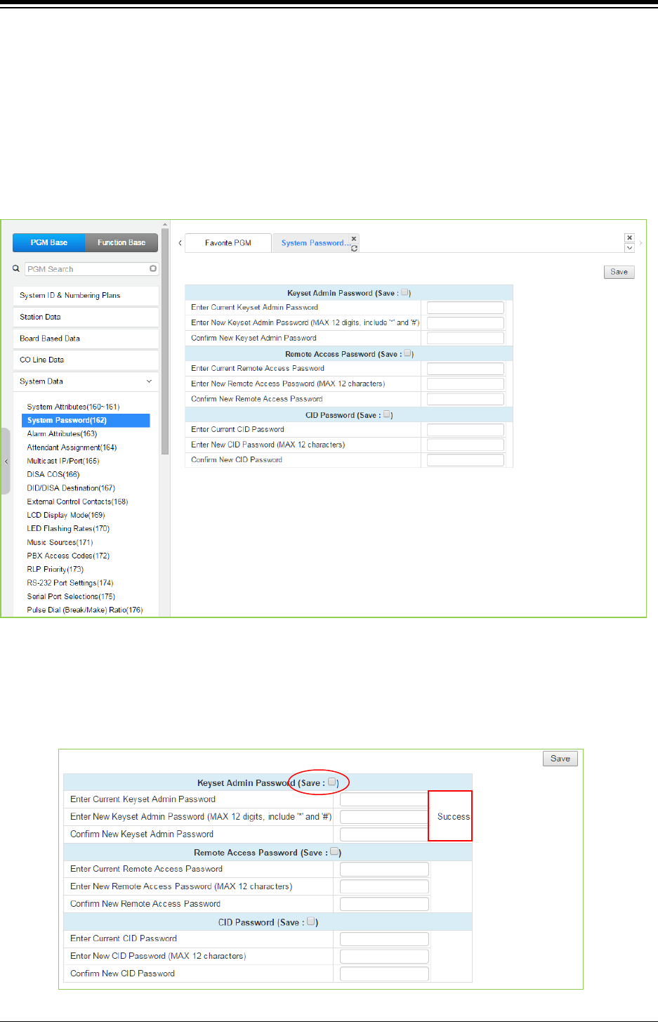
iPECS eMG80 & eMG800 & UCP
Administration and Programming Manual Issue 1.6
352
4.4.5.2 System Password - PGM 162
Selecting System Password will display the System Password data entry page. Use the check
boxes to indicate which attributes to modify; data for checked attributes is stored for the Keyset
Admin, Remote Access Password, or CID password when saved. Click [Save] button after
changing Value.
It is important to use strong password for lowering overall risks of a security breach. The
best way to choose good password are designed to make passwords less easily
discovered by intelligent guessing.
Figure 4.4.5.2-1 System Password
Access to the system database and maintenance functions can be protected by passwords up to
twelve (12) digits. Three passwords can be defined, Keyset Admin, Remote Access and CID.
Check the save box and enter the password and click the save button.
The following success message is displayed if the password is correct and saved successfully.
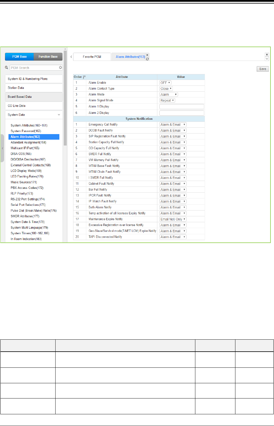
iPECS eMG80 & eMG800 & UCP
Administration and Programming Manual Issue 1.6
353
4.4.5.3 Alarm Attributes - PGM 163
Selecting Alarm Attributes will display the Alarm Attributes data entry page. Click [Save] button
after changing Value.
Figure 4.4.5.3-1 Alarm Attributes
The system can monitor an external contact. This contact is most often employed as an Alarm
indicator or Doorbell. The Alarm attributes define the operation of the external contact. For the
Alarm, the signal to assigned stations can be repeating or a single burst, the former is often
desired. For the Doorbell, a single tone is sent each time the contact activates. Refer to Table
4.4.5.3-1 for a description of the features and the data entries required for each attribute.
If the related alarm attributes are set to ‘Alarm & Email’ or ‘Email Noti only’, the system sends an
email to the address that set in PGM 160~161 Alarm Attributes ‘Alarm Receiver E-Mail Address
(To) & Notification Receiver E-Mail Address (To)’.
Table 4.4.5.3-1 ALARM ATTRIBUTES
ATTRIBUTE DESCRIPTION RANGE DEFAULT
Alarm Enable This entry enables/disables the contact monitoring
circuitry.
OFF
ON
OFF
Alarm Contact Type This parameter establishes the contact state that will
activate the Alarm, close or open.
Close/
Open
Close
Alarm Mode The contact can be treated to function as a doorbell or an
alarm.
Alarm/
Door-Bell
Alarm
Alarm Signal Mode The assigned stations will receive a Repeating signal or
single burst (Once) of alarm tone.
Repeat/
Once
Repeat

iPECS eMG80 & eMG800 & UCP
Administration and Programming Manual Issue 1.6
354
Table 4.4.5.3-1 ALARM ATTRIBUTES
ATTRIBUTE DESCRIPTION RANGE DEFAULT
Alarm 1 Display
In case of UCP600/2400, {Alarm 1 Display} and {Alarm 2
Display} are added. Otherwise, {Alarm Display} is added.
When alarm port 1 is activated, the string of {Alarm 1
Display} or {Alarm Display} is displayed in assigned
stations.
When alarm port 2 is activated, the string of {Alarm 2
Display} is displayed in assigned stations.(UCP600/2400)
Alarm 2 Display
System Notification
Emergency Call Notify
This entry enables/disables the Emergency call
notification.
OFF,
Alarm & Email,
Email Noti
Only,
Alarm Only
Alarm & Email
DCOB Fault Notify
This entry enables/disables DCOB Fault notification.
Alarm & Email
SIP Registration Fault
Notify
This entry enables/disables SIP Registration Fault
notification.
Alarm & Email
Station Capacity Full
Notify
This entry enables user to get the notification as alarm
when Station Capacity is over the capacity.
Alarm & Email
CO Capacity Full
Notify
This entry enables user to get the notification as alarm
when CO Capacity is over the capacity.
Alarm & Email
SMDR Full Notify This entry enables user to get the notification as alarm
when SMDR is over the capacity.
Alarm & Email
VM Memory Full
Notify
This entry enables user to get the notification as alarm
when the memory of Voice Mail is full.
Alarm & Email
WTIM (WTIB) Base
Fault Notify
This entry enables user to get the notification as alarm
when WTIM (WTIB) base gets the fault.
Alarm & Email
WTIM (WTIB) Chain
Fault Notify
This entry enables user to get the notification as alarm
when WTIM (WTIB) chain gets the fault.
Alarm & Email
I SMDR Full Notify This entry enables user to get the notification as alarm
when I SMDR is over the capacity.
Alarm & Email
Cabinet Fault Notify This entry enables user to get the notification as alarm
when the cabinet has fault only for eMG800 & UCP.
Alarm & Email
Bar Full Notify This entry enables user to get the notification as alarm
when Bar is full.
Alarm & Email
IPCR Fault Notify This entry enables user to get the notification as alarm
when IPCR gets the fault.
Alarm & Email
IP Watch Fault Notify This entry enables user to get the notification as alarm
when IP Watch has fault only for eMG800 & UCP.
Alarm & Email
Bath Alarm Notify This entry enables user to get the notification as alarm
about Bath Alarm.
Alarm & Email
Temp activation of all
license Expiry Notify
This entry enables user to get the notification as alarm
before Temp activation of all license expires.
Alarm & Email
Maintenance Expire
Notify
This entry enables user to get the notification as alarm
before Maintenance license expires.
Email Noti
Only
Excessive
Registration over
license Notify
This entry enables user to get the notification as alarm in
case of the excessive registration over License. Alarm & Email
Geo-Slave/Survival
Mode (T-NET LCM)
Expire Notify
This entry enables user to get the notification as alarm
before Geographical slave/Survival mode (T-NET LCM)
license expires.
Alarm & Email
TAPI Disconnected
Notify
This entry enables user to get the notification as alarm
when TAPI is disconnected.
Alarm & Email
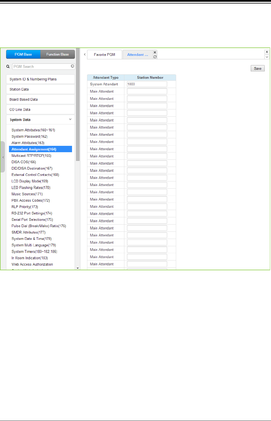
iPECS eMG80 & eMG800 & UCP
Administration and Programming Manual Issue 1.6
355
4.4.5.4 Attendant Assignment - PGM 164
Selecting Attendant Assignment will display the Attendant Assignment data entry page. Click
[Save] button after changing Value.
Figure 4.4.5.4-1 Attendant Assignment
eMG80 is consist of 1 System attendant and 3 Main attendant. eMG800 is consist of 1 System
attendant and 4 Main attendant. UCP is consist of 1 System attendant and 49 Main attendant.
The System Attendant has higher priority in call handling and system management functions. As
a default, the System Attendant is assigned Station 100 for eMG80 & Station 1000 for
eMG800/UCP. Main Attendants are not assigned by default.
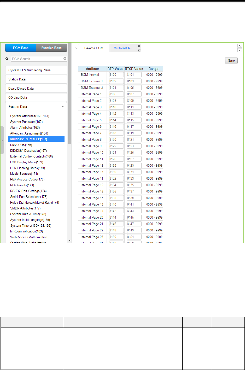
iPECS eMG80 & eMG800 & UCP
Administration and Programming Manual Issue 1.6
356
4.4.5.5 Multi-cast IP/Port - PGM 165
Selecting Multi-cast IP/Port will display the Multi-cast IP/Port data entry page. Click [Save] button
after changing Value.
Figure 4.4.5.5-1 Multi-cast IP/Port
Multi-cast is employed by the system to send BGM, MOH, paging and Push-To-Talk packets.
Employing a single multi-cast packet reduces the overall LAN traffic. In some cases, specifically
when multiple systems are connected to the same default gateway (router) it may be
advantageous to define different IP ports for each system.
Table 4.4.5.5-1 eMG80 MULTI-CAST IP/Port
ATTRIBUTE DESCRIPTION RANGE DEFAULT
BGM Internal RTP and RTCP ports for internal BGM. 0000-9999 8100
(8101)
BGM External 1 RTP and RTCP ports for external BGM 1. 0000-9999 8102
(8103)
BGM External 2 RTP and RTCP ports for external BGM 1. 0000-9999 8104
(8105)

iPECS eMG80 & eMG800 & UCP
Administration and Programming Manual Issue 1.6
357
Table 4.4.5.5-1 eMG80 MULTI-CAST IP/Port
ATTRIBUTE DESCRIPTION RANGE DEFAULT
Internal Page 1 RTP and RTCP ports for Internal Page 1. 0000-9999 8106
(8107)
Internal Page 2 RTP and RTCP ports for Internal Page 2. 0000-9999 8108
(8109)
Internal Page 3 RTP and RTCP ports for Internal Page 3. 0000-9999 8110
(8111)
Internal Page 4 RTP and RTCP ports for Internal Page 4. 0000-9999 8112
(8113)
Internal Page 5 RTP and RTCP ports for Internal Page 5. 0000-9999 8114
(8115)
Internal Page 6 RTP and RTCP ports for Internal Page 6. 0000-9999 8116
(8117)
Internal Page 7 RTP and RTCP ports for Internal Page 7. 0000-9999 8118
(8119)
Internal Page 8 RTP and RTCP ports for Internal Page 8. 0000-9999 8120
(8121)
Internal Page 9 RTP and RTCP ports for Internal Page 9. 0000-9999 8122
(8123)
Internal Page 10 RTP and RTCP ports for Internal Page 10. 0000-9999 8124
(8125)
Internal Page 11 RTP and RTCP ports for Internal Page 11. 0000-9999 8126
(8127)
Internal Page 12 RTP and RTCP ports for Internal Page 12. 0000-9999 8128
(8129)
Internal Page 13 RTP and RTCP ports for Internal Page 13. 0000-9999 8130
(8131)
Internal Page 14 RTP and RTCP ports for Internal Page 14. 0000-9999 8132
(8133)
Internal Page 15 RTP and RTCP ports for Internal Page 15. 0000-9999 8134
(8135)
Internal Page 16 RTP and RTCP ports for Internal Page 16. 0000-9999 8136
(8137)
Internal Page 17 RTP and RTCP ports for Internal Page 17. 0000-9999 8138
(8139)
Internal Page 18 RTP and RTCP ports for Internal Page 18. 0000-9999 8140
(8141)
Internal Page 19 RTP and RTCP ports for Internal Page 19. 0000-9999 8142
(8143)
Internal Page 20 RTP and RTCP ports for Internal Page 20. 0000-9999 8144
(8145)
Internal Page 21 RTP and RTCP ports for Internal Page 21. 0000-9999 8146
(8147)
Internal Page 22 RTP and RTCP ports for Internal Page 22. 0000-999 8148
(8149)
Internal Page 23 RTP and RTCP ports for Internal Page 23. 0000-9999 8150
(8151)
Internal Page 24 RTP and RTCP ports for Internal Page 24. 0000-9999 8152
(8153)

iPECS eMG80 & eMG800 & UCP
Administration and Programming Manual Issue 1.6
358
Table 4.4.5.5-1 eMG80 MULTI-CAST IP/Port
ATTRIBUTE DESCRIPTION RANGE DEFAULT
Internal Page 25 RTP and RTCP ports for Internal Page 25. 0000-9999 8154
(8155)
Internal Page 26 RTP and RTCP ports for Internal Page 26. 0000-9999 8156
(8157)
Internal Page 27 RTP and RTCP ports for Internal Page 27 0000-9999 8158
(8159)
Internal Page 28 RTP and RTCP ports for Internal Page 28 0000-9999 8160
(8161)
Internal Page 29 RTP and RTCP ports for Internal Page 29 0000-9999 8162
(8163)
Internal Page 30 RTP and RTCP ports for Internal Page 30 0000-9999 8164
(8165)
Internal Page 31 RTP and RTCP ports for Internal Page 31 0000-9999 8166
(8167)
Internal Page 32 RTP and RTCP ports for Internal Page 32 0000-9999 8168
(8169)
Internal Page 33 RTP and RTCP ports for Internal Page 33 0000-9999 8170
(8171)
Internal Page 34 RTP and RTCP ports for Internal Page 34 0000-9999 8172
(8173)
Internal Page 35 RTP and RTCP ports for Internal Page 35 0000-9999 8174
(8175)
Internal Page All RTP and RTCP ports for Internal All Call Page 0000-9999 8176
(8177)
External Page 1 RTP and RTCP ports for External Page 1. 0000-9999 8178
(8179)
External Page 2 RTP and RTCP ports for External Page 2. 0000-9999 8180
(8181)
External Page All RTP and RTCP ports for External All Call Page. 0000-9999 8182
(8183)
Page All RTP and RTCP ports for All Call Page. 0000-9999 8184
(8185)
PTT 1 RTP and RTCP ports for PTT group 1. 0000-9999 8186
(8187)
PTT 2 RTP and RTCP ports for PTT group 2. 0000-9999 8188
(8189)
PTT 3 RTP and RTCP ports for PTT group 3. 0000-9999 8190
(8191)
PTT 4 RTP and RTCP ports for PTT group 4. 0000-9999 8192
(8193)
PTT 5 RTP and RTCP ports for PTT group 5. 0000-9999 8194
(8195)
PTT 6 RTP and RTCP ports for PTT group 6. 0000-9999 8196
(8197)
PTT 7 RTP and RTCP ports for PTT group 7. 0000-9999 8198
(8199)
PTT 8 RTP and RTCP ports for PTT group 8. 0000-9999 8200
(8201)

iPECS eMG80 & eMG800 & UCP
Administration and Programming Manual Issue 1.6
359
Table 4.4.5.5-1 eMG80 MULTI-CAST IP/Port
ATTRIBUTE DESCRIPTION RANGE DEFAULT
PTT 9 RTP and RTCP ports for PTT group 9. 0000-9999 8202
(8203)
PTT All RTP and RTCP ports for PTT group ALL 0000-9999 8204
(8205)
BGM Internal VSF RTP and RTCP ports for VSF BGM 0000-9999 8206
(8207)
SLT MOH 1 RTP and RTCP ports for SLT MOH1 0000-9999 8208
(8209)
SLT MOH 2 RTP and RTCP ports for SLT MOH2 0000-9999 8210
(8211)
SLT MOH 3 RTP and RTCP ports for SLT MOH3 0000-9999 8212
(8213)
SLT MOH 4 RTP and RTCP ports for SLT MOH4 0000-9999 8214
(8215)
SLT MOH 5 RTP and RTCP ports for SLT MOH5 0000-9999 8216
(8217)
VSF MOH2 RTP and RTCP ports for VSF MOH2 0000-9999 8218
(8219)
VSF MOH3 RTP and RTCP ports for VSF MOH3 0000-9999 8220
(8221)
Table 4.4.5.5-2 eMG800 MULTI-CAST IP/Port
ATTRIBUTE DESCRIPTION RANGE DEFAULT
BGM Internal RTP and RTCP ports for internal BGM. 0000-9999 8100
(8101)
BGM External 1 RTP and RTCP ports for external BGM 1. 0000-9999 8102
(8103)
BGM External 2 RTP and RTCP ports for external BGM 1. 0000-9999 8104
(8105)
Internal Page 1-100 RTP and RTCP ports for Internal Page 1. 0000-9999 8106-8304
(8107-8305)
Internal Page All RTP and RTCP ports for Internal All Call Page 0000-9999 8306
(8307)
External Page 1 RTP and RTCP ports for External Page 1. 0000-9999 8308
(8309)
External Page 2 RTP and RTCP ports for External Page 2. 0000-9999 8310
(8311)
External Page All RTP and RTCP ports for External All Call Page. 0000-9999 8312
(8313)
Page All RTP and RTCP ports for All Call Page. 0000-9999 8314
(8315)
PTT 1-9 RTP and RTCP ports for PTT group 1. 0000-9999 8316-8332
(8317-8333)
PTT All RTP and RTCP ports for PTT group ALL 0000-9999 8334
(8335)
BGM Internal VSF RTP and RTCP ports for VSF BGM 0000-9999 8336
(8337)

iPECS eMG80 & eMG800 & UCP
Administration and Programming Manual Issue 1.6
360
Table 4.4.5.5-2 eMG800 MULTI-CAST IP/Port
ATTRIBUTE DESCRIPTION RANGE DEFAULT
SLT MOH 1-5 RTP and RTCP ports for SLT MOH1 0000-9999 8338-8346
(8339-8347)
VSF MOH2-3 RTP and RTCP ports for VSF MOH2 0000-9999 8348-8350
(8349-8351)
Table 4.4.5.5-3 UCP MULTI-CAST RTP/RTCP
ATTRIBUTE DESCRIPTION RANGE DEFAULT
BGM Internal RTP and RTCP ports for internal BGM. 0000-9999 8100
(8101)
BGM External 1 RTP and RTCP ports for external BGM 1. 0000-9999 8102
(8103)
BGM External 2 RTP and RTCP ports for external BGM 1. 0000-9999 8104
(8105)
Internal Page 1 ~ Internal Page 100 RTP and RTCP ports for Internal Page 1. 0000-9999 8106~8304
(8107~8305)
Internal Page All RTP and RTCP ports for Internal All Call Page 0000-9999 8306
(8307)
External Page 1 RTP and RTCP ports for External Page 1. 0000-9999 8308
(8309)
External Page 2 RTP and RTCP ports for External Page 2. 0000-9999 8310
(8311)
External Page All RTP and RTCP ports for External All Call Page. 0000-9999 8312
(8313)
Page All RTP and RTCP ports for All Call Page. 0000-9999 8314
(8315)
PTT 1 RTP and RTCP ports for PTT group 1. 0000-9999 8316
(8317)
PTT 2 RTP and RTCP ports for PTT group 2. 0000-9999 8318
(8319)
PTT 3 RTP and RTCP ports for PTT group 3. 0000-9999 8320
(8321)
PTT 4 RTP and RTCP ports for PTT group 4. 0000-9999 8322
(8323)
PTT 5 RTP and RTCP ports for PTT group 5. 0000-9999 8324
(8325)
PTT 6 RTP and RTCP ports for PTT group 6. 0000-9999 8326
(8327)
PTT 7 RTP and RTCP ports for PTT group 7. 0000-9999 8328
(8329)
PTT 8 RTP and RTCP ports for PTT group 8. 0000-9999 8330
(8331)
PTT 9 RTP and RTCP ports for PTT group 9. 0000-9999 8332
(8333)
PTT All RTP and RTCP ports for PTT group ALL 0000-9999 8334
(8335)
BGM Internal VSF RTP and RTCP ports for VSF BGM (VSF MOH) 0000-9999 8336
(8337)

iPECS eMG80 & eMG800 & UCP
Administration and Programming Manual Issue 1.6
361
Table 4.4.5.5-3 UCP MULTI-CAST RTP/RTCP
ATTRIBUTE DESCRIPTION RANGE DEFAULT
SLT MOH 1 RTP and RTCP ports for SLT MOH1 0000-9999 8338
(8339)
SLT MOH 2 RTP and RTCP ports for SLT MOH2 0000-9999 8340
(8341)
SLT MOH 3 RTP and RTCP ports for SLT MOH3 0000-9999 8342
(8343)
SLT MOH 4 RTP and RTCP ports for SLT MOH4 0000-9999 8344
(8345)
SLT MOH 5 RTP and RTCP ports for SLT MOH5 0000-9999 8346
(8347)
VSF MOH2 RTP and RTCP ports for VSF MOH2 0000-9999 8348
(8349)
VSF MOH3 RTP and RTCP ports for VSF MOH3 0000-9999 8350
(8351)
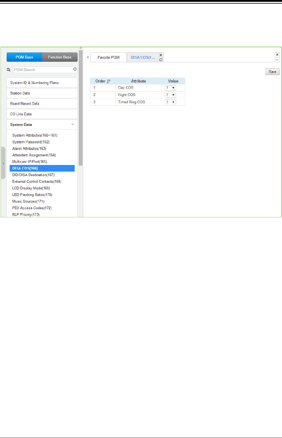
iPECS eMG80 & eMG800 & UCP
Administration and Programming Manual Issue 1.6
362
4.4.5.6 DISA COS - PGM 166
Selecting DISA COS will display the DISA COS data entry page. Click [Save] button after
changing Value.
Figure 4.4.5.6-1 DISA COS
A DISA user is subject to the dialing restrictions assigned in the DISA Class-of-Service (COS).
The restrictions applied are the same as with the corresponding Station COS levels 1~11 and
interact with the CO/IP COS in the same manner. An assignment is made for Day, Timed and
Night Ring mode of system operation. The default for all three modes (Day, Night, Timed ring) of
DISA COS is 7, allowing internal calls only.
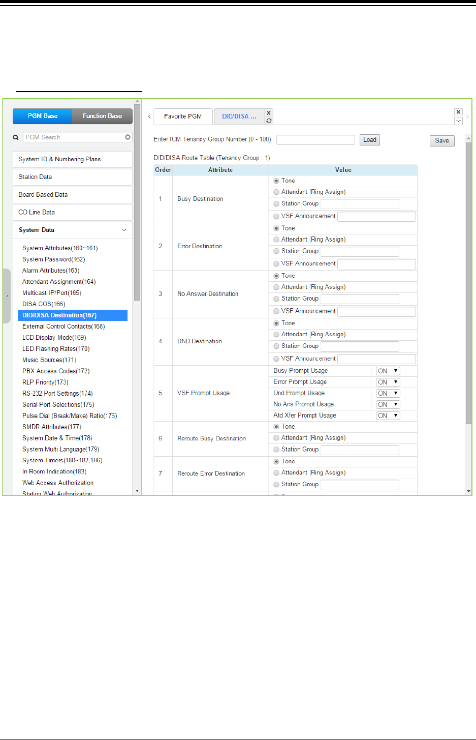
iPECS eMG80 & eMG800 & UCP
Administration and Programming Manual Issue 1.6
363
4.4.5.7 DID/DISA Destination - PGM 167
Selecting DID/DISA Destination displays the Tenant Group input page. Select Tenant Group, the
system will display the DID/DISA Destination Attributes. Click [Save] button after changing Value.
Enter ICM Tenancy group
: eMG80 : 0-15 / eMG800: 0-32 / UCP: 0-100
Figure 4.4.5.7-1 DID/DISA Destination
When a DID line or DISA user dials an invalid/vacant or busy station number the caller will be
sent to the assigned destination that is selected according to the CO Tenancy group of the
DID/DISA line. The destination is separately defined for invalid, busy, and No Answer conditions
and can be defined as the Attendant, busy tone, a Station Group or a VSF Announcement.
For calls on a DID line to a busy station, DID Call Wait can be assigned, refer to ‘Common
Attributes section’, and the call will queue for the station for the No-Answer time. After the No-
answer time, the call routes to the DID/DISA Destination unless forwarded. Also, for DID calls
only, announcements (prompts) can be sent from the VSF or UVM gateway (in case of UCP) to
the caller for various conditions, busy, error, DND, No Answer, or Attendant Transfer.
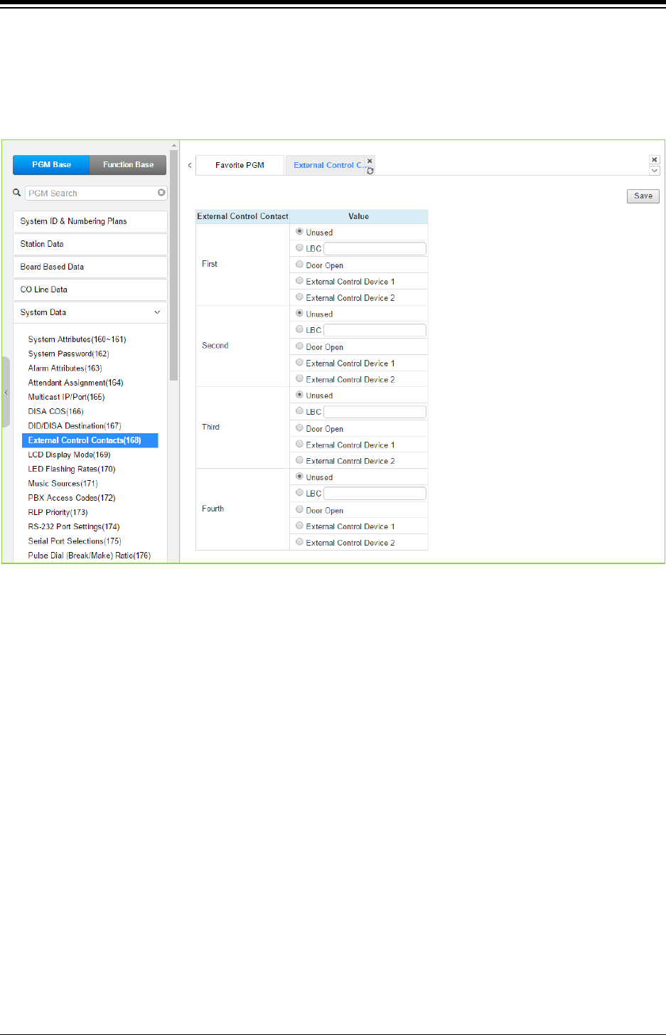
iPECS eMG80 & eMG800 & UCP
Administration and Programming Manual Issue 1.6
364
4.4.5.8 External Control Contacts - PGM 168
Selecting External Control Contacts will display the External Control Contact data entry page.
Click [Save] button after changing Value.
The number of External Control Contact: 2 (eMG80), 2 (eMG800), 4 (UCP)
Figure 4.4.5.8-1 External Control Contact
The system includes a programmable contact, which can be used to control external devices.
Refer to the table ‘System capacity’ for number of available contacts. Each contact is assigned to
activate under one of several conditions. As a Loud Bell Contact (LBC), the contact will activate
when the assigned station or group receives an external call. For LBC, when the system is in the
Night or Timed Ring mode, the contact will activate for incoming UNA (Universal Night Answer)
calls and will ignore any station assignment. The contact may alternatively activate as a Door
Lock Release contact, when External Page Zone 1 is accessed or when External Page Zone 2 is
accessed.
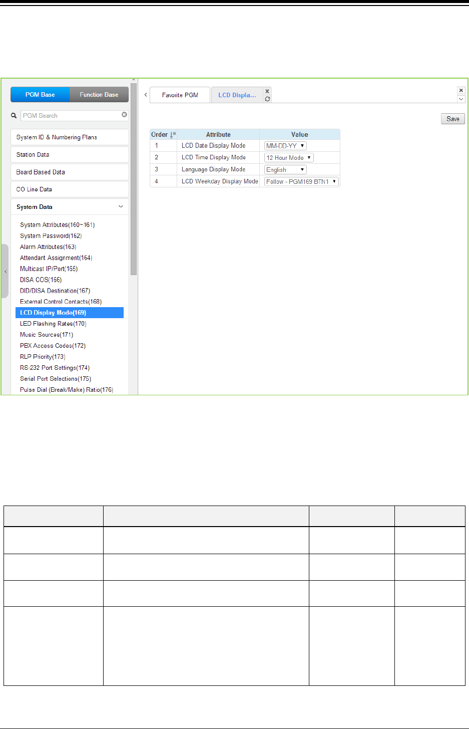
iPECS eMG80 & eMG800 & UCP
Administration and Programming Manual Issue 1.6
365
4.4.5.9 LCD Display Mode - PGM 169
Selecting LCD Display Mode will display the data entry page. Click [Save] button after changing
Value.
Figure 4.4.5.9-1 LCD Display Mode
The LCD display mode sets the time (12/24 hr.), date (day/month order) and language. Refer to
Table 4.4.5.9-1 and Table 4.4.5.9-2 for a description of the modes and the data entries required.
Table 4.4.5.9-1 LCD DISPLAY MODES
ATTRIBUTE DESCRIPTION RANGE DEFAULT
LCD Date Display
Mode
Sets the Date display as month/day or day/month. DD-MM-YY
MM-DD-YY
MM-DD-YY
LCD Time Display
Mode
Sets the Time display mode as 12 hour or 24-hour
(military) time.
12 Hour Mode
24 Hour Mode
12 Hour
Language Display
Mode
Sets the Language used in the display; refer to
Table 4.4.5.9-2 below.
English
LCD Weekday Display
Mode
Sets the Day-of-Week (DoW) display mode:
no DoW display mm/dd/DoW, (alpha month
display, overrides setting of button 1 above.
display mm/dd/DoW, numeric month display,
overrides setting of button 1 above.
Follow - PGM169
BTN1/
Type1
(MM/DD WDY)/
Type2
(MM DD WDY)
Follow -
PGM169
BTN1

iPECS eMG80 & eMG800 & UCP
Administration and Programming Manual Issue 1.6
366
Table 4.4.5.9-2 LCD LANGUAGE SELECTION
LANGUAGE
English
Italian
Finnish
Dutch
Swedish
Danish
Norwegian
Hebrew
German
French
Portuguese
Spanish
Korean
Estonian
Russian
Turkish
Polish
Greek
Arabic
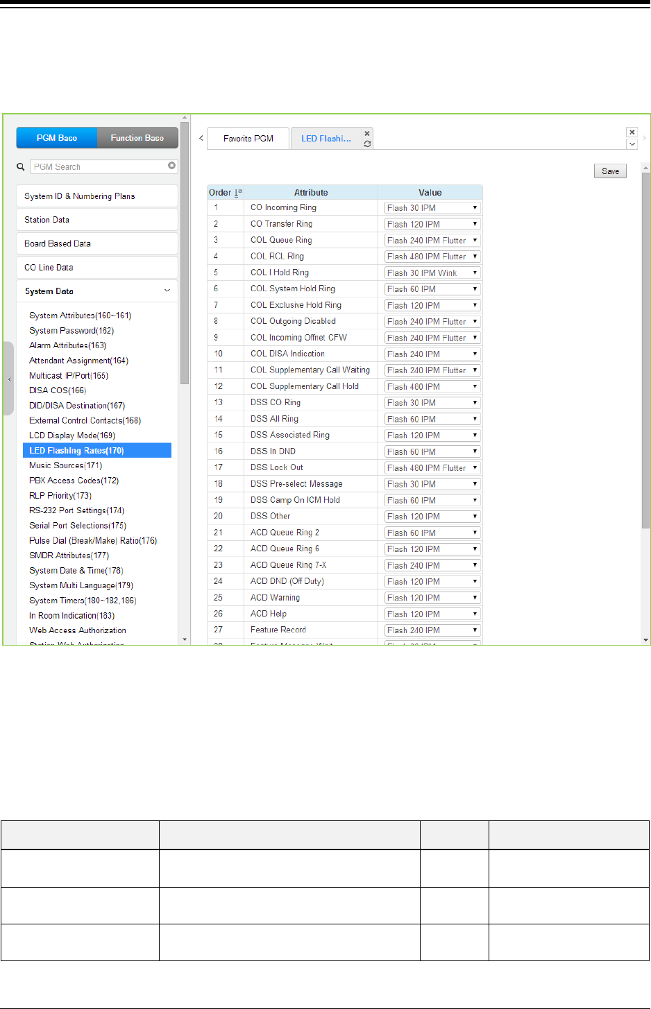
iPECS eMG80 & eMG800 & UCP
Administration and Programming Manual Issue 1.6
367
4.4.5.10 LED Flashing Rate - PGM 170
Selecting LED Flashing Rate will display the data entry page. Click [Save] button after changing
Value.
Figure 4.4.5.10-1 LED Flashing Rate
The LED flash rate for various functions and states can be assigned any one of the system‘s 15
signals. The various functions and states are shown in the following table. The 15 flash signals
available in the system are shown in the table ‘LED flash rate’.
Table 4.4.5.10-1 LED INDICATION
ATTRIBUTE DESCRIPTION RANGE DEFAULT
CO Incoming Ring CO button Incoming ring flashing rate. 00-14 FLASH 30 IPM
(2)
CO Transfer Ring CO button transfer ring flashing rate. 00-14 FLASH 120 IPM
(10)
COL Queue Ring CO button queue call back ring flashing rate. 00-14 FLASH 240 IPM FLUTTER
(6)

iPECS eMG80 & eMG800 & UCP
Administration and Programming Manual Issue 1.6
368
Table 4.4.5.10-1 LED INDICATION
ATTRIBUTE DESCRIPTION RANGE DEFAULT
COL RCL Ring CO button recall ring flashing rate. 00-14 FLASH 480 IPM FLUTTER
(8)
COL I Hold Ring CO button I hold flashing rate. 00-14 FLASH 30 IPM WINK
(12)
COL System Hold Ring CO button system hold flashing rate. 00-14 FLASH 60 IPM
(3)
COL Exclusive Hold Ring CO button exclusives hold flashing rate. 00-14 FLASH 120 IPM
(10)
COL Outgoing Disabled CO button outgoing disabled flashing rate. 00-14 FLASH 240 IPM FLUTTER
(6)
COL Incoming Off-net
CFW
CO button incoming off-net call forward
flashing rate.
00-14 FLASH 240 IPM FLUTTER
(6)
COL DISA Indication CO button DISA indication flashing rate. 00-14 FLASH 240 IPM
(5)
COL Supplementary Call
Waiting
CO button supplementary call waiting flashing
rate.
00-14 FLASH 240 IPM FLUTTER
(6)
COL Supplementary Call
Hold
CO button supplementary hold flashing rate. 00-14 FLASH 480 IPM
(8)
DSS CO Ring DSS button CO ring flashing rate. 00-14 FLASH 30 IPM
(2)
DSS All Ring DSS button ICM ALL ring flashing rate. 00-14 FLASH 60 IPM
(3)
DSS Associated Ring DSS button ICM ring associate device
flashing rate.
00-14 FLASH 120 IPM
(10)
DSS Incoming Ring DSS button station is in DND. 00-14 FLASH 60 IPM
(3)
DSS Lock Out DSS button station is in lock out. 00-14 FLASH 480 IPM FLUTTER
(8)
DSS Pre-select Message DSS button station is in pre-selected
message.
00-14 FLASH 30 IPM
(2)
DSS camp on ICM Hold DSS button station is in ICM hold. 00-14 FLASH 60 IPM
(3)
DSS Other DSS button station is in other state. 00-14 FLASH 120 IPM
(10)
ACD Queue Ring 2 CIQ #1 Threshold. 00-14 FLASH 60 IPM
(3)
ACD Queue Ring 6 CIQ #2 Threshold. 00-14 FLASH 120 IPM
(10)
ACD Queue Ring 7-X CIQ #3 Threshold. 00-14 FLASH 240 IPM
(5)
ACD DND (Off Duty) ACD an agent is off duty (ACD DND). 00-14 FLASH 120 IPM
(10)
ACD Warning ACD warning tone. 00-14 FLASH 120 IPM
(10)
ACD Help ACD help request/response. 00-14 FLASH 120 IPM
(10)
Feature Record FEATURE voice record button. 00-14 FLASH 240 IPM
(5)

iPECS eMG80 & eMG800 & UCP
Administration and Programming Manual Issue 1.6
369
Table 4.4.5.10-1 LED INDICATION
ATTRIBUTE DESCRIPTION RANGE DEFAULT
Feature Message Wait FEATURE message wait. 00-14 FLASH 30 IPM
(2)
DSS Out-of-service state DSS button a station is in out-of-service state. 00-14 FLASH OFF
(00)
On-demand Ring mode DND led of attendant station for ring mode. 00-14 FLASH 60 IPM
(3)
Night Ring mode
DND led of attendant station for ring mode.
00-14
FLASH Steady
Timed Ring mode DND led of attendant station for ring mode. 00-14 FLASH 240 IPM
(5)
Auto Ring mode DND led of attendant station for ring mode. 00-14 eMG: FLASH 480 IPM (8)
UCP: FLASH Off (00)
Page Hold Button HOLD LED for paging. 00-14 FLASH 60 IPM
(3)
DSS Station DND(off duty) DSS button station in Station DND. 00-14 FLASH 120 IPM
(10)
Message Wait (Call Back) Message wait. 00-14 eMG: FLASH 30 IPM (2)
UCP: FLASH Off (00)
DSS in use DSS button station is in use. 00-14 Steady On
(1)
Table 4.4.5.10-2 LED FLASH RATE TABLE
Flash Rate DESCRIPTION
1 Steady On
2 30 ipm flash (30% On)
3 60 ipm flash (30% On)
4 60 ipm double wink (30% On-Off-On-Off & 70% On)
5 240 ipm flash (30% On)
6 240 ipm flutter (30% On-Off-On-Off-On & 70% Off)
7 480 ipm flash (30% On)
8 480 ipm flutter (30% On-Off-On-Off-On & 70% Off)
9 15 ipm flash (30% On)
10 120 ipm flash (30% On)
11 120 ipm flutter (30% On-Off-On-Off-On & 70% Off)
12 30 ipm double flash (30% On-Off-On & 70% Off)
13 480 ipm double wink (30% On-Off-On-Off & 70% On)
14 480 ipm double flash (30% On-Off-On & 70% Off)
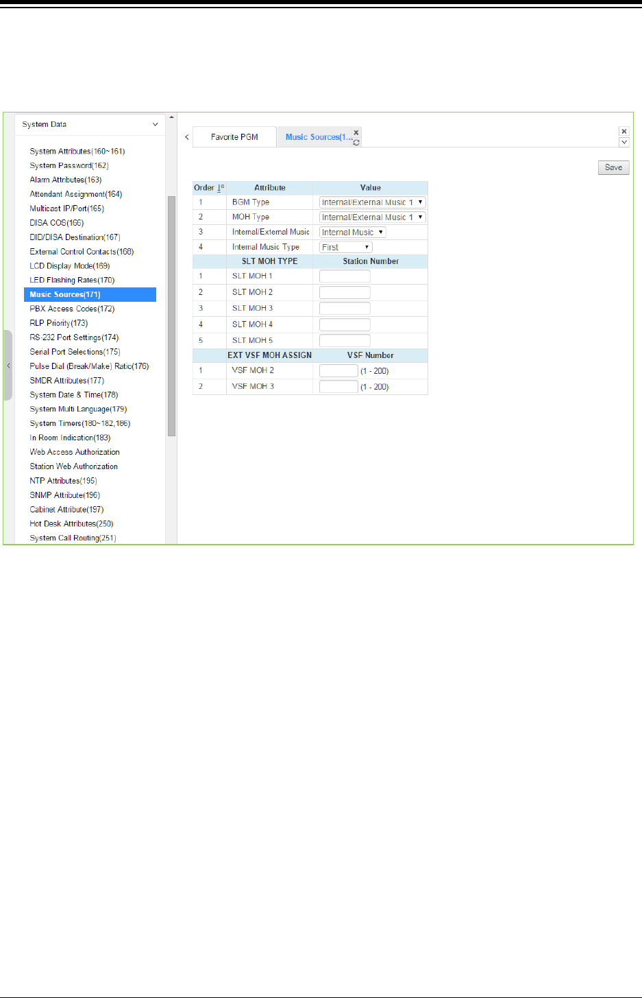
iPECS eMG80 & eMG800 & UCP
Administration and Programming Manual Issue 1.6
370
4.4.5.11 Music Sources - PGM 171
Selecting Music Sources will display the Music Sources data entry page. Click [Save] button after
changing Value.
Figure 4.4.5.11-1 Music Sources
Music inputs are provided for use as the Background Music and/or Music-On-Hold source inputs.
Up to three VSF announcements may be recorded and played as MOH to the connected caller.
The “VSF MOH” selection employs System announcement number 201, and for the VSF MOH 2
and VSF MOH 3 selections, any unused announcement can be employed. In addition, up to five
SLT ports may be used as MOH to the held caller.
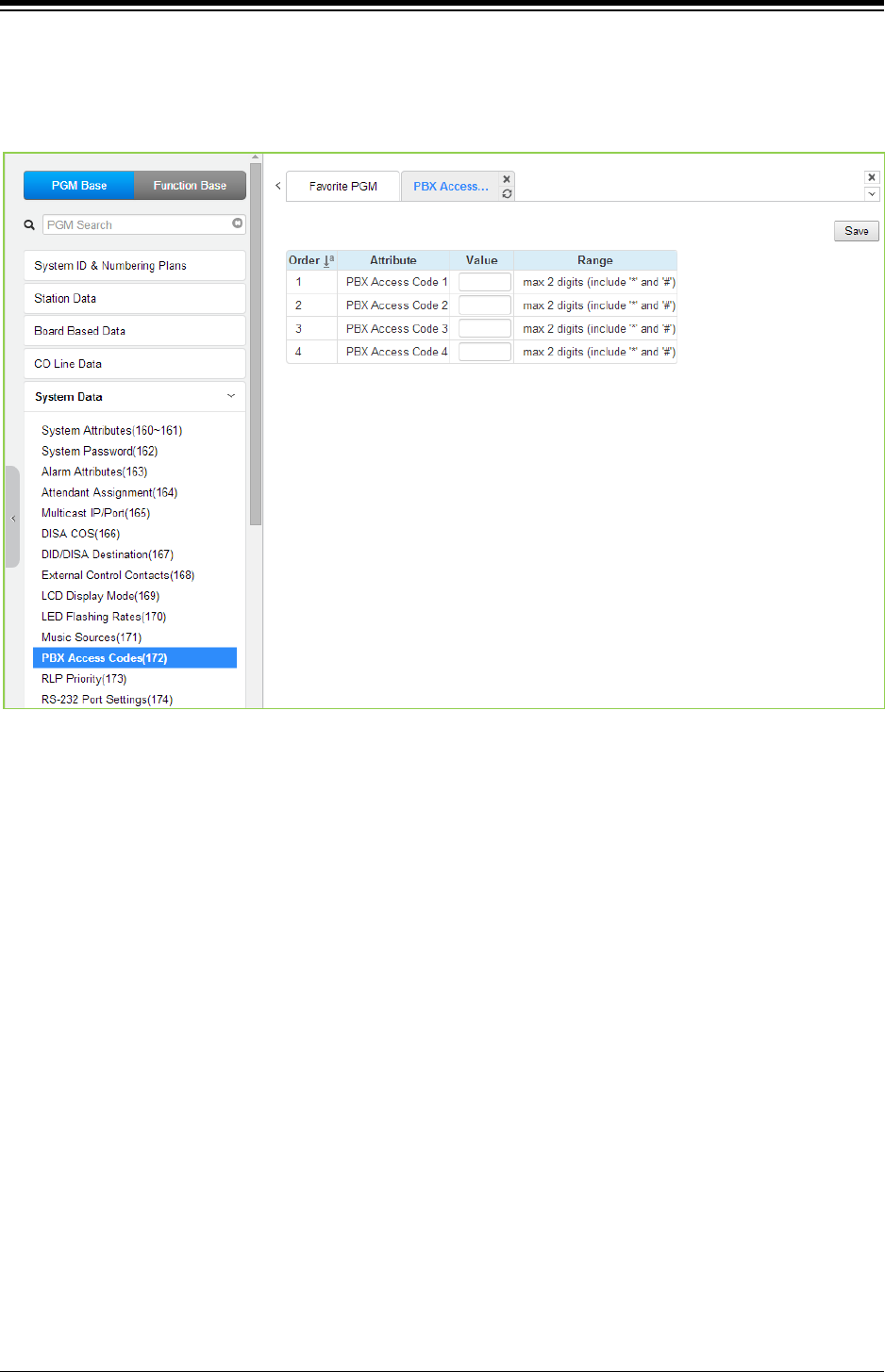
iPECS eMG80 & eMG800 & UCP
Administration and Programming Manual Issue 1.6
371
4.4.5.12 PBX Access Codes - PGM 172
Selecting PBX Access Codes will display the PBX Access Codes data entry page. Click [Save]
button after changing Value.
Figure 4.4.5.12-1 PBX Access Codes
When the system is used “behind” a PBX/CTX, the system needs to recognize the PBX/CTX
Trunk access codes to implement proper dialing restriction, tone detection sequences and Flash
timing. A maximum of four (4) Trunk Access Codes of one (1) or two (2) digits can be entered.
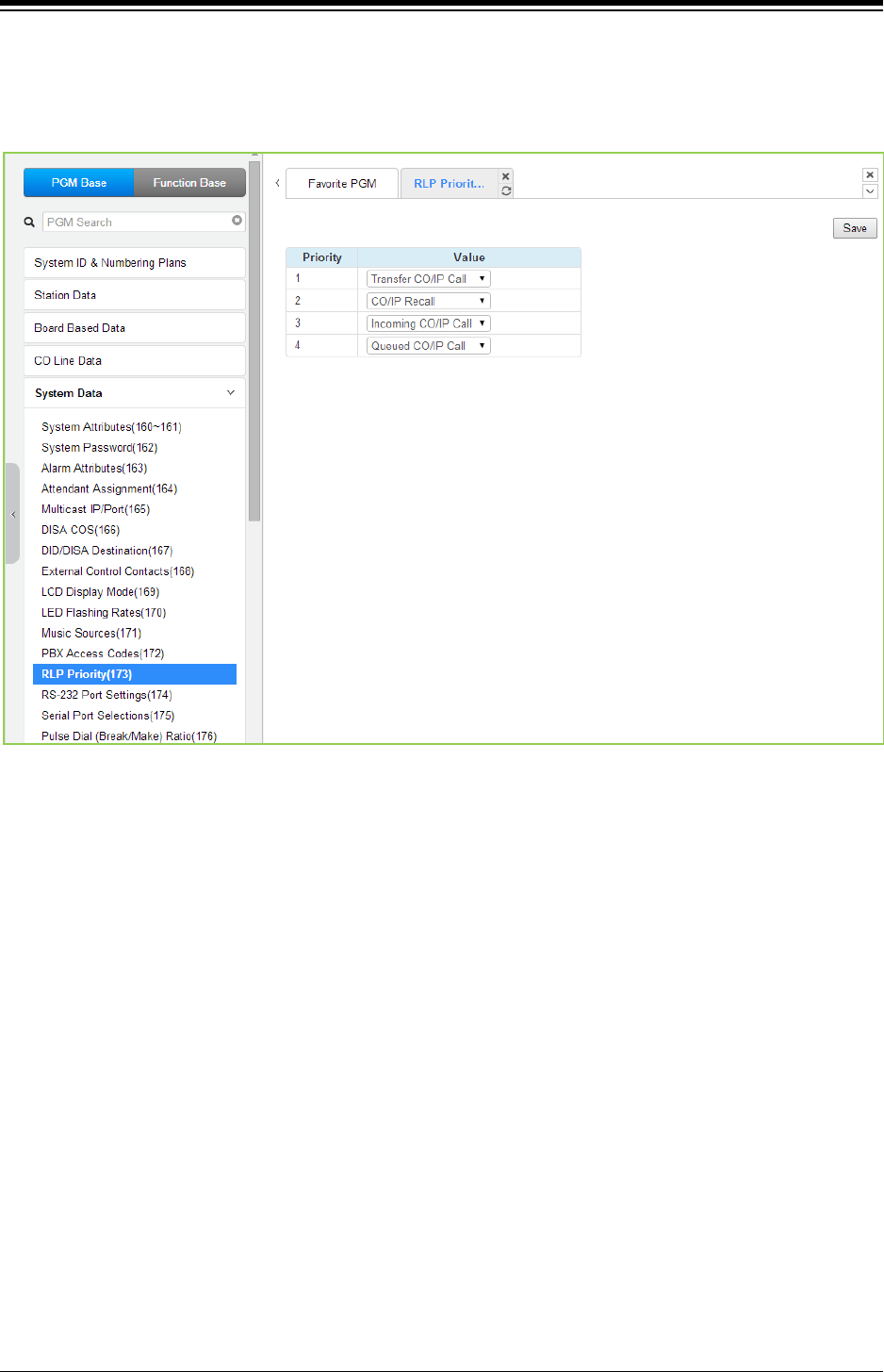
iPECS eMG80 & eMG800 & UCP
Administration and Programming Manual Issue 1.6
372
4.4.5.13 Ringing Line Preference Priority - PGM 173
Selecting Ring Line Preference Priority will display the Ringing Line Preference Priority data entry
page. Click [Save] button after changing Value.
Figure 4.4.5.13-1 Ringing Line Preference Priority
When multiple calls are ringing at the same time to a station assigned Ringing Line Preference,
the order of preference is based on the type of call: CO/IP Transfer, CO/IP Recall, Incoming call,
CO/IP Queue. A queued CO/IP call is always assigned the lowest priority.
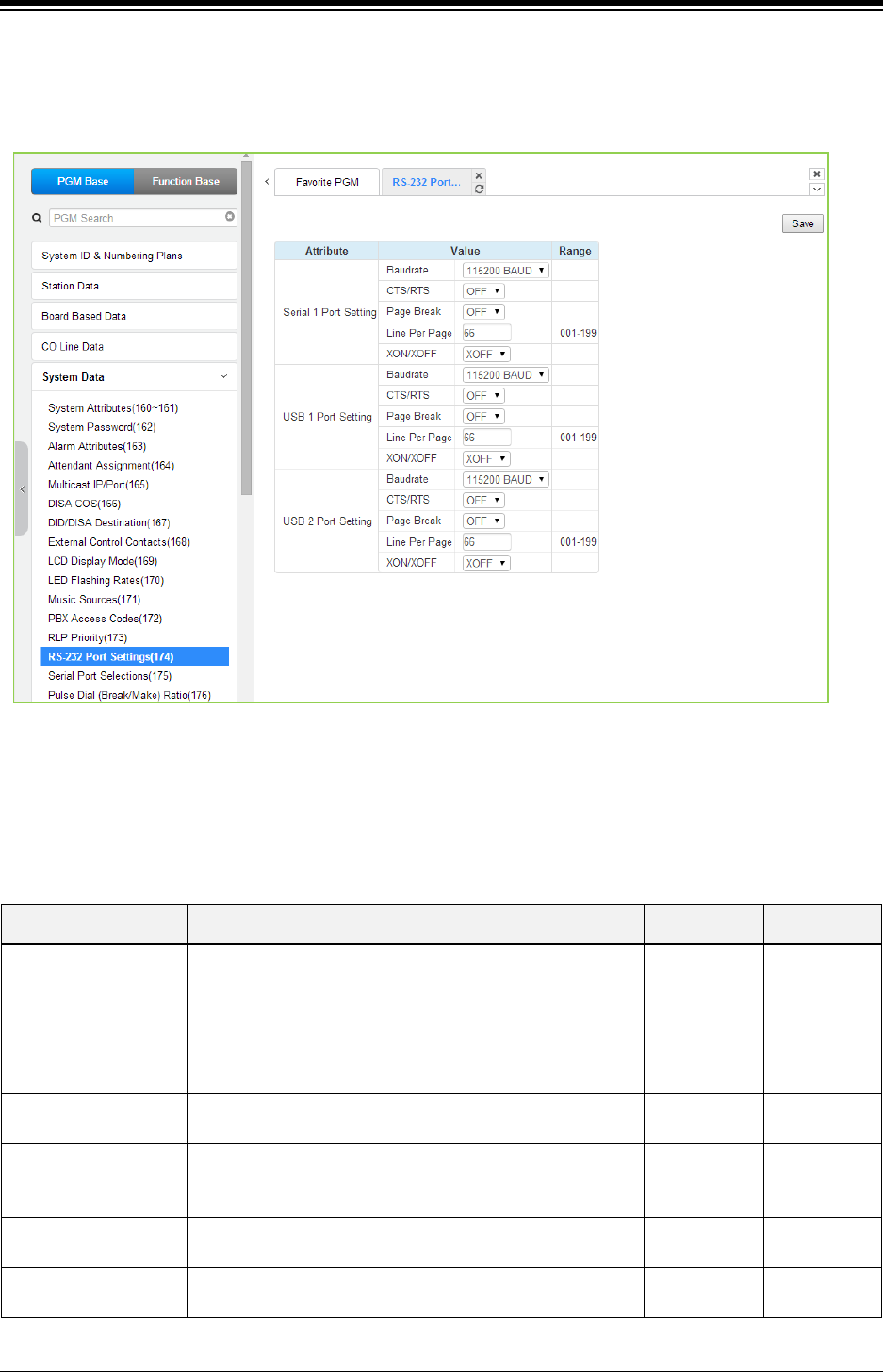
iPECS eMG80 & eMG800 & UCP
Administration and Programming Manual Issue 1.6
373
4.4.5.14 RS-232 Port Settings - PGM 174
Selecting RS-232 Port and USB 1&2 port Settings will display the RS-232 Port and USB 1&2 port
Settings data entry page. Click [Save] button after changing Value.
Figure 4.4.5.14-1 RS232 Port and USB 1&2 port Settings
Certain characteristics of each port are programmable including baud rate, RS 232 control, and
page settings. Refer to the following table for a description of the settings and the data entries
available.
Table 4.4.5.14-1 RS232 PORT and USB 1&2 port Settings
ATTRIBUTE DESCRIPTION RANGE DEFAULT
Baud Rate This entry establishes the BAUD rate for the RS-232 serial
port.
Unknown/
9600/
19200/
38400/
57600/
115200
115200
CTS/RTS The system’s RS232 port can support Clear-to-Send (CTS)
and Ready-to-Send (RTS), control leads.
OFF
ON
OFF
Page Break
The system can send a page break command over the
serial port at the end of each page.
See Lines per Page below for page length set-up.
OFF
ON OFF
Line Per Page This entry sets the page length, the number of lines the
system will send before sending the page break.
001~199 66
XON/XOFF This entry enables/disables XON/XOFF protocol. XON/
XOFF
XOFF
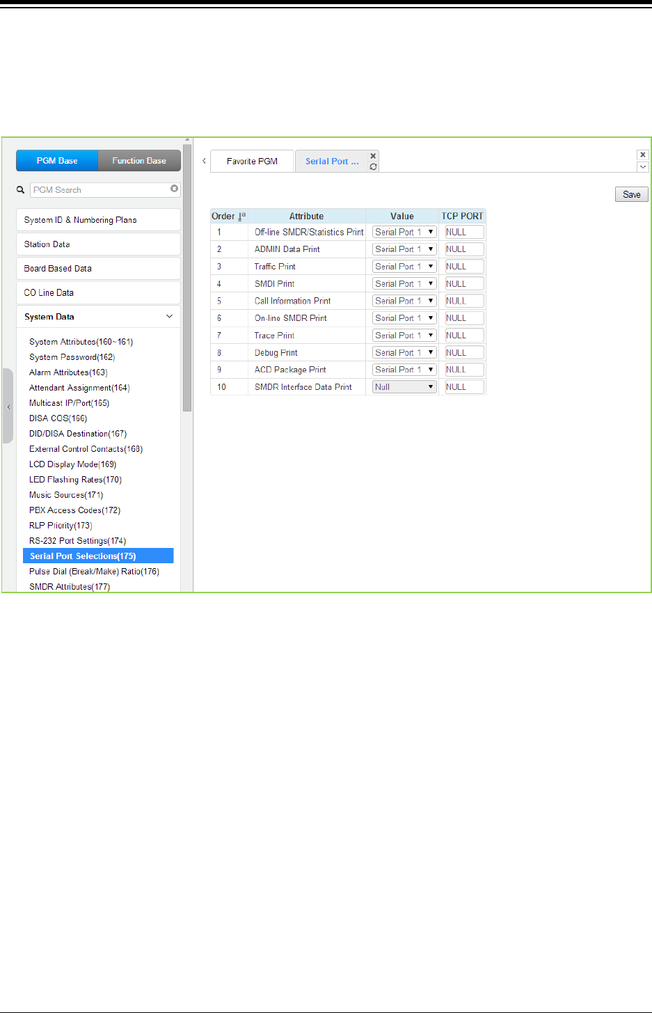
iPECS eMG80 & eMG800 & UCP
Administration and Programming Manual Issue 1.6
374
4.4.5.15 Serial Port Selections - PGM 175
Selecting Serial Port Selections will display the Serial Port Selections data entry page. For each
function select the desired output using the drop-down menu and, if a TCP channel is assigned,
enter the TCP port. Click [Save] button after changing Value.
Figure 4.4.5.15-1 Serial Port Selections
The system has six (6) serial ports (1 RS232, 3 TCP Channels and 2 USB serial). A serial port is
assigned to each function that requires a serial output.
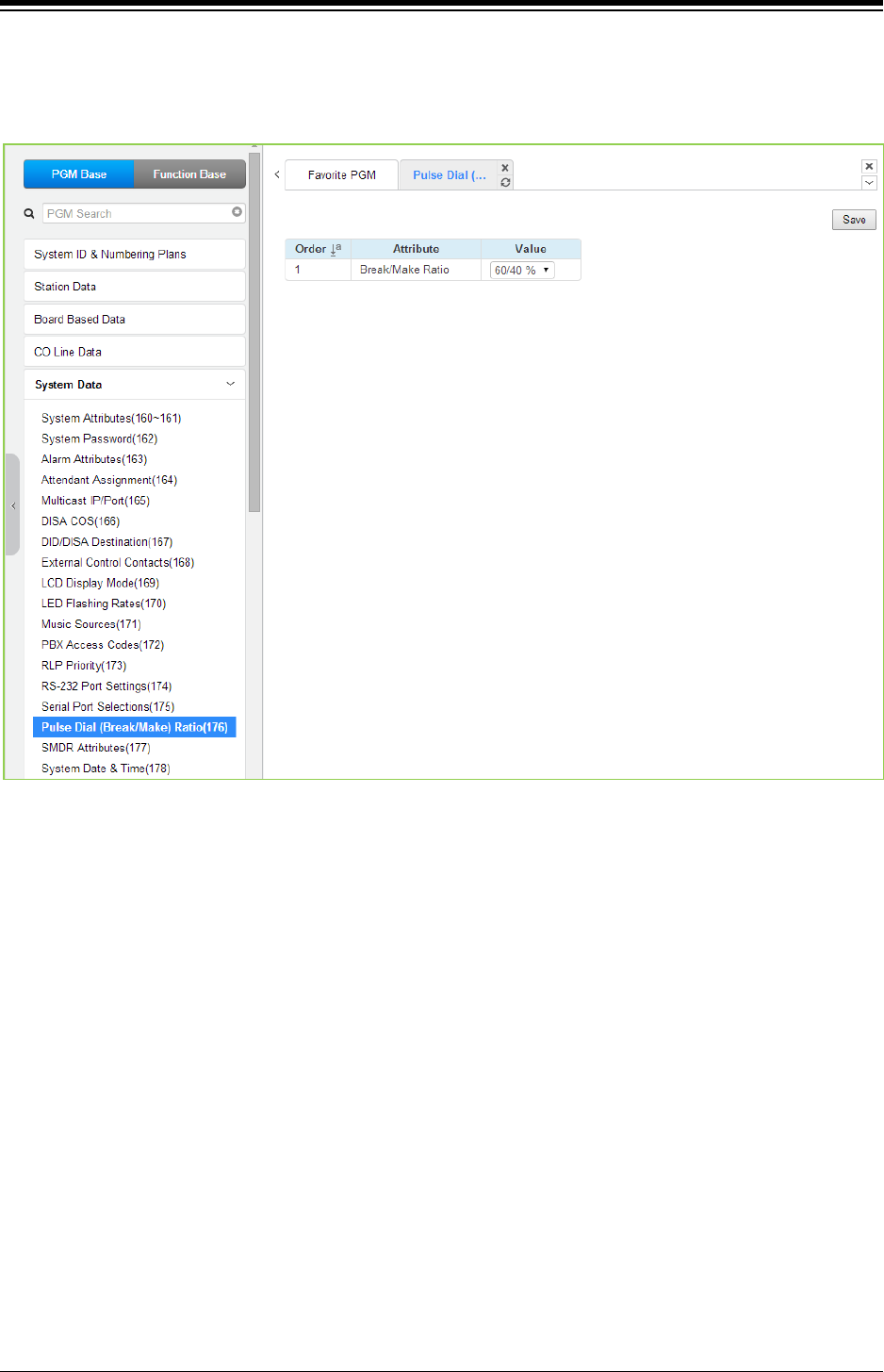
iPECS eMG80 & eMG800 & UCP
Administration and Programming Manual Issue 1.6
375
4.4.5.16 Pulse Dial (Break/Make) Ratio - PGM 176
Selecting Pulse Dial (Break/Make) Ratio will display the Break/Make Ratio data entry page. Click
[Save] button after changing Value.
Figure 4.4.5.16-1 Break/Make Ratio
For Pulse dial CO Lines, the system supports 10pps and break/make ratios of 60/40% or 66/33%.
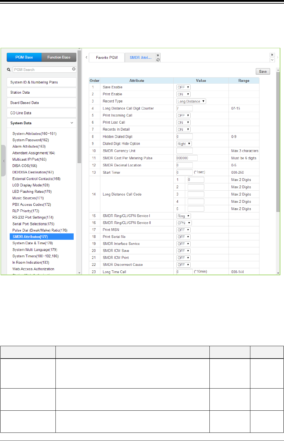
iPECS eMG80 & eMG800 & UCP
Administration and Programming Manual Issue 1.6
376
4.4.5.17 SMDR Attributes - PGM 177
Selecting SMDR Attributes will display the SMDR Attributes data entry page. Click [Save] button
after changing Value.
Figure 4.4.5.17-1 SMDR Attributes
Station Message Detail Recording (SMDR), which is output over an RS 232 port or TCP channel,
contains details on both incoming and outgoing calls. Various SMDR attributes can be assigned
including; output records for all calls or LD only, call cost per pulse when using call metering, etc.
Refer to the following table for a description of each Attribute and the data entries required.
Table 4.4.5.17-1 SMDR ATTRIBUTES
ATTRIBUTE DESCRIPTION RANGE DEFAULT
Save Enable
The system can output all outgoing call records (ON) or, to
allow for PSTN call set-up times, only records for calls that
exceed the SMDR Timer (OFF). For SMDR Timer settings
refer to “Start Timer” as the below.
OFF
ON OFF
Print Enable
The system can output SMDR records automatically as they
occur (real-time) or only when requested. When this attribute
is ON, SMDR is sent at call completion.
OFF
ON ON
Record Type
The system can record all outgoing calls or only long distance
calls. Long distance calls are identified by the LD digit count
and LD codes assigned in “Long Distance code”.
Long Distance/
ALL calls
Long
Distance

iPECS eMG80 & eMG800 & UCP
Administration and Programming Manual Issue 1.6
377
Table 4.4.5.17-1 SMDR ATTRIBUTES
ATTRIBUTE DESCRIPTION RANGE DEFAULT
Long Distance Call
Digit Counter
Dialed numbers, which exceed the assigned LD digit count are
considered long distance calls for SMDR and COS purposes. 07-15 07
Print Incoming Call
The system can output records for Incoming calls as well as
outgoing calls. If enabled, incoming as well as outgoing calls
are recorded.
OFF
ON OFF
Print Lost Call When incoming call records are enabled, the system can also
provide records for unanswered incoming (abandoned) calls.
OFF
ON ON
Records In Detail
The system can output detailed call records (ON) or summary
call information (total number of calls, cost and cost for each
station).
OFF
ON ON
Hidden Dialed Digit
For security purposes, digits dialed for an outgoing call can be
hidden and replaced with “*”. This field defines the number of
digits to hide. The Dialed Digit Hide Option below defines
whether leading or trailing digits are hidden The station must
be assigned for SMDR Hidden digits in ‘Common Attributes
section’.
0~9 0
Dialed Digit Hide
Option
When “HIDDEN DIALED DIGIT” is enabled, above, this field
determines if leading or trailing digits are hidden.
Right/
Left Right
SMDR Currency Unit The unit of currency used for call cost can be identified with 3-
characters for easy reference.
Max. 3
characters
SMDR Cost Per
Metering Pulse
When call metering is provided by the PSTN, the cost per
metering pulse can be assigned.
6-digits 000000
SMDR Decimal
Location
This value determines the position of the decimal in the Cost
per Pulse entry above, starting from the right most digits.
0~5 0
Start Timer To allow for call set-up times through the PSTN, a “Valid call
timer” can be set.
000~250
(msec)
0
Long Distance Code
For SMDR and COS purposes, five (5) Long Distance codes
of up to two (2) digits each can be assigned. If dialed as the
1st digits, the call is considered an LD call.
5 two digit LD
codes, use * as
wild card(any
digit)
SMDR CLI or Ring
Service I
For incoming calls, the system will send the defined data item
for “Field I”. The data item may be CLI, CPN or Ring Service
Time. Note the User dialed number is always provided for an
outgoing call.
RING/
CLI/
CPN
RING
SMDR Ring/CLI/CPN
Service II
For incoming calls, the system will send the defined data item
for “Field II”. The data item may be CLI, CPN or Ring Service
Time.
RING/
CLI/
CPN
CPN
Print MSN For an ISDN call involving an MSN number, the MSN number
Information can be included in the SMDR Record.
OFF
ON OFF
Print Serial No
Each SMDR Record can include a record number starting at 1
and incrementing until the records are deleted. The record
number will reset to 1 when SMDR capacity is reached or
SMDR Mail Auto Delete Set is enabled under System
Attributes.
OFF
ON OFF
SMDR Interface
Service
When enabled, the system stores SMDR data to send to
applications including NMS (Network Management System)
upon request.
OFF
CO CALL,
CO & ICM
CALL
OFF

iPECS eMG80 & eMG800 & UCP
Administration and Programming Manual Issue 1.6
378
Table 4.4.5.17-1 SMDR ATTRIBUTES
ATTRIBUTE DESCRIPTION RANGE DEFAULT
SMDR ICM Save When enabled, intercom call data is stored as part of the
SMDR data.
OFF
ON
OFF
SMDR ICM Print When enabled, intercom call data is printed as part of the On-
line SMDR.
OFF
ON
OFF
SMDR Disconnect
Cause
When enabled, the disconnect cause is stored in Off-line
SMDR data and printed as parted of the On-line SMDR.
OFF
ON
OFF
Long time call
To monitor long duration external calls, a “Long Time Call” can
be set. If CO call duration exceeds this value, a notification will
be sent to NMS server and alarm. If set to “000” the feature is
disabled.
000 ~ 144
(10 min.) 0
Print SMDR from any
CO to NET call
When a CO call is transferred to a Net transit-out CO, the local
SMDR record is deleted.
OFF
ON
OFF
Transfer Call Charge
Rate
When a call is transferred by a station, the SMDR record can
be charged based on the following options.
1. Individual: When a call is transferred to another station, the
transferred call is charged both stations based on the time on
the call.
2. Integrate transferring station: When a call is transferred to
another station, the call is charged to the transferring station.
3. Integrate transferred station: When a call is transferred to
another station, the call is charged to the station receiving the
transfer.
Individual/
Integrate
transferring
station/
Integrate
transferred
station
Individual
Station
Attendant Transfer
Charge Rate
When a call is transferred by a station, the SMDR record can
be charged based on the following options.
1. Individual charging: When the Attendant places an outgoing
call and transfers the call to a station, the Transfer Call
Charge Rate above.
2. Attendant station charging: When Attendant places an
outgoing call and transfers this call to a station, the call is
charged to the Attendant.
3. Transferred station charging: When the Attendant places an
outgoing call and transfers this call to a station, the call is
charged to the receiving station.
Individual
charging/
Attendant
station
charging/
Transferred
station
charging
Individual
charging
International Access
Code
The system will recognize the digits assigned as the
International access code digit sequence when dialed as the
first digits.
Max. 4 digits
Mobile Access Code
The system will recognize the digits assigned as the Mobile
network access code digit sequence when dialed as the first
digits.
Max. 4 digits
VSF Voicemail
indication
Calls to the Voice Mail may be shown as I (Incoming call) or V
(New indication) for Voice Mail in the SMDR record.
I (Incoming
call)/
V (New
indication)
I(Incoming
call)
Display Nxxxx for Net
number
An “N” can be included in the SMDR to identify the call as a
Network call.
OFF/
ON
OFF
Outgoing call type
Select SMDR type for outgoing call.
- All call: SMDR can be provided for all outgoing call.
- Answered call: SMDR can be provided in case the called
party is answered.
All Call,
Answered Call All Call
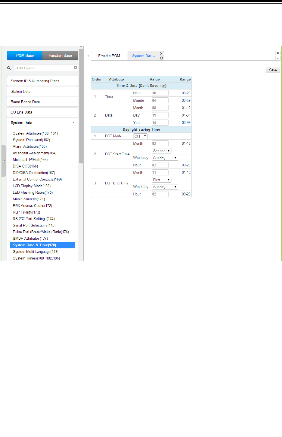
iPECS eMG80 & eMG800 & UCP
Administration and Programming Manual Issue 1.6
379
4.4.5.18 System Date & Time - PGM 178
Selecting System Date & Time will display the System Date & Time and DST data entry page.
Click [Save] button after changing Value.
Figure 4.4.5.18-1 System Date & Time
The System Date and Time are established by the [Time & Date] menu. The date and time are
employed for several features and functions including; LCR, LCD displays, SMDR outputs, Auto
Ring mode Selection, Wake-up Alarm, etc.
If Daylight Savings Time is enabled the system time will be adjust one-hour forward and back at
the DST start and end times, respectively.
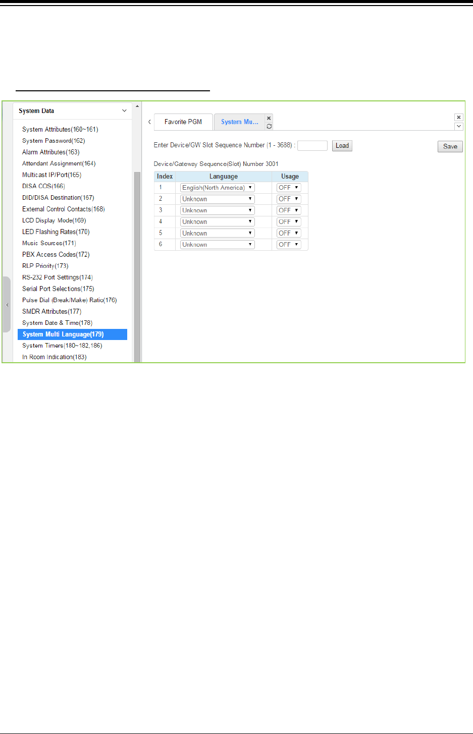
iPECS eMG80 & eMG800 & UCP
Administration and Programming Manual Issue 1.6
380
4.4.5.19 System Multi Language - PGM 179
Selecting System Multi Language will display the System Multi Language data entry page. Click
[Save] button after changing Value.
Enter Device/GW slot sequence number
: eMG80 : 1-300 / eMG800: 1-2890 / UCP: 1-3688
Figure 4.4.5.19-1 System Multi-Language
The VSF (VMIU, VMIB, UVM) supports multiple languages (18 languages); up to six languages
may be supported simultaneously. Once the prompts are downloaded to the VMIU and VMIB, the
caller receives the Language selection announcement for DISA and CCR calls as well as
preceding a Station Group announcement or DID error announcement. The language selection
announcement will only affect the language prompts enabled for use with the device indicated by
the Sequence number.
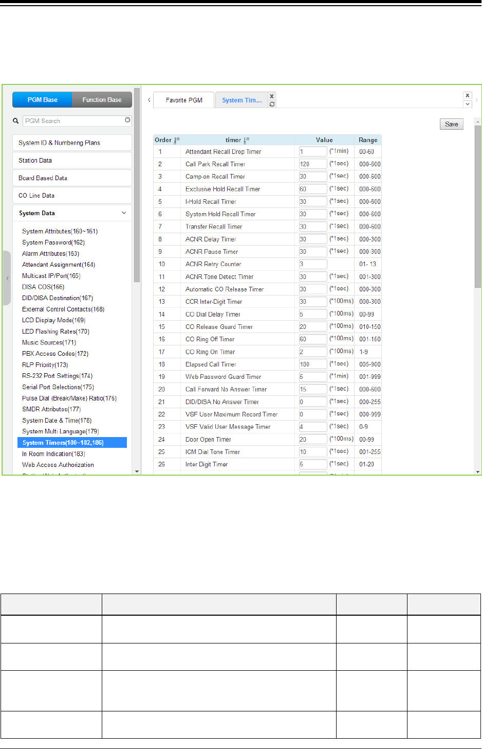
iPECS eMG80 & eMG800 & UCP
Administration and Programming Manual Issue 1.6
381
4.4.5.20 System Timers - PGM 180 ~ 182 & 186
Selecting System Timers will display the System Timers data entry page. Click [Save] button
after changing Value.
Figure 4.4.5.20-1 System Timers
A number of timers can be assigned to control and affect many features and functions. Refer to
the following table for a description of the timers and the input required.
Table 4.4.5.20-1 SYSTEM TIMERS
ATTRIBUTE DESCRIPTION RANGE DEFAULT
Attendant Recall Timer Enter the desired time that Attendant receives recall
after the system will disconnect the call.
00~60
(minutes)
01
Call Park Recall Timer Enter the desired recall time for call park. Parked call
will recall the station at a specified time.
000~600
(seconds)
120
Camp-on Recall Timer
When a call is transferred using Camp-On, this field
determines the desired recall time for Camp-on. The
station receives the call again with a specified time.
000~600
(seconds) 030
Exclusive Hold Recall
Timer
Enter the desired time for Exclusive hold. The station
receives the call again after a specified time.
000~600
(seconds)
060

iPECS eMG80 & eMG800 & UCP
Administration and Programming Manual Issue 1.6
382
Table 4.4.5.20-1 SYSTEM TIMERS
ATTRIBUTE DESCRIPTION RANGE DEFAULT
I-Hold Recall Timer Enter the desired time for Hold recall. The station
receives the call again after a specified time.
000~600
(seconds)
030
System Hold Recall
Timer
Enter the desired time for System hold recall time. The
station receives the call again after a specified time.
000~600
(seconds)
030
Transfer Recall Timer Enter the desired time for transferring the call again to
the receiving station.
000~600
(seconds)
030
ACNR Delay Timer
If the ACNR Pause Timer expires and no CO/IP Line is
available for ACNR recall, in this filed, you can set the
delay time before ACNR attempts to access a CO/IP
line again. This feature doesn’t affect the ACNR retry
counter.
000~300
(seconds) 030
ACNR Pause Timer Enter the desired time for pause between ACNR recall
attempts.
000~300
(seconds)
030
ACNR Retry Counter
Enter the number of ACNR retry attempts. ACNR will
finish after a specified times.
Regarding CIS country, the range is from 1 to 9.
1~13 03
ACNR Tone Detect
Timer
If call progress tones are not available for ACNR, the
system will wait the specified time after dialing before
considering the called party as “busy/no answer”.
001~300
(seconds) 30
Automatic CO Release
Timer
If a user accesses a CO/IP Line and takes no action,
the system will automatically release the CO/IP Line
when the specified time is over or expired.
000~300
(seconds) 030
CCR Inter-digit Timer Inter-digit timer used with Customer Call Routing
function.
000~300
(seconds)
030
CO Dial Delay Timer To prevent dialing when CO/PBX has slow response,
dialing by the system can be delayed using this timer.
00~99
(minutes)
05
CO Release Guard
Timer
When a CO/IP Line is returned to idle, the system will
deny access for the specified time to assure the PSTN
returns the CO/IP Line circuitry to be idle.
010~150
(seconds) 020
CO Ring Off Timer
This timer sets the maximum ‘OFF’ duration of the
incoming ring cycle for the Ring Detect circuitry of the
system to detect an abandoned call.
001~150
(seconds) 060
CO Ring ON Timer
This timer sets the ‘ON’ time of the incoming ring cycle
for the Ring Detect circuitry of the system to recognize
an incoming call.
1~9
(100 msec) 2
Elapsed Call Timer
Users can receive a periodic tone indicating the length
of an outgoing call. This timer sets the time before and
between the tones. Note CO Warning Tone must be
enabled for the station in Station Data in ‘Station Data
section’.
005~900
(seconds) 180
Web Password Guard
Timer
If no data packet is received during a Web connection,
after the guard time a password check will be initiated
by the system.
001~999
(minutes) 5
Call Forward No
Answer Timer
When a user activates No-Answer Forward, calls will
ring for this duration before being forward. The Station
No-Answer Forward timer section will take precedence.
000~600
(seconds) 15
DID/DISA No Answer
Timer
A DID/DISA call to a busy station will forward to the
DID/DISA Destination assigned under section should
this timer expires.
000~255
(seconds) 00

iPECS eMG80 & eMG800 & UCP
Administration and Programming Manual Issue 1.6
383
Table 4.4.5.20-1 SYSTEM TIMERS
ATTRIBUTE DESCRIPTION RANGE DEFAULT
VSF User Maximum
Record Timer
This timer sets the maximum duration allowed for the
User Greeting in the system’s VSF.
000~999
(seconds)
0
VSF Valid User
Message Timer
This timer sets the minimum duration allowed for a User
Greeting.
0~9
(seconds)
4
Door Open Timer This timer sets the minimum time required to activate
the contact assigned as a door open contact.
00~99
(100 msec)
20
ICM Dial Tone Timer
If a user goes off-hook to receive Intercom dial tone and
takes no action for this timer, the user will receive error
tone.
001~255
(seconds) 10
Inter Digit Timer
This timer sets the maximum time allowed between
each user-dialed digit. At expiration, the user will
receive error-tone.
01~20
(seconds) 5
MSG Wait Reminder
Tone Timer
An iPECS IP or LDP Phone user will receive periodic
reminder tones of a message waiting at intervals of this
timer.
00~60
(minutes) 00
Paging Timeout Timer Determines the maximum duration of a page after
which the caller and Page Zone are released.
000~255
(seconds)
15
Pause Timer
A Timed pause of this duration is used in speed dial
and during other automatically dialed digits sent to the
PSTN.
1~9
(seconds) 3
Soft auto RLS Timer
When a Soft Key is used on the 6000 or 7000 series
iPECS IP or LDP Phone, after expiration of this timer,
the display will return to the previous display.
1-30
(seconds) 10
VM Pause Timer
When the system sends a “Pause” to Voice Mail using
in-band signals, this timer defines the Pause duration.
(Not available in the USA.)
1-90
(ms) 30
SLT Hook Switch
Bounce Timer
This timer determines the duration the system
considers an actual state change in the hook-switch
and not a spurious contact bounce.
01~25
(100 msec.) 1
SLT Maximum Hook
Switch Flash Timer
This timer sets the maximum time an SLT user can
depress the hook-switch for a Flash signal.
01~25
(100 msec.)
10
SLT Minimum Hook
Flash Timer
This time sets the minimum time an SLT user must
depress the hook-switch for a Flash signal.
000~250
(10 msec.)
30
Station Auto Release
Timer
For an internal call, the system will return a station to
idle if the call remains unanswered for this duration.
000~300
(seconds)
60
Unsupervised
Conference Timer
This timer determines the duration of an “Unsupervised
Conference” before the station is recalled or the
conference is dropped. 00 means 10 minutes.
00~99
(minutes) 10
Prime Line Delay Timer
This timer sets the delay (no action duration) for
delayed (Warm) Prime Line operation.
01~20
(seconds)
5
Wink Signal Timer This timer sets the duration of the “Seize Acknowledge
Signal” (Wink) sent to the PSTN on a DID line.
010~200
(10 msec.)
10
En-block Inter Digit
Timer
When an ISDN Line is assigned to send digits En-block,
CO Attribute section, the system will send digits if the
user dials “#” or this En-block inter-digit timer expires.
01~20
(seconds) 5
DTMF Duration Timer This timer establishes the duration of DTMF tones sent
on an analog CO line.
04~99
(10 msec.)
10
Flex DID Timer The system will receive DID digits for this timer.
After the timer expires, the system will use the last 2 to
01~99
(100 msec)
30

iPECS eMG80 & eMG800 & UCP
Administration and Programming Manual Issue 1.6
384
Table 4.4.5.20-1 SYSTEM TIMERS
ATTRIBUTE DESCRIPTION RANGE DEFAULT
4 digits received as DID digits.
R2 Out Manage Timer Reserved for future usage for R2 timers. 01~50
(seconds)
14
R2 In Manage Timer Reserved for future usage for R2 timers. 01~50
(seconds)
14
R2 Disappear Timer Reserved for future usage for R2 timers. 01~50
(seconds)
14
R2 Pulse Timer Reserved for future usage for R2 timers. 01~30
(*20ms)
7
R2 Ready Timer Reserved for future usage for R2 timers. 000~500
(*200ms)
7
Dial Tone Delay Timer Reserved for future usage for R2 timers. 01~30
(*20ms)
20
Wake Up Fail Timer
At expiration of this timer, the system will notify the
Attendant when a user does not respond to a Wake up
alarm.
00~99 20
VSF Cut Error Tone
Timer
The duration of Voice Messages in the built-in Voice
Mail are reduced by this timer to remove error tone that
may be sent by the carrier after disconnect.
00~90
(seconds) 0
On Hook Auto Idle
Timer
When an iPECS IP or LDP Phone receives a
disconnect message or signal from CO line the phones
goes to idle after this timer.
00~99
(seconds) 0
IP Watch Timer
When Local redundancy is implemented, should the
LAN cable fail, both call servers may attempt to be
active. To protect against this “dual active” case, the
system can periodically check for an active back-up
module.
0~250
(1 sec.) 0
Prepaid Call Drop
Warning Timer
When the Prepaid funds are exhausted, the user will
receive a warning tone indicating the call will be
dropped after this timer expires.
00-99 10
Emergency retry timer
System try to make emergency call according to the CO
access rule/Prefer CO/CO group if system could not
seize predefined emergency Co line within this timer.
00~99
(seconds) 0
Record Warning
Repeat Timer
If record warning tone is set and this timer is set greater
than 1, it works periodically when it’s recorded.
000~999
(seconds)
0
Error Tone Timer This timer sets the duration for Error Tone. 5~180
(seconds)
30
Howling Tone Timer This timer sets the duration for Howling Tone. 0~180
(seconds)
30
VM Notify Play Delay
Over CO Timer
When VM notification to the mobile uses an analog loop
start Line, system will treat the call as the answered
after this timer and play the new message prompt.
1~99
(1 sec.) 10
Fax Detect timer It is maximum fax tone detection time to deliver FAX
call to fax destination.
1~20
(1 sec.)
10
Auto Pause Release
timer
IPCR Mute function will be released by this auto pause
released timer.
0~255
(1 sec.)
0
UCS Ring ACK Timer UCS Client is ringing before expiring the Ring ACK
timer and afterwards will hear Error tones.
0~20
(seconds)
0
Short Modem Timer
If {Short modem} of a SLT is ON, the SLT maintains the
01~60
10

iPECS eMG80 & eMG800 & UCP
Administration and Programming Manual Issue 1.6
385
Table 4.4.5.20-1 SYSTEM TIMERS
ATTRIBUTE DESCRIPTION RANGE DEFAULT
modem mode for this time.
(1 sec.)
Call log/Directory Auto
Idle Timer
When the timer is set "xx" and there is no action by a
user while navigating call log/directory menu in a
station, the station will go to idle in case of on-hook
state.
If the timer is set to 0, the feature is not worked.
Condition
1. The call log auto idle timer is supported only below
phones.
- LIP-90xx series (9010/20/30/40)
- LIP-80xxE series (8012E/24/40E)
- LDP phones.
* Firmware of LIP-90xx and LIP-80xxE series should
be upgraded (LIP-90xx: A.0Eb or later version, LIP-
80xxE: A.1Fn or later version).
2. The DECT phone and LIP-9070 do not support the
directory auto idle timer.
00,
10-99 (1 sec.) 0
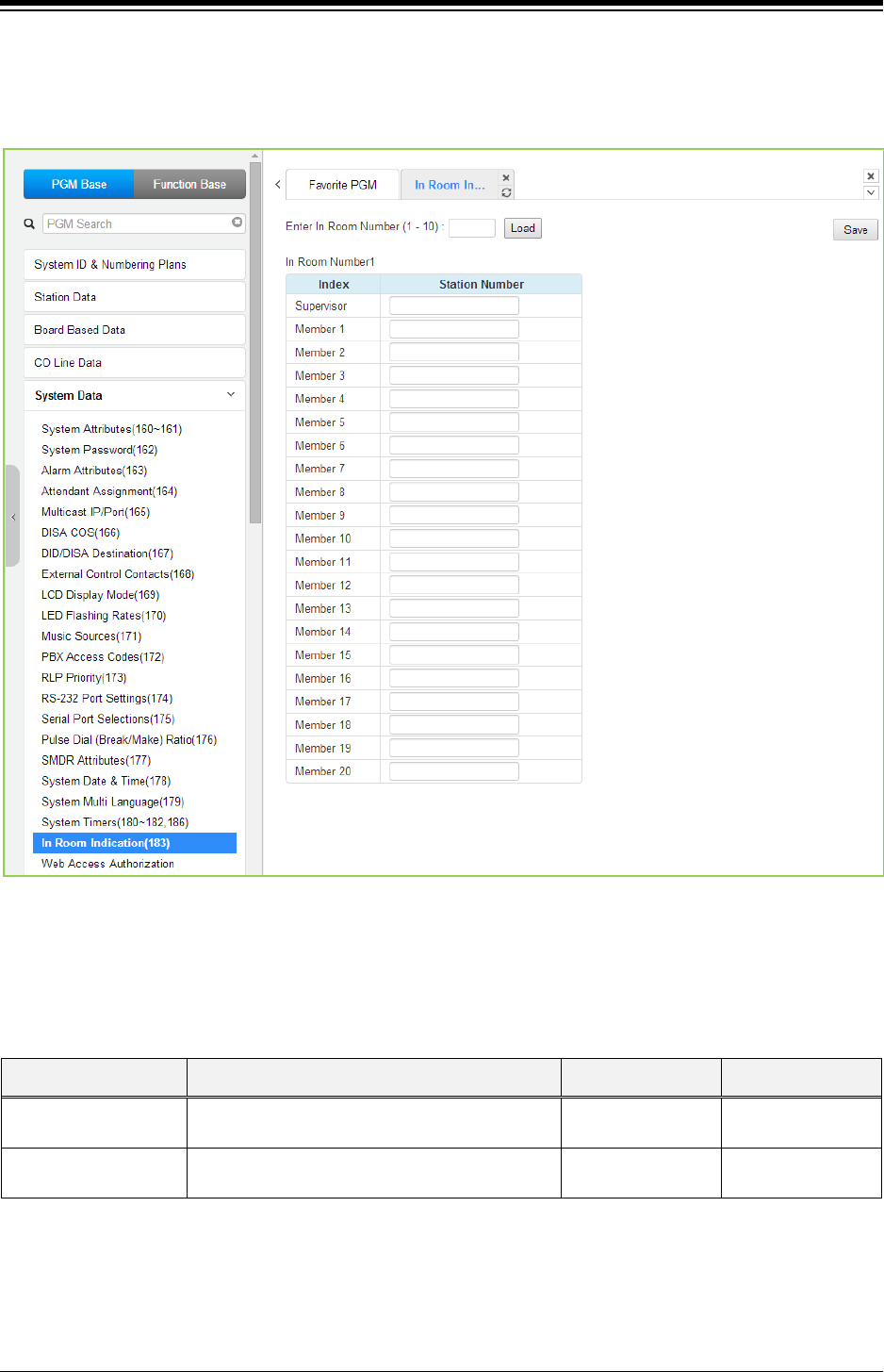
iPECS eMG80 & eMG800 & UCP
Administration and Programming Manual Issue 1.6
386
4.4.5.21 In-Room Indication - PGM 183
Selecting In-Room indication will display the In Room data entry page. Click [Save] button after
changing Value.
Figure 4.4.5.21-1 In-Room Indication
The Supervisor Station can set the In-Room Indication for all members in the In-Room indication
group. Up to 10 Supervisors (groups) can be configured can be programmed, and each can have
up to 20 members in the group, excluding the Supervisor.
ATTRIBUTE DESCRIPTION RANGE DEFAULT
Supervisor This entry assigns the Station number for the In-
Room Group Supervisor.
Station number
Member 01~20 This entry assigns stations as members of the
In-Room Group.
Station number
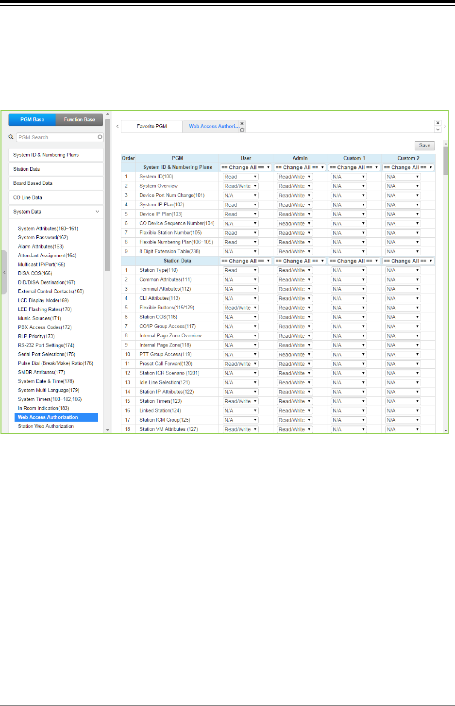
iPECS eMG80 & eMG800 & UCP
Administration and Programming Manual Issue 1.6
387
4.4.5.22 Web Access Authorization
Selecting Web Access Authorization will display the Web Access Authorization data entry page.
This page is only displayed when a password is defined. Click [Save] button after changing Value.
A user can select three authorization option (N/A, Read, Read/Write) only in Web Access &
Station Web Authorization PGM of Web Admin.
Figure 4.4.5.22-1 Web Access Authorization
Three different passwords can be assigned for the access to the iPECS Web administration so
that the different levels of access to the program fields can be allowed. Four levels (User,
Administrator, Custom1, and Custom2) have access to the assigned fields in this page by
selecting N/A, Read, Read/Write. The Maintenance password has access all the programming
fields and the maintenance fields including trace settings, device log view, gain & cadence control,
lock key install and device delete feature. In addition, the Maintenance level user can assign the
authorities of the other user levels.
In the Maintenance menu, the Database, SMDR, and Voice Mail Delete fields can be chosen by
User level or Admin Level.
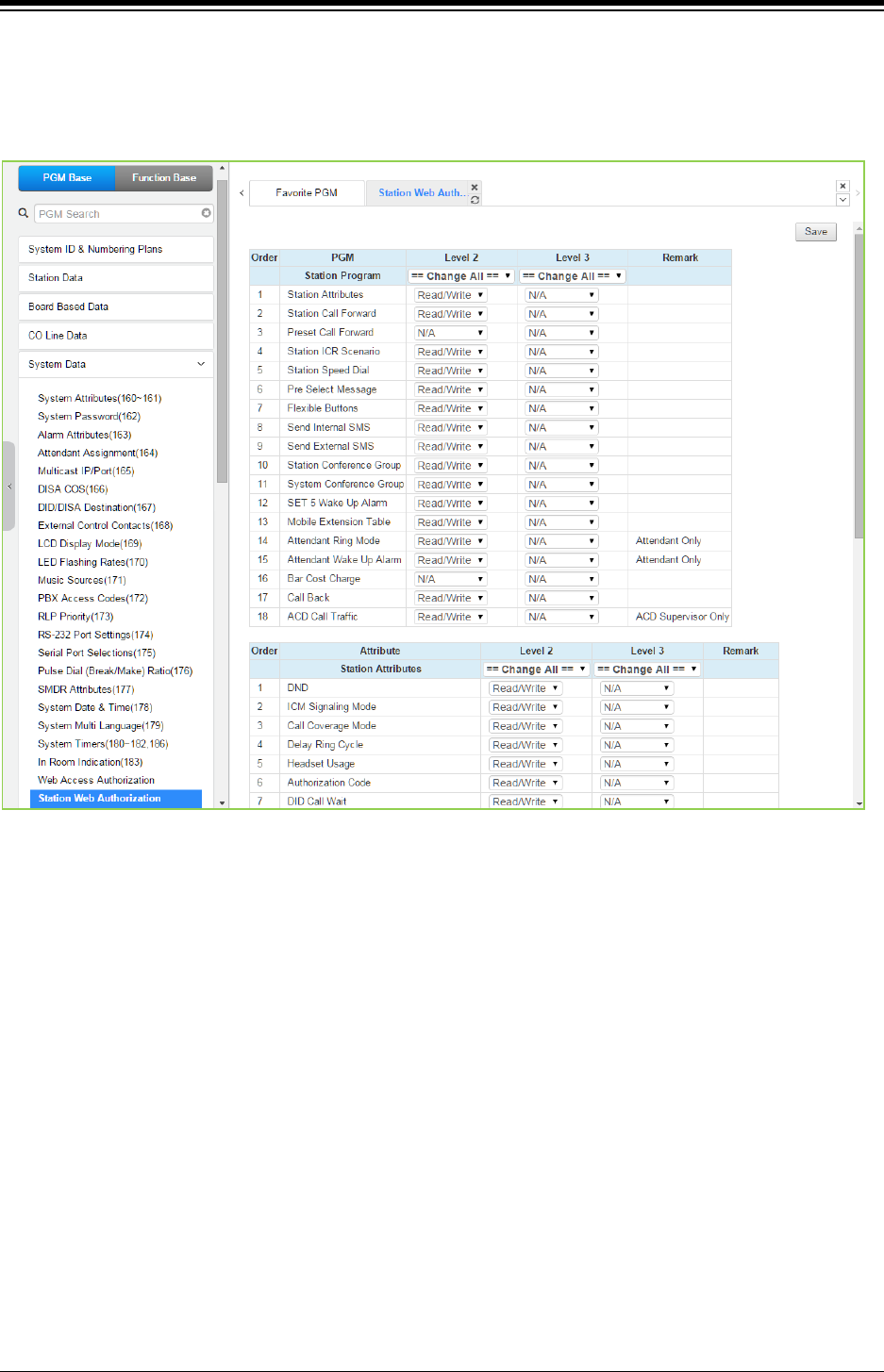
iPECS eMG80 & eMG800 & UCP
Administration and Programming Manual Issue 1.6
388
4.4.5.23 Station Web Access Authorization
Selecting Station Web Authorization will display the Web authorization data entry page. Click
[Save] button after changing Value.
Figure 4.4.5.23-1 Station Web Access Authorization
Three access levels can be assigned to each station for access to the Station Web pages in
Station Data (Common Attributes (111): ‘Station Web Level’). Level 1 has access to all Station
pages and attributes. The pages and attributes for Levels 2 and 3 are programmable.
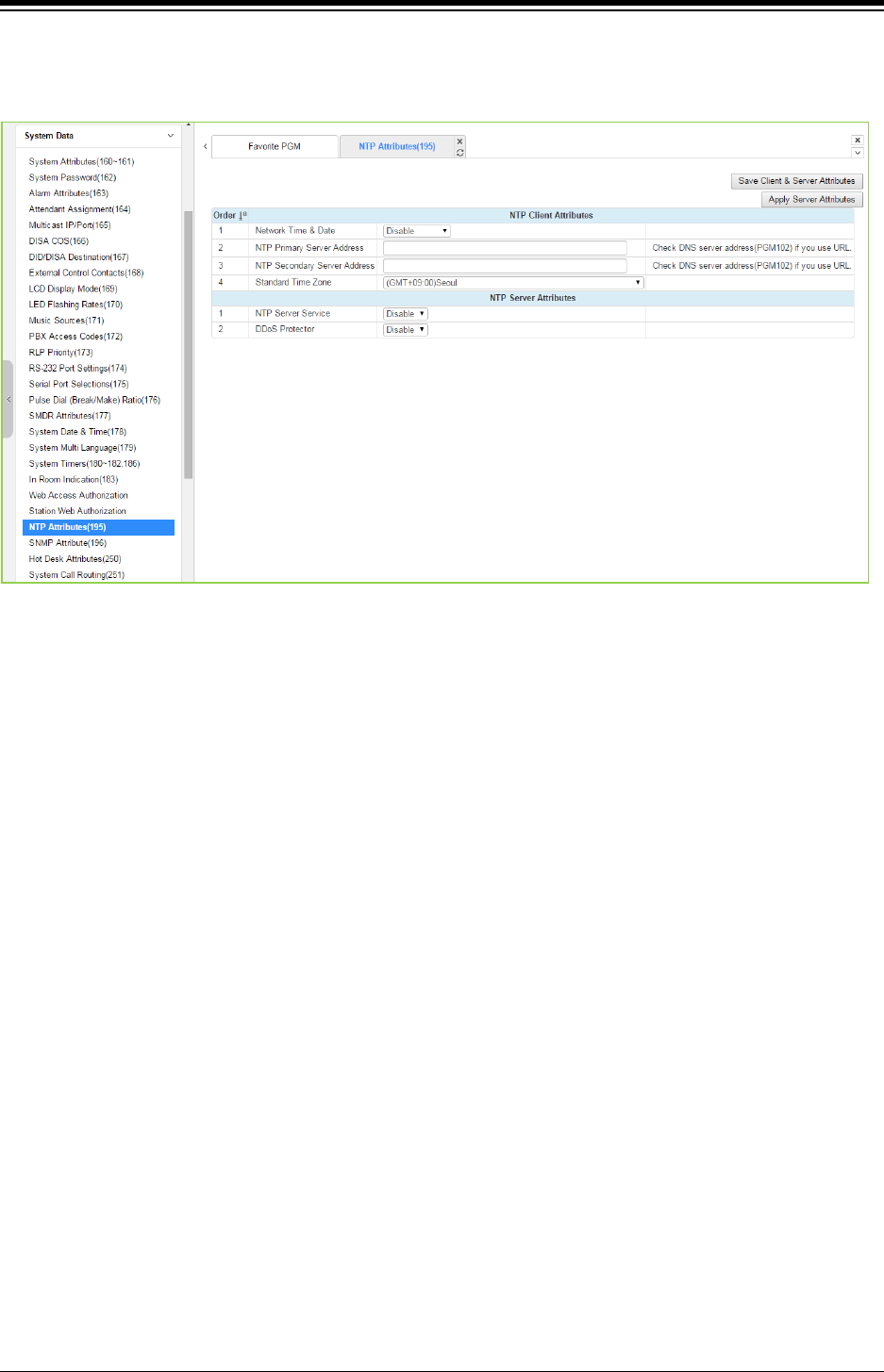
iPECS eMG80 & eMG800 & UCP
Administration and Programming Manual Issue 1.6
389
4.4.5.24 NTP Attributes - PGM 195
Selecting NTP Attributes will display the System NTP Attributes entry page.
Figure 4.4.5.24-1 NTP Attributes
The system can employ the Network Time Protocol (NTP) to synchronize the system time with an
NTP time server. The system requests the time from the NTP server at 10-minute intervals and
then determines the time differential. If the system time is more 2 seconds off the NTP time, the
system time is adjusted to synchronize with the NTP server time.
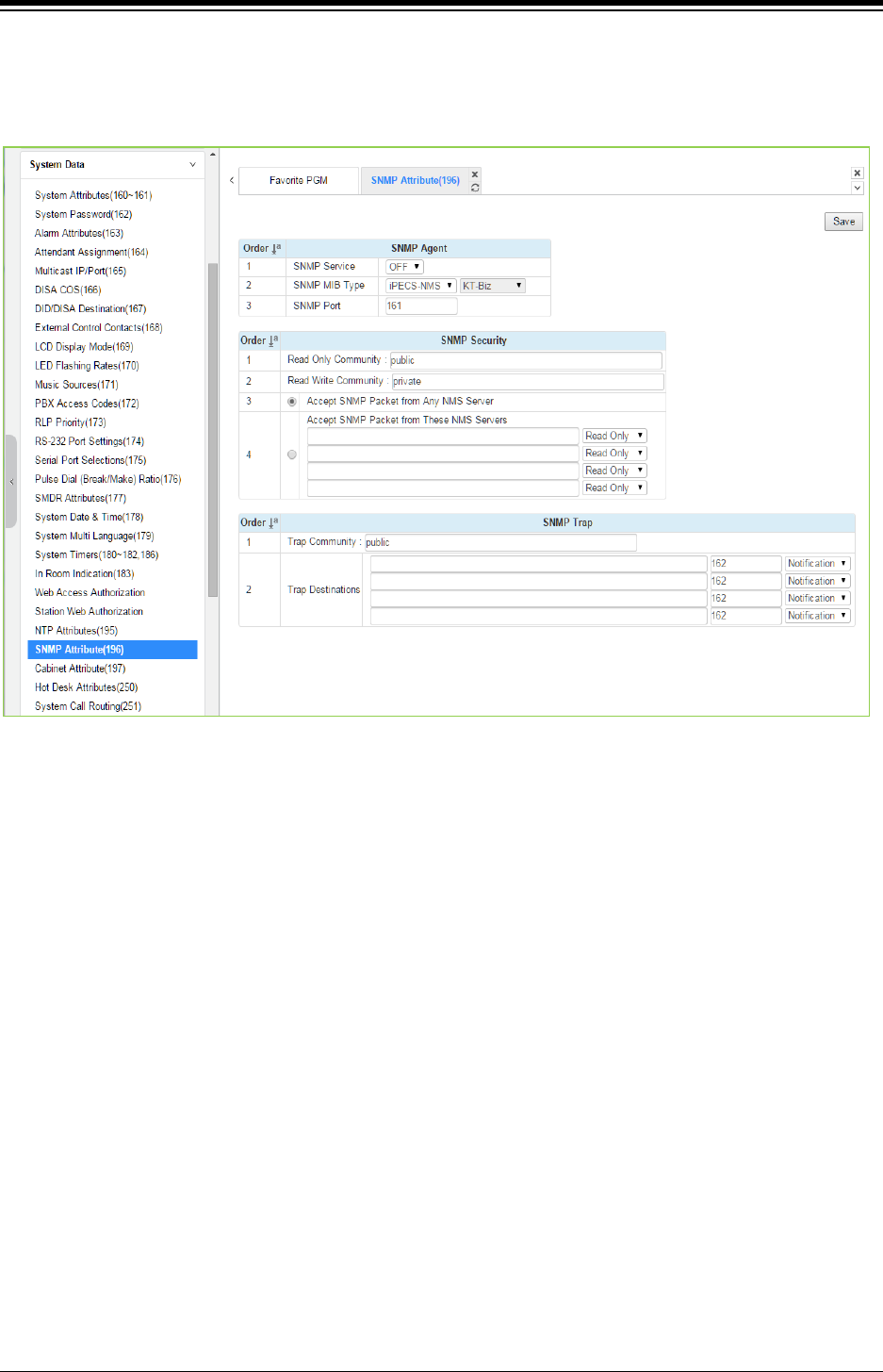
iPECS eMG80 & eMG800 & UCP
Administration and Programming Manual Issue 1.6
390
4.4.5.25 SNMP Attribute - PGM 196
Selecting SNMP Attribute will display the SNMP Attributes entry page. Click [Save] button after
changing Value.
Figure 4.4.5.25-1 SNMP Attribute
SNMP Attributes, as shown on the screen, are divided into three categories: SNMP Agent, SNMP
Security, and SNMP Trap. The SNMP Service field enables the SNMP agent running in the
iPECS call server. The SNMP port field defines the UDP port used for communications from
iPECS system for SNMP messages. This port should not be changed.
In SNMP Security are the Read Only and Read Write SNMP Community fields, 4 to 16
characters. The SNMP community designates an SNMP communication group to which an
SNMP message belongs, and is a logical relationship between the SNMP agent (iPECS system)
and SNMP manager (iPECS NMS). The SNMP community settings must be the same for the
iPECS systrem and the iPECS NMS server.
Read Only Community (default=Public)—Defines a community string used when the
iPECS NMS reads data from iPECS system.
Read Write Community (default=Private)—Defines the community string used when
iPECS NMS reads or writes data to iPECS system.
Although iPECS system can accept packets from any SNMP manger such as iPECS NMS, for
improved security, the IP address of specific servers can be defined and allowed Read only or
Read Write access. It is recommended that the system be assigned with the IP address of a
specific NMS server with Read Write access.
The SNMP Trap configuration defines the Trap Community, and the Trap Destination, which

iPECS eMG80 & eMG800 & UCP
Administration and Programming Manual Issue 1.6
391
includes the IP Address of the SNMP manager, iPECS NMS, and the .message type. The Trap
Community designates a communication group to which a Trap message belongs, and is a
logical relationship between the SNMP agent (iPECS system) and SNMP manager (iPECS NMS).
This 4 to 16 character string should be the same as the Trap community string defined in the
iPECS NMS. The Trap community should be the same for all iPECS systems registered to an
iPECS NMS server whereas the SNMP community may be defined with different strings for each
iPECS system.
The Trap Destination defines the IP address of the iPECS NMS server and the port, 162. Enter
the IP address of the NMS server but, the port should not be changed. The pull down menu next
to the address is used to define the message type. Three values are available:
Trap – message type is defined in SNMPv1, but because iPECS-NMS and iPECS
system use SNMPV2, the Trap type message is not recommended.
Notification – message type sent from the SNMP agent once without checking the
reception of the message.
Inform – message type requires an acknowledgement from the SNMP manager. If the
agent does not receive a response, the message is resent. Inform messages are
intended for use in environments with high packet loss however, use of the Inform
message type may detrimentally affect iPECS system performance.
The iPECS SNMP attributes are defined here. Refer to Table 4.4.5.25-1 for description and
values that can be entered.
Table 4.4.5.25-1 SNMP ATTRIBUTES
ATTRIBUTE DESCRIPTION RANGE DEFAULT
SNMP service SNMP Service field is used to set the SNMP agent in the
iPECS ON or OFF.
OFF
ON
OFF
SNMP MIB Type Select SNMP MIB specification.
U-CEMS is KOREA telecom speciation.
iPECS-NMS/
U-CEMS
iPECS-NMS
SNMP Port SNMP Protocol port number. 161
Read Only Community
Read only community should be used when SNMP
manager (NMS) is trying to read data from SNMP agent
(eMG)
4 ~ 16
characters public
Read Write Community
When the SNMP manager (NMS) needs to read and write
data to the agent (iPECS system). This attribute should be
enabled.
4 ~ 16
characters private
Trap Community
For the SNMP agent (eMG/UCP), this field defines the
destination IP address to receive trapped messages
(Alarm/fault events).
4 ~ 16
characters public
Trap Destination IP address of iPECS NMS server, port 162 should not be
changed.
IP address Public
Message Type Defines how the agent sends the Message.
Notification/
Inform/
Trap
Notification
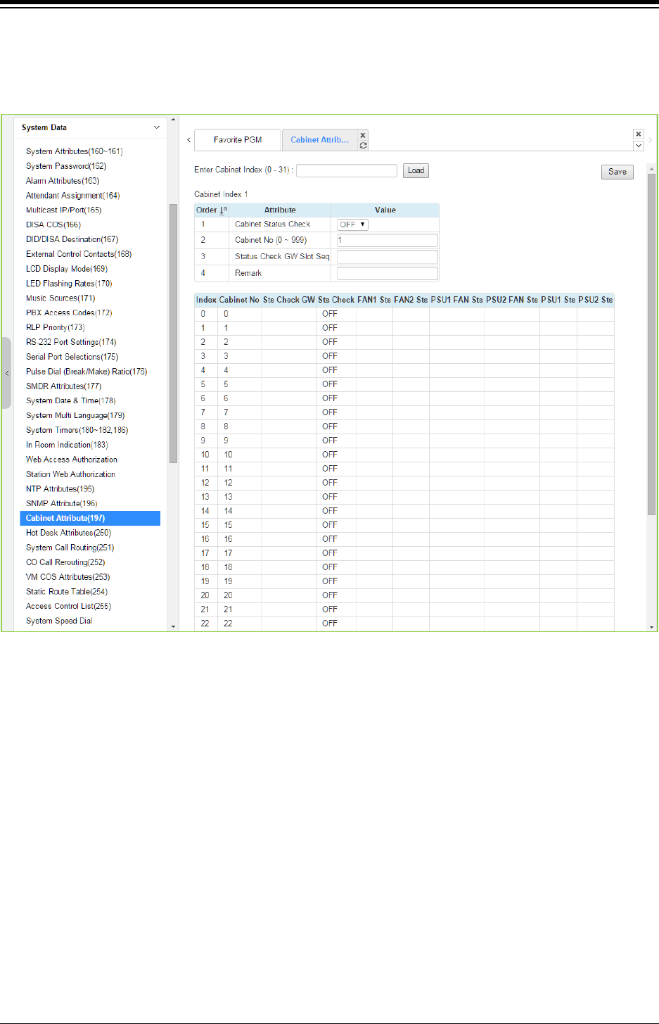
iPECS eMG80 & eMG800 & UCP
Administration and Programming Manual Issue 1.6
392
4.4.5.26 Cabinet Attribute for UCP - PGM 197
Selecting Cabinet Attribute will display the Cabinet Attributes entry page. Click [Save] button after
changing Value.
Figure 4.4.5.26-1 Cabinet Attribute
This Web page displays system cabinet configurations and alarm status.
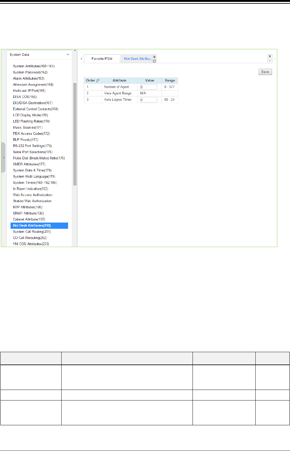
iPECS eMG80 & eMG800 & UCP
Administration and Programming Manual Issue 1.6
393
4.4.5.27 Hot Desk Attributes - PGM 250
Selecting Hot Desk Attributes will display the Hot Desk Attributes data entry page. Click [Save]
button after changing Value.
Figure 4.4.5.27-1 Hot Desk Attributes
Hot Desk feature is available only for LIP phone, NOT for Digital phone and LIP-8002/2E.
A Hot Desk station allows a user to login for access to the system features and resources. Once
logged in, the user is provided access to system features and resources employing the database
for the user‘s assigned station.
User station numbers, which are used as the Agent ID, are assigned automatically by the system.
The system assigns station numbers to each agent starting at the highest station number
available.
Table 4.4.5.27-1 HOT DESK ATTRIBUTES
ATTRIBUTE DESCRIPTION RANGE DEFAULT
Number of Agent Assign number of Hot desk agent.
eMG80: 0-100
eMG800: 0-300
UCP:0-1200
0
View Agent Range View the assigned station numbers for agents. N/A
Auto Logout Timer
A Hot desk station will return to inactive if the
logged in user takes no action for the Auto Logout
timer.
00~24 Hrs. 00
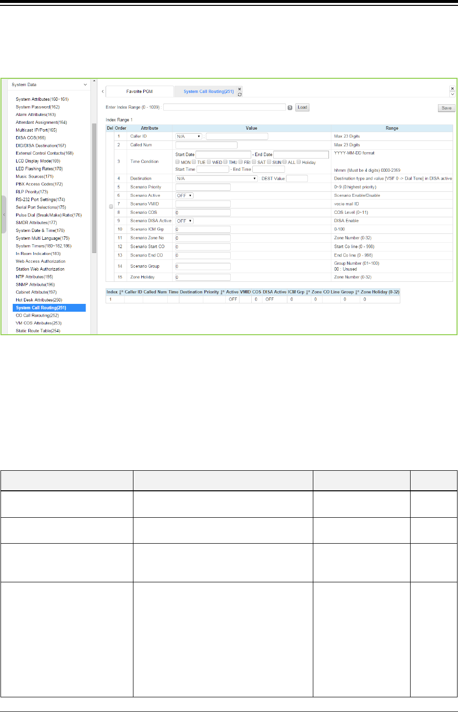
iPECS eMG80 & eMG800 & UCP
Administration and Programming Manual Issue 1.6
394
4.4.5.28 System Call Routing - PGM 251
Selecting System Call Routing will display the System Call Routing data entry page. Enter a valid
Index range and click [Load] to enter Call Routing data. Click [Save] button after changing Value.
Figure 4.4.5.28-1 System Call Routing
System Call Routing establishes scenarios with criteria to route calls. Criteria include time 0f day,
day of week, Caller and Called numbers, etc. System Call Routing takes precedent over other
system based call routing. However, Station and CO Call Routing scenarios take precedence
over System Call Routing scenarios.
Table 4.4.5.28-1 System Call Routing Attributes
ATTRIBUTE DESCRIPTION RANGE DEFAULT
Caller ID This field defines the Caller Id for the
scenario.
Max. 23 Digits N/A
Called Num This field defines the Called number for this
scenario.
Max. 23 Digits
Time condition (Start Day and
End Day, weeks, start time and
end time)
The time and day for activation of the
scenario can be defined.
YYYY-MM-DD
hhmm
(Must be 4 digits)
Destination (Type and Value)
This field defines the destination type and
value for call routing when the scenario
criteria are met.
STA
Station Group
SPD
PABX/
VSF/
VSF(#)/
Net Station/
Company room/
INT Page/
N/A

iPECS eMG80 & eMG800 & UCP
Administration and Programming Manual Issue 1.6
395
Table 4.4.5.28-1 System Call Routing Attributes
ATTRIBUTE DESCRIPTION RANGE DEFAULT
EXT Page/
All Page/
VM/
ICLID Table
Scenario Priority
Each scenario can be assigned a priority.
The highest priority scenario meeting the
criteria is used to route the call.
0-9
(Highest priority)
Scenario Active A scenario must be active to be employed. If
not active the scenario is ignored.
ON
OFF
OFF
Scenario VMID A Voice Mail Id can be associated with the
scenario for routing to a Voice Mailbox.
Voice mail ID
Scenario COS If DISA is active for the scenario, the COS
can be assigned for the call.
0-11
(COS level)
0
Scenario DISA Active The scenario can employ DISA for the
incoming call routing.
OFF/
ON
OFF
Scenario ICM Group The scenario can route calls to a specific
Tenancy group.
eMG80:0-15,
eMG800:0-32
UCP:0-100
0
Scenario Zone No.
A zone can be assigned so that only CO
calls to a CO/IP Line in the Zone will route
based on the scenario.
0-32 0
Scenario Start CO and End CO This field defines a range of CO/IP Lines that
will employ to the scenario.
eMG80:0-74,
eMG800:0-600
UCP:0-998
0
Scenario Group: this is used for
scenario group by attendant.
Scenarios can be group allowing the
Attendant to select a group of scenarios to
route calls.
eMG80: Group
number(01~15/
00: unused)
eMG800: Group
number(01~32/
00: unused)
UCP:0-100
0
Zone Holiday
A Zone can be assigned for routing calls
using the scenario during Holiday periods
defined for the Zone.
0-32 0

iPECS eMG80 & eMG800 & UCP
Administration and Programming Manual Issue 1.6
396
4.4.5.29 CO Call Rerouting - PGM 252
Selecting CO Call Rerouting will display the CO Call Rerouting data entry page. Enter a valid
Index range and click [Load] to enter Call Routing data. Click [Save] button after changing Value.
Figure 4.4.5.29-1 CO Call Rerouting
CO Call Rerouting establishes routing for CO/IP calls with a specified caller id on CO/IP Lines
from a specified group. The rerouting sends calls out over another CO/IP Line or group, a
network destination, a DISA call or to another station. The incoming CO group and compare digits
determine if the call should be rerouted and the destination is determined by the CO code and
Telephone number, which is dialed when the incoming group and compare digits are matched.
The routing type determines if the call is routed normal (N/A) or if the call is routed over a network
or employs DISA.
Example CRR chart
Index Incoming CO group Compare Code CO Code + Tel number Routing Type
0 1 454 88005123456 N/A
1 2 456** 8901123456 N/A
2 1 42*555 9123456 N/A
3 5 353 8901123456 NET Type
4 5 401 DISA Type
- Index 0: If an incoming call on a CO/IP Line from group has digits “454” then seize CO 5
and send digit 123456.

iPECS eMG80 & eMG800 & UCP
Administration and Programming Manual Issue 1.6
397
- Index 1: If an incoming call on a CO/IP Line from group 2 has digits “456**” then seize
CO group 1 and send digit 123456.
- Index 2: If an incoming call on a CO/IP Line from group1 has digits “42*555” then seize
the first CO/IP Line and send digit 123456.
- Index 3; if an incoming call on a CO/IP Line from group 5 has digits “353” then seize CO
group 1 and send digit 123456 as a transit-out call over the Network.
- Index 4: If an incoming call on a CO/IP Line from group 5 has digits “401” then activate
DISA and await digits from the caller.
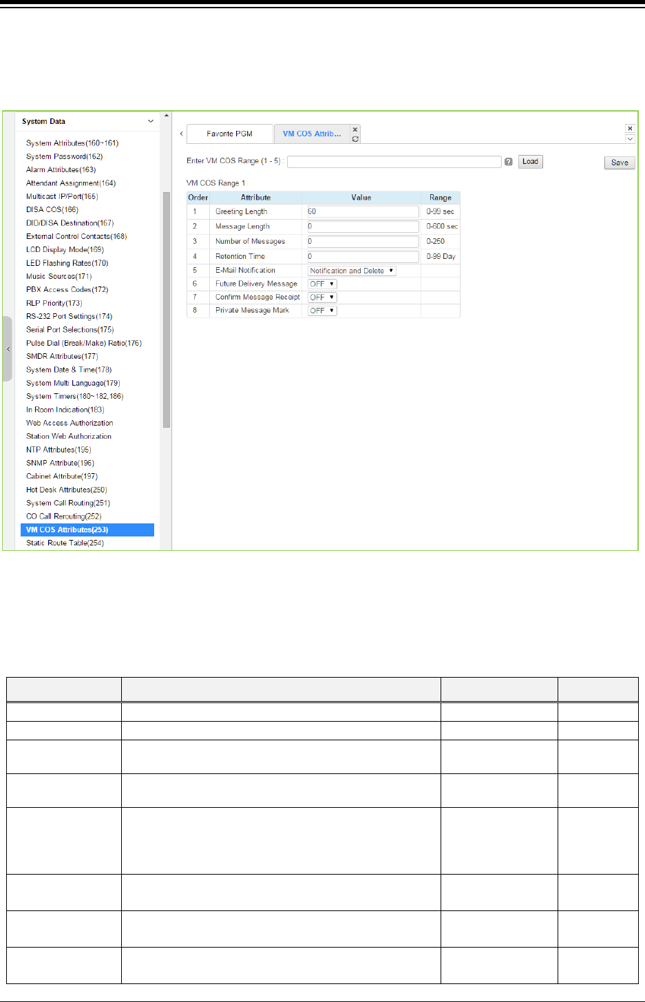
iPECS eMG80 & eMG800 & UCP
Administration and Programming Manual Issue 1.6
398
4.4.5.30 VM COS Attributes – PGM 253
Selecting VM COS Attributes will display the VM COS Attributes data entry page. Select a valid
VM COS and click [Load] to enter VM COS data. Click [Save] button after changing Value.
Figure 4.4.5.30-1 VM COS Attributes
VM COS establishes various common characteristics of the user’s Voice Mailbox including
greeting and message length, E-mail notification, message retention, etc.
Table 4.4.5.30-1 VM COS ATTRIBUTES
ATTRIBUTE DESCRIPTION RANGE DEFAULT
Greeting Length
This defines maximum user greeting length.
0-99 (Seconds)
60
Message Length
This defines maximum user message recording time.
0-600 (Seconds)
0
Number Of
Messages
This defines maximum number of voice mail message. 0-250 0
Retention Time Voice mail messages will be automatically deleted after
this number of days.
0-99 Days 0
E-Mail Notification E-mail notification can be enabled or disabled and, if
enabled, the message can be deleted after notification.
Disable/
Notification Only/
Notification &
Delete
Notification &
Delete
Future Delivery
Message
Future Delivery of messages can be enabled or
disabled.
OFF
ON
OFF
Confirm Message
Receipt
Confirm message receipt can be enabled or disabled. OFF
ON
OFF
Private Message
Mark
Private message mark can be enabled or disabled. OFF
ON
OFF
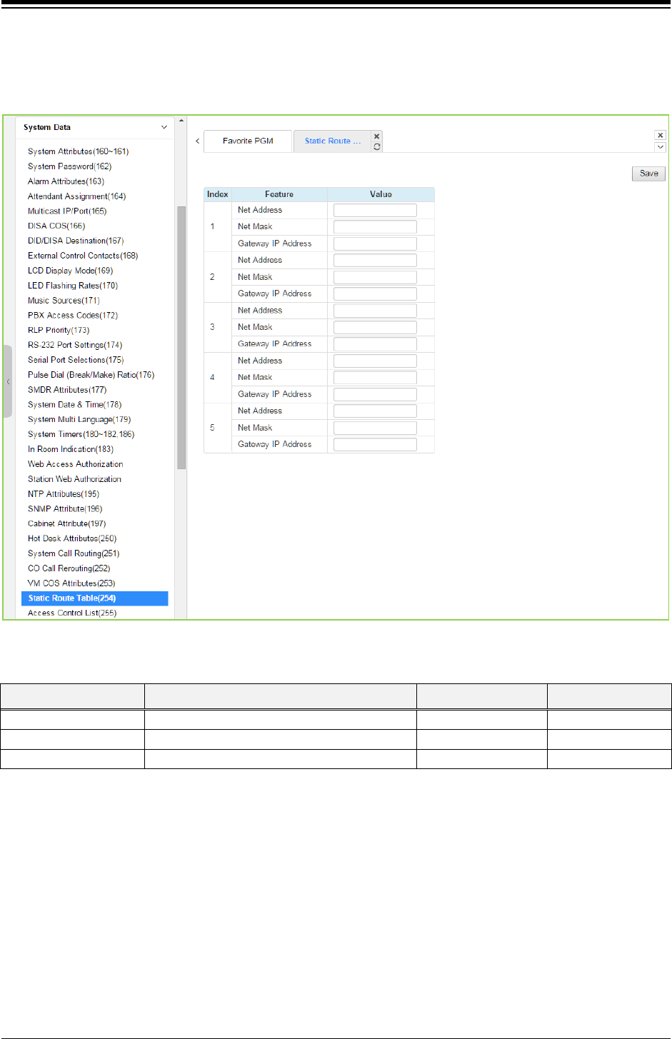
iPECS eMG80 & eMG800 & UCP
Administration and Programming Manual Issue 1.6
399
4.4.5.31 Static Route Attributes – PGM 254
Selecting Static route Attributes will display the static route attributes data entry page. Click [Save]
button after changing Value.
Figure 4.4.5.31-1 Static Route Table Attributes
Table 4.4.5.31-1 STATIC ROUTE TABLE ATTIBUTES
ATTRIBUTE DESCRIPTION RANGE DEFAULT
Net address
Network IP address
IP address
Net mask
Net mask
Gateway IP address
Gateway(route) IP address
IP address
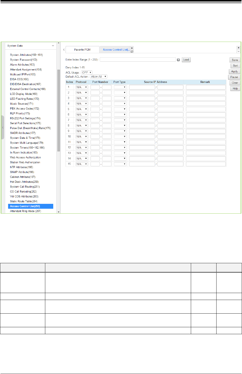
iPECS eMG80 & eMG800 & UCP
Administration and Programming Manual Issue 1.6
400
4.4.5.32 Access Control List – PGM 255
Access Control List will display the access control attributes data entry page. Enter a valid index
range and click [Load] to enter ACL data. Click [Save] button after changing Value.
Figure 4.4.5.32-1 Access Control List
Access Control determines the Source IP addresses that can access the system for specific
protocols.
Table 4.4.5.32-1 ACCESS CONTROL LIST
ATTRIBUTE DESCRIPTION RANGE DEFAULT
Protocol This field defines the accessing protocol type.
N/A, ALL,
TCP, UDP,
ICMP
N/A
Port number
This field further defines the protocol TCP/IP port number.
Port type The port number can be configured as either the source or destination
port number.
DEST/
SRC
Source IP address The allowed source IP address and net mask allowed access is
defined by this field.
Remark
This is a general remark field.
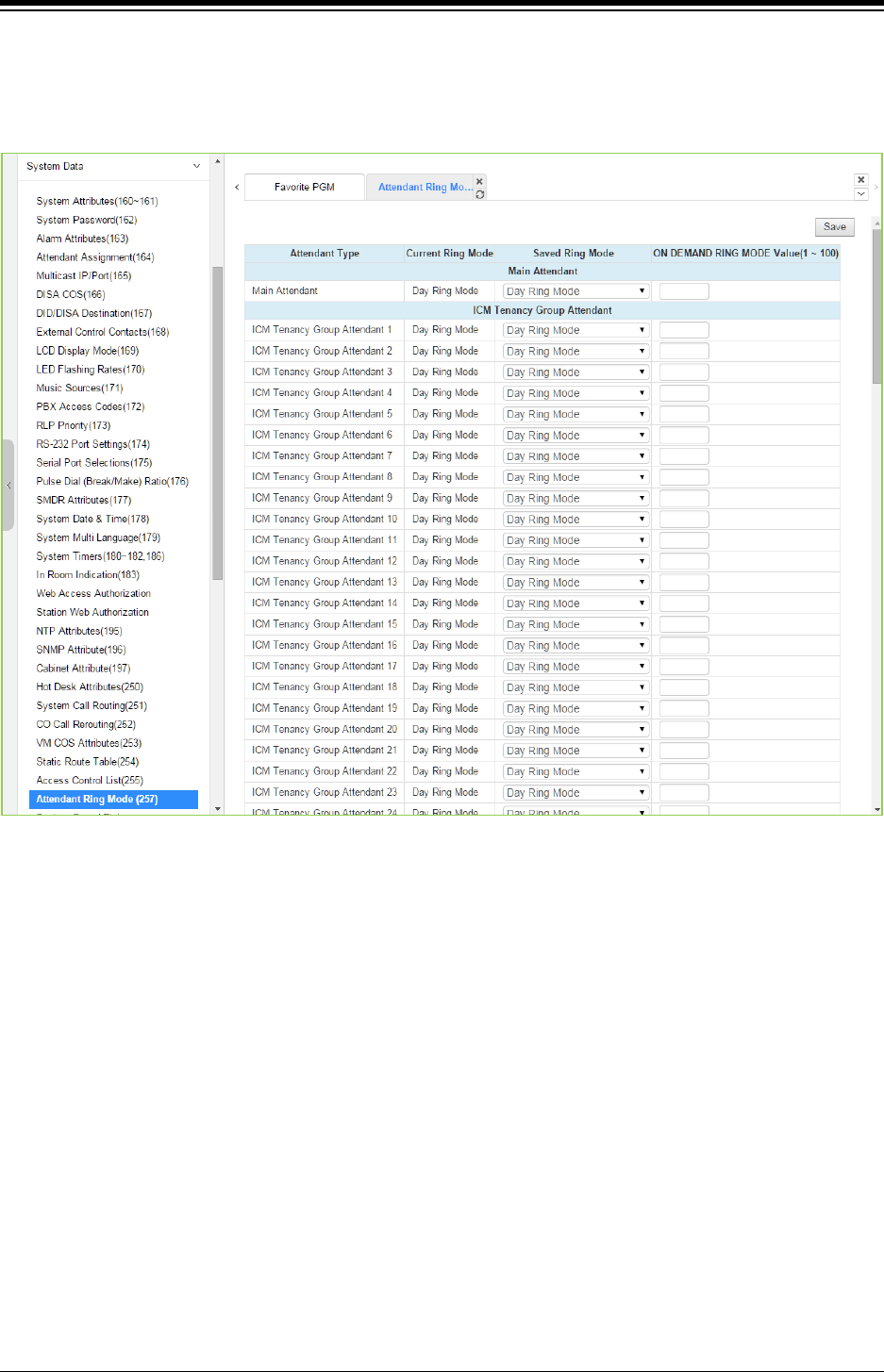
iPECS eMG80 & eMG800 & UCP
Administration and Programming Manual Issue 1.6
401
4.4.5.33 Attendant Ring Mode – PGM 257
Selecting Attendant ring mode will display Attendant ring mode entry page. Click [Save] button
after changing Value.
Figure 4.4.5.33-1 Attendant Ring Mode
Administrator assigns the ring mode to 1 Main attendant and 15 ICM Tenancy Group Attendant.
Five ring modes are supported as Day, Night, Timed, Auto, On demand ring mode (eMG80:
1~15/ eMG800: 1~32/UCP: 1~100).
The Attendant controls the system Ring mode changing from Auto ring Mode to Day, Night,
Timed or On demand ring mode. Based on the ring mode selected in the field of Saved Ring
Mode, different ring assignments, COS (Class of Service) and answering privileges are invoked
for the system users.
In case Main attendant select the other ring mode of Day ring mode in the field of Saved Ring
Mode, ICM Tenancy group attendant controls the system ring mode instead of Main attendant.
So Current Ring Mode and Saved Ring Mode of ICM Tenancy group attendant may be different.
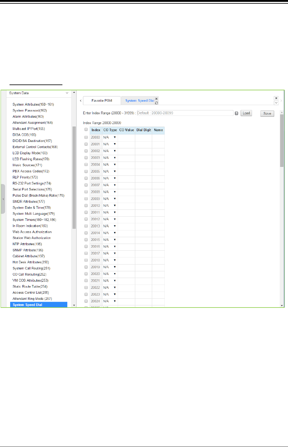
iPECS eMG80 & eMG800 & UCP
Administration and Programming Manual Issue 1.6
402
4.4.5.34 System Speed Dial
Selecting System Speed Dial will display the System Speed Dial entry page. Enter a valid range
of System Speed Dial numbers and click [Load] to enter Speed Dial data. For convenience, the
copy, paste, and drag is available to enter or modify data. Click [Save] button after changing
Value.
The index range is flexible according to selecting ‘Speed Numbering’ in ‘System ID (100)’.
Enter Index range
: eMG80: 2000-4999 / eMG800: 2000-9999 / UCP: 20000-31999
Figure 4.4.5.34-1 System Speed Dial List
The eMG80 (eMG800/UCP) has memory for 3000(8000/12,000) Speed Dial numbers of up to 25
digits each. Each System Speed bin (index) is assigned the CO/IP Line for the Speed Dial, the
number to be dialed and a name for Dial-by-Name.
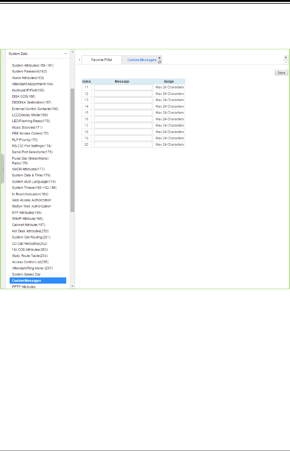
iPECS eMG80 & eMG800 & UCP
Administration and Programming Manual Issue 1.6
403
4.4.5.35 Custom Messages
Selecting Custom Messages will display the Custom Message Table data entry page. Click [Save]
button after changing Value.
Figure 4.4.5.35-1 Custom Message
The system’s 10 Custom messages can be defined with up to 24 characters each.
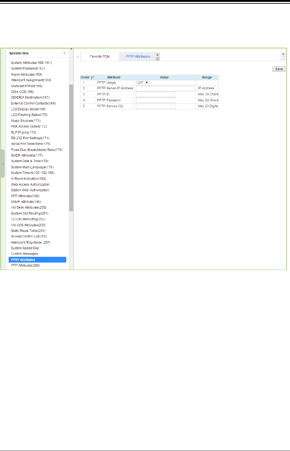
iPECS eMG80 & eMG800 & UCP
Administration and Programming Manual Issue 1.6
404
4.4.5.36 PPTP Attributes
Selecting PPTP Attributes will display the PPTP Attributes Table data entry page. Click [Save]
button after changing Value.
Figure 4.4.5.36-1 PPTP Attributes
When required, the system supports Point to Point Tunneling Protocol (PPTP). PPTP must be
enabled and values for the PPTP server IP address, Id and password must be entered and a
server name may be entered.
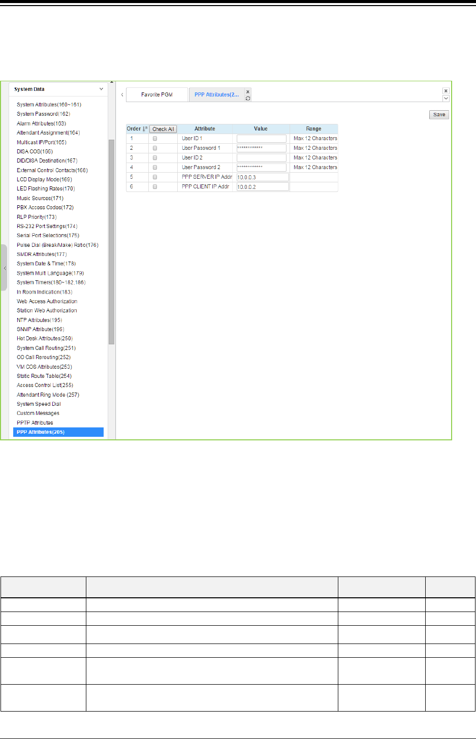
iPECS eMG80 & eMG800 & UCP
Administration and Programming Manual Issue 1.6
405
4.4.5.37 PPP Attributes for eMG – PGM 205
Selecting PPP Attributes will display the PPP Attributes data entry page. Use the check mark to
indicate which attributes to modify; data for checked attributes is stored by clicking [Save] button.
Figure 4.4.5.37-1 PPP Attributes
In addition to remote access via an IP network connection, the system database may be
accessed remotely via an ISDN connection. Placing a call over an ISDN Line to the designated
PPP Station will provide a connection to the system database. The system will request a user id
and password, which must match one of the User Ids and passwords assigned. After a matching
id and password are received, the iPECS Login Home page is provided.
Table 4.4.5.37-1 PPP ATTRIBUTES
ATTRIBUTE DESCRIPTION RANGE DEFAULT
User ID 1
The System accepts this PPP ID 1 as valid.
Max. 12 characters
likppp01
User Password 1
The password entered is used to authorize PPP ID 1.
Max. 12 characters
Ipkts01
User ID 2 The System accepts this PPP ID 2 as valid. Max. 12 characters likppp02
User Password 2
The password entered is used to authorize PPP ID 2.
Max. 12 characters
Ipkts02
PPP Server IP
Addr
When configured, the PPP Server IP Address must match
this entry. To apply this option the system must be restarted.
IP Address
PPP Client IP Addr When configured, the PPP Client IP Address must match
this entry. To apply this option the system must be restarted.
IP Address
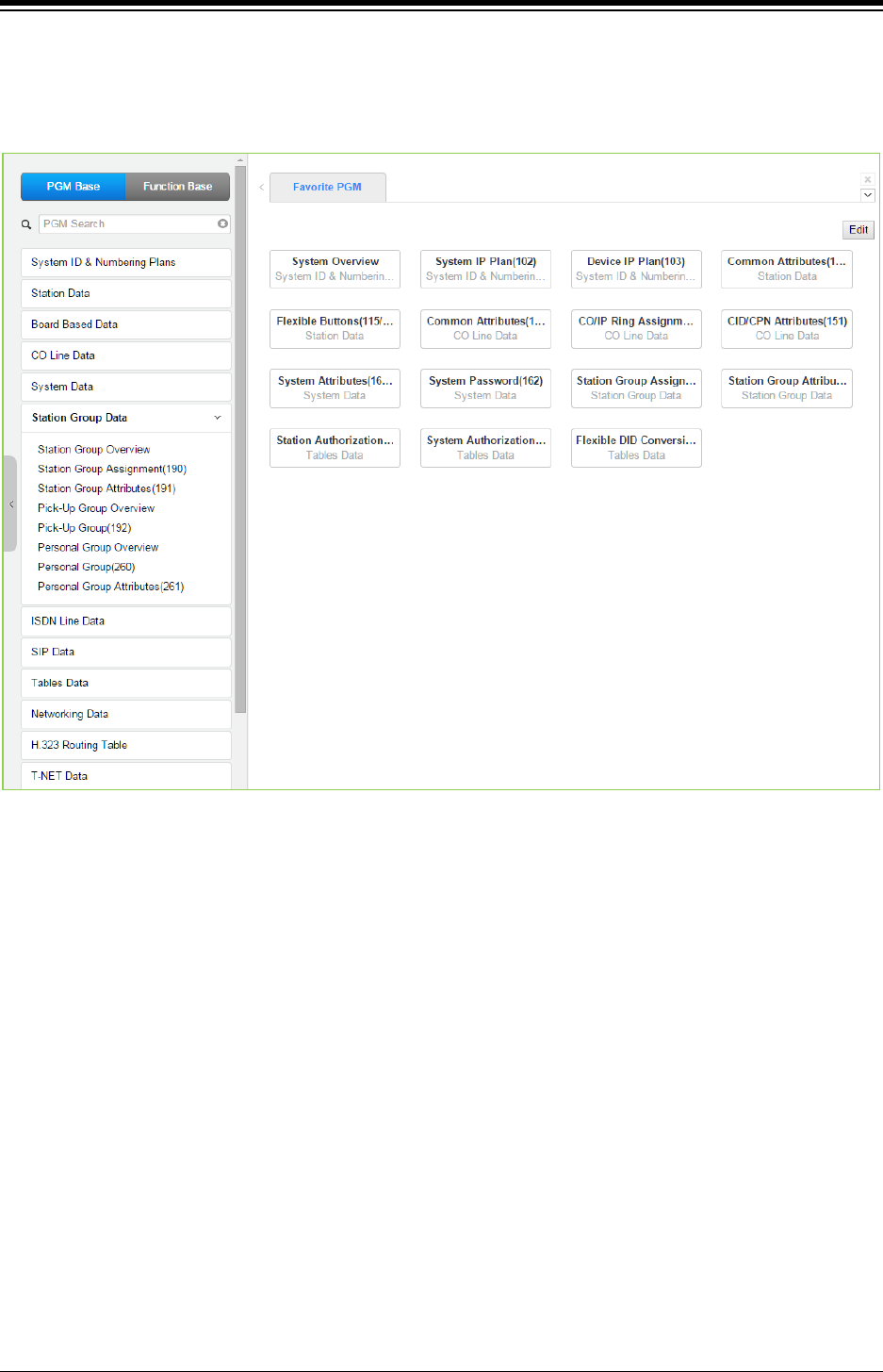
iPECS eMG80 & eMG800 & UCP
Administration and Programming Manual Issue 1.6
406
4.4.6 Station Group Data
Selecting the Station Group Data program group returns the sub-menu displayed in the left frame
as shown in the following figure.
Figure 4.4.6-1 Station Group Data
Stations can be grouped so that incoming calls will search (Station) for an idle station in the group.
The system allows assignment of three Station processes, Circular, Terminal and ACD. In
addition, there are eight (8) functional groups available: ACD (Automatic Call Distribution) based
on ACD station, Ring, Call Pick-Up, External Voice Mail (SLT connected), VSF-Voice Mail, iPECS
Feature Server Voice Mail and Network Voice Mail, and UCS Groups.
Certain types of groups can incorporate announcements, which are given to the calling party. The
system‘s VSF can store up to two hundreds (200) announcements for use with Station Groups.
Note that a station can belong to multiple groups if the groups are all of the same type. Also note
that when a station group is assigned to a group type (Circular, Terminal, ACD, VM, FS VM, VSF-
VM, Net VM, UCS and Ring), the group attributes are initialized to the default values.
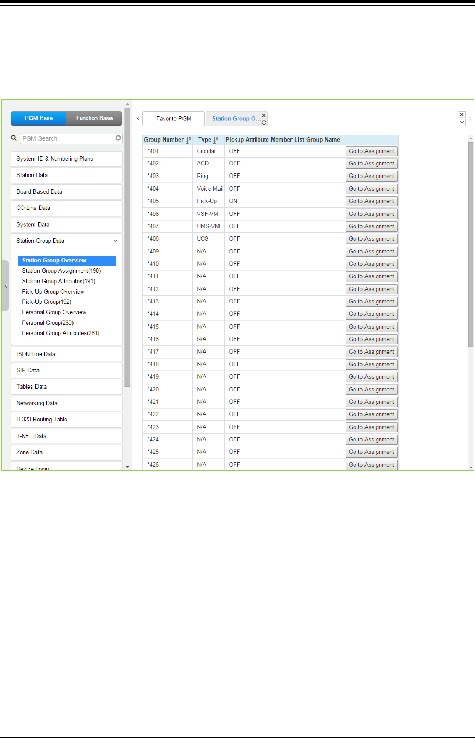
iPECS eMG80 & eMG800 & UCP
Administration and Programming Manual Issue 1.6
407
4.4.6.1 Station Group Overview
Selecting the Station Group Overview item will return the Station Group Overview page. This
page displays the Station Group attributes (type, pick-up attribute, Member list, and Group name)
for all the Station Groups.
Figure 4.4.6.1-1 Station Group Overview
All information of each group will be displayed and changed the assignment on this page.
Each Group can be assigned Type, Pickup attributes, Member list, and Group name by clicking
“Go to Assignment” on this page. Station Group Assignment (190) will be displayed and directly
go to Station Group Attributes (191) of the group by clicking “Go to Attributes”.
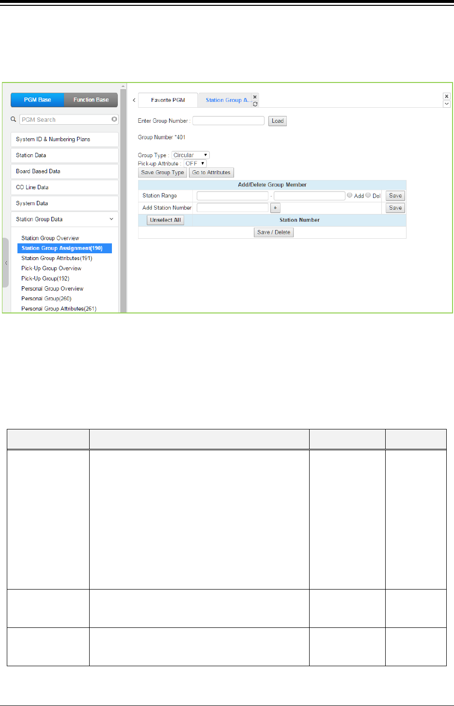
iPECS eMG80 & eMG800 & UCP
Administration and Programming Manual Issue 1.6
408
4.4.6.2 Station Group Assignment - PGM 190
Selecting Station Group Assignment will display the Station Group data entry page. Enter the
desired Station Group number and click [Load] to display the Group Assignment.
Figure 4.4.6.2-1 Station Group Assignments
Under Station Group Assignments the type, members and Pick-Up attributes are assigned to the
Station Group. Note for the Net VM group, the network number must be assigned as the Net VM
group member station.
Table 4.4.6.2-1 STATION GROUP ASSIGNMENT
ATTRIBUTE − DESCRIPTION RANGE DEFAULT
Group Type Defines the type of station group.
N/A,
Circular,
Terminal,
ACD,
Ring,
Voice Mail,
Pick-Up,
VSF-VM,
UMS VM,
NET VM,
UCS
N/A
Pick-up Attribute
Stations can pick-up group calls ringing at other
stations in the group. This does not apply to the VM
groups.
OFF
ON OFF
Member
Assigns stations as members of a station group or, for
the Net VM group type, defines the Net Number of the
group.
-
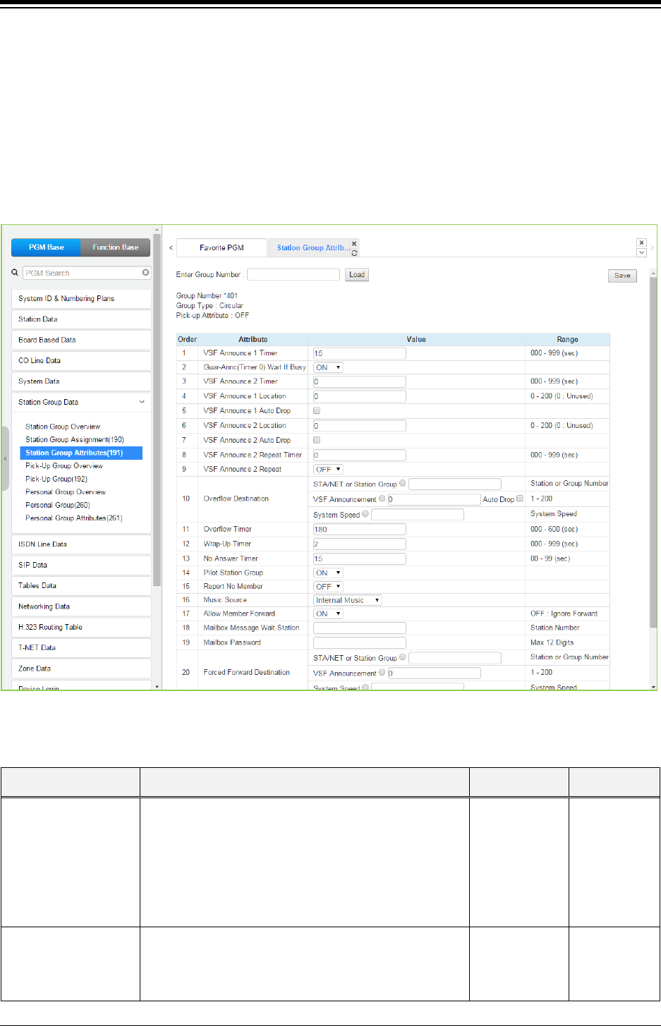
iPECS eMG80 & eMG800 & UCP
Administration and Programming Manual Issue 1.6
409
4.4.6.3 Station Group Attributes - PGM 191
Selecting Station Group Attributes will display the Station Group Attributes data entry page. Enter
the Station Group number and click [Load], the Web page for the selected group will be
displayed as in Figure 4.4.6.3-1 to Figure 4.4.6.3-8 based on the Group type.
Each type of group has a different set of available attributes relating to announcements, timers,
overflow, etc. Table 4.4.6.3-1 through Table 4.4.6.3-8 provides descriptions for the attributes and
data entries required. Note that the attributes for the Circular and Terminal Station groups are
given in Table 4.4.6.3-1 and the UCD attributes include the ACD functions Table 4.4.6.3-2.
Figure 4.4.6.3-1 Terminal & Circular Group Attributes
Table 4.4.6.3-1 TERMINAL & CIRCULAR GROUP ATTRIBUTES
ATTRIBUTE − DESCRIPTION RANGE DEFAULT
VSF Announce 1 Timer
If all stations in the group are busy when a call is offered,
the call may continue to wait (queue) for an available
station. If the queue period exceeds the VSF Announce
1
timer, the call is sent to a VSF announcement. If the
timer is set to 000, the call will receive the first
announcement, in full, prior to the station process
(guaranteed announcement).
000~999
(seconds) 015
Guar-Annc(Timer 0)
Wait If Busy
When a call assigned to receive a guaranteed
announcement arrives and all channels are busy, the call
may wait with Ring back until a channel is available (ON)
or bypass the announcement (OFF).
OFF
ON ON

iPECS eMG80 & eMG800 & UCP
Administration and Programming Manual Issue 1.6
410
Table 4.4.6.3-1 TERMINAL & CIRCULAR GROUP ATTRIBUTES
ATTRIBUTE − DESCRIPTION RANGE DEFAULT
VSF Announce 2 Timer
After the 1st announcement, the 2nd ANNC TMR is
activated. At expiration, if the call remains queued to the
group, the call is sent to the assigned 2nd VSF
announcement.
000~999
(seconds) 000
VSF Announce 1
Location
The Station Group can be assigned an announcement,
which is played if the call remains queued beyond the
VSF Announce 1 Timer duration. The announcement
location is the VSF Announcement number. An entry of
00 indicates no announcement.
00~200 00: none
VSF Announce 1 Auto
Drop
If this attribute is selected, the call will drop after the 1st
VSF announcement.
Check box
VSF Announce 2
Location
The Station Group can be assigned a 2nd
announcement, which is played if the call remains
queued beyond the VSF Announce 2 Timer duration.
The announcement location is the VSF Announcement
number. An entry of 00 indicates no announcement.
00~200 00: none
VSF Announce 2 Auto
Drop
If this attribute is selected, the call will drop after the 2nd
VSF announcement.
Check box
VSF Announce 2
Repeat Timer
The 2nd announcement can be repeated to callers that
remain in queue at intervals of the Announcement 2
Repeat Timer. Note VSF Announce 2 Repeat below
must be “ON”.
000~999
(seconds) 000
VSF Announce 2
Repeat
After the 2nd announcement, if the call remains queued
to the group, the 2nd VSF announcement can be
repeated at the Announce 2 Repeat Timer interval,
defined above.
OFF
ON OFF
Overflow Destination
A call to the group will continue to route through the
group until answered or all group members have been
tried. The call will remain at the last station or route to the
assigned overflow destination. If VSF Announcement is
selected, Auto Drop can be checked.
STA/NET or
Station Group/
VSF
Announcement/
Auto Drop/
System SPD
Overflow Timer
A call to the group will remain at the last station in the
group or can be sent to the assigned Overflow
Destination after expiration of the Overflow Timer.
000~600
(seconds) 180
Wrap-Up Timer
After terminating a group call, a Group member will be
maintained in a busy state for the duration of the Wrap-
Up timer.
000~999
(seconds) 002
No Answer Timer
Calls to a station in the group are directed to the station,
if unavailable or unanswered in the No Answer Timer,
the call can be routed based on the assigned hunt
process.
00~99
(seconds) 15
Pilot Station Group A circular/terminal Station group can be set so that only
calls to the pilot number (station group number) will hunt.
OFF
ON
ON
REPT No Member
If a call is received and no members are on-duty, an ICM
call will return re-order tone, while a CO/IP call will be
routed to the overflow destination.
OFF
ON OFF
Music Source A Music source can be assigned so that calls to the
group will receive audio from the assigned source in
Ring back tone/
Internal Music/
Internal Music

iPECS eMG80 & eMG800 & UCP
Administration and Programming Manual Issue 1.6
411
Table 4.4.6.3-1 TERMINAL & CIRCULAR GROUP ATTRIBUTES
ATTRIBUTE − DESCRIPTION RANGE DEFAULT
place of ring-back tone. External Music/
VSF MOH/
SLT MOH1~5/
VSF MOH2~3
Allow Forward Member
A member activating Call forward may be placed in an
unavailable state for Station group calls (ON). When
OFF, group calls are sent to the member as normal
(OFF).
OFF
ON ON
Mailbox Message Wait
Station
When a call overflows or routes to the VM group, a
station number is used to identify the Mailbox for the
group messages.
Station Number
Mailbox Password
The password associated with a group Mailbox is defined
here. The password is used in conjunction with the group
Mailbox as with a normal station.
Max. 12 digits
Forced Forward
Destination
Calls to a Station group may forward directly to a defined
destination, bypassing the hunt process. “Forced
Forward”, below, must be enabled.
STA./NET or
Station group/
VSF
Announcement/
Sys. Speed
Forced Forward
Destination Usage
Calls to a Station group may forward directly to a defined
destination, see above “Forced Forward Destination”
when Forced Forward is enabled for the group.
OFF
ON OFF
Group Name A name can be designated for the group. Max. 12
characters
Maximum Queued Call
Counter
When the number of calls queued to the group match
this parameter, new calls will receive error tone and be
disconnected after the VSF Announcement 1, if
assigned, is played.
00-99 99
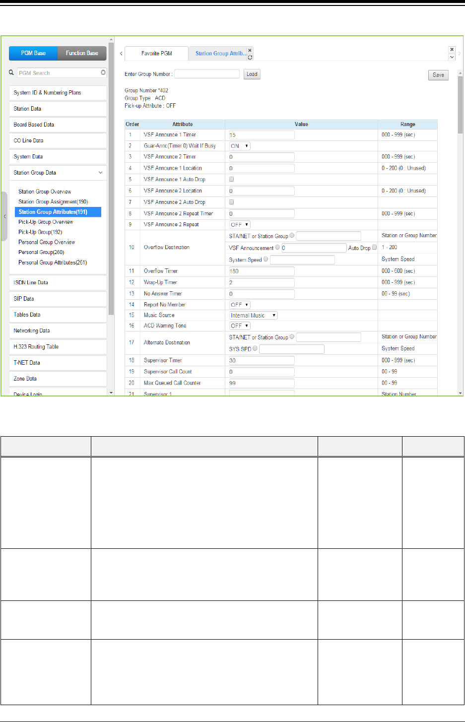
iPECS eMG80 & eMG800 & UCP
Administration and Programming Manual Issue 1.6
412
Figure 4.4.6.3-2 ACD Group Attributes
Table 4.4.6.3-2 ACD GROUP ATTRIBUTES
ATTRIBUTE DESCRIPTION RANGE DEFAULT
VSF Announce 1
Timer
If all stations in the group are busy when a call is
offered, the call may continue to wait (queue) for an
available station. If the queue period exceeds the VSF
Announce 1 Timer, the call is sent to a VSF
announcement. If the timer is set to 000, the call will
receive the first announcement, in full, prior to the hunt
process (guaranteed announcement).
000~999
(seconds) 015
Guar-Annc (Timer 0)
Wait If Busy
When a call assigned to receive a guaranteed
announcement arrives and all channels are busy, the
call may wait with Ring back until a channel is available
(ON) or bypass the announcement. (OFF)
OFF
ON ON
VSF Announce 2
Timer
After the 1st announcement, a 2nd timer is activated. At
expiration, if the call remains queued to the group, the
call is sent to the assigned 2nd VSF announcement.
000~999
(seconds) 000
VSF Announce 1
Location
Each Station Group can be assigned an announcement,
which is played if the call remains queued beyond the
VSF Announce 1 Timer duration. The announcement
location is a VSF announcement number. An entry of 00
indicates no announcement.
00~200 00: none

iPECS eMG80 & eMG800 & UCP
Administration and Programming Manual Issue 1.6
413
Table 4.4.6.3-2 ACD GROUP ATTRIBUTES
ATTRIBUTE DESCRIPTION RANGE DEFAULT
VSF Announce 1
Auto Drop
If this attribute is selected, the call will drop after the 1st
VSF announcement
VSF Announce 2
Location
The Station Group can be assigned a 2nd
announcement, which is played if the call remains
queued beyond the VSF Announce 2 Timer duration.
The announcement location is a VSF announcement
number. An entry of 00 indicates no announcement.
00~200 00: none
VSF Announce 2
Auto Drop
If this attribute is selected, the call will drop after the 2nd
VSF announcement
VSF Announce 2
Repeat Timer
The 2nd announcement can be repeated to calls that
remain in queue at intervals of the VSF Announce 2
Repeat Timer. Note repeating must be “ON” under VSF
Announce 2 Repeat below.
000~999
(seconds) 000
VSF Announce 2
Repeat
After the 2nd announcement, if the call remains queued
to the group, the 2nd VSF announcement can be
repeated at the VSF Announce 2 Repeat Timer interval.
OFF
ON OFF
Overflow Destination
A call to the group will continue to route through the
group until answered or all group members have been
tried. The call will queue to the group or route to the
assigned Overflow Destination. If VSF Announce is
assigned, Auto Drop is available.
STA/NET or Station
Group/
VSF
Announcement/
Auto Drop/
System SPD
Overflow Timer
A call to a group will remain queued to the group or be
sent to the assigned Overflow Destination after
expiration of the Overflow Timer
000~600
(seconds) 180
Wrap-Up Timer
After terminating a group call, a Station Group member
will be maintained in a busy state for the duration of the
Wrap-Up timer.
000~999
(seconds) 002
ACD No Answer
Timer
Calls to an agent in the group are directed to the
station, if unanswered in the NO ANSWER TIMER, the
call can be routed another agent
00-99
(seconds) 00
REPT No Member
If a call is received and no members are on-duty, an
ICM call will return re-order tone, while a CO/IP call will
be routed to the overflow destination.
OFF
ON OFF
Music Source
A Music source can be assigned so that calls to the
group will receive audio from the assigned source in
place of ring-back tone while in queue.
Ring back tone/
Internal Music/
External Music/
VSF MOH/
SLT MOH1~5/
VSF MOH2~3
Internal Music
ACD Warning Tone
An ACD supervisor can monitor agent conversations. A
warning tone can be provided to the agent and
connected party when the supervisor activates the
monitor feature.
OFF
ON OFF
Alternate Destination
When a call comes into the group and there are no
group members available, the call will be routed to the
assigned Alternate Destination.
STA/NET or Station
Group,
System SPD
....

iPECS eMG80 & eMG800 & UCP
Administration and Programming Manual Issue 1.6
414
Table 4.4.6.3-2 ACD GROUP ATTRIBUTES
ATTRIBUTE DESCRIPTION RANGE DEFAULT
Supervisor Timer
When calls have been in queue longer than the
Supervisor Timer, the ACD supervisor is notified by a
display of the longest queue time.
000~999
(seconds) 030
Supervisor Call
Count
When the number of calls in queue exceeds the
Supervisor Call Count, the ACD Supervisor is notified
by a display of queued calls.
00~99 00
Maximum Queued
Call Counter
When the number of calls queued to the group match
this parameter, new calls will receive error tone and be
disconnected after the VSF Announcement 1, if
assigned, is played.
00-99 99
Supervisor 1 to 5 Any valid iPECS IP or LDP Phone with display can be
assigned as a Supervisor, max. 5 ACD Supervisors.
Station
ACD DND Wrap
Timer
This parameter sets the duration a station will receive
ring before the system places the station in ACD DND
and unavailable for group calls. A setting of ‘00’
disables automatic ACD DND.
002~200
(Sec.) 010
Entered Caller ID
ICLID Usage
Within 5 seconds of a guaranteed announcement, the
caller may dial digits as an ICLID. The user-dialed digits
are compared to the ICLID Table entries, for routing or,
for a single dialed digit, to the ACD CCR table below.
OFF
ON OFF
Forward Member
Calls
A member activating Call Forward may be placed in an
unavailable state for Station group calls (ON). When
OFF, group calls are sent to the member as normal.
OFF : no FWD
ON : FWD ON
Group Name An ACD group name can be designated. Max. 12 characters
CIQ Route 1
When an ACD call is queued, the caller may be allowed
to dial a digit to exit the queue and route to another
destination. The alternate destination is based on the
user-dialed digit and can be a station, Station group,
system-speed bin, or network station. Dial the digit
below for the type of destination and enter the value
associated with the destination.
1: Enter a station number.
2: Enter a Station group number.
3: Enter a system speed bin.
4: Enter a network station number
Not selected
CIQ Route 2
CIQ Route 3
CIQ Route 4
CIQ Route 5
CIQ Route 6
CIQ Route 7
CIQ Route 8
CIQ Route 9
CIQ Route 0
ZAP Tone Agents using a headset can have ACD calls connected
to them automatically preceded by a tone (Zap tone).
OFF
ON
OFF
CIQ Announcement
If enabled, queued callers receive the CIQ message
(You are # in queue) after the 1st and 2nd
announcement.
OFF
ON OFF
Mailbox Message
Wait Station
When an ACD call overflows or routes to the VM group,
a station number is used to identify the Mailbox for the
ACD group messages
Station number
Mailbox Password
The password associated with an ACD group Mailbox is
defined here. The password is used in conjunction with
the ACD group Mailbox as with a normal station.
Max. 12 digits

iPECS eMG80 & eMG800 & UCP
Administration and Programming Manual Issue 1.6
415
Table 4.4.6.3-2 ACD GROUP ATTRIBUTES
ATTRIBUTE DESCRIPTION RANGE DEFAULT
CIQ Display To
Agent - Mode
When an ACD call is in queue, the Call in queue
information is displayed in the LCD of agent and
supervisor phones.
OFF
ON OFF
CIQ #1 Page Alert -
Threshold
If the queued call count exceeds the threshold, the
system plays the CIQ #1 Announcement to the CIQ #1
Page Zone after the CIQ #1 Announcement Delay
Timer. The announcement is repeated at intervals of the
CIQ #1 Announcement Repeat Timer.
00-99 10
CIQ #1 Page Alert –
Announcement
Location
VSF announcement number for the CIQ #1
Announcement. 00-200 0
CIQ #1 Page Alert –
Page Zone Page Zone to receive CIQ #1 Announcement.
eMG80:00~15 or
00-40/
eMG800:0~105/
UCP:0~105
00
CIQ #1 Page Alert -
Delay Time
Delay timer for CIQ #1 Announcement 000-180 015
CIQ #1 Page Alert -
Repeat Time
Interval for repeating the CIQ #1 Announcement. 000-180 045
CIQ #2 Page Alert -
Threshold
If the queued call count exceeds the threshold, the
system plays the CIQ #2 Announcement to the CIQ #2
Page Zone after the CIQ #2 Announcement Delay
Timer. The announcement is repeated at intervals of the
CIQ #2 Announcement Repeat Timer.
00-99 20
CIQ #2 Page Alert -
Announcement
Location
VSF announcement number for the CIQ #2
Announcement. 00-200 0
CIQ #2 Page Alert –
Page Zone Page Zone to receive CIQ #2 Announcement.
eMG80:00~15 or
00-40/
eMG800:0~105/
UCP:0~105
00
CIQ #2 Page Alert -
Delay Time
Delay timer for CIQ #2 Announcement 000-180 015
CIQ #2 Page Alert -
Repeat Time
Interval for repeating the CIQ #2 Announcement. 000-180 025
CIQ #3 Page Alert -
Threshold
If the queued call count exceeds the threshold, the
system plays the CIQ #3 Announcement to the CIQ #3
Page Zone after the CIQ #3 Announcement Delay
Timer. The announcement is repeated at intervals of the
CIQ #3 Announcement Repeat Timer.
00-99 30
CIQ #3 Page Alert -
Announcement
Location
VSF announcement number for the CIQ #3
Announcement. 00-200 0
CIQ #3 Page Alert -
Page
Zone
Page Zone to receive the CIQ #3 Announcement.
eMG80:00~15 or
00-40/
eMG800:0~105
UCP:0~105
00
CIQ #3 Page Alert -
Delay Time
Delay timer for the CIQ #3 Announcement 000-180 015

iPECS eMG80 & eMG800 & UCP
Administration and Programming Manual Issue 1.6
416
Table 4.4.6.3-2 ACD GROUP ATTRIBUTES
ATTRIBUTE DESCRIPTION RANGE DEFAULT
CIQ #3 Page Alert -
Repeat Time
Interval for repeating the CIQ #3 Announcement. 000-180 005
Forced Forward
Destination
Calls to a Station group may forward directly to a
defined destination, by passing the hunt process.
“Forced Forward”, below, must be enabled.
STA./NET or
Station group,
VSF
Announcement,
Sys. Speed
Forced Forward Dest
Usage
Calls to a Station group may forward directly to a
defined destination, see above “Forced Forward
Destination” when Forced Forward is enabled for the
group.
OFF
ON OFF
Auto Ring Mode
Reference table of Auto Ring Mode Table Time for ACD
Group Ring Mode. When Manual Change is selected,
the Group supervisor can change the ACD group ring
mode manually with ACD Group Ring Mode flexible
number.
Manual Change/
eMG: Table 0 ~ 15
UCP: Table 0 ~ 100
Manual
Change
Day Destination
When the ACD Ring Mode Table schedule is in the Day
mode, ACD group calls route to the destination defined
here.
Normal Service,
STA/NET or Station
group,
VSF
Announcement,
Sys. Speed
Normal
Service
Night Destination
When the ACD Ring Mode Table schedule is in the
Night mode, ACD group calls route to the destination
defined here.
Normal Service,
STA/NET or Station
group,
VSF
Announcement,
Sys. Speed
Normal
Service
Timed Destination
When the ACD Ring Mode Table schedule is in the
Timed mode, ACD group calls route to the destination
defined here.
Normal Service,
STA/NET or Station
group,
VSF
Announcement,
Sys. Speed
Normal
Service
ACD Group Queuing
Call Indication
If there are queued group calls, the queuing indication
can be served to group members by Mute Ring and
LED button flashing.
OFF
ON (RING and
LED)
ON (LED only)
OFF
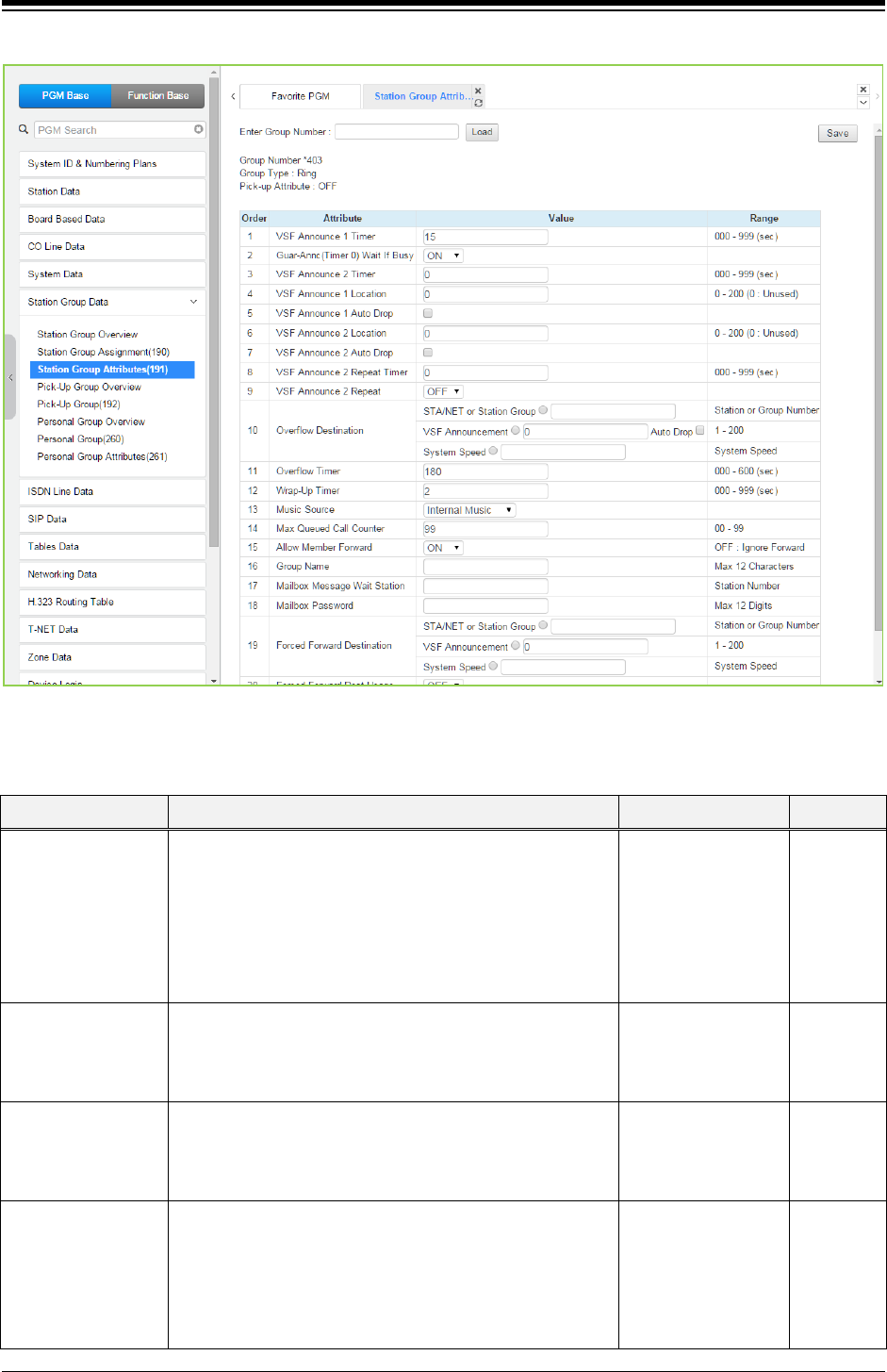
iPECS eMG80 & eMG800 & UCP
Administration and Programming Manual Issue 1.6
417
Figure 4.4.6.3-3 Ring Group Attributes
Table 4.4.6.3-3 RING GROUP ATTRIBUTES
ATTRIBUTE DESCRIPTION RANGE DEFAULT
VSF Announce 1
Timer
If all stations in the group are busy when a call is offered,
the call may continue to wait (queue) for an available
station. If the queue period exceeds the VSF Announce 1
Timer, the call is sent to a VSF announcement. If the timer
is set to 000, the call will receive the first announcement,
in full, prior to the hunt process (guaranteed
announcement).
000~999
(seconds) 015
Guar-Ann(Timer 0)
Wait If Busy
When a call assigned to receive a guaranteed
announcement arrives and all channels are busy, the call
may wait with Ring back until a channel is available (ON)
or bypass the announcement. (OFF)
OFF
ON ON
VSF Announce 2
Timer
After the 1st announcement, a 2nd announcement Timer
is activated. At expiration, if the call remains queued to the
group, the call is sent to the assigned 2nd VSF
announcement.
000~999
(seconds) 000
VSF Announce 1
Location
Each Ring Group can be assigned an announcement,
which is played if the call remains queued beyond the VSF
Announce 1 Timer duration. The announcement location is
a VSF Announcement number. An entry of 00 indicates no
announcement.
00~200 00: none

iPECS eMG80 & eMG800 & UCP
Administration and Programming Manual Issue 1.6
418
Table 4.4.6.3-3 RING GROUP ATTRIBUTES
ATTRIBUTE DESCRIPTION RANGE DEFAULT
VSF Announce 1
Auto Drop
If this attribute is selected, the call will drop after the 1st
VSF announcement.
Check box
VSF Announce 2
Location
The Ring Group can be assigned a 2nd announcement,
which is played if the call remains queued beyond the VSF
Announce 2 Timer duration. The announcement location is
a VSF Announcement number. An entry of 00 indicates no
announcement.
00~200 00: none
VSF announce Auto
Drop
If this attribute is selected, the call will drop after the 2nd
VSF announcement
Check box
VSF Announce 2
Repeat Timer
The 2nd announcement can be repeated to calls that
remain in queue at intervals of the VSF Announce 2
Repeat Timer. Note VSF Announce 2 Repeat below must
be “ON”.
000~999
(seconds) 000
VSF Announce 2
Repeat
After the 2nd announcement, if the call remains queued to
the group, the 2nd VSF announcement can be repeated at
the VSF Announce 2 Repeat Timer interval, defined
above.
OFF
ON OFF
Overflow Destination
A call to the group will continue to ring group member
stations until answered. The call will remain at the last
station or routes to the assigned Overflow Destination. If
VSF Announce is assigned, Auto Drop is available.
STA/NET or Station
Group,
VSF Announcement,
Auto Drop,
System SPD
Overflow Timer
A call to a group will remain in the group or route to the
assigned Overflow Destination after expiration of the
Overflow Timer.
000~600
(seconds) 180
Wrap-Up Timer
After terminating group call, a Station Group member will
be maintained in a busy state for the duration of the Wrap-
Up Timer.
000~999
(seconds) 002
Music Source
A Music source can be assigned so that calls to the group
will receive audio from the assigned source in place of
ring-back tone.
Ring back tone/
Internal Music/
External Music/
VSF MOH/
SLT MOH1~5/
VSF MOH2~3
Internal
Music
Maximum Queued
Call Counter
When the number of calls queued to the group match this
parameter, new calls will receive error tone and be
disconnected after the VSF AA announcement, if
assigned, is played.
00-99 99
Allow Forward
Member
A member activating Call Forward may be placed in an
unavailable state for Station group calls (ON). When OFF,
group calls are sent to the member as normal.
OFF : no FWD
ON : FWD ON
Group name
A group name can be designated.
Max.12 characters
Mailbox Message
Wait Station
When a call overflows or routes to the VM group, a station
number is used to identify the Mailbox for the group
messages.
Station number
Mailbox Password
The password associated with the group Mailbox is
defined here. The password is used in conjunction with the
group Mailbox as with a normal station.
Max. 12 digits
Forced Forward
Calls to a Station group may forward directly to a defined
STA/NET or Station
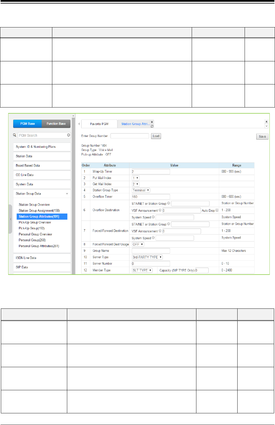
iPECS eMG80 & eMG800 & UCP
Administration and Programming Manual Issue 1.6
419
Table 4.4.6.3-3 RING GROUP ATTRIBUTES
ATTRIBUTE DESCRIPTION RANGE DEFAULT
Destination destination, bypassing the hunt process. “Forced
Forward”, below, must be enabled.
group,
VSF Announcement,
Sys. Speed
Forced Forward
Dest Usage
Calls to a Station group may forward directly to a defined
destination, see above “Forced Forward Destination” when
Forced Forward is enabled for the group.
OFF
ON OFF
Ring group
indication
When a station calls a Ring Group, DSS/BLF buttons
assigned for the calling station will flash and muted ring is
received.
OFF,
Mute,
Burst
Mute
Figure 4.4.6.3-4 External Voice Mail Group Attributes
Table 4.4.6.3-4 EXTERNAL VOICE MAIL GROUP ATTRIBUTES
ATTRIBUTE DESCRIPTION RANGE DEFAULT
Wrap-Up Timer
After terminating a group call, the VM port will be
maintained in a busy state for the duration of the
Wrap-Up timer.
000~900
(seconds) 002
Put Mail Index
For external analog Voice Mail groups, an index to the
Voice Mail Dial Table that contains the “Put Mail” dial
code.
1~4 1
Get Mail Index
For external analog Voice Mail groups, an index to the
Voice Mail Dial Table that contains the “Get Mail” dial
code.
1~4 2
Station Group Type
The type of Station Group process applied to the SLT
ports connected to the VM can be assigned as
Circular or Terminal.
Terminal/
Circular Terminal

iPECS eMG80 & eMG800 & UCP
Administration and Programming Manual Issue 1.6
420
Table 4.4.6.3-4 EXTERNAL VOICE MAIL GROUP ATTRIBUTES
ATTRIBUTE DESCRIPTION RANGE DEFAULT
Overflow Timer
A call to a group will remain at the last station in the
group or be sent to the assigned Overflow Destination
after expiration of the Overflow Time.
000~600
(seconds) 180
Overflow Destination
A call to the group will continue to route through the
group until answered or all group members have been
tried. The call will remain at the last station or will
route to the assigned Overflow Destination. If
assigned VSF Announce, Auto Drop is available.
STA/NET or
Station Group,
VSF
Announcement,
Auto Drop,
System Speed
-
Forced Forward
Destination
Calls to a Station group may forward directly to a
defined destination, by passing the hunt process.
“Forced Forward”, below, must be enabled.
STA/NET or
Station group,
VSF
Announcement,
Sys. Speed
Forced Forward Dest
Usage
Calls to a Station group may forward directly to a
defined destination, see above “Forced Forward
Destination” when Forced Forward is enabled for the
group.
OFF
ON OFF
Group Name A group name can be designated. Max. 12
character
Server type
When a third party SIP server is used for AA/VM, or
the IPCR or third party SIP recording server is used,
the server type must be selected.
IPCR/
3rd party 3rd party
Server number
Each IPCR and third party SIP server must be
assigned a server number from 01 ~ 10 which
correlates this group with an Agent table.
eMG: 0-2
UPC:0-10 0
Member Type
Member type is assigned as SLT type or SIP Type. In
case of SIP Type, enter the capacity from 1-140 for
eMG80 & 1-1200 for eMG800 & 1-2400 for UCP.
eMG80:0-140
eMG800:0-1200
UCP:0-2400
(SLT Type/ SIP
Type)
SLT Type
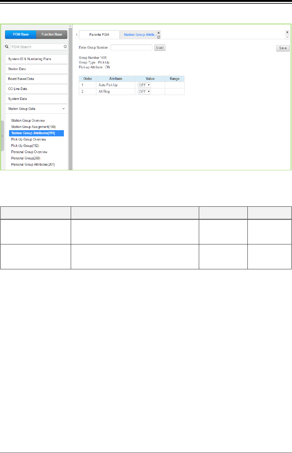
iPECS eMG80 & eMG800 & UCP
Administration and Programming Manual Issue 1.6
421
Figure 4.4.6.3-5 Pick-Up Group Attributes
Table 4.4.6.3-5 PICK-UP GROUP ATTRIBUTES
ATTRIBUTE DESCRIPTION RANGE DEFAULT
Auto Pick Up
If a group member is ringing, other members of
the Group can Pick-Up the ringing call by simply
going “Off-hook”.
OFF
ON OFF
All Ring
When a call is offered to a member of the Pick-Up
Group in the Tone Ring mode, all members will
ring. Note Auto Pickup above must be “ON”.
OFF
ON OFF
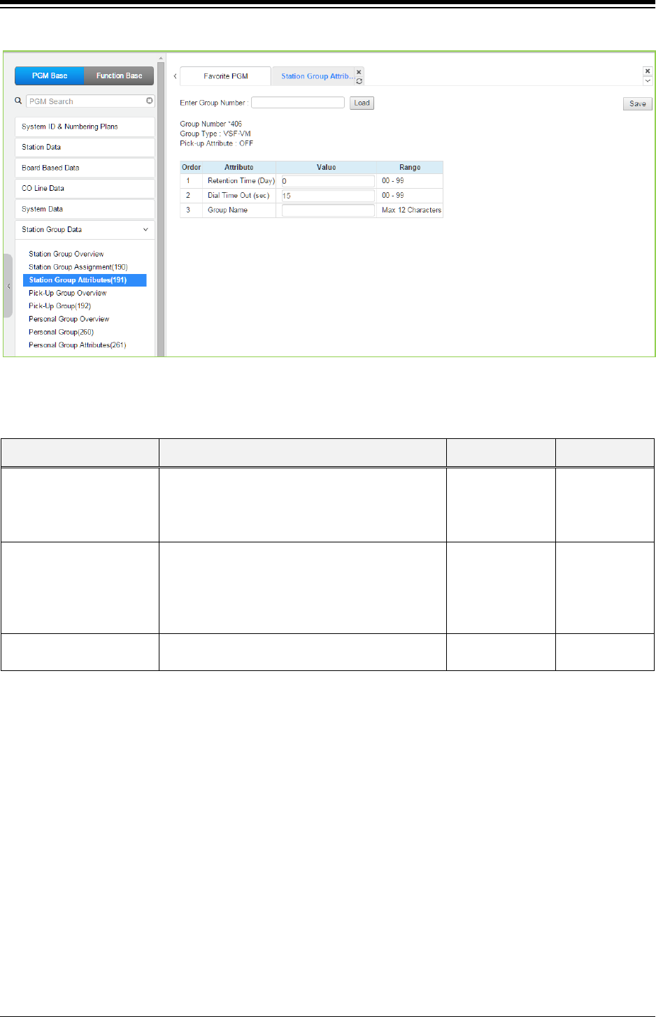
iPECS eMG80 & eMG800 & UCP
Administration and Programming Manual Issue 1.6
422
Figure 4.4.6.3-6 VSF Group Attributes
Table 4.4.6.3-6 VSF GROUP ATTRIBUTES
ATTRIBUTE DESCRIPTION RANGE DEFAULT
Retention Time (day)
When voice messages are stored in the VSF, the
system will maintain (store) the message for the
maximum number of days set in this program (0 to
99 days). (Not used)
00-99
(day) 0
Dial Time Out (sec)
This timer determines the inter-digit time for a
VSF-AA or a VM session. If this timer expires
while the VSF AA or VM is awaiting user input, the
system will assume the remote party has
disconnected and will return the channel to idle.
00-99
(seconds) 15
Group Name A group name can be designated. Max. 12
characters
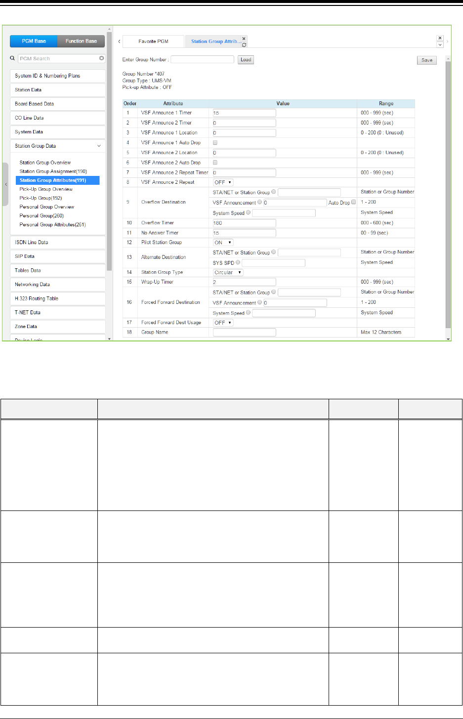
iPECS eMG80 & eMG800 & UCP
Administration and Programming Manual Issue 1.6
423
Figure 4.4.6.3-7 iPECS Feature Server Voice Mail Group (UMS-VM) Attributes
Table 4.4.6.3-7 FEATURE SERVER VOICE MAIL GROUP ATTRIBUTES
ATTRIBUTE DESCRIPTION RANGE DEFAULT
VSF Announce 1
Timer
If all stations in the group are busy when a call is offered,
the call may continue to wait (queue) for an available FS-
VM channel. If the queue period exceeds the VSF
Announce 1 Timer, the call is sent to a VSF
announcement. If the timer is set to 000, the call will
receive the first announcement, in full, prior to the station
process (guaranteed announcement).
000~999
(seconds) 015
VSF Announce 2
Timer
After the 1st announcement, a 2nd Announcement Timer
is activated. At expiration, if the call remains queued to
the group, the call is sent to the assigned VSF Announce
2 Location.
000~999
(seconds) 000
VSF Announce 1
Location
Each group can be assigned an announcement, which is
played if the call remains queued beyond the VSF
Announce 1 Timer duration. The announcement location
is a VSF Announcement number. An entry of 00
indicates
no announcement.
00~200 00: none
VSF Announce 1 Auto
Drop
If this attribute is selected, the call will drop after the 1st
VSF announcement.
Check box
VSF Announce 2
Location
The Group can be assigned a 2nd announcement, which
is played if the call remains queued beyond the VSF
Announce 2 Timer duration. The announcement location
is a VSF Announcement number. An entry of 00 indicates
00~200 00: none

iPECS eMG80 & eMG800 & UCP
Administration and Programming Manual Issue 1.6
424
Table 4.4.6.3-7 FEATURE SERVER VOICE MAIL GROUP ATTRIBUTES
ATTRIBUTE DESCRIPTION RANGE DEFAULT
no announcement.
VSF Announce 2 Auto
Drop
If this attribute is selected, the call will drop after the 2nd
VSF announcement.
Check box
VSF Announce 2
Repeat Timer
The 2nd announcement can be repeated to calls that
remain in queue at intervals of the announcement 2
repeat timer. Note VSF Announce 2 Repeat below must
be “ON”.
000~999
(seconds) 000
VSF Announce 2
Repeat
After the 2nd announcement, if the call remains queued
to the group, the 2nd VSF announcement can be
repeated at the VSF Announce Repeat timer interval,
above.
OFF
ON OFF
Overflow Destination
A call to the group will continue to route through the
group until answered or all group members have been
tried. The call will remain at the last station or route to the
assigned Overflow Destination. If assigned VSF
Announce, Auto Drop is available.
STA/NET or
Station group,
VSF
Announcement,
Auto drop,
System Speed
Overflow Timer
A call to a group will remain at the last station in the
group or route to the assigned Overflow Destination after
expiration of the Overflow Timer.
000~600
(seconds) 180
No Answer Timer
Calls to a station in the group are directed to the station,
if unavailable or unanswered in the No Answer Timer, the
call can be routed based on the assigned hunt process.
00~99
(seconds) 15
Pilot Station Group A FS-VM Station group can be set so that only calls to
the pilot number (station group number) will hunt.
OFF
ON
ON
Alternate Destination
When a call comes into the group and there are no group
members available, the call will be routed to the assigned
Alternate Destination.
STA/NET or
Station group,
System SPD
Station Group type The Station group process for the FS-VM group can be
defined as Circular or Terminal.
Circular/
Terminal
Circular
Wrap-Up Timer After terminating any call, the FS port will be maintained
in a busy state for the duration of the Wrap-Up Timer.
000~999
(seconds)
2
Forced Forward
Destination
Calls to a group may forward directly to a defined
destination, by passing the hunt process. “Forced
Forward”, below, must be enabled.
Sta./NET or
Station group,
VSF
announcement,
Sys. Speed
Forced Forward Dest
Usage
Calls to a Station group may forward directly to a defined
destination, see above “Forced Forward Destination”
when Forced Forward is enabled for the group.
OFF
ON OFF
Group Name A group name can be designated. Max. 12
characters
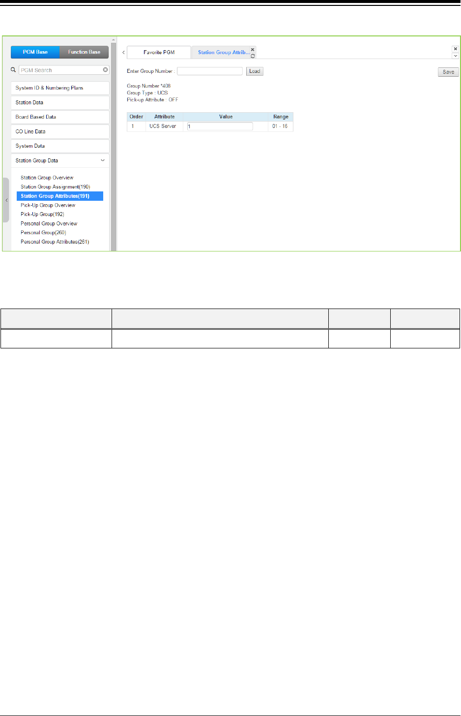
iPECS eMG80 & eMG800 & UCP
Administration and Programming Manual Issue 1.6
425
Figure 4.4.6.3-8 iPECS UCS Server Group Attributes
Table 4.4.6.3-8 UCS GROUP ATTRIBUTES
ATTRIBUTE DESCRIPTION RANGE DEFAULT
UC Server UCS Server number, this value must be set to 1. 00-16 1
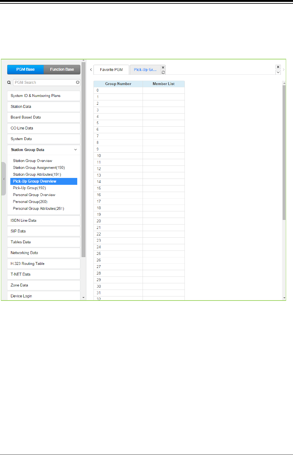
iPECS eMG80 & eMG800 & UCP
Administration and Programming Manual Issue 1.6
426
4.4.6.4 Pick Up Group Overview
Selecting the Pick Up Group Overview item will return the Station Pick Up Group Overview page.
This page displays the Station Group member stations for all the Station Pick Up Groups. Note
that data cannot be entered on this page.
Figure 4.4.6.4-1 Pick Up Group Overview
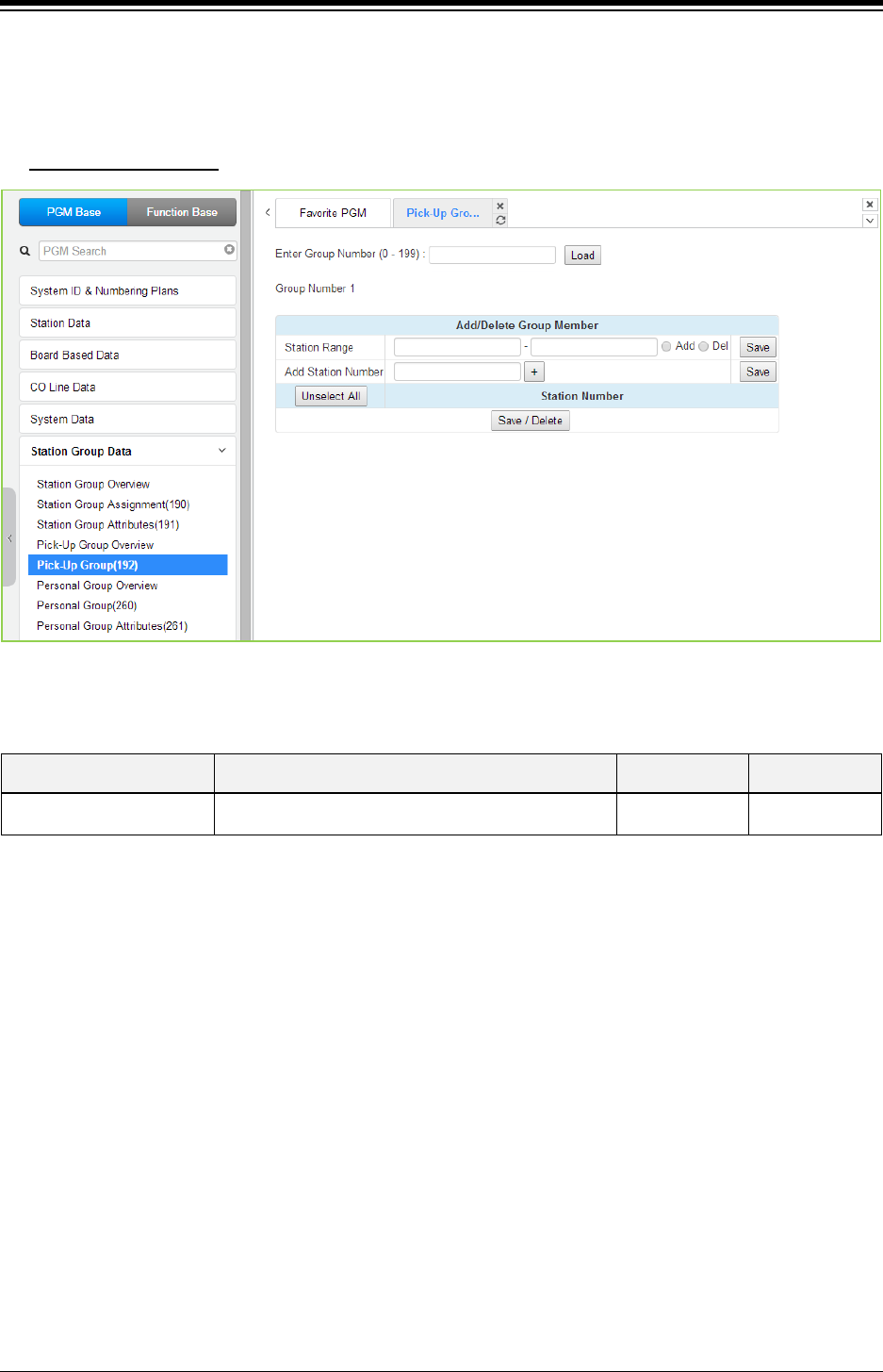
iPECS eMG80 & eMG800 & UCP
Administration and Programming Manual Issue 1.6
427
4.4.6.5 Pick Up Group - PGM 192
Selecting Pick Up Group will display the Pick Up Group entry page. Enter the desired Pick Up
Group number and click [Load] to display the group member Assignment.
Enter Group Number
: eMG80: 0-49 / eMG800: 0-199 / UCP: 0-199
Figure 4.4.6.5-1 Pick Up Group
Table 4.4.6.5-1 PICK UP GROUP ASSIGNMENT
ATTRIBUTE DESCRIPTION RANGE DEFAULT
Member Assign stations as members of the Pick-Up group.
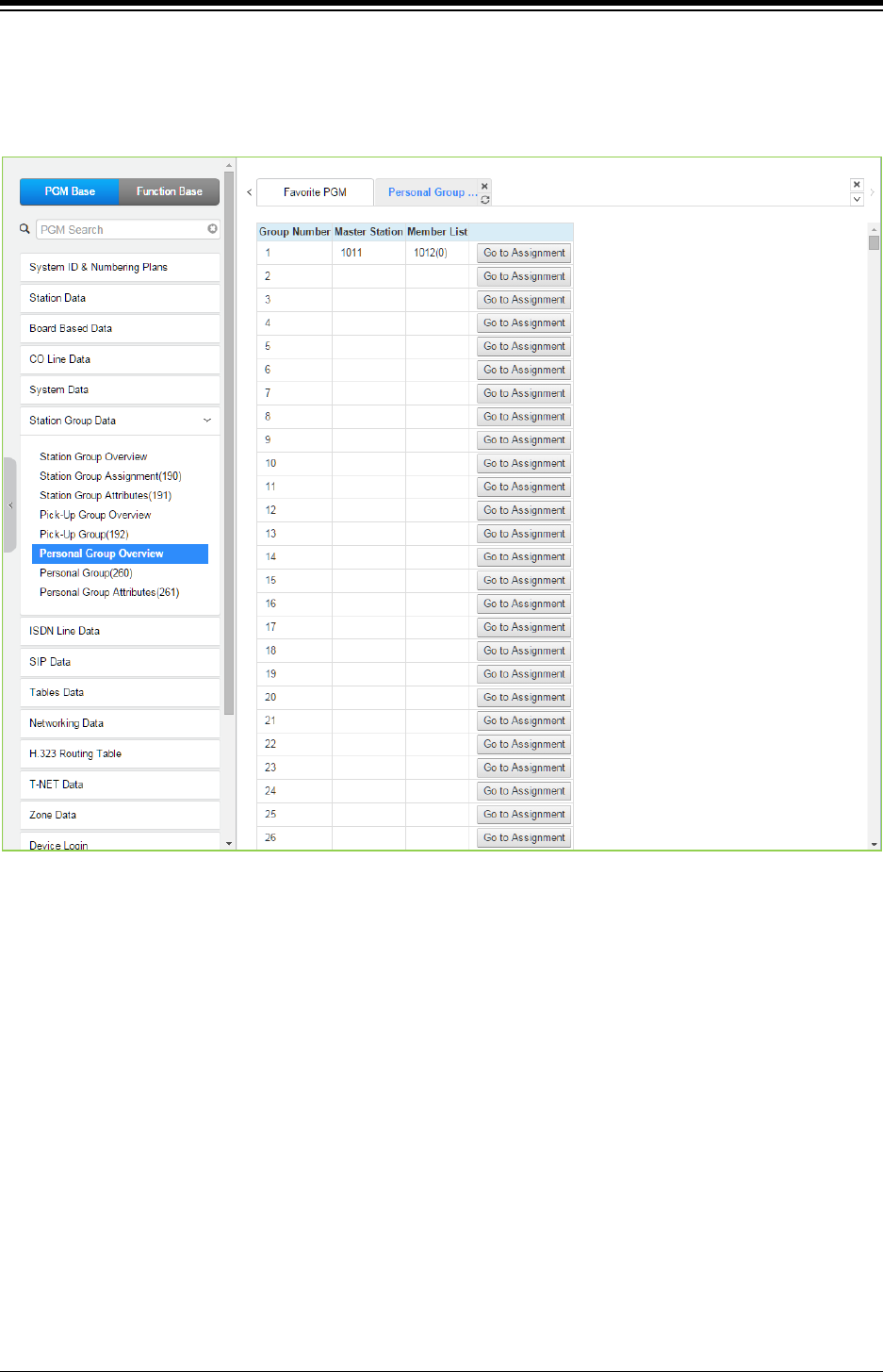
iPECS eMG80 & eMG800 & UCP
Administration and Programming Manual Issue 1.6
428
4.4.6.6 Personal Group Overview
Selecting Personal Group Overview displays the master station and member list for all the
personal groups.
Figure 4.4.6.6-1 Personal Group Overview
Clicking [Go to Assignment] goes to move Personal group (260) for assigning Master station &
Member Station and setting Personal group attributes directly.
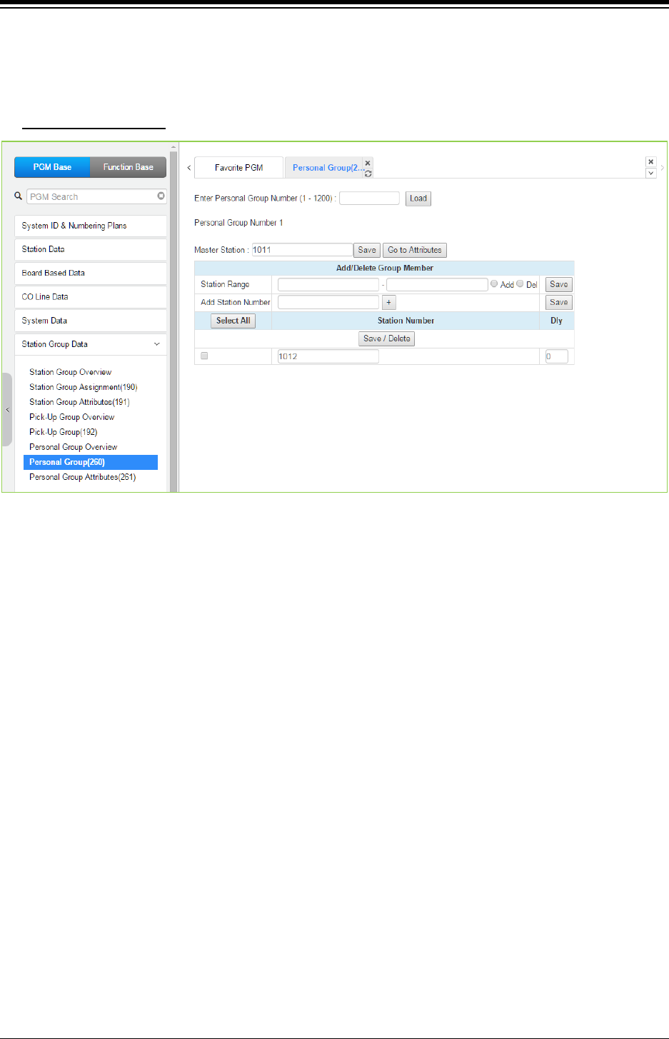
iPECS eMG80 & eMG800 & UCP
Administration and Programming Manual Issue 1.6
429
4.4.6.7 Personal Group - PGM 260
Selecting Personal Group will display the Personal Group entry page. Enter a valid Personal
Group number and click load to enter group data.
Enter Group Number
: eMG80: 1-70 / eMG800: 1-600 / UCP: 1-1200
Figure 4.4.6.7-1 Personal Group
Several stations can share same station number. That means Personal Group is extended
feature of Linked Pair.
A Personal Group is composed with a master station and several member stations.
A master station and all member stations share master station‘s number.
In case of Member station, each member station can be set the delay (Dly) time.
By using this shared number, almost features (Call To xxx / Call From xxx / SMDR / Message
Wait…) can be activated.
But, some features can be chosen by PGM 261 attribute about all station activating or individual
station working.
In PGM 260, Personal group master and member can be assigned.
In PGM 261, Personal group attribute can be set.
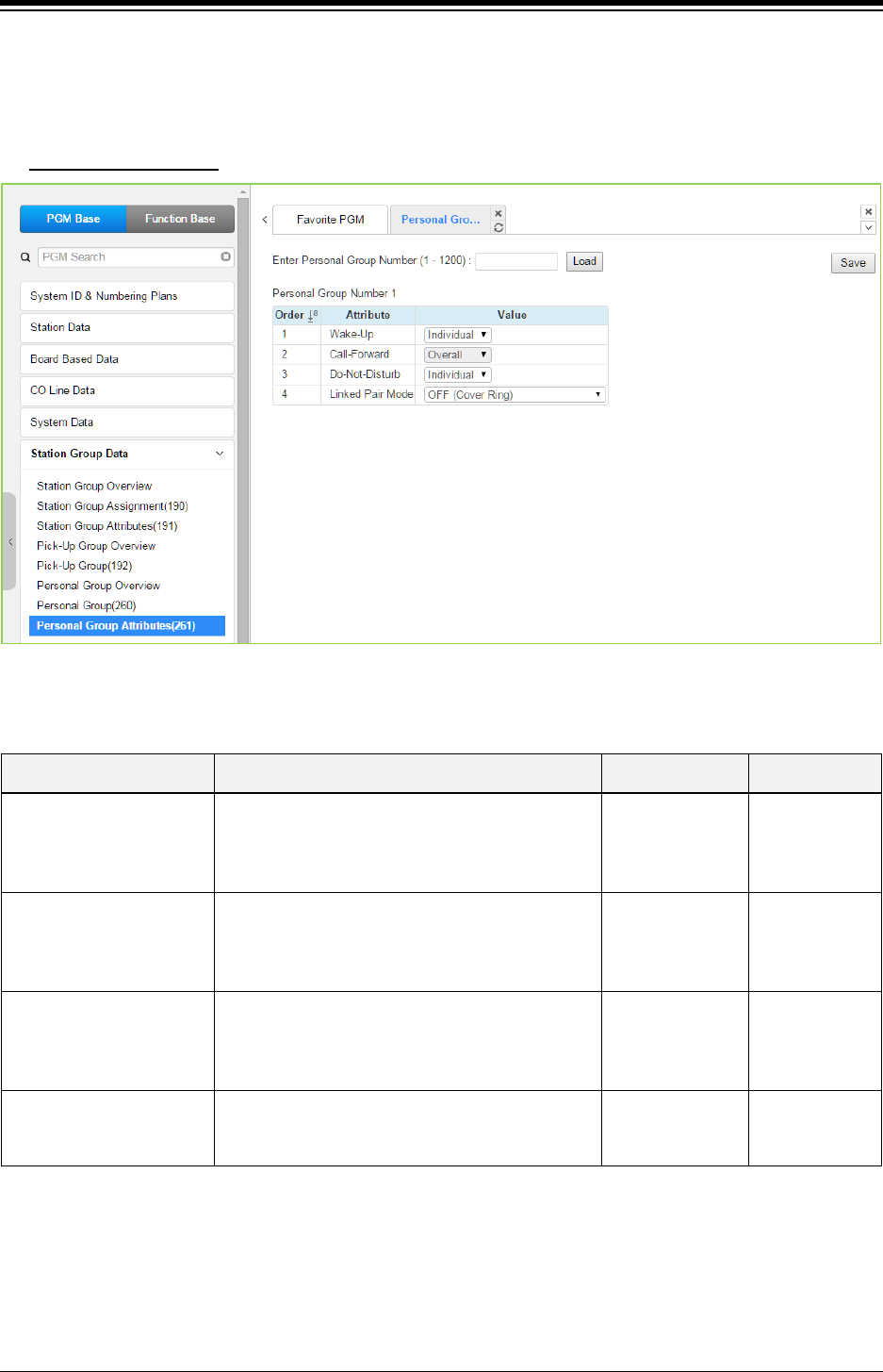
iPECS eMG80 & eMG800 & UCP
Administration and Programming Manual Issue 1.6
430
4.4.6.8 Personal Group Attribute - PGM 261
Selecting Personal Group Attribute will display the Personal Group Attribute entry page. Enter a
valid Personal Group number to enter the group data. Click [Save] button after changing Value.
Enter Group Number
: eMG80: 1-70 / eMG800: 1-600 / UCP: 1-1200
Figure 4.4.6.8-1 Personal Group Attributes
Table 4.4.6.8-1 PERSONAL GROUP ATTRIBUTES
ATTRIBUTE DESCRIPTION RANGE DEFAULT
Wake-Up
If this value is set to Overall, all member wake-up
follow by master wake up.
If this value is set to Individual, individual wake-up
is worked by each station.
Individual/
Overall Individual
Call-Forward
If this value is set to Overall, call forward setting
affect to Master and all members.
If this value is set to Individual, individual Call
Forward is worked by each station.
Individual/
Overall Overall
Do-Not Disturb
If this value is set to Overall, DND setting affect to
Master and all members.
If this value is set to Individual, individual DND is
worked by each station.
Individual/
Overall Individual
Linked Pair Mode
If this value is set to ON, Master and Member
Stations are linked and only one station can be
activated.
OFF(Cover Ring)/
ON(Cover Ring
and State Sync.)
OFF(Cover
Ring)
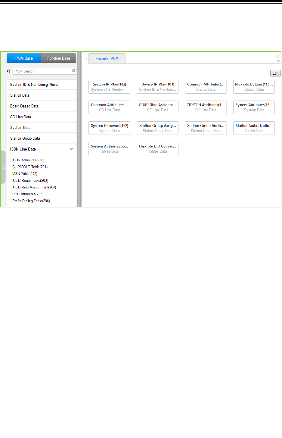
iPECS eMG80 & eMG800 & UCP
Administration and Programming Manual Issue 1.6
431
4.4.7 ISDN Line Data
Selecting the ISDN Line Data program group returns the sub-menu displayed in the left frame as
shown in the following figure.
Figure 4.4.7-1 ISDN Line Data
Each ISDN (Integrated Services Digital Network) Line provides digital services to the end-user.
Basic Rate Lines have three (3) channels, 2 B channels and a D channel. The 2 B channels
provide 64 Kbps each, a total of 128 Kbps for “Bearer” or voice channels. The D channel provides
a 16 Kbps signaling channel. Primary Rate Lines have 23/30 64 Kbps ‘B’ channels and 1/2 64
Kbps signaling channels. For proper operation, entries are required for various attributes and
Tables to match the ISDN circuit and services.
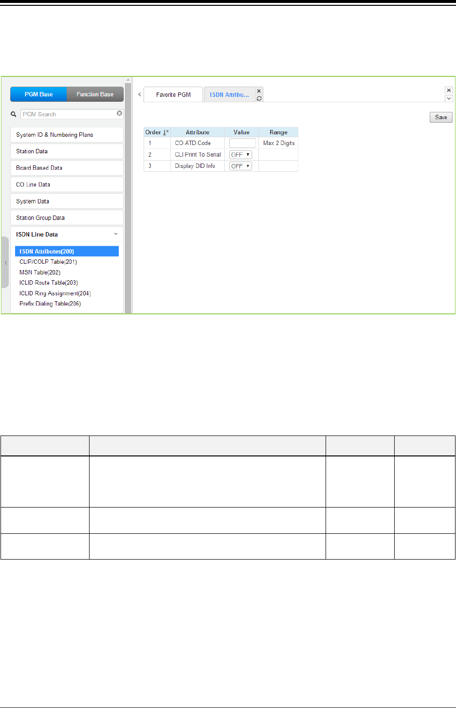
iPECS eMG80 & eMG800 & UCP
Administration and Programming Manual Issue 1.6
432
4.4.7.1 ISDN Attributes - PGM 200
Selecting ISDN Attributes will display the ISDN Attributes data entry page. Click [Save] button
after changing Value.
Figure 4.4.7.1-1 ISDN Attributes
ISDN attributes define several characteristics of the ISDN interface. ISDN call cost services
(Advice of Charge), CLI modification, voice encoding, and other characteristics of the interface
are defined, refer to the following table.
Table 4.4.7.1-1 ISDN ATTRIBUTES
ATTRIBUTE DESCRIPTION RANGE DEFAULT
CO ATD Code
When the system is set to send the station number with
ISDN CLIP or COLP, either the station number or this ATD
code will be sent based on Common Attributes section,
EXT or ATD assignment.
Max.2 Digits
CLI Print To Serial The ISDN Calling Line Id may be included in call records,
refer to SMDR Attributes section.
OFF/
ON
OFF
Display DID
Information
Display DID digit information on LCD and print it to serial
port.
OFF/
ON
OFF
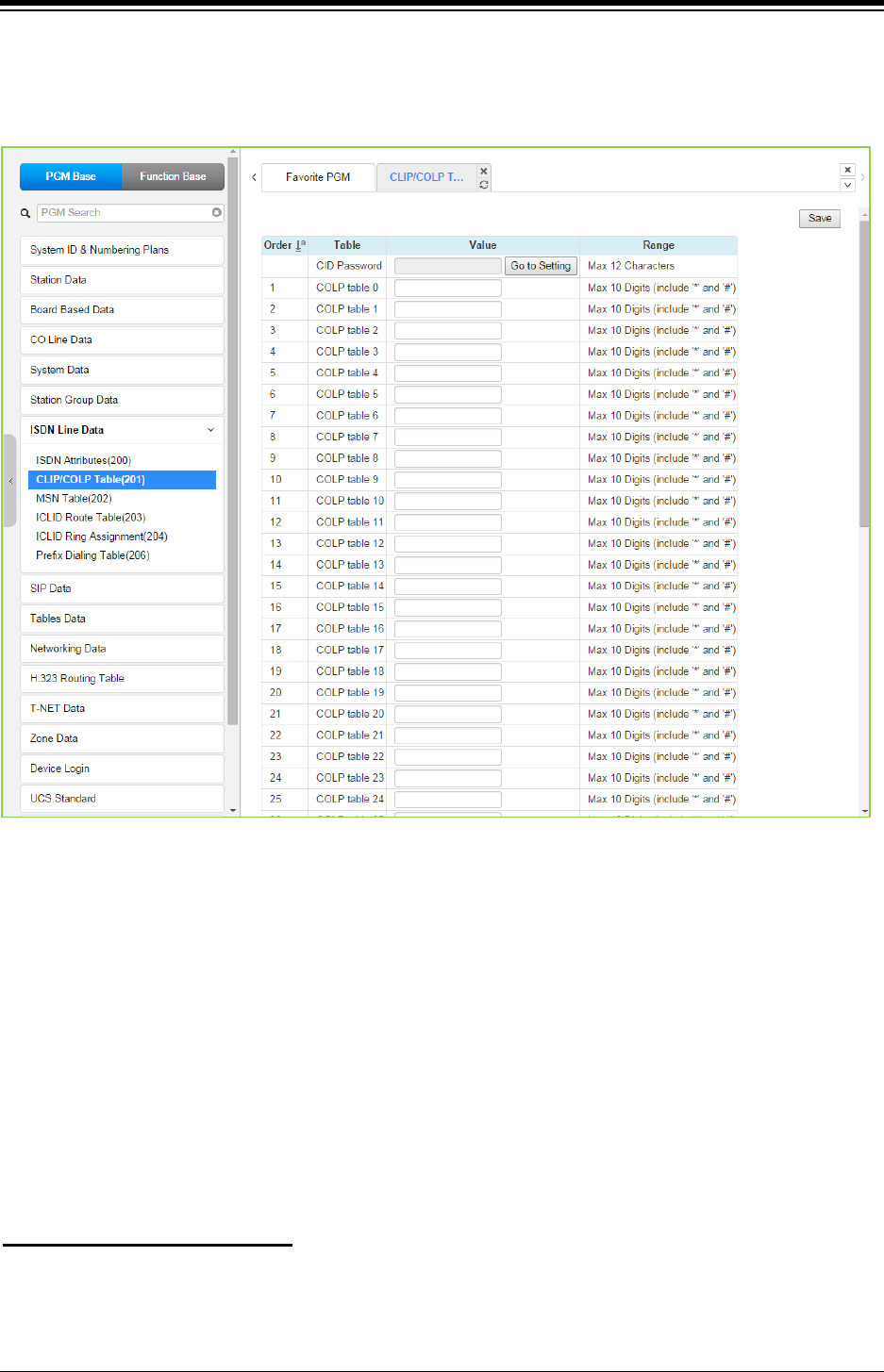
iPECS eMG80 & eMG800 & UCP
Administration and Programming Manual Issue 1.6
433
4.4.7.2 CLIP/COLP Table - PGM 201
Selecting CLIP/COLP Table will display the CLIP/COLP Table Attributes data entry page. Click
[Save] button after changing Value.
Figure 4.4.7.2-1 CLIP/COLP Table
Normally, the system will send the primary Directory Number of the ISDN Line in the ISDN call
SETUP and CONNECT messages to identify the caller (CLIP) or the answering (COLP) party
respectively. Under certain circumstances, it may be desirable to provide the secondary or DID
number for the ISDN Line. In these cases, the CLIP/COLP Table may be used to define the digits
sent. The number sent is selected based on the index assigned for the CO/IP Line under
‘CID/CPN Attributes section’.
The CLI Station Number is sent in place of the station number. For all other entries, the station
number is sent as a suffix to the number in the Table. Note that this number is sent only if
CLIR/COLR is disabled under the CLIR Service and COLR Service assignments in the Station
ISDN Attributes.
You can set the CID password to click “Go to Setting” button. After clicking it, you will move to the
following PGM 162 and set the CID password, and then save CID password to mark tick on the
save box and click the Save button.
Setting CID Password directly
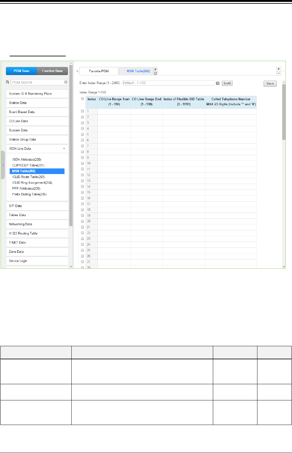
iPECS eMG80 & eMG800 & UCP
Administration and Programming Manual Issue 1.6
434
4.4.7.3 MSN Table - PGM 202
Selecting MSN Table will display the MSN Table data entry page. For convenience, the copy,
paste, and drag is available to enter or modify data. Click [Save] button after changing Value.
Enter Index Range
: eMG80: 1-500 / eMG800: 1-1500 / UCP: 1-2400
Figure 4.4.7.3-1 MSN Tables
When an ISDN Line assigned for DID operation receives an incoming call, the call will be routed
to a station based on the Flexible DID Table Index assigned in the MSN Table. Each iPECS
configuration has a different capacity as indicated by the entry range in the following table.
Table 4.4.7.3-1 MSN TABLE ATTRIBUTES
ATTRIBUTE DESCRIPTION RANGE DEFAULT
CO Line Range Enter the CO Line Range. eMG80:1-74
eMG800:1-600
UCP:1-998
None
Index of Flexible DID Table Index to the Flexible DID Table. 0~9999 None
Called Telephone Number
When the received MSN number matches this entry,
the call is routed based on the DID Table index entered
above.
Max. 23 Digits
(Include * and #)
None
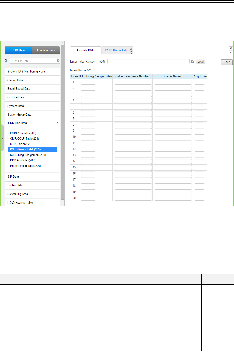
iPECS eMG80 & eMG800 & UCP
Administration and Programming Manual Issue 1.6
435
4.4.7.4 ICLID Route Table - PGM 203
Selecting ICLID Route Table will display the ICLID Route Table data entry page. Click [Save]
button after changing field.
Figure 4.4.7.4-1 ICLID Route Table
The system can employ ICLID (Incoming Calling Line Id) to determine the routing of incoming
external calls. Each CO/IP Line, including DID Lines and ACD group calls may be assigned to
employ ICLID routing. The system will compare the received ICLID to entries in the ICLID Route
Table and, if a match is found, will route the call to the destination defined in the ICLID Ring
Assignment Table index assigned here.
Table 4.4.7.4-1 ICLID ROUTE TABLE ATTRIBUTES
ATTRIBUTE DESCRIPTION RANGE DEFAULT
ICLID Ring Assign Index Index to the ICLID Ring Assignment Table that
determines the call routing.
eMG: 001~250
UCP: 001~500
None
Caller Telephone
Number
ICLID (Incoming Caller Id) to match for the index. If the
Caller Id matches the Table entry, the index is used to
select the route.
24 Digits None
Caller Name ICLID name that is sent by the system to the
destination for the ICLID routed call.
12 characters None
Ring Tone
If the received Caller Id matches the Caller Telephone
Number, the Ring tone selected here is employed for
the call alerting.
01 ~ 16 Ring Tone
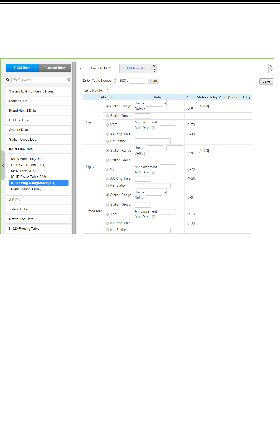
iPECS eMG80 & eMG800 & UCP
Administration and Programming Manual Issue 1.6
436
4.4.7.5 ICLID Ring Assignment Table - PGM 204
Selecting ICLID Ring Assignment Table will display the ICLID Ring Assignment Table data entry
page. The station number starts 100 for eMG80 and 1000 for eMG800/UCP. Click [Save] button
after changing Value.
Figure 4.4.7.5-1 ICLID Ring Assignment Table
If the Incoming Caller ID matches an entry in the ICLID Route Table, the index from the Table is
used to determine the call routing from the ICLID Ring Assignment Table. Separate ring
assignments are made for Day, Night, and Timed Ring mode for each index, 001 to 250, in this
table. When assigned to ring to a VSF announcement, the call can be automatically dropped after
the announcement by entering ‘#’ after the announcement number.
When CO Lines are programmed to Ring an external AA/VM, VSF or Feature Server Group as
an Automated Attendant, the Ring signal can be on an immediate or delayed basis allowing other
stations/groups to be assigned Ring and answer prior to signaling the AA. The delay is defined in
seconds from 00 to 30.
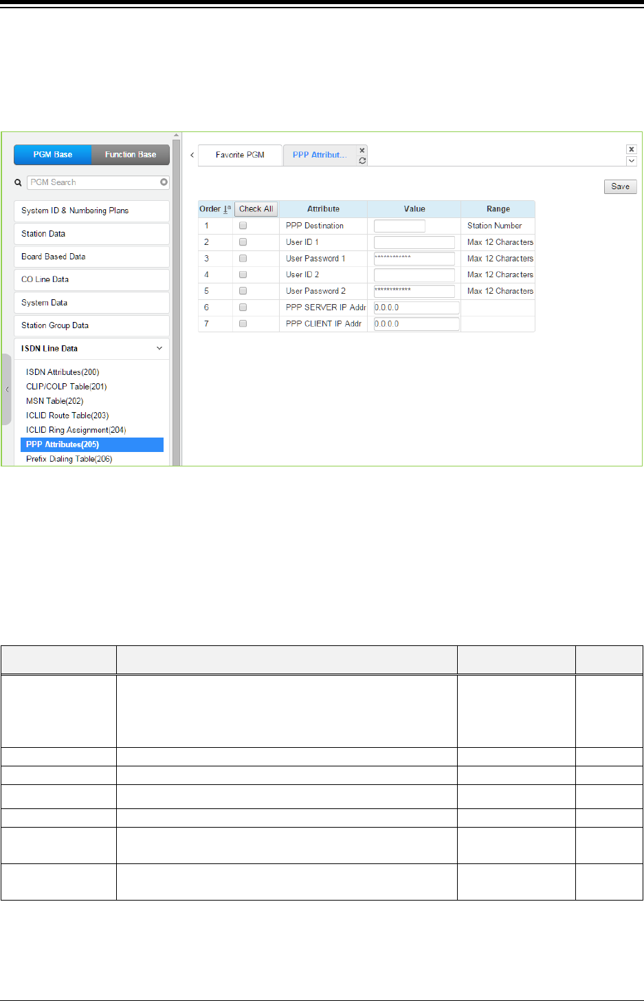
iPECS eMG80 & eMG800 & UCP
Administration and Programming Manual Issue 1.6
437
4.4.7.6 PPP Attributes for UCP - PGM 205
Selecting PPP Attributes will display the PPP Attributes data entry page. Use the check boxes to
indicate which attributes to define; data for checked attributes is stored for the entire range of
stations when saved. Click [Save] button after changing Value.
Figure 4.4.7.6-1 PPP Attributes
In addition to remote access via an IP network connection, the system database may be
accessed remotely via an ISDN connection. Placing a call over an ISDN Line to the designated
PPP Station will provide a connection to the system database. The system will request a user id
and password, which must match one of the User Ids and passwords assigned. After a matching
ID and password are received, iPECS Login Home page is provided.
Table 4.4.7.6-1 PPP ATTRIBUTES
ATTRIBUTE DESCRIPTION RANGE DEFAULT
PPP Destination
If the incoming capability is 64 Kbps unrestricted digital and
the called party number matches the PPP destination, the
system will automatically answer the call and request PPP
ID and password.
Station number None
User ID 1
The System accepts this PPP ID 1 as valid.
Max. 12 characters
likppp01
User Password 1
The password entered is used to authorize PPP ID 1.
Max. 12 characters
Ipkts01
User ID 2 The System accepts this PPP ID 2 as valid. Max. 12 characters likppp02
User Password 2 The password entered is used to authorize PPP ID 2. Max. 12 characters Ipkts02
PPP Server IP
Addr
When configured, the PPP Server IP Address must match
this entry. To apply this option the system must be restarted.
IP Address
PPP Client IP Addr When configured, the PPP Client IP Address must match
this entry. To apply this option the system must be restarted.
IP Address
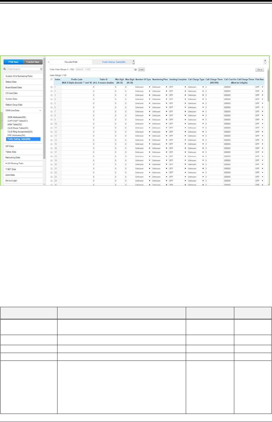
iPECS eMG80 & eMG800 & UCP
Administration and Programming Manual Issue 1.6
438
4.4.7.7 Prefix Dialing Table - PGM 206
Selecting ISDN Prefix Dialing Attributes will display the Prefix Dialing Table Attributes data entry
page. For convenience, the copy, paste, and drag is available to enter or modify data. Click [Save]
button after changing Value.
Figure 4.4.7.7-1 Prefix Dialing Table Attributes
Prefix Dialing Table. With this table, three features can be supported.
1. Analog CO Call Charge with NPR metering.
2. SIP direct dialing with no wait inter-digit timer.
3. ISDN Prefix Call – ISDN en-block Dialing with Prefix Call Setup.
If first some digits (up to 8 digits) of outgoing dial number are matched with Prefix Code of each
table, this table can start work. By each Co-line (PGM 142 – F20), Table ID (0-6) can be set. This
table ID (PGM 142 – F20) is associated with PGM 206 – each table ID.
Table 4.4.7.7-1 Prefix dialing Table Attributes
ATTRIBUTE DESCRIPTION RANGE DEFAULT
Prefix Code Enter the Prefix code. (Max 8 digits) Max. 8 Digits
(Include * and #)
Table ID Enter Table ID (0-6). 0 means NOT used. 0-6 0
Min Digit
Select the minimum dial digits (00-30).
00-30
0
Max Digit
Select the maximum dial digits (00-30).
00-30
0
Number Of Type
Select Number of Type (0~6).
Unknown/International/National/Network
Spec/Subscriber/Abbreviated /Reserved.
Unknown/
International/
National/
Network spec/
Subscriber/
Abbreviated/
Reserved
Unknown

iPECS eMG80 & eMG800 & UCP
Administration and Programming Manual Issue 1.6
439
Table 4.4.7.7-1 Prefix dialing Table Attributes
ATTRIBUTE DESCRIPTION RANGE DEFAULT
Numbering Plan
Select Numbering Plan (0~6).
Unknown/ISDN/Data Numbering/Telex/National
Standard/Private /Reserved.
Unknown/
ISDN Telephony/
Data numbering/
Telex/
National standard/
Private/
Reserved
Unknown
Sending Complete
Select Sending Complete option. (On/Off)
ON/OFF
OFF
Call Charge Type
Call Charge Type (0~5).
Unknown/Local/Long
Distance/International/Mobile/reserved
Unknown/
Local/
Long distance/
International/
Mobile/
Reserved
Unknown
Call Charge Timer Call Charge Timer can be assigned. By this timer
value Call Metering can be established.
000-999 0
Call Cost
Call Cost is calculated by CALL TIMER. (ex : timer is
1 min, cost is 000020, then after 3 minute call, total
call cost is calculated to 000060)
000000-999999 000000
Flat Rate If Flat Rate is ON, Flat Rate is applied by CALL COST
per a call.
ON/OFF OFF
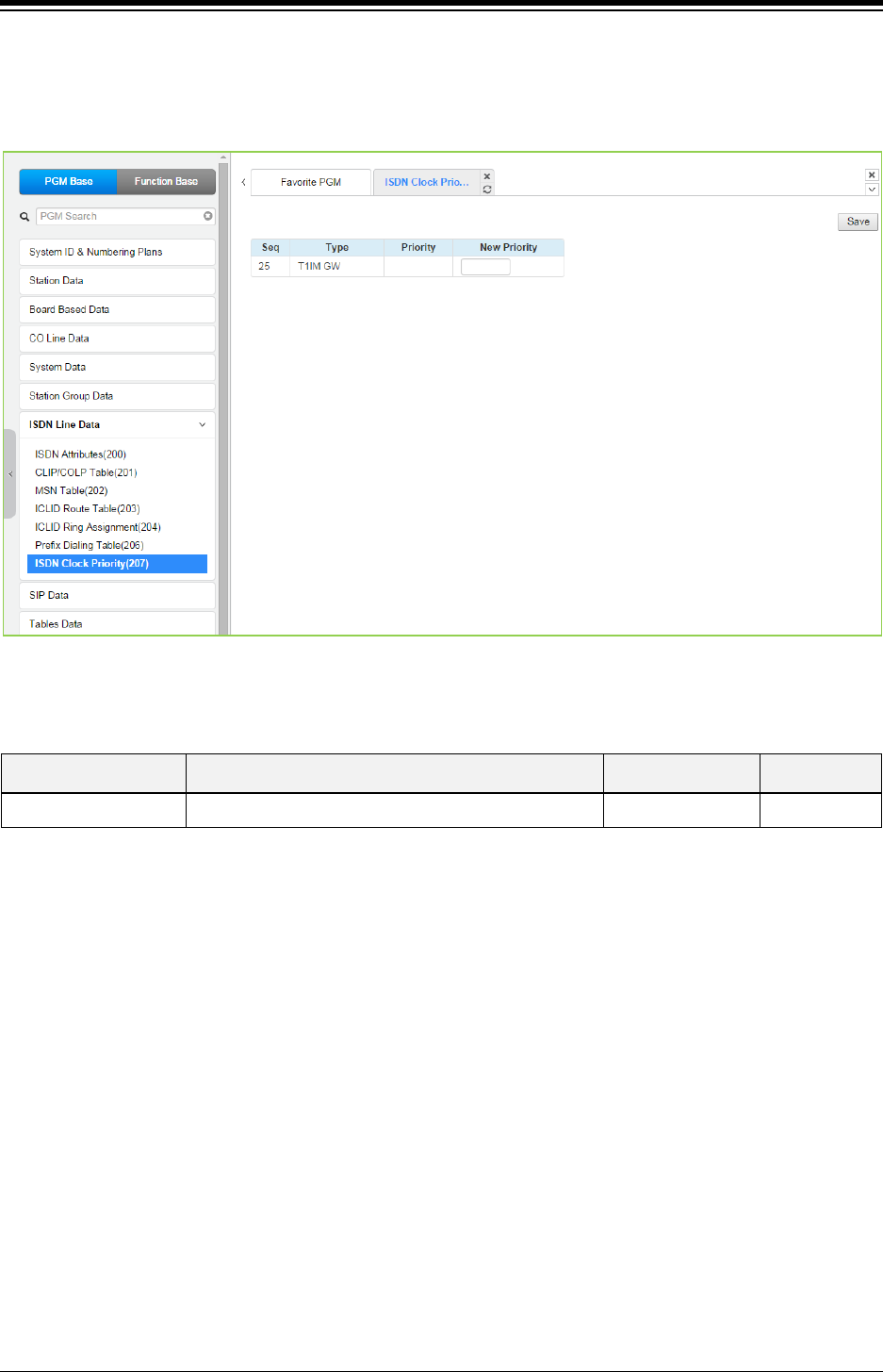
iPECS eMG80 & eMG800 & UCP
Administration and Programming Manual Issue 1.6
440
4.4.7.8 ISDN Clock Priority for eMG800 - PGM 207
Selecting ISDN Clock Priority will display the ISDN Clock priority Attributes data entry page. Click
[Save] button after changing Value.
Figure 4.4.7.7-1 ISDN Clock Priority Attributes
Table 4.4.7.7-1 ISDN Clock Priority Attributes
ATTRIBUTE DESCRIPTION RANGE DEFAULT
Priority Clock priority if more than one ISDN boards are used 1-18
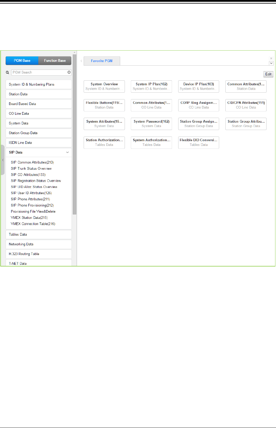
iPECS eMG80 & eMG800 & UCP
Administration and Programming Manual Issue 1.6
441
4.4.8 SIP Data
Selecting the SIP Data program group returns the sub-menu displayed in the left frame as shown
in the following figure.
Figure 4.4.8-1 SIP Data
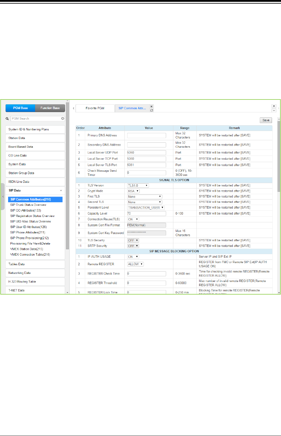
iPECS eMG80 & eMG800 & UCP
Administration and Programming Manual Issue 1.6
442
4.4.8.1 SIP Common (System based) Attributes - PGM 210
Selecting SIP Common Attributes will display the SIP System based Attributes data entry page.
The attributes are system based SIP server data that running on MPB/UCP. Click [Save] button
after changing Value.
DNS server address is where system can get IP address of external party that was written in
Name in system. Local UDP/TCP/TLS Port is MPB/UCP‘s SIP signaling port number.
‘Signal TLS Option’ is for the SIP signaling by TLS configuration.
‘SIP Status’ the status of is running of SIP server in MPB/UCP.
Figure 4.4.8.1-1 SIP Common Attributes
Check Message Send Timer – This is Keep Alive Message (OPTIONS) frequency from SIP
server (MPB/UCP) to SIP Phone. If a SIP Phone does not respond to system‘s Keep Alive
Message then system will make the status of SIP Phone to ‘disconnected’ in system.
Keep Alive Message (OPTIONS) programming for a SIP station is as below:
− Frequency: SIP Data / SIP Common Attributes (210) - Check Message Send Timer.
− Usage ON/OFF for a SIP Extension: SIP Data / SIP Phone Attributes (211) – Keep Alive
Usage.
− Retry Count: IP Data / SIP Phone Attributes (211) – Retry Count.

iPECS eMG80 & eMG800 & UCP
Administration and Programming Manual Issue 1.6
443
Table 4.4.8.1-1 SIP Common Attributes
ATTRIBUTE DESCRIPTION RANGE DEFAULT
Primary DNS
Address
Name Resolution Server.
System will be restarted after Save.
IP Address
(Max. 32 characters)
Secondary DNS
Address
Name Resolution Server.
System will be restarted after Save.
IP Address
(Max. 32 characters)
Local Server UDP
Port
SIP UDP signaling port.
System will be restarted after Save.
5060
Local Server TCP
Port
SIP TCP signaling port.
System will be restarted after Save.
5060
Local Server TLS
Port
SIP TLS signaling port.
System will be restarted after Save.
5061
Check Message
Send Timer Keep Alive (OPTIONS Message) sending frequency
0, 10 ~ 3600
(Sec.)
0: OFF
0
Signal TLS option
TLS Version
TLS version.
TLS1.0: TLS1.0 is used for TLS connection.
TLS1.2: TLS1.2 is used for TLS connection.
SSL3(Auto) : TLS1.0 or TLS1.2 is used – auto
negotiation
System will be restarted after Save.
TLS1.0/
TLS1.2/
SSL3(Auto)
TLS1.0
Crypt Mode TLS Crypt Mode.
System will be restarted after Save.
RSA/ECC RSA
First TLS SIP signaling TLS encryption primary key method.
System will be restarted after Save.
None/
ARIA-128/
AES-128/
ARIA-128-SHA2/
AES-128-SHA2/
AES-256-SHA2(RSA)
None
Second TLS SIP signaling TLS encryption secondary key method.
System will be restarted after Save.
None/
ARIA-128/
AES-128/
ARIA-128-SHA2/
AES-128-SHA2/
AES-256-SHA2(RSA)
None
Persistent Level
TLS signaling path method
TRANSACTION : different path with INVITE, INFO,
MESSAGE
TRANSACTION_USER : same path with INVITE, INFO,
MESSAGE
System will be restarted after Save.
TRANSACTION/
TRANSACTION_USE
R
TRANSACTI
ON_USER
Capacity Level TLS session maintenance rate, maximum 70%.
System will be restarted after Save.
0 - 100 70
Connection Reuse
(TLS)
TLS session maintain or not. OFF
ON
ON
System Cert File
Format
The system supports two certification formats Privacy-
Enhanced Electronic Mail (PEM) or Distinguished
Encoding Rules (DER).
PEM(Normal)
DER (Normal)
PEM
(Normal)
System Cert Key
password
Password to encrypt private key. Max. 16 characters

iPECS eMG80 & eMG800 & UCP
Administration and Programming Manual Issue 1.6
444
Table 4.4.8.1-1 SIP Common Attributes
ATTRIBUTE DESCRIPTION RANGE DEFAULT
TLS Security Change password that is used to encrypt TLS
certification periodically.
OFF
ON
OFF
SRTP Security Allow only SRTP call (blocking none SRTP call). OFF
ON
OFF
SIP Message blocking option
IP AUTH USAGE
ON: Discard SIP Request (INVITE
, REGISTER, NOTIFY,
OPTIONS, MESSAGE …) if VIA IP and From IP are
neither the server IP nor SIP Extension IP.
OFF
ON ON
Remote Register
ALLOW: proceed REGISTER from remote site.
DENY: Discard all remote REGISTER.
(It is applied with IP AUTH USAGE ON)
ALLOW/
DENY ALLOW
REGISTER Check
Time
Time interval to check invalid remote REGISTER
flooding. (It is applied with IP AUTH USAGE ON and
Remote REGISTER ALLOW)
0~3600
(Sec.) 0
REGISTER
Threshold
Threshold value to decide if it is invalid remote
REGISTER flooding. (It is applied with IP AUTH USAGE
ON and Remote REGISTER ALLOW)
0~60000 0
REGISTER Lock
Time
Time interval to discard remote REGISTER if it is
REGISTER flooding state. (It is applied with IP AUTH
USAGE ON and Remote REGISTER ALLOW)
0~250
(Min.) 0
SIP SMS Option
SMS Domain Domain Name used for sending SIP SMS Max. 32 characters
SMS request URI Request URI for sending SIP SMS.
This is only for Korea telecom.
Max. 32 characters 1549
SMS Mode Assign SMS mode(normal or external)
This is only for Korea telecom.
Normal,
External
Normal
SIP FAX Option
Start w/ G.711
Fax
G711 Fax path through Mode. G711 will be negotiated
as voice path and Fax will send this voice path.
OFF
ON
OFF
G.711 Fax
method
G711 Fax Mode. VBD – VBD codec attribute will be
added in SDP.
711A/711U/711A(VBD)
.711U(VBD)
711A
T38 FAX
Failover(711)
When T38 Negotiation is failed, G711 Codec will be used
for Fax Transmission.
OFF
ON
OFF
Miscellaneous Option
OCS Prefix Code
When the server type assigned for a SIP Trunk is OCS,
the system will send these digits as a prefix to the
number in the SIP “To:” header.
Max. 8 Digits
SIP Pound Use
SIP employs Enblock dialing where the user dials all
digits before they are sent to the carrier for processing.
When the user completes dialing of a SIP call, ‘#’ is used
to indicate end of dialing. If users must be able to dial ‘#’,
SIP Pound Use can be disabled and the system will
automatically send digits at expiration of the inter-digit
time.
OFF
ON OFF
BLF SYNC
NOTIFY Timer
When the system reboots, the button LEDs of SIP
phones may indicate erroneous status. To display proper
status LEDs, the system sends a Notify message to
10-360 10

iPECS eMG80 & eMG800 & UCP
Administration and Programming Manual Issue 1.6
445
Table 4.4.8.1-1 SIP Common Attributes
ATTRIBUTE DESCRIPTION RANGE DEFAULT
synchronize the LED states at expiration of this timer.
SRTP
PATH(SIPEXT)
For SIP extensions connected to the same LAN as the
system, the SRTP path can be established through a
VoIP channel (Packet Relay) or directly between the
end-points.
VOIM RELAY or
DIRECT
VOIM
RELAY
DNS SRV Usage
The system can be configured to query the DNS for the
SRV resource record, which defines domains for various
services.
OFF
ON OFF
Out OF Rsc
Response
When the system has no resources available for the SIP
Request, the system will respond with this code.
503/
486
503
Error Code For
Trunk Rerouting
If iPECS system receives this Error Code in response to
a request, the call will be rerouted. The semi-colon (;) is
used to separate multiple SIP message codes.
SIP QOS Option
SIP QOS Method
Selection
For SIP messages, the system can employ Diff Serv or
TOS to implement QoS.
DSCP/
TOS
TOS
SIP Signal DSCP
value
When Diff Serv is selected as the QoS method, the
DSCP value for SIP signaling messages is defined.
0~63 0
SIP Signal TOS
value
When TOS is selected as the QoS method, the TOS
value for SIP signaling messages is defined.
0~7 5
RTP DSCP value When DSCP is selected as the QoS method, the DSCP
value for RTP packets is defined.
0~63 0
RTP TOS value When TOS is selected as the QoS method, the TOS
value for RTP packets is defined.
0~7 5
SIP T-NET Option
CM Prefix
Korea Telecom only, when employing an iPECS system
as the CM, iPECS system will require a Prefix to set-up a
SIP trunk call.
Max. 4 Digits
CM Prefix Method
Korea Telecom only, enables the Prefix method for
processing a call with a SIP trunk through iPECS
system.
Normal,
With prefix Normal
SIP Trunk Register Option
Register Retry
Timer
When registration fails, iPECS system attempts to
register periodically at intervals of this timer.
20~3600 60
Option Check
number
Korea Telecom only, a SIP Options message is used for
redundancy. If the system does not respond to the
Option message after the number of attempts, the
redundant server becomes active
1~20 1
Option Check
Interval
Korea Telecom only, a SIP Options message is used for
redundancy. The Option message is sent at intervals of
this timer.
20~3600 20
SIP Alarm Server Option
Alarm Server
Usage
If this value is changed, all WTIB will restart. OFF/ON OFF
Alarm Server
Address
Enter the alarm server address up to 32 characters. Max. 32 characters
Alarm Server UDP
Default UDP port for Alarm server. Port 5060
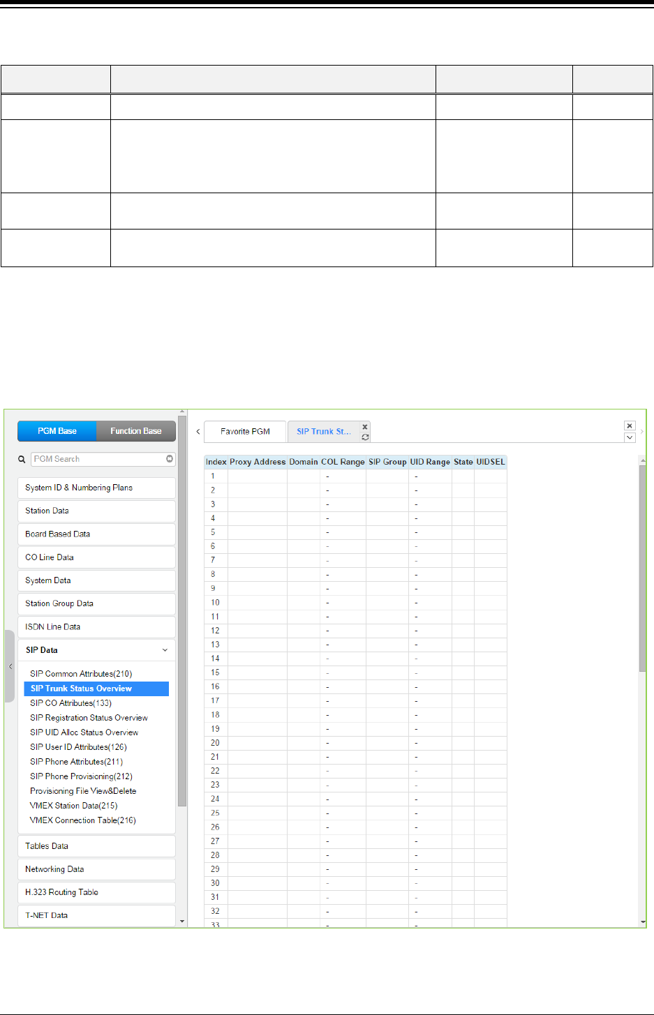
iPECS eMG80 & eMG800 & UCP
Administration and Programming Manual Issue 1.6
446
Table 4.4.8.1-1 SIP Common Attributes
ATTRIBUTE DESCRIPTION RANGE DEFAULT
Port
Alarm Server
Check Usage
If IPECS doesn’t receive reply for this option 3
consecutive times, will not send Message and
Information to Alarm server. PGM 210 check message
send timer.
OFF/
ON OFF
Terminal State
Announcement
Information (Terminal state) is sent to Alarm server if this
value is ON, not sent to Alarm server if this value is OFF.
OFF/
ON
OFF
600BE Channels
for Alarm
The number of 600BE channels reserved for Alarm SMS. 0~1 0
4.4.8.2 SIP Trunk Status Overview
Selecting SIP Trunk Status Overview displays the overview page. The page displays the Proxy,
Domain, etc. for the SIP Trunks configured in PGM 133.
Figure 4.4.8.2-1 SIP trunk status overview
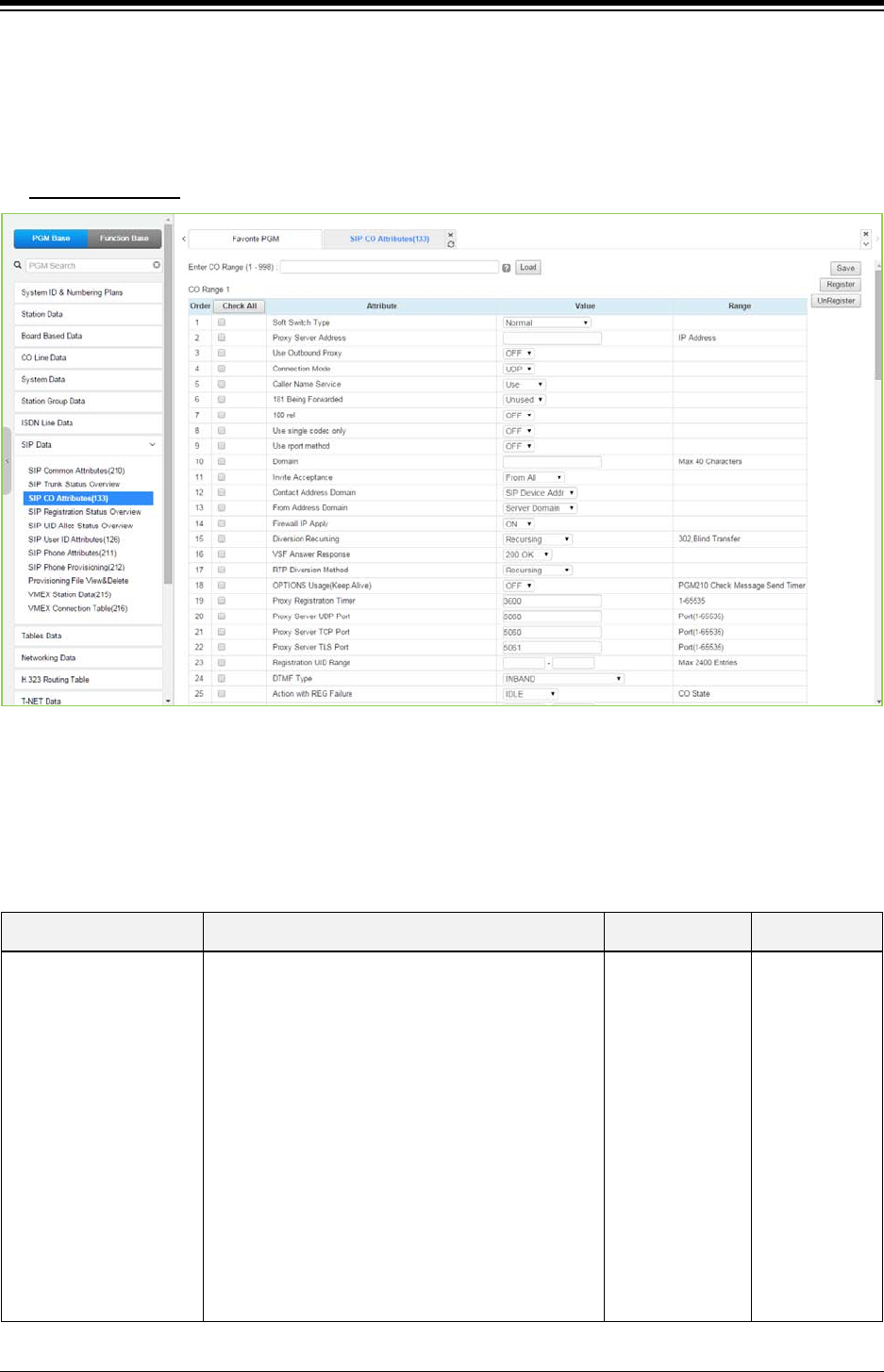
iPECS eMG80 & eMG800 & UCP
Administration and Programming Manual Issue 1.6
447
4.4.8.3 SIP CO Attributes - PGM 133
Selecting SIP CO Attributes returns the SIP CO Attributes data input page. Enter the CO Range
and click [Load] to enter attribute values. Use the check mark to indicate which attributes to
modify; data for checked attributes is stored by clicking [Save] button.
Enter CO Range
: eMG80: 1-74 / eMG800: 1-600 / UCP: 1-998
Figure 4.4.8.3-1 SIP CO Attributes
Various parameters must be entered for proper operation of SIP Trunk including the SIP proxy
and Registrar as outlined in the following table.
Table 4.4.8.3-1 SIP CO ATTRIBUTES
ATTRIBUTE DESCRIPTION RANGE DEFAULT
Soft Switch Type
Allows identification of soft-switch to support
extended soft-switch capabilities.
KT, SK TELINK, etc.: Service Provider.
Normal/
Broadsoft/
KT/
SK TELINK/
KT-C/
MS OCS/
SKYPE
CONNECT/
SIP-CC/
TI PK0/
ERICSSON IMS/
DNS
REDUNT(Tele2)/
MS LYNC
KT-CENTREX
Normal

iPECS eMG80 & eMG800 & UCP
Administration and Programming Manual Issue 1.6
448
Table 4.4.8.3-1 SIP CO ATTRIBUTES
ATTRIBUTE DESCRIPTION RANGE DEFAULT
Proxy Server Address SIP Proxy server IP address up to 64 characters. IP address
Use Outbound Proxy
The SIP module will communicate only to SIP Proxy
Server.
In this case, destination address of all
communication will be the IP of SIP Proxy Server.
Use Outbound Proxy flag should be 'OFF' when you
use that SIP module for channels of 3rd-party SIP
Extensions.
OFF/
ON OFF
Connection Mode This field establishes the SIP connection mode as
UDP, TCP or TLS for SIP signaling messages.
UDP/TCP/
TLS
UDP
Caller Name Service
The caller name may be included in SIP messages.
When included, the name can display in the LCD of
iPECS IP and LDP Phones. In addition, the Contact
Display Name assigned to the SIP User Id (PGM
126) will be sent in the SIP message.
Unused /
Use Use
181 Being Forwarded A SIP 181 Message is sent when a call is being
redirected or forwarded, if enabled.
Unused /
Use
Unused
100rel support
To improve reliability of Provisional SIP messages,
the system is configured to send and expect to
receive an ACK response to such messages.
OFF
ON OFF
Use single codec only
During capabilities negotiation, the system sends
the first priority codec id or the prioritized list of
codecs as defined in the Codec priority settings
below.
OFF
ON OFF
Use rport method
When employed behind a NAPT server, the system
can use the Rport parameter in the SIP Via header
to request the SIP server respond to the IP address
and port of the originator.
OFF
ON OFF
Domain Domain name of the Service Provider’s SIP Call
server that is used in SIP “To:” headers.
Max. 40
characters
Invite Acceptance
The system can accept SIP INVITE requests from
any domain or only from the “Domain” specified
above.
Domain Only /
From All From All
Contact Address Domain
The system will populate the SIP “Contact” header
Domain with either the iPECS device IP address or
the “Domain” specified above.
SIP Device Addr/
Server Domain
SIP Device
Addr
From Address Domain
The system will populate the SIP “From” header
Domain with either the iPECS device IP address or
the “Domain” specified above.
SIP Device Addr/
Server Domain Server Domain
Firewall IP Apply
When the iPECS system and VoIP devices are
assigned a Firewall IP address, the system can use
either the Firewall or local IP address in the Via and
Contact headers as well as in SDP messages.
OFF
ON ON
Diversion Recursing
When a SIP call is redirected by a 3xx Diversion
response such as when a call forwards, the SIP
message can be forked (recursing) or forwarded
(non-recursing).
Recursing /
Non-Recursing Recursing
VSF Answer Response The system can respond to a SIP Invite with a SIP
183 Session Progress message. This allows a VSF
183 Msg.
200 OK
200 OK

iPECS eMG80 & eMG800 & UCP
Administration and Programming Manual Issue 1.6
449
Table 4.4.8.3-1 SIP CO ATTRIBUTES
ATTRIBUTE DESCRIPTION RANGE DEFAULT
announcement to play and user dialed digits to be
analyzed by CCR and, if the CCR destination is an
external number, the system can send a SIP 3xx
call diversion message to forward the call via the
SIP network.
RTP Diversion Method Reserved Currently. Recursing /
Non-Recursing
Recursing
OPTIONS Usage (Keep
Alive)
With “OPTIONS Usage” ON, an Option message is
sent at intervals of the Check Message Send Timer
assigned in PGM 210 to assure a connection with
the SIP CO. SIP COs generally provide an Option
message. In this case, the UCP should not be
enabled here.
OFF
ON OFF
Proxy Registration Timer
Periodically, the system must re-register with the
SIP Registrar. While this timing is often negotiated
with the Registrar, the system can be configured
with this timer to establish the re-register interval.
1-65535 3600
Proxy Server UDP Port When employing UDP transport, this port number is
employed for messages to the SIP proxy.
Port 5060
Proxy Server TCP Port When employing TCP transport, this port number is
employed for messages to the SIP proxy.
Port 5060
Proxy Server TLS Port When employing TLS transport, this port number is
employed for messages to the SIP proxy.
Port 5061
Registration UID Range
The User Id indices from the SIP User ID Attributes
Table PGM 126 that will register with the SIP
Service Provider’s SIP Registrar must be
configured.
Max. 140 Entries
DTMF Type
DTMF dialing signals can be sent from the system
using in-band or various Info messages. The
method or type must match the SIP Call Server.
INBAND/
2833/
INFO (DTMF)/
INFO (DTMF
RELAY)/
INFO(TELEPHON
E EVENT)/
INFO(NORTEL
NETWORKS)
INBAND
Action with REG Failure
When registration fails, the link is down to the SIP
Call server, or the system receives no response to
an Invite message in the “Call Setup No-response”
timer below, the call will return error tone (Wait
Idle), or Fail-over to a Line from the Fail-over CO
Group specified below (Idle).
IDLE/
WATI IDLE IDLE
Media Port The UDP ports used for RTP (media) packets can
be limited to a fixed range. UDP Port
eMG80:6000-
7036
eMG800:6000-
14400
UCP:6000-
19972

iPECS eMG80 & eMG800 & UCP
Administration and Programming Manual Issue 1.6
450
Table 4.4.8.3-1 SIP CO ATTRIBUTES
ATTRIBUTE DESCRIPTION RANGE DEFAULT
Secondary Proxy Server
Secondary Proxy Server
Address
It is used for SIP proxy server redundancy.
KOREA telecom only.
IP Address
Secondary Domain It is used for SIP proxy server redundancy.
KOREA telecom only.
Max. 32
Characters
Secondary Proxy Server
UDP Port
It is used for SIP proxy server redundancy.
KOREA telecom only.
Port
ID Presentation Option
ID Usage
P-Asserted-ID
The system normally provides a P-Asserted ID in
SIP messages. The system can be configured not
to provide the header.
Unused
Use Use
Remote-Party-ID
The system normally provides a Remote-Party-ID in
SIP messages. The system can be configured not
to provide the header.
Unused
Use Use
Privacy(CLIR)
Presentation
SIP employs various headers that include a User Id
and Name. In some cases, it may desirable to
restrict the called party from receiving this
information. Several options for Caller Id restriction
can be applied.
Anonymous
Name &
Anonymous
Number/
Anonymous
Name/
Privacy: user/
Privacy: id/
Privacy:
user;id;critical/
Privacy: id &
anonymous & P-
Preferred-ID
Anonymous
Name &
Anonymous
Number
ID Individuality
CID Password Enter CID Password.
From ID
The Id in the “From” header of SIP messages can
be based on the calling station, the User Id or a
fixed User Id.
Extension SIP User Id: one of three SIP User
Ids assigned to the station in PGM 111. Select
which of the three indices to use in the SIP UID
Selection below.
Extension outgoing CLI: the CLI configured for
the station through Web PGM 113 and 151.
Authorized Representative Id: the User Id of the
“Authorized Representative Id” assigned to the SIP
User Id that is indexed to the station in PGM 111.
The specific index is selected below as the SIP UID
Selection.
Fixed Table: the SIP User ID from the SIP UID
Fixed Table Index attribute assigned below.
Extension SIP-
User-ID Table/
Extension
outgoing-CLI/
Authorized
Representative
ID/
Fixed Table
Extension SIP-
User-ID Table
From Display The “Display” field of the “From” header can be
configured to use the below:
SYS RULE/
Extension
SYS RULE

iPECS eMG80 & eMG800 & UCP
Administration and Programming Manual Issue 1.6
451
Table 4.4.8.3-1 SIP CO ATTRIBUTES
ATTRIBUTE DESCRIPTION RANGE DEFAULT
System Rule:
a. From ID = Extension SIP User-ID Table,
display Contact Display Name from PGM 126,
otherwise display Station Name from PGM 111 or
blank.
b. From ID = Extension Outgoing CLI, display
Station Name from PGM 111 or blank.
c. From ID = Authorized Rep Id, display
Contact Display Name of Authorized Rep Id from
PGM 126 otherwise display Station Name from
PGM 111 or blank.
d. From ID = Fixed Table display Contact
Display Name from PGM 126 or Station Name from
PGM 111 or blank.
Extension outgoing CLI: the CLI configured for
the station through Web PGM 113 and 151
outgoing-CLI
P-Asserted-ID
The Id in the “P-Asserted Id” header of SIP
messages can be based on the calling station, the
User Id or a fixed User ID.
Ext SIP User ID: one of three SIP User Table
indices assigned to the station in PGM 111. Select
which of three in the SIP UID Selection below.
Extension outgoing CLI: the CLI configured for
the station through Web PGM 113 and 151.
Authorized Representative ID: the User Id of
the “Authorized Representative ID” assigned to the
SIP User Id that is indexed to the station in PGM
111. The specific index is selected below as the SIP
UID Selection.
Fixed Table: the SIP User ID from the SIP UID
Fixed Table Index attribute assigned below.
Extension SIP-
User-ID Table/
Extension
outgoing-CLI/
Authorized
Representative
ID/
Fixed Table
Extension SIP-
User-ID Table
P-Asserted-ID Display
The “Display” field of the “P-Asserted Id” header
can be configured to use the below:
System Rule:
a. P-Asserted ID = Extension SIP User-ID
Table, display Contact Display Name from PGM
126, otherwise display Station Name from PGM 111
or blank
b. P-Asserted ID = Extension Outgoing CLI,
display Station Name from PGM 11 or blank
c. P-Asserted ID = Authorized Rep Id, display
Contact Display Name of Authorized Rep Id from
PGM 126 otherwise display Station Name from
PGM 111 or blank
d. P-Asserted ID = Fixed Table display
Contact Display Name from PGM 126 or Station
Name from PGM 111 or blank
Extension outgoing CLI: the CLI configured for
the station through Web PGM 113 and 151.
SYS RULE/
Extension
outgoing-CLI
SYS RULE

iPECS eMG80 & eMG800 & UCP
Administration and Programming Manual Issue 1.6
452
Table 4.4.8.3-1 SIP CO ATTRIBUTES
ATTRIBUTE DESCRIPTION RANGE DEFAULT
Contact ID
The Id in the “Contact ID” header of SIP messages
can be based on the calling station, the User Id or a
fixed User ID.
Ext SIP User ID: one of three SIP User Table
indices assigned to the station in PGM 111. Select
which of three in the SIP UID Selection below.
Extension outgoing CLI: the CLI configured for
the station through Web PGM 113 and 151.
Fixed Table: the SIP User Id from the SIP UID
Fixed Table Index attribute assigned below
Extension SIP-
User-ID Table/
Extension
outgoing-CLI/
Fixed Table
Extension SIP-
User-ID Table
Remote-Party-ID
The Id in the “Remote-Party ID” header of SIP
messages can be based on the calling station, the
User Id or a fixed User Id.
Ext SIP User ID: one of three SIP User Table
indices assigned to the station in PGM 111. Select
which of three in the SIP UID Assignment section
below.
Extension outgoing CLI: the CLI configured for
the station through Web PGM 113 and 151.
Fixed Table: the SIP User ID from the SIP UID
Fixed Table Index attribute assigned below.
Extension SIP-
User-ID Table/
Extension
outgoing-CLI/
Fixed Table
Extension SIP-
User-ID Table
Offnet Call Route ID Transit
CO to Offnet Direct Call Route
The below applies to calls routed from a CO/IP Line to an Off-net location by the system over a SIP Trunk.
From/Contact ID
The ID in the “From” and “Contact” headers of SIP
messages employ System Attendant CLI, the
original CLI or a fixed User Id.
Sys Atd: the CLI configured for the System
Attendant through Web PGM 113 and 151.
Original CLI: the CLI received by the system for
the original incoming call.
Fixed Table: the SIP User ID from the SIP UID
Fixed Table Index attribute assigned below.
SYS ATD/
Original CLI/
Fixed Table
SYST ATD
From Display
The “Display” field of the “From” header can be
configured to use the below:
System Rule:
a. From ID = System Atd, display Contact
Display Name from PGM 126, otherwise display
Attendant Station Name from PGM 111 or blank.
b. From ID = Original CLI, display the Name in
received by the system for the original call.
c. From ID = Fixed Table display Contact
Display Name from PGM 126 or Station Name from
PGM 111 or blank.
Original CLI: the CLI received by the system for
the original incoming call.
SYS RULE/
Original CLI SYS RULE
P-Asserted-ID
The ID in the “P-Asserted ID” header of SIP
messages can be based on the System Attendant,
the Original CLI or a fixed User ID.
SYS ATD/
Original CLI/
Fixed Table
SYST ATD

iPECS eMG80 & eMG800 & UCP
Administration and Programming Manual Issue 1.6
453
Table 4.4.8.3-1 SIP CO ATTRIBUTES
ATTRIBUTE DESCRIPTION RANGE DEFAULT
Sys Atd: CLI: the CLI configured for the System
Attendant through Web PGM 113 and 151.
Original CLI: the CLI received by the system for
the original incoming call.
Fixed Table: the SIP User Id from the SIP UID
Fixed Table Index attribute assigned below.
P-Asserted-ID Display
The “Display” field of the “P-Asserted Id” header
can be configured to use the below:
System Rule:
a. P-Asserted ID = System Atd, display
Contact Display Name from PGM 126, otherwise
display Attendant Station Name from PGM 111 or
blank.
b. P-Asserted ID = Original CLI, display the
Name in received by the system for the original call.
c. P-Asserted ID = Fixed Table display
Contact Display Name from PGM 126 or Station
Name from PGM 111 or blank.
Original CLI: the CLI received by the system for
the original incoming call.
SYS RULE/
Original CLI SYS RULE
Remote-Party-ID
The Id in the “Remote-Party ID” header of SIP
messages can be based on the System Attendant,
the Original CLI or a fixed User ID.
Sys Atd: the CLI configured for the System
Attendant through Web PGM 113 and 151.
Original CLI: the CLI received by the system for
the original incoming call.
Fixed Table: the SIP User ID from the SIP UID
Fixed Table Index attribute assigned below.
SYS ATD/
Original CLI/
Fixed Table
Original CLI
Diversion
The Id in the “Diversion” header of SIP messages
can be based on the System Attendant, the Original
CLI or a fixed User ID, or Unused.
Unused: no Diversion header provided.
Sys Atd: the CLI configured for the System.
Attendant through Web PGM 113 and 151.
Original CLI: the CLI received by the system for
the original incoming call.
Fixed Table: the SIP User ID from the SIP UID
Fixed Table Index attribute assigned below.
Unused/
SYS ATD/
Original CLI/
Fixed Table
Unused
Offnet Call Forward by Station
The below apply to calls routed from a CO/IP Line to an Off-net location by a station over a SIP Trunk.
From/Contact ID
The Id in the “From” and “Contact” headers of SIP
messages employ the forwarding Station, the
original CLI or a fixed User ID.
Extension: the Extension SIP User ID or
Extension Outgoing CLI as assigned for the From
ID under ID Individuality.
Original CLI: the CLI received by the system for
the original incoming call.
Extension/
Original CLI/
Fixed Table
Extension

iPECS eMG80 & eMG800 & UCP
Administration and Programming Manual Issue 1.6
454
Table 4.4.8.3-1 SIP CO ATTRIBUTES
ATTRIBUTE DESCRIPTION RANGE DEFAULT
Fixed Table: the SIP User ID from the SIP UID
Fixed Table Index attribute assigned below.
From Display
The “Display” field of the “From” header can be
configured to use the below:
System Rule:
a. From ID = Extension, display Contact
Display Name from PGM 126, otherwise display
Station Name from PGM 111 or blank.
b. From ID = Original CLI, display the Name in
received by the system for the original call.
c. From ID = Fixed Table display Contact
Display Name from PGM 126 or blank.
Original CLI: the CLI received by the system for
the original incoming call.
SYS RULE/
Original CLI SYS RULE
P-Asserted-ID
The Id in the “P-Asserted ID” header of SIP
messages employ the forwarding Station, the
original CLI or a fixed User ID
Extension: the Extension SIP User ID or
Extension Outgoing CLI as assigned for the From
ID under ID Individuality.
Original CLI: the CLI received by the system for
the original incoming call
Fixed Table: the SIP User ID from the SIP UID
Fixed Table Index attribute assigned below.
Extension/
Original CLI/
Fixed Table
Extension
P-Asserted-ID Display
The “Display” field of the “P-Asserted Id” header
can be configured to use the below:
System Rule:
a. P-Asserted ID = Extension, display Contact
Display Name from PGM 126, otherwise display
Station Name from PGM 111 or blank.
b. P-Asserted ID = Original CLI, display the
Name in received by the system for the original call.
c. P-Asserted ID = Fixed Table display
Contact Display Name from PGM 126 or blank.
Original CLI: the CLI received by the system for
the original incoming call.
SYS RULE/
Original CLI SYS RULE
Remote-Party-ID
The Id in the “Remote Party ID” header of SIP
messages employ the forwarding station, the
original CLI or a fixed User ID.
Extension: the Extension SIP User ID or
Extension Outgoing CLI as assigned for the From
ID under ID Individuality.
Original CLI: the CLI received by the system for
the original incoming call.
Fixed Table: the SIP User Id from the SIP UID
Fixed Table Index attribute assigned below.
Extension/
Original CLI/
Fixed Table
Extension
Diversion
The Id in the “Diversion” header of SIP messages
can be based on the forwarding station, the Original
CLI or a fixed User ID, or Unused.
Unused/
SYS ATD/
Original CLI/
Unused

iPECS eMG80 & eMG800 & UCP
Administration and Programming Manual Issue 1.6
455
Table 4.4.8.3-1 SIP CO ATTRIBUTES
ATTRIBUTE DESCRIPTION RANGE DEFAULT
Unused: no Diversion header provided.
Extension: the Extension SIP User ID or
Extension Outgoing CLI as assigned for the From
ID under ID Individuality.
Original CLI: the CLI received by the system for
the original incoming call.
Fixed Table: the SIP User ID from the SIP UID
Fixed Table Index attribute assigned below.
Fixed Table
Mobile Extension External Call
The below applies to calls routed to a Mobile Extension over a SIP Trunk
From/Contact ID
The Id in the “From” and “Contact” headers of SIP
messages employ the calling station, the original
CLI or a fixed User ID.
Extension: the Extension SIP User ID or
Extension Outgoing CLI as assigned for the From
ID under ID Individuality.
Original CLI: the CLI received by the system for
the original incoming call or Station number for ICM
call.
Fixed Table: the SIP User ID from the SIP UID
Fixed Table Index attribute assigned below.
Extension/
Original CLI/
Fixed Table
Extension
From Display
The “Display” field of the “From” header can be
configured to use the below:
System Rule:
a. From ID = Extension, display Contact
Display Name from PGM 126, otherwise display
Station Name from PGM 111 or blank.
b. From ID = Original CLI, display Station
Name from PGM 111 for ICM call or the Name in
received by the system for the original outside call.
c. From ID = Fixed Table display Contact
Display Name from PGM 126 or blank.
Original CLI: the CLI received by the system for
the original incoming call.
SYS RULE/
Original CLI SYS RULE
P-Asserted-ID
The Id in the “P-Asserted Id” header of SIP
messages employ the calling station, the original
CLI or a fixed User ID.
Extension: the Extension SIP User ID or
Extension Outgoing CLI as assigned for the From
ID under ID Individuality.
Original CLI: the CLI received by the system for
the original incoming call or station number for ICM
call.
Fixed Table: the SIP User ID from the SIP UID
Fixed Table Index attribute assigned below.
Extension/
Original CLI/
Fixed Table
Extension
P-Asserted-ID Display
The “Display” field of the “P-Asserted ID” header
can be configured to use the below:
System Rule:
a. P-Asserted ID = Extension, display Contact
SYS RULE/
Original CLI SYS RULE

iPECS eMG80 & eMG800 & UCP
Administration and Programming Manual Issue 1.6
456
Table 4.4.8.3-1 SIP CO ATTRIBUTES
ATTRIBUTE DESCRIPTION RANGE DEFAULT
Display Name from PGM 126, otherwise display
Station Name from PGM 111 or blank.
b. P-Asserted = Original CLI, display Station
Name from PGM 111 for ICM call or the Name in
received by the system for the original outside call.
c. P-Asserted = Fixed Table display Contact
Display Name from PGM 126 or blank.
Original CLI: the CLI received by the system for
the original incoming call.
Remote-Party-ID
The Id in the “Remote Party Id” header of SIP
messages employ the Station CLI, the original CLI
or a fixed User ID.
Extension: the Extension SIP User ID or
Extension Outgoing CLII as assigned for the From
ID under ID Individuality.
Original CLI: the CLI received by the system for
the original incoming call or station number for ICM
call.
Fixed Table: the SIP User ID from the SIP UID
Fixed Table Index attribute assigned below.
Extension/
Original CLI/
Fixed Table
Extension
Diversion
The Id in the “Diversion” header of SIP messages
can be based on the calling station, the Original CLI
or a fixed User ID, or Unused.
Unused: no Diversion header provided.
Extension: the Extension SIP User ID or
Extension Outgoing CLII as assigned for the From
ID under ID Individuality.
Original CLI: the CLI received by the system for
the original incoming call or the station number for
ICM call.
Fixed Table: the SIP User Id from the SIP UID
Fixed Table Index attribute assigned below.
Unused/
SYS ATD/
Original CLI/
Fixed Table
Unused
SIP UID Assignment
SIP User ID Fixed Table
Index
When a header is assigned to use “Fixed Table”,
the ID from this SIP User ID (PGM 126) Table index
is used.
Index
SIP User ID SELECTION
When a header is assigned to use the “Extension
SIP-User-ID Table”, the SIP User ID is selected
using this SIP UID index in the Station Attributes
(PGM 111).
Index,
Index 2,
Index 3
SIP User Table
Index
External CODEC Priority Configuration
1st ~5th priority
1st. priority
2nd. priority
3rd. priority
4th. priority
5th. Priority
1. If specify priority to a specific CODEC then it will
work for negotiation RTP data.
2. If only 1st. priority is specified and the others are
None/
g.711-u/
g.711-a/
g.723.1/
g.729/
g.729-a/
g.722
none

iPECS eMG80 & eMG800 & UCP
Administration and Programming Manual Issue 1.6
457
Table 4.4.8.3-1 SIP CO ATTRIBUTES
ATTRIBUTE DESCRIPTION RANGE DEFAULT
none, then it will work as single CODEC only does.
SIP Call Setup Failover Option
Call Setup No Response
When the system initiates a SIP Trunk call and
receives no response from the SIP proxy server,
after expiration of this timer the SIP call is canceled
and a Fail-over call placed on the Fail-over CO/IP
Line group specified below. Note the timer can be
set at 3 to 15 seconds and ‘0’, which disables Fail-
over.
0, 3 ~ 15 sec 5sec
Failover CO Group
Number
When the system attempts to initiate a SIP Trunk
call and the SIP Trunk is in an OOS state or the SIP
proxy server does not respond in the No Response
time above, the system will cancel the SIP call and
place a call over a CO/IP Line from this group.
eMG80:1 ~ 21
eMG800:1~201
(Max. Numbers of
CO Group)
none
SIP Session Timer
Session Timer Usage
During a SIP call or “session”, there are no
signaling packets sent or received from the SIP Call
server. In order to assure a session is still active,
the system can periodically send an Option
message that the SIP Call server should
acknowledge.
ON/OFF OFF
Session Timer Value When “Session Timer Usage” is enabled, the
system will verify the session at this timer interval.
90~ 3600 360
Min SE
During negotiation with “Session Timer Usage”
enabled, the system will use this value as the
minimum Session expiration timer and will not
respond to a SIP Option message prior to expiration
of this timer.
90~ 3600 90
URI Formatting and Rules
General Formatting
To Field Method
The SIP “To:” header is formatted using the SIP or
Telephony method as shown below.
SIP method
To: < sip:[Number]@[Domain];user=phone >
Telephony method
To: < tel:+[Number] >Domain
sip: method/
tel: method SIP: method
Numbering Format
When assigned the Telephony method for the “To”
header, the number format can be:
Local - [tel:+Number]@[Domain] or
Global (+E164) - [tel:+E.164
Address]@[Domain]
E.164 Address: Nation + Area Code + Number
Local/
Global Local
Local: include Area Code
The Area code (PGM 143) can be added as a prefix
if the ‘Numbering Format’ is set as Local.
Example:
user dials ‘8701234’ and the Area code is ‘042’
The resulting “To” field URI is
Yes
No No

iPECS eMG80 & eMG800 & UCP
Administration and Programming Manual Issue 1.6
458
Table 4.4.8.3-1 SIP CO ATTRIBUTES
ATTRIBUTE DESCRIPTION RANGE DEFAULT
tel:+0428701234@[Domain]
Global: include phone-
context
If the ‘Numbering Format’ is Global and the ‘To
Field Method’ is Telephony, the ‘phone-context’ can
be added as below.
user dials ‘0011428701234’ from Country code 82
The resulting “To” field URI is,
tel:+0011428701234@[Domain];phone-context=+82
Yes
No No
Specific Formatting by Conversion (example)
From 4 digits To 6 digits User Dial Result
0 +82 0314504639 +82314504639
00 + 0082314504639 +82314504639
1588 1588 15886724 15886724
031 0314504639 4504639
SRTP Setting
SRTP Usage
When implemented by the carrier, the system can
encrypt media (RTP) packets employing SRTP
(Secure Real-Time Transport Protocol). But VoIP
Virtual switching channel does not support SRTP.
OFF
ON OFF
1st CRYPTO
The first priority Crypt method for SRTP.
The range is as below:
None
ARIA_CM_192_HMAC_SHA1_80
AES_CM_128_HMAC_SHA1_80
ARIA_CM_128_HMAC_SHA1_80
AES_CM_192_HMAC_SHA1_80
ARIA_CM_256_HMAC_SHA1_80
AES_CM_256_HMAC_SHA1_80
None
2nd CRYPTO
The second priority Crypt method for SRTP.
The range is as below:
None
ARIA_CM_192_HMAC_SHA1_80
AES_CM_128_HMAC_SHA1_80
ARIA_CM_128_HMAC_SHA1_80
AES_CM_192_HMAC_SHA1_80
ARIA_CM_256_HMAC_SHA1_80
AES_CM_256_HMAC_SHA1_80
None
Caller/Called ID
ID Option
Caller ID Selection For the purposes of display and ICLID call routing,
iPECS employ this header as the “Caller ID”.
P-Asserted-ID/
Remote-Party-D/
From ID
P-Asserted-ID
Display Caller
Name(Though Id is
Anonymous)
Even though the User ID is Anonymous, the system
can display the SIP “From” header “Display Name”
field for the call.
No
Yes No
Called ID Selection For the purposes of call routing, the “SIP Request”
or “To” header will be employed by the system as
Request URI/
To ID
Request URI

iPECS eMG80 & eMG800 & UCP
Administration and Programming Manual Issue 1.6
459
Table 4.4.8.3-1 SIP CO ATTRIBUTES
ATTRIBUTE DESCRIPTION RANGE DEFAULT
the “Called Party ID”.
Miscellaneous set
Drop Busy Station
While busy, the system can be configured to
terminate a station call, and accept and connect any
new call from the SIP Trunk. For special use, it is
available only in Italy.
No
Yes No
Ignore INBAND DTMF
In some situations, DTMF tones from the connected
party may be received along with the DTMF Type
specified above. This can cause errors in detection
such as double digits. In this case, the system can
be configured to ignore Inband DTMF signals. Note
do not disable Inband signals if selected as the
“DTMF Type” above as this may disable DTMF
detection.
No
Yes No
SIP Trunk Group
Multiple SIP User ID ranges may register with the
SIP CO, for example, SIP COs from different
providers. When different SIP User ID ranges are
required on a SIP CO, a different SIP Trunk Group
should be assigned to each range. Note this has no
relationship with the CO/IP Line Group.
0~71
(0:Normal/1-
71:Check To
header)
0
Send Refer for Transfer
The system can employ the SIP Refer method to
forward or transfer incoming calls to an “Off-net”
location if supported by the SIP Service Provider.
No
Yes No
CN Payload Insert
When Comfort Noise generation is desired, the
system will provide a Comfort Noise Payload during
periods of silence.
No
Yes No
Ignore 180 after 183
If the option is Yes, an appropriate ring back tone
may be played to the calling party when the called
party's phone is alerting without changing the
internal or system ring back tone. For example,
when placing a call from USA to Korea, a Korean
ring back tone is heard by the caller.
No
Yes No
Add “user=phone” param For outgoing SIP call, "user=phone" will be added in
Request URI of INVITE.
No
Yes
No
Advice of Charge
When assigned, The system estimates the call cost
for display on the phone with appropriate regional
protocol support.
No Service,
SIP AOC No Service
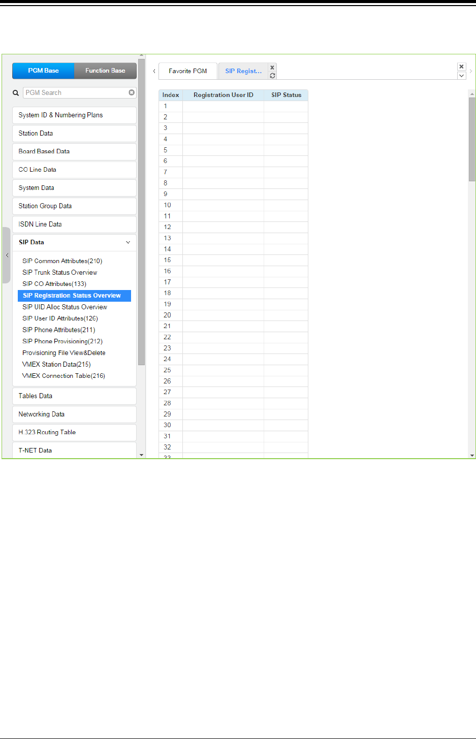
iPECS eMG80 & eMG800 & UCP
Administration and Programming Manual Issue 1.6
460
4.4.8.4 SIP Registration Status Overview
Figure 4.4.8.4-1 SIP Registration status overview
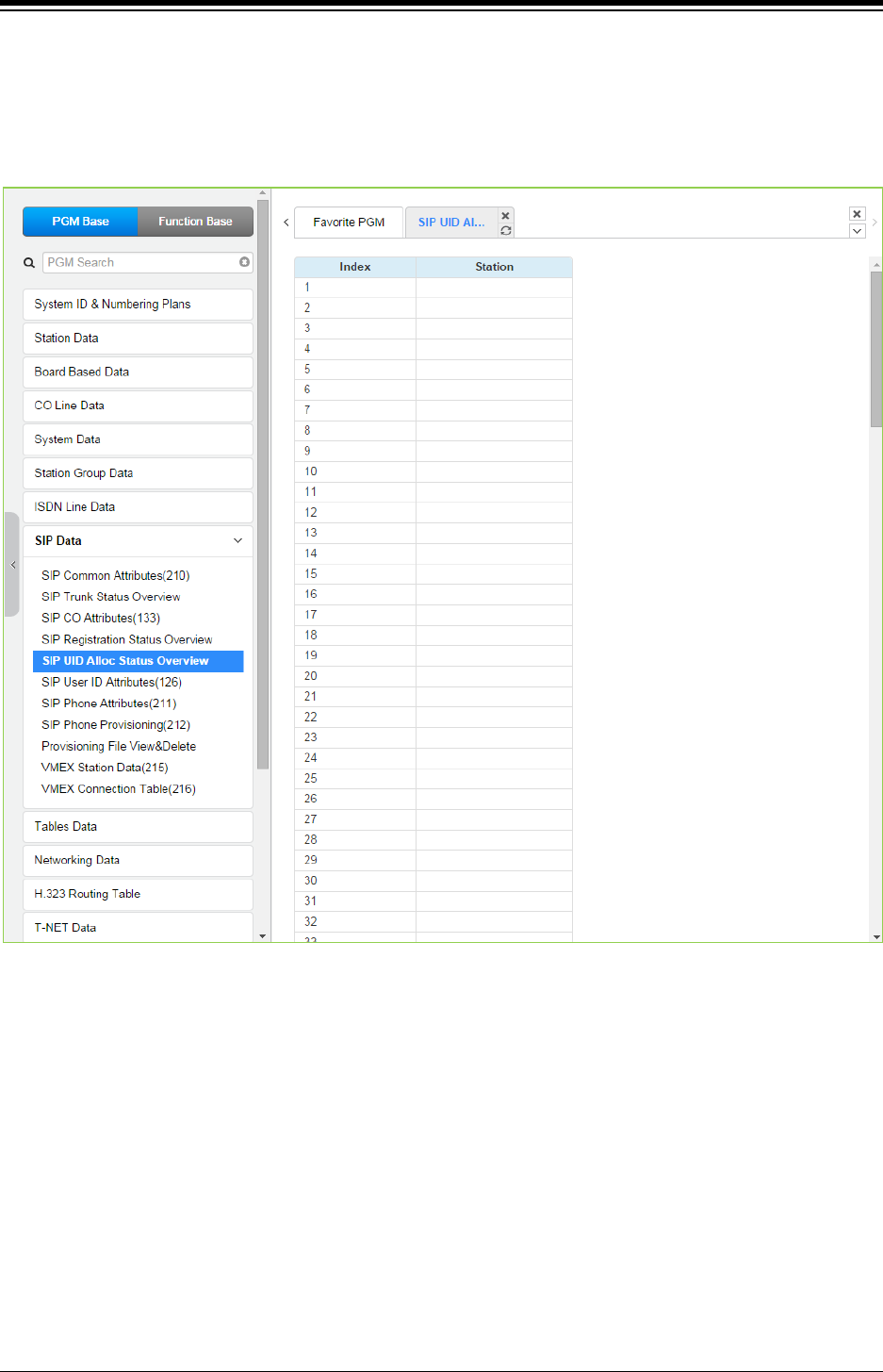
iPECS eMG80 & eMG800 & UCP
Administration and Programming Manual Issue 1.6
461
4.4.8.5 SIP UID Allocation Status Overview
Selecting SIP User ID Allocation Status will display the allocation overview page. The SIP User Id
Allocation Status Overview page displays the station(s) assigned to each SIP User Id index in the
Station Common Attributes PGM 111.
Figure 4.4.8.5-1 SIP UID Allocation Status Overview
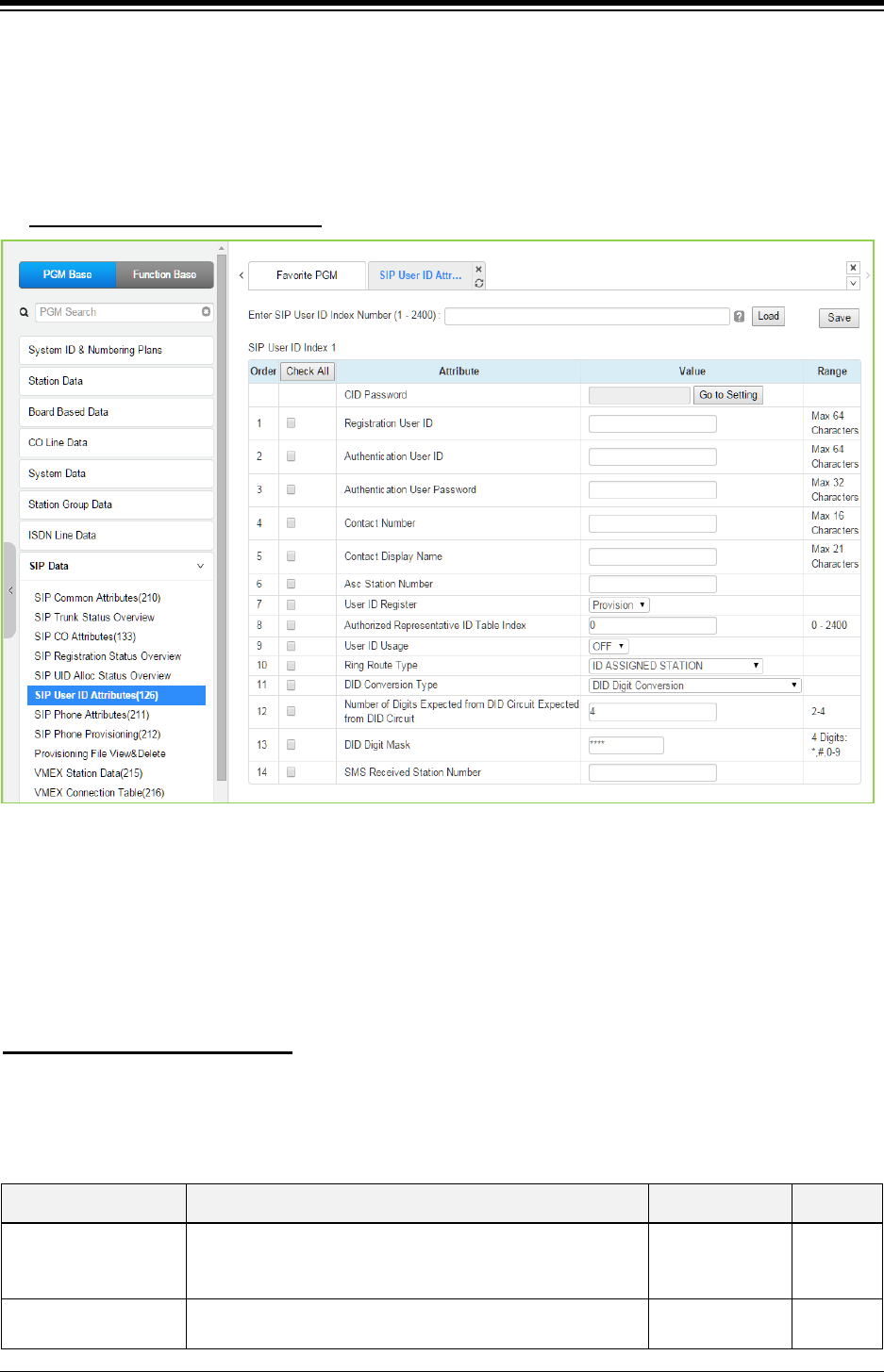
iPECS eMG80 & eMG800 & UCP
Administration and Programming Manual Issue 1.6
462
4.4.8.6 SIP User ID Attributes – PGM 126
Selecting SIP User ID Attributes will display the SIP User ID input page. Enter a valid SIP User ID
Index Number range, see Station Data, and click [Load] to view the SIP User ID Attributes for the
first index in the range. Enter new data and click [Save] to modify the attributes for the index
range.
Enter SIP User ID Index number
: eMG80: 1-140 / eMG800: 1-1200 / UCP: 1-2400
Figure 4.4.8.6-1 SIP User ID Attributes
For each station, an index to the SIP User Id Attributes Table is defined in PGM 111 Station
Attributes. The SIP User Id Attributes Table defines SIP characteristics associated with the index
including User ID, Authentication name, etc. These characteristics are required for proper
operation of the system and registration of the iPECS IP and LDP phones when employed with
SIP trunk. See also, PGM 133. Note PGM 126 and PGM 133 are accessible only via Web Admin.
You can set the CID password to click “Go to Setting” button. After clicking it, you will move to the
following PGM 162 and set the CID password, and then save CID password to mark tick on the
save box and click the Save button.
Setting CID Password directly
Table 4.4.8.6-1 SIP User ID ATTRIBUTES
ATTRIBUTE DESCRIPTION RANGE DEFAULT
Registration User ID
This field defines the SIP User Id from by the SIP Service
provider. The User Id has the format User ID@Domain.
Note the domain is commonly the system IP address.
Max. 64
characters
Authentication User ID The SIP Service Provider may require authentication of the
user for registration and at other times during call setup.
Max. 64
characters

iPECS eMG80 & eMG800 & UCP
Administration and Programming Manual Issue 1.6
463
Table 4.4.8.6-1 SIP User ID ATTRIBUTES
ATTRIBUTE DESCRIPTION RANGE DEFAULT
The Authentication name from the provider must be entered
for proper SIP registration.
Authentication User
Password
The SIP Service Provider may require authentication of the
user for registration and at other times during call setup.
The Authentication password from the provider must be
assigned for proper SIP registration.
Max. 32
characters
Contact Number The Contact header of SIP messages is populated with the
specified SIP User ID.
Max. 16
characters
Contact Display Name The Display Name specified is used for the Contact header
Name field.
Max. 21
characters
Associative Station
Number
Not used. Station number
User ID Register
The SIP Trunks are provided in two formats
1) Registered: the system must register for service
often using Authentication
2) Provision: the provider sends all SIP messages to a
fixed IP; the system does not register for service.
Register/
Provision Provision
Authorized
Representative ID
Table Index
The User Id can be assigned an index of another User ID.
When the SIP CO is configured to employ the Authorized
Representative Id as the SIP “From” or “Contact” header,
the indexed User ID is employed.
eMG80:0~140
eMG800:0~1200
UCP:0~2400
0
User ID Usage
If registration is enabled (User ID Register above) the
iPECS can send the User ID or Authorized Representative
ID to the SIP Proxy to register the ID. Otherwise, only the
Authentication Name and password are used.
OFF
ON OFF
Ring Route Type
Incoming calls from a SIP trunk can be routed
1) to the ID assigned Station (any station with any of the
SIP
User ID Table Indices in PGM 111 matching the incoming
SIP User Id),
2) based on CO/IP Ring assignments (PGM 144),
3) using DID treatment defined below, or
4) follow the MSN Table routing (PGM 145).
ID Assigned
Station/
Ring Assignment/
DID Conversion/
MSN-DID
Conversion(PGM
145)
ID
assigned
Station
DID Conversion Type
When the Ring Route above is defined as DID, the system
will send the call to a destination based on the DID
conversion selected here. The digits in the SIP User ID may
be used “as is” to identify the desired station, modified
based on the DID Digit mask below and routed to the
resulting station or the modified DID number can be used as
an index to the Flexible DID Conversion Table, PGM 231 to
route the call.
DID Digit
Conversion/
Use ‘as is’/
Modify Using
Flexible DID
Conversion Table
Use ‘as is’
Number of Digits (2-4)
Expected from DID
Circuit
When DID Digit Conversion or Flexible DID Conversion
Table routing is used, the number of digits received is
defined in this field.
2-4 3
DID Digit Mask
(4digits: *,#,0-9
When DID Digit Conversion or Flexible DID Conversion
Table routing is used, the digit conversion is defined in this
field. For each of the four (4) digits, use “*” to accept any
digit, “#” to delete the digit, or a digit 0-9 to replace the digit.
4 Digits: *, #, 0-9 #***
SMS Received Station
Number
When an SMS is received for this User Id, the Station to
receive the SMS must be defined.
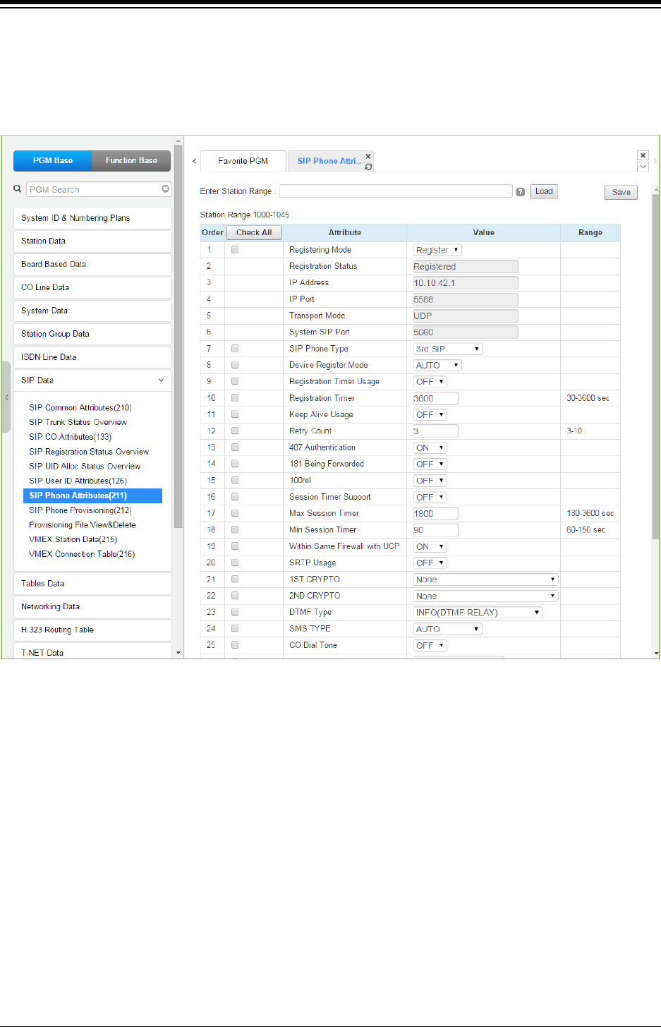
iPECS eMG80 & eMG800 & UCP
Administration and Programming Manual Issue 1.6
464
4.4.8.7 SIP Phone Attributes - PGM 211
Selecting SIP Phone Attributes will display the SIP Phone input page. Enter a valid SIP Station
Number or range, and click [Load] to view the SIP Phone Attributes for the first Station Number
in the range. Enter new data and click [Save] to modify the attributes for a Station or range.
Figure 4.4.8.7-1 SIP Phone Attributes
< Registration >
For a new registration of SIP station, input ID/PWD & Desired Station Number in PGM 443 of
Station User Login Table. This SIP Phone Attributes are for Stations that are already registered to
system.
− Register Mode - Register/ Manual: Set Registration Time Out or Not
− Registration Status: View connection status (Disconnected or Not) for a station
− IP Address: SIP Phone‘s IP address
− IP Port: SIP Phone‘s IP Port Number
− Transport Mode: SIP signaling method
− SIP Phone Type: Automatically Assigned by System
− Device NAT Usage: Automatic Detection
− Registration Timer Usage: OFF – Assign (Re-) Registration Timer by Provisioning
(212), ON – Assign (Re-) Registration Timer by SIP Phone Attributes (211).
− Registration Timer: more than 10 minute recommended.
− 407 Authentication: Authentication of Registration (and Call Setup). To implement

iPECS eMG80 & eMG800 & UCP
Administration and Programming Manual Issue 1.6
465
authentication, user login Password should be available in PGM 443 for the
Station.
< Keep Alive / NAT Resolution >
To keep stable information of SIP Phone‘s Connection, IP address and Port number that is under
NAT environment, system uses ‘OPTIONS’ message to implement Keep Alive and assist NAT
resolution - effort to maintain IP address of SIP Phone by sending message so often from system
to SIP Phone. SIP Phone should be capable to answer for ‘OPTIONS’ message
− Check Message Sending Timer in [SIP Data / SIP Attributes (210)] : 120 seconds
− Keep Alive Usage for a SIP Station in [SIP Data / SIP Phone Attributes (211)] : ON
− Retry Count for a SIP Station in [SIP Data / SIP Phone Attributes (211)] : 3
< System Firewall Resolution >
In case of firewall routed with MPB, to distinguish remote SIP Phone that is outside of firewall
from system local area a check bit is required per a SIP Station. With this check bit, system can
determine whether to serve communication using firewall mapped WAN IP address of MPB or
serve communication using LAN IP address of MPB/UCP.
− SIP Phones that are outside of system protect firewall : [SIP Data / SIP Phone
Attributes (211)] – ‘Same Firewall with MPB/UCP’ to ‘OFF’
< Session Timer >
To confirm talk state frequently during in talk state, system sends ‘UPDATE’ message to SIP
Phone. If there is no response for the UPDATE message with in Maximum session timer, system
will disconnect the talking call.
− [SIP Data / SIP Phone Attributes (211)] – Session Timer Support : ON
− [SIP Data / SIP Phone Attributes (211)] – Max Session Timer : if exceed, disconnect
talking call
− [SIP Data / SIP Phone Attributes (211)] – Min Session Timer: minimum guard timer for
session timer negotiation.
< SRTP >
Voice & Video Data Encryption requires synchronization of CRYPTO method between system
and SIP Phone side. If system specifies SRTP information then same information should be in
SIP Phone side by Phone user programming.
SRTP usage requires a SRTP relay channel via system VOIU and VOIB/VOIM.
− [SIP Data / SIP Phone Attributes (211)] – SRTP Usage: ON
→SIP Phone self-programming is required, too – SRTP ON
− [SIP Data / SIP Phone Attributes (211)] – 1st CRYPTO key generation type: one of
ARIA_CM_192_HMAC_SHA1_80, AES_CM_128_HMAC_SHA1_80,
ARIA_CM_128_HMAC_SHA1_80
→SIP Phone self-programming is required, too – 1st/2nd CRYPTO method
− [SIP Data / SIP Phone Attributes (211)] – 2nd CRYPTO key generation type: one of
ARIA_CM_192_HMAC_SHA1_80, AES_CM_128_HMAC_SHA1_80,
ARIA_CM_128_HMAC_SHA1_80
→SIP Phone self-programming is required, too – 1st/2nd CRYPTO method

iPECS eMG80 & eMG800 & UCP
Administration and Programming Manual Issue 1.6
466
< DTMF >
1) INFO (OUT BAND) type DTMF
- Presented in SIP signaling message.
- INFO (SIMPLE DTMF) / INFO (NORTEL NETWORKS) / INFO (DTMF RELAY) / INFO
(TELEPHONE EVENT)
- Default: INFO (DTMF RELAY)
2) TONE (INBAND) type DTMF
- Presented in RTP packet
- Additional VOIU/VOIB (VOIM) DSP channel is required to detect DTMF in RTP
- INBAND / 2833
<CO DIAL TONE>
This is to avoid double play of CO dial tone
‘Set’ if SIP phone plays CO dial tone by itself. If not, there will be another CO dial tone from
external.
<Request URI Type>
Some SIP Phone will reject Request-URI if IP and port in domain field is different from its
contact IP and port.
‘Normal’: IP and port number in Request URI domain field will be the real IP and port number
of the SIP phone.
‘KT-FMC’: IP and port number in Request URI domain field will be system IP and port
<Busy Serve>
System Busy Tone: there will be a ‘busy-tone’ on busy state that is presented by system.
Additional VOIB/VOIU/VOIM DSP channel is required.
486 Busy Message: there will be ‘486 busy’ SIP signaling response on busy state.
<Call Initiation Mode>
For a SIP station, system can establish multiple or single call sessions. With this option system
can control ‘call-wait’ option in system side. Normally, the SIP Phone has its ‘call-wait ON/OFF’
option by itself.
Options are as below:
‘Multiple’: for a new additional call to SIP Phone, system initiates every call for the SIP
Phone regarding it is on idle state. The ‘call-wait allow/deny’ is decided by SIP Phone itself.
‘Single’: system initiates only one call for a SIP Phone. The ‘call-wait’ is denied by system
side. So, a call to a busy SIP station will be implemented on a busy state call-control.
Table 4.4.8.7-1 SIP PHONE ATTRIBUTES
ATTRIBUTE DESCRIPTION RANGE DEFAULT
Registration Mode Initial registration of a SIP phone is accomplished
employing the parameters set in Station User Login
Manual
Register
Register

iPECS eMG80 & eMG800 & UCP
Administration and Programming Manual Issue 1.6
467
Table 4.4.8.7-1 SIP PHONE ATTRIBUTES
ATTRIBUTE DESCRIPTION RANGE DEFAULT
PGM 443. The SIP phone can be required to register
with the system periodically based on the Registration
Timer or the registration can be maintained without the
need for the SIP phone to reregister with the system
(Manual).
Registration Status The system will display the status of the SIP phone
registration.
IP address The system will display the IP address of the registered
SIP phone.
IP Port The system will display the IP port used for the
registered SIP phone.
Transport Mode
The system will display the IP transport used by the
registered SIP phone for signaling messages (UDP,
TCP or TLS). In case of TLS, the options configured in
the SIP Common Attributes (PGM 210) apply.
UDP
System SIP Port The system will display the system SIP Port.
SIP Phone Type
The type of SIP phone is generally determined by the
system and can be an Ericsson-LG standard SIP
phones or the 3rd party SIP phone type.
3rd SIP
Device register mode
The Register Mode determines if the SIP phone is
behind a NAT server. When set in the Auto mode, the
system will determine if the phone is behind a NAT
server.
AUTO,
NO NAT,
NAT
AUTO
Registration Timer
usage
When the Registration Mode is “Register”, the phone
must register with the system periodically. The timer
that determines the period can be the Registration
Timer below (ON) or, when OFF, the timer is assigned
through provisioning (PGM212).
OFF
ON OFF
Registration Timer
When the Registration Timer is enabled above, the
system informs the SIP phone that registration is
required at intervals of this Registration Timer. If the
phone does not register within the timer, the phone is
placed in an Out-of-Service state until the phone
registers. Note shorter times will increase LAN traffic.
30-3600 3600
Keep Alive Usage
The system will periodically send an Option message to
assure a connection with the registered SIP phone.
Note when separated by a NAT server, Keep-Alive
should be employed to maintain the NAT table record.
The Check Message Sending Timer in PGM 210
determines the frequency.
OFF
ON OFF
Retry Count
The system periodically sends an Option message to
assure a connection with the registered SIP phone. If
there is no response, the system sends additional
Option messages, and, after the retry count, considers
the SIP phone Out-of-Service.
3-10 3
407 Authentication
The system can challenge the SIP phone during
registration and outgoing call set-up with a SIP 407
Authentication message requiring the SIP phone to
provide the Authentication Id and password assigned in
OFF
ON ON

iPECS eMG80 & eMG800 & UCP
Administration and Programming Manual Issue 1.6
468
Table 4.4.8.7-1 SIP PHONE ATTRIBUTES
ATTRIBUTE DESCRIPTION RANGE DEFAULT
the Station Login PGM 443.
181 Being Forwarded N/A OFF
ON
OFF
100 rel Support N/A OFF
ON
OFF
Session Timer
Support
During a SIP call or “session”, there are no signaling
packets sent or received from the SIP Call server. In
order to assure a session is still active, the system can
periodically send an Update message that the SIP Call
server should acknowledge.
OFF
ON OFF
Max Session Timer When “Session Timer Support” is enabled, the system
will verify the session at this timer interval.
180-3600 1800
Min Session Timer
During negotiation with “Session Timer Support”
enabled, the system will use this value as the minimum
Session expiration timer and will not respond to a SIP
Option message prior to expiration of this timer.
60-150 90
Within same firewall
with UCP (MPB)
For a remote SIP phone, the system must
communicate with the phone employing the system’s
“Firewall” address (OFF). Otherwise, the system
employs the LAN address to communicate with the SIP
phone.
OFF
ON ON
SRTP Usage
When supported by the SIP phone, the system can
encrypt media (RTP) packets employing SRTP (Secure
Real-Time Protocol).
OFF
ON OFF
1st CRYPTO
The first priority cryptographic method for SRTP is
selected from the below:
None
ARIA_CM_192_HMAC_SHA1_80
AES_CM_128_HMAC_SHA1_80
ARIA_CM_128_HMAC_SHA1_80
AES_CM_192_HMAC_SHA1_80
ARIA_CM_256_HMAC_SHA1_80
AES_CM_256_HMAC_SHA1_80
None
2nd CRYPTO
The second priority cryptographic method for SRTP is
selected from the below:
None
ARIA_CM_192_HMAC_SHA1_80
AES_CM_128_HMAC_SHA1_80
ARIA_CM_128_HMAC_SHA1_80
AES_CM_192_HMAC_SHA1_80
ARIA_CM_256_HMAC_SHA1_80
AES_CM_256_HMAC_SHA1_80
None
DTMF Type
DTMF dialing signals sent by the SIP phone must be
defined for the system to detect the tones properly. For
Inband DTMF, a VoIP channel is required.
INBAND,
2833,
INFO(SIMPLE
DTMF),
INFO(NORTEL
NETWORKS),
INFO(DTMF
INFO(DTMF
RELAY)

iPECS eMG80 & eMG800 & UCP
Administration and Programming Manual Issue 1.6
469
Table 4.4.8.7-1 SIP PHONE ATTRIBUTES
ATTRIBUTE DESCRIPTION RANGE DEFAULT
RELAY),
INFO(TELEPHONE
EVENT)
SMS Type The Short Message Service Protocol (type) must be
selected to support SMS.
AUTO,
Text/plan,
Text/plan(KR),
Xnipm+xml
AUTO
CO DIAL TONE
When the user of a SIP phone dials a CO/IP Line
access code with Enblock dialing, the system can
provide virtual dial tone to the user.
OFF
ON OFF
MWI NOTIFY
For compatible SIP phones, the system supports SIP
Subscribe/Notify. When enabled here, the system
sends Message Waiting notifications to the SIP phone.
OFF
message-summary OFF
Request URI Type
The SIP Request header Domain field can use the SIP
phone’s IP address and port (Normal) or for ‘KT-FMC’
the Request URI Domain field will be system IP and
port.
Normal
KT FMC Normal
Busy Service
To indicate a busy condition to the SIP phone, the
system can provide RTP packets with busy tone or the
SIP 486 Busy message. Providing busy tone requires a
VoIP DSP channel in the system.
System Busy Tone,
486 Busy Message
System Busy
Tone
Call Initiation Mode
The system can route calls to the SIP phone while busy
(Multiple). In this case, the SIP phone determines if Call
Waiting is supported. Otherwise, if the SIP phone is
busy, the system routes calls based on the busy
treatment (Single).
Multiple,
Single Multiple
Pre Audio Connection
For DTMF
The system normally provides the 183 Session
Progress SIP message to establish a “Pre-audio”
connection. The “Pre-audio” connection permits the
system to send tones (CO dial tone or ringback tone) to
the SIP phone. In addition, the SIP phone can send
DTMF tones the user dials in response to CO dial tone
or a remote IVR message. Some SIP phones may
require the 200 OK message, which “answers” the call,
to allow dialing after the call has been initiated.
183 Session
Progress,
200 OK
183 Session
Progress
Do Not Overwrite
Station Name
This feature can be set in case of the following Range:
- OFF(REG): Extension name will be updated with
displayed in REGISTER message.
- ON: Extension name will not be updated.
- OFF(INV): Extension name will be updated with
displayed in INVITE message.
- OFF(REG+INV): Extension name will be updated
with displayed in REGISTER or INVITE message.
OFF(REG),
ON,
OFF(INV),
OFF(REG+INV)
OFF(REG)
Follow CO Enblock
Process
Skip "dial tone by system" phase and deliver
transparent message of CO trunk to SIP phone.
OFF
ON
OFF
Suffix DID Tbl to CLI If this option is ON, CLI is published by suffixing DID
Conversion table index.
OFF
ON
OFF
SIP Profile
Select the SIP Profile type between Default and
CISCO-CP.
- Default: Normal SIP phone.
- CISCO-CP: CISCO SIP phone.
Default,
CISCO-CP Default
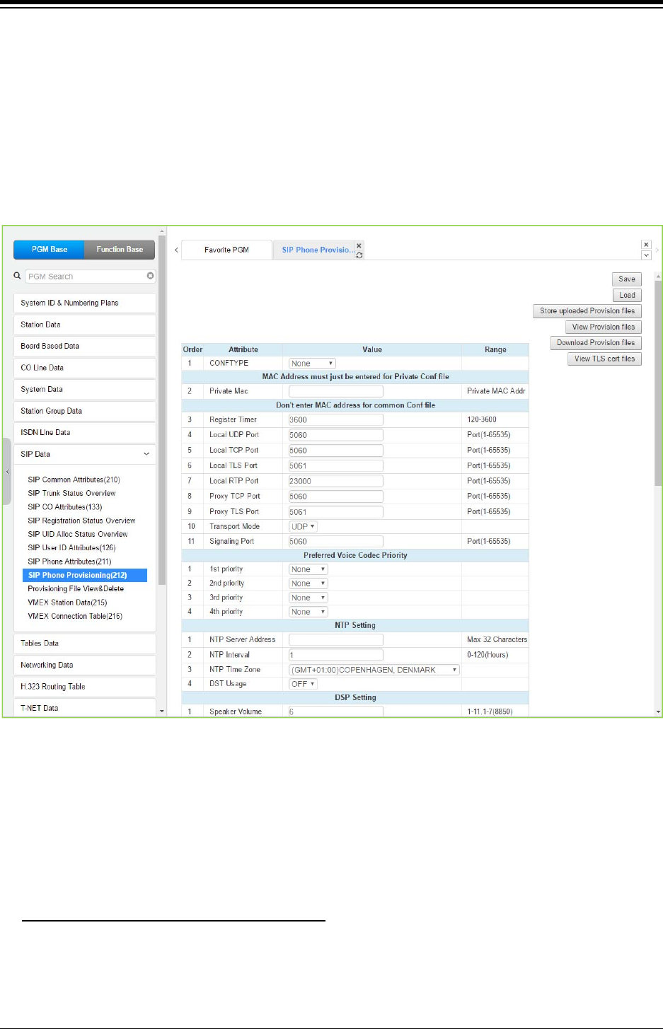
iPECS eMG80 & eMG800 & UCP
Administration and Programming Manual Issue 1.6
470
4.4.8.8 SIP Phone Provisioning - PGM 212
Selecting SIP Phone Provisioning will display the SIP Phone Provisioning Data input page. Select
one of CONFTYPE (Ericsson-LG Enterprise SIP Phone Type) and set the attributes you want to
set for those types of SIP Phones on their registration to system and press [Save] button.
To store provisioning files that have been uploaded to the iPECS system, press [Store uploaded
Provision files]. To view the stored configuration files, press [View Provision files]. To
download Provision files, press [Download Provision files]. To view TLS Cert. files, press [View
TLS Cert files] button.
Figure 4.4.8.8-1 SIP Phone Provisioning
<Why?>
To pre-assign default attributes and download configuration to SIP Extensions when they register
to System.
< For Who? (for all of specified Phone type or for one MAC specified Phone) >
CONFTYPE: select Phone Type / Mandatory
< Ericsson-LG Enterprise WIT-400HE >
− Currently MPB/UCP (TFTP only) does not proceed provisioning for WIT400H(http
only) because of different method
→But, WIT-400HE follows System’s default provisioning by itself automatically.

iPECS eMG80 & eMG800 & UCP
Administration and Programming Manual Issue 1.6
471
< Ericsson-LG Enterprise LIP8002 / LIP88xx/LIP-8XXXE >
− MPB/UCP proceed provisioning for LIP8002 / LIP88xx/LIP-8XXXE
< Other 3rd party SIP Extensions >
− Does not proceed provisioning
Private Mac: specify MAC address if provisioning target is only for one specific SIP
extension / Optional
< For What ? >
Re-Registration Timer: this will be useless if [SIP User ID Attributes (PGM 126) - Registration
Timer Usage] is ON
SIP Extension’s Local UDP/TCP/TLS Port number
Proxy Port: Server port number in sight of SIP Extension toward MPB/UCP
Transport: Signaling mode
SIP Extension’s CODEC Priority
NTP Server and DST setting
The default volume of Speaker/Handset/Headset, maximum volume of Handset
Table 4.4.8.8-1 SIP PHONE PROVISIONING
ATTRIBUTE DESCRIPTION RANGE DEFAULT
CONFTYPE To modify or view a Configuration file, from the drop-down,
select an Ericsson-LG Enterprise SIP Phone type. None
MAC address must just be entered for Private Conf file
Private MAC
There are two types of Config files, a global file for all phones of
a specific type and a phone specific file. To view or modify a
Phone specific file, enter the MAC address of the SIP phone.
Private MAC
address
Don’t enter MAC address for common Conf file
Registration Timer
When the SIP User ID Attributes are configured with
Registration Mode=Register and the Registration Timer
Usage=OFF, this timer is used to determine the valid
registration period.
120-3600 3600
Local UDP Port When employing UDP transport, this port number is employed
for messages from the SIP phone. Port (1-65535) 5060
Local TCP Port When employing TCP transport, this port number is employed
for messages from the SIP phone. Port (1-65535) 5060
Local TLS Port When employing TLS transport, this port number is employed
for messages from the SIP phone. Port (1-65535) 5061
Local RTP Port The system sends RTP packets to the SIP phone using the first
port available starting with this port number. Port (1-65535) 23000
Proxy TCP Port The SIP phone will send messages to the UCP system over this
SIP Server port. Port (1-65535) 5060
Proxy TLS Port The SIP phone will send messages to the UCP system over this
SIP Server port. Port (1-65535) 5061
Transport Mode
The IP packet transport mode used between the system and
SIP phone for signaling messages is defined as UDP, TCP or
TLS. In case of TLS, the options configured in the SIP Common
UPD
TCP
TLS
UDP

iPECS eMG80 & eMG800 & UCP
Administration and Programming Manual Issue 1.6
472
Table 4.4.8.8-1 SIP PHONE PROVISIONING
ATTRIBUTE DESCRIPTION RANGE DEFAULT
Attributes (PGM 210) apply.
Signaling Port When SIP phone transports the message to the system, this
port number is employed for messages from the SIP phone. Port (1-65535) 5060
Preferred Voice CODEC Priority
1st priority ~ 4th
priority
When the system negotiates with the SIP phone, the Codec
priority specified is employed. If only the 1st. priority Codec is
defined, only that Codec is available from the phone.
If the Codec is not supported by the remote party, the call will
fail.
G.711-u
G.711-a
G.723.1
G-729
G.722
None
NTP Setting (Need for TLS)
NTP Server
Address
The IP8800 series phones employ NTP to determine the time of
day. The NTP server id must be configured for the phone.
Max. 32
Characters
NTP Interval The phone periodically checks the NTP server to determine the
proper time of day.
0-120
(Hours) 1
NTP Time Zone The phone must be configured with the local Time Zone for
proper operation and time display. GMT
DST Usage The phone must be configured to support Daylight Saving Time. ON
OFF OFF
DSP Setting
Speaker Volume The default volume level of SIP phone speaker can be set
through the Config file.
1-11,
1-7 (IP8850) 6
Handset Volume The default volume level of SIP phone handset can be set
through the Config file.
1-11,
1-7 (IP8850) 6
Headset Volume The default volume level of SIP phone headset can be set
through the Config file.
1-11,
1-7 (IP8850) 6
MAX Handset
Volume
The default maximum volume level of SIP phone handset can
be set through the Config file.
1-11 11
Digit Map
Dial Tone Digit A digit string can be defined in the Config file so that the SIP
phone will provide a “Second Dial Tone” to the user.
Max. 256
Digits
Inter Digit Timer Inter digit timer between Dial digit in SIP Phone. 01-20
(Sec.) 3
Pause Timer Dial Pause timer in SIP Phone. 01-20
(Sec.) 3
Digit Map Send setup to system numbering plan. Max. 1000
Emergency Code The Emergency dial code for the SIP phone can be set through
the Config file. Max. 1000
System Setting
Feature Sync.
With Do Not Disturb and Call Forward feature synchronization
ON, when SIP Phone changes the DND or Call Forward state,
the system is informed of the change in status.
ON
OFF ON
Auto Idle Timer Phone goes to idle after this timer when the phone receives
disconnect message or signal from system.
00-99
(Sec.) 5
Check Domain The IP8800 SIP Phones can be configured to verify the domain
in SIP messages match the registered proxy server.
OFF
ON ON
Telnet Usage The IP8800 series phones can support Tenet access to the CLI. Enable Disable

iPECS eMG80 & eMG800 & UCP
Administration and Programming Manual Issue 1.6
473
Table 4.4.8.8-1 SIP PHONE PROVISIONING
ATTRIBUTE DESCRIPTION RANGE DEFAULT
Disable
WEB Usage The IP8800 series phones incorporate a Web server for access
to the phone configuration files.
Enable
Disable Disable
Security Setting
Cert File Format The system supports two certification formats Privacy-Enhanced
Electronic Mail (PEM) or Distinguished Encoding Rules (DER).
PEM(Normal),
DER (Normal) PEM(Normal)
Crypt Mode The system provisioning cryptosystem is configured to employ
either RSA or ECC (Elliptic Curve Cryptography).
RSA
ECC RSA
TLS Version TLS (Transport Layer Security) version can be selected. The
default is TLS 1.2 for strong secure.
TLS1.0
TLS1.2 TLS1.2
First TLS Crypto
SIP signaling TLS encryption primary key method.
System will be restarted after Save.
The range is as below:
None,
AES_128_CBC_SHA,
ARIA_128_CBC_SHA,
AES_128_CBC_SHA256,
ARIA_256_CBC_SHA256
Refer to
description None
Second TLS
Crypto
SIP signaling TLS encryption second key method.
System will be restarted after Save.
The range is as below:
None,
AES_128_CBC_SHA,
ARIA_128_CBC_SHA,
AES_128_CBC_SHA256,
ARIA_256_CBC_SHA256
Refer to
description None
SRTP Usage
When implemented by the carrier, the system can encrypt
media (RTP) packets employing SRTP (Secure Real-Time
Transport Protocol).
Disable,
Enable Disable
First SRTP Crypto
The first priority Crypt method for SRTP.
The range is as below:
None,
AES_CM_128_HMAC_SHA1_80,
ARIA_CM_128_HMAC_SHA1_80,
ARIA_CM_192_HMAC_SHA1_80
Refer to
description None
Second SRTP
Crypto
The second priority Crypt method for SRTP.
The range is as below:
None,
AES_CM_128_HMAC_SHA1_80,
ARIA_CM_128_HMAC_SHA1_80,
ARIA_CM_192_HMAC_SHA1_80
Refer to
description None
Save button: save provisioning for the specified common CONFTYPE or specific SIP Extension with Private MAC.
Store uploaded Provision files button: Store the uploaded provision files.
Download Provision files button: download the provision files.
View Provision files button: display all of saved provisioning information.
View TLS Cert files button: display all of saved TLS Cert files information.
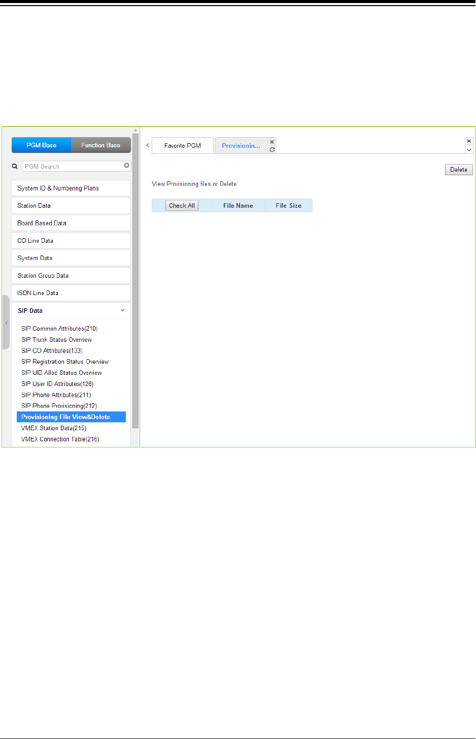
iPECS eMG80 & eMG800 & UCP
Administration and Programming Manual Issue 1.6
474
4.4.8.9 Provisioning File View & Delete
Selecting Provisioning File View & Delete displays a list of all the Provisioning files stored in the
provisioning files directory as shown in the following figure. Note this does not included files that
have been uploaded to iPECS eMG/UCP file system but not “stored” under PGM 212. To delete
a file from the provisioning file directory, check the box in front of the file to be deleted then click
[Delete].
Figure 4.4.8.9-1 Provisioning File View & Delete
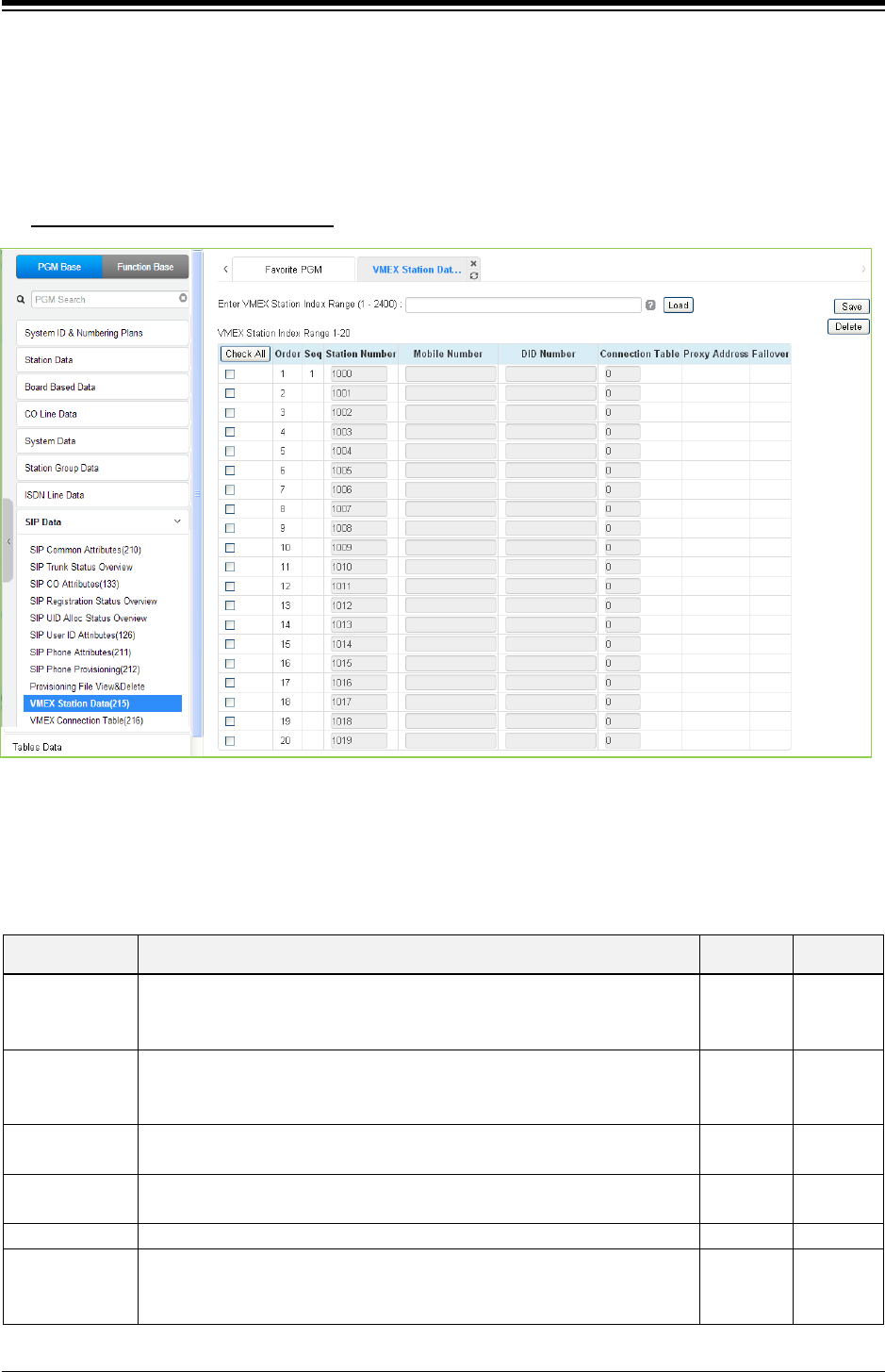
iPECS eMG80 & eMG800 & UCP
Administration and Programming Manual Issue 1.6
475
4.4.8.10 VMEX Station Data - PGM 215
Selecting VMEX Station data will display the VMEX Station Data input page as shown in the
following figure. Enter a range, and click [Load] to view the VMEX Data for all stations in the
range. Use the check boxes to indicate the VMEX Station Data to modify. After modifying the
data, click [Save] to store the VMEX Station Data.
Enter VMEX Station Index Range
: eMG80: 1-140 / eMG800: 1-1200 / UCP: 1-2400
Figure 4.4.8.10-1 VMEX Station Data
The Virtual Mobile Extension feature permits a remote mobile phone to act as a station within the
system employing SIP. For proper operation, various parameters as shown in the following table
must be configured for the Station data.
Table 4.4.8.10-1 VMEX Station Data
ATTRIBUTE DESCRIPTION RANGE DEFAULT
Station Number
The station number of the VMEX can be modified. The VMEX station
number must not conflict with other numbering plans. The station number
can be modified here or in PGM 105 and is affected by the 8 Digit Table
Station
Number
Mobile Number
The Caller Id of the Mobile phone must be entered to allow the system to
recognize the VMEX phone. The mobile number here must match the
number in the SIP From header.
DID Number The DID number associated with the VMEX must be configured to allow
for recognition of calls to the VMEX.
Connection
Table
An index to the Connection Table PGM 216 must be entered. One of ten
indices can be assigned permitting the use of multiple SIP Call servers.
0 ~ 10
Proxy Address
The SIP Proxy for the VMEX must be configured for access to the VMEX.
Fail-over
The index (Station Number) of the Mobile Extension Table (PGM 236)
can be assigned for Fail-over operation. In this case, the Table entry
must be configured for fail-over operation.
Station
Number
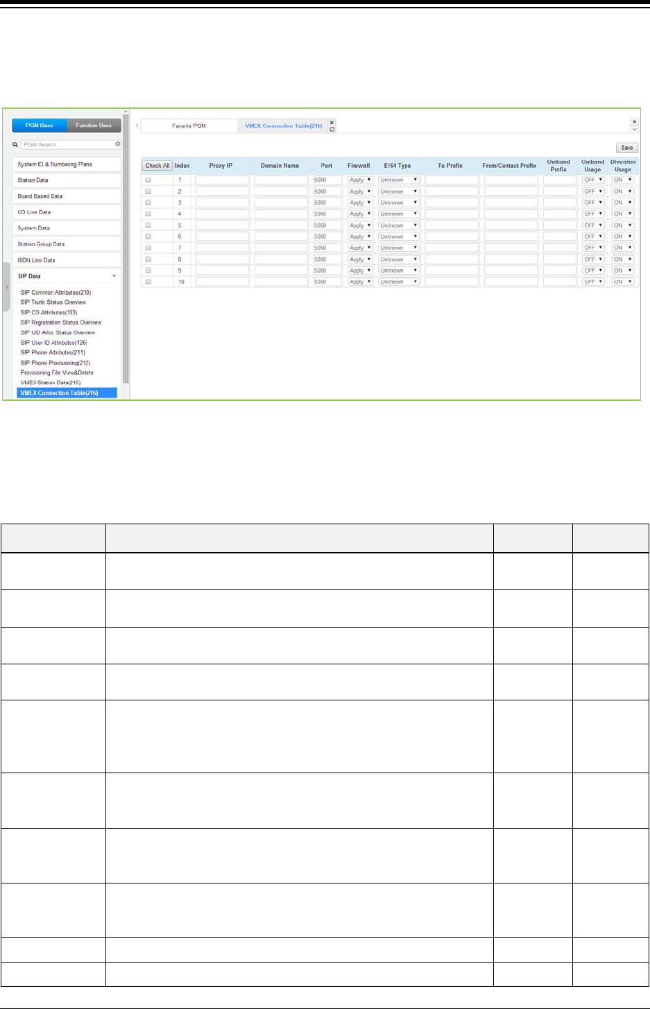
iPECS eMG80 & eMG800 & UCP
Administration and Programming Manual Issue 1.6
476
4.4.8.11 VMEX Connection table - PGM 216
Selecting VMEX Connection table will display the VMEX Connection Data input page. Use the
check boxes to indicate the Table index data to modify and click [Save] button to store.
Figure 4.4.8.11-1 VMEX Connection Table
With VMEX, the carrier’s Mobile network sends calls to and from the Mobile phone directly to the
system employing a SIP Call server. For proper operation, the SIP Call server must be configured
and special prefix codes must be defined for calls from and to the mobile phone.
Table 4.4.8.11-1 VMEX Connection Table
ATTRIBUTE DESCRIPTION RANGE DEFAULT
Proxy IP This field assigns the IP address or URL of the Service Provider’s
SIP Proxy server.
Domain Name Domain name of the Service Provider’s SIP Call server that is used
in SIP “To:” headers.
Port Normally SIP signaling messages are sent on port 5060. If desired a
different port can be defined.
5060
Firewall The iPECS system can use the Firewall address or LAN address of
the iPECS system board when communicating with the VMEX.
Not/
Apply
Apply
E164
The structure of the received SIP invite To header from the VMEX
can be defined for proper conversion. This field is not presently
used.
Unknown
International
National
Local
Unknown
To Prefix
A special prefix code is included in the SIP invite “To” header sent
from iPECS system to the carrier’s SIP Call server to identify VMEX
service
3 to 5 digits
From Contact
Prefix
A special prefix code is included in the SIP invite “From” and
“Contact” header sent from iPECS system to the carrier’s SIP Call
server to identify VMEX service
3 to 5 digits
Outbound Prefix
A special prefix code that must be in the SIP invite “To” header
received by iPECS system for calls from the VMEX. If the prefix
received does not match this entry, the call is rejected.
8 digits
Outbound Usage Not used.
Diversion Usage Not used
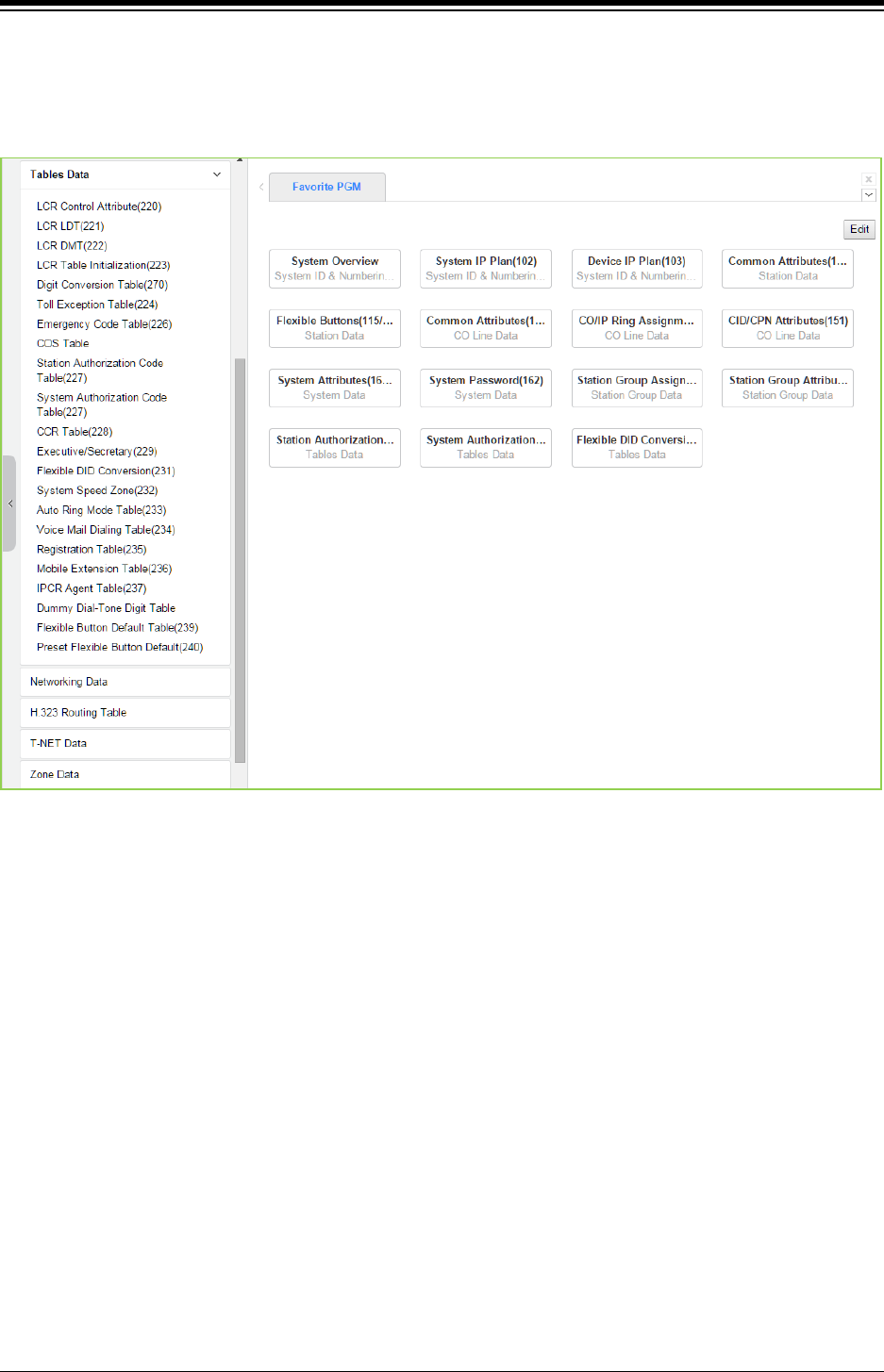
iPECS eMG80 & eMG800 & UCP
Administration and Programming Manual Issue 1.6
477
4.4.9 Tables Data
Selecting the Tables Data group returns the sub-menu displayed in the left frame as shown in the
following figure.
Figure 4.4.9-1 Tables Data
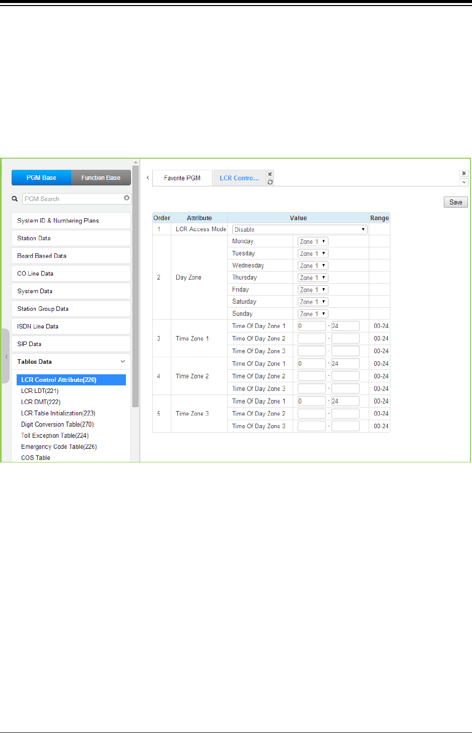
iPECS eMG80 & eMG800 & UCP
Administration and Programming Manual Issue 1.6
478
4.4.9.1 LCR Control Attributes - PGM 220
Selecting LCR Control Attributes will display the LCR Control Attributes data entry page. Click
[Save] button after changing Value.
The LCR Tables provide a mechanism to define the database, which will route outgoing calls,
particularly long distance, using the most cost effective route. User dialed digits are compared to
table entries and modified appropriately based on time of day, day of week, and assigned routes.
There are four LCR Tables, LCR Control Attributes, LCR Leading Digit Table, LCR Digit
Modification Table, and LCR Initialization Table.
Figure 4.4.9.1-1 LCR Control Attributes
The LCR Control Attributes Table, among other items, allows assignment of the LCR Access
Modes. The LCR Access Modes defines the user operations that will access the LCR feature.
The LCR Access Modes are:
LCR Disabled.
Loop (user dials ‘9’ or CO/IP Group code (8xx), or presses a Loop button).
Loop and Internal (user dials digits without a CO/IP Access Code prefix).
Loop and Direct CO Line (user dials CO Line Access Code (88xx) or pressing a {CO
line} button).
Loop, Direct CO Line, and Internal.
Internal, Loop, Direct CO and Direct Loop.
In addition, days of the week are grouped into zones (Day Zones) and the time of day can be set
into three groups (Time Zones). The following table provides general descriptive information and
input ranges.

iPECS eMG80 & eMG800 & UCP
Administration and Programming Manual Issue 1.6
479
Table 4.4.9.1-1 LCR Control Attribute
ATTRIBUTE DESCRIPTION RANGE DEFAULT
LCR Access Mode This entry defines the effective LCR modes, the modes
by which the user can access LCR.
Disable/
Only Loop LCR/
Internal and Loop
LCR/
Loop and Direct
CO LCR/
Internal, Loop and
Direct CO LCR/
Internal, Loop,
Direct CO and
Direct Loop LCR
Disable
Day Zone
Each day of the week is assigned to a Day Zone (1~3).
The active Day Zone is the Zone assigned to the
current day of the week.
Zone1~3
(days of the
week)
Zone 1
Time Zone1
This entry defines the hours of the day during which
each Zone is active for Time Zone 1. Note hours not
defined in Time Zone 2 and 3 are automatically part of
Time Zone 1.
00~24 00~24
Time Zone2
This entry defines the hours of the day during which
each Zone 2 is active for Time Zone 2. Note hours not
defined in Time Zone 2 and 3 are automatically part of
Time Zone 1.
00~24 00~24
Time Zone3
This entry defines the hours of the day during which
Zone 3 is active for Time Zone 3. Note hours not
defined in Time Zone 2 and 3 are automatically part of
Time Zone 1.
00~24 00~24
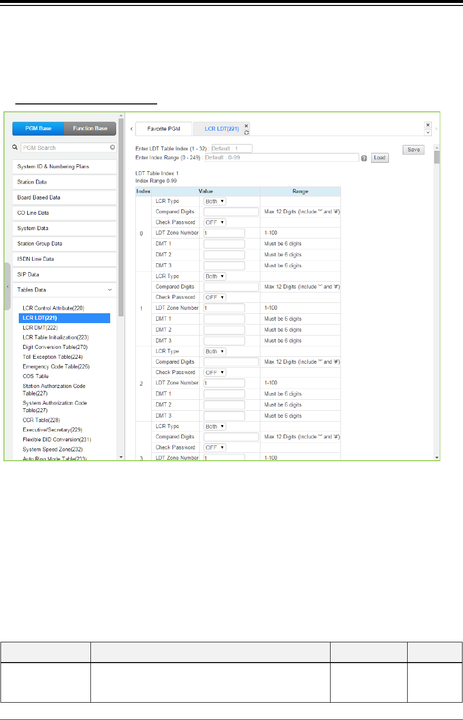
iPECS eMG80 & eMG800 & UCP
Administration and Programming Manual Issue 1.6
480
4.4.9.2 LCR LDT (Leading Digit Table) - PGM 221
Selecting LCR-LDT (Leading Digit Table) will display the LCR-LDT data entry page. Select the
LDT Index range desired, blue text above the table header. Click [Save] button after changing
Value.
Enter LDT Table Index Range
: eMG80: 1-10 / eMG800: 1-32 / UCP: 1-32
Figure 4.4.9.2-1 LCR Leading Digit Table
The Leading Digits Table is used to analyze the user-dialed digits to determine an appropriate
Digit Modification Table Index. LDT Tables are provided for 10 for eMG80 system & 32 for
eMG800/UCP system. The Table is divided into bins. The applicable LCR Access Modes (LCR
Type) and the digits (up to the first 12) dialed by the user are compared with the entries in the
Leading Digit Table. In addition, indices to the Digit Modification Table are defined for each of the
three (3) Zones and Time Zones configured in the LCR Control Attributes. The following table
provides a brief description and entries for the Leading Digit Table.
Table 4.4.9.2-1 LCR LEADING DIGITS
ATTRIBUTE DESCRIPTION RANGE DEFAULT
LCR Type This entry defines the LCR modes that will apply to this
LDT index.
Internal,
CO Line,
Both
Both

iPECS eMG80 & eMG800 & UCP
Administration and Programming Manual Issue 1.6
481
Table 4.4.9.2-1 LCR LEADING DIGITS
ATTRIBUTE DESCRIPTION RANGE DEFAULT
Compared Digits
Up to 12 digits that, if matched by the user dialed digits, will
access the DMT Indices of the associated Leading Digit
Table bin.
Max. 12 digits
(Include * and #)
Check Password
If enabled (ON), when the dialed digits match the LDT
digits, the system will send second dial tone to request the
user input a valid Authorization code.
OFF
ON OFF
LDT Zone Number
If the LDT Zone Number of a station/co line is equal to this
value, this LDT table is available to the station/co line.
(Station Data->Common Attributes(111), CO Line Data-
>Common Attributes(140))
1-100 1
DMT1
This entry defines the Digit Modification Table index
(00~99) for each Time Zone for Day Zone 1. The
appropriate index will be selected for the current Day and
Time Zone. One entry (DMT index) is made for each Time
Zone, six (6) digits.
Must be 6 digits
3 DMT indices
DMT2
This entry defines the Digit Modification Table index
(00~99) for each Time Zone for Day Zone 2. The
appropriate index will be selected for the current Day and
Time Zone. One entry (DMT index) is made for each Time
Zone, six (6) digits.
Must be 6 digits
3 DMT indices
DMT3
This entry defines the Digit Modification Table index
(00~99) for each Time Zone for Day Zone 3. The
appropriate index will be selected for the current Day and
Time Zone. One entry (DMT index) is made for each Time
Zone, six (6) digits.
Must be 6 digits
3 DMT indices
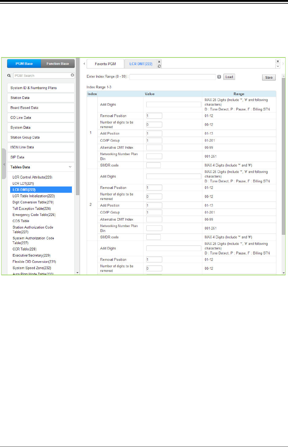
iPECS eMG80 & eMG800 & UCP
Administration and Programming Manual Issue 1.6
482
4.4.9.3 LCR DMT (Digit Modification Table) - PGM 222
Selecting LCR DMT (Digit Modification Table) will display the LCR-DMT data entry page. Enter
the DMT Table Index range then click [Load] to modify the DMT data. Click [Save] button after
changing Value.
Figure 4.4.9.3-1 LCR Digit Modification Table
Using the index determined from the analysis of the LCR Leading Digits Table, the dialed number
is modified in accordance with the Digit Modification Table and sent over the CO/IP group
assigned for the index.
Digits of the dialed number can be deleted based on the “Removal Position” and “Number of
digits to be removed” entries and a digit stream can be inserted in the resulting number. Counting
from the first dialed digit, the Removal Position defines the location of the digit where removal
begins and, the Number of digits to be removed defines the number of digits to remove. The “Add
Digits” are then inserted in the resulting number at the digit position assigned by the Add Position
entry. The resulting number is then dialed over the CO/IP path assigned. If the assigned path is
not available, the “Alternate DMT index” is used to determine the number and CO/IP path to be
used.

iPECS eMG80 & eMG800 & UCP
Administration and Programming Manual Issue 1.6
483
Table 4.4.9.3-1 LCR DIGIT MODIFICATION
ATTRIBUTE DESCRIPTION RANGE DEFAULT
Add Digits
This entry defines the digit stream to insert in the number
after digit removal. Digits 0~9, ‛*‘, ‛#‘, and special
characters,
P: timed Pause
D: Dial tone detect
F: Billing station number
Max. 25 digits
Removal Position This entry defines the position of the digit where removal
is to begin, starting with the 1st dialed digit (01).
01~12 1
Number of digits to
be removed
This entry defines the number of digits to remove starting
at the “Removal Position
00~12 0
Add Position This entry defines the position in the number, after digit
removal, where the Add Digits are inserted.
01~13 1
CO/IP Group This entry defines the CO/IP Group that the system will
attempt to use for the call.
eMG80:01-21
eMG800:01-202
UCP: 01-201
1
Alternative DMT
Index
This entry defines an Alternate Digit Modification Table
Index to use if no path is available in the assigned CO/IP
Group.
00~99
Networking
Number Plan Bin
This entry defines the Net Number Plan Table bin that
the system will attempt to use for the transit out call.
001-251
SMDR Code
This only used for TNET with CM. This code will be send
to CM when the TNET status is changed from Local
survival mode to bypass mode.
Max. 4 digits
(Include * and #)
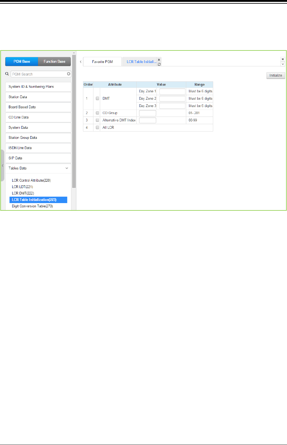
iPECS eMG80 & eMG800 & UCP
Administration and Programming Manual Issue 1.6
484
4.4.9.4 LCR Table Initialization - PGM 223
Selecting LCR Table Initialization will display the LCR Table Initialization data entry page. Click
[Initialize] button to initialize input data.
Figure 4.4.9.4-1 LCR Table Initialization
The LCR Table Initialization allows global values to be assigned to the various Digit Modification
Table entries. In addition, the LCR Leading Digits and LCR Digit Modification Tables can be
initialized to the default (no entries) state.
The CO group rage is from 1 to 21 for eMG80 and from 1 to 201 for eMG800/UCP.
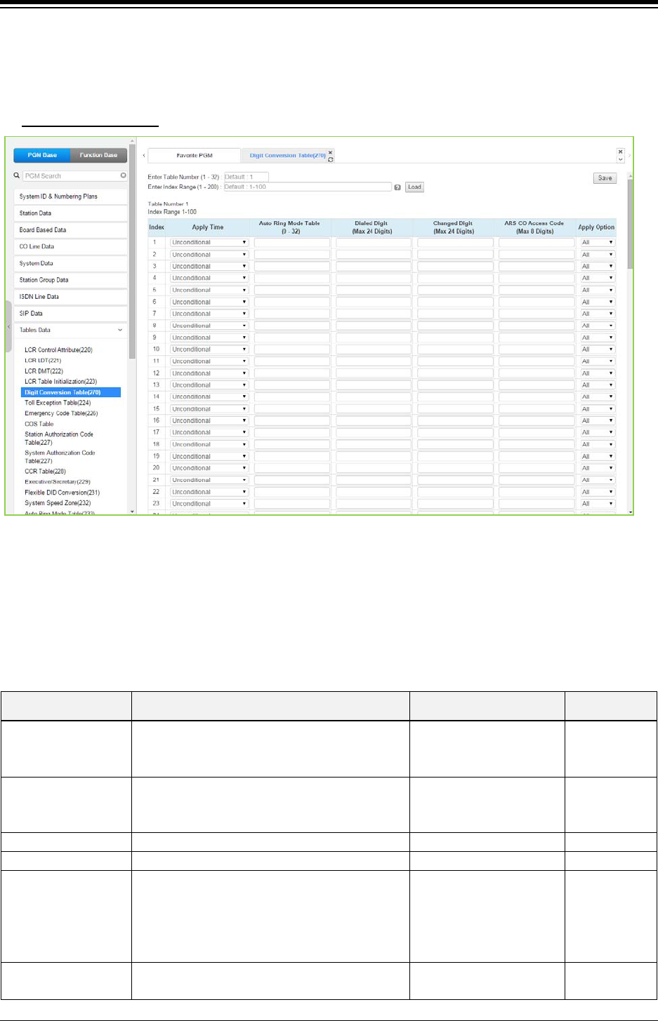
iPECS eMG80 & eMG800 & UCP
Administration and Programming Manual Issue 1.6
485
4.4.9.5 Digit Conversion Table - PGM 270
Selecting Digit Conversion Table will display the page shown. Click [Save] button after changing
Value.
Enter Table Number
: eMG80: 1-15 / eMG800: 1-32 / UCP: 1-32
Figure 4.4.9.5-1 Digit Conversion Table
The Digit Conversion Table index is assigned to the Station and CO line. In addition, digit
conversion can be applied according to the Apply Time Type (Unconditional, Day/Night/Timed or
LCR/Time) as necessary. Each Table has 200 entries of up to 24 digits. Entries in the Tables can
be any digit (0-9), “*”, “#”,”X” (Mask Digit), “F” (Ignore digit). Each Index can be applied by Apply
Option (All/Station/CO line/Disable).
Table 4.4.9.5-1 Digit Conversion table
ATTRIBUTE DESCRIPTION RANGE DEFAULT
Apply time The Apply time type to be applied when the
dialed digit is dialed.
Unconditional,
Follow Day/Night/Timed,
Follow LCR
Unconditional
Auto Ring Mode table Day/Night/Timed Time Table Index.
N/A,
eMG:00-15
UCP:00-32
N/A
Dialed digit
Dialed digit to be compared.
Max. 24 Digits
Changed digit
Changed digit.
Max. 24 Digits
ARS CO Access
Code
If a selected path is not available for some
reason (All Busy, Line Fault etc.) after digit
conversion, Alternative Route Selection (ARS)
will connect calls using predefined designated
ARS digit in digit conversion table.
Max. 8 Digits
Apply option The Apply Option can be applied according to
the caller.
All / Station /
CO line / Disable
All
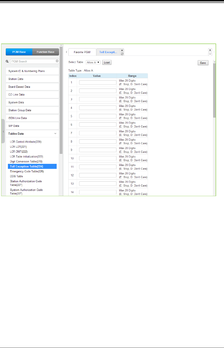
iPECS eMG80 & eMG800 & UCP
Administration and Programming Manual Issue 1.6
486
4.4.9.6 Toll Exception Table - PGM 224
Selecting Toll Exception Table will display the Toll Table data entry page. Select the desired
Allow or Deny Table, blue text above the table header, desired. Click [Save] button after
changing Value.
Figure 4.4.9.6-1 Toll Exception Table
There are ten Toll restriction Tables arranged in pairs. Each pair consists of an Allow Table and a
Deny Table. Allow and Deny entries for Table `A‘ apply to Station and DISA Class of Service 2/4
and 11. Allow and Deny entries for Table `B‘ apply to Station and DISA Class of Service 3/4 and
11. Allow and Deny entries for Table `C‘ apply to Station and DISA Class of Service 5 and 6.
Allow and Deny entries for Table `D‘ apply to Station and DISA Class of Service 8/10 and 11.
Allow and Deny entries for Table `E‘ apply to Station and DISA Class of Service 9 to 11. The
Allow and Deny Tables each permit up to 50 entries of up to 20 digits. Entries in the Tables can
be any digit (0-9), “#” as a wild card (don‘t care) digit, or “*” as an end of entry digit.
Based on Table entries, stations or DISA users are allowed or denied dialing specified numbers.
The following rules apply to establishing restrictions based on the Table entries:
If the appropriate Allow/Deny Table pair has no entries and COS is 2 to 4, no
restrictions are applied. If the COS is 5 or 6, no Long Distance dialing is allowed.
If entries are only made in the Allow Table, only those numbers entered can be dialed,
all other dialed numbers will be restricted.
If entries are only made in the Deny Table, only those numbers entered will be
restricted and all other numbers can be dialed.
When there are entries in both the Allow and Deny Table pair, if the number is in the
Deny Table, the number will be restricted otherwise the number can be dialed without
restriction.
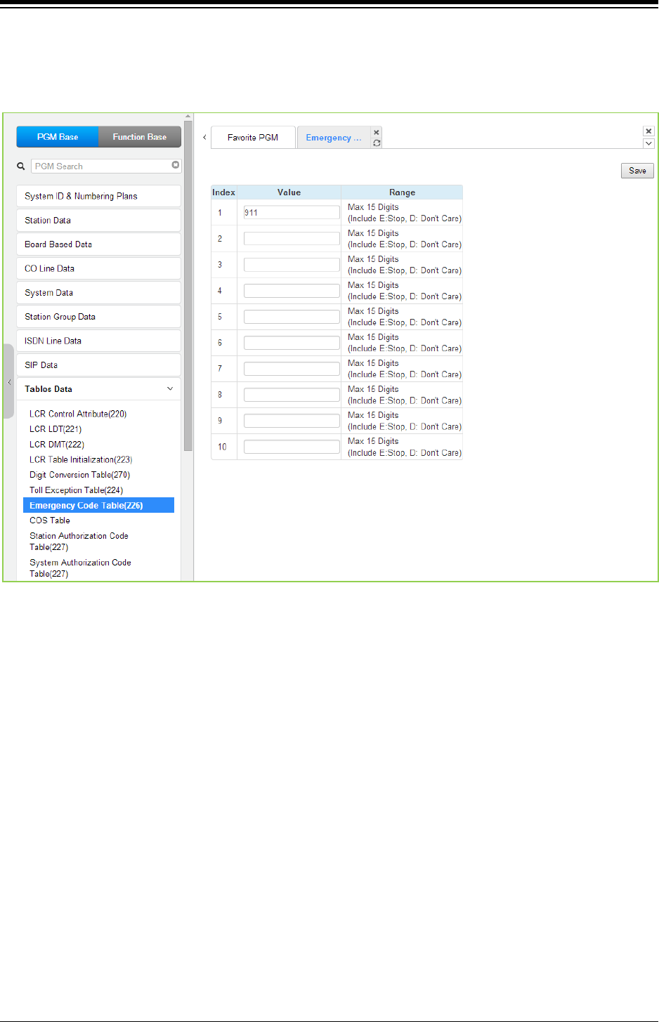
iPECS eMG80 & eMG800 & UCP
Administration and Programming Manual Issue 1.6
487
4.4.9.7 Emergency Code Table - PGM 226
Selecting Emergency Code Table will display the Emergency Code Table data entry page. Click
[Save] button after changing Value.
Figure 4.4.9.7-1 Emergency Code Table
The Emergency Code Table is used to identify emergency numbers which, when dialed, will
override all COS dialing restrictions. An Emergency Code number may be up to fifteen (15) digits
in length.
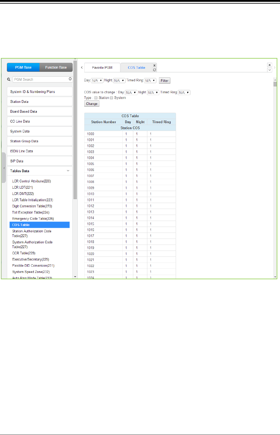
iPECS eMG80 & eMG800 & UCP
Administration and Programming Manual Issue 1.6
488
4.4.9.8 COS Table
Selecting COS Table will display the COS Table data entry page. Data can be filtered to display
specific modes and the values to change can be limited to a specific mode and type, Station or
System Authorization codes.
Figure 4.4.9.8-1 COS Table
Assignments for COS are made for the Day, Night, and Timed Ring for each station and system
Authorization code. The standard Station COS 1 to 11 is assigned to each Authorization code.
Note the COS may also be defined in the Station and System Authorization Code Tables.
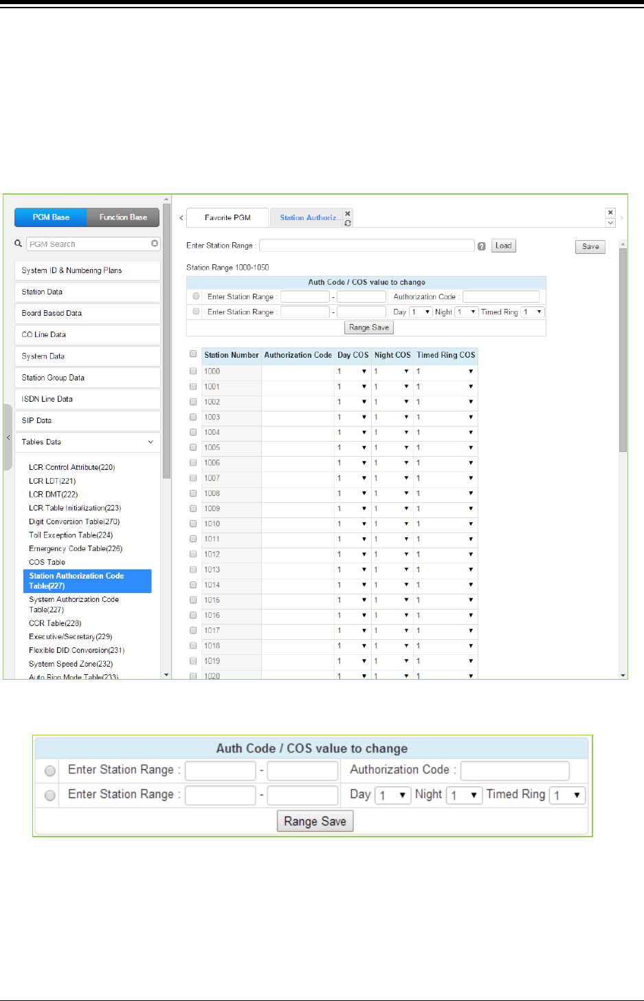
iPECS eMG80 & eMG800 & UCP
Administration and Programming Manual Issue 1.6
489
4.4.9.9 Authorization Codes Table - PGM 227
There are two Authorization Code Tables, the System Authorization Code Table and Station
Authorization Code Table. Selecting Station Authorization Code Table will display the data entry
page in Figure 4.4.9.9-1 and selecting System Authorization Code Table will display the page in
Figure 4.4.9.9-2. Enter a Station or System Index range and click [Load] to modify the data. For
convenience, the copy, paste, and drag is available to enter or modify data. Please click [Save]
button to apply after changing Value.
Figure 4.4.9.9-1 Station Authorization Code Table
User can change the authorization code and COS for the station range across the board and click
the Range save button to save.
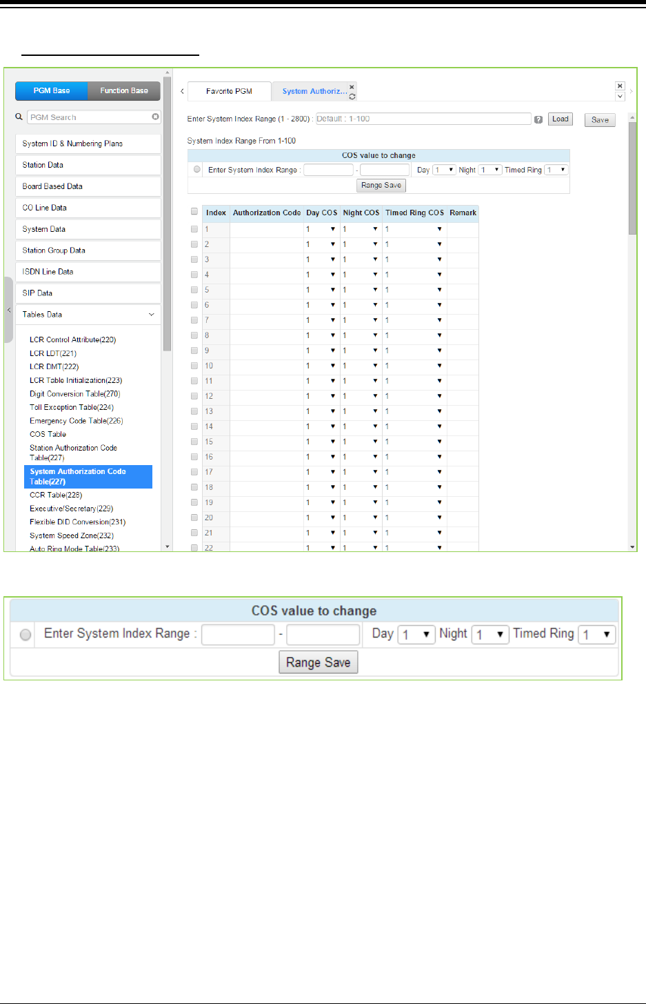
iPECS eMG80 & eMG800 & UCP
Administration and Programming Manual Issue 1.6
490
Enter System Index Range
: eMG80: 1-360 / eMG800: 1-1200 / UCP: 1-2800
Figure 4.4.9.9-2 System Authorization Code Table
User can change COS for the system index range across the board and click the Range save
button to save.
Authorization codes are employed to control access to system resources and facilities. Walking
COS, CO/IP Group access, DISA calls and certain Call Forward types may require input of a valid
Authorization code. Codes up to 12 digits may be entered into the system database.
There are two types of Authorization codes, station and system. The Station entries are
associated with individual stations. The number of system Authorization codes varies based on
the configuration; the number of available codes is provided in Table 2.1-x. Each Authorization
code may be assigned a separate COS for Day, Night and Timed Ring mode operation.
The system will allow the station associated Authorization codes to be duplicated. However, the
iPECS will not allow duplicate or conflicting system level codes unless the ‘*’ and Authorization
table indexing is used to enter codes. Conflicting codes occur when a shorter code contains the
first digits of a longer code, i.e. 12 conflicts with 1234.

iPECS eMG80 & eMG800 & UCP
Administration and Programming Manual Issue 1.6
491
Table 4.4.9.9-1 STATION CLASS-OF-SERVICE
STATION
COS RESTRICTIONS
1
No restrictions are placed on dialing from the station.
2
The assignments in Exception Table A are monitored for allow and deny numbers.
3
The assignments in Exception Table B are monitored for allow and deny numbers.
4
The assignments in both Exception Tables A & B are monitored for allow and deny numbers.
5 The leading digit dialed cannot be a Long Distance code, default “0”, and further
denied/allowed based on Exception Table C.
6 The leading digits dialed cannot be a Long Distance code & digit count cannot exceed the LD
digit counter, default 8 digits, and further denied/allowed based on Exception Table C.
7 Intercom and paging calls are allowed. No outgoing dialing except for emergency calls is
allowed on CO Lines.
8
The assignments in the Exception Table D are monitored for allow and deny numbers.
9
The assignments in the Exception Table E are monitored for allow and deny numbers.
10
The assignments in the Exception Table D & E are monitored for allow and deny numbers.
11 The assignments in the Exception Table A & B and D & E are monitored for allow and deny
numbers.
Table 4.4.9.9-2 STATION/CO LINE COS TOLL RESTRICTIONS
CO COS 1 CO COS 2 CO COS 3 CO COS 4 CO COS 5
STA COS 1 No Restriction No Restriction No Restriction Only Local
Call(LD
code/counter)
and Table C
No Restriction
STA COS 2 Exception Table
A governs the
dialing
Exception Table
A governs the
dialing
No Restriction Only Local
Call(LD
code/counter)
and Table C
No Restriction
STA COS 3 Exception Table
B governs the
dialing
No Restriction Exception Table
B governs the
dialing
Only Local
Call(LD
code/counter)
and Table C
No Restriction
STA COS 4 Exception Table
A & B governs
the dialing
Exception Table
A governs the
dialing
Exception Table
B governs the
dialing
Only Local
Call(LD
code/counter)
and Table C
No Restriction
STA COS 5 Local Call only
(LD Code, “1” or
“0”) and Table C
Local Call only
(LD Code, “1” or
“0”) and Table C
Local Call only
(LD Code, “1” or
“0”) and Table C
Only Local
Call(LD
code/counter)
and Table C
No Restriction
STA COS 6 Only Local Call
(LD code/counter)
and Table C
Only Local Call
(LD
code/counter)
and Table C
Only Local Call
(LD
code/counter)
and Table C
Only Local
Call(LD
code/counter)
and Table C
No Restriction
STA COS 7 In-house dialing
only
In-house dialing
only
In-house dialing
only
In-house dialing
only
In-house dialing
only

iPECS eMG80 & eMG800 & UCP
Administration and Programming Manual Issue 1.6
492
Table 4.4.9.9-2 STATION/CO LINE COS TOLL RESTRICTIONS
CO COS 1 CO COS 2 CO COS 3 CO COS 4 CO COS 5
STA COS 8 Exception Table
D governs the
dialing
Exception Table
D governs the
dialing
No Restriction Only Local
Call(LD
code/counter)
and Table C
No Restriction
STA COS 9 Exception Table
E governs the
dialing
Exception Table
E governs the
dialing
No Restriction Only Local
Call(LD
code/counter)
and Table C
No Restriction
STA COS 10 Exception Table
D & E governs
the dialing
Exception Table
D & E governs
the dialing
No Restriction Only Local
Call(LD
code/counter)
and Table C
No Restriction
STA COS 11 Exception Table
A & B and D & E
governs the
dialing
Exception Table
A & B and D & E
governs the
dialing
No Restriction Only Local
Call(LD
code/counter)
and Table C
No Restriction
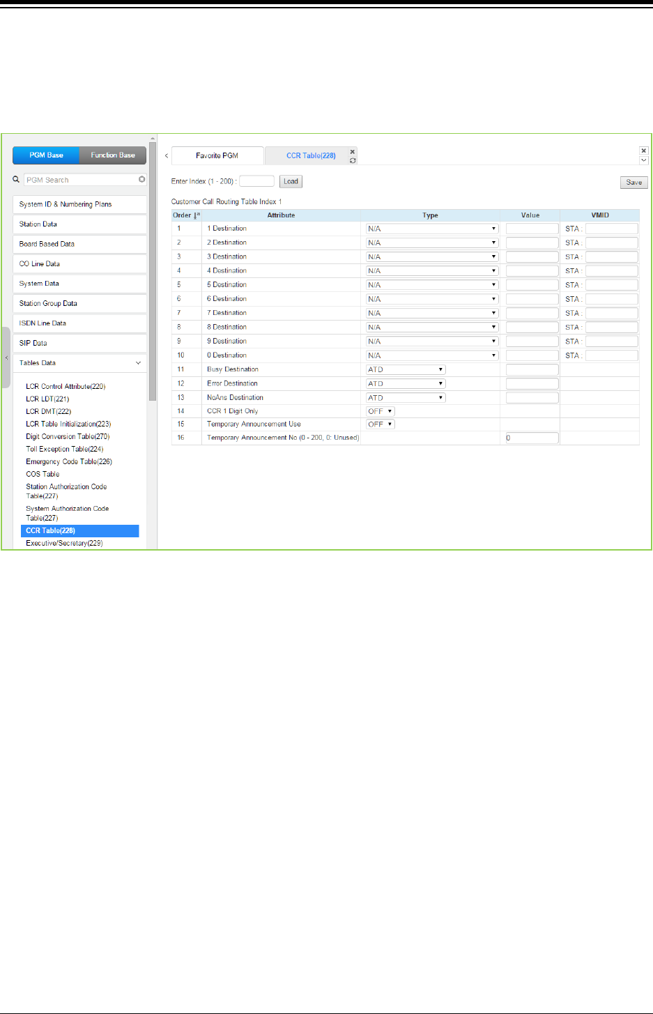
iPECS eMG80 & eMG800 & UCP
Administration and Programming Manual Issue 1.6
493
4.4.9.10 Customer Call Routing Table - PGM 228
Selecting CCR Table will display the Customer Call Routing data entry page. Enter an index to
select the appropriate CCR Table and click [Load] to modify the table. Click [Save] button after
changing Value.
Figure 4.4.9.10-1 Customer Call Routing Table
The system incorporates IVR (Interactive Voice Response) capabilities called CCR (Customer
Call Routing). After, or during a VSF Announcement, the caller may dial digits to select a
destination or route for the call. The CCR Table defines the destination type and value associated
with the digit dialed by the caller in response to the index, a VSF Announcement (01-70). The
available destinations are shown in Table 4.4.9.10-1 below.
Up to 70 single-level Audio Text menus may be assigned or, multi-level menu structures
(maximum 70 levels) can be established using one menu as a destination for the previous level.
Each CCR announcement can have re-route destination – Busy / Error / No Answer case.
Each re-routed destination types are Tone / Attendant / Station Group / VSF Announcement
number.
The table includes a “CCR 1 Digit Only” option. When this option is enabled, the system will
accept only a single digit as the entry. When the option is OFF, the caller can dial multiple digits
that are accepted as DISA dialing.
Temporary announcement can be used in holiday, or emergency case.
When Temporary Announcement Usage is set to ON, programmed Temp Announcement is
played instead of CCR table announcement.
This Temporary Announcement can be set also by Remote Access - by using [Remote Access to
Mobile Extension] feature.

iPECS eMG80 & eMG800 & UCP
Administration and Programming Manual Issue 1.6
494
After access to Mobile Extension,
To turn On Temp Announcement, 8 + CCR Announcement Number.
To turn Off Temp Announcement, 9 + CCR Announcement Number.
Table 4.4.9.10-1 CCR DESTINATIONS (PGM 228)
TYPE DESCRIPTION
N/A
01
Route to a Station
02
Route to a Station Group
03
Route with System Speed Dial
04
Route as PBX Transfer with System Speed Dial (Flash then dial speed dial digits)
05
Route to VSF Announcement
06
Route to VSF Announcement and disconnect
07
Route to Networked Station
08
Conference Room
09
Internal Page
10
External page
11
All Call Page
12
Route to voice mail (station group/station number)
13
Company Directory (USA Only)
14
Record VM Greeting (USA Only)
15
Room type Conf Group Join
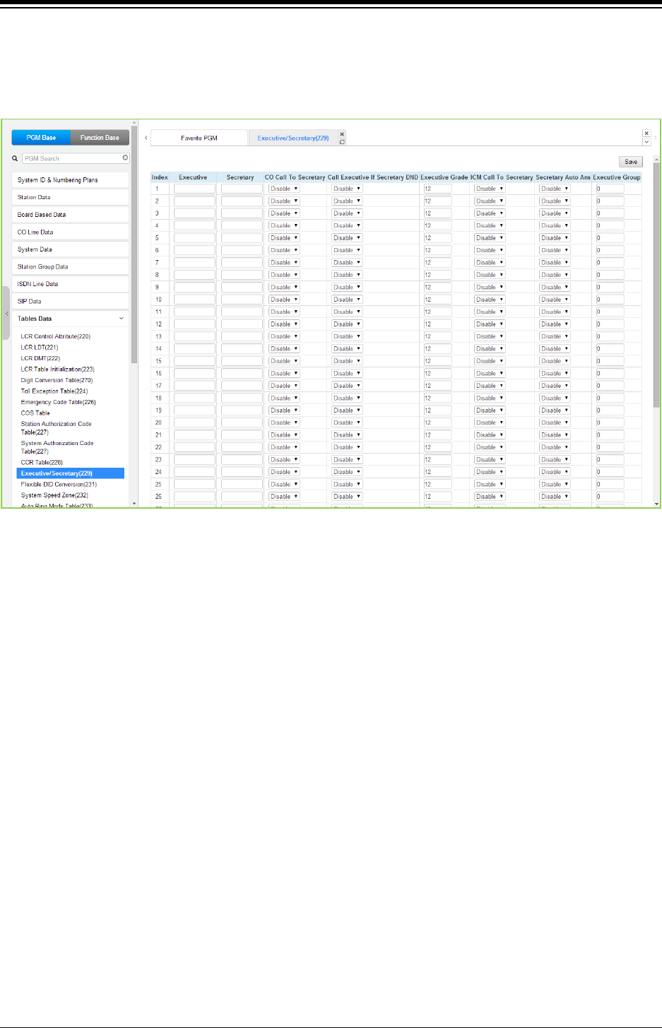
iPECS eMG80 & eMG800 & UCP
Administration and Programming Manual Issue 1.6
495
4.4.9.11 Executive/Secretary Table - PGM 229
Selecting Executive/Secretary will display the Executive/Secretary Table data entry page. Click
[Save] button after changing Value.
Figure 4.4.9.11-1 Executive/Secretary Table
Stations can be paired as Executive/Secretary pairs so that when the Executive enters DND,
intercom and transferred calls are automatically routed to the Secretary. An Executive may have
only one Secretary however, a Secretary can be assigned to multiple Executives. A Secretary of
one pair may be the Executive of another however, assignments that form a loop-back are not
allowed. In addition, when active, the Secretary can be assigned to receive the Executive‘s voice
messages, refer to Common Attributes section.
The “CO Call to Sec” option will route all CO calls to the Executive to the defined Secretary‘s
station regardless of the Executive‘s station status. The “Call Exec if Sec DND” option will route
Executive calls back to the Executive if the Secretary is in DND. The Exec Grade permits higher
grade Executives to override the Executive/Secretary Forward feature to call a lower grade
Executive (Korea only). The highest grade is 1 and the lowest grade is 12. The “ICM Call to Sec”
option will route all internal calls to the Executive(except for calls from higher or same grade
executive) to the defined Secretary‘s station regardless of the Executive‘s station status.
Refer to the following table for a description of the Executive/Secretary parameters and the input
required.

iPECS eMG80 & eMG800 & UCP
Administration and Programming Manual Issue 1.6
496
Table 4.4.9.11-1 Executive/Secretary Table
ATTRIBUTE DESCRIPTION RANGE DEFAULT
Executive
Assign Executive.
Secretary
Assign Secretary.
CO Call to Secretary
If desired, all incoming CO calls to the Exec. The call is
routed to the Secretary’s station regardless of the
Executive’s status.
Enable/
Disable Disable
Call Executive if Secretary is in
DND
If the Secretary is in DND, Executive calls can be routed
back to the Executive.
Enable/
Disable
Disable
Executive grade
Higher (or equal) grade Executives can override the
Executive/Secretary Forward feature (5th: ICM call to
SEC) to call a lower grade Executive. Highest grade: 01,
Lowest grade: 12.
01~12 12
ICM Call to Secretary
If this option is ON, all internal calls to the executive
station (except for calls from higher or same grade
executive) are routed to the Secretary’s station
regardless of the Executive’s status.
8801 Default value
Korea, India, Israel, Turkey,
Thailand : ON
Otherwise : OFF
Enable/
Disable Disable
Secretary Auto Answer When executive call to the secretary who is in ‘T’ mode.
The call will be answered by hands free mode if it is ON.
Enable/
Disable
Disable
Executive Group
If Group is greater than 1, it works that lower grade
executive can call to higher grade executive directly
when they are same group.
00-50 00
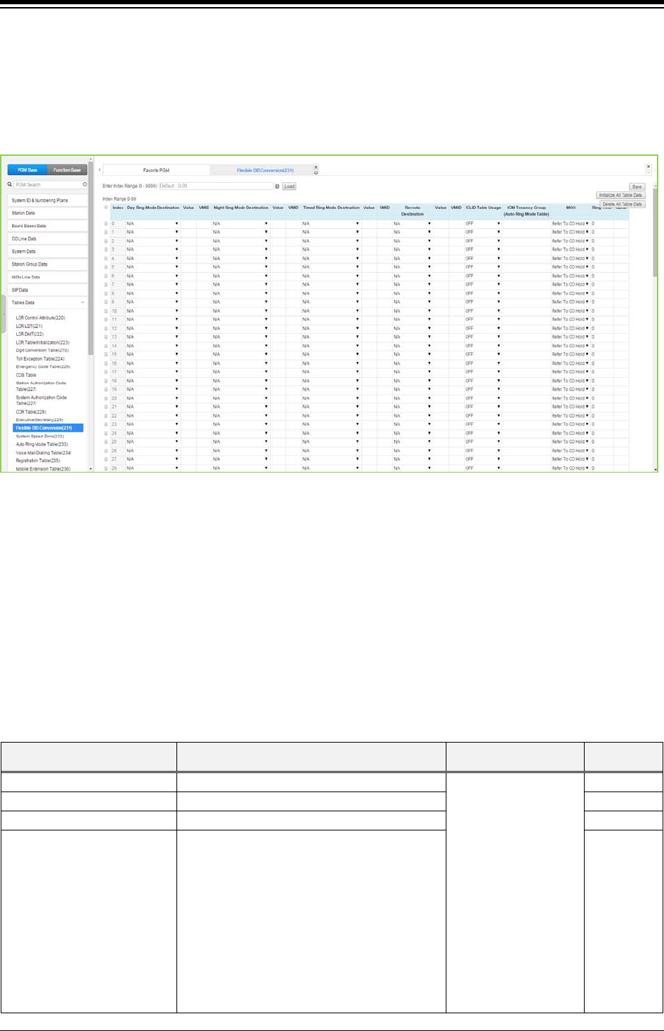
iPECS eMG80 & eMG800 & UCP
Administration and Programming Manual Issue 1.6
497
4.4.9.12 Flexible DID Conversion Table - PGM 231
Selecting Flexible DID Conversion Table will display the Flexible DID Table data entry page. For
convenience, the copy, paste, and drag is available to enter or modify data. Click [Save] button
after changing Value. Click [Initialize All table Data] to initialize all table and Click [Delete All
Table Data] to delete.
Figure 4.4.9.12-1 Flexible DID Conversion Table
When the received DID digits are converted, the resulting three-digit number may be used as an
index to the Flexible DID Conversion Table. The Flexible DID Table index is used when DID Line
is assigned a Conversion type 2, refer to the DID Service attributes section 4.4.4.6. Using the
index from the digit conversion a destination for the DID call is determined by a Look-up in the
Flexible DID Table. The destination for the call is generally defined as a type and a value. The
type selects options such as station, station group, VSF, etc. The value specifies the particular
station, station group, etc. In addition, ICLID routing can be enabled for DID lines or can be
assigned as an index to the Auto Ring Mode table.
Table 4.4.9.12-1 FLEXIBLE DID CONVERSION
ATTRIBUTE DESCRIPTION RANGE DEFAULT
Day Ring Mode Destination
Destination setting for Day Ring mode.
N/A,
Station,
Station Group,
System Speed,
PABX transfer with
system speed,
VSF announcement,
VSF announcement
and Disconnect,
Networking,
Conference room,
Internal page,
External page,
N/A
Night Ring Mode Destination
Destination setting for Night Ring mode.
N/A
Timed Ring Mode Destination
Destination setting for Timed Ring mode.
N/A
Reroute Destination Destination setting for Reroute Ring mode. N/A

iPECS eMG80 & eMG800 & UCP
Administration and Programming Manual Issue 1.6
498
Table 4.4.9.12-1 FLEXIBLE DID CONVERSION
ATTRIBUTE DESCRIPTION RANGE DEFAULT
All call page,
Voice mail (Station
group),
ICLID Table,
Company Directory,
Record VM Greeting,
Room type
Conf Group
Join
ICLID Table
Use ICLID Routing, section 4.4.7.4.
OFF/ON
OFF
ICM Tenancy Group
(Auto Ring Table)
A DID Conversion Table Index can be
assigned to employ an ICM Tenancy Group
Auto Ring Table to determine
Day/Night/Timed operation mode.
eMG80: 0~15
eMG800: 0~32
UCP: 0~100
N/A
MOH A Music source is assigned so that calls to the
destination receive audio from the source in
place of ring-back tone.
Refer to CO Hold,
Internal/External Music
1,
External Music 2,
VSF MOH,
SLT MOH 1,
SLT MOH 2,
SLT MOH 3,
SLT MOH 4,
SLT MOH 5,
VSF MOH 2,
VSF MOH 3
Refer to CO
Hold
Ring Tone A call routed with the DID Conversion Table
will employ the selected Ring tone to alert the
destination.
0-16 0
Name An eleven character Name can be configured
for the Table bin.
11 characters
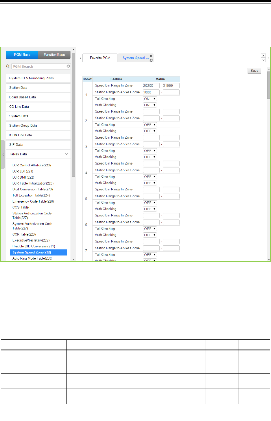
iPECS eMG80 & eMG800 & UCP
Administration and Programming Manual Issue 1.6
499
4.4.9.13 System Speed Zone Table - PGM 232
Selecting System Speed Zone will display the System Speed Zone data entry page. Click [Save]
button after changing Value.
Figure 4.4.9.13-1 System Speed Zone
System Speed Dial Bins assigned to a zone are only available to stations allowed access to that
zone. Each zone can be assigned to apply the appropriate Station and CO Line COS for the
speed dial number prior to dialing.
The speed Bin in Zone and Station Range to access zone is different according to selecting
Speed Numbering, refer to ‘Speed Numbering’ in System ID (100)
Table 4.4.9.13-1 SYSTEM SPEED ZONES
ATTRIBUTE DESCRIPTION RANGE DEFAULT
Speed Bin Range in Zone
A range of Speed Dial Bins is assigned to a zone.
Station Range to Access
Zone
A range of Stations is permitted access to the System
Speed dials in the Zone.
Toll Checking Toll restriction can be applied to Speed Dials in the Zone. OFF
ON
ON
Auth Checking The user can be required to enter a valid Authorization
code to use Speed Dials in the zone.
OFF
ON
ON
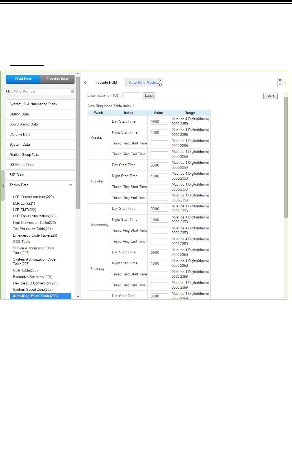
iPECS eMG80 & eMG800 & UCP
Administration and Programming Manual Issue 1.6
500
4.4.9.14 Auto Ring Mode Table - PGM 233
Selecting Auto Ring Mode Table will display the Auto Ring Mode Table data entry page. Enter the
desired index (Tenancy Group) and click [Load] to enter data. Click [Save] button after changing
Value.
Enter Index
: eMG80: 0-15 / eMG800: 0-32 / UCP: 0-100
Figure 4.4.9.14-1 Auto Ring Mode Table
The system can be programmed to automatically select the Ring and COS based on time of day
and day of the week. Three Ring & COS modes are available, Day, Night, and Timed. The Ring
assignments are as defined in CO Ring Assignments. COS assignments are made in the Station
COS and DISA COS programs discussed in sections, respectively.
The start times for Day, Night and start and end times for Timed modes are entered for each day
of the week. After the Timed end time the mode returns to day if time is not in the Night mode.
The Attendant can override the Automatic selection and select the desired mode (Day, Night, and
Timed) manually. A separate Auto Ring Table can be established for each ICM Tenancy Group in
section (indices 1 ~ 15 for eMG80 & indices 1~32 for eMG800 & 1~100 for UCP) and for the
system (index 00).
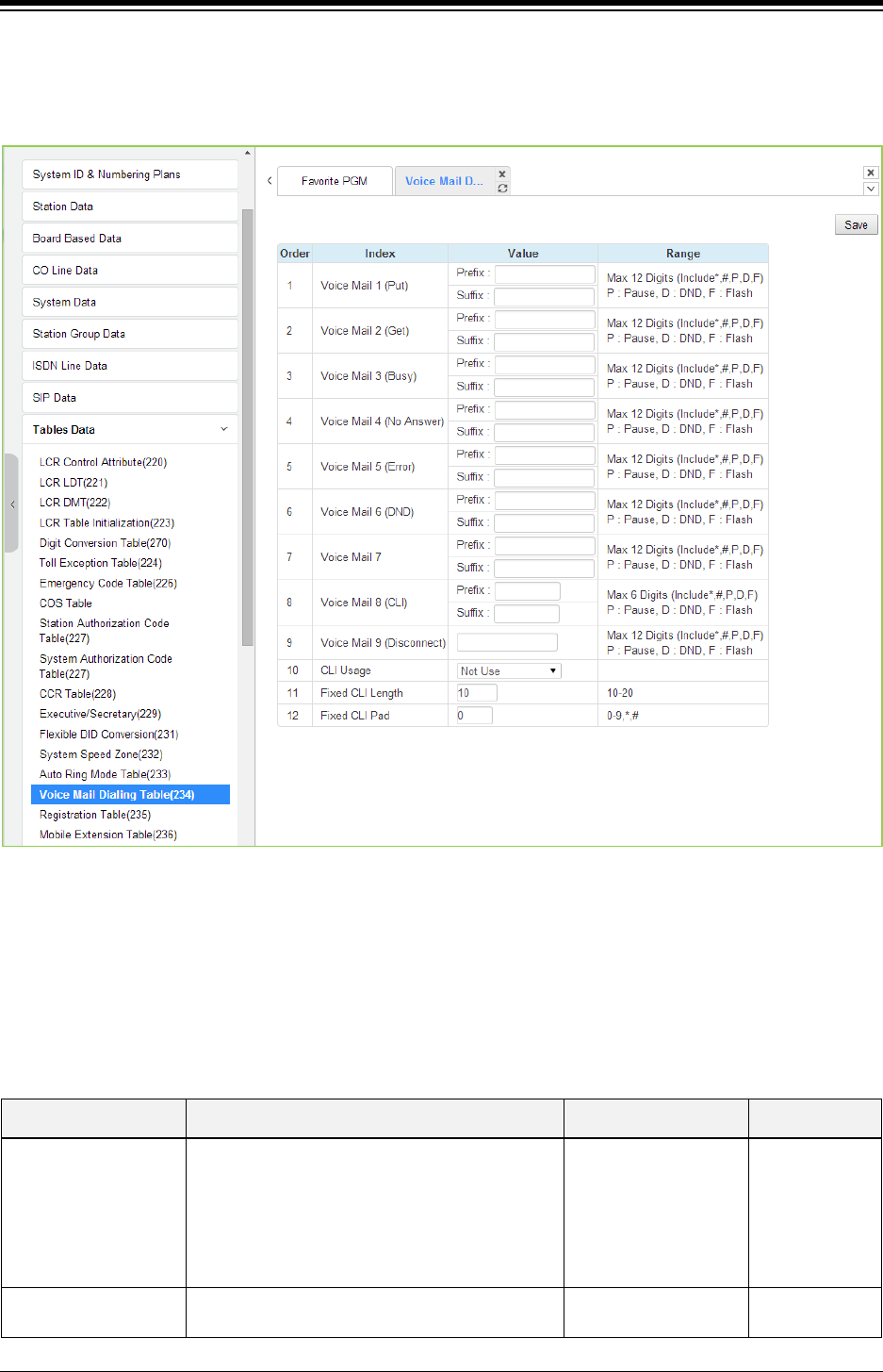
iPECS eMG80 & eMG800 & UCP
Administration and Programming Manual Issue 1.6
501
4.4.9.15 Voice Mail Dialing Table - PGM 234
Selecting Voice Mail Dialing Table will display the Voice Mail Dialing data entry page. Click [Save]
button after changing Value.
Figure 4.4.9.15-1 External Voice Mail Dialing Table
When an external Voice Mail system is used that connects to an SLT port, a digit sequence must
be defined for the system to signal various call characteristics to the Voice Mail system. The
external Voice Mail uses the sequences to determine appropriate announcements or further call
routing. The Table permits the definition of digits as either a prefix or suffix to other digits (station
number for mailbox identification). Sequences are defined for such call characteristics as Put Mail,
Get Mail, No Answer call, etc. as described in the following table.
Table 4.4.9.15-1 VOICE MAIL DIALING TABLE
ATTRIBUTE DESCRIPTION RANGE DEFAULT
Voice Mail 1 (Put)
Code to send when the voice mail is to receive
call to record a message.
Put Mail.
When you enter the Digit, the following Digit
means as below:
P: Pause, D: DND, F: Flash
Prefix
Suffix
(Max. 12 Digits/
Include *, #, P, D, F)
Voice Mail 2 (Get) Code to send when the voice mail is to playback
a recorded message.
Prefix
Suffix

iPECS eMG80 & eMG800 & UCP
Administration and Programming Manual Issue 1.6
502
Table 4.4.9.15-1 VOICE MAIL DIALING TABLE
ATTRIBUTE DESCRIPTION RANGE DEFAULT
Get Mail.
When you enter the Digit, the following Digit
means as below:
P: Pause, D: DND, F: Flash
(Max. 12 Digits/
Include *, #, P, D, F)
Voice Mail 3 (Busy)
Code to send when the voice mail is to receive a
call when the user is busy.
Busy Mail.
When you enter the Digit, the following Digit
means as below:
P: Pause, D: DND, F: Flash
Prefix
Suffix
(Max. 12 Digits/
Include *, #, P, D, F)
Voice Mail 4 (No
Answer)
Code to send when the voice mail is to receive a
call when the user did not answer.
No Answer Mail.
When you enter the Digit, the following Digit
means as below:
P: Pause, D: DND, F: Flash
Prefix
Suffix
(Max. 12 Digits/
Include *, #, P, D, F)
Voice Mail 5 (Error)
Code to send when the voice mail is to receive a
call when a user dialing error exists.
Error Mail.
When you enter the Digit, the following Digit
means as below:
P: Pause, D: DND, F: Flash
Prefix
Suffix
(Max. 12 Digits/
Include *, #, P, D, F)
Voice Mail 6 (DND)
Code to send when the voice mail is to receive a
call when the user is in DND.
DND Mail.
When you enter the Digit, the following Digit
means as below:
P: Pause, D: DND, F: Flash
Prefix
Suffix
(Max. 12 Digits/
Include *, #, P, D, F)
Voice Mail 7
When you enter the Digit, the following Digit
means as below:
P: Pause, D: DND, F: Flash
Prefix
Suffix
(Max. 12 Digits/
Include *, #, P, D, F)
Voice Mail 8(CLI)
When you enter the Digit, the following Digit
means as below:
P: Pause, D: DND, F: Flash
Prefix
Suffix
(Max. 12 Digits/
Include *, #, P, D, F)
Voice Mail 9
(Disconnect)
Code for disconnect call.
Disconnect Mail.
When you enter the Digit, the following Digit
means as below:
P: Pause, D: DND, F: Flash
Prefix
Suffix
(Max. 12 Digits/
Include *, #, P, D, F)
CLI Usage
Not use: Do not send CLI
Real CLI length: Send CLI without padding
before prefix code.
Fixed CLI length: Send CLI with fixed length.
Not use,
Real CLI length,
Fixed CLI length
Not use
Fixed CLI Length Define length of CLI. 10-20 10
Fixed CLI Pad Define padding character for CLI. 0-9,*,# 0
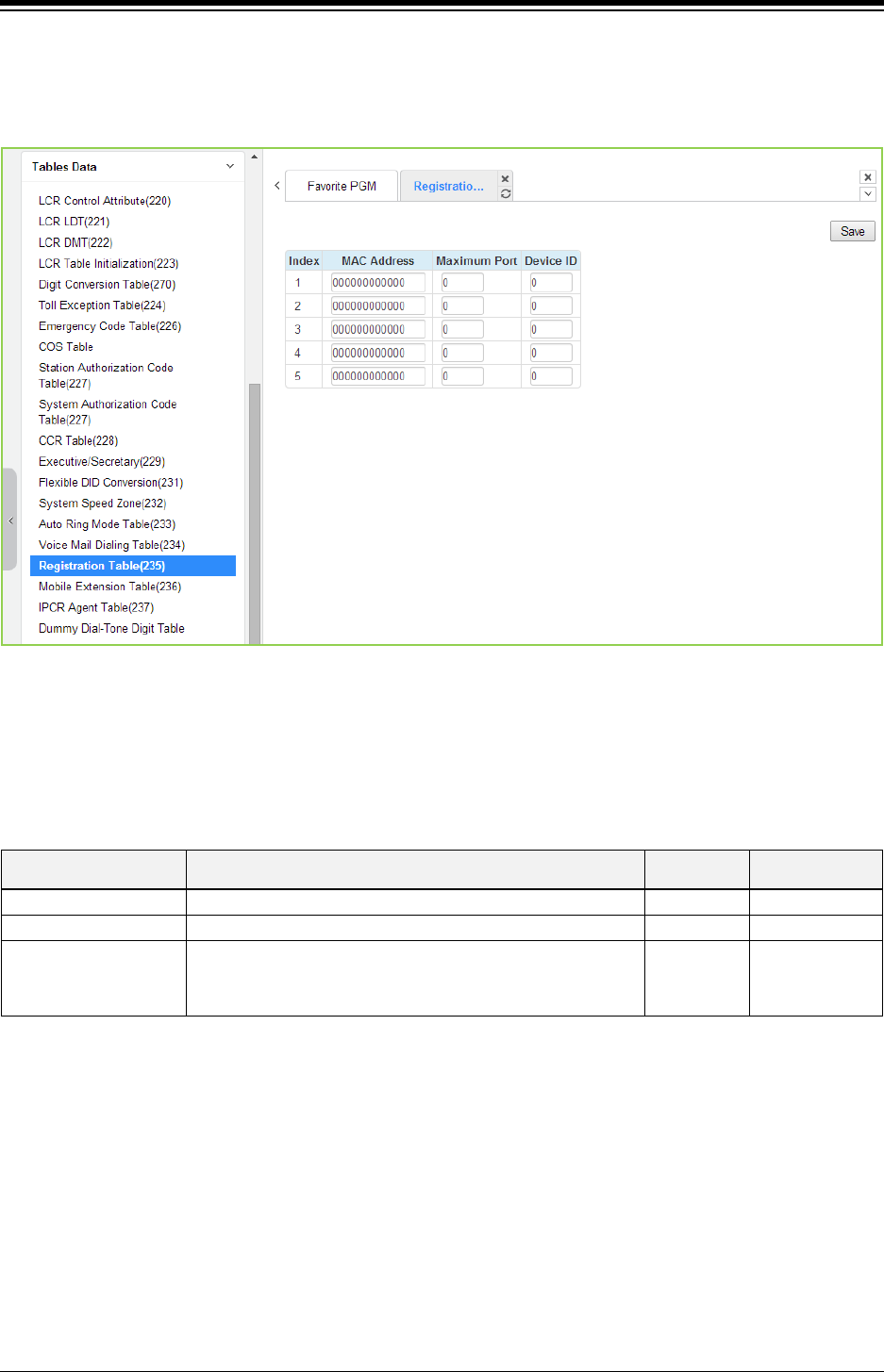
iPECS eMG80 & eMG800 & UCP
Administration and Programming Manual Issue 1.6
503
4.4.9.16 Registration Table - PGM 235
Selecting Registration Table will display the Registration data entry page. Click [Save] button
after changing Value.
Figure 4.4.9.16-1 MAC Registration Table
When multiple iPECS systems are located on the same LAN, it may be desirable to register add-
on devices employing the Registration Table.
Table 4.4.9.16-1 MAC REGISTRATION TABLE
ATTRIBUTE DESCRIPTION RANGE DEFAULT
MAC Address
Enter MAC address of a device to register
000000000000
Maximum Port
Enter maximum number of ports (channels) for the device.
00-99
00
Device ID
A device ID may be entered for registration. The Device ID
available are shown at the bottom of the System Overview
Web page.
0-255 0
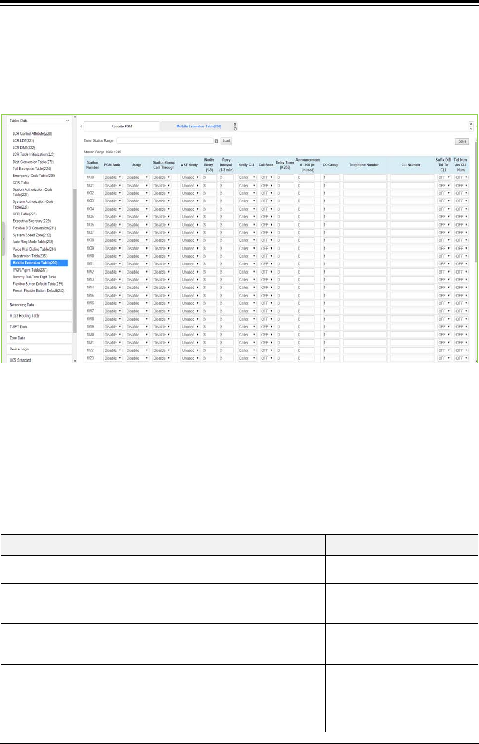
iPECS eMG80 & eMG800 & UCP
Administration and Programming Manual Issue 1.6
504
4.4.9.17 Mobile Extension Table - PGM 236
Selecting Mobile Extension Table will display the Mobile Extension data entry page. Select the
Station Order range desired, blue text above the table header. Selecting the blue colored text in
the Table header will sort the table based on the selected column. Click [Save] button after
changing Value.
Figure 4.4.9.17-1 Mobile Extension Table
A mobile phone can be used in conjunction with an iPECS Phone. The Mobile phone can access
system resources available to the user‘s wired phone and will receive ring for incoming iPECS
calls. The user may be allowed to enable the Mobile extension and define the mobile number.
The system can be defined to employ a specific CO/IP Line Group to place calls to the Mobile
phone. In addition, the mobile phone can be assigned to receive Station group calls to the
primary extension. Also, parameters for notification of new VSF voice mails can be defined.
Table 4.4.9.17-1 MOBILE EXTENSION TABLE
ATTRIBUTE DESCRIPTION RANGE DEFAULT
PGM Authority The user may be allowed to activate the mobile
extension feature.
Disable
Enable
Disable
Usage Mobile extension feature can be enabled and Fail
Over to Mobile extension can be included.
Disable
Mobile Ext
Fail Over
Disable
Station Group Call
Enable
When the paired station is a member of a Station
group (ACD, Circular, or Terminal), group calls can
be sent to the active mobile extension.
Disable
Enable Disable
VSF Notify
When enabled the active Mobile Extension will
receive notification by the system when the user has
a new message in the built-in Voice Mail.
Unused
Use Unused
Notify Retry The number of attempts the system will make to
complete a notification when receiving busy/no-
1 – 9 Times 3 Times

iPECS eMG80 & eMG800 & UCP
Administration and Programming Manual Issue 1.6
505
Table 4.4.9.17-1 MOBILE EXTENSION TABLE
ATTRIBUTE DESCRIPTION RANGE DEFAULT
answer is defined.
Retry Interval
This field defines the time between notification
attempts. If a notification fails, the system will retry
after the timer expires.
1 – 3 minutes 3 Minute
Notify CLI
When the system sends CLI to the Mobile Extension,
the CLI can be either the original caller’s CLI or the
CLI of the station.
Caller
My Ext. Caller
Call Back
If “ON”, an incoming Mobile Extension call will be
released before answered and system places a call
to Mobile Extension. After the Mobile answers, the
dial tone is provided and the Mobile Extension can
place internal or external calls.
OFF
ON OFF
Delay Timer
When the Mobile Extension requests a Call Back, the
system will place the Call Back after expiration of this
Delay timer.
0 ~ 255 0
Announcement
A system announcement can be recorded to provide
the Mobile caller with a menu of dialing commands
available to the remote Mobile user, remote control.
0-200 0
CO Group The CO/IP Line group used to call (ring) the Mobile
Extension is defined.
eMG80:1~21
eMG800:1~201
UCP: 1~201
1
Telephone Number
The telephone number of the Mobile extension or
Fail-over number of the station must be assigned for
proper operation.
Not assigned
CLI Number
When the Mobile Telephone number and CLI do not
match, the CLI entered here is used to authorize
incoming calls from the Mobile.
Not assigned
Suffix DID table index
to the CLI
An incoming DID call is passed to the Mobile
Extension with the original caller’s CLI and the
Flexible DID Conversion Table index.
(format: ‘original CLI’ + ‘*’ + ‘DID Table Index’)
OFF/ON OFF
Tel Num As CLI Num
If this option is set to ON, Telephone Number is used
the same as CLI Number.
That means, when the mobile user calls to his
station, if Telephone Number or CLI Number is
matched with his mobile number, then the mobile
user hears system dial tone, and calling to outside is
available.
If this option is set to OFF, only CLI Number is
matched, system dial tone is served.
OFF/ON ON
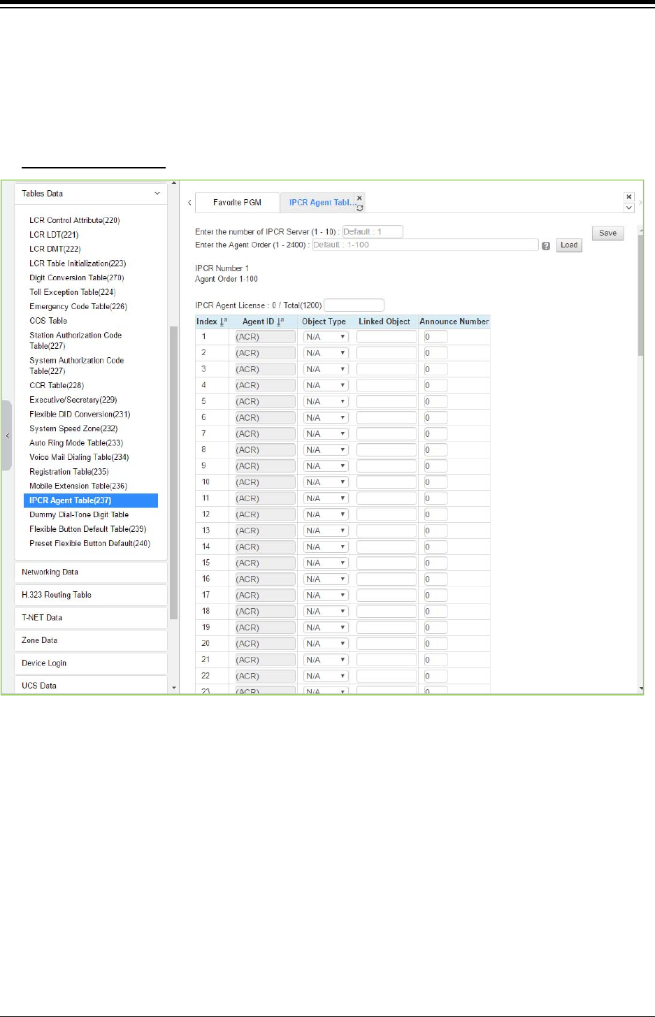
iPECS eMG80 & eMG800 & UCP
Administration and Programming Manual Issue 1.6
506
4.4.9.18 IPCR Agent Table - PGM 237
Selecting IPCR Agent Table will display the IPCR Agent data entry page. Select the Index and
Agent ID Order range desired, blue text above the table header. Selecting the blue colored text in
the Table header will sort the table based on the selected column. Click [Save] button after
changing Value.
Enter the Agent order: eMG80: 1-140 / eMG800: 1-1200 / UCP: 1-2400
Figure 4.4.9.18-1 IPCR Agent Table
This table correlates an Object Type (Station or CO/IP Line) to the IPCR (Call Recording) Agent
index in the IPCR server. The table is also employed with third-party servers for call recording.
When a call is placed or received by the station or CO/IP Line, the call is recorded in the IPCR
server under the Agent ID (Order number).
Multiple Announcement (1~9) in IPCR can be entered in ‘Announce Number’.
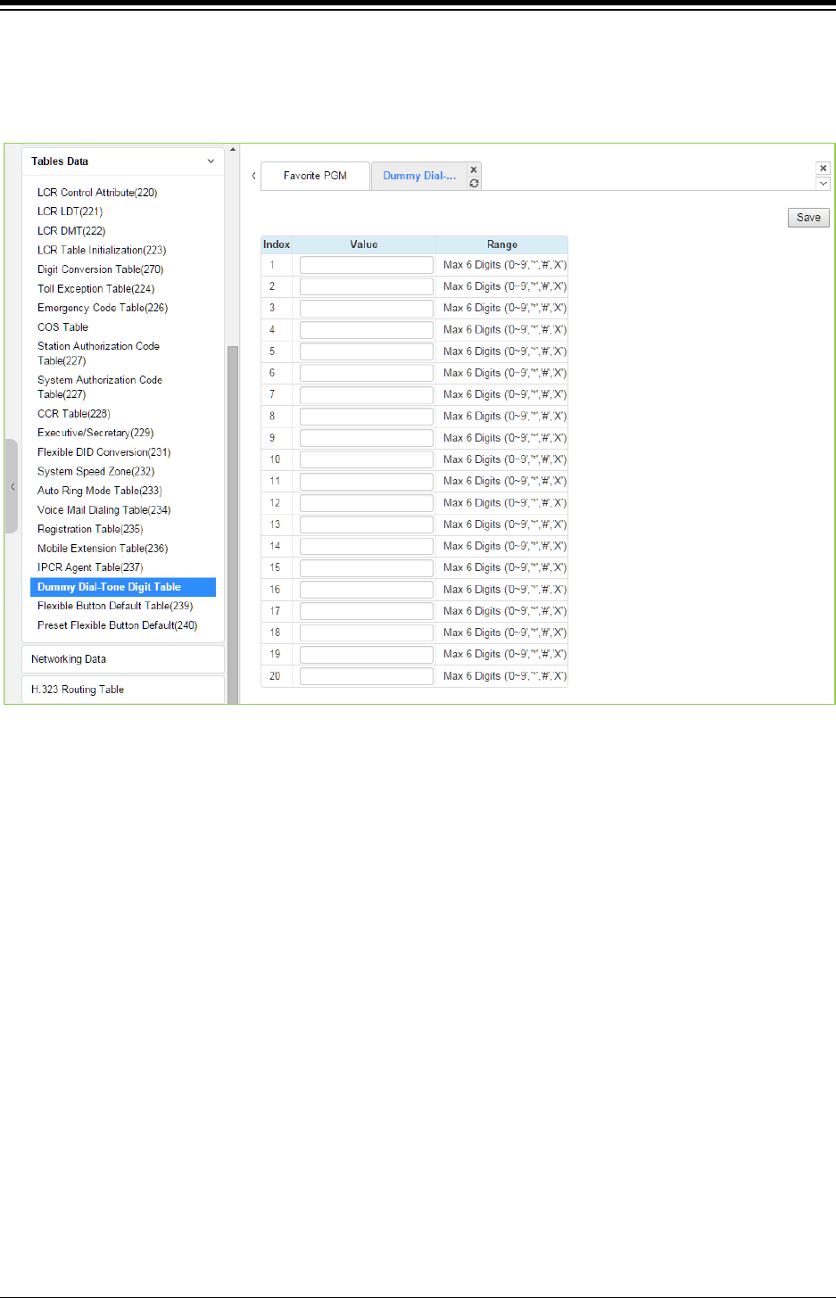
iPECS eMG80 & eMG800 & UCP
Administration and Programming Manual Issue 1.6
507
4.4.9.19 Dummy Dial-Tone Digit Table
Selecting Dummy Dial-Tone Digit Table will display the Dummy Dial-Tone Digit data entry page.
Click [Save] button after changing Value.
Figure 4.4.9.19-1 Dummy Dial-Tone Digit Table
When digit conversion is programmed, the CO line is seized after digit conversion is completed
and therefore user cannot hear the CO dial tone from PX until completing digit conversion. For
this case, a dummy dial tone can be programmed. Pressing one of pre-programmed digits (‘0–9’,
‘*’, ‘#’, X’) will provide CO dial tone to the user regardless of CO line seizure.
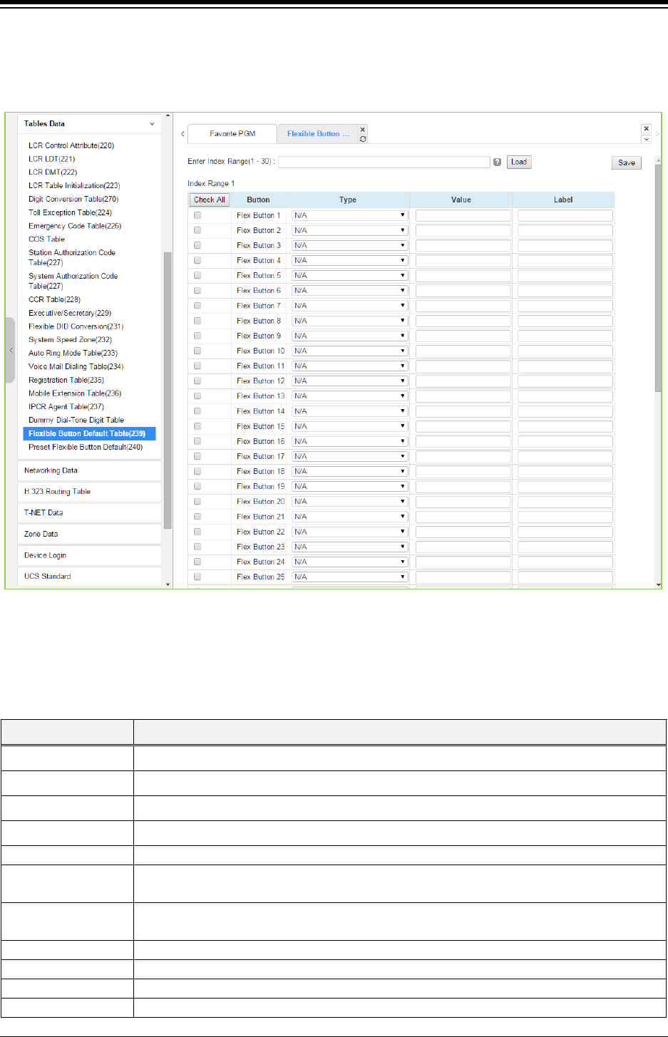
iPECS eMG80 & eMG800 & UCP
Administration and Programming Manual Issue 1.6
508
4.4.9.20 Flexible Button Default Table – PGM 239
Selecting Flexible button default table will display the below page. Use the check mark to indicate
which attributes to modify; data for checked attributes is stored by clicking [Save] button.
Figure 4.4.9.20-1 Flexible Button Default Table
The system provide 30 default flexible button table so administrator can be configured each table
for using ‘Preset Flexible Button Default (240)’.
Administrator can assign the type among the below types on Flexible button.
Table 4.4.9.20-1 FLEX BUTTON TYPE
TYPE REMARK
N/A Empty (unassigned), may be defined by the user.
CO Line Assigns button to access a defined CO/IP line.
CO Group Assigns button to access a free line in the CO/IP Group.
Loop Assigns button to access a loop line.
Station Number
Assigns button as DSS/BLF for the assigned station number.
Programming
(Numbering Plan)
Assigns button to dial a code from the Flexible Numbering Plan, see Appendix section.
Programming (PGM) Assigns button to perform a User Program function from the Fixed Numbering Plan,
Appendix section.
Station Speed Bin
Station Speed Dial bin.
System Speed Bin
System Speed Dial bin.
Net Station Number
Refer to section Network Numbering Plan Table - PGM 324.
U-Loop
U-Loop button for call wait of internal & external call.
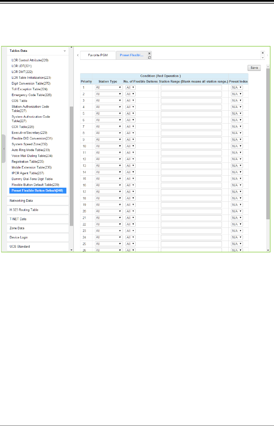
iPECS eMG80 & eMG800 & UCP
Administration and Programming Manual Issue 1.6
509
4.4.9.21 Preset Flexible Button Default – PGM 240
Selecting Preset flexible button default will display the below page. Click [Save] button after
changing Value.
Figure 4.4.9.21-1 Preset Flexible Button Default
Administrator can assign Preset flexible button table to the station automatically by default.
Before connecting the station, administrator has to set this table according to Priority, Station
Type, the number of Button, Station Range, and check the preset Index (1~30). The preset index
means the range of Flexible Button Default Table (PGM 239).
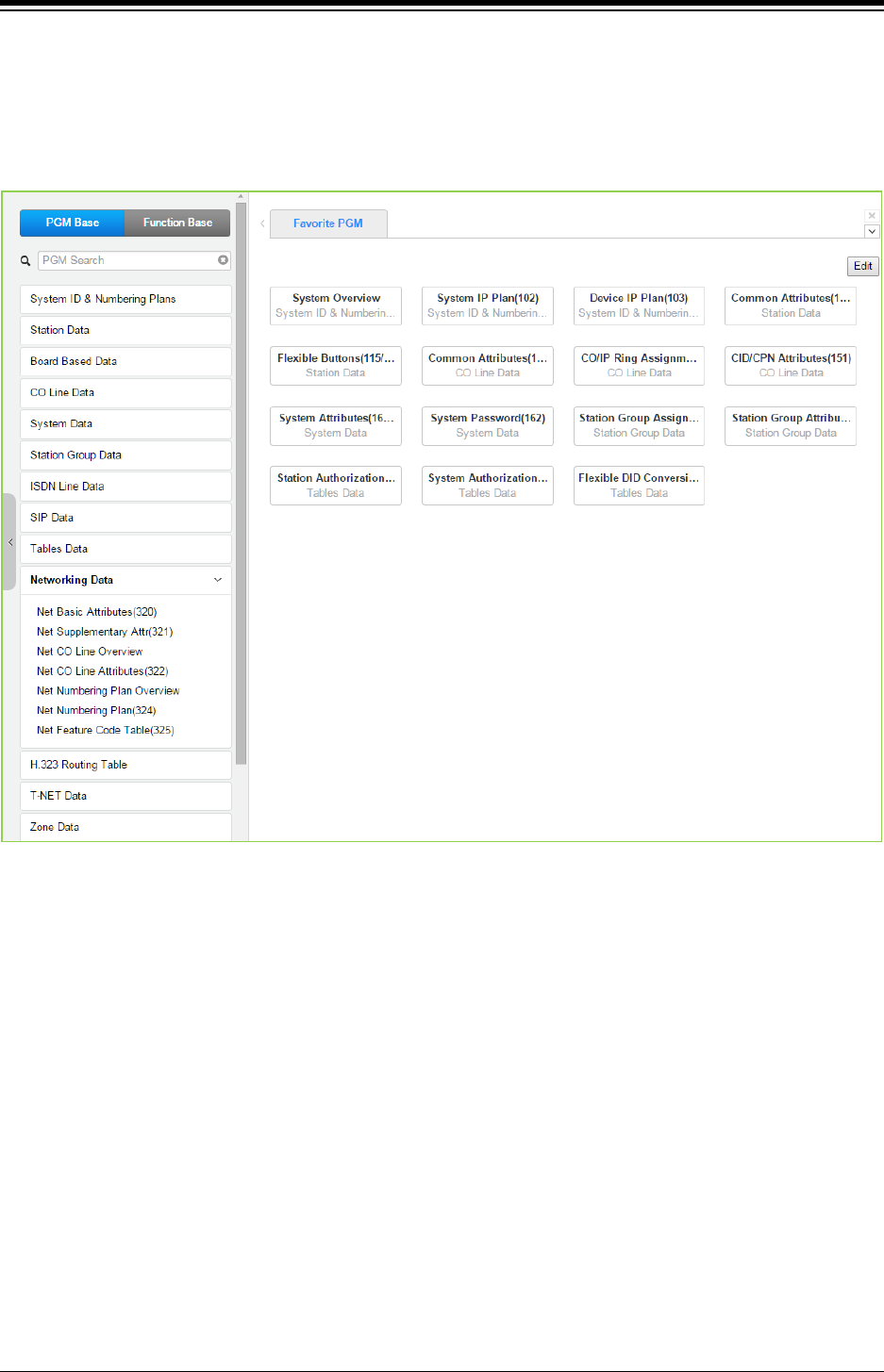
iPECS eMG80 & eMG800 & UCP
Administration and Programming Manual Issue 1.6
510
4.4.10 Networking Data
Selecting the Networking Data program group returns the sub-menu displayed in the left frame as
shown in the following figure.
Figure 4.4.10-1 Networking Data
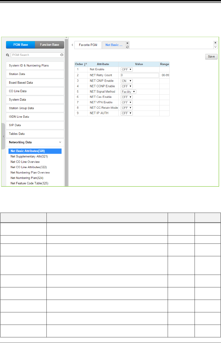
iPECS eMG80 & eMG800 & UCP
Administration and Programming Manual Issue 1.6
511
4.4.10.1 Network Basic Attributes - PGM 320
Selecting Network Basic Attributes will display the Network Basic Attributes entry page. Click
[Save] button after changing Value.
Figure 4.4.10.1-1 Network Basic Attributes
Table 4.4.10.1-1 NETWORK BASIC ATTRIBUTES
ATTRIBUTE DESCRIPTION RANGE DEFAULT
Net Enable For operation, the Networking function must be enabled here.
Note a license is required.
OFF
ON
OFF
Net Retry Count Not used. 00-99 0
Net CNIP Enable The name of calling station is sent to the called iPECS UCP.
CNIP is shown in the LCD of the called party’s station.
OFF
ON
ON
Net CONP Enable
The name of the connected station is sent to the calling iPECS
system. The CONP is shown in the LCD of the calling party’s
station.
OFF
ON OFF
Net Signal Method Network signaling can be sent in the Facility or User QSIG
supplementary service message.
UUS/
Facility
Facility
Net Cas Enable Not used. OFF
ON
OFF
Net VPN Enable Not used. OFF
ON
OFF
Net CC Retain Mode This field defines the Network signaling retain mode for CCBS
service.
OFF
ON
OFF
Net IP Auth. For operation, the Networking function must be enabled here.
Note a license is required.
OFF
ON
OFF
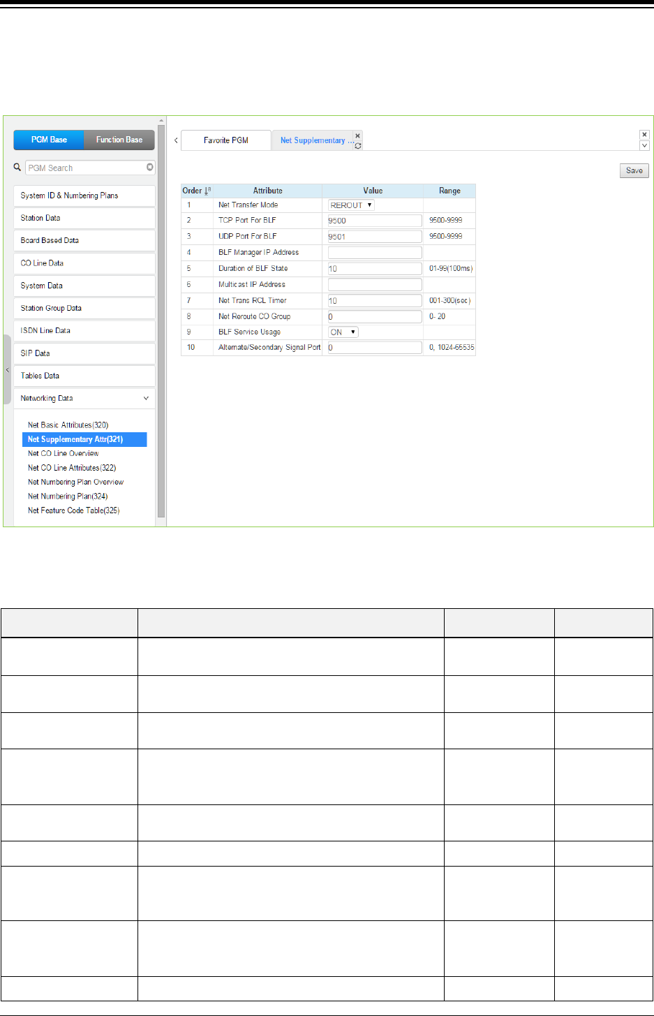
iPECS eMG80 & eMG800 & UCP
Administration and Programming Manual Issue 1.6
512
4.4.10.2 Network Supplementary Attributes - PGM 321
Selecting Network Supplementary Attributes will display the Network Supplementary Attributes
entry page. Click [Save] button after changing Value.
Figure 4.4.10.2-1 Network Supplementary Attributes
Table 4.4.10.2-1 NETWORK SUPPLEMENTARY ATTRIBUTES
ATTRIBUTE DESCRIPTION RANGE DEFAULT
Net Transfer Mode Call Forward and Transfer over the network employs
the selected Rerouting or Join method
REROUT/
JOIN
REROUT
TCP Port for BLF The TCP/IP port for BLF message packets to BLF
Manager is defined.
9500-9999 9500
UDP Port for BLF The UDP port for BLF message packets to BLF
Manager is defined.
9500-9999 9501
BLF Manager IP
The IP Address of BLF Manager server is required
when iPECS UCP is configured with eMG systems in
the Network.
0.0.0.0
Duration of BLF State The system sends BLF messages to the BLF
Manager at intervals of this timer.
01-99
(Sec.)
10
Multicast IP The multicast IP address for BLF service. 0.0.0.0
Net Trans Recall timer
When a call forward or transfer does not receive a
response for the Network system, the call recalls the
transferring party at expiration of this timer.
001-300
(msec) 10
NET Reroute CO
Group
If an outgoing SIP call receives no response after
expiration of this timer, the call is rerouted to the
alternate CO line.
eMG80:0~20
eMG800:0~200
UCP:0~200
BLF Service Usage BLF Manager support must be enabled for use. OFF, ON ON
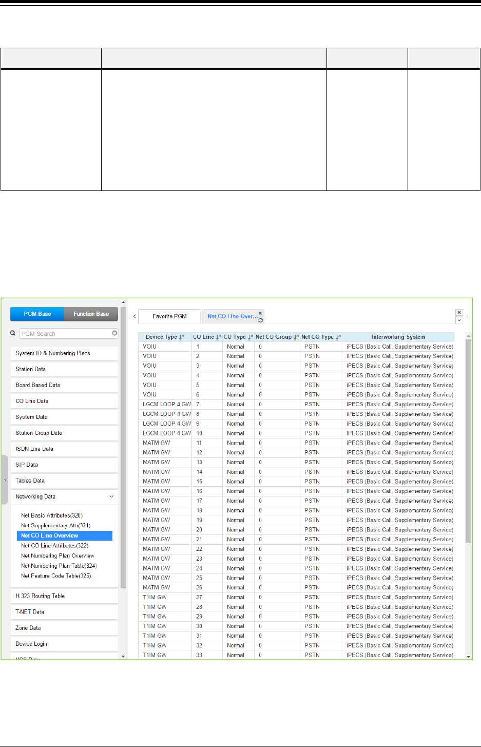
iPECS eMG80 & eMG800 & UCP
Administration and Programming Manual Issue 1.6
513
Table 4.4.10.2-1 NETWORK SUPPLEMENTARY ATTRIBUTES
ATTRIBUTE DESCRIPTION RANGE DEFAULT
Alternate/Secondary
signal port
This signal port is used to add an alternate or
secondary receiving signal port. A default receiving
signal port is TCP 1720 and an additional signal port
will be opened if this field is configured to valid value.
When the system is installed behind xDSL modem,
the problem of consecutive second call can happen
by uncontrolled H.323 ALG function at xDSL modem.
This field can be used to solve the problem of
consecutive second call.
0,
1024-65535 0
4.4.10.3 Net CO Line Overview
Selecting Net CO Line Overview will be displayed as below.
Figure 4.4.10.3-1 Network CO Line Overview
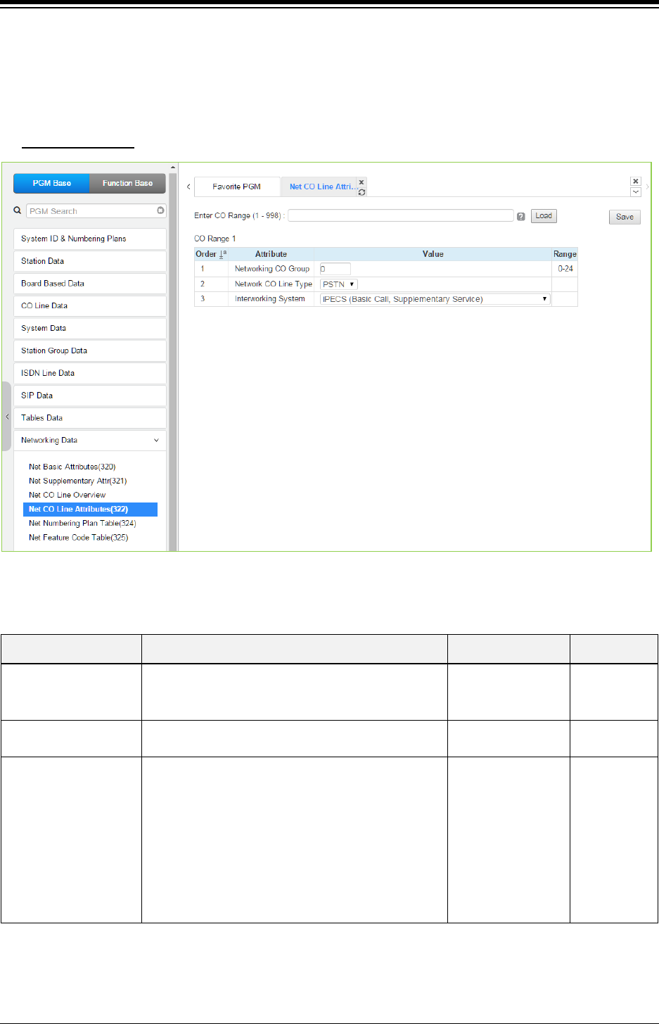
iPECS eMG80 & eMG800 & UCP
Administration and Programming Manual Issue 1.6
514
4.4.10.4 Network CO Line Attributes - PGM 322
Selecting Network CO Line Attributes will display the Network CO Line Group entry page. Enter a
valid CO/IP Line range and click [Load] to enter the Network CO Line data. Click [Save] button
after changing Value.
Enter CO Range
: eMG80: 1-74 / eMG800: 1-600 / UCP: 1-998
Figure 4.4.10.4-1 Network CO Line Attributes
Table 4.4.10.4-1 NETWORK CO LINE ATTRIBUTES
ATTRIBUTE DESCRIPTION RANGE DEFAULT
Networking CO Group
The CO/IP Lines in the assigned group are employed
as Network CO Lines, connecting to other systems in
the network.
00-24 00
Network CO Line Type The CO/IP Line is assigned for use by the network as
a PSTN (carrier) or connection to the network.
NET/
PSTN
PSTN
Interworking System
Select Qsig interworking system among the below
type.
- iPECS (Basic call, Supplementary service)
- Nortel (Basic call, Name service)
- Panasonic (Basic call, Name service-Tunneled
message)
- Cisco (Basic call, Name service-Display IE)
- Simens (Basic call, Name service)
- Astra (Basic call)
Refer to Description
iPECS (Basic
call,
Supplementar
y service)
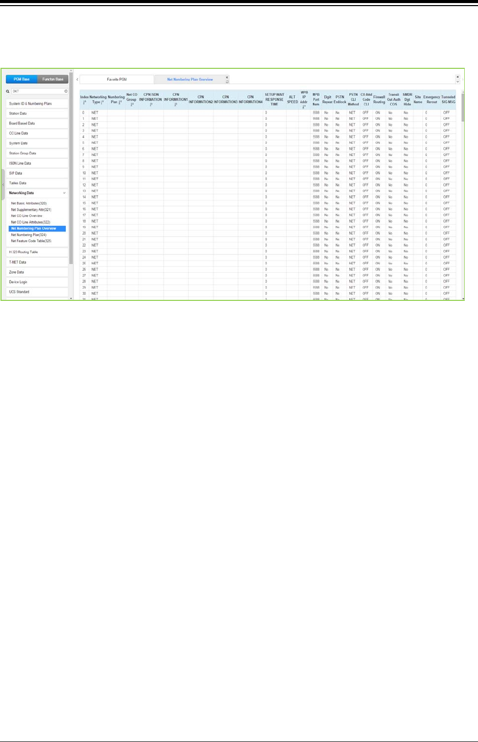
iPECS eMG80 & eMG800 & UCP
Administration and Programming Manual Issue 1.6
515
4.4.10.5 Network Numbering Plan Table Overview
Selecting Network Numbering Plan Table Overview will be displayed as below.
Figure 4.4.10.5-1 Network Numbering Plan Table overview
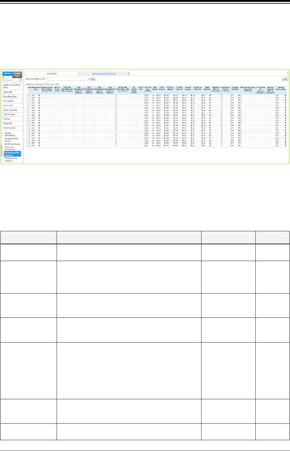
iPECS eMG80 & eMG800 & UCP
Administration and Programming Manual Issue 1.6
516
4.4.10.6 Network Numbering Plan - PGM 324
Selecting Network Numbering Plan Table will display the Network Numbering Plan Table data
entry page. Enter a valid table index and click [Load] to enter the Network Numbering Plan data.
For convenience, the copy, paste, and drag is available to enter or modify data. Click [Save]
button after changing Value.
Figure 4.4.10.6-1 Network Numbering Plan Table
The Network Numbering Plan establishes the digit strings that make-up the numbering plan and
associated routing for each Plan code.
Table 4.4.10.6-1 NETWORK NUMBERING PLAN TABLE
ATTRIBUTE DESCRIPTION RANGE DEFAULT
Network Type The type or use of the code is defined as directed to the
PSTN (carrier) or a Networked system.
NET / PSTN NET
Numbering Plan
Code
This field defines the digits, 0 ~ 9 that make up a Network
Numbering Plan code. An ‘*’ will represent any digit. To
assign the code for the stations in another system, enter
the common station number digits followed by “#”.
Max. 16 digits
(Include * and #)
Networking CO
Group
The Numbering Plan CO Group indicates the Network
CO/IP Group that is used for the connection. A ‘00’ entry
is an internal net station number.
00-24
CPN ISDN
Information
When an ISDN Line is used to place a network call, the
CPN ISDN Information and the network Number are used
as the Called party number.
Max. 16 digits
CPN Information
When a VoIP channel is used to place a network call, the
CPN used is the IP address associated with the VoIP
channel.
1: 00 CPN INFORMATION 01
2: 00 CPN INFORMATION 02
3: 00 CPN INFORMATION 03
4: 00 CPN INFORMATION 04
Enter IP address
Setup Wait
Response Time
Networking call-setup failure timer when there is no
proceeding message from network (i.e. IP-Network is
down)
0, 3~15 Sec. 0
ALT Speed Bin Should the Network path fail, the system can place the
call over an alternative path using a System Speed Dial
eMG80:2000~4999
eMG800:2000~9999

iPECS eMG80 & eMG800 & UCP
Administration and Programming Manual Issue 1.6
517
Table 4.4.10.6-1 NETWORK NUMBERING PLAN TABLE
ATTRIBUTE DESCRIPTION RANGE DEFAULT
number. UCP: 20000~31999
MPB IP Address This field is the IP Address of the destination system for
the code
0.0.0.0
MPB Port number The TCP/IP port number of destination system for the
Net Numbering Plan code is defined.
0000-9999 5588
Digit Repeat
When the number plan code, see above, is for PSTN call
or transit-call, the number code can be included in
SETUP message.
Yes
No No
PSTN Enblock
When a PSTN receives a Transit-out call from a
networked user, the digits can be sent En-block (YES) or
Over-lap (NO).
Yes
No No
PSTN CLI Method
The CLI sent with the call for this code can be set as the
NET CLI (station number) or PSTN, which sends the CLI
configured for the CO/IP Line and Station CLI.
NET
PSTN NET
CO Attendant Code
CLI
When a networked system places a transit out call, the
Centralized ATD CLI can be sent.
OFF
ON
OFF
Firewall Routing
When the system can communicate with the networked
system directly, over a common VPN, the systems Non
Firewall address is sent in IP packets (OFF). Otherwise,
the Firewall IP address is sent (ON).
OFF
ON ON
Transit Out Auth
COS
When a user requests a transit-out call by seizing a CO
line, COS may be applied according to the authorization
code.
Yes
No No
SMDR Digit Hide
For a Transit-out call from the iPECS, the networked
system that places the call may desire to receive the
Authorization code
Yes
No No
Site name A twelve-character name can be assigned to the system
for use with network calls.
Max. 12 characters
Emergency reroute
timer
When a networked station places an Emergency call and
the “Emergency CO or Group” in the Station Common
Attributes is a Transit-out CO/IP Line or group, the call
will Fail-over to the “Fail-over CO Group” in PGM 133 or
the “Net Reroute CO Group” in PGM 321 after this timer
expires. The “Fail-over CO Group” will have priority.
0-10
(Sec.) 00
Tunneled SIG MSG
Send and Receive H323 message that include ISDN
QSIG message. It is used to make networking with
Panasonic system.
OFF
ON OFF
Alternate/Secondary
signal port
This destination signal port is used on calling to remote
network system. A default destination signal port is TCP
1720 but the port number is changed if this field is
configured to valid value. When the system is installed
behind xDSL modem, the problem of consecutive second
call can happen by uncontrolled H.323 ALG function at
xDSL modem. This field can be used to solve the
problem of consecutive second call. Here, the value
should be an alternate or secondary receiving signal port
which is configured at remote system.
0-65535
Local route ID These two fields are used when a remote network Max. 15 characters

iPECS eMG80 & eMG800 & UCP
Administration and Programming Manual Issue 1.6
518
Table 4.4.10.6-1 NETWORK NUMBERING PLAN TABLE
ATTRIBUTE DESCRIPTION RANGE DEFAULT
Remote route ID
system want to check the route ID value to authenticate
the system. Here, ‘Local Route ID’ is the route ID string
for local system. And ‘Remote Route ID’ is the route ID
string for remote system.
Max. 15 characters
Sending Name
option
Basically the calling party name is transferred in QSIG
messages. This field is an additional way to send the
calling party name. In some PBX systems, the Q.931
Display IE field is used to transferring the calling party
name and this value can be used as an interoperating
solution for displaying the calling party name.
OFF,
Display IE(CISCO) OFF
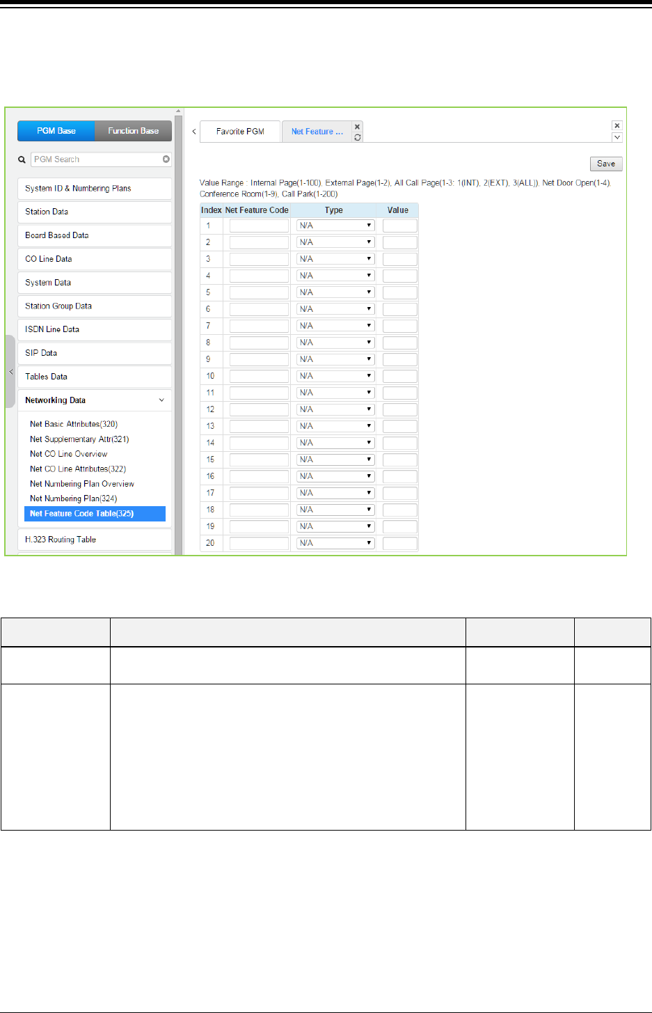
iPECS eMG80 & eMG800 & UCP
Administration and Programming Manual Issue 1.6
519
4.4.10.7 Network Feature Code Table - PGM 325
Selecting Network Feature Code Table returns the data entry page. Click [Save] button after
changing Value.
Figure 4.4.10.7-1 Network Feature Code Table
Table 4.4.10.7-1 NETWORK FEATURE CODE TABLE
ATTRIBUTE DESCRIPTION RANGE DEFAULT
Net Feature Code Digit sequence or code used to activate special Network
Features.
16 digits None
Net Feature type Each Network Feature Code is assigned to activate a feature
in the destination system.
N/A,
Internal Page,
External Page,
All Call Page,
Net Door Open,
Conference
Room,
Call Park,
N/A
In case of eMG80, the value range is as below:
Internal page: 1-35, External page (1), All Call page (1-3: 1(INT), 2(EXT), 3(ALL)), Net door Open
(1-2), Conference Room (1-9), Call Park (1-19)
In case of eMG800, the value range is as below:
Internal page: 1-100, External page (1), All Call page (1-3: 1(INT), 2(EXT), 3(ALL)), Net door
Open (1-2), Conference Room (1-9), Call Park (1-200)
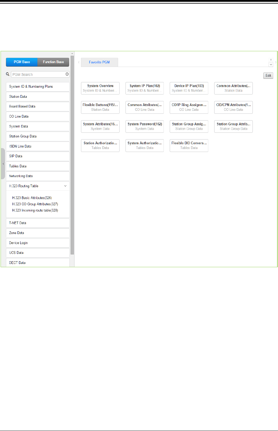
iPECS eMG80 & eMG800 & UCP
Administration and Programming Manual Issue 1.6
520
4.4.11 H.323 Routing Table
Selecting the H.323 Data program group returns the sub-menu displayed in the left frame as
shown in the following figure.
Figure 4.4.11-1 H.323 Routing Table Main Page
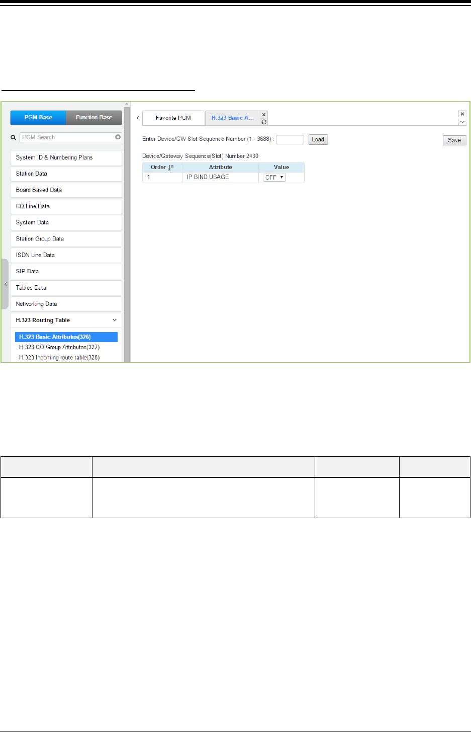
iPECS eMG80 & eMG800 & UCP
Administration and Programming Manual Issue 1.6
521
4.4.11.1 H.323 Basic Attributes -PGM 326
Selecting H.323 Basic Attributes will display the data entry page. Click [Save] button after
changing Value.
Enter Device/GW slot sequence number
: eMG80: 1-300 / eMG800: 1-2890 / UCP: 1-3688
Figure 4.4.11.1-1 H.323 Basic Attributes
H.323 Signaling can be operated with each VOIB/VOIM or MPB/UCP.
Table 4.4.11.1-1 H.323 Basic Attributes
ATTRIBUTE DESCRIPTION RANGE DEFAULT
IP Band Usage
If it is set to ON, system allows H.323 signaling with
system IP address. Or, each VOIB/VOIM IP Address
can be used.
OFF
ON OFF
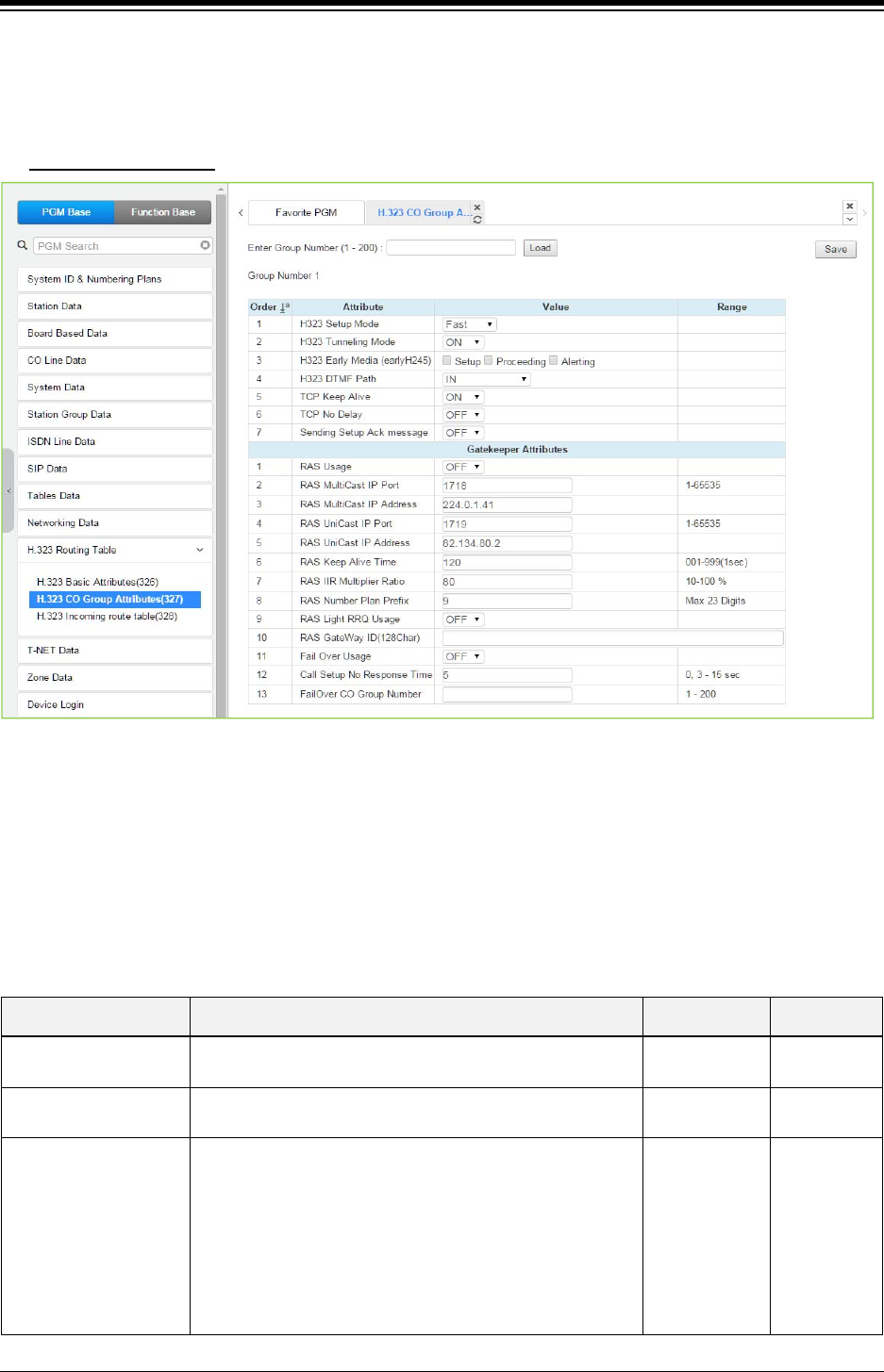
iPECS eMG80 & eMG800 & UCP
Administration and Programming Manual Issue 1.6
522
4.4.11.2 H.323 CO Group Attributes -PGM 327
Selecting H.323 CO Group Attributes will display the data entry page. Click [Save] button after
changing Value.
Enter Group number: eMG80: 1-20 / eMG800: 1-200 / UCP: 1-200
Figure 4.4.11.2-1 H.323 CO Group Attributes
The VOIP channels are used for Distributed Networking, access to SIP or H.323 networks and for
remote iPECS devices. When the standard H.323 VoIP protocol is employed for an external VoIP
call, several attributes of these channels can be assigned. The H.323 call set-up mode and
tunneling (H.245 Encapsulation) can be established.
Also for H.323 support, a RAS (Registration, Admissions and Status) channel can be defined.
The RAS channel IP addresses (uni-cast and multi-cast) as well as the IP port Numbering Plan
and other H.323 set-up characteristics are defined.
Table 4.4.11.2-1 H.323 CO Group Attributes
ATTRIBUTE DESCRIPTION RANGE DEFAULT
H.323 Setup mode H.323 IP calls can be set-up using the H.323 normal or
Fast Start mode.
Fast
Norm Fast
H.323 Tunneling mode H.323 IP calls can be set-up using the H.245
encapsulation (Tunneling).
OFF
ON ON
H323 Early Media
(early H245)
This feature is the ability of two user endpoints to
communicate before call is actually established in normal
call mode. This feature is not used when 'H323 Setup
Mode' is 'Fast'.
* Setup: Caller party tries to open early media on receiving
the Setup message.
* Proceeding: Calling party tries to open early media on
receiving the Proceeding message.
Setup,
Proceeding,
Alerting

iPECS eMG80 & eMG800 & UCP
Administration and Programming Manual Issue 1.6
523
Table 4.4.11.2-1 H.323 CO Group Attributes
ATTRIBUTE DESCRIPTION RANGE DEFAULT
* Alerting: Calling party tries to open early media on
receiving the Alerting message.
H.323 DTMF Path During a connection, DTMF Digits can be sent in-band or
out of band (H.245).
IN/
RFC2833/
H245_ALNUM/
H225_SIG/
H245_SIG
IN
TCP Keep Alive The system will send a polling message every 75 seconds
to assure the status of the TCP connection.
OFF
ON ON
TCP No Delay
Normally small chunks of TCP (H323) messages are
combined into one packet and be sent to remote party to
improve the efficiency of network. Sometimes this action
yields the H323 signaling problem when system is behind
NAT router and there is H323 ALG is running. 'OFF' value
can be a solution to overcome the problem.
OFF
ON OFF
Sending Setup Ack
message
System provides SETUP ACK message when there is no
‘sending complete IE’ in SETUP message.
OFF
ON OFF
Gatekeeper Attributes
RAS Usage Determine whether VOIU/VOIB/VOIM will be used as a
Gatekeeper.
OFF
ON OFF
RAS MultiCast IP Port Multi-cast IP Port for RAS Information of Gatekeeper. 1~65535 1718
RAS MultiCast IP
Address Multi-cast IP address for RAS Information of Gatekeeper. IP Address 224.0.1.41
RAS UniCast IP Port Uni-cast IP Port for RAS Information of Gatekeeper. 1~65535 1719
RAS UniCast IP
Address Uni-cast IP address for RAS Information of Gatekeeper. IP Address 82.134.80.2
RAS Keep Alive Time The time between exchange of RAS Information between
GK and VOIB/VOIU.
001-999
(SEC) 120
RAS IIR Multiplier Ratio
This feature is used when H323 call is routed by RAS
gatekeeper. Keep alive interval time between the system
and gatekeeper is provided by gatekeeper on registration
time. This value of ratio is used to change the keep alive
interval time from gatekeeper.
10~100% 80
RAS Number Plan
Prefix The numbering plan for Calling Number in RAS Setup. Max. 23 digits
RAS Light RRQ usage The Gatekeeper ID (This can be programmed only via
WEB Admin).
OFF
ON OFF
RAS Gateway ID
The system can be assigned to use the simple RRQ
(Registration Request) message (ON) or the full RRQ
message (OFF).
Max. 128
characters
Fail over Usage The H.323 call will be failover to another line (FAIL OVER
USAGE: ON).
OFF
ON OFF
Call Setup No
Response time The H.323 call will be failover. The time will be set. 0, 3-15
(Sec.) 0
Fail over CO Group
number If the H.323 call will be failover, assign another CO group.
eMG80:1-20
eMG800:1-200
UCP:1-200
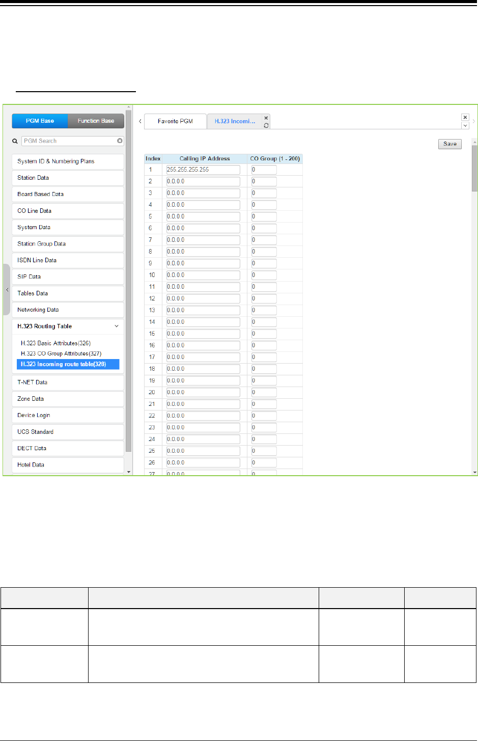
iPECS eMG80 & eMG800 & UCP
Administration and Programming Manual Issue 1.6
524
4.4.11.3 H.323 Incoming Route table -PGM 328
Selecting H.323 Incoming Route table will display the data entry page. Click [Save] button after
changing Value.
Enter CO Group number
: eMG80 : 1-20 / eMG800: 1-200 / UCP: 1-200
Figure 4.4.11.3-1 H.323 Incoming Route table
To get the direct H.323, the From IP-Address and ‘incoming CO Group number’ to be routed
should be assigned.
Table 4.4.11.3-1 H.323 Incoming Route table
ATTRIBUTE DESCRIPTION RANGE DEFAULT
Calling IP Address
IP address associated with H.323 incoming calls.
255.255.255.255 is used when external call cones from
unknown IP Address which is not listed in this table entry.
0.0.0.0
CO Group CO group number associated with H.323 incoming calls.
eMG80:1~20
eMG800:1~200
UCP:1~200
0
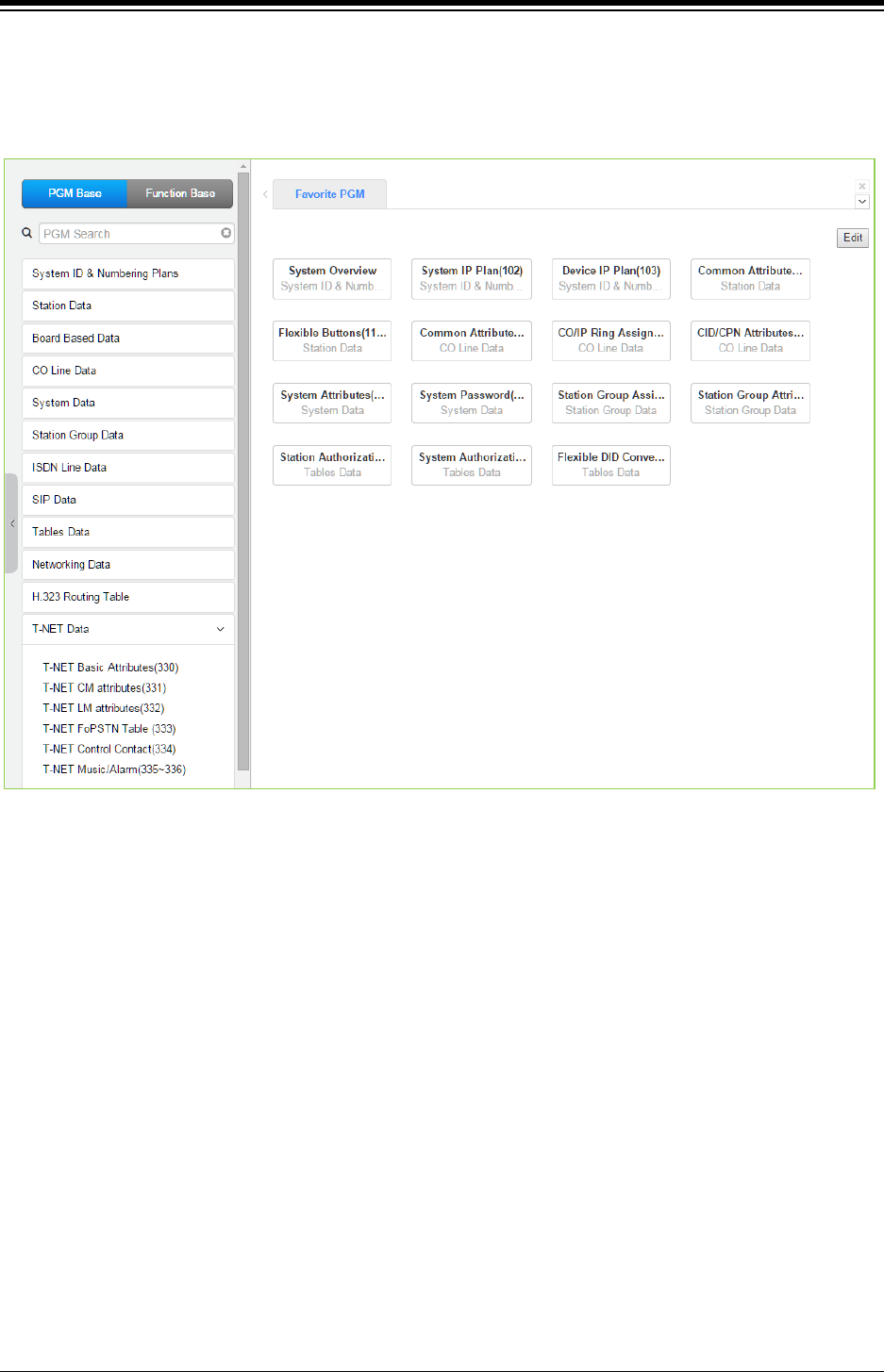
iPECS eMG80 & eMG800 & UCP
Administration and Programming Manual Issue 1.6
525
4.4.12 T-NET Data
Selecting the T-NET Data program group returns the sub-menu displayed in the left frame as
shown in the following figure.
Figure 4.4.12-1 T-NET Data Main Page
In a Centralized Control T-NET (Transparent Network), remote devices may be registered to a
Central iPECS system(CM) and to a Local iPECS system (LM). In this way, the CM maintains
control of the remote device. Should the WAN connection between an LM and CM fail (polling
error), the LM will initiate operational control of the locally registered devices. Calls between the
systems (CM and LM) can automatically shift to PSTN Modules registered with the LM for Fail-
over operation. The configuration and characteristics of LMs and CM are configurable as is Fail-
over operation.
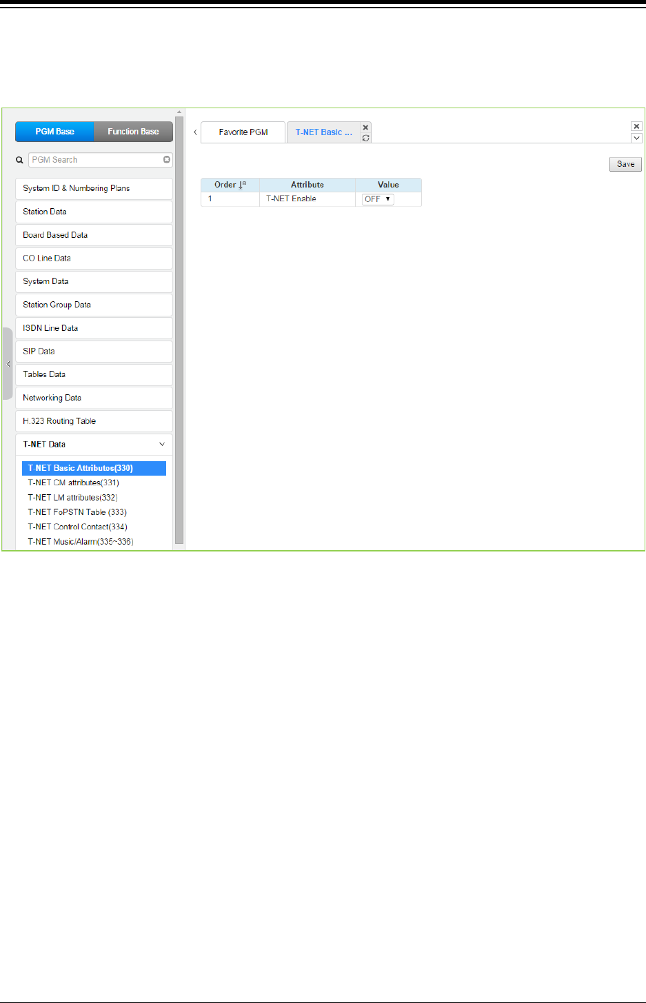
iPECS eMG80 & eMG800 & UCP
Administration and Programming Manual Issue 1.6
526
4.4.12.1 T-NET Basic Attributes -PGM 330
Selecting T-Net Basic Attributes will display the data entry page. Click [Save] button after
changing Value.
Figure 4.4.12.1-1 Zone number overview
Each iPECS system in a Central Control network environment must be enabled for T-NET
operation in order to function as part of the network.
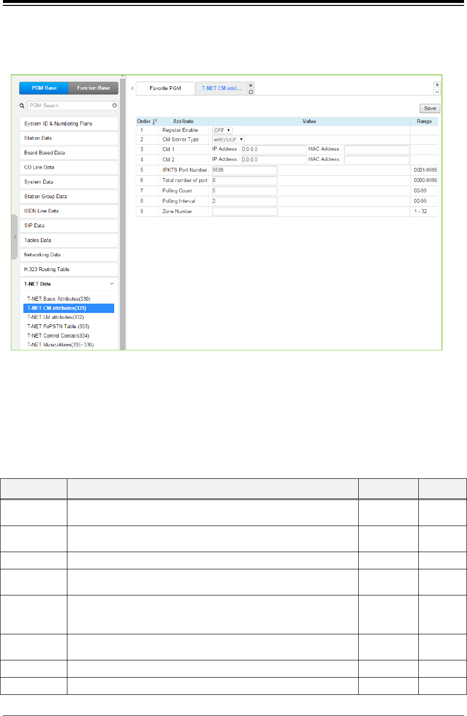
iPECS eMG80 & eMG800 & UCP
Administration and Programming Manual Issue 1.6
527
4.4.12.2 T-NET CM Attributes -PGM 331
Selecting T-Net CM Attributes will display the data entry page. Click [Save] button after changing
Value.
Figure 4.4.12.2-1 T-NET CM Attributes
Each LM (Local iPECS system), which is part of a Central Control Network, must be defined with
the IP Address of the CM (Central iPECS system). The LM configuration data is sent to the CM at
the time the LM registers with the CM. Total port counts define the ports, which are allocated in
the CM database for use by devices registered to the LM. The number of ports defined in the
database of each LM must be equal to or less than the ports defined in the CM for the LM, see
PGM 332, in order to register properly.
Table 4.4.12.2-1 T-NET CM ATTRIBUTES
ATTRIBUTE DESCRIPTION RANGE DEFAULT
Register
Enable
This field informs the LM to attempt registration with the CM. This field
must be set to ON for proper registration.
OFF
ON OFF
CM server type Assign the type of CM server; iPECS eMG/UCP or iPECS CM. eMG/UCP,
CM
eMG/UCP
IP Address This field defines the IP address of the CM that will be used by the LM. IPv4 address
IPKTS Port
number
In the TNET environment, the IPKTS protocol signaling UDP port is
defined. At present this field is not used, do not change this port number.
0001-9999 5588
Total number
of
port
This field defines the total number of ports the LM will request be
allocated by the CM for devices attached to the LM. This value must be
equal to or less than the port count in the CM for the LM devices.
0000-9999 0
Polling Count This field defines the maximum polling failures an LM considers a WAN
fault.
00-99 5
Polling interval This field defines the interval time between LM to CM polling attempts. 00-99 2
Zone Number Zone number can be assigned to Device or GW. 1-32
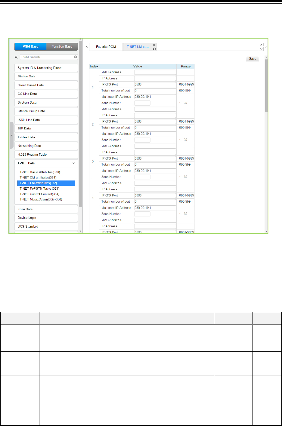
iPECS eMG80 & eMG800 & UCP
Administration and Programming Manual Issue 1.6
528
4.4.12.3 T-NET LM Attributes -PGM 332
Selecting T-Net LM Attributes will display as below. Click [Save] button after changing Value.
Figure 4.4.12.3-1 T-NET LM Attributes
The CM (Central iPECS system) must be programmed with the MAC and IP address of each LM
(Local iPECS system) in the Centralized Control network as well as the maximum configuration of
each LM. Up to 100 Local iPECS system (LMs) may be defined and configuration entered. The
port counts define the ports that are allocated in the CM database for use by devices registered to
the LM. The number of ports defined in the database for each LM in PGM 331, must be equal to
or less than the ports defined in the CM for the LM, in order to register properly.
Table 4.4.12.3-1 T-NET LM ATTRIBUTES
ATTRIBUTE DESCRIPTION RANGE DEFAULT
Mac Address This field defines the MAC address of the LM that will be part of the T-
NET environment and is used by the CM for authorization.
MAC address
IP Address This field is the IP address of the LM. IPv4 address
IPKTS Port
In the T-NET environment, the IP KTS protocol signaling UDP port is
defined. At present this field is not used, do not change this port
number.
0001-9999 5588
Total no of
port
This field defines the total number of ports the LM will request from the
CM for devices attached to the LM. This value must be equal to or more
than the port count defined in the LM.
000-999 0
Multicast IP
address
This field defines the multicast IP address that could be used in T-NET
branch site.
IPv4 address
Zone number Zone number can be assigned to Device or GW. 1-32
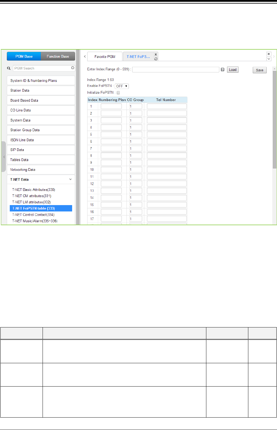
iPECS eMG80 & eMG800 & UCP
Administration and Programming Manual Issue 1.6
529
4.4.12.4 T-NET FoPSTN table -PGM 333
Selecting T-NET FoPSTN Table will display the data entry page. Enter an index range then click
[Load] to modify the data. Click [Save] button after changing Value.
Figure 4.4.12.4-1 T-NET FoPSTN table
The Fail-over function allows the systems in T-NET environment to complete calls between
systems over a PSTN (analog or digital) line should the WAN connection to the CM fail. A CO
gateway Module must be registered to the LM for local CO services. Users may call others in the
normal manner and the call is routed over CO facilities to the remote CM. When calls are directed
to a DID line at the receiving system, the system will select a line from the assigned CO Group
and dial the Tel Number with the station number dialed as the trailing digits.
Table 4.4.12.4-1 Fail Over to PSTN ATTRIBUTES
ATTRIBUTE DESCRIPTION RANGE DEFAULT
Numbering Plan
Station numbers associated with the remote system. A range can
be indicated by using “*” to indicate the range. Example: 21* covers
210 to 219 or 2100 to 2199.
Station number
CO Group
This field defines the CO Group of the local system that will be used
to place calls to the stations entered in the Fail Over Numbering
Plan above, should WAN failure occur.
eMG80:1~20
eMG800:1~200
UCP:1~200
Tel Number
This field defines the telephone number the system should dial to
place a call to the stations entered in the FO Numbering Plan,
should WAN failure occur. An “*” may be entered as a wild card to
indicate insertion of the dialed station number.
24 digits
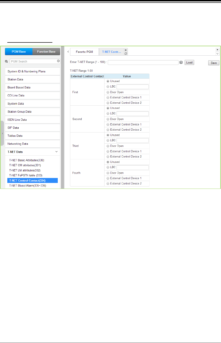
iPECS eMG80 & eMG800 & UCP
Administration and Programming Manual Issue 1.6
530
4.4.12.5 T-NET Control Contact -PGM 334
Selecting T-NET Control Contact will display the data entry page. Enter the T-NET range from the
T-Net LM Attributes then click [Load] to modify the data. Click [Save] button after changing Value.
Enter T-NET Range
: eMG80: 1-15 / eMG800: 1-32 / UCP: 1-100
Figure 4.4.12.5-1 T-NET Control Contact
Each LM incorporates relay contacts that can be employed as a Door Lock Release. The contact
activates a third party Door Lock Release mechanism activated by dialing the Door Unlock code
at a local station.
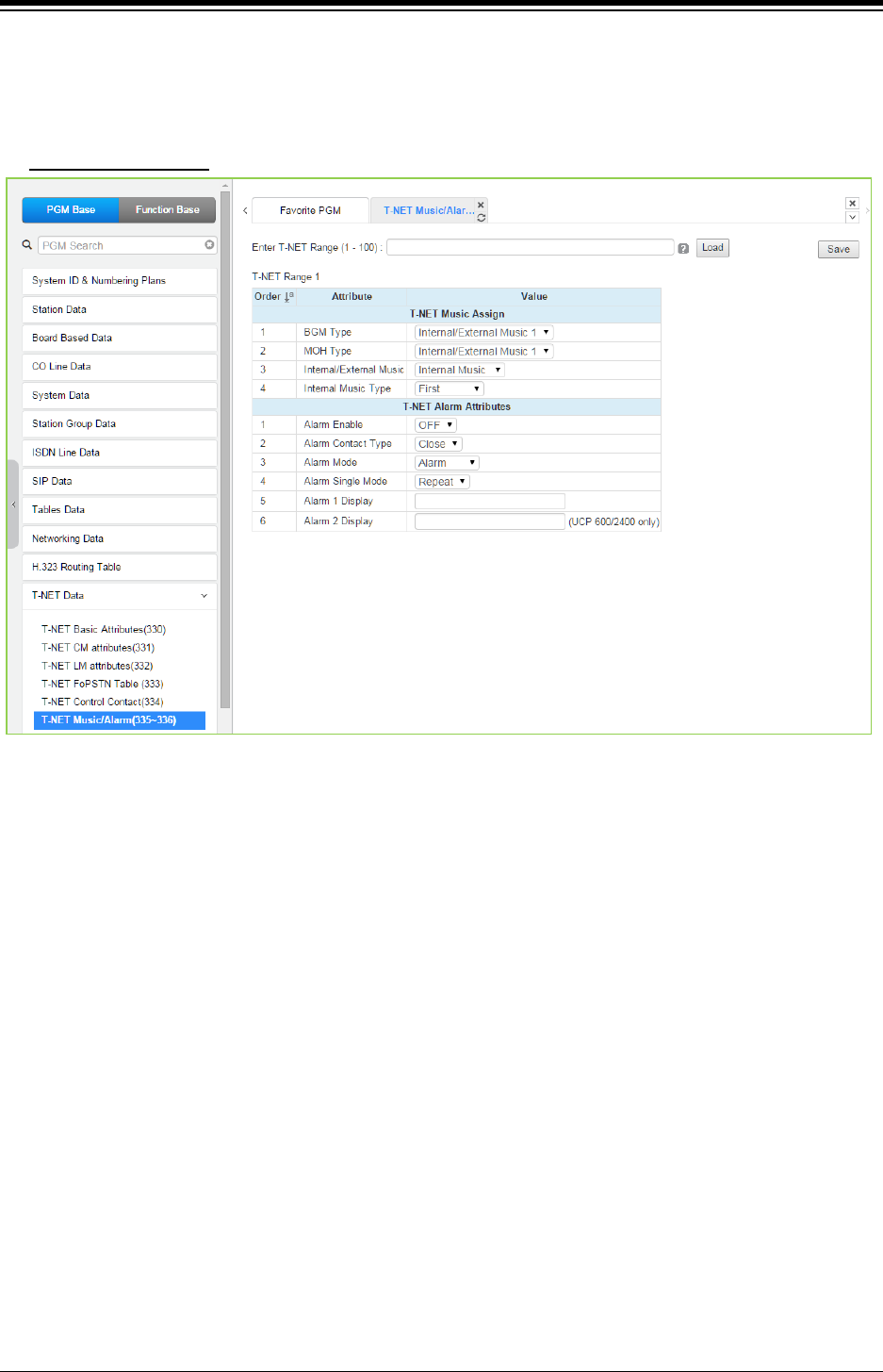
iPECS eMG80 & eMG800 & UCP
Administration and Programming Manual Issue 1.6
531
4.4.12.6 T-NET Music/Alarm -PGM 335 ~ 336
Selecting T-NET Music/Alarm will display the data entry page. Enter the T-NET range from the T-
Net LM Attributes then click [Load] to modify the data. Click [Save] button after changing Value.
Enter T-NET Range
: eMG80: 1-15 / eMG800: 1-32 / UCP: 1-100
Figure 4.4.12.6-1 T-NET Music/Alarm
To minimize WAN traffic, the CM does not provide BGM/MOH to an LM. The LM employs local
BGM and MOH facilities to reduce traffic load on the WAN and IP channel processors. The LM
uses IP Multicast for local BGM and MOH transport. In addition, the Alarm contacts of the LM can
be defined for use as a local alarm or doorbell.
When alarm port 1 of the LM is activated, the string of {Alarm 1 Display} is displayed in assigned
stations.
When alarm port 2 of the LM is activated, the string of {Alarm 2 Display} is displayed in assigned
stations (if LM is UCP600/2400).
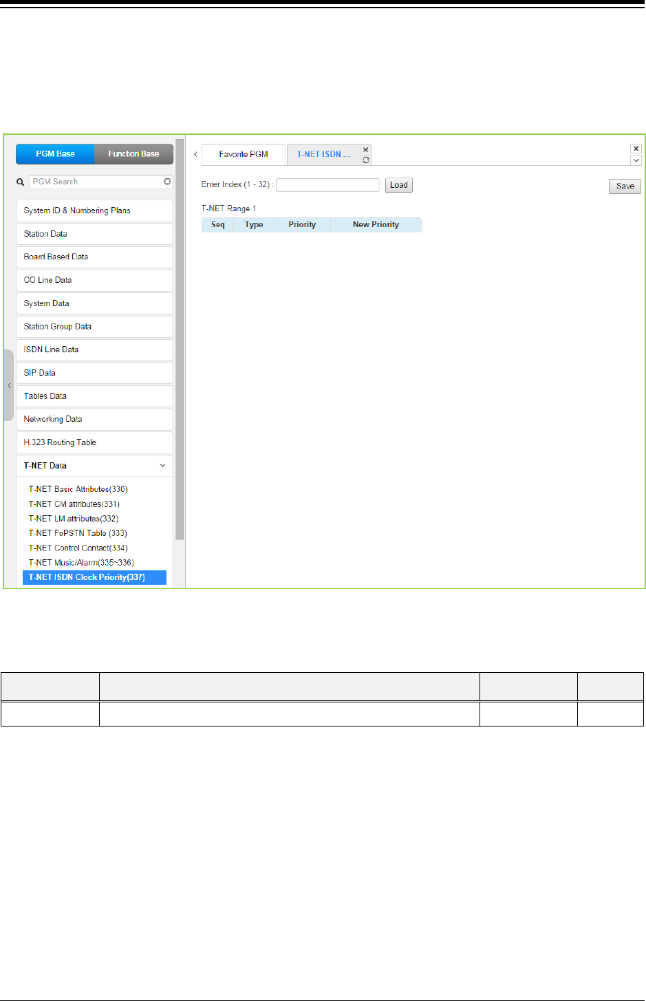
iPECS eMG80 & eMG800 & UCP
Administration and Programming Manual Issue 1.6
532
4.4.12.7 T-NET ISDN Clock Priority for eMG800 - PGM 337
Selecting T-NET ISDN Clock priority will display the data entry page. Enter the T-NET range from
the T-Net LM Attributes then click [Load] to modify the data. Click [Save] button after changing
Value.
Figure 4.4.12.7-1 T-NET ISDN Clock Priority
Table 4.4.12.7-1 T-NET ISDN Clock priority
ATTRIBUTE DESCRIPTION RANGE DEFAULT
Priority ISDN clock priority in a TNET site. 1-18
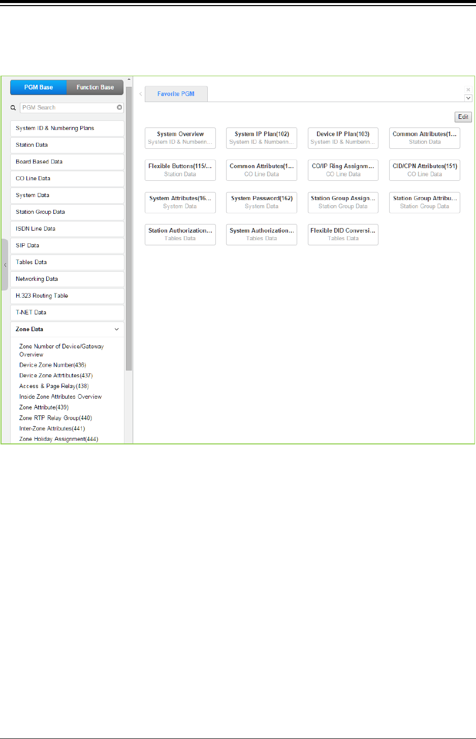
iPECS eMG80 & eMG800 & UCP
Administration and Programming Manual Issue 1.6
533
4.4.13 Zone Data
Selecting the Zone Data program group returns the sub-menu displayed.
Figure 4.4.13-1 Zone Data Main Page
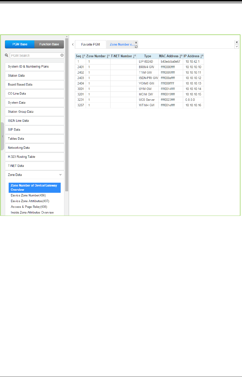
iPECS eMG80 & eMG800 & UCP
Administration and Programming Manual Issue 1.6
534
4.4.13.1 Zone Number Overview
Selecting Zone Number Overview returns the data entry page.
Figure 4.4.13.1-1 Zone number overview
Zone data is a tool employed to easily manage the characteristics of groups of devices under the
control of an MPB/UCP. Such devices can be grouped to a Zone to define common
characteristics including Country Code, DSCP, RTP packet handling, etc. Common attributes are
defined at the device, Zone and Inter-zone level. Device settings have priority over system and
Zone settings, while Zone settings have priority over system settings.
Generally, transport of RTP packets should be a peer-to-peer communication over either a LAN
or VPN. If iPECS devices are separated by a NAPT server or direct peer-to-peer communications
is not available, packet relay must be employed to assure communication. In packet relay, RTP
packets are received by a local VoIP channel, which is under control of the MPB/UCP, and the IP
address is translated from a public to the device’s private address. The VoIP channel implements
a secure channel using IPSec protocol. Devices can be assigned as part of an “RTP Relay group”
to use the same VoIP channels to implement relay of RTP packets. Packet relay groups also
provide for conversion of multi-cast packets from the MPB/UCP to uni-cast and back again at the
group level to multi-cast. Note packet relay requires a VoIP channel be available locally for each
simultaneous call that requires packet relay.
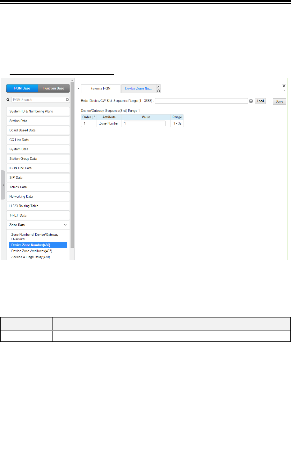
iPECS eMG80 & eMG800 & UCP
Administration and Programming Manual Issue 1.6
535
4.4.13.2 Device Zone Number – PGM 436
Selecting the Device Zone Number returns the Zone Number data input page. Enter the
Sequence number range (refer to section 4.4.1.4 System & Device IP Address Plan - PGM 102 &
103) and click [Load] to assign a Zone number for the device. Click [Save] button after changing
Value.
Enter Device/GW sequence Range
: eMG80: 1-300 / eMG800: 1-2890 / UCP: 1-3688
Figure 4.4.13.2-1 Device Zone Number
Device Zone Number assigns a device to one of up to 32 specific Zones.
Table 4.4.13.2-1 DEVICE ZONE ATTRIBUTES
ATTRIBUTE DESCRIPTION RANGE DEFAULT
Zone number Zone number can be assigned to Device or GW. 1-32 1
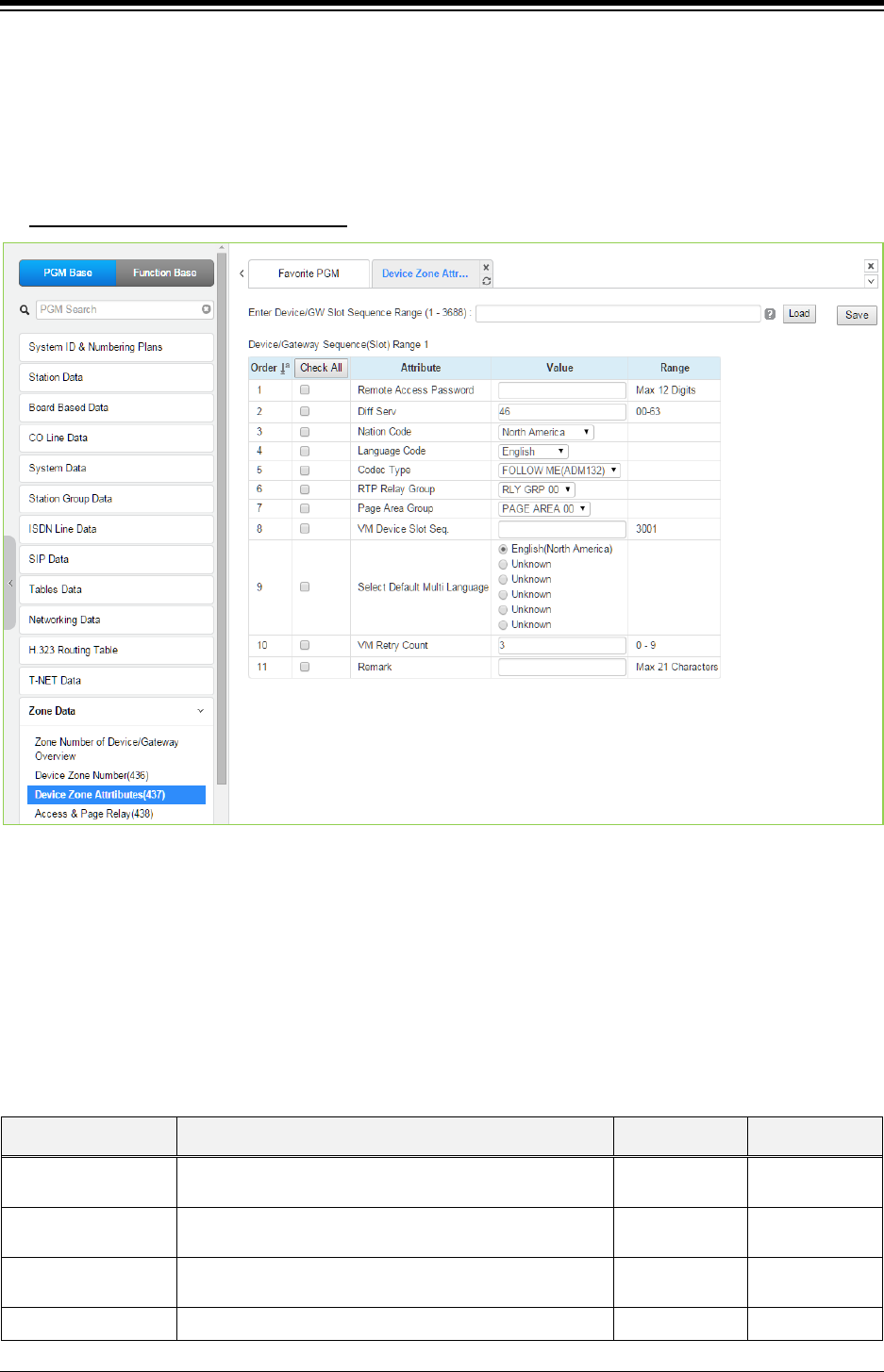
iPECS eMG80 & eMG800 & UCP
Administration and Programming Manual Issue 1.6
536
4.4.13.3 Device Zone Attributes – PGM 437
Selecting the Device Zone Attributes returns the Device Zone Attributes data input page. Enter
the Sequence number Range (refer to section 4.4.1.4 System & Device IP Address Plan - PGM
102 & 103) and click [Load] to assign a Zone number for the device. Use the check mark to
indicate which attributes to modify; data for checked attributes is stored by clicking [Save] button.
Enter Device/GW sequence Range
: eMG80: 1-300 / eMG800: 1-2890 / UCP: 1-3688
Figure 4.4.13.3-1 Device Zone Attributes
Device Zone Attributes define characteristics specific to the device including the registration
password, Diff Serv Code Point, Nation, etc. In addition, Zone characteristics set at the Device
level take precedence over characteristics for the Zone Attributes. While a Zone may incorporate
up to 15 different RTP packet Relay Groups, for clarity a single RTP Relay Group should be used
within a Zone.
Table 4.4.13.3-1 DEVICE ZONE ATTRIBUTES
ATTRIBUTE DESCRIPTION RANGE DEFAULT
Remote Access
Password
Registration password assigned in device for Remote
stand-alone device only
Max. 12 digits None
Diff Serv MPB assigned code point will take precedence. Applies
to all devices
0-63 4
Country Code Country location of the device.
Available selections are given in Country code table.
Country Code Nation
dependent
Language Code Each device can be assigned a local language or Language Code Nation

iPECS eMG80 & eMG800 & UCP
Administration and Programming Manual Issue 1.6
537
Table 4.4.13.3-1 DEVICE ZONE ATTRIBUTES
ATTRIBUTE DESCRIPTION RANGE DEFAULT
English as the LCD Display Language. dependent
Codec Type
The codec selection method can be defined as device
based, see PGM 132, or based on the codec type
assigned to the Zone.
Follow Zone,
Follow Me
(ADM132)
Follow Me
(ADM132)
RTP Relay Group
This attribute defines the RTP Relay group employed by
the device, 00-no relay. Zone parameters define the
VoIP device to employ.
00-15 00
(no relay)
Page Area Group
The Paging Area Group identity is employed to
determine when multicast to unicast conversion is
needed to relay paging data across the network using a
VoIP channel of a VOIU/VOIM or Paging Agent (VoIP
channel of an iPECS LIP Phone).
00-15
00
(same paging
relay area)
VM Device Slot
Sequence.
(VMIU/VMIB Slot
Sequence)
The VSF gateway used to support Voice Mail for a
device is defined. The VSF/UVM must be under control
of the same eMG/UCP as the device.
eMG80: Max. 3
Digits
eMG800/UCP:
Max. 4Digits
Select Default Multi
Language
The recorded language selection prompt is played to the
user when accessing the built-in AA/VM. The system
supports up to six languages.
1 ~ 6 1
VM Retry Count
The user may select an available language. If the
language is unavailable, the user may attempt to enter a
valid language type based on this retry counter. If the
user cannot enter a valid language, the announcement is
provided in the default language.
0-9 3
Remark Descriptive information to help installer/programmer in
identifying the device Zone, i.e. Branch1.
Max. 21
characters
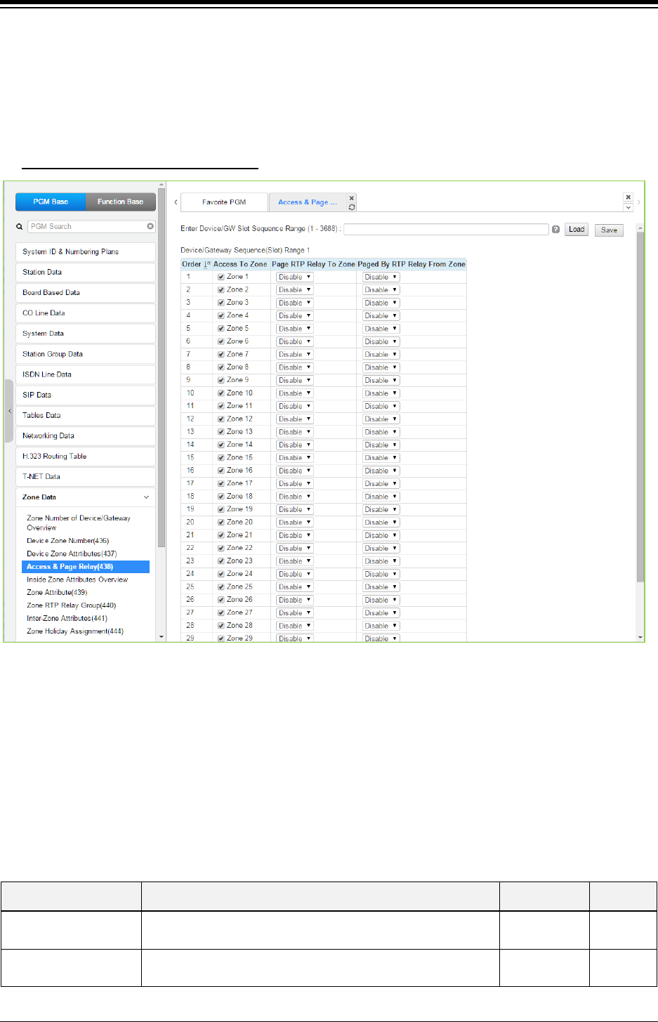
iPECS eMG80 & eMG800 & UCP
Administration and Programming Manual Issue 1.6
538
4.4.13.4 Access & Page Relay – PGM 438
Selecting Access & Page Relay returns the Access & Page RTP packet relay data input page.
Enter the Sequence number Range (refer to section 4.4.1.4 System & Device IP Address Plan -
PGM 102 & 103) and click [Load] to define packet relay characteristics for Paging between
Zones. Click [Save] button after changing Value.
Enter Device/GW sequence Range
: eMG80: 1-300 / eMG800: 1-2890 / UCP: 1-3688
Figure 4.4.13.4-1 Zone Page RTP Packet Relay
iPECS protocol employs multi-cast to send of RTP packets to multiple devices at one time. This
improves efficiency and lowers traffic by sending a single multi-cast packet to multi-cast group
members. In particular, paging employs this multi-cast technique. However, since multi-cast is not
commonly supported outside of the LAN, uni-cast must be used to transport such signals
between routers. At the receiving Zone, a local VoIP channel receives the uni-cast signal from the
controlling MPB. The VoIP channel then converts the packet address to a multi-cast signal for
delivery to devices in the same Zone RTP Relay Group.
Table 4.4.13.4-1 Zone Page RTP Packet Relay
ATTRIBUTE DESCRIPTION RANGE DEFAULT
Page RTP Relay to
Zone
The device can be configured to relay RTP packets for paging
to other zone members, Paging Rely.
Disable
Enable
Disable
Page By RTP Relay
From Zone
The device can be configured to receive relayed packets from
the assigned Zones(s).
Disable
Enable
Disable
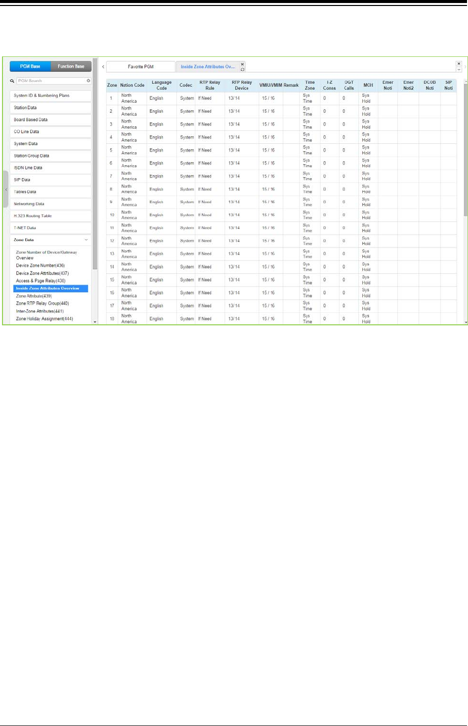
iPECS eMG80 & eMG800 & UCP
Administration and Programming Manual Issue 1.6
539
4.4.13.5 Inside Zone Attributes Overview
Figure 4.4.13.5-1 Zone Attributes Overview
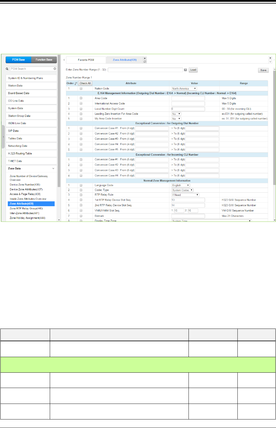
iPECS eMG80 & eMG800 & UCP
Administration and Programming Manual Issue 1.6
540
4.4.13.6 Zone Attribute – PGM 439
Selecting the Zone Attributes returns the Zone Attributes data input page. Enter the desired Zone
number range and click [Load] to assign Zone characteristics. Use the check mark to indicate
which attributes to modify; data for checked attributes is stored by clicking [Save] button.
Figure 4.4.13.6-1 Zone Attributes
The nation code, codec and VMIU/VMIB assigned for a Zone will be employed by all devices in
the Zone unless a different entry is made in Device Zone data. If the Device Zone data is default
or assigned by the MPB, the Zone data will take precedence.
The Zone Attributes define when and which VoIP channels to use for RTP packet relay. Local
VoIP channels are assigned to perform the packet relay function and the use can be defined as “if
needed” or use the assigned RTP Relay Group. For “if Need”, the MPB will employ the IP KTS
STUN protocol to determine when packet relay is required. If assigned “RTP Relay Group”,
packet relay will always be employed for RTP packet receipt.
Table 4.4.13.6-1 ZONE ATTRIBUTES
ATTRIBUTE DESCRIPTION RANGE DEFAULT
Nation Code Nation code of devices in the zone. Available selections
are given in Country code table.
Country code
E.164 Management Information (Outgoing Dial Number : E164-> Normal) (Incoming CLI Number: Normal -
>164)
Area Code Assign area code that is use to convert CLI format
(normal <-> E.164)
Max 5 Digits
International
Access Code
Assign international access code that is use to convert
CLI format (normal <-> E.164)
Max 5 Digits
Local Number Digit
Count
CLI length is over this count then it is long distance call
otherwise it is local call.
00-30 0

iPECS eMG80 & eMG800 & UCP
Administration and Programming Manual Issue 1.6
541
Table 4.4.13.6-1 ZONE ATTRIBUTES
ATTRIBUTE DESCRIPTION RANGE DEFAULT
(it is for incoming CLI)
Leading Zero
Insertion for Area
code
For an outgoing call, the system can insert a zero (‘0’) in
front of area code.
No
Yes No
My Area Code
Insertion
For an outgoing call, the system can insert my area code
in the CLI.
No
Yes
No
Exceptional Conversion : for Outgoing Dial Number
Conversion Case
#1
The first digits, up to four (4), dialed by the user can be
converted to a digit string of up to six (6) digits and may
include a plus (+) sign. For example if the “From” digits
are 00 and the “To” digits are +820, if the user dials
002233432, the system converts the number to +820
2233432.
From (4-digits) and
To (6-digits)
Conversion Case
#2
Conversion Case
#3
Conversion Case
#4
Conversion Case
#5
Exceptional Conversion : for Incoming CLI Number
Conversion Case
#1
The first digits, up to four (4), received as the CLI can be
converted to a digit string of up to six (6) digits and may
include a plus (+) sign. For example if the “From” digits
are 00 and the “To” digits are +820, if the user dials
002233432, the system converts the number to +820
2233432.
From (4-digits) and
To (6-digits)
Conversion Case
#2
Conversion Case
#3
Conversion Case
#4
Normal Zone Management Information
Language Code Language code of devices in the zone. Language Code Nation
dependent
Codec Type Assigns the codec employed by devices in the Zone.
System codec
G.711
G.723.1
G.729
G.722
System codec
RTP Relay Rule
Assigns when to use the packet relay function, with “If
Need” the MPB will automatically determines when to use
packet relay, while “RTP Relay Group” will always
implement packet relay for RTP packets.
If need/
Relay Group/
Forced to Relay
If need
1st RTP Relay
Device Slot Seq.
Assigns the local VOIU or VOIB IP channels that will be
used to implement packet relay for devices in the Zone.
Sequence
Number
eMG80:13
eMG800:19
2nd RTP Relay
Device Slot Seq.
Back-up VoIP channels for RTP packet relay use in the
Zone.
Sequence
Number
eMG80:14
eMG800:NA
VM Device Slot
Sequence
(VMIU/VMIB Slot
Sequence)
Assigns the UVMU/UVM/VMIU/VMIB used to support
Voice Mail for devices in the Zone. The
UVMU/UVM/VMIU/VMIB must be under control of the
same MPB/UCP as the device being assigned.
Sequence
Number
eMG80: 2
(1:15/2:16)
eMG800: 3
Remark Descriptive information to help installer/programmer in Max. 21 characters

iPECS eMG80 & eMG800 & UCP
Administration and Programming Manual Issue 1.6
542
Table 4.4.13.6-1 ZONE ATTRIBUTES
ATTRIBUTE DESCRIPTION RANGE DEFAULT
identifying the device Zone, i.e. Branch1.
Display time zone The time & date displayed at the station are based on the
time zone selected or the system time
Time zone,
System time
System time
Max Total Inter
Zone Connections
This parameter may be used to limit the number of
maximum Inter Zone connections. When this value is set
to 0, there is no limit on the total Inter Zone connections.
eMG80:0-140 (0:
No limit)
eMG800: 0-1200
(0: No limit)
UCP: 0-2400 (0:
No limit)
0
Max Outgoing CO
Calls
This field may be used to limit the number of outgoing
CO/IP calls from the Zone. When this value is set to 0,
there is no limit on the number of outgoing CO/IP calls.
eMG80:0-74 (0: No
limit)
eMG800: 0-600 (0:
No limit)
UCP: 0-998 (0: No
limit)
0
Zone MOH Assign A Music source can be assigned so that calls to this zone.
Refer to Sys Hold,
Internal music
External Music
VSFMOH,
SLT MOH1~5,
VSF MOH2~3
Refer to Sys
Hold
Emergency Call
Notify Station
Assigns the destination station for Emergency Call
Notification.
Station number
Emergency Call
Notify 2nd Station
This field assigns a secondary station to receive
notification of an Emergency call from a device in the
Zone.
Station number
DCOB Fault Notify
Station
This field assigns the station to receive notification of a
DCOB (Digital CO Board) fault.
Station number
SIP Registration
Fault Notify Station
This field assigns the station to receive notification of a
SIP Trunk registration fault.
Station number
Daylight Saving
Usage
If option is "System DST mode", the zone will follow the
system DST mode (System Date &Time (178)).
If option is "OFF", the zone will not apply the Daylight
Saving Time.
System DST mode,
OFF
System DST
mode
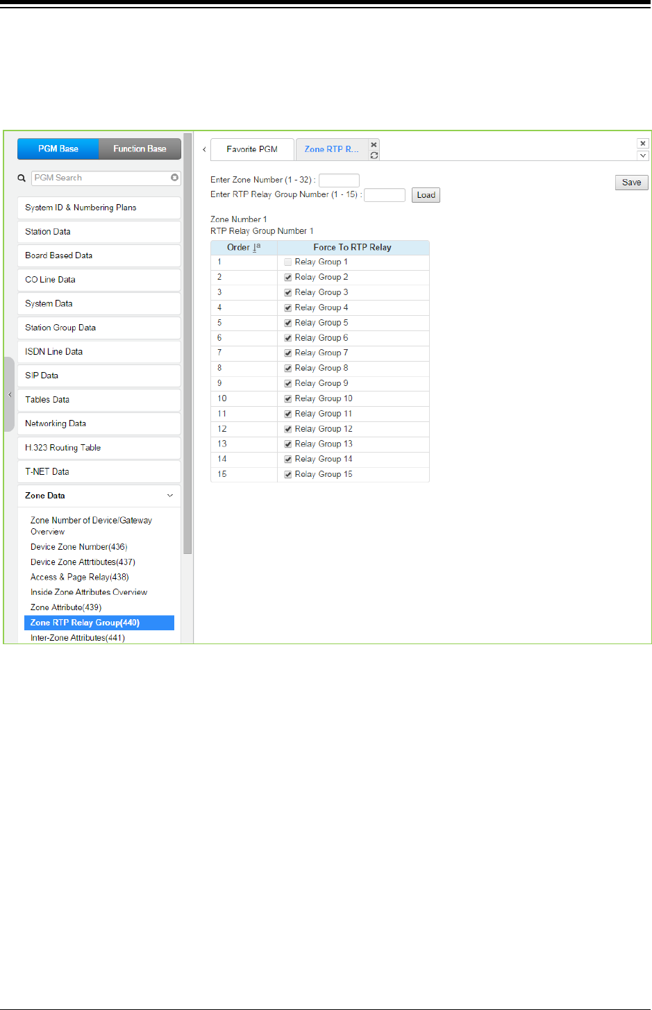
iPECS eMG80 & eMG800 & UCP
Administration and Programming Manual Issue 1.6
543
4.4.13.7 Zone RTP Relay Group – PGM 440
Selecting the Zone RTP Relay Group returns the RTP Relay ON/OFF data input page. Enter the
desired Zone and Group numbers and click [Load] button to assign Zone characteristics. Click
[Save] button after changing Value.
Figure 4.4.13.7-1 Zone RTP Packet Relay Groups
While it is strongly recommended that a Zone only have a single RTP Relay Group, up to 15
Groups can be assigned to a Zone. Devices in an RTP Relay Group should have common
requirements for packet relay use. In some situations, it may be necessary to implement packet
relay to groups in a Zone. Note that when “if Need” is assigned as the RTP Relay Rule in the
Zone Attributes, assignments here are ignored.
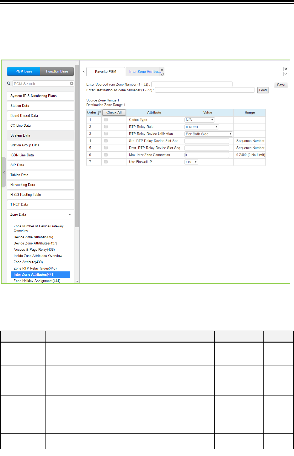
iPECS eMG80 & eMG800 & UCP
Administration and Programming Manual Issue 1.6
544
4.4.13.8 Inter Zone Attribute – PGM 441
Selecting the Inter Zone Attribute returns the data input page. Enter the desired Source and
Destination Zone number range and click [Load] to assign Zone characteristics. Click [Save]
button after changing Value.
Figure 4.4.13.8-1 Inter-Zone Attributes
Inter Zone Attributes define RTP packet relay treatment for communications between devices in
different Zones.
Table 4.4.13.8-1 INTER-ZONE ATTRIBUTES
ATTRIBUTE DESCRIPTION RANGE DEFAULT
Codec Type Assigns the codec employed by devices in the Zone.
System Codec/
G.711 / G.723.1
G.729 / G.722
NA
RTP Relay Rule
Assigns when to use the packet relay function between Zones,
with “If Need” the MPB will automatically determine when to use
packet relay, while “RTP Relay Group” will always implement
packet relay for RTP packets between the Zones.
If need/
Always not/
Forced to do
If need
RTP Relay
Device
Utilization
Assigns how to employ the Source and Destination VoIP
channels. The assigned Source channels may be used for both
sides of the communication or separately only for a device in the
Source Zone. The Destination channels are then used as back-up
channels or only for devices in the Destination Zone.
For Both Side/
Separated (SRC
to DEST)
For Both
side
Src RTP Relay
Device Slot Seq.
The Sequence number associated with the VoIP channels in the
Source Zone that handle Packet Relay.
Sequence
Number

iPECS eMG80 & eMG800 & UCP
Administration and Programming Manual Issue 1.6
545
Table 4.4.13.8-1 INTER-ZONE ATTRIBUTES
ATTRIBUTE DESCRIPTION RANGE DEFAULT
Dest. RTP
Relay Device
Slot Seq.
The Sequence number associated with the VoIP channels to
handle packet relay for the Destination Zone is defined. When
Utilization is Separate the channels are used for devices in the
destination Zone, otherwise they are used as back up for both
sides.
Sequence
Number
Max Inter Zone
connection
This field determines the maximum Inter Zone connections
between the source zone and destination zone. When this value is
set to 0, there is no limit on the number of connections between
the zones.
eMG80:0-140
eMG800: 0-1200
UCP:0-2400
0
Use Firewall IP
If this option is set to ON, System use Firewall IP of VoIP board
for RTP relay between Zones. But, if this option is OFF, System
use Local IP of VoIP board for RTP relay between zones.
OFF
ON ON
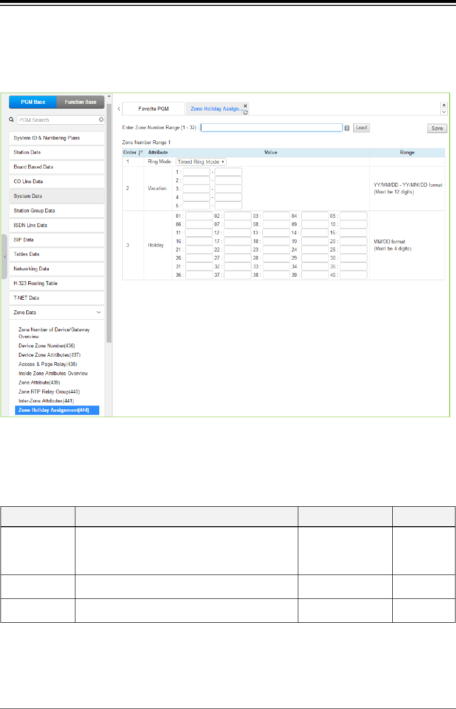
iPECS eMG80 & eMG800 & UCP
Administration and Programming Manual Issue 1.6
546
4.4.13.9 Zone Holiday Assignment - PGM 444
Selecting the Zone Holiday Assignments returns the data input page. Enter the desired Source
and Destination Zone numbers range and click [Load] to assign Zone holiday. Click [Save]
button after changing Value.
Figure 4.4.13.9-1 Zone Holiday Assignment
Holidays and vacation day intervals for each zone can be established to define the Service mode
(Day, Night, and Timed) Up to 40 holidays and 5 vacation intervals can be defined.
Table 4.4.13.9-1 ZONE HOLIDAY ASSIGNMENT
ATTRIBUTE DESCRIPTION RANGE DEFAULT
Ring Mode Enter the desired Service mode for the Holiday or
Vacation.
Day Ring Mode/
Night Ring Mode/
Timed Ring Mode/
N/A
Timed Ring
Mode
Vacation Five ranges may be entered for vacation periods, enter
the start and end dates as YY/MM/DD – YY/MM/DD.
Must be 12 digits None
Holiday Each Zone can have up to 40 holidays assigned,
entering the date as MM/DD.
Must be 4 digits None
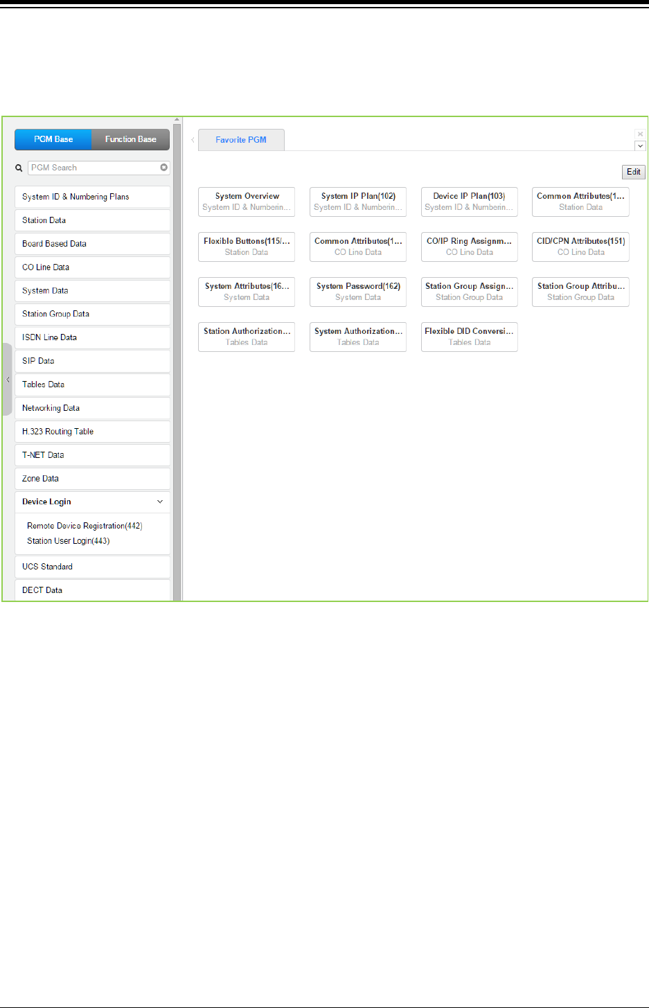
iPECS eMG80 & eMG800 & UCP
Administration and Programming Manual Issue 1.6
547
4.4.14 Device Login
Selecting the Device Login Data program group returns the sub-menu displayed in the left frame
as shown in the following figure.
Figure 4.4.14-1 Device Login Data Main Page
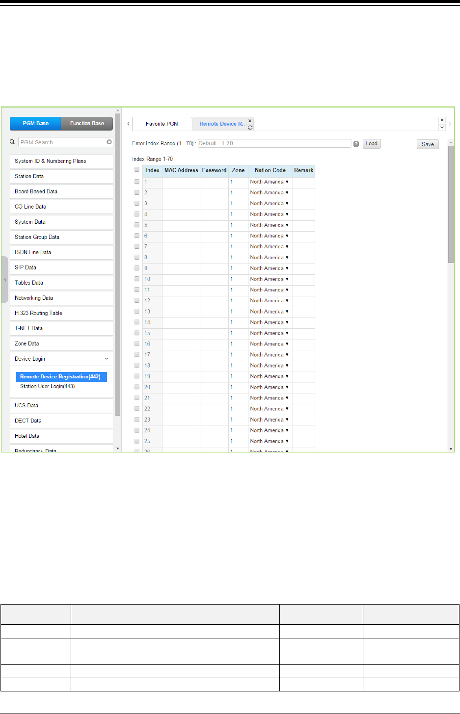
iPECS eMG80 & eMG800 & UCP
Administration and Programming Manual Issue 1.6
548
4.4.14.1 Remote Device Registration – PGM 442
Selecting the Remote Device Registration will display the Remote Registration Table data input
page. Enter a Table index range and select [Load] to enter MAC address information. For
convenience, the copy, paste, and drag is available to enter or modify data. Click [Save] button
after changing Value.
Figure 4.4.14.1-1 Remote Device Registration
When a device attempts to register with the controlling iPECS, the system will check the device
MAC address and password against the Registration table. If a match is found, the device is
registered regardless of Dip-switch 2 position of eMG and Dip Switch position 3 of UCP. The
system database is updated and the device receives device specific configuration data from the
MPB/UCP.
Table 4.4.14.1-1 REMOTE DEVICE REGISTRATION
ATTRIBUTE DESCRIPTION RANGE DEFAULT
Mac Address
Mac address of remote device
MAC Address
Password Password, if any, assigned in the devices database
via Device Web admin.
Up to 12 digits
Zone
The Zone to be assigned to the device.
01-32
01
Nation code
Nation or country location of the device.
Assigned in System ID
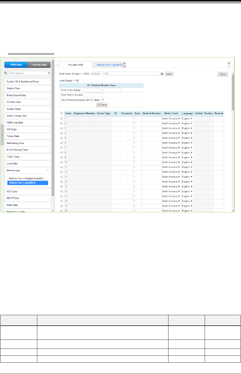
iPECS eMG80 & eMG800 & UCP
Administration and Programming Manual Issue 1.6
549
4.4.14.2 Station User Login – PGM 443
Selecting the Station User Login will display the User Login Registration data input page. Enter
an index range then click [Load] to modify Station Login data. For convenience, the copy, paste,
and drag is available to enter or modify data. Click [Save] button after changing Value.
Enter Index Range
: eMG80: 1-140 / eMG800: 1-1200 / UCP: 1-2400
Figure 4.4.14.2-1 Station User Login
Station User Login configures User credentials for registration of iPECS UCS clients and initial
registration of SIP phones. A station must register with the system each time it is connected to
the system. The ID and password are assigned along with other characteristics of the remote
station such as Zone, desired station number, country code, Language and a remark can be
defined. The iPECS UCS Client can be configured as link-paired station by assigning the same
Desired-Number as a registered desktop iPECS LIP Phone.
Note for the UCS Client, the UCS Standard Client Login, PGM 446, may be employed in place of
PGM 443 as a single point to configure the client information.
Table 4.4.14.2-1 STATION USER LOGIN
ATTRIBUTE DESCRIPTION RANGE DEFAULT
Registered
Number
Station number registered to the station, displayed only after
registration.
Station number
Device Type This filed is indicated what kind of device type is.
ID
The User Login ID must be entered for registration
12 Characters
Password
The User Login password must be entered for registration.
12 digits

iPECS eMG80 & eMG800 & UCP
Administration and Programming Manual Issue 1.6
550
Table 4.4.14.2-1 STATION USER LOGIN
ATTRIBUTE DESCRIPTION RANGE DEFAULT
Zone
The device can be assigned to a Zone.
1-32
1
Desired Number
The desired number can be entered for the device. To link an
iPECS UCS and iPECS LIP Phone, enter the station number
of the registered iPECS LIP Phone prior to registration of the
iPECS UCS or the UCS Client, PGM 446 may be used as the
single administration point.
Station number
Nation code The Nation code for the device is assigned. Assigned in
System ID
Language The default Language type for system voice prompts can be
assigned to the device from the available languages.
Language Code Nation
dependent
Linked This field indicates the Linked pair status of the station.
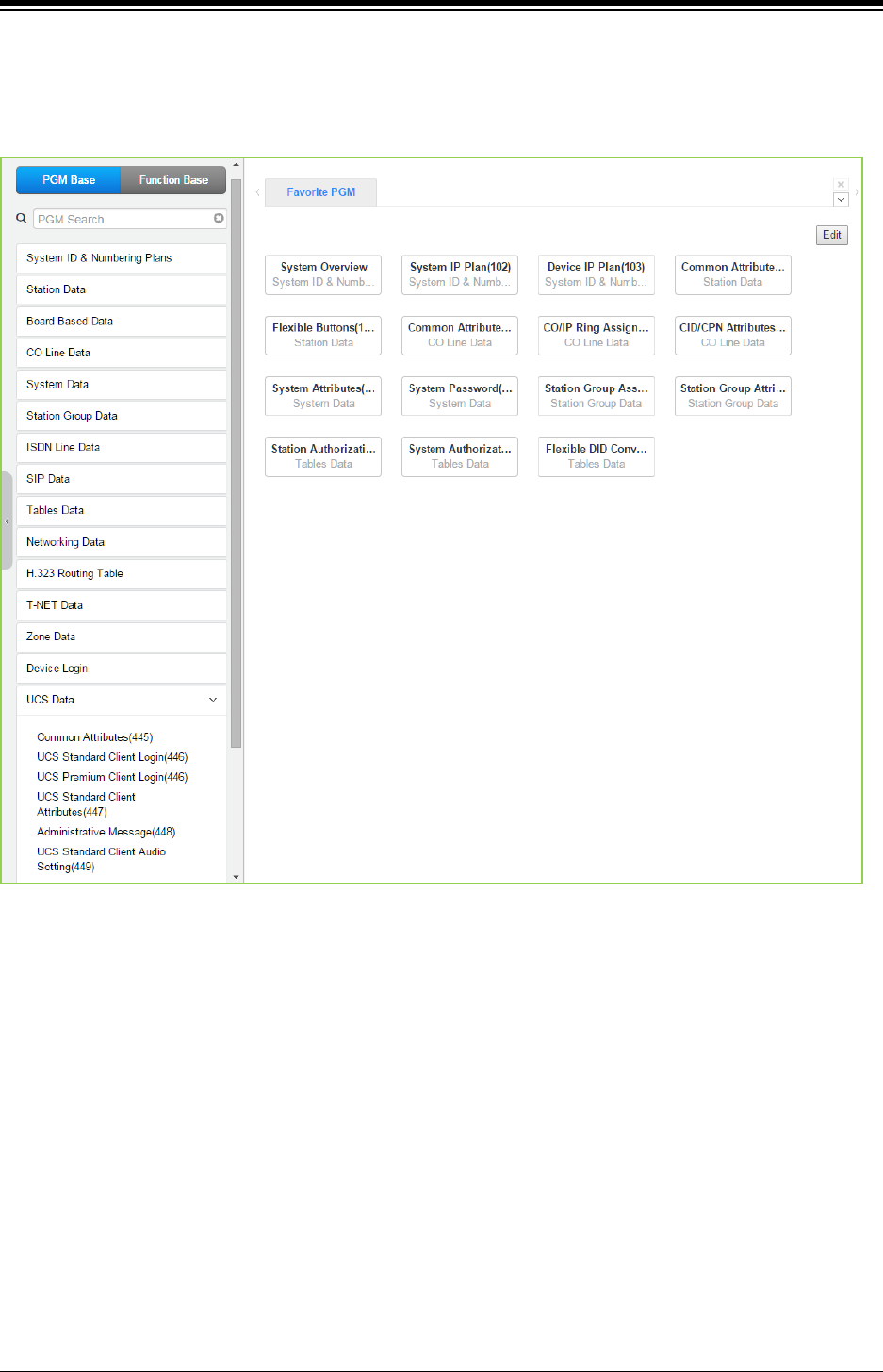
iPECS eMG80 & eMG800 & UCP
Administration and Programming Manual Issue 1.6
551
4.4.15 UCS Data
Selecting the UCS Data group returns the sub-menu displayed in the left frame as shown in the
following figure.
Figure 4.4.15-1 UCS Data Main Page
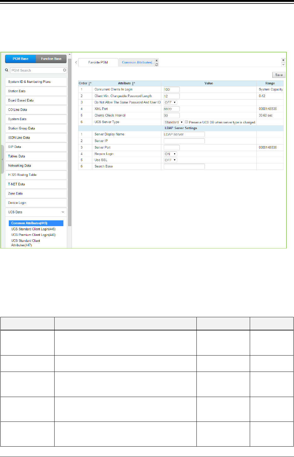
iPECS eMG80 & eMG800 & UCP
Administration and Programming Manual Issue 1.6
552
4.4.15.1 Common Attributes – PGM 445
Selecting Common attributes will display the common attributes input page. Click [Save] button
after changing Value.
Figure 4.4.15.1-1 Common Attributes
Common Attributes for the UCS Clients include client login characteristics and LDAP server
information shared with the clients as shown in the following table.
Table 4.4.15.1-1 Common attributes
ATTRIBUTE DESCRIPTION RANGE DEFAULT
Concurrent Clients
in login
iPECS system employs a per-seat license. The number
of UCS Clients that are active at a time cannot exceed
the licensed capacity.
System capacity 100
Minimum Password
Length
The minimum length of a UCS Client password can be
defined up to 12 characters.
0-12 12
Do Not Allow the
Same Password
and User ID
The User ID can be employed as the password if
permitted (OFF).
OFF
ON OFF
XML Port
The system employs XML to send or request certain
information such as the User picture. The TCP/IP port
can be defined.
8899
Clients Check
Interval
Periodically, iPECS system will verify the status of
logged in UCS clients.
30-60
Seconds
30

iPECS eMG80 & eMG800 & UCP
Administration and Programming Manual Issue 1.6
553
Table 4.4.15.1-1 Common attributes
ATTRIBUTE DESCRIPTION RANGE DEFAULT
UCS Server Type
The server that provides UCS service can be iPECS
system (Standard) or the external UCS Server
(Premium). Additional video and collaboration features
are provided by the UCS Server as Premium service.
When the UCS Server is employed, the Standard Client
Login information (PGM 446) is transferred from iPECS
system to the UCS Server after the client is registered.
If "Preserve UCS DB when server type is changed" is
checked, UCS DB will not be initialized when UCS
server mode is changed.
Standard
Premium Standard
LDAP Server Settings
Server Display
Name
When the UCS Client requires access to an LDAP
server, the system will provide the LDAP server
information to the client. The server name is defined in
this field.
15 characters
Server IP When an LDAP server is employed, the IP address of
the server must be defined.
0.0.0.0
Server Port When an LDAP server is employed, the TCP/IP port of
the server must be defined.
00001-65535
Require Login The UCS Client ID and Password may be required for
log in to the LDAP server.
OFF
ON
ON
Use SSL When supported by the server, the client can employ
SSL (Secure Sockets Layer) for added security.
OFF
ON
OFF
Search Base
Search base means Search option. You can get the
search option from LDAP Server manager. For
example, if OU (Organization Unit) is OC and DC
(Directory Company) are ucapp and com, you can give
the option "OU=OC, DC=ucapp, DC=com" in this field.
You will get the desired directory.
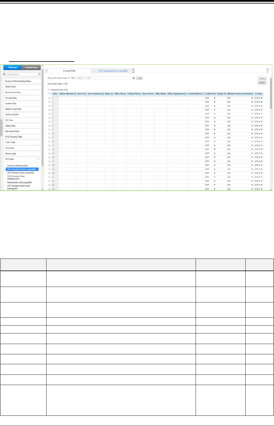
iPECS eMG80 & eMG800 & UCP
Administration and Programming Manual Issue 1.6
554
4.4.15.2 UCS Standard Client Login – PGM 446
Selecting UCS Standard Client Login will display the UCS standard client login input page. Enter
the Client index and click [Load] to modify the Client data. Use the check boxes to indicate the
attributes to modify. Click [Save] button after changing Value.
Enter UCS Client Index
: eMG80: 1-32 / eMG800: 1-200 / UCP: 1-200
Figure 4.4.15.2-1 UCS Standard Client Login
The UCS Client information is configured for each client prior to registration. When the UCS
Server is employed to provide Premium service, iPECS system will transfer the information to the
server after the client registers and, after registration, any changes to the client configuration are
accomplished in the UCS Server.
Table 4.4.15.2-1 UCS Standard Client Login
ATTRIBUTE DESCRIPTION RANGE DEFAULT
Station Number The station number for the UCS Client can be assigned here
and will update PGM 103 and 443.
User ID The UCS Client Id for the UCS Client can be assigned here
and will update PGM 103 and 443.
Min. 4 characters
User PWD The UCS Client password, up to 32 characters must be
assigned.
Max. 32 characters
Name
The user’s name, up to 32 characters should be entered.
Max. 32 characters
Office Phone
Set Office phone number.
Max. 32 characters
Cellular Phone Set Cellular phone number. Max. 32 characters
Home Phone Set Home phone number. Max. 32 characters
Office Name Set Office name. Max. 32 characters
Office Department Set Office Department. Max. 32 characters
Email address Set Email address. Max. 40 characters
Linked Pair
If the UCS Client is part of a Linked pair, it must be enabled
here. By entering the Station number of iPECS IP Phone as
the UCS Client Station Number, the stations will employ MAC
linking.
OFF
ON OFF

iPECS eMG80 & eMG800 & UCP
Administration and Programming Manual Issue 1.6
555
Table 4.4.15.2-1 UCS Standard Client Login
ATTRIBUTE DESCRIPTION RANGE DEFAULT
Unique ID
When the UCS Server is employed, each client must have a
unique Id of at least 40 characters, which identifies the clients
to the UCS Server. Once the Client registers, iPECS system
will send the information to the UCS Server. Note that the UCS
Server Type in PGM 445 must be configured as “Premium”.
Min. 40 characters
Mutual presence
permission
The presence status of the Client can be shared with other
clients.
OFF
ON
ON
License The status of license will be displayed and select the license
for usage among range.
STD-V
STD-NV
MOBILE
License
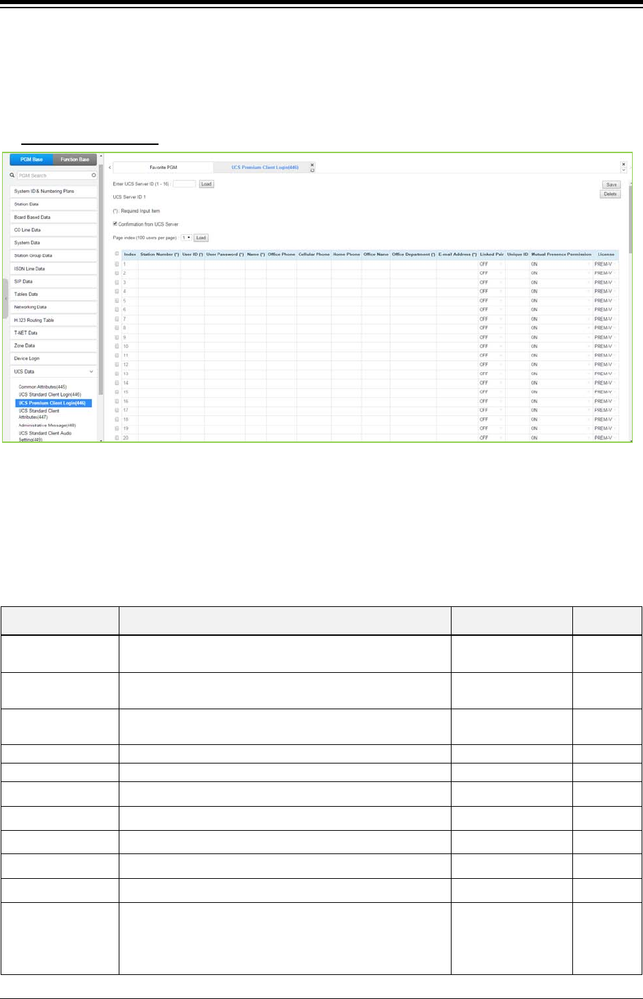
iPECS eMG80 & eMG800 & UCP
Administration and Programming Manual Issue 1.6
556
4.4.15.3 UCS Premium Client Login – PGM 446
Selecting UCS Premium Client Login will display the UCS Premium client login input page. Enter
the Client index and click [Load] to modify the Client data. Use the check boxes to indicate the
attributes to modify. Click [Save] button after changing Value.
Enter UCS Server ID
: eMG80: 1-2 / eMG800: 1-5 / UCP: 1-16
Figure 4.4.15-1 UCS Premium Client Login
The UCS Client information is configured for each client prior to registration. When the UCS
Server is employed to provide Premium service, iPECS system will transfer the information to the
server after the client registers and, after registration, any changes to the client configuration are
accomplished in the UCS Server.
Table 4.4.15.3-1 UCS Premium Client Login
ATTRIBUTE DESCRIPTION RANGE DEFAULT
Station Number The station number for the UCS Client can be assigned
here and will update PGM 103 and 443.
User ID The UCS Client Id for the UCS Client can be assigned here
and will update PGM 103 and 443.
Min. 4 characters
User PWD The UCS Client password, up to 32 characters must be
assigned.
Max. 32 characters
Name
The user’s name, up to 32 characters should be entered.
Max. 32 characters
Office Phone
Set Office phone number.
Max. 32 characters
Cellular Phone Set Cellular phone number. Max. 32 characters
Home Phone Set Home phone number. Max. 32 characters
Office Name Set Office name. Max. 32 characters
Office Department Set Office Department. Max. 32 characters
Email address Set Email address. Max. 40 characters
Linked Pair
If the UCS Client is part of a Linked pair, it must be enabled
here. By entering the Station number of iPECS IP Phone as
the UCS Client Station Number, the stations will employ
MAC linking.
OFF
ON OFF

iPECS eMG80 & eMG800 & UCP
Administration and Programming Manual Issue 1.6
557
Table 4.4.15.3-1 UCS Premium Client Login
ATTRIBUTE DESCRIPTION RANGE DEFAULT
Unique ID
When the UCS Server is employed, each client must have
a unique Id of at least 40 characters, which identifies the
clients to the UCS Server. Once the Client registers, iPECS
system will send the information to the UCS Server. Note
that the UCS Server Type in PGM 445 must be configured
as “Premium”.
Min. 40 characters
Mutual presence
permission
The presence status of the Client can be shared with other
clients.
OFF
ON
ON
License The status of license will be displayed and select the
license for usage among range.
PREM-V
PREM-NV
MOBILE
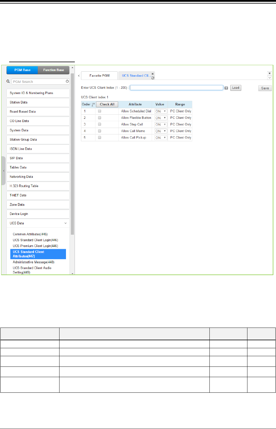
iPECS eMG80 & eMG800 & UCP
Administration and Programming Manual Issue 1.6
558
4.4.15.4 UCS Standard Client Attributes – PGM 447
Selecting UCS Standard client attributes will display the UCS standard client attributes input page.
Enter the UCS Client index then click [Load] to modify the client data. Use the check mark to
indicate which attributes to modify; data for checked attributes is stored by clicking [Save] button.
Enter UCS Client Index
: eMG80: 1-32 / eMG800: 1-200 / UCP: 1-200
Figure 4.4.15.4-1 UCS Standard Client Attributes
The UCS Client can be allowed or denied access to several features as described in Table
4.4.15.4-1.
Table 4.4.15.4-1 UCS Standard Client Attributes
ATTRIBUTE DESCRIPTION RANGE DEFAULT
Allow Scheduled Dial
Allows Scheduled Dialing from the client.
OFF/ON
ON
Allow Flexible Button
Allows the user to access Flex buttons on the UCS Client.
OFF/ON
ON
Allow Step Call Allows access to the step-call feature by the UCS client. OFF/ON ON
Allow Call Memo Allows the UCS Client access to the Call Memo feature. OFF/ON ON
Allow Call Pickup Permits the UCS Client use of the Direct and Group Call Pick-
up features.
OFF/ON ON
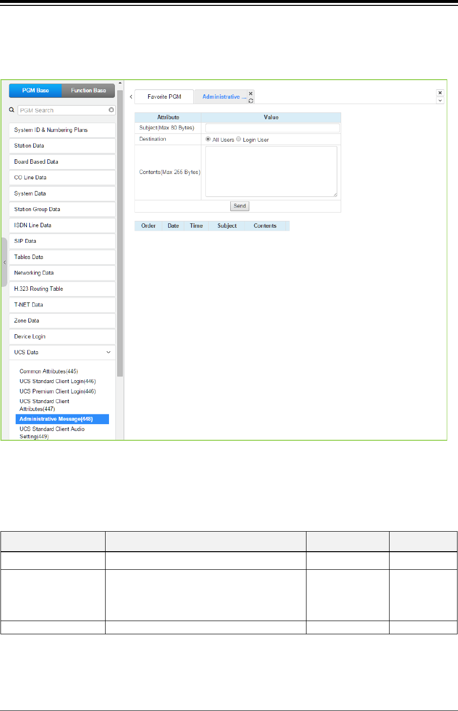
iPECS eMG80 & eMG800 & UCP
Administration and Programming Manual Issue 1.6
559
4.4.15.5 Administrative Message – PGM 448
Selecting Administrative Message will display the administrative message input page. Click
[Send] button after filling out the subject and Contents and checking the destination.
Figure 4.4.15.5-1 Administrative Message
An administrator can send a message to UCS Clients such as a Welcome message.
Table 4.4.15.5-1 Administrative Message
ATTRIBUTE DESCRIPTION RANGE DEFAULT
Subject Message subject. Max. 80 bytes
Destination
The message can be sent to currently active UCS
Clients or to All Clients. For the All Clients
selection, the message is sent to all active Clients
and as each Client logs in.
Login user
All users All
Contents
Message body.
Max. 255 bytes
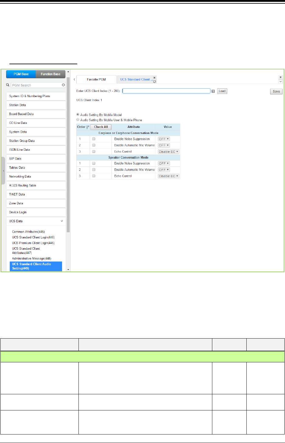
iPECS eMG80 & eMG800 & UCP
Administration and Programming Manual Issue 1.6
560
4.4.15.6 UCS Standard Client Audio Setting – PGM 449
Selecting UCS Standard Client Audio setting will display the audio setting input page. Enter the
Client index and click [Load] to modify the Client data. Use the check mark to indicate which
attributes to modify; data for checked attributes is stored by clicking [Save] button.
Enter UCS Client Index
: eMG80: 1-32 / eMG800: 1-200 / UCP: 1-200
Figure 4.4.15.6-1 UCS Standard Client Audio Setting
Audio characteristic for the Speaker and earphone mode can be established for best overall
audio performance.
Table 4.4.15.6-1 Audio Setting by Mobile User & Mobile phone
ATTRIBUTE DESCRIPTION RANGE DEFAULT
Earpiece or Earphone conversion mode
Enable Noise Suppression The system can implement various levels of “Noise
suppression from “OFF” to “Very High” in six levels.
OFF
ON
OFF
Enable Automatic Mic. Volume The system can implement Auto gain control for the
Earphone.
OFF
ON
OFF
Echo Control Echo cancellation can be enabled for the Earphone.
Disable
Minimum
Low
Disable EC

iPECS eMG80 & eMG800 & UCP
Administration and Programming Manual Issue 1.6
561
Table 4.4.15.6-1 Audio Setting by Mobile User & Mobile phone
ATTRIBUTE DESCRIPTION RANGE DEFAULT
Moderate
High
Maximum
Speaker Conversation Mode
Enable Noise Suppression The system can implement various levels of “Noise
suppression from “OFF” to “Very High” in six levels.
OFF
ON
OFF
Enable Automatic Mic. Volume The system can implement Auto gain control for the
Speakerphone.
OFF
ON
OFF
Echo Control Echo cancellation can be enabled for the
Speakerphone.
Disable
Minimum
Low
Moderate
High
Maximum
OFF
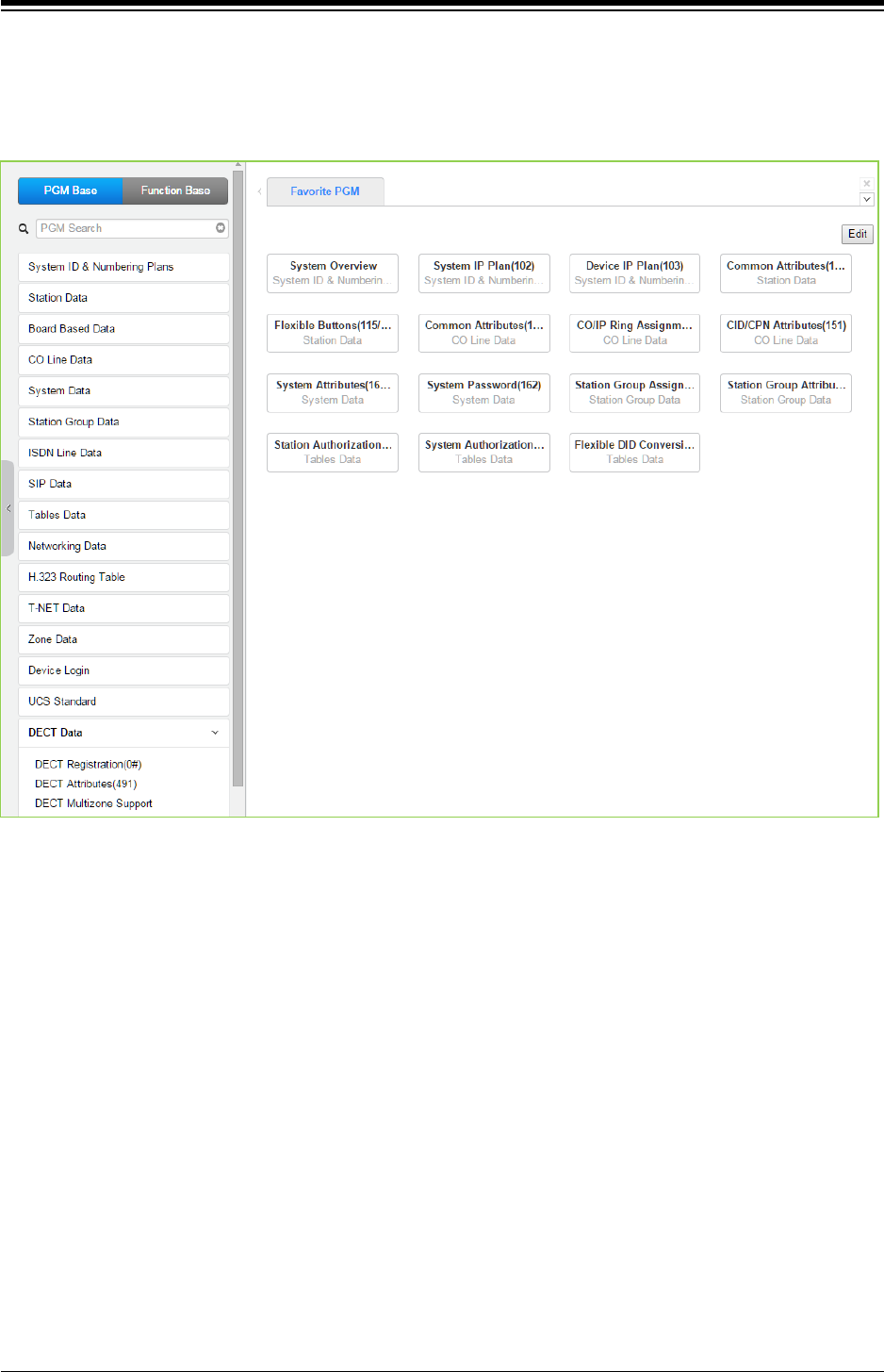
iPECS eMG80 & eMG800 & UCP
Administration and Programming Manual Issue 1.6
562
4.4.16 DECT Data
Selecting the DECT Data program group returns the sub-menu displayed in the left frame as
shown in the following figure.
Figure 4.4.16-1 DECT Data Main Page
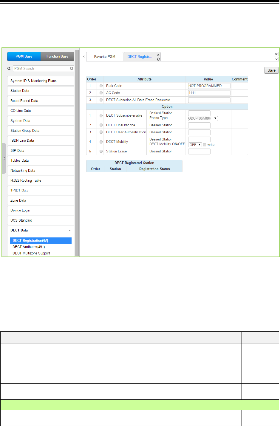
iPECS eMG80 & eMG800 & UCP
Administration and Programming Manual Issue 1.6
563
4.4.16.1 DECT Registration (0#)
Selecting DECT Registration returns the DECT Registration input page. Use the check mark to
indicate which attributes to modify; data for checked attributes is stored by clicking [Save] button.
Figure 4.4.16.1-1 DECT Subscription Screen
On this page, the DECT PARK and authorization codes are defined. Several “Options” are
available to enable subscription, unsubscribe a DECT station, enable mobility, etc. A chart is
included displaying the registered and subscribed DECT terminals.
Table 4.4.16.1-1 DECT Registration
ATTRIBUTE DESCRIPTION RANGE DEFAULT
Park Code
The PARK (Portable Access Rights Key) Code is a
unique system Id entered at the DECT handset during
the subscription process.
14 digits Not
programmed
AC Code The Authentication Code is entered at a DECT handset
to verify subscription.
Up to 8 digits 1111
DECT Subscribe All
Data Erase Password
To erase all data of DECT, enter the password.
Option
DECT Subscribe
Enable
Enables the system to accept subscription from a
DECT handset.

iPECS eMG80 & eMG800 & UCP
Administration and Programming Manual Issue 1.6
564
Table 4.4.16.1-1 DECT Registration
ATTRIBUTE DESCRIPTION RANGE DEFAULT
Desired Station Desired station number for the wireless DECT handset. Station Number
Phone Type
Several types of handsets may be selected.
GDC-480H/500H,
GDC-400/450H,
Standard GAP
GDC-
480H/500H
Press [Send] button after entering the number and
type.
DECT Unsubscribe
To terminate a subscription, enter the station number
for the DECT handset. Note the Station must be
connected, otherwise use Station Erase field below.
Station number
DECT User
Authentication
To subscribe successfully, the user will be required to
enter the Station Authorization Code from PGM 227.
DECT Mobility
When a DECT handset is registered to multiple
systems that are networked, calls can be routed over
the network to the DECT handset location.
Station number
Enter the registered station number, select Mobility ON
or OFF and click [write] box then Save the page.
OFF
ON
OFF
Station Erase
To terminate the registration for a DECT phone that is
not connected, enter the registered station number and
click [Save] button.
Station number
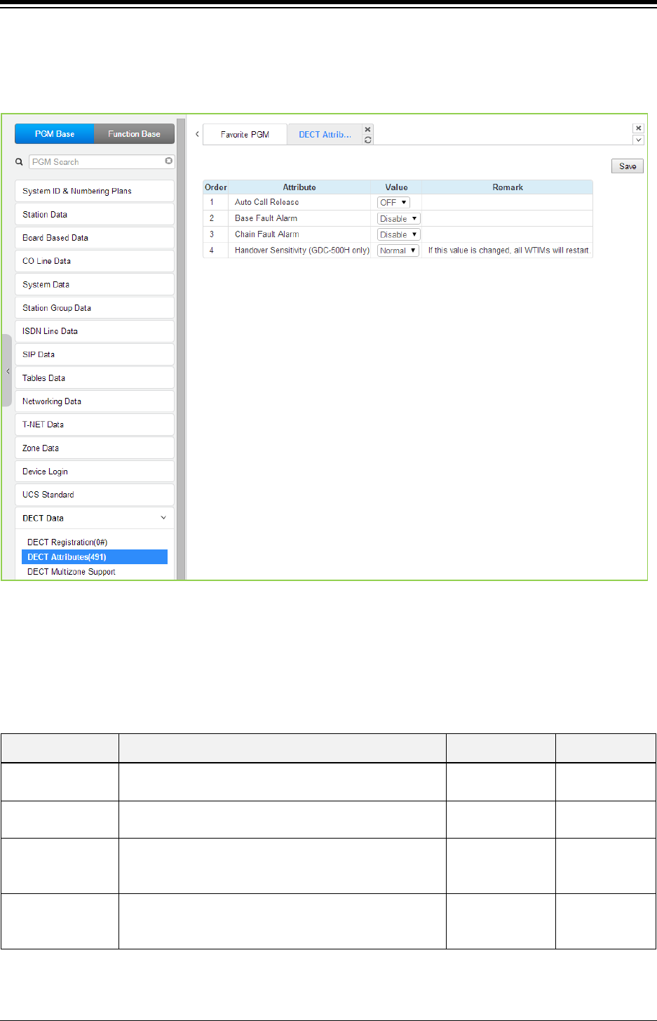
iPECS eMG80 & eMG800 & UCP
Administration and Programming Manual Issue 1.6
565
4.4.16.2 DECT ATTRIBUTES - PGM 491
Selecting the DECT Attributes returns the DECT ATTRIBUTES input page. Click [Save] button
after changing Value.
Figure 4.4.16.2-1 DECT ATTRIBUTES
DECT Attributes define functions associated with the DECT equipment and operation as shown
in the following table.
Table 4.4.16.2-1 DECT Attributes
ATTRIBUTE DESCRIPTION RANGE DEFAULT
Auto Call Release If enabled, when the other party of an active internal call
disconnects, DECT terminal returns to idle.
OFF
ON
OFF
Base Fault Alarm If enabled, DECT Base station alarms are sent to the
Attendant.
Disable
Enable
Disable
Chain Fault Alarm
If enabled, alarms are sent to the Attendant indicating a
fault in the link between WTIM modules. This feature is
only for UCP.
Disable
Enable Disable
Handover
Sensitivity (GDC-
500H only)
The user can control the handover sensitivity of GDC-
500H. (Normal or Strong)
If this value is changed, all WTIBs will restart.
Normal
Strong Normal
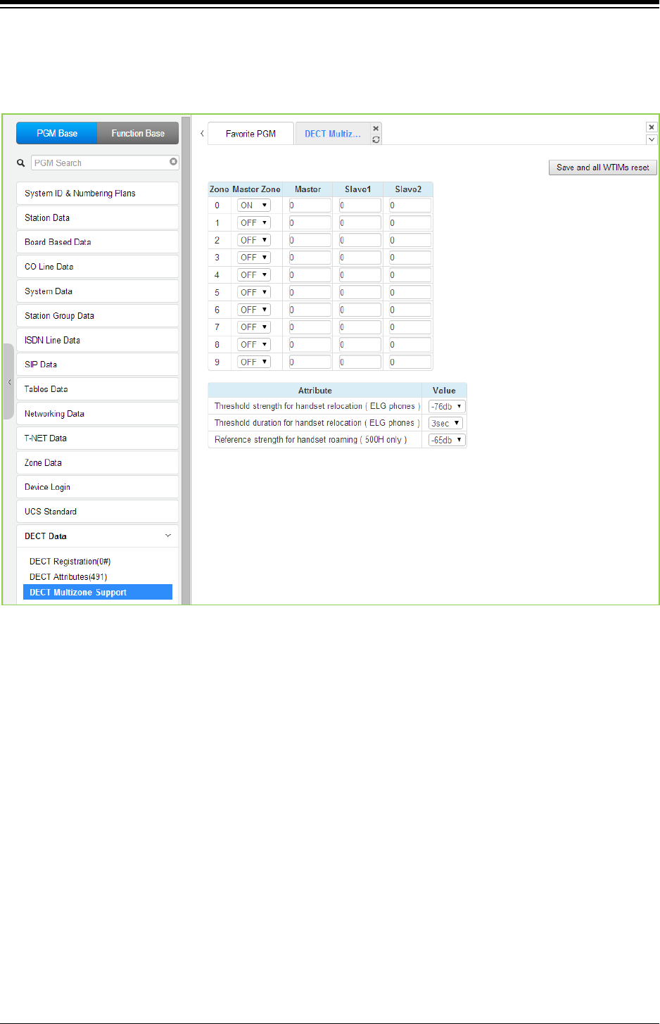
iPECS eMG80 & eMG800 & UCP
Administration and Programming Manual Issue 1.6
566
4.4.16.3 DECT Multi-zone support
Selecting the DECT Multi-zone support will display the DECT Multi-zone support input page. Click
[Save and All WTIM (WTIB)s reset] button after changing Value to apply.
Figure 4.4.16.3-1 DECT Multi-zone support attributes
It is for roaming of DECT phones in large sites with more than 3 WTIM (WTIB).
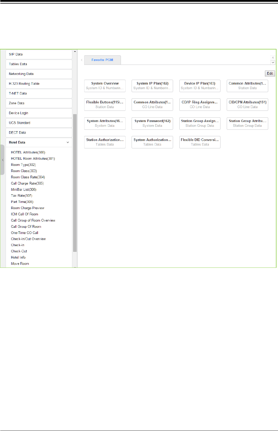
iPECS eMG80 & eMG800 & UCP
Administration and Programming Manual Issue 1.6
567
4.4.17 Hotel Data
Selecting the hotel data returns the sub-menu displayed in the left frame as shown in the
following figure.
Figure 4.4.17-1 Hotel Data main page
With Hotel Data, we describe the function on another Hotel Feature and Programming manual.
Refer to “Hotel Feature and Programming manual’.
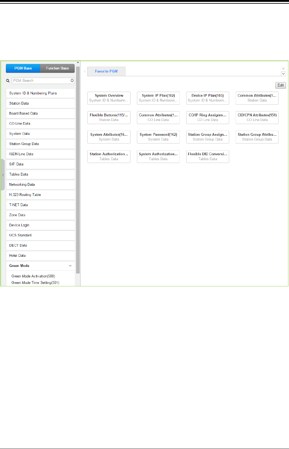
iPECS eMG80 & eMG800 & UCP
Administration and Programming Manual Issue 1.6
568
4.4.18 Green Mode for eMG - PGM 500
Selecting the Green Mode program group returns the sub-menu displayed in the left frame as
shown in the following figure.
Figure 4.4.18-1 Green mode main page
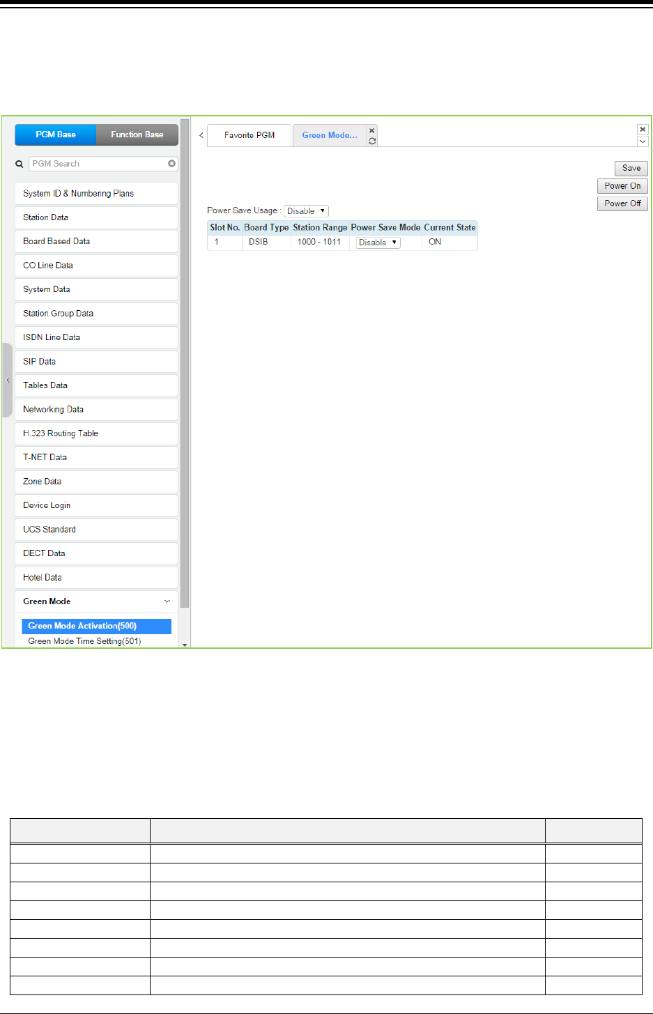
iPECS eMG80 & eMG800 & UCP
Administration and Programming Manual Issue 1.6
569
4.4.18.1 Green mode activation
Selecting Green Mode Activation returns the page shown. Click [Save] button after changing
Value.
Figure 4.4.18.1-1 Green Mode Activation
The system can disable the power of a Digital Phone or Single Line Telephone (SLT) installed in
the HYIB/SLIB/DSIB to save power during night or holiday mode. The power ON/OFF can be
controlled by Web admin manually or automatically by assigning power ON/OFF time.
Table 4.4.18.1-1 Green Mode Activation Attributes
ATTRIBUTE DESCRIPTION DEFAULT
Power Save Usage
Enables or Disables Power Save usage.
Disable
Slot No.
The Slot Number of board supporting power control.
Board Type
Board Type.
Station Range
Station Number Range of board supporting power control.
Power Save Mode
Enables or Disables Power Save Usage Mode of each board.
Disable
Current Status
Displays the current status of board power ON/OFF.
ON
Power ON button
Power ON manually all of stations in Power Save used board.
Power OFF button
Power OFF manually all of stations in Power Save used board.
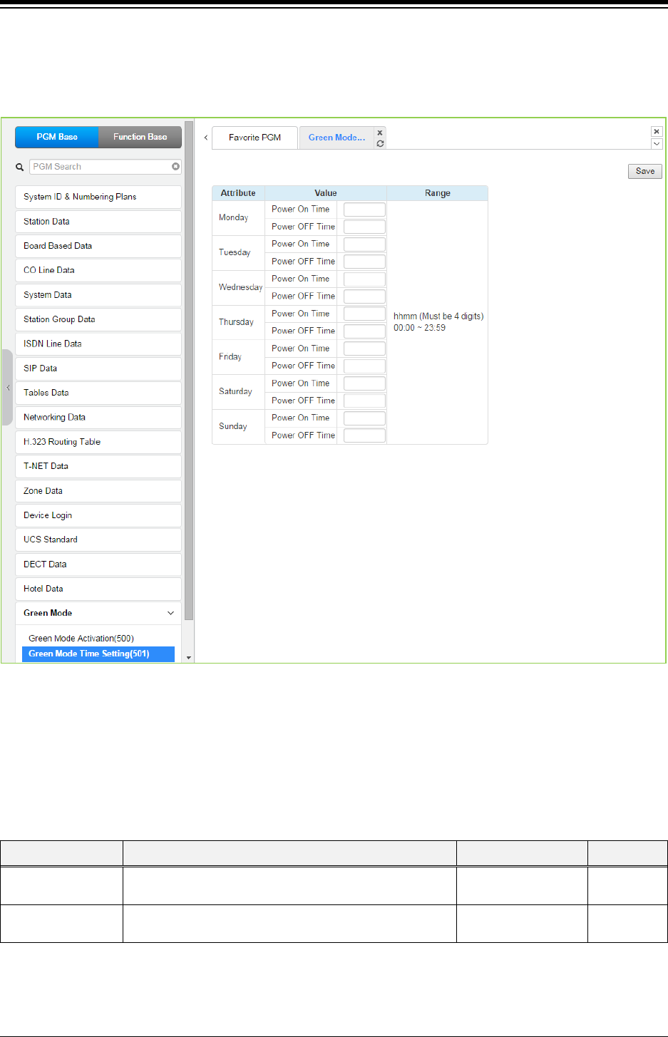
iPECS eMG80 & eMG800 & UCP
Administration and Programming Manual Issue 1.6
570
4.4.18.2 Green Mode Time Setting
Selecting the Green Mode Time Setting returns the page shown. Click [Save] button after
changing Value.
Figure 4.4.18.2-1 Green Mode Time Setting
The power ON/OFF time can be assigned to control Green Mode automatically. The power
ON/OFF time can be defined at each day in a week. And when defined that time, power to assign
board will be served or not.
Table 4.4.18.2-1 Green Mode Time Setting
ATTRIBUTE DESCRIPTION RANGE DEFAULT
Power ON Time The time to start power supply to assigned board. hhmm
(Must be 4 Digits)
Power OFF Time The time to stop power supply to assigned board. hhmm
(Must be 4 Digits)
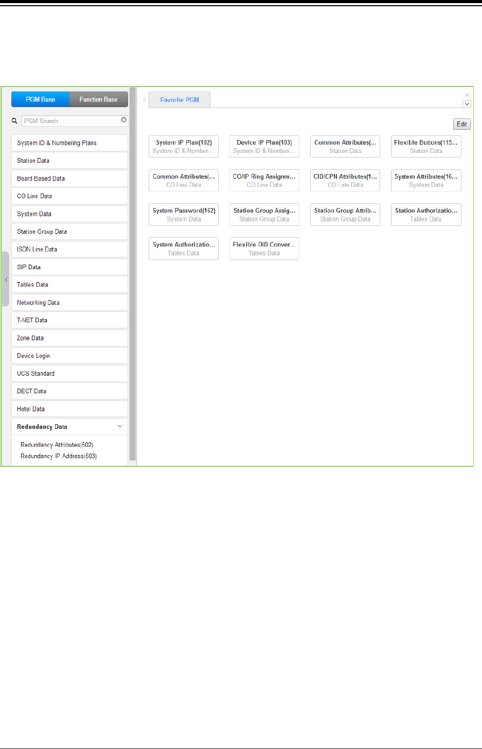
iPECS eMG80 & eMG800 & UCP
Administration and Programming Manual Issue 1.6
571
4.4.19 Redundancy Data for UCP600 & 2400
Selecting the redundancy data returns the sub-menu displayed in the left frame as shown in the
following figure.
Figure 4.4.19-1 Redundancy Data main page
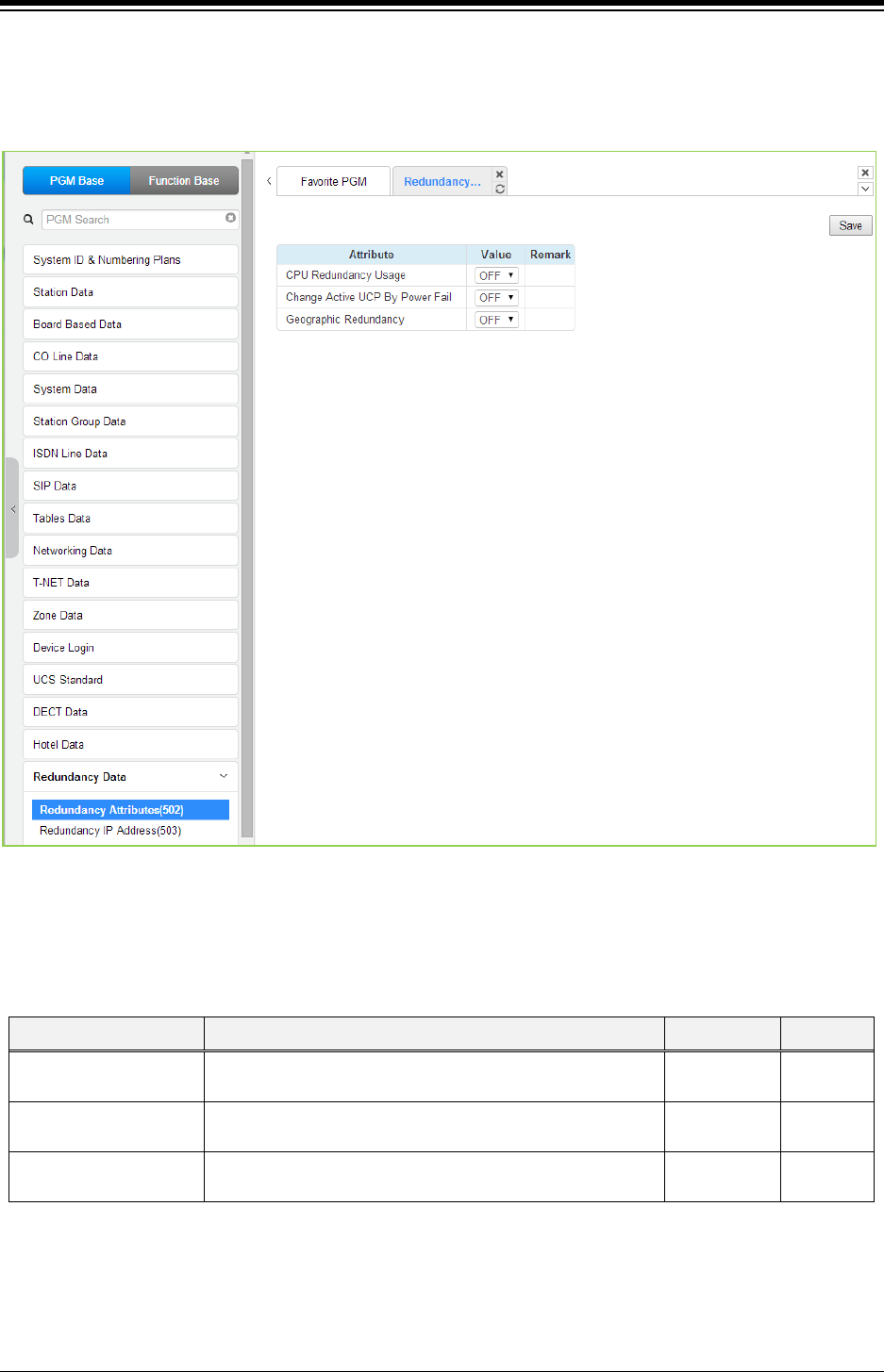
iPECS eMG80 & eMG800 & UCP
Administration and Programming Manual Issue 1.6
572
4.4.19.1 Redundancy Attributes – PGM 502
Selecting Redundancy attributes will display the page shown. Click [Save] button after changing
Value.
Figure 4.4.19.1-1 Redundancy Attributes
The Redundancy attributes enable redundancy and activate “Geographical” redundancy.
Table 4.4.19.1-1 Redundancy Attributes
ATTRIBUTE DESCRIPTION RANGE DEFAULT
CPU Redundancy
usage
When redundancy is employed, this field informs the master
UCP that a redundant UCP is available.
OFF
ON
OFF
Change Active UCP By
Power Fail
When power fails, the active UCP is changed to the standby
mode and the standby UCP becomes active.
OFF
ON
OFF
Geographical
Redundancy
Geographical redundancy permits remote location of the
redundant UCP modules.
OFF
ON
OFF
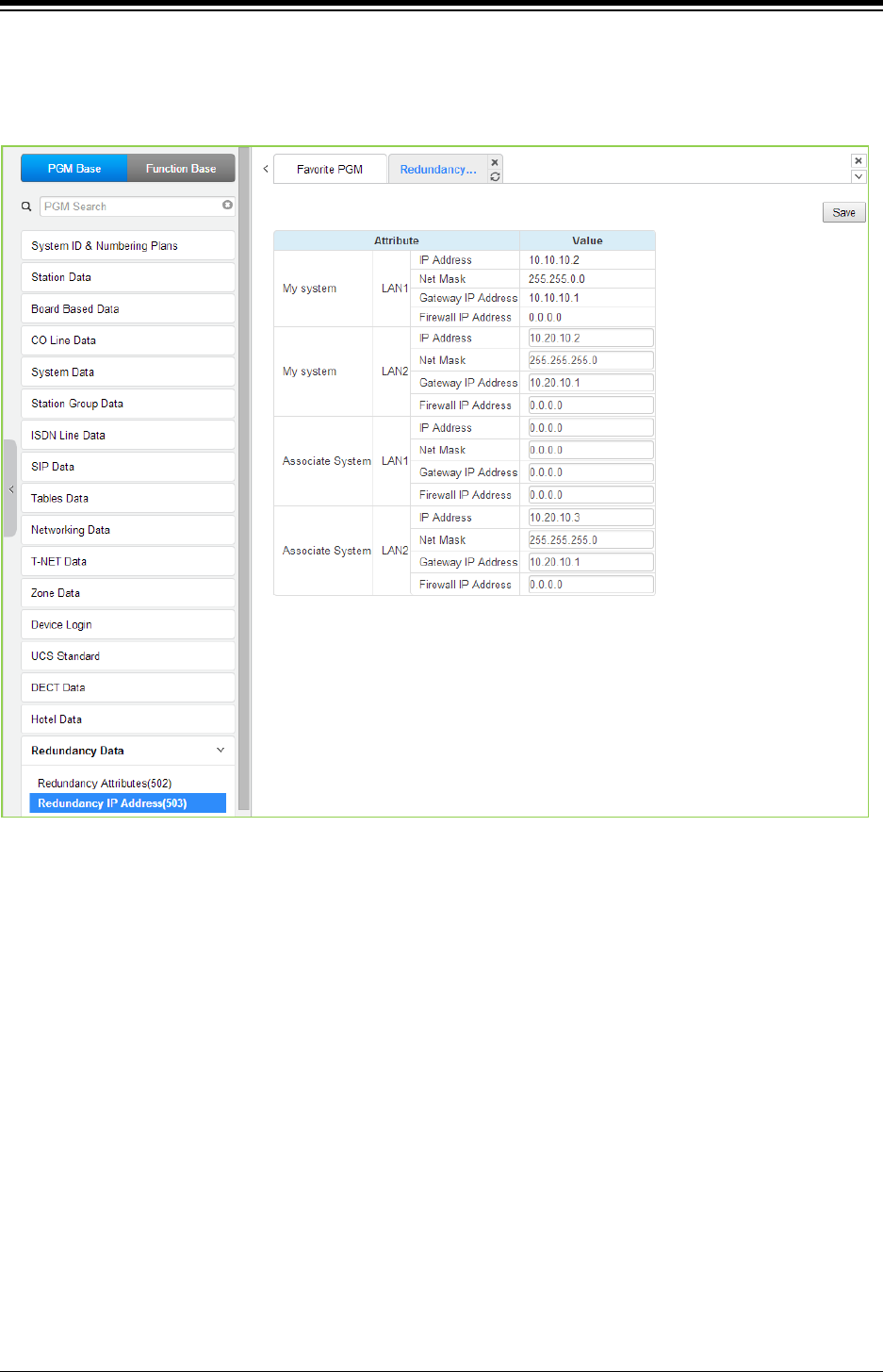
iPECS eMG80 & eMG800 & UCP
Administration and Programming Manual Issue 1.6
573
4.4.19.2 Redundancy IP Address – PGM 503
Selecting the redundancy IP Address will display the page shown. Click [Save] button after
changing Value.
Figure 4.4.19.2-1 Redundancy IP Address
For proper operation, the IP addressing parameters of the LAN1 ports of the redundant UCP
modules must be defined for Redundancy.
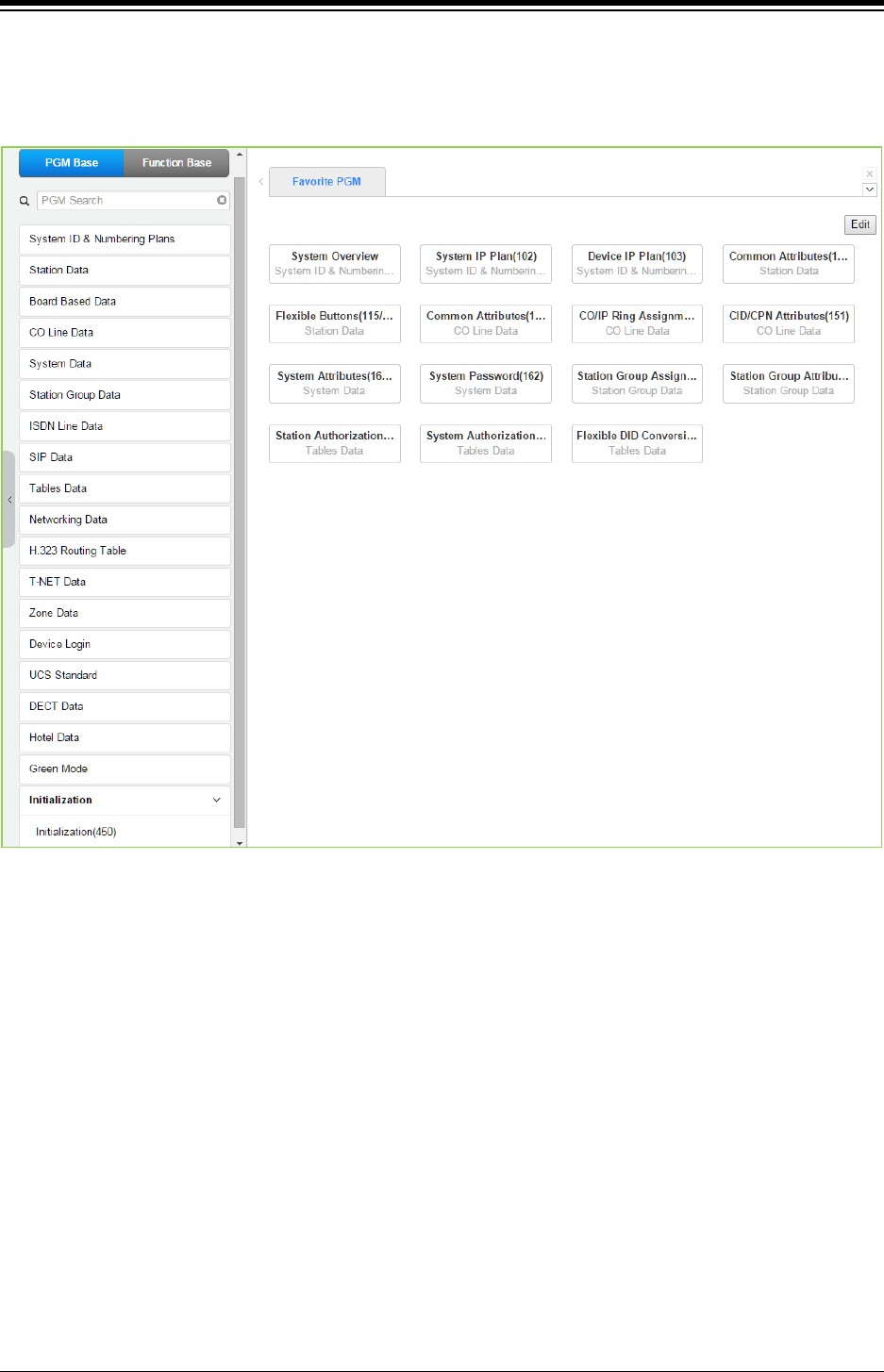
iPECS eMG80 & eMG800 & UCP
Administration and Programming Manual Issue 1.6
574
4.4.20 Initialization - PGM 450
Selecting Initialization will return the sub-menu in the left frame in as shown in the following figure.
Figure 4.4.20-1 Initialization
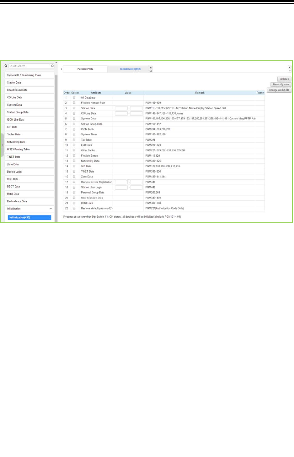
iPECS eMG80 & eMG800 & UCP
Administration and Programming Manual Issue 1.6
575
4.4.20.1 Initialization Table - PGM 450
Selecting Initialization will display the Initialization Table data entry page. Use the check mark to
indicate which attributes to modify; data for checked attributes is initialized by clicking [Initialize]
button or reset system by clicking [Reset system] button.
Figure 4.4.20.1-1 Initialization Menu
The system has been pre-programmed with certain features using the default data. The default
data are loaded into memory when the system is initialized. The system should always be
initialized when first installed or the database appears corrupted.
In addition, the UCP system can be restarted from this page and, if redundant processors are
equipped, the active and standby UCP modules can be modified.
The system can be initialized manually during installation.
Note
1) If you reset eMG system when Dip switch 2 is On, all database will be initialized including
PGM 101-104.
2) If you reset UCP system when Dip switch 4 is On, all database will be initialized including
PGM 101-104.
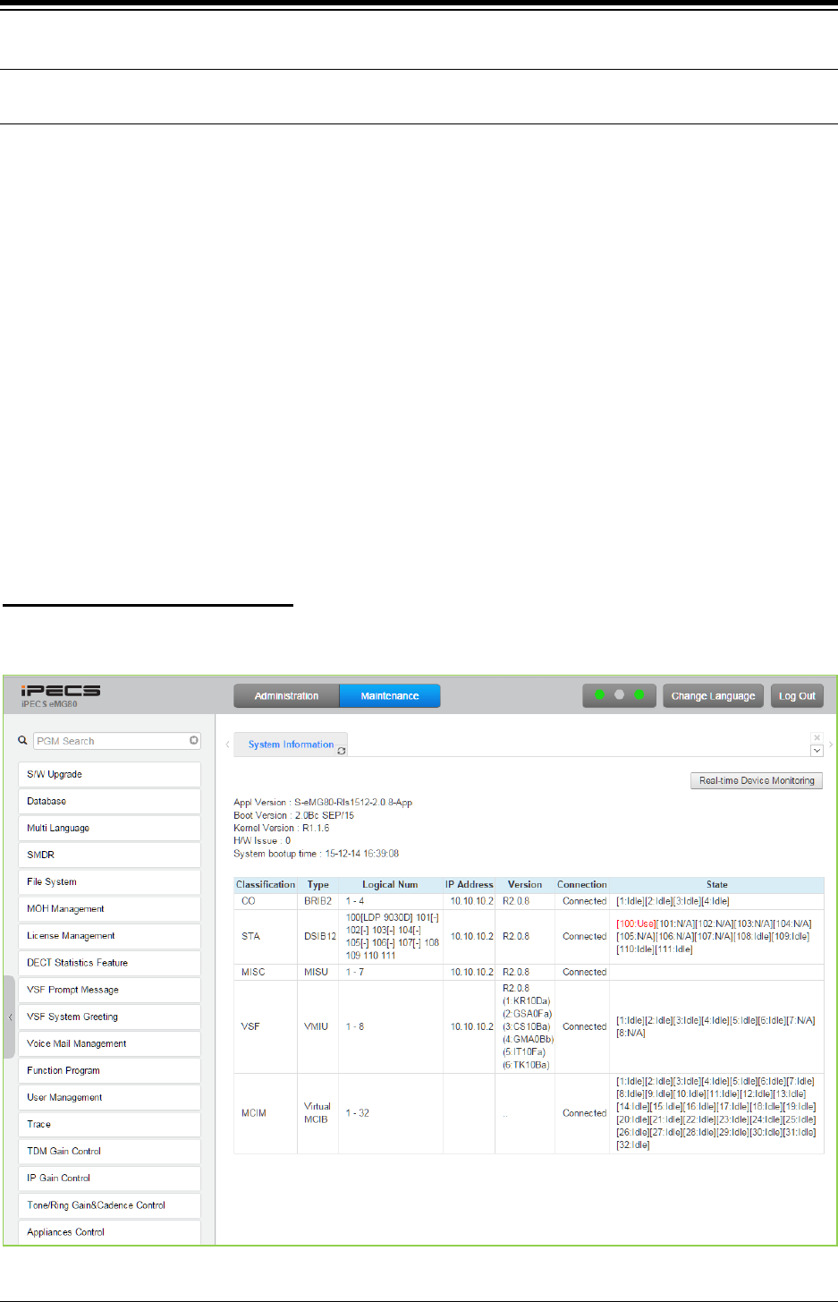
iPECS eMG80 & eMG800 & UCP
Administration and Programming Manual Issue 1.6
576
4.5 Maintenance
The Maintenance tab main screen displays information on the system software versions as well
as information on modules and terminals connected to the system. From this page, the database
upload/download, software upgrade, access control, license install and other management
functions shown in Figure 4.5-1 ~ 4.5-3 are accessed. In addition, at the top of the central screen,
detailed software version information is provided. Also, you can monitor the device in real time by
clicking [Real-time Device Monitoring].
As eMG/UCP software is being upgraded regularly, we cannot guarantee the software
version displayed and it may be different from the current version.
Among Menus on Maintenance, the following functions are not available at UCP2400.
1. VSF Prompt message
2. VSF System greeting
3. Voice Mail USB Backup on VSF Mail Management
You can monitor the current status about Device in real time. The new information is highlighted
in red.
Real time monitoring for Device
Figure 4.5-1 eMG80 Maintenance Main Page
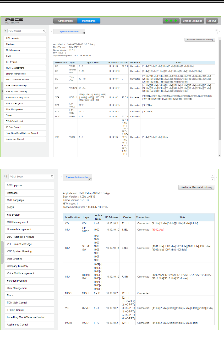
iPECS eMG80 & eMG800 & UCP
Administration and Programming Manual Issue 1.6
577
Figure 4.5-2 eMG800 Maintenance Main Page
Figure 4.5-3 UCP Maintenance Main Page
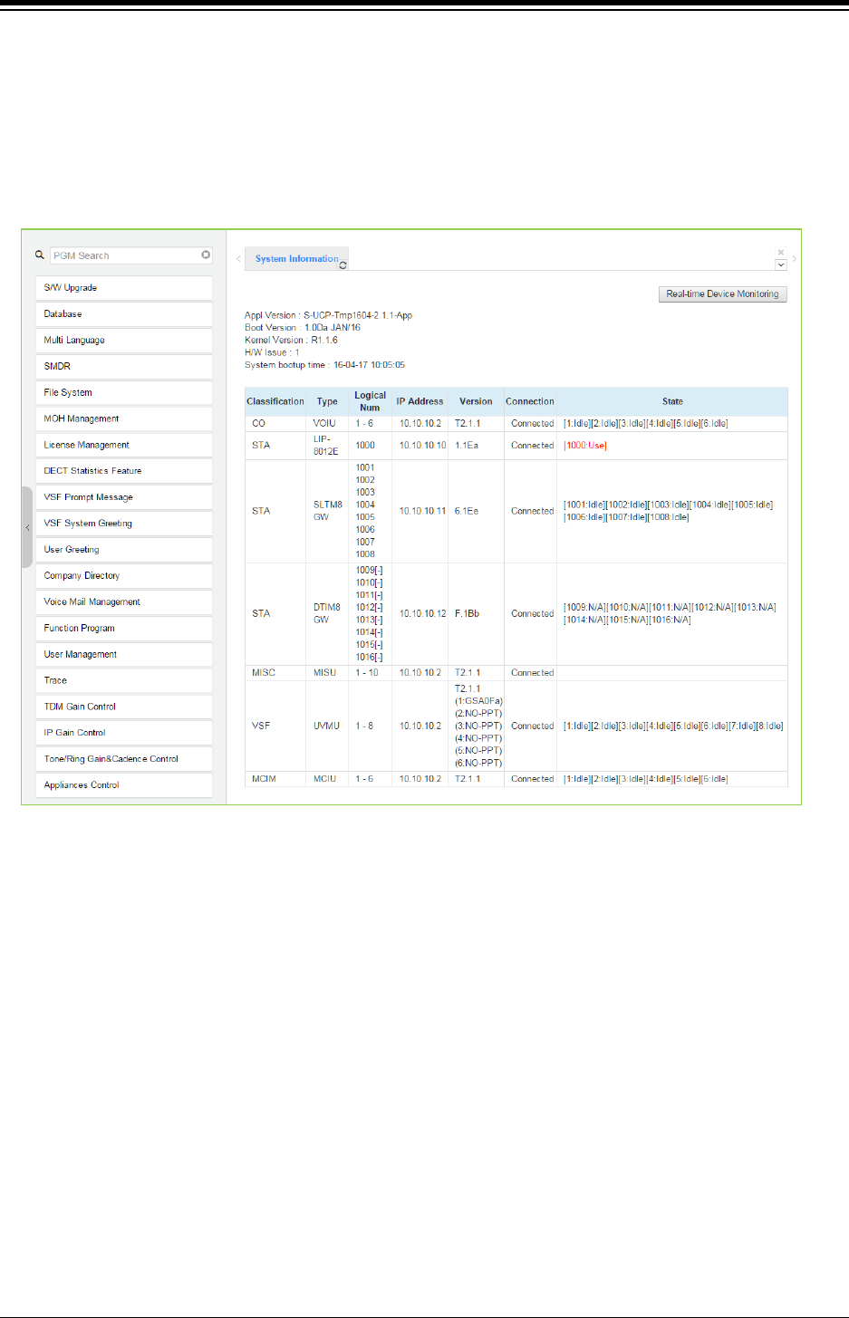
iPECS eMG80 & eMG800 & UCP
Administration and Programming Manual Issue 1.6
578
4.5.1 S/W Upgrade
iPECS system employs a NAND based memory file system thus, html, UCP/MPB upgrade and
iPECS appliance image files can be uploaded without impact to the current database. All of
iPECS series modules can be upgraded by remote access through the system. Selecting S/W
Upgrade from the Maintenance page displays the Appliance Version page and sub-menus
display in the left frame as shown in the following figure.
Figure 4.5.1-1 S/W Upgrade
There are two types of upgrade images: application and kernel image. If both are required,
upgrade the kernel first and then the application.
The VMIU is part of the MPB and VSF prompts are upgraded by uploading prompt files to the
MPB. VMIB prompts are upgraded by direct upload of prompt files to the VMIB.
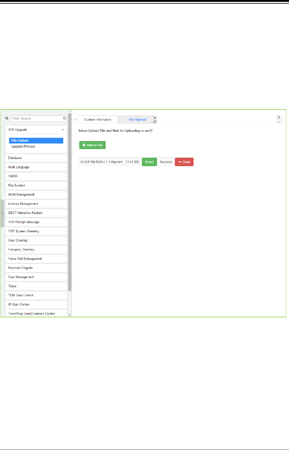
iPECS eMG80 & eMG800 & UCP
Administration and Programming Manual Issue 1.6
579
4.5.1.1 File Upload
From the File Upload page, click [Select file] button and then open the pop-up folder. Select the
desired file to upload to the system’s memory and click the [Start] button. The file is sent to the
system’s memory, saved and automatically loaded upon a system reset or restart.
Prior to upload, verify sufficient memory is available in eMG/UCP File System for the files to be
uploaded. Refer to ‘File System section’ to view the free disk space and delete any unused files.
Note names of files required for normal system operation will be grey out and cannot be deleted.
Html image files are extracted and previous HTML files are deleted at completion of the upload
process. New VSF prompt files are also available immediately upon successful uploaded.
Figure 4.5.1.1-1 File Upload
* If file upload succeeds, a success page will be displayed.
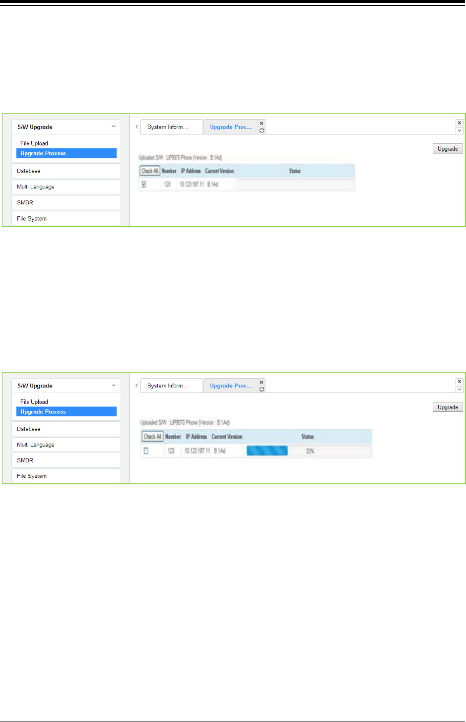
iPECS eMG80 & eMG800 & UCP
Administration and Programming Manual Issue 1.6
580
4.5.1.2 Upgrade Process
If the iPECS Appliance image is uploaded, the appliances of the type for which an image was
uploaded will be displayed and can be selected to upgrade, as shown in the following figure
Upgrade Process. Select the desired appliance and click [Upgrade] button, the upgrade process
will start and a progress screen will be displayed.
Figure 4.5.1.2-1 Upgrade Process
4.5.1.2.1 Upgrade Process View
The Upgrade Process View provides a status window; refer to the following Upgrade Process
View, for Module and terminal upgrade activity in process.
Figure 4.5.1.2-1 Upgrade Process View

iPECS eMG80 & eMG800 & UCP
Administration and Programming Manual Issue 1.6
581
4.5.1.2.2 iPECS eMG/UCP Upgrade Process
The following shows the order in which the upgrade process proceeds and firmware files for
iPECS and modules. Note the xxxx in the ROM file names indicates the version number of the file.
iPECS Software Full Upgrade Sequence
1. Upload MPB/UCP application image.
MPB/UCP Upgrade Process
iPECS UCP UCP application image
(Example, S-UCP-Rls1601-2.1.1-app.rom
iPECS eMG eMG 80/800 MPB application image
(Example,
eMG80: S-eMG80MPB-Rls1512-2.1.1-App
eMG800: S-eMG800MPB-Rls1512-2.1.1-App)
2. Restart MPB/UCP.
Note:
If the new system database is not compatible with existing system database, it will be necessary
to initialize the system database. This can be done manually using the Initialize Dip Switch
located on the UCP/MPB module or via the Initialization Web page.
Upgrade of the UCP/MPB includes HTML files; a separate upload of the HTML files is not
required. HTML files can be separately upgraded under the File System
1. Upload Appliance application image to MPB
Appliances Upgrade Process
LIP 8012/8024/8040E application image:
GS98Pxxxx.rom (xxxx indicates the version)
LIP 8002E application image:
GS99Pxxxx.rom (xxxx indicates the version)
2. Select target appliances & Upgrade application image and click [Upgrade].
3. Wait until upgrade process completes.
4. Automatically restart when upgrade completes successfully.
1. Access to VSF Prompt Upgrade page.
Upgrade of Voice Prompt for eMG
2. Select First/Second/Third for multiple language voice prompt.
3. Upload the proper prompt file.
VSF prompt file:
??96Wxxxx.rom (?? Is nation, i.e. GS, DM, KR, etc. ; xxxx indicates the version)
1. Access to MPB.
Upgrade of Voice Prompt to VMIU for eMG
2. Select First/Second/Third for multiple language of voice prompt.
3. Upload the proper prompt file to VMIU.
VMIB prompt file:
??96Wxxxx.rom (?? Is nation, i.e. GS, DM, KR, etc. ; xxxx indicates the version)
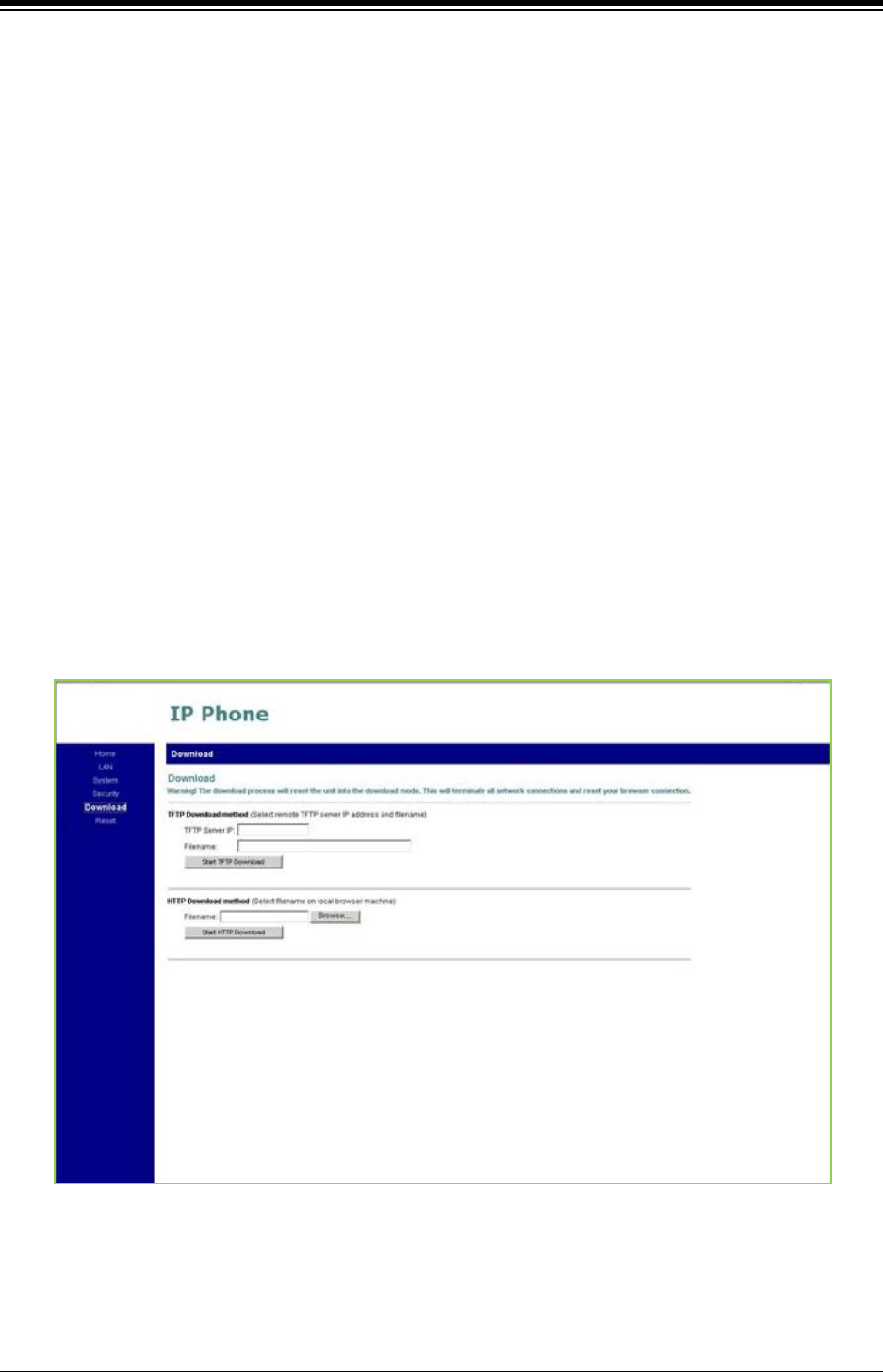
iPECS eMG80 & eMG800 & UCP
Administration and Programming Manual Issue 1.6
582
4.5.1.3 Upgrade HTML Files
The “File View” Menu is used to upload file and reload the system’s html files. Upload time of html
will take 5 ~ 10 minutes.
4.5.1.3.1 Appliances Upgrade (Device and iPECS Phone)
Upload appliance image, and click [Upgrade process] button to select upgrade appliances. If
appliances are selected, click [Upgrade] button. The page shown in Figure 4.5.1.2-1 will be
displayed indicating the Upload command has been sent and upgrade process is working. This
page will display the Upload status. When the appliance upgrade process is successful, the
status is updated to “Success”. If the upgrade process fails, the process is attempted an
additional three (3) times before abandoned.
4.5.1.3.2 Direct Appliances Upgrade
Should the above managed upgrade process fail, appliances (Devices and iPECS Phones) can
be upgraded directly using the appliance IP address as the upgrade destination address. Note
the later may require local access.
Figure 4.5.1.3.2-1 iPECS Phone Direct Connect Upgrade
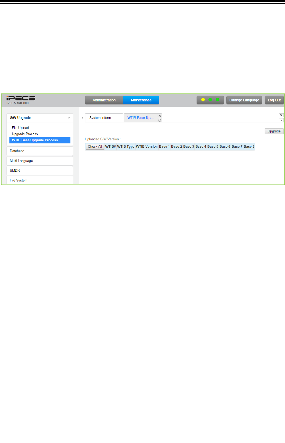
iPECS eMG80 & eMG800 & UCP
Administration and Programming Manual Issue 1.6
583
4.5.1.4 WTIB Base upgrade Process for eMG800
Upgrade WTIB base image of eMG800.
1. Upload WTIB base image to MPB.
2. Select target base & Upgrade.
3. Wait until upgrade process completes.
4. Automatically restart when upgrade completes successfully.
Figure 4.5.1.4 WTIB Base Upgrade Process
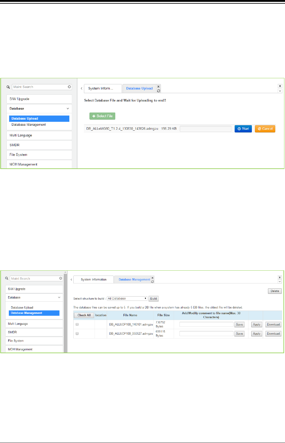
iPECS eMG80 & eMG800 & UCP
Administration and Programming Manual Issue 1.6
584
4.5.2 Database
4.5.2.1 Database Upload
The Database Upload selection will display the Database Upload page as shown in figure. Select
[Select Files] then select the database file desired from the local PC and click [Start] to upload
the database to the system.
Figure 4.5.2.1-1 Database Upload
4.5.2.2 Database management
Selecting Database Management will display the Database Download page. Select the structure
to determine the portion or structure of the download. Click [Download] then select the directory
and file name in the pop-ups that follow to save the file to the PC. After building a database file,
the download function will be available. A maximum of five downloadable files for various types of
data and structure can be built; building additional files deletes the oldest.
Figure 4.5.2.2-1 Database Download
You can add or modify the file name by entering the characters including special character (#,
$, %, &, ', ( ), -, ., @, _). The comment will be created as [XXXXX] before ‘.admgzu’. It is useful to
search DB after downloading.
Clicking on [Download] button will present the File Download window. Files should be saved to
disk. Note that this screen will appear for all download processes.
A user can apply DB file from USB memory. The DB file name is composed of system type, DB
type, date & time and version information.
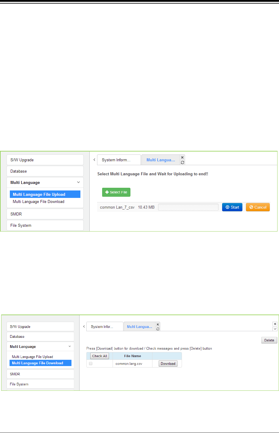
iPECS eMG80 & eMG800 & UCP
Administration and Programming Manual Issue 1.6
585
4.5.3 Multi Language
The system can employ either English or a “Local Language” for the Web page displays. The
multi-language file, which is a csv (comma separated variable) formatted file, is downloaded to a
PC and the English terms are translated to the local language. The modified file can then be
uploaded to iPECS system. Once uploaded, the user can select the “Change Language” button
and select either English or the Local Language translation for Web page displays.
4.5.3.1 Multi Language File Upload
The Multi Language File Upload selection returns the Multi Language File Upload page as shown
in figure. By selecting the Multi Language File desired from the local PC, the desired Multi
Language File can be uploaded to iPECS system.
Figure 4.5.3.1-1 Multi Language File Upload
4.5.3.2 Multi Language File Download
Selecting Multi Language File Download will display the Multi Language File Download page
figure. Selecting this option will download the entire iPECS system Multi Language File to the
local PC. This also allows the Multi Language File in the PC to be uploaded to iPECS system
using the file upload procedures in S/W Upgrade section.
Figure 4.5.3.2-1 Multi Language File Download
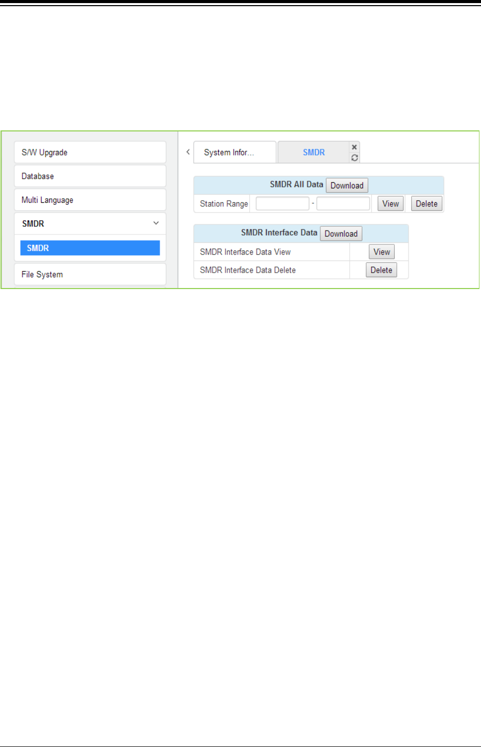
iPECS eMG80 & eMG800 & UCP
Administration and Programming Manual Issue 1.6
586
4.5.4 SMDR
The iPECS system can download SMDR data in a SYLK format file (.slk). The file is compressed
using the “gz” file format. After unzipping, the file can be opened under any common spreadsheet
application. The system will provide a view of SMDR data for the station range entered in the
Web page Figure. This page may also be employed to delete SMDR records for the station range
entered.
Figure 4.5.4-1 SMDR Access
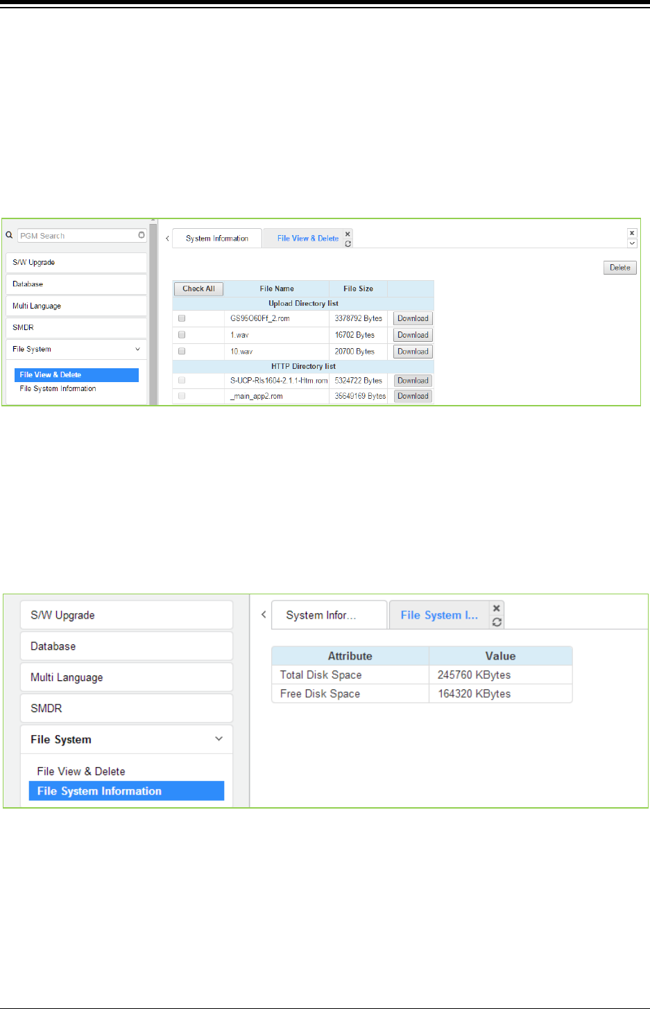
iPECS eMG80 & eMG800 & UCP
Administration and Programming Manual Issue 1.6
587
4.5.5 File System
4.5.5.1 File View & Delete
The File View & Delete page displays a list of the various files stored in the file system memory.
To delete a file, check the box for the file and click [Delete]. Files can also be downloaded to the
PC using the [Download] button to the right of the file name.
Note the system requires the files displayed in grey and the system will not allow deletion of these
files.
Figure 4.5.5.1-1 File View and Delete
4.5.5.2 File System Information
The File System Information page displays the disk status including the total and free disk space
as shown in figure. Use this page to determine if the free space on the disk is sufficient for
uploading Upgrade files, section 4.5.1.
Figure 4.5.5.2-1 File System Information
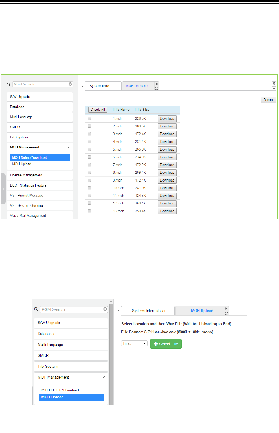
iPECS eMG80 & eMG800 & UCP
Administration and Programming Manual Issue 1.6
588
4.5.6 MOH (Music On-Hold) Management
4.5.6.1 MOH Delete & Download
The MOH Delete & Download page displays a list of the thirteen files stored in the file system
memory. To delete a file, check the box for the file and click [Delete]. Files can also be
downloaded to the PC using the [Download] button to the right of the file name.
Figure 4.5.6.1-1 MOH Delete & Download
4.5.6.2 MOH Upload
Selecting “MOH Upload” will display the page shown in figure. Here MOH can be uploaded to the
system for each of up to thirteen (13) MOH. MOH files format must be followed as shown in the
page ‘G.711 a/u-Law wav (8000Hz, 16bit, mono)’.
Figure 4.5.6.2-1 MOH Upload
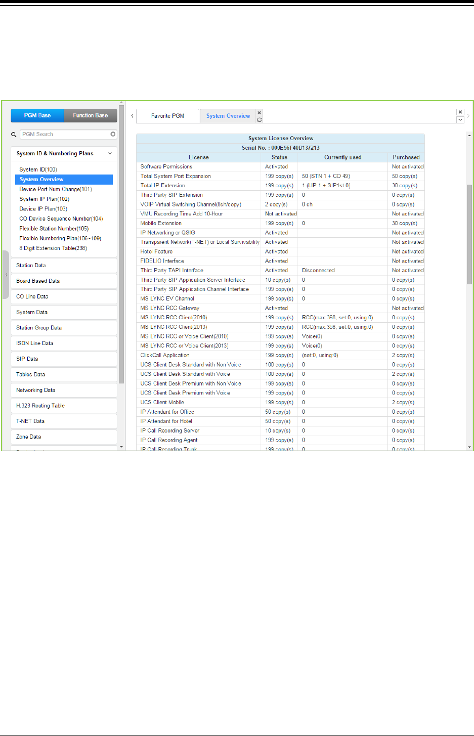
iPECS eMG80 & eMG800 & UCP
Administration and Programming Manual Issue 1.6
589
4.5.7 License Install
Various licenses can be installed to expand capacity of the system and Auto Attendant/Voice Mail
services available in the system as well as soft clients and feature applications. After obtaining a
license, the code is entered in the Value column as shown in Figure 4.5.7-1.
Figure 4.5.7-1 License Install
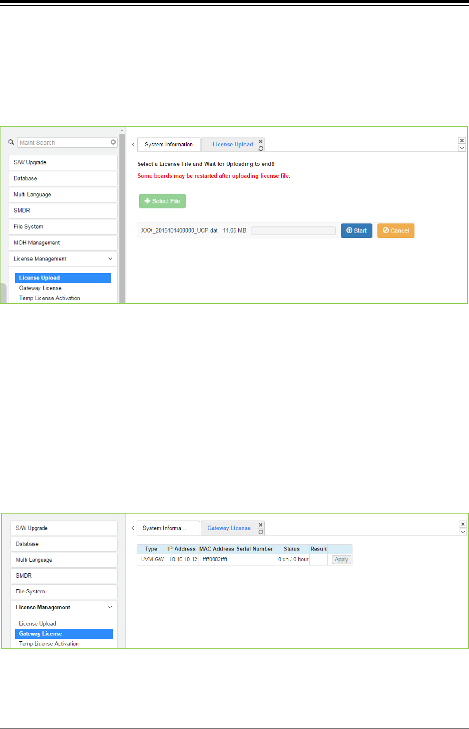
iPECS eMG80 & eMG800 & UCP
Administration and Programming Manual Issue 1.6
590
4.5.7.1 License upload
Before License upload, make sure that the date of system is set correctly. Click the Select files
button and then open the pop-up folder. Select a valid license file to upload to the system and
click the [Start] button. If the file which is sent to the system is “System License File”, it will be
saved and automatically applied without restart. The enabled features by uploading license file
can be shown in “System Overview” page.
Figure 4.5.7.1-1 License Upload
You can check license upload detailed log by clicking "Log View" button.
4.5.7.2 Gateway License for UCP
All gateways which can have gateway license type are displayed in this web page. If a valid
gateway license file was uploaded by “License Upload” and a gateway with matched serial
number is registered in system, [Apply] button will be activated. This button is used to send the
license file to the gateway. After the license file is sent, it will be deleted and the gateway will be
restarted to apply features of the license file.
1) The following figure is before uploading the license.
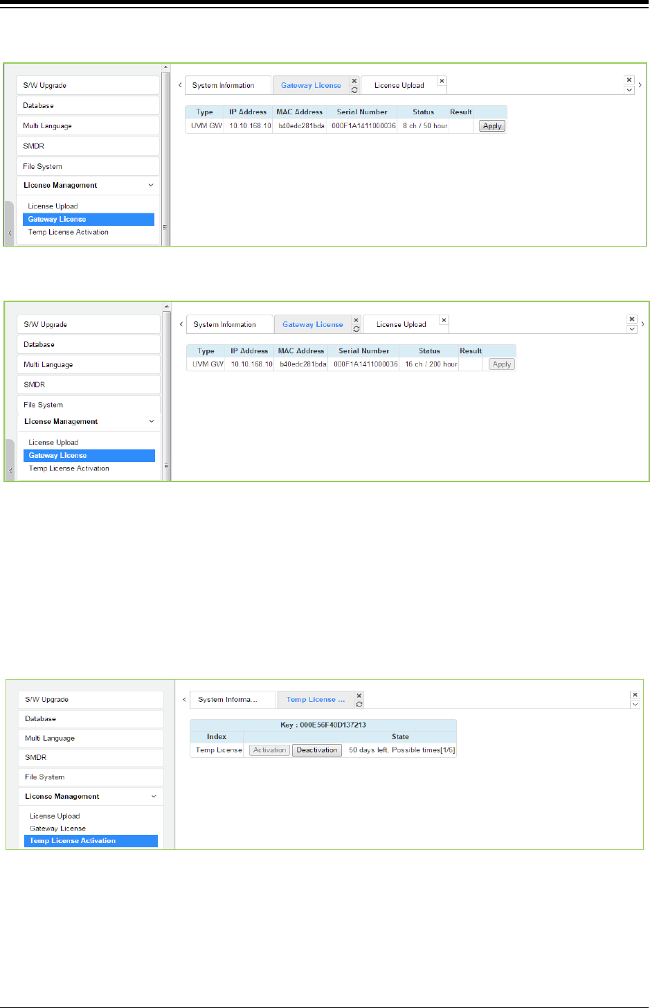
iPECS eMG80 & eMG800 & UCP
Administration and Programming Manual Issue 1.6
591
2) After re fresh, the following figure is displayed and click the apply button to activate.
3) The final step is to reset the gateway license and then refresh. You can see the following
figure for Gateway license.
4.5.7.3 Temp License Activation
Before Temp License Activation, make sure that the date of system is set correctly. In this page,
Temp License can be activated by clicking [Activation] button. Remaining days and activation
times are displayed in State column. The Temp License can be activated totally 6 times. It is valid
for 60 days at first activation and is valid 30 days from second activation. Therefore the license
file which has correct port number and features must be uploaded. Otherwise, system may enter
“Limited Service Mode” due to the mismatched license.
Figure 4.5.7.3-1 Temp License Activation
Notification
1) Please back up your DB before you activate a temporary license.
2) Must verify the present license before the temporary license expires.
3) If a temp license expires, upload a new license file or use within the scope of current
license file. Otherwise, the system may go to [Limited Service Mode].
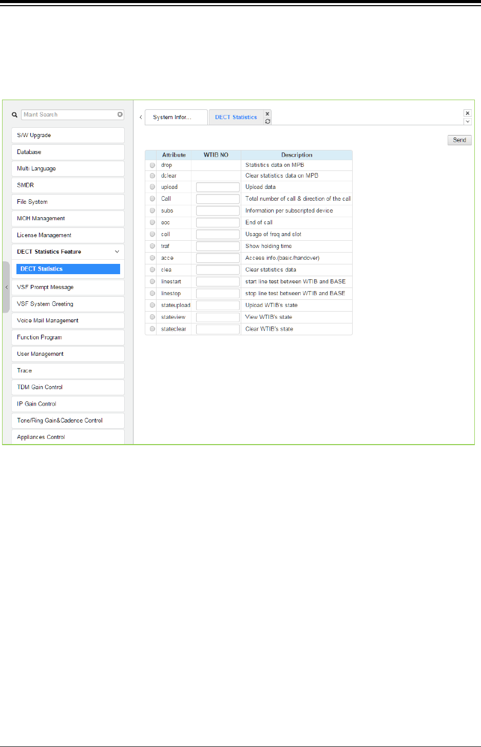
iPECS eMG80 & eMG800 & UCP
Administration and Programming Manual Issue 1.6
592
4.5.8 DECT Statistics Feature
Selecting DECT Statistics Feature displays the page shown in figure. Select the desired radial
button and, where needed, enter the WTIM/WTIB sequence number then click [Send] to view the
statistics.
Figure 4.5.8-1 DECT Statistics Feature
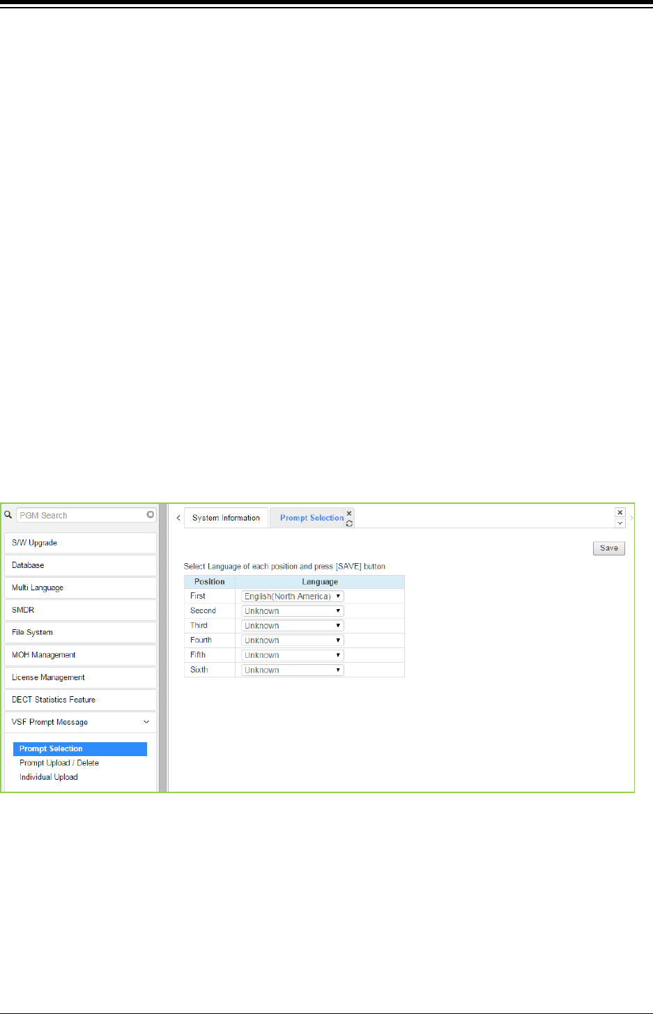
iPECS eMG80 & eMG800 & UCP
Administration and Programming Manual Issue 1.6
593
4.5.9 VSF Prompt Upload
iPECS sytem delivers system prompts in up to six (6) languages. The prompts for each language
are stored in a separate file. Files for each of the languages supported are available from the
local Ericsson-LG Enterprise representative. The entire prompt file or individual prompts may be
uploaded to the system. Once uploaded to the system the file is employed to play prompts to
iPECS eMG/UCP user.
UCP2400 doesn’t support VSF prompt message.
VSF prompt sub-menu is a little different among eMG80, eMG800, and UCP.
Prompt selection: eMG800 and UCP are available.
Prompt Upload /Delete: Available.
Individual upload: Available.
4.5.9.1 Prompt selection
Selecting Prompt Selection displays the page shown in figure. The System Voice Prompt
language files are stored in the VSF memory and are enabled with the Prompt Selection page. A
reference “Position” is assigned a language selected from the drop-down menu. Once the
language for each position is selected, saving the page enables all the languages selected.
Figure 4.5.9.1-1 Prompt Selection for eMG800 & UCP
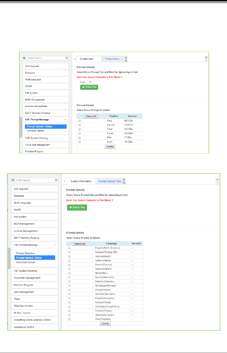
iPECS eMG80 & eMG800 & UCP
Administration and Programming Manual Issue 1.6
594
4.5.9.2 Prompt Upload/Delete
Selecting Prompt Upload/Delete displays the page shown in Figure 4.5.9.2-1 & Figure 4.5.9.2-2.
From this page, the entire prompt file for selected languages can be deleted and updated prompt
files uploaded to the system. The Select file button is used to upload files. The check box and
Delete button are used to delete old or unused language files.
Figure 4.5.9.2-1 Prompt Upload & Delete for eMG80
Figure 4.5.9.2-2 Prompt Upload & Delete for eMG800 & UCP
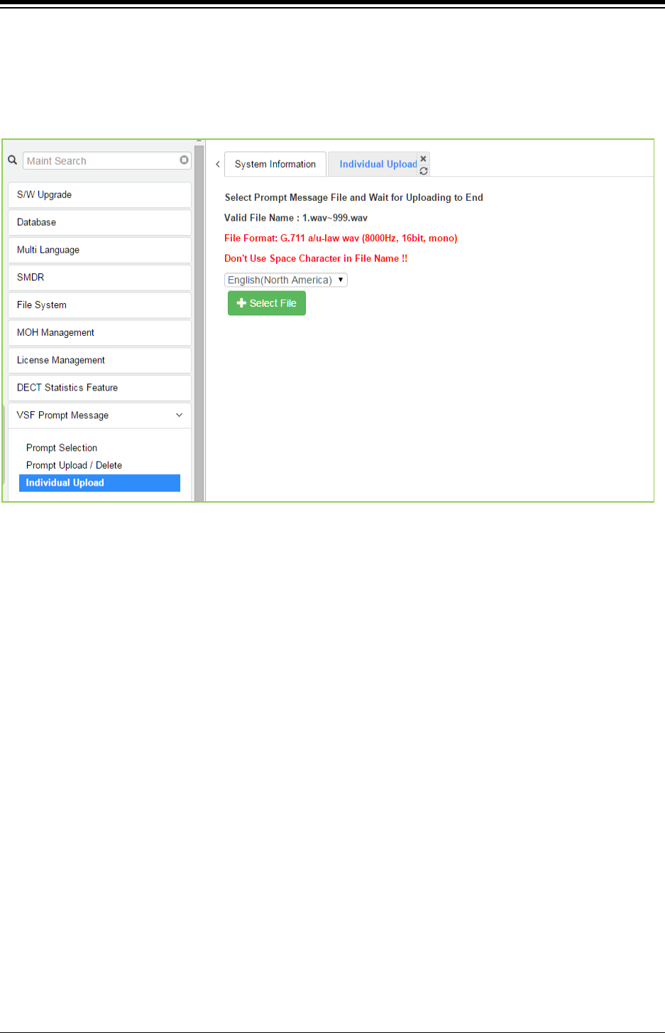
iPECS eMG80 & eMG800 & UCP
Administration and Programming Manual Issue 1.6
595
4.5.9.3 Individual Upload
Selecting “Individual Upload” will display the page shown in figure. Here individual system
prompts can be uploaded to the system for each of up to six (6) languages. Prompt files must be
appropriately named and must be in a G.711 a/u-Law format.
Figure 4.5.9.3-1 Individual Upload
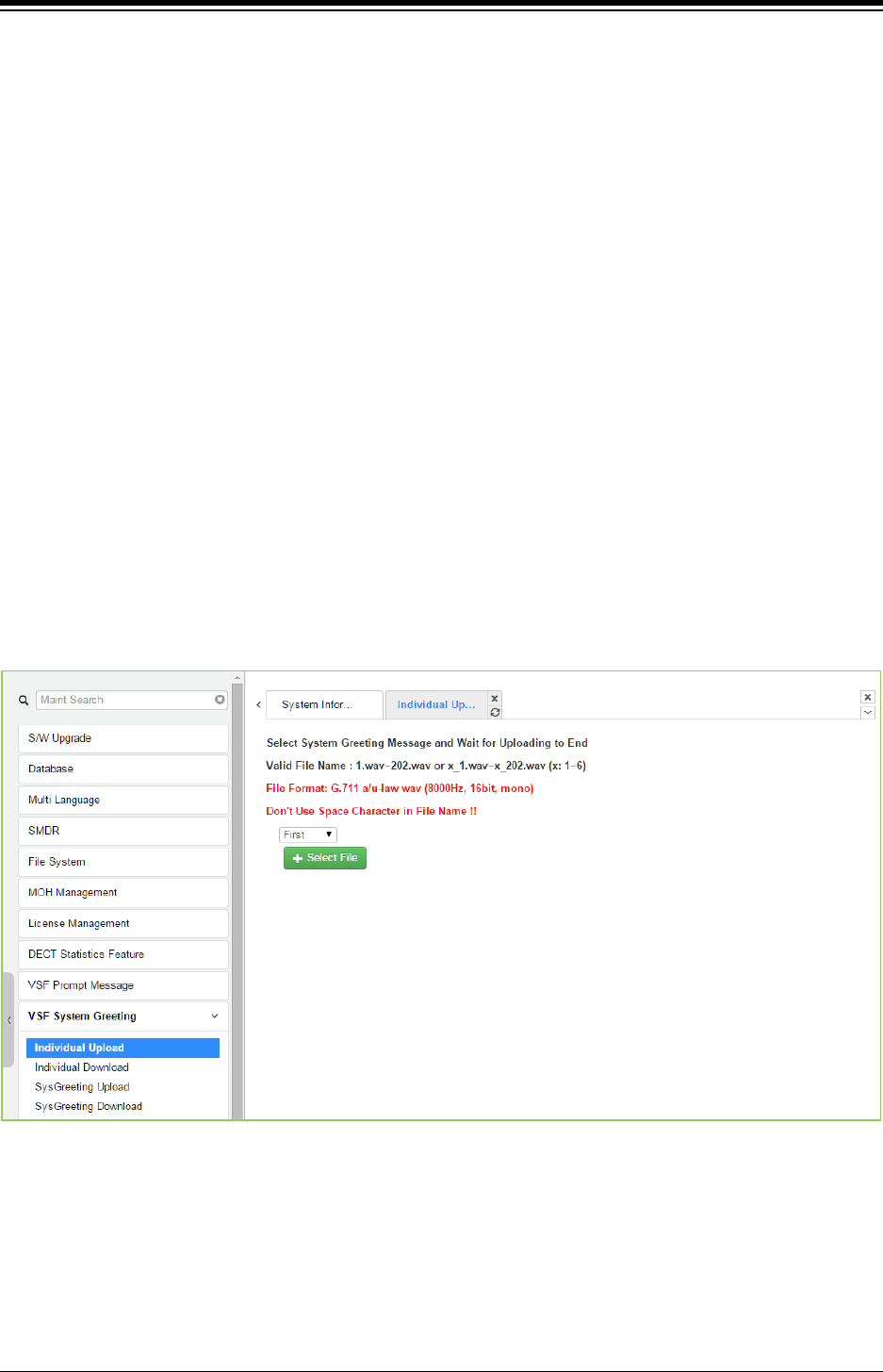
iPECS eMG80 & eMG800 & UCP
Administration and Programming Manual Issue 1.6
596
4.5.10 VSF System Greeting
The System Greetings (Announcements) can be downloaded from the system or Uploaded to the
system. Individual announcements can be recorded externally and then uploaded to the system.
Like prompts, the individual announcement files must be in a .wav format using the g.711 codec.
Individual greetings for each Language position can be uploaded as well as downloaded.
Clicking on the message will download the message to the browser, which will play the message.
To save the message, right click and select save as. Locate a directory and change the file
name, if desired and click save.
All announcements can be downloaded from the system as a back-up file and uploaded to the
VSF memory as required.
UCP2400 doesn’t support VSF system greeting.
4.5.10.1 Individual Upload
Selecting Individual Upload displays the page shown in Figure 4.5.10.1-1. From this page,
individual pre-recorded announcements for each language position can be uploaded from the PC
to the VSF gateway. Select the language position and assure the file name matches the
appropriate System Announcement number. The file format must be shown on the page.
Figure 4.5.10.1-1 Individual Upload
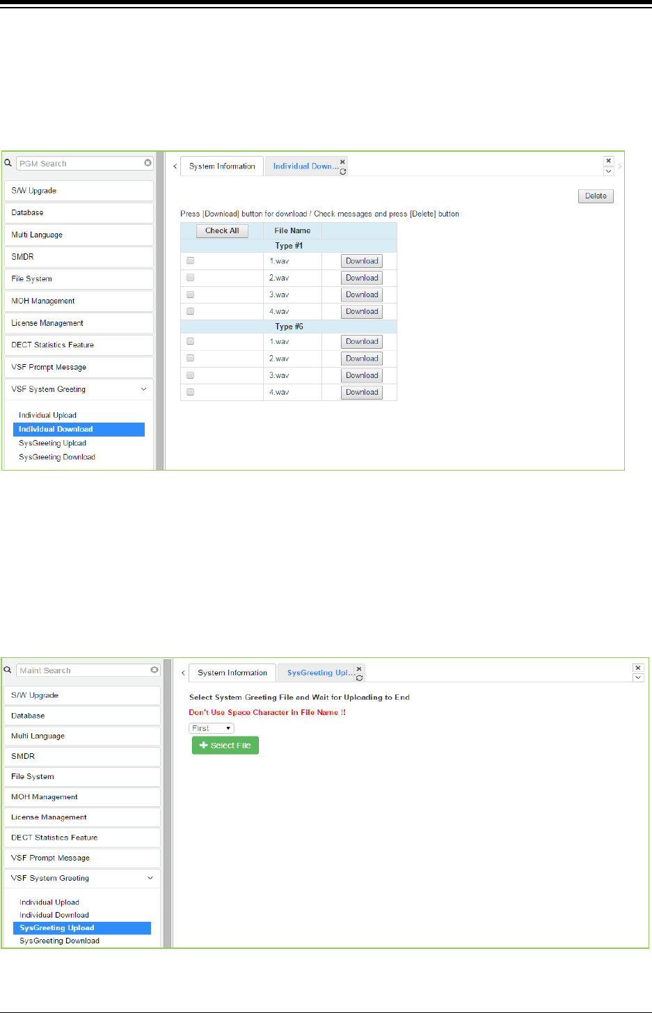
iPECS eMG80 & eMG800 & UCP
Administration and Programming Manual Issue 1.6
597
4.5.10.2 Individual download
Selecting Individual Download displays the page shown in figure. The page will display a list of
System announcement in the VSF memory. Individual files may be downloaded with the
Download button next to the announcement file name or using the checkbox and the delete
button the announcement can be deleted from the VSF memory.
Figure 4.5.10.2-1 Individual Download
4.5.10.3 System greeting Upload
Selecting System Greeting Upload displays the page shown in figure. From this page,
announcements for each language “Position” can be uploaded to the VSF memory. First, select
the language position then click the Select Files button to select the file to upload from the PC.
Figure 4.5.10.3-1 System Greeting Upload
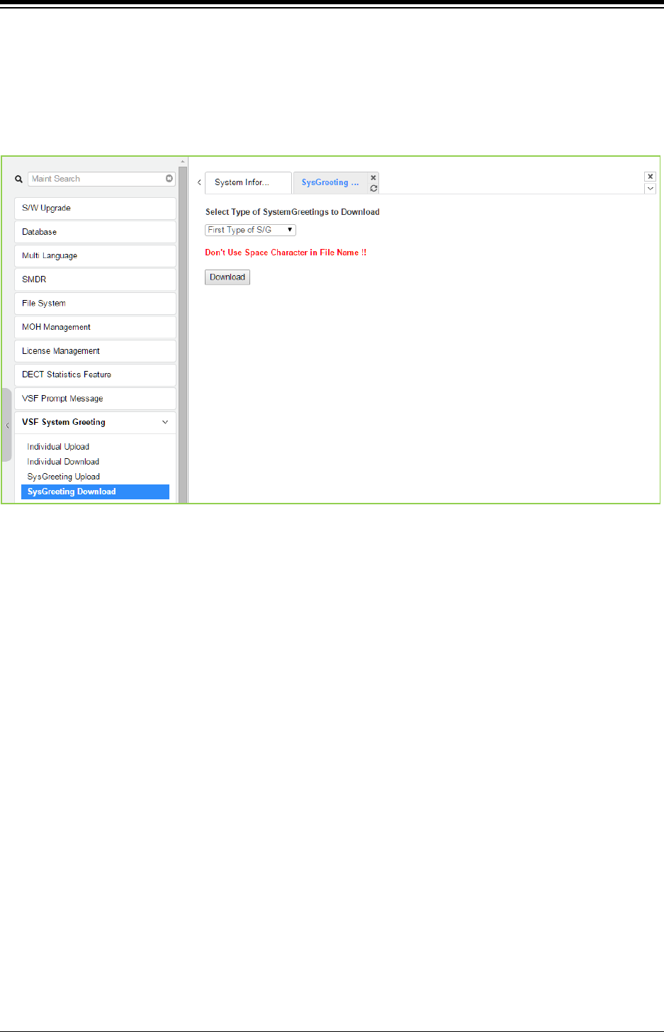
iPECS eMG80 & eMG800 & UCP
Administration and Programming Manual Issue 1.6
598
4.5.10.4 System greeting Download
Selecting System Greeting Download displays the page shown in figure. From this page,
announcements for each language “Position” can be downloaded from the VSF memory as a
back-up file. First, select the language position, click the Download button then follow the normal
save file process to store the file to the PC.
Figure 4.5.10.4-1 System Greeting Download
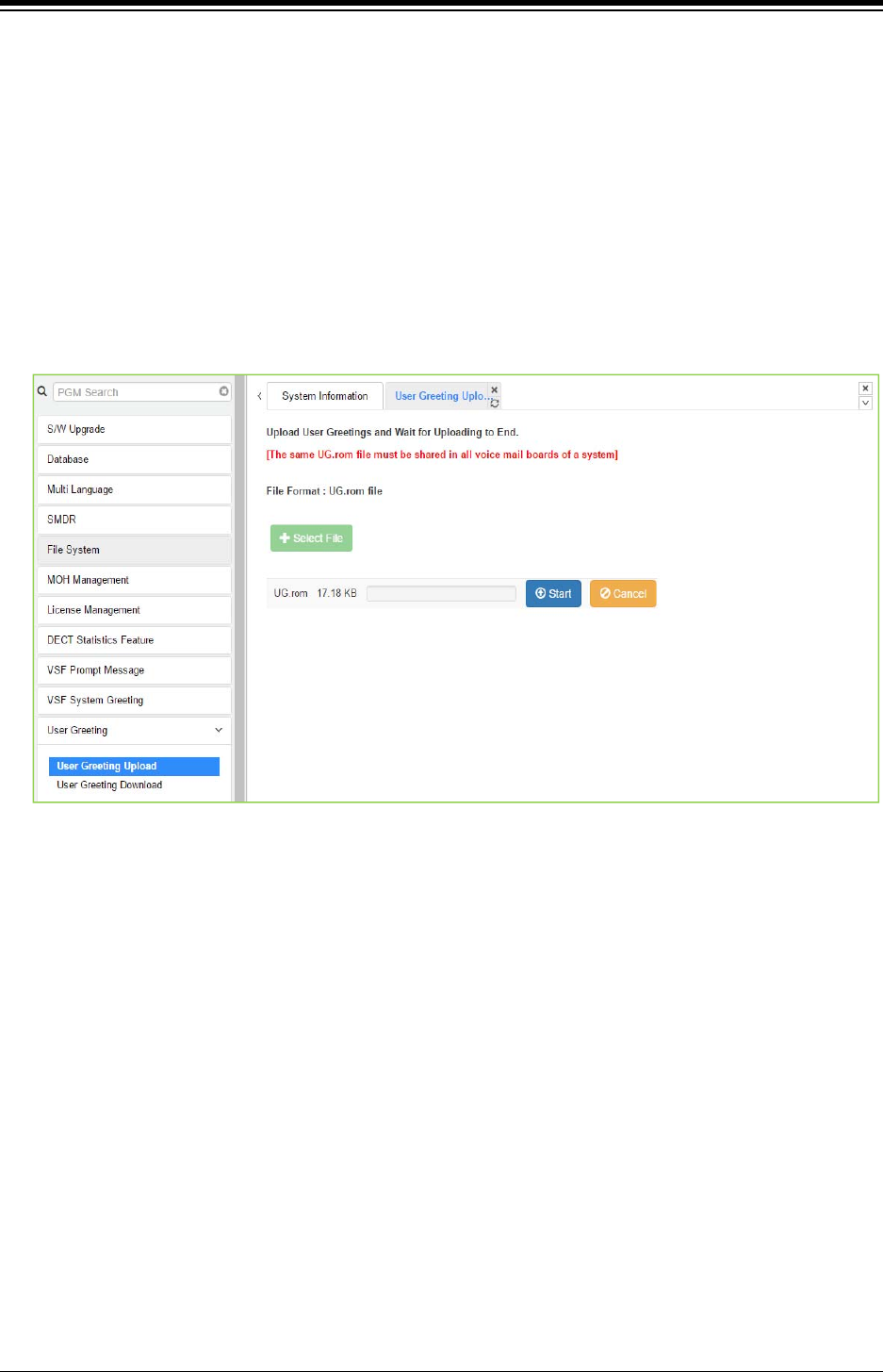
iPECS eMG80 & eMG800 & UCP
Administration and Programming Manual Issue 1.6
599
4.5.11 User Greeting
Administrators can upload or download User greeting to System. So User greetings are available
to use at iPECS phones.
4.5.11.1 User Greeting Upload
To upload the User Greeting, complete the following steps:
› Click [Select File] button.
› Select the User greeting file (rom file) from folder.
› Click [Start] to upload and then display the following figure ‘success’.
Figure 4.5.11.1-1 User Greeting Upload
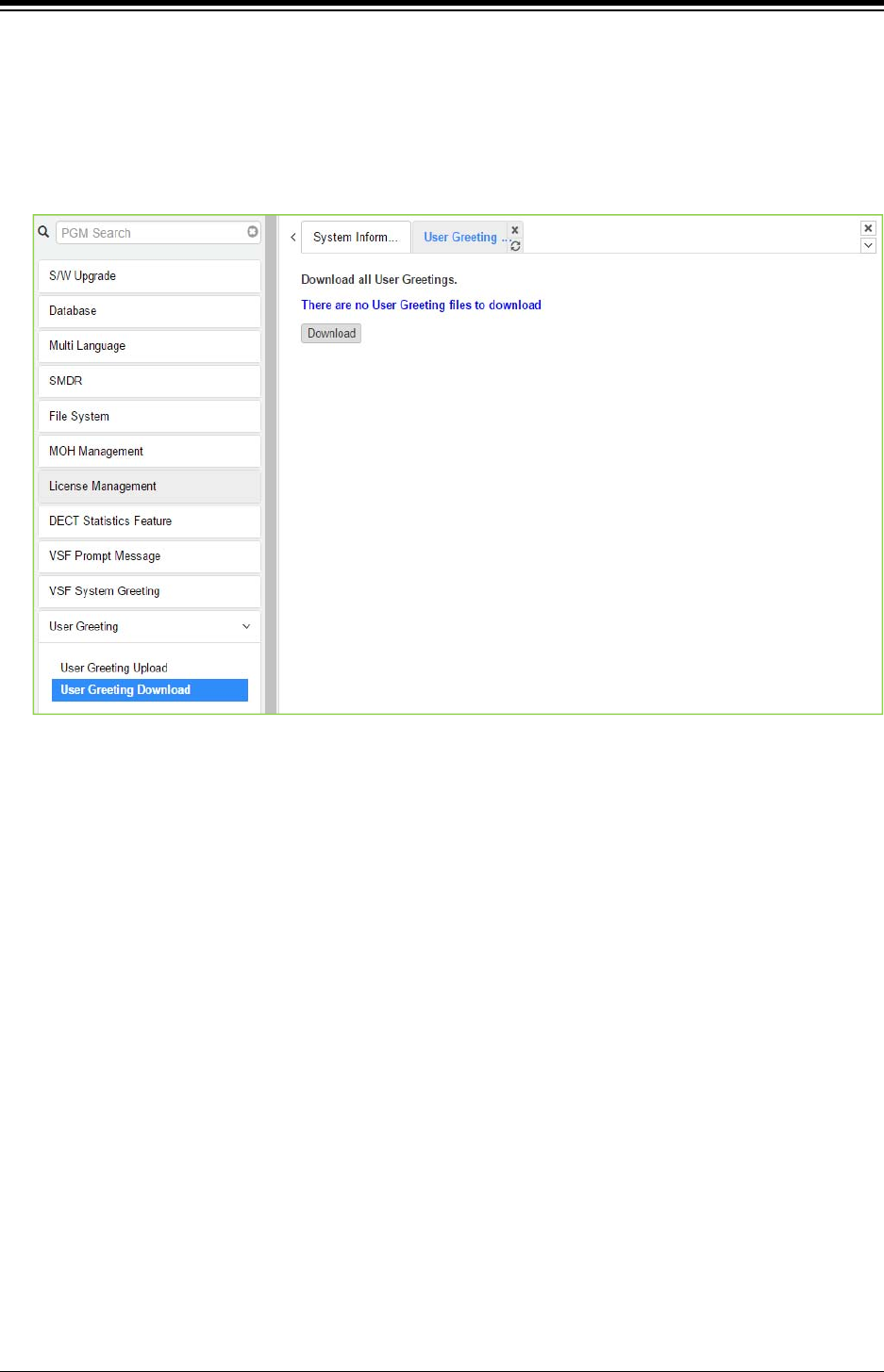
iPECS eMG80 & eMG800 & UCP
Administration and Programming Manual Issue 1.6
600
4.5.11.2 User Greeting Download
To download the User Greeting from System, complete the following steps:
› Click [Download] button.
› The tab will be displayed at the left bottom of page. Click the arrow box and select [Open] to
show.
Figure 4.5.11.2-1 User Greeting Download
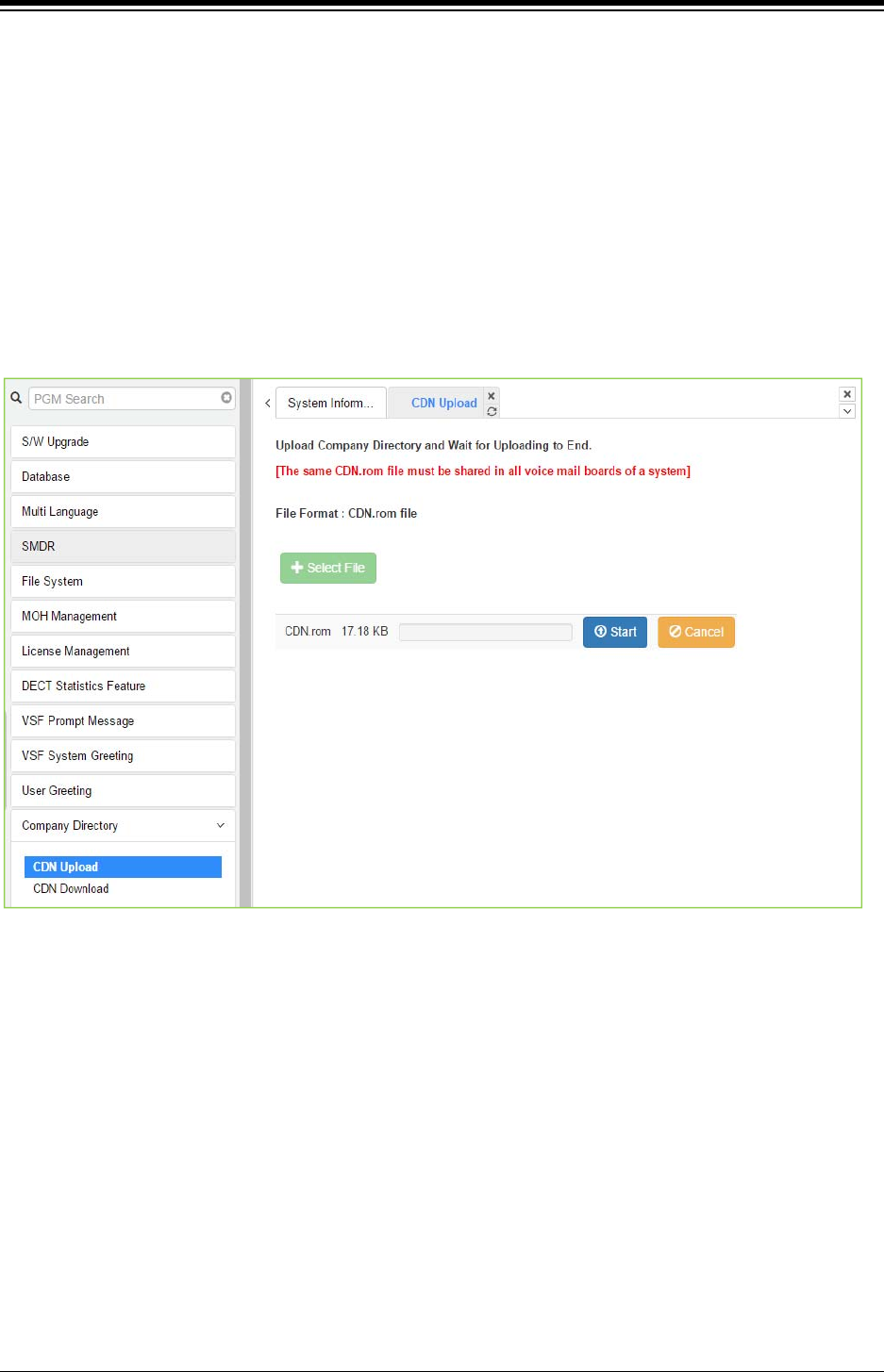
iPECS eMG80 & eMG800 & UCP
Administration and Programming Manual Issue 1.6
601
4.5.12 Company Directory
Administrators can upload or download company directories to System. So company directories
are available to use at iPECS phones.
4.5.12.1 CDN Upload
To upload the Company Directory, complete the following steps:
› Click [Select File] button.
› Select the Company Directory file (rom file) from folder.
› Click [Start] to upload and then display the following figure ‘success’.
Figure 4.5.12.1-1 CDN Upload
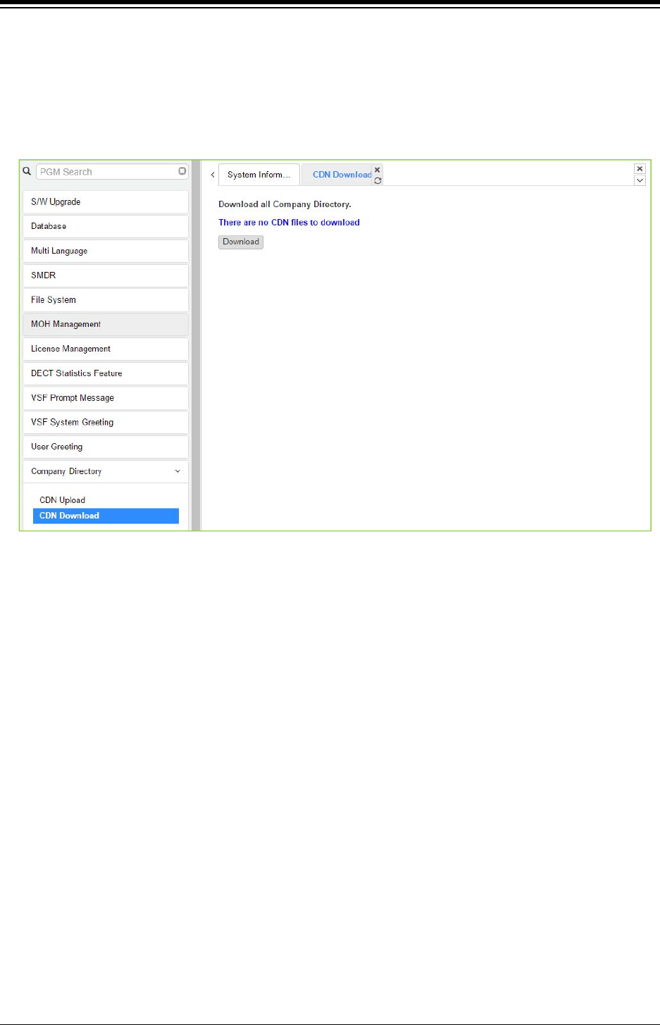
iPECS eMG80 & eMG800 & UCP
Administration and Programming Manual Issue 1.6
602
4.5.12.2 CDN Download
To download the Company Directory from System, complete the following steps:
› Click [Download] button.
› The tab will be displayed at the left bottom of page. Click the arrow box and select [Open] to
show.
Figure 4.5.12.2-1 CDN Download
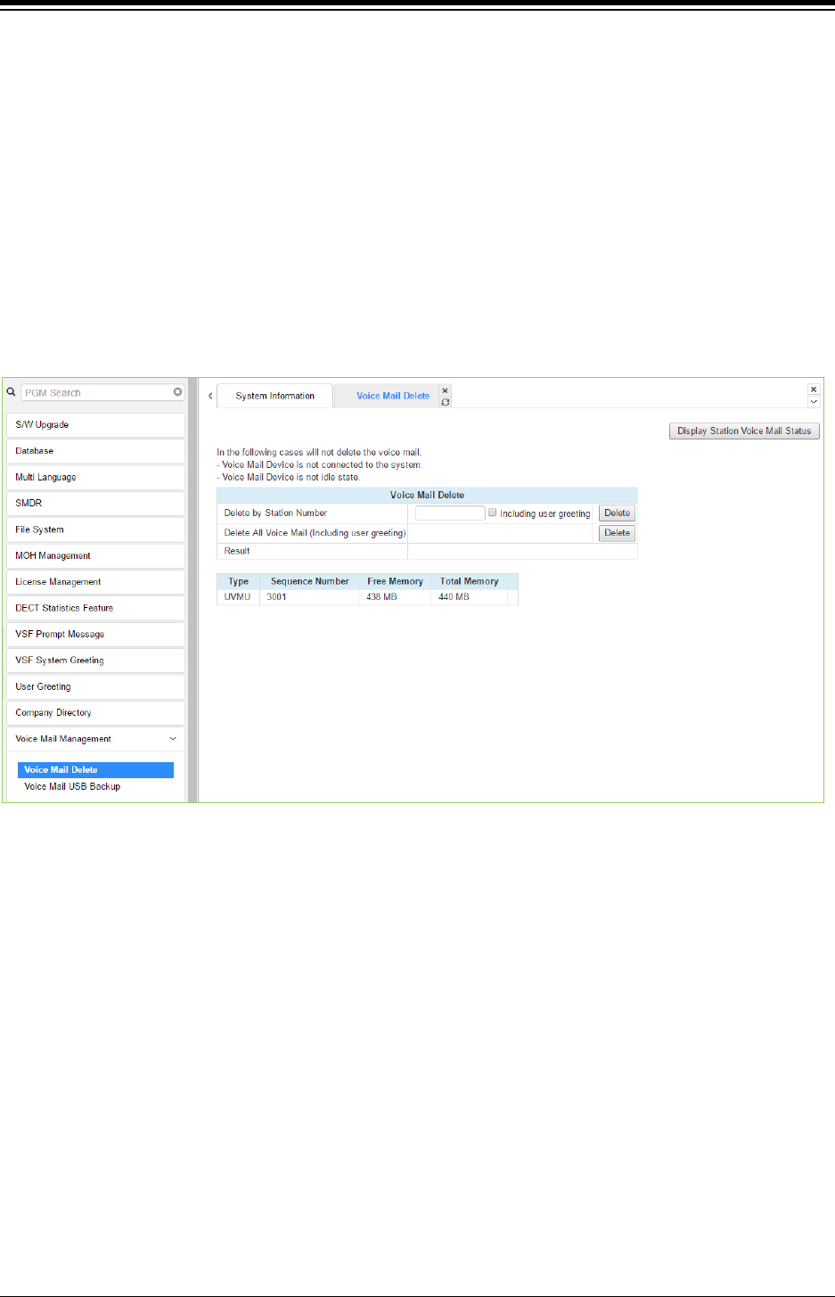
iPECS eMG80 & eMG800 & UCP
Administration and Programming Manual Issue 1.6
603
4.5.13 Voice Mail Management
The Voice Mail Management permits the administrator to view the status of the built-in Voice Mail
boxes and delete the all messages, delete messages for specific stations, or back-up all the
messages to the PC.
4.5.13.1 Voice Mail Delete
Selecting Voice Mail Delete displays the page as shown in figure. From this page, messages
stored in the VMIU (VMIB) can be deleted for all stations or a station range. In addition, using the
“Display Station Voice Mail Status” button, the number of messages for each station is displayed.
Figure 4.5.13.1-1 Voice Mail Delete
A user can delete user greeting if you set "Including user greeting" option when a user delete
voice mail.
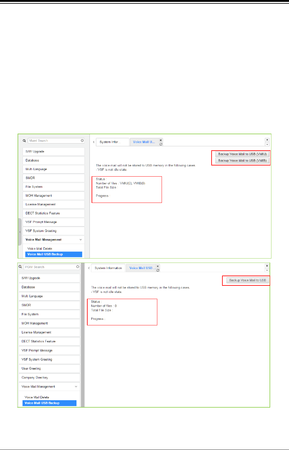
iPECS eMG80 & eMG800 & UCP
Administration and Programming Manual Issue 1.6
604
4.5.13.2 Voice Mail USB Backup
Selecting Voice Mail Backup displays the page shown in figure.
In case of eMG, this page permits the Administrator to send all Voice messages in the
VMIU/VMIB memory to the USB port of the KSU. Note the VSF must be idle and a USB memory
device installed in the system.
The eMG800 has only [Backup Voice Mail to USB (VMIU)].
In case of UCP, this page permits the Administrator to send all Voice messages in the VSF
gateway memory to the USB port of the UCP module. Note the VSF gateway must be idle and a
USB memory device installed in the UCP module.
UCP2400 doesn’t support Voice mail USB Backup.
Figure 4.5.13.2-1 Voice Mail USB Backup
To back up Voice Mail, click the backup Voice Mail to USB button. User can find all information
about the status, Number of files, Total file size, and the percentage of Progress by text.
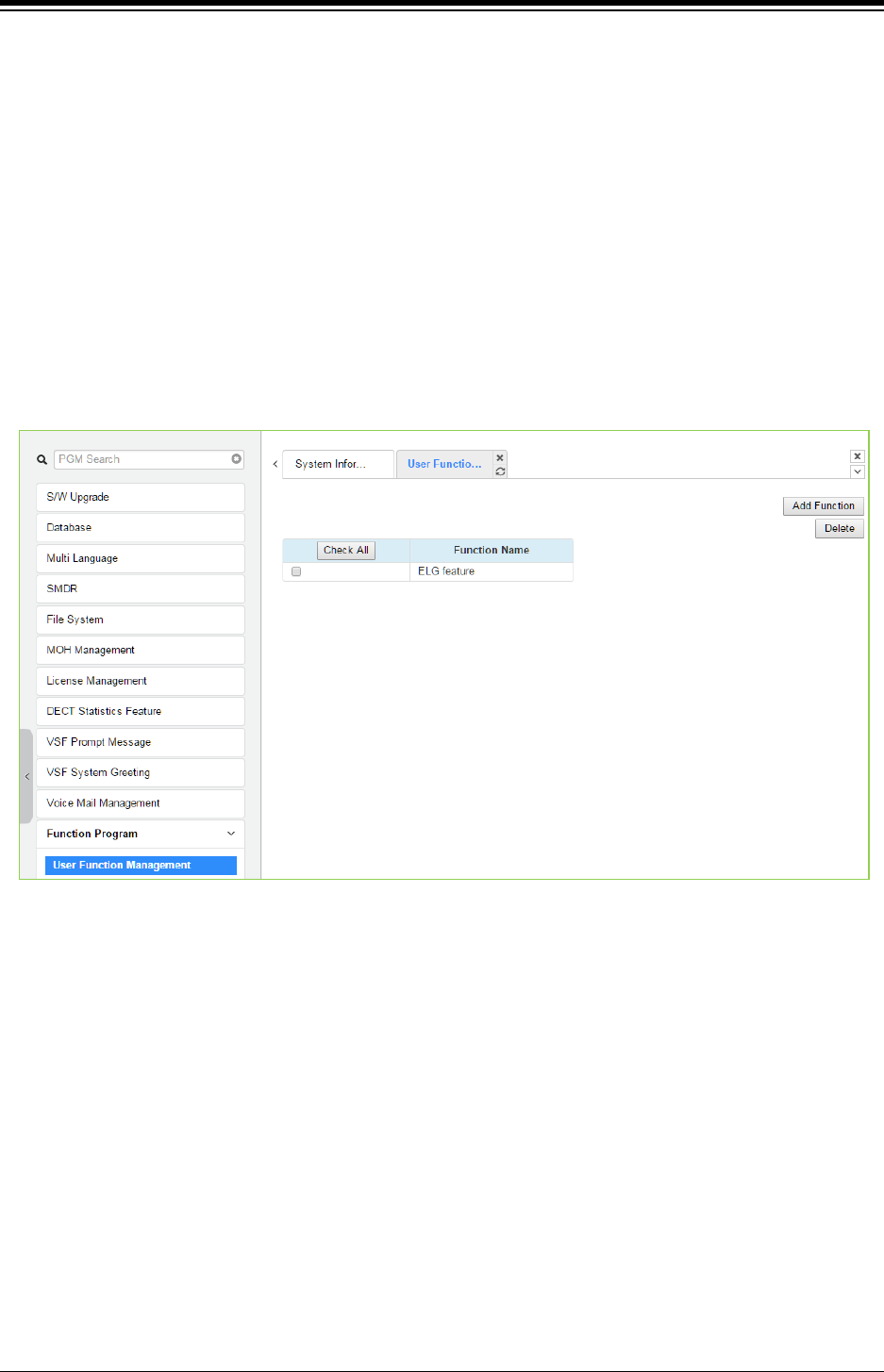
iPECS eMG80 & eMG800 & UCP
Administration and Programming Manual Issue 1.6
605
4.5.14 Function program
The Function Program allows the administrator to build a set of programs with attributes in a
structure customized to the administrator. The Function programs can then be accessed under
the Administration pages using the “Function Base” button at the top of the left navigation page.
Single level and multi-level programs can be structured. The User Function Management permits
functions to be deleted or, with the “Add Function” button, new program functions can be added.
4.5.14.1 User Function Management Page
Selecting User Function Management displays the page shown in figure. Using the check box
and Delete button Function programs previously saved can be deleted.
Figure 4.5.14.1-1 User Function Management Page

iPECS eMG80 & eMG800 & UCP
Administration and Programming Manual Issue 1.6
606
This step is divided into 5 steps and you can make the desired function each step. The following
is the guide to make Name and add the function on each step:
Adding Function
1) To enter the function name, English, Numbering, Underscore (_) and Parentheses are
available. Function name has to be filled out.
2) To enter the step name, English, Numbering, and Special letters except Double
quotation marks are available.
3) The step name doesn’t need to be filled out, but the function has to be configured each
step.
4) To cancel or close this tab, click the close button (X) and pop up the blow;
1. Click the Add Function button.
2. On the below window, click the desired PGM in the left frame. First fill out the function
name and step name. To configure the step 1, click the Make table to check the desired
function and then click the Save button.
Check All: check all functions
Save: Save the checked functions
Initialize: Initialize the checked functions
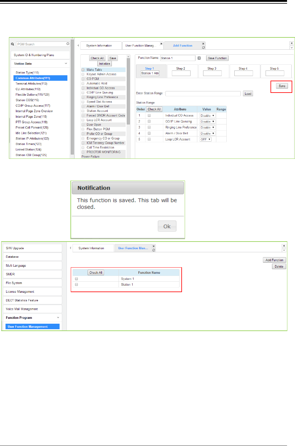
iPECS eMG80 & eMG800 & UCP
Administration and Programming Manual Issue 1.6
607
3. The selected functions are displayed and click the Save button after checking each
functions. The rest steps are the same as the step 1.
4. Finally, click the Save Function to save and then click the OK button.
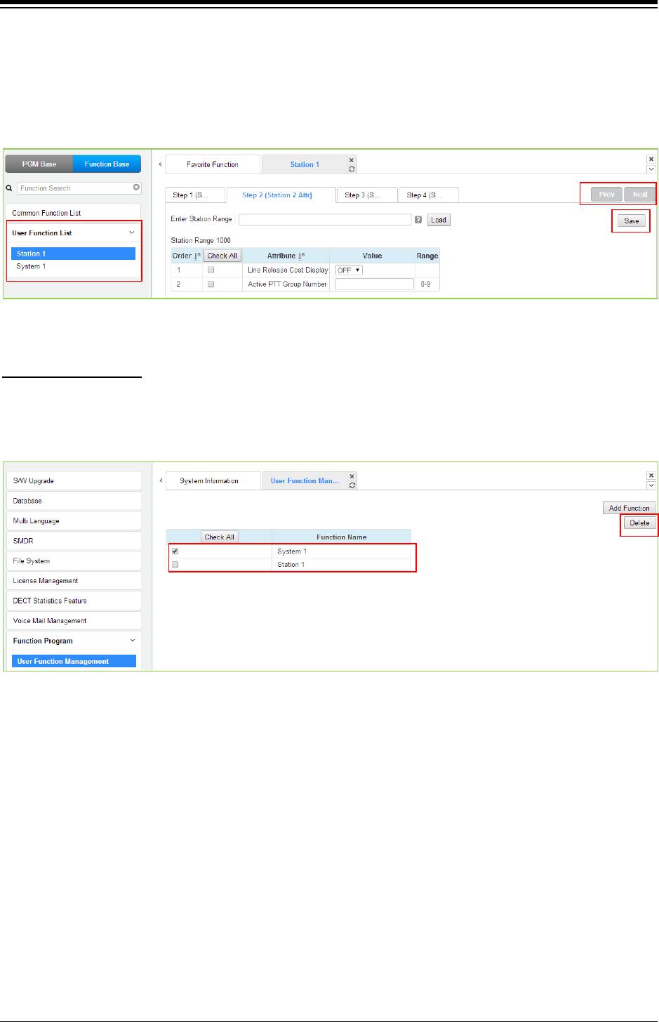
iPECS eMG80 & eMG800 & UCP
Administration and Programming Manual Issue 1.6
608
5. To check the function, click Function Base button in the left frame and User Function List
and you will see the following figure.
You can enable or disable the function by checking each function and then click the save
after setting Value. Also move to each step by clicking the next button or Previous button.
To delete the user function, click Maintenance at the top of window and then click the Function
Program -> User Function Management. Check the desired function to delete and click the delete
button.
Deleting Function
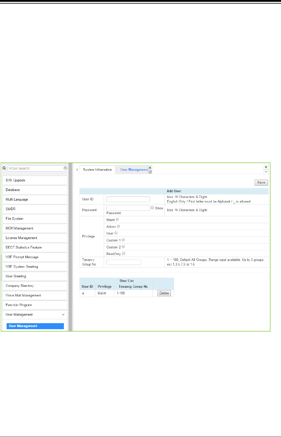
iPECS eMG80 & eMG800 & UCP
Administration and Programming Manual Issue 1.6
609
4.5.15 User Management
iPECS UCP supports up to 50 system accounts and up to ten (10) users may simultaneously
access system Web services. The default ID is ‘admin’ and the password is ‘1234’. The Access
privilege is determined based on the entered system account (ID/Password) and the privilege
assigned for the user.
Please follow up the below instructions to make User ID:
1) Maximum 16 characters & digits.
2) In English only.
3) First letter must be Alphabet. The rest are available: Alphabet, number, underscore (_).
4) Don’t use ‘blank’.
It is strongly recommended that a unique User ID and strong password be entered to
minimize the risk of admin and maintenance access by unauthorized personnel.
User should register more than a maintenance ID.
Figure 4.5.15-1 User Management
4.5.15.1 Company (Tenant group) Administrator Account
The main (maintenance) administrator of the system can make new administrator account for
each tenant group. The tenant group administrator can configure the system according to tenant
group and ‘Web access authorization’ in System Data. Managing the available feature will be
assigned Web Access Authorization in System Data.
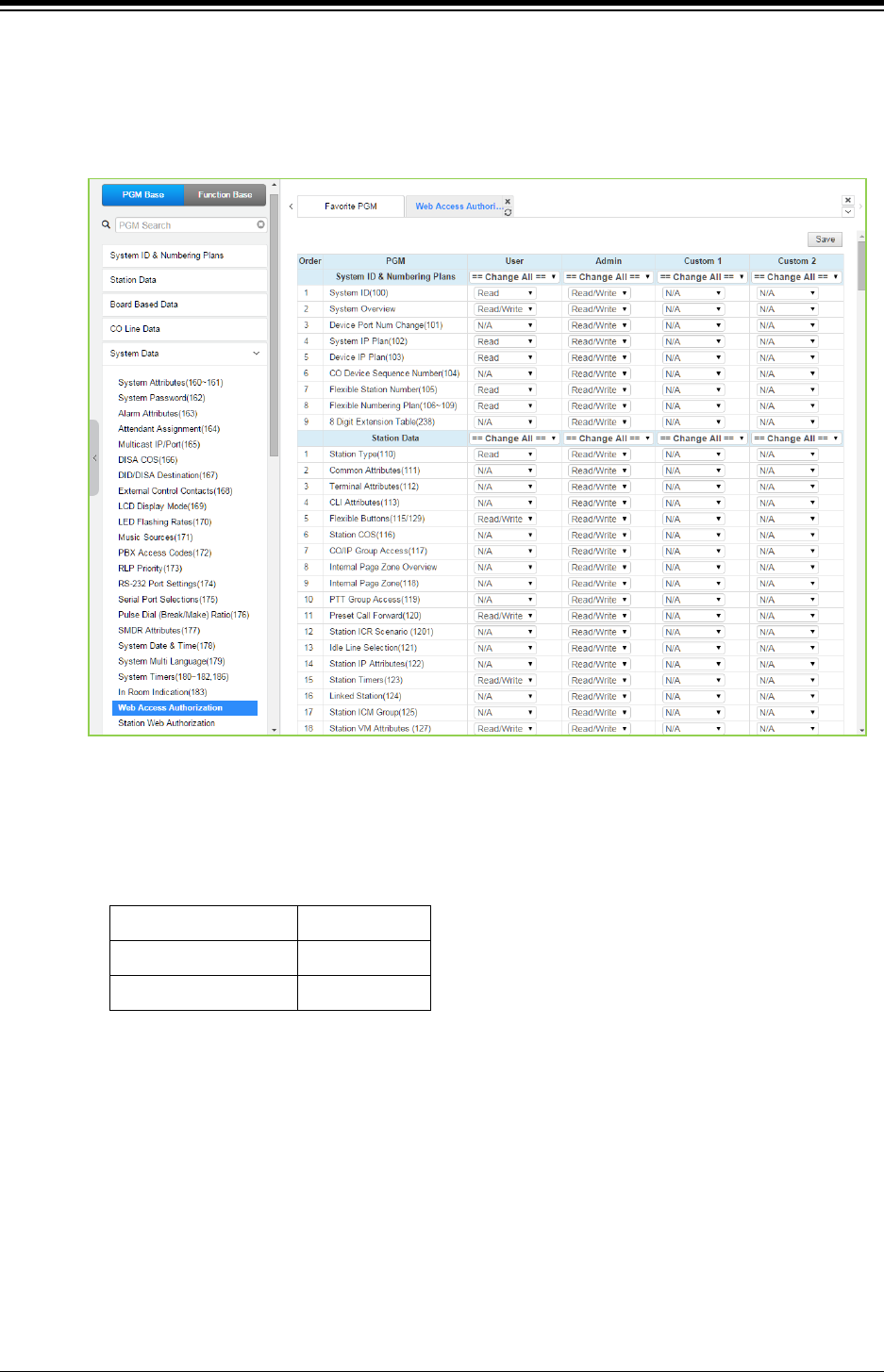
iPECS eMG80 & eMG800 & UCP
Administration and Programming Manual Issue 1.6
610
Operation
1. Web Access Authorization
> Program Custom#1 and #2 privilege columns by selecting N/A, Read, Read/Write for
Tenant group administrator.
2. User Management: add User account for Tenant group administrator.
1) Enter ID and Password.
2) Select Custom 1 or Custom 2.
3) Enter the desired Tenant group number.
UCP100/600/2400
100 groups
eMG800 32 groups
eMG80
15 groups
Note
- Maximum 50 users (including Maintenance, Admin and User privilege).
- The main administrator can’t add Tenant group administrator account for all tenant
group because the number of tenant group of UCP is 100.
4) Click [Save] button to create Account.
5) Log in with the account.
6) The available PGM menu will be displayed by assigning ‘Web Access Authorization’.
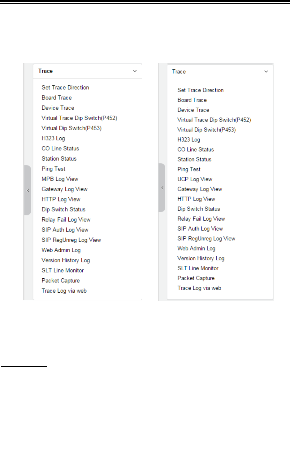
iPECS eMG80 & eMG800 & UCP
Administration and Programming Manual Issue 1.6
611
4.5.16 Trace
The system software incorporates routines to monitor and output detailed call and feature
processing information, and event logs. Information is provided on a system or device level as
requested. Administrators can find the information on this page.
Figure 4.5.16-1 Trace Main Page
We explain [Packet Capture] and [Trace Log via web] among them because it is very useful to
use Web admin.
A user can start and stop capturing packets and download packet capture result. The dump file
will be replaced when new capturing is started.
Packet Capture
Default option is included. The file name is packetdump.cap. -i eth0 -w packetdump.cap -c 10000
- Option explanation
protocol filter: tcp or udp or icmp
port filter: both source and destination port -> port #number, source port -> src port #number,
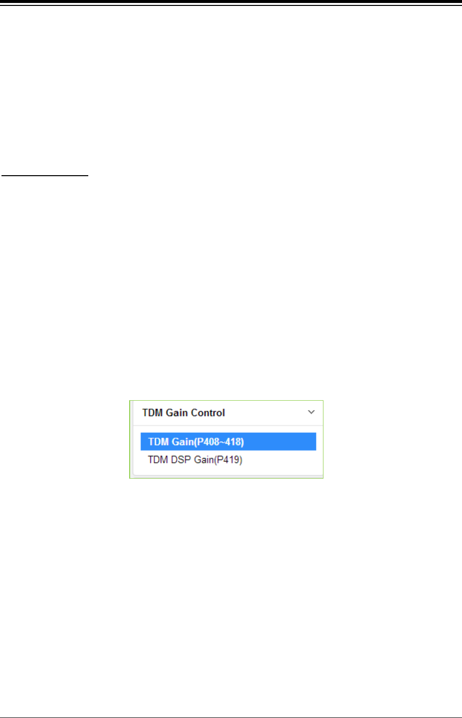
iPECS eMG80 & eMG800 & UCP
Administration and Programming Manual Issue 1.6
612
destination port -> dst port #number
IP filter: both source and destination host IP -> host #IP_ADDR, source host IP -> src host
#IP_ADDR, destination host IP -> dst host #IP_ADDR
# Example
UDP and Port 5588 and Source IP address 10.1.1.100: udp and port 5588 and src host
10.1.1.100
A user can start and stop logging and download trace log result. The log file will be replaced
when new logging is started.
Trace Log via web
1. Set 'Trace Attribute' to 'COM1(UART1)' from 'Set Trace Direction' menu.
2. Set 'Board Trace', 'Device Trace' and 'Virtual Trace Dip Switch(P452)' menu.
3. Click [Start] button.
4.5.17 TDM Gain Control
Control voice gain of TDM device for each direction. For more information to change Value, it is
recommended that you ask your dealer or an authorized Ericsson-LG Enterprise representative.
We can’t guarantee the damage according to changing Value arbitrarily.
Figure 4.5.17-1 TDM Main Page
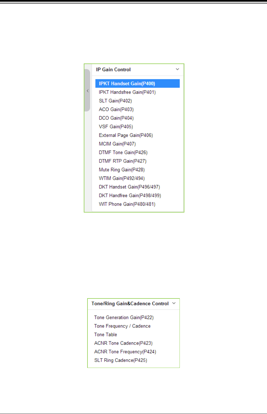
iPECS eMG80 & eMG800 & UCP
Administration and Programming Manual Issue 1.6
613
4.5.18 IP Gain Control
Audio gain for signals from and to each type of device is adjustable through the IP Gain Control
page. The default gain values for the system are set to match the Nation Code. For more
information to change Value, it is recommended that you ask your dealer or an authorized
Ericsson-LG Enterprise representative. We can’t guarantee the damage according to changing
Value arbitrarily.
Figure 4.5.18-1 IP Gain Control Main Page
4.5.19 Tone/ Ring Gain & Cadence Control
Selecting Tone Table will display the page shown. Here the tones, cadence and gain used with
features can be managed. For more information to change Value, it is recommended that you ask
your dealer or an authorized Ericsson-LG Enterprise representative. We can’t guarantee the
damage according to changing Value arbitrarily.
Figure 4.5.19-1 Tone/Ring Gain & Cadence Control Main Page
Control system tone/ring cadence and frequency.
System announcement or music can be provided instead of system ring/tone if it is assigned in
tone table.
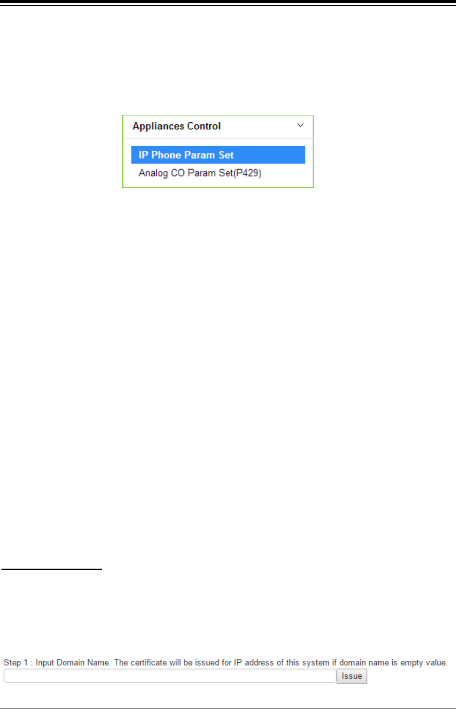
iPECS eMG80 & eMG800 & UCP
Administration and Programming Manual Issue 1.6
614
4.5.20 Appliances Control
The Appliances Control page permits control of several characteristics of IP phones and analog
CO lines such as Comfort Noise level and side tone. For more information to change Value, it is
recommended that you ask your dealer or an authorized Ericsson-LG Enterprise representative.
We can’t guarantee the damage according to changing Value arbitrarily.
Figure 4.5.20-1 Appliances Control Main Page
4.5.21 Web Certificate
SSL stands for Secure Sockets Layer, a global standard security technology that enables
encrypted communication between a web browser and a web server. It is utilized by millions of
online businesses and individuals to decrease the risk of sensitive information (e.g. credit card
numbers, user names, passwords, emails, etc.) from being stolen or tampered with by hackers
and identity thieves. In essence, SSL allows for a private “conversation” just between the two
intended parties.
To create this secure connection, an SSL certificate (also referred to as a “digital certificate”) is
installed on a web server and serves two functions:
- It authenticates the identity of the website (this guarantees visitors that they’re not on a
bogus site)
- It encrypts the data that’s being transmitted.
The web server certificated must have a domain name however default web certificate of a
system has no information for domain. So, a web browser displays warning message about
ERR_CERT_AUTHORITY_INVALID. To clear this warning, an administrator has to issue a
certificate for the system.
There is a need to generate own self signed certificate in order to mitigate the vulnerability of
security and do not display the caution pop-up such as 'un-trusted site' because the system use
IP address or URL. This certificate is needed to use 'https//XXX' , not 'http://xxx'.
Please must check date and time. The certificate will not operate well on PC or Mobile device if
the time of certificate issued on between system and PC or Mobile device is different.
To create Certificate
Step 1: Enter Domain name and then click [Issue] button. The certificate will be used for IP
address of this system if Domain name is not entered as blank.
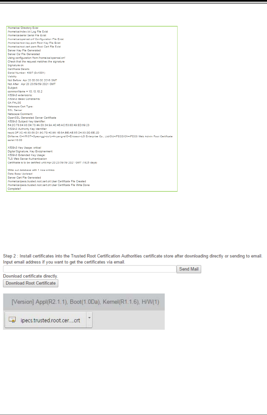
iPECS eMG80 & eMG800 & UCP
Administration and Programming Manual Issue 1.6
615
The following result is displayed on browser.
Step 2: Install Certificates into the Trusted Root Certification Authorities certificate store after
downloading directly as below picture or sending to email for installing the desired devices if you
want to get the certificates via email.
The way to install Certificates is followed by the type of Windows OS, Android OS, or iOS OS.
Step 3: Restart Web server to apply New certificate by clicking [Web Server Restart] button.
Note
Clean up all certificate and files by clicking [Server Certificate Clean up] button.
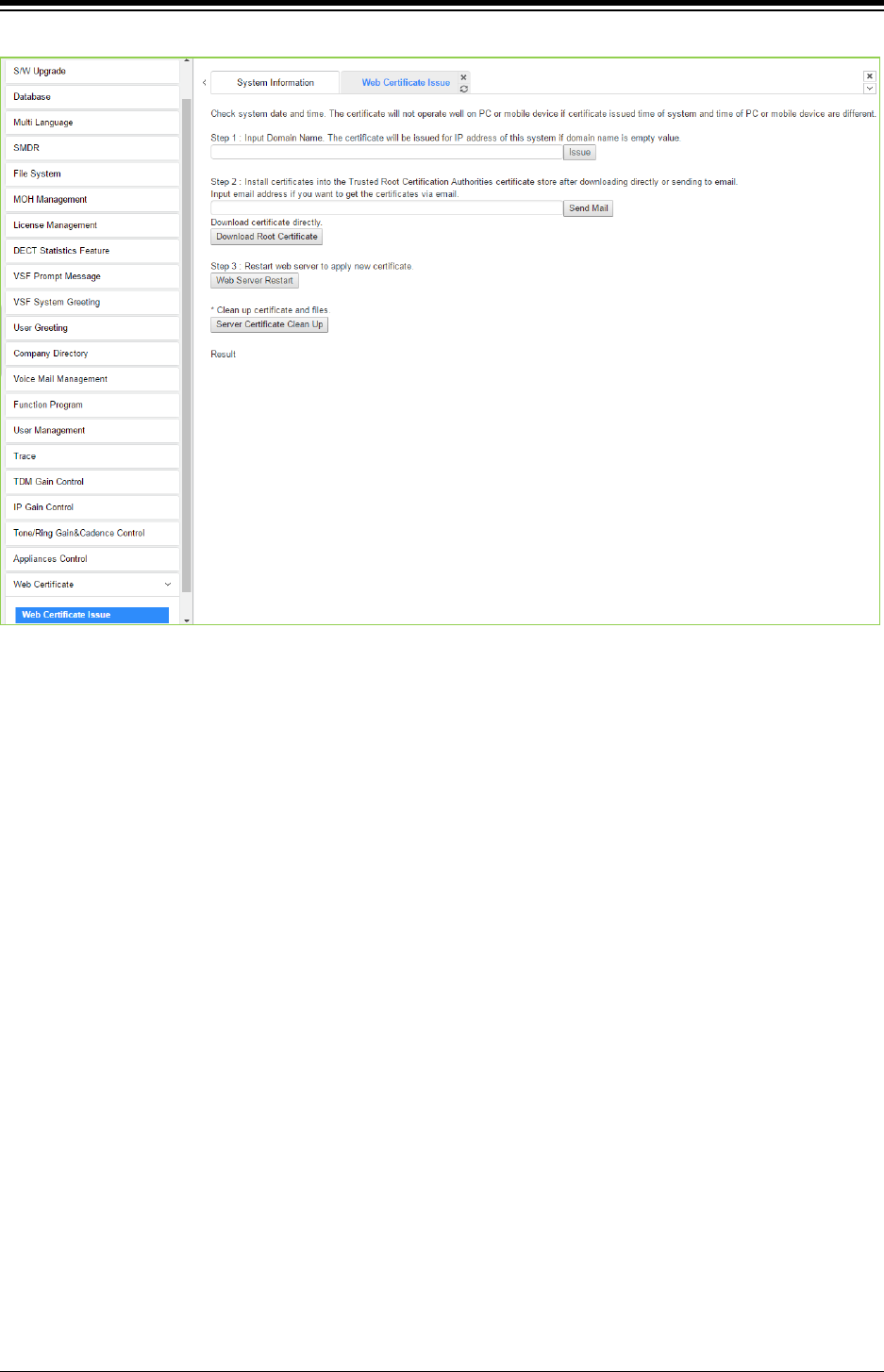
iPECS eMG80 & eMG800 & UCP
Administration and Programming Manual Issue 1.6
616
Figure 4.5.21-1 Web Certificate Issue
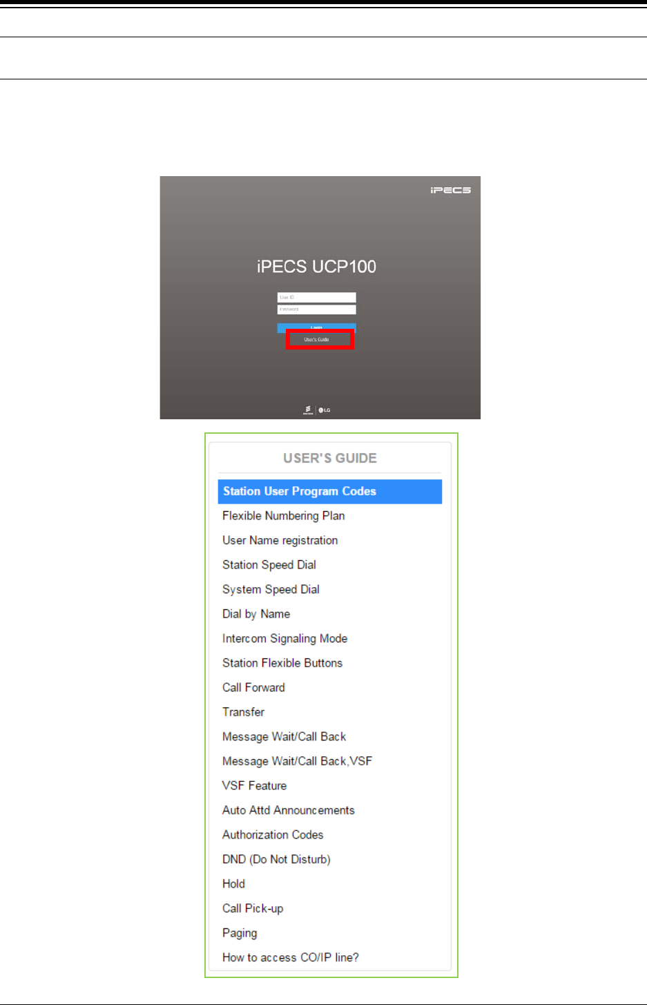
iPECS eMG80 & eMG800 & UCP
Administration and Programming Manual Issue 1.6
617
4.6 On-Line web user guide
We provide On-line web user guide about the frequent use of features to a user.
You can access it in the login page as below without entering ID and Password.
We didn’t explain the user guide because you can easily get the information on the following
features on the web.
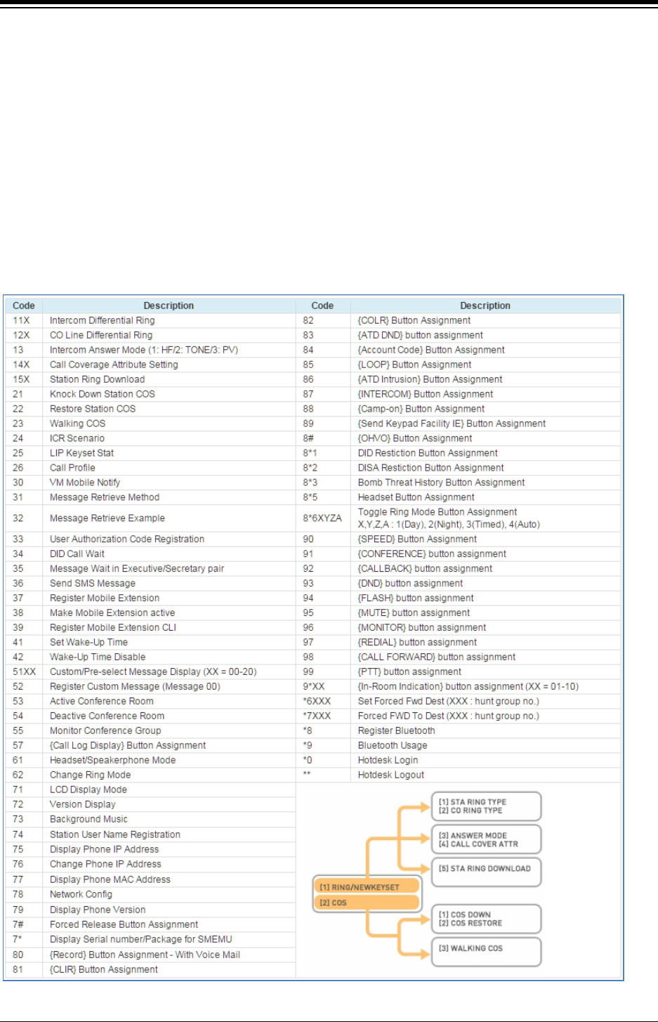
iPECS eMG80 & eMG800 & UCP
Administration and Programming Manual Issue 1.6
618
Appendix A Program Codes
User and Attendant Program Codes, refer to Table A-1 and A-2, are digit sequences users and
the Attendant may dial while in the User Program Mode to assign Flex buttons and affect the
status of a feature or setting. For more information on the User Program Mode, refer to the iPECS
Features and Operation Manual.
Many of these codes may be assigned to a button of an iPECS IP or LDP Phone by pressing the
[PGM] button as the first entry of a Flexible button assignment, see Flex button Programming in
the iPECS Features and Operation Manual.
Table A-1 Station User Program codes

iPECS eMG80 & eMG800 & UCP
Administration and Programming Manual Issue 1.6
619
Table A-2 Attendant User Program Codes
CODE FUNCTION
0111
Print SMDR, by Station
0112
Delete SMDR, by Station
0113
Display Call Charge
0114
Abort Print
0115
Print Lost Call Report
0116
Delete Lost Call Report
0121
Print Traffic Analysis (All summary)
0122
Print Traffic Analysis (All summary periodically)
0123
Abort “Print Traffic Analysis (All summary periodically)”
0124
Print Traffic Analysis (Attendant)
0125
Print Traffic Analysis (Call summary)
0126
Print Traffic Analysis (Call Hourly)
0127
Print Traffic Analysis (H/W Usage)
0128
Print Traffic Analysis (CO summary)
0129
Print Traffic Analysis (CO Hourly)
021
Set ICM only Mode
022
Restore Station COS
031
Authorization Code Registration
032
Erase Authorization
041
System Date/Time set
042
LCD Date Mode
043
LCD Time Mode
044
Set Wake Up Time from Attendant
045
Wake Up Disable from Attendant
046
PX Clock Set through ISDN message
047
Hot Desk login
048
Hot Desk logout
051
Custom/Pre-select Message
052
DND/Call Forward/Pre-selected MSG Cancel
053
Custom Display Message (11-20)
054
Monitor Conference Room
055
Delete Conference Room
06
VSF – Record System Greeting
071
Register Station Name
072
Isolate CO Fault Line
073
Automatic Day/Night/Timed Ring Table
074
External Page Music -1 Assignment/Cancel
075
External Page Music -2 Assignment/Cancel
076
LCD Display Language
077
PTT Login / Logout
078
Display CPU redundancy state
079
Font Set
070
Contrast Set
08
Emergency History about emergency call
*#
Admin Programming Code to enter

iPECS eMG80 & eMG800 & UCP
Administration and Programming Manual Issue 1.6
620
Appendix B Flexible Numbering Plan
(Web based)
The System Numbering Plan can be selected from 1 of 9 basic Numbering Plans. Table B-1
provides a brief description of the plans and Table B-2 for eMG and Table B-3 for UCP provide
the Numbering Plan codes for each of the nine basic plans. The Number Plan is selected in
Program 100 and individual codes in the plan can be changed using the Flexible Numbering Plan
Programs 106 to 109.
Table B-1 Numbering Plan Description
Plan Number Description eMG80 eMG800 UCP
1
Basic Numbering Plan
100 - 239
1000-2199
1000 – 3399
2
The station number can be within 799
100 - 239
1000-2199
1000 – 3399
3
Australia Default
100 - 239
1000-2199
1000 – 3399
4
New Zealand Default
700– 839
7000-8199
1000 – 3399
5
Italy Default
200– 339
2000-3199
2000– 4399
6
Finland Default
210 – 349
2100-3299
2100 –4499
7
Default for Sweden
100– 239
1000-2199
1000 – 3399
8
Default for Norway
100– 239
1000-2199
1000 – 3399
9
Default for Israel
100– 239
1000-2199
1000 – 3399
Table B-2 eMG Basic Numbering Plan 1-4, Default Values
Feature Basic Numbering Plan
1 2 3 4 Remark
Intercom Call for eMG80
100 ~239
100-239
100-239
700-839
Intercom Call for eMG800 1000-2199 1000-
2199
1000-
2199
1000-
2199
1 Internal Page Zone eMG80:301~335
eMG800:*301~*400
*301~*335 *101~*135 #101~#135
2
Internal All Call Page
543
*543
#3
#3
3
Meet Me Page
544
*544
##
##
4
External Page Zone 1
545
*545
#41
#41
5
External All Call Page
548
*548
#5
#5
6
All Call Page (Internal/External)
549
*549
#00
#00
7
SMDR Account Code Enter
550
*550
550
550
SLT
8
Flash Command to CO Line
551
*551
551
551
SLT
9
SLT Last Number Redial
552
*552
552
552
SLT
10
Do Not Disturb (Toggle On/Off)
553
*553
553
553
SLT
11
Call Forward
554
*554
554
554
12
Speed Dial Programming
555
*555
555
555
SLT
13
Activate Message Wait/Callback
556
*556
556
556
SLT
14
Message Wait/Callback Answer
557
* 557
557
557
SLT
15
SLT Speed Dial Access
558
* 558
558
558
SLT
16
DND/FWD Cancel
559
* 559
559
559
SLT
17
SLT CO System Hold
560
* 560
560
560
SLT

iPECS eMG80 & eMG800 & UCP
Administration and Programming Manual Issue 1.6
621
Feature Basic Numbering Plan
1 2 3 4 Remark
18
SLT Program Mode Access
561
* 561
561
561
SLT
19
Attendant Unavailable
562
* 562
562
562
20
AME Feature
564
* 564
564
564
21
Alarm Reset
565
* 565
565
* 565
22
Group Call Pickup
566
**
**
*1
23
Universal Night Answer
567
* 567
567
567
24
Account Code with bin
568
* 568
568
568
25
Walking COS
569
* 569
569
569
26
ACD agent On/Off Duty
571
* 571
571
571
27
ACD Supervisor Login
572
* 572
572
572
28
ACD Supervisor Logout
573
* 573
573
573
29
ACD Help Code
574
* 574
574
574
30
ACD Calls In Queue Display
575
* 575
575
575
31
ACD Supervisor Status
576
* 576
576
576
32
ACD Supervisor Monitor
577
* 577
577
577
33 ACD Reroute Queued Call
Answer
578 * 578 578 578
34 ACD Reroute Queued Call No
answer
579 * 579 579 579
35
Camp-On Answer
621
* 621
*521
*521
SLT
36 Call Park Locations eMG80:#601~#619
eMG800:#601~#800
#601 -#
619
#601 –
#619
#601 –
#619
37 Station Group Pilot Number eMG80:401~449
eMG800:401~500
*401 –
*440
*620 –
*659
*620 –
*659
38 Station User VSF Features
Access
*66 66 *78 *78
39
Call Coverage Ring
76
*76
*76
*76
40
Direct Call Pickup
*77
*77
*77
*77
41
Access CO Group
89
89
#89
#89
42
Access Individual CO/IP Line
88
88
#88
#88
43
Access Held CO/IP
8*
8*
#8*
#8*
44
Access Held Individual CO/IP
8#
8#
#8#
#8#
45
Access CO in First CO Group
9
9
9
0
46
Attendant Call
0
0
0
9
47
VM Message Wait Enabled
*8
*8
*8
*8
48
VM Message Wait cancel
*9
*9
*9
*9
49
Door Open (1st Door )
#*1
#*1
#*1
#*1
50
Door Open (2nd Door )
#*2
#*2
#*2
#*2
51
MCID Request
*0
*0
*0
*0
52 Unsupervised conference time
Extension code
## ## *## *##
53
PTT Group Login/Logout
#0
#0
#*0
#*0
54
ACD Agent primary login
581
* 581
581
581
55
ACD Agent primary logout
582
* 582
582
582
56
ACD Agent secondary login
583
* 583
583
583
57
ACD Agent secondary logout
584
* 584
584
584
58
Wrap-up end
585
* 585
585
585
59
T-NET CM Login/out
586
* 586
586
586

iPECS eMG80 & eMG800 & UCP
Administration and Programming Manual Issue 1.6
622
Feature Basic Numbering Plan
1 2 3 4 Remark
60
Enter Into Conf-Room
59
* 59
*59
*59
61
Enter Into Conf-Group
68
* 68
*79
*79
62
Station ICR
587
* 587
587
587
63
Pick up Group Pick-Up
588
* 588
588
588
64
Emergency Page
589
* 589
589
589
65
Remote Mobile Extension Control
580
* 580
580
580
66 ACD agent ON/OFF Duty-All
group
58* * 58* 58* 58*
67
SLT ACNR
58#
* 58#
58#
58#
68
ACD Supervisor Ring Mode
570
* 570
570
570
69
Company Directory Name
563
* 563
563
563
70
ISDN Supplementary Hold
57*
*57*
57*
57*
71
ISDN Supplementary Conf
57#
*57#
57#
57#
72
Forced Channel Seize
56*
*56*
56*
56*
73
Override DND/Forward
56#
*56#
56#
56#
74
Cancel Call Back
75
Transfer to VSF Number
55*
*55*
55*
55*
76
CCR
#2
#2
#2
#2
77
Room type conf Group join
5*0
5*0
5*0
5*0
77
Last Number Redial ( LNR )
[REDIAL]
[REDIAL]
[REDIAL]
[REDIAL]
Keyset
78
Save Number Redial
[Save]
[Save]
[Save]
[Save]
Keyset
79 Station Speed Dial Access [SPEED] + XXX [SPEED] +
XXX
[SPEED] +
XXX
[SPEED] +
XXX
80 System Speed Dial Access [SPEED] + XXXX [SPEED] +
XXXX
[SPEED] +
XXXX
[SPEED] +
XXXX
Table B-2 eMG Basic Numbering Plan 5-9, Default Values
Feature Basic Numbering Plan
5 6 7 8 9 Remark
Intercom Call for eMG80
200-339
210-349
100-239
100-239
100 ~239
Intercom Call for eMG800
2000-3199
2100-3299
1000-2199
1000-2199
1000-2199
1
Internal Page Zone
*101-*135
*301-*335
401- 429
*301- *335
301~335
2
Internal All Call Page
#3
*543
43
*543
543
3
Meet Me Page
##
*544
44
*544
544
4
External Page Zone 1
#41
*545
45
*545
545
5
External All Call Page
#5
*548
48
*548
548
6 All Call Page
(Internal/External)
#00 *549 49 *549 549
7 SMDR Account Code
Enter
50 *550 *550 550 SLT
8 Flash Command to CO
Line
51 *551 51 *551 551 SLT
9
SLT Last Number Redial
52
*552
52
*552
552
SLT
10 Do Not Disturb (Toggle
On/Off)
53 *553 53 *553 553 SLT
11
Call Forward
54
*554
54
*554
554
12
Speed Dial Programming
55
*555
55
*555
555
SLT

iPECS eMG80 & eMG800 & UCP
Administration and Programming Manual Issue 1.6
623
Table B-2 eMG Basic Numbering Plan 5-9, Default Values
Feature Basic Numbering Plan
5 6 7 8 9 Remark
13 Activate Message
Wait/Callback
56 *556 56 *556 556 SLT
14 Message Wait/Callback
Answer
57 *557 57 *557 557 SLT
15
SLT Speed Dial Access
58
*558
58
*558
558
SLT
16
DND/FWD Cancel
59
*559
59
*559
559
SLT
17
SLT CO System Hold
690
*560
*10
*560
560
SLT
18 SLT Program Mode
Access
691 *561 50 *561 561 SLT
19
Attendant Unavailable
692
*562
*12
*562
562
20
AME Feature
694
*564
*36
*564
564
21
Alarm Reset
695
*565
*13
*565
565
22
Group Call Pickup
**
*566
*14
*566
**
23
Universal Night Answer
697
*567
*15
*567
567
24
Account Code with bin
698
*568
*16
*568
568
25
Walking COS
699
*569
*17
*569
569
26
ACD agent On/Off Duty
671
*571
*20
*571
571
27
ACD Supervisor Login
672
*572
*21
*572
572
28
ACD Supervisor Logout
673
*573
*22
*573
573
29
ACD Help Code
674
*574
*23
*574
574
30 ACD Calls In Queue
Display
675 *575 *24 *575 575
31
ACD Supervisor Status
676
*576
*25
*576
576
32
ACD Supervisor Monitor
677
*577
*26
*577
577
33 ACD Reroute Queued
Call Answer
678 *578 *27 *578 578
34 ACD Reroute Queued
Call No answer
679 *579 *28 *579 579
35
Camp-On Answer
621
*621
*29
*621
*621
SLT
36
Call Park Locations
#601 – #619
#601 – #619
601 – 619
#601 – #619
#601~#619
37 Station Group Pilot
Number
720 – 759 *401 - *440 620 – 659 *401 - *440 620~659
38 Station User VSF
Features Access *66 66 *11 66 *66
39
Call Coverage Ring
*76
*76
*30
*76
76
40
Direct Call Pickup
*77
*77
7
*77
*77
41
Access CO Group
89
89
89
#89
89
42 Access Individual CO/IP
Line
88 88 88 #88 88
43
Access Held CO/IP
8*
8*
8*
#8*
8*
44 Access Held Individual
CO/IP
8# 8# 8# #8# 8#
45 Access CO in First CO
Group
0 9 9 0 9
46
Attendant Call
9
0
0
#9
0
47 VM Message Wait
Enabled
*8 *8 *8 *8 *8

iPECS eMG80 & eMG800 & UCP
Administration and Programming Manual Issue 1.6
624
Table B-2 eMG Basic Numbering Plan 5-9, Default Values
Feature Basic Numbering Plan
5 6 7 8 9 Remark
48
VM Message Wait cancel
*9
*9
*9
*9
*9
49
Door Open (1st Door )
#*1
#*1
*31
#*1
#*1
50
Door Open (2nd Door )
#*2
#*2
*32
#*2
#*2
51 MCID Request *0 *0 *35 *0 *0
(Except
USA
version)
52 Unsupervised conference
time Extension code
*## ## *37 ## ##
53
PTT Group Login/Logout
#*0
#0
*38
#0
#0
54
ACD Agent primary login
681
*581
*40
*581
581
55
ACD Agent primary logout
682
*582
*41
*582
582
56 ACD Agent secondary
login
683 *583 *42 *583 583
57 ACD Agent secondary
logout
684 *584 *43 *584 584
58
Wrap-up end
685
*585
*44
*585
585
59
T-NET CM Login/out
686
*586
*45
*586
586
60
Enter Into Conf-Room
*59
*59
*46
*59
59
61
Enter Into Conf-Group
*68
*68
*47
*68
*68
62
Station ICR
687
*587
*48
*587
587
63
Pick up Group Pick-Up
688
*588
*49
*588
588
64
Emergency Page
689
*589
*50
*589
589
65 Remote Mobile Extension
Control
680 *580 ** 580 580
66 ACD Agent ON/OFF Duty-
All group
68* *58* *5# *58* 58*
67
SLT ACNR
68#
*58#
*51
*58#
58#
68 ACD Supervisor Ring
Mode
67* *570 *52 *570 570
69
Company Directory Name
*21
*563
*53
*563
563
70
ISDN Supplementary Hold
*22
*57*
*54
*57*
57*
71 ISDN Supplementary
Conf
*23 *57# *55 *57# 57#
72
Forced Channel Seize
*24
*56*
*56
*56*
56*
73
Override DND/Forward
*25
*56#
*57
*56#
56#
74
Cancel Call Back
*58
75
Transfer to VSF Number
*55
*55*
*59
*55*
55*
76
CCR
#2
#2*
#2
#2
77 Room type conf Group
join
5*0 5*0 *61 5*0
77 Last Number Redial
( LNR )
[REDIAL] [REDIAL] [REDIAL] [REDIAL] [REDIAL] Keyset
78
Save Number Redial
[Save]
[Save]
[Save]
[Save]
[Save]
Keyset
79 Station Speed Dial
Access
[SPEED] +
XXX
[SPEED] +
XXX
[SPEED] +
XXX
[SPEED] +
XXX
[SPEED] +
XXX
80 System Speed Dial
Access
[SPEED] +
XXXX
[SPEED] +
XXXX
[SPEED] +
XXXX
[SPEED] +
XXXX
[SPEED] +
XXXX

iPECS eMG80 & eMG800 & UCP
Administration and Programming Manual Issue 1.6
625
Table B-3 UCP Basic Numbering Plan 1-4, Default Values
Feature Basic Numbering Plan
1 2 3 4 Remark
Intercom Call
1000 ~3399
1000 ~3399
1000 ~3399
1000 ~3399
Internal Page Zone
*301~*400
*301~*400
*101~*200
*301~*400
Internal All Call Page
543
*543
#3
#43
Meet Me Page
544
*544
##
##
External Page Zone 1-2
545-546
*545-*546
#41-#42
#41-#42
External All Call Page
548
*548
#5
#5
All Call Page
549
*549
#00
#00
SMDR Account Code Enter
550
*550
550
#9
SLT
Flash Command to CO Line
551
*551
551
551
SLT
SLT Last Number Redial
552
*552
552
552
SLT
DND (Toggle On/Off)
553
*553
553
553
SLT
Call Forward
554
*554
554
554
Speed Dial Programming
555
*555
555
555
SLT
Activate Message Wait/Callback
556
*556
556
*66
SLT
Message Wait/Callback Answer
557
* 557
557
*67
SLT
SLT Speed Dial Access
558
* 558
558
#8
SLT
DND/FWD cancel
559
* 559
559
559
SLT
SLT CO System Hold
560
* 560
560
560
SLT
SLT Program Mode Access
561
* 561
561
561
SLT
Attendant Unavailable
562
* 562
562
562
AME Feature
564
* 564
564
564
Alarm Reset
565
* 565
565
* 565
Group Call Pickup
566
* 566
**
*1
Universal Night Answer
567
* 567
567
2
Account Code with bin
568
* 568
568
568
Walking COS
569
* 569
569
569
ACD Agent On/Off Duty
571
* 571
571
571
ACD Supervisor Login
572
* 572
572
572
ACD Supervisor Logout
573
* 573
573
573
ACD Help Code
574
* 574
574
574
ACD Calls In Queue Display
575
* 575
575
575
ACD Supervisor Status
576
* 576
576
576
ACD Supervisor Monitor
577
* 577
577
577
ACD Reroute Queued Call Answer
578
* 578
578
578
ACD Reroute Queued Call No Answer
579
* 579
579
579
Camp-On Answer
621
* 621
621
621
SLT
Call Parking Locations
#601~#800
#601~#800
#601~#800
#101~#300
Station Group Pilot Number
401 – 500
*401 – *500
*401 – *500
#620 – #719
Station User VSF Features Access
66x
66x
*66x
69x
x: 1 ~ 3
Call Coverage Ring
76
*76
*76
67
Direct Call Pickup
77
*77
*77
*77
Access CO Group
89xx
89xx
89xx
89xx
xxx: 000~201,
Access Individual CO/IP Line
88xxx
88xxx
88xxx
48xxx
xxx: 001~999
Access Held CO/IP
8*
8*
8*
4*
Access Held Individual CO/IP
8#xx
8#xx
8#xx
4#xx
xx: 01~74

iPECS eMG80 & eMG800 & UCP
Administration and Programming Manual Issue 1.6
626
Table B-3 UCP Basic Numbering Plan 1-4, Default Values
Feature Basic Numbering Plan
1 2 3 4 Remark
Access CO in First CO Group
9
9
9
1
Attendant Call
0
0
0
0
VM Message Wait Enabled
*8
*8
*8
*8
VM Message Wait Cancel
*9
*9
*9
*9
Door Open (1st Door )
#*1
#*1
#*1
#*1
Door Open (2nd Door )
#*2
#*2
#*2
#*2
Door Open (3rd Door )
#*3
#*3
#*3
#*3
Door Open (4th Door )
#*4
#*4
#*4
#*4
MCID Request
*0
*0
*0
*0
Unsupervised conference time
Extension code
## ## * ## *22
PTT Group Login/Logout
#0
#0
#*0
*21
ACD Agent primary login
581
* 581
581
581
ACD Agent primary logout
582
* 582
582
582
ACD Agent secondary login
583
* 583
583
583
ACD Agent secondary logout
584
* 584
584
584
Wrap-up end
585
* 585
585
585
T-NET CM Login/out
586
* 586
586
586
Enter Into Conf-Room
59
* 59
* 59
59
Enter Into Conf-Group
68
* 68
* 68
68
Station ICR
587
* 587
587
587
Pick up Group Pick-Up
588
* 588
588
588
Emergency Page
589
* 589
589
589
Remote Mobile Extension Control
580
* 580
580
580
ACD Agent ON/OFF Duty-All group
58*
* 58*
58*
58*
SLT ACNR
58#
* 58#
58#
58#
ACD Supervisor Ring Mode
570
* 570
570
570
Company Directory Name
563
* 563
563
563
ISDN Supplementary Hold
57*
*57*
57*
57*
ISDN Supplementary Conf
57#
*57#
57#
57#
Forced Channel Seize
56*
*56*
56*
56*
Override DND/Forward
56#
*56#
56#
56#
Cancel Call Back
Transfer to VSF Number
55*
*55*
55*
55*
CCR
#2
#2
#2
#2
Room type Conf Group join
5*0
5*0
5*0
5*0
Last Number Redial ( LNR )
[REDIAL]
[REDIAL]
[REDIAL]
[REDIAL]
Keyset
Save Number Redial
[Save]
[Save]
[Save]
[Save]
Keyset
Station Speed Dial Access [SPEED] +
XXX
[SPEED] +
XXX
[SPEED] +
XXX
[SPEED] +
XXX
XXX:
000~099
System Speed Dial Access [SPEED] +
XXXXX
[SPEED] +
XXXXX
[SPEED] +
XXXXX
[SPEED] +
XXXXX
XXXXX:
20000~31999

iPECS eMG80 & eMG800 & UCP
Administration and Programming Manual Issue 1.6
627
Table B-3 UCP Basic Numbering Plan 5-9, Default Values
Feature Basic Numbering Plan
5 6 7 8 9 Remark
Intercom Call
2000-4399
2100-4439
1000-3339
1000-3339
1000-3339
Internal Page Zone
*101-*200
*301-*400
301- 400
*301- *400
*301- *400
Internal All Call Page
#3
*543
43
*543
543
Meet Me Page
##
*544
44
*544
544
External Page Zone 1-2
#41- #42
*545 - *546
45- 46
*545 - *546
545-546
External All Call Page
#5
*548
48
548
548
All Call Page
#00
*549
49
*549
549
SMDR Account Code Enter
50
*550
0
*550
550
SLT
Flash Command to CO Line
51
*551
51
*551
551
SLT
SLT Last Number Redial
52
*552
52
*552
552
SLT
DND (Toggle On/Off)
53
*553
53
*553
553
SLT
Call Forward
54
*554
54
*554
554
Speed Dial Programming
55
*555
55
*555
555
SLT
Activate Message
Wait/Callback
56 *556 56 *556 556 SLT
Message Wait/Callback
Answer
57 *557 57 *557 557 SLT
SLT Speed Dial Access
58
*558
58
*558
558
SLT
DND/FWD cancel
59
*559
59
*559
559
SLT
SLT CO System Hold
690
*560
*10
*560
560
SLT
SLT Program Mode Access
691
*561
50
*561
561
SLT
Attendant Unavailable
692
*562
*12
*562
562
AME Feature
694
*564
*36
*564
564
Alarm Reset
695
*565
*13
*565
565
Group Call Pickup
**
*566
*14
*566
**
Universal Night Answer
697
*567
*15
*567
567
Account Code with bin
698
*568
*16
*568
568
Walking COS
699
*569
*17
*569
569
ACD Agent On/Off Duty
671
*571
*20
*571
571
ACD Supervisor Login
672
*572
*21
*572
572
ACD Supervisor Logout
673
*573
*22
*573
573
ACD Help Code
674
*574
*23
*574
574
ACD Calls In Queue Display
675
*575
*24
*575
575
ACD Supervisor Status
676
*576
*25
*576
576
ACD Supervisor Monitor
677
*577
*26
*577
577
ACD Reroute Queued Call
Answer
678 *578 *27 *578 578
ACD Reroute Queued Call
No Answer
679 *579 *28 *579 579
Camp-On Answer
621
*621
*629
*621
*621
SLT
Call Parking Locations
#601 – #800
#601 – #800
#601 – #800
#601 – #800
#601 – #800
Station Group Pilot Number
720 – 819
*401 - *500
#401 - #500
*401 - *500
620-719
Station User VSF Features
Access
*66x 66x 67x 66x *66 x: 1 ~ 3
Call Coverage Ring
*76
*76
*76
*76
76
Direct Call Pickup
*77
*77
*77
*77
*77
Access CO Group
89xxx
89xxx
89xxx
#89xxx
89
xxx: 000-

iPECS eMG80 & eMG800 & UCP
Administration and Programming Manual Issue 1.6
628
Table B-3 UCP Basic Numbering Plan 5-9, Default Values
Feature Basic Numbering Plan
5 6 7 8 9 Remark
201
Access Individual CO/IP
Line
88xxx 88xxx 88xxx #88xxx 88 xxx:
001~999
Access Held CO/IP
8*
8*
8*
#8*
8*
Access Held Individual
CO/IP
8#xxx 8#xxx 8#xxx #8#xxx 8# xxx:
001~999
Access CO in First CO
Group
0 9 9 0 9
Attendant Call
9
0
0
#9
0
VM Message Wait Enabled
*8
*8
*8
*8
*8
VM Message Wait Cancel
*9
*9
*9
*9
*9
Door Open (1st Door )
#*1
#*1
*31
#*1
#*1
Door Open (2nd Door )
#*2
#*2
*32
#*2
#*2
Door Open (3rd Door )
#*3
#*3
*33
#*3
Door Open (4th Door )
#*4
#*4
*34
#*4
MCID Request *0 *0 *35 *0 *0
(Except
USA
version)
Unsupervised conference
time Extension code
*## ## *37 ## ##
PTT Group Login/Logout
#*0
#0
*38
#0
#0
ACD Agent primary login
681
*581
*40
*581
581
ACD Agent primary logout
682
*582
*41
*582
582
ACD Agent secondary login
683
*583
*42
*583
583
ACD Agent secondary
logout
684 *584 *43 *584 584
Wrap-up end
685
*585
*44
*585
585
T-NET CM Login/out
686
*586
*45
*586
586
Enter Into Conf-Room
*59
*59
*46
*59
59
Enter Into Conf-Group
*68
*68
*47
*68
*68
Station ICR
687
*587
*48
*587
587
Pick up Group Pick-Up
688
588
*49
*588
588
Emergency Page
689
*589
*50
*589
589
Remote Mobile Extension
Control
680 *580 ** #1 580
ACD Agent ON/OFF Duty-
All group
68* *58* *5# *58* 58*
SLT ACNR
68#
*58#
*51
*58#
58#
ACD Supervisor Ring Mode
67*
*570
*52
*570
570
Company Directory Name
*21
*563
*53
*563
563
ISDN Supplementary Hold
*22
*57*
*54
*57*
57*
ISDN Supplementary Conf
*23
*57#
*55
*57#
57#
Forced Channel Seize
*24
*56*
*56
*56*
56*
Override DND/Forward
*25
*56#
*57
*56#
56#
Cancel Call Back
Transfer to VSF Number
55*
*55*
*59
*55*
55*
CCR
#2
#2*
#2
#2
#2

iPECS eMG80 & eMG800 & UCP
Administration and Programming Manual Issue 1.6
629
Table B-3 UCP Basic Numbering Plan 5-9, Default Values
Feature Basic Numbering Plan
5 6 7 8 9 Remark
Room type Conf Group join
5*0
5*0
5*0
5*0
Last Number Redial ( LNR )
[REDIAL]
[REDIAL]
[REDIAL]
[REDIAL]
[REDIAL]
Keyset
Save Number Redial
[Save]
[Save]
[Save]
[Save]
[Save]
Keyset
Station Speed Dial Access [SPEED] +
XXX
[SPEED] +
XXX
[SPEED] +
XXX
[SPEED] +
XXX
[SPEED] +
XXX
XXX:
000~099
System Speed Dial Access [SPEED] +
XXXXX
[SPEED] +
XXXXX
[SPEED] +
XXXXX
[SPEED] +
XXXXX
[SPEED] +
XXXXX
XXXXX:
20000~3
1999

iPECS eMG80 & eMG800 & UCP
Administration and Programming Manual Issue 1.6
630
Appendix C Database Details & Default
for Station Administration for eMG
The following Tables, divided based on the Program group and Program, provide the default
values assigned to all Admin entries. Prior to changing an entry during programming assure you
have an understanding of the PROGRAM and its purpose.
Table C-1 SYSTEM ID
BTN SUB-MENU DEFAULT REMARK
PGM: 100 -System ID
1
Country Code
1
Maximum 4 digits
2
Customer Site Name
Maximum 24 characters
3
My Area Code
Maximum 6 digits
4
Numbering Plan Type 1 Overall default Numbering Plan, the 1st station digit should
be 1 – 4.
2
The station number can be from 100~799.
3
Australia Default
4
New Zealand Default
5
Italy Default
6 Finland Default, Max Station Ports is 60.
Stations above Max ports will be displayed “***”.
7 Max Station Ports 70 Stations above Max ports will be
displayed “***”.
8
The station number can be from 100~ 999.
5
PRIFIX Usage
6
System ID reset
System reset
Table C-2 Numbering Plans
BTN SUB-MENU DEFAULT REMARK
PGM: 102 -System IP Address Plan
1
MPB Address
10.10.10.2
Public IP Address for H.323 calls
2
MPB Subnet mask
255.255.255.0
3
Router IP Address
10.10.10.1
Router IP Address for WAN access
4 System start IP address 10.10.10.10 Private start address for system to
module & terminal communications
5 System end IP address 10.10.10.254 Private end address for system to
module & terminal communications
6
System Subnet mask
255.255.255.0
7
Automatic IP Address Assignment
ON
8
Second System IP Address
0.0.0.0
Second Private IP Address for modules
9 Second System Net Mask 255.255.255.0 Second Private Sub-net Mask for
modules
10 Firewall IP Address 0.0.0.0 IP Address of firewall for external
network (WAN/IP) access
11
First Start Mac Address
00:00:00:00:00:00
First : Start MAC Address to register a

iPECS eMG80 & eMG800 & UCP
Administration and Programming Manual Issue 1.6
631
Table C-2 Numbering Plans
BTN SUB-MENU DEFAULT REMARK
device regardless of the 3
rd
dip switch
12 First End Mac Address 00:00:00:00:00:00 First : End MAC Address to register a
device regardless of the 3
rd
dip switch
13 Second Start Mac Address 00:00:00:00:00:00 Second : Start MAC Address to register
a device regardless of the 3
rd
dip switch
14 Second End Mac Address 00:00:00:00:00:00 Second : End MAC Address to register
a device regardless of the 3
rd
dip switch
15 System IP Address plan Reset Returns System IP Address Plan to
default values.
16
Unused
0.0.0.0
17
Unused
0.0.0.0
18
MPB DNS IP Address
0.0.0.0
19
MPB DHCP
OFF
PGM: 103 Device IP Address Plan
1 CO/IP Device IP Address
10.10.10.10~254
-
OFF
MCAST
Flex 1: Set IP Address
Flex 2: Set Mac Address
Flex 3: ARP
Flex 4: Registration
Flex 5: CPU Type
Flex 6: Device ID (type)
2 Station IP Address
10.10.10.10~254
-
OFF
MCAST
Flex 1: Set IP Address
Flex 2: Set Mac Address
Flex 3: ARP
Flex 4: Registration
Flex 5: CPU Type
Flex 6: Device ID (type)
3 MISU IP Address
10.10.10.10~254
-
OFF
MCAST
Flex 1: Set IP Address
Flex 2: Set Mac Address
Flex 3: ARP
Flex 4: Registration
Flex 5: CPU Type
Flex 6: Device ID (type)
4 VMIB & VSF IP Address
10.10.10.10~254
-
On
On
Flex 1: Set IP Address
Flex 2: Set Mac Address
Flex 3: ARP
Flex 4: Registration
Flex 5: CPU Type
Flex 6: Device ID (type)
5 MCIB_V IP Address
10.10.10.10~254
-
OFF
MCAST
Flex 1: Set IP Address
Flex 2: Set Mac Address
Flex 3: ARP
Flex 4: Registration
Flex 5: CPU Type
Flex 6: Device ID (type)
6
Device IP Address Plan
System Reset
7 WITB IP Address
10.10.10.10~254
-
OFF
MCAST
Flex 1: Set IP Address
Flex 2: Set Mac Address
Flex 3: ARP
Flex 4: Registration

iPECS eMG80 & eMG800 & UCP
Administration and Programming Manual Issue 1.6
632
Table C-2 Numbering Plans
BTN SUB-MENU DEFAULT REMARK
Flex 5: CPU Type
Flex 6: Device ID (type)
PGM: 104 - CO/IP Device Sequence Number
CO/IP Device Sequence Assignment Next available Sequence numbers are assigned to the
maximum available for the system.
PGM: 105 - Flexible Station Number, Base 1
Flexible Station Number 1~140 Default Numbering Plan Country Code
1.
PGM: 106 -Flexible Numbering Plan part A, Base 1
1
Internal Page Zone
301~335
2
Internal All Call Page
543
3
Meet Me Page
544
4
External Page Zone 1
545
5
Unused
6
External All Call Page
548
7
All Call Page (Internal & External)
549
8
SMDR Account Code Enter
550
SLT
9
Flash Command to CO Line
551
SLT
10
Last Number Redial
552
SLT
11
DND (Toggle On/Off)
553
SLT
12
Call Forward
554
13
Speed Dial Programming
555
SLT
14
Message Wait/Callback Enable
556
SLT
15
Message Wait/Callback Return
557
SLT
16
Speed Dial Access
558
SLT
17
Cancel DND/FWD/Pre-MSG
559
SLT
18
CO System Hold
560
SLT
19
Programming Mode Enter Code
561
SLT
20
Attendant Unavailable
562
21
Alarm Reset
565
22
Group Call Pickup
566
23
Universal Night Answer
567
24
Account Code
568
PGM: 107 -Flexible Numbering Plan part B, Base 1
1
Walking COS Code
569
2
ACD Agent On/Off Duty
571
3
ACD/UCD Supervisor Login
572
4
ACD/UCD Supervisor Logout
573
5
ACD/UCD Help Code
574
6
ACD/UCD Calls In Queue Display
575
7
ACD/UCD Supervisor Status Display
576
8
ACD Supervisor Monitor
577
9
ACD Reroute Queued Call w/ answer
578
10
ACD Reroute Queued Call w/o answer
579
11
Camp-On Answer
621
12
Call Park Locations
#601~#619
13
Group Pilot Number
401-440
14
Station User VSF Features
*66

iPECS eMG80 & eMG800 & UCP
Administration and Programming Manual Issue 1.6
633
Table C-2 Numbering Plans
BTN SUB-MENU DEFAULT REMARK
15
Call Coverage Ring
76
16
Direct Call Pickup
*77
17
CO/IP Group Access
89
18
Individual CO/IP Access
88
19
Retrieve Last Held CO/IP
8*
20
Retrieve Held Individual CO/IP
8#
21
Access 1
st
available CO Line
9
22
Attendant Call
0
23
VM Message Waiting Enable
*8
24
VM Message Waiting Cancel
*9
PGM: 108 - Flexible Numbering Plan part C, Base 1
1
1
st
Door Open
#*1
2
2
nd
Door Open
#*2
PGM: 109 - Flexible Numbering Plan part D, Base 1
1
MCID Request
*0
2
Answering Machine Emulation
564
3
Unsupervised conference extend code
##
4
PTT Group login in-out code
#0
5
ACD Agent Primary Login Code
581
6
ACD Agent Primary Logout Code
582
7
ACD Agent Secondary Login Code
583
8
ACD Agent Secondary Logout Code
584
9
ACD Wrap-up End
585
10
TNET Login/out Code
586
11
Enter Into Conf-Room
59
12
Enter into Conf-Group
68
13
Station ICR
587
14
Pick Up Group Pick-up
588
15
Emergency Page
589
16
Remote MEX Control
580
17
All Group Agent On/Off Duty
58*
18
SLT ACNR Code
58#
19
ACD Supervisor Ring Mode
570
20
Company Directory Name
563
21
ISDN SUPPLEMENT HOLD
57*
22
ISDN SUPPLEMENT CONFERENCE
57#
23
Forced Seize Busy Station/CO
56*
24
Added Flexible Numbering Plan
24-1
Override DND/Call forward
56#
24-2
Cancel Call Back
24-3
Transfer To VSF Announcement Number
55*
24-4
CCR
#2
Table C-3 STATION DATA
BTN SUB-MENU RANGE DEFAULT REMARK
PGM: 110 - Station Type
1 Station Type 1-8

iPECS eMG80 & eMG800 & UCP
Administration and Programming Manual Issue 1.6
634
Table C-3 STATION DATA
BTN SUB-MENU RANGE DEFAULT REMARK
2 DSS/DLS MAP Station
PGM: 111 -Station Attributes I
1 Auto Speaker Selection 1: ON, 0: OFF ON
2 Call Forward 1: ON, 0: OFF OFF
3 DND
0: OFF, 1:ALL,
2:icm call only, 3:co
call only
OFF
4 Data Line Security 1: ON, 0: OFF OFF
5 Howler Tone 1: ON, 0: OFF ON
6 No Touch Answer 1: ON, 0: OFF OFF
7 Page Access 1: ON, 0: OFF OFF
8 Speaker/Headset Ring S/H/BOTH Speaker SPKR: Speakerphone
9 Speakerphone/Headset ON/OFF Speaker ON: Speakerphone
10 LCD Display LED Ring/MWI MWI
11 Loop LCR Account 1: ON, 0: OFF OFF Station based LOOP LCR
authorization option
12 Call Coverage 1: ON, 0: OFF OFF
13 Call Coverage Delay Ring 0~9 0
14 Off-net Forward Disable 0:ENA, 1:DIS Enable Off-net Forward Activation
(Except USA version)
15 Forced ICM Mode Change 1:ON, 0:OFF OFF
16 Active PTT Group 0~9
17 Station ICM Tenancy Group 1~15 1
18 VMIU/VMIB Board Sequence Number
19 SIP User ID Table Index 000-140 000 Index to Station SIP Attributes
Table (PGM 126, Web only)
20 Camp on Tone 1: ON, 0: OFF ON
21 Serial DSS 1: Disable
0 : Enable Enable
22 ICM Dial Tone Source
0: dial tone
1: Int/Ext 1
2: Ext 2
3: VSF
4~8:SLT MOH1~5
9~10:VSF
MOH2~3
dial tone
23 ICM Ring Back Tone Source
0: ring back tone
1: Int/Ext 1
2: Ext 2
3: VSF
4~8:SLT MOH1~5
9~10:VSF
MOH2~3
ring back
tone
24 UMS Attach Message 1: ON, 0: OFF ON
PGM: 112 - Station Attributes II
1 CO Call Time Tone 1: ON, 0: OFF OFF
2 Automatic Hold 1: ON, 0: OFF ATD:ON
Others: OFF
3 CO Call Time Restriction 1: ON, 0: OFF OFF
4 CO Line Access EN/DIS ENABLE

iPECS eMG80 & eMG800 & UCP
Administration and Programming Manual Issue 1.6
635
Table C-3 STATION DATA
BTN SUB-MENU RANGE DEFAULT REMARK
5 CO/IP Line Queuing EN/DIS ENABLE
6 CO PGM EN/DIS DISABLE
7 Ringing Line Preference EN/DIS ENABLE
8 Speed Dial Access EN/DIS ENABLE
9 UCD Group Service 1: ON, 0: OFF OFF
10 Ring Group Service 1: ON, 0: OFF OFF
11 Two Way Record 1: ON, 0: OFF OFF
12 Message Speed Scroll 0-7 3 Scroll speed for Graphic LCD
Key-set
13 Hot Desk Station 1:ON, 0:OFF OFF
14 Prefer CO/CO Group
CO Access Code
Or CO Group
Access Code
..
15 Send SLT CLI 1:ON, 0:OFF ON Send CLI info to SLT/Soft/Wit
phone.
16 ACD Member Priority 0 ~ 9 0
17 ez Attendant Password 1: ON, 0: OFF OFF
18 Emergency CO
CO Access Code
Or CO Group
Access Code
Any CO
19 Station Account code required 1: ON, 0: OFF OFF
20 Auto Call recording 1: ON, 0: OFF OFF
21 Call Recording Station Station number
22 Voice Mail Back-up 1: ON, 0: OFF OFF
23 VM Back-up Station Station number
24 VM Back-up Prompt 1: ON, 0: OFF OFF
PGM: 113 - Station Attributes III
1 ADMIN EN/DIS ENABLE
2 VSF Access EN/DIS ENABLE
3 Group Listen EN/DIS DISABLE
4 Override Privilege EN/DIS DISABLE
5 SMDR Hidden Dialed Digits EN/DIS DISABLE
6 Voice Over EN/DIS ENABLE
7 Prime Line 1: HOT, 0: WARM WARM
8 Alarm/Door Bell Attribute EN/DIS DISABLE
9 DID Call Wait 1: ON, 0: OFF ON
10 Left Message Executive 1: ON, 0: OFF ON
11 E & MIC Headset 1: ON, 0: OFF OFF For new Soft-Key Key-set
12 En-block Mode 1: ON, 0: OFF OFF For new Soft-Key Key-set
13 VSF Message Retrieve 1: FIFO, 0: LIFO FIFO
14 VMID Number Station number STA # For adjunct Voice Mail-box id
15 Auto ACD DND dial-pad digit 0 0=no reason code
16 Fwd if OOS 1: ON, 0: OFF OFF
17 Backlight 0 ~2 busy 0: Off, 1: busy, 2: always on
18 VSF Mail Server IP address 0.0.0.0
19 VSF Mail Address Web Admin 132 to modify
20 Block Back Call 1: ON, 0: OFF OFF
21 By Pass DTMF 1: ON, 0: OFF OFF
22 Proctor Monitor 1: ON, 0: OFF OFF

iPECS eMG80 & eMG800 & UCP
Administration and Programming Manual Issue 1.6
636
Table C-3 STATION DATA
BTN SUB-MENU RANGE DEFAULT REMARK
23 VSF Mail Server ID Web Admin
24 Added Station Attribute (2
nd
)
24-1 VSF Mail Server P/W Web Admin
24-2 Door Open EN/DIS ENABLE
24-3 VSF MSG DD/TM 1: ON, 0: OFF ON
24-4 OGM DEST NOT
ASSIGNED
24-5 VSF DEL MSG 1: ON, 0: OFF OFF
24-6 VM PWD CHECK
0: No password
1: PWD only
2: Station number
and Password
Station
number and
password
24-7 Barge In Mode
0: Disable
1: Monitor
2:Monitor&Join &
Disconnect
Disable
24-8 SLT Flash Mode
0: Transfer
1: Drop
2: Ignore
3: Hold Release
Transfer
24-9 RLS Cost Display 1: ON, 0: OFF OFF
24-10 LDT Table Index No. of LDT Table 1
24-11 WEB Call Back EN/DIS DISABLE
24-12 VSF SMTP Security 0-2 0 0 : NO Security / 1 : SSL / 2 :
TLS
24-13 VSF SMTP Port 00001-65535 25
24-14 VSF Sender Mail Address Web Admin
24-15 Prepaid call 0: OFF
1: ON
OFF
24-16 Prepaid money
000000 -999999
0
24-17 Default VM number
24-18 SKT mode
0: Default
1: Short
2: Long
3: Far
Default (0)
24-19 Off hook ring
0: BURST
1: MUTE
2: SYSTEM
3:SILENCE
Refer to
System (2)
24-20 SIP color ring
24-21 Forced account code
0: OFF, 1: ON
OFF
24-22 Flexible Bin PGM
0: OFF, 1: ON
ON
24-23 Station Web level
LEVEL 1 ~ LEVEL 3
LEVEL 1
24-24 Headset page
1~3
(SPKR/
HEADSET/
Both)
1: SPKR
PGM: 114 - Station Attributes IV
1 CLIP Display 1: ON, 0: OFF OFF

iPECS eMG80 & eMG800 & UCP
Administration and Programming Manual Issue 1.6
637
Table C-3 STATION DATA
BTN SUB-MENU RANGE DEFAULT REMARK
2 COLP Display 1: ON, 0: OFF OFF
3 Progress Indication 1: ON, 0: OFF OFF
4 CLIR Service 1: ON, 0: OFF OFF
5 COLR Service 1: ON, 0: OFF OFF
6 Station CLI 1 Max 12 digits Station No
7 3.1 kHz Audio 1: ON, 0: OFF OFF
8 CLI Name Display 1: ON, 0: OFF OFF
9 CLI/IP Redirect Display 1: Red, 0: CLI CLI
10 CLI Message Wait 1: ON, 0: OFF OFF
11 EXT OR ATD 1: ATD,0: EXT EXT
12 MSN Wait 1: ON, 0: OFF OFF
13 Unused
14 DID Restriction 1: ON, 0: OFF OFF
15 DISA Restriction 1: ON, 0: OFF OFF
16 Unused
17 Modem Enable 1: ON, 0: OFF OFF
18 FAST CLI For Transfer Call 1: ORI, 0: TRN TRN
19 Unused
20 PICK UP By Flex Button 1: ON, 0: OFF ON
21 Multi Language Prompt 1 – 6 1
22 Pre-Sel Msg DND 1: ON, 0: OFF OFF
23 Pre-Sel Msg Language Prompt 1 – 6 1
24 Added station attributes
24-1 Station CLI 2 Max 16 Chars Station No
24-2 Station CLI 3 Max 16 Chars Station No
24-3 Station CLI 4 Max 16 Chars Station No
24-4 Station CLI 5 Max 16 Chars Station No
24-5 SLT CID type (0:FSK/1:DTMF) FSK
24-6 Wakeup announcement 0-200 0
24-7 Camp on enable 0: OFF
1: ON ON
24-8 Gain table 1–3 1
24-9 Tone table 1–5 1
24-10 Digit conversion table eMG80: 1-15
eMG800: 1-32 0
24-11 Video on calling 1: ON, 0: OFF OFF
24-12 E.164 CLI To 1: ON, 0: OFF OFF
24-13 Flexible page 1-3 3 page
24-14 Align LCD 0-2 0 0: Not align, 1: Left, 2: Right
24-15 Two way recording 0-200 00
24-16 LDT Zone 001-100 001
24-17 ECM Fax (T38) 1: ON, 0: OFF ON
24-18 Display restrict 1: ON, 0: OFF OFF
24-19 Small popup use 1: ON, 0: OFF OFF
24-20 Large popup timer 0-5 0
24-21 MWI LED 0-4 0
0:ALL MWI, 1:VM MWI
2: CLI MWI, 3: SMS MWI
4: ICM MWI
24-22 NFC Auth use 1: ON, 0: OFF ON

iPECS eMG80 & eMG800 & UCP
Administration and Programming Manual Issue 1.6
638
Table C-3 STATION DATA
BTN SUB-MENU RANGE DEFAULT REMARK
24-23 Short Modem 1: ON, 0: OFF OFF
PGM: 115 - Flexible Buttons Assignment
01~
24
Flexible Buttons Assignment 1: Empty Button
2: Station PGM
Button
3: {Speed Dial
xx}Button
4: Numbering Plan
Button
5: Network DSS
Number
6: MSN Number
PGM: 116 - Station COS
1 Station COS: Day Ring 1~11 1
2 Station COS: Night Ring 1~11 1
3 Station COS: Timed Ring 1~11 1
PGM: 117 - CO Line/IP Channel Group Access
CO/IP Group 01~20 1
PGM: 118 - Internal Page Zone Access
Internal Page Zone Access 001-024 Group 01
PGM: 119 - PTT Group Access
PTT Page Zone 01~10
PGM: 120 - Preset Call Forward
Preset Call Forward 1~8 + destination -
1: Unconditional Forward
2: Internal Busy Forward
3: Internal No Answer Forward
4: External Busy Forward
5: External No Answer
Forward
6: Voice Mail box
7: Internal DND
8: External DND
PGM: 121 - Idle Line Selection
Type 1~7 -
1: Flex Button
2: CO Line
3: CO Group
4: Station Number
5: Hunt Group
6: Station Speed
7: System Speed
PGM: 122 – Station IP Attributes
1 Direct IP Call EN/DIS ENABLE
PGM: 123 - Station Timers
1 Station Fwd No-Answer Timer 000~600 000 1 second increments
2 Cur off timer 00~99 00 1 minute increments

iPECS eMG80 & eMG800 & UCP
Administration and Programming Manual Issue 1.6
639
Table C-3 STATION DATA
BTN SUB-MENU RANGE DEFAULT REMARK
PGM: 124 - Linked Pair Station Attributes
1 Set IP Address xxx.xxx.xxx.xxx
2 Router IP Address xxx.xxx.xxx.xxx
3 Set Mac Address xx:xx:xx:xx:xx:xx
PGM: 125 - ICM Tenant Group
1 Group Attendant Station No.
2 Group Access Group 01~15 Group 01
PGM: 127 – Station VM Attributes
1 VM COS 1-5 1
2 Administrator Mail Box EN/DIS DISABLE
3 Announce Only Mail Box EN/DIS DISABLE
4 Announce Only Option Previous Menu
Hang Up
Previous
Menu
5 Company Directory – First Name
6 Company Directory – Last Name
7 Cascade Mail Box
8 Cascade Type 1: ON, 0: OFF OFF
9 Message Rewind/Fast Forward
Time 3-99(SEC) 4
10 Notify Retry count 00-99 3
11 Notify Dial time 00-99 5
PGM: 128 – Station CCR Table
1-10 Station CCR 1-14
11 CCR table usage 1: ON, 0: OFF OFF
12 CCR One Digit 1: ON, 0: OFF OFF
13 * Button Used As 0-3 0
14 # Button Used As 0-3 0
PGM: 129 - DSS Label Edit
LSS Label LSS index + button … Max 16 char.
Table C-4 BOARD DATA
BTN SUB-MENU RANGE DEFAULT REMARK
PGM: 130 - H.323 VoIP Attributes
1 H.323 Setup Mode 0~1 Fast 0: Fast/1: Normal
2 H.323 Tunneling Mode 1: ON, 0: OFF ON 0:Off/1:On
3 H.323 DTMF Path 0~1 0: In-band 1:Out/0:In
4 H.323 DiffServ Pre tagging 00~63 4
5 RAS Usage 1: ON, 0: OFF OFF
6 RAS Multi-cast IP Address IP address 224.0.1.41
7 RAS Multi-cast IP port Port number 1718
8 RAS Uni-cast IP Address IP address 82.134.80.2
9 RAS Uni-cast IP port Port number 1719
10 RAS Keep-alive Timer 001 ~ 999 120 1 second increments
11 RAS Numbering Plan prefix 24 digits
12 RAS Gateway Id 128 characters Web Admin only

iPECS eMG80 & eMG800 & UCP
Administration and Programming Manual Issue 1.6
640
Table C-4 BOARD DATA
BTN SUB-MENU RANGE DEFAULT REMARK
13 RAS Light RRQ 1: ON, 0: OFF OFF
14 TCP Keep Alive 1: ON, 0: OFF ON
15 FAIL OVER USAGE 1: ON, 0: OFF OFF
16 Fail over Time 03-10 (Sec.) 5
17 Fail over Group 01-21
18 Q931 START PORT 00001-65535 2048
19 Q931 END PORT 00001-65535 2559
20 H245 START PORT 00001-65535 2560
21 H245 END PORT 00001-65535 3071
22 RAS START PORT 00001-65535 2048
23 RAS END PORT 00001-65535 3071
24 H.323 VoIP Attributes
24-1 MEDIA START PORT 00001-65535 6000
24-2 MEDIA END PORT 00001-65535 7036
24-3 DATA START PORT 00001-65535 8500
24-4 DATA END PORT 00001-65535 8548
PGM: 131 -T1/E1/PRI Attributes
1 T1 Setup Mode 0~1 D4 0:D4/1:ESF
2 T1 Line Mode 0~1 B8ZS 0: B8ZS/1:AMI
3 PRI Line Mode 0~1 TE 0:NT/1:TE
4 PRI/E1 CRC Check 1: ON, 0: OFF OFF
5 E1 R2 DSP Check 1: ON, 0: OFF OFF
6 DCO PX Type
1: S1240
2: TDX1B
3: STANDARD
4: CONGES_DIS
STANDARD
PGM: 132 - Board Base Attributes
1 Router IP address IP Address
2 Device CODEC Type 0-4 4
0: G.711,
1: G.723.1,
2: G.729,
3: G.722
4: System Codec refer to
PGM 161-button 9.
3 Firewall IP address IP Address
4 RTP Security 1: ON, 0: OFF ON
5 TNET Enable 1: ON, 0: OFF OFF
6 UMS Sender e-mail address 40 Characters Web only to modify
7 T38 Enable 1: ON, 0: OFF OFF
8 USE Board IP for SIP 1: ON, 0: OFF OFF
9 RTP firewall IP IP address
10 T38 Port Usage
0: DIFF WITH
VOICE
1: SAME AS
VOICE
2: TRIGGERING
0
11 RFC2833 Payload 000-127 0
12 RFC2833 Volume 00-36 0 -dB

iPECS eMG80 & eMG800 & UCP
Administration and Programming Manual Issue 1.6
641
Table C-4 BOARD DATA
BTN SUB-MENU RANGE DEFAULT REMARK
13 RFC2833 Redundancy 1-8 0
Table C-5 CO LINE DATA
BTN SUB-MENU RANGE DEFAULT REMARK
PGM: 140 - CO Service Attributes
CO Service Type Flex 1~4 1 (Normal) 1: Normal CO line, 2: DID,
3: TIE Line, 4: Unused
PGM: 141 - CO/IP Line Attributes I
1 CO/IP Group Assignment 01-20
2 CO Line COS 1~5 1
3 CO Start Signal 1: Ground, 0: Loop Loop
4 CO Line Type 1: PBX, 0: CO CO
5 CO Line Signal Type 1: DTMF, 0: Pulse DTMF
6 Flash Type 1: Ground, 0: Loop Loop
7 Universal Night Answer 1: ON, 0: OFF OFF
8 CO/IP Group Auth 1: ON, 0: OFF OFF
9 Data Station No 4 digits FAX/Modem can be assigned
to STA
10 Tenancy Group 00~ 15 00
11 CO VoIP Mode 1 ~ 6 Common
1: Common, 2: H.323 only, 3:
SIP only, 4: RTP RLY, 5:
H.323/TRP RLY, 6: SIP/RTP
RLY
12 PROCTOR ON/OFF 1: ON, 0: OFF OFF
13 WAIT IF VSF BUSY 1: ON, 0: OFF ON
14 Unused
15 Unused
16 COL RING TONE 1-12 0 0 is Not Available
17 Unused
18 Gain table index 1-3 1
19 Tone table index 1-5 1
20 Digit conversion table index 01-15 01
PGM: 142 - CO/IP Line Attributes II
1 CO Line Name Display 1: ON, 0: OFF OFF
2 CO Line Name Assign 12 characters - Max 12 character, alpha entry
3 Metering Unit 0~6 0
4 Line Drop using CPT 1: ON, 0: OFF OFF Not Supported
5 DISA Authorization Code 1: ON, 0: OFF ON
6 CO Line MOH 0~10 1
0: Refer to System hold, 1:
INT Music, 2: EXT music, 3:
VSF MOH, 4~8: SLT
MOH1~5, 9~10: VSF MOH2~3
7 CO Dial Tone 1: ON, 0: OFF ON
8 CO Ring Back Tone 1: ON, 0: OFF OFF
9 CO Error Tone 1: ON, 0: OFF OFF
10 CO Busy Tone 1: ON, 0: OFF OFF
11 DISA CO Access 1: ON, 0: OFF OFF

iPECS eMG80 & eMG800 & UCP
Administration and Programming Manual Issue 1.6
642
Table C-5 CO LINE DATA
BTN SUB-MENU RANGE DEFAULT REMARK
12 CO Flash Timer 000~300 050 10 msec. Increments
13 Open Loop Detect Timer 00~20 04 100 msec. Increments
14 ICLID Detect Timer 00~20 00 1 sec. Increments
15 SMS OUTGOING 0: Disable
1: Enable Disable
16 SMS RCV STATION
17 CO Line Dial Tone Source
0: dial tone
1: INT Music,
2: EXT music,
3: VSF MOH,
4~8: SLT MOH1~5,
9~10: VSF
MOH2~3
dial tone
18 CO Line Ring Back Tone Source
0: ring back tone
1: INT Music,
2: EXT music,
3: VSF MOH,
4~8: SLT MOH1~5,
9~10: VSF
MOH2~3
ring back
tone
19 REJECT ANONYMOUS 1: ON / 0:OFF OFF
20 PREFIX TABLE ID 0-6 0
If prefix table ID is set to 0,
then prefix dialing call cannot
be applied.
If prefix table ID is set to (1-6),
then prefix dialing call can be
applied with PREFIX DIALING
TABLE(PGM 206)
21 Cut Off Timer 00-99 00 Co base call cut off timer can
be set at this field.
22 DISA Delay Timer 0-9 0
23 LDT Table Index 1-10 1
24 DISA Answer Timer 0-9 0
PGM: 143 - ISDN Line Attributes
1 COLP Table Index None
2 CLIP Table Index None
3 EN-BLOC Sending 1: ON, 0: OFF ON
4 Type Of Number 0~4 International
0: Unknown
1: International
2: National
3: Unused
4: Subscriber
5 DID Remove digit count 00~99 00 Received digits deleted from
left
6 TEI Type 1: Auto, 0: Fixed Auto
7 ISDN-SS CD/CR 1: ON, 0: OFF Disable
0: Disable, 1: Deflect,
3: Reroute
(Except USA version)
8 ISDN One Digit Remove 1: ON, 0: OFF OFF (For Italy)
9 Advice of Charge Type 0~5 0
0: None
1: Italy/Spain
2: Finland

iPECS eMG80 & eMG800 & UCP
Administration and Programming Manual Issue 1.6
643
Table C-5 CO LINE DATA
BTN SUB-MENU RANGE DEFAULT REMARK
3: Australia
4: Belgium
5: ETSI Standard
10 ISDN Line Type 1: μ-Law, 0: A-Law μ-Law
11 Calling Sub-address 1: ON, 0: OFF OFF
12 Incoming Prefix Code Insertion 1: ON, 0: OFF OFF
13 Outgoing Prefix Code Insertion 1: ON, 0: OFF ON
14 International Access Code Max 4 digit
15 My Area Code Max 6 Digits
16 My Area Prefix Code Max 4 Digits
17 CLI Transit Code 1: ORI 0: CFW CFW
18 Preserve Name for DID calls 1: ON, 0: OFF OFF
19 ISDN Redirecting number No SVC / ORI/CFW No SVC
20 Choice Incoming CLI Transit Point CLI
/ Original CLI
Transit Point
CLI
21 Calling Party Numbering Plan 0-6 1
0: Unknown.
1: ISDN / Telephony.
2: Data / Numbering.
3: Telex.
4: National Standard.
5: Private.
6: Reserved.
22 Called Party Numbering Plan 0-6 0
0: Unknown.
1: ISDN / Telephony.
2: Data / Numbering.
3: Telex.
4: National Standard.
5: Private.
6: Reserved.
23 Screening Indicator 0-3 0
0: User Provided, No Service.
1: User Provided, Pass.
2: User Provided, Fail.
3: Network Provided.
24 Added CO line attributes
24-1 Station CLI Type Station CLI 1-5 Station CLI 1
24-2 ISDN PLUS Code Max 4 digits -
24-3 CP/ALERT INBAND 1: ON, 0: OFF OFF
24-4 Disconnect INBAND 1: ON, 0: OFF OFF
24-5 Bursting to Caller 1: ON, 0: OFF OFF
PGM: 144 - CO Ring Assignment
1 Day Station/Group Dial 1: Station + Delay (0~9
ring cycles)
Dial 2: Hunt group
Dial 3: VSF announcement
(01~70)
Dial 4: AA Ring delay Time
(00~30 sec.)
2 Night Station/Group
3 Timed Ring Station/Group
PGM: 145 - DID Service Attributes
1 DID Signal 1: Immediate Wink

iPECS eMG80 & eMG800 & UCP
Administration and Programming Manual Issue 1.6
644
Table C-5 CO LINE DATA
BTN SUB-MENU RANGE DEFAULT REMARK
2: Wink
3: Delayed Dial
2 DID conversion Type 0-2 1
0: DID Data Conversion
(PGM230)
1: call to the valid extension.
2: convert with Flex DID Table
(PGM231)
3 DID Digit Receive Number 2-4 3
4 DID Digit Mask 4 digits #***
PGM: 146 - DISA Service Attributes
DISA (Day/Night/Timed Ring)
Flex 1: Day
Flex 2: Night
Flex 3: Timed
Enter VMIB/VMIU
Announcement number.
PGM: 147 - CO Preset Forward Attributes
1 CO Preset Forward Timer 00~99 00 1 second increments
2 ICLID Ring Table Index 001~250 None
3 VMID Number 0000~9999 None
PGM: 148 – CO Additional Attribute
1 CID type
0: Disabled
1: FSK
2: DTAS FSK
3: DTMF
4: Russian CID
FSK
2 RCID detect 0: LOCAL
1: ALL
ALL
3 RCID request 0: USER
1: AUTO AUTO
4 RCID request first delay timer 10-150(10msec) 20
5 RCID no answer timer 1-300(sec) 20
6 RCID digit number 4-10 7
7 RCID request count 1-3 1
8 RCID request retry delay timer 10-30(10msec) 10
9 COLLECT CALL BLOCKING
0: Disabled
1: Double Answer
2: With Indication
Disabled
10 COLLECT CALL ANSWER TIMER 1-250 10
11 COLLECT CALL IDLE TIMER 1-250 20
12 Analog line monitoring ON/OFF ON
13 Ring detection register 000-255 000
PGM: 150 - NA ISDN Line Attributes
1 Local Exchange Type 1~4 NI 1
1: NI 1
2: NI 2
3: 5 ESS
4: NORTEL
2 SPID Number 9~23 digits
3 Directory Number 23 digits
4 EKTS Mode 1:EKTS /0:NONE NONE
5 Type for 1/2/3 0~5 0 0: Unknown
1: International

iPECS eMG80 & eMG800 & UCP
Administration and Programming Manual Issue 1.6
645
Table C-5 CO LINE DATA
BTN SUB-MENU RANGE DEFAULT REMARK
2: National
3: Network
4: Subscriber
5: Abbreviated
6 Type for 4/5/6 0~5 0
0: Unknown
1: International
2: National
3: Network
4: Subscriber
5: Abbreviated
7 Type for 7/8/9 0~5 0
0: Unknown
1: International
2: National
3: Network
4: Subscriber
5: Abbreviated
8 Type for 10/11 0~5 0
0: Unknown
1: International
2: National
3: Network
4: Subscriber
5: Abbreviated
5 Type for 1/2/3 0~5 0
0: Unknown
1: International
2: National
3: Network
4: Subscriber
5: Abbreviated
PGM: 151 - ISDN CO Line Attributes
1 T200 1~5 (Sec.) 1
2 T201 1~5 (Sec.) 1
3 T202 1~5 (Sec.) 2
4 T203 5~15 (Sec.) 10
5 T204 5~15 (Sec.) 10
6 T302 10~30 (Sec.) 15
7 T303 1~10 (Sec.) 4
8 T305 10~60 (Sec.) 30
9 T308 1~10 (Sec.) 4
10 T309 1~100 (Sec.) 90
11 T310 10~60 (Sec.) 40
12 N200 1% 3
13 N201 250~300 (bytes) 260
14 N202 1~5 3
15 N204 1~5 1
16 K_Valule 1~5 1
PGM: 152 - T1 Line Timers Attributes
1 Pause Time 1~9 2 1 sec increments
2 Release Guard Time 01~60 20 100 msec increments

iPECS eMG80 & eMG800 & UCP
Administration and Programming Manual Issue 1.6
646
Table C-5 CO LINE DATA
BTN SUB-MENU RANGE DEFAULT REMARK
3 Dial-Tone Delay Time 02~50 10 100 msec increments
4 Inter-Digit Time 15~30 15 20 msec increments
5 Wink Time 07~15 10 20 msec increments
6 Pulse Rate 0~3 0
0 : 60-40(10pps)
1 : 66-33(10pps)
2 : 60-40(20pps)
3 : 66-33(20pps)
7 Seize DTC Time 0~127 3 20 msec increments
8 Release Time 0~127 7 20 msec increments
9 Address Signaling Type 1:DTMF, 0:Pulse DTMF
10 Ring Start Time 2~9 2 100 msec increments
11 Ring Stop Time 10~60 60 100 msec increments
12 Collect Digit 1~6 3
13 Digit Store Time 01~15 15 1 sec increments
PGM: 153 - DCOB CO Line Attributes
1 Line Status 1~9 6
2 DNIS Service 1: ON, 0: OFF OFF
3 Number of CLI Digits 01-15 10
4 DCOB Type 0-2 2
5 Call Category 1-9 1
6 DID Digit number 00~32 0
Table C-6 SYSTEM DATA
BTN SUB-MENU RANGE DEFAULT REMARK
PGM: 160 - System Attributes I
1 Attendant Call Queuing Ring-
Back Tone 1: RBT, 0: MOH MOH
2 Camp-on, MOH/Ring-Back Tone 1: RBT, 0: MOH MOH
3 CO Dial-Tone Detect 1: ON, 0: OFF OFF
4 CO Line Choice 0 ~ 2 Last 0: Round Robin,1: Last Used,
2: First
5 DISA Retry Counter 1~9 3
6 External Night Ring 1: ON, 0: OFF OFF
7 Hold Preference 1: Sys, 0: Excl System System/Exclusive Hold
8 Print LCR Converted Digit 1: LCR, 0: User LCR
9 Attendant Call Queue Available 1: ON, 0: OFF OFF
10 All Attendant PGM ‘0’ Access 1: ON, 0: OFF OFF (Except USA version)
11 Off-Net Prompt Usage 1: ON, 0: OFF OFF (Except USA version)
12 Unsupervised Conf Timer
Extension 1: ON, 0: OFF OFF
13 ACD Information Print 1: ON, 0: OFF OFF
14 Call Log List Number 15 ~ 50 15
15 Off-net DTMF Tone 1: ON, 0: OFF ON
16 Authorization Retry Counter 1 ~ 9 3
17 Conference Room Telephone
number 8 digits

iPECS eMG80 & eMG800 & UCP
Administration and Programming Manual Issue 1.6
647
Table C-6 SYSTEM DATA
BTN SUB-MENU RANGE DEFAULT REMARK
18 MPB DIFFSERV 00-63 04
19 UPGRADE MODE 1: FTP, 0: TFTP FTP
20 TRANSFER TONE 1: RBT, 0: MOH RBT
21 CONF WARN TONE 1: ON, 0: OFF ON
22 TLS for WEB 1: ON, 0: OFF OFF
23 DUMMY DIAL TONE 1: ON, 0: OFF OFF
24 ADDED ATTR ADDED ATTR
24-1 SIP STA MODE 0: RTD, 1: PTP RTD
24-2 SYS AUTH END CODE 0: OFF, 1: ON OFF
24-3 STN VM FEATURE USAGE 0: OFF, 1: ON ON
24-4 Remote VM access
0: OFF, 1: ON
ON
24-5 Transfer Tone usage
0: OFF, 1: ON
OFF
24-6 LCR Dial tone detect
0: OFF, 1: ON
OFF
24-7 ICM Call log
0: OFF, 1: ON
OFF
24-8 ATD password usage
0: OFF, 1: ON
OFF
24-9 Pickup STA name usage
0: OFF, 1: ON
OFF
24-10 Display LCR mode
0: OFF, 1: ON
ON
24-11 Easy 5 wake up usage
0: OFF, 1: ON
OFF
24-12 WEB login usage
0: OFF, 1: ON
OFF
24-13 VM MEX notify over LCO 0: DISABLE
1: ENABLE
DISABLE
24-14 Modem ASC CO line
00-74
0
24-15 Meet me soft display
0: OFF, 1: ON
ON
24-16 Device information request
interval time 015-255 015
24-17 Number of CLI Wait list
000-255
000
PGM: 161 - System Attributes II
1 Off-Hook Ring Signal Type 1: Mute, 0: Burst Mute
2 Page Warning Tone 1: ON, 0: OFF ON
3 Privacy 1: ON, 0: OFF ON
4 Privacy Warning Tone 1: ON, 0: OFF ON
5 ACD PRNT Enable 1: ON, 0: OFF OFF
6 ACD PRNT Timer 001~255 10 10 second increments
7 ACD Clear after PRNT 1: ON, 0: OFF OFF
8 Override 1
st
CO Group 1: ON, 0: OFF ON
9 Base Codec Type 0-3 G711 0: G711, 1: G.723.1, 2: G.729,
3: G.722
10 G.711 Packetization 10/20/30 20 1 msec increments
11 G.723 Packetization 30/60 30 1 msec increments
12 Network Time/Date
0: DISABLE
1: ISDN CLOCK
2: NTP
DISABLE (USA version do not support
ISDN CLOCK)
13 Incoming Call Toll Check 1: ON, 0: OFF ON
14 Web Server TCP port 00001~65535 00080
15 Web Password Security 1: ON, 0: OFF OFF
16 Old Auth. Code Usage 1: ON, 0: OFF ON
17 COS 7 on Auth code entry
failure 1: ON, 0: OFF OFF

iPECS eMG80 & eMG800 & UCP
Administration and Programming Manual Issue 1.6
648
Table C-6 SYSTEM DATA
BTN SUB-MENU RANGE DEFAULT REMARK
18 Unified Message Format 1: ON, 0: OFF OFF
19 Record Warning Tone 1: ON, 0: OFF ON
20 Unused
21 Unused
22 SMS CENTER NUMBER 23 digits
23 SMS PROTOCOL 0 ~ 8 NONE
0: No PSTN SMS support,
1: ETSI-P1
2: ETSI-P2
3: KT-LivingNet
4: SIP-Text
5: SIP-XML
6: KT-IP-PBX
7: SKN-IP-PBX
8: KT XML
24 ADDED ATTR
24-1 G.722 PACKETIZATION(1ms) 10/20/30 msec 20
24-2 Unused
24-3 SMS CENTER CLI 23 digits
24-4 TRANSIT-OUT SECURITY 1: ON, 0: OFF ON
24-5 EMR CALL ATD NOTIFY 1: ON, 0: OFF ON
24-6 Unused
24-7 FIRST DIGIT * IN SPD
0: DISPLAY
SECURITY
1: DIGIT *
DISPLAY
SECURITY
24-8 Strong password 1: ON, 0: OFF ON
24-9 VSF/VMIB SMTP PORT 0 – 65535 25
24-10 ICM BUSY SVC 1: OHVO,
0: INTR OHVO
24-11 AUTO SAVE NEW MSG 1: ON, 0: OFF OFF
24-12 IGMP QUERY USAGE 1: ON, 0: OFF OFF
24-13 IGMP INTV_TMR(1sec) 0~3600 (Sec.) 180
24-14 IGMP QUERY ALL HOSTS 1: ON, 0: OFF ON
24-15 IGMP QUERY GENERIC 1: ON, 0: OFF OFF
24-16 RING-GROUP INDICATION 1: ON, 0: OFF OFF
24-17 RESTRICT * AND # 1: ON, 0: OFF OFF
24-18 RESTRICT ANS DGT DISP 1: ON, 0: OFF ON
24-19 IP BIND USAGE 1: ON, 0: OFF OFF
24-20 ACD MAILSEND WEEKLY SET 0-7 0
24-21 ACD MAILSEND DAILY SET 00-23
24-22 ACD DEL AFTER MAILSEND 1: ON, 0: OFF OFF
24-23 NEW 5 WAKE UP USAGE 1: ON, 0: OFF OFF
24-24 ACD GROUP INDICATION
0: OFF,
1: ON RING,
2: ON LED
OFF
PGM: 162 - System Password
1 Admin Password Max 12 digits -
2 Maintenance Password Max 12 digits -
PGM: 163 - Alarm Attributes

iPECS eMG80 & eMG800 & UCP
Administration and Programming Manual Issue 1.6
649
Table C-6 SYSTEM DATA
BTN SUB-MENU RANGE DEFAULT REMARK
1 Alarm Enable 1: ON, 0: OFF OFF
2 Alarm Contact Type 1: Close,
0: Open Close
3 Alarm/Door Bell Mode 1: Alarm,
0: Door-Bell Alarm
4 Alarm Signal Mode 1: Repeat,
0: Once Repeat
5 Emergency call notification 0: OFF
1: ON
ON
6 DCOB Fault notification 0: OFF
1: ON
ON
7 SIP registration fault notification 0: OFF
1: ON
ON
PGM: 164 - Attendant Assignment
1 Attendant Assignment Station 1: 100 (1000) Button 1 : System Attendant
Button 2: Main Attendants
PGM: 165 - Multicast RTP / RTCP
1 Multicast RTP Flex 1 – 61 8100-8220 Max 4 digit
2 Multicast RTCP Flex 1 – 61 8101 - 8221 Max 4 digit
PGM: 166 - DISA COS
1 Day mode COS 1~11 1
2 Night mode COS 1~11 1
3 Timed mode COS 1~11 1
PGM: 167 - DID/DISA Destination
1 Busy Destination Flex 1~4 Flex 1(Tone) F1: Tone, F2: Attendant, F3:
Hunt, F4: Announce
2 Error Destination Flex 1~4 Flex 1(Tone) F1: Tone, F2: Attendant, F3:
Hunt, F4: Announce
3 No Answer Destination Flex 1~4 Flex 1(Tone) F1: Tone, F2: Attendant, F3:
Hunt, F4: Announce
4 VSF Prompts usage Flex 1~5 Flex 1~5: ON 1: ON, 0: OFF
5 Reroute Busy Destination Flex 1~3 Flex 1(Tone) F1: Tone, F2: Attendant, F3:
Hunt
6 Reroute Error Destination Flex 1~3 Flex 1(Tone) F1: Tone, F2: Attendant, F3:
Hunt
7 Reroute No Answer Destination Flex 1~3 Flex 1(Tone) F1: Tone, F2: Attendant, F3:
Hunt
8 DND Destination Flex 1~3 Flex 1(Tone) F1: Tone, F2: Attendant, F3:
Hunt
9 Reroute Net CO busy
Destination Flex 1~3 Flex 1(Tone) F1: Tone, F2: Attendant, F3:
Hunt
PGM: 168 - External Control Contacts
1 First Contact 1~3 - 1: LBC, 2: Door, 3: Ext. 1,
2 Second Contact 1~3 - 1: LBC, 2: Door, 3: Ext. 1,
PGM: 169 - LCD Date/Time & Language Mode
1 Date Display Mode 1: MMDDYY
0: DDMMYY
MMDDYY
2 Time Display Mode 1: 12H, 0: 24H 12H

iPECS eMG80 & eMG800 & UCP
Administration and Programming Manual Issue 1.6
650
Table C-6 SYSTEM DATA
BTN SUB-MENU RANGE DEFAULT REMARK
3 Language Display Mode 00~17 00 (Eng)
4 Weekday Display Mode 0~2 0
0 : PGM 169 BTN 1
1 : MM/DD WDY
2 : MM DD WDY
PGM: 170 - Flexible Button LED Flashing Rate
1 CO Incoming Ring Flashing Rate 00~14 FLASH 30 IPM
(2)
2 CO Transfer Ring Flashing Rate 00~14 FLASH 120 IPM
(10)
3 CO Queue Ring Flashing Rate 00~14 FLASH 240 IPM
FLUTTER (6)
4 CO Recall Ring Flashing Rate 00~14 FLASH 480 IPM
FLUTTER (8)
5 CO I Hold Flashing Rate 00~14 FLASH 30 IPM
WINK (12)
6 CO System Hold Flashing Rate 00~14 FLASH 60 IPM
(3)
7 CO Exclusive Hold Flashing Rate 00~14 FLASH 120 IPM
(10)
8 CO Out-going disabled Flashing
Rate 00~14 FLASH 240 IPM
FLUTTER (6)
9 CO incoming call off-net forward
Flashing Rate 00~14 FLASH 240 IPM
FLUTTER (6)
10 CO DISA Indication Flashing
Rate 00~14 FLASH 240 IPM
(5)
11 CO supplementary call waiting
Flashing Rate 00~14 FLASH 240 IPM
FLUTTER (6)
12 CO Supplementary Hold Flashing
Rate 00~14 FLASH 480 IPM
(7)
13 DSS button Flashing Rate for CO
Ring 00~14 FLASH 30 IPM
(2)
14 DSS button Flashing Rate for
ICM all Call 00~14 FLASH 60 IPM
(3)
15 DSS button Flashing Rate for
ICM Ring associate 00~14 FLASH 120 IPM
(10)
16 DSS button Flashing Rate for a
station in DND 00~14 FLASH 60 IPM
(3)
17 DSS button Flashing Rate for a
station in Lock-out 00~14 FLASH 480 IPM
FLUTTER (8)
18
DSS button Flashing Rate for a
station in pre-selected message
mode
00~14 FLASH 30 IPM
(2)
19 DSS button Flashing Rate for a
station in ICM Hold 00~14 FLASH 60 IPM
(3)
20 DSS button Flashing Rate for a
station in other case 00~14 FLASH 120 IPM
(10)
21 CIQ #1 Threshold 00~14 FLASH 60 IPM
(3)
22 CIQ #2 Threshold 00~14
FLASH 120 IPM

iPECS eMG80 & eMG800 & UCP
Administration and Programming Manual Issue 1.6
651
Table C-6 SYSTEM DATA
BTN SUB-MENU RANGE DEFAULT REMARK
(10)
23 CIQ #3 Threshold 00~14 FLASH 240 IPM
(5)
24 ACD DND button 00~14 FLASH 120 IPM
(10)
25 ACD Warning tone 00~14 FLASH 120 IPM
(10)
26 ACD Help Button 00~14 FLASH 120 IPM
(10)
27 Voice Record button 00~14 FLASH 240 IPM
(5)
28 Message Wait button 00~14 FLASH 30 IPM
(2)
29 DSS Out-of-service state 00~14 FLASH OFF
(00)
30 On-demand Ring mode 00~14 FLASH 60 IPM
(3)
31 Night Ring mode 00~14 FLASH
STEADY (01)
32 Timed Ring mode 00~14 FLASH 240 IPM
(5)
33 Auto Ring mode 00~14 FLASH 480 IPM
(7)
34 Page Hold Button 00~14 FLASH 60 IPM
(3)
35 DSS Off duty 00~14 FLASH 120 IPM
(10)
PGM: 171 - Music Source
1 BGM Type 0~10 1
00: No BGM
01: INT Music
02: EXT Music
03: VSF MOH
04: SLT MOH1
05: SLT MOH2
06: SLT MOH3
07: SLT MOH4
08: SLT MOH5
09: VSF MOH2
10: VSF MOH3
2 MOH Type 0~10 1
00: Hold tone
01: INT Music
02: EXT Music
03: VSF MOH
04: SLT MOH1
05: SLT MOH2
06: SLT MOH3
07: SLT MOH4
08: SLT MOH5
09: VSF MOH2

iPECS eMG80 & eMG800 & UCP
Administration and Programming Manual Issue 1.6
652
Table C-6 SYSTEM DATA
BTN SUB-MENU RANGE DEFAULT REMARK
10: VSF MOH3
3 Int/Ext1 Music 00~12 Romance
00: ROMANCE
01: TURKISH MARCH
02: GREEN SLEEVE
03: FUR ELISE
04: CARMEN
05: WALTZ
06: PAVANE
07: SICHILIANO
08: SONATA
09: S PRING
10: CAMPANELLA
11: BADINERIE
12: BLUE DANUBE
4 SLT MOH
F1: SLTMOH1
F2: SLTMOH2
F3: SLTMOH3
F4: SLTMOH4
F5: SLTMOH5
5 VSF MOH 2 01-70 N/A
6 VSF MOH 3 01-70 N/A
PGM: 172 - PBX Access Codes
1 –4 PBX Access Code Max 2 digits - Maximum 4 PBX access code
PGM: 173 - Ringing Line Preference Priority
1 Transfer CO Call 1~4 1
2 Recalling CO Call 1~4 2
3 Incoming CO Call 1~4 3
4 Queued CO Call 1~4 4
PGM: 174 - RS-232 Port Settings
1 Baud Rate 1~6 115200
1: Unused
2: 9600 BAUD
3: 19200 BAUD
4: 38400 BAUD
5: 57600 BAUD
6: 115200 BAUD
2 CTS/RTS 1: ON, 0: OFF OFF
3 Page Break 1: ON, 0: OFF OFF
4 Line Page 001~199 066
5 XON/XOF 1: XON, 0: XOFF XOFF
PGM: 175 - Serial Port Function Selection
Print Port Selection Flex 1~2 Flex 1: Select Print Port,
Flex 2: Select TCP port
1 Select Print Port SERIAL1 1-2: Serial, 3-5: dynamic TCP
port
1-1 Off-line SMDR/Statistics Print 1~7 SERIAL1
1-2 Admin Print 1~7 SERIAL1
1-3 Traffic Print 1~7 SERIAL1
1-4 SMDI Print 1~7 SERIAL1

iPECS eMG80 & eMG800 & UCP
Administration and Programming Manual Issue 1.6
653
Table C-6 SYSTEM DATA
BTN SUB-MENU RANGE DEFAULT REMARK
1-5 Call Info Print 1~7 SERIAL1
1-6 On-line SMDR Print 1~7 SERIAL1
1-7 Trace Print 1~5 SERIAL1
1-8 Debug Print 1~7 SERIAL1
1-9 ACD Package Print 1~7 SERIAL1
2 Select TCP port
2-1 Off-line SMDR/Statistics Print 1-9999 NULL
2-2 Admin Print 1-9999 NULL
2-3 Traffic Print 1-9999 NULL
2-4 SMDI Print 1-9999 NULL
2-5 Call Info Print 1-9999 NULL
2-6 On-line SMDR Print 1-9999 NULL
2-7 Trace Print 1-9999 NULL
2-8 Debug Print 1-9999 NULL
2-9 ACD Package Print 1-9999 NULL
2-10 ISMDR Print 1-9999 NULL
PGM: 176 - Break/Make Ratio
1 Break/Make ratio 1: 66/33
0: 60/40 60/40
PGM: 177 - SMDR Attributes
1 SMDR Save Enable 1: ON, 0: OFF OFF
2 SMDR Print Enable 1: ON, 0: OFF ON ON: Real-time, OFF: On-
demand
3 SMDR Recording Call Type 1: LD, 0: ALL LD LD: Long Distance, ALL: All
4 SMDR LD Call Digit Counter 07~15 07
5 Print Incoming Call 1: ON, 0: OFF OFF
6 Print Lost Call 1: ON, 0: OFF ON
7 Records in Detail 1: ON, 0: OFF ON
8 SMDR Dial Digit Hidden 0~9 0
9 SMDR Currency unit 3 Characters -
10 SMDR Cost Per Unit Pulse 6 digits 000000
11 SMDR Decimal Location 0~5 0
12 SMDR Start Timer 000~250 000 1 sec increments
13 SMTP Mail Server Address 12 digits
14 User Mail Address e-mail address 40 character modify via Web
only
SMDR System Domain Name 18 characters Web only
15 Mail Send Weekly Set 0-7 0
16 Mail Send Daily Set 00-23 00
17 Auto Send Mode 1: ON, 0: OFF OFF
18 Auto Delete Mode 1: ON, 0: OFF OFF
19 SMDR Long Distance Codes Flex 1~Flex 5 0 Maximum 5 LD codes, 2 digits
each
20 SMDR Ring/CLI/CPN (SVC_1)
0: Ring
1: CLI
2: CPN
RING
For incoming call, 0: Ring
Service Time, 1: CLI, 2: CPN,
3: None Dialed number for
outgoing call
21 MSN Print on SMDR 1: ON, 0: OFF OFF

iPECS eMG80 & eMG800 & UCP
Administration and Programming Manual Issue 1.6
654
Table C-6 SYSTEM DATA
BTN SUB-MENU RANGE DEFAULT REMARK
22 SMDR Ring/CLI/CPN (SVC_2)
0: Ring
1: CLI
2: CPN
3: None
CPN
For incoming call, 0: Ring
Service Time, 1: CLI, 2: CPN,
3: None
23 Print Serial No 1: ON, 0: OFF OFF
24 SMDR Attributes 01-19
24-1 Hidden digit location 1: Right, 0: Left Left
24-2 SMDR Interface Service 1: ON, 0: OFF OFF
24-3 SMDR ICM Save 1: ON, 0: OFF OFF
24-4 SMDR ICM Print 1: ON, 0: OFF OFF
24-5 SMDR Disconnect Cause 1: ON, 0: OFF OFF
24-6 Long Time Call(10min) 000-144 000
24-7 SMDR No Out Net Call 1: ON, 0: OFF OFF
24-8 Unused
24-9 Unused
24-10 SMTP Mail Server ID 40 characters
24-11 SMTP Mail Server PWID 20 characters
24-12 Transferred Call Charge Rate
0: Individual
1: Integrate
Transferring
Station
2: Integrate
Transferred
Station
Individual
24-13 Attendant Transfer Charge Rate
0: Individual
1: Attendant
Charging
2: Transferred
Station Charging
Individual
24-14 SMTP Mail Server Domain
Address 100 Character
24-15 SMTP sender Mail (WEB) Max 40
Characters
-
24-16 SMTP security
0-2
(0:No security
1:SSL
2:TLS)
0
24-17 SMTP port
1-65535
25
24-18 VSF VM Display 0:’I’
1:’V’
0:’I’
24-19 Display N type
1:ON, 2:OFF
OFF
PGM: 178 - System Date & Time
1 System Time
HH:MM
- Hour/Minute sequence.
2 System Date
MMDDYY
- Month/Day/Year sequence
3 DST Enable Mode 0: OFF, 1: ON OFF Activate / deactivate DST
ability
4 DST Start Time See DST Table
2
nd
Sunday of
March at 2:00
AM
Web Only, DST Table format
5 DST End Time See DST Table 1
st
Sunday in
Nov. at 2:00 Web Only, DST Table format

iPECS eMG80 & eMG800 & UCP
Administration and Programming Manual Issue 1.6
655
Table C-6 SYSTEM DATA
BTN SUB-MENU RANGE DEFAULT REMARK
AM
PGM: 179 - Multi-Language Support
1 1
st
language 1: ON, 0: OFF ON US
2 2
nd
Language 1: ON, 0: OFF OFF Korea
3 3
rd
Language 1: ON, 0: OFF OFF Turkey
4 4
th
Language 1: ON, 0: OFF OFF Russia
5 5
th
Language 1: ON, 0: OFF OFF Australia
6 6
th
Language 1: ON, 0: OFF OFF Germany
PGM: 180 - System Timers I
1 ATD Recall Timer 00~60 01 1 min increments
2 Call Park Timer 000~600 120 1 sec increments
3 Camp-On Recall Timer 000~200 030 1 sec increments
4 Exclusive Hold Recall Timer 000~300 060 1 sec increments
5 I-Hold Recall Timer 000~300 030 1 sec increments
6 System Hold Recall Timer 000~300 030 1 sec increments
7 Transfer Recall Timer 000~300 030 1 sec increments
8 ACNR Delay Timer 000~300 030 1 sec increments
9 ACNR Pause Timer 030~300 030 1 sec increments
10 ACNR Retry Counter 1~13 3
11 ACNR Tone Detect Timer 001~300 030 1 sec increments
12 Automatic CO Release Timer 000~300 030 1 sec increments
13 CCR Inter-digit Timer 000~300 030 100 msec increments
14 CO Restrict Timer 00~99 00 1 minute increments
15 CO Dial Delay Timer 00~99 05 100 msec increments
16 CO Release Guard Timer 010~150 020 100 msec increments
17 CO Ring Off Timer 010~150 060 100 msec increments
18 CO Ring On Timer 1~9 2 100 msec increments
19 CO Elapsed Call Timer 005~900 180 1 sec increments
20 Web Password Guard Timer 001~999 5 1 min increments
21 On hook idle Timer 00~99 0 1 sec increments
22 Call recording repeat time 000~999 0
PGM: 181 - System Timers II
1 Call Fwd No Answer Timer 000~600 015 1 sec increments
2 DID/DISA No Answer Timer 000~255 000 1 sec increments
3 VSF User Max Record Timer 000~999 60 1 sec increments
4 VSF Valid User Message Timer 0~9 4 1 sec increments
5 Door Open Timer 05~99 20 100 msec increments
6 ICM Dial Tone Timer 01~20 10 1 sec increments
7 Inter-Digit Timer 01~20 05 1 sec increments
8 Message Wait Reminder Tone
Timer 00~60 00 1 min increments
9 Paging Timeout Timer 000~255 015 1 sec increments
10 Pause Timer 1~9 3 1 sec increments
11 3-Soft Auto Release Timer 01-30 10 1 sec increments
(Reserved for new keyset)
12 VM Pause Timer 1-90 30 100 msec increments
(Except USA version)

iPECS eMG80 & eMG800 & UCP
Administration and Programming Manual Issue 1.6
656
Table C-6 SYSTEM DATA
BTN SUB-MENU RANGE DEFAULT REMARK
13 VSF cut error Timer 1-90 00 1 sec increments
14 Unused
15 Emergency retry timer 00~99
(1 sec.)
00 1 sec increments
16 Error tone timer 005~180
(1 sec.)
30 1 sec increments
17 Howling tone timer 000~180
(1 sec.)
30 1 sec increments
18 Notification play delay 1~99
(1 sec.)
10 1 sec increments
19 Short Modem timer 1~60
(1 sec.)
10 1 sec increments
PGM: 182 - System Timers III
1 SLT Hook Switch Bounce Timer 01~25 01 100 msec increments
2 SLT Max Hook Switch Flash
Timer 01~25 07 100 msec increments
3 SLT Min Hook-flash Timer 000~250 010 10 msec increments
4 Station Auto Release Timer 000~300 060 1 sec increments
5 Unsupervised Conference Timer 00~99 10 1 minute increments
6 Prime Line Delay Timer 01~20 05 1 sec increments
7 Wink Timer 010~200 010 10 msec increments
8 En-block Inter-Digit Timer 01~20 5 1 sec increments
9 DTMF Duration Timer 04~99 10 10 msec increments
10 Flexible DID Timer 01~99 30 100 msec increments
11 Wakeup fail Timer 00~99 20 1 sec increments
12 Prepaid warn timer 00~99 00 1 sec increments
PGM: 183 -In room indication
1 Supervisor
2 Member 01~20
PGM: 186 - DCOB System Attributes
1 R2 Out manage Timer 01~50 14 1 sec increments
2 R2 Incoming manage Timer 01~50 14 1 sec increments
3 R2 Disappear Timer 01~50 14 1 sec increments
4 R2 Pulse Timer 01~30 07 20 msec increments
5 R2 Ready Timer 000~500 07 20 msec increments
6 R2 Dial tone Delay Timer 01~30 20 1 sec increments
PGM: 195 – NTP Attributes
1 Network Time/Date
0 : Disable
1: ISDN
2: NTP
Disable TIME SOURCE
PGM: 253 – VM COS Attributes
1 Greeting Length 00-99 60
2 Message Length 000-600 0
3 Number Of Messages 000-250 0
4 Retention Time 00-99 0
5 E-mail Notification 0: OFF Notification &

iPECS eMG80 & eMG800 & UCP
Administration and Programming Manual Issue 1.6
657
Table C-6 SYSTEM DATA
BTN SUB-MENU RANGE DEFAULT REMARK
1: Notification
2: Notification &
Delete
Delete
6 Future Delivery Message 1: ON, 0: OFF OFF
7 Confirm Message Receipt 1: ON, 0: OFF OFF
8 Private Message Mark 1: ON, 0: OFF OFF
PGM: 260 – Personal Group
1 Master Station Station Range -
2 Member Station Station Range -
PGM: 261 – Personal Group Attributes
1 Use Master Wake Up 1: ON, 0: OFF OFF
2 Use Master Call Forward 1: ON, 0: OFF ON
3 Use Master DND 1: ON, 0: OFF OFF
4 Set linked pair 1: ON, 0: OFF OFF
Table C-7 STATION GROUP DATA
BTN SUB-MENU RANGE DEFAULT REMARK
PGM: 190 - Station Group Assignment, 401 – 439
1 Group Type 0~10 0
0: No Assignment
1: Circular
2: Terminal
3: UCD/ACD
4: Ring
5: VM
6: Pick-Up
7: VSF-VM
8: UMS
9: NET-VM
10: UCS
2 Pick-up Attribute 1: ON, 0: OFF OFF Not applicable VM group
3 Circular group
PGM: 191 - Station Group Attributes, by Group Type
CIRCULAR GROUP
1 VSF Announce 1 Timer 000~999 015 1 second increments
2 VSF Announce 2 Timer 000~999 000 1 second increments
3 VSF Announce 1 Location 00~200 00
4 VSF Announce 2 Location 00~200 00
5 VSF Announce 2 Repeat Timer 000~999 000 1 second increments
6 VSF Announce 2 Repeat 1: ON, 0: OFF OFF
7 Overflow Destination Station/Group/
VSF/Speed
-
8 Overflow Timer 000~600 180 1 second increments
9 Wrap-Up Timer 000~999 002 1 second increments
10 No Answer Timer 00~99 15 1 second increments
11 Pilot Hunt 1: ON, 0: OFF ON
12 Report No Member 1: ON, 0: OFF OFF
13 Music Source 00~10 1
00: Ring-back

iPECS eMG80 & eMG800 & UCP
Administration and Programming Manual Issue 1.6
658
Table C-7 STATION GROUP DATA
BTN SUB-MENU RANGE DEFAULT REMARK
01: INT Music
02: EXT Music
03: VSF MOH
04: SLT MOH1
05: SLT MOH2
06: SLT MOH3
07: SLT MOH4
08: SLT MOH5
09: VSF MOH2
10: VSF MOH3
14 Member Forward 1: ON, 0: OFF ON
15 Mailbox Message Wait Station Station Number None
16 Mailbox Password 12 digits None
17 Forced destination 1~4
18 Forced forward destination usage 1: ON, 0: OFF OFF
19 WAIT IF 1ST ANNC BUSY 1: ON, 0: OFF ON
20 Group name 20 character ….
21 Maximum queue call count 00-99 99
TERMINAL GROUP
1 VSF Announce 1 Timer 000~999 015 1 second increments
2 VSF Announce 2 Timer 000~999 000 1 second increments
3 VSF Announce 1 Location 00~200 00
4 VSF Announce 2 Location 00~200 00
5 VSF Announce 2 Repeat Timer 000~999 000 1 second increments
6 VSF Announce 2 Repeat 1: ON, 0: OFF OFF
7 Overflow Destination Station/Group/
VSF/Speed
-
8 Overflow Timer 000~600 180 1 second increments
9 Wrap-Up Timer 000~999 002 1 second increments
10 No Answer Timer 00~99 15 1 second increments
11 Pilot Hunt 1: ON, 0: OFF ON
12 Report No Member 1: ON, 0: OFF OFF
13 Music Source 00~10 1
00: Ring-back
01: INT Music
02: EXT Music
03: VSF MOH
04: SLT MOH1
05: SLT MOH2
06: SLT MOH3
07: SLT MOH4
08: SLT MOH5
09: VSF MOH2
10: VSF MOH3
14 Member Forward 1: ON, 0: OFF ON
15 Mailbox Message Wait Station Station Number None
16 Mailbox Password 12 digits None
17 Forced destination 1~4
18 Forced forward destination usage 1: ON, 0: OFF OFF
19 WAIT IF 1ST ANNC BUSY 1: ON, 0: OFF ON

iPECS eMG80 & eMG800 & UCP
Administration and Programming Manual Issue 1.6
659
Table C-7 STATION GROUP DATA
BTN SUB-MENU RANGE DEFAULT REMARK
20 Group name 20 character ….
21 Maximum queue call count 00-99 99
UCD/ACD GROUP
1 VSF Announce 1 Timer 000~999 15 1 second increments
2 VSF Announce 2 Timer 000~999 000 1 second increments
3 VSF Announce 1 Location 00~200 00
4 VSF Announce 2 Location 00~200 00
5 VSF Announce 2 Repeat Timer 000~999 00 1 second increments
6 VSF Announce 2 Repeat 1: ON, 0: OFF OFF
7 Overflow Destination Station/Group/
VSF/Speed -
8 Overflow Timer 000~600 180 1 second increments
9 Wrap-Up Timer 000~999 000 1 second increments
10 Report No Member 1: ON, 0: OFF OFF
11 Music Source 0~10 1
00: Ring-back
01: INT Music
02: EXT Music
03: VSF MOH
04: SLT MOH1
05: SLT MOH2
06: SLT MOH3
07: SLT MOH4
08: SLT MOH5
09: VSF MOH2
10: VSF MOH3
12 ACD Warning Tone 1: ON, 0: OFF OFF
13 Alternate Destination Station/Group
/Speed
14 Supervisor Timer 000~999 030 1 second increments
15 Supervisor Call Count 00~99 00
16 WAIT IF 1ST ANNC BUSY 1: ON, 0: OFF ON
17 Maximum Queued Call Counter 00~99 99
18 Supervisors Station - Max, 5 station can be
supervisors
19 UCD/ACD Station Priority 0~9 0
20 ACD DND Wrap-up Timer 002~200 010 1 second increments
21 ACD ICLID Usage 1: ON, 0: OFF OFF When guaranteed
announcement is used
22 ACD Group Name 20 Character -
23 ACD CIQ Route Flex 1 ~ 10
Flex 10 : when caller dial “0”
Flex 1~9 : caller digit 1~9
Ex.) When Flex 1 is pressed
1: Station Number
2: Hunt Group Number
3: System Speed Number
4: Network Station Number
24 ACD Sub Attribute Flex 1-20
24-1 Zap Tone 1: ON, 0: OFF OFF
24-2 Mailbox Message Wait Station Station Number None

iPECS eMG80 & eMG800 & UCP
Administration and Programming Manual Issue 1.6
660
Table C-7 STATION GROUP DATA
BTN SUB-MENU RANGE DEFAULT REMARK
24-3 Mailbox Password 12 digits None
24-4 Call In Queue Display 1: ON, 0: OFF OFF
24-5 Forced forward destination usage 1: ON, 0: OFF OFF
24-6 Call In Queue #1 Threshold 00~99 10
24-7 Call In Queue #1 Announcement
Location 00~200
24-8 Call In Queue #1 Page zone 00~15 or
00~40 00
24-9 Call In Queue #1 Announcement
Delay Timer 000~180 015 1 second increments
24-10 Call In Queue #1 Announcement
Repeat Timer 000~180 045 1 second increments
24-11 Call In Queue #2 Threshold 00~99 20
24-12 Call In Queue #2 Announcement
Location 00~200
24-13 Call In Queue #2 Page zone 00~15 or
00~40
00
24-14 Call In Queue #2 Announcement
Delay Timer 000~180 015 1 second increments
24-15 Call In Queue #2 Announcement
Repeat Timer 000~180 025 1 second increments
24-16 Call In Queue #3 Threshold 00~99 30
24-17 Call In Queue #3 Announcement
Location 00~200
24-18 Call In Queue #3 Page zone 00~15 or
00~40 00
24-19 Call In Queue #3 Announcement
Delay Timer 000~180 015 1 second increments
24-20 Call In Queue #3 Announcement
Repeat Timer 000~180 005 1 second increments
24-21 Call in Queue Mention 1: ON, 0: OFF OFF
24-22 ACD No-answer Timer 000 ~ 180 000 1 second increments
24-23 Member Forward 1: ON, 0: OFF ON
24-24 Forward destination 1-4
RING GROUP
1 VSF Announce 1 Timer 000~999 015 1 second increments
2 VSF Announce 2 Timer 000~999 00 1 second increments
3 VSF Announce 1 Location 00~200 00
4 VSF Announce 2 Location 00~200 00
5 VSF Announce 2 Repeat Timer 000~999 000 1 second increments
6 VSF Announce 2 Repeat 1: ON, 0: OFF OFF
7 Overflow Destination Station/Group/
VSF/Speed -
8 Overflow Timer 000~600 180 1 second increments
9 Wrap-Up Timer 000~999 002 1 second increments
10 Music Source 0~10 1
11 Maximum Queued Call Counter 00~99 99
00: Ring-back
01: INT Music
02: EXT Music
03: VSF MOH

iPECS eMG80 & eMG800 & UCP
Administration and Programming Manual Issue 1.6
661
Table C-7 STATION GROUP DATA
BTN SUB-MENU RANGE DEFAULT REMARK
04: SLT MOH1
05: SLT MOH2
06: SLT MOH3
07: SLT MOH4
08: SLT MOH5
09: VSF MOH2
10: VSF MOH3
12 Member Forward 1: ON, 0: OFF ON
13 Mailbox Message Wait Station Station Number None
14 Mailbox Password 12 digits None
15 Forced destination 1~4
16 Forced forward destination usage 1: ON, 0: OFF OFF
17 WAIT IF 1ST ANNC BUSY 1: ON, 0: OFF ON
18 Group name 20 characters ….
External VM GROUP
1 Wrap-Up Timer 000~999 000 1 second increments
2 Put Mail Index 1~4 1
3 Get Mail Index 1~4 2
4 VM Group Hunt Type 1: Circular
0: Terminal
Terminal
5 Overflow Timer 000~600 180 1 second increments
6 Overflow Destination Station/Group or
System Speed
-
7 Forced forward usage 0: OFF / 1: ON OFF
8 Forced forward destination 1-4 .
9 Group name 20 characters .
10 Server type 0: IPCR
1: 3rd
3rd
11 Server number 01-10
12 Member type 0: SIP
1: SLT
SIP
13 Server capacity 000~140 0
PICK-UP GROUP
1 Auto Pick-Up 1: ON, 0: OFF OFF
2 All Group Member Ringing 1: ON, 0: OFF OFF
VSF-VM GROUP
1 Retention 00 ~ 99 00 1 Day increments
2 Dial time 00 ~ 99 15 1 second increments
3 Group name 20 characters ...
UMS GROUP
1 VSF Announce 1 Timer 000~999 15 1 second increments
2 VSF Announce 2 Timer 000~999 000 1 second increments
3 VSF Announce 1 Location 01~70 00
4 VSF Announce 2 Location 01~70 00
5 VSF Announce 2 Repeat Timer 000~999 00
6 VSF Announce 2 Repeat 1: ON, 0: OFF OFF
7 Overflow Destination Station/Group/ -

iPECS eMG80 & eMG800 & UCP
Administration and Programming Manual Issue 1.6
662
Table C-7 STATION GROUP DATA
BTN SUB-MENU RANGE DEFAULT REMARK
VSF/Speed
8 Overflow Timer 000~600 180 1 second increments
9 No Answer Timer 00~99 15 1 second increments
10 Pilot Hunt 1: ON, 0: OFF ON
11 Alternate Destination Station/Group
12 Hunt Type 1: Circular
0: Terminal Circular
13 Wrap-Up Timer 002~999 002 1 second increments
14 Forced forward usage 0: OFF
1: ON OFF
15 Forced forward destination 1-4 ...
16 Group name 20 characters ...
UCS GROUP
Select UCS Flex 1
1 UCS Server 01 ~ 16 1 Only selection 1 is supported
PGM: 192 - Pick up Group Assignment
1 Member assignment Station -
Table C-8 ISDN LINE & ICLID ROUTING DATA
BTN SUB-MENU RANGE DEFAULT REMARK
PGM: 200 - ISDN Attributes
1 CO ATD CODE 2 digits -
2 CLI Print To Serial 1: ON, 0: OFF OFF
3 Display DID info 1: ON, 0: OFF OFF
PGM: 201 - CLIP/COLP Table
1 CLIP/COLP Table 00~49
PGM: 202 - MSN Table
1 CO range
2 Index 000~999 Index to PGM 231 Table
3 Telephone number 23 digits
PGM: 203 - ICLID Route Table
1 Index 001~250 - The bin no of PGM 204
2 ICLID Telephone number 24 digits -
3 ICLID Name 12 characters
4 ICLID Tone 01~12 2 digits
PGM: 204 - ICLID RING Assignment Table
1 Day Station/Group Flex 1: Station + Delay (0~9
ring cycles)
Flex 2: Hunt group
Flex 3: VSF announcement
(01~70)
Flex 4: AA Ring delay Time
(00~30 sec.)
2 Night Station/Group
3 Timed Ring Station/Group
PGM: 205 - PPP Attributes
1 PPP Destination Station number Station Number None

iPECS eMG80 & eMG800 & UCP
Administration and Programming Manual Issue 1.6
663
Table C-8 ISDN LINE & ICLID ROUTING DATA
BTN SUB-MENU RANGE DEFAULT REMARK
2 PPP User ID 1 12 Characters likppp01
3 PPP Password 1 12 Characters Ipkts01
4 PPP User ID 2 12 Characters likppp02
5 PPP Password 2 12 Characters Ipkts02
6 Server IP address IP address
7 Client IP address IP address
PGM: 206 - PREFIX Dialing Table Attributes
1 PREFIX CODE Max. 8 digits -
2 TABLE ID 0-6 0
3 MIN DIGIT 00-30 0
4 MAX DIGIT 00-30 0
5 NUM OF TYPE 0-6 0 (UNKNOWN)
0:Unknown
1:International
2:National
3:Network Spec.
4:Subscriber
5:Abbreviated
6:Reserved
6 NUM PLAN 0-6 0 (UNKNOWN)
0:Unknonw
1:ISDN/Telephony
2:Data numbering
3:Telex
4:National standard
5:Private
6:Reserved
7 SENDING COMPLETE 1:ON / 0:OFF OFF
8 CALL CHARGE TYPE 0-5 0 (UNKNOWN)
0:Unknown
1:Local
2:Long Distance
3:International
4:Mobile
5:reserved
9 CALL CHARGE TIMER 000-999 000
10 Prefix table
Table C-9 TABLES DATA
BTN SUB-MENU RANGE DEFAULT REMARK
PGM: 220 - LCR Control Attributes
1 LCR Access Mode 1~6 M00
1: M00
2: M01
3: M02
4: M11
5: M12
6: M13
2
Set the Day of week zone
1 MON 1~3 1
2 TUE 1~3 1
3 WED 1~3 1

iPECS eMG80 & eMG800 & UCP
Administration and Programming Manual Issue 1.6
664
Table C-9 TABLES DATA
BTN SUB-MENU RANGE DEFAULT REMARK
4 THUR 1~3 1
5 FRI 1~3 1
6 SAT 1~3 1
7 SUN 1~3 1
3
Set the Time Zone of Day zone1
1 00~24
2 00~24
3 00~24
4
Set the Time Zone of Day zone1
1 00~24
2 00~24
3 00~24
5
Set the Time Zone of Day zone1
1 00~24
2 00~24
3 00~24
PGM: 221 - LCR Leading Digit Table
1 LCR Type 1~3 Both 1: Internal 2: CO Line, 3: Both
2 Code (leading digit) Max. 12 digits -
3 Day Zone 1 DMT 6 digits Time Zone 1~3: 2 digits each
4 Day Zone 2 DMT 6 digits Time Zone 1~3: 2 digits each
5 Day Zone 3 DMT 6 digits Time Zone 1~3: 2 digits each
6 Check Password 1: ON, 0: OFF OFF LCR code authorization
PGM: 222 - LCR Digit Modification Table
1 Added Digit Max. 25 digits
2 Removal Position 01~12 01
3 Number of Remove digits 00~12 00
4 Add Position 01~13 01
5 CO/IP Group 01-21 01
6 Alt Index 00~99 -
7 Net num plan bin 000~251
8 SMDR code 4 digit
PGM: 223 - LCR Table Initialization
1 DMT Of Day zone 1 6 digits Time Zone 1~3: 2 digits each
2 DMT Of Day zone 2 6 digits Time Zone 1~3: 2 digits each
3 DMT Of Day zone 3 6 digits Time Zone 1~3: 2 digits each
4 CO Group Init 01-21
5 Alt Index Init 00~99
6 Initialize All LCR
PGM: 224 - TOLL Table
1 Allow Table A (01~50) Max. 20 digits -
2 Deny Table A (01~50) Max. 20 digits -
3 Allow Table B (01~50) Max. 20 digits -
4 Deny Table B (01~50) Max. 20 digits -
5 Allow Table C (01~50) Max. 20 digits -
6 Deny Table C (01~50) Max. 20 digits -

iPECS eMG80 & eMG800 & UCP
Administration and Programming Manual Issue 1.6
665
Table C-9 TABLES DATA
BTN SUB-MENU RANGE DEFAULT REMARK
7 Allow Table D (01~50) Max. 20 digits -
8 Deny Table D (01~50) Max. 20 digits -
9 Allow Table E (01~50) Max. 20 digits -
10 Deny Table E (01~50) Max. 20 digits -
PGM: 226 - Emergency Code Table
Emergency Code Table (01~10) Max. 15 digits
PGM: 227 - Authorization Code Table
Table entry Max. 12 digits Flex 1: Station
Flex 2: System
1 Station Authorization code
1-1 Station Authorization code Max. 12 digits
2 System Authorization code 001~360
2-1 System Authorization code Max. 12 digits
2-2 Set COS Flex1~3
PGM: 228 - Customer Call Routing Table
CCR Table index 01 ~ 70
1~14 Select Flex 1 ~ 14 Station -
1: Station
2: Hunt Group
3: System Speed
4: PABX Xfer
5: VSF Announcement
6: Call Disconnect
Announcement
7: Route to Networked Station
8: Conference Room
9: Internal Page
10: External Page
11: All Call Page
12: Voice Mail (Station Group)
13: Company Directory (USA
Only)
14: Record VM Greeting (USA
Only)
PGM: 229 - Executive/Secretary Pairs
1 Executive/Secretary Pair Station 36 entries
2 CO Call to Secretary ON/OFF OFF
3 Call to Exec if Secretary in DND ON/OFF OFF
4 Executive grade 01 ~ 12 12
5 ICM call to SEC 0: OFF
1: ON OFF
6 SEC auto answer 0: OFF
1: ON
OFF
7 EXEC GROUP 00-50 00
PGM: 231 - Flexible DID Conversion Table
1 DID Destination Name 11 characters -
2 Day Destination 1~15 - 1: station
2: group
3: System
3 Night Destination 1~15 -
4 Timed Ring Destination 1~15 -

iPECS eMG80 & eMG800 & UCP
Administration and Programming Manual Issue 1.6
666
Table C-9 TABLES DATA
BTN SUB-MENU RANGE DEFAULT REMARK
5 Reroute Destination 1~15 -
4: PBX Xfer
5: VSF
6: VSF & Disconnect
7: Networked Station
8: Conference Room
9: Int Page
10: Ext Page
11 : All Page
12 : VM
13 : ICLID Table
14 : Company Directory (USA
Only)
15 : Record VM Greeting (USA
Only)
6 Use ICLID ON/OFF OFF
7 Auto Ring Table (00-16),16:N/A N/A
8 MOH 00-10 00
9 Ring Tone (00-12), 0:N/A N/A
PGM: 232 - System Speed Zone
1 Speed Bin Range in Zone 2200~4999 2200~4999
2 Station Range 100~239 100~239
3 Toll Checking 1: ON, 0: OFF ON
4 Authorization check 1: ON, 0: OFF ON
PGM: 233 Auto Ring Mode Assignment (Day/Night/Timed RING) Table
1 Monday Timer 0000~2359
Assign Day, Night and Timed
start times Default 0900, 1800,
none
2 Tuesday Timer 0000~2359
3 Wednesday 0000~2359
4 Thursday 0000~2359
5 Friday 0000~2359
6 Saturday 0000~2359
7 Sunday 0000~2359
PGM: 234 - Voice Mail Dial Table
1 VM dial codes 1 12 digits
P#
1: Prefix/2: Suffix/Any digits
2 VM dial codes 2 12 digits
P##
1: Prefix/2: Suffix/Any digits
3 VM dial codes 3 12 digits
P#*3P
1: Prefix/2: Suffix/Any digits
4 VM dial codes 4 12 digits
P#*4P
1: Prefix/2: Suffix/Any digits
5 VM dial codes 5 12 digits
P#*5P
1: Prefix/2: Suffix/Any digits
6 VM dial codes 6 12 digits
P#*6P
1: Prefix/2: Suffix/Any digits
7 VM dial codes 7 12 digits
1: Prefix/2: Suffix/Any digits
8 VM dial codes 8 12 digits
1: Prefix/2: Suffix/Any digits
9 VM dial codes 9 12 digits
*****
1: Prefix/2: Suffix/Any digits
PGM: 235 – MAC Registration Table
1 Mac Address Information -
2 Max port of device 00~99 0
3 Device ID 0~255 0 (N/A)
PGM: 236 - Mobile Extension Table
1 Program Authority 1: ON, 0: OFF OFF

iPECS eMG80 & eMG800 & UCP
Administration and Programming Manual Issue 1.6
667
Table C-9 TABLES DATA
BTN SUB-MENU RANGE DEFAULT REMARK
2 Access Authority
0: Disable
1: Mobile EXT.
2: Fail over
Disable
3 CO Group 01-20 01
4 Telephone number
5 Mobile extension CLI
6 Hunt Call enable 1: ON, 0: OFF OFF
7 VSF Notify 1: ON, 0: OFF OFF
8 Notify Retry 1 to 9 Times 3 Times
9 Retry Interval 1 to 3 minute 3 minute
10 Notify by My CLI
0: OFF, 1: ON
OFF
11 Call back
0: OFF, 1: ON
OFF
12 Delay timer
000~255
0
13 Announcement
0~200
0
14 Suffix DID table
0: OFF, 1: ON
OFF
PGM: 250 –Hot Desk Attributes
1 Number of Agents 000~140 000
2 View Agent Range N/A
3 Auto Logout Timer 00~24 00 1 hours increments
PGM: 252 –CO Call Rerouting
1 Enable CRR 1: ON, 0: OFF OFF
2 Init CRR
3 CRR attributes 000~169
3-1 Compare CO group 01~20 01
3-2 Receive digit Max. 12 digits
3-3 CO+TEL number Max. 20 digits
3-4 Type
PGM: 270 –Digit conversion table
1 Apply time
0: Unconditional
1: Follow DNT
2: Follow LCR
Unconditional
2 Dialed digit Max. 24 digits
3 Unconditionally changed Max. 24 digits
4-15 Changed digit Max. 24 digits
16 Ring mode table 00–15, none 0
17 Apply option
0: All
1: Reserved
2: CO line
3: Disable
All
Table C-10 NETWORKING DATA
BTN SUB-MENU RANGE DEFAULT REMARK
PGM: 320 - Network Basic Attributes
1 Networking Enable 1: ON, 0: OFF OFF
2 Retry Count 00~99 00
3 CNIP Enable 1: ON, 0: OFF ON

iPECS eMG80 & eMG800 & UCP
Administration and Programming Manual Issue 1.6
668
Table C-10 NETWORKING DATA
BTN SUB-MENU RANGE DEFAULT REMARK
4 CONP Enable 1: ON, 0: OFF OFF
5 Signal Method 1: FAC, 0: UUS FAC
6 CAS Enable 1: ON, 0: OFF OFF (Not used)
7 VPN Enable 1: ON, 0: OFF OFF (Not used)
8 CC Retain Mode 1: ON, 0: OFF OFF (Not used)
PGM: 321 - Network Supplementary Attributes
1 Transfer Mode 1: REROUTE
0: JOIN
REROUTE
2 TCP Port for BLF 0000~9999 9500
3 UDP Port for BLF 0000~9999 9501
4 BLF Manager IP Address IP address 0.0.0.0 (#: Skip)
5 Duration of BLF STS 01~99 10 100 ms increments
6 Multicast IP Address IP address 0.0.0.0 (#: Skip)
7 Transfer Fault Recall Timer 001~300 10 1 second increments
8 VoIP Call Reroute 00~20 00
9 BLF service usage 1: ON, 0: OFF ON
PGM: 322 - Network CO Line Attributes
1 Network CO Line Group 00~24 00 CO group programming for
Networking call between
systems.
2 Net CO Line Type 0: PSTN
1: NET
PSTN
PGM: 324 - Network Numbering Plan Table
1 System Use 0: NET
1: PSTN
NET
2 Numbering Plan Code 16 digits -
3 Numbering Plan Net CO Group 00~24
4 CPN Information Flex 1~2 -
5 Alternate Speed Bin 2000~4999 -
6 Destination MPB IP Address IP address 0.0.0.0 (Skip: #)
7 Destination MPB Port No 0000-9999 5588
8 Digit Repeat 0: NO, 1: YES NO
9 Net PSTN En-block 0: NO, 1: YES NO
10 CO ATD code CLI 1: ON, 0: OFF OFF
11 Firewall 1: ON, 0: OFF OFF
12 AUTHO CODE COS USE 0: NO, 1: YES NO
13 SMDR DIAL HIDDEN 0: NO, 1: YES NO
14 NET PSTN CLI 0: NET
1: PSTN
NET
15 Site name Max.12
characters
16 Emergency reroute 00~10 00
PGM: 325 - Network Feature Code
1 Net Feature Code 16 digits -
2 Net Feature Destination 1~6 - 1 : INT PAGE
2 : EXT PAGE
3 : ALL CALL PAGE
4: DOOR OPEN

iPECS eMG80 & eMG800 & UCP
Administration and Programming Manual Issue 1.6
669
Table C-10 NETWORKING DATA
BTN SUB-MENU RANGE DEFAULT REMARK
5:Conference Room (1-9)
6:Call park (01-19)
Table C-11 Zone Holiday Assignment
BTN SUB-MENU RANGE DEFAULT REMARK
PGM: 444 – Zone Holiday Assignment
1 Ring Mode
0:DAY
1: NIGHT
2:TIMED
3: N/A
TIMED
2
Vacation
12 digits
-
3
Holiday
4 digits
-
Table D-12 Green Mode Activation
BTN SUB-MENU RANGE DEFAULT REMARK
PGM: 500 – Green Mode Activation
1 Power Save Usage 0: Disable
1: Enable
Disable
2 Power On/Off 0: OFF
1: ON
ON
3
Power Save Mode
Flex 1~6
-
4
Power Current State
Flex 1~6
-
PGM: 501 – Green Mode Time Setting
1
Power ON Time
2
Power OFF Time
Table C-13 INITIALIZATION
ITEM DESCRIPTION REMARK
PGM: 450 - Initialization
1
Flexible Numbering Plan
2
Station Data
3
CO Line Data
4
System Data
5
Station Group Data
6
ISDN Data
7
System Timer Data
8
Toll Table Data
9
LCR Table Data
10
Other Tables
11
Flexible Button Data
12
Network
13
All Data
14
System Reset
15
Unused

iPECS eMG80 & eMG800 & UCP
Administration and Programming Manual Issue 1.6
670
Table C-13 INITIALIZATION
ITEM DESCRIPTION REMARK
16
Personal Group
17
Default Password
Table C-14 PRINT-OUT DATABASE
ITEM DESCRIPTION REMARK
1
Flexible Numbering Plan
2
IP Setting Plan
3
Station Data
Enter station range
4
CO Line Data
Enter CO range
5
System Data
6
Station Group Data
7
ISDN Data
8
System Timer Data
9
Toll Table Data
10
LCR Table Data
11
Other Tables
12
Nation Specific Data
13
Flexible Button Data
Enter station range
14
All Data
15
LCD Message
16
QUIT Print Out
17
String Length
10 or 20 character
18
Board Base Attributes
19
Networking Table
20
Hotel Data
21
String Length
22
Working LCD Print-out
Table C-15 VIRTUAL DIP SWITCH
BTN SUB-MENU RANGE REMARK
PGM: 452 - Virtual Trace Dip Switch Access
1 Call Trace ON/OFF Press Flex Button (Toggle: ON/OFF, LED lights if
trace is ON)
2 VoIP Trace ON/OFF Press Flex Button (Toggle: ON/OFF, LED lights if
trace is ON)
3 HTTP Trace ON/OFF Press Flex Button (Toggle: ON/OFF, LED lights if
trace is ON)
4 Multicast Trace ON/OFF Press Flex Button (Toggle: ON/OFF, LED lights if
trace is ON)
5 CTI Trace ON/OFF Press Flex Button (Toggle: ON/OFF, LED lights if
trace is ON)
6 Raw Trace ON/OFF Press Flex Button (Toggle: ON/OFF, LED lights if
trace is ON)
7 MPMP Trace ON/OFF Press Flex Button (Toggle: ON/OFF, LED lights if
trace is ON)
8
CPU Redundancy Trace
ON/OFF
Press Flex Button (Toggle: ON/OFF, LED lights if

iPECS eMG80 & eMG800 & UCP
Administration and Programming Manual Issue 1.6
671
Table C-15 VIRTUAL DIP SWITCH
BTN SUB-MENU RANGE REMARK
trace is ON)
9 MISU/VMIU Trace ON/OFF Press Flex Button (Toggle: ON/OFF, LED lights if
trace is ON)
10 DSP Trace ON/OFF Press Flex Button (Toggle: ON/OFF, LED lights if
trace is ON)
11 SIP Trace ON/OFF Press Flex Button (Toggle: ON/OFF, LED lights if
trace is ON)
12 ISMDR Trace ON/OFF Press Flex Button (Toggle: ON/OFF, LED lights if
trace is ON)
13 SIP MSG Trace ON/OFF Press Flex Button (Toggle: ON/OFF, LED lights if
trace is ON)
14 FULL SIP Trace ON/OFF Press Flex Button (Toggle: ON/OFF, LED lights if
trace is ON)
15 Hotel Trace ON/OFF Press Flex Button (Toggle: ON/OFF, LED lights if
trace is ON)
16 SIP EXT Trace ON/OFF Press Flex Button (Toggle: ON/OFF, LED lights if
trace is ON)
17 DEBUG Trace ON/OFF Press Flex Button (Toggle: ON/OFF, LED lights if
trace is ON)
18 IPATD Trace ON/OFF Press Flex Button (Toggle: ON/OFF, LED lights if
trace is ON)
19 ISDN Trace ON/OFF Press Flex Button (Toggle: ON/OFF, LED lights if
trace is ON)
20 SPI Trace ON/OFF Press Flex Button (Toggle: ON/OFF, LED lights if
trace is ON)
21 DECT Trace ON/OFF Press Flex Button (Toggle: ON/OFF, LED lights if
trace is ON)
22 HTTPXML Trace ON/OFF Press Flex Button (Toggle: ON/OFF, LED lights if
trace is ON)
PGM: 453 - Virtual Dip Switch Access
1 Device Polling ON/OFF Press Flex Button (Toggle: ON/OFF, LED lights if
trace is ON)
2 SMDI Setting ON/OFF Press Flex Button (Toggle: ON/OFF, LED lights if
trace is ON)
3 Multicast LED ON/OFF Press Flex Button (Toggle: ON/OFF, LED lights if
trace is ON)
4 Auto Negotiation MANUAL/AUTO Press Flex Button (Toggle: ON/OFF, LED lights if
trace is Manual)
5 Full or Half duplex FULL/HALF Press Flex Button (Toggle: ON/OFF, LED lights if
trace is HALF)
6 100 M or 10 M Tx/Rx bps 100/10 Press Flex Button (Toggle: ON/OFF, LED lights if
trace is 10 M bps)

iPECS eMG80 & eMG800 & UCP
Administration and Programming Manual Issue 1.6
672
Table C-16 DECT DATA
BTN SUB-MENU RANGE DEFAULT REMARK
PGM: 491 - DECT ATTRIBUTES
1
AUTO CALL RLS
ON/OFF
OFF
2
BASE FAULT ALARM
Enable/Disable
Disable
3
CHAIN FAULT ALARM
Enable/Disable
Disable
Table C-17 NATION SPECIFIC
BTN SUB-MENU RANGE REMARK
PGM: 400 - IP Phone (H/S) Receive Gain Control
- IPKT Rx Gain Flex 1-8
PGM: 401 - IP Phone (H/F) Receive Gain Control
- IPKT Rx Gain Flex 1-8
PGM: 402 - SLT Receive Gain Control
- SLT Rx Gain Flex 1-8
PGM: 403 - ACO Receive Gain Control
− - ACO Rx Gain Flex 1-8
PGM: 404 - DCO Receive Gain Control
− - DCO Rx Gain Flex 1-8
PGM: 422 - Tone Generation Gain
− - Tone Generation Gain 01-37
PGM: 423 - ACNR Tone Cadence
− - ACNR Tone Cadence 1-5
PGM: 424 - ACNR Ring Frequency
− - ACNR-Ring Frequency 1-5
PGM: 425 - SLT Tone Cadence
− - SLT Tone Cadence 1-2
PGM: 426 - DTMF PCM Tone Generation Gain
− - DTMF PCM Tone Generation Gain 1-5
PGM: 427 - DTMF RTP Tone Generation Gain
− - DTMF RTP Tone Generation Gain 1-4
PGM: 429 - LCOB Configuration
− - LCOB Configuration Type 1-5
PGM: 480 - WIT Phone Rx Gain Control
− - WIT Rx Gain Flex 1-14
PGM: 481 - WIT Phone Tx Gain Control
− - WIT Tx Gain Flex 1-14
PGM: 496 - DKT Phone (H/S) Rx Gain Control
− - DKT(H/S) Rx Gain Flex 1-13
PGM: 497 - DKT Phone (H/S) Tx Gain Control
− - DKT(H/S) Tx Gain Flex 1-13

iPECS eMG80 & eMG800 & UCP
Administration and Programming Manual Issue 1.6
673
Table C-17 NATION SPECIFIC
BTN SUB-MENU RANGE REMARK
PGM: 498 - DKT Phone (H/F) Rx Gain Control
− - DKT(H/F) Rx Gain Flex 1-13
PGM: 499 - DKT Phone (H/F) Tx Gain Control
− - DKT(H/F) Tx Gain Flex 1-13

iPECS eMG80 & eMG800 & UCP
Administration and Programming Manual Issue 1.6
Thanks for purchasing iPECS system
The contents of this document are subject to revision without
notice due to continued progress in methodology, design
and manufacturing. Ericsson-LG Enterprise shall have no
liability for any error or damage of any kind resulting from the
use of this document.
