UW LaTeX Thesis Ece254 Manual
User Manual:
Open the PDF directly: View PDF ![]() .
.
Page Count: 119 [warning: Documents this large are best viewed by clicking the View PDF Link!]
- List of Tables
- List of Figures
- Preface
- I Lab Administration
- II Lab Projects
- III Development Environment Quick Reference Guide
- Keil Software Development Tools
- Programming MCB1700
- Introduction to ECE Linux Programming Environment
- Forms
- MDK-ARM Installation
- Keil MCB1700 Hardware Environment
- References
Electrical and Computer Engineering
(ECE) Operating Systems and
System Programming ECE254
Laboratory Manual
by
Yiqing Huang
Paul A.S. Ward
Jeff Zarnett
Electrical and Computer Engineering Department
University of Waterloo
Waterloo, Ontario, Canada, May 15, 2017
c
Y. Huang, P.A.S. Ward and J. Zarnett 2016
Contents
List of Tables vii
List of Figures x
Preface 1
I Lab Administration 1
II Lab Projects 6
1 Introduction to ARM RL-RTX Kernel and Application Programming 7
1.1 Objective .................................... 7
1.2 StarterFiles................................... 7
1.3 Pre-labPreparation............................... 8
1.4 Warm-upExercises............................... 8
1.4.1 Build and Run the HelloWorld Application . . . . . . . . . . . . . . 8
1.5 Real-time Executive Exercises . . . . . . . . . . . . . . . . . . . . . . . . . 13
1.5.1 ManualofRL-RTX........................... 14
1.5.2 Creating a Real-time Executive Application . . . . . . . . . . . . . 14
1.5.3 Building an RL-RTX Library for Cortex-M3 . . . . . . . . . . . . . 18
1.5.4 Creating a Multi-project Workspace . . . . . . . . . . . . . . . . . . 21
1.5.5 Making an RTX Application with a Self-built RTX Library . . . . . 23
ii
1.6 Assignment ................................... 25
1.6.1 Questions ................................ 25
1.6.2 Programming Project Description . . . . . . . . . . . . . . . . . . . 26
1.6.3 Adding a New Function to the RTX Library . . . . . . . . . . . . . 26
1.6.4 Using the Newly Created RTX Function . . . . . . . . . . . . . . . 28
1.7 Deliverables ................................... 29
1.7.1 Pre-lab Deliverables . . . . . . . . . . . . . . . . . . . . . . . . . . 29
1.7.2 Post-lab Deliverables . . . . . . . . . . . . . . . . . . . . . . . . . . 29
1.8 MarkingRubric................................. 29
2 Task Management in ARM RL-RTX 30
2.1 Objective .................................... 30
2.2 Starterfiles ................................... 30
2.3 Pre-labPreparation............................... 31
2.4 Assignment ................................... 31
2.4.1 Questions ................................ 31
2.4.2 Programming Project . . . . . . . . . . . . . . . . . . . . . . . . . . 33
2.4.3 Source Code File Organization Convention . . . . . . . . . . . . . . 36
2.4.4 Third-party Testing . . . . . . . . . . . . . . . . . . . . . . . . . . . 37
2.5 Deliverables ................................... 37
2.5.1 Pre-Lab Deliverables . . . . . . . . . . . . . . . . . . . . . . . . . . 37
2.5.2 Post-Lab Deliverables . . . . . . . . . . . . . . . . . . . . . . . . . . 38
2.6 MarkingRubric................................. 38
3 Inter-task Communication and Concurrency 40
3.1 Objective .................................... 40
3.2 StarterFiles................................... 41
3.3 Pre-labPreparation............................... 41
3.4 Assignment ................................... 42
3.5 Deliverables ................................... 45
iii
3.5.1 Pre-lab Deliverables . . . . . . . . . . . . . . . . . . . . . . . . . . 45
3.5.2 Post-lab Deliverables . . . . . . . . . . . . . . . . . . . . . . . . . . 45
3.6 ReportMarkingRubric............................. 45
4 Memory Management 47
4.1 Objective .................................... 47
4.2 StarterFiles................................... 47
4.3 Pre-labPreparation............................... 47
4.4 Assignment ................................... 48
4.4.1 Programming Project . . . . . . . . . . . . . . . . . . . . . . . . . . 48
4.4.2 Report.................................. 52
4.4.3 Third-party Testing and Source Code File Organization . . . . . . . 52
4.5 Deliverable ................................... 53
4.5.1 Pre-Lab Deliverables . . . . . . . . . . . . . . . . . . . . . . . . . . 53
4.5.2 Post-Lab Deliverables . . . . . . . . . . . . . . . . . . . . . . . . . . 53
4.6 MarkingRubric................................. 53
III Development Environment Quick Reference Guide 55
1 Keil Software Development Tools 56
1.1 Creating an Application in µVision4 IDE .................. 56
1.1.1 Create a New Project . . . . . . . . . . . . . . . . . . . . . . . . . . 57
1.1.2 Managing Project Components . . . . . . . . . . . . . . . . . . . . 57
1.1.3 BuildandDownload .......................... 61
1.2 Debugging.................................... 63
1.2.1 Simulation................................ 64
1.2.2 Configure In-Memory Execution Using ULINK Cortex Debugger . . 64
iv
2 Programming MCB1700 67
2.1 The Thumb-2 Instruction Set Architecture . . . . . . . . . . . . . . . . . . 67
2.2 ARM Architecture Procedure Call Standard (AAPCS) . . . . . . . . . . . 67
2.3 Cortex Microcontroller Software Interface Standard (CMSIS) . . . . . . . . 70
2.3.1 CMSISfiles ............................... 71
2.3.2 Cortex-M Core Peripherals . . . . . . . . . . . . . . . . . . . . . . . 71
2.3.3 System Exceptions . . . . . . . . . . . . . . . . . . . . . . . . . . . 73
2.3.4 Intrinsic Functions . . . . . . . . . . . . . . . . . . . . . . . . . . . 73
2.3.5 VendorPeripherals ........................... 73
2.4 Accessing C Symbols from Assembly . . . . . . . . . . . . . . . . . . . . . 74
2.5 SVC Programming: Writing an RTX API Function . . . . . . . . . . . . . 76
3 Introduction to ECE Linux Programming Environment 79
3.1 Linux Hardware Environment . . . . . . . . . . . . . . . . . . . . . . . . . 79
3.2 How to Connect to Linux Servers . . . . . . . . . . . . . . . . . . . . . . . 79
3.3 Work Environment Setup . . . . . . . . . . . . . . . . . . . . . . . . . . . 80
3.3.1 Setting up Remote Linux Graphic Support . . . . . . . . . . . . . . 80
3.3.2 Mapping Linux Account on Nexus . . . . . . . . . . . . . . . . . . . 81
3.4 Basic Software Development Tools . . . . . . . . . . . . . . . . . . . . . . . 83
3.4.1 Editor .................................. 83
3.4.2 CCompiler ............................... 84
3.4.3 Debugger ................................ 84
3.5 More on Development Tools . . . . . . . . . . . . . . . . . . . . . . . . . . 85
3.5.1 How to Automate Build . . . . . . . . . . . . . . . . . . . . . . . . 85
3.5.2 Version Control Software . . . . . . . . . . . . . . . . . . . . . . . . 87
3.5.3 Integrated Development Environment . . . . . . . . . . . . . . . . . 88
3.6 ManPage .................................... 88
A Forms 90
B MDK-ARM Installation 92
v

C Keil MCB1700 Hardware Environment 94
C.1 MCB1700 Board Overview . . . . . . . . . . . . . . . . . . . . . . . . . . . 94
C.2 Cortex-M3Processor .............................. 94
C.2.1 Registers................................. 97
C.2.2 Processor mode and privilege levels . . . . . . . . . . . . . . . . . . 99
C.2.3 Stacks .................................. 100
C.3 MemoryMap .................................. 100
C.4 Exceptions and Interrupts . . . . . . . . . . . . . . . . . . . . . . . . . . . 101
C.4.1 VectorTable............................... 101
C.4.2 ExceptionEntry ............................ 101
C.4.3 EXC RETURN Value............................ 104
C.4.4 ExceptionReturn............................ 104
C.5 DataTypes ................................... 105
References 106
vi

List of Tables
1 Project Deliverable Weight of the Lab Grade, Scheduled Lab Sessions and
Deadlines..................................... 3
1.1 Lab1MarkingRubric.............................. 29
2.1 Lab2MarkingRubric.............................. 39
3.1 Timing measurement data table for given (N, B, P, C) values. . . . . . . . 46
3.2 Lab3MarkingRubric.............................. 46
4.1 Lab4MarkingRubric.............................. 54
2.1 Assembler instruction examples . . . . . . . . . . . . . . . . . . . . . . . . 68
2.2 Core Registers and AAPCS Usage . . . . . . . . . . . . . . . . . . . . . . . 69
2.3 CMSIS intrinsic functions . . . . . . . . . . . . . . . . . . . . . . . . . . . 74
3.1 Programming Steps and Tools . . . . . . . . . . . . . . . . . . . . . . . . . 83
C.1 Summary of processor mode, execution privilege level, and stack use options 100
C.2 LPC1768MemoryMap............................. 101
C.3 LPC1768 Exception and Interrupt Table . . . . . . . . . . . . . . . . . . . 102
C.4 EXC RETURN bitfields .............................. 104
C.5 EXC RETURN ValuesonCortex-M3 ....................... 104
vii

List of Figures
1.1 Keil IDE: List of Targets . . . . . . . . . . . . . . . . . . . . . . . . . . . . 8
1.2 Keil IDE: Target Option Button . . . . . . . . . . . . . . . . . . . . . . . . 9
1.3 Keil IDE: Target Default Memory Map Configuration . . . . . . . . . . . . 9
1.4 Keil IDE: Simulator Debugger Configuration . . . . . . . . . . . . . . . . . 10
1.5 KeilIDE:BuildButton............................. 10
1.6 Keil IDE: Start/Stop Debug Session Button . . . . . . . . . . . . . . . . . 10
1.7 Keil IDE: Evaluation Mode Code Size Warning Dialog Box . . . . . . . . . 10
1.8 Keil IDE: Enable UART Window View . . . . . . . . . . . . . . . . . . . . 11
1.9 Keil IDE: UART Window View and Run Button . . . . . . . . . . . . . . . 11
1.10 Keil IDE: Target In-Memory Execution Memory Map Configuration . . . . 12
1.11 Keil IDE: ULINK2/ME Cortex Debugger Configuration . . . . . . . . . . . 12
1.12 Keil IDE: RL-RTX Manual . . . . . . . . . . . . . . . . . . . . . . . . . . . 14
1.13 Keil IDE: Using RTX Kernel . . . . . . . . . . . . . . . . . . . . . . . . . . 17
1.14 Keil IDE: RTX HelloWorld Project Files . . . . . . . . . . . . . . . . . . . 17
1.15 Configuring RTX Kernel . . . . . . . . . . . . . . . . . . . . . . . . . . . . 18
1.16 RTX Library Source Files for Cortex-M3 . . . . . . . . . . . . . . . . . . . 19
1.17 RTX Library Project Components for Cortex-M3 . . . . . . . . . . . . . . 20
1.18 RTX Library Project Optimization Level Setting . . . . . . . . . . . . . . 21
1.19 Keil IDE: Create New Multi-Project Worksapce . . . . . . . . . . . . . . . 21
1.20 Keil IDE: Naming a New Multi-Project Worksapce . . . . . . . . . . . . . 22
1.21 Keil IDE: Adding a µVision Project into Worksapce . . . . . . . . . . . . 22
1.22 Keil IDE: Adding RTX CM Lib.uvproj into Worksapce . . . . . . . . . . . . 23
viii
1.23 Keil IDE: Workspace with Two Projects . . . . . . . . . . . . . . . . . . . 23
1.24KeilIDE:BatchBuild ............................. 24
1.25 Keil IDE: Set an Active Project . . . . . . . . . . . . . . . . . . . . . . . . 24
1.26 Keil IDE: Removing Linkage with Stocked RTX Library . . . . . . . . . . 25
1.27 Keil IDE: Adding Your Own RTX Library . . . . . . . . . . . . . . . . . . 25
2.1 KeilIDE:Search ................................ 32
2.2 Keil IDE: Location of Test Specification File. . . . . . . . . . . . . . . . . . 38
1.1 Keil IDE: Create a New Project . . . . . . . . . . . . . . . . . . . . . . . . 57
1.2 KeilIDE:ChooseMCU ............................ 58
1.3 Keil IDE: Copy Startup Code . . . . . . . . . . . . . . . . . . . . . . . . . 58
1.4 Keil IDE: A default new project . . . . . . . . . . . . . . . . . . . . . . . . 58
1.5 Keil IDE: Manage Project Components . . . . . . . . . . . . . . . . . . . . 59
1.6 Keil IDE: Manage Components Window . . . . . . . . . . . . . . . . . . . 59
1.7 Keil IDE: Updated Project Profile . . . . . . . . . . . . . . . . . . . . . . . 60
1.8 Keil IDE: Add Source File to Source Group . . . . . . . . . . . . . . . . . 60
1.9 Keil IDE: Updated Project Profile . . . . . . . . . . . . . . . . . . . . . . . 60
1.10 Keil IDE: Create New File . . . . . . . . . . . . . . . . . . . . . . . . . . . 61
1.11 Keil IDE: Final Project Setting . . . . . . . . . . . . . . . . . . . . . . . . 61
1.12 Keil IDE: Selecting Output Folder . . . . . . . . . . . . . . . . . . . . . . . 62
1.13 Keil IDE: Build Target . . . . . . . . . . . . . . . . . . . . . . . . . . . . . 62
1.14 Keil IDE: Build Target . . . . . . . . . . . . . . . . . . . . . . . . . . . . . 63
1.15 Keil IDE: Download Target to Flash . . . . . . . . . . . . . . . . . . . . . 63
1.16KeilIDE:Debugging .............................. 65
1.17 Keil IDE: Using Simulator for Debugging . . . . . . . . . . . . . . . . . . . 66
1.18 Keil IDE: Using ULINK Cortex Debugger . . . . . . . . . . . . . . . . . . 66
1.19 Keil IDE: Configure for In-Memory Execution . . . . . . . . . . . . . . . . 66
2.1 RoleofCMSIS ................................. 70
2.2 CMSISOrganization .............................. 71
ix
2.3 CMSISOrganization .............................. 72
2.4 CMSISNVICFunctions ............................ 72
2.5 SVC as a Gateway for OS Functions [8] . . . . . . . . . . . . . . . . . . . . 76
3.1 Invoking Terminal Clients on an ECE Nexus PC . . . . . . . . . . . . . . 80
3.2 Invoking Xming on an ECE Nexus Computer . . . . . . . . . . . . . . . . 81
3.3 SSH Secure Shell Client X11 Setting . . . . . . . . . . . . . . . . . . . . . 81
3.4 PuTTY X11 Forwarding Setting . . . . . . . . . . . . . . . . . . . . . . . . 82
3.5 SSH Secure Shell Client X11 Setting . . . . . . . . . . . . . . . . . . . . . 82
B.1 MDK-ARM Installation Steps: Choose Example Projects . . . . . . . . . . 92
B.2 MDK-ARM Installation Steps: Finish . . . . . . . . . . . . . . . . . . . . . 93
B.3 MDK-ARM Installation Steps: ULINK Pro Driver . . . . . . . . . . . . . . 93
C.1 MCB1700 Board Components . . . . . . . . . . . . . . . . . . . . . . . . . 95
C.2 MCB1700 Board Block Diagram . . . . . . . . . . . . . . . . . . . . . . . . 95
C.3 LPC1768 Block Diagram . . . . . . . . . . . . . . . . . . . . . . . . . . . . 96
C.4 Simplified Cortex-M3 Block Diagram . . . . . . . . . . . . . . . . . . . . . 97
C.5 Cortex-M3Registers .............................. 98
C.6 Cortex-M3 Operating Mode and Privilege Level . . . . . . . . . . . . . . . 99
C.7 Cortex-M3 Exception Stack Frame . . . . . . . . . . . . . . . . . . . . . . 103
x
Preface
Two operating systems are used in laboratories. One is the ARM RL-RTX that supports
ARM Cortex-M3 processors on Keil MCB1700 boards. The second is the general purpose
operating system Linux that supports Intel/AMD processors on personal computers.
The ARM RL-RTX, a real-time operating system library, is for practising the operating
system kernel programming aspect of the course. The Linux computing environment is for
practising system programming aspect of the course.
The first purpose of this document is to provide the descriptions of each laboratory
project. The second purpose of this document is a quick reference guide of the relevant
development tools for completing laboratory projects.
Who Should Read This Lab Manual?
This lab manual is written for students who are taking Electrical and Computer Engineer-
ing (ECE) Operating Systems and System programming course ECE254 in the University
of Waterloo.
What is in This Lab Manual?
This manual is divided into three parts.
Part I describes the lab administration policies
Part II is a set of course laboratory projects as follows.
•Lab1: Introduction to ARM RL-RTX kernel and application programming
•Lab2: Task management in ARM RL-RTX
•Lab3: Inter-task communication and concurrency in Linux
1

•Lab4: Memory management in Linux
Part III is the reference guide of the development tools for ARM RL-RTX and Linux.
The main topics are as follows.
•Keil MCB1700 Development Hardware Environment and Software Tools
–Keil MCB1700 hardware environment
–Keil MCB1700 software development Tools
–Programming MCB1700 with ARM RL-RTX
∗Building an RTX application
∗Building a customized ARM RL-RTX library
∗Creating an application with customized ARM RL-RTX library
–Programming MCB1700
•Software Development Tools on Linux
–Linux hardware environment
–Editors
–Compiler
–Debugger
–Utility to automate build
–Utility for version control
Acknowledgments
We would like to sincerely thank our students who took ECE254 and MTE2411courses in
the past three years. They provided constructive feedback every term to make the manual
more useful to address problems that students would encounter when working on each lab
assignment.
Special thank goes to Thomas Reidemeister who shared his prototyping work in SE3502
course project on Keil MCB1700 boards with us.
1MTE241 is the course number for Introduction to Real-time Systems in the University of Waterloo
Mechatronics Engineering program.
2SE350 is the course number for Operating Systems in the University of Waterloo Software Engineering
Program.
2
We are grateful to teaching assistants Bo Zhu, Nabil Drawil, Pei Wang, Shasha Zhu,
Zheng Wu and Zack Newsham who provided valuable feedback and improved lab tutorials.
Professor Ajit Singh, Professor Rodolfo Pellizzoni, Carlos Moreno and Douglas W.
Harder in the Electrical and Computer Engineering department have provided valuable
laboratory project improvement feedback. Professor Pellizzoni proof-read the entire man-
ual meticulously. Douglas W. Harder also carefully proof-read descriptions of part of the
labs. We warmly acknowledge their contributions.
The project and manual won’t be possible without lab facilities. Thank Roger Sander-
son for providing us with lab tools and resources. Our gratitude also goes out to Eric Praet-
zel who sets up the Keil boards in lab and maintains the Keil software on Nexus machines;
Laura Winger who managed to customize the boards so that we have the neat plastic cover
to protect our hardware. We appreciate that Bernie Roehl and Rasoul Keshavarzi-Valdani
have shared their valuable Keil board experiences with us. Bob Boy from ARM always
answers our questions in a detailed and timely manner. Thank everyone who has helped.
3
Part I
Lab Administration
1
Lab Administration Policy
Group Lab Policy
•Group Size. All labs are done in a group of two. A size of three is only considered
in a lab section that has an odd number of students and only one group is allowed to
have a size of three. All group of three requests are processed on a first-come first-
served basis. A group size of one is not permitted except that your group is split up.
There is no workload reduction if you do the labs individually. Everyone in the group
normally gets the same mark. The Learn at URL http://learn.uwaterloo.ca is
used to signup for groups. The lab group signup is due by 10:00pm on the First
Friday of the academic term. Late group sign-up is not accepted and will result in
losing the entire lab sign-up mark, which is 2% of the total lab grade.
•Group Split-up. If you notice workload imbalance, try to solve it as soon as possible
within your group or split-up the group as the last resort. Group split-up is only
allowed once. You are allowed to join a one member group after the split-up. But
you are not allowed to split up from the newly formed group again. There is one
grace day deduction penalty to be applied to each member in the old group. We
highly recommend everyone to stay with your group members as much as possible,
for the ability to do team work will be an important skill in your future career. Please
choose your lab partners carefully. A copy of the code and documentation completed
before the group split-up will be given to each individual in the group.
•Group Split-up Deadline. To split from your group for a particular lab, you need
to notify the lab instructor in writing and sign the group slip-up form (see Appendix).
Labn(n=1,2,3,4) group split-up form needs to be submitted to the lab instructor by
4:30pm Thursday in the week that Labnhas scheduled lab sessions. If you are late
to submit the split-up form, then you need to finish Labnas a group and submit
your split-up form during the week where Lab(n+1) has scheduled sessions and split
starting from Lab(n+1).
2
Deliverable Weight Lab Session Week Deadline
Group Sign-up 2% Week 1 10:00pm Friday in Week 1
LAB1 8% Week 1 10:00pm Wednesday in Week 2
LAB2 30% Weeks 3 and 5 10:00pm Wednesday in Week 6
LAB3 30% Weeks 7 and 9 10:00pm Wednesday in Week 10
LAB4 30% Week 11 10:00pm Wednesday in Week 12
Table 1: Project Deliverable Weight of the Lab Grade, Scheduled Lab Sessions and Dead-
lines.
Lab Assignments Grading and Deadline Policy
Labs are graded by lab TAs based on the rubric listed in each lab. The weight of each lab
towards your final lab grade is listed in Table 1.
•Lab Assignment Preparation and Due Dates. Students are required to prepare
the lab well before they come to the schedule lab session. Pre-lab deliverable for each
lab is due before the scheduled lab session starts. During the scheduled lab session,
we either provide in lab help or conduct lab assignment evaluation or do both at the
same time.
The detailed deadlines of post-lab deliverables are displayed in Table 1.
•Lab Assignment Late Submissions. Late submission is accepted within five days
after the deadline of the lab. No late submission is accepted five days after the lab
deadline. There are five grace days 3that can be used for some post-lab deliverables
late submissions 4. A group split-up will consume one grace day. After all grace days
are consumed, a 10% per day late submission penalty will be applied. However if it
is five days after the lab deadline, no late submission is accepted.
•Lab Re-grading. To initiate a re-grading process, contact the grading TA in charge
first. The re-grading is a rigid process. The entire lab will be re-graded. Your new
grades may be lower, unchanged or higher than the original grade received. If you
are still not satisfied with the grades received after the re-grading, escalate your case
to the lab instructor to request a review and the lab instructor will finalize the case.
3Grace days are calendar days. Days in weekends are counted.
4A post-lab deliverable that does not accept a late submission will be clearly stated in the lab assignment
description. Normally grace days are for lab reports. Labs whose evaluation involves demonstrations do
not accept late submissions of the code.
3

Lab Repeating Policy
For a student who repeats the course, labs need to be re-done with a new lab partner.
Simply turning in the old lab code is not allowed. We understand that the student may
choose a similar route to the solution chosen last time the course was taken. However it
should not be identical. The labs will be done a second time, we expect that the student
will improve the older solutions. Also the new lab partner should be contributing equally,
which will also lead to differences in the solutions.
Note that the policy is course specific to the discretion of the course instructor and the
lab instructor.
Lab Assignments Solution Internet Policy
It is not permitted to post your lab assignment solution source code or lab report on the
internet freely for public to access. For example, it is not acceptable to host a public repos-
itory on GitHub that contains your lab assignment solutions. A warning with instructions
to take the lab assignment solutions off the internet will be sent out upon the first offence.
If no action is taken from the offender within twenty-four hours, then a lab grade zero will
automatically be assigned to the offender.
Seeking Help Outside Scheduled Lab Hours
•Discussion Forum. We recommend students to use the Learn discussion forum to
ask the teaching team questions instead of sending individual emails to lab teaching
staff. For questions related to lab projects, our target response time is one business
day before the deadline of the particular lab in question. 5.After the deadline, there
is no guarantee on the response time.
•Office Hours. The Learn system calendar gives the office hour details.
•Appointments. Students can also make appointments with lab teaching staff should
their problems are not resolved by discussion forum or during office hours. The
appointment booking is by email.
To make the appointment efficient and effective, when requesting an appointment,
please specify three preferred times and roughly how long the appointment needs to
5Our past experiences show that the number of questions spike when deadline is close. The teaching
staff will not be able to guarantee one business day response time when workload is above average, though
we always try our best to provide timely response.
4
be. On average, an appointment is fifteen minutes per project group. Please also
summarize the main questions to be asked in your appointment requesting email. If
a question requires teaching staff to look at a code fragment, please bring a laptop
with necessary development software installed.
Please note that teaching staff will not debug student’s program for the student. De-
bugging is part of the exercise of finishing a programming assignment. Teaching staff
will be able to demonstrate how to use the debugger and provide case specific debug-
ging tips. Teaching staff will not give direct solution to a lab assignment. Guidances
and hints will be provided to help students to find the solution by themselves.
Lab Facility After Hour Access Policy
After hour access to the lab will be given to the class when we start to use the Keil boards
in lab. However please be advised that the after hour access is a privilege. Students
are required to keep the lab equipment and furniture in good conditions to maintain this
privilege.
No food or drink is allowed in the lab (water is permitted). Please be informed that you
may share the lab with other classes. When resources become too tight, certain cooperation
is required such as taking turns to use the stations in the lab.
5
Part II
Lab Projects
6
Lab 1
Introduction to ARM RL-RTX
Kernel and Application
Programming
1.1 Objective
This Lab is to introduce the Keil µVision4 IDE and ARM RL-RTX development. Stu-
dents will build the ARM RL-RTX from source. After this lab, students will have a good
understanding of the following:
•How to create a µVision RTX project;
•How to build an RL-RTX library from source;
•How to create an application with self-built RTX Library;
•How to use SVC as the gateway to program OS functions.
1.2 Starter Files
In https://github.com/yqh/ECE254 GitHub repository, the lab1/starter/ directory
contains the following:
•Startup/: frequently used source code; and
•HelloWorld/: aµVision project that prints “Hello World!” to UART0.
7
1.3 Pre-lab Preparation
•Read Part III Chapters 1 and Section 2.5.
1.4 Warm-up Exercises
Change to the directory where you have the ece254 lab repository. Use ”git pull” com-
mand to fetch any newly updated files from https://github.com/yqh/ECE254.
Notes
•The Keil IDE does not tolerate space(s) in the path name on Nexus. For example,
a project in a directory which contains My Documents as part of the path name
sometimes will give you error saying certain files could not be created.
1.4.1 Build and Run the HelloWorld Application
This exercise is to familiarize you with the simulator target and in-memory execution target
executions. When you open the provided HellowWorld project, you will see the following
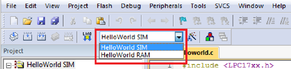
two targets as shown in Figure 1.1.
Figure 1.1: Keil IDE: List of Targets
•The HelloWorld SIM target is to use simulator to debug the target with the default
memory map.
•The HelloWorld RAM target is to use the hardware ULINK/ME Cortex debugger to
debug the target. The memory map is reconfigured (see 1.2.2) to relocate everything
to RAM and a debugger initialization file (see 1.1) is required.
8
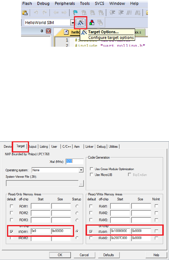
Figure 1.2: Keil IDE: Target Option Button
Execution of the HelloWorld SIM Target
Open the HelloWorld application and follow the steps listed below.
1. Click the Target Option button (see figure 1.2) to verify the following:
•the default memory map is used (see figure1.3); and
Figure 1.3: Keil IDE: Target Default Memory Map Configuration
•the simulator is used (see figure 1.4).
2. Build the HelloWorld SIM Target by pressing the Build button or F7 (see Figure
1.5).
3. Click the Start/Stop Debug Session button or press Ctrl-F5 to enter the simulator
(see Figure 1.6).
9
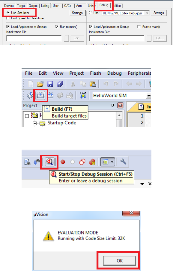
Figure 1.4: Keil IDE: Simulator Debugger Configuration
Figure 1.5: Keil IDE: Build Button
Figure 1.6: Keil IDE: Start/Stop Debug Session Button
Figure 1.7: Keil IDE: Evaluation Mode Code Size Warning Dialog Box
4. Click OK when you are prompt with the code size limit of 32K in evaluation mode
warning dialogue box (see Figure 1.7).
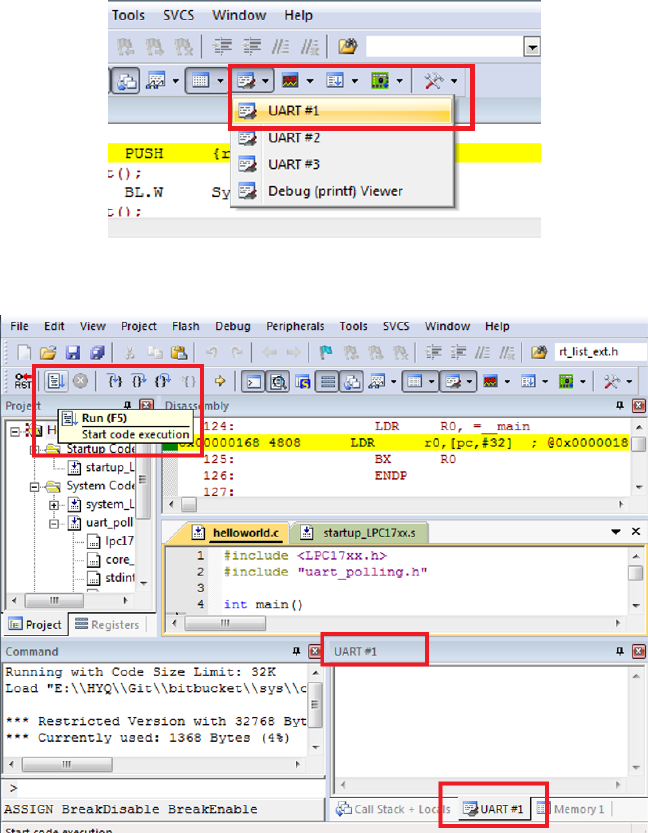
5. Choose UART#1 from the Serial Windows button (see Figure 1.8). You will see the
UART#1 window shown up at the bottom right part of the screen (see Figure 1.9).
6. Click the Run button or press F5 key to execute the program under simulator (see
10
Execution of the HelloWorld RAM Target
Open the HelloWorld application and follow the steps listed below.
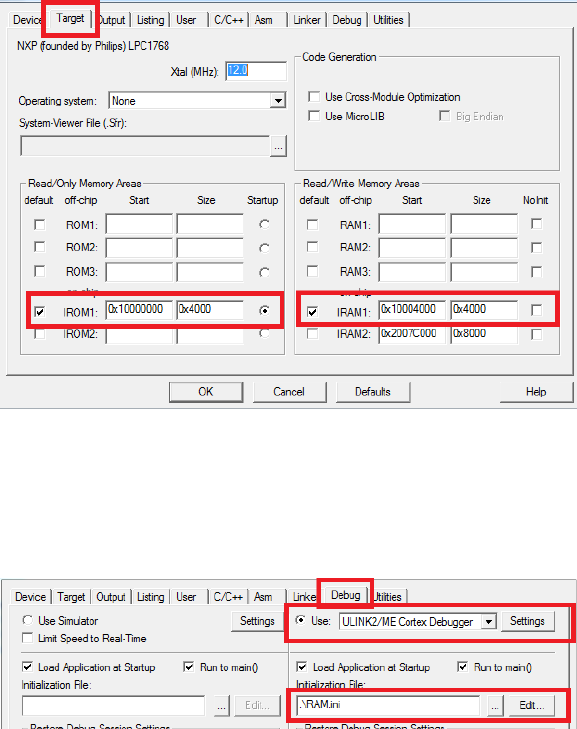
1. Click the Target Option button (see figure 1.2) to verify the following:
•the in-memory exectuion memory map is used (see figure1.10); and
Figure 1.10: Keil IDE: Target In-Memory Execution Memory Map Configuration
•the ULINK2/ME Cortex Debugger is selected with a valid initialization file (see
figure 1.11).
Figure 1.11: Keil IDE: ULINK2/ME Cortex Debugger Configuration
2. Build the HelloWorld RAM Target by pressing the Build button or F7 (see Figure
1.5).
3. Start a PuTTY terminal and make sure you have the correct configuration as shown
in Figures 1.12(a) and 1.12(b).
12

(a) PuTTY Session for Serial Port Communication (b) PuTTY Serial Port Configuration
4. Click the Start/Stop Debug Session button or press Ctrl-F5 to enter a debug session
(see Figure 1.6). This target uses the hardware ULINK2/ME Cortex Debugger. Note
you should not click the Download button to load the code to the board. When you
start a debug session, the debugger initialization file (i.e. RAM.ini) will execute the
LOAD command to load the code to the board.
5. Click OK when you are prompt with the code size limit of 32K in evaluation mode
warning dialogue box (see Figure 1.7).
6. Click the Run button or press F5 key to execute the program on the board and you
should see “Hello World!” displayed on PuTTY. Note that nothing will appear in
the UART#1 window because we are not using the simulator to debug.
7. Click the Start/Stop Debug Session button or press Ctrl-F5 to exit from the debug
session (see Figure 1.6).
1.5 Real-time Executive Exercises
The Keil MDK-ARM contains the RealView Real-Time Library (RL-ARM), which has
a Real-time Executive (RTX) named RL-RTX. The RTX kernel is a real time operating
system (RTOS) that enables one to create applications that simultaneously perform mul-
tiple functions or tasks (statically created processes). Tasks can be assigned execution
priorities. The RTX kernel uses the execution priorities to select the next task to run
13
(preemptive scheduling). It provides additional functions for inter-task communication,
memory management and peripheral management.
RTX programs are written using standard C constructs and compiled with the RealView
Compiler. The RTL.h header file defines the RTX functions and macros that allow you to
easily declare tasks and access all RTOS features.
1.5.1 Manual of RL-RTX
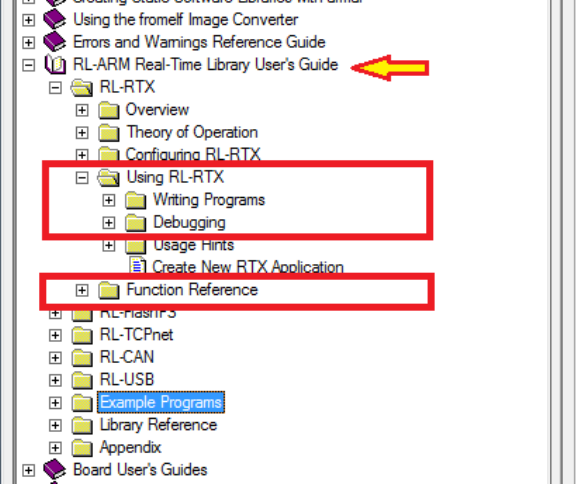
The manual of the RL-RTX is accessible through the Keil MDK-ARM Help (see Figure
1.12). The highlighted sections are highly recommended to read through.
Figure 1.12: Keil IDE: RL-RTX Manual
1.5.2 Creating a Real-time Executive Application
Overview
Our goal is to create an application that simultaneously run two tasks which output to
UART. The first task displays the value of a loop variable ievery one second. The second
task displays “Task2: Hellow World!” every three seconds. By using the task management
14

and time management functions provided by RL-RTX, we could create such an application
very easily.
Listing 1.1 shows the source code of the modified helloworld.c which now calls RTX
API functions. Two tasks are defined. A task is a function whose prototype starts with
the keyword __task. A task function normally never terminates. If a task function needs
to terminate, then os_tsk_delete_self() is required to be called. Otherwise undefined
behaviour will happen and will cost lots of your time to debug without any clue.
/**
* @file: helloworld.c
* @brief: Two simple tasks running pseduo-parallelly
*/
#include <LPC17xx.h>
#include <RTL.h>
#include <stdio.h>
#include "uart_polling.h"
__task void task1()
{
unsigned int i = 0;
for(;; i++)
{
printf("Task1: %d\n", i);
os_dly_wait(100);
}
}
__task void task2()
{
while(1)
{
printf("Task2: HelloWorld!\n");
os_dly_wait(300);
}
}
__task void init(void)
{
15

os_tsk_create(task1, 1); // task1 at priority 1
os_tsk_create(task2, 1); // task2 at priority 1
os_tsk_delete_self(); // must delete itself before exiting
}
int main ()
{
SystemInit();
uart0_init();
os_sys_init(init);
}
Listing 1.1: RTX HelloWorld C Source Code
Detailed Steps
To create an RL-RTX application for MCB1700 boards, first you need to follow the same
steps as you create a regular µVision application. We already have a HelloWorld ap-
plication from the warm-up exercises. To modify this already created application into
an RL-RTX application, replace the helloworld.c with the modified one as shown in
Listing1.1, which use some RL-RTX API functions.
Next you will need to do three extra steps to make the application an RTX application
and the steps are:
1. To include the RTX Library header file RTL.h in the source code.
All the RTX kernel APIs are listed in RTL.h file which is by default located at
ARM\RV31\INC\ under the Keil software installation directory. You will need to in-
clude this file in your C file before you can call any RL-RTX API functions. Adding
the following line in your source code helloworld.c after the #include <LPC17xx.h>
line:
#include <RTL.h>
2. To tell the linker to link with the RTX library.
The RL-RTX kernel comes in the form of a pre-compiled library, which by default is
located at ARM\RV31\LIB\ under the Keil software installation directory. In order to
16
use the functions in this library, one needs to link the application with RTX kernel
library. This is achieved by specifying “RTX kernel” under Operating system in the
target option setting (see Figure 1.13).
Figure 1.13: Keil IDE: Using RTX Kernel
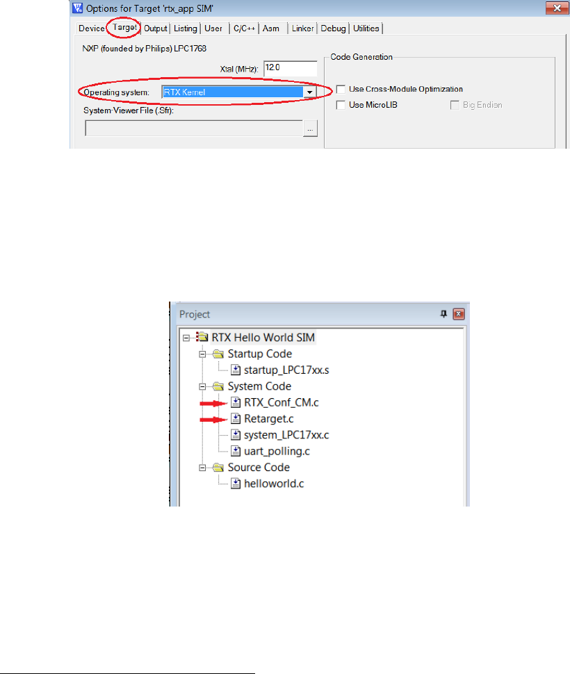
3. To configure the RTX kernel by modifying source code of RTX_Conf_CM.c.
Figure 1.14 is the HelloWorld RTX project setup. Comparing it with the non-RTX
µVision HelloWorld application used in the warm-up exercises, RTX_Conf_CM.c and
Retarget.c1are two new files added to the project.
Figure 1.14: Keil IDE: RTX HelloWorld Project Files
The RTX_Conf_CM.c is for RTX kernel configuration such as how big the stack a task
needs, how long the time slice should be and what is the CPU frequency et. al..
The configuration is at source code level through the Configuration Wizard in the
µVision editing window (see Figure 1.15). Special attention should be paid to the
following setting to avoid hard to debug problems:
1These two files are located in the lab1 starter/Startup directory on GitHub. You should copy these
two files to the HelloWorld/src directory where the source code files of the project are located and then
add the copied files to the project group. Directly adding these two files to the project group from the
starter/Startup folder is not a good programming practice.
17
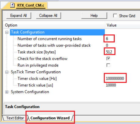
•Do remember to configure the CPU speed to 100 MHZ through the RTX_Conf_CM.c
configuration wizard. Otherwise you will get wrong timing result.
•The default stack size is 200 bytes. Using printf() family functions such as
sprintf() can easily cause a stack overflow. Normally 512B would be sufficient.
If you are not tight on memory, 1 KB is safer.
•The number of concurrent running tasks is the maximum active tasks the appli-
cation is allowed to have. If the code has more active tasks than this number,
your application will run into undefined hard to debug behaviour.
Figure 1.15: Configuring RTX Kernel
The Retarget.c is not RTX application specific. This file implements the low-level
I/O functions that higher level I/O functions in C library such as printf() needs.
With this file, your RTX task can call C library functions such as printf() and the
output will appear in UART0.
Build the project and execute it both inside the simulator and on the actual board.
Note that the simulator runs the application a lot slower than the actual board. One wall
clock second is about one minute inside the simulator.
1.5.3 Building an RL-RTX Library for Cortex-M3
The ARM RL-RTX kernel comes with source code. You can modify the source code and
build your own modified ARM RL-RTX Library. The simplest way to do this is to make a
18
copy of the existing RTX library project for Cortex-M processors and then start to make
modifications. Here are detailed steps:
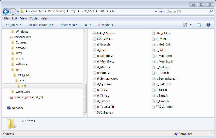
1. Create a folder to hold your RTX Cortex-M3 library project. Let’s name the folder
RTX_CM3.
2. Go to ARM\RL\RTX under the Keil software installation directory and copy the fol-
lowing items to your RTX Cortex-M3 library project folder of RTX_CM3. Note you
need to preserve the original directory structure when you make the copy of all the
files listed below. Note that the CM directory needs to be put under SRC directory.
•RTX_Lib_CM.uvopt
•RTX_Lib_CM.uvproj
•SRC\CM
Figure 1.16: RTX Library Source Files for Cortex-M3
3. Start working on your own copy of the RTX library from now on. Remove HAL_CM1.c
and HAL_CM4.c files that are under RTX_CM3\SRC\CM directory (see figure 1.16). These
two files are for Cortex-M1 and Cortex-M4 processors which is not the hardware in
the lab.
19
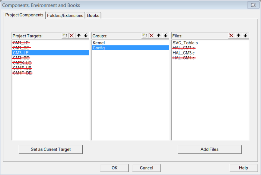
Figure 1.17: RTX Library Project Components for Cortex-M3
4. Open RTX_Lib_CM.uvproj under your RTX_CM3 directory that you newly created.
Right click the CM3_LE target under the project window to bring up the menu and
click “Manage Components”. You will only need the CM3_LE target, which supports
NXP1768 on MCB1700 boards. Remove all other targets in the Project Targets
window. You also need to remove the HAL_CM1.c and HAL_CM4.c files in the Files
window (see Figure 1.17).
5. Click the Target Option button and activate the C/C++ tab. Set the optimization to
Level 0 (-O0) in the Language / Code Generation section (see Figure 1.18). Turning
off the compiler optimization will allow the debugger to provide useful debugging
information during the development.
6. Click the Build button to build the library. You will notice a .lib file is created under
CM3_LE folder and this is the RTX library for Cortex-M3 processor you just built.
The RTX library cannot be executed. You will need to create an RTX Application
which calls some of the functions inside the RTX library file in order to see the effect
of the library. We will further discuss how to do this in Section 1.5.5.
20
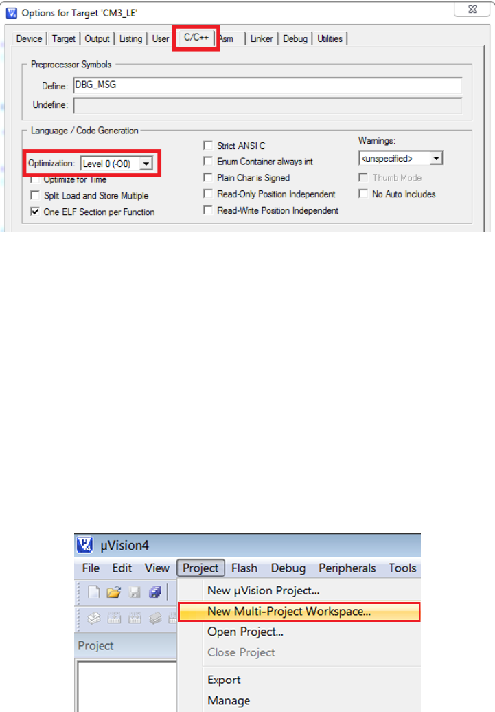
Figure 1.18: RTX Library Project Optimization Level Setting
1.5.4 Creating a Multi-project Workspace
We now have two RTX related projects. One is the RTX HelloWorld application that
uses the RL-RTX built by ARM. The second is the self built RTX library for Cortex-M3
processors. We would like to create a workspace so that we can work on these two projects
in the same IDE window. The steps are as follows.
1. Put the HelloWorld RTX application and the self-built RTX library for Cortex-M3
project in the same folder.
2. Click Project →New Multi-Project Workspace (see Figure 1.19).
Figure 1.19: Keil IDE: Create New Multi-Project Worksapce
A new window appears to ask you to give a name for the multi-project workspace and
let’s call it helloworld_rtxlib.uvmpw (see Figure 1.20) and press the Save button.
21
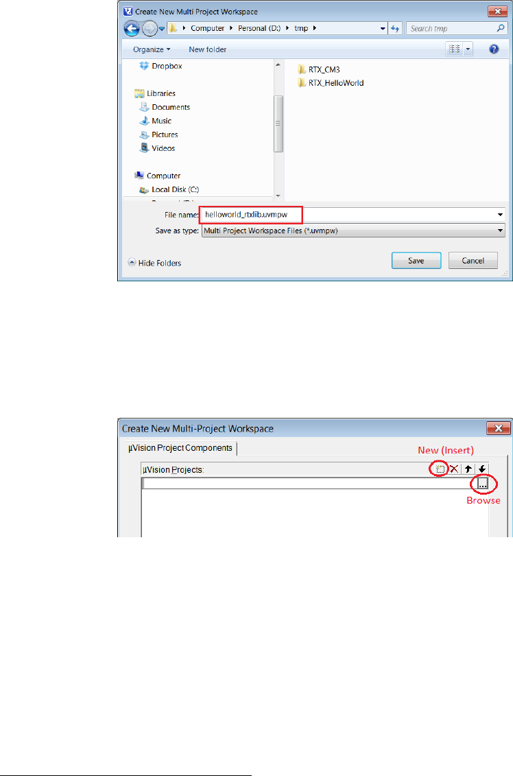
Figure 1.20: Keil IDE: Naming a New Multi-Project Worksapce
3. A new dialogue box will pop up to ask you add µVision projects into the workspace.
Click the New button to start adding a project and click the Browse button to select
a project file (see Figure 1.21).
Figure 1.21: Keil IDE: Adding a µVision Project into Worksapce
Add the RTX_CM_Lib.uvproj to the workspace first(see Figure 1.22). Similarly, add
the RTX_HelloWorld.uvproj to the workspace. Click the OK button to finish adding
projects into the workspace.
4. Two projects appear under the Project Window (see Figure 1.23. Click the Batch
Build button (see Figure 1.23 to bring up the Batch Build window.
Select all the targets you want to build in a batch (see Figure 1.24). By setting up
batch build, multiple targets can be built by a single click of the Build button inside
the batch build dialogue box2.
2Whenever you make a change in the RTX Library project, you need to rebuild the library and the
application that uses the library. So batch build will make multiple builds easy to carry out.
22
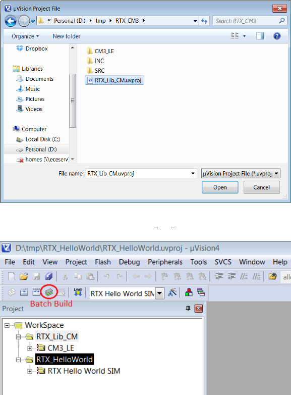
Figure 1.22: Keil IDE: Adding RTX CM Lib.uvproj into Worksapce
Figure 1.23: Keil IDE: Workspace with Two Projects
1.5.5 Making an RTX Application with a Self-built RTX Library
Having finished the workspace setup, we now start to modify the RTX HelloWorld appli-
cation so that it links with the self-built RTX Library instead of the pre-built RTX library
provided by ARM. The steps are as follows.
1. Activate the RTX_HelloWorld project by highlighting the project name and right
click. Then click the Set as Active Project (see Figure 1.25).
2. Remove the pre-built RTX library by ARM from the target option setting (see Figure
1.26).
23
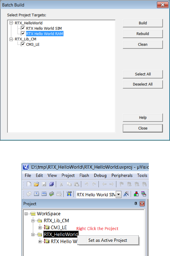
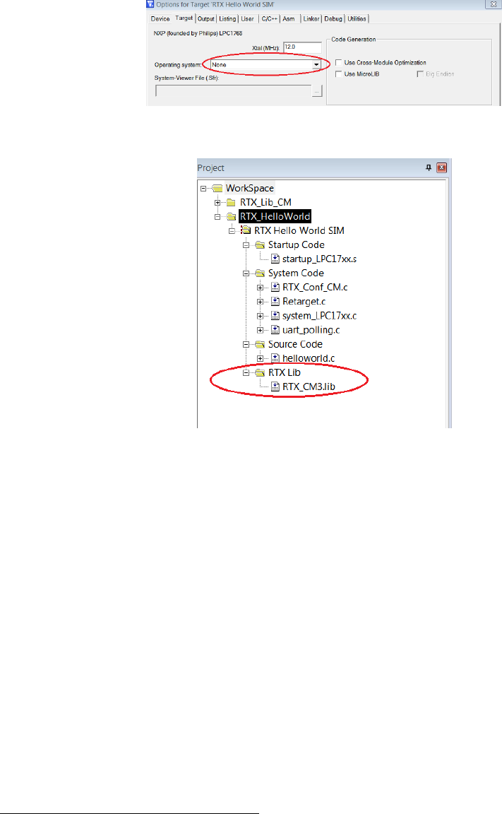
Figure 1.26: Keil IDE: Removing Linkage with Stocked RTX Library
Figure 1.27: Keil IDE: Adding Your Own RTX Library
1.6 Assignment
1.6.1 Questions
The RTX_lib.c is located at ARM\RV31\INC under the default Keil installation directory3.
The variable os_active_TCB is defined in this file and mainly used in rt_Task.c file.
The rt_TypeDef.h has the kernel data structure definitions. Read rt_TypeDef.h and
rt_Task.c files and answer the following questions.
1. Which global variable has the os_active_TCB array length information?
2. What does os_active_TCB array in RTX_lib.c contain?
3. Which global variable has the os idle task TCB information?
4. Is the TCB of the os idle task an element in the os_active_TCB?
3The default installation directory is C:\Software\Keil on ECE Nexus PCs.
25

1.6.2 Programming Project Description
The requirements of the programming project is described in this section. We will provide
more instructions on how to set up a template of the programming project in Section 1.6.3
1. Add a function to RL-RTX API to return the number of active tasks in the system.
int os_tsk_count_get (void);
A task is considered active when its state is not set to INACTIVE in the TCB. Note
that the os idle task is a valid task that you should check the state as well. You need
to use the SVC as the gateway to access the kernel data structure.
2. Write five simple tasks. One of the tasks calls the os_tsk_count_get function to
test the number of active tasks in the system returned by the function.
1.6.3 Adding a New Function to the RTX Library
The self-built RTX library for Cortex-M3 for now provides the same functionality as the
pre-built RTX Library provided by ARM for Cortex-M3 processors. In this lab program-
ming project, you are asked to add one new function to the RTX Library. This means you
need to modify the source code of the RTX library project.
The default RTL.h file is the RTX user interface. When a new RTX API function is
added to the RTX, the corresponding user level interface of the function needs to be added
to this file. However to make the newly added function easy to view, we instead will create
a new RTL_ext.h file which contains the user level interface of the newly added functions.
A good place to put this new header file will be in the directory where the RTX_CM3 library
project is resided. Let’s create a directory and name it INC. Inside this directory, create a
file named RTL_ext.h. Listing 1.2 gives the user interface of the required new function.
Then we need to create the corresponding kernel functions which does the actual work
of calculating how many tasks are not in the INACTIVE state. Since this function is
related to task management, it is natural to add the kernel function rt_tsk_count_get()
implementation in rt_Task.h and rt_Task.c files. However, for the same reason for easy
to view the changes we will make to the kernel, we will create two new kernel source code
files in the RTX_CM3\SRC\CM directory and name them as rt_Task_ext.h (see Listing 1.3
) and rt_Task_ext.c (see Listing 1.4). The rt_Task_ext.c should be added to the RTX
library project under the kernel group.
26

/**
* @file: RTL_ext.h
*/
#ifndef __RTL_EXT_H__
#define __RTL_EXT_H__
#ifdef __cplusplus
extern "C" {
#endif
typedef unsigned int U32;
#if !(__TARGET_ARCH_6S_M || __TARGET_ARCH_7_M || __TARGET_ARCH_7E_M)
/*---------------------------------------------------------------------
* Functions ARM
*-------------------------------------------------------------------*/
#else
/*---------------------------------------------------------------------
* Functions Cortex-M
*-------------------------------------------------------------------*/
#define __SVC_0 __svc_indirect(0)
/* ECE254 Comment: added for lab2 */
extern int rt_tsk_count_get(void);
#define os_tsk_count_get() _os_tsk_get((U32)rt_tsk_count_get)
extern int _os_tsk_get (U32 p) __SVC_0;
#ifdef __cplusplus
}
#endif
#endif
#endif
/* end of file */
Listing 1.2: The RTL ext.h C Source Code
/**
* @file: rt_Task_ext.h
*/
extern int rt_tsk_count_get (void);
/* end of file */
Listing 1.3: The rt Task ext.h C Source Code
27

/**
* @file: rt_Task_ext.c
*/
#include "rt_TypeDef.h"
#include "RTX_Config.h"
#include "rt_System.h"
#include "rt_Task.h"
#include "rt_List.h"
#include "rt_MemBox.h"
#include "rt_Robin.h"
#include "rt_HAL_CM.h"
#include "rt_Task_ext.h"
int rt_tsk_count_get (void) {
/* add your own code here */
/* change the following line to return the number of active tasks */
return 0;
}
/* end of file */
Listing 1.4: The rt Task ext.c Template C Source Code
1.6.4 Using the Newly Created RTX Function
To use the newly created function, you will need to include the newly created RTL_ext.h
header file in the C source code. Then a task can call this function to obtain the number
of tasks that are not in INACTIVE state. The following is an example code excerpt.
#include "../../RTX_CM3/INC/RTL_ext.h"
//...
__task void task1()
{
int num;
while (1) {
// ...
num = os_tsk_count_get();
printf("number of tasks: %d.\n", num);
// ...
}
}
28

Points Description
3 Answers to lab assignment questions
2 Building a multi-project workspace that contains
a self-built RTX and an application that links with
this RTX
3 Implementation of os_tsk_count_get
2 Implementation of testing tasks to test
os_tsk_count_get()
Table 1.1: Lab1 Marking Rubric
1.7 Deliverables
1.7.1 Pre-lab Deliverables
There is no pre-lab deliverable.
1.7.2 Post-lab Deliverables
Submit a compressed archive file that contains the following:
1. Answers to questions in Section 1.6.1.
2. The entire folder that contains the multi-project workspace where the modified RTX
library project and the RTX application project source code to solve the programming
project (see Section 1.6.2) are located. Include a README (any useful instructions
for evaluation TA) in the folder.
Name the file lab1_Gid.zip, where id is your two digit Group ID, and submit it to
Lab1 Dropbox in Learn.
1.8 Marking Rubric
Table 1.1 shows the rubric for marking the lab.
29
Lab 2
Task Management in ARM RL-RTX
2.1 Objective
This lab is to learn about, and gain practical experience in ARM RL-RTX kernel program-
ming. In particular, you will add three functions to ARM RL-RTX library. After this lab,
students will have a good understanding of:
•how to program an RTX function to read kernel task control block related data
structure; and
•how to block and unblock a task by using context switching related kernel functions.
2.2 Starter files
The lab2/starter directory in the ECE254 GitHub repository contains a template lab2
project, which is a multi-project workspace that contains one RTX library project and
one RTX application that uses the RTX library built by the first RTX library project. In
the RTX Library project there two files modified from the original ARM RL-RTX source
code so that the ret_val in TCB is changed to U32 and the corresponding assembly code
affected due to this changed is modified accordingly. It is very important that you use
these modified files rather than the original ones from ARM. These two files are
•the modified HAL_CM3.c; and
•the modified rt_TypeDef.h.
In the RTX application project, you are provided with the following code :
30
•main_task_exp.c
which has the subroutine to map a function pointer address to the function name.
2.3 Pre-lab Preparation
None
2.4 Assignment
This lab requires students to read the existing ARM RL-RTX source code and then use the
relevant kernel routines to accomplish a programming project (see Section 2.4.1). Read-
ing source code and answer the questions in Section 2.4.1 will help you to complete the
programming project.
2.4.1 Questions
Questions 1-4 are to help you finish Part A. Questions 5-10 are to help you finish Part B.
Please solve questions before you proceed with coding.
1. Read rt_get_TID() code in rt_Task.c file. Assume that a non-idle task has a task
ID of n, what is the index of this task’s TCB in the os_active_TCB array?
2. Read the rt_TypeDef.h file and answer the following questions.
•What is the purpose of the p_lnk variable in the struct OS_TCB?
•What is the purpose of tsk_stack and stack variables in struct OS_TCB?
•If you have a variable with type of struct OS_XCB *, will casting this variable
to struct OS_TCB * keep the p_lnk field?
3. Read the rt_Task.c and RTX_lib.c files and answer the following question.
•What is the purpose of variables mp_tcb and mp_stk?
You may want to search the entire source code to further explore how these variables
are set and used (see Figure 2.1).
4. Read Section C.2.3 and study rt_init_stack() and rt_get_PSP() functions source
code in HAL_CM3.c file and answer the following questions.
31
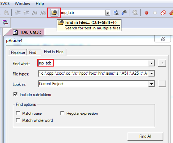
Figure 2.1: Keil IDE: Search
•Which registers are saved on the task stack?
•Which bits of which global variable contain the default task stack size in bytes?
•How to determine the memory address of the first item that is pushed onto a
task stack?
•For a task that is not in RUNNING state, how to determine the memory address
of the last item that is pushed onto its task stack (i.e. the top of the stack)?
•For a task that is in RUNNING state, how to determine the memory address of
the last item that is pushed onto its task stack (i.e. the top of the stack)?
5. Read the RTX Library Reference in the Keil IDE Help (see 1.12) and answer the
following questions:
•In an RTX application, how to declare a memory pool named "mympool" that
has 20 blocks of memory with block size of 12 bytes?
•Write one line of code to initialize the "mympool".
•What is the corresponding kernel function of _alloc_box()?
•What is the corresponding kernel function of _free_box()?
6. Read the rt_TypeDef.h file. What is the purpose of ret_val in the struct OS_TCB?
32

7. Read the rt_List.c file and answer the following questions:
•What does the rt_put_prio() function do?
•What does the rt_get_first() function do?
You may want to further explore other functions in the rt_List.c file.
8. Read the rt_Task.c file and answer the following questions:
•What does the rt_block() function do?
•What does the rt_dispatch() function do?
9. How to set the return value of a function becomes a bit tricky when context switching
is involved. One such example is os_mbx_wait() function. This function will return
OS_R_MBX if the task has waited until a message was put in the mailbox (i.e. the task
was blocked to wait for a message to arrive and then unblocked when the message
arrives). Read the rt_Mailbox.c file and find the lines where the return value
of OS_R_MBX is set. Why the corresponding kernel function rt_mbx_wait() does
not have a line to set the return value to OS_R_MBX? You may skip the code in
functions isr_mbx_receive() and rt_mbx_psh() for the purpose of completing this
assignment.
10. To block a task, you will need to create a queue that the blocked tasks can stay.
There are two global queues for now in the kernel and they are os_rdy and os_dly.
What data structure do these two queues use?
2.4.2 Programming Project
Part A
To get familiar with kernel source code, a good start is to write a function to retrieve
a kernel data structure. In this assignment, you are to implement a primitive to obtain
the task status information from the RTX at runtime given the task id. The function
description is as follows.
•OS_RESULT os_tsk_get (OS_TID task_id, RL_TASK_INFO *buffer)
The primitive returns information about a task. The system call returns a rl_task_info
structure , which contains the following fields:
33

typedef struct rl_task_info {
U8 state; /* Task state */
U8 prio; /* Execution priority */
U8 task_id; /* Task ID value for optimized TCB access */
U8 stack_usage; /* Stack usage percent value. eg.=58 if 58% */
void (*ptask)(); /* Task entry address */
} RL_TASK_INFO;
The state field describes the state of this task and is one of:
INACTIVE
Tasks which have not been started or tasks which have been deleted are in
INACTIVE state.
READY
Tasks which are ready to run are in the READY state.
RUNNING
The task that is currently running is in the RUNNING state. Only one task at a
time can be in this state.
WAIT_DLY
Tasks which are waiting for a delay to expire are in the WAIT_DLY state. The
task is switched to the READY state once the delay has expired.
WAIT_SEM
Tasks which are waiting for a semaphore are in the WAIT_SEM state. When the
token is obtained from the semaphore, the task is switched to the READY state.
WAIT_MUT
Tasks which are waiting for a free mutex are in the WAIT_MUT state. When a
mutex is released, the task acquires the mutex and switches to the READY state.
WAIT_MBX
34

Tasks which are waiting for a mailbox message are in the WAIT_MBX state. Once
the message has arrived, the task is switched to the READY state. Tasks waiting
to send a message when the mailbox is full are also put into the WAIT_MBX state.
When the message is read out from the mailbox, the task is switched to the
READY state.
WAIT_MEM
Tasks which are waiting for memory are in the WAIT_MEM state. Once the mem-
ory is available, the task is switched to READY state. The os_mem_alloc()
function is used to place a task in WAIT_MEM state.
These states are described in details in the RL-ARM Real-Time Library User’s Guide
→Theory of Operation→Task Management section except for WAIT_MEM state. Read
Part B regarding how tasks are blocked upon calling os_mem_alloc() function.
The prio field describes the priority of this task.
The task_id field describes the id of task assigned by the OS.
The stack_usage describes how much stack space is used by this task. The value is
the percent value. For example, if 58% of this task stack is used, stack_usage is set
to 58.
The ptask field describes the entry address of this task function.
The function returns OS_R_OK on success and OS_R_NOK otherwise.
Part B
You are to write two memory management RTX functions to manage a memory pool
for tasks. You may assume there is only one user-defined memory pool in the system.
The memory pool is declared by _declare_box() and further initialized by _init_box(),
which are existing RTX functions.
The function you are going to add are described as follows.
•void *os_mem_alloc (void *box_mem)
The primitive allocates a fixed-size of memory to the calling task from the memory
pool pointed by box_mem and returns a pointer to the allocated memory. When there
is not enough memory available, the calling task is blocked until enough memory
35

becomes available. If several tasks are waiting for memory and memory becomes
available, the highest priority waiting task will get the memory. Within the same
priority waiting tasks, the one that waits longest will get the memory.
•OS_RESULT os_mem_free (void *box_mem, void *box)
The primitive returns a memory block whose address is box to memory pool with
starting address of box_mem. Note the box is allocated by os_mem_alloc from the
meory pool of box_mem. It returns OS_R_OK on success and OS_R_NOK otherwise.
If several tasks are waiting for memory and memory becomes available, the highest
priority waiting task will get the memory and be unblocked. Preemption may happen
if the unblocked task has higher priority than the task that calls this function to free
up the memory.
Create a set of testing tasks to demonstrate that you have successfully implemented
the required functions in Parts A and B. Your test tasks should do the following tests.
•A task periodically prints task status of each task in the system.
•A task can allocate a fixed size of memory.
•A task will get blocked if there is no memory available when os_mem_alloc() is
called.
•A blocked on memory task will be resumed once enough memory is available in the
system.
•Create a testing scenario that multiple tasks with different priorities are all blocked
waiting for memory. When memory becomes available, test whether it is the highest
priority task that waits the longest that gets the memory first.
2.4.3 Source Code File Organization Convention
To make the changes you have made to the RTX library obvious to the grading teaching
assistant. We would like to impose the following source code file organization convention.
•The newly added RTX function user interface is in RTL_ext.h file.
•The corresponding kernel function of an os_xxx() function should be named as
rt_xxx() in the kernel space.
36
•All extended task management related kernel functions are in rt_Task_ext.[ch]
files.
•All extended memory management related kernel functions are in rt_MemBox_ext.[ch]
files.
•When you want to add extra code to an existing rt_xxx.[ch] file, create new
rt_xxx_ext.[ch] files instead and put the code in these new files.
•For any miscellaneous source code that you cannot figure out where to put, create
rt_misc_ext.[ch] files and put the code in these files.
•You should try to avoid changing existing RTX library source code. If you are not
able to do so, then write detailed comments in the existing source code where you
make the changes and what the changes are. The comments should look like the
following:
/* Start: ECE254 Lab2 Changes by GroupID */
/* Detailed comments about the changes ...*/
// Changed source code appear here
/* End: ECE254 Lab2 Changes by GroupID */
2.4.4 Third-party Testing
We will provide a third-party testing RTX application to test the implementation of the
newly added os_* functions in the RTX library. The third-party testing application make
application level function calls to the RTX library you will build. Your own testing appli-
cation will not be tested by the third-party testing.
2.5 Deliverables
2.5.1 Pre-Lab Deliverables
None
37
2.5.2 Post-Lab Deliverables
Submit a compressed archive file that contains the following:
1. A lab2_QA.txt file which contains answer to questions in Section 2.4.1.
2. Your entire multi-project workspace to solve the programming project. Do not hard
code the absolute path of file names in your project files including but not limited to
source code, the RAM.ini file or the .uvproj files. Always use relative paths so that
the grading TA will be able to compile your project.
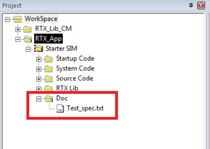
3. A test description file to describe what each testing task does. Name the file Test_spec.txt.
This file is added to the RTX application project as shown in Figure 2.2.
Figure 2.2: Keil IDE: Location of Test Specification File.
4. A README file to describe what you have submitted and how to build and run your
project(s).
Name the file lab2_Gid.zip, where id is your two digit Group ID, and submit it to Lab3
Dropbox in Learn.
2.6 Marking Rubric
Table 2.1 shows the marking rubric for this lab.
38

Points Sub-total Description
20 Answers to questions
30 Part A Implementation
15 os_tsk_get function implementation
10 self-implemented testing cases to test Part A API
function
5 Third-party testing case result
50 Part B Implementation
20 os_mem_alloc and os_mem_free implementation
20 self-implemented testing cases to test the correct-
ness of Part B API functions
10 Third-party testing case result
Table 2.1: Lab2 Marking Rubric
39

Lab 3
Inter-task Communication and
Concurrency
3.1 Objective
This lab is to learn about, and gain practical experience in inter-task communication and
concurrency control in a general Linux environment. A task can be implemented as a
process or a thread. Tasks communicate by message passing or shared memory in this
lab project. For message passing, tasks do not share any memory. The operating system
message passing facility takes care of shared memory access within its kernel space. For
shared memory, tasks need to take care of the shared memory conflicting operations. The
operating system provides concurrency control facility such as semaphore and mutex library
calls.
The choice of implementing a task as a process or a thread and the inter-task com-
munication by message passing or shared memory results in different performance. This
lab compares the performance of inter-process communication by message passing with
inter-thread communication by shared memory with concurrency control 1by solving a
producer consumer problem.
After this lab, students will have a good understanding of, and ability to program with
•the fork() and exec() system calls, and their use for creating a new child process
on the Linux platform;
1Sharing data among threads in a general Linux environment is straight forward because threads share
the same memory [6]. The challenging part of sharing memory is the concurrency control to avoid race
conditions.
40
•the wait() family system calls, and their use to obtain the status-change information
of a child process; and
•the POSIX message queue facility (<mqueue.h>) on the Linux platform for inter-
process communication.
•the pthread pthread_create() and pthread_join() to create and join threads; and
•the pthread sem_init(),sem_post() and sem_wait() library calls for inter-thread
communication concurrency control in a general Linux environment.
3.2 Starter Files
The starter file is on GitHub at http://github.com/yqh/ECE254/ under directory lab3/starter.
It contains one sub-directory:
•ALP/: sample code of fork() from [6];
•cmd_arg: sample code of capturing command line input arguments;
•gettimeofday/: sample code of using gettimeofday();
•mqueue/: sample code of using POSIX queue functions; and
•tools/: a shell script to compute statistics of timing data.
3.3 Pre-lab Preparation
1. Read Chapter 3.
2. Read Section 3.2.2 about fork() and exec() and Sections 3.4.1 and 3.4.2 about
wait() in [6].
3. Complete the example code of wait() on page 57 in [6] by including necessary header
files and compile it. Execute it to examine the difference of the output from the
output of the code in Listing 3.4.
4. Read the man page (section 7) of mq_overview
(http://linux.die.net/man/7/mq_overview).
5. Build and execute the sample code in the mqueue sub-directory from the lab3 starter
files.
41

6. Read Linux man page of semaphore overview.
man 7 sem_overview
7. Read Sections 4.1, 4.4 and 4.5 about thread programming in [6].
8. Read supplementary materials regarding POSIX pthread in [5]
(http://www.cs.cf.ac.uk/Dave/C/node29.html#SECTION002940000000000000000).
3.4 Assignment
Solve the producer-consumer problem with a bounded buffer in a general Linux environ-
ment.
This is a classic multi-tasking problem in which there are one or more tasks that create
data (these tasks are referred to as “producers”) and one or more tasks that use the data
(these tasks are referred to as “consumers”) 2. We will have a system of Pproducers and
Cconsumers . Three experimental cases then exist:
•single producer/single consumer;
•single producer/multi-consumer; and
•multi-producer/single consumer.
The producer tasks will together generate a fixed number, N, integers in total. Each
producer will generate a set of integers, one at a time. Since there is more than one
producer, and we do not want the producers to have to coordinate their actions since that
would require additional inter-task communication, we will adopt the following approach:
each producer has an identity number, id, from 0to P-1. The producer with identity
number id will produce the integers isuch that i%P == id. For example, if there are
7producers, producer number 3will produce the integers 3,10,17,. . . . Each time a
new number is created, it is placed into a fixed-size buffer, size Bintegers, shared with the
consumer tasks. When there are Bintegers in the buffer, producers stop producing.
Each consumer is likewise given an integer identity, cid, from 0to C-1. Each consumer
task reads the integer out of the buffer, one at a time, and calculates the square root of the
2If it helps, you can think of the producer as a keyboard device driver and the consumer as the
application wishing to read keystrokes from the keyboard; in such a scenario the person typing at the
keyboard may enter more data than the consuming program wants, or conversely, the consuming program
may have to wait for the person to type in characters. This is, however, only one of many cases where
producer/consumer scenarios occur, so do not get too tied to this particular usage scenario.
42
integer. When the square root of the integer is itself an integer, the consumer prints out
its identity, the original integer taken from the buffer, and the value of the square root on
the terminal screen (in Linux). For example, if there are 6 consumers and consumer with
cid = 3 read the value 16 from the buffer, it will display 3 16 4.
Given that the buffer has a fixed size, B, and assuming that N > B, it is possible for the
producers to have produced enough integers that the buffer is filled before any consumer
has read any data. If this happens, the producer is blocked, and must wait till there is at
least one free spot in the buffer.
Similarly, it is possible for the consumers to read all of the data from the buffer, and
yet more data is expected from the producers. In such a case, the consumer is blocked,
and must wait for the producers to deposit one or more additional integers into the buffer.
Further, if any given producer or consumer is using the buffer, all other consumers and
producers must wait, pending that usage being finished. That is, all access to the buffer
represents a critical section, and must be protected as such.
The program terminates when the consumers have read all Ncharacters from the pro-
ducers and finish displaying all square roots that are integers. Note that there is a subtle
but complex issue to solve: there are multiple consumers that are reading from the buffer,
and thus a mechanism needs to be established to determine whether or not some consumer
has read the last integer.
Question: Is there a similar problem for the producers to deal with, or is their situation
simpler?
Requirements
Let Nbe the number of integers the producers should produce in total, Bbe the buffer size,
Pbe the number of producers and Cbe the number of consumers. The producer consumer
system is called with the execution command:
./produce <N> <B> <P> <C>
The command will execute per the above description and will then print out the time
it took to execute. You should measure the time before you create the first process/thread
and the time after the last integer is consumed and consumers finish displaying all received
integers with perfect square roots. On Linux, use gettimeofday() for time measurement
and terminal screen for display. Thus your last line of output should be something like:
System execution time: <whatever the result is>
43
For a set of given (N,B,P,C) tuple values, run your application and measure the time
it takes. Note for a give value of (N,B,P,C), you need to run multiple times to compute
the average execution time in a general Linux environment.
Compare the performance of multi-process communication by message queue with
multi-thread communication by shared memory.
1. Implement each producer/consumer task as a process. Use message queue as the
bounded buffer for inter-task communications. You start your program with one
process which then forks multiple producer processes and multiple consumer pro-
cesses. Note that shared memory access is taken care of by the operating system
message passing facility. However, kernel memory is finite, and thus there cannot be
an unbounded number of messages outstanding; at some point the producer must
stop generating messages and the consumer must consume them, otherwise the ker-
nel’s memory will be completely consumed with messages, blocking the sender from
further progress. What is needed, therefore, is to set up the correct queue size. When
the queue is full, the producer is blocked by the system and cannot continue to send
messages until a message is consumed.
2. Create a process with a fixed buffer size in which producers and consumers are threads
within the process and the buffer is a shared global data structure such as a circular
queue that all threads share access to. Note that shared memory access needs to be
taken care of at the application level. The POSIX thread semaphore and mutex are
to be used for concurrency control.
A Sample Program Run
[ecelinux1:]./produce 20 2 1 3
0 0 0
2 1 1
2 4 2
2 9 3
1 16 4
System execution time: 0.000642 seconds
Note that due to concurrency, your output may not be exactly the same as the sample
output above. Also depending on the implementation details and the platform where the
program runs, the sample system execution time is only for illustration purpose. The exact
system execution time value your program produces will be different than the one shown
in the sample run.
44
3.5 Deliverables
3.5.1 Pre-lab Deliverables
There is no pre-lab deliverable for this lab.
3.5.2 Post-lab Deliverables
Submit a compressed archive file that contains the following:
1. A directory named src, where it contains the source code and a README which gives
build instructions.
2. A lab report named lab3_rpt.pdf which contains the following items.
•Timing analysis for Linux environment
–Two tables that show the average timing measurement data for the (N,B,P,C)
values shown in Table 3.1 for a general Linux environment. One table is
for the timing result by the approach of inter-process communication with
message queue. Another table is for the timing result by the approach of
inter-thread communication with shared memory. Note that for each row
in the table, you need to run the program X(We recommend the value of X
to be 500.) times and compute the average time.
–Given (N,B,P,C) = (398, 8, 1, 3), run your program Xtimes (i.e. X=500)
on Linux platform. Present the average timing measurement data and its
standard deviation.
–Compare the timing results of multi-thread with shared memory and multi-
process with message queue. Discuss the advantages and disadvantages of
these two approaches to solve the same problem.
•Add an appendix in the report which contains your source code of the producer
and consumer well as any other routine that create these processes/tasks. Note
that you are required to comment the code appropriately so that any other
programmer can follow your algorithms and logic.
3.6 Report Marking Rubric
The Rubric for marking the submitted source code and report is listed in Table 3.2.
45
N B P C Time
100 4 1 1
100 4 1 2
100 4 1 3
100 4 2 1
100 4 3 1
100 8 1 1
100 8 1 2
100 8 1 3
100 8 2 1
100 8 3 1
398 8 1 1
398 8 1 2
398 8 1 3
398 8 2 1
398 8 3 1
Table 3.1: Timing measurement data table for given (N, B, P, C) values.
Points Sub-Points I Sub-Points II Description
20 Source Code
5 Code compilation
15 Correct implementation of the algo-
rithm and execution gives the expected
results
30 Report
30 Timing measurement results of
ecelinux
12 Average timing measurement results
6 Average system execution time mean
and standard deviation results given
(N,B,P,C) =(398,8,1,3).
12 Discussion of the advantages and dis-
advantages of POSIX queue among
processes and shared memory among
threads
Table 3.2: Lab3 Marking Rubric
46
Lab 4
Memory Management
4.1 Objective
This lab is to learn about and gain practical experience in memory allocation strategy
implementation and to do some evaluation on the merits of these algorithms. You will
implement two memory allocation algorithms: best fit and worst fit, and perform analysis
to determine which is better. This lab is to be completed on a Linux platform. After this
lab, students will have a good understanding of the strength and weaknesses of dynamic
memory allocation algorithms and the ability to manage a limited resource (memory) in
an efficient way.
4.2 Starter Files
The starter file is on GitHub at http://github.com/yqh/ECE254/ under lab4/starter.
It contains the following files:
•main_test.c: a code template file for writing testing cases;
•Makefile: a sample makefile;
•mem.h: the memory management routine interface file; and
•mem.c: the source code template file to be completed by students.
4.3 Pre-lab Preparation
•Review the algorithms of best fit and worst fit in lecture notes.
47

4.4 Assignment
There is a programming project and a report which documents the data structure and
algorithms of the programming project and contains analysis of the outcome of the two
allocation algorithms with experimental data.
4.4.1 Programming Project
You are to implement two memory allocation algorithms: best fit and worst fit. For
each allocation algorithm, you will first implement a memory initialization function, which
requests a chunk of free memory dynamically from the system to be managed by different
allocation algorithms. Then you will implement an allocation function and a de-allocation
function. One utility function will also be implemented to help analyze the efficiency of
allocation algorithm and its implementation. Then, you will write a number of tests to
test the correctness of your implementations. Finally, you will write an analysis on the
strengths and weaknesses of the two different allocation algorithms.
Description of Functions
The specification of each function to be implemented are described below:
•Memory initialization functions:
NAME
best_fit_memory_init,worst_fit_memory_init - Initialize dynamic memory
to be managed
SYNOPSIS
#include "mem.h"
int best_fit_memory_init(size_t size);
int worst_fit_memory_init(size_t size);
DESCRIPTION
These functions initialize the system with a single block of memory. The name
of the function indicates the allocation algorithm to be used. They will always
initialize the system as if no memory has been allocated (i.e., all memory is free).
The input parameter size is the memory size in bytes.
48

You are to use the malloc() function inside the initialization function to acquire
a chunk of memory of size bytes and then initialize your own memory allocator
data structure based on the memory allocation algorithm. Note that malloc()
can only be used in the initialization function implementation once to request
the memory to be managed by your allocator and de-allocator from the system.
It should not be used in other places in the code. Instead, you need to implement
your own version of allocator without the need of calling malloc() again.
You are responsible for designing and implementing the structures used to track
what memory is currently allocated and what is free. Any memory you use
for this will be inside the block of memory that the allocation algorithms are
responsible for managing. The space your structures are needed to maintain
un-allocated (free) memory is defined as free space. There is a trade off to be
made between space and speed. The more space your structures require, the less
space is available for allocator to return to users. On the other hand, larger data
structures may result in faster operations, if the data structures are efficient.
Having different memory initialization functions for different memory allocation
algorithm gives you the possibility of using different data structures for different
memory allocating algorithms. This does not, however, imply you must use
different data structures for different algorithms. It is possible your algorithms
may use a common data structure. It is your decision.
RETURN VALUE
These functions return 0on success and -1 on failure. An example cause of
failure is the size value is too small.
•Allocation functions:
NAME
best_fit_alloc,worst_fit_alloc - Allocate dynamic memory
SYNOPSIS
#include "mem.h"
void *best_fit_alloc(size_t size);
void *worst_fit_alloc(size_t size);
DESCRIPTION
These are two allocation functions. The name of the function indicates the
49

allocation algorithm to be used. 1The input parameter size in each allocator
is the number of bytes requested from the allocator. Each allocator then returns
the starting address of a block of memory of the appropriate size. The memory
address should be four bytes aligned. Memory requests may be of any size from
one byte all the way up to the full size of memory given in the initialization
function. For a request for Nbytes, return a memory block of (N+δ) bytes,
where δ= 0,1,2,3, and (N+δ) is a multiple of four. Should δ > 0, the additional
space is just internal fragmentation which may be ignored (and the user will not
be told).
If for some reason the memory request cannot be satisfied, such as there being
insufficient available memory, a pointer to 0or NULL should be returned. For
example, a request of zero byte will return NULL. Recall that the space your
structures are needed to maintain un-allocated (free) memory is defined as free
space. One subtle point is that because the data structures for managing the
memory is counted into the total size of memory initialized, the actual maximum
size that is available to allocate to user is the size of memory initialized minus
the space consumed by the memory management data structures. Assuming the
system is initialized with Nbytes, an allocation request of Nbytes will return
NULL, for the system requires some space, say X(X > 0) byte(s) to manage the
memory. Similarly, assuming the biggest free memory block has a size of Mbytes,
then a request of Mbytes may return NULL, since your data structure choice
may require new space of X(X > 0) byte(s) to manage these Mbytes.
RETURN VALUE
These functions return a pointer to the allocated memory or NULL if the request
fails.
•Deallocation functions:
NAME
best_fit_dealloc,worst_fit_dealloc - Free dynamic memory
SYNOPSIS
#include "mem.h"
void best_fit_dealloc(void *ptr);
void worst_fit_dealloc(void *ptr);
1The best fit memory init() or worst fit memory init() function needs to be invoked before calling
one of these two functions.
50

DESCRIPTION
These are the de-allocation functions. The name of the function indicates the
allocation algorithm used. The best_fit_dealloc() function takes the starting
address of a block of memory returned by best_fit_alloc() and frees the block
of memory. Similarly, the worst_fit_dealloc() function takes the starting
address of a block of memory returned by worst_fit_alloc() and frees the
block of memory. If the freed memory block is adjacent to other free memory
blocks, it is merged with them immediately (i.e. immediate coalescence) and the
combined block is then re-integrated into the memory under management. You
are not required to clear the block (that is, fill the memory with zeros). If the
input parameter of best_fit_dealloc() and worst_fit_dealloc() is not an
address returned by best_fit_alloc() and worst_fit_alloc() respectively,
the behaviour of the function is undefined and is left as a free engineering choice.
Similarly, if a block is deallocated more than once, without having been allocated
in the meantime, the behaviour of the function is also undefined.
RETURN VALUE
These functions return no value.
•Utility functions:
NAME
best_fit_count_extfrag,worst_fit_count_extfrag - Count external frag-
mented memory blocks
SYNOPSIS
#include "mem.h"
int best_fit_count_extfrag(size_t size);
int worst_fit_count_extfrag(size_t size);
DESCRIPTION
These are utility functions that counts the number of free (i.e. unallocated)
memory blocks in memory that are of a size less than the input value of size.
The input value size is in bytes. The name of the function indicates the allo-
cation algorithm used.
Testing
The lab does not require the memory allocator/de-allocator to be re-entrant. In order to
test your implementation of the required functions, create a single task and let it allo-
51
cate and de-allocate memory in different ways and possibly multiple times. The provided
main_test.c file is for writing testing code. Create a set of testing scenarios to test
functions implemented and document the testing specification in the report (See 4.4.2).
Implement the tests in main_test.c file.
There is no hard requirement on what tests to be implemented. The rule of thumb
is that the tests will convince yourself that your implementation is correct. However to
provide more leads to testing ideas, you may want to consider repeatedly requesting and
then releasing and make sure no extra memory appears or no memory gets lost. The sum
of free memory and allocated memory should always be constant.
Another test you want to include is about the external fragmentation. Allocating
and de-allocating memory with different sizes and see how external fragmentation is af-
fected. The utility functions best_fit_count_exfrag() and worst_fit_count_exfrag()
are useful tools.
4.4.2 Report
Create your own experiment to compare the two allocation algorithms from the external
fragmentation point of view. Use your own experimental data to conduct an analysis and
draw a conclusion. Write the following items in a report and name it report.pdf.
•Statement of the problem to be discussed in the report;
•Descriptions of the data structure and algorithms to implement the allocation algo-
rithms;
•Testing scenario description;
•Experimental data to support comparison results; and
•The comparison conclusion.
To illustrate key algorithms, pseudocode is a good way to describe the algorithm from a
high-level point of view.
4.4.3 Third-party Testing and Source Code File Organization
We will write a third-party testing program to verify the correctness of your implementation
of the functions. We will test best fit and worst fit separately. In order to do so, we will
need to enforce certain source code file organization standard.
52
Download all the starter files and put them under a directory and name the directory
as src. Do not change the file names. Do not make any changes of the contents of mem.h
file. Do not change the existing function prototype in the given mem.c. You are allowed
to add self-defined new functions to mem.c. You are also allowed to create new .h and .c
files. The newly created .h file is allowed to be included in the mem.c file. However in
order for us to test your implementation, we require you not to include any newly created
header files in the main_test.c file. To include more default system defined header files
(i.e. include files with angle brackets) is allowed.
You should have one Makefile to build a final executable with name main_test.out.
We expect that typing command make will generate the main_test.out. Note that the
main_test.c calls the memory management functions you will implement. During testing,
the main_test.c file will be replaced by a third-party testing code with the same file name.
Using the provided template main_test.c under the starter folder to test your Makefile
before submission.
4.5 Deliverable
4.5.1 Pre-Lab Deliverables
None.
4.5.2 Post-Lab Deliverables
Create a compressed archive file that contains everything under the src directory and
report.pdf. Name the compressed file lab4_Gid.zip, where id is your two digit Group
ID, and submit to Learn Lab4 Dropbox.
4.6 Marking Rubric
The Rubric for marking the submitted source code and report is listed in Table 4.1. The
correctness of your implementation will be tested by a third-party testing program and a
minimum 10 points will be deducted if we find memory is lost or extra memory appears
after repeating allocation and de-allocation function calls. Your grade will be relative to
the amount of error the third-party testing program has identified.
53

Points Sub-Points Description
35 Source Code
5 Code compilation
25 Correct implementation of the algorithm and exe-
cution gives the expected results
5 Student provided testing implementation
15 Report
1 Statement of the problem to be discussed in the
report
5 Description of data structures and algorithms
4 Testing scenario description
3 Experimental data for comparison results
2 Conclusion
Table 4.1: Lab4 Marking Rubric
54
Part III
Development Environment Quick
Reference Guide
55

Chapter 1
Keil Software Development Tools
The Keil MDK-ARM development tools are used for MCB1700 boards in our lab. The
tools include
•µVision4 IDE which combines the project manager, source code editor and program
debugger into one environment;
•ARM compiler, assembler, linker and utilities;
•Real-Time Library which includes an RTX Real-Time Kernel with source code;
•ULINK USB-JTAG Adapter which allows you to debug the embedded programs
running on the board.
The MDK-Lite is the evaluation version and does not require a license. However it
has a code size limit of 32KB, which is adequate for your course projects. The MDK-Lite
version 4.60.0.0 1is installed on all lab computers. If you want to install the software on
your own computer, Appendix B gives detailed instruction.
1.1 Creating an Application in µVision4 IDE
To get started with the Keil IDE, the MDK-ARM Primer
http ://www.keil.com/support/man/docs/gsac/
1The latest version is 5.1.0.0. We have not fully tested the supplied sample code with this version. This
manual is based on version 4.60.0.0.
56
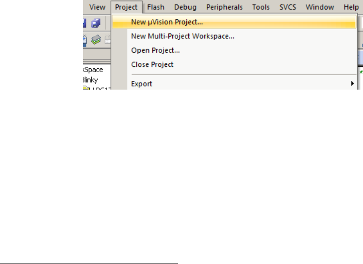
is a good place to start. We will walk you through the IDE by developing a simple
HelloWorld application which displays Hello World through the UART0 that is connected
to the lab PC. Note the HelloWorld example uses polling rather than interrupt.
1.1.1 Create a New Project
1. Create a folder named HelloWorld on your computer 2. Then create HelloWorld\src
sub-folder.
2. Copy the following files to HelloWorld\src folder from lab1\starter\Startup
folder:
•startup_LPC17xx.s
•system_LPC17xx.c
•uart_polling.c
•uart_polling.h
3. Create a new µVision project by click
•Project →New µVision Project (See Figure 1.1)
Figure 1.1: Keil IDE: Create a New Project
•Choose NXP(Founded by Philips) →LPC1768 (See Figure 1.2(a) and Figure
1.2(b))
•Answer “No” when you are asked to copy the startup code (See Figure 1.3).
1.1.2 Managing Project Components
You just finished creating a new project. One the left side of the IDE is the Project window
and expand all objects, you will see the default project setup as shown in Figure 1.4.
2The folder path name should not contain spaces on Nexus computers.
57
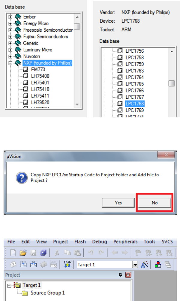
(a) Choose NXP (b) Choose LPC1768
Figure 1.2: Keil IDE: Choose MCU
Figure 1.3: Keil IDE: Copy Startup Code
Figure 1.4: Keil IDE: A default new project
1. Rename the Target
The “Target 1” is the default name of the project build target and you can rename
58
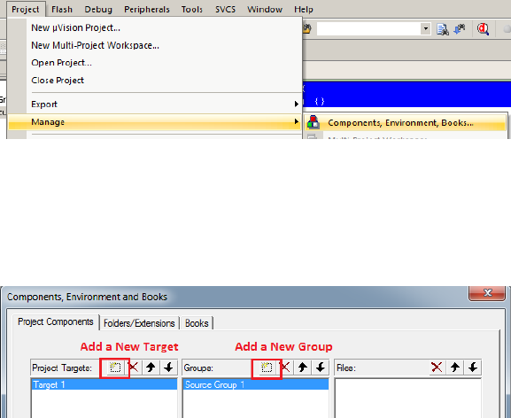
it by clicking the target name to highlight it and then click the highlighted name to
input a new target name, say “HelloWorld SIM”
2. Rename the Source Group
The IDE allows you to group source files to different groups to better manage the
source code. By default “Source Group 1” is created. You can rename the source
group by clicking the source group name to highlight it and then click again to input
a new name, say “Startup Code”.
3. Add a New Source Group
You can add new source groups to your project. Click Project →Manage →Compo-
nents, Environment, Books... (See Figure 1.5). You can now add new source groups
Figure 1.5: Keil IDE: Manage Project Components
to the project. Let’s add “System Code” and “Source Code” source groups to the
project (See Figure 1.6. Your project will now look like Figure 1.7
Figure 1.6: Keil IDE: Manage Components Window
4. Add Source Code to a Source Group
Now add system_LPC17xx.c to System Code group by double clicking the source
group name and choose the file from the file window. Double clicking the file name
will add the file to the source group. Or you can select the file and click the “Add”
button at the lower right corner of the window (See Figure 1.8).
Similarly, add uart_polling.c to System Code group and startup_LPC17xx.s to
Startup Code group. Your project will now look like Figure 1.9.
59
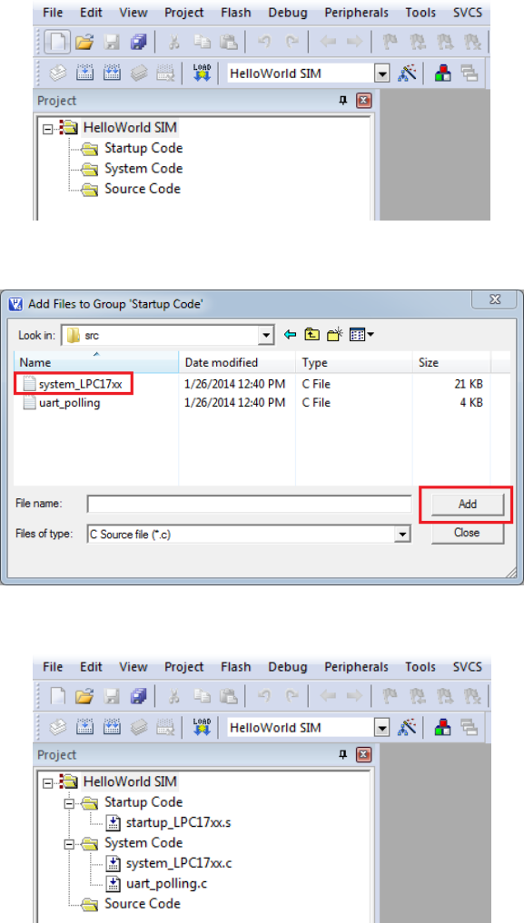
Figure 1.7: Keil IDE: Updated Project Profile
Figure 1.8: Keil IDE: Add Source File to Source Group
Figure 1.9: Keil IDE: Updated Project Profile
5. Create a new source file
The project does not have a main function yet. We now create a new file by clicking
60
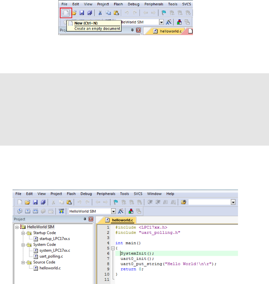
the “New” button (See Figure 1.10). Before typing anything to the file, save the file
Figure 1.10: Keil IDE: Create New File
and name it helloworld.c. Write the following code to the helloworld.c file:
#include <LPC17xx.h>
#include "uart_polling.h"
int main() {
SystemInit();
uart0_init();
uart0_put_string("Hello World!\n\r");
return 0;
}
Then add helloworld.c to the Source Code group. Your final project would look
like the screen shot in Figure 1.11.
Figure 1.11: Keil IDE: Final Project Setting
1.1.3 Build and Download
Follow the following steps to configure your project for build:
61
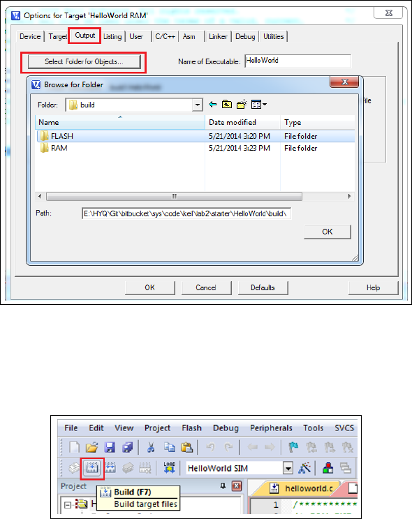
•Create the following folders to hold different build-related files for the two targets.
–HelloWorld\build\FLASH
–HelloWorld\build\RAM
•Click the Target Option button and select the Output tab. Click the “Select the
Folders for Objects” button to bring up the Browse for Folder dialogue box (see Figure
1.12). You will chose the FLASH folder if you want to build the HelloWorld SIM target
and RAM folder if you want to build the HelloWorld RAM target. Similarly, you could
select the Listing tab to specify the location of the listing files.
Figure 1.12: Keil IDE: Selecting Output Folder
To build the target, click the “Build” button (see Figure 1.13). If nothing is wrong, the
Figure 1.13: Keil IDE: Build Target
build output window at the bottom of the IDE will show a log similar like the one shown
in Figure 1.14
62
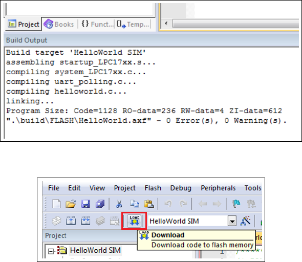
Figure 1.14: Keil IDE: Build Target
Figure 1.15: Keil IDE: Download Target to Flash
To download the code to the board, click the “Load” button (see Figure 1.15). The
download is through the ULINK-ME.
You will need a terminal emulator such as PuTTY that talks directly to COM ports in
order to see output of the serial port. Open up the PuTTY on your PC and choose COM1.
An example PuTTY Serial configuration is shown in Figures 1.16(a) and 1.16(b). Press
the Reset button on the board and you should see “Hello World!” displayed on PuTTY.
1.2 Debugging
You can use either the simulator within the IDE or the ULINK Cortex Debugger to debug
your program. To start a debug session, click Debug→Start/Stop Debug Session from the
IDE menu bar or press Ctrl+F5. Figure 1.16 shows the a typical debug session interface.
As any other GUI debugger, the IDE allows you to set up break points and step
through your source code. It also shows the registers, which is very helpful for debugging
low level code. Click View, Debug and Peripherals from the IDE menu bar and explore
the functionality of the debugger.
63
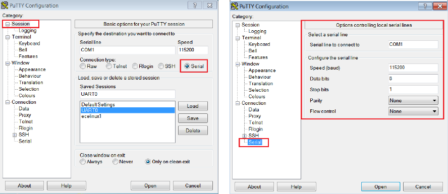
(a) PuTTY Session for Serial Port Communication (b) PuTTY Serial Port Configuration
1.2.1 Simulation
Most of the development normally is done under the simulation mode. The default setting
of the project uses the simulator to debug as shown in the target option (see Figure 1.17
Instead of load the program to the board for execution, you can run the code using the
debugger under simulation mode.Note that the simulator runs the application a lot slower
than the actual board. One wall clock second is about one minute inside the simulator.
1.2.2 Configure In-Memory Execution Using ULINK Cortex De-
bugger
When you debug hardware related problems, you most likely will find the ULINK Cortex
Debugger is helpful. You need to configure the debugger as shown in Figure 1.18.
The default image memory map setting is that the code is executed from the ROM
(see Figure1.19(a). Since the ROM portion of the code needs to be flashed in order to
be executed on the board, this incurs wear-and-tear on the on-chip flash of the LPC1768.
Since most attempts to write a functioning RTX will eventually require some more or less
elaborate debugging, the flash memory might wear out quickly. Unlike the flash memory
stick file systems where the wear is aimed to be uniformly distributed across the memory
portion, this flash memory will get used over and over again in the same portion.
The ARM compiler can be configured to have a different starting address. We can
create a RAM target where the code starting address is in RAM (see Figure 1.19(b). An
64
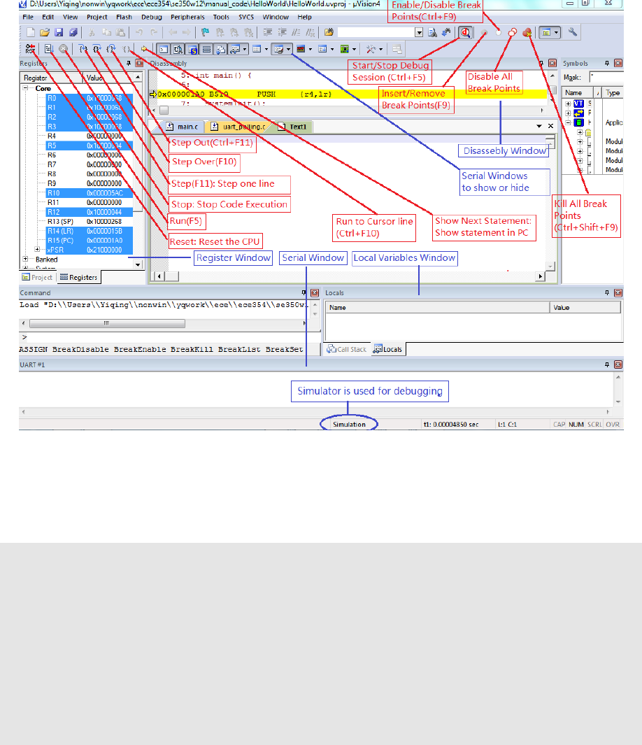
Figure 1.16: Keil IDE: Debugging
initialization file RAM.ini (see Listing 1.1)is needed to do the proper setting of SP, PC and
vector table offset register.
FUNC void Setup (void) {
SP = _RDWORD(0x10000000); // Setup Stack Pointer
PC = _RDWORD(0x10000004); // Setup Program Counter
_WDWORD(0xE000ED08, 0x10000000); // Setup Vector Table
Offset Register
}
// You need to provide the path of the .axf file here
LOAD build\RAM\HelloWorld.axf INCREMENTAL // Download
Setup(); // Setup for Running
g, main
Listing 1.1: The RAM.ini file
To download the code to the board, one should not use the download button. Instead,
the debug button is used to initiate a debug session and the command
65
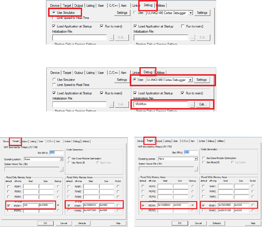
Figure 1.17: Keil IDE: Using Simulator for Debugging
Figure 1.18: Keil IDE: Using ULINK Cortex Debugger
(a) Default Memory Setting (b) In-Memory Execution Setting
Figure 1.19: Keil IDE: Configure for In-Memory Execution
LOAD build\RAM\HelloWorld.axf INCREMENTAL
in the RAM.ini file will load the code to the board. You will need to edit this command so
that the path of the .axf reflects the actual path of your .axf location.
66
Chapter 2
Programming MCB1700
2.1 The Thumb-2 Instruction Set Architecture
The Cortex-M3 supports only the Thumb-2 (and traditional Thumb) instruction set. With
support for both 16-bit and 32-bit instructions in the Thumb-2 instruction set, there is no
need to switch the processor between Thumb state (16-bit instructions) and ARM state
(32-bit instructions).
In the RTOS lab, you will need to program a little bit in the assembler language. We
introduce a few assembly instructions that you most likely need to use in your project in
this section.
The general formatting of the assembler code is as follows:
label
opcode operand1,operand2, . . . ;Comments
The label is optional. Normally the first operand is the destination of the operation (note
STR is one exception).
Table 2.1 lists some assembly instructions that the RTX project may use. For complete
instruction set reference, we refer the reader to Section 34.2 (ARM Cortex-M3 User Guide:
Instruction Set) in [4].
2.2 ARM Architecture Procedure Call Standard (AAPCS)
The AAPCS (ARM Architecture Procedure Call Standard) defines how subroutines can be
separately written, separately compiled, and separately assembled to work together. The
67

Mnemonic Operands/Examples Description
LDR Rt,[Rn,#offset] Load Register with word
LDR R1,[R0,#24] Load word value from an memory address R0+24 into R1
LDM Rn{!},reglist Load Multiple registers
LDM R4,{R0 −R1}Load word value from memory address R4 to R0, increment the
address, load the value from the updated address to R1.
STR Rt,[Rn,#offset] Store Register word
STR R3,[R2,R6] Store word in R3 to memory address R2+R6
STR R1,[SP,#20] Store word in R1 to memory address SP+20
MRS Rd,spec reg Move from special register to general register
MRS R0,MSP Read MSP into R0
MRS R0,PSP Read PSP into R0
MSR spec reg,Rm Move from general register to special register
MSR MSP,R0 Write R0 to MSP
MSR PSP,R0 Write R0 to PSP
PUSH reglist Push registers onto stack
PUSH {R4 −R11,LR}push in order of decreasing the register numbers
POP reglist Pop registers from stack
POP {R4 −R11,PC}pop in order of increasing the register numbers
BL label Branch with Link
BL funC Branch to address labeled by funC, return address stored in LR
BLX Rm Branch indirect with link
BLX R12 Branch with link and exchange (Call) to an address stored in R12
BX Rm Branch indirect
BX LR Branch to address in LR, normally for function call return
Table 2.1: Assembler instruction examples
68
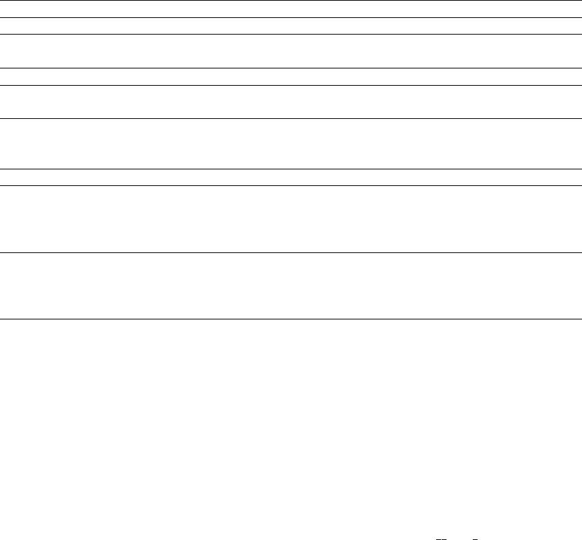
C compiler follows the AAPCS to generate the assembly code. Table 2.2 lists registers
used by the AAPCS.
Register Synonym Special Role in the procedure call standard
r15 PC The Program Counter.
r14 LR The Link Register.
r13 SP The Stack Pointer (full descending stack).
r12 IP The Intra-Procedure-call scratch register.
r11 v8 Variable-register 8.
r10 v7 Variable-register 7.
r9 v6 Platform register.
SB The meaning of this register is defined by platform standard.
TR
r8 v5 Variable-register 5.
r7 v4 Variable-register 4.
r6 v3 Variable-register 3.
r5 v2 Variable-register 2.
r4 v1 Variable-register 1.
r3 a4 argument / scratch register 4
r2 a3 argument / scratch register 3
r1 a2 argument / result / scratch register 2
r0 a1 argument / result / scratch register 1
Table 2.2: Core Registers and AAPCS Usage
Registers R0-R3 are used to pass parameters to a function and they are not preserved.
The compiler does not generate assembler code to preserve the values of these registers.
R0 is also used for return value of a function.
Registers R4-R11 are preserved by the called function. If the compiler generated as-
sembler code uses registers in R4-R11, then the compiler generate assembler code to auto-
matically push/pop the used registers in R4-R11 upon entering and exiting the function.
R12-R15 are special purpose registers. A function that has the svc indirect keyword
makes the compiler put the first parameter in the function to R12 followed by an SVC
instruction. R13 is the stack pointer (SP). R14 is the link register (LR), which normally
is used to save the return address of a function. R15 is the program counter (PC).
Note that the exception stack frame automatically backs up R0-R3, R12, LR and
PC together with the xPSR. This allows the possibility of writing the exception handler in
purely C language without the need of having a small piece of assembly code to save/restore
R0-R3, LR and PC upon entering/exiting an exception handler routine.
69
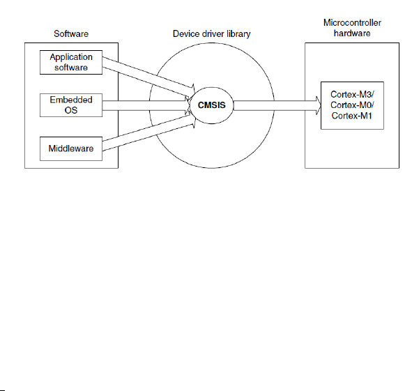
2.3 Cortex Microcontroller Software Interface Stan-
dard (CMSIS)
The Cortex Microcontroller Software Interface Standard (CMSIS) was developed by ARM.
It provides a standardized access interface for embedded software products (see Figure 2.1).
This improves software portability and re-usability. It enables software solution suppliers
to develop products that can work seamlessly with device libraries from various silicon
vendors [2].
Figure 2.1: Role of CMSIS[8]
The CMSIS uses standardized methods to organize header files that makes it easy to
learn new Cortex-M microcontroller products and improve software portability. With the
<device>.h (e.g. LPC17xx.h) and system startup code files (e.g., startup_LPC17xx.s),
your program has a common way to access
•Cortex-M processor core registers with standardized definitions for NVIC, Sy-
sTick, MPU registers, System Control Block registers , and their core access functions
(see core cm ∗.[ch] files).
•system exceptions with standardized exception number and handler names to
allow RTOS and middleware components to utilize system exceptions without having
compatibility issues.
•intrinsic functions with standardized name to produce instructions that cannot
be generated by IEC/ISO C.
•system initialization by common methods for each MCU. Fore example, the stan-
dardized SystemInit() function to configure clock.
•system clock frequency with standardized variable named as SystemFrequency
defined in the device driver.
70
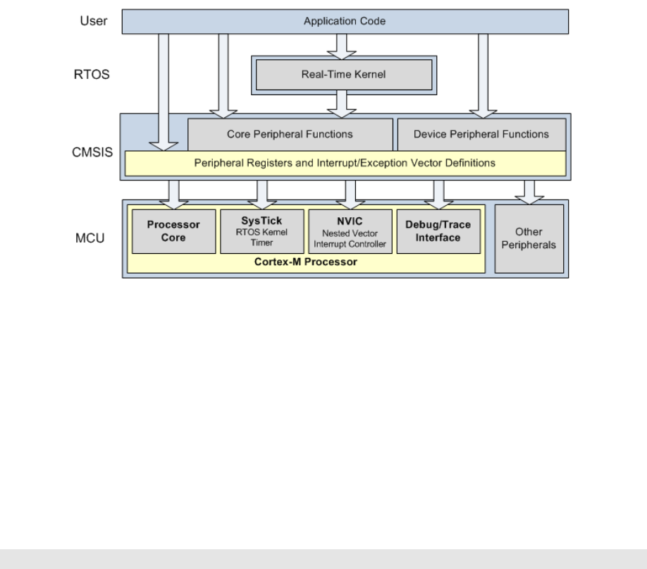
•vendor peripherals with standardized C structure.
Figure 2.2: CMSIS Organization[2]
2.3.1 CMSIS files
The CMSIS is divided into multiple layers (See Figure 2.2). For each device, the MCU
vendor provides a device header file <device>.h (e.g., LPC17xx.h) which pulls in additional
header files required by the device driver library and the Core Peripheral Access Layer (see
Figure 2.3).
By including the <device>.h (e.g., LPC17xx.h) file into your code file. The first step
to initialize the system can be done by calling the CMSIS function as shown in Listing 2.1.
SystemInit(); // Initialize the MCU clock
Listing 2.1: CMSIS SystemInit()
The CMSIS compliant device drivers also contain a startup code (e.g., startup_LPC17xx.s),
which include the vector table with standardized exception handler names (See Section
2.3.3.
2.3.2 Cortex-M Core Peripherals
We only introduce the NVIC programming in this section. The Nested Vectored Interrupt
Controller (NVIC) can be accessed by using CMSIS functions (see Figure 2.4). As an
71
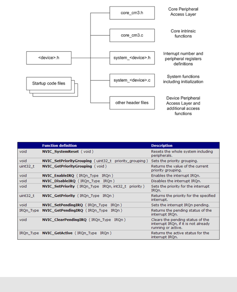

2.3.3 System Exceptions
Writing an exception handler becomes very easy. One just defines a function that takes
no input parameter and returns void. The function takes the name of the standardized
exception handler name as defined in the startup code (e.g., startup_LPC17xx.s). The
following listing shows an example to write the UART0 interrupt handler entirely in C.
void UART0_Handler (void)
{
// write your IRQ here
}
Another way is to use the embedded assembly code:
__asm void UART0_Handler(void)
{
;do some asm instructions here
BL __cpp(a_c_function) ; a_c_function is a regular C function
;do some asm instructions here,
}
2.3.4 Intrinsic Functions
ANSI cannot directly access some Cortex-M3 instructions. The CMSIS provides intrinsic
functions that can generate these instructions. The CMSIS also provides a number of
functions for accessing the special registers using MRS and MSR instructions. The intrinsic
functions are provided by the RealView Compiler. Table 2.3 lists some intrinsic functions
that your RTOS project most likely will need to use. We refer the reader to Tables 613
and 614 one page 650 in Section 34.2.2 of [4] for the complete list of intrinsic functions.
2.3.5 Vendor Peripherals
All vendor peripherals are organized as C structure in the <device>.h file (e.g., LPC17xx.h).
For example, to read a character received in the RBR of UART0, we can use the following
code.
unsigned char ch;
ch = LPC_UART0->RBR; // read UART0 RBR and save it in ch
73

Instruction CMSIS Intrinsic Function
CPSIE I void enable irq(void)
CPSID I void disable irq(void)
Special Register Access CMSIS Function
CONTROL Read uinit32 t get CONTROL(void)
Write void set CONTROL(uint32 t value)
MSP Read uinit32 t get MSP(void)
Write void set MSP(uint32 t value)
PSP Read uinit32 t get PSP(void)
Write void set PSP(uint32 t value)
Table 2.3: CMSIS intrinsic functions defined in core cmFunc.h
2.4 Accessing C Symbols from Assembly
Only embedded assembly is support in Cortex-M3 (i.e. inline assembly is not supported).
To write an embedded assembly function, you need to use the asm keyword. For exam-
ple the the function “embedded asm function” in Listing 2.2 is an embedded assembly
function. You can only put assembly instructions inside this function. Note that inline
assembly is not supported in Cortex-M3.
The cpp keyword allows one to access C compile-time constant expressions, including
the addresses of data or functions with external linkage, from the assembly code. The
expression inside the cpp can be one of the followings:
•A global variable defined in C
typedef struct pcb {
struct * mp_next;
uint32_t m_sp;
//.....
} pcb_t;
pcb_t g_pcb;
uint32_t g_var;
__asm embedded_asm_function(void) {
LDR R3, =__cpp(&g_pcb) ; load R3 with the address of g_pcb
LDM R3, {R1, R2} ; load R1 with g_pcb.mp_next
; load R2 with g_pcb.m_sp
LDR R4, =__cpp(g_var) ; load R4 with the value of g_var
74

}
Listing 2.2: Example of accessing global variable from assembly
•A C function
extern void a_c_function(void);
...
__asm embedded_asm_function(void) {
;......
BL __cpp(a_c_function) ; a_c_function is regular C function
;......
}
•A constant expression in the range of 0 −255 defined in C.
uint8_t const g_flag;
__asm embedded_asm_function(void) {
;......
MOV R4, #_cpp(g_flag) ; load g_flag value to R4
;......
}
Note the MOV instruction only applies to immediate constant value in the range of
0−255.
You can also use the IMPORT directive to import a C symbol in the embedded assembly
function and then start to use the imported symbol just as a regular assembly symbol. For
example
void a_c_function (void) {
// do something
}
__asm embedded_asm_add(void) {
IMPORT a_c_function ; a_c_function is a regular C function
BL a_c_function ; branch with link to a_c_function
}
75
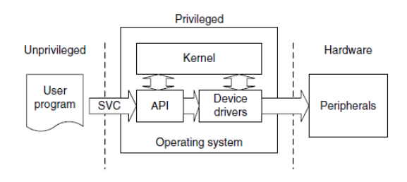
Names in the __cpp expression are looked up in the C context of the __asm function.
Any names in the result of the __cpp expression are mangled as required and automatically
have IMPORT statements generated from them.
2.5 SVC Programming: Writing an RTX API Func-
tion
Figure 2.5: SVC as a Gateway for OS Functions [8]
A function in RTX API requires a service from the operating system. It needs to be
implemented through the proper gateway by trapping from the user level into the kernel
level. On Cortex-M3, the SVC instruction is used to achieve this purpose.
The basic idea is that when a function in RTX API is called from the user level,
this function will trigger an SVC instruction. The SVC_Handler, which is the CMSIS
standardized exception handler for SVC exception will then invoke the a kernel function
that provides the actual service (see Figure 2.5). Effectively, the RTX API function is
a wrapper that invokes SVC exception handler and passes corresponding kernel service
operation information to the SVC handler.
To generate an SVC instruction, there are two methods. One is a direct method and
the other one is an indirect method.
The direct method is to program at assembly instruction level. We can use the embed-
ded assembly mechanism and write SVC assembly instruction inside the embedded assembly
function. The ARM RL-RTX API functions that are not started with the os_ prefix are
implemented in this way. Examples are _alloc_box and _free_box defined in HAL_CM3.c.
Listing 2.3 shows the code snippet of the _alloc_box.
76

__asm void *_alloc_box(void *box_mem) {
LDR R12,=__cpp(rt_alloc_box)
; privileged mode code handling omitted for brevity reason
SVC 0
BX LR
ALIGN
}
Listing 2.3: Code Snippet of alloc box
The corresponding kernel function is the C function rt_alloc_box defined in rt_MemBox.c.
This function entry point is loaded to r12. Then SVC 0 causes an SVC exception with
immediate number 0. In the SVC exception handler, we can then branch with link and
exchange to the address stored in r12. Listing 2.4 is an excerpt of the SVC_handler in
HAL_CM3.c from the ARM RL-RTX source code.
__asm void SVC_Handler(void) {
MRS R0, PSP
;Extract SVC number, if SVC 0, then do the following
LDM R0, {R0-R3, R12}; Read R0-R3, R12 from stack
BLX R12 ; R12 contains the kernel function entry point
;Code to handle context switching is omitted
MVN LR, #:NOT:0xFFFFFFFD; set EXC_RETURN, thread mode, PSP
BX LR ;
;User SVC code is omitted
}
Listing 2.4: Code Snippet of SVC Handler
The indirect method is to ask the compiler to generate the SVC instruction from C code.
The ARM compiler provides an intrinsic keyword named __svc_indirect which passes
an operation code to the SVC handler in r12[3]. This keyword is a function qualifier. The
two input we need to provide to the compiler is
•svc_num, the immediate value used in the SVC instruction and
•op_num, the value passed in r12 to the handler to determine the function to perform.
The following is the syntax of an indirect SVC.
77

__svc_indirect(int svc_num)
return_type function_name(int op_num[, argument-list]);
The system handler must make use of the r12 value to select the required operation. For
example The RL-RTX provide the following user level function to terminate a task:
#include <rtl.h>
OS_RESULT os_tsk_delete (OS_TID taskid)
In RTL.h, the following code is revelent to the implementation of the function.
#define __SVC_0 __svc_indirect(0)
extern OS_RESULT rt_tsk_delete(OS_TID task_id);
#define os_tsk_delete(task_id) _os_task_delete ((U32) rt_tsk_delete,
task_id)
extern OS_RESULT _os_tsk_delete (U32 p, OS_TID task_id) __SVC_0;
The compiler generates two assembly instructions
LDR.W r12, [pc, #offset]; Load rt_tsk_delete in r12
SVC 0x00
The SVC_handler in Listing 2.4 then can be used to handle the SVC 0 exception.
78
Chapter 3
Introduction to ECE Linux
Programming Environment
3.1 Linux Hardware Environment
There are ten Linux servers that are open to ECE undergraduate students. They are
ecelinux1.uwaterloo.ca -ecelinux10.uwaterloo.ca. To access these machines from
off campus. You will need to use the campus VPN. You could also first ssh into ecelinux4
and then ssh into other Linux servers from there. Note that the ecelinux4 should not be
used for computing jobs, it is for accessing other Linux servers on campus. Linux CentOS
is installed on all these machines.
3.2 How to Connect to Linux Servers
The servers are accessed by remote login. You will need to have a terminal client that
supports secure shell (ssh) installed before you can log onto one of the ecelinux servers.
Two popular terminal clients are:
•Windows secure shell client and
•PuTTY .
Both terminal clients are installed on ECE Nexus machines. Use your WatIAM cre-
dential to login onto these machines.
To use the SSH Secure shell windows client, click Start →All Programs →Internet
Tools →Secure shell client. Figure 3.1(a) is a screen shot taken on a Nexus computer.
79
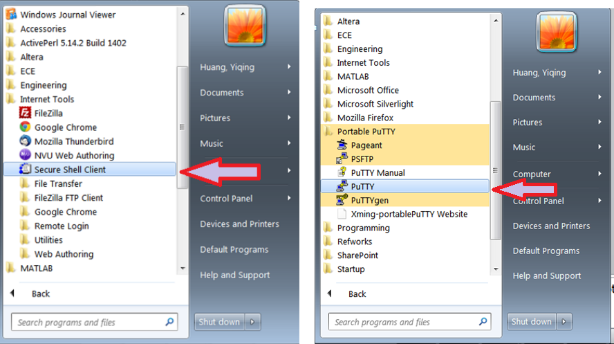
To use the PuTTY, click Start →All Programs →Portable PuTTY →PuTTY.
Figure 3.1(b) is a screen shot taken on a Nexus computer.
(a) SSH Secure Shell Client (b) PuTTY
Figure 3.1: Invoking Terminal Clients on an ECE Nexus PC
3.3 Work Environment Setup
3.3.1 Setting up Remote Linux Graphic Support
After you login, you will notice that you are in a command line shell environment, one
where GUI applications cannot be run. For example the ddd debugger is an important GUI
application you will most likely want to use. You will need to configure your environment
to support GUI application to be able to display graphics on your terminal.
First start the X server on your local machine. Xming is a popular and free X server
which is installed on ECE Nexus computers. Start Xming by clicking All Programs →
Xming (see Figure 3.2).
The second step is to configure the terminal client so that X11 forwarding is enabled.
80
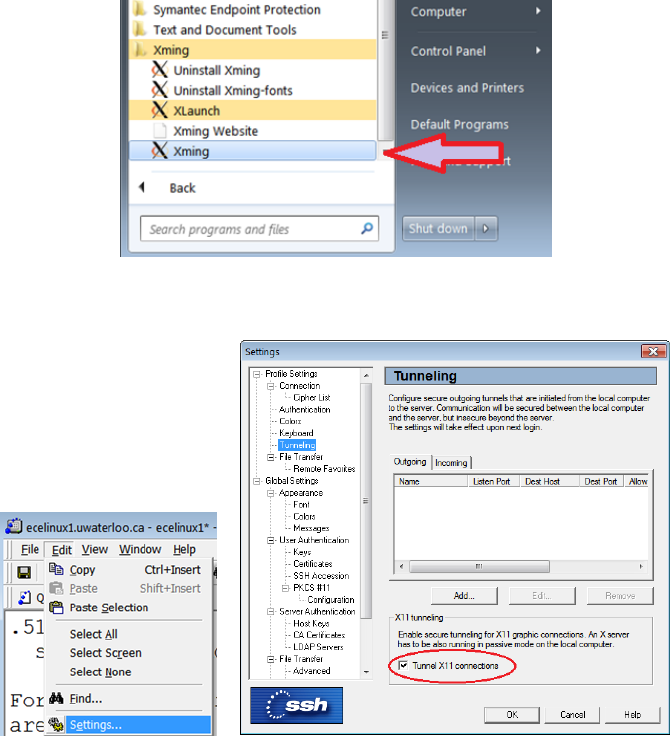
Figure 3.2: Invoking Xming on an ECE Nexus Computer
(a) Setting (b) X11 Tunneling Setting
Figure 3.3: SSH Secure Shell Client X11 Setting
For SSH secure shell client, select Edit →Settings to bring up the setting dialog window
(see Figure 3.3(a)). Go to Profile Settings →Tunneling and put a check mark beside the
Tunnel X11 connection item (see Figure 3.3(b)).
For PuTTY, go to Connection →SSH →X11 and put a check mark beside the Enable
X11 forwarding item (see Figure 3.4).
3.3.2 Mapping Linux Account on Nexus
Your ECE Linux files can be access through network drive mapping on Nexus machines.
Open My Computer →Tools →Map Network Drive (see Figure 3.5(a)). Under Driver,
81
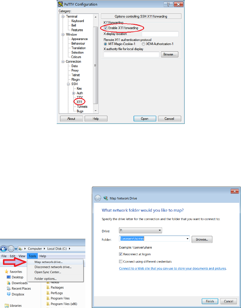
Figure 3.4: PuTTY X11 Forwarding Setting
pick a drive letter, say P. Under Folder, type \\eceserv\homes. Put a check mark beside
Reconnect at logon item and click Finish (see Figure 3.5(b)). You will use your WatIAM
credential to authenticate yourself.
(a) Prepare to Map a Network
Drive
(b) Configuring Network Drive Mapping
Figure 3.5: SSH Secure Shell Client X11 Setting
82
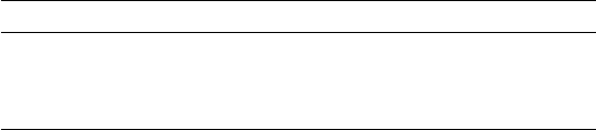
3.4 Basic Software Development Tools
To develop a program, there are three important steps. First, a program is started from
source code written by programmers. Second, the source code is then compiled into object
code, which is a binary. Non-trivial project normally contains more than one source file.
Each source file is compiled into one object code and the linker would finally link all the
object code to generate the final target, which is the executable that runs. People refer to
compiling and linking as building a target. It is very rare that the target will run perfectly
the first time it is built. Most of time you need to fix defects and bugs in your code and the
this is the third step. The debugger is a tool to help you identify the bug and fix it. Table
3.1 shows the key steps in programming work flow, the corresponding tools are needed and
some example tools provided by a general purpose Linux operating system.
Task Tool Examples
Editing the source code Editor vi, emacs
Compiling the source code Compiler gcc
Debugging the program Debugger gdb, ddd
Table 3.1: Programming Steps and Tools
At each development step, you will have a choice of tools to get the work done. Most of
you probably are more familiar with a certain Integrated Development Environment (IDE)
which integrates all these tools into a single environment. For example Eclipse and Visual
Studio. However another choice is that you pick your favorite tool in each programming
step and build your own tool chain. Many seasoned Linux programmers build their own
tool chains. A few popular tools are introduced in the following subsections.
3.4.1 Editor
Some editors are designed to better suit programmers’ needs than others. The vi (vim and
gvim belong to the vi family) and emacs (xemacs belongs to emacs family) are the two
most popular editors for programming purposes.
Two simple notepad editors pico and nano are also available for a simple editing job.
These editors are not designed for serious programming activity. To use one of them to
write your first Hello World program is fine though.
After you finish editing the C source code, give the file name an extension of .c. Listing
3.1 is the source code of printing ”Hello World!” to the screen.
83

#include <stdio.h>
#include <stdlib.h>
int main()
{
printf("Hello World!\n");
exit(0);
}
Listing 3.1: HelloWorld C source Code
Next we will compile and execute the program.
3.4.2 C Compiler
The executablegcc is the GNU project C and C++ compiler. To compile the HelloWorld
source code in Listing 3.1, type the following command at the prompt:
gcc helloworld.c
You will notice that a new file named a.out is generated. This is the executable
generated from the source code. To run it, type the following command at the prompt and
hit Enter.
./a.out
The result is“Hello World!” appearing on the screen.
You can also instruct the compiler to name the executable another name instead of
the default a.out. The -o option in gcc allows one to name the executable a name. For
example, the following command will generate an executable named “helloworld.out”.
gcc helloworld.c -o helloworld.out
although there is no requirement that the name ends in .out.
3.4.3 Debugger
The GNU debugger gdb is a command line debugger. Many GUI debugger uses gdb as
the back-end engine. One GNU GUI debugger is ddd. It has a powerful data display
functionality.
84
GDB needs to read debugging information from the binary in order to be able to
help one to debug the code. The -g option in gcc tells the compiler to produce such
debugging information in the generated executable. In order to use gdb to debug our
simple HelloWorld program, we need to compile it with the following command:
gcc -g helloworld.c -o helloworld.out
The following command calls gdb to debug the helloworld.out
gdb helloworld.out
This starts a gdb session. At the (gdb) prompt, you can issue gdb command such as
b main to set up a break point at the entry point of main function. The llists source
code. The nsteps to the next statement in the same function. The ssteps into a function.
The pprints a variable value provided you supply the name of the variable. Type hto see
more gdb commands.
Compared to gdb command line interface, the ddd GUI interface is more user friendly
and easy to use. To start a ddd session, type the command
ddd
and click File →Open Program to open an executable such as helloworld.out. You will
then see gdb console in the bottom window with the source window on top of the gdb
console window. You could see the value of variables of the program through the data
window, which is on top of the source code window. Select View →to toggle all these
three windows.
3.5 More on Development Tools
For any non-trivial software project, it normally contains multiple source code files. De-
velopers need tools to manage the project build process. Also project normally are done
by several developers. A version control tool is also needed.
3.5.1 How to Automate Build
Make is an utility to automate the build process. Compilation is a cpu-intensive job and
one only wants to re-compile the file that has been changed when you build a target
instead of re-compile all source file regardless. The make utility uses a Makefile to specify
85

the dependency of object files and automatically recompile files that has been modified
after the last target is built.
In a Makefile, one specifies the targets to be built, what prerequisites the target depends
on and what commands are used to build the target given these prerequisites. These are
the rules contained in Makefile. The Makefile has its own syntax and is a good reference
on Make. The general form of a Makefile rule is:
target ...: prerequisites ...
recipe
...
...
One important note is that each recipe line starts with a TAB key rather than white spaces.
Listing 3.2 is our first attempt to write a very simple Makefile.
helloworld.out: helloworld.c
gcc −o helloworld.out helloworld.c
Listing 3.2: Hello World Makefile: First Attempt
Our second attempt is to break the single line gcc command into two steps. First is to
compile the source code into object code .o file. Second is to link the object code to one
final executable binary. Listing 3.3 is our second attempted version of Makefile.
helloworld.out: helloworld.o
gcc −o helloworld.out helloworld.o
helloworld.o: helloworld.c
gcc −c helloworld.c
Listing 3.3: Hello World Makefile: Second Attempt
When a project contains multiple files, separating object code compilation and linking
stages would give a clear dependency relationship among code. Assume that we now need
to build a project that contains two source files src1.c and src2.c and we want the final
executable to be named as app.out. Listing 3.4 is a typical example Makefile that is closer
to what you will see in the real world.
all : app.out
app.out: src1 .o src2.o
gcc −o app.out src1.o src2.o
src1.o: src1 .c
gcc −c src1.c
86

src2.o: src2 .c
gcc −c src2.c
clean:
rm ∗.o app.out
Listing 3.4: A More Real Makefile: First Attempt
We also have added a target named clean so that make clean will clean the build.
So far we have seen the Makefile contains explicit rules. Makefile can also contain
implicit rules,variable definitions,directives and comments. Listing 3.5 is a Makefile that
is used in the real world.
1# Makefile to build app.out
2CC=gcc
3CFLAGS=−Wall −g
4LD=gcc
5LDFLAGS=−g
7OBJS=src1.o src2.o
9all : app.out
10 app.out: $(OBJS)
11 $(LD) $(CFLAGS) $(LDFLAGS) −o$@ $(OBJS)
12 .c.o:
13 $(CC) $(CFLAGS) −c $<
14 .PHONY: clean
15 clean:
16 rm −f∗.o ∗.out
Listing 3.5: A Real World Makefile
Line 1 is a comment. Lines 2−7 are variable definitions. Line 12 is an implicit rule to gen-
erate .o file for each .c file. See http://www.gnu.org/software/make/manual/make.html
if you want to explore more of makefile.
3.5.2 Version Control Software
ECE Linux has the following version control software installed.
•CVS
•SVN
•Git
87
Choose your favourite one. Any one of them will be able to help you manage ECE254 code
repository. Git is getting more and more popularity these days. If you decide to use GitHub
to host your repository, please make sure it is a private one. Go to http://github.com/edu
to see how to obtain five private repositories for two years on GitHub for free.
3.5.3 Integrated Development Environment
Eclipse with C/C++ Plug-in has been installed on all ECE Linux servers. You will need
to first set up the X Window support properly (see section 3.3.1, then type the following
command to bring up the eclipse frontend.
/opt/eclipse64/eclipse
This eclipse is not the same as the default eclipse under /usr/bin directory. You may find
running eclipse over network performs poorly at home though. It depends on how fast
your network speed is.
If you have Linux operating system installed on your own personal computer, then you
can download the eclipse with C/C++ plugin from the eclipse web site and then run it
from your own local computer. However you should always make sure the program will
also work on ecelinux machines, which is the environment TAs would be using to test your
code.
3.6 Man Page
Linux provides manual pages. You can use the command man followed by the specific
command or function you are interested in to obtain detailed information.
Mange pages are grouped into sections. We list frequently used sections here:
•Section 1 contains user commands.
•Section 2 contains system calls
•Section 3 contains library functions
•Section 7 covers conventions and miscellany.
To specify which section you want to see, provide the section number after the man
command. For example,
88
man 2 stat
shows the system call stat man page. If you omit the 2in the command, then it will
return the command stat man page.
You can also use man -k or apropos followed by a string to obtain a list of man pages
that contain the string. The Whatis database is searched and now run man whatis to see
more details of Whatis.
89
Appendix A
Forms
Lab administration related forms are given in this appendix.
90

ECE254 Request to Leave a Project Group Form
Name:
Quest ID:
Student ID:
Lab Assignment ID
Group ID:
Name of Other Group Members:
Provide the reason for leaving the project group here:
Signature Date
91
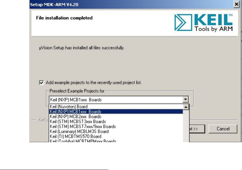
Appendix B
MDK-ARM Installation
There is only a windows port for the Keil MDK-ARM for now. The MDK-ARM V4.60.0.0
direct download link is inside the Learn (http://learn.uwaterloo.ca)1.
During the process of the installation of the MDK-ARM, you will be asked to add
example code. Choose Keil(NXP) MCB1xxx Boards example projects (see Figure B.1).
Figure B.1: MDK-ARM Installation Steps: Choose Example Projects
1The latest version of MDK-ARM is at Keil website http://www.keil.com/download/product/. How-
ever the lab manual is written for V4.60.0.0. We haven’t tested the latest version.
92
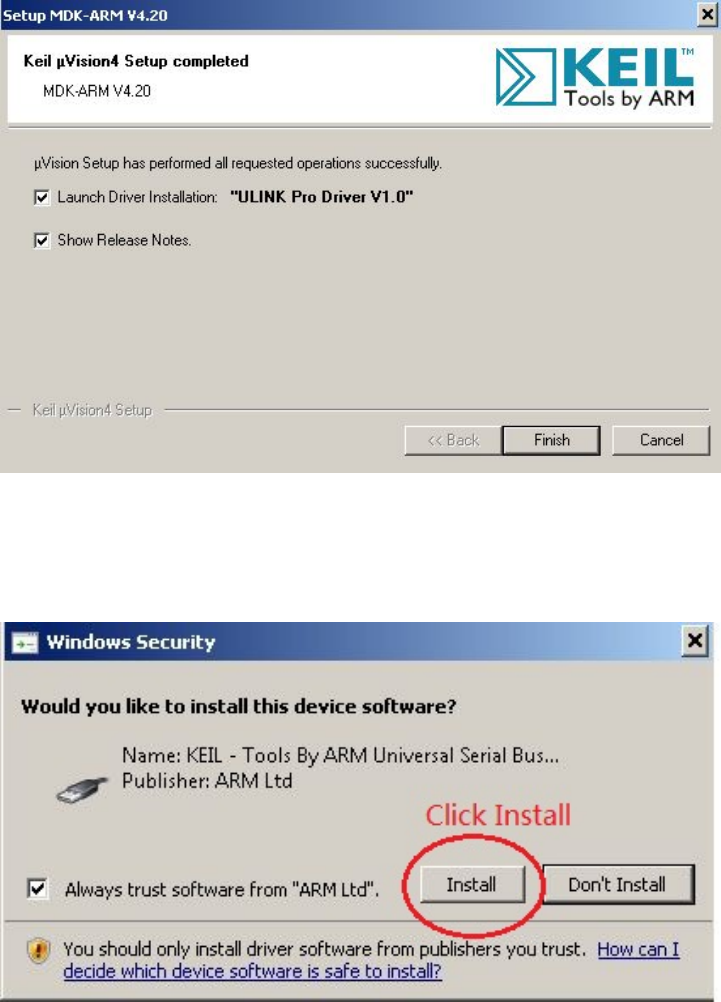
Figure B.2: MDK-ARM Installation Steps: Finish
At the last step of MDK-ARM installation, be sure that the launch the “ULINK Pro Driver
Figure B.3: MDK-ARM Installation Steps: ULINK Pro Driver
V1.0” driver installation check box is checked (see Figure B.2. Once you click “Finish”
button, the ULINK Pro Driver installation starts. Click “Install” button to install the
driver (see Figure B.3).
93
Appendix C
Keil MCB1700 Hardware
Environment
C.1 MCB1700 Board Overview
The Keil MCB1700 board is populated with NXP LPC1768 Microcontroller. Figure C.1
shows the important interface and hardware components of the MCB1700 board.
Figure C.2 is the hardware block diagram that helps you to understand the MCB1700
board components. Note that our lab will only use a small subset of the components which
include the LPC1768 CPU, COM and Dual RS232.
The LPC1768 is a 32-bit ARM Cortex-M3 microcontroller for embedded applications
requiring a high level of integration and low power dissipation. The LPC1768 operates at
up to an 100 MHz CPU frequency. The peripheral complement of LPC1768 includes 512KB
of on-chip flash memory, 64KB of on-chip SRAM and a variety of other on-chip peripherals.
Among the on-chip peripherals, there are system control block, pin connect block, 4 UARTs
and 4 general purpose timers, some of which will be used in your RTX course project.
Figure C.3 is the simplified LPC1768 block diagram [4], where the components to be used
in your RTX project are circled with red. Note that this manual will only discuss the
components that are relevant to the RTX course project. The LPC17xx User Manual is
the complete reference for LPC1768 MCU.
C.2 Cortex-M3 Processor
The Cortex-M3 processor is the central processing unit (CPU) of the LPC1768 chip. The
processor is a 32-bit microprocessor with a 32-bit data path, a 32-bit register bank, and
94
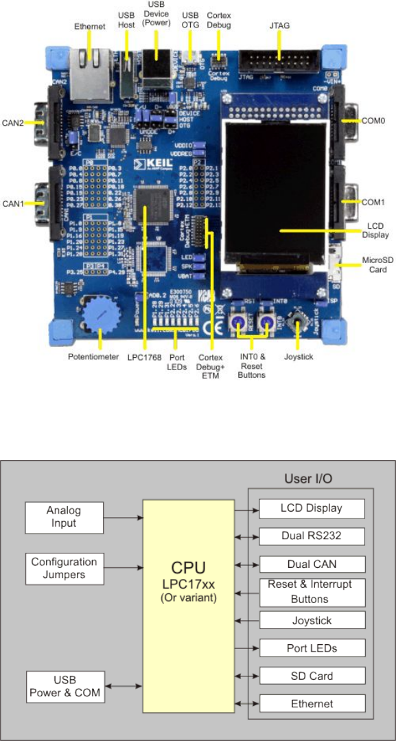
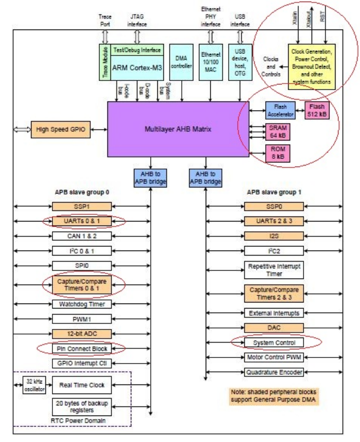
Figure C.3: LPC1768 Block Diagram
96
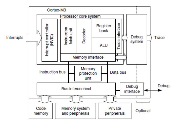
Figure C.4: Simplified Cortex-M3 Block Diagram[8]
32-bit memory interfaces. Figure C.4 is the simplified block diagram of the Cortex-M3
processor [8]. The processor has private peripherals which are system control block, system
timer, NVIC (Nested Vectored Interrupt Controller) and MPU (Memory Protection Unit).
The MPU programming is not required in the course project. The processor includes
a number of internal debugging components which provides debugging features such as
breakpoints and watchpoints.
C.2.1 Registers
The processor core registers are shown in Figure C.5. For detailed description of each
register, Chapter 34 in [4] is the complete reference.
•R0-R12 are 32-bit general purpose registers for data operations. Some 16-bit Thumb
instructions can only access the low registers (R0-R7).
•R13(SP) is the stack pointer alias for two banked registers shown as follows:
–Main Stack Pointer (MSP): This is the default stack pointer and also reset
value. It is used by the OS kernel and exception handlers.
–Process Stack Pointer (PSP): This is used by user application code.
97
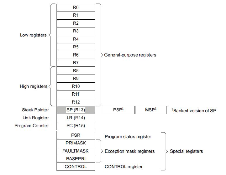
Figure C.5: Cortex-M3 Registers[4]
On reset, the processor loads the MSP with the value from address 0x00000000. The
lowest 2 bits of the stack pointers are always 0, which means they are always word
aligned.
In Thread mode, when bit[1] of the CONTROL register is 0, MSP is used. When
bit[1] of the CONTROL register is 1, PSP is used.
•R14(LR) is the link register. The return address of a subroutine is stored in the link
register when the subroutine is called.
•R15(PC) is the program counter. It can be written to control the program flow.
•Special Registers are as follows:
–Program Status registers (PSRs)
–Interrupt Mask registers (PRIMASK, FAULTMASK, and BASEPRI)
–Control register (CONTROL)
When at privilege level, all the registers are accessible. When at unprivileged (user) level,
access to these registers are limited.
98
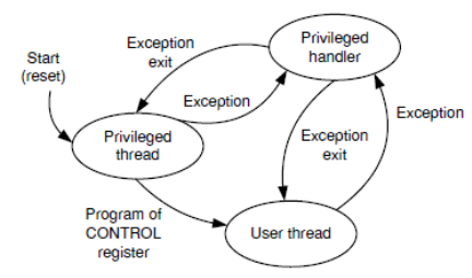
C.2.2 Processor mode and privilege levels
The Cortex-M3 processor supports two modes of operation, Thread mode and Handler
mode.
•Thread mode is entered upon Reset and is used to execute application software.
•Handler mode is used to handle exceptions. The processor returns to Thread mode
when it has finished exception handling.
Software execution has two access levels, Privileged level and Unprivileged (User) level.
•Privileged
The software can use all instructions and has access to all resources. Your RTOS
kernel functions are running in this mode.
•Unprivileged (User)
The software has limited access to MSR and MRS instructions and cannot use the
CPS instruction. There is no access to the system timer, NVIC , or system control
block. The software might also have restricted access to memory or peripherals. User
processes such as the wall clock process should run at this level.
When the processor is in Handler mode, it is at the privileged level. When the processor
is in Thread mode, it can run at privileged or unprivileged (user) level. The bit[0] in
CONTROL register determines the execution privilege level. Figure C.6 illustrate the
mode and privilege level of the processor.
Figure C.6: Cortex-M3 Operating Mode and Privilege Level[8]
Note that only privileged software can write to the CONTROL register to change the
privilege level for software execution in Thread mode. Unprivileged software can use the
99

SVC instruction to make a supervisor call to transfer control to privileged software. Another
way to change between Privileged Thread mode and Unprivileged thread mode is to modify
the EXC RETURN value in the LR (R14) when returning from an exception. You probably
want to use this mechanism for context switching.
C.2.3 Stacks
The processor uses a full descending stack. This means the stack pointer indicates the last
stacked item on the stack memory. When the processor pushes a new item onto the stack,
it decrements the stack pointer and then writes the item to the new memory location.
The processor implements two stacks, the main stack and the process stack. One of
these two stacks is banked out depending on the stack in use. This means only one stack
is visible at a time as R13. In Handler mode, the main stack is always used. The bit[1] in
CONTROL register reads as zero and ignores writes in Handler mode. In Thread mode,
the bit[1] setting in CONTROL register determines whether the main stack or the process
stack is currently used. Table C.1 summarizes the processor mode, execution privilege
level, and stack use options.
Processor Used to Privilege level for CONTROL Stack used
mode execute software execution Bit[0] Bit[1]
Thread Applications Privileged 0 0 Main Stack
Unprivileged 1 1 Process Stack
Handler Exception handlers Privileged - 0 Main Stack
Table C.1: Summary of processor mode, execution privilege level, and stack use options
C.3 Memory Map
The Cortex-M3 processor has a single fixed 4GB address space. Table C.2 shows how this
space is used on the LPC1768.
Note that the memory map is not continuous. For memory regions not shown in the
table, they are reserved. When accessing reserved memory region, the processor’s behavior
is not defined. All the peripherals are memory-mapped and the LPC17xx.h file defines the
data structure to access the memory-mapped peripherals in C.
100

Address Range General Use Address range details Description
0x0000 0000 to On-chip non-volatile 0x0000 0000 −0x0007 FFFF 512 KB flash memory
0x1FFF FFFF memory
On-chip SRAM 0x1000 0000 −0x1000 7FFF 32 KB local SRAM
Boot ROM 0x1FFF 0000 −0x1FFF 1FFF 8 KB Boot ROM
0x2000 0000 to On-chip SRAM 0x2007 C000 −0x2007 FFFF AHB SRAM - bank0 (16 KB)
0x3FFF FFFF (typically used for 0x2008 0000 −0x2008 3FFF AHB SRAM - bank1 (16 KB)
peripheral data)
GPIO 0x2009 C000 −0x2009 FFFF GPIO
0x4000 0000 to APB Peripherals 0x4000 0000 −0x4007 FFFF APB0 Peripherals
0x5FFF FFFF 0x4008 0000 −0x400F FFFF APB1 Peripherals
AHB peripherals 0x5000 0000 −0x501F FFFF DMA Controller, Ethernet
interface, and USB interface
0xE000 0000 to Cortex-M3 Private 0xE000 0000 −0xE00F FFFF Cortex-M3 private registers(NVIC,
0xE00F FFFF Peripheral Bus (PPB) MPU and SysTick Timer et. al.)
Table C.2: LPC1768 Memory Map
C.4 Exceptions and Interrupts
The Cortex-M3 processor supports system exceptions and interrupts. The processor and
the Nested Vectored Interrupt Controller (NVIC) prioritize and handle all exceptions. The
processor uses Handler mode to handle all exceptions except for reset.
C.4.1 Vector Table
Exceptions are numbered 1-15 for system exceptions and 16 and above for external inter-
rupt inputs. LPC1768 NVIC supports 35 vectored interrupts. Table C.3 shows system
exceptions and some frequently used interrupt sources. See Table 50 and Table 639 in
[4] for the complete exceptions and interrupts sources. On system reset, the vector table
is fixed at address 0x00000000. Privileged software can write to the VTOR (within the
System Control Block) to relocate the vector table start address to a different memory
location, in the range 0x00000080 to 0x3FFFFF80.
C.4.2 Exception Entry
Exception entry occurs when there is a pending exception with sufficient priority and either
•the processor is in Thread mode
101

Exception IRQ Vector address Exception Priority C PreFix
number number or offset type
1 - 0x00000004 Reset -3, the highest
2 -14 0x00000008 NMI -2, NMI
3 -13 0x0000000C Hard fault -1 HardFault
4 -12 0x00000010 Memory Configurable MemManage
management fault
.
.
.
11 -5 0x0000002C SVCall Configurable SVC
.
.
.
14 -2 0x00000038 PendSV Configurable PendSVC
15 -1 0x0000003C SysTick Configurable SysTick
16 0 0x00000040 WDT Configurable WDT IRQ
17 1 0x00000044 Timer0 Configurable TIMER0 IRQ
18 2 0x00000048 Timer1 Configurable TIMER1 IRQ
19 3 0x0000004C Timer2 Configurable TIMER2 IRQ
20 4 0x00000050 Timer3 Configurable TIMER3 IRQ
21 5 0x00000054 UART0 Configurable UART0 IRQ
22 6 0x00000058 UART1 Configurable UART1 IRQ
23 7 0x0000005C UART2 Configurable UART2 IRQ
24 8 0x00000060 UART3 Configurable UART3 IRQ
.
.
.
Table C.3: LPC1768 Exception and Interrupt Table
•the processor is in Handler mode and the new exception is of higher priority than
the exception being handled, in which case the new exception preempts the original
exception (This is the nested exception case which is not required in our RTOS lab).
When an exception takes place, the following happens
•Stacking
When the processor invokes an exception (except for tail-chained or a late-arriving
exception, which are not required in the RTOS lab), it automatically stores the
following eight registers to the SP:
–R0-R3, R12
–PC (Program Counter)
–PSR (Processor Status Register)
–LR (Link Register, R14)
102
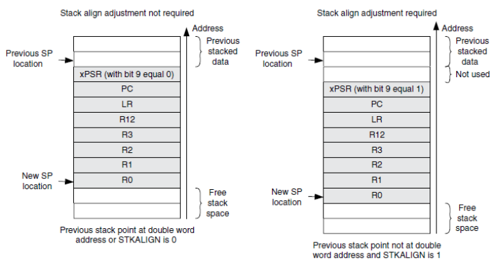
Figure C.7 shows the exception stack frame. Note that by default the stack frame is
aligned to double word address starting from Cortex-M3 revision 2. The alignment
feature can be turned off by programming the STKALIGN bit in the System Control
Block (SCB) Configuration Control Register (CCR) to 0. On exception entry, the
processor uses bit[9] of the stacked PSR to indicate the stack alignment. On return
from the exception, it uses this stacked bit to restore the correct stack alignment.
Figure C.7: Cortex-M3 Exception Stack Frame [8]
•Vector Fetching
While the data bus is busy stacking the registers, the instruction bus fetches the
exception vector (the starting address of the exception handler) from the vector
table. The stacking and vector fetch are performed on separate bus interfaces, hence
they can be carried out at the same time.
•Register Updates
After the stacking and vector fetch are completed, the exception vector will start to
execute. On entry of the exception handler, the following registers will be updated
as follows:
–SP: The SP (MSP or PSP) will be updated to the new location during stacking.
Stacking from the privileged/unprivileged thread to the first level of the ex-
ception handler uses the MSP/PSP. During the execution of exception handler
routine, the MSP will be used when stack is accessed.
–PSR: The IPSR will be updated to the new exception number
103

–PC: The PC will change to the vector handler when the vector fetch completes
and starts fetching instructions from the exception vector.
–LR: The LR will be updated to a special value called EXC RETURN. This indicates
which stack pointer corresponds to the stack frame and what operation mode
the processor was in before the exception entry occurred.
–Other NVIC registers: a number of other NVIC registers will be updated .For
example the pending status of exception will be cleared and the active bit of
the exception will be set.
C.4.3 EXC RETURN Value
EXC RETURN is the value loaded into the LR on exception entry. The exception mechanism
relies on this value to detect when the processor has completed an exception handler. The
EXC RETURN bits [31 : 4] is always set to 0xFFFFFFF by the processor. When this value is
loaded into the PC, it indicates to the processor that the exception is complete and the
processor initiates the exception return sequence. Table C.4 describes the EXC RETURN bit
fields. Table C.5 lists Cortex-M3 allowed EXC RETURN values.
Bits 31:4 3 2 1 0
Description 0xFFFFFFF Return mode Return stack Reserved; Process state
(Thread/Handler) must be 0 (Thumb/ARM)
Table C.4: EXC RETURN bit fields [8]
Value Description
Return Exception return SP after return
Mode gets state from
0xFFFFFFF1 Handler MSP MSP
0xFFFFFFF9 Thread MSP MSP
0xFFFFFFFD Thread PSP PSP
Table C.5: EXC RETURN Values on Cortex-M3
C.4.4 Exception Return
Exception return occurs when the processor is in Handler mode and executes one of the
following instructions to load the EXC RETURN value into the PC:
104

•aPOP instruction that includes the PC. This is normally used when the EXC RETURN
in LR upon entering the exception is pushed onto the stack.
•aBX instruction with any register. This is normally used when LR contains the proper
EXC RETURN value before the exception return, then BX LR instruction will cause an
exception return.
•aLDR or LDM instruction with the PC as the destination. This is another way to load
PC with the EXC RETURN value.
Note unlike the ColdFire processor which has the RTE as the special instruction for
exception return, in Cortex-M3, a normal return instruction is used so that the whole
interrupt handler can be implemented as a C subroutine.
When the exception return instruction is executed, the following exception return se-
quences happen:
•Unstacking: The registers (i.e. exception stack frame) pushed to the stack will be
restored. The order of the POP will be the same as in stacking. The SP will also be
changed back.
•NVIC register update: The active bit of the exception will be cleared. The pending
bit will be set again if the external interrupt is still asserted, causing the processor
to reenter the interrupt handler.
C.5 Data Types
The processor supports 32-bit words, 16-bit halfwords and 8-bit bytes. It supports 64-bit
data transfer instructions. All data memory accesses are managed as little-endian.
105
Bibliography
[1] MCB1700 User’s Guide. http://www.keil.com/support/man/docs/mcb1700. 95
[2] MDK Primer. http://www.keil.com/support/man/docs/gsac. 70, 71, 72
[3] Realview compilation tools version 4.0: Compiler reference guide, 2007-2010. 77
[4] LPC17xx User Manual, Rev2.0, 2010. 67, 73, 94, 97, 98, 101
[5] AD Marshall. Programming in c unix system calls and subroutines using c. Available
on-line at http://www.cs.cf.ac.uk/Dave/C/CE.html, 1999. 42
[6] M. Mitchell, J. Oldham, and A. Samuel. Advanced linux programming. Available
on-line at http://advancedlinuxprogramming.com, 2001. 40, 41, 42
[7] W. Stallings. Operating systems: internals and design principles. Prentice Hall, seventh
edition, 2011.
[8] J. Yiu. The Definitive Guide to the ARM Cortex-M3. Newnes, 2009. x, 70, 76, 97, 99,
103, 104
106
