FEATURE Echo Span LU81, LU83, And LU84 Quick Start Guide Echospan Lu81 Lu83 Qsg
User Manual: EchoSpan LU81, LU83, and LU84 Quick Start Guide Flowline Liquid Level Sensors ation - AutomationDirect
Open the PDF directly: View PDF ![]() .
.
Page Count: 8
Flowline, Inc. | 10500 Humbolt Street, Los Alamitos, CA 90720 p 562.598.3015 f 562.431.8507 w flowline.com QS301550 Rev D1
©2016 Flowline, Inc.
All Rights Reserved
Made in USA
LU81, LU83 & LU84 Series Quick Start
Ultrasonic Liquid Level Transmitter

| 2 QS301550 Rev D1
WELCOME TO THE ECHOSPAN® QUICK START
The EchoSpan® Quick Start provides basic mounting, setup and use instructions for getting the
EchoSpan® up and running quickly. If you have a non-standard installation or setup requirement that is
not addressed here, please refer to the EchoSpan® Manual or other support documentation located at
flowline.com.
WE DO YOUR LEVEL BEST
Thank you for purchasing EchoSpan®. The sensor provides integrated LCD and three push-button
configuration. This quick start includes everything you’ll need to get the sensor up and running.
COMPONENTS
Depending on how the sensor part number that was shipped, EchoSpan® comes with a Viton® gasket for
installation and the Quick Start.
EchoSpan®
LU81-5101 & LU81-5161
LU83-5101 & LU83-5161
LU84-5101 & LU84-5161
Viton® gasket (2”)
P/N: 200129
ENCLOSURE
While the switch housing is liquid-resistant the EchoSpan® is not designed to be operational when immersed.
It should be mounted in such a way that the enclosure and transducer do not come into contact with the
application media under normal operational conditions. The enclosure has a flip cover with dual 1/2” NPT
female conduit ports and an internal terminal strip for wiring. Before closing the enclosure, make sure that the
enclosure gasket is properly seated, and that any conduit fittings, cable connectors or plugs are installed
correctly and sealed. Note: If using the Flowline LM90-1001 (liquid tight fitting) on the ½” conduit, the cable
minimum is 0.170” (4.3mm) and the maximum is 0.450” (11.4mm).
QS301550 Rev D1 3 |
MOUNTING THE ECHOSPAN®
The sensor should always be mounted perpendicular to the liquid surface using the provided Viton® mounting
gasket. Insure that there are no restrictions or obstacles in the path of the acoustic signal. For further
mounting information, please refer to the EchoSpan® manual at www.flowline.com.
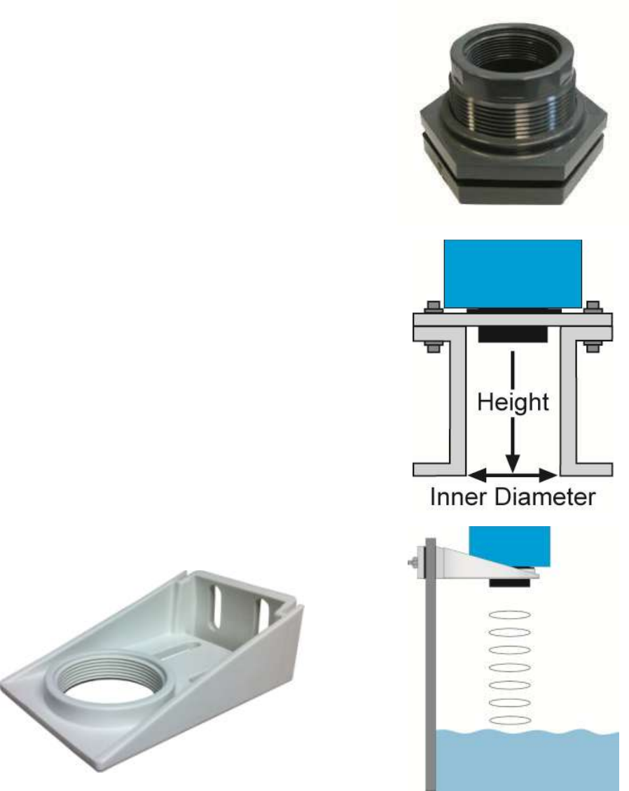
Mounting with a Tank Adapter:
Select a tank adapter fitting, such as the LM52-2890.
Mounting in Riser:
As installations with tall, narrow risers can impede the
acoustic signal. 2" diameter risers should be no taller than
5". Larger diameter risers should be no taller than 12".
For best results, follow a 2:1 Height to Inner Diameter
ratio (example: 8” High to 4” Inner Diameter).
Mounting in Side Mount Bracket:
Use Flowline's LM50-1001 side mount bracket.
LM50-1001 Shown
| 4 QS301550 Rev D1
IMPORTANT MOUNTING GUIDELINES
1) Never mount the sensor at an angle.
2) Liquid should never enter the dead band.
3) Mount at least 3” from the side wall.
4) Never mount the sensor in a vacuum.
5) Do not obstruct the sensor’s beam width.
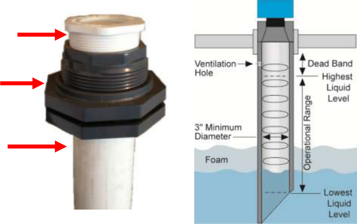
Mounting with a Stand-Pipe:
A stand-pipe may be used to dampen turbulence, separate surface foam from the point of measurement or
increase performance in heavy vapor. When mounting the sensor in a stand-pipe, the minimum diameter of the
pipe is 3”. Larger diameter pipes can be used. The pipe should be attached with a coupling or tank adapter and
reducer bushing. Avoid the use of multiple pipe fittings when possible. An ideal mount would be to select a 3”
tank adapter (S x T or S x S) and connect the pipe to the inside slip and use a reducer bushing to attach the
sensor (see example below).
The pipe length should run the measurement span and the bottom of the pipe should remain submerged at all
times to prevent foam from entering the pipe. Cut the bottom end of the pipe at 45° and drill a 1/4” pressure
equalization hole within the sensor’s dead band. Locate the stand-pipe away from pump outlets and/or other
sources of substantial turbulence which might cause the liquid in the pipe to oscillate.
3” x 2”
Reducer Bushing
(TxT)
3” Tank
Adapter
(S x T)
3” PVC Pipe
Stand-Pipe Example
Stand-Pipe Mounting
QS301550 Rev D1 5 |
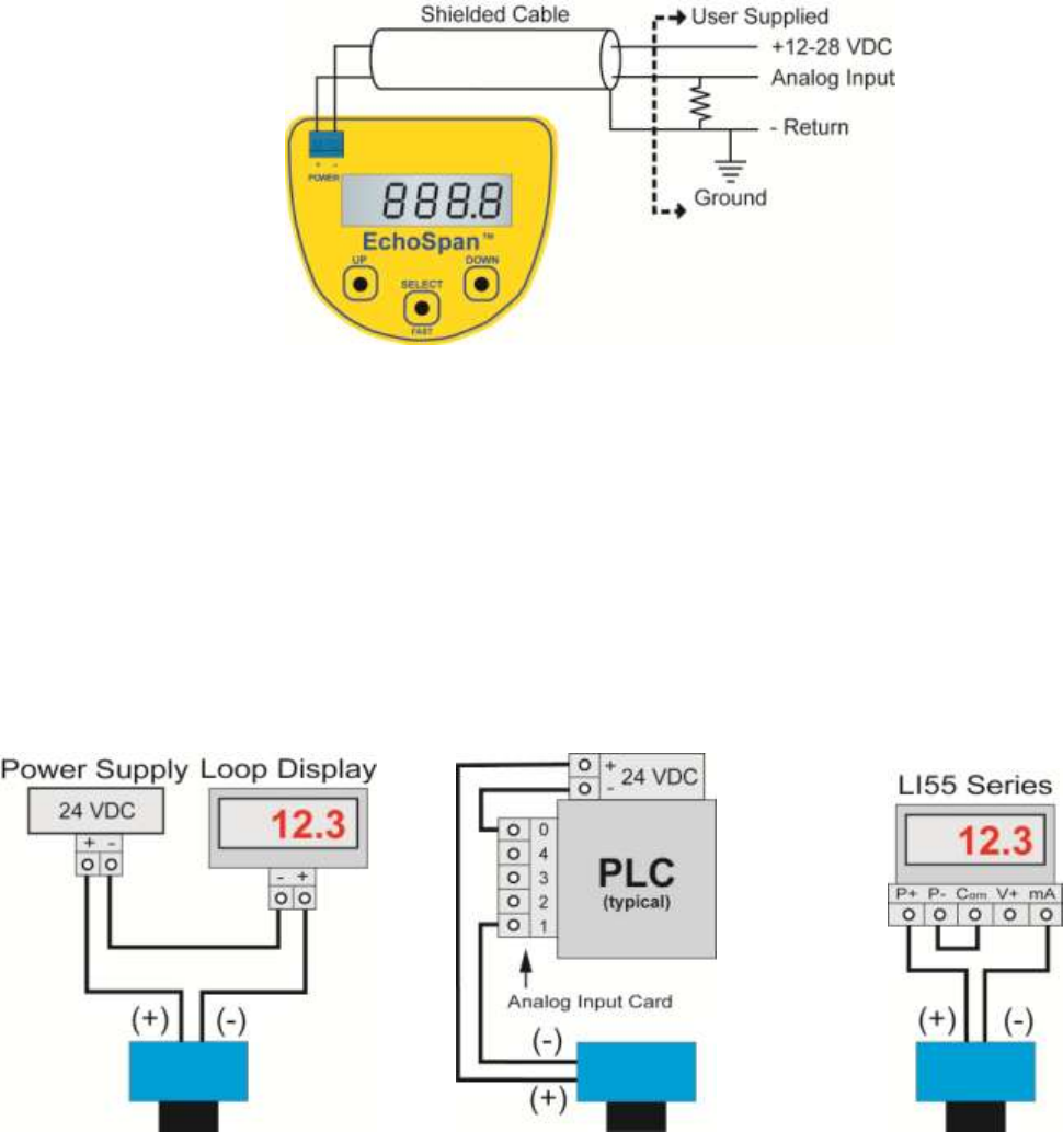
WIRING THE ECHOSPAN®
The following wiring diagram can be used for the 4-20 mA output of the EchoSpan®.
Notes on Safety
Where personal safety or significant property damage can occur due to a spill, the installation must
have a redundant backup safety system installed.
Wiring should always be completed by a licensed electrician.
The sensor must be chemically compatible with the application.
Design a fail-safe system for possible sensor and/or power failure.
Never use the sensor in classified hazardous environments.
Wiring to Common Devices
Wiring to Loop Display
Wiring to Generic PLC
Wiring to DataView™
LI55 series

| 6 QS301550 Rev D1
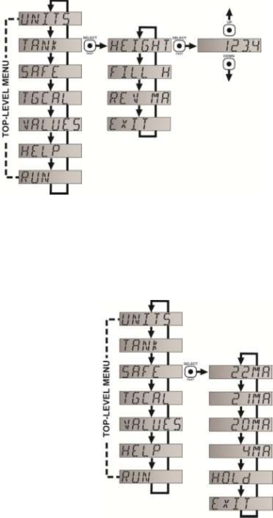
TOP-LEVEL MENU
The sensor is configured with the three buttons on the sensor face (UP,
DOWN and SELECT) and the sensor’s LCD. To access the sensor’s Top-
level menu, simply hold down the SELECT button for five seconds. The
display menu will automatically begin to scroll through the TOP-LEVEL
MENU.
When the menu scrolls to an item you wish to configure, simply press the
SELECT button to choose that item. The TOP-LEVEL MENU will continue to
scroll through the following (UNITS – TANK – SAFE – TGCAL – VALUES –
HELP – RUN), If you miss your selection, it will appear again shortly.
To return to the TOP-LEVEL MENU, press SELECT when EXIT appears.
To return to Operational Mode of the sensor, press SELECT when RUN appears in the TOP-LEVEL
MENU.
Note: To speed up the scrolling of the values on the display, hold down the SELECT button while
holding down the UP or DOWN buttons.
Set Units:
The EchoSpan® displays information in the following units:
inches, feet, centimeters, meters or percentage. The value
shown on the display represents the amount of liquid in the
tank.
1) In TOP-LEVEL MENU mode, select UNITS.
2) Next, select INCHES, FEET, CM, METERS or PERCNT.
SAVED will display.
3) Finally, select EXIT to return to the TOP-LEVEL MENU.
Measuring Sensor Height and Fill-Height:
HEIGHT – Distance from the transducer face to the bottom of the
tank.
FILL-H – Maximum fill height of the liquid from the bottom of the
tank.
Note: The Height and Fill Height settings also determine the 4 to 20 mA
current span. The Height setting determines the 4mA position and the
Fill-H setting determines the 20 mA position.
QS301550 Rev D1 7 |
Set Height and Fill Height:
This setting customizes the reading for your installation.
Follow these instructions to set the height and fill height for your tank:
1) In TOP-LEVEL MENU mode, select TANK.
2) Select HEIGHT.
3) Use the UP and DOWN buttons, set the
HEIGHT of your tank.
4) To enter the value, press and hold SELECT for
2 seconds and release. SAVED will display.
HEIGHT is now set.
5) Select FILL-H.
6) Use the UP and DOWN buttons, set the
HEIGHT of your tank.
7) To enter the value, press and hold SELECT for 2 seconds and release. SAVED will display.
FILL-H is now set.
8) Select EXIT to return to the TOP-LEVEL MENU.
9) Select RUN to return to Operational Mode.
Note: The Height and Fill Height settings also determine the 4 to 20 mA current span.
The Height setting determines the 4mA position and the Fill-H setting determines the 20 mA position.
Select Fail-Safe Output / LOST:
In the event the sensor does not receive an echo, the Fail-Safe
Current Output or LOST setting can be set to output a current of
4mA, 20mA, 21mA, 22mA or HOLD (last known value). During fail-
safe, the display will read LOST.
1) In TOP-LEVEL MENU mode, select SAFE.
2) Select 4mA, 20mA, 21mA, 22mA or HOLD. SAVED will
display.
3) Select EXIT to return to the TOP-LEVEL MENU.
TROUBLESHOOTING
If you face any issues not addressed in this Quick Start, please refer
to the EchoSpan® Manual located on Flowline’s website at
www.flowline.com.
| 8 QS301550 Rev D1
WARRANTY
Flowline warrants to the original purchaser of its products that such products will be free from defects in
material and workmanship under normal use and service in accordance with instructions furnished by Flowline
for a period of two years from the date of manufacture of such products. Flowline's obligation under this
warranty is solely and exclusively limited to the repair or replacement, at Flowline's option, of the products or
components, which Flowline's examination determines to its satisfaction to be defective in material or
workmanship within the warranty period. Flowline must be notified pursuant to the instructions below of any
claim under this warranty within thirty (30) days of any claimed lack of conformity of the product. Any product
repaired under this warranty will be warranted only for the remainder of the original warranty period. Any
product provided as a replacement under this warranty will be warranted for the full two years from the date of
manufacture.
RETURNS
Products cannot be returned to Flowline without Flowline's prior authorization. To return a product that is
thought to be defective, go to flowline.com, and submit a customer return (MRA) request form and follow the
instructions therein. All warranty and non-warranty product returns to Flowline must be shipped prepaid and
insured. Flowline will not be responsible for any products lost or damaged in shipment.
LIMITATIONS
This warranty does not apply to products which: 1) are beyond the warranty period or are products for which
the original purchaser does not follow the warranty procedures outlined above; 2) have been subjected to
electrical, mechanical or chemical damage due to improper, accidental or negligent use; 3) have been modified
or altered; 4) anyone other than service personnel authorized by Flowline have attempted to repair; 5) have
been involved in accidents or natural disasters; or 6) are damaged during return shipment to Flowline. Flowline
reserves the right to unilaterally waive this warranty and dispose of any product returned to Flowline where: 1)
there is evidence of a potentially hazardous material present with the product; or 2) the product has remained
unclaimed at Flowline for more than 30 days after Flowline has dutifully requested disposition. This warranty
contains the sole express warranty made by Flowline in connection with its products. ALL IMPLIED
WARRANTIES, INCLUDING WITHOUT LIMITATION, THE WARRANTIES OF MERCHANTABILITY AND
FITNESS FOR A PARTICULAR PURPOSE, ARE EXPRESSLY DISCLAIMED. The remedies of repair or
replacement as stated above are the exclusive remedies for the breach of this warranty. IN NO EVENT SHALL
FLOWLINE BE LIABLE FOR ANY INCIDENTAL OR CONSEQUENTIAL DAMAGES OF ANY KIND
INCLUDING PERSONAL OR REAL PROPERTY OR FOR INJURY TO ANY PERSON. THIS WARRANTY
CONSTITUTES THE FINAL, COMPLETE AND EXCLUSIVE STATEMENT OF WARRANTY TERMS AND NO
PERSON IS AUTHORIZED TO MAKE ANY OTHER WARRANTIES OR REPRESENTATIONS ON BEHALF
OF FLOWLINE. This warranty will be interpreted pursuant to the laws of the State of California. If any portion
of this warranty is held to be invalid or unenforceable for any reason, such finding will not invalidate any other
provision of this warranty.
For complete product documentation, video training, and technical support, go to flowline.com.
For phone support, call 562-598-3015 from 8am to 5pm PST, Mon - Fri.
(Please make sure you have the Part and Serial number available.)
