Ftp://ftp.comtrol.com/dev_mstr/rts/software/redboot/user_guide/ecos 2.0_redboot Ecos 2.0 Redboot
ftp://ftp.comtrol.com/dev_mstr/DM/software/redboot/user_guide/ecos-2.0_redboot ecos-2.0_redboot user guide pdf
ftp://ftp.comtrol.com/dev_mstr/pro/software/redboot/user_guide/ecos-2.0_redboot ecos-2.0_redboot user guide pdf
User Manual: ftp://ftp.comtrol.com/dev_mstr/rts/software/redboot/user_guide/ecos-2.0_redboot user guide pdf
Open the PDF directly: View PDF ![]() .
.
Page Count: 814 [warning: Documents this large are best viewed by clicking the View PDF Link!]
- eCos Reference Manual
- Table of Contents
- List of Tables
- List of Examples
- I. The eCos Kernel
- Kernel Overview
- SMP Support
- Thread creation
- Thread information
- Thread control
- Thread termination
- Thread priorities
- Perthread data
- Thread destructors
- Exception handling
- Counters
- Clocks
- Alarms
- Mutexes
- Condition Variables
- Semaphores
- Mail boxes
- Event Flags
- Spinlocks
- Scheduler Control
- Interrupt Handling
- Kernel Realtime Characterization
- II. RedBoot User's Guide
- Chapter 1. Getting Started with RedBoot
- Chapter 2. RedBoot Commands and Examples
- Introduction
- Common Commands
- alias
- baudrate
- cache
- channel
- cksum
- disks
- dump
- help
- ipaddress
- load
- mcmp
- mfill
- ping
- reset
- version
- Flash Image System (FIS)
- fis init
- fis list
- fis free
- fis create
- fis load
- fis delete
- fis lock
- fis unlock
- fis erase
- fis write
- Persistent State Flashbased Configuration and Control
- Executing Programs from RedBoot
- go
- exec
- Chapter 3. Rebuilding RedBoot
- Chapter 4. Updating RedBoot
- Chapter 5. Installation and Testing
- AM3x/MN103E010 Matsushita MN103E010 (AM33/2.0) ASB2305 Board
- ARM/ARM7 ARM Evaluator7T
- ARM/ARM7+ARM9 ARM Integrator
- ARM/ARM7+ARM9 ARM PID Board and EPI Dev7+Dev9
- ARM/ARM7 Atmel AT91 Evaluation Board (EB40)
- ARM/ARM7 Cirrus Logic EP7xxx (EDB7211, EDB7212, EDB7312)
- ARM/ARM9 Agilent AAED2000
- ARM/ARM9 Altera Excalibur
- ARM/StrongARM(SA110) Intel EBSA 285
- ARM/StrongARM(SA1100) Intel Brutus
- ARM/StrongARM(SA1100) Intel SA1100 Multimedia Board
- ARM/StrongARM(SA1110) Intel SA1110 (Assabet)
- ARM/StrongARM(SA11X0) Bright Star Engineering commEngine and nanoEngine
- ARM/StrongARM(SA11X0) Compaq iPAQ PocketPC
- ARM/StrongARM(SA11X0) Intrinsyc CerfCube
- ARM/Xscale Cyclone IQ80310
- ARM/Xscale Intel IQ80321
- CalmRISC/CalmRISC16 Samsung CalmRISC16 Core Evaluation Board
- CalmRISC/CalmRISC32 Samsung CalmRISC32 Core Evaluation Board
- FRV/FRV400 Fujitsu FRV 400 (MB93091)
- IA32/x86 x86Based PC
- MIPS/MIPS32(CoreLV 4Kc)+MIPS64(CoreLV 5Kc) Atlas Board
- MIPS/MIPS32(CoreLV 4Kc)+MIPS64(CoreLV 5Kc) Malta Board
- MIPS/RM7000 PMCSierra Ocelot
- MIPS/VR4375 NEC DDBVRC4375
- PowerPC/MPC860T Analogue & Micro PowerPC 860T
- PowerPC/MPC8XX Motorola MBX
- SuperH/SH3(SH7708) Hitachi EDK7708
- SuperH/SH3(SH7709) Hitachi Solution Engine 7709
- SuperH/SH3(SH7729) Hitachi HS7729PCI
- SuperH/SH3(SH77X9) Hitachi Solution Engine 77X9
- SuperH/SH4(SH7751) Hitachi Solution Engine 7751
- III. The eCos Hardware Abstraction Layer (HAL)
- Chapter 6. Introduction
- Chapter 7. Architecture, Variant and Platform
- Chapter 8. General principles
- Chapter 9. HAL Interfaces
- Base Definitions
- Architecture Characterization
- Interrupt Handling
- HAL I/O
- Cache Control
- Linker Scripts
- Diagnostic Support
- SMP Support
- Chapter 10. Exception Handling
- HAL Startup
- Vectors and VSRs
- Default Synchronous Exception Handling
- Default Interrupt Handling
- Chapter 11. Porting Guide
- Introduction
- HAL Structure
- Virtual Vectors (eCos/ROM Monitor Calling Interface)
- HAL Coding Conventions
- Platform HAL Porting
- Variant HAL Porting
- Architecture HAL Porting
- Chapter 12. Future developments
- IV. The ISO Standard C and Math Libraries
- Chapter 13. C and math library overview
- V. I/O Package (Device Drivers)
- Chapter 14. Introduction
- Chapter 15. User API
- Chapter 16. Serial driver details
- Raw Serial Driver
- TTY driver
- Chapter 17. How to Write a Driver
- How to Write a Serial Hardware Interface Driver
- Serial testing with serfilter
- Chapter 18. Device Driver Interface to the Kernel
- Interrupt Model
- Synchronization
- SMP Support
- Device Driver Models
- Synchronization Levels
- The API
- cygdrvisrlock
- cygdrvisrunlock
- cygdrvspinlockinit
- cygdrvspinlockdestroy
- cygdrvspinlockspin
- cygdrvspinlockclear
- cygdrvspinlocktry
- cygdrvspinlocktest
- cygdrvspinlockspinintsave
- cygdrvspinlockclearintsave
- cygdrvdsrlock
- cygdrvdsrunlock
- cygdrvmutexinit
- cygdrvmutexdestroy
- cygdrvmutexlock
- cygdrvmutextrylock
- cygdrvmutexunlock
- cygdrvmutexrelease
- cygdrvcondinit
- cygdrvconddestroy
- cygdrvcondwait
- cygdrvcondsignal
- cygdrvcondbroadcast
- cygdrvinterruptcreate
- cygdrvinterruptdelete
- cygdrvinterruptattach
- cygdrvinterruptdetach
- cygdrvinterruptmask
- cygdrvinterruptmaskintunsafe
- cygdrvinterruptunmask
- cygdrvinterruptunmaskintunsafe
- cygdrvinterruptacknowledge
- cygdrvinterruptconfigure
- cygdrvinterruptlevel
- cygdrvinterruptsetcpu
- cygdrvinterruptgetcpu
- cygISRt
- cygDSRt
- VI. File System Support Infrastructure
- Chapter 19. Introduction
- Chapter 20. File System Table
- Chapter 21. Mount Table
- Chapter 22. File Table
- Chapter 23. Directories
- Chapter 24. Synchronization
- Chapter 25. Initialization and Mounting
- Chapter 26. Sockets
- Chapter 27. Select
- Chapter 28. Devices
- Chapter 29. Writing a New Filesystem
- VII. PCI Library
- Chapter 30. The eCos PCI Library
- VIII. eCos POSIX compatibility layer
- Chapter 31. POSIX Standard Support
- Process Primitives POSIX Section 3
- Process Environment POSIX Section 4
- Files and Directories POSIX Section 5
- Input and Output POSIX Section 6
- Device and Class Specific Functions POSIX Section 7
- C Language Services POSIX Section 8
- System Databases POSIX Section 9
- Data Interchange Format POSIX Section 10
- Synchronization POSIX Section 11
- Memory Management POSIX Section 12
- Execution Scheduling POSIX Section 13
- Clocks and Timers POSIX Section 14
- Message Passing POSIX Section 15
- Thread Management POSIX Section 16
- ThreadSpecific Data POSIX Section 17
- Thread Cancellation POSIX Section 18
- NonPOSIX Functions
- IX. ITRON
- Chapter 32. ITRON API
- Introduction to ITRON
- ITRON and eCos
- Task Management Functions
- TaskDependent Synchronization Functions
- Synchronization and Communication Functions
- Extended Synchronization and Communication Functions
- Interrupt management functions
- Memory pool Management Functions
- Time Management Functions
- System Management Functions
- Network Support Functions
- ITRON Configuration FAQ
- X. TCP/IP Stack Support for eCos
- Chapter 33. Ethernet Driver Design
- Chapter 34. Sample Code
- Chapter 35. Configuring IP Addresses
- Chapter 36. Tests and Demonstrations
- Chapter 37. Support Features
- Chapter 38. TCP/IP Library Reference
- getdomainname
- gethostname
- byteorder
- ethers
- getaddrinfo
- gethostbyname
- getifaddrs
- getnameinfo
- getnetent
- getprotoent
- getrrsetbyname
- getservent
- ifnametoindex
- inet
- inet6optionspace
- inet6rthdrspace
- inetnet
- ipx
- isoaddr
- linkaddr
- netaddrcmp
- ns
- resolver
- accept
- bind
- connect
- getpeername
- getsockname
- getsockopt
- ioctl
- poll
- select
- send
- shutdown
- socket
- socketpair
- XI. FreeBSD TCP/IP Stack port for eCos
- Chapter 39. Networking Stack Features
- Chapter 40. Freebsd TCP/IP stack port
- Chapter 41. APIs
- XII. OpenBSD TCP/IP Stack port for eCos
- Chapter 42. Networking Stack Features
- Chapter 43. OpenBSD TCP/IP stack port
- Chapter 44. APIs
- XIII. DNS for eCos and RedBoot
- Chapter 45. DNS
- XIV. Ethernet Device Drivers
- Chapter 46. Generic Ethernet Device Driver
- XV. SNMP
- Chapter 47. SNMP for eCos
- XVI. Embedded HTTP Server
- Chapter 48. Embedded HTTP Server
- XVII. FTP Client for eCos TCP/IP Stack
- Chapter 49. FTP Client Features
- XVIII. CRC Algorithms
- Chapter 50. CRC Functions
- XIX. CPU load measurements
- Chapter 51. CPU Load Measurements
- XX. Application profiling
- Chapter 52. Profiling functions
- XXI. eCos Power Management Support
- XXII. eCos USB Slave Support
- Introduction
- USB Enumeration Data
- Starting up a USB Device
- Devtab Entries
- Receiving Data from the Host
- Sending Data to the Host
- Halted Endpoints
- Control Endpoints
- Data Endpoints
- Writing a USB Device Driver
- Testing
- XXIII. eCos Support for Developing USBethernet Peripherals
- XXIV. eCos Synthetic Target
- XXV. SA11X0 USB Device Driver
- XXVI. NEC uPD985xx USB Device Driver
- XXVII. Synthetic Target Ethernet Driver
- XXVIII. Synthetic Target Watchdog Device
eCos Reference Manual
eCos Reference Manual
Copyright © 1998, 1999, 2000, 2001, 2002, 2003 by Red Hat, Inc.Nick Garnett (eCosCentric)Jonathan Larmour
(eCosCentric)Andrew Lunn (Ascom)Gary Thomas (MLB Associates)Bart Veer (eCosCentric)
Documentation licensing terms
This material may be distributed only subject to the terms and conditions set forth in the Open Publication License, v1.0 or later (the latest version is
presently available at http://www.opencontent.org/openpub/).
Distribution of substantively modified versions of this document is prohibited without the explicit permission of the copyright holder.
Distribution of the work or derivative of the work in any standard (paper) book form is prohibited unless prior permission is obtained from the copyright
holder.
Trademarks
Red Hat, the Red Hat Shadow Man logo®, eCos™, RedBoot™, GNUPro®, and Insight™ are trademarks of Red Hat, Inc.
Sun Microsystems® and Solaris® are registered trademarks of Sun Microsystems, Inc.
SPARC® is a registered trademark of SPARC International, Inc., and is used under license by Sun Microsystems, Inc.
Intel® is a registered trademark of Intel Corporation.
Motorola™ is a trademark of Motorola, Inc.
ARM® is a registered trademark of Advanced RISC Machines, Ltd.
MIPS™ is a trademark of MIPS Technologies, Inc.
Toshiba® is a registered trademark of the Toshiba Corporation.
NEC® is a registered trademark if the NEC Corporation.
Cirrus Logic® is a registered trademark of Cirrus Logic, Inc.
Compaq® is a registered trademark of the Compaq Computer Corporation.
Matsushita™ is a trademark of the Matsushita Electric Corporation.
Samsung® and CalmRISC™ are trademarks or registered trademarks of Samsung, Inc.
Linux® is a registered trademark of Linus Torvalds.
UNIX® is a registered trademark of The Open Group.
Microsoft®, Windows®, and Windows NT® are registered trademarks of Microsoft Corporation, Inc.
All other brand and product names, trademarks, and copyrights are the property of their respective owners.
Warranty
eCos and RedBoot are open source software, covered by a modified version of the GNU General Public Licence (http://www.gnu.org/copyleft/gpl.html), and
you are welcome to change it and/or distribute copies of it under certain conditions. See http://sources.redhat.com/ecos/license-overview.html for more
information about the license.
eCos and RedBoot software have NO WARRANTY.
Because this software is licensed free of charge, there are no warranties for it, to the extent permitted by applicable law. Except when otherwise stated in
writing, the copyright holders and/or other parties provide the software “as is” without warranty of any kind, either expressed or implied, including, but not
limited to, the implied warranties of merchantability and fitness for a particular purpose. The entire risk as to the quality and performance of the software is
with you. Should the software prove defective, you assume the cost of all necessary servicing, repair or correction.
In no event, unless required by applicable law or agreed to in writing, will any copyright holder, or any other party who may modify and/or redistribute the
program as permitted above, be liable to you for damages, including any general, special, incidental or consequential damages arising out of the use or
inability to use the program (including but not limited to loss of data or data being rendered inaccurate or losses sustained by you or third parties or a failure
of the program to operate with any other programs), even if such holder or other party has been advised of the possibility of such damages.
Table of Contents
I. The eCos Kernel ...............................................................................................................................................xxv
Kernel Overview ............................................................................................................................................27
SMP Support..................................................................................................................................................35
Thread creation ..............................................................................................................................................39
Thread information ........................................................................................................................................43
Thread control................................................................................................................................................47
Thread termination.........................................................................................................................................49
Thread priorities.............................................................................................................................................51
Per-thread data ...............................................................................................................................................53
Thread destructors..........................................................................................................................................55
Exception handling ........................................................................................................................................ 57
Counters .........................................................................................................................................................59
Clocks............................................................................................................................................................. 61
Alarms............................................................................................................................................................63
Mutexes .......................................................................................................................................................... 65
Condition Variables........................................................................................................................................71
Semaphores ....................................................................................................................................................75
Mail boxes...................................................................................................................................................... 77
Event Flags.....................................................................................................................................................79
Spinlocks........................................................................................................................................................83
Scheduler Control ..........................................................................................................................................85
Interrupt Handling.......................................................................................................................................... 87
Kernel Real-time Characterization................................................................................................................. 93
II. RedBoot™ User’s Guide .................................................................................................................................ciii
1. Getting Started with RedBoot......................................................................................................................1
More information about RedBoot on the web........................................................................................ 1
Installing RedBoot.................................................................................................................................. 1
User Interface .........................................................................................................................................2
RedBoot Editing Commands.................................................................................................................. 2
RedBoot Startup Mode........................................................................................................................... 3
RedBoot Resource Usage....................................................................................................................... 4
Flash Resources ............................................................................................................................4
RAM Resources............................................................................................................................ 5
Configuring the RedBoot Environment.................................................................................................. 5
Target Network Configuration ...................................................................................................... 5
Host Network Configuration.........................................................................................................6
Enable TFTP on Red Hat Linux 6.2....................................................................................7
Enable TFTP on Red Hat Linux 7 (or newer) ..................................................................... 7
Enable BOOTP/DHCP server on Red Hat Linux................................................................ 7
Enable DNS server on Red Hat Linux ................................................................................8
RedBoot network gateway ..................................................................................................9
Verification.................................................................................................................................. 10
2. RedBoot Commands and Examples...........................................................................................................11
Introduction ..........................................................................................................................................11
Common Commands............................................................................................................................ 13
v
alias .............................................................................................................................................13
baudrate.......................................................................................................................................15
cache ...........................................................................................................................................17
channel........................................................................................................................................19
cksum..........................................................................................................................................21
disks ............................................................................................................................................23
dump ...........................................................................................................................................25
help..............................................................................................................................................27
ip_address ...................................................................................................................................29
load..............................................................................................................................................31
mcmp...........................................................................................................................................35
mfill.............................................................................................................................................37
ping .............................................................................................................................................39
reset.............................................................................................................................................41
version.........................................................................................................................................43
Flash Image System (FIS) ....................................................................................................................45
fis init ..........................................................................................................................................45
fis list...........................................................................................................................................47
fis free..........................................................................................................................................49
fis create ......................................................................................................................................51
fis load.........................................................................................................................................55
fis delete ......................................................................................................................................57
fis lock.........................................................................................................................................59
fis unlock.....................................................................................................................................61
fis erase........................................................................................................................................63
fis write........................................................................................................................................65
Persistent State Flash-based Configuration and Control ......................................................................67
Executing Programs from RedBoot...................................................................................................... 70
go.................................................................................................................................................71
exec ............................................................................................................................................. 73
3. Rebuilding RedBoot................................................................................................................................... 75
Introduction ..........................................................................................................................................75
Rebuilding RedBoot using ecosconfig........................................................................................75
Rebuilding RedBoot from the Configuration Tool .....................................................................76
4. Updating RedBoot...................................................................................................................................... 79
Introduction ..........................................................................................................................................79
Load and start a RedBoot RAM instance ...................................................................................79
Update the primary RedBoot flash image................................................................................... 80
Reboot; run the new RedBoot image..........................................................................................81
5. Installation and Testing ..............................................................................................................................83
AM3x/MN103E010 Matsushita MN103E010 (AM33/2.0) ASB2305 Board .....................................83
Overview.....................................................................................................................................83
Initial Installation........................................................................................................................83
Preparing to program the board......................................................................................... 83
Preparing to use the JTAG debugger................................................................................. 84
Loading the RAM-based RedBoot via JTAG.................................................................... 84
Loading the boot PROM-based RedBoot via the RAM mode RedBoot........................... 85
Additional Commands ................................................................................................................86
vi
Memory Maps.............................................................................................................................87
Rebuilding RedBoot....................................................................................................................87
ARM/ARM7 ARM Evaluator7T.......................................................................................................... 88
Overview.....................................................................................................................................88
Initial Installation........................................................................................................................88
Quick download instructions ......................................................................................................88
Special RedBoot Commands ......................................................................................................89
Memory Maps.............................................................................................................................89
Rebuilding RedBoot....................................................................................................................89
ARM/ARM7+ARM9 ARM Integrator................................................................................................. 90
Overview.....................................................................................................................................90
Initial Installation........................................................................................................................90
Quick download instructions ......................................................................................................90
Special RedBoot Commands ......................................................................................................91
Memory Maps.............................................................................................................................91
Rebuilding RedBoot....................................................................................................................92
ARM/ARM7+ARM9 ARM PID Board and EPI Dev7+Dev9............................................................. 92
Overview.....................................................................................................................................93
Initial Installation Method...........................................................................................................93
Special RedBoot Commands ......................................................................................................93
Memory Maps.............................................................................................................................93
Rebuilding RedBoot....................................................................................................................93
ARM/ARM7 Atmel AT91 Evaluation Board (EB40).......................................................................... 94
Overview.....................................................................................................................................94
Initial Installation Method...........................................................................................................94
Special RedBoot Commands ......................................................................................................95
Memory Maps.............................................................................................................................95
Rebuilding RedBoot....................................................................................................................96
ARM/ARM7 Cirrus Logic EP7xxx (EDB7211, EDB7212, EDB7312).............................................. 96
Overview.....................................................................................................................................96
Initial Installation Method...........................................................................................................97
Special RedBoot Commands ......................................................................................................97
Memory Maps.............................................................................................................................97
Platform Resource Usage............................................................................................................98
Rebuilding RedBoot....................................................................................................................98
ARM/ARM9 Agilent AAED2000........................................................................................................ 98
Overview.....................................................................................................................................98
Initial Installation Method...........................................................................................................98
RedBoot as Primary Bootmonitor..................................................................................... 98
Special RedBoot Commands ....................................................................................................100
Memory Maps...........................................................................................................................101
Rebuilding RedBoot..................................................................................................................101
ARM/ARM9 Altera Excalibur ...........................................................................................................102
Overview...................................................................................................................................102
Initial Installation Method.........................................................................................................102
Flash management ....................................................................................................................103
Special RedBoot Commands ....................................................................................................103
Memory Maps...........................................................................................................................103
vii
Rebuilding RedBoot..................................................................................................................104
ARM/StrongARM(SA110) Intel EBSA 285...................................................................................... 104
Overview...................................................................................................................................104
Initial Installation Method.........................................................................................................105
Communication Channels.........................................................................................................105
Special RedBoot Commands ....................................................................................................105
Memory Maps...........................................................................................................................105
Platform Resource Usage..........................................................................................................105
Rebuilding RedBoot..................................................................................................................106
ARM/StrongARM(SA1100) Intel Brutus .......................................................................................... 106
Overview...................................................................................................................................106
Initial Installation Method.........................................................................................................106
Special RedBoot Commands ....................................................................................................106
Memory Maps...........................................................................................................................106
Platform Resource Usage..........................................................................................................107
Rebuilding RedBoot..................................................................................................................107
ARM/StrongARM(SA1100) Intel SA1100 Multimedia Board .........................................................108
Overview...................................................................................................................................108
Initial Installation Method.........................................................................................................108
Special RedBoot Commands ....................................................................................................108
Memory Maps...........................................................................................................................108
Platform Resource Usage..........................................................................................................109
Rebuilding RedBoot..................................................................................................................109
ARM/StrongARM(SA1110) Intel SA1110 (Assabet)........................................................................ 109
Overview...................................................................................................................................110
Initial Installation Method.........................................................................................................110
Special RedBoot Commands ....................................................................................................110
Memory Maps...........................................................................................................................110
Platform Resource Usage..........................................................................................................111
Rebuilding RedBoot..................................................................................................................111
ARM/StrongARM(SA11X0) Bright Star Engineering commEngine and nanoEngine..................... 111
Overview...................................................................................................................................111
Initial Installation......................................................................................................................112
Download Instructions.............................................................................................................. 112
Cohabiting with POST in Flash................................................................................................113
Special RedBoot Commands ....................................................................................................113
Memory Maps...........................................................................................................................114
Nano Platform Port ................................................................................................................... 115
Ethernet Driver.......................................................................................................................... 115
Rebuilding RedBoot..................................................................................................................115
ARM/StrongARM(SA11X0) Compaq iPAQ PocketPC..................................................................... 116
Overview...................................................................................................................................116
Initial Installation......................................................................................................................116
Installing RedBoot on the iPAQ using Windows/CE ......................................................116
Installing RedBoot on the iPAQ - using the Compaq boot loader................................... 117
Setting up and testing RedBoot....................................................................................... 117
Installing RedBoot permanently...................................................................................... 118
Restoring Windows/CE................................................................................................... 119
viii
Additional commands...............................................................................................................119
Memory Maps...........................................................................................................................119
Rebuilding RedBoot..................................................................................................................120
ARM/StrongARM(SA11X0) Intrinsyc CerfCube.............................................................................. 120
Overview...................................................................................................................................121
Initial Installation......................................................................................................................121
Additional commands...............................................................................................................121
Memory Maps...........................................................................................................................122
Rebuilding RedBoot..................................................................................................................122
ARM/Xscale Cyclone IQ80310 .........................................................................................................123
Overview...................................................................................................................................123
Initial Installation Method.........................................................................................................123
Error codes................................................................................................................................ 124
Using RedBoot with ARM Bootloader.....................................................................................124
Special RedBoot Commands ....................................................................................................125
IQ80310 Hardware Tests ..........................................................................................................125
Rebuilding RedBoot..................................................................................................................126
Interrupts...................................................................................................................................126
Memory Maps...........................................................................................................................128
Platform Resource Usage..........................................................................................................129
ARM/Xscale Intel IQ80321 ...............................................................................................................129
Overview...................................................................................................................................129
Initial Installation Method.........................................................................................................129
Switch Settings .........................................................................................................................130
LED Codes................................................................................................................................130
Special RedBoot Commands ....................................................................................................132
Memory Tests..................................................................................................................133
Repeating Memory Tests................................................................................................. 133
Repeat-On-Fail Memory Tests ........................................................................................ 133
Rotary Switch S1 Test ..................................................................................................... 133
7 Segment LED Tests......................................................................................................133
i82544 Ethernet Configuration........................................................................................ 134
Battery Status Test........................................................................................................... 134
Battery Backup SDRAM Memory Test .......................................................................... 134
Timer Test........................................................................................................................ 134
PCI Bus Test.................................................................................................................... 134
CPU Cache Loop............................................................................................................. 135
Rebuilding RedBoot..................................................................................................................135
Interrupts...................................................................................................................................135
Memory Maps...........................................................................................................................136
Platform Resource Usage..........................................................................................................137
CalmRISC/CalmRISC16 Samsung CalmRISC16 Core Evaluation Board........................................ 137
Overview...................................................................................................................................137
Initial Installation Method.........................................................................................................138
Special RedBoot Commands ....................................................................................................138
Special Note on Serial Channel ................................................................................................138
Rebuilding RedBoot..................................................................................................................138
CalmRISC/CalmRISC32 Samsung CalmRISC32 Core Evaluation Board........................................ 139
ix
Overview...................................................................................................................................139
Initial Installation Method.........................................................................................................139
Special RedBoot Commands ....................................................................................................140
Special Note on Serial Channel ................................................................................................140
Rebuilding RedBoot..................................................................................................................140
FRV/FRV400 Fujitsu FR-V 400 (MB-93091).................................................................................... 140
Overview...................................................................................................................................140
Initial Installation Method.........................................................................................................141
Special RedBoot Commands ....................................................................................................141
Memory Maps...........................................................................................................................141
Rebuilding RedBoot..................................................................................................................141
IA32/x86 x86-Based PC..................................................................................................................... 142
Overview...................................................................................................................................142
Initial Installation......................................................................................................................142
Flash management ....................................................................................................................143
Special RedBoot Commands ....................................................................................................143
Memory Maps...........................................................................................................................143
Rebuilding RedBoot..................................................................................................................143
MIPS/MIPS32(CoreLV 4Kc)+MIPS64(CoreLV 5Kc) Atlas Board ..................................................143
Overview...................................................................................................................................143
Initial Installation......................................................................................................................144
Quick download instructions........................................................................................... 144
Atlas download format.................................................................................................... 144
Flash management ....................................................................................................................145
Additional config options................................................................................................ 145
Additional commands...............................................................................................................145
Interrupts...................................................................................................................................146
Memory Maps...........................................................................................................................146
Rebuilding RedBoot..................................................................................................................147
MIPS/MIPS32(CoreLV 4Kc)+MIPS64(CoreLV 5Kc) Malta Board.................................................. 147
Overview...................................................................................................................................147
Initial Installation......................................................................................................................147
Quick download instructions........................................................................................... 148
Malta download format ................................................................................................... 148
Additional commands...............................................................................................................148
Interrupts...................................................................................................................................149
Memory Maps...........................................................................................................................150
Rebuilding RedBoot..................................................................................................................150
MIPS/RM7000 PMC-Sierra Ocelot ...................................................................................................150
Overview...................................................................................................................................151
Additional commands...............................................................................................................151
Memory Maps...........................................................................................................................151
Rebuilding RedBoot..................................................................................................................152
MIPS/VR4375 NEC DDB-VRC4375................................................................................................152
Overview...................................................................................................................................152
Initial Installation Method.........................................................................................................153
Special RedBoot Commands ....................................................................................................153
Memory Maps...........................................................................................................................153
x
Ethernet Driver.......................................................................................................................... 154
Rebuilding RedBoot..................................................................................................................154
PowerPC/MPC860T Analogue & Micro PowerPC 860T .................................................................. 154
Overview...................................................................................................................................154
Initial Installation Method.........................................................................................................154
Special RedBoot Commands ....................................................................................................155
Memory Maps...........................................................................................................................155
Rebuilding RedBoot..................................................................................................................155
PowerPC/MPC8XX Motorola MBX.................................................................................................. 155
Overview...................................................................................................................................155
Initial Installation Method.........................................................................................................156
Special RedBoot Commands ....................................................................................................156
Memory Maps...........................................................................................................................156
Rebuilding RedBoot..................................................................................................................157
SuperH/SH3(SH7708) Hitachi EDK7708.......................................................................................... 157
Overview...................................................................................................................................157
Initial Installation Method.........................................................................................................157
Memory Maps...........................................................................................................................157
Rebuilding RedBoot..................................................................................................................158
SuperH/SH3(SH7709) Hitachi Solution Engine 7709 .......................................................................158
Overview...................................................................................................................................158
Initial Installation Method.........................................................................................................158
Special RedBoot Commands ....................................................................................................159
Memory Maps...........................................................................................................................160
Ethernet Driver.......................................................................................................................... 160
Rebuilding RedBoot..................................................................................................................160
SuperH/SH3(SH7729) Hitachi HS7729PCI....................................................................................... 160
Overview...................................................................................................................................161
Initial Installation Method.........................................................................................................161
Special RedBoot Commands ....................................................................................................161
Memory Maps...........................................................................................................................162
Rebuilding RedBoot..................................................................................................................163
SuperH/SH3(SH77X9) Hitachi Solution Engine 77X9 .....................................................................163
Overview...................................................................................................................................163
Initial Installation Method.........................................................................................................163
Special RedBoot Commands ....................................................................................................164
Memory Maps...........................................................................................................................165
Ethernet Driver.......................................................................................................................... 165
Rebuilding RedBoot..................................................................................................................165
SuperH/SH4(SH7751) Hitachi Solution Engine 7751 .......................................................................165
Overview...................................................................................................................................165
Initial Installation Method.........................................................................................................166
Special RedBoot Commands ....................................................................................................166
Memory Maps...........................................................................................................................167
Ethernet Driver.......................................................................................................................... 167
Rebuilding RedBoot..................................................................................................................167
xi
III. The eCos Hardware Abstraction Layer (HAL)..........................................................................................169
6. Introduction..............................................................................................................................................171
7. Architecture, Variant and Platform ..........................................................................................................173
8. General principles ....................................................................................................................................175
9. HAL Interfaces......................................................................................................................................... 177
Base Definitions.................................................................................................................................. 177
Byte order..................................................................................................................................177
Label Translation ...................................................................................................................... 177
Base types .................................................................................................................................177
Atomic types.............................................................................................................................178
Architecture Characterization............................................................................................................. 178
Register Save Format................................................................................................................178
Thread Context Initialization....................................................................................................178
Thread Context Switching ........................................................................................................179
Bit indexing...............................................................................................................................180
Idle thread activity ....................................................................................................................180
Reorder barrier.......................................................................................................................... 180
Breakpoint support....................................................................................................................180
GDB support.............................................................................................................................181
Setjmp and longjmp support.....................................................................................................181
Stack Sizes ................................................................................................................................181
Address Translation .................................................................................................................. 182
Global Pointer...........................................................................................................................182
Interrupt Handling ..............................................................................................................................182
Vector numbers .........................................................................................................................182
Interrupt state control................................................................................................................ 183
ISR and VSR management .......................................................................................................184
Interrupt controller management...............................................................................................184
Clock control.............................................................................................................................186
Microsecond Delay...................................................................................................................186
HAL I/O.............................................................................................................................................. 186
Register address ........................................................................................................................ 186
Register read ............................................................................................................................. 187
Register write............................................................................................................................ 187
Cache Control..................................................................................................................................... 187
Cache Dimensions ....................................................................................................................188
Global Cache Control ...............................................................................................................189
Cache Line Control................................................................................................................... 190
Linker Scripts ..................................................................................................................................... 191
Diagnostic Support.............................................................................................................................192
SMP Support ...................................................................................................................................... 192
Target Hardware Limitations .................................................................................................... 192
HAL Support.............................................................................................................................193
CPU Control.................................................................................................................... 193
Test-and-set Support........................................................................................................ 194
Spinlocks .........................................................................................................................194
Scheduler Lock................................................................................................................ 195
Interrupt Routing............................................................................................................. 196
xii
10. Exception Handling................................................................................................................................ 197
HAL Startup .......................................................................................................................................197
Vectors and VSRs............................................................................................................................... 198
Default Synchronous Exception Handling ......................................................................................... 200
Default Interrupt Handling .................................................................................................................200
11. Porting Guide ......................................................................................................................................... 203
Introduction ........................................................................................................................................203
HAL Structure ....................................................................................................................................203
HAL Classes .............................................................................................................................203
File Descriptions.......................................................................................................................204
Common HAL................................................................................................................. 205
Architecture HAL............................................................................................................ 205
Variant HAL ....................................................................................................................206
Platform HAL.................................................................................................................. 207
Auxiliary HAL ................................................................................................................208
Virtual Vectors (eCos/ROM Monitor Calling Interface) .................................................................... 208
Virtual Vectors .......................................................................................................................... 208
Initialization (or Mechanism vs. Policy)......................................................................... 208
Pros and Cons of Virtual Vectors .................................................................................... 209
Available services............................................................................................................ 210
The COMMS channels .............................................................................................................210
Console and Debugging Channels .................................................................................. 210
Mangling .........................................................................................................................211
Controlling the Console Channel .................................................................................... 211
Footnote: Design Reasoning for Control of Console Channel........................................ 212
The calling Interface API.......................................................................................................... 213
Implemented Services .....................................................................................................213
Compatibility................................................................................................................... 214
Implementation details ....................................................................................................215
New Platform Ports ......................................................................................................... 215
New architecture ports.....................................................................................................215
IO channels ...............................................................................................................................215
Available Procedures.......................................................................................................216
Usage............................................................................................................................... 217
Compatibility................................................................................................................... 218
Implementation Details ...................................................................................................218
New Platform Ports ......................................................................................................... 218
HAL Coding Conventions..................................................................................................................219
Implementation issues...............................................................................................................219
Source code details ...................................................................................................................220
Nested Headers .........................................................................................................................221
Platform HAL Porting........................................................................................................................221
HAL Platform Porting Process .................................................................................................222
Brief overview................................................................................................................. 222
Step-by-step..................................................................................................................... 222
Minimal requirements............................................................................................ 223
Adding features...................................................................................................... 224
Hints ................................................................................................................................225
xiii
HAL Platform CDL ..................................................................................................................226
eCos Database .................................................................................................................226
CDL File Layout ............................................................................................................. 227
Startup Type .................................................................................................................... 228
Build options ...................................................................................................................228
Common Target Options .................................................................................................230
Platform Memory Layout .........................................................................................................233
Layout Files..................................................................................................................... 233
Reserved Regions............................................................................................................ 233
Platform Serial Device Support ................................................................................................ 233
Variant HAL Porting........................................................................................................................... 235
HAL Variant Porting Process.................................................................................................... 235
HAL Variant CDL..................................................................................................................... 236
Cache Support...........................................................................................................................237
Architecture HAL Porting .................................................................................................................. 238
HAL Architecture Porting Process ...........................................................................................238
CDL Requirements ...................................................................................................................244
12. Future developments ..............................................................................................................................247
IV. The ISO Standard C and Math Libraries...................................................................................................249
13. C and math library overview.................................................................................................................. 251
Included non-ISO functions ...............................................................................................................251
Math library compatibility modes ......................................................................................................252
matherr() ...................................................................................................................................252
Thread-safety and re-entrancy .................................................................................................. 254
Some implementation details .............................................................................................................254
Thread safety ......................................................................................................................................256
C library startup.................................................................................................................................. 256
V. I/O Package (Device Drivers).........................................................................................................................259
14. Introduction............................................................................................................................................261
15. User API................................................................................................................................................. 263
16. Serial driver details................................................................................................................................. 265
Raw Serial Driver ............................................................................................................................... 265
Runtime Configuration .............................................................................................................265
API Details................................................................................................................................267
cyg_io_write.................................................................................................................... 267
cyg_io_read .....................................................................................................................267
cyg_io_get_config ...........................................................................................................267
cyg_io_set_config............................................................................................................ 270
TTY driver.......................................................................................................................................... 271
Runtime configuration ..............................................................................................................271
API details.................................................................................................................................272
17. How to Write a Driver............................................................................................................................ 275
How to Write a Serial Hardware Interface Driver.............................................................................. 276
DevTab Entry ............................................................................................................................ 277
Serial Channel Structure ........................................................................................................... 277
Serial Functions Structure.........................................................................................................278
Callbacks...................................................................................................................................279
xiv
Serial testing with ser_filter................................................................................................................ 281
Rationale ...................................................................................................................................281
The Protocol..............................................................................................................................281
The Serial Tests......................................................................................................................... 282
Serial Filter Usage.....................................................................................................................282
A Note on Failures.................................................................................................................... 284
Debugging.................................................................................................................................284
18. Device Driver Interface to the Kernel ....................................................................................................285
Interrupt Model................................................................................................................................... 285
Synchronization.................................................................................................................................. 285
SMP Support ...................................................................................................................................... 286
Device Driver Models......................................................................................................................... 286
Synchronization Levels ...................................................................................................................... 287
The API .............................................................................................................................................. 288
cyg_drv_isr_lock.......................................................................................................................288
cyg_drv_isr_unlock...................................................................................................................289
cyg_drv_spinlock_init...............................................................................................................289
cyg_drv_spinlock_destroy ........................................................................................................ 289
cyg_drv_spinlock_spin .............................................................................................................290
cyg_drv_spinlock_clear ............................................................................................................290
cyg_drv_spinlock_try ...............................................................................................................291
cyg_drv_spinlock_test ..............................................................................................................291
cyg_drv_spinlock_spin_intsave................................................................................................292
cyg_drv_spinlock_clear_intsave...............................................................................................292
cyg_drv_dsr_lock......................................................................................................................293
cyg_drv_dsr_unlock..................................................................................................................293
cyg_drv_mutex_init .................................................................................................................. 294
cyg_drv_mutex_destroy............................................................................................................ 294
cyg_drv_mutex_lock................................................................................................................. 295
cyg_drv_mutex_trylock ............................................................................................................ 295
cyg_drv_mutex_unlock............................................................................................................. 296
cyg_drv_mutex_release ............................................................................................................ 296
cyg_drv_cond_init ....................................................................................................................296
cyg_drv_cond_destroy.............................................................................................................. 297
cyg_drv_cond_wait...................................................................................................................297
cyg_drv_cond_signal ................................................................................................................298
cyg_drv_cond_broadcast ..........................................................................................................298
cyg_drv_interrupt_create ..........................................................................................................299
cyg_drv_interrupt_delete ..........................................................................................................300
cyg_drv_interrupt_attach ..........................................................................................................300
cyg_drv_interrupt_detach .........................................................................................................301
cyg_drv_interrupt_mask ...........................................................................................................301
cyg_drv_interrupt_mask_intunsafe...........................................................................................301
cyg_drv_interrupt_unmask .......................................................................................................302
cyg_drv_interrupt_unmask_intunsafe.......................................................................................302
cyg_drv_interrupt_acknowledge............................................................................................... 303
cyg_drv_interrupt_configure.....................................................................................................303
cyg_drv_interrupt_level............................................................................................................304
xv
cyg_drv_interrupt_set_cpu .......................................................................................................304
cyg_drv_interrupt_get_cpu....................................................................................................... 305
cyg_ISR_t .................................................................................................................................305
cyg_DSR_t................................................................................................................................306
VI. File System Support Infrastructure.............................................................................................................309
19. Introduction............................................................................................................................................311
20. File System Table...................................................................................................................................313
21. Mount Table ...........................................................................................................................................315
22. File Table................................................................................................................................................317
23. Directories..............................................................................................................................................319
24. Synchronization ..................................................................................................................................... 321
25. Initialization and Mounting.................................................................................................................... 323
26. Sockets ...................................................................................................................................................325
27. Select......................................................................................................................................................327
28. Devices................................................................................................................................................... 329
29. Writing a New Filesystem...................................................................................................................... 331
VII. PCI Library..................................................................................................................................................335
30. The eCos PCI Library ............................................................................................................................337
PCI Library......................................................................................................................................... 337
PCI Overview............................................................................................................................ 337
Initializing the bus.....................................................................................................................337
Scanning for devices................................................................................................................. 337
Generic config information....................................................................................................... 338
Specific config information.......................................................................................................339
Allocating memory ...................................................................................................................339
Interrupts...................................................................................................................................340
Activating a device.................................................................................................................... 340
Links .........................................................................................................................................341
PCI Library reference......................................................................................................................... 341
PCI Library API........................................................................................................................341
Definitions.................................................................................................................................342
Types and data structures..........................................................................................................342
Functions...................................................................................................................................342
Resource allocation................................................................................................................... 344
PCI Library Hardware API.......................................................................................................345
HAL PCI support......................................................................................................................346
VIII. eCos POSIX compatibility layer...............................................................................................................349
31. POSIX Standard Support .......................................................................................................................351
Process Primitives [POSIX Section 3] ............................................................................................... 351
Functions Implemented.............................................................................................................351
Functions Omitted.....................................................................................................................352
Notes .........................................................................................................................................352
Process Environment [POSIX Section 4]........................................................................................... 352
Functions Implemented.............................................................................................................352
Functions Omitted.....................................................................................................................353
Notes .........................................................................................................................................353
Files and Directories [POSIX Section 5]............................................................................................ 354
xvi
Functions Implemented.............................................................................................................354
Functions Omitted.....................................................................................................................354
Notes .........................................................................................................................................354
Input and Output [POSIX Section 6].................................................................................................. 355
Functions Implemented.............................................................................................................355
Functions Omitted.....................................................................................................................355
Notes .........................................................................................................................................355
Device and Class Specific Functions [POSIX Section 7]................................................................... 355
Functions Implemented.............................................................................................................355
Functions Omitted.....................................................................................................................356
Notes .........................................................................................................................................356
C Language Services [POSIX Section 8]........................................................................................... 356
Functions Implemented.............................................................................................................356
Functions Omitted.....................................................................................................................357
Notes .........................................................................................................................................357
System Databases [POSIX Section 9]................................................................................................ 357
Functions Implemented.............................................................................................................357
Functions Omitted.....................................................................................................................357
Notes .........................................................................................................................................357
Data Interchange Format [POSIX Section 10]................................................................................... 358
Synchronization [POSIX Section 11]................................................................................................. 358
Functions Implemented.............................................................................................................358
Functions Omitted.....................................................................................................................358
Notes .........................................................................................................................................359
Memory Management [POSIX Section 12] .......................................................................................359
Functions Implemented.............................................................................................................359
Functions Omitted.....................................................................................................................359
Notes .........................................................................................................................................359
Execution Scheduling [POSIX Section 13]........................................................................................ 360
Functions Implemented.............................................................................................................360
Functions Omitted.....................................................................................................................360
Notes .........................................................................................................................................360
Clocks and Timers [POSIX Section 14]............................................................................................. 361
Functions Implemented.............................................................................................................361
Functions Omitted.....................................................................................................................361
Notes .........................................................................................................................................361
Message Passing [POSIX Section 15]................................................................................................ 362
Functions Implemented.............................................................................................................362
Functions Omitted.....................................................................................................................362
Notes .........................................................................................................................................362
Thread Management [POSIX Section 16].......................................................................................... 362
Functions Implemented.............................................................................................................363
Functions Omitted.....................................................................................................................363
Notes .........................................................................................................................................363
Thread-Specific Data [POSIX Section 17]......................................................................................... 364
Functions Implemented.............................................................................................................364
Functions Omitted.....................................................................................................................364
Notes .........................................................................................................................................364
xvii
Thread Cancellation [POSIX Section 18] .......................................................................................... 364
Functions Implemented.............................................................................................................364
Functions Omitted.....................................................................................................................365
Notes .........................................................................................................................................365
Non-POSIX Functions........................................................................................................................ 365
General I/O Functions...............................................................................................................365
Socket Functions.......................................................................................................................365
Notes .........................................................................................................................................366
References and Bibliography.......................................................................................................................367
IX. µITRON ......................................................................................................................................................... 367
32. µITRON API..........................................................................................................................................369
Introduction to µITRON..................................................................................................................... 369
µITRON and eCos.............................................................................................................................. 369
Task Management Functions.............................................................................................................. 370
Error checking...........................................................................................................................371
Task-Dependent Synchronization Functions...................................................................................... 372
Error checking...........................................................................................................................372
Synchronization and Communication Functions................................................................................ 373
Error checking...........................................................................................................................374
Extended Synchronization and Communication Functions ...............................................................375
Interrupt management functions......................................................................................................... 375
Error checking...........................................................................................................................376
Memory pool Management Functions................................................................................................ 376
Error checking...........................................................................................................................378
Time Management Functions ............................................................................................................. 379
Error checking...........................................................................................................................379
System Management Functions.......................................................................................................... 380
Error checking...........................................................................................................................380
Network Support Functions................................................................................................................ 380
µITRON Configuration FAQ.............................................................................................................. 381
X. TCP/IP Stack Support for eCos.....................................................................................................................387
33. Ethernet Driver Design........................................................................................................................... 389
34. Sample Code ..........................................................................................................................................391
35. Configuring IP Addresses ...................................................................................................................... 393
36. Tests and Demonstrations ......................................................................................................................395
Loopback tests.................................................................................................................................... 395
Building the Network Tests ................................................................................................................ 395
Standalone Tests ................................................................................................................................. 395
Performance Test ................................................................................................................................ 396
Interactive Tests.................................................................................................................................. 397
Maintenance Tools.............................................................................................................................. 398
37. Support Features ....................................................................................................................................401
TFTP................................................................................................................................................... 401
DHCP .................................................................................................................................................401
38. TCP/IP Library Reference .....................................................................................................................403
getdomainname................................................................................................................................... 403
gethostname........................................................................................................................................ 404
xviii
byteorder............................................................................................................................................. 405
ethers................................................................................................................................................... 407
getaddrinfo.......................................................................................................................................... 408
gethostbyname.................................................................................................................................... 414
getifaddrs ............................................................................................................................................417
getnameinfo ........................................................................................................................................418
getnetent .............................................................................................................................................422
getprotoent.......................................................................................................................................... 423
getrrsetbyname ...................................................................................................................................425
getservent............................................................................................................................................ 427
if_nametoindex................................................................................................................................... 428
inet......................................................................................................................................................429
inet6_option_space............................................................................................................................. 433
inet6_rthdr_space ...............................................................................................................................437
inet_net ...............................................................................................................................................440
ipx....................................................................................................................................................... 442
iso_addr ..............................................................................................................................................443
link_addr............................................................................................................................................. 444
net_addrcmp .......................................................................................................................................445
ns......................................................................................................................................................... 446
resolver ...............................................................................................................................................447
accept.................................................................................................................................................. 450
bind..................................................................................................................................................... 452
connect................................................................................................................................................ 453
getpeername........................................................................................................................................ 455
getsockname .......................................................................................................................................457
getsockopt........................................................................................................................................... 458
ioctl..................................................................................................................................................... 462
poll...................................................................................................................................................... 463
select................................................................................................................................................... 465
send..................................................................................................................................................... 467
shutdown............................................................................................................................................. 470
socket.................................................................................................................................................. 471
socketpair............................................................................................................................................ 473
XI. FreeBSD TCP/IP Stack port for eCos ......................................................................................................... 475
39. Networking Stack Features .................................................................................................................... 477
40. Freebsd TCP/IP stack port ..................................................................................................................... 479
Targets ................................................................................................................................................479
Building the Network Stack ............................................................................................................... 479
41. APIs........................................................................................................................................................ 481
Standard networking........................................................................................................................... 481
Enhanced Select()............................................................................................................................... 481
XII. OpenBSD TCP/IP Stack port for eCos......................................................................................................483
42. Networking Stack Features .................................................................................................................... 485
43. OpenBSD TCP/IP stack port.................................................................................................................. 487
Targets ................................................................................................................................................487
Building the Network Stack ............................................................................................................... 487
xix
44. APIs........................................................................................................................................................ 489
Standard networking........................................................................................................................... 489
Enhanced Select()............................................................................................................................... 489
XIII. DNS for eCos and RedBoot .......................................................................................................................491
45. DNS........................................................................................................................................................ 493
DNS API............................................................................................................................................. 493
XIV. Ethernet Device Drivers.............................................................................................................................495
46. Generic Ethernet Device Driver............................................................................................................. 497
Generic Ethernet API .........................................................................................................................497
Review of the functions...................................................................................................................... 499
Init function...............................................................................................................................499
Start function.............................................................................................................................500
Stop function.............................................................................................................................500
Control function........................................................................................................................501
Can-send function.....................................................................................................................502
Send function ............................................................................................................................502
Deliver function ........................................................................................................................ 503
Receive function ....................................................................................................................... 503
Poll function..............................................................................................................................504
Interrupt-vector function........................................................................................................... 504
Upper Layer Functions....................................................................................................................... 504
Callback Init function ...............................................................................................................505
Callback Tx-Done function.......................................................................................................505
Callback Receive function ........................................................................................................505
Calling graph for Transmission and Reception ..................................................................................505
Transmission ............................................................................................................................. 505
Receive...................................................................................................................................... 506
XV. SNMP ............................................................................................................................................................509
47. SNMP for eCos ......................................................................................................................................511
Version................................................................................................................................................ 511
SNMP packages in the eCos source repository.................................................................................. 511
MIBs supported ..................................................................................................................................511
Changes to eCos sources ....................................................................................................................512
Starting the SNMP Agent................................................................................................................... 512
Configuring eCos................................................................................................................................ 513
Version usage (v1, v2 or v3) ..................................................................................................... 513
Traps.......................................................................................................................................... 514
snmpd.conf file........................................................................................................................514
Test cases ............................................................................................................................................ 515
SNMP clients and package use........................................................................................................... 516
Unimplemented features..................................................................................................................... 516
MIB Compiler .................................................................................................................................... 517
snmpd.conf .........................................................................................................................................518
xx
XVI. Embedded HTTP Server ...........................................................................................................................527
48. Embedded HTTP Server ........................................................................................................................ 529
Intrduction ..........................................................................................................................................529
Server Organization............................................................................................................................ 529
Server Configuration ..........................................................................................................................530
CYGNUM_HTTPD_SERVER_PORT ................................................................................................530
CYGDAT_HTTPD_SERVER_ID..................................................................................................... 530
CYGNUM_HTTPD_THREAD_COUNT ..............................................................................................530
CYGNUM_HTTPD_THREAD_PRIORITY ........................................................................................530
CYGNUM_HTTPD_THREAD_STACK_SIZE.................................................................................... 530
CYGNUM_HTTPD_SERVER_BUFFER_SIZE.................................................................................. 531
CYGNUM_HTTPD_SERVER_DELAY ..............................................................................................531
Support Functions and Macros........................................................................................................... 531
HTTP Support...........................................................................................................................531
General HTML Support............................................................................................................ 532
Table Support............................................................................................................................532
Forms Support...........................................................................................................................532
Predefined Handlers.................................................................................................................. 533
System Monitor ..................................................................................................................................534
XVII. FTP Client for eCos TCP/IP Stack..........................................................................................................535
49. FTP Client Features ...............................................................................................................................537
FTP Client API................................................................................................................................... 537
ftp_get .......................................................................................................................................537
ftp_put.......................................................................................................................................537
ftpclient_printf ..........................................................................................................................537
XVIII. CRC Algorithms......................................................................................................................................539
50. CRC Functions....................................................................................................................................... 541
CRC API............................................................................................................................................. 541
cyg_posix_crc32 .......................................................................................................................541
cyg_crc32.................................................................................................................................. 541
cyg_ether_crc32........................................................................................................................ 541
cyg_crc16.................................................................................................................................. 541
XIX. CPU load measurements............................................................................................................................543
51. CPU Load Measurements ...................................................................................................................... 545
CPU Load API.................................................................................................................................... 545
cyg_cpuload_calibrate ..............................................................................................................545
cyg_cpuload_create...................................................................................................................545
cyg_cpuload_delete...................................................................................................................545
cyg_cpuload_get .......................................................................................................................546
Implementation details..............................................................................................................546
XX. Application profiling....................................................................................................................................547
52. Profiling functions.................................................................................................................................. 549
API...................................................................................................................................................... 549
profile_on..................................................................................................................................549
xxi
XXI. eCos Power Management Support............................................................................................................551
Introduction..................................................................................................................................................553
Power Management Information.................................................................................................................. 557
Changing Power Modes...............................................................................................................................561
Support for Policy Modules ......................................................................................................................... 563
Attached and Detached Controllers ............................................................................................................. 567
Implementing a Power Controller................................................................................................................ 569
XXII. eCos USB Slave Support ..........................................................................................................................573
Introduction..................................................................................................................................................575
USB Enumeration Data................................................................................................................................ 579
Starting up a USB Device ............................................................................................................................ 585
Devtab Entries.............................................................................................................................................. 587
Receiving Data from the Host...................................................................................................................... 591
Sending Data to the Host .............................................................................................................................595
Halted Endpoints.......................................................................................................................................... 597
Control Endpoints ........................................................................................................................................599
Data Endpoints.............................................................................................................................................605
Writing a USB Device Driver ...................................................................................................................... 607
Testing..........................................................................................................................................................613
XXIII. eCos Support for Developing USB-ethernet Peripherals..................................................................... 625
Introduction..................................................................................................................................................627
Initializing the USB-ethernet Package.........................................................................................................629
USB-ethernet Data Transfers .......................................................................................................................631
USB-ethernet State Handling....................................................................................................................... 633
Network Device for the eCos TCP/IP Stack ................................................................................................ 635
Example Host-side Device Driver................................................................................................................ 637
Communication Protocol .............................................................................................................................639
XXIV. eCos Synthetic Target..............................................................................................................................641
Overview ...................................................................................................................................................... 643
Installation.................................................................................................................................................... 647
Running a Synthetic Target Application......................................................................................................649
The I/O Auxiliary’s User Interface .............................................................................................................. 655
The Console Device.....................................................................................................................................661
System Calls................................................................................................................................................. 663
Writing New Devices - target....................................................................................................................... 665
Writing New Devices - host......................................................................................................................... 671
Porting..........................................................................................................................................................681
XXV. SA11X0 USB Device Driver .....................................................................................................................685
SA11X0 USB Device Driver ....................................................................................................................... 687
XXVI. NEC uPD985xx USB Device Driver.......................................................................................................691
NEC uPD985xx USB Device Driver ...........................................................................................................693
XXVII. Synthetic Target Ethernet Driver.........................................................................................................697
Synthetic Target Ethernet Driver.................................................................................................................. 699
XXVIII. Synthetic Target Watchdog Device ..................................................................................................... 705
Synthetic Target Watchdog Device .............................................................................................................. 707
xxii
List of Tables
13-1. Behavior of math exception handling...........................................................................................................253
List of Examples
1-1. Sample DHCP configuration file........................................................................................................................ 8
1-2. Sample /etc/named.conf for Red Hat Linux 7.x ...........................................................................................8
xxiii
xxiv
I. The eCos Kernel
Kernel Overview
Name
Kernel — Overview of the eCos Kernel
Description
The kernel is one of the key packages in all of eCos. It provides the core functionality needed for developing
multi-threaded applications:
1. The ability to create new threads in the system, either during startup or when the system is already running.
2. Control over the various threads in the system, for example manipulating their priorities.
3. A choice of schedulers, determining which thread should currently be running.
4. A range of synchronization primitives, allowing threads to interact and share data safely.
5. Integration with the system’s support for interrupts and exceptions.
In some other operating systems the kernel provides additional functionality. For example the kernel may also
provide memory allocation functionality, and device drivers may be part of the kernel as well. This is not the case
for eCos. Memory allocation is handled by a separate package. Similary each device driver will typically be a
separate package. Various packages are combined and configured using the eCos configuration technology to meet
the requirements of the application.
The eCos kernel package is optional. It is possible to write single-threaded applications which do not use any kernel
functionality, for example RedBoot. Typically such applications are based around a central polling loop, continually
checking all devices and taking appropriate action when I/O occurs. A small amount of calculation is possible every
iteration, at the cost of an increased delay between an I/O event occurring and the polling loop detecting the event.
When the requirements are straightforward it may well be easier to develop the application using a polling loop,
avoiding the complexities of multiple threads and synchronization between threads. As requirements get more
complicated a multi-threaded solution becomes more appropriate, requiring the use of the kernel. In fact some of
the more advanced packages in eCos, for example the TCP/IP stack, use multi-threading internally. Therefore if
the application uses any of those packages then the kernel becomes a required package, not an optional one.
The kernel functionality can be used in one of two ways. The kernel provides its own C API, with functions like
cyg_thread_create and cyg_mutex_lock. These can be called directly from application code or from other
packages. Alternatively there are a number of packages which provide compatibility with existing API’s, for exam-
ple POSIX threads or µITRON. These allow application code to call standard functions such as pthread_create,
and those functions are implemented using the basic functionality provided by the eCos kernel. Using compatibility
packages in an eCos application can make it much easier to reuse code developed in other environments, and to
share code.
Although the different compatibility packages have similar requirements on the underlying kernel, for example the
ability to create a new thread, there are differences in the exact semantics. For example, strict µITRON compliance
requires that kernel timeslicing is disabled. This is achieved largely through the configuration technology. The
kernel provides a number of configuration options that control the exact semantics that are provided, and the
various compatibility packages require particular settings for those options. This has two important consequences.
First, it is not usually possible to have two different compatibility packages in one eCos configuration because they
will have conflicting requirements on the underlying kernel. Second, the semantics of the kernel’s own API are only
27
Kernel Overview
loosely defined because of the many configuration options. For example cyg_mutex_lock will always attempt to
lock a mutex, but various configuration options determine the behaviour when the mutex is already locked and
there is a possibility of priority inversion.
The optional nature of the kernel package presents some complications for other code, especially device drivers.
Wherever possible a device driver should work whether or not the kernel is present. However there are some
parts of the system, especially those related to interrupt handling, which should be implemented differently
in multi-threaded environments containing the eCos kernel and in single-threaded environments without the
kernel. To cope with both scenarios the common HAL package provides a driver API, with functions such as
cyg_drv_interrupt_attach. When the kernel package is present these driver API functions map directly on to
the equivalent kernel functions such as cyg_interrupt_attach, using macros to avoid any overheads. When the
kernel is absent the common HAL package implements the driver API directly, but this implementation is simpler
than the one in the kernel because it can assume a single-threaded environment.
Schedulers
When a system involves multiple threads, a scheduler is needed to determine which thread should currently be
running. The eCos kernel can be configured with one of two schedulers, the bitmap scheduler and the multi-level
queue (MLQ) scheduler. The bitmap scheduler is somewhat more efficient, but has a number of limitations. Most
systems will instead use the MLQ scheduler. Other schedulers may be added in the future, either as extensions to
the kernel package or in separate packages.
Both the bitmap and the MLQ scheduler use a simple numerical priority to determine which thread should be
running. The number of priority levels is configurable via the option CYGNUM_KERNEL_SCHED_PRIORITIES, but
a typical system will have up to 32 priority levels. Therefore thread priorities will be in the range 0 to 31, with 0
being the highest priority and 31 the lowest. Usually only the system’s idle thread will run at the lowest priority.
Thread priorities are absolute, so the kernel will only run a lower-priority thread if all higher-priority threads are
currently blocked.
The bitmap scheduler only allows one thread per priority level, so if the system is configured with 32 priority levels
then it is limited to only 32 threads — still enough for many applications. A simple bitmap can be used to keep
track of which threads are currently runnable. Bitmaps can also be used to keep track of threads waiting on a mutex
or other synchronization primitive. Identifying the highest-priority runnable or waiting thread involves a simple
operation on the bitmap, and an array index operation can then be used to get hold of the thread data structure
itself. This makes the bitmap scheduler fast and totally deterministic.
The MLQ scheduler allows multiple threads to run at the same priority. This means that there is no limit on the
number of threads in the system, other than the amount of memory available. However operations such as finding
the highest priority runnable thread are a little bit more expensive than for the bitmap scheduler.
Optionally the MLQ scheduler supports timeslicing, where the scheduler automatically switches from one runnable
thread to another when some number of clock ticks have occurred. Timeslicing only comes into play when there
are two runnable threads at the same priority and no higher priority runnable threads. If timeslicing is disabled
then a thread will not be preempted by another thread of the same priority, and will continue running until either it
explicitly yields the processor or until it blocks by, for example, waiting on a synchronization primitive. The con-
figuration options CYGSEM_KERNEL_SCHED_TIMESLICE and CYGNUM_KERNEL_SCHED_TIMESLICE_TICKS control
timeslicing. The bitmap scheduler does not provide timeslicing support. It only allows one thread per priority level,
so it is not possible to preempt the current thread in favour of another one with the same priority.
Another important configuration option that affects the MLQ scheduler is CY-
GIMP_KERNEL_SCHED_SORTED_QUEUES. This determines what happens when a thread blocks, for example by
28
Kernel Overview
waiting on a semaphore which has no pending events. The default behaviour of the system is last-in-first-out
queuing. For example if several threads are waiting on a semaphore and an event is posted, the thread that gets
woken up is the last one that called cyg_semaphore_wait. This allows for a simple and fast implementation of
both the queue and dequeue operations. However if there are several queued threads with different priorities, it
may not be the highest priority one that gets woken up. In practice this is rarely a problem: usually there will be at
most one thread waiting on a queue, or when there are several threads they will be of the same priority. However
if the application does require strict priority queueing then the option CYGIMP_KERNEL_SCHED_SORTED_QUEUES
should be enabled. There are disadvantages: more work is needed whenever a thread is queued, and the scheduler
needs to be locked for this operation so the system’s dispatch latency is worse. If the bitmap scheduler is used
then priority queueing is automatic and does not involve any penalties.
Some kernel functionality is currently only supported with the MLQ scheduler, not the bitmap scheduler. This
includes support for SMP systems, and protection against priority inversion using either mutex priority ceilings or
priority inheritance.
Synchronization Primitives
The eCos kernel provides a number of different synchronization primitives: mutexes,condition variables,counting
semaphores,mail boxes and event flags.
Mutexes serve a very different purpose from the other primitives. A mutex allows multiple threads to share a
resource safely: a thread locks a mutex, manipulates the shared resource, and then unlocks the mutex again. The
other primitives are used to communicate information between threads, or alternatively from a DSR associated
with an interrupt handler to a thread.
When a thread that has locked a mutex needs to wait for some condition to become true, it should use a condition
variable. A condition variable is essentially just a place for a thread to wait, and which another thread, or DSR, can
use to wake it up. When a thread waits on a condition variable it releases the mutex before waiting, and when it
wakes up it reacquires it before proceeding. These operations are atomic so that synchronization race conditions
cannot be introduced.
A counting semaphore is used to indicate that a particular event has occurred. A consumer thread can wait for this
event to occur, and a producer thread or a DSR can post the event. There is a count associated with the semaphore
so if the event occurs multiple times in quick succession this information is not lost, and the appropriate number of
semaphore wait operations will succeed.
Mail boxes are also used to indicate that a particular event has occurred, and allows for one item of data to be
exchanged per event. Typically this item of data would be a pointer to some data structure. Because of the need to
store this extra data, mail boxes have a finite capacity. If a producer thread generates mail box events faster than
they can be consumed then, to avoid overflow, it will be blocked until space is again available in the mail box. This
means that mail boxes usually cannot be used by a DSR to wake up a thread. Instead mail boxes are typically only
used between threads.
Event flags can be used to wait on some number of different events, and to signal that one or several of these
events have occurred. This is achieved by associating bits in a bit mask with the different events. Unlike a counting
semaphore no attempt is made to keep track of the number of events that have occurred, only the fact that an event
has occurred at least once. Unlike a mail box it is not possible to send additional data with the event, but this does
mean that there is no possibility of an overflow and hence event flags can be used between a DSR and a thread as
well as between threads.
29
Kernel Overview
The eCos common HAL package provides its own device driver API which contains some of the above synchro-
nization primitives. These allow the DSR for an interrupt handler to signal events to higher-level code. If the
configuration includes the eCos kernel package then the driver API routines map directly on to the equivalent
kernel routines, allowing interrupt handlers to interact with threads. If the kernel package is not included and the
application consists of just a single thread running in polled mode then the driver API is implemented entirely
within the common HAL, and with no need to worry about multiple threads the implementation can obviously be
rather simpler.
Threads and Interrupt Handling
During normal operation the processor will be running one of the threads in the system. This may be an application
thread, a system thread running inside say the TCP/IP stack, or the idle thread. From time to time a hardware
interrupt will occur, causing control to be transferred briefly to an interrupt handler. When the interrupt has been
completed the system’s scheduler will decide whether to return control to the interrupted thread or to some other
runnable thread.
Threads and interrupt handlers must be able to interact. If a thread is waiting for some I/O operation to complete,
the interrupt handler associated with that I/O must be able to inform the thread that the operation has completed.
This can be achieved in a number of ways. One very simple approach is for the interrupt handler to set a volatile
variable. A thread can then poll continuously until this flag is set, possibly sleeping for a clock tick in between.
Polling continuously means that the cpu time is not available for other activities, which may be acceptable for some
but not all applications. Polling once every clock tick imposes much less overhead, but means that the thread may
not detect that the I/O event has occurred until an entire clock tick has elapsed. In typical systems this could be as
long as 10 milliseconds. Such a delay might be acceptable for some applications, but not all.
A better solution would be to use one of the synchronization primitives. The interrupt handler could signal a
condition variable, post to a semaphore, or use one of the other primitives. The thread would perform a wait
operation on the same primitive. It would not consume any cpu cycles until the I/O event had occurred, and when
the event does occur the thread can start running again immediately (subject to any higher priority threads that
might also be runnable).
Synchronization primitives constitute shared data, so care must be taken to avoid problems with concurrent access.
If the thread that was interrupted was just performing some calculations then the interrupt handler could manipulate
the synchronization primitive quite safely. However if the interrupted thread happened to be inside some kernel call
then there is a real possibility that some kernel data structure will be corrupted.
One way of avoiding such problems would be for the kernel functions to disable interrupts when executing any
critical region. On most architectures this would be simple to implement and very fast, but it would mean that
interrupts would be disabled often and for quite a long time. For some applications that might not matter, but many
embedded applications require that the interrupt handler run as soon as possible after the hardware interrupt has
occurred. If the kernel relied on disabling interrupts then it would not be able to support such applications.
Instead the kernel uses a two-level approach to interrupt handling. Associated with every interrupt vector is an
Interrupt Service Routine or ISR, which will run as quickly as possible so that it can service the hardware. However
an ISR can make only a small number of kernel calls, mostly related to the interrupt subsystem, and it cannot make
any call that would cause a thread to wake up. If an ISR detects that an I/O operation has completed and hence
that a thread should be woken up, it can cause the associated Deferred Service Routine or DSR to run. A DSR is
allowed to make more kernel calls, for example it can signal a condition variable or post to a semaphore.
Disabling interrupts prevents ISRs from running, but very few parts of the system disable interrupts and then only
for short periods of time. The main reason for a thread to disable interrupts is to manipulate some state that is
30
Kernel Overview
shared with an ISR. For example if a thread needs to add another buffer to a linked list of free buffers and the ISR
may remove a buffer from this list at any time, the thread would need to disable interrupts for the few instructions
needed to manipulate the list. If the hardware raises an interrupt at this time, it remains pending until interrupts are
reenabled.
Analogous to interrupts being disabled or enabled, the kernel has a scheduler lock. The various kernel functions
such as cyg_mutex_lock and cyg_semaphore_post will claim the scheduler lock, manipulate the kernel data
structures, and then release the scheduler lock. If an interrupt results in a DSR being requested and the scheduler
is currently locked, the DSR remains pending. When the scheduler lock is released any pending DSRs will run.
These may post events to synchronization primitives, causing other higher priority threads to be woken up.
For an example, consider the following scenario. The system has a high priority thread A, responsible for processing
some data coming from an external device. This device will raise an interrupt when data is available. There are two
other threads B and C which spend their time performing calculations and occasionally writing results to a display
of some sort. This display is a shared resource so a mutex is used to control access.
At a particular moment in time thread A is likely to be blocked, waiting on a semaphore or another synchronization
primitive until data is available. Thread B might be running performing some calculations, and thread C is runnable
waiting for its next timeslice. Interrupts are enabled, and the scheduler is unlocked because none of the threads are
in the middle of a kernel operation. At this point the device raises an interrupt. The hardware transfers control
to a low-level interrupt handler provided by eCos which works out exactly which interrupt occurs, and then the
corresponding ISR is run. This ISR manipulates the hardware as appropriate, determines that there is now data
available, and wants to wake up thread A by posting to the semaphore. However ISR’s are not allowed to call
cyg_semaphore_post directly, so instead the ISR requests that its associated DSR be run and returns. There are
no more interrupts to be processed, so the kernel next checks for DSR’s. One DSR is pending and the scheduler is
currently unlocked, so the DSR can run immediately and post the semaphore. This will have the effect of making
thread A runnable again, so the scheduler’s data structures are adjusted accordingly. When the DSR returns thread
B is no longer the highest priority runnable thread so it will be suspended, and instead thread A gains control over
the cpu.
In the above example no kernel data structures were being manipulated at the exact moment that the interrupt
happened. However that cannot be assumed. Suppose that thread B had finished its current set of calculations and
wanted to write the results to the display. It would claim the appropriate mutex and manipulate the display. Now
suppose that thread B was timesliced in favour of thread C, and that thread C also finished its calculations and
wanted to write the results to the display. It would call cyg_mutex_lock. This kernel call locks the scheduler,
examines the current state of the mutex, discovers that the mutex is already owned by another thread, suspends
the current thread, and switches control to another runnable thread. Another interrupt happens in the middle of
this cyg_mutex_lock call, causing the ISR to run immediately. The ISR decides that thread A should be woken
up so it requests that its DSR be run and returns back to the kernel. At this point there is a pending DSR, but the
scheduler is still locked by the call to cyg_mutex_lock so the DSR cannot run immediately. Instead the call to
cyg_mutex_lock is allowed to continue, which at some point involves unlocking the scheduler. The pending DSR
can now run, safely post the semaphore, and thus wake up thread A.
If the ISR had called cyg_semaphore_post directly rather than leaving it to a DSR, it is likely that there would
have been some sort of corruption of a kernel data structure. For example the kernel might have completely lost
track of one of the threads, and that thread would never have run again. The two-level approach to interrupt han-
dling, ISR’s and DSR’s, prevents such problems with no need to disable interrupts.
31
Kernel Overview
Calling Contexts
eCos defines a number of contexts. Only certain calls are allowed from inside each context, for example most
operations on threads or synchronization primitives are not allowed from ISR context. The different contexts are
initialization, thread, ISR and DSR.
When eCos starts up it goes through a number of phases, including setting up the hardware and invoking C++ static
constructors. During this time interrupts are disabled and the scheduler is locked. When a configuration includes
the kernel package the final operation is a call to cyg_scheduler_start. At this point interrupts are enabled, the
scheduler is unlocked, and control is transferred to the highest priority runnable thread. If the configuration also
includes the C library package then usually the C library startup package will have created a thread which will call
the application’s main entry point.
Some application code can also run before the scheduler is started, and this code runs in initialization context.
If the application is written partly or completely in C++ then the constructors for any static objects will be run.
Alternatively application code can define a function cyg_user_start which gets called after any C++ static
constructors. This allows applications to be written entirely in C.
void
cyg_user_start(void)
{
/* Perform application-specific initialization here */
}
It is not necessary for applications to provide a cyg_user_start function since the system will provide a default
implementation which does nothing.
Typical operations that are performed from inside static constructors or cyg_user_start include creating threads,
synchronization primitives, setting up alarms, and registering application-specific interrupt handlers. In fact for
many applications all such creation operations happen at this time, using statically allocated data, avoiding any
need for dynamic memory allocation or other overheads.
Code running in initialization context runs with interrupts disabled and the scheduler locked. It is not permitted
to reenable interrupts or unlock the scheduler because the system is not guaranteed to be in a totally consis-
tent state at this point. A consequence is that initialization code cannot use synchronization primitives such as
cyg_semaphore_wait to wait for an external event. It is permitted to lock and unlock a mutex: there are no other
threads running so it is guaranteed that the mutex is not yet locked, and therefore the lock operation will never
block; this is useful when making library calls that may use a mutex internally.
At the end of the startup sequence the system will call cyg_scheduler_start and the various threads will
start running. In thread context nearly all of the kernel functions are available. There may be some restrictions
on interrupt-related operations, depending on the target hardware. For example the hardware may require
that interrupts be acknowledged in the ISR or DSR before control returns to thread context, in which case
cyg_interrupt_acknowledge should not be called by a thread.
At any time the processor may receive an external interrupt, causing control to be transferred from the current
thread. Typically a VSR provided by eCos will run and determine exactly which interrupt occurred. Then the VSR
will switch to the appropriate ISR, which can be provided by a HAL package, a device driver, or by the application.
During this time the system is running at ISR context, and most of the kernel function calls are disallowed. This
includes the various synchronization primitives, so for example an ISR is not allowed to post to a semaphore to
indicate that an event has happened. Usually the only operations that should be performed from inside an ISR are
32
Kernel Overview
ones related to the interrupt subsystem itself, for example masking an interrupt or acknowledging that an interrupt
has been processed. On SMP systems it is also possible to use spinlocks from ISR context.
When an ISR returns it can request that the corresponding DSR be run as soon as it is safe to do so, and that
will run in DSR context. This context is also used for running alarm functions, and threads can switch temporar-
ily to DSR context by locking the scheduler. Only certain kernel functions can be called from DSR context, al-
though more than in ISR context. In particular it is possible to use any synchronization primitives which cannot
block. These include cyg_semaphore_post,cyg_cond_signal,cyg_cond_broadcast,cyg_flag_setbits,
and cyg_mbox_tryput. It is not possible to use any primitives that may block such as cyg_semaphore_wait,
cyg_mutex_lock, or cyg_mbox_put. Calling such functions from inside a DSR may cause the system to hang.
The specific documentation for the various kernel functions gives more details about valid contexts.
Error Handling and Assertions
In many APIs each function is expected to perform some validation of its parameters and possibly of the current
state of the system. This is supposed to ensure that each function is used correctly, and that application code is not
attempting to perform a semaphore operation on a mutex or anything like that. If an error is detected then a suitable
error code is returned, for example the POSIX function pthread_mutex_lock can return various error codes
including EINVAL and EDEADLK. There are a number of problems with this approach, especially in the context of
deeply embedded systems:
1. Performing these checks inside the mutex lock and all the other functions requires extra cpu cycles and adds
significantly to the code size. Even if the application is written correctly and only makes system function calls
with sensible arguments and under the right conditions, these overheads still exist.
2. Returning an error code is only useful if the calling code detects these error codes and takes appropriate action.
In practice the calling code will often ignore any errors because the programmer “knows” that the function is
being used correctly. If the programmer is mistaken then an error condition may be detected and reported, but
the application continues running anyway and is likely to fail some time later in mysterious ways.
3. If the calling code does always check for error codes, that adds yet more cpu cycles and code size overhead.
4. Usually there will be no way to recover from certain errors, so if the application code detected an error such
as EINVAL then all it could do is abort the application somehow.
The approach taken within the eCos kernel is different. Functions such as cyg_mutex_lock will not return an error
code. Instead they contain various assertions, which can be enabled or disabled. During the development process
assertions are normally left enabled, and the various kernel functions will perform parameter checks and other
system consistency checks. If a problem is detected then an assertion failure will be reported and the application
will be terminated. In a typical debug session a suitable breakpoint will have been installed and the developer can
now examine the state of the system and work out exactly what is going on. Towards the end of the development
cycle assertions will be disabled by manipulating configuration options within the eCos infrastructure package, and
all assertions will be eliminated at compile-time. The assumption is that by this time the application code has been
mostly debugged: the initial version of the code might have tried to perform a semaphore operation on a mutex, but
any problems like that will have been fixed some time ago. This approach has a number of advantages:
1. In the final application there will be no overheads for checking parameters and other conditions. All that code
will have been eliminated at compile-time.
33
Kernel Overview
2. Because the final application will not suffer any overheads, it is reasonable for the system to do more work
during the development process. In particular the various assertions can test for more error conditions and
more complicated errors. When an error is detected it is possible to give a text message describing the error
rather than just return an error code.
3. There is no need for application programmers to handle error codes returned by various kernel function calls.
This simplifies the application code.
4. If an error is detected then an assertion failure will be reported immediately and the application will be halted.
There is no possibility of an error condition being ignored because application code did not check for an error
code.
Although none of the kernel functions return an error code, many of them do return a status condition. For example
the function cyg_semaphore_timed_wait waits until either an event has been posted to a semaphore, or until a
certain number of clock ticks have occurred. Usually the calling code will need to know whether the wait operation
succeeded or whether a timeout occurred. cyg_semaphore_timed_wait returns a boolean: a return value of zero
or false indicates a timeout, a non-zero return value indicates that the wait succeeded.
In conventional APIs one common error conditions is lack of memory. For example the POSIX function
pthread_create usually has to allocate some memory dynamically for the thread stack and other per-thread
data. If the target hardware does not have enough memory to meet all demands, or more commonly if the
application contains a memory leak, then there may not be enough memory available and the function call would
fail. The eCos kernel avoids such problems by never performing any dynamic memory allocation. Instead it is the
responsibility of the application code to provide all the memory required for kernel data structures and other
needs. In the case of cyg_thread_create this means a cyg_thread data structure to hold the thread details, and a
char array for the thread stack.
In many applications this approach results in all data structures being allocated statically rather than dynamically.
This has several advantages. If the application is in fact too large for the target hardware’s memory then there will
be an error at link-time rather than at run-time, making the problem much easier to diagnose. Static allocation
does not involve any of the usual overheads associated with dynamic allocation, for example there is no need to
keep track of the various free blocks in the system, and it may be possible to eliminate malloc from the system
completely. Problems such as fragmentation and memory leaks cannot occur if all data is allocated statically.
However, some applications are sufficiently complicated that dynamic memory allocation is required, and the
various kernel functions do not distinguish between statically and dynamically allocated memory. It still remains
the responsibility of the calling code to ensure that sufficient memory is available, and passing null pointers to the
kernel will result in assertions or system failure.
34
SMP Support
Name
SMP — Support Symmetric Multiprocessing Systems
Description
eCos contains support for limited Symmetric Multi-Processing (SMP). This is only available on selected architec-
tures and platforms. The implementation has a number of restrictions on the kind of hardware supported. These are
described in the Section called SMP Support in Chapter 9.
The following sections describe the changes that have been made to the eCos kernel to support SMP operation.
System Startup
The system startup sequence needs to be somewhat different on an SMP system, although this is largely transparent
to application code. The main startup takes place on only one CPU, called the primary CPU. All other CPUs, the
secondary CPUs, are either placed in suspended state at reset, or are captured by the HAL and put into a spin as
they start up. The primary CPU is responsible for copying the DATA segment and zeroing the BSS (if required),
calling HAL variant and platform initialization routines and invoking constructors. It then calls cyg_start to enter
the application. The application may then create extra threads and other objects.
It is only when the application calls cyg_scheduler_start that the secondary CPUs are initialized. This routine
scans the list of available secondary CPUs and invokes HAL_SMP_CPU_START to start each CPU. Finally it calls an
internal function Cyg_Scheduler::start_cpu to enter the scheduler for the primary CPU.
Each secondary CPU starts in the HAL, where it completes any per-CPU initialization before calling into the kernel
at cyg_kernel_cpu_startup. Here it claims the scheduler lock and calls Cyg_Scheduler::start_cpu.
Cyg_Scheduler::start_cpu is common to both the primary and secondary CPUs. The first thing this code does
is to install an interrupt object for this CPU’s inter-CPU interrupt. From this point on the code is the same as for
the single CPU case: an initial thread is chosen and entered.
From this point on the CPUs are all equal, eCos makes no further distinction between the primary and secondary
CPUs. However, the hardware may still distinguish between them as far as interrupt delivery is concerned.
Scheduling
To function correctly an operating system kernel must protect its vital data structures, such as the run queues,
from concurrent access. In a single CPU system the only concurrent activities to worry about are asynchronous
interrupts. The kernel can easily guard its data structures against these by disabling interrupts. However, in a multi-
CPU system, this is inadequate since it does not block access by other CPUs.
The eCos kernel protects its vital data structures using the scheduler lock. In single CPU systems this is a simple
counter that is atomically incremented to acquire the lock and decremented to release it. If the lock is decremented
to zero then the scheduler may be invoked to choose a different thread to run. Because interrupts may continue to
be serviced while the scheduler lock is claimed, ISRs are not allowed to access kernel data structures, or call kernel
35
SMP Support
routines that can. Instead all such operations are deferred to an associated DSR routine that is run during the lock
release operation, when the data structures are in a consistent state.
By choosing a kernel locking mechanism that does not rely on interrupt manipulation to protect data structures,
it is easier to convert eCos to SMP than would otherwise be the case. The principal change needed to make eCos
SMP-safe is to convert the scheduler lock into a nestable spin lock. This is done by adding a spinlock and a CPU
id to the original counter.
The algorithm for acquiring the scheduler lock is very simple. If the scheduler lock’s CPU id matches the current
CPU then it can just increment the counter and continue. If it does not match, the CPU must spin on the spinlock,
after which it may increment the counter and store its own identity in the CPU id.
To release the lock, the counter is decremented. If it goes to zero the CPU id value must be set to NONE and the
spinlock cleared.
To protect these sequences against interrupts, they must be performed with interrupts disabled. However, since
these are very short code sequences, they will not have an adverse effect on the interrupt latency.
Beyond converting the scheduler lock, further preparing the kernel for SMP is a relatively minor matter. The main
changes are to convert various scalar housekeeping variables into arrays indexed by CPU id. These include the
current thread pointer, the need_reschedule flag and the timeslice counter.
At present only the Multi-Level Queue (MLQ) scheduler is capable of supporting SMP configurations. The main
change made to this scheduler is to cope with having several threads in execution at the same time. Running threads
are marked with the CPU that they are executing on. When scheduling a thread, the scheduler skips past any running
threads until it finds a thread that is pending. While not a constant-time algorithm, as in the single CPU case, this
is still deterministic, since the worst case time is bounded by the number of CPUs in the system.
A second change to the scheduler is in the code used to decide when the scheduler should be called to choose a
new thread. The scheduler attempts to keep the n CPUs running the n highest priority threads. Since an event or
interrupt on one CPU may require a reschedule on another CPU, there must be a mechanism for deciding this. The
algorithm currently implemented is very simple. Given a thread that has just been awakened (or had its priority
changed), the scheduler scans the CPUs, starting with the one it is currently running on, for a current thread that
is of lower priority than the new one. If one is found then a reschedule interrupt is sent to that CPU and the scan
continues, but now using the current thread of the rescheduled CPU as the candidate thread. In this way the new
thread gets to run as quickly as possible, hopefully on the current CPU, and the remaining CPUs will pick up the
remaining highest priority threads as a consequence of processing the reschedule interrupt.
The final change to the scheduler is in the handling of timeslicing. Only one CPU receives timer interrupts, although
all CPUs must handle timeslicing. To make this work, the CPU that receives the timer interrupt decrements the
timeslice counter for all CPUs, not just its own. If the counter for a CPU reaches zero, then it sends a timeslice
interrupt to that CPU. On receiving the interrupt the destination CPU enters the scheduler and looks for another
thread at the same priority to run. This is somewhat more efficient than distributing clock ticks to all CPUs, since
the interrupt is only needed when a timeslice occurs.
All existing synchronization mechanisms work as before in an SMP system. Additional synchronization mecha-
nisms have been added to provide explicit synchronization for SMP, in the form of spinlocks.
SMP Interrupt Handling
The main area where the SMP nature of a system requires special attention is in device drivers and especially
interrupt handling. It is quite possible for the ISR, DSR and thread components of a device driver to execute on
different CPUs. For this reason it is much more important that SMP-capable device drivers use the interrupt-related
36
SMP Support
functions correctly. Typically a device driver would use the driver API rather than call the kernel directly, but it is
unlikely that anybody would attempt to use a multiprocessor system without the kernel package.
Two new functions have been added to the Kernel API to do interrupt routing:cyg_interrupt_set_cpu and
cyg_interrupt_get_cpu. Although not currently supported, special values for the cpu argument may be used in
future to indicate that the interrupt is being routed dynamically or is CPU-local. Once a vector has been routed to
a new CPU, all other interrupt masking and configuration operations are relative to that CPU, where relevant.
There are more details of how interrupts should be handled in SMP systems in the Section called SMP Support in
Chapter 18.
37
SMP Support
38
Thread creation
Name
cyg_thread_create — Create a new thread
Synopsis
#include <cyg/kernel/kapi.h>
void cyg_thread_create(cyg_addrword_t sched_info, cyg_thread_entry_t* entry,
cyg_addrword_t entry_data, char* name, void* stack_base, cyg_ucount32 stack_size,
cyg_handle_t* handle, cyg_thread* thread);
Description
The cyg_thread_create function allows application code and eCos packages to create new threads. In many
applications this only happens during system initialization and all required data is allocated statically. However
additional threads can be created at any time, if necessary. A newly created thread is always in suspended state
and will not start running until it has been resumed via a call to cyg_thread_resume. Also, if threads are created
during system initialization then they will not start running until the eCos scheduler has been started.
The name argument is used primarily for debugging purposes, making it easier to keep track of which
cyg_thread structure is associated with which application-level thread. The kernel configuration option
CYGVAR_KERNEL_THREADS_NAME controls whether or not this name is actually used.
On creation each thread is assigned a unique handle, and this will be stored in the location pointed at by the
handle argument. Subsequent operations on this thread including the required cyg_thread_resume should use
this handle to identify the thread.
The kernel requires a small amount of space for each thread, in the form of a cyg_thread data structure, to hold
information such as the current state of that thread. To avoid any need for dynamic memory allocation within the
kernel this space has to be provided by higher-level code, typically in the form of a static variable. The thread
argument provides this space.
Thread Entry Point
The entry point for a thread takes the form:
void
thread_entry_function(cyg_addrword_t data)
{
...
}
39
Thread creation
The second argument to cyg_thread_create is a pointer to such a function. The third argument entry_data
is used to pass additional data to the function. Typically this takes the form of a pointer to some static data, or a
small integer, or 0if the thread does not require any additional data.
If the thread entry function ever returns then this is equivalent to the thread calling cyg_thread_exit. Even
though the thread will no longer run again, it remains registered with the scheduler. If the application needs to
re-use the cyg_thread data structure then a call to cyg_thread_delete is required first.
Thread Priorities
The sched_info argument provides additional information to the scheduler. The exact details depend on the
scheduler being used. For the bitmap and mlqueue schedulers it is a small integer, typically in the range 0 to 31,
with 0 being the highest priority. The lowest priority is normally used only by the system’s idle thread. The exact
number of priorities is controlled by the kernel configuration option CYGNUM_KERNEL_SCHED_PRIORITIES.
It is the responsibility of the application developer to be aware of the various threads in the system, including those
created by eCos packages, and to ensure that all threads run at suitable priorities. For threads created by other
packages the documentation provided by those packages should indicate any requirements.
The functions cyg_thread_set_priority,cyg_thread_get_priority, and
cyg_thread_get_current_priority can be used to manipulate a thread’s priority.
Stacks and Stack Sizes
Each thread needs its own stack for local variables and to keep track of function calls and returns. Again it is
expected that this stack is provided by the calling code, usually in the form of static data, so that the kernel does not
need any dynamic memory allocation facilities. cyg_thread_create takes two arguments related to the stack, a
pointer to the base of the stack and the total size of this stack. On many processors stacks actually descend from
the top down, so the kernel will add the stack size to the base address to determine the starting location.
The exact stack size requirements for any given thread depend on a number of factors. The most important is
of course the code that will be executed in the context of this code: if this involves significant nesting of
function calls, recursion, or large local arrays, then the stack size needs to be set to a suitably high value.
There are some architectural issues, for example the number of cpu registers and the calling conventions
will have some effect on stack usage. Also, depending on the configuration, it is possible that some other
code such as interrupt handlers will occasionally run on the current thread’s stack. This depends in
part on configuration options such as CYGIMP_HAL_COMMON_INTERRUPTS_USE_INTERRUPT_STACK and
CYGSEM_HAL_COMMON_INTERRUPTS_ALLOW_NESTING.
Determining an application’s actual stack size requirements is the responsibility of the application developer,
since the kernel cannot know in advance what code a given thread will run. However, the system does provide
some hints about reasonable stack sizes in the form of two constants: CYGNUM_HAL_STACK_SIZE_MINIMUM and
CYGNUM_HAL_STACK_SIZE_TYPICAL. These are defined by the appropriate HAL package. The MINIMUM value is
appropriate for a thread that just runs a single function and makes very simple system calls. Trying to create a
thread with a smaller stack than this is illegal. The TYPICAL value is appropriate for applications where application
calls are nested no more than half a dozen or so levels, and there are no large arrays on the stack.
If the stack sizes are not estimated correctly and a stack overflow occurs, the probably result is some form of
memory corruption. This can be very hard to track down. The kernel does contain some code to help detect stack
overflows, controlled by the configuration option CYGFUN_KERNEL_THREADS_STACK_CHECKING: a small amount
40
Thread creation
of space is reserved at the stack limit and filled with a special signature: every time a thread context switch occurs
this signature is checked, and if invalid that is a good indication (but not absolute proof) that a stack overflow has
occurred. This form of stack checking is enabled by default when the system is built with debugging enabled. A
related configuration option is CYGFUN_KERNEL_THREADS_STACK_MEASUREMENT: enabling this option means that
a thread can call the function cyg_thread_measure_stack_usage to find out the maximum stack usage to date.
Note that this is not necessarily the true maximum because, for example, it is possible that in the current run no
interrupt occurred at the worst possible moment.
Valid contexts
cyg_thread_create may be called during initialization and from within thread context. It may not be called from
inside a DSR.
Example
A simple example of thread creation is shown below. This involves creating five threads, one producer and four
consumers or workers. The threads are created in the system’s cyg_user_start: depending on the configuration
it might be more appropriate to do this elsewhere, for example inside main.
#include <cyg/hal/hal_arch.h>
#include <cyg/kernel/kapi.h>
// These numbers depend entirely on your application
#define NUMBER_OF_WORKERS 4
#define PRODUCER_PRIORITY 10
#define WORKER_PRIORITY 11
#define PRODUCER_STACKSIZE CYGNUM_HAL_STACK_SIZE_TYPICAL
#define WORKER_STACKSIZE (CYGNUM_HAL_STACK_SIZE_MINIMUM + 1024)
static unsigned char producer_stack[PRODUCER_STACKSIZE];
static unsigned char worker_stacks[NUMBER_OF_WORKERS][WORKER_STACKSIZE];
static cyg_handle_t producer_handle, worker_handles[NUMBER_OF_WORKERS];
static cyg_thread_t producer_thread, worker_threads[NUMBER_OF_WORKERS];
static void
producer(cyg_addrword_t data)
{
...
}
static void
worker(cyg_addrword_t data)
{
...
}
void
cyg_user_start(void)
{
int i;
41
Thread creation
cyg_thread_create(PRODUCER_PRIORITY, &producer, 0, "producer",
producer_stack, PRODUCER_STACKSIZE,
&producer_handle, &producer_thread);
cyg_thread_resume(producer_handle);
for (i = 0; i < NUMBER_OF_WORKERS; i++) {
cyg_thread_create(WORKER_PRIORITY, &worker, i, "worker",
worker_stacks[i], WORKER_STACKSIZE,
&(worker_handles[i]), &(worker_threads[i]));
cyg_thread_resume(worker_handles[i]);
}
}
Thread Entry Points and C++
For code written in C++ the thread entry function must be either a static member function of a class or an ordinary
function outside any class. It cannot be a normal member function of a class because such member functions take
an implicit additional argument this, and the kernel has no way of knowing what value to use for this argument.
One way around this problem is to make use of a special static member function, for example:
class fred {
public:
void thread_function();
static void static_thread_aux(cyg_addrword_t);
};
void
fred::static_thread_aux(cyg_addrword_t objptr)
{
fred* object = static_cast<fred*>(objptr);
object->thread_function();
}
static fred instance;
extern "C" void
cyg_start( void )
{
...
cyg_thread_create( ...,
&fred::static_thread_aux,
static_cast<cyg_addrword_t>(&instance),
...);
...
}
Effectively this uses the entry_data argument to cyg_thread_create to hold the this pointer. Unfortunately
this approach does require the use of some C++ casts, so some of the type safety that can be achieved when
programming in C++ is lost.
42
Thread information
Name
cyg_thread_self, cyg_thread_idle_thread, cyg_thread_get_stack_base,
cyg_thread_get_stack_size, cyg_thread_measure_stack_usage,
cyg_thread_get_next, cyg_thread_get_info, cyg_thread_find — Get basic thread
information
Synopsis
#include <cyg/kernel/kapi.h>
cyg_handle_t cyg_thread_self(void);
cyg_handle_t cyg_thread_idle_thread(void);
cyg_addrword_t cyg_thread_get_stack_base(cyg_handle_t thread);
cyg_uint32 cyg_thread_get_stack_size(cyg_handle_t thread);
cyg_uint32 cyg_thread_measure_stack_usage(cyg_handle_t thread);
cyg_bool cyg_thread_get_next(cyg_handle_t *thread, cyg_uint16 *id);
cyg_bool cyg_thread_get_info(cyg_handle_t thread, cyg_uint16 id, cyg_thread_info
*info);
cyg_handle_t cyg_thread_find(cyg_uint16 id);
Description
These functions can be used to obtain some basic information about various threads in the system. Typically they
serve little or no purpose in real applications, but they can be useful during debugging.
cyg_thread_self returns a handle corresponding to the current thread. It will be the same as the value filled in
by cyg_thread_create when the current thread was created. This handle can then be passed to other functions
such as cyg_thread_get_priority.
cyg_thread_idle_thread returns the handle corresponding to the idle thread. This thread is created automati-
cally by the kernel, so application-code has no other way of getting hold of this information.
cyg_thread_get_stack_base and cyg_thread_get_stack_size return information about a specific thread’s
stack. The values returned will match the values passed to cyg_thread_create when this thread was created.
cyg_thread_measure_stack_usage is only available if the configuration option
CYGFUN_KERNEL_THREADS_STACK_MEASUREMENT is enabled. The return value is the maximum number of bytes
of stack space used so far by the specified thread. Note that this should not be considered a true upper bound, for
example it is possible that in the current test run the specified thread has not yet been interrupted at the deepest
point in the function call graph. Never the less the value returned can give some useful indication of the thread’s
stack requirements.
cyg_thread_get_next is used to enumerate all the current threads in the system. It should be called initially with
the locations pointed to by thread and id set to zero. On return these will be set to the handle and ID of the first
thread. On subsequent calls, these parameters should be left set to the values returned by the previous call. The
43
Thread information
handle and ID of the next thread in the system will be installed each time, until a false return value indicates the
end of the list.
cyg_thread_get_info fills in the cyg_thread_info structure with information about the thread described by the
thread and id arguments. The information returned includes the thread’s handle and id, its state and name,
priorities and stack parameters. If the thread does not exist the function returns false.
The cyg_thread_info structure is defined as follows by <cyg/kernel/kapi.h>, but may be extended in future
with additional members, and so its size should not be relied upon:
typedef struct
{
cyg_handle_t handle;
cyg_uint16 id;
cyg_uint32 state;
char *name;
cyg_priority_t set_pri;
cyg_priority_t cur_pri;
cyg_addrword_t stack_base;
cyg_uint32 stack_size;
cyg_uint32 stack_used;
} cyg_thread_info;
cyg_thread_find returns a handle for the thread whose ID is id. If no such thread exists, a zero handle is
returned.
Valid contexts
cyg_thread_self may only be called from thread context. cyg_thread_idle_thread may be called from
thread or DSR context, but only after the system has been initialized. cyg_thread_get_stack_base,
cyg_thread_get_stack_size and cyg_thread_measure_stack_usage may be called any time after the
specified thread has been created, but measuring stack usage involves looping over at least part of the thread’s
stack so this should normally only be done from thread context.
Examples
A simple example of the use of the cyg_thread_get_next and cyg_thread_get_info follows:
#include <cyg/kernel/kapi.h>
#include <stdio.h>
void show_threads(void)
{
cyg_handle_t thread = 0;
cyg_uint16 id = 0;
while( cyg_thread_get_next( &thread, &id ) )
{
cyg_thread_info info;
44
Thread information
if( !cyg_thread_get_info( thread, id, &info ) )
break;
printf("ID: %04x name: %10s pri: %d\n",
info.id, info.name?info.name:"----", info.set_pri );
}
}
45
Thread information
46
Thread control
Name
cyg_thread_yield, cyg_thread_delay, cyg_thread_suspend, cyg_thread_resume,
cyg_thread_release — Control whether or not a thread is running
Synopsis
#include <cyg/kernel/kapi.h>
void cyg_thread_yield(void);
void cyg_thread_delay(cyg_tick_count_t delay);
void cyg_thread_suspend(cyg_handle_t thread);
void cyg_thread_resume(cyg_handle_t thread);
void cyg_thread_release(cyg_handle_t thread);
Description
These functions provide some control over whether or not a particular thread can run. Apart from the required use of
cyg_thread_resume to start a newly-created thread, application code should normally use proper synchronization
primitives such as condition variables or mail boxes.
Yield
cyg_thread_yield allows a thread to relinquish control of the processor to some other runnable thread which has
the same priority. This can have no effect on any higher-priority thread since, if such a thread were runnable, the
current thread would have been preempted in its favour. Similarly it can have no effect on any lower-priority thread
because the current thread will always be run in preference to those. As a consequence this function is only useful
in configurations with a scheduler that allows multiple threads to run at the same priority, for example the mlqueue
scheduler. If instead the bitmap scheduler was being used then cyg_thread_yield() would serve no purpose.
Even if a suitable scheduler such as the mlqueue scheduler has been configured, cyg_thread_yield will still
rarely prove useful: instead timeslicing will be used to ensure that all threads of a given priority get a fair slice
of the available processor time. However it is possible to disable timeslicing via the configuration option
CYGSEM_KERNEL_SCHED_TIMESLICE, in which case cyg_thread_yield can be used to implement a form of
cooperative multitasking.
Delay
cyg_thread_delay allows a thread to suspend until the specified number of clock ticks have occurred. For ex-
ample, if a value of 1 is used and the system clock runs at a frequency of 100Hz then the thread will sleep for up
to 10 milliseconds. This functionality depends on the presence of a real-time system clock, as controlled by the
configuration option CYGVAR_KERNEL_COUNTERS_CLOCK.
47
Thread control
If the application requires delays measured in milliseconds or similar units rather than in clock ticks, some calcula-
tions are needed to convert between these units as described in Clocks. Usually these calculations can be done by the
application developer, or at compile-time. Performing such calculations prior to every call to cyg_thread_delay
adds unnecessary overhead to the system.
Suspend and Resume
Associated with each thread is a suspend counter. When a thread is first created this counter is initialized to 1.
cyg_thread_suspend can be used to increment the suspend counter, and cyg_thread_resume decrements it.
The scheduler will never run a thread with a non-zero suspend counter. Therefore a newly created thread will not
run until it has been resumed.
An occasional problem with the use of suspend and resume functionality is that a thread gets suspended
more times than it is resumed and hence never becomes runnable again. This can lead to very
confusing behaviour. To help with debugging such problems the kernel provides a configuration option
CYGNUM_KERNEL_MAX_SUSPEND_COUNT_ASSERT which imposes an upper bound on the number of suspend calls
without matching resumes, with a reasonable default value. This functionality depends on infrastructure assertions
being enabled.
Releasing a Blocked Thread
When a thread is blocked on a synchronization primitive such as a semaphore or a mutex, or when it is waiting
for an alarm to trigger, it can be forcibly woken up using cyg_thread_release. Typically this will call the
affected synchronization primitive to return false, indicating that the operation was not completed successfully.
This function has to be used with great care, and in particular it should only be used on threads that have been
designed appropriately and check all return codes. If instead it were to be used on, say, an arbitrary thread that is
attempting to claim a mutex then that thread might not bother to check the result of the mutex lock operation -
usually there would be no reason to do so. Therefore the thread will now continue running in the false belief that it
has successfully claimed a mutex lock, and the resulting behaviour is undefined. If the system has been built with
assertions enabled then it is possible that an assertion will trigger when the thread tries to release the mutex it does
not actually own.
The main use of cyg_thread_release is in the POSIX compatibility layer, where it is used in the implementation
of per-thread signals and cancellation handlers.
Valid contexts
cyg_thread_yield can only be called from thread context, A DSR must always run to completion and cannot
yield the processor to some thread. cyg_thread_suspend,cyg_thread_resume, and cyg_thread_release
may be called from thread or DSR context.
48
Thread termination
Name
cyg_thread_exit, cyg_thread_kill, cyg_thread_delete — Allow threads to terminate
Synopsis
#include <cyg/kernel/kapi.h>
void cyg_thread_exit(void);
void cyg_thread_kill(cyg_handle_t thread);
void cyg_thread_delete(cyg_handle_t thread);
Description
In many embedded systems the various threads are allocated statically, created during initialization, and never
need to terminate. This avoids any need for dynamic memory allocation or other resource management facilities.
However if a given application does have a requirement that some threads be created dynamically, must terminate,
and their resources such as the stack be reclaimed, then the kernel provides the functions cyg_thread_exit,
cyg_thread_kill, and cyg_thread_delete.
cyg_thread_exit allows a thread to terminate itself, thus ensuring that it will not be run again by the scheduler.
However the cyg_thread data structure passed to cyg_thread_create remains in use, and the handle returned
by cyg_thread_create remains valid. This allows other threads to perform certain operations on the terminated
thread, for example to determine its stack usage via cyg_thread_measure_stack_usage. When the handle and
cyg_thread structure are no longer required, cyg_thread_delete should be called to release these resources. If
the stack was dynamically allocated then this should not be freed until after the call to cyg_thread_delete.
Alternatively, one thread may use cyg_thread_kill on another This has much the same effect as the affected
thread calling cyg_thread_exit. However killing a thread is generally rather dangerous because no attempt is
made to unlock any synchronization primitives currently owned by that thread or release any other resources that
thread may have claimed. Therefore use of this function should be avoided, and cyg_thread_exit is preferred.
cyg_thread_kill cannot be used by a thread to kill itself.
cyg_thread_delete should be used on a thread after it has exited and is no longer required. After this call the
thread handle is no longer valid, and both the cyg_thread structure and the thread stack can be re-used or freed. If
cyg_thread_delete is invoked on a thread that is still running then there is an implicit call to cyg_thread_kill.
Valid contexts
cyg_thread_exit,cyg_thread_kill and cyg_thread_delete can only be called from thread context.
49
Thread termination
50
Thread priorities
Name
cyg_thread_get_priority, cyg_thread_get_current_priority,
cyg_thread_set_priority — Examine and manipulate thread priorities
Synopsis
#include <cyg/kernel/kapi.h>
cyg_priority_t cyg_thread_get_priority(cyg_handle_t thread);
cyg_priority_t cyg_thread_get_current_priority(cyg_handle_t thread);
void cyg_thread_set_priority(cyg_handle_t thread, cyg_priority_t priority);
Description
Typical schedulers use the concept of a thread priority to determine which thread should run next. Exactly
what this priority consists of will depend on the scheduler, but a typical implementation would be a small
integer in the range 0 to 31, with 0 being the highest priority. Usually only the idle thread will run at the
lowest priority. The exact number of priority levels available depends on the configuration, typically the option
CYGNUM_KERNEL_SCHED_PRIORITIES.
cyg_thread_get_priority can be used to determine the priority of a thread, or more correctly the value last used
in a cyg_thread_set_priority call or when the thread was first created. In some circumstances it is possible
that the thread is actually running at a higher priority. For example, if it owns a mutex and priority ceilings or
inheritance is being used to prevent priority inversion problems, then the thread’s priority may have been boosted
temporarily. cyg_thread_get_current_priority returns the real current priority.
In many applications appropriate thread priorities can be determined and allocated statically. However, if it is
necessary for a thread’s priority to change at run-time then the cyg_thread_set_priority function provides
this functionality.
Valid contexts
cyg_thread_get_priority and cyg_thread_get_current_priority can be called from thread or DSR con-
text, although the latter is rarely useful. cyg_thread_set_priority should also only be called from thread
context.
51
Thread priorities
52
Per-thread data
Name
cyg_thread_new_data_index, cyg_thread_free_data_index, cyg_thread_get_data,
cyg_thread_get_data_ptr, cyg_thread_set_data — Manipulate per-thread data
Synopsis
#include <cyg/kernel/kapi.h>
cyg_ucount32 cyg_thread_new_data_index(void);
void cyg_thread_free_data_index(cyg_ucount32 index);
cyg_addrword_t cyg_thread_get_data(cyg_ucount32 index);
cyg_addrword_t* cyg_thread_get_data_ptr(cyg_ucount32 index);
void cyg_thread_set_data(cyg_ucount32 index, cyg_addrword_t data);
Description
In some applications and libraries it is useful to have some data that is specific to each thread. For example, many
of the functions in the POSIX compatibility package return -1 to indicate an error and store additional information
in what appears to be a global variable errno. However, if multiple threads make concurrent calls into the POSIX
library and if errno were really a global variable then a thread would have no way of knowing whether the current
errno value really corresponded to the last POSIX call it made, or whether some other thread had run in the
meantime and made a different POSIX call which updated the variable. To avoid such confusion errno is instead
implemented as a per-thread variable, and each thread has its own instance.
The support for per-thread data can be disabled via the configuration option CYGVAR_KERNEL_THREADS_DATA.
If enabled, each cyg_thread data structure holds a small array of words. The size of this array is determined by
the configuration option CYGNUM_KERNEL_THREADS_DATA_MAX. When a thread is created the array is filled with
zeroes.
If an application needs to use per-thread data then it needs an index into this array which has not yet been allocated
to other code. This index can be obtained by calling cyg_thread_new_data_index, and then used in subsequent
calls to cyg_thread_get_data. Typically indices are allocated during system initialization and stored in static
variables. If for some reason a slot in the array is no longer required and can be re-used then it can be released by
calling cyg_thread_free_data_index,
The current per-thread data in a given slot can be obtained using cyg_thread_get_data. This implicitly operates
on the current thread, and its single argument should be an index as returned by cyg_thread_new_data_index.
The per-thread data can be updated using cyg_thread_set_data. If a particular item of per-thread data is needed
repeatedly then cyg_thread_get_data_ptr can be used to obtain the address of the data, and indirecting through
this pointer allows the data to be examined and updated efficiently.
Some packages, for example the error and POSIX packages, have pre-allocated slots in the array of per-thread
data. These slots should not normally be used by application code, and instead slots should be allocated during
initialization by a call to cyg_thread_new_data_index. If it is known that, for example, the configuration will
53
Per-thread data
never include the POSIX compatibility package then application code may instead decide to re-use the slot allo-
cated to that package, CYGNUM_KERNEL_THREADS_DATA_POSIX, but obviously this does involve a risk of strange
and subtle bugs if the application’s requirements ever change.
Valid contexts
Typically cyg_thread_new_data_index is only called during initialization, but may also be called at any time
in thread context. cyg_thread_free_data_index, if used at all, can also be called during initialization or from
thread context. cyg_thread_get_data,cyg_thread_get_data_ptr, and cyg_thread_set_data may only be
called from thread context because they implicitly operate on the current thread.
54
Thread destructors
Name
cyg_thread_add_destructor, cyg_thread_rem_destructor — Call functions on thread
termination
Synopsis
#include <cyg/kernel/kapi.h>
typedef void (*cyg_thread_destructor_fn)(cyg_addrword_t);
cyg_bool_t cyg_thread_add_destructor(cyg_thread_destructor_fn fn, cyg_addrword_t data);
cyg_bool_t cyg_thread_rem_destructor(cyg_thread_destructor_fn fn, cyg_addrword_t data);
Description
These functions are provided for cases when an application requires a function to be automatically called when a
thread exits. This is often useful when, for example, freeing up resources allocated by the thread.
This support must be enabled with the configuration option CYGPKG_KERNEL_THREADS_DESTRUCTORS. When en-
abled, you may register a function of type cyg_thread_destructor_fn to be called on thread termination using
cyg_thread_add_destructor. You may also provide it with a piece of arbitrary information in the data argu-
ment which will be passed to the destructor function fn when the thread terminates. If you no longer wish to call a
function previous registered with cyg_thread_add_destructor, you may call cyg_thread_rem_destructor
with the same parameters used to register the destructor function. Both these functions return true on success and
false on failure.
By default, thread destructors are per-thread, which means that registering a destructor function only registers
that function for the current thread. In other words, each thread has its own list of destructors. Alternatively you
may disable the configuration option CYGSEM_KERNEL_THREADS_DESTRUCTORS_PER_THREAD in which case any
registered destructors will be run when any threads exit. In other words, the thread destructor list is global and all
threads have the same destructors.
There is a limit to the number of destructors which may be registered, which can be controlled with the
CYGNUM_KERNEL_THREADS_DESTRUCTORS configuration option. Increasing this value will very slightly
increase the amount of memory in use, and when CYGSEM_KERNEL_THREADS_DESTRUCTORS_PER_THREAD
is enabled, the amount of memory used per thread will increase. When the limit has been reached,
cyg_thread_add_destructor will return false.
Valid contexts
When CYGSEM_KERNEL_THREADS_DESTRUCTORS_PER_THREAD is enabled, these functions must
only be called from a thread context as they implicitly operate on the current thread. When
CYGSEM_KERNEL_THREADS_DESTRUCTORS_PER_THREAD is disabled, these functions may be called from thread
or DSR context, or at initialization time.
55
Thread destructors
56
Exception handling
Name
cyg_exception_set_handler, cyg_exception_clear_handler,
cyg_exception_call_handler — Handle processor exceptions
Synopsis
#include <cyg/kernel/kapi.h>
void cyg_exception_set_handler(cyg_code_t exception_number, cyg_exception_handler_t*
new_handler, cyg_addrword_t new_data, cyg_exception_handler_t** old_handler,
cyg_addrword_t* old_data);
void cyg_exception_clear_handler(cyg_code_t exception_number);
void cyg_exception_call_handler(cyg_handle_t thread, cyg_code_t exception_number,
cyg_addrword_t exception_info);
Description
Sometimes code attempts operations that are not legal on the current hardware, for example dividing by zero, or ac-
cessing data through a pointer that is not properly aligned. When this happens the hardware will raise an exception.
This is very similar to an interrupt, but happens synchronously with code execution rather than asynchronously and
hence can be tied to the thread that is currently running.
The exceptions that can be raised depend very much on the hardware, especially the processor. The corresponding
documentation should be consulted for more details. Alternatively the architectural HAL header file hal_intr.h,
or one of the variant or platform header files it includes, will contain appropriate definitions. The details of how to
handle exceptions, including whether or not it is possible to recover from them, also depend on the hardware.
Exception handling is optional, and can be disabled through the configuration option
CYGPKG_KERNEL_EXCEPTIONS. If an application has been exhaustively tested and is trusted never to raise
a hardware exception then this option can be disabled and code and data sizes will be reduced somewhat.
If exceptions are left enabled then the system will provide default handlers for the various exceptions, but
these do nothing. Even the specific type of exception is ignored, so there is no point in attempting to
decode this and distinguish between say a divide-by-zero and an unaligned access. If the application installs
its own handlers and wants details of the specific exception being raised then the configuration option
CYGSEM_KERNEL_EXCEPTIONS_DECODE has to be enabled.
An alternative handler can be installed using cyg_exception_set_handler. This requires a code for the excep-
tion, a function pointer for the new exception handler, and a parameter to be passed to this handler. Details of the
previously installed exception handler will be returned via the remaining two arguments, allowing that handler to
be reinstated, or null pointers can be used if this information is of no interest. An exception handling function
should take the following form:
void
my_exception_handler(cyg_addrword_t data, cyg_code_t exception, cyg_addrword_t info)
57

Exception handling
{
...
}
The data argument corresponds to the new_data parameter supplied to cyg_exception_set_handler. The
exception code is provided as well, in case a single handler is expected to support multiple exceptions. The info
argument will depend on the hardware and on the specific exception.
cyg_exception_clear_handler can be used to restore the default handler, if desired. It is also possible for
software to raise an exception and cause the current handler to be invoked, but generally this is useful only for
testing.
By default the system maintains a single set of global exception handlers. However, since exceptions
occur synchronously it is sometimes useful to handle them on a per-thread basis, and have a different
set of handlers for each thread. This behaviour can be obtained by disabling the configuration
option CYGSEM_KERNEL_EXCEPTIONS_GLOBAL. If per-thread exception handlers are being used then
cyg_exception_set_handler and cyg_exception_clear_handler apply to the current thread. Otherwise
they apply to the global set of handlers.
Caution
In the current implementation cyg_exception_call_handler can only be used on the current
thread. There is no support for delivering an exception to another thread.
Note: Exceptions at the eCos kernel level refer specifically to hardware-related events such as unaligned
accesses to memory or division by zero. There is no relation with other concepts that are also known as
exceptions, for example the throw and catch facilities associated with C++.
Valid contexts
If the system is configured with a single set of global exception handlers then cyg_exception_set_handler
and cyg_exception_clear_handler may be called during initialization or from thread context. If instead per-
thread exception handlers are being used then it is not possible to install new handlers during initialization be-
cause the functions operate implicitly on the current thread, so they can only be called from thread context.
cyg_exception_call_handler should only be called from thread context.
58
Counters
Name
cyg_counter_create, cyg_counter_delete, cyg_counter_current_value,
cyg_counter_set_value, cyg_counter_tick — Count event occurrences
Synopsis
#include <cyg/kernel/kapi.h>
void cyg_counter_create(cyg_handle_t* handle, cyg_counter* counter);
void cyg_counter_delete(cyg_handle_t counter);
cyg_tick_count_t cyg_counter_current_value(cyg_handle_t counter);
void cyg_counter_set_value(cyg_handle_t counter, cyg_tick_count_t new_value);
void cyg_counter_tick(cyg_handle_t counter);
Description
Kernel counters can be used to keep track of how many times a particular event has occurred. Usually this event is
an external signal of some sort. The most common use of counters is in the implementation of clocks, but they can
be useful with other event sources as well. Application code can attach alarms to counters, causing a function to be
called when some number of events have occurred.
A new counter is initialized by a call to cyg_counter_create. The first argument is used to return a handle to the
new counter which can be used for subsequent operations. The second argument allows the application to provide
the memory needed for the object, thus eliminating any need for dynamic memory allocation within the kernel. If
a counter is no longer required and does not have any alarms attached then cyg_counter_delete can be used to
release the resources, allowing the cyg_counter data structure to be re-used.
Initializing a counter does not automatically attach it to any source of events. Instead some other code needs to
call cyg_counter_tick whenever a suitable event occurs, which will cause the counter to be incremented
and may cause alarms to trigger. The current value associated with the counter can be retrieved using
cyg_counter_current_value and modified with cyg_counter_set_value. Typically the latter function is
only used during initialization, for example to set a clock to wallclock time, but it can be used to reset a counter if
necessary. However cyg_counter_set_value will never trigger any alarms. A newly initialized counter has a
starting value of 0.
The kernel provides two different implementations of counters. The default is CY-
GIMP_KERNEL_COUNTERS_SINGLE_LIST which stores all alarms attached to the counter on a single list. This is
simple and usually efficient. However when a tick occurs the kernel code has to traverse this list, typically at DSR
level, so if there are a significant number of alarms attached to a single counter this will affect the system’s
dispatch latency. The alternative implementation, CYGIMP_KERNEL_COUNTERS_MULTI_LIST, stores each alarm in
one of an array of lists such that at most one of the lists needs to be searched per clock tick. This involves extra
code and data, but can improve real-time responsiveness in some circumstances. Another configuration option that
is relevant here is CYGIMP_KERNEL_COUNTERS_SORT_LIST, which is disabled by default. This provides a trade
59
Counters
off between doing work whenever a new alarm is added to a counter and doing work whenever a tick occurs. It is
application-dependent which of these is more appropriate.
Valid contexts
cyg_counter_create is typically called during system initialization but may also be called in thread
context. Similarly cyg_counter_delete may be called during initialization or in thread context.
cyg_counter_current_value,cyg_counter_set_value and cyg_counter_tick may be called during
initialization or from thread or DSR context. In fact, cyg_counter_tick is usually called from inside a DSR in
response to an external event of some sort.
60
Clocks
Name
cyg_clock_create, cyg_clock_delete, cyg_clock_to_counter,
cyg_clock_set_resolution, cyg_clock_get_resolution, cyg_real_time_clock,
cyg_current_time — Provide system clocks
Synopsis
#include <cyg/kernel/kapi.h>
void cyg_clock_create(cyg_resolution_t resolution, cyg_handle_t* handle, cyg_clock*
clock);
void cyg_clock_delete(cyg_handle_t clock);
void cyg_clock_to_counter(cyg_handle_t clock, cyg_handle_t* counter);
void cyg_clock_set_resolution(cyg_handle_t clock, cyg_resolution_t resolution);
cyg_resolution_t cyg_clock_get_resolution(cyg_handle_t clock);
cyg_handle_t cyg_real_time_clock(void);
cyg_tick_count_t cyg_current_time(void);
Description
In the eCos kernel clock objects are a special form of counter objects. They are attached to a specific type of
hardware, clocks that generate ticks at very specific time intervals, whereas counters can be used with any event
source.
In a default configuration the kernel provides a single clock instance, the real-time clock. This gets used for times-
licing and for operations that involve a timeout, for example cyg_semaphore_timed_wait. If this functionality is
not required it can be removed from the system using the configuration option CYGVAR_KERNEL_COUNTERS_CLOCK.
Otherwise the real-time clock can be accessed by a call to cyg_real_time_clock, allowing applications to attach
alarms, and the current counter value can be obtained using cyg_current_time.
Applications can create and destroy additional clocks if desired, using cyg_clock_create and
cyg_clock_delete. The first argument to cyg_clock_create specifies the resolution this clock will run at. The
second argument is used to return a handle for this clock object, and the third argument provides the kernel with
the memory needed to hold this object. This clock will not actually tick by itself. Instead it is the responsibility of
application code to initialize a suitable hardware timer to generate interrupts at the appropriate frequency, install
an interrupt handler for this, and call cyg_counter_tick from inside the DSR. Associated with each clock is a
kernel counter, a handle for which can be obtained using cyg_clock_to_counter.
Clock Resolutions and Ticks
At the kernel level all clock-related operations including delays, timeouts and alarms work in units of clock ticks,
rather than in units of seconds or milliseconds. If the calling code, whether the application or some other package,
needs to operate using units such as milliseconds then it has to convert from these units to clock ticks.
61
Clocks
The main reason for this is that it accurately reflects the hardware: calling something like nanosleep with a delay
of ten nanoseconds will not work as intended on any real hardware because timer interrupts simply will not happen
that frequently; instead calling cyg_thread_delay with the equivalent delay of 0 ticks gives a much clearer
indication that the application is attempting something inappropriate for the target hardware. Similarly, passing a
delay of five ticks to cyg_thread_delay makes it fairly obvious that the current thread will be suspended for
somewhere between four and five clock periods, as opposed to passing 50000000 to nanosleep which suggests a
granularity that is not actually provided.
A secondary reason is that conversion between clock ticks and units such as milliseconds can be somewhat expen-
sive, and whenever possible should be done at compile-time or by the application developer rather than at run-time.
This saves code size and cpu cycles.
The information needed to perform these conversions is the clock resolution. This is a structure with two fields,
a dividend and a divisor, and specifies the number of nanoseconds between clock ticks. For example a clock
that runs at 100Hz will have 10 milliseconds between clock ticks, or 10000000 nanoseconds. The ratio between the
resolution’s dividend and divisor will therefore be 10000000 to 1, and typical values for these might be 1000000000
and 100. If the clock runs at a different frequency, say 60Hz, the numbers could be 1000000000 and 60 respectively.
Given a delay in nanoseconds, this can be converted to clock ticks by multiplying with the the divisor and then
dividing by the dividend. For example a delay of 50 milliseconds corresponds to 50000000 nanoseconds, and with
a clock frequency of 100Hz this can be converted to ((50000000 * 100) / 1000000000) = 5 clock ticks. Given the
large numbers involved this arithmetic normally has to be done using 64-bit precision and the long long data type,
but allows code to run on hardware with unusual clock frequencies.
The default frequency for the real-time clock on any platform is usually about 100Hz, but platform-specific docu-
mentation should be consulted for this information. Usually it is possible to override this default by configuration
options, but again this depends on the capabilities of the underlying hardware. The resolution for any clock can
be obtained using cyg_clock_get_resolution. For clocks created by application code, there is also a function
cyg_clock_set_resolution. This does not affect the underlying hardware timer in any way, it merely updates
the information that will be returned in subsequent calls to cyg_clock_get_resolution: changing the actual
underlying clock frequency will require appropriate manipulation of the timer hardware.
Valid contexts
cyg_clock_create is usually only called during system initialization (if at all), but may also be called from
thread context. The same applies to cyg_clock_delete. The remaining functions may be called during initial-
ization, from thread context, or from DSR context, although it should be noted that there is no locking between
cyg_clock_get_resolution and cyg_clock_set_resolution so theoretically it is possible that the former
returns an inconsistent data structure.
62
Alarms
Name
cyg_alarm_create, cyg_alarm_delete, cyg_alarm_initialize, cyg_alarm_enable,
cyg_alarm_disable — Run an alarm function when a number of events have occurred
Synopsis
#include <cyg/kernel/kapi.h>
void cyg_alarm_create(cyg_handle_t counter, cyg_alarm_t* alarmfn, cyg_addrword_t data,
cyg_handle_t* handle, cyg_alarm* alarm);
void cyg_alarm_delete(cyg_handle_t alarm);
void cyg_alarm_initialize(cyg_handle_t alarm, cyg_tick_count_t trigger,
cyg_tick_count_t interval);
void cyg_alarm_enable(cyg_handle_t alarm);
void cyg_alarm_disable(cyg_handle_t alarm);
Description
Kernel alarms are used together with counters and allow for action to be taken when a certain number of events
have occurred. If the counter is associated with a clock then the alarm action happens when the appropriate number
of clock ticks have occurred, in other words after a certain period of time.
Setting up an alarm involves a two-step process. First the alarm must be created with a call to cyg_alarm_create.
This takes five arguments. The first identifies the counter to which the alarm should be attached. If the alarm should
be attached to the system’s real-time clock then cyg_real_time_clock and cyg_clock_to_counter can be
used to get hold of the appropriate handle. The next two arguments specify the action to be taken when the alarm
is triggered, in the form of a function pointer and some data. This function should take the form:
void
alarm_handler(cyg_handle_t alarm, cyg_addrword_t data)
{
...
}
The data argument passed to the alarm function corresponds to the third argument passed to cyg_alarm_create.
The fourth argument to cyg_alarm_create is used to return a handle to the newly-created alarm object, and the
final argument provides the memory needed for the alarm object and thus avoids any need for dynamic memory
allocation within the kernel.
Once an alarm has been created a further call to cyg_alarm_initialize is needed to activate it. The first argu-
ment specifies the alarm. The second argument indicates the number of events, for example clock ticks, that need
to occur before the alarm triggers. If the third argument is 0 then the alarm will only trigger once. A non-zero value
specifies that the alarm should trigger repeatedly, with an interval of the specified number of events.
63
Alarms
Alarms can be temporarily disabled and reenabled using cyg_alarm_disable and cyg_alarm_enable. Alter-
natively another call to cyg_alarm_initialize can be used to modify the behaviour of an existing alarm. If an
alarm is no longer required then the associated resources can be released using cyg_alarm_delete.
The alarm function is invoked when a counter tick occurs, in other words when there is a call to
cyg_counter_tick, and will happen in the same context. If the alarm is associated with the system’s real-time
clock then this will be DSR context, following a clock interrupt. If the alarm is associated with some other
application-specific counter then the details will depend on how that counter is updated.
If two or more alarms are registered for precisely the same counter tick, the order of execution of the alarm functions
is unspecified.
Valid contexts
cyg_alarm_create cyg_alarm_initialize is typically called during system initialization but may
also be called in thread context. The same applies to cyg_alarm_delete.cyg_alarm_initialize,
cyg_alarm_disable and cyg_alarm_enable may be called during initialization or from thread or DSR
context, but cyg_alarm_enable and cyg_alarm_initialize may be expensive operations and should only be
called when necessary.
64
Mutexes
Name
cyg_mutex_init, cyg_mutex_destroy, cyg_mutex_lock, cyg_mutex_trylock,
cyg_mutex_unlock, cyg_mutex_release, cyg_mutex_set_ceiling,
cyg_mutex_set_protocol — Synchronization primitive
Synopsis
#include <cyg/kernel/kapi.h>
void cyg_mutex_init(cyg_mutex_t* mutex);
void cyg_mutex_destroy(cyg_mutex_t* mutex);
cyg_bool_t cyg_mutex_lock(cyg_mutex_t* mutex);
cyg_bool_t cyg_mutex_trylock(cyg_mutex_t* mutex);
void cyg_mutex_unlock(cyg_mutex_t* mutex);
void cyg_mutex_release(cyg_mutex_t* mutex);
void cyg_mutex_set_ceiling(cyg_mutex_t* mutex, cyg_priority_t priority);
void cyg_mutex_set_protocol(cyg_mutex_t* mutex, enum cyg_mutex_protocol protocol/);
Description
The purpose of mutexes is to let threads share resources safely. If two or more threads attempt to manipulate a data
structure with no locking between them then the system may run for quite some time without apparent problems,
but sooner or later the data structure will become inconsistent and the application will start behaving strangely and
is quite likely to crash. The same can apply even when manipulating a single variable or some other resource. For
example, consider:
static volatile int counter = 0;
void
process_event(void)
{
...
counter++;
}
Assume that after a certain period of time counter has a value of 42, and two threads A and B running at the
same priority call process_event. Typically thread A will read the value of counter into a register, increment
this register to 43, and write this updated value back to memory. Thread B will do the same, so usually counter
will end up with a value of 44. However if thread A is timesliced after reading the old value 42 but before writing
back 43, thread B will still read back the old value and will also write back 43. The net result is that the counter
only gets incremented once, not twice, which depending on the application may prove disastrous.
65
Mutexes
Sections of code like the above which involve manipulating shared data are generally known as critical regions.
Code should claim a lock before entering a critical region and release the lock when leaving. Mutexes provide an
appropriate synchronization primitive for this.
static volatile int counter = 0;
static cyg_mutex_t lock;
void
process_event(void)
{
...
cyg_mutex_lock(&lock);
counter++;
cyg_mutex_unlock(&lock);
}
A mutex must be initialized before it can be used, by calling cyg_mutex_init. This takes a pointer to a
cyg_mutex_t data structure which is typically statically allocated, and may be part of a larger data structure. If a
mutex is no longer required and there are no threads waiting on it then cyg_mutex_destroy can be used.
The main functions for using a mutex are cyg_mutex_lock and cyg_mutex_unlock. In normal operation
cyg_mutex_lock will return success after claiming the mutex lock, blocking if another thread currently owns the
mutex. However the lock operation may fail if other code calls cyg_mutex_release or cyg_thread_release,
so if these functions may get used then it is important to check the return value. The current owner of a mutex
should call cyg_mutex_unlock when a lock is no longer required. This operation must be performed by the
owner, not by another thread.
cyg_mutex_trylock is a variant of cyg_mutex_lock that will always return immediately, returning success or
failure as appropriate. This function is rarely useful. Typical code locks a mutex just before entering a critical
region, so if the lock cannot be claimed then there may be nothing else for the current thread to do. Use of this
function may also cause a form of priority inversion if the owner owner runs at a lower priority, because the
priority inheritance code will not be triggered. Instead the current thread continues running, preventing the owner
from getting any cpu time, completing the critical region, and releasing the mutex.
cyg_mutex_release can be used to wake up all threads that are currently blocked inside a call to
cyg_mutex_lock for a specific mutex. These lock calls will return failure. The current mutex owner is not
affected.
Priority Inversion
The use of mutexes gives rise to a problem known as priority inversion. In a typical scenario this requires three
threads A, B, and C, running at high, medium and low priority respectively. Thread A and thread B are temporarily
blocked waiting for some event, so thread C gets a chance to run, needs to enter a critical region, and locks a mutex.
At this point threads A and B are woken up - the exact order does not matter. Thread A needs to claim the same
mutex but has to wait until C has left the critical region and can release the mutex. Meanwhile thread B works on
something completely different and can continue running without problems. Because thread C is running a lower
priority than B it will not get a chance to run until B blocks for some reason, and hence thread A cannot run either.
The overall effect is that a high-priority thread A cannot proceed because of a lower priority thread B, and priority
inversion has occurred.
66
Mutexes
In simple applications it may be possible to arrange the code such that priority inversion cannot occur, for example
by ensuring that a given mutex is never shared by threads running at different priority levels. However this may not
always be possible even at the application level. In addition mutexes may be used internally by underlying code,
for example the memory allocation package, so careful analysis of the whole system would be needed to be sure
that priority inversion cannot occur. Instead it is common practice to use one of two techniques: priority ceilings
and priority inheritance.
Priority ceilings involve associating a priority with each mutex. Usually this will match the highest priority thread
that will ever lock the mutex. When a thread running at a lower priority makes a successful call to cyg_mutex_lock
or cyg_mutex_trylock its priority will be boosted to that of the mutex. For example, given the previous example
the priority associated with the mutex would be that of thread A, so for as long as it owns the mutex thread C will
run in preference to thread B. When C releases the mutex its priority drops to the normal value again, allowing A
to run and claim the mutex. Setting the priority for a mutex involves a call to cyg_mutex_set_ceiling, which
is typically called during initialization. It is possible to change the ceiling dynamically but this will only affect
subsequent lock operations, not the current owner of the mutex.
Priority ceilings are very suitable for simple applications, where for every thread in the system it is possible to
work out which mutexes will be accessed. For more complicated applications this may prove difficult, especially
if thread priorities change at run-time. An additional problem occurs for any mutexes outside the application,
for example used internally within eCos packages. A typical eCos package will be unaware of the details of the
various threads in the system, so it will have no way of setting suitable ceilings for its internal mutexes. If those
mutexes are not exported to application code then using priority ceilings may not be viable. The kernel does provide
a configuration option CYGSEM_KERNEL_SYNCH_MUTEX_PRIORITY_INVERSION_PROTOCOL_DEFAULT_PRIORITY
that can be used to set the default priority ceiling for all mutexes, which may prove sufficient.
The alternative approach is to use priority inheritance: if a thread calls cyg_mutex_lock for a mutex that it cur-
rently owned by a lower-priority thread, then the owner will have its priority raised to that of the current thread.
Often this is more efficient than priority ceilings because priority boosting only happens when necessary, not for
every lock operation, and the required priority is determined at run-time rather than by static analysis. However
there are complications when multiple threads running at different priorities try to lock a single mutex, or when
the current owner of a mutex then tries to lock additional mutexes, and this makes the implementation significantly
more complicated than priority ceilings.
There are a number of configuration options associated with priority inversion.
First, if after careful analysis it is known that priority inversion cannot arise then
the component CYGSEM_KERNEL_SYNCH_MUTEX_PRIORITY_INVERSION_PROTOCOL
can be disabled. More commonly this component will be enabled, and one of either
CYGSEM_KERNEL_SYNCH_MUTEX_PRIORITY_INVERSION_PROTOCOL_INHERIT or
CYGSEM_KERNEL_SYNCH_MUTEX_PRIORITY_INVERSION_PROTOCOL_CEILING will be selected, so that one of
the two protocols is available for all mutexes. It is possible to select multiple protocols, so that some mutexes can
have priority ceilings while others use priority inheritance or no priority inversion protection at all. Obviously
this flexibility will add to the code size and to the cost of mutex operations. The default for all mutexes will
be controlled by CYGSEM_KERNEL_SYNCH_MUTEX_PRIORITY_INVERSION_PROTOCOL_DEFAULT, and can be
changed at run-time using cyg_mutex_set_protocol.
Priority inversion problems can also occur with other synchronization primitives such as semaphores. For example
there could be a situation where a high-priority thread A is waiting on a semaphore, a low-priority thread C needs
to do just a little bit more work before posting the semaphore, but a medium priority thread B is running and
preventing C from making progress. However a semaphore does not have the concept of an owner, so there is no
way for the system to know that it is thread C which would next post to the semaphore. Hence there is no way for
the system to boost the priority of C automatically and prevent the priority inversion. Instead situations like this
67

Mutexes
have to be detected by application developers and appropriate precautions have to be taken, for example making
sure that all the threads run at suitable priorities at all times.
Warning
The current implementation of priority inheritance within the eCos kernel does not handle
certain exceptional circumstances completely correctly. Problems will only arise if a thread
owns one mutex, then attempts to claim another mutex, and there are other threads at-
tempting to lock these same mutexes. Although the system will continue running, the current
owners of the various mutexes involved may not run at the priority they should. This situation
never arises in typical code because a mutex will only be locked for a small critical region,
and there is no need to manipulate other shared resources inside this region. A more com-
plicated implementation of priority inheritance is possible but would add significant overhead
and certain operations would no longer be deterministic.
Warning
Support for priority ceilings and priority inheritance is not implemented for all schedulers. In
particular neither priority ceilings nor priority inheritance are currently available for the bitmap
scheduler.
Alternatives
In nearly all circumstances, if two or more threads need to share some data then protecting this data with a mutex
is the correct thing to do. Mutexes are the only primitive that combine a locking mechanism and protection against
priority inversion problems. However this functionality is achieved at a cost, and in exceptional circumstances such
as an application’s most critical inner loop it may be desirable to use some other means of locking.
When a critical region is very very small it is possible to lock the scheduler, thus ensuring that no other
thread can run until the scheduler is unlocked again. This is achieved with calls to cyg_scheduler_lock
and cyg_scheduler_unlock. If the critical region is sufficiently small then this can actually improve both
performance and dispatch latency because cyg_mutex_lock also locks the scheduler for a brief period of time.
This approach will not work on SMP systems because another thread may already be running on a different
processor and accessing the critical region.
Another way of avoiding the use of mutexes is to make sure that all threads that access a particular critical region
run at the same priority and configure the system with timeslicing disabled (CYGSEM_KERNEL_SCHED_TIMESLICE).
Without timeslicing a thread can only be preempted by a higher-priority one, or if it performs some operation that
can block. This approach requires that none of the operations in the critical region can block, so for example it is
not legal to call cyg_semaphore_wait. It is also vulnerable to any changes in the configuration or to the various
thread priorities: any such changes may now have unexpected side effects. It will not work on SMP systems.
Recursive Mutexes
The implementation of mutexes within the eCos kernel does not support recursive locks. If a thread has locked a
mutex and then attempts to lock the mutex again, typically as a result of some recursive call in a complicated call
graph, then either an assertion failure will be reported or the thread will deadlock. This behaviour is deliberate.
68
Mutexes
When a thread has just locked a mutex associated with some data structure, it can assume that that data structure is
in a consistent state. Before unlocking the mutex again it must ensure that the data structure is again in a consistent
state. Recursive mutexes allow a thread to make arbitrary changes to a data structure, then in a recursive call lock
the mutex again while the data structure is still inconsistent. The net result is that code can no longer make any
assumptions about data structure consistency, which defeats the purpose of using mutexes.
Valid contexts
cyg_mutex_init,cyg_mutex_set_ceiling and cyg_mutex_set_protocol are normally called during ini-
tialization but may also be called from thread context. The remaining functions should only be called from thread
context. Mutexes serve as a mutual exclusion mechanism between threads, and cannot be used to synchronize
between threads and the interrupt handling subsystem. If a critical region is shared between a thread and a DSR
then it must be protected using cyg_scheduler_lock and cyg_scheduler_unlock. If a critical region is shared
between a thread and an ISR, it must be protected by disabling or masking interrupts. Obviously these operations
must be used with care because they can affect dispatch and interrupt latencies.
69
Mutexes
70
Condition Variables
Name
cyg_cond_init, cyg_cond_destroy, cyg_cond_wait, cyg_cond_timed_wait,
cyg_cond_signal, cyg_cond_broadcast — Synchronization primitive
Synopsis
#include <cyg/kernel/kapi.h>
void cyg_cond_init(cyg_cond_t* cond, cyg_mutex_t* mutex);
void cyg_cond_destroy(cyg_cond_t* cond);
cyg_bool_t cyg_cond_wait(cyg_cond_t* cond);
cyg_bool_t cyg_cond_timed_wait(cyg_cond_t* cond, cyg_tick_count_t abstime);
void cyg_cond_signal(cyg_cond_t* cond);
void cyg_cond_broadcast(cyg_cond_t* cond);
Description
Condition variables are used in conjunction with mutexes to implement long-term waits for some condition to
become true. For example consider a set of functions that control access to a pool of resources:
cyg_mutex_t res_lock;
res_t res_pool[RES_MAX];
int res_count = RES_MAX;
void res_init(void)
{
cyg_mutex_init(&res_lock);
<fill pool with resources>
}
res_t res_allocate(void)
{
res_t res;
cyg_mutex_lock(&res_lock); // lock the mutex
if( res_count == 0 ) // check for free resource
res = RES_NONE; // return RES_NONE if none
else
{
res_count--; // allocate a resources
res = res_pool[res_count];
}
71
Condition Variables
cyg_mutex_unlock(&res_lock); // unlock the mutex
return res;
}
void res_free(res_t res)
{
cyg_mutex_lock(&res_lock); // lock the mutex
res_pool[res_count] = res; // free the resource
res_count++;
cyg_mutex_unlock(&res_lock); // unlock the mutex
}
These routines use the variable res_count to keep track of the resources available. If there are none then
res_allocate returns RES_NONE, which the caller must check for and take appropriate error handling actions.
Now suppose that we do not want to return RES_NONE when there are no resources, but want to wait for one to
become available. This is where a condition variable can be used:
cyg_mutex_t res_lock;
cyg_cond_t res_wait;
res_t res_pool[RES_MAX];
int res_count = RES_MAX;
void res_init(void)
{
cyg_mutex_init(&res_lock);
cyg_cond_init(&res_wait, &res_lock);
<fill pool with resources>
}
res_t res_allocate(void)
{
res_t res;
cyg_mutex_lock(&res_lock); // lock the mutex
while( res_count == 0 ) // wait for a resources
cyg_cond_wait(&res_wait);
res_count--; // allocate a resource
res = res_pool[res_count];
cyg_mutex_unlock(&res_lock); // unlock the mutex
return res;
}
void res_free(res_t res)
{
72
Condition Variables
cyg_mutex_lock(&res_lock); // lock the mutex
res_pool[res_count] = res; // free the resource
res_count++;
cyg_cond_signal(&res_wait); // wake up any waiting allocators
cyg_mutex_unlock(&res_lock); // unlock the mutex
}
In this version of the code, when res_allocate detects that there are no resources it calls cyg_cond_wait.
This does two things: it unlocks the mutex, and puts the calling thread to sleep on the condition variable. When
res_free is eventually called, it puts a resource back into the pool and calls cyg_cond_signal to wake up any
thread waiting on the condition variable. When the waiting thread eventually gets to run again, it will re-lock the
mutex before returning from cyg_cond_wait.
There are two important things to note about the way in which this code works. The first is that the mutex unlock
and wait in cyg_cond_wait are atomic: no other thread can run between the unlock and the wait. If this were not
the case then a call to res_free by that thread would release the resource but the call to cyg_cond_signal would
be lost, and the first thread would end up waiting when there were resources available.
The second feature is that the call to cyg_cond_wait is in a while loop and not a simple if statement. This is
because of the need to re-lock the mutex in cyg_cond_wait when the signalled thread reawakens. If there are
other threads already queued to claim the lock then this thread must wait. Depending on the scheduler and the
queue order, many other threads may have entered the critical section before this one gets to run. So the condition
that it was waiting for may have been rendered false. Using a loop around all condition variable wait operations is
the only way to guarantee that the condition being waited for is still true after waiting.
Before a condition variable can be used it must be initialized with a call to cyg_cond_init. This requires two
arguments, memory for the data structure and a pointer to an existing mutex. This mutex will not be initialized
by cyg_cond_init, instead a separate call to cyg_mutex_init is required. If a condition variable is no longer
required and there are no threads waiting on it then cyg_cond_destroy can be used.
When a thread needs to wait for a condition to be satisfied it can call cyg_cond_wait. The thread must have
already locked the mutex that was specified in the cyg_cond_init call. This mutex will be unlocked and the
current thread will be suspended in an atomic operation. When some other thread performs a signal or broadcast
operation the current thread will be woken up and automatically reclaim ownership of the mutex again, allowing it
to examine global state and determine whether or not the condition is now satisfied. The kernel supplies a variant of
this function, cyg_cond_timed_wait, which can be used to wait on the condition variable or until some number of
clock ticks have occurred. The mutex will always be reclaimed before cyg_cond_timed_wait returns, regardless
of whether it was a result of a signal operation or a timeout.
There is no cyg_cond_trywait function because this would not serve any purpose. If a thread has locked the
mutex and determined that the condition is satisfied, it can just release the mutex and return. There is no need to
perform any operation on the condition variable.
When a thread changes shared state that may affect some other thread blocked on a condition variable, it should
call either cyg_cond_signal or cyg_cond_broadcast. These calls do not require ownership of the mutex, but
usually the mutex will have been claimed before updating the shared state. A signal operation only wakes up the
first thread that is waiting on the condition variable, while a broadcast wakes up all the threads. If there are no
threads waiting on the condition variable at the time, then the signal or broadcast will have no effect: past signals
are not counted up or remembered in any way. Typically a signal should be used when all threads will check the
73
Condition Variables
same condition and at most one thread can continue running. A broadcast should be used if threads check slightly
different conditions, or if the change to the global state might allow multiple threads to proceed.
Valid contexts
cyg_cond_init is typically called during system initialization but may also be called in thread context. The
same applies to cyg_cond_delete.cyg_cond_wait and cyg_cond_timedwait may only be called from thread
context since they may block. cyg_cond_signal and cyg_cond_broadcast may be called from thread or DSR
context.
74
Semaphores
Name
cyg_semaphore_init, cyg_semaphore_destroy, cyg_semaphore_wait,
cyg_semaphore_timed_wait, cyg_semaphore_post, cyg_semaphore_peek —
Synchronization primitive
Synopsis
#include <cyg/kernel/kapi.h>
void cyg_semaphore_init(cyg_sem_t* sem, cyg_count32 val);
void cyg_semaphore_destroy(cyg_sem_t* sem);
cyg_bool_t cyg_semaphore_wait(cyg_sem_t* sem);
cyg_bool_t cyg_semaphore_timed_wait(cyg_sem_t* sem, cyg_tick_count_t abstime);
cyg_bool_t cyg_semaphore_trywait(cyg_sem_t* sem);
void cyg_semaphore_post(cyg_sem_t* sem);
void cyg_semaphore_peek(cyg_sem_t* sem, cyg_count32* val);
Description
Counting semaphores are a synchronization primitive that allow threads to wait until an event has occurred. The
event may be generated by a producer thread, or by a DSR in response to a hardware interrupt. Associated with
each semaphore is an integer counter that keeps track of the number of events that have not yet been processed. If
this counter is zero, an attempt by a consumer thread to wait on the semaphore will block until some other thread
or a DSR posts a new event to the semaphore. If the counter is greater than zero then an attempt to wait on the
semaphore will consume one event, in other words decrement the counter, and return immediately. Posting to a
semaphore will wake up the first thread that is currently waiting, which will then resume inside the semaphore wait
operation and decrement the counter again.
Another use of semaphores is for certain forms of resource management. The counter would correspond to how
many of a certain type of resource are currently available, with threads waiting on the semaphore to claim a
resource and posting to release the resource again. In practice condition variables are usually much better suited
for operations like this.
cyg_semaphore_init is used to initialize a semaphore. It takes two arguments, a pointer to a cyg_sem_t structure
and an initial value for the counter. Note that semaphore operations, unlike some other parts of the kernel API, use
pointers to data structures rather than handles. This makes it easier to embed semaphores in a larger data structure.
The initial counter value can be any number, zero, positive or negative, but typically a value of zero is used to
indicate that no events have occurred yet.
cyg_semaphore_wait is used by a consumer thread to wait for an event. If the current counter is greater than 0,
in other words if the event has already occurred in the past, then the counter will be decremented and the call will
return immediately. Otherwise the current thread will be blocked until there is a cyg_semaphore_post call.
75
Semaphores
cyg_semaphore_post is called when an event has occurs. This increments the counter and wakes up
the first thread waiting on the semaphore (if any). Usually that thread will then continue running inside
cyg_semaphore_wait and decrement the counter again. However other scenarioes are possible. For example the
thread calling cyg_semaphore_post may be running at high priority, some other thread running at medium
priority may be about to call cyg_semaphore_wait when it next gets a chance to run, and a low priority thread
may be waiting on the semaphore. What will happen is that the current high priority thread continues running until
it is descheduled for some reason, then the medium priority thread runs and its call to cyg_semaphore_wait
succeeds immediately, and later on the low priority thread runs again, discovers a counter value of 0, and blocks
until another event is posted. If there are multiple threads blocked on a semaphore then the configuration option
CYGIMP_KERNEL_SCHED_SORTED_QUEUES determines which one will be woken up by a post operation.
cyg_semaphore_wait returns a boolean. Normally it will block until it has successfully decremented the
counter, retrying as necessary, and return success. However the wait operation may be aborted by a call to
cyg_thread_release, and cyg_semaphore_wait will then return false.
cyg_semaphore_timed_wait is a variant of cyg_semaphore_wait. It can be used to wait until either an event
has occurred or a number of clock ticks have happened. The function returns success if the semaphore wait op-
eration succeeded, or false if the operation timed out or was aborted by cyg_thread_release. If support for
the real-time clock has been removed from the current configuration then this function will not be available.
cyg_semaphore_trywait is another variant which will always return immediately rather than block, again re-
turning success or failure.
cyg_semaphore_peek can be used to get hold of the current counter value. This function is rarely useful except
for debugging purposes since the counter value may change at any time if some other thread or a DSR performs a
semaphore operation.
Valid contexts
cyg_semaphore_init is normally called during initialization but may also be called from thread context.
cyg_semaphore_wait and cyg_semaphore_timed_wait may only be called from thread context because these
operations may block. cyg_semaphore_trywait,cyg_semaphore_post and cyg_semaphore_peek may be
called from thread or DSR context.
76
Mail boxes
Name
cyg_mbox_create, cyg_mbox_delete, cyg_mbox_get, cyg_mbox_timed_get,
cyg_mbox_tryget, cyg_mbox_peek_item, cyg_mbox_put, cyg_mbox_timed_put,
cyg_mbox_tryput, cyg_mbox_peek, cyg_mbox_waiting_to_get,
cyg_mbox_waiting_to_put — Synchronization primitive
Synopsis
#include <cyg/kernel/kapi.h>
void cyg_mbox_create(cyg_handle_t* handle, cyg_mbox* mbox);
void cyg_mbox_delete(cyg_handle_t mbox);
void* cyg_mbox_get(cyg_handle_t mbox);
void* cyg_mbox_timed_get(cyg_handle_t mbox, cyg_tick_count_t abstime);
void* cyg_mbox_tryget(cyg_handle_t mbox);
cyg_count32 cyg_mbox_peek(cyg_handle_t mbox);
void* cyg_mbox_peek_item(cyg_handle_t mbox);
cyg_bool_t cyg_mbox_put(cyg_handle_t mbox, void* item);
cyg_bool_t cyg_mbox_timed_put(cyg_handle_t mbox, void* item, cyg_tick_count_t abstime);
cyg_bool_t cyg_mbox_tryput(cyg_handle_t mbox, void* item);
cyg_bool_t cyg_mbox_waiting_to_get(cyg_handle_t mbox);
cyg_bool_t cyg_mbox_waiting_to_put(cyg_handle_t mbox);
Description
Mail boxes are a synchronization primitive. Like semaphores they can be used by a consumer thread to wait until a
certain event has occurred, but the producer also has the ability to transmit some data along with each event. This
data, the message, is normally a pointer to some data structure. It is stored in the mail box itself, so the producer
thread that generates the event and provides the data usually does not have to block until some consumer thread
is ready to receive the event. However a mail box will only have a finite capacity, typically ten slots. Even if the
system is balanced and events are typically consumed at least as fast as they are generated, a burst of events can
cause the mail box to fill up and the generating thread will block until space is available again. This behaviour is
very different from semaphores, where it is only necessary to maintain a counter and hence an overflow is unlikely.
Before a mail box can be used it must be created with a call to cyg_mbox_create. Each mail box has a unique
handle which will be returned via the first argument and which should be used for subsequent operations.
cyg_mbox_create also requires an area of memory for the kernel structure, which is provided by the cyg_mbox
second argument. If a mail box is no longer required then cyg_mbox_delete can be used. This will simply
discard any messages that remain posted.
The main function for waiting on a mail box is cyg_mbox_get. If there is a pending message because of a call
to cyg_mbox_put then cyg_mbox_get will return immediately with the message that was put into the mail box.
Otherwise this function will block until there is a put operation. Exceptionally the thread can instead be unblocked
by a call to cyg_thread_release, in which case cyg_mbox_get will return a null pointer. It is assumed that there
77
Mail boxes
will never be a call to cyg_mbox_put with a null pointer, because it would not be possible to distinguish between
that and a release operation. Messages are always retrieved in the order in which they were put into the mail box,
and there is no support for messages with different priorities.
There are two variants of cyg_mbox_get. The first, cyg_mbox_timed_get will wait until either a message is
available or until a number of clock ticks have occurred. If no message is posted within the timeout then a null
pointer will be returned. cyg_mbox_tryget is a non-blocking operation which will either return a message if one
is available or a null pointer.
New messages are placed in the mail box by calling cyg_mbox_put or one of its variants. The main put function
takes two arguments, a handle to the mail box and a pointer for the message itself. If there is a spare slot in the
mail box then the new message can be placed there immediately, and if there is a waiting thread it will be woken
up so that it can receive the message. If the mail box is currently full then cyg_mbox_put will block until there
has been a get operation and a slot is available. The cyg_mbox_timed_put variant imposes a time limit on the
put operation, returning false if the operation cannot be completed within the specified number of clock ticks. The
cyg_mbox_tryput variant is non-blocking, returning false if there are no free slots available and the message
cannot be posted without blocking.
There are a further four functions available for examining the current state of a mailbox. The results of these
functions must be used with care because usually the state can change at any time as a result of activity within
other threads, but they may prove occasionally useful during debugging or in special situations. cyg_mbox_peek
returns a count of the number of messages currently stored in the mail box. cyg_mbox_peek_item retrieves the
first message, but it remains in the mail box until a get operation is performed. cyg_mbox_waiting_to_get and
cyg_mbox_waiting_to_put indicate whether or not there are currently threads blocked in a get or a put operation
on a given mail box.
The number of slots in each mail box is controlled by a configuration option
CYGNUM_KERNEL_SYNCH_MBOX_QUEUE_SIZE, with a default value of 10. All mail boxes are the same size.
Valid contexts
cyg_mbox_create is typically called during system initialization but may also be called in thread context. The
remaining functions are normally called only during thread context. Of special note is cyg_mbox_put which can
be a blocking operation when the mail box is full, and which therefore must never be called from DSR context. It
is permitted to call cyg_mbox_tryput,cyg_mbox_tryget, and the information functions from DSR context but
this is rarely useful.
78
Event Flags
Name
cyg_flag_init, cyg_flag_destroy, cyg_flag_setbits, cyg_flag_maskbits,
cyg_flag_wait, cyg_flag_timed_wait, cyg_flag_poll, cyg_flag_peek,
cyg_flag_waiting — Synchronization primitive
Synopsis
#include <cyg/kernel/kapi.h>
void cyg_flag_init(cyg_flag_t* flag);
void cyg_flag_destroy(cyg_flag_t* flag);
void cyg_flag_setbits(cyg_flag_t* flag, cyg_flag_value_t value);
void cyg_flag_maskbits(cyg_flag_t* flag, cyg_flag_value_t value);
cyg_flag_value_t cyg_flag_wait(cyg_flag_t* flag, cyg_flag_value_t pattern,
cyg_flag_mode_t mode);
cyg_flag_value_t cyg_flag_timed_wait(cyg_flag_t* flag, cyg_flag_value_t pattern,
cyg_flag_mode_t mode, cyg_tick_count_t abstime);
cyg_flag_value_t cyg_flag_poll(cyg_flag_t* flag, cyg_flag_value_t pattern,
cyg_flag_mode_t mode);
cyg_flag_value_t cyg_flag_peek(cyg_flag_t* flag);
cyg_bool_t cyg_flag_waiting(cyg_flag_t* flag);
Description
Event flags allow a consumer thread to wait for one of several different types of event to occur. Alternatively it is
possible to wait for some combination of events. The implementation is relatively straightforward. Each event flag
contains a 32-bit integer. Application code associates these bits with specific events, so for example bit 0 could
indicate that an I/O operation has completed and data is available, while bit 1 could indicate that the user has
pressed a start button. A producer thread or a DSR can cause one or more of the bits to be set, and a consumer
thread currently waiting for these bits will be woken up.
Unlike semaphores no attempt is made to keep track of event counts. It does not matter whether a given event
occurs once or multiple times before being consumed, the corresponding bit in the event flag will change only
once. However semaphores cannot easily be used to handle multiple event sources. Event flags can often be used
as an alternative to condition variables, although they cannot be used for completely arbitrary conditions and they
only support the equivalent of condition variable broadcasts, not signals.
Before an event flag can be used it must be initialized by a call to cyg_flag_init. This takes a pointer to a
cyg_flag_t data structure, which can be part of a larger structure. All 32 bits in the event flag will be set to 0,
indicating that no events have yet occurred. If an event flag is no longer required it can be cleaned up with a call to
cyg_flag_destroy, allowing the memory for the cyg_flag_t structure to be re-used.
79
Event Flags
A consumer thread can wait for one or more events by calling cyg_flag_wait. This takes three arguments. The
first identifies a particular event flag. The second is some combination of bits, indicating which events are of
interest. The final argument should be one of the following:
CYG_FLAG_WAITMODE_AND
The call to cyg_flag_wait will block until all the specified event bits are set. The event flag is not cleared
when the wait succeeds, in other words all the bits remain set.
CYG_FLAG_WAITMODE_OR
The call will block until at least one of the specified event bits is set. The event flag is not cleared on return.
CYG_FLAG_WAITMODE_AND | CYG_FLAG_WAITMODE_CLR
The call will block until all the specified event bits are set, and the entire event flag is cleared when the call
succeeds. Note that if this mode of operation is used then a single event flag cannot be used to store disjoint
sets of events, even though enough bits might be available. Instead each disjoint set of events requires its own
event flag.
CYG_FLAG_WAITMODE_OR | CYG_FLAG_WAITMODE_CLR
The call will block until at least one of the specified event bits is set, and the entire flag is cleared when the
call succeeds.
A call to cyg_flag_wait normally blocks until the required condition is satisfied. It will return the value of
the event flag at the point that the operation succeeded, which may be a superset of the requested events. If
cyg_thread_release is used to unblock a thread that is currently in a wait operation, the cyg_flag_wait call
will instead return 0.
cyg_flag_timed_wait is a variant of cyg_flag_wait which adds a timeout: the wait operation must succeed
within the specified number of ticks, or it will fail with a return value of 0. cyg_flag_poll is a non-blocking vari-
ant: if the wait operation can succeed immediately it acts like cyg_flag_wait, otherwise it returns immediately
with a value of 0.
cyg_flag_setbits is called by a producer thread or from inside a DSR when an event occurs. The specified bits
are or’d into the current event flag value. This may cause a waiting thread to be woken up, if its condition is now
satisfied.
cyg_flag_maskbits can be used to clear one or more bits in the event flag. This can be called from a producer
when a particular condition is no longer satisfied, for example when the user is no longer pressing a particular
button. It can also be used by a consumer thread if CYG_FLAG_WAITMODE_CLR was not used as part of the wait
operation, to indicate that some but not all of the active events have been consumed. If there are multiple consumer
threads performing wait operations without using CYG_FLAG_WAITMODE_CLR then typically some additional syn-
chronization such as a mutex is needed to prevent multiple threads consuming the same event.
Two additional functions are provided to query the current state of an event flag. cyg_flag_peek returns the
current value of the event flag, and cyg_flag_waiting can be used to find out whether or not there are any
threads currently blocked on the event flag. Both of these functions must be used with care because other threads
may be operating on the event flag.
80
Event Flags
Valid contexts
cyg_flag_init is typically called during system initialization but may also be called in thread context. The same
applies to cyg_flag_destroy.cyg_flag_wait and cyg_flag_timed_wait may only be called from thread
context. The remaining functions may be called from thread or DSR context.
81
Event Flags
82
Spinlocks
Name
cyg_spinlock_create, cyg_spinlock_destroy, cyg_spinlock_spin,
cyg_spinlock_clear, cyg_spinlock_test, cyg_spinlock_spin_intsave,
cyg_spinlock_clear_intsave — Low-level Synchronization Primitive
Synopsis
#include <cyg/kernel/kapi.h>
void cyg_spinlock_init(cyg_spinlock_t* lock, cyg_bool_t locked);
void cyg_spinlock_destroy(cyg_spinlock_t* lock);
void cyg_spinlock_spin(cyg_spinlock_t* lock);
void cyg_spinlock_clear(cyg_spinlock_t* lock);
cyg_bool_t cyg_spinlock_try(cyg_spinlock_t* lock);
cyg_bool_t cyg_spinlock_test(cyg_spinlock_t* lock);
void cyg_spinlock_spin_intsave(cyg_spinlock_t* lock, cyg_addrword_t* istate);
void cyg_spinlock_clear_intsave(cyg_spinlock_t* lock, cyg_addrword_t istate);
Description
Spinlocks provide an additional synchronization primitive for applications running on SMP systems. They operate
at a lower level than the other primitives such as mutexes, and for most purposes the higher-level primitives should
be preferred. However there are some circumstances where a spinlock is appropriate, especially when interrupt
handlers and threads need to share access to hardware, and on SMP systems the kernel implementation itself
depends on spinlocks.
Essentially a spinlock is just a simple flag. When code tries to claim a spinlock it checks whether or not the flag
is already set. If not then the flag is set and the operation succeeds immediately. The exact implementation of this
is hardware-specific, for example it may use a test-and-set instruction to guarantee the desired behaviour even if
several processors try to access the spinlock at the exact same time. If it is not possible to claim a spinlock then
the current thead spins in a tight loop, repeatedly checking the flag until it is clear. This behaviour is very different
from other synchronization primitives such as mutexes, where contention would cause a thread to be suspended.
The assumption is that a spinlock will only be held for a very short time. If claiming a spinlock could cause the
current thread to be suspended then spinlocks could not be used inside interrupt handlers, which is not acceptable.
This does impose a constraint on any code which uses spinlocks. Specifically it is important that spinlocks are held
only for a short period of time, typically just some dozens of instructions. Otherwise another processor could be
blocked on the spinlock for a long time, unable to do any useful work. It is also important that a thread which
owns a spinlock does not get preempted because that might cause another processor to spin for a whole timeslice
period, or longer. One way of achieving this is to disable interrupts on the current processor, and the function
cyg_spinlock_spin_intsave is provided to facilitate this.
Spinlocks should not be used on single-processor systems. Consider a high priority thread which attempts to claim
a spinlock already held by a lower priority thread: it will just loop forever and the lower priority thread will never
83
Spinlocks
get another chance to run and release the spinlock. Even if the two threads were running at the same priority, the
one attempting to claim the spinlock would spin until it was timesliced and a lot of cpu time would be wasted. If an
interrupt handler tried to claim a spinlock owned by a thread, the interrupt handler would loop forever. Therefore
spinlocks are only appropriate for SMP systems where the current owner of a spinlock can continue running on a
different processor.
Before a spinlock can be used it must be initialized by a call to cyg_spinlock_init. This takes two arguments,
a pointer to a cyg_spinlock_t data structure, and a flag to specify whether the spinlock starts off locked or
unlocked. If a spinlock is no longer required then it can be destroyed by a call to cyg_spinlock_destroy.
There are two routines for claiming a spinlock: cyg_spinlock_spin and cyg_spinlock_spin_intsave. The
former can be used when it is known the current code will not be preempted, for example because it is running in
an interrupt handler or because interrupts are disabled. The latter will disable interrupts in addition to claiming the
spinlock, so is safe to use in all circumstances. The previous interrupt state is returned via the second argument,
and should be used in a subsequent call to cyg_spinlock_clear_intsave.
Similarly there are two routines for releasing a spinlock: cyg_spinlock_clear and
cyg_spinlock_clear_intsave. Typically the former will be used if the spinlock was claimed by a call to
cyg_spinlock_spin, and the latter when cyg_spinlock_intsave was used.
There are two additional routines. cyg_spinlock_try is a non-blocking version of cyg_spinlock_spin: if
possible the lock will be claimed and the function will return true; otherwise the function will return immediately
with failure. cyg_spinlock_test can be used to find out whether or not the spinlock is currently locked. This
function must be used with care because, especially on a multiprocessor system, the state of the spinlock can
change at any time.
Spinlocks should only be held for a short period of time, and attempting to claim a spinlock will never cause a
thread to be suspended. This means that there is no need to worry about priority inversion problems, and concepts
such as priority ceilings and inheritance do not apply.
Valid contexts
All of the spinlock functions can be called from any context, including ISR and DSR context. Typically
cyg_spinlock_init is only called during system initialization.
84
Scheduler Control
Name
cyg_scheduler_start, cyg_scheduler_lock, cyg_scheduler_unlock,
cyg_scheduler_safe_lock, cyg_scheduler_read_lock — Control the state of the scheduler
Synopsis
#include <cyg/kernel/kapi.h>
void cyg_scheduler_start(void);
void cyg_scheduler_lock(void);
void cyg_scheduler_unlock(void);
cyg_ucount32 cyg_scheduler_read_lock(void);
Description
cyg_scheduler_start should only be called once, to mark the end of system initialization. In typical configu-
rations it is called automatically by the system startup, but some applications may bypass the standard startup in
which case cyg_scheduler_start will have to be called explicitly. The call will enable system interrupts, allow-
ing I/O operations to commence. Then the scheduler will be invoked and control will be transferred to the highest
priority runnable thread. The call will never return.
The various data structures inside the eCos kernel must be protected against concurrent updates. Consider a call
to cyg_semaphore_post which causes a thread to be woken up: the semaphore data structure must be updated to
remove the thread from its queue; the scheduler data structure must also be updated to mark the thread as runnable;
it is possible that the newly runnable thread has a higher priority than the current one, in which case preemption
is required. If in the middle of the semaphore post call an interrupt occurred and the interrupt handler tried to
manipulate the same data structures, for example by making another thread runnable, then it is likely that the
structures will be left in an inconsistent state and the system will fail.
To prevent such problems the kernel contains a special lock known as the scheduler lock. A typical kernel function
such as cyg_semaphore_post will claim the scheduler lock, do all its manipulation of kernel data structures, and
then release the scheduler lock. The current thread cannot be preempted while it holds the scheduler lock. If an
interrupt occurs and a DSR is supposed to run to signal that some event has occurred, that DSR is postponed until
the scheduler unlock operation. This prevents concurrent updates of kernel data structures.
The kernel exports three routines for manipulating the scheduler lock. cyg_scheduler_lock can be called to
claim the lock. On return it is guaranteed that the current thread will not be preempted, and that no other code
is manipulating any kernel data structures. cyg_scheduler_unlock can be used to release the lock, which may
cause the current thread to be preempted. cyg_scheduler_read_lock can be used to query the current state of
the scheduler lock. This function should never be needed because well-written code should always know whether
or not the scheduler is currently locked, but may prove useful during debugging.
The implementation of the scheduler lock involves a simple counter. Code can call cyg_scheduler_lock multiple
times, causing the counter to be incremented each time, as long as cyg_scheduler_unlock is called the same
85
Scheduler Control
number of times. This behaviour is different from mutexes where an attempt by a thread to lock a mutex multiple
times will result in deadlock or an assertion failure.
Typical application code should not use the scheduler lock. Instead other synchronization primitives such as mu-
texes and semaphores should be used. While the scheduler is locked the current thread cannot be preempted, so any
higher priority threads will not be able to run. Also no DSRs can run, so device drivers may not be able to service
I/O requests. However there is one situation where locking the scheduler is appropriate: if some data structure
needs to be shared between an application thread and a DSR associated with some interrupt source, the thread can
use the scheduler lock to prevent concurrent invocations of the DSR and then safely manipulate the structure. It is
desirable that the scheduler lock is held for only a short period of time, typically some tens of instructions. In ex-
ceptional cases there may also be some performance-critical code where it is more appropriate to use the scheduler
lock rather than a mutex, because the former is more efficient.
Valid contexts
cyg_scheduler_start can only be called during system initialization, since it marks the end of that phase. The
remaining functions may be called from thread or DSR context. Locking the scheduler from inside the DSR has
no practical effect because the lock is claimed automatically by the interrupt subsystem before running DSRs, but
allows functions to be shared between normal thread code and DSRs.
86
Interrupt Handling
Name
cyg_interrupt_create, cyg_interrupt_delete, cyg_interrupt_attach,
cyg_interrupt_detach, cyg_interrupt_configure, cyg_interrupt_acknowledge,
cyg_interrupt_enable, cyg_interrupt_disable, cyg_interrupt_mask,
cyg_interrupt_mask_intunsafe, cyg_interrupt_unmask,
cyg_interrupt_unmask_intunsafe, cyg_interrupt_set_cpu,
cyg_interrupt_get_cpu, cyg_interrupt_get_vsr, cyg_interrupt_set_vsr — Manage
interrupt handlers
Synopsis
#include <cyg/kernel/kapi.h>
void cyg_interrupt_create(cyg_vector_t vector, cyg_priority_t priority, cyg_addrword_t
data, cyg_ISR_t* isr, cyg_DSR_t* dsr, cyg_handle_t* handle, cyg_interrupt* intr);
void cyg_interrupt_delete(cyg_handle_t interrupt);
void cyg_interrupt_attach(cyg_handle_t interrupt);
void cyg_interrupt_detach(cyg_handle_t interrupt);
void cyg_interrupt_configure(cyg_vector_t vector, cyg_bool_t level, cyg_bool_t up);
void cyg_interrupt_acknowledge(cyg_vector_t vector);
void cyg_interrupt_disable(void);
void cyg_interrupt_enable(void);
void cyg_interrupt_mask(cyg_vector_t vector);
void cyg_interrupt_mask_intunsafe(cyg_vector_t vector);
void cyg_interrupt_unmask(cyg_vector_t vector);
void cyg_interrupt_unmask_intunsafe(cyg_vector_t vector);
void cyg_interrupt_set_cpu(cyg_vector_t vector, cyg_cpu_t cpu);
cyg_cpu_t cyg_interrupt_get_cpu(cyg_vector_t vector);
void cyg_interrupt_get_vsr(cyg_vector_t vector, cyg_VSR_t** vsr);
void cyg_interrupt_set_vsr(cyg_vector_t vector, cyg_VSR_t* vsr);
Description
The kernel provides an interface for installing interrupt handlers and controlling when interrupts occur. This func-
tionality is used primarily by eCos device drivers and by any application code that interacts directly with hardware.
However in most cases it is better to avoid using this kernel functionality directly, and instead the device driver
API provided by the common HAL package should be used. Use of the kernel package is optional, and some ap-
plications such as RedBoot work with no need for multiple threads or synchronization primitives. Any code which
calls the kernel directly rather than the device driver API will not function in such a configuration. When the kernel
package is present the device driver API is implemented as #define’s to the equivalent kernel calls, otherwise it
is implemented inside the common HAL package. The latter implementation can be simpler than the kernel one
because there is no need to consider thread preemption and similar issues.
87
Interrupt Handling
The exact details of interrupt handling vary widely between architectures. The functionality provided by the kernel
abstracts away from many of the details of the underlying hardware, thus simplifying application development.
However this is not always successful. For example, if some hardware does not provide any support at all for
masking specific interrupts then calling cyg_interrupt_mask may not behave as intended: instead of masking
just the one interrupt source it might disable all interrupts, because that is as close to the desired behaviour as is
possible given the hardware restrictions. Another possibility is that masking a given interrupt source also affects all
lower-priority interrupts, but still allows higher-priority ones. The documentation for the appropriate HAL packages
should be consulted for more information about exactly how interrupts are handled on any given hardware. The
HAL header files will also contain useful information.
Interrupt Handlers
Interrupt handlers are created by a call to cyg_interrupt_create. This takes the following arguments:
cyg_vector_t vector
The interrupt vector, a small integer, identifies the specific interrupt source. The appropriate hardware docu-
mentation or HAL header files should be consulted for details of which vector corresponds to which device.
cyg_priority_t priority
Some hardware may support interrupt priorities, where a low priority interrupt handler can in turn be inter-
rupted by a higher priority one. Again hardware-specific documentation should be consulted for details about
what the valid interrupt priority levels are.
cyg_addrword_t data
When an interrupt occurs eCos will first call the associated interrupt service routine or ISR, then optionally
a deferred service routine or DSR. The data argument to cyg_interrupt_create will be passed to both
these functions. Typically it will be a pointer to some data structure.
cyg_ISR_t isr
When an interrupt occurs the hardware will transfer control to the appropriate vector service routine or VSR,
which is usually provided by eCos. This performs any appropriate processing, for example to work out exactly
which interrupt occurred, and then as quickly as possible transfers control the installed ISR. An ISR is a C
function which takes the following form:
cyg_uint32
isr_function(cyg_vector_t vector, cyg_addrword_t data)
{
cyg_bool_t dsr_required = 0;
...
return dsr_required ? CYG_ISR_CALL_DSR : CYG_ISR_HANDLED;
}
The first argument identifies the particular interrupt source, especially useful if there multiple instances of
a given device and a single ISR can be used for several different interrupt vectors. The second argument
is the data field passed to cyg_interrupt_create, usually a pointer to some data structure. The exact
conditions under which an ISR runs will depend partly on the hardware and partly on configuration options.
88
Interrupt Handling
Interrupts may currently be disabled globally, especially if the hardware does not support interrupt priorities.
Alternatively interrupts may be enabled such that higher priority interrupts are allowed through. The ISR may
be running on a separate interrupt stack, or on the stack of whichever thread was running at the time the
interrupt happened.
A typical ISR will do as little work as possible, just enough to meet the needs of the hardware and then
acknowledge the interrupt by calling cyg_interrupt_acknowledge. This ensures that interrupts will be
quickly reenabled, so higher priority devices can be serviced. For some applications there may be one device
which is especially important and whose ISR can take much longer than normal. However eCos device drivers
usually will not assume that they are especially important, so their ISRs will be as short as possible.
The return value of an ISR is normally one of CYG_ISR_CALL_DSR or CYG_ISR_HANDLED. The former indi-
cates that further processing is required at DSR level, and the interrupt handler’s DSR will be run as soon as
possible. The latter indicates that the interrupt has been fully handled and no further effort is required.
An ISR is allowed to make very few kernel calls. It can manipulate the interrupt mask, and on SMP systems
it can use spinlocks. However an ISR must not make higher-level kernel calls such as posting to a semaphore,
instead any such calls must be made from the DSR. This avoids having to disable interrupts throughout the
kernel and thus improves interrupt latency.
cyg_DSR_t dsr
If an interrupt has occurred and the ISR has returned a value CYG_ISR_CALL_DSR, the system will call the
deferred service routine or DSR associated with this interrupt handler. If the scheduler is not currently locked
then the DSR will run immediately. However if the interrupted thread was in the middle of a kernel call and
had locked the scheduler, then the DSR will be deferred until the scheduler is again unlocked. This allows the
DSR to make certain kernel calls safely, for example posting to a semaphore or signalling a condition variable.
A DSR is a C function which takes the following form:
void
dsr_function(cyg_vector_t vector,
cyg_ucount32 count,
cyg_addrword_t data)
{
}
The first argument identifies the specific interrupt that has caused the DSR to run. The second argument
indicates the number of these interrupts that have occurred and for which the ISR requested a DSR. Usually
this will be 1, unless the system is suffering from a very heavy load. The third argument is the data field
passed to cyg_interrupt_create.
cyg_handle_t* handle
The kernel will return a handle to the newly created interrupt handler via this argument. Subsequent operations
on the interrupt handler such as attaching it to the interrupt source will use this handle.
cyg_interrupt* intr
This provides the kernel with an area of memory for holding this interrupt handler and associated data.
89
Interrupt Handling
The call to cyg_interrupt_create simply fills in a kernel data structure. A typical next step is to call
cyg_interrupt_attach using the handle returned by the create operation. This makes it possible to have
several different interrupt handlers for a given vector, attaching whichever one is currently appropriate.
Replacing an interrupt handler requires a call to cyg_interrupt_detach, followed by another call to
cyg_interrupt_attach for the replacement handler. cyg_interrupt_delete can be used if an interrupt
handler is no longer required.
Some hardware may allow for further control over specific interrupts, for example whether an interrupt is level or
edge triggered. Any such hardware functionality can be accessed using cyg_interrupt_configure: the level
argument selects between level versus edge triggered; the up argument selects between high and low level, or
between rising and falling edges.
Usually interrupt handlers are created, attached and configured during system initialization, while global interrupts
are still disabled. On most hardware it will also be necessary to call cyg_interrupt_unmask, since the sensible
default for interrupt masking is to ignore any interrupts for which no handler is installed.
Controlling Interrupts
eCos provides two ways of controlling whether or not interrupts happen. It is possible to disable and reenable all
interrupts globally, using cyg_interrupt_disable and cyg_interrupt_enable. Typically this works by ma-
nipulating state inside the cpu itself, for example setting a flag in a status register or executing special instructions.
Alternatively it may be possible to mask a specific interrupt source by writing to one or to several interrupt mask
registers. Hardware-specific documentation should be consulted for the exact details of how interrupt masking
works, because a full implementation is not possible on all hardware.
The primary use for these functions is to allow data to be shared between ISRs and other code such as DSRs or
threads. If both a thread and an ISR need to manipulate either a data structure or the hardware itself, there is a
possible conflict if an interrupt happens just when the thread is doing such manipulation. Problems can be avoided
by the thread either disabling or masking interrupts during the critical region. If this critical region requires only
a few instructions then usually it is more efficient to disable interrupts. For larger critical regions it may be more
appropriate to use interrupt masking, allowing other interrupts to occur. There are other uses for interrupt masking.
For example if a device is not currently being used by the application then it may be desirable to mask all interrupts
generated by that device.
There are two functions for masking a specific interrupt source, cyg_interrupt_mask and
cyg_interrupt_mask_intunsafe. On typical hardware masking an interrupt is not an atomic operation,
so if two threads were to perform interrupt masking operations at the same time there could be problems.
cyg_interrupt_mask disables all interrupts while it manipulates the interrupt mask. In situations where
interrupts are already know to be disabled, cyg_interrupt_mask_intunsafe can be used instead. There are
matching functions cyg_interrupt_unmask and cyg_interrupt_unmask_intsafe.
SMP Support
On SMP systems the kernel provides an additional two functions related to interrupt handling.
cyg_interrupt_set_cpu specifies that a particular hardware interrupt should always be handled on one specific
processor in the system. In other words when the interrupt triggers it is only that processor which detects it, and it
is only on that processor that the VSR and ISR will run. If a DSR is requested then it will also run on the same
CPU. The function cyg_interrupt_get_cpu can be used to find out which interrupts are handled on which
processor.
90
Interrupt Handling
VSR Support
When an interrupt occurs the hardware will transfer control to a piece of code known as the VSR, or Vector Service
Routine. By default this code is provided by eCos. Usually it is written in assembler, but on some architectures it
may be possible to implement VSRs in C by specifying an interrupt attribute. Compiler documentation should be
consulted for more information on this. The default eCos VSR will work out which ISR function should process
the interrupt, and set up a C environment suitable for this ISR.
For some applications it may be desirable to replace the default eCos VSR and handle some interrupts directly. This
minimizes interrupt latency, but it requires application developers to program at a lower level. Usually the best way
to write a custom VSR is to copy the existing one supplied by eCos and then make appropriate modifications.
The function cyg_interrupt_get_vsr can be used to get hold of the current VSR for a given interrupt vector,
allowing it to be restored if the custom VSR is no longer required. cyg_interrupt_set_vsr can be used to install
a replacement VSR. Usually the vsr argument will correspond to an exported label in an assembler source file.
Valid contexts
In a typical configuration interrupt handlers are created and attached during system initialization, and never
detached or deleted. However it is possible to perform these operations at thread level, if desired. Similarly
cyg_interrupt_configure,cyg_interrupt_set_vsr, and cyg_interrupt_set_cpu are usually called
only during system initialization, but on typical hardware may be called at any time. cyg_interrupt_get_vsr
and cyg_interrupt_get_cpu may be called at any time.
The functions for enabling, disabling, masking and unmasking interrupts can be called in any context, when appro-
priate. It is the responsibility of application developers to determine when the use of these functions is appropriate.
91
Interrupt Handling
92
Kernel Real-time Characterization
Name
tm_basic — Measure the performance of the eCos kernel
Description
When building a real-time system, care must be taken to ensure that the system will be able to perform properly
within the constraints of that system. One of these constraints may be how fast certain operations can be performed.
Another might be how deterministic the overall behavior of the system is. Lastly the memory footprint (size) and
unit cost may be important.
One of the major problems encountered while evaluating a system will be how to compare it with possible alterna-
tives. Most manufacturers of real-time systems publish performance numbers, ostensibly so that users can compare
the different offerings. However, what these numbers mean and how they were gathered is often not clear. The
values are typically measured on a particular piece of hardware, so in order to truly compare, one must obtain
measurements for exactly the same set of hardware that were gathered in a similar fashion.
Two major items need to be present in any given set of measurements. First, the raw values for the various opera-
tions; these are typically quite easy to measure and will be available for most systems. Second, the determinacy of
the numbers; in other words how much the value might change depending on other factors within the system. This
value is affected by a number of factors: how long interrupts might be masked, whether or not the function can
be interrupted, even very hardware-specific effects such as cache locality and pipeline usage. It is very difficult to
measure the determinacy of any given operation, but that determinacy is fundamentally important to proper overall
characterization of a system.
In the discussion and numbers that follow, three key measurements are provided. The first measurement is an
estimate of the interrupt latency: this is the length of time from when a hardware interrupt occurs until its Inter-
rupt Service Routine (ISR) is called. The second measurement is an estimate of overall interrupt overhead: this
is the length of time average interrupt processing takes, as measured by the real-time clock interrupt (other in-
terrupt sources will certainly take a different amount of time, but this data cannot be easily gathered). The third
measurement consists of the timings for the various kernel primitives.
Methodology
Key operations in the kernel were measured by using a simple test program which exercises the various kernel
primitive operations. A hardware timer, normally the one used to drive the real-time clock, was used for these
measurements. In most cases this timer can be read with quite high resolution, typically in the range of a few
microseconds. For each measurement, the operation was repeated a number of times. Time stamps were obtained
directly before and after the operation was performed. The data gathered for the entire set of operations was then
analyzed, generating average (mean), maximum and minimum values. The sample variance (a measure of how
close most samples are to the mean) was also calculated. The cost of obtaining the real-time clock timer values was
also measured, and was subtracted from all other times.
Most kernel functions can be measured separately. In each case, a reasonable number of iterations are performed.
Where the test case involves a kernel object, for example creating a task, each iteration is performed on a different
object. There is also a set of tests which measures the interactions between multiple tasks and certain kernel
primitives. Most functions are tested in such a way as to determine the variations introduced by varying numbers
93
Kernel Real-time Characterization
of objects in the system. For example, the mailbox tests measure the cost of a ’peek’ operation when the mailbox
is empty, has a single item, and has multiple items present. In this way, any effects of the state of the object or how
many items it contains can be determined.
There are a few things to consider about these measurements. Firstly, they are quite micro in scale and only measure
the operation in question. These measurements do not adequately describe how the timings would be perturbed in
a real system with multiple interrupting sources. Secondly, the possible aberration incurred by the real-time clock
(system heartbeat tick) is explicitly avoided. Virtually all kernel functions have been designed to be interruptible.
Thus the times presented are typical, but best case, since any particular function may be interrupted by the clock
tick processing. This number is explicitly calculated so that the value may be included in any deadline calculations
required by the end user. Lastly, the reported measurements were obtained from a system built with all options
at their default values. Kernel instrumentation and asserts are also disabled for these measurements. Any number
of configuration options can change the measured results, sometimes quite dramatically. For example, mutexes
are using priority inheritance in these measurements. The numbers will change if the system is built with priority
inheritance on mutex variables turned off.
The final value that is measured is an estimate of interrupt latency. This particular value is not explicitly calculated
in the test program used, but rather by instrumenting the kernel itself. The raw number of timer ticks that elapse
between the time the timer generates an interrupt and the start of the timer ISR is kept in the kernel. These values
are printed by the test program after all other operations have been tested. Thus this should be a reasonable estimate
of the interrupt latency over time.
Using these Measurements
These measurements can be used in a number of ways. The most typical use will be to compare different real-
time kernel offerings on similar hardware, another will be to estimate the cost of implementing a task using eCos
(applications can be examined to see what effect the kernel operations will have on the total execution time).
Another use would be to observe how the tuning of the kernel affects overall operation.
Influences on Performance
A number of factors can affect real-time performance in a system. One of the most common factors, yet most
difficult to characterize, is the effect of device drivers and interrupts on system timings. Different device drivers
will have differing requirements as to how long interrupts are suppressed, for example. The eCos system has been
designed with this in mind, by separating the management of interrupts (ISR handlers) and the processing required
by the interrupt (DSR—Deferred Service Routine— handlers). However, since there is so much variability here,
and indeed most device drivers will come from the end users themselves, these effects cannot be reliably measured.
Attempts have been made to measure the overhead of the single interrupt that eCos relies on, the real-time clock
timer. This should give you a reasonable idea of the cost of executing interrupt handling for devices.
Measured Items
This section describes the various tests and the numbers presented. All tests use the C kernel API (available by way
of cyg/kernel/kapi.h). There is a single main thread in the system that performs the various tests. Additional
threads may be created as part of the testing, but these are short lived and are destroyed between tests unless
otherwise noted. The terminology “lower priority” means a priority that is less important, not necessarily lower in
94
Kernel Real-time Characterization
numerical value. A higher priority thread will run in preference to a lower priority thread even though the priority
value of the higher priority thread may be numerically less than that of the lower priority thread.
Thread Primitives
Create thread
This test measures the cyg_thread_create() call. Each call creates a totally new thread. The set of threads
created by this test will be reused in the subsequent thread primitive tests.
Yield thread
This test measures the cyg_thread_yield() call. For this test, there are no other runnable threads, thus the
test should just measure the overhead of trying to give up the CPU.
Suspend [suspended] thread
This test measures the cyg_thread_suspend() call. A thread may be suspended multiple times; each thread
is already suspended from its initial creation, and is suspended again.
Resume thread
This test measures the cyg_thread_resume() call. All of the threads have a suspend count of 2, thus this
call does not make them runnable. This test just measures the overhead of resuming a thread.
Set priority
This test measures the cyg_thread_set_priority() call. Each thread, currently suspended, has its priority
set to a new value.
Get priority
This test measures the cyg_thread_get_priority() call.
Kill [suspended] thread
This test measures the cyg_thread_kill() call. Each thread in the set is killed. All threads are known to be
suspended before being killed.
Yield [no other] thread
This test measures the cyg_thread_yield() call again. This is to demonstrate that the
cyg_thread_yield() call has a fixed overhead, regardless of whether there are other threads in the system.
Resume [suspended low priority] thread
This test measures the cyg_thread_resume() call again. In this case, the thread being resumed is lower
priority than the main thread, thus it will simply become ready to run but not be granted the CPU. This test
measures the cost of making a thread ready to run.
Resume [runnable low priority] thread
This test measures the cyg_thread_resume() call again. In this case, the thread being resumed is lower
priority than the main thread and has already been made runnable, so in fact the resume call has no effect.
95
Kernel Real-time Characterization
Suspend [runnable] thread
This test measures the cyg_thread_suspend() call again. In this case, each thread has already been made
runnable (by previous tests).
Yield [only low priority] thread
This test measures the cyg_thread_yield() call. In this case, there are many other runnable threads, but
they are all lower priority than the main thread, thus no thread switches will take place.
Suspend [runnable->not runnable] thread
This test measures the cyg_thread_suspend() call again. The thread being suspended will become non-
runnable by this action.
Kill [runnable] thread
This test measures the cyg_thread_kill() call again. In this case, the thread being killed is currently
runnable, but lower priority than the main thread.
Resume [high priority] thread
This test measures the cyg_thread_resume() call. The thread being resumed is higher priority than the
main thread, thus a thread switch will take place on each call. In fact there will be two thread switches; one to
the new higher priority thread and a second back to the test thread. The test thread exits immediately.
Thread switch
This test attempts to measure the cost of switching from one thread to another. Two equal priority threads are
started and they will each yield to the other for a number of iterations. A time stamp is gathered in one thread
before the cyg_thread_yield() call and after the call in the other thread.
Scheduler Primitives
Scheduler lock
This test measures the cyg_scheduler_lock() call.
Scheduler unlock [0 threads]
This test measures the cyg_scheduler_unlock() call. There are no other threads in the system and the
unlock happens immediately after a lock so there will be no pending DSR’s to run.
Scheduler unlock [1 suspended thread]
This test measures the cyg_scheduler_unlock() call. There is one other thread in the system which is
currently suspended.
Scheduler unlock [many suspended threads]
This test measures the cyg_scheduler_unlock() call. There are many other threads in the system which
are currently suspended. The purpose of this test is to determine the cost of having additional threads in the
system when the scheduler is activated by way of cyg_scheduler_unlock().
96
Kernel Real-time Characterization
Scheduler unlock [many low priority threads]
This test measures the cyg_scheduler_unlock() call. There are many other threads in the system which are
runnable but are lower priority than the main thread. The purpose of this test is to determine the cost of having
additional threads in the system when the scheduler is activated by way of cyg_scheduler_unlock().
Mutex Primitives
Init mutex
This test measures the cyg_mutex_init() call. A number of separate mutex variables are created. The
purpose of this test is to measure the cost of creating a new mutex and introducing it to the system.
Lock [unlocked] mutex
This test measures the cyg_mutex_lock() call. The purpose of this test is to measure the cost of locking a
mutex which is currently unlocked. There are no other threads executing in the system while this test runs.
Unlock [locked] mutex
This test measures the cyg_mutex_unlock() call. The purpose of this test is to measure the cost of unlocking
a mutex which is currently locked. There are no other threads executing in the system while this test runs.
Trylock [unlocked] mutex
This test measures the cyg_mutex_trylock() call. The purpose of this test is to measure the cost of locking
a mutex which is currently unlocked. There are no other threads executing in the system while this test runs.
Trylock [locked] mutex
This test measures the cyg_mutex_trylock() call. The purpose of this test is to measure the cost of locking
a mutex which is currently locked. There are no other threads executing in the system while this test runs.
Destroy mutex
This test measures the cyg_mutex_destroy() call. The purpose of this test is to measure the cost of deleting
a mutex from the system. There are no other threads executing in the system while this test runs.
Unlock/Lock mutex
This test attempts to measure the cost of unlocking a mutex for which there is another higher priority thread
waiting. When the mutex is unlocked, the higher priority waiting thread will immediately take the lock. The
time from when the unlock is issued until after the lock succeeds in the second thread is measured, thus giving
the round-trip or circuit time for this type of synchronizer.
Mailbox Primitives
Create mbox
This test measures the cyg_mbox_create() call. A number of separate mailboxes is created. The purpose of
this test is to measure the cost of creating a new mailbox and introducing it to the system.
97
Kernel Real-time Characterization
Peek [empty] mbox
This test measures the cyg_mbox_peek() call. An attempt is made to peek the value in each mailbox, which
is currently empty. The purpose of this test is to measure the cost of checking a mailbox for a value without
blocking.
Put [first] mbox
This test measures the cyg_mbox_put() call. One item is added to a currently empty mailbox. The purpose
of this test is to measure the cost of adding an item to a mailbox. There are no other threads currently waiting
for mailbox items to arrive.
Peek [1 msg] mbox
This test measures the cyg_mbox_peek() call. An attempt is made to peek the value in each mailbox, which
contains a single item. The purpose of this test is to measure the cost of checking a mailbox which has data to
deliver.
Put [second] mbox
This test measures the cyg_mbox_put() call. A second item is added to a mailbox. The purpose of this test
is to measure the cost of adding an additional item to a mailbox. There are no other threads currently waiting
for mailbox items to arrive.
Peek [2 msgs] mbox
This test measures the cyg_mbox_peek() call. An attempt is made to peek the value in each mailbox, which
contains two items. The purpose of this test is to measure the cost of checking a mailbox which has data to
deliver.
Get [first] mbox
This test measures the cyg_mbox_get() call. The first item is removed from a mailbox that currently contains
two items. The purpose of this test is to measure the cost of obtaining an item from a mailbox without blocking.
Get [second] mbox
This test measures the cyg_mbox_get() call. The last item is removed from a mailbox that currently contains
one item. The purpose of this test is to measure the cost of obtaining an item from a mailbox without blocking.
Tryput [first] mbox
This test measures the cyg_mbox_tryput() call. A single item is added to a currently empty mailbox. The
purpose of this test is to measure the cost of adding an item to a mailbox.
Peek item [non-empty] mbox
This test measures the cyg_mbox_peek_item() call. A single item is fetched from a mailbox that contains a
single item. The purpose of this test is to measure the cost of obtaining an item without disturbing the mailbox.
Tryget [non-empty] mbox
This test measures the cyg_mbox_tryget() call. A single item is removed from a mailbox that contains
exactly one item. The purpose of this test is to measure the cost of obtaining one item from a non-empty
mailbox.
98
Kernel Real-time Characterization
Peek item [empty] mbox
This test measures the cyg_mbox_peek_item() call. An attempt is made to fetch an item from a mailbox
that is empty. The purpose of this test is to measure the cost of trying to obtain an item when the mailbox is
empty.
Tryget [empty] mbox
This test measures the cyg_mbox_tryget() call. An attempt is made to fetch an item from a mailbox that is
empty. The purpose of this test is to measure the cost of trying to obtain an item when the mailbox is empty.
Waiting to get mbox
This test measures the cyg_mbox_waiting_to_get() call. The purpose of this test is to measure the cost of
determining how many threads are waiting to obtain a message from this mailbox.
Waiting to put mbox
This test measures the cyg_mbox_waiting_to_put() call. The purpose of this test is to measure the cost of
determining how many threads are waiting to put a message into this mailbox.
Delete mbox
This test measures the cyg_mbox_delete() call. The purpose of this test is to measure the cost of destroying
a mailbox and removing it from the system.
Put/Get mbox
In this round-trip test, one thread is sending data to a mailbox that is being consumed by another thread. The
time from when the data is put into the mailbox until it has been delivered to the waiting thread is measured.
Note that this time will contain a thread switch.
Semaphore Primitives
Init semaphore
This test measures the cyg_semaphore_init() call. A number of separate semaphore objects are created
and introduced to the system. The purpose of this test is to measure the cost of creating a new semaphore.
Post [0] semaphore
This test measures the cyg_semaphore_post() call. Each semaphore currently has a value of 0 and there
are no other threads in the system. The purpose of this test is to measure the overhead cost of posting to a
semaphore. This cost will differ if there is a thread waiting for the semaphore.
Wait [1] semaphore
This test measures the cyg_semaphore_wait() call. The semaphore has a current value of 1 so the call is
non-blocking. The purpose of the test is to measure the overhead of “taking” a semaphore.
Trywait [0] semaphore
This test measures the cyg_semaphore_trywait() call. The semaphore has a value of 0 when the call is
made. The purpose of this test is to measure the cost of seeing if a semaphore can be “taken” without blocking.
In this case, the answer would be no.
99
Kernel Real-time Characterization
Trywait [1] semaphore
This test measures the cyg_semaphore_trywait() call. The semaphore has a value of 1 when the call is
made. The purpose of this test is to measure the cost of seeing if a semaphore can be “taken” without blocking.
In this case, the answer would be yes.
Peek semaphore
This test measures the cyg_semaphore_peek() call. The purpose of this test is to measure the cost of ob-
taining the current semaphore count value.
Destroy semaphore
This test measures the cyg_semaphore_destroy() call. The purpose of this test is to measure the cost of
deleting a semaphore from the system.
Post/Wait semaphore
In this round-trip test, two threads are passing control back and forth by using a semaphore. The time from
when one thread calls cyg_semaphore_post() until the other thread completes its cyg_semaphore_wait()
is measured. Note that each iteration of this test will involve a thread switch.
Counters
Create counter
This test measures the cyg_counter_create() call. A number of separate counters are created. The purpose
of this test is to measure the cost of creating a new counter and introducing it to the system.
Get counter value
This test measures the cyg_counter_current_value() call. The current value of each counter is obtained.
Set counter value
This test measures the cyg_counter_set_value() call. Each counter is set to a new value.
Tick counter
This test measures the cyg_counter_tick() call. Each counter is “ticked” once.
Delete counter
This test measures the cyg_counter_delete() call. Each counter is deleted from the system. The purpose
of this test is to measure the cost of deleting a counter object.
Alarms
Create alarm
This test measures the cyg_alarm_create() call. A number of separate alarms are created, all attached to the
same counter object. The purpose of this test is to measure the cost of creating a new counter and introducing
it to the system.
100
Kernel Real-time Characterization
Initialize alarm
This test measures the cyg_alarm_initialize() call. Each alarm is initialized to a small value.
Disable alarm
This test measures the cyg_alarm_disable() call. Each alarm is explicitly disabled.
Enable alarm
This test measures the cyg_alarm_enable() call. Each alarm is explicitly enabled.
Delete alarm
This test measures the cyg_alarm_delete() call. Each alarm is destroyed. The purpose of this test is to
measure the cost of deleting an alarm and removing it from the system.
Tick counter [1 alarm]
This test measures the cyg_counter_tick() call. A counter is created that has a single alarm attached to it.
The purpose of this test is to measure the cost of “ticking” a counter when it has a single attached alarm. In
this test, the alarm is not activated (fired).
Tick counter [many alarms]
This test measures the cyg_counter_tick() call. A counter is created that has multiple alarms attached to
it. The purpose of this test is to measure the cost of “ticking” a counter when it has many attached alarms. In
this test, the alarms are not activated (fired).
Tick & fire counter [1 alarm]
This test measures the cyg_counter_tick() call. A counter is created that has a single alarm attached to it.
The purpose of this test is to measure the cost of “ticking” a counter when it has a single attached alarm. In
this test, the alarm is activated (fired). Thus the measured time will include the overhead of calling the alarm
callback function.
Tick & fire counter [many alarms]
This test measures the cyg_counter_tick() call. A counter is created that has multiple alarms attached to
it. The purpose of this test is to measure the cost of “ticking” a counter when it has many attached alarms.
In this test, the alarms are activated (fired). Thus the measured time will include the overhead of calling the
alarm callback function.
Alarm latency [0 threads]
This test attempts to measure the latency in calling an alarm callback function. The time from the clock
interrupt until the alarm function is called is measured. In this test, there are no threads that can be run, other
than the system idle thread, when the clock interrupt occurs (all threads are suspended).
Alarm latency [2 threads]
This test attempts to measure the latency in calling an alarm callback function. The time from the clock inter-
rupt until the alarm function is called is measured. In this test, there are exactly two threads which are running
when the clock interrupt occurs. They are simply passing back and forth by way of the cyg_thread_yield()
call. The purpose of this test is to measure the variations in the latency when there are executing threads.
101
Kernel Real-time Characterization
Alarm latency [many threads]
This test attempts to measure the latency in calling an alarm callback function. The time from the clock inter-
rupt until the alarm function is called is measured. In this test, there are a number of threads which are running
when the clock interrupt occurs. They are simply passing back and forth by way of the cyg_thread_yield()
call. The purpose of this test is to measure the variations in the latency when there are many executing threads.
102
II. RedBoot™ User’s Guide
ciii
Kernel Real-time Characterization
civ
Chapter 1. Getting Started with RedBoot
RedBoot™ is an acronym for "Red Hat Embedded Debug and Bootstrap", and is the standard embedded system
debug/bootstrap environment from Red Hat, replacing the previous generation of debug firmware: CygMon and
GDB stubs. It provides a complete bootstrap environment for a range of embedded operating systems, such as em-
bedded Linux™ and eCos™, and includes facilities such as network downloading and debugging. It also provides
a simple flash file system for boot images.
RedBoot provides a wide set of tools for downloading and executing programs on embedded target systems, as
well as tools for manipulating the target system’s environment. It can be used for both product development (debug
support) and for end product deployment (flash and network booting).
Here are some highlights of RedBoot’s capabilities:
•Boot scripting support
•Simple command line interface for RedBoot configuration and management, accessible via serial (terminal) or
Ethernet (telnet)
•Integrated GDB stubs for connection to a host-based debugger via serial or ethernet. (Ethernet connectivity is
limited to local network only)
•Attribute Configuration - user control of aspects such as system time and date (if applicable), default Flash image
to boot from, default failsafe image, static IP address, etc.
•Configurable and extensible, specifically adapted to the target environment
•Network bootstrap support including setup and download, via BOOTP, DHCP and TFTP
•X/YModem support for image download via serial
•Power On Self Test
Although RedBoot is derived from eCos, it may be used as a generalized system debug and bootstrap control
software for any embedded system and any operating system. For example, with appropriate additions, RedBoot
could replace the commonly used BIOS of PC (and certain other) architectures. Red Hat is currently installing
RedBoot on all embedded platforms as a standard practice, and RedBoot is now generally included as part of all
Red Hat Embedded Linux and eCos ports. Users who specifically wish to use RedBoot with the eCos operating
system should refer to the Getting Started with eCos document, which provides information about the portability
and extendability of RedBoot in an eCos environment.
More information about RedBoot on the web
The RedBoot Net Distribution web site (http://sources.redhat.com/redboot/) contains downloadable sources and
documentation for all publically released targets, including the latest features and updates.
Installing RedBoot
To install the RedBoot package, follow the procedures detailed in the accompanying README.
Although there are other possible configurations, RedBoot is usually run from the target platform’s flash boot
sector or boot ROM, and is designed to run when your system is initially powered on. The method used to install
1
Chapter 1. Getting Started with RedBoot
the RedBoot image into non-volatile storage varies from platform to platform. In general, it requires that the image
be programmed into flash in situ or programmed into the flash or ROM using a device programmer. In some cases
this will be done at manufacturing time; the platform being delivered with RedBoot already in place. In other cases,
you will have to program RedBoot into the appropriate device(s) yourself. Installing to flash in situ may require
special cabling or interface devices and software provided by the board manufacturer. The details of this installation
process for a given platform will be found in Installation and Testing. Once installed, user-specific configuration
options may be applied, using the fconfig command, providing that persistent data storage in flash is present in the
relevant RedBoot version. See the Section called Configuring the RedBoot Environment for details.
User Interface
RedBoot provides a command line user interface (CLI). At the minimum, this interface is normally available on
a serial port on the platform. If more than one serial interface is available, RedBoot is normally configured to try
to use any one of the ports for the CLI. Once command input has been received on one port, that port is used
exclusively until the board is reset or the channel is manually changed by the user. If the platform has networking
capabilities, the RedBoot CLI is also accessible using the telnet access protocol. By default, RedBoot runs
telnet on port TCP/9000, but this is configurable and/or settable by the user.
RedBoot also contains a set of GDB "stubs", consisting of code which supports the GDB remote protocol. GDB
stub mode is automatically invoked when the ’$’ character appears anywhere on a command line unless escaped
using the ’\’ character. The platform will remain in GDB stub mode until explicitly disconnected (via the GDB
protocol). The GDB stub mode is available regardless of the connection method; either serial or network. Note that
if a GDB connection is made via the network, then special care must be taken to preserve that connection when
running user code. eCos contains special network sharing code to allow for this situation, and can be used as a
model if this methodology is required in other OS environments.
RedBoot Editing Commands
RedBoot uses the following line editing commands.
NOTE: In this description, ^A means the character formed by typing the letter “A” while holding down the control
key.
•Delete (0x7F) or Backspace (0x08) erases the character to the left of the cursor.
•^A moves the cursor (insertion point) to the beginning of the line.
•^K erases all characters on the line from the cursor to the end.
•^E positions the cursor to the end of the line.
•^D erases the character under the cursor.
•^F moves the cursor one character to the right.
•^B moves the cursor one character to the left.
2
Chapter 1. Getting Started with RedBoot
•^P replaces the current line by a previous line from the history buffer. A small number of lines can be kept as
history. Using ^P (and ^N), the current line can be replaced by any one of the previously typed lines.
•^N replaces the current line by the next line from the history buffer.
In the case of the fconfig command, additional editing commands are possible. As data are entered for this com-
mand, the current/previous value will be displayed and the cursor placed at the end of that data. The user may
use the editing keys (above) to move around in the data to modify it as appropriate. Additionally, when certain
characters are entered at the end of the current value, i.e. entered separately, certain behavior is elicited.
•^ (caret) switch to editing the previous item in the fconfig list. If fconfig edits item A, followed by item B,
pressing ^ when changing item B, allows you to change item A. This is similar to the up arrow. Note: ^P and ^N
do not have the same meaning while editing fconfig data and should not be used.
•. (period) stop editing any further items. This does not change the current item.
•Return leaves the value for this item unchanged. Currently it is not possible to step through the value for the
start-up script; it must always be retyped.
RedBoot Startup Mode
RedBoot can normally be configured to run in a number of startup modes (or just "modes" for short), determining
its location of residence and execution:
ROM mode
In this mode, RedBoot both resides and executes from ROM memory (flash or EPROM). This mode is used
when there are limited RAM resources. The flash commands cannot update the region of flash where the
RedBoot image resides. In order to update the RedBoot image in flash, it is necessary to run a RAM mode
instance of RedBoot.
ROMRAM mode
In this mode, RedBoot resides in ROM memory (flash or EPROM), but is copied to RAM memory before it
starts executing. The RAM footprint is larger than for ROM mode, but there are two advantages to make up
for this: it normally runs faster (relevant only on slower boards) and it is able to update the flash region where
the image resides.
RAM mode
In this mode, RedBoot both resides and executes from RAM memory. This is used for updating a primary
ROM mode image in situ and sometimes as part of the RedBoot installation on the board when there’s already
an existing (non-RedBoot) boot monitor available.
You can only use ROM and ROMRAM mode images for booting a board - a RAM mode image cannot run
unless loaded by another ROM monitor. There is no need for this startup mode if a RedBoot ROMRAM mode
image is the primary boot monitor. When this startup mode is programmed into flash (as a convenience as it’s
fast to load from flash) it will generally be named as "RedBoot[RAM]" in the FIS directory.
3
Chapter 1. Getting Started with RedBoot
The chosen mode has influence on flash and RAM resource usage (see the Section called RedBoot Resource Usage)
and the procedure of an in situ update of RedBoot in flash (see Chapter 4).
The startup mode is controlled by the option CYG_HAL_STARTUP which resides in the platform HAL. Some
platforms provide only some of the RAM, ROM, and ROMRAM modes, others provide additional modes.
To see mode of a currently executing RedBoot, issue the version command, which prints the RedBoot banner,
including the startup mode (here ROM):
RedBoot>version
RedBoot(tm) bootstrap and debug environment [ROM]
Non-certified release, version UNKNOWN - built 13:31:57, May 17 2002
RedBoot Resource Usage
RedBoot takes up both flash and RAM resources depending on its startup mode and number of enabled features.
There are also other resources used by RedBoot, such as timers. Platform-specific resources used by RedBoot are
listed in the platform specific parts of this manual.
Both flash and RAM resources used by RedBoot depend to some degree on the features enabled in the RedBoot
configuration. It is possible to reduce in particular the RAM resources used by RedBoot by removing features
that are not needed. Flash resources can also be reduced, but due to the granularity of the flash (the block sizes),
reductions in feature size do not always result in flash resource savings.
Flash Resources
On many platforms, a ROM mode RedBoot image resides in the first flash sectors, working as the board’s primary
boot monitor. On these platforms, it is also normal to reserve a similar amount of flash for a secondary RAM mode
image, which is used when updating the primary ROM mode image.
On other platforms, a ROMRAM mode RedBoot image is used as the primary boot monitor. On these platforms
there is not normally reserved space for a RAM mode RedBoot image, since the ROMRAM mode RedBoot is
capable of updating the primary boot monitor image.
Most platforms also contain a FIS directory (keeping track of available flash space) and a RedBoot config block
(containing RedBoot board configuration data).
To see the amount of reserved flash memory, run the fis list command:
RedBoot> fis list
Name FLASH addr Mem addr Length Entry point
RedBoot 0x00000000 0x00000000 0x00020000 0x00000000
RedBoot[RAM] 0x00020000 0x06020000 0x00020000 0x060213C0
RedBoot config 0x0007F000 0x0007F000 0x00001000 0x00000000
FIS directory 0x00070000 0x00070000 0x0000F000 0x00000000
4
Chapter 1. Getting Started with RedBoot
To save flash resources, use a ROMRAM mode RedBoot, or if using a ROM mode RedBoot, avoid reserving space
for the RedBoot[RAM] image (this is done by changing the RedBoot configuration) and download the RAM mode
RedBoot whenever it is needed. If the RedBoot image takes up a fraction of an extra flash block, it may be possible
to reduce the image size enough to free this block by removing some features.
RAM Resources
RedBoot reserves RAM space for its run-time data, and such things as CPU exception/interrupt tables. It normally
does so at the bottom of the memory map. It may also reserve space at the top of the memory map for configurable
RedBoot features such as the net stack and zlib decompression support.
To see the actual amount of reserved space, issue the version command, which prints the RedBoot banner, including
the RAM usage:
RedBoot> version
RedBoot(tm) bootstrap and debug environment [ROM]
Non-certified release, version UNKNOWN - built 13:31:57, May 17 2002
Platform: FooBar (SH 7615)
Copyright (C) 2000, 2001, 2002, Red Hat, Inc.
RAM: 0x06000000-0x06080000, 0x06012498-0x06061000 available
FLASH: 0x00000000 - 0x00080000, 8 blocks of 0x00010000 bytes each.
To simplify operations that temporarily need data in free memory, the limits of free RAM are also available as
aliases (aligned to the nearest kilo-byte limit). These are named FREEMEMLO and FREEMEMHI, and can be
used in commands like any user defined alias:
RedBoot> load -r -b %{FREEMEMLO} file
Raw file loaded 0x06012800-0x06013e53, assumed entry at 0x06012800
RedBoot> x -b %{FREEMEMHI}
06061000: 86 F5 EB D8 3D 11 51 F2 96 F4 B2 DC 76 76 8F 77 |....=.Q.....vv.w|
06061010: E6 55 DD DB F3 75 5D 15 E0 F3 FC D9 C8 73 1D DA |.U...u]......s..|
To reduce RedBoot’s RAM resource usage, use a ROM mode RedBoot. The RedBoot features that use most RAM
are the net stack, the flash support and the gunzip support. These, and other features, can be disabled to reduce the
RAM footprint, but obviously at the cost of lost functionality.
Configuring the RedBoot Environment
Once installed, RedBoot will operate fairly generically. However, there are some features that can be configured
for a particular installation. These depend primarily on whether flash and/or networking support are available. The
remainder of this discussion assumes that support for both of these options is included in RedBoot.
5
Chapter 1. Getting Started with RedBoot
Target Network Configuration
Each node in a networked system needs to have a unique address. Since the network support in RedBoot is based on
TCP/IP, this address is an IP (Internet Protocol) address. There are two ways for a system to “know” its IP address.
First, it can be stored locally on the platform. This is known as having a static IP address. Second, the system can
use the network itself to discover its IP address. This is known as a dynamic IP address. RedBoot supports this
dynamic IP address mode by use of the BOOTP (a subset of DHCP) protocol. In this case, RedBoot will ask the
network (actually some generic server on the network) for the IP address to use.
NOTE: Currently, RedBoot only supports BOOTP. In future releases, DHCP may also be supported, but such
support will be limited to additional data items, not lease-based address allocation.
The choice of IP address type is made via the fconfig command. Once a selection is made, it will be stored in flash
memory. RedBoot only queries the flash configuration information at reset, so any changes will require restarting
the platform.
Here is an example of the RedBoot fconfig command, showing network addressing:
RedBoot> fconfig -l
Run script at boot: false
Use BOOTP for network configuration: false
Local IP address: 192.168.1.29
Default server IP address: 192.168.1.101
DNS server IP address: 192.168.1.1
GDB connection port: 9000
Network debug at boot time: false
In this case, the board has been configured with a static IP address listed as the Local IP address. The default server
IP address specifies which network node to communicate with for TFTP service. This address can be overridden
directly in the TFTP commands.
The DNS server IP address option controls where RedBoot should make DNS lookups. A setting of 0.0.0.0
will disable DNS lookups. The DNS server IP address can also be set at runtime.
If the selection for Use BOOTP for network configuration had been true, these IP addresses would be de-
termined at boot time, via the BOOTP protocol. The final number which needs to be configured, regardless of
IP address selection mode, is the GDB connection port. RedBoot allows for incoming commands on either the
available serial ports or via the network. This port number is the TCP port that RedBoot will use to accept incoming
connections.
These connections can be used for GDB sessions, but they can also be used for generic RedBoot commands. In
particular, it is possible to communicate with RedBoot via the telnet protocol. For example, on Linux®:
% telnet redboot_board 9000
Connected to redboot_board
Escape character is ‘^]’.
RedBoot>
Host Network Configuration
RedBoot may require three different classes of service from a network host:
6
Chapter 1. Getting Started with RedBoot
•dynamic IP address allocation, using BOOTP
•TFTP service for file downloading
•DNS server for hostname lookups
Depending on the host system, these services may or may not be available or enabled by default. See your system
documentation for more details.
In particular, on Red Hat Linux, neither of these services will be configured out of the box. The following will
provide a limited explanation of how to set them up. These configuration setups must be done as root on the host
or server machine.
Enable TFTP on Red Hat Linux 6.2
1. Ensure that you have the tftp-server RPM package installed. By default, this installs the TFTP server in a
disabled state. These steps will enable it:
2. Make sure that the following line is uncommented in the control file /etc/inetd.conf
tftp dgram udp wait root /usr/sbin/tcpd /usr/sbin/in.tftpd
3. If it was necessary to change the line in Step 2, then the inetd server must be restarted, which can be done via
the command:
# service inet reload
Enable TFTP on Red Hat Linux 7 (or newer)
1. Ensure that the xinetd RPM is installed.
2. Ensure that the tftp-server RPM is installed.
3. Enable TFTP by means of the following:
/sbin/chkconfig tftp on
Reload the xinetd configuration using the command:
/sbin/service xinetd reload
Create the directory /tftpboot using the command
mkdir /tftpboot
NOTE: Under Red Hat 7 you must address files by absolute pathnames, for example: /tftpboot/boot.img
not /boot.img, as you may have done with other implementations. On systems newer than Red Hat 7 (7.1 and
beyond), filenames are once again relative to the /tftpboot directory.
7
Chapter 1. Getting Started with RedBoot
Enable BOOTP/DHCP server on Red Hat Linux
First, ensure that you have the proper package, dhcp (not dhcpd) installed. The DHCP server provides Dynamic
Host Configuration, that is, IP address and other data to hosts on a network. It does this in different ways. Next,
there can be a fixed relationship between a certain node and the data, based on that node’s unique Ethernet Station
Address (ESA, sometimes called a MAC address). The other possibility is simply to assign addresses that are free.
The sample DHCP configuration file shown does both. Refer to the DHCP documentation for more details.
Example 1-1. Sample DHCP configuration file
--------------- /etc/dhcpd.conf -----------------------------
default-lease-time 600;
max-lease-time 7200;
option subnet-mask 255.255.255.0;
option broadcast-address 192.168.1.255;
option domain-name-servers 198.41.0.4, 128.9.0.107;
option domain-name “bogus.com”;
allow bootp;
shared-network BOGUS {
subnet 192.168.1.0 netmask 255.255.255.0 {
option routers 192.168.1.101;
range 192.168.1.1 192.168.1.254;
}
}
host mbx {
hardware ethernet 08:00:3E:28:79:B8;
fixed-address 192.168.1.20;
filename “/tftpboot/192.168.1.21/zImage”;
default-lease-time -1;
server-name “srvr.bugus.com”;
server-identifier 192.168.1.101;
option host-name “mbx”;
}
Once the DHCP package has been installed and the configuration file set up, type:
#service dhcpd start
Enable DNS server on Red Hat Linux
First, ensure that you have the proper RPM package, caching-nameserver installed. Then change the configura-
tion (in /etc/named.conf) so that the forwarders point to the primary nameservers for your machine, normally
using the nameservers listed in /etc/resolv.conf.
Example 1-2. Sample /etc/named.conf for Red Hat Linux 7.x
--------------- /etc/named.conf -----------------------------
// generated by named-bootconf.pl
options {
directory "/var/named";
8
Chapter 1. Getting Started with RedBoot
/*
* If there is a firewall between you and nameservers you want
* to talk to, you might need to uncomment the query-source
* directive below. Previous versions of BIND always asked
* questions using port 53, but BIND 8.1 uses an unprivileged
* port by default.
*/
// query-source address * port 53;
forward first;
forwarders {
212.242.40.3;
212.242.40.51;
};
};
//
// a caching only nameserver config
//
// Uncomment the following for Red Hat Linux 7.2 or above:
// controls {
// inet 127.0.0.1 allow { localhost; } keys { rndckey; };
// };
// include "/etc/rndc.key";
zone "." IN {
type hint;
file "named.ca";
};
zone "localhost" IN {
type master;
file "localhost.zone";
allow-update { none; };
};
zone "0.0.127.in-addr.arpa" IN {
type master;
file "named.local";
allow-update { none; };
};
Make sure the server is started with the command:
#service named start
and is started on next reboot with the command
#chkconfig named on
Finally, you may wish to change /etc/resolv.conf to use 127.0.0.1 as the nameserver for your local machine.
9
Chapter 1. Getting Started with RedBoot
RedBoot network gateway
RedBoot cannot communicate with machines on different subnets because it does not support routing. It al-
ways assumes that it can get to an address directly, therefore it always tries to ARP and then send packets di-
rectly to that unit. This means that whatever it talks to must be on the same subnet. If you need to talk to
a host on a different subnet (even if it’s on the same ‘wire’), you need to go through an ARP proxy, provid-
ing that there is a Linux box connected to the network which is able to route to the TFTP server. For exam-
ple: /proc/sys/net/ipv4/conf/<interface>/proxy_arp where <interface>should be replaced with
whichever network interface is directly connected to the board.
Verification
Once your network setup has been configured, perform simple verification tests as follows:
•Reboot your system, to enable the setup, and then try to ‘ping’ the target board from a host.
•Once communication has been established, try to ping a host using the RedBoot ping command - both by IP
address and hostname.
•Try using the RedBoot load command to download a file from a host.
10

Chapter 2. RedBoot Commands and Examples
Introduction
RedBoot provides three basic classes of commands:
•Program loading and execution
•Flash image and configuration management
•Miscellaneous commands
Given the extensible and configurable nature of eCos and RedBoot, there may be extended or enhanced sets of
commands available.
The basic format for commands is:
RedBoot> COMMAND [-S]... [-s val]... operand
Commands may require additional information beyond the basic command name. In most cases this additional
information is optional, with suitable default values provided if they are not present.
Format Description Example
-S A boolean switch; the behavior of
the command will differ, depending
on the presence of the switch. In this
example, the -f switch indicates that
a complete initialization of the FIS
data should be performed. There may
be many such switches available for
any given command and any or all of
them may be present, in any order.
RedBoot> fis init -f
-s val A qualified value; the letter "s"
introduces the value, qualifying it’s
meaning. In the example, -b
0x100000 specifies where the
memory dump should begin. There
may be many such switches
available for any given command
and any or all of them may be
present, in any order.
RedBoot> dump -b 0x100000
-l 0x20
11

Chapter 2. RedBoot Commands and Examples
Format Description Example
operand A simple value; some commands
require a single parameter for which
an additional -X switch would be
redundant. In the example, JFFS2 is
the name of a flash image. The
image name is always required, thus
is no need to qualify it with a switch.
Note that any un-qualified operand
must always appear at the end of the
command.
RedBoot> fis delete JFFS2
The list of available commands, and their syntax, can be obtained by typing help at the command line:
RedBoot> help
Manage aliases kept in FLASH memory
alias name [value]
Set/Query the system console baud rate
baudrate [-b <rate>]
Manage machine caches
cache [ON | OFF]
Display/switch console channel
channel [-1|<channel number>]
Display disk partitions
disks
Display (hex dump) a range of memory
dump -b <location> [-l <length>] [-s]
Manage flash images
fis {cmds}
Manage configuration kept in FLASH memory
fconfig [-i] [-l] [-n] [-f] [-d] | [-d] nickname [value]
Execute code at a location
go [-w <timeout>] [entry]
Help about help?
help [<topic>]
Set/change IP addresses
ip_address [-l <local_ip_address>] [-h <server_address>]
Load a file
load [-r] [-v] [-d] [-c <channel>] [-h <host>] [-m {TFTP | HTTP | {x|y}MODEM | disk}]
[-b <base_address>] <file_name>
Network connectivity test
ping [-v] [-n <count>] [-t <timeout>] [-i <IP_addr]
-h <host>
Reset the system
reset
Display RedBoot version information
version
Display (hex dump) a range of memory
x -b <location> [-l <length>] [-s]
12

Commands can be abbreviated to their shortest unique string. Thus in the list above, d,du,dum and dump are all
valid for the dump command. The fconfig command can be abbreviated fc, but fwould be ambiguous with fis.
There is one additional, special command. When RedBoot detects ’$’ or ’+’ (unless escaped via ’\’) in a command,
it switches to GDB protocol mode. At this point, the eCos GDB stubs take over, allowing connections from a GDB
host. The only way to get back to RedBoot from GDB mode is to restart the platform.
NOTE: Multiple commands may be entered on a single line, separated by the semi-colon “;” character.
The standard RedBoot command set is structured around the bootstrap environment. These commands are designed
to be simple to use and remember, while still providing sufficient power and flexibility to be useful. No attempt
has been made to render RedBoot as the end-all product. As such, things such as the debug environment are left to
other modules, such as GDB stubs, which are typically included in RedBoot.
The command set may be also be extended on a platform basis.
Common Commands
alias
Name
alias — Manipulate command line aliases
Synopsis
alias {name} [ value]
Arguments
Name Type Description Default
name Name The name for this alias. none
value String Replacement value for the
alias.
none
Description
The alias command is used to maintain simple command line aliases. These aliases are shorthand for longer ex-
pressions. When the pattern %{name} appears in a command line, including in a script, the corresponding value
will be substituted. Aliases may be nested.
13
alias
If no value is provided, then the current value of the alias is displayed.
If the system supports non-volatile configuration data via the fconfig command (see the Section called Persistent
State Flash-based Configuration and Control in Chapter 2), then the value will be saved and used when the system
is reset.
Examples
Set an alias.
RedBoot> alias joe "This is Joe"
Update RedBoot non-volatile configuration - continue (y/n)? n
Display an alias.
RedBoot> alias joe
’joe’ = ’This is Joe’
Use an alias. Note: the "=" command simply echoes the command to to console.
RedBoot> = %{joe}
This is Joe
Aliases can be nested.
RedBoot> alias frank "Who are you? %{joe}"
Update RedBoot non-volatile configuration - continue (y/n)? n
RedBoot> = %{frank}
Who are you? This is Joe
Notice how the value of %{frank} changes when %{joe} is changed since the value of %{joe} is not evaluated
until %{frank} is evaluated.
RedBoot> alias joe "This is now Josephine"
Update RedBoot non-volatile configuration - continue (y/n)? n
RedBoot> = %{frank}
Who are you? This is now Josephine
14

baudrate
Name
baudrate — Set the baud rate for the system serial console
Synopsis
baudrate [-b rate]
Arguments
Name Type Description Default
-b rate Number The baud rate to use for the
serial console.
none
Description
The baudrate command sets the baud rate for the system serial console.
If no value is provided, then the current value of the console baud rate is displayed.
If the system supports non-volatile configuration data via the fconfig command (see the Section called Persistent
State Flash-based Configuration and Control in Chapter 2), then the value will be saved and used when the system
is reset.
Examples
Show the current baud rate.
RedBoot> baudrate
Baud rate = 38400
Change the console baud rate. In order to make this operation safer, there will be a slight pause after the first
message to give you time to change to the new baud rate. If it doesn’t work, or a less than affirmative answer is
given to the "continue" prompt, then the baud rate will revert to the current value. Only after the baud rate has been
firmly established will RedBoot give you an opportunity to save the value in persistent storage.
RedBoot> baudrate -b 57600
Baud rate will be changed to 57600 - update your settings
Device baud rate changed at this point
Baud rate changed to 57600 - continue (y/n)? y
15
baudrate
Update RedBoot non-volatile configuration - continue (y/n)? n
16

cache
Name
cache — Control hardware caches
Synopsis
cache [on | off]
Arguments
Name Type Description Default
on Turn the caches on none
off Turn the caches off none
Description
The cache command is used to manipulate the caches on the processor.
With no options, this command specifies the state of the system caches.
When an option is given, the caches are turned off or on appropriately.
Examples
Show the current cache state.
RedBoot> cache
Data cache: On, Instruction cache: On
Disable the caches.
RedBoot> cache off
RedBoot> cache
Data cache: Off, Instruction cache: Off
Enable the caches.
RedBoot> cache on
17
cache
RedBoot> cache
Data cache: On, Instruction cache: On
18

channel
Name
channel — Select the system console channel
Synopsis
channel [-1 | channel_number]
Arguments
Name Type Description Default
-1 Reset the console channel none
channel_number Number Select a channel none
Description
With no arguments, the channel command displays the current console channel number.
When passed an argument of 0 upward, this command switches the console channel to that channel number. The
mapping between channel numbers and physical channels is platform specific but will typically be something like
channel 0 is the first serial port, channel 1 is the second, etc.
When passed an argument of -1, this command reverts RedBoot to responding to whatever channel receives input
first, as happens when RedBoot initially starts execution.
Examples
Show the current channel.
RedBoot> channel
Current console channel id: 0
Change to an invalid channel.
RedBoot> channel 99
**Error: bad channel number ’99’
Revert to the default channel setting (any console mode).
19
channel
RedBoot> channel -1
20

cksum
Name
cksum — Compute POSIX checksums
Synopsis
cksum {-b location} {-l length}
Arguments
Name Type Description Default
-b location Memory address Location in memory for
stat of data.
none
-l length Number Length of data none
Description
Computes the POSIX checksum on a range of memory (either RAM or FLASH). The values printed (decimal
cksum, decimal length, hexadecimal cksum, hexadecimal length) can be compared with the output from the Linux
program ’cksum’.
Examples
Checksum a buffer.
RedBoot> cksum -b 0x100000 -l 0x100
POSIX cksum = 3286483632 256 (0xc3e3c2b0 0x00000100)
Checksum an area of memory after loading a file. Note that the base address and length parameters are provided
by the preceding load command.
RedBoot> load -r -b %{FREEMEMLO} redboot.bin
Raw file loaded 0x06012800-0x0602f0a8
RedBoot> cksum
Computing cksum for area 0x06012800-0x0602f0a8
POSIX cksum = 2092197813 116904 (0x7cb467b5 0x0001c8a8)
21
cksum
22
disks
Name
disks — List available disk partitions.
Synopsis
disks
Arguments
None.
Description
The disks command is used to list disk partitions recognized by RedBoot.
Examples
Show what disk partitions are available.
RedBoot> disks
hda1 Linux Swap
hda2 Linux
00100000: 00 3E 00 06 00 06 00 06 00 00 00 00 00 00 00 00 |.>..............|
00100010: 00 00 00 78 00 70 00 60 00 60 00 60 00 60 00 60 |...x.p.‘.‘.‘.‘.‘|
23
disks
24

dump
Name
dump — Display memory.
Synopsis
dump {-b location} [-l length] [-s] [-1 | -2 | -4]
Arguments
Name Type Description Default
-b location Memory address Location in memory for
start of data.
none
-l length Number Length of data 32
-s Boolean Format data using
Motorola S-records.
-1 Access one byte (8 bits) at
a time. Only the least
significant 8 bits of the
pattern will be used.
-1
-2 Access two bytes (16 bits)
at a time. Only the least
significant 16 bits of the
pattern will be used.
-1
-4 Access one word (32 bits)
at a time.
-1
Description
Display a range of memory on the system console.
The xis a synonym for dump.
Note that this command could be detrimental if used on memory mapped hardware registers.
The memory is displayed at most sixteen bytes per line, first as the raw hex value, followed by an ASCII interpre-
tation of the data.
25
dump
Examples
Display a buffer, one byte at a time.
RedBoot> mfill -b 0x100000 -l 0x20 -p 0xDEADFACE
RedBoot> x -b 0x100000
00100000: CE FA AD DE CE FA AD DE CE FA AD DE CE FA AD DE |................|
00100010: CE FA AD DE CE FA AD DE CE FA AD DE CE FA AD DE |................|
Display a buffer, one short (16 bit) word at a time. Note in this case that the ASCII interpretation is suppressed.
RedBoot> dump -b 0x100000 -2
00100000: FACE DEAD FACE DEAD FACE DEAD FACE DEAD
00100010: FACE DEAD FACE DEAD FACE DEAD FACE DEAD
Display a buffer, one word (32 bit) word at a time. Note in this case that the ASCII interpretation is suppressed.
RedBoot> dump -b 0x100000 -4
00100000: DEADFACE DEADFACE DEADFACE DEADFACE
00100010: DEADFACE DEADFACE DEADFACE DEADFACE
Display the same buffer, using Motorola S-record format.
RedBoot> dump -b 0x100000 -s
S31500100000CEFAADDECEFAADDECEFAADDECEFAADDE8E
S31500100010CEFAADDECEFAADDECEFAADDECEFAADDE7E
Display a buffer, with visible ASCII strings.
RedBoot> d -b 0xfe00b000 -l 0x80
0xFE00B000: 20 25 70 0A 00 00 00 00 41 74 74 65 6D 70 74 20 | %p.....Attempt |
0xFE00B010: 74 6F 20 6C 6F 61 64 20 53 2D 72 65 63 6F 72 64 |to load S-record|
0xFE00B020: 20 64 61 74 61 20 74 6F 20 61 64 64 72 65 73 73 | data to address|
0xFE00B030: 3A 20 25 70 20 5B 6E 6F 74 20 69 6E 20 52 41 4D |: %p [not in RAM|
0xFE00B040: 5D 0A 00 00 2A 2A 2A 20 57 61 72 6E 69 6E 67 21 |]...*** Warning!|
0xFE00B050: 20 43 68 65 63 6B 73 75 6D 20 66 61 69 6C 75 72 | Checksum failur|
0xFE00B060: 65 20 2D 20 41 64 64 72 3A 20 25 6C 78 2C 20 25 |e - Addr: %lx, %|
0xFE00B070: 30 32 6C 58 20 3C 3E 20 25 30 32 6C 58 0A 00 00 |02lX <> %02lX...|
0xFE00B080: 45 6E 74 72 79 20 70 6F 69 6E 74 3A 20 25 70 2C |Entry point: %p,|
26

help
Name
help — Display help on available commands
Synopsis
help [topic]
Arguments
Name Type Description Default
topic String Which command to
provide help for.
All commands
Description
The help command displays information about the available RedBoot commands. If a topic is given, then the
display is restricted to information about that specific command.
If the command has sub-commands, e.g. fis, then the topic specific display will print additional information about
the available sub-commands. special (ICMP) packets to a specific host. These packets should be automatically
returned by that host. The command will indicate how many of these round-trips were successfully completed.
Examples
Show generic help. Note that the contents of this display will depend on the various configuration options for
RedBoot when it was built.
RedBoot> help
Manage aliases kept in FLASH memory
alias name [value]
Manage machine caches
cache [ON | OFF]
Display/switch console channel
channel [-1|<channel number>]
Compute a 32bit checksum [POSIX algorithm] for a range of memory
cksum -b <location>-l <length>
Display (hex dump) a range of memory
dump -b <location>[-l <length>] [-s] [-1|2|4]
Manage FLASH images
fis {cmds}
Manage configuration kept in FLASH memory
fconfig [-i] [-l] [-n] [-f] [-d] | [-d] nickname [value]
27
help
Execute code at a location
go [-w <timeout>] [entry]
Help about help?
help [<topic>]
Set/change IP addresses
ip_address [-l <local_ip_address>] [-h <server_address>]
Load a file
load [-r] [-v] [-d] [-h <host>] [-m {TFTP | HTTP | {x|y}MODEM -c <channel_number>}]
[-b <base_address>]<file_name>
Compare two blocks of memory
mcmp -s <location>-d <location>-l <length>[-1|-2|-4]
Fill a block of memory with a pattern
mfill -b <location>-l <length>-p <pattern>[-1|-2|-4]
Network connectivity test
ping [-v] [-n <count>] [-l <length>] [-t <timeout>] [-r <rate>]
[-i <IP_addr>] -h <IP_addr>
Reset the system
reset
Display RedBoot version information
version
Display (hex dump) a range of memory
x -b <location>[-l <length>] [-s] [-1|2|4]
Help about a command with sub-commands.
RedBoot> help fis
Manage FLASH images
fis {cmds}
Create an image
fis create -b <mem_base>-l <image_length>[-s <data_length>]
[-f <flash_addr>] [-e <entry_point>] [-r <ram_addr>] [-n] <name>
Display an image from FLASH Image System [FIS]
fis delete name
Erase FLASH contents
fis erase -f <flash_addr>-l <length>
Display free [available] locations within FLASH Image System [FIS]
fis free
Initialize FLASH Image System [FIS]
fis init [-f]
Display contents of FLASH Image System [FIS]
fis list [-c] [-d]
Load image from FLASH Image System [FIS] into RAM
fis load [-d] [-b <memory_load_address>] [-c] name
Write raw data directly to FLASH
fis write -f <flash_addr>-b <mem_base>-l <image_length>
28

ip_address
Name
ip_address — Set IP addresses
Synopsis
ip_address [-l local_IP_address] [-h server_IP_address] [-d DNS_server_IP_address]
Arguments
Name Type Description Default
-l local_IP_address Numeric IP or DNS name The IP address RedBoot
should use.
none
-h
server_IP_address
Numeric IP or DNS name The IP address of the
default server. Use of this
address is implied by other
commands, such as load.
none
-d
DNS_server_IP_address
Numeric IP or DNS name The IP address of the DNS
server.
none
Description
The ip_address command is used to show and/or change the basic IP addresses used by RedBoot. IP addresses
may be given as numeric values, e.g. 192.168.1.67, or as symbolic names such as www.redhat.com if DNS support
is enabled.
The -l option is used to set the IP address used by the target device.
The -h option is used to set the default server address, such as is used by the load command.
The -d option is used to set the default DNS server address which is used for resolving symbolic network addresses.
Note that an address of 0.0.0.0 will disable DNS lookups.
Examples
Display the current network settings.
RedBoot> ip_address
IP: 192.168.1.31, Default server: 192.168.1.101, DNS server IP: 0.0.0.0
29
ip_address
Change the DNS server address.
RedBoot> ip_address -d 192.168.1.101
IP: 192.168.1.31, Default server: 192.168.1.101, DNS server IP: 192.168.1.101
Change the default server address.
RedBoot> ip_address -h 192.168.1.104
IP: 192.168.1.31, Default server: 192.168.1.104, DNS server IP: 192.168.1.101
30

load
Name
load — Download programs or data to the RedBoot platform
Synopsis
load [-v ] [-d ] [-r ] [-m [[xmodem | ymodem] | tftp | disk] ] [-h server_IP_address] [-b location] [-c
channel] [file_name]
Arguments
Name Type Description Default
-v Boolean Display a small spinner
(indicator) while the
download is in progress.
This is just for feedback,
especially during long
loads. Note that the option
has no effect when using a
serial download method
since it would interfere
with the protocol.
quiet
-d Boolean Decompress data stream
(gzip data)
non-compressed data
-r Boolean Raw (or binary) data formatted (S-records, ELF
image, etc)
-m tftp Transfer data via the
network using TFTP
protocol.
TFTP
-m http Transfer data via the
network using HTTP
protocol.
TFTP
-m xmodem Transfer data using
X-modem protocol.
TFTP
-m ymodem Transfer data using
Y-modem protocol.
TFTP
-m disk Transfer data from a local
disk.
TFTP
-h
server_IP_address
Numeric IP or DNS name The IP address of the TFTP
or HTTP server.
Value set by ip_address
31

load
Name Type Description Default
-b location Number Address in memory to load
the data. Formatted data
streams will have an
implied load address which
this option may override.
Depends on data format
-c channel Number Specify which I/O channel
to use for download. This
option is only supported
when using either xmodem
or ymodem protocol.
Depends on data format
file_name String The name of the file on the
TFTP or HTTP server or
the local disk. Details of
how this is specified for
TFTP are host-specific. For
local disk files, the name
must be in disk:filename
format. The disk portion
must match one of the disk
names listed by the disks
command.
None
Description
The load command is used to download data into the target system. Data can be loaded via a network connection,
using either the TFTP or HTTP protocols, or the console serial connection using the X/Y modem protocol. Files
may also be loaded directly from local filesystems on disk. Files to be downloaded may either be executable images
in ELF executable program format, Motorola S-record (SREC) format or raw data.
Examples
Download a Motorola S-record (or ELF) image, using TFTP, specifying the base memory address.
RedBoot> load redboot.ROM -b 0x8c400000
Address offset = 0x0c400000
Entry point: 0x80000000, address range: 0x80000000-0x8000fe80
Download a Motorola S-record (or ELF) image, using HTTP, specifying the host [server] address.
RedBoot> load /redboot.ROM -m HTTP -h 192.168.1.104
Address offset = 0x0c400000
Entry point: 0x80000000, address range: 0x80000000-0x8000fe80
32
load
Load an ELF file from /dev/hda1 which should be an EXT2 partition:
RedBoot> load -mode disk hda1:hello.elf
Entry point: 0x00020000, address range: 0x00020000-0x0002fd70
33
load
34

mcmp
Name
mcmp — Compare two segments of memory
Synopsis
mcmp {-s location1} {-d location1} {-l length} [-1 | -2 | -4]
Arguments
Name Type Description Default
-s location1 Memory address Location for start of data. none
-d location2 Memory address Location for start of data. none
-l length Number Length of data none
-1 Access one byte (8 bits) at
a time. Only the least
significant 8 bits of the
pattern will be used.
-4
-2 Access two bytes (16 bits)
at a time. Only the least
significant 16 bits of the
pattern will be used.
-4
-4 Access one word (32 bits)
at a time.
-4
Description
Compares the contents of two ranges of memory (RAM, ROM, FLASH, etc).
Examples
Compare two buffers which match (result is quiet).
RedBoot> mfill -b 0x100000 -l 0x20 -p 0xDEADFACE
RedBoot> mfill -b 0x200000 -l 0x20 -p 0xDEADFACE
RedBoot> mcmp -s 0x100000 -d 0x200000 -l 0x20
Compare two buffers which don’t match. Only the first non-matching element is displayed.
35
mcmp
RedBoot> mcmp -s 0x100000 -d 0x200000 -l 0x30 -2
Buffers don’t match - 0x00100020=0x6000, 0x00200020=0x0000
36

mfill
Name
mfill — Fill RAM with a specified pattern
Synopsis
mfill {-b location} {-l length} {-p value} [-1 | -2 | -4]
Arguments
Name Type Description Default
-b location Memory address Location in memory for
start of data.
none
-l length Number Length of data none
-p pattern Number Data value to fill with 0
-1 Access one byte (8 bits) at
a time. Only the least
significant 8 bits of the
pattern will be used.
-4
-2 Access two bytes (16 bits)
at a time. Only the least
significant 16 bits of the
pattern will be used.
-4
-4 Access one word (32 bits)
at a time.
-4
Description
Fills a range of memory with the given pattern.
Examples
Fill a buffer with zeros.
RedBoot> x -b 0x100000 -l 0x20
00100000: 00 3E 00 06 00 06 00 06 00 00 00 00 00 00 00 00 |.>..............|
00100010: 00 00 00 78 00 70 00 60 00 60 00 60 00 60 00 60 |...x.p.‘.‘.‘.‘.‘|
RedBoot> mfill -b 0x100000 -l 0x20
RedBoot> x -b 0x100000 -l 0x20
00100000: 00 00 00 00 00 00 00 00 00 00 00 00 00 00 00 00 |................|
37
mfill
00100010: 00 00 00 00 00 00 00 00 00 00 00 00 00 00 00 00 |................|
Fill a buffer with a pattern.
RedBoot> mfill -b 0x100000 -l 0x20 -p 0xDEADFACE
RedBoot> x -b 0x100000 -l 0x20
00100000: CE FA AD DE CE FA AD DE CE FA AD DE CE FA AD DE |................|
00100010: CE FA AD DE CE FA AD DE CE FA AD DE CE FA AD DE |................|
38

ping
Name
ping — Verify network connectivity
Synopsis
ping [-v ] [-i local_IP_address] [-l length] [-n count] [-t timeout] [-r rate] {-h
server_IP_address}
Arguments
Name Type Description Default
-v Boolean Be verbose, displaying
information about each
packet sent.
quiet
-n local_IP_address Number Controls the number of
packets to be sent.
10
-i local_IP_address Numeric IP or DNS name The IP address RedBoot
should use.
Value set by ip_address
-h
server_IP_address
Numeric IP or DNS name The IP address of the host
to contact.
none
-l length Number The length of the ICMP
data payload.
64
-r length Number How fast to deliver packets,
i.e. time between
successive sends. A value
of 0 sends packets as
quickly as possible.
1000ms (1 second)
-t length Number How long to wait for the
round-trip to complete,
specified in milliseconds.
1000ms (1 second)
Description
The ping command checks the connectivity of the local network by sending special (ICMP) packets to a specific
host. These packets should be automatically returned by that host. The command will indicate how many of these
round-trips were successfully completed.
39
ping
Examples
Test connectivity to host 192.168.1.101.
RedBoot> ping -h 192.168.1.101
Network PING - from 192.168.1.31 to 192.168.1.101
PING - received 10 of 10 expected
Test connectivity to host 192.168.1.101, with verbose reporting.
RedBoot> ping -h 192.168.1.101 -v -n 4
Network PING - from 192.168.1.31 to 192.168.1.101
seq: 1, time: 1 (ticks)
seq: 2, time: 1 (ticks)
seq: 3, time: 1 (ticks)
seq: 4, time: 1 (ticks)
PING - received 10 of 10 expected
Test connectivity to a non-existent host (192.168.1.109).
RedBoot> ping -h 192.168.1.109 -v -n 4
PING: Cannot reach server ’192.168.1.109’ (192.168.1.109)
40
reset
Name
reset — Reset the device
Synopsis
reset
Arguments
None
Description
The reset command causes the target platform to be reset. Where possible (hardware support permitting), this will
be equivalent to a power-on reset condition.
Examples
Reset the platform.
RedBoot> reset
... Resetting.+... Waiting for network card: .
Socket Communications, Inc: Low Power Ethernet CF Revision C 5V/3.3V 08/27/98
Ethernet eth0: MAC address 00:c0:1b:00:ba:28
IP: 192.168.1.29, Default server: 192.168.1.101
RedBoot(tm) bootstrap and debug environment [ROM]
Non-certified release, version UNKNOWN - built 10:41:41, May 14 2002
Platform: Compaq iPAQ Pocket PC (StrongARM 1110)
Copyright (C) 2000, 2001, 2002, Red Hat, Inc.
RAM: 0x00000000-0x01fc0000, 0x00014748-0x01f71000 available
FLASH: 0x50000000 - 0x51000000, 64 blocks of 0x00040000 bytes each.
RedBoot>
41
reset
42
version
Name
version — Display RedBoot version information
Synopsis
version
Arguments
None
Description
The version command simply displays version information about RedBoot.
Examples
Display RedBoot’s version.
RedBoot> version
RedBoot(tm) debug environment - built 09:12:03, Feb 12 2001
Platform: XYZ (PowerPC 860)
Copyright (C) 2000, 2001, Red Hat, Inc.
RAM: 0x00000000-0x00400000
43
version
44

Flash Image System (FIS)
If the platform has flash memory, RedBoot can use this for image storage. Executable images, as well as data, can
be stored in flash in a simple file store. The fis command (fis is short for Flash Image System) is used to manipulate
and maintain flash images.
fis init
Name
fis init — Initialize Flash Image System (FIS)
Synopsis
fis init [-f]
Arguments
Name Type Description Default
-f All blocks of flash memory
(except for the boot blocks)
will be erased as part of the
initialization procedure.
Description
This command is used to initialize the Flash Image System (FIS). It should normally only be executed once, when
RedBoot is first installed on the hardware. If the reserved images or their sizes in the FIS change, due to a different
configuration of RedBoot being used, it may be necessary to issue the command again though.
Note: Subsequent executions will cause loss of previously stored information in the FIS.
Examples
Initialize the FIS directory.
RedBoot> fis init
About to initialize [format] flash image system - continue (y/n)? y
45
fis init
*** Initialize FLASH Image System
Warning: device contents not erased, some blocks may not be usable
... Erase from 0x00070000-0x00080000: .
... Program from 0x0606f000-0x0607f000 at 0x00070000: .
Initialize the FIS directory and all of flash memory, except for first blocks of the flash where the boot monitor
resides.
RedBoot> fis init -f
About to initialize [format] flash image system - continue (y/n)? y
*** Initialize FLASH Image System
... Erase from 0x00020000-0x00070000: .....
... Erase from 0x00080000-0x00080000:
... Erase from 0x00070000-0x00080000: .
... Program from 0x0606f000-0x0607f000 at 0x00070000: .
46

fis list
Name
fis list — List Flash Image System directory
Synopsis
fis list [-f]
Arguments
Name Type Description Default
-c Show image checksum
instead of memory address
(column Mem addr is
replaced by Checksum).
-d Show image data length
instead of amount of flash
occupied by image
(column Length is
replaced by Datalen).
Description
This command lists the images currently available in the FIS. Certain images used by RedBoot have fixed names
and have reserved slots in the FIS (these can be seen after using the fis init command). Other images can be
manipulated by the user.
Note: The images are listed in the order they appear in the FIS directory, not by name or creation time.
Examples
List the FIS directory.
RedBoot> fis list
Name FLASH addr Mem addr Length Entry point
RedBoot 0x00000000 0x00000000 0x00020000 0x00000000
RedBoot config 0x0007F000 0x0007F000 0x00001000 0x00000000
FIS directory 0x00070000 0x00070000 0x0000F000 0x00000000
47
fis list
List the FIS directory, with image checksums substituted for memory addresses.
RedBoot> fis list -c
Name FLASH addr Checksum Length Entry point
RedBoot 0x00000000 0x00000000 0x00020000 0x00000000
RedBoot config 0x0007F000 0x00000000 0x00001000 0x00000000
FIS directory 0x00070000 0x00000000 0x0000F000 0x00000000
List the FIS directory with image data lengths substituted for flash block reservation lengths.
RedBoot> fis list
Name FLASH addr Mem addr Datalen Entry point
RedBoot 0x00000000 0x00000000 0x00000000 0x00000000
RedBoot config 0x0007F000 0x0007F000 0x00000000 0x00000000
FIS directory 0x00070000 0x00070000 0x00000000 0x00000000
48
fis free
Name
fis free — Free flash image
Synopsis
fis free
Description
This command shows which areas of the flash memory are currently not in use. When a block contains non-erased
contents it is considered in use. Since it is possible to force an image to be loaded at a particular flash location, this
command can be used to check whether that location is in use by any other image.
Note: There is currently no cross-checking between actual flash contents and the FIS directory, which mans
that there could be a segment of flash which is not erased that does not correspond to a named image, or
vice-versa.
Examples
Show free flash areas.
RedBoot> fis free
0xA0040000 .. 0xA07C0000
0xA0840000 .. 0xA0FC0000
49
fis free
50

fis create
Name
fis create — Create flash image
Synopsis
fis create {-b data address} {-l length} [-f flash address] [-e entry] [-r relocation
address] [-s data length] [-n ] [name]
Arguments
Name Type Description Default
-b Number Address of data to be
written to the flash.
Address of last loaded file.
If not set in a load
operation, it must be
specified.
-l Number Length of flash area to
occopy. If specified, and
the named image already
exists, the length must
match the value in the FIS
directory.
Length of area reserved in
FIS directory if the image
already exists, or the length
of the last loaded file. If
neither are set, it must be
specified.
-f Number Address of flash area to
occopy.
The address of an area
reserved in the FIS
directory for extant images.
Otherwise the first free
block which is large
enough will be used.
-e Number Entry address for an
executable image, used by
the fis load command.
The entry address of last
loaded file.
-r Number Address where the image
should be relocated to by
the fis load command. This
is only relevant for images
that will be loaded with the
fis load command.
The load address of the last
loaded file.
51

fis create
Name Type Description Default
-s Number Actual length of data
written to image. This is
used to control the range
over which the checksum is
made.
It defaults to the length of
the last loaded file.
-n When set, no image data
will be written to the flash.
Only the FIS directory will
be updated.
name String Name of flash image.
Description
This command creates an image in the FIS directory. The data for the image must exist in RAM memory before the
copy. Typically, you would use the RedBoot load command to load file into RAM and then the fis create command
to write it to a flash image.
Examples
Trying to create an extant image, will require the action to be verified.
RedBoot> fis create RedBoot -f 0xa0000000 -b 0x8c400000 -l 0x20000
An image named ‘RedBoot’ exists - continue (y/n)? n
Create a new test image, let the command find a suitable place.
RedBoot> fis create junk -b 0x8c400000 -l 0x20000
... Erase from 0xa0040000-0xa0060000: .
... Program from 0x8c400000-0x8c420000 at 0xa0040000: .
... Erase from 0xa0fe0000-0xa1000000: .
... Program from 0x8c7d0000-0x8c7f0000 at 0xa0fe0000: .
Update the RedBoot[RAM] image.
RedBoot> load redboot_RAM.img
Entry point: 0x060213c0, address range: 0x06020000-0x06036cc0
RedBoot> fis create RedBoot[RAM]
No memory address set.
An image named ’RedBoot[RAM]’ exists - continue (y/n)? y
* CAUTION * about to program ’RedBoot[RAM]’
at 0x00020000..0x00036cbf from 0x06020000 - continue (y/n)? y
... Erase from 0x00020000-0x00040000: ..
... Program from 0x06020000-0x06036cc0 at 0x00020000: ..
... Erase from 0x00070000-0x00080000: .
... Program from 0x0606f000-0x0607f000 at 0x00070000: .
52
fis create
53
fis create
54

fis load
Name
fis load — Load flash image
Synopsis
fis load [-b load address] [-c ] [-d ] [name]
Arguments
Name Type Description Default
-b Number Address the image should
be loaded to. Executable
images normally load at the
location to which the file
was linked. This option
allows the image to be
loaded to a specific
memory location, possibly
overriding any assumed
location.
If not specified, the address
associated with the image
in the FIS directory will be
used.
-c Compute and print the
checksum of the image
data after it has been
loaded into memory.
-d Decompress gzipped image
while copying it from flash
to RAM.
name String The name of the file, as
shown in the FIS directory.
Description
This command is used to transfer an image from flash memory to RAM.
Once the image has been loaded, it may be executed using the go command.
55
fis load
Examples
Load and run RedBoot[RAM] image.
RedBoot> fis load RedBoot[RAM]
RedBoot> go
56

fis delete
Name
fis delete — Delete flash image
Synopsis
fis delete {name}
Arguments
Name Type Description Default
name Number Name of image that should
be deleted.
Description
This command removes an image from the FIS. The flash memory will be erased as part of the execution of this
command, as well as removal of the name from the FIS directory.
Note: Certain images are reserved by RedBoot and cannot be deleted. RedBoot will issue a warning if this is
attempted.
Examples
RedBoot> fis list
Name flash addr Mem addr Length Entry point
RedBoot 0xA0000000 0xA0000000 0x020000 0x80000000
RedBoot config 0xA0FC0000 0xA0FC0000 0x020000 0x00000000
FIS directory 0xA0FE0000 0xA0FE0000 0x020000 0x00000000
junk 0xA0040000 0x8C400000 0x020000 0x80000000
RedBoot> fis delete junk
Delete image ‘junk’ - continue (y/n)? y
... Erase from 0xa0040000-0xa0060000: .
... Erase from 0xa0fe0000-0xa1000000: .
... Program from 0x8c7d0000-0x8c7f0000 at 0xa0fe0000: .
57
fis delete
58

fis lock
Name
fis lock — Lock flash area
Synopsis
fis lock {-f flash_address} {-l length}
Arguments
Name Type Description Default
flash_address Number Address of area to be
locked.
length Number Length of area to be
locked.
Description
This command is used to write-protect (lock) a portion of flash memory, to prevent accidental overwriting of
images. In order to make make any modifications to the flash, a matching fis unlock command must be issued.
This command is optional and will only be provided on hardware which can support write-protection of the flash
space.
Note: Depending on the system, attempting to write to write-protected flash may generate errors or warnings,
or be benignly quiet.
Examples
Lock an area of the flash
RedBoot> fis lock -f 0xa0040000 -l 0x20000
... Lock from 0xa0040000-0xa0060000: .
59
fis lock
60

fis unlock
Name
fis unlock — Unlock flash area
Synopsis
fis unlock {-f flash_address} {-l length}
Arguments
Name Type Description Default
flash_address Number Address of area to be
unlocked.
length Number Length of area to be
unlocked.
Description
This command is used to unlock a portion of flash memory forcibly, allowing it to be updated. It must be issued
for regions which have been locked before the FIS can reuse those portions of flash.
Note: Some flash devices power up in locked state and always need to be manually unlocked before they can
be written to.
Examples
Unlock an area of the flash
RedBoot> fis unlock -f 0xa0040000 -l 0x20000
... Unlock from 0xa0040000-0xa0060000: .
61
fis unlock
62

fis erase
Name
fis erase — Erase flash area
Synopsis
fis erase {-f flash_address} {-l length}
Arguments
Name Type Description Default
flash_address Number Address of area to be
erased.
length Number Length of area to be erased.
Description
This command is used to erase a portion of flash memory forcibly. There is no cross-checking to ensure that the
area being erased does not correspond to an existing image.
Examples
Erase an area of the flash
RedBoot> fis erase -f 0xa0040000 -l 0x20000
... Erase from 0xa0040000-0xa0060000: .
63
fis erase
64

fis write
Name
fis write — Write flash area
Synopsis
fis write {-b mem_address} {-l length} {-f flash_address}
Arguments
Name Type Description Default
mem_address Number Address of data to be
written to flash.
length Number Length of data to be
writtem.
flash_address Number Address of flash to write to.
Description
This command is used to write data from memory to flash. There is no cross-checking to ensure that the area being
written to does not correspond to an existing image.
Examples
Write an area of data to the flash
RedBoot> fis write -b 0x0606f000 -l 0x1000 -f 0x00020000
* CAUTION * about to program FLASH
at 0x00020000..0x0002ffff from 0x0606f000 - continue (y/n)? y
... Erase from 0x00020000-0x00030000: .
... Program from 0x0606f000-0x0607f000 at 0x00020000: .
65
fis write
66
Chapter 2. RedBoot Commands and Examples
Persistent State Flash-based Configuration and Control
RedBoot provides flash management support for storage in the flash memory of multiple executable images and of
non-volatile information such as IP addresses and other network information.
RedBoot on platforms that support flash based configuration information will report the following message the first
time that RedBoot is booted on the target:
flash configuration checksum error or invalid key
This error can be ignored if no flash based configuration is desired, or can be silenced by running the fconfig
command as described below. At this point you may also wish to run the fis init command. See other fis commands
in the Section called Flash Image System (FIS).
Certain control and configuration information used by RedBoot can be stored in flash.
The details of what information is maintained in flash differ, based on the platform and the configuration. However,
the basic operation used to maintain this information is the same. Using the fconfig -l command, the information
may be displayed and/or changed.
If the optional flag -i is specified, then the configuration database will be reset to its default state. This is also
needed the first time RedBoot is installed on the target, or when updating to a newer RedBoot with different
configuration keys.
If the optional flag -l is specified, the configuration data is simply listed. Otherwise, each configuration parameter
will be displayed and you are given a chance to change it. The entire value must be typed - typing just carriage
return will leave a value unchanged. Boolean values may be entered using the first letter (tfor true, ffor false).
At any time the editing process may be stopped simply by entering a period (.) on the line. Entering the caret
(^) moves the editing back to the previous item. See “RedBoot Editing Commands”, the Section called RedBoot
Editing Commands in Chapter 1.
If any changes are made in the configuration, then the updated data will be written back to flash after getting
acknowledgment from the user.
If the optional flag -n is specified (with or without -l) then “nicknames” of the entries are used. These are shorter
and less descriptive than “full” names. The full name may also be displayed by adding the -f flag.
The reason for telling you nicknames is that a quick way to set a single entry is provided, using the format
RedBoot> fconfig nickname value
If no value is supplied, the command will list and prompt for only that entry. If a value is supplied, then the entry
will be set to that value. You will be prompted whether to write the new information into flash if any change was
made. For example
RedBoot> fconfig -l -n
boot_script: false
bootp: false
bootp_my_ip: 10.16.19.176
bootp_server_ip: 10.16.19.66
dns_ip: 10.16.19.1
gdb_port: 9000
net_debug: false
RedBoot> fconfig bootp_my_ip 10.16.19.177
bootp_my_ip: 10.16.19.176 Setting to 10.16.19.177
Update RedBoot non-volatile configuration - continue (y/n)? y
67
Chapter 2. RedBoot Commands and Examples
... Unlock from 0x507c0000-0x507e0000: .
... Erase from 0x507c0000-0x507e0000: .
... Program from 0x0000a8d0-0x0000acd0 at 0x507c0000: .
... Lock from 0x507c0000-0x507e0000: .
RedBoot>
Additionally, nicknames can be used like aliases via the format %{nickname}. This allows the values stored by
fconfig to be used directly by scripts and commands.
Depending on how your terminal program is connected and its capabilities, you might find that you are unable
to use line-editing to delete the ‘old’ value when using the default behaviour of fconfig nickname or just plain
fconfig, as shown in this example:
RedBoot> fco bootp
bootp: false_
The user deletes the word “false;” and enters “true” so the display looks like this:
RedBoot> fco bootp
bootp: true
Update RedBoot non-volatile configuration - continue (y/n)? y
... Unlock from ...
RedBoot> _
To edit when you cannot backspace, use the optional flag -d (for “dumb terminal”) to provide a simpler interface
thus:
RedBoot> fco -d bootp
bootp: false ? _
and you enter the value in the obvious manner thus:
RedBoot> fco -d bootp
bootp: false ? true
Update RedBoot non-volatile configuration - continue (y/n)? y
... Unlock from ...
RedBoot> _
One item which is always present in the configuration data is the ability to execute a script at boot time. A sequence
of RedBoot commands can be entered which will be executed when the system starts up. Optionally, a time-
out period can be provided which allows the user to abort the startup script and proceed with normal command
processing from the console.
RedBoot> fconfig -l
Run script at boot: false
Use BOOTP for network configuration: false
Local IP address: 192.168.1.29
Default server IP address: 192.168.1.101
DNS server IP address: 192.168.1.1
68
Chapter 2. RedBoot Commands and Examples
GDB connection port: 9000
Network debug at boot time: false
The following example sets a boot script and then shows it running.
RedBoot> fconfig
Run script at boot: false t
Boot script:
Enter script, terminate with empty line
>> fi li
Boot script timeout: 0 10
Use BOOTP for network configuration: false .
Update RedBoot non-volatile configuration - continue (y/n)? y
... Erase from 0xa0fc0000-0xa0fe0000: .
... Program from 0x8c021f60-0x8c022360 at 0xa0fc0000: .
RedBoot>
RedBoot(tm) debug environment - built 08:22:24, Aug 23 2000
Copyright (C) 2000, Red Hat, Inc.
RAM: 0x8c000000-0x8c800000
flash: 0xa0000000 - 0xa1000000, 128 blocks of 0x00020000 bytes ea.
Socket Communications, Inc: Low Power Ethernet CF Revision C \
5V/3.3V 08/27/98 IP: 192.168.1.29, Default server: 192.168.1.101 \
== Executing boot script in 10 seconds - enter ^C to abort
RedBoot> fi li
Name flash addr Mem addr Length Entry point
RedBoot 0xA0000000 0xA0000000 0x020000 0x80000000
RedBoot config 0xA0FC0000 0xA0FC0000 0x020000 0x00000000
FIS directory 0xA0FE0000 0xA0FE0000 0x020000 0x00000000
RedBoot>
NOTE: The bold characters above indicate where something was entered on the console. As you can see,
the fi li command at the end came from the script, not the console. Once the script is executed, command
processing reverts to the console.
NOTE: RedBoot supports the notion of a boot script timeout, i.e. a period of time that RedBoot waits before
executing the boot time script. This period is primarily to allow the possibility of canceling the script. Since a
timeout value of zero (0) seconds would never allow the script to be aborted or canceled, this value is not
allowed. If the timeout value is zero, then RedBoot will abort the script execution immediately.
On many targets, RedBoot may be configured to run from ROM or it may be configured to run from RAM. Other
configurations are also possible. All RedBoot configurations will execute the boot script, but in certain cases it
may be desirable to limit the execution of certain script commands to one RedBoot configuration or the other. This
can be accomplished by prepending {<startup type>} to the commands which should be executed only by the
RedBoot configured for the specified startup type. The following boot script illustrates this concept by having the
ROM based RedBoot load and run the RAM based RedBoot. The RAM based RedBoot will then list flash images.
69
Chapter 2. RedBoot Commands and Examples
RedBoot> fco
Run script at boot: false t
Boot script:
Enter script, terminate with empty line
>> {ROM}fis load RedBoot[RAM]
>> {ROM}go
>> {RAM}fis li
>>
Boot script timeout (1000ms resolution): 2
Use BOOTP for network configuration: false
...
Update RedBoot non-volatile configuration - continue (y/n)? y
... Unlock from 0x007c0000-0x007e0000: .
... Erase from 0x007c0000-0x007e0000: .
... Program from 0xa0015030-0xa0016030 at 0x007df000: .
... Lock from 0x007c0000-0x007e0000: .
RedBoot> reset
... Resetting.
+Ethernet eth0: MAC address 00:80:4d:46:01:05
IP: 192.168.1.153, Default server: 192.168.1.10
RedBoot(tm) bootstrap and debug environment [ROM]
Red Hat certified release, version R1.xx - built 17:37:36, Aug 14 2001
Platform: IQ80310 (XScale)
Copyright (C) 2000, 2001, Red Hat, Inc.
RAM: 0xa0000000-0xa2000000, 0xa001b088-0xa1fdf000 available
FLASH: 0x00000000 - 0x00800000, 64 blocks of 0x00020000 bytes each.
== Executing boot script in 2.000 seconds - enter ^C to abort
RedBoot> fis load RedBoot[RAM]
RedBoot> go
+Ethernet eth0: MAC address 00:80:4d:46:01:05
IP: 192.168.1.153, Default server: 192.168.1.10
RedBoot(tm) bootstrap and debug environment [RAM]
Red Hat certified release, version R1.xx - built 13:03:47, Aug 14 2001
Platform: IQ80310 (XScale)
Copyright (C) 2000, 2001, Red Hat, Inc.
RAM: 0xa0000000-0xa2000000, 0xa0057fe8-0xa1fdf000 available
FLASH: 0x00000000 - 0x00800000, 64 blocks of 0x00020000 bytes each.
== Executing boot script in 2.000 seconds - enter ^C to abort
RedBoot> fis li
Name FLASH addr Mem addr Length Entry point
RedBoot 0x00000000 0x00000000 0x00040000 0x00002000
RedBoot config 0x007DF000 0x007DF000 0x00001000 0x00000000
FIS directory 0x007E0000 0x007E0000 0x00020000 0x00000000
RedBoot>
70

Executing Programs from RedBoot
Once an image has been loaded into memory, either via the load command or the fis load command, execution
may be transfered to that image.
NOTE: The image is assumed to be a stand-alone entity, as RedBoot gives the entire platform over to it. Typical
examples would be an eCos application or a Linux kernel.
go
Name
go — Execute a program
Synopsis
go [-w timeout] [ start_address]
Arguments
Name Type Description Default
-w timeout Number How long to wait before
starting execution.
0
start_address Number Address in memory to
begin execution.
Value set by last load or fis
load command.
Description
The go command causes RedBoot to give control of the target platform to another program. This program must
execute stand alone, e.g. an eCos application or a Linux kernel.
If the -w option is used, RedBoot will print a message and then wait for a period of time before starting the
execution. This is most useful in a script, giving the user a chance to abort executing a program and move on in the
script.
71
go
Examples
Execute a program - no explicit output from RedBoot.
RedBoot> go 0x40040
Execute a program with a timeout.
RedBoot> go -w 10
About to start execution at 0x00000000 - abort with ^C within 10 seconds
^C
RedBoot>
Note that the starting address was implied (0x00000000 in this example). The user is prompted that execution will
commence in 10 seconds. At anytime within that 10 seconds the user may type Ctrl+C on the console and RedBoot
will abort execution and return for the next command, either from a script or the console.
72

exec
Name
exec — Execute a Linux kernel
Synopsis
exec [-w timeout] [-r ramdisk_address] [-s ramdisk_length] [-b load_address {-l
load_length} ] [-c kernel_command_line] [ entry_point]
Arguments
Name Type Description Default
-w timeout Number Time to wait before starting
execution.
0
-r ramdisk_address Number Address in memory of
"initrd"-style ramdisk -
passed to Linux kernel.
None
-s ramdisk_length Number Length of ramdisk image -
passed to Linux kernel.
None
-b load_address Number Address in memory of the
Linux kernel image.
Value set by load or fis
load
-l load_length Number Length of Linux kernel
image.
none
-c ker-
nel_command_line
String Command line to pass to
the Linux kernel.
None
entry_address Number Starting address for Linux
kernel execution
Implied by architecture
Description
The exec command is used to execute a non-eCos application, typically a Linux kernel. Additional information
may be passed to the kernel at startup time. This command is quite special (and unique from the go command) in
that the program being executed may expect certain environmental setups, for example that the MMU is turned off,
etc.
The Linux kernel expects to have been loaded to a particular memory location which is architecture depen-
dent(0xC0008000 in the case of the SA1110). Since this memory is used by RedBoot internally, it is not possible
to load the kernel to that location directly. Thus the requirement for the "-b" option which tells the command where
the kernel has been loaded. When the exec command runs, the image will be relocated to the appropriate location
before being started. The "-r" and "-s" options are used to pass information to the kernel about where a statically
73
exec
loaded ramdisk (initrd) is located.
The "-c" option can be used to pass textual "command line" information to the kernel. If the command line data
contains any punctuation (spaces, etc), then it must be quoted using the double-quote character ’"’. If the quote
character is required, it should be written as ’\"’.
Examples
Execute a Linux kernel, passing a command line, which needs relocation. The result from RedBoot is normally
quiet, with the target platform being passed over to Linux immediately.
RedBoot> exec -b 0x100000 -l 0x80000 -c "noinitrd root=/dev/mtdblock3 console=ttySA0"
Execute a Linux kernel, default entry address and no relocation required, with a timeout. The emphasized lines are
output from the loaded kernel.
RedBoot> exec -c "console=ttyS0,38400 ip=dhcp nfsroot=/export/elfs-sh" -w 5
Now booting linux kernel:
Base address 0x8c001000 Entry 0x8c210000
Cmdline : console=ttyS0,38400 ip=dhcp nfsroot=/export/elfs-sh
About to start execution at 0x8x210000 - abort with ^C within 5 seconds
Linux version 2.4.10-pre6 (...) (gcc version 3.1-stdsh-010931) #3 Thu Sep 27 11:04:23 BST 2001
74
Chapter 3. Rebuilding RedBoot
Introduction
RedBoot is built as an application on top of eCos. The makefile rules for building RedBoot are part of the eCos
CDL package, so it’s possible to build eCos from the Configuration Tool, as well as from the command line using
ecosconfig.
Building RedBoot requires only a few steps: selecting the platform and the RedBoot template, importing a platform
specific configuration file, and finally starting the build.
The platform specific configuration file makes sure the settings are correct for building RedBoot on the given
platform. Each platform should provide at least two of these configuration files: redboot_RAM.ecm for a RAM
mode RedBoot configuration and redboot_ROM.ecm or redboot_ROMRAM.ecm for a ROM or ROMRAM mode
RedBoot configuration. There may be additional configuration files according to the requirements of the particular
platform.
The RedBoot build process results in a number of files in the install bin directory. The ELF file redboot.elf is
the pricipal result. Depending on the platform CDL, there will also be generated versions of RedBoot in other file
formats, such as redboot.bin (binary format, good when doing an update of a primary RedBoot image, see the
Section called Update the primary RedBoot flash image in Chapter 4), redboot.srec (Motorola S-record format,
good when downloading a RAM mode image for execution), and redboot.img (stripped ELF format, good when
downloading a RAM mode image for execution, smaller than the .srec file). Some platforms may provide additional
file formats and also relocate some of these files to a particular address making them more suitable for downloading
using a different boot monitor or flash programming tools.
The platform specific information in Chapter 5 should be consulted, as there may be other special instructions
required to build RedBoot for particular platforms.
Rebuilding RedBoot using ecosconfig
To rebuild RedBoot using the ecosconfig tool, create a temporary directory for building RedBoot, name it according
to the desired configuration of RedBoot, here RAM:
$mkdir /tmp/redboot_RAM
$cd /tmp/redboot_RAM
Create the build tree according to the chosen platform, here using the Hitachi Solution Engine 7751 board as an
example:
Note: It is assumed that the environment variable ECOS_REPOSITORY points to the eCos/RedBoot source
tree.
$ecosconfig new se7751 redboot
U CYGPKG_HAL_SH_7750, new inferred value 0
U CYGPKG_HAL_SH_7751, new inferred value 1
U CYGHWR_HAL_SH_IRQ_USE_IRQLVL, new inferred value 1
U CYGSEM_HAL_USE_ROM_MONITOR, new inferred value 0
75
Chapter 3. Rebuilding RedBoot
U CYGDBG_HAL_COMMON_CONTEXT_SAVE_MINIMUM, new inferred value 0
U CYGDBG_HAL_DEBUG_GDB_INCLUDE_STUBS, new inferred value 1
U CYGFUN_LIBC_STRING_BSD_FUNCS, new inferred value 0
U CYGPKG_NS_DNS_BUILD, new inferred value 0
Replace the platform name ("se7751") with the appropriate name for the chosen platform.
Then import the appropriate platform RedBoot configuration file, here for RAM configuration:
$ecosconfig import ${ECOS_REPOSITORY}/hal/sh/se7751/VERSION/misc/redboot_RAM.ecm
$ecosconfig tree
Replace architecture ("sh"), platform ("se7751") and version ("VERSION") with those appropriate for the chosen
platform and the version number of its HAL package. Also replace the configuration name ("redboot_RAM.ecm")
with that of the appropriate configuration file.
RedBoot can now be built:
$make
The resulting RedBoot files will be in the associated install directory, in this example, ./install/bin.
In Chapter 5 each platform’s details are described in the form of shell variables. Using those, the steps to build
RedBoot are:
export REDBOOT_CFG=redboot_ROM
export VERSION=VERSION
mkdir /tmp/${REDBOOT_CFG}
cd /tmp/${REDBOOT_CFG}
ecosconfig new ${TARGET} redboot
ecosconfig import ${ECOS_REPOSITORY}/hal/${ARCH_DIR}/${PLATFORM_DIR}/${VERSION}/misc/${REDBOOT_CFG}.ecm
ecosconfig tree
make
To build for another configuration, simply change the REDBOOT_CFG definition accordingly. Also make sure the
VERSION variable matches the version of the platform package.
Rebuilding RedBoot from the Configuration Tool
To rebuild RedBoot from the Configuration Tool, open the template window (Build->Templates) and select the
appropriate Hardware target and in Packages select "redboot". Then press OK. Depending on the platform, a
number of conflicts may need to be resolved before the build can be started; select "Continue".
Import the desired RedBoot configuration file from the platform HAL (File->Import...). Depending on the plat-
form, a number of conflicts may need to be resolved before the build can be started; select "Continue". For example,
if the platform selected is Hitachi SE7751 board and the RAM configuration RedBoot should be built, import the
file hal/sh/se7751/VERSION/misc/redboot_RAM.ecm.
Save the configuration somewhere suitable with enough disk space for building RedBoot (File->Save...). Choose
the name according to the RedBoot configuration, for example redboot_RAM.ecc.
Then start the build (Build->Library) and wait for it to complete. The resulting RedBoot files will be in the associ-
ated install directory, for the example this would be redboot_RAM_install/bin.
76
Chapter 3. Rebuilding RedBoot
As noted above, each platform’s details are described in Chapter 5. Use the infor-
mation provided in the shell variables to find the configuration file - the path to it is
${ECOS_REPOSITORY}/hal/${ARCH_DIR}/${PLATFORM_DIR}/${VERSION}/misc/${REDBOOT_CFG}.ecm,
where ECOS_REPOSITORY points to the eCos/RedBoot sources, VERSION is the version of the package
(usually "current") and REDBOOT_CFG is the desired configuration, e.g. redboot_RAM.
77
Chapter 3. Rebuilding RedBoot
78
Chapter 4. Updating RedBoot
Introduction
RedBoot normally resides in an EPROM or, more common these days, a flash on the board. In the former case,
updating RedBoot necessitates physically removing the part and reprogramming a new RedBoot image into it
using prommer hardware. In the latter case, it is often possible to update RedBoot in situ using Redboot’s flash
management commands.
The process of updating RedBoot in situ is documented in this section. For this process, it is assumed that the target
is connected to a host system and that there is a serial connection giving access to the RedBoot CLI. For platforms
with a ROMRAM mode RedBoot, skip to the Section called Update the primary RedBoot flash image.
Note: The addresses and sizes included in the below are examples only, and will differ from those you will see.
This is normal and should not cause concern.
Load and start a RedBoot RAM instance
There are a number of choices here. The basic case is where a RAM mode image has been stored in the FIS (flash
Image System). To load and execute this image, use the commands:
RedBoot> fis load RedBoot[RAM]
RedBoot> go
If this image is not available, or does not work, then an alternate RAM mode image must be loaded:
RedBoot> load redboot_RAM.img
Entry point: 0x060213c0, address range: 0x06020000-0x060369c8
RedBoot> go
Note: This command loads the RedBoot image using the TFTP protocol via a network connection. Other
methods of loading are available, refer to the load command for more details.
Note: If you expect to be doing this more than once, it is a good idea to program the RAM mode image into the
flash. You do this using the fis create command after having downloaded the RAM mode image, but before
you start it.
Some platforms support locking (write protecting) certain regions of the flash, while others do not. If your
platform does not support locking, simply ignore the fis unlock and fis lock steps (the commands will not be
recognized by RedBoot).
RedBoot> fis unlock RedBoot[RAM]
... Unlock from 0x00000000-0x00020000: ..
79
Chapter 4. Updating RedBoot
RedBoot> fis create RedBoot[RAM]
An image named ’RedBoot[RAM]’ exists - continue (y/n)? y
* CAUTION * about to program ’RedBoot[RAM]’
at 0x00020000..0x000369c7 from 0x06020000 - continue (y/n)?y
... Erase from 0x00020000-0x00040000: ..
... Program from 0x06020000-0x060369c8 at 0x00020000: ..
... Erase from 0x00070000-0x00080000: .
... Program from 0x0606f000-0x0607f000 at 0x00070000: .
RedBoot> fis lock RedBoot[RAM]
... Lock from 0x00000000-0x00020000: ..
Update the primary RedBoot flash image
An instance of RedBoot should now be running on the target from RAM. This can be verified by looking for the
mode identifier in the banner. It should be either [RAM] or [ROMRAM].
If this is the first time RedBoot is running on the board or if the flash contents has been damaged, initialize the FIS
directory:
RedBoot> fis init -f
About to initialize [format] FLASH image system - continue (y/n)? y
*** Initialize FLASH Image System
... Erase from 0x00020000-0x00070000: .....
... Erase from 0x00080000-0x00080000:
... Erase from 0x00070000-0x00080000: .
... Program from 0x0606f000-0x0607f000 at 0x00070000: .
It is important to understand that the presence of a correctly initialized FIS directory allows RedBoot to automati-
cally determine the flash parameters. Additionally, executing the steps below as stated without loading other data or
using other flash commands (than possibly fis list) allows RedBoot to automatically determine the image location
and size parameters. This greatly reduces the risk of potential critical mistakes due to typographical errors. It is
still always possible to explicitly specify parameters, and indeed override these, but it is not advised.
Note: If the new RedBoot image has grown beyond the slot in flash reserved for it, it is necessary to change the
RedBoot configuration option CYGBLD_REDBOOT_MIN_IMAGE_SIZE so the FIS is created with adequate
space reserved for RedBoot images. In this case, it is necessary to re-initialize the FIS directory as described
above, using a RAM mode RedBoot compiled with the updated configuration.
Using the load command, download the new flash based image from the host, relocating the image to RAM::
RedBoot> load -r -b %{FREEMEMLO} redboot_ROM.bin
Raw file loaded 0x06046800-0x06062fe8, assumed entry at 0x06046800
80
Chapter 4. Updating RedBoot
Note: This command loads the RedBoot image using the TFTP protocol via a network connection. Other
methods of loading are available, refer to the load command for more details.
Note: Note that the binary version of the image is being downloaded. This is to ensure that the memory after
the image is loaded should match the contents of the file on the host. Loading SREC or ELF versions of
the image does not guarantee this since these formats may contain holes, leaving bytes in these holes in an
unknown state after the load, and thus causing a likely cksum difference. It is possible to use these, but then
the step verifying the cksum below may fail.
Once the image is loaded into RAM, it should be checksummed, thus verifying that the image on the target is
indeed the image intended to be loaded, and that no corruption of the image has happened. This is done using the
cksum command:
RedBoot> cksum
Computing cksum for area 0x06046800-0x06062fe8
POSIX cksum = 2535322412 116712 (0x971df32c 0x0001c7e8)
Compare the numbers with those for the binary version of the image on the host. If they do not match, try down-
loading the image again.
Assuming the cksum matches, the next step is programming the image into flash using the FIS commands.
Some platforms support locking (write protecting) certain regions of the flash, while others do not. If your platform
does not support locking, simply ignore the fis unlock and fis lock steps (the commands will not be recognized by
RedBoot).
RedBoot> fis unlock RedBoot
... Unlock from 0x00000000-0x00020000: ..
RedBoot> fis create RedBoot
An image named ’RedBoot’ exists - continue (y/n)? y
* CAUTION * about to program ’RedBoot’
at 0x00000000..0x0001c7e7 from 0x06046800 - continue (y/n)? y
... Erase from 0x00000000-0x00020000: ..
... Program from 0x06046800-0x06062fe8 at 0x00000000: ..
... Erase from 0x00070000-0x00080000: .
... Program from 0x0606f000-0x0607f000 at 0x00070000: .
RedBoot> fis lock RedBoot
... Lock from 0x00000000-0x00020000: ..
Reboot; run the new RedBoot image
Once the image has been successfully written into the flash, simply reset the target and the new version of RedBoot
should be running.
When installing RedBoot for the first time, or after updating to a newer RedBoot with different configuration keys,
it is necessary to update the configuration directory in the flash using the fconfig command. See the Section called
Persistent State Flash-based Configuration and Control in Chapter 2.
81
Chapter 4. Updating RedBoot
82

Chapter 5. Installation and Testing
AM3x/MN103E010 Matsushita MN103E010 (AM33/2.0) ASB2305 Board
Overview
RedBoot supports the debug serial port and the built in ethernet port for communication and downloads. The
default serial port settings are 115200,8,N,1 with RTS/CTS flow control. RedBoot can run from either flash, and
can support flash management for either the boot PROM or the system flash regions.
The following RedBoot configurations are supported:
Configuration Mode Description File
PROM [ROM] RedBoot running from the
boot PROM and able to
access the system flash.
redboot_ROM.ecm
FLASH [ROM] RedBoot running from the
system flash and able to
access the boot PROM.
redboot_FLASH.ecm
RAM [RAM] RedBoot running from
RAM and able to access
the boot PROM.
redboot_RAM.ecm
Initial Installation
Unless a pre-programmed system flash module is available to be plugged into a new board, RedBoot must be
installed with the aid of a JTAG interface unit. To achieve this, the RAM mode RedBoot must be loaded directly
into RAM by JTAG and started, and then that must be used to store the ROM mode RedBoot into the boot PROM.
These instructions assume that you have binary images of the RAM-based and boot PROM-based RedBoot images
available.
Preparing to program the board
If the board is to be programmed, whether via JTAG or RedBoot, some hardware settings need to be changed:
•Jumper across ST18 on the board to allow write access to the boot PROM.
•Set DIP switch S1-3 to OFF to allow RedBoot to write to the system flash.
•Set the switch S5 (on the front of the board) to boot from whichever flash is not being programmed. Note that the
RedBoot image cannot access the flash from which it is currently executing (it can only access the other flash).
83
Chapter 5. Installation and Testing
The RedBoot binary image files should also be copied to the TFTP pickup area on the host providing TFTP services
if that is how RedBoot should pick up the images it is going to program into the flash. Alternatively, the images
can be passed by YMODEM over the serial link.
Preparing to use the JTAG debugger
The JTAG debugger will also need setting up:
1. Install the JTAG debugger software (WICE103E) on a PC running Windows (WinNT is probably the best
choice for this) in “C:/PanaX”.
2. Install the Matsushita provided “project” into the “C:/Panax/wice103e/prj” directory.
3. Install the RedBoot image files into the “C:/Panax/wice103e/prj” directory under the names redboot.ram and
redboot.prom.
4. Make sure the PC’s BIOS has the parallel port set to full bidirectional mode.
5. Connect the JTAG debugger to the PC’s parallel port.
6. Connect the JTAG debugger to the board.
7. Set the switch on the front of the board to boot from “boot PROM”.
8. Power up the JTAG debugger and then power up the board.
9. Connect the board’s Debug Serial port to a computer by a null modem cable.
10. Start minicom or some other serial communication software and set for 115200 baud, 1-N-8 with hardware
(RTS/CTS) flow control.
Loading the RAM-based RedBoot via JTAG
To perform the first half of the operation, the following steps should be followed:
1. Start the JTAG debugger software.
2. Run the following commands at the JTAG debugger’s prompt to set up the MMU registers on the CPU.
ed 0xc0002000, 0x12000580
ed 0xd8c00100, 0x8000fe01
ed 0xd8c00200, 0x21111000
ed 0xd8c00204, 0x00100200
ed 0xd8c00208, 0x00000004
ed 0xd8c00110, 0x8400fe01
ed 0xd8c00210, 0x21111000
ed 0xd8c00214, 0x00100200
ed 0xd8c00218, 0x00000004
ed 0xd8c00120, 0x8600ff81
ed 0xd8c00220, 0x21111000
ed 0xd8c00224, 0x00100200
ed 0xd8c00228, 0x00000004
84
Chapter 5. Installation and Testing
ed 0xd8c00130, 0x8680ff81
ed 0xd8c00230, 0x21111000
ed 0xd8c00234, 0x00100200
ed 0xd8c00238, 0x00000004
ed 0xd8c00140, 0x9800f801
ed 0xd8c00240, 0x00140000
ed 0xd8c00244, 0x11011100
ed 0xd8c00248, 0x01000001
ed 0xda000000, 0x55561645
ed 0xda000004, 0x000003c0
ed 0xda000008, 0x9000fe01
ed 0xda00000c, 0x9200fe01
ed 0xda000000, 0xa89b0654
3. Run the following commands at the JTAG debugger’s prompt to tell it what regions of the CPU’s address space
it can access:
ex 0x80000000,0x81ffffff,/mexram
ex 0x84000000,0x85ffffff,/mexram
ex 0x86000000,0x867fffff,/mexram
ex 0x86800000,0x87ffffff,/mexram
ex 0x8c000000,0x8cffffff,/mexram
ex 0x90000000,0x93ffffff,/mexram
4. Instruct the debugger to load the RAM RedBoot image into RAM:
_pc=90000000
u_pc
rd redboot.ram,90000000
5. Load the boot PROM RedBoot into RAM:
rd redboot.prom,91020000
6. Start RedBoot in RAM:
g
Note that RedBoot may take some time to start up, as it will attempt to query a BOOTP or DHCP server to try
and automatically get an IP address for the board. Note, however, that it should send a plus over the serial port
immediately, and the 7-segment LEDs should display “rh 8”.
Loading the boot PROM-based RedBoot via the RAM mode RedBoot
Once the RAM mode RedBoot is up and running, it can be communicated with by way of the serial port. Commands
can now be entered directly to RedBoot for flashing the boot PROM.
85
Chapter 5. Installation and Testing
1. Instruct RedBoot to initialise the boot PROM:
RedBoot> fi init
2. Write the previously loaded redboot.prom image into the boot PROM:
RedBoot> fi write -f 0x80000000 -b 0x91020000 -l 0x00020000
3. Check that RedBoot has written the image:
RedBoot> dump -b 0x91020000
RedBoot> dump -b 0x80000000
Barring the difference in address, the two dumps should be the same.
4. Close the JTAG software and power-cycle the board. The RedBoot banners should be displayed again over the
serial port, followed by the RedBoot prompt. The boot PROM-based RedBoot will now be running.
5. Power off the board and unjumper ST18 to write-protect the contents of the boot PROM. Then power the board
back up.
6. Run the following command to initialise the system flash:
RedBoot> fi init
Then program the system flash based RedBoot into the system flash:
RedBoot> load -r -b %{FREEMEMLO} redboot_FLASH.bin
RedBoot> fi write -f 0x84000000 -b %{FREEMEMLO} -l 0x00020000
NOTE: RedBoot arranges the flashes on booting such that they always appear at the same addresses, no
matter which one was booted from.
7. A similar sequence of commands can be used to program the boot PROM when RedBoot has been booted
from an image stored in the system flash.
RedBoot> load -r -b %{FREEMEMLO} /tftpboot/redboot_ROM.bin
RedBoot> fi write -f 0x80000000 -b %{FREEMEMLO} -l 0x00020000
See the Section called Persistent State Flash-based Configuration and Control in Chapter 2 for details on
configuring the RedBoot in general, and also the Section called Flash Image System (FIS) in Chapter 2 for
more details on programming the system flash.
Additional Commands
The exec command which allows the loading and execution of Linux kernels, is supported for this architecture (see
the Section called Executing Programs from RedBoot in Chapter 2). The exec parameters used for ASB2305 board
are:
86
Chapter 5. Installation and Testing
-w <time>
Wait time in seconds before starting kernel
-c "params"
Parameters passed to kernel
<addr>
Kernel entry point, defaulting to the entry point of the last image loaded
The parameter string is stored in the on-chip memory at location 0x8C001000, and is prefixed by “cmdline:” if it
was supplied.
Memory Maps
RedBoot sets up the following memory map on the ASB2305 board.
NOTE: The regions mapped between 0x80000000-0x9FFFFFFF are cached by the CPU. However, all those
regions can be accessed uncached by adding 0x20000000 to the address.
Physical Address Range Description
----------------------- -----------
0x80000000 - 0x9FFFFFFF Cached Region
0x80000000 - 0x81FFFFFF Boot PROM
0x84000000 - 0x85FFFFFF System Flash
0x86000000 - 0x86007FFF 64Kbit Sys Config EEPROM
0x86F90000 - 0x86F90003 4x 7-segment LEDs
0x86FA0000 - 0x86FA0003 Software DIP Switches
0x86FB0000 - 0x86FB001F PC16550 Debug Serial Port
0x8C000000 - 0x8FFFFFFF On-Chip Memory (repeated 16Kb SRAM)
0x90000000 - 0x93FFFFFF SDRAM
0x98000000 - 0x9BFFFFFF Paged PCI Memory Space (64Mb)
0x9C000000 - 0x9DFFFFFF PCI Local SRAM (32Mb)
0x9E000000 - 0x9E03FFFF PCI I/O Space
0x9E040000 - 0x9E0400FF AM33-PCI Bridge Registers
0x9FFFFFF4 - 0x9FFFFFF7 PCI Memory Page Register
0x9FFFFFF8 - 0x9FFFFFFF PCI Config Registers
0xA0000000 - 0xBFFFFFFF Uncached Mirror Region
0xC0000000 - 0xDFFFFFFF CPU Control Registers
The ASB2305 HAL makes use of the on-chip memory in the following way:
0x8C000000 - 0x8C0000FF hal_vsr_table
0x8C000100 - 0x8C0001FF hal_virtual_vector_table
0x8C001000 - Linux command line (RedBoot exec command)
- 0x8C003FFF Emergency DoubleFault Exception Stack
Currently the CPU’s interrupt table lies at the beginning of the RedBoot image, which must therefore be aligned to
a 0xFF000000 mask.
87

Chapter 5. Installation and Testing
Rebuilding RedBoot
These shell variables provide the platform-specific information needed for building RedBoot according to the
procedure described in Chapter 3:
export TARGET=asb2305
export ARCH_DIR=mn10300
export PLATFORM_DIR=asb2305
The names of configuration files are listed above with the description of the associated modes.
ARM/ARM7 ARM Evaluator7T
Overview
RedBoot supports both serial ports for communication and downloads. The default serial port settings are
38400,8,N,1.
The following RedBoot configurations are supported:
Configuration Mode Description File
ROM [ROM] RedBoot running from
flash address 0x20000,
with ARM Boot Monitor in
flash boot sector.
redboot_ROMA.ecm
Initial Installation
RedBoot is installed using the on-board boot environment. See the user manual for full details.
Quick download instructions
Here are quick start instructions for downloading the prebuilt Redboot image:
•Boot the board and press ENTER:
ARM Evaluator7T Boot Monitor PreRelease 1.00
Press ENTER within 2 seconds to stop autoboot
Boot:
•Erase the part of the flash where RedBoot will get programmed:
Boot: flasherase 01820000 10000
88
Chapter 5. Installation and Testing
•Prepare to download the UU-encoded version of the RedBoot image:
Boot: download 10000
Ready to download. Use ’transmit’ option on terminal emulator to download file.
•Either use ASCII transmit option in the terminal emulator, or on Linux, simply cat the file to the serial port:
$cat redboot.UU > /dev/ttyS0
When complete, you should see:
Loaded file redboot.bin at address 000100000, size = 41960
Boot:
•Program the flash:
Boot: flashwrite 01820000 10000 10000
•And verify that the module is available:
Boot: rommodules
Header Base Limit
018057c8 01800000 018059e7 BootStrapLoader v1.0 Apr 27 2000 10:33:58
01828f24 01820000 0182a3e8 RedBoot Apr 5 2001
•Reboot the board and you should see the RedBoot banner.
Special RedBoot Commands
None.
Memory Maps
RedBoot sets up the following memory map on the E7T board.
NOTE: The virtual memory maps in this section use a C and B column to indicate whether or not the region is
cached (C) or buffered (B).
Physical Address Range C B Description
----------------------- - - -----------
0x00000000 - 0x0007ffff Y N SDRAM
0x03ff0000 - 0x03ffffff N N Microcontroller registers
0x01820000 - 0x0187ffff N N System flash (mirrored)
89

Chapter 5. Installation and Testing
Rebuilding RedBoot
These shell variables provide the platform-specific information needed for building RedBoot according to the
procedure described in Chapter 3:
export TARGET=e7t
export ARCH_DIR=arm
export PLATFORM_DIR=e7t
The names of configuration files are listed above with the description of the associated modes.
ARM/ARM7+ARM9 ARM Integrator
Overview
RedBoot supports both serial ports for communication and downloads. The default serial port settings are
38400,8,N,1.
The following RedBoot configurations are supported:
Configuration Mode Description File
ROM [ROM] RedBoot running from the
board’s flash boot sector.
redboot_ROM.ecm
RAM [RAM] RedBoot running from
RAM with RedBoot in the
flash boot sector.
redboot_RAM.ecm
ROMRAM [ROMRAM] RedBoot running from
RAM, but contained in the
board’s flash boot sector.
redboot_ROMRAM.ecm
Initial Installation
RedBoot is installed using the on-board bootPROM environment. See the user manual for full details.
Quick download instructions
Here are quick start instructions for downloading the prebuilt Redboot image:
•Set DIP switch S1[1] to the ON position and reset or power the board up. You will see the bootPROM startup
message on serial port A (J14):
Initialising...
90
Chapter 5. Installation and Testing
ARM bootPROM [Version 1.3] Rebuilt on Jun 26 2001 at 22:04:10
Running on a Integrator Evaluation Board
Board Revision V1.0, ARM966E-S Processor
Memory Size is 16MBytes, Flash Size is 32MBytes
Copyright (c) ARM Limited 1999 - 2001. All rights reserved.
Board designed by ARM Limited
Hardware support provided at http://www.arm.com/
For help on the available commands type ? or h
boot Monitor >
•Issue the FLASH ROM load command:
boot Monitor > L
Load Motorola S-Records into flash
Deleting Image 0
The S-Record loader only accepts input on the serial port.
Type Ctrl/C to exit loader.
•Either use the ASCII transmit option in the terminal emulator, or on Linux, simply cat the file to the serial port:
$cat redboot.srec > /dev/ttyS0
When complete, type Ctrl-C and you should see something similar to:
................................
................................
....................
Downloaded 5,394 records in 81 seconds.
Overwritten block/s
0
boot Monitor >
•Set DIP switch S1[1] to the OFF position and reboot the board and you should see the RedBoot banner.
Special RedBoot Commands
None.
Memory Maps
RedBoot sets up the following memory map on the Integrator board.
NOTE: The virtual memory maps in this section use a C and B column to indicate whether or not the region is
cached (C) or buffered (B).
91
Chapter 5. Installation and Testing
ARM7TDMI
--------
Physical Address Range C B Description
----------------------- - - -----------
0x00000000 - 0x0007ffff N N SSRAM
0x00080000 - 0x0fffffff N N SDRAM (depends on part fitted)
0x10000000 - 0x1fffffff N N System control and peripheral registers
0x20000000 - 0x23ffffff N N Boot ROM (contains boot Monitor)
0x24000000 - 0x27ffffff N N FLASH ROM (contains RedBoot)
0x28000000 - 0x2bffffff N N SSRAM echo area
0x40000000 - 0x5fffffff N N PCI Memory access windows
0x60000000 - 0x60ffffff N N PCI IO access window
0x61000000 - 0x61ffffff N N PCI config space window
0x62000000 - 0x6200ffff N N PCI bridge register window
0x80000000 - 0x8fffffff N N SDRAM echo area (used for PCI accesses)
ARM966E
-------
Physical Address Range C B Description
----------------------- - - -----------
0x00000000 - 0x000fffff N N SSRAM
0x00100000 - 0x0fffffff N N SDRAM (depends on part fitted)
0x10000000 - 0x1fffffff N N System control and peripheral registers
0x20000000 - 0x23ffffff N N Boot ROM (contains boot Monitor)
0x24000000 - 0x27ffffff N N FLASH ROM (contains RedBoot)
0x28000000 - 0x2bffffff N N SSRAM echo area
0x40000000 - 0x5fffffff N N PCI Memory access windows
0x60000000 - 0x60ffffff N N PCI IO access window
0x61000000 - 0x61ffffff N N PCI config space window
0x62000000 - 0x6200ffff N N PCI bridge register window
0x80000000 - 0x8fffffff N N SDRAM echo area (used for PCI accesses)
Rebuilding RedBoot
These shell variables provide the platform-specific information needed for building RedBoot according to the
procedure described in Chapter 3:
export TARGET=integrator
export ARCH_DIR=arm
export PLATFORM_DIR=integrator
The names of configuration files are listed above with the description of the associated modes.
92

Chapter 5. Installation and Testing
ARM/ARM7+ARM9 ARM PID Board and EPI Dev7+Dev9
Overview
RedBoot uses either of the serial ports. The default serial port settings are 38400,8,N,1. Management of onboard
flash is also supported.
The following RedBoot configurations are supported:
Configuration Mode Description File
ROM [ROM] RedBoot running from the
board’s flash boot sector.
redboot_ROM.ecm
RAM [RAM] RedBoot running from
RAM with RedBoot in the
flash boot sector.
redboot_RAM.ecm
Initial Installation Method
Device programmer is used to program socketed flash parts with ROM version of RedBoot.
Alternatively, to install RedBoot on a target that already has eCos GDB stubs, download the RAM mode image of
RedBoot and run it. Initialize the flash image directory: fis init Then download the ROM version of RedBoot and
program it into flash:
RedBoot> load -b %{FREEMEMLO} -m ymodem
RedBoot> fi cr RedBoot
Special RedBoot Commands
None.
Memory Maps
RedBoot sets up the following memory map on the PID board.
Physical Address Range Description
----------------------- -----------
0x00000000 - 0x0007ffff DRAM
0x04000000 - 0x04080000 flash
0x08000000 - 0x09ffffff ASB Expansion
0x0a000000 - 0x0bffffff APB Reference Peripheral
0x0c000000 - 0x0fffffff NISA Serial, Parallel and PC Card ports
93

Chapter 5. Installation and Testing
Rebuilding RedBoot
These shell variables provide the platform-specific information needed for building RedBoot according to the
procedure described in Chapter 3:
export TARGET=pid
export ARCH_DIR=arm
export PLATFORM_DIR=pid
The names of configuration files are listed above with the description of the associated modes.
ARM/ARM7 Atmel AT91 Evaluation Board (EB40)
Overview
RedBoot supports both serial ports. The default serial port settings are 38400,8,N,1. RedBoot also supports minimal
flash management on the EB40. However, since the flash device (AT29LV1024) is so small (only the upper 64K is
available for general use), only the simple flash write command ’fis write’ is supported.
The following RedBoot configurations are supported:
Configuration Mode Description File
ROM [ROM] RedBoot running from the
board’s flash boot sector.
redboot_ROM.ecm
RAM [RAM] RedBoot running from
RAM with RedBoot in the
flash boot sector.
redboot_RAM.ecm
ROMRAM [ROMRAM] RedBoot running from
RAM, but contained in the
board’s flash boot sector.
redboot_ROMRAM.ecm
Initial Installation Method
This development board comes with ARM’s debug tool, Angel, installed in flash. At this time, Angel will not be
replaced. Rather, RedBoot will be placed in the alternate half of flash. Switch SW1 is used which monitor to boot.
Selecting SW1 to "lower mem" will choose Angel. Select SW1 to "Upper mem" for RedBoot once it has been
installed.
Set SW1 to "lower mem" and connect serial port A to a host computer. Using GDB from the host and Angel on
the board, download the RAM mode image of RedBoot to the board. SW1 should then be set to "upper mem" just
before starting RedBoot using the ’cont’ command. Once RedBoot is started, the Angel session must be interrupted
(on Linux this can be done using ^Z). Follow this by connecting to the board using minicom at 38400-8N1. At this
point, RedBoot will be running on the board in RAM. Now, download the ROMRAM mode image and program it
94
Chapter 5. Installation and Testing
to flash.
arm-elf-gdb redboot_RAM.elf
(gdb) tar rdi s=/dev/ttyS0
Angel Debug Monitor (serial) 1.04 (Advanced RISC Machines SDT 2.5) for
AT91EB40 (2.00)
Angel Debug Monitor rebuilt on Apr 07 2000 at 12:40:31
Serial Rate: 9600
Connected to ARM RDI target.
(gdb) set $cpsr=0xd3
(gdb) load
Loading section .rom_vectors, size 0x40 lma 0x2020000
Loading section .text, size 0x7fd8 lma 0x2020040
Loading section .rodata, size 0x15a0 lma 0x2028018
Loading section .data, size 0x2e4 lma 0x20295b8
Start address 0x2020040 , load size 39068
Transfer rate: 6250 bits/sec, 500 bytes/write.
At this point, set SW1 to "upper mem".
(gdb) cont
Continuing.
At this point, suspend the GDB session (use Ctrl-Z) and start a terminal emulator:
RedBoot> version
RedBoot(tm) bootstrap and debug environment [RAM]
Non-certified release, version UNKNOWN - built 14:09:27, Jul 20 2001
Platform: Atmel AT91/EB40 (ARM7TDMI)
Copyright (C) 2000, 2001, Red Hat, Inc.
RAM: 0x02000000-0x02080000, 0x020116d8-0x0207fd00 available
FLASH: 0x01010000 - 0x01020000, 256 blocks of 0x00000100 bytes each.
RedBoot> load -m ymodem -b %{FREEMEMLO}
Use minicom to send the file redboot_ROMRAM.srec via YModem.
RedBoot> fi wr -f 0x01010000 -b %{FREEMEMLO} -l 0xe100
Press the "reset" pushbutton and RedBoot should come up on the board.
Special RedBoot Commands
None.
95

Chapter 5. Installation and Testing
Memory Maps
This processor has no MMU, so the only memory map is for physical addresses.
Physical Address Range Description
----------------------- ----------------------------------
0x00000000 - 0x00000fff On-chip SRAM
0x01000000 - 0x0101ffff Flash
0x02000000 - 0x0207ffff RAM
0xffe00000 - 0xffffffff I/O registers
The flash based RedBoot image occupies virtual addresses 0x01010000 - 0x0101dfff
Rebuilding RedBoot
These shell variables provide the platform-specific information needed for building RedBoot according to the
procedure described in Chapter 3:
export TARGET=eb40
export ARCH_DIR=arm
export PLATFORM_DIR=at91
The names of configuration files are listed above with the description of the associated modes.
ARM/ARM7 Cirrus Logic EP7xxx (EDB7211, EDB7212, EDB7312)
Overview
RedBoot supports both serial ports on the board and the ethernet port. The default serial port settings are
38400,8,N,1. RedBoot also supports flash management on the EDB7xxx for the NOR flash only.
The following RedBoot configurations are supported:
Configuration Mode Description File
ROM [ROM] RedBoot running from the
board’s flash boot sector.
redboot_ROM.ecm
RAM [RAM] RedBoot running from
RAM with RedBoot in the
flash boot sector.
redboot_RAM.ecm
ROMRAM [ROMRAM] RedBoot running from
RAM, but contained in the
board’s flash boot sector
(EDB7312 only).
redboot_ROMRAM.ecm
96
Chapter 5. Installation and Testing
Initial Installation Method
A Windows or Linux utility is used to program flash using serial port #1 via on-chip programming firmware. See
board documentation for details on in situ flash programming.
Special RedBoot Commands
None.
Memory Maps
The MMU page tables and LCD display buffer, if enabled, are located at the end of DRAM.
NOTE: The virtual memory maps in this section use a C and B column to indicate whether or not the region is
cached (C) or buffered (B).
Physical Address Range Description
----------------------- ----------------------------------
0x00000000 - 0x01ffffff NOR Flash (EDB7211, EDB7212)
0x00000000 - 0x00ffffff NOR Flash (EDB7312)
0x10000000 - 0x11ffffff NAND Flash
0x20000000 - 0x2fffffff Expansion 2
0x30000000 - 0x3fffffff Expansion 3
0x40000000 - 0x4fffffff PCMCIA 0
0x50000000 - 0x5fffffff PCMCIA 1
0x60000000 - 0x600007ff On-chip SRAM
0x80000000 - 0x8fffffff I/O registers
0xc0000000 - 0xc1ffffff DRAM (EDB7211, EDB7212)
0xc0000000 - 0xc0ffffff DRAM (EDB7312)
Virtual Address Range C B Description
----------------------- - - ----------------------------------
0x00000000 - 0x01ffffff Y Y DRAM
0x00000000 - 0x00fcffff Y Y DRAM (EDB7312)
0x20000000 - 0x2fffffff N N Expansion 2
0x30000000 - 0x3fffffff N N Expansion 3
0x40000000 - 0x4fffffff N N PCMCIA 0
0x50000000 - 0x5fffffff N N PCMCIA 1
0x60000000 - 0x600007ff Y Y On-chip SRAM
0x80000000 - 0x8fffffff N N I/O registers
0xc0000000 - 0xc001ffff N Y LCD buffer (if configured)
0xe0000000 - 0xe1ffffff Y Y NOR Flash (EDB7211, EDB7212)
0xe0000000 - 0xe0ffffff Y Y NOR Flash (EDB7312)
0xf0000000 - 0xf1ffffff Y Y NAND Flash
The flash based RedBoot image occupies virtual addresses 0xe0000000 - 0xe003ffff.
97

Chapter 5. Installation and Testing
Platform Resource Usage
The EP7xxx timer #2 is used as a polled timer to provide timeout support for network and XModem file transfers.
Rebuilding RedBoot
These shell variables provide the platform-specific information needed for building RedBoot according to the
procedure described in Chapter 3:
export TARGET=edb7211
export TARGET=edb7212
export TARGET=edb7312
export ARCH_DIR=arm
export PLATFORM_DIR=edb7xxx
Use one of the TARGET settings only.
The names of configuration files are listed above with the description of the associated modes.
ARM/ARM9 Agilent AAED2000
Overview
RedBoot supports the serial and ethernet ports on the board. The default serial port settings are 38400,8,N,1.
RedBoot also supports flash management on the AAED2000.
The following RedBoot configurations are supported:
Configuration Mode Description File
ROMRAM [ROMRAM] RedBoot running from
RAM, but contained in the
board’s flash boot sector.
redboot_primary_ROMRAM.ecm
RAM [RAM] RedBoot running from
RAM with RedBoot in the
flash boot sector.
redboot_primary_RAM.ecm
Initial Installation Method
It is possible to install RedBoot in one of two ways. Either as the primary bootmonitor on the board (installed to
blocks 0-1 of the flash) or as the secondary bootmonitor on the board (installed to blocks 1-2 of the flash).
Presently, only the former method is supported.
98
Chapter 5. Installation and Testing
RedBoot as Primary Bootmonitor
RedBoot is installed in flash using the on-board ARM Boot Monitor.
Boot the board while pressing SPACE. This should bring up the Boot Monitor:
ARM bootPROM [Version 1.3] Rebuilt on Jul 16 2001 at 16:21:36
Running on a P920 board Evaluation Board
Board Revision V1.0, ARM920T processor Processor
Memory Size is 32MBytes, Flash Size is 32MBytes
Copyright (c) ARM Limited 1999 - 2001. All rights reserved.
Board designed by ARM Limited
Hardware support provided at http://www.arm.com/
For help on the available commands type ? or h
boot Monitor >
Download the RAM mode image of RedBoot configured as a primary bootmonitor using the ARM bootmonitor’s
SREC-download command:
boot Monitor >m
Load Motorola S-Record image into memory and execute it
The S-Record loader only accepts input on the serial port.
Record addresses must be between 0x00008000 and 0x01E0F510.
Type Ctrl/C to exit loader.
Use the terminal emulator’s ASCII upload command, or (on Linux) simply cat the file to the serial port:
$cat redboot_primary_RAM/redboot.srec >/dev/ttyS1
You should see RedBoot start up:
FLASH configuration checksum error or invalid key
Ethernet eth0: MAC address 00:30:d3:03:04:99
IP: 192.168.42.111, Default server: 192.168.42.3
RedBoot(tm) bootstrap and debug environment [RAM]
Non-certified release, version UNKNOWN - built 13:15:40, Nov 9 2001
Platform: AAED2000 system (ARM9) [Primary]
Copyright (C) 2000, 2001, Red Hat, Inc.
RAM: 0x00000000-0x01f80000, 0x0006f208-0x01f51000 available
FLASH: 0x60000000 - 0x62000000, 256 blocks of 0x00020000 bytes each.
RedBoot>
As can be seen from the output above, the network has been configured to give the board an IP address and
information about the default server. If things are not set up on your network, you can still continue, but use the
Y-modem download method when loading the RedBoot ROMRAM mode image. Now initialize RedBoot’s FIS:
RedBoot>fis init
About to initialize [format] FLASH image system - continue (y/n)? y
*** Initialize FLASH Image System
Warning: device contents not erased, some blocks may not be usable
... Erase from 0x61fe0000-0x62000000: .
... Program from 0x01f5f000-0x01f5f300 at 0x61fe0000: .
99
Chapter 5. Installation and Testing
Download the ROMRAM mode image of RedBoot via ethernet:
RedBoot>load -b %{FREEMEMLO} redboot_primary_ROMRAM/redboot.srec
or using serial Y-modem protocol:
RedBoot>load -mode ymodem -b %{FREEMEMLO}
(Use the terminal emulator’s Y-modem upload command to send the file red-
boot_primary_ROMRAM/redboot.srec.) When the image has been downloaded, program it into
flash:
Address offset = 0x00ff8000
Entry point: 0x00008040, address range: 0x00008000-0x0002da80
RedBoot>fi cr RedBoot
An image named ’RedBoot’ exists - continue (y/n)? y
* CAUTION * about to program ’RedBoot’
at 0x60000000..0x6003ffff from 0x00100000 - continue (y/n)? y
... Erase from 0x60000000-0x60040000: ..
... Program from 0x00100000-0x00140000 at 0x60000000: ..
... Erase from 0x61fe0000-0x62000000: .
... Program from 0x01f5f000-0x01f7f000 at 0x61fe0000: .
Now reset the board. You should see the RedBoot banner.
Special RedBoot Commands
The exec command which allows the loading and execution of Linux kernels, is supported for this board (see the
Section called Executing Programs from RedBoot in Chapter 2). The exec parameters used for the AAED2000 are:
-b <addr>
Location Linux kernel was loaded to
-l <len>
Length of kernel
-c "params"
Parameters passed to kernel
-r <addr>
’initrd’ ramdisk location
-s <len>
Length of initrd ramdisk
The parameters for kernel image base and size are automatically set after a load operation. So one way of starting
the kernel would be:
RedBoot>load -r -b 0x100000 zImage
100
Chapter 5. Installation and Testing
Raw file loaded 0x00100000-0x001a3d6c
RedBoot>exec -c "console=ttyAC0,38400"
Using base address 0x00100000 and length 0x000a3d6c
Uncompressing Linux.....
An image could also be put in flash and started directly:
RedBoot>exec -b 0x60040000 -l 0xc0000 -c "console=ttyAC0,38400"
Uncompressing Linux.....
Memory Maps
The MMU page tables are located at 0x4000.
NOTE: The virtual memory maps in this section use a C and B column to indicate whether or not the region is
cached (C) or buffered (B).
Physical Address Range Description
----------------------- ----------------------------------
0x00000000 - 0x01ffffff Flash
0x10000000 - 0x100fffff Ethernet
0x30000000 - 0x300fffff Board registers
0x40000000 - 0x4fffffff PCMCIA Slot (0)
0x50000000 - 0x5fffffff Compact Flash Slot (1)
0x80000000 - 0x800037ff I/O registers
0xb0060000 - 0xb00fffff On-chip SRAM
0xf0000000 - 0xfd3fffff SDRAM
Virtual Address Range C B Description
----------------------- - - ----------------------------------
0x00000000 - 0x01f7ffff Y Y SDRAM
0x01f80000 - 0x01ffffff Y Y SDRAM (used for LCD frame buffer)
0x10000000 - 0x100fffff N N Ethernet
0x30000000 - 0x300fffff N N Board registers
0x40000000 - 0x4fffffff N N PCMCIA Slot (0)
0x50000000 - 0x5fffffff N N Compact Flash Slot (1)
0x60000000 - 0x61ffffff N N Flash
0x80000000 - 0x800037ff N N I/O registers
0xf0000000 - 0xffffffff N N SDRAM (uncached)
Rebuilding RedBoot
These shell variables provide the platform-specific information needed for building RedBoot according to the
procedure described in Chapter 3:
export TARGET=aaed
101

Chapter 5. Installation and Testing
export ARCH_DIR=arm
export PLATFORM_DIR=arm9/aaed2000
The names of configuration files are listed above with the description of the associated modes.
ARM/ARM9 Altera Excalibur
Overview
RedBoot supports the serial port labelled P2 on the board. The default serial port settings are 57600,8,N,1. RedBoot
also supports flash management on the Excalibur.
The following RedBoot configurations are supported:
Configuration Mode Description File
ROMRAM [ROMRAM] RedBoot running from
RAM, but contained in the
board’s flash boot sector.
redboot_ROMRAM.ecm
RAM [RAM] RedBoot running from
RAM with RedBoot in the
flash boot sector.
redboot_RAM.ecm
REDBOOT [ROMRAM] RedBoot running from top
of RAM, but contained in
the board’s flash boot
sector.
redboot_REDBOOT.ecm
NOTE: RedBoot is currently hardwired to use a 128MB SDRAM SIMM module.
Initial Installation Method
A Windows utility (exc_flash_programmer.exe) is used to program flash using the ByteBlasterMV JTAG unit. See
board documentation for details on in situ flash programming.
For ethernet to work (under Linux) the following jumper settings should be used on a REV 2 board:
SW2-9 : OFF
U179 : 2-3
JP14-18 : OPEN
JP40-41 : 2-3
JP51-55 : 2-3
102
Chapter 5. Installation and Testing
Flash management
The ROMRAM and REDBOOT configurations supported on this platform differ only in the memory layout
(ROMRAM configuration runs RedBoot from 0x00008000 while REDBOOT configuration runs RedBoot from
0x07f80000). The REDBOOT configuration allows applications to be loaded and run from address 0x00008000.
Special RedBoot Commands
The exec command which allows the loading and execution of Linux kernels, is supported for this board (see the
Section called Executing Programs from RedBoot in Chapter 2). The exec parameters used for the Excalibur are:
-b <addr>
Location Linux kernel was loaded to
-l <len>
Length of kernel
-c "params"
Parameters passed to kernel
-r <addr>
’initrd’ ramdisk location
-s <len>
Length of initrd ramdisk
The parameters for kernel image base and size are automatically set after a load operation. So one way of starting
the kernel would be:
RedBoot>load -r -b 0x100000 zImage
Raw file loaded 0x00100000-0x001a3d6c
RedBoot>exec -c "console=ttyUA0,57600"
Using base address 0x00100000 and length 0x000a3d6c
Uncompressing Linux.....
An image could also be put in flash and started directly:
RedBoot>exec -b 0x40400000 -l 0xc0000 -c "console=ttyUA0,57600"
Uncompressing Linux.....
103
Chapter 5. Installation and Testing
Memory Maps
The MMU page tables are located at 0x4000.
NOTE: The virtual memory maps in this section use a C and B column to indicate whether or not the region is
cached (C) or buffered (B).
Physical Address Range Description
----------------------- ----------------------------------
0x00000000 - 0x07ffffff SDRAM
0x08000000 - 0x0805ffff On-chip SRAM
0x40000000 - 0x40ffffff Flash
0x7fffc000 - 0x7fffffff I/O registers
0x80000000 - 0x8001ffff PLD
Virtual Address Range C B Description
----------------------- - - ----------------------------------
0x00000000 - 0x07ffffff Y Y SDRAM
0x08000000 - 0x0805ffff Y Y On-chip SRAM
0x40000000 - 0x403fffff N Y Flash
0x7fffc000 - 0x7fffffff N N I/O registers
0x80000000 - 0x8001ffff N N PLD
Rebuilding RedBoot
These shell variables provide the platform-specific information needed for building RedBoot according to the
procedure described in Chapter 3:
export TARGET=excalibur_arm9
export ARCH_DIR=arm
export PLATFORM_DIR=arm9/excalibur
The names of configuration files are listed above with the description of the associated modes.
ARM/StrongARM(SA110) Intel EBSA 285
Overview
RedBoot uses the single EBSA-285 serial port. The default serial port settings are 38400,8,N,1. If the EBSA-285
is used as a host on a PCI backplane, ethernet is supported using an Intel PRO/100+ ethernet adapter. Management
of onboard flash is also supported.
The following RedBoot configurations are supported:
104

Chapter 5. Installation and Testing
Configuration Mode Description File
ROM [ROM] RedBoot running from the
board’s flash boot sector.
redboot_ROM.ecm
RAM [RAM] RedBoot running from
RAM with RedBoot in the
flash boot sector.
redboot_RAM.ecm
Initial Installation Method
A linux application is used to program the flash over the PCI bus. Sources and build instructions for this utility are
located in the RedBoot sources in: packages/hal/arm/ebsa285/current/support/linux/safl_util
Communication Channels
Serial, Intel PRO 10/100+ 82559 PCI ethernet card.
Special RedBoot Commands
None.
Memory Maps
Physical and virtual mapping are mapped one to one on the EBSA-285 using a first level page table located at
address 0x4000. No second level tables are used.
NOTE: The virtual memory maps in this section use a C and B column to indicate whether or not the region is
cached (C) or buffered (B).
Address Range C B Description
----------------------- - - ----------------------------------
0x00000000 - 0x01ffffff Y Y SDRAM
0x40000000 - 0x400fffff N N 21285 Registers
0x41000000 - 0x413fffff Y N flash
0x42000000 - 0x420fffff N N 21285 CSR Space
0x50000000 - 0x50ffffff Y Y Cache Clean
0x78000000 - 0x78ffffff N N Outbound Write Flush
0x79000000 - 0x7c0fffff N N PCI IACK/Config/IO
0x80000000 - 0xffffffff N Y PCI Memory
105

Chapter 5. Installation and Testing
Platform Resource Usage
Timer3 is used as a polled timer to provide timeout support for networking and XModem file transfers.
Rebuilding RedBoot
These shell variables provide the platform-specific information needed for building RedBoot according to the
procedure described in Chapter 3:
export TARGET=ebsa285
export ARCH_DIR=arm
export PLATFORM_DIR=ebsa285
The names of configuration files are listed above with the description of the associated modes.
ARM/StrongARM(SA1100) Intel Brutus
Overview
RedBoot supports both board serial ports on the Brutus board. The default serial port settings are 38400,8,N,1.
flash management is not currently supported.
The following RedBoot configurations are supported:
Configuration Mode Description File
ROM [ROM] RedBoot running from the
board’s flash boot sector.
redboot_ROM.ecm
RAM [RAM] RedBoot running from
RAM with RedBoot in the
flash boot sector.
redboot_RAM.ecm
Initial Installation Method
Device programmer is used to program socketed flash parts.
Special RedBoot Commands
None.
106
Chapter 5. Installation and Testing
Memory Maps
The first level page table is located at physical address 0xc0004000. No second level tables are used.
NOTE: The virtual memory maps in this section use a C and B column to indicate whether or not the region is
cached (C) or buffered (B).
Physical Address Range Description
----------------------- ----------------------------------
0x00000000 - 0x000fffff Boot ROM
0x08000000 - 0x083fffff Application flash
0x10000000 - 0x100fffff SRAM
0x18000000 - 0x180fffff Chip Select 3
0x20000000 - 0x3fffffff PCMCIA
0x80000000 - 0xbfffffff SA-1100 Internal Registers
0xc0000000 - 0xc7ffffff DRAM Bank 0
0xc8000000 - 0xcfffffff DRAM Bank 1
0xd0000000 - 0xd7ffffff DRAM Bank 2
0xd8000000 - 0xdfffffff DRAM Bank 3
0xe0000000 - 0xe7ffffff Cache Clean
Virtual Address Range C B Description
----------------------- - - ----------------------------------
0x00000000 - 0x003fffff Y Y DRAM Bank 0
0x00400000 - 0x007fffff Y Y DRAM Bank 1
0x00800000 - 0x00bfffff Y Y DRAM Bank 2
0x00c00000 - 0x00ffffff Y Y DRAM Bank 3
0x08000000 - 0x083fffff Y Y Application flash
0x10000000 - 0x100fffff Y N SRAM
0x20000000 - 0x3fffffff N N PCMCIA
0x40000000 - 0x400fffff Y Y Boot ROM
0x80000000 - 0xbfffffff N N SA-1100 Internal Registers
0xe0000000 - 0xe7ffffff Y Y Cache Clean
Platform Resource Usage
The SA11x0 OS timer is used as a polled timer to provide timeout support for XModem file transfers.
Rebuilding RedBoot
These shell variables provide the platform-specific information needed for building RedBoot according to the
procedure described in Chapter 3:
export TARGET=brutus
export ARCH_DIR=arm
export PLATFORM_DIR=sa11x0/brutus
107

Chapter 5. Installation and Testing
The names of configuration files are listed above with the description of the associated modes.
ARM/StrongARM(SA1100) Intel SA1100 Multimedia Board
Overview
RedBoot supports both board serial ports. The default serial port settings are 38400,8,N,1. flash management is
also supported.
The following RedBoot configurations are supported:
Configuration Mode Description File
ROM [ROM] RedBoot running from the
board’s flash boot sector.
redboot_ROM.ecm
RAM [RAM] RedBoot running from
RAM with RedBoot in the
flash boot sector.
redboot_RAM.ecm
Initial Installation Method
A device programmer is used to program socketed flash parts.
Special RedBoot Commands
None.
Memory Maps
The first level page table is located at physical address 0xc0004000. No second level tables are used.
NOTE: The virtual memory maps in this section use a C and B column to indicate whether or not the region is
cached (C) or buffered (B).
Physical Address Range Description
----------------------- ----------------------------------
0x00000000 - 0x000fffff Boot flash
0x08000000 - 0x083fffff Application flash
0x10000000 - 0x107fffff SA-1101 Board Registers
0x18000000 - 0x180fffff Ct8020 DSP
0x18400000 - 0x184fffff XBusReg
0x18800000 - 0x188fffff SysRegA
0x18c00000 - 0x18cfffff SysRegB
108
Chapter 5. Installation and Testing
0x19000000 - 0x193fffff Spare CPLD A
0x19400000 - 0x197fffff Spare CPLD B
0x20000000 - 0x3fffffff PCMCIA
0x80000000 - 0xbfffffff SA1100 Internal Registers
0xc0000000 - 0xc07fffff DRAM Bank 0
0xe0000000 - 0xe7ffffff Cache Clean
Virtual Address Range C B Description
----------------------- - - ----------------------------------
0x00000000 - 0x007fffff Y Y DRAM Bank 0
0x08000000 - 0x083fffff Y Y Application flash
0x10000000 - 0x100fffff N N SA-1101 Registers
0x18000000 - 0x180fffff N N Ct8020 DSP
0x18400000 - 0x184fffff N N XBusReg
0x18800000 - 0x188fffff N N SysRegA
0x18c00000 - 0x18cfffff N N SysRegB
0x19000000 - 0x193fffff N N Spare CPLD A
0x19400000 - 0x197fffff N N Spare CPLD B
0x20000000 - 0x3fffffff N N PCMCIA
0x50000000 - 0x500fffff Y Y Boot flash
0x80000000 - 0xbfffffff N N SA1100 Internal Registers
0xc0000000 - 0xc07fffff N Y DRAM Bank 0
0xe0000000 - 0xe7ffffff Y Y Cache Clean
Platform Resource Usage
The SA11x0 OS timer is used as a polled timer to provide timeout support for XModem file transfers.
Rebuilding RedBoot
These shell variables provide the platform-specific information needed for building RedBoot according to the
procedure described in Chapter 3:
export TARGET=sa1100mm
export ARCH_DIR=arm
export PLATFORM_DIR=sa11x0/sa1100mm
The names of configuration files are listed above with the description of the associated modes.
109

Chapter 5. Installation and Testing
ARM/StrongARM(SA1110) Intel SA1110 (Assabet)
Overview
RedBoot supports the board serial port and the compact flash ethernet port. The default serial port settings are
38400,8,N,1. RedBoot also supports flash management on the Assabet.
The following RedBoot configurations are supported:
Configuration Mode Description File
ROM [ROM] RedBoot running from the
board’s flash boot sector.
redboot_ROM.ecm
RAM [RAM] RedBoot running from
RAM with RedBoot in the
flash boot sector.
redboot_RAM.ecm
Initial Installation Method
A Windows or Linux utility is used to program flash over parallel port driven JTAG interface. See board documen-
tation for details on in situ flash programming.
The flash parts are also socketed and may be programmed in a suitable device programmer.
Special RedBoot Commands
None.
Memory Maps
The first level page table is located at physical address 0xc0004000. No second level tables are used.
NOTE: The virtual memory maps in this section use a C and B column to indicate whether or not the region is
cached (C) or buffered (B).
Physical Address Range Description
----------------------- ----------------------------------
0x00000000 - 0x07ffffff flash
0x08000000 - 0x0fffffff SA-1111 Board flash
0x10000000 - 0x17ffffff Board Registers
0x18000000 - 0x1fffffff Ethernet
0x20000000 - 0x2fffffff SA-1111 Board PCMCIA
0x30000000 - 0x3fffffff Compact Flash
0x40000000 - 0x47ffffff SA-1111 Board
0x48000000 - 0x4bffffff GFX
0x80000000 - 0xbfffffff SA-1110 Internal Registers
110
Chapter 5. Installation and Testing
0xc0000000 - 0xc7ffffff DRAM Bank 0
0xc8000000 - 0xcfffffff DRAM Bank 1
0xd0000000 - 0xd7ffffff DRAM Bank 2
0xd8000000 - 0xdfffffff DRAM Bank 3
0xe0000000 - 0xe7ffffff Cache Clean
Virtual Address Range C B Description
----------------------- - - ----------------------------------
0x00000000 - 0x01ffffff Y Y DRAM Bank 0
0x08000000 - 0x0fffffff Y Y SA-1111 Board flash
0x10000000 - 0x17ffffff N N Board Registers
0x18000000 - 0x1fffffff N N Ethernet
0x20000000 - 0x2fffffff N N SA-1111 Board PCMCIA
0x30000000 - 0x3fffffff N N Compact Flash
0x40000000 - 0x47ffffff N N SA-1111 Board
0x48000000 - 0x4bffffff N N GFX
0x50000000 - 0x57ffffff Y Y flash
0x80000000 - 0xbfffffff N N SA-1110 Internal Registers
0xc0000000 - 0xc1ffffff N Y DRAM Bank 0
0xe0000000 - 0xe7ffffff Y Y Cache Clean
Platform Resource Usage
The SA11x0 OS timer is used as a polled timer to provide timeout support for network and XModem file transfers.
Rebuilding RedBoot
These shell variables provide the platform-specific information needed for building RedBoot according to the
procedure described in Chapter 3:
export TARGET=assabet
export ARCH_DIR=arm
export PLATFORM_DIR=sa11x0/assabet
The names of configuration files are listed above with the description of the associated modes.
ARM/StrongARM(SA11X0) Bright Star Engineering commEngine and
nanoEngine
Overview
RedBoot supports a serial port and the built in ethernet port for communication and downloads. The default serial
port settings are 38400,8,N,1. RedBoot runs from and supports flash management for the system flash region.
111

Chapter 5. Installation and Testing
The following RedBoot configurations are supported:
Configuration Mode Description File
POST [ROM] RedBoot running from the
first free flash block at
0x40000.
redboot_ROM.ecm
RAM [RAM] RedBoot running from
RAM with RedBoot in the
flash boot sector.
redboot_RAM.ecm
Initial Installation
Unlike other targets, the nanoEngine comes equipped with boot firmware which you cannot modify. See chapter
5, "nanoEngine Firmware" of the nanoEngine Hardware Reference Manual (we refer to "July 17, 2000 Rev 0.6")
from Bright Star Engineering.
Because of this, eCos, and therefore Redboot, only supports a special configuration of the ROM mode, starting at
offset 0x40000 in the flash.
Briefly, the POST-configuration RedBoot image lives in flash following the BSE firmware. The BSE firmware is
configured, using its standard bootcmd command, to run RedBoot at startup.
Download Instructions
You can perform the initial load of the POST-configuration RedBoot image into flash using the BSE firmware’s
load command. This will load a binary file, using TFTP, and program it into flash in one operation. Because no
memory management is used in the BSE firmware, flash is mapped from address zero upwards, so the address for
the RedBoot POST image is 0x40000. You must use the binary version of RedBoot for this, redboot-post.bin.
This assumes you have set up the other BSE firmware config parameters such that it can communicate over your
network to your TFTP server.
>load redboot-post.bin 40000
loading ... erasing blk at 00040000
erasing blk at 00050000
94168 bytes loaded cksum 00008579
done
>
>set bootcmd "go 40000"
>get
myip = 10.16.19.198
netmask = 255.255.255.0
eth = 0
gateway = 10.16.19.66
serverip = 10.16.19.66
bootcmd = go 40000
>
112
Chapter 5. Installation and Testing
NOTE: the BSE firmware runs its serial IO at 9600 Baud; RedBoot runs instead at 38400 Baud. You must
select the right baud rate in your terminal program to be able to set up the BSE firmware.
After a reset, the BSE firmware will print
Boot: BSE 2000 Sep 12 2000 14:00:30
autoboot: "go 40000" [hit ESC to abort]
and then RedBoot starts, switching to 38400 Baud.
Once you have installed a bootable RedBoot in the system in this manner, we advise re-installing using the generic
method described in Chapter 4 in order that the Flash Image System contains an appropriate description of the flash
entries.
Cohabiting with POST in Flash
The configuration file named redboot_POST.ecm configures RedBoot to build for execution at address
0x50040000 (or, during bootup, 0x00040000). This is to allow power-on self-test (POST) code or immutable
firmware to live in the lower addresses of the flash and to run before RedBoot gets control. The assumption is that
RedBoot will be entered at its base address in physical memory, that is 0x00040000.
Alternatively, for testing, you can call it in an already running system by using go 0x50040040 at another Red-
Boot prompt, or a branch to that address. The address is where the reset vector points. It is reported by RedBoot’s
load command and listed by the fis list command, amongst other places.
Using the POST configuration enables a normal config option which causes linking and initialization against mem-
ory layout files called "...post..." rather than "...rom..." or "...ram..." in the include/pkgconf directory. Specifi-
cally:
include/pkgconf/mlt_arm_sa11x0_nano_post.h
include/pkgconf/mlt_arm_sa11x0_nano_post.ldi
include/pkgconf/mlt_arm_sa11x0_nano_post.mlt
It is these you should edit if you wish to move the execution address from 0x50040000 in the POST configuration.
Startup mode naturally remains ROM in this configuration.
Because the nanoEngine contains immutable boot firmware at the start of flash, RedBoot for this target is configured
to reserve that area in the Flash Image System, and to create by default an entry for the POST mode RedBoot.
RedBoot> fis list
Name FLASH addr Mem addr Length Entry point
(reserved) 0x50000000 0x50000000 0x00040000 0x00000000
RedBoot[post] 0x50040000 0x00100000 0x00020000 0x50040040
RedBoot config 0x503E0000 0x503E0000 0x00010000 0x00000000
FIS directory 0x503F0000 0x503F0000 0x00010000 0x00000000
RedBoot>
The entry "(reserved)" ensures that the FIS cannot attempt to overwrite the BSE firmware, thus ensuring that the
board remains bootable and recoverable even after installing a broken RedBoot image.
113
Chapter 5. Installation and Testing
Special RedBoot Commands
The nanoEngine/commEngine has one or two Intel i82559 Ethernet controllers installed, but these have no associ-
ated serial EEPROM in which to record their Ethernet Station Address (ESA, or MAC address). The BSE firmware
records an ESA for the device it uses, but this information is not available to RedBoot; we cannot share it.
To keep the ESAs for the two ethernet interfaces, two new items of RedBoot configuration data are introduced.
You can list them with the RedBoot command fconfig -l thus:
RedBoot> fconfig -l
Run script at boot: false
Use BOOTP for network configuration: false
Local IP address: 10.16.19.91
Default server IP address: 10.16.19.66
Network hardware address [MAC] for eth0: 0x00:0xB5:0xE0:0xB5:0xE0:0x99
Network hardware address [MAC] for eth1: 0x00:0xB5:0xE0:0xB5:0xE0:0x9A
GDB connection port: 9000
Network debug at boot time: false
RedBoot>
You should set them before running RedBoot or eCos applications with the board connected to a network. The
fconfig command can be used as for any configuration data item; the entire ESA is entered in one line.
Memory Maps
The first level page table is located at physical address 0xc0004000. No second level tables are used.
NOTE: The virtual memory maps in this section use a C and B column to indicate whether or not the region is
cached (C) or buffered (B).
Physical Address Range Description
----------------------- ----------------------------------
0x00000000 - 0x003fffff 4Mb FLASH (nCS0)
0x18000000 - 0x18ffffff Internal PCI bus - 2 x i82559 ethernet
0x40000000 - 0x4fffffff External IO or PCI bus
0x80000000 - 0xbfffffff SA-1110 Internal Registers
0xc0000000 - 0xc7ffffff DRAM Bank 0 - 32Mb SDRAM
0xc8000000 - 0xcfffffff DRAM Bank 1 - empty
0xe0000000 - 0xe7ffffff Cache Clean
Virtual Address Range C B Description
----------------------- - - ----------------------------------
0x00000000 - 0x001fffff Y Y DRAM - 8Mb to 32Mb
0x18000000 - 0x180fffff N N Internal PCI bus - 2 x i82559 ethernet
0x40000000 - 0x4fffffff N N External IO or PCI bus
0x50000000 - 0x51ffffff Y Y Up to 32Mb FLASH (nCS0)
0x80000000 - 0xbfffffff N N SA-1110 Internal Registers
0xc0000000 - 0xc0ffffff N Y DRAM Bank 0: 8 or 16Mb
0xc8000000 - 0xc8ffffff N Y DRAM Bank 1: 8 or 16Mb or absent
0xe0000000 - 0xe7ffffff Y Y Cache Clean
114
Chapter 5. Installation and Testing
The ethernet devices use a "PCI window" to communicate with the CPU. This is 1Mb of SDRAM which is
shared with the ethernet devices that are on the PCI bus. It is neither cached nor buffered, to ensure that CPU
and PCI accesses see correct data in the correct order. By default it is configured to be megabyte number 30,
at addresses 0x01e00000-0x01efffff. This can be modified, and indeed must be, if less than 32Mb of SDRAM
is installed, via the memory layout tool, or by moving the section __pci_window referred to by symbols CYG-
MEM_SECTION_pci_window* in the linker script.
Though the nanoEngine ships with 32Mb of SDRAM all attached to DRAM bank 0, the code can cope with any
of these combinations also; "2 x " in this context means one device in each DRAM Bank.
1 x 8Mb = 8Mb 2 x 8Mb = 16Mb
1 x 16Mb = 16Mb 2 x 16Mb = 32Mb
All are programmed the same in the memory controller.
Startup code detects which is fitted and programs the memory map accordingly. If the device(s) is 8Mb, then there
are gaps in the physical memory map, because a high order address bit is not connected. The gaps are the higher
2Mb out of every 4Mb.
The SA11x0 OS timer is used as a polled timer to provide timeout support within RedBoot.
Nano Platform Port
The nano is in the set of SA11X0-based platforms. It uses the arm architectural HAL, the sa11x0 variant HAL,
plus the nano platform hal. These are components
CYGPKG_HAL_ARM hal/arm/arch/
CYGPKG_HAL_ARM_SA11X0 hal/arm/sa11x0/var
CYGPKG_HAL_ARM_SA11X0_NANO hal/arm/sa11x0/nano
respectively.
The target name is "nano" which includes all these, plus the ethernet driver packages, flash driver, and so on.
Ethernet Driver
The ethernet driver is in two parts:
A generic ether driver for Intel i8255x series devices, specifically the i82559, is devs/eth/intel/i82559. Its
package name is CYGPKG_DEVS_ETH_INTEL_I82559.
The platform-specific ether driver is devs/eth/arm/nano. Its package is CYGPKG_DEVS_ETH_ARM_NANO. This
tells the generic driver the address in IO memory of the chip, for example, and other configuration details. This
driver picks up the ESA from RedBoot’s configuration data - unless configured to use a static ESA in the usual
manner.
115

Chapter 5. Installation and Testing
Rebuilding RedBoot
These shell variables provide the platform-specific information needed for building RedBoot according to the
procedure described in Chapter 3:
export TARGET=nano
export ARCH_DIR=arm
export PLATFORM_DIR=sa11x0/nano
The names of configuration files are listed above with the description of the associated modes.
ARM/StrongARM(SA11X0) Compaq iPAQ PocketPC
Overview
RedBoot supports the serial port via cradle or cable, and Compact Flash ethernet cards if fitted for communication
and downloads. The LCD touchscreen may also be used for the console, although by default RedBoot will switch
exclusively to one channel once input arrives.
The default serial port settings are 38400,8,N,1. RedBoot runs from and supports flash management for the system
flash region.
The following RedBoot configurations are supported:
Configuration Mode Description File
ROM [ROM] RedBoot running from the
board’s flash boot sector.
redboot_ROM.ecm
RAM [RAM] RedBoot running from
RAM with RedBoot in the
flash boot sector.
redboot_RAM.ecm
WinCE [RAM] RedBoot running from
RAM, started from
OSloader.
redboot_WinCE.ecm
Initial Installation
RedBoot ROM and WinCE mode images are needed by the installation process.
Installing RedBoot on the iPAQ using Windows/CE
The Windows/CE environment originally shipped with the iPAQ contains a hidden mini-loader, sometimes referred
to as the "Parrot" loader. This loader can be started by holding down the action button (the joypad) while resetting
the unit or when powering on. At this point, a blue bird will appear on the LCD screen. Also at this point, a simple
116
Chapter 5. Installation and Testing
loader can be accessed over the serial port at 115200/8N1. Using this loader, the contents of the iPAQ flash memory
can be saved to a Compact Flash memory card.
NOTE: We have only tested this operation with a 32Mbyte CF memory card. Given that the backup will take
16MBytes + 1KByte, something more than a 16MByte card will be required.
Use the "r2c" command to dump Flash contents to the CF memory card. Once this completes, RedBoot can be
installed with no fear since the Parrot loader can be used to restore the Flash contents at a later time.
If you expect to completely recover the state of the iPAQ Win/CE environment, then HotSync should be run to
backup all "RAM" files as well before installing RedBoot.
The next step in installing RedBoot on the iPAQ actually involves Windows/CE, which is the native environment
on the unit. Using WinCE, you need to install an application which will run a RAM based version of RedBoot.
Once this is installed and running, RedBoot can be used to update the flash with a native/ROM version of RedBoot.
•Using ActiveSync, copy the file OSloader to your iPAQ.
•Using ActiveSync, copy the file redboot_WinCE.bin to the iPAQ as bootldr in its root directory. Note: this is not
the top level folder displayed by Windows (Mobile Device), but rather the ’My Pocket PC’ folder within it.
•Execute OSloader. If you didn’t create a shortcut, then you will have to poke around for it using the WinCE file
explorer.
•Choose the Tools->BootLdr->Run after loading from file menu item.
At this point, the RAM based version of RedBoot should be running. You should be able to return to this point by
just executing the last two steps of the previous process if necessary.
Installing RedBoot on the iPAQ - using the Compaq boot loader
This method of installation is no longer supported. If you have previously installed either the Compaq boot loader
or older versions of RedBoot, restore the Win/CE environment and proceed as outlined above.
Setting up and testing RedBoot
When RedBoot first comes up, it will want to initialize its LCD touch screen parameters. It does this by displaying a
keyboard graphic and asks you to press certain keys. Using the stylus, press and hold until the prompt is withdrawn.
When you lift the stylus, RedBoot will continue with the next calibration.
Once the LCD touchscreen has been calibrated, RedBoot will start. The calibration step can be skipped by pressing
the return/abort button on the unit (right most button with a curved arrow icon). Additionally, the unit will assume
default values if the screen is not touched within about 15 seconds.
Once RedBoot has started, you should get information similar to this on the LCD screen. It will also appear on the
serial port at 38400,8,N,1.
RedBoot(tm) bootstrap and debug environment [ROM]
Non-certified release, version UNKNOWN - built 06:17:41, Mar 19 2001
117

Chapter 5. Installation and Testing
Platform: Compaq iPAQ Pocket PC (StrongARM 1110)
Copyright (C) 2000, 2001, Red Hat, Inc.
RAM: 0x00000000-0x01fc0000, 0x0001f200-0x01f70000 available
FLASH: 0x50000000 - 0x51000000, 64 blocks of 0x00040000 bytes
each.
Since the LCD touchscreen is only 30 characters wide, some of this data will be off the right hand side of the
display. The joypad may be used to pan left and right in order to see the full lines.
If you have a Compact Flash ethernet card, RedBoot should find it. You’ll need to have BOOTP enabled for this
unit (see your sysadmin for details). If it does, it will print a message like:
... Waiting for network card: .Ready!
Socket Communications Inc: CF+ LPE Revision E 08/04/99
IP: 192.168.1.34, Default server: 192.168.1.101
Installing RedBoot permanently
Once you are satisfied with the setup and that RedBoot is operating properly in your environment, you can set up
your iPAQ unit to have RedBoot be the bootstrap application.
CAUTION
This step will destroy your Windows/CE environment.
Before you take this step, it is strongly recommended you save your WinCE FLASH contents
as outlined above using the "parrot" loader, or by using the Compaq OSloader:
•Using OSloader on the iPAQ, select the Tools->Flash->Save to files....
menu item.
•Four (4) files, 4MB each in size will be created.
•After each file is created, copy the file to your computer, then delete the
file from the iPAQ to make room in the WinCE ramdisk for the next file.
You will need to download the version of RedBoot designed as the ROM bootstrap. Then install it permanently
using these commands:
RedBoot> lo -r -b 0x100000 redboot_ROM.bin
RedBoot> fi loc -f 0x50000000 -l 0x40000
RedBoot> fis init
RedBoot> fi unl -f 0x50040000 -l 0x40000
RedBoot> fi cr RedBoot -b 0x100000
RedBoot> fi loc -f 0x50040000 -l 0x40000
RedBoot> reset
118

Chapter 5. Installation and Testing
WARNING
You must type these commands exactly! Failure to do so may render your iPAQ totally use-
less. Once you’ve done this, RedBoot should come up every time you reset.
Restoring Windows/CE
To restore Windows/CE from the backup taken in the Section called Installing RedBoot permanently, visit
http://www.handhelds.org/projects/wincerestoration.html for directions.
Additional commands
The exec command which allows the loading and execution of Linux kernels, is supported for this board (see the
Section called Executing Programs from RedBoot in Chapter 2). The exec parameters used for the iPAQ are:
-b <addr>
Location Linux kernel was loaded to
-l <len>
Length of kernel
-c "params"
Parameters passed to kernel
-r <addr>
’initrd’ ramdisk location
-s <len>
Length of initrd ramdisk
Linux kernels may be run on the iPAQ using the sources from the anonymous CVS repository at the
Handhelds project (http://www.handhelds.org/) with the elinux.patch patch file applied. This file
can be found in the misc/ subdirectory of the iPAQ platform HAL in the RedBoot sources, normally
hal/arm/sa11x0/ipaq/VERSION/misc/
On the iPAQ (and indeed all SA11x0 platforms), Linux expects to be loaded at address 0xC0008000 and the entry
point is also at 0xC0008000.
119
Chapter 5. Installation and Testing
Memory Maps
RedBoot sets up the following memory map on the iPAQ: The first level page table is located at physical address
0xC0004000. No second level tables are used.
NOTE: The virtual memory maps in this section use a C and B column to indicate whether or not the region is
cached (C) or buffered (B).
Physical Address Range Description
----------------------- ----------------------------------
0x00000000 - 0x01ffffff 16Mb to 32Mb FLASH (nCS0) [organized as below]
0x000000 - 0x0003ffff Parrot Loader
0x040000 - 0x0007ffff RedBoot
0xf80000 - 0x00fbffff Fconfig data
0xfc0000 - 0x00ffffff FIS directory
0x30000000 - 0x3fffffff Compact Flash
0x48000000 - 0x4bffffff iPAQ internal registers
0x80000000 - 0xbfffffff SA-1110 Internal Registers
0xc0000000 - 0xc1ffffff DRAM Bank 0 - 32Mb SDRAM
0xe0000000 - 0xe7ffffff Cache Clean
Virtual Address Range C B Description
----------------------- - - ----------------------------------
0x00000000 - 0x01ffffff Y Y DRAM - 32Mb
0x30000000 - 0x3fffffff N N Compact Flash
0x48000000 - 0x4bffffff N N iPAQ internal registers
0x50000000 - 0x51ffffff Y Y Up to 32Mb FLASH (nCS0)
0x80000000 - 0xbfffffff N N SA-1110 Internal Registers
0xc0000000 - 0xc1ffffff N Y DRAM Bank 0: 32Mb
0xe0000000 - 0xe7ffffff Y Y Cache Clean
Rebuilding RedBoot
These shell variables provide the platform-specific information needed for building RedBoot according to the
procedure described in Chapter 3:
export TARGET=ipaq
export ARCH_DIR=arm
export PLATFORM_DIR=sa11x0/ipaq
The names of configuration files are listed above with the description of the associated modes.
120

Chapter 5. Installation and Testing
ARM/StrongARM(SA11X0) Intrinsyc CerfCube
Overview
RedBoot supports the serial port and the builtin ethernet connection for communication and downloads.
The default serial port settings are 38400,8,N,1. RedBoot runs from and supports flash management for the system
flash region.
The following RedBoot configurations are supported:
Configuration Mode Description File
ROM [ROM] RedBoot running from the
board’s flash boot sector.
redboot_ROM.ecm
RAM [RAM] RedBoot running from
RAM with RedBoot in the
flash boot sector.
redboot_RAM.ecm
Initial Installation
The original boot loader supplied with the CerfCube can be used to install RedBoot. Connect to the device using
a serial port at 38400/8N1. Copy the binary RedBoot ROM mode image to an available TFTP server. Issue these
commands to the Instrinsyc loader:
download tftp:x.x.x.x redboot_ROM.bin 0xc0000000
flashloader 0x00000000 0xc0000000 0x20000
where x.x.x.x is the IP address of the TFTP server.
NOTE: Other installation methods may be available via the Intrinsyc loader. Contact Intrinsyc for details.
Additional commands
The exec command which allows the loading and execution of Linux kernels, is supported for this board (see the
Section called Executing Programs from RedBoot in Chapter 2). The exec parameters used for the CerfCube are:
-b <addr>
Location Linux kernel was loaded to
-l <len>
Length of kernel
121
Chapter 5. Installation and Testing
-c "params"
Parameters passed to kernel
-r <addr>
’initrd’ ramdisk location
-s <len>
Length of initrd ramdisk
Memory Maps
RedBoot sets up the following memory map on the CerfCube: The first level page table is located at physical
address 0xC0004000. No second level tables are used.
NOTE: The virtual memory maps in this section use a C and B column to indicate whether or not the region is
cached (C) or buffered (B).
Physical Address Range Description
----------------------- ----------------------------------
0x00000000 - 0x01ffffff 16Mb to 32Mb FLASH (nCS0) [organized as below]
0x000000 - 0x0001ffff RedBoot
0x020000 - 0x0003ffff RedBoot [RAM version]
0xfc0000 - 0x00fdffff Fconfig data
0xfe0000 - 0x00ffffff FIS directory
0x0f000000 - 0x0fffffff Onboard ethernet
0x10000000 - 0x17ffffff CerfCube internal registers
0x20000000 - 0x3fffffff PCMCIA / Compact Flash
0x80000000 - 0xbfffffff SA-1110 Internal Registers
0xc0000000 - 0xc1ffffff DRAM Bank 0 - 32Mb SDRAM
0xe0000000 - 0xe7ffffff Cache Clean
Virtual Address Range C B Description
----------------------- - - ----------------------------------
0x00000000 - 0x01ffffff Y Y DRAM - 32Mb
0x08000000 - 0x0fffffff N N Onboard ethernet controller
0x10000000 - 0x17ffffff N N CerfCube internal registers
0x20000000 - 0x3fffffff N N PCMCIA / Compact Flash
0x50000000 - 0x51ffffff Y Y Up to 32Mb FLASH (nCS0)
0x80000000 - 0xbfffffff N N SA-1110 Internal Registers
0xc0000000 - 0xc1ffffff N Y DRAM Bank 0: 32Mb
0xe0000000 - 0xe7ffffff Y Y Cache Clean
122

Chapter 5. Installation and Testing
Rebuilding RedBoot
These shell variables provide the platform-specific information needed for building RedBoot according to the
procedure described in Chapter 3:
export TARGET=cerf
export ARCH_DIR=arm
export PLATFORM_DIR=sa11x0/cerf
The names of configuration files are listed above with the description of the associated modes.
ARM/Xscale Cyclone IQ80310
Overview
RedBoot supports both serial ports and the built-in ethernet port for communication and downloads. The default
serial port settings are 115200,8,N,1. RedBoot also supports flash management for the onboard 8MB flash.
The following RedBoot configurations are supported:
Configuration Mode Description File
ROM [ROM] RedBoot running from the
board’s flash boot sector.
redboot_ROM.ecm
RAM [RAM] RedBoot running from
RAM with RedBoot in the
flash boot sector.
redboot_RAM.ecm
ROMA [ROM] RedBoot running from
flash address 0x40000,
with ARM bootloader in
flash boot sector.
redboot_ROMA.ecm
RAMA [RAM] RedBoot running from
RAM with ARM
bootloader in flash boot
sector.
redboot_RAMA.ecm
Initial Installation Method
The board manufacturer provides a DOS application which is capable of programming the flash over the PCI bus,
and this is required for initial installations of RedBoot. Please see the board manual for information on using this
utility. In general, the process involves programming one of the two flash based RedBoot images to flash. The
ROM mode RedBoot (which runs from the flash boot sector) should be programmed to flash address 0x00000000.
The ROMA RedBoot mode (which is started by the ARM bootloader) should be programmed to flash address
0x00004000.
123
Chapter 5. Installation and Testing
To install RedBoot to run from the flash boot sector, use the manufacturer’s flash utility to install the ROM mode
image at address zero.
To install RedBoot to run from address 0x40000 with the ARM bootloader in the flash boot sector, use the manu-
facturer’s flash utility to install the ROMA mode image at address 0x40000.
After booting the initial installation of RedBoot, this warning may be printed:
flash configuration checksum error or invalid key
This is normal, and indicates that the flash must be configured for use by RedBoot. Even if the above message is
not printed, it may be a good idea to reinitialize the flash anyway. Do this with the fis command:
RedBoot> fis init
About to initialize [format] flash image system - continue (y/n)? y
*** Initialize flash Image System
Warning: device contents not erased, some blocks may not be usable
... Unlock from 0x007e0000-0x00800000: .
... Erase from 0x007e0000-0x00800000: .
... Program from 0xa1fd0000-0xa1fd0400 at 0x007e0000: .
... Lock from 0x007e0000-0x00800000: .
Followed by the fconfig command:
RedBoot> fconfig
Run script at boot: false
Use BOOTP for network configuration: false
Local IP address: 192.168.1.153
Default server IP address: 192.168.1.10
GDB connection port: 1000
Network debug at boot time: false
Update RedBoot non-volatile configuration - continue (y/n)? y
... Unlock from 0x007c0000-0x007e0000: .
... Erase from 0x007c0000-0x007e0000: .
... Program from 0xa0013018-0xa0013418 at 0x007c0000: .
... Lock from 0x007c0000-0x007e0000: .
Note: When later updating RedBoot in situ, it is important to use a matching ROM and RAM mode pair of
images. So use either RAM/ROM or RAMA/ROMA images. Do not mix them.
Error codes
RedBoot uses the two digit LED display to indicate errors during board initialization. Possible error codes are:
88 - Unknown Error
55 - I2C Error
FF - SDRAM Error
01 - No Error
124
Chapter 5. Installation and Testing
Using RedBoot with ARM Bootloader
RedBoot can coexist with ARM tools in flash on the IQ80310 board. In this configuration, the ARM bootloader
will occupy the flash boot sector while RedBoot is located at flash address 0x40000. The sixteen position rotary
switch is used to tell the ARM bootloader to jump to the RedBoot image located at address 0x40000. RedBoot is
selected by switch position 0 or 1. Other switch positions are used by the ARM firmware and RedBoot will not be
started.
Special RedBoot Commands
A special RedBoot command, diag, is used to access a set of hardware diagnostics provided by the board manu-
facturer. To access the diagnostic menu, enter diag at the RedBoot prompt:
RedBoot> diag
Entering Hardware Diagnostics - Disabling Data Cache!
1 - Memory Tests
2 - Repeating Memory Tests
3 - 16C552 DUART Serial Port Tests
4 - Rotary Switch S1 Test for positions 0-3
5 - seven Segment LED Tests
6 - Backplane Detection Test
7 - Battery Status Test
8 - External Timer Test
9 - i82559 Ethernet Configuration
10 - i82559 Ethernet Test
11 - Secondary PCI Bus Test
12 - Primary PCI Bus Test
13 - i960Rx/303 PCI Interrupt Test
14 - Internal Timer Test
15 - GPIO Test
0 - quit Enter the menu item number (0 to quit):
Tests for various hardware subsystems are provided, and some tests require special hardware in order to execute
normally. The Ethernet Configuration item may be used to set the board ethernet address.
IQ80310 Hardware Tests
1 - Memory Tests
2 - Repeating Memory Tests
3 - 16C552 DUART Serial Port Tests
4 - Rotary Switch S1 Test for positions 0-3
5 - 7 Segment LED Tests
6 - Backplane Detection Test
7 - Battery Status Test
8 - External Timer Test
9 - i82559 Ethernet Configuration
10 - i82559 Ethernet Test
11 - i960Rx/303 PCI Interrupt Test
12 - Internal Timer Test
13 - Secondary PCI Bus Test
14 - Primary PCI Bus Test
125
Chapter 5. Installation and Testing
15 - Battery Backup SDRAM Memory Test
16 - GPIO Test
17 - Repeat-On-Fail Memory Test
18 - Coyonosa Cache Loop (No return)
19 - Show Software and Hardware Revision
0 - quit
Enter the menu item number (0 to quit):
Tests for various hardware subsystems are provided, and some tests require special hardware in order to execute
normally. The Ethernet Configuration item may be used to set the board ethernet address.
Rebuilding RedBoot
These shell variables provide the platform-specific information needed for building RedBoot according to the
procedure described in Chapter 3:
export TARGET=iq80310
export ARCH_DIR=arm
export PLATFORM_DIR=iq80310
The names of configuration files are listed above with the description of the associated modes.
Interrupts
RedBoot uses an interrupt vector table which is located at address 0xA000A004. Entries in this table are pointers
to functions with this protoype::
int irq_handler( unsigned vector, unsigned data )
On an IQ80310 board, the vector argument is one of 49 interrupts defined in
hal/arm/iq80310/current/include/hal_platform_ints.h::
// *** 80200 CPU ***
#define CYGNUM_HAL_INTERRUPT_reserved0 0
#define CYGNUM_HAL_INTERRUPT_PMU_PMN0_OVFL 1 // See Ch.12 - Performance Mon.
#define CYGNUM_HAL_INTERRUPT_PMU_PMN1_OVFL 2 // PMU counter 0/1 overflow
#define CYGNUM_HAL_INTERRUPT_PMU_CCNT_OVFL 3 // PMU clock overflow
#define CYGNUM_HAL_INTERRUPT_BCU_INTERRUPT 4 // See Ch.11 - Bus Control Unit
#define CYGNUM_HAL_INTERRUPT_NIRQ 5 // external IRQ
#define CYGNUM_HAL_INTERRUPT_NFIQ 6 // external FIQ
// *** XINT6 interrupts ***
#define CYGNUM_HAL_INTERRUPT_DMA_0 7
#define CYGNUM_HAL_INTERRUPT_DMA_1 8
#define CYGNUM_HAL_INTERRUPT_DMA_2 9
#define CYGNUM_HAL_INTERRUPT_GTSC 10 // Global Time Stamp Counter
#define CYGNUM_HAL_INTERRUPT_PEC 11 // Performance Event Counter
#define CYGNUM_HAL_INTERRUPT_AAIP 12 // application accelerator unit
126
Chapter 5. Installation and Testing
// *** XINT7 interrupts ***
// I2C interrupts
#define CYGNUM_HAL_INTERRUPT_I2C_TX_EMPTY 13
#define CYGNUM_HAL_INTERRUPT_I2C_RX_FULL 14
#define CYGNUM_HAL_INTERRUPT_I2C_BUS_ERR 15
#define CYGNUM_HAL_INTERRUPT_I2C_STOP 16
#define CYGNUM_HAL_INTERRUPT_I2C_LOSS 17
#define CYGNUM_HAL_INTERRUPT_I2C_ADDRESS 18
// Messaging Unit interrupts
#define CYGNUM_HAL_INTERRUPT_MESSAGE_0 19
#define CYGNUM_HAL_INTERRUPT_MESSAGE_1 20
#define CYGNUM_HAL_INTERRUPT_DOORBELL 21
#define CYGNUM_HAL_INTERRUPT_NMI_DOORBELL 22
#define CYGNUM_HAL_INTERRUPT_QUEUE_POST 23
#define CYGNUM_HAL_INTERRUPT_OUTBOUND_QUEUE_FULL 24
#define CYGNUM_HAL_INTERRUPT_INDEX_REGISTER 25
// PCI Address Translation Unit
#define CYGNUM_HAL_INTERRUPT_BIST 26
// *** External board interrupts (XINT3) ***
#define CYGNUM_HAL_INTERRUPT_TIMER 27 // external timer
#define CYGNUM_HAL_INTERRUPT_ETHERNET 28 // onboard enet
#define CYGNUM_HAL_INTERRUPT_SERIAL_A 29 // 16x50 uart A
#define CYGNUM_HAL_INTERRUPT_SERIAL_B 30 // 16x50 uart B
#define CYGNUM_HAL_INTERRUPT_PCI_S_INTD 31 // secondary PCI INTD
// The hardware doesn’t (yet?) provide masking or status for these
// even though they can trigger cpu interrupts. ISRs will need to
// poll the device to see if the device actually triggered the
// interrupt.
#define CYGNUM_HAL_INTERRUPT_PCI_S_INTC 32 // secondary PCI INTC
#define CYGNUM_HAL_INTERRUPT_PCI_S_INTB 33 // secondary PCI INTB
#define CYGNUM_HAL_INTERRUPT_PCI_S_INTA 34 // secondary PCI INTA
// *** NMI Interrupts go to FIQ ***
#define CYGNUM_HAL_INTERRUPT_MCU_ERR 35
#define CYGNUM_HAL_INTERRUPT_PATU_ERR 36
#define CYGNUM_HAL_INTERRUPT_SATU_ERR 37
#define CYGNUM_HAL_INTERRUPT_PBDG_ERR 38
#define CYGNUM_HAL_INTERRUPT_SBDG_ERR 39
#define CYGNUM_HAL_INTERRUPT_DMA0_ERR 40
#define CYGNUM_HAL_INTERRUPT_DMA1_ERR 41
#define CYGNUM_HAL_INTERRUPT_DMA2_ERR 42
#define CYGNUM_HAL_INTERRUPT_MU_ERR 43
#define CYGNUM_HAL_INTERRUPT_reserved52 44
#define CYGNUM_HAL_INTERRUPT_AAU_ERR 45
#define CYGNUM_HAL_INTERRUPT_BIU_ERR 46
// *** ATU FIQ sources ***
127
Chapter 5. Installation and Testing
#define CYGNUM_HAL_INTERRUPT_P_SERR 47
#define CYGNUM_HAL_INTERRUPT_S_SERR 48
The data passed to the ISR is pulled from a data table (hal_interrupt_data) which immediately follows the
interrupt vector table. With 49 interrupts, the data table starts at address 0xA000A0C8.
An application may create a normal C function with the above prototype to be an ISR. Just poke its address into the
table at the correct index and enable the interrupt at its source. The return value of the ISR is ignored by RedBoot.
Memory Maps
The first level page table is located at 0xa0004000. Two second level tables are also used. One second level table is
located at 0xa0008000 and maps the first 1MB of flash. The other second level table is at 0xa0008400, and maps
the first 1MB of SDRAM.
NOTE: The virtual memory maps in this section use a C and B column to indicate whether or not the region is
cached (C) or buffered (B).
Physical Address Range Description
----------------------- ----------------------------------
0x00000000 - 0x00000fff flash Memory
0x00001000 - 0x00001fff 80312 Internal Registers
0x00002000 - 0x007fffff flash Memory
0x00800000 - 0x7fffffff PCI ATU Outbound Direct Window
0x80000000 - 0x83ffffff Primary PCI 32-bit Memory
0x84000000 - 0x87ffffff Primary PCI 64-bit Memory
0x88000000 - 0x8bffffff Secondary PCI 32-bit Memory
0x8c000000 - 0x8fffffff Secondary PCI 64-bit Memory
0x90000000 - 0x9000ffff Primary PCI IO Space
0x90010000 - 0x9001ffff Secondary PCI IO Space
0x90020000 - 0x9fffffff Unused
0xa0000000 - 0xbfffffff SDRAM
0xc0000000 - 0xefffffff Unused
0xf0000000 - 0xffffffff 80200 Internal Registers
Virtual Address Range C B Description
----------------------- - - ----------------------------------
0x00000000 - 0x00000fff Y Y SDRAM
0x00001000 - 0x00001fff N N 80312 Internal Registers
0x00002000 - 0x007fffff Y N flash Memory
0x00800000 - 0x7fffffff N N PCI ATU Outbound Direct Window
0x80000000 - 0x83ffffff N N Primary PCI 32-bit Memory
0x84000000 - 0x87ffffff N N Primary PCI 64-bit Memory
0x88000000 - 0x8bffffff N N Secondary PCI 32-bit Memory
0x8c000000 - 0x8fffffff N N Secondary PCI 64-bit Memory
0x90000000 - 0x9000ffff N N Primary PCI IO Space
0x90010000 - 0x9001ffff N N Secondary PCI IO Space
0xa0000000 - 0xbfffffff Y Y SDRAM
128

Chapter 5. Installation and Testing
0xc0000000 - 0xcfffffff Y Y Cache Flush Region
0xd0000000 - 0xd0000fff Y N first 4k page of flash
0xf0000000 - 0xffffffff N N 80200 Internal Registers
Platform Resource Usage
The external timer is used as a polled timer to provide timeout support for networking and XModem file transfers.
ARM/Xscale Intel IQ80321
Overview
RedBoot supports the serial port and the built-in ethernet port for communication and downloads. The default serial
port settings are 115200,8,N,1. RedBoot also supports flash management for the onboard 8MB flash.
The following RedBoot configurations are supported:
Configuration Mode Description File
ROM [ROM] RedBoot running from the
board’s flash boot sector.
redboot_ROM.ecm
RAM [RAM] RedBoot running from
RAM with RedBoot in the
flash boot sector.
redboot_RAM.ecm
Initial Installation Method
The board manufacturer provides a DOS application which is capable of programming the flash over the PCI bus,
and this is required for initial installations of RedBoot. Please see the board manual for information on using this
utility. In general, the process involves programming the ROM mode RedBoot image to flash. RedBoot should be
programmed to flash address 0x00000000 using the DOS utility.
After booting the initial installation of RedBoot, this warning may be printed:
flash configuration checksum error or invalid key
This is normal, and indicates that the flash must be configured for use by RedBoot. Even if the above message is
not printed, it may be a good idea to reinitialize the flash anyway. Do this with the fis command:
RedBoot> fis init
About to initialize [format] FLASH image system - continue (y/n)? y
*** Initialize FLASH Image System
Warning: device contents not erased, some blocks may not be usable
... Unlock from 0xf07e0000-0xf0800000: .
129

Chapter 5. Installation and Testing
... Erase from 0xf07e0000-0xf0800000: .
... Program from 0x01ddf000-0x01ddf400 at 0xf07e0000: .
... Lock from 0xf07e0000-0xf0800000: .
Switch Settings
The 80321 board is highly configurable through a number of switches and jumpers. RedBoot makes some assump-
tions about board configuration and attention must be paid to these assumptions for reliable RedBoot operation:
•The onboard ethernet and the secondary slot may be placed in a private space so that they are not seen by a PC
BIOS. If the board is to be used in a PC with BIOS, then the ethernet should be placed in this private space so
that RedBoot and the BIOS do not conflict.
•RedBoot assumes that the board is plugged into a PC with BIOS. This requires RedBoot to detect when the
BIOS has configured the PCI-X secondary bus. If the board is placed in a backplane, RedBoot will never see
the BIOS configure the secondary bus. To prevent this wait, set switch S7E1-3 to ON when using the board in a
backplane.
•For the remaining switch settings, the following is a known good configuration:
S1D1 All OFF
S7E1 7 is ON, all others OFF
S8E1 2,3,5,6 are ON, all others OFF
S8E2 2,3 are ON, all others OFF
S9E1 3 is ON, all others OFF
S4D1 1,3 are ON, all others OFF
J9E1 2,3 jumpered
J9F1 2,3 jumpered
J3F1 Nothing jumpered
J3G1 2,3 jumpered
J1G2 2,3 jumpered
LED Codes
RedBoot uses the two digit LED display to indicate status during board initialization. Possible codes are:
LED Actions
-------------------------------------------------------------
Power-On/Reset
88
Set the CPSR
130
Chapter 5. Installation and Testing
Enable coprocessor access
Drain write and fill buffer
Setup PBIU chip selects
A1
Enable the Icache
A2
Move FLASH chip select from 0x0 to 0xF0000000
Jump to new FLASH location
A3
Setup and enable the MMU
A4
I2C interface initialization
90
Wait for I2C initialization to complete
91
Send address (via I2C) to the DIMM
92
Wait for transmit complete
93
Read SDRAM PD data from DIMM
94
Read remainder of EEPROM data.
An error will result in one of the following
error codes on the LEDs:
77 BAD EEPROM checksum
55 I2C protocol error
FF bank size error
A5
Setup DDR memory interface
A6
Enable branch target buffer
Drain the write & fill buffers
Flush Icache, Dcache and BTB
Flush instuction and data TLBs
Drain the write & fill buffers
SL
ECC Scrub Loop
SE
A7
Clean, drain, flush the main Dcache
A8
Clean, drain, flush the mini Dcache
Flush Dcache
Drain the write & fill buffers
A9
Enable ECC
AA
Save SDRAM size
131
Chapter 5. Installation and Testing
Move MMU tables into RAM
AB
Clean, drain, flush the main Dcache
Clean, drain, flush the mini Dcache
Drain the write & fill buffers
AC
Set the TTB register to DRAM mmu_table
AD
Set mode to IRQ mode
A7
Move SWI & Undefined "vectors" to RAM (at 0x0)
A6
Switch to supervisor mode
A5
Move remaining "vectors" to RAM (at 0x0)
A4
Copy DATA to RAM
Initialize interrupt exception environment
Initialize stack
Clear BSS section
A3
Call platform specific hardware initialization
A2
Run through static constructors
A1
Start up the eCos kernel or RedBoot
Special RedBoot Commands
A special RedBoot command, diag, is used to access a set of hardware diagnostics. To access the diagnostic menu,
enter diag at the RedBoot prompt:
RedBoot> diag
Entering Hardware Diagnostics - Disabling Data Cache!
IQ80321 Hardware Tests
1 - Memory Tests
2 - Repeating Memory Tests
3 - Repeat-On-Fail Memory Tests
4 - Rotary Switch S1 Test
5 - 7 Segment LED Tests
6 - i82544 Ethernet Configuration
7 - Baterry Status Test
8 - Battery Backup SDRAM Memory Test
9 - Timer Test
10 - PCI Bus test
11 - CPU Cache Loop (No Return)
0 - quit
132
Chapter 5. Installation and Testing
Enter the menu item number (0 to quit):
Tests for various hardware subsystems are provided, and some tests require special hardware in order to execute
normally. The Ethernet Configuration item may be used to set the board ethernet address.
Memory Tests
This test is used to test installed DDR SDRAM memory. Five different tests are run over the given address ranges.
If errors are encountered, the test is aborted and information about the failure is printed. When selected, the user
will be prompted to enter the base address of the test range and its size. The numbers must be in hex with no leading
“0x”
Enter the menu item number (0 to quit): 1
Base address of memory to test (in hex): 100000
Size of memory to test (in hex): 200000
Testing memory from 0x00100000 to 0x002fffff.
Walking 1’s test:
0000000100000002000000040000000800000010000000200000004000000080
0000010000000200000004000000080000001000000020000000400000008000
0001000000020000000400000008000000100000002000000040000000800000
0100000002000000040000000800000010000000200000004000000080000000
passed
32-bit address test: passed
32-bit address bar test: passed
8-bit address test: passed
Byte address bar test: passed
Memory test done.
Repeating Memory Tests
The repeating memory tests are exactly the same as the above memory tests, except that the tests are automatically
rerun after completion. The only way out of this test is to reset the board.
Repeat-On-Fail Memory Tests
This is similar to the repeating memory tests except that when an error is found, the failing test continuously retries
on the failing address.
Rotary Switch S1 Test
This tests the operation of the sixteen position rotary switch. When run, this test will display the current position
of the rotary switch on the LED display. Slowly dial through each position and confirm reading on LED.
133
Chapter 5. Installation and Testing
7 Segment LED Tests
This tests the operation of the seven segment displays. When run, each LED cycles through 0 through F and a
decimal point.
i82544 Ethernet Configuration
This test initializes the ethernet controller’s serial EEPROM if the current contents are invalid. In any case, this test
will also allow the user to enter a six byte ethernet MAC address into the serial EEPROM.
Enter the menu item number (0 to quit): 6
Current MAC address: 00:80:4d:46:00:02
Enter desired MAC address: 00:80:4d:46:00:01
Writing to the Serial EEPROM... Done
******** Reset The Board To Have Changes Take Effect ********
Battery Status Test
This tests the current status of the battery. First, the test checks to see if the battery is installed and reports that
finding. If the battery is installed, the test further determines whether the battery status is one or more of the
following:
•Battery is charging.
•Battery is fully discharged.
•Battery voltage measures within normal operating range.
Battery Backup SDRAM Memory Test
This tests the battery backup of SDRAM memory. This test is a three step process:
1. Select Battery backup test from main diag menu, then write data to SDRAM.
2. Turn off power for 60 seconds, then repower the board.
3. Select Battery backup test from main diag menu, then check data that was written in step 1.
Timer Test
This tests the internal timer by printing a number of dots at one second intervals.
134
Chapter 5. Installation and Testing
PCI Bus Test
This tests the secondary PCI-X bus and socket. This test requires that an IQ80310 board be plugged into the
secondary slot of the IOP80321 board. The test assumes at least 32MB of installed memory on the IQ80310. That
memory is mapped into the IOP80321 address space and the memory tests are run on that memory.
CPU Cache Loop
This test puts the CPU into a tight loop run entirely from the ICache. This should prevent all external bus accesses.
Rebuilding RedBoot
These shell variables provide the platform-specific information needed for building RedBoot according to the
procedure described in Chapter 3:
export TARGET=iq80321
export ARCH_DIR=arm
export PLATFORM_DIR=xscale/iq80321
The names of configuration files are listed above with the description of the associated modes.
Interrupts
RedBoot uses an interrupt vector table which is located at address 0x8004. Entries in this table are pointers to
functions with this protoype::
int irq_handler( unsigned vector, unsigned data )
On an IQ80321 board, the vector argument is one of 32 interrupts defined in
hal/arm/xscale/verde/current/include/hal_var_ints.h::
// *** 80200 CPU ***
#define CYGNUM_HAL_INTERRUPT_DMA0_EOT 0
#define CYGNUM_HAL_INTERRUPT_DMA0_EOC 1
#define CYGNUM_HAL_INTERRUPT_DMA1_EOT 2
#define CYGNUM_HAL_INTERRUPT_DMA1_EOC 3
#define CYGNUM_HAL_INTERRUPT_RSVD_4 4
#define CYGNUM_HAL_INTERRUPT_RSVD_5 5
#define CYGNUM_HAL_INTERRUPT_AA_EOT 6
#define CYGNUM_HAL_INTERRUPT_AA_EOC 7
#define CYGNUM_HAL_INTERRUPT_CORE_PMON 8
#define CYGNUM_HAL_INTERRUPT_TIMER0 9
#define CYGNUM_HAL_INTERRUPT_TIMER1 10
#define CYGNUM_HAL_INTERRUPT_I2C_0 11
#define CYGNUM_HAL_INTERRUPT_I2C_1 12
#define CYGNUM_HAL_INTERRUPT_MESSAGING 13
#define CYGNUM_HAL_INTERRUPT_ATU_BIST 14
#define CYGNUM_HAL_INTERRUPT_PERFMON 15
#define CYGNUM_HAL_INTERRUPT_CORE_PMU 16
135
Chapter 5. Installation and Testing
#define CYGNUM_HAL_INTERRUPT_BIU_ERR 17
#define CYGNUM_HAL_INTERRUPT_ATU_ERR 18
#define CYGNUM_HAL_INTERRUPT_MCU_ERR 19
#define CYGNUM_HAL_INTERRUPT_DMA0_ERR 20
#define CYGNUM_HAL_INTERRUPT_DMA1_ERR 22
#define CYGNUM_HAL_INTERRUPT_AA_ERR 23
#define CYGNUM_HAL_INTERRUPT_MSG_ERR 24
#define CYGNUM_HAL_INTERRUPT_SSP 25
#define CYGNUM_HAL_INTERRUPT_RSVD_26 26
#define CYGNUM_HAL_INTERRUPT_XINT0 27
#define CYGNUM_HAL_INTERRUPT_XINT1 28
#define CYGNUM_HAL_INTERRUPT_XINT2 29
#define CYGNUM_HAL_INTERRUPT_XINT3 30
#define CYGNUM_HAL_INTERRUPT_HPI 31
The data passed to the ISR is pulled from a data table (hal_interrupt_data) which immediately follows the
interrupt vector table. With 32 interrupts, the data table starts at address 0x8084.
An application may create a normal C function with the above prototype to be an ISR. Just poke its address into the
table at the correct index and enable the interrupt at its source. The return value of the ISR is ignored by RedBoot.
Memory Maps
The RAM based page table is located at RAM start + 0x4000. RedBoot may be configured for one of two memory
maps. The difference between them is the location of RAM and the PCI outbound windows. The alternative mem-
ory map may be used when building RedBoot or eCos by using the RAM_ALTMAP and ROM_ALTMAP startup types in
the configuration.
NOTE: The virtual memory maps in this section use a C, B, and X column to indicate the caching policy for the
region..
X C B Description
- - - ---------------------------------------------
0 0 0 Uncached/Unbuffered
0 0 1 Uncached/Buffered
0 1 0 Cached/Buffered Write Through, Read Allocate
0 1 1 Cached/Buffered Write Back, Read Allocate
1 0 0 Invalid -- not used
1 0 1 Uncached/Buffered No write buffer coalescing
1 1 0 Mini DCache - Policy set by Aux Ctl Register
1 1 1 Cached/Buffered Write Back, Read/Write Allocate
Physical Address Range Description
----------------------- ----------------------------------
0x00000000 - 0x7fffffff ATU Outbound Direct Window
0x80000000 - 0x900fffff ATU Outbound Translate Windows
0xa0000000 - 0xbfffffff SDRAM
0xf0000000 - 0xf0800000 FLASH (PBIU CS0)
0xfe800000 - 0xfe800fff UART (PBIU CS1)
136
Chapter 5. Installation and Testing
0xfe840000 - 0xfe840fff Left 7-segment LED (PBIU CS3)
0xfe850000 - 0xfe850fff Right 7-segment LED (PBIU CS2)
0xfe8d0000 - 0xfe8d0fff Rotary Switch (PBIU CS4)
0xfe8f0000 - 0xfe8f0fff Baterry Status (PBIU CS5)
0xfff00000 - 0xffffffff Verde Memory mapped Registers
Default Virtual Map X C B Description
----------------------- - - - ----------------------------------
0x00000000 - 0x1fffffff 1 1 1 SDRAM
0x20000000 - 0x9fffffff 0 0 0 ATU Outbound Direct Window
0xa0000000 - 0xb00fffff 0 0 0 ATU Outbound Translate Windows
0xc0000000 - 0xdfffffff 0 0 0 Uncached alias for SDRAM
0xe0000000 - 0xe00fffff 1 1 1 Cache flush region (no phys mem)
0xf0000000 - 0xf0800000 0 1 0 FLASH (PBIU CS0)
0xfe800000 - 0xfe800fff 0 0 0 UART (PBIU CS1)
0xfe840000 - 0xfe840fff 0 0 0 Left 7-segment LED (PBIU CS3)
0xfe850000 - 0xfe850fff 0 0 0 Right 7-segment LED (PBIU CS2)
0xfe8d0000 - 0xfe8d0fff 0 0 0 Rotary Switch (PBIU CS4)
0xfe8f0000 - 0xfe8f0fff 0 0 0 Baterry Status (PBIU CS5)
0xfff00000 - 0xffffffff 0 0 0 Verde Memory mapped Registers
Alternate Virtual Map X C B Description
----------------------- - - - ----------------------------------
0x00000000 - 0x000fffff 1 1 1 Alias for 1st MB of SDRAM
0x00100000 - 0x7fffffff 0 0 0 ATU Outbound Direct Window
0x80000000 - 0x900fffff 0 0 0 ATU Outbound Translate Windows
0xa0000000 - 0xbfffffff 1 1 1 SDRAM
0xc0000000 - 0xdfffffff 0 0 0 Uncached alias for SDRAM
0xe0000000 - 0xe00fffff 1 1 1 Cache flush region (no phys mem)
0xf0000000 - 0xf0800000 0 1 0 FLASH (PBIU CS0)
0xfe800000 - 0xfe800fff 0 0 0 UART (PBIU CS1)
0xfe840000 - 0xfe840fff 0 0 0 Left 7-segment LED (PBIU CS3)
0xfe850000 - 0xfe850fff 0 0 0 Right 7-segment LED (PBIU CS2)
0xfe8d0000 - 0xfe8d0fff 0 0 0 Rotary Switch (PBIU CS4)
0xfe8f0000 - 0xfe8f0fff 0 0 0 Baterry Status (PBIU CS5)
0xfff00000 - 0xffffffff 0 0 0 Verde Memory mapped Registers
Platform Resource Usage
The Verde programmable timer0 is used for timeout support for networking and XModem file transfers.
CalmRISC/CalmRISC16 Samsung CalmRISC16 Core Evaluation Board
Overview
The Samsung CalmRISC16 evaluation platform consists of two boards connected by a ribbon cable. One board
contains the CPU core and memory. The other board is called the MDSChip board and provides the host interface.
137

Chapter 5. Installation and Testing
The calmRISC16 is a harvard architecture with separate 22-bit program and data addresses. The instruction set
provides no instruction for writing to program memory. The MDSChip board firmware (called CalmBreaker) pro-
vides a pseudo register interface so that code running on the core has access to a serial channel and a mechanism to
write to program memory. The serial channel is fixed at 57600-8-N-1 by the firmware. The CalmBreaker firmware
also provides a serial protocol which allows a host to download a program and to start or stop the core board.
The following RedBoot configurations are supported:
Configuration Mode Description File
ROM [ROM] RedBoot running via the
MDSChip board.
redboot_ROM.ecm
Initial Installation Method
The CalmRISC16 core is controlled through the MDSChip board. There is no non-volatile storage available for
RedBoot, so RedBoot must be downloaded to the board on every power cycle. A small utility program is used to
download S-record files to the eval board. Sources and build instructions for this utility are located in the RedBoot
sources in: packages/hal/calmrisc16/ceb/current/support
To download the RedBoot image, first press the reset button on the MDSChip board. The green ’Run’ LED on the
core board should go off. Now, use the utility to download the RedBoot image with:
$calmbreaker -p /dev/term/b --reset --srec-code -f redboot.elf
Note that the ’-p /dev/term/b’ specifies the serial port to use and will vary from system to system. The download
will take about two minutes. After it finishes, start RedBoot with:
$calmbreaker -p /dev/term/b --run
The ’Run’ LED on the core board should be on. Connecting to the MDSboard with a terminal and typing enter
should result in RedBoot reprinting the command prompt.
Special RedBoot Commands
None.
Special Note on Serial Channel
The MDSChip board uses a relatively slow microcontroller to provide the pseudo-register interface to the core
board. This pseudo-register interface provides access to the serial channel and write access to program memory.
Those interfaces are slow and the serial channel is easily overrun by a fast host. For this reason, GDB must be told
to limit the size of code download packets to avoid serial overrun. This is done with the following GDB command:
(gdb) set download-write-size 25
138

Chapter 5. Installation and Testing
Rebuilding RedBoot
These shell variables provide the platform-specific information needed for building RedBoot according to the
procedure described in Chapter 3:
export TARGET=calm16_ceb
export ARCH_DIR=calmrisc16
export PLATFORM_DIR=ceb
The names of configuration files are listed above with the description of the associated modes.
CalmRISC/CalmRISC32 Samsung CalmRISC32 Core Evaluation Board
Overview
The Samsung CalmRISC32 evaluation platform consists of two boards connected by a ribbon cable. One board
contains the CPU core and memory. The other board is called the MDSChip board and provides the host interface.
The calmRISC32 is a harvard architecture with separate 32-bit program and data addresses. The instruction set
provides no instruction for writing to program memory. The MDSChip board firmware (called CalmBreaker) pro-
vides a pseudo register interface so that code running on the core has access to a serial channel and a mechanism to
write to program memory. The serial channel is fixed at 57600-8-N-1 by the firmware. The CalmBreaker firmware
also provides a serial protocol which allows a host to download a program and to start or stop the core board.
The following RedBoot configurations are supported:
Configuration Mode Description File
ROM [ROM] RedBoot running via the
MDSChip board.
redboot_ROM.ecm
Initial Installation Method
The calmRISC32 core is controlled through the MDSChip board. There is no non-volatile storage available for
RedBoot, so RedBoot must be downloaded to the board on every power cycle. A small utility program is used to
download S-record files to the eval board. Sources and build instructions for this utility are located in the RedBoot
sources in: packages/hal/calmrisc32/ceb/current/support
To download the RedBoot image, first press the reset button on the MDSChip board. The green ’Run’ LED on the
core board should go off. Now, use the utility to download the RedBoot image with:
$calmbreaker -p /dev/term/b --reset --srec-code -f redboot.elf
Note that the ’-p /dev/term/b’ specifies the serial port to use and will vary from system to syetm. The download
will take about two minutes. After it finishes, start RedBoot with:
$calmbreaker -p /dev/term/b --run
139

Chapter 5. Installation and Testing
The ’Run’ LED on the core board should be on. Connecting to the MDSboard with a terminal and typing enter
should result in RedBoot reprinting the command prompt.
Special RedBoot Commands
None.
Special Note on Serial Channel
The MDSChip board uses a relatively slow microcontroller to provide the pseudo-register interface to the core
board. This pseudo-register interface provides access to the serial channel and write access to program memory.
Those interfaces are slow and the serial channel is easily overrun by a fast host. For this reason, GDB must be told
to limit the size of code download packets to avoid serial overrun. This is done with the following GDB command:
(gdb) set download-write-size 25
Rebuilding RedBoot
These shell variables provide the platform-specific information needed for building RedBoot according to the
procedure described in Chapter 3:
export TARGET=calm32_ceb
export ARCH_DIR=calmrisc32
export PLATFORM_DIR=ceb
The names of configuration files are listed above with the description of the associated modes.
FRV/FRV400 Fujitsu FR-V 400 (MB-93091)
Overview
RedBoot supports both serial ports, which are available via the stacked serial connectors on the mother board. The
topmost port is the default and is considered to be port 0 by RedBoot. The bottommost port is serial port 1. The
default serial port settings are 38400,8,N,1.
FLASH management is also supported, but only for the FLASH device in IC7. This arrangement allows for IC8 to
retain either the original Fujitsu board firmware, or some application specific contents.
The following RedBoot configurations are supported:
Configuration Mode Description File
140

Chapter 5. Installation and Testing
Configuration Mode Description File
ROMRAM [ROMRAM] RedBoot running from
RAM, but contained in the
board’s flash boot sector.
redboot_ROMRAM.ecm
RAM [RAM] RedBoot running from
RAM with RedBoot in the
flash boot sector.
redboot_RAM.ecm
Initial Installation Method
RedBoot can be installed by directly programming the FLASH device in IC7 or by using the Fujitsu provided
software to download and install a version into the FLASH device. Complete instructions are provided separately.
Special RedBoot Commands
None.
Memory Maps
The memory map of this platform is fixed by the hardware (cannot be changed by software). The only attributes
which can be modified are control over cacheability, as noted below.
Address Cache? Resource
00000000-03EFFFFF Yes SDRAM (via plugin DIMM)
03F00000-03FFFFFF No SDRAM (used for PCI window)
10000000-1FFFFFFF No MB86943 PCI bridge
20000000-201FFFFF No SRAM
21000000-23FFFFFF No Motherboard resources
24000000-25FFFFFF No PCI I/O space
26000000-2FFFFFFF No PCI Memory space
30000000-FDFFFFFF ?? Unused
FE000000-FEFFFFFF No I/O devices
FF000000-FF1FFFFF No IC7 - RedBoot FLASH
FF200000-FF3FFFFF No IC8 - unused FLASH
FF400000-FFFFFFFF No Misc other I/O
NOTE: The only configuration currently suppored requires a 64MB SDRAM DIMM to be present on the CPU
card. No other memory configuration is supported at this time.
141

Chapter 5. Installation and Testing
Rebuilding RedBoot
These shell variables provide the platform-specific information needed for building RedBoot according to the
procedure described in Chapter 3:
export TARGET=frv400
export ARCH_DIR=frv
export PLATFORM_DIR=frv400
The names of configuration files are listed above with the description of the associated modes.
IA32/x86 x86-Based PC
Overview
RedBoot supports two serial ports and an Intel i82559 based ethernet card (for example an Intel EtherExpress Pro
10/100) for communication and downloads. The default serial port settings are 38400,8,N,1.
The following RedBoot configurations are supported:
Configuration Mode Description File
Floppy [Floppy] RedBoot running from a
boot floppy disk installed
in the A: drive of the PC.
redboot_ROM.ecm
Initial Installation
RedBoot takes the form of a self-booting image that must be written onto a formatted floppy disk. The process will
erase any file system or data that already exists on that disk, so proceed with caution.
For Red Hat Linux users, this can be done by:
$dd conv=sync if=install/bin/redboot.bin of=/dev/fd0H1440
For NT Cygwin users, this can be done by first ensuring that the raw floppy device is mounted as /dev/fd0.
To check if this is the case, type the command mount at the Cygwin bash prompt. If the floppy drive is already
mounted, it will be listed as something similar to the following line:
\\.\a: /dev/fd0 user binmode
If this line is not listed, then mount the floppy drive using the command:
$mount -f -b //./a: /dev/fd0
To actually install the boot image on the floppy, use the command:
142
Chapter 5. Installation and Testing
$dd conv=sync if=install/bin/redboot.bin of=/dev/fd0
Insert this floppy in the A: drive of the PC to be used as a target and ensure that the BIOS is configured to boot
from A: by default. On reset, the PC will boot from the floppy and be ready to be debugged via either serial line,
or via the ethernet interface if it is installed.
NOTE: Unreliable floppy media may cause the write to silently fail. This can be determined if the RedBoot
image does not correctly boot. In such cases, the floppy should be (unconditionally) reformatted using the
fdformat command on Linux, or format a: /u on DOS/Windows.
Flash management
PC RedBoot does not support any FLASH commands.
Special RedBoot Commands
None.
Memory Maps
All selectors are initialized to map the entire 32-bit address space in the familiar protected mode flat model. Page
translation is not used. RAM up to 640K is mapped to 0x0 to 0xa0000. RAM above 640K is mapped from address
0x100000 upwards. Space is reserved between 0xa0000 and 0x100000 for option ROMs and the BIOS.
Rebuilding RedBoot
These shell variables provide the platform-specific information needed for building RedBoot according to the
procedure described in Chapter 3:
export TARGET=pc
export ARCH_DIR=i386
export PLATFORM_DIR=pc
The names of configuration files are listed above with the description of the associated modes.
MIPS/MIPS32(CoreLV 4Kc)+MIPS64(CoreLV 5Kc) Atlas Board
Overview
RedBoot supports the DgbSer serial port and the built in ethernet port for communication and downloads. The
default serial port settings are 115200,8,N,1. RedBoot runs from and supports flash management for the system
143

Chapter 5. Installation and Testing
flash region.
The following RedBoot configurations are supported:
Configuration Mode Description File
ROM [ROM] RedBoot running from the
board’s flash boot sector.
redboot_ROM.ecm
RAM [RAM] RedBoot running from
RAM with RedBoot in the
flash boot sector.
redboot_RAM.ecm
Initial Installation
RedBoot is installed using the code download facility built into the Atlas board. See the Atlas User manual for
details, and also the Atlas download format in the Section called Atlas download format.
Quick download instructions
Here are quick start instructions for downloading the prebuilt RedBoot image.
1. Locate the prebuilt files in the bin directory: deleteall.dl and redboot.dl.
2. Make sure switch S1-1 is OFF and switch S5-1 is ON. Reset the board and verify that the LED display reads
Flash DL.
3. Make sure your parallel port is connected to the 1284 port Of the Atlas board.
4. Send the deleteall.dl file to the parallel port to erase previous images:
$cat deleteall.dl >/dev/lp0
When this is complete, the LED display should read Deleted.
5. Send the ROM mode RedBoot image to the board:
$cat redboot.dl >/dev/lp0
When this is complete, the LED display should show the last address programmed. This will be something
like: 1fc17000.
6. Change switch S5-1 to OFF and reset the board. The LED display should read RedBoot.
7. Run the RedBoot fis init and fconfig commands to initialize the flash. See the Section called Additional config
options,the Section called Flash Image System (FIS) in Chapter 2 and the Section called Persistent State
Flash-based Configuration and Control in Chapter 2 for details.
Atlas download format
In order to download RedBoot to the Atlas board, it must be converted to the Atlas download format. There are
different ways of doing this depending on which version of the developer’s kit is shipped with the board.
144
Chapter 5. Installation and Testing
The Atlas Developer’s Kit CD contains an srec2flash utility. The source code for this utility is part of
the yamon/yamon-src-01.01.tar.gz tarball on the Dev Kit CD. The path in the expanded tarball is
yamon/bin/tools. To use srec2flash to convert the S-record file:
$srec2flash -EL -S29 redboot.srec >redboot.dl
The Atlas/Malta Developer’s Kit CD contains an srecconv.pl utility which requires Perl. This utilty is part of
the yamon/yamon-src-02.00.tar.gz tarball on the Dev Kit CD. The path in the expanded tarball is ya-
mon/bin/tools. To use srecconv to convert the S-record file:
$cp redboot_ROM.srec redboot_ROM.rec
$srecconv.pl -ES L -A 29 redboot_ROM
The resulting file is named redboot_ROM.fl.
Flash management
Additional config options
The ethernet MAC address is stored in flash manually using the fconfig command. You can use the YAMON setenv
ethaddr command to print out the board ethernet address. Typically, it is:
00:0d:a0:00:xx:xx
where xx.xx is the hex representation of the board serial number.
Additional commands
The exec command which allows the loading and execution of Linux kernels, is supported for this architecture (see
the Section called Executing Programs from RedBoot in Chapter 2). The exec parameters used for MIPS boards
are:
-b <addr>
Location to store command line and environment passed to kernel
-w <time>
Wait time in seconds before starting kernel
-c "params"
Parameters passed to kernel
<addr>
Kernel entry point, defaulting to the entry point of the last image loaded
Linux kernels on MIPS platforms expect the entry point to be called with arguments in the registers equivalent to
a C call with prototype:
145
Chapter 5. Installation and Testing
void Linux(int argc, char **argv, char **envp);
RedBoot will place the appropriate data at the offset specified by the -b parameter, or by default at address
0x80080000, and will set the arguments accordingly when calling into the kernel.
The default entry point, if no image with explicit entry point has been loaded and none is specified, is 0x80000750.
Interrupts
RedBoot uses an interrupt vector table which is located at address 0x80000400. Entries in this table are pointers to
functions with this protoype:
int irq_handler( unsigned vector, unsigned data )
On an atlas board, the vector argument is one of 25 interrupts defined in
hal/mips/atlas/VERSION/include/plf_intr.h:
#define CYGNUM_HAL_INTERRUPT_SER 0
#define CYGNUM_HAL_INTERRUPT_TIM0 1
#define CYGNUM_HAL_INTERRUPT_2 2
#define CYGNUM_HAL_INTERRUPT_3 3
#define CYGNUM_HAL_INTERRUPT_RTC 4
#define CYGNUM_HAL_INTERRUPT_COREHI 5
#define CYGNUM_HAL_INTERRUPT_CORELO 6
#define CYGNUM_HAL_INTERRUPT_7 7
#define CYGNUM_HAL_INTERRUPT_PCIA 8
#define CYGNUM_HAL_INTERRUPT_PCIB 9
#define CYGNUM_HAL_INTERRUPT_PCIC 10
#define CYGNUM_HAL_INTERRUPT_PCID 11
#define CYGNUM_HAL_INTERRUPT_ENUM 12
#define CYGNUM_HAL_INTERRUPT_DEG 13
#define CYGNUM_HAL_INTERRUPT_ATXFAIL 14
#define CYGNUM_HAL_INTERRUPT_INTA 15
#define CYGNUM_HAL_INTERRUPT_INTB 16
#define CYGNUM_HAL_INTERRUPT_INTC 17
#define CYGNUM_HAL_INTERRUPT_INTD 18
#define CYGNUM_HAL_INTERRUPT_SERR 19
#define CYGNUM_HAL_INTERRUPT_HW1 20
#define CYGNUM_HAL_INTERRUPT_HW2 21
#define CYGNUM_HAL_INTERRUPT_HW3 22
#define CYGNUM_HAL_INTERRUPT_HW4 23
#define CYGNUM_HAL_INTERRUPT_HW5 24
The data passed to the ISR is pulled from a data table (hal_interrupt_data) which immediately follows the
interrupt vector table. With 25 interrupts, the data table starts at address 0x80000464 on atlas.
An application may create a normal C function with the above prototype to be an ISR. Just poke its address into the
table at the correct index and enable the interrupt at its source. The return value of the ISR is ignored by RedBoot.
146

Chapter 5. Installation and Testing
Memory Maps
Memory Maps RedBoot sets up the following memory map on the Atlas board.
Physical Address Range Description
----------------------- -------------
0x00000000 - 0x07ffffff SDRAM
0x08000000 - 0x17ffffff PCI Memory Space
0x18000000 - 0x1bdfffff PCI I/O Space
0x1be00000 - 0x1bffffff System Controller
0x1c000000 - 0x1dffffff System flash
0x1e000000 - 0x1e3fffff Monitor flash
0x1f000000 - 0x1fbfffff FPGA
Rebuilding RedBoot
These shell variables provide the platform-specific information needed for building RedBoot according to the
procedure described in Chapter 3:
export TARGET=atlas_mips32_4kc
export TARGET=atlas_mips64_5kc
export ARCH_DIR=mips
export PLATFORM_DIR=atlas
Use one of the TARGET settings only.
The names of configuration files are listed above with the description of the associated modes.
MIPS/MIPS32(CoreLV 4Kc)+MIPS64(CoreLV 5Kc) Malta Board
Overview
RedBoot supports both front facing serial ports and the built in ethernet port for communication and downloads.
The default serial port settings are 38400,8,N,1. RedBoot runs from and supports flash management for the system
flash region.
The following RedBoot configurations are supported:
Configuration Mode Description File
ROM [ROM] RedBoot running from the
board’s flash boot sector.
redboot_ROM.ecm
RAM [RAM] RedBoot running from
RAM with RedBoot in the
flash boot sector.
redboot_RAM.ecm
147
Chapter 5. Installation and Testing
Initial Installation
RedBoot is installed using the code download facility built into the Malta board. See the Malta User manual for
details, and also the Malta download format in the Section called Malta download format.
Quick download instructions
Here are quick start instructions for downloading the prebuilt RedBoot image.
1. Locate the prebuilt files in the bin directory: deleteall.fl and redboot_ROM.fl.
2. Make sure switch S5-1 is ON. Reset the board and verify that the LED display reads Flash DL.
3. Make sure your parallel port is connected to the 1284 port Of the Atlas board.
4. Send the deleteall.fl file to the parallel port to erase previous images:
$cat deleteall.fl >/dev/lp0
When this is complete, the LED display should read Deleted.
5. Send the RedBoot image to the board:
$cat redboot_ROM.fl >/dev/lp0
When this is complete, the LED display should show the last address programmed. This will be something
like: 1fc17000.
6. Change switch S5-1 to OFF and reset the board. The LED display should read RedBoot.
7. Run the RedBoot fis init and fconfig commands to initialize the flash. See the Section called Flash Image
System (FIS) in Chapter 2 and the Section called Persistent State Flash-based Configuration and Control in
Chapter 2 for details.
Malta download format
In order to download RedBoot to the Malta board, it must be converted to the Malta download format.
The Atlas/Malta Developer’s Kit CD contains an srecconv.pl utility which requires Perl. This utility is part of
the yamon/yamon-src-02.00.tar.gz tarball on the Dev Kit CD. The path in the expanded tarball is ya-
mon/bin/tools. To use srecconv to convert the S-record file:
$cp redboot_ROM.srec redboot_ROM.rec
$srecconv.pl -ES L -A 29 redboot_ROM
The resulting file is named redboot_ROM.fl.
Additional commands
The exec command which allows the loading and execution of Linux kernels, is supported for this architecture (see
the Section called Executing Programs from RedBoot in Chapter 2). The exec parameters used for MIPS boards
are:
148
Chapter 5. Installation and Testing
-b <addr>
Location to store command line and environment passed to kernel
-w <time>
Wait time in seconds before starting kernel
-c "params"
Parameters passed to kernel
<addr>
Kernel entry point, defaulting to the entry point of the last image loaded
Linux kernels on MIPS platforms expect the entry point to be called with arguments in the registers equivalent to
a C call with prototype:
void Linux(int argc, char **argv, char **envp);
RedBoot will place the appropriate data at the offset specified by the -b parameter, or by default at address
0x80080000, and will set the arguments accordingly when calling into the kernel.
The default entry point, if no image with explicit entry point has been loaded and none is specified, is 0x80000750.
Interrupts
RedBoot uses an interrupt vector table which is located at address 0x80000200. Entries in this table are pointers to
functions with this protoype:
int irq_handler( unsigned vector, unsigned data )
On the malta board, the vector argument is one of 22 interrupts defined in
hal/mips/malta/VERSION/include/plf_intr.h:
#define CYGNUM_HAL_INTERRUPT_SOUTH_BRIDGE_INTR 0
#define CYGNUM_HAL_INTERRUPT_SOUTH_BRIDGE_SMI 1
#define CYGNUM_HAL_INTERRUPT_CBUS_UART 2
#define CYGNUM_HAL_INTERRUPT_COREHI 3
#define CYGNUM_HAL_INTERRUPT_CORELO 4
#define CYGNUM_HAL_INTERRUPT_COMPARE 5
#define CYGNUM_HAL_INTERRUPT_TIMER 6
#define CYGNUM_HAL_INTERRUPT_KEYBOARD 7
#define CYGNUM_HAL_INTERRUPT_CASCADE 8
#define CYGNUM_HAL_INTERRUPT_TTY1 9
#define CYGNUM_HAL_INTERRUPT_TTY0 10
#define CYGNUM_HAL_INTERRUPT_11 11
#define CYGNUM_HAL_INTERRUPT_FLOPPY 12
#define CYGNUM_HAL_INTERRUPT_PARALLEL 13
#define CYGNUM_HAL_INTERRUPT_REAL_TIME_CLOCK 14
#define CYGNUM_HAL_INTERRUPT_I2C 15
#define CYGNUM_HAL_INTERRUPT_PCI_AB 16
#define CYGNUM_HAL_INTERRUPT_PCI_CD 17
149
Chapter 5. Installation and Testing
#define CYGNUM_HAL_INTERRUPT_MOUSE 18
#define CYGNUM_HAL_INTERRUPT_19 19
#define CYGNUM_HAL_INTERRUPT_IDE_PRIMARY 20
#define CYGNUM_HAL_INTERRUPT_IDE_SECONDARY 21
The data passed to the ISR is pulled from a data table (hal_interrupt_data) which immediately follows the
interrupt vector table. With 22 interrupts, the data table starts at address 0x80000258.
An application may create a normal C function with the above prototype to be an ISR. Just poke its address into the
table at the correct index and enable the interrupt at its source. The return value of the ISR is ignored by RedBoot.
Memory Maps
Memory Maps RedBoot sets up the following memory map on the Malta board.
NOTE: The virtual memory maps in this section use a C and B column to indicate whether or not the region is
cached (C) or buffered (B).
Physical Address Range C B Description
----------------------- - - -----------
0x80000000 - 0x81ffffff Y Y SDRAM
0x9e000000 - 0x9e3fffff Y N System flash (cached)
0x9fc00000 - 0x9fffffff Y N System flash (mirrored)
0xa8000000 - 0xb7ffffff N N PCI Memory Space
0xb4000000 - 0xb40fffff N N Galileo System Controller
0xb8000000 - 0xb80fffff N N Southbridge / ISA
0xb8100000 - 0xbbdfffff N N PCI I/O Space
0xbe000000 - 0xbe3fffff N N System flash (noncached)
0xbf000000 - 0xbfffffff N N Board logic FPGA
Rebuilding RedBoot
These shell variables provide the platform-specific information needed for building RedBoot according to the
procedure described in Chapter 3:
export TARGET=malta_mips32_4kc
export ARCH_DIR=mips
export PLATFORM_DIR=malta
The names of configuration files are listed above with the description of the associated modes.
150

Chapter 5. Installation and Testing
MIPS/RM7000 PMC-Sierra Ocelot
Overview
RedBoot uses the front facing serial port. The default serial port settings are 38400,8,N,1. RedBoot also supports
ethernet. Management of onboard flash is also supported.
The following RedBoot configurations are supported:
Configuration Mode Description File
ROM [ROM] RedBoot running from the
board’s flash boot sector.
redboot_ROM.ecm
RAM [RAM] RedBoot running from
RAM with RedBoot in the
flash boot sector.
redboot_RAM.ecm
Additional commands
The exec command which allows the loading and execution of Linux kernels, is supported for this architecture (see
the Section called Executing Programs from RedBoot in Chapter 2). The exec parameters used for MIPS boards
are:
-b <addr>
Location to store command line and environment passed to kernel
-w <time>
Wait time in seconds before starting kernel
-c "params"
Parameters passed to kernel
<addr>
Kernel entry point, defaulting to the entry point of the last image loaded
Linux kernels on MIPS platforms expect the entry point to be called with arguments in the registers equivalent to
a C call with prototype:
void Linux(int argc, char **argv, char **envp);
RedBoot will place the appropriate data at the offset specified by the -b parameter, or by default at address
0x80080000, and will set the arguments accordingly when calling into the kernel.
The default entry point, if no image with explicit entry point has been loaded and none is specified, is 0x80000750.
151

Chapter 5. Installation and Testing
Memory Maps
RedBoot sets up the following memory map on the Ocelot board.
Note that these addresses are accessed through kseg0/1 and thus translate to the actual address range 0x80000000-
0xbfffffff, depending on the need for caching/non-caching access to the bus.
NOTE: The virtual memory maps in this section use a C and B column to indicate whether or not the region is
cached (C) or buffered (B).
Physical Address Range Description
----------------------- -----------
0x00000000 - 0x0fffffff SDRAM
0x10000000 - 0x10ffffff PCI I/O space
0x12000000 - 0x13ffffff PCI Memory space
0x14000000 - 0x1400ffff Galileo system controller
0x1c000000 - 0x1c0000ff PLD (board logic)
0x1fc00000 - 0x1fc7ffff flash
Rebuilding RedBoot
These shell variables provide the platform-specific information needed for building RedBoot according to the
procedure described in Chapter 3:
export TARGET=ocelot
export ARCH_DIR=mips
export PLATFORM_DIR=rm7000/ocelot
The names of configuration files are listed above with the description of the associated modes.
MIPS/VR4375 NEC DDB-VRC4375
Overview
RedBoot supports only serial port 1, which is connected to the upper of the stacked serial connectors on the board.
The default serial port settings are 38400,8,N,1. FLASH management is also supported.
The following RedBoot configurations are supported:
Configuration Mode Description File
ROMRAM [ROMRAM] RedBoot running from
RAM, but contained in the
board’s flash boot sector.
redboot_ROMRAM.ecm
152

Chapter 5. Installation and Testing
Configuration Mode Description File
RAM [RAM] RedBoot running from
RAM with RedBoot in the
flash boot sector.
redboot_RAM.ecm
Initial Installation Method
A device programmer should be used to program a socketed FLASH part (AMD 29F040). The board as delivered
is configured for a 512K EPROM. To install a FLASH ROM, Jumpers J30, J31 and J36 need to be changed as
described in the board’s User Manual.
Special RedBoot Commands
None.
Memory Maps
RedBoot sets up the memory map primarily as described in the board’s User Manual. There are some minor
differences, noted in the following table:
Physical Virtual Resource
Addresses Addresses
00000000-01FFFFFF 80000000-81FFFFFF Base SDRAM (cached)
00000000-01FFFFFF A0000000-A1FFFFFF Base SDRAM (uncached)
0C000000-0C0BFFFF AC000000-AC0B0000 PCI IO space
0F000000-0F0001FF AF000000-AF0001FF VRC4375 Registers
1C000000-1C0FFFFF BC000000-BC0FFFFF VRC4372 Registers
1C100000-1DFFFFFF BC100000-BDFFFFFF PCI Memory space
1FC00000-1FC7FFFF BFC00000-BFC7FFFF FLASH ROM
80000000-8000000D C0000000-C000000D RTC
8000000E-80007FFF C000000E-C0007FFF NVRAM
81000000-81FFFFFF C1000000-C1FFFFFF Z85C30 DUART
82000000-82FFFFFF C2000000-C2FFFFFF Z8536 Timer
83000000-83FFFFFF C3000000-C3FFFFFF 8255 Parallel port
87000000-87FFFFFF C7000000-C7FFFFFF Seven segment display
NOTE: By default the VRC4375 SIMM control registers are not programmed since the values used must
depend on the SIMMs installed. If SIMMs are to be used, correct values must be placed in these registers
before accessing the SIMM address range.
NOTE: The allocation of address ranges to devices in the PCI IO and memory spaces is handled by the eCos
PCI support library. They do not correspond to those described in the board User Manual.
153

Chapter 5. Installation and Testing
NOTE: The MMU has been set up to relocate the VRC4372 supported devices mapped at physical addresses
0x8xxxxxxx to virtual addresses 0xCxxxxxxx.
Ethernet Driver
The ethernet driver is in two parts:
A generic ether driver for the Intel i21143 device is located in devs/eth/intel/i21143. Its package name is
CYGPKG_DEVS_ETH_INTEL_I21143.
The platform-specific ether driver is devs/eth/mips/vrc4375. Its package is CYG-
PKG_DEVS_ETH_MIPS_VRC4375. This tells the generic driver the address in IO memory of the chip, for example,
and other configuration details. The ESA (MAC address) is by default collected from on-board serial EEPROM,
unless configured statically within this package.
Rebuilding RedBoot
These shell variables provide the platform-specific information needed for building RedBoot according to the
procedure described in Chapter 3:
export TARGET=vrc4373
export ARCH_DIR=mips
export PLATFORM_DIR=vrc4373
The names of configuration files are listed above with the description of the associated modes.
PowerPC/MPC860T Analogue & Micro PowerPC 860T
Overview
RedBoot uses the SMC1 serial port. The default serial port settings are 38400,8,N,1. Ethernet is also supported
using the RJ-45 connector. Management of onboard flash is also supported.
The following RedBoot configurations are supported:
Configuration Mode Description File
ROMRAM [ROMRAM] RedBoot running from
RAM, but contained in the
board’s flash boot sector.
redboot_ROMRAM.ecm
154

Chapter 5. Installation and Testing
Initial Installation Method
RedBoot must be installed at the A & M factory.
Special RedBoot Commands
None.
Memory Maps
Memory Maps RedBoot sets up the following memory map on the MBX board.
Physical Address Range Description
----------------------- -----------
0x00000000 - 0x007fffff DRAM
0xfe000000 - 0xfe0fffff flash (AMD29LV8008B)
0xff000000 - 0xff0fffff MPC registers
Rebuilding RedBoot
These shell variables provide the platform-specific information needed for building RedBoot according to the
procedure described in Chapter 3:
export TARGET=viper
export ARCH_DIR=powerpc
export PLATFORM_DIR=viper
The names of configuration files are listed above with the description of the associated modes.
PowerPC/MPC8XX Motorola MBX
Overview
RedBoot uses the SMC1/COM1 serial port. The default serial port settings are 38400,8,N,1. Ethernet is also sup-
ported using the 10-base T connector.
Management of onboard flash is also supported.
The following RedBoot configurations are supported:
Configuration Mode Description File
ROM [ROM] RedBoot running from the
board’s flash boot sector.
redboot_ROM.ecm
155

Chapter 5. Installation and Testing
Configuration Mode Description File
RAM [RAM] RedBoot running from
RAM with RedBoot in the
flash boot sector.
redboot_RAM.ecm
Initial Installation Method
Device programmer is used to program the XU1 socketed flash part (AM29F040B) with the ROM mode image of
RedBoot. Use the on-board EPPC-Bug monitor to update RedBoot.
This assumes that you have EPPC-Bug in the on-board flash. This can be determined by setting up the board
according to the following instructions and powering up the board.
The EPPC-Bug prompt should appear on the SMC1 connector at 9600 baud, 8N1.
1. Set jumper 3 to 2-3 [allow XU1 flash to be programmed]
2. Set jumper 4 to 2-3 [boot EPPC-Bug]
If it is available, program the flash by following these steps:
1. Prepare EPPC-Bug for download:
EPPC-Bug>lo 0
At this point the monitor is ready for input. It will not return the prompt until the file has been downloaded.
2. Use the terminal emulator’s ASCII download feature (or a simple clipboard copy/paste operation) to download
the redboot.ppcbug file.
Note that on Linux, Minicom’s ASCII download feature seems to be broken. A workaround is to load the file
into emacs (or another editor) and copy the full contents to the clipboard. Then press the mouse paste-button
(usually the middle one) over the Minicom window.
3. Program the flash with the downloaded data:
EPPC-Bug>pflash 40000 60000 fc000000
4. Switch off the power, and change jumper 4 to 1-2. Turn on the power again. The board should now boot using
the newly programmed RedBoot.
Special RedBoot Commands
None.
156

Chapter 5. Installation and Testing
Memory Maps
Memory Maps RedBoot sets up the following memory map on the MBX board.
Physical Address Range Description
----------------------- -----------
0x00000000 - 0x003fffff DRAM
0xfa100000 - 0xfa100003 LEDs
0xfe000000 - 0xfe07ffff flash (AMD29F040B)
0xff000000 - 0xff0fffff MPC registers
Rebuilding RedBoot
These shell variables provide the platform-specific information needed for building RedBoot according to the
procedure described in Chapter 3:
export TARGET=mbx
export ARCH_DIR=powerpc
export PLATFORM_DIR=mbx
The names of configuration files are listed above with the description of the associated modes.
SuperH/SH3(SH7708) Hitachi EDK7708
Overview
RedBoot uses the serial port. The default serial port settings are 38400,8,N,1.
Management of onboard flash is also supported.
The following RedBoot configurations are supported:
Configuration Mode Description File
ROM [ROM] RedBoot running from the
board’s flash boot sector.
redboot_ROM.ecm
RAM [RAM] RedBoot running from
RAM with RedBoot in the
flash boot sector.
redboot_RAM.ecm
Initial Installation Method
Program the ROM RedBoot image into flash using an eprom programmer.
157

Chapter 5. Installation and Testing
Memory Maps
RedBoot sets up the following memory map on the EDK7708 board.
Physical Address Range Description
----------------------- -----------
0x80000000 - 0x8001ffff Flash (AT29LV1024)
0x88000000 - 0x881fffff DRAM
0xa4000000 - 0xa40000ff LED ON
0xb8000000 - 0xb80000ff LED ON
Rebuilding RedBoot
These shell variables provide the platform-specific information needed for building RedBoot according to the
procedure described in Chapter 3:
export TARGET=edk7708
export ARCH_DIR=sh
export PLATFORM_DIR=edk7708
The names of configuration files are listed above with the description of the associated modes.
SuperH/SH3(SH7709) Hitachi Solution Engine 7709
Overview
This description covers the MS7709SE01 variant. See the Section called SuperH/SH3(SH77X9) Hitachi Solution
Engine 77X9 for instructions for the MS7729SE01 and MS7709SSE0101 variants.
RedBoot uses the COM1 and COM2 serial ports. The default serial port settings are 38400,8,N,1. Ethernet is also
supported using the 10-base T connector.
Management of onboard flash is also supported.
The following RedBoot configurations are supported:
Configuration Mode Description File
ROM [ROM] RedBoot running from the
board’s flash boot sector.
redboot_ROM.ecm
RAM [RAM] RedBoot running from
RAM with RedBoot in the
flash boot sector.
redboot_RAM.ecm
158
Chapter 5. Installation and Testing
Initial Installation Method
The Solution Engine ships with the Hitachi boot monitor in EPROM which allows for initial programming of
RedBoot:
1. Set switch SW4-1 to ON [boot from EPROM]
2. Connect a serial cable to CN1 (SCI) and power up the board.
3. After the boot monitor banner, invoke the flash download/program command:
Ready >fl
4. The monitor should now ask for input:
Flash ROM data copy to RAM
Please Send A S-format Record
At this point copy the RedBoot ROM SREC file to the serial port:
$cat redboot_SE7709RP_ROM.eprom.srec >/dev/ttyS0
Eventually you should see something like
Start Addrs = A1000000
End Addrs = A1xxxxxx
Transfer complete
from the monitor.
5. Set switch SW4-1 to OFF [boot from flash] and reboot the board. You should now see the RedBoot banner.
Special RedBoot Commands
The exec command which allows the loading and execution of Linux kernels is supported for this board (see the
Section called Executing Programs from RedBoot in Chapter 2). The exec parameters used for the SE77x9 are:
-b <addr>
Parameter block address. This is normally the first page of the kernel image and defaults to 0x8c101000
-i <addr>
Start address of initrd image
-j <size>
Size of initrd image
-c "args"
Kernel arguments string
-m <flags>
Mount rdonly flags. If set to a non-zero value the root partition will be mounted read-only.
-f <flags>
RAM disk flags. Should normally be 0x4000
159
Chapter 5. Installation and Testing
-r <device number>
Root device specification. /dev/ram is 0x0101
-l <type>
Loader type
Finally the kernel entry address can be specified as an optional argument. The default is 0x8c102000
For the the SE77x9, Linux by default expects to be loaded at 0x8c001000 which conflicts with the data space
used by RedBoot. To work around this, either change the CONFIG_MEMORY_START kernel option to a
higher address, or use the compressed kernel image and load it at a higher address. For example, setting
CONFIG_MEMORY_START to 0x8c100000, the kernel expects to be loaded at address 0x8c101000 with the
entry point at 0x8c102000.
Memory Maps
RedBoot sets up the following memory map on the SE77x9 board.
Physical Address Range Description
----------------------- -----------
0x80000000 - 0x803fffff Flash (MBM29LV160)
0x81000000 - 0x813fffff EPROM (M27C800)
0x8c000000 - 0x8dffffff DRAM
0xb0000000 - 0xb03fffff Ethernet (DP83902A)
0xb0800000 - 0xb08fffff 16C552A
0xb1000000 - 0xb100ffff Switches
0xb1800000 - 0xb18fffff LEDs
0xb8000000 - 0xbbffffff PCMCIA (MaruBun)
Ethernet Driver
The ethernet driver uses a hardwired ESA which can, at present, only be changed in CDL.
Rebuilding RedBoot
These shell variables provide the platform-specific information needed for building RedBoot according to the
procedure described in Chapter 3:
export TARGET=se77x9
export ARCH_DIR=sh
export PLATFORM_DIR=se77x9
The names of configuration files are listed above with the description of the associated modes.
160

Chapter 5. Installation and Testing
SuperH/SH3(SH7729) Hitachi HS7729PCI
Overview
RedBoot uses the COM1 and COM2 serial ports (and the debug port on the motherboard). The default serial port
settings are 38400,8,N,1. Ethernet is also supported using a D-Link DFE-530TX PCI plugin card. Management of
onboard flash is also supported.
The following RedBoot configurations are supported:
Configuration Mode Description File
ROM [ROM] RedBoot running from the
board’s flash boot sector.
redboot_ROM.ecm
RAM [RAM] RedBoot running from
RAM with RedBoot in the
flash boot sector.
redboot_RAM.ecm
Initial Installation Method
A ROM mode RedBoot image must be programmed into the two EPROMs. Two files with a split version of the
ROM mode image is provided: it is also possible to recreate these from the redboot.bin file, but requires the
split_word.c program in hal/sh/hs7729pci/VERSION/misc to be built and executed with the redboot.bin
filename as sole argument.
After doing this it is advised that another ROM mode image of RedBoot is programmed into the on-board flash,
and that copy be used for booting the board. This allows for software programmed updates of RedBoot instead of
having to reprogram the EPROMs.
1. Program the EPROMs with RedBoot. The .lo image should go in socket M1 and the .hi image in socket M2.
2. Set switch SW1-6 to ON [boot from EPROM]
3. Follow the instructions under Flash management for updating the flash copy of RedBoot, but force the flash
destination address with
-f 0x80400000
due to setting of the SW1-6 switch.
4. Set switch SW1-6 to OFF [boot from flash] and reboot the board. You should now see the RedBoot banner. At
this time you may want to issue the command fis init to initialize the flash table with the correct addresses.
Special RedBoot Commands
The exec command which allows the loading and execution of Linux kernels is supported for this board (see the
Section called Executing Programs from RedBoot in Chapter 2). The exec parameters used for the HS7729PCI are:
161
Chapter 5. Installation and Testing
-b <addr>
Parameter block address. This is normally the first page of the kernel image and defaults to 0x8c101000
-i <addr>
Start address of initrd image
-j <size>
Size of initrd image
-c "args"
Kernel arguments string
-m <flags>
Mount rdonly flags. If set to a non-zero value the root partition will be mounted read-only.
-f <flags>
RAM disk flags. Should normally be 0x4000
-r <device number>
Root device specification. /dev/ram is 0x0101
-l <type>
Loader type
Finally the kernel entry address can be specified as an optional argument. The default is 0x8c102000
On the HS7729PCI, Linux expects to be loaded at address 0x8c101000 with the entry point at 0x8c102000. This
is configurable in the kernel using the CONFIG_MEMORY_START option.
Memory Maps
RedBoot sets up the following memory map on the HS7729PCI board.
Physical Address Range Description
----------------------- -----------
0x80000000 - 0x803fffff Flash (MBM29LV160)
0x80400000 - 0x807fffff EPROM (M27C800)
0x82000000 - 0x82ffffff SRAM
0x89000000 - 0x89ffffff SRAM
0x8c000000 - 0x8fffffff SDRAM
0xa8000000 - 0xa800ffff SuperIO (FDC37C935A)
0xa8400000 - 0xa87fffff USB function (ML60851C)
0xa8800000 - 0xa8bfffff USB host (SL11HT)
0xa8c00000 - 0xa8c3ffff Switches
0xa8c40000 - 0xa8c7ffff LEDs
0xa8c80000 - 0xa8cfffff Interrupt controller
0xb0000000 - 0xb3ffffff PCI (SD0001)
0xb8000000 - 0xbbffffff PCMCIA (MaruBun)
162

Chapter 5. Installation and Testing
Rebuilding RedBoot
These shell variables provide the platform-specific information needed for building RedBoot according to the
procedure described in Chapter 3:
export TARGET=hs7729pci
export ARCH_DIR=sh
export PLATFORM_DIR=hs7729pci
The names of configuration files are listed above with the description of the associated modes.
SuperH/SH3(SH77X9) Hitachi Solution Engine 77X9
Overview
This description covers the MS7729SE01 and MS7709SSE0101 variants. See the Section called
SuperH/SH3(SH7709) Hitachi Solution Engine 7709 for instructions for the MS7709SE01 variant.
RedBoot uses the COM1 and COM2 serial ports. The default serial port settings are 38400,8,N,1. Ethernet is also
supported using the 10-base T connector. Management of onboard flash is also supported.
The following RedBoot configurations are supported:
Configuration Mode Description File
ROM [ROM] RedBoot running from the
board’s flash boot sector.
redboot_ROM.ecm
RAM [RAM] RedBoot running from
RAM with RedBoot in the
flash boot sector.
redboot_RAM.ecm
Initial Installation Method
The Solution Engine ships with the Hitachi boot monitor in EPROM which allows for initial programming of
RedBoot:
1. Set switches SW4-3 and SW4-4 to ON [boot from EPROM]
2. Connect a serial cable to COM2 and power up the board.
3. After the boot monitor banner, invoke the flash download/program command:
Ready >fl
163
Chapter 5. Installation and Testing
4. The monitor should now ask for input:
Flash ROM data copy to RAM
Please Send A S-format Record
At this point copy the RedBoot ROM SREC file to the serial port:
$cat redboot_ROM.eprom.srec >/dev/ttyS0
Eventually you should see something like
Start Addrs = A1000000
End Addrs = A1xxxxxx
Transfer complete
from the monitor.
5. Set switch SW4-3 to OFF [boot from flash] and reboot the board. You should now see the RedBoot banner.
Special RedBoot Commands
The exec command which allows the loading and execution of Linux kernels is supported for this board (see the
Section called Executing Programs from RedBoot in Chapter 2). The exec parameters used for the SE77x9 are:
-b <addr>
Parameter block address. This is normally the first page of the kernel image and defaults to 0x8c101000
-i <addr>
Start address of initrd image
-j <size>
Size of initrd image
-c "args"
Kernel arguments string
-m <flags>
Mount rdonly flags. If set to a non-zero value the root partition will be mounted read-only.
-f <flags>
RAM disk flags. Should normally be 0x4000
-r <device number>
Root device specification. /dev/ram is 0x0101
-l <type>
Loader type
Finally the kernel entry address can be specified as an optional argument. The default is 0x8c102000
On the SE77x9, Linux expects to be loaded at address 0x8c101000 with the entry point at 0x8c102000. This is
configurable in the kernel using the CONFIG_MEMORY_START option.
164

Chapter 5. Installation and Testing
Memory Maps
RedBoot sets up the following memory map on the SE77x9 board.
Physical Address Range Description
----------------------- -----------
0x80000000 - 0x803fffff Flash (MBM29LV160)
0x81000000 - 0x813fffff EPROM (M27C800)
0x8c000000 - 0x8dffffff SDRAM
0xb0000000 - 0xb03fffff Ethernet (DP83902A)
0xb0400000 - 0xb07fffff SuperIO (FDC37C935A)
0xb0800000 - 0xb0bfffff Switches
0xb0c00000 - 0xbfffffff LEDs
0xb1800000 - 0xb1bfffff PCMCIA (MaruBun)
Ethernet Driver
The ethernet driver uses a hardwired ESA which can, at present, only be changed in CDL.
Rebuilding RedBoot
These shell variables provide the platform-specific information needed for building RedBoot according to the
procedure described in Chapter 3:
export TARGET=se77x9
export ARCH_DIR=sh
export PLATFORM_DIR=se77x9
The names of configuration files are listed above with the description of the associated modes.
SuperH/SH4(SH7751) Hitachi Solution Engine 7751
Overview
RedBoot uses the COM1 serial port. The default serial port settings are 38400,8,N,1. Ethernet is also supported
using the 10-base T connector. Management of onboard flash is also supported.
The following RedBoot configurations are supported:
Configuration Mode Description File
ROM [ROM] RedBoot running from the
board’s flash boot sector.
redboot_ROM.ecm
165

Chapter 5. Installation and Testing
Configuration Mode Description File
RAM [RAM] RedBoot running from
RAM with RedBoot in the
flash boot sector.
redboot_RAM.ecm
Initial Installation Method
The Solution Engine ships with the Hitachi boot monitor in EPROM which allows for initial programming of
RedBoot:
1. Set switches SW5-3 and SW5-4 to ON [boot from EPROM]
2. Connect a serial cable to COM1 and power up the board.
3. After the boot monitor banner, invoke the flash download/program command:
Ready >fl
4. The monitor should now ask for input:
Flash ROM data copy to RAM
Please Send A S-format Record
At this point copy the RedBoot ROM SREC file to the serial port:
$cat redboot_ROM.eprom.srec >/dev/ttyS0
Eventually you should see something like
Start Addrs = A1000000
End Addrs = A1xxxxxx
Transfer complete
from the monitor.
5. Set switch SW5-3 to OFF [boot from flash] and reboot the board. You should now see the RedBoot banner.
Special RedBoot Commands
The exec command which allows the loading and execution of Linux kernels is supported for this board (see the
Section called Executing Programs from RedBoot in Chapter 2). The exec parameters used for the SE7751 are:
-b <addr>
Parameter block address. This is normally the first page of the kernel image and defaults to 0x8c101000
-i <addr>
Start address of initrd image
-j <size>
Size of initrd image
166
Chapter 5. Installation and Testing
-c "args"
Kernel arguments string
-m <flags>
Mount rdonly flags. If set to a non-zero value the root partition will be mounted read-only.
-f <flags>
RAM disk flags. Should normally be 0x4000
-r <device number>
Root device specification. /dev/ram is 0x0101
-l <type>
Loader type
Finally the kernel entry address can be specified as an optional argument. The default is 0x8c102000
On the SE7751, Linux expects to be loaded at address 0x8c101000 with the entry point at 0x8c102000. This is
configurable in the kernel using the CONFIG_MEMORY_START option.
Memory Maps
RedBoot sets up the following memory map on the SE7751 board.
Physical Address Range Description
----------------------- -----------
0x80000000 - 0x803fffff Flash (MBM29LV160)
0x81000000 - 0x813fffff EPROM (M27C800)
0x8c000000 - 0x8fffffff SDRAM
0xb8000000 - 0xb8ffffff PCMCIA (MaruBun)
0xb9000000 - 0xb9ffffff Switches
0xba000000 - 0xbaffffff LEDs
0xbd000000 - 0xbdffffff PCI MEM space
0xbe200000 - 0xbe23ffff PCI Ctrl space
0xbe240000 - 0xbe27ffff PCI IO space
Ethernet Driver
The ethernet driver uses a hardwired ESA which can, at present, only be changed in CDL.
Rebuilding RedBoot
These shell variables provide the platform-specific information needed for building RedBoot according to the
procedure described in Chapter 3:
export TARGET=se7751
export ARCH_DIR=sh
167
Chapter 5. Installation and Testing
export PLATFORM_DIR=se7751
The names of configuration files are listed above with the description of the associated modes.
168
III. The eCos Hardware Abstraction
Layer (HAL)
Chapter 6. Introduction
This is an initial specification of the eCos Hardware Abstraction Layer (HAL). The HAL abstracts the underlying
hardware of a processor architecture and/or the platform to a level sufficient for the eCos kernel to be ported onto
that platform.
Caveat: This document is an informal description of the HAL capabilities and is not intended to be full documen-
tation, although it may be used as a source for such. It also describes the HAL as it is currently implemented for
the architectures targeted in this release. It most closely describes the HALs for the MIPS, I386 and PowerPC
HALs. Other architectures are similar but may not be organized precisely as described here.
171
Chapter 6. Introduction
172
Chapter 7. Architecture, Variant and Platform
We have identified three levels at which the HAL must operate.
•The architecture HAL abstracts the basic CPU architecture and includes things like interrupt delivery, context
switching, CPU startup etc.
•The variant HAL encapsulates features of the CPU variant such as caches, MMU and FPU features. It also
deals with any on-chip peripherals such as memory and interrupt controllers. For architectural variations, the
actual implementation of the variation is often in the architectural HAL, and the variant HAL simply provides
the correct configuration definitions.
•The platform HAL abstracts the properties of the current platform and includes things like platform startup,
timer devices, I/O register access and interrupt controllers.
The boundaries between these three HAL levels are necessarily blurred since functionality shifts between levels on
a target-by-target basis. For example caches and MMU may be either an architecture feature or a variant feature.
Similarly, memory and interrupt controllers may be on-chip and in the variant HAL, or off-chip and in the platform
HAL.
Generally there is a separate package for each of the architecture, variant and package HALs for a target. For some
of the older targets, or where it would be essentially empty, the variant HAL is omitted.
173
Chapter 7. Architecture, Variant and Platform
174
Chapter 8. General principles
The HAL has been implemented according to the following general principles:
1. The HAL is implemented in C and assembler, although the eCos kernel is largely implemented in C++. This
is to permit the HAL the widest possible applicability.
2. All interfaces to the HAL are implemented by CPP macros. This allows them to be implemented as inline
C code, inline assembler or function calls to external C or assembler code. This allows the most efficient
implementation to be selected without affecting the interface. It also allows them to be redefined if the platform
or variant HAL needs to replace or enhance a definition from the architecture HAL.
3. The HAL provides simple, portable mechanisms for dealing with the hardware of a wide range of architectures
and platforms. It is always possible to bypass the HAL and program the hardware directly, but this may lead
to a loss of portability.
175
Chapter 8. General principles
176
Chapter 9. HAL Interfaces
This section describes the main HAL interfaces.
Base Definitions
These are definitions that characterize the properties of the base architecture that are used to compile the portable
parts of the kernel. They are concerned with such things a portable type definitions, endianness, and labeling.
These definitions are supplied by the cyg/hal/basetype.h header file which is supplied by the architecture HAL.
It is included automatically by cyg/infra/cyg_type.h.
Byte order
CYG_BYTEORDER
This defines the byte order of the target and must be set to either CYG_LSBFIRST or CYG_MSBFIRST.
Label Translation
CYG_LABEL_NAME(name)
This is a wrapper used in some C and C++ files which use labels defined in assembly code or the linker
script. It need only be defined if the default implementation in cyg/infra/cyg_type.h, which passes the
name argument unaltered, is inadequate. It should be paired with CYG_LABEL_DEFN().
CYG_LABEL_DEFN(name)
This is a wrapper used in assembler sources and linker scripts which define labels. It need only be defined
if the default implementation in cyg/infra/cyg_type.h, which passes the name argument unaltered, is
inadequate. The most usual alternative definition of this macro prepends an underscore to the label name.
Base types
cyg_halint8
cyg_halint16
cyg_halint32
cyg_halint64
cyg_halcount8
cyg_halcount16
cyg_halcount32
cyg_halcount64
cyg_halbool
177
Chapter 9. HAL Interfaces
These macros define the C base types that should be used to define variables of the given size. They only need to
be defined if the default types specified in cyg/infra/cyg_type.h cannot be used. Note that these are only the
base types, they will be composed with signed and unsigned to form full type specifications.
Atomic types
cyg_halatomic CYG_ATOMIC
These types are guaranteed to be read or written in a single uninterruptible operation. It is architecture defined what
size this type is, but it will be at least a byte.
Architecture Characterization
These are definition that are related to the basic architecture of the CPU. These include the CPU context save
format, context switching, bit twiddling, breakpoints, stack sizes and address translation.
Most of these definition are found in cyg/hal/hal_arch.h. This file is supplied by the architecture HAL.
If there are variant or platform specific definitions then these will be found in cyg/hal/var_arch.h or
cyg/hal/plf_arch.h. These files are include automatically by this header, so need not be included explicitly.
Register Save Format
typedef struct HAL_SavedRegisters
{
/* architecture-dependent list of registers to be saved */
} HAL_SavedRegisters;
This structure describes the layout of a saved machine state on the stack. Such states are saved during thread context
switches, interrupts and exceptions. Different quantities of state may be saved during each of these, but usually a
thread context state is a subset of the interrupt state which is itself a subset of an exception state. For debugging
purposes, the same structure is used for all three purposes, but where these states are significantly different, this
structure may contain a union of the three states.
Thread Context Initialization
HAL_THREAD_INIT_CONTEXT( sp, arg, entry, id )
This macro initializes a thread’s context so that it may be switched to by HAL_THREAD_SWITCH_CONTEXT(). The
arguments are:
sp
A location containing the current value of the thread’s stack pointer. This should be a variable or a structure
field. The SP value will be read out of here and an adjusted value written back.
178
Chapter 9. HAL Interfaces
arg
A value that is passed as the first argument to the entry point function.
entry
The address of an entry point function. This will be called according the C calling conventions, and the value
of arg will be passed as the first argument. This function should have the following type signature void
entry(CYG_ADDRWORD arg).
id
A thread id value. This is only used for debugging purposes, it is ORed into the initialization pattern for
unused registers and may be used to help identify the thread from its register dump. The least significant 16
bits of this value should be zero to allow space for a register identifier.
Thread Context Switching
HAL_THREAD_LOAD_CONTEXT( to )
HAL_THREAD_SWITCH_CONTEXT( from, to )
These macros implement the thread switch code. The arguments are:
from
A pointer to a location where the stack pointer of the current thread will be stored.
to
A pointer to a location from where the stack pointer of the next thread will be read.
For HAL_THREAD_LOAD_CONTEXT() the current CPU state is discarded and the state of the destination thread is
loaded. This is only used once, to load the first thread when the scheduler is started.
For HAL_THREAD_SWITCH_CONTEXT() the state of the current thread is saved onto its stack, using the current value
of the stack pointer, and the address of the saved state placed in *from. The value in *to is then read and the
state of the new thread is loaded from it.
While these two operations may be implemented with inline assembler, they are normally implemented as calls
to assembly code functions in the HAL. There are two advantages to doing it this way. First, the return link of
the call provides a convenient PC value to be used in the saved context. Second, the calling conventions mean
that the compiler will have already saved the caller-saved registers before the call, so the HAL need only save the
callee-saved registers.
The implementation of HAL_THREAD_SWITCH_CONTEXT() saves the current CPU state on the stack, including the
current interrupt state (or at least the register that contains it). For debugging purposes it is useful to save the entire
register set, but for performance only the ABI-defined callee-saved registers need be saved. If it is implemented,
the option CYGDBG_HAL_COMMON_CONTEXT_SAVE_MINIMUM controls how many registers are saved.
The implementation of HAL_THREAD_LOAD_CONTEXT() loads a thread context, destroying the current context.
With a little care this can be implemented by sharing code with HAL_THREAD_SWITCH_CONTEXT(). To load a
thread context simply requires the saved registers to be restored from the stack and a jump or return made back to
the saved PC.
179
Chapter 9. HAL Interfaces
Note that interrupts are not disabled during this process, any interrupts that occur will be delivered onto the stack
to which the current CPU stack pointer points. Hence the stack pointer should never be invalid, or loaded with a
value that might cause the saved state to become corrupted by an interrupt. However, the current interrupt state
is saved and restored as part of the thread context. If a thread disables interrupts and does something to cause a
context switch, interrupts may be re-enabled on switching to another thread. Interrupts will be disabled again when
the original thread regains control.
Bit indexing
HAL_LSBIT_INDEX( index, mask )
HAL_MSBIT_INDEX( index, mask )
These macros place in index the bit index of the least significant bit in mask. Some architectures have instruction
level support for one or other of these operations. If no architectural support is available, then these macros may
call C functions to do the job.
Idle thread activity
HAL_IDLE_THREAD_ACTION( count )
It may be necessary under some circumstances for the HAL to execute code in the kernel idle thread’s loop. An
example might be to execute a processor halt instruction. This macro provides a portable way of doing this. The
argument is a copy of the idle thread’s loop counter, and may be used to trigger actions at longer intervals than
every loop.
Reorder barrier
HAL_REORDER_BARRIER()
When optimizing the compiler can reorder code. In some parts of multi-threaded systems, where the order of
actions is vital, this can sometimes cause problems. This macro may be inserted into places where reordering
should not happen and prevents code being migrated across it by the compiler optimizer. It should be placed
between statements that must be executed in the order written in the code.
Breakpoint support
HAL_BREAKPOINT( label )
HAL_BREAKINST
HAL_BREAKINST_SIZE
These macros provide support for breakpoints.
HAL_BREAKPOINT() executes a breakpoint instruction. The label is defined at the breakpoint instruction so that
exception code can detect which breakpoint was executed.
180
Chapter 9. HAL Interfaces
HAL_BREAKINST contains the breakpoint instruction code as an integer value. HAL_BREAKINST_SIZE is the size of
that breakpoint instruction in bytes. Together these may be used to place a breakpoint in any code.
GDB support
HAL_THREAD_GET_SAVED_REGISTERS( sp, regs )
HAL_GET_GDB_REGISTERS( regval, regs )
HAL_SET_GDB_REGISTERS( regs, regval )
These macros provide support for interfacing GDB to the HAL.
HAL_THREAD_GET_SAVED_REGISTERS() extracts a pointer to a HAL_SavedRegisters structure from a stack
pointer value. The stack pointer passed in should be the value saved by the thread context macros. The macro will
assign a pointer to the HAL_SavedRegisters structure to the variable passed as the second argument.
HAL_GET_GDB_REGISTERS() translates a register state as saved by the HAL and into a register dump in the format
expected by GDB. It takes a pointer to a HAL_SavedRegisters structure in the regs argument and a pointer to the
memory to contain the GDB register dump in the regval argument.
HAL_SET_GDB_REGISTERS() translates a GDB format register dump into a the format expected by the HAL. It
takes a pointer to the memory containing the GDB register dump in the regval argument and a pointer to a
HAL_SavedRegisters structure in the regs argument.
Setjmp and longjmp support
CYGARC_JMP_BUF_SIZE
hal_jmp_buf[CYGARC_JMP_BUF_SIZE]
hal_setjmp( hal_jmp_buf env )
hal_longjmp( hal_jmp_buf env, int val )
These functions provide support for the C setjmp() and longjmp() functions. Refer to the C library for further
information.
Stack Sizes
CYGNUM_HAL_STACK_SIZE_MINIMUM
CYGNUM_HAL_STACK_SIZE_TYPICAL
The values of these macros define the minimum and typical sizes of thread stacks.
CYGNUM_HAL_STACK_SIZE_MINIMUM defines the minimum size of a thread stack. This is enough for the thread
to function correctly within eCos and allows it to take interrupts and context switches. There should also be
enough space for a simple thread entry function to execute and call basic kernel operations on objects like mu-
texes and semaphores. However there will not be enough room for much more than this. When creating stacks
for their own threads, applications should determine the stack usage needed for application purposes and then add
CYGNUM_HAL_STACK_SIZE_MINIMUM.
181
Chapter 9. HAL Interfaces
CYGNUM_HAL_STACK_SIZE_TYPICAL is a reasonable increment over CYGNUM_HAL_STACK_SIZE_MINIMUM, usu-
ally about 1kB. This should be adequate for most modest thread needs. Only threads that need to define significant
amounts of local data, or have very deep call trees should need to use a larger stack size.
Address Translation
CYGARC_CACHED_ADDRESS(addr)
CYGARC_UNCACHED_ADDRESS(addr)
CYGARC_PHYSICAL_ADDRESS(addr)
These macros provide address translation between different views of memory. In many architectures a given mem-
ory location may be visible at different addresses in both cached and uncached forms. It is also possible that the
MMU or some other address translation unit in the CPU presents memory to the program at a different virtual
address to its physical address on the bus.
CYGARC_CACHED_ADDRESS() translates the given address to its location in cached memory. This is typically where
the application will access the memory.
CYGARC_UNCACHED_ADDRESS() translates the given address to its location in uncached memory. This is typically
where device drivers will access the memory to avoid cache problems. It may additionally be necessary for the
cache to be flushed before the contents of this location is fully valid.
CYGARC_PHYSICAL_ADDRESS() translates the given address to its location in the physical address space. This is
typically the address that needs to be passed to device hardware such as a DMA engine, ethernet device or PCI
bus bridge. The physical address may not be directly accessible to the program, it may be re-mapped by address
translation.
Global Pointer
CYGARC_HAL_SAVE_GP()
CYGARC_HAL_RESTORE_GP()
These macros insert code to save and restore any global data pointer that the ABI uses. These are necessary when
switching context between two eCos instances - for example between an eCos application and RedBoot.
Interrupt Handling
These interfaces contain definitions related to interrupt handling. They include definitions of exception and interrupt
numbers, interrupt enabling and masking, and realtime clock operations.
These definitions are normally found in cyg/hal/hal_intr.h. This file is supplied by the architecture HAL.
Any variant or platform specific definitions will be found in cyg/hal/var_intr.h,cyg/hal/plf_intr.h or
cyg/hal/hal_platform_ints.h in the variant or platform HAL, depending on the exact target. These files are
include automatically by this header, so need not be included explicitly.
182
Chapter 9. HAL Interfaces
Vector numbers
CYGNUM_HAL_VECTOR_XXXX
CYGNUM_HAL_VSR_MIN
CYGNUM_HAL_VSR_MAX
CYGNUM_HAL_VSR_COUNT
CYGNUM_HAL_INTERRUPT_XXXX
CYGNUM_HAL_ISR_MIN
CYGNUM_HAL_ISR_MAX
CYGNUM_HAL_ISR_COUNT
CYGNUM_HAL_EXCEPTION_XXXX
CYGNUM_HAL_EXCEPTION_MIN
CYGNUM_HAL_EXCEPTION_MAX
CYGNUM_HAL_EXCEPTION_COUNT
All possible VSR, interrupt and exception vectors are specified here, together with maximum and minimum values
for range checking. While the VSR and exception numbers will be defined in this file, the interrupt numbers will
normally be defined in the variant or platform HAL file that is included by this header.
There are two ranges of numbers, those for the vector service routines and those for the interrupt service routines.
The relationship between these two ranges is undefined, and no equivalence should be assumed if vectors from the
two ranges coincide.
The VSR vectors correspond to the set of exception vectors that can be delivered by the CPU architecture, many
of these will be internal exception traps. The ISR vectors correspond to the set of external interrupts that can be
delivered and are usually determined by extra decoding of the interrupt controller by the interrupt VSR.
Where a CPU supports synchronous exceptions, the range of such exceptions allowed are defined by
CYGNUM_HAL_EXCEPTION_MIN and CYGNUM_HAL_EXCEPTION_MAX. The CYGNUM_HAL_EXCEPTION_XXXX
definitions are standard names used by target independent code to test for the presence of particular exceptions in
the architecture. The actual exception numbers will normally correspond to the VSR exception range. In future
other exceptions generated by the system software (such as stack overflow) may be added.
CYGNUM_HAL_ISR_COUNT,CYGNUM_HAL_VSR_COUNT and CYGNUM_HAL_EXCEPTION_COUNT define the number of
ISRs, VSRs and EXCEPTIONs respectively for the purposes of defining arrays etc. There might be a transla-
tion from the supplied vector numbers into array offsets. Hence CYGNUM_HAL_XXX_COUNT may not simply be
CYGNUM_HAL_XXX_MAX -CYGNUM_HAL_XXX_MIN or CYGNUM_HAL_XXX_MAX+1.
Interrupt state control
CYG_INTERRUPT_STATE
HAL_DISABLE_INTERRUPTS( old )
HAL_RESTORE_INTERRUPTS( old )
HAL_ENABLE_INTERRUPTS()
HAL_QUERY_INTERRUPTS( state )
These macros provide control over the state of the CPUs interrupt mask mechanism. They should normally manip-
ulate a CPU status register to enable and disable interrupt delivery. They should not access an interrupt controller.
CYG_INTERRUPT_STATE is a data type that should be used to store the interrupt state returned by
HAL_DISABLE_INTERRUPTS() and HAL_QUERY_INTERRUPTS() and passed to HAL_RESTORE_INTERRUPTS().
183
Chapter 9. HAL Interfaces
HAL_DISABLE_INTERRUPTS() disables the delivery of interrupts and stores the original state of the interrupt mask
in the variable passed in the old argument.
HAL_RESTORE_INTERRUPTS() restores the state of the interrupt mask to that recorded in old.
HAL_ENABLE_INTERRUPTS() simply enables interrupts regardless of the current state of the mask.
HAL_QUERY_INTERRUPTS() stores the state of the interrupt mask in the variable passed in the state argument.
The state stored here should also be capable of being passed to HAL_RESTORE_INTERRUPTS() at a later point.
It is at the HAL implementer’s discretion exactly which interrupts are masked by this mechanism. Where a CPU
has more than one interrupt type that may be masked separately (e.g. the ARM’s IRQ and FIQ) only those that can
raise DSRs need to be masked here. A separate architecture specific mechanism may then be used to control the
other interrupt types.
ISR and VSR management
HAL_INTERRUPT_IN_USE( vector, state )
HAL_INTERRUPT_ATTACH( vector, isr, data, object )
HAL_INTERRUPT_DETACH( vector, isr )
HAL_VSR_SET( vector, vsr, poldvsr )
HAL_VSR_GET( vector, pvsr )
HAL_VSR_SET_TO_ECOS_HANDLER( vector, poldvsr )
These macros manage the attachment of interrupt and vector service routines to interrupt and exception vectors
respectively.
HAL_INTERRUPT_IN_USE() tests the state of the supplied interrupt vector and sets the value of the state parameter
to either 1 or 0 depending on whether there is already an ISR attached to the vector. The HAL will only allow one
ISR to be attached to each vector, so it is a good idea to use this function before using HAL_INTERRUPT_ATTACH().
HAL_INTERRUPT_ATTACH() attaches the ISR, data pointer and object pointer to the given vector. When an
interrupt occurs on this vector the ISR is called using the C calling convention and the vector number and data
pointer are passed to it as the first and second arguments respectively.
HAL_INTERRUPT_DETACH() detaches the ISR from the vector.
HAL_VSR_SET() replaces the VSR attached to the vector with the replacement supplied in vsr. The old VSR
is returned in the location pointed to by pvsr.
HAL_VSR_GET() assigns a copy of the VSR to the location pointed to by pvsr.
HAL_VSR_SET_TO_ECOS_HANDLER() ensures that the VSR for a specific exception is pointing at the eCos excep-
tion VSR and not one for RedBoot or some other ROM monitor. The default when running under RedBoot is for
exceptions to be handled by RedBoot and passed to GDB. This macro diverts the exception to eCos so that it may
be handled by application code. The arguments are the VSR vector to be replaces, and a location in which to store
the old VSR pointer, so that it may be replaced at a later point.
Interrupt controller management
HAL_INTERRUPT_MASK( vector )
HAL_INTERRUPT_UNMASK( vector )
HAL_INTERRUPT_ACKNOWLEDGE( vector )
184
Chapter 9. HAL Interfaces
HAL_INTERRUPT_CONFIGURE( vector, level, up )
HAL_INTERRUPT_SET_LEVEL( vector, level )
These macros exert control over any prioritized interrupt controller that is present. If no priority controller exists,
then these macros should be empty.
Note: These macros may not be reentrant, so care should be taken to prevent them being called while interrupts
are enabled. This means that they can be safely used in initialization code before interrupts are enabled, and in
ISRs. In DSRs, ASRs and thread code, however, interrupts must be disabled before these macros are called.
Here is an example for use in a DSR where the interrupt source is unmasked after data processing:
...
HAL_DISABLE_INTERRUPTS(old);
HAL_INTERRUPT_UNMASK(CYGNUM_HAL_INTERRUPT_ETH);
HAL_RESTORE_INTERRUPTS(old);
...
HAL_INTERRUPT_MASK() causes the interrupt associated with the given vector to be blocked.
HAL_INTERRUPT_UNMASK() causes the interrupt associated with the given vector to be unblocked.
HAL_INTERRUPT_ACKNOWLEDGE() acknowledges the current interrupt from the given vector. This is usually exe-
cuted from the ISR for this vector when it is prepared to allow further interrupts. Most interrupt controllers need
some form of acknowledge action before the next interrupt is allowed through. Executing this macro may cause
another interrupt to be delivered. Whether this interrupts the current code depends on the state of the CPU interrupt
mask.
HAL_INTERRUPT_CONFIGURE() provides control over how an interrupt signal is detected. The arguments are:
vector
The interrupt vector to be configured.
level
Set to true if the interrupt is detected by level, and false if it is edge triggered.
up
If the interrupt is set to level detect, then if this is true it is detected by a high signal level, and if false by a
low signal level. If the interrupt is set to edge triggered, then if this is true it is triggered by a rising edge and
if false by a falling edge.
HAL_INTERRUPT_SET_LEVEL() provides control over the hardware priority of the interrupt. The arguments are:
vector
The interrupt whose level is to be set.
level
The priority level to which the interrupt is to set. In some architectures the masking of an interrupt
is achieved by changing its priority level. Hence this function, HAL_INTERRUPT_MASK() and
HAL_INTERRUPT_UNMASK() may interfere with each other.
185
Chapter 9. HAL Interfaces
Clock control
HAL_CLOCK_INITIALIZE( period )
HAL_CLOCK_RESET( vector, period )
HAL_CLOCK_READ( pvalue )
These macros provide control over a clock or timer device that may be used by the kernel to provide time-out, delay
and scheduling services. The clock is assumed to be implemented by some form of counter that is incremented or
decremented by some external source and which raises an interrupt when it reaches a predetermined value.
HAL_CLOCK_INITIALIZE() initializes the timer device to interrupt at the given period. The period is essentially
the value used to initialize the timer counter and must be calculated from the timer frequency and the desired
interrupt rate. The timer device should generate an interrupt every period cycles.
HAL_CLOCK_RESET() re-initializes the timer to provoke the next interrupt. This macro is only really necessary
when the timer device needs to be reset in some way after each interrupt.
HAL_CLOCK_READ() reads the current value of the timer counter and puts the value in the location pointed to by
pvalue. The value stored will always be the number of timer cycles since the last interrupt, and hence ranges
between zero and the initial period value. If this is a count-down cyclic timer, some arithmetic may be necessary to
generate this value.
Microsecond Delay
HAL_DELAY_US(us)
This is an optional definition. If defined the macro implements a busy loop delay for the given number of microsec-
onds. This is usually implemented by waiting for the required number of hardware timer ticks to pass.
This operation should normally be used when a very short delay is needed when controlling hardware, program-
ming FLASH devices and similar situations where a wait/timeout loop would otherwise be used. Since it may
disable interrupts, and is implemented by busy waiting, it should not be used in code that is sensitive to interrupt
or context switch latencies.
HAL I/O
This section contains definitions for supporting access to device control registers in an architecture neutral fashion.
These definitions are normally found in the header file cyg/hal/hal_io.h. This file itself contains macros that
are generic to the architecture. If there are variant or platform specific IO access macros then these will be found in
cyg/hal/var_io.h and cyg/hal/plf_io.h in the variant or platform HALs respectively. These files are include
automatically by this header, so need not be included explicitly.
This header (or more likely cyg/hal/plf_io.h) also defines the PCI access macros. For more information on
these see the Section called PCI Library reference in Chapter 30.
186
Chapter 9. HAL Interfaces
Register address
HAL_IO_REGISTER
This type is used to store the address of an I/O register. It will normally be a memory address, an integer port
address or an offset into an I/O space. More complex architectures may need to code an address space plus offset
pair into a single word, or may represent it as a structure.
Values of variables and constants of this type will usually be supplied by configuration mechanisms or in target
specific headers.
Register read
HAL_READ_XXX( register, value )
HAL_READ_XXX_VECTOR( register, buffer, count, stride )
These macros support the reading of I/O registers in various sizes. The XXX component of the name may be UINT8,
UINT16,UINT32.
HAL_READ_XXX() reads the appropriately sized value from the register and stores it in the variable passed as the
second argument.
HAL_READ_XXX_VECTOR() reads count values of the appropriate size into buffer. The stride controls how
the pointer advances through the register space. A stride of zero will read the same register repeatedly, and a stride
of one will read adjacent registers of the given size. Greater strides will step by larger amounts, to allow for sparsely
mapped registers for example.
Register write
HAL_WRITE_XXX( register, value )
HAL_WRITE_XXX_VECTOR( register, buffer,count, stride )
These macros support the writing of I/O registers in various sizes. The XXX component of the name may be UINT8,
UINT16,UINT32.
HAL_WRITE_XXX() writes the appropriately sized value from the variable passed as the second argument stored it
in the register.
HAL_WRITE_XXX_VECTOR() writes count values of the appropriate size from buffer. The stride controls
how the pointer advances through the register space. A stride of zero will write the same register repeatedly, and a
stride of one will write adjacent registers of the given size. Greater strides will step by larger amounts, to allow for
sparsely mapped registers for example.
Cache Control
This section contains definitions for supporting control of the caches on the CPU.
187
Chapter 9. HAL Interfaces
These definitions are usually found in the header file cyg/hal/hal_cache.h. This file may be defined in the
architecture, variant or platform HAL, depending on where the caches are implemented for the target. Often there
will be a generic implementation of the cache control macros in the architecture HAL with the ability to override
or undefine them in the variant or platform HAL. Even when the implementation of the cache macros is in the
architecture HAL, the cache dimensions will be defined in the variant or platform HAL. As with other files, the
variant or platform specific definitions are usually found in cyg/hal/var_cache.h and cyg/hal/plf_cache.h
respectively. These files are include automatically by this header, so need not be included explicitly.
There are versions of the macros defined here for both the Data and Instruction caches. these are distinguished by
the use of either DCACHE or ICACHE in the macro names. Some architectures have a unified cache, where both data
and instruction share the same cache. In these cases the control macros use UCACHE and the DCACHE and ICACHE
macros will just be calls to the UCACHE version. In the following descriptions, XCACHE is used to stand for any of
these. Where there are issues specific to a particular cache, this will be explained in the text.
There might be target specific restrictions on the use of some of the macros which it is the user’s responsibility to
comply with. Such restrictions are documented in the header file with the macro definition.
Note that destructive cache macros should be used with caution. Preceding a cache invalidation with a cache syn-
chronization is not safe in itself since an interrupt may happen after the synchronization but before the invalidation.
This might cause the state of dirty data lines created during the interrupt to be lost.
Depending on the architecture’s capabilities, it may be possible to temporarily disable the cache while doing the
synchronization and invalidation which solves the problem (no new data would be cached during an interrupt).
Otherwise it is necessary to disable interrupts while manipulating the cache which may take a long time.
Some platform HALs now support a pair of cache state query macros: HAL_ICACHE_IS_ENABLED( x ) and
HAL_DCACHE_IS_ENABLED( x ) which set the argument to true if the instruction or data cache is enabled, re-
spectively. Like most cache control macros, these are optional, because the capabilities of different targets and
boards can vary considerably. Code which uses them, if it is to be considered portable, should test for their exis-
tence first by means of #ifdef. Be sure to include <cyg/hal/hal_cache.h>in order to do this test and (maybe)
use the macros.
Cache Dimensions
HAL_XCACHE_SIZE
HAL_XCACHE_LINE_SIZE
HAL_XCACHE_WAYS
HAL_XCACHE_SETS
These macros define the size and dimensions of the Instruction and Data caches.
HAL_XCACHE_SIZE
Defines the total size of the cache in bytes.
HAL_XCACHE_LINE_SIZE
Defines the cache line size in bytes.
HAL_XCACHE_WAYS
Defines the number of ways in each set and defines its level of associativity. This would be 1 for a direct
mapped cache, 2 for a 2-way cache, 4 for 4-way and so on.
188
Chapter 9. HAL Interfaces
HAL_XCACHE_SETS
Defines the number of sets in the cache, and is calculated from the previous values.
Global Cache Control
HAL_XCACHE_ENABLE()
HAL_XCACHE_DISABLE()
HAL_XCACHE_INVALIDATE_ALL()
HAL_XCACHE_SYNC()
HAL_XCACHE_BURST_SIZE( size )
HAL_DCACHE_WRITE_MODE( mode )
HAL_XCACHE_LOCK( base, size )
HAL_XCACHE_UNLOCK( base, size )
HAL_XCACHE_UNLOCK_ALL()
These macros affect the state of the entire cache, or a large part of it.
HAL_XCACHE_ENABLE() and HAL_XCACHE_DISABLE()
Enable and disable the cache.
HAL_XCACHE_INVALIDATE_ALL()
Causes the entire contents of the cache to be invalidated. Depending on the hardware, this may
require the cache to be disabled during the invalidation process. If so, the implementation must use
HAL_XCACHE_IS_ENABLED() to save and restore the previous state.
Note: If this macro is called after HAL_XCACHE_SYNC() with the intention of clearing the cache (invalidating
the cache after writing dirty data back to memory), you must prevent interrupts from happening between
the two calls:
...
HAL_DISABLE_INTERRUPTS(old);
HAL_XCACHE_SYNC();
HAL_XCACHE_INVALIDATE_ALL();
HAL_RESTORE_INTERRUPTS(old);
...
Since the operation may take a very long time, real-time responsiveness could be affected, so only do this
when it is absolutely required and you know the delay will not interfere with the operation of drivers or the
application.
HAL_XCACHE_SYNC()
Causes the contents of the cache to be brought into synchronization with the contents of memory. In some
implementations this may be equivalent to HAL_XCACHE_INVALIDATE_ALL().
189
Chapter 9. HAL Interfaces
HAL_XCACHE_BURST_SIZE()
Allows the size of cache to/from memory bursts to be controlled. This macro will only be defined if this
functionality is available.
HAL_DCACHE_WRITE_MODE()
Controls the way in which data cache lines are written back to memory. There will be definitions for the pos-
sible modes. Typical definitions are HAL_DCACHE_WRITEBACK_MODE and HAL_DCACHE_WRITETHRU_MODE.
This macro will only be defined if this functionality is available.
HAL_XCACHE_LOCK()
Causes data to be locked into the cache. The base and size arguments define the memory region that will be
locked into the cache. It is architecture dependent whether more than one locked region is allowed at any one
time, and whether this operation causes the cache to cease acting as a cache for addresses outside the region
during the duration of the lock. This macro will only be defined if this functionality is available.
HAL_XCACHE_UNLOCK()
Cancels the locking of the memory region given. This should normally correspond to a region supplied in a
matching lock call. This macro will only be defined if this functionality is available.
HAL_XCACHE_UNLOCK_ALL()
Cancels all existing locked memory regions. This may be required as part of the cache initialization on some
architectures. This macro will only be defined if this functionality is available.
Cache Line Control
HAL_DCACHE_ALLOCATE( base , size )
HAL_DCACHE_FLUSH( base , size )
HAL_XCACHE_INVALIDATE( base , size )
HAL_DCACHE_STORE( base , size )
HAL_DCACHE_READ_HINT( base , size )
HAL_DCACHE_WRITE_HINT( base , size )
HAL_DCACHE_ZERO( base , size )
All of these macros apply a cache operation to all cache lines that match the memory address region defined by the
base and size arguments. These macros will only be defined if the described functionality is available. Also, it is
not guaranteed that the cache function will only be applied to just the described regions, in some architectures it
may be applied to the whole cache.
HAL_DCACHE_ALLOCATE()
Allocates lines in the cache for the given region without reading their contents from memory, hence the
contents of the lines is undefined. This is useful for preallocating lines which are to be completely overwritten,
for example in a block copy operation.
HAL_DCACHE_FLUSH()
Invalidates all cache lines in the region after writing any dirty lines to memory.
190
Chapter 9. HAL Interfaces
HAL_XCACHE_INVALIDATE()
Invalidates all cache lines in the region. Any dirty lines are invalidated without being written to memory.
HAL_DCACHE_STORE()
Writes all dirty lines in the region to memory, but does not invalidate any lines.
HAL_DCACHE_READ_HINT()
Hints to the cache that the region is going to be read from in the near future. This may cause the region to be
speculatively read into the cache.
HAL_DCACHE_WRITE_HINT()
Hints to the cache that the region is going to be written to in the near future. This may have the identical
behavior to HAL_DCACHE_READ_HINT().
HAL_DCACHE_ZERO()
Allocates and zeroes lines in the cache for the given region without reading memory. This is useful if a large
area of memory is to be cleared.
Linker Scripts
When an eCos application is linked it must be done under the control of a linker script. This script defines the
memory areas, addresses and sized, into which the code and data are to be put, and allocates the various sections
generated by the compiler to these.
The linker script actually used is in lib/target.ld in the install directory. This is actually manufactured out of
two other files: a base linker script and an .ldi file that was generated by the memory layout tool.
The base linker script is usually supplied either by the architecture HAL or the variant HAL. It consists of a set of
linker script fragments, in the form of C preprocessor macros, that define the major output sections to be generated
by the link operation. The .ldi file, which is #include’ed by the base linker script, uses these macro definitions
to assign the output sections to the required memory areas and link addresses.
The .ldi file is supplied by the platform HAL, and contains knowledge of the memory layout of the target platform.
These files generally conform to a standard naming convention, each file being of the form:
pkgconf/mlt_<architecture>_<variant>_<platform>_<startup>.ldi
where <architecture>,<variant>and <platform>are the respective HAL package names and
<startup>is the startup type which is usually one of ROM,RAM or ROMRAM.
In addition to the .ldi file, there is also a congruously name .h file. This may be used by the application to access
information defined in the .ldi file. Specifically it contains the memory layout defined there, together with any
additional section names defined by the user. Examples of the latter are heap areas or PCI bus memory access
windows.
The .ldi is manufactured by the Memory Layout Tool (MLT). The MLT saves the memory configuration into a
file named
include/pkgconf/mlt_<architecture>_<variant>_<platform>_<startup>.mlt
191
Chapter 9. HAL Interfaces
in the platform HAL. This file is used by the MLT to manufacture both the .ldi and .h files. Users should beware
that direct edits the either of these files may be overwritten if the MLT is run and regenerates them from the .mlt
file.
The names of the .ldi and .h files are defined by macro definitions in pkgconf/system.h. These are
CYGHWR_MEMORY_LAYOUT_LDI and CYGHWR_MEMORY_LAYOUT_H respectively. While there will be little need for
the application to refer to the .ldi file directly, it may include the .h file as follows:
#include CYGHWR_MEMORY_LAYOUT_H
Diagnostic Support
The HAL provides support for low level diagnostic IO. This is particularly useful during early development as an
aid to bringing up a new platform. Usually this diagnostic channel is a UART or some other serial IO device, but
it may equally be a a memory buffer, a simulator supported output channel, a ROM emulator virtual UART, and
LCD panel, a memory mapped video buffer or any other output device.
HAL_DIAG_INIT() performs any initialization required on the device being used to generate diagnostic output.
This may include, for a UART, setting baud rate, and stop, parity and character bits. For other devices it may
include initializing a controller or establishing contact with a remote device.
HAL_DIAG_WRITE_CHAR(c) writes the character supplied to the diagnostic output device.
HAL_DIAG_READ_CHAR(c) reads a character from the diagnostic device into the supplied variable. This is not
supported for all diagnostic devices.
These macros are defined in the header file cyg/hal/hal_diag.h. This file is usually supplied by the variant or
platform HAL, depending on where the IO device being used is located. For example for on-chip UARTs it would
be in the variant HAL, but for a board-level LCD panel it would be in the platform HAL.
SMP Support
eCos contains support for limited Symmetric Multi-Processing (SMP). This is only available on selected architec-
tures and platforms.
Target Hardware Limitations
To allow a reasonable implementation of SMP, and to reduce the disruption to the existing source base, a number
of assumptions have been made about the features of the target hardware.
•Modest multiprocessing. The typical number of CPUs supported is two to four, with an upper limit around
eight. While there are no inherent limits in the code, hardware and algorithmic limitations will probably become
significant beyond this point.
•SMP synchronization support. The hardware must supply a mechanism to allow software on two CPUs to syn-
chronize. This is normally provided as part of the instruction set in the form of test-and-set, compare-and-swap
or load-link/store-conditional instructions. An alternative approach is the provision of hardware semaphore reg-
192
Chapter 9. HAL Interfaces
isters which can be used to serialize implementations of these operations. Whatever hardware facilities are
available, they are used in eCos to implement spinlocks.
•Coherent caches. It is assumed that no extra effort will be required to access shared memory from any processor.
This means that either there are no caches, they are shared by all processors, or are maintained in a coherent
state by the hardware. It would be too disruptive to the eCos sources if every memory access had to be bracketed
by cache load/flush operations. Any hardware that requires this is not supported.
•Uniform addressing. It is assumed that all memory that is shared between CPUs is addressed at the same loca-
tion from all CPUs. Like non-coherent caches, dealing with CPU-specific address translation is considered too
disruptive to the eCos source base. This does not, however, preclude systems with non-uniform access costs for
different CPUs.
•Uniform device addressing. As with access to memory, it is assumed that all devices are equally accessible to
all CPUs. Since device access is often made from thread contexts, it is not possible to restrict access to device
control registers to certain CPUs, since there is currently no support for binding or migrating threads to CPUs.
•Interrupt routing. The target hardware must have an interrupt controller that can route interrupts to specific CPUs.
It is acceptable for all interrupts to be delivered to just one CPU, or for some interrupts to be bound to specific
CPUs, or for some interrupts to be local to each CPU. At present dynamic routing, where a different CPU may be
chosen each time an interrupt is delivered, is not supported. ECos cannot support hardware where all interrupts
are delivered to all CPUs simultaneously with the expectation that software will resolve any conflicts.
•Inter-CPU interrupts. A mechanism to allow one CPU to interrupt another is needed. This is necessary so that
events on one CPU can cause rescheduling on other CPUs.
•CPU Identifiers. Code running on a CPU must be able to determine which CPU it is running on. The CPU Id is
usually provided either in a CPU status register, or in a register associated with the inter-CPU interrupt delivery
subsystem. ECos expects CPU Ids to be small positive integers, although alternative representations, such as
bitmaps, can be converted relatively easily. Complex mechanisms for getting the CPU Id cannot be supported.
Getting the CPU Id must be a cheap operation, since it is done often, and in performance critical places such as
interrupt handlers and the scheduler.
HAL Support
SMP support in any platform depends on the HAL supplying the appropriate operations. All HAL SMP
support is defined in the cyg/hal/hal_smp.h header. Variant and platform specific definitions will be in
cyg/hal/var_smp.h and cyg/hal/plf_smp.h respectively. These files are include automatically by this
header, so need not be included explicitly.
SMP support falls into a number of functional groups.
CPU Control
This group consists of descriptive and control macros for managing the CPUs in an SMP system.
HAL_SMP_CPU_TYPE
A type that can contain a CPU id. A CPU id is usually a small integer that is used to index arrays of variables
that are managed on an per-CPU basis.
193
Chapter 9. HAL Interfaces
HAL_SMP_CPU_MAX
The maximum number of CPUs that can be supported. This is used to provide the size of any arrays that have
an element per CPU.
HAL_SMP_CPU_COUNT()
Returns the number of CPUs currently operational. This may differ from HAL_SMP_CPU_MAX depending
on the runtime environment.
HAL_SMP_CPU_THIS()
Returns the CPU id of the current CPU.
HAL_SMP_CPU_NONE
A value that does not match any real CPU id. This is uses where a CPU type variable must be set to a null
value.
HAL_SMP_CPU_START( cpu )
Starts the given CPU executing at a defined HAL entry point. After performing any HAL level initialization,
the CPU calls up into the kernel at cyg_kernel_cpu_startup().
HAL_SMP_CPU_RESCHEDULE_INTERRUPT( cpu, wait )
Sends the CPU a reschedule interrupt, and if wait is non-zero, waits for an acknowledgment. The interrupted
CPU should call cyg_scheduler_set_need_reschedule() in its DSR to cause the reschedule to occur.
HAL_SMP_CPU_TIMESLICE_INTERRUPT( cpu, wait )
Sends the CPU a timeslice interrupt, and if wait is non-zero, waits for an acknowledgment. The interrupted
CPU should call cyg_scheduler_timeslice_cpu() to cause the timeslice event to be processed.
Test-and-set Support
Test-and-set is the foundation of the SMP synchronization mechanisms.
HAL_TAS_TYPE
The type for all test-and-set variables. The test-and-set macros only support operations on a single bit (usually
the least significant bit) of this location. This allows for maximum flexibility in the implementation.
HAL_TAS_SET( tas, oldb )
Performs a test and set operation on the location tas.oldb will contain true if the location was already set,
and false if it was clear.
HAL_TAS_CLEAR( tas, oldb )
Performs a test and clear operation on the location tas.oldb will contain true if the location was already
set, and false if it was clear.
194
Chapter 9. HAL Interfaces
Spinlocks
Spinlocks provide inter-CPU locking. Normally they will be implemented on top of the test-and-set mechanism
above, but may also be implemented by other means if, for example, the hardware has more direct support for
spinlocks.
HAL_SPINLOCK_TYPE
The type for all spinlock variables.
HAL_SPINLOCK_INIT_CLEAR
A value that may be assigned to a spinlock variable to initialize it to clear.
HAL_SPINLOCK_INIT_SET
A value that may be assigned to a spinlock variable to initialize it to set.
HAL_SPINLOCK_SPIN( lock )
The caller spins in a busy loop waiting for the lock to become clear. It then sets it and continues. This is all
handled atomically, so that there are no race conditions between CPUs.
HAL_SPINLOCK_CLEAR( lock )
The caller clears the lock. One of any waiting spinners will then be able to proceed.
HAL_SPINLOCK_TRY( lock, val )
Attempts to set the lock. The value put in val will be true if the lock was claimed successfully, and false
if it was not.
HAL_SPINLOCK_TEST( lock, val )
Tests the current value of the lock. The value put in val will be true if the lock is claimed and false of it is
clear.
Scheduler Lock
The scheduler lock is the main protection for all kernel data structures. By default the kernel implements the
scheduler lock itself using a spinlock. However, if spinlocks cannot be supported by the hardware, or there is a
more efficient implementation available, the HAL may provide macros to implement the scheduler lock.
HAL_SMP_SCHEDLOCK_DATA_TYPE
A data type, possibly a structure, that contains any data items needed by the scheduler lock implementation.
A variable of this type will be instantiated as a static member of the Cyg_Scheduler_SchedLock class and
passed to all the following macros.
HAL_SMP_SCHEDLOCK_INIT( lock, data )
Initialize the scheduler lock. The lock argument is the scheduler lock counter and the data argument is a
variable of HAL_SMP_SCHEDLOCK_DATA_TYPE type.
195
Chapter 9. HAL Interfaces
HAL_SMP_SCHEDLOCK_INC( lock, data )
Increment the scheduler lock. The first increment of the lock from zero to one for any CPU may cause it to
wait until the lock is zeroed by another CPU. Subsequent increments should be less expensive since this CPU
already holds the lock.
HAL_SMP_SCHEDLOCK_ZERO( lock, data )
Zero the scheduler lock. This operation will also clear the lock so that other CPUs may claim it.
HAL_SMP_SCHEDLOCK_SET( lock, data, new )
Set the lock to a different value, in new. This is only called when the lock is already known to be owned by
the current CPU. It is never called to zero the lock, or to increment it from zero.
Interrupt Routing
The routing of interrupts to different CPUs is supported by two new interfaces in hal_intr.h.
Once an interrupt has been routed to a new CPU, the existing vector masking and configuration operations should
take account of the CPU routing. For example, if the operation is not invoked on the destination CPU itself, then
the HAL may need to arrange to transfer the operation to the destination CPU for correct application.
HAL_INTERRUPT_SET_CPU( vector, cpu )
Route the interrupt for the given vector to the given cpu.
HAL_INTERRUPT_GET_CPU( vector, cpu )
Set cpu to the id of the CPU to which this vector is routed.
196
Chapter 10. Exception Handling
Most of the HAL consists of simple macros or functions that are called via the interfaces described in the previous
section. These just perform whatever operation is required by accessing the hardware and then return. The exception
to this is the handling of exceptions: either synchronous hardware traps or asynchronous device interrupts. Here
control is passed first to the HAL, which then passed it on to eCos or the application. After eCos has finished with
it, control is then passed back to the HAL for it to tidy up the CPU state and resume processing from the point at
which the exception occurred.
The HAL exceptions handling code is usually found in the file vectors.S in the architecture HAL. Since the reset
entry point is usually implemented as one of these it also deals with system startup.
The exact implementation of this code is under the control of the HAL implementer. So long as it interacts correctly
with the interfaces defined previously it may take any form. However, all current implementation follow the same
pattern, and there should be a very good reason to break with this. The rest of this section describes these operate.
Exception handling normally deals with the following broad areas of functionality:
•Startup and initialization.
•Hardware exception delivery.
•Default handling of synchronous exceptions.
•Default handling of asynchronous interrupts.
HAL Startup
Execution normally begins at the reset vector with the machine in a minimal startup state. From here the HAL
needs to get the machine running, set up the execution environment for the application, and finally invoke its entry
point.
The following is a list of the jobs that need to be done in approximately the order in which they should be accom-
plished. Many of these will not be needed in some configurations.
•Initialize the hardware. This may involve initializing several subsystems in both the architecture, variant and
platform HALs. These include:
•Initialize various CPU status registers. Most importantly, the CPU interrupt mask should be set to disable
interrupts.
•Initialize the MMU, if it is used. On many platforms it is only possible to control the cacheability of address
ranges via the MMU. Also, it may be necessary to remap RAM and device registers to locations other than
their defaults. However, for simplicity, the mapping should be kept as close to one-to-one physical-to-virtual
as possible.
•Set up the memory controller to access RAM, ROM and I/O devices correctly. Until this is done it may not be
possible to access RAM. If this is a ROMRAM startup then the program code can now be copied to its RAM
address and control transferred to it.
197
Chapter 10. Exception Handling
•Set up any bus bridges and support chips. Often access to device registers needs to go through various bus
bridges and other intermediary devices. In many systems these are combined with the memory controller, so
it makes sense to set these up together. This is particularly important if early diagnostic output needs to go
through one of these devices.
•Set up diagnostic mechanisms. If the platform includes an LED or LCD output device, it often makes sense to
output progress indications on this during startup. This helps with diagnosing hardware and software errors.
•Initialize floating point and other extensions such as SIMD and multimedia engines. It is usually necessary
to enable these and maybe initialize control and exception registers for these extensions.
•Initialize interrupt controller. At the very least, it should be configured to mask all interrupts. It may also be
necessary to set up the mapping from the interrupt controller’s vector number space to the CPU’s exception
number space. Similar mappings may need to be set up between primary and secondary interrupt controllers.
•Disable and initialize the caches. The caches should not normally be enabled at this point, but it may be
necessary to clear or initialize them so that they can be enabled later. Some architectures require that the
caches be explicitly reinitialized after a power-on reset.
•Initialize the timer, clock etc. While the timer used for RTC interrupts will be initialized later, it may be
necessary to set up the clocks that drive it here.
The exact order in which these initializations is done is architecture or variant specific. It is also often not
necessary to do anything at all for some of these options. These fragments of code should concentrate on get-
ting the target up and running so that C function calls can be made and code can be run. More complex ini-
tializations that cannot be done in assembly code may be postponed until calls to hal_variant_init() or
hal_platform_init() are made.
Not all of these initializations need to be done for all startup types. In particular, RAM startups can reasonably
assume that the ROM monitor or loader has already done most of this work.
•Set up the stack pointer, this allows subsequent initialization code to make proper procedure calls. Usually the
interrupt stack is used for this purpose since it is available, large enough, and will be reused for other purposes
later.
•Initialize any global pointer register needed for access to globally defined variables. This allows subsequent
initialization code to access global variables.
•If the system is starting from ROM, copy the ROM template of the .data section out to its correct position in
RAM. (the Section called Linker Scripts in Chapter 9).
•Zero the .bss section.
•Create a suitable C call stack frame. This may involve making stack space for call frames, and arguments, and
initializing the back pointers to halt a GDB backtrace operation.
•Call hal_variant_init() and hal_platform_init(). These will perform any additional initialization
needed by the variant and platform. This typically includes further initialization of the interrupt controller, PCI
bus bridges, basic IO devices and enabling the caches.
•Call cyg_hal_invoke_constructors() to run any static constructors.
•Call cyg_start(). If cyg_start() returns, drop into an infinite loop.
198
Chapter 10. Exception Handling
Vectors and VSRs
The CPU delivers all exceptions, whether synchronous faults or asynchronous interrupts, to a set of hardware
defined vectors. Depending on the architecture, these may be implemented in a number of different ways. Examples
of existing mechanisms are:
PowerPC
Exceptions are vectored to locations 256 bytes apart starting at either zero or 0xFFF00000. There are 16 such
vectors defined by the basic architecture and extra vectors may be defined by specific variants. One of the base
vectors is for all external interrupts, and another is for the architecture defined timer.
MIPS
Most exceptions and all interrupts are vectored to a single address at either 0x80000000 or 0xBFC00180.
Software is responsible for reading the exception code from the CPU cause register to discover its true
source. Some TLB and debug exceptions are delivered to different vector addresses, but these are not used
currently by eCos. One of the exception codes in the cause register indicates an external interrupt. Additional
bits in the cause register provide a first-level decode for the interrupt source, one of which represents an
architecture defined timer.
IA32
Exceptions are delivered via an Interrupt Descriptor Table (IDT) which is essentially an indirection table
indexed by exception number. The IDT may be placed anywhere in memory. In PC hardware the standard
interrupt controller can be programmed to deliver the external interrupts to a block of 16 vectors at any offset
in the IDT. There is no hardware supplied mechanism for determining the vector taken, other than from the
address jumped to.
ARM
All exceptions, including the FIQ and IRQ interrupts, are vectored to locations four bytes apart starting at
zero. There is only room for one instruction here, which must immediately jump out to handling code higher
in memory. Interrupt sources have to be decoded entirely from the interrupt controller.
With such a wide variety of hardware approaches, it is not possible to provide a generic mechanism for the substi-
tution of exception vectors directly. Therefore, eCos translates all of these mechanisms in to a common approach
that can be used by portable code on all platforms.
The mechanism implemented is to attach to each hardware vector a short piece of trampoline code that makes an
indirect jump via a table to the actual handler for the exception. This handler is called the Vector Service Routine
(VSR) and the table is called the VSR table.
The trampoline code performs the absolute minimum processing necessary to identify the exception source, and
jump to the VSR. The VSR is then responsible for saving the CPU state and taking the necessary actions to handle
the exception or interrupt. The entry conditions for the VSR are as close to the raw hardware exception entry state
as possible - although on some platforms the trampoline will have had to move or reorganize some registers to do
its job.
To make this more concrete, consider how the trampoline code operates in each of the architectures described
above:
199
Chapter 10. Exception Handling
PowerPC
A separate trampoline is contained in each of the vector locations. This code saves a few work registers away
to the special purposes registers available, loads the exception number into a register and then uses that to
index the VSR table and jump to the VSR. The VSR is entered with some registers move to the SPRs, and
one of the data register containing the number of the vector taken.
MIPS
A single trampoline routine attached to the common vector reads the exception code out of the cause register
and uses that value to index the VSR table and jump to the VSR. The trampoline uses the two registers defined
in the ABI for kernel use to do this, one of these will contain the exception vector number for the VSR.
IA32
There is a separate 3 or 4 instruction trampoline pointed to by each active IDT table entry. The trampoline for
exceptions that also have an error code pop it from the stack and put it into a memory location. Trampolines
for non-error-code exceptions just zero the memory location. Then all trampolines push an interrupt/exception
number onto the stack, and take an indirect jump through a precalculated offset in the VSR table. This is all
done without saving any registers, using memory-only operations. The VSR is entered with the vector number
pushed onto the stack on top of the standard hardware saved state.
ARM
The trampoline consists solely of the single instruction at the exception entry point. This is an indirect jump
via a location 32 bytes higher in memory. These locations, from 0x20 up, form the VSR table. Since each
VSR is entered in a different CPU mode (SVC,UNDEF,ABORT,IRQ or FIQ) there has to be a different VSR
for each exception that knows how to save the CPU state correctly.
Default Synchronous Exception Handling
Most synchronous exception VSR table entries will point to a default exception VSR which is responsible for
handling all exceptions in a generic manner. The default VSR simply saves the CPU state, makes any adjustments
to the CPU state that is necessary, and calls cyg_hal_exception_handler().
cyg_hal_exception_handler() needs to pass the exception on to some handling code. There are two basic
destinations: enter GDB or pass the exception up to eCos. Exactly which destination is taken depends on the
configuration. When the GDB stubs are included then the exception is passed to them, otherwise it is passed to
eCos.
If an eCos application has been loaded by RedBoot then the VSR table entries will all point into RedBoot’s ex-
ception VSR, and will therefore enter GDB if an exception occurs. If the eCos application wants to handle an
exception itself, it needs to replace the the VSR table entry with one pointing to its own VSR. It can do this with
the HAL_VSR_SET_TO_ECOS_HANDLER() macro.
Default Interrupt Handling
Most asynchronous external interrupt vectors will point to a default interrupt VSR which decodes the actual inter-
rupt being delivered from the interrupt controller and invokes the appropriate ISR.
200
Chapter 10. Exception Handling
The default interrupt VSR has a number of responsibilities if it is going to interact with the Kernel cleanly and
allow interrupts to cause thread preemption.
To support this VSR an ISR vector table is needed. For each valid vector three pointers need to be stored: the ISR,
its data pointer and an opaque (to the HAL) interrupt object pointer needed by the kernel. It is implementation
defined whether these are stored in a single table of triples, or in three separate tables.
The VSR follows the following approximate plan:
1. Save the CPU state. In non-debug configurations, it may be possible to get away with saving less than the
entire machine state. The option CYGDBG_HAL_COMMON_INTERRUPTS_SAVE_MINIMUM_CONTEXT is supported
in some targets to do this.
2. Increment the kernel scheduler lock. This is a static member of the Cyg_Scheduler class, however it has also
been aliased to cyg_scheduler_sched_lock so that it can be accessed from assembly code.
3. (Optional) Switch to an interrupt stack if not already running on it. This allows nested interrupts to be de-
livered without needing every thread to have a stack large enough to take the maximum possible nesting. It
is implementation defined how to detect whether this is a nested interrupt but there are two basic techniques.
The first is to inspect the stack pointer and switch only if it is not currently within the interrupt stack range;
the second is to maintain a counter of the interrupt nesting level and switch only if it is zero. The option
CYGIMP_HAL_COMMON_INTERRUPTS_USE_INTERRUPT_STACK controls whether this happens.
4. Decode the actual external interrupt being delivered from the interrupt controller. This will yield the ISR
vector number. The code to do this usually needs to come from the variant or platform HAL, so is usually
present in the form of a macro or procedure callout.
5. (Optional) Re-enable interrupts to permit nesting. At this point we can potentially allow higher priority inter-
rupts to occur. It depends on the interrupt architecture of the CPU and platform whether more interrupts will
occur at this point, or whether they will only be delivered after the current interrupt has been acknowledged
(by a call to HAL_INTERRUPT_ACKNOWLEDGE() in the ISR).
6. Using the ISR vector number as an index, retrieve the ISR pointer and its data pointer from the ISR vector
table.
7. Construct a C call stack frame. This may involve making stack space for call frames, and arguments, and
initializing the back pointers to halt a GDB backtrace operation.
8. Call the ISR, passing the vector number and data pointer. The vector number and a pointer to the saved state
should be preserved across this call, preferably by storing them in registers that are defined to be callee-saved
by the calling conventions.
9. If this is an un-nested interrupt and a separate interrupt stack is being used, switch back to the interrupted
thread’s own stack.
10. Use the saved ISR vector number to get the interrupt object pointer from the ISR vector table.
11. Call interrupt_end() passing it the return value from the ISR, the interrupt object pointer and a pointer
to the saved CPU state. This function is implemented by the Kernel and is responsible for finishing off the
interrupt handling. Specifically, it may post a DSR depending on the ISR return value, and will decrement the
scheduler lock. If the lock is zeroed by this operation then any posted DSRs may be called and may in turn
result in a thread context switch.
12. The return from interrupt_end() may occur some time after the call. Many other threads may have ex-
ecuted in the meantime. So here all we may do is restore the machine state and resume execution of the
201
Chapter 10. Exception Handling
interrupted thread. Depending on the architecture, it may be necessary to disable interrupts again for part of
this.
The detailed order of these steps may vary slightly depending on the architecture, in particular where interrupts are
enabled and disabled.
202
Chapter 11. Porting Guide
Introduction
eCos has been designed to be fairly easy to port to new targets. A target is a specific platform (board) using a given
architecture (CPU type). The porting is facilitated by the hierarchical layering of the eCos sources - all architecture
and platform specific code is implemented in a HAL (hardware abstraction layer).
By porting the eCos HAL to a new target the core functionality of eCos (infra, kernel, uITRON, etc) will be able to
run on the target. It may be necessary to add further platform specific code such as serial drivers, display drivers,
ethernet drivers, etc. to get a fully capable system.
This document is intended as a help to the HAL porting process. Due to the nature of a porting job, it is impossible
to give a complete description of what has to be done for each and every potential target. This should not be
considered a clear-cut recipe - you will probably need to make some implementation decisions, tweak a few things,
and just plain have to rely on common sense.
However, what is covered here should be a large part of the process. If you get stuck, you are advised
to read the ecos-discuss archive (http://sourceware.cygnus.com/ml/ecos-discuss/) where you may find
discussions which apply to the problem at hand. You are also invited to ask questions on the ecos-discuss
mailing list (http://sourceware.cygnus.com/ecos/intouch.html) to help you resolve problems - but as is
always the case with community lists, do not consider it an oracle for any and all questions. Use common
sense - if you ask too many questions which could have been answered by reading the documentation
(http://sourceware.cygnus.com/ecos/docs-latest/), FAQ (http://sourceware.cygnus.com/fom/ecos) or source code
(http://sourceware.cygnus.com/cgi-bin/cvsweb.cgi/ecos/packages/?cvsroot=ecos), you are likely to be ignored.
This document will be continually improved by Red Hat engineers as time allows. Feedback and help with improv-
ing the document is sought, so if you have any comments at all, please do not hesitate to post them on ecos-discuss
(mailto:ecos-discuss@sourceware.cygnus.com?subject=[porting]<subject>) (please prefix the subject with [port-
ing]).
At the moment this document is mostly an outline. There are many details to fill in before it becomes complete.
Many places you’ll just find a list of keywords / concepts that should be described (please post on ecos-discuss if
there are areas you think are not covered).
All pages or sections where the caption ends in [TBD] contain little more than key words and/or random thoughts
- there has been no work done as such on the content. The word FIXME may appear in the text to highlight places
where information is missing.
HAL Structure
In order to write an eCos HAL it’s a good idea to have at least a passing understanding of how the HAL interacts
with the rest of the system.
203

Chapter 11. Porting Guide
HAL Classes
The eCos HAL consists of four HAL sub-classes. This table gives a brief description of each class and partly
reiterates the description in Chapter 7. The links refer to the on-line CVS tree (specifically to the sub-HALs used
by the PowerPC MBX target).
HAL type Description Functionality Overview
Common HAL (hal/common)
(http://sourceware.cygnus.com/cgi-
bin/cvsweb.cgi/ecos/packages/hal/common/current?cvsroot=ecos)
Configuration options and
functionality shared by all HALs.
Generic debugging functionality,
driver API, eCos/ROM monitor
calling interface, and tests.
Architecture HAL
(hal/<architecture>/arch)
(http://sourceware.cygnus.com/cgi-
bin/cvsweb.cgi/ecos/packages/hal/powerpc/arch/current?cvsroot=ecos)
Functionality specific to the given
architecture. Also default
implementations of some
functionality which can be
overridden by variant or platform
HALs.
Architecture specific debugger
functionality (handles single
stepping, exception-to-signal
conversion, etc.), exception/interrupt
vector definitions and handlers,
cache definition and control macros,
context switching code, assembler
functions for early system
initialization, configuration options,
and possibly tests.
Variant HAL
(hal/<architecture>/<variant>)
(http://sourceware.cygnus.com/cgi-
bin/cvsweb.cgi/ecos/packages/hal/powerpc/mpc8xx/current?cvsroot=ecos)
Some CPU architectures consist of a
number variants, for example MIPS
CPUs come in both 32 and 64 bit
versions, and some variants have
embedded features additional to the
CPU core.
Variant extensions to the architecture
code (cache, exception/interrupt),
configuration options, possibly
drivers for variant on-core devices,
and possibly tests.
Platform HAL
(hal/<architecture>/<platform>)
(http://sourceware.cygnus.com/cgi-
bin/cvsweb.cgi/ecos/packages/hal/powerpc/mbx/current?cvsroot=ecos)
Contains functionality and
configuration options specific to the
platform.
Early platform initialization code,
platform memory layout
specification, configuration options
(processor speed, compiler options),
diagnostic IO functions, debugger IO
functions, platform specific
extensions to architecture or variant
code (off-core interrupt controller),
and possibly tests.
Auxiliary HAL
(hal/<architecture>/<module>)
(http://sourceware.cygnus.com/cgi-
bin/cvsweb.cgi/ecos/packages/hal/powerpc/quicc/current?cvsroot=ecos)
Some variants share common
modules on the core. Motorola’s
PowerPC QUICC is an example of
such a module.
Module specific functionality
(interrupt controller, simple device
drivers), possibly tests.
File Descriptions
Listed below are the files found in various HALs, with a short description of what each file contains. When looking
in existing HALs beware that they do not necessarily follow this naming scheme. If you are writing a new HAL,
204

Chapter 11. Porting Guide
please try to follow it as closely as possible. Still, no two targets are the same, so sometimes it makes sense to use
additional files.
Common HAL
File Description
include/dbg-thread-syscall.h Defines the thread debugging syscall function. This is
used by the ROM monitor to access the thread
debugging API in the RAM application. .
include/dbg-threads-api.h Defines the thread debugging API. .
include/drv_api.h Defines the driver API.
include/generic-stub.h Defines the generic stub features.
include/hal_if.h Defines the ROM/RAM calling interface API.
include/hal_misc.h Defines miscellaneous helper functions shared by all
HALs.
include/hal_stub.h Defines eCos mappings of GDB stub features.
src/dbg-threads-syscall.c Thread debugging implementation.
src/drv_api.c Driver API implementation. Depending on
configuration this provides either wrappers for the
kernel API, or a minimal implementation of these
features. This allows drivers to be written relying only
on HAL features.
src/dummy.c Empty dummy file ensuring creation of libtarget.a.
src/generic-stub.c Generic GDB stub implementation. This provides the
communication protocol used to communicate with
GDB over a serial device or via the network.
src/hal_if.c ROM/RAM calling interface implementation. Provides
wrappers from the calling interface API to the eCos
features used for the implementation.
src/hal_misc.c Various helper functions shared by all platforms and
architectures.
src/hal_stub.c Wrappers from eCos HAL features to the features
required by the generic GDB stub.
src/stubrom/stubrom.c The file used to build eCos GDB stub images. Basically
a cyg_start function with a hard coded breakpoint.
src/thread-packets.c More thread debugging related functions.
src/thread-pkts.h Defines more thread debugging related function.
Architecture HAL
Some architecture HALs may add extra files for architecture specific serial drivers, or for handling interrupts and
exceptions if it makes sense.
205

Chapter 11. Porting Guide
Note that many of the definitions in these files are only conditionally defined - if the equivalent variant or platform
headers provide the definitions, those override the generic architecture definitions.
File Description
include/arch.inc Various assembly macros used during system
initialization.
include/basetype.h Endian, label, alignment, and type size definitions.
These override common defaults in CYGPKG_INFRA.
include/hal_arch.h Saved register frame format, various thread, register and
stack related macros.
include/hal_cache.h Cache definitions and cache control macros.
include/hal_intr.h Exception and interrupt definitions. Macros for
configuring and controlling interrupts. eCos real-time
clock control macros.
include/hal_io.h Macros for accessing IO devices.
include/<arch>_regs.h Architecture register definitions.
include/<arch>_stub.h Architecture stub definitions. In particular the register
frame layout used by GDB. This may differ from the
one used by eCos.
include/<arch>.inc Architecture convenience assembly macros.
src/<arch>.ld Linker macros.
src/context.S Functions handling context switching and
setjmp/longjmp.
src/hal_misc.c Exception and interrupt handlers in C. Various other
utility functions.
src/hal_mk_defs.c Used to export definitions from C header files to
assembler header files.
src/hal_intr.c Any necessary interrupt handling functions.
src/<arch>stub.c Architecture stub code. Contains functions for
translating eCos exceptions to UNIX signals and
functions for single-stepping.
src/vectors.S Exception, interrupt and early initialization code.
Variant HAL
Some variant HALs may add extra files for variant specific serial drivers, or for handling interrupts/exceptions if it
makes sense.
Note that these files may be mostly empty if the CPU variant can be controlled by the generic architecture macros.
The definitions present are only conditionally defined - if the equivalent platform headers provide the definitions,
those override the variant definitions.
File Description
206

Chapter 11. Porting Guide
File Description
include/var_arch.h Saved register frame format, various thread, register and
stack related macros.
include/var_cache.h Cache related macros.
include/var_intr.h Interrupt related macros.
include/var_regs.h Extra register definitions for the CPU variant.
include/variant.inc Various assembly macros used during system
initialization.
src/var_intr.c Interrupt functions if necessary.
src/var_misc.c hal_variant_init function and any necessary extra
functions.
src/variant.S Interrupt handler table definition.
src/<arch>_<variant>.ld Linker macros.
Platform HAL
Extras files may be added for platform specific serial drivers. Extra files for handling interrupts and exceptions will
be present if it makes sense.
File Description
include/hal_diag.h Defines functions used for HAL diagnostics output.
This would normally be the ROM calling interface
wrappers, but may also be the low-level IO functions
themselves, saving a little overhead.
include/platform.inc Platform initialization code. This includes memory
controller, vectors, and monitor initialization.
Depending on the architecture, other things may need
defining here as well: interrupt decoding, status register
initialization value, etc.
include/plf_cache.h Platform specific cache handling.
include/plf_intr.h Platform specific interrupt handling.
include/plf_io.h PCI IO definitions and macros. May also be used to
override generic HAL IO macros if the platform
endianness differs from that of the CPU.
include/plf_stub.h Defines stub initializer and board reset details.
src/hal_diag.c May contain the low-level device drivers. But these may
also reside in plf_stub.c
src/platform.S Memory controller setup macro, and if necessary
interrupt springboard code.
src/plf_misc.c Platform initialization code.
src/plf_mk_defs.c Used to export definitions from C header files to
assembler header files.
207

Chapter 11. Porting Guide
File Description
src/plf_stub.c Platform specific stub initialization and possibly the
low-level device driver.
The platform HAL also contains files specifying the platform’s memory layout. These files are located in in-
clude/pkgconf.
Auxiliary HAL
Auxiliary HALs contain whatever files are necessary to provide the required functionality. There are no predefined
set of files required in an auxiliary HAL.
Virtual Vectors (eCos/ROM Monitor Calling Interface)
Some eCos platforms have supported full debugging capabilities via CygMon since day one. Platforms of the ar-
chitectures PowerPC, ARM, and SH do not provide those features unless a GDB stub is included in the application.
This is going to change. All platforms will (eventually) support all the debugging features by relying on a
ROM/RAM calling interface (also referred to as virtual vector table) provided by the ROM monitor. This calling
interface is based on the tables used by libbsp and is thus backwards compatible with the existing CygMon
supported platforms.
Virtual Vectors
What are virtual vectors, what do they do, and why are they needed?
"Virtual vectors" is the name of a table located at a static location in the target address space. This table contains
64 vectors that point to service functions or data.
The fact that the vectors are always placed at the same location in the address space means that both ROM and
RAM startup configurations can access these and thus the services pointed to.
The primary goal is to allow services to be provided by ROM configurations (ROM monitors such as RedBoot in
particular) with clients in RAM configurations being able to use these services.
Without the table of pointers this would be impossible since the ROM and RAM applications would be linked
separately - in effect having separate name spaces - preventing direct references from one to the other.
This decoupling of service from client is needed by RedBoot, allowing among other things debugging of applica-
tions which do not contain debugging client code (stubs).
Initialization (or Mechanism vs. Policy)
Virtual vectors are a mechanism for decoupling services from clients in the address space.
The mechanism allows services to be implemented by a ROM monitor, a RAM application, to be switched out at
run-time, to be disabled by installing pointers to dummy functions, etc.
208
Chapter 11. Porting Guide
The appropriate use of the mechanism is specified loosely by a policy. The general policy dictates that the vectors
are initialized in whole by ROM monitors (built for ROM or RAM), or by stand-alone applications.
For configurations relying on a ROM monitor environment, the policy is to allow initialization on a service by
service basis. The default is to initialize all services, except COMMS services since these are presumed to already
be carrying a communication session to the debugger / console which was used for launching the application. This
means that the bulk of the code gets tested in normal builds, and not just once in a blue moon when building new
stubs or a ROM configuration.
The configuration options are written to comply with this policy by default, but can be overridden by the user if
desired. Defaults are:
•For application development: the ROM monitor provides debugging and diagnostic IO services, the RAM appli-
cation relies on these by default.
•For production systems: the application contains all the necessary services.
Pros and Cons of Virtual Vectors
There are pros and cons associated with the use of virtual vectors. We do believe that the pros generally outweigh
the cons by a great margin, but there may be situations where the opposite is true.
The use of the services are implemented by way of macros, meaning that it is possible to circumvent the virtual
vectors if desired. There is (as yet) no implementation for doing this, but it is possible.
Here is a list of pros and cons:
Pro: Allows debugging without including stubs
This is the primary reason for using virtual vectors. It allows the ROM monitor to provide most of the debug-
ging infrastructure, requiring only the application to provide hooks for asynchronous debugger interrupts and
for accessing kernel thread information.
Pro: Allows debugging to be initiated from arbitrary channel
While this is only true where the application does not actively override the debugging channel setup, it is a
very nice feature during development. In particular it makes it possible to launch (and/or debug) applications
via Ethernet even though the application configuration does not contain networking support.
Pro: Image smaller due to services being provided by ROM monitor
All service functions except HAL IO are included in the default configuration. But if these are all disabled the
image for download will be a little smaller. Probably doesn’t matter much for regular development, but it is a
worthwhile saving for the 20000 daily tests run in the Red Hat eCos test farm.
Con: The vectors add a layer of indirection, increasing application size and reducing performance.
The size increase is a fraction of what is required to implement the services. So for RAM configurations there
is a net saving, while for ROM configurations there is a small overhead.
The performance loss means little for most of the services (of which the most commonly used is diagnostic
IO which happens via polled routines anyway).
209
Chapter 11. Porting Guide
Con: The layer of indirection is another point of failure.
The concern primarily being that of vectors being trashed by rogue writes from bad code, causing a complete
loss of the service and possibly a crash. But this does not differ much from a rogue write to anywhere else in
the address space which could cause the same amount of mayhem. But it is arguably an additional point of
failure for the service in question.
Con: All the indirection stuff makes it harder to bring a HAL up
This is a valid concern. However, seeing as most of the code in question is shared between all HALs and
should remain unchanged over time, the risk of it being broken when a new HAL is being worked on should
be minimal.
When starting a new port, be sure to implement the HAL IO drivers according to the scheme used in other
drivers, and there should be no problem.
However, it is still possible to circumvent the vectors if they are suspect of causing problems: simply change
the HAL_DIAG_INIT and HAL_DIAG_WRITE_CHAR macros to use the raw IO functions.
Available services
The hal_if.h file in the common HAL defines the complete list of available services. A few worth mentioning in
particular:
•COMMS services. All HAL IO happens via the communication channels.
•uS delay. Fine granularity (busy wait) delay function.
•Reset. Allows a software initiated reset of the board.
The COMMS channels
As all HAL IO happens via the COMMS channels these deserve to be described in a little more detail. In particular
the controls of where diagnostic output is routed and how it is treated to allow for display in debuggers.
Console and Debugging Channels
There are two COMMS channels - one for console IO and one for debugging IO. They can be individually config-
ured to use any of the actual IO ports (serial or Ethernet) available on the platform.
The console channel is used for any IO initiated by calling the diag_*() functions. Note that these should only be
used during development for debugging, assertion and possibly tracing messages. All proper IO should happen via
proper devices. This means it should be possible to remove the HAL device drivers from production configurations
where assertions are disabled.
The debugging channel is used for communication between the debugger and the stub which remotely controls the
target for the debugger (the stub runs on the target). This usually happens via some protocol, encoding commands
and replies in some suitable form.
210
Chapter 11. Porting Guide
Having two separate channels allows, e.g., for simple logging without conflicts with the debugger or interactive IO
which some debuggers do not allow.
Mangling
As debuggers usually have a protocol using specialized commands when communicating with the stub on the
target, sending out text as raw ASCII from the target on the same channel will either result in protocol errors (with
loss of control over the target) or the text may just be ignored as junk by the debugger.
To get around this, some debuggers have a special command for text output. Mangling is the process of encoding
diagnostic ASCII text output in the form specified by the debugger protocol.
When it is necessary to use mangling, i.e. when writing console output to the same port used for debugging, a
mangler function is installed on the console channel which mangles the text and passes it on to the debugger
channel.
Controlling the Console Channel
Console output configuration is either inherited from the ROM monitor launching the application, or it is speci-
fied by the application. This is controlled by the new option CYGSEM_HAL_VIRTUAL_VECTOR_INHERIT_CONSOLE
which defaults to enabled when the configuration is set to use a ROM monitor.
If the user wants to specify the console configuration in the application image, there are two new options that are
used for this.
Defaults are to direct diagnostic output via a mangler to the debugging channel
(CYGDBG_HAL_DIAG_TO_DEBUG_CHAN enabled). The mangler type is controlled by the option
CYGSEM_HAL_DIAG_MANGLER. At present there are only two mangler types:
GDB
This causes a mangler appropriate for debugging with GDB to be installed on the console channel.
None
This causes a NULL mangler to be installed on the console channel. It will redirect the IO to/from the debug
channel without mangling of the data. This option differs from setting the console channel to the same IO port
as the debugging channel in that it will keep redirecting data to the debugging channel even if that is changed
to some other port.
Finally, by disabling CYGDBG_HAL_DIAG_TO_DEBUG_CHAN, the diagnostic output is directed in raw form to the
specified console IO port.
In summary this results in the following common configuration scenarios for RAM startup configurations:
•For regular debugging with diagnostic output appearing in the debugger, mangling is enabled and stubs disabled.
Diagnostic output appears via the debugging channel as initiated by the ROM monitor, allowing for correct
behavior whether the application was launched via serial or Ethernet, from the RedBoot command line or from
a debugger.
211
Chapter 11. Porting Guide
•For debugging with raw diagnostic output, mangling is disabled.
Debugging session continues as initiated by the ROM monitor, whether the application was launched via serial
or Ethernet. Diagnostic output is directed at the IO port configured in the application configuration.
Note:: There is one caveat to be aware of. If the application uses proper devices (be it serial or Ethernet)
on the same ports as those used by the ROM monitor, the connections initiated by the ROM monitor will be
terminated.
And for ROM startup configurations:
•Production configuration with raw output and no debugging features (configured for RAM or ROM), mangling
is disabled, no stubs are included.
Diagnostic output appears (in unmangled form) on the specified IO port.
•RedBoot configuration, includes debugging features and necessary mangling.
Diagnostic and debugging output port is auto-selected by the first connection to any of the supported IO ports.
Can change from interactive mode to debugging mode when a debugger is detected - when this happens a
mangler will be installed as required.
•GDB stubs configuration (obsoleted by RedBoot configuration), includes debugging features, mangling is hard-
wired to GDB protocol.
Diagnostic and debugging output is hardwired to configured IO ports, mangling is hardwired.
Footnote: Design Reasoning for Control of Console Channel
The current code for controlling the console channel is a replacement for an older implementation which had some
shortcomings which addressed by the new implementation.
This is what the old implementation did: on initialization it would check if the CDL configured console channel
differed from the active debug channel - and if so, set the console channel, thereby disabling mangling.
The idea was that whatever channel was configured to be used for console (i.e., diagnostic output) in the application
was what should be used. Also, it meant that if debug and console channels were normally the same, a changed
console channel would imply a request for unmangled output.
But this prevented at least two things:
•It was impossible to inherit the existing connection by which the application was launched (either by RedBoot
commands via telnet, or by via a debugger).
This was mostly a problem on targets supporting Ethernet access since the diagnostic output would not be
returned via the Ethernet connection, but on the configured serial port.
212
Chapter 11. Porting Guide
The problem also occurred on any targets with multiple serial ports where the ROM monitor was configured to
use a different port than the CDL defaults.
•Proper control of when to mangle or just write out raw ASCII text.
Sometimes it’s desirable to disable mangling, even if the channel specified is the same as that used for debugging.
This usually happens if GDB is used to download the application, but direct interaction with the application on
the same channel is desired (GDB protocol only allows output from the target, no input).
The calling Interface API
The calling interface API is defined by hal_if.h and hal_if.c in hal/common.
The API provides a set of services. Different platforms, or different versions of the ROM monitor for a single
platform, may implement fewer or extra service. The table has room for growth, and any entries which are not
supported map to a NOP-service (when called it returns 0 (false)).
A client of a service should either be selected by configuration, or have suitable fall back alternatives in case the
feature is not implemented by the ROM monitor.
Note:: Checking for unimplemented service when this may be a data field/pointer instead of a function: suggest
reserving the last entry in the table as the NOP-service pointer. Then clients can compare a service entry with
this pointer to determine whether it’s initialized or not.
The header file cyg/hal/hal_if.h defines the table layout and accessor macros (allowing primitive type checking
and alternative implementations should it become necessary).
The source file hal_if.c defines the table initialization function. All HALs should call this during platform ini-
tialization - the table will get initialized according to configuration. Also defined here are wrapper functions which
map between the calling interface API and the API of the used eCos functions.
Implemented Services
This is a brief description of the services, some of which are described in further detail below.
VERSION
Version of table. Serves as a way to check for how many features are available in the table. This is the index
of the last service in the table.
KILL_VECTOR
[Presently unused by the stub code, but initialized] This vector defines a function to execute when the system
receives a kill signal from the debugger. It is initialized with the reset function (see below), but the application
(or eCos) can override it if necessary.
213
Chapter 11. Porting Guide
CONSOLE_PROCS
The communication procedure table used for console IO (see the Section called IO channels.
DEBUG_PROCS
The communication procedure table used for debugger IO (see the Section called IO channels).
FLUSH_DCACHE
Flushes the data cache for the specified region. Some implementations may flush the entire data cache.
FLUSH_ICACHE
Flushes (invalidates) the instruction cache for the specified region. Some implementations may flush the entire
instruction cache.
SET_DEBUG_COMM
Change debugging communication channel.
SET_CONSOLE_COMM
Change console communication channel.
DBG_SYSCALL
Vector used to communication between debugger functions in ROM and in RAM. RAM eCos configurations
may install a function pointer here which the ROM monitor uses to get thread information from the kernel
running in RAM.
RESET
Resets the board on call. If it is not possible to reset the board from software, it will jump to the ROM entry
point which will perform a "software" reset of the board.
CONSOLE_INTERRUPT_FLAG
Set if a debugger interrupt request was detected while processing console IO. Allows the actual breakpoint
action to be handled after return to RAM, ensuring proper backtraces etc.
DELAY_US
Will delay the specified number of microseconds. The precision is platform dependent to some extend - a
small value (<100us) is likely to cause bigger delays than requested.
FLASH_CFG_OP
For accessing configuration settings kept in flash memory.
INSTALL_BPT_FN
Installs a breakpoint at the specified address. This is used by the asynchronous breakpoint support (see ).
214
Chapter 11. Porting Guide
Compatibility
When a platform is changed to support the calling interface, applications will use it if so configured. That means
that if an application is run on a platform with an older ROM monitor, the service is almost guaranteed to fail.
For this reason, applications should only use Console Comm for HAL diagnostics output if explicitly configured
to do so (CYGSEM_HAL_VIRTUAL_VECTOR_DIAG).
As for asynchronous GDB interrupts, the service will always be used. This is likely to cause a crash under older
ROM monitors, but this crash may be caught by the debugger. The old workaround still applies: if you need
asynchronous breakpoints or thread debugging under older ROM monitors, you may have to include the debugging
support when configuring eCos.
Implementation details
During the startup of a ROM monitor, the calling table will be initialized. This also happens if eCos is configured
not to rely on a ROM monitor.
Note:: There is reserved space (256 bytes) for the vector table whether it gets used or not. This may be
something that we want to change if we ever have to shave off every last byte for a given target.
If thread debugging features are enabled, the function for accessing the thread information gets registered in the
table during startup of a RAM startup configuration.
Further implementation details are described where the service itself is described.
New Platform Ports
The hal_platform_init() function must call hal_if_init().
The HAL serial driver must, when called via cyg_hal_plf_comms_init() must initialize the communication
channels.
The reset() function defined in hal_if.c will attempt to do a hardware reset, but if this fails it will fall
back to simply jumping to the reset entry-point. On most platforms the startup initialization will go a long way
to reset the target to a sane state (there will be exceptions, of course). For this reason, make sure to define
HAL_STUB_PLATFORM_RESET_ENTRY in plf_stub.h.
All debugging features must be in place in order for the debugging services to be functional. See general platform
porting notes.
New architecture ports
There are no specific requirements for a new architecture port in order to support the calling interface, but the basic
debugging features must be in place. See general architecture porting notes.
215
Chapter 11. Porting Guide
IO channels
The calling interface provides procedure tables for all IO channels on the platform. These are used for console
(diagnostic) and debugger IO, allowing a ROM monitor to provided all the needed IO routines. At the same time,
this makes it easy to switch console/debugger channels at run-time (the old implementation had hardwired drivers
for console and debugger IO, preventing these to change at run-time).
The hal_if provides wrappers which interface these services to the eCos infrastructure diagnostics routines. This is
done in a way which ensures proper string mangling of the diagnostics output when required (e.g. O-packetization
when using a GDB compatible ROM monitor).
Available Procedures
This is a brief description of the procedures
CH_DATA
Pointer to the controller IO base (or a pointer to a per-device structure if more data than the IO base is
required). All the procedures below are called with this data item as the first argument.
WRITE
Writes the buffer to the device.
READ
Fills a buffer from the device.
PUTC
Write a character to the device.
GETC
Read a character from the device.
CONTROL
Device feature control. Second argument specifies function:
SETBAUD
Changes baud rate.
GETBAUD
Returns the current baud rate.
INSTALL_DBG_ISR
[Unused]
REMOVE_DBG_ISR
[Unused]
216
Chapter 11. Porting Guide
IRQ_DISABLE
Disable debugging receive interrupts on the device.
IRQ_ENABLE
Enable debugging receive interrupts on the device.
DBG_ISR_VECTOR
Returns the ISR vector used by the device for debugging receive interrupts.
SET_TIMEOUT
Set GETC timeout in milliseconds.
FLUSH_OUTPUT
Forces driver to flush data in its buffers. Note that this may not affect hardware buffers (e.g. FIFOs).
DBG_ISR
ISR used to handle receive interrupts from the device (see ).
GETC_TIMEOUT
Read a character from the device with timeout.
Usage
The standard eCos diagnostics IO functions use the channel procedure table when
CYGSEM_HAL_VIRTUAL_VECTOR_DIAG is enabled. That means that when you use diag_printf (or the libc printf
function) the stream goes through the selected console procedure table. If you use the virtual vector function
SET_CONSOLE_COMM you can change the device which the diagnostics output goes to at run-time.
You can also use the table functions directly if desired (regardless of the CYGSEM_HAL_VIRTUAL_VECTOR_DIAG
setting - assuming the ROM monitor provides the services). Here is a small example which changes the console to
use channel 2, fetches the comm procs pointer and calls the write function from that table, then restores the console
to the original channel:
#define T "Hello World!\n"
int
main(void)
{
hal_virtual_comm_table_t* comm;
int cur = CYGACC_CALL_IF_SET_CONSOLE_COMM(CYGNUM_CALL_IF_SET_COMM_ID_QUERY_CURRENT);
CYGACC_CALL_IF_SET_CONSOLE_COMM(2);
comm = CYGACC_CALL_IF_CONSOLE_PROCS();
CYGACC_COMM_IF_WRITE(*comm, T, strlen(T));
CYGACC_CALL_IF_SET_CONSOLE_COMM(cur);
217
Chapter 11. Porting Guide
}
Beware that if doing something like the above, you should only do it to a channel which does not have GDB at the
other end: GDB ignores raw data, so you would not see the output.
Compatibility
The use of this service is controlled by the option CYGSEM_HAL_VIRTUAL_VECTOR_DIAG which is disabled per
default on most older platforms (thus preserving backwards compatibility with older stubs). On newer ports, this
option should always be set.
Implementation Details
There is an array of procedure tables (raw comm channels) for each IO device of the platform which get initialized
by the ROM monitor, or optionally by a RAM startup configuration (allowing the RAM configuration to take full
control of the target). In addition to this, there’s a special table which is used to hold mangler procedures.
The vector table defines which of these channels are selected for console and debugging IO respectively: console
entry can be empty, point to mangler channel, or point to a raw channel. The debugger entry should always point
to a raw channel.
During normal console output (i.e., diagnostic output) the console table will be used to handle IO if defined. If not
defined, the debug table will be used.
This means that debuggers (such as GDB) which require text streams to be mangled (O-packetized in the case of
GDB), can rely on the ROM monitor install mangling IO routines in the special mangler table and select this for
console output. The mangler will pass the mangled data on to the selected debugging channel.
If the eCos configuration specifies a different console channel from that used by the debugger, the console entry
will point to the selected raw channel, thus overriding any mangler provided by the ROM monitor.
See hal_if_diag_* routines in hal_if.c for more details of the stream path of diagnostic output. See
cyg_hal_gdb_diag_*() routines in hal_stub.c for the mangler used for GDB communication.
New Platform Ports
Define CDL options CYGNUM_HAL_VIRTUAL_VECTOR_COMM_CHANNELS,
CYGNUM_HAL_VIRTUAL_VECTOR_DEBUG_CHANNEL, and CYGNUM_HAL_VIRTUAL_VECTOR_CONSOLE_CHANNEL.
If CYGSEM_HAL_VIRTUAL_VECTOR_DIAG is set, make sure the infra diag code uses the hal_if diag functions:
#define HAL_DIAG_INIT() hal_if_diag_init()
#define HAL_DIAG_WRITE_CHAR(_c_) hal_if_diag_write_char(_c_)
#define HAL_DIAG_READ_CHAR(_c_) hal_if_diag_read_char(&_c_)
In addition to the above functions, the platform HAL must also provide a function cyg_hal_plf_comms_init which
initializes the drivers and the channel procedure tables.
Most of the other functionality in the table is more or less possible to copy unchanged from existing ports. Some
care is necessary though to ensure the proper handling of interrupt vectors and timeouts for various devices handled
by the same driver. See PowerPC/Cogent platform HAL for an example implementation.
218
Chapter 11. Porting Guide
Note:: When vector table console code is not used, the platform HAL must map the HAL_DIAG_INIT,
HAL_DIAG_WRITE_CHAR and HAL_DIAG_READ_CHAR macros directly to the low-level IO functions,
hardwired to use a compile-time configured channel.
Note:: On old ports the hardwired HAL_DIAG_INIT,HAL_DIAG_WRITE_CHAR and HAL_DIAG_READ_CHAR imple-
mentations will also contain code to O-packetize the output for GDB. This should not be adopted for new ports!
On new ports the ROM monitor is guaranteed to provide the necessary mangling via the vector table. The
hardwired configuration should be reserved for ROM startups where achieving minimal image size is crucial.
HAL Coding Conventions
To get changes and larger submissions included into the eCos source repository, we ask that you adhere to a set
of coding conventions. The conventions are defined as an attempt to make a consistent tree. Consistency makes it
easier for people to read, understand and maintain the code, which is important when many people work on the
same project.
The below is only a brief, and probably incomplete, summary of the rules. Please look through files in the area
where you are making changes to get a feel for any additional conventions. Also feel free to ask on the list if you
have specific questions.
Implementation issues
There are a few implementation issues that should be kept in mind:
HALs
HALs must be written in C and assembly only. C++ must not be used. This is in part to keep the HALs simple
since this is usually the first part of eCos a newcomer will see, and in part to maintain the existing de facto
standard.
IO access
Use HAL IO access macros for code that might be reused on different platforms than the one you are writing
it for.
MMU
If it is necessary to use the MMU (e.g., to prevent caching of IO areas), use a simple 1-1 mapping of memory if
possible. On most platforms where using the MMU is necessary, it will be possible to achieve the 1-1 mapping
using the MMU’s provision for mapping large continuous areas (hardwired TLBs or BATs). This reduces the
footprint (no MMU table) and avoids execution overhead (no MMU-related exceptions).
219
Chapter 11. Porting Guide
Assertions
The code should contain assertions to validate argument values, state information and any assumptions the
code may be making. Assertions are not enabled in production builds, so liberally sprinkling assertions
throughout the code is good.
Testing
The ability to test your code is very important. In general, do not add new code to the eCos runtime unless
you also add a new test to exercise that code. The test also serves as an example of how to use the new code.
Source code details
Line length
Keep line length below 78 columns whenever possible.
Comments
Whenever possible, use // comments instead of /**/.
Indentation
Use spaces instead of TABs. Indentation level is 4. Braces start on the same line as the expression. See below
for emacs mode details.
;;=================================================================
;; eCos C/C++ mode Setup.
;;
;; bsd mode: indent = 4
;; tail comments are at col 40.
;; uses spaces not tabs in C
(defun ecos-c-mode ()
"C mode with adjusted defaults for use with the eCos sources."
(interactive)
(c++-mode)
(c-set-style "bsd")
(setq comment-column 40)
(setq indent-tabs-mode nil)
(show-paren-mode 1)
(setq c-basic-offset 4)
(set-variable ’add-log-full-name "Your Name")
(set-variable ’add-log-mailing-address "Your email address"))
(defun ecos-asm-mode ()
"ASM mode with adjusted defaults for use with the eCos sources."
(interactive)
(setq comment-column 40)
(setq indent-tabs-mode nil)
(asm-mode)
(setq c-basic-offset 4)
220
Chapter 11. Porting Guide
(set-variable ’add-log-full-name "Your Name")
(set-variable ’add-log-mailing-address "Your email address"))
(setq auto-mode-alist
(append ’(("/local/ecc/.*\\.C$" . ecos-c-mode)
("/local/ecc/.*\\.cc$" . ecos-c-mode)
("/local/ecc/.*\\.cpp$" . ecos-c-mode)
("/local/ecc/.*\\.inl$" . ecos-c-mode)
("/local/ecc/.*\\.c$" . ecos-c-mode)
("/local/ecc/.*\\.h$" . ecos-c-mode)
("/local/ecc/.*\\.S$" . ecos-asm-mode)
("/local/ecc/.*\\.inc$" . ecos-asm-mode)
("/local/ecc/.*\\.cdl$" . tcl-mode)
) auto-mode-alist))
Nested Headers
In order to allow platforms to define all necessary details, while still maintaining the ability to share code between
common platforms, all HAL headers are included in a nested fashion.
The architecture header (usually hal_XXX.h) includes the variant equivalent of the header (var_XXX.h) which in
turn includes the platform equivalent of the header (plf_XXX.h).
All definitions that may need to be overridden by a platform are then only conditionally defined, depending on
whether a lower layer has already made the definition:
hal_intr.h: #include <var_intr.h>
#ifndef MACRO_DEFINED
# define MACRO ...
# define MACRO_DEFINED
#endif
var_intr.h: #include <plf_intr.h>
#ifndef MACRO_DEFINED
# define MACRO ...
# define MACRO_DEFINED
#endif
plf_intr.h:
# define MACRO ...
# define MACRO_DEFINED
This means a platform can opt to rely on the variant or architecture implementation of a feature, or implement it
itself.
221
Chapter 11. Porting Guide
Platform HAL Porting
This is the type of port that takes the least effort. It basically consists of describing the platform (board) for the
HAL: memory layout, early platform initialization, interrupt controllers, and a simple serial device driver.
Doing a platform port requires a preexisting architecture and possibly a variant HAL port.
HAL Platform Porting Process
Brief overview
The easiest way to make a new platform HAL is simply to copy an existing platform HAL of the same archi-
tecture/variant and change all the files to match the new one. In case this is the first platform for the architec-
ture/variant, a platform HAL from another architecture should be used as a template.
The best way to start a platform port is to concentrate on getting RedBoot to run. RedBoot is a simpler environment
than full eCos, it does not use interrupts or threads, but covers most of the basic startup requirements.
RedBoot normally runs out of FLASH or ROM and provides program loading and debugging facilities. This allows
further HAL development to happen using RAM startup configurations, which is desirable for the simple reason
that downloading an image which you need to test is often many times faster than either updating a flash part, or
indeed, erasing and reprogramming an EPROM.
There are two approaches to getting to this first goal:
1. The board is equipped with a ROM monitor which allows "load and go" of ELF, binary, S-record or some
other image type which can be created using objcopy. This allows you to develop RedBoot by downloading
and running the code (saving time).
When the stub is running it is a good idea to examine the various hardware registers to help you write the
platform initialization code.
Then you may have to fiddle a bit going through step two (getting it to run from ROM startup). If at all possible,
preserve the original ROM monitor so you can revert to it if necessary.
2. The board has no ROM monitor. You need to get the platform initialization and stub working by repeatedly
making changes, updating flash or EPROM and testing the changes. If you are lucky, you have a JTAG or
similar CPU debugger to help you. If not, you will probably learn to appreciate LEDs. This approach may also
be needed during the initial phase of moving RedBoot from RAM startup to ROM, since it is very unlikely to
work first time.
Step-by-step
Given that no two platforms are exactly the same, you may have to deviate from the below. Also, you should
expect a fair amount of fiddling - things almost never go right the first time. See the hints section below for some
suggestions that might help debugging.
The description below is based on the HAL layout used in the MIPS, PC and MN10300 HALs. Eventually all
HALs should be converted to look like these - but in a transition period there will be other HALs which look
222
Chapter 11. Porting Guide
substantially different. Please try to adhere to the following as much is possible without causing yourself too much
grief integrating with a HAL which does not follow this layout.
Minimal requirements
These are the changes you must make before you attempt to build RedBoot. You are advised to read all the sources
though.
1. Copy an existing platform HAL from the same or another architecture. Rename the files as necessary to follow
the standard: CDL and MLT related files should contain the <arch>_<variant>_<platform>triplet.
2. Adjust CDL options. Primarily option naming, real-time clock/counter, and CYGHWR_MEMORY_LAYOUT
variables, but also other options may need editing. Look through the architecture/variant CDL files to see if
there are any requirements/features which where not used on the platform you copied. If so, add appropriate
ones. See the Section called HAL Platform CDL for more details.
3. Add the necessary packages and target descriptions to the top-level ecos.db file. See the Section called eCos
Database. Initially, the target entry should only contain the HAL packages. Other hardware support packages
will be added later.
4. Adjust the MLT files in include/pkgconf to match the memory layout on the platform. For initial testing
it should be enough to just hand edit .h and .ldi files, but eventually you should generate all files using the
memory layout editor in the configuration tool. See the Section called Platform Memory Layout for more
details.
5. Edit the misc/redboot_<STARTUP>.ecm for the startup type you have chosen to begin with. Rename
any platform specific options and remove any that do not apply. In the cdl_configuration section, com-
ment out any extra packages that are added, particularly packages such as CYGPKG_IO_FLASH and CYG-
PKG_IO_ETH_DRIVERS. These are not needed for initial porting and will be added back later.
6. If the default IO macros are not correct, override them in plf_io.h. This may be necessary if the platform uses
a different endianness from the default for the CPU.
7. Leave out/comment out code that enables caches and/or MMU if possible. Execution speed will not be a
concern until the port is feature complete.
8. Implement a simple serial driver (polled mode only). Make sure the initialization function properly hooks the
procedures up in the virtual vector IO channel tables. RedBoot will call the serial driver via these tables.
By copying an existing platform HAL most of this code will be already done, and will only need the platform
specific hardware access code to be written.
9. Adjust/implement necessary platform initialization. This can be found in platform.inc and platform.S
files (ARM: hal_platform_setup.h and <platform>_misc.c, PowerPC: <platform>.S). This step
can be postponed if you are doing a RAM startup RedBoot first and the existing ROM monitor handles board
initialization.
10. Define HAL_STUB_PLATFORM_RESET (optionally empty) and HAL_STUB_PLATFORM_RESET_ENTRY so that
RedBoot can reset-on-detach - this is very handy, often removing the need for physically resetting the board
between downloads.
You should now be able to build RedBoot. For ROM startup:
% ecosconfig new <target_name>redboot
223
Chapter 11. Porting Guide
% ecosconfig import $(ECOS_REPOSITORY)/hal/<architecture>/<platform>/<version>/misc/redboot_ROM.ecm
% ecosconfig tree
% make
You may have to make further changes than suggested above to get the make command to succeed. But when it
does, you should find a RedBoot image in install/bin. To program this image into flash or EPROM, you may need to
convert to some other file type, and possibly adjust the start address. When you have the correct objcopy command
to do this, add it to the CYGBLD_BUILD_GDB_STUBS custom build rule in the platform CDL file.
Having updated the flash/EPROM on the board, you should see output on the serial port looking like this when
powering on the board:
RedBoot(tm) bootstrap and debug environment [ROMRAM]
Non-certified release, version UNKNOWN - built 15:42:24, Mar 14 2002
Platform: <PLATFORM>(<ARCHITECTURE> <VARIANT>)
Copyright (C) 2000, 2001, 2002, Red Hat, Inc.
RAM: 0x00000000-0x01000000, 0x000293e8-0x00ed1000 available
FLASH: 0x24000000 - 0x26000000, 256 blocks of 0x00020000 bytes each.
RedBoot>
If you do not see this output, you need to go through all your changes and figure out what’s wrong. If there’s a
user programmable LED or LCD on the board it may help you figure out how far RedBoot gets before it hangs.
Unfortunately there’s no good way to describe what to do in this situation - other than that you have to play with
the code and the board.
Adding features
Now you should have a basic RedBoot running on the board. This means you have a the correct board initialization
and a working serial driver. It’s time to flesh out the remaining HAL features.
1. Reset. As mentioned above it is desirable to get the board to reset when GDB disconnects. When GDB dis-
connects it sends RedBoot a kill-packet, and RedBoot first calls HAL_STUB_PLATFORM_RESET(), attempting
to perform a software-invoked reset. Most embedded CPUs/boards have a watchdog which is capable of trig-
gering a reset. If your target does not have a watchdog, leave HAL_STUB_PLATFORM_RESET() empty and rely
on the fallback approach.
If HAL_STUB_PLATFORM_RESET() did not cause a reset, RedBoot will jump to
HAL_STUB_PLATFORM_RESET_ENTRY - this should be the address where the CPU will start execution after a
reset. Re-initializing the board and drivers will usually be good enough to make a hardware reset unnecessary.
After the reset caused by the kill-packet, the target will be ready for GDB to connect again. During a days
work, this will save you from pressing the reset button many times.
Note that it is possible to disconnect from the board without causing it to reset by using the GDB command
"detach".
2. Single-stepping is necessary for both instruction-level debugging and for breakpoint support. Single-stepping
support should already be in place as part of the architecture/variant HAL, but you want to give it a quick test
since you will come to rely on it.
224
Chapter 11. Porting Guide
3. Real-time clock interrupts drive the eCos scheduler clock. Many embedded CPUs have an on-core timer (e.g.
SH) or decrementer (e.g. MIPS, PPC) that can be used, and in this case it will already be supported by the
architecture/variant HAL. You only have to calculate and enter the proper CYGNUM_HAL_RTC_CONSTANTS
definitions in the platform CDL file.
On some targets it may be necessary to use a platform-specific timer source for driving the real-time clock.
In this case you also have to enter the proper CDL definitions, but must also define suitable versions of the
HAL_CLOCK_XXXX macros.
4. Interrupt decoding usually differs between platforms because the number and type of devices on the board
differ. In plf_intr.h (ARM: hal_platform_ints.h) you must either extend or replace the default
vector definitions provided by the architecture or variant interrupt headers. You may also have to define
HAL_INTERRUPT_XXXX control macros.
5. Caching may also differ from architecture/variant definitions. This maybe just the cache sizes, but there can
also be bigger differences for example if the platform supports 2nd level caches.
When cache definitions are in place, enable the caches on startup. First verify that the system is stable for
RAM startups, then build a new RedBoot and install it. This will test if caching, and in particular the cache
sync/flush operations, also work for ROM startup.
6. Asynchronous breakpoints allow you to stop application execution and enter the debugger. Asynchronous
breakpoint details are described in .
You should now have a completed platform HAL port. Verify its stability and completeness by running all the eCos
tests and fix any problems that show up (you have a working RedBoot now, remember! That means you can debug
the code to see why it fails).
Given the many configuration options in eCos, there may be hidden bugs or missing features that do not show up
even if you run all the tests successfully with a default configuration. A comprehensive test of the entire system
will take many configuration permutations and many many thousands of tests executed.
Hints
•JTAG or similar CPU debugging hardware can greatly reduce the time it takes to write a HAL port since you
always have full visibility of what the CPU is doing.
•LEDs can be your friends if you don’t have a JTAG device. Especially in the start of the porting effort if you
don’t already have a working ROM monitor on the target. Then you have to get a basic RedBoot working while
basically being blindfolded. The LED can make it little easier, as you’ll be able to do limited tracking of program
flow and behavior by switching the LED on and off. If the board has multiple LEDs you can show a number
(using binary notation with the LEDs) and sprinkle code which sets different numbers throughout the code.
•Debugging the interrupt processing is possible if you are careful with the way you program the very early
interrupt entry handling. Write it so that as soon as possible in the interrupt path, taking a trap (exception) does
not harm execution. See the SH vectors.S code for an example. Look for cyg_hal_default_interrupt_vsr
and the label cyg_hal_default_interrupt_vsr_bp_safe, which marks the point after which traps/single-
stepping is safe.
225
Chapter 11. Porting Guide
Being able to display memory content, CPU registers, interrupt controller details at the time of an interrupt can
save a lot of time.
•Using assertions is a good idea. They can sometimes reveal subtle bugs or missing features long before you
would otherwise have found them, let alone notice them.
The default eCos configuration does not use assertions, so you have to enable them by switching on the option
CYGPKG_INFRA_DEBUG in the infra package.
•The idle loop can be used to help debug the system.
Triggering clock from the idle loop is a neat trick for examining system behavior either before interrupts are
fully working, or to speed up "the clock".
Use the idle loop to monitor and/or print out variables or hardware registers.
•hal_mk_defs is used in some of the HALs (ARM, SH) as a way to generate assembler symbol definitions from
C header files without imposing an assembler/C syntax separation in the C header files.
HAL Platform CDL
The platform CDL both contains details necessary for the building of eCos, and platform-specific configuration
options. For this reason the options differ between platforms, and the below is just a brief description of the most
common options.
See Components Writers Guide for more details on CDL. Also have a quick look around in existing platform CDL
files to get an idea of what is possible and how various configuration issues can be represented with CDL.
eCos Database
The eCos configuration system is made aware of a package by adding a package description in ecos.db. As an
example we use the TX39/JMR3904 platform:
package CYGPKG_HAL_MIPS_TX39_JMR3904 {
alias { "Toshiba JMR-TX3904 board" hal_tx39_jmr3904 tx39_jmr3904_hal }
directory hal/mips/jmr3904
script hal_mips_tx39_jmr3904.cdl
hardware
description "
The JMR3904 HAL package should be used when targeting the
actual hardware. The same package can also be used when
running on the full simulator, since this provides an
accurate simulation of the hardware including I/O devices.
To use the simulator in this mode the command
‘target sim --board=jmr3904’ should be used from inside gdb."
}
226
Chapter 11. Porting Guide
This contains the title and description presented in the Configuration Tool when the package is selected. It also
specifies where in the tree the package files can be found (directory) and the name of the CDL file which
contains the package details (script).
To be able to build and test a configuration for the new target, there also needs to be a target entry in the ecos.db
file.
target jmr3904 {
alias { "Toshiba JMR-TX3904 board" jmr tx39 }
packages { CYGPKG_HAL_MIPS
CYGPKG_HAL_MIPS_TX39
CYGPKG_HAL_MIPS_TX39_JMR3904
}
description "
The jmr3904 target provides the packages needed to run
eCos on a Toshiba JMR-TX3904 board. This target can also
be used when running in the full simulator, since the simulator provides an
accurate simulation of the hardware including I/O devices.
To use the simulator in this mode the command
‘target sim --board=jmr3904’ should be used from inside gdb."
}
The important part here is the packages section which defines the various hardware specific packages that con-
tribute to support for this target. In this case the MIPS architecture package, the TX39 variant package, and the
JMR-TX3904 platform packages are selected. Other packages, for serial drivers, ethernet drivers and FLASH
memory drivers may also appear here.
CDL File Layout
All the platform options are contained in a CDL package named
CYGPKG_HAL_<architecture>_<variant>_<platform>. They all share more or less
the same cdl_package details:
cdl_package CYGPKG_HAL_MIPS_TX39_JMR3904 {
display "JMR3904 evaluation board"
parent CYGPKG_HAL_MIPS
requires CYGPKG_HAL_MIPS_TX39
define_header hal_mips_tx39_jmr3904.h
include_dir cyg/hal
description "
The JMR3904 HAL package should be used when targeting the
actual hardware. The same package can also be used when
running on the full simulator, since this provides an
accurate simulation of the hardware including I/O devices.
To use the simulator in this mode the command
‘target sim --board=jmr3904’ should be used from inside gdb."
compile platform.S plf_misc.c plf_stub.c
define_proc {
puts $::cdl_system_header "#define CYGBLD_HAL_TARGET_H <pkgconf/hal_mips_tx39.h>"
puts $::cdl_system_header "#define CYGBLD_HAL_PLATFORM_H <pkgconf/hal_mips_tx39_jmr3904.h>"
}
227
Chapter 11. Porting Guide
...
}
This specifies that the platform package should be parented under the MIPS packages, requires the TX39 variant
HAL and all configuration settings should be saved in cyg/hal/hal_mips_tx39_jmt3904.h.
The compile line specifies which files should be built when this package is enabled, and the define_proc defines
some macros that are used to access the variant or architecture (the _TARGET_ name is a bit of a misnomer) and
platform configuration options.
Startup Type
eCos uses an option to select between a set of valid startup configurations. These are normally RAM, ROM and pos-
sibly ROMRAM. This setting is used to select which linker map to use (i.e., where to link eCos and the application
in the memory space), and how the startup code should behave.
cdl_component CYG_HAL_STARTUP {
display "Startup type"
flavor data
legal_values {"RAM" "ROM"}
default_value {"RAM"}
no_define
define -file system.h CYG_HAL_STARTUP
description "
When targeting the JMR3904 board it is possible to build
the system for either RAM bootstrap, ROM bootstrap, or STUB
bootstrap. RAM bootstrap generally requires that the board
is equipped with ROMs containing a suitable ROM monitor or
equivalent software that allows GDB to download the eCos
application on to the board. The ROM bootstrap typically
requires that the eCos application be blown into EPROMs or
equivalent technology."
}
The no_define and define pair is used to make the setting of this option appear in the file system.h instead of
the default specified in the header.
Build options
A set of options under the components CYGBLD_GLOBAL_OPTIONS and CYGHWR_MEMORY_LAYOUT specify how
eCos should be built: what tools and compiler options should be used, and which linker fragments should be used.
cdl_component CYGBLD_GLOBAL_OPTIONS {
display "Global build options"
flavor none
parent CYGPKG_NONE
description "
Global build options including control over
compiler flags, linker flags and choice of toolchain."
228
Chapter 11. Porting Guide
cdl_option CYGBLD_GLOBAL_COMMAND_PREFIX {
display "Global command prefix"
flavor data
no_define
default_value { "mips-tx39-elf" }
description "
This option specifies the command prefix used when
invoking the build tools."
}
cdl_option CYGBLD_GLOBAL_CFLAGS {
display "Global compiler flags"
flavor data
no_define
default_value { "-Wall -Wpointer-arith -Wstrict-prototypes -Winline -Wundef -Woverloaded-
virtual -g -O2 -ffunction-sections -fdata-sections -fno-rtti -fno-exceptions -fvtable-gc -
finit-priority" }
description "
This option controls the global compiler flags which
are used to compile all packages by
default. Individual packages may define
options which override these global flags."
}
cdl_option CYGBLD_GLOBAL_LDFLAGS {
display "Global linker flags"
flavor data
no_define
default_value { "-g -nostdlib -Wl,--gc-sections -Wl,-static" }
description "
This option controls the global linker flags. Individual
packages may define options which override these global flags."
}
}
cdl_component CYGHWR_MEMORY_LAYOUT {
display "Memory layout"
flavor data
no_define
calculated { CYG_HAL_STARTUP == "RAM" ? "mips_tx39_jmr3904_ram" : \
"mips_tx39_jmr3904_rom" }
cdl_option CYGHWR_MEMORY_LAYOUT_LDI {
display "Memory layout linker script fragment"
flavor data
no_define
define -file system.h CYGHWR_MEMORY_LAYOUT_LDI
calculated { CYG_HAL_STARTUP == "RAM" ? "<pkgconf/mlt_mips_tx39_jmr3904_ram.ldi>":\
"<pkgconf/mlt_mips_tx39_jmr3904_rom.ldi>" }
}
cdl_option CYGHWR_MEMORY_LAYOUT_H {
display "Memory layout header file"
flavor data
no_define
229
Chapter 11. Porting Guide
define -file system.h CYGHWR_MEMORY_LAYOUT_H
calculated { CYG_HAL_STARTUP == "RAM" ? "<pkgconf/mlt_mips_tx39_jmr3904_ram.h>":\
"<pkgconf/mlt_mips_tx39_jmr3904_rom.h>" }
}
}
Common Target Options
All platforms also specify real-time clock details:
# Real-time clock/counter specifics
cdl_component CYGNUM_HAL_RTC_CONSTANTS {
display "Real-time clock constants."
flavor none
cdl_option CYGNUM_HAL_RTC_NUMERATOR {
display "Real-time clock numerator"
flavor data
calculated 1000000000
}
cdl_option CYGNUM_HAL_RTC_DENOMINATOR {
display "Real-time clock denominator"
flavor data
calculated 100
}
# Isn’t a nice way to handle freq requirement!
cdl_option CYGNUM_HAL_RTC_PERIOD {
display "Real-time clock period"
flavor data
legal_values { 15360 20736 }
calculated { CYGHWR_HAL_MIPS_CPU_FREQ == 50 ? 15360 : \
CYGHWR_HAL_MIPS_CPU_FREQ == 66 ? 20736 : 0 }
}
}
The NUMERATOR divided by the DENOMINATOR gives the number of nanoseconds per tick. The PERIOD is the divider
to be programmed into a hardware timer that is driven from an appropriate hardware clock, such that the timer
overflows once per tick (normally generating a CPU interrupt to mark the end of a tick). The tick default rate is
typically 100Hz.
Platforms that make use of the virtual vector ROM calling interface (see the Section called Virtual Vectors
(eCos/ROM Monitor Calling Interface)) will also specify details necessary to define configuration channels (these
options are from the SH/EDK7707 HAL) :
cdl_option CYGNUM_HAL_VIRTUAL_VECTOR_COMM_CHANNELS {
display "Number of communication channels on the board"
flavor data
calculated 1
}
cdl_option CYGNUM_HAL_VIRTUAL_VECTOR_DEBUG_CHANNEL {
display "Debug serial port"
flavor data
230
Chapter 11. Porting Guide
legal_values 0 to CYGNUM_HAL_VIRTUAL_VECTOR_COMM_CHANNELS-1
default_value 0
description "
The EDK/7708 board has only one serial port. This option
chooses which port will be used to connect to a host
running GDB."
}
cdl_option CYGNUM_HAL_VIRTUAL_VECTOR_CONSOLE_CHANNEL {
display "Diagnostic serial port"
flavor data
legal_values 0 to CYGNUM_HAL_VIRTUAL_VECTOR_COMM_CHANNELS-1
default_value 0
description "
The EDK/7708 board has only one serial port. This option
chooses which port will be used for diagnostic output."
}
The platform usually also specify an option controlling the ability to co-exist with a ROM monitor:
cdl_option CYGSEM_HAL_USE_ROM_MONITOR {
display "Work with a ROM monitor"
flavor booldata
legal_values { "Generic" "CygMon" "GDB_stubs" }
default_value { CYG_HAL_STARTUP == "RAM" ? "CygMon" : 0 }
parent CYGPKG_HAL_ROM_MONITOR
requires { CYG_HAL_STARTUP == "RAM" }
description "
Support can be enabled for three different varieties of ROM monitor.
This support changes various eCos semantics such as the encoding
of diagnostic output, or the overriding of hardware interrupt
vectors.
Firstly there is \"Generic\" support which prevents the HAL
from overriding the hardware vectors that it does not use, to
instead allow an installed ROM monitor to handle them. This is
the most basic support which is likely to be common to most
implementations of ROM monitor.
\"CygMon\" provides support for the Cygnus ROM Monitor.
And finally, \"GDB_stubs\" provides support when GDB stubs are
included in the ROM monitor or boot ROM."
}
Or the ability to be configured as a ROM monitor:
cdl_option CYGSEM_HAL_ROM_MONITOR {
display "Behave as a ROM monitor"
flavor bool
default_value 0
parent CYGPKG_HAL_ROM_MONITOR
requires { CYG_HAL_STARTUP == "ROM" }
description "
Enable this option if this program is to be used as a ROM monitor,
i.e. applications will be loaded into RAM on the board, and this
ROM monitor may process exceptions or interrupts generated from the
application. This enables features such as utilizing a separate
231
Chapter 11. Porting Guide
interrupt stack when exceptions are generated."
}
The latter option is accompanied by a special build rule that extends the generic ROM monitor build rule in the
common HAL:
cdl_option CYGBLD_BUILD_GDB_STUBS {
display "Build GDB stub ROM image"
default_value 0
requires { CYG_HAL_STARTUP == "ROM" }
requires CYGSEM_HAL_ROM_MONITOR
requires CYGBLD_BUILD_COMMON_GDB_STUBS
requires CYGDBG_HAL_DEBUG_GDB_INCLUDE_STUBS
requires ! CYGDBG_HAL_DEBUG_GDB_BREAK_SUPPORT
requires ! CYGDBG_HAL_DEBUG_GDB_THREAD_SUPPORT
requires ! CYGDBG_HAL_COMMON_INTERRUPTS_SAVE_MINIMUM_CONTEXT
requires ! CYGDBG_HAL_COMMON_CONTEXT_SAVE_MINIMUM
no_define
description "
This option enables the building of the GDB stubs for the
board. The common HAL controls takes care of most of the
build process, but the final conversion from ELF image to
binary data is handled by the platform CDL, allowing
relocation of the data if necessary."
make -priority 320 {
<PREFIX>/bin/gdb_module.bin : <PREFIX>/bin/gdb_module.img
$(OBJCOPY) -O binary $< $@
}
}
Most platforms support RedBoot, and some options are needed to configure for RedBoot.
cdl_component CYGPKG_REDBOOT_HAL_OPTIONS {
display "Redboot HAL options"
flavor none
no_define
parent CYGPKG_REDBOOT
active_if CYGPKG_REDBOOT
description "
This option lists the target’s requirements for a valid Redboot
configuration."
cdl_option CYGBLD_BUILD_REDBOOT_BIN {
display "Build Redboot ROM binary image"
active_if CYGBLD_BUILD_REDBOOT
default_value 1
no_define
description "This option enables the conversion of the Redboot ELF
image to a binary image suitable for ROM programming."
make -priority 325 {
<PREFIX>/bin/redboot.bin : <PREFIX>/bin/redboot.elf
$(OBJCOPY) --strip-debug $< $(@:.bin=.img)
232
Chapter 11. Porting Guide
$(OBJCOPY) -O srec $< $(@:.bin=.srec)
$(OBJCOPY) -O binary $< $@
}
}
}
The important part here is the make command in the CYGBLD_BUILD_REDBOOT_BIN option which emits makefile
commands to translate the .elf file generated by the link phase into both a binary file and an S-Record file. If a
different format is required by a PROM programmer or ROM monitor, then different output formats would need to
be generated here.
Platform Memory Layout
The platform memory layout is defined using the Memory Configuration Window in the Configuration Tool.
Note: If you do not have access to a Windows machine, you can hand edit the .h and .ldi files to match the
properties of your platform. If you want to contribute your port back to the eCos community, ask someone on
the list to make proper memory map files for you.
Layout Files
The memory configuration details are saved in three files:
.mlt
This is the Configuration Tool save-file. It is only used by the Configuration Tool.
.ldi
This is the linker script fragment. It defines the memory and location of sections by way of macros defined in
the architecture or variant linker script.
.h
This file describes some of the memory region details as C macros, allowing eCos or the application adapt the
memory layout of a specific configuration.
These three files are generated for each startup-type, since the memory details usually differ.
Reserved Regions
Some areas of the memory space are reserved for specific purposes, making room for exception vectors and various
tables. RAM startup configurations also need to reserve some space at the bottom of the memory map for the ROM
monitor.
These reserved areas are named with the prefix "reserved_" which is handled specially by the Configuration Tool:
instead of referring to a linker macro, the start of the area is labeled and a gap left in the memory map.
233
Chapter 11. Porting Guide
Platform Serial Device Support
The first step is to set up the CDL definitions. The configuration options that need to be set are the following:
CYGNUM_HAL_VIRTUAL_VECTOR_COMM_CHANNELS
The number of channels, usually 0, 1 or 2.
CYGNUM_HAL_VIRTUAL_VECTOR_DEBUG_CHANNEL
The channel to use for GDB.
CYGNUM_HAL_VIRTUAL_VECTOR_DEBUG_CHANNEL_BAUD
Initial baud rate for debug channel.
CYGNUM_HAL_VIRTUAL_VECTOR_CONSOLE_CHANNEL
The channel to use for the console.
CYGNUM_HAL_VIRTUAL_VECTOR_CONSOLE_CHANNEL_BAUD
The initial baud rate for the console channel.
CYGNUM_HAL_VIRTUAL_VECTOR_CONSOLE_CHANNEL_DEFAULT
The default console channel.
The code in hal_diag.c need to be converted to support the new serial device. If this the same as a device already
supported, copy that.
The following functions and types need to be rewritten to support a new serial device.
struct channel_data_t;
Structure containing base address, timeout and ISR vector number for each serial device supported. Extra
fields my be added if necessary for the device. For example some devices have write-only control registers, so
keeping a shadow of the last value written here can be useful.
xxxx_ser_channels[];
Array of channel_data_t, initialized with parameters of each channel. The index into this array is the
channel number used in the CDL options above and is used by the virtual vector mechanism to refer to each
channel.
void cyg_hal_plf_serial_init_channel(void *__ch_data)
Initialize the serial device. The parameter is actually a pointer to a channel_data_t and should be cast back
to this type before use. This function should use the CDL definition for the baud rate for the channel it is
initializing.
void cyg_hal_plf_serial_putc(void * __ch_data, char *c)
Send a character to the serial device. This function should poll for the device being ready to send and then
write the character. Since this is intended to be a diagnostic/debug channel, it is often also a good idea to poll
for end of transmission too. This ensures that as much data gets out of the system as possible.
234
Chapter 11. Porting Guide
bool cyg_hal_plf_serial_getc_nonblock(void* __ch_data, cyg_uint8* ch)
This function tests the device and if a character is available, places it in *ch and returns TRUE. If no character
is available, then the function returns FALSE immediately.
int cyg_hal_plf_serial_control(void *__ch_data, __comm_control_cmd_t __func, ...)
This is an IOCTL-like function for controlling various aspects of the serial device. The only part in which
you may need to do some work initially is in the __COMMCTL_IRQ_ENABLE and __COMMCTL_IRQ_DISABLE
cases to enable/disable interrupts.
int cyg_hal_plf_serial_isr(void *__ch_data, int* __ctrlc, CYG_ADDRWORD __vector, CYG_ADDRWORD
__data)
This interrupt handler, called from the spurious interrupt vector, is specifically for dealing with Ctrl-C
interrupts from GDB. When called this function should do the following:
1. Check for an incoming character. The code here is very similar to that in
cyg_hal_plf_serial_getc_nonblock().
2. Read the character and call cyg_hal_is_break().
3. If result is true, set *__ctrlc to 1.
4. Return CYG_ISR_HANDLED.
void cyg_hal_plf_serial_init()
Initialize each of the serial channels. First call cyg_hal_plf_serial_init_channel() for each channel.
Then call the CYGACC_COMM_IF_* macros for each channel. This latter set of calls are identical for all chan-
nels, so the best way to do this is to copy and edit an existing example.
Variant HAL Porting
A variant port can be a fairly limited job, but can also require quite a lot of work. A variant HAL describes how
a specific CPU variant differs from the generic CPU architecture. The variant HAL can re-define cache, MMU,
interrupt, and other features which override the default implementation provided by the architecture HAL.
Doing a variant port requires a preexisting architecture HAL port. It is also likely that a platform port will have to
be done at the same time if it is to be tested.
HAL Variant Porting Process
The easiest way to make a new variant HAL is simply to copy an existing variant HAL and change all the files to
match the new variant. If this is the first variant for an architecture, it may be hard to decide which parts should be
put in the variant - knowledge of other variants of the architecture is required.
Looking at existing variant HALs (e.g., MIPS tx39, tx49) may be a help - usually things such as caching, interrupt
and exception handling differ between variants. Initialization code, and code for handling various core components
(FPU, DSP, MMU, etc.) may also differ or be missing altogether on some variants. Linker scripts may also require
specific variant versions.
235
Chapter 11. Porting Guide
Note: Some CPU variants may require specific compiler support. That support must be in place before you
can undertake the eCos variant port.
HAL Variant CDL
The CDL in a variant HAL tends to depend on the exact functionality supported by the variant. If it implements
some of the devices described in the platform HAL, then the CDL for those will be here rather than there (for
example the real-time clock).
There may also be CDL to select options in the architecture HAL to configure it to a particular architectural variant.
Each variant needs an entry in the ecos.db file. This is the one for the SH3:
package CYGPKG_HAL_SH_SH3 {
alias { "SH3 architecture" hal_sh_sh3 }
directory hal/sh/sh3
script hal_sh_sh3.cdl
hardware
description "
The SH3 (SuperH 3) variant HAL package provides generic
support for SH3 variant CPUs."
}
As you can see, it is very similar to the platform entry.
The variant CDL file will contain a package entry named for the architecture and variant, matching the package
name in the ecos.db file. Here is the initial part of the MIPS VR4300 CDL file:
cdl_package CYGPKG_HAL_MIPS_VR4300 {
display "VR4300 variant"
parent CYGPKG_HAL_MIPS
implements CYGINT_HAL_MIPS_VARIANT
hardware
include_dir cyg/hal
define_header hal_mips_vr4300.h
description "
The VR4300 variant HAL package provides generic support
for this processor architecture. It is also necessary to
select a specific target platform HAL package."
This defines the package, placing it under the MIPS architecture package in the hierarchy. The implements line in-
dicates that this is a MIPS variant. The architecture package uses this to check that exactly one variant is configured
in.
The variant defines some options that cause the architecture HAL to configure itself to support this variant.
cdl_option CYGHWR_HAL_MIPS_64BIT {
display "Variant 64 bit architecture support"
calculated 1
}
236
Chapter 11. Porting Guide
cdl_option CYGHWR_HAL_MIPS_FPU {
display "Variant FPU support"
calculated 1
}
cdl_option CYGHWR_HAL_MIPS_FPU_64BIT {
display "Variant 64 bit FPU support"
calculated 1
}
These tell the architecture that this is a 64 bit MIPS architecture, that it has a floating point unit, and that we are
going to use it in 64 bit mode rather than 32 bit mode.
The CDL file finishes off with some build options.
define_proc {
puts $::cdl_header "#include <pkgconf/hal_mips.h>"
}
compile var_misc.c
make {
<PREFIX>/lib/target.ld: <PACKAGE>/src/mips_vr4300.ld
$(CC) -E -P -Wp,-MD,target.tmp -DEXTRAS=1 -xc $(INCLUDE_PATH) $(CFLAGS) -o $@ $<
@echo $@ ": \\" >$(notdir $@).deps
@tail +2 target.tmp >> $(notdir $@).deps
@echo >> $(notdir $@).deps
@rm target.tmp
}
cdl_option CYGBLD_LINKER_SCRIPT {
display "Linker script"
flavor data
no_define
calculated { "src/mips_vr4300.ld" }
}
}
The define_proc causes the architecture configuration file to be included into the configuration file for the variant.
The compile causes the single source file for this variant, var_misc.c to be compiled. The make command emits
makefile rules to combine the linker script with the .ldi file to generate target.ld. Finally, in the MIPS HALs,
the main linker script is defined in the variant, rather than the architecture, so CYGBLD_LINKER_SCRIPT is defined
here.
Cache Support
The main area where the variant is likely to be involved is in cache support. Often the only thing that distinguishes
one CPU variant from another is the size of its caches.
237
Chapter 11. Porting Guide
In architectures such as the MIPS and PowerPC where cache instructions are part of the ISA, most of the actual
cache operations are implemented in the architecture HAL. In this case the variant HAL only needs to define the
cache dimensions. The following are the cache dimensions defined in the MIPS VR4300 variant var_cache.h.
// Data cache
#define HAL_DCACHE_SIZE (8*1024) // Size of data cache in bytes
#define HAL_DCACHE_LINE_SIZE 16 // Size of a data cache line
#define HAL_DCACHE_WAYS 1 // Associativity of the cache
// Instruction cache
#define HAL_ICACHE_SIZE (16*1024) // Size of cache in bytes
#define HAL_ICACHE_LINE_SIZE 32 // Size of a cache line
#define HAL_ICACHE_WAYS 1 // Associativity of the cache
#define HAL_DCACHE_SETS (HAL_DCACHE_SIZE/(HAL_DCACHE_LINE_SIZE*HAL_DCACHE_WAYS))
#define HAL_ICACHE_SETS (HAL_ICACHE_SIZE/(HAL_ICACHE_LINE_SIZE*HAL_ICACHE_WAYS))
Additional cache macros, or overrides for the defaults, may also appear in here. While some architectures have in-
structions for managing cache lines, overall enable/disable operations may be handled via variant specific registers.
If so then var_cache.h should also define the HAL_XCACHE_ENABLE() and HAL_XCACHE_DISABLE() macros.
If there are any generic features that the variant does not support (cache locking is a typical example) then
var_cache.h may need to disable definitions of certain operations. It is architecture dependent exactly how this
is done.
Architecture HAL Porting
A new architecture HAL is the most complex HAL to write, and it the least easily described. Hence this section is
presently nothing more than a place holder for the future.
HAL Architecture Porting Process
The easiest way to make a new architecture HAL is simply to copy an existing architecture HAL of an, if possible,
closely matching architecture and change all the files to match the new architecture. The MIPS architecture HAL
should be used if possible, as it has the appropriate layout and coding conventions. Other HALs may deviate from
that norm in various ways.
Note: eCos is written for GCC. It requires C and C++ compiler support as well as a few compiler features
introduced during eCos development - so compilers older than eCos may not provide these features. Note
that there is no C++ support for any 8 or 16 bit CPUs. Before you can undertake an eCos port, you need the
required compiler support.
The following gives a rough outline of the steps needed to create a new architecture HAL. The exact order and
set of steps needed will vary greatly from architecture to architecture, so a lot of flexibility is required. And of
course, if the architecture HAL is to be tested, it is necessary to do variant and platform ports for the initial target
simultaneously.
238
Chapter 11. Porting Guide
1. Make a new directory for the new architecture under the hal directory in the source repository. Make an arch
directory under this and populate this with the standard set of package directories.
2. Copy the CDL file from an example HAL changing its name to match the new HAL. Edit the file, changing
option names as appropriate. Delete any options that are specific to the original HAL, and and any new options
that are necessary for the new architecture. This is likely to be a continuing process during the development of
the HAL. See the Section called CDL Requirements for more details.
3. Copy the hal_arch.h file from an example HAL. Within this file you need to change or define the following:
•Define the HAL_SavedRegisters structure. This may need to reflect the save order of any group register
save/restore instructions, the interrupt and exception save and restore formats, and the procedure calling
conventions. It may also need to cater for optional FPUs and other functional units. It can be quite difficult
to develop a layout that copes with all requirements.
•Define the bit manipulation routines, HAL_LSBIT_INDEX() and HAL_MSBIT_INDEX(). If the architecture
contains instructions to perform these, or related, operations, then these should be defined as inline assem-
bler fragments. Otherwise make them calls to functions.
•Define HAL_THREAD_INIT_CONTEXT(). This initializes a restorable CPU context onto a stack pointer so
that a later call to HAL_THREAD_LOAD_CONTEXT() or HAL_THREAD_SWITCH_CONTEXT() will execute it
correctly. This macro needs to take account of the same optional features of the architecture as the definition
of HAL_SavedRegisters.
•Define HAL_THREAD_LOAD_CONTEXT() and HAL_THREAD_SWITCH_CONTEXT(). These should just be calls
to functions in context.S.
•Define HAL_REORDER_BARRIER(). This prevents code being moved by the compiler and is necessary in
some order-sensitive code. This macro is actually defined identically in all architecture, so it can just be
copied.
•Define breakpoint support. The macro HAL_BREAKPOINT(label) needs to be an inline assembly frag-
ment that invokes a breakpoint. The breakpoint instruction should be labeled with the label argument.
HAL_BREAKINST and HAL_BREAKINST_SIZE define the breakpoint instruction for debugging purposes.
•Define GDB support. GDB views the registers of the target as a linear array, with each register having a
well defined offset. This array may differ from the ordering defined in HAL_SavedRegisters. The macros
HAL_GET_GDB_REGISTERS() and HAL_SET_GDB_REGISTERS() translate between the GDB array and the
HAL_SavedRegisters structure. The HAL_THREAD_GET_SAVED_REGISTERS() translates a stack pointer
saved by the context switch macros into a pointer to a HAL_SavedRegisters structure. Usually this is a
one-to-one translation, but this macro allows it to differ if necessary.
•Define long jump support. The type hal_jmp_buf and the functions hal_setjmp() and hal_longjmp()
provide the underlying implementation of the C library setjmp() and longjmp().
•Define idle thread action. Generally the macro HAL_IDLE_THREAD_ACTION() is defined to call a function
in hal_misc.c.
•Define stack sizes. The macros CYGNUM_HAL_STACK_SIZE_MINIMUM and
CYGNUM_HAL_STACK_SIZE_TYPICAL should be defined to the minimum size for any thread stack and a
reasonable default for most threads respectively. It is usually best to construct these out of component sizes
for the CPU save state and procedure call stack usage. These definitions should not use anything other than
numerical values since they can be used from assembly code in some HALs.
•Define memory access macros. These macros provide translation between cached and uncached and physical
memory spaces. They usually consist of masking out bits of the supplied address and ORing in alternative
239
Chapter 11. Porting Guide
address bits.
•Define global pointer save/restore macros. These really only need defining if the calling conventions of the
architecture require a global pointer (as does the MIPS architecture), they may be empty otherwise. If it is
necessary to define these, then take a look at the MIPS implementation for an example.
4. Copy hal_intr.h from an example HAL. Within this file you should change or define the following:
•Define the exception vectors. These should be detailed in the architecture specification. Essentially for each
exception entry point defined by the architecture there should be an entry in the VSR table. The offsets of
these VSR table entries should be defined here by CYGNUM_HAL_VECTOR_* definitions. The size of the VSR
table also needs to be defined here.
•Map any hardware exceptions to standard names. There is a group of exception vector name of the form
CYGNUM_HAL_EXCEPTION_* that define a wide variety of possible exceptions that many architectures raise.
Generic code detects whether the architecture can raise a given exception by testing whether a given
CYGNUM_HAL_EXCEPTION_* definition is present. If it is present then its value is the vector that raises that
exception. This does not need to be a one-to-one correspondence, and several CYGNUM_HAL_EXCEPTION_*
definitions may have the same value.
Interrupt vectors are usually defined in the variant or platform HALs. The interrupt number space may
either be continuous with the VSR number space, where they share a vector table (as in the i386) or may be
a separate space where a separate decode stage is used (as in MIPS or PowerPC).
•Declare any static data used by the HAL to handle interrupts and exceptions. This is usually
three vectors for interrupts: hal_interrupt_handlers[],hal_interrupt_data[] and
hal_interrupt_objects[], which are sized according to the interrupt vector definitions. In addition a
definition for the VSR table, hal_vsr_table[] should be made. These vectors are normally defined in
either vectors.S or hal_misc.c.
•Define interrupt enable/disable macros. These are normally inline assembly fragments to execute the in-
structions, or manipulate the CPU register, that contains the CPU interrupt enable bit.
•A feature that many HALs support is the ability to execute DSRs on the interrupt stack. This is not an essen-
tial feature, and is better left unimplemented in the initial porting effort. If this is required, then the macro
HAL_INTERRUPT_STACK_CALL_PENDING_DSRS() should be defined to call a function in vectors.S.
•Define the interrupt and VSR attachment macros. If the same arrays as for other HALs have been used for
VSR and interrupt vectors, then these macro can be copied across unchanged.
5. A number of other header files also need to be filled in:
•basetype.h. This file defines the basic types used by eCos, together with the endianness and some other
characteristics. This file only really needs to contain definitions if the architecture differs significantly from
the defaults defined in cyg_type.h
•hal_io.h. This file contains macros for accessing device IO registers. If the architecture uses memory
mapped IO, then these can be copied unchanged from an existing HAL such as MIPS. If the architecture
uses special IO instructions, then these macros must be defined as inline assembler fragments. See the I386
HAL for an example. PCI bus access macros are usually defined in the variant or platform HALs.
240
Chapter 11. Porting Guide
•hal_cache.h. This file contains cache access macros. If the architecture defines cache instructions, or
control registers, then the access macros should be defined here. Otherwise they must be defined in the
variant or platform HAL. Usually the cache dimensions (total size, line size, ways etc.) are defined in the
variant HAL.
•arch.inc and <architecture>.inc. These files are assembler headers used by vectors.S and con-
text.S.<architecture>.inc is a general purpose header that should contain things like register aliases,
ABI definitions and macros useful to general assembly code. If there are no such definitions, then this file
need not be provided. arch.inc contains macros for performing various eCos related operations such as
initializing the CPU, caches, FPU etc. The definitions here may often be configured or overridden by defi-
nitions in the variant or platform HALs. See the MIPS HAL for an example of this.
6. Write vectors.S. This is the most important file in the HAL. It contains the CPU initialization code, exception
and interrupt handlers. While other HALs should be consulted for structures and techniques, there is very little
here that can be copied over without major edits.
The main pieces of code that need to be defined here are:
•Reset vector. This usually need to be positioned at the start of the ROM or FLASH, so should be in a linker
section of its own. It can then be placed correctly by the linker script. Normally this code is little more than
a jump to the label _start.
•Exception vectors. These are the trampoline routines connected to the hardware exception entry points that
vector through the VSR table. In many architectures these are adjacent to the reset vector, and should occupy
the same linker section. If the architecture allow the vectors to be moved then it may be necessary for these
trampolines to be position independent so they can be relocated at runtime.
The trampolines should do the minimum necessary to transfer control from the hardware vector to the VSR
pointed to by the matching table entry. Exactly how this is done depends on the architecture. Usually the
trampoline needs to get some working registers by either saving them to CPU special registers (e.g. PowerPC
SPRs), using reserved general registers (MIPS K0 and K1), using only memory based operations (IA32),
or just jumping directly (ARM). The VSR table index to be used is either implicit in the entry point taken
(PowerPC, IA32, ARM), or must be determined from a CPU register (MIPS).
•Write kernel startup code. This is the location the reset vector jumps to, and can be in the main text section
of the executable, rather than a special section. The code here should first initialize the CPU and other
hardware subsystems. The best approach is to use a set of macro calls that are defined either in arch.inc or
overridden in the variant or platform HALs. Other jobs that this code should do are: initialize stack pointer;
copy the data section from ROM to RAM if necessary; zero the BSS; call variant and platform initializers;
call cyg_hal_invoke_constructors(); call initialize_stub() if necessary. Finally it should call
cyg_start(). See the Section called HAL Startup in Chapter 10 for details.
•Write the default exception VSR. This VSR is installed in the VSR table for all synchronous exception
vectors. See the Section called Default Synchronous Exception Handling in Chapter 10 for details of what
this VSR does.
•Write the default interrupt VSR. This is installed in all VSR table entries that correspond to external inter-
rupts. See the Section called Default Synchronous Exception Handling in Chapter 10 for details of what this
VSR does.
241
Chapter 11. Porting Guide
•Write hal_interrupt_stack_call_pending_dsrs(). If this function is defined in hal_arch.h then it
should appear here. The purpose of this function is to call DSRs on the interrupt stack rather than the current
thread’s stack. This is not an essential feature, and may be left until later. However it interacts with the stack
switching that goes on in the interrupt VSR, so it may make sense to write these pieces of code at the same
time to ensure consistency.
When this function is implemented it should do the following:
•Take a copy of the current SP and then switch to the interrupt stack.
•Save the old SP, together with the CPU status register (or whatever register contains the interrupt enable
status) and any other registers that may be corrupted by a function call (such as any link register) to
locations in the interrupt stack.
•Enable interrupts.
•Call cyg_interrupt_call_pending_DSRs(). This is a kernel functions that actually calls any pending
DSRs.
•Retrieve saved registers from the interrupt stack and switch back to the current thread stack.
•Merge the interrupt enable state recorded in the save CPU status register with the current value of the sta-
tus register to restore the previous enable state. If the status register does not contain any other persistent
state then this can be a simple restore of the register. However if the register contains other state bits that
might have been changed by a DSR, then care must be taken not to disturb these.
•Define any data items needed. Typically vectors.S may contain definitions for the VSR table, the interrupt
tables and the interrupt stack. Sometimes these are only default definitions that may be overridden by the
variant or platform HALs.
7. Write context.S. This file contains the context switch code. See the Section called Thread Context Switching
in Chapter 9 for details of how these functions operate. This file may also contain the implementation of
hal_setjmp() and hal_longjmp().
8. Write hal_misc.c. This file contains any C data and functions needed by the HAL. These might include:
•hal_interrupt_*[]. In some HALs, if these arrays are not defined in vectors.S then they must be
defined here.
•cyg_hal_exception_handler(). This function is called from the exception VSR. It usually does extra
decoding of the exception and invokes any special handlers for things like FPU traps, bus errors or memory
exceptions. If there is nothing special to be done for an exception, then it either calls into the GDB stubs, by
calling __handle_exception(), or invokes the kernel by calling cyg_hal_deliver_exception().
•hal_arch_default_isr(). The hal_interrupt_handlers[] array is usually initialized with pointers
to hal_default_isr(), which is defined in the common HAL. This function handles things like Ctrl-C
processing, but if that is not relevant, then it will call hal_arch_default_isr(). Normally this function
should just return zero.
•cyg_hal_invoke_constructors(). This calls the constructors for all static objects before the program
starts. eCos relies on these being called in the correct order for it to function correctly. The exact way
in which constructors are handled may differ between architectures, although most use a simple table of
242
Chapter 11. Porting Guide
function pointers between labels __CTOR_LIST__ and __CTOR_END__ which must called in order from the
top down. Generally, this function can be copied directly from an existing architecture HAL.
•Bit indexing functions. If the macros HAL_LSBIT_INDEX() and HAL_MSBIT_INDEX() are defined as func-
tion calls, then the functions should appear here. The main reason for doing this is that the architecture does
not have support for bit indexing and these functions must provide the functionality by conventional means.
While the trivial implementation is a simple for loop, it is expensive and non-deterministic. Better, constant
time, implementations can be found in several HALs (MIPS for example).
•hal_delay_us(). If the macro HAL_DELAY_US() is defined in hal_intr.h then it should be defined
to call this function. While most of the time this function is called with very small values, occasionally
(particularly in some ethernet drivers) it is called with values of several seconds. Hence the function should
take care to avoid overflow in any calculations.
•hal_idle_thread_action(). This function is called from the idle thread via the
HAL_IDLE_THREAD_ACTION() macro, if so defined. While normally this function does nothing, during
development this is often a good place to report various important system parameters on LCDs, LED or
other displays. This function can also monitor system state and report any anomalies. If the architecture
supports a halt instruction then this is a good place to put an inline assembly fragment to execute it. It is
also a good place to handle any power saving activity.
9. Create the <architecture>.ld file. While this file may need to be moved to the variant HAL in the future,
it should initially be defined here, and only moved if necessary.
This file defines a set of macros that are used by the platform .ldi files to generate linker scripts. Most
GCC toolchains are very similar so the correct approach is to copy the file from an existing architecture and
edit it. The main things that will need editing are the OUTPUT_FORMAT() directive and maybe the creation or
allocation of extra sections to various macros. Running the target linker with just the --verbose argument
will cause it to output its default linker script. This can be compared with the .ld file and appropriate edits
made.
10. If GDB stubs are to be supported in RedBoot or eCos, then support must be included for these. The most
important of these are include/<architecture>-stub.h and src/<architecture>-stub.c. In all ex-
isting architecture HALs these files, and any support files they need, have been derived from files supplied in
libgloss, as part of the GDB toolchain package. If this is a totally new architecture, this may not have been
done, and they must be created from scratch.
include/<architecture>-stub.h contains definitions that are used by the GDB stubs to describe the
size, type, number and names of CPU registers. This information is usually found in the GDB support files for
the architecture. It also contains prototypes for the functions exported by src/<architecture>-stub.c;
however, since this is common to all architectures, it can be copied from some other HAL.
src/<architecture>-stub.c implements the functions exported by the header. Most of this is fairly
straight forward: the implementation in existing HALs should show exactly what needs to be done. The only
complex part is the support for single-stepping. This is used a lot by GDB, so it cannot be avoided. If the
architecture has support for a trace or single-step trap then that can be used for this purpose. If it does not
then this must be simulated by planting a breakpoint in the next instruction. This can be quite involved since
it requires some analysis of the current instruction plus the state of the CPU to determine where execution is
going to go next.
243
Chapter 11. Porting Guide
CDL Requirements
The CDL needed for any particular architecture HAL depends to a large extent on the needs of that architecture.
This includes issues such as support for different variants, use of FPUs, MMUs and caches. The exact split between
the architecture, variant and platform HALs for various features is also somewhat fluid.
To give a rough idea about how the CDL for an architecture is structured, we will take as an example the I386
CDL.
This first section introduces the CDL package and placed it under the main HAL package. Include files from
this package will be put in the include/cyg/hal directory, and definitions from this file will be placed in in-
clude/pkgconf/hal_i386.h. The compile line specifies the files in the src directory that are to be compiled
as part of this package.
cdl_package CYGPKG_HAL_I386 {
display "i386 architecture"
parent CYGPKG_HAL
hardware
include_dir cyg/hal
define_header hal_i386.h
description "
The i386 architecture HAL package provides generic
support for this processor architecture. It is also
necessary to select a specific target platform HAL
package."
compile hal_misc.c context.S i386_stub.c hal_syscall.c
Next we need to generate some files using non-standard make rules. The first is vectors.S, which is not put into
the library, but linked explicitly with all applications. The second is the generation of the target.ld file from
i386.ld and the startup-selected .ldi file. Both of these are essentially boilerplate code that can be copied and
edited.
make {
<PREFIX>/lib/vectors.o : <PACKAGE>/src/vectors.S
$(CC) -Wp,-MD,vectors.tmp $(INCLUDE_PATH) $(CFLAGS) -c -o $@ $<
@echo $@ ": \\" >$(notdir $@).deps
@tail +2 vectors.tmp >> $(notdir $@).deps
@echo >> $(notdir $@).deps
@rm vectors.tmp
}
make {
<PREFIX>/lib/target.ld: <PACKAGE>/src/i386.ld
$(CC) -E -P -Wp,-MD,target.tmp -DEXTRAS=1 -xc $(INCLUDE_PATH) $(CFLAGS) -o $@ $<
@echo $@ ": \\" >$(notdir $@).deps
@tail +2 target.tmp >> $(notdir $@).deps
@echo >> $(notdir $@).deps
@rm target.tmp
}
244
Chapter 11. Porting Guide
The i386 is currently the only architecture that supports SMP. The following CDL simply enabled the HAL SMP
support if required. Generally this will get enabled as a result of a requires statement in the kernel. The requires
statement here turns off lazy FPU switching in the FPU support code, since it is inconsistent with SMP operation.
cdl_component CYGPKG_HAL_SMP_SUPPORT {
display "SMP support"
default_value 0
requires { CYGHWR_HAL_I386_FPU_SWITCH_LAZY == 0 }
cdl_option CYGPKG_HAL_SMP_CPU_MAX {
display "Max number of CPUs supported"
flavor data
default_value 2
}
}
The i386 HAL has optional FPU support, which is enabled by default. It can be disabled to improve system
performance. There are two FPU support options: either to save and restore the FPU state on every context switch,
or to only switch the FPU state when necessary.
cdl_component CYGHWR_HAL_I386_FPU {
display "Enable I386 FPU support"
default_value 1
description "This component enables support for the
I386 floating point unit."
cdl_option CYGHWR_HAL_I386_FPU_SWITCH_LAZY {
display "Use lazy FPU state switching"
flavor bool
default_value 1
description "
This option enables lazy FPU state switching.
The default behaviour for eCos is to save and
restore FPU state on every thread switch, interrupt
and exception. While simple and deterministic, this
approach can be expensive if the FPU is not used by
all threads. The alternative, enabled by this option,
is to use hardware features that allow the FPU state
of a thread to be left in the FPU after it has been
descheduled, and to allow the state to be switched to
a new thread only if it actually uses the FPU. Where
only one or two threads use the FPU this can avoid a
lot of unnecessary state switching."
}
}
The i386 HAL also has support for different classes of CPU. In particular, Pentium class CPUs have extra func-
tional units, and some variants of GDB expect more registers to be reported. These options enable these features.
Generally these are enabled by requires statements in variant or platform packages, or in .ecm files.
cdl_component CYGHWR_HAL_I386_PENTIUM {
245
Chapter 11. Porting Guide
display "Enable Pentium class CPU features"
default_value 0
description "This component enables support for various
features of Pentium class CPUs."
cdl_option CYGHWR_HAL_I386_PENTIUM_SSE {
display "Save/Restore SSE registers on context switch"
flavor bool
default_value 0
description "
This option enables SSE state switching. The default
behaviour for eCos is to ignore the SSE registers.
Enabling this option adds SSE state information to
every thread context."
}
cdl_option CYGHWR_HAL_I386_PENTIUM_GDB_REGS {
display "Support extra Pentium registers in GDB stub"
flavor bool
default_value 0
description "
This option enables support for extra Pentium registers
in the GDB stub. These are registers such as CR0-CR4, and
all MSRs. Not all GDBs support these registers, so the
default behaviour for eCos is to not include them in the
GDB stub support code."
}
}
In the i386 HALs, the linker script is provided by the architecture HAL. In other HALs, for example MIPS, it is
provided in the variant HAL. The following option provides the name of the linker script to other elements in the
configuration system.
cdl_option CYGBLD_LINKER_SCRIPT {
display "Linker script"
flavor data
no_define
calculated { "src/i386.ld" }
}
Finally, this interface indicates whether the platform supplied an implementation of the
hal_i386_mem_real_region_top() function. If it does then it will contain a line of the form: implements
CYGINT_HAL_I386_MEM_REAL_REGION_TOP. This allows packages such as RedBoot to detect the presence of
this function so that they may call it.
cdl_interface CYGINT_HAL_I386_MEM_REAL_REGION_TOP {
display "Implementations of hal_i386_mem_real_region_top()"
}
}
246
Chapter 12. Future developments
The HAL is not complete, and will evolve and increase over time. Among the intended developments are:
•Common macros for interpreting the contents of a saved machine context. These would allow portable code,
such as debug stubs, to extract such values as the program counter and stack pointer from a state without having
to interpret a HAL_SavedRegisters structure directly.
•Debugging support. Macros to set and clear hardware and software breakpoints. Access to other areas of machine
state may also be supported.
•Static initialization support. The current HAL provides a dynamic interface to things like thread context initial-
ization and ISR attachment. We also need to be able to define the system entirely statically so that it is ready to
go on restart, without needing to run code. This will require extra macros to define these initializations. Such
support may have a consequential effect on the current HAL specification.
•CPU state control. Many CPUs have both kernel and user states. Although it is not intended to run any code in
user state for the foreseeable future, it is possible that this may happen eventually. If this is the case, then some
minor changes may be needed to the current HAL API to accommodate this. These should mostly be extensions,
but minor changes in semantics may also be required.
•Physical memory management. Many embedded systems have multiple memory areas with varying properties
such as base address, size, speed, bus width, cacheability and persistence. An API is needed to support the
discovery of this information about the machine’s physical memory map.
•Memory management control. Some embedded processors have a memory management unit. In some cases
this must be enabled to allow the cache to be controlled, particularly if different regions of memory must have
different caching properties. For some purposes, in some systems, it will be useful to manipulate the MMU
settings dynamically.
•Power management. Macros to access and control any power management mechanisms available on the CPU im-
plementation. These would provide a substrate for a more general power management system that also involved
device drivers and other hardware components.
•Generic serial line macros. Most serial line devices operate in the same way, the only real differences being
exactly which bits in which registers perform the standard functions. It should be possible to develop a set
of HAL macros that provide basic serial line services such as baud rate setting, enabling interrupts, polling for
transmit or receive ready, transmitting and receiving data etc. Given these it should be possible to create a generic
serial line device driver that will allow rapid bootstrapping on any new platform. It may be possible to extend
this mechanism to other device types.
247
Chapter 12. Future developments
248
IV. The ISO Standard C and Math
Libraries
Chapter 13. C and math library overview
eCos provides compatibility with the ISO 9899:1990 specification for the standard C library, which is essentially
the same as the better-known ANSI C3.159-1989 specification (C-89).
There are three aspects of this compatibility supplied by eCos. First there is a C library which implements the
functions defined by the ISO standard, except for the mathematical functions. This is provided by the eCos C
library packages.
Then eCos provides a math library, which implements the mathematical functions from the ISO C library. This
distinction between C and math libraries is frequently drawn — most standard C library implementations provide
separate linkable files for the two, and the math library contains all the functions from the math.h header file.
There is a third element to the ISO C library, which is the environment in which applications run when they use
the standard C library. This environment is set up by the C library startup procedure (the Section called C library
startup) and it provides (among other things) a main() entry point function, an exit() function that does the
cleanup required by the standard (including handlers registered using the atexit() function), and an environment
that can be read with getenv().
The description in this manual focuses on the eCos-specific aspects of the C library (mostly related to eCos’s
configurability) as well as mentioning the omissions from the standard in this release. We do not attempt to define
the semantics of each function, since that information can be found in the ISO, ANSI, POSIX and IEEE standards,
and the many good books that have been written about the standard C library, that cover usage of these functions
in a more general and useful way.
Included non-ISO functions
The following functions from the POSIX specification are included for convenience:
extern char **environ variable (for setting up the environment for use with getenv())
_exit()
strtok_r()
rand_r()
asctime_r()
ctime_r()
localtime_r()
gmtime_r()
eCos provides the following additional implementation-specific functions within the standard C library to adjust
the date and time settings:
void cyg_libc_time_setdst(
cyg_libc_time_dst state
);
This function sets the state of Daylight Savings Time. The values for state are:
CYG_LIBC_TIME_DSTNA unknown
CYG_LIBC_TIME_DSTOFF off
251
Chapter 13. C and math library overview
CYG_LIBC_TIME_DSTON on
void cyg_libc_time_setzoneoffsets(
time_t stdoffset, time_t dstoffset
);
This function sets the offsets from UTC used when Daylight Savings Time is enabled or disabled. The offsets are
in time_t’s, which are seconds in the current inplementation.
Cyg_libc_time_dst cyg_libc_time_getzoneoffsets(
time_t *stdoffset, time_t *dstoffset
);
This function retrieves the current setting for Daylight Savings Time along with the offsets used for both STD and
DST. The offsets are both in time_t’s, which are seconds in the current implementation.
cyg_bool cyg_libc_time_settime(
time_t utctime
);
This function sets the current time for the system The time is specified as a time_t in UTC. It returns non-zero on
error.
Math library compatibility modes
This math library is capable of being operated in several different compatibility modes. These options deal solely
with how errors are handled.
There are 4 compatibility modes: ANSI/POSIX 1003.1; IEEE-754; X/Open Portability Guide issue 3 (XPG3); and
System V Interface Definition Edition 3.
In IEEE mode, the matherr() function (see below) is never called, no warning messages are printed on the stderr
output stream, and errno is never set.
In ANSI/POSIX mode, errno is set correctly, but matherr() is never called and no warning messages are printed
on the stderr output stream.
In X/Open mode, errno is set correctly, matherr() is called, but no warning messages are printed on the stderr
output stream.
In SVID mode, functions which overflow return a value HUGE (defined in math.h), which is the maximum single
precision floating point value (as opposed to HUGE_VAL which is meant to stand for infinity). errno is set correctly
and matherr() is called. If matherr() returns 0, warning messages are printed on the stderr output stream for
some errors.
The mode can be compiled-in as IEEE-only, or any one of the above methods settable at run-time.
Note: This math library assumes that the hardware (or software floating point emulation) supports IEEE-754
style arithmetic, 32-bit 2’s complement integer arithmetic, doubles are in 64-bit IEEE-754 format.
252

Chapter 13. C and math library overview
matherr()
As mentioned above, in X/Open or SVID modes, the user can supply a function matherr() of the form:
int matherr( struct exception *e )
where struct exception is defined as:
struct exception {
int type;
char *name;
double arg1, arg2, retval;
};
type is the exception type and is one of:
DOMAIN
argument domain exception
SING
argument singularity
OVERFLOW
overflow range exception
UNDERFLOW
underflow range exception
TLOSS
total loss of significance
PLOSS
partial loss of significance
name is a string containing the name of the function
arg1 and arg2 are the arguments passed to the function
retval is the default value that will be returned by the function, and can be changed by matherr()
Note: matherr must have “C” linkage, not “C++” linkage.
If matherr returns zero, or the user doesn’t supply their own matherr, then the following usually happens in SVID
mode:
Table 13-1. Behavior of math exception handling
Type Behavior
253

Chapter 13. C and math library overview
Type Behavior
DOMAIN 0.0 returned, errno=EDOM, and a message printed on
stderr
SING HUGE of appropriate sign is returned, errno=EDOM,
and a message is printed on stderr
OVERFLOW HUGE of appropriate sign is returned, and
errno=ERANGE
UNDERFLOW 0.0 is returned and errno=ERANGE
TLOSS 0.0 is returned, errno=ERANGE, and a message is
printed on stderr
PLOSS The current implementation doesn’t return this type
X/Open mode is similar except that the message is not printed on stderr and HUGE_VAL is used in place of HUGE
Thread-safety and re-entrancy
With the appropriate configuration options set below, the math library is fully thread-safe if:
•Depending on the compatibility mode, the setting of the errno variable from the C library is thread-safe
•Depending on the compatibility mode, sending error messages to the stderr output stream using the C library
fputs() function is thread-safe
•Depending on the compatibility mode, the user-supplied matherr() function and anything it depends on are
thread-safe
In addition, with the exception of the gamma*() and lgamma*() functions, the math library is reentrant (and thus
safe to use from interrupt handlers) if the Math library is always in IEEE mode.
Some implementation details
Here are some details about the implementation which might be interesting, although they do not affect the ISO-
defined semantics of the library.
•It is possible to configure eCos to have the standard C library without the kernel. You might want to do this to
use less memory. But if you disable the kernel, you will be unable to use memory allocation, thread-safety and
certain stdio functions such as input. Other C library functionality is unaffected.
•The opaque type returned by clock() is called clock_t, and is implemented as a 64 bit integer. The value
returned by clock() is only correct if the kernel is configured with real-time clock support, as determined by
the CYGVAR_KERNEL_COUNTERS_CLOCK configuration option in kernel.h .
•The FILE type is not implemented as a structure, but rather as a CYG_ADDRESS.
•The GNU C compiler will place its own built-in implementations instead of some C library functions. This can
be turned off with the -fno-builtin option. The functions affected by this are abs() ,cos() ,fabs() ,labs() ,
memcmp() ,memcpy() ,sin() ,sqrt() ,strcmp() ,strcpy() , and strlen() .
254
Chapter 13. C and math library overview
•For faster execution speed you should avoid this option and let the compiler use its built-ins. This can be turned
off by invoking GCC with the -fno-builtin option.
•memcpy() and memset() are located in the infrastructure package, not in the C library package. This is because
the compiler calls these functions, and the kernel needs to resolve them even if the C library is not configured.
•Error codes such as EDOM and ERANGE, as well as strerror() , are implemented in the error package. The
error package is separate from the rest of the C and math libraries so that the rest of eCos can use these error
handling facilities even if the C library is not configured.
•When free() is invoked, heap memory will normally be coalesced. If the
CYGSEM_KERNEL_MEMORY_COALESCE configuration parameter is not set, memory will not be
coalesced, which might cause programs to fail.
•Signals, as implemented by <signal.h>, are guaranteed to work correctly if raised using the raise() function
from a normal working program context. Using signals from within an ISR or DSR context is not expected to
work. Also, it is not guaranteed that if CYGSEM_LIBC_SIGNALS_HWEXCEPTIONS is set, that handling a
signal using signal() will necessarily catch that form of exception. For example, it may be expected that a
divide-by-zero error would be caught by handling SIGFPE. However it depends on the underlying HAL imple-
mentation to implement the required hardware exception. And indeed the hardware itself may not be capable of
detecting these exceptions so it may not be possible for the HAL implementer to do this in any case. Despite this
lack of guarantees in this respect, the signals implementation is still ISO C compliant since ISO C does not offer
any such guarantees either.
•The getenv() function is implemented (unless the CYGPKG_LIBC_ENVIRONMENT configuration option is
turned off), but there is no shell or putenv() function to set the environment dynamically. The environment is
set in a global variable environ, declared as:
extern char **environ; // Standard environment definition
The environment can be statically initialized at startup time using the CYG-
DAT_LIBC_DEFAULT_ENVIRONMENT option. If so, remember that the final entry of the array initializer
must be NULL.
Here is a minimal eCos program which demonstrates the use of environments (see also the test case in lan-
guage/c/libc/current/tests/stdlib/getenv.c):
#include <stdio.h>
#include <stdlib.h>// Main header for stdlib functions
extern char **environ; // Standard environment definition
int
main( int argc, char *argv[] )
{
char *str;
char *env[] = { "PATH=/usr/local/bin:/usr/bin",
"HOME=/home/fred",
"TEST=1234=5678",
"home=hatstand",
NULL };
printf("Display the current PATH environment variable\n");
255
Chapter 13. C and math library overview
environ = (char **)&env;
str = getenv("PATH");
if (str==NULL) {
printf("The current PATH is unset\n");
} else {
printf("The current PATH is \"%s\"\n", str);
}
return 0;
}
Thread safety
The ISO C library has configuration options that control thread safety, i.e. working behavior if multiple threads call
the same function at the same time.
The following functionality has to be configured correctly, or used carefully in a multi-threaded environment:
•mblen()
•mbtowc()
•wctomb()
•printf() (and all standard I/O functions except for sprintf() and sscanf()
•strtok()
•rand() and srand()
•signal() and raise()
•asctime() ,ctime() ,gmtime() , and localtime()
•the errno variable
•the environ variable
•date and time settings
In some cases, to make eCos development easier, functions are provided (as specified by POSIX 1003.1) that
define re-entrant alternatives, i.e. rand_r(),strtok_r(),asctime_r(),ctime_r(),gmtime_r(), and local-
time_r(). In other cases, configuration options are provided that control either locking of functions or their shared
data, such as with standard I/O streams, or by using per-thread data, such as with the errno variable.
In some other cases, like the setting of date and time, no re-entrant or thread-safe alternative or configuration is
provided as it is simply not a worthwhile addition (date and time should rarely need to be set.)
C library startup
The C library includes a function declared as:
void cyg_iso_c_start( void )
256
Chapter 13. C and math library overview
This function is used to start an environment in which an ISO C style program can run in the most compatible way.
What this function does is to create a thread which will invoke main() — normally considered a program’s entry
point. In particular, it can supply arguments to main() using the CYGDAT_LIBC_ARGUMENTS configuration
option, and when returning from main(), or calling exit(), pending stdio file output is flushed and any functions
registered with atexit() are invoked. This is all compliant with the ISO C standard in this respect.
This thread starts execution when the eCos scheduler is started. If the eCos kernel package is not available (and
hence there is no scheduler), then cyg_iso_c_start() will invoke the main() function directly, i.e. it will not
return until the main() function returns.
The main() function should be defined as the following, and if defined in a C++ file, should have “C” linkage:
extern int main(
int argc,
char *argv[] )
The thread that is started by cyg_iso_c_start() can be manipulated directly, if you wish. For example you can
suspend it. The kernel C API needs a handle to do this, which is available by including the following in your source
code.
extern cyg_handle_t cyg_libc_main_thread;
Then for example, you can suspend the thread with the line:
cyg_thread_suspend( cyg_libc_main_thread );
If you call cyg_iso_c_start() and do not provide your own main() function, the system will provide a main()
for you which will simply return immediately.
In the default configuration, cyg_iso_c_start() is invoked automatically by the cyg_package_start() func-
tion in the infrastructure configuration. This means that in the simplest case, your program can indeed consist of
simply:
int main( int argc, char *argv[] )
{
printf("Hello eCos\n");
}
If you override cyg_package_start() or cyg_start(), or disable the infrastructure configuration option
CYGSEM_START_ISO_C_COMPATIBILITY then you must ensure that you call cyg_iso_c_start() yourself
if you want to be able to have your program start at the entry point of main() automatically.
257
Chapter 13. C and math library overview
258
V. I/O Package (Device Drivers)
Chapter 14. Introduction
The I/O package is designed as a general purpose framework for supporting device drivers. This includes all classes
of drivers from simple serial to networking stacks and beyond.
Components of the I/O package, such as device drivers, are configured into the system just like all other compo-
nents. Additionally, end users may add their own drivers to this set.
While the set of drivers (and the devices they represent) may be considered static, they must be accessed via an
opaque “handle”. Each device in the system has a unique name and the cyg_io_lookup() function is used to
map that name onto the handle for the device. This “hiding” of the device implementation allows for generic,
named devices, as well as more flexibility. Also, the cyg_io_lookup() function provides drivers the opportunity
to initialize the device when usage actually starts.
All devices have a name. The standard provided devices use names such as “/dev/console” and
“/dev/serial0”, where the “/dev/” prefix indicates that this is the name of a device.
The entire I/O package API, as well as the standard set of provided drivers, is written in C.
Basic functions are provided to send data to and receive data from a device. The details of how this is done is left to
the device [class] itself. For example, writing data to a block device like a disk drive may have different semantics
than writing to a serial port.
Additional functions are provided to manipulate the state of the driver and/or the actual device. These functions
are, by design, quite specific to the actual driver.
This driver model supports layering; in other words, a device may actually be created “on top of” another device.
For example, the “tty” (terminal-like) devices are built on top of simple serial devices. The upper layer then has the
flexibility to add features and functions not found at the lower layers. In this case the “tty” device provides for line
buffering and editing not available from the simple serial drivers.
Some drivers will support visibility of the layers they depend upon. The “tty” driver allows information about the
actual serial device to be manipulated by passing get/set config calls that use a serial driver “key” down to the serial
driver itself.
261
Chapter 14. Introduction
262
Chapter 15. User API
All functions, except cyg_io_lookup() require an I/O “handle”.
All functions return a value of the type Cyg_ErrNo. If an error condition is detected, this value will be negative and
the absolute value indicates the actual error, as specified in cyg/error/codes.h. The only other legal return value
will be ENOERR. All other function arguments are pointers (references). This allows the drivers to pass information
efficiently, both into and out of the driver. The most striking example of this is the “length” value passed to the
read and write functions. This parameter contains the desired length of data on input to the function and the actual
transferred length on return.
// Lookup a device and return its handle
Cyg_ErrNo cyg_io_lookup(
const char *name,
cyg_io_handle_t *handle )
This function maps a device name onto an appropriate handle. If the named device is not in the system, then the
error -ENOENT is returned. If the device is found, then the handle for the device is returned by way of the handle
pointer *handle.
// Write data to a device
Cyg_ErrNo cyg_io_write(
cyg_io_handle_t handle,
const void *buf,
cyg_uint32 *len )
This function sends data to a device. The size of data to send is contained in *len and the actual size sent will be
returned in the same place.
// Read data from a device
Cyg_ErrNo cyg_io_read(
cyg_io_handle_t handle,
void *buf,
cyg_uint32 *len )
This function receives data from a device. The desired size of data to receive is contained in *len and the actual
size obtained will be returned in the same place.
// Get the configuration of a device
Cyg_ErrNo cyg_io_get_config(
cyg_io_handle_t handle,
cyg_uint32 key,
void *buf,
cyg_uint32 *len )
This function is used to obtain run-time configuration about a device. The type of information retrieved is specified
by the key. The data will be returned in the given buffer. The value of *len should contain the amount of
data requested, which must be at least as large as the size appropriate to the selected key. The actual size of
263
Chapter 15. User API
data retrieved is placed in *len. The appropriate key values differ for each driver and are all listed in the file
<cyg/io/config_keys.h>.
// Change the configuration of a device
Cyg_ErrNo cyg_io_set_config(
cyg_io_handle_t handle,
cyg_uint32 key,
const void *buf,
cyg_uint32 *len )
This function is used to manipulate or change the run-time configuration of a device. The type of information is
specified by the key. The data will be obtained from the given buffer. The value of *len should contain the
amount of data provided, which must match the size appropriate to the selected key. The appropriate key values
differ for each driver and are all listed in the file <cyg/io/config_keys.h>.
264
Chapter 16. Serial driver details
Two different classes of serial drivers are provided as a standard part of the eCos system. These are described as
“raw serial” (serial) and “tty-like” (tty).
Raw Serial Driver
Use the include file <cyg/io/serialio.h>for this driver.
The raw serial driver is capable of sending and receiving blocks of raw data to a serial device. Controls are provided
to configure the actual hardware, but there is no manipulation of the data by this driver.
There may be many instances of this driver in a given system, one for each serial channel. Each channel corresponds
to a physical device and there will typically be a device module created for this purpose. The device modules
themselves are configurable, allowing specification of the actual hardware details, as well as such details as whether
the channel should be buffered by the serial driver, etc.
Runtime Configuration
Runtime configuration is achieved by exchanging data structures with the driver via the cyg_io_set_config()
and cyg_io_get_config() functions.
typedef struct {
cyg_serial_baud_rate_t baud;
cyg_serial_stop_bits_t stop;
cyg_serial_parity_t parity;
cyg_serial_word_length_t word_length;
cyg_uint32 flags;
} cyg_serial_info_t;
The field word_length contains the number of data bits per word (character). This must be one of the values:
CYGNUM_SERIAL_WORD_LENGTH_5
CYGNUM_SERIAL_WORD_LENGTH_6
CYGNUM_SERIAL_WORD_LENGTH_7
CYGNUM_SERIAL_WORD_LENGTH_8
The field baud contains a baud rate selection. This must be one of the values:
CYGNUM_SERIAL_BAUD_50
CYGNUM_SERIAL_BAUD_75
CYGNUM_SERIAL_BAUD_110
CYGNUM_SERIAL_BAUD_134_5
CYGNUM_SERIAL_BAUD_150
CYGNUM_SERIAL_BAUD_200
CYGNUM_SERIAL_BAUD_300
CYGNUM_SERIAL_BAUD_600
265
Chapter 16. Serial driver details
CYGNUM_SERIAL_BAUD_1200
CYGNUM_SERIAL_BAUD_1800
CYGNUM_SERIAL_BAUD_2400
CYGNUM_SERIAL_BAUD_3600
CYGNUM_SERIAL_BAUD_4800
CYGNUM_SERIAL_BAUD_7200
CYGNUM_SERIAL_BAUD_9600
CYGNUM_SERIAL_BAUD_14400
CYGNUM_SERIAL_BAUD_19200
CYGNUM_SERIAL_BAUD_38400
CYGNUM_SERIAL_BAUD_57600
CYGNUM_SERIAL_BAUD_115200
CYGNUM_SERIAL_BAUD_234000
The field stop contains the number of stop bits. This must be one of the values:
CYGNUM_SERIAL_STOP_1
CYGNUM_SERIAL_STOP_1_5
CYGNUM_SERIAL_STOP_2
Note: On most hardware, a selection of 1.5 stop bits is only valid if the word (character) length is 5.
The field parity contains the parity mode. This must be one of the values:
CYGNUM_SERIAL_PARITY_NONE
CYGNUM_SERIAL_PARITY_EVEN
CYGNUM_SERIAL_PARITY_ODD
CYGNUM_SERIAL_PARITY_MARK
CYGNUM_SERIAL_PARITY_SPACE
The field flags is a bitmask which controls the behavior of the serial device driver. It should be built from the
values CYG_SERIAL_FLAGS_xxx defined below:
#define CYG_SERIAL_FLAGS_RTSCTS 0x0001
If this bit is set then the port is placed in “hardware handshake” mode. In this mode, the CTS and RTS pins control
when data is allowed to be sent/received at the port. This bit is ignored if the hardware does not support this level
of handshake.
typedef struct {
cyg_int32 rx_bufsize;
cyg_int32 rx_count;
cyg_int32 tx_bufsize;
cyg_int32 tx_count;
} cyg_serial_buf_info_t;
The field rx_bufsize contains the total size of the incoming data buffer. This is set to zero on devices that do
not support buffering (i.e. polled devices).
The field rx_count contains the number of bytes currently occupied in the incoming data buffer. This is set to
zero on devices that do not support buffering (i.e. polled devices).
266
Chapter 16. Serial driver details
The field tx_bufsize contains the total size of the transmit data buffer. This is set to zero on devices that do not
support buffering (i.e. polled devices).
The field tx_count contains the number of bytes currently occupied in the transmit data buffer. This is set to
zero on devices that do not support buffering (i.e. polled devices).
API Details
cyg_io_write
cyg_io_write(handle, buf, len)
Send the data from buf to the device. The driver maintains a buffer to hold the data. The size of the intermediate
buffer is configurable within the interface module. The data is not modified at all while it is being buffered. On
return, *len contains the amount of characters actually consumed .
It is possible to configure the write call to be blocking (default) or non-blocking. Non-blocking mode requires both
the configuration option CYGOPT_IO_SERIAL_SUPPORT_NONBLOCKING to be enabled, and the specific device to
be set to non-blocking mode for writes (see cyg_io_set_config()).
In blocking mode, the call will not return until there is space in the buffer and the entire contents of buf have been
consumed.
In non-blocking mode, as much as possible gets consumed from buf. If everything was consumed, the call returns
ENOERR. If only part of the buf contents was consumed, -EAGAIN is returned and the caller must try again. On
return, *len contains the number of characters actually consumed .
The call can also return -EINTR if interrupted via the cyg_io_get_config()/ABORT key.
cyg_io_read
cyg_io_read(handle, buf, len)
Receive data into the buffer, buf, from the device. No manipulation of the data is performed before being trans-
ferred. An interrupt driven interface module will support data arriving when no read is pending by buffering the
data in the serial driver. Again, this buffering is completely configurable. On return, *len contains the number of
characters actually received.
It is possible to configure the read call to be blocking (default) or non-blocking. Non-blocking mode requires both
the configuration option CYGOPT_IO_SERIAL_SUPPORT_NONBLOCKING to be enabled, and the specific device to
be set to non-blocking mode for reads (see cyg_io_set_config()).
In blocking mode, the call will not return until the requested amount of data has been read.
In non-blocking mode, data waiting in the device buffer is copied to buf, and the call returns immediately. If there
was enough data in the buffer to fulfill the request, ENOERR is returned. If only part of the request could be fulfilled,
-EAGAIN is returned and the caller must try again. On return, *len contains the number of characters actually
received.
The call can also return -EINTR if interrupted via the cyg_io_get_config()/ABORT key.
267
Chapter 16. Serial driver details
cyg_io_get_config
cyg_io_get_config(handle, key, buf, len)
This function returns current [runtime] information about the device and/or driver.
CYG_IO_GET_CONFIG_SERIAL_INFO
Buf type:
cyg_serial_info_t
Function:
This function retrieves the current state of the driver and hardware. This information contains fields for
hardware baud rate, number of stop bits, and parity mode. It also includes a set of flags that control the
port, such as hardware flow control.
CYG_IO_GET_CONFIG_SERIAL_BUFFER_INFO
Buf type:
cyg_serial_buf_info_t
Function:
This function retrieves the current state of the software buffers in the serial drivers. For both receive and
transmit buffers it returns the total buffer size and the current number of bytes occupied in the buffer. It
does not take into account any buffering such as FIFOs or holding registers that the serial device itself
may have.
CYG_IO_GET_CONFIG_SERIAL_OUTPUT_DRAIN
Buf type:
void *
Function:
This function waits for any buffered output to complete. This function only completes when there is no
more data remaining to be sent to the device.
268
Chapter 16. Serial driver details
CYG_IO_GET_CONFIG_SERIAL_OUTPUT_FLUSH
Buf type:
void *
Function:
This function discards any buffered output for the device.
CYG_IO_GET_CONFIG_SERIAL_INPUT_DRAIN
Buf type:
void *
Function:
This function discards any buffered input for the device.
CYG_IO_GET_CONFIG_SERIAL_ABORT
Buf type:
void*
Function:
This function will cause any pending read or write calls on this device to return with -EABORT.
CYG_IO_GET_CONFIG_SERIAL_READ_BLOCKING
Buf type:
cyg_uint32 (values 0 or 1)
Function:
This function will read back the blocking-mode setting for read calls on this device. This call is only
available if the configuration option CYGOPT_IO_SERIAL_SUPPORT_NONBLOCKING is enabled.
269
Chapter 16. Serial driver details
CYG_IO_GET_CONFIG_SERIAL_WRITE_BLOCKING
Buf type:
cyg_uint32 (values 0 or 1)
Function:
This function will read back the blocking-mode setting for write calls on this device. This call is only
available if the configuration option CYGOPT_IO_SERIAL_SUPPORT_NONBLOCKING is enabled.
cyg_io_set_config
cyg_io_set_config(handle, key, buf,len)
This function is used to update or change runtime configuration of a port.
CYG_IO_SET_CONFIG_SERIAL_INFO
Buf type:
cyg_serial_info_t
Function:
This function updates the information for the driver and hardware. The information contains fields for
hardware baud rate, number of stop bits, and parity mode. It also includes a set of flags that control the
port, such as hardware flow control.
CYG_IO_SET_CONFIG_SERIAL_READ_BLOCKING
Buf type:
cyg_uint32 (values 0 or 1)
Function:
This function will set the blocking-mode for read calls on this device. This call is only available if the
configuration option CYGOPT_IO_SERIAL_SUPPORT_NONBLOCKING is enabled.
270
Chapter 16. Serial driver details
CYG_IO_SET_CONFIG_SERIAL_WRITE_BLOCKING
Buf type:
cyg_uint32 (values 0 or 1)
Function:
This function will set the blocking-mode for write calls on this device. This call is only available if the
configuration option CYGOPT_IO_SERIAL_SUPPORT_NONBLOCKING is enabled.
TTY driver
Use the include file <cyg/io/ttyio.h>for this driver.
This driver is built on top of the simple serial driver and is typically used for a device that interfaces with humans
such as a terminal. It provides some minimal formatting of data on output and allows for line-oriented editing on
input.
Runtime configuration
Runtime configuration is achieved by exchanging data structures with the driver via the cyg_io_set_config()
and cyg_io_get_config() functions.
typedef struct {
cyg_uint32 tty_out_flags;
cyg_uint32 tty_in_flags;
} cyg_tty_info_t;
The field tty_out_flags is used to control what happens to data as it is send to the serial port. It contains a
bitmap comprised of the bits as defined by the CYG_TTY_OUT_FLAGS_xxx values below.
#define CYG_TTY_OUT_FLAGS_CRLF 0x0001 // Map ’\n’ =>’\n\r’ on output
If this bit is set in tty_out_flags, any occurrence of the character "\n" will be replaced by the sequence "\n\r"
before being sent to the device.
The field tty_in_flags is used to control how data is handled as it comes from the serial port. It contains a
bitmap comprised of the bits as defined by the CYG_TTY_IN_FLAGS_xxx values below.
#define CYG_TTY_IN_FLAGS_CR 0x0001 // Map ’\r’ =>’\n’ on input
If this bit is set in tty_in_flags, the character "\r" (“return” or “enter” on most keyboards) will be mapped to
"\n".
#define CYG_TTY_IN_FLAGS_CRLF 0x0002 // Map ’\n\r’ =>’\n’ on input
271
Chapter 16. Serial driver details
If this bit is set in tty_in_flags, the character sequence "\n\r" (often sent by DOS/Windows based terminals)
will be mapped to "\n".
#define CYG_TTY_IN_FLAGS_BINARY 0x0004 // No input processing
If this bit is set in tty_in_flags, the input will not be manipulated in any way before being placed in the user’s
buffer.
#define CYG_TTY_IN_FLAGS_ECHO 0x0008 // Echo characters as processed
If this bit is set in tty_in_flags, characters will be echoed back to the serial port as they are processed.
API details
cyg_io_read(handle, buf, len)
This function is used to read data from the device. In the default case, data is read until an end-of-line character
("\n" or "\r") is read. Additionally, the characters are echoed back to the [terminal] device. Minimal editing of the
input is also supported.
Note: When connecting to a remote target via GDB it is not possible to provide console input while GDB is con-
nected. The GDB remote protocol does not support input. Users must disconnect from GDB if this functionality
is required.
cyg_io_write(handle, buf, len)
This function is used to send data to the device. In the default case, the end-of-line character "\n" is replaced by the
sequence "\n\r".
cyg_io_get_config(handle, key, buf, len)
This function is used to get information about the channel’s configuration at runtime.
CYG_IO_GET_CONFIG_TTY_INFO
Buf type:
cyg_tty_info_t
Function:
This function retrieves the current state of the driver.
Serial driver keys (see above) may also be specified in which case the call is passed directly to the serial driver.
cyg_io_set_config(handle, key, buf, len)
272
Chapter 16. Serial driver details
This function is used to modify the channel’s configuration at runtime.
CYG_IO_SET_CONFIG_TTY_INFO
Buf type:
cyg_tty_info_t
Function:
This function changes the current state of the driver.
Serial driver keys (see above) may also be specified in which case the call is passed directly to the serial driver.
273
Chapter 16. Serial driver details
274
Chapter 17. How to Write a Driver
A device driver is nothing more than a named entity that supports the basic I/O functions - read, write, get config,
and set config. Typically a device driver also uses and manages interrupts from the device. While the interface
is generic and device driver independent, the actual driver implementation is completely up to the device driver
designer.
That said, the reason for using a device driver is to provide access to a device from application code in as general
purpose a fashion as reasonable. Most driver writers are also concerned with making this access as simple as
possible while being as efficient as possible.
Most device drivers are concerned with the movement of information, for example data bytes along a serial in-
terface, or packets in a network. In order to make the most efficient use of system resources, interrupts are used.
This will allow other application processing to take place while the data transfers are under way, with interrupts
used to indicate when various events have occurred. For example, a serial port typically generates an interrupt after
a character has been sent “down the wire” and the interface is ready for another. It makes sense to allow further
application processing while the data is being sent since this can take quite a long time. The interrupt can be used
to allow the driver to send a character as soon as the current one is complete, without any active participation by
the application code.
The main building blocks for device drivers are found in the include file: <cyg/io/devtab.h>
All device drivers in eCos are described by a device table entry, using the cyg_devtab_entry_t type. The entry
should be created using the DEVTAB_ENTRY() macro, like this:
DEVTAB_ENTRY(l, name, dep_name, handlers, init, lookup, priv)
Arguments
l
The "C" label for this device table entry.
name
The "C" string name for the device.
dep_name
For a layered device, the "C" string name of the device this device is built upon.
handlers
A pointer to the I/O function "handlers" (see below).
init
A function called when eCos is initialized. This function can query the device, setup hardware, etc.
275
Chapter 17. How to Write a Driver
lookup
A function called when cyg_io_lookup() is called for this device.
priv
A placeholder for any device specific data required by the driver.
The interface to the driver is through the handlers field. This is a pointer to a set of functions which implement
the various cyg_io_XXX() routines. This table is defined by the macro:
DEVIO_TABLE(l, write, read, get_config, set_config)
Arguments
l
The "C" label for this table of handlers.
write
The function called as a result of cyg_io_write().
read
The function called as a result of cyg_io_read().
get_config
The function called as a result of cyg_io_get_config().
set_config
The function called as a result of cyg_io_set_config().
When eCos is initialized (sometimes called “boot” time), the init() function is called for all devices in the system.
The init() function is allowed to return an error in which case the device will be placed “off line” and all I/O
requests to that device will be considered in error.
The lookup() function is called whenever the cyg_io_lookup() function is called with this device name. The
lookup function may cause the device to come “on line” which would then allow I/O operations to proceed. Future
versions of the I/O system will allow for other states, including power saving modes, etc.
How to Write a Serial Hardware Interface Driver
The standard serial driver supplied with eCos is structured as a hardware independent portion and a hardware
dependent interface module. To add support for a new serial port, the user should be able to use the existing
hardware independent portion and just add their own interface driver which handles the details of the actual device.
The user should have no need to change the hardware independent portion.
The interfaces used by the serial driver and serial implementation modules are contained in the file
<cyg/io/serial.h>
276
Chapter 17. How to Write a Driver
Note: In the sections below we use the notation <<xx>> to mean a module specific value, referred to as “xx”
below.
DevTab Entry
The interface module contains the devtab entry (or entries if a single module supports more than one interface).
This entry should have the form:
DEVTAB_ENTRY(<<module_name>>,
<<device_name>>,
0,
&serial_devio,
<<module_init>>,
<<module_lookup>>,
&<<serial_channel>>
);
Arguments
module_name
The "C" label for this devtab entry
device_name
The "C" string for the device. E.g. /dev/serial0.
serial_devio
The table of I/O functions. This set is defined in the hardware independent serial driver and should be used.
module_init
The module initialization function.
module_lookup
The device lookup function. This function typically sets up the device for actual use, turning on interrupts,
configuring the port, etc.
serial_channel
This table (defined below) contains the interface between the interface module and the serial driver proper.
Serial Channel Structure
Each serial device must have a “serial channel”. This is a set of data which describes all operations on the device.
It also contains buffers, etc., if the device is to be buffered. The serial channel is created by the macro:
SERIAL_CHANNEL_USING_INTERRUPTS(l, funs, dev_priv, baud,stop, parity, word_length,
flags, out_buf, out_buflen, in_buf, in_buflen)
277
Chapter 17. How to Write a Driver
Arguments
l
The "C" label for this structure.
funs
The set of interface functions (see below).
dev_priv
A placeholder for any device specific data for this channel.
baud
The initial baud rate value (cyg_serial_baud_t).
stop
The initial stop bits value (cyg_serial_stop_bits_t).
parity
The initial parity mode value (cyg_serial_parity_t).
word_length
The initial word length value (cyg_serial_word_length_t).
flags
The initial driver flags value.
out_buf
Pointer to the output buffer. NULL if none required.
out_buflen
The length of the output buffer.
in_buf
pointer to the input buffer. NULL if none required.
in_buflen
The length of the input buffer.
If either buffer length is zero, no buffering will take place in that direction and only polled mode functions will be
used.
The interface from the hardware independent driver into the hardware interface module is contained in the funs
table. This is defined by the macro:
278
Chapter 17. How to Write a Driver
Serial Functions Structure
SERIAL_FUNS(l, putc, getc, set_config, start_xmit, stop_xmit)
Arguments
l
The "C" label for this structure.
putc
bool (*putc)(serial_channel *priv, unsigned char c)
This function sends one character to the interface. It should return true if the character is actually consumed.
It should return false if there is no space in the interface
getc
unsigned char (*getc)(serial_channel *priv)
This function fetches one character from the interface. It will be only called in a non-interrupt driven mode,
thus it should wait for a character by polling the device until ready.
set_config
bool (*set_config)(serial_channel *priv,cyg_serial_info_t *config)
This function is used to configure the port. It should return true if the hardware is updated to match the
desired configuration. It should return false if the port cannot support some parameter specified by the given
configuration. E.g. selecting 1.5 stop bits and 8 data bits is invalid for most serial devices and should not be
allowed.
start_xmit
void (*start_xmit)(serial_channel *priv)
In interrupt mode, turn on the transmitter and allow for transmit interrupts.
stop_xmit
void (*stop_xmit)(serial_channel *priv)
In interrupt mode, turn off the transmitter.
279
Chapter 17. How to Write a Driver
Callbacks
The device interface module can execute functions in the hardware independent driver via chan->callbacks.
These functions are available:
void (*serial_init)( serial_channel *chan )
This function is used to initialize the serial channel. It is only required if the channel is being used in interrupt
mode.
void (*xmt_char)( serial_channel *chan )
This function would be called from an interrupt handler after a transmit interrupt indicating that additional charac-
ters may be sent. The upper driver will call the putc function as appropriate to send more data to the device.
void (*rcv_char)( serial_channel *chan, unsigned char c )
This function is used to tell the driver that a character has arrived at the interface. This function is typically called
from the interrupt handler.
Furthermore, if the device has a FIFO it should require the hardware independent driver to provide block transfer
functionality (driver CDL should include "implements CYGINT_IO_SERIAL_BLOCK_TRANSFER"). In that
case, the following functions are available as well:
bool (*data_xmt_req)(serial_channel *chan,
int space,
int* chars_avail,
unsigned char** chars)
void (*data_xmt_done)(serial_channel *chan)
Instead of calling xmt_char() to get a single character for transmission at a time, the driver should call
data_xmt_req() in a loop, requesting character blocks for transfer. Call with a space argument of how much
space there is available in the FIFO.
If the call returns true, the driver can read chars_avail characters from chars and copy them into the FIFO.
If the call returns false, there are no more buffered characters and the driver should continue without filling up
the FIFO.
When all data has been unloaded, the driver must call data_xmt_done().
bool (*data_rcv_req)(serial_channel *chan,
int avail,
int* space_avail,
unsigned char** space)
void (*data_rcv_done)(serial_channel *chan)
Instead of calling rcv_char() with a single character at a time, the driver should call data_rcv_req() in a loop,
requesting space to unload the FIFO to. avail is the number of characters the driver wishes to unload.
If the call returns true, the driver can copy space_avail characters to space.
If the call returns false, the input buffer is full. It is up to the driver to decide what to do in that case (callback
functions for registering overflow are being planned for later versions of the serial driver).
When all data has been unloaded, the driver must call data_rcv_done().
280
Chapter 17. How to Write a Driver
Serial testing with ser_filter
Rationale
Since some targets only have one serial connection, a serial testing harness needs to be able to share the connection
with GDB (however, the test and GDB can also run on separate lines).
The serial filter (ser_filter) sits between the serial port and GDB and monitors the exchange of data between GDB
and the target. Normally, no changes are made to the data.
When a test request packet is sent from the test on the target, it is intercepted by the filter.
The filter and target then enter a loop, exchanging protocol data between them which GDB never sees.
In the event of a timeout, or a crash on the target, the filter falls back into its pass-through mode. If this happens
due to a crash it should be possible to start regular debugging with GDB. The filter will stay in the pass-though
mode until GDB disconnects.
The Protocol
The protocol commands are prefixed with an "@" character which the serial filter is looking for. The protocol
commands include:
PING
Allows the test on the target to probe for the filter. The filter responds with OK, while GDB would just ignore
the command. This allows the tests to do nothing if they require the filter and it is not present.
CONFIG
Requests a change of serial line configuration. Arguments to the command specify baud rate, data bits, stop
bits, and parity. [This command is not fully implemented yet - there is no attempt made to recover if the new
configuration turns out to cause loss of data.]
BINARY
Requests data to be sent from the filter to the target. The data is checksummed, allowing errors in the transfer
to be detected. Sub-options of this command control how the data transfer is made:
NO_ECHO
(serial driver receive test) Just send data from the filter to the target. The test verifies the checksum and
PASS/FAIL depending on the result.
EOP_ECHO
(serial driver half-duplex receive and send test) As NO_ECHO but the test echoes back the data to the filter.
The filter does a checksum on the received data and sends the result to the target. The test PASS/FAIL
depending on the result of both checksum verifications.
281
Chapter 17. How to Write a Driver
DUPLEX_ECHO
(serial driver duplex receive and send test) Smaller packets of data are sent back and forth in a pattern
that ensures that the serial driver will be both sending and receiving at the same time. Again, checksums
are computed and verified resulting in PASS/FAIL.
TEXT
This is a test of the text translations in the TTY layer. Requests a transfer of text data from the target to
the filter and possibly back again. The filter treats this as a binary transfer, while the target ma be doing
translations on the data. The target provides the filter with checksums for what it should expect to see. This
test is not implemented yet.
The above commands may be extended, and new commands added, as required to test (new) parts of the serial
drivers in eCos.
The Serial Tests
The serial tests are built as any other eCos test. After running the make tests command, the tests can be found in
install/tests/io_serial/
serial1
A simple API test.
serial2
A simple serial send test. It writes out two strings, one raw and one encoded as a GDB O-packet
serial3 [ requires the serial filter ]
This tests the half-duplex send and receive capabilities of the serial driver.
serial4 [ requires the serial filter ]
This test attempts to use a few different serial configurations, testing the driver’s configuration/setup function-
ality.
serial5 [ requires the serial filter ]
This tests the duplex send and receive capabilities of the serial driver.
All tests should complete in less than 30 seconds.
Serial Filter Usage
Running the ser_filter program with no (or wrong) arguments results in the following output:
Usage: ser_filter [-t -S] TcpIPport SerialPort BaudRate
or: ser_filter -n [-t -S] SerialPort BaudRate
-t: Enable tracing.
-S: Output data read from serial line.
282
Chapter 17. How to Write a Driver
-c: Output data on console instead of via GDB.
-n: No GDB.
The normal way to use it with GDB is to start the filter:
$ser_filter -t 9000 com1 38400
In this case, the filter will be listening on port 9000 and connect to the target via the serial port COM1 at 38400 baud.
On a UNIX host, replace "COM1" with a device such as "/dev/ttyS0".
The -t option enables tracing which will cause the filter to describe its actions on the console.
Now start GDB with one of the tests as an argument:
$mips-tx39-elf-gdb -nw install/tests/io_serial/serial3
Then connect to the filter:
(gdb) target remote localhost:9000
This should result in a connection in exactly the same way as if you had connected directly to the target on the
serial line.
(gdb) c
Which should result in output similar to the below:
Continuing.
INFO: <BINARY:16:1!>
PASS: <Binary test completed>
INFO: <BINARY:128:1!>
PASS: <Binary test completed>
INFO: <BINARY:256:1!>
PASS: <Binary test completed>
INFO: <BINARY:1024:1!>
PASS: <Binary test completed>
INFO: <BINARY:512:0!>
PASS: <Binary test completed>
...
PASS: <Binary test completed>
INFO: <BINARY:16384:0!>
PASS: <Binary test completed>
PASS: <serial13 test OK>
EXIT: <done>
If any of the individual tests fail the testing will terminate with a FAIL.
With tracing enabled, you would also see the filter’s status output:
The PING command sent from the target to determine the presence of the filter:
[400 11:35:16] Dispatching command PING
[400 11:35:16] Responding with status OK
Each of the binary commands result in output similar to:
[400 11:35:16] Dispatching command BINARY
283
Chapter 17. How to Write a Driver
[400 11:35:16] Binary data (Size:16, Flags:1).
[400 11:35:16] Sending CRC: ’170231!’, len: 7.
[400 11:35:16] Reading 16 bytes from target.
[400 11:35:16] Done. in_crc 170231, out_crc 170231.
[400 11:35:16] Responding with status OK
[400 11:35:16] Received DONE from target.
This tracing output is normally sent as O-packets to GDB which will display the tracing text. By using the -c
option, the tracing text can be redirected to the console from which ser_filter was started.
A Note on Failures
A serial connection (especially when driven at a high baud rate) can garble the transmitted data because of noise
from the environment. It is not the job of the serial driver to ensure data integrity - that is the job of protocols
layering on top of the serial driver.
In the current implementation the serial tests and the serial filter are not resilient to such data errors. This means
that the test may crash or hang (possibly without reporting a FAIL). It also means that you should be aware of
random errors - a FAIL is not necessarily caused by a bug in the serial driver.
Ideally, the serial testing infrastructure should be able to distinguish random errors from consistent errors - the
former are most likely due to noise in the transfer medium, while the latter are more likely to be caused by faulty
drivers. The current implementation of the infrastructure does not have this capability.
Debugging
If a test fails, the serial filter’s output may provide some hints about what the problem is. If the option -S is used
when starting the filter, data received from the target is printed out:
[400 11:35:16] 0000 50 41 53 53 3a 3c 42 69 ’PASS:<Bi’
[400 11:35:16] 0008 6e 61 72 79 20 74 65 73 ’nary.tes’
[400 11:35:16] 0010 74 20 63 6f 6d 70 6c 65 ’t.comple’
[400 11:35:16] 0018 74 65 64 3e 0d 0a 49 4e ’ted>..IN’
[400 11:35:16] 0020 46 4f 3a 3c 42 49 4e 41 ’FO:<BINA’
[400 11:35:16] 0028 52 59 3a 31 32 38 3a 31 ’RY:128:1’
[400 11:35:16] 0030 21 3e 0d 0a 40 42 49 4e ’!..@BIN’
[400 11:35:16] 0038 41 52 59 3a 31 32 38 3a ’ARY:128:’
[400 11:35:16] 0040 31 21 .. .. .. .. .. .. ’1!’
In the case of an error during a testing command the data received by the filter will be printed out, as will the data
that was expected. This allows the two data sets to be compared which may give some idea of what the problem is.
284
Chapter 18. Device Driver Interface to the Kernel
This chapter describes the API that device drivers may use to interact with the kernel and HAL. It is primarily
concerned with the control and management of interrupts and the synchronization of ISRs, DSRs and threads.
The same API will be present in configurations where the kernel is not present. In this case the functions will be
supplied by code acting directly on the HAL.
Interrupt Model
eCos presents a three level interrupt model to device drivers. This consists of Interrupt Service Routines (ISRs) that
are invoked in response to a hardware interrupt; Deferred Service Routines (DSRs) that are invoked in response to
a request by an ISR; and threads that are the clients of the driver.
Hardware interrupts are delivered with minimal intervention to an ISR. The HAL decodes the hardware source of
the interrupt and calls the ISR of the attached interrupt object. This ISR may manipulate the hardware but is only
allowed to make a restricted set of calls on the driver API. When it returns, an ISR may request that its DSR should
be scheduled to run.
A DSR will be run when it is safe to do so without interfering with the scheduler. Most of the time the DSR will
run immediately after the ISR, but if the current thread is in the scheduler, it will be delayed until the thread is
finished. A DSR is allowed to make a larger set of driver API calls, including, in particular, being able to call
cyg_drv_cond_signal() to wake up waiting threads.
Finally, threads are able to make all API calls and in particular are allowed to wait on mutexes and condition
variables.
For a device driver to receive interrupts it must first define ISR and DSR routines as shown below,
and then call cyg_drv_interrupt_create(). Using the handle returned, the driver must then call
cyg_drv_interrupt_attach() to actually attach the interrupt to the hardware vector.
Synchronization
There are three levels of synchronization supported:
1. Synchronization with ISRs. This normally means disabling interrupts to prevent the ISR running during
a critical section. In an SMP environment, this will also require the use of a spinlock to synchronize with
ISRs, DSRs or threads running on other CPUs. This is implemented by the cyg_drv_isr_lock() and
cyg_drv_isr_unlock() functions. This mechanism should be used sparingly and for short periods only.
For finer grained synchronization, individual spinlocks are also supplied.
2. Synchronization with DSRs. This will be implemented in the kernel by taking the scheduler lock to prevent
DSRs running during critical sections. In non-kernel configurations it will be implemented by non-kernel code.
This is implemented by the cyg_drv_dsr_lock() and cyg_drv_dsr_unlock() functions. As with ISR syn-
285
Chapter 18. Device Driver Interface to the Kernel
chronization, this mechanism should be used sparingly. Only DSRs and threads may use this synchronization
mechanism, ISRs are not allowed to do this.
3. Synchronization with threads. This is implemented with mutexes and condition variables. Only threads may
lock the mutexes and wait on the condition variables, although DSRs may signal condition variables.
Any data that is accessed from more than one level must be protected against concurrent access. Data that is
accessed by ISRs must be protected with the ISR lock, or a spinlock at all times, even in ISRs. Data that is shared
between DSRs and threads should be protected with the DSR lock. Data that is only accessed by threads must be
protected with mutexes.
SMP Support
Some eCos targets contain support for Symmetric Multi-Processing (SMP) configurations, where more than one
CPU may be present. This option has a number of ramifications for the way in which device drivers must be written
if they are to be SMP-compatible.
Since it is possible for the ISR, DSR and thread components of a device driver to execute on different CPUs, it is
important that SMP-compatible device drivers use the driver API routines correctly.
Synchronization between threads and DSRs continues to require that the thread-side code use
cyg_drv_dsr_lock() and cyg_drv_dsr_unlock() to protect access to shared data. While it is not strictly
necessary for DSR code to claim the DSR lock, since DSRs are run with it claimed already, it is good practice to
do so.
Synchronization between ISRs and DSRs or threads requires that access to sensitive data be protected, in all places,
by calls to cyg_drv_isr_lock() and cyg_drv_isr_unlock(). Disabling or masking interrupts is not adequate,
since the thread or DSR may be running on a different CPU and interrupt enable/disable only work on the current
CPU.
The ISR lock, for SMP systems, not only disables local interrupts, but also acquires a spinlock to protect against
concurrent access from other CPUs. This is necessary because ISRs are not run with the scheduler lock claimed.
Hence they can run in parallel with the other components of the device driver.
The ISR lock provided by the driver API is just a shared spinlock that is available for use by all drivers. If a driver
needs to implement a finer grain of locking, it can use private spinlocks, accessed via the cyg_drv_spinlock_*()
functions.
Device Driver Models
There are several ways in which device drivers may be built. The exact model chosen will depend on the properties
of the device and the behavior desired. There are three basic models that may be adopted.
The first model is to do all device processing in the ISR. When it is invoked the ISR programs the device
hardware directly and accesses data to be transferred directly in memory. The ISR should also call
cyg_drv_interrupt_acknowledge(). When it is finished it may optionally request that its DSR be invoked.
The DSR does nothing but call cyg_drv_cond_signal() to cause a thread to be woken up. Thread level code
must call cyg_drv_isr_lock(), or cyg_drv_interrupt_mask() to prevent ISRs running while it manipulates
shared memory.
286
Chapter 18. Device Driver Interface to the Kernel
The second model is to defer device processing to the DSR. The ISR simply prevents further delivery of
interrupts by either programming the device, or by calling cyg_drv_interrupt_mask(). It must then call
cyg_drv_interrupt_acknowledge() to allow other interrupts to be delivered and then request that its DSR be
called. When the DSR runs it does the majority of the device handling, optionally signals a condition variable to
wake a thread, and finishes by calling cyg_drv_interrupt_unmask() to re-allow device interrupts. Thread
level code uses cyg_drv_dsr_lock() to prevent DSRs running while it manipulates shared memory. The eCos
serial device drivers use this approach.
The third model is to defer device processing even further to a thread. The ISR behaves exactly as in the previous
model and simply blocks and acknowledges the interrupt before request that the DSR run. The DSR itself only calls
cyg_drv_cond_signal() to wake the thread. When the thread awakens it performs all device processing, and has
full access to all kernel facilities while it does so. It should finish by calling cyg_drv_interrupt_unmask() to
re-allow device interrupts. The eCos ethernet device drivers are written to this model.
The first model is good for devices that need immediate processing and interact infrequently with thread level. The
second model trades a little latency in dealing with the device for a less intrusive synchronization mechanism. The
last model allows device processing to be scheduled with other threads and permits more complex device handling.
Synchronization Levels
Since it would be dangerous for an ISR or DSR to make a call that might reschedule the current thread (by trying
to lock a mutex for example) all functions in this API have an associated synchronization level. These levels are:
Thread
This function may only be called from within threads. This is usually the client code that makes calls into the
device driver. In a non-kernel configuration, this will be code running at the default non-interrupt level.
DSR
This function may be called by either DSR or thread code.
ISR
This function may be called from ISR, DSR or thread code.
The following table shows, for each API function, the levels at which is may be called:
Callable from:
Function ISR DSR Thread
-------------------------------------------------------------------------
cyg_drv_isr_lock X X X
cyg_drv_isr_unlock X X X
cyg_drv_spinlock_init X
cyg_drv_spinlock_destroy X
cyg_drv_spinlock_spin X X X
cyg_drv_spinlock_clear X X X
cyg_drv_spinlock_try X X X
cyg_drv_spinlock_test X X X
cyg_drv_spinlock_spin_intsave X X X
cyg_drv_spinlock_clear_intsave X X X
287
Chapter 18. Device Driver Interface to the Kernel
cyg_drv_dsr_lock X X
cyg_drv_dsr_unlock X X
cyg_drv_mutex_init X
cyg_drv_mutex_destroy X
cyg_drv_mutex_lock X
cyg_drv_mutex_trylock X
cyg_drv_mutex_unlock X
cyg_drv_mutex_release X
cyg_drv_cond_init X
cyg_drv_cond_destroy X
cyg_drv_cond_wait X
cyg_drv_cond_signal X X
cyg_drv_cond_broadcast X X
cyg_drv_interrupt_create X
cyg_drv_interrupt_delete X
cyg_drv_interrupt_attach X X X
cyg_drv_interrupt_detach X X X
cyg_drv_interrupt_mask X X X
cyg_drv_interrupt_unmask X X X
cyg_drv_interrupt_acknowledge X X X
cyg_drv_interrupt_configure X X X
cyg_drv_interrupt_level X X X
cyg_drv_interrupt_set_cpu X X X
cyg_drv_interrupt_get_cpu X X X
The API
This section details the Driver Kernel Interface. Note that most of these functions are identical to Kernel C API
calls, and will in most configurations be wrappers for them. In non-kernel configurations they will be supported
directly by the HAL, or by code to emulate the required behavior.
This API is defined in the header file <cyg/hal/drv_api.h>.
cyg_drv_isr_lock
Function:
void cyg_drv_isr_lock()
Arguments:
None
Result:
None
Level:
ISR
288
Chapter 18. Device Driver Interface to the Kernel
Description:
Disables delivery of interrupts, preventing all ISRs running. This function maintains a counter of the number
of times it is called.
cyg_drv_isr_unlock
Function:
void cyg_drv_isr_unlock()
Arguments:
None
Result:
None
Level:
ISR
Description:
Re-enables delivery of interrupts, allowing ISRs to run. This function decrements the counter maintained by
cyg_drv_isr_lock(), and only re-allows interrupts when it goes to zero.
cyg_drv_spinlock_init
Function:
void cyg_drv_spinlock_init(cyg_spinlock_t *lock, cyg_bool_t locked )
Arguments:
lock - pointer to spinlock to initialize
locked - initial state of lock
Result:
None
Level:
Thread
Description:
Initialize a spinlock. The locked argument indicates how the spinlock should be initialized: TRUE for locked
or FALSE for unlocked state.
289
Chapter 18. Device Driver Interface to the Kernel
cyg_drv_spinlock_destroy
Function:
void cyg_drv_spinlock_destroy(cyg_spinlock_t *lock )
Arguments:
lock - pointer to spinlock destroy
Result:
None
Level:
Thread
Description:
Destroy a spinlock that is no longer of use. There should be no CPUs attempting to claim the lock at the time
this function is called, otherwise the behavior is undefined.
cyg_drv_spinlock_spin
Function:
void cyg_drv_spinlock_spin(cyg_spinlock_t *lock )
Arguments:
lock - pointer to spinlock to claim
Result:
None
Level:
ISR
Description:
Claim a spinlock, waiting in a busy loop until it is available. Wherever this is called from, this operation effec-
tively pauses the CPU until it succeeds. This operations should therefore be used sparingly, and in situations
where deadlocks/livelocks cannot occur. Also see cyg_drv_spinlock_spin_intsave().
cyg_drv_spinlock_clear
Function:
void cyg_drv_spinlock_clear(cyg_spinlock_t *lock )
290
Chapter 18. Device Driver Interface to the Kernel
Arguments:
lock - pointer to spinlock to clear
Result:
None
Level:
ISR
Description:
Clear a spinlock. This clears the spinlock and allows another CPU to claim it. If there is more than one CPU
waiting in cyg_drv_spinlock_spin() then just one of them will be allowed to proceed.
cyg_drv_spinlock_try
Function:
cyg_bool_t cyg_drv_spinlock_try(cyg_spinlock_t *lock )
Arguments:
lock - pointer to spinlock to try
Result:
TRUE if the spinlock was claimed, FALSE otherwise.
Level:
ISR
Description:
Try to claim the spinlock without waiting. If the spinlock could be claimed immediately then TRUE is returned.
If the spinlock is already claimed then the result is FALSE.
cyg_drv_spinlock_test
Function:
cyg_bool_t cyg_drv_spinlock_test(cyg_spinlock_t *lock )
Arguments:
lock - pointer to spinlock to test
Result:
TRUE if the spinlock is available, FALSE otherwise.
291
Chapter 18. Device Driver Interface to the Kernel
Level:
ISR
Description:
Inspect the state of the spinlock. If the spinlock is not locked then the result is TRUE. If it is locked then the
result will be FALSE.
cyg_drv_spinlock_spin_intsave
Function:
void cyg_drv_spinlock_spin_intsave(cyg_spinlock_t *lock,
cyg_addrword_t *istate )
Arguments:
lock - pointer to spinlock to claim
istate - pointer to interrupt state save location
Result:
None
Level:
ISR
Description:
This function behaves exactly like cyg_drv_spinlock_spin() except that it also disables interrupts
before attempting to claim the lock. The current interrupt enable state is saved in *istate.
Interrupts remain disabled once the spinlock had been claimed and must be restored by calling
cyg_drv_spinlock_clear_intsave().
In general, device drivers should use this function to claim and release spinlocks rather than the
non-_intsave() variants, to ensure proper exclusion with code running on both other CPUs and this CPU.
cyg_drv_spinlock_clear_intsave
Function:
void cyg_drv_spinlock_clear_intsave( cyg_spinlock_t *lock,
cyg_addrword_t istate )
292
Chapter 18. Device Driver Interface to the Kernel
Arguments:
lock - pointer to spinlock to clear
istate - interrupt state to restore
Result:
None
Level:
ISR
Description:
This function behaves exactly like cyg_drv_spinlock_clear() except that it also restores an interrupt
state saved by cyg_drv_spinlock_spin_intsave(). The istate argument must have been initialized by
a previous call to cyg_drv_spinlock_spin_intsave().
cyg_drv_dsr_lock
Function:
void cyg_drv_dsr_lock()
Arguments:
None
Result:
None
Level:
DSR
Description:
Disables scheduling of DSRs. This function maintains a counter of the number of times it has been called.
cyg_drv_dsr_unlock
Function:
void cyg_drv_dsr_unlock()
Arguments:
None
293
Chapter 18. Device Driver Interface to the Kernel
Result:
None
Level:
DSR
Description:
Re-enables scheduling of DSRs. This function decrements the counter incremented by
cyg_drv_dsr_lock(). DSRs are only allowed to be delivered when the counter goes to zero.
cyg_drv_mutex_init
Function:
void cyg_drv_mutex_init(cyg_drv_mutex *mutex)
Arguments:
mutex - pointer to mutex to initialize
Result:
None
Level:
Thread
Description:
Initialize the mutex pointed to by the mutex argument.
cyg_drv_mutex_destroy
Function:
void cyg_drv_mutex_destroy( cyg_drv_mutex *mutex )
Arguments:
mutex - pointer to mutex to destroy
Result:
None
294
Chapter 18. Device Driver Interface to the Kernel
Level:
Thread
Description:
Destroy the mutex pointed to by the mutex argument. The mutex should be unlocked and there should be no
threads waiting to lock it when this call in made.
cyg_drv_mutex_lock
Function:
cyg_bool cyg_drv_mutex_lock( cyg_drv_mutex *mutex )
Arguments:
mutex - pointer to mutex to lock
Result:
TRUE it the thread has claimed the lock, FALSE otherwise.
Level:
Thread
Description:
Attempt to lock the mutex pointed to by the mutex argument. If the mutex is already locked by another
thread then this thread will wait until that thread is finished. If the result from this function is FALSE then the
thread was broken out of its wait by some other thread. In this case the mutex will not have been locked.
cyg_drv_mutex_trylock
Function:
cyg_bool cyg_drv_mutex_trylock( cyg_drv_mutex *mutex )
Arguments:
mutex - pointer to mutex to lock
Result:
TRUE if the mutex has been locked, FALSE otherwise.
Level:
Thread
295
Chapter 18. Device Driver Interface to the Kernel
Description:
Attempt to lock the mutex pointed to by the mutex argument without waiting. If the mutex is already locked
by some other thread then this function returns FALSE. If the function can lock the mutex without waiting,
then TRUE is returned.
cyg_drv_mutex_unlock
Function:
void cyg_drv_mutex_unlock( cyg_drv_mutex *mutex )
Arguments:
mutex - pointer to mutex to unlock
Result:
None
Level:
Thread
Description:
Unlock the mutex pointed to by the mutex argument. If there are any threads waiting to claim the lock, one
of them is woken up to try and claim it.
cyg_drv_mutex_release
Function:
void cyg_drv_mutex_release( cyg_drv_mutex *mutex )
Arguments:
mutex - pointer to mutex to release
Result:
None
Level:
Thread
Description:
Release all threads waiting on the mutex pointed to by the mutex argument. These threads will return from
cyg_drv_mutex_lock() with a FALSE result and will not have claimed the mutex. This function has no
effect on any thread that may have the mutex claimed.
296
Chapter 18. Device Driver Interface to the Kernel
cyg_drv_cond_init
Function:
void cyg_drv_cond_init( cyg_drv_cond *cond, cyg_drv_mutex *mutex )
Arguments:
cond - condition variable to initialize
mutex - mutex to associate with this condition variable
Result:
None
Level:
Thread
Description:
Initialize the condition variable pointed to by the cond argument. The mutex argument must point to a
mutex with which this condition variable is associated. A thread may only wait on this condition variable
when it has already locked the associated mutex. Waiting will cause the mutex to be unlocked, and when the
thread is reawakened, it will automatically claim the mutex before continuing.
cyg_drv_cond_destroy
Function:
void cyg_drv_cond_destroy( cyg_drv_cond *cond )
Arguments:
cond - condition variable to destroy
Result:
None
Level:
Thread
Description:
Destroy the condition variable pointed to by the cond argument.
297
Chapter 18. Device Driver Interface to the Kernel
cyg_drv_cond_wait
Function:
void cyg_drv_cond_wait( cyg_drv_cond *cond )
Arguments:
cond - condition variable to wait on
Result:
None
Level:
Thread
Description:
Wait for a signal on the condition variable pointed to by the cond argument. The thread must have locked
the associated mutex, supplied in cyg_drv_cond_init(), before waiting on this condition variable. While
the thread waits, the mutex will be unlocked, and will be re-locked before this function returns. It is
possible for threads waiting on a condition variable to occasionally wake up spuriously. For this reason it
is necessary to use this function in a loop that re-tests the condition each time it returns. Note that this
function performs an implicit scheduler unlock/relock sequence, so that it may be used within an explicit
cyg_drv_dsr_lock()...cyg_drv_dsr_unlock() structure.
cyg_drv_cond_signal
Function:
void cyg_drv_cond_signal( cyg_drv_cond *cond )
Arguments:
cond - condition variable to signal
Result:
None
Level:
DSR
Description:
Signal the condition variable pointed to by the cond argument. If there are any threads waiting on this variable
at least one of them will be awakened. Note that in some configurations there may not be any difference
between this function and cyg_drv_cond_broadcast().
298
Chapter 18. Device Driver Interface to the Kernel
cyg_drv_cond_broadcast
Function:
void cyg_drv_cond_broadcast( cyg_drv_cond *cond )
Arguments:
cond - condition variable to broadcast to
Result:
None
Level:
DSR
Description:
Signal the condition variable pointed to by the cond argument. If there are any threads waiting on this variable
they will all be awakened.
cyg_drv_interrupt_create
Function:
void cyg_drv_interrupt_create( cyg_vector_t vector,
cyg_priority_t priority,
cyg_addrword_t data,
cyg_ISR_t *isr,
cyg_DSR_t *dsr,
cyg_handle_t *handle,
cyg_interrupt *intr
)
Arguments:
vector - vector to attach to
priority - queuing priority
data - data pointer
isr - interrupt service routine
dsr - deferred service routine
handle - returned handle
intr - put interrupt object here
Result:
None
299
Chapter 18. Device Driver Interface to the Kernel
Level:
Thread
Description:
Create an interrupt object and returns a handle to it. The object contains information about which interrupt
vector to use and the ISR and DSR that will be called after the interrupt object is attached to the vector. The
interrupt object will be allocated in the memory passed in the intr parameter. The interrupt object is not
immediately attached; it must be attached with the cyg_interrupt_attach() call.
cyg_drv_interrupt_delete
Function:
void cyg_drv_interrupt_delete( cyg_handle_t interrupt )
Arguments:
interrupt - interrupt to delete
Result:
None
Level:
Thread
Description:
Detach the interrupt from the vector and free the memory passed in the intr argument to
cyg_drv_interrupt_create() for reuse.
cyg_drv_interrupt_attach
Function:
void cyg_drv_interrupt_attach( cyg_handle_t interrupt )
Arguments:
interrupt - interrupt to attach
Result:
None
Level:
ISR
300
Chapter 18. Device Driver Interface to the Kernel
Description:
Attach the interrupt to the vector so that interrupts will be delivered to the ISR when the interrupt occurs.
cyg_drv_interrupt_detach
Function:
void cyg_drv_interrupt_detach( cyg_handle_t interrupt )
Arguments:
interrupt - interrupt to detach
Result:
None
Level:
ISR
Description:
Detach the interrupt from the vector so that interrupts will no longer be delivered to the ISR.
cyg_drv_interrupt_mask
Function:
void cyg_drv_interrupt_mask(cyg_vector_t vector )
Arguments:
vector - vector to mask
Result:
None
Level:
ISR
Description:
Program the interrupt controller to stop delivery of interrupts on the given vector. On architectures which
implement interrupt priority levels this may also disable all lower priority interrupts.
301
Chapter 18. Device Driver Interface to the Kernel
cyg_drv_interrupt_mask_intunsafe
Function:
void cyg_drv_interrupt_mask_intunsafe(cyg_vector_t vector )
Arguments:
vector - vector to mask
Result:
None
Level:
ISR
Description:
Program the interrupt controller to stop delivery of interrupts on the given vector. On architectures which
implement interrupt priority levels this may also disable all lower priority interrupts. This version differs from
cyg_drv_interrupt_mask() in not being interrupt safe. So in situations where, for example, interrupts are
already known to be disabled, this may be called to avoid the extra overhead.
cyg_drv_interrupt_unmask
Function:
void cyg_drv_interrupt_unmask(cyg_vector_t vector )
Arguments:
vector - vector to unmask
Result:
None
Level:
ISR
Description:
Program the interrupt controller to re-allow delivery of interrupts on the given vector.
cyg_drv_interrupt_unmask_intunsafe
Function:
void cyg_drv_interrupt_unmask_intunsafe(cyg_vector_t vector )
302
Chapter 18. Device Driver Interface to the Kernel
Arguments:
vector - vector to unmask
Result:
None
Level:
ISR
Description:
Program the interrupt controller to re-allow delivery of interrupts on the given vector. This version differs
from cyg_drv_interrupt_unmask() in not being interrupt safe.
cyg_drv_interrupt_acknowledge
Function:
void cyg_drv_interrupt_acknowledge( cyg_vector_t vector )
Arguments:
vector - vector to acknowledge
Result:
None
Level:
ISR
Description:
Perform any processing required at the interrupt controller and in the CPU to cancel the current interrupt
request on the vector. An ISR may also need to program the hardware of the device to prevent an immediate
re-triggering of the interrupt.
cyg_drv_interrupt_configure
Function:
void cyg_drv_interrupt_configure( cyg_vector_t vector,
cyg_bool_t level,
cyg_bool_t up
)
Arguments:
vector - vector to configure
303
Chapter 18. Device Driver Interface to the Kernel
level - level or edge triggered
up - rising/falling edge, high/low level
Result:
None
Level:
ISR
Description:
Program the interrupt controller with the characteristics of the interrupt source. The level argument chooses
between level- or edge-triggered interrupts. The up argument chooses between high and low level for level
triggered interrupts or rising and falling edges for edge triggered interrupts. This function only works with
interrupt controllers that can control these parameters.
cyg_drv_interrupt_level
Function:
void cyg_drv_interrupt_level( cyg_vector_t vector,
cyg_priority_t level
)
Arguments:
vector - vector to configure
level - level to set
Result:
None
Level:
ISR
Description:
Program the interrupt controller to deliver the given interrupt at the supplied priority level. This function only
works with interrupt controllers that can control this parameter.
304
Chapter 18. Device Driver Interface to the Kernel
cyg_drv_interrupt_set_cpu
Function:
void cyg_drv_interrupt_set_cpu( cyg_vector_t vector,
cyg_cpu_t cpu
)
Arguments:
vector - interrupt vector to route
cpu - destination CPU
Result:
None
Level:
ISR
Description:
This function causes all interrupts on the given vector to be routed to the specified CPU. Subsequently, all such
interrupts will be handled by that CPU. This only works if the underlying hardware is capable of performing
this kind of routing. This function does nothing on a single CPU system.
cyg_drv_interrupt_get_cpu
Function:
cyg_cpu_t cyg_drv_interrupt_set_cpu( cyg_vector_t vector )
Arguments:
vector - interrupt vector to query
Result:
The CPU to which this vector is routed
Level:
ISR
Description:
In multi-processor systems this function returns the id of the CPU to which interrupts on the given vector are
current being delivered. In single CPU systems this function returns zero.
305
Chapter 18. Device Driver Interface to the Kernel
cyg_ISR_t
Type:
typedef cyg_uint32 cyg_ISR_t( cyg_vector_t vector,
cyg_addrword_t data
)
Fields:
vector - vector being delivered
data - data value supplied by client
Result:
Bit mask indicating whether interrupt was handled and whether the DSR should be called.
Description:
Interrupt Service Routine definition. A pointer to a function with this prototype is passed to
cyg_interrupt_create() when an interrupt object is created. When an interrupt is delivered the function
will be called with the vector number and the data value that was passed to cyg_interrupt_create().
The return value is a bit mask containing one or both of the following bits:
CYG_ISR_HANDLED
indicates that the interrupt was handled by this ISR. It is a configuration option whether this will prevent
further ISR being run.
CYG_ISR_CALL_DSR
causes the DSR that was passed to cyg_interrupt_create() to be scheduled to be called.
cyg_DSR_t
Type:
typedef void cyg_DSR_t( cyg_vector_t vector,
cyg_ucount32 count,
cyg_addrword_t data
)
Fields:
vector - vector being delivered
count - number of times DSR has been scheduled
data - data value supplied by client
306
Chapter 18. Device Driver Interface to the Kernel
Result:
None
Description:
Deferred Service Routine prototype. A pointer to a function with this prototype is passed to
cyg_interrupt_create() when an interrupt object is created. When the ISR requests the scheduling of its
DSR, this function will be called at some later point. In addition to the vector and data arguments, which
will be the same as those passed to the ISR, this routine is also passed a count of the number of times the
ISR has requested that this DSR be scheduled. This counter is zeroed each time the DSR actually runs, so it
indicates how many interrupts have occurred since it last ran.
307
Chapter 18. Device Driver Interface to the Kernel
308
VI. File System Support Infrastructure
Chapter 19. Introduction
This document describes the filesystem infrastructure provided in eCos. This is implemented by the FILEIO pack-
age and provides POSIX compliant file and IO operations together with the BSD socket API. These APIs are
described in the relevant standards and original documentation and will not be described here. See Chapter 31 for
details of which parts of the POSIX standard are supported.
This document is concerned with the interfaces presented to client filesystems and network protocol stacks.
The FILEIO infrastructure consist mainly of a set of tables containing pointers to the primary interface functions of
a file system. This approach avoids problems of namespace pollution (for example several filesystems can have a
function called read(), so long as they are static). The system is also structured to eliminate the need for dynamic
memory allocation.
New filesystems can be written directly to the interfaces described here. Existing filesystems can be ported very
easily by the introduction of a thin veneer porting layer that translates FILEIO calls into native filesystem calls.
The term filesystem should be read fairly loosely in this document. Object accessed through these interfaces could
equally be network protocol sockets, device drivers, fifos, message queues or any other object that can present a
file-like interface.
311
Chapter 19. Introduction
312
Chapter 20. File System Table
The filesystem table is an array of entries that describe each filesystem implementation that is part of the system
image. Each resident filesystem should export an entry to this table using the FSTAB_ENTRY() macro.
Note: At present we do not support dynamic addition or removal of table entries. However, an API similar to
mount() would allow new entries to be added to the table.
The table entries are described by the following structure:
struct cyg_fstab_entry
{
const char *name; // filesystem name
CYG_ADDRWORD data; // private data value
cyg_uint32 syncmode; // synchronization mode
int (*mount) ( cyg_fstab_entry *fste, cyg_mtab_entry *mte );
int (*umount) ( cyg_mtab_entry *mte );
int (*open) ( cyg_mtab_entry *mte, cyg_dir dir, const char *name,
int mode, cyg_file *fte );
int (*unlink) ( cyg_mtab_entry *mte, cyg_dir dir, const char *name );
int (*mkdir) ( cyg_mtab_entry *mte, cyg_dir dir, const char *name );
int (*rmdir) ( cyg_mtab_entry *mte, cyg_dir dir, const char *name );
int (*rename) ( cyg_mtab_entry *mte, cyg_dir dir1, const char *name1,
cyg_dir dir2, const char *name2 );
int (*link) ( cyg_mtab_entry *mte, cyg_dir dir1, const char *name1,
cyg_dir dir2, const char *name2, int type );
int (*opendir) ( cyg_mtab_entry *mte, cyg_dir dir, const char *name,
cyg_file *fte );
int (*chdir) ( cyg_mtab_entry *mte, cyg_dir dir, const char *name,
cyg_dir *dir_out );
int (*stat) ( cyg_mtab_entry *mte, cyg_dir dir, const char *name,
struct stat *buf);
int (*getinfo) ( cyg_mtab_entry *mte, cyg_dir dir, const char *name,
int key, char *buf, int len );
int (*setinfo) ( cyg_mtab_entry *mte, cyg_dir dir, const char *name,
int key, char *buf, int len );
};
The name field points to a string that identifies this filesystem implementation. Typical values might be "romfs",
"msdos", "ext2" etc.
The data field contains any private data that the filesystem needs, perhaps the root of its data structures.
The syncmode field contains a description of the locking protocol to be used when accessing this filesystem. It
will be described in more detail in Chapter 24.
313
Chapter 20. File System Table
The remaining fields are pointers to functions that implement filesystem operations that apply to files and directories
as whole objects. The operation implemented by each function should be obvious from the names, with a few
exceptions:
The opendir() function pointer opens a directory for reading. See Chapter 23 for details.
The getinfo() and setinfo() function pointers provide support for various minor control and information
functions such as pathconf() and access().
With the exception of the mount() and umount() functions, all of these functions take three standard arguments, a
pointer to a mount table entry (see later) a directory pointer (also see later) and a file name relative to the directory.
These should be used by the filesystem to locate the object of interest.
314
Chapter 21. Mount Table
The mount table records the filesystems that are actually active. These can be seen as being analogous to mount
points in Unix systems.
There are two sources of mount table entries. Filesystems (or other components) may export static entries to the
table using the MTAB_ENTRY() macro. Alternatively, new entries may be installed at run time using the mount()
function. Both types of entry may be unmounted with the umount() function.
A mount table entry has the following structure:
struct cyg_mtab_entry
{
const char *name; // name of mount point
const char *fsname; // name of implementing filesystem
const char *devname; // name of hardware device
CYG_ADDRWORD data; // private data value
cyg_bool valid; // Valid entry?
cyg_fstab_entry *fs; // pointer to fstab entry
cyg_dir root; // root directory pointer
};
The name field identifies the mount point. This is used to direct rooted filenames (filenames that begin with "/") to
the correct filesystem. When a file name that begins with "/" is submitted, it is matched against the name fields of
all valid mount table entries. The entry that yields the longest match terminating before a "/", or end of string, wins
and the appropriate function from the filesystem table entry is then passed the remainder of the file name together
with a pointer to the table entry and the value of the root field as the directory pointer.
For example, consider a mount table that contains the following entries:
{ "/", "msdos", "/dev/hd0", ... }
{ "/fd", "msdos", "/dev/fd0", ... }
{ "/rom", "romfs", "", ... }
{ "/tmp", "ramfs", "", ... }
{ "/dev", "devfs", "", ... }
An attempt to open "/tmp/foo" would be directed to the RAM filesystem while an open of "/bar/bundy" would be
directed to the hard disc MSDOS filesystem. Opening "/dev/tty0" would be directed to the device management
filesystem for lookup in the device table.
Unrooted file names (those that do not begin with a ’/’) are passed straight to the filesystem that contains the current
directory. The current directory is represented by a pair consisting of a mount table entry and a directory pointer.
The fsname field points to a string that should match the name field of the implementing filesystem. During
initialization the mount table is scanned and the fsname entries looked up in the filesystem table. For each match,
the filesystem’s _mount_ function is called and if successful the mount table entry is marked as valid and the fs
pointer installed.
The devname field contains the name of the device that this filesystem is to use. This may match an entry in the
device table (see later) or may be a string that is specific to the filesystem if it has its own internal device drivers.
315
Chapter 21. Mount Table
The data field is a private data value. This may be installed either statically when the table entry is defined, or
may be installed during the mount() operation.
The valid field indicates whether this mount point has actually been mounted successfully. Entries with a false
valid field are ignored when searching for a name match.
The fs field is installed after a successful mount() operation to point to the implementing filesystem.
The root field contains a directory pointer value that the filesystem can interpret as the root of its directory tree.
This is passed as the dir argument of filesystem functions that operate on rooted filenames. This field must be
initialized by the filesystem’s mount() function.
316
Chapter 22. File Table
Once a file has been opened it is represented by an open file object. These are allocated from an array of avail-
able file objects. User code accesses these open file objects via a second array of pointers which is indexed by
small integer offsets. This gives the usual Unix file descriptor functionality, complete with the various duplication
mechanisms.
A file table entry has the following structure:
struct CYG_FILE_TAG
{
cyg_uint32 f_flag; /* file state */
cyg_uint16 f_ucount; /* use count */
cyg_uint16 f_type; /* descriptor type */
cyg_uint32 f_syncmode; /* synchronization protocol */
struct CYG_FILEOPS_TAG *f_ops; /* file operations */
off_t f_offset; /* current offset */
CYG_ADDRWORD f_data; /* file or socket */
CYG_ADDRWORD f_xops; /* extra type specific ops */
cyg_mtab_entry *f_mte; /* mount table entry */
};
The f_flag field contains some FILEIO control bits and some bits propagated from the flags argument of the
open() call (defined by CYG_FILE_MODE_MASK).
The f_ucount field contains a use count that controls when a file will be closed. Each duplicate in the file
descriptor array counts for one reference here. It is also incremented around each I/O operation to ensure that the
file cannot be closed while it has current I/O operations.
The f_type field indicates the type of the underlying file object. Some of the possible values here are
CYG_FILE_TYPE_FILE,CYG_FILE_TYPE_SOCKET or CYG_FILE_TYPE_DEVICE.
The f_syncmode field is copied from the syncmode field of the implementing filesystem. Its use is described
in Chapter 24.
The f_offset field records the current file position. It is the responsibility of the file operation functions to keep
this field up to date.
The f_data field contains private data placed here by the underlying filesystem. Normally this will be a pointer
to, or handle on, the filesystem object that implements this file.
The f_xops field contains a pointer to any extra type specific operation functions. For example, the socket I/O
system installs a pointer to a table of functions that implement the standard socket operations.
The f_mte field contains a pointer to the parent mount table entry for this file. It is used mainly to implement the
synchronization protocol. This may contain a pointer to some other data structure in file objects not derived from a
filesystem.
The f_ops field contains a pointer to a table of file I/O operations. This has the following structure:
struct CYG_FILEOPS_TAG
{
317
Chapter 22. File Table
int (*fo_read) (struct CYG_FILE_TAG *fp, struct CYG_UIO_TAG *uio);
int (*fo_write) (struct CYG_FILE_TAG *fp, struct CYG_UIO_TAG *uio);
int (*fo_lseek) (struct CYG_FILE_TAG *fp, off_t *pos, int whence );
int (*fo_ioctl) (struct CYG_FILE_TAG *fp, CYG_ADDRWORD com,
CYG_ADDRWORD data);
int (*fo_select) (struct CYG_FILE_TAG *fp, int which, CYG_ADDRWORD info);
int (*fo_fsync) (struct CYG_FILE_TAG *fp, int mode );
int (*fo_close) (struct CYG_FILE_TAG *fp);
int (*fo_fstat) (struct CYG_FILE_TAG *fp, struct stat *buf );
int (*fo_getinfo) (struct CYG_FILE_TAG *fp, int key, char *buf, int len );
int (*fo_setinfo) (struct CYG_FILE_TAG *fp, int key, char *buf, int len );
};
It should be obvious from the names of most of these functions what their responsibilities are. The fo_getinfo()
and fo_setinfo() function pointers, like their counterparts in the filesystem structure, implement minor control
and info functions such as fpathconf().
The second argument to the fo_read() and fo_write() function pointers is a pointer to a UIO structure:
struct CYG_UIO_TAG
{
struct CYG_IOVEC_TAG *uio_iov; /* pointer to array of iovecs */
int uio_iovcnt; /* number of iovecs in array */
off_t uio_offset; /* offset into file this uio corresponds to */
ssize_t uio_resid; /* residual i/o count */
enum cyg_uio_seg uio_segflg; /* see above */
enum cyg_uio_rw uio_rw; /* see above */
};
struct CYG_IOVEC_TAG
{
void *iov_base; /* Base address. */
ssize_t iov_len; /* Length. */
};
This structure encapsulates the parameters of any data transfer operation. It provides support for scatter/gather
operations and records the progress of any data transfer. It is also compatible with the I/O operations of any BSD-
derived network stacks and filesystems.
When a file is opened (or a file object created by some other means, such as socket() or accept()) it is the
responsibility of the filesystem open operation to initialize all the fields of the object except the f_ucount,
f_syncmode and f_mte fields. Since the f_flag field will already contain bits belonging to the FILEIO
infrastructure, any changes to it must be made with the appropriate logical operations.
318
Chapter 23. Directories
Filesystem operations all take a directory pointer as one of their arguments. A directory pointer is an opaque
handle managed by the filesystem. It should encapsulate a reference to a specific directory within the filesystem.
For example, it may be a pointer to the data structure that represents that directory (such as an inode), or a pointer
to a pathname for the directory.
The chdir() filesystem function pointer has two modes of use. When passed a pointer in the dir_out argument,
it should locate the named directory and place a directory pointer there. If the dir_out argument is NULL then
the dir argument is a previously generated directory pointer that can now be disposed of. When the infrastructure
is implementing the chdir() function it makes two calls to filesystem chdir() functions. The first is to get a
directory pointer for the new current directory. If this succeeds the second is to dispose of the old current directory
pointer.
The opendir() function is used to open a directory for reading. This results in an open file object that can be read
to return a sequence of struct dirent objects. The only operations that are allowed on this file are read,lseek and
close. Each read operation on this file should return a single struct dirent object. When the end of the directory
is reached, zero should be returned. The only seek operation allowed is a rewind to the start of the directory, by
supplying an offset of zero and a whence specifier of SEEK_SET.
Most of these considerations are invisible to clients of a filesystem since they will access directories via the POSIX
opendir(),readdir() and closedir() functions.
Support for the getcwd() function is provided by three mechanisms. The first is to use the FS_INFO_GETCWD
getinfo key on the filesystem to use any internal support that it has for this. If that fails it falls back on one of the
two other mechanisms. If CYGPKG_IO_FILEIO_TRACK_CWD is set then the current directory is tracked textually in
chdir() and the result of that is reported in getcwd(). Otherwise an attempt is made to traverse the directory tree
to its root using ".." entries.
This last option is complicated and expensive, and relies on the filesystem supporting "." and ".." entries. This is
not always the case, particularly if the filesystem has been ported from a non-UNIX-compatible source. Tracking
the pathname textually will usually work, but might not produce optimum results when symbolic links are being
used.
319
Chapter 23. Directories
320
Chapter 24. Synchronization
The FILEIO infrastructure provides a synchronization mechanism for controlling concurrent access to filesystems.
This allows existing filesystems to be ported to eCos, even if they do not have their own synchronization mech-
anisms. It also allows new filesystems to be implemented easily without having to consider the synchronization
issues.
The infrastructure maintains a mutex for each entry in each of the main tables: filesystem table, mount table and
file table. For each class of operation each of these mutexes may be locked before the corresponding filesystem
operation is invoked.
The synchronization protocol required by a filesystem is described by the syncmode field of the filesystem table
entry. This is a combination of the following flags:
CYG_SYNCMODE_FILE_FILESYSTEM
Lock the filesystem table entry mutex during all filesystem level operations.
CYG_SYNCMODE_FILE_MOUNTPOINT
Lock the mount table entry mutex during all filesystem level operations.
CYG_SYNCMODE_IO_FILE
Lock the file table entry mutex during all I/O operations.
CYG_SYNCMODE_IO_FILESYSTEM
Lock the filesystem table entry mutex during all I/O operations.
CYG_SYNCMODE_IO_MOUNTPOINT
Lock the mount table entry mutex during all I/O operations.
CYG_SYNCMODE_SOCK_FILE
Lock the file table entry mutex during all socket operations.
CYG_SYNCMODE_SOCK_NETSTACK
Lock the network stack table entry mutex during all socket operations.
CYG_SYNCMODE_NONE
Perform no locking at all during any operations.
The value of the syncmode field in the filesystem table entry will be copied by the infrastructure to the open file
object after a successful open() operation.
321
Chapter 24. Synchronization
322
Chapter 25. Initialization and Mounting
As mentioned previously, mount table entries can be sourced from two places. Static entries may be defined by
using the MTAB_ENTRY() macro. Such entries will be automatically mounted on system startup. For each entry in
the mount table that has a non-null name field the filesystem table is searched for a match with the fsname field.
If a match is found the filesystem’s mount entry is called and if successful the mount table entry marked valid and
the fs field initialized. The mount() function is responsible for initializing the root field.
The size of the mount table is defined by the configuration value CYGNUM_FILEIO_MTAB_MAX. Any entries that
have not been statically defined are available for use by dynamic mounts.
A filesystem may be mounted dynamically by calling mount(). This function has the following prototype:
int mount( const char *devname,
const char *dir,
const char *fsname);
The devname argument identifies a device that will be used by this filesystem and will be assigned to the dev-
name field of the mount table entry.
The dir argument is the mount point name, it will be assigned to the name field of the mount table entry.
The fsname argument is the name of the implementing filesystem, it will be assigned to the fsname entry of the
mount table entry.
The process of mounting a filesystem dynamically is as follows. First a search is made of the mount table for an
entry with a NULL name field to be used for the new mount point. The filesystem table is then searched for an entry
whose name matches fsname. If this is successful then the mount table entry is initialized and the filesystem’s
mount() operation called. If this is successful, the mount table entry is marked valid and the fs field initialized.
Unmounting a filesystem is done by the umount() function. This can unmount filesystems whether they were
mounted statically or dynamically.
The umount() function has the following prototype:
int umount( const char *name );
The mount table is searched for a match between the name argument and the entry name field. When a match
is found the filesystem’s umount() operation is called and if successful, the mount table entry is invalidated by
setting its valid field false and the name field to NULL.
323
Chapter 25. Initialization and Mounting
324
Chapter 26. Sockets
If a network stack is present, then the FILEIO infrastructure also provides access to the standard BSD socket calls.
The netstack table contains entries which describe the network protocol stacks that are in the system image. Each
resident stack should export an entry to this table using the NSTAB_ENTRY() macro.
Each table entry has the following structure:
struct cyg_nstab_entry
{
cyg_bool valid; // true if stack initialized
cyg_uint32 syncmode; // synchronization protocol
char *name; // stack name
char *devname; // hardware device name
CYG_ADDRWORD data; // private data value
int (*init)( cyg_nstab_entry *nste );
int (*socket)( cyg_nstab_entry *nste, int domain, int type,
int protocol, cyg_file *file );
};
This table is analogous to a combination of the filesystem and mount tables.
The valid field is set true if the stack’s init() function returned successfully and the syncmode field contains
the CYG_SYNCMODE_SOCK_* bits described above.
The name field contains the name of the protocol stack.
The devname field names the device that the stack is using. This may reference a device under "/dev", or may be
a name that is only meaningful to the stack itself.
The init() function pointer is called during system initialization to start the protocol stack running. If it returns
non-zero the valid field is set false and the stack will be ignored subsequently.
The socket() function is called to attempt to create a socket in the stack. When the socket() API function is
called the netstack table is scanned and for each valid entry the socket() function pointer is called. If this returns
non-zero then the scan continues to the next valid stack, or terminates with an error if the end of the table is reached.
The result of a successful socket call is an initialized file object with the f_xops field pointing to the following
structure:
struct cyg_sock_ops
{
int (*bind) ( cyg_file *fp, const sockaddr *sa, socklen_t len );
int (*connect) ( cyg_file *fp, const sockaddr *sa, socklen_t len );
int (*accept) ( cyg_file *fp, cyg_file *new_fp,
struct sockaddr *name, socklen_t *anamelen );
int (*listen) ( cyg_file *fp, int len );
int (*getname) ( cyg_file *fp, sockaddr *sa, socklen_t *len, int peer );
int (*shutdown) ( cyg_file *fp, int flags );
int (*getsockopt)( cyg_file *fp, int level, int optname,
325
Chapter 26. Sockets
void *optval, socklen_t *optlen);
int (*setsockopt)( cyg_file *fp, int level, int optname,
const void *optval, socklen_t optlen);
int (*sendmsg) ( cyg_file *fp, const struct msghdr *m,
int flags, ssize_t *retsize );
int (*recvmsg) ( cyg_file *fp, struct msghdr *m,
socklen_t *namelen, ssize_t *retsize );
};
It should be obvious from the names of these functions which API calls they provide support for. The get-
name() function pointer provides support for both getsockname() and getpeername() while the sendmsg()
and recvmsg() function pointers provide support for send(),sendto(),sendmsg(),recv(),recvfrom() and
recvmsg() as appropriate.
326
Chapter 27. Select
The infrastructure provides support for implementing a select mechanism. This is modeled on the mechanism in
the BSD kernel, but has been modified to make it implementation independent.
The main part of the mechanism is the select() API call. This processes its arguments and calls the fo_select()
function pointer on all file objects referenced by the file descriptor sets passed to it. If the same descriptor appears
in more than one descriptor set, the fo_select() function will be called separately for each appearance.
The which argument of the fo_select() function will either be CYG_FREAD to test for read conditions,
CYG_FWRITE to test for write conditions or zero to test for exceptions. For each of these options the function
should test whether the condition is satisfied and if so return true. If it is not satisfied then it should call
cyg_selrecord() with the info argument that was passed to the function and a pointer to a cyg_selinfo
structure.
The cyg_selinfo structure is used to record information about current select operations. Any object that needs to
support select must contain an instance of this structure. Separate cyg_selinfo structures should be kept for each of
the options that the object can select on - read, write or exception.
If none of the file objects report that the select condition is satisfied, then the select() API function puts the
calling thread to sleep waiting either for a condition to become satisfied, or for the optional timeout to expire.
A selectable object must have some asynchronous activity that may cause a select condition to become true - either
via interrupts or the activities of other threads. Whenever a selectable condition is satisfied, the object should call
cyg_selwakeup() with a pointer to the appropriate cyg_selinfo structure. If the thread is still waiting, this will
cause it to wake up and repeat its poll of the file descriptors. This time around, the object that caused the wakeup
should indicate that the select condition is satisfied, and the select() API call will return.
Note that select() does not exhibit real time behaviour: the iterative poll of the descriptors, and the wakeup
mechanism mitigate against this. If real time response to device or socket I/O is required then separate threads
should be devoted to each device of interest and should use blocking calls to wait for a condition to become ready.
327
Chapter 27. Select
328
Chapter 28. Devices
Devices are accessed by means of a pseudo-filesystem, "devfs", that is mounted on "/dev". Open operations are
translated into calls to cyg_io_lookup() and if successful result in a file object whose f_ops functions translate
filesystem API functions into calls into the device API.
329
Chapter 28. Devices
330
Chapter 29. Writing a New Filesystem
To create a new filesystem it is necessary to define the fstab entry and the file IO operations. The easiest way to
do this is to copy an existing filesystem: either the test filesystem in the FILEIO package, or the RAM or ROM
filesystem packages.
To make this clearer, the following is a brief tour of the FILEIO relevant parts of the RAM filesystem.
First, it is necessary to provide forward definitions of the functions that constitute the filesystem interface:
//==========================================================================
// Forward definitions
// Filesystem operations
static int ramfs_mount ( cyg_fstab_entry *fste, cyg_mtab_entry *mte );
static int ramfs_umount ( cyg_mtab_entry *mte );
static int ramfs_open ( cyg_mtab_entry *mte, cyg_dir dir, const char *name,
int mode, cyg_file *fte );
static int ramfs_unlink ( cyg_mtab_entry *mte, cyg_dir dir, const char *name );
static int ramfs_mkdir ( cyg_mtab_entry *mte, cyg_dir dir, const char *name );
static int ramfs_rmdir ( cyg_mtab_entry *mte, cyg_dir dir, const char *name );
static int ramfs_rename ( cyg_mtab_entry *mte, cyg_dir dir1, const char *name1,
cyg_dir dir2, const char *name2 );
static int ramfs_link ( cyg_mtab_entry *mte, cyg_dir dir1, const char *name1,
cyg_dir dir2, const char *name2, int type );
static int ramfs_opendir ( cyg_mtab_entry *mte, cyg_dir dir, const char *name,
cyg_file *fte );
static int ramfs_chdir ( cyg_mtab_entry *mte, cyg_dir dir, const char *name,
cyg_dir *dir_out );
static int ramfs_stat ( cyg_mtab_entry *mte, cyg_dir dir, const char *name,
struct stat *buf);
static int ramfs_getinfo ( cyg_mtab_entry *mte, cyg_dir dir, const char *name,
int key, void *buf, int len );
static int ramfs_setinfo ( cyg_mtab_entry *mte, cyg_dir dir, const char *name,
int key, void *buf, int len );
// File operations
static int ramfs_fo_read (struct CYG_FILE_TAG *fp, struct CYG_UIO_TAG *uio);
static int ramfs_fo_write (struct CYG_FILE_TAG *fp, struct CYG_UIO_TAG *uio);
static int ramfs_fo_lseek (struct CYG_FILE_TAG *fp, off_t *pos, int whence );
static int ramfs_fo_ioctl (struct CYG_FILE_TAG *fp, CYG_ADDRWORD com,
CYG_ADDRWORD data);
static int ramfs_fo_fsync (struct CYG_FILE_TAG *fp, int mode );
static int ramfs_fo_close (struct CYG_FILE_TAG *fp);
static int ramfs_fo_fstat (struct CYG_FILE_TAG *fp, struct stat *buf );
static int ramfs_fo_getinfo (struct CYG_FILE_TAG *fp, int key, void *buf, int len );
static int ramfs_fo_setinfo (struct CYG_FILE_TAG *fp, int key, void *buf, int len );
// Directory operations
331
Chapter 29. Writing a New Filesystem
static int ramfs_fo_dirread (struct CYG_FILE_TAG *fp, struct CYG_UIO_TAG *uio);
static int ramfs_fo_dirlseek (struct CYG_FILE_TAG *fp, off_t *pos, int whence );
We define all of the fstab entries and all of the file IO operations. We also define alternatives for the fo_read and
fo_lseek file IO operations.
We can now define the filesystem table entry. There is a macro, FSTAB_ENTRY to do this:
//==========================================================================
// Filesystem table entries
// -------------------------------------------------------------------------
// Fstab entry.
// This defines the entry in the filesystem table.
// For simplicity we use _FILESYSTEM synchronization for all accesses since
// we should never block in any filesystem operations.
FSTAB_ENTRY( ramfs_fste, "ramfs", 0,
CYG_SYNCMODE_FILE_FILESYSTEM|CYG_SYNCMODE_IO_FILESYSTEM,
ramfs_mount,
ramfs_umount,
ramfs_open,
ramfs_unlink,
ramfs_mkdir,
ramfs_rmdir,
ramfs_rename,
ramfs_link,
ramfs_opendir,
ramfs_chdir,
ramfs_stat,
ramfs_getinfo,
ramfs_setinfo);
The first argument to this macro gives the fstab entry a name, the remainder are initializers for the field of the
structure.
We must also define the file operations table that is installed in all open file table entries:
// -------------------------------------------------------------------------
// File operations.
// This set of file operations are used for normal open files.
static cyg_fileops ramfs_fileops =
{
ramfs_fo_read,
ramfs_fo_write,
ramfs_fo_lseek,
ramfs_fo_ioctl,
cyg_fileio_seltrue,
ramfs_fo_fsync,
ramfs_fo_close,
ramfs_fo_fstat,
ramfs_fo_getinfo,
ramfs_fo_setinfo
332
Chapter 29. Writing a New Filesystem
};
These all point to functions supplied by the filesystem except the fo_select field which is filled with a pointer
to cyg_fileio_seltrue(). This is provided by the FILEIO package and is a select function that always returns
true to all operations.
Finally, we need to define a set of file operations for use when reading directories. This table only defines the
fo_read and fo_lseek operations. The rest are filled with stub functions supplied by the FILEIO package that
just return an error code.
// -------------------------------------------------------------------------
// Directory file operations.
// This set of operations are used for open directories. Most entries
// point to error-returning stub functions. Only the read, lseek and
// close entries are functional.
static cyg_fileops ramfs_dirops =
{
ramfs_fo_dirread,
(cyg_fileop_write *)cyg_fileio_enosys,
ramfs_fo_dirlseek,
(cyg_fileop_ioctl *)cyg_fileio_enosys,
cyg_fileio_seltrue,
(cyg_fileop_fsync *)cyg_fileio_enosys,
ramfs_fo_close,
(cyg_fileop_fstat *)cyg_fileio_enosys,
(cyg_fileop_getinfo *)cyg_fileio_enosys,
(cyg_fileop_setinfo *)cyg_fileio_enosys
};
If the filesystem wants to have an instance automatically mounted on system startup, it must also define a mount
table entry. This is done with the MTAB_ENTRY macro. This is an example from the test filesystem of how this is
used:
MTAB_ENTRY( testfs_mte1,
"/",
"testfs",
"",
0);
The first argument provides a name for the table entry. The following arguments provide initialization for the name,
fsname,devname and data fields respectively.
These definitions are adequate to let the new filesystem interact with the FILEIO package. The new filesystem now
needs to be fleshed out with implementations of the functions defined above. Obviously, the exact form this takes
will depend on what the filesystem is intended to do. Take a look at the RAM and ROM filesystems for examples
of how this has been done.
333
Chapter 29. Writing a New Filesystem
334
VII. PCI Library
Chapter 30. The eCos PCI Library
The PCI library is an optional part of eCos, and is only applicable to some platforms.
PCI Library
The eCos PCI library provides the following functionality:
1. Scan the PCI bus for specific devices or devices of a certain class.
2. Read and change generic PCI information.
3. Read and change device-specific PCI information.
4. Allocate PCI memory and IO space to devices.
5. Translate a device’s PCI interrupts to equivalent HAL vectors.
Example code fragments are from the pci1 test (see io/pci/<release>/tests/pci1.c).
All of the functions described below are declared in the header file <cyg/io/pci.h>which all clients of the PCI
library should include.
PCI Overview
The PCI bus supports several address spaces: memory, IO, and configuration. All PCI devices must support manda-
tory configuration space registers. Some devices may also present IO mapped and/or memory mapped resources.
Before devices on the bus can be used, they must be configured. Basically, configuration will assign PCI IO and/or
memory address ranges to each device and then enable that device. All PCI devices have a unique address in con-
figuration space. This address is comprised of a bus number, a device number, and a function number. Special
devices called bridges are used to connect two PCI busses together. The PCI standard supports up to 255 busses
with each bus having up to 32 devices and each device having up to 8 functions.
The environment in which a platform operates will dictate if and how eCos should configure devices on the PCI
bus. If the platform acts as a host on a single PCI bus, then devices may be configured individually from the relevant
device driver. If the platform is not the primary host, such as a PCI card plugged into a PC, configuration of PCI
devices may be left to the PC BIOS. If PCI-PCI bridges are involved, configuration of all devices is best done all
at once early in the boot process. This is because all devices on the secondary side of a bridge must be evaluated
for their IO and memory space requirements before the bridge can be configured.
Initializing the bus
The PCI bus needs to be initialized before it can be used. This only needs to be done once - some HALs may do it
as part of the platform initialization procedure, other HALs may leave it to the application or device drivers to do
it. The following function will do the initialization only once, so it’s safe to call from multiple drivers:
void cyg_pci_init( void );
337
Chapter 30. The eCos PCI Library
Scanning for devices
After the bus has been initialized, it is possible to scan it for devices. This is done using the function:
cyg_bool cyg_pci_find_next( cyg_pci_device_id cur_devid,
cyg_pci_device_id *next_devid );
It will scan the bus for devices starting at cur_devid. If a device is found, its devid is stored in next_devid
and the function returns true.
The pci1 test’s outer loop looks like:
cyg_pci_init();
if (cyg_pci_find_next(CYG_PCI_NULL_DEVID, &devid)) {
do {
<use devid>
} while (cyg_pci_find_next(devid, &devid));
}
What happens is that the bus gets initialized and a scan is started. CYG_PCI_NULL_DEVID causes
cyg_pci_find_next() to restart its scan. If the bus does not contain any devices, the first call to
cyg_pci_find_next() will return false.
If the call returns true, a loop is entered where the found devid is used. After devid processing has completed, the
next device on the bus is searched for; cyg_pci_find_next() continues its scan from the current devid. The loop
terminates when no more devices are found on the bus.
This is the generic way of scanning the bus, enumerating all the devices on the bus. But if the application is looking
for a device of a given device class (e.g., a SCSI controller), or a specific vendor device, these functions simplify
the task a bit:
cyg_bool cyg_pci_find_class( cyg_uint32 dev_class,
cyg_pci_device_id *devid );
cyg_bool cyg_pci_find_device( cyg_uint16 vendor, cyg_uint16 device,
cyg_pci_device_id *devid );
They work just like cyg_pci_find_next(), but only return true when the dev_class or vendor/device qualifiers
match those of a device on the bus. The devid serves as both an input and an output operand: the scan starts at the
given device, and if a device is found devid is updated with the value for the found device.
The <cyg/io/pci_cfg.h>header file (included by pci.h) contains definitions for PCI class, vendor and device
codes which can be used as arguments to the find functions. The list of vendor and device codes is not complete:
add new codes as necessary. If possible also register the codes at the PCI Code List (http://www.yourvote.com/pci)
(http://www.yourvote.com/pci) which is where the eCos definitions are generated from.
Generic config information
When a valid device ID (devid) is found using one of the above functions, the associated device can be queried and
controlled using the functions:
void cyg_pci_get_device_info ( cyg_pci_device_id devid,
cyg_pci_device *dev_info );
void cyg_pci_set_device_info ( cyg_pci_device_id devid,
cyg_pci_device *dev_info );
338
Chapter 30. The eCos PCI Library
The cyg_pci_device structure (defined in pci.h) primarily holds information as described by the PCI specification
[1]. The pci1 test prints out some of this information:
// Get device info
cyg_pci_get_device_info(devid, &dev_info);
diag_printf("\n Command 0x%04x, Status 0x%04x\n",
dev_info.command, dev_info.status);
The command register can also be written to, controlling (among other things) whether the device responds to IO
and memory access from the bus.
Specific config information
The above functions only allow access to generic PCI config registers. A device can have extra config registers not
specified by the PCI specification. These can be accessed with these functions:
void cyg_pci_read_config_uint8( cyg_pci_device_id devid,
cyg_uint8 offset, cyg_uint8 *val);
void cyg_pci_read_config_uint16( cyg_pci_device_id devid,
cyg_uint8 offset, cyg_uint16 *val);
void cyg_pci_read_config_uint32( cyg_pci_device_id devid,
cyg_uint8 offset, cyg_uint32 *val);
void cyg_pci_write_config_uint8( cyg_pci_device_id devid,
cyg_uint8 offset, cyg_uint8 val);
void cyg_pci_write_config_uint16( cyg_pci_device_id devid,
cyg_uint8 offset, cyg_uint16 val);
void cyg_pci_write_config_uint32( cyg_pci_device_id devid,
cyg_uint8 offset, cyg_uint32 val);
The write functions should only be used for device-specific config registers since using them on generic registers
may invalidate the contents of a previously fetched cyg_pci_device structure.
Allocating memory
A PCI device ignores all IO and memory access from the PCI bus until it has been activated. Activation cannot
happen until after device configuration. Configuration means telling the device where it should map its IO and
memory resources. This is done with one of the following functions::
cyg_bool cyg_pci_configure_device( cyg_pci_device *dev_info );
cyg_bool cyg_pci_configure_bus( cyg_uint8 bus, cyg_uint8 *next_bus );
The cyg_pci_configure_device handles all IO and memory regions that need configuration on non-bridge
devices. On platforms with multiple busses connected by bridges, the cyg_pci_configure_bus function
should be used. It will recursively configure all devices on the given bus and all subordinate busses.
cyg_pci_configure_bus will use cyg_pci_configure_device to configure individual non-bridge devices.
Each region is represented in the PCI device’s config space by BARs (Base Address Registers) and is handled
individually according to type using these functions:
cyg_bool cyg_pci_allocate_memory( cyg_pci_device *dev_info,
cyg_uint32 bar,
CYG_PCI_ADDRESS64 *base );
339
Chapter 30. The eCos PCI Library
cyg_bool cyg_pci_allocate_io( cyg_pci_device *dev_info,
cyg_uint32 bar,
CYG_PCI_ADDRESS32 *base );
The memory bases (in two distinct address spaces) are increased as memory regions are allocated to devices.
Allocation will fail (the function returns false) if the base exceeds the limits of the address space (IO is 1MB,
memory is 2^32 or 2^64 bytes).
These functions can also be called directly by the application/driver if necessary, but this should not be necessary.
The bases are initialized with default values provided by the HAL. It is possible for an application to override these
using the following functions:
void cyg_pci_set_memory_base( CYG_PCI_ADDRESS64 base );
void cyg_pci_set_io_base( CYG_PCI_ADDRESS32 base );
When a device has been configured, the cyg_pci_device structure will contain the physical address in the CPU’s
address space where the device’s memory regions can be accessed.
This information is provided in base_map[] - there is a 32 bit word for each of the device’s BARs. For 32 bit PCI
memory regions, each 32 bit word will be an actual pointer that can be used immediately by the driver: the memory
space will normally be linearly addressable by the CPU.
However, for 64 bit PCI memory regions, some (or all) of the region may be outside of the CPUs address space. In
this case the driver will need to know how to access the region in segments. This functionality may be adopted by
the eCos HAL if deemed useful in the future. The 2GB available on many systems should suffice though.
Interrupts
A device may generate interrupts. The HAL vector associated with a given device on the bus is platform specific.
This function allows a driver to find the actual interrupt vector for a given device:
cyg_bool cyg_pci_translate_interrupt( cyg_pci_device *dev_info,
CYG_ADDRWORD *vec );
If the function returns false, no interrupts will be generated by the device. If it returns true, the CYG_ADDRWORD
pointed to by vec is updated with the HAL interrupt vector the device will be using. This is how the function is
used in the pci1 test:
if (cyg_pci_translate_interrupt(&dev_info, &irq))
diag_printf(" Wired to HAL vector %d\n", irq);
else
diag_printf(" Does not generate interrupts.\n");
The application/drive should attach an interrupt handler to a device’s interrupt before activating the device.
Activating a device
When the device has been allocated memory space it can be activated. This is not done by the library since a driver
may have to initialize more state on the device before it can be safely activated.
340
Chapter 30. The eCos PCI Library
Activating the device is done by enabling flags in its command word. As an example, see the pci1 test which can
be configured to enable the devices it finds. This allows these to be accessed from GDB (if a breakpoint is set on
cyg_test_exit):
#ifdef ENABLE_PCI_DEVICES
{
cyg_uint16 cmd;
// Don’t use cyg_pci_set_device_info since it clears
// some of the fields we want to print out below.
cyg_pci_read_config_uint16(dev_info.devid,
CYG_PCI_CFG_COMMAND, &cmd);
cmd |= CYG_PCI_CFG_COMMAND_IO|CYG_PCI_CFG_COMMAND_MEMORY;
cyg_pci_write_config_uint16(dev_info.devid,
CYG_PCI_CFG_COMMAND, cmd);
}
diag_printf(" **** Device IO and MEM access enabled\n");
#endif
Note: The best way to activate a device is actually through cyg_pci_set_device_info(), but in this particular
case the cyg_pci_device structure contents from before the activation is required for printout further down in
the code.
Links
See these links for more information about PCI:
1. http://www.pcisig.com/ - information on the PCI specifications
2. http://www.yourvote.com/pci/ - list of vendor and device IDs
3. http://www.picmg.org/ - PCI Industrial Computer Manufacturers Group
PCI Library reference
This document defines the PCI Support Library for eCos.
The PCI support library provides a set of routines for accessing the PCI bus configuration space in a portable
manner. This is provided by two APIs. The high level API is used by device drivers, or other code, to access the
PCI configuration space portably. The low level API is used by the PCI library itself to access the hardware in a
platform-specific manner, and may also be used by device drivers to access the PCI configuration space directly.
Underlying the low-level API is HAL support for the basic configuration space operations. These should not gen-
erally be used by any code other than the PCI library, and are present in the HAL to allow low level initialization
of the PCI bus and devices to take place if necessary.
341
Chapter 30. The eCos PCI Library
PCI Library API
The PCI library provides the following routines and types for accessing the PCI configuration space.
The API for the PCI library is found in the header file <cyg/io/pci.h>.
Definitions
The header file contains definitions for the common configuration structure offsets and specimen values for device,
vendor and class code.
Types and data structures
The following types are defined:
typedef CYG_WORD32 cyg_pci_device_id;
This is comprised of the bus number, device number and functional unit numbers packed into a single
word. The macro CYG_PCI_DEV_MAKE_ID(), in conjunction with the CYG_PCI_DEV_MAKE_DEVFN()
macro, may be used to construct a device id from the bus, device and functional unit numbers. Similarly
the macros CYG_PCI_DEV_GET_BUS(),CYG_PCI_DEV_GET_DEVFN(),CYG_PCI_DEV_GET_DEV(), and
CYG_PCI_DEV_GET_FN() may be used to extract the constituent parts of a device id. It should not be necessary to
use these macros under normal circumstances. The following code fragment demonstrates how these macros may
be used:
// Create a packed representation of device 1, function 0
cyg_uint8 devfn = CYG_PCI_DEV_MAKE_DEVFN(1,0);
// Create a packed devid for that device on bus 2
cyg_pci_device_id devid = CYG_PCI_DEV_MAKE_ID(2, devfn);
diag_printf("bus %d, dev %d, func %d\n",
CYG_PCI_DEV_GET_BUS(devid),
CYG_PCI_DEV_GET_DEV(CYG_PCI_DEV_GET_DEVFN(devid)),
CYG_PCI_DEV_GET_FN(CYG_PCI_DEV_GET_DEVFN(devid));
typedef struct cyg_pci_device;
This structure is used to contain data read from a PCI device’s configuration header by
cyg_pci_get_device_info(). It is also used to record the resource allocations made to the device.
typedef CYG_WORD64 CYG_PCI_ADDRESS64;
typedef CYG_WORD32 CYG_PCI_ADDRESS32;
Pointers in the PCI address space are 32 bit (IO space) or 32/64 bit (memory space). In most platform and device
configurations all of PCI memory will be linearly addressable using only 32 bit pointers as read from base_map[].
The 64 bit type is used to allow handling 64 bit devices in the future, should it be necessary, without changing the
library’s API.
342
Chapter 30. The eCos PCI Library
Functions
void cyg_pci_init(void);
Initialize the PCI library and establish contact with the hardware. This function is idempotent and can be called
either by all drivers in the system, or just from an application initialization function.
cyg_bool cyg_pci_find_device( cyg_uint16 vendor,
cyg_uint16 device,
cyg_pci_device_id *devid );
Searches the PCI bus configuration space for a device with the given vendor and device ids. The search starts at
the device pointed to by devid, or at the first slot if it contains CYG_PCI_NULL_DEVID.*devid will be updated
with the ID of the next device found. Returns true if one is found and false if not.
cyg_bool cyg_pci_find_class( cyg_uint32 dev_class,
cyg_pci_device_id *devid );
Searches the PCI bus configuration space for a device with the given dev_class class code. The search starts at
the device pointed to by devid, or at the first slot if it contains CYG_PCI_NULL_DEVID.
*devid will be updated with the ID of the next device found. Returns true if one is found and false if not.
cyg_bool cyg_pci_find_next( cyg_pci_device_id cur_devid,
cyg_pci_device_id *next_devid );
Searches the PCI configuration space for the next valid device after cur_devid. If cur_devid is given the
value CYG_PCI_NULL_DEVID, then the search starts at the first slot. It is permitted for next_devid to point to
cur_devid. Returns true if another device is found and false if not.
cyg_bool cyg_pci_find_matching( cyg_pci_match_func *matchp,
void * match_callback_data,
cyg_pci_device_id *devid );
Searches the PCI bus configuration space for a device whose properties match those required by the caller supplied
cyg_pci_match_func. The search starts at the device pointed to by devid, or at the first slot if it contains
CYG_PCI_NULL_DEVID. The devid will be updated with the ID of the next device found. This function returns
true if a matching device is found and false if not.
The match_func has a type declared as:
typedef cyg_bool (cyg_pci_match_func)( cyg_uint16 vendor,
cyg_uint16 device,
cyg_uint32 class,
void * user_data);
The vendor,device, and class are from the device configuration space. The user_data is the callback
data passed to cyg_pci_find_matching.
void cyg_pci_get_device_info ( cyg_pci_device_id devid,
cyg_pci_device *dev_info );
This function gets the PCI configuration information for the device indicated in devid. The common fields of
the cyg_pci_device structure, and the appropriate fields of the relevant header union member are filled in from the
343
Chapter 30. The eCos PCI Library
device’s configuration space. If the device has not been enabled, then this function will also fetch the size and type
information from the base address registers and place it in the base_size[] array.
void cyg_pci_set_device_info ( cyg_pci_device_id devid,
cyg_pci_device *dev_info );
This function sets the PCI configuration information for the device indicated in devid. Only the configuration
space registers that are writable are actually written. Once all the fields have been written, the device info will be
read back into *dev_info, so that it reflects the true state of the hardware.
void cyg_pci_read_config_uint8( cyg_pci_device_id devid,
cyg_uint8 offset, cyg_uint8 *val );
void cyg_pci_read_config_uint16( cyg_pci_device_id devid,
cyg_uint8 offset, cyg_uint16 *val );
void cyg_pci_read_config_uint32( cyg_pci_device_id devid,
cyg_uint8 offset, cyg_uint32 *val );
These functions read registers of the appropriate size from the configuration space of the given device. They
should mainly be used to access registers that are device specific. General PCI registers are best accessed through
cyg_pci_get_device_info().
void cyg_pci_write_config_uint8( cyg_pci_device_id devid,
cyg_uint8 offset, cyg_uint8 val );
void cyg_pci_write_config_uint16( cyg_pci_device_id devid,
cyg_uint8 offset, cyg_uint16 val );
void cyg_pci_write_config_uint32( cyg_pci_device_id devid,
cyg_uint8 offset, cyg_uint32 val );
These functions write registers of the appropriate size to the configuration space of the given device. They
should mainly be used to access registers that are device specific. General PCI registers are best accessed
through cyg_pci_get_device_info(). Writing the general registers this way may render the contents of a
cyg_pci_device structure invalid.
Resource allocation
These routines allocate memory and I/O space to PCI devices.
cyg_bool cyg_pci_configure_device( cyg_pci_device *dev_info )
Allocate memory and IO space to all base address registers using the current memory and IO base addresses
in the library. The allocated base addresses, translated into directly usable values, will be put into the matching
base_map[] entries in *dev_info. If *dev_info does not contain valid base_size[] entries, then the result
is false. This function will also call cyg_pci_translate_interrupt() to put the interrupt vector into the HAL
vector entry.
cyg_bool cyg_pci_configure_bus( cyg_uint8 bus, cyg_uint8 *next_bus )
Allocate memory and IO space to all base address registers on all devices on the given bus and all subordinate
busses. If a PCI-PCI bridge is found on bus, this function will call itself recursively in order to configure the bus
on the other side of the bridge. Because of the nature of bridge devices, all devices on the secondary side of a bridge
must be allocated memory and IO space before the memory and IO windows on the bridge device can be properly
configured. The next_bus argument points to the bus number to assign to the next subordinate bus found. The
344
Chapter 30. The eCos PCI Library
number will be incremented as new busses are discovered. If successful, true is returned. Otherwise, false is
returned.
cyg_bool cyg_pci_translate_interrupt( cyg_pci_device *dev_info,
CYG_ADDRWORD *vec );
Translate the device’s PCI interrupt (INTA#-INTD#) to the associated HAL vector. This may also depend on which
slot the device occupies. If the device may generate interrupts, the translated vector number will be stored in vec
and the result is true. Otherwise the result is false.
cyg_bool cyg_pci_allocate_memory( cyg_pci_device *dev_info,
cyg_uint32 bar,
CYG_PCI_ADDRESS64 *base );
cyg_bool cyg_pci_allocate_io( cyg_pci_device *dev_info,
cyg_uint32 bar,
CYG_PCI_ADDRESS32 *base );
These routines allocate memory or I/O space to the base address register indicated by bar. The base address in
*base will be correctly aligned and the address of the next free location will be written back into it if the allocation
succeeds. If the base address register is of the wrong type for this allocation, or dev_info does not contain valid
base_size[] entries, the result is false. These functions allow a device driver to set up its own mappings if it
wants. Most devices should probably use cyg_pci_configure_device().
void cyg_pci_set_memory_base( CYG_PCI_ADDRESS64 base );
void cyg_pci_set_io_base( CYG_PCI_ADDRESS32 base );
These routines set the base addresses for memory and I/O mappings to be used by the memory allocation routines.
Normally these base addresses will be set to default values based on the platform. These routines allow these to be
changed by application code if necessary.
PCI Library Hardware API
This API is used by the PCI library to access the PCI bus configuration space. Although it should not normally
be necessary, this API may also be used by device driver or application code to perform PCI bus operations not
supported by the PCI library.
void cyg_pcihw_init(void);
Initialize the PCI hardware so that the configuration space may be accessed.
void cyg_pcihw_read_config_uint8( cyg_uint8 bus,
cyg_uint8 devfn, cyg_uint8 offset, cyg_uint8 *val);
void cyg_pcihw_read_config_uint16( cyg_uint8 bus,
cyg_uint8 devfn, cyg_uint8 offset, cyg_uint16 *val);
void cyg_pcihw_read_config_uint32( cyg_uint8 bus,
cyg_uint8 devfn, cyg_uint8 offset, cyg_uint32 *val);
These functions read a register of the appropriate size from the PCI configuration space at an address composed
from the bus,devfn and offset arguments.
void cyg_pcihw_write_config_uint8( cyg_uint8 bus,
cyg_uint8 devfn, cyg_uint8 offset, cyg_uint8 val);
345
Chapter 30. The eCos PCI Library
void cyg_pcihw_write_config_uint16( cyg_uint8 bus,
cyg_uint8 devfn, cyg_uint8 offset, cyg_uint16 val);
void cyg_pcihw_write_config_uint32( cyg_uint8 bus,
cyg_uint8 devfn, cyg_uint8 offset, cyg_uint32 val);
These functions write a register of the appropriate size to the PCI configuration space at an address composed from
the bus,devfn and offset arguments.
cyg_bool cyg_pcihw_translate_interrupt( cyg_uint8 bus,
cyg_uint8 devfn,
CYG_ADDRWORD *vec);
This function interrogates the device and determines which HAL interrupt vector it is connected to.
HAL PCI support
HAL support consists of a set of C macros that provide the implementation of the low level PCI API.
HAL_PCI_INIT()
Initialize the PCI bus.
HAL_PCI_READ_UINT8( bus, devfn, offset, val )
HAL_PCI_READ_UINT16( bus, devfn, offset, val )
HAL_PCI_READ_UINT32( bus, devfn, offset, val )
Read a value from the PCI configuration space of the appropriate size at an address composed from the bus,
devfn and offset.
HAL_PCI_WRITE_UINT8( bus, devfn, offset, val )
HAL_PCI_WRITE_UINT16( bus, devfn, offset, val )
HAL_PCI_WRITE_UINT32( bus, devfn, offset, val )
Write a value to the PCI configuration space of the appropriate size at an address composed from the bus,devfn
and offset.
HAL_PCI_TRANSLATE_INTERRUPT( bus, devfn, *vec, valid )
Translate the device’s interrupt line into a HAL interrupt vector.
HAL_PCI_ALLOC_BASE_MEMORY
HAL_PCI_ALLOC_BASE_IO
These macros define the default base addresses used to initialize the memory and I/O allocation pointers.
HAL_PCI_PHYSICAL_MEMORY_BASE
HAL_PCI_PHYSICAL_IO_BASE
PCI memory and IO range do not always correspond directly to physical memory or IO addresses. Frequently the
PCI address spaces are windowed into the processor’s address range at some offset. These macros define offsets to
be added to the PCI base addresses to translate PCI bus addresses into physical memory addresses that can be used
to access the allocated memory or IO space.
346
Chapter 30. The eCos PCI Library
Note: The chunk of PCI memory space directly addressable though the window by the CPU may be smaller
than the amount of PCI memory actually provided. In that case drivers will have to access PCI memory space
in segments. Doing this will be platform specific and is currently beyond the scope of the HAL.
HAL_PCI_IGNORE_DEVICE( bus, dev, fn )
This macro, if defined, may be used to limit the devices which are found by the bus scanning functions. This is
sometimes necessary for devices which need special handling. If this macro evaluates to true, the given device
will not be found by cyg_pci_find_next or other bus scanning functions.
347
Chapter 30. The eCos PCI Library
348
VIII. eCos POSIX compatibility layer
Chapter 31. POSIX Standard Support
eCos contains support for the POSIX Specification (ISO/IEC 9945-1)[POSIX].
POSIX support is divided between the POSIX and the FILEIO packages. The POSIX package provides support for
threads, signals, synchronization, timers and message queues. The FILEIO package provides support for file and
device I/O. The two packages may be used together or separately, depending on configuration.
This document takes a functional approach to the POSIX library. Support for a function implies that the data types
and definitions necessary to support that function, and the objects it manipulates, are also defined. Any exceptions
to this are noted, and unless otherwise noted, implemented functions behave as specified in the POSIX standard.
This document only covers the differences between the eCos implementation and the standard; it does not provide
complete documentation. For full information, see the POSIX standard [POSIX]. Online, the Open Group Single
Unix Specification [SUS2] provides complete documentation of a superset of POSIX. If you have access to a
Unix system with POSIX compatibility, then the manual pages for this will be of use. There are also a number of
books available. [Lewine] covers the process, signal, file and I/O functions, while [Lewis1], [Lewis2], [Nichols]
and [Norton] cover Pthreads and related topics (see Bibliography, xref). However, many of these books are oriented
toward using POSIX in non-embedded systems, so care should be taken in applying them to programming under
eCos.
The remainder of this chapter broadly follows the structure of the POSIX Specification. References to the appro-
priate section of the Standard are included.
Omitted functions marked with “// TBA” are potential candidates for later implementation.
Process Primitives [POSIX Section 3]
Functions Implemented
int kill(pid_t pid, int sig);
int pthread_kill(pthread_t thread, int sig);
int sigaction(int sig, const struct sigaction ∗act,
struct sigaction ∗oact);
int sigqueue(pid_t pid, int sig, const union sigval value);
int sigprocmask(int how, const sigset_t ∗set,
sigset_t ∗oset);
int pthread_sigmask(int how, const sigset_t ∗set,
sigset_t ∗oset);
int sigpending(sigset_t ∗set);
int sigsuspend(const sigset_t ∗set);
int sigwait(const sigset_t ∗set, int ∗sig);
int sigwaitinfo(const sigset_t ∗set, siginfo_t ∗info);
int sigtimedwait(const sigset_t ∗set, siginfo_t ∗info,
const struct timespec ∗timeout);
int sigemptyset(sigset_t ∗set);
int sigfillset(sigset_t ∗set);
int sigaddset(sigset_t ∗set, int signo);
int sigdelset(sigset_t ∗set, int signo);
int sigismember(const sigset_t ∗set, int signo);
unsigned int alarm( unsigned int seconds );
int pause( void );
351
Chapter 31. POSIX Standard Support
unsigned int sleep( unsigned int seconds );
Functions Omitted
pid_t fork(void);
int execl( const char ∗path, const char ∗arg, ... );
int execv( const char ∗path, char ∗const argv[] );
int execle( const char ∗path, const char ∗arg, ... );
int execve( const char ∗path, char ∗const argv[],
char ∗const envp[] );
int execlp( const char ∗path, const char ∗arg, ... );
int execvp( const char ∗path, char ∗const argv[] );
int pthread_atfork( void(∗prepare)(void),
void (∗parent)(void),
void (∗child)() );
pid_t wait( int ∗stat_loc );
pid_t waitpid( pid_t pid, int ∗stat_loc,
int options );
void _exit( int status );
Notes
•Signal handling may be enabled or disabled with the CYGPKG_POSIX_SIGNALS option. Since signals are
used by other POSIX components, such as timers, disabling signals will disable those components too.
•kill() and sigqueue() may only take a pid argument of zero, which maps to the current process.
•The SIGEV_THREAD notification type is not currently implemented.
•Job Control and Memory Protection signals are not supported.
•An extra implementation defined si_code value, SI_EXCEPT, is defined to distinguish hardware generated
exceptions from others.
•Extra signals are defined: _SIGTRAP_,_SIGIOT_, _SIGEMT_, and _SIGSYS_. These are largely to maintain
compatibility with the signal numbers used by GDB.
•Signal delivery may currently occur at unexpected places in some API functions. Using longjmp() to transfer
control out of a signal handler may result in the interrupted function not being able to complete properly. This
may result in later function calls failing or deadlocking.
Process Environment [POSIX Section 4]
Functions Implemented
int uname( struct utsname ∗name );
time_t time( time_t ∗tloc );
char ∗getenv( const char ∗name );
352
Chapter 31. POSIX Standard Support
int isatty( int fd );
long sysconf( int name );
Functions Omitted
pid_t getpid( void );
pid_t getppid( void );
uid_t getuid( void );
uid_t geteuid( void );
gid_t getgid( void );
gid_t getegid( void );
int setuid( uid_t uid );
int setgid( gid_t gid );
int getgroups( int gidsetsize, gid_t grouplist[] );
char ∗getlogin( void );
int getlogin_r( char ∗name, size_t namesize );
pid_t getpgrp( void );
pid_t setsid( void );
int setpgid( pid_t pid, pid_t pgid );
char ∗ctermid( char ∗s);
char ∗ttyname( int fd ); // TBA
int ttyname_r( int fd, char ∗name, size_t namesize); // TBA
clock_t times( struct tms ∗buffer ); // TBA
Notes
•The fields of the utsname structure are initialized as follows:
sysname “eCos”
nodename “” (gethostname() is currently not available)
release Major version number of the kernel
version Minor version number of the kernel
machine “” (Requires some config tool changes)
The sizes of these strings are defined by CYG_POSIX_UTSNAME_LENGTH and
CYG_POSIX_UTSNAME_NODENAME_LENGTH. The latter defaults to the value of the former, but may
also be set independently to accommodate a longer node name.
•The time() function is currently implemented in the C library.
•A set of environment strings may be defined at configuration time with the
CYGDAT_LIBC_DEFAULT_ENVIRONMENT option. The application may also define an environment by
direct assignment to the environ variable.
•At present isatty() assumes that any character device is a tty and that all other devices are not ttys. Since the
only kind of device that eCos currently supports is serial character devices, this is an adequate distinction.
353
Chapter 31. POSIX Standard Support
•All system variables supported by sysconf will yield a value. However, those that are irrelevant to eCos will
either return the default minimum defined in <limits.h>, or zero.
Files and Directories [POSIX Section 5]
Functions Implemented
DIR ∗opendir( const char ∗dirname );
struct dirent ∗readdir( DIR ∗dirp );
int readdir_r( DIR ∗dirp, struct dirent ∗entry,
struct dirent ∗∗result );
void rewinddir( DIR ∗dirp );
int closedir( DIR ∗dirp );
int chdir( const char ∗path );
char ∗getcwd( char ∗buf, size_t size );
int open( const char ∗path , int oflag , ... );
int creat( const char ∗path, mode_t mode );
int link( const char ∗existing, const char ∗new );
int mkdir( const char ∗path, mode_t mode );
int unlink( const char ∗path );
int rmdir( const char ∗path );
int rename( const char ∗old, const char ∗new );
int stat( const char ∗path, struct stat ∗buf );
int fstat( int fd, struct stat ∗buf );
int access( const char ∗path, int amode );
long pathconf(const char ∗path, int name);
long fpathconf(int fd, int name);
Functions Omitted
mode_t umask( mode_t cmask );
int mkfifo( const char ∗path, mode_t mode );
int chmod( const char ∗path, mode_t mode ); // TBA
int fchmod( int fd, mode_t mode ); // TBA
int chown( const char ∗path, uid_t owner, gid_t group );
int utime( const char ∗path, const struct utimbuf ∗times ); // TBA
int ftruncate( int fd, off_t length ); // TBA
Notes
•If a call to open() or creat() supplies the third _mode_ parameter, it will currently be ignored.
•Most of the functionality of these functions depends on the underlying filesystem.
•Currently access() only checks the F_OK mode explicitly, the others are all assumed to be true by default.
354
Chapter 31. POSIX Standard Support
•The maximum number of open files allowed is supplied by the CYGNUM_FILEIO_NFILE option. The maxi-
mum number of file descriptors is supplied by the CYGNUM_FILEIO_NFD option.
Input and Output [POSIX Section 6]
Functions Implemented
int dup( int fd );
int dup2( int fd, int fd2 );
int close(int fd);
ssize_t read(int fd, void ∗buf, size_t nbyte);
ssize_t write(int fd, const void ∗buf, size_t nbyte);
int fcntl( int fd, int cmd, ... );
off_t lseek(int fd, off_t offset, int whence);
int fsync( int fd );
int fdatasync( int fd );
Functions Omitted
int pipe( int fildes[2] );
int aio_read( struct aiocb ∗aiocbp ); // TBA
int aio_write( struct aiocb ∗aiocbp ); // TBA
int lio_listio( int mode, struct aiocb ∗const list[],
int nent, struct sigevent ∗sig); // TBA
int aio_error( struct aiocb ∗aiocbp ); // TBA
int aio_return( struct aiocb ∗aiocbp ); // TBA
int aio_cancel( int fd, struct aiocb ∗aiocbp ); // TBA
int aio_suspend( const struct aiocb ∗const list[],
int nent, const struct timespec ∗timeout ); // TBA
int aio_fsync( int op, struct aiocb ∗aiocbp );
// TBA
Notes
•Only the F_DUPFD command of fcntl() is currently implemented.
•Most of the functionality of these functions depends on the underlying filesystem.
Device and Class Specific Functions [POSIX Section 7]
Functions Implemented
speed_t cfgetospeed( const struct termios ∗termios_p );
355
Chapter 31. POSIX Standard Support
int cfsetospeed( struct termios ∗termios_p, speed_t speed );
speed_t cfgetispeed( const struct termios ∗termios_p );
int cfsetispeed( struct termios ∗termios_p, speed_t speed );
int tcgetattr( int fd, struct termios ∗termios_p );
int tcsetattr( int fd, int optional_actions,
const struct termios ∗termios_p );
int tcsendbreak( int fd, int duration );
int tcdrain( int fd );
int tcflush( int fd, int queue_selector );
int tcsendbreak( int fd, int action );
Functions Omitted
pid_t tcgetpgrp( int fd );
int tcsetpgrp( int fd, pid_t pgrp );
Notes
•Only the functionality relevant to basic serial device control is implemented. Only very limited support for
canonical input is provided, and then only via the “tty” devices, not the “serial” devices. None of the functionality
relevant to job control, controlling terminals and sessions is implemented.
•Only MIN = 0 and TIME = 0 functionality is provided.
•Hardware flow control is supported if the underlying device driver and serial port support it.
•Support for break, framing and parity errors depends on the functionality of the hardware and device driver.
C Language Services [POSIX Section 8]
Functions Implemented
char ∗setlocale( int category, const char ∗locale );
int fileno( FILE ∗stream );
FILE ∗fdopen( int fd, const char ∗type );
int getc_unlocked( FILE ∗stream);
int getchar_unlocked( void );
int putc_unlocked( FILE ∗stream );
int putchar_unlocked( void );
char ∗strtok_r( char ∗s, const char ∗sep,
char ∗∗lasts );
char ∗asctime_r( const struct tm ∗tm, char ∗buf );
char ∗ctime_r( const time_t ∗clock, char ∗buf );
struct tm ∗gmtime_r( const time_t ∗clock,
struct tm ∗result );
struct tm ∗localtime_r( const time_t ∗clock,
struct tm ∗result );
356
Chapter 31. POSIX Standard Support
int rand_r( unsigned int ∗seed );
Functions Omitted
void flockfile( FILE ∗file );
int ftrylockfile( FILE ∗file );
void funlockfile( FILE ∗file );
int sigsetjmp( sigjmp_buf env, int savemask ); // TBA
void siglongjmp( sigjmp_buf env, int val ); // TBA
void tzset(void); // TBA
Notes
•setlocale() is implemented in the C library Internationalization package.
•Functions fileno() and fdopen() are implemented in the C library STDIO package.
•Functions getc_unlocked(),getchar_unlocked(),putc_unlocked() and putchar_unlocked() are defined but are
currently identical to their non-unlocked equivalents.
•strtok_r(),asctime_r(),ctime_r(),gmtime_r(),localtime_r() and rand_r() are all currently in the C library,
alongside their non-reentrant versions.
System Databases [POSIX Section 9]
Functions Implemented
<none>
Functions Omitted
struct group ∗getgrgid( gid_t gid );
int getgrgid( gid_t gid, struct group ∗grp, char ∗buffer,
size_t bufsize, struct group ∗∗result );
struct group ∗getgrname( const char ∗name );
int getgrname_r( const char ∗name, struct group ∗grp,
char ∗buffer, size_t bufsize, struct group ∗∗result );
struct passwd ∗getpwuid( uid_t uid );
int getpwuid_r( uid_t uid, struct passwd ∗pwd,
char ∗buffer, size_t bufsize, struct passwd ∗∗result );
struct passwd ∗getpwnam( const char ∗name );
int getpwnam_r( const char ∗name, struct passwd ∗pwd,
char ∗buffer, size_t bufsize, struct passwd ∗∗result );
357
Chapter 31. POSIX Standard Support
Notes
•None of the functions in this section are implemented.
Data Interchange Format [POSIX Section 10]
This section details tar and cpio formats. Neither of these is supported by eCos.
Synchronization [POSIX Section 11]
Functions Implemented
int sem_init(sem_t ∗sem, int pshared, unsigned int value);
int sem_destroy(sem_t ∗sem);
int sem_wait(sem_t ∗sem);
int sem_trywait(sem_t ∗sem);
int sem_post(sem_t ∗sem);
int sem_getvalue(sem_t ∗sem, int ∗sval);
int pthread_mutexattr_init( pthread_mutexattr_t ∗attr);
int pthread_mutexattr_destroy( pthread_mutexattr_t ∗attr);
int pthread_mutex_init(pthread_mutex_t ∗mutex,
const pthread_mutexattr_t ∗mutex_attr);
int pthread_mutex_destroy(pthread_mutex_t ∗mutex);
int pthread_mutex_lock(pthread_mutex_t ∗mutex);
int pthread_mutex_trylock(pthread_mutex_t ∗mutex);
int pthread_mutex_unlock(pthread_mutex_t ∗mutex);
int pthread_condattr_init(pthread_condattr_t ∗attr);
int pthread_condattr_destroy(pthread_condattr_t ∗attr);
int pthread_cond_init(pthread_cond_t ∗cond,
const pthread_condattr_t ∗attr);
int pthread_cond_destroy(pthread_cond_t ∗cond);
int pthread_cond_signal(pthread_cond_t ∗cond);
int pthread_cond_broadcast(pthread_cond_t ∗cond);
int pthread_cond_wait(pthread_cond_t ∗cond,
pthread_mutex_t ∗mutex);
int pthread_cond_timedwait(pthread_cond_t ∗cond,
pthread_mutex_t ∗mutex,
const struct timespec ∗abstime);
Functions Omitted
sem_t ∗sem_open(const char ∗name, int oflag, ...); // TBA
int sem_close(sem_t ∗sem); // TBA
int sem_unlink(const char ∗name); // TBA
int pthread_mutexattr_getpshared( const pthread_mutexattr_t ∗attr,
int ∗pshared );
int pthread_mutexattr_setpshared( const pthread_mutexattr_t ∗attr,
358
Chapter 31. POSIX Standard Support
int pshared );
int pthread_condattr_getpshared( const pthread_condattr_t ∗attr,
int ∗pshared);
int pthread_condattr_setpshared( const pthread_condattr_t ∗attr,
int pshared);
Notes
•The presence of semaphores is controlled by the CYGPKG_POSIX_SEMAPHORES option. This in turn causes
the _POSIX_SEMAPHORES feature test macro to be defined and the semaphore API to be made available.
•The pshared argument to sem_init() is not implemented, its value is ignored.
•Functions sem_open(),sem_close() and sem_unlink() are present but always return an error (ENOSYS).
•The exact priority inversion protocols supported may be controlled with the
_POSIX_THREAD_PRIO_INHERIT and _POSIX_THREAD_PRIO_PROTECT configuration options.
•{_POSIX_THREAD_PROCESS_SHARED}is not defined, so the process-shared mutex and condition
variable attributes are not supported, and neither are the functions pthread_mutexattr_getpshared(),
pthread_mutexattr_setpshared(),pthread_condattr_getpshared() and pthread_condattr_setpshared().
•Condition variables do not become bound to a particular mutex when pthread_cond_wait() is called. Hence
different threads may wait on a condition variable with different mutexes. This is at variance with the standard,
which requires a condition variable to become (dynamically) bound by the first waiter, and unbound when the
last finishes. However, this difference is largely benign, and the cost of policing this feature is non-trivial.
Memory Management [POSIX Section 12]
Functions Implemented
<none>
Functions Omitted
int mlockall( int flags );
int munlockall( void );
int mlock( const void ∗addr, size_t len );
int munlock( const void ∗addr, size_t len );
void mmap( void ∗addr, size_t len, int prot, int flags,
int fd, off_t off );
int munmap( void ∗addr, size_t len );
int mprotect( const void ∗addr, size_t len, int prot );
int msync( void ∗addr, size_t len, int flags );
int shm_open( const char ∗name, int oflag, mode_t mode );
int shm_unlink( const char ∗name );
359
Chapter 31. POSIX Standard Support
Notes
None of these functions are currently provided. Some may be implemented in a restricted form in the future.
Execution Scheduling [POSIX Section 13]
Functions Implemented
int sched_yield(void);
int sched_get_priority_max(int policy);
int sched_get_priority_min(int policy);
int sched_rr_get_interval(pid_t pid, struct timespec ∗t);
int pthread_attr_setscope(pthread_attr_t ∗attr, int scope);
int pthread_attr_getscope(const pthread_attr_t ∗attr, int ∗scope);
int pthread_attr_setinheritsched(pthread_attr_t ∗attr, int inherit);
int pthread_attr_getinheritsched(const pthread_attr_t ∗attr, int ∗inherit);
int pthread_attr_setschedpolicy(pthread_attr_t ∗attr, int policy);
int pthread_attr_getschedpolicy(const pthread_attr_t ∗attr, int ∗policy);
int pthread_attr_setschedparam( pthread_attr_t ∗attr, const struct sched_param ∗param);
int pthread_attr_getschedparam( const pthread_attr_t ∗attr,
struct sched_param ∗param);
int pthread_setschedparam(pthread_t thread, int policy,
const struct sched_param ∗param);
int pthread_getschedparam(pthread_t thread, int ∗policy,
struct sched_param ∗param);
int pthread_mutexattr_setprotocol( pthread_mutexattr_t ∗attr,
int protocol);
int pthread_mutexattr_getprotocol( pthread_mutexattr_t ∗attr,
int ∗protocol);
int pthread_mutexattr_setprioceiling( pthread_mutexattr_t ∗attr,
int prioceiling);
int pthread_mutexattr_getprioceiling( pthread_mutexattr_t ∗attr,
int ∗prioceiling);
int pthread_mutex_setprioceiling( pthread_mutex_t ∗mutex,
int prioceiling,
int ∗old_ceiling);
int pthread_mutex_getprioceiling( pthread_mutex_t ∗mutex,
int ∗prioceiling);
Functions Omitted
int sched_setparam(pid_t pid, const struct sched_param ∗param);
int sched_getparam(pid_t pid, struct sched_param ∗param);
int sched_setscheduler(pid_t pid, int policy,
const struct sched_param ∗param);
int sched_getscheduler(pid_t pid);
360
Chapter 31. POSIX Standard Support
Notes
•The functions sched_setparam(),sched_getparam(),sched_setscheduler() and sched_getscheduler() are present
but always return an error.
•The scheduler policy SCHED_OTHER is equivalent to SCHED_RR.
•Only PTHREAD_SCOPE_SYSTEM is supported as a contentionscope attribute.
•The default thread scheduling attributes are:
contentionscope PTHREAD_SCOPE_SYSTEM
inheritsched PTHREAD_INHERIT_SCHED
schedpolicy SCHED_OTHER
schedparam.sched 0
•Mutex priority inversion protection is controlled by a number of kernel configuration options.
If CYGSEM_KERNEL_SYNCH_MUTEX_PRIORITY_INVERSION_PROTOCOL_INHERIT
is defined then {_POSIX_THREAD_PRIO_INHERIT}will be defined and
PTHREAD_PRIO_INHERIT may be set as the protocol in a pthread_mutexattr_t object. If
CYGSEM_KERNEL_SYNCH_MUTEX_PRIORITY_INVERSION_PROTOCOL_CEILING is defined then
{_POSIX_THREAD_PRIO_PROTECT}will be defined and PTHREAD_PRIO_PROTECT may be set as the
protocol in a pthread_mutexattr_t object.
•The default attribute values set by pthread_mutexattr_init() is to set the protocol attribute to
PTHREAD_PRIO_NONE and the prioceiling attribute to zero.
Clocks and Timers [POSIX Section 14]
Functions Implemented
int clock_settime( clockid_t clock_id,
const struct timespec ∗tp);
int clock_gettime( clockid_t clock_id, struct timespec ∗tp);
int clock_getres( clockid_t clock_id, struct timespec ∗tp);
int timer_create( clockid_t clock_id, struct sigevent ∗evp,
timer_t ∗timer_id);
int timer_delete( timer_t timer_id );
int timer_settime( timer_t timerid, int flags,
const struct itimerspec ∗value,
struct itimerspec ∗ovalue );
int timer_gettime( timer_t timerid, struct itimerspec ∗value );
int timer_getoverrun( timer_t timerid );
int nanosleep( const struct timespec ∗rqtp, struct timespec ∗rmtp);
Functions Omitted
<none>
361
Chapter 31. POSIX Standard Support
Notes
•Currently timer_getoverrun() only reports timer notifications that are delayed in the timer subsystem. If they
are delayed in the signal subsystem, due to signal masks for example, this is not counted as an overrun.
•The option CYGPKG_POSIX_TIMERS allows the timer support to be enabled or disabled, and causes
_POSIX_TIMERS to be defined appropriately. This will cause other parts of the POSIX system to have limited
functionality.
Message Passing [POSIX Section 15]
Functions Implemented
mqd_t mq_open( const char ∗name, int oflag, ... );
int mq_close( mqd_t mqdes );
int mq_unlink( const char ∗name );
int mq_send( mqd_t mqdes, const char ∗msg_ptr,
size_t msg_len, unsigned int msg_prio );
ssize_t mq_receive( mqd_t mqdes, char ∗msg_ptr,
size_t msg_len, unsigned int ∗msg_prio );
int mq_setattr( mqd_t mqdes, const struct mq_attr ∗mqstat,
struct mq_attr ∗omqstat );
int mq_getattr( mqd_t mqdes, struct mq_attr ∗mqstat );
int mq_notify( mqd_t mqdes, const struct sigevent ∗notification );
From POSIX 1003.1d draft:
int mq_send( mqd_t mqdes, const char ∗msg_ptr,
size_t msg_len, unsigned int msg_prio,
const struct timespec *abs_timeout );
ssize_t mq_receive( mqd_t mqdes, char ∗msg_ptr,
size_t msg_len, unsigned int ∗msg_prio,
const struct timespec *abs_timeout );
Functions Omitted
<none>
Notes
•The presence of message queues is controlled by the CYGPKG_POSIX_MQUEUES option. Setting this will
cause [_POSIX_MESSAGE_PASSING] to be defined and the message queue API to be made available.
•Message queues are not currently filesystem objects. They live in their own name and descriptor spaces.
362
Chapter 31. POSIX Standard Support
Thread Management [POSIX Section 16]
Functions Implemented
int pthread_attr_init(pthread_attr_t ∗attr);
int pthread_attr_destroy(pthread_attr_t ∗attr);
int pthread_attr_setdetachstate(pthread_attr_t ∗attr,
int detachstate);
int pthread_attr_getdetachstate(const pthread_attr_t ∗attr,
int ∗detachstate);
int pthread_attr_setstackaddr(pthread_attr_t ∗attr,
void ∗stackaddr);
int pthread_attr_getstackaddr(const pthread_attr_t ∗attr,
void ∗∗stackaddr);
int pthread_attr_setstacksize(pthread_attr_t ∗attr,
size_t stacksize);
int pthread_attr_getstacksize(const pthread_attr_t ∗attr,
size_t ∗stacksize);
int pthread_create( pthread_t ∗thread,
const pthread_attr_t ∗attr,
void ∗(∗start_routine)(void ∗),
void ∗arg);
pthread_t pthread_self( void );
int pthread_equal(pthread_t thread1, pthread_t thread2);
void pthread_exit(void ∗retval);
int pthread_join(pthread_t thread, void ∗∗thread_return);
int pthread_detach(pthread_t thread);
int pthread_once(pthread_once_t ∗once_control,
void (∗init_routine)(void));
Functions Omitted
<none>
Notes
•The presence of thread support as a whole is controlled by the the CYGPKG_POSIX_PTHREAD configuration
option. Note that disabling this will also disable many other features of the POSIX package, since these are
intimately bound up with the thread mechanism.
•The default (non-scheduling) thread attributes are:
detachstate PTHREAD_CREATE_JOINABLE
stackaddr unset
stacksize unset
•Dynamic thread stack allocation is only provided if there is an implementation of malloc() configured (i.e. a
package implements the CYGINT_MEMALLOC_MALLOC_ALLOCATORS interface). If there is no malloc()
363
Chapter 31. POSIX Standard Support
available, then the thread creator must supply a stack. If only a stack address is supplied then the stack is assumed
to be PTHREAD_STACK_MIN bytes long. This size is seldom useful for any but the most trivial of threads. If
a different sized stack is used, both the stack address and stack size must be supplied.
•The value of PTHREAD_THREADS_MAX is supplied by the
CYGNUM_POSIX_PTHREAD_THREADS_MAX option. This defines the maximum
number of threads allowed. The POSIX standard requires this value to be at least 64, and this is the default
value set.
•When the POSIX package is installed, the thread that calls main() is initialized as a POSIX thread. The priority
of that thread is controlled by the CYGNUM_POSIX_MAIN_DEFAULT_PRIORITY option.
Thread-Specific Data [POSIX Section 17]
Functions Implemented
int pthread_key_create(pthread_key_t ∗key,
void (∗destructor)(void ∗));
int pthread_setspecific(pthread_key_t key, const void ∗pointer);
void ∗pthread_getspecific(pthread_key_t key);
int pthread_key_delete(pthread_key_t key);
Functions Omitted
<none>
Notes
•The value of PTHREAD_DESTRUCTOR_ITERATIONS is provided by the
CYGNUM_POSIX_PTHREAD_DESTRUCTOR_ITERATIONS option. This controls the number of times
that a key destructor will be called while the data item remains non-NULL.
•The value of PTHREAD_KEYS_MAX is provided by the CYGNUM_POSIX_PTHREAD_KEYS_MAX op-
tion. This defines the maximum number of per-thread data items supported. The POSIX standard calls for this
to be a minimum of 128, which is rather large for an embedded system. The default value for this option is set
to 128 for compatibility but it should be reduced to a more usable value.
Thread Cancellation [POSIX Section 18]
Functions Implemented
int pthread_cancel(pthread_t thread);
int pthread_setcancelstate(int state, int ∗oldstate);
364
Chapter 31. POSIX Standard Support
int pthread_setcanceltype(int type, int ∗oldtype);
void pthread_testcancel(void);
void pthread_cleanup_push( void (∗routine)(void ∗),
void ∗arg);
void pthread_cleanup_pop( int execute);
Functions Omitted
<none>
Notes
Asynchronous cancellation is only partially implemented. In particular, cancellation may occur in unexpected
places in some functions. It is strongly recommended that only synchronous cancellation be used.
Non-POSIX Functions
In addition to the standard POSIX functions defined above, the following non-POSIX functions are defined in the
FILEIO package.
General I/O Functions
int ioctl( int fd, CYG_ADDRWORD com, CYG_ADDRWORD data );
int select( int nfd, fd_set ∗in, fd_set ∗out, fd_set ∗ex, struct timeval ∗tv);
Socket Functions
int socket( int domain, int type, int protocol);
int bind( int s, const struct sockaddr ∗sa, unsigned int len);
int listen( int s, int len);
int accept( int s, struct sockaddr ∗sa, socklen_t ∗addrlen);
int connect( int s, const struct sockaddr ∗sa, socklen_t len);
int getpeername( int s, struct sockaddr ∗sa, socklen_t ∗len);
int getsockname( int s, struct sockaddr ∗sa, socklen_t ∗len);
int setsockopt( int s, int level, int optname, const void ∗optval,
socklen_t optlen);
int getsockopt( int s, int level, int optname, void ∗optval,
socklen_t ∗optlen);
ssize_t recvmsg( int s, struct msghdr ∗msg, int flags);
ssize_t recvfrom( int s, void ∗buf, size_t len, int flags,
struct sockaddr ∗from, socklen_t ∗fromlen);
ssize_t recv( int s, void ∗buf, size_t len, int flags);
ssize_t sendmsg( int s, const struct msghdr ∗msg, int flags);
ssize_t sendto( int s, const void ∗buf, size_t len, int flags,
const struct sockaddr ∗to, socklen_t tolen);
ssize_t send( int s, const void ∗buf, size_t len, int flags);
365
Chapter 31. POSIX Standard Support
int shutdown( int s, int how);
Notes
•The precise behaviour of these functions depends mainly on the functionality of the underlying filesystem or
network stack to which they are applied.
366
References and Bibliography
[Lewine] Donald A. Lweine Posix Programmer’s Guide: Writing Portable Unix Programs With the POSIX.1 Standard O’Reilly
& Associates; ISBN: 0937175730.
[Lewis1] Bil Lewis Daniel J. Berg Threads Primer: A Guide to Multithreaded Programming Prentice Hall ISBN: 013443698
[Lewis2] Bil Lewis Daniel J. Berg Multithreaded Programming With Pthreads Prentice Hall Computer Books ISBN:
0136807291
[Nichols] Bradford Nichols Dick Buttlar Jacqueline Proulx Farrell Pthreads Programming: A POSIX Standard for Better
Multiprocessing (O’Reilly Nutshell) O’Reilly & Associates ISBN: 1565921151
[Norton] Scott J. Norton Mark D. Depasquale Thread Time: The MultiThreaded Programming Guide Prentice Hall ISBN:
0131900676
[POSIX] Portable Operating System Interface(POSIX) - Part 1: System Application Programming Interface (API)[C Lan-
guage] ISO/IEC 9945-1:1996, IEEE
[SUS2] Open Group; Single Unix Specification, Version 2 http://www.opengroup.org/public/pubs/online/7908799/index.html
IX. µITRON
Chapter 32. µITRON API
Introduction to µITRON
The µITRON specification defines a highly flexible operating system architecture designed specifically for appli-
cation in embedded systems. The specification addresses features which are common to the majority of proces-
sor architectures and deliberately avoids virtualization which would adversely impact real-time performance. The
µITRON specification may be implemented on many hardware platforms and provides significant advantages by
reducing the effort involved in understanding and porting application software to new processor architectures.
Several revisions of the µITRON specification exist. In this release, eCos supports the µITRON version 3.02 speci-
fication, with complete “Standard functionality” (level S), plus many “Extended” (level E) functions. The definitive
reference on µITRON is Dr. Sakamura’s book: µITRON 3.0, An Open and Portable Real-Time Operating System
for Embedded Systems. The book can be purchased from the IEEE Press, and an ASCII version of the standard can
be found online at http://www.itron.gr.jp/. The old address http://tron.um.u-tokyo.ac.jp/TRON/ITRON/ still exists
as a mirror site.
µITRON and eCos
The eCos kernel implements the functionality used by the µITRON compatibility subsystem. The configuration of
the kernel influences the behavior of µITRON programs.
In particular, the default configuration has time slicing (also known as round-robin scheduling) switched on; this
means that a task can be moved from RUN state to READY state at any time, in order that one of its peers may
run. This is not strictly conformant to the µITRON specification, which states that timeslicing may be imple-
mented by periodically issuing a rot_rdq(0) call from within a periodic task or cyclic handler; otherwise it
is expected that a task runs until it is pre-empted in consequence of synchronization or communication calls it
makes, or the effects of an interrupt or other external event on a higher priority task cause that task to become
READY. To disable timeslicing functionality in the kernel and µITRON compatibility environment, please dis-
able the CYGSEM_KERNEL_SCHED_TIMESLICE configuration option in the kernel package. A description of kernel
scheduling is in Kernel Overview.
For another example, the semantics of task queueing when waiting on a synchronization object depend solely on
the way the underlying kernel is configured. As discussed above, the multi-level queue scheduler is the only one
which is µITRON compliant, and it queues waiting tasks in FIFO order. Future releases of that scheduler might
be configurable to support priority ordering of task queues. Other schedulers might be different again: for example
the bitmap scheduler can be used with the µITRON compatibility layer, even though it only allows one task at
each priority and as such is not µITRON compliant, but it supports only priority ordering of task queues. So which
queueing scheme is supported is not really a property of the µITRON compatibility layer; it depends on the kernel.
In this version of the µITRON compatibility layer, the calls to disable and enable scheduling and interrupts
(dis_dsp(),ena_dsp(),loc_cpu() and unl_cpu()) call underlying kernel functions; in particular, the
xxx_dsp() functions lock the scheduler entirely, which prevents dispatching of DSRs; functions implemented by
DSRs include clock counters and alarm timers. Thus time “stops” while dispatching is disabled with dis_dsp().
Like all parts of the eCos system, the detailed semantics of the µITRON layer are dependent on its configuration
and the configuration of other components that it uses. The µITRON configuration options are all defined in the
369
Chapter 32. µITRON API
file pkgconf/uitron.h, and can be set using the configuration tool or editing the .ecc file in your build directory
by hand.
An important configuration option for the µITRON compatibility layer is “Option: Return Error Codes for Bad
Params” ( CYGSEM_UITRON_BAD_PARAMS_RETURN_ERRORS ), which allows a lot of the error checking code in the
µITRON compatibility layer to be removed. Of course this leaves a program open to undetected errors, so it should
only be used once an application is fully debugged and tested. Its benefits include reduced code size and faster
execution. However, it affects the API significantly, in that with this option enabled, bad calls do not return errors,
but cause an assert failure (if that is itself enabled) or malfunction internally. There is discussion in more detail
about this in each section below.
We now give a brief description of the µITRON functions which are implemented in this release. Note that all C
and C++ source files should have the following #include statement:
#include <cyg/compat/uitron/uit_func.h>
Task Management Functions
The following functions are fully supported in this release:
ER sta_tsk(
ID tskid,
INT stacd )
void ext_tsk( void )
void exd_tsk( void )
ER dis_dsp( void )
ER ena_dsp( void )
ER chg_pri(
ID tskid,
PRI tskpri )
ER rot_rdq(
PRI tskpri )
ER get_tid(
ID *p_tskid )
ER ref_tsk(
T_RTSK *pk_rtsk,
ID tskid )
ER ter_tsk(
ID tskid )
ER rel_wai(
ID tskid )
370
Chapter 32. µITRON API
The following two functions are supported in this release, when enabled with the configuration option CYG-
PKG_UITRON_TASKS_CREATE_DELETE with some restrictions:
ER cre_tsk(
ID tskid,
T_CTSK *pk_ctsk )
ER del_tsk(
ID tskid )
These functions are restricted as follows:
Because of the static initialization facilities provided for system objects, a task is allocated stack space statically
in the configuration. So while tasks can be created and deleted, the same stack space is used for that task (task ID
number) each time. Thus the stack size (pk_ctsk->stksz) requested in cre_tsk() is checked for being less than
that which was statically allocated, and otherwise ignored. This ensures that the new task will have enough stack
to run. For this reason del_tsk() does not in any sense free the memory that was in use for the task’s stack.
The task attributes (pk_ctsk->tskatr) are ignored; current versions of eCos do not need to know whether a task is
written in assembler or C/C++ so long as the procedure call standard appropriate to the CPU is followed.
Extended information (pk_ctsk->exinf) is ignored.
Error checking
For all these calls, an invalid task id (tskid) (less than 1 or greater than the number of configured tasks) only returns
E_ID when bad params return errors ( CYGSEM_UITRON_BAD_PARAMS_RETURN_ERRORS is enabled, see above).
Similarly, the following conditions are only checked for, and only return errors if
CYGSEM_UITRON_BAD_PARAMS_RETURN_ERRORS is enabled:
•pk_crtk in cre_tsk() is a valid pointer, otherwise return E_PAR
•ter_tsk() or rel_wai() on the calling task returns E_OBJ
•the CPU is not locked already in dis_dsp() and ena_dsp() ; returns E_CTX
•priority level in chg_pri() and rot_rdq() is checked for validity, E_PAR
•return value pointer in get_tid() and ref_tsk() is a valid pointer, or E_PAR
The following conditions are checked for, and return error codes if appropriate, regardless of the setting of
CYGSEM_UITRON_BAD_PARAMS_RETURN_ERRORS :
•When create and delete functions cre_tsk() and del_tsk() are supported, all calls which use a valid task ID
number check that the task exists; if not, E_NOEXS is returned
•When supported, cre_tsk() : the task must not already exist; otherwise E_OBJ
•When supported, cre_tsk() : the requested stack size must not be larger than that statically configured for the
task; see the configuration options “Static initializers”, and “Default stack size”. Else E_NOMEM
•When supported, del_tsk() : the underlying eCos thread must not be running - this would imply either a bug
or some program bypassing the µITRON compatibility layer and manipulating the thread directly. E_OBJ
•sta_tsk() : the task must be dormant, else E_OBJ
371
Chapter 32. µITRON API
•ter_tsk() : the task must not be dormant, else E_OBJ
•chg_pri() : the task must not be dormant, else E_OBJ
•rel_wai() : the task must be in WAIT or WAIT-SUSPEND state, else E_OBJ
Task-Dependent Synchronization Functions
These functions are fully supported in this release:
ER sus_tsk(
ID tskid )
ER rsm_tsk(
ID tskid )
ER frsm_tsk(
ID tskid )
ER slp_tsk( void )
ER tslp_tsk(
TMO tmout )
ER wup_tsk(
ID tskid )
ER can_wup(
INT *p_wupcnt, ID tskid )
Error checking
The following conditions are only checked for, and only return errors if
CYGSEM_UITRON_BAD_PARAMS_RETURN_ERRORS is enabled (see the configuration option
“Return Error Codes for Bad Params”):
•invalid tskid; less than 1 or greater than CYGNUM_UITRON_TASKS returns E_ID
•wup_tsk() ,sus_tsk() ,rsm_tsk() ,frsm_tsk() on the calling task returns E_OBJ
•dispatching is enabled in tslp_tsk() and slp_tsk() , or E_CTX
•tmout must be positive, otherwise E_PAR
•return value pointer in can_wup() is a valid pointer, or E_PAR
The following conditions are checked for, and can return error codes, regardless of the setting of
CYGSEM_UITRON_BAD_PARAMS_RETURN_ERRORS:
•When create and delete functions cre_tsk() and del_tsk() are supported, all calls which use a valid task ID
number check that the task exists; if not, E_NOEXS is returned
•sus_tsk() : the task must not be dormant, else E_OBJ
372
Chapter 32. µITRON API
•frsm/rsm_tsk() : the task must be suspended, else E_OBJ
•tslp/slp_tsk() : return codes E_TMOUT, E_RLWAI and E_DLT are returned depending on the reason for
terminating the sleep
•wup_tsk() and can_wup() : the task must not be dormant, or E_OBJ is returned
Synchronization and Communication Functions
These functions are fully supported in this release:
ER sig_sem(
ID semid )
ER wai_sem(
ID semid )
ER preq_sem(
ID semid )
ER twai_sem(
ID semid, TMO tmout )
ER ref_sem(
T_RSEM *pk_rsem , ID semid )
ER set_flg(
ID flgid, UINT setptn )
ER clr_flg(
ID flgid, UINT clrptn )
ER wai_flg(
UINT *p_flgptn, ID flgid ,
UINT waiptn , UINT wfmode )
ER pol_flg(
UINT *p_flgptn, ID flgid ,
UINT waiptn , UINT wfmode )
ER twai_flg(
UINT *p_flgptn ID flgid ,
UINT waiptn , UINT wfmode, TMO tmout )
ER ref_flg(
T_RFLG *pk_rflg, ID flgid )
ER snd_msg(
ID mbxid, T_MSG *pk_msg )
ER rcv_msg(
T_MSG **ppk_msg, ID mbxid )
ER prcv_msg(
373
Chapter 32. µITRON API
T_MSG **ppk_msg, ID mbxid )
ER trcv_msg(
T_MSG **ppk_msg, ID mbxid , TMO tmout )
ER ref_mbx(
T_RMBX *pk_rmbx, ID mbxid )
The following functions are supported in this release (with some restrictions) if enabled with the appropriate con-
figuration option for the object type (for example CYGPKG_UITRON_SEMAS_CREATE_DELETE):
ER cre_sem(
ID semid, T_CSEM *pk_csem )
ER del_sem(
ID semid )
ER cre_flg(
ID flgid, T_CFLG *pk_cflg )
ER del_flg(
ID flgid )
ER cre_mbx(
ID mbxid, T_CMBX *pk_cmbx )
ER del_mbx(
ID mbxid )
In general the queueing order when waiting on a synchronization object depends on the underlying kernel config-
uration. The multi-level queue scheduler is required for strict µITRON conformance and it queues tasks in FIFO
order, so requests to create an object with priority queueing of tasks (pk_cxxx->xxxatr = TA_TPRI) are rejected
with E_RSATR. Additional undefined bits in the attributes fields must be zero.
In general, extended information (pk_cxxx->exinf) is ignored.
For semaphores, the initial semaphore count (pk_csem->isemcnt) is supported; the new semaphore’s count is set.
The maximum count is not supported, and is not in fact defined in type pk_csem.
For flags, multiple tasks are allowed to wait. Because single task waiting is a subset of this, the W bit (TA_WMUL)
of the flag attributes is ignored; all other bits must be zero. The initial flag value is supported.
For mailboxes, the buffer count is defined statically by kernel configuration option
CYGNUM_KERNEL_SYNCH_MBOX_QUEUE_SIZE; therefore the buffer count field is not supported and is not in fact
defined in type pk_cmbx. Queueing of messages is FIFO ordered only, so TA_MPRI (in pk_cmbx->mbxatr) is
not supported.
Error checking
The following conditions are only checked for, and only return errors if
CYGSEM_UITRON_BAD_PARAMS_RETURN_ERRORS is enabled:
•invalid object id; less than 1 or greater than CYGNUM_UITRON_TASKS/SEMAS/MBOXES as appropriate returns
E_ID
374
Chapter 32. µITRON API
•dispatching is enabled in any call which can sleep, or E_CTX
•tmout must be positive, otherwise E_PAR
•pk_cxxx pointers in cre_xxx() must be valid pointers, or E_PAR
•return value pointer in ref_xxx() is valid pointer, or E_PAR
•flag wait pattern must be non-zero, and mode must be valid, or E_PAR
•return value pointer in flag wait calls is a valid pointer, or E_PAR
The following conditions are checked for, and can return error codes, regardless of the setting of
CYGSEM_UITRON_BAD_PARAMS_RETURN_ERRORS :
•When create and delete functions cre_xxx() and del_xxx() are supported, all calls which use a valid object
ID number check that the object exists. If not, E_NOEXS is returned.
•In create functions cre_xxx() , when supported, if the object already exists, then E_OBJ
•In any call which can sleep, such as twai_sem() : return codes E_TMOUT, E_RLWAI, E_DLT or of course
E_OK are returned depending on the reason for terminating the sleep
•In polling functions such as preq_sem() return codes E_TMOUT or E_OK are returned depending on the state
of the synchronization object
•In creation functions, the attributes must be compatible with the selected underlying kernel configuration: in
cre_sem() pk_csem->sematr must be equal to TA_TFIFO else E_RSATR.
•In cre_flg() pk_cflg->flgatr must be either TA_WMUL or TA_WSGL else E_RSATR.
•In cre_mbx() pk_cmbx->mbxatr must be TA_TFIFO +TA_MFIFO else E_RSATR.
Extended Synchronization and Communication Functions
None of these functions are supported in this release.
Interrupt management functions
These functions are fully supported in this release:
void ret_int( void )
ER loc_cpu( void )
ER unl_cpu( void )
ER dis_int(
UINT eintno )
ER ena_int(
UINT eintno )
void ret_wup(
ID tskid )
375
Chapter 32. µITRON API
ER iwup_tsk(
ID tskid )
ER isig_sem(
ID semid )
ER iset_flg(
ID flgid ,
UID setptn )
ER isend_msg(
ID mbxid ,
T_MSG *pk_msg )
Note that ret_int() and the ret_wup() are implemented as macros, containing a “return” statement.
Also note that ret_wup() and the ixxx_yyy() style functions will only work when called from an ISR whose
associated DSR is cyg_uitron_dsr(), as specified in include file <cyg/compat/uitron/uit_ifnc.h>, which
defines the ixxx_yyy() style functions also.
If you are writing interrupt handlers more in the eCos style, with separate ISR and DSR routines both of your own
devising, do not use these special functions from a DSR: use plain xxx_yyy() style functions (with no ‘i’ prefix)
instead, and do not call any µITRON functions from the ISR at all.
The following functions are not supported in this release:
ER def_int(
UINT dintno,
T_DINT *pk_dint )
ER chg_iXX(
UINT iXXXX )
ER ref_iXX(
UINT * p_iXXXX )
These unsupported functions are all Level C (CPU dependent). Equivalent functionality is available via other eCos-
specific APIs.
Error checking
The following conditions are only checked for, and only return errors if
CYGSEM_UITRON_BAD_PARAMS_RETURN_ERRORS is enabled:
•loc/unl_cpu() : these must only be called in a µITRON task context, else E_CTX.
•dis/ena_int() : the interrupt number must be in range as specified by the platform HAL in qustion, else
E_PAR.
376
Chapter 32. µITRON API
Memory pool Management Functions
These functions are fully supported in this release:
ER get_blf(
VP *p_blf, ID mpfid )
ER pget_blf(
VP *p_blf, ID mpfid )
ER tget_blf(
VP *p_blf, ID mpfid, TMO tmout )
ER rel_blf(
ID mpfid, VP blf )
ER ref_mpf(
T_RMPF *pk_rmpf, ID mpfid )
ER get_blk(
VP *p_blk, ID mplid, INT blksz )
ER pget_blk(
VP *p_blk, ID mplid, INT blksz )
ER tget_blk(
VP *p_blk, ID mplid, INT blksz, TMO tmout )
ER rel_blk(
ID mplid, VP blk )
ER ref_mpl(
T_RMPL *pk_rmpl, ID mplid )
Note that of the memory provided for a particular pool to manage in the static initialization of the memory pool
objects, some memory will be used to manage the pool itself. Therefore the number of blocks * the blocksize will
be less than the total memory size.
The following functions are supported in this release, when enabled with CYG-
PKG_UITRON_MEMPOOLVAR_CREATE_DELETE or CYGPKG_UITRON_MEMPOOLFIXED_CREATE_DELETE as
appropriate, with some restrictions:
ER cre_mpl(
ID mplid, T_CMPL *pk_cmpl )
ER del_mpl(
ID mplid )
ER cre_mpf(
ID mpfid, T_CMPF *pk_cmpf )
ER del_mpf(
ID mpfid )
Because of the static initialization facilities provided for system objects, a memory pool is allocated a region of
memory to manage statically in the configuration. So while memory pools can be created and deleted, the same area
377
Chapter 32. µITRON API
of memory is used for that memory pool (memory pool ID number) each time. The requested variable pool size
(pk_cmpl->mplsz) or the number of fixed-size blocks (pk_cmpf->mpfcnt) times the block size (pk_cmpf->blfsz)
are checked for fitting within the statically allocated memory area, so if a create call succeeds, the resulting pool
will be at least as large as that requested. For this reason del_mpl() and del_mpf() do not in any sense free the
memory that was managed by the deleted pool for use by other pools; it may only be managed by a pool of the
same object id.
For both fixed and variable memory pools, the queueing order when waiting on a synchronization object depends
on the underlying kernel configuration. The multi-level queue scheduler is required for strict µITRON conformance
and it queues tasks in FIFO order, so requests to create an object with priority queueing of tasks (pk_cxxx->xxxatr
= TA_TPRI) are rejected with E_RSATR. Additional undefined bits in the attributes fields must be zero.
In general, extended information (pk_cxxx->exinf) is ignored.
Error checking
The following conditions are only checked for, and only return errors if
CYGSEM_UITRON_BAD_PARAMS_RETURN_ERRORS is enabled:
•invalid object id; less than 1 or greater than CYGNUM_UITRON_MEMPOOLVAR/MEMPOOLFIXED as appropriate re-
turns E_ID
•dispatching is enabled in any call which can sleep, or E_CTX
•tmout must be positive, otherwise E_PAR
•pk_cxxx pointers in cre_xxx() must be valid pointers, or E_PAR
•return value pointer in ref_xxx() is a valid pointer, or E_PAR
•return value pointers in get block routines is a valid pointer, or E_PAR
•blocksize request in get variable block routines is greater than zero, or E_PAR
The following conditions are checked for, and can return error codes, regardless of the setting of
CYGSEM_UITRON_BAD_PARAMS_RETURN_ERRORS:
•When create and delete functions cre_xxx() and del_xxx() are supported, all calls which use a valid object
ID number check that the object exists. If not, E_NOEXS is returned.
•When create functions cre_xxx() are supported, if the object already exists, then E_OBJ
•In any call which can sleep, such as get_blk() : return codes E_TMOUT, E_RLWAI, E_DLT or of course
E_OK are returned depending on the reason for terminating the sleep
•In polling functions such as pget_blk() return codes E_TMOUT or E_OK are returned depending on the state
of the synchronization object
•In creation functions, the attributes must be compatible with the selected underlying kernel configuration: in
cre_mpl() pk_cmpl->mplatr must be equal to TA_TFIFO else E_RSATR.
•In cre_mpf() pk_cmpf->mpfatr must be equal to TA_TFIFO else E_RSATR.
•In creation functions, the requested size of the memory pool must not be larger than that statically configured
for the pool else E_RSATR; see the configuration option “Option: Static initializers”. In cre_mpl() pk_cmpl-
>mplsz is the field of interest
378

Chapter 32. µITRON API
•In cre_mpf() the product of pk_cmpf->blfsz and pk_cmpf->mpfcnt must be smaller than the memory
statically configured for the pool else E_RSATR
•In functions which return memory to the pool rel_blk() and rel_blf() , if the free fails, for example because
the memory did not come from that pool originally, then E_PAR is returned
Time Management Functions
These functions are fully supported in this release:
ER set_tim(
SYSTIME *pk_tim )
Caution
Setting the time may cause erroneous operation of the kernel, for example a task performing
a wait with a time-out may never awaken.
ER get_tim(
SYSTIME *pk_tim )
ER dly_tsk(
DLYTIME dlytim )
ER def_cyc(
HNO cycno, T_DCYC *pk_dcyc )
ER act_cyc(
HNO cycno, UINT cycact )
ER ref_cyc(
T_RCYC *pk_rcyc, HNO cycno )
ER def_alm(
HNO almno, T_DALM *pk_dalm )
ER ref_alm(
T_RALM *pk_ralm, HNO almno )
void ret_tmr( void )
Error checking
The following conditions are only checked for, and only return errors if
CYGSEM_UITRON_BAD_PARAMS_RETURN_ERRORS is enabled:
•invalid handler number; less than 1 or greater than CYGNUM_UITRON_CYCLICS/ALARMS as appropriate, or
E_PAR
•dispatching is enabled in dly_tsk() , or E_CTX
379
Chapter 32. µITRON API
•dlytim must be positive or zero, otherwise E_PAR
•return value pointer in ref_xxx() is a valid pointer, or E_PAR
•params within pk_dalm and pk_dcyc must be valid, or E_PAR
•cycact in act_cyc() must be valid, or E_PAR
•handler must be defined in ref_xxx() and act_cyc() , or E_NOEXS
•parameter pointer must be a good pointer in get_tim() and set_tim() , otherwise E_PAR is returned
The following conditions are checked for, and can return error codes, regardless of the setting of
CYGSEM_UITRON_BAD_PARAMS_RETURN_ERRORS :
•dly_tsk() : return code E_RLWAI is returned depending on the reason for terminating the sleep
System Management Functions
These functions are fully supported in this release:
ER get_ver(
T_VER *pk_ver )
ER ref_sys(
T_RSYS *pk_rsys )
ER ref_cfg(
T_RCFG *pk_rcfg )
Note that the information returned by each of these calls may be configured to match the user’s own versioning
system, and the values supplied by the default configuration may be inappropriate.
These functions are not supported in this release:
ER def_svc(
FN s_fncd,
T_DSVC *pk_dsvc )
ER def_exc(
UINT exckind,
T_DEXC *pk_dexc )
Error checking
The following conditions are only checked for, and only return errors if
CYGSEM_UITRON_BAD_PARAMS_RETURN_ERRORS is enabled:
•return value pointer in all calls is a valid pointer, or E_PAR
380
Chapter 32. µITRON API
Network Support Functions
None of these functions are supported in this release.
µITRON Configuration FAQ
Q: How are µITRON objects created?
For each type of uITRON object (tasks, semaphores, flags, mboxes, mpf, mpl) these two quantities are controlled
by configuration:
•The maximum number of this type of object.
•The number of these objects which exist initially.
This is assuming that for the relevant object type, create and delete operations are enabled; enabled is the default.
For example, the option CYGPKG_UITRON_MBOXES_CREATE_DELETE controls whether the functions cre_mbx()
and del_mbx() exist in the API. If not, then the maximum number of mboxes is the same as the initial number of
mboxes, and so on for all µITRON object types.
Mboxes have no initialization, so there are only a few, simple configuration options:
•CYGNUM_UITRON_MBOXES is the total number of mboxes that you can have in the system. By default this is 4, so
you can use mboxes 1,2,3 and 4. You cannot create mboxes outside this range; trying to cre_mbx(5,...) will
return an error.
•CYGNUM_UITRON_MBOXES_INITIALLY is the number of mboxes created automatically for you, during startup.
By default this is 4, so all 4 mboxes exist already, and an attempt to create one of these eg. cre_mbx(3,...)
will return an error because the mbox in quesion already exists. You can delete a pre-existing mbox, and then
re-create it.
If you change CYGNUM_UITRON_MBOXES_INITIALLY, for example to 0, no mboxes are created automatically for
you during startup. Any attempt to use an mbox without creating it will return E_NOEXS because the mbox does
not exist. You can create an mbox, say cre_mbx(3,...) and then use it, say snd_msg(3,&foo), and all will be
well.
Q: How are µITRON objects initialized?
Some object types have optional initialization. Semaphores are an example. You could have
CYGNUM_UITRON_SEMAS=10 and CYGNUM_UITRON_SEMAS_INITIALLY=5 which means you can use semaphores
1-5 straight off, but you must create semaphores 6-10 before you can use them. If you decide not to initialize
semaphores, semaphores 1-5 will have an initial count of zero. If you decide to initialize them, you must
supply a dummy initializer for semaphores 6-10 also. For example, in terms of the configuration output in
pkgconf/uitron.h:
#define CYGDAT_UITRON_SEMA_INITIALIZERS \
CYG_UIT_SEMA( 1 ), \
CYG_UIT_SEMA( 0 ), \
CYG_UIT_SEMA( 0 ), \
CYG_UIT_SEMA( 99 ), \
CYG_UIT_SEMA( 1 ), \
CYG_UIT_SEMA_NOEXS, \
CYG_UIT_SEMA_NOEXS, \
381
Chapter 32. µITRON API
CYG_UIT_SEMA_NOEXS, \
CYG_UIT_SEMA_NOEXS, \
CYG_UIT_SEMA_NOEXS
Semaphore 1 will have initial count 1, semaphores 2 and 3 will be zero, number 4 will be 99 initially, 5 will be one
and numbers 6 though 10 do not exist initially.
Aside: this is how the definition of the symbol would appear in the configuration header file pkgconf/uitron.h —
unfortunately editing such a long, multi-line definition is somewhat cumbersome in the GUI config tool in current
releases. The macros CYG_UIT_SEMA() — to create a semaphore initializer — and CYG_UIT_SEMA_NOEXS — to
invoke a dummy initializer — are provided in in the environment to help with this. Similar macros are provided for
other object types. The resulting #define symbol is used in the context of a C++ array initializer, such as:
Cyg_Counting_Semaphore2 cyg_uitron_SEMAS[ CYGNUM_UITRON_SEMAS ] = {
CYGDAT_UITRON_SEMA_INITIALIZERS
};
which is eventually macro-processed to give
Cyg_Counting_Semaphore2 cyg_uitron_SEMAS[ 10 ] = {
Cyg_Counting_Semaphore2( ( 1 ) ),
Cyg_Counting_Semaphore2( ( 0 ) ),
Cyg_Counting_Semaphore2( ( 0 ) ),
Cyg_Counting_Semaphore2( ( 99 ) ),
Cyg_Counting_Semaphore2( ( 1 ) ),
Cyg_Counting_Semaphore2(0),
Cyg_Counting_Semaphore2(0),
Cyg_Counting_Semaphore2(0),
Cyg_Counting_Semaphore2(0),
Cyg_Counting_Semaphore2(0),
};
so you can see how it is necessary to include the dummy entries in that definition, otherwise the resulting code will
not compile correctly.
If you choose CYGNUM_UITRON_SEMAS_INITIALLY=0 it is meaningless to initialize them, for they must be created
and so initialized then, before use.
Q: What about µITRON tasks?
Some object types require initialization. Tasks are an example of this. You must provide a task with a priority, a
function to enter when the task starts, a name (for debugging purposes), and some memory to use for the stack. For
example (again in terms of the resulting definitions in pkgconf/uitron.h):
#define CYGNUM_UITRON_TASKS 4 // valid task ids are 1,2,3,4
#define CYGNUM_UITRON_TASKS_INITIALLY 4 // they all exist at start
#define CYGDAT_UITRON_TASK_EXTERNS \
extern "C" void startup( unsigned int ); \
extern "C" void worktask( unsigned int ); \
extern "C" void lowtask( unsigned int ); \
static char stack1[ CYGNUM_UITRON_STACK_SIZE ], \
stack2[ CYGNUM_UITRON_STACK_SIZE ], \
stack3[ CYGNUM_UITRON_STACK_SIZE ], \
stack4[ CYGNUM_UITRON_STACK_SIZE ];
382
Chapter 32. µITRON API
#define CYGDAT_UITRON_TASK_INITIALIZERS \
CYG_UIT_TASK("main task", 8, startup, &stack1, sizeof( stack1 )), \
CYG_UIT_TASK("worker 2" , 9, worktask, &stack2, sizeof( stack2 )), \
CYG_UIT_TASK("worker 3" , 9, worktask, &stack3, sizeof( stack3 )), \
CYG_UIT_TASK("low task" ,20, lowtask, &stack4, sizeof( stack4 )), \
So this example has all four tasks statically configured to exist, ready to run, from the start of time. The “main
task” runs a routine called startup() at priority 8. Two “worker” tasks run both a priority 9, and a “low priority”
task runs at priority 20 to do useful non-urgent background work.
Task ID | Exists at | Function | Priority | Stack | Stack
number | startup | entry | | address | size
--------+-----------+----------+----------+---------+----------
1 | Yes | startup | 8 | &stack1 | CYGNUM...
2 | Yes | worktask | 9 | &stack2 | CYGNUM...
3 | Yes | worktask | 9 | &stack3 | CYGNUM...
4 | Yes | lowtask | 20 | &stack4 | CYGNUM...
--------+-----------+----------+----------+---------+----------
Q: How can I create µITRON tasks in the program?
You must provide free slots in the task table in which to create new tasks, by configuring the number of tasks
existing initially to be smaller than the total. For a task ID which does not initially exist, it will be told what routine
to call, and what priority it is, when the task is created. But you must still set aside memory for the task to use for
its stack, and give it a name during initialization. For example:
#define CYGNUM_UITRON_TASKS 4 // valid task ids are 1-4
#define CYGNUM_UITRON_TASKS_INITIALLY 1 // only task #1 exists
#define CYGDAT_UITRON_TASK_EXTERNS \
extern "C" void startup( unsigned int ); \
static char stack1[ CYGNUM_UITRON_STACK_SIZE ], \
stack2[ CYGNUM_UITRON_STACK_SIZE ], \
stack3[ CYGNUM_UITRON_STACK_SIZE ], \
stack4[ CYGNUM_UITRON_STACK_SIZE ];
#define CYGDAT_UITRON_TASK_INITIALIZERS \
CYG_UIT_TASK( "main", 8, startup, &stack1, sizeof( stack1 ) ), \
CYG_UIT_TASK_NOEXS( "slave", &stack2, sizeof( stack2 ) ), \
CYG_UIT_TASK_NOEXS( "slave2", &stack3, sizeof( stack3 ) ), \
CYG_UIT_TASK_NOEXS( "slave3", &stack4, sizeof( stack4 ) ), \
So tasks numbered 2,3 and 4 have been given their stacks during startup, though they do not yet exist in terms of
cre_tsk() and del_tsk() so you can create tasks 2–4 at runtime.
Task ID | Exists at | Function | Priority | Stack | Stack
number | startup | entry | | address | size
--------+-----------+----------+----------+---------+----------
1 | Yes | startup | 8 | &stack1 | CYGNUM...
2 | No | N/A | N/A | &stack2 | CYGNUM...
3 | No | N/A | N/A | &stack3 | CYGNUM...
4 | No | N/A | N/A | &stack4 | CYGNUM...
--------+-----------+----------+----------+---------+----------
383
Chapter 32. µITRON API
(you must have at least one task at startup in order that the system can actually run; this is not so for other uITRON
object types)
Q: Can I have different stack sizes for µITRON tasks?
Simply set aside different amounts of memory for each task to use for its stack. Going back to a typical default
setting for the µITRON tasks, the definitions in pkgconf/uitron.h might look like this:
#define CYGDAT_UITRON_TASK_EXTERNS \
extern "C" void task1( unsigned int ); \
extern "C" void task2( unsigned int ); \
extern "C" void task3( unsigned int ); \
extern "C" void task4( unsigned int ); \
static char stack1[ CYGNUM_UITRON_STACK_SIZE ], \
stack2[ CYGNUM_UITRON_STACK_SIZE ], \
stack3[ CYGNUM_UITRON_STACK_SIZE ], \
stack4[ CYGNUM_UITRON_STACK_SIZE ];
#define CYGDAT_UITRON_TASK_INITIALIZERS \
CYG_UIT_TASK( "t1", 1, task1, &stack1, CYGNUM_UITRON_STACK_SIZE ), \
CYG_UIT_TASK( "t2", 2, task2, &stack2, CYGNUM_UITRON_STACK_SIZE ), \
CYG_UIT_TASK( "t3", 3, task3, &stack3, CYGNUM_UITRON_STACK_SIZE ), \
CYG_UIT_TASK( "t4", 4, task4, &stack4, CYGNUM_UITRON_STACK_SIZE )
Note that CYGNUM_UITRON_STACK_SIZE is used to control the size of the stack objects themselves, and to tell the
system what size stack is being provided.
Suppose instead stack sizes of 2000, 1000, 800 and 800 were required: this could be achieved by using the GUI
config tool to edit these options, or editting the .ecc file to get these results in pkgconf/uitron.h:
#define CYGDAT_UITRON_TASK_EXTERNS \
extern "C" void task1( unsigned int ); \
extern "C" void task2( unsigned int ); \
extern "C" void task3( unsigned int ); \
extern "C" void task4( unsigned int ); \
static char stack1[ 2000 ], \
stack2[ 1000 ], \
stack3[ 800 ], \
stack4[ 800 ];
#define CYGDAT_UITRON_TASK_INITIALIZERS \
CYG_UIT_TASK( "t1", 1, task1, &stack1, sizeof( stack1 ) ), \
CYG_UIT_TASK( "t2", 2, task2, &stack2, sizeof( stack2 ) ), \
CYG_UIT_TASK( "t3", 3, task3, &stack3, sizeof( stack3 ) ), \
CYG_UIT_TASK( "t4", 4, task4, &stack4, sizeof( stack4 ) )
Note that the sizeof() operator has been used to tell the system what size stacks are provided, rather than quoting a
number (which is difficult for maintenance) or the symbol CYGNUM_UITRON_STACK_SIZE (which is wrong).
We recommend using (if available in your release) the stacksize symbols provided in the architectural HAL for your
target, called CYGNUM_HAL_STACK_SIZE_TYPICAL and CYGNUM_HAL_STACK_SIZE_MINIMUM. So a better (more
portable) version of the above might be:
#define CYGDAT_UITRON_TASK_EXTERNS \
extern "C" void task1( unsigned int ); \
extern "C" void task2( unsigned int ); \
384
Chapter 32. µITRON API
extern "C" void task3( unsigned int ); \
extern "C" void task4( unsigned int ); \
static char stack1[ CYGNUM_HAL_STACK_SIZE_TYPICAL + 1200 ], \
stack2[ CYGNUM_HAL_STACK_SIZE_TYPICAL + 200 ], \
stack3[ CYGNUM_HAL_STACK_SIZE_TYPICAL ], \
stack4[ CYGNUM_HAL_STACK_SIZE_TYPICAL ];
#define CYGDAT_UITRON_TASK_INITIALIZERS \
CYG_UIT_TASK( "t1", 1, task1, &stack1, sizeof( stack1 ) ), \
CYG_UIT_TASK( "t2", 2, task2, &stack2, sizeof( stack2 ) ), \
CYG_UIT_TASK( "t3", 3, task3, &stack3, sizeof( stack3 ) ), \
CYG_UIT_TASK( "t4", 4, task4, &stack4, sizeof( stack4 ) )
385
Chapter 32. µITRON API
386
X. TCP/IP Stack Support for eCos
The Common Networking for eCos package provides support for a complete TCP/IP networking stack. The de-
sign allows for the actual stack to be modular and at the current time two different implementations, one based on
OpenBSD from 2000 and a new version based on FreeBSD, are available. The particulars of each stack implemen-
tation are presented in separate sections following this top-level discussion.
Chapter 33. Ethernet Driver Design
Currently, the networking stack only supports ethernet based networking.
The network drivers use a two-layer design. One layer is hardware independent and contains all the stack specific
code. The other layer is platform dependent and communicates with the hardware independent layer via a very
simple API. In this way, hardware device drivers can actually be used with other stacks, if the same API can be
provided by that stack. We designed the drivers this way to encourage the development of other stacks in eCos
while allowing re-use of the actual hardware specific code.
More comprehensive documentation of the ethernet device driver and the associated API can be found in the generic
ethernet device driver documentation Part XIV in eCos Reference Manual The driver and API is the same as the
minimal debug stack used by the RedBoot application. See the RedBoot documentation Part II in eCos Reference
Manual for further information.
389
Chapter 33. Ethernet Driver Design
390
Chapter 34. Sample Code
Many examples using the networking support are provided. These are arranged as eCos test programs,
primarily for use in verifying the package, but they can also serve as useful frameworks for program
design. We have taken a KISS approach to building programs which use the network. A single include file
<network.h>is all that is required to access the stack. A complete, annotated test program can be found at
net/common/VERSION/tests/ftp_test.c, with its associated files.
391
Chapter 34. Sample Code
392
Chapter 35. Configuring IP Addresses
Each interface (“eth0” and “eth1”) has independent configuration of its setup. Each can be set up manually (in
which case you must write code to do this), or by using BOOTP/DHCP, or explicitly, with configured values. If
additional interfaces are added, these must be configured manually.
The configurable values are:
•IP address
•netmask
•broadcast address
•gateway/router
•server address.
Server address is the DHCP server if applicable, but in addition, many test cases use it as “the machine to talk to”
in whatever manner the test exercises the protocol stack.
The initialization is invoked by calling the C routine
void init_all_network_interfaces(void);
Additionally, if the system is configured to support IPv6 then each interface may have an address assigned which
is a composite of a 64 bit prefix and the 32 bit IPv4 address for that interface. The prefix is controlled by the CDL
setting CYGHWR_NET_DRIVER_ETH0_IPV6_PREFIX for “eth0”, etc. This is a CDL booldata type, allowing
this address to be suppressed if not desired.
Refer to the test cases, .../packages/net/common/VERSION/tests/ftp_test.c for example usage, and the
source files in .../packages/net/common/VERSION/src/bootp_support.c and network_support.c to see
what that call does.
This assumes that the MAC address (also known as ESA or Ethernet Station Address) is already defined in the
serial EEPROM or however the particular target implements this; support for setting the MAC address is hardware
dependent.
DHCP support is active by default, and there are configuration options to control it. Firstly, in the top level of the
“Networking” configuration tree, “Use full DHCP instead of BOOTP” enables DHCP, and it contains an option
to have the system provide a thread to renew DHCP leases and manage lease expiry. Secondly, the individual
interfaces “eth0” and “eth1” each have new options within the “Use BOOTP/DHCP to initialize ‘ethX’” to select
whether to use DHCP rather than BOOTP.
Note that you are completely at liberty to ignore this startup code and its configuration in building your application.
init_all_network_interfaces() is provided for three main purposes:
•For use by Red Hat’s own test programs.
•As an easy “get you going” utility for newcomers to eCos.
393
Chapter 35. Configuring IP Addresses
•As readable example code from which further development might start.
If your application has different requirements for bringing up available network interfaces, setting up routes, de-
termining IP addresses and the like from the defaults that the example code provides, you can write your own
initialization code to use whatever sequence of ioctl() function calls carries out the desired setup. Analogously,
in larger systems, a sequence of “ifconfig” invocations is used; these mostly map to ioctl() calls to manipulate
the state of the interface in question.
394
Chapter 36. Tests and Demonstrations
Loopback tests
By default, only tests which can execute on any target will be built. These therefore do not actually use external
network interfaces (though they may configure and initialize them) but are limited to testing via the loopback
interface.
ping_lo_test - ping test of the loopback address
tcp_lo_select - simple test of select with TCP via loopback
tcp_lo_test - trivial TCP test via loopback
udp_lo_test - trivial UDP test via loopback
multi_lo_select - test of multiple select() calls simultaneously
Building the Network Tests
To build further network tests, ensure that the configuration option CYGPKG_NET_BUILD_TESTS is set in your
build and then make the tests in the usual way. Alternatively (with that option set) use
make -C net/common/VERSION/ tests
after building the eCos library, if you wish to build only the network tests.
This should give test executables in install/tests/net/common/VERSION/tests including the following:
socket_test - trivial test of socket creation API
mbuf_test - trivial test of mbuf allocation API
ftp_test - simple FTP test, connects to “server”
ping_test - pings “server” and non-existent host to test timeout
dhcp_test - ping test, but also relinquishes and
reacquires DHCP leases periodically
flood - a flood ping test; use with care
tcp_echo - data forwarding program for performance test
nc_test_master - network characterization master
nc_test_slave - network characterization slave
server_test - a very simple server example
tftp_client_test - performs a tftp get and put from/to “server”
tftp_server_test - runs a tftp server for a short while
set_mac_address - set MAC address(es) of interfaces in NVRAM
bridge - contributed network bridge code
nc6_test_master - IPv4/IPv6 network characterization master
nc6_test_slave - IPv4/IPv6 network characterization slave
ga_server_test - a very simple IPv4/IPv6 server example
395
Chapter 36. Tests and Demonstrations
Standalone Tests
socket_test - trivial test of socket creation API
mbuf_test - trivial test of mbuf allocation API
These two do not communicate over the net; they just perform simple API tests then exit.
ftp_test - simple FTP test, connects to “server”
This test initializes the interface(s) then connects to the FTP server on the “server” machine for for each active
interface in turn, confirms that the connection was successful, disconnects and exits. This tests interworking with
the server.
ping_test - pings “server” and non-existent host to test timeout
This test initializes the interface(s) then pings the server machine in the standard way, then pings address “32 up”
from the server in the expectation that there is no machine there. This confirms that the successful ping is not a
false positive, and tests the receive timeout. If there is such a machine, of course the 2nd set of pings succeeds,
confirming that we can talk to a machine not previously mentioned by configuration or by bootp. It then does the
same thing on the other interface, eth1.
dhcp_test - ping test, but also manipulates DHCP leases
This test is very similar to the ping test, but in addition, provided the network package is not configured to do this
automatically, it manually relinquishes and reclaims DHCP leases for all available interfaces. This tests the external
API to DHCP. See section below describing this.
flood - a flood ping test; use with care
This test performs pings on all interfaces as quickly as possible, and only prints status information periodically.
Flood pinging is bad for network performance; so do not use this test on general purpose networks unless protected
by a switch.
Performance Test
tcp_echo - data forwarding program for performance test
tcp_echo is one part of the standard performance test we use. The other parts are host programs tcp_source and
tcp_sink. To make these (under LINUX) cd to the tests source directory in the eCos repository and type “make
-f make.linux” - this should build tcp_source and tcp_sink.
The LINUX program “tcp_source” sends data to the target. On the target, “tcp_echo” sends it onwards to
“tcp_sink” running on LINUX. So the target must receive and send on all the data that tcp_source sends it; the
time taken for this is measured and the data rate is calculated.
To invoke the test, first start tcp_echo on the target board and wait for it to become quiescent - it will report work
to calibrate a CPU load which can be used to simulate real operating conditions for the stack.
Then on your LINUX machine, in one terminal window, invoke tcp_sink giving it the IP address (or hostname)
of one interface of the target board. For example “tcp_sink 10.130.39.66”. tcp_echo on the target will print
something like “SINK connection from 10.130.39.13:1143” when tcp_sink is correctly invoked.
396
Chapter 36. Tests and Demonstrations
Next, in another LINUX terminal window, invoke tcp_source, giving it the IP address (or hostname) of an
interface of the target board, and optionally a background load to apply to the target while the test runs. For
example, “tcp_source 194.130.39.66” to run the test with no additional target CPU load, or “tcp_source
194.130.39.66 85” to load it up to 85% used. The target load must be a multiple of 5. tcp_echo on the target will
print something like “SOURCE connection from 194.130.39.13:1144” when tcp_source is correctly invoked.
You can connect tcp_sink to one target interface and tcp_source to another, or both to the same interface. Similarly,
you can run tcp_sink and tcp_source on the same LINUX machine or different ones. TCP/IP and ARP look
after them finding one another, as intended.
nc_test_master - network characterization master
nc_test_slave - network characterization slave
These tests talk to each other to measure network performance. They can each run on either a test target or a
LINUX host computer given some customization to your local environment. As provided, nc_test_slave must
run on the test target, and nc_test_master must be run on a LINUX host, and be given the test target’s IP address
or hostname.
The tests print network performance for various packet sizes over UDP and TCP, versus various additional CPU
loads on the target.
The programs
nc6_test_slave
nc6_test_master
are additional forms which support both IPv4 and IPv6 addressing.
Interactive Tests
server_test - a very simple server example
This test simply awaits a connection on port 7734 and after accepting a connection, gets a packet (with a timeout
of a few seconds) and prints it.
The connection is then closed. We then loop to await the next connection, and so on. To use it, telnet to the target
on port 7734 then type something (quickly!)
% telnet 172.16.19.171 7734
Hello target board
and the test program will print something like:
connection from 172.16.19.13:3369
buf = "Hello target board"
ga_server_test - another very simple server example
This is a variation on the ga_server_test test with the difference being that it uses the getaddrinfo function to set
up its addresses. On a system with IPv6 enabled, it will listen on port 7734 for a TCP connection via either IPv4
or IPv6.
tftp_client_test - performs a tftp get and put from/to “server”
397
Chapter 36. Tests and Demonstrations
This is only partially interactive. You need to set things up on the “server” in order for this to work, and you will
need to look at the server afterwards to confirm that all was well.
For each interface in turn, this test attempts to read by tftp from the server, a file called tftp_get and prints the
status and contents it read (if any). It then writes the same data to a file called tftp_put on the same server.
In order for this to succeed, both files must already exist. The TFTP protocol does not require that a WRQ request
_create_ a file, just that it can write it. The TFTP server on Linux certainly will only allow writes to an existing
file, given the appropriate permission. Thus, you need to have these files in place, with proper permission, before
running the test.
The conventional place for the tftp server to operate in LINUX is /tftpboot/; you will likely need root privileges
to create files there. The data contents of tftp_get can be anything you like, but anything very large will waste
lots of time printing it on the test’s stdout, and anything above 32kB will cause a buffer overflow and unpredictable
failure.
Creating an empty tftp_put file (eg. by copying /dev/null to it) is neatest. So before the test you should have
something like:
-rw-rw-rw- 1 root 1076 May 1 11:39 tftp_get
-rw-rw-rw- 1 root 0 May 1 15:52 tftp_put
note that both files have public permissions wide open. After running the test, tftp_put should be a copy of
tftp_get.
-rw-rw-rw- 1 root 1076 May 1 11:39 tftp_get
-rw-rw-rw- 1 root 1076 May 1 15:52 tftp_put
tftp_server_test - runs a tftp server for a short while
This test is truly interactive, in that you can use a standard tftp application to get and put files from the server, during
the 5 minutes that it runs. The dummy filesystem which underlies the server initially contains one file, called “uu”
which contains part of a familiar text and some padding. It also accommodates creation of 3 further files of up to
1Mb in size and names of up to 256 bytes. Exceeding these limits will cause a buffer overflow and unpredictable
failure.
The dummy filesystem is an implementation of the generic API which allows a true filesystem to be attached to
the tftp server in the network stack.
We have been testing the tftp server by running the test on the target board, then using two different host computers
connecting to the different target interfaces, putting a file from each, getting the “uu” file, and getting the file from
the other computer. This verifies that data is preserved during the transfer as well as interworking with standard
tftp applications.
Maintenance Tools
set_mac_address - set MAC address(es) of interfaces in NVRAM
This program makes an example ioctl() call SIOCSIFHWADDR “Socket IO Set InterFace HardWare ADDRess”
to set the MAC address on targets where this is supported and enabled in the configuration. You must edit the source
to choose a MAC address and further edit it to allow this very dangerous operation. Not all ethernet drivers support
398
Chapter 36. Tests and Demonstrations
this operation, because most ethernet hardware does not support it — or it comes pre-set from the factory. Do not
use this program.
399
Chapter 36. Tests and Demonstrations
400
Chapter 37. Support Features
TFTP
The TFTP client and server are described in tftp_support.h; the client API is simple and can be easily under-
stood by reading tftp_client_test.c.
The server is more complex. It requires a filesystem implementation to be supplied by the user, and attached to the
tftp server by means of a vector of function pointers:
struct tftpd_fileops {
int (∗open)(const char ∗, int);
int (∗close)(int);
int (∗write)(int, const void ∗, int);
int (∗read)(int, void ∗, int);
};
These functions have the obvious semantics. The structure describing the filesystem is an argument to the
tftpd_start(int, struct tftpd_fileops ∗); call. The first argument is the port to use for the server.
As discussed in the description of the tftp_server_test above, an example filesystem is provided in
net/common/VERSION/src/tftp_dummy_file.c for use by the tftp server test. The dummy filesystem is not a
supported part of the network stack, it exists purely for demonstration purposes.
DHCP
This API publishes a routine to maintain DHCP state, and a semaphore that is signalled when a lease requires
attention: this is your clue to call the aforementioned routine.
The intent with this API is that a simple DHCP client thread, which maintains the state of the interfaces, can go as
follows: (after init_all_network_interfaces() is called from elsewhere)
while ( 1 ) {
while ( 1 ) {
cyg_semaphore_wait( &dhcp_needs_attention );
if ( ! dhcp_bind() ) // a lease expired
break; // If we need to re-bind
}
dhcp_halt(); // tear everything down
init_all_network_interfaces(); // re-initialize
}
and if the application does not want to suffer the overhead of a separate thread and its stack for this, this function-
ality can be placed in the app’s server loop in an obvious fashion. That is the goal of breaking out these internal
elements. For example, some server might be arranged to poll DHCP from time to time like this:
while ( 1 ) {
init_all_network_interfaces();
401
Chapter 37. Support Features
open-my-listen-sockets();
while ( 1 ) {
serve-one-request();
// sleeps if no connections, but not forever;
// so this loop is polled a few times a minute...
if ( cyg_semaphore_trywait( &dhcp_needs_attention )) {
if ( ! dhcp_bind() ) {
close-my-listen-sockets();
dhcp_halt();
break;
}
}
}
}
If the configuration option CYGOPT_NET_DHCP_DHCP_THREAD is defined, then eCos provides a
thread as described initially. Independent of this option, initialization of the interfaces still occurs in
init_all_network_interfaces() and your startup code can call that. It will start the DHCP management
thread if configured. If a lease fails to be renewed, the management thread will shut down all interfaces and
attempt to initialize all the interfaces again from scratch. This may cause chaos in the app, which is why managing
the DHCP state in an application aware thread is actually better, just far less convenient for testing.
402
Chapter 38. TCP/IP Library Reference
getdomainname
GETDOMAINNAME(3) System Library Functions Manual GETDOMAINNAME(3)
NAME
getdomainname, setdomainname - get/set YP domain name of current host
SYNOPSIS
#include <unistd.h>
int
getdomainname(char *name, size_t namelen);
int
setdomainname(const char *name, size_t namelen);
DESCRIPTION
The getdomainname() function returns the YP domain name for the current
processor, as previously set by setdomainname(). The parameter namelen
specifies the size of the name array. If insufficient space is provided,
the returned name is truncated. The returned name is always null termi-
nated.
setdomainname() sets the domain name of the host machine to be name,
which has length namelen. This call is restricted to the superuser and
is normally used only when the system is bootstrapped.
RETURN VALUES
If the call succeeds a value of 0 is returned. If the call fails, a
value of -1 is returned and an error code is placed in the global vari-
able errno.
ERRORS
The following errors may be returned by these calls:
[EFAULT] The name or namelen parameter gave an invalid address.
[EPERM] The caller tried to set the domain name and was not
the superuser.
SEE ALSO
domainname(1), gethostid(3), gethostname(3), sysctl(3), sysctl(8), yp(8)
BUGS
Domain names are limited to MAXHOSTNAMELEN (from <sys/param.h>) charac-
ters, currently 256. This includes the terminating NUL character.
403
Chapter 38. TCP/IP Library Reference
If the buffer passed to getdomainname() is too small, other operating
systems may not guarantee termination with NUL.
HISTORY
The getdomainname function call appeared in SunOS 3.x.
BSD May 6, 1994 BSD
gethostname
GETHOSTNAME(3) System Library Functions Manual GETHOSTNAME(3)
NAME
gethostname, sethostname - get/set name of current host
SYNOPSIS
#include <unistd.h>
int
gethostname(char *name, size_t namelen);
int
sethostname(const char *name, size_t namelen);
DESCRIPTION
The gethostname() function returns the standard host name for the current
processor, as previously set by sethostname(). The parameter namelen
specifies the size of the name array. If insufficient space is provided,
the returned name is truncated. The returned name is always null termi-
nated.
sethostname() sets the name of the host machine to be name, which has
length namelen. This call is restricted to the superuser and is normally
used only when the system is bootstrapped.
RETURN VALUES
If the call succeeds a value of 0 is returned. If the call fails, a
value of -1 is returned and an error code is placed in the global vari-
able errno.
ERRORS
The following errors may be returned by these calls:
[EFAULT] The name or namelen parameter gave an invalid address.
[EPERM] The caller tried to set the hostname and was not the
superuser.
SEE ALSO
hostname(1), getdomainname(3), gethostid(3), sysctl(3), sysctl(8), yp(8)
STANDARDS
404
Chapter 38. TCP/IP Library Reference
The gethostname() function call conforms to X/Open Portability Guide
Issue 4.2 (“XPG4.2”).
HISTORY
The gethostname() function call appeared in 4.2BSD.
BUGS
Host names are limited to MAXHOSTNAMELEN (from <sys/param.h>) characters,
currently 256. This includes the terminating NUL character.
If the buffer passed to gethostname() is smaller than MAXHOSTNAMELEN,
other operating systems may not guarantee termination with NUL.
BSD June 4, 1993 BSD
byteorder
BYTEORDER(3) System Library Functions Manual BYTEORDER(3)
NAME
htonl, htons, ntohl, ntohs, htobe32, htobe16, betoh32, betoh16, htole32,
htole16, letoh32, letoh16, swap32, swap16 - convert values between dif-
ferent byte orderings
SYNOPSIS
#include <sys/types.h>
#include <machine/endian.h>
u_int32_t
htonl(u_int32_t host32);
u_int16_t
htons(u_int16_t host16);
u_int32_t
ntohl(u_int32_t net32);
u_int16_t
ntohs(u_int16_t net16);
u_int32_t
htobe32(u_int32_t host32);
u_int16_t
htobe16(u_int16_t host16);
u_int32_t
betoh32(u_int32_t big32);
u_int16_t
betoh16(u_int16_t big16);
405
Chapter 38. TCP/IP Library Reference
u_int32_t
htole32(u_int32_t host32);
u_int16_t
htole16(u_int16_t host16);
u_int32_t
letoh32(u_int32_t little32);
u_int16_t
letoh16(u_int16_t little16);
u_int32_t
swap32(u_int32_t val32);
u_int16_t
swap16(u_int16_t val16);
DESCRIPTION
These routines convert 16- and 32-bit quantities between different byte
orderings. The “swap” functions reverse the byte ordering of the given
quantity, the others converts either from/to the native byte order used
by the host to/from either little- or big-endian (a.k.a network) order.
Apart from the swap functions, the names can be described by this form:
{src-order}to{dst-order}{size}. Both {src-order} and {dst-order} can
take the following forms:
h Host order.
n Network order (big-endian).
be Big-endian (most significant byte first).
le Little-endian (least significant byte first).
One of the specified orderings must be ‘h’. {size} will take these
forms:
l Long (32-bit, used in conjunction with forms involving ‘n’).
s Short (16-bit, used in conjunction with forms involving ‘n’).
16
16-bit.
32
32-bit.
The swap functions are of the form: swap{size}.
Names involving ‘n’ convert quantities between network byte order and
host byte order. The last letter (‘s’ or ‘l’) is a mnemonic for the tra-
ditional names for such quantities, short and long, respectively. Today,
the C concept of short and long integers need not coincide with this tra-
ditional misunderstanding. On machines which have a byte order which is
the same as the network order, routines are defined as null macros.
The functions involving either “be”, “le”, or “swap” use the num-
bers 16 and 32 for specifying the bitwidth of the quantities they operate
on. Currently all supported architectures are either big- or little-
406
Chapter 38. TCP/IP Library Reference
endian so either the “be” or “le” variants are implemented as null
macros.
The routines mentioned above which have either {src-order} or {dst-order}
set to ‘n’ are most often used in conjunction with Internet addresses and
ports as returned by gethostbyname(3) and getservent(3).
SEE ALSO
gethostbyname(3), getservent(3)
HISTORY
The byteorder functions appeared in 4.2BSD.
BUGS
On the vax, alpha, i386, and so far mips, bytes are handled backwards
from most everyone else in the world. This is not expected to be fixed
in the near future.
BSD June 4, 1993 BSD
ethers
ETHERS(3) System Library Functions Manual ETHERS(3)
NAME
ether_aton, ether_ntoa, ether_addr, ether_ntohost, ether_hostton,
ether_line - get ethers entry
SYNOPSIS
#include <netinet/if_ether.h>
char *
ether_ntoa(struct ether_addr *e);
struct ether_addr *
ether_aton(char *s);
int
ether_ntohost(char *hostname, struct ether_addr *e);
int
ether_hostton(char *hostname, struct ether_addr *e);
int
ether_line(char *l, struct ether_addr *e, char *hostname);
DESCRIPTION
Ethernet addresses are represented by the following structure:
struct ether_addr {
u_int8_t ether_addr_octet[6];
};
407
Chapter 38. TCP/IP Library Reference
The ether_ntoa() function converts this structure into an ASCII string of
the form “xx:xx:xx:xx:xx:xx”, consisting of 6 hexadecimal numbers sepa-
rated by colons. It returns a pointer to a static buffer that is reused
for each call. The ether_aton() converts an ASCII string of the same
form and to a structure containing the 6 octets of the address. It
returns a pointer to a static structure that is reused for each call.
The ether_ntohost() and ether_hostton() functions interrogate the
database mapping host names to Ethernet addresses, /etc/ethers. The
ether_ntohost() function looks up the given Ethernet address and writes
the associated host name into the character buffer passed. This buffer
should be MAXHOSTNAMELEN characters in size. The ether_hostton() func-
tion looks up the given host name and writes the associated Ethernet
address into the structure passed. Both functions return zero if they
find the requested host name or address, and -1 if not.
Each call reads /etc/ethers from the beginning; if a ‘+’ appears alone on
a line in the file, then ether_hostton() will consult the ethers.byname
YP map, and ether_ntohost() will consult the ethers.byaddr YP map.
The ether_line() function parses a line from the /etc/ethers file and
fills in the passed struct ether_addr and character buffer with the Eth-
ernet address and host name on the line. It returns zero if the line was
successfully parsed and -1 if not. The character buffer should be
MAXHOSTNAMELEN characters in size.
FILES
/etc/ethers
SEE ALSO
ethers(5)
HISTORY
The ether_ntoa(), ether_aton(), ether_ntohost(), ether_hostton(), and
ether_line() functions were adopted from SunOS and appeared in NetBSD 0.9
b.
BUGS
The data space used by these functions is static; if future use requires
the data, it should be copied before any subsequent calls to these func-
tions overwrite it.
BSD December 16, 1993 BSD
getaddrinfo
GETADDRINFO(3) System Library Functions Manual GETADDRINFO(3)
NAME
getaddrinfo, freeaddrinfo, gai_strerror - nodename-to-address translation
in protocol-independent manner
408
Chapter 38. TCP/IP Library Reference
SYNOPSIS
#include <sys/types.h>
#include <sys/socket.h>
#include <netdb.h>
int
getaddrinfo(const char *nodename, const char *servname,
const struct addrinfo *hints, struct addrinfo **res);
void
freeaddrinfo(struct addrinfo *ai);
char *
gai_strerror(int ecode);
DESCRIPTION
The getaddrinfo() function is defined for protocol-independent nodename-
to-address translation. It performs the functionality of
gethostbyname(3) and getservbyname(3), but in a more sophisticated man-
ner.
The addrinfo structure is defined as a result of including the <netdb.h>
header:
struct addrinfo { *
int ai_flags; /* AI_PASSIVE, AI_CANONNAME, AI_NUMERICHOST */
int ai_family; /* PF_xxx */
int ai_socktype; /* SOCK_xxx */
int ai_protocol; /* 0 or IPPROTO_xxx for IPv4 and IPv6 */
size_t ai_addrlen; /* length of ai_addr */
char *ai_canonname; /* canonical name for nodename */
struct sockaddr *ai_addr; /* binary address */
struct addrinfo *ai_next; /* next structure in linked list */
};
The nodename and servname arguments are pointers to NUL-terminated
strings or NULL. One or both of these two arguments must be a non-null
pointer. In the normal client scenario, both the nodename and servname
are specified. In the normal server scenario, only the servname is spec-
ified. A non-null nodename string can be either a node name or a numeric
host address string (i.e., a dotted-decimal IPv4 address or an IPv6 hex
address). A non-null servname string can be either a service name or a
decimal port number.
The caller can optionally pass an addrinfo structure, pointed to by the
third argument, to provide hints concerning the type of socket that the
caller supports. In this hints structure all members other than
ai_flags, ai_family, ai_socktype, and ai_protocol must be zero or a null
pointer. A value of PF_UNSPEC for ai_family means the caller will accept
any protocol family. A value of 0 for ai_socktype means the caller will
accept any socket type. A value of 0 for ai_protocol means the caller
will accept any protocol. For example, if the caller handles only TCP
and not UDP, then the ai_socktype member of the hints structure should be
set to SOCK_STREAM when getaddrinfo() is called. If the caller handles
409
Chapter 38. TCP/IP Library Reference
only IPv4 and not IPv6, then the ai_family member of the hints structure
should be set to PF_INET when getaddrinfo() is called. If the third
argument to getaddrinfo() is a null pointer, this is the same as if the
caller had filled in an addrinfo structure initialized to zero with
ai_family set to PF_UNSPEC.
Upon successful return a pointer to a linked list of one or more addrinfo
structures is returned through the final argument. The caller can pro-
cess each addrinfo structure in this list by following the ai_next
pointer, until a null pointer is encountered. In each returned addrinfo
structure the three members ai_family, ai_socktype, and ai_protocol are
the corresponding arguments for a call to the socket() function. In each
addrinfo structure the ai_addr member points to a filled-in socket
address structure whose length is specified by the ai_addrlen member.
If the AI_PASSIVE bit is set in the ai_flags member of the hints struc-
ture, then the caller plans to use the returned socket address structure
in a call to bind(). In this case, if the nodename argument is a null
pointer, then the IP address portion of the socket address structure will
be set to INADDR_ANY for an IPv4 address or IN6ADDR_ANY_INIT for an IPv6
address.
If the AI_PASSIVE bit is not set in the ai_flags member of the hints
structure, then the returned socket address structure will be ready for a
call to connect() (for a connection-oriented protocol) or either
connect(), sendto(), or sendmsg() (for a connectionless protocol). In
this case, if the nodename argument is a null pointer, then the IP
address portion of the socket address structure will be set to the loop-
back address.
If the AI_CANONNAME bit is set in the ai_flags member of the hints struc-
ture, then upon successful return the ai_canonname member of the first
addrinfo structure in the linked list will point to a NUL-terminated
string containing the canonical name of the specified nodename.
If the AI_NUMERICHOST bit is set in the ai_flags member of the hints
structure, then a non-null nodename string must be a numeric host address
string. Otherwise an error of EAI_NONAME is returned. This flag pre-
vents any type of name resolution service (e.g., the DNS) from being
called.
The arguments to getaddrinfo() must sufficiently be consistent and unam-
biguous. Here are pitfall cases you may encounter:
o getaddrinfo() will raise an error if members of the hints structure
are not consistent. For example, for internet address families,
getaddrinfo() will raise an error if you specify SOCK_STREAM to
ai_socktype while you specify IPPROTO_UDP to ai_protocol.
o If you specify a servname which is defined only for certain
ai_socktype, getaddrinfo() will raise an error because the arguments
are not consistent. For example, getaddrinfo() will raise an error
if you ask for “tftp” service on SOCK_STREAM.
o For internet address families, if you specify servname while you set
410
Chapter 38. TCP/IP Library Reference
ai_socktype to SOCK_RAW, getaddrinfo() will raise an error, because
service names are not defined for the internet SOCK_RAW space.
o If you specify a numeric servname, while leaving ai_socktype and
ai_protocol unspecified, getaddrinfo() will raise an error. This is
because the numeric servname does not identify any socket type, and
getaddrinfo() is not allowed to glob the argument in such case.
All of the information returned by getaddrinfo() is dynamically allo-
cated: the addrinfo structures, the socket address structures, and canon-
ical node name strings pointed to by the addrinfo structures. To return
this information to the system the function freeaddrinfo() is called.
The addrinfo structure pointed to by the ai argument is freed, along with
any dynamic storage pointed to by the structure. This operation is
repeated until a NULL ai_next pointer is encountered.
To aid applications in printing error messages based on the EAI_xxx codes
returned by getaddrinfo(), gai_strerror() is defined. The argument is
one of the EAI_xxx values defined earlier and the return value points to
a string describing the error. If the argument is not one of the EAI_xxx
values, the function still returns a pointer to a string whose contents
indicate an unknown error.
Extension for scoped IPv6 address
The implementation allows experimental numeric IPv6 address notation with
scope identifier. By appending the percent character and scope identi-
fier to addresses, you can fill sin6_scope_id field for addresses. This
would make management of scoped address easier, and allows cut-and-paste
input of scoped address.
At this moment the code supports only link-local addresses with the for-
mat. Scope identifier is hardcoded to name of hardware interface associ-
ated with the link. (such as ne0). Example would be like
“fe80::1%ne0”, which means “fe80::1 on the link associated with ne0
interface”.
The implementation is still very experimental and non-standard. The cur-
rent implementation assumes one-by-one relationship between interface and
link, which is not necessarily true from the specification.
EXAMPLES
The following code tries to connect to “www.kame.net” service “http”.
via stream socket. It loops through all the addresses available, regard-
less from address family. If the destination resolves to IPv4 address,
it will use AF_INET socket. Similarly, if it resolves to IPv6, AF_INET6
socket is used. Observe that there is no hardcoded reference to particu-
lar address family. The code works even if getaddrinfo returns addresses
that are not IPv4/v6.
struct addrinfo hints, *res, *res0;
int error;
int s;
const char *cause = NULL;
memset(&hints, 0, sizeof(hints));
411
Chapter 38. TCP/IP Library Reference
hints.ai_family = PF_UNSPEC;
hints.ai_socktype = SOCK_STREAM;
error = getaddrinfo("www.kame.net", "http", &hints, &res0);
if (error) {
errx(1, "%s", gai_strerror(error));
/*NOTREACHED*/
}
s = -1;
for (res = res0; res; res = res->ai_next) {
s = socket(res->ai_family, res->ai_socktype,
res->ai_protocol);
if (s <0) {
cause = "socket";
continue;
}
if (connect(s, res->ai_addr, res->ai_addrlen) <0) {
cause = "connect";
close(s);
s = -1;
continue;
}
break; /* okay we got one */
}
if (s <0) {
err(1, cause);
/*NOTREACHED*/
}
freeaddrinfo(res0);
The following example tries to open a wildcard listening socket onto ser-
vice “http”, for all the address families available.
struct addrinfo hints, *res, *res0;
int error;
int s[MAXSOCK];
int nsock;
const char *cause = NULL;
memset(&hints, 0, sizeof(hints));
hints.ai_family = PF_UNSPEC;
hints.ai_socktype = SOCK_STREAM;
hints.ai_flags = AI_PASSIVE;
error = getaddrinfo(NULL, "http", &hints, &res0);
if (error) {
errx(1, "%s", gai_strerror(error));
/*NOTREACHED*/
}
nsock = 0;
for (res = res0; res && nsock <MAXSOCK; res = res->ai_next) {
s[nsock] = socket(res->ai_family, res->ai_socktype,
res->ai_protocol);
if (s[nsock] <0) {
cause = "socket";
412
Chapter 38. TCP/IP Library Reference
continue;
}
if (bind(s[nsock], res->ai_addr, res->ai_addrlen) <0) {
cause = "bind";
close(s[nsock]);
continue;
}
(void) listen(s[nsock], 5);
nsock++;
}
if (nsock == 0) {
err(1, cause);
/*NOTREACHED*/
}
freeaddrinfo(res0);
DIAGNOSTICS
Error return status from getaddrinfo() is zero on success and non-zero on
errors. Non-zero error codes are defined in <netdb.h>, and as follows:
EAI_ADDRFAMILY Address family for nodename not supported.
EAI_AGAIN Temporary failure in name resolution.
EAI_BADFLAGS Invalid value for ai_flags.
EAI_FAIL Non-recoverable failure in name resolution.
EAI_FAMILY ai_family not supported.
EAI_MEMORY Memory allocation failure.
EAI_NODATA No address associated with nodename.
EAI_NONAME nodename nor servname provided, or not known.
EAI_SERVICE servname not supported for ai_socktype.
EAI_SOCKTYPE ai_socktype not supported.
EAI_SYSTEM System error returned in errno.
If called with proper argument, gai_strerror() returns a pointer to a
string describing the given error code. If the argument is not one of
the EAI_xxx values, the function still returns a pointer to a string
whose contents indicate an unknown error.
SEE ALSO
getnameinfo(3), gethostbyname(3), getservbyname(3), hosts(5),
resolv.conf(5), services(5), hostname(7), named(8)
R. Gilligan, S. Thomson, J. Bound, and W. Stevens, Basic Socket Interface
Extensions for IPv6, RFC2553, March 1999.
Tatsuya Jinmei and Atsushi Onoe, An Extension of Format for IPv6 Scoped
Addresses, internet draft, draft-ietf-ipngwg-scopedaddr-format-02.txt,
work in progress material.
Craig Metz, "Protocol Independence Using the Sockets API", Proceedings of
the freenix track: 2000 USENIX annual technical conference, June 2000.
HISTORY
The implementation first appeared in WIDE Hydrangea IPv6 protocol stack
413
Chapter 38. TCP/IP Library Reference
kit.
STANDARDS
The getaddrinfo() function is defined in IEEE POSIX 1003.1g draft speci-
fication, and documented in “Basic Socket Interface Extensions for
IPv6” (RFC2553).
BUGS
The current implementation is not thread-safe.
The text was shamelessly copied from RFC2553.
BSD May 25, 1995 BSD
gethostbyname
GETHOSTBYNAME(3) System Library Functions Manual GETHOSTBYNAME(3)
NAME
gethostbyname, gethostbyname2, gethostbyaddr, gethostent, sethostent,
endhostent, hstrerror, herror - get network host entry
SYNOPSIS
#include <netdb.h>
extern int h_errno;
struct hostent *
gethostbyname(const char *name);
struct hostent *
gethostbyname2(const char *name, int af);
struct hostent *
gethostbyaddr(const char *addr, int len, int af);
struct hostent *
gethostent(void);
void
sethostent(int stayopen);
void
endhostent(void);
void
herror(const char *string);
const char *
hstrerror(int err);
DESCRIPTION
The gethostbyname() and gethostbyaddr() functions each return a pointer
414
Chapter 38. TCP/IP Library Reference
to an object with the following structure describing an internet host
referenced by name or by address, respectively. This structure contains
either information obtained from the name server (i.e., resolver(3) and
named(8)), broken-out fields from a line in /etc/hosts, or database
entries supplied by the yp(8) system. resolv.conf(5) describes how the
particular database is chosen.
struct hostent {
char *h_name; /* official name of host */
char **h_aliases; /* alias list */
int h_addrtype; /* host address type */
int h_length; /* length of address */
char **h_addr_list; /* list of addresses from name server */
};
#define h_addr h_addr_list[0] /* address, for backward compatibility */
The members of this structure are:
h_name Official name of the host.
h_aliases A zero-terminated array of alternate names for the host.
h_addrtype The type of address being returned.
h_length The length, in bytes, of the address.
h_addr_list A zero-terminated array of network addresses for the host.
Host addresses are returned in network byte order.
h_addr The first address in h_addr_list; this is for backward com-
patibility.
The function gethostbyname() will search for the named host in the cur-
rent domain and its parents using the search lookup semantics detailed in
resolv.conf(5) and hostname(7).
gethostbyname2() is an advanced form of gethostbyname() which allows
lookups in address families other than AF_INET, for example AF_INET6.
The gethostbyaddr() function will search for the specified address of
length len in the address family af. The only address family currently
supported is AF_INET.
The sethostent() function may be used to request the use of a connected
TCP socket for queries. If the stayopen flag is non-zero, this sets the
option to send all queries to the name server using TCP and to retain the
connection after each call to gethostbyname() or gethostbyaddr(). Other-
wise, queries are performed using UDP datagrams.
The endhostent() function closes the TCP connection.
The herror() function prints an error message describing the failure. If
its argument string is non-null, it is prepended to the message string
and separated from it by a colon (‘:’) and a space. The error message is
printed with a trailing newline. The contents of the error message is
415
Chapter 38. TCP/IP Library Reference
the same as that returned by hstrerror() with argument h_errno.
FILES
/etc/hosts
/etc/resolv.conf
DIAGNOSTICS
Error return status from gethostbyname(), gethostbyname2(), and
gethostbyaddr() is indicated by return of a null pointer. The external
integer h_errno may then be checked to see whether this is a temporary
failure or an invalid or unknown host.
The variable h_errno can have the following values:
HOST_NOT_FOUND No such host is known.
TRY_AGAIN This is usually a temporary error and means that the
local server did not receive a response from an authori-
tative server. A retry at some later time may succeed.
NO_RECOVERY Some unexpected server failure was encountered. This is
a non-recoverable error.
NO_DATA The requested name is valid but does not have an IP
address; this is not a temporary error. This means that
the name is known to the name server but there is no
address associated with this name. Another type of
request to the name server using this domain name will
result in an answer; for example, a mail-forwarder may be
registered for this domain.
SEE ALSO
resolver(3), getaddrinfo(3), getnameinfo(3), hosts(5), resolv.conf(5),
hostname(7), named(8)
CAVEAT
If the search routines in resolv.conf(5) decide to read the /etc/hosts
file, gethostent() and other functions will read the next line of the
file, re-opening the file if necessary.
The sethostent() function opens and/or rewinds the file /etc/hosts. If
the stayopen argument is non-zero, the file will not be closed after each
call to gethostbyname(), gethostbyname2(), or gethostbyaddr().
The endhostent() function closes the file.
HISTORY
The herror() function appeared in 4.3BSD. The endhostent(),
gethostbyaddr(), gethostbyname(), gethostent(), and sethostent() func-
tions appeared in 4.2BSD.
BUGS
These functions use static data storage; if the data is needed for future
use, it should be copied before any subsequent calls overwrite it. Only
the Internet address formats are currently understood.
416
Chapter 38. TCP/IP Library Reference
YP does not support any address families other than AF_INET and uses the
traditional database format.
BSD March 13, 1997 BSD
getifaddrs
GETIFADDRS(3) System Library Functions Manual GETIFADDRS(3)
NAME
getifaddrs - get interface addresses
SYNOPSIS
#include <sys/types.h>
#include <sys/socket.h>
#include <ifaddrs.h>
int
getifaddrs(struct ifaddrs **ifap);
void
freeifaddrs(struct ifaddrs *ifap);
DESCRIPTION
The getifaddrs() function stores a reference to a linked list of the net-
work interfaces on the local machine in the memory referenced by ifap.
The list consists of ifaddrs structures, as defined in the include file
<ifaddrs.h>. The ifaddrs structure contains at least the following
entries:
struct ifaddrs *ifa_next; /* Pointer to next struct */
char *ifa_name; /* Interface name */
u_int ifa_flags; /* Interface flags */
struct sockaddr *ifa_addr; /* Interface address */
struct sockaddr *ifa_netmask; /* Interface netmask */
struct sockaddr *ifa_broadaddr; /* Interface broadcast address */
struct sockaddr *ifa_dstaddr; /* P2P interface destination */
void *ifa_data; /* Address specific data */
ifa_next
Contains a pointer to the next structure on the list. This field
is set to NULL in last structure on the list.
ifa_name
Contains the interface name.
ifa_flags
Contains the interface flags, as set by ifconfig(8).
ifa_addr
References either the address of the interface or the link level
417
Chapter 38. TCP/IP Library Reference
address of the interface, if one exists, otherwise it is NULL.
(The sa_family field of the ifa_addr field should be consulted to
determine the format of the ifa_addr address.)
ifa_netmask
References the netmask associated with ifa_addr, if one is set,
otherwise it is NULL.
ifa_broadaddr
This field, which should only be referenced for non-P2P inter-
faces, references the broadcast address associated with ifa_addr,
if one exists, otherwise it is NULL.
ifa_dstaddr
References the destination address on a P2P interface, if one
exists, otherwise it is NULL.
ifa_data
References address family specific data. For AF_LINK addresses
it contains a pointer to the struct if_data (as defined in
include file <net/if.h>) which contains various interface
attributes and statistics. For all other address families, it
contains a pointer to the struct ifa_data (as defined in include
file <net/if.h>) which contains per-address interface statistics.
The data returned by getifaddrs() is dynamically allocated and should be
freed using freeifaddrs() when no longer needed.
RETURN VALUES
Upon successful completion, a value of 0 is returned. Otherwise, a value
of -1 is returned and errno is set to indicate the error.
ERRORS
The getifaddrs() may fail and set errno for any of the errors specified
for the library routines ioctl(2), socket(2), malloc(3), or sysctl(3).
BUGS
If both <net/if.h> and <ifaddrs.h> are being included, <net/if.h> must be
included before <ifaddrs.h>.
SEE ALSO
ioctl(2), socket(2), sysctl(3), networking(4), ifconfig(8)
HISTORY
The getifaddrs() function first appeared in BSDI BSD/OS. The function is
supplied on OpenBSD since OpenBSD 2.7.
BSD February 24, 2003 BSD
418
Chapter 38. TCP/IP Library Reference
getnameinfo
GETNAMEINFO(3) System Library Functions Manual GETNAMEINFO(3)
NAME
getnameinfo - address-to-nodename translation in protocol-independent
manner
SYNOPSIS
#include <sys/types.h>
#include <sys/socket.h>
#include <netdb.h>
int
getnameinfo(const struct sockaddr *sa, socklen_t salen, char *host,
size_t hostlen, char *serv, size_t servlen, int flags);
DESCRIPTION
The getnameinfo() function is defined for protocol-independent address-
to-nodename translation. Its functionality is a reverse conversion of
getaddrinfo(3), and implements similar functionality with
gethostbyaddr(3) and getservbyport(3) in more sophisticated manner.
This function looks up an IP address and port number provided by the
caller in the DNS and system-specific database, and returns text strings
for both in buffers provided by the caller. The function indicates suc-
cessful completion by a zero return value; a non-zero return value indi-
cates failure.
The first argument, sa, points to either a sockaddr_in structure (for
IPv4) or a sockaddr_in6 structure (for IPv6) that holds the IP address
and port number. The salen argument gives the length of the sockaddr_in
or sockaddr_in6 structure.
The function returns the nodename associated with the IP address in the
buffer pointed to by the host argument. The caller provides the size of
this buffer via the hostlen argument. The service name associated with
the port number is returned in the buffer pointed to by serv, and the
servlen argument gives the length of this buffer. The caller specifies
not to return either string by providing a zero value for the hostlen or
servlen arguments. Otherwise, the caller must provide buffers large
enough to hold the nodename and the service name, including the terminat-
ing null characters.
Unfortunately most systems do not provide constants that specify the max-
imum size of either a fully-qualified domain name or a service name.
Therefore to aid the application in allocating buffers for these two
returned strings the following constants are defined in <netdb.h>:
#define NI_MAXHOST MAXHOSTNAMELEN
#define NI_MAXSERV 32
The first value is actually defined as the constant MAXDNAME in recent
versions of BIND’s <arpa/nameser.h> header (older versions of BIND define
this constant to be 256) and the second is a guess based on the services
419
Chapter 38. TCP/IP Library Reference
listed in the current Assigned Numbers RFC.
The final argument is a flag that changes the default actions of this
function. By default the fully-qualified domain name (FQDN) for the host
is looked up in the DNS and returned. If the flag bit NI_NOFQDN is set,
only the nodename portion of the FQDN is returned for local hosts.
If the flag bit NI_NUMERICHOST is set, or if the host’s name cannot be
located in the DNS, the numeric form of the host’s address is returned
instead of its name (e.g., by calling inet_ntop() instead of
gethostbyaddr()). If the flag bit NI_NAMEREQD is set, an error is
returned if the host’s name cannot be located in the DNS.
If the flag bit NI_NUMERICSERV is set, the numeric form of the service
address is returned (e.g., its port number) instead of its name. The two
NI_NUMERICxxx flags are required to support the -n flag that many com-
mands provide.
A fifth flag bit, NI_DGRAM, specifies that the service is a datagram ser-
vice, and causes getservbyport() to be called with a second argument of
"udp" instead of its default of "tcp". This is required for the few
ports (512-514) that have different services for UDP and TCP.
These NI_xxx flags are defined in <netdb.h>.
Extension for scoped IPv6 address
The implementation allows experimental numeric IPv6 address notation with
scope identifier. IPv6 link-local address will appear as string like
“fe80::1%ne0”, if NI_WITHSCOPEID bit is enabled in flags argument.
Refer to getaddrinfo(3) for the notation.
EXAMPLES
The following code tries to get numeric hostname, and service name, for
given socket address. Observe that there is no hardcoded reference to
particular address family.
struct sockaddr *sa; /* input */
char hbuf[NI_MAXHOST], sbuf[NI_MAXSERV];
if (getnameinfo(sa, sa->sa_len, hbuf, sizeof(hbuf), sbuf,
sizeof(sbuf), NI_NUMERICHOST | NI_NUMERICSERV)) {
errx(1, "could not get numeric hostname");
/*NOTREACHED*/
}
printf("host=%s, serv=%s\n", hbuf, sbuf);
The following version checks if the socket address has reverse address
mapping.
struct sockaddr *sa; /* input */
char hbuf[NI_MAXHOST];
if (getnameinfo(sa, sa->sa_len, hbuf, sizeof(hbuf), NULL, 0,
NI_NAMEREQD)) {
errx(1, "could not resolve hostname");
420
Chapter 38. TCP/IP Library Reference
/*NOTREACHED*/
}
printf("host=%s\n", hbuf);
DIAGNOSTICS
The function indicates successful completion by a zero return value; a
non-zero return value indicates failure. Error codes are as below:
EAI_AGAIN The name could not be resolved at this time. Future
attempts may succeed.
EAI_BADFLAGS The flags had an invalid value.
EAI_FAIL A non-recoverable error occurred.
EAI_FAMILY The address family was not recognized or the address
length was invalid for the specified family.
EAI_MEMORY There was a memory allocation failure.
EAI_NONAME The name does not resolve for the supplied parameters.
NI_NAMEREQD is set and the host’s name cannot be
located, or both nodename and servname were null.
EAI_SYSTEM A system error occurred. The error code can be found
in errno.
SEE ALSO
getaddrinfo(3), gethostbyaddr(3), getservbyport(3), hosts(5),
resolv.conf(5), services(5), hostname(7), named(8)
R. Gilligan, S. Thomson, J. Bound, and W. Stevens, Basic Socket Interface
Extensions for IPv6, RFC2553, March 1999.
Tatsuya Jinmei and Atsushi Onoe, An Extension of Format for IPv6 Scoped
Addresses, internet draft, draft-ietf-ipngwg-scopedaddr-format-02.txt,
work in progress material.
Craig Metz, "Protocol Independence Using the Sockets API", Proceedings of
the freenix track: 2000 USENIX annual technical conference, June 2000.
HISTORY
The implementation first appeared in WIDE Hydrangea IPv6 protocol stack
kit.
STANDARDS
The getaddrinfo() function is defined IEEE POSIX 1003.1g draft specifica-
tion, and documented in “Basic Socket Interface Extensions for IPv6”
(RFC2553).
BUGS
The current implementation is not thread-safe.
The text was shamelessly copied from RFC2553.
421
Chapter 38. TCP/IP Library Reference
OpenBSD intentionally uses different NI_MAXHOST value from what RFC2553
suggests, to avoid buffer length handling mistakes.
BSD May 25, 1995 BSD
getnetent
GETNETENT(3) System Library Functions Manual GETNETENT(3)
NAME
getnetent, getnetbyaddr, getnetbyname, setnetent, endnetent - get network
entry
SYNOPSIS
#include <netdb.h>
struct netent *
getnetent(void);
struct netent *
getnetbyname(char *name);
struct netent *
getnetbyaddr(in_addr_t net, int type);
void
setnetent(int stayopen);
void
endnetent(void);
DESCRIPTION
The getnetent(), getnetbyname(), and getnetbyaddr() functions each return
a pointer to an object with the following structure containing the bro-
ken-out fields of a line in the network database, /etc/networks.
struct netent {
char *n_name; /* official name of net */
char **n_aliases; /* alias list */
int n_addrtype; /* net number type */
in_addr_t n_net; /* net number */
};
The members of this structure are:
n_name The official name of the network.
n_aliases A zero-terminated list of alternate names for the network.
n_addrtype The type of the network number returned; currently only
AF_INET.
422
Chapter 38. TCP/IP Library Reference
n_net The network number. Network numbers are returned in machine
byte order.
The getnetent() function reads the next line of the file, opening the
file if necessary.
The setnetent() function opens and rewinds the file. If the stayopen
flag is non-zero, the net database will not be closed after each call to
getnetbyname() or getnetbyaddr().
The endnetent() function closes the file.
The getnetbyname() and getnetbyaddr() functions search the domain name
server if the system is configured to use one. If the search fails, or
no name server is configured, they sequentially search from the beginning
of the file until a matching net name or net address and type is found,
or until EOF is encountered. Network numbers are supplied in host order.
FILES
/etc/networks
DIAGNOSTICS
Null pointer (0) returned on EOF or error.
SEE ALSO
resolver(3), networks(5)
HISTORY
The getnetent(), getnetbyaddr(), getnetbyname(), setnetent(), and
endnetent() functions appeared in 4.2BSD.
BUGS
The data space used by these functions is static; if future use requires
the data, it should be copied before any subsequent calls to these func-
tions overwrite it. Only Internet network numbers are currently under-
stood. Expecting network numbers to fit in no more than 32 bits is
naive.
BSD March 13, 1997 BSD
getprotoent
GETPROTOENT(3) System Library Functions Manual GETPROTOENT(3)
NAME
getprotoent, getprotobynumber, getprotobyname, setprotoent, endprotoent -
get protocol entry
SYNOPSIS
#include <netdb.h>
struct protoent *
423
Chapter 38. TCP/IP Library Reference
getprotoent(void);
struct protoent *
getprotobyname(char *name);
struct protoent *
getprotobynumber(int proto);
void
setprotoent(int stayopen);
void
endprotoent(void);
DESCRIPTION
The getprotoent(), getprotobyname(), and getprotobynumber() functions
each return a pointer to an object with the following structure contain-
ing the broken-out fields of a line in the network protocol database,
/etc/protocols.
struct protoent {
char *p_name; /* official name of protocol */
char **p_aliases; /* alias list */
int p_proto; /* protocol number */
};
The members of this structure are:
p_name The official name of the protocol.
p_aliases A zero-terminated list of alternate names for the protocol.
p_proto The protocol number.
The getprotoent() function reads the next line of the file, opening the
file if necessary.
The setprotoent() function opens and rewinds the file. If the stayopen
flag is non-zero, the net database will not be closed after each call to
getprotobyname() or getprotobynumber().
The endprotoent() function closes the file.
The getprotobyname() and getprotobynumber() functions sequentially search
from the beginning of the file until a matching protocol name or protocol
number is found, or until EOF is encountered.
RETURN VALUES
Null pointer (0) returned on EOF or error.
FILES
/etc/protocols
SEE ALSO
424
Chapter 38. TCP/IP Library Reference
protocols(5)
HISTORY
The getprotoent(), getprotobynumber(), getprotobyname(), setprotoent(),
and endprotoent() functions appeared in 4.2BSD.
BUGS
These functions use a static data space; if the data is needed for future
use, it should be copied before any subsequent calls overwrite it. Only
the Internet protocols are currently understood.
BSD June 4, 1993 BSD
getrrsetbyname
GETRRSETBYNAME(3) System Library Functions Manual GETRRSETBYNAME(3)
NAME
getrrsetbyname - retrieve DNS records
SYNOPSIS
#include <netdb.h>
int
getrrsetbyname(const char *hostname, unsigned int rdclass,
unsigned int rdtype, unsigned int flags, struct rrsetinfo **res);
int
freerrset(struct rrsetinfo **rrset);
DESCRIPTION
getrrsetbyname() gets a set of resource records associated with a
hostname, class and type. hostname is a pointer a to null-terminated
string. The flags field is currently unused and must be zero.
After a successful call to getrrsetbyname(), *res is a pointer to an
rrsetinfo structure, containing a list of one or more rdatainfo struc-
tures containing resource records and potentially another list of
rdatainfo structures containing SIG resource records associated with
those records. The members rri_rdclass and rri_rdtype are copied from
the parameters. rri_ttl and rri_name are properties of the obtained
rrset. The resource records contained in rri_rdatas and rri_sigs are in
uncompressed DNS wire format. Properties of the rdataset are represented
in the rri_flags bitfield. If the RRSET_VALIDATED bit is set, the data
has been DNSSEC validated and the signatures verified.
The following structures are used:
struct rdatainfo {
unsigned int rdi_length; /* length of data */
unsigned char *rdi_data; /* record data */
};
425
Chapter 38. TCP/IP Library Reference
struct rrsetinfo {
unsigned int rri_flags; /* RRSET_VALIDATED ... */
unsigned int rri_rdclass; /* class number */
unsigned int rri_rdtype; /* RR type number */
unsigned int rri_ttl; /* time to live */
unsigned int rri_nrdatas; /* size of rdatas array */
unsigned int rri_nsigs; /* size of sigs array */
char *rri_name; /* canonical name */
struct rdatainfo *rri_rdatas; /* individual records */
struct rdatainfo *rri_sigs; /* individual signatures */
};
All of the information returned by getrrsetbyname() is dynamically allo-
cated: the rrsetinfo and rdatainfo structures, and the canonical host
name strings pointed to by the rrsetinfostructure. Memory allocated for
the dynamically allocated structures created by a successful call to
getrrsetbyname() is released by freerrset(). rrset is a pointer to a
struct rrset created by a call to getrrsetbyname().
If the EDNS0 option is activated in resolv.conf(3), getrrsetbyname() will
request DNSSEC authentication using the EDNS0 DNSSEC OK (DO) bit.
RETURN VALUES
getrrsetbyname() returns zero on success, and one of the following error
codes if an error occurred:
ERRSET_NONAME the name does not exist
ERRSET_NODATA the name exists, but does not have data of the desired
type
ERRSET_NOMEMORY memory could not be allocated
ERRSET_INVAL a parameter is invalid
ERRSET_FAIL other failure
SEE ALSO
resolver(3), resolv.conf(5), named(8)
AUTHORS
Jakob Schlyter <jakob@openbsd.org>
HISTORY
getrrsetbyname() first appeared in OpenBSD 3.0. The API first appeared
in ISC BIND version 9.
BUGS
The data in *rdi_data should be returned in uncompressed wire format.
Currently, the data is in compressed format and the caller can’t uncom-
press since it doesn’t have the full message.
CAVEATS
The RRSET_VALIDATED flag in rri_flags is set if the AD (autenticated
data) bit in the DNS answer is set. This flag should not be trusted
unless the transport between the nameserver and the resolver is secure
(e.g. IPsec, trusted network, loopback communication).
426
Chapter 38. TCP/IP Library Reference
BSD Oct 18, 2000 BSD
getservent
GETSERVENT(3) System Library Functions Manual GETSERVENT(3)
NAME
getservent, getservbyport, getservbyname, setservent, endservent - get
service entry
SYNOPSIS
#include <netdb.h>
struct servent *
getservent(void);
struct servent *
getservbyname(char *name, char *proto);
struct servent *
getservbyport(int port, char *proto);
void
setservent(int stayopen);
void
endservent(void);
DESCRIPTION
The getservent(), getservbyname(), and getservbyport() functions each
return a pointer to an object with the following structure containing the
broken-out fields of a line in the network services database,
/etc/services.
struct servent {
char *s_name; /* official name of service */
char **s_aliases; /* alias list */
int s_port; /* port service resides at */
char *s_proto; /* protocol to use */
};
The members of this structure are:
s_name The official name of the service.
s_aliases A zero-terminated list of alternate names for the service.
s_port The port number at which the service resides. Port numbers
are returned in network byte order.
s_proto The name of the protocol to use when contacting the service.
427
Chapter 38. TCP/IP Library Reference
The getservent() function reads the next line of the file, opening the
file if necessary.
The setservent() function opens and rewinds the file. If the stayopen
flag is non-zero, the net database will not be closed after each call to
getservbyname() or getservbyport().
The endservent() function closes the file.
The getservbyname() and getservbyport() functions sequentially search
from the beginning of the file until a matching protocol name or port
number (specified in network byte order) is found, or until EOF is
encountered. If a protocol name is also supplied (non-null), searches
must also match the protocol.
FILES
/etc/services
DIAGNOSTICS
Null pointer (0) returned on EOF or error.
SEE ALSO
getprotoent(3), services(5)
HISTORY
The getservent(), getservbyport(), getservbyname(), setservent(), and
endservent() functions appeared in 4.2BSD.
BUGS
These functions use static data storage; if the data is needed for future
use, it should be copied before any subsequent calls overwrite it.
Expecting port numbers to fit in a 32-bit quantity is probably naive.
BSD January 12, 1994 BSD
if_nametoindex
IF_NAMETOINDEX(3) System Library Functions Manual IF_NAMETOINDEX(3)
NAME
if_nametoindex, if_indextoname, if_nameindex, if_freenameindex - convert
interface index to name, and vice versa
SYNOPSIS
#include <net/if.h>
unsigned int
if_nametoindex(const char *ifname);
char *
if_indextoname(unsigned int ifindex, char *ifname);
428
Chapter 38. TCP/IP Library Reference
struct if_nameindex *
if_nameindex(void);
void
if_freenameindex(struct if_nameindex *ptr);
DESCRIPTION
These functions map interface indexes to interface names (such as
“lo0”), and vice versa.
The if_nametoindex() function converts an interface name specified by the
ifname argument to an interface index (positive integer value). If the
specified interface does not exist, 0 will be returned.
if_indextoname() converts an interface index specified by the ifindex
argument to an interface name. The ifname argument must point to a
buffer of at least IF_NAMESIZE bytes into which the interface name corre-
sponding to the specified index is returned. (IF_NAMESIZE is also
defined in <net/if.h> and its value includes a terminating null byte at
the end of the interface name.) This pointer is also the return value of
the function. If there is no interface corresponding to the specified
index, NULL is returned.
if_nameindex() returns an array of if_nameindex structures.
if_nametoindex is also defined in <net/if.h>, and is as follows:
struct if_nameindex {
unsigned int if_index; /* 1, 2, ... */
char *if_name; /* null terminated name: "le0", ... */
};
The end of the array of structures is indicated by a structure with an
if_index of 0 and an if_name of NULL. The function returns a null
pointer on error. The memory used for this array of structures along
with the interface names pointed to by the if_name members is obtained
dynamically. This memory is freed by the if_freenameindex() function.
if_freenameindex() takes a pointer that was returned by if_nameindex() as
argument (ptr), and it reclaims the region allocated.
DIAGNOSTICS
if_nametoindex() returns 0 on error, positive integer on success.
if_indextoname() and if_nameindex() return NULL on errors.
SEE ALSO
R. Gilligan, S. Thomson, J. Bound, and W. Stevens, “Basic Socket Inter-
face Extensions for IPv6,” RFC2553, March 1999.
STANDARDS
These functions are defined in “Basic Socket Interface Extensions for
IPv6” (RFC2533).
BSD May 21, 1998 BSD
429
Chapter 38. TCP/IP Library Reference
inet
INET(3) System Library Functions Manual INET(3)
NAME
inet_addr, inet_aton, inet_lnaof, inet_makeaddr, inet_netof,
inet_network, inet_ntoa, inet_ntop, inet_pton - Internet address manipu-
lation routines
SYNOPSIS
#include <sys/socket.h>
#include <netinet/in.h>
#include <arpa/inet.h>
in_addr_t
inet_addr(const char *cp);
int
inet_aton(const char *cp, struct in_addr *addr);
in_addr_t
inet_lnaof(struct in_addr in);
struct in_addr
inet_makeaddr(unsigned long net, unsigned long lna);
in_addr_t
inet_netof(struct in_addr in);
in_addr_t
inet_network(const char *cp);
char *
inet_ntoa(struct in_addr in);
const char *
inet_ntop(int af, const void *src, char *dst, size_t size);
int
inet_pton(int af, const char *src, void *dst);
DESCRIPTION
The routines inet_aton(), inet_addr() and inet_network() interpret char-
acter strings representing numbers expressed in the Internet standard ‘.’
notation. The inet_pton() function converts a presentation format
address (that is, printable form as held in a character string) to net-
work format (usually a struct in_addr or some other internal binary rep-
resentation, in network byte order). It returns 1 if the address was
valid for the specified address family, or 0 if the address wasn’t
parseable in the specified address family, or -1 if some system error
occurred (in which case errno will have been set). This function is
presently valid for AF_INET and AF_INET6. The inet_aton() routine inter-
prets the specified character string as an Internet address, placing the
address into the structure provided. It returns 1 if the string was suc-
cessfully interpreted, or 0 if the string was invalid. The inet_addr()
430
Chapter 38. TCP/IP Library Reference
and inet_network() functions return numbers suitable for use as Internet
addresses and Internet network numbers, respectively.
The function inet_ntop() converts an address from network format (usually
a struct in_addr or some other binary form, in network byte order) to
presentation format (suitable for external display purposes). It returns
NULL if a system error occurs (in which case, errno will have been set),
or it returns a pointer to the destination string. The routine
inet_ntoa() takes an Internet address and returns an ASCII string repre-
senting the address in ‘.’ notation. The routine inet_makeaddr() takes
an Internet network number and a local network address and constructs an
Internet address from it. The routines inet_netof() and inet_lnaof()
break apart Internet host addresses, returning the network number and
local network address part, respectively.
All Internet addresses are returned in network order (bytes ordered from
left to right). All network numbers and local address parts are returned
as machine format integer values.
INTERNET ADDRESSES (IP VERSION 4)
Values specified using the ‘.’ notation take one of the following forms:
a.b.c.d
a.b.c
a.b
a
When four parts are specified, each is interpreted as a byte of data and
assigned, from left to right, to the four bytes of an Internet address.
Note that when an Internet address is viewed as a 32-bit integer quantity
on a system that uses little-endian byte order (such as the Intel 386,
486 and Pentium processors) the bytes referred to above appear as
“d.c.b.a”. That is, little-endian bytes are ordered from right to
left.
When a three part address is specified, the last part is interpreted as a
16-bit quantity and placed in the rightmost two bytes of the network
address. This makes the three part address format convenient for speci-
fying Class B network addresses as “128.net.host”.
When a two part address is supplied, the last part is interpreted as a
24-bit quantity and placed in the rightmost three bytes of the network
address. This makes the two part address format convenient for specify-
ing Class A network addresses as “net.host”.
When only one part is given, the value is stored directly in the network
address without any byte rearrangement.
All numbers supplied as “parts” in a ‘.’ notation may be decimal,
octal, or hexadecimal, as specified in the C language (i.e., a leading 0x
or 0X implies hexadecimal; otherwise, a leading 0 implies octal; other-
wise, the number is interpreted as decimal).
INTERNET ADDRESSES (IP VERSION 6)
In order to support scoped IPv6 addresses, getaddrinfo(3) and
431
Chapter 38. TCP/IP Library Reference
getnameinfo(3) are recommended rather than the functions presented here.
The presentation format of an IPv6 address is given in [RFC1884 2.2]:
There are three conventional forms for representing IPv6 addresses as
text strings:
1. The preferred form is x:x:x:x:x:x:x:x, where the ’x’s are the hex-
adecimal values of the eight 16-bit pieces of the address. Exam-
ples:
FEDC:BA98:7654:3210:FEDC:BA98:7654:3210
1080:0:0:0:8:800:200C:417A
Note that it is not necessary to write the leading zeros in an indi-
vidual field, but there must be at least one numeral in every field
(except for the case described in 2.).
2. Due to the method of allocating certain styles of IPv6 addresses, it
will be common for addresses to contain long strings of zero bits.
In order to make writing addresses
containing zero bits easier a special syntax is available to com-
press the zeros. The use of “::” indicates multiple groups of 16
bits of zeros. The “::” can only appear once in an address. The
“::” can also be used to compress the leading and/or trailing
zeros in an address.
For example the following addresses:
1080:0:0:0:8:800:200C:417A a unicast address
FF01:0:0:0:0:0:0:43 a multicast address
0:0:0:0:0:0:0:1 the loopback address
0:0:0:0:0:0:0:0 the unspecified addresses
may be represented as:
1080::8:800:200C:417A a unicast address
FF01::43 a multicast address
::1 the loopback address
:: the unspecified addresses
3. An alternative form that is sometimes more convenient when dealing
with a mixed environment of IPv4 and IPv6 nodes is
x:x:x:x:x:x:d.d.d.d, where the ’x’s are the hexadecimal values of
the six high-order 16-bit pieces of the address, and the ’d’s are
the decimal values of the four low-order 8-bit pieces of the address
(standard IPv4 representation). Examples:
0:0:0:0:0:0:13.1.68.3
0:0:0:0:0:FFFF:129.144.52.38
or in compressed form:
::13.1.68.3
432
Chapter 38. TCP/IP Library Reference
::FFFF:129.144.52.38
DIAGNOSTICS
The constant INADDR_NONE is returned by inet_addr() and inet_network()
for malformed requests.
SEE ALSO
byteorder(3), gethostbyname(3), getnetent(3), inet_net(3), hosts(5),
networks(5)
STANDARDS
The inet_ntop and inet_pton functions conforms to the IETF IPv6 BSD API
and address formatting specifications. Note that inet_pton does not
accept 1-, 2-, or 3-part dotted addresses; all four parts must be speci-
fied. This is a narrower input set than that accepted by inet_aton.
HISTORY
The inet_addr, inet_network, inet_makeaddr, inet_lnaof and inet_netof
functions appeared in 4.2BSD. The inet_aton and inet_ntoa functions
appeared in 4.3BSD. The inet_pton and inet_ntop functions appeared in
BIND 4.9.4.
BUGS
The value INADDR_NONE (0xffffffff) is a valid broadcast address, but
inet_addr() cannot return that value without indicating failure. Also,
inet_addr() should have been designed to return a struct in_addr. The
newer inet_aton() function does not share these problems, and almost all
existing code should be modified to use inet_aton() instead.
The problem of host byte ordering versus network byte ordering is confus-
ing.
The string returned by inet_ntoa() resides in a static memory area.
BSD June 18, 1997 BSD
inet6_option_space
INET6_OPTION_SPACE(3) System Library Functions Manual INET6_OPTION_SPACE(3)
NAME
inet6_option_space, inet6_option_init, inet6_option_append,
inet6_option_alloc, inet6_option_next, inet6_option_find - IPv6 Hop-by-
Hop and Destination Options manipulation
SYNOPSIS
#include <netinet/in.h>
int
inet6_option_space(int nbytes);
int
433
Chapter 38. TCP/IP Library Reference
inet6_option_init(void *bp, struct cmsghdr **cmsgp, int type);
int
inet6_option_append(struct cmsghdr *cmsg, const u_int8_t *typep,
int multx, int plusy);
u_int8_t *
inet6_option_alloc(struct cmsghdr *cmsg, int datalen, int multx,
int plusy);;
int
inet6_option_next(const struct cmsghdr *cmsg, u_int8_t **tptrp);
int
inet6_option_find(const struct cmsghdr *cmsg, u_int8_t **tptrp,
int type);
DESCRIPTION
Building and parsing the Hop-by-Hop and Destination options is compli-
cated due to alignment constranints, padding and ancillary data manipula-
tion. RFC2292 defines a set of functions to help the application. The
function prototypes for these functions are all in the <netinet/in.h>
header.
inet6_option_space
inet6_option_space() returns the number of bytes required to hold an
option when it is stored as ancillary data, including the cmsghdr struc-
ture at the beginning, and any padding at the end (to make its size a
multiple of 8 bytes). The argument is the size of the structure defining
the option, which must include any pad bytes at the beginning (the value
y in the alignment term “xn + y”), the type byte, the length byte, and
the option data.
Note: If multiple options are stored in a single ancillary data object,
which is the recommended technique, this function overestimates the
amount of space required by the size of N-1 cmsghdr structures, where N
is the number of options to be stored in the object. This is of little
consequence, since it is assumed that most Hop-by-Hop option headers and
Destination option headers carry only one option (appendix B of
[RFC-2460]).
inet6_option_init
inet6_option_init() is called once per ancillary data object that will
contain either Hop-by-Hop or Destination options. It returns 0 on suc-
cess or -1 on an error.
bp is a pointer to previously allocated space that will contain the
ancillary data object. It must be large enough to contain all the indi-
vidual options to be added by later calls to inet6_option_append() and
inet6_option_alloc().
cmsgp is a pointer to a pointer to a cmsghdr structure. *cmsgp is ini-
tialized by this function to point to the cmsghdr structure constructed
by this function in the buffer pointed to by bp.
434
Chapter 38. TCP/IP Library Reference
type is either IPV6_HOPOPTS or IPV6_DSTOPTS. This type is stored in the
cmsg_type member of the cmsghdr structure pointed to by *cmsgp.
inet6_option_append
This function appends a Hop-by-Hop option or a Destination option into an
ancillary data object that has been initialized by inet6_option_init().
This function returns 0 if it succeeds or -1 on an error.
cmsg is a pointer to the cmsghdr structure that must have been initial-
ized by inet6_option_init().
typep is a pointer to the 8-bit option type. It is assumed that this
field is immediately followed by the 8-bit option data length field,
which is then followed immediately by the option data. The caller ini-
tializes these three fields (the type-length-value, or TLV) before call-
ing this function.
The option type must have a value from 2 to 255, inclusive. (0 and 1 are
reserved for the Pad1 and PadN options, respectively.)
The option data length must have a value between 0 and 255, inclusive,
and is the length of the option data that follows.
multx is the value x in the alignment term “xn + y”. It must have a
value of 1, 2, 4, or 8.
plusy is the value y in the alignment term “xn + y”. It must have a
value between 0 and 7, inclusive.
inet6_option_alloc
This function appends a Hop-by-Hop option or a Destination option into an
ancillary data object that has been initialized by inet6_option_init().
This function returns a pointer to the 8-bit option type field that
starts the option on success, or NULL on an error.
The difference between this function and inet6_option_append() is that
the latter copies the contents of a previously built option into the
ancillary data object while the current function returns a pointer to the
space in the data object where the option’s TLV must then be built by the
caller.
cmsg is a pointer to the cmsghdr structure that must have been initial-
ized by inet6_option_init().
datalen is the value of the option data length byte for this option.
This value is required as an argument to allow the function to determine
if padding must be appended at the end of the option. (The
inet6_option_append() function does not need a data length argument since
the option data length must already be stored by the caller.)
multx is the value x in the alignment term “xn + y”. It must have a
value of 1, 2, 4, or 8.
plusy is the value y in the alignment term “xn + y”. It must have a
value between 0 and 7, inclusive.
435
Chapter 38. TCP/IP Library Reference
inet6_option_next
This function processes the next Hop-by-Hop option or Destination option
in an ancillary data object. If another option remains to be processed,
the return value of the function is 0 and *tptrp points to the 8-bit
option type field (which is followed by the 8-bit option data length,
followed by the option data). If no more options remain to be processed,
the return value is -1 and *tptrp is NULL. If an error occurs, the
return value is -1 and *tptrp is not NULL.
cmsg is a pointer to cmsghdr structure of which cmsg_level equals
IPPROTO_IPV6 and cmsg_type equals either IPV6_HOPOPTS or IPV6_DSTOPTS.
tptrp is a pointer to a pointer to an 8-bit byte and *tptrp is used by
the function to remember its place in the ancillary data object each time
the function is called. The first time this function is called for a
given ancillary data object, *tptrp must be set to NULL.
Each time this function returns success, *tptrp points to the 8-bit
option type field for the next option to be processed.
inet6_option_find
This function is similar to the previously described inet6_option_next()
function, except this function lets the caller specify the option type to
be searched for, instead of always returning the next option in the
ancillary data object. cmsg is a pointer to cmsghdr structure of which
cmsg_level equals IPPROTO_IPV6 and cmsg_type equals either IPV6_HOPOPTS
or IPV6_DSTOPTS.
tptrp is a pointer to a pointer to an 8-bit byte and *tptrp is used by
the function to remember its place in the ancillary data object each time
the function is called. The first time this function is called for a
given ancillary data object, *tptrp must be set to NULL. ~ This function
starts searching for an option of the specified type beginning after the
value of *tptrp. If an option of the specified type is located, this
function returns 0 and *tptrp points to the 8- bit option type field for
the option of the specified type. If an option of the specified type is
not located, the return value is -1 and *tptrp is NULL. If an error
occurs, the return value is -1 and *tptrp is not NULL.
DIAGNOSTICS
inet6_option_init() and inet6_option_append() return 0 on success or -1
on an error.
inet6_option_alloc() returns NULL on an error.
On errors, inet6_option_next() and inet6_option_find() return -1 setting
*tptrp to non NULL value.
EXAMPLES
RFC2292 gives comprehensive examples in chapter 6.
SEE ALSO
W. Stevens and M. Thomas, Advanced Sockets API for IPv6, RFC2292,
February 1998.
436
Chapter 38. TCP/IP Library Reference
S. Deering and R. Hinden, Internet Protocol, Version 6 (IPv6)
Specification, RFC2460, December 1998.
HISTORY
The implementation first appeared in KAME advanced networking kit.
STANDARDS
The functions are documented in “Advanced Sockets API for IPv6”
(RFC2292).
BUGS
The text was shamelessly copied from RFC2292.
BSD December 10, 1999 BSD
inet6_rthdr_space
INET6_RTHDR_SPACE(3) System Library Functions Manual INET6_RTHDR_SPACE(3)
NAME
inet6_rthdr_space, inet6_rthdr_init, inet6_rthdr_add,
inet6_rthdr_lasthop, inet6_rthdr_reverse, inet6_rthdr_segments,
inet6_rthdr_getaddr, inet6_rthdr_getflags - IPv6 Routing Header Options
manipulation
SYNOPSIS
#include <netinet/in.h>
size_t
inet6_rthdr_space(int type, int segments);
struct cmsghdr *
inet6_rthdr_init(void *bp, int type);
int
inet6_rthdr_add(struct cmsghdr *cmsg, const struct in6_addr *addr,
unsigned int flags);
int
inet6_rthdr_lasthop(struct cmsghdr *cmsg, unsigned int flags);
int
inet6_rthdr_reverse(const struct cmsghdr *in, struct cmsghdr *out);
int
inet6_rthdr_segments(const struct cmsghdr *cmsg);
struct in6_addr *
inet6_rthdr_getaddr(struct cmsghdr *cmsg, int index);
int
437
Chapter 38. TCP/IP Library Reference
inet6_rthdr_getflags(const struct cmsghdr *cmsg, int index);
DESCRIPTION
RFC2292 IPv6 advanced API defines eight functions that the application
calls to build and examine a Routing header. Four functions build a
Routing header:
inet6_rthdr_space() return #bytes required for ancillary data
inet6_rthdr_init() initialize ancillary data for Routing header
inet6_rthdr_add() add IPv6 address & flags to Routing header
inet6_rthdr_lasthop() specify the flags for the final hop
Four functions deal with a returned Routing header:
inet6_rthdr_reverse() reverse a Routing header
inet6_rthdr_segments() return #segments in a Routing header
inet6_rthdr_getaddr() fetch one address from a Routing header
inet6_rthdr_getflags() fetch one flag from a Routing header
The function prototypes for these functions are all in the <netinet/in.h>
header.
inet6_rthdr_space
This function returns the number of bytes required to hold a Routing
header of the specified type containing the specified number of segments
(addresses). For an IPv6 Type 0 Routing header, the number of segments
must be between 1 and 23, inclusive. The return value includes the size
of the cmsghdr structure that precedes the Routing header, and any
required padding.
If the return value is 0, then either the type of the Routing header is
not supported by this implementation or the number of segments is invalid
for this type of Routing header.
Note: This function returns the size but does not allocate the space
required for the ancillary data. This allows an application to allocate
a larger buffer, if other ancillary data objects are desired, since all
the ancillary data objects must be specified to sendmsg(2) as a single
msg_control buffer.
inet6_rthdr_init
This function initializes the buffer pointed to by bp to contain a
cmsghdr structure followed by a Routing header of the specified type.
The cmsg_len member of the cmsghdr structure is initialized to the size
of the structure plus the amount of space required by the Routing header.
The cmsg_level and cmsg_type members are also initialized as required.
The caller must allocate the buffer and its size can be determined by
calling inet6_rthdr_space().
438
Chapter 38. TCP/IP Library Reference
Upon success the return value is the pointer to the cmsghdr structure,
and this is then used as the first argument to the next two functions.
Upon an error the return value is NULL.
inet6_rthdr_add
This function adds the address pointed to by addr to the end of the Rout-
ing header being constructed and sets the type of this hop to the value
of flags. For an IPv6 Type 0 Routing header, flags must be either
IPV6_RTHDR_LOOSE or IPV6_RTHDR_STRICT.
If successful, the cmsg_len member of the cmsghdr structure is updated to
account for the new address in the Routing header and the return value of
the function is 0. Upon an error the return value of the function is -1.
inet6_rthdr_lasthop
This function specifies the Strict/Loose flag for the final hop of a
Routing header. For an IPv6 Type 0 Routing header, flags must be either
IPV6_RTHDR_LOOSE or IPV6_RTHDR_STRICT.
The return value of the function is 0 upon success, or -1 upon an error.
Notice that a Routing header specifying N intermediate nodes requires N+1
Strict/Loose flags. This requires N calls to inet6_rthdr_add() followed
by one call to inet6_rthdr_lasthop().
inet6_rthdr_reverse
This function takes a Routing header that was received as ancillary data
(pointed to by the first argument, in) and writes a new Routing header
that sends datagrams along the reverse of that route. Both arguments are
allowed to point to the same buffer (that is, the reversal can occur in
place).
The return value of the function is 0 on success, or -1 upon an error.
inet6_rthdr_segments
This function returns the number of segments (addresses) contained in the
Routing header described by cmsg. On success the return value is between
1 and 23, inclusive. The return value of the function is -1 upon an
error.
inet6_rthdr_getaddr
This function returns a pointer to the IPv6 address specified by index
(which must have a value between 1 and the value returned by
inet6_rthdr_segments()) in the Routing header described by cmsg. An
application should first call inet6_rthdr_segments() to obtain the number
of segments in the Routing header.
Upon an error the return value of the function is NULL.
inet6_rthdr_getflags
This function returns the flags value specified by index (which must have
a value between 0 and the value returned by inet6_rthdr_segments()) in
the Routing header described by cmsg. For an IPv6 Type 0 Routing header
the return value will be either IPV6_RTHDR_LOOSE or IPV6_RTHDR_STRICT.
439
Chapter 38. TCP/IP Library Reference
Upon an error the return value of the function is -1.
Note: Addresses are indexed starting at 1, and flags starting at 0, to
maintain consistency with the terminology and figures in RFC2460.
DIAGNOSTICS
inet6_rthdr_space() returns 0 on errors.
inet6_rthdr_add(), inet6_rthdr_lasthop() and inet6_rthdr_reverse() return
0 on success, and returns -1 on error.
inet6_rthdr_init() and inet6_rthdr_getaddr() return NULL on error.
inet6_rthdr_segments() and inet6_rthdr_getflags() return -1 on error.
EXAMPLES
RFC2292 gives comprehensive examples in chapter 8.
SEE ALSO
W. Stevens and M. Thomas, Advanced Sockets API for IPv6, RFC2292,
February 1998.
S. Deering and R. Hinden, Internet Protocol, Version 6 (IPv6)
Specification, RFC2460, December 1998.
HISTORY
The implementation first appeared in KAME advanced networking kit.
STANDARDS
The functions are documented in “Advanced Sockets API for IPv6”
(RFC2292).
BUGS
The text was shamelessly copied from RFC2292.
inet6_rthdr_reverse() is not implemented yet.
BSD December 10, 1999 BSD
inet_net
INET_NET(3) System Library Functions Manual INET_NET(3)
NAME
inet_net_ntop, inet_net_pton - Internet network number manipulation rou-
tines
SYNOPSIS
#include <sys/socket.h>
#include <netinet/in.h>
#include <arpa/inet.h>
440
Chapter 38. TCP/IP Library Reference
char *
inet_net_ntop(int af, const void *src, int bits, char *dst, size_t size);
int
inet_net_pton(int af, const char *src, void *dst, size_t size);
DESCRIPTION
The inet_net_ntop() function converts an Internet network number from
network format (usually a struct in_addr or some other binary form, in
network byte order) to CIDR presentation format (suitable for external
display purposes). bits is the number of bits in src that are the net-
work number. It returns NULL if a system error occurs (in which case,
errno will have been set), or it returns a pointer to the destination
string.
The inet_net_pton() function converts a presentation format Internet net-
work number (that is, printable form as held in a character string) to
network format (usually a struct in_addr or some other internal binary
representation, in network byte order). It returns the number of bits
(either computed based on the class, or specified with /CIDR), or -1 if a
failure occurred (in which case errno will have been set. It will be set
to ENOENT if the Internet network number was not valid).
The only value for af currently supported is AF_INET. size is the size
of the result buffer dst.
NETWORK NUMBERS (IP VERSION 4)
Internet network numbers may be specified in one of the following forms:
a.b.c.d/bits
a.b.c.d
a.b.c
a.b
a
When four parts are specified, each is interpreted as a byte of data and
assigned, from left to right, to the four bytes of an Internet network
number. Note that when an Internet network number is viewed as a 32-bit
integer quantity on a system that uses little-endian byte order (such as
the Intel 386, 486, and Pentium processors) the bytes referred to above
appear as “d.c.b.a”. That is, little-endian bytes are ordered from
right to left.
When a three part number is specified, the last part is interpreted as a
16-bit quantity and placed in the rightmost two bytes of the Internet
network number. This makes the three part number format convenient for
specifying Class B network numbers as “128.net.host”.
When a two part number is supplied, the last part is interpreted as a
24-bit quantity and placed in the rightmost three bytes of the Internet
network number. This makes the two part number format convenient for
specifying Class A network numbers as “net.host”.
When only one part is given, the value is stored directly in the Internet
441
Chapter 38. TCP/IP Library Reference
network number without any byte rearrangement.
All numbers supplied as “parts” in a ‘.’ notation may be decimal,
octal, or hexadecimal, as specified in the C language (i.e., a leading 0x
or 0X implies hexadecimal; otherwise, a leading 0 implies octal; other-
wise, the number is interpreted as decimal).
SEE ALSO
byteorder(3), inet(3), networks(5)
HISTORY
The inet_net_ntop and inet_net_pton functions first appeared in BIND
4.9.4.
BSD June 18, 1997 BSD
ipx
IPX(3) System Library Functions Manual IPX(3)
NAME
ipx_addr, ipx_ntoa - IPX address conversion routines
SYNOPSIS
#include <sys/types.h>
#include <netipx/ipx.h>
struct ipx_addr
ipx_addr(const char *cp);
char *
ipx_ntoa(struct ipx_addr ipx);
DESCRIPTION
The routine ipx_addr() interprets character strings representing IPX
addresses, returning binary information suitable for use in system calls.
The routine ipx_ntoa() takes IPX addresses and returns ASCII strings rep-
resenting the address in a notation in common use:
<network number>.<host number>.<port number>
Trailing zero fields are suppressed, and each number is printed in hex-
adecimal, in a format suitable for input to ipx_addr(). Any fields lack-
ing super-decimal digits will have a trailing ‘H’ appended.
An effort has been made to ensure that ipx_addr() be compatible with most
formats in common use. It will first separate an address into 1 to 3
fields using a single delimiter chosen from period (‘.’), colon (‘:’), or
pound-sign (‘#’). Each field is then examined for byte separators (colon
or period). If there are byte separators, each subfield separated is
taken to be a small hexadecimal number, and the entirety is taken as a
network-byte-ordered quantity to be zero extended in the high-network-
442
Chapter 38. TCP/IP Library Reference
order bytes. Next, the field is inspected for hyphens, in which case the
field is assumed to be a number in decimal notation with hyphens separat-
ing the millenia. Next, the field is assumed to be a number: It is
interpreted as hexadecimal if there is a leading ‘0x’ (as in C), a trail-
ing ‘H’ (as in Mesa), or there are any super-decimal digits present. It
is interpreted as octal is there is a leading ‘0’ and there are no super-
octal digits. Otherwise, it is converted as a decimal number.
RETURN VALUES
None. (See BUGS.)
SEE ALSO
ns(4), hosts(5), networks(5)
HISTORY
The precursor ns_addr() and ns_ntoa() functions appeared in 4.3BSD.
BUGS
The string returned by ipx_ntoa() resides in a static memory area. The
function ipx_addr() should diagnose improperly formed input, and there
should be an unambiguous way to recognize this.
BSD June 4, 1993 BSD
iso_addr
ISO_ADDR(3) System Library Functions Manual ISO_ADDR(3)
NAME
iso_addr, iso_ntoa - network address conversion routines for Open System
Interconnection
SYNOPSIS
#include <sys/types.h>
#include <netiso/iso.h>
struct iso_addr *
iso_addr(char *cp);
char *
iso_ntoa(struct iso_addr *isoa);
DESCRIPTION
The routine iso_addr() interprets character strings representing OSI
addresses, returning binary information suitable for use in system calls.
The routine iso_ntoa() takes OSI addresses and returns ASCII strings rep-
resenting NSAPs (network service access points) in a notation inverse to
that accepted by iso_addr().
Unfortunately, no universal standard exists for representing OSI network
addresses.
443
Chapter 38. TCP/IP Library Reference
The format employed by iso_addr() is a sequence of hexadecimal “digits”
(optionally separated by periods), of the form:
<hex digits>.<hex digits>.<hex digits>
Each pair of hexadecimal digits represents a byte with the leading digit
indicating the higher-ordered bits. A period following an even number of
bytes has no effect (but may be used to increase legibility). A period
following an odd number of bytes has the effect of causing the byte of
address being translated to have its higher order bits filled with zeros.
RETURN VALUES
iso_ntoa() always returns a null terminated string. iso_addr() always
returns a pointer to a struct iso_addr. (See BUGS.)
SEE ALSO
iso(4)
HISTORY
The iso_addr() and iso_ntoa() functions appeared in 4.3BSD-Reno.
BUGS
The returned values reside in a static memory area.
The function iso_addr() should diagnose improperly formed input, and
there should be an unambiguous way to recognize this.
BSD June 4, 1993 BSD
link_addr
LINK_ADDR(3) System Library Functions Manual LINK_ADDR(3)
NAME
link_addr, link_ntoa - elementary address specification routines for link
level access
SYNOPSIS
#include <sys/types.h>
#include <sys/socket.h>
#include <net/if_dl.h>
void
link_addr(const char *addr, struct sockaddr_dl *sdl);
char *
link_ntoa(const struct sockaddr_dl *sdl);
DESCRIPTION
The link_addr() function interprets character strings representing link-
level addresses, returning binary information suitable for use in system
calls. link_ntoa() takes a link-level address and returns an ASCII
444
Chapter 38. TCP/IP Library Reference
string representing some of the information present, including the link
level address itself, and the interface name or number, if present. This
facility is experimental and is still subject to change.
For link_addr(), the string addr may contain an optional network inter-
face identifier of the form “name unit-number”, suitable for the first
argument to ifconfig(8), followed in all cases by a colon and an inter-
face address in the form of groups of hexadecimal digits separated by
periods. Each group represents a byte of address; address bytes are
filled left to right from low order bytes through high order bytes.
Thus le0:8.0.9.13.d.30 represents an Ethernet address to be transmitted
on the first Lance Ethernet interface.
RETURN VALUES
link_ntoa() always returns a null-terminated string. link_addr() has no
return value. (See BUGS.)
SEE ALSO
iso(4), ifconfig(8)
HISTORY
The link_addr() and link_ntoa() functions appeared in 4.3BSD-Reno.
BUGS
The returned values for link_ntoa reside in a static memory area.
The function link_addr() should diagnose improperly formed input, and
there should be an unambiguous way to recognize this.
If the sdl_len field of the link socket address sdl is 0, link_ntoa()
will not insert a colon before the interface address bytes. If this
translated address is given to link_addr() without inserting an initial
colon, the latter will not interpret it correctly.
BSD July 28, 1993 BSD
net_addrcmp
NET_ADDRCMP(3) System Library Functions Manual NET_ADDRCMP(3)
NAME
net_addrcmp - compare socket address structures
SYNOPSIS
#include <netdb.h>
int
net_addrcmp(struct sockaddr *sa1, struct sockaddr *sa2);
DESCRIPTION
The net_addrcmp() function compares two socket address structures, sa1
445
Chapter 38. TCP/IP Library Reference
and sa2.
RETURN VALUES
If sa1 and sa2 are for the same address, net_addrcmp() returns 0.
The sa_len fields are compared first. If they do not match,
net_addrcmp() returns -1 or 1 if sa1->sa_len is less than or greater than
sa2->sa_len, respectively.
Next, the sa_family members are compared. If they do not match,
net_addrcmp() returns -1 or 1 if sa1->sa_family is less than or greater
than sa2->sa_family, respectively.
Lastly, if each socket address structure’s sa_len and sa_family fields
match, the protocol-specific data (the sa_data field) is compared. If
there’s a match, both sa1 and sa2 must refer to the same address, and 0
is returned; otherwise, a value >0 or <0 is returned.
HISTORY
A net_addrcmp() function was added in OpenBSD 2.5.
BSD July 3, 1999 BSD
ns
NS(3) System Library Functions Manual NS(3)
NAME
ns_addr, ns_ntoa - Xerox NS(tm) address conversion routines
SYNOPSIS
#include <sys/types.h>
#include <netns/ns.h>
struct ns_addr
ns_addr(char *cp);
char *
ns_ntoa(struct ns_addr ns);
DESCRIPTION
The routine ns_addr() interprets character strings representing XNS
addresses, returning binary information suitable for use in system calls.
The routine ns_ntoa() takes XNS addresses and returns ASCII strings rep-
resenting the address in a notation in common use in the Xerox Develop-
ment Environment:
<network number>.<host number>.<port number>
Trailing zero fields are suppressed, and each number is printed in hex-
adecimal, in a format suitable for input to ns_addr(). Any fields lack-
ing super-decimal digits will have a trailing ‘H’ appended.
446
Chapter 38. TCP/IP Library Reference
Unfortunately, no universal standard exists for representing XNS
addresses. An effort has been made to ensure that ns_addr() be compati-
ble with most formats in common use. It will first separate an address
into 1 to 3 fields using a single delimiter chosen from period (‘.’),
colon (‘:’), or pound-sign ‘#’. Each field is then examined for byte
separators (colon or period). If there are byte separators, each sub-
field separated is taken to be a small hexadecimal number, and the
entirety is taken as a network-byte-ordered quantity to be zero extended
in the high-network-order bytes. Next, the field is inspected for
hyphens, in which case the field is assumed to be a number in decimal
notation with hyphens separating the millenia. Next, the field is
assumed to be a number: It is interpreted as hexadecimal if there is a
leading ‘0x’ (as in C), a trailing ‘H’ (as in Mesa), or there are any
super-decimal digits present. It is interpreted as octal is there is a
leading ‘0’ and there are no super-octal digits. Otherwise, it is con-
verted as a decimal number.
RETURN VALUES
None. (See BUGS.)
SEE ALSO
hosts(5), networks(5)
HISTORY
The ns_addr() and ns_toa() functions appeared in 4.3BSD.
BUGS
The string returned by ns_ntoa() resides in a static memory area. The
function ns_addr() should diagnose improperly formed input, and there
should be an unambiguous way to recognize this.
BSD June 4, 1993 BSD
resolver
RESOLVER(3) System Library Functions Manual RESOLVER(3)
NAME
res_query, res_search, res_mkquery, res_send, res_init, dn_comp,
dn_expand - resolver routines
SYNOPSIS
#include <sys/types.h>
#include <netinet/in.h>
#include <arpa/nameser.h>
#include <resolv.h>
int
res_query(char *dname, int class, int type, u_char *answer, int anslen);
int
447
Chapter 38. TCP/IP Library Reference
res_search(char *dname, int class, int type, u_char *answer, int anslen);
int
res_mkquery(int op, char *dname, int class, int type, char *data,
int datalen, struct rrec *newrr, char *buf, int buflen);
int
res_send(char *msg, int msglen, char *answer, int anslen);
int
res_init(void);
int
dn_comp(char *exp_dn, char *comp_dn, int length, char **dnptrs,
char **lastdnptr);
int
dn_expand(u_char *msg, u_char *eomorig, u_char *comp_dn, u_char *exp_dn,
int length);
DESCRIPTION
These routines are used for making, sending, and interpreting query and
reply messages with Internet domain name servers.
Global configuration and state information that is used by the resolver
routines is kept in the structure _res. Most of the values have reason-
able defaults and can be ignored. Options stored in _res.options are
defined in <resolv.h> and are as follows. Options are stored as a simple
bit mask containing the bitwise OR of the options enabled.
RES_INIT True if the initial name server address and default domain
name are initialized (i.e., res_init() has been called).
RES_DEBUG Print debugging messages.
RES_AAONLY Accept authoritative answers only. With this option,
res_send() should continue until it finds an authoritative
answer or finds an error. Currently this is not imple-
mented.
RES_USEVC Use TCP connections for queries instead of UDP datagrams.
RES_STAYOPEN Used with RES_USEVC to keep the TCP connection open
between queries. This is useful only in programs that
regularly do many queries. UDP should be the normal mode
used.
RES_IGNTC Unused currently (ignore truncation errors, i.e., don’t
retry with TCP).
RES_RECURSE Set the recursion-desired bit in queries. This is the
default. (res_send() does not do iterative queries and
expects the name server to handle recursion.)
RES_DEFNAMES If set, res_search() will append the default domain name
448
Chapter 38. TCP/IP Library Reference
to single-component names (those that do not contain a
dot). This option is enabled by default.
RES_DNSRCH If this option is set, res_search() will search for host
names in the current domain and in parent domains; see
hostname(7). This is used by the standard host lookup
routine gethostbyname(3). This option is enabled by
default.
RES_USE_INET6 Enables support for IPv6-only applications. This causes
IPv4 addresses to be returned as an IPv4 mapped address.
For example, 10.1.1.1 will be returned as ::ffff:10.1.1.1.
The option is not meaningful on OpenBSD.
The res_init() routine reads the configuration file (if any; see
resolv.conf(5)) to get the default domain name, search list, and the
Internet address of the local name server(s). If no server is config-
ured, the host running the resolver is tried. The current domain name is
defined by the hostname if not specified in the configuration file; it
can be overridden by the environment variable LOCALDOMAIN. This environ-
ment variable may contain several blank-separated tokens if you wish to
override the search list on a per-process basis. This is similar to the
search command in the configuration file. Another environment variable
RES_OPTIONS can be set to override certain internal resolver options
which are otherwise set by changing fields in the _res structure or are
inherited from the configuration file’s options command. The syntax of
the RES_OPTIONS environment variable is explained in resolv.conf(5).
Initialization normally occurs on the first call to one of the following
routines.
The res_query() function provides an interface to the server query mecha-
nism. It constructs a query, sends it to the local server, awaits a
response, and makes preliminary checks on the reply. The query requests
information of the specified type and class for the specified fully qual-
ified domain name dname. The reply message is left in the answer buffer
with length anslen supplied by the caller.
The res_search() routine makes a query and awaits a response like
res_query(), but in addition, it implements the default and search rules
controlled by the RES_DEFNAMES and RES_DNSRCH options. It returns the
first successful reply.
The remaining routines are lower-level routines used by res_query(). The
res_mkquery() function constructs a standard query message and places it
in buf. It returns the size of the query, or -1 if the query is larger
than buflen. The query type op is usually QUERY, but can be any of the
query types defined in <arpa/nameser.h>. The domain name for the query
is given by dname. newrr is currently unused but is intended for making
update messages.
The res_send() routine sends a pre-formatted query and returns an answer.
It will call res_init() if RES_INIT is not set, send the query to the
local name server, and handle timeouts and retries. The length of the
reply message is returned, or -1 if there were errors.
449
Chapter 38. TCP/IP Library Reference
The dn_comp() function compresses the domain name exp_dn and stores it in
comp_dn. The size of the compressed name is returned or -1 if there were
errors. The size of the array pointed to by comp_dn is given by length.
The compression uses an array of pointers dnptrs to previously compressed
names in the current message. The first pointer points to the beginning
of the message and the list ends with NULL. The limit to the array is
specified by lastdnptr. A side effect of dn_comp() is to update the list
of pointers for labels inserted into the message as the name is com-
pressed. If dnptr is NULL, names are not compressed. If lastdnptr is
NULL, the list of labels is not updated.
The dn_expand() entry expands the compressed domain name comp_dn to a
full domain name The compressed name is contained in a query or reply
message; msg is a pointer to the beginning of the message. The uncom-
pressed name is placed in the buffer indicated by exp_dn which is of size
length. The size of compressed name is returned or -1 if there was an
error.
FILES
/etc/resolv.conf configuration file see resolv.conf(5).
SEE ALSO
gethostbyname(3), resolv.conf(5), hostname(7), named(8)
RFC1032, RFC1033, RFC1034, RFC1035, RFC1535, RFC974
Name Server Operations Guide for BIND.
HISTORY
The res_query function appeared in 4.3BSD.
BSD June 4, 1993 BSD
accept
ACCEPT(2) System Calls Manual ACCEPT(2)
NAME
accept - accept a connection on a socket
SYNOPSIS
#include <sys/types.h>
#include <sys/socket.h>
int
accept(int s, struct sockaddr *addr, socklen_t *addrlen);
DESCRIPTION
The argument s is a socket that has been created with socket(2), bound to
an address with bind(2), and is listening for connections after a
listen(2). The accept() argument extracts the first connection request
on the queue of pending connections, creates a new socket with the same
450
Chapter 38. TCP/IP Library Reference
properties of s, and allocates a new file descriptor for the socket. If
no pending connections are present on the queue, and the socket is not
marked as non-blocking, accept() blocks the caller until a connection is
present. If the socket is marked non-blocking and no pending connections
are present on the queue, accept() returns an error as described below.
The accepted socket may not be used to accept more connections. The
original socket s remains open.
The argument addr is a result parameter that is filled in with the
address of the connecting entity as known to the communications layer.
The exact format of the addr parameter is determined by the domain in
which the communication is occurring. The addrlen is a value-result
parameter; it should initially contain the amount of space pointed to by
addr; on return it will contain the actual length (in bytes) of the
address returned. This call is used with connection-based socket types,
currently with SOCK_STREAM.
It is possible to select(2) or poll(2) a socket for the purposes of doing
an accept() by selecting it for read.
For certain protocols which require an explicit confirmation, such as ISO
or DATAKIT, accept() can be thought of as merely dequeuing the next con-
nection request and not implying confirmation. Confirmation can be
implied by a normal read or write on the new file descriptor, and rejec-
tion can be implied by closing the new socket.
One can obtain user connection request data without confirming the con-
nection by issuing a recvmsg(2) call with an msg_iovlen of 0 and a non-
zero msg_controllen, or by issuing a getsockopt(2) request. Similarly,
one can provide user connection rejection information by issuing a
sendmsg(2) call with providing only the control information, or by call-
ing setsockopt(2).
RETURN VALUES
The call returns -1 on error. If it succeeds, it returns a non-negative
integer that is a descriptor for the accepted socket.
ERRORS
The accept() will fail if:
[EBADF] The descriptor is invalid.
[ENOTSOCK] The descriptor references a file, not a socket.
[EOPNOTSUPP] The referenced socket is not of type SOCK_STREAM.
[EINVAL] The referenced socket is not listening for connections
(that is, listen(2) has not yet been called).
[EFAULT] The addr parameter is not in a writable part of the
user address space.
[EWOULDBLOCK] The socket is marked non-blocking and no connections
are present to be accepted.
451
Chapter 38. TCP/IP Library Reference
[EMFILE] The per-process descriptor table is full.
[ENFILE] The system file table is full.
[ECONNABORTED] A connection has been aborted.
SEE ALSO
bind(2), connect(2), listen(2), poll(2), select(2), poll(2), socket(2)
HISTORY
The accept() function appeared in 4.2BSD.
BSD February 15, 1999 BSD
bind
BIND(2) System Calls Manual BIND(2)
NAME
bind - bind a name to a socket
SYNOPSIS
#include <sys/types.h>
#include <sys/socket.h>
int
bind(int s, const struct sockaddr *name, socklen_t namelen);
DESCRIPTION
bind() assigns a name to an unnamed socket. When a socket is created
with socket(2) it exists in a name space (address family) but has no name
assigned. bind() requests that name be assigned to the socket.
NOTES
Binding a name in the UNIX domain creates a socket in the file system
that must be deleted by the caller when it is no longer needed (using
unlink(2)).
The rules used in name binding vary between communication domains. Con-
sult the manual entries in section 4 for detailed information.
RETURN VALUES
If the bind is successful, a 0 value is returned. A return value of -1
indicates an error, which is further specified in the global errno.
ERRORS
The bind() call will fail if:
[EBADF] S is not a valid descriptor.
[ENOTSOCK] S is not a socket.
452
Chapter 38. TCP/IP Library Reference
[EADDRNOTAVAIL] The specified address is not available from the local
machine.
[EADDRINUSE] The specified address is already in use.
[EINVAL] The socket is already bound to an address.
[EINVAL] The family of the socket and that requested in
name->sa_family are not equivalent.
[EACCES] The requested address is protected, and the current
user has inadequate permission to access it.
[EFAULT] The name parameter is not in a valid part of the user
address space.
The following errors are specific to binding names in the UNIX domain.
[ENOTDIR] A component of the path prefix is not a directory.
[ENAMETOOLONG] A component of a pathname exceeded {NAME_MAX} charac-
ters, or an entire path name exceeded {PATH_MAX} char-
acters.
[ENOENT] A prefix component of the path name does not exist.
[ELOOP] Too many symbolic links were encountered in translat-
ing the pathname.
[EIO] An I/O error occurred while making the directory entry
or allocating the inode.
[EROFS] The name would reside on a read-only file system.
[EISDIR] An empty pathname was specified.
SEE ALSO
connect(2), getsockname(2), listen(2), socket(2)
HISTORY
The bind() function call appeared in 4.2BSD.
BSD February 15, 1999 BSD
connect
CONNECT(2) System Calls Manual CONNECT(2)
NAME
connect - initiate a connection on a socket
SYNOPSIS
453
Chapter 38. TCP/IP Library Reference
#include <sys/types.h>
#include <sys/socket.h>
int
connect(int s, const struct sockaddr *name, socklen_t namelen);
DESCRIPTION
The parameter s is a socket. If it is of type SOCK_DGRAM, this call
specifies the peer with which the socket is to be associated; this
address is that to which datagrams are to be sent, and the only address
from which datagrams are to be received. If the socket is of type
SOCK_STREAM, this call attempts to make a connection to another socket.
The other socket is specified by name, which is an address in the commu-
nications space of the socket. Each communications space interprets the
name parameter in its own way. Generally, stream sockets may success-
fully connect() only once; datagram sockets may use connect() multiple
times to change their association. Datagram sockets may dissolve the
association by connecting to an invalid address, such as a null address.
RETURN VALUES
If the connection or binding succeeds, 0 is returned. Otherwise a -1 is
returned, and a more specific error code is stored in errno.
ERRORS
The connect() call fails if:
[EBADF] S is not a valid descriptor.
[ENOTSOCK] S is a descriptor for a file, not a socket.
[EADDRNOTAVAIL] The specified address is not available on this
machine.
[EAFNOSUPPORT] Addresses in the specified address family cannot be
used with this socket.
[EISCONN] The socket is already connected.
[ETIMEDOUT] Connection establishment timed out without establish-
ing a connection.
[EINVAL] A TCP connection with a local broadcast, the all-ones
or a multicast address as the peer was attempted.
[ECONNREFUSED] The attempt to connect was forcefully rejected.
[EINTR] A connect was interrupted before it succeeded by the
delivery of a signal.
[ENETUNREACH] The network isn’t reachable from this host.
[EADDRINUSE] The address is already in use.
[EFAULT] The name parameter specifies an area outside the pro-
cess address space.
454
Chapter 38. TCP/IP Library Reference
[EINPROGRESS] The socket is non-blocking and the connection cannot
be completed immediately. It is possible to select(2)
or poll(2) for completion by selecting the socket for
writing, and also use getsockopt(2) with SO_ERROR to
check for error conditions.
[EALREADY] The socket is non-blocking and a previous connection
attempt has not yet been completed.
The following errors are specific to connecting names in the UNIX domain.
These errors may not apply in future versions of the UNIX IPC domain.
[ENOTDIR] A component of the path prefix is not a directory.
[ENAMETOOLONG] A component of a pathname exceeded {NAME_MAX} charac-
ters, or an entire path name exceeded {PATH_MAX} char-
acters.
[ENOENT] The named socket does not exist.
[EACCES] Search permission is denied for a component of the
path prefix.
[EACCES] Write access to the named socket is denied.
[ELOOP] Too many symbolic links were encountered in translat-
ing the pathname.
SEE ALSO
accept(2), getsockname(2), getsockopt(2), poll(2), select(2), socket(2)
HISTORY
The connect() function call appeared in 4.2BSD.
BSD February 15, 1999 BSD
getpeername
GETPEERNAME(2) System Calls Manual GETPEERNAME(2)
NAME
getpeername - get name of connected peer
SYNOPSIS
#include <sys/types.h>
#include <sys/socket.h>
int
getpeername(int s, struct sockaddr *name, socklen_t *namelen);
DESCRIPTION
455
Chapter 38. TCP/IP Library Reference
getpeername() returns the address information of the peer connected to
socket s. One common use occurs when a process inherits an open socket,
such as TCP servers forked from inetd(8). In this scenario,
getpeername() is used to determine the connecting client’s IP address.
getpeername() takes three parameters:
s Contains the file descriptor of the socket whose peer should be looked
up.
name Points to a sockaddr structure that will hold the address informa-
tion for the connected peer. Normal use requires one to use a structure
specific to the protocol family in use, such as sockaddr_in (IPv4) or
sockaddr_in6 (IPv6), cast to a (struct sockaddr *).
For greater portability, especially with the newer protocol families, the
new struct sockaddr_storage should be used. sockaddr_storage is large
enough to hold any of the other sockaddr_* variants. On return, it can
be cast to the correct sockaddr type, based the protocol family contained
in its ss_family field.
namelen Indicates the amount of space pointed to by name, in bytes.
If address information for the local end of the socket is required, the
getsockname(2) function should be used instead.
If name does not point to enough space to hold the entire socket address,
the result will be truncated to namelen bytes.
RETURN VALUES
If the call succeeds, a 0 is returned and namelen is set to the actual
size of the socket address returned in name. Otherwise, errno is set and
a value of -1 is returned.
ERRORS
On failure, errno is set to one of the following:
[EBADF] The argument s is not a valid descriptor.
[ENOTSOCK] The argument s is a file, not a socket.
[ENOTCONN] The socket is not connected.
[ENOBUFS] Insufficient resources were available in the system to
perform the operation.
[EFAULT] The name parameter points to memory not in a valid
part of the process address space.
SEE ALSO
accept(2), bind(2), getsockname(2), getpeereid(2), socket(2)
HISTORY
The getpeername() function call appeared in 4.2BSD.
456
Chapter 38. TCP/IP Library Reference
BSD July 17, 1999 BSD
getsockname
GETSOCKNAME(2) System Calls Manual GETSOCKNAME(2)
NAME
getsockname - get socket name
SYNOPSIS
#include <sys/types.h>
#include <sys/socket.h>
int
getsockname(int s, struct sockaddr *name, socklen_t *namelen);
DESCRIPTION
getsockname() returns the locally bound address information for a speci-
fied socket.
Common uses of this function are as follows:
o When bind(2) is called with a port number of 0 (indicating the kernel
should pick an ephemeral port) getsockname() is used to retrieve the
kernel-assigned port number.
o When a process calls bind(2) on a wildcard IP address, getsockname()
is used to retrieve the local IP address for the connection.
o When a function wishes to know the address family of a socket,
getsockname() can be used.
getsockname() takes three parameters:
s, Contains the file desriptor for the socket to be looked up.
name points to a sockaddr structure which will hold the resulting address
information. Normal use requires one to use a structure specific to the
protocol family in use, such as sockaddr_in (IPv4) or sockaddr_in6
(IPv6), cast to a (struct sockaddr *).
For greater portability (such as newer protocol families) the new struc-
ture sockaddr_storage exists. sockaddr_storage is large enough to hold
any of the other sockaddr_* variants. On return, it should be cast to
the correct sockaddr type, according to the current protocol family.
namelen Indicates the amount of space pointed to by name, in bytes. Upon
return, namelen is set to the actual size of the returned address infor-
mation.
If the address of the destination socket for a given socket connection is
needed, the getpeername(2) function should be used instead.
457
Chapter 38. TCP/IP Library Reference
If name does not point to enough space to hold the entire socket address,
the result will be truncated to namelen bytes.
RETURN VALUES
On success, getsockname() returns a 0, and namelen is set to the actual
size of the socket address returned in name. Otherwise, errno is set,
and a value of -1 is returned.
ERRORS
If getsockname() fails, errno is set to one of the following:
[EBADF] The argument s is not a valid descriptor.
[ENOTSOCK] The argument s is a file, not a socket.
[ENOBUFS] Insufficient resources were available in the system to
perform the operation.
[EFAULT] The name parameter points to memory not in a valid
part of the process address space.
SEE ALSO
accept(2), bind(2), getpeername(2), getpeereid(2), socket(2)
BUGS
Names bound to sockets in the UNIX domain are inaccessible; getsockname
returns a zero length name.
HISTORY
The getsockname() function call appeared in 4.2BSD.
BSD July 17, 1999 BSD
getsockopt
GETSOCKOPT(2) System Calls Manual GETSOCKOPT(2)
NAME
getsockopt, setsockopt - get and set options on sockets
SYNOPSIS
#include <sys/types.h>
#include <sys/socket.h>
int
getsockopt(int s, int level, int optname, void *optval,
socklen_t *optlen);
int
setsockopt(int s, int level, int optname, const void *optval,
socklen_t optlen);
458
Chapter 38. TCP/IP Library Reference
DESCRIPTION
getsockopt() and setsockopt() manipulate the options associated with a
socket. Options may exist at multiple protocol levels; they are always
present at the uppermost “socket” level.
When manipulating socket options the level at which the option resides
and the name of the option must be specified. To manipulate options at
the socket level, level is specified as SOL_SOCKET. To manipulate
options at any other level the protocol number of the appropriate proto-
col controlling the option is supplied. For example, to indicate that an
option is to be interpreted by the TCP protocol, level should be set to
the protocol number of TCP; see getprotoent(3).
The parameters optval and optlen are used to access option values for
setsockopt(). For getsockopt() they identify a buffer in which the value
for the requested option(s) are to be returned. For getsockopt(), optlen
is a value-result parameter, initially containing the size of the buffer
pointed to by optval, and modified on return to indicate the actual size
of the value returned. If no option value is to be supplied or returned,
optval may be NULL.
optname and any specified options are passed uninterpreted to the appro-
priate protocol module for interpretation. The include file
<sys/socket.h> contains definitions for socket level options, described
below. Options at other protocol levels vary in format and name; consult
the appropriate entries in section 4 of the manual.
Most socket-level options utilize an int parameter for optval. For
setsockopt(), the parameter should be non-zero to enable a boolean
option, or zero if the option is to be disabled. SO_LINGER uses a struct
linger parameter, defined in <sys/socket.h>, which specifies the desired
state of the option and the linger interval (see below). SO_SNDTIMEO and
SO_RCVTIMEO use a struct timeval parameter, defined in <sys/time.h>.
The following options are recognized at the socket level. Except as
noted, each may be examined with getsockopt() and set with setsockopt().
SO_DEBUG enables recording of debugging information
SO_REUSEADDR enables local address reuse
SO_REUSEPORT enables duplicate address and port bindings
SO_KEEPALIVE enables keep connections alive
SO_DONTROUTE enables routing bypass for outgoing messages
SO_LINGER linger on close if data present
SO_BROADCAST enables permission to transmit broadcast messages
SO_OOBINLINE enables reception of out-of-band data in band
SO_SNDBUF set buffer size for output
SO_RCVBUF set buffer size for input
SO_SNDLOWAT set minimum count for output
SO_RCVLOWAT set minimum count for input
SO_SNDTIMEO set timeout value for output
SO_RCVTIMEO set timeout value for input
SO_TYPE get the type of the socket (get only)
SO_ERROR get and clear error on the socket (get only)
459
Chapter 38. TCP/IP Library Reference
SO_DEBUG enables debugging in the underlying protocol modules.
SO_REUSEADDR indicates that the rules used in validating addresses sup-
plied in a bind(2) call should allow reuse of local addresses.
SO_REUSEPORT allows completely duplicate bindings by multiple processes
if they all set SO_REUSEPORT before binding the port. This option per-
mits multiple instances of a program to each receive UDP/IP multicast or
broadcast datagrams destined for the bound port. SO_KEEPALIVE enables
the periodic transmission of messages on a connected socket. Should the
connected party fail to respond to these messages, the connection is con-
sidered broken and processes using the socket are notified via a SIGPIPE
signal when attempting to send data. SO_DONTROUTE indicates that outgo-
ing messages should bypass the standard routing facilities. Instead,
messages are directed to the appropriate network interface according to
the network portion of the destination address.
SO_LINGER controls the action taken when unsent messages are queued on
socket and a close(2) is performed. If the socket promises reliable
delivery of data and SO_LINGER is set, the system will block the process
on the close(2) attempt until it is able to transmit the data or until it
decides it is unable to deliver the information (a timeout period mea-
sured in seconds, termed the linger interval, is specified in the
setsockopt() call when SO_LINGER is requested). If SO_LINGER is disabled
and a close(2) is issued, the system will process the close in a manner
that allows the process to continue as quickly as possible.
The option SO_BROADCAST requests permission to send broadcast datagrams
on the socket. Broadcast was a privileged operation in earlier versions
of the system. With protocols that support out-of-band data, the
SO_OOBINLINE option requests that out-of-band data be placed in the nor-
mal data input queue as received; it will then be accessible with recv(2)
or read(2) calls without the MSG_OOB flag. Some protocols always behave
as if this option is set. SO_SNDBUF and SO_RCVBUF are options to adjust
the normal buffer sizes allocated for output and input buffers, respec-
tively. The buffer size may be increased for high-volume connections, or
may be decreased to limit the possible backlog of incoming data. The
system places an absolute limit on these values.
SO_SNDLOWAT is an option to set the minimum count for output operations.
Most output operations process all of the data supplied by the call,
delivering data to the protocol for transmission and blocking as neces-
sary for flow control. Nonblocking output operations will process as
much data as permitted subject to flow control without blocking, but will
process no data if flow control does not allow the smaller of the low
water mark value or the entire request to be processed. A select(2) or
poll(2) operation testing the ability to write to a socket will return
true only if the low water mark amount could be processed. The default
value for SO_SNDLOWAT is set to a convenient size for network efficiency,
often 1024. SO_RCVLOWAT is an option to set the minimum count for input
operations. In general, receive calls will block until any (non-zero)
amount of data is received, then return with the smaller of the amount
available or the amount requested. The default value for SO_RCVLOWAT is
1. If SO_RCVLOWAT is set to a larger value, blocking receive calls nor-
mally wait until they have received the smaller of the low water mark
value or the requested amount. Receive calls may still return less than
the low water mark if an error occurs, a signal is caught, or the type of
460
Chapter 38. TCP/IP Library Reference
data next in the receive queue is different than that returned.
SO_SNDTIMEO is an option to set a timeout value for output operations.
It accepts a struct timeval parameter with the number of seconds and
microseconds used to limit waits for output operations to complete. If a
send operation has blocked for this much time, it returns with a partial
count or with the error EWOULDBLOCK if no data was sent. In the current
implementation, this timer is restarted each time additional data are
delivered to the protocol, implying that the limit applies to output por-
tions ranging in size from the low water mark to the high water mark for
output. SO_RCVTIMEO is an option to set a timeout value for input opera-
tions. It accepts a struct timeval parameter with the number of seconds
and microseconds used to limit waits for input operations to complete.
In the current implementation, this timer is restarted each time addi-
tional data are received by the protocol, and thus the limit is in effect
an inactivity timer. If a receive operation has been blocked for this
much time without receiving additional data, it returns with a short
count or with the error EWOULDBLOCK if no data were received.
Finally, SO_TYPE and SO_ERROR are options used only with getsockopt().
SO_TYPE returns the type of the socket, such as SOCK_STREAM; it is useful
for servers that inherit sockets on startup. SO_ERROR returns any pend-
ing error on the socket and clears the error status. It may be used to
check for asynchronous errors on connected datagram sockets or for other
asynchronous errors.
RETURN VALUES
A 0 is returned if the call succeeds, -1 if it fails.
ERRORS
The call succeeds unless:
[EBADF] The argument s is not a valid descriptor.
[ENOTSOCK] The argument s is a file, not a socket.
[ENOPROTOOPT] The option is unknown at the level indicated.
[EFAULT] The address pointed to by optval is not in a valid
part of the process address space. For getsockopt(),
this error may also be returned if optlen is not in a
valid part of the process address space.
SEE ALSO
connect(2), ioctl(2), poll(2), select(2), poll(2), socket(2),
getprotoent(3), protocols(5)
BUGS
Several of the socket options should be handled at lower levels of the
system.
HISTORY
The getsockopt() system call appeared in 4.2BSD.
BSD February 15, 1999 BSD
461
Chapter 38. TCP/IP Library Reference
ioctl
IOCTL(2) System Calls Manual IOCTL(2)
NAME
ioctl - control device
SYNOPSIS
#include <sys/ioctl.h>
int
ioctl(int d, unsigned long request, ...);
DESCRIPTION
The ioctl() function manipulates the underlying device parameters of spe-
cial files. In particular, many operating characteristics of character
special files (e.g., terminals) may be controlled with ioctl() requests.
The argument d must be an open file descriptor. The third argument is
called arg and contains additional information needed by this device to
perform the requested function. arg is either an int or a pointer to a
device-specific data structure, depending upon the given request.
An ioctl request has encoded in it whether the argument is an “in”
parameter or “out” parameter, and the size of the third argument (arg)
in bytes. Macros and defines used in specifying an ioctl request are
located in the file <sys/ioctl.h>.
RETURN VALUES
If an error has occurred, a value of -1 is returned and errno is set to
indicate the error.
ERRORS
ioctl() will fail if:
[EBADF] d is not a valid descriptor.
[ENOTTY] d is not associated with a character special device.
[ENOTTY] The specified request does not apply to the kind of
object that the descriptor d references.
[EINVAL] request or arg is not valid.
[EFAULT] arg points outside the process’s allocated address
space.
SEE ALSO
cdio(1), chio(1), mt(1), execve(2), fcntl(2), intro(4), tty(4)
HISTORY
462
Chapter 38. TCP/IP Library Reference
An ioctl() function call appeared in Version 7 AT&T UNIX.
BSD December 11, 1993 BSD
poll
POLL(2) System Calls Manual POLL(2)
NAME
poll - synchronous I/O multiplexing
SYNOPSIS
#include <poll.h>
int
poll(struct pollfd *fds, int nfds, int timeout);
DESCRIPTION
poll() provides a mechanism for reporting I/O conditions across a set of
file descriptors.
The arguments are as follows:
fds Points to an array of pollfd structures, which are defined as:
struct pollfd {
int fd;
short events;
short revents;
};
The fd member is an open file descriptor. The events and
revents members are bitmasks of conditions to monitor and condi-
tions found, respectively.
nfds The number of pollfd structures in the array.
timeout Maximum interval to wait for the poll to complete, in millisec-
onds. If this value is 0, then poll() will return immediately.
If this value is INFTIM (-1), poll() will block indefinitely
until a condition is found.
The calling process sets the events bitmask and poll() sets the revents
bitmask. Each call to poll() resets the revents bitmask for accuracy.
The condition flags in the bitmasks are defined as:
POLLIN Data is available on the file descriptor for reading.
POLLNORM Same as POLLIN.
POLLPRI Same as POLLIN.
463
Chapter 38. TCP/IP Library Reference
POLLOUT Data can be written to the file descriptor without blocking.
POLLERR This flag is not used in this implementation and is provided
only for source code compatibility.
POLLHUP The file descriptor was valid before the polling process and
invalid after. Presumably, this means that the file descrip-
tor was closed sometime during the poll.
POLLNVAL The corresponding file descriptor is invalid.
POLLRDNORM Same as POLLIN.
POLLRDBAND Same as POLLIN.
POLLWRNORM Same as POLLOUT.
POLLWRBAND Same as POLLOUT.
POLLMSG This flag is not used in this implementation and is provided
only for source code compatibility.
All flags except POLLIN, POLLOUT, and their synonyms are for use only in
the revents member of the pollfd structure. An attempt to set any of
these flags in the events member will generate an error condition.
In addition to I/O multiplexing, poll() can be used to generate simple
timeouts. This functionality may be achieved by passing a null pointer
for fds.
WARNINGS
The POLLHUP flag is only a close approximation and may not always be
accurate.
RETURN VALUES
Upon error, poll() returns a -1 and sets the global variable errno to
indicate the error. If the timeout interval was reached before any
events occurred, a 0 is returned. Otherwise, poll() returns the number
of file descriptors for which revents is non-zero.
ERRORS
poll() will fail if:
[EINVAL] nfds was either a negative number or greater than the number
of available file descriptors.
[EINVAL] An invalid flags was set in the events member of the pollfd
structure.
[EINVAL] The timeout passed to poll() was too large.
[EAGAIN] Resource allocation failed inside of poll(). Subsequent calls
to poll() may succeed.
[EINTR] poll() caught a signal during the polling process.
464
Chapter 38. TCP/IP Library Reference
SEE ALSO
poll(2), select(2), sysconf(3)
HISTORY
A poll() system call appeared in AT&T System V UNIX.
BSD December 13, 1994 BSD
select
SELECT(2) System Calls Manual SELECT(2)
NAME
select - synchronous I/O multiplexing
SYNOPSIS
#include <sys/types.h>
#include <sys/time.h>
#include <unistd.h>
int
select(int nfds, fd_set *readfds, fd_set *writefds, fd_set *exceptfds,
struct timeval *timeout);
FD_SET(fd, &fdset);
FD_CLR(fd, &fdset);
FD_ISSET(fd, &fdset);
FD_ZERO(&fdset);
DESCRIPTION
select() examines the I/O descriptor sets whose addresses are passed in
readfds, writefds, and exceptfds to see if some of their descriptors are
ready for reading, are ready for writing, or have an exceptional condi-
tion pending, respectively. The first nfds descriptors are checked in
each set; i.e., the descriptors from 0 through nfds-1 in the descriptor
sets are examined. On return, select() replaces the given descriptor
sets with subsets consisting of those descriptors that are ready for the
requested operation. select() returns the total number of ready descrip-
tors in all the sets.
The descriptor sets are stored as bit fields in arrays of integers. The
following macros are provided for manipulating such descriptor sets:
FD_ZERO(&fdset) initializes a descriptor set fdset to the null set.
FD_SET(fd, &fdset) includes a particular descriptor fd in fdset.
FD_CLR(fd, &fdset) removes fd from fdset. FD_ISSET(fd, &fdset) is non-
zero if fd is a member of fdset, zero otherwise. The behavior of these
macros is undefined if a descriptor value is less than zero or greater
than or equal to FD_SETSIZE, which is normally at least equal to the max-
465
Chapter 38. TCP/IP Library Reference
imum number of descriptors supported by the system.
If timeout is a non-null pointer, it specifies a maximum interval to wait
for the selection to complete. If timeout is a null pointer, the select
blocks indefinitely. To effect a poll, the timeout argument should be
non-null, pointing to a zero-valued timeval structure. timeout is not
changed by select(), and may be reused on subsequent calls; however, it
is good style to re-initialize it before each invocation of select().
Any of readfds, writefds, and exceptfds may be given as null pointers if
no descriptors are of interest.
RETURN VALUES
select() returns the number of ready descriptors that are contained in
the descriptor sets, or -1 is an error occurred. If the time limit
expires, select() returns 0. If select() returns with an error, includ-
ing one due to an interrupted call, the descriptor sets will be unmodi-
fied.
ERRORS
An error return from select() indicates:
[EFAULT] One or more of readfds, writefds, or exceptfds points
outside the process’s allocated address space.
[EBADF] One of the descriptor sets specified an invalid
descriptor.
[EINTR] A signal was delivered before the time limit expired
and before any of the selected events occurred.
[EINVAL] The specified time limit is invalid. One of its com-
ponents is negative or too large.
SEE ALSO
accept(2), connect(2), gettimeofday(2), poll(2), read(2), recv(2),
send(2), write(2), getdtablesize(3)
BUGS
Although the provision of getdtablesize(3) was intended to allow user
programs to be written independent of the kernel limit on the number of
open files, the dimension of a sufficiently large bit field for select
remains a problem. The default bit size of fd_set is based on the symbol
FD_SETSIZE (currently 256), but that is somewhat smaller than the current
kernel limit to the number of open files. However, in order to accommo-
date programs which might potentially use a larger number of open files
with select, it is possible to increase this size within a program by
providing a larger definition of FD_SETSIZE before the inclusion of
<sys/types.h>. The kernel will cope, and the userland libraries provided
with the system are also ready for large numbers of file descriptors.
Alternatively, to be really safe, it is possible to allocate fd_set bit-
arrays dynamically. The idea is to permit a program to work properly
even if it is execve(2)’d with 4000 file descriptors pre-allocated. The
following illustrates the technique which is used by userland libraries:
466
Chapter 38. TCP/IP Library Reference
fd_set *fdsr;
int max = fd;
fdsr = (fd_set *)calloc(howmany(max+1, NFDBITS),
sizeof(fd_mask));
if (fdsr == NULL) {
...
return (-1);
}
FD_SET(fd, fdsr);
n = select(max+1, fdsr, NULL, NULL, &tv);
...
free(fdsr);
Alternatively, it is possible to use the poll(2) interface. poll(2) is
more efficient when the size of select()’s fd_set bit-arrays are very
large, and for fixed numbers of file descriptors one need not size and
dynamically allocate a memory object.
select() should probably have been designed to return the time remaining
from the original timeout, if any, by modifying the time value in place.
Even though some systems stupidly act in this different way, it is
unlikely this semantic will ever be commonly implemented, as the change
causes massive source code compatibility problems. Furthermore, recent
new standards have dictated the current behaviour. In general, due to
the existence of those brain-damaged non-conforming systems, it is unwise
to assume that the timeout value will be unmodified by the select() call,
and the caller should reinitialize it on each invocation. Calculating
the delta is easily done by calling gettimeofday(2) before and after the
call to select(), and using timersub() (as described in getitimer(2)).
Internally to the kernel, select() works poorly if multiple processes
wait on the same file descriptor. Given that, it is rather surprising to
see that many daemons are written that way (i.e., httpd(8)).
HISTORY
The select() function call appeared in 4.2BSD.
BSD March 25, 1994 BSD
send
SEND(2) System Calls Manual SEND(2)
NAME
send, sendto, sendmsg - send a message from a socket
SYNOPSIS
#include <sys/types.h>
#include <sys/socket.h>
467
Chapter 38. TCP/IP Library Reference
ssize_t
send(int s, const void *msg, size_t len, int flags);
ssize_t
sendto(int s, const void *msg, size_t len, int flags,
const struct sockaddr *to, socklen_t tolen);
ssize_t
sendmsg(int s, const struct msghdr *msg, int flags);
DESCRIPTION
send(), sendto(), and sendmsg() are used to transmit a message to another
socket. send() may be used only when the socket is in a connected state,
while sendto() and sendmsg() may be used at any time.
The address of the target is given by to with tolen specifying its size.
The length of the message is given by len. If the message is too long to
pass atomically through the underlying protocol, the error EMSGSIZE is
returned, and the message is not transmitted.
No indication of failure to deliver is implicit in a send(). Locally
detected errors are indicated by a return value of -1.
If no messages space is available at the socket to hold the message to be
transmitted, then send() normally blocks, unless the socket has been
placed in non-blocking I/O mode. The select(2) or poll(2) system calls
may be used to determine when it is possible to send more data.
The flags parameter may include one or more of the following:
#define MSG_OOB 0x1 /* process out-of-band data */
#define MSG_DONTROUTE 0x4 /* bypass routing, use direct interface */
The flag MSG_OOB is used to send “out-of-band” data on sockets that
support this notion (e.g., SOCK_STREAM); the underlying protocol must
also support “out-of-band” data. MSG_DONTROUTE is usually used only by
diagnostic or routing programs.
See recv(2) for a description of the msghdr structure.
RETURN VALUES
The call returns the number of characters sent, or -1 if an error
occurred.
ERRORS
send(), sendto(), and sendmsg() fail if:
[EBADF] An invalid descriptor was specified.
[ENOTSOCK] The argument s is not a socket.
[EFAULT] An invalid user space address was specified for a
parameter.
[EMSGSIZE] The socket requires that message be sent atomically,
468
Chapter 38. TCP/IP Library Reference
and the size of the message to be sent made this
impossible.
[EAGAIN] The socket is marked non-blocking and the requested
operation would block.
[ENOBUFS] The system was unable to allocate an internal buffer.
The operation may succeed when buffers become avail-
able.
[ENOBUFS] The output queue for a network interface was full.
This generally indicates that the interface has
stopped sending, but may be caused by transient con-
gestion.
[EACCES] The SO_BROADCAST option is not set on the socket, and
a broadcast address was given as the destination.
[EHOSTUNREACH] The destination address specified an unreachable host.
[EINVAL] The flags parameter is invalid.
[EHOSTDOWN] The destination address specified a host that is down.
[ENETDOWN] The destination address specified a network that is
down.
[ECONNREFUSED] The destination host rejected the message (or a previ-
ous one). This error can only be returned by con-
nected sockets.
[ENOPROTOOPT] There was a problem sending the message. This error
can only be returned by connected sockets.
[EDESTADDRREQ] The socket is not connected, and no destination
address was specified.
[EISCONN] The socket is already connected, and a destination
address was specified.
In addition, send() and sendto() may return the following error:
[EINVAL] len was larger than SSIZE_MAX.
Also, sendmsg() may return the following errors:
[EINVAL] The sum of the iov_len values in the msg_iov array
overflowed an ssize_t.
[EMSGSIZE] The msg_iovlen member of msg was less than 0 or larger
than IOV_MAX.
[EAFNOSUPPORT] Addresses in the specified address family cannot be
used with this socket.
469
Chapter 38. TCP/IP Library Reference
SEE ALSO
fcntl(2), getsockopt(2), poll(2), recv(2), select(2), poll(2), socket(2),
write(2)
HISTORY
The send() function call appeared in 4.2BSD.
BSD July 28, 1998 BSD
shutdown
SHUTDOWN(2) System Calls Manual SHUTDOWN(2)
NAME
shutdown - shut down part of a full-duplex connection
SYNOPSIS
#include <sys/types.h>
#include <sys/socket.h>
int
shutdown(int s, int how);
DESCRIPTION
The shutdown() call causes all or part of a full-duplex connection on the
socket associated with s to be shut down. If how is SHUT_RD, further
receives will be disallowed. If how is SHUT_WR, further sends will be
disallowed. If how is SHUT_RDWR, further sends and receives will be dis-
allowed.
RETURN VALUES
A 0 is returned if the call succeeds, -1 if it fails.
ERRORS
The call succeeds unless:
[EINVAL] how is not SHUT_RD, SHUT_WR, or SHUT_RDWR.
[EBADF] s is not a valid descriptor.
[ENOTSOCK] s is a file, not a socket.
[ENOTCONN] The specified socket is not connected.
SEE ALSO
connect(2), socket(2)
HISTORY
The shutdown() function call appeared in 4.2BSD. The how arguments used
to be simply 0, 1, and 2, but now have named values as specified by
X/Open Portability Guide Issue 4 (“XPG4”).
470
Chapter 38. TCP/IP Library Reference
BSD June 4, 1993 BSD
socket
SOCKET(2) System Calls Manual SOCKET(2)
NAME
socket - create an endpoint for communication
SYNOPSIS
#include <sys/types.h>
#include <sys/socket.h>
int
socket(int domain, int type, int protocol);
DESCRIPTION
socket() creates an endpoint for communication and returns a descriptor.
The domain parameter specifies a communications domain within which com-
munication will take place; this selects the protocol family which should
be used. These families are defined in the include file <sys/socket.h>.
The currently understood formats are
AF_UNIX (UNIX internal protocols),
AF_INET (ARPA Internet protocols),
AF_INET6 (ARPA IPv6 protocols),
AF_ISO (ISO protocols),
AF_NS (Xerox Network Systems protocols),
AF_IPX (Internetwork Packet Exchange), and
AF_IMPLINK (IMP host at IMP link layer).
The socket has the indicated type, which specifies the semantics of com-
munication. Currently defined types are:
SOCK_STREAM
SOCK_DGRAM
SOCK_RAW
SOCK_SEQPACKET
SOCK_RDM
A SOCK_STREAM type provides sequenced, reliable, two-way connection based
byte streams. An out-of-band data transmission mechanism may be sup-
ported. A SOCK_DGRAM socket supports datagrams (connectionless, unreli-
able messages of a fixed (typically small) maximum length). A
SOCK_SEQPACKET socket may provide a sequenced, reliable, two-way connec-
tion-based data transmission path for datagrams of fixed maximum length;
a consumer may be required to read an entire packet with each read system
call. This facility is protocol specific, and presently implemented only
for PF_NS. SOCK_RAW sockets provide access to internal network protocols
and interfaces. The types SOCK_RAW, which is available only to the supe-
ruser, and SOCK_RDM, which is planned, but not yet implemented, are not
471
Chapter 38. TCP/IP Library Reference
described here.
The protocol specifies a particular protocol to be used with the socket.
Normally only a single protocol exists to support a particular socket
type within a given protocol family. However, it is possible that many
protocols may exist, in which case a particular protocol must be speci-
fied in this manner. The protocol number to use is particular to the
communication domain in which communication is to take place; see
protocols(5). A value of 0 for protocol will let the system select an
appropriate protocol for the requested socket type.
Sockets of type SOCK_STREAM are full-duplex byte streams, similar to
pipes. A stream socket must be in a connected state before any data may
be sent or received on it. A connection to another socket is created
with a connect(2) call. Once connected, data may be transferred using
read(2) and write(2) calls or some variant of the send(2) and recv(2)
calls. When a session has been completed a close(2) may be performed.
Out-of-band data may also be transmitted as described in send(2) and
received as described in recv(2).
The communications protocols used to implement a SOCK_STREAM ensure that
data is not lost or duplicated. If a piece of data for which the peer
protocol has buffer space cannot be successfully transmitted within a
reasonable length of time, then the connection is considered broken and
calls will indicate an error with -1 returns and with ETIMEDOUT as the
specific code in the global variable errno. The protocols optionally
keep sockets “warm” by forcing transmissions roughly every minute in
the absence of other activity. An error is then indicated if no response
can be elicited on an otherwise idle connection for a extended period
(e.g., 5 minutes). A SIGPIPE signal is raised if a process sends on a
broken stream; this causes naive processes, which do not handle the sig-
nal, to exit.
SOCK_SEQPACKET sockets employ the same system calls as SOCK_STREAM sock-
ets. The only difference is that read(2) calls will return only the
amount of data requested, and any remaining in the arriving packet will
be discarded.
SOCK_DGRAM and SOCK_RAW sockets allow sending of datagrams to correspon-
dents named in send(2) calls. Datagrams are generally received with
recvfrom(2), which returns the next datagram with its return address.
An fcntl(2) call can be used to specify a process group to receive a
SIGURG signal when the out-of-band data arrives. It may also enable non-
blocking I/O and asynchronous notification of I/O events via SIGIO.
The operation of sockets is controlled by socket level options. These
options are defined in the file <sys/socket.h>. setsockopt(2) and
getsockopt(2) are used to set and get options, respectively.
RETURN VALUES
A -1 is returned if an error occurs, otherwise the return value is a
descriptor referencing the socket.
ERRORS
472
Chapter 38. TCP/IP Library Reference
The socket() call fails if:
[EPROTONOSUPPORT] The protocol type or the specified protocol is not
supported within this domain.
[EMFILE] The per-process descriptor table is full.
[ENFILE] The system file table is full.
[EACCES] Permission to create a socket of the specified type
and/or protocol is denied.
[ENOBUFS] Insufficient buffer space is available. The socket
cannot be created until sufficient resources are
freed.
SEE ALSO
accept(2), bind(2), connect(2), getsockname(2), getsockopt(2), ioctl(2),
listen(2), poll(2), read(2), recv(2), select(2), send(2), setsockopt(2),
shutdown(2), socketpair(2), write(2), getprotoent(3), netintro(4)
An Introductory 4.3 BSD Interprocess Communication Tutorial, reprinted in
UNIX Programmer’s Supplementary Documents Volume 1.
BSD Interprocess Communication Tutorial, reprinted in UNIX Programmer’s
Supplementary Documents Volume 1.
HISTORY
The socket() function call appeared in 4.2BSD.
BSD June 4, 1993 BSD
socketpair
SOCKETPAIR(2) System Calls Manual SOCKETPAIR(2)
NAME
socketpair - create a pair of connected sockets
SYNOPSIS
#include <sys/types.h>
#include <sys/socket.h>
int
socketpair(int d, int type, int protocol, int *sv);
DESCRIPTION
The socketpair() call creates an unnamed pair of connected sockets in the
specified domain d, of the specified type, and using the optionally spec-
ified protocol. The descriptors used in referencing the new sockets are
returned in sv[0] and sv[1]. The two sockets are indistinguishable.
473
Chapter 38. TCP/IP Library Reference
RETURN VALUES
A 0 is returned if the call succeeds, -1 if it fails.
ERRORS
The call succeeds unless:
[EMFILE] Too many descriptors are in use by this process.
[EAFNOSUPPORT] The specified address family is not supported on this
machine.
[EPROTONOSUPPORT] The specified protocol is not supported on this
machine.
[EOPNOTSUPP] The specified protocol does not support creation of
socket pairs.
[EFAULT] The address sv does not specify a valid part of the
process address space.
[ENFILE] The system file table is full.
SEE ALSO
pipe(2), read(2), write(2)
BUGS
This call is currently implemented only for the LOCAL domain. Many oper-
ating systems only accept a protocol of PF_UNSPEC, so that should be used
instead of PF_LOCAL for maximal portability.
STANDARDS
The socketpair() function conforms to X/Open Portability Guide Issue 4.2
(“XPG4.2”).
HISTORY
The socketpair() function call appeared in 4.2BSD.
BSD June 4, 1993 BSD
474
XI. FreeBSD TCP/IP Stack port for
eCos
TCP/IP Networking for eCos now provides a complete TCP/IP networking stack, based on a recent snapshot of the
FreeBSD code, released by the KAME project. The networking support is fully featured and well tested within the
eCos environment.
Chapter 39. Networking Stack Features
Since this networking package is based on BSD code, it is very complete and robust. The eCos implementation
includes support for the following protocols:
•IPv4
•UDP
•TCP
•ICMP
•raw packet interface
•Multi-cast addressing
•IPv6 (including UDP, ICP, ICMP)
These additional features are also present in the package, but are not supported:
•Berkeley Packet Filter
•Uni-cast support
•Multi-cast routing
477
Chapter 39. Networking Stack Features
478
Chapter 40. Freebsd TCP/IP stack port
This document describes how to get started with the Freebsd TCP/IP network stack.
Targets
A number of ethernet devices may be supported. The default configuration supports two instances of the interface
by default, and you will need to write your own driver instantiation code, and supplemental startup and initialization
code, if you should add additional ones.
The target for your board will normally be supplied with an ethernet driver, in which case including the network
stack and generic ethernet driver package to your build will automatically enable usage of the ethernet device
driver. If your target is not supplied with an ethernet driver, you will need to use loopback (see the Section called
Loopback tests in Chapter 36).
Building the Network Stack
Using the Build->Packages dialog, add the packages “Networking”, “Freebsd TCP/IP Stack” and
“Common Ethernet Support” to your configuration. Their package names are CYGPKG_NET,
CYGPKG_NET_FREEBSD_STACK and CYGPKG_NET_ETH_DRIVERS respectively.
A short-cut way to do this is by using the “net” template if it is available for your platform.
The platform-specific ethernet device driver for your platform will be added as part of the target selection (in the
Build->Templates “Hardware” item), along with the PCI I/O subsystem (if relevent) and the appropriate serial
device driver.
For example, the PowerPC MBX target selection adds the package PKG_NET_QUICC_ETH_DRIVERS, and the
Cirrus Logic EDB7xxx target selection adds the package CYGPKG_NET_EDB7XXX_ETH_DRIVERS. After
this, eCos and its tests can be built exactly as usual.
Note: By default, most of the network tests are not built. This is because some of them require manual in-
tervention, i.e. they are to be run “by hand”, and are not suitable for automated testing. To build the full set
of network tests, set the configuration option CYGPKG_NET_BUILD_TESTS “Build networking tests (demo
programs)” within “Networking support build options”.
479
Chapter 40. Freebsd TCP/IP stack port
480
Chapter 41. APIs
Standard networking
The APIs for the standard networking calls such as socket(),recv() and so on, are in header files relative to
the top-level include directory, within the standard subdirectories as conventionally found in /usr/include. For
example:
install/include/arpa/tftp.h
install/include/netinet/tcpip.h
install/include/sys/socket.h
install/include/sys/socketvar.h
install/include/sys/sockio.h
Enhanced Select()
The network stack supports an extension to the standard select semantics which allows all threads that are waiting
to be restarted even if the select conditions are not satisfied.
The standard select() API:
int
select(int nfd,
fd_set ∗in, fd_set ∗out, fd_set ∗ex,
struct timeval ∗tv);
does not support the restart.
The additional API:
int
cyg_select_with_abort(int nfd,
fd_set ∗in, fd_set ∗out, fd_set ∗ex,
struct timeval ∗tv)
behaves exactly as select() with the additional feature that a call to
void cyg_select_abort(void)
will cause all threads waiting in any cyg_select_with_abort() call to cease waiting and continue execution.
481
Chapter 41. APIs
482
XII. OpenBSD TCP/IP Stack port for
eCos
TCP/IP Networking for eCos now provides a complete TCP/IP networking stack, which is derived from a recent
stable release of OpenBSD. The networking support is fully featured and well tested within the eCos environment.
Chapter 42. Networking Stack Features
Since this networking package is based on BSD code, it is very complete and robust. The eCos implementation
includes support for the following protocols:
•IPv4
•UDP
•TCP
•ICMP
•raw packet interface
These additional features are also present in the package, but are not supported:
•Berkeley Packet Filter
•Multi-cast and uni-cast support, including multi-casting routing
•IPv6
485
Chapter 42. Networking Stack Features
486
Chapter 43. OpenBSD TCP/IP stack port
This document describes how to get started with the OpenBSD TCP/IP network stack.
Targets
A number of ethernet devices may be supported. The default configuration supports two instances of the interface
by default, and you will need to write your own driver instantiation code, and supplemental startup and initialization
code, if you should add additional ones.
The target for your board will normally be supplied with an ethernet driver, in which case including the network
stack and generic ethernet driver package to your build will automatically enable usage of the ethernet device
driver. If your target is not supplied with an ethernet driver, you will need to use loopback (see the Section called
Loopback tests in Chapter 36).
Building the Network Stack
Using the Build->Packages dialog, add the packages “Networking”, “OpenBSD TCP/IP Stack”
and “Common Ethernet Support” to your configuration. Their package names are CYGPKG_NET,
CYGPKG_NET_OPENBSD_STACK and CYGPKG_NET_ETH_DRIVERS respectively.
A short-cut way to do this is by using the “net” template if it is available for your platform.
The platform-specific ethernet device driver for your platform will be added as part of the target selection (in the
Build->Templates “Hardware” item), along with the PCI I/O subsystem (if relevent) and the appropriate serial
device driver.
For example, the PowerPC MBX target selection adds the package PKG_NET_QUICC_ETH_DRIVERS, and the
Cirrus Logic EDB7xxx target selection adds the package CYGPKG_NET_EDB7XXX_ETH_DRIVERS. After
this, eCos and its tests can be built exactly as usual.
Note: By default, most of the network tests are not built. This is because some of them require manual in-
tervention, i.e. they are to be run “by hand”, and are not suitable for automated testing. To build the full set
of network tests, set the configuration option CYGPKG_NET_BUILD_TESTS “Build networking tests (demo
programs)” within “Networking support build options”.
487
Chapter 43. OpenBSD TCP/IP stack port
488
Chapter 44. APIs
Standard networking
The APIs for the standard networking calls such as socket(),recv() and so on, are in header files relative to
the top-level include directory, within the standard subdirectories as conventionally found in /usr/include. For
example:
install/include/arpa/tftp.h
install/include/netinet/tcpip.h
install/include/sys/socket.h
install/include/sys/socketvar.h
install/include/sys/sockio.h
network.h at the top level defines various extensions, for example the API
init_all_network_interfaces(void) described above. We advise including network.h whether you use
these features or not.
In general, using the networking code may require definition of two symbols: _KERNEL and __ECOS. _KERNEL
is not normally required; __ECOS is normally required. So add this to your compile lines for files which use the
network stack:
-D__ECOS
To expand a little, it’s like this because this is a port of a standard distribution external to Red Hat. One goal is
to perturb the sources as little as possible, so that upgrading and maintenance from the external distribution is
simplified. The __ECOS symbol marks out Red Hat’s additions in making the port. The _KERNEL symbol is
traditional UNIX practice: it distinguishes a compilation which is to be linked into the kernel from one which is
part of an application. eCos applications are fully linked, so this distinction does not apply. _KERNEL can however
be used to control the visibility of the internals of the stack, so depending on what features your application uses,
it may or may not be necessary.
The include file network.h undefines _KERNEL unconditionally, to provide an application-like compilation en-
vironment. If you were writing code which, for example, enumerates the stack’s internal structures, that is a kernel-
like compilation environment, so you would need to define _KERNEL (in addition to __ECOS) and avoid including
network.h.
Enhanced Select()
The network stack supports an extension to the standard select semantics which allows all threads that are waiting
to be restarted even if the select conditions are not satisfied.
The standard select() API:
int
489
Chapter 44. APIs
select(int nfd,
fd_set ∗in, fd_set ∗out, fd_set ∗ex,
struct timeval ∗tv);
does not support the restart.
The additional API:
int
cyg_select_with_abort(int nfd,
fd_set ∗in, fd_set ∗out, fd_set ∗ex,
struct timeval ∗tv)
behaves exactly as select() with the additional feature that a call to
void cyg_select_abort(void)
will cause all threads waiting in any cyg_select_with_abort() call to cease waiting and continue execution.
490
XIII. DNS for eCos and RedBoot
eCos and RedBoot can both use the DNS package to perform network name lookups.
Chapter 45. DNS
DNS API
The DNS client uses the normal BSD API for performing lookups: gethostbyname() and gethostbyaddr().
There are a few restrictions:
•Only IPv4 is supported, ie IPv6 addresses cannot be looked up.
•If the DNS server returns multiple authoritive records for a host name, the hostent will only contain a record for
the first entry.
•The code has been made thread safe. ie multiple threads may call gethostbyname() without causing problems
to the hostent structure returned. What is not safe is one thread using both gethostbyname() and gethost-
byaddr(). A call to one will destroy the results from the previous call to the other function.
To initialise the DNS client the following function must be called:
#include <network.h>
int cyg_dns_res_init(struct in_addr *dns_server)
where dns_server is the address of the DNS server the client should query. On Error this function returns -1,
otherwise 0 for success. If lookups are attemped before this function has been called, they will fail and return
NULL.
A default, hard coded, server may be specified in the CDL option CYGDAT_NS_DNS_DEFAULT_SERVER. The use of
this is controlled by CYGPKG_NS_DNS_DEFAULT. If this is enabled, init_all_network_interfaces will initial-
ize the resolver with the hard coded address. The DHCP client or user code my override this address by calling
cyg_dns_res_init again.
The DNS client understands the concepts of the target being in a domain. By default no domain will be used. Host
name lookups should be for fully qualified names. The domain name can be set and retrieved using the functions:
int getdomainname(char *name, size_t len);
int setdomainname(const char *name, size_t len);
Alternatively, a hard coded domain name can be set using CDL. The boolean CYGPKG_NS_DNS_DOMAINNAME en-
ables this and the domain name is taken from CYGPKG_NS_DNS_DOMAINNAME_NAME.
Once set, the DNS client will first perform a lookup with the domain name appended. If this fails it will then
perform a second lookup without the appended domain name.
493
Chapter 45. DNS
494
XIV. Ethernet Device Drivers
Chapter 46. Generic Ethernet Device Driver
Generic Ethernet API
This file provides a simple description of how to write a low-level, hardware dependent ethernet driver.
There is a high-level driver (which is only code — with no state of its own) that is part of the stack. There will be
one or more low-level drivers tied to the actual network hardware. Each of these drivers contains one or more driver
instances. The intent is that the low-level drivers know nothing of the details of the stack that will be using them.
Thus, the same driver can be used by the eCos supported TCP/IP stack, RedBoot, or any other, with no changes.
A driver instance is contained within a struct eth_drv_sc:
struct eth_hwr_funs {
// Initialize hardware (including startup)
void (*start)(struct eth_drv_sc *sc,
unsigned char *enaddr,
int flags);
// Shut down hardware
void (*stop)(struct eth_drv_sc *sc);
// Device control (ioctl pass-thru)
int (*control)(struct eth_drv_sc *sc,
unsigned long key,
void *data,
int data_length);
// Query - can a packet be sent?
int (*can_send)(struct eth_drv_sc *sc);
// Send a packet of data
void (*send)(struct eth_drv_sc *sc,
struct eth_drv_sg *sg_list,
int sg_len,
int total_len,
unsigned long key);
// Receive [unload] a packet of data
void (*recv)(struct eth_drv_sc *sc,
struct eth_drv_sg *sg_list,
int sg_len);
// Deliver data to/from device from/to stack memory space
// (moves lots of memcpy()s out of DSRs into thread)
void (*deliver)(struct eth_drv_sc *sc);
// Poll for interrupts/device service
void (*poll)(struct eth_drv_sc *sc);
// Get interrupt information from hardware driver
int (*int_vector)(struct eth_drv_sc *sc);
// Logical driver interface
struct eth_drv_funs *eth_drv, *eth_drv_old;
};
struct eth_drv_sc {
struct eth_hwr_funs *funs;
void *driver_private;
const char *dev_name;
int state;
497
Chapter 46. Generic Ethernet Device Driver
struct arpcom sc_arpcom; /* ethernet common */
};
Note: If you have two instances of the same hardware, you only need one struct eth_hwr_funs shared between
them.
There is another structure which is used to communicate with the rest of the stack:
struct eth_drv_funs {
// Logical driver - initialization
void (*init)(struct eth_drv_sc *sc,
unsigned char *enaddr);
// Logical driver - incoming packet notifier
void (*recv)(struct eth_drv_sc *sc,
int total_len);
// Logical driver - outgoing packet notifier
void (*tx_done)(struct eth_drv_sc *sc,
CYG_ADDRESS key,
int status);
};
Your driver does not create an instance of this structure. It is provided for driver code to use in the eth_drv member
of the function record. Its usage is described below in the Section called Upper Layer Functions
One more function completes the API with which your driver communicates with the rest of the stack:
extern void eth_drv_dsr(cyg_vector_t vector,
cyg_ucount32 count,
cyg_addrword_t data);
This function is designed so that it can be registered as the DSR for your interrupt handler. It will awaken the
“Network Delivery Thread” to call your deliver routine. See the Section called Deliver function.
You create an instance of struct eth_drv_sc using the ETH_DRV_SC() macro which sets up the structure, including
the prototypes for the functions, etc. By doing things this way, if the internal design of the ethernet drivers changes
(e.g. we need to add a new low-level implementation function), existing drivers will no longer compile until up-
dated. This is much better than to have all of the definitions in the low-level drivers themselves and have them be
(quietly) broken if the interfaces change.
The “magic” which gets the drivers started (and indeed, linked) is similar to what is used for the I/O subsystem.
This is done using the NETDEVTAB_ENTRY() macro, which defines an initialization function and the basic data
structures for the low-level driver.
typedef struct cyg_netdevtab_entry {
const char *name;
bool (*init)(struct cyg_netdevtab_entry *tab);
void *device_instance;
unsigned long status;
} cyg_netdevtab_entry_t;
498
Chapter 46. Generic Ethernet Device Driver
The device_instance entry here would point to the struct eth_drv_sc entry previously defined. This allows the
network driver setup to work with any class of driver, not just ethernet drivers. In the future, there will surely be
serial PPP drivers, etc. These will use the NETDEVTAB_ENTRY() setup to create the basic driver, but they will most
likely be built on top of other high-level device driver layers.
To instantiate itself, and connect it to the system, a hardware driver will have a template (boilerplate) which looks
something like this:
#include <cyg/infra/cyg_type.h>
#include <cyg/hal/hal_arch.h>
#include <cyg/infra/diag.h>
#include <cyg/hal/drv_api.h>
#include <cyg/io/eth/netdev.h>
#include <cyg/io/eth/eth_drv.h>
ETH_DRV_SC(DRV_sc,
0, // No driver specific data needed
"eth0", // Name for this interface
HRDWR_start,
HRDWR_stop,
HRDWR_control,
HRDWR_can_send
HRDWR_send,
HRDWR_recv,
HRDWR_deliver,
HRDWR_poll,
HRDWR_int_vector
);
NETDEVTAB_ENTRY(DRV_netdev,
"DRV",
DRV_HRDWR_init,
&DRV_sc);
This, along with the referenced functions, completely define the driver.
Note: If one needed the same low-level driver to handle multiple similar hardware interfaces, you would need
multiple invocations of the ETH_DRV_SC()/NETDEVTAB_ENTRY() macros. You would add a pointer to some in-
stance specific data, e.g. containing base addresses, interrupt numbers, etc, where the
0, // No driver specific data
is currently.
Review of the functions
Now a brief review of the functions. This discussion will use generic names for the functions — your driver should
use hardware-specific names to maintain uniqueness against any other drivers.
499
Chapter 46. Generic Ethernet Device Driver
Init function
static bool DRV_HDWR_init(struct cyg_netdevtab_entry *tab)
This function is called as part of system initialization. Its primary function is to decide if the hardware (as indicated
via tab->device_instance) is working and if the interface needs to be made available in the system. If this is the
case, this function needs to finish with a call to the ethernet driver function:
struct eth_drv_sc *sc = (struct eth_drv_sc *)tab->device_instance;
....initialization code....
// Initialize upper level driver
(sc->funs->eth_drv->init)( sc, unsigned char *enaddr );
where enaddr is a pointer to the ethernet station address for this unit, to inform the stack of this device’s readiness
and availability.
Note: The ethernet station address (ESA) is supposed to be a world-unique, 48 bit address for this particular
ethernet interface. Typically it is provided by the board/hardware manufacturer in ROM.
In many packages it is possible for the ESA to be set from RedBoot, (perhaps from ’fconfig’ data), hard-
coded from CDL, or from an EPROM. A driver should choose a run-time specified ESA (e.g. from RedBoot)
preferentially, otherwise (in order) it should use a CDL specified ESA if one has been set, otherwise an EPROM
set ESA, or otherwise fail. See the cl/cs8900a ethernet driver for an example.
Start function
static void
HRDWR_start(struct eth_drv_sc *sc, unsigned char *enaddr, int flags)
This function is called, perhaps much later than system initialization time, when the system (an application) is
ready for the interface to become active. The purpose of this function is to set up the hardware interface to start
accepting packets from the network and be able to send packets out. The receiver hardware should not be enabled
prior to this call.
Note: This function will be called whenever the up/down state of the logical interface changes, e.g. when the
IP address changes, or when promiscuous mode is selected by means of an ioctl() call in the application.
This may occur more than once, so this function needs to be prepared for that case.
Note: In future, the flags field (currently unused) may be used to tell the function how to start up, e.g. whether
interrupts will be used, alternate means of selecting promiscuous mode etc.
500
Chapter 46. Generic Ethernet Device Driver
Stop function
static void HRDWR_stop(struct eth_drv_sc *sc)
This function is the inverse of “start.” It should shut down the hardware, disable the receiver, and keep it from
interacting with the physical network.
Control function
static int
HRDWR_control(
struct eth_drv_sc *sc, unsigned long key,
void *data, int len)
This function is used to perform low-level “control” operations on the interface. These operations would typically
be initiated via ioctl() calls in the BSD stack, and would be anything that might require the hardware setup to
change (i.e. cannot be performed totally by the platform-independent layers).
The key parameter selects the operation, and the data and len params point describe, as required, some data
for the operation in question.
Available Operations:
ETH_DRV_SET_MAC_ADDRESS
This operation sets the ethernet station address (ESA or MAC) for the device. Normally this address is kept
in non-volatile memory and is unique in the world. This function must at least set the interface to use the new
address. It may also update the NVM as appropriate.
ETH_DRV_GET_IF_STATS_UD
ETH_DRV_GET_IF_STATS
These acquire a set of statistical counters from the interface, and write the information into the memory
pointed to by data. The “UD” variant explicitly instructs the driver to acquire up-to-date values. This is a
separate option because doing so may take some time, depending on the hardware.
The definition of the data structure is in cyg/io/eth/eth_drv_stats.h.
This call is typically made by SNMP, see Chapter 47.
ETH_DRV_SET_MC_LIST
This entry instructs the device to set up multicast packet filtering to receive only packets addressed to the
multicast ESAs in the list pointed to by data.
The format of the data is a 32-bit count of the ESAs in the list, followed by packed bytes which are the ESAs
themselves, thus:
#define ETH_DRV_MAX_MC 8
struct eth_drv_mc_list {
int len;
unsigned char addrs[ETH_DRV_MAX_MC][ETHER_ADDR_LEN];
501
Chapter 46. Generic Ethernet Device Driver
};
ETH_DRV_SET_MC_ALL
This entry instructs the device to receive all multicast packets, and delete any explicit filtering which had been
set up.
This function should return zero if the specified operation was completed successfully. It should return non-zero if
the operation could not be performed, for any reason.
Can-send function
static int HRDWR_can_send(struct eth_drv_sc *sc)
This function is called to determine if it is possible to start the transmission of a packet on the interface. Some
interfaces will allow multiple packets to be "queued" and this function allows for the highest possible utilization of
that mode.
Return the number of packets which could be accepted at this time, zero implies that the interface is saturated/busy.
Send function
struct eth_drv_sg {
CYG_ADDRESS buf;
CYG_ADDRWORD len;
};
static void
HRDWR_send(
struct eth_drv_sc *sc,
struct eth_drv_sg *sg_list, int sg_len,
int total_len, unsigned long key)
This function is used to send a packet of data to the network. It is the responsibility of this function to somehow
hand the data over to the hardware interface. This will most likely require copying, but just the address/length
values could be used by smart hardware.
Note: All data in/out of the driver is specified via a “scatter-gather” list. This is just an array of address/length
pairs which describe sections of data to move (in the order given by the array), as in the struct eth_drv_sg
defined above and pointed to by sg_list.
Once the data has been successfully sent by the interface (or if an error occurs), the driver should call (sc->funs-
>eth_drv->tx_done)() (see the Section called Callback Tx-Done function) using the specified key. Only then
will the upper layers release the resources for that packet and start another transmission.
502
Chapter 46. Generic Ethernet Device Driver
Note: In future, this function may be extended so that the data need not be copied by having the function return
a “disposition” code (done, send pending, etc). At this point, you should move the data to some “safe” location
before returning.
Deliver function
static void
HRDWR_deliver(struct eth_drv_sc *sc)
This function is called from the “Network Delivery Thread” in order to let the device driver do the time-consuming
work associated with receiving a packet — usually copying the entire packet from the hardware or a special memory
location into the network stack’s memory.
After handling any outstanding incoming packets or pending transmission status, it can unmask the device’s inter-
rupts, and free any relevant resources so it can process further packets.
It will be called when the interrupt handler for the network device has called
eth_drv_dsr( vector, count, (cyg_addrword_t)sc );
to alert the system that “something requires attention.” This eth_drv_dsr() call must occur from within the
interrupt handler’s DSR (not the ISR) or actually be the DSR, whenever it is determined that the device needs
attention from the foreground. The third parameter (data in the prototype of eth_drv_dsr() must be a valid
struct eth_drv_sc pointer sc.
The reason for this slightly convoluted train of events is to keep the DSR (and ISR) execution time as short as
possible, so that other activities of higher priority than network servicing are not denied the CPU by network
traffic.
To deliver a newly-received packet into the network stack, the deliver routine must call
(sc->funs->eth_drv->recv)(sc, len);
which will in turn call the receive function, which we talk about next. See also the Section called Callback Receive
function below.
Receive function
static void
HRDWR_recv(
struct eth_drv_sc *sc,
struct eth_drv_sg *sg_list, int sg_len)
This function is a call back, only invoked after the upper-level function
(sc->funs->eth_drv->recv)(struct eth_drv_sc *sc, int total_len)
503
Chapter 46. Generic Ethernet Device Driver
has been called itself from your deliver function when it knows that a packet of data is available on the interface.
The (sc->funs->eth_drv->recv)() function then arranges network buffers and structures for the data and then
calls HRDWR_recv() to actually move the data from the interface.
A scatter-gather list (struct eth_drv_sg) is used once more, just like in the send case.
Poll function
static void
HRDWR_poll(struct eth_drv_sc *sc)
This function is used when in a non-interrupt driven system, e.g. when interrupts are completely disabled. This
allows the driver time to check whether anything needs doing either for transmission, or to check if anything has
been received, or if any other processing needs doing.
It is perfectly correct and acceptable for the poll function to look like this:
static void
HRDWR_poll(struct eth_drv_sc *sc)
{
my_interrupt_ISR(sc);
HRDWR_deliver(struct eth_drv_sc *sc);
}
provided that both the ISR and the deliver functions are idempotent and harmless if called when there is no attention
needed by the hardware. Some devices might not need a call to the ISR here if the deliver function contains all the
“intelligence.”
Interrupt-vector function
static int
HRDWR_int_vector(struct eth_drv_sc *sc)
This function returns the interrupt vector number used for receive interrupts. This is so that the common GDB
stubs can detect when to check for incoming “CTRL-C” packets (used to asynchronously halt the application)
when debugging over ethernet. The GDB stubs need to know which interrupt the ethernet device uses so that they
can mask or unmask that interrupt as required.
Upper Layer Functions
Upper layer functions are called by drivers to deliver received packets or transmission completion status back up
into the network stack.
These functions are defined by the hardware independent upper layers of the networking driver support. They are
present to hide the interfaces to the actual networking stack so that the hardware drivers may be used by different
network stack implementations without change.
504
Chapter 46. Generic Ethernet Device Driver
These functions require a pointer to a struct eth_drv_sc which describes the interface at a logical level. It is assumed
that the low level hardware driver will keep track of this pointer so it may be passed “up” as appropriate.
Callback Init function
void (sc->funs->eth_drv->init)(
struct eth_drv_sc *sc, unsigned char *enaddr)
This function establishes the device at initialization time. It should be called once per device instance only, from the
initialization function, if all is well (see the Section called Init function). The hardware should be totally initialized
(not “started”) when this function is called.
Callback Tx-Done function
void (sc->funs->eth_drv->tx_done)(
struct eth_drv_sc *sc,
unsigned long key, int status)
This function is called when a packet completes transmission on the interface. The key value must be one of the
keys provided to HRDWR_send() above. The value status should be non-zero (details currently undefined) to
indicate that an error occurred during the transmission, and zero if all was well.
It should be called from the deliver function (see the Section called Deliver function) or poll function (see the
Section called Poll function).
Callback Receive function
void (sc->funs->eth_drv->recv)(struct eth_drv_sc *sc, int len)
This function is called to indicate that a packet of length len has arrived at the interface. The callback
HRDWR_recv() function described above will be used to actually unload the data from the interface into buffers
used by the device independent layers.
It should be called from the deliver function (see the Section called Deliver function) or poll function (see the
Section called Poll function).
Calling graph for Transmission and Reception
It may be worth clarifying further the flow of control in the transmit and receive cases, where the hardware driver
does use interrupts and so DSRs to tell the “foreground” when something asynchronous has occurred.
505
Chapter 46. Generic Ethernet Device Driver
Transmission
1. Some foreground task such as the application, SNMP “daemon”, DHCP management thread or whatever, calls
into network stack to send a packet, or the stack decides to send a packet in response to incoming traffic such
as a “ping” or ARP request.
2. The driver calls the HRDWR_can_send() function in the hardware driver.
3. HRDWR_can_send() returns the number of available "slots" in which it can store a pending transmit packet. If
it cannot send at this time, the packet is queued outside the hardware driver for later; in this case, the hardware
is already busy transmitting, so expect an interrupt as described below for completion of the packet currently
outgoing.
4. If it can send right now, HRDWR_send() is called. HRDWR_send() copies the data into special hardware buffers,
or instructs the hardware to “send that.” It also remembers the key that is associated with this tx request.
5. These calls return .. . time passes . . .
6. Asynchronously, the hardware makes an interrupt to say “transmit is done.” The ISR quietens the interrupt
source in the hardware and requests that the associated DSR be run.
7. The DSR calls (or is) the eth_drv_dsr() function in the generic driver.
8. eth_drv_dsr() in the generic driver awakens the “Network Delivery Thread” which calls the deliver function
HRDWR_deliver() in the driver.
9. The deliver function realizes that a transmit request has completed, and calls the callback tx-done function
(sc->funs->eth_drv->tx_done)() with the same key that it remembered for this tx.
10. The callback tx-done function uses the key to find the resources associated with this transmit request; thus the
stack knows that the transmit has completed and its resources can be freed.
11. The callback tx-done function also enquires whether HRDWR_can_send() now says “yes, we can send” and
if so, dequeues a further transmit request which may have been queued as described above. If so, then
HRDWR_send() copies the data into the hardware buffers, or instructs the hardware to "send that" and re-
members the new key, as above. These calls then all return to the “Network Delivery Thread” which then
sleeps, awaiting the next asynchronous event.
12. All done .. .
Receive
1. Asynchronously, the hardware makes an interrupt to say “there is ready data in a receive buffer.” The ISR
quietens the interrupt source in the hardware and requests that the associated DSR be run.
2. The DSR calls (or is) the eth_drv_dsr() function in the generic driver.
3. eth_drv_dsr() in the generic driver awakens the “Network Delivery Thread” which calls the deliver function
HRDWR_deliver() in the driver.
4. The deliver function realizes that there is data ready and calls the callback receive function (sc->funs-
>eth_drv->recv)() to tell it how many bytes to prepare for.
5. The callback receive function allocates memory within the stack (eg. MBUFs in BSD/Unix style stacks) and
prepares a set of scatter-gather buffers that can accommodate the packet.
506
Chapter 46. Generic Ethernet Device Driver
6. It then calls back into the hardware driver routine HRDWR_recv(). HRDWR_recv() must copy the data from the
hardware’s buffers into the scatter-gather buffers provided, and return.
7. The network stack now has the data in-hand, and does with it what it will. This might include recursive calls
to transmit a response packet. When this all is done, these calls return, and the “Network Delivery Thread”
sleeps once more, awaiting the next asynchronous event.
507
Chapter 46. Generic Ethernet Device Driver
508
XV. SNMP
Chapter 47. SNMP for eCos
Version
This is a port of UCD-SNMP-4.1.2
Originally this document said: See http://ucd-snmp.ucdavis.edu/ for details. And send them a postcard.
The project has since been renamed “net-snmp” and re-homed at http://net-snmp.sourceforge.net/ (http://net-
snmp.sourceforge.net/) where various new releases (of the original, not eCos ports) are available.
The original source base from which we worked to create the eCos port is available from various archive
sites such as ftp://ftp.freesnmp.com/mirrors/net-snmp/ (ftp://ftp.freesnmp.com/mirrors/net-snmp/) or
ftp://sunsite.cnlab-switch.ch/mirror/ucd-snmp/ (ftp://sunsite.cnlab-switch.ch/mirror/ucd-snmp/) generally with
this filename and details:
ucd-snmp-4.1.2.tar.gz. . . . . . Nov 2 2000 1164k (ftp://ftp.freesnmp.com/mirrors/net-
snmp/ucd-snmp-4.1.2.tar.gz)
SNMP packages in the eCos source repository
The SNMP/eCos package consists of two eCos packages; the SNMP library and the SNMP agent.
The sources are arranged this way partly for consistency with the original release from UCD, and so as to accom-
modate possible future use of the SNMP library without having an agent present. That could be used to build an
eCos-based SNMP client application.
The library contains support code for talking SNMP over the net - the SNMP protocol itself - and a MIB file parser
(ASN-1) which is not used in the agent case.
The agent contains the application specific handler files to get information about the system into the SNMP world,
together with the SNMP agent thread (snmpd in UNIX terms).
MIBs supported
The standard set in MIB-II, together with the Ether-Like MIB, are supported by default. The MIB files used to
compile the handlers in the agent and to “drive” the testing (snmpwalk et al under LINUX) are those acquired from
that same UCD distribution.
These are the supported MIBs; all are below mib2 == 1.3.6.1.2.1:
system { mib2 1 }
interfaces { mib2 2 }
[ address-translation “at” { mib2 3 } is deprecated ]
ip { mib2 4 }
icmp { mib2 5 }
tcp { mib2 6 }
udp { mib2 7 }
[ exterior gateway protocol “egp” { mib2 8 } not supported ]
511
Chapter 47. SNMP for eCos
[ cmot { mib2 9 } is “historic”, just a placeholder ]
dot3 { mib2 10 7 } == { transmission 7 } “EtherLike MIB”
snmp { mib2 11 }
On inclusion of SNMPv3 support packages, the following MIBs are added to the default set of MIBs enumerated
above :
snmpEngine { snmpFrameworkMIBObjects 1 } SNMP-FRAMEWORK-MIB, as described in
RFC-2571 for support of SNMPv3
framework.
usmStats { usmMIBObjects 1 } SNMP-USER-BASED-SM-MIB, as
usmUser { usmMIBObjects 2 } specified in RFC-2574 for support
of user based security model in
SNMPv3 management domains.
Changes to eCos sources
Small changes have been made in three areas:
1. Various hardware-specific ethernet drivers.
2. The generic ethernet device driver.
3. The OpenBSD TCP/IP networking package.
These changes were made in order to export information about the driver and the network that the SNMP agent
must report. The changes were trivial in the case of the network stack, since it was already SNMP-friendly. The
generic ethernet device driver was re-organized to have an extensive header file and to add a couple of APIs to
extract statistics that the hardware-specific device drivers keep within themselves.
There may be a performance hit for recording that data; disabling a config option named something like
CYGDBG_DEVS_ETH_xxxx_xxxx_KEEP_STATISTICS depending on the specific device driver will prevent that.
Not all platform ethernet device drivers export complete SNMP statistical information; if the exported information
is missing, SNMP will report zero values for such data (in the dot3 MIB).
The interface chipset has an ID which is an OID; not all the latest greatest devices are listed in the abailable
database, so new chipsets may need to be added to the client MIB, if not defined in those from UCD.
Starting the SNMP Agent
A routine to instantiate and start the SNMP agent thread in the default configuration is provided in
PACKAGES/net/snmp/agent/VERSION/src/snmptask.c
It starts the snmpd thread at priority CYGPKG_NET_THREAD_PRIORITY+1 by default, ie. one step less important
than the TCP/IP stack service thread. It also statically creates and uses a very large stack of around 100 KiloBytes.
To use that convenience function, this code fragment may be copied (in plain C).
#ifdef CYGPKG_SNMPAGENT
{
extern void cyg_net_snmp_init(void);
512
Chapter 47. SNMP for eCos
cyg_net_snmp_init();
}
#endif
In case you need to perform initialization, for example setting up SNMPv3 security features, when the snmp agent
starts and every time it restarts, you can register a callback function by simply writing the global variable:
externC void (*snmpd_reinit_function)( void );
with a suitable function pointer.
The entry point to the SNMP agent is
externC void snmpd( void (*initfunc)( void ) );
so you can of course easily start it in a thread of your choice at another priority instead if required, after performing
whatever other initialization your SNMP MIBs need. A larger than default stacksize is required. The initfunc
parameter is the callback function mentioned above — a NULL parameter there is safe and obviously means no
callback is registered.
Note that if you call snmpd(); yourself and do not call cyg_net_snmp_init(); then that routine, global vari-
able, and the default large stack will not be used. This is the recommended way control such features from your
application; create and start the thread yourself at the appropriate moment.
Other APIs from the snmpd module are available, specifically:
void SnmpdShutDown(int a);
which causes the snmpd to restart itself — including the callback to your init function — as soon as possible.
The parameter ais ignored. It is there because in snmpd’s “natural environment” this routine is a UNIX signal
handler.
The helper functions in the network stack for managing DHCP leases will call SnmpdShutDown() when necessary,
for example if network interfaces go down and/or come up again.
Configuring eCos
To use the SNMP agent, the SNMP library and agent packages must be included in your configuration. To incorpo-
rate the stack into your configuration select the SNMP library and SNMP agent packages in the eCos Configuration
Tool, or at the command line type:
$ecosconfig add snmplib snmpagent
After adding the networking, common ethernet device drivers, snmp library and snmp agent packages, there is no
configuration required. However there are a number of configuration options that can be set such as some details
for the System MIB, and disabling SNMPv3 support (see below).
Starting the SNMP agent is not integrated into network tests other than snmpping below, nor is it started automati-
cally in normal eCos startup - it is up to the application to start the agent when it is ready, at least after the network
interfaces are both ‘up’.
513
Chapter 47. SNMP for eCos
Version usage (v1, v2 or v3)
The default build supports all three versions of the SNMP protocol, but without any dispatcher functionality (rfc
2571, section 3.1.1.2). This has the following implications :
1. There is no community authentication for v1 and v2c.
2. Security provided by v3 can be bypassed by using v1/v2c protocol.
To provide the dispatcher with rfc 2571 type functionality, it is required to set up security models and access
profiles. This can be provided in the normal Unix style by writing the required configurations in snmpd.conf file.
Application code may setup profiles in snmpd.conf and optionally set the environment variable SNMPCONFPATH
to point to the file if it is not in the usual location. The whole concept works in the usual way as with the standard
UCD-SNMP distribution.
Traps
The support of the trapsink command in the snmpd.conf file is not tested and there may be problems for it
working as expected. Moreover, in systems that do not have filesystem support, there is no way to configure a
trap-session in the conventional way.
For reasons mentioned above, applications need to initialize their own trap sessions and pass it the details of trap-
sink. The following is a small sample for initializing a v1 trap session :
typedef struct trap {
unsigned char ip [4];
unsigned int port;
unsigned char community [256];
}
trap trapsink;
unsinged char sink [16];
...
...
if (trapsink.ip != 0) {
sprintf (sink, "%d.%d.%d.%d",
trapsink[0], trapsink[1], trapsink[2], trapsink[3]);
if (create_trap_session (sink,
trapsink.port,
(char *)trapsink.community,
SNMP_VERSION_1,
SNMP_MSG_TRAP) == 0) {
log_error ("Creation of trap session failed \n");
}
}
snmpd.conf file
Using snmpd.conf requires the inclusion of one of the file-system packages (eg. CYGPKG_RAMFS) and CYG-
PKG_FILEIO. With these two packages included, the SNMP sub-system will read the snmpd.conf file from the
514
Chapter 47. SNMP for eCos
location specified in SNMPCONFPATH, or the standard builtin locations, and use these profiles. Only the profiles
specified in the ACCESS-CONTROL section of snmpd.conf file have been tested and shown to work. Other profiles
which have been implemented in UCD-SNMP-4.1.2’s snmpd.conf may not work because the sole purpose of
adding support for the snmpd.conf file has been to set up ACCESS-CONTROL models.
At startup, the SNMP module tries to look for file snmp.conf. If this file is not available, the module successively
looks for files snmpd.conf,snmp.local.conf and snmpd.local.conf at the locations pointed to by SNMP-
CONFPATH environment variable. In case SNMPCONFPATH is not defined, the search sequence is carried out in default
directories. The default directories are :/usr/share/snmp,/usr/local/share/snmp and $(HOME)/.snmp. The
configurations read from these files are used to control both, SNMP applications and the SNMP agent; in the usual
UNIX fashion.
The inclusion of snmpd.conf support is enabled by default when suitable filesystems and FILEIO packages are
active.
Test cases
Currently only one test program is provided which uses SNMP.
"snmpping" in the SNMP agent package runs the ping test from the TCPIP package, with the snmpd running also.
This allows you to interrogate it using host tools of your choice. It supports MIBs as documented above, so eg.
snmpwalk <hostname>public dot3 under Linux/UNIX should have the desired effect.
For serious testing, you should increase the length of time the test runs by setting
CYGNUM_SNMPAGENT_TESTS_ITERATIONS to something big (e.g., 999999). Build the test (make -C
net/snmp/agent/current tests) and run it on the target.
Then start several jobs, some for pinging the board (to make the stats change) and some for interrogating the snmpd.
Set $IP to whatever IP address the board has:
# in a root shell, for flood ping
while(1)
date
ping -f -c 3001 $IP
sleep 5
ping -c 32 -s 2345 $IP
end
# have more than one of these going at once
setenv MIBS all
while (1)
snmpwalk -OS $IP public
date
end
Leave to run for a couple of days or so to test stability.
The test program can also test snmpd.conf support. It tries to build a minimal snmpd.conf file on a RAM filesystem
and passes it to the snmp sub-system. With this profile on target, the following snmp[cmd] (cmd=walk, get, set)
should work :
snmp[cmd] -v1 $IP crux $OID
snmp[cmd] -v2 $IP crux $OID
515
Chapter 47. SNMP for eCos
snmp[cmd] -v3 $IP -u root -L noAuthNoPriv $OID
snmp[cmd] -v3 $IP -u root -L authNoPriv -A MD5 -a md5passwd $OID
The following commands would however fail since they violate the access model :
snmp[cmd] $IP public $OID
snmp[cmd] -v1 $IP public $OID
snmp[cmd] -v2c $IP public $OID
snmp[cmd] -v3 $IP -u no_user -L noAuthNoPriv $OID
snmp[cmd] -v3 $IP -u root -L authNoPriv -A MD5 -a badpasswd $OID
SNMP clients and package use
SNMP clients may use these packages, but this usage is currently untested: the reason why this port to eCos exists
is to acquire the SNMP agent. The fact that that the SNMP API (for clients) exists is a side-effect. See the standard
man page SNMP_API(3) for details. There are further caveats below about client-side use of the SNMP library.
All of the SNMP header files are installed beneath .../include/ucd-snmp in the install tree. The SNMP code it-
self assumes that directory is on its include path, so we recommend that client code does the same. Further,
like the TCP/IP stack, compiling SNMP code requires definition of _KERNEL and __ECOS, and additionally
IN_UCD_SNMP_SOURCE.
Therefore, add all of these to your compile lines if you wish to include SNMP header files:
-D_KERNEL
-D__ECOS
-DIN_UCD_SNMP_SOURCE=1
-I$(PREFIX)/include/ucd-snmp
Unimplemented features
Currently, the filesystem and persistent storage areas are left undone, to be implemented by the application.
The SNMP library package is intended to support client and agent code alike. It therefore contains lots of assump-
tions about the presence of persistent storage ie. a filesystem. Currently, by default, eCos has no such thing, so
those areas have been simply commented out and made to return empty lists or say “no data here.”
Specifically the following files have omitted/unimplemented code :
PACKAGES/net/snmp/lib/VERSION/src/parse.c
contains code to enumerate MIB files discovered in the system MIB directories (“/usr/share/snmp/mibs”),
and read them all in, building data structures that are used by client programs to interrogate an agent. This is not
required in an agent, so the routine which enumerates the directories returns an empty list.
PACKAGES/net/snmp/lib/VERSION/src/read_config.c contains two systems:
The first tries to read the configuration file as described in the snmpd.conf file section and the second system
contains code to record persistent data as files in a directory (typically /var/ucd-snmp) thus preserving the state
permanently.
The first part is partially implemented to support multiple profiles and enables dispatcher functionality as discussed
in the Section called Version usage (v1, v2 or v3). The second part is not supported at all in the default implemen-
516
Chapter 47. SNMP for eCos
tation. As required, a cleaner interface to permit application code to manage persistent data will be developed in
consultation with customers.
MIB Compiler
In the directory /snmp/agent/VERSION/utils/mib2c, there are the following files:
README-eCos notes about running with a nonstandard
perl path.
README.mib2c the README from UCD; full instructions on
using mib2c
mib2c the perl program
mib2c.conf a configuration file altered to include the
eCos/UCD
mib2c.conf-ORIG copyright and better #include paths; and
the ORIGinal.
mib2c.storage.conf other config files, not modified.
mib2c.vartypes.conf
mib2c is provided BUT it requires the SNMP perl package SNMP-3.1.0, and that in turn requires perl
nsPerl5.005_03 (part of Red Hat Linux from 6.0, April 1999).
These are available from the CPAN (“the Comprehensive Perl Archive Network”) as usual; http://www.cpan.org/
and links from there. Specifically:
•PERL itself: http://people.netscape.com/kristian/nsPerl/
•http://people.netscape.com/richm/nsPerl/nsPerl5.005_03-11-i686-linux.tar.gz
•SNMP.pl http://www.cpan.org/modules/01modules.index.html
•http://cpan.valueclick.com/modules/by-category/05_Networking_Devices_IPC/SNMP/
•http://www.cpan.org/authors/id/G/GS/GSM/SNMP.tar.gz
(note that the .tar.gz files are not browsable)
For documentation on the files produced, see the documentation available at http://ucd-snmp.ucdavis.edu/ in gen-
eral, and file AGENT.txt in particular.
It is likely that the output of mib2c will be further customized depending on eCos customer needs; it’s easy to do
this by editing the mib2c.conf file to add or remove whatever you need with the resulting C sources.
The UCD autoconf-style configuration does not apply to eCos. So if you add a completely new MIB to the agent,
and support it using mib2c so that the my_new_mib.c file contains a init_my_new_mib() routine to register the
MIB handler, you will also need to edit a couple of control files; these claim to be auto-generated, but in the eCos
release, they’re not, don’t worry.
PACKAGES/net/snmp/agent/VERSION/include/mib_module_includes.h
contains a number of lines like
#include “mibgroup/mibII/interfaces.h”
so add your new MIB thus:
517
Chapter 47. SNMP for eCos
#include “mibgroup/mibII/my_new_mib.h”
PACKAGES/net/snmp/agent/VERSION/include/mib_module_inits.h
contains a number of lines like
init_interfaces();
init_dot3();
and so on; add your new MIB as follows:
init_my_new_mib();
and this should work correctly.
snmpd.conf
SNMPD.CONF(5) SNMPD.CONF(5)
NAME
share/snmp/snmpd.conf - configuration file for the ucd-
snmp SNMP agent.
DESCRIPTION
snmpd.conf is the configuration file which defines how the
ucd-smnp SNMP agent operates. These files may contain any
of the directives found in the DIRECTIVES section below.
This file is not required for the agent to operate and
report mib entries.
PLEASE READ FIRST
First, make sure you have read the snmp_config(5) manual
page that describes how the ucd-snmp configuration files
operate, where they are located and how they all work
together.
EXTENSIBLE-MIB
The ucd-snmp SNMP agent reports much of its information
through queries to the 1.3.6.1.4.1.2021 section of the mib
tree. Every mib in this section has the following table
entries in it.
.1 -- index
This is the table’s index numbers for each of the
DIRECTIVES listed below.
.2 -- name
The name of the given table entry. This should be
unique, but is not required to be.
.100 -- errorFlag
518
Chapter 47. SNMP for eCos
This is a flag returning either the integer value 1
or 0 if an error is detected for this table entry.
.101 -- errorMsg
This is a DISPLAY-STRING describing any error trig-
gering the errorFlag above.
.102 -- errorFix
If this entry is SNMPset to the integer value of 1
AND the errorFlag defined above is indeed a 1, a
program or script will get executed with the table
entry name from above as the argument. The program
to be executed is configured in the config.h file
at compile time.
Directives
proc NAME
proc NAME MAX
proc NAME MAX MIN
Checks to see if the NAME’d processes are running
on the agent’s machine. An error flag (1) and a
description message are then passed to the
1.3.6.1.4.1.2021.2.100 and 1.3.6.1.4.1.2021.2.101
mib tables (respectively) if the NAME’d program is
not found in the process table as reported by
"/bin/ps -e".
If MAX and MIN are not specified, MAX is assumed to
be infinity and MIN is assumed to be 1.
If MAX is specified but MIN is not specified, MIN
is assumed to be 0.
procfix NAME PROG ARGS
This registers a command that knows how to fix
errors with the given process NAME. When
1.3.6.1.4.1.2021.2.102 for a given NAMEd program is
set to the integer value of 1, this command will be
called. It defaults to a compiled value set using
the PROCFIXCMD definition in the config.h file.
exec NAME PROG ARGS
exec MIBNUM NAME PROG ARGS
If MIBNUM is not specified, the agent executes the
named PROG with arguments of ARGS and returns the
exit status and the first line of the STDOUT output
of the PROG program to queries of the
1.3.6.1.4.1.2021.8.100 and 1.3.6.1.4.1.2021.8.101
mib tables (respectively). All STDOUT output
beyond the first line is silently truncated.
519
Chapter 47. SNMP for eCos
If MIBNUM is specified, it acts as above but
returns the exit status to MIBNUM.100.0 and the
entire STDOUT output to the table MIBNUM.101 in a
mib table. In this case, the MIBNUM.101 mib con-
tains the entire STDOUT output, one mib table entry
per line of output (ie, the first line is output as
MIBNUM.101.1, the second at MIBNUM.101.2, etc...).
Note: The MIBNUM must be specified in dotted-inte-
ger notation and can not be specified as
".iso.org.dod.internet..." (should instead
be
Note: The agent caches the exit status and STDOUT
of the executed program for 30 seconds after
the initial query. This is to increase
speed and maintain consistency of informa-
tion for consecutive table queries. The
cache can be flushed by a snmp-set request
of integer(1) to 1.3.6.1.4.1.2021.100.VER-
CLEARCACHE.
execfix NAME PROG ARGS
This registers a command that knows how to fix
errors with the given exec or sh NAME. When
1.3.6.1.4.1.2021.8.102 for a given NAMEd entry is
set to the integer value of 1, this command will be
called. It defaults to a compiled value set using
the EXECFIXCMD definition in the config.h file.
disk PATH
disk PATH [ MINSPACE | MINPERCENT% ]
Checks the named disks mounted at PATH for avail-
able disk space. If the disk space is less than
MINSPACE (kB) if specified or less than MINPERCENT
(%) if a % sign is specified, or DEFDISKMINI-
MUMSPACE (kB) if not specified, the associated
entry in the 1.3.6.1.4.1.2021.9.100 mib table will
be set to (1) and a descriptive error message will
be returned to queries of 1.3.6.1.4.1.2021.9.101.
load MAX1
load MAX1 MAX5
load MAX1 MAX5 MAX15
Checks the load average of the machine and returns
an error flag (1), and an text-string error message
to queries of 1.3.6.1.4.1.2021.10.100 and
1.3.6.1.4.1.2021.10.101 (respectively) when the
1-minute, 5-minute, or 15-minute averages exceed
520
Chapter 47. SNMP for eCos
the associated maximum values. If any of the MAX1,
MAX5, or MAX15 values are unspecified, they default
to a value of DEFMAXLOADAVE.
file FILE [MAXSIZE]
Monitors file sizes and makes sure they don’t grow
beyond a certain size. MAXSIZE defaults to infi-
nite if not specified, and only monitors the size
without reporting errors about it.
Errors
Any errors in obtaining the above information are reported
via the 1.3.6.1.4.1.2021.101.100 flag and the
1.3.6.1.4.1.2021.101.101 text-string description.
SMUX SUB-AGENTS
To enable and SMUX based sub-agent, such as gated, use the
smuxpeer configuration entry
smuxpeer OID PASS
For gated a sensible entry might be
.1.3.6.1.4.1.4.1.3 secret
ACCESS CONTROL
snmpd supports the View-Based Access Control Model (vacm)
as defined in RFC 2275. To this end, it recognizes the
following keywords in the configuration file: com2sec,
group, access, and view as well as some easier-to-use
wrapper directives: rocommunity, rwcommunity, rouser,
rwuser.
rocommunity COMMUNITY [SOURCE] [OID]
rwcommunity COMMUNITY [SOURCE] [OID]
These create read-only and read-write communities
that can be used to access the agent. They are a
quick method of using the following com2sec, group,
access, and view directive lines. They are not as
efficient either, as groups aren’t created so the
tables are possibly larger. In other words: don’t
use these if you have complex situations to set up.
The format of the SOURCE is token is described in
the com2sec directive section below. The OID token
restricts access for that community to everything
below that given OID.
rouser USER [noauth|auth|priv] [OID]
rwuser USER [noauth|auth|priv] [OID]
Creates a SNMPv3 USM user in the VACM access
configuration tables. Again, its more efficient
(and powerful) to use the combined com2sec, group,
access, and view directives instead.
521
Chapter 47. SNMP for eCos
The minimum level of authentication and privacy the
user must use is specified by the first token
(which defaults to "auth"). The OID parameter
restricts access for that user to everything below
the given OID.
com2sec NAME SOURCE COMMUNITY
This directive specifies the mapping from a
source/community pair to a security name. SOURCE
can be a hostname, a subnet, or the word "default".
A subnet can be specified as IP/MASK or IP/BITS.
The first source/community combination that matches
the incoming packet is selected.
group NAME MODEL SECURITY
This directive defines the mapping from security-
model/securityname to group. MODEL is one of v1,
v2c, or usm.
access NAME CONTEXT MODEL LEVEL PREFX READ WRITE NOTIFY
The access directive maps from group/security
model/security level to a view. MODEL is one of
any, v1, v2c, or usm. LEVEL is one of noauth,
auth, or priv. PREFX specifies how CONTEXT should
be matched against the context of the incoming pdu,
either exact or prefix. READ, WRITE and NOTIFY
specifies the view to be used for the corresponding
access. For v1 or v2c access, LEVEL will be
noauth, and CONTEXT will be empty.
view NAME TYPE SUBTREE [MASK]
The defines the named view. TYPE is either included
or excluded. MASK is a list of hex octets, sepa-
rated by ’.’ or ’:’. The MASK defaults to "ff" if
not specified.
The reason for the mask is, that it allows you to
control access to one row in a table, in a rela-
tively simple way. As an example, as an ISP you
might consider giving each customer access to his
or her own interface:
view cust1 included interfaces.ifTable.ifEntry.ifIndex.1 ff.a0
view cust2 included interfaces.ifTable.ifEntry.ifIndex.2 ff.a0
(interfaces.ifTable.ifEntry.ifIndex.1 == .1.3.6.1.2.1.2.2.1.1.1,
ff.a0 == 11111111.10100000. which nicely covers up and including
the row index, but lets the user vary the field of the row)
VACM Examples:
# sec.name source community
com2sec local localhost private
com2sec mynet 10.10.10.0/24 public
com2sec public default public
522
Chapter 47. SNMP for eCos
# sec.model sec.name
group mygroup v1 mynet
group mygroup v2c mynet
group mygroup usm mynet
group local v1 local
group local v2c local
group local usm local
group public v1 public
group public v2c public
group public usm public
# incl/excl subtree mask
view all included .1 80
view system included system fe
view mib2 included .iso.org.dod.internet.mgmt.mib-2 fc
# context sec.model sec.level prefix read write notify
access mygroup "" any noauth exact mib2 none none
access public "" any noauth exact system none none
access local "" any noauth exact all all all
Default VACM model
The default configuration of the agent, as shipped, is functionally
equivalent to the following entries:
com2sec public default public
group public v1 public
group public v2c public
group public usm public
view all included .1
access public "" any noauth exact all none none
SNMPv3 CONFIGURATION
engineID STRING
The snmpd agent needs to be configured with an
engineID to be able to respond to SNMPv3 messages.
With this configuration file line, the engineID
will be configured from STRING. The default value
of the engineID is configured with the first IP
address found for the hostname of the machine.
createUser username (MD5|SHA) authpassphrase [DES] [priv-
passphrase]
This directive should be placed into the "/var/ucd-
snmp"/snmpd.conf file instead of the other normal
locations. The reason is that the information is
read from the file and then the line is removed
(eliminating the storage of the master password for
that user) and replaced with the key that is
derived from it. This key is a localized key, so
that if it is stolen it can not be used to access
other agents. If the password is stolen, however,
it can be.
MD5 and SHA are the authentication types to use,
523
Chapter 47. SNMP for eCos
but you must have built the package with openssl
installed in order to use SHA. The only privacy
protocol currently supported is DES. If the pri-
vacy passphrase is not specified, it is assumed to
be the same as the authentication passphrase. Note
that the users created will be useless unless they
are also added to the VACM access control tables
described above.
Warning: the minimum pass phrase length is 8 char-
acters.
SNMPv3 users can be created at runtime using the
snmpusm command.
SETTING SYSTEM INFORMATION
syslocation STRING
syscontact STRING
Sets the system location and the system contact for
the agent. This information is reported by the
’system’ table in the mibII tree.
authtrapenable NUMBER
Setting authtrapenable to 1 enables generation of
authentication failure traps. The default value is
2 (disable).
trapcommunity STRING
This defines the default community string to be
used when sending traps. Note that this command
must be used prior to any of the following three
commands that are intended use this community
string.
trapsink HOST [COMMUNITY [PORT]]
trap2sink HOST [COMMUNITY [PORT]]
informsink HOST [COMMUNITY [PORT]]
These commands define the hosts to receive traps
(and/or inform notifications). The daemon sends a
Cold Start trap when it starts up. If enabled, it
also sends traps on authentication failures. Mul-
tiple trapsink, trap2sink and informsink lines may
be specified to specify multiple destinations. Use
trap2sink to send SNMPv2 traps and informsink to
send inform notifications. If COMMUNITY is not
specified, the string from a preceding trapcommu-
nity directive will be used. If PORT is not speci-
fied, the well known SNMP trap port (162) will be
used.
524
Chapter 47. SNMP for eCos
PASS-THROUGH CONTROL
pass MIBOID EXEC
Passes entire control of MIBOID to the EXEC pro-
gram. The EXEC program is called in one of the
following three ways:
EXEC -g MIBOID
EXEC -n MIBOID
These call lines match to SNMP get and get-
next requests. It is expected that the EXEC
program will take the arguments passed to it
and return the appropriate response through
it’s stdout.
The first line of stdout should be the mib
OID of the returning value. The second line
should be the TYPE of value returned, where
TYPE is one of the text strings: string,
integer, unsigned, objectid, timeticks,
ipaddress, counter, or gauge. The third
line of stdout should be the VALUE corre-
sponding with the returned TYPE.
For instance, if a script was to return the
value integer value "42" when a request for
.1.3.6.1.4.100 was requested, the script
should return the following 3 lines:
.1.3.6.1.4.100
integer
42
To indicate that the script is unable to
comply with the request due to an end-of-mib
condition or an invalid request, simple exit
and return no output to stdout at all. A
snmp error will be generated corresponding
to the SNMP NO-SUCH-NAME response.
EXEC -s MIBOID TYPE VALUE
For SNMP set requests, the above call method
is used. The TYPE passed to the EXEC pro-
gram is one of the text strings: integer,
counter, gauge, timeticks, ipaddress, objid,
or string, indicating the type of value
passed in the next argument.
Return nothing to stdout, and the set will
assumed to have been successful. Otherwise,
return one of the following error strings to
signal an error: not-writable, or wrong-type
and the appropriate error response will be
generated instead.
525
Chapter 47. SNMP for eCos
Note: By default, the only community
allowed to write (ie snmpset) to
your script will be the "private"
community,or community #2 if defined
differently by the "community" token
discussed above. Which communities
are allowed write access are con-
trolled by the RWRITE definition in
the snmplib/snmp_impl.h source file.
EXAMPLE
See the EXAMPLE.CONF file in the top level source direc-
tory for a more detailed example of how the above informa-
tion is used in real examples.
RE-READING snmpd.conf and snmpd.local.conf
The ucd-snmp agent can be forced to re-read its configura-
tion files. It can be told to do so by one of two ways:
1. An snmpset of integer(1) to
1.3.6.1.4.1.2021.100.VERUPDATECONFIG.
2. A "kill -HUP" signal sent to the snmpd agent pro-
cess.
FILES
share/snmp/snmpd.conf
SEE ALSO
snmp_config(5), snmpd(1), EXAMPLE.conf, read_config(3).
27 Jan 2000 SNMPD.CONF(5)
526
XVI. Embedded HTTP Server
Chapter 48. Embedded HTTP Server
Intrduction
The eCos HTTPD package provides a simple HTTP server for use with applications in eCos. This server is specif-
ically aimed at the remote control and monitoring requirements of embedded applications. For this reason the
emphasis is on dynamically generated content, simple forms handling and a basic CGI interface. It is not intended
to be a general purpose server for delivering arbitrary web content. For these purposes a port of the GoAhead web
server is available from www.goahead.com.
Server Organization
The server consists of one or more threads running in parallel to any application threads and which serve web pages
to clients. Apart from defining content, the application does not need to do anything to start the HTTP server.
The HTTP server is started by a static constructor. This simply creates an initial thread and sets it running. Since this
is called before the scheduler is started, nothing will happen until the application calls cyg_scheduler_start().
When the thread gets to run it first optionally delays for some period of time. This is to allow the application to
perform any initialization free of any interference from the HTTP server. When the thread does finally run it creates
a socket, binds it to the HTTP server port, and puts it into listen mode. It will then create any additional HTTPD
server threads that have been configured before becoming a server thread itself.
Each HTTPD server thread simply waits for a connection to be made to the server port. When the connection is
made it reads the HTTP request and extracts the filename being accessed. If the request also contains form data,
this is also preserved. The filename is then looked up in a table.
Each table entry contains a filename pattern string, a pointer to a handler function, and a user defined argument for
the function. Table entries are defined using the same link-time table building mechanism used to generate device
tables. This is all handled by the CYG_HTTPD_TABLE_ENTRY() macro which has the following format:
#include <cyg/httpd/httpd.h>
CYG_HTTPD_TABLE_ENTRY( __name, __pattern, __handler, __arg )
The __name argument is a variable name for the table entry since C does not allow us to define anonymous data
structures. This name should be chosen so that it is unique and does not pollute the name space. The __pattern
argument is the match pattern. The __handler argument is a pointer to the handler function and __arg the user
defined value.
The link-time table building means that several different pieces of code can define server table entries, and so long
as the patterns do not clash they can be totally oblivious of each other. However, note also that this mechanism does
not guarantee the order in which entries appear, this depends on the order of object files in the link, which could
vary from one build to the next. So any tricky pattern matching that relies on this may not always work.
A request filename matches an entry in the table if either it exactly matches the pattern string, or if the pattern
ends in an asterisk, and it matches everything up to that point. So for example the pattern "/monitor/threads.html"
will only match that exact filename, but the pattern "/monitor/thread-*" will match "/monitor/thread-0040.html",
"/monitor/thread-0100.html" and any other filename starting with "/monitor/thread-".
529
Chapter 48. Embedded HTTP Server
When a pattern is matched, the hander function is called. It has the following prototype:
cyg_bool cyg_httpd_handler(FILE *client,
char *filename,
char *formdata,
void *arg);
The client argument is the TCP connection to the client: anything output through this stream will be returned
to the browser. The filename argument is the filename from the HTTP request and the formdata argument
is any form response data, or NULL if none was sent. The arg argument is the user defined value from the table
entry.
The handler is entirely responsible for generating the response to the client, both HTTP header and content. If
the handler decides that it does not want to generate a response it can return false, in which case the table scan
is resumed for another match. If no match is found, or no handler returns true, then a default response page is
generated indicating that the requested page cannot be found.
Finally, the server thread closes the connection to the client and loops back to accept a new connection.
Server Configuration
The HTTP server has a number of configuration options:
CYGNUM_HTTPD_SERVER_PORT
This option defines the TCP port that the server will listen on. It defaults to the standard HTTP port number 80. It
may be changed to a different number if, for example, another HTTP server is using the main HTTP port.
CYGDAT_HTTPD_SERVER_ID
This is the string that is reported to the client in the "Server:" field of the HTTP header.
CYGNUM_HTTPD_THREAD_COUNT
The HTTP server can be configured to use more than one thread to service HTTP requests. If you expect to serve
complex pages with many images or other components that are fetched separately, or if any pages may take a long
time to send, then it may be useful to increase the number of server threads. For most uses, however, the connection
queuing in the TCP/IP stack and the speed with which each page is generated, means that a single thread is usually
adequate.
CYGNUM_HTTPD_THREAD_PRIORITY
The HTTP server threads can be run at any priority. The exact priority depends on the importance of the server
relative to the rest of the system. The default is to put them in the middle of the priority range to provide reasonable
response without impacting genuine high priority threads.
530
Chapter 48. Embedded HTTP Server
CYGNUM_HTTPD_THREAD_STACK_SIZE
This is the amount of stack to be allocated for each of the HTTPD threads. The actual stack size allocated will be
this value plus the values of CYGNUM_HAL_STACK_SIZE_MINIMUM and CYGNUM_HTTPD_SERVER_BUFFER_SIZE.
CYGNUM_HTTPD_SERVER_BUFFER_SIZE
This defines the size of the buffer used to receive the first line of each HTTP request. If you expect to use particularly
long URLs or have very complex forms, this should be increased.
CYGNUM_HTTPD_SERVER_DELAY
This defines the number of system clock ticks that the HTTP server will wait before initializing itself and spawning
any extra server threads. This is to give the application a chance to initialize properly without any interference from
the HTTPD.
Support Functions and Macros
The emphasis of this server is on dynamically generated content, rather than fetching it from a filesystem. To do
this the handler functions make calls to fprintf() and fputs(). Such handler functions would end up a mass
of print calls, with the actual structure of the HTML page hidden in the format strings and arguments, making
maintenance and debugging very difficult. Such an approach would also result in the definition of many, often only
slightly different, format strings, leading to unnecessary bloat.
In an effort to expose the structure of the HTML in the structure of the C code, and to maximize the sharing of
string constants, the cyg/httpd/httpd.h header file defines a set of helper functions and macros. Most of these
are wrappers for predefined print calls on the client stream passed to the hander function. For examples of their
use, see the System Monitor example.
Note: All arguments to macros are pointers to strings, unless otherwise stated. In general, wherever a function
or macro has an attr or __attr parameter, then the contents of this string will be inserted into the tag being
defined as HTML attributes. If it is a NULL or empty string it will be ignored.
HTTP Support
void cyg_http_start( FILE *client, char *content_type, int content_length );
void cyg_http_finish( FILE *client );
#define html_begin(__client)
#define html_end( __client )
The function cyg_http_start() generates a simple HTTP response header containing the value of
CYGDAT_HTTPD_SERVER_ID in the "Server" field, and the values of content_type and content_length
in the "Content-type" and "Content-length" field respectively. The function cyg_http_finish() just adds an
extra newline to the end of the output and then flushes it to force the data out to the client.
531
Chapter 48. Embedded HTTP Server
The macro html_begin() generates an HTTP header with a "text/html" content type followed by an opening
"<html>" tag. html_end() generates a closing "</html>" tag and calls cyg_http_finish().
General HTML Support
void cyg_html_tag_begin( FILE *client, char *tag, char *attr );
void cyg_html_tag_end( FILE *client, char *tag );
#define html_tag_begin( __client, __tag, __attr )
#define html_tag_end( __client, __tag )
#define html_head( __client, __title, __meta )
#define html_body_begin( __client, __attr )
#define html_body_end( __client )
#define html_heading( __client, __level, __heading )
#define html_para_begin( __client, __attr )
#define html_url( __client, __text, __link )
#define html_image( __client, __source, __alt, __attr )
The function cyg_html_tag_begin() generates an opening tag with the given name. The function
cyg_html_tag_end() generates a closing tag with the given name. The macros html_tag_begin() and
html_tag_end are just wrappers for these functions.
The macro html_head() generates an HTML header section with __title as the title. The __meta argument
defines any meta tags that will be inserted into the header. html_body_begin() and html_body_end generate
HTML body begin and end tags.
html_heading() generates a complete HTML header where __level is a numerical level, between 1 and 6, and
__heading is the heading text. html_para_begin() generates a paragraph break.
html_url() inserts a URL where __text is the displayed text and __link is the URL of the linked page.
html_image() inserts an image tag where __source is the URL of the image to be included and __alt is the
alternative text for when the image is not displayed.
Table Support
#define html_table_begin( __client, __attr )
#define html_table_end( __client )
#define html_table_header( __client, __content, __attr )
#define html_table_row_begin( __client, __attr )
#define html_table_row_end( __client )
#define html_table_data_begin( __client, __attr )
#define html_table_data_end( __client )
html_table_begin() starts a table and html_table_end() end it. html_table_header() generates a simple
table column header containg the string __content.
html_table_row_begin() and html_table_row_end() begin and end a table row, and similarly
html_table_data_begin() and html_table_data_end() begin and end a table entry.
532
Chapter 48. Embedded HTTP Server
Forms Support
#define html_form_begin( __client, __url, __attr )
#define html_form_end( __client )
#define html_form_input( __client, __type, __name, __value, __attr )
#define html_form_input_radio( __client, __name, __value, __checked )
#define html_form_input_checkbox( __client, __name, __value, __checked )
#define html_form_input_hidden( __client, __name, __value )
#define html_form_select_begin( __client, __name, __attr )
#define html_form_option( __client, __value, __label, __selected )
#define html_form_select_end( __client )
void cyg_formdata_parse( char *data, char *list[], int size );
char *cyg_formlist_find( char *list[], char *name );
html_form_begin() begins a form, the __url argument is the value for the action attribute.
html_form_end() ends the form.
html_form_input() defines a general form input element with the given type, name and value.
html_form_input_radio creates a radio button with the given name and value; the __checked argument
is a boolean expression that is used to determine whether the checked attribute is added to the tag. Similarly
html_form_input_checkbox() defines a checkbox element. html_form_input_hidden() defines a hidden
form element with the given name and value.
html_form_select_begin() begins a multiple choice menu with the given name. html_form_select_end()
end it. html_form_option() defines a menu entry with the given value and label; the __selected argument is
a boolean expression controlling whether the selected attribute is added to the tag.
cyg_formdata_parse() converts a form response string into an NULL-terminated array of "name=value" entries.
The data argument is the string as passed to the handler function; note that this string is not copied and will be
updated in place to form the list entries. list is a pointer to an array of character pointers, and is size elements
long. cyg_formlist_find() searches a list generated by cyg_formdata_parse() and returns a pointer to the
value part of the string whose name part matches name; if there is no match it will return NULL.
Predefined Handlers
int cyg_httpd_send_html( FILE *client, char *filename, char *request, void *arg );
typedef struct
{
char *content_type;
cyg_uint32 content_length;
cyg_uint8 *data;
} cyg_httpd_data;
#define CYG_HTTPD_DATA( __name, __type, __length, __data )
int cyg_httpd_send_data( FILE *client, char *filename, char *request, void *arg );
The HTTP server defines a couple of predefined handers to make it easier to deliver simple, static content.
cyg_httpd_send_html() takes a NULL-terminated string as the argument and sends it to the client with an HTTP
header indicating that it is HTML. The following is an example of its use:
533
Chapter 48. Embedded HTTP Server
char cyg_html_message[] = "<head><title>Welcome</title></head>\n"
"<body><h2>Welcome to my Web Page</h2></body>\n"
CYG_HTTPD_TABLE_ENTRY( cyg_html_message_entry,
"/message.html",
cyg_httpd_send_html,
cyg_html_message );
cyg_httpd_send_data() Sends arbitrary data to the client. The argument is a pointer to a cyg_httpd_data struc-
ture that defines the content type and length of the data, and a pointer to the data itself. The CYG_HTTPD_DATA()
macro automates the definition of the structure. Here is a typical example of its use:
static cyg_uint8 ecos_logo_gif[] = {
...
};
CYG_HTTPD_DATA( cyg_monitor_ecos_logo_data,
"image/gif",
sizeof(ecos_logo_gif),
ecos_logo_gif );
CYG_HTTPD_TABLE_ENTRY( cyg_monitor_ecos_logo,
"/monitor/ecos.gif",
cyg_httpd_send_data,
&cyg_monitor_ecos_logo_data );
System Monitor
Included in the HTTPD package is a simple System Monitor that is intended to act as a test and an example of how
to produce servers. It is also hoped that it might be of some use in and of itself.
The System Monitor is intended to work in the background of any application. Adding the network stack and
the HTTPD package to any configuration will enable the monitor by default. It may be disabled by disabling the
CYGPKG_HTTPD_MONITOR option.
The monitor is intended to be simple and self-explanatory in use. It consists of four main pages. The thread monitor
page presents a table of all current threads showing such things as id, state, priority, name and stack dimensions.
Clicking on the thread ID will link to a thread edit page where the thread’s state and priority may be manipulated.
The interrupt monitor just shows a table of the current interrupts and indicates which are active. The memory
monitor shows a 256 byte page of memory, with controls to change the base address and display element size.
The network monitor page shows information extracted from the active network interfaces and protocols. Finally,
if kernel instrumentation is enabled, the instrumentation page provides some controls over the instrumentation
mechanism, and displays the instrumentation buffer.
534
XVII. FTP Client for eCos TCP/IP Stack
The ftpclient package provides an FTP (File Transfer Protocol) client for use with the TCP/IP stack in eCos.
Chapter 49. FTP Client Features
FTP Client API
This package implements an FTP client. The API is in include file install/include/ftpclient.h and it can
be used thus:
#include <network.h>
#include <ftpclient.h>
It looks like this:
ftp_get
int ftp_get(char ∗hostname,
char ∗username,
char ∗passwd,
char ∗filename,
char ∗buf,
unsigned buf_size,
ftp_printf_t ftp_printf);
Use the FTP protocol to retrieve a file from a server. Only binary mode is supported. The filename can include a
directory name. Only use unix style ‘/’ file separators, not ‘\’. The file is placed into buf.buf has maximum size
buf_size. If the file is bigger than this, the transfer fails and FTP_TOOBIG is returned. Other error codes listed
in the header can also be returned. If the transfer is successful the number of bytes received is returned.
ftp_put
int ftp_put(char ∗hostname,
char ∗username,
char ∗passwd,
char ∗filename,
char ∗buf,
unsigned buf_size,
ftp_printf_t ftp_printf);
Use the FTP protocol to send a file to a server. Only binary mode is supported. The filename can include a directory
name. Only use unix style ‘/’ file separators, not ‘\’. The contents of buf are placed into the file on the server. If
an error occurs one of the codes listed will be returned. If the transfer is successful zero is returned.
ftpclient_printf
void ftpclient_printf(unsigned error, const char *fmt, ...);
ftp_get() and ftp_put take a pointer to a function to use for printing out diagnostic and error messages. This is
a sample implementation which can be used if you don’t want to implement the function yourself. error will be
537
Chapter 49. FTP Client Features
true when the message to print is an error message. Otherwise the message is diagnostic, eg. the commands sent
and received from the server.
538
XVIII. CRC Algorithms
The CRC package provides implementation of CRC algorithms. This includes the POSIX CRC calculation which
produces the same result as the cksum command on Linux, another 32 bit CRC by Gary S. Brown and a 16bit
CRC. The CRC used for Ethernet FCS is also implemented.
Chapter 50. CRC Functions
CRC API
The package implements a number of CRC functions as described below. The API to these functions is in the
include file cyg/crc/crc.h.
cyg_posix_crc32
This function implements a 32 bit CRC which is compliant to the POSIX 1008.2 Standard. This is the same as the
Linux cksum program.
cyg_uint32 cyg_posix_crc32(unsigned char ∗s, int len);
The CRC calculation is run over the data pointed to by s, of length len. The CRC is returned as an unsigned long.
cyg_crc32
These functions implement a 32 bit CRC by Gary S. Brown. They use the polynomial
X^32+X^26+X^23+X^22+X^16+X^12+X^11+X^10+X^8+X^7+X^5+X^4+X^2+X^1+X^0.
cyg_uint32 cyg_crc32(unsigned char ∗s, int len);
cyg_uint32 cyg_crc32_accumulate(cyg_uint32 crc, unsigned char ∗s, int len);
The CRC calculation is run over the data pointed to by s, of length len. The CRC is returned as an unsigned long.
The CRC can be calculated over data separated into multiple buffers by using the function
cyg_crc32_accumulate(). The parameter crc should be the result from the previous CRC calculation.
cyg_ether_crc32
These functions implement the 32 bit CRC used by the Ethernet FCS word.
cyg_uint32 cyg_ether_crc32(unsigned char ∗s, int len);
cyg_uint32 cyg_ether_crc32_accumulate(cyg_uint32 crc, unsigned char ∗s, int len);
The CRC calculation is run over the data pointed to by s, of length len. The CRC is returned as an unsigned long.
The CRC can be calculated over data separated into multiple buffers by using the function
cyg_ether_crc32_accumulate(). The parameter crc should be the result from the previous CRC
calculation.
cyg_crc16
This function implements a 16 bit CRC. It uses the polynomial x^16+x^12+x^5+1.
cyg_uint16 cyg_crc16(unsigned char ∗s, int len);
541
Chapter 50. CRC Functions
The CRC calculation is run over the data pointed to by s, of length len. The CRC is returned as an unsigned short.
542
XIX. CPU load measurements
The cpuload package provides a way to estimate the cpuload. It gives an estimated percentage load for the last 100
milliseconds, 1 second and 10 seconds.
Chapter 51. CPU Load Measurements
CPU Load API
The package allows the CPU load to be estimated. The measurement code must first be calibrated to the target it is
running on. Once this has been performed the measurement process can be started. This is a continuous process,
so always providing the most up to data measurements. The process can be stopped at any time if required. Once
the process is active, the results can be retrieved.
Note that if the target/processor performs any power saving actions, such as reducing the clock speed, or halting
until the next interrupt etc, these will interfere with the CPU load measurement. Under these conditions the mea-
surement results are undefined. The synthetic target is one such system. See the implementation details at the foot
of this page for further information.
SMP systems are not supported, only uniprocessor system.
The API for load measuring functions can be found in the file cyg/cpuload/cpuload.h.
cyg_cpuload_calibrate
This function is used to calibrate the cpu load measurement code. It makes a measurement to determine the CPU
properties while idle.
void cyg_cpuload_calibrate(cyg_uint32 *calibration);
The function returns the calibration value at the location pointed to by calibration.
This function is quite unusual. For it to work correctly a few conditions must be met. The function makes use of
the two highest thread priorities. No other threads must be using these priorities while the function is being used.
The kernel scheduler must be started and not disabled. The function takes 100ms to complete during which time
no other threads will be run.
cyg_cpuload_create
This function starts the CPU load measurments.
void cyg_cpuload_create(cyg_cpuload_t *cpuload,
cyg_uint32 calibrate,
cyg_handle_t *handle);
The measurement process is started and a handle to it is returned in *handle. This handle is used to access the
results and the stop the measurement process.
cyg_cpuload_delete
This function stops the measurement process.
void cyg_cpuload_delete(cyg_handle_t handle);
545
Chapter 51. CPU Load Measurements
handle should be the value returned by the create function.
cyg_cpuload_get
This function returns the latest measurements.
void cyg_cpuload_get(cyg_handle_t handle,
cyg_uint32 *average_point1s,
cyg_uint32 *average_1s,
cyg_uint32 *average_10s);
handle should be the value returned by the create function. The load measurements for the last 100ms, 1s and
10s are returned in *average_point1s,*average_1s and *average_10s respectively.
Implementation details
This section gives a few details of how the measurements are made. This should help to understand what the results
mean.
When there are no other threads runnable, eCos will execute the idle thread. This thread is always runnable
and uses the lowest thread priority. The idle thread does little. It is an endless loop which increments the vari-
able, idle_thread_loops and executes the macro HAL_IDLE_THREAD_ACTION. The cpu load measurement code
makes use of the variable. It periodically examines the value of the variable and sees how much it has changed.
The idler the system, the more it will have incremented. From this it is simple to determine the load of the system.
The function cyg_cpuload_calibrate executes the idle thread for 100ms to determine how much
idle_thread_loops is incremented on a system idle for 100ms. cyg_cpuload_create starts an alarm which
every 100ms calls an alarm function. This function looks at the difference in idle_thread_loops since the
last invocation of the alarm function and so calculated how idle or busy the system has been. The structure
cyg_cpuload is updated during the alarm functions with the new results. The 100ms result is simply the result
from the last measurement period. A simple filter is used to average the load over a period of time, namely 1s and
10s. Due to rounding errors, the 1s and 10s value will probably never reach 100% on a fully loaded system, but
99% is often seen.
As stated above, clever power management code will interfere with these measurements. The basic assumption is
that the idle thread will be executed un-hindered and under the same conditions as when the calibration function
was executed. If the CPU clock rate is reduced, the idle thread counter will be incremented less and so the CPU
load measurements will give values too high. If the CPU is halted entirely, 100% cpu load will be measured.
546
XX. Application profiling
The profile_gprof package provides a mechanism to measure the runtime performance of an application. This is
done by gathering an execution histogram.
When profiling is started on the target device, a TFTP server will be started which exports the single file PRO-
FILE.DAT This analysis data can then be fetched by connecting to the target with a TFTP client program and then
be processed by the gprof utility program.
NOTE: Be sure and specify binary mode transfers for this data file, which may not be the default with on some
TFTP client programs.
NOTE: The port used for this TFTP server is configurable. The default will be the IETF standard port of 69/UDP,
but it may be changed to any UDP port via the CYGNUM_PROFILE_TFTP_PORT CDL option.
Chapter 52. Profiling functions
API
In order for profile data to be gathered for an application, the program has to initiate the process. Once started,
execution histogram data will be collected in a dynamic memory buffer. This data can be uploaded to a host using
TFTP. A side effect of the upload of the data is that the histogram is reset. This is useful, especially for high
resolution histograms, since the histogram data are collected as 16-bit counters which can be quickly saturated. For
example, if the histogram is being collected at a rate of 10,000 samples per second, a hot spot in the program could
saturate after only 6.5 seconds.
The API for the application profiling functions can be found in the file <cyg/profile/profile.h>.
profile_on
This function is used to initiate the gathering of the runtime execution histogram data.
void profile_on(void *start, void *end, int bucket_size, int resolution);
Calling this function will initiate execution profiling. An execution histogram is collected at the rate of reso-
lution times per second. The area between start and end will be divided up into a number of buckets, each
representing bucket_size program bytes in length. Using statistical sampling (via a high speed timer), when
the program counter is found to be within the range start..end, the appropriate bucket (histogram entry) will be
incremented.
The choice of resolution and bucket_size control how large the data gathered will be, as well as how
much overhead is encumbered for gathering the histogram. Smaller values for bucket_size will garner better
results (gprof can more closely align the data with actual function names) at the expense of a larger data buffer.
NOTE: The value of bucket_size will be rounded up to a power of two.
549
Chapter 52. Profiling functions
550
XXI. eCos Power Management Support
Introduction
Name
Introduction — eCos support for Power Management
Introduction
The eCos Power Management package provides a framework for incorporating power management facilities in an
embedded application. However its functionality is deliberately limited.
1. The package does not contain any support for controlling the current power mode of any given processor,
device or board. Instead it is the responsibility of the appropriate HAL or device driver package to imple-
ment such support, by implementing power controllers. The power management package groups these power
controllers together and provides an interface for manipulating them.
2. The package does not contain any power management policy support. Specifically, including this package in an
application does not by itself ever cause the system to go into low-power mode. Instead it is the responsibility
of a separate policy module, provided by higher-level application code or by some other package, to decide
when it would be appropriate to switch from one power mode to another. The power management package
then provides the mechanisms for making it happen.
Including Power Management
The power management package is never included automatically in an eCos configuration: it is not part of any target
specification or of any template. Instead it must be added explicitly to a configuration if the intended application
requires power management functionality. When using the command-line ecosconfig tool this can be achieved
using a command such as:
$ ecosconfig add power
The generic eCos user documentation should be consulted for more information on how to use the various tools.
The functionality provided by the power management package is defined in the header file cyg/power/power.h.
This header file can be used by both C and C++ code.
Power Modes
There are four defined modes of operation:
active
The system is fully operational, and power consumption is expected to be high.
idle
There has been little or no activity for a short period of time. It is up to the policy module to determine what
constitutes a short period of time, but typically it will be some tenths of a second or some small number of
553
Introduction
seconds. A possible action when entering idle mode is to reduce the system’s clock speed, thus reducing the
power drawn by the cpu.
Note that typically this power mode is not entered automatically whenever the idle thread starts running.
Instead it is entered when the policy module discovers that for a certain period of time the system has been
spending most of its time in the idle thread. Theoretically it is possible to implement a policy module that
would cause a switch to idle mode as soon as the idle thread starts running, but that could result in a great
many power mode changes for no immediate benefit.
sleep
The system has been idle for a significant period of time, perhaps some tens of seconds. It is desirable to shut
down any hardware that is drawing a significant amount of power, for example a screen backlight.
off
The system is powered down. Power consumption should be minimized. Some special action may be needed
before the system comes back up, for example the user may need to press a specific button.
The exact transitions that will happen are decided by the policy module. One policy module might include transi-
tions from active to idle, from idle to sleep, from sleep to off, and from any of idle, sleep or off directly back to
active. Another policy module might only use the active and off states, bypassing the intermediate ones.
Power Controllers
The power management package operates primarily on power controllers. The main functionality provided by a
power controller is to switch the power mode for some part of the system, for example the lcd display or the cpu.
A power controller consists primarily of a function which will be invoked to switch the power mode for the part of
the overall system being controlled, plus some auxiliary data. A typical system will include a number of different
power controllers:
1. Usually there will be one power controller power_controller_cpu associated with the processor or with the
target platform, and provided by the corresponding HAL package. It is this controller which is responsible for
switching off the system when entering the off mode, which makes it somewhat special: attempting to switch
off the cpu before other devices like the lcd display does not make sense because the cpu would no longer
be executing any instructions for the latter operation. Therefore this power controller has to be invoked last
when switching to a lower-power mode, and similarly when switching back to a higher-power mode it will be
invoked first.
It should be noted that providing power management support is not a hard requirement when porting eCos
to a new processor or platform, and many eCos ports predate the availability of power management support.
Therefore for any given platform it is distinctly possible that power_controller_cpu is not yet provided,
and if full power management functionality is desired then the appropriate HAL package would have to be
extended first. System developers should examine the relevant HAL documentation and sources to determine
what is actually available.
2. Some or all of the device drivers will supply their own power controllers, as part of the device driver package.
It is not required that all device drivers provide power controllers. In some cases, especially for devices that
554
Introduction
are integrated with the processor, power_controller_cpu will take care of the integrated devices as a side
effect. In other cases the hardware may not provide any functionality that allows power consumption to be
controlled. For any given device driver it is also possible that no power controller exists either because it was
not required when the driver was written, or because the driver predates the availability of power management.
Again the relevant documentation and sources should be consulted for further information.
3. There may be power controllers which are not associated directly with any specific hardware. For example a
TCP/IP stack could provide a power controller so that it gets informed when the system has been reactivated:
by looking at the system clock it can determine for how long the system has been switched off; using this
information it can then recover from expired dhcp leases, or even to shut down any stream connections that
may have become invalid (although arguably the stack should have refused to go to off mode while there were
open connections).
Basic Operation
By default the Power Management package creates a thread during initialization. It is also possible for the pack-
age to be used without such a thread, for example in configurations which do not include a full kernel, and this
alternative is described below. When a separate thread is used the stacksize and priority for this thread can be con-
trolled by configuration options CYGNUM_POWER_THREAD_STACKSIZE and CYGNUM_POWER_THREAD_PRIORITY.
Typically the thread will just wait on a semaphore internal to the package, and will do nothing until some other
part of the system requests a change to the power mode.
At some point the policy module will decide that the system should move into a lower-power mode, for example
from active to idle. This is achieved by calling the function power_set_mode, provided by the power management
package and declared in cyg/power/power.h, with a single argument, PowerMode_Idle. This function manip-
ulates some internal state and posts the semaphore, thus waking up the power management thread. Note that the
function returns before the mode change has completed, and in fact depending on thread priorities this return may
happen before any power controller has been invoked.
When the power management thread wakes up it examines the internal state to figure out what it should be doing. In
this case it is supposed to change the global power mode, so it will iterate over all the power controllers requesting
each one to switch to the idle mode. It is up to each power controller to handle this request appropriately. Optionally
the thread will invoke a callback function after processing each power controller, so that higher-level code such as
the policy module can more easily keep track of the actual state of each controller. Once the thread has iterated
through all the power controllers it will again wait on the internal semaphore for the next request to arrive.
Note: At present the power management thread always runs at a single priority, which defaults to a low priority.
A possible future enhancement would be to support two separate priorities. When switching to a lower-powered
mode the thread would run at a low priority as before, thus allowing other threads to run and get a chance to
cancel this mode change. When switching to a higher-powered mode the thread would run at a high priority.
This could be especially important when moving out of the off state: for example it would ensure that all device
drivers get a chance to wake up before ordinary application threads get to run again and possibly attempt I/O
operations.
Although usually calls to power_set_mode will come from just one place in the policy module, this is not a hard
requirement. It is possible for multiple threads to call this function, with no need for any synchronization. If the
power management thread is in the middle of performing a mode change and a new request comes in, the thread
will detect this, abort the current operation, and start iterating through the power controllers again with the new
555
Introduction
mode. This check happens between every power controller invocation. Usefully this makes it possible for power
controllers themselves to manipulate power modes: a power controller is invoked to change mode; for some reason
it determines that the new mode is inappropriate; it calls power_set_mode to move the system back to another
mode; when the power controller returns this event will be detected; the power management thread will abort the
current mode change, and start the new one.
In addition to changing the power mode for the system as a whole, individual controllers can be manipulated using
the function power_set_controller_mode. For example, while the system as a whole might be in active mode
certain devices might be kept in sleep mode until they are explicitly activated. It is possible to mix concurrent
calls to power_set_mode and power_set_controller_mode, and when a power controller is invoked it may use
power_set_controller_mode to request further changes to its own or to another controller’s mode as required.
There are some scenarios where the power management package should not use its own thread. One scenario is if
the configuration is specifically for a single-threaded application such as RedBoot. Another scenario is if the policy
module already involves a separate thread: it may make more sense if the various power management operations are
synchronous with respect to the calling thread. The use of a separate thread inside the power management package
is controlled by the configuration option CYGPKG_POWER_THREAD, which is active only if the kernel package is
present and enabled by default.
If no separate power management thread is used then obviously the implementations of power_set_mode and
power_set_controller_mode will be somewhat different: instead of waking up a separate thread to do the
work, these functions will now manipulate the power controllers directly. If the system does still involve multiple
threads then only one thread may call power_set_mode or power_set_controller_mode at a time: the power
management package will not provide any synchronization, that must happen at a higher level. However when a
power controller is invoked it can still call these functions as required.
556
Power Management Information
Name
Obtaining Power Management Information — finding out about the various power controllers in the
system
Synopsis
#include <cyg/power/power.h>
extern PowerController __POWER__[], __POWER_END__;
extern PowerController power_controller_cpu;
extern cyg_handle_t power_thread_handle;
PowerMode power_get_mode (void);
PowerMode power_get_desired_mode (void);
PowerMode power_get_controller_mode ( PowerController* controller );
PowerMode power_get_controller_desired_mode ( PowerController* controller );
const char* power_get_controller_id ( PowerController* controller );
Accessing Power Controllers
All the power controllers in a system are held in a table, filled in at link-time. The symbols __POWER__ and
__POWER_END can be used to iterate through this table, for example:
PowerController* controller;
for (controller = &(__POWER__[0]);
controller != &(__POWER_END__);
controller++) {
...
}
Each controller has an associated priority, controlling the order in which they appear in the table. Typically a
software-only component such as a TCP/IP stack would use a small number for the priority, so that it appears near
the start of the table, whereas a device driver would be nearer the back of the table. When switching to a lower-
powered mode the power management package will iterate through this table from front to back, thus ensuring that
for example the TCP/IP stack gets a chance to shut down before the underlying ethernet or other hardware that the
stack depends on. Similarly when switching to a higher-powered mode the power management package will iterate
through this table from back to front.
In most systems there will be one special controller, power_controller_cpu, which should be provided by one
of the architectural, variant or platform HAL packages. This controller will always be the last entry in the table. It is
responsible for the final power down operation when switching to off mode. Other packages such as device drivers
may or may not declare variable identifiers for their power controllers, allowing those controllers to be accessed by
name as well as by their entries in the global table.
557
Power Management Information
Global Power Modes
The function power_get_mode can be called at any time to determine the current power mode for the system
as a whole. The return value will be one of PowerMode_Active,PowerMode_Idle,PowerMode_Sleep or Pow-
erMode_Off. In normal circumstances it is unlikely that PowerMode_Off would be returned since that mode
generally means that the cpu is no longer running.
The function power_get_desired_mode returns the power mode that the system should be running at. Most of the
time this will be the same value as returned by power_get_mode. However a different value may be returned when
in the middle of changing power modes. For example, if the current thread runs at a higher priority than the power
management thread then the latter may have been pre-empted in the middle of a mode change: power_get_mode
will return the mode the system was running at before the mode change started, and power_get_desired_mode
will return the mode the system should end up in when the mode change completes, barring further calls to
power_set_mode.
Individual Controller Power Modes
The power management package keeps track of the current and desired modes for each power controller, as well
as the modes for the system as a whole. The function power_get_controller_mode takes a single argument,
a pointer to a power controller, and returns the power mode that controller is currently running at. Similarly
power_get_controller_desired_mode returns the power mode that controller should be running at. Most of
the time the current and desired modes for a given controller will be the same, and will also be the same as the
global power mode. However if the power management thread is preeempted in the middle of a mode change then
some of the controllers will have been updated to the desired global mode, whereas others will still be at the old
mode. The power management package also provides functionality for manipulating individual controllers, and for
detaching controllers from global mode changes.
Power Controller Identification
In some scenarios the power management package will run completely automated, and there is no need to identify
individual power controllers. Any form of identification such as a string description would serve no purpose, but
would still consume memory in the final system. In other scenarios it may be very desirable to provide some
means of identification. For example, while still debugging it may be useful to see a simple string when printing
the contents of a power controller structure. Alternatively, if the application is expected to provide some sort
of user interface that gives control over which parts of the system are enabled or disabled, a string identifier
for each controller would be useful. To cope with these scenarios the power management package provides a
configuration option CYGIMP_POWER_PROVIDE_STRINGS. When enabled, each power controller will contain a
pointer to a constant string which can be accessed via a function power_get_controller_id. When disabled the
system will not contain these strings, and the function will not be provided. The following code illustrates how to
use this function.
#include <stdio.h>
#include <pkgconf/system.h>
#ifndef CYGPKG_POWER
# error The power management package is not present.
#endif
#include <pkgconf/power.h>
#ifndef CYGIMP_POWER_PROVIDE_STRINGS
# error Power controller identifiers are not available.
558
Power Management Information
#endif
#include <cyg/power/power.h>
static const char*
mode_to_string(PowerMode mode)
{
const char* result;
switch(mode) {
case PowerMode_Active : result = "active"; break;
case PowerMode_Idle : result = "idle"; break;
case PowerMode_Sleep : result = "sleep"; break;
case PowerMode_Off : result = "off"; break;
default : result = "<unknown>"; break;
}
return result;
}
int
main(int argc, char** argv)
{
PowerController* controller;
for (controller = &(__POWER__[0]);
controller != &(__POWER_END__);
controller++) {
printf("Controller @ %p: %s, %s\n", controller,
power_get_controller_id(controller),
mode_to_string(power_get_controller_mode(controller)));
}
return 0;
}
The Power Management Thread
If the power management package is configured to use a separate thread then a handle for that thread is made
available to higher-level code via the variable power_thread_handle. This handle can be used for a variety of
purposes, including manipulating that thread’s priority.
559
Power Management Information
560
Changing Power Modes
Name
Changing Power Modes — reducing or increasing power consumption as needed
Synopsis
#include <cyg/power/power.h>
void power_set_mode ( PowerMode new_mode );
void power_set_controller_mode ( PowerController* controller , PowerMode new_mode );
void power_set_controller_mode_now ( PowerController* controller , PowerMode new_mode
);
Changing the Global Power Mode
The primary functionality supported by the power management package is to change the system’s global power
mode. This is achieved by calling the function power_set_mode with a single argument, which should be one
of PowerMode_Active,PowerMode_Idle,PowerMode_Sleep or PowerMode_Off. Typically this function will
only be invoked in certain scenarios:
1. A typical system will contain a policy module which is primarily responsible for initiating power mode
changes, and a thread inside the power management package. The policy module will call power_set_mode,
which has the effect of manipulating some internal state in the power management package and waking up
its thread. When this thread gets scheduled to run (its priority is controlled by a configuration option), it will
iterate over the power controllers and invoke each controller to change its power mode. There is support for a
callback function, and for detached power controllers.
2. After a call to power_set_mode but before the power management thread has had a chance to iterate over
all the controllers, or even before the thread has been rescheduled at all, the policy module may decide that a
different power mode would be more appropriate for the current situation and calls power_set_mode again.
This has the effect of aborting the previous mode change, followed by the power management thread iterating
over the power controllers again for the new mode.
3. If there is no single policy module responsible for power mode changes, any code can call power_set_mode.
If there are multiple calls in quick succession, earlier calls will be aborted and the system should end up in the
power mode corresponding to the last call
4. As a special case, it is possible for a power controller to call power_set_mode when invoked by the power
management thread. For example a power controller could decide that it is inappropriate for the system to go
to sleep because the device it is associated with is still busy. The effect is as if the policy module had called
power_set_mode again before the mode change had completed.
If the power management package has been configured not to use a separate thread then obviously the behaviour is
somewhat different. The call to power_set_mode will now iterate over the various power controllers immediately,
rather than leaving this to a separate thread, and the whole mode change completes before power_set_mode re-
turns. If some other thread or a DSR calls power_set_mode concurrently the behaviour of the system is undefined.
561
Changing Power Modes
However, it is still legal for a power controller to call power_set_mode: effectively this is a recursive call; it is
detected by the system, and internal state is updated; the recursive power_set_mode call now returns, and when
the power controller returns back to the original power_set_mode call it detects what has happened, aborts the
previous mode change, and starts a new mode change as requested by the controller.
power_set_mode is normally invoked from thread context. If a separate power management thread is used it can
be invoked safely from DSR context. If the system is configured not to use such a thread, it may or may not be
safe to invoke this function from DSR context: essentially the function just iterates through the various power
controllers, and the documentation or source code of each controller present in the current system will have to be
examined to determine whether or not this can happen safely in DSR context. power_set_mode should never be
invoked from ISR context.
Manipulating an Individual Power Controller
In some cases it is desirable to set the power mode of an individual controller separately from the mode for
the system as a whole. For example if a device is not currently being used then the associated power con-
troller could be set to PowerMode_Off, even while the system as a whole is still active. This can be achieved
by calling the function power_set_controller_mode. It takes two arguments: the first identifies a particular
controller; the second specifies the desired new power mode for that controller. The function operates in much
the same way as power_set_mode, for example if a separate power management thread is being used then
power_set_controller_mode operates by manipulating some internal state and waking up that thread. The lim-
itations are also much the same as for power_set_mode, so for example power_set_controller_mode should
not be invoked from inside ISRs.
Manipulating individual controllers is often used in conjunction with the function
power_set_controller_attached, allowing the policy module to specify which controllers are affected by
global mode changes.
Direct Manipulation of a Power Controller
In exceptional circumstances it may be necessary to invoke a power controller directly, bypassing the
power management thread and higher-level functionality such as callback functions. The function
power_set_controller_mode_now allows this. It takes two arguments, a controller and a mode, just like
power_set_controller_mode.
Use of power_set_controller_mode_now is dangerous. For example no attempt is made to synchronise with
any other power mode changes that might be happening concurrently. A possible use is when the system gets woken
up out of sleep mode: depending on the hardware, on which power controllers are present, and on the application
code it may be necessary to wake up some power controllers immediately before the system as a whole is ready to
run again.
562
Support for Policy Modules
Name
Support for Policy Modules — closer integration with higher-level code
Synopsis
#include <cyg/power/power.h>
void power_set_policy_callback ( void (*)(PowerController*, PowerMode, PowerMode,
PowerMode, PowerMode) callback );
void (*)(PowerController*, PowerMode, PowerMode, PowerMode, PowerMode)
power_get_policy_callback (void);
CYG_ADDRWORD power_get_controller_policy_data ( PowerController* controller );
void power_set_controller_policy_data ( PowerController* controller , CYG_ADDRWORD
data );
Policy Callbacks
The use of a separate thread to perform power mode changes in typical configurations can cause problems for
some policy modules. Specifically, the policy module can request a mode change for the system as a whole or
for an individual controller, but it does not know when the power management thread actually gets scheduled to
run again and carry out the request. Although it would be possible for the policy module to perform some sort of
polling, in general that is undesirable.
To avoid such problems the policy module can install a callback function using power_set_policy_callback.
The current callback function can be retrieved using power_get_policy_callback. If a callback function has
been installed then it will be called by the power management package whenever a power controller has been
invoked to perform a mode change. The callback will be called in the context of the power management thread, so
usually it will have to make use of thread synchronisation primitives to interact with the main policy module. It is
passed five arguments:
1. The power controller that has just been invoked to perform a mode change.
2. The mode this controller was running at before the invocation.
3. The current mode this controller is now running at.
4. The desired mode before the power controller was invoked. Usually this will be the same as the current mode,
unless the controller has decided for some reason that this was inappropriate.
5. The current desired mode. This will differ from the previous argument only if there has was another call to
power_set_mode or power_set_controller_mode while the power controller was being invoked, probably
by the power controller itself.
A simple example of a policy callback function would be:
static void
power_callback(
563
Support for Policy Modules
PowerController* controller,
PowerMode old_mode,
PowerMode new_mode,
PowerMode old_desired_mode,
powerMode new_desired_mode)
{
printf("Power mode change: %s, %s -> %d\n",
power_get_controller_id(controller),
mode_to_string(old_mode),
mode_to_string(new_mode));
CYG_UNUSED_PARAM(PowerMode, old_desired_mode);
CYG_UNUSED_PARAM(PowerMode, new_desired_mode);
}
int
main(int argc, char** argv)
{
...
power_set_policy_callback(&power_callback);
...
}
If power_set_controller_mode_now is used to manipulate an individual controller the policy callback will not
be invoked. This function may get called from any context including DSRs, and even if there is already a call to
the policy callback happening in some other context, so invoking the callback would usually be unsafe.
If the power management package has not been configured to use a separate thread then power_set_mode and
power_set_controller_mode will manipulate the power controllers immediately and invoke the policy callback
afterwards. Therefore the policy callback will typically run in the same context as the main policy module.
Policy-specific Controller Data
Some policy modules may want to associate some additional data with each power controller. This could be
achieved by for example maintaining a hash table or similar data structure, but for convenience the power man-
agement package allows higher-level code, typically the policy module, to store and retrieve one word of data in
each power controller. The function power_set_controller_policy_data takes two arguments, a pointer to a
power controller and a CYG_ADDRWORD of data: by appropriate use of casts this word could be an integer or a
pointer to some data structure. The matching function power_get_controller_policy_data retrieves the word
previously installed, and can be cast back to an integer or pointer. The default value for the policy data is 0.
For example the following code fragment stores a simple index value in each power controller. This could then be
retrieved by the policy callback.
unsigned int i = 0;
PowerController* controller;
for (controller = &(__POWER__[0]);
controller != &(__POWER_END__);
controller++) {
power_set_controller_policy_data(controller, (CYG_ADDRWORD) i++);
}
564
Support for Policy Modules
Not all policy modules will require per-controller data. The configuration option CY-
GIMP_POWER_PROVIDE_POLICY_DATA can be used to control this functionality, thus avoiding wasting a small
amount of memory inside each power controller structure.
565
Support for Policy Modules
566
Attached and Detached Controllers
Name
Attached and Detached Controllers — control which power controllers are affected by global
changes
Synopsis
#include <cyg/power/power.h>
cyg_bool power_get_controller_attached ( PowerController* controller );
void power_set_controller_attached ( PowerController* controller , cyg_bool new_state
);
Detaching Power Controllers
By default the global operation power_set_mode affects all power controllers. There may be circumstances when
this is not desirable. For example if a particular device is not currently being used then it can be left switched off:
the rest of the system could be moving between active, idle and sleep modes, but there is no point in invoking
the power controller for the unused device. To support this the power management package supports the concept
of attached and detached controllers. By default all controllers are attached, and hence will be affected by global
mode changes. A specific controller can be detached using the function power_set_controller_attached. This
function takes two arguments, one to specify a particular controller and another to specify the desired new state.
power_get_controller_attached can be used to determine whether or not a specific controller is currently
attached.
The attached or detached state of a controller only affects what happens during a global mode change, in other
words following a call to power_set_mode. It is still possible to manipulate a detached controller using
power_set_controller_mode or power_set_controller_mode_now.
567
Attached and Detached Controllers
568
Implementing a Power Controller
Name
Implementing a Power Controller — adding power management support to device drivers and other
packages
Implementing a Power Controller
A system will have some number of power controllers. Usually there will be one power controller for the cpu,
power_controller_cpu, typically provided by one of the HAL packages and responsible for managing the pro-
cessor itself and associated critical components such as memory. Some or all of the device drivers will provide
power controllers, allowing the power consumption of the associated devices to be controlled. There may be some
arbitrary number of other controllers present in the system. The power management package does not impose any
restrictions on the number or nature of the power controllers in the system, other than insisting that at most one
power_controller_cpu be provided.
Each power controller involves a single data structure of type PowerController, defined in the header file
cyg/power/power.h. These data structures should all be placed in the table __POWER__, so that the power
management package and other code can easily locate all the controllers in the system. This table is constructed at
link-time, avoiding code-size or run-time overheads. To facilitate this the package provides two macros which
should be used to define a power controller, POWER_CONTROLLER() and POWER_CONTROLLER_CPU().
The macro POWER_CONTROLLER takes four arguments:
1. A variable name. This can be used to access the power controller directly, as well as via the table.
2. A priority. The table of power controllers is sorted, such that power controllers with a numerically lower
priority come earlier in the table. The special controller power_controller_cpu always comes at the end of
the table. When moving from a high-power mode to a lower-powered mode, the power management package
iterates through the table from front to back. When moving to a higher-powered mode the reverse direction
is used. The intention is that the power controller for a software-only package such as a TCP/IP stack should
appear near the start of the table, whereas the controllers for the ethernet and similar devices would be near the
end of the table. Hence when the policy module initiates a mode change to a lower-powered mode the TCP/IP
stack gets a chance to cancel this mode change, before the devices it depends on are powered down. Similarly
when moving to a higher-powered mode the devices will be re-activated before any software that depends on
those devices.
The header file cyg/power/power.h defines three priorities PowerPri_Early,PowerPri_Typical and
PowerPri_Late. For most controllers one of these priorities, possibly with a small number added or sub-
tracted, will give sufficient control. If an application developer is uncertain about the relative priorities of the
various controllers, a simple test program that iterates over the table will quickly eliminate any confusion.
3. A constant string identifier. If the system has been configured without support for such identifiers
(CYGIMP_POWER_PROVIDE_STRINGS) then this identifer will be discarded at compile-time. Otherwise it will
be made available to higher-level code using the function power_get_controller_id.
4. A function pointer. This will be invoked to perform actual mode changes, as described below.
A typical example of the use of the POWER_CONTROLLER macro would be as follows:
569
Implementing a Power Controller
#include <pkgconf/system.h>
#ifdef CYGPKG_POWER
# include <cyg/power/power.h>
static void
xyzzy_device_power_mode_change(
PowerController* controller,
PowerMode desired_mode,
PowerModeChange change)
{
// Do the work
}
static POWER_CONTROLLER(xyzzy_power_controller, \
PowerPri_Late, \
"xyzzy device", \
&xyzzy_device_power_mode_change);
#endif
This creates a variable xyzzy_power_controller, which is a power controller data structure that will end up
near the end of the table of power controllers. Higher-level code can iterate through this table and report the string
"xyzzy device" to the user. Whenever there is a mode change operation that affects this controller, the function
xyzzy_device_power_mode_change will be invoked. The variable is declared static so this controller cannot be
manipulated by name in any other code. Alternatively, if the variable had not been declared static other code could
manipulate this controller by name as well as through the table, especially if the package for the xyzzy device
driver explicitly declared this variable in an exported header file. Obviously exporting the variable involves a slight
risk of a name clash at link time.
The above code explicitly checks for the presence of the power management package before including that pack-
age’s header file or providing any related functionality. Since power management functionality is optional, such
checks are recommended.
The macro POWER_CONTROLLER_CPU only takes two arguments, a string identifier and a mode change function
pointer. This macro always instantiates a variable power_controller_cpu so there is no need to provide a variable
name. The resulting power controller structure always appears at the end of the table, so there is no need to specify
a priority. Typical usage of the POWER_CONTROLLER_CPU macro would be:
static void
wumpus_processor_power_mode_change(
PowerController* controller,
PowerMode desired_mode,
PowerModeChange change)
{
// Do the work
}
POWER_CONTROLLER_CPU("wumpus processor", \
&wumpus_processor_power_mode_change);
This defines a power controller structure power_controller_cpu. It should not be declared static since higher-
level code may well want to manipulate the cpu’s power mode directly, and the variable is declared by the power
management package’s header file.
570
Implementing a Power Controller
Some care has to be taken to ensure that the power controllers actually end up in the final executable. If a power
controller variable ends up in an ordinary library and is never referenced directly then typically the linker will
believe that the variable is not needed and it will not end up in the executable. For eCos packages this can be
achieved in the CDL, by specifying that the containing source file should end up in libextras.a rather than the
default libtarget.a:
cdl_package CYGPKG_HAL_WUMPUS_ARCH {
...
compile -library=libextras.a data.c
}
If the file data.c instantiates a power controller this is now guaranteed to end up in the final executable, as
intended. Typically HAL and device driver packages will already have some data that must not be eliminated by
the linker, so they will already contain a file that gets built into libextras.a. For power controllers defined inside
application code it is important that the power controllers end up in .o object files rather than in .a library archive
files.
All the real work of a power controller is done by the mode change function. If the power management package
has been configured to use a separate thread then this mode change function will be invoked by that thread (except
for the special case of power_set_controller_mode_now). If no separate thread is used then the mode change
function will be invoked directly by power_set_mode or power_set_controller_mode.
The mode change function will be invoked with three arguments. The first argument identifies the power con-
troller. Usually this argument is not actually required since a given mode change function will only ever be in-
voked for a single power controller. For example, xyzzy_device_power_mode_change will only ever be used
in conjunction with xyzzy_power_controller. However there may be some packages which contain multiple
controllers, all of which can share a single mode change function, and in that case it is essential to identify the
specific controller. The second argument specifies the mode the controller should switch to, if possible: it will be
one of PowerMode_Active,PowerMode_Idle,PowerMode_Sleep or PowerMode_Off. The final argument will
be one of PowerModeChange_Controller, PowerModeChange_ControllerNow, or PowerModeChange_Global,
and identifies the call that caused this invocation. For example, if the mode change function was invoked because
of a call to power_set_mode then this argument will be PowerModeChange_Global. It is up to each controller to
decide how to interpret this final argument. A typical controller might reject a global request to switch to off mode
if the associated device is still busy, but if the request was aimed specifically at this controller then it could instead
abort any current I/O operations and switch off the device.
The PowerController data structure contains one field, mode, that needs to be updated by the power mode change
function. At all times it should indicate the current mode for this controller. When a mode change is requested the
desired mode is passed as the second argument. The exact operation of the power mode change function depends
very much on what is being controlled and the current circumstances, but some guidelines are possible:
1. If the request can be satisfied without obvious detriment, do so and update the mode field. Reducing the power
consumption of a device that is not currently being used is generally harmless.
2. If a request is a no-op, for example if the system is switching from idle to sleep mode and the controller does
not distinguish between these modes, simply act as if the request was satisfied.
3. If a request is felt to be unsafe, for example shutting down a device that is still in use, then the controller may
decide to reject this request. This is especially true if the request was a global mode change as opposed to one
intended specifically for this controller: in the latter case the policy module should be given due deference.
There are a number of ways in which a request can be rejected:
571
Implementing a Power Controller
a. If the request cannot be satisfied immediately but may be feasible in a short while, leave the mode field
unchanged. Higher-level code in the policy module can interpret this as a hint to retry the operation a
little bit later. This approach is also useful if the mode change can be started but will take some time to
complete, for example shutting down a socket connection, and additional processing will be needed later
on.
b. If the request is felt to be inappropriate, for example switching off a device that is still in use, the mode
change function can call power_set_controller_mode to reset the desired mode for this controller
back to the current mode. Higher-level code can then interpret this as a hint that there is more activity in
the system than had been apparent.
c. For a global mode change, if the new mode is felt to be inappropriate then the power controller can call
power_set_mode to indicate this. An example of this would be the policy module deciding to switch off
the whole unit while there is still I/O activity.
Mode change functions should not directly manipulate any other fields in the PowerController data structure. If it
is necessary to keep track of additional data then static variables can be used.
It should be noted that the above are only guidelines. Their application in any given situation may be unclear.
In addition the detailed requirements of specific systems will vary, so even if the power controller for a given
device driver follows the above guidelines exactly it may turn out that slightly different behaviour would be more
appropriate for the actual system that is being developed. Fortunately the open source nature of eCos allows system
developers to fine-tune power controllers to meet their exact requirements.
572
XXII. eCos USB Slave Support
573
Implementing a Power Controller
574
Introduction
Name
Introduction — eCos support for USB slave devices
Introduction
The eCos USB slave support allows developers to produce USB peripherals. It consists of a number of different
eCos packages:
1. Device drivers for specific implementations of USB slave hardware, for example the on-chip USB Device
Controller provided by the Intel SA1110 processor. A typical USB peripheral will only provide one USB slave
port and therefore only one such device driver package will be needed. Usually the device driver package
will be loaded automatically when you create an eCos configuration for target hardware that has a USB slave
device. If you select a target which does have a USB slave device but no USB device driver is loaded, this
implies that no such device driver is currently available.
2. The common USB slave package. This serves two purposes. It defines the API that specific device drivers
should implement. It also provides various utilities that will be needed by most USB device drivers and appli-
cations, such as handlers for standard control messages. Usually this package will be loaded automatically at
the same time as the USB device driver.
3. The common USB package. This merely provides some information common to both the host and slave sides
of USB, such as details of the control protocol. It is also used to place the other USB-related packages ap-
propriately in the overall configuration hierarchy. Usually this package will be loaded at the same time as the
USB device driver.
4. Class-specific USB support packages. These make it easier to develop specific classes of USB peripheral,
such as a USB-ethernet device. If no suitable package is available for a given class of peripheral then the
USB device driver can instead be accessed directly from application code. Such packages will never be loaded
automatically since the configuration system has no way of knowing what class of USB peripheral is being
developed. Instead developers have to add the appropriate package or packages explicitly.
These packages only provide support for developing USB peripherals, not USB hosts.
USB Concepts
Information about USB can be obtained from a number of sources including the USB Implementers Forum web
site (http://www.usb.org/). Only a brief summary is provided here.
A USB network is asymmetrical: it consists of a single host, one or more slave devices, and possibly some number
of intermediate hubs. The host side is significantly more complicated than the slave side. Essentially, all operations
are initiated by the host. For example, if the host needs to receive some data from a particular USB peripheral then
it will send an IN token to that peripheral; the latter should respond with either a NAK or with appropriate data.
Similarly, when the host wants to transmit data to a peripheral it will send an OUT token followed by the data;
the peripheral will return a NAK if it is currently unable to receive more data or if there was corruption, otherwise
it will return an ACK. All transfers are check-summed and there is a clearly-defined error recovery process. USB
peripherals can only interact with the host, not with each other.
575
Introduction
USB supports four different types of communication: control messages, interrupt transfers, isochronous transfers,
and bulk transfers. Control messages are further subdivided into four categories: standard, class, vendor and a
reserved category. All USB peripherals must respond to certain standard control messages, and usually this will be
handled by the common USB slave package (for complicated peripherals, application support will be needed). Class
and vendor control messages may be handled by an class-specific USB support package, for example the USB-
ethernet package will handle control messages such as getting the MAC address or enabling/disabling promiscuous
mode. Alternatively, some or all of these messages will have to be handled by application code.
Interrupt transfers are used for devices which need to be polled regularly. For example, a USB keyboard might be
polled once every millisecond. The host will not poll the device more frequently than this, so interrupt transfers
are best suited to peripherals that involve a relatively small amount of data. Isochronous transfers are intended for
multimedia-related peripherals where typically a large amount of video or audio data needs to be exchanged contin-
uously. Given appropriate host support a USB peripheral can reserve some of the available bandwidth. Isochronous
transfers are not reliable; if a particular packet is corrupted then it will just be discarded and software is expected to
recover from this. Bulk transfers are used for everything else: after taking care of any pending control, isochronous
and interrupt transfers the host will use whatever bandwidth remains for bulk transfers. Bulk transfers are reliable.
Transfers are organized into USB packets, with the details depending on the transfer type. Control messages always
involve an initial 8-byte packet from host to peripheral, optionally followed by some additional packets; in theory
these additional packets can be up to 64 bytes, but hardware may limit it to 8 bytes. Interrupt transfers involve a
single packet of up to 64 bytes. Isochronous transfers involve a single packet of up to 1024 bytes. Bulk transfers
involve multiple packets. There will be some number, possibly zero, of 64-byte packets. The transfer is terminated
by a single packet of less than 64 bytes. If the transfer involves an exact multiple of 64 bytes than the final packet
will be 0 bytes, consisting of just a header and checksum which typically will be generated by the hardware. There
is no pre-defined limit on the size of a bulk transfer. Instead higher-level protocols are expected to handle this, so
for a USB-ethernet peripheral the protocol could impose a limit of 1514 bytes of data plus maybe some additional
protocol overhead.
Transfers from the host to a peripheral are addressed not just to that peripheral but to a specific endpoint within
that peripheral. Similarly, the host requests incoming data from a specific endpoint rather than from the peripheral
as a whole. For example, a combined keyboard/touchpad device could provide the keyboard events on endpoint 1
and the mouse events on endpoint 2. A given USB peripheral can have up to 16 endpoints for incoming data and
another 16 for outgoing data. However, given the comparatively high speed of USB I/O this endpoint addressing is
typically implemented in hardware rather than software, and the hardware will only implement a small number of
endpoints. Endpoint 0 is generally used only for control messages.
In practice, many of these details are irrelevant to application code or to class packages. Instead, such higher-level
code usually just performs blocking read and write, or non-blocking USB-specific calls, to transfer data between
host and target via a specific endpoint. Control messages are more complicated but are usually handled by existing
code.
When a USB peripheral is plugged into the host there is an initial enumeration and configuration process. The
peripheral provides information such as its class of device (audio, video, etc.), a vendor id, which endpoints should
be used for what kind of data, and so on. The host OS uses this information to identify a suitable host device driver.
This could be a generic driver for a class of peripherals, or it could be a vendor-specific driver. Assuming a suitable
driver is installed the host will then activate the USB peripheral and perform additional application-specific initial-
isation. For example for a USB-ethernet device this would involve obtaining an ethernet MAC address. Most USB
peripherals will be fairly simple, but it is possible to build multifunction peripherals with multiple configurations,
interfaces, and alternate interface settings.
It is not possible for any of the eCos packages to generate all the enumeration data automatically. Some of the
576
Introduction
required information such as the vendor id cannot be supplied by generic packages; only by the application de-
veloper. Class support code such as the USB-ethernet package could in theory supply some of the information
automatically, but there are also hardware dependencies such as which endpoints get used for incoming and outgo-
ing ethernet frames. Instead it is the responsibility of the application developer to provide all the enumeration data
and perform some additional initialisation. In addition, the common USB slave package can handle all the stan-
dard control messages for a simple USB peripheral, but for something like a multifunction peripheral additional
application support is needed.
Note: The initial implementation of the eCos USB slave packages involved hardware that only supported
control and bulk transfers, not isochronous or interrupt. There may be future changes to the USB code and
API to allow for isochronous and interrupt transfers, especially the former. Other changes may be required to
support different USB devices. At present there is no support for USB remote wakeups, since again it is not
supported by the hardware.
eCos USB I/O Facilities
For protocols other than control messages, eCos provides two ways of performing USB I/O. The first involves
device table or devtab entries such as /dev/usb1r, with one entry per endpoint per USB device. It is possible to
open these devices and use conventional blocking I/O functions such as read and write to exchange data between
host and peripheral.
There is also a lower-level USB-specific API, consisting of functions such as usbs_start_rx_buffer. A USB
device driver will supply a data structure for each endpoint, for example a usbs_rx_endpoint structure for every
receive endpoint. The first argument to usbs_start_rx_buffer should be a pointer to such a data structure. The
USB-specific API is non-blocking: the initial call merely starts the transfer; some time later, once the transfer has
completed or has been aborted, the device driver will invoke a completion function.
Control messages are different. With four different categories of control messages including application and vendor
specific ones, the conventional open/read/write model of I/O cannot easily be applied. Instead, a USB device
driver will supply a usbs_control_endpoint data structure which can be manipulated appropriately. In practice the
standard control messages will usually be handled by the common USB slave package, and other control messages
will be handled by class-specific code such as the USB-ethernet package. Typically, application code remains
responsible for supplying the enumeration data and for actually starting up the USB device.
Enabling the USB code
If the target hardware contains a USB slave device then the appropriate USB device driver and the common pack-
ages will typically be loaded into the configuration automatically when that target is selected (assuming a suitable
device driver exists). However, the driver will not necessarily be active. For example a processor might have an
on-chip USB device, but not all applications using that processor will want to use USB functionality. Hence by
default the USB device is disabled, ensuring that applications do not suffer any memory or other penalties for
functionality that is not required.
If the application developer explicitly adds a class support package such as the USB-ethernet one then this im-
plies that the USB device is actually needed, and the device will be enabled automatically. However, if no suitable
class package is available and the USB device will instead be accessed by application code, it is necessary to
enable the USB device manually. Usually the easiest way to do this is to enable the configuration option CYG-
577
Introduction
GLO_IO_USB_SLAVE_APPLICATION, and the USB device driver and related packages will adjust accordingly. Al-
ternatively, the device driver may provide some configuration options to provide more fine-grained control.
578
USB Enumeration Data
Name
Enumeration Data — The USB enumeration data structures
Synopsis
#include <cyg/io/usb/usb.h>
#include <cyg/io/usb/usbs.h>
typedef struct usb_device_descriptor {
...
} usb_device_descriptor __attribute__((packed));
typedef struct usb_configuration_descriptor {
...
} usb_configuration_descriptor __attribute__((packed));
typedef struct usb_interface_descriptor {
...
} usb_interface_descriptor __attribute__((packed));
typedef struct usb_endpoint_descriptor {
...
} usb_endpoint_descriptor;
typedef struct usbs_enumeration_data {
usb_device_descriptor device;
int total_number_interfaces;
int total_number_endpoints;
int total_number_strings;
const usb_configuration_descriptor* configurations;
const usb_interface_descriptor* interfaces;
const usb_endpoint_descriptor* endpoints;
const unsigned char** strings;
} usbs_enumeration_data;
USB Enumeration Data
When a USB host detects that a peripheral has been plugged in or powered up, one of the first steps is to ask the
peripheral to describe itself by supplying enumeration data. Some of this data depends on the class of peripheral.
Other fields are vendor-specific. There is also a dependency on the hardware, specifically which endpoints are
available should be used. In general it is not possible for generic code to provide this information, so it is the
responsibility of application code to provide a suitable usbs_enumeration_data data structure and install it in the
endpoint 0 data structure during initialization. This must happen before the USB device is enabled by a call to
usbs_start, for example:
const usbs_enumeration_data usb_enum_data = {
...
579
USB Enumeration Data
};
int
main(int argc, char** argv)
{
usbs_sa11x0_ep0.enumeration_data = &usb_enum_data;
...
usbs_start(&usbs_sa11x0_ep0);
...
}
For most applications the enumeration data will be static, although the usbs_enumeration_data structure can be
filled in at run-time if necessary. Full details of the enumeration data can be found in the Universal Serial Bus
specification obtainable from the USB Implementers Forum web site (http://www.usb.org/), although the meaning
of most fields is fairly obvious. The various data structures and utility macros are defined in the header files
cyg/io/usb/usb.h and cyg/io/usb/usbs.h. Note that the example code below makes use of the gcc labelled
element extension.
usb_device_descriptor
The main information about a USB peripheral comes from a single usb_device_descriptor structure, which is
embedded in the usbs_enumeration_data structure. A typical example might look like this:
const usbs_enumeration_data usb_enum_data = {
{
length: USB_DEVICE_DESCRIPTOR_LENGTH,
type: USB_DEVICE_DESCRIPTOR_TYPE,
usb_spec_lo: USB_DEVICE_DESCRIPTOR_USB11_LO,
usb_spec_hi: USB_DEVICE_DESCRIPTOR_USB11_HI,
device_class: USB_DEVICE_DESCRIPTOR_CLASS_VENDOR,
device_subclass: USB_DEVICE_DESCRIPTOR_SUBCLASS_VENDOR,
device_protocol: USB_DEVICE_DESCRIPTOR_PROTOCOL_VENDOR,
max_packet_size: 8,
vendor_lo: 0x42,
vendor_hi: 0x42,
product_lo: 0x42,
product_hi: 0x42,
device_lo: 0x00,
device_hi: 0x01,
manufacturer_str: 1,
product_str: 2,
serial_number_str: 0,
number_configurations: 1
},
...
};
The length and type fields are specified by the USB standard. The usb_spec_lo and usb_spec_hi fields
identify the particular revision of the standard that the peripheral implements, for example revision 1.1.
The device class, subclass, and protocol fields are used by generic host-side USB software to determine which host-
side device driver should be loaded to interact with the peripheral. A number of standard classes are defined, for
580
USB Enumeration Data
example mass-storage devices and human-interface devices. If a peripheral implements one of the standard classes
then a standard existing host-side device driver may exist, eliminating the need to write a custom driver. The
value 0xFF (VENDOR) is reserved for peripherals that implement a vendor-specific protocol rather than a standard
one. Such peripherals will require a custom host-side device driver. The value 0x00 (INTERFACE) is reserved and
indicates that the protocol used by the peripheral is defined at the interface level rather than for the peripheral as a
whole.
The max_package_size field specifies the maximum length of a control message. There is a lower bound of
eight bytes, and typical hardware will not support anything larger because control messages are usually small and
not performance-critical.
The vendor_lo and vendor_hi fields specify a vendor id, which must be obtained from the USB Implemen-
tor’s Forum. The numbers used in the code fragment above are examples only and must not be used in real USB
peripherals. The product identifier is determined by the vendor, and different USB peripherals should use different
identifiers. The device identifier field should indicate a release number in binary-coded decimal.
The above fields are all numerical in nature. A USB peripheral can also provide a number of strings as described
below, for example the name of the vendor can be provided. The various _str fields act as indices into an array
of strings, with index 0 indicating that no string is available.
A typical USB peripheral involves just a single configuration. However more complicated peripherals can support
multiple configurations. Only one configuration will be active at any one time, and the host will switch between
them as appropriate. If a peripheral does involve multiple configurations then typically it will be the responsibility
of application code to handle the standard set-configuration control message.
usb_configuration_descriptor
A USB peripheral involves at least one and possible several different configurations. The usbs_enumeration_data
structure requires a pointer to an array, possibly of length 1, of usb_configuration_descriptor structures. Usually a
single structure suffices:
const usb_configuration_descriptor usb_configuration = {
length: USB_CONFIGURATION_DESCRIPTOR_LENGTH,
type: USB_CONFIGURATION_DESCRIPTOR_TYPE,
total_length_lo: USB_CONFIGURATION_DESCRIPTOR_TOTAL_LENGTH_LO(1, 2),
total_length_hi: USB_CONFIGURATION_DESCRIPTOR_TOTAL_LENGTH_HI(1, 2),
number_interfaces: 1,
configuration_id: 1,
configuration_str: 0,
attributes: USB_CONFIGURATION_DESCRIPTOR_ATTR_REQUIRED |
USB_CONFIGURATION_DESCRIPTOR_ATTR_SELF_POWERED,
max_power: 50
};
const usbs_enumeration_data usb_enum_data = {
...
configurations: &usb_configuration,
...
};
The values for the length and type fields are determined by the standard. The total_length field depends
on the number of interfaces and endpoints used by this configuration, and convenience macros are provided to
581
USB Enumeration Data
calculate this: the first argument to the macros specify the number of interfaces, the second the number of end-
points. The number_interfaces field is self-explanatory. If the peripheral involves multiple configurations
then each one must have a unique id, and this will be used in the set-configuration control message. The id 0is
reserved, and a set-configuration control message that uses this id indicates that the peripheral should be inactive.
Configurations can have a string description if required. The attributes field must have the REQUIRED bit set;
the SELF_POWERED bit informs the host that the peripheral has its own power supply and will not draw any power
over the bus, leaving more bus power available to other peripherals; the REMOTE_WAKEUP bit is used if the periph-
eral can interrupt the host when the latter is in power-saving mode. For peripherals that are not self-powered, the
max_power field specifies the power requirements in units of 2mA.
usb_interface_descriptor
A USB configuration involves one or more interfaces, typically corresponding to different streams of data. For
example, one interface might involve video data while another interface is for audio. Multiple interfaces in a single
configuration will be active at the same time.
const usb_interface_descriptor usb_interface = {
length: USB_INTERFACE_DESCRIPTOR_LENGTH,
type: USB_INTERFACE_DESCRIPTOR_TYPE,
interface_id: 0,
alternate_setting: 0,
number_endpoints: 2,
interface_class: USB_INTERFACE_DESCRIPTOR_CLASS_VENDOR,
interface_subclass: USB_INTERFACE_DESCRIPTOR_SUBCLASS_VENDOR,
interface_protocol: USB_INTERFACE_DESCRIPTOR_PROTOCOL_VENDOR,
interface_str: 0
};
const usbs_enumeration_data usb_enum_data = {
...
total_number_interfaces: 1,
interfaces: &usb_interface,
...
};
Again, the length and type fields are specified by the standard. Each interface within a configuration requires
its own id. However, a given interface may have several alternate settings, in other words entries in the interfaces
array with the same id but different alternate_setting fields. For example, there might be one setting which
requires a bandwidth of 100K/s and another setting that only needs 50K/s. The host can use the standard set-
interface control message to choose the most appropriate setting. The handling of this request is the responsibility
of higher-level code, so the application may have to install its own handler.
The number of endpoints used by an interface is specified in the number_endpoints field. Exact details of
which endpoints are used is held in a separate array of endpoint descriptors. The class, subclass and protocol fields
are used by host-side code to determine which host-side device driver should handle this specific interface. Usually
this is determined on a per-peripheral basis in the usb_device_descriptor structure, but that can defer the details to
individual interfaces. A per-interface string is allowed as well.
For USB peripherals involving multiple configurations, the array of usb_interface_descriptor structures should first
contain all the interfaces for the first configuration, then all the interfaces for the second configuration, and so on.
582
USB Enumeration Data
usb_endpoint_descriptor
The host also needs information about which endpoint should be used for what. This involves an array of endpoint
descriptors:
const usb_endpoint_descriptor usb_endpoints[] = {
{
length: USB_ENDPOINT_DESCRIPTOR_LENGTH,
type: USB_ENDPOINT_DESCRIPTOR_TYPE,
endpoint: USB_ENDPOINT_DESCRIPTOR_ENDPOINT_OUT | 1,
attributes: USB_ENDPOINT_DESCRIPTOR_ATTR_BULK,
max_packet_lo: 64,
max_packet_hi: 0,
interval: 0
},
{
length: USB_ENDPOINT_DESCRIPTOR_LENGTH,
type: USB_ENDPOINT_DESCRIPTOR_TYPE,
endpoint: USB_ENDPOINT_DESCRIPTOR_ENDPOINT_IN | 2,
attributes: USB_ENDPOINT_DESCRIPTOR_ATTR_BULK,
max_packet_lo: 64,
max_packet_hi: 0,
interval: 0
}
};
const usbs_enumeration_data usb_enum_data = {
...
total_number_endpoints: 2,
endpoints: usb_endpoints,
...
};
As usual the values for the length and type fields are specified by the standard. The endpoint field gives both
the endpoint number and the direction, so in the above example endpoint 1 is used for OUT (host to peripheral)
transfers and endpoint 2 is used for IN (peripheral to host) transfers. The attributes field indicates the USB
protocol that should be used on this endpoint: CONTROL,ISOCHRONOUS,BULK or INTERRUPT. The max_packet
field specifies the maximum size of a single USB packet. For bulk transfers this will typically be 64 bytes. For
isochronous transfers this can be up to 1023 bytes. For interrupt transfers it can be up to 64 bytes, although usually
a smaller value will be used. The interval field is ignored for control and bulk transfers. For isochronous
transfers it should be set to 1. For interrupt transfers it can be a value between 1 and 255, and indicates the number
of milliseconds between successive polling operations.
For USB peripherals involving multiple configurations or interfaces the array of endpoint descriptors should be
organized sequentially: first the endpoints corresponding to the first interface of the first configuration, then the
second interface in that configuration, and so on; then all the endpoints for all the interfaces in the second configu-
ration; etc.
583
USB Enumeration Data
Strings
The enumeration data can contain a number of strings with additional information. Unicode encoding is used for
the strings, and it is possible for a peripheral to supply a given string in multiple languages using the appropriate
characters. The first two bytes of each string give a length and type field. The first string is special; after the two
bytes header it consists of an array of 2-byte language id codes, indicating the supported languages. The language
code 0x0409 corresponds to English (United States).
const unsigned char* usb_strings[] = {
"\004\003\011\004",
"\020\003R\000e\000d\000 \000H\000a\000t\000"
};
const usbs_enumeration_data usb_enum_data = {
...
total_number_strings: 2,
strings: usb_strings,
...
};
The default handler for standard control messages assumes that the peripheral only uses a single language. If this is
not the case then higher-level code will have to handle the standard get-descriptor control messages when a string
descriptor is requested.
usbs_enumeration_data
The usbs_enumeration_data data structure collects together all the various descriptors that make up the enumeration
data. It is the responsibility of application code to supply a suitable data structure and install it in the control
endpoints’s enumeration_data field before the USB device is started.
584
Starting up a USB Device
Name
usbs_start — Starting up a USB Device
Synopsis
#include <cyg/io/usb/usbs.h>
void usbs_start(usbs_control_endpoint* ep0);
Description
Initializing a USB device requires some support from higher-level code, typically the application, in the form of
enumeration data. Hence it is not possible for the low-level USB driver to activate a USB device itself. Instead the
higher-level code has to take care of this by invoking usbs_start. This function takes a pointer to a USB control
endpoint data structure. USB device drivers should provide exactly one such data structure for every USB device,
so the pointer uniquely identifies the device.
const usbs_enumeration_data usb_enum_data = {
...
};
int
main(int argc, char** argv)
{
usbs_sa11x0_ep0.enumeration_data = &usb_enum_data;
...
usbs_start(&usbs_sa11x0_ep0);
...
}
The exact behaviour of usbs_start depends on the USB hardware and the device driver. A typical implementation
would change the USB data pins from tristated to active. If the peripheral is already plugged into a host then the
latter should detect this change and start interacting with the peripheral, including requesting the enumeration data.
Some of this may happen before usbs_start returns, but given that multiple interactions between USB host and
peripheral are required it is likely that the function will return before the peripheral is fully configured. Control
endpoints provide a mechanism for informing higher-level code of USB state changes. usbs_start will return
even if the peripheral is not currently connected to a host: it will not block until the connection is established.
usbs_start should only be called once for a given USB device. There are no defined error conditions. Note that
the function affects the entire USB device and not just the control endpoint: there is no need to start any data
endpoints as well.
585
Starting up a USB Device
586
Devtab Entries
Name
Devtab Entries — Data endpoint data structure
Synopsis
/dev/usb0c
/dev/usb1r
/dev/usb2w
Devtab Entries
USB device drivers provide two ways of transferring data between host and peripheral. The first involves USB-
specific functionality such as usbs_start_rx_buffer. This provides non-blocking I/O: a transfer is started, and
some time later the device driver will call a supplied completion function. The second uses the conventional I/O
model: there are entries in the device table corresponding to the various endpoints. Standard calls such as open
can then be used to get a suitable handle. Actual I/O happens via blocking read and write calls. In practice the
blocking operations are simply implemented using the underlying non-blocking functionality.
Each endpoint will have its own devtab entry. The exact names are controlled by the device driver package, but
typically the root will be /dev/usb. This is followed by one or more decimal digits giving the endpoint number,
followed by cfor a control endpoint, rfor a receive endpoint (host to peripheral), and wfor a transmit endpoint (pe-
ripheral to host). If the target hardware involves more than one USB device then different roots should be used, for
example /dev/usb0c and /dev/usb1_0c. This may require explicit manipulation of device driver configuration
options by the application developer.
At present the devtab entry for a control endpoint does not support any I/O operations.
write operations
cyg_io_write and similar functions in higher-level packages can be used to perform a transfer from peripheral to
host. Successive write operations will not be coalesced. For example, when doing a 1000 byte write to an endpoint
that uses the bulk transfer protocol this will involve 15 full-size 64-byte packets and a terminating 40-byte packet.
USB device drivers are not expected to do any locking, and if higher-level code performs multiple concurrent write
operations on a single endpoint then the resulting behaviour is undefined.
A USB write operation will never transfer less data than specified. It is the responsibility of higher-level code to
ensure that the amount of data being transferred is acceptable to the host-side code. Usually this will be defined
by a higher-level protocol. If an attempt is made to transfer more data than the host expects then the resulting
behaviour is undefined.
There are two likely error conditions. EPIPE indicates that the connection between host and target has been broken.
EAGAIN indicates that the endpoint has been stalled, either at the request of the host or by other activity inside the
peripheral.
587
Devtab Entries
read operations
cyg_io_read and similar functions in higher-level packages can be used to perform a transfer from host to pe-
ripheral. This should be a complete transfer: higher-level protocols should define an upper bound on the amount
of data being transferred, and the read operation should involve at least this amount of data. The return value will
indicate the actual transfer size, which may be less than requested.
Some device drivers may support partial reads, but USB device drivers are not expected to perform any buffering
because that involves both memory and code overheads. One technique that may work for bulk transfers is to exploit
the fact that such transfers happen in 64-byte packets. It is possible to read an initial 64 bytes, corresponding to
the first packet in the transfer. These 64 bytes can then be examined to determine the total transfer size, and the
remaining data can be transferred in another read operation. This technique is not guaranteed to work with all
USB hardware. Also, if the delay between accepting the first packet and the remainder of the transfer is excessive
then this could cause timeout problems for the host-side software. For these reasons the use of partial reads should
be avoided.
There are two likely error conditions. EPIPE indicates that the connection between host and target has been broken.
EAGAIN indicates that the endpoint has been stalled, either at the request of the host or by other activity inside the
peripheral.
USB device drivers are not expected to do any locking. If higher-level code performs multiple concurrent read
operations on a single endpoint then the resulting behaviour is undefined.
select operations
Typical USB device drivers will not provide any support for select. Consider bulk transfers from the host to
the peripheral. At the USB device driver level there is no way of knowing in advance how large a transfer will
be, so it is not feasible for the device driver to buffer the entire transfer. It may be possible to buffer part of the
transfer, for example the first 64-byte packet, and copy this into application space at the start of a read, but this
adds code and memory overheads. Worse, it means that there is an unknown but potentially long delay between
a peripheral accepting the first packet of a transfer and the remaining packets, which could confuse or upset the
host-side software.
With some USB hardware it may be possible for the device driver to detect OUT tokens from the host without
actually accepting the data, and this would indicate that a read is likely to succeed. However, it would not be
reliable since the host-side I/O operation could time out. A similar mechanism could be used to implement select
for outgoing data, but again this would not be reliable.
Some device drivers may provide partial support for select anyway, possibly under the control of a configuration
option. The device driver’s documentation should be consulted for further information. It is also worth noting that
the USB-specific non-blocking API can often be used as an alternative to select.
get_config and set_config operations
There are no set_config or get_config (also known as ioctl) operations defined for USB devices. Some
device drivers may provide hardware-specific facilities this way.
Note: Currently the USB-specific functions related to halted endpoints cannot be accessed readily via devtab
entries. This functionality should probably be made available via set_config and get_config. It may also prove
useful to provide a get_config operation that maps from the devtab entries to the underlying endpoint data
structures.
588
Devtab Entries
Presence
The devtab entries are optional. If the USB device is accessed primarily by class-specific code such as the USB-
ethernet package and that package uses the USB-specific API directly, the devtab entries are redundant. Even if
application code does need to access the USB device, the non-blocking API may be more convenient than the
blocking I/O provided via the devtab entries. In these cases the devtab entries serve no useful purpose, but they still
impose a memory overhead. It is possible to suppress the presence of these entries by disabling the configuration
option CYGGLO_IO_USB_SLAVE_PROVIDE_DEVTAB_ENTRIES.
589
Devtab Entries
590
Receiving Data from the Host
Name
usbs_start_rx_buffer — Receiving Data from the Host
Synopsis
#include <cyg/io/usb/usbs.h>
void usbs_start_rx_buffer(usbs_rx_endpoint* ep, unsigned char* buffer, int length, void
(*)(void*,int) complete_fn, void * complete_data);
void usbs_start_rx(usbs_rx_endpoint* ep);
Description
usbs_start_rx_buffer is a USB-specific function to accept a transfer from host to peripheral. It can be used
for bulk, interrupt or isochronous transfers, but not for control messages. Instead those involve manipulating the
usbs_control_endpoint data structure directly. The function takes five arguments:
1. The first argument identifies the specific endpoint that should be used. Different USB devices will support
different sets of endpoints and the device driver will provide appropriate data structures. The device driver’s
documentation should be consulted for details of which endpoints are available.
2. The buffer and length arguments control the actual transfer. USB device drivers are not expected to
perform any buffering or to support partial transfers, so the length specified should correspond to the maximum
transfer that is currently possible and the buffer should be at least this large. For isochronous transfers the USB
specification imposes an upper bound of 1023 bytes, and a smaller limit may be set in the enumeration data.
Interrupt transfers are similarly straightforward with an upper bound of 64 bytes, or less as per the enumeration
data. Bulk transfers are more complicated because they can involve multiple 64-byte packets plus a terminating
packet of less than 64 bytes, so there is no predefined limit on the transfer size. Instead it is left to higher-level
protocols to specify an appropriate upper bound.
One technique that may work for bulk transfers is to exploit the fact that such transfers happen in 64-byte
packets: it may be possible to receive an initial 64 bytes, corresponding to the first packet in the transfer; these
64 bytes can then be examined to determine the total transfer size, and the remaining data can be transferred in
another receive operation. This technique is not guaranteed to work with all USB hardware. Also, if the delay
between accepting the first packet and the remainder of the transfer is excessive then this could cause timeout
problems for the host-side software. For these reasons this technique should be avoided.
3. usbs_start_rx_buffer is non-blocking. It merely starts the receive operation, and does not wait for com-
pletion. At some later point the USB device driver will invoke the completion function parameter with two
arguments: the completion data defined by the last parameter and a result field. A result >=0indicates a
successful transfer of that many bytes, which may be less than the upper bound imposed by the length
argument. A result <0indicates an error. The most likely errors are -EPIPE to indicate that the connection
591
Receiving Data from the Host
between the host and the target has been broken, and -EAGAIN for when the endpoint has been halted. Specific
USB device drivers may specify additional error conditions.
The normal sequence of events is that the USB device driver will update the appropriate hardware registers. At
some point after that the host will attempt to send data by transmitting an OUT token followed by a data packet,
and since a receive operation is now in progress the data will be accepted and ACK’d. If there were no receive
operation then the peripheral would instead generate a NAK. The USB hardware will generate an interrupt once
the whole packet has been received, and the USB device driver will service this interrupt and arrange for a DSR
to be called. Isochronous and interrupt transfers involve just a single packet. However, bulk transfers may involve
multiple packets so the device driver has to check whether the packet was a full 64 bytes or whether it was a
terminating packet of less than this. When the device driver DSR detects a complete transfer it will inform higher-
level code by invoking the supplied completion function.
This means that the completion function will normally be invoked by a DSR and not in thread context - although
some USB device drivers may have a different implementation. Therefore the completion function is restricted in
what it can do. In particular it must not make any calls that will or may block such as locking a mutex or allocating
memory. The kernel documentation should be consulted for more details of DSR’s and interrupt handling generally.
It is possible that the completion function will be invoked before usbs_start_rx_buffer returns. Such an event
would be unusual because the transfer cannot happen until the next time the host tries to send data to this peripheral,
but it may happen if for example another interrupt happens and a higher priority thread is scheduled to run. Also, if
the endpoint is currently halted then the completion function will be invoked immediately with -EAGAIN: typically
this will happen in the current thread rather than in a separate DSR. The completion function is allowed to start
another transfer immediately by calling usbs_start_rx_buffer again.
USB device drivers are not expected to perform any locking. It is the responsibility of higher-level code to ensure
that there is only one receive operation for a given endpoint in progress at any one time. If there are concurrent
calls to usbs_start_rx_buffer then the resulting behaviour is undefined. For typical USB applications this does
not present any problems, because only one piece of code will access a given endpoint at any particular time.
The following code fragment illustrates a very simple use of usbs_start_rx_buffer to implement a blocking
receive, using a semaphore to synchronise between the foreground thread and the DSR. For a simple example like
this no completion data is needed.
static int error_code = 0;
static cyg_sem_t completion_wait;
static void
completion_fn(void* data, int result)
{
error_code = result;
cyg_semaphore_post(&completion_wait);
}
int
blocking_receive(usbs_rx_endpoint* ep, unsigned char* buf, int len)
{
error_code = 0;
usbs_start_rx_buffer(ep, buf, len, &completion_fn, NULL);
cyg_semaphore_wait(&completion_wait);
return error_code;
}
592
Receiving Data from the Host
594
Sending Data to the Host
Name
usbs_start_tx_buffer — Sending Data to the Host
Synopsis
#include <cyg/io/usb/usbs.h>
void usbs_start_tx_buffer(usbs_tx_endpoint* ep, const unsigned char* buffer, int
length, void (*)(void*,int) complete_fn, void * complete_data);
void usbs_start_tx(usbs_tx_endpoint* ep);
Description
usbs_start_tx_buffer is a USB-specific function to transfer data from peripheral to host. It can be used for
bulk, interrupt or isochronous transfers, but not for control messages; instead those involve manipulating the
usbs_control_endpoint data structure directly. The function takes five arguments:
1. The first argument identifies the specific endpoint that should be used. Different USB devices will support
different sets of endpoints and the device driver will provide appropriate data structures. The device driver’s
documentation should be consulted for details of which endpoints are available.
2. The buffer and length arguments control the actual transfer. USB device drivers are not allowed to modify
the buffer during the transfer, so the data can reside in read-only memory. The transfer will be for all the data
specified, and it is the responsibility of higher-level code to make sure that the host is expecting this amount
of data. For isochronous transfers the USB specification imposes an upper bound of 1023 bytes, but a smaller
limit may be set in the enumeration data. Interrupt transfers have an upper bound of 64 bytes or less, as per
the enumeration data. Bulk transfers are more complicated because they can involve multiple 64-byte packets
plus a terminating packet of less than 64 bytes, so the basic USB specification does not impose an upper limit
on the total transfer size. Instead it is left to higher-level protocols to specify an appropriate upper bound. If
the peripheral attempts to send more data than the host is willing to accept then the resulting behaviour is
undefined and may well depend on the specific host operating system being used.
For bulk transfers, the USB device driver or the underlying hardware will automatically split the transfer up
into the appropriate number of full-size 64-byte packets plus a single terminating packet, which may be 0
bytes.
3. usbs_start_tx_buffer is non-blocking. It merely starts the transmit operation, and does not wait for com-
pletion. At some later point the USB device driver will invoke the completion function parameter with two
arguments: the completion data defined by the last parameter, and a result field. This result will be either an
error code <0, or the amount of data transferred which should correspond to the length argument. The
most likely errors are -EPIPE to indicate that the connection between the host and the target has been broken,
and -EAGAIN for when the endpoint has been halted. Specific USB device drivers may define additional error
conditions.
595
Sending Data to the Host
The normal sequence of events is that the USB device driver will update the appropriate hardware registers. At
some point after that the host will attempt to fetch data by transmitting an IN token. Since a transmit operation
is now in progress the peripheral can send a packet of data, and the host will generate an ACK. At this point the
USB hardware will generate an interrupt, and the device driver will service this interrupt and arrange for a DSR
to be called. Isochronous and interrupt transfers involve just a single packet. However, bulk transfers may involve
multiple packets so the device driver has to check whether there is more data to send and set things up for the next
packet. When the device driver DSR detects a complete transfer it will inform higher-level code by invoking the
supplied completion function.
This means that the completion function will normally be invoked by a DSR and not in thread context - although
some USB device drivers may have a different implementation. Therefore the completion function is restricted in
what it can do, in particular it must not make any calls that will or may block such as locking a mutex or allocating
memory. The kernel documentation should be consulted for more details of DSR’s and interrupt handling generally.
It is possible that the completion function will be invoked before usbs_start_tx_buffer returns. Such an event
would be unusual because the transfer cannot happen until the next time the host tries to fetch data from this
peripheral, but it may happen if, for example, another interrupt happens and a higher priority thread is scheduled
to run. Also, if the endpoint is currently halted then the completion function will be invoked immediately with
-EAGAIN: typically this will happen in the current thread rather than in a separate DSR. The completion function
is allowed to start another transfer immediately by calling usbs_start_tx_buffer again.
USB device drivers are not expected to perform any locking. It is the responsibility of higher-level code to ensure
that there is only one transmit operation for a given endpoint in progress at any one time. If there are concurrent
calls to usbs_start_tx_buffer then the resulting behaviour is undefined. For typical USB applications this does
not present any problems because only piece of code will access a given endpoint at any particular time.
The following code fragment illustrates a very simple use of usbs_start_tx_buffer to implement a blocking
transmit, using a semaphore to synchronise between the foreground thread and the DSR. For a simple example like
this no completion data is needed.
static int error_code = 0;
static cyg_sem_t completion_wait;
static void
completion_fn(void* data, int result)
{
error_code = result;
cyg_semaphore_post(&completion_wait);
}
int
blocking_transmit(usbs_tx_endpoint* ep, const unsigned char* buf, int len)
{
error_code = 0;
usbs_start_tx_buffer(ep, buf, len, &completion_fn, NULL);
cyg_semaphore_wait(&completion_wait);
return error_code;
}
There is also a utility function usbs_start. This can be used by code that wants to manipulate data
endpoints directly, specifically the complete_fn,complete_data,buffer and buffer_size fields.
usbs_start_tx just calls a function supplied by the device driver.
596
Halted Endpoints
Name
Halted Endpoints — Support for Halting and Halted Endpoints
Synopsis
#include <cyg/io/usb/usbs.h>
cyg_bool usbs_rx_endpoint_halted(usbs_rx_endpoint* ep);
void usbs_set_rx_endpoint_halted(usbs_rx_endpoint* ep, cyg_bool new_state);
void usbs_start_rx_endpoint_wait(usbs_rx_endpoint* ep, void (*)(void*, int)
complete_fn, void * complete_data);
cyg_bool usbs_tx_endpoint_halted(usbs_tx_endpoint* ep);
void usbs_set_tx_endpoint_halted(usbs_tx_endpoint* ep, cyg_bool new_state);
void usbs_start_tx_endpoint_wait(usbs_tx_endpoint* ep, void (*)(void*, int)
complete_fn, void * complete_data);
Description
Normal USB traffic involves straightforward handshakes, with either an ACK to indicate that a packet was trans-
ferred without errors, or a NAK if an error occurred, or if a peripheral is currently unable to process another packet
from the host, or has no packet to send to the host. There is a third form of handshake, a STALL, which indicates
that the endpoint is currently halted.
When an endpoint is halted it means that the host-side code needs to take some sort of recovery action before
communication over that endpoint can resume. The exact circumstances under which this can happen are not
defined by the USB specification, but one example would be a protocol violation if say the peripheral attempted
to transmit more data to the host than was permitted by the protocol in use. The host can use the standard control
messages get-status, set-feature and clear-feature to examine and manipulate the halted status of a given endpoint.
There are USB-specific functions which can be used inside the peripheral to achieve the same effect. Once an
endpoint has been halted the host can then interact with the peripheral using class or vendor control messages to
perform appropriate recovery, and then the halted condition can be cleared.
Halting an endpoint does not constitute a device state change, and there is no mechanism by which higher-level
code can be informed immediately. However, any ongoing receive or transmit operations will be aborted with an
-EAGAIN error, and any new receives or transmits will fail immediately with the same error.
There are six functions to support halted endpoints, one set for receive endpoints and another for transmit end-
points, with both sets behaving in essentially the same way. The first, usbs_rx_endpoint_halted, can be used
to determine whether or not an endpoint is currently halted: it takes a single argument that identifies the endpoint
of interest. The second function, usbs_set_rx_endpoint_halted, can be used to change the halted condition
of an endpoint: it takes two arguments; one to identify the endpoint and another to specify the new state. The
last function usbs_start_rx_endpoint_wait operates in much the same way as usbs_start_rx_buffer:
when the endpoint is no longer halted the device driver will invoke the supplied completion function with a sta-
tus of 0. The completion function has the same signature as that for a transfer operation. Often it will be possi-
597
Halted Endpoints
ble to use a single completion function and have the foreground code invoke either usbs_start_rx_buffer or
usbs_start_rx_endpoint_wait depending on the current state of the endpoint.
598
Control Endpoints
Name
Control Endpoints — Control endpoint data structure
Synopsis
#include <cyg/io/usb/usbs.h>
typedef struct usbs_control_endpoint {
*hellip;
} usbs_control_endpoint;
usbs_control_endpoint Data Structure
The device driver for a USB slave device should supply one usbs_control_endpoint data structure per USB device.
This corresponds to endpoint 0 which will be used for all control message interaction between the host and that
device. The data structure is also used for internal management purposes, for example to keep track of the current
state. In a typical USB peripheral there will only be one such data structure in the entire system, but if there are
multiple USB slave ports, allowing the peripheral to be connected to multiple hosts, then there will be a separate
data structure for each one. The name or names of the data structures are determined by the device drivers. For
example, the SA11x0 USB device driver package provides usbs_sa11x0_ep0.
The operations on a control endpoint do not fit cleanly into a conventional open/read/write I/O model. For example,
when the host sends a control message to the USB peripheral this may be one of four types: standard, class, vendor
and reserved. Some or all of the standard control messages will be handled automatically by the common USB slave
package or by the device driver itself. Other standard control messages and the other types of control messages may
be handled by a class-specific package or by application code. Although it would be possible to have devtab entries
such as /dev/usbs_ep0/standard and /dev/usbs_ep0/class, and then support read and write operations on
these devtab entries, this would add significant overhead and code complexity. Instead, all of the fields in the control
endpoint data structure are public and can be manipulated directly by higher level code if and when required.
Control endpoints involve a number of callback functions, with higher-level code installing suitable function point-
ers in the control endpoint data structure. For example, if the peripheral involves vendor-specific control messages
then a suitable handler for these messages should be installed. Although the exact details depend on the device
driver, typically these callback functions will be invoked at DSR level rather than thread level. Therefore, only
certain eCos functions can be invoked; specifically, those functions that are guaranteed not to block. If a potentially
blocking function such as a semaphore wait or a mutex lock operation is invoked from inside the callback then the
resulting behaviour is undefined, and the system as a whole may fail. In addition, if one of the callback functions
involves significant processing effort then this may adversely affect the system’s real time characteristics. The eCos
kernel documentation should be consulted for more details of DSR handling.
Initialization
The usbs_control_endpoint data structure contains the following fields related to initialization.
typedef struct usbs_control_endpoint {
599
Control Endpoints
...
const usbs_enumeration_data* enumeration_data;
void (*start_fn)(usbs_control_endpoint*);
...
};
It is the responsibility of higher-level code, usually the application, to define the USB enumeration data. This
needs to be installed in the control endpoint data structure early on during system startup, before the USB device
is actually started and any interaction with the host is possible. Details of the enumeration data are supplied in
the section USB Enumeration Data. Typically, the enumeration data is constant for a given peripheral, although it
can be constructed dynamically if necessary. However, the enumeration data cannot change while the peripheral is
connected to a host: the peripheral cannot easily claim to be a keyboard one second and a printer the next.
The start_fn member is normally accessed via the utility usbs_start rather than directly. It is provided by the
device driver and should be invoked once the system is fully initialized and interaction with the host is possible.
A typical implementation would change the USB data pins from tristated to active. If the peripheral is already
plugged into a host then the latter should detect this change and start interacting with the peripheral, including
requesting the enumeration data.
State
There are three usbs_control_endpoint fields related to the current state of a USB slave device, plus some state
constants and an enumeration of the possible state changes:
typedef struct usbs_control_endpoint {
...
int state;
void (*state_change_fn)(struct usbs_control_endpoint*, void*,
usbs_state_change, int);
void* state_change_data;
...
};
#define USBS_STATE_DETACHED 0x01
#define USBS_STATE_ATTACHED 0x02
#define USBS_STATE_POWERED 0x03
#define USBS_STATE_DEFAULT 0x04
#define USBS_STATE_ADDRESSED 0x05
#define USBS_STATE_CONFIGURED 0x06
#define USBS_STATE_MASK 0x7F
#define USBS_STATE_SUSPENDED (1 << 7)
typedef enum {
USBS_STATE_CHANGE_DETACHED = 1,
USBS_STATE_CHANGE_ATTACHED = 2,
USBS_STATE_CHANGE_POWERED = 3,
USBS_STATE_CHANGE_RESET = 4,
USBS_STATE_CHANGE_ADDRESSED = 5,
USBS_STATE_CHANGE_CONFIGURED = 6,
USBS_STATE_CHANGE_DECONFIGURED = 7,
USBS_STATE_CHANGE_SUSPENDED = 8,
USBS_STATE_CHANGE_RESUMED = 9
600
Control Endpoints
} usbs_state_change;
The USB standard defines a number of states for a given USB peripheral. The initial state is detached, where the
peripheral is either not connected to a host at all or, from the host’s perspective, the peripheral has not started up
yet because the relevant pins are tristated. The peripheral then moves via intermediate attached and powered states
to its default or reset state, at which point the host and peripheral can actually start exchanging data. The first
message is from host to peripheral and provides a unique 7-bit address within the local USB network, resulting in a
state change to addressed. The host then requests enumeration data and performs other initialization. If everything
succeeds the host sends a standard set-configuration control message, after which the peripheral is configured and
expected to be up and running. Note that some USB device drivers may be unable to distinguish between the
detached,attached and powered states but generally this is not important to higher-level code.
A USB host should generate at least one token every millisecond. If a peripheral fails to detect any USB traffic for a
period of time then typically this indicates that the host has entered a power-saving mode, and the peripheral should
do the same if possible. This corresponds to the suspended bit. The actual state is a combination of suspended
and the previous state, for example configured and suspended rather than just suspended. When the peripheral
subsequently detects USB traffic it would switch back to the configured state.
The USB device driver and the common USB slave package will maintain the current state in the control endpoint’s
state field. There should be no need for any other code to change this field, but it can be examined whenever ap-
propriate. In addition whenever a state change occurs the generic code can invoke a state change callback function.
By default, no such callback function will be installed. Some class-specific packages such as the USB-ethernet
package will install a suitable function to keep track of whether or not the host-peripheral connection is up, that is
whether or not ethernet packets can be exchanged. Application code can also update this field. If multiple parties
want to be informed of state changes, for example both a class-specific package and application code, then typi-
cally the application code will install its state change handler after the class-specific package and is responsible for
chaining into the package’s handler.
The state change callback function is invoked with four arguments. The first identifies the control endpoint. The
second is an arbitrary pointer: higher-level code can fill in the state_change_data field to set this. The third
argument specifies the state change that has occurred, and the last argument supplies the previous state (the new
state is readily available from the control endpoint structure).
eCos does not provide any utility functions for updating or examining the state_change_fn or
state_change_data fields. Instead, it is expected that the fields in the usbs_control_endpoint data structure
will be manipulated directly. Any utility functions would do just this, but at the cost of increased code and cpu
overheads.
Standard Control Messages
typedef struct usbs_control_endpoint {
...
unsigned char control_buffer[8];
usbs_control_return (*standard_control_fn)(struct usbs_control_endpoint*, void*);
void* standard_control_data;
...
} usbs_control_endpoint;
typedef enum {
USBS_CONTROL_RETURN_HANDLED = 0,
USBS_CONTROL_RETURN_UNKNOWN = 1,
USBS_CONTROL_RETURN_STALL = 2
} usbs_control_return;
601
Control Endpoints
extern usbs_control_return usbs_handle_standard_control(struct usbs_control_endpoint*);
When a USB peripheral is connected to the host it must always respond to control messages sent to endpoint 0.
Control messages always consist of an initial eight-byte header, containing fields such as a request type. This may
be followed by a further data transfer, either from host to peripheral or from peripheral to host. The way this is
handled is described in the Buffer Management section below.
The USB device driver will always accept the initial eight-byte header, storing it in the control_buffer field.
Then it determines the request type: standard, class, vendor, or reserved. The way in which the last three of these
are processed is described in the section Other Control Messages. Some standard control messages will be handled
by the device driver itself; typically the set-address request and the get-status,set-feature and clear-feature requests
when applied to endpoints.
If a standard control message cannot be handled by the device driver itself, the driver checks the
standard_control_fn field in the control endpoint data structure. If higher-level code has installed a
suitable callback function then this will be invoked with two argument, the control endpoint data structure itself
and the standard_control_data field. The latter allows the higher level code to associate arbitrary data
with the control endpoint. The callback function can return one of three values: HANDLED to indicate that the
request has been processed; UNKNOWN if the message should be handled by the default code; or STALL to
indicate an error condition. If higher level code has not installed a callback function or if the callback function has
returned UNKNOWN then the device driver will invoke a default handler, usbs_handle_standard_control
provided by the common USB slave package.
The default handler can cope with all of the standard control messages for a simple USB peripheral. However, if
the peripheral involves multiple configurations, multiple interfaces in a configuration, or alternate settings for an
interface, then this cannot be handled by generic code. For example, a multimedia peripheral may support various
alternate settings for a given data source with different bandwidth requirements, and the host can select a setting
that takes into account the current load. Clearly higher-level code needs to be aware when the host changes the
current setting, so that it can adjust the rate at which data is fed to or retrieved from the host. Therefore the higher-
level code needs to install its own standard control callback and process appropriate messages, rather than leaving
these to the default handler.
The default handler will take care of the get-descriptor request used to obtain the enumeration data. It has support
for string descriptors but ignores language encoding issues. If language encoding is important for the peripheral
then this will have to be handled by an application-specific standard control handler.
The header file <cyg/io/usb/usb.h>defines various constants related to control messages, for example the
function codes corresponding to the standard request types. This header file is provided by the common USB
package, not by the USB slave package, since the information is also relevant to USB hosts.
Other Control Messages
typedef struct usbs_control_endpoint {
...
usbs_control_return (*class_control_fn)(struct usbs_control_endpoint*, void*);
void* class_control_data;
usbs_control_return (*vendor_control_fn)(struct usbs_control_endpoint*, void*);
void* vendor_control_data;
usbs_control_return (*reserved_control_fn)(struct usbs_control_endpoint*, void*);
void* reserved_control_data;
...
} usbs_control_endpoint;
602
Control Endpoints
Non-standard control messages always have to be processed by higher-level code. This could be class-specific
packages. For example, the USB-ethernet package will handle requests for getting the MAC address and for en-
abling or disabling promiscuous mode. In all cases the device driver will store the initial request in the con-
trol_buffer field, check for an appropriate handler, and invoke it with details of the control endpoint and
any handler-specific data that has been installed alongside the handler itself. The handler should return either
USBS_CONTROL_RETURN_HANDLED to report success or USBS_CONTROL_RETURN_STALL to report failure. The de-
vice driver will report this to the host.
If there are multiple parties interested in a particular type of control messages, it is the responsibility of application
code to install an appropriate handler and process the requests appropriately.
Buffer Management
typedef struct usbs_control_endpoint {
...
unsigned char* buffer;
int buffer_size;
void (*fill_buffer_fn)(struct usbs_control_endpoint*);
void* fill_data;
int fill_index;
usbs_control_return (*complete_fn)(struct usbs_control_endpoint*, int);
...
} usbs_control_endpoint;
Many USB control messages involve transferring more data than just the initial eight-byte header. The header
indicates the direction of the transfer, OUT for host to peripheral or IN for peripheral to host. It also specifies a
length field, which is exact for an OUT transfer or an upper bound for an IN transfer. Control message handlers
can manipulate six fields within the control endpoint data structure to ensure that the transfer happens correctly.
For an OUT transfer, the handler should examine the length field in the header and provide a single buffer for all the
data. A class-specific protocol would typically impose an upper bound on the amount of data, allowing the buffer
to be allocated statically. The handler should update the buffer and complete_fn fields. When all the data has
been transferred the completion callback will be invoked, and its return value determines the response sent back to
the host. The USB standard allows for a new control message to be sent before the current transfer has completed,
effectively cancelling the current operation. When this happens the completion function will also be invoked. The
second argument to the completion function specifies what has happened, with a value of 0 indicating success and
an error code such as -EPIPE or -EIO indicating that the current transfer has been cancelled.
IN transfers are a little bit more complicated. The required information, for example the enumeration data, may not
be in a single contiguous buffer. Instead a mechanism is provided by which the buffer can be refilled, thus allowing
the transfer to move from one record to the next. Essentially, the transfer operates as follows:
1. When the host requests another chunk of data (typically eight bytes), the USB device driver will exam-
ine the buffer_size field. If non-zero then buffer contains at least one more byte of data, and then
buffer_size is decremented.
2. When buffer_size has dropped to 0, the fill_buffer_fn field will be examined. If non-null it will
be invoked to refill the buffer.
3. The fill_data and fill_index fields are not used by the device driver. Instead these fields are available
to the refill function to keep track of the current state of the transfer.
603
Control Endpoints
4. When buffer_size is 0 and fill_buffer_fn is NULL, no more data is available and the transfer has
completed.
5. Optionally a completion function can be installed. This will be invoked with 0 if the transfer completes suc-
cessfully, or with an error code if the transfer is cancelled because of another control messsage.
If the requested data is contiguous then the only fields that need to be manipulated are buffer and
buffer_size, and optionally complete_fn. If the requested data is not contiguous then the initial control
message handler should update fill_buffer_fn and some or all of the other fields, as required. An example
of this is the handling of the standard get-descriptor control message by usbs_handle_standard_control.
Polling Support
typedef struct usbs_control_endpoint {
void (*poll_fn)(struct usbs_control_endpoint*);
int interrupt_vector;
...
} usbs_control_endpoint;
In nearly all circumstances USB I/O should be interrupt-driven. However, there are special environments such as
RedBoot where polled operation may be appropriate. If the device driver can operate in polled mode then it will
provide a suitable function via the poll_fn field, and higher-level code can invoke this regularly. This polling
function will take care of all endpoints associated with the device, not just the control endpoint. If the USB hardware
involves a single interrupt vector then this will be identified in the data structure as well.
604
Data Endpoints
Name
Data Endpoints — Data endpoint data structures
Synopsis
#include <cyg/io/usb/usbs.h>
typedef struct usbs_rx_endpoint {
void (*start_rx_fn)(struct usbs_rx_endpoint*);
void (*set_halted_fn)(struct usbs_rx_endpoint*, cyg_bool);
void (*complete_fn)(void*, int);
void* complete_data;
unsigned char* buffer;
int buffer_size;
cyg_bool halted;
} usbs_rx_endpoint;
typedef struct usbs_tx_endpoint {
void (*start_tx_fn)(struct usbs_tx_endpoint*);
void (*set_halted_fn)(struct usbs_tx_endpoint*, cyg_bool);
void (*complete_fn)(void*, int);
void* complete_data;
const unsigned char* buffer;
int buffer_size;
cyg_bool halted;
} usbs_tx_endpoint;
Receive and Transmit Data Structures
In addition to a single usbs_control_endpoint data structure per USB slave device, the USB device driver should
also provide receive and transmit data structures corresponding to the other endpoints. The names of these are
determined by the device driver. For example, the SA1110 USB device driver package provides usbs_sa11x0_ep1
for receives and usbs_sa11x0_ep2 for transmits.
Unlike control endpoints, the common USB slave package does provide a number of utility routines to manipulate
data endpoints. For example usbs_start_rx_buffer can be used to receive data from the host into a buffer. In
addition the USB device driver can provide devtab entries such as /dev/usbs1r and /dev/usbs2w, so higher-level
code can open these devices and then perform blocking read and write operations.
However, the operation of data endpoints and the various endpoint-related functions is relatively straightforward.
First consider a usbs_rx_endpoint structure. The device driver will provide the members start_rx_fn and
set_halted_fn, and it will maintain the halted field. To receive data, higher-level code sets the buffer,
buffer_size,complete_fn and optionally the complete_data fields. Next the start_rx_fn member
should be called. When the transfer has finished the device driver will invoke the completion function, using
complete_data as the first argument and a size field for the second argument. A negative size indicates an
error of some sort: -EGAIN indicates that the endpoint has been halted, usually at the request of the host; -EPIPE
605
Data Endpoints
indicates that the connection between the host and the peripheral has been broken. Certain device drivers may
generate other error codes.
If higher-level code needs to halt or unhalt an endpoint then it can invoke the set_halted_fn member. When
an endpoint is halted, invoking start_rx_fn wit buffer_size set to 0 indicates that higher-level code wants
to block until the endpoint is no longer halted; at that point the completion function will be invoked.
USB device drivers are allowed to assume that higher-level protocols ensure that host and peripheral agree on the
amount of data that will be transferred, or at least on an upper bound. Therefore there is no need for the device
driver to maintain its own buffers, and copy operations are avoided. If the host sends more data than expected then
the resulting behaviour is undefined.
Transmit endpoints work in essentially the same way as receive endpoints. Higher-level code should set the
buffer and buffer_size fields to point at the data to be transferred, then call start_tx_fn, and the
device driver will invoked the completion function when the transfer has completed.
USB device drivers are not expected to perform any locking. If at any time there are two concurrent receive
operations for a given endpoint, or two concurrent transmit operations, then the resulting behaviour is undefined.
It is the responsibility of higher-level code to perform any synchronisation that may be necessary. In practice,
conflicts are unlikely because typically a given endpoint will only be accessed sequentially by just one part of the
overall system.
606
Writing a USB Device Driver
Name
Writing a USB Device Driver — USB Device Driver Porting Guide
Introduction
Often the best way to write a USB device driver will be to start with an existing one and modify it as necessary.
The information given here is intended primarily as an outline rather than as a complete guide.
Note: At the time of writing only one USB device driver has been implemented. Hence it is possible, perhaps
probable, that some portability issues have not yet been addressed. One issue involves the different types
of transfer, for example the initial target hardware had no support for isochronous or interrupt transfers, so
additional functionality may be needed to switch between transfer types. Another issue would be hardware
where a given endpoint number, say endpoint 1, could be used for either receiving or transmitting data, but
not both because a single fifo is used. Issues like these will have to be resolved as and when additional USB
device drivers are written.
The Control Endpoint
A USB device driver should provide a single usbs_control_endpoint data structure for every USB device. Typical
peripherals will have only one USB port so there will be just one such data structure in the entire system, but
theoretically it is possible to have multiple USB devices. These may all involve the same chip, in which case a
single device driver should support multiple device instances, or they may involve different chips. The name or
names of these data structures are determined by the device driver, but appropriate care should be taken to avoid
name clashes.
A USB device cannot be used unless the control endpoint data structure exists. However, the presence of USB
hardware in the target processor or board does not guarantee that the application will necessarily want to use
that hardware. To avoid unwanted code or data overheads, the device driver can provide a configuration op-
tion to determine whether or not the endpoint 0 data structure is actually provided. A default value of CY-
GINT_IO_USB_SLAVE_CLIENTS ensures that the USB driver will be enabled automatically if higher-level code
does require USB support, while leaving ultimate control to the user.
The USB device driver is responsible for filling in the start_fn,poll_fn and interrupt_vector fields.
Usually this can be achieved by static initialization. The driver is also largely responsible for maintaining the
state field. The control_buffer array should be used to hold the first packet of a control message. The
buffer and other fields related to data transfers will be managed jointly by higher-level code and the device
driver. The remaining fields are generally filled in by higher-level code, although the driver should initialize them
to NULL values.
Hardware permitting, the USB device should be inactive until the start_fn is invoked, for example by tristating
the appropriate pins. This prevents the host from interacting with the peripheral before all other parts of the system
have initialized. It is expected that the start_fn will only be invoked once, shortly after power-up.
Where possible the device driver should detect state changes, such as when the connection between host and
peripheral is established, and report these to higher-level code via the state_change_fn callback, if any. The
607
Writing a USB Device Driver
state change to and from configured state cannot easily be handled by the device driver itself, instead higher-level
code such as the common USB slave package will take care of this.
Once the connection between host and peripheral has been established, the peripheral must be ready to accept
control messages at all times, and must respond to these within certain time constraints. For example, the standard
set-address control message must be handled within 50ms. The USB specification provides more information on
these constraints. The device driver is responsible for receiving the initial packet of a control message. This packet
will always be eight bytes and should be stored in the control_buffer field. Certain standard control messages
should be detected and handled by the device driver itself. The most important is set-address, but usually the get-
status, set-feature and clear-feature requests when applied to halted endpoints should also be handled by the driver.
Other standard control messages should first be passed on to the standard_control_fn callback (if any), and
finally to the default handler usbs_handle_standard_control provided by the common USB slave package.
Class, vendor and reserved control messages should always be dispatched to the appropriate callback and there is
no default handler for these.
Some control messages will involve further data transfer, not just the initial packet. The device driver must handle
this in accordance with the USB specification and the buffer management strategy. The driver is also responsible for
keeping track of whether or not the control operation has succeeded and generating an ACK or STALL handshake.
The polling support is optional and may not be feasible on all hardware. It is only used in certain specialised
environments such as RedBoot. A typical implementation of the polling function would just check whether or not
an interrupt would have occurred and, if so, call the same code that the interrupt handler would.
Data Endpoints
In addition to the control endpoint data structure, a USB device driver should also provide appropriate data end-
point data structures. Obviously this is only relevant if the USB support generally is desired, that is if the control
endpoint is provided. In addition, higher-level code may not require all the endpoints, so it may be useful to provide
configuration options that control the presence of each endpoint. For example, the intended application might only
involve a single transmit endpoint and of course control messages, so supporting receive endpoints might waste
memory.
Conceptually, data endpoints are much simpler than the control endpoint. The device driver has to supply
two functions, one for data transfers and another to control the halted condition. These implement the
functionality for usbs_start_rx_buffer,usbs_start_tx_buffer,usbs_set_rx_endpoint_halted and
usbs_set_tx_endpoint_halted. The device driver is also responsible for maintaining the halted status.
For data transfers, higher-level code will have filled in the buffer,buffer_size,complete_fn and com-
plete_data fields. The transfer function should arrange for the transfer to start, allowing the host to send or
receive packets. Typically this will result in an interrupt at the end of the transfer or after each packet. Once the
entire transfer has been completed, the driver’s interrupt handling code should invoke the completion function. This
can happen either in DSR context or thread context, depending on the driver’s implementation. There are a number
of special cases to consider. If the endpoint is halted when the transfer is started then the completion function
can be invoked immediately with -EAGAIN. If the transfer cannot be completed because the connection is broken
then the completion function should be invoked with -EPIPE. If the endpoint is stalled during the transfer, either
because of a standard control message or because higher-level code calls the appropriate set_halted_fn, then
again the completion function should be invoked with -EAGAIN. Finally, the <usbs_start_rx_endpoint_wait
and usbs_start_tx_endpoint_wait functions involve calling the device driver’s data transfer function with a
buffer size of 0 bytes.
608
Writing a USB Device Driver
Note: Giving a buffer size of 0 bytes a special meaning is problematical because it prevents transfers of that
size. Such transfers are allowed by the USB protocol, consisting of just headers and acknowledgements and
an empty data phase, although rarely useful. A future modification of the device driver specification will address
this issue, although care has to be taken that the functionality remains accessible through devtab entries as
well as via low-level accesses.
Devtab Entries
For some applications or higher-level packages it may be more convenient to use traditional open/read/write I/O
calls rather than the non-blocking USB I/O calls. To support this the device driver can provide a devtab entry for
each endpoint, for example:
#ifdef CYGVAR_DEVS_USB_SA11X0_EP1_DEVTAB_ENTRY
static CHAR_DEVIO_TABLE(usbs_sa11x0_ep1_devtab_functions,
&cyg_devio_cwrite,
&usbs_devtab_cread,
&cyg_devio_bwrite,
&cyg_devio_bread,
&cyg_devio_select,
&cyg_devio_get_config,
&cyg_devio_set_config);
static CHAR_DEVTAB_ENTRY(usbs_sa11x0_ep1_devtab_entry,
CYGDAT_DEVS_USB_SA11X0_DEVTAB_BASENAME "1r",
0,
&usbs_sa11x0_ep1_devtab_functions,
&usbs_sa11x0_devtab_dummy_init,
0,
(void*) &usbs_sa11x0_ep1);
#endif
Again care must be taken to avoid name clashes. This can be achieved by having a configuration option to control
the base name, with a default value of e.g. /dev/usbs, and appending an endpoint-specific string. This gives the
application developer sufficient control to eliminate any name clashes. The common USB slave package provides
functions usbs_devtab_cwrite and usbs_devtab_cread, which can be used in the function tables for transmit
and receive endpoints respectively. The private field priv of the devtab entry should be a pointer to the underlying
endpoint data structure.
Because devtab entries are never accessed directly, only indirectly, they would usually be eliminated by the linker.
To avoid this the devtab entries should normally be defined in a separate source file which ends up the special
library libextras.a rather than in the default library libtarget.a.
Not all applications or higher-level packages will want to use the devtab entries and the blocking I/O facilities. It
may be appropriate for the device driver to provide additional configuration options that control whether or not any
or all of the devtab entries should be provided, to avoid unnecessary memory overheads.
609
Writing a USB Device Driver
Interrupt Handling
A typical USB device driver will need to service interrupts for all of the endpoints and possibly for additional USB
events such as entering or leaving suspended mode. Usually these interrupts need not be serviced directly by the
ISR. Instead, they can be left to a DSR. If the peripheral is not able to accept or send another packet just yet, the
hardware will generate a NAK and the host will just retry a little bit later. If high throughput is required then it may
be desirable to handle the bulk transfer protocol largely at ISR level, that is take care of each packet in the ISR and
only activate the DSR once the whole transfer has completed.
Control messages may involve invoking arbitrary callback functions in higher-level code. This should normally
happen at DSR level. Doing it at ISR level could seriously affect the system’s interrupt latency and impose unac-
ceptable constraints on what operations can be performed by those callbacks. If the device driver requires a thread
anyway then it may be appropriate to use this thread for invoking the callbacks, but usually it is not worthwhile to
add a new thread to the system just for this; higher-level code is expected to write callbacks that function sensibly
at DSR level. Much the same applies to the completion functions associated with data transfers. These should also
be invoked at DSR or thread level.
Support for USB Testing
Optionally a USB device driver can provide support for the USB test software. This requires defining a number
of additional data structures, allowing the generic test code to work out just what the hardware is capable of and
hence what testing can be performed.
The key data structure is usbs_testing_endpoint, defined in cyg/io/usb/usbs.h. In addition some commonly
required constants are provided by the common USB package in cyg/io/usb/usb.h. One usbs_testing_endpoint
structure should be defined for each supported endpoint. The following fields need to be filled in:
endpoint_type
This specifies the type of endpoint and should be one of USB_ENDPOINT_DESCRIPTOR_ATTR_CONTROL,
BULK,ISOCHRONOUS or INTERRUPT.
endpoint_number
This identifies the number that should be used by the host to address this endpoint. For a control endpoint it
should be 0. For other types of endpoints it should be between 1 and 15.
endpoint_direction
For control endpoints this field is irrelevant. For other types of endpoint it should be either
USB_ENDPOINT_DESCRIPTOR_ENDPOINT_IN or USB_ENDPOINT_DESCRIPTOR_ENDPOINT_OUT. If a given
endpoint number can be used for traffic in both directions then there should be two entries in the array, one
for each direction.
endpoint
This should be a pointer to the appropriate usbs_control_endpoint, usbs_rx_endpoint or usbs_tx_endpoint
structure, allowing the generic testing code to perform low-level I/O.
devtab_entry
If the endpoint also has an entry in the system’s device table then this field should give the corresponding
string, for example "/dev/usbs1r". This allows the generic testing code to access the device via higher-level
610
Writing a USB Device Driver
calls like open and read.
min_size
This indicates the smallest transfer size that the hardware can support on this endpoint. Typically this will be
one.
Note: Strictly speaking a minimum size of one is not quite right since it is valid for a USB transfer to involve
zero bytes, in other words a transfer that involves just headers and acknowledgements and an empty data
phase, and that should be tested as well. However current device drivers interpret a transfer size of 0 as
special, so that would have to be resolved first.
max_size
Similarly, this specifies the largest transfer size. For control endpoints the USB protocol uses only two bytes
to hold the transfer length, so there is an upper bound of 65535 bytes. In practice it is very unlikely that
any control transfers would ever need to be this large, and in fact such transfers would take a long time and
probably violate timing constraints. For other types of endpoint any of the protocol, the hardware, or the device
driver may impose size limits. For example a given device driver might be unable to cope with transfers larger
than 65535 bytes. If it should be possible to transfer arbitrary amounts of data then a value of -1 indicates no
upper limit, and transfer sizes will be limited by available memory and by the capabilities of the host machine.
max_in_padding
This field is needed on some hardware where it is impossible to send packets of a certain size. For example the
hardware may be incapable of sending an empty bulk packet to terminate a transfer that is an exact multiple
of the 64-byte bulk packet size. Instead the driver has to do some padding and send an extra byte, and the host
has to be prepared to receive this extra byte. Such a driver should specify a value of 1for the padding field.
For most drivers this field should be set to 0.
A better solution would be for the device driver to supply a fragment of Tcl code that would adjust the receive
buffer size only when necessary, rather than for every transfer. Forcing receive padding on all transfers when
only certain transfers will actually be padded reduces the accuracy of certain tests.
alignment
On some hardware data transfers may need to be aligned to certain boundaries, for example a word boundary
or a cacheline boundary. Although in theory device drivers could hide such alignment restrictions from higher-
level code by having their own buffers and performing appropriate copying, that would be expensive in terms
of both memory and cpu cycles. Instead the generic testing code will align any buffers passed to the device
driver to the specified boundary. For example, if the driver requires that buffers be aligned to a word boundary
then it should specify an alignment value of 4.
The device driver should provide an array of these structures usbs_testing_endpoints[]. The USB testing
code examines this array and uses the information to perform appropriate tests. Because different USB devices
support different numbers of endpoints the number of entries in the array is not known in advance, so instead the
testing code looks for a special terminator USBS_TESTING_ENDPOINTS_TERMINATOR. An example array, showing
just the control endpoint and the terminator, might look like this:
611
Writing a USB Device Driver
usbs_testing_endpoint usbs_testing_endpoints[] = {
{
endpoint_type : USB_ENDPOINT_DESCRIPTOR_ATTR_CONTROL,
endpoint_number : 0,
endpoint_direction : USB_ENDPOINT_DESCRIPTOR_ENDPOINT_IN,
endpoint : (void*) &ep0.common,
devtab_entry : (const char*) 0,
min_size : 1,
max_size : 0x0FFFF,
max_in_padding : 0,
alignment : 0
},
...,
USBS_TESTING_ENDPOINTS_TERMINATOR
};
Note: The use of a single array usbs_testing_endpoints limits USB testing to platforms with a single USB
device: if there were multiple devices, each defining their own instance of this array, then there would a collision
at link time. In practice this should not be a major problem since typical USB peripherals only interact with a
single host machine via a single slave port. In addition, even if a peripheral did have multiple slave ports the
current USB testing code would not support this since it would not know which port to use.
612
Testing
Name
Testing — Testing of USB Device Drivers
Introduction
The support for USB testing provided by the eCos USB common slave package is somewhat different in nature
from the kind of testing used in many other packages. One obvious problem is that USB tests cannot be run on just
a bare target platform: instead the target platform must be connected to a suitable USB host machine, and that host
machine must be running appropriate software for the test code to interact with. This is very different from say a
kernel test which typically will have no external dependencies. Another important difference between USB testing
and say a C library strcmp test is sensitivity to timing and to hardware boundary conditions: although a simple test
case that just performs a small number of USB transfers is better than no testing at all, it should also be possible to
run tests for hours or days on end, under a variety of loads. In order to provide the required functionality the basic
architecture of the USB testing support is as follows:
1. There is a single target-side program usbtarget. By default when this is run on a target platform it will appear
to do nothing. In fact it is waiting to be contacted by another program usbhost which will tell it what test or
tests to run. usbtarget provides mechanisms for running a wide range of tests.
2. usbtarget is a generic program, but USB testing depends to some extent on the functionality provided by the
hardware. For example there is no point in testing bulk transmits to endpoint 12 if the target hardware does not
support an endpoint 12. Therefore each USB device driver should supply information about what the hardware
is actually capable of, in the form of an array of usbs_testing_endpoint data structures.
3. There is a single host-side program usbhost, which acts as a counterpart to usbtarget. Again usbhost has no
built-in knowledge of the test or tests that are supposed to run, it only provides mechanisms for running a
wide range of tests. On start-up usbhost will search the USB bus for hardware running the target-side program,
specifically a USB device that identifies itself as the product "Red Hat eCos USB test".
4. usbhost contains a Tcl interpreter, and will execute any Tcl scripts specified on the command line together
with appropriate arguments. The Tcl interpreter has been extended with various commands such as us-
btest::bulktest, so the script can perform the desired test or tests.
5. Adding a new test simply involves writing a short Tcl script that invokes the appropriate USB-specific com-
mands. Running multiple tests involves passing appropriate arguments to usbhost, or alternatively writing a
single script that just invokes other scripts.
The current implementation of usbhost depends heavily on functionality provided by the Linux kernel and in
particular the usbdevfs support. It uses /proc/bus/usb/devices to find out what devices are attached to the
bus, and will then access the device by opening /proc/bus/usb/xxx/yyy and performing ioctl operations.
This allows USB testing to take place without having to write a new host-side device driver, but getting the code
working on host machines not running Linux would obviously be problematical.
613
Testing
Building and Running the Target-side Code
The target-side component of the USB testing software consists of a single program usbtarget which contains
support for a range of different tests, under the control of host-side software. This program is not built by default
alongside other eCos test cases since it will only operate in certain environments, specifically when the target
board’s connector is plugged into a Linux host, and when the appropriate host-side software has been installed
on that host. Instead the user must enable a configuration option CYGBLD_IO_USB_SLAVE_USBTEST to add the
program to the list of tests for the current configuration.
Starting the usbtarget program does not require anything unusual, so it can be run in a normal gdb session just
like any eCos application. After initialization the program will wait for activity from the host. Depending on the
hardware, the Linux host will detect that a new USB peripheral is present on the bus either when the usbtarget
initialization is complete or when the cable between target and host is connected. The host will perform the normal
USB enumeration sequence and discover that the peripheral does not match any known vendor or product id and
that there is no device driver for "Red Hat eCos USB test", so it will ignore the peripheral. When the usbhost
program is run on the host it will connect to the target-side software, and testing can now commence.
Building and Running the Host-side Code
Note: In theory the host-side software should be built when the package is installed in the component repos-
itory, and removed when a package is uninstalled. The current eCos administration tool does not provide this
functionality.
The host-side software should be built via the usual sequence of "configure/make/make install". It can only be built
on a Linux host and the configure script contains an explicit test for this. Because the eCos component repository
should generally be treated as a read-only resource the configure script will also prevent you from trying to build
inside the source tree. Instead a separate build tree is required. Hence a typical sequence for building the host-side
software would be as follows:
$ mkdir usbhost_build
$ cd usbhost_build
$<repo>packages/io/usb/slave/current/host/configure ➊ ➋ <args>➌
$ make
<output from make>
$ su ➍
$ make install
<output from make install>
$
➊The location of the eCos component repository should be substituted for <repo>.
➋If the package has been obtained via CVS or anonymous CVS then the package version will be current, as
per the example. If instead the package has been obtained as part of a full eCos release or as a separate .epk
file then the appropriate package version should be used instead of current.
➌The configure script takes the usual arguments such as --prefix= to specify where the executables and
support files should be installed. The only other parameter that some users may wish to specify is the location
of a suitable Tcl installation. By default usbhost will use the existing Tcl installation in /usr, as provided by
your Linux distribution. An alternative Tcl installation can be specified using the parameter --with-tcl=,
614
Testing
or alternatively using some combination of --with-tcl-include,--with-tcl-lib and --with-
tcl-version.
➍One of the host-side executables that gets built, usbchmod, needs to be installed with suid root privileges.
Although the Linux kernel makes it possible for applications to perform low-level USB operations such as
transmitting bulk packets, by default access to this functionality is restricted to programs with superuser priv-
ileges. It is undesirable to run a complex program such as usbhost with such privileges, especially since the
program contains a general-purpose Tcl interpreter. Therefore when usbhost starts up and discovers that it does
not have sufficient access to the appropriate entries in /proc/bus/usb, it spawns an instance of usbchmod to
modify the permissions on these entries. usbchmod will only do this for a USB device "Red Hat eCos USB
test", so installing this program suid root should not introduce any security problems.
During make install the following actions will take place:
1. usbhost will be installed in /usr/local/bin, or some other bin directory if the default location is
changed at configure-time using a --prefix= or similar option. It will be installed as the executable
usbhost_<version>, for example usbhost_current, thus allowing several releases of the USB slave package to
co-exist. For convenience a symbolic link from usbhost to this executable will be created, so users can just
run usbhost to access the most recently-installed version.
2. usbchmod will be installed in /usr/local/libexec/ecos/io_usb_slave_<version>. This program
should only be run by usbhost, not invoked directly, so it is not placed in the bin directory. Again the
presence of the package version in the directory name allows multiple releases of the package to co-exist.
3. A Tcl script usbhost.tcl will get installed in the same directory as usbchmod. This Tcl script is loaded
automatically by the usbhost executable.
4. A number of additional Tcl scripts, for example list.tcl will get installed alongside usbhost.tcl. These
correspond to various test cases provided as standard. If a given test case is specified on the command line
and cannot be found relative to the current directory then usbhost will search the install directory for these test
cases.
Note: Strictly speaking installing the usbhost.tcl and other Tcl scripts below the libexec directory devi-
ates from standard practice: they are architecture-independent data files so should be installed below the
share subdirectory. In practice the files are sufficiently small that there is no point in sharing them, and
keeping them below libexec simplifies the host-side software somewhat.
The usbhost should be run only when there is a suitable target attached to the USB bus and running the usbtarget
program. It will search /proc/bus/usb/devices for an entry corresponding to this program, invoke usbchmod
if necessary to change the access rights, and then interact with usbtarget over the USB bus. usbhost should be
invoked as follows:
$ usbhost [-v|--version] [-h|--help] [-V|--verbose] <test>[<test parameters>]
1. The -v or --version option will display version information for usbhost including the version of the USB
slave package that was used to build the executable.
2. The -h or --help option will display usage information.
615
Testing
3. The -V or --verbose option can be used to obtain more information at run-time, for example some output
for every USB transfer. This option can be repeated multiple times to increase the amount of output.
4. The first argument that does not begin with a hyphen specifies a test that should be run, in the form of a Tcl
script. For example an argument of list.tcl will cause usbhost to look for a script with that name, adding a
.tcl suffix if necessarary, and run that script. usbhost will look in the current directory first, then in the install
tree for standard test scripts provided by the USB slave package.
5. Some test scripts may want their own parameters, for example a duration in seconds. These can be passed on
the command line after the name of the test, for example usbhost mytest 60.
Writing a Test
Each test is defined by a Tcl script, running inside an interpreter provided by usbhost. In addition to the normal Tcl
functionality this interpreter provides a number of variables and functions related to USB testing. For example there
is a variable bulk_in_endpoints that lists all the endpoints on the target that can perform bulk IN operations,
and a related array bulk_in which contains information such as the minimum and maximum packets sizes. There
is a function bulktest which can be used to perform bulk tests on a particular endpoint. A simple test script
aimed at specific hardware could ignore the information variables since it would know exactly what USB hardware
is available on the target, whereas a general-purpose script would use the information to adapt to the hardware
capabilities.
To avoid namespace pollution all USB-related Tcl variables and functions live in the usbtest:: namespace.
Therefore accessing requires either explicitly including the namespace any references, for example
$usbtest::bulk_in_endpoints, or by using Tcl’s namespace import facility.
A very simple test script might look like this:
usbtest::bulktest 1 out 4000
usbtest::bulktest 2 in 4000
if { [usbtest::start 60] } {
puts "Test successful"
} else
puts "Test failed"
foreach result $usbtest::results {
puts $result
}
}
This would perform a test run involving 4000 bulk transfers from the host to the target’s endpoint 1, and concur-
rently 4000 bulk transfers from endpoint 2. Default settings for packet sizes, contents, and delays would be used.
The actual test would not start running until usbtest is invoked, and it is expected that the test would complete
within 60 seconds. If any failures occur then they are reported.
Available Hardware
Each target-side USB device driver provides information about the actual capabilities of the hardware, for example
which endpoints are available. Strictly speaking it provides information about what is actually supported by the
device driver, which may be a subset of what the hardware is capable of. For example, the hardware may support
isochronous transfers on a particular endpoint but if there is no software support for this in the driver then this
616
Testing
endpoint will not be listed. When usbhost first contacts the usbtarget program running on the target platform, it
obtains this information and makes it available to test scripts via Tcl variables:
bulk_in_endpoints
This is a simple list of the endpoints which can support bulk IN transfers. For example if the target-side
hardware supports these transfers on endpoints 3 and 5 then the value would be "3 5" Typical test scripts
would iterate over the list using something like:
if { 0 != [llength $usbtest::bulk_in_endpoints] } {
puts"Bulk IN endpoints: $usbtest::bulk_in_endpoints"
foreach endpoint $usbtest:bulk_in_endpoints {
...
}
}
bulk_in()
This array holds additional information about each bulk IN endpoint. The array is indexed by two fields, the
endpoint number and one of min_size,max_size,max_in_padding and devtab:
min_size
This field specifies a lower bound on the size of bulk transfers, and will typically will have a value of 1.
Note: The typical minimum transfer size of a single byte is not strictly speaking correct, since un-
der some circumstances it can make sense to have a transfer size of zero bytes. However current
target-side device drivers interpret a request to transfer zero bytes as a way for higher-level code to
determine whether or not an endpoint is stalled, so it is not actually possible to perform zero-byte
transfers. This issue will be addressed at some future point.
max_size
This field specifies an upper bound on the size of bulk transfers. Some target-side drivers may be limited
to transfers of say 0x0FFFF bytes because of hardware limitations. In practice the transfer size is likely to
be limited primarily to limit memory consumption of the test code on the target hardware, and to ensure
that tests complete reasonably quickly. At the time of writing transfers are limited to 4K.
max_in_padding
On some hardware it may be necessary for the target-side device driver to send more data than is
actually intended. For example the SA11x0 USB hardware cannot perform bulk transfers that are an
exact multiple of 64 bytes, instead it must pad such transfers with an extra byte and the host must be
ready to accept and discard this byte. The max_in_padding field indicates the amount of padding that
is required. The low-level code inside usbhost will use this field automatically, and there is no need for
test scripts to adjust packet sizes for padding. The field is provided for informational purposes only.
617
Testing
devtab
This is a string indicating whether or not the target-side USB device driver supports access to this
endpoint via entries in the device table, in other words through conventional calls like open and write.
Some device drivers may only support low-level USB access because typically that is what gets used
by USB class-specific packages such as USB-ethernet. An empty string indicates that no devtab entry is
available, otherwise it will be something like "/dev/usbs2w".
Typical test scripts would access this data using something like:
foreach endpoint $usbtest:bulk_in_endpoints {
puts "Endpoint $endpoint: "
puts " minimum transfer size $usbtest::bulk_in($endpoint,min_size)"
puts " maximum transfer size $usbtest::bulk_in($endpoint,max_size)"
if { 0 == $usbtest::bulk_in($endpoint,max_in_padding) } {
puts " no IN padding required"
} else {
puts " $usbtest::bulk_in($endpoint,max_in_padding) bytes of IN padding required"
}
if { "" == $usbtest::bulk_in($endpoint,devtab) } {
puts " no devtab entry provided"
} else {
puts " corresponding devtab entry is $usbtest::bulk_in($endpoint,devtab)"
}
}
bulk_out_endpoint
This is a simple list of the endpoints which can support bulk OUT transfers. It is analogous to
bulk_in_endpoints.
bulk_out()
This array holds additional information about each bulk OUT endpoint. It can be accessed in the same way
as bulk_in(), except that there is no max_in_padding field because that field only makes sense for IN
transfers.
control()
This array holds information about the control endpoint. It contains two fields, min_size and max_size.
Note that there is no variable control_endpoints because a USB target always supports a single control
endpoint 0. Similarly the control array does not use an endpoint number as the first index because that would
be redundant.
isochronous_in_endpoints and isochronous_in()
These variables provide the same information as bulk_in_endpoints and bulk_in, but for endpoints that
support isochronous IN transfers.
isochronous_out_endpoints and isochronous_out()
These variables provide the same information as bulk_out_endpoints and bulk_out, but for endpoints
that support isochronous OUT transfers.
618
Testing
interrupt_in_endpoints and interrupt_in()
These variables provide the same information as bulk_in_endpoints and bulk_in, but for endpoints that
support interrupt IN transfers.
interrupt_out_endpoints and interrupt_out()
These variables provide the same information as bulk_out_endpoints and bulk_out, but for endpoints
that support interrupt OUT transfers.
Testing Bulk Transfers
The main function for initiating a bulk test is usbtest::bulktest. This takes three compulsory arguments, and
can be given a number of additional arguments to control the exact behaviour. The compulsory arguments are:
endpoint
This specifies the endpoint to use. It should correspond to one of the entries in
usbtest::bulk_in_endpoints or usbtest::bulk_out_endpoints, depending on the transfer direction.
direction
This should be either in or out.
number of transfers
This specifies the number of transfers that should take place. The testing software does not currently support
the concept of performing transfers for a given period of time because synchronising this on both the host
and a wide range of targets is difficult. However it is relatively easy to work out the approximate time a
number of bulk transfers should take place, based on a typical bandwidth of 1MB/second and assuming say
a 1ms overhead per transfer. Alternatively a test script could perform a small initial run to determine what
performance can actually be expected from a given target, and then use this information to run a much longer
test.
Additional arguments can be used to control the exact transfer. For example a txdelay+ argument can be used
to slowly increase the delay between transfers. All such arguments involve a value which can be passed either as
part of the argument itself, for example txdelay+=5, or as a subsequent argument, txdelay+ 5. The possible
arguments fall into a number of categories: data, I/O mechanism, transmit size, receive size, transmit delay, and
receive delay.
Data
An obvious parameter to control is the actual data that gets sent. This can be controlled by the argument data
which can take one of five values: none,bytefill,intfill,byteseq and wordseq. The default value is none.
none
The transmit code will not attempt to fill the buffer in any way, and the receive code will not check it. The
actual data that gets transferred will be whatever happened to be in the buffer before the transfer started.
bytefill
The entire buffer will be filled with a single byte, as per memset.
619
Testing
intfill
The buffer will be treated as an array of 32-bit integers, and will be filled with the same integer repeated the
appropriate number of times. If the buffer size is not a multiple of four bytes then the last few bytes will be
set to 0.
byteseq
The buffer will be filled with a sequence of bytes, generated by a linear congruential generator. If the first byte
in the buffer is filled with the value x, the next byte will be (m*x)+i. For example a sequence of slowly incre-
menting bytes can be achieved by setting both the multiplier and the increment to 1. Alternatively a pseudo-
random number sequence can be achieved using values 1103515245 and 12345, as per the standard C library
rand function. For convenience these two constants are available as Tcl variables usbtest::MULTIPLIER
and usbtest::INCREMENT.
wordseq
This acts like byteseq, except that the buffer is treated as an array of 32-bit integers rather than as an array
of bytes. If the buffer is not a multiple of four bytes then the last few bytes will be filled with zeroes.
The above requires three additional parameters data1,data* and data+.data1 specifies the value to be used
for byte or word fills, or the first number when calculating a sequence. The default value is 0.data* and data+
specify the multiplier and increment for a sequence, and have default values of 1and 0respectively. For example,
to perform a bulk transfer of a pseudo-random sequence of integers starting with 42 the following code could be
used:
bulktest 2 IN 1000 data=wordseq data1=42 \
data* $usbtest::MULTIPLIER data+ $usbtest::INCREMENT
The above parameters define what data gets transferred for the first transfer, but a test can involve multiple transfers.
The data format will be the same for all transfers, but it is possible to adjust the current value, the multiplier, and
the increment between each transfer. This is achieved with parameters data1*,data1+,data**,data*+,
data+*, and data++, with default values of 1 for each multiplier and 0 for each increment. For example, if the
multiplier for the first transfer is set to 2using data*, and arguments data** 2 and data*+ -1 are also supplied,
then the multiplier for subsequent transfers will be 3,5,9,....
Note: Currently it is not possible for a test script to send specific data, for example a specific sequence of bytes
captured by a protocol analyser that caused a problem. If the transfer was from host to target then the target
would have to know the exact sequence of bytes to expect, which means transferring data over the USB bus
when that data is known to have caused problems in the past. Similarly for target to host transfers the target
would have to know what bytes to send. A possible future extension of the USB testing support would allow for
bounce operations, where a given message is first sent to the target and then sent back to the host, with only
the host checking that the data was returned correctly.
I/O Mechanism
On the target side USB transfers can happen using either low-level USB calls such as usbs_start_rx_buffer,
or by higher-level calls which go through the device table. By default the target-side code will use the low-level
calls. If it is desired to test the higher-level calls instead, for example because those are what the application uses,
then that can be achieved with an argument mechanism=devtab.
620
Testing
Transmit Size
The next set of arguments can be used to control the size of the transmitted buffer: txsize1,txsize>=,
txsize<= txsize*,txsize/, and txsize+.
txsize1 determines the size of the first transfer, and has a default value of 32 bytes. The size of the next transfer
is calculated by first multiplying by the txsize* value, then dividing by the txsize/ value, and finally adding
the txsize+ value. The defaults for these are 1,1, and 0respectively, which means that the transfer size will
remain unchanged. If for example the transfer size should increase by approximately 50 per cent each time then
suitable values might be txsize* 3,txsize/ 2, and txsize+ 1.
The txsize>=and txsize<=arguments can be used to impose lower and upper bounds on the transfer. By
default the min_size and max_size values appropriate for the endpoint will be used. If at any time the current
size falls outside the bounds then it will be normalized.
Receive Size
The receive size, in other words the number of bytes that either host or target will expect to receive as opposed to the
number of bytes that actually get sent, can be adjusted using a similar set of arguments: rxsize1,rxsize>=,
rxsize<=,rxsize*,rxsize/ and rxsize+. The current receive size will be adjusted between transfers just
like the transmit size. However when communicating over USB it is not a good idea to attempt to receive less data
than will actually be sent: typically neither the hardware nor the software will be able to do anything useful with
the excess, so there will be problems. Therefore if at any time the calculated receive size is less than the transmit
size, the actual receive will be for the exact number of bytes that will get transmitted. However this will not affect
the calculations for the next receive size.
The default values for rxsize1,rxsize*,rxsize/ and rxsize+ are 0,1,1and 0respectively. This means
that the calculated receive size will always be less than the transmit size, so the receive operation will be for the
exact number of bytes transmitted. For some USB protocols this would not accurately reflect the traffic that will
happen. For example with USB-ethernet transfer sizes will vary between 16 and 1516 bytes, so the receiver will
always expect up to 1516 bytes. This can be achieved using rxsize1 1516, leaving the other parameters at their
default values.
For target hardware which involves non-zero max_in_padding, on the host side the padding will be added auto-
matically to the receive size if necessary.
Transmit and Receive Delays
Typically during the testing there will be some minor delays between transfers on both host and target. Some of
these delays will be caused by timeslicing, for example another process running on the host, or a concurrent test
thread running inside the target. Other delays will be caused by the USB bus itself, for example activity from
another device on the bus. However it is desirable that test cases be allowed to inject additional and somewhat
more controlled delays into the system, for example to make sure that the target behaves correctly even if the target
is not yet ready to receive data from the host.
The transmit delay is controlled by six parameters: txdelay1,txdelay*,txdelay/,txdelay+,
txdelay>=and txdelay<=. The default values for these are 0,1,1,0,0and 1000000000 respectively, so
that by default transmits will happen as quickly as possible. Delays are measured in nanoseconds, so a value of
1000000 would correspond to a delay of 0.001 seconds or one millisecond. By default delays have an upper
bound of one second. Between transfers the transmit delay is updated in much the same was as the transfer sizes.
621
Testing
The receive delay is controlled by a similar set of six parameters: rxdelay1,rxdelay*,rxdelay/,rxde-
lay+,rxdelay>=and rxdelay<=. The default values for these are the same as for transmit delays.
The transmit delay is used on the side which sends data over the USB bus, so for a bulk IN transfer it is the target
that sends data and hence sleeps for the specified transmit delay, while the host receives data sleeps for the receive
delay. For an OUT transfer the positions are reversed.
It should be noted that although the delays are measured in nanoseconds, the actual delays will be much less precise
and are likely to be of the order of milliseconds. The exact details will depend on the kernel clock speed.
Other Types of Transfer
Support for testing other types of USB traffic such as isochronous transfers is not yet implemented.
Starting a Test and Collecting Results
A USB test script should prepare one or more transfers using appropriate functions such as usbtest::bulktest.
Once all the individual tests have been prepared they can be started by a call to usbtest::start. This takes a
single argument, a maximum duration measured in seconds. If all transfers have not been completed in the specified
time then any remaining transfers will be aborted.
usbtest::start will return 1if all the tests have succeeded, or 0if any of them have failed. More detailed reports
will be stored in the Tcl variable usbtests::results, which will be a list of string messages.
Existing Test Scripts
A number of test scripts are provided as standard. These are located in the host subdirectory of the common
USB slave package, and will be installed as part of the process of building the host-side software. When a script
is specified on the command line usbhost will first search for it in the current directory, then in the install tree.
Standard test scripts include the following:
list.tcl
This script simply displays information about the capabilities of the target platform, as provided by the target-
side USB device driver. It can help with tracking down problems, but its primary purpose is to let users check
that everything is working correctly: if running usbhost list.tcl outputs sensible information then the user
knows that the target side is running correctly and that communication between host and target is possible.
verbose.tcl
The target-side code can provide information about what is happening while tests are prepared and run.
This facility should not normally be used since the extra I/O involved will significantly affect the behaviour
of the system, but in some circumstances it may prove useful. Since an eCos application cannot easily be
given command-line arguments the target-side verbosity level cannot be controlled using -V or --verbose
options. Instead it can be controlled from inside gdb by changing the integer variable verbose. Alternatively
it can be manipulated by running the test script verbose.tcl. This script takes a single argument, the desired
verbosity level, which should be a small integer. For example, to disable target-side run-time logging the
command usbhost verbose 0 can be used.
622
Testing
Possible Problems
If all transfers succeed within the specified time then both host and target remain in synch and further tests can
be run without problem. However, if at any time a failure occurs then things get more complicated. For example,
if the current test involves a series of bulk OUT transfers and the target detects that for one of these transfers it
received less data than was expected then the test has failed, and the target will stop accepting data on this endpoint.
However the host-side software may not have detected anything wrong and is now blocked trying to send the next
lot of data.
The test code goes to considerable effort to recover from problems such as these. On the host-side separate threads
are used for concurrent transfers, and on the target-side appropriate asynchronous I/O mechanisms are used. In
addition there is a control thread on the host that checks the state of all the main host-side threads, and the state of
the target using private control messages. If it discovers that one side has stopped sending or receiving data because
of an error and the other side is blocked as a result, it will set certain flags and then cause one additional transfer to
take place. That additional transfer will have the effect of unblocking the other side, which then discovers that an
error has occurred by checking the appropriate flags. In this way both host and target should end up back in synch,
and it is possible to move on to the next set of tests.
However, the above assumes that the testing has not triggered any serious hardware conditions. If instead the target-
side hardware has been left in some strange state so that, for example, it will no longer raise an interrupt for traffic
on a particular endpoint then recovery is not currently possible, and the testing software will just hang.
A possible future enhancement to the testing software would allow the host-side to raise a USB reset signal when-
ever a failure occurs, in the hope that this would clear any remaining problems within the target-side USB hardware.
623
Testing
624
XXIII. eCos Support for Developing
USB-ethernet Peripherals
625
Testing
626
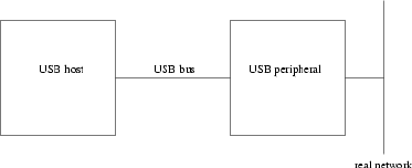
Introduction
Name
Introduction — eCos support for developing USB ethernet peripherals
Introduction
The eCos USB-ethernet package provides additional support for USB peripherals that involve some sort of ethernet-
style network. This can be a traditional ethernet, or it can involve some other networking technology that uses
ethernet frames as a unit of transfer. It provides functions to transfer ethernet frames over the USB bus, handles
certain control messages from the host, and optionally it can provide a network device driver for use by the eCos
TCP/IP stack. The package comes with an example host-side device driver.
The USB-ethernet package is not tied to any specific hardware. It requires the presence of USB hardware and
a suitable device driver, but not all USB peripherals involve ethernet communications. Hence the configuration
system cannot load the package automatically for specific targets, in the way that a USB device driver or an ethernet
driver can be loaded automatically. Instead, the package has to be added explicitly. When using the command line
tools this will involve an operation like the following:
$ ecosconfig add usbs_eth
Typically, this will automatically cause the USB device driver to become active. Loading the USB-ethernet package
automatically provides functionality for initialization,data transfer, and the handling of control messages and state
changes. If the current configuration includes the eCos TCP/IP stack then the network device driver support will
be enabled as well by default, allowing the stack to exchange ethernet frames over the USB bus.
There is a USB standard for a class of communication devices including ethernet. The package does not implement
this standard, due to limitations in the hardware for which the package was first developed. Instead, the package
uses its own protocol between USB host device driver and the peripheral.
Usage Scenarios
The USB-ethernet package can be used several different scenarios. In a simple scenario, the peripheral serves only
to connect the USB host to a suitable network:
After initialization, and once the USB connection between host and peripheral has been established, higher-level
code needs to detect packets that are intended for the host, and to forward these. This can be achieved by the
low-level usbs_eth_start_tx function. Similarly, higher-level code needs to detect packets coming from the
host, using usbs_eth_start_rx, and to forward these using the real network. As far as the host is concerned it
is connected directly to the network. In this scenario there is no confusion about addresses: there is a single MAC
627
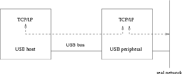
Introduction
address for the host/peripheral combination, corresponding to the connection to the real network, and it is this
address which should be supplied during initialization.
In a more complicated scenario, there is a TCP/IP stack running inside the peripheral.
This involves the USB-ethernet package providing a service both to the host and to the eCos TCP/IP stack. It
achieves the latter by acting as an eCos network device. Typically, the TCP/IP stack will be configured to act as a
network bridge. The USB peripheral needs to examine the packets arriving over the real network. Some of these
packets will be intended for the host, while others will be intended for the peripheral itself. To distinguish between
these two scenarios, two distinct MAC addresses are needed: one for the host, and one for the peripheral. Similarly,
packets sent by the host may have to be forwarded via the real network, or they may be intended for the TCP/IP
stack inside the peripheral. Packets generated inside the peripheral’s TCP/IP stack may need to be sent via the
real network or over the USB bus. The network bridge software will have to take care of all these possibilities.
Unusually for a network bridge, one of the network segments being bridged will only ever have one machine
attached.
There are other possible usage scenarios. For example, the peripheral might not be attached to a real network at
all. Instead it could be the USB host that acts as a network bridge, allowing a TCP/IP stack inside the peripheral
to communicate with the outside world. The various details will depend on the exact type of peripheral being
developed.
628
Initializing the USB-ethernet Package
Name
usbs_eth_init — Initializing the USB-ethernet Package
Synopsis
#include <cyg/io/usb/usbs_eth.h>
void usbs_eth_init(usbs_eth* usbeth, usbs_control_endpoint* ep0, usbs_rx_endpoint* ep1,
usbs_tx_endpoint* ep2, unsigned char* mac_address);
Description
The USB-ethernet package is not tied to any specific hardware. It requires certain functionality: there must be
USB-slave hardware supported by a device driver; there must also be two endpoints for bulk transfers between host
and peripheral, one for each direction; there must also be a control endpoint, although of course that is implicit
with any USB hardware.
However, USB-slave hardware may well provide more endpoints than the minimum required for ethernet support.
Some of those endpoints might be used by other packages, while other endpoints might be used directly by the
application, or might not be needed for the peripheral being built. There is also the possibility of a USB peripheral
that supports multiple configurations, with the ethernet support active in only some of those configurations. The
USB-ethernet package has no knowledge about any of this, so it relies on higher-level code to tell it which endpoints
should be used and other information. This is the purpose of the usbs_eth_init function.
The first argument identifies the specific usbs_eth data structure that is affected. It is expected that the vast majority
of affected applications will only provide a single USB-ethernet device to a single host, and the package auto-
matically provides a suitable data structure usbs_eth0 to support this. If multiple usbs_eth structures are needed
for some reason then these need to be instantiated by other code, and each one needs to be initialised by a call to
usbs_eth_init().
The next three arguments identify the endpoints that should be used for USB communications: a control endpoint,
a receive endpoint for ethernet packets coming from the host to the peripheral, and a transmit endpoint for ethernet
packets going in the other direction. Obviously all three endpoints should be provided by the same USB hardware.
The USB-ethernet package assumes that it has sole access to the receive and transmit endpoints, subject to the use
of usbs_eth_disable and usbs_eth_enable control functions. The package also assumes that no other code is
interested in USB state changes or class control messages: it installs handlers usbs_eth_state_change_handler
and usbs_eth_class_control_handler in the control endpoint. If any other code does need to handle USB state
changes or class control messages then replacement handlers should be installed after the call to usbs_eth_init,
and those replacements should invoke the USB-ethernet ones when appropriate.
The final argument to usbs_eth_init specifies the MAC address (or Ethernet Station Address) that should be
provided to the host-side device driver. Since the USB-ethernet package does not interact directly with a real
ethernet device it cannot obtain the MAC address from any hardware. Instead, it must be supplied by higher-level
code. The details depend on the scenario in which the USB-ethernet package is being used.
629
Initializing the USB-ethernet Package
The call to usbs_eth_init should normally happen after the enumeration data has been provided but before the
underlying USB device driver has been started. If the USB device were to be started first then a connection between
host and peripheral could be established immediately, and the host-side device driver would attempt to contact the
USB-ethernet package for information such as the MAC address.
int
main(int argc, char** argv)
{
unsigned char host_MAC[6] = { 0x40, 0x5d, 0x90, 0xa9, 0xbc, 0x02 };
usbs_sa11x0_ep0.enumeration_data = &usb_enum_data;
...
usbs_eth_init(&usbs_eth0, &usbs_sa11x0_ep0, &usbs_sa11x0_ep1, &usbs_sa11x0_ep2, host_MAC);
...
usbs_start(&usbs_sa11x0_ep0);
...
}
630
USB-ethernet Data Transfers
Name
USB-ethernet Data Transfers — Exchanging ethernet packets with the USB host
Synopsis
#include <cyg/io/usb/usbs_eth.h>
void usbs_eth_start_rx(usbs_eth* usbseth, unsigned char* buffer, void (*)(usbs_eth*,
void*, int) complete_fn, void* complete_data);
void usbs_eth_start_tx(usbs_eth* usbseth, unsigned char* buffer, void (*)(usbs_eth*,
void*, int) complete_fn, void* complete_data);
Description
The USB-ethernet package provides two main modes of operation. In the first mode it provides a network de-
vice driver for use by a TCP/IP stack running inside the USB peripheral. All incoming ethernet packages should
be passed up the TCP/IP stack, and only the stack will generate outgoing packets. Apart from initialization and
possibly certain control operations, higher-level code will not interact with the USB-ethernet package directly.
In the second mode there is no TCP/IP stack running inside the USB peripheral. For example, a simple USB-
ethernet converter has an ethernet chip and a USB port: ethernet packets received by the ethernet chip need to be
forwarded to the USB host, and ethernet packets sent by the USB host need to be sent out of the ethernet chip.
usbs_eth_start_rx and usbs_eth_start_tx allow for this lower-level access to the USB-ethernet package.
The two modes of operation are mutually exclusive. If the network device driver mode is enabled then application
code should communicate at the TCP/IP level, and not by using the lower-level functions. Instead, it is the network
device driver that will make use of these functions, and it assumes that it has exclusive access. The package does
not perform any locking.
The transmit and receive functions work in much the same way. The first argument identifies the usbs_eth structure
that should be used. For the majority of applications this will be usbs_eth0. The second argument specifies the
location of the ethernet packet; outgoing for usbs_eth_start_tx and incoming for usbs_eth_start_rx. This
buffer should correspond to the protocol:
1. Outgoing packets can consist of up to 1516 bytes, consisting of a two-byte header specific to USB-ethernet
followed by a standard ethernet frame (a header with 6-byte destination address, 6-byte source address and
a further two bytes, followed by a payload of up to 1500 bytes). The two-byte USB-ethernet header consists
simply of the size of the ethernet frame, i.e. the size of the rest of the packet not including the USB-ethernet
header, with the least significant byte first.
2. For incoming packets the supplied buffer should usually be at least 1516 bytes. There may be special cir-
cumstances in which a smaller buffer might be safe; for example, if the host-side device driver is modified
to support only smaller packets. Once the packet has been received the buffer will contain a two-byte header
specific to USB-ethernet, followed by a normal ethernet frame. The header gives the size of the ethernet frame,
excluding the header, with the least significant byte first.
631
USB-ethernet Data Transfers
Both usbs_eth_start_tx and usbs_eth_start_rx are asynchronous: the transfer is started and, some time
later, a completion function will be invoked. The third and fourth arguments to both usbs_eth_start_tx and
usbs_eth_start_rx supply the completion function and an argument to that function respectively. The comple-
tion function will be invoked with three arguments: a pointer to the usbs_eth data structure, usually usbs_eth0;
the supplied completion data ; and a return code field. A negative value indicates that an error occurred, for ex-
ample -EPIPE if the connection between USB host and peripheral has been broken, or -EAGAIN if an endpoint
has been halted. A positive value indicates the total size of the transfer, which should correspond to the size in the
USB-ethernet header plus an additional two bytes for the header itself.
If the data transfer is succesful then the completion function will typically be invoked in DSR context rather than
in thread context, although this depends on the implementation of the underlying USB device driver. Therefore the
completion function is restricted in what it can do; in particular, it must not make any calls that will or may block
such as locking a mutex or allocating memory. The kernel documentation should be consulted for more details of
DSR’s and interrupt handling generally. Note that if the transfer finishes quickly then the completion function may
be invoked before usbs_eth_start_rx or usbs_eth_start_tx returns. This is especially likely to happen if the
current thread is descheduled after starting the data transfer but before returning from these functions.
For transmit operations, it is possible for usbs_eth_start_tx to invoke the completion function immediately.
If there is no current connection between host and target then the transmit will fail immediately with -EPIPE. In
addition the USB-ethernet package will check the destination MAC address and make sure that the ethernet frame
really is intended for the host: either it must be for the address specified in the initialization call usbs_eth_init,
or it must be a broadcast packet, or the host must have enabled promiscuous mode.
632
USB-ethernet State Handling
Name
USB-ethernet State Handling — Maintaining the USB-ethernet connection with the host
Synopsis
#include <cyg/io/usb/usbs_eth.h>
usbs_control_return usbs_eth_class_control_handler(usbs_control_endpoint* ep0, void*
callback_data);
void usbs_eth_state_change_handler(usbs_control_endpoint* ep0, void* callback_data,
usbs_state_change change, int old_state);
void usbs_eth_disable(usbs_eth* usbseth>);
void usbs_eth_enable(usbs_eth* usbseth>);
Description
When the USB-ethernet package is initialized by a call to usbs_eth_init it installs
usbs_eth_state_change_handler to handle USB state changes. This allows the package to detect when
the connection between the host and the peripheral is established or broken, resulting in internal calls to
usbs_eth_enable and usbs_eth_disable respectively. This is appropriate if no other code needs to access the
USB device. However, if there is other code, either other USB-related packages or the application itself, that
needs to perform I/O over the USB bus, then typically the USB-ethernet package should not have exclusive access
to state change events. Instead, the assumption is that higher-level code, typically provided by the application, will
install an alternative state change handler in the control endpoint data structure after the call to usbs_eth_init.
This alternative handler will either chain into usbs_eth_state_change_handler when appropriate, or else it
will invoke usbs_eth_enable and usbs_eth_disable directly. For further details of state change handlers and
control endpoints generally, see the documentation for the common USB-slave package.
Similarly, usbs_eth_init will install usbs_eth_class_control_handler in the control endpoint data struc-
ture as the appropriate handler for class-specific USB control messages. This code will handle the ethernet-specific
control messages , for example requests by the host to enable or disable promiscuous mode or to obtain the MAC
address. If the USB device is not shared with any other code then this is both necessary and sufficient. However,
if other code is involved and if that code also needs to process certain control messages, higher-level code should
install its own handler and chain to the USB-ethernet one when appropriate. It should be noted that the request
code is encoded in just a single byte, so there is a real possibility that exactly the same number will be used by
different protocols for different requests. Any such problems will have to be identified and resolved by application
developers, and may involve modifying the source code for the USB-ethernet package.
As an alternative to chaining the state change handler, higher-level code can instead call usbs_eth_disable
and usbs_eth_enable directly. These functions may also be called if the USB-ethernet package should become
inactive for reasons not related directly to events on the USB bus. The main effect of usbs_eth_enable is to restart
receive operations and to allow transmits. The main effect of usbs_eth_disable is to block further transmits: any
current receive operations need to be aborted at the USB level, for example by halting the appropriate endpoint.
633
USB-ethernet State Handling
634
Network Device for the eCos TCP/IP Stack
Name
Network Device — USB-ethernet support for the eCos TCP/IP Stack
Description
If the USB peripheral involves running the eCos TCP/IP stack and that stack needs to use USB-ethernet as a
transport layer (or as one of the transports), then the USB-ethernet package can provide a suitable network device
driver. It is still necessary for higher-level code to perform appropriate initialization by calling usbs_eth_init,
but after that it will be the TCP/IP stack rather than application code that transmits or receives ethernet frames.
Not all peripherals involving the USB-ethernet package will require a TCP/IP stack. Hence the provision of the
network device is controlled by a configuration option CYGPKG_USBS_ETHDRV. By default this will be enabled if
the TCP/IP package CYGPKG_NET is loaded, and disabled otherwise.
There are a number of other configuration options related to the network device. CYG-
FUN_USBS_ETHDRV_STATISTICS determines whether or not the package will maintain statistics, mainly intended
for SNMP: by default this will be enabled if the SNMP support package CYGPKG_SNMPAGENT is loaded, and
disabled otherwise. The name of the ethernet device is controlled by CYGDATA_USBS_ETHDRV_NAME, and has a
default value of either eth0 or eth1 depending on whether or not there is another network device driver present
in the configuration.
Usually eCos network device drivers default to using DHCP for obtaining necessary information such as IP ad-
dresses. This is not appropriate for USB-ethernet devices. On the host-side the USB-ethernet network device will
not exist until the USB peripheral has been plugged in and communication has been established. Therefore any
DHCP daemon on the host would not be listening on that network device at the point that eCos requests its IP
and other information. A related issue is that the use of DHCP would imply the presence of a DHCP daemon on
every affected host machine, as opposed to a single daemon (plus backups) for the network as a whole. For these
reasons the USB-ethernet package precludes the use of DHCP as a way of setting the IP address, instead requiring
alternatives such as manual configuration.
635
Network Device for the eCos TCP/IP Stack
636
Example Host-side Device Driver
Name
Example Host-side Device Driver — Provide host-side support for the eCos USB-ethernet package
Description
The USB-ethernet package is supplied with a single host-side device driver. This driver has been developed against
the Linux kernel 2.2.16-22, as shipped with Red Hat 7. The driver is provided as is and should not be considered
production quality: for example it only checks for a bogus vendor id 0x4242 rather than an official vendor id
supplied by the USB Implementers Forum (http://www.usb.org/). Also, if the peripheral involves multiple config-
urations or multiple interfaces, it will fail to detect this. However, the driver can be used for simple testing and
as the basis of a full device driver. Details of the protocol used between host and peripheral can be found in the
Communication Protocol section.
The host-side device driver can be found in the host subdirectory of the USB-ethernet package, specifically the
file ecos_usbeth.c, and comes with a Makefile. Both files may need to be modified for specific applications.
For example, the vendor id table ecos_usbeth_implementations may need to be updated for the specific USB
peripheral being built. The Makefile assumes that the Linux kernel sources reside in /usr/src/linux, and
that the kernel has already been configured and built. Assuming this is the case, the device driver can be built
simply by invoking make with no additional arguments. This will result in a dynamically loadable kernel module,
ecos_usbeth.o, in the current directory.
Note: As normal for Linux kernel builds, the generated files such as ecos_usbeth.o live in the same directory
as the source tree. This is very different from eCos where the source tree (or component repository) is kept
separate from any builds. There may be problems if the component repository is kept read-only or if it is put
under source code control. Any such problems can be avoided by making a copy of the host subdirectory and
building that copy.
Loading the kernel module into the current system requires root privileges. If the generic USB support is also a
loadable module and has not been loaded already, this must happen first:
# insmod usb-uhci
Using /lib/modules/2.2.16-22/usb/usb-uhci.o
Depending on the host hardware, the uhci or usb-ohci modules may be more appropriate. Loading the generic
USB module will typically result in a number of messages to the logfile /var/log/messages, giving details of
the specific host-side hardware that has been detected plus any hubs. The next step is to load the USB-ethernet
module:
# insmod ecos_usbeth.o
This should result in a number of additional diagnostics in the logfile:
Apr 1 18:01:08 grumpy kernel: eCos USB-ethernet device driver
Apr 1 18:01:08 grumpy kernel: usb.c: registered new driver ecos_usbeth
637
Example Host-side Device Driver
If a suitable USB peripheral is now connected the host will detect this, assign an address in the local USB network,
obtain enumeration data, and find a suitable device driver. Assuming the peripheral and device driver agree on the
supported vendor ids, the ecos_usbeth.o module will be selected and this will be reported in the system log:
Apr 1 18:04:12 grumpy kernel: usb.c: USB new device connect, assigned device number 3
Apr 1 18:04:12 grumpy kernel: eCos-based USB ethernet peripheral active at eth1
What can happen next depends very much on the software that is running on top of the USB-ethernet package
inside the peripheral. For example, if there is a TCP/IP stack then it should be possible to bring up a network
connection between host and peripheral using ifconfig.
638
Communication Protocol
Name
Communication Protocol — Protocol used between the host-side device driver and the eCos USB-ethernet
package
Description
There is a USB standard for the protocol to be used between the host and a class of communication devices,
including ethernet. However, the eCos USB-ethernet package does not implement this protocol: the target hardware
for which the package was first developed had certain limitations, and could not implement the standard. Instead,
the package implements a simple new protocol.
A USB-ethernet peripheral involves bulk transfers on two endpoints: one endpoint will be used for packets from
host to peripheral and the other will be used for the opposite direction. Transfers in both directions are variable
length, with a lower limit of 16 bytes and an upper limit of 1516 bytes. The first two bytes of each transfer
constitute a header specific to USB-ethernet. The next 14 bytes form the normal header for an ethernet frame:
destination MAC address, source MAC address, and a protocol field. The remaining data, up to 1500 bytes, are the
payload. The first two bytes give the size of the ethernet frame, least significant byte first, with a value between 14
and 1514.
For example an ARP request from host to peripheral involves an ethernet frame of 42 bytes (0x002A), with the
usual 14-byte header and a 28-byte payload. The destination is the broadcast address 0xFFFFFFFFFFFF. The
source depends on the MAC address specified for the host in the call to usbs_eth_init, e.g. 0x405D90A9BC02.
The remaining data is as specified by the appropriate IETF RFC’s (http://www.ietf.org). The actual bulk USB
transfer involves the following sequence of 44 bytes:
2a 00 ff ff ff ff ff ff 40 5d 90 a9 bc 02 08 06
00 01 08 00 06 04 00 01 40 5d 90 a9 bc 02 0a 00
00 01 00 00 00 00 00 00 0a 00 00 02
In addition there are two control messages. These will be sent by the host to endpoint 0, the control endpoint,
and by default they will be handled by usbs_eth_class_control_handler. If class-specific control messages
are intercepted by other code then it is the responsibility of that code to invoke the USB-ethernet handler when
appropriate.
The first control message can be used by the host to obtain a MAC address:
#define ECOS_USBETH_CONTROL_GET_MAC_ADDRESS 0x01
The control message’s type field should specify IN as the direction. The request field should be 0x01. The
length fields should specify a size of 6 bytes. The remaining fields of the control message will be ignored by
the USB-ethernet package. The response consists of the 6-byte MAC address supplied by the initialization call
usbs_eth_init.
The second control message can be used by the host to enable or disable promiscuous mode.
#define ECOS_USBETH_CONTROL_SET_PROMISCUOUS_MODE 0x02
639
Communication Protocol
This control message involves no further data so the length field should be set to 0. The value field should be
non-zero to enable promiscuous mode, zero to disable it. The request field should be 0x02. The remaining fields in
the control message will be ignored. It is the responsibility of the host-side device driver to keep track of whether
or not promiscuous mode is currently enabled. It will be disabled when the peripheral changes to Configured state,
typically at the point where the host-side device driver has been activated.
640
XXIV. eCos Synthetic Target
641
Communication Protocol
642
Overview
Name
The eCos synthetic target — Overview
Description
Usually eCos runs on either a custom piece of hardware, specially designed to meet the needs of a specific applica-
tion, or on a development board of some sort that is available before the final hardware. Such boards have a number
of things in common:
1. Obviously there has to be at least one processor to do the work. Often this will be a 32-bit processor, but it
can be smaller or larger. Processor speed will vary widely, depending on the expected needs of the application.
However the exact processor being used tends not to matter very much for most of the development process:
the use of languages such as C or C++ means that the compiler will handle those details.
2. There needs to be memory for code and for data. A typical system will have two different types of memory.
There will be some non-volatile memory such as flash, EPROM or masked ROM. There will also be some
volatile memory such as DRAM or SRAM. Often the code for the final application will reside in the non-
volatile memory and all of the RAM will be available for data. However updating non-volatile memory requires
a non-trivial amount of effort, so for much of the development process it is more convenient to burn suitable
firmware, for example RedBoot, into the non-volatile memory and then use that to load the application being
debugged into RAM, alongside the application data and a small area reserved for use by the firmware.
3. The platform must provide certain mimimal I/O facilities. Most eCos configurations require a clock signal
of some sort. There must also be some way of outputting diagnostics to the user, often but not always via
a serial port. Unless special debug hardware is being used, source level debugging will require bidirectional
communication between a host machine and the target hardware, usually via a serial port or an ethernet device.
4. All the above is not actually very useful yet because there is no way for the embedded device to interact with
the rest of the world, except by generating diagnostics. Therefore an embedded device will have additional
I/O hardware. This may be fairly standard hardware such as an ethernet or USB interface, or special hardware
designed specifically for the intended application, or quite often some combination. Standard hardware such as
ethernet or USB may be supported by eCos device drivers and protocol stacks, whereas the special hardware
will be driven directly by application code.
Much of the above can be emulated on a typical PC running Linux. Instead of running the embedded application
being developed on a target board of some sort, it can be run as a Linux process. The processor will be the PC’s
own processor, for example an x86, and the memory will be the process’ address space. Some I/O facilities can
be emulated directly through system calls. For example clock hardware can be emulated by setting up a SIGALRM
signal, which will cause the process to be interrupted at regular intervals. This emulation of real hardware will not
be particularly accurate, the number of cpu cycles available to the eCos application between clock ticks will vary
widely depending on what else is running on the PC, but for much development work it will be good enough.
Other I/O facilities are provided through an I/O auxiliary process, ecosynth, that gets spawned by the eCos appli-
cation during startup. When an eCos device driver wants to perform some I/O operation, for example send out an
ethernet packet, it sends a request to the I/O auxiliary. That is an ordinary Linux application so it has ready access
to all normal Linux I/O facilities. To emulate a device interrupt the I/O auxiliary can raise a SIGIO signal within
the eCos application. The HAL’s interrupt subsystem installs a signal handler for this, which will then invoke the
643
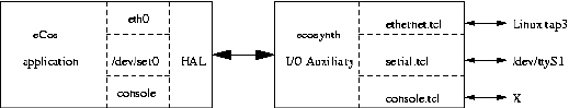
Overview
standard eCos ISR/DSR mechanisms. The I/O auxiliary is based around Tcl scripting, making it easy to extend and
customize. It should be possible to configure the synthetic target so that its I/O functionality is similar to what will
be available on the final target hardware for the application being developed.
A key requirement for synthetic target code is that the embedded application must not be linked with any of the
standard Linux libraries such as the GNU C library: that would lead to a confusing situation where both eCos and
the Linux libraries attempted to provide functions such as printf. Instead the synthetic target support must be
implemented directly on top of the Linux kernels’ system call interface. For example, the kernel provides a system
call for write operations. The actual function write is implemented in the system’s C library, but all it does is move
its arguments on to the stack or into certain registers and then execute a special trap instruction such as int 0x80.
When this instruction is executed control transfers into the kernel, which will validate the arguments and perform
the appropriate operation. Now, a synthetic target application cannot be linked with the system’s C library. Instead
it contains a function cyg_hal_sys_write which, like the C library’s write function, pushes its arguments on
to the stack and executes the trap instruction. The Linux kernel cannot tell the difference, so it will perform the
I/O operation requested by the synthetic target. With appropriate knowledge of what system calls are available,
this makes it possible to emulate the required I/O facilities. For example, spawning the ecosynth I/O auxiliary
involves system calls cyg_hal_sys_fork and cyg_hal_sys_execve, and sending a request to the auxiliary uses
cyg_hal_sys_write.
In many ways developing for the synthetic target is no different from developing for real embedded targets. eCos
must be configured appropriately: selecting a suitable target such as i386linux will cause the configuration sys-
tem to load the appropriate packages for this hardware; this includes an architectural HAL package and a platform-
specific package; the architectural package contains generic code applicable to all Linux platforms, whereas the
platform package is for specific Linux implementations such as the x86 version and contains any processor-specific
code. Selecting this target will also bring in some device driver packages. Other aspects of the configuration such as
which API’s are supported are determined by the template, by adding and removing packages, and by fine-grained
configuration.
In other ways developing for the synthetic target can be much easier than developing for a real embedded target.
For example there is no need to worry about building and installing suitable firmware on the target hardware, and
then downloading and debugging the actual application over a serial line or a similar connection. Instead an eCos
application built for the synthetic target is mostly indistinguishable from an ordinary Linux program. It can be run
simply by typing the name of the executable file at a shell prompt. Alternatively you can debug the application
using whichever version of gdb is provided by your Linux distribution. There is no need to build or install special
toolchains. Essentially using the synthetic target means that the various problems associated with real embedded
hardware can be bypassed for much of the development process.
The eCos synthetic target provides emulation, not simulation. It is possible to run eCos in suitable architectural
simulators but that involves a rather different approach to software development. For example, when running eCos
on the psim PowerPC simulator you need appropriate cross-compilation tools that allow you to build PowerPC
executables. These are then loaded into the simulator which interprets every instruction and attempts to simulate
what would happen if the application were running on real hardware. This involves a lot of processing overhead,
but depending on the functionality provided by the simulator it can give very accurate results. When developing for
the synthetic target the executable is compiled for the PC’s own processor and will be executed at full speed, with
644
Overview
no need for a simulator or special tools. This will be much faster and somewhat simpler than using an architectural
simulator, but no attempt is made to accurately match the behaviour of a real embedded target.
645
Overview
646
Installation
Name
Installation — Preparing to use the synthetic target
Host-side Software
To get the full functionality of the synthetic target, users must build and install the I/O auxiliary ecosynth and
various support files. It is possible to develop applications for the synthetic target without the auxiliary, but only
limited I/O facilities will be available. The relevant code resides in the host subdirectory of the synthetic target
architectural HAL package, and building it involves the standard configure,make, and make install steps.
There are two main ways of building the host-side software. It is possible to build both the generic host-side
software and all package-specific host-side software, including the I/O auxiliary. in a single build tree. This involves
using the configure script at the toplevel of the eCos repository, which will automatically search the packages
hierarchy for host-side software. For more information on this, see the README.host file at the top of the repository.
Note that if you have an existing build tree which does not include the synthetic target architectural HAL package
then it will be necessary to rerun the toplevel configure script: the search for appropriate packages happens at
configure time.
The alternative is to build just the host-side for this package. This involves creating a suitable build directory and
running the configure script. Note that building directly in the source tree is not allowed.
$ cd <somewhere suitable>
$ mkdir synth_build
$ cd synth_build
$<repo<>/packages/hal/synth/arch/<version>/host/configure <options>
$ make
$ make install
The code makes extensive use of Tcl/TK and requires version 8.3 or later. This is checked by the configure script.
By default it will use the system’s Tcl installation in /usr. If a different, more recent Tcl installation should be
used then its location can be specified using the options --with-tcl=<path>,--with-tcl-header=<path>
and --with-tcl-lib=<path>. For more information on these options see the README.host file at the toplevel
of the eCos repository.
Some users may also want to specify the install location using a --prefix=<path>option. The default install
location is /usr/local. It is essential that the bin subdirectory of the install location is on the user’s search PATH,
otherwise the eCos application will be unable to locate and execute the I/O auxiliary ecosynth.
Because ecosynth is run automatically by an eCos application rather than explicitly by the user, it is not installed
in the bin subdirectory itself. Instead it is installed below libexec, together with various support files such as
images. At configure time it is usually possible to specify an alternative location for libexec using --exec-
prefix=<path>or --libexecdir=<path>. These options should not be used for this package because the
eCos application is built completely separately and does not know how the host-side was configured.
647
Installation
Toolchain
When developing eCos applications for a normal embedded target it is necessary to use a suitable cross-compiler
and related tools such as the linker. Developing for the synthetic target is easier because you can just use the
standard GNU tools (gcc, g++, ld, . . . ) which were provided with your Linux distribution, or which you used to
build your own Linux setup. Any reasonably recent version of the tools, for example gcc 2.96(Red Hat) as shipped
with Red Hat Linux 7, should be sufficient.
There is one important limitation when using these tools: current gdb will not support debugging of eCos threads
on the synthetic target. As far as gdb is concerned a synthetic target application is indistinguishable from a normal
Linux application, so it assumes that any threads will be created by calls to the Linux pthread_create function
provided by the C library. Obviously this is not the case since the application is never linked with that library.
Therefore gdb never notices the eCos thread mechanisms and assumes the application is single-threaded. Fixing
this is possible but would involve non-trivial changes to gdb.
Theoretically it is possible to develop synthetic target applications on, for example, a PC running Windows and
then run the resulting executables on another machine that runs Linux. This is rarely useful: if a Linux machine is
available then usually that machine will also be used for building ecos and the application. However, if for some
reason it is necessary or desirable to build on another machine then this requires a suitable cross-compiler and
related tools. If the application will be running on a typical PC with an x86 processor then a suitable configure triplet
would be i686-pc-linux-gnu. The installation instructions for the various GNU tools should be consulted
for further information.
Hardware Preparation
Preparing a real embedded target for eCos development can be tricky. Often the first step is to install suitable
firmware, usually RedBoot. This means creating and building a special configuration for eCos with the RedBoot
template, then somehow updating the target’s flash chips with the resulting RedBoot image. Typically it will also
be necessary to get a working serial connection, and possibly set up ethernet as well. Although usually none of
the individual steps are particularly complicated, there are plenty of ways in which things can go wrong and it
can be hard to figure out what is actually happening. Of course some board manufacturers make life easier for
their developers by shipping hardware with RedBoot preinstalled, but even then it is still necessary to set up
communication between host and target.
None of this is applicable to the synthetic target. Instead you can just build a normal eCos configuration, link your
application with the resulting libraries, and you end up with an executable that you can run directly on your Linux
machine or via gdb. A useful side effect of this is that application development can start before any real embedded
hardware is actually available.
Typically the memory map for a synthetic target application will be set up such that there is a read-only ROM
region containing all the code and constant data, and a read-write RAM region for the data. The default locations
and sizes of these regions depend on the specific platform being used for development. Note that the application
always executes out of ROM: on a real embedded target much of the development would involve running RedBoot
firmware there, with application code and data loaded into RAM; usually this would change for the final system; the
firmware would be replaced by the eCos application itself, configured for ROM bootstrap, and it would perform
the appropriate hardware initialization. Therefore the synthetic target actually emulates the behaviour of a final
system, not of a development environment. In practice this is rarely significant, although having the code in read-
only memory can help catch some problems in application code.
648
Running a Synthetic Target Application
Name
Execution — Arguments and configuration files
Description
The procedure for configuring and building eCos and an application for the synthetic target is the same as for any
other eCos target. Once an executable has been built it can be run like any Linux program, for example from a shell
prompt,
$ ecos_hello <options>
or using gdb:
$ gdb --nw --quiet --args ecos_hello <options>
(gdb) run
Starting program: ecos_hello <options>
By default use of the I/O auxiliary is disabled. If its I/O facilities are required then the option --io must be used.
Note: In future the default behaviour may change, with the I/O auxiliary being started by default. The option
--nio can be used to prevent the auxiliary from being run.
Command-line Arguments
The syntax for running a synthetic target application is:
$<ecos_app>[options] [-- [app_options]]
Command line options up to the -- are passed on to the I/O auxiliary. Subsequent arguments are not passed on
to the auxiliary, and hence can be used by the eCos application itself. The full set of arguments can be accessed
through the variables cyg_hal_sys_argc and cyg_hal_sys_argv.
The following options are accepted as standard:
--io
This option causes the eCos application to spawn the I/O auxiliary during HAL initialization. Without this
option only limited I/O will be available.
--nio
This option prevents the eCos application from spawning the I/O auxiliary. In the current version of the
software this is the default.
649
Running a Synthetic Target Application
-nw,--no-windows
The I/O auxiliary can either provide a graphical user interface, or it can run in a text-only mode. The default is
to provide the graphical interface, but this can be disabled with -nw. Emulation of some devices, for example
buttons connected to digital inputs, requires the graphical interface.
-w,--windows
The -w causes the I/O auxiliary to provide a graphical user interface. This is the default.
-v,--version
The -v option can be used to determine the version of the I/O auxiliary being used and where it has been
installed. Both the auxiliary and the eCos application will exit immediately.
-h,--help
-h causes the I/O auxiliary to list all accepted command-line arguments. This happens after all devices have
been initialized, since the host-side support for some of the devices may extend the list of recognised options.
After this both the auxiliary and the eCos application will exit immediately. This option implies -nw.
-k,--keep-going
If an error occurs in the I/O auxiliary while reading in any of the configuration files or initializing devices, by
default both the auxiliary and the eCos application will exit. The -k option can be used to make the auxiliary
continue in spite of errors, although obviously it may not be fully functional.
-nr,--no-rc
Normally the auxiliary processes two user configuration files during startup: initrc.tcl and mainrc.tcl.
This can be suppressed using the -nr option.
-x,--exit
When providing a graphical user interface the I/O auxiliary will normally continue running even after the
eCos application has exited. This allows the user to take actions such as saving the current contents of the
main text window. If run with -x then the auxiliary will exit as soon the application exits.
-nx,--no-exit
When the graphical user interface is disabled with -nw the I/O auxiliary will normally exit immediately when
the eCos application exits. Without the graphical frontend there is usually no way for the user to interact
directly with the auxiliary, so there is no point in continuing to run once the eCos application will no longer
request any I/O operations. Specifying the -nx option causes the auxiliary to continue running even after the
application has exited.
-V,--verbose
This option causes the I/O auxiliary to output some additional information, especially during initialization.
-l <file>,--logfile <file>
Much of the output of the eCos application and the I/O auxiliary is simple text, for example resulting from
eCos printf or diag_printf calls. When running in graphical mode this output goes to a central text
window, and can be saved to a file or edited via menus. The -l can be used to automatically generate an
additional logfile containing all the text. If graphical mode is disabled then by default all the text just goes to
650
Running a Synthetic Target Application
the current standard output. Specifying -l causes most of the text to go into a logfile instead, although some
messages such as errors generated by the auxiliary itself will still go to stdout as well.
-t <file>,--target <file>
During initialization the I/O auxiliary reads in a target definition file. This file holds information such as which
Linux devices should be used to emulate the various eCos devices. The -t option can be used to specify which
target definition should be used for the current run, defaulting to default.tdf. It is not necessary to include
the .tdf suffix, this will be appended automatically if necessary.
-geometry <geometry>
This option can be used to control the size and position of the main window, as per X conventions.
The I/O auxiliary loads support for the various devices dynamically and some devices may accept additional com-
mand line arguments. Details of these can be obtained using the -h option or by consulting the device-specific
documentation. If an unrecognised command line argument is used then a warning will be issued.
The Target Definition File
The eCos application will want to access devices such as eth0 or /dev/ser0. These need to be mapped on to
Linux devices. For example some users may all traffic on the eCos /dev/ser0 serial device to go via the Linux
serial device /dev/ttyS1, while ethernet I/O for the eCos eth0 device should be mapped to the Linux ethertap
device tap3. Some devices may need additional configuration information, for example to limit the number of
packets that should be buffered within the I/O auxiliary. The target definition file provides all this information.
By default the I/O auxiliary will look for a file default.tdf. An alternative target definition can be specified on
the command line using -t, for example:
$ bridge_app --io -t twineth
A.tdf suffix will be appended automatically if necessary. If a relative pathname is used then the I/O auxiliary
will search for the target definition file in the current directory, then in ~/.ecos/synth/, and finally in its install
location.
A typical target definition file might look like this:
synth_device console {
# appearance -foreground white -background black
filter trace {^TRACE:.*} -foreground HotPink1 -hide 1
}
synth_device ethernet {
eth0 real eth1
eth1 ethertap tap4 00:01:02:03:FE:06
## Maximum number of packets that should be buffered per interface.
## Default 16
#max_buffer 32
## Filters for the various recognised protocols.
## By default all filters are visible and use standard colours.
filter ether -hide 0
#filter arp -hide 1
651
Running a Synthetic Target Application
#filter ipv4 -hide 1
#filter ipv6 -hide 1
}
A target definition file is actually a Tcl script that gets run in the main interpreter of the I/O auxiliary during ini-
tialization. This provides a lot of flexibility if necessary. For example the script could open a socket to a resource
management server of some sort to determine which hardware facilities are already in use and adapt accordingly.
Another possibility is to adapt based on command line arguments. Users who are not familiar with Tcl program-
ming should still be able to edit a simple target definition file without too much difficulty, using a mixture of
cut’n’paste, commenting or uncommenting various lines, and making small edits such as changing tap4 to eth2.
Each type of device will have its own entry in the target definition file, taking the form:
synth_device <device type>{
<options>
}
The documentaton for each synthetic target device should provide details of the options available for that device,
and often a suitable fragment that can be pasted into a target definition file and edited. There is no specific set of
options that a given device will always provide. However in practice many devices will use common code exported
by the main I/O auxiliary, or their implementation will involve some re-use of code for an existing device. Hence
certain types of option are common to many devices.
A good example of this is filters, which control the appearance of text output. The above target definition file defines
a filter trace for output from the eCos application. The regular expression will match output from the infrastructure
package’s tracing facilities when CYGDBG_USE_TRACING and CYGDBG_INFRA_DEBUG_TRACE_ASSERT_SIMPLE are
enabled. With the current settings this output will not be visible by default, but can be made visible using the
menu item System Filters. If made visible the trace output will appear in an unusual colour, so users can easily
distinguish the trace output from other text. All filters accept the following options:
-hide [0|1]
This controls whether or not text matching this filter should be invisible by default or not. At run-time the
visibility of each filter can be controlled using the System Filters menu item.
-foreground <colour>
This specifies the foreground colour for all text matching this filter. The colour can be specified using an RGB
value such as #F08010, or a symbolic name such as "light steel blue". The X11 utility showrgb can be
used to find out about the available colours.
-background <colour>
This specifies the background colour for all text matching the filter. As with -foreground the colour can be
specified using a symbolic name or an RGB value.
Some devices may create their own subwindows, for example to monitor ethernet traffic or to provide additional
I/O facilities such as emulated LED’s or buttons. Usually the target definition file can be used to control the layout
of these windows.
The I/O auxiliary will not normally warn about synth_device entries in the target definition file for devices that are
not actually needed by the current eCos application. This makes it easier to use a single file for several different
applications. However it can lead to confusion if an entry is spelled incorrectly and hence does not actually get
652

Running a Synthetic Target Application
used. The -V command line option can be used to get warnings about unused device entries in the target definition
file.
If the body of a synth_device command contains an unrecognised option and the relevant device is in use, the I/O
auxiliary will always issue a warning about such options.
User Configuration Files
During initialization the I/O auxiliary will execute two user configuration files, initrc.tcl and mainrc.tcl. It
will look for these files in the directory ~/.ecos/synth/. If that directory does not yet exist it will be created and
populated with initial dummy files.
Both of these configuration files are Tcl scripts and will be run in the main interpreter used by the I/O auxiliary
itself. This means that they have full access to the internals of the auxiliary including the various Tk widgets, and
they can perform file or socket I/O if desired. The section Writing New Devices - host contains information about
the facilities available on the host-side for writing new device drivers, and these can also be used in the initialization
scripts.
The initrc.tcl script is run before the auxiliary has processed any requests from the eCos application, and hence
before any devices have been instantiated. At this point the generic command-line arguments has been processed,
the target definition file has been read in, and the hooks functionality has been initialized. If running in graphical
mode the main window will have been created, but has been withdrawn from the screen to allow new widgets to
be added without annoying screen flicker. A typical initrc.tcl script could add some menu or toolbar options,
or install a hook function that will be run when the eCos application exits.
The mainrc.tcl script is run after eCos has performed all its device initialization and after C++ static constructors
have run, and just before the call to cyg_start which will end up transferring control to the application itself. A
typical mainrc.tcl script could look at what interrupt vectors have been allocated to which devices and create a
little monitor window that shows interrupt activity.
Session Information
When running in graphical mode, the I/O auxiliary will read in a file ~/.ecos/synth/guisession containing
session information. This file should not normally be edited manually, instead it gets updated automatically when
the auxiliary exits. The purpose of this file is to hold configuration options that are manipulated via the graphical
interface, for example which browser should be used to display online help.
Warning
GUI session functionality is not yet available in the current release. When that functionality
is fully implemented it is possible that some target definition file options may be removed, to
be replaced by graphical editing via a suitable preferences dialog, with the current settings
saved in the session file.
653
Running a Synthetic Target Application
654
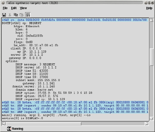
The I/O Auxiliary’s User Interface
Name
User Interface — Controlling the I/O Auxiliary
Description
The synthetic target auxiliary is designed to support both extensions and user customization. Support for the desired
devices is dynamically loaded, and each device can extend the user interface. For example it is possible for a
device to add menu options, place new buttons on the toolbar, create its own sub-window within the overall layout,
or even create entire new toplevel windows. These subwindows or toplevels could show graphs of activity such
as interrupts or packets being transferred. They could also allow users to interact with the eCos application, for
example by showing a number of buttons which will be mapped on to digital inputs in the eCos application.
Different applications will have their own I/O requirements, changing the host-side support files that get loaded
and that may modify the user interface. The I/O auxiliary also reads in user configuration scripts which can enhance
the interface in the same way. Therefore the exact user interface will depend on the user and on the eCos application
being run. However the overall layout is likely to remain the same.
The title bar identifies the window as belonging to an eCos synthetic target application and lists both the application
name and its process id. The latter is especially useful if the application was started directly from a shell prompt
and the user now wants to attach a gdb session. The window has a conventional menu bar with the usual entries,
plus a toolbar with buttons for common operations such as cut and paste. Balloon help is supported.
There is a central text window, possibly surrounded by various sub-windows for various devices. For example there
could be a row of emulated LED’s above the text window, and monitors of ethernet traffic and interrupt activity on
655

The I/O Auxiliary’s User Interface
the right. At the bottom of the window is a status line, including a small animation that shows whether or not the
eCos application is still running.
Menus and the Toolbar
Usually there will be four menus on the menu bar: File,Edit,View and Help.
On the File menu there are three entries related to saving the current contents of the central text window. Save is
used to save the currently visible contents of the text window. Any text that is hidden because of filters will not
be written to the savefile. If there has been a previous Save or Save As operation then the existing savefile will
be re-used, otherwise the user will be asked to select a suitable file. Save As also saves just the currently visible
contents but will always prompt the user for a filename. Save All can be used to save the full contents of the text
window, including any text that is currently hidden. It will always prompt for a new filename, to avoid confusion
with partial savefiles.
Usually the eCos application will be run from inside gdb or from a shell prompt. Killing off the application while
it is being debugged in a gdb session is not a good idea, it would be better to use gdb’s own kill command. Alterna-
tively the eCos application itself can use the CYG_TEST_EXIT or cyg_hal_sys_exit functionality. However it is
possible to terminate the application from the I/O auxiliary using Kill eCos. A clean shutdown will be attempted,
but that can fail if the application is currently halted inside gdb or if it has crashed completely. As a last resort
SIGKILL will be used.
When operating in graphical mode the I/O auxiliary will normally continue to run even after the eCos application
has exited. This allows the user to examine the last few lines of output, and perhaps perform actions such as saving
the output to a file. The Exit menu item can be used to shut down the auxiliary. Note that this behaviour can be
changed with command line arguments --exit and --no-exit.
If Exit is used while the eCos application is still running then the I/O auxiliary will first attempt to terminate the
application cleanly, and then exit.
The Edit menu contains the usual entries for text manipulation: Cut,Copy,Paste,Clear and Select All. These all
operate on the central text window. By default this window cannot be edited so the cut, paste and clear operations
are disabled. If the user wants to edit the contents of the text window then the Read Only checkbutton should be
toggled.
656

The I/O Auxiliary’s User Interface
The Preferences menu item brings up a miscellaneous preferences dialog. One of the preferences relates to online
help: the I/O auxiliary does not currently have a built-in html viewer; instead it will execute an external browser of
some sort. With the example settings shown, the I/O auxiliary will first attempt to interact with an existing mozilla
session. If that fails it will try to run a new mozilla instance, or as a last result use the Gnome help viewer.
The View menu contains the System Filters entry, used to edit the settings for the current filters.
The Help menu can be used to activate online help for eCos generally, for the synthetic target as a whole, and for
specific devices supported by the generic target. The Preferences dialog can be used to select the browser that will
be used.
Note: At the time of writing there is no well-defined toplevel index file for all eCos documentation. Hence the rel-
evant menu item is disabled. Documentation for the synthetic target and the supported devices is stored as part
of the package itself so can usually be found fairly easily. It may be necessary to set the ECOS_REPOSITORY
environment variable.
The Main Text Window
The central text window holds the console output from the eCos application: the screen shot above shows DHCP
initialization data from the TCP/IP stack, and some output from the main thread at the bottom. Some devices can
insert text of their own, for example the ethernet device support can be configured to show details of incoming
and outgoing packets. Mixing the output from the eCos application and the various devices can make it easier to
understand the order in which events occur.
The appearance of text from different sources can be controlled by means of filters, and it is also possible to hide
some of the text. For example, if tracing is enabled in the eCos configuration then the trace output can be given
its own colour scheme, making it stand out from the rest of the output. In addition the trace output is generally
voluminous so it can be hidden by default, made visible only to find out more about what was happening when a
particular problem occurred. Similarly the ethernet device support can output details of the various packets being
transferred, and using a different background colour for this output again makes it easier to distinguish from console
output.
657

The I/O Auxiliary’s User Interface
The default appearance for most filters is controlled via the target definition file. An example entry might be:
filter trace {^TRACE:.*} -foreground HotPink1 -hide 1
The various colours and the hide flag for each filter can be changed at run-time, using the System Filters item on
the View menu. This will bring up a dialog like the following:
It should be noted that the text window is line-oriented, not character-oriented. If an eCos application sends a
partial line of text then that will remain buffered until a newline character is received, rather than being displayed
immediately. This avoids confusion when there is concurrent output from several sources.
By default the text window is read-only. This means it will not allow cut, paste and clear operations, and keyboard
input will be ignored. The Edit menu has a checkbutton Read Only which can be toggled to allow write operations.
For example, a user could type in a reminder of what was happening at this time, or paste in part of a gdb session.
Such keyboard input does not get forwarded to the eCos application: if the latter requires keyboard input then that
should happen via a separate keyboard device.
Positioning Optional Windows
Some devices may create their own subwindows, for example to monitor ethernet traffic or to provide additional
I/O facilities such as emulated LED’s or buttons. Usually the target definition file can be used to control the layout
of these windows. This requires an understanding of the overall layout of the display.
658

The I/O Auxiliary’s User Interface
Subwindows are generally packed in one of eight frames surrounding the central text window: .main.nw,.main.n,
.main.ne,.main.w,.main.e,.main.sw,.main.s, and .main.se. To position a row of LED’s above the text
window and towards the left, a target definition file could contain an entry such as:
synth_device led {
pack -in .main.n -side left
...
}
Similarly, to put a traffic monitor window on the right of the text window would involve something like:
...
monitor_pack -in .main.e -side bottom
...
Often it will be sufficient to specify a container frame and one of left,right,top or bottom. Full control over
the positioning requires an understanding of Tcl/Tk and in particular the packing algorithm, and an appropriate
reference work should be consulted.
Global Settings
Note: This section still to be written - it should document the interaction between X resources and ecosynth,
and how users can control settings such as the main foreground and background colours.
659
The I/O Auxiliary’s User Interface
660
The Console Device
Name
The console device — Show output from the eCos application
Description
The eCos application can generate text output in a variety of ways, including calling printf or diag_printf.
When the I/O auxiliary is enabled the eCos startup code will instantiate a console device to process all such output.
If operating in text mode the output will simply go to standard output, or to a logfile if the -l command line option
is specified. If operating in graphical mode the output will go to the central text window, and optionally to a logfile
as well. In addition it is possible to control the appearance of the main text via the target definition file, and to
install extra filters for certain types of text.
It should be noted that the console device is line-oriented, not character-oriented. This means that outputting partial
lines is not supported, and some functions such as fflush and setvbuf will not operate as expected. This limi-
tation prevents much possible confusion when using filters to control the appearance of the text window, and has
some performance benefits - especially when the eCos application generates a great deal of output such as when
tracing is enabled. For most applications this is not a problem, but it is something that developers should be aware
of.
The console device is output-only, it does not provide any support for keyboard input. If the application requires
keyboard input then that should be handled by a separate eCos device package and matching host-side code.
Installation
The eCos side of the console device is implemented by the architectural HAL itself, in the source file
synth_diag.c, rather than in a separate device package. Similarly the host-side implementation, console.tcl,
is part of the architectural HAL’s host-side support. It gets installed automatically alongside the I/O auxiliary
itself, so no separate installation procedure is required.
Target Definition File
The target definition file can contain a number of entries related to the console device. These are all optional, they
only control the appearance of text output. If such control is desired then the relevant options should appear in the
body of a synth_device entry:
synth_device console {
...
}
The first option is appearance, used to control the appearance of any text generated by the eCos application that
does not match one of the installed filters. This option takes the same argument as any other filter, for example:
synth_device console {
appearance -foreground white -background black
...
}
661
The Console Device
Any number of additional filters can be created with a filter option, for example:
synth_device console {
...
filter trace {^TRACE:.*} -foreground HotPink1 -hide 1
...
}
The first argument gives the new filter a name which will be used in the filters dialog. Filter names should be
unique. The second argument is a Tcl regular expression. The console support will match each line of eCos output
against this regular expression, and if a match is found then the filter will be used for this line of text. The above
example matches any line of output that begins with TRACE:, which corresponds to the eCos infrastructure’s tracing
facilities. The remaining options control the desired appearance for matched text. If some eCos output matches the
regular expressions for several different filters then only the first match will be used.
Target-side Configuration Options
There are no target-side configuration options related to the console device.
Command Line Arguments
The console device does not use any command-line arguments.
Hooks
The console device does not provide any hooks.
Additional Tcl Procedures
The console device does not provide any additional Tcl procedures that can be used by other scripts.
662
System Calls
Name
cyg_hal_sys_xyz — Access Linux system facilities
Synopsis
#include <cyg/hal/hal_io.h>
int cyg_hal_sys_xyzzy(...);
Description
On a real embedded target eCos interacts with the hardware by peeking and poking various registers, manipulating
special regions of memory, and so on. The synthetic target does not access hardware directly. Instead I/O and
other operations are emulated by making appropriate Linux system calls. The HAL package exports a number of
functions which allow other packages, or even application code, to make these same system calls. However this
facility must be used with care: any code which calls, for example, cyg_hal_sys_write will only ever run on the
synthetic target; that functionality is obviously not provided on any real hardware because there is no underlying
Linux kernel to implement it.
The synthetic target only provides a subset of the available system calls, specifically those calls which have proved
useful to implement I/O emulation. This subset can be extended fairly easily if necessary. All of the available calls,
plus associated data structures and macros, are defined in the header file cyg/hal/hal_io.h. There is a simple
convention: given a Linux system call such as open, the synthetic target will prefix cyg_hal_sys and provide a
function with that name. The second argument to the open system call is a set of flags such as O_RDONLY, and
the header file will define a matching constant CYG_HAL_SYS_O_RDONLY. There are also data structures such as
cyg_hal_sys_sigset_t, matching the Linux data structure sigset_t.
In most cases the functions provided by the synthetic target behave as per the documentation for the Linux system
calls, and section 2 of the Linux man pages can be consulted for more information. There is one important dif-
ference: typically the documentation will say that a function returns -1 to indicate an error, with the actual error
code held in errno; the actual underlying system call and hence the cyg_hal_sys_xyz provided by eCos instead
returns a negative number to indicate an error, with the absolute value of that number corresponding to the error
code; usually it is the C library which handles this and manipulates errno, but of course synthetic target applications
are not linked with that Linux library.
However, there are some exceptions. The Linux kernel has evolved over the years, and some of the original system
call interfaces are no longer appropriate. For example the original select system call has been superseded by
_newselect, and that is what the select function in the C library actually uses. The old call is still available to
preserve binary compatibility but, like the C library, eCos makes use of the new one because it provides the ap-
propriate functionality. In an attempt to reduce confusion the eCos function is called cyg_hal_sys__newselect,
in other words it matches the official system call naming scheme. The authoritive source of information on such
matters is the Linux kernel sources themselves, and especially its header files.
663
System Calls
eCos packages and applications should never #include Linux header files directly. For example, doing a
#include </usr/include/fcntl.h>to access additional macros or structure definitions, or alternatively
manipulating the header file search path, will lead to problems because the Linux header files are likely to
duplicate and clash with definitions in the eCos headers. Instead the appropriate functionality should be extracted
from the Linux headers and moved into either cyg/hal/hal_io.h or into application code, with suitable
renaming to avoid clashes with eCos names. Users should be aware that large-scale copying may involve licensing
complications.
Adding more system calls is usually straightforward and involves adding one or more lines to the platform-specific
file in the appropriate platform HAL, for example syscall-i386-linux-1.0.S. However it is necessary to do
some research first about the exact interface implemented by the system call, because of issues such as old system
calls that have been superseded. The required information can usually be found fairly easily by searching through
the Linux kernel sources and possibly the GNU C library sources.
664
Writing New Devices - target
Name
Writing New Devices — extending the synthetic target, target-side
Synopsis
#include <cyg/hal/hal_io.h>
int synth_auxiliary_instantiate(const char* package, const char* version, const char*
device, const char* instance, const char* data);
void synth_auxiliary_xchgmsg(int device_id, int request, int arg1, int arg2, const
unsigned char* txdata, int txlen, int* reply, unsigned char* rxdata, int* rxlen, int
max_rxlen);
Description
In some ways writing a device driver for the synthetic target is very similar to writing one for a real target. Obviously
it has to provide the standard interface for that class of device, so for example an ethernet device has to provide
can_send,send,recv and similar functions. Many devices will involve interrupts, so the driver contains ISR and
DSR functions and will call cyg_drv_interrupt_create,cyg_drv_interrupt_acknowledge, and related
functions.
In other ways writing a device driver for the synthetic target is very different. Usually the driver will not have any
direct access to the underlying hardware. In fact for some devices the I/O may not involve real hardware, instead
everything is emulated by widgets on the graphical display. Therefore the driver cannot just peek and poke device
registers, instead it must interact with host-side code by exchanging message. The synthetic target HAL provides a
function synth_auxiliary_xchgmsg for this purpose.
Initialization of a synthetic target device driver is also very different. On real targets the device hardware already
exists when the driver’s initialization routine runs. On the synthetic target it is first necessary to instantiate the
device inside the I/O auxiliary, by a call to synth_auxiliary_instantiate. That function performs a special
message exchange with the I/O auxiliary, causing it to load a Tcl script for the desired type of device and run an
instantiation procedure within that script.
Use of the I/O auxiliary is optional: if the user does not specify --io on the command line then the auxiliary will
not be started and hence most I/O operations will not be possible. Device drivers should allow for this possibility,
for example by just discarding any data that gets written. The HAL exports a flag synth_auxiliary_running
which should be checked.
Instantiating a Device
Device instantiation should happen during the C++ prioritized static constructor phase of system initialization,
before control switches to cyg_user_start and general application code. This ensures that there is a clearly
665
Writing New Devices - target
defined point at which the I/O auxiliary knows that all required devices have been loaded. It can then perform
various consistency checks and clean-ups, run the user’s mainrc.tcl script, and make the main window visible.
For standard devices generic eCos I/O code will call the device initialization routines at the right time, iterating
through the DEVTAB table in a static constructor. The same holds for network devices and file systems. For more
custom devices code like the following can be used:
#include <cyg/infra/cyg_type.h>
class mydev_init {
public:
mydev_init() {
...
}
};
static mydev_init mydev_init_object CYGBLD_ATTRIB_INIT_PRI(CYG_INIT_IO);
Some care has to be taken because the object mydev_init_object will typically not be referenced by other code,
and hence may get eliminated at link-time. If the code is part of an eCos package then problems can be avoided by
putting the relevant file in libextras.a:
cdl_package CYGPKG_DEVS_MINE {
...
compile -library=libextras.a init.cxx
}
For devices inside application code the same can be achieved by linking the relevant module as a .o file rather than
putting it in a .a library.
In the device initialization routine the main operation is a call to synth_auxiliary_instantiate. This takes
five arguments, all of which should be strings:
package
For device drivers which are eCos packages this should be a directory path relative to the eCos repository,
for example devs/eth/synth/ecosynth. This will allow the I/O auxiliary to find the various host-side
support files for this package within the install tree. If the device is application-specific and not part of an
eCos package then a NULL pointer can be used, causing the I/O auxiliary to search for the support files in the
current directory and then in ~/.ecos/synth instead.
version
For eCos packages this argument should be the version of the package that is being used, for example cur-
rent. A simple way to get this version is to use the SYNTH_MAKESTRING macro on the package name. If the
device is application-specific then a NULL pointer should be used.
device
This argument specifies the type of device being instantiated, for example ethernet. More specifically the
I/O auxiliary will append a .tcl suffix, giving the name of a Tcl script that will handle all I/O requests for
the device. If the application requires several instances of a type of device then the script will only be loaded
once, but the script will contain an instantiation procedure that will be called for each device instance.
666
Writing New Devices - target
instance
If it is possible to have multiple instances of a device then this argument identifies the particular instance, for
example eth0 or eth1. Otherwise a NULL pointer can be used.
data
This argument can be used to pass additional initialization data from eCos to the host-side support. This
is useful for devices where eCos configury must control certain aspects of the device, rather than host-side
configury such as the target definition file, because eCos has compile-time dependencies on some or all of the
relevant options. An example might be an emulated frame buffer where eCos has been statically configured
for a particular screen size, orientation and depth. There is no fixed format for this string, it will be interpreted
only by the device-specific host-side Tcl script. However the string length should be limited to a couple of
hundred bytes to avoid possible buffer overflow problems.
Typical usage would look like:
if (!synth_auxiliary_running) {
return;
}
id = synth_auxiliary_instantiate("devs/eth/synth/ecosynth",
SYNTH_MAKESTRING(CYGPKG_DEVS_ETH_ECOSYNTH),
"ethernet",
"eth0",
(const char*) 0);
The return value will be a device identifier which can be used for subsequent calls to synth_auxiliary_xchgmsg.
If the device could not be instantiated then -1 will be returned. It is the responsibility of the host-side software to
issue suitable diagnostics explaining what went wrong, so normally the target-side code should fail silently.
Once the desired device has been instantiated, often it will be necessary to do some additional initialization by
a message exchange. For example an ethernet device might need information from the host-side about the MAC
address, the interrupt vector, and whether or not multicasting is supported.
Communicating with a Device
Once a device has been instantiated it is possible to perform I/O by sending messages to the appropriate Tcl script
running inside the auxiliary, and optionally getting back replies. I/O operations are always initiated by the eCos
target-side, it is not possible for the host-side software to initiate data transfers. However the host-side can raise
interrupts, and the interrupt handler inside the target can then exchange one or more messages with the host.
There is a single function to perform I/O operations, synth_auxiliary_xchgmsg. This takes the following argu-
ments:
device_id
This should be one of the identifiers returned by a previous call to synth_auxiliary_instantiate, speci-
fying the particular device which should perform some I/O.
request
Request are just signed 32-bit integers that identify the particular I/O operation being requested. There is no
fixed set of codes, instead each type of device can define its own.
667
Writing New Devices - target
arg1
arg2
For some requests it is convenient to pass one or two additional parameters alongside the request code. For
example an ethernet device could define a multicast-all request, with arg1 controlling whether this mode
should be enabled or disabled. Both arg1 and arg2 should be signed 32-bit integers, and their values are
interpreted only by the device-specific Tcl script.
txdata
txlen
Some I/O operations may involve sending additional data, for example an ethernet packet. Alternatively a
control operation may require many more parameters than can easily be encoded in arg1 and arg2, so those
parameters have to be placed in a suitable buffer and extracted at the other end. txdata is an arbitrary buffer
of txlen bytes that should be sent to the host-side. There is no specific upper bound on the number of bytes
that can be sent, but usually it is a good idea to allocate the transmit buffer statically and keep transfers down
to at most several kilobytes.
reply
If the host-side is expected to send a reply message then reply should be a pointer to an integer variable and
will be updated with a reply code, a simple 32-bit integer. The synthetic target HAL code assumes that the
host-side and target-side agree on the protocol being used: if the host-side will not send a reply to this message
then the reply argument should be a NULL pointer; otherwise the host-side must always send a reply code
and the reply argument must be valid.
rxdata
rxlen
Some operations may involve additional data coming from the host-side, for example an incoming ethernet
packet. rxdata should be a suitably-sized buffer, and rxlen a pointer to an integer variable that will end up
containing the number of bytes that were actually received. These arguments will only be used if the host-side
is expected to send a reply and hence the reply argument was not NULL.
max_rxlen
If a reply to this message is expected and that reply may involve additional data, max_rxlen limits the size of
that reply. In other words, it corresponds to the size of the rxdata buffer.
Most I/O operations involve only some of the arguments. For example transmitting an ethernet packet would use the
request,txdata and txlen fields (in addition to device_id which is always required), but would not involve
arg1 or arg2 and no reply would be expected. Receiving an ethernet packet would involve request,rxdata,
rxlen and max_rxlen; in addition reply is needed to get any reply from the host-side at all, and could be used
to indicate whether or not any more packets are buffered up. A control operation such as enabling multicast mode
would involve request and arg1, but none of the remaining arguments.
Interrupt Handling
Interrupt handling in the synthetic target is much the same as on a real target. An interrupt object is created using
cyg_drv_interrupt_create, attached, and unmasked. The emulated device - in other words the Tcl script run-
ning inside the I/O auxiliary - can raise an interrupt. Subject to interrupts being disabled and the appropriate vector
being masked, the system will invoke the specified ISR function. The synthetic target HAL implementation does
668
Writing New Devices - target
have some limitations: there is no support for nested interrupts, interrupt priorities, or a separate interrupt stack.
Supporting those might be appropriate when targetting a simulator that attempts to model real hardware accurately,
but not for the simple emulation provided by the synthetic target.
Of course the actual implementation of the ISR and DSR functions will be rather different for a synthetic target
device driver. For real hardware the device driver will interact with the device by reading and writing device regis-
ters, managing DMA engines, and the like. A synthetic target driver will instead call synth_auxiliary_xchgmsg
to perform the I/O operations.
There is one other significant difference between interrupt handling on the synthetic target and on real hardware.
Usually the eCos code will know which interrupt vectors are used for which devices. That information is fixed when
the target hardware is designed. With the synthetic target interrupt vectors are assigned to devices on the host side,
either via the target definition file or dynamically when the device is instantiated. Therefore the initialization code
for a target-side device driver will need to request interrupt vector information from the host-side, via a message
exchange. Such interrupt vectors will be in the range 1 to 31 inclusive, with interrupt 0 being reserved for the
real-time clock.
669
Writing New Devices - target
670
Writing New Devices - host
Name
Writing New Devices — extending the synthetic target, host-side
Description
On the host-side adding a new device means writing a Tcl/Tk script that will handle instantiation and subsequent
requests from the target-side. These scripts all run in the same full interpreter, extended with various commands
provided by the main I/O auxiliary code, and running in an overall GUI framework. Some knowledge of program-
ming with Tcl/Tk is required to implement host-side device support.
Some devices can be implemented entirely using a Tcl/Tk script. For example, if the final system will have some
buttons then those can be emulated in the synthetic target using a few Tk widgets. A simple emulation could just
have the right number of buttons in a row. A more advanced emulation could organize the buttons with the right
layout, perhaps even matching the colour scheme, the shapes, and the relative sizes. With other devices it may be
necessary for the Tcl script to interact with an external program, because the required functionality cannot easily be
accessed from a Tcl script. For example interacting with a raw ethernet device involves some ioctl calls, which is
easier to do in a C program. Therefore the ethernet.tcl script which implements the host-side ethernet support
spawns a separate program rawether, written in C, that performs the low-level I/O. Raw ethernet access usually
also requires root privileges, and running a small program rawether with such privileges is somewhat less of a
security risk than the whole eCos application, the I/O auxiliary, and various dynamically loaded Tcl scripts.
Because all scripts run in a single interpreter, some care has to be taken to avoid accidental sharing of global
variables. The best way to avoid problems is to have each script create its own Tcl namespace, so for example the
ethernet.tcl script creates a namespace ethernet:: and all variables and procedures reside in this namespace.
Similarly the I/O auxiliary itself makes use of a synth:: namespace.
Building and Installation
When an eCos device driver or application code instantiates a device, the I/O auxiliary will attempt to load a
matching Tcl script. The third argument to synth_auxiliary_instantiate specifies the type of device, for
example ethernet, and the I/O auxiliary will append a .tcl suffix and look for a script ethernet.tcl.
If the device being instantiated is application-specific rather than part of an eCos package, the I/O auxiliary will
look first in the current directory, then in ~/.ecos/synth. If it is part of an eCos package then the auxiliary will
expect to find the Tcl script and any support files below libexec/ecos in the install tree - note that the same
install tree must be used for the I/O auxiliary itself and for any device driver support. The directory hierarchy
below libexec/ecos matches the structure of the eCos repository, allowing multiple versions of a package to be
installed to allow for incompatible protocol changes.
The preferred way to build host-side software is to use autoconf and automake. Usually this involves little more
than copying the acinclude.m4,configure.in and Makefile.am files from an existing package, for example
the synthetic target ethernet driver, and then making minor edits. In acinclude.m4 it may be necessary to ad-
just the path to the root of the repository. configure.in may require a similar change, and the AC_INIT macro
invocation will have to be changed to match one of the files in the new package. A critical macro in this file
is ECOS_PACKAGE_DIRS which will set up the correct install directory. Makefile.am may require some more
changes, for example to specify the data files that should be installed (including the Tcl script). These files should
671
Writing New Devices - host
then be processed using aclocal,autoconf and automake in that order. Actually building the software then just
involves configure,make and make install, as per the instructions in the toplevel README.host file.
To assist developers, if the environment variable ECOSYNTH_DEVEL is set then a slightly different algorithm is
used for locating device Tcl scripts. Instead of looking only in the install tree the I/O auxiliary will also look in the
source tree, and if the script there is more recent than the installed version it will be used in preference. This allows
developers to modify the master copy without having to run make install all the time.
If a script needs to know where it has been installed it can examine the Tcl variable synth::device_install_dir
. This variable gets updated whenever a script is loaded, so if the value may be needed later it should be saved away
in a device-specific variable.
Instantiation
The I/O auxiliary will source the device-specific Tcl script when the eCos application first attempts to instantiate
a device of that type. The script should return a procedure that will be invoked to instantiate a device.
namespace eval ethernet {
...
proc instantiate { id instance data } {
...
return ethernet::handle_request
}
}
return ethernet::instantiate
The id argument is a unique identifier for this device instance. It will also be supplied on subsequent calls to
the request handler, and will match the return value of synth_auxiliary_instantiate on the target side. A
common use for this value is as an array index to support multiple instances of this types of device. The instance
and data arguments match the corresponding arguments to synth_auxiliary_instantiate on the target side,
so a typical value for instance would be eth0, and data is used to pass arbitrary initialization parameters from
target to host.
The actual work done by the instantiation procedure is obviously device-specific. It may involve allocating an
interrupt vector, adding a device-specific subwindow to the display, opening a real Linux device, establishing a
socket connection to some server, spawning a separate process to handle the actual I/O, or a combination of some
or all of the above.
If the device is successfully instantiated then the return value should be a handler for subsequent I/O requests.
Otherwise the return value should be an empty string, and on the target-side the synth_auxiliary_instantiate
call will return -1. The script is responsible for providing diagnostics explaining why the device could not be
instantiated.
Handling Requests
When the target-side calls synth_auxiliary_xchgmsg, the I/O auxiliary will end up calling the request handler
for the appropriate device instance returned during instantiation:
namespace eval ethernet {
...
proc handle_request { id request arg1 arg2 txdata txlen max_rxlen } {
672
Writing New Devices - host
...
if { <some condition>} {
synth::send_reply <error code>0 ""
return
}
...
synth::send_reply <reply code>$packet_len $packet
}
...
}
The id argument is the same device id that was passed to the instantiate function, and is typically used as an array
index to access per-device data. The request,arg1,arg2, and max_rxlen are the same values that were passed
to synth_auxiliary_xchgmsg on the target-side, although since this is a Tcl script obviously the numbers have
been converted to strings. The txdata buffer is raw data as transmitted by the target, or an empty string if the I/O
operation does not involve any additional data. The Tcl procedures binary scan,string index and string range
may be found especially useful when manipulating this buffer. txlen is provided for convenience, although string
length $txdata would give the same information.
The code for actually processing the request is of course device specific. If the target does not expect a reply
then the request handler should just return when finished. If a reply is expected then there should be a call to
synth::send_reply. The first argument is the reply code, and will be turned into a 32-bit integer on the target side.
The second argument specifies the length of the reply data, and the third argument is the reply data itself. For some
devices the Tcl procedure binary format may prove useful. If the reply involves just a code and no additional data,
the second and third arguments should be 0and an empty string respectively.
Attempts to send a reply when none is expected, fail to send a reply when one is expected, or send a reply that is
larger than the target-side expects, will all be detected by the I/O auxiliary and result in run-time error messages.
It is not possible for the host-side code to send unsolicited messages to the target. If host-side code needs attention
from the target, for example because some I/O operation has completed, then an interrupt should be raised.
Interrupts
The I/O auxiliary provides a number of procedures for interrupt handling.
synth::interrupt_allocate <name>
synth::interrupt_get_max
synth::interrupt_get_devicename <vector>
synth::interrupt_raise <vector>
synth::interrupt_allocate is normally called during device instantiation, and returns the next free interrupt vector.
This can be passed on to the target-side device driver in response to a suitable request, and it can then install an
interrupt handler on that vector. Interrupt vector 0is used within the target-side code for the real-time clock, so the
allocated vectors will start at 1. The argument identifies the device, for example eth0. This is not actually used
internally, but can be accessed by user-initialization scripts that provide some sort of interrupt monitoring facility
(typically via the interrupt hook). It is possible for a single device to allocate multiple interrupt vectors, but the
synthetic target supports a maximum of 32 such vectors.
synth::interrupt_get_max returns the highest interrupt vector that has been allocated, or 0if there have been
no calls to synth::interrupt_allocate.synth::interrupt_get_devicename returns the string that was passed to
synth::interrupt_allocate when the vector was allocated.
673
Writing New Devices - host
synth::interrupt_raise can be called any time after initialization. The argument should be the vector returned
by synth::interrupt_allocate for this device. It will activate the normal eCos interrupt handling mechanism so,
subject to interrupts being enabled and this particular interrupt not being masked out, the appropriate ISR will run.
Note: At this time it is not possible for a device to allocate a specific interrupt vector. The order in which interrupt
vectors are assigned to devices effectively depends on the order in which the eCos devices get initialized, and
that may change if the eCos application is rebuilt. A future extension may allow devices to allocate specific
vectors, thus making things more deterministic. However that will introduce new problems, in particular the
code will have to start worrying about requests for vectors that have already been allocated.
Flags and Command Line Arguments
The generic I/O auxiliary code will process the standard command line arguments, and will set various flag vari-
ables accordingly. Some of these should be checked by device-specific scripts.
synth::flag_gui
This is set when the I/O auxiliary is operating in graphical mode rather than text mode. Some functionality
such as filters and the GUI layout are only available in graphical mode.
if { $synth::flag_gui } {
...
}
synth::flag_verbose
The user has requested additional information during startup. Each device driver can decide how much addi-
tional information, if any, should be produced.
synth::flag_keep_going
The user has specified -k or --keep-going, so even if an error occurs the I/O auxiliary and the various device
driver scripts should continue running if at all possible. Diagnostics should still be generated.
Some scripts may want to support additional command line arguments. This facility should be used with care since
there is no way to prevent two different scripts from trying to use the same argument. The following Tcl procedures
are available:
synth::argv_defined <name>
synth::argv_get_value <name>
synth::argv_defined returns a boolean to indicate whether or not a particular argument is present. If the argument
is the name part of a name/value pair, an =character should be appended. Typical uses might be:
if { [synth::argv_defined "-o13"] } {
...
}
if { [synth::argv_defined "-mark="] } {
...
674
Writing New Devices - host
}
The first call checks for a flag -o13 or --o13 - the code treats options with single and double hyphens inter-
changeably. The second call checks for an argument of the form -mark=<value>or a pair of arguments -mark
<value>. The value part of a name/value pair can be obtained using synth::argv_get_value;
variable speed 1
if { [synth::argv_defined "-mark="] } {
set mark [synth::argv_get_value "-mark="]
if { ![string is integer $mark] || ($mark < 1) || ($mark > 9) } {
<issue diagnostic>
} else {
set speed $mark
}
}
synth::argv_get_value should only be used after a successful call to synth::argv_defined. At present there is no
support for some advanced forms of command line argument processing. For example it is not possible to repeat a
certain option such as -v or --verbose, with each occurrence increasing the level of verbosity.
If a script is going to have its own set of command-line arguments then it should give appropriate details if the user
specifies --help. This involves a hook function:
namespace eval my_device {
proc help_hook { } {
puts " -o13 : activate the omega 13 device"
puts " -mark <speed>: set speed. Valid values are 1 to 9."
}
synth::hook_add "help" my_device::help_hook
}
The Target Definition File
Most device scripts will want to check entries in the target definition file for run-time configuration information.
The Tcl procedures for this are as follows:
synth::tdf_has_device <name>
synth::tdf_get_devices
synth::tdf_has_option <devname> <option>
synth::tdf_get_option <devname> <option>
synth::tdf_get_options <devname> <option>
synth::tdf_get_all_options <devname>
synth::tdf_has_device can be used to check whether or not the target definition file had an entry
synth_device <name>. Usually the name will match the type of device, so the console.tcl script will look
for a target definition file entry console.synth::tdf_get_devices returns a list of all device entries in the target
definition file.
Once it is known that the target definition file has an entry for a certain device, it is possible to check for options
within the entry. synth::tdf_has_option just checks for the presence, returning a boolean:
if { [synth::tdf_has_option "console" "appearance"] } {
675
Writing New Devices - host
...
}
synth::tdf_get_option returns a list of all the arguments for a given option. For example, if the target definition
file contains an entry:
synth_device console {
appearance -foreground white -background black
filter trace {^TRACE:.*} -foreground HotPink1 -hide 1
filter xyzzy {.*xyzzy.*} -foreground PapayaWhip
}
A call synth::tdf_get_option console appearance will return the list {-foreground white -background
black}. This list can be manipulated using standard Tcl routines such as llength and lindex. Some options can
occur multiple times in one entry, for example filter in the console entry. synth::tdf_get_options returns a
list of lists, with one entry for each option occurrence. synth::tdf_get_all_options returns a list of lists of all
options. This time each entry will include the option name as well.
The I/O auxiliary will not issue warnings about entries in the target definition file for devices which were not
loaded, unless the -v or --verbose command line argument was used. This makes it easier to use a single target
definition file for different applications. However the auxiliary will issue warnings about options within an entry
that were ignored, because often these indicate a typing mistake of some sort. Hence a script should always call
synth::tdf_has_option,synth:;tdf_get_option or synth::tdf_get_options for all valid options, even if some of
the options preclude the use of others.
Hooks
Some scripts may want to take action when particular events occur, for example when the eCos application has
exited and there is no need for further I/O. This is supported using hooks:
namespace eval my_device {
...
proc handle_ecos_exit { arg_list } {
...
}
synth::hook_add "ecos_exit" my_device::handle_ecos_exit
}
It is possible for device scripts to add their own hooks and call all functions registered for those hooks. A typical
use for this is by user initialization scripts that want to monitor some types of I/O. The available Tcl procedures for
manipulating hooks are:
synth::hook_define <name>
synth::hook_defined <name>
synth::hook_add <name> <function>
synth::hook_call <name> <args>
synth::hook_define creates a new hook with the specified name. This hook must not already exist.
synth::hook_defined can be used to check for the existence of a hook. synth::hook_add allows other scripts
to register a callback function for this hook, and synth::hook_call allows the owner script to invoke all such
callback functions. A hook must already be defined before a callback can be attached. Therefore typically device
scripts will only use standard hooks and their own hooks, not hooks created by some other device, because the
676
Writing New Devices - host
order of device initialization is not sufficiently defined. User scripts run from mainrc.tcl can use any hooks that
have been defined.
synth::hook_call takes an arbitrary list of arguments, for example:
synth::hook_call "ethernet_rx" "eth0" $packet
The callback function will always be invoked with a single argument, a list of the arguments that were passed to
synth::hook_call:
proc rx_callback { arg_list } {
set device [lindex $arg_list 0]
set packet [lindex $arg_list 1]
}
Although it might seem more appropriate to use Tcl’s eval procedure and have the callback functions invoked
with the right number of arguments rather than a single list, that would cause serious problems if any of the data
contained special characters such as [or $. The current implementation of hooks avoids such problems, at the cost
of minor inconvenience when writing callbacks.
A number of hooks are defined as standard. Some devices will add additional hooks, and the device-specific docu-
mentation should be consulted for those. User scripts can add their own hooks if desired.
exit
This hook is called just before the I/O auxiliary exits. Hence it provides much the same functionality as
atexit in C programs. The argument list passed to the callback function will be empty.
ecos_exit
This hook is called when the eCos application has exited. It is used mainly to shut down I/O operations: if the
application is no longer running then there is no point in raising interrupts or storing incoming packets. The
callback argument list will be empty.
ecos_initialized
The synthetic target HAL will send a request to the I/O auxiliary once the static constructors have been run.
All devices should now have been instantiated. A script could now check how many instances there are of
a given type of device, for example ethernet devices, and create a little monitor window showing traffic on
all the devices. The ecos_initialized callbacks will be run just before the user’s mainrc.tcl script. The
callback argument list will be empty.
help
This hook is also invoked once static constructors have been run, but only if the user specified -h or --help.
Any scripts that add their own command line arguments should add a callback to this hook which outputs
details of the additional arguments. The callback argument list will be empty.
interrupt
Whenever a device calls synth::interrupt_raise the interrupt hook will be called with a single argument,
the interrupt vector. The main use for this is to allow user scripts to monitor interrupt traffic.
677
Writing New Devices - host
Output and Filters
Scripts can use conventional facilities for sending text output to the user, for example calling puts or directly
manipulating the central text widget .main.centre.text. However in nearly all cases it is better to use output
facilities provided by the I/O auxiliary itself:
synth::report <msg>
synth::report_warning <msg>
synth::report_error <msg>
synth::internal_error <msg>
synth::output <msg> <filter>
synth::report is intended for messages related to the operation of the I/O auxiliary itself, especially additional
output resulting from -v or --verbose. If running in text mode the output will go to standard output. If running in
graphical mode the output will go to the central text window. In both modes, use of -l or --logfile will modify
the behaviour.
synth::report_warning,synth::report_error and synth::internal_error have the obvious meaning, including
prepending strings such as Warning: and Error:. When the eCos application informs the I/O auxiliary that all
static constructors have run, if at that point there have been any calls to synth::error then the I/O auxiliary will exit.
This can be suppressed with command line arguments -k or --keep-going.synth::internal_error will output
some information about the current state of the I/O auxiliary and then exit immediately. Of course it should never
be necessary to call this function.
synth::output is the main routine for outputting text. The second argument identifies a filter. If running in text
mode the filter is ignored, but if running in graphical mode the filter can be used to control the appearance of this
output. A typical use would be:
synth::output $line "console"
This outputs a single line of text using the console filter. If running in graphical mode the default appearance of
this text can be modified with the appearance option in the synth_device console entry of the target definition
file. The System filters menu option can be used to change the appearance at run-time.
Filters should be created before they are used. The procedures available for this are:
synth::filter_exists <name>
synth::filter_get_list
synth::filter_add <name>[options]
synth::filter_parse_options <options> <parsed_options> <message>
synth::filter_add_parsed <name> <parsed_options>
synth::filter_exists can be used to check whether or not a particular filter already exists: creating two filters with
the same name is not allowed. synth::filter_get_list returns a list of the current known filters. synth::filter_add
can be used to create a new filter. The first argument names the new filter, and the remaining arguments control the
initial appearance. A typical use might be:
synth::filter_add "my_device_tx" -foreground yellow -hide 1
It is assumed that the supplied arguments are valid, which typically means that they are hard-wired in the script.
If instead the data comes out of a configuration file and hence may be invalid, the I/O auxiliary provides a parsing
utility. Typical usage would be:
array set parsed_options [list]
678
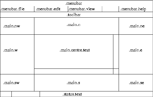
Writing New Devices - host
set message ""
if { ![synth::filter_parse_options $console_appearance parsed_options message] } {
synth::report_error \
"Invalid entry in target definition file $synth::target_definition\
\n synth_device \"console\", entry \"appearance\"\n$message"
} else {
synth::filter_add_parsed "console" parsed_options
}
On success parsed_options will be updated with an internal representation of the desired appearance, which can
then be used in a call to synth::filter_add_parsed. On failure message will be updated with details of the parsing
error that occurred.
The Graphical Interface
When the I/O auxiliary is running in graphical mode, many scripts will want to update the user interface in some
way. This may be as simple as adding another entry to the help menu for the device, or adding a new button to the
toolbar. It may also involve adding new subwindows, or even creating entire new toplevel windows. These may
be simple monitor windows, displaying additional information about what is going on in the system in a graphical
format. Alternatively they may emulate actual I/O operations, for example button widgets could be used to emulate
real physical buttons.
The I/O auxiliary does not provide many procedures related to the graphical interface. Instead it is expected that
scripts will just update the widget hierarchy directly.
So adding a new item to the Help menu involves a .menubar.help add operation with suitable arguments. Adding
a new button to the toolbar involves creating a child window in .toolbar and packing it appropriately. Scripts can
create their own subwindows and then pack it into one of .main.nw,.main.n,.main.ne,.main.w,.main.e,
.main.sw,.main.s or .main.se. Normally the user should be allowed to control this via the target definition
file. The central window .main.centre should normally be left alone by other scripts since it gets used for text
output.
The following graphics-related utilities may be found useful:
synth::load_image <image name> <filename>
synth::register_ballon_help <widget> <message>
679
Writing New Devices - host
synth::handle_help <URL>
synth::load_image can be used to add a new image to the current interpreter. If the specified file has a .xbm
extension then the image will be a monochrome bitmap, otherwise it will be a colour image of some sort. A
boolean will be returned to indicate success or failure, and suitable diagnostics will be generated if necessary.
synth::register_balloon_help provides balloon help for a specific widget, usually a button on the toolbar.
synth::handle_help is a utility routine that can be installed as the command for displaying online help, for exam-
ple:
.menubar.help add command -label "my device" -command \
[list synth::handle_help "file://$path"]
680
Porting
Name
Porting — Adding support for other hosts
Description
The initial development effort of the eCos synthetic target happened on x86 Linux machines. Porting to other
platforms involves addressing a number of different issues. Some ports should be fairly straightforward, for exam-
ple a port to Linux on a processor other than an x86. Porting to Unix or Unix-like operating systems other than
Linux may be possible, but would involve more effort. Porting to a completely different operating system such as
Windows would be very difficult. The text below complements the eCos Porting Guide.
Other Linux Platforms
Porting the synthetic target to a Linux platform that uses a processor other than x86 should be straightforward.
The simplest approach is to copy the existing i386linux directory tree in the hal/synth hierarchy, then rename
and edit the ten or so files in this package. Most of the changes should be pretty obvious, for example on a 64-bit
processor some new data types will be needed in the basetype.h header file. It will also be necessary to update
the toplevel ecos.db database with an entry for the new HAL package, and a new target entry will be needed.
Obviously a different processor will have different register sets and calling conventions, so the code for saving and
restoring thread contexts and for implementing setjmp and longjmp will need to be updated. The exact way of
performing Linux system calls will vary: on x86 linux this usually involves pushing some registers on the stack
and then executing an int 0x080 trap instruction, but on a different processor the arguments might be passed in
registers instead and certainly a different trap instruction will be used. The startup code is written in assembler, but
needs to do little more than extract the process’ argument and environment variables and then jump to the main
linux_entry function provided by the architectural synthetic target HAL package.
The header file hal_io.h provided by the architectural HAL package provides various structure definitions, func-
tion prototypes, and macros related to system calls. These are correct for x86 linux, but there may be problems on
other processors. For example a structure field that is currently defined as a 32-bit number may in fact may be a
64-bit number instead.
The synthetic target’s memory map is defined in two files in the include/pkgconf subdirectory. For x86 the
default memory map involves eight megabytes of read-only memory for the code at location 0x1000000 and another
eight megabytes for data at 0x2000000. These address ranges may be reserved for other purposes on the new
architecture, so may need changing. There may be some additional areas of memory allocated by the system for
other purposes, for example the startup stack and any environment variables, but usually eCos applications can and
should ignore those.
Other HAL functionality such as interrupt handling, diagnostics, and the system clock are provided by the architec-
tural HAL package and should work on different processors with few if any changes. There may be some problems
in the code that interacts with the I/O auxiliary because of lurking assumptions about endianness or the sizes of
various data types.
When porting to other processors, a number of sources of information are likely to prove useful. Obviously the
Linux kernel sources and header files constitute the ultimate authority on how things work at the system call level.
681
Porting
The GNU C library sources may also prove very useful: for a normal Linux application it is the C library that
provides the startup code and the system call interface.
Other Unix Platforms
Porting to a Unix or Unix-like operating system other than Linux would be somewhat more involved. The first
requirement is toolchains: the GNU compilers, gcc and g++, must definitely be used; use of other GNU tools
such as the linker may be needed as well, because eCos depends on functionality such as prioritizing C++ static
constructors, and other linkers may not implement this or may implement it in a different and incompatible way.
A closely related requirement is the use of ELF format for binary executables: if the operating system still uses an
older format such as COFF then there are likely to be problems because they do not provide the flexibility required
by eCos.
In the architectural HAL there should be very little code that is specific to Linux. Instead the code should work
on any operating system that provides a reasonable implementation of the POSIX standard. There may be some
problems with program startup, but those could be handled at the architectural level. Some changes may also
be required to the exception handling code. However one file which will present a problem is hal_io.h, which
contains various structure definitions and macros used with the system call interface. It is likely that many of these
definitions will need changing, and it may well be appropriate to implement variant HAL packages for the different
operating systems where this information can be separated out. Another possible problem is that the generic code
assumes that system calls such as cyg_hal_sys_write are available. On an operating system other than Linux it is
possible that some of these are not simple system calls, and instead wrapper functions will need to be implemented
at the variant HAL level.
The generic I/O auxiliary code should be fairly portable to other Unix platforms. However some of the device
drivers may contain code that is specific to Linux, for example the PF_PACKET socket address family and the
ethertap virtual tunnelling interface. These may prove quite difficult to port.
The remaining porting task is to implement one or more platform HAL packages, one per processor type that is
supported. This should involve much the same work as a port to another processor running Linux.
When using other Unix operating systems the kernel source code may not be available, which would make any
porting effort more challenging. However there is still a good chance that the GNU C library will have been ported
already, so its source code may contain much useful information.
Windows Platforms
Porting the current synthetic target code to some version of Windows or to another non-Unix platform is likely
to prove very difficult. The first hurdle that needs to be crossed is the file format for binary executables: current
Windows implementations do not use ELF, instead they use their own format PE which is a variant of the rather
old and limited COFF format. It may well prove easier to first write an ELF loader for Windows executables, rather
than try to get eCos to work within the constraints of PE. Of course that introduces new problems, for example
existing source-level debuggers will still expect executables to be in PE format.
Under Linux a synthetic target application is not linked with the system’s C library or any other standard system
library. That would cause confusion, for example both eCos and the system’s C library might try to define the
printf function, and introduce complications such as working with shared libraries. For much the same reasons,
a synthetic target application under Windows should not be linked with any Windows DLL’s. If an ELF loader has
been specially written then this may not be much of a problem.
682
Porting
The next big problem is the system call interface. Under Windows system calls are generally made via DLL’s, and
it is not clear that the underlying trap mechanism is well-documented or consistent between different releases of
Windows.
The current code depends on the operating system providing an implementation of POSIX signal handling. This is
used for I/O purposes, for example SIGALRM is used for the system clock, and for exceptions. It is not known what
equivalent functionality is available under Windows.
Given the above problems a port of the synthetic target to Windows may or may not be technically feasible, but it
would certainly require a very large amount of effort.
683
Porting
684
XXV. SA11X0 USB Device Driver
685
Porting
686

SA11X0 USB Device Driver
Name
SA11X0 USB Support — Device driver for the on-chip SA11X0 USB device
SA11X0 USB Hardware
The Intel StrongARM SA11x0 family of processors is supplied with an on-chip USB slave device, the UDC (USB
Device Controller). This supports three endpoints. Endpoint 0 can only be used for control messages. Endpoint 1
can only be used for bulk transfers from host to peripheral. Endpoint 2 can only be used for bulk transfers from
peripheral to host. Isochronous and interrupt transfers are not supported.
Caution
Different revisions of the SA11x0 silicon have had various problems with the USB support.
The device driver has been tested primarily against stepping B4 of the SA1110 processor,
and may not function as expected with other revisions. Application developers should obtain
the manufacturer’s current errata sheets and specification updates. The B4 stepping still has
a number of problems, but the device driver can work around these. However there is a
penalty in terms of extra code, extra cpu cycles, and increased dispatch latency because
extra processing is needed at DSR level. Interrupt latency should not be affected.
There is one specific problem inherent in the UDC design of which application developers
should be aware: the hardware cannot fully implement the USB standard for bulk transfers. A
bulk transfer typically consists of some number of full-size 64-byte packets and is terminated
by a packet less than the full size. If the amount of data transferred is an exact multiple of 64
bytes then this requires a terminating packet of 0 bytes of data (plus header and checksum).
The SA11x0 USB hardware does not allow a 0-byte packet to be transmitted, so the device
driver is forced to substitute a 1-byte packet and the host receives more data than expected.
Protocol support is needed so that the appropriate host-side device driver can allow buffer
space for the extra byte, detect when it gets sent, and discard it. Consequently certain stan-
dard USB class protocols cannot be implemented using the SA11x0, and therefore custom
host-side device drivers will generally have to be provided, rather than re-using existing ones
that understand the standard protocol.
Endpoint Data Structures
The SA11x0 USB device driver can provide up to three data structures corresponding to the three endpoints:
a usbs_control_endpoint structure usbs_sa11x0_ep0; a usbs_rx_endpoint usbs_sa11x0_ep1; and a
usbs_tx_endpoint usbs_sa11x0_ep2. The header file cyg/io/usb/usbs_sa11x0.h provides declarations for
these.
Not all applications will require support for all the endpoints. For example, if the intended use of the UDC only
involves peripheral to host transfers then usbs_sa11x0_ep1 is redundant. The device driver provides configuration
options to control the presence of each endpoint:
1. Endpoint 0 is controlled by CYGFUN_DEVS_USB_SA11X0_EP0. This defaults to enabled if there are any higher-
level packages that require USB hardware or if the global preference CYGGLO_IO_USB_SLAVE_APPLICATION
687
SA11X0 USB Device Driver
is enabled, otherwise it is disabled. Usually this has the desired effect. It may be necessary to override this in
special circumstances, for example if the target board uses an external USB chip in preference to the UDC and
it is that external chip’s device driver that should be used rather than the on-chip UDC. It is not possible to
disable endpoint 0 and at the same time enable one or both of the other endpoints, since a USB device is only
usable if it can process the standard control messages.
2. Endpoint 1 is controlled by CYGPKG_DEVS_USB_SA11X0_EP1. By default it is enabled whenever endpoint 0 is
enabled, but it can be disabled manually when not required.
3. Similarly endpoint 2 is controlled by CYGPKG_DEVS_USB_SA11X0_EP2. This is also enabled by default when-
ever endpoint 0 is enabled, but it can be disabled manually.
The SA11X0 USB device driver implements the interface specified by the common eCos USB Slave Support
package. The documentation for that package should be consulted for further details. There is only one major
deviation: when there is a peripheral to host transfer on endpoint 2 which is an exact multiple of the bulk transfer
packet size (usually 64 bytes) the device driver has to pad the transfer with one extra byte. This is because of a
hardware limitation: the UDC is incapable of transmitting 0-byte packets as required by the USB specification.
Higher-level code, including the host-side device driver, needs to be aware of this and adapt accordingly.
The device driver assumes a bulk packet size of 64 bytes, so this value should be used in the endpoint descriptors
in the enumeration data provided by application code. There is experimental code for running with DMA disabled,
in which case the packet size will be 16 bytes rather than 64.
Devtab Entries
In addition to the endpoint data structures the SA11X0 USB device driver can also provide devtab
entries for each endpoint. This allows higher-level code to use traditional I/O operations such as
open/read/write rather than the USB-specific non-blocking functions like usbs_start_rx_buffer.
These devtab entries are optional since they are not always required. The relevant configuration options are
CYGVAR_DEVS_USB_SA11X0_EP0_DEVTAB_ENTRY,CYGVAR_DEVS_USB_SA11X0_EP1_DEVTAB_ENTRY and
CYGVAR_DEVS_USB_SA11X0_EP2_DEVTAB_ENTRY. By default these devtab entries are provided if the global
preference CYGGLO_USB_SLAVE_PROVIDE_DEVTAB_ENTRIES is enabled, which is usually the case. Obviously a
devtab entry for a given endpoint will only be provided if the underlying endpoint is enabled. For example, there
will not be a devtab entry for endpoint 1 if CYGPKG_DEVS_USB_SA11X0_EP1 is disabled.
The names for the three devtab entries are determined by using a configurable base name and appending 0c,1r
or 2w. The base name is determined by the configuration option CYGDAT_DEVS_USB_SA11X0_DEVTAB_BASENAME
and has a default value of /dev/usbs, so the devtab entry for endpoint 1 would default to /dev/usbs1r. If the
target hardware involves multiple USB devices then application developers may have to change the base name to
prevent a name clash.
DMA Engines
The SA11X0 UDC provides only limited fifos for bulk transfers on endpoints 1 and 2; smaller than the normal
64-byte bulk packet size. Therefore a typical transfer requires the use of DMA engines. The SA11x0 provides six
DMA engines that can be used for this, and the endpoints require one each (assuming both endpoints are enabled).
At the time of writing there is no arbitration mechanism to control access to the DMA engines. By default the
device driver will use DMA engine 4 for endpoint 1 and DMA engine 5 for endpoint 2, and it assumes that no other
code uses these particular engines.
688
SA11X0 USB Device Driver
The exact DMA engines that will be used are determined by the configuration options
CYGNUM_DEVS_USB_SA11X0_EP1_DMA_CHANNEL and CYGNUM_DEVS_USB_SA11X0_EP2_DMA_CHANNEL. These
options have the booldata flavor, allowing the use of DMA to be disabled completely in addition to controlling
which DMA engines are used. If DMA is disabled then the device driver will attempt to work purely using the
fifos, and the packet size will be limited to only 16 bytes. This limit should be reflected in the appropriate endpoint
descriptors in the enumeration data. The code for driving the endpoints without DMA should be considered
experimental. At best it will be suitable only for applications where the amount of data transferred is relatively
small, because four times as many interrupts will be raised and performance will suffer accordingly.
689
SA11X0 USB Device Driver
690
XXVI. NEC uPD985xx USB Device
Driver
691
SA11X0 USB Device Driver
692
NEC uPD985xx USB Device Driver
Name
NEC uPD985xx USB Support — Device driver for the on-chip NEC uPD985xx USB device
NEC uPD985xx USB Hardware
The NEC uPD985xx family of processors is supplied with an on-chip USB slave device, the UDC (USB Device
Controller). This supports seven endpoints. Endpoint 0 can only be used for control messages. Endpoints 1 and
2 are for isochronous transmits and receives respectively. Endpoints 3 and 4 support bulk transmits and receives.
Endpoints 5 and 6 normally support interrupt transmits and receives, but endpoint 5 can also be configured to
support bulk transmits. At this time only the control endpoint 0, the bulk endpoints 3 and 4, and the interrupt
endpoint 5 are supported.
Endpoint Data Structures
The uPD985xx USB device driver can provide up to four data structures corresponding to the four
supported endpoints: a usbs_control_endpoint structure usbs_upd985xx_ep0; usbs_tx_endpoint structures
usbs_upd985xx_ep3 and usbs_upd985xx_ep5; and a usbs_rx_endpoint usbs_upd985xx_ep4. The header file
cyg/io/usb/usbs_nec_upd985xx.h provides declarations for these.
Not all applications will require support for all the endpoints. For example, if the intended use of the UDC only
involves peripheral to host transfers then usbs_upd985xx_ep4 is redundant. The device driver provides configu-
ration options to control the presence of each endpoint:
1. Endpoint 0 is controlled by CYGFUN_DEVS_USB_UPD985XX_EP0. This defaults to enabled if
there are any higher-level packages that require USB hardware or if the global preference
CYGGLO_IO_USB_SLAVE_APPLICATION is enabled, otherwise it is disabled. Usually this has the desired
effect. It may be necessary to override this in special circumstances, for example if the target board uses an
external USB chip in preference to the UDC and it is that external chip’s device driver that should be used
rather than the on-chip UDC. It is not possible to disable endpoint 0 and at the same time enable one or both
of the other endpoints, since a USB device is only usable if it can process the standard control messages.
2. Endpoint 3 is controlled by CYGPKG_DEVS_USB_UPD985XX_EP3. By default this endpoint is disabled: accord-
ing to NEC erratum U3 there may be problems when attempting bulk transfers of 192 bytes or greater. As an
alternative the device driver provides support for endpoint 5, configured to allow bulk transfers. Endpoint 3
can be enabled if the application only requires bulk transfers of less than 192 bytes, or if this erratum is not
applicable to the system being developed for other reasons.
3. Endpoint 4 is controlled by CYGPKG_DEVS_USB_UPD985XX_EP4. This is enabled by default whenever endpoint
0 is enabled, but it can be disabled manually.
4. Endpoint 5 is controlled by CYGPKG_DEVS_USB_UPD985XX_EP5. This is enabled by default
whenever endpoint 0 is enabled, but it can be disabled manually. There is also a configuration option
CYGIMP_DEVS_USB_UPD985XX_EP5_BULK, enabled by default. This option allows the endpoint to be used
for bulk transfers rather than interrupt transfers.
693
NEC uPD985xx USB Device Driver
The uPD985xx USB device driver implements the interface specified by the common eCos USB Slave Support
package. The documentation for that package should be consulted for further details.
The device driver assumes a bulk packet size of 64 bytes, so this value should be used in the endpoint descriptors
in the enumeration data provided by application code. The device driver also assumes a control packet size of eight
bytes, and again this should be reflected in the enumeration data. If endpoint 5 is configured for interrupt rather
than bulk transfers then the maximum packet size is limited to 64 bytes by the USB standard.
Devtab Entries
In addition to the endpoint data structures the uPD985xx USB device driver can also
provide devtab entries for each endpoint. This allows higher-level code to use traditional I/O
operations such as open/read/write rather than the USB-specific non-blocking functions like
usbs_start_rx_buffer. These devtab entries are optional since they are not always required.
The relevant configuration options are CYGVAR_DEVS_USB_UPD985XX_EP0_DEVTAB_ENTRY,
CYGVAR_DEVS_USB_UPD985XX_EP3_DEVTAB_ENTRY,CYGVAR_DEVS_USB_UPD985XX_EP4_DEVTAB_ENTRY, and
CYGVAR_DEVS_USB_UPD985XX_EP5_DEVTAB_ENTRY. By default these devtab entries are provided if the global
preference CYGGLO_USB_SLAVE_PROVIDE_DEVTAB_ENTRIES is enabled, which is usually the case. Obviously a
devtab entry for a given endpoint will only be provided if the underlying endpoint is enabled. For example, there
will not be a devtab entry for endpoint 4 if CYGPKG_DEVS_USB_UPD985XX_EP4 is disabled.
The names for the devtab entries are determined by using a configurable base name and appending 0c,3w,4r or
5w. The base name is determined by the configuration option CYGDAT_DEVS_USB_UPD985XX_DEVTAB_BASENAME
and has a default value of /dev/usbs, so the devtab entry for endpoint 4 would default to /dev/usbs4r. If the
target hardware involves multiple USB devices then application developers may have to change the base name to
prevent a name clash with other USB device drivers.
Restrictions
The current device driver imposes a restriction on certain bulk receives on endpoint 4. If the protocol being used
involves variable-length transfers, in other words if the host is allowed to send less data than a maximum-sized
transfer, then the buffer passed to the device driver for receives must be aligned to a 16-byte cacheline boundary
and it must be a multiple of this 16-byte cacheline size. This restriction does not apply if the protocol only involves
fixed-size transfers.
Optional Hardware Workarounds
The NEC errata list a number of other problems that affect the USB device driver. The device driver contains
workarounds for these, which are enabled by default but can be disabled if the application developer knows that
the errata are not relevant to the system being developed.
Erratum S1 lists a possible problem if the device driver attempts multiple writes to the USB hardware. This is
circumvented by a dummy read operation after every write. If the workaround is not required then the configuration
option CYGIMP_DEVS_USB_UPD985XX_IBUS_WRITE_LIMIT can be disabled.
Errata U3 and U4 describe various problems related to concurrent transmissions on different endpoints. By de-
fault the device driver works around this by serializing all transmit operations. For example if the device driver
needs to send a response to a control message on endpoint 0 while there is an ongoing bulk transfer on end-
694
NEC uPD985xx USB Device Driver
point 5, the response is delayed until the bulk transfer has completed. Under typical operating conditions this
does not cause any problems: endpoint 0 traffic usually happens only during initialization, when the target is
connected to the host, while endpoint 5 traffic only happens after initialization. However if transmit serializa-
tion is inappropriate for the system being developed then it can be disabled using the configuration option CY-
GIMP_DEVS_USB_UPD985XX_SERIALIZE_TRANSMITS.
Platform Dependencies
On some platforms it is necessary for the low-level USB device driver to perform some additional operations
during start-up. For example it may be necessary to manipulate one of the processor’s GPIO lines before the host
can detect a new USB peripheral and attempt to communicate with it. This avoids problems if the target involves
a significant amount of work prior to device driver initialization, for example a power-on self-test sequence. If the
USB host attempted to contact the target before the USB device driver had been initialized, it would fail to get the
expected responses and conclude that the target was not a functional USB peripheral.
Platform-specific initialization code can be provided via a macro UPD985XX_USB_PLATFORM_INIT. Typically this
macro would be defined in the platform HAL’s header file cyg/hal/plf_io.h. If the current platform defines
such a macro, the USB device driver will invoke it during the endpoint 0 start-up operation.
695
NEC uPD985xx USB Device Driver
696
XXVII. Synthetic Target Ethernet Driver
697
NEC uPD985xx USB Device Driver
698
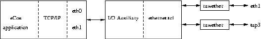
Synthetic Target Ethernet Driver
Name
Synthetic Target Ethernet Support — Allow synthetic target applications to perform ethernet I/O
Overview
The synthetic target ethernet package can provide up to four network devices, eth0 to eth3. These can be used
directly by the eCos application or, more commonly, by a TCP/IP stack that is linked with the eCos application.
Each eCos device can be mapped on to a real Linux network device. For example, if the Linux PC has two ethernet
cards and eth1 is not currently being used by Linux itself, then one of the eCos devices can be mapped on to this
Linux device. Alternatively, it is possible to map some or all of the eCos devices on to the ethertap support provided
by the Linux kernel.
The ethernet package depends on the I/O auxiliary provided by the synthetic target architectural HAL package.
During initialization the eCos application will attempt to instantiate the desired devices, by sending a request to
the auxiliary. This will load a Tcl script ethernet.tcl that is responsible for handling the instantiation request
and subsequent I/O operations, for example transmitting an ethernet packet. However, some of the low-level I/O
operations cannot conveniently be done by a Tcl script so ethernet.tcl will actually run a separate program
rawether to interact with the Linux network device.
On the target-side there are configuration options to control which network devices should be present. For many
applications a single device will be sufficient, but if the final eCos application is something like a network bridge
then the package can support multiple devices. On the host-side each eCos network device needs to be mapped on
to a Linux one, either a real ethernet device or an ethertap device. This is handled by an entry in the target definition
file:
synth_device ethernet {
eth0 real eth1
eth1 ethertap tap3 00:01:02:03:FE:05
...
}
The ethernet package also comes with support for packet logging, and provides various facilities for use by user
Tcl scripts.
Installation
Before a synthetic target eCos application can access ethernet devices it is necessary to build and install host-side
support. The relevant code resides in the host subdirectory of the synthetic target ethernet package, and building
it involves the standard configure,make and make install steps. The build involves a new executable rawether
which must be able to access a raw Linux network device. This is achieved by installing it suid root, so the make
install step has to be run with superuser privileges.
699

Synthetic Target Ethernet Driver
Caution
Installing rawether suid root introduces a potential security problem. Although normally
rawether is executed only by the I/O auxiliary, theoretically it can be run by any program.
Effectively it gives any user the ability to monitor all ethernet traffic and to inject arbitrary
packets into the network. Also, as with any suid root programs there may be as yet undis-
covered exploits. Users and system administrators should consider the risks before running
make install.
There are two main ways of building the host-side software. It is possible to build both the generic host-side
software and all package-specific host-side software, including the ethernet support, in a single build tree. This
involves using the configure script at the toplevel of the eCos repository. For more information on this, see the
README.host file at the top of the repository. Note that if you have an existing build tree which does not include
the synthetic target ethernet support then it will be necessary to rerun the toplevel configure script: the search for
appropriate packages happens at configure time.
The alternative is to build just the host-side for this package. This requires a separate build directory, building
directly in the source tree is disallowed. The configure options are much the same as for a build from the toplevel,
and the README.host file can be consulted for more details. It is essential that the ethernet support be configured
with the same --prefix option as other eCos host-side software, especially the I/O auxiliary provided by the
architectural synthetic target HAL package, otherwise the I/O auxiliary will be unable to locate the ethernet support.
Target-side Configuration Options
The target-side code can be configured to support up to four ethernet devices, eth0 to eth3. By default eth0 is
enabled if the configuration includes a TCP/IP stack, otherwise it is disabled. The other three devices are always
disabled by default. If any of the devices are enabled then there will also be the usual configuration options related
to building this package. Other options related to network devices, for example whether or not to use DHCP, are
provided by the generic network device package.
Real Ethernet
One obvious way of providing a synthetic target eCos application with ethernet I/O is to use a real ethernet device
in the PC: transmitted packets go out on a real network, and packets on the network addressed to the right MAC
address are passed on to eCos. This way synthetic target networking behaves just like networking on a real target
with ethernet hardware. For example, if there is a DHCP server anywhere on the network then eCos will be able to
contact it during networking startup and get hold of IP address information.
Configuring the ethernet support to use a real ethernet device requires a simple entry in the target definition file:
synth_device ethernet {
<eCos device>real <linux device>
...
}
For example, to map the eCos network device eth0 to the Linux device eth1:
synth_device ethernet {
eth0 real eth1
...
700
Synthetic Target Ethernet Driver
}
It is not possible for an ethernet device to be shared by both the eCos TCP/IP stack and the Linux one: there would
be no simple way to work out which stack incoming packets are intended for. In theory it might be possible to do
some demultiplexing using distinct IP addresses, but it would be impossible to support some functionality such
as DHCP. Therefore the rawether program will refuse to access any ethernet device already in use. On a typical
Linux system eth0 will be used for Linux networking, and the PC will have to be equipped with additional ethernet
devices for use by eCos.
The rawether program will access the hardware via the appropriate Linux device driver, so it is important that the
system is set up such that the relevant module will be automatically loaded or is already loaded. The details of this
will depend on the installed distribution and version, but typically it will involve an entry in /etc/modules.conf.
Ethertap
The Linux kernel’s ethertap facility provides a virtual network interface. A Linux application, for example the
rawether program, can open a special character device /dev/net/tun, perform various ioctl calls, and then
write and read ethernet packets. When the device is opened the Linux kernel automatically creates a new network
interface, for example tap0. The Linux TCP/IP stack can be made to use this network interface like any other
interface, receiving and transmitting ethernet packets. The net effect is a virtual network connecting just the Linux
and eCos TCP/IP stacks, with no other nodes attached. By default all traffic remains inside this virtual network and
is never forwarded to a real network.
Support for the ethertap facility may or may not be provided automatically, depending on your
Linux distribution and version. If your system does not have a device /dev/net/tun or a
module tun.o then the appropriate kernel documentation should be consulted, for example
/usr/src/linux-2.4/Documentation/networking/tuntap.txt. If you are using an old Linux kernel then
the ethertap functionality may be missing completely. When the rawether program is configured and built, the
configure script will check for a file /usr/include/linux/if_tun.h. If that file is missing then rawether will
be built without ethertap functionality, and only real ethernet interfaces will be supported.
The target definition file is used to map eCos network devices on to ethertap devices. The simplest usage is:
synth_device ethernet {
eth0 ethertap
...
}
The Linux kernel will automatically allocate the next available tap network interface. Usually this will be tap0 but
if other software is using the ethertap facility, for example to implement a VPN, then a different number may be
allocated. Usually it will be better to specify the particular tap device that should be used for each eCos device, for
example:
synth_device ethernet {
eth0 ethertap tap3
eth1 ethertap tap4
...
}
The user now knows exactly which eCos device is mapped onto which Linux device, avoiding much potential
confusion. Because the virtual devices are emulated ethernet devices, they require MAC addresses. There is no
701
Synthetic Target Ethernet Driver
physical hardware to provide these addresses, so normally MAC addresses will be invented. That means that each
time the eCos application is run it will have different MAC addresses, which makes it more difficult to compare
the results of different runs. To get more deterministic behaviour it is possible to specify the MAC addresses in the
target definition file:
synth_device ethernet {
eth0 ethertap tap3 00:01:02:03:FE:05
eth1 ethertap tap4 00:01:02:03:FE:06
...
}
During the initialization phase the eCos application will instantiate the various network devices. This will cause
the I/O auxiliary to load the ethernet.tcl script and spawn rawether processes, which in turn will open
/dev/net/tun and perform the appropriate ioctl calls. On the Linux side there will now be new network in-
terfaces such as tap3, and these can be configured like any other network interface using commands such as
ifconfig. In addition, if the Linux system is set up with hotplug support then it may be possible to arrange for
the network interface to become active automatically. On a Red Hat Linux system this would require files such as
/etc/sysconfig/network-scripts/ifcfg-tap3, containing data like:
DEVICE="tap3"
BOOTPROTO="none"
BROADCAST=10.2.2.255
IPADDR="10.2.2.1"
NETMASK="255.255.255.0"
NETWORK=10.2.2.0
ONBOOT="no"
This gives the Linux interface the address 10.2.2.1 on the network 10.2.2.0. The eCos network
device should be configured with a compatible address. One way of doing this would be to enable
CYGHWR_NET_DRIVER_ETH0_ADDRS, set CYGHWR_NET_DRIVER_ETH0_ADDRS_IP to 10.2.2.2, and similarly
update the NETMASK,BROADCAST,GATEWAY and SERVER configuration options.
It should be noted that the ethertap facility provides a virtual network, and any packets transmitted by the eCos
application will not appear on a real network. Therefore usually there will no accessible DHCP server, and eCos
cannot use DHCP or BOOTP to obtain IP address information. Instead the eCos configuration should use manual
or static addresses.
An alternative approach would be to set up the Linux box as a network bridge, using commands like brctl to
connect the virtual network interface tap3 to a physical network interface such as eth0. Any packets sent by the
eCos application will get forwarded automatically to the real network, and some packets on the real network will
get forwarded over the virtual network to the eCos application. Note that the eCos application might also get some
packets that were not intended for it, but usually those will just be discarded by the eCos TCP/IP stack. The exact
details of setting up a network bridge are left as an exercise to the reader.
Packet Logging
The ethernet support comes with support for logging the various packets that are transferred, including a simple
protocol analyser. This generates simple text output using the filter mechanisms provided by the I/O auxiliary, so
it is possible to control the appearance and visibility of different types of output. For example the user might want
to see IPv4 headers and all ICMPv4 and ARP operations, but not TCP headers or any of the packet data.
702
Synthetic Target Ethernet Driver
The protocol analyser is not intended to be a fully functional analyser with knowledge of many different TCP/IP
protocols, advanced search facilities, graphical traffic displays, and so on. Functionality like that is already provided
by other tools such as ethereal and tcpdump. Achieving similar levels of functionality would require a lot of work,
for very little gain. It is still useful to have some protocol analysis functionality available because the output will be
interleaved with other output, for example printf calls from the application. That may make it easier to understand
the sequence of events.
One problem with logging ethernet traffic is that it can involve very large amounts of data. If the application is
expected to run for a long time or is very I/O intensive then it is easy to end up with many megabytes. When
running in graphical mode all the logging data will be held in memory, even data that is not currently visible.
At some point the system will begin to run low on memory and performance will suffer. To avoid problems, the
ethernet script maintains a flag that controls whether or not packet logging is active. The default is to run with
logging disabled, but this can be changed in the target definition file:
synth_device ethernet {
...
logging 1
}
The ethernet script will add a toolbar button that allows this flag to be changed at run-time, allowing the user to
capture traffic for certain periods of time while the application continues running.
The target definition file can contain the following entries for the various packet logging filters:
synth_device ethernet {
...
filter ether -hide 0 -background LightBlue -foreground "#000080"
filter arp -hide 0 -background LightBlue -foreground "#000050"
filter ipv4 -hide 0 -background LightBlue -foreground "#000040"
filter ipv6 -hide 1 -background LightBlue -foreground "#000040"
filter icmpv4 -hide 0 -background LightBlue -foreground "#000070"
filter icmpv6 -hide 1 -background LightBlue -foreground "#000070"
filter udp -hide 0 -background LightBlue -foreground "#000030"
filter tcp -hide 0 -background LightBlue -foreground "#000020"
filter hexdata -hide 1 -background LightBlue -foreground "#000080"
filter asciidata -hide 1 -background LightBlue -foreground "#000080"
}
All output will show the eCos network device, for example eth0, and the direction relative to the eCos application.
Some of the filters will show packet headers, for example ether gives details of the ethernet packet header and tcp
gives information about TCP headers such as whether or not the SYN flag is set. The TCP and UDP filters will also
show source and destination addresses, using numerical addresses and if possible host names. However, host names
will only be shown if the host appears in /etc/hosts: doing full DNS lookups while the data is being captured
would add significantly to complexity and overhead. The hexdata and asciidata filters show the remainder of
the packets after the ethernet, IP and TCP or UDP headers have been stripped.
Some of the filters will provide raw dumps of some of the packet data. Showing up to 1500 bytes of data for each
packet would be expensive, and often the most interesting information is near the start of the packet. Therefore it
is possible to set a limit on the number of bytes that will be shown using the target definition file. The default limit
is 64 bytes.
synth_device ethernet {
...
703
Synthetic Target Ethernet Driver
max_show 128
}
User Interface Additions
When running in graphical mode the ethernet script extends the user interface in two ways: a button is added to
the toolbar so that users can enable or disable packet logging; and an entry is added to the Help menu for the
ethernet-specific documentation.
Command Line Arguments
The synthetic target ethernet support does not use any command line arguments. All configuration is handled
through the target definition file.
Hooks
The ethernet support defines two hooks that can be used by other scripts, especially user scripts: ethernet_tx and
ethernet_rx. The tx hook is called whenever eCos tries to transmit a packet. The rx hook is called whenever an
incoming packet is passed to the eCos application. Note that this may be a little bit after the packet was actually
received by the I/O auxiliary since it can buffer some packets. Both hooks are called with two arguments, the name
of the network device and the packet being transferred. Typical usage might look like:
proc my_tx_hook { arg_list } {
set dev [lindex $arg_list 0]
incr ::my_ethernet_tx_packets($dev)
incr ::my_ethernet_tx_bytes($dev) [string length [lindex $arg_list 1]]
}
proc my_rx_hook { arg_list } {
set dev [lindex $arg_list 0]
incr ::my_ethernet_rx_packets($dev)
incr ::my_ethernet_rx_bytes($dev) [string length [lindex $arg_list 1]]
}
synth::hook_add "ethernet_tx" my_tx_hook
synth::hook_add "ethernet_rx" my_rx_hook
The global arrays my_ethernet_tx_packets etc. will now be updated whenever there is ethernet traffic. Other
code, probably running at regular intervals by use of the Tcl after procedure, can then use this information to
update a graphical monitor of some sort.
Additional Tcl Procedures
The ethernet support provides one additional Tcl procedure that can be used by other scripts;
ethernet::devices_get_list
This procedure returns a list of the ethernet devices that have been instantiated, for example {eth0 eth1}.
704
XXVIII. Synthetic Target Watchdog
Device
705
Synthetic Target Ethernet Driver
706
Synthetic Target Watchdog Device
Name
Synthetic Target Watchdog Device — Emulate watchdog hardware in the synthetic target
Overview
Some target hardware comes equipped with a watchdog timer. Application code can start this timer and after a
certain period of time, typically a second, the watchdog will trigger. Usually this causes the hardware to reboot.
The application can prevent this by regularly resetting the watchdog. An automatic reboot can be very useful when
deploying hardware in the field: a hardware glitch could cause the unit to hang; or the software could receive an
unexpected sequence of inputs, never seen in the laboratory, causing the system to lock up. Often the hardware is
still functional, and a reboot sorts out the problem with only a brief interruption in service.
The synthetic target watchdog package emulates watchdog hardware. During system initialization watchdog device
will be instantiated, and the watchdog.tcl script will be loaded by the I/O auxiliary. When the eCos application
starts the watchdog device, the watchdog.tcl script will start checking the state of the eCos application at one
second intervals. A watchdog reset call simply involves a message to the I/O auxiliary. If the watchdog.tcl script
detects that a second has elapsed without a reset then it will send a SIGPWR signal to the eCos application, causing
the latter to terminate. If gdb is being used to run the application, the user will get a chance to investigate what is
happening. This behaviour is different from real hardware in that there is no automatic reboot, but the synthetic
target is used only for development purposes, not deployment in the field: if a reboot is desired then this can be
achieved very easily by using gdb commands to run another instance of the application.
Installation
Before a synthetic target eCos application can use a watchdog device it is necessary to build and install host-side
support. The relevant code resides in the host subdirectory of the synthetic target watchdog package, and building
it involves the standard configure,make and make install steps. The implementation of the watchdog support
does not require any executables, just a Tcl script watchdog.tcl and some support files, so the make step is a
no-op.
There are two main ways of building the host-side software. It is possible to build both the generic host-side
software and all package-specific host-side software, including the watchdog support, in a single build tree. This
involves using the configure script at the toplevel of the eCos repository. For more information on this, see the
README.host file at the top of the repository. Note that if you have an existing build tree which does not include
the synthetic target watchdog support then it will be necessary to rerun the toplevel configure script: the search for
appropriate packages happens at configure time.
The alternative is to build just the host-side for this package. This requires a separate build directory, building
directly in the source tree is disallowed. The configure options are much the same as for a build from the toplevel,
and the README.host file can be consulted for more details. It is essential that the watchdog support be configured
with the same --prefix option as other eCos host-side software, especially the I/O auxiliary provided by the
architectural synthetic target HAL package, otherwise the I/O auxiliary will be unable to locate the watchdog
support.
707
Synthetic Target Watchdog Device
Target-side Configuration
The watchdog device depends on the generic watchdog support, CYGPKG_IO_WATCHDOG: if the generic support is
absent then the watchdog device will be inactive. Some templates include this generic package by default, but not
all. If the configuration does not include the generic package then it can be added using the eCos configuration
tools, for example:
$ ecosconfig add CYGPKG_IO_WATCHDOG
By default the configuration will use the hardware-specific support, i.e. this package. However the generic watch-
dog package contains an alternative implementation using the kernel alarm facility, and that implementation can be
selected if desired. However usually it will be better to rely on an external watchdog facility as provided by the I/O
auxiliary and the watchdog.tcl script: if there are serious problems within the application, for example memory
corruption, then an internal software-only implementation will not be reliable.
The watchdog resolution is currently fixed to one second: if the device does not receive a reset signal at least once
a second then the watchdog will trigger and the eCos application will be terminated with a SIGPWR signal. The
current implementation does not allow this resolution to be changed.
On some targets the watchdog device does not perform a hard reset. Instead the device works more or less via
the interrupt subsystem, allowing application code to install action routines that will be called when the watchdog
triggers. The synthetic target watchdog support effectively does perform a hard reset, by sending a SIGPWR signal
to the eCos application, and there is no support for action routines.
The synthetic target watchdog package provides some configuration options for manipulating the compiler flags
used for building the target-side code. That code is fairly simple, so for nearly all applications the default flags will
suffice.
It should be noted that the watchdog device is subject to selective linking. Unless some code explicitly references
the device, for example by calling the start and reset functions, the watchdog support will not appear in the final
executable. This is desirable because a watchdog device has no effect until started.
Wallclock versus Elapsed Time
On real hardware the watchdog device uses wallclock time: if the device does not receive a reset signal within
a set period of time then the watchdog will trigger. When developing for the synthetic target this is not always
appropriate. There may be other processes running, using up some or most of the cpu time. For example, the
application may be written such that it will issue a reset after some calculations which are known to complete within
half a second, well within the one-second resolution of the watchdog device. However if other Linux processes are
running then the synthetic target application may get timesliced, and half a second of computation may take several
seconds of wallclock time.
Another problem with using wallclock time is that it interferes with debugging: if the application hits a breakpoint
then it is unlikely that the user will manage to restart it in less than a second, and the watchdog will not get reset in
time.
To avoid these problems the synthetic target watchdog normally uses consumed cpu time rather than wallclock
time. If the application is timesliced or if it is halted inside gdb then it does not consume any cpu time. The
application actually has to spend a whole second’s worth of cpu cycles without issuing a reset before the watchdog
triggers.
However using consumed cpu time is not a perfect solution either. If the application makes blocking system
calls then it is not using cpu time. Interaction with the I/O auxiliary involves system calls, but these should take
708

Synthetic Target Watchdog Device
only a short amount of time so their effects can be ignored. If the application makes direct system calls such as
cyg_hal_sys_read then the system behaviour becomes undefined. In addition by default the idle thread will make
blocking select system calls, effectively waiting until an interrupt occurs. If an application spends much of its
time idle then the watchdog device may take much longer to trigger than expected. It may be desirable to enable
the synthetic target HAL configuration option CYGIMP_HAL_IDLE_THREAD_SPIN, causing the idle thread to spin
rather than block, at the cost of wasted cpu cycles.
The default is to use consumed cpu time, but this can be changed in the target definition file:
synth_device watchdog {
use wallclock_time
...
}
User Interface
When the synthetic target is run in graphical mode the watchdog device extends the user interface in two ways. The
Help menu is extended with an entry for the watchdog-specific documentation. There is also a graphical display of
the current state of the watchdog. Initially the watchdog is asleep:
When application code starts the device the watchdog will begin to keep an eye on things (or occasionally both
eyes).
If the watchdog triggers the display will change again, and optionally the user can receive an audible alert. The
location of the watchdog display within the I/O auxiliary’s window can be controlled via a watchdog_pack entry
in the target definition file. For example the following can be used to put the watchdog display to the right of the
central text window:
synth_device watchdog {
watchdog_pack -in .main.e -side top
...
}
The user interface section of the generic synthetic target HAL documentation can be consulted for more information
on window packing.
709
Synthetic Target Watchdog Device
By default the watchdog support will not generate an audible alert when the watchdog triggers, to avoid annoying
colleagues. Sound can be enabled in the target definition file, and two suitable files sound1.au and sound2.au
are supplied as standard:
synth_device watchdog {
sound sound1.au
...
}
An absolute path can be specified if desired:
synth_device watchdog {
sound /usr/share/emacs/site-lisp/emacspeak/sounds/default-8k/alarm.au
...
}
Sound facilities are not built into the I/O auxiliary itself, instead an external program is used. The default player
is play, a front-end to the sox application shipped with some Linux distributions. If another player should be used
then this can be specified in the target definition file:
synth_device watchdog {
...
sound_player my_sound_player
The specified program will be run in the background with a single argument, the sound file.
Command Line Arguments
The watchdog support does not use any command line arguments. All configuration is handled through the target
definition file.
Hooks
The watchdog support does not provide any hooks for use by other scripts. There is rarely any need for customizing
the system’s behaviour when a watchdog triggers because those should be rare events, even during application
development.
Additional Tcl Procedures
The watchdog support does not provide any additional Tcl procedures or variables for use by other scripts.
710
