Elekmaker Motor Instructions
User Manual:
Open the PDF directly: View PDF ![]() .
.
Page Count: 5
An Inexpensive Two-Dimensional Translation Stage for
Mapping Photoelectric Response
Yushi Hu, Finnegan Clark
Enrico Fermi Institute
University of Chicago
October 11, 2018
Abstract
We have constructed a low-budget, two-dimensional translation stage controlled by
a Raspberry Pi in a Linux lab environment. It was required that this stage—with a
light source attached—be able to remotely accept coordinate commands during photo
detection tests inside a dark box. The comparable industry product costs ∼$2,000
compared to the ∼$200 we spent.
We have also constructed a Python library that enables remote communication
with the stage and that tracks the light source’s position during testing. This Python
library can be easily modified and imported by other Python scripts.
1 Motivation and Requirements
In order to execute improved photo response tests in the development of Large Area Pi-
cosecond PhotoDetectors (LAPPD), it was required that we develop a programmable, two-
dimensional translation stage capable of transporting a light source. Specifically, it was
required that the stage be able to execute consistent, custom motions within an 8.5 inch x
8.5 inch area elevated approximately 12 inches above the photo detector and that the frame
of the stage be affixed to the flange of the vacuum vessel in which the photo detector is
developed. Given our Linux lab environment and desired functionalities, it was necessary
that we make mechanical modifications to, develop software for, and modify the firmware of
the EleksMaker A3 Pro CNC laser printer (enabling it to read g-code commands over serial
communication).
2 Building the Stage
2.1 Materials
Building the stage required the following:
•EleksMaker A3 Pro purchased without laser module [Eleksmaker Page and Assembly
Instructions]
1
•Raspberry Pi 3.0 [Raspberry Pi]
•Arduino IDE software [Arduino IDE page]
•Grbl CNC control firmware [Grbl CNC Project]
2.2 Hardware
Hardware construction consisted of assembling the EleksMaker A3 (following factory instruc-
tions) as well as machining the structural parts necessary to mount the stage on our vacuum
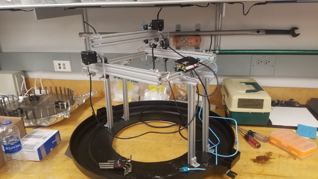
vessel. See Figure 1for the completed stage.
Figure 1: Completed stage secured to base of dark box assembly with modified platform di-
mensions and legs
2.3 Flashing Grbl firmware onto the Mana SE chip
The plain text g-code compatibility we needed was achieved using an open-source firmware
called Grbl. Grbl is a versatile CNC control firmware that reads plain text g-code commands
through serial communication. It can be flashed onto the Mana SE chip that comes with
the EleksMaker A3 as follows:
1. Connect the Mana SE chip (the chip on the EleksMaker’s motor control board) to a
Linux computer via Micro-USB to USB cable. Our device was recognized as /dev/ttyUSB0
by the Linux computer.
•Note: if you have the Arduino IDE on your Raspberry Pi, you can still follow this
procedure but on the Pi.
2. Download Grbl firmware (v1.1) from the Grbl page on github and open the Arduino
IDE software.
3. Once in the Arudino IDE, follow Grbl installation instructions as follows:
Sketch→Include Library→Add .ZIP Library
2
•Important:When adding library, select the Grblfolder inside the grbl-masterfolder.
•If you accidentally select the .zipfile or the wrong folder, you will need to navigate
to your Arduino library, delete the mistake, and redo this step.
4. Open the GrblUpload example in the Arduino IDE:
•File→Examples →Grbl, and select GrblUpload.
5. Compile and upload Grbl to the chip:
•Connect the Mana SE on the EleksMaker to your computer with the provided
cable
•Make sure your board is set to the Arduino Nano in Tool →Board menu and the
serial port is selected correctly in Tool →Serial Port (Ours was ttyUSB0).
•Click Upload and Grbl should compile and flash to the Mana SE.
6. Once Grbl is flashed to the Mana SE, the stage can be decoupled from the Linux
computer and controlled through the Raspberry Pi. Connect the EleksMaker A3 Pro
to the Raspberry Pi. It will automatically mount. (Ours mounted as /dev/ttyUSB0
on the Raspberry Pi)
3 Position Control and Readout
3.1 Introduction
We built a Python library (motor.py) containing APIs that can be easily used by other
Python scripts to send commands to and track the position of the stage. It is able to open
serial communication with the motor control board, define a set of axes, accept absolute
coordinates commands, and send g-code commands to the board that can be read and
executed by Grbl. The default unit of the library is centimeters, and the user can set
whatever step length and origin point they want at any time. The program will automatically
adapt the corresponding commands and track movement history, thereby providing a flexible
absolute coordinate system for the user.
3.2 Downloads
The library can be downloaded at:
https://github.com/WilliamYSHu/ElekMaker3/blob/master/motor.py
The sample program can be downloaded at:
https://github.com/WilliamYSHu/ElekMaker3/blob/master/testmotor.py
3.3 Preparation
A preparation or ‘handshake’ must be executed between the Raspberry Pi and the Mana SE
chip. It only needs to be performed one time after the chip is connected to the Raspberry
Pi, and from then on the Python library will be able to communicate with the Mana SE
chip.
3
1. Open a screen session on the Mana SE, e.g.:
screen /dev/ttyUSB0 115200
2. Then terminate the screen session completely:
Press Ctrl+A and then type :quit
3.4 API Functions
Please refer to the sample program to understand how to import and use the functions in
the libraries. Below are descriptions of each function:
1. motor.Motor(motorSer)
Creates the motor class. It takes the location of the device (Eg. ours was ‘/dev/ttyUSB0’)
2. motorOpen()
Opens the serial port and sets the parameters of the stage. For further customization,
please go into the motor.py file and edit the corresponding numbers:
•The default step length is 1cm.
•The default boundaries of the platform in the X and Y directions are 10cm.
•The default baud rate of the port is 115200.
3. setOrigin()
Sets current position as origin point of the absolute coordinate system. It will auto-
matically change the coordinates of the boundaries of the platform in order to avoid
illegal commands.
4. redefineStep(s)
Takes the new step length as the parameter of the function. The unit should be cm.
Default step is 1cm.
5. takeCor(x,y)
Takes the position coordinate x,y as parameter. The unit is the step defined by user
or 1cm by default. Illegal movements which will make the stage go out of bounds are
prohibited. It will also show the time that the stage needs to complete the command
and will print a message when the motion is complete. The function returns the time
needed to complete the command (in seconds), so users can use this return value to
realize functions like: ”pause stage for 5 seconds after movement.”
6. returnPos()
Returns the position of the stage. It will return the coordinate in both user defined
step and in cm.
7. motorClose()
Closes the serial communication.
4
4 Performance
The process of converting between g-code values and physical distance has resulted in an
uncertainty in the position value returned of ±0.25 mm. However, the motion of the machine
is consistent. Consistency was tested by repeating a simple square motion command 100
times. There was no displacement between the initial and final positions.
5 Acknowledgements
We thank Mark Qiu and Mesut Caliskan for their work constructing the dark box base
and also Eric Spieglan, Henry Frisch, and Evan Angelico for their advice and assistance
throughout the process. Many thank also the developers of the Grbl CNC Project for
providing their firmware open-source.
5
