Epson Stylus Photo 890, 1280, 1290 Service Manual. Www.s Manuals.com. Manual
User Manual: Inkjet Printer Epson Stylus Photo 1290 - Service manuals and Schematics, Disassembly / Assembly. Free.
Open the PDF directly: View PDF ![]() .
.
Page Count: 206 [warning: Documents this large are best viewed by clicking the View PDF Link!]
- EPSON Stylus PHOTO 890/1280/1290
- PRODUCT DESCRIPTIONS
- 1.1 Overview
- 1.2 Basic Specifications
- 1.3 Interface
- 1.4 Operations
- 1.5 Dimension
- OPERATING PRINCIPLES
- TROUBLESHOOTING
- DISASSEMBLY AND ASSEMBLY
- 4.1 Overview
- 4.2 Disassembly Procedures
- 4.2.1 HOUSING Removal
- 4.2.2 Circuit Board Assembly Removal
- 4.2.3 Panel Unit Removal
- 4.2.4 Printhead Unit Removal
- 4.2.5 TRAY, ABSORBER ASSEMBLY Removal
- 4.2.6 Ink Unit Removal
- 4.2.7 MOTOR ASSEMBLY, CR Removal
- 4.2.8 MOTOR ASSEMBLY, ASF Removal
- 4.2.9 DE Unit Removal
- 4.2.10 ASF Unit Removal
- 4.2.11 Carriage Unit Removal
- 4.2.12 BOARD ASSEMBLY, ENCODER Removal
- 4.2.13 ROLLER, PF Removal
- 4.2.14 MOTOR ASSEMBLY, PF Removal
- 4.2.15 PE Sensor Unit Removal
- ADJUSTMENT
- 5.1 Overview
- 5.2 Adjustment
- 5.3 Individual Adjustment Program
- 5.4 Sequential Repair Adjustment Program
- MAINTENANCE
- APPENDIX
- PRODUCT DESCRIPTIONS

EPSON Stylus PHOTO 890/1280/1290
Color ink jet printer
SEIJ00025
®
SERVICE MANUAL
Stylus PHOTO 890
Stylus PHOTO 1290/1280
Notice
All rights reserved. No part of this manual may be reproduced, stored in a retrieval system, or transmitted in any form or by any means electronic,
mechanical, photocopying, or otherwise, without the prior written permission of SEIKO EPSON CORPORATION.
All effort have been made to ensure the accuracy of the contents of this manual. However, should any errors be detected, SEIKO EPSON would
greatly appreciate being informed of them.
The contents of this manual are subject to change without notice.
All effort have been made to ensure the accuracy of the contents of this manual. However, should any errors be detected, SEIKO EPSON would
greatly appreciate being informed of them.
The above not withstanding SEIKO EPSON CORPORATION can assume no responsibility for any errors in this manual or the consequences
thereof.
EPSON is a registered trademark of SEIKO EPSON CORPORATION.
General Notice: Other product names used herein are for identification purpose only and may be trademarks or registered trademarks of their
respective owners. EPSON disclaims any and all rights in those marks.
Copyright © 2000 SEIKO EPSON CORPORATION.
Imaging & Information Product Division
TPCS Quality Assurance Center

PRECAUTIONS
Precautionary notations throughout the text are categorized relative to 1)Personal injury and 2) damage to equipment.
DANGER Signals a precaution which, if ignored, could result in serious or fatal personal injury. Great caution should be exercised in performing
procedures preceded by DANGER Headings.
WARNING Signals a precaution which, if ignored, could result in damage to equipment.
The precautionary measures itemized below should always be observed when performing repair/maintenance procedures.
DANGER
1. ALWAYS DISCONNECT THE PRODUCT FROM THE POWER SOURCE AND PERIPHERAL DEVICES PERFORMING ANY MAINTENANCE OR REPAIR PROCEDURES.
2. NO WORK SHOULD BE PERFORMED ON THE UNIT BY PERSONS UNFAMILIAR WITH BASIC SAFETY MEASURES AS DICTATED FOR ALL ELECTRONICS
TECHNICIANS IN THEIR LINE OF WORK.
3. WHEN PERFORMING TESTING AS DICTATED WITHIN THIS MANUAL, DO NOT CONNECT THE UNIT TO A POWER SOURCE UNTIL INSTRUCTED TO DO SO. WHEN
THE POWER SUPPLY CABLE MUST BE CONNECTED, USE EXTREME CAUTION IN WORKING ON POWER SUPPLY AND OTHER ELECTRONIC COMPONENTS.
4. WHEN DISASSEMBLING OR ASSEMBLING A PRODUCT, MAKE SURE TO WEAR GLOVES TO AVOID INJURIER FROM METAL PARTS WITH SHARP EDGES.
WARNING
1. REPAIRS ON EPSON PRODUCT SHOULD BE PERFORMED ONLY BY AN EPSON CERTIFIED REPAIR TECHNICIAN.
2. MAKE CERTAIN THAT THE SOURCE VOLTAGES IS THE SAME AS THE RATED VOLTAGE, LISTED ON THE SERIAL NUMBER/RATING PLATE. IF THE EPSON
PRODUCT HAS A PRIMARY AC RATING DIFFERENT FROM AVAILABLE POWER SOURCE, DO NOT CONNECT IT TO THE POWER SOURCE.
3. ALWAYS VERIFY THAT THE EPSON PRODUCT HAS BEEN DISCONNECTED FROM THE POWER SOURCE BEFORE REMOVING OR REPLACING PRINTED CIRCUIT
BOARDS AND/OR INDIVIDUAL CHIPS.
4. IN ORDER TO PROTECT SENSITIVE MICROPROCESSORS AND CIRCUITRY, USE STATIC DISCHARGE EQUIPMENT, SUCH AS ANTI-STATIC WRIST STRAPS, WHEN
ACCESSING INTERNAL COMPONENTS.
5. DO NOT REPLACE IMPERFECTLY FUNCTIONING COMPONENTS WITH COMPONENTS WHICH ARE NOT MANUFACTURED BY EPSON. IF SECOND SOURCE IC OR
OTHER COMPONENTS WHICH HAVE NOT BEEN APPROVED ARE USED, THEY COULD CAUSE DAMAGE TO THE EPSON PRODUCT, OR COULD VOID THE
WARRANTY OFFERED BY EPSON.
PREFACE
This manual describes basic functions, theory of electrical and mechanical operations, maintenance and repair procedures of EPSON Stylus PHOTO 890/1280/
1290. The instructions and procedures included herein are intended for the experienced repair technicians, and attention should be given to the precautions on the
preceding page. The chapters are organized as follows:
CHAPTER 1. PRODUCT DESCRIPTIONS
Provides a general overview and specifications of the product.
CHAPTER 2. OPERATING PRINCIPLES
Describes the theory of electrical and mechanical operations of the product.
CHAPTER 3. TROUBLESHOOTING
Provides the step-by-step procedures for troubleshooting.
CHAPTER 4. DISASSEMBLY AND ASSEMBLY
Describes the step-by-step procedures for disassembling and assembling the
product.
CHAPTER 5. ADJUSTMENTS
Provides Epson-approved methods for adjustment.
CHAPTER 6. MAINTENANCE
Provides preventive maintenance procedures and the lists of Epson-approved
lubricants and adhesives required for servicing the product.
APPENDIX
Provides the following additional information for reference:
• EEPROM Address Map
• Connector Pin Assignments
• Component Layout
• Exploded Diagrams
• Electrical Board Circuit Diagrams

Symbols Used in this Manual
Various symbols are used throughout this manual either to provide additional information on a specific topic or to warn of possible danger present
during a procedure or an action. Be aware of all symbols when they are used, and always read NOTE, CAUTION, or WARNING messages.
Indicates an operating or maintenance procedure, practice or condition that is necessary to keep the product’s quality.
Indicates an operating or maintenance procedure, practice, or condition that, if not strictly observed, could result in damage to, or
destruction of, equipment.
May indicate an operating or maintenance procedure, practice or condition that is necessary to accomplish a task efficiently. It may also
provide additional information that is related to a specific subject, or comment on the results achieved through a previous action.
Indicates an operating or maintenance procedure, practice or condition that, if not strictly observed, could result in injury or loss of life.
A D J U S T M E N T
R E Q U I R E D
C A U T I O N
CHECK
P O I N T
W ARNING

Revision Status
Revision Issued Date Description
A November 16, 2000 First Release
B December 27, 2000
Revision:
• page -78: A warning message for static electricity added.
• page -79: Caution messages for torque and ink tube position added
• page -90& page -92: Caution messages for ink tube installation added.
• page -121: PG adjustment tool added.
C February 8, 2001
Revision:
• All chapters: Stylus PHOTO 1280(for EAI) added.
• page -68: Misdescription for Maintenance Request Error corrected.
• page -128: Stylus PHOTO 1280(for EAI) added to Destination in the adjustment program.
• page -182: C393 MAIN-C Board circuit diagram added.
D June 4,2002 Revision:
• “Lubrication” on page -156: The lubrication of Oil O-12 for the Stylus Photo 1280/1290 added.

Table of Contents
Chapter 1 PRODUCT DESCRIPTIONS
1.1 Overview ............................................................................................................ 11
1.1.1 Features ...................................................................................................... 11
1.1.2 Accessories, Consumable Products, and Options ...................................... 12
1.2 Basic Specifications .......................................................................................... 14
1.2.1 Printing Specification ................................................................................ 14
1.2.2 Control Code .............................................................................................. 14
1.2.3 Paper Feeding ............................................................................................ 14
1.2.4 Input Data Buffer ....................................................................................... 14
1.2.5 Paper Specifications ................................................................................... 15
1.2.5.1 EPSON Special Media ...................................................................... 15
1.2.6 Printing Area .............................................................................................. 17
1.2.6.1 Cut Sheet ........................................................................................... 17
1.2.6.2 Envelopes .......................................................................................... 18
1.2.7 Adjust Lever .............................................................................................. 18
1.2.8 Ink Cartridge .............................................................................................. 19
1.2.9 Electric Specification ................................................................................. 20
1.2.10 Reliability ................................................................................................ 20
1.2.11 Environmental Condition ......................................................................... 21
1.3 Interface ............................................................................................................. 22
1.3.1 Parallel Interface (Forward Channel) ........................................................ 22
1.3.2 Parallel Interface (Reserve Channel) ......................................................... 25
1.3.3 USB Interface ............................................................................................ 26
1.3.4 Prevention of Data Transfer Time-out ....................................................... 27
1.3.5 Interface Selection ..................................................................................... 27
1.3.6 IEEE1284.4 Protocol ................................................................................. 27
1.4 Operations ......................................................................................................... 28
1.4.1 Buttons ....................................................................................................... 28
1.4.2 Indicators ................................................................................................... 28
1.4.3 Panel Functions .......................................................................................... 28
1.4.4 Special Setting Mode ................................................................................. 29
1.4.5 Printer Initialization ................................................................................... 30
1.4.6 Initialization Value .................................................................................... 30
1.5 Dimension .......................................................................................................... 31
Chapter 2 OPERATING PRINCIPLES
2.1 Overview ............................................................................................................ 34
2.1.1 Printhead Mechanism ................................................................................ 35
2.1.2 Carriage Mechanism .................................................................................. 36
2.1.2.1 Carriage Motor (CR Motor) .............................................................. 36
2.1.2.2 Platen Gap (PG) /Parallelism Adjustment Mechanism ..................... 37
2.1.2.3 Carriage Home Position (HP) Detection ........................................... 37
2.1.3 Paper Feeding Mechanism ......................................................................... 37
2.1.3.1 CR Lock Mechanism ......................................................................... 39
2.1.4 Paper Loading Mechanism ........................................................................ 40
2.1.4.1 Drive Transmission to the ASF Unit ................................................. 40
2.1.4.2 Paper Loading Operation .................................................................. 41
2.1.4.3 Pump Mechanism .............................................................................. 42
2.1.4.4 Capping Mechanism .......................................................................... 43
2.2 Electrical Circuit Operating Principles .......................................................... 44
2.2.1 C378PSB/PSE Board ................................................................................. 44
2.2.1.1 Electrical Circuit ............................................................................... 44
2.2.1.2 Protection Circuits ............................................................................. 46
2.2.1.3 Power Supply Control Function ........................................................ 46
2.2.1.4 Energy Save Mode ............................................................................ 46
2.2.2 C393MAIN Board Circuit Operation Principles ....................................... 47
2.2.2.1 Printhead Driver Circuit .................................................................... 50
2.2.2.2 RTC (Real Time Clock)/ Reset/ EEPROM Circuit ........................... 51
2.2.2.3 Motor Driver Circuit ......................................................................... 52
2.2.2.4 ASF/Pump Motor Driver Circuit ....................................................... 57
2.2.2.5 Sensor Circuit .................................................................................... 58
Chapter 3 TROUBLESHOOTING
3.1 Overview ............................................................................................................ 61
3.1.1 Self-Diagnostic Function ........................................................................... 62
3.1.1.1 Troubleshooting with LED Error Indicators ..................................... 62
3.1.1.2 Error Conditions ................................................................................ 62
3.1.1.3 Remedies for Paper Out Error ........................................................... 65

3.1.1.4 Remedies for the Paper Jam Error ..................................................... 67
3.1.1.5 Remedies for No Ink Cartridge Error/Ink Cartridge Problem ........... 67
3.1.1.6 Remedies for Maintenance Request Error ......................................... 68
3.1.1.7 Remedies for Fatal Error ................................................................... 69
3.1.2 Isolating the Faulty Part on the Power Supply Board ................................ 72
3.1.3 Isolating the Faulty Part according to the Phenomenon ............................ 72
Chapter 4 DISASSEMBLY AND ASSEMBLY
4.1 Overview ............................................................................................................ 78
4.1.1 Precaution for Disassembling the Printer .................................................. 78
4.1.2 Tools .......................................................................................................... 79
4.1.3 Specifications for Screws .......................................................................... 80
4.1.4 Service Checks After Repair ..................................................................... 81
4.2 Disassembly Procedures ................................................................................... 82
4.2.1 HOUSING Removal .................................................................................. 83
4.2.2 Circuit Board Assembly Removal ............................................................. 84
4.2.3 Panel Unit Removal ................................................................................... 86
4.2.4 Printhead Unit Removal ............................................................................ 88
4.2.5 TRAY, ABSORBER ASSEMBLY Removal ............................................ 89
4.2.6 Ink Unit Removal ...................................................................................... 91
4.2.7 MOTOR ASSEMBLY, CR Removal ........................................................ 94
4.2.8 MOTOR ASSEMBLY, ASF Removal ...................................................... 95
4.2.9 DE Unit Removal ...................................................................................... 96
4.2.10 ASF Unit Removal .................................................................................. 99
4.2.10.1 SHAFT, ROLLER, LD Removal .................................................. 101
4.2.10.2 ROLLER ASSEMBLY, LD, RIGHT/LEFT Removal ................. 106
4.2.11 Carriage Unit Removal .......................................................................... 107
4.2.12 BOARD ASSEMBLY, ENCODER Removal ....................................... 109
4.2.13 ROLLER, PF Removal .......................................................................... 110
4.2.13.1 SCALE, PF Installation ................................................................. 113
4.2.14 MOTOR ASSEMBLY, PF Removal ..................................................... 116
4.2.15 PE Sensor Unit Removal ....................................................................... 117
Chapter 5 ADJUSTMENT
5.1 Overview .......................................................................................................... 119
5.1.1 Adjustment Items ..................................................................................... 119
5.1.2 Adjustment Tools ..................................................................................... 120
5.2 Adjustment ...................................................................................................... 121
5.2.1 Parallelism Adjustment ............................................................................ 121
5.2.1.1 Using PG Adjustment Tool ............................................................. 121
5.2.1.2 Using Thickness Gauge ................................................................... 124
5.2.2 Backlash Adjsutment ............................................................................ 125
5.2.3 Adjustment Program Feature ................................................................... 127
5.2.3.1 How to Install the Program ............................................................. 128
5.2.3.2 How to Uninstall the Program ......................................................... 128
5.2.4 Starting the Service Program ................................................................... 128
5.2.4.1 Adjusting Program Initial Setting ................................................... 128
5.3 Individual Adjustment Program ................................................................... 130
5.3.1 Head ID .................................................................................................... 130
5.3.1.1 Head ID Input ............................................................................... 130
5.3.1.2 Head ID Check ................................................................................ 132
5.3.2 Bi-Directional Adjustment .................................................................... 133
5.3.2.1 Input Bi-D Adjustment Value ...................................................... 135
5.3.2.2 Check Present Adjustment Data ...................................................... 136
5.3.3 Input/Check USB ID ............................................................................... 137
5.3.3.1 Input USB ID .................................................................................. 138
5.3.3.2 Check USB ID ................................................................................. 138
5.3.4 Maintenance ............................................................................................. 139
5.3.4.1 Head Cleaning Operation ................................................................ 139
5.3.5 Ink Charge Operation ............................................................................. 140
5.3.6 Refurbishment for DOA .......................................................................... 141
5.3.7 Protection Counter ................................................................................... 143
5.3.7.1 Check the Present Counter Value .................................................... 143
5.3.7.2 Clear the Protection Counter Value ................................................ 143
5.3.8 Appendix Items ........................................................................................ 145
5.3.8.1 CSIC Information ......................................................................... 145
5.3.8.2 EEPROM Data Check ................................................................... 146
5.3.8.3 Changing EEPROM Data .............................................................. 146
5.3.9 A4 Check Pattern Printing ....................................................................... 147
5.4 Sequential Repair Adjustment Program ...................................................... 149
5.4.1 Function ................................................................................................... 149
5.4.1.1 How to start the program ................................................................. 149
5.4.1.2 Printhead Removal .......................................................................... 150
5.4.1.3 Printhead Replacement .................................................................... 151
5.4.1.4 Main Board Replacement ................................................................ 152
5.4.1.5 Carriage Unit Replacement/ Removal ............................................. 152
5.4.1.6 CR Motor Replacement ................................................................... 152
5.4.1.7 Printer Mechanism Replacement .................................................... 152

5.4.1.8 Waste Ink Pad Replacement ............................................................ 152
5.4.1.9 Clogged Nozzle Recovery ............................................................... 152
Chapter 6 MAINTENANCE
6.1 Overview .......................................................................................................... 155
6.1.1 Cleaning ................................................................................................... 155
6.1.2 Service Maintenance ................................................................................ 155
6.1.2.1 Head Cleaning ................................................................................. 155
6.1.2.2 Maintenance Request Error Clear ................................................... 155
6.1.3 Lubrication ............................................................................................... 156
Chapter 7 APPENDIX
7.1 Connector Summary ...................................................................................... 166
7.1.1 Connector Alignment ............................................................................... 166
7.1.2 Connector Pin Assignment ...................................................................... 166
7.1.3 EEPROM Address Map ........................................................................... 169
7.2 Circuit Board Component Layout ................................................................ 174
7.3 Electrical Circuit Board Diagrams ............................................................... 179
7.4 Exploded Diagrams ........................................................................................ 186
7.4.1 Exploded Diagrams for Stylus PHOTO 890 ........................................... 186
7.4.2 Exploded Diagrams for Stylus PHOTO 1280/1290 ................................ 191
7.5 Parts List ......................................................................................................... 196
7.5.1 Parts List for Stylus PHOTO 890 ............................................................ 196
7.5.2 Parts List for Stylus PHOTO 1280/1290 ................................................. 201

CHAPTER
1
PRODUCT DESCRIPTIONS
EPSON Stylus PHOTO 890/1280/1290 Revision C
PRODUCT DESCRIPTIONS Overview 11
1.1 Overview
The EPSON Stylus PHOTO 890 and EPSON Stylus PHOTO 1280/1290 are designed
for both home use and office use. Stylus PHOTO 1280 is for EAI use only.
1.1.1 Features
The main features of the products are:
High-quality color print (6 colors)
High-speed & image quality bidirectional printing
Photo quality print enabled by photo mach technology
Supports microweave and super microweave
Prints at high resolution (2880x 720 dpi)
Two built-in interfaces
Bi-directional parallel interface (IEEE-1284 level 1 device)
USB I/F
Small size requiring less space.
Used only in Windows or Macintosh environment.
Built-in ASF (auto sheet feeder) supports multiple sizes of paper.
Stylus PHOTO 890: From postcard size up to A4
Stylus PHOTO 1280/1290: From postcard size up to A3 (W)
CSIC keeps track of ink life information on the ink cartridge side.
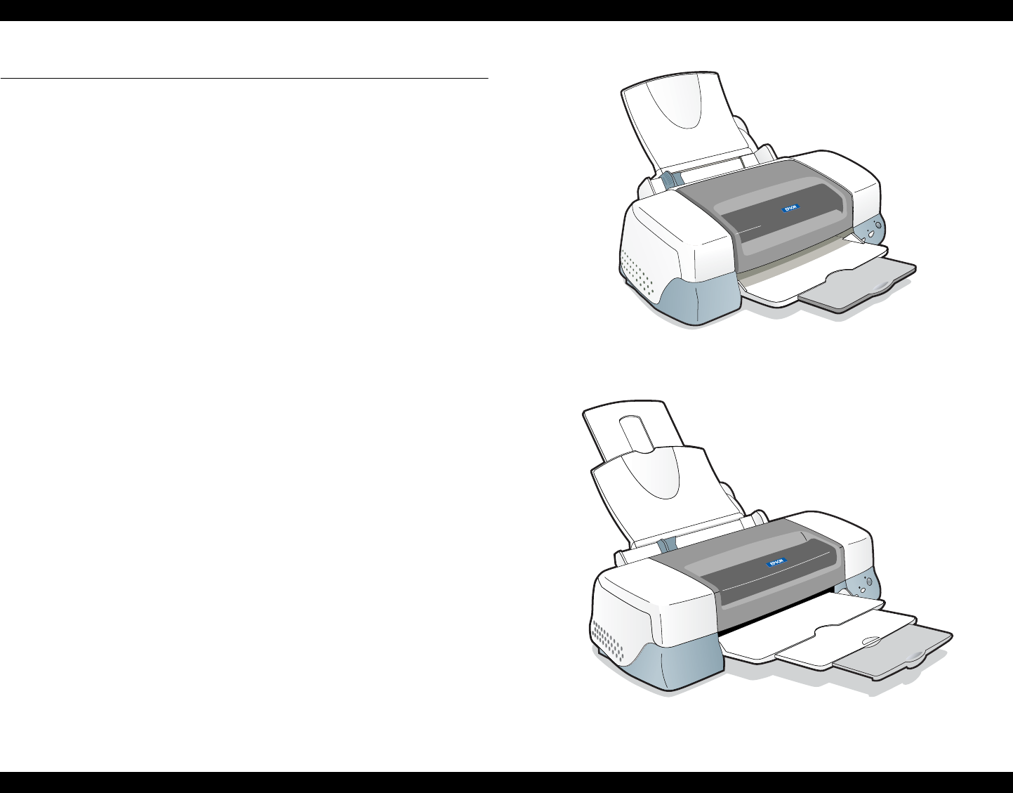
Figure 1-1. Stylus PHOTO 890
Figure 1-2. Stylus PHOTO 1280/1290

EPSON Stylus PHOTO 890/1280/1290 Revision C
PRODUCT DESCRIPTIONS Overview 12
1.1.2 Accessories, Consumable Products, and Options
ACCESSORIES
Users Guide
Ink cartridge (Black and color)
CD-ROM (Printer driver and utilities)
CONSUMABLE PRODUCTS
NOTE: The product codes of the ink cartridges may vary by location.
NOTE: The availability of special media varies by location.
NOTE: The products with an asterisk (*)are only available for Stylus PHOTO
1280/1290.
Table 1-1. Consumable Products
Product Name Code
Black ink cartridge T007
Color ink cartridge (Stylus PHOTO 890) T008
Color ink cartridge (Stylus PHOTO 1280/1290) T009
EPSON Premium Ink Jet Plain Paper (A4) S041214
EPSON 360 dpi Ink Jet Paper (A4)
EPSON 360 dpi Ink Jet Paper (Letter)
EPSON 360 dpi Ink Jet Paper (A3)*
EPSON 360 dpi Ink Jet Paper (Super A3/B)*
S041059/S041025
S041060/S041028
S041065/S041046
S041066/S041047
EPSON Iron-On Cool Peel Transfer Paper (A4)
EPSON Iron-On Cool Peel Transfer Paper (Letter)
EPSON Iron-On Cool Peel Transfer Paper (A3)*
S041154
S041153/S041155
S041238
EPSON Photo Quality Ink Jet Paper (A4)
EPSON Photo Quality Ink Jet Paper (Letter)
EPSON Photo Quality Ink Jet Paper (Legal)
EPSON Photo Quality Ink Jet Paper (A3)*
EPSON Photo Quality Ink Jet Paper (Super A3/B)*
EPSON Photo Quality Ink Jet Paper (B)*
S041061/S041026
S041062/S041029
S041067/S041048
S041068/S041045
S041069/S041043
S041070/S041044
EPSON Photo Quality Ink Jet Cards (A6)
EPSON Photo Quality Ink Jet Cards(5x8”)
EPSON Photo Quality Ink Jet Cards(8x10”)
S041054
S041121
S041122
EPSON Photo Quality Self Adhesive Sheet (A4) S041106
EPSON Ink Jet Note Cards A6 (with envelops) S041147
EPSON Ink Jet Greeting Cards 5x8” (with envelopes)
EPSON Ink Jet Greeting Cards 8x10” (with envelopes)
S041148
S041149
EPSON Matte Paper-Heavyweight (A4)
EPSON Matte Paper-Heavyweight (Letter)
EPSON Matte Paper-Heavyweight (A3)*
EPSON Matte Paper-Heavyweight (Super A3/Super B)*
S041256/S041258/
S041259
S041257
S041260/S041261/
S041262
S041263/S041264/
S041265
EPSON Photo Paper (A4)
EPSON Photo Paper (Letter)
EPSON Photo Paper (A3)*
EPSON Photo Paper (Super A3/Super B)*
EPSON Photo Paper (B)*
EPSON Photo Paper (4x6”)
EPSON Photo Paper (100 x 150 mm)
EPSON Photo Paper (200 x 300 mm)
EPSON Photo Paper (89 mmx 7M)
EPSON Photo Paper (100 mm x 8M)
EPSON Photo Paper (210 mm x 10M)
EPSON Photo Paper (329 mm x 10M)*
S041140
S041141
S041142
S041143
S041156
S041134
S041255
S041254
S041281
S041279
S041280
S041233
EPSON Panoramic Photo Paper (210 x 594 mm) S041145
EPSON Photo Paper Cards (A4) S041177
Table 1-1. Consumable Products (continued)
Product Name Code
EPSON Stylus PHOTO 890/1280/1290 Revision C
PRODUCT DESCRIPTIONS Overview 13
OPTIONS
* The asterisks are substitutions for the last digits of the product name, which may vary by
country.
Photo Quality Glossy Film (A4)
Photo Quality Glossy Film (Letter)
Photo Quality Glossy Film (A3)*
Photo Quality Glossy Film (Super A3/B)*
Photo Quality Glossy Film (B)*
Photo Quality Glossy Film (A6)
S041071
S041072
S041073
S041074
S041075
S041107
EPSON Photo Stickers 16 (A6)
EPSON Photo Stickers 4 (A6)
S041144
S041176
EPSON Ink Jet Transparencies (A4)
EPSON Ink Jet Transparencies (Letter)
S041063
S041064
EPSON Premium Glossy Photo Paper (A4)
EPSON Premium Glossy Photo Paper (Letter)
EPSON Premium Glossy Photo Paper (A3)*
EPSON Premium Glossy Photo Paper (B)*
EPSON Premium Glossy Photo Paper (Super A3/ SuperB)*
S041287/S041297
S041286
S041288
S041290
S041289
EPSON Ink Jet Back Light Film (A3)* S041131
Table 1-2. Options
Product Name Code
Parallel Interface cable (shielded) C83602*
USB I/F Interface cable (shielded) C83623*
Roll Paper Holder C81106*
Table 1-1. Consumable Products (continued)
Product Name Code
EPSON Stylus PHOTO 890/1280/1290 Revision C
PRODUCT DESCRIPTIONS Basic Specifications 14
1.2 Basic Specifications
1.2.1 Printing Specification
Print Method: On demand ink jet
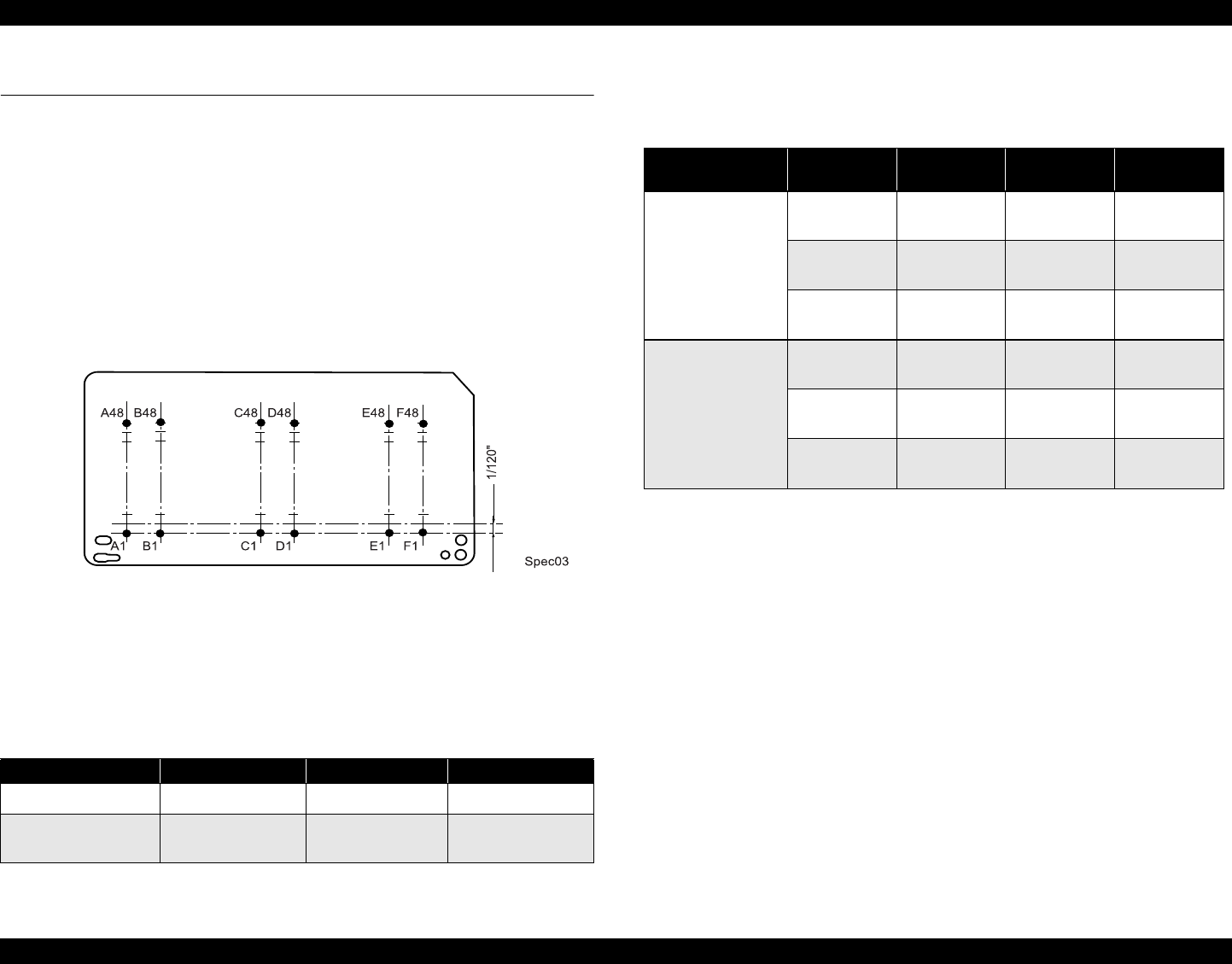
Nozzle Configuration
Monochrome: 48 nozzles (120 dpi)
Color: 48 nozzles x 5 (Cyan, Magenta, Yellow, Light cyan,
Light magenta) (120 dpi)
The following figure shows nozzle configuration viewed from the back of the
printhead:
Figure 1-3. Nozzle Configuration
Print Direction Bi-direction with logic seeking
Print Speed & Printable Columns
Character Mode
* The value is the speed of normal-dot printing.
Raster Graphic Mode
1.2.2 Control Code
ESC/P Raster command
EPSON Remote command
1.2.3 Paper Feeding
Feeding method: Friction feed with ASF
Paper Path: Cut-sheet ASF (top entry, front out)
Feed Speed: 110mm/sec (10.16mm feed)
152.4mm(6.0inch)/sec (Fast, continues feed)
1.2.4 Input Data Buffer
256 KB
Table 1-3. Character Mode
Model Character Pitch Printable Columns LQ Speed
Stylus PHOTO 890 10 CPI (Pica) 80 238CPS*
Stylus PHOTO 1280/
1290 10 CPI (Pica) 127 238CPS*
Table 1-4. Raster Graphics Mode
Model Horizontal
Resolution Printable
Area Available Dot CR Speed
Stylus PHOTO 890
180 dpi 209.8mm/
8.26” 1488 23.8/19 IPS
360 dpi 209.8mm/
8.26” 2976 23.8/19 IPS
720 dpi 209.8mm/
8.26” 5952 19 IPS
Stylus PHOTO
1280/1290
180 dpi 322.986mm/
12.716” 2289 23.8/19 IPS
360 dpi 322.986mm/
12.716” 4578 23.8/19 IPS
720 dpi 322.986mm/
12.716” 9156 19 IPS
EPSON Stylus PHOTO 890/1280/1290 Revision C
PRODUCT DESCRIPTIONS Basic Specifications 15
1.2.5 Paper Specifications
The asterisk(*) indicates Stylus PHOTO 1280/1290 use only.
CUT SHEET
Size: See the table below:
Quality: Plain paper, Bond paper
Thickness: 0.08mm- 0.11mm (0.003”- 0.004”)
(Normal paper)
Weight: 64g/m2 - 90g/m2 (55kg-78kg, 17lb.- 24Ib.)
ENVELOPE
Size (Width x Length):
#10 241.3mm (9 1/2”) x 104.8mm(4 1/8”)
DL 220mm (8.7”) x 110mm (4.3”)
C6 162mm (6.4”) x 114mm (4.5”)
220 x 132 220mm x 132 mm
Thickness: 0.16mm (0.006”) - 0.52mm (0.02”)
Weight: 45g/m2 (12Ib.) - 75g/m2 (20Ib.)
Quality: Bond paper, PPC, Air mail
Note1: Envelope printing is only available at normal temperature.
Note 2: Keep the longer side of the envelope horizontally at setting.
1.2.5.1 EPSON Special Media
EPSON offers specifically- designed media for ink jet printers.
PHOTO QUALITY INK JET PAPER
Size (Width x Length):
A3+*329mm x 483mm
A3 *297mm x 420mm
A4 210mm x 297mm
A6 105mm x 148mm
B*210mm x 297mm
Letter 216mm x 279mm
Legal 216mm x 356mm
5” x 8” 127mm x 203mm
8” x 10” 203mm x 254mm
Table 1-5. Paper Specifications - Cut Sheet
Size Specifications (Width x Length)
A3*297mm (11.7”) x 420mm (16.5”)
A4 210 mm (8.3”) x 297 mm (11.7”)
A5 148 mm x 210 mm
A6 148mm x 105 mm
B*279 mm x 432
Letter 216 mm (8.5”) x 279 mm (11.0”)
Half Letter 139.7 mm x 215.9 mm
Legal 216 mm (8.5”) x 356 mm (14.0”)
Executive 184.2 mm (7.25”) x 266.7 mm (10.5”)
2L 178 mm x 127 mm
L 127 mm x 127 mm
5” x 8” 127 mm x 203 mm
8” x 10” 203 mm x 254 mm
Double Side A4 210 mm x 297 mm
User Defined 89 to 241.3 mm x 89 to 1117.6 mm

EPSON Stylus PHOTO 890/1280/1290 Revision C
PRODUCT DESCRIPTIONS Basic Specifications 16
360 DPI INK JET PAPER
Size (Width x Length):
A3+*329mm x 483mm
A3 *297mm x 420mm
A4 210mm x 297mm
A6 105mm x 148mm
Letter 216mm x 279mm
INK JET TRANSPARENCIES
Size (Width x Length):
A4 210mm x 297mm
Letter 216mm x 279mm
PHOTO QUALITY GLOSSY FILM
Size (Width x Length):
A3+*329mm x 483mm
A3 *297mm x 420mm
A4 210mm x 297mm
A6 105mm x 148mm
B*210mm x 297mm
Letter 216mm x 279mm
PHOTO PAPER
Size (width x length):
+A3*329mm x 483mm
A3 *297mm x 420mm
A4 210mm x 297mm
A6* 105mm x 148mm
B*210mm x 297mm
Letter 216mm x 279mm
Photo Paper Card 2 175.4mm x 113.6mm (cut-line)
Panoramic Photo Paper 210mm x 594mm
152.4mm (6“) x 101.6mm (4“)(no cut-line)
100mm x 150mm
200 x 300mm 216mm x 338mm(cut-line)
Roll Paper (89mm x 7m, 100mm x 8m,
210mm x 10m, 329mm x 10m*)
PHOTO QUALITY ADHESIVE SHEET
Size (Width x Length):
A4 210mm x 297mm
Letter 216mm x 279mm
IRON-ON COOL PEEL TRANSFER PAPER
Size (Width x Length):
A3 *297mm x 420mm
A4 210mm x 297mm
Letter 216mm x 279mm
PHOTO STICKERS
Size (Width x Length):
A6 105mm x 148mm /16
A6 105mm x 148mm /4
MATTE PAPER-HEAVYWEIGHT
Size (Width x Length):
A3+*329mm x 483mm
A3 *297mm x 420mm
A4 210mm x 297mm
B*210mm x 297mm
Letter 216mm x 279mm
100mm x 150mm
Roll Paper (89mm x 7m, 100mm x 8m,
210mm x 10m, 329mm x 10m*)
EPSON Stylus PHOTO 890/1280/1290 Revision C
PRODUCT DESCRIPTIONS Basic Specifications 17
PREMIUM GLOSSY PHOTO PAPER
Size (Width x Length):
+A3*329mm x 483mm
A3 *297mm x 420mm
A4 210mm x 297mm
B*210mm x 297mm
Letter 216mm x 279mm
Roll Paper (89mm x 7m, 100mm x 8m,
127mm x 8m*,210mm x 10m,
329mm x 10m*)
INK JET BACK LIGHT FILM
Size (Width x Length):
A3* 297mm x 420mm
1.2.6 Printing Area
1.2.6.1 Cut Sheet
See the figure below and the following tables for the printing area for Stylus PHOTO
890/Stylus PHOTO 1280/1290.
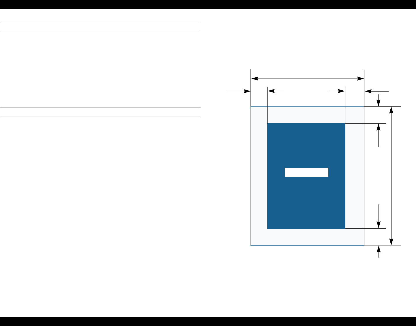
Figure 1-4. Printable Area for Cut Sheet
Printable Area
LM RM
PW
TM
BM
PL
EPSON Stylus PHOTO 890/1280/1290 Revision C
PRODUCT DESCRIPTIONS Basic Specifications 18
* : Stylus PHOTO 1290 only.
*1:Bottom margin can be reduced to 3mm when paper dimension is
defined by using command, otherwise it remains 14mm.
As for an area between 3mm and 14mm margin, print quality may
decline.
*2: Zero mm can be set by special command.
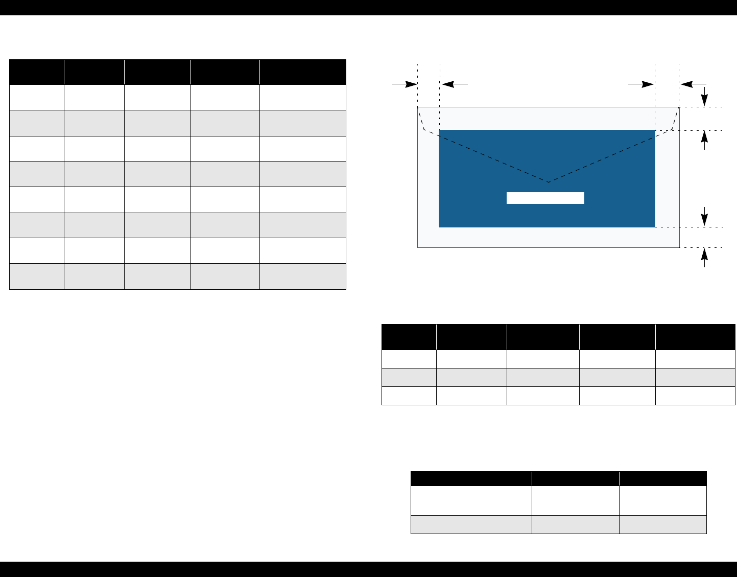
1.2.6.2 Envelopes
Figure 1-5. Printable Area for Envelopes
1.2.7 Adjust Lever
Set the adjust lever according to the type of paper as shown in the following table.
Table 1-6. Printing Area
Paper Size Left Margin
(min.) Right Margin
(min.) Top Margin
(min.) Bottom Margin
(min.)
A3* 3 mm
(0.12”)*2 3 mm (0.12”)*2 3 mm (0.12”)*2 14 mm (0.54”) /
3mm (0.12”) *1*2
A3+* 3 mm
(0.12”)*2 3 mm (0.12”)*2 3 mm (0.12”)*2 14 mm (0.54”) /
3mm (0.12”) *1*2
A4 3 mm
(0.12”)*2 3 mm (0.12”)*2 3 mm (0.12”)*2 14 mm (0.54”) /
3mm (0.12”) *1*2
Letter 3 mm
(0.12”)*2 3 mm (0.12”)*2 3 mm (0.12”)*2 14 mm (0.54”) /
3mm (0.12”) *1*2
B5 3 mm
(0.12”)*2 3 mm (0.12”)*2 3 mm (0.12”)*2 14 mm (0.54”) /
3mm (0.12”) *1*2
Legal 3 mm
(0.12”)*2 3 mm (0.12”)*2 3 mm (0.12”)*2 14 mm (0.54”) /
3mm (0.12”) *1*2
Statement 3 mm
(0.12”)*2 3 mm (0.12”)*2 3 mm (0.12”)*2 14 mm (0.54”) /
3mm (0.12”) *1*2
Exclusive 3 mm
(0.12”)*2 3 mm (0.12”)*2 3 mm (0.12”)*2 14 mm (0.54”) /
3mm (0.12”) *1*2
Table 1-7. Envelope Margin
Size Left Margin
(min.) Right Margin
(min.) Top Margin
(min.) Bottom Margin
(min.)
#10 3 mm (0.12”) 28 mm (1.10”) 3 mm (0.12”) 14 mm (0.55”)
DL 3 mm (0.12”) 7 mm (0.28”) 3 mm (0.12”) 14 mm (0.55”)
C6 3 mm (0.12”) 3 mm (0.12”) 3 mm (0.12”) 14 mm (0.55”)
Table 1-8. Adjust Lever Setting Position
Paper Setting Position Gap
Cut sheet, OHP Sheet, Label,
Postcard Front (0) 0 mm
Envelope Rear (+) +0.9 mm
Printable Area
LM RM
TM
BM

EPSON Stylus PHOTO 890/1280/1290 Revision C
PRODUCT DESCRIPTIONS Basic Specifications 19
1.2.8 Ink Cartridge
BLACK INK CARTRIDGE
The black ink cartridge specifications for Stylus PHOTO 890 and Stylus PHOTO
1280/1290 are common.
Type: Exclusive Cartridge
Color: Black
Print Capacity: 540 pages/A4
(ISO/IEC 10561 Letter Pattern at 360 dpi)
Ink Life: 2 years from the indicated date of production
Storage Temperature
Packed (in transit): -30 to 60 oC (within a month at 40 oC, within 120
hours at 60 oC)
Packed (storage): -30 to 40 oC (within a month at 40 oC)
Installed: -20 oC to 40 oC (within a month at 40 oC)
Dimension: 20.1 mm (W) x 66.85 mm (D) x 38.5 mm (H)
COLOR INK CARTRIDGE
Note some of the color ink specifications for the Stylus PHOTO 890 and Stylus
PHOTO 1280/1290 are different as indicated.
Type: Exclusive Cartridge
Color: Magenta, Cyan, Yellow, Light Cyan,
Light Magenta
Print Capacity:
Stylus PHOTO 890 220 pages / A4 (360 dpi, 5% duty each color)
Stylus PHOTO 1280/1290330 pages / A4 (360 dpi, 5% duty each color)
Ink Life: 2 years from the indicated date of production
Storage Temperature
Packed (in transit): -30 to 60 oC (within a month at 40 oC, within 120 hours
at 60 oC)
Packed (storage): -30 to 40 oC (within a month at 40 oC)
Installed: -20 oC to 40 oC (within a month at 40 oC)
Dimension:
Stylus PHOTO 890 49.1 mm (W) x 66.85 mm (D) x 38.5 mm (H)
Stylus PHOTO 1280/129049.1 mm (W) x 84.05 mm (D) x 41.8mm (H)

EPSON Stylus PHOTO 890/1280/1290 Revision C
PRODUCT DESCRIPTIONS Basic Specifications 20
1.2.9 Electric Specification
120V VERSION
Rated Voltage: AC120V
Input Voltage Range: AC99∼132V
Rated Frequency Range: 50∼ 60Hz
Input Frequency Range: 49.5∼ 60.5Hz
Rated Current: 0.4A(Max0.7A)
Power Consumption: Approx. 15W (ISO10561 Letter Pattern)
Approx. 3W in standby mode
Energy Star compliant
Insulation Resistance: 10M ohms min.
(between AC line and chassis, DC 500V)
Dielectric Strength: AC 1000V rms. 1 minute or
AC 1200V rms. 1 second
(between AC line and chassis)
220 ∼ 240V VERSION
Rated Voltage: AC220V∼240V
Input Voltage Range: AC198∼264V
Rated Frequency Range: 50∼60Hz
Input Frequency Range: 49.5∼60.5Hz
Rated Current: 0.2 A(Max0.35A)
Power Consumption: Approx. 15W (ISO10561 Letter Pattern)
Approx. 3W in standby mode
Energy Star compliant
Insulation Resistance: 10M ohms min.
(between AC line and chassis, DC 500V)
Dielectric Strength: AC 1500V rms. 1 minute
(between AC line and chassis)
1.2.10 Reliability
Total Print Volume Black: 25,000 pages (A4, Letter)
Color: 10,000 pages (A4, Letter)
Printhead Life: 3000 million dots/nozzle
EPSON Stylus PHOTO 890/1280/1290 Revision C
PRODUCT DESCRIPTIONS Basic Specifications 21
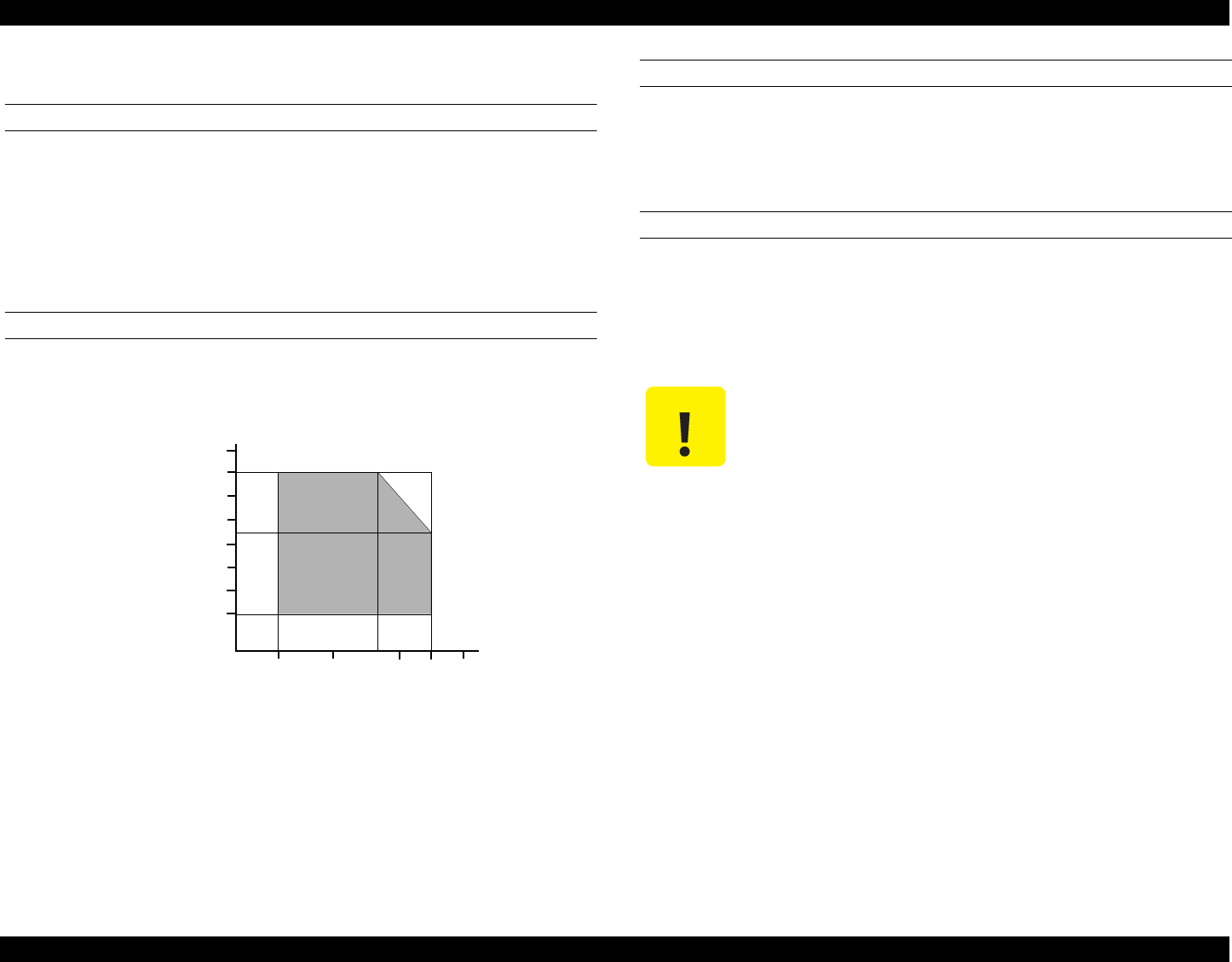
1.2.11 Environmental Condition
TEMPERATURE
Operating: 10 to 35°C*2
Non-Operating: -20 to 60°C*1
Within 1 month at 40°C /120 hours at 60°C
*1: In a shipment container.
*2: Refer to Figure 1-6 "Temperature/Humidity Range" for condition.
HUMIDITY
Operating: 20 to 80% RH (without condensation)*2
Not-Operating: 5 to 85% RH (without condensation)*1
Figure 1-6. Temperature/Humidity Range
*1: In a shipment container.
*2: Refer to Figure 1-6 "Temperature/Humidity Range" for condition.
RESISTANCE TO SHOCK
Operating: 1G, within 1 ms, X, Y, Z directions
Non-operating: 2G, within 2 ms, X, Y, Z directions*1
*1: In a shipment container.
RESISTANCE TO VIBRATION
Operating: 0.15G
Non-operating: 0.50G*1
*1: In a shipment container.
10 27 30 35 40
20
Temperature (°C)
20
30
40
50
90
80
70
60
Humidity (%)
C A U T I O N When storing the printer, make sure the printhead is capped.
When transporting the printer, ensure the ink cartridges are
installed in the printer and the printhead is capped.
If the printer power is off with the printhead left uncapped, turn
the printer on with the ink cartridges installed, cap the
printhead, and turn the printer off.
Ink freezes at below -4°C. It will be usable again after keeping it
for about three hours at 25°C.
EPSON Stylus PHOTO 890/1280/1290 Revision C
PRODUCT DESCRIPTIONS Interface 22
1.3 Interface
The EPSON Stylus PHOTO 890/1280/1290 provides USB and parallel interfaces as
standard.
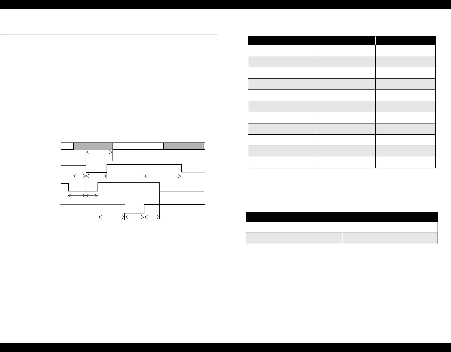
1.3.1 Parallel Interface (Forward Channel)
Transmission Mode: 8 bit parallel, IEEE-1284 compatibility mode
Synchronization: By STROBE pulse
Handshaking: By BUSY and ACKNLG signal
Signal Level: TTL compatible level
Adaptable Connector: 57-30360 (amphenol) or equivalent
Figure 1-7. Data Transmission Timing
* Rise and fall time of every output signal.
** Rise and fall time of every input signal.
*** Typical timing for tack is shown on the following page.
DATA
data byte n data byte n+1
-STROBE
BUSY
-ACKNLG
thold
tsetup tstb
tready tbusy
treply tack tnbusy
tnext
Table 1-9. Parameters
Parameter Minimum Maximum
tsetup 500ns -
thold 500ns -
tstb 500ns -
tready 0 -
tbusy - 500ns
tt-out* - 120ns
tt-in** - 200ns
treply 0 -
tack 500ns 10us
tnbusy 0 -
tnext 0 -
Table 1-10. Typical Time of Tack
Parallel I/F Mode Typical Time of tack
High Speed 0.5us
Normal Speed 2us
EPSON Stylus PHOTO 890/1280/1290 Revision C
PRODUCT DESCRIPTIONS Interface 23
* A low logic level on the Logic H signal is 2.0V or less when the printer is turned off,
and this signal is equal to or exceeding 3.0V when the printer is turned on. The
receiver shall provide an impedance equivalent to 7.5K ohm to ground.
Table 1-11.
Signal Level: TTL Compatible (IEEE-1284 level 1 device)
Parameter Minimum Maximum Condition
VOH* - 5.5V
VOL* -0.5V -
IOH* - 0.32mA VOH = 2.4V
IOL* -12mA VOL = 0.4V
CO - 50pF
VIH -2.0V
VIL 0.8V -
IIH -0.32mA VIH = 2.0V
IIL - 12mA VIL = 0.8V
CI - 50pF

EPSON Stylus PHOTO 890/1280/1290 Revision C
PRODUCT DESCRIPTIONS Interface 24
NOTE: In/Out refers to the direction of signal flow seen from the printer side.
Table 1-12. Connector Pin Assignment and Signals
Pin No. Signal Name Return
GND Pin In/Out Functional Description
1 -STROBE 19 In The strobe pulse. Read-in of data is performed at the falling edge of this pulse.
2-9 DATA0-DATA7 20-27 In The DATA0 through DATA7 signals represent data bits 0 to 7, respectively.
Each signal is at high level when data is logical 1 and low level when data is logical 0.
10 -ACKNLG 28 Out This signal is a negative pulse indicating that the printer can accept data again.
11 BUSY 29 Out A high signal indicates that the printer cannot receive data.
12 PE 28 Out A high signal indicates paper-out error.
13 SLCT 28 Out Always at high level when the printer is turned on.
14 -AFXT 30 In Not used.
17 Chassis GND - - Chassis GND
18 Logic H - Out Pulled up to +5V via 3.9K ohm resister.
31 -INIT 30 In The falling edge of a negative pulse or a low signal on this line causes the printer to initialize. Minimum
50us pulse is necessary.
32 -ERROR 29 Out A low signal indicates printer error condition.
35 +5 -Out Pulled up to +5V via 3.3K ohm resister.
36 -SLIN 30 In Not used.
16,33
19-30 GND - - Signal GND
15,34 NC - - Not connected.

EPSON Stylus PHOTO 890/1280/1290 Revision C
PRODUCT DESCRIPTIONS Interface 25
1.3.2 Parallel Interface (Reserve Channel)
Transmission Mode: IEEE-1284 nibble mode
Adaptable Connector See forward channel.
Synchronization: Refer to the IEEE-1284 specification
Handshaking: Refer to the IEEE-1284 specification
Data Trans. Timing: Refer to the IEEE-1284 specification
Signal Level: IEEE-1284 level 1 device (See forward channel.)
NOTE: In/Out refers to the direction of signal flow from the printer’s point of view.
Extensibility Request:
The printer responds affirmatively when the extensibility request values are 00H
or 04H, which means:
00H: Request Nibble Mode Reverse Channel Transfer.
04H: Request Device ID;
Return Data Using Nibble Mode Rev Channel Transfer.
Table 1-13. Connector Pin Assignment and Signals
Pin No. Signal Name Return
GND Pin In/Out Functional Description
1 HostClk 19 In Host clock signal.
2-9 DATA0-DATA7 20-27 In
The DATA0 through DATA7 signals represent data bits 0 to 7, respectively. Each signal is
at high level when data is logical 1 and low level when data is logical 0. These signals are
used to transfer the 1284 extensibility request values to the printer.
10 PtrClk 28 Out Printer clock signal.
11 PtrBusy / DataBit-3,7 29 Out Printer busy signal and reverse channel transfer data bit 3 or 7.
12 AckDataReq / DataBit-2,6 28 Out Acknowledge data request signal and reverse channel transfer data bit 2 or 6.
13 Xflag / DataBit-1,5 28 Out X-flag signal and reverse channel transfer data bit 1 or 5.
14 HostBusy 30 In Host busy signal.
31 -INIT 30 In Not used.
32 -DataAvail / DataBit-0,4 29 Out Data available signal and reverse channel transfer data bit 0 or 4.
36 1284-Active 30 In 1284 active signal.
18 Logic-H - Out Pulled up to +5V via 3.9K ohm resistor.
35 +5V -Out Pulled up to +5V via 3.3K ohm resistor.
17 Chassis GND - - Chassis GND
16,33, 19-30 GND - - Signal GND
15,34 NC - - Not connected
EPSON Stylus PHOTO 890/1280/1290 Revision C
PRODUCT DESCRIPTIONS Interface 26
Device ID:
The printer sends the following device ID string when requested.
When IEEE1284.4 is enabled,
<00H><5AH>*1/ <00H><5CH>*2
MFG: EPSON
CMD: ESCPL2,BDC,D4
MDL: Stylus[SP]Photo[SP]890
/Stylus[SP]Photo[SP]1290
CLS: PRINTER
DES: EPSONStylus[SP]Photo[SP]890
/EPSONStylus[SP]Photo[SP]1290
When IEEE1284.4 is enabled,
<00H><57H>*1/ <00H> <59H>*2
MFG: EPSON
CMD: ESCPL2,BDC,D4
MDL: Stylus[SP]Photo[SP]890
/Stylus[SP]Photo[SP]1290
CLS: PRINTER
DES: EPSONStylus[SP]Photo[SP]890
/EPSONStylus[SP]Photo[SP]1290
*1: Stylus PHOTO 890 only
*2: Stylus PHOTO 1280/1290 only
NOTE 1:[00H] denotes a hexadecimal value of zero.
NOTE 2:MDL value depends on the EEPROM setting.
NOTE 3:CMD value depends on the IEEE1284.4 setting.
1.3.3 USB Interface
Standard: Based on:
“Universal Serial Bus Specifications Rev. 1.1”
“Universal Serial Bus Device Class Definition for
Printing Devices Version 1.1”
Bit rate: 12Mbps (Full Speed Device)
Data encoding: NRZI
Adaptable connector: USB Series B
Recommended cable length:2 meters
Figure 1-8. USB Pin Assignment
Table 1-14. Connector Pin Assignment and Signals
Pin No. Signal Name I/O Function Description
1VCC -
Cable power. Max. power
consumption is 2mA.
2-Data Bi-D Data
3+DataBi-D
Data, pull up to +3.3 V via 1.5K
ohm resistor.
4Ground -Cable ground
Pin #1
Pin #3
Pin #2
Pin #4

EPSON Stylus PHOTO 890/1280/1290 Revision C
PRODUCT DESCRIPTIONS Interface 27
1.3.4 Prevention of Data Transfer Time-out
Generally, hosts abandon data transfer to peripherals when the peripheral is in the busy
state for dozens of seconds continuously. To prevent this kind of time-out, the printer
receives data very slowly, several bytes per minute, even if the printer is in the busy
state. The slowdown starts when the remaining input buffer becomes several hundreds
of bytes, and the printer finally gets into the busy state continuously when the input
buffer is full.
USB and IEEE1284.4 on the parallel interface do not require such function.
1.3.5 Interface Selection
The printer has two built-in interfaces: the USB and parallel interface.
These interfaces are selected automatically.
Automatic Selection
In this automatic interface selection mode, the printer is initialized to the idle state
while scanning which interface receives data when it is powered on. Then the
interface which received data first is selected. When the host stops data transfer
and the printer is in the stand-by state for seconds, the printer is returned to the idle
state. As long as the host sends data or the printer interface is in the busy state, the
selected interface is let as it is.
Interface State and Interface Selection
When the parallel interface is not selected, the interface gets into the busy state.
When the printer is initialized or returned to the idle state, the parallel interface
gets into the ready state. Note that the interrupt signal such as the -INIT signal on
the parallel interface is not effective while that interface is not selected.
1.3.6 IEEE1284.4 Protocol
The packet protocol described by IEEE1284.4 standard allows a device to carry on
multiple exchanges or conversations which contain data and/or control information
with another device at the same time across a single point-to-point link. The protocol is
not, however, a device control language. It does provide basic transport-level flow
control and multiplexing services. The multiplexed logical channels are independent of
each other and blocking of one has no effect on the others. The protocol operates over
IEEE1284.
Automatic Selection
An initial state is compatible interface and starts IEEE1284.4 communication
when magic strings (1284.4 synchronous commands) are received.
On
An initial state is IEEE1284.4 communication and data that received it by the time
it is able to take synchronization by magic string (1284.4 synchronous commands)
is discarded.
Off
An initial state is compatible interface and never starts IEEE1284.4
communication even if magic strings (1284.4 synchronous commands) are
received.
EPSON Stylus PHOTO 890/1280/1290 Revision C
PRODUCT DESCRIPTIONS Operations 28
1.4 Operations
1.4.1 Buttons
Roll Paper button
Maintenance button
Ink Cartridge replacement button
Power button
1.4.2 Indicators
Power
Lights when the operating switch is “ON” and AC power is supplied.
Error
Lights during the error condition, and blinks during the ink low condition.
Figure 1-9. Control Panel
1.4.3 Panel Functions
*1: Press the button for 3 seconds.
*2: According to the content of 1BH of the EEPROM, one of the following
actions needs to be carried out. (See Table 1-17 on page 29)
*3: Do not mention the information to the users.
Error indicator
Power indicator
Maintenance button
Roll Paper button
Ink Cartridge
replacement
button
Power button
Table 1-15. Panel Functions
Buttons Function
Maintenance
• Loads or ejects paper.
• Returns a carriage to the home position when the
carriage is at the ink cartridge replacement position.
• Starts the head cleaning*1.
• Returns from an error condition.
Roll Paper
• Loads or ejects Roll Paper. (Back Out feed*1)
• Feeds and returns from the Tear-Off operation.
• Returns a carriage to the home position when the
carriage is at the ink cartridge replacement position.
Ink Cartridge Replacement
• Starts the Ink Cartridge change sequence.
Moves the carriage to the carriage change position.
• Returns a carriage to the home position when the
carriage is at the ink cartridge replacement position.
Table 1-16. Power On Panel Functions
Buttons Pressing with Power On Function
Maintenance • Starts status printing*2.
Roll Paper • Changes code pages /select IEEE1284.4 mode for
parallel I/F*3.
Maintenance
+
Roll Paper
• Enters the special settings mode. (Factory use only).
EPSON Stylus PHOTO 890/1280/1290 Revision C
PRODUCT DESCRIPTIONS Operations 29
*4: Factory default setting.
1.4.4 Special Setting Mode
To enter the special setting mode, press the Maintenance button and the Roll Paper
button while turning on the printer until the Power indicator blinks. While it is blinking
(for 3 seconds), press the specified button to activate the desirable setting mode.
NOTE: The special setting mode is not described in the user’s manual.
*1: Pressing the button for 10 seconds.
EEPROM/Timer IC Reset
The following will be reset when this operation is executed.
Interface selection (04H)
CL Time (68H, 69H)
Power Off timer (6AH, 6BH)
Waste Ink Counter Reset
The following will be reset when this operation is executed.
Ink counter A0 (6CH, 6DH)
Ink counter A80 (6EH, 6FH)
Table 1-17. Content of 1BH of EEPROM
[bit7] [bit6] Actions
00 Prints firmware version, ink counter, selected code
page and nozzle check pattern.
11
01 Starts the hex-dump mode.
10 Starts the self test mode. Table 1-18. Special Setting Mode
Buttons Functions
Maintenance • Initializes the EEPROM and Timer IC.
Roll Paper*1 • Resets the ink overflow counter (Protection
Counter) in the EEPROM.

EPSON Stylus PHOTO 890/1280/1290 Revision C
PRODUCT DESCRIPTIONS Operations 30
1.4.5 Printer Initialization
EPSON Stylus PHOTO 890/1280/1290 executes initialization by using 3 methods
mentioned below.
1. Hard Initialization
The Hard Unitization will be performed when the printer is turned on or
recognizes the cold reset command. (remote RS command)
The following will be performed during initialization.
Initializes printer mechanism.
Clears input data buffer.
Clears print buffer.
Sets default values.
2. Software Initialization
The ESC@ command also initializes the printer.
The following will be performed during initialization.
Clears print buffer.
Sets default values.
3. Panel Initialization
The Panel Initialization will be performed if the printer is turned off and back on
within 10 seconds, or *INIT signal (negative pulse) is input.
The following will be performed during initialization.
Caps the printer head.
Ejects paper.
Clears input data buffer.
Clears print buffer.
Sets default values.
1.4.6 Initialization Value
When the printer is initialized, it clears the following settings to their initialization
values. However, panel setting values, default setting values, and values set by the
remote command remain as they are.
Top of page Current TOP
Line feed 4.23mm(1/6 inch)
Right margin 80 columns (Stylus PHOTO 890)
127 columns (Stylus PHOTO 1280/1290)
Left margin 1st column
Character pitch 10 cpi
Print mode Text mode (Non graphics mode)
EPSON Stylus PHOTO 890/1280/1290 Revision C
PRODUCT DESCRIPTIONS Dimension 31
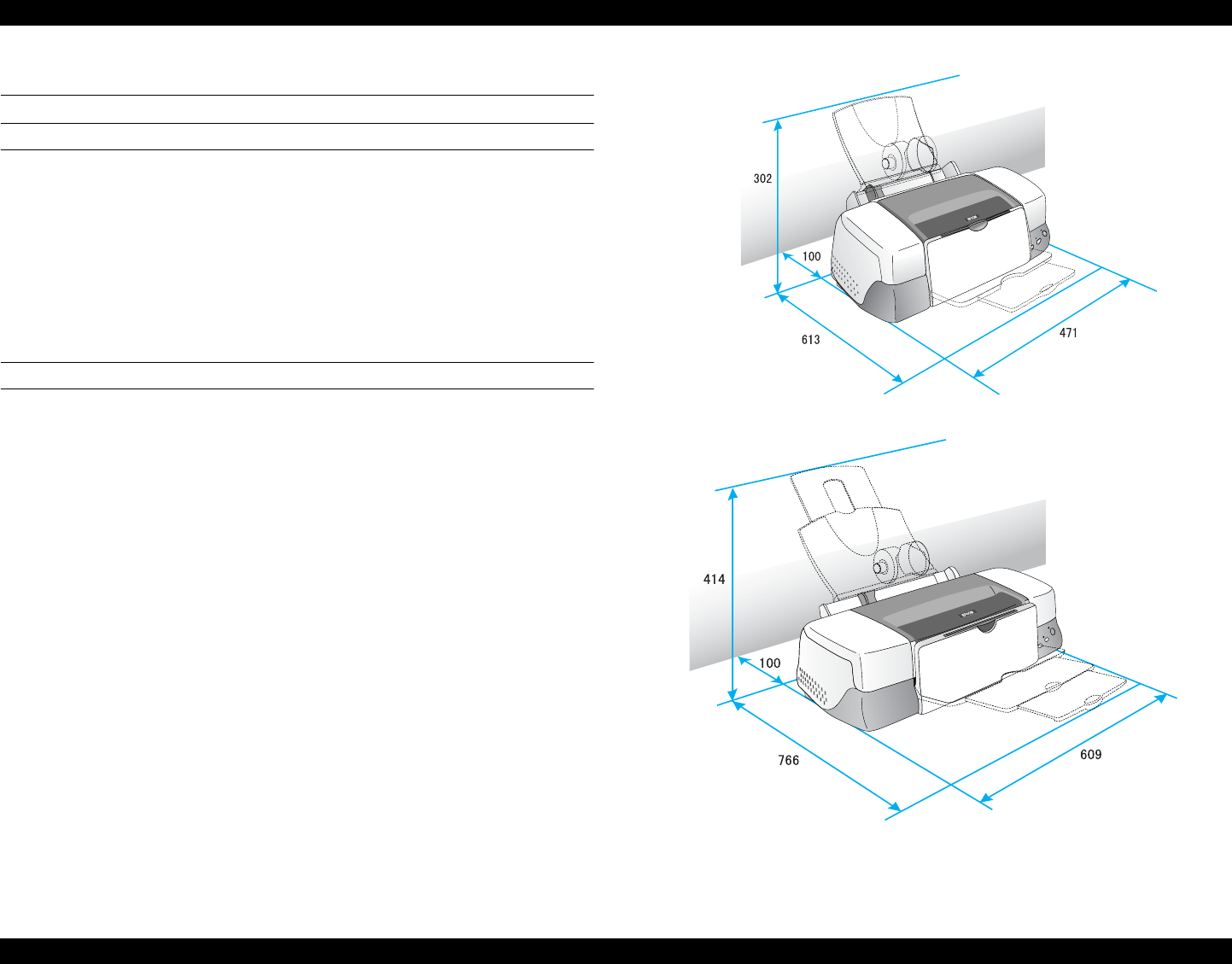
1.5 Dimension
EXTERNAL DIMENSION
Stylus PHOTO 890
When stored(mm): 471 (W) x 290 (D) x 175 (H)
For use(mm): 471 (W) x 613 (D) x 302(H)
Stylus PHOTO 1280/1290
When stored(mm): 609(W) x 311(D) x 175 mm (H)
For use(mm): 609(W) x 766(D) x 414mm (H)
WEIGHT
Stylus PHOTO 890: 6.0 kg
Stylus PHOTO 1280/1290:8.4 kg
Figure 1-10. Stylus PHOTO 890 in Use
Figure 1-11. Stylus PHOTO 1280/1290 in Use

EPSON Stylus PHOTO 890/1280/1290 Revision C
PRODUCT DESCRIPTIONS Dimension 32

CHAPTER
2
OPERATING PRINCIPLES
EPSON Stylus Photo 890/1280/1290 Revision C
OPERATING PRINCIPLES Overview 34
2.1 Overview
This section describes the operating principles of the printer mechanism and electrical
circuit boards. The major components of the EPSON Stylus Photo 890/1280/1290 are:
Printer mechanism: Stylus Photo 890: M4T12
Stylus Photo 1290: M4S61
Main board:
Stylus Photo 890 : C393MAIN-C/C393MAIN-B
Stylus Photo 1290: C393MAIN/C393MAIN-B
Power supply board: C378PSB/PSE Board
PRINTER MECHANISM
Unlike other EPSON ink jet printers, the
EPSON Stylus Photo 890/1280/1290
uses a DC
motor as power source. The DC motor enables the printer to lower noise during
printing. Table 2-1 shows various motor types used in the printer and their applications.
Table 2-1. Motor Types and Corresponding Applications
The basic structure of the printer mechanism is mostly common to the Stylus COLOR
400, except that the Stylus Photo 890/1290 uses a Pump/ASF motor. With this motor
equipped, the paper loading mechanism and the pumping mechanisms are
independently driven, which allows the printer to offer higher throughput.
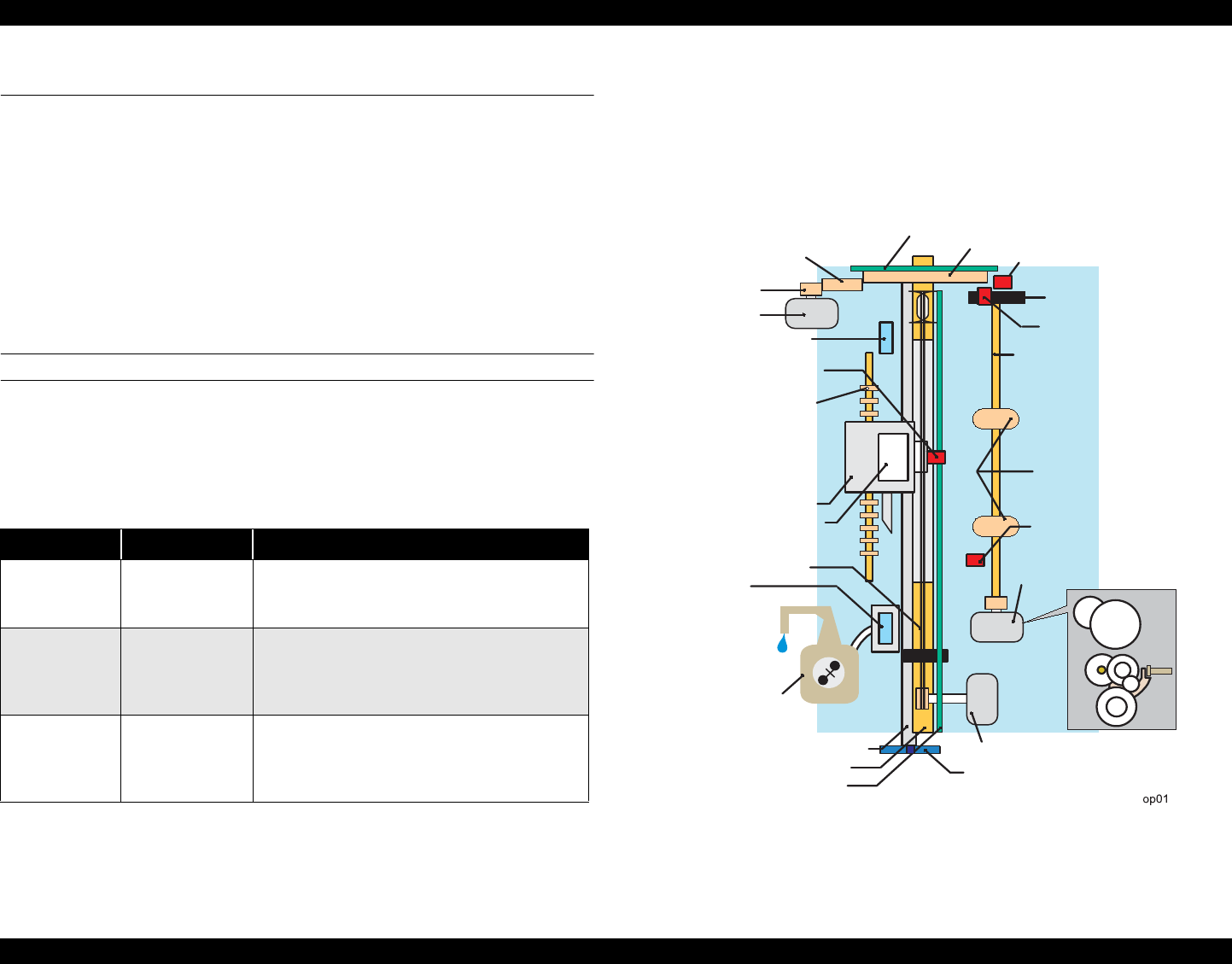
Figure 2-1 shows the printer mechanism block diagram for the Stylus Photo 890/1290.
Figure 2-1. Printer Mechanism Block Diagram
Table 2-2.
Motor Name Type Application / Feature
CR motor DC motor with
brush
Drives the carriage making little noise. Works with
a linear scale to monitor motor’s operating
condition.
PF motor DC motor with
brush
Supplies power to drive paper feeding rollers used to
send paper at specified speeds and load/eject paper.
To monitor paper feeding pitch, a loop scale is
attached beside the high-precision gear.
Pump/ASF
motor
4-Phase / 48-pole
stepping motor
Sends drive for pump operation and paper feeding
from ASF. Since this is a stepping motor, it has no
scales or photo sensors that are used to monitor
motor’s operating condition.
Intermittent Gear
PF Motor Pinion
PF Motor
Flashing Window
(at 80th or 136th column)
Photo Interrupter (Encoder)
Notched Roller
Rotary Encoder
PF Drive Gear (high precision)
ASF Sensor
Detector Wheel
LD Roller Shaft
Loading Rollers
PE Sensor
Pump/ASF Motor
CR Motor
PG Lever
Liner Scale
PF Roller
CR Guide Shaft
Pump Unit
Cap Unit
(without a valve)
Timing Belt
Printhead
Carriage Unit
ASF/Pump Disengage
Gear Train
Photo Interrupter (Encoder)
EPSON Stylus Photo 890/1280/1290 Revision C
OPERATING PRINCIPLES Overview 35
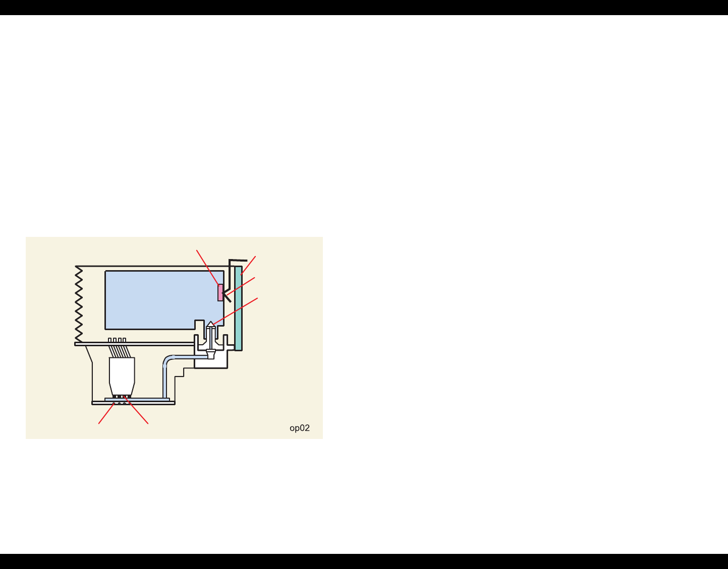
2.1.1 Printhead Mechanism
The printhead mechanism operating principles of the Stylus Photo 890/1290 are
basically the same as for the previous EPSON ink jet printers. This printer, however,
employs a newly developed ink and improved printhead driving method to provide a
higher print quality and faster printing speed than ever. Also, an IC called CSIC that
stores ink-life data is attached to each ink cartridge. With this IC, ink life of each
cartridge can be individually monitored. Note, like for other models, a head voltage
must be written with a PC.
The printhead mechanism consists of ink cartridges and printheads. Each printhead is
composed of PZT (Piezo Electric Element), nozzle surface, ink supply needle, nozzle
selection circuit board, cartridge sensor, CSIC, and CSIC connection circuit. Figure 2-2
shows its component layout.
Figure 2-2. Printhead Mechanism
Ink Cartridge
An ink cartridge stores ink to be supplied to the printhead.
CSIC:
CSIC is a non-volatile memory EEPROM attached to each black and color ink
cartridge. It keeps the following information:
1) Ink remaining level
2) Number of cleanings performed
3) Number of installation of the ink cartridge
4) Accumulated installation time of the cartridge
5) Model name of the printer in use
6) Ink cartridge production information
Printhead
PZT
Driven by the print signal from the control circuit board, it ejects ink from the
nozzle plate.
Nozzle plate
Ink pressured by the PZT is ejected from this plate.
Ink supply needle
Connects the ink cartridge and printhead to run ink to the printhead.
CSIC connection circuit
Connects the control circuit board and CSIC attached on the ink cartridge.
One end of the harness is connected to the control board together with the
printhead cable.
Nozzle selection circuit board
This circuit, controlled by ASIC on the control circuit board, selects nozzles
to be driven for printing. On the other hand, head drive voltage is produced on
the controller circuit side.
Nozzle Selector
Circuit Board
Ink Supply Needle
CSIC
PZT
Nozzle Plate
CSIC Connection
Circuit
Ink Cartridge
EPSON Stylus Photo 890/1280/1290 Revision C
OPERATING PRINCIPLES Overview 36
2.1.2 Carriage Mechanism
The carriage mechanism of the Stylus Photo 890/1290 is composed of the carriage
motor (CR motor), carriage guide shaft, platen gap adjustment/parallelism adjustment
mechanism, carriage lock mechanism, and so on.
2.1.2.1 Carriage Motor (CR Motor)
The carriage mechanism of this printer is mostly the same as for other ink jet printers’
except it uses a DC motor as power source. See the table below for the carriage motor
specifications.
Table 2-3. Carriage Motor Specifications
In previous ink jet printers, since a stepping motor is used as a CR motor, the CR motor
controls the carriage position under the open loop system. This printer, however,
controls carriage speed and position with the closed loop system enabled by a DC
motor and encoder. This system, also used in the Stylus COLOR 900, is applied to
maintain a constant print quality. The CR motor also produces the print timing signal
(PTS signal) used for an accurate ink ejection timing. (Refer to Section 2.2.2.3 for
further information on the CR motor control circuit.)
For printing, the CR motor moves the carriage unit in the printing area along the CR
guide shaft.
Figure 2-3. Carriage Mechanism (Top view)
Table 2-4.
Items Specifications
Type DC Motor with brush
Drive Voltage +42 V +/- 5% (Applied to the driver)
Coil resistance 29.2 ohms +/- 25%
Inductance 30.0 mH +/- 25%
Drive Method Constant Current Chopping
Driver IC LB1947
Op03
Adjust Lever
CR Motor
Photo Coupler
Carriage Unit
Linear Encoder
Platen Surface
Parallelism Adjustment
Bushing
Carriage Guide
Shaft
Eccentric Shaft
EPSON Stylus Photo 890/1280/1290 Revision C
OPERATING PRINCIPLES Overview 37
2.1.2.2 Platen Gap (PG) /Parallelism Adjustment Mechanism
The PG adjust lever is attached to the left end of the carriage guide shaft. When the
carriage guide shaft, which has an eccentricity, rotates as the adjustment lever moves, it
narrows or widens the distance (=PG: from 1.2 mm to 2.1 mm). This mechanism
enables the user to print with a correct PG according to print result or other conditions
such as paper curl.
Also, the parallelism adjustment bushings are attached to the right and left ends of the
carriage guide shaft. They are used to set the carriage guide shaft parallel with a platen.
Table 2-5. Platen Gap Adjust Lever Setting
2.1.2.3 Carriage Home Position (HP) Detection
Unlike previous Epson ink jet printers, the carriage home position is detected with the
drive current from the CR motor and speed/position signal from the linear encoder.
2.1.3 Paper Feeding Mechanism
The paper feeding mechanism transports paper loaded from ASF using the PF rollers
and paper eject rollers. A new type of DC motor is used as the PF motor. See the table
below for the PF motor specifications.
Table 2-7. PF Motor Specifications
Stepping motor that is used in other printers as the PF motor controls paper feed by the
open loop system. On the other hand, this printer controls paper feeding mechanism
with the closed loop system by employing the DC motor and rotary encoder for more
accurate paper feeding. Therefore, a rotary encoder attached to the left end of the PR
roller shaft controls paper feed amount. For detailed information, see Section "PF
motor driver circuit".
Drive from the PF motor is sent to the PF rollers and paper eject rollers as described
below.
Drive transmission to the PF rollers:
PF motor pinion gear → Spur gear (76) → PF rollers
Drive transmission to the eject rollers:
PF motor pinion gear → Spur gear (76) → Combination gear (13.5, 308) → Spur
gear (28) → Paper eject rollers
Table 2-6.
Lever Position PG adjustment value
Front (0) 0 mm (=PG is 1.2 mm)
Rear (+) + 0.9 mm (=PG is 2.1 mm)
Table 2-8.
Item Description
Motor type DC Motor with Brush
Drive voltage +42V +/- 5% (Applied to the driver)
Coil Resistance 29.2ohm +/- 25%
Inductance 30.0mH +/- 25%
Control method Constant current chopping drive
EPSON Stylus Photo 890/1280/1290 Revision C
OPERATING PRINCIPLES Overview 38
Figure 2-4 gives the paper feeding mechanism block diagram, showing the parts along
the PF motor drive transmission paths.
Figure 2-4. Paper Feeding Mechanism
The printer loads paper at the ASF, which is detected by the PE sensor attached to the
right side of the top frame, and advances it to send the paper’s leading edge to the
halfway of the front paper guide. Then, to correct paper deflection, the printer feeds the
paper back specified steps toward ASF, and advances the paper again toward the front
paper guide and stops it at the specified TOF (Top Of Form) position. Once printing
starts, the paper is fed by the PF rollers and sub rollers. For printing or transporting the
tailing edge area (14 mm), a notched roller and drive from the paper eject roller are
used. Like the Stylus Photo 870/1270, this printer also provides this extra printable
range of 14 mm from the bottom edge, excluding the bottom margin of 3mm, by
changing the position of the star wheel gear; it has been shifted by 5° from the top of
the eject roller toward the front paper guide. Due to this change, the tailing edge of
paper is suppressed, and the printer can advance paper steadily. See Figure 2-5 next
page that shows how paper is transported and parts involved.
Figure 2-5. Paper Transportation
PF Motor Pinion Gear
Paper Eject Roller
Front Paper Guide
Combination Gear
(13.5, 308)
PF Roller
Paper Eject Roller
Spur Gear (76)
PF Motor
[Previous Models]
Paper
Notched Roller
PrintheadSupport Roller
PF Roller
Paper Eject Roller
Platen Surface
5°
Steady Feeding
Bottom Margin (3 mm)
[Stylus Photo 890/1290]
EPSON Stylus Photo 890/1280/1290 Revision C
OPERATING PRINCIPLES Overview 39
2.1.3.1 CR Lock Mechanism
The carriage lock mechanism prevents the carriage from being left uncapped for a long
time, which is usually caused by vibration during printer transportation, user’s
mishandling of the printer, and so on. If the carriage unit is left uncapped for a long
time, ink on the printhead surface dries gradually and, eventually, ink can not flow to
nozzles. In addition to that, there is a possibility that the nozzles clogged with dried ink
can not be recovered by a head cleaning. To avoid this problem, the printer locks the
carriage unit under the circumstances below:
After Power-Off
If the printer power is turned off in the middle of printing or other operations, the
printer completes the initialization sequence and then performs a carriage lock.
After Power-On
When the printer is turned on, the printer automatically begins a power-on cleaning
and then performs a carriage lock.
[Power-on cleaning]
The printer runs a power-on cleaning automatically when its power is turned on. Since
the timer IC on the main control circuit board is powered by a lithium battery that is
also mounted on the board, it keeps counting the printer’s power off time. According to
the power of time counted, the printer selects the cleaning level to perform.
After paper ejection
If the printer does not receive any print data after Load/Eject button is pressed, it
performs a carriage lock and enters a standby status. But if paper is fed into the printer,
the printer does not perform it.
Figure 2-6. CR Lock Mechanism
Top View
Bushing
Paper Eject Roller
CR Lock Lever
Middle Frame
Right Side View
EPSON Stylus Photo 890/1280/1290 Revision C
OPERATING PRINCIPLES Overview 40
2.1.4 Paper Loading Mechanism
The paper loading mechanism loads paper at the ASF unit and feeds paper to the PF
rollers. The ASF unit is the same as in previous models. A 4-phase 48-pole PM type
stepping motor is used as the ASF/Pump motor to drive ASF. Drive sent from this
motor is transmitted to the ASF side and Pump side via the disengage mechanism (DE
mechanism). See Figure for the ASF/Pump motor specifications.
The rotation directions in order to drive ASF unit/ Pump mechanism are as shown
below.
*1: Refer to “Drive Transmission to the ASF Unit” on page -40
*2: CW refers to clockwise from ASF/Pump Motor Pinion side
*3: CCW refers to counterclockwise from ASF/Pump Motor Pinion side
Drive from the ASF/Pump motor is sent to the ASF unit by the switching operation of
the carriage unit and the DE mechanism described in the following section.
2.1.4.1 Drive Transmission to the ASF Unit
1) The CR unit moves to the right end of the CR shaft, which then pushes the DE
lock lever to the right end.
2) The ASF/Pump motor rotates counterclockwise specified steps (viewed from the
motor pinion gear side).
3) With the ASF-Pump motor’s rotation of step 2), the planetary gear set in the DE
unit shifts toward the combination gear (12, 22.4).
4) The carriage unit moves from the right end of the CR shaft specified steps, which
causes the DE lock lever to fix the planetary gear unit.
5) Torque from the ASF/Pump motor is transmitted as described below.
Motor pinion gear → Planetary gear (15.2) → Combination gear (12, 22.4) →
Combination gear (14, 28) → Spur gear (32) in ASF
Figure 2-7 shows the disengage mechanism and its parts.
Figure 2-7. Disengage Mechanism
The ASF unit loads paper by the torque sent from the ASF/Pump motor via the DE
mechanism as described in the following section.
Table 2-9. ASF/Pump Motor Specifications
Items Description
Motor type 4 Phase/ 48-pole /PM type pulse motor
Drive method Bipolar constant current drive
Drive voltage +42V +/- 5% (applied to the driver)
Coil Resistance 10.4 ohm +/- 10%
Inductance 15.0 ohm +/- 10%
Table 2-10. Directions of ASF Unit/Pump Mechanism Rotation
Rotation Direction ASF Paper Loading Roller
Rotation Direction Pump Rotation Direction*1
CW*2 Reverse Rotation Normal Rotation
CCW*3 Normal Rotation Reverse Rotation
A
Combination Gear
14, 28 Combination Gear 12, 22.4
Planetary Gear 15.2 Unit
DE Lock Lever
Combination Gear 17.19, 25.6
ASF-Pump Motor Pinion Gear
EPSON Stylus Photo 890/1280/1290 Revision C
OPERATING PRINCIPLES Overview 41
2.1.4.2 Paper Loading Operation
Multiple paper loading prevention mechanism is included in the ASF unit to ensure
steady paper loading. To prevent any paper from falling from the paper set position
into the paper path, the paper return lever pushes paper that may have fallen off back
onto the hopper. After this motion is completed, the LD roller starts loading paper. The
paper loading mechanism, including the multiple paper loading prevention mechanism,
is described in the following steps.
1) When the printer power is turned on, the ASF/Pump motor rotates
counterclockwise to detect ASF home position. Then it rotates clockwise specified
steps to set the LD roller and paper return lever in their standby status. (See
“Standby State” in Figure 2-1.)
2) When the paper loading signal is sent from the PC and the Load/Eject button is
pressed, the ASF/Pump motor turns counterclockwise to let the LD roller start
loading paper. (See “Paper Pick Up State” in Figure 2-1.)
3) When the paper is transported to the PF roller, the LD roller stops where it loses
friction. (See “PF Roller Paper Feed State” in Figure 2-1.)
4) When the next print signal is sent and Load/Eject button is pressed*, the ASF/
Pump motor rotates clockwise specified steps to set the LD roller and the paper
return lever in standby status. (See “Standby State” in Figure 2-1.)
* If the printer does not receive any print signal for TBD seconds in step 4, the LD
roller and the paper return lever automatically return to the standby state.
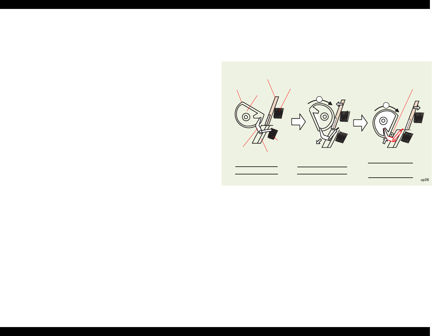
Flowchart 2-1. Multiple Paper Loading Prevention Mechanism
2
3
PF Roller Paper
Feeding State
Paper Load State
LD Roller Cam
Hopper
Hopper Spring Pinch Roller
Pad
Pad Spring
Paper Return
Lever
Standby State
EPSON Stylus Photo 890/1280/1290 Revision C
OPERATING PRINCIPLES Overview 42
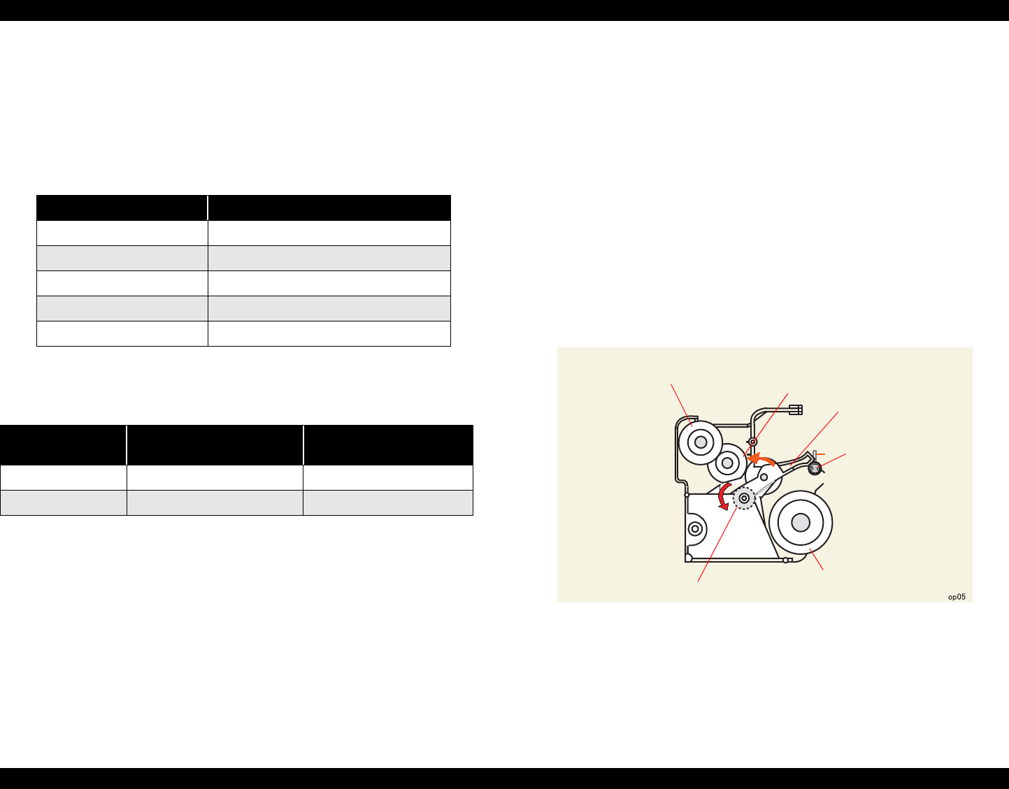
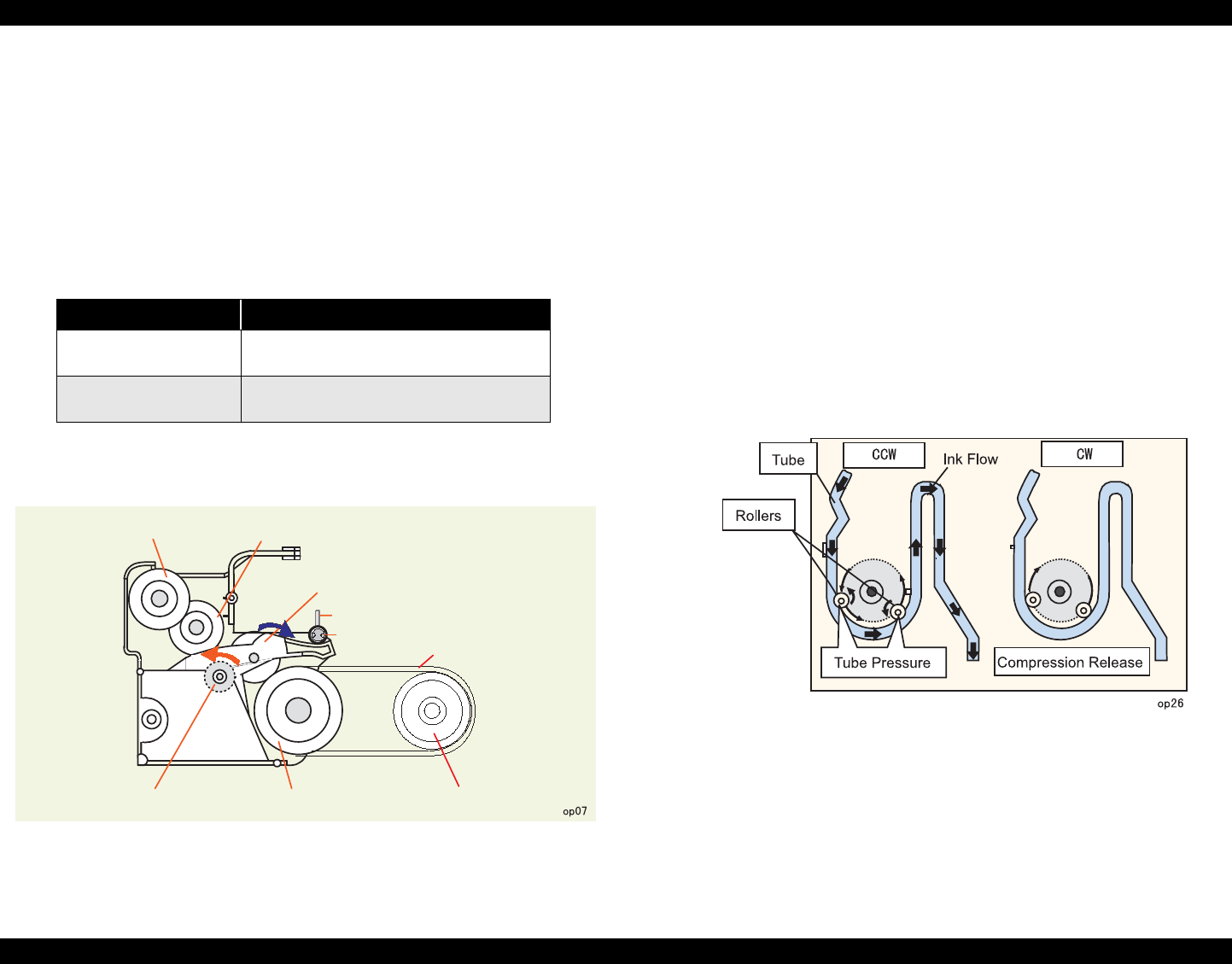
2.1.4.3 Pump Mechanism
The pump mechanism absorbs ink from the printhead and the cap assembly. The wiper
for head cleaning is included in the cap assembly.
The pump mechanism is driven by the ASF/Pump motor, a 4phase 48-pole PM type
stepping motor. See Table for the ASF/Pump motor specifications. When the torque
from the ASF/Pump motor is switched to the pump unit side, the pump mechanism acts
differently according to the directions of the ASF/Pump motor rotation, as shown in the
table below.
Figure 2-8. Torque to the Pump Mechanism
Torque transmission to the pump unit
The torque from the ASF/Pump motor is transmitted to the pump mechanism as
described below:
1) The CR unit moves to the right end of the CR shaft, which then pushes the DE
lock lever to the right end.
2) The ASF-Pump motor rotates clockwise (viewed from the motor pinion gear
side) specified steps.
3) With the rotation of step 2), the planetary gear set in the DE unit moves toward
the combination gear (17.19, 25.6).
4) The CR unit moves specified steps from the right end of the CR shaft to the
left. With this motion, the DE lock lever fixes the planetary gear set.
5) Torque from the ASF/Pump motor is transmitted as described below.
Motor pinion gear → Planetary gear (15.2) → Combination gear (17.19, 25.6)
→ Tension belt → Pump unit gear → Pump unit
DE pump mechanism and operating principle are as shown in the figure below.
Figure 2-9. Pump Operating Principle
1. When the pump unit rotates CCW from ASP/Pump motor side, rollers rotates
compressing a tube, and the ink in the tube is pressed from the capping unit down
to waste ink pads.
2) When the pump unit rotates CW, the rollers stop compressing the tube, and the ink
is not pressed to the waste in pack.
Table 2-11. ASF/Pump Motor Functions
Directions Corresponding Functions
Counterclockwise • Absorbs ink.
•Sets the wiper.
Clockwise • Releases tube.
• Resets the wiper.
A
Combination Gear 12, 22.4
Planetary Gear 15.2
DE Lock Lever
Tension Belt
Pump Unit Gear
Combination Gear 17.19, 25.6
ASF/Pump Motor Pinion Gear
Combination Gear 14, 28
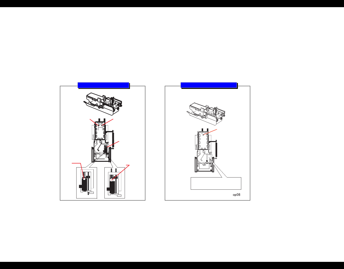
EPSON Stylus Photo 890/1280/1290 Revision C
OPERATING PRINCIPLES Overview 43
2.1.4.4 Capping Mechanism
The capping mechanism, which is driven by the pump unit, caps the printhead closely
to maintain air tightness inside the cap. This operation is required to vacuum ink from
the ink cartridges, printhead, and cap. Also, to moisten the inside of the cap while the
printer power is off, this mechanism works to keep the cap and the printhead surface in
a tight contact. This function prevents ink from clogging while the printer is not in use.
The capping mechanism of this printer is a newly designed valveless capping
mechanism. So, unlike previous printers, it does not integrates an air valve. The air
valve is usually equipped to remove bubbles created inside the cap by releasing the
negative pressure. However, due to change in the ink sequence, the new valveless
capping mechanism enables the printer to maintain the initial ink charge and cleaning
effects at the same level as before. Figure 2-10 outlines the valveless capping
mechanism.
Figure 2-10. Valveless Capping Mechanism
Negative
pressure is
released here. Ink Ejection
Hole
Valve
Released state
Closed state
Ink Ejection
Hole
There is no air valve
assembled.
Stylus Photo 890/1290
Previous Models
EPSON Stylus Photo 890/1280/1290 Revision C
OPERATING PRINCIPLES Electrical Circuit Operating Principles 44
2.2 Electrical Circuit Operating Principles
The electric circuit of the Stylus Photo 890/1290 consists of the following:
Control circuit board: C393MAIN/C393MAIN-B/C393MAIN-C
Power supply board: C378PSB/PSE
Panel board: C393PNL
Refer to Figure 2-11 for the major connection of the boards and their roles.
Figure 2-11. Electric Circuit of Stylus COLOR 890/1290
2.2.1 C378PSB/PSE Board
The power supply board for the Stylus Photo 890 and Stylus Photo 1290 is C378PSB/
PSE. It uses a RCC switching regulator system, and supplies +42VDC and +5VDC to
the printer mechanism and control board.
2.2.1.1 Electrical Circuit
The table below shows the voltages produced in this circuit and their applications.
Table 2-12. Application of the DC Voltages
NOTE: The 5VDC is only applied to the parts and locations shown in the table above.
The C393MAIN uses 3.3V drive chips for most of the logic-line chips (CPU,
ASIC, ROM, DRAM). For this reason, those chips are not driven by the +5VDC
produced by the but power supply board but the 3.3VDC that is reduced by the
3.3VDC regulator on the C378PSB/PSE.
C378PSB/PSE Power
Supply Board
C378PSB/PSE Power
Supply Board
Power OFF +5VDC +42VDC
C393PNL Panel Board
C393PNL Panel Board
3.3V Regulator
3.3V Regulator
C393MAIN / C393MAIN-B/
C393MAIN-C Control Board
CR Motor
PF Motor
ASF/Pump Motor
Head Driver Circuit
Sensors
Printer Mechanism
Printer Mechanism
C393MAIN / C393MAIN-B/
C393MAIN-C Control Board
Table 2-13.
Voltage Application
+42VDC ± 2VDC
• CR Motor
• ASF/Pump Motor
• PF Motor
• Head driving power supply
+5VDC ± 0.25VDC
• Logic sensor circuit
•Panel LED
• Nozzle selection circuit (on the printhead)
• I/F control circuit
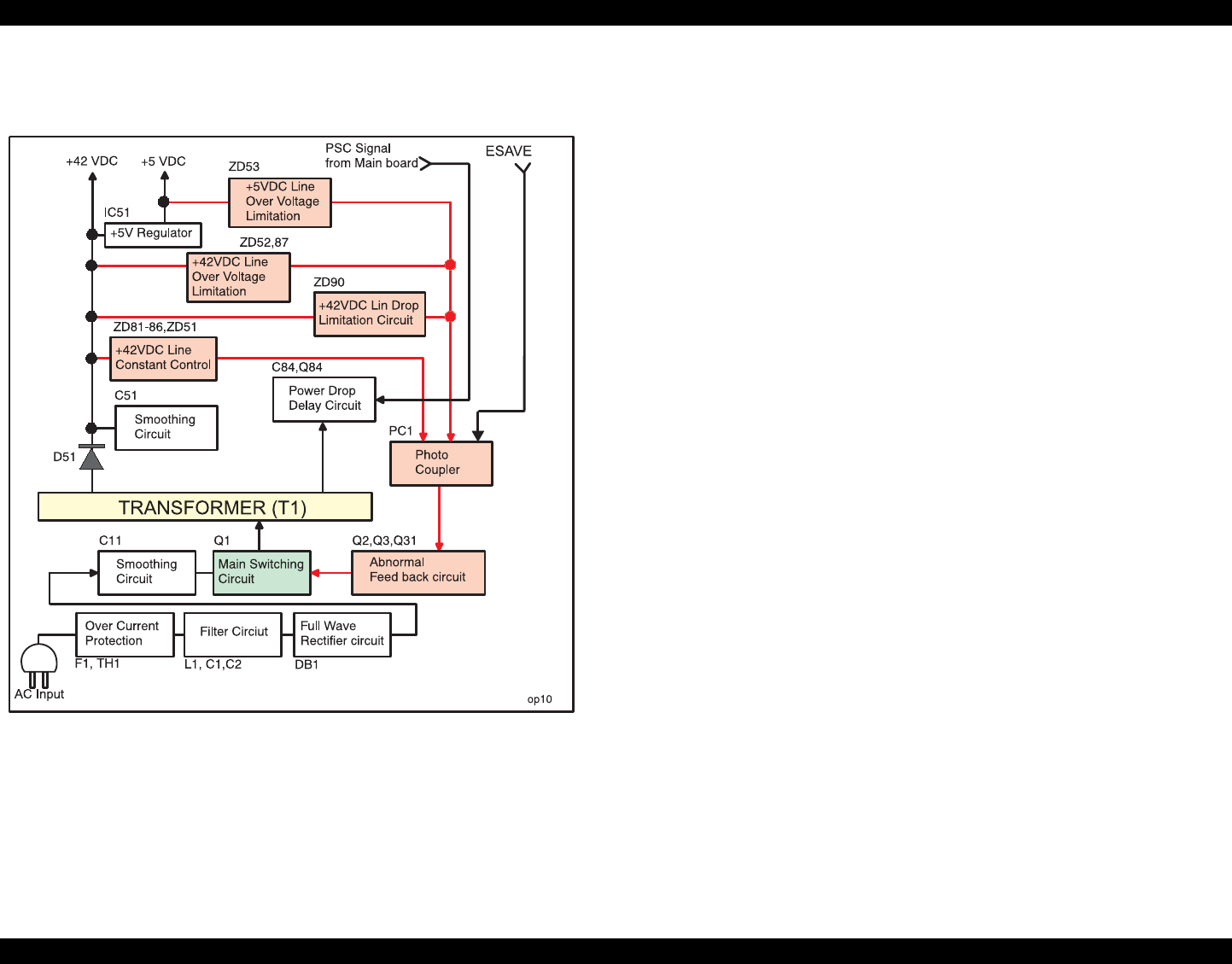
EPSON Stylus Photo 890/1280/1290 Revision C
OPERATING PRINCIPLES Electrical Circuit Operating Principles 45
Figure 2-12 shows the block diagram for the C378PSB/PSE board.
Figure 2-12. C378PSB/PSE Board Block Diagram
The C378PSB/PSE Board produces the +42VDC and +5VDC using AC power as
described below:
1. Regardless of the power switch’s on/off condition, voltage is always applied to the
primary side of the power supply board from the moment or at the state that AC-
plug is plugged in. F1, a fuse, prevents AC100V from flowing into the circuit. A
power thermistor TH1 also protects the circuit from rush current after power-on.
The filter circuit composed of L1, C1, and C2 prevents high harmonic wave noise
generated in the switching circuit from going out, and eliminates the noise from
outside.
2) The AC voltage is full-wave rectified by the diode bridge DB1 and smoothed by
C11.
3) Switching FET Q1 turns on via starting resistors R18 and R28 that are located on
the AC side to begin switching operation. By arranging the starting resistors on the
AC side, half waves of the AC voltage are only applied, and power used for this
operation is reduced compared with usual serial layout.
4) When the primary side is on, because the diode (D51) on the secondary side is
installed in the reverse direction, energy (current) led by the electromagnetic
induction through the trans (T1) does not flow to the secondary side.
5) When the energy charged in the transformer reaches a saturated state, the voltage
which keeps Q1 on becomes weak gradually. At the point this voltage drops to a
certain level, C13 absorbs the reverse current and Q1 quickly shuts off.
6) When the primary side is turned off, the energy charged in T1 is opened according
to the diode(D51) direction on the secondary side. +42 V DC is output by these
circuit operations and the number of T1 spiral coil.
7) +5VDC is generated out of this +42VDC. Forming reference sawteeth waveforms
with an external RC integrating circuit, IC51 produces stable +5VDC with a
chopping circuit.

EPSON Stylus Photo 890/1280/1290 Revision C
OPERATING PRINCIPLES Electrical Circuit Operating Principles 46
2.2.1.2 Protection Circuits
The C378PSB/PSE board has the various protection circuits to stop voltage outputs if
an abnormal condition relating to the control circuit or the printer mechanism’s duty
occurs.
+42VDC Line Constant Voltage Control Circuit:
The output level of the +42V line is monitored by a detection circuit composed of
numbers of Zener diodes, and the information is fed back to the primary side via
photo coupler PC1. Along with the fed back signal, the switching FET on the
primary side varies the level of the voltage output to the secondary side by
changing its frequency to keep the voltage up.
+42VDC line over current protection circuit:
If the +42 VDC line is over currented, the output voltage level drops drastically.
When the voltage level is 36V or lower, zener diode ZD90 detects that condition
and sends information to the primary side via photo coupler PC1. In the primary
circuit, then, switching operation stops to protect the electrical circuits and printer
mechanism. To reset the circuit, turn the printer off and back on.
+42VDC line over voltage protection circuit:
If the voltage level of the +42VDC line exceeds 59V, zener diodes D52 and ZD87
detect it and feed back the information to the primary side via photo coupler PC1.
The switching operation in the primary side then stops to protect the electrical
circuits and printer mechanism.
+5V line constant voltage/constant current control circuit:
Both +5V line output voltage and +5V line output current are monitored by
chopper IC (IC51). Detected information is input to the IC’s internal comparator
and stabilizing circuit. When the IC detects abnormally high current level, it stops
outputting voltage. The circuit recovers automatically.
+5V line over voltage protection circuit:
If the +5VDC output level exceeds 12V, zener diode ZD53 detects that condition
and feeds back the information to the primary side via photo coupler PC1. The
switching operation in the primary side then stops to protect the electrical circuits
and printer mechanism.
2.2.1.3 Power Supply Control Function
Since this printer has the power switch in the secondary circuit, even if its power is
turned off through the operation panel, it can continue to supply voltage to the +5VDC
line and +42VDC line for about 30 seconds. This extra time allows the printer to
complete the following operations:
If the printer is in a printing motion and the CR unit is out of its home position, the
printer stops printing, returns the CR unit to the home position, and performs CR
lock operation. Then the printer power shuts down.
If the printer is not printing but paper loaded at ASF remains in the printer, the
printer ejects the paper before the printer power shuts down.
2.2.1.4 Energy Save Mode
The power supply circuit enters the energy save mode by the signal ESAVE sent from
the control circuit. One the circuit is in this mode, it maintains the +42V line level in a
range from +20V to +23V.
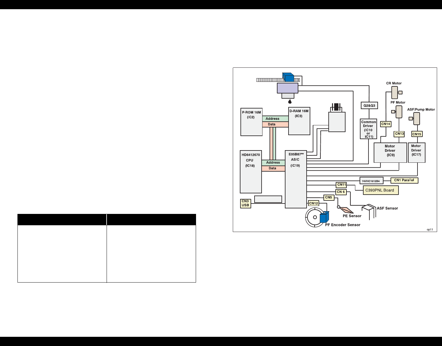
EPSON Stylus Photo 890/1280/1290 Revision C
OPERATING PRINCIPLES Electrical Circuit Operating Principles 47
2.2.2 C393MAIN Board Circuit Operation Principles
The C393MAIN board includes the following:
Logic circuit (CPU, ASIC, DRAM, EEPROM, and so on)
Various motor control/driver circuits (CR motor, PF motor, and ASF/Pump
motor)
Head control/driver circuits
Interface circuit (parallel I/F, USB I/F)
Sensor circuit
Timer circuit
Reset circuit
The C393MAIN/C393MAIN-B/C393MAIN-C board is mainly different from other
main boards in the following points.
Use of 3.3V drive logic chips
IC21, the 3.3 V regulator IC on the C393MAIN, produces 3.3 V by pressuring
down the 5.5 VDC generated on the C378PSB/PSE board to drive several chips.
These chips are used to reduce power used to drive the logic circuit. See the table
below that separately shows the chips driven by the +5V and +3V.
Table 2-14. 3.3V Drive Chips & 5.5V Drive Chips
There are three kinds of main board installed on EPSON Stylus Photo 890/1280/1290.
Stylus Photo 890 is equipped with either C393MAIN-B or C393MAIN-C while Stylus
Photo 1290 is equipped with either C393MAIN or C393MAIN-B. Block diagram of
each main board are shown in the following figures below.
Figure 2-13. Block Diagram for the C393MAIN Board
(For Stylus Photo 1290 only)
Table 2-15.
+5V 3.3V
Sensors
USB I/F Circuit
(Except high speed)
PNL Board
CPU
ASIC
P-ROM
D-RAM
RTC/Reset/EEPROM
USB I/F Circuit
(During high speed)
CR1
Timer &
Reset IC
(IC4)
Head
CR Encoder senser
IC4
IC7 E0BA13KA
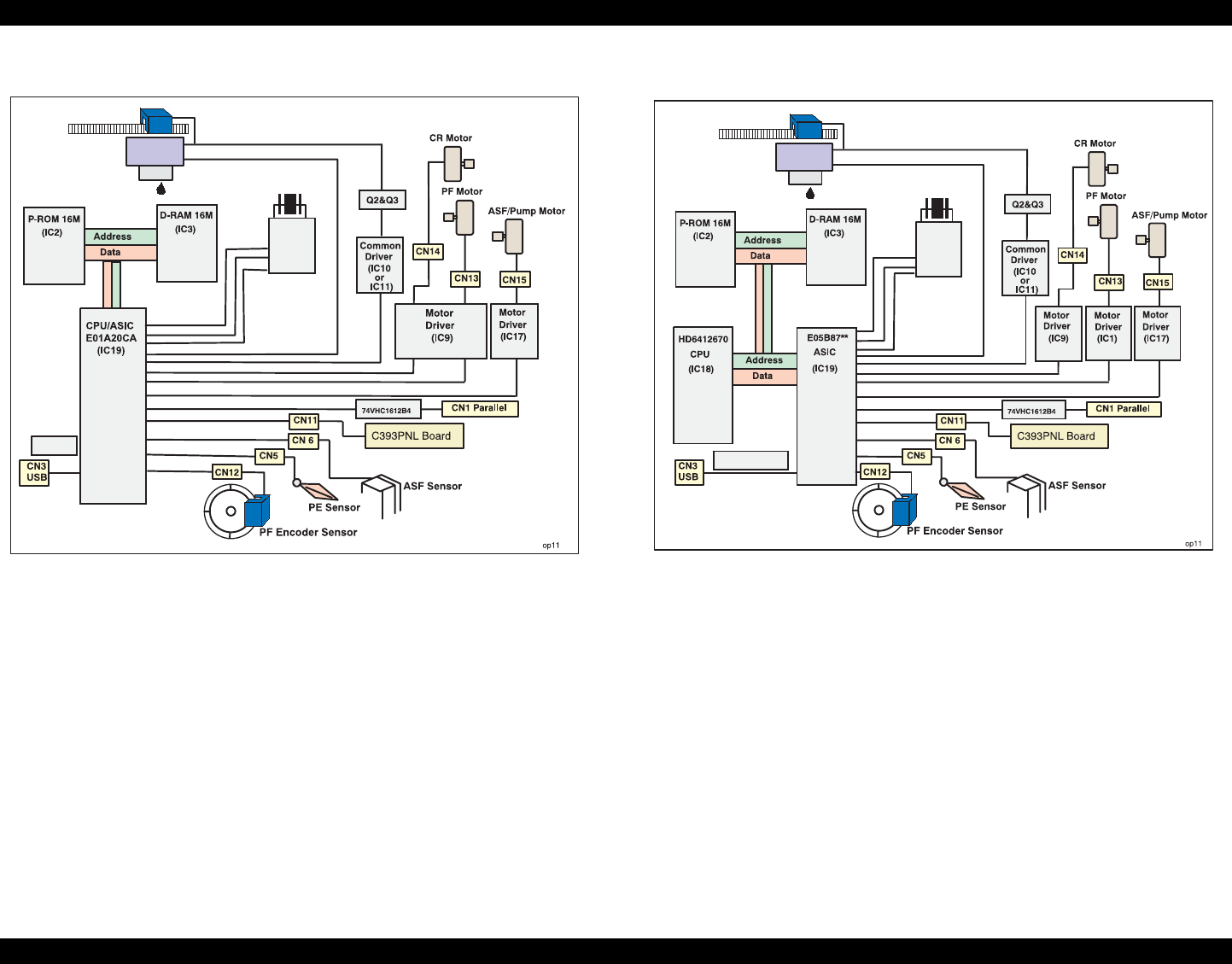
EPSON Stylus Photo 890/1280/1290 Revision C
OPERATING PRINCIPLES Electrical Circuit Operating Principles 48
Figure 2-14. Block Diagram for the C393MAIN-B Board
(For Stylus Photo 890/1290) Figure 2-15. Block Diagram for the C393MAIN-C Board
(For Stylus Photo 890 only)
CR1
Timer &
Reset IC
(IC4)
Head
CR Encoder senser
IC4
IC7
E0BA13KA
CR1
Timer &
Reset IC
(IC4)
Head
CR Encoder senser
IC4
IC7 E0BA13KA

EPSON Stylus Photo 890/1280/1290 Revision C
OPERATING PRINCIPLES Electrical Circuit Operating Principles 49
Table 2-16 shows the major ICs on the C393MAIN Board and their functions.
Table 2-16. Major Element on C393MAIN
IC Location Functions
CPU (HD6412670)
(C393MAIN/
C393MAIN-C)
IC18
A 144-pin QFP package. Operates at 24.0MHz. Power supply voltage is
3.3V.
• Sets the current value for the ASF/Pump motor.
• Measures the printhead temperature.
• Several interrupting functions
• Outputs the system clock signal.
ASIC (E05B87**)
(C393MAIN/
C393MAIN-C) IC19
A 240-pin QFP package. Operates at 48.0MHz/24.0MHz/28.0MHz. Power
supply voltage is 3.3V.
• Controls interfaces.
• Controls specified motors.
• Controls the printhead drive waveform circuit.
• Transfers serial data to the printhead.
• Controls the ASF/Pump motor
• Receives panel control signals and sensor signals
•EEPROM
• Controls detection of the signals output from the encoder.
ASIC
(E01A20CA**) IC19 • CPU and ASIC are built in in the IC.
PROM IC2 8/16Mbit
• Stores the firmware or firmware +CG
DRAM IC5 A 16Mbit DRAM. Power supply voltage is 3.3V.
• Serves as specified buffers and work area
RTC IC
RTC9822** IC4 • Resets the +5V/+24 VDC line circuits.
• Serves as the timer powered by a lithium battery.
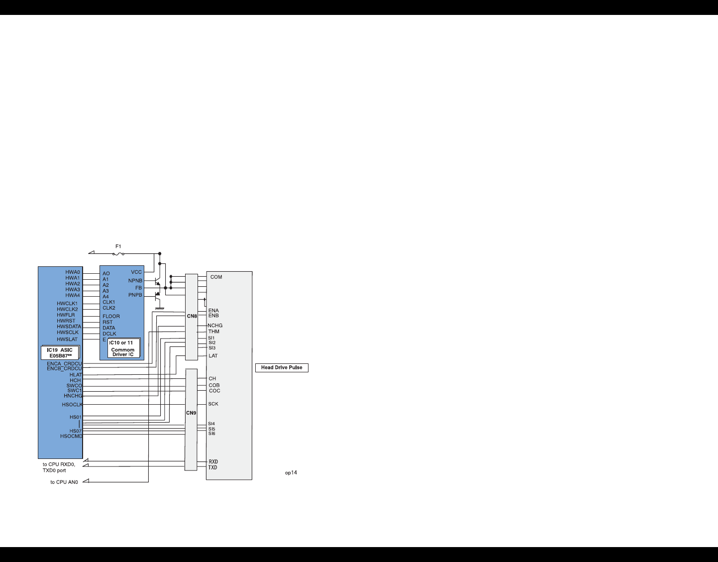
EPSON Stylus Photo 890/1280/1290 Revision C
OPERATING PRINCIPLES Electrical Circuit Operating Principles 50
2.2.2.1 Printhead Driver Circuit
The printhead driver circuit includes:
Common driver IC10 (E09A14RA)/IC11 (E09A15KA) directly attached to
the C393MAIN board.
Nozzle selector IC (IR2C95F or SED6125T0A) on the head board.
The common driver generates reference drive waveforms according to the output
signals from ASIC on the C393MAIN board. The reference drive waveforms are
amplified by the transistors Q2 and Q3 and then transferred to the nozzle selector IC on
the head board. Print data is converted to serial data by the ASIC and then also sent to
the nozzle selector IC on the head board. Based on the serial data, the nozzle selector
IC determines the nozzles to be actuated. The selected nozzles (PZT) are driven
according to the drive waveforms produced by the common driver. See Figure 2-16 for
the printhead driver circuit block diagram.
Figure 2-16. Printhead Driver Circuit
Head common driver circuit
The head common driver IC10 (E09A14RA)/IC11 (E09A15KA) generates
reference head drive waveforms according to the output of the following 9 signal
lines: A0-A4, CLK1, CLK2, RST, FLOOR, and DATA.
By the DATA signal output from the IC19 ASIC (E01A20CA**), the original data
for the head drive waveform is written in the memory in the IC10/IC11. Addresses
for the written data are determined by the A0 - A4 signals, and, of among, data
used to determine the waveform angles is selected. Then, setting the selected data,
producing trapezoid waveform value, and canceling the data are performed by the
rising edges of the CLK1 and CLK2 signals.
Head nozzle selector circuit
Print data is converted into serial data by the ASIC (E01A20CA**). Then the
converted data is allocated to the six rows, the number of the head nozzle rows, to
be transferred to the nozzle selector IR2C95F (Sharp) or SED6125T0A (EPSON)
through the six signal lines (HS01 to HS06). Data transmission from IC19 ASIC
(E01A20CA**) to the nozzle selector synchronizes with the LAT signal and SCK
clock signal. Referring to the transferred data, The nozzle selector IC selects the
nozzles to be activated, and the PZTs of the activated nozzles are driven by the
drive waveforms output from the head common driver.
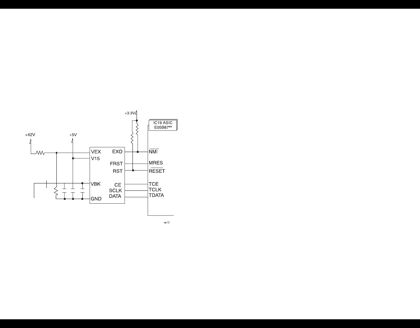
EPSON Stylus Photo 890/1280/1290 Revision C
OPERATING PRINCIPLES Electrical Circuit Operating Principles 51
2.2.2.2 RTC (Real Time Clock)/ Reset/ EEPROM Circuit
RTC9822**includes built-in RTC and EEPROM and functions as a reset. The RTC
part has an electric two-layer condenser for backup. The RTC/Reset/EEPROM circuits
are attached on the C393MAIN board to monitor two voltages: +5V for the logic line
and +42V for the drive line. When each circuit detects abnormality on the
corresponding line, it resets CPU and ASIC to prevent the printer from operating
abnormally.
IC4 RTC9822** is attached on the main board as a RTC/Reset/ EEPROM circuit IC.
EEPROM part backups default setting value and each parameter. IC4
RTC9822**monitors +3.3, +5V, and +45 lines but can reset them independently. See
Figure 2-17 for the block diagram for the reset circuits.
Figure 2-17. RTC/Reset/EEPROM Circuit Block Diagram
+3.3V Line Reset Circuit
The VDD port of IC4 reset IC monitors the +5V line. When the IC detects an
abnormal voltage level (2.5 V or lower), it outputs a reset signal from the RST port
to CPU and ASIC.
+5V Line Reset Circuit
The VDD port of IC4 reset IC monitors the +5V line. When the IC detects an
abnormal voltage level (4.2 V or lower), it outputs a reset signal from the RST port
to CPU and ASIC.
+42V line reset circuit
The VIN port of the IC5 reset IC monitors the +45V line. When the IC detects an
abnormal voltage level (36V or lower), it outputs a reset signal from the VDT port
to CPU and ASIC.
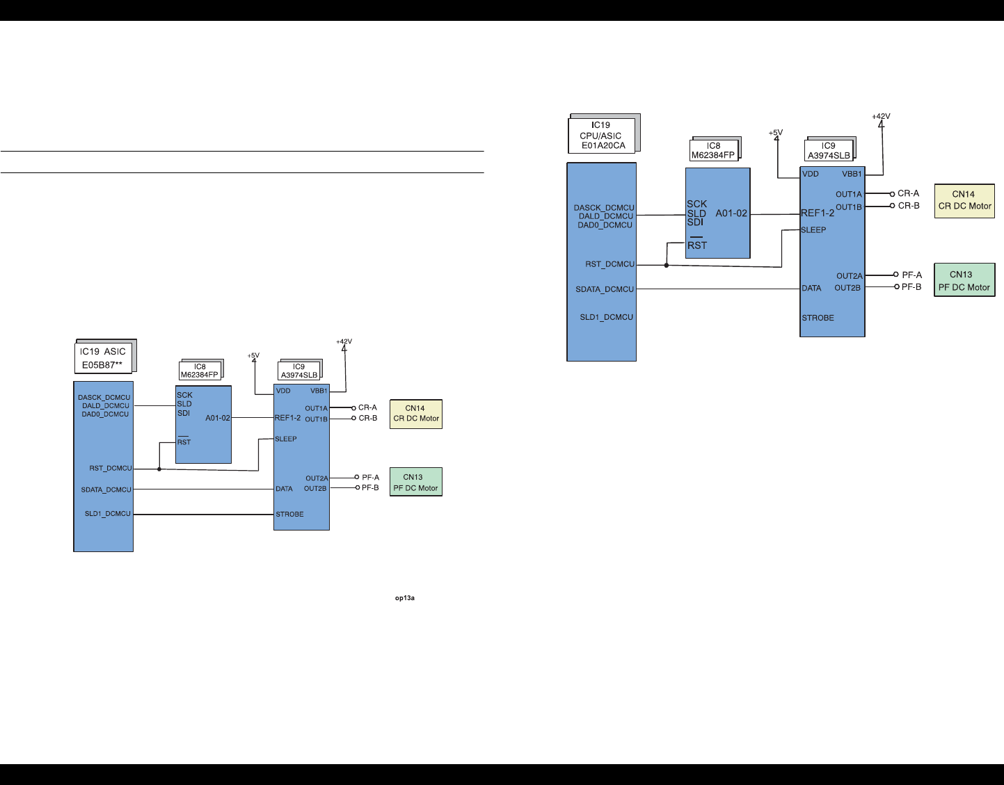
EPSON Stylus Photo 890/1280/1290 Revision C
OPERATING PRINCIPLES Electrical Circuit Operating Principles 52
2.2.2.3 Motor Driver Circuit
Stylus Photo 890/1290 is equipped with 3 kinds of motors, the CR motor and PF motor
that are a DC motor and an ASF/Pump motor, and a stepping motor. The DC motor on
the C393MAIN board is used for DC motor control.
CR motor driver circuit
IC9 (A39374SLB) on the C393MAIN/C393MAIN-B board controls the CR and PFDC
motor while IC9(A3958SLB) on the C393MAIN-C board controls the CR motor.
ASIC sends signals of IC9 through IC8 and determines current of the CR motor. By
setting RST_DCMCU of ASIC “LOW “ level, the motor turns into a
“SLEEP”condition for energy saving.
The block diagram of the CR motor driver IC (IC9) is as shown below.
Figure 2-18. CR Motor Driver Circuit Block Diagram (C393MAIN)
Figure 2-19. CR Motor Driver Block Diagram (C393MAIN-B)
op13b
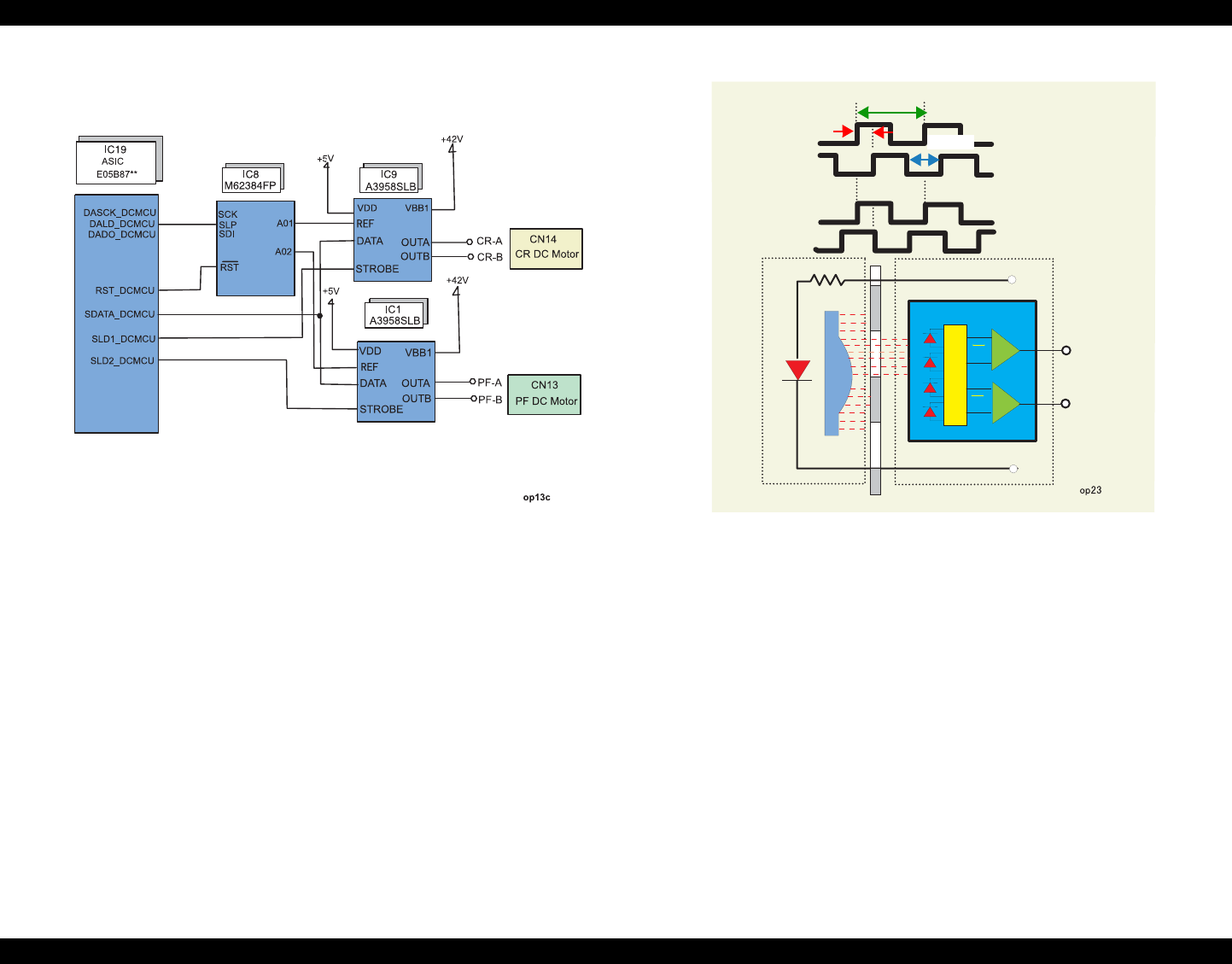
EPSON Stylus Photo 890/1280/1290 Revision C
OPERATING PRINCIPLES Electrical Circuit Operating Principles 53
Figure 2-20. CR Motor Driver Circuit Block Diagram (C393MAIN-C)
NOTE: When C393MAIN-C is installed, ASIC sends signals of IC9 and IC1 through IC8
and determines current of the CR motor.
ASIC (IC19) controls the CR position by referring to the pulses sent from the linear
encoder. Based on the data sent from ASIC, the CPU sets an appropriate drive current
value used to determine the CR position and the direction in which the CR moves.
ASIC outputs specified control signals to the motor driver. The motor driver IC9 then
outputs CR motor drive current to the CR motor.
Unlike stepping motors, the DC motor that drives the carriage
can not detect the current
carriage position by referring to the pulses given. For this reason, a linear scale is
attached along the carriage operation range to detect the carriage position. The linear
encoder sensor outputs two kinds of TTL level pulses: Phase A and Phase B.
Figure 2-21. CR Linear Scale Encoder Pulse
Direction for the CR’s current movement is detected based on the pulse waveforms of
the shifted Phases A and B. Carriage position is, on the other hand, controlled based on
a cycle of Phase A output waveform (1 cycle=1/180 inches). Also, all rising and falling
edges of the waveforms in the both phases (1 cycle=720) are used to control the
position of the CR that is in its home position for ink system.
Home position detection
Home position is detected based on the pulses output from the linear scale sensor
and DC motor control current value. The basic home position detection sequence
is as described below:
1) The linear encoder pulse counter in the ASIC (IC19) is reset by an
initialization sequence at power-on.
2) The CR motor turns forward (clockwise) to move the carriage to the right.
ASIC(IC19)assumes that the CR is in contact with the right frame when the
following conditions are satisfied:
+
-
+
-
1/720”
1/180”
1/360”
Phase B
Phase A
Phase B
Phase A
Phase B
Phase A Forward Rotation
(Clockwise)
Backward Rotation
(Counterclockwise)
LED
Lens
Photo
Diodes
Photo
Diodes Comparators
Comparators
B
A
A
B
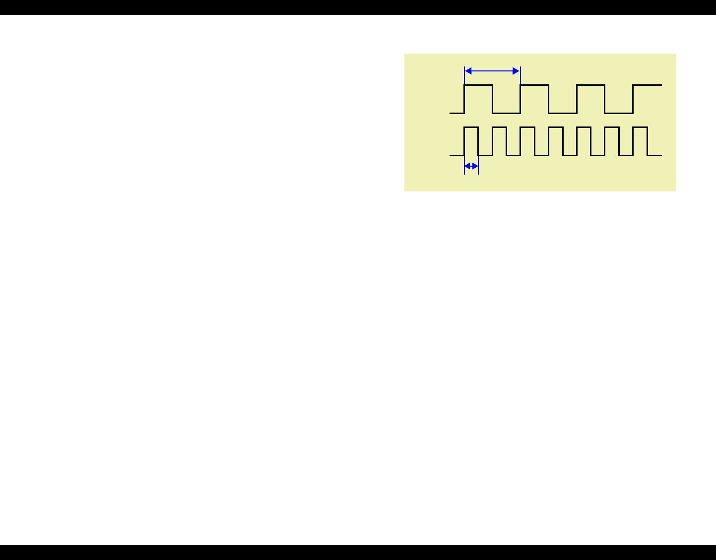
EPSON Stylus Photo 890/1280/1290 Revision C
OPERATING PRINCIPLES Electrical Circuit Operating Principles 54
ASIC(IC19) detects the motor control current value is 720mA.
P1 (= number of pulses output during the above carriage movement) is
30* or less.
* Specified value that indicates CR is in the home position. (All edges in the
waveform are used in this condition.)
3) The CR motor rotates backward (counterclockwise) to move the carriage back
to the left, and ASIC(IC19) assumes that the carriage enters the CR lock lever
position when the following conditions are satisfied:
ASIC(IC19) detects the motor control current value is 500 mA.
Difference between P1 and P2 (= number of pulses output while the CR
moves from the right frame) is 30 or less.
4) The CR motor rotates backward to move the carriage to the right again, and if
ASIC (IC19) detects the motor control current value is 720 mA, it assumes
that the CR comes in back in contact with the right frame.
5) Difference between P1 and P3 (= number of pulses output for the CR’s
movement from the CR lock lever position to the right frame) is 4 or less.
When all the conditions in the sequence are satisfied, the printer detects the CR is in
the home position.
PTS (Print Timing Signal) production
The circuit produces PTS signal (cycle: 1/360 inches) by dividing waveform
cycles of Phase A. The print timing signal is used to eject ink at a correct timing.
Figure 2-22. Print Timing Signal and Linear Encoder Phase A
Phase B
Phase B
1/180”
1/360”
Phase A
Phase A
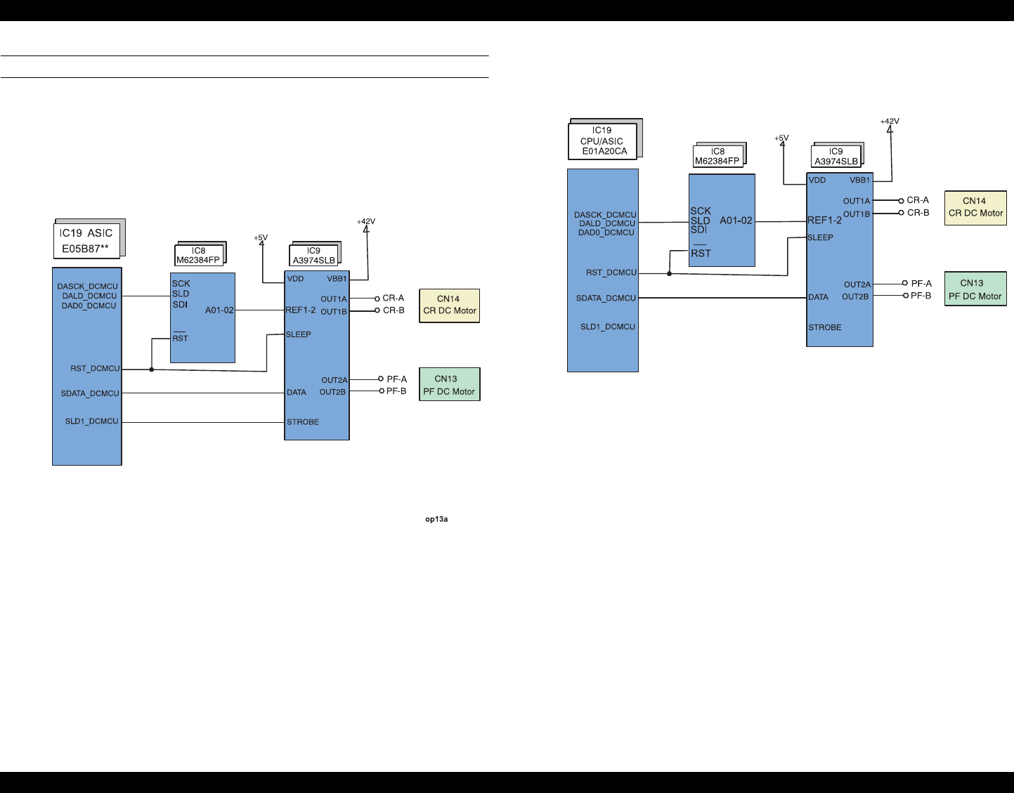
EPSON Stylus Photo 890/1280/1290 Revision C
OPERATING PRINCIPLES Electrical Circuit Operating Principles 55
PF motor driver circuit
DC motor is used as the PF motor in this printer. IC9 (A39374SLB) on the
C393MAIN/C393MAIN-B board controls the CR and PFDC motor while
IC9(A3958SLB) on the C393MAIN-C board controls the CR motor.
The block diagram of the PF motor driver circuit is as shown below:
Figure 2-23. PF Motor Driver Circuit Block Diagram (C393MAIN)
Figure 2-24. PF Motor Driver Circuit Block Diagram (C393MAIN-B)
op13b
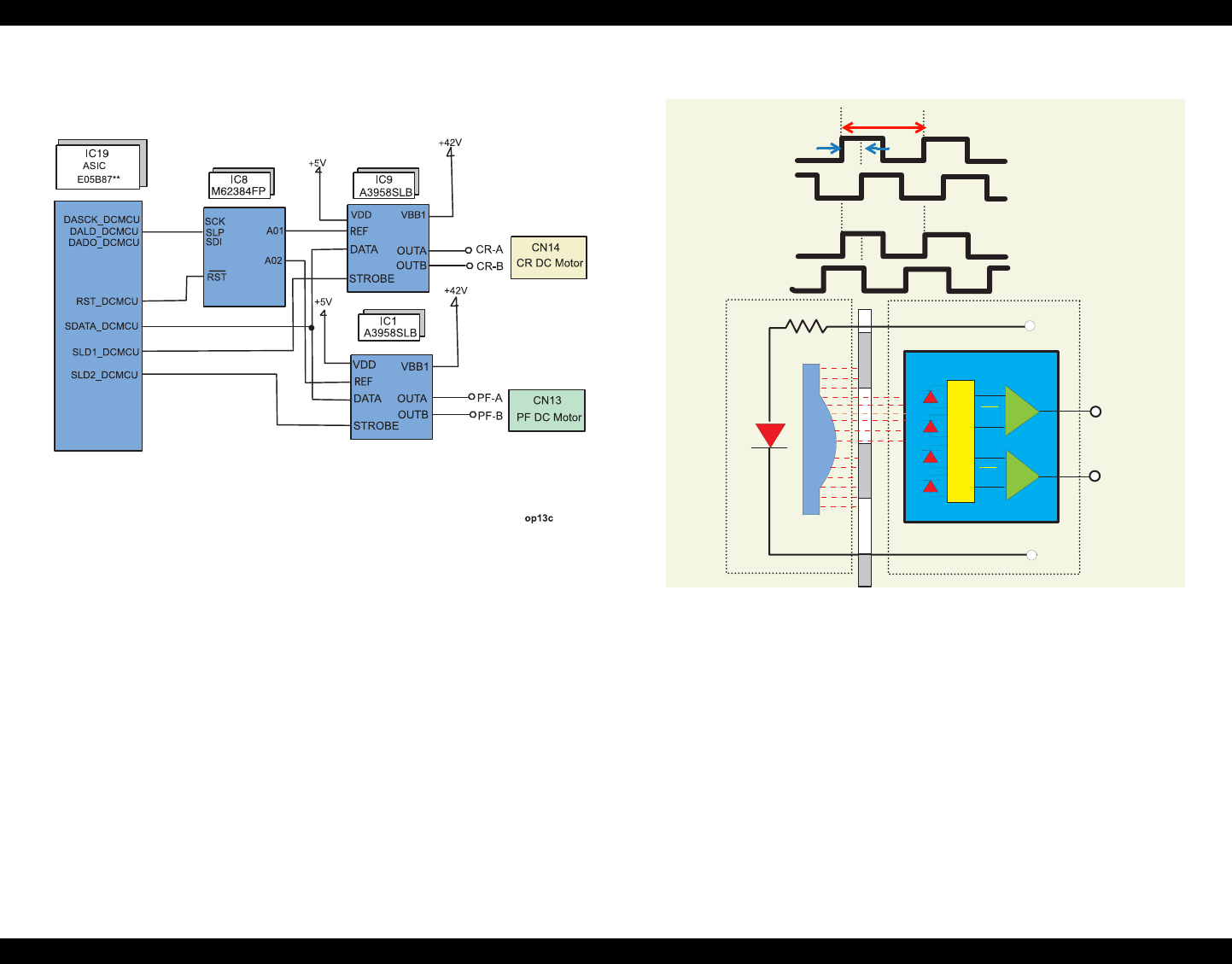
EPSON Stylus Photo 890/1280/1290 Revision C
OPERATING PRINCIPLES Electrical Circuit Operating Principles 56
Figure 2-25. PF Motor Driver Circuit Block Diagram (C393MAIN-C)
ASIC(IC19)controls paper feeding amount by referring to the encoder pulses. ASIC
sends a proper drive current value to the motor driver. Based on the control signal from
ASIC, the motor driver (IC9or IC1) outputs drive current to the PF motor.
Unlike a stepping motor, this DC motor can not detect paper feeding amount by
referring to the pulses given. For this reason, a loop scale is attached on the Gear 76 to
detect paper feed amount.
The loop scale encoder sensor outputs two kinds of TTL level pulses Phase A and
Phase B to ASIC (IC19). Direction of the PF motor rotation is determined by the phase
between the output waveforms from Phase A and the waveforms form Phase B
Figure 2-26. Loop Scale Encoder Pulse
+
-
+
-
op25
Comparators
Photo
Diodes
Phase B
Phase A
1/1440”
1/5760“
Forward Rotation
(Clockwise)
Backward Rotation
(Counterclockwise)
Phase A
Phase A
Phase B
Phase B
LED
Lens
Photo
Diodes Comparators
B
A
A
B
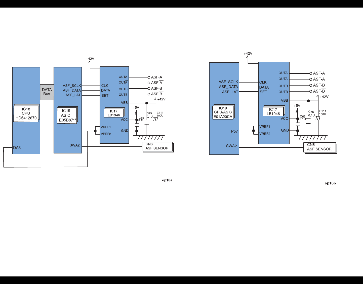
EPSON Stylus Photo 890/1280/1290 Revision C
OPERATING PRINCIPLES Electrical Circuit Operating Principles 57
2.2.2.4 ASF/Pump Motor Driver Circuit
ASF/Pump motor is a PM type stepping motor. The block diagram for the ASF/Pump
motor is as shown below:
Figure 2-27. ASF/Pump Motor Circuit Block Diagram
(C393MAIN/C393MAIN-C) Figure 2-28. ASF/Pump Motor Circuit Block Diagram
(C393MAIN-B)
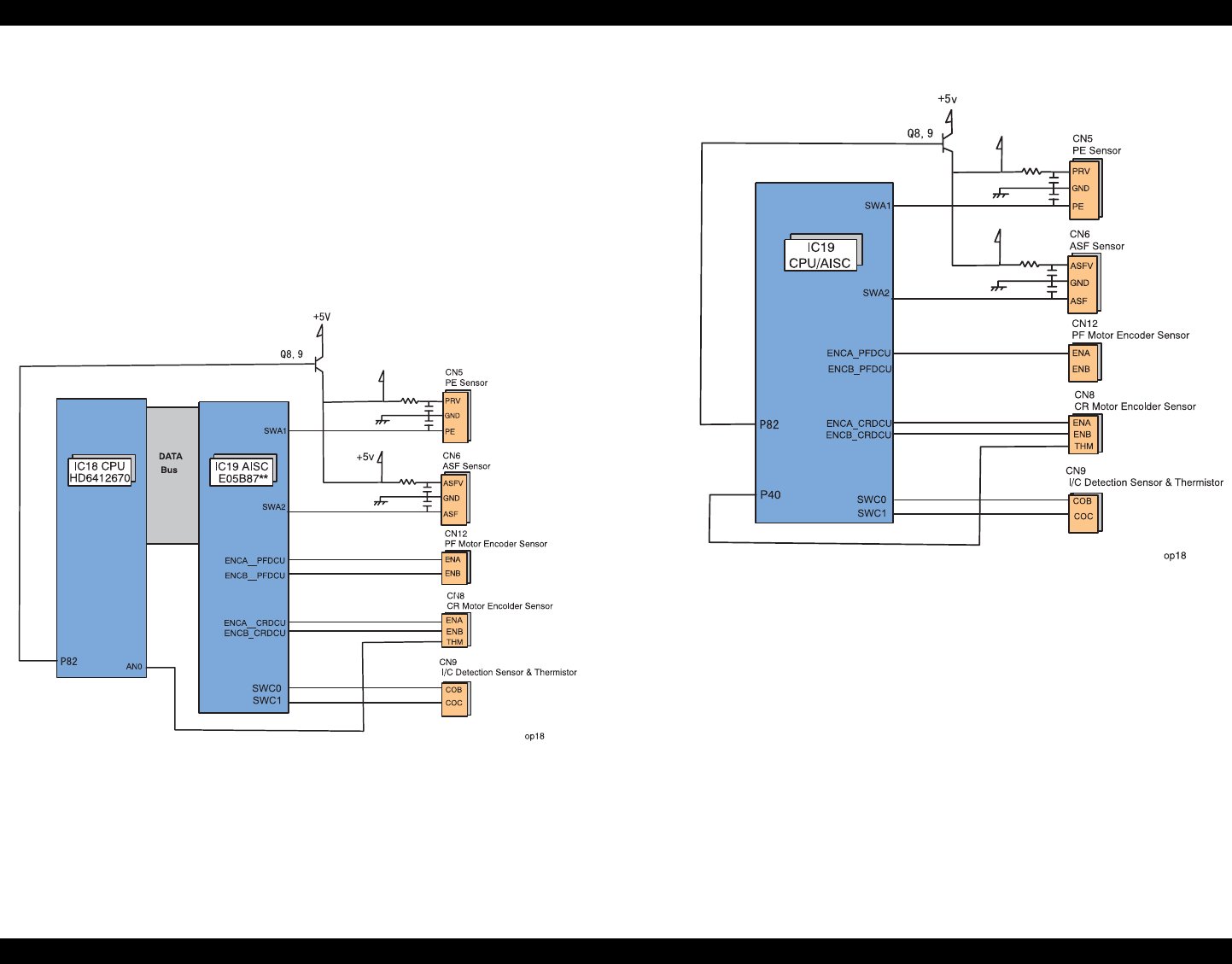
EPSON Stylus Photo 890/1280/1290 Revision C
OPERATING PRINCIPLES Electrical Circuit Operating Principles 58
2.2.2.5 Sensor Circuit
Stylus Photo 890/1290 has the following five sensors to detect printer’s status.
PE sensor
ASF sensor
Ink cartridge sensor (CSIC connector on the head board)
Head thermistor sensor
PF motor encoder
CR motor encoder
The block diagram for the sensor circuit is as shown below:
Figure 2-29. Sensor Circuit Block Diagram
(C393MAIN/C393MAIN-C)
Figure 2-30. Sensor Circuit Block Diagram (C393MAIN-B)

EPSON Stylus Photo 890/1280/1290 Revision C
OPERATING PRINCIPLES Electrical Circuit Operating Principles 59
Each sensor’s functions and operating principles are as described below:
PE sensor
The PE sensor is located at the bottom right edge of the top frame in the printer
mechanism. It detects paper on the rear paper guide using a photo sensor and PE
sensor lever that are included in the sensor. When paper is present, the PE sensor
lever does not cut in between the photo sensor terminals. So it outputs a LOW
signal to the ASIC. If there is no paper, on the other hand, the lever cuts in between
the photo sensor terminals. So it outputs a HIGH signal to the ASIC.
ASF sensor
The ASF sensor, located at the left edge of the ASF, detects ASF home position.
This sensor consists of the ASF HP detector wheel and a transmission photo
sensor. A small portion of the ASF HP sensor has a cutout, and when the cutout
comes into position between the photo diode terminals, that condition is detected
as ASF home position. In this status, since the photo diode terminals are not
blocked by the wheel, a LOW signal is output to ASIC. Otherwise, a HIGH signal
is output. Referring to the ASF home position detected by this sensor, the printer
drives the ASF/Pump motor to set the LD roller and paper return lever ready to the
paper loading position.
Ink cartridge sensor (CSIC connector on the head board)
Ink cartridge sensor detects whether a black or color ink cartridge is installed.
Installation condition is determined depending on the CSIC’s connection. When a
cartridge is installed, a LOW signal to ASIC is output. On the other hand, a HIGH
signal is output when a cartridge is out.
Head thermistor
The head thermistor is directly attached on the head driver board. It monitors the
temperature around the printhead and feeds back the temperature to the CPU
analog port. The printer refers to this information to control head driver voltage
based on the ink viscosity.
PF motor encoder
The PF motor encoder includes the loop scale attached to the left end of the PF
roller shaft and the transmission photo sensor. The minimum resolution of the
sensor is 1/180 inches. The sensor outputs HIGH signals for the black lines and
LOW signals for the transparent parts to the ASIC. The printer controls the PF
motor based on the signals output from this sensor.
CR motor encoder
CR motor encoder consists of the transmission photo sensor assembled in the CR
unit and the linear scale attached along the CR scanning line. The minimum
resolution of the sensor is 1/180 inch. It outputs HIGH signals for the black bands
and LOW signals for the transparent parts of the linear scale to the ASIC. The
printer controls the CR motor based on the signals output from this sensor. CR
home position is also detected based on the signals from this sensor.

CHAPTER
3
TROUBLESHOOTING
EPSON Stylus Photo 890/1280/1290 Revision C
TROUBLESHOOTING Overview 61
3.1 Overview
This chapter describes how to troubleshoot problems. It consists of the sections shown
in the flowchart below. When identifying and troubleshooting problems, be sure to
proceed to the correct section specified in the flowchart.
Figure 3-1. Troubleshooting Flowchart
Following sections give detailed information on each step in the flowchart. Be sure to
perform troubleshooting by following the specified steps without omitting any
necessary operations.
Following tables show the checkpoints for each motor and sensor.
STARTSTART
Troubleshooting with
LED error indicators
Isolating the defective
parts on the power supply
board
Isolating the problem
with exhibited
phenomenon
Table 3-1. Motor Resistance and Measurement Procedure
Motor Connector
to check Check pins Coil resistance
CR Motor CN14 Pin 1 & 2 29.2 Ω +/- 25%
PF Motor CN13 Pin 1 & 2 29.2 Ω +/- 25%
ASF/Pump Motor CN15 Pin 1 & 3 or Pin
2 & 4 10.4 Ω +/-10%
Table 3-2. Sensor Check and Measurement Procedure
Sensor Checkpoints Signal level Corresponding
condition
PE Sensor CN5, Pin 1 &2 LOW Paper present
HIGH Paper out
ASF Sensor CN6, Pin 1 &2
LOW In the ASF home
position
HIGH Out of the ASF home
position
EPSON Stylus Photo 890/1280/1290 Revision C
TROUBLESHOOTING Overview 62
3.1.1 Self-Diagnostic Function
The EPSON Stylus PHOTO 890/1290 is equipped with the self-diagnostic function.
With this function, the printer can check its operations after power-on, and shows its
various conditions using LED indicators.
3.1.1.1 Troubleshooting with LED Error Indicators
l
3.1.1.2 Error Conditions
This printer indicates an error when detecting the following conditions, and sets the
interface signal “/ERROR” to LOW and “BUSY” to HIGH to stop data input. In this
condition, the printer automatically enters non-printable status. Note if the printer is
establishing communication by IEEE1284.4 protocol, however, it remains in printable
status.
Each error condition is described below:
Ink Out
When the printer runs out of the most of the ink of any color, it warns Ink Low and
keeps printing.
Ink End
Ink in black/color cartridge ends.
Remaining level of ink is low. In this case, the printer warns of the condition with
LED indicators. If ink runs out, on the other hand, the printer shows an ink end
condition and stops its operation. Note the error occurs if ink of any color in the
color ink cartridge runs out.
Paper Out
The printer attempts to load paper but fails.
Table 3-3. Error Indication of Operation Panel
Printer Status Indicators Priority
Power Error
Power On condition On - 11
Ink sequence Blink - 7
Ink Cartridge replacement mode Blink - 6
Data Processing Blink - 10
Paper Out*1 -On5
Paper Jam*1 -On 5
Double Feed Error*1 On 4
Ink End (Black)*1 -On->Blink 9
Ink Level Low (Black) - Blink->Blink 9
Ink End (Color)*1 -On->Blink2 9
Ink Level Low (Color) - Blink->Blink2 9
Ink End (Black & Color)*1 -Blink->Blink 9
Ink Level Low (Black & Color) - Blink->On 9
No Ink Cartridge (Black or Color) -On 8
Reset, Timer IC reset, EEPROM
clear On On -
Ink Overflow Counter Reset On On
Maintenance Request (Ink
Overflow Counter error) Alt Blink Alt Blink 2
Fatal Error Off On 1
Special setting Blink2 Blink2 -
Table 3-3. Error Indication of Operation Panel
Printer Status Indicators Priority
Power Error

EPSON Stylus Photo 890/1280/1290 Revision C
TROUBLESHOOTING Overview 63
Paper Jam
The printer fails to eject remaining paper with the specified number of paper
feeding steps at power-on.
The printer can not eject paper despite the FF command is sent or Maintenance
Switch is pressed.
No Ink Cartridge
Ink cartridge is not installed or installed incorrectly.
Information in CSIC of the ink cartridge is not read or written properly.
Maintenance Request
Total wasted ink amount reaches its capacity by cleaning and flashing. The printer
indicates the error and stops operations.
Fatal Error
A fatal error is indicated when a carriage control error or CG access error occurs.
Double Feed Error
If the printer fails to load paper during duplex printing, the error occurs. Refer to
C A U T I O N Maintenance request error is not cleared until the waste ink pad is
replaced with a new one, and the waste ink counter in EEPROM is
reset by the service operation.

EPSON Stylus Photo 890/1280/1290 Revision C
TROUBLESHOOTING Overview 64
Table 3-4. Error Condition and Possible Causes
No. Error Possible Causes Refer to:
1 Paper Out 1. Failure in paper loading
2. PE sensor connector is disconnected.
3. Sensor actuator is not acting properly or sensor bracket is not installed correctly.
4. PE sensor is defective.
5. ASF operates abnormally.
Table 3-5
2Paper Jam 1. Paper length is beyond the specifications.
2. The sensor is left on because paper dust or other foreign matter is lodged.
3. Sensor actuator is not acting properly or sensor bracket is not installed correctly.
4. PE sensor is defective.
5. Hopper release lever is not attached properly.
Table 3-6
3 Ink End / No Ink Cartridge 1. CSIC is not connected properly.
2. CSIC is defective.
3. Head FPC is defective.
4. Control board is defective.
Table 3-7
4Maintenance Request Protect counter is showing limit. Table
5 Fatal Error 1. Linear encoder FFC is disconnected from the sensor or liner encoder is not attached
to the carriage.
2. Linear encoder is dislocated.
3. ASF sensor is dislocated or ASF sensor connector is disconnected.
4. ASF sensor is defective or it fails to detect ASF home position.
5. PF encoder FFC is disconnected from the encoder sensor or the encoder fails to read
the slit pattern on the loop scale.
6. CR motor coil is discontinued or burned.
7. PF motor coil is discontinued or /burned.
8. ASF/Pump motor coil is discontinued or burned.
Improper engagement of ASF gear (32) and the combination gear (14, 28) in the DE
unit.
9. Torsion spring (0.618) has come off the DE lock lever or hook in the DE unit.
Table 3-9
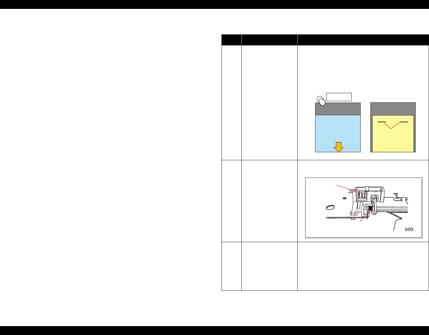
EPSON Stylus Photo 890/1280/1290 Revision C
TROUBLESHOOTING Overview 65
3.1.1.3 Remedies for Paper Out Error
This section provides checkpoints and corresponding actions to take when a Paper Out
error occurs for either of the following reasons:
Paper is set in the ASF hopper but not fed.
Paper is loaded but not detected by the PE sensor actuator.
Be sure to follow the steps in the order listed in the table.
NOTE: If the exhibited problem is similar to a problem listed under “Problem”, take the
actions in the right column. If not, proceed to the next step.
Table 3-5. Remedies for Paper Out Error
Step Problem Check & Actions
1 Maintenance Switch is
pressed but paper is not
loaded even when the
ASF LD rollers turn,
and a Paper Out error is
displayed.
1. Set a cleaning sheet in the ASF up side down.
2. Holding the top edge, press the Maintenance Switch to
remove micro pearl from the paper load roller.
To remove severe soiling, staple a cloth moistened with
alcohol to a postcard and clean the roller in the same
manner.
2 The Maintenance
Switch is pressed and
the ASF LD rollers
turn. But they turn
again to send paper
beyond TOP position.
Then a Paper Out error
is displayed.
Check if the connector (yellow, 3-pin) for the PE sensor is
connected to PE sensor or CN5 on the Main Board.
Ditto Ditto • Using your hand, move the actuator as if it were being
pushed by incoming paper. Then release the actuator
and check if it automatically returns to its original
position with the tension of the torsion spring.
• Referring to the illustration above, check that the sensor
base is securely installed to the frame. If the sensor base
is loose or installed insecurely, instal it securely.
Non-adhesive Area
Cloth moistened
with alcohol
Adhesive Area
This side down
Staples
CL Sheet
Base Sheet
(Postcard)
Base Sheet
(Postcard)
Non-adhesive Area
Torsion Spring
PE Sensor
Connector
<Printer Bottom>

EPSON Stylus Photo 890/1280/1290 Revision C
TROUBLESHOOTING Overview 66
3 Ditto Check if the PE sensor is defective. Manually toggling the
actuator, measure the voltage at CN5/Pin 3. The correct
voltage levels are as follows:
4 The Maintenance
SwitchMaintenance
SwitchMaintenance
Switch is pressed and
the hopper appears to
be working OK. But
paper is not loaded.
Then a Paper Out error
is displayed.
Hand-rotate the shaft in the ASF in the paper feed direction
and check if the hopper springs back every time you rotate
the shaft.
NOTE: Even though the ASF HP sensor is working
properly, the hopper does not load paper if it is not
operating at the correct timing. To solve that problem,
disassemble and reassemble the ASF or replace it. In case
the ASF HP sensor detects the ASF home position during
paper feed sequence, the printer enters a fatal error
condition.
Table 3-5. Remedies for Paper Out Error (continued)
Step Problem Check & Actions
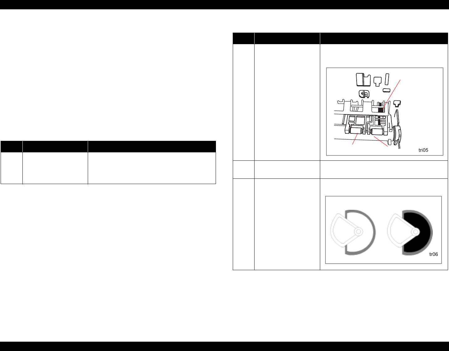
EPSON Stylus Photo 890/1280/1290 Revision C
TROUBLESHOOTING Overview 67
3.1.1.4 Remedies for the Paper Jam Error
This section includes the checkpoints and actions to take to troubleshoot the Paper Jam
error when it occurs during paper feeding or after the printer is turned on.
The printer detects the Paper Jam Error in the following condition.
When the printer is turned on, the PE sensor detects paper and attempts to
eject it using the PF roller. But the paper detection signal does no change to
HIGH.
Be sure to follow the steps in the order described in the tables.
NOTE: If the exhibited problem is similar to a problem listed under “Problem”, take the
actions in the right column. If not, proceed to the next step.
3.1.1.5 Remedies for No Ink Cartridge Error/Ink Cartridge
Problem
This section includes the checkpoints and corresponding actions to take to troubleshoot
the No Ink Cartridge Error / Ink Cartridge Problem.
Be sure to follow the steps in the order listed in the table.
Table 3-6. Remedies for Paper Jam Error
Step Problem Check & Actions
1 The PF roller turn to eject
paper but can not eject it
completely. Then a Paper
Jam error is displayed.
Explain to the user that a Paper Jam error occurs if the
paper whose length is beyond the specifications is
used.
2 The printer is turned on,
the PF roller turns
continuously for ten
seconds, and then a Paper
Jam error is displayed.
Check if there is any paper debris or dust lodged on the
PE sensor. Also, viewing the PE sensor from the front,
check its lever is set in the correct position.
3 ditto Referring to Table 3-5 / Step 3, check if the sensor is
operating properly.
4 Paper is loaded at the ASF
and fed by the PF roller,
but its leading edge dose
not reach the front paper
guide.
The ASF repeats paper
feeding motion and the
Fatal Error is displayed.
Check if the ASF hopper release lever is properly
installed to the LD roller shaft.
Table 3-6. Remedies for Paper Jam Error
Step Problem Check & Actions
PE Sensor Lever
Paper Guide Assy. PF Roller
Left ASF Hopper
Right ASF Hopper

EPSON Stylus Photo 890/1280/1290 Revision C
TROUBLESHOOTING Overview 68
NOTE: If the exhibited problem is similar to a problem listed under “Problem”, take the
actions in the right column. If not, proceed to the next step. 3.1.1.6 Remedies for Maintenance Request Error
If the printer is in this error condition (ink overflow counter error), it stops all
operations including data transfer, except for Special Setting Mode.
Table 3-7. Remedies for No Ink Cartridge Error/Ink Cartridge Problem
Step Problem Check & Actions
1 The printer is turned on
and then displays a No
Ink Cartridge error.
• Check if any ink cartridges are installed improperly.
If so, reinstall them.
• Try removing the ink cartridges and reinstalling them.
2 Ditto Check the level of the ink remaining using the printer
driver or progress meter.
3 Ditto Replace the ink cartridges with new ones.
• CSIC is defective.
4 Ditto • Check if the head FFC is correctly connected to the
head.
• Check if the head FFC is properly connected to the
connector on the main board.
• Check if the main board is defective.
Table 3-8. Remedies for Maintenance Request Error
Step Problem Check & Actions
1 The Power(green) and Error (red)
LEDs blink alternately.
• Remove Absorber Tray (Refer to
“TRAY, ABSORBER ASSEMBLY
Removal” on page -89).
• Replace Waste Ink Pad with a new one.
2 Ditto • Switch to Sepecial Setting Mode
Turn the power on while pressing the
Maintenance and Roll Paper Switches
simultaniously to switch to Special
Setting Mode.
3 Ditto • While the Power and Error LEDs are
blinking (3 seconds), press the Roll
Paper Switch for 10 seconds.
• Then, the ink overflow counter in
EEPROM is reset.
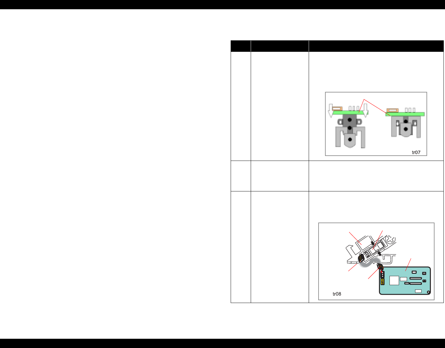
EPSON Stylus Photo 890/1280/1290 Revision C
TROUBLESHOOTING Overview 69
3.1.1.7 Remedies for Fatal Error
A fatal error is basically caused by any of the following conditions:
The printer fails to detect the CR home position.
The printer fails to detect signals from the linear scale.
The ASF sensor fails to detect the ASF home position.
The following table shows various causes of the fatal error and corresponding
solutions. Be sure to follow the steps correctly to troubleshoot the fatal error.
NOTE: If the exhibited problem is similar to a problem listed under “Problem”, take the
actions in the right column. If not, proceed to the next step.
Table 3-9. Remedies for Fatal Error
Step Problem Check & Actions
1 The printer is powered
on and the CR unit
leaves its home
position and then
collides with the right/
left frame. After that, a
fatal error is displayed.
Check the linear encoder board visually for the following:
• Is the linear encoder board properly installed to the
carriage? If not, install it properly.
• Is the encoder FFC connected to the connector? If not,
connect it properly.
2 Ditto • Check that the linear encoder belt passes through the
slot in the sensor.
• Check that the sensor is free from dust and paper
debris.
3 When the Printer is
turned on, the CR
moves a little and you
hear the ASF Hopper
moving.
After that, a fatal error
is displayed.
• Referring to the figure below, check that the ASF
sensor is attached to the correct position.
• Check that both connectors 1 and 2 are securely
connected.
Linear Encoder Board
ASF Sensor
ASF Frame (Left)
Connector 1
Connector 2
(CN6)
Control
Board
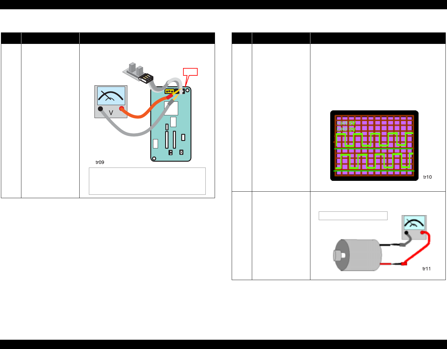
EPSON Stylus Photo 890/1280/1290 Revision C
TROUBLESHOOTING Overview 70
4 Ditto Turn the printer on and check for the correct voltages at
the pins shown in the figure below:
Table 3-9. Remedies for Fatal Error (continued)
Step Problem Check & Actions
To Pin 3
(ASFV)
To Pin 2
(GND)
CN6
• When the ASF HP detector wheel is in home
position, the voltage is 0.7 V or less.
• When the ASF HP detector wheel is out of home
position, the voltage is 2.4 V or more.
5 The printer is turned on
and the carriage and the
PF motor move a little.
After that, a fatal error
is displayed.
Check for the signal output from the PF encoder at either
pair of the following pins on the main control board:
• Pin 1 an Pin 4 of CN12
• Pin 1 and Pin 2 of CN12
Check for the signal output from the linear encoder at
either pair of the following pins on the main control board:
• Pin 1 an Pin 4 of CN12
• Pin 1 and Pin 2 of CN12
6 The printer is turned on
but the CR motor does
not operate at all. After
that, a fatal error is
displayed.
Measure the coil resistance of the CR motor using a meter
as shown below:
Table 3-9. Remedies for Fatal Error (continued)
Step Problem Check & Actions
Encoder Output Waveform
CR MotorCR Motor
Resistance: 29.2Ω ± 25%
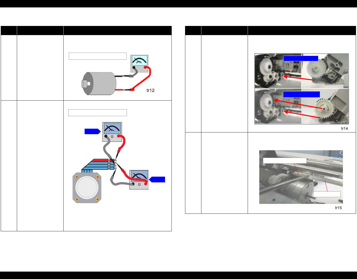
EPSON Stylus Photo 890/1280/1290 Revision C
TROUBLESHOOTING Overview 71
7 The printer is turned on
but the PF motor does
not operate at all. After
that, a fatal error is
displayed.
Measure the coil resistance of the PF motor using a meter
as shown below:
8 The printer is turned on
but the ASF hopper
does not make noises.
After that, a fatal error
is displayed.
Measure the coil resistance of the ASF/Pump motor.
NOTE: Be sure to measure the resistance at each pair of
points shown above.
Table 3-9. Remedies for Fatal Error (continued)
Step Problem Check & Actions
PF Motor PF Motor
Resistance: 29.2Ω ± 25%
To Pin 1
To Pin 3
To Pin 2
To Pin 4
CR Motor
CR Motor
Step 2
Resistance: 10.4 Ω ± 10%
Step 1
9 The Printer is turned on
but:
• ASF makes no
noises.
• ASF does not move
but its gear is
making noises.
After that, a fatal error
is displayed.
Check that the ASF unit is properly installed by the correct
points as shown below:
10 The printer is turned on
but the ASF dose not
move at all. After that,
a fatal error is
displayed.
Check that the torsion spring is securely attached to the
DE lock lever and DE unit.
Table 3-9. Remedies for Fatal Error (continued)
Step Problem Check & Actions
Stylus Photo 890
Stylus Photo 1290
Tension Spring (0.618)
DE Lock Lever

EPSON Stylus Photo 890/1280/1290 Revision C
TROUBLESHOOTING Overview 72
3.1.2 Isolating the Faulty Part on the Power Supply Board
This section explains how to troubleshoot the following problems:
The printer is turned on but it does not perform initialization and no LED
indicators come on.
Problems occurs after the printer is turned on.
Be sure to troubleshoot in the order specified since the steps are listed in the
disassembly order to facilitate the job.
NOTE: If you answer “Yes” to a question listed under “Checkpoint”, take the action
described to the right under “Action”. If “No”, proceed to the next step.
3.1.3 Isolating the Faulty Part according to the
Phenomenon
Refer to this section if you could not solve the problem in Section 3.1.1.1 or Section
3.1.2 or need more information to isolate the cause according to the exhibited
phenomenon. This section mostly covers the problems relating to the main control
circuit and other parts.
Table 3-10. Isolating the Faulty Part on the Power Supply Board
Step Checkpoint Action
1 Is the Panel FFC
disconnected from the
connector on the panel
board?
The power switch for this printer is in the secondary
side. Therefore, if the FFC does not transmit signals, the
power supply board is not active despite the main board
operates properly.
2 Is the Panel FFC
disconnected from CN11
(black, 12-pin) on the
Main Board?
The power switch for this printer is in the secondary
side. Therefore, if the FFC does not transmit signals, the
power supply board is not active despite the main board
operates properly.
3 Has the Pin 3 of the panel
FFC broken?
Check for the Pin 3 using a circuit tester.
4 Has the fuse (F1) on the
power supply board
blown out?
Check if the F1 located beside CN1 on the power supply
board has blown out.
5 Is CN1 on the power
supply board
disconnected?
Check if CN1 is properly connected. CN1 supplies AC
power to the primary side of the power supply board.
6 Is CN10 on the main
board disconnected?
Check if CN10 on the main board is properly connected.
CN10 supplies DC voltage to the control circuit.
7 - Replace the Power Supply Board with a new one.
Table 3-11. Phenomenons Exhibited
No. Phenomenon Exhibited Table to refer to
1 CR motor does not rotate. Table 3-12
2 PF motor does not rotate. Table 3-13
3 Pump/ASF motor does not rotate. Table 3-14
4Cleaning does not solve the print problem. Table 3-15
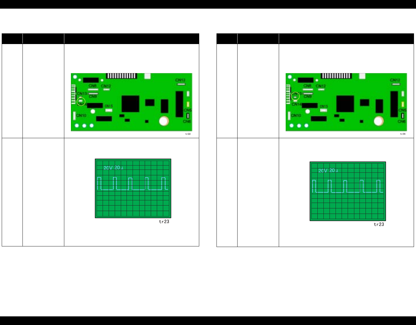
EPSON Stylus Photo 890/1280/1290 Revision C
TROUBLESHOOTING Overview 73
Table 3-12. CR Motor does not Work
Step Checkpoint Action
1 Getting ready for
checking
waveforms.
Using an oscilloscope, check the outputwaveform at CN14
(CR motor connector) on the main board. For checking, press
the Maintenance Switch to drive the CR motor.
NOTE: Be sure to disconnect the CR motor cable.
2 Checking the
waveforms to
solve the
problem.
Drive the CR motor and check that the waveform shown below
is output from each pin of CN14.
• If the waveform appears as shown, replace the CR motor.
• If not, replace the main control board.
Table 3-13. PF Motor does not Work
Step Checkpoint Action
1 Getting ready for
checking
waveforms.
Using an oscilloscope, check the outputwaveform at CN13 (PF
motor connector) on the main board. For checking, press the
Maintenance Switch to drive the PF motor.
NOTE: Be sure to disconnect the PF motor cable.
2 Checking the
waveform to
solve the
problem.
Drive the PF motor and check that the waveform shown below
is output from each pin of CN13.
• If the waveform appears as shown, replace the PF motor.
• If not, replace the main control board.
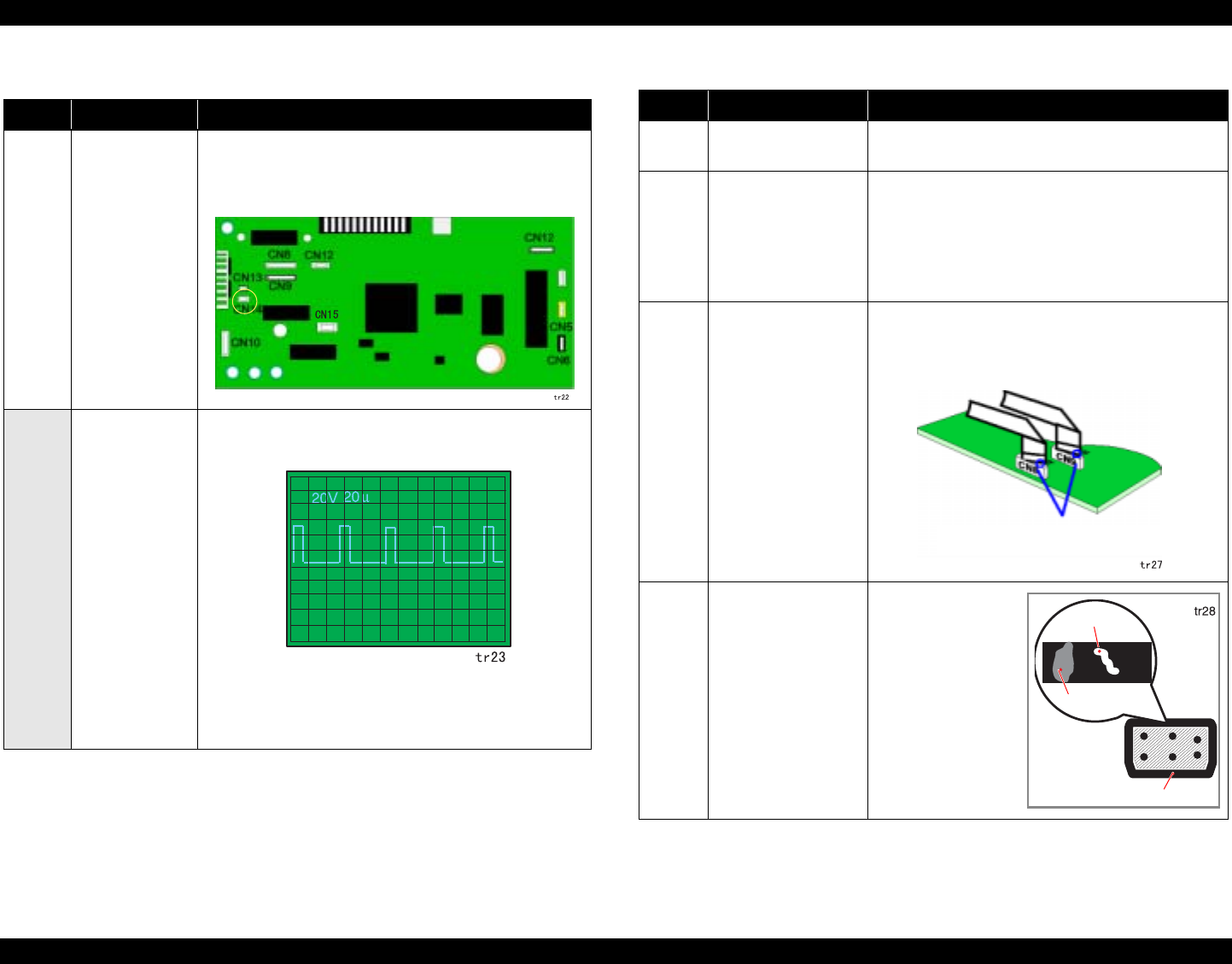
EPSON Stylus Photo 890/1280/1290 Revision C
TROUBLESHOOTING Overview 74
Table 3-14. ASF/Pump Motor does not Work
Step Checkpoint Action
1 Getting ready for
checking
waveforms.
Using an oscilloscope, check the outputwaveform at CN115
(ASF motor connector) on the main board. For checking,
press the Maintenance Switch to drive the CR motor.
NOTE: Be sure to disconnect the ASF/Pump motor cable.
2 Checking the
waveforms to
solve the
problem.
Drive the ASF/Pump motor and check that the waveform
shown below is output from each pin of CN15.
• If the waveform appears as shown, replace the ASF/Pump
motor.
• If not, replace the main control board.
Table 3-15. Cleaning Does not Solve the Problem
Step Checkpoint Action
1 Run the head cleaning
7 or 8 times repeatedly.
Run the head cleaning by pressing the Cleaning button.
2 Perform the initial ink
charge operation.
You can perform the initial ink charge operation in the
manner described below:
1. Using the adjustment program, perform the initial
ink charge operation (= resets the initial ink charge
flag in the EEPROM).
2. Turn the printer off and back on.
3 Printhead FFC is
disconnected.
Take out the main board and check if the head FFCs are
connected to CN8 and CN9. If they are connected aslant
as shown below, reconnect them, and then run a print
check.
4 Check the cap for any
foreign matter, dirt, or
damage.
Remove the printer
mechanism and
release the carriage
lock to move the
carriage unit away
from home position.
Then, examine the cap
rubber closely for any
problem in the figure
at right.
Check that the connectors are not
connected aslant.
Dust
Rubber part
Damage
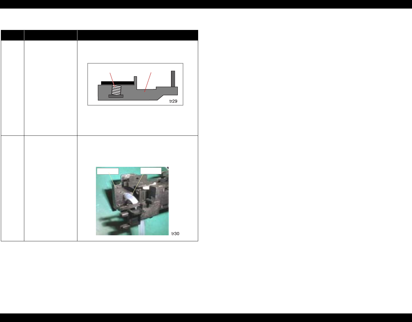
EPSON Stylus Photo 890/1280/1290 Revision C
TROUBLESHOOTING Overview 75
5 Check if the
compression spring has
come off the cap unit.
Check if the compression spring is correctly assembled
in the cap unit as shown below.
Note if the compression spring has come off the cap
unit, the cap can not cover the head closely with enough
air tightness, and ink will not be absorbed as a result.
6 Check if any ink tubes
are disconnected from
the cap unit.
Referring to the figure below, check the following:
• Are all ink tubes securely connected to the cap unit?
• Are any ink tubes damaged?
Table 3-15. Cleaning Does not Solve the Problem (continued)
Step Checkpoint Action
Compression Spring Cap Unit
Cap Unit Ink Tube
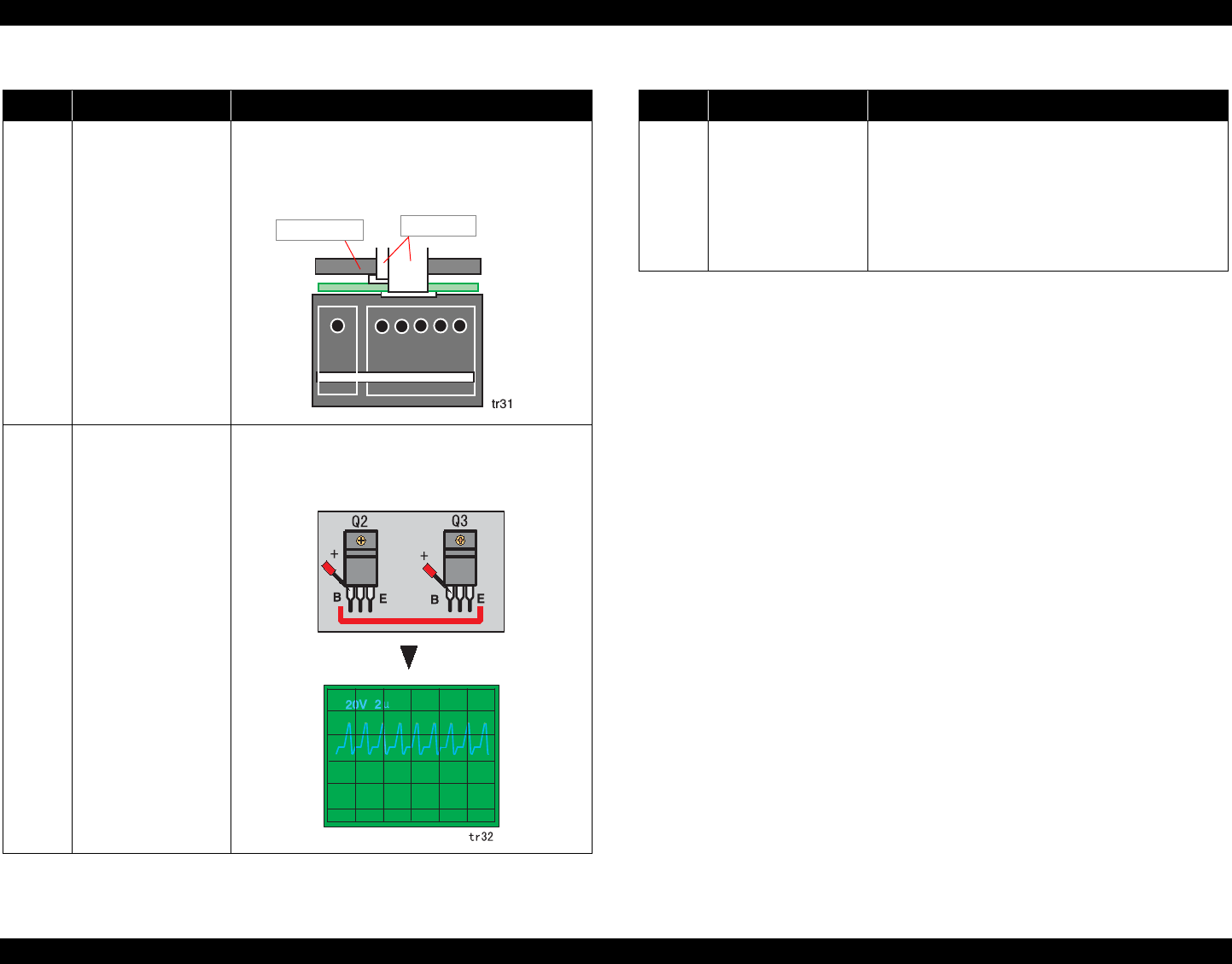
EPSON Stylus Photo 890/1280/1290 Revision C
TROUBLESHOOTING Overview 76
7 Check if the head FFCs
have come off the
printhead.
Remove the head FFC holder from the CR unit, and
check that both FFCs are properly connected. Even if
they appear to be properly connected (not slant), try
disconnecting and then connecting them.
8 Check if the head
driver is defective.
The common driver transistors Q2 and Q3 are attached
the heat sink on the main board. To check their
conditions, check the sawtooth waveform at the emitter
terminals the transistors using an oscilloscope.
Table 3-15. Cleaning Does not Solve the Problem (continued)
Step Checkpoint Action
Head FFCs
Head Board
9 Check if the pre-driver
IC (IC10 or IC11) is
defective.
If the waveform is not output in the previous step, check
for the waveform at the base of Q2 and Q3. Check for
the sawtooth waveform output from the pre-driver IC.
• If the correct waveform is output, transistor Q2/Q3 is
defective.
• If the correct waveform is not output, the pre-driver
IC is defective.
Table 3-15. Cleaning Does not Solve the Problem (continued)
Step Checkpoint Action

CHAPTER
4
DISASSEMBLY AND ASSEMBLY

EPSON Stylus Photo 890/1280/1290 Revision C
DISASSEMBLY AND ASSEMBLY Overview 78
4.1 Overview
This chapter describes procedures for disassembling the main components of the
EPSON Stylus Photo 890/1280/1290. Unless otherwise specified, disassembly units or
components can be reassembled by reversing the disassembly procedure. Therefore, no
assembly procedures are included in this chapter. Precautions for any disassembly or
assembly procedure are described under the heading “CAUTION” and “CHECK
POINT”. Any adjustments required after disassembling the units are described under
the heading “REQUIRED ADJUSTMENT”.
4.1.1 Precaution for Disassembling the Printer
See the precautions given under the heading “WARNING” and.“CAUTION” in this
section when disassembling or assembling EPSON Stylus Photo 890/1280/1290.
W ARNING Disconnect the power cable before disassembling or
assembling the printer.
If you need to work on the printer with power applied,
strictly follow the instructions in this manual.
Wear protective goggles to protect your eyes from ink. If
ink gets in your eye, flush the eye with fresh water and
see a doctor immediately.
Always wear gloves for disassembly and reassembly to
avoid injury from sharp metal edges.
To protect sensitive microprocessors and circuitry, use
static discharge equipment, such as anti-static wrist
straps, when accessing internal components.
Never touch the ink or wasted ink with bare hands. If ink
comes into contact with your skin, wash it off with soap
and water immediately. If irritation occurs, contact a
physician.
EPSON Stylus Photo 890/1280/1290 Revision C
DISASSEMBLY AND ASSEMBLY Overview 79
4.1.2 Tools
Table 4-1 lists the tools recommended for disassembling, assembling, or adjusting the
printer. Use only tools that meet these specifications.
NOTE: *1: Common cartridge with Stylus Photo 870/1270.
*2: Common cartridge with Stylus Photo 870.
*3: Common cartridge with Stylus Photo 1270.
C A U T I O N Never remove the ink cartridge from the carriage unless
this manual specifies to do so.
When transporting the printer after installing the ink
cartridge, be sure to pack the printer for transportation
without removing the ink cartridge.
Use only recommended tools for disassembling,
assembling or adjusting the printer.
Observe the specified torque when tightening screws.
Apply lubricants and adhesives as specified. (See
Chapter 6 for details.)
Make the specified adjustments when you disassemble
the printer.
(See Chapter 5 for details.)
When assembling, if an ink cartridge is removed and
needs to be installed again, be sure to install a new ink
cartridge because of the following reasons;
1.Once the ink cartridge mounted on the printer is removed,
air comes in and creates bubbles in the cartridge. These
bubbles clog ink path and cause printing malfunction.
2.If an ink cartridge in use is removed and is reinstalled, ink
quantity will not be detected correctly since the counter to
check ink consumption is cleared.
Because of the reasons above, make sure to return the
printer to the user with a new ink cartridge installed.
Make sure the tip of the waste ink tube is located at
correct position when reassembling the waste ink tube.
Otherwise it will cause ink leakage.
Table 4-1. Tool List
Tools Commercially
Available Code
(+) Driver No.2 O.K. B743800200
(+) Driver No.1 O.K. B743800400
Tweezers O.K. B741000100
Hexagon Box Driver
(Paired side: 5.5mm) O.K. B741700100
Scale PF unit Assembling tool EPSON exclusive 1050767
Mounting Plate Scale Attachment
tool EPSON exclusive 1051765
ROM Extractor No.F749 EPSON exclusive 2035659
Black Empty Cartridge
(Stylus Photo 890/1290)*1 EPSON exclusive 1049785 (#F738)
Color Empty Cartridge
(Stylus Photo 890 only)*2 EPSON exclusive 1049786 (#F741)
Color Empty Cartridge
(Stylus Photo 1290 only)*3 EPSON exclusive 1049787 (#F742)

EPSON Stylus Photo 890/1280/1290 Revision C
DISASSEMBLY AND ASSEMBLY Overview 80
4.1.3 Specifications for Screws
Table 4-2 shows screw specifications. During assembly and disassembly, make sure
that the specified types of screws are used at proper locations, referring to the table
below.
Table 4-2. Screw Specifications
Body Name Size
+Bind S-tite (CBS) M3x6
+Bind P-tite (CBP) M3x6
+Bind P-tite (CBP) M3x8
+Bind P-tite (CBP) M2.5x5
+Pan head (C.P.) M3x6
--- +Pan head B-tite Sems M3X8
+Bind S-tight Sems (CBS Sems) M3x6
+Bind S-tight (CBS) M3x10
--- +Pan head B-tite Sems 1.7 x 5
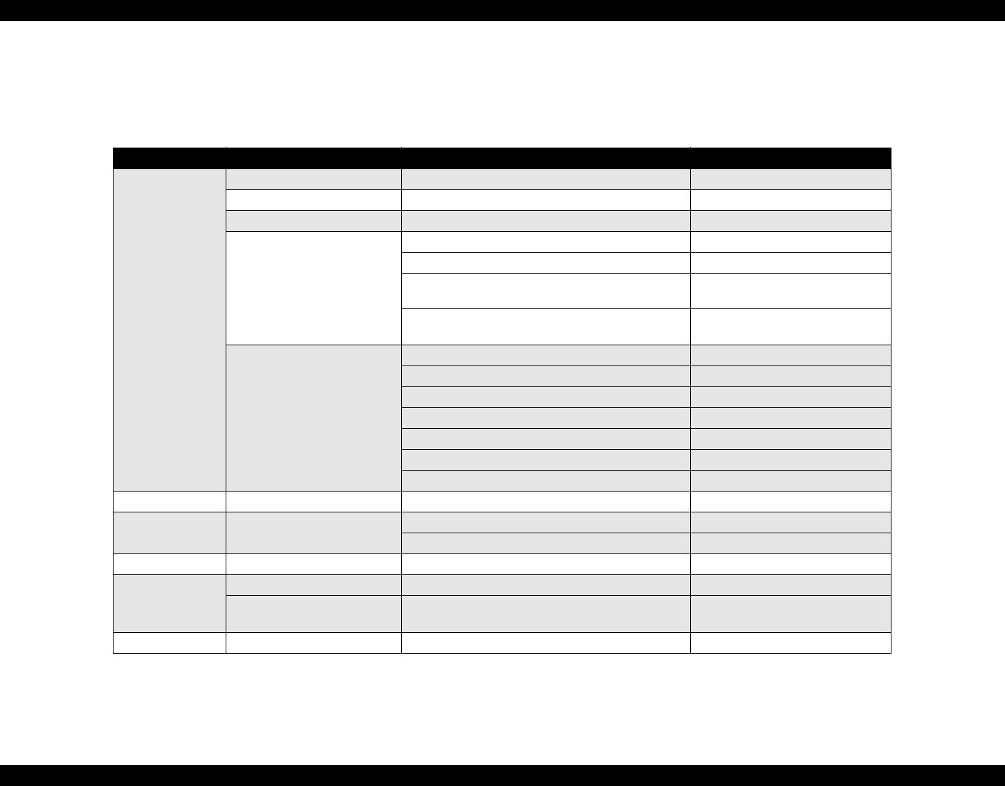
EPSON Stylus Photo 890/1280/1290 Revision C
DISASSEMBLY AND ASSEMBLY Overview 81
4.1.4 Service Checks After Repair
Before returning the printer after servicing, use the check list below, which enables you
to keep record of servicing and shipping more efficiently.
Table 4-3. Inspection Checklist for Repaired Printer
Category Component Item to check Is Check Required?
Printer units
Self-test Is the operation normal? Checked / Not necessary
On-line test Was the on-line test successful? Checked / Not necessary
Printhead Is ink ejected normally from all nozzles? Checked / Not necessary
Carriage mechanism
Does the carriage move smoothly? Checked / Not necessary
Any abnormal noise during movement? Checked / Not necessary
Any dirt or obstacles around the shaft of carriage
guide? Checked / Not necessary
Is the CR motor at the correct temperature
(not over heating)? Checked / Not necessary
Paper feeding mechanism
Is paper fed smoothly? Checked / Not necessary
Does paper get jammed? Checked / Not necessary
Does paper get skew during paper feeding? Checked / Not necessary
Are papers multi fed? Checked / Not necessary
Does the PF motor get overheated? Checked / Not necessary
Abnormal noise during paper feeding? Checked / Not necessary
Is the paper path clear of all obstructions? Checked / Not necessary
Adjustment Specified adjustment items Are adjusted conditions all right? Checked / Not necessary
Lubricant Specified lubricated item Is lubrication applied to the specified locations? Checked / Not necessary
Is the quantity of lubrication adequate? Checked / Not necessary
Function ROM version Newest version: Checked / Not necessary
Shipment package
Ink cartridges are the ink cartridges installed correctly? Checked / Not necessary
Protection conditions during
transport Is all the pointed parts firmly fixed? Checked / Not necessary
Others Attached items Are all attached items from users included? Checked / Not necessary
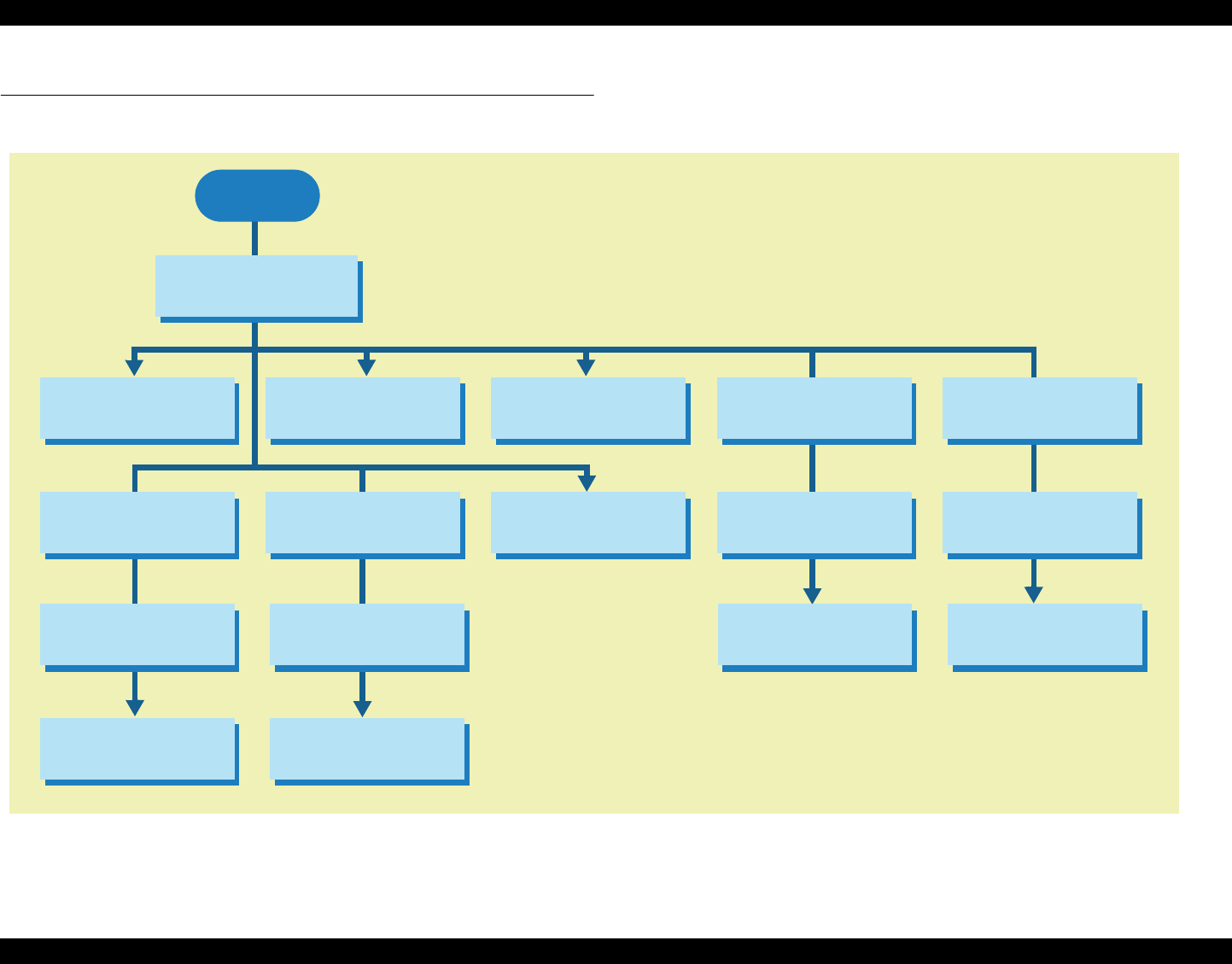
EPSON Stylus Photo 890/1280/1290 Revision C
DISASSEMBLY AND ASSEMBLY Disassembly Procedures 82
4.2 Disassembly Procedures
The flowchart below shows procedures for disassembly.
Figure 4-1. Flowchart of Disassembly
START
HOUSING Removal
MOTOR ASSEMBLY,
CR Removal
DE Unit Removal
PE Sensor Unit
Removal
Printhead Unit
Removal
Panel Unit Removal
TRAY, ABSORBER
ASSEMBLY Removal
Ink Unit Removal
MOTOR ASSEMBLY,
ASF Removal
BOARD ASSEMBLY,
ENCODER Removal
ASF Unit Removal Carriage Unit
Removal
ROLLER, PF Removal
SHAFT, ROLLER,
LD Removal
ROLLER ASSEMBLY,
LD, RIGHT/LEFT MOTOR ASSEMBLY,
PF Removal
START
Circuit Board
Assembly Removal
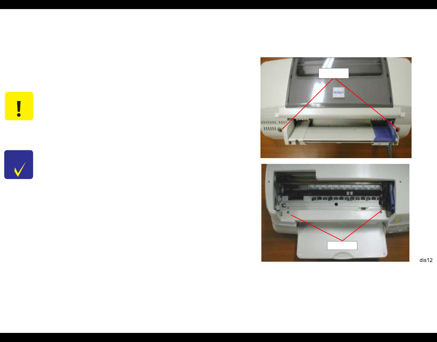
EPSON Stylus Photo 890/1280/1290 Revision C
DISASSEMBLY AND ASSEMBLY Disassembly Procedures 83
4.2.1 HOUSING Removal
Since the printer mechanism itself structures the bottom part, it appears just by
removing HOUSING.
1. Open the printer cover and set the PG adjustment lever to (+).
2. Remove the four screws (CBS, 3x10) securing HOUSING, and remove it.
Figure 4-2. HOUSING Removal
C A U T I O N When removing HOUSING, push it to the rear a little first, and
then lift it up.
CHECK
P O I N T
When installing HOUSING, make sure the PG
adjustment lever is set to (+).
After assembling HOUSING, ensure the head FFC is
not caught in the back of HOUSING.
CBS (3x10)
CBS (3x10)
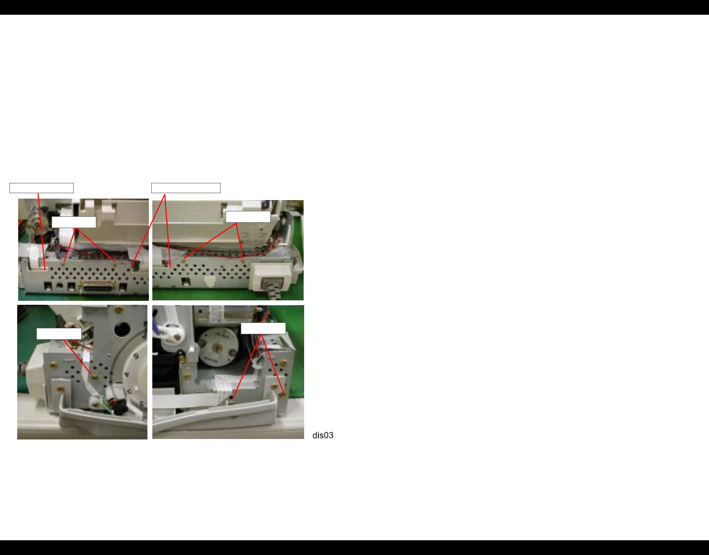
EPSON Stylus Photo 890/1280/1290 Revision C
DISASSEMBLY AND ASSEMBLY Disassembly Procedures 84
4.2.2 Circuit Board Assembly Removal
Since BOARD ASSEMBLY, MAIN and BOARD ASSEMBLY, POWER SUPPLY
are built in a bracket separated from the Printer Mechanism, they can be removed as
one unit.
1. Remove HOUSING. (Refer to Section 4.2.1.)
2. Remove the screws (CBS, 3x6) securing the M/B Unit to the printer mechanism.
Refer to Figure 4-3.
Stylus Photo 890: 7 screws
Stylus Photo 1290: 8 screws
Figure 4-3. Removing the M/B Shield Plate
3. Lifting up SHIELD PLATE, M/B Unit a little, remove COVER, CABLE and
COVER, CABLE; B together with the cables.
4. Disconnect all cables from the connectors on the main board and power supply
board.
CN1(AC Source connector on the power supply board)
CN5 (PE sensor)
CN6 (ASF sensor)
CN15 (ASF/Pump motor)
CN8 (Head FFC)
CN9 (Head FFC)
CN19 (from the secondary side of the PS board)
CN11 (Panel Unit)
CN12 (PF Encoder Sensor)
5. After removing BOARD ASSY, MAIN without cables, remove SHIELD PLATE,
M/B Unit from the printer mechanism.
COVER,
CBS (3x6)
COVER, CABLE
CBS (3x6)
CBS (3x6)
CBS (3x6)
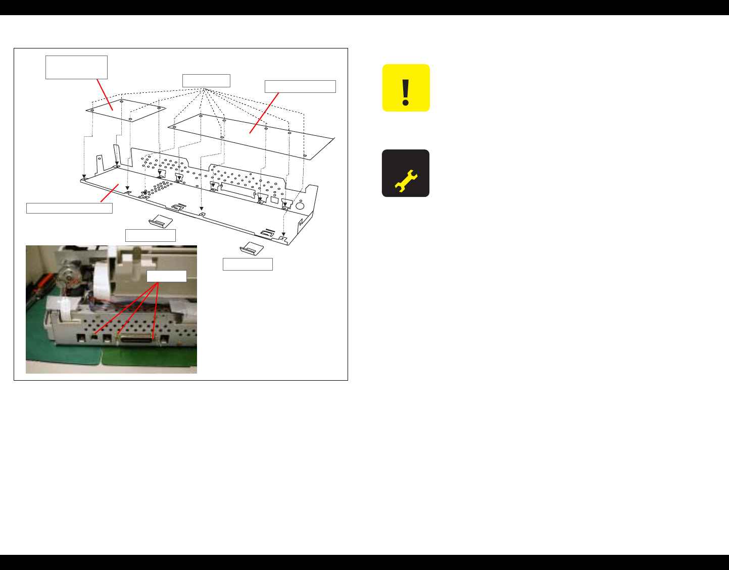
EPSON Stylus Photo 890/1280/1290 Revision C
DISASSEMBLY AND ASSEMBLY Disassembly Procedures 85
Figure 4-4. Circuit Board Removal
6. For removing each circuit board assembly from the M/B Shield Plate, remove the
screws securing each unit and shield plate.
C393MAIN Board: Total 10 screws
7 screws: CBS (3x6)
3 screws: CP (3x6)
C378PSB/PSE Board: Total 4 screws (CBS, 3x6)
C393MAIN Board
Earth Plate
CBS (3x6)
Earth Plate
SHIELD PLATE, M/
CP (3x6)
C378PSB/PSE
Board C A U T I O N Since the CN10 is a locking connector, be sure to unlock it
before disconnecting the cables.
Since the head FFCs have the same number of pins, be sure to
connect them to the right connectors.
When connecting the cables, connect them to the correct
connectors paying attention to the number of the pins.
A D J U S T M E N T
R E Q U I R E D
Be sure to perform the following adjustments when you replace
the Main Board:
1. Head ID input (Refer to Chapter 5.)
2. Bi-D adjustment (Refer to Chapter 5.)
3. USB ID input (Refer to Chapter 5.)
Be sure to replace the following parts when replacing the Main
Board:
1. Waste ink absorbers
2. Ink cartridge (BK & Color)
Note this part replacement is required since several counters stored
in the EEPROM are lost with a Main board replacement.
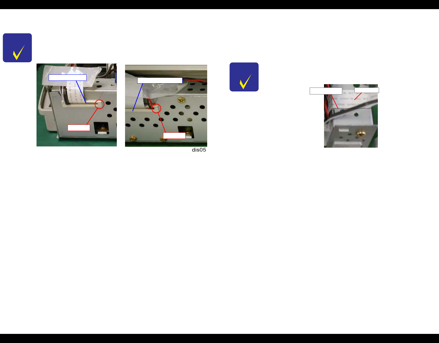
EPSON Stylus Photo 890/1280/1290 Revision C
DISASSEMBLY AND ASSEMBLY Disassembly Procedures 86
4.2.3 Panel Unit Removal
1. Remove HOUSING. (Refer to Section 4.2.1.)
2. Remove the harness for the Panel Unit from the frame in the printer mechanism.
3. Remove 4 screws (CBS, 3x6) securing the Panel Unit together with HOUSING,
REINFORCING, RIGHT to the printer mechanism.
4. Release the hook for the for HOUSING, REINFORCING, RIGHT from the square
cutout in the printer mechanism.
CHECK
P O I N T When installing SHIELD PLATE, M/B to the printer
mechanism, set the cables, COVER CABLE, and COVER,
CABLE; B as shown in the figure below:
Figure 4-5. Setting the Cables to the Cable Covers
COVER, COVER, CABLE; B
Opening
Opening
CHECK
P O I N T When installing the harness to the printer mechanism, be sure to
stick it along the marking line on the frame.
Harness
Marking Line
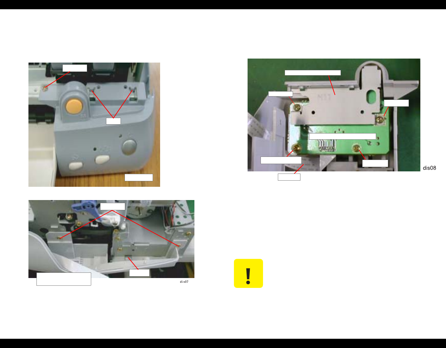
EPSON Stylus Photo 890/1280/1290 Revision C
DISASSEMBLY AND ASSEMBLY Disassembly Procedures 87
5. Remove 1 screw (CBP, 3x8) securing Panel Unit to the printer mechanism and
release the pins fit in the printer mechanism.
Then remove the Panel Unit along with HOUSING, REINFORCING, RIGHT.
Figure 4-6. Panel Unit Removal
6. Remove 2 screws (CBP, 3x8) securing SHIELD PLAT, PANEL to the Panel Unit,
and then remove SHIELD PLATE, PANEL.
Figure 4-7. BOARD ASSEMBLY, PANEL Removal
7. Remove screws (CBP, 3x8 & Cup P-Tite, 3x6) securing BOARD ASSEMBLY
PANEL to the Panel Unit.
8. Disconnect the harness from BOARD ASSEMBLY, PANEL.
HOUSING,
REINFORCING, RIGHT
Cutout
CBS (3x6)
CBS (3x6)
Pins
Panel Unit
C A U T I O N When removing the Panel Unit, watch out for the stacker
assembly. Since the stacker assembly is attached to the Panel
Unit and HOUSING, PANEL, LEFT, if you remove the Panel
Unit, the stacker assembly will also come off.
BOARD ASSEMBLY, PANEL
CBP (3x8)
Harness
Cup P-Tite (3x6) CBP (3x8)
CBP (3x8)
SHIELD PLATE, PANEL
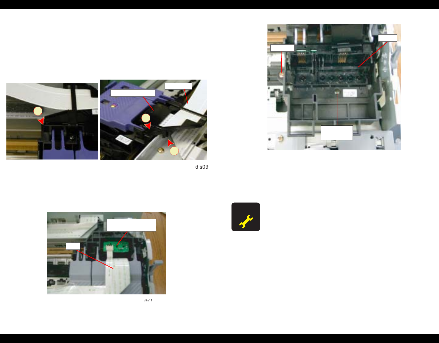
EPSON Stylus Photo 890/1280/1290 Revision C
DISASSEMBLY AND ASSEMBLY Disassembly Procedures 88
4.2.4 Printhead Unit Removal
1. Remove HOUSING. (Refer to Section 4.2.1.)
2. Set the PG lever to the rear.
3. Using tweezers, put the CR lock lever down to unlock the carriage.
4. Release the three hooks (A, B, C) fixing HOLDER, CABLE to the carriage, and
remove HOLDER, CABLE.
Figure 4-8. Printhead Removal
5. Disconnect the head FFC from the connector on the printhead.
6. Remove the FFC from the BOARD ASSEMBLY, ENCODER.
Figure 4-9. Encoder FFC Removal
Figure 4-10. HEAD Removal
7. Move the carriage to the left end of the printer manually.
8. Remove 2 screw (CBP, 3x6 & CCB Sems W2, 2.5x6) securing the printhead to the
carriage, and remove the printhead.
Head FFC
A
B
C
HOLDER, CABLE
BOARD ASSEMBLY,
ENCODER
FFC
A D J U S T M E N T
R E Q U I R E D When you replace the Printhead Unit, perform the following
adjustments:
1. Initial ink charge (Refer to Chapter 5)
2. Head ID Input (Refer to Chapter 5)
3. Bi-D Adjustment (Chapter 5)
CBP (3x6)
HEAD
CBB (W2)
M2.5x6
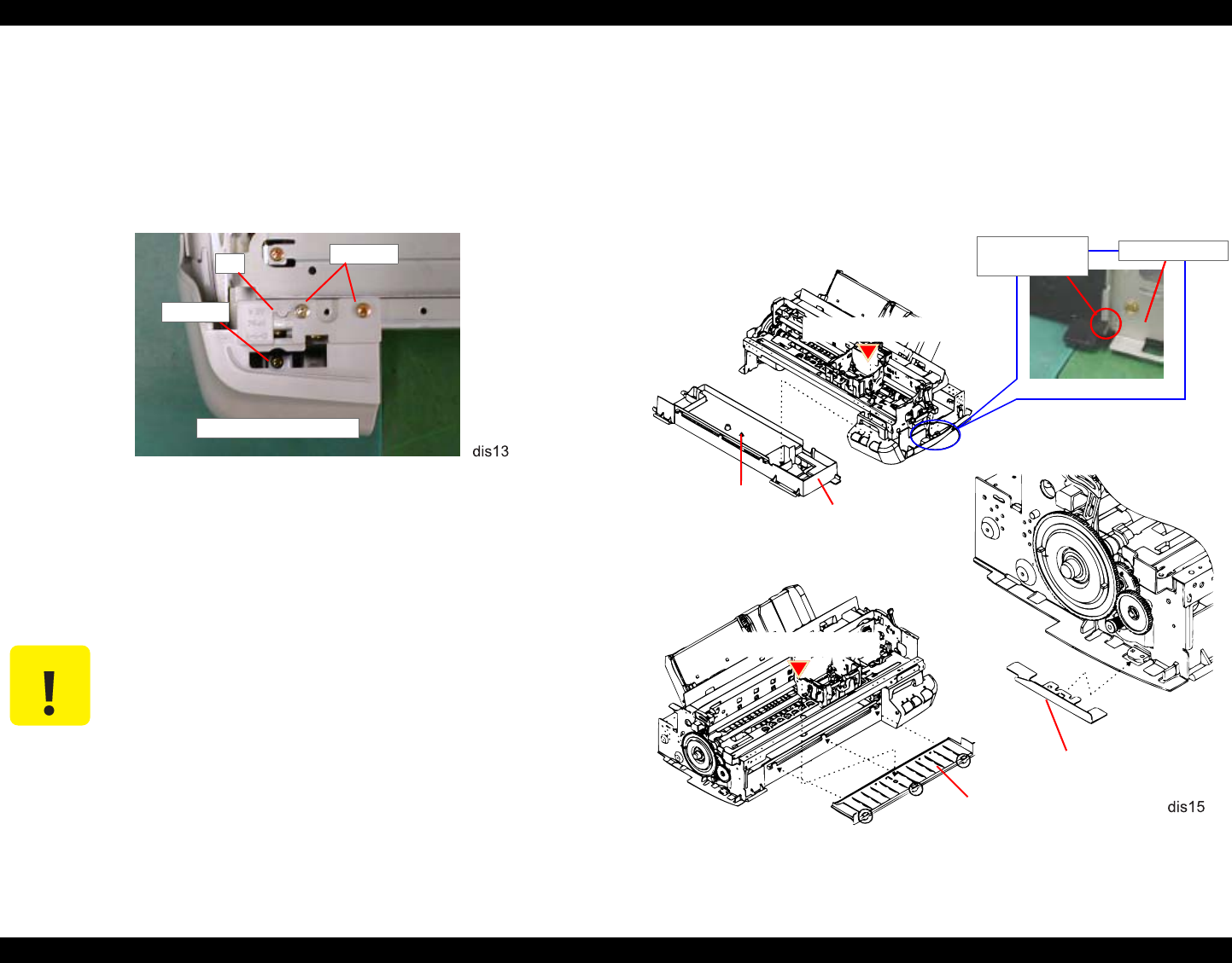
EPSON Stylus Photo 890/1280/1290 Revision C
DISASSEMBLY AND ASSEMBLY Disassembly Procedures 89
4.2.5 TRAY, ABSORBER ASSEMBLY Removal
1. Remove HOUSING. (Refer to Section 4.2.1.)
2. Remove the Panel Unit. (Refer to Section 4.2.3.)
3. Remove 2 screws (CBS, 3x6) securing HOUSING, PANEL, LEFT to the front left
part of the printer mechanism.
Figure 4-11. HOUSING, PANEL, LEFT Removal
4. Remove 1 screw (CBP, 3x8) securing HOUSING, PANEL, LEFT to the
HOUSING, SUB, LEFT.
5. Release the pin fixing HOUSING, PANEL, LEFT to the printer mechanism, and
then remove HOUSING, PANEL, LEFT toward the front.
6. Remove 2 screws (CBS, 3x6) securing HOUSING, SUB, LEFT to the printer
mechanism.
7. Release 3 hooks (2 at the bottom and 1 in the front) fixing HOUSING, SUB, LEFT
to the printer mechanism, and remove HOUSING, SUB, LEFT.
8. Remove 1 or 2 screws (CBP, 3x6: Stylus Photo 890 1 screw, Stylus Photo 1290 2
screws) securing PAPER GUIDE, LOWER to TRAY, ABSORBER ASSEMBLY
at the middle of the printer mechanism, and then remove PAPER GUIDE,
LOWER.
Figure 4-12. TRAY, ABSORBER ASSEMBLY Removal
C A U T I O N When removing HOUSING, PANEL, LEFT, watch out for the
Stacker Assembly. Since the Stacker Assembly is fixed by the
Panel Unit and HOUSING, PANEL, LEFT, it will come off as
HOUSING, PANEL, LEFT is removed.
HOUSING, PANEL, LEFT
Pin CBS (3x6)
CBP (3x8)
ABSORBER,
WASTE INK,
LARGE/SMALL
CBP (3x8)
TRAY, ABSORBER
CBP (3x8)
SPACER, TRAY
PAPER GUIDE,
LOWER
FRAME,
Hook in TRAY,
ABSORBER

EPSON Stylus Photo 890/1280/1290 Revision C
DISASSEMBLY AND ASSEMBLY Disassembly Procedures 90
9. Removing 1 screw (CBP, 3x8) securing TRAY, ABSORBER ASSEMBLY to the
right part of the printer mechanism.
10. Remove SPACER, TRAY securing TRAY, ABSORBER to the left side of the
printer mechanism, and then remove TRAY, ABSORBER by moving it
downward.
11. Remove ABSORBER, WASTE INK, LARGE/ SMALL from TRAY,
ABSORBER.
C A U T I O N When installing TRAY, ABSORBER ASSEMBLY to the
printer mechanism, make sure they are securely jointed with
SPACER, TRAY. Refer to Figure 4-12.
Be careful not to damage SCALE, PF, (loop scale) when
installing SPACER, TRAY.
When installing ABSORBER ASSEMBLY, make sure the Ink
Tube is correctly placed in the ABSORBER ASSEMBLY. If
not, it may cause an ink leakage.
A D J U S T M E N T
R E Q U I R E D
If you replace TRAY, ABSORBER ASSEMBLY, be sure to
perform the Waste ink counter reset operation. (Refer to
Chapter.)
When installing TRAY, ABSORBER ASSEMBLY to the
printer mechanism, make sure it securely joins to FRAME,
RIGHT by its hook in the right.
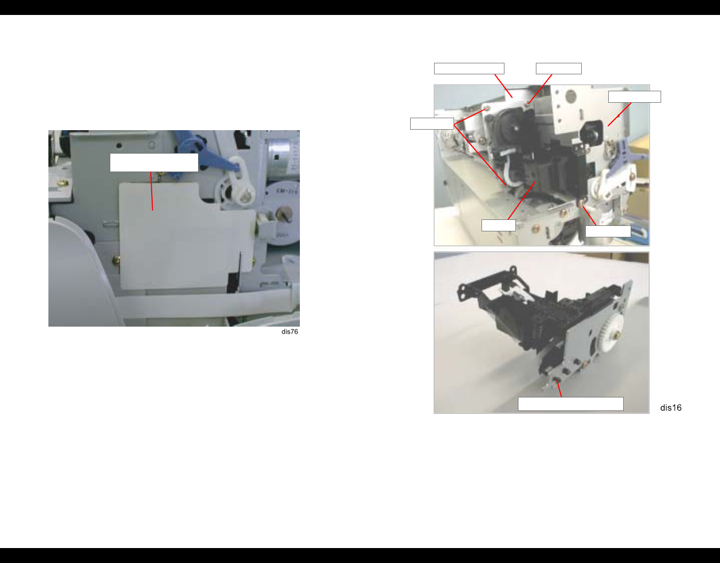
EPSON Stylus Photo 890/1280/1290 Revision C
DISASSEMBLY AND ASSEMBLY Disassembly Procedures 91
4.2.6 Ink Unit Removal
NOTE: Ink Unit consists of the Pump Unit, Cleaner Head, and Cap Assembly.
1. Remove HOUSING. (Refer to Section 4.2.1.)
2. Remove the Panel Unit. (Refer to Section 4.2.3.)
3. Remove SHEET, INK STOPPER.
Figure 4-13. SHEET, INK STOPPER Removal
4. Remove TRAY, ABSORBER ASSEMBLY. (Refer to Section 4.2.5.)
5. Remove the three screws (CBS, 3x6) securing the Ink Unit to the FRAME,
MIDDLE.
6. Remove 3 screws (CBS, 3x6) securing the Ink Unit to FRAME, TOP. Then
remove the Ink System Assembly.
7. Release the hook fixing the Cap Assembly to the Ink Unit, and then remove the
Cap Assembly.
8. Disconnect the tube from the Cap Assembly.
Figure 4-14. Ink Unit Removal
SHEET, INK STOPPER
CBS (3x6)
Ink Unit
Hook in the Cap Assembly
FRAME, MIDDLE CBS (3x6)
CBS (3x6)
FRAME, TOP
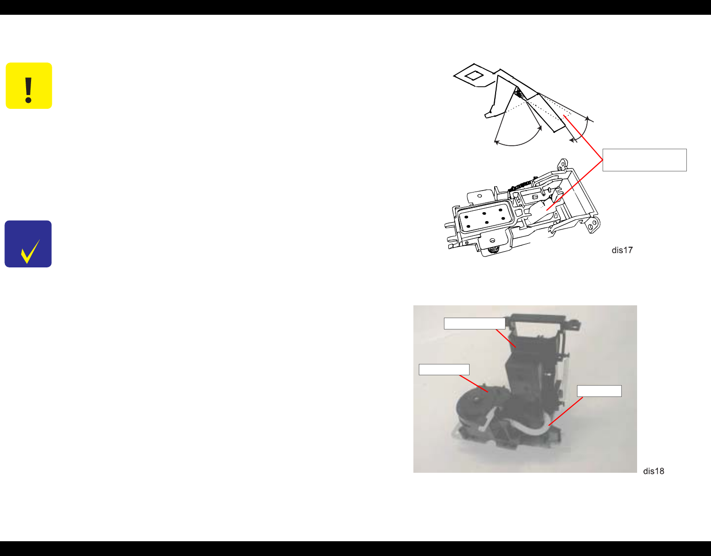
EPSON Stylus Photo 890/1280/1290 Revision C
DISASSEMBLY AND ASSEMBLY Disassembly Procedures 92
Figure 4-15. Setting the ABSORBER, SLIDER, CAP
Figure 4-16. Ink Tube Installation (1)
C A U T I O N 1. When handling CLEANER, HEAD, note the points below:
Do not touch CLEANER, HEAD with your bare hands.
Ware gloves or use tweezers.
Do not smear CLEANER, HEAD with oil or grease.
When installing CLEANER, HEAD, set the rubber side
(black side) facing to the right.
2. When replacing the Cap Assembly, do not touch its sealing
rubber part.
When assembling, make sure the Ink Tube is correctly placed
at the correct position. If not, it may cause an ink leakage.
CHECK
P O I N T
1. When assembling the Cap Assembly to the Ink System
Assembly, make sure ABSORBER, SLIDER, CAP is assembled
in the cap assembly. ABSORBER, SLIDER, CAP should be set
as shown in Figure 4-15 in advance.
2. Check that the ink tube is securely connected to the connection
part of the Cap Assembly. (See Figure 4-16.) Also, make sure
the tube is not bent or crushed by the connection area. (See
Figure 4-17.)
3. Check that the ink tube is placed correctly in the Ink System.
(See to Figure 4-16.) Pay special attention in connecting the tube
to the Pump Unit. Connect the tube by strictly following the
instruction given in Figure 4-18.
4. When assembling, be careful not to crush or leave any stress on
the ink tube that connects the Pump Unit and Cap Assembly.
Also,
5. After installing the Pump Unit, ensure that CLEANER, HEAD
moves back and forth with rotation of the gear.
About 60-90°ABSORBER,
SLIDER, CAP
About 45°
Cap Assembly
Pump Unit
Ink Tube
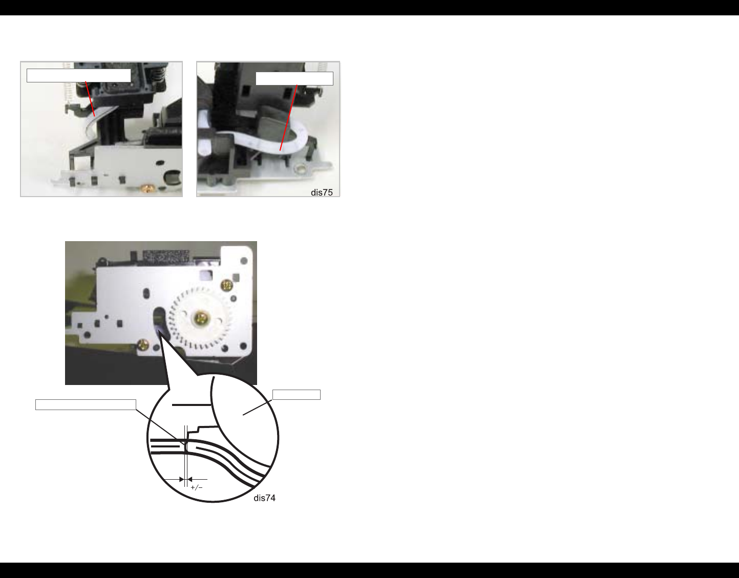
EPSON Stylus Photo 890/1280/1290 Revision C
DISASSEMBLY AND ASSEMBLY Disassembly Procedures 93
Figure 4-17. Ink Tube Installation (2)
Figure 4-18. Connecting the Tube to the Pump Unit
Tube is not stretched out. Tube is not bent.
Pump Unit
Marking line on the tube
2 mm
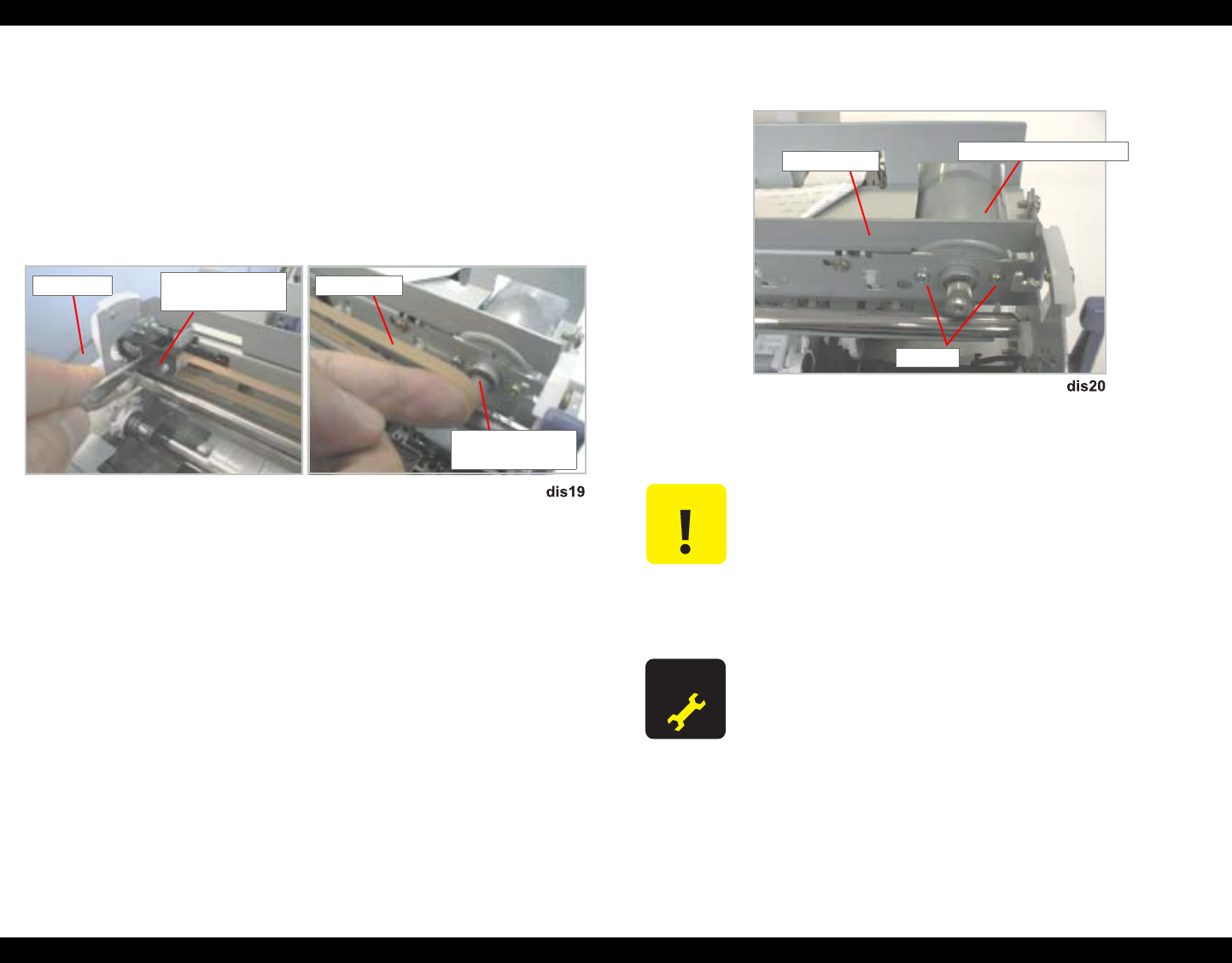
EPSON Stylus Photo 890/1280/1290 Revision C
DISASSEMBLY AND ASSEMBLY Disassembly Procedures 94
4.2.7 MOTOR ASSEMBLY, CR Removal
1. Remove HOUSING. (Refer to Section 4.2.1)
2. Using tweezers or a small screw driver, put the carriage lock lever down to the
front, and then slide the carriage to the middle of the printer mechanism.
3. Push the HOLDER, PULLEY, DRIVEN to loosen the CR Timing Belt, and then
disengage the timing belt from the pulley on the CR motor.
Figure 4-19. Timing Belt Removal
4. Disconnect the connector for MOTOR ASSEMBLY, CR from the connector on
the main board. (Refer to Section 4.2.2.)
5. Remove 2 screws (CP, 3x6) securing MOTOR ASSEMBLY, CR to FRAME,
TOP, and then remove MOTOR ASSEMBLY, CR.
Figure 4-20. MOTOR ASSEMBLY, CR Removal
Pulley in MOTOR
ASSEMBLY, CR
SCALE, HOLDER, PULLEY,
DRIVEN Timing Belt
C A U T I O N When pushing HOLDER, PULLEY, DRIVEN, be careful not
to damage SCALE, PF (loop scale).
When releasing the timing belt, be careful not to damage
SCALE, CR (linear encoder).
When removing MOTOR ASSEMBLY, CR, be sure not to hit
the edge of the installation hole with the motor’s pulley.
A D J U S T M E N T
R E Q U I R E D
When removing MOTOR ASSEMBLY, CR, execute Bi-D
adjustment. See “Bi-Directional Adjustment“on page 133.
CP (3x6)
FRAME, TOP MOTOR ASSEMBLY, CR
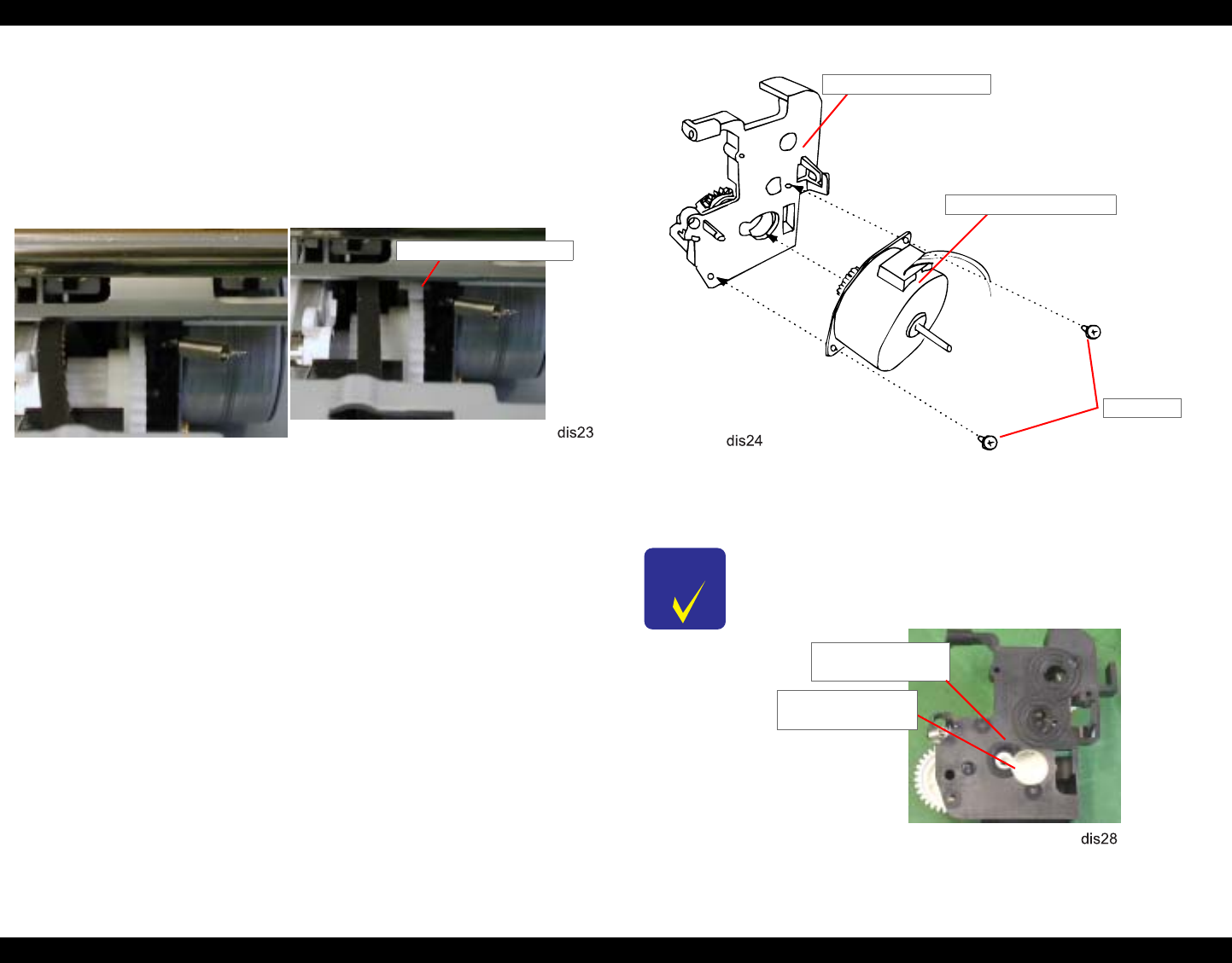
EPSON Stylus Photo 890/1280/1290 Revision C
DISASSEMBLY AND ASSEMBLY Disassembly Procedures 95
4.2.8 MOTOR ASSEMBLY, ASF Removal
1. Remove HOUSING (Refer to Section 4.2.1.)
2. Remove the harness for MOTOR ASSEMBLY, ASF from the main board. (Refer
to Section 4.2.2.)
3. Lower LEVER, PLANETARY UNIT.
Figure 4-21. Setting LEVER, PLANETARY UNIT
4. Remove 2 screws (CBP, 3x8) securing MOTOR ASSEMBLY, ASF to
BRACKET, MOTOR, ASF. Then push the motor assembly to the rear and then to
the right to remove it.
Figure 4-22. MOTOR ASSEMBLY, ASF Removal
[Lever is held up.] [Lever is lowered.]
LEVER, PLANETARY
CHECK
P O I N T When installing MOTOR, ASSEMBLY, ASF5, make sure the
DE unit and LEVER, PLANETARY UNIT are set as shown
below:
CBP (3x8)
BRACKET, MOTOR, ASF
MOTOR ASSEMBLY, ASF
DE Unit (BRACKET,
MOTOR, ASF)
LEVER,
PLANETARY UNIT
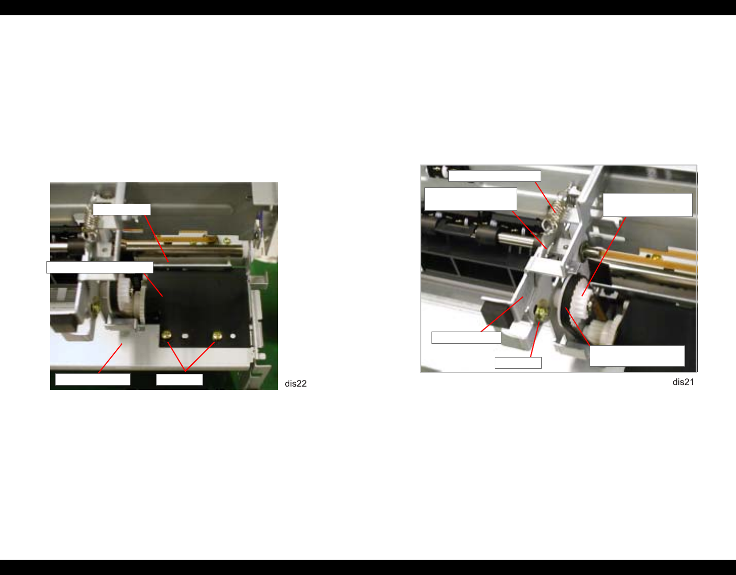
EPSON Stylus Photo 890/1280/1290 Revision C
DISASSEMBLY AND ASSEMBLY Disassembly Procedures 96
4.2.9 DE Unit Removal
1. Remove HOUSING (Refer to Section 4.2.2.)
2. Remove MOTOR ASSEMBLY, CR. (See Section 4.2.7.)
3. Remove the Ink Unit. (Refer to Section 4.2.6.)
4. Remove 2 screws (CBS, 3x6) securing SHEET, PROTECTION INK to FRAME,
BOTTOM, and then remove the sheet.
Figure 4-23. SHEET, PROTECTION, INK Removal
5. Remove MOTOR, CR. (Refer to Section 4.2.7.)
6. Loosen 1 (CBS, 3x6) securing the LEVER ASSEMBLY, COMBINATION
GEAR to FRAME, MIDDLE.
7. Remove the tension sprig (7.37) hung to FRAME MIDDLE and LEVER
ASSEMBLY, COMBINATION GEAR, and then remove TENSION BELT,
PUMP, TRANSMISSION from the combination gear (12, 22.92).
Figure 4-24. TENSION BELT, PUMP, TRANSMISSION Removal
FRAME, TOP
CBS (3x6)
SHEET, PROTECTION, INK
FRAME, BOTTOM
TENSION BELT, PUMP,
TRANSMISSION
TENSION SPRING, 7.37
LEVER ASSEMBLY,
COMBINATION GEAR
FRAME, MIDDLE
CBS (3x6)
COMBINATION
GEAR, 12, 22.92
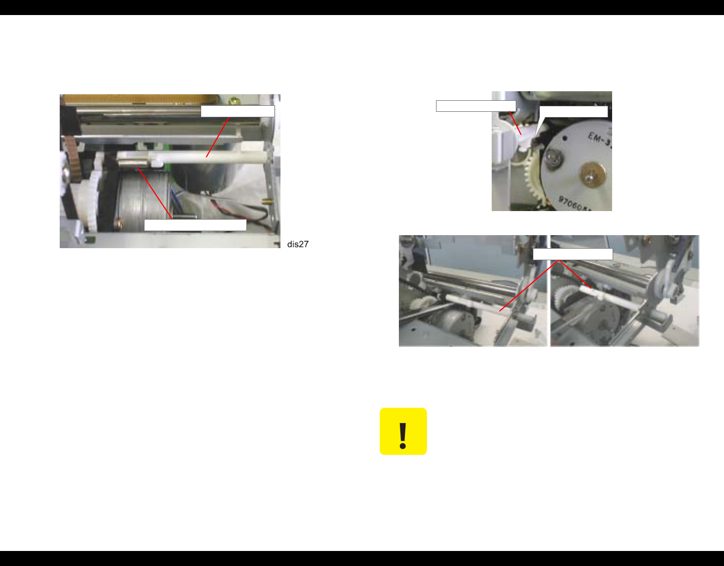
EPSON Stylus Photo 890/1280/1290 Revision C
DISASSEMBLY AND ASSEMBLY Disassembly Procedures 97
8. Remove the tension spring (0.618) attached to the LEVER, DE, LOCK and DE
Unit.
Figure 4-25. TENSION SPRING, 0.618 Removal
9. Release the hook in the DE Unit (BRACKET, MOTOR, ASF) securing LEVER,
DE, LOCK. Then push the lever out to the right to release it from the installation
hole in the DE Unit and remove it.
Figure 4-26. LEVER, DE, LOCK Removal
LEVER, DE,
TENSION SPRING, 0.618
C A U T I O N When removing LEVER, DE, LOCK, be careful not to break the
hook in the DE Unit.
Locking position
LEVER, DE, LOCK
LEVER, DE, LOCK
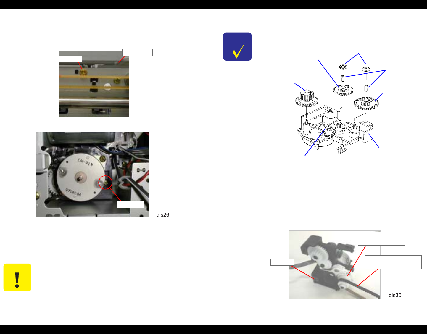
EPSON Stylus Photo 890/1280/1290 Revision C
DISASSEMBLY AND ASSEMBLY Disassembly Procedures 98
10. Remove the CBS screw (3x6) and CBP (3x8) screw securing the DE unit to
FRAME, MIDDLE and FRAME, TOP, respectively. Then remove DE unit.
Figure 4-27. DE Unit Removal
11. Remove the harnesses from the harness clamp in the DE Unit.
C A U T I O N Be sure to remove the screw (CBP, 3x8) carefully so you do not
damage the linear encoder (SCALE, CR).
CBP (3x6)
CBP (3x8)
SCALE, CR
CHECK
P O I N T
Check that all gears are assembled in the DE unit correctly as
shown in the figure below:
Figure 4-28. Parts Layout in DE Unit
Before assembling MOTOR ASSEMBLY, ASF to the DE Unit,
set LEVER, PLANETARY UNIT to the pump side. (See Figure
4-28.)
Set TENSION BELT, PUMP, TRANSMISSION to the 17.19
gear of the Combination Gear (17.19, 25.6) before securing the
DE unit to FRAME, MIDDLE.
Combination Gear,
12, 22.4
Combination Gear,
17.19, 25.6
LEVER, PLANETARY UNIT
Combination
Gear, 14, 28
Felt, D3.6
Retaining Ring, D8.8
BRACKET,
MOTOR, ASF
Combination Gear,
17.19, 25.6
TENSION BELT, PUMP,
TRANSMISSION
DE Unit
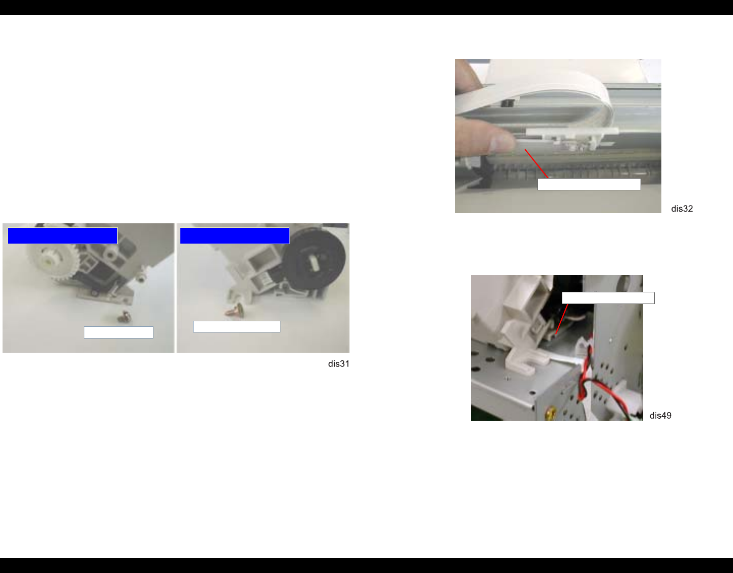
EPSON Stylus Photo 890/1280/1290 Revision C
DISASSEMBLY AND ASSEMBLY Disassembly Procedures 99
4.2.10 ASF Unit Removal
1. Remove HOUSING. (Refer to Section 4.2.1.)
2. Remove the following cables from the cable clamp in the left side of the ASF
Assembly.
ASF HP sensor cable
MOTOR ASSEMBLY, PF cable
3. Disconnect the ASF HP sensor cable from the connector on the sensor.
4. Remove the head FFC from the ASF Unit.
5. Remove 1 screw (CBS Sems, 3x6) and SHAFT, MOUNT, CR that are securing
the ASF Unit to FRAME, BOTTOM at the rear right and rear left, respectively.
Figure 4-29. ASF Unit Removal (1)
6. Tilting the paper support sub unit, release the hook fixing the ASF Unit to
FRAME, BOTTOM, and remove the ASF Unit toward the rear.
Figure 4-30. ASF Unit Removal (2)
Figure 4-31. ASF Unit Removal (3)
ASF viewed from the left
ASF viewed from the right
CBS Sems (3x6) SHAFT, MOUNT, CR
Paper Support Sub Unit
Hook in the ASF Unit
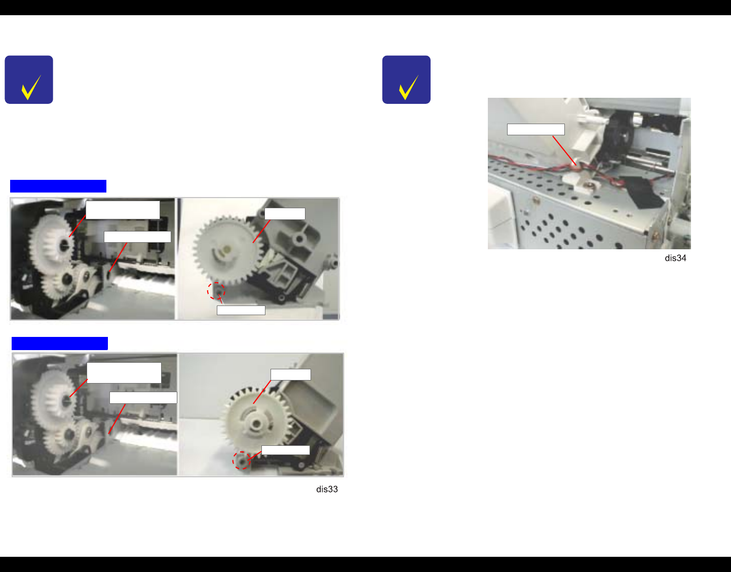
EPSON Stylus Photo 890/1280/1290 Revision C
DISASSEMBLY AND ASSEMBLY Disassembly Procedures 100
Figure 4-32. Check Points in ASF Assembly
CHECK
P O I N T
When installing the ASF assembly to FRAME, BOTTOM, make
sure the protrusion on the ASF fits in the installation hole in
FRAME, MIDDLE. (See Figure 4-32.)
When installing the ASF Unit, ensure the spur gear 32 in the
ASF Unit and the inner gear of the combination gear (14, 28) in
the DE Unit are meshed. (See Figure 4-32.)
When installing the ASF Unit, make sure the Hopper Assembly
is raised.
Stylus Photo 890
Stylus Photo 1290
Protrusion
Gear 32
Installation Hole
Gear 32
Combination Gear
14, 28
Installation Hole
Protrusion
Combination Gear
14, 28
CHECK
P O I N T
When connecting the cables for ASF HP sensor and MOTOR
ASSEMBLY, PF, set them in the cable clamp in the rear left part
of the ASF Unit as shown in the figure below:
Cable Clamp
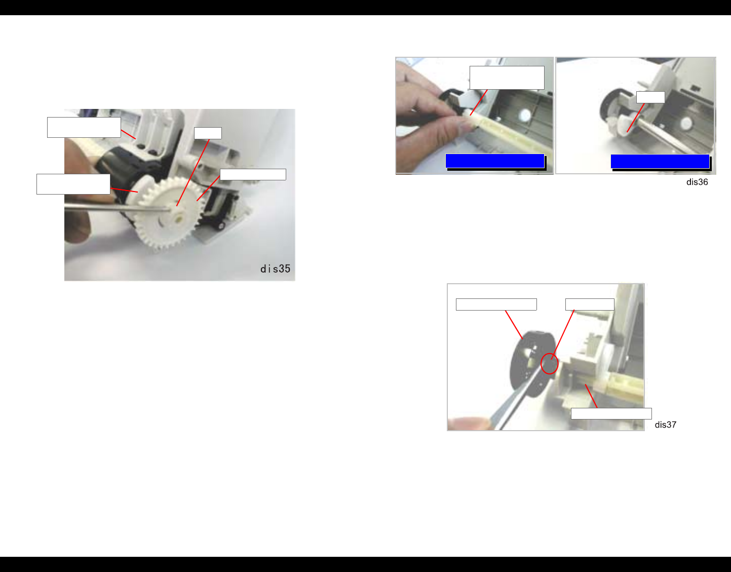
EPSON Stylus Photo 890/1280/1290 Revision C
DISASSEMBLY AND ASSEMBLY Disassembly Procedures 101
4.2.10.1 SHAFT, ROLLER, LD Removal
1. Remove the ASF Unit. (Refer to Section 4.2.10.)
2. Releasing the hook on Gear, 32, remove the gear from SHAFT, ROLLER, LD.
Figure 4-33. SPUR GEAR, 32 Removal
3. Remove LEVER, HOPPER, RELEASE from the right end of SHAFT, ROLLER,
LD.
4. Remove HOLDER, SHEET, PAPER FEED from the right and left LD roller units.
5. Move the left LD roller assembly to the middle and then:
Stylus Photo 890:
Remove BUSHING, FIXING, LEFT from the left end of
SHAFT, ROLLER, LD
Stylus Photo 1290:
Remove the E-ring from the left end of SHAFT, ROLLER,
LD.
Figure 4-34. BUSHING, FIXING, SHAFT/E-Ring Removal
6. Move SHAFT, ROLLER, LD to the left.
7. Release the fixing tab in WHEEL, DETECTOR, and then remove WHEEL,
DETECTOR from SHAFT, ROLLER, LD.
Figure 4-35. WHEEL, DETECTOR Removal
HOLDER, SHEET,
PAPER FEED
LEVER, HOPPER,
RELEASE
Hook
SPUR GEAR, 32
Stylus Photo 890 Stylus Photo 1290
BUSHING, FIXING,
SHAFT, LEFT
E-Ring
WHEEL, DETECTOR Fixing Tab
SHAFT, ROLLER, LD
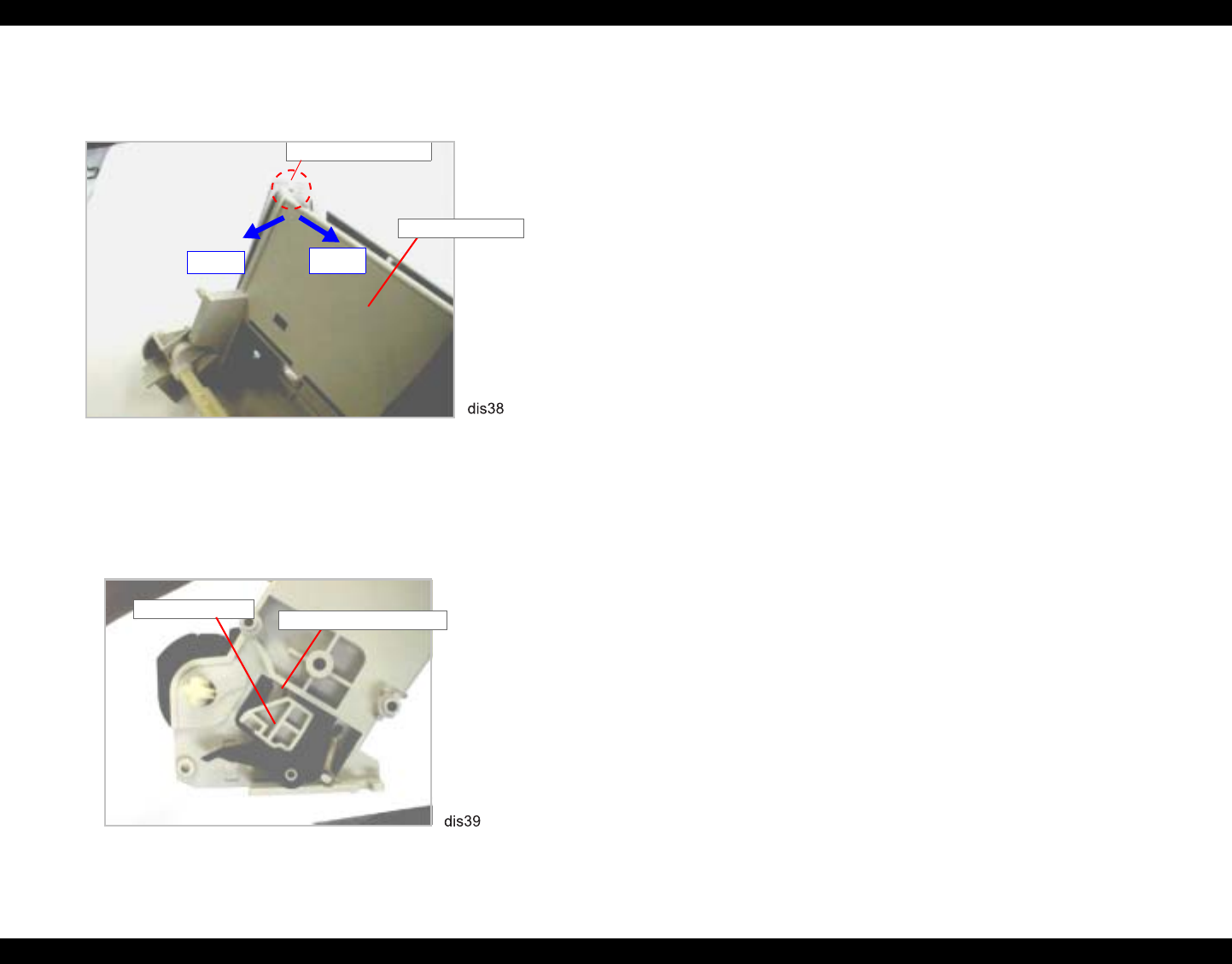
EPSON Stylus Photo 890/1280/1290 Revision C
DISASSEMBLY AND ASSEMBLY Disassembly Procedures 102
8. Release the Hopper Assembly from the pin in the top left corner of ASF, FRAME;
B in the order indicated with arrows in the figure below.
Figure 4-36. Hopper Assembly Removal (1)
9. Releasing the Hopper Assembly from the protrusion at the top right edge of
FRAME, ASF; B, detach the arm of the Hopper Assembly from the square cutout
in the right frame of FRAME, ASF; B.
Figure 4-37. Hopper Assembly Removal (2)
10. Using tweezers, remove the left and right compression springs (1.961) from the
Hopper Assembly and FRAME, ASF; B. (See Figure 4-38.)
11. Lifting up the right edge of SHAFT, ROLLER, LD a little, remove the shaft by
pulling it out to the right along with LD rollers. (See Figure 4-38.)
12. Remove the left LEVER, HOPPER, RELEASE from SHAFT, ROLLER, LD. (See
Figure 4-38.)
13. Remove the LD roller assemblies from SHAFT, ROLLER, LD. (See Figure 4-38.)
Step 2 Step 1
Pin in FRAME, ASF;B
Hopper Assembly
Hopper Assembly Cutout in FRAME, ASF; B
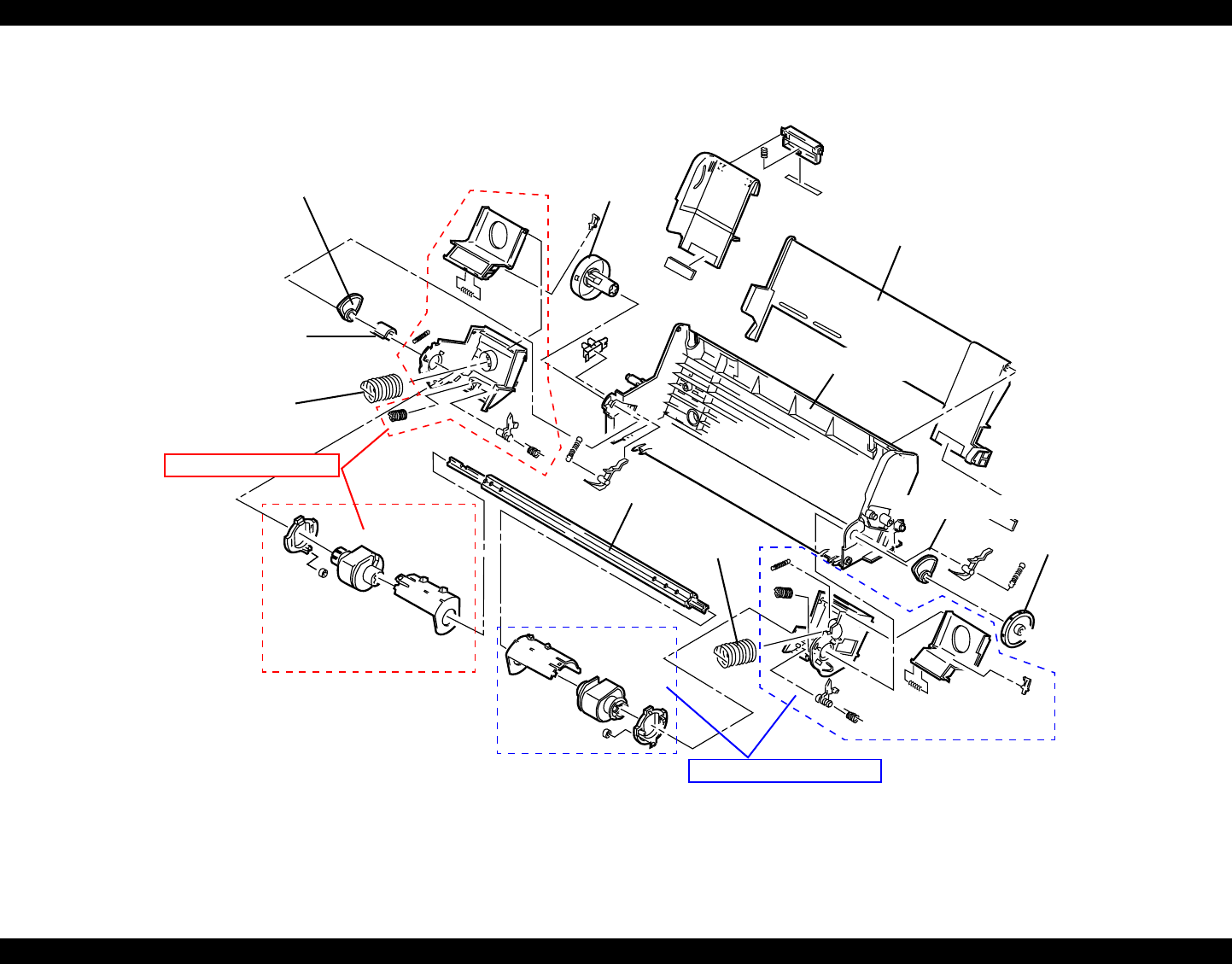
EPSON Stylus Photo 890/1280/1290 Revision C
DISASSEMBLY AND ASSEMBLY Disassembly Procedures 103
Figure 4-38. Hopper Assembly Removal/ASF Unit Disassembly
LEVER, HOPPER, RELEASE WHEEL
DETECTOR
Hopper Assembly
Gear, 32
FRAME, ASF;B
COMPRESSION SPRING, 1.961
Right LD Roller Assembly
BUSHING, FIXING, SHAFT, LEFT
Left LD Roller Assembly
LEVER, HOPPER, RELEASE
COMPRESSION
SPRING, 1.961
SHAFT,
ROLLER, LD
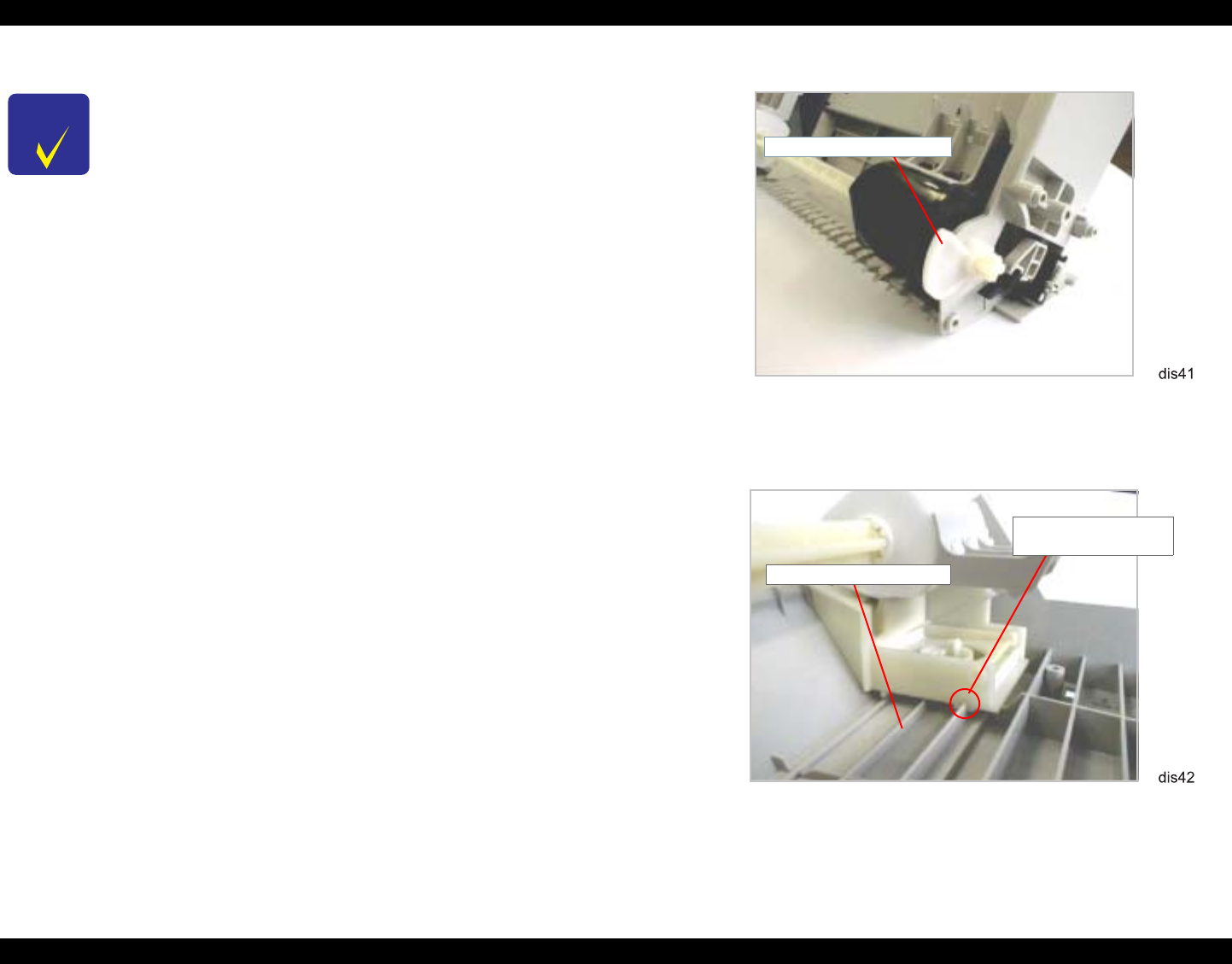
EPSON Stylus Photo 890/1280/1290 Revision C
DISASSEMBLY AND ASSEMBLY Disassembly Procedures 104
Figure 4-39. LEVER, HOPPER, RELEASE Installation
Figure 4-40. LD Roller Assembly Installation (1)
CHECK
P O I N T
While assembling the ASF Unit, be careful not to smear any
parts with oil on the cam parts. If oil gets other parts, it should
be wiped off.
When installing LEVER, HOPPER, RELEASE, set it in the
correct direction. (See Figure 4-39.)
Be sure to attach the following parts to SHAFT, ROLLER, LD
securely. (See Figure 4-38.)
- BUSHING, FIXING, SHAFT, LEFT (white plastic part)
- WHEEL, DETECTOR (black plastic part)
When installing the LD Roller Assemblies to SHAFT,
ROLLER, LD, make sure the black one (right LD Roller
Assembly) goes to the right.
When setting the right and left LD Roller Assemblies, align
their grooves with the rail rib in FRAME, ASF; B. (See Figure
4-40.)
LEVER, HOPPER,
RELEASE
Rail Rib in FRAME, ASF; B
Groove in the LD Roller
Assembly
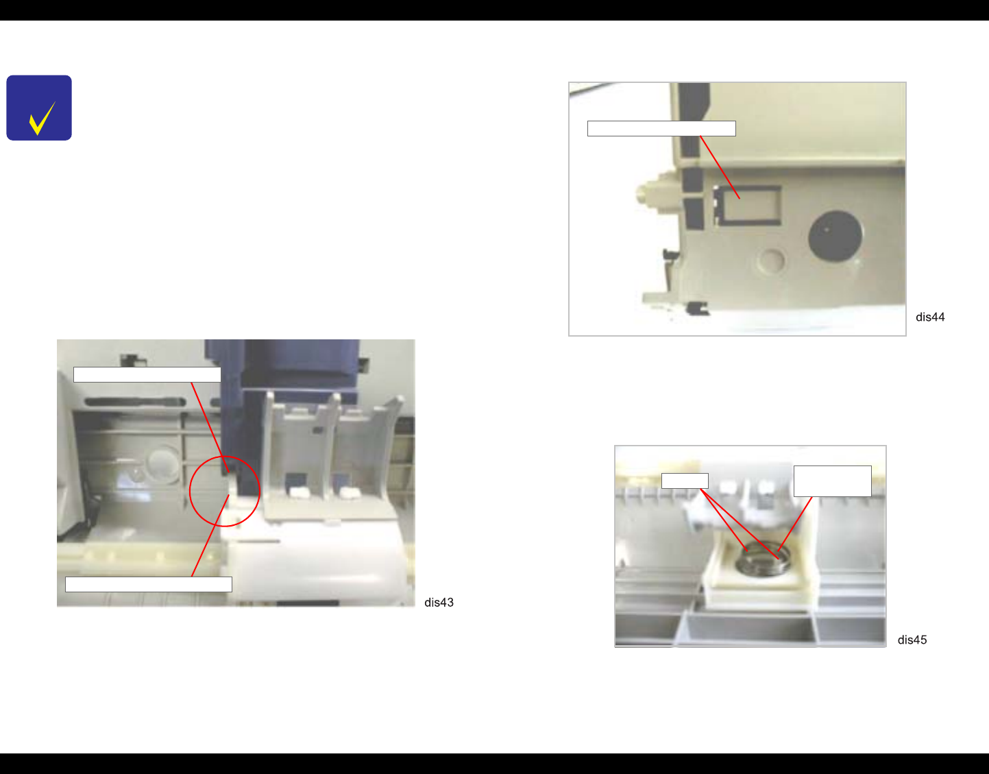
EPSON Stylus Photo 890/1280/1290 Revision C
DISASSEMBLY AND ASSEMBLY Disassembly Procedures 105
Figure 4-41. LD Roller Assembly Installation (2)
Figure 4-42. Hook Fixing the LD Roller Assembly
Figure 4-43. Holding Compression Spring with the Hooks
CHECK
P O I N T
When installing the edge guide to the left LD Roller Assembly,
ensure that the rib in the LD Roller Assembly fits correctly into
the groove in the edge guide. (See Figure 4-41.)
Make sure that the right LD Roller Assembly is fixed with the
hook in FRAME, ASF; B. You can check its condition from the
back of the ASF Unit. (See Figure 4-42.)
Before assembling the ASF Unit, hold each compression spring
(1.961) with the hook of the spring bearing in the Hopper
Assembly. Then, after attaching the Hopper Assembly to
FRAME, ASF; B, release the springs from the hooks through
the cutouts in the back of the frame. (See Figure 4-43.)
Rib in the LD Roller Assembly
Groove in the Edge Guide
Hook in the FRAME, ASF; B
Hooks Compression
Spring 1.961
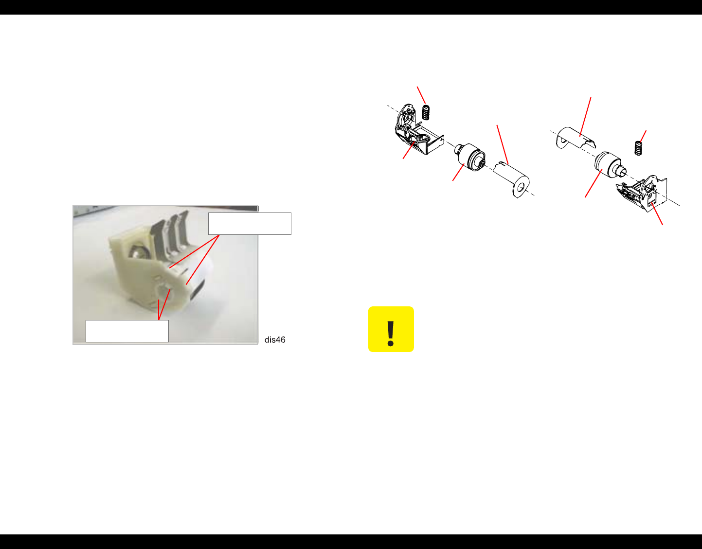
EPSON Stylus Photo 890/1280/1290 Revision C
DISASSEMBLY AND ASSEMBLY Disassembly Procedures 106
4.2.10.2 ROLLER ASSEMBLY, LD, RIGHT/LEFT Removal
1. Remove the ASF Unit. (Refer to Section 4.2.10.)
2. Remove SHAFT, ROLLER, LD. (Refer to Section 4.2.10.1.)
3. Release the hooks in COVER, ROLLER, LD, RIGHT/LEFT (two hooks in each)
fixing itself to LD ASSEMBLY, RIGHT/LEFT, and then remove the COVER,
ROLLER, LD, RIGHT/LEFT.
4. Release the hooks in ROLLER ASSEMBLY, LD, RIGHT/LEFT (two hooks in
each) securing itself to LD ASSEMBLY, RIGHT/LEFT. Then remove ROLLER
ASSEMBLY, LD, RIGHT/LEFT.
Figure 4-44. Hooks to Release
Figure 4-45. ROLLER ASSEMBLY, LD, RIGHT/LEFT Removal
Hooks in ROLLER
ASSEMBLY, LD, LEFT
Hooks in COVER,
ROLLER, LD, LEFT
C A U T I O N Do not touch the surface of the ROLLER ASSEMBLY, LD with
your bare hands.
Compression
Spring, 1.961
ROLLER ASSY.,
LD, LEFT
COVER,
ROLLER, LD,
ROLLER ASSY,
LD, RIGHT
Compression
Spring, 1.961
LD ASSY., RIGHT
LD ASSY., LEFT
COVER, ROLLER,
LD, LEFT
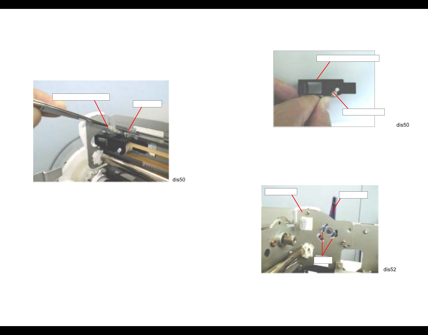
EPSON Stylus Photo 890/1280/1290 Revision C
DISASSEMBLY AND ASSEMBLY Disassembly Procedures 107
4.2.11 Carriage Unit Removal
1. Remove HOUSING. (Refer to Section 4.2.1)
2. Disconnect the head FFC from the printhead. (Refer to Section 4.2.4.)
3. Remove the Tension Spring 1.494 hanging SCALE, CR to the left side of
FRAME, TOP. Then remove SCALE, CR.
Figure 4-46. Remove the Tension Spring 1.491& CR Encoder Slit
4. Loosen the Timing Belt by pushing HOLDER, PULLEY, DRIVEN and disengage
the belt from the pulley of the CR motor. (Refer to Figure 4-20.)
5. Push PULLEY, DRIVEN down and remove it from HOLDER, PULLEY,
DRIVEN.
Figure 4-47. PULLEY, DRIVEN Removal
6. Remove the Timing Belt from PULLEY, DRIVEN.
7. Remove LEVER, PG by releasing its hooks from the cutouts in the right side of
FRAME, TOP. Then remove the LEVER, PG.
Figure 4-48. LEVER, PG Removal
SCALE, CR
TENSION SPRING, 1.494
PULLEY, DRIVEN
HOLDER, PULLEY,
FRAME, TOP
Hooks
LEVER, PG
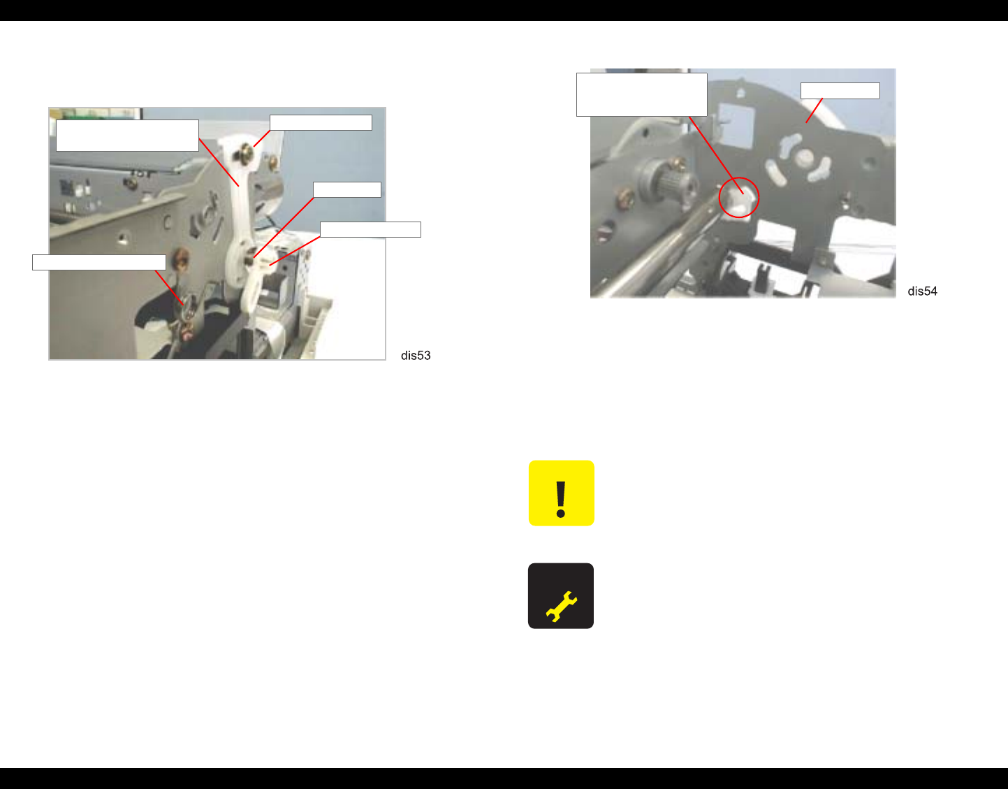
EPSON Stylus Photo 890/1280/1290 Revision C
DISASSEMBLY AND ASSEMBLY Disassembly Procedures 108
8. Remove the torsion spring (63.7) hung onto FRAME, TOP and LEVER, PG.
Figure 4-49. LEVER, PG, SUB Removal
9. Remove LEVER, PG from LEVER, PG, SUB.
10. Release the hook fixing LEVER, PG, SUB to SHAFT, CR, GUIDE. Then remove
LEVER, PG, SUB and 1 leaf spring (6.2x0.15x11).
11. Remove 1 screw (CBS Tite Sems R2, 3x6) securing BUSHING, PARALLELISM
ADJUSTMENT, RIGHT to FRAME, TOP.
12. Rotate BUSHING, PARALLELISM ADJUSTMENT, RIGHT to align its notch
with the cutout in FRAME, TOP. Then remove the bushing.
Figure 4-50.
BUSHING, PARALLELISM ADJUSTMENT, RIGHT Removal
13. Remove SHAFT, CR, GUIDE from FRAME, TOP together with the Carriage
Unit.
14. Remove SHAFT, CR, GUIDE and the oil pad from the Carriage Unit.
BUSHING, PARALLELISM
ADJUSTMENT, RIGHT
CBS Tite Sems R2
Leaf Spring
LEVER, PG, SUB
TORSION SPRING, 63.7
C A U T I O N Do not touch SCALE, CR (linear scale) with your bare hands,
because if its surface is dirty or damaged, it will cause the
carriage to operate abnormally.
Do not touch SCALE, PF (loop scale) with your bare hands,
because if its surface is dirty or damaged, it will adversely
affect paper feeding accuracy.
A D J U S T M E N T
R E Q U I R E D
If you replace the Carriage Unit, perform the Platen Gap
Adjustment.
FRAME, TOP
Notch in BUSHING,
PARALLELISM
ADJUSTMENT,
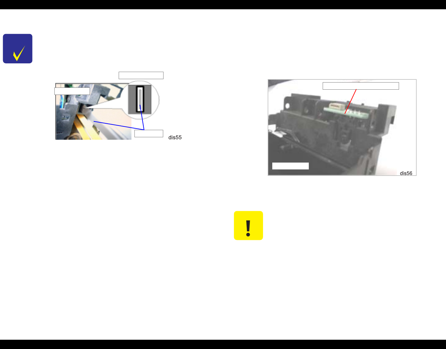
EPSON Stylus Photo 890/1280/1290 Revision C
DISASSEMBLY AND ASSEMBLY Disassembly Procedures 109
4.2.12 BOARD ASSEMBLY, ENCODER Removal
1. Remove the head FFC. (Refer to Section 4.2.4.)
2. Pushing BOARD ASSEMBLY, ENCODER (linear encoder) to the rear, remove it
upward.
Figure 4-51. BOARD ASSEMBLY, ENCODER Removal
CHECK
P O I N T
When installing the Leaf Spring (6.2x 0.15x11), set it with its
convex side facing inward. Refer to Figure 4-49.
After setting SCALE, CR through the slot for the sensor in the
Carriage Unit, ensure that it is not in contact with either side of
the slot by viewing them from the side.
When installing SHAFT, CR, GUIDE, make sure that the oil
pad is set in the correct position.
Slit for the sensor
SCALE, CR
Carriage Unit
C A U T I O N When removing BOARD ASSEMBLY, ENCODER, be sure not
to force it out using a screw driver or equivalent. Otherwise, the
sensor mounting position in the Carriage Unit may be damaged.
When installing BOARD ASSEMBLY, ENCODER, be careful
not to mar SCALE, CR.
Make sure SCALE, CR and the sensor are not in contact.
BOARD ASSEMBLY, ENCODER
Carriage Unit
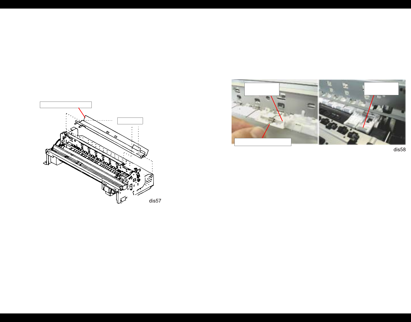
EPSON Stylus Photo 890/1280/1290 Revision C
DISASSEMBLY AND ASSEMBLY Disassembly Procedures 110
4.2.13 ROLLER, PF Removal
1. Remove HOUSING. (Refer to Section 4.2.1)
2. Remove the Panel Unit. (Refer to Section 4.2.3.)
3. Remove HOUSING, PANEL, LEFT. (Refer to Section 4.2.5.)
4. Remove the ASF Unit. (Refer to Section 4.2.10.)
5. Remove the Carriage Unit. (Refer to Section 4.2.11.)
6. Remove the three screws (CBS, 3x6) securing GUIDE PLATE, CR Unit to
FRAME, TOP. Then remove GUIDE PLATE, CR Unit.
Figure 4-52. GUIDE PLATE, CR Unit Removal
7. Remove PAPER GUIDE, RIGHT Unit and the five PAPER GUIDE, UPPER Unit
(eight for Stylus Photo 1290) from FRAME, TOP in the manner described below:
PAPER GUIDE, UPPER Unit
Remove the torsion spring (117.6). Then remove the unit to the rear.
PAPER GUIDE, RIGHT Unit
Remove the torsion spring (117.6). Then remove the unit to the front.
Figure 4-53. PAPER GUIDE, UPPER/RIGHT Unit Removal
8. Release the hook securing PAPER GUIDE, LEFT* to FRAME, TOP. Then shift
the unit to the left first, and remove it to the rear.
* PAPER GUIDE, LEFT is not assembled in Stylus Photo 1290.
CBS (3x6)
GUIDE PLATE, CR Unit
PAPER GUIDE,
UPPER Unit
TORSION SPRING, 117.6
PAPER GUIDE,
RIGHT Unit
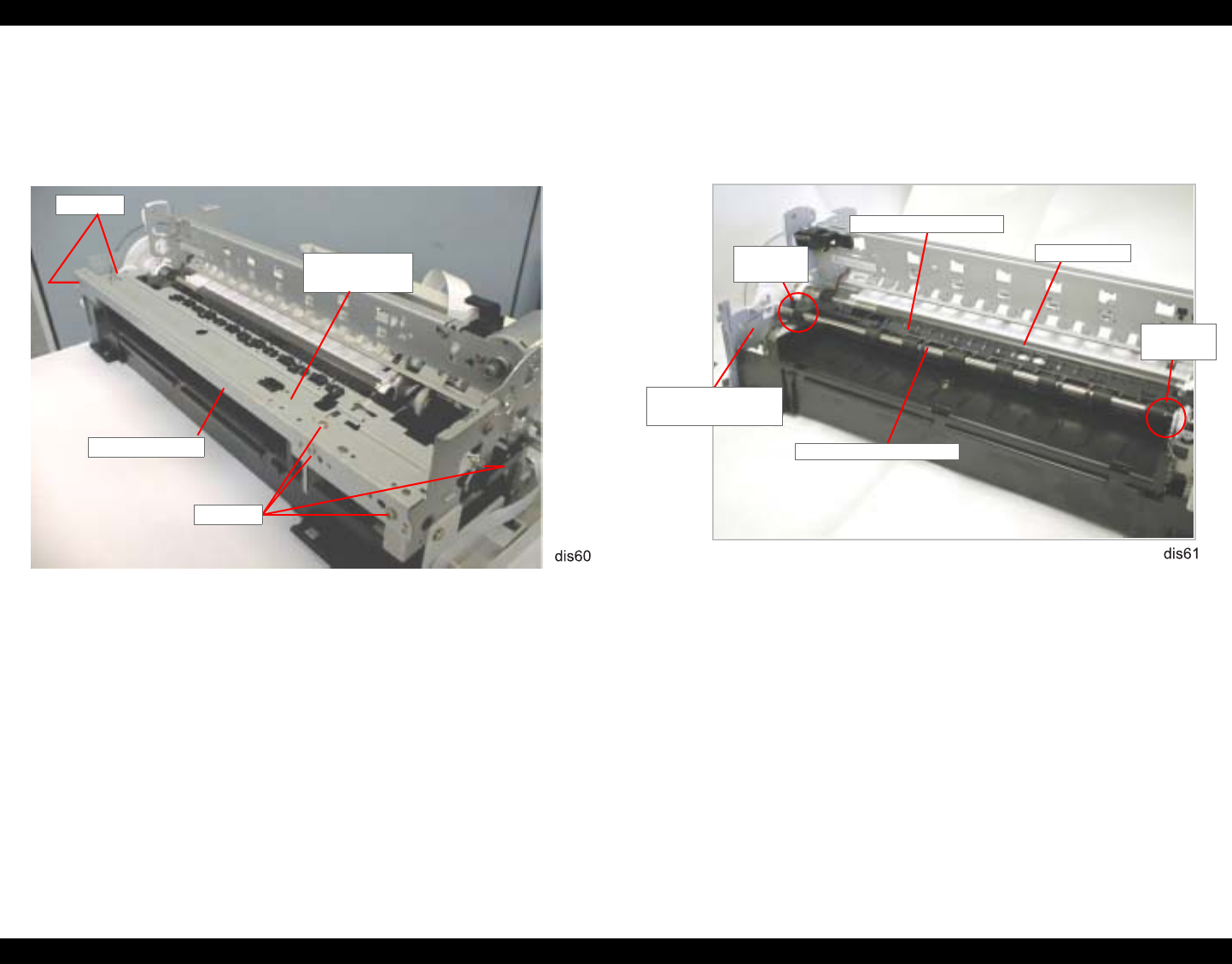
EPSON Stylus Photo 890/1280/1290 Revision C
DISASSEMBLY AND ASSEMBLY Disassembly Procedures 111
9. Remove the three screws (CBS, 3x6) securing FRAME, TOP to the printer
mechanism. Then remove FRAME, TOP.
10. Remove the three screws (CBS, 3x6) securing FRAME, PAPER EJECT Unit to
the printer mechanism, and then remove FRAME, PAPER EJECT Unit.
Figure 4-54. FRAME, FRONT/FRAME, PAPER EJECT Removal
11. Remove PAPER GUIDE, FRONT from ROLLER, PF by releasing its two U-
shaped forks fixing ROLLER, PAPER EJECT.
12. Remove CONTACT SPRING, PAPER EJECT hung to FRAME, LEFT and
ROLLER, PAPER EJECT.
Figure 4-55. PAPER GUIDE, FRONT Removal
FRAME, FRONT
CBS (3x6)
FRAME, PAPER
EJECT Unit
CBS (3x6)
ROLLER, PAPER
PAPER GUIDE,
ROLLER,
U-Shaped
Forks
U-Shaped
Forks
CONTACT
SPRING, PAPER
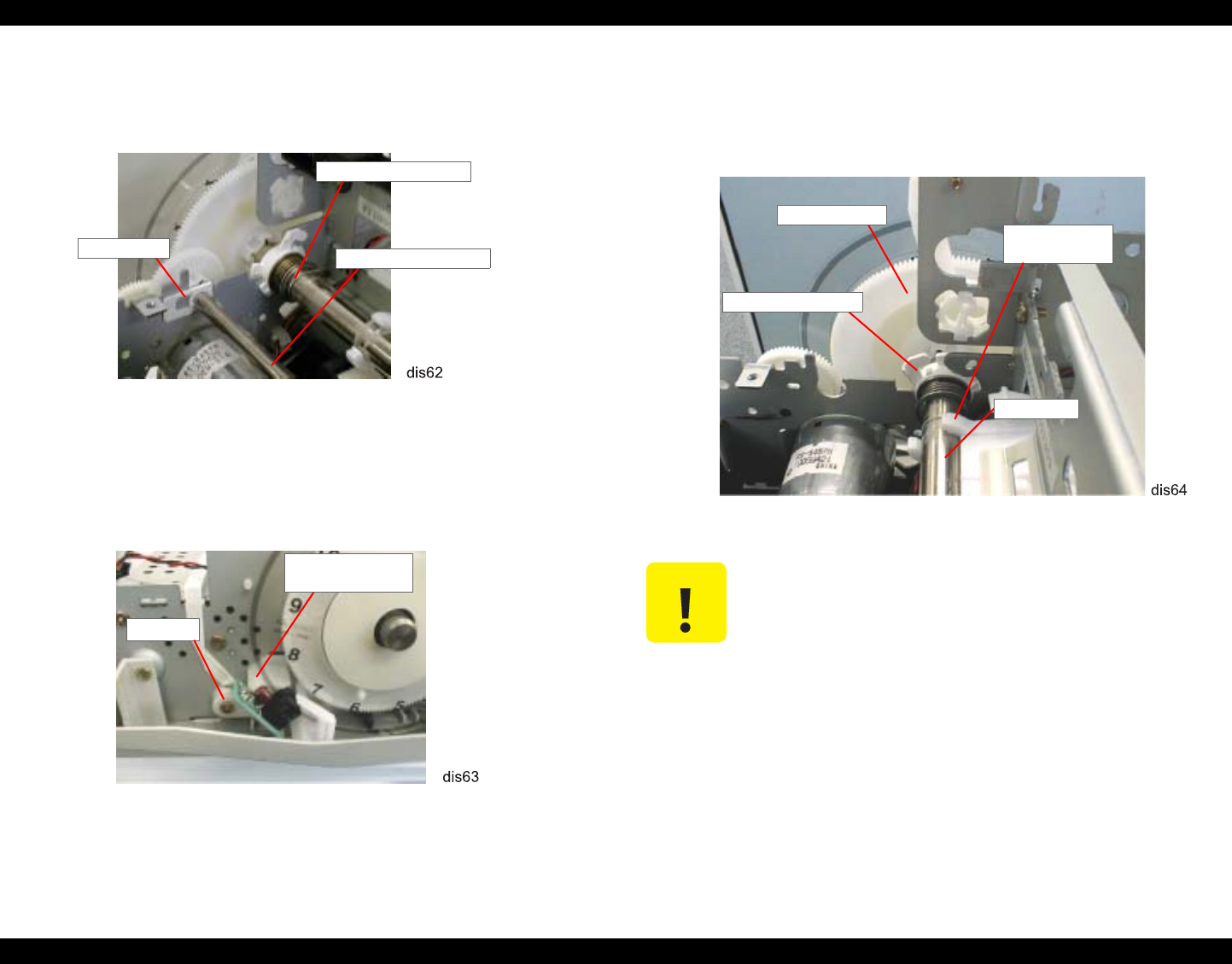
EPSON Stylus Photo 890/1280/1290 Revision C
DISASSEMBLY AND ASSEMBLY Disassembly Procedures 112
13. Raise 2 bushings (6) attached to the right and left ends of ROLLER, PAPER
EJECT to release them from FRAME, LEFT and FRAME, MIDDLE. Them
remove ROLLER, PAPER EJECT.
Figure 4-56. ROLLER, PAPER EJECT Removal
14. Remove 1 screw (CBS, 3x6) securing BRACKET, BOARD ASSEMBLY to
FRAME, LEFT together with BOARD ASSEMBLY, ENCODER (PF Encoder
Sensor). Then remove BRACKET, BOARD ASSEMBLY.
Figure 4-57. PF Encoder Removal
15. Remove CONTACT SPRING, PF hung to ROLLER, PF and FRAME, BOTTOM.
(Refer to Figure 4-56.)
16. Unhook BUSHING, 12, LEFT attached to the left end of ROLLER, PF and then
turn the bushing until it is aligned with the cutout in FRAME, LEFT.
17. Release ROLLER, PF from the hook in PAPER GUIDE, REAR, and then remove
ROLLER, PF.
Figure 4-58. ROLLER, PF Removal
CONTACT SPRING, PF
BUSHING, 6 ROLLER, PAPER
CBS (3x6)
BRACKET, BOARD
ASSEMBLY C A U T I O N During disassembly/assembly, be careful not to bend or damage
SCALE, PF.
Do not touch SCALE, PF with your bare hands. Also, be careful
not to damage its surface since it is coated with special material
to improve accuracy in paper feeding.
Avoid touching the tooth plane of SPUR GEAR 76 attached to
the left end of ROLLER, PF. (See Figure 4-58.)
SPUR GEAR, 76
BUSHING, 12, LEFT
ROLLER, PF
Hook in PAPER
GUIDE, REAR
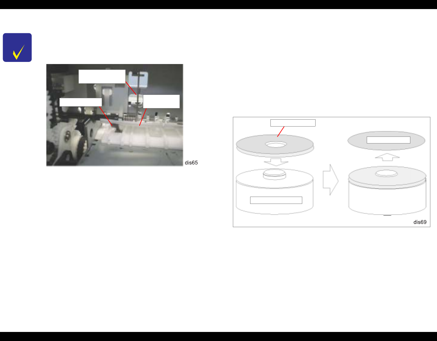
EPSON Stylus Photo 890/1280/1290 Revision C
DISASSEMBLY AND ASSEMBLY Disassembly Procedures 113
4.2.13.1 SCALE, PF Installation
This section describes how to install the following parts:
SCALE, PF (Loop Scale)
BRACKET, SCALE
TAPE, D50 (Double-sided adhesive tape)
1. Get “Mounting Plate Scale Attachment tool”. (AS Tool code: 1051765)
2. Place BRACKET, SCALE on the tool with its taped side facing upward.
3. Peel off the protection sheet from the tape on BRACKET, SCALE.
Figure 4-60. Pre-operation for BRACKET, SCALE Installation
CHECK
P O I N T
When installing PAPER GUIDE, RIGHT to FRAME, TOP
with the torsion spring, insert PAPER GUIDE, RIGHT Unit
from the front making sure the PE sensor lever is set in the hole
of the paper guide.
Figure 4-59. PAPER GUIDE, RIGHT Installation
When mounting the torsion springs (117.6) to PAPER GUIDE,
UPPER / PAPER GUIDE, RIGHT, fit the arm of each torsion
spring (117.6) in the groove of the corresponding paper guide.
When installing CONTACT SPRING, PF, fit the loop of the
spring in the groove near the left end of ROLLER, PF.
If you replace SCALE, PF (loop scale) or SPUR GEAR (76),
you are required to install a new SCALE, PF using the specified
tools. (Refer to the next section.)
TORSION SPRING,
117.6
PE Sensor Lever PAPER GUIDE,
RIGHT Unit
Protection Sheet
Tool (Code: 1051765)
BRACKET,
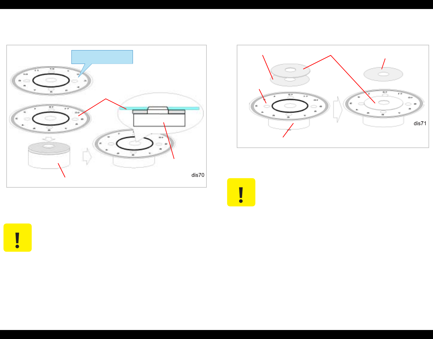
EPSON Stylus Photo 890/1280/1290 Revision C
DISASSEMBLY AND ASSEMBLY Disassembly Procedures 114
4. Set SCALE, PF onto BRACKET, SCALE with its front side facing downward.
Figure 4-61. Attaching SCALE, PF
5. Remove the base sheet of TAPE, D50 and stick it to SCALE, PF.
Figure 4-62. TAPE, D50 Installation
6. Peel off the protection sheet from TAPE, D50 on SCALE, PF.
C A U T I O N Do not touch the following areas:
- Inner side of the SCALE, PF’s shaft hole through which the
PF Roller Shaft is installed.
- Printed face of SCALE, PF
If BRACKET, SCALE is not aligned with the circle printed on
SCALE, PF, it should not be a problem.
Tool
(Code: 1051765)
SCALE,
Set the scale’s front side
facing downward.
Tool (Code: 1051765) C A U T I O N If TAPE, D50 is not aligned with the circle printed on SCALE,
PF, it should not be a problem.
TAPE, D50 Protection Sheet
SCALE,
Tool (Code: 1051765)
Protection Sheet
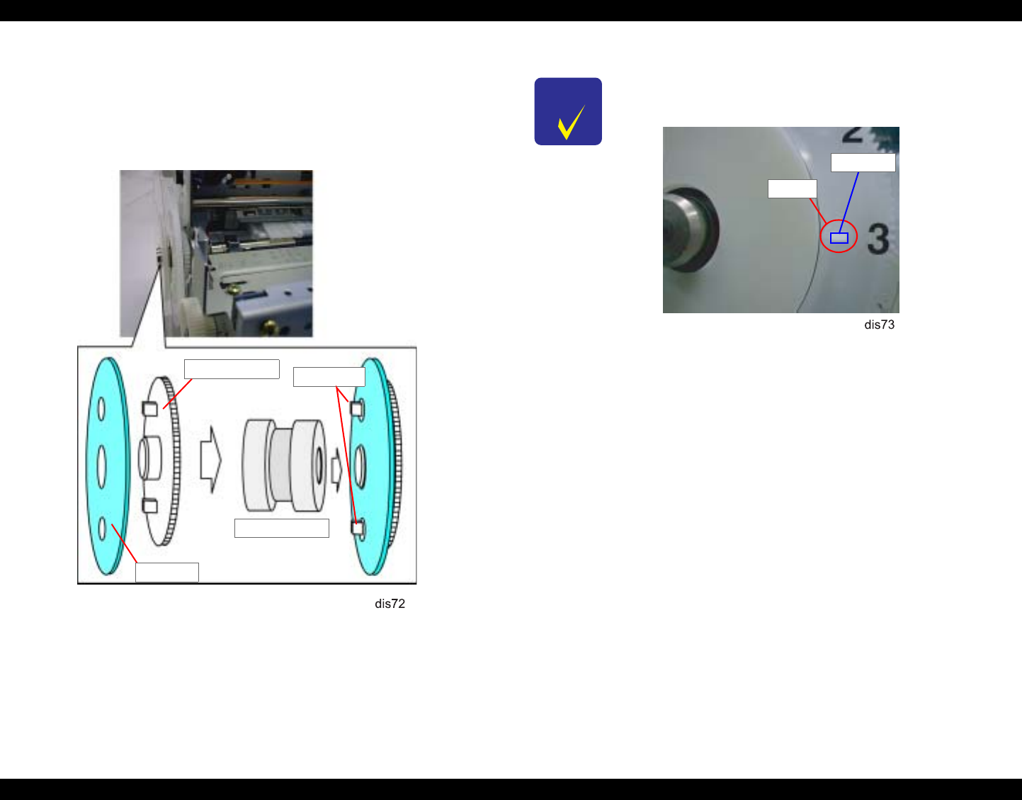
EPSON Stylus Photo 890/1280/1290 Revision C
DISASSEMBLY AND ASSEMBLY Disassembly Procedures 115
7. Fit the round cutouts in SCALE, PF to the protrusions on SPUR GEAR (76)
making sure the scale and the gear are parallel. But note you don’t attach the scale
to the gear yet.
8. Attach SCALE, PF to the gear using “Scale PF unit Assembling tool” (AS tool
code: 1051767).
Figure 4-63. Loop Scale Installation
SPUR GEAR, 76 Protrusions
Tool (#1051767)
SCALE, PF
CHECK
P O I N T
Check that the protrusions on the gear (76) are sticking out
from the cutouts in the scale.
Ensure SCALE, PF is free form any dirt or damage.
Cutout
Protrusion
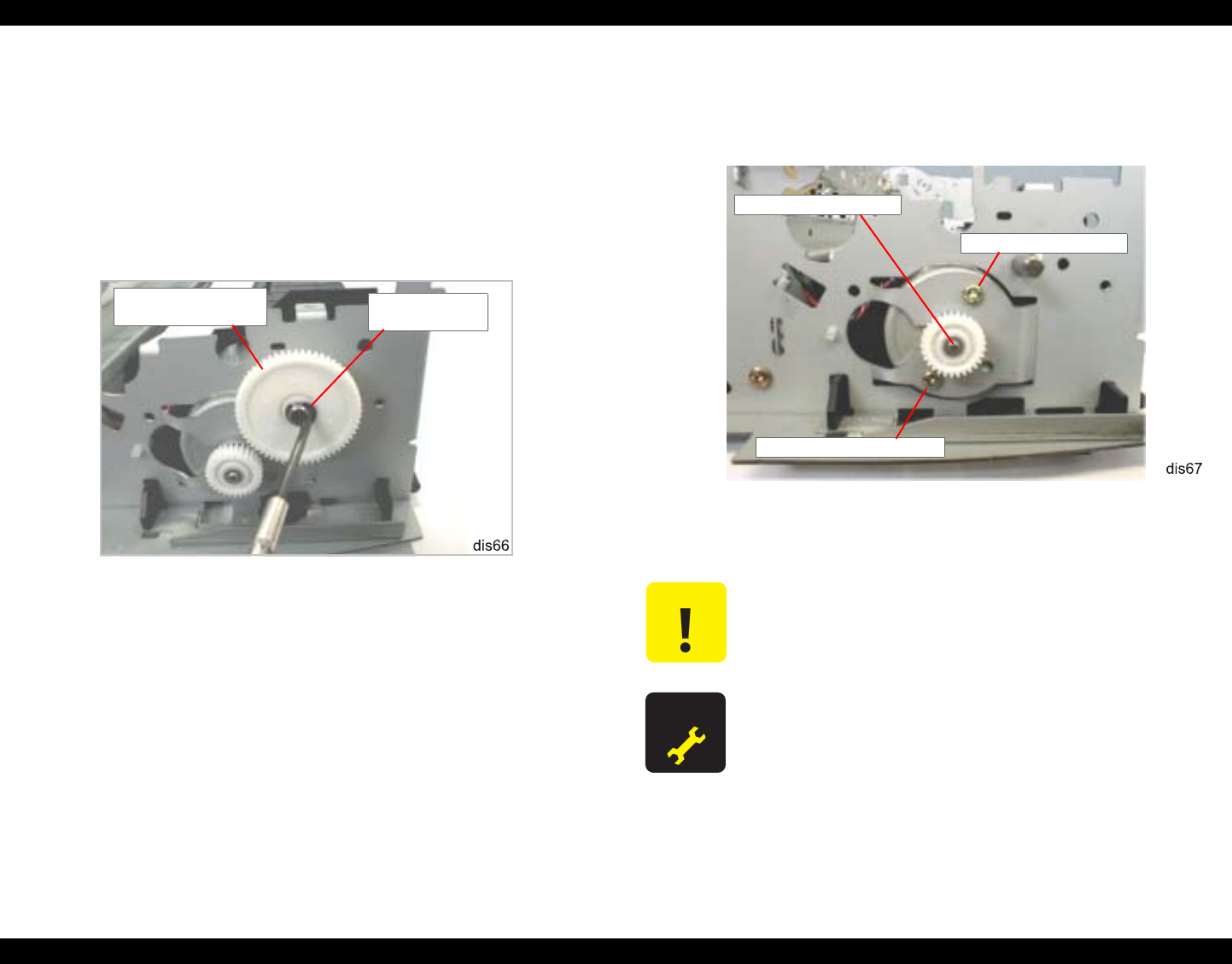
EPSON Stylus Photo 890/1280/1290 Revision C
DISASSEMBLY AND ASSEMBLY Disassembly Procedures 116
4.2.14 MOTOR ASSEMBLY, PF Removal
1. Remove HOUSING. (Refer to Section 4.2.1)
2. Remove the ASF Unit. (Refer to Section 4.2.10.)
3. Remove the Carriage Unit. (Refer to Section 4.2.11.)
4. Remove ROLLER, PF. (Refer to Section 4.2.13.)
5. Remove 1 plane washer (4.1x0.5x4.5) fixing the combination gear (13.5, 30) to
FRAME, LEFT, and then remove the combination gear.
Figure 4-64. Removing COMBINATION GEAR and PLANE WASHER
6. Remove 1 screw (CBS, 3x6), plane washer (3.3x0.5x8), and SCREW,
MOUNTING, PF that are securing MOTOR ASSEMBLY, PF to FRAME, LEFT.
Then remove MOTOR ASSEMBLY, PF.
Figure 4-65. PF Motor Removal
COMBINATION
GEAR, 13.5, 30 PLANE WASHER
(4.1x0.5x6.5)
C A U T I O N Be careful not to damage the teeth of COMBINATION GEAR,
13.5, 30.
A D J U S T M E N T
R E Q U I R E D If you replace MOTOR ASSEMBLY, PF, adjust backlash for the
PF pinion and SPUR GEAR, 76. (See Chapter 5.)
MOTOR ASSEMBLY, PF
SCREW, MOUNTING, PF
CBS (3x6), PLANE WASHER
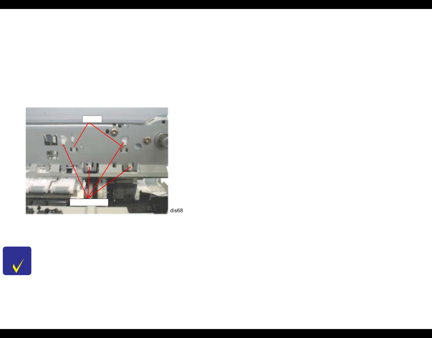
EPSON Stylus Photo 890/1280/1290 Revision C
DISASSEMBLY AND ASSEMBLY Disassembly Procedures 117
4.2.15 PE Sensor Unit Removal
1. Remove HOUSING. (Refer to Section 4.2.1)
2. Remove the ASF Unit. (Refer to Section 4.2.10.)
3. Remove the DE Unit. (Refer to Section 4.2.9.)
4. Remove PAPER GUIDE, RIGHT Unit. (Refer to Section 4.2.13.)
5. Remove the timing belt. (Refer to Section 4.2.11.)
6. Release 2 hooks securing the PE sensor unit to FRAME, TOP, lift up the PE
sensor unit, and then remove it to the rear.
Figure 4-66. PE Sensor Unit Removal
CHECK
P O I N T When installing the PE Sensor Unit, ensure that the sensor lever
is set in the square hole in PAPER GUIDE, RIGHT Unit. (See
Figure 4-59.)
PE Sensor Unit
Hooks

CHAPTER
5
ADJUSTMENT

EPSON Stylus Photo 890/1280/1290 Revision C
ADJUSTMENT Overview 119
5.1 Overview
This chapter describes adjustments required if the printer is disassembled and
assembled for repair or service.
5.1.1 Adjustment Items
Table 5-1 lists the required adjustments for this printer. If any of the services listed in
the table below is carried out, all adjustments corresponding to the service items need
to be performed to ensure proper operations for this printer.
The table below lists the type of repair and required adjustments in the order to be
made.
Table 5-1. Adjustment Item
No. Item When to perform
1Parallelism Adjustment
(without the adjustment
program)
• When you replace or remove the carriage
guide shaft.
• When you replace or remove the parallelism
adjustment bushing.
2Backlash Adjsutment
(without the adjustment
program)
• When you replace the PF motor.
• When you remove the Gear 76.
3Ink Charge • When you replace or remove the printhead.
4Head ID Input • When you replace the printhead.
• When you replace the main board.
NOTE: New head ID is not written until
EEPROM is reset.
6Bi-Directional Adjustment • When you replace the printhead.
• When you replace the main board.
• When you replace the CR motor assembly.
• When you remove the carriage unit.
7Input USB ID • When you replace the main board.
8Protection Counter Clear • When you replace the waste ink pad.
Table 5-2. Type of Repair and Required Adjustment
No. Type of repair Required adjustment
1 Printhead removal 1. Head Cleaning
2. Bi-Directional Adjustment
2Printhead replacement
1. Head ID Input
2. Ink Charge
3. Nozzle Check
4. Bi-Directional Adjustment
3 Main board replacement
1. Head ID Input
2. Bi-Directional Adjustment.
3. Input USB ID
4. Protection Counter Clear
4Carriage unit replacement or removal 1. Parallelism Adjustment
2. Bi-Directional Adjustment
5 CR Motor replacement 1. Bi-Directional Adjustment
6Printer mechanism replacement
1. Head ID Input
2. Ink Charge
3. Bi-Directional Adjustment
7 Waste Ink Pad replacement 1. Protection Counter Clear
8
Replacement or removal of the
following parts.
1) PF motor
2) Gear 76
3) PF roller assembly
1. Backlash Adjsutment

EPSON Stylus Photo 890/1280/1290 Revision C
ADJUSTMENT Overview 120
5.1.2 Adjustment Tools
The table below shows adjustment tools you need for servicing the Stylus PHOTO
1280.
Table 5-3. Adjustment Tools
Tool Type of adjustment Specifications
Thickness Gauge Parallelism Adjustment Thickness: 1.14 mm
Microscope Backlash Adjsutment Magnified ratio: x 15
Minimum scale: 0.1mm
Service Program • Ink Charge
• Head ID Input/Check
• Head Cleaning
• Refurbishment for DOA
• USB ID Input/Check
• Bi-Directional Adjustment
• Protection Counter Clear
• Nozzle Check
A 3.5- inch HD floppy disk
(Choose either Win.95 or 98)
C A U T I O N Never use a deformed (twisted or warped) or rusty thickness
gauge.
Wipe off any dirt, grease, or foreign matter on the thickness
gauge before you use it.
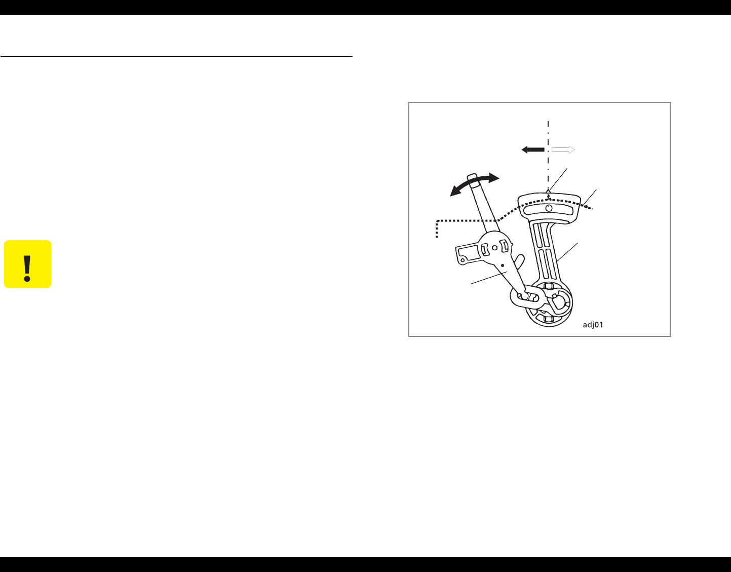
EPSON Stylus Photo 890/1280/1290 Revision C
ADJUSTMENT Adjustment 121
5.2 Adjustment
This section explains the procedure for each adjustment.
5.2.1 Parallelism Adjustment
When you remove/replace the carriage unit, make a parallelism adjustment because
you need to remove the parallelism adjustment bushings. This adjustment enables you
to provide an appropriate distance between the printhead and platen as well as to set the
CR guide shaft in parallel with the paper.
Using the PG adjustment tool is the best way to adjust the PG (Platen Gap) as accurate
as possible. You may substitute a thickness gauge (1.14mm) for the PG adjustment
tool, however, the accuracy of PG may decline comparing to using the PG adjustment
tool.
5.2.1.1 Using PG Adjustment Tool
1. Install the right and left Parallel Adjustment Bushings to the printer mechanism by
aligning their marks with the notches on the frames.
Figure 5-1. Initial Position of the Parallelism Adjustment Bushing
2. Set the PG Lever to the front side (the “0” position).
3. If the Carriage Unit is locked, unlock it by pushing down the lock lever using
tweezers.
C A U T I O N Do not scratch the special coated surface of the PF roller
assembly and rib surface of the front paper guide; B.
Before starting the adjustment, wipe the PG adjustment tool
and thickness gauge with a clean cloth moistened with alcohol.
Be careful not to damage the printhead surface or leave any dirt
on it. (Make sure the PG adjustment tool and thickness gauge is
free from any stain, and also do not touch the head surface with
the thickness gauge.
Be sure to perform the Printhead Rmoval with the ink
cartridges installed.
Mark
Notch on the frame
To the rear
(= gap is narrowed)
To the front
(= gap is widen)
Frame
Right Parallelism
Adjustment Bushing
PG Lever
(+)
(0)
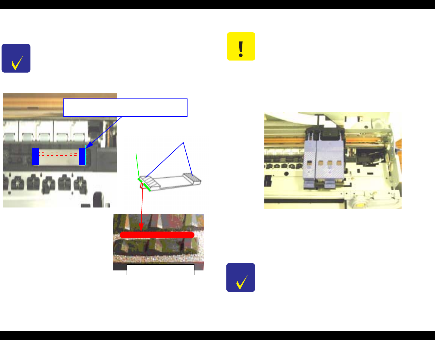
EPSON Stylus Photo 890/1280/1290 Revision C
ADJUSTMENT Adjustment 122
4. Move the Carriage to the center of the printer mechanism. Put the PG adjustment
tool right on the rightmost rib of Paper Guide Front.
Figure 5-2. Setting PG Adjustment Tool
5. Set the PG Lever to the rear side (the “+” position).
6. Move the Carriage to right until it covers the right C part of the PG adjustment
tool. Make sure the right edge of the printhead frame is placed right above the C
part of the PG adjustment tool.
Set the PG Lever to the front side (the “0” position).
Table 5-4. Carriage on PG Adjustment Tool
7. Set the Right Parallel Adjustment Bushing forward. By moving the bushing to the
back one notch at a time, find the position where the printhead touches the PG
adjustment tool. From the touching point, move the bushing forward (Wider PG
direction) by one notch.
CHECK
P O I N T
Make sure to align the edge of the PG adjustment tool on the
rightmost part of Front Paper Guide with the jut out portion of the
tool Part) placed on the rear ditch of Front Paper Guide.
Front Paper Guide
Set PG Adjustment tool right on
the rightmost rib of Paper Guide Front.
C Part
A Part
B Part
(narrow side)
B Part
(wide side)
C A U T I O N To move the Carriage Unit, pull the timing belt with your hand.
Be careful not to damage the CR scale (linear encoder).
CHECK
P O I N T
Platen Gap becomes wider when moving the Parallel Adjustment
Bushing forward and becomes narrower when moving
backward.
Make a PG adjustment at least 3 times, both sides and repeat one
side.
Make sure a peak portion of the frame engages with a valley
portion of Parallel Adjustment Busing.

EPSON Stylus Photo 890/1280/1290 Revision C
ADJUSTMENT Adjustment 123
8. Perform the PG adjustment to the left side.
Move the Carriage to the center of the printer mechanism. Put the PG adjustment
tool right on the leftmost rib of Paper Guide Front.
9. Set the Left Parallel Adjustment Bushing forward. By moving the bushing to the
back one notch at a time, find the position where the printhead touches the PG
adjustment tool. From the touching point, move the bushing forward (Wider PG
direction) by one notch
10. Move the PG lever to the rear (+).
11. Move the Carriage Unit over the PG adjustment tool on the left.
12. Bring the PG lever to the front (0).
13. Make the adjustment as in the same manner as in step 6 and 7.
14. Bring the PG lever to the rear (+).
15. Move the carriage back over the PG adjustment tool on the right.
16. Move the PG lever back to the front (0).
17. Make the adjustment again on the Right Parallel Adjustment Bushing. If the result
is good, the adjustment is completed.
18. Fasten the bushing screws on both sides.
CHECK
P O I N T
Make sure to align the edge of the PG adjustment tool on the
leftmost part of Front Paper Guide with the jut out portion of the
tool (bottom part) placed on the rear ditch of Front Paper Guide.
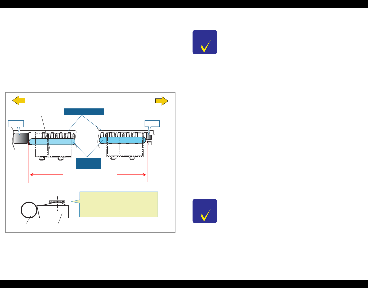
EPSON Stylus Photo 890/1280/1290 Revision C
ADJUSTMENT Adjustment 124
5.2.1.2 Using Thickness Gauge
Using the PG adjustment tool is the best way to adjust the PG (Platen Gap) as accurate
as possible. You may substitute a thickness gauge (1.14mm) for the PG adjustment
tool, however, the accuracy of PG may decline comparing to using the PG adjustment
tool.
1. Follow Step 1 to 3 in 5.2.1.1“Using PG Adjustment Tool” on page -121.
2. Bring the Carriage to the center of the printer mechanism. Then place the thickness
gauges (1.14 mm) on the front paper guide aligning them with the right and left
square cutouts in the front paper guide. (See Figure 5-3.)
Figure 5-3. Placing the Thickness Gauge
3. Move the Carriage Unit over the gauge on the right.
4. If the printhead does not touch the gauge, turn the bushing to the rear to make the
printhead touch the gauge and then, from the touching position, bring the bushing
back by one notch. On the other hand, if the printhead already touches the gauge,
turn the bushing to the front to make the printhead touch the gauge, and then push
the bushing back by one notch.
5. Move the PG lever to the rear (+).
6. Move the carriage unit over the thickness gauge on the left.
7. Bring the PG lever to the font (0).
8. Make the adjustment as in the same manner as in step 4.
9. Bring the PG lever to the rear (+).
10. Move the carriage back over the thickness gauge on the right.
11. Move the PG lever back to the front (0).
12. Make the adjustment again on the right parallelism adjustment bushing. If the
result is good, the adjustment is completed.
13. Fasten the bushing screws on both sides.
Cutout
Thickness
Gauge
Carriage Unit
Left Edge Right Edge
(Home Position Side)
Front Paper Guide
PF Roller
Front Paper Guide
Gauge Aligning Position
Cutout
• Set the gauge on the horizontal top of
the ribs.
• Bring the rib tops to the middle of
the gauge.
CHECK
P O I N T
To move the carriage unit, pull the timing belt with your hand.
Be careful not to damage the CR scale (linear encoder).
CHECK
P O I N T
Platen Gap becomes wider when moving the Parallel Adjustment
Bushing forward and becomes narrower when moving
backward.
Make a PG adjustment at least 3 times, both sides and repeat one
side.
Make sure a peak portion of the frame engages with a valley
portion of Parallel Adjustment Busing.
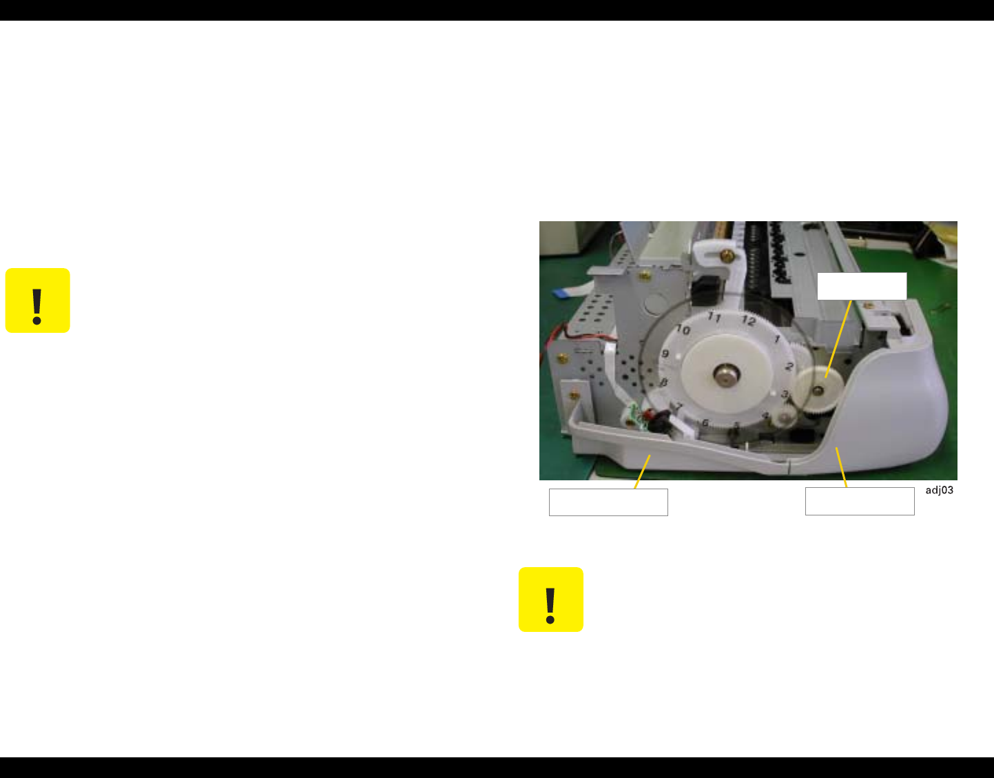
EPSON Stylus Photo 890/1280/1290 Revision C
ADJUSTMENT Adjustment 125
5.2.2 Backlash Adjsutment
This section describes Backlash Adjsutment that is to be made after removing the PF
motor. This adjustment provides an appropriate backlash (= 0.1 mm or less) for PF
motor pinion gear and the gear (76). You need to make this adjustment when you
replace any of the following parts:
PF motor assembly
Gear 76
PF roller unit
Before you begin, make sure the following parts are removed:
COMBINATION GEAR, 13.5, 30
TRAY, ABSORBER ASSEMBLY
HOUSING, PANEL, LEFT
HOUSING, REINFORCING, LEFT
See the following figure for locations.
Figure 5-4. Parts to Remove
C A U T I O N Failure in making this adjustment causes the printer to operate
abnormally as described below:
If backlash is too little:
1. The PF motor dose not rotate correctly and paper feeding
accuracy declines.
2. Gear 76 and the PF pinion gear make abnormal noises
during printing.
If backlash is too large, the PF motor dose not rotate correctly
and paper feeding accuracy declines.
C A U T I O N Be careful not to damage the PF Loop scale when removing
COMBINATION GEAR, 13.5, 30.
HOUSING,
REINFORCING, HOUSING, PANEL,
LEFT
COMBINATIO
N GEAR, 13.5,30
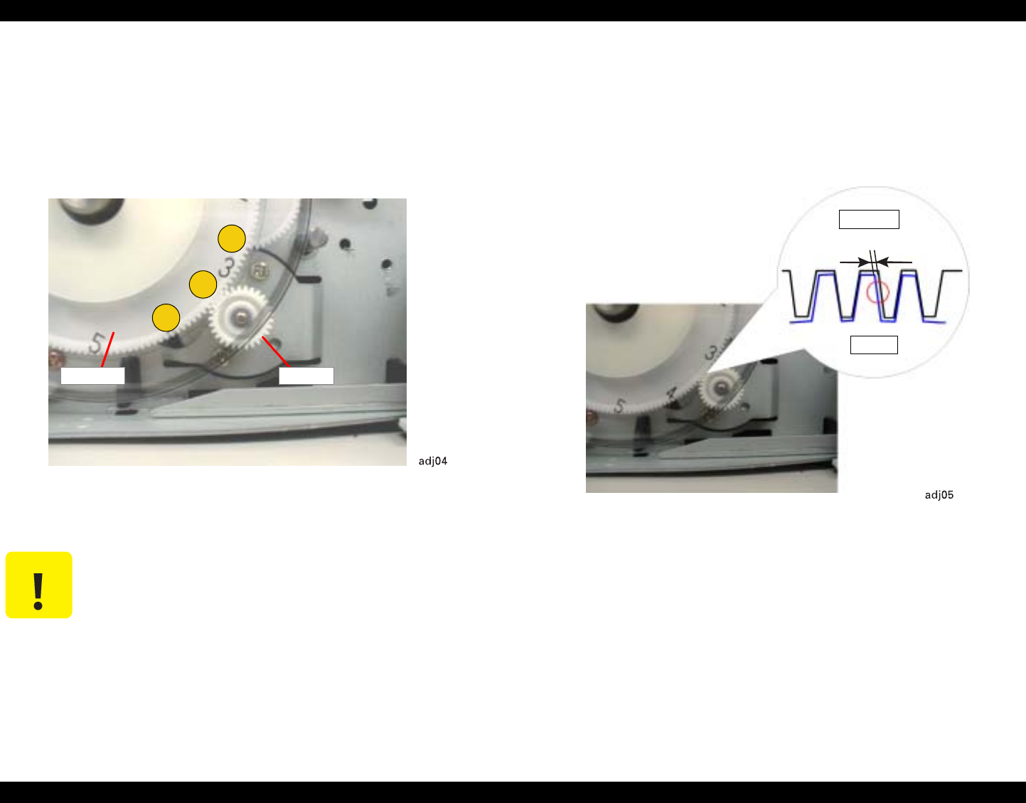
EPSON Stylus Photo 890/1280/1290 Revision C
ADJUSTMENT Adjustment 126
1. Loosen the screw (CBS, 3x6) securing the PF motor assembly to the left frame by
rotating it half.
2. Holding the PF motor assembly, get the pinion mesh the gear 76.
3. Press the gear 76 by the point 2 in the figure below lightly and release it to ensure
the gear comes back to its original position.
Figure 5-5. Checking for Gear Engagement
4) Press the gear by the indicated positions 1 and 3 (each point is 2.5 cm apart from
the point 2) and check that the gear squeaks at each point. If not, start over from
the step 2.
5. Fasten the screw (CBS, 3x6) to secure the PF motor assembly to the left frame.
6. Press the gear 76 by the point 2 and release it again to ensure it returns to its
original position.
7. Using a microscope, check for a correct backlash. Backlash at its minimum point
should be 0 - 0.1 mm. If larger, repeat the adjustment.
Figure 5-6. Checking for the Backlash
C A U T I O N When pressing the gear 76 together with the PF scale, be careful
not to damage or stain the scale.
1
2
3
PINION
GEAR, 76
2
3
GEAR, 76
PINION
0 - 0.1 mm
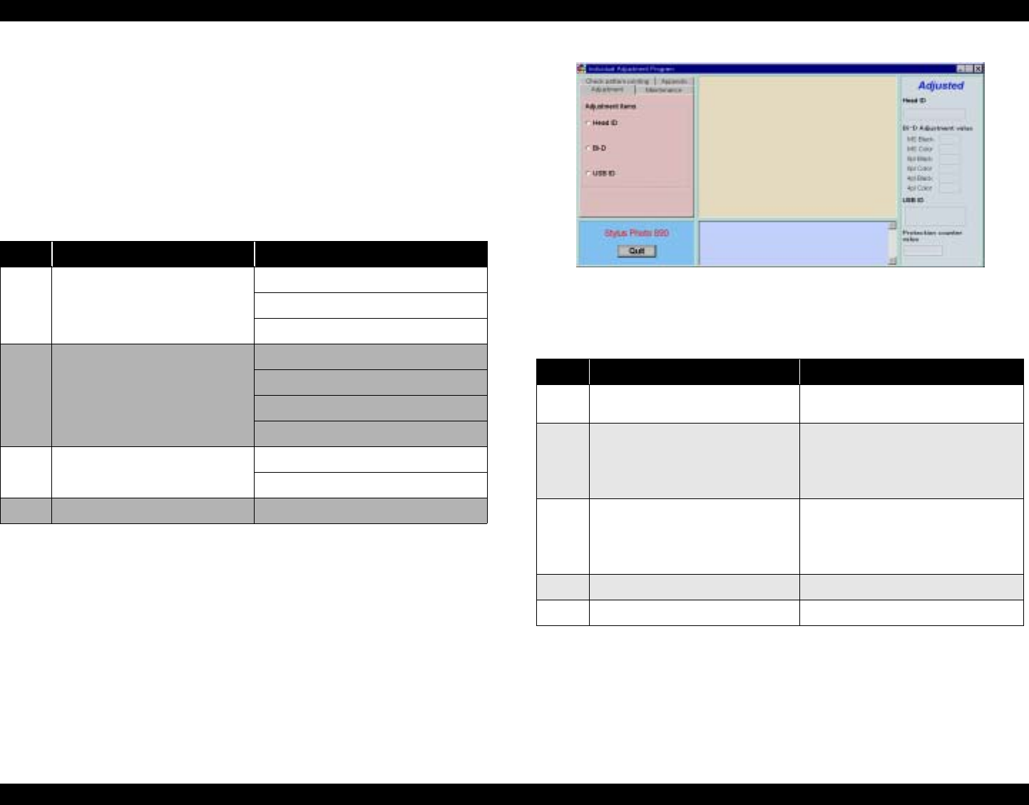
EPSON Stylus Photo 890/1280/1290 Revision C
ADJUSTMENT Adjustment 127
5.2.3 Adjustment Program Feature
This adjustment program, which is available for both Stylus Photo 890 and Stylus
Photo 1290, consists of two independent main programs; Individual Adjustment
Program and Sequential Repair Program. The basic adjustment items you can perform
using this program are as shown in the following tables:
Individual Adjustment Service Program
This program can independently adjust the service items. The adjustment/
maintenance items are shown below.
Figure 5-7. Independent Adjustment Program Main Menu
Sequential Repair Service Program
Table 5-5. Individual Adjustment Program
No. Service Items Adjustment Items
1Adjustment Head ID Input
Bi-Directional Adjustment
Input USB ID
2 Maintenance Head Cleaning
Ink Charge
Refurbishment for DOA
Protection Counter
3Appendix CSIC Information
EEPROM Date
4Check Pattern Printing A4 Normal Paper Printing
Table 5-6. Sequential Repair Service Program
No. Repair Items Adjustment Items
1 Printhead Removal 1. Head Cleaning
2. Bi-Directional Adjustment
2Printhead Replacement 1. Head ID Input
2. Ink Charge
3. Nozzle Check
4. Bi-Directional Adjustment
3 Main Board Replacement 1. Head ID Input
2. Bi-Directional Adjustment
3. Input USB ID
4. Protection Counter Clear
4Carriage Unit Removal/Replacement 1. Bi-Directional Adjustment
5 CR Motor Replacement 1. Bi-Directional Adjustment
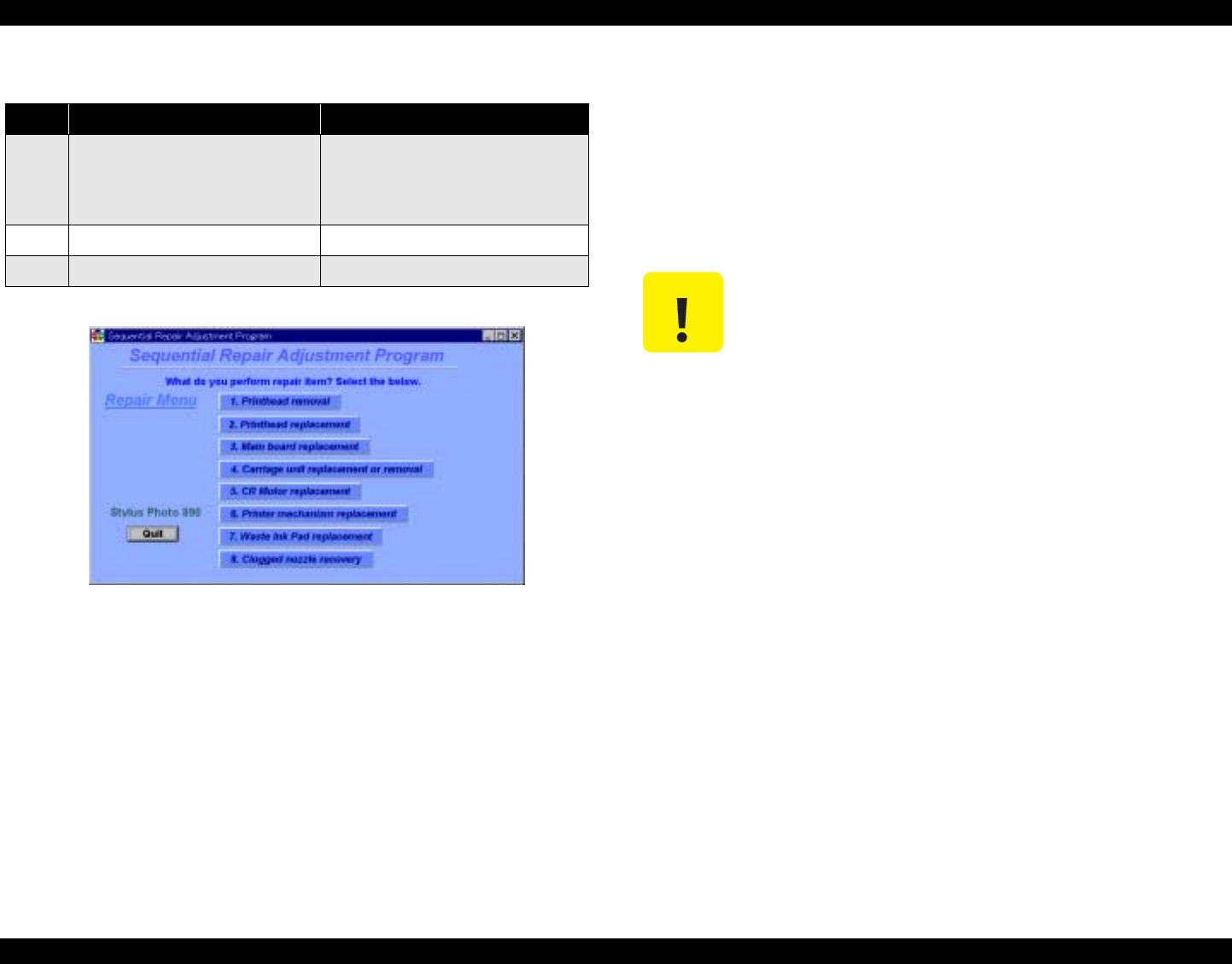
EPSON Stylus Photo 890/1280/1290 Revision C
ADJUSTMENT Adjustment 128
Figure 5-8. Sequential Repair Service Program Main Menu
5.2.3.1 How to Install the Program
Before installing the program, note the points below:
Use Windows 95 or higher.
Use LPT 1 only as the printer port. (Use a USB interface cable only when
performing Input USB ID .)
Install the program in the order listed below:
1. According to the version of your computer, insert either “Windows 95” or
“Windows 98” floppy disk to your computer or select Service Program in the
CD-ROM.
2. Click Stylus Photo 890/1290 95 or 98.exe. The program automatically start and
the initial window appears on the screen.
5.2.3.2 How to Uninstall the Program
Access Control Panel> Add/Remove Programs and uninstall the program.
5.2.4 Starting the Service Program
5.2.4.1 Adjusting Program Initial Setting
In order to start the program, you have to input the following information below:
6Printer Mechanism Replacement 1. Head ID Input
2. Ink Charge
3. Nozzle Check
4. Bi-Directional Adjustment
7 Waste Ink Pads Replacement 1. Protection Counter
8Clogged Nozzle Recovery 1. Nozzle Check
Table 5-6. Sequential Repair Service Program
No. Repair Items Adjustment Items
C A U T I O N While you are running the service program on Windows 95, you
can not use EPSON Status Monitor. Therefore, close the printer
window on the task bar before you start the program.
If you can not start the program because LPT1 is set to ECP
Printer Port, turn it off in the order below:
1. Delete all printer drivers.
2. Access Control Panel>System>Device Manager>Ports and
delete ECP Printer Port.)
3. Reboot the computer.
If you leave the printer in a non-printing status for 5 minutes or
more, the carriage automatically returns to home position. In this
case, you need to reboot the computer to run the program.
Do not change the setting for Font size in Display settings.
Be sure to connect a parallel interface cable to the printer before
you start the program. Otherwise, the program freezes.
Do not send any command to the printer during a check pattern
print.
While the service program is running, if the printer is turned off
or the interface cable is disconnected, you need to launch the
program again.
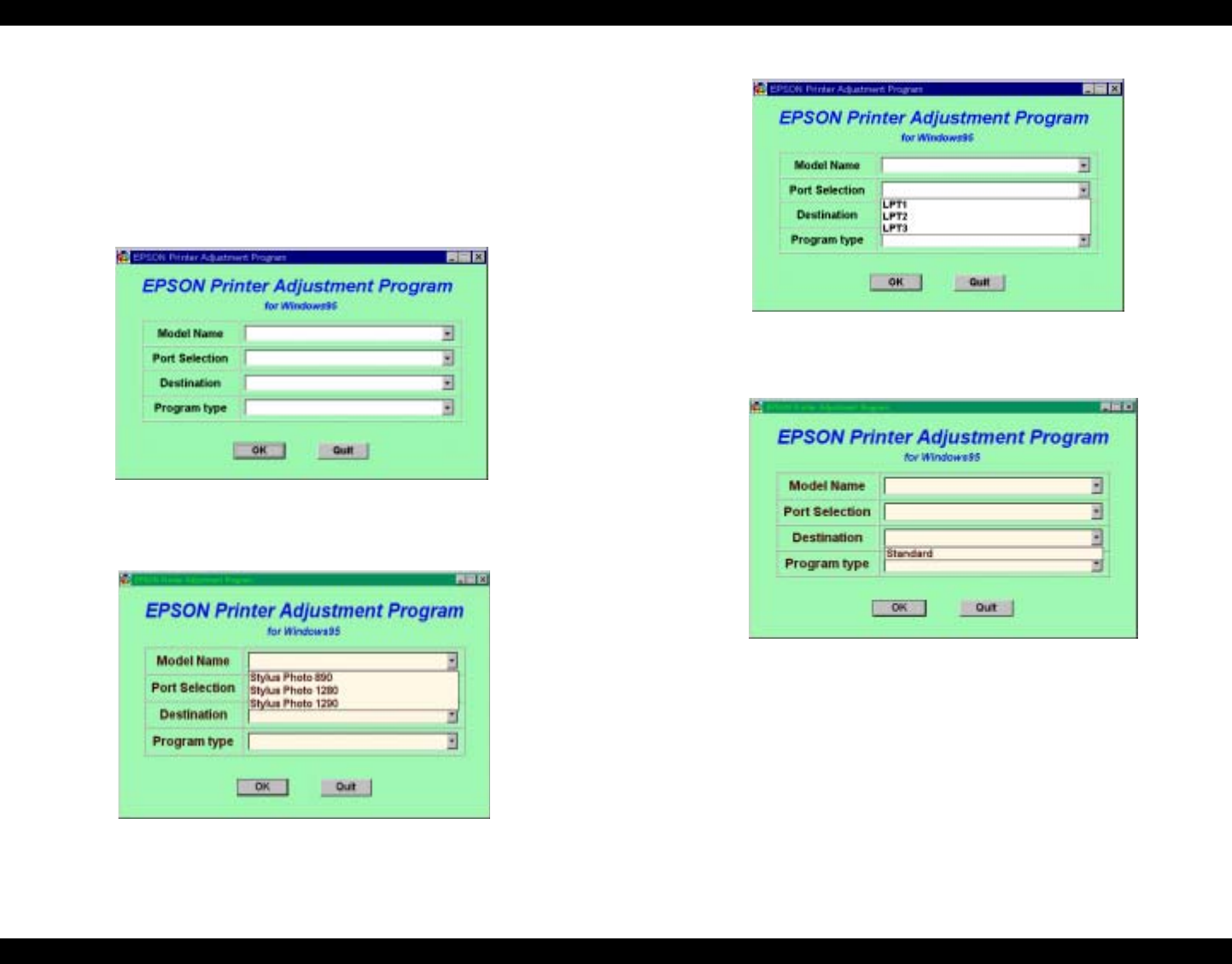
EPSON Stylus Photo 890/1280/1290 Revision C
ADJUSTMENT Adjustment 129
Model Name (Stylus PHOTO 890/1280/1290)
Stylus PHOTO 1280 is for EAI only.
Port Selection (LPT1/2/3)
Destination (Standard)
Program Type (Individual Adjustment Program/ Sequential Repair Service
Program)
1. When you start the service program, the initial window appears:
Figure 5-9. Initial Window
2. Select Model Name:
Figure 5-10. Model Selection
3. Select Port.
Figure 5-11. Port Selection
4. Select Destination.
Figure 5-12. Destination Selection
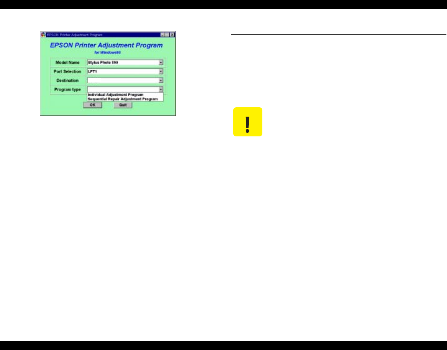
EPSON Stylus Photo 890/1280/1290 Revision C
ADJUSTMENT Individual Adjustment Program 130
5. Select Program Type.
Figure 5-13. Program Type Selection
6. After choosing four items on the window, click OK. If you want to exit the
program, click Quit.
5.3 Individual Adjustment Program
5.3.1 Head ID
This adjustment needs to be executed when you replace any of the following parts:
Printhead
Main Board
Printer mechanism
NOTE: In this section, Stylus Photo 890 program windows are used as examples.
5.3.1.1 Head ID Input
The Head ID is written to the EEPROM on the Main Board with this function.
1. Start the program and input all the required information on the initial window.
Then the main menu appears on the screen. (See 5.2.4.1“Adjusting Program Initial
Setting” on page -128)
2. Select Head ID from the main menu.
Standard
C A U T I O N If you replace the printhead, Main Board, or printer mechanism,
make this adjustment prior to any other adjustment items.
This adjustment is very important to keep good printer
performance. If an wrong ID is input, the printer will exhibit a
dot missing problem or does not print at all.
After making this adjustment, perform all other necessary
adjustments listed in Table 5-2.
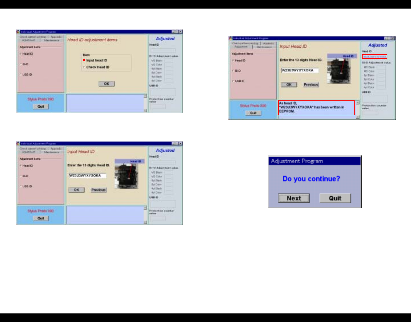
EPSON Stylus Photo 890/1280/1290 Revision C
ADJUSTMENT Individual Adjustment Program 131
3. The Head ID Adjustment window appears. Select Input Head ID and click OK.
Figure 5-14. Head ID Adjustment Window
4. The Input Head ID window appears. Enter 13 digit Head ID and click OK.
Figure 5-15. Head ID Input
5. The following message appears on the window and the Head ID Input is
completed.
Figure 5-16. Head ID Input Completed
6. When you exit this window, click Quit. The exit window appears. Click Quit and
the program is closed. If you want to continue, click Next.
Figure 5-17. Exit Window
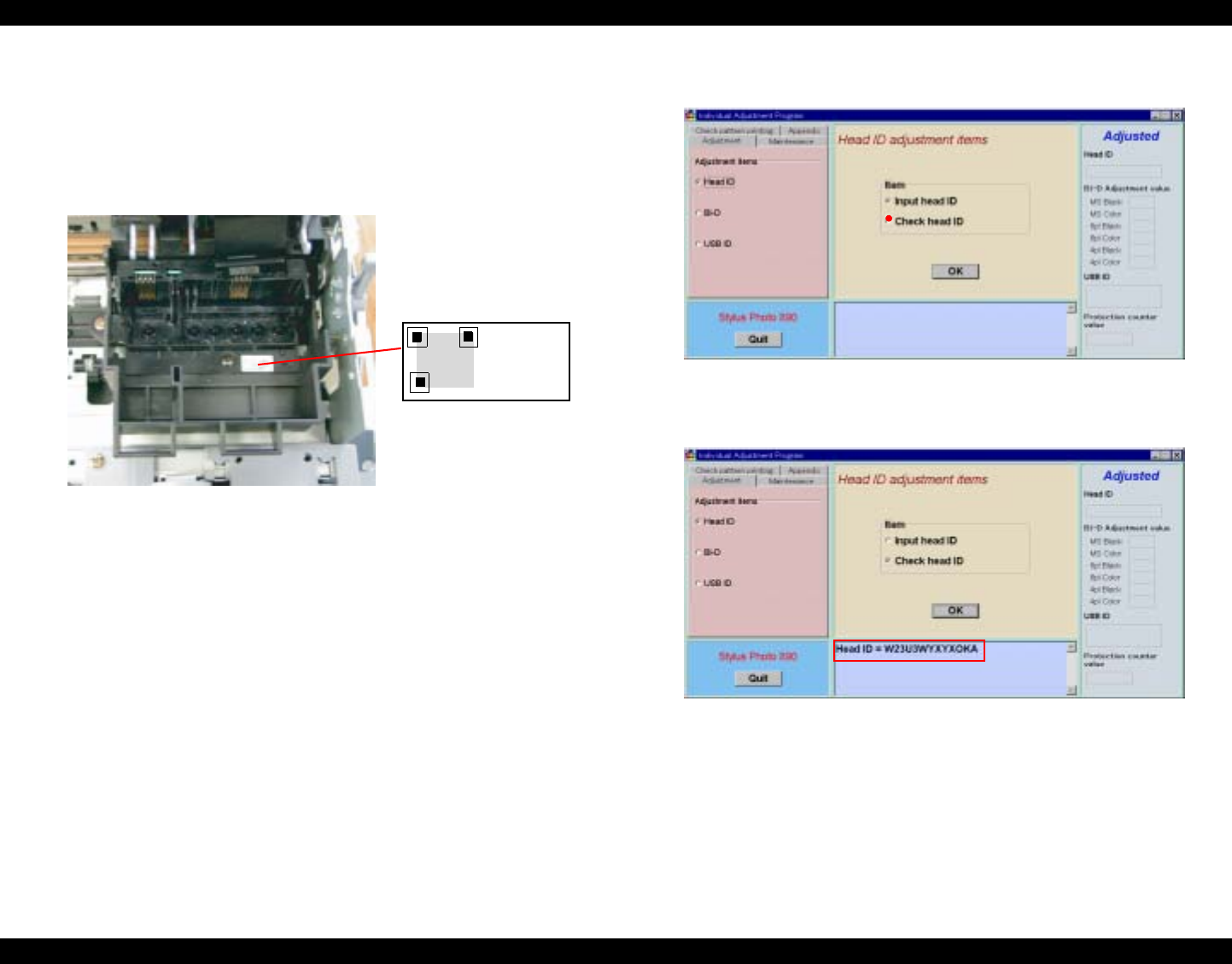
EPSON Stylus Photo 890/1280/1290 Revision C
ADJUSTMENT Individual Adjustment Program 132
5.3.1.2 Head ID Check
You can find the Head ID on the following units.
Where to Find the Head ID
The 13 digit Head ID is written on the label inside the printhead.
The Head ID begins from the upper left to the right. Therefore the Head ID is
“W23U3WYXYXOKA” in this case.
Figure 5-18. Head ID Sample
Check Current Head ID
You can confirm the present Head ID written in the EEPROM by following the
procedures below.
1. Start the program and input all the required information on the initial window.
Then the main menu appears on the screen. (See 5.2.4.1“Adjusting Program Initial
Setting” on page -128)
2. Select Head ID from the main menu.
3. The Head ID Adjustment window appears. Select Check Head ID and click
OK.
Figure 5-19. Head ID Adjustment Window
4. The current Head ID is displayed.
Figure 5-20. Current Head ID Check
W23U3
WYXYX
OKA
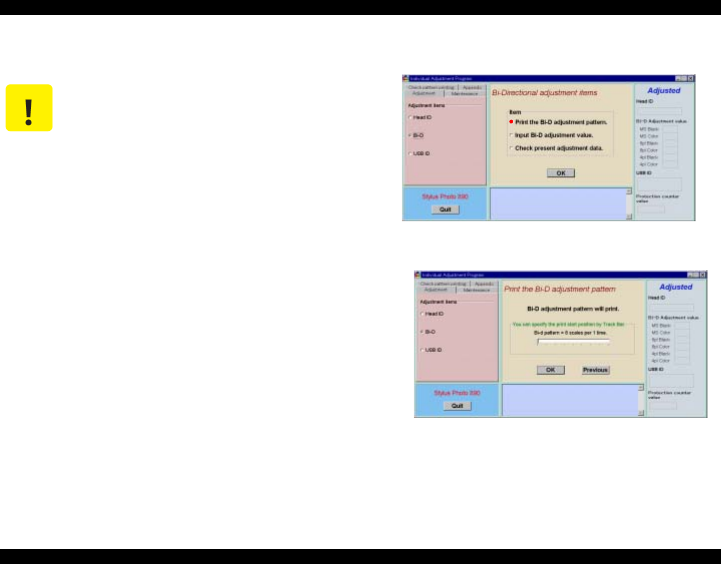
EPSON Stylus Photo 890/1280/1290 Revision C
ADJUSTMENT Individual Adjustment Program 133
5. To exit or continue the program, refer to Figure 5-17.“Exit Window” on
page -131.
5.3.2 Bi-Directional Adjustment
This adjustment is required when line misalignment (incorrect print timing) between
the two directions (from left to right and vice versa) is noticed. The adjustment value is
memorized in EEPROM on the main board. You need to make this adjustment under
any of the following conditions.
When you:
Replace the printer mechanism.
Replace the main board.
Remove the CR motor.
Remove the CR unit.
NOTE: You are recommended you should make this adjustment if you disassemble the
carriage mechanism.
1. Start the program and input all the required information on the initial window.
Then the main menu appears on the screen. (See 5.2.4.1“Adjusting Program Initial
Setting” on page -128)
2. Select Bi-D from the main menu.
3. The Bi-Directional Adjustment window appears. Select Print Bi-D Adjustment
Pattern and click OK.
Figure 5-21. Bi-Directional Adjustment Window
4. Click OK, and then the Bi-D Adjustment Patterns will automatically be printed.
Figure 5-22. Bi-Directional Adjustment Pattern Printing
C A U T I O N The Head ID Input to EEPROM is not effective until the printer is
next turned on.
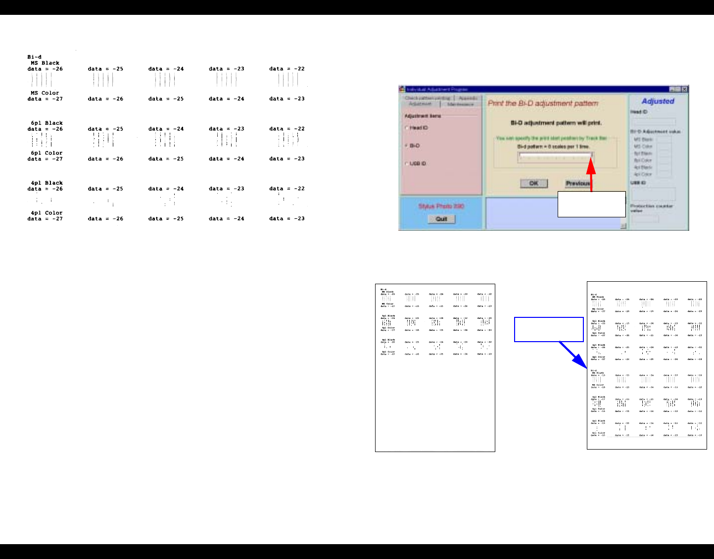
EPSON Stylus Photo 890/1280/1290 Revision C
ADJUSTMENT Individual Adjustment Program 134
5. The Bi-Directional Adjustment patterns are printed as follows.
Figure 5-23. First Bi-Directional Adjustment Pattern Sample
NOTE: To save sheets of paper during Bi-D Pattern Printing, you can set an initial
printing start position by using the track bar on the window. The printing start
position can be determined according to the track bar you set. With this function,
you can print out the Bi-D Adjustment Patterns twice on an A4 size sheet. (Refer
to Figure 5-25)
6. During the adjustment printing, using the track bar is recommended for the second
or later test printing to save paper. The track bar can be set to 8 levels. For the
second printing, however, setting the bar to the right end is recommended. After
setting the bar, click OK.
Figure 5-24. Second Bi-Directional Adjustment Pattern Printing
7. The second Bi-D Adjustment Patterns are printed as follows.
Figure 5-25. Second Bi-Directional Adjustment Pattern Sample
Set the track bar to
the right end.
The second print
start position
After First Pattern Printing
After Second Pattern Printing
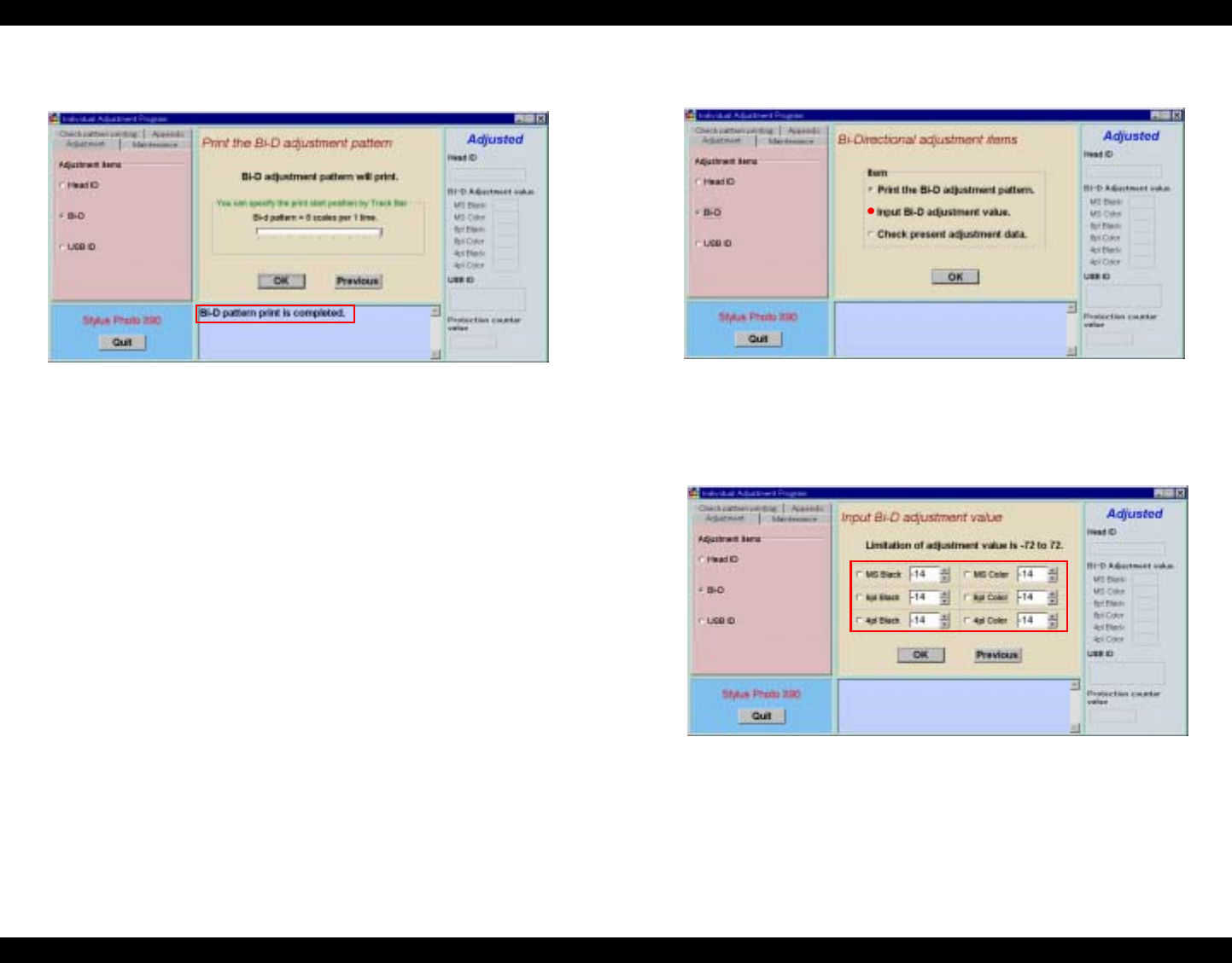
EPSON Stylus Photo 890/1280/1290 Revision C
ADJUSTMENT Individual Adjustment Program 135
8. The following message appears on the window and the Bi-Directional
Adjustment Pattern Printing is completed.
Figure 5-26. Bi-Directional Adjustment Pattern Printing Completed
9. To exit or continue the program, click Quit on the lower left. Refer to Figure
5-17.“Exit Window” on page -131.
5.3.2.1 Input Bi-D Adjustment Value
1. Start the program and input all the required information on the initial window.
Then the main menu appears on the screen. (See 5.2.4.1“Adjusting Program Initial
Setting” on page -128)
2. Select Bi-D from the main menu.
3. The Bi-Directional Adjustment window appears. Select Input Bi-D Adjustment
Value and click OK.
Figure 5-27. Bi-Directional Adjustment Window
4. The Input Bi-D Adjustment Value window appears and the current Bi-D
Adjustment values are displayed. Referring to the printout, input the setting values
using the ↑ or ↓ key or directly type it in.
Figure 5-28. Input Bi-D Adjustment Value Window
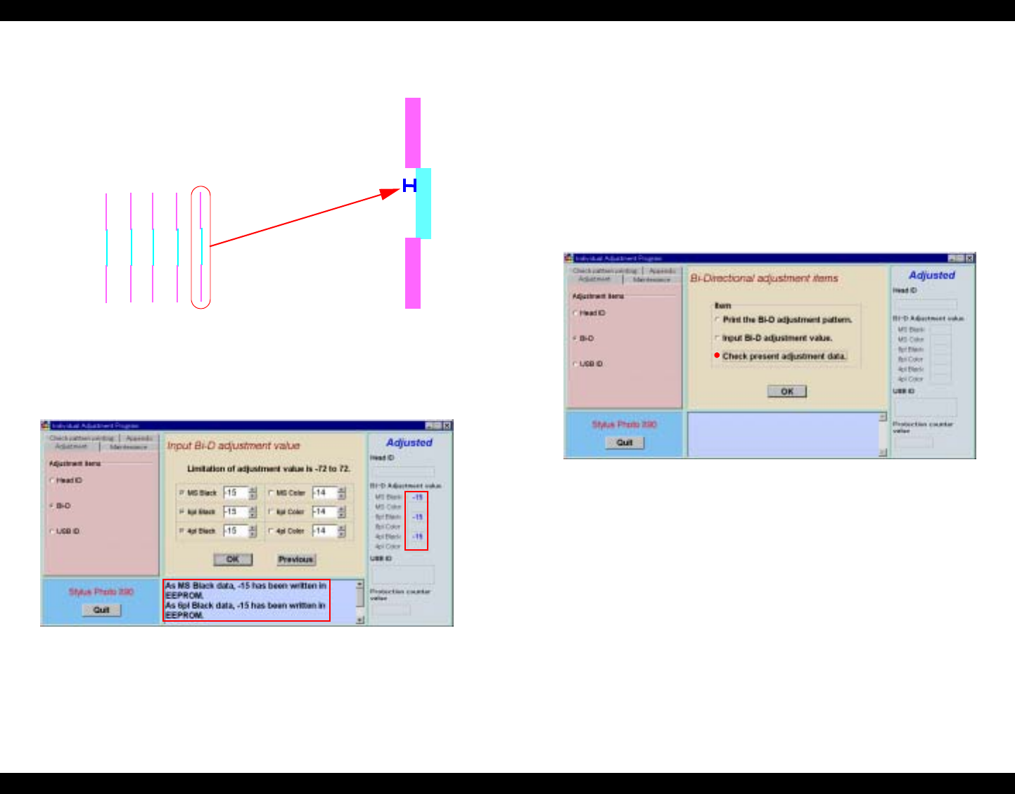
EPSON Stylus Photo 890/1280/1290 Revision C
ADJUSTMENT Individual Adjustment Program 136
5. When you adjust the setting values, make sure that the Bi-D gap becomes less than
60 µ m.
Figure 5-29. Bi-D Adjustment Printing Example
6. After changing the values, click OK. The following message appears on the
window and the Input Bi-D Adjustment Value is completed.
Figure 5-30. Input Bi-D Adjustment Value Completed
7. To continue with other mode, click Previous and select a different item. Print the
Bi-D Adjustment Patterns if necessary.
8. Repeat the steps from 1 to 7 until you get the best result.
9. To exit or continue the program, click Quit on the lower left. Refer to Figure
5-17.“Exit Window” on page -131.
5.3.2.2 Check Present Adjustment Data
1. Start the program and input all the required information on the initial window.
Then the main menu appears on the screen. (See 5.2.4.1“Adjusting Program Initial
Setting” on page -128)
2. Select Bi-D from the main menu.
3. The Bi-Directional Adjustment window appears. Select Check Present
Adjustment Data and click OK.
Figure 5-31. Bi-Directional Adjustment Window
Bi-d
MS Color
data = -14 Bi-D Gap
Less than 60 µm
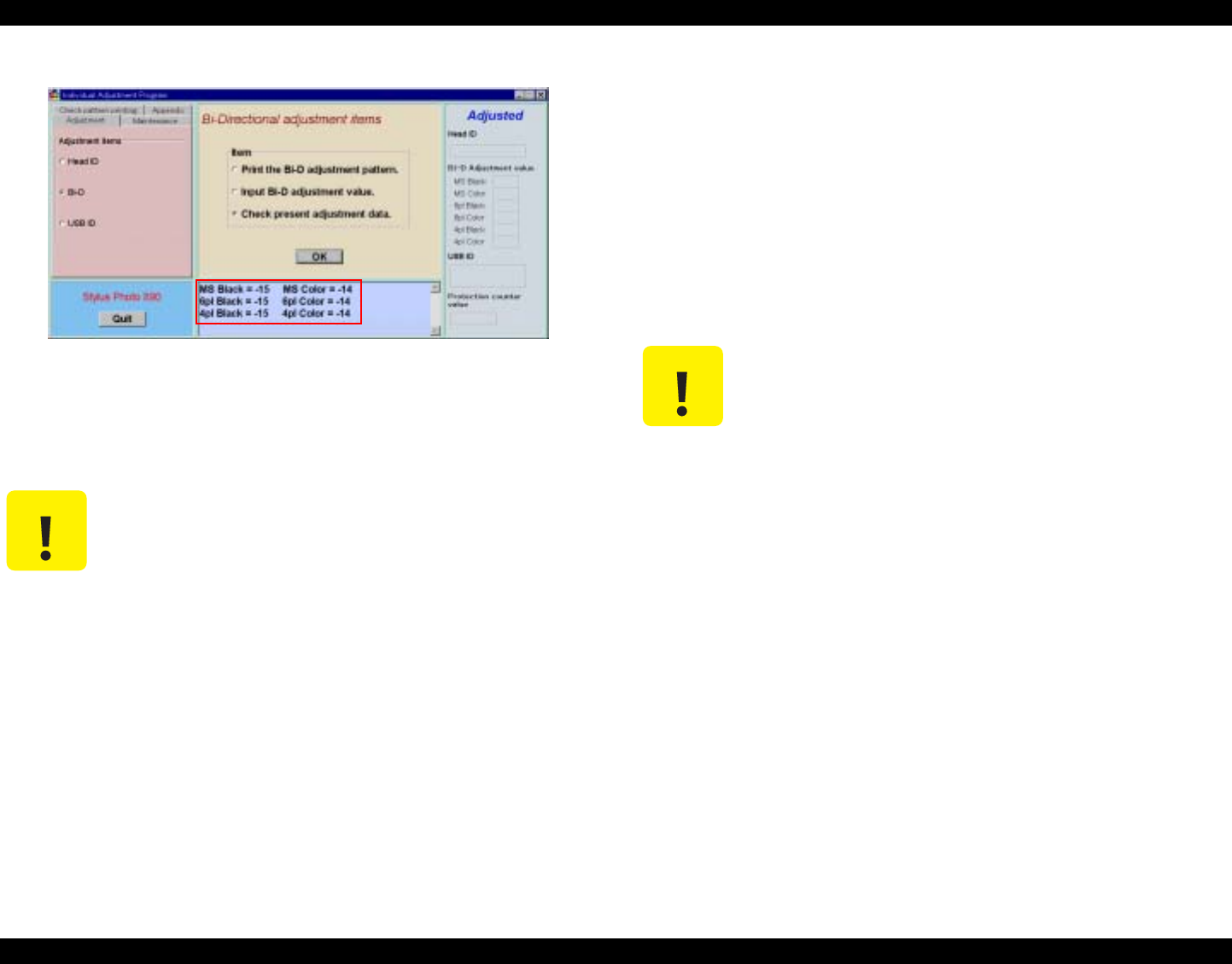
EPSON Stylus Photo 890/1280/1290 Revision C
ADJUSTMENT Individual Adjustment Program 137
4. Click OK and the present adjustment values are displayed.
Figure 5-32. Present Adjustment Data Display
5. To exit or continue the program, click Quit on the lower left. Refer to Figure
5-17.“Exit Window” on page -131.
5.3.3 Input/Check USB ID
You are required to perform Input USB ID whenever you replace the main board.
The Stylus PHOTO 1280 is equipped with the USB interface as standard. In the
Windows 98 or iMAC environment, the USB port driver controls its device using the
USB ID stored in EEPROM. Therefore, you need to input a unique USB ID for a new
main board.
During a repair service, a new USB ID is formed with a 10-digit product serial number
and the rest (8-digit) produced by the service program. You need to input the new USB
ID in EEPROM.
C A U T I O N The setting value is not effective until the printer is turned off and
back on. It is because the setting value is stored in EEPROM when
the printer is turned off.
C A U T I O N You need to input a new USB ID for the following reasons:
1. If the main board is replaced, the ID for the board is no longer
used.
2. If the ID is in conflict with an ID used for any other peripheral
devices, the printer can not be connected with a USB interface.
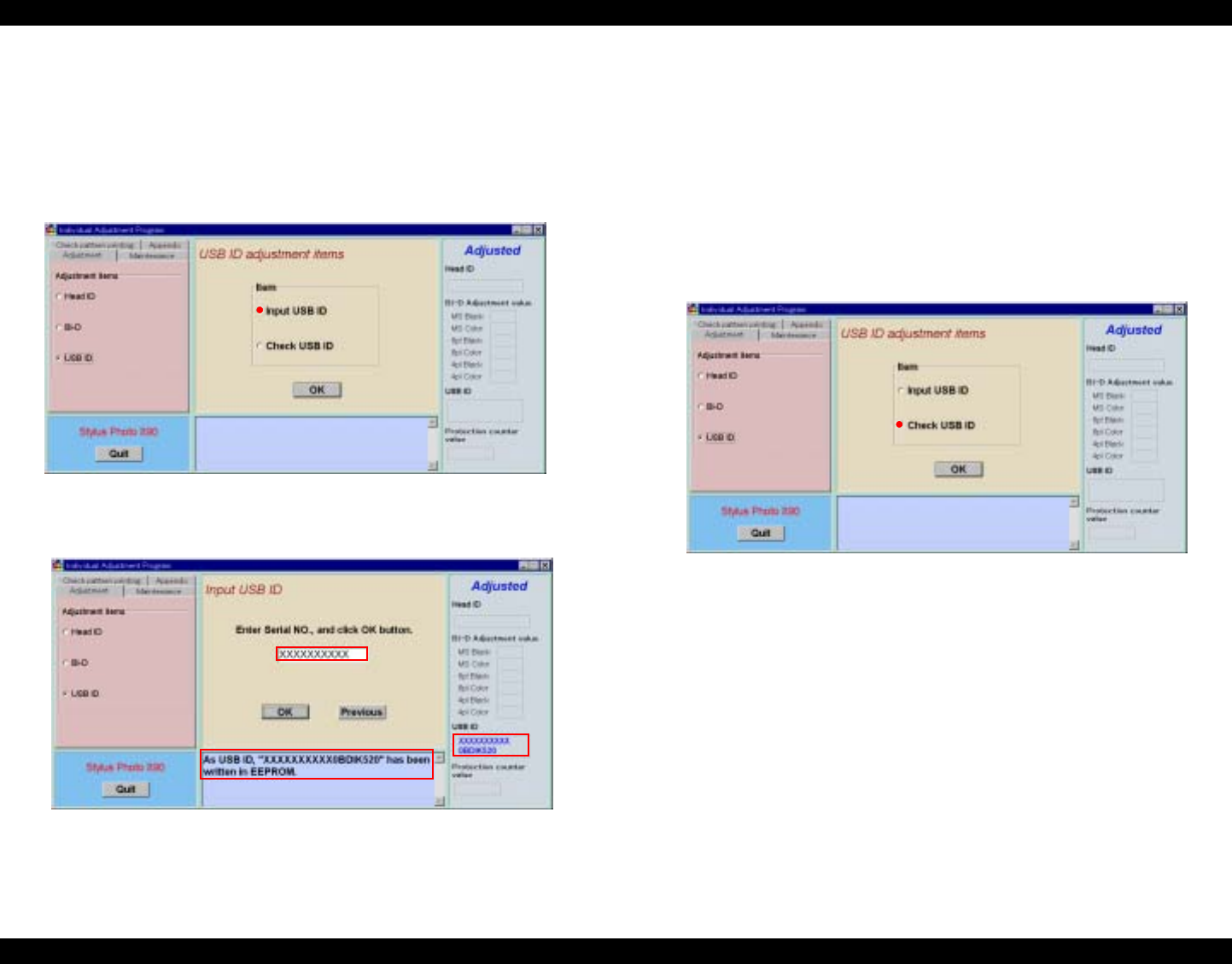
EPSON Stylus Photo 890/1280/1290 Revision C
ADJUSTMENT Individual Adjustment Program 138
5.3.3.1 Input USB ID
1. Start the program and input all the required information on the initial window.
Then the main menu appears on the screen. (See 5.2.4.1“Adjusting Program Initial
Setting” on page -128)
2. Select USB ID from the main menu.
3. The USB ID Adjustment items window appears. Select Input USB ID .
Figure 5-33. Input USB ID Selection
4. Input a10-digit serial number and click OK. The new USB ID number is displayed.
Figure 5-34. USB ID Input Window
5. To exit or continue the program, click Quit on the lower left. Refer to Figure
5-17.“Exit Window” on page -131.
5.3.3.2 Check USB ID
1. Start the program and input all the required information on the initial window.
Then the main menu appears on the screen. (See 5.2.4.1“Adjusting Program Initial
Setting” on page -128)
2. Select USB ID from the main menu.
3. The USB ID Adjustment items window appears. Select Check USB ID and click
OK.
Figure 5-35. Check USB ID Selection
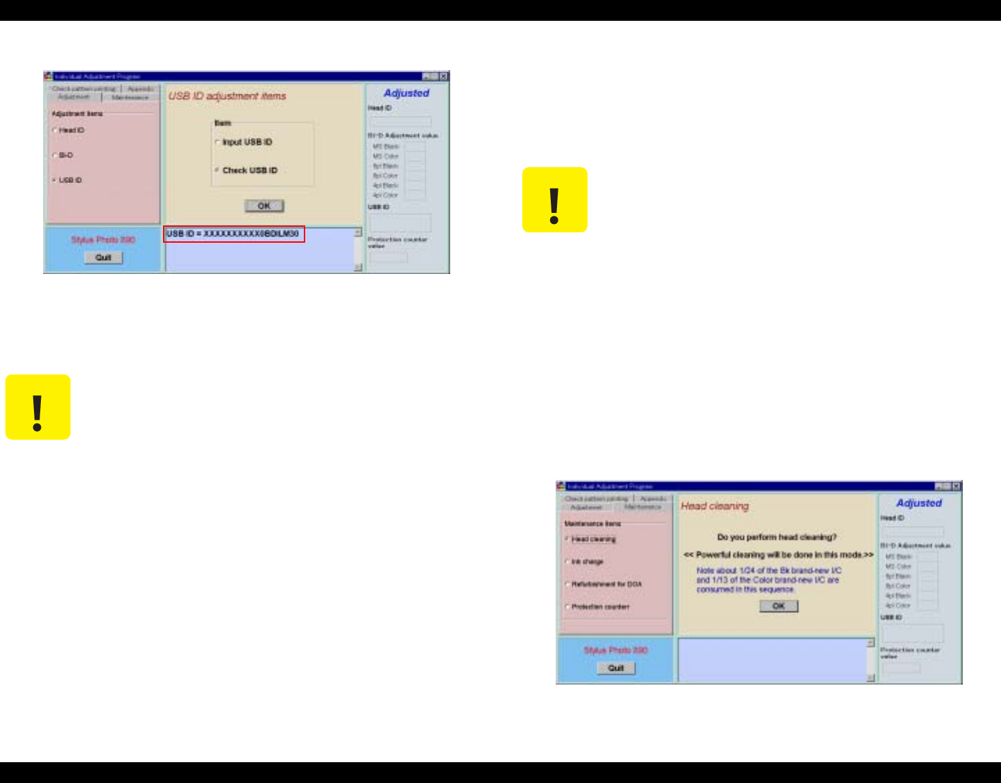
EPSON Stylus Photo 890/1280/1290 Revision C
ADJUSTMENT Individual Adjustment Program 139
4. A present USB ID is displayed.
Figure 5-36. Present USB ID Displayed
5. To exit or continue the program, click Quit on the lower left. Refer to Figure
5-17.“Exit Window” on page -131.
5.3.4 Maintenance
5.3.4.1 Head Cleaning Operation
Head Cleaning is more powerful than the head cleaning performed by pressing the
cleaning button. It is effective when a dot missing problem occurs.
1. Set A4 Normal Paper on the ASF.
2. Start the program and input all the required information on the initial window.
Then the main menu appears on the screen. (See 5.2.4.1“Adjusting Program Initial
Setting” on page -128)
3. Select Maintenance Items.
4. Select Head Cleaning from the main menu.
5. The Head Cleaning window appears. Click OK and then, the printer will start the
Head Cleaning operations.
Figure 5-37. Head Cleaning Window
C A U T I O N Be sure to input the correct printer serial number. If you input a
wrong number, it is still accepted.
Confirmation of USB port function is effective only under the
Windows 98 environment.
The new ID is not effective until the printer is turned on since the
new ID is stored in EEPROM when the printer is turned off.
C A U T I O N Head Cleaning function uses the following amount of ink at a time:
[Stylus Photo 890]
Black ink cartridge: Approximately 1/24
Color ink cartridge: Approximately 1/13
[Stylus Photo 1290]
Black ink cartridge: Approximately 1/24
Color ink cartridge: Approximately 1/20
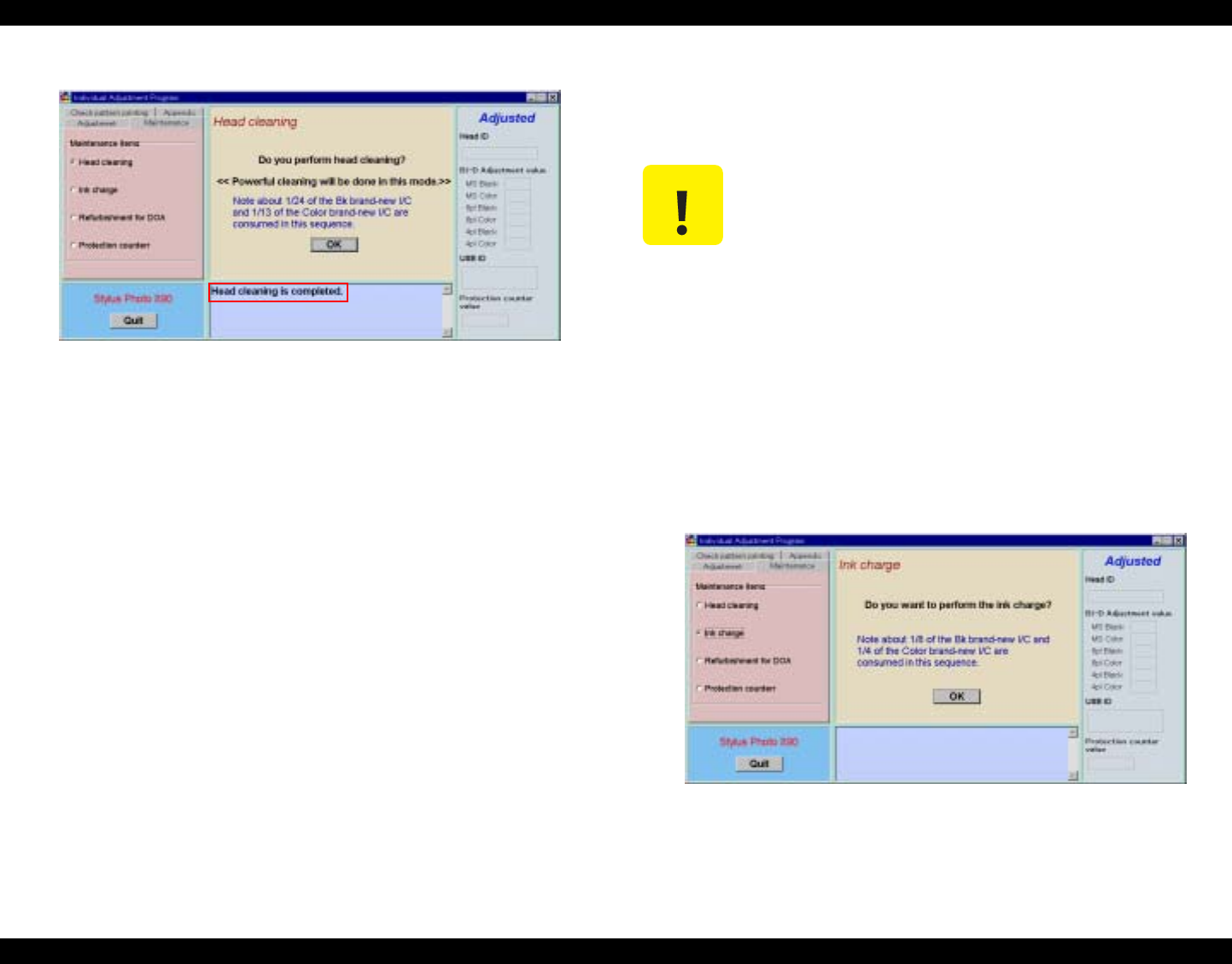
EPSON Stylus Photo 890/1280/1290 Revision C
ADJUSTMENT Individual Adjustment Program 140
6. When the cleaning is completed, the following message appears on the window.
Figure 5-38. Head Cleaning Completed
7. To exit or continue the program, click Quit on the lower left. Refer to Figure
5-17.“Exit Window” on page -131.
5.3.5 Ink Charge Operation
If the Head Cleaning is not powerful enough to solve the dot missing problem,
perform Ink Charge that consumes more ink.
1. Start the program and input all the required information on the initial window.
Then the main menu appears on the screen. (See 5.2.4.1“Adjusting Program Initial
Setting” on page -128)
2. Select Maintenance Items.
3. Select Ink Charge from the main menu.
4. The Ink Charge window appears. Click OK and then, the printer begins the ink
charge operation.
Figure 5-39. Initial Ink Charge Window
C A U T I O N The initial ink charge operation consumes the following amount
of ink at a time:
[Stylus Photo 890]
Black ink cartridge: Approximately 1/8
Color ink cartridge: Approximately 1/4
[Stylus Photo 1290]
Black ink cartridge: Approximately 1/8
Color ink cartridge: Approximately 1/7
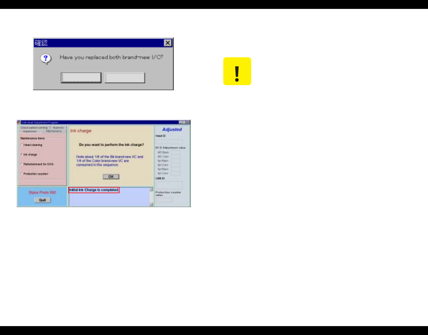
EPSON Stylus Photo 890/1280/1290 Revision C
ADJUSTMENT Individual Adjustment Program 141
5. The following message appears. After replacing both black and color I/Cs with
new ones, click Yes. The printer begins the ink charge operation.
Figure 5-40. I/C Replacement Message
6. When the ink charge is completed, the following message appears on the window.
Figure 5-41. Ink Charge Replacement Completed
7. To exit or continue the program, click Quit on the lower left. Refer to Figure
5-17.“Exit Window” on page -131.
5.3.6 Refurbishment for DOA
This function is used when the cavity of the printhead and cap assembly needs to be
cleaned.
1. Set the dummy cartridges I/Cs filled with S46 to the CR unit.
2. Start the program and input all the required information on the initial window.
Then the main menu appears on the screen. (See 5.2.4.1“Adjusting Program Initial
Setting” on page -128)
3. Select Maintenance Items.
Yes No
C A U T I O N After carrying out this function, replace the Waste Drain Ink
Pad with a new one and reset the Waste Drain Ink Pad Counter
(Protection Counter). If not, ink or S46 liquid may leak from the
ink pad during the transportation.
Prepare the following tools:
1. Dummy Ink Cartridges
2. Injector
3. S46 Liquid
This operation is available only once. Do not use this function
repeatedly. Repetition of this function may cause overflow of the
ink and S46 liquid.
When you refurbish a repairing product using the program, do it
on your responsibility.
When you charge S46 liquid into dummy ink cartridges with the
injector, make sure to full the cartridges up with the S46 liquid.
If not, the printhead may not be completely cleaned in this
operation.
Keep the S46 liquid and dummy ink cartridges clean even not in
use.
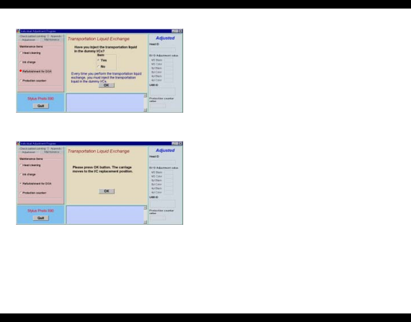
EPSON Stylus Photo 890/1280/1290 Revision C
ADJUSTMENT Individual Adjustment Program 142
4. Select Refurbishment for DOA from the main menu and click OK.
Figure 5-42. Transportation Liquid Exchange Window
5. Click OK and the Transportation Liquid Exchange Operation will start.
Figure 5-43. Transportation Liquid Exchange Operation
6. To exit or continue the program, click Quit on the lower left. Refer to Figure
5-17.“Exit Window” on page -131.
7. Remove the dummy I/Cs from the CR unit.
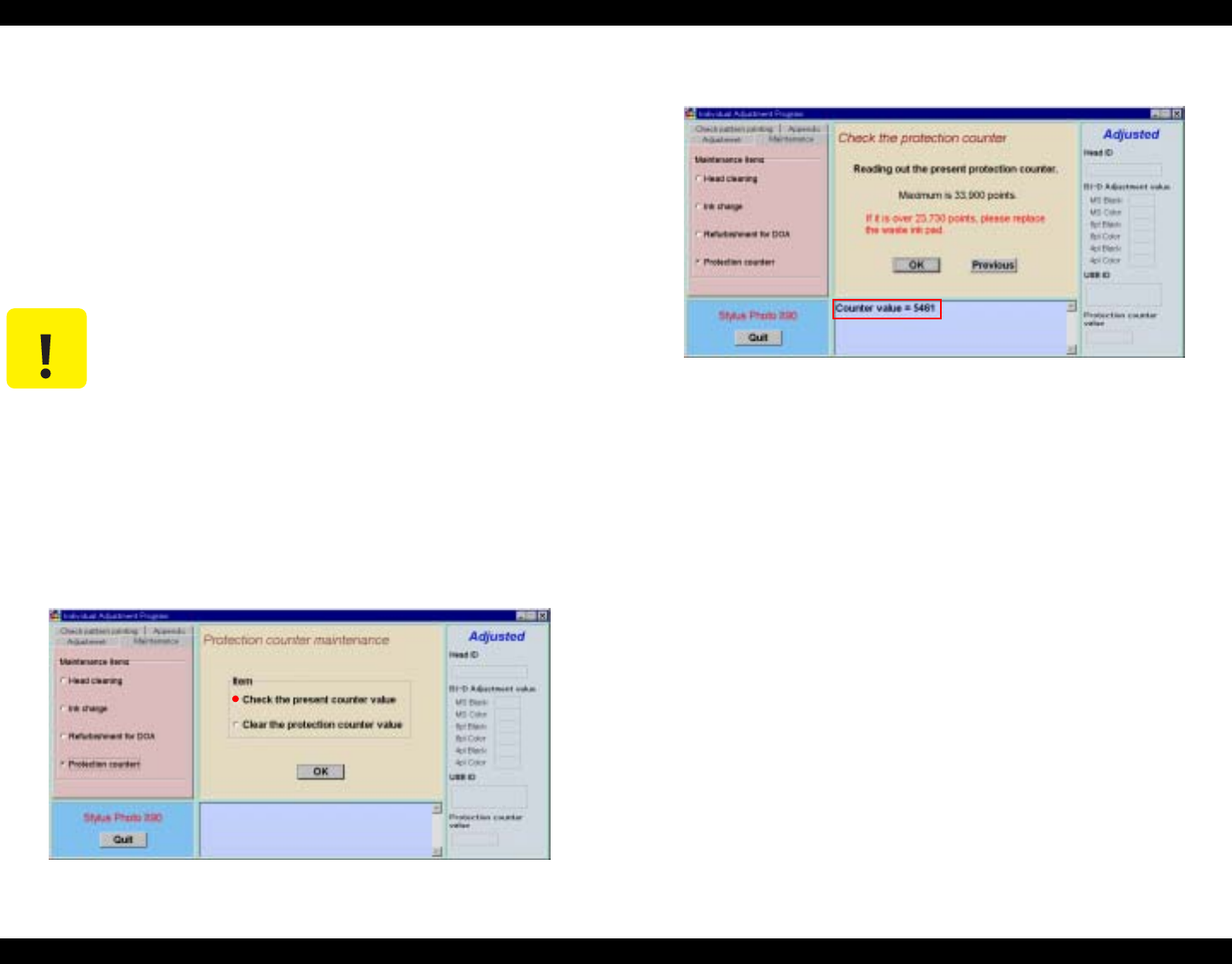
EPSON Stylus Photo 890/1280/1290 Revision C
ADJUSTMENT Individual Adjustment Program 143
5.3.7 Protection Counter
This function enables you to check the current value for the protect counter A. The
protect counter A monitors the level of waste ink flown into the waste ink absorber. If
the wasted ink level excesses the limit, it will overflow into the printer. To avoid this,
the printer indicates “Maintenance Request” when the counter reaches to the limit and
stops accepting any data except for the power signal from the control panel. During the
repair service, you are required to replace the waste ink absorbers and reset the
protection counter. For the waste ink absorber replacement procedure, see
4.2.5“TRAY, ABSORBER ASSEMBLY Removal” on page -89. Note you can also
reset the protection counter by the panel operation.
5.3.7.1 Check the Present Counter Value
1. Start the program and input all the required information on the initial window.
Then the main menu appears on the screen. (See 5.2.4.1“Adjusting Program Initial
Setting” on page -128)
2. Select Maintenance Items.
3. The Protection Counter Maintenance window appears. Select Check the
Present Counter Value and click OK.
Figure 5-44. Protection Counter Maintenance Window
4. The Check the Protection Counter window appears. Click OK, and the current
protection counter value will be displayed.
Figure 5-45. Protection Counter Value Displayed
5. To return to the Check the Protection Counter window, click Previous.
6. To exit or continue the program, click Quit on the lower left on the window.
(Refer to Figure 5-17.“Exit Window” on page -131.)
5.3.7.2 Clear the Protection Counter Value
1. Start the program and input all the required information on the initial window.
Then the main menu appears on the screen. (See 5.2.4.1“Adjusting Program Initial
Setting” on page -128)
2. Select Maintenance Items.
C A U T I O N Protection Counter does not clear “Maintenance Request” but
resets the protection counter only.
To clear “Maintenance Request”, refer to Chapter 1/Section
1.4.4 or Chapter 3/Section 3.1.1.6.
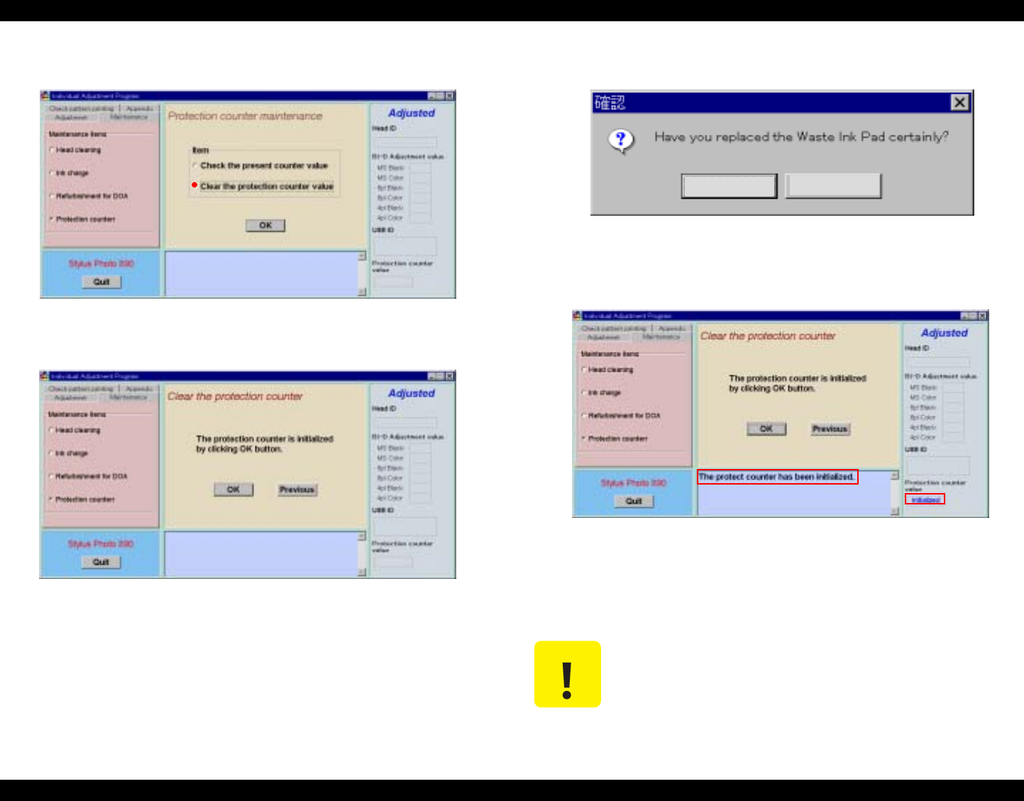
EPSON Stylus Photo 890/1280/1290 Revision C
ADJUSTMENT Individual Adjustment Program 144
3. The Protection Counter Maintenance window appears. Select Clear the
Protection Counter Value and click OK.
Figure 5-46. Protection Counter Maintenance Window
4. The Clear the Protection Counter window appears and click OK,.
Figure 5-47. Clear the Protection Counter Window
5. The following message is displayed. After replacing the Waste Ink Pad with a new
one, click (Y).
Figure 5-48. Waste Ink Pad Replacement Massage
6. The protection counter is cleared and the following message is displayed.
Figure 5-49. Counter Value Display Window
7. To return to the Check the Protection Counter window, click Previous.
8. To exit or continue the program, click Quit on the lower left on the window.
(Refer to Figure 5-17.“Exit Window” on page -131.)
C A U T I O N Whenever you reset the protection counter, make sure to replace
the Waste Ink Pad with a new one. (Refer to TRAY, ABSORBER
ASSEMBLY Removal).
Yes No
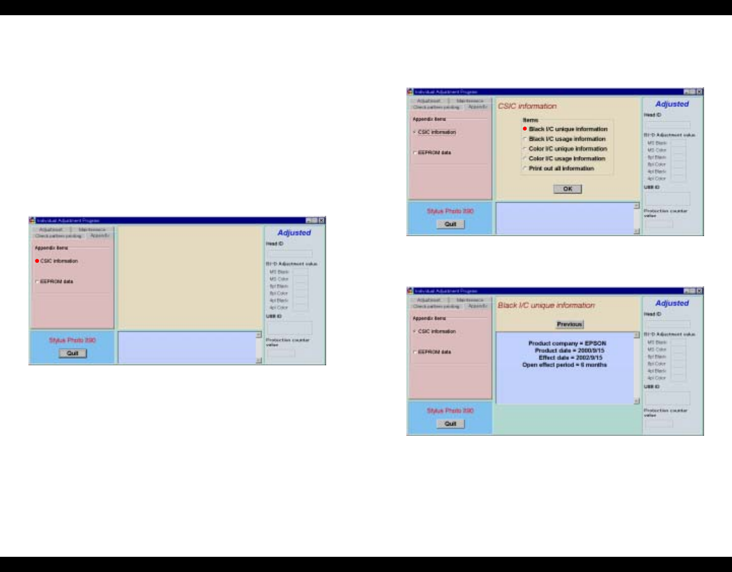
EPSON Stylus Photo 890/1280/1290 Revision C
ADJUSTMENT Individual Adjustment Program 145
5.3.8 Appendix Items
5.3.8.1 CSIC Information
CSIC is installed with the data for black and color cartridges in the EEPROM. The
EEPROM records the information of black/color ink cartridge life and so on.
According to the data in the EEPROM, the information of ink cartridge life and others
is displayed on the status windows.
1. Start the program and input all the required information on the initial window.
Then the main menu appears on the screen. (See 5.2.4.1“Adjusting Program Initial
Setting” on page -128)
2. Select Appendix Items.
3. The Appendix Items window appears. Select CSIC Information.
Figure 5-50. CSIC Information Selection
4. Select the necessary item and click OK. (e.g. Black Ink Cartridge Unique
Information is selected here).
If you need all of the information listed on the window, select Print Out All
Information.
Figure 5-51. CSIC Information
5. The selected information is displayed.
Figure 5-52. Black I/C Unique Information
6. To select other items, click Previous to return to the CSIS Information window.
7. To exit or continue the program, click Quit on the lower left on the window.
(Refer to Figure 5-17.“Exit Window” on page -131.)
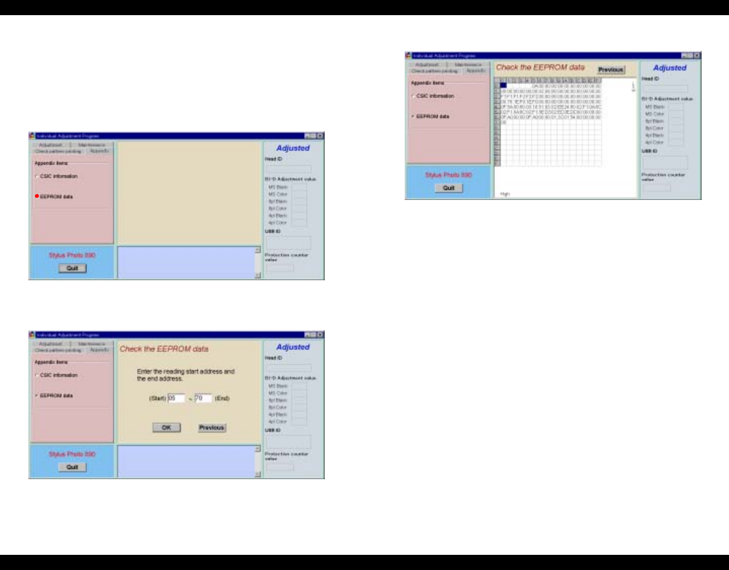
EPSON Stylus Photo 890/1280/1290 Revision C
ADJUSTMENT Individual Adjustment Program 146
5.3.8.2 EEPROM Data Check
1. Start the program and input all the required information on the initial window.
Then the main menu appears on the screen. (See 5.2.4.1“Adjusting Program Initial
Setting” on page -128)
2. Select Appendix Items.
3. The Appendix Items window appears. Select EEPROM Data.
Figure 5-53. EEPROM Data Selection
4. Input the reading start address and end address. Click OK.
Figure 5-54. Reading Start/End Address Input
5. The information of the designated address is displayed as follows.
Figure 5-55. EEPROM Data Displayed
6. Click Previous twice to return to the EEPROM Data window.
7. To exit or continue the program, click Quit on the lower left on the window.
(Refer to Figure 5-17.“Exit Window” on page -131.)
5.3.8.3 Changing EEPROM Data
1. Start the program and input all the required information on the initial window.
Then the main menu appears on the screen. (See 5.2.4.1“Adjusting Program Initial
Setting” on page -128)
2. Select Appendix Items.
3. The Appendix Items window appears. Select EEPROM Data.
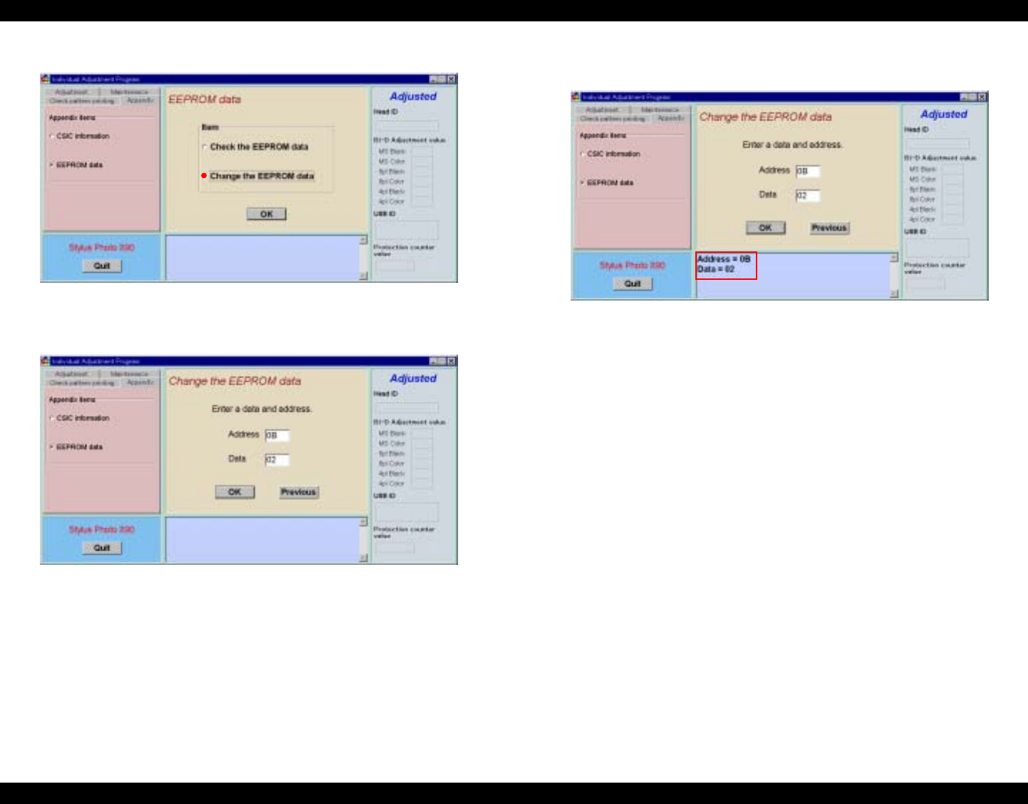
EPSON Stylus Photo 890/1280/1290 Revision C
ADJUSTMENT Individual Adjustment Program 147
4. The the EEPROM Data window appears. Select Change the EEPROM Data.
Figure 5-56. EEPROM Data Selection
5. Input the EEPROM address and data needs to be changed and click OK.
Figure 5-57. EEPROM Data Change Window
6. When the EEPROM data is changed, a new address and data is displayed at the
lower left.
Figure 5-58. EEPROM Data Change Completed
7. Click Previous twice to return to the EEPROM Data window.
8. To exit or continue the program, click Quit on the lower left on the window.
(Refer to Figure 5-17.“Exit Window” on page -131.)
5.3.9 A4 Check Pattern Printing
This function lets the printer to print several test patterns on a A4 paper to allow you to
check the adjustment results.
1. Set A4 Normal Paper on the ASF.
2. Start the program and input all the required information on the initial window.
Then the main menu appears on the screen. (See 5.2.4.1“Adjusting Program Initial
Setting” on page -128)
3. Select Check Pattern Printing Items.
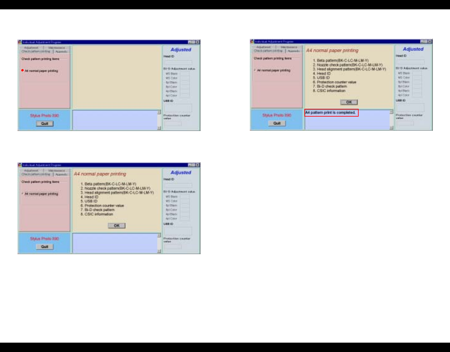
EPSON Stylus Photo 890/1280/1290 Revision C
ADJUSTMENT Individual Adjustment Program 148
4. The Check Pattern Printing window appears. Select A4 Normal Paper
Printing.
Figure 5-59. A4 Normal Printing Selection
5. Click OK. All of the 8 items on the window are printed on A4 Normal sheets.
Figure 5-60. A4 Normal Paper Printing
6. When the printing is completed, the following message is displayed on the
window.
Figure 5-61. A4 Normal Paper Printing Completed
7. To exit or continue the program, click Quit on the lower left on the window.
(Refer to Figure 5-17.“Exit Window” on page -131.)
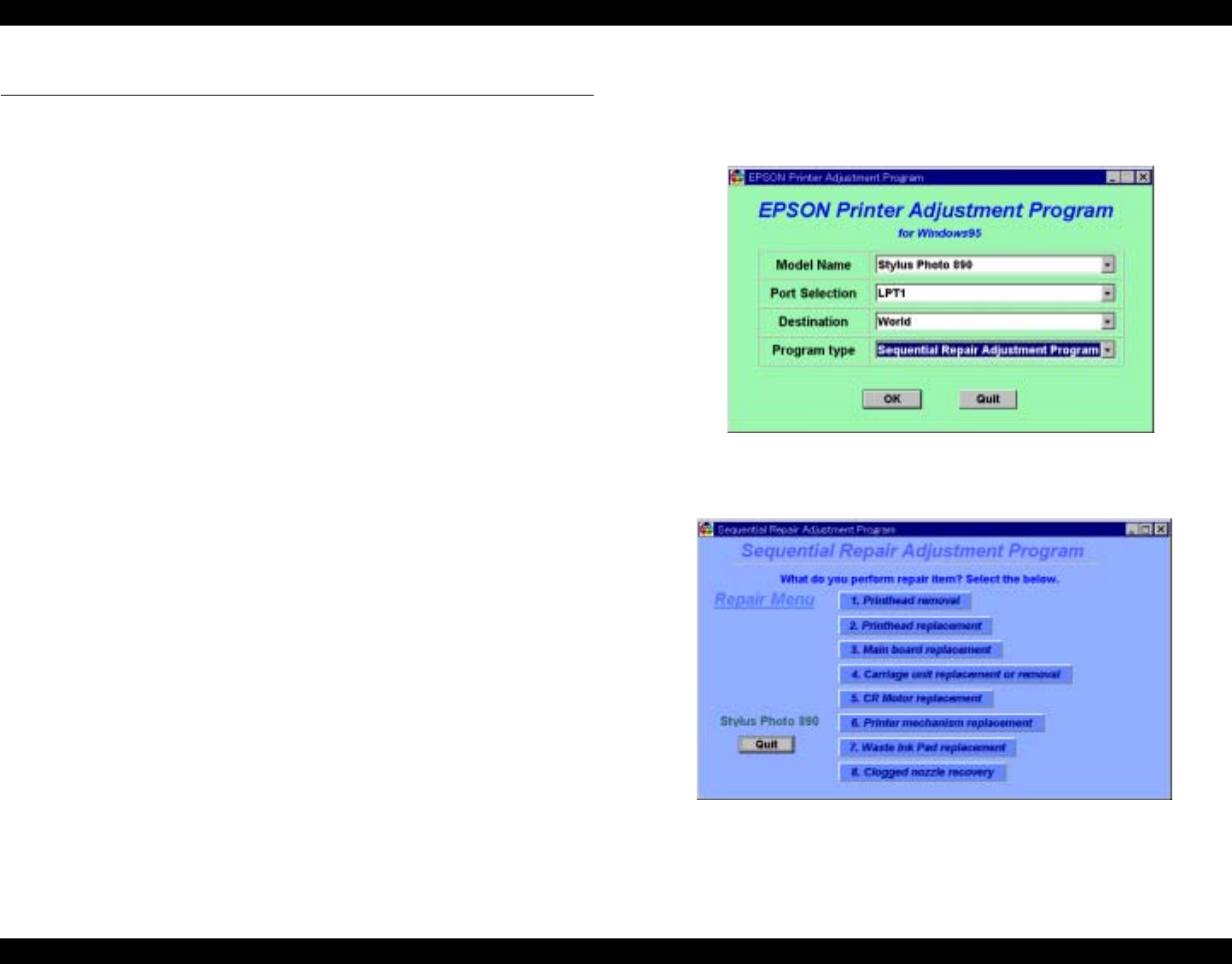
EPSON Stylus Photo 890/1280/1290 Revision C
ADJUSTMENT Sequential Repair Adjustment Program 149
5.4 Sequential Repair Adjustment Program
This program is common for both Stylus Photo 890 and Stylus Photo 1290.
NOTE: In this section, Stylus Photo 890 program windows are used as examples.
5.4.1 Function
In this section, the sequential operations needs to be done are explained. This service
program provides appropriate adjustment orders for repair, and the following
adjustment items are included:
Printhead Removal
Printhead Replacement
Main Board Replacement
Carriage Unit Replacement/Removal
CR Motor Replacement
Printer Mechanism Replacement
Waste Ink Pad Replacement
Clogged Nozzle Recovery
5.4.1.1 How to start the program
1. Start the program and input all the required information on the initial window.
Make sure to chose Sequential Repair Adjustment Program for Program Type.
(See 5.2.4.1“Adjusting Program Initial Setting” on page -128)
Figure 5-62. Program Type Selection
2. Select a repair item and click OK. The main menu appears.
Figure 5-63. sequential Repair Adjustment Program Main Menu
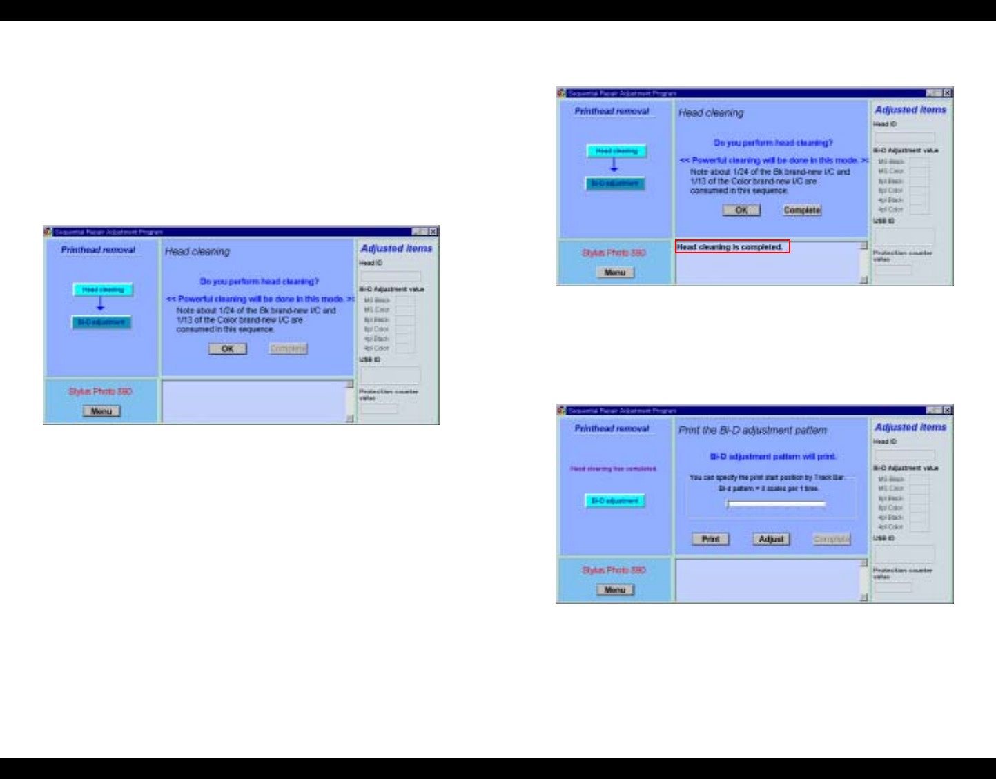
EPSON Stylus Photo 890/1280/1290 Revision C
ADJUSTMENT Sequential Repair Adjustment Program 150
5.4.1.2 Printhead Removal
When you remove the printhead and reinstall it, select this function and execute the
operations following the procedures below.
1. Reinstall the printhead to the carriage unit of the under-repair printer mechanism.
2. Select Printhead Rmoval from the main menu.
3. Select Head Cleaning and click OK. For detailed information on the ink
consumption amount during the Head Cleaning operation, refer to 5.3.4.1“Head
Cleaning Operation” on page -139.
Figure 5-64. Head Cleaning Window
4. When the Head Cleaning is completed, the following message is displayed on the
window.
Figure 5-65. Head Cleaning Completed
5. Select Bi-D Adjustment and click Print. According to the printed Bi-D
Adjustment Pattern, continue the adjustment until you get the best result. If you
need to change the Bi-D Adjustment values, click Adjust and change the
adjustment values. Refer to 5.3.2“Bi-Directional Adjustment” on page -133.
Figure 5-66. Bi-D Adjustment Pattern Printing
NOTE: To save sheets of paper during Bi-D Pattern Printing, you can set an initial
printing start position by using the track bar on the window. The printing start
position can be determined according to the track bar you set. Refer to 5.3.2“Bi-
Directional Adjustment” on page -133.
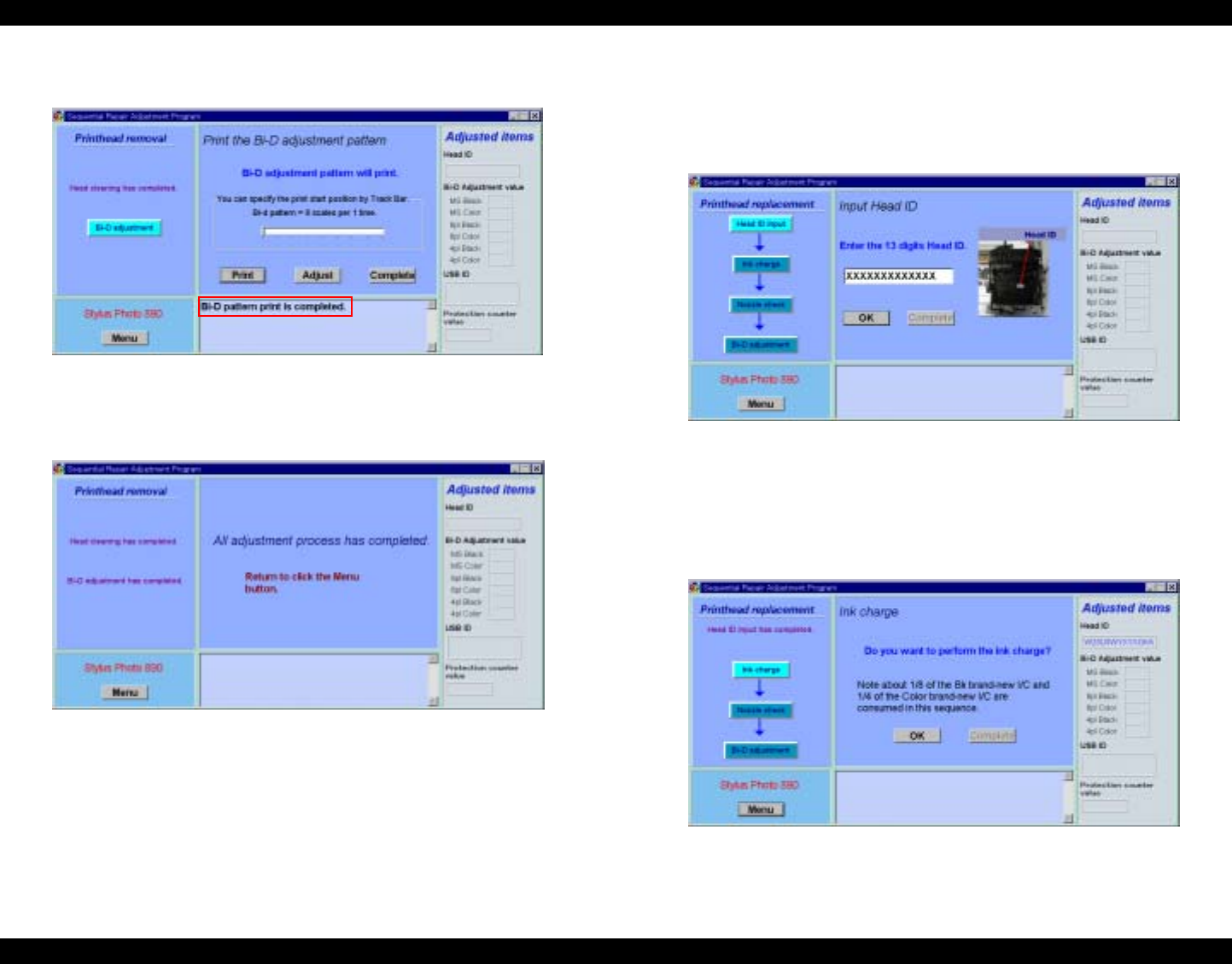
EPSON Stylus Photo 890/1280/1290 Revision C
ADJUSTMENT Sequential Repair Adjustment Program 151
6. When the Bi-D pattern printing is finished, the following message is displayed.
Click Complete.
Figure 5-67. Bi-D Pattern Printing Completed
7. The following message appears. All of the Printhead Removal operations are
completed.
Figure 5-68. Printhead Removal Operations Completed
8. To return to the main menu, click the Menu button at the lower left.
5.4.1.3 Printhead Replacement
1. Replace the printhead with a new one. Select Printhead Replacement from the
main menu.
2. The Head ID window appears. Input a 13-digit Head ID and click OK.
Figure 5-69. Head ID Input Window
3. The following massage, “As head ID, ’xxxxxxxxxxxxx’ has been written in
EEPROM” is displayed. Click Complete.
4. Select Ink Charge. For the procedures, refer to 5.3.5“Ink Charge Operation” on
page -140.
Figure 5-70. Ink Charge Window
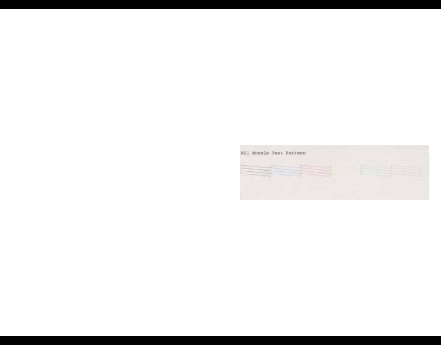
EPSON Stylus Photo 890/1280/1290 Revision C
ADJUSTMENT Sequential Repair Adjustment Program 152
5. Execute Nozzle Check. Refer to 5.4.1.9“Clogged Nozzle Recovery” on
page -152.
6. Execute Bi-D Adjustment. Refer to 5.3.2“Bi-Directional Adjustment” on
page -133
5.4.1.4 Main Board Replacement
1. Select Main Board Replacement from the main menu.
2. Execute Head ID Input. Refer to 5.4.1.3“Printhead Replacement” on page -151.
3. Execute Bi-D Adjustment. Refer to 5.3.2“Bi-Directional Adjustment” on
page -133.
4. Execute USB ID Input. Refer to 5.3.3“Input/Check USB ID” on page -137.
5. Execute Protection Counter Clear. Refer to 5.3.7“Protection Counter” on
page -143.
5.4.1.5 Carriage Unit Replacement/ Removal
1. After removing or replacing the Carriage Unit with a new one, select Carriage
Unit Replacement/Removal from the main menu.
2. Execute Bi-D Adjustment. Refer to 5.3.2“Bi-Directional Adjustment” on
page -133.
5.4.1.6 CR Motor Replacement
1. After replacing the CR Motor, select CR Motor Replacement from the main
menu.
2. Execute Bi-D Adjustment. Refer to 5.3.2“Bi-Directional Adjustment” on
page -133.
5.4.1.7 Printer Mechanism Replacement
Make this adjustment when you replace the printer mechanism with a new one. Since
the Printer Mechanism Replacement Procedures are the same as those of the Printhead
Replacement, refer to 5.4.1.3“Printhead Replacement” on page -151.
5.4.1.8 Waste Ink Pad Replacement
When you replace the Waste Ink Pad with a new one, the protector counter needs to be
cleared.
1. Select Waste Ink Pad Replacement from the main menu.
2. Execute Protection Counter Clear. Refer to 5.3.7“Protection Counter” on
page -143.
5.4.1.9 Clogged Nozzle Recovery
1. Select Clogged Nozzle Recovery from the main menu.
2. Select Nozzle Check and click Print. If a dot missing problem occurs, click
Cleaning to execute nozzle cleaning. Repeat the procedures, if necessary, until the
nozzle problem is recovered.
3. The Nozzle Check Patter is printed as follows.
Figure 5-71. Nozzle Check Pattern Sample
NOTE: To save sheets of paper during Nozzle Check Pattern Printing, you can set an
initial printing start position by using the track bar on the window. The printing
start position can be determined according to the track bar you set. With this
function, you can print out Nozzle Check Printing Patterns multiple times on an
A4 size sheet.
4. For the second or later test printing using, using the track bar is recommended to
save paper. The track bar can be set to 8 levels. For the second printing, setting the
bar to the first is recommended. After setting the bar, click OK.

EPSON Stylus Photo 890/1280/1290 Revision C
ADJUSTMENT Sequential Repair Adjustment Program 153
5. The second or third test printing patterns are printed as follows.
Figure 5-72. Second/Third Nozzle Check Pattern Printing Sample
6. When the Nozzle functions properly, click Complete.
7. To return to the main menu, click the Menu button at the lower left.
The Second Nozzle Check Pattern
starts from here.
The Third Nozzle Check Pattern
starts from here.

CHAPTER
6
MAINTENANCE

EPSON Stylus Photo 890/1280/1290 Revision D
MAINTENANCE Overview 155
6.1 Overview
This section describes points and procedures for maintaining the printer in its optimum
condition.
6.1.1 Cleaning
The printer has no mechanical components which require regular cleaning. Therefore,
note that the points suggested below are only to check for dirt, and cleaning should be
performed upon necessity.
Housing:
Use a soft clean cloth moistened with water to wipe off any dirt. If the housing is
stained with ink, use a cloth moistened with neutral detergent to wipe it off.
Inside the Printer:
Use a vacuum cleaner to remove any paper dust.
6.1.2 Service Maintenance
If print irregularity (missing dot, white line, etc.) has occurred or the printer indicates
“Maintenance Error”, take the following actions to clear the error.
6.1.2.1 Head Cleaning
The printer has a built-in head cleaning function, which is activated through the control
panel operation. Run a head cleaning in the following order:
1. Confirm that the printer is in stand-by state. (The power lamp is not blinking.)
2. Hold down the cleaning button on the control panel for 3 seconds or longer. (The
power LED blinks during the cleaning.)
6.1.2.2 Maintenance Request Error Clear
Ink is used for cleaning as well as printing. During cleaning, the printer drains some ink
into the waste ink pads. The protection counter A in EEPROM on the main board keeps
track of the quantity of ink drained into the waste ink pads. When the counter reaches
the predefined service limit, the printer assumes the waste ink pad is full of ink and
requests ink pad replacement by indicating a maintenance request error.
Service limit of the protection counter A:
The service limit of the protection counter A = 35400
Timing for replacing the waste ink pad:
When the total amount of the waste ink reaches the predetermined limit, a
maintenance error occurs. In this condition, the printer does not accept any input
but from the power button.
Current counter value can be found on a status print sheet that also shows the
firmware version, selected code page, and nozzle check pattern. During
servicing, you are required to check the counter value and if the counter is
close to its limit, notify your customer of the situation and recommend that the
waste ink pad be replaced (If the waste ink pad is not replaced at that time,
there is a possibility that a maintenance error will occur soon after the printer
is returned to the customer). Once you have the confirmation of the customer,
replace the waste ink pad and reset the counter.
The counter limit is generally 25000 pages and 10000 pages for black and
color, respectively. In normal use, the counter reaches the limit in 5 years.
C A U T I O N Never use chemical solvents, such as thinner, to clean the printer.
These chemicals can damage the printer components.
Be careful not to damage the components in attempt to clean
inside the printer.
Do not scratch the surface of “ROLLER, ASSEMBLY, PF”. (Use
a soft brush to wipe off the dust, or use a soft cloth moistened
with alcohol.)
EPSON Stylus Photo 890/1280/1290 Revision D
MAINTENANCE Overview 156
Replacement procedure:
Refer to Section 4.2.5.
Operation after replacement:
Perform “Waste ink counter reset”. Refer to Chapter 1/Section 1.4.4 for details.
6.1.3 Lubrication
The type and amount of oil and grease used to lubricate the printer parts are determined
based on the results of internal evaluations. Therefore, be sure to apply the specified
type and amount of oil and grease to the specified part of the printer mechanism during
servicing.
Table 6-1. Specified Lubricants
C A U T I O N Never use oil and grease other than those specified in this
manual. Use of different types of lubricant can damage the
printer and its components.
Never apply larger amount of lubricant than specified in this
manual.
Type Name EPSON Code Supplier
Grease G-26 1080614 EPSON
Grease G-56 1059150 EPSON
Oil O-12 1038991 EPSON
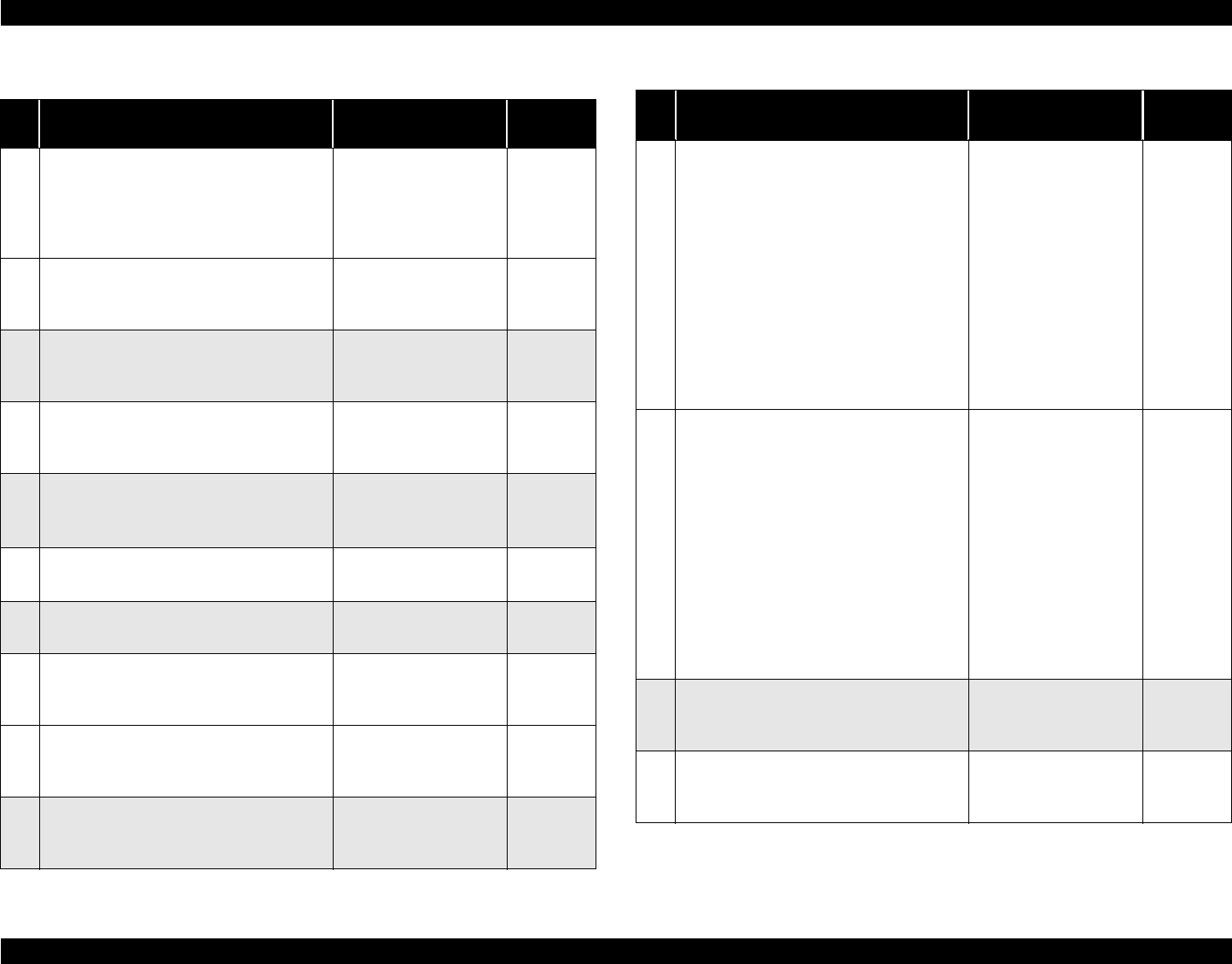
EPSON Stylus Photo 890/1280/1290 Revision D
MAINTENANCE Overview 157
Table 6-2. Lubrication Point
Lubrication Point Lubricant Type &
Amount Refer to:
1COMBINATION GEAR, 12, 22.92,
LEVER ASSY
• Using a brush, apply the grease evenly to
the inside surface of the bushing except
for the part in witch E-Ring is installed.
G-26 Page 159
2BUSHING, 12, RIGHT
• Using a brush, apply the grease evenly to
the inside surface of the bushing.
G-26
A 3-mm wide bead
Page 159
3HOLDER, PULLEY, DRIVEN G-26
φ 1 x 3mm (for each of
the 4 points)
Page 159
4BUSHING, 12, LEFT
• Using a brush, apply the grease to the
inside surface of the bushing.
G-26
A 3-mm wide bead
Page 160
5BUSHING, 6
• Using a brush, apply the grease to the
inside surface of the bushing.
G-26
A 1-mm wide bead
Page 160
6PULLEY, DRIVEN
• Apply the grease to the flat surface.
G-26
φ 1 x 1mm (2 points)
Page 161
7SHAFT, PULLEY, DRIVEN G-26
φ 1 x 1mm
Page 161
8COMBINATION GEAR, 12, 22.4
• Using a dispenser, apply the oil to the
entire inside circumference of the gear.
O-12 Page 161
9COMBINATION GEAR, 14, 28
• Using a flux dispenser, apply the oil to the
entire inside circumference of the gear.
O-12 Page 161
10 Shaft C
• Using a brush, apply the oil to the whole
surface of Shaft C with G-26.
G-26 Page 161
11 FELT, D3.6 for COMBINATION GEAR
12, 22.4 (set the felt to Shaft B)
• Lubricate the inner all part of the
Combination Gear, 12,22.4 with O-12 by
brush.
• Dip the felt in the oil to soak it
• Insert the Felt, D3.6 with O-12 to Shaft B.
NOTE:1) Do not use Felt with white
core.
2) Do not spill on Lever Planet
Unit during insertion of Felt.
3) Do not hang down oil to any
part except on the shaft.
O-12
Soak in.
Page 161
12 FELT, D3.6 for COMBINATION GEAR
14, 28 (set the felt to Shaft A)
• Lubricate the inner all part of the
Combination Gear, 14,28 with O-12 by
brush.
• Dip the felt in the oil to soak it
• Insert the Felt, D3.6 with O-12 to Shaft A.
NOTE:1) Do not use Felt with white
core.
2) Do not spill on Lever Planet
Unit during insertion of Felt.
3) Do not hang down oil to any
part except on the shaft.
O-12
Soak in.
Page 161
13 Groove on “ROLLER, PF”
• Apply the grease to the groove on the
Roller PF.
G-26
φ 1 x 5mm
Page 162
14 Contact area for ROLLER, EJECT and
GROUND SPRING, EJECT
• Apply the grease while rotating the shaft.
G-26
φ 1 x 2mm
Page 162
Table 6-2. Lubrication Point (continued)
Lubrication Point Lubricant Type &
Amount Refer to:

EPSON Stylus Photo 890/1280/1290 Revision D
MAINTENANCE Overview 158
15 Contact areas for ROLLER, PF and
PAPER GUIDE, REAR
• Apply the grease to the contact area while
rotating the shaft.
NOTE: Do not get the grease on the
specially coated area of ROLLER,
PF.
G-26
φ 1 x 1/2 of the
circumference
Page 162
16 PAPER GUIDE, FRONT (6 points)
• Lubricate slots(4) and hooks(2) of Paper
Guide Front with G-26 using syringe.
G-26
•φ 1 x 2mm
(Eject Roller side-
[2])
•φ 1 x 10mm
(PF Roller side[1])
•φ 1 x 2mm([2] hooks
& [1] slot)
Page 162
17-
1
SHAFT, CR (EPSON Stylus Photo 890
only)
• Apply G-56 on Shaft, CR (2 spots).
• After applying the grease, move the
Carriage to left to right to distribute the
grease evenly on the shaft.
G-56 Page 163
17-
2SHAFT, CR (EPSON Stylus Photo
1280/1290)
• Apply O-12 on the Oil Pad (1049380)
O-12
• 0.70-0.74cc or 0.63-
0.67g
18 COMBINATION GEAR 13.5, 30 shaft in
FRAME, LEFT G-26
φ 1 x 5mm
Page 163
Table 6-2. Lubrication Point (continued)
Lubrication Point Lubricant Type &
Amount Refer to:
19 LD Roller Assy hole in the FRAME, ASF;
B
• Using a brush, apply the grease evenly to
the entire inside surface of the hole.
G-26
φ 1 x 1mm
Page 163
20 Latches (right & left) in the Hopper Assy
along which the hopper release levers turn
(2 spots).
• Use a brush to apply the grease.
G-26
A 2-mm wide bead for
each one.
Page 164
21 GUIDE PLATE, CR
• Apply the grease to the Carriage using the
Guide Place CR Lubricating jig.
• Spread the G-26 evenly by moving the
Carriage once.
G-26
φ 1 x 270mm(See the
figure for length.)
Page 164
W ARNING Never apply oil directly to the CR guide shaft. This may cause a
fatal damage to the main components of the printer. (EPSON
Stylus Photo 1280/1290)
Avoid applying too much oil to the oil pad. Otherwise, you may
critically damage the main components of the printer. (EPSON
Stylus Photo 1280/1290)
Table 6-2. Lubrication Point (continued)
Lubrication Point Lubricant Type &
Amount Refer to:
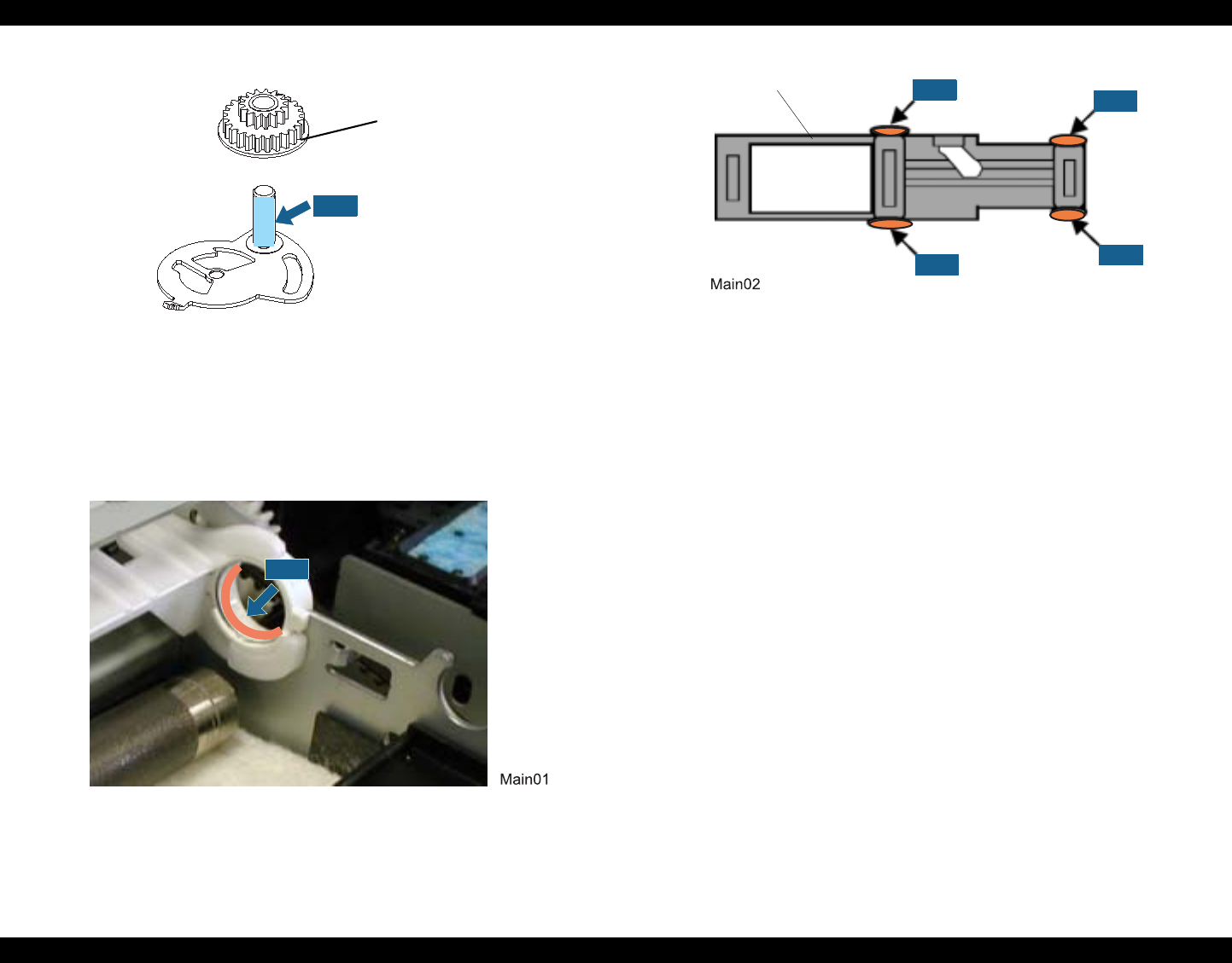
EPSON Stylus Photo 890/1280/1290 Revision D
MAINTENANCE Overview 159
Figure 6-1. Lever Assy, Combination Gear, 12,22.92
Figure 6-2. Bushing, 12, Right
Figure 6-3. Holder, Pulley, Driven
COMBINATION GEAR, 12,22.9
G-26
G-26
HOLDER, PULLEY, DRIVEN G-26 G-26
G-26
G-26
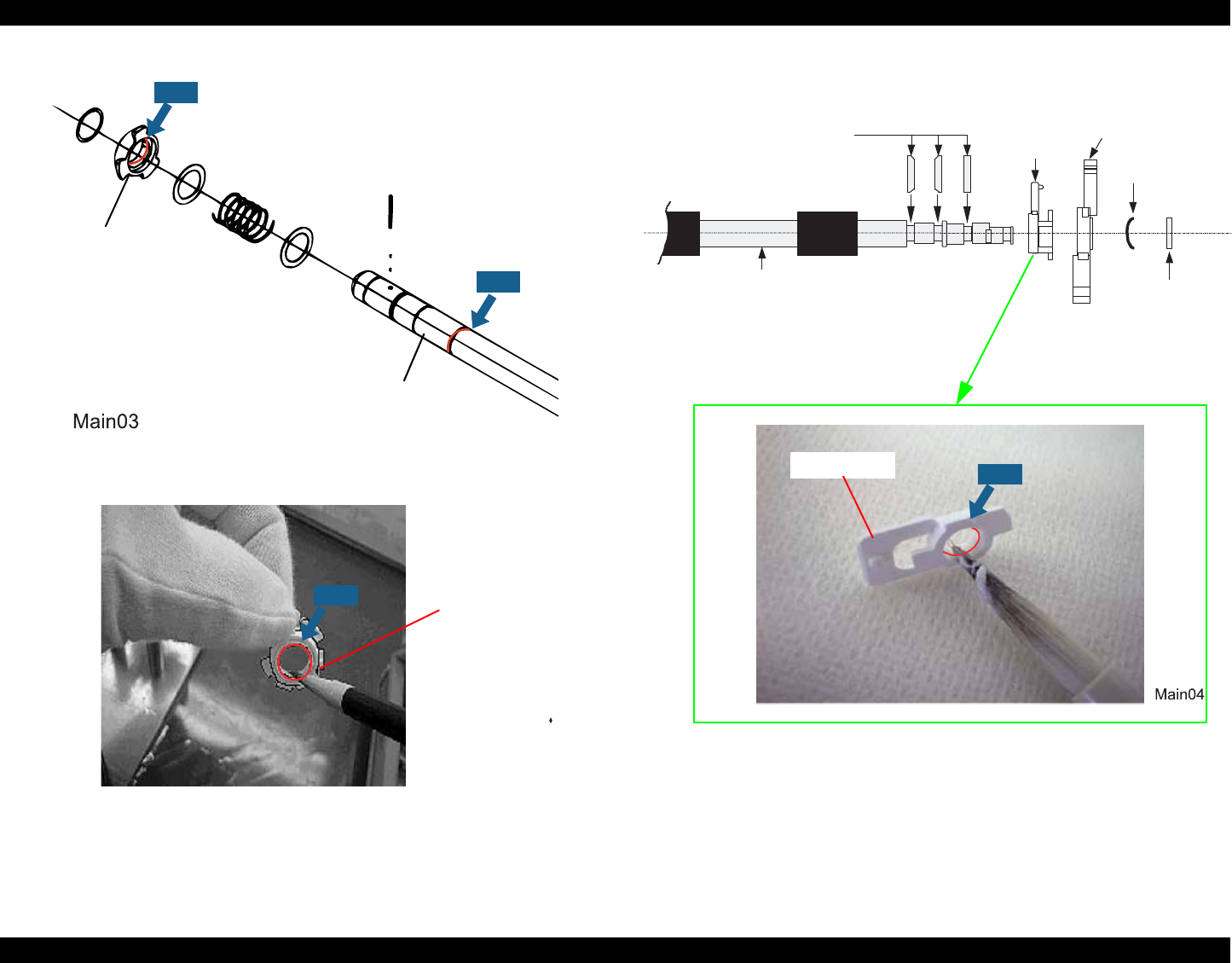
EPSON Stylus Photo 890/1280/1290 Revision D
MAINTENANCE Overview 160
Figure 6-4. Bushing, 12, Left Figure 6-5. Bushing, 6
BUSHING, 12, LEFT
G-26
SHAFT, CR, GUIDE
G-26
BUSHING, 12, LEFT
G-26
ROLLER, ASSY, EJECT
E RING, 4, F/UC
BUSHING, 6
LEVER, CR, LOCK
PLAIN WASHER,
5.1X0.7X11,S/Na
U-TYPE SPRING,
5.2X0.13X10,S/Na
BUSHING, 6 G-26
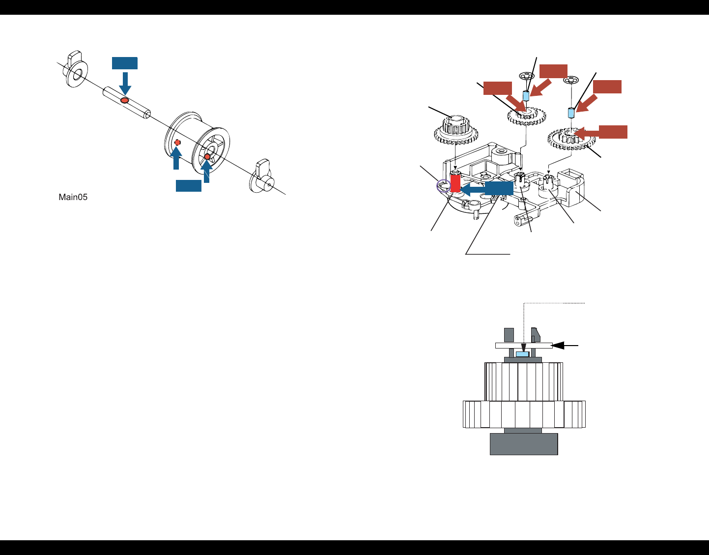
EPSON Stylus Photo 890/1280/1290 Revision D
MAINTENANCE Overview 161
Figure 6-6. Shaft, Pulley, Driven
Figure 6-7. Combination Gear, 12,22.4 & 14.28
SHAFT, PULLEY, DRIVEN
PULLEY, DRIVEN
G-26
G-26
COMBINATION
GEAR, 12, 22.4
COMBINATION
GEAR, 17.19, 25.6
FELT, D3.6
MOUNTING
PLATE,
MOTOR, ASF
COMBINATION
GEAR, 14, 28
O-12
O-12
O-12
FELT, D3.6
G-26
FELT, D3.6
SHAFT, C SHAFT, B SHAFT, A
Screw hole for
Motor Assy, ASF
*No oil
O-12
LEVER PLANET UNIT
SET RING, D8.8
must fit in
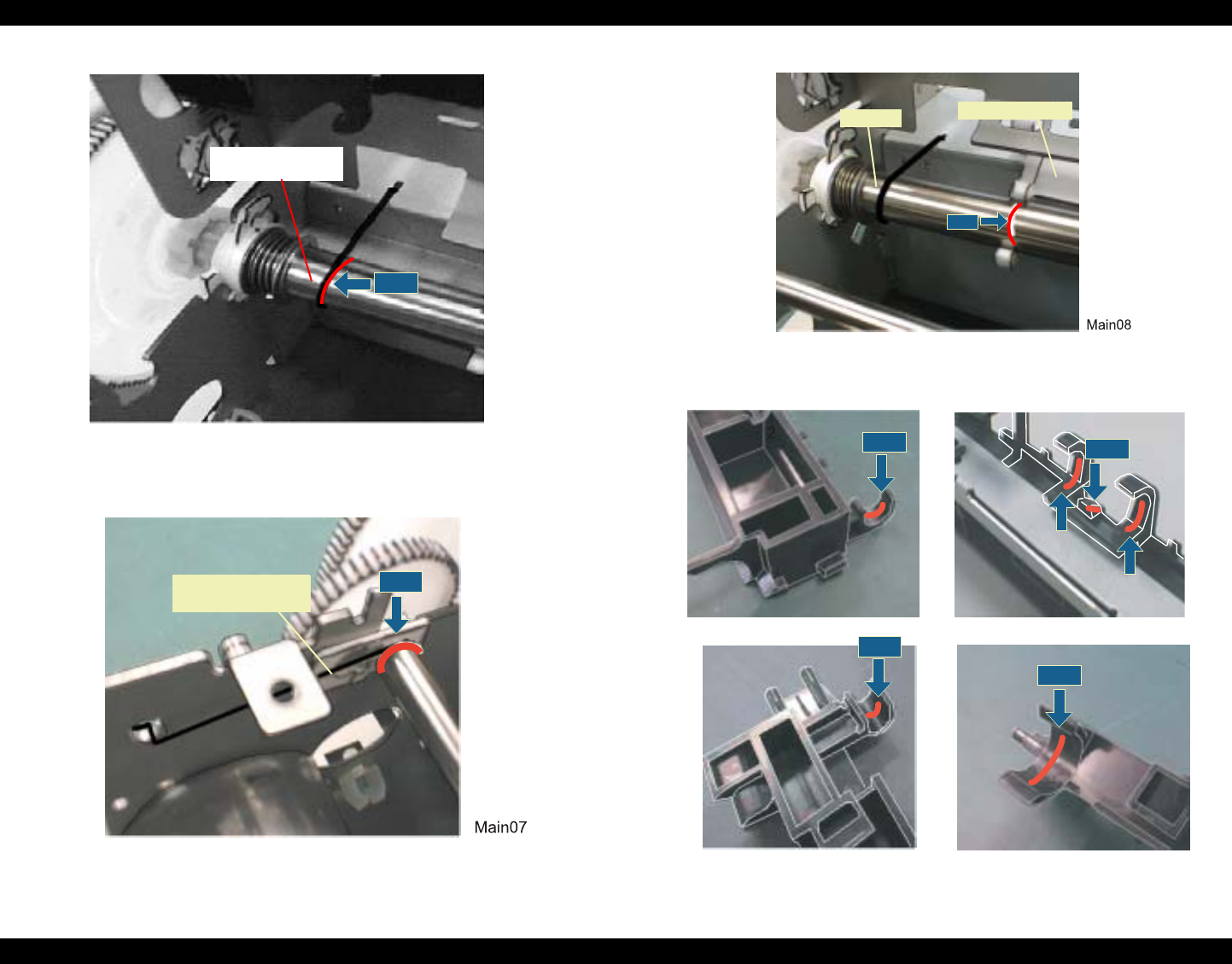
EPSON Stylus Photo 890/1280/1290 Revision D
MAINTENANCE Overview 162
Figure 6-8. Groove on Roller, PF
Figure 6-9. Roller, Eject & Ground Spring, Eject
Figure 6-10. Roller, PF
Figure 6-11. Paper Guide, Front (6 spots)
SHAFT, CR
G-26
CONTACT SPRING,
PAPER EJECT
G-26
ROLLE PAPER GUIDE,
G-26
G-26 G-26
G-26
G-26
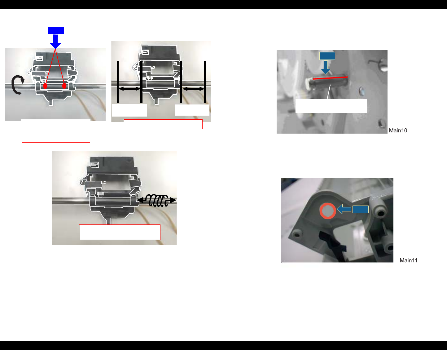
EPSON Stylus Photo 890/1280/1290 Revision D
MAINTENANCE Overview 163
Figure 6-12. Shaft, CR (EPSON Stylus Photo 1280/12909 Carriage
Unit)
]
Figure 6-13. Combination Gear, 13.5,30
Figure 6-14. Frame, ASF; B
Approx. 3 cm Approx. 3 cm
G-56
After applying G-56 on the
shaft, rotate the shaft half
way.
Move the Carriage to left to right.
Rotating the Shaft, to distribute the
grease evenly on the shaft.
G-26
COMBINATION GEAR, 13.5,30
SHAFT
G-26
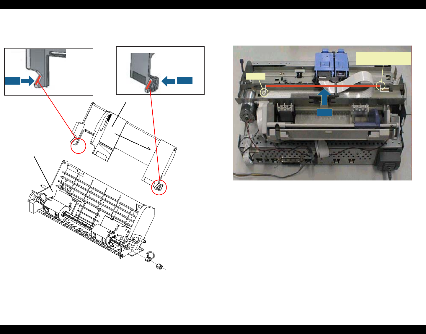
EPSON Stylus Photo 890/1280/1290 Revision D
MAINTENANCE Overview 164
Figure 6-15. Hopper Assy (right and left)
Figure 6-16. Guide Plate, CR
G-26 G-26
FRAME, ASF; B
HOPPER ASSY
Screw
Hook for the CR motor
linear scale
G-26

CHAPTER
7
APPENDIX
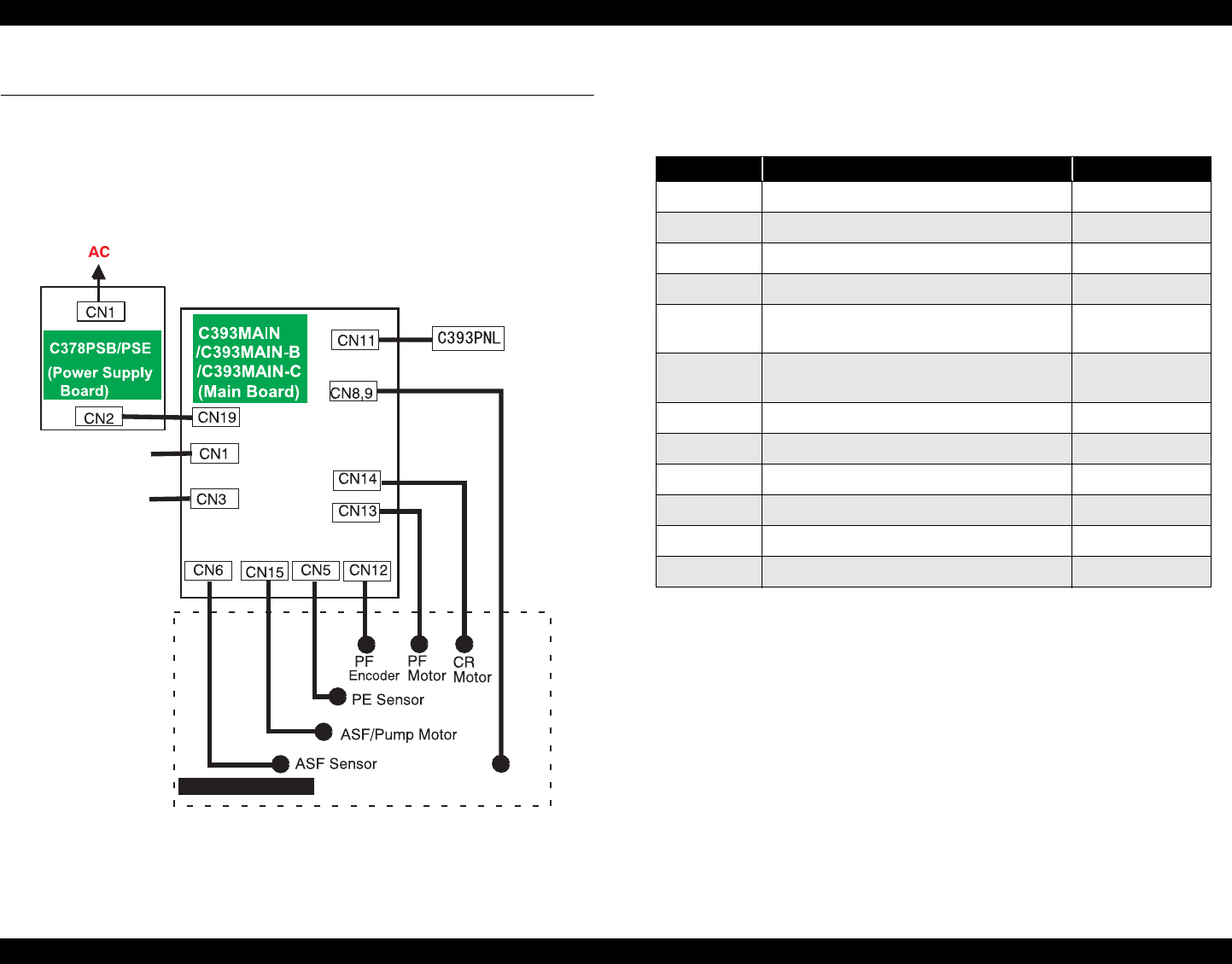
EPSON Stylus PHOTO 890/1280/1290 Revision C
APPENDIX Connector Summary 166
7.1 Connector Summary
7.1.1 Connector Alignment
This section provides information on connectors connecting main components of the
printer.
Figure 7-1. Cable Connection
7.1.2 Connector Pin Assignment
Print Head
Parallel I/F
Printer Mechanism
USB I/F
(CSIC,CR Encoder
)
appn0
1
Table 7-1. Connector Assignment
Connector Function Table to refer to
CN1 Parallel interface connector
CN3 USB interface connector
CN5 PE sensor connector Table 7-2
CN6 ASF sensor connector Table 7-3
CN8 Printhead connector (including the CR encoder
input line) Table 7-4
CN9 Printhead connector (including CSIC
communication and head temperature detection) Table 7-5
CN11 Control panel connector Table 7-6
CN12 PF encoder connector Table 7-7
CN13 CR motor connector Table 7-8
CN14 PF motor connector Table 7-9
CN15 ASF/Pump Motor Table 7-10
CN19 Power Table 7-11
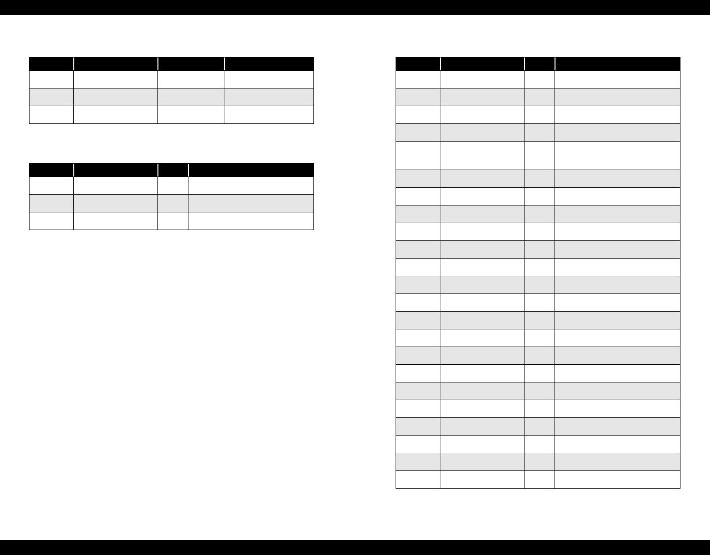
EPSON Stylus PHOTO 890/1280/1290 Revision C
APPENDIX Connector Summary 167
Table 7-2. Connector Pin Assignment - CN5
Pin Signal Name I/O Function
1 PE I PE signal
2GND −GND
3PEV −+5V
Table 7-3. Connector Pin Assignment - CN6
Pin Signal Name I/O Function
1 ASF I ASF HP detection
2GND -GND
3ASFV-+5V
Table 7-4. Connector Pin Assignment - CN8
Pin Signal Name I/O Function
1 COM - Head drive pulse
2GND -Ground
3 COM - Head drive pulse
4GND -Ground
5VHV-
+42V power supply for nozzle
selector
6GND -Ground
7 SEL I Command Selection
8GND -Ground
9VDD-+5V
10 LAT OHead data latch pulse output
11 GND - Ground
12 NCHG OHead NCHG
13 THM I Thermistor detect signal
14 SI1 OHead data
15 SI2 O Head data
16 SI3 OHead data
17 SP O SP signal
18 NC - -
19 GND - Ground
20 ENA ICR encoder output A
21 VDD - +5V
22 ENB ICR encoder output B
23 GNB - Ground
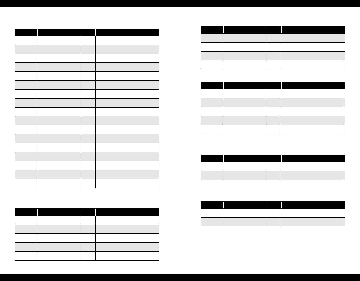
EPSON Stylus PHOTO 890/1280/1290 Revision C
APPENDIX Connector Summary 168
Table 7-5. Connector Pin Assignment - CN9
Pin Signal Name I/O Function
1 SI6 O Head data
2SI5 OHead data
3 SI4 O Head data
4GND -Ground
5SCKO
6GND -Head NCHG
7 CH O Ground
8COC IClock
9 RXD O Ground
10 COB ISP signal
11 TXD I Head data
12 VDD3.3 -Head data
13 GND - Head data
14 COM -Head data
15 GND - Head data
16 COM -Head data
17 GND - Ground
Table 7-6. Connector Pin Assignment - CN11
Pin Signal Name I/O Function
1 SW2 I Switch signal input
2LED0 OLED output
3 GND - Ground
4VCC -+5V
5 LED3 O LED output
6SW1 ISwitch input
7PSCIPower switch
8SW0 ISwitch input
9 SW2 I Switch input
Table 7-7. Connector Pin Assignment - CN12
Pin Signal Name I/O Function
1GND-
Ground
2ENB IRotary encoder Phase B output
3VCC-+5V
4ENA IRotary encoder Phase A output
5GND-
Ground
Table 7-8. Connector Pin Assignment - CN13
Pin Signal Name I/O Function
1 PF-A O PF motor Phase A
2PF-B OPF motor Phase B
Table 7-9. Connector Pin Assignment - CN14
Pin Signal Name I/O Function
1 CR-A O CR motor Phase A
2CR-B OCR motor Phase B
Table 7-6. Connector Pin Assignment - CN11
Pin Signal Name I/O Function
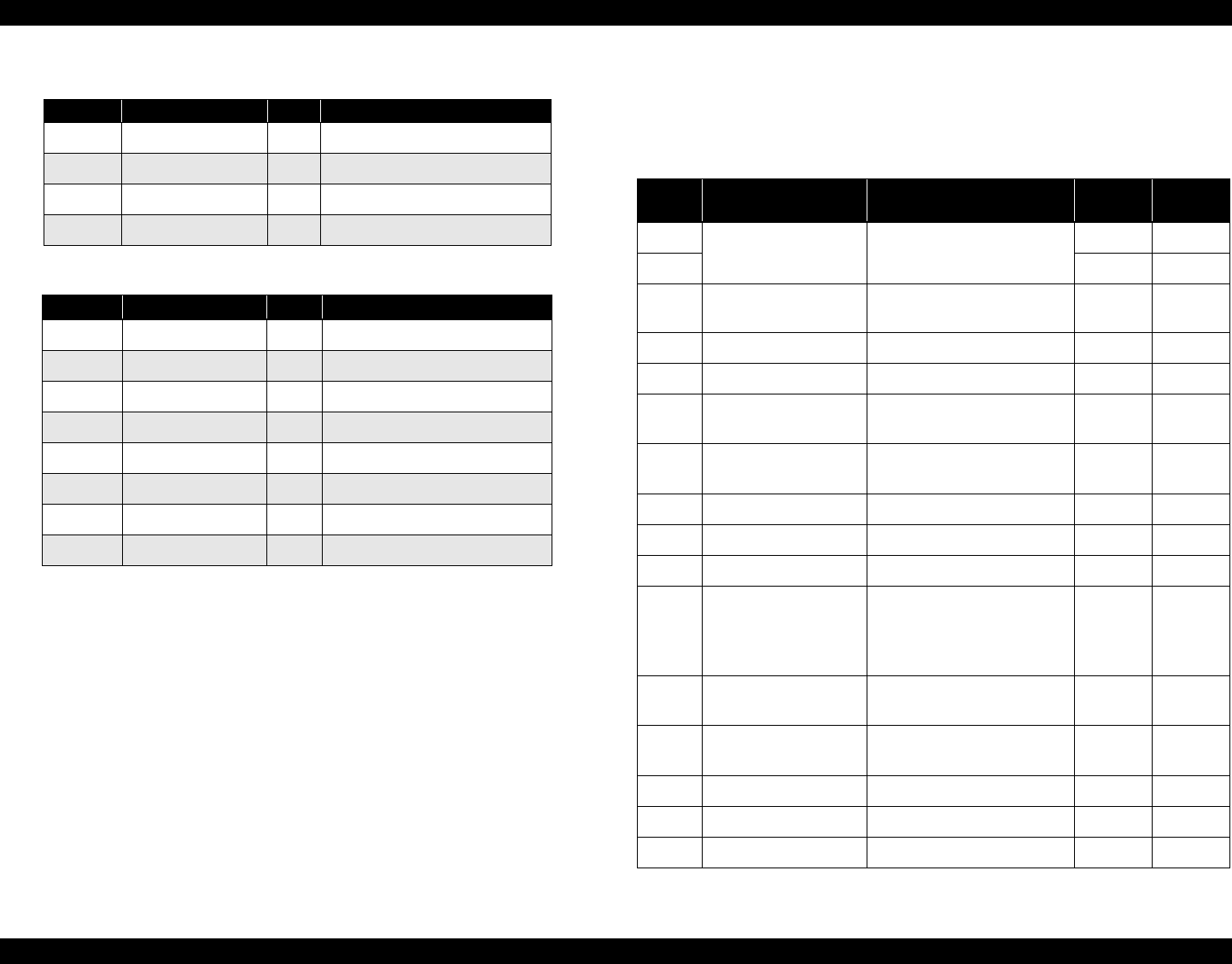
EPSON Stylus PHOTO 890/1280/1290 Revision C
APPENDIX Connector Summary 169
7.1.3 EEPROM Address Map
This section provides the EEPROM address map.
Table 7-10. Connector Pin Assignment - CN15
Pin Signal Name I/O Function
1 A O ASF/Pump Motor Phase A
2 B O ASF/Pump Motor Phase B
3 /A O ASF/Pump Motor Phase /A
4/B OASF/Pump Motor Phase /B
Table 7-11. Connector Pin Assignment
Pin Signal Name I/O Function
1 +42V - +42V Power
2+42V -+42V Power
3 GND - Ground
4ESAVE OEnergy saving mode
5 PSC O Secondary power ON/OFF
6GND -Ground
7 GND - Ground
8+5V -+5V Power
Table 7-12. EEPROM Address Map
Address
Explanation Setting QPIT
Settings Factory
Settings
00H Pass word 0FH -
01H 5AH -
02H EEPROM mapping
revision 41H -
03H Reserved 00H -
04H Interface selection 0: Auto, 1: Parallel, 2: USB 00H 00H *2
05H Interface time-out 0 to 255 (by second, value of 0
means 10 seconds) 0AH 0AH
06H Compatibility speed 0: Fast, 1: Slow,
2: Special-1, 3: Special 2 00H 00H
07H ECP speed*a 0: Fast, 1: Slow 00H 00H
08H IEEE1284.4 for Parallel 0: Auto, 1: On, 2: Off 00H 01H
09H IEEE1284.4 for USB 0: Auto, 1: On, 2: Off 00H 01H
0AH 1/F Control flags
bit1: ECP mode
(0=Off, 1=On)*b
bit0: IEEE1284 mode (0=On,
1=Off)*c
00H 00H
0BH -
0FH Reserved 00H -
10H -
15H CPSI pass word 00H 00H
16H Print direction control 0: Bi-D, 1: Uni-D, 2: Auto 02H 02H
17H CG table 08H: PC437, 0AH: PC850 00H 00H
18H Font 0: Courier 00H 00H
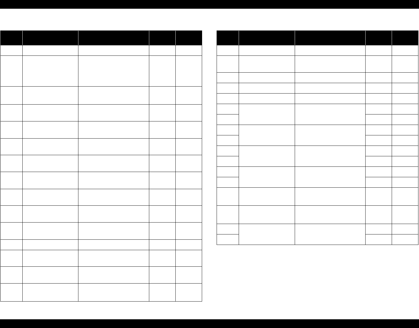
EPSON Stylus PHOTO 890/1280/1290 Revision C
APPENDIX Connector Summary 170
19H Pitch 0: 10cpi 00H 00H
1AH Auto LF, Network I/F
mode
bit1: Network I/F mode (0=Off,
1=On)
bit0: Auto line feed
(0=Off, 1=On)
00H 00H
1BH Check model control bit7: Self test mode
bit6: Hex dump mode 00H 00H
1CH -
1FH Reserved 00H -
20H Bi-D Adjustment for
MultiShot (Bk)
-72<=n<=+72
(by 0.00882mm(1/2880 inch) 00H *1
21H Bi-D Adjustment for
6plVSD (Bk)
-72<=n<=+72
(by 0.00882mm(1/2880 inch) 00H *1
22H Bi-D Adjustment for
4plVSD (Bk)
-72<=n<=+72
(by 0.00882mm(1/2880 inch) 00H *1
23H Bi-D Adjustment for
MultiShot (Cl)
-72<=n<=+72
(by 0.00882mm(1/2880 inch) 00H *1
24H Bi-D Adjustment for
6plVSD (Cl)
-72<=n<=+72
(by 0.00882mm(1/2880 inch) 00H *1
25H Bi-D Adjustment for
4plVSD (Cl)
-72<=n<=+72
(by 0.00882mm(1/2880 inch) 00H *1
26H 1st Dot Position
Adjustment
-72<=n<=+72
(by 0.00882mm(1/2880 inch) 00H *1
27H Reserved 00H -
28H reserved for CR Phase
on Home 00H -
29H reserved for Paper
Sensor Adjust 00H -
2AH Roll paper flag bit1: Panel Load Mode
bit0: Rollpaper Mode 00H 00H
Table 7-12. EEPROM Address Map (continued)
Address
Explanation Setting QPIT
Settings Factory
Settings
2BH Error Code 00H 00H
2CH Error Counter at Initial
Fills I/S 00H *1
2DH CR Measurement Data 00H 00H
2CH PF Measurement Data 00H 00H
2FH Reserved 00H -
30H Top margin 42 to 44x360 (by 0.0706 (1/360
inch))
00H 00H
31H 78H 78H
32H Bottom margin 1244 to 44x360 (by 0.0706 (1/
360 inch))
1EH 1EH
33H F0H F0H
34H Page length 1244 to 44x360 (by 0.0706 (1/
360 inch))
1EH 1EH
35H F0H F0H
36H Reserved 00H -
37H 00H-
38H-
3BH
Accumulate page
counter by 1 page 00H 00H
3CH-
3FH Accumulate print pass by 1 pass 00H 00H
40H Password 0FH -
41H 5AH -
Table 7-12. EEPROM Address Map (continued)
Address
Explanation Setting QPIT
Settings Factory
Settings
EPSON Stylus PHOTO 890/1280/1290 Revision C
APPENDIX Connector Summary 171
42H Ink flag1
bit7: CSIC disable
bit6: Black one-time
bit5: Color one-time
bit4: Initial fill required
bit3: Reserved
bit2: Ink cleaning seq.
bit1: Black CL required
bit0: Color CL required
00H 10H
43H Ink flag2
bit7: Reserved
bit6: Black 1st cartridge
bit5: YMC 1st cartridge
bit4: Black CSIC changed
bit3: YMC CSIC changed
bit2: YMC cartridge changed
and cleaned
bit1: Black cartridge changed
and cleaned
bit0: Black cartridge only
changed and cleaned
00H 00H
44H
Ink counter Cb
00H 00H
45H 00H 00H
46H 00H 00H
47H 00H 00H
48H
Ink counter Cy
00H 00H
49H 00H 00H
4AH 00H 00H
4BH 00H 00H
Table 7-12. EEPROM Address Map (continued)
Address
Explanation Setting QPIT
Settings Factory
Settings
4CH
Ink counter Cc
00H 00H
4DH 00H 00H
4EH 00H 00H
4FH 00H 00H
50H
Ink counter Cm
00H 00H
51H 00H 00H
52H 00H 00H
53H 00H 00H
54H
Ink counter Clc
00H 00H
55H 00H 00H
56H 00H 00H
57H 00H 00H
58H
Ink counter Clm
00H 00H
59H 00H 00H
5AH 00H 00H
5BH 00H 00H
5CH 00H 00H
5DH 00H 00H
5EH 00H 00H
5FH 00H 00H
60H Ink counter Rb0 00H 00H
61H 00H 00H
62H Ink counter Rb80 00H 00H
63H 00H 00H
Table 7-12. EEPROM Address Map (continued)
Address
Explanation Setting QPIT
Settings Factory
Settings
EPSON Stylus PHOTO 890/1280/1290 Revision C
APPENDIX Connector Summary 172
64H Ink counter Ry0 00H 00H
65H 00H 00H
66H Ink counter Ry80 00H 00H
67H 00H 00H
68H CL time 00H 00H*2
69H 00H 00H*2
6AH Power off time 00H 00H*2
6BH 00H 00H*2
6CH Ink counter A0 00H 00H*3
6DH 00H 00H*3
6EH
Ink counter A80
00H 00H*3
6FH 00H 00H*3
70H Accumulated printing
time
00H 00H
71H 00H 00H
72H CSIC1_InkName1 00H 00H
73H CSIC2_InkName2 00H 00H
74H
Reserved
00H 00H
75H 00H 00H
76H 00H 00H
77H 00H 00H
78H Cleaning KK counter 00H 00H
79H Cleaning 1 counter 00H 00H
7AH Cleaning 1 dash counter 00H 00H
7BH Cleaning 2 counter 00H 00H
Table 7-12. EEPROM Address Map (continued)
Address
Explanation Setting QPIT
Settings Factory
Settings
7CH Home out cleaning
counter 00H 00H
7DH Timer cleaning counter 00H 00H
7EH Bk change cleaning
counter 00H 00H
7FH Color change cleaning
counter 00H 00H
80H Password 0FH -
81H 5AH -
82H Power unit select 00H *1
83H-
9FH Reserved 00H -
A0H Head Actuator Rank ID
for VhN +1<=n<=+201 00H *1
A1H Head Actuator Rank ID
for VhM +1<=n<=+201 00H *1
A2H Head Actuator Rank ID
for VhL +1<=n<=+201 00H *1
A3H Head Actuator Rank ID
for VhU +1<=n<=+201 00H *1
A4H Head Actuator Rank ID
for VhM2 +1<=n<=+201 00H *1
A5H Head Actuator Rank ID
for VhB +1<=n<=+201 00H *1
A6H Head Actuator Rank ID
for AR 00H *1
A7H Microweave ID 00H *1
A8H Head Actuator Rank ID
for Iw_B +30<=n<=+70 00H *1
Table 7-12. EEPROM Address Map (continued)
Address
Explanation Setting QPIT
Settings Factory
Settings
EPSON Stylus PHOTO 890/1280/1290 Revision C
APPENDIX Connector Summary 173
A9H Head Actuator Rank ID
for Iw_C +30<=n<=+70 00H *1
AAH Head Actuator Rank ID
for Iw_M +30<=n<=+70 00H *1
ABH Head Actuator Rank ID
for Iw_Y +30<=n<=+70 00H *1
ACH Head Actuator Rank ID
for Iw_LC +30<=n<=+70 00H *1
ADH Head Actuator Rank ID
for Iw_LM +30<=n<=+70 00H *1
AEH 00H *1
AFH 00H *1
B0H CSIC printer name
For Stylus PHOTO 890:
0Fh:R4C7260 (Japan)
8Fh:R4C7260 (World)
For Stylus PHOTO 1280/1290:
10h:R4C7260 (Japan)
90h:R4C7260 (World)
00H *1
B1H-
BFH Reserved 00H *1
C0H Password 0FH -
C1H 5AH -
C2H -
D3H USB ID 00H *1
D4H -
D7H Reserved 00H -
Table 7-12. EEPROM Address Map (continued)
Address
Explanation Setting QPIT
Settings Factory
Settings
D8H
Custom EEPROM sub
number
00H 00H
D9H 00H 00H
DAH 00H 00H
DBH 00H 00H
DCH Panel mask function
bit7: Entry self-test
bit6: Entry Hex-Dump
bit5: Extended settings
bit4: Reserved
00H 00H
DDH Reserved 00H -
DEH 00H -
DFH Factory reserved 00H -
E0H Market ID 0: World, 1: Japan,
2: Custom 00H 00H
E1H Reserved 00H -
E2H -
FFH Model Name 00H -
*a: Enable or disable reverse transfer. (When disabled, ignore -SLIN signal.)
*b: BUSY signal delay time from fall-edge of a -STB signal. (Fast: Maximum 1MB/second,
Slow: Maximum 600KB/second)
*c: Select IEEE1284 transfer mode. (ECP or Nibble)
NOTE:
*1: Adjusted at factory.
*2: Initialized by the EEPROM reset of the special setting mode.
*3: Initialized by the Waste ink counter reset of the special setting mode.
Table 7-12. EEPROM Address Map (continued)
Address
Explanation Setting QPIT
Settings Factory
Settings
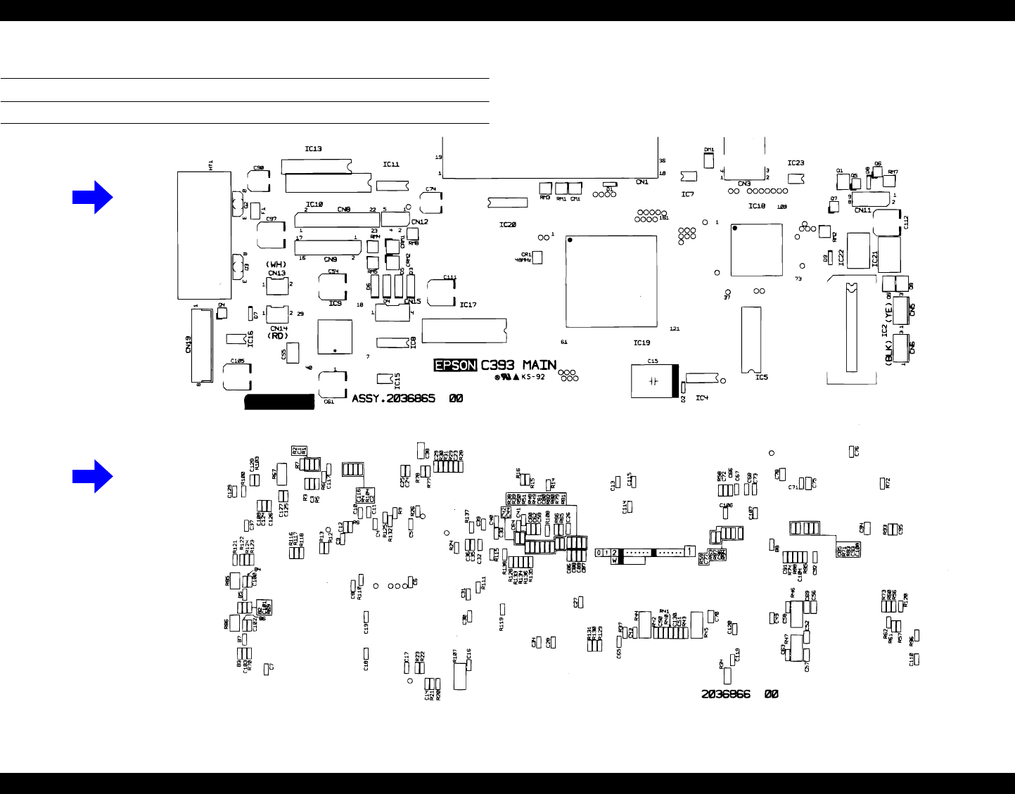
EPSON Stylus PHOTO 890/1280/1290 Revision C
APPENDIX Circuit Board Component Layout 174
7.2 Circuit Board Component Layout
C393MAIN CONTROL CIRCUIT BOARD
Figure 7-2. Component Layout - C393MAIN
Component Side
Soldered Side
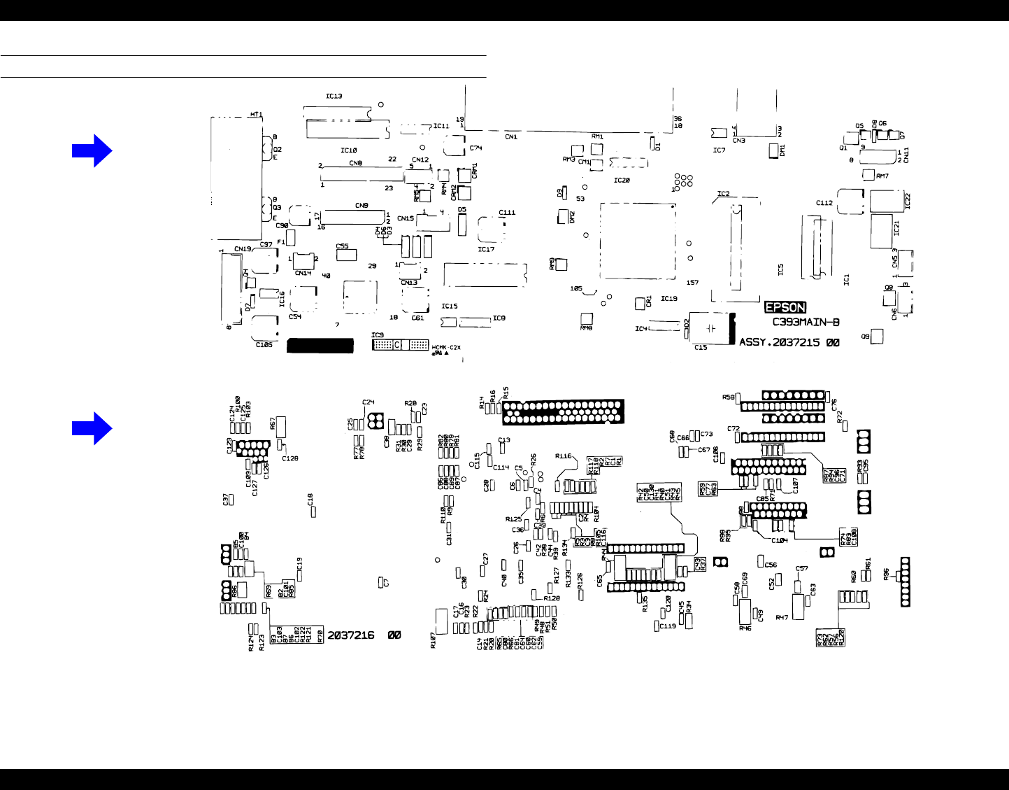
EPSON Stylus PHOTO 890/1280/1290 Revision C
APPENDIX Circuit Board Component Layout 175
C393MAIN-B CONTROL CIRCUIT BOARD
Figure 7-3. Component Layout - C393MAIN-B
Component Side
Soldered Side
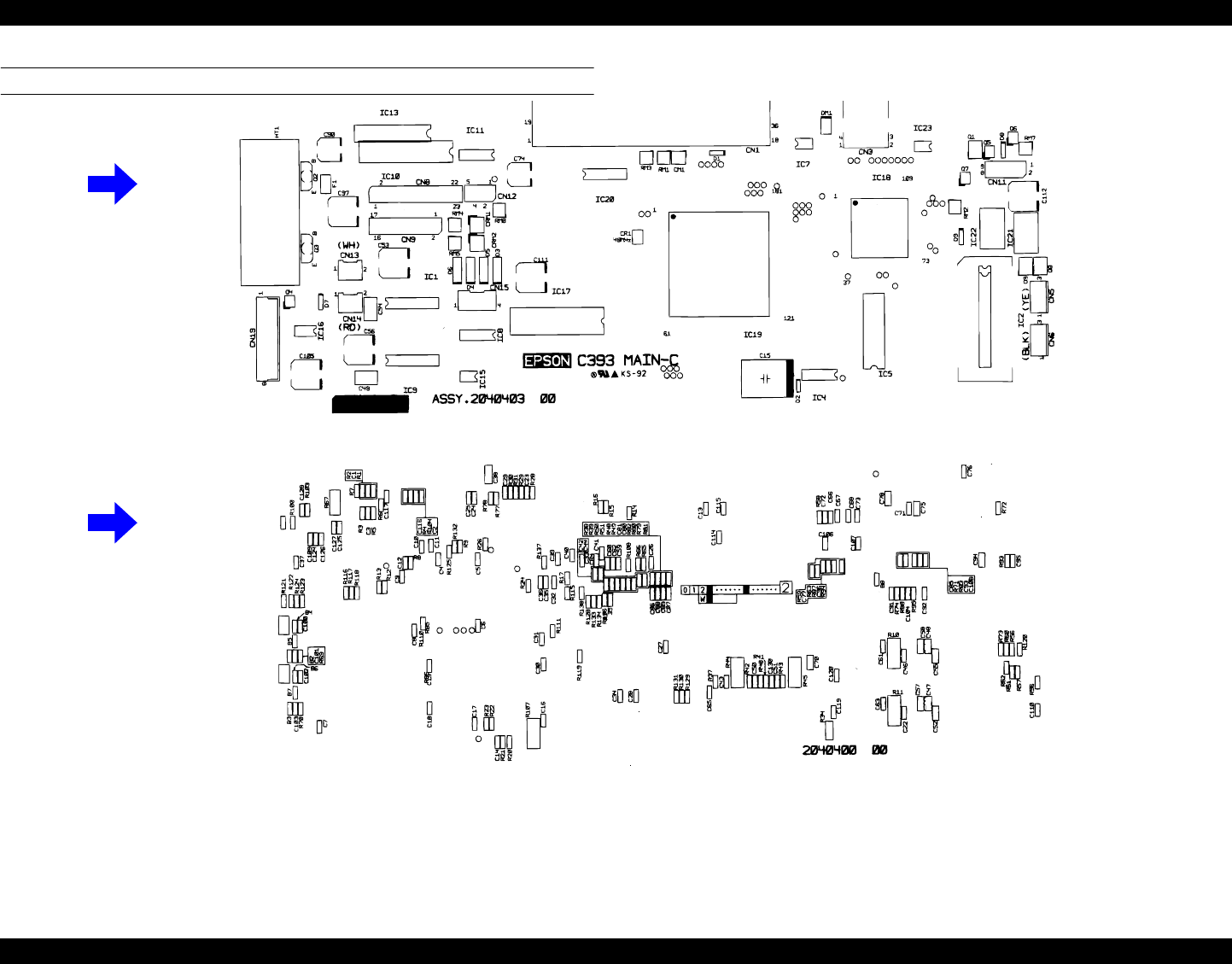
EPSON Stylus PHOTO 890/1280/1290 Revision C
APPENDIX Circuit Board Component Layout 176
C393MAIN-C CONTROL CIRCUIT BOARD
Figure 7-4. Component Layout - C393MAIN-C
Component Side
Soldered Side
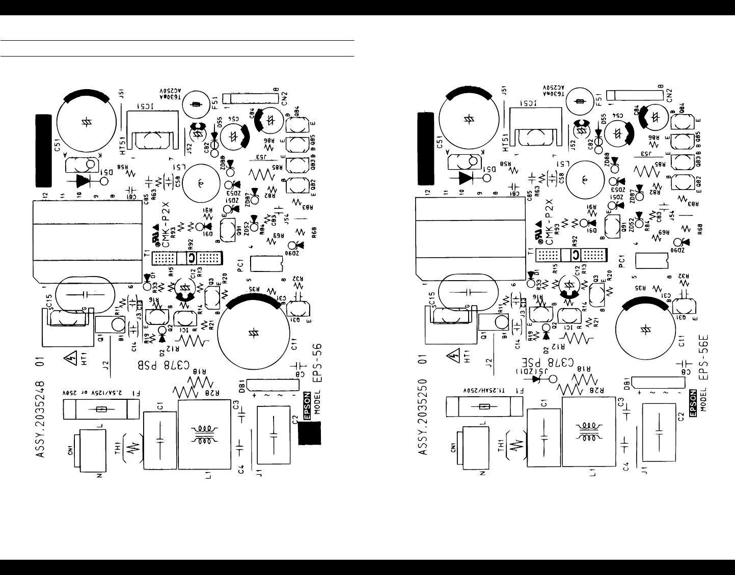
EPSON Stylus PHOTO 890/1280/1290 Revision C
APPENDIX Circuit Board Component Layout 177
C378PSB/PSE CIRCUIT BOARD
Figure 7-5. Component Layout - C378PSB Figure 7-6. Component Layout - C378PSE
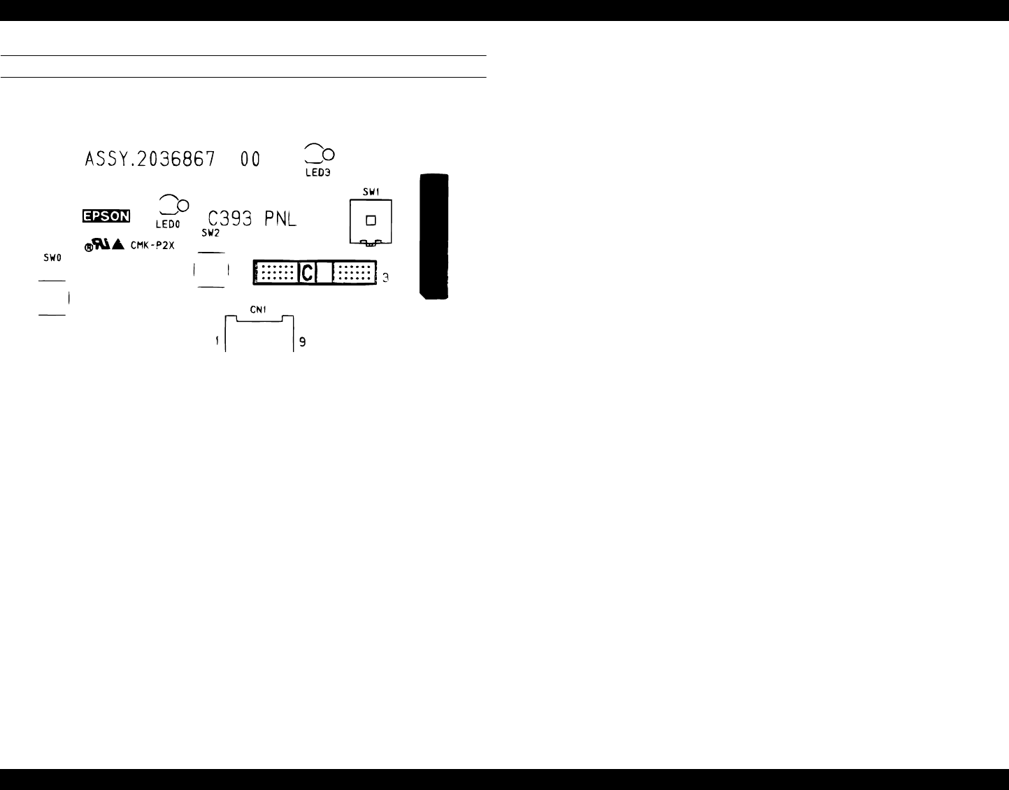
EPSON Stylus PHOTO 890/1280/1290 Revision C
APPENDIX Circuit Board Component Layout 178
C393PNL CIRCUIT BOARD
Figure 7-7. Component Layout - C393PNL

EPSON Stylus PHOTO 890/1280/1290 Revision C
APPENDIX Electrical Circuit Board Diagrams 179
7.3 Electrical Circuit Board Diagrams
See the following pages for the electrical circuit board diagrams below:
C393MAIN
C393MAIN-B
C393MAIN-C
C393PNL
C378PSB
C378PSE
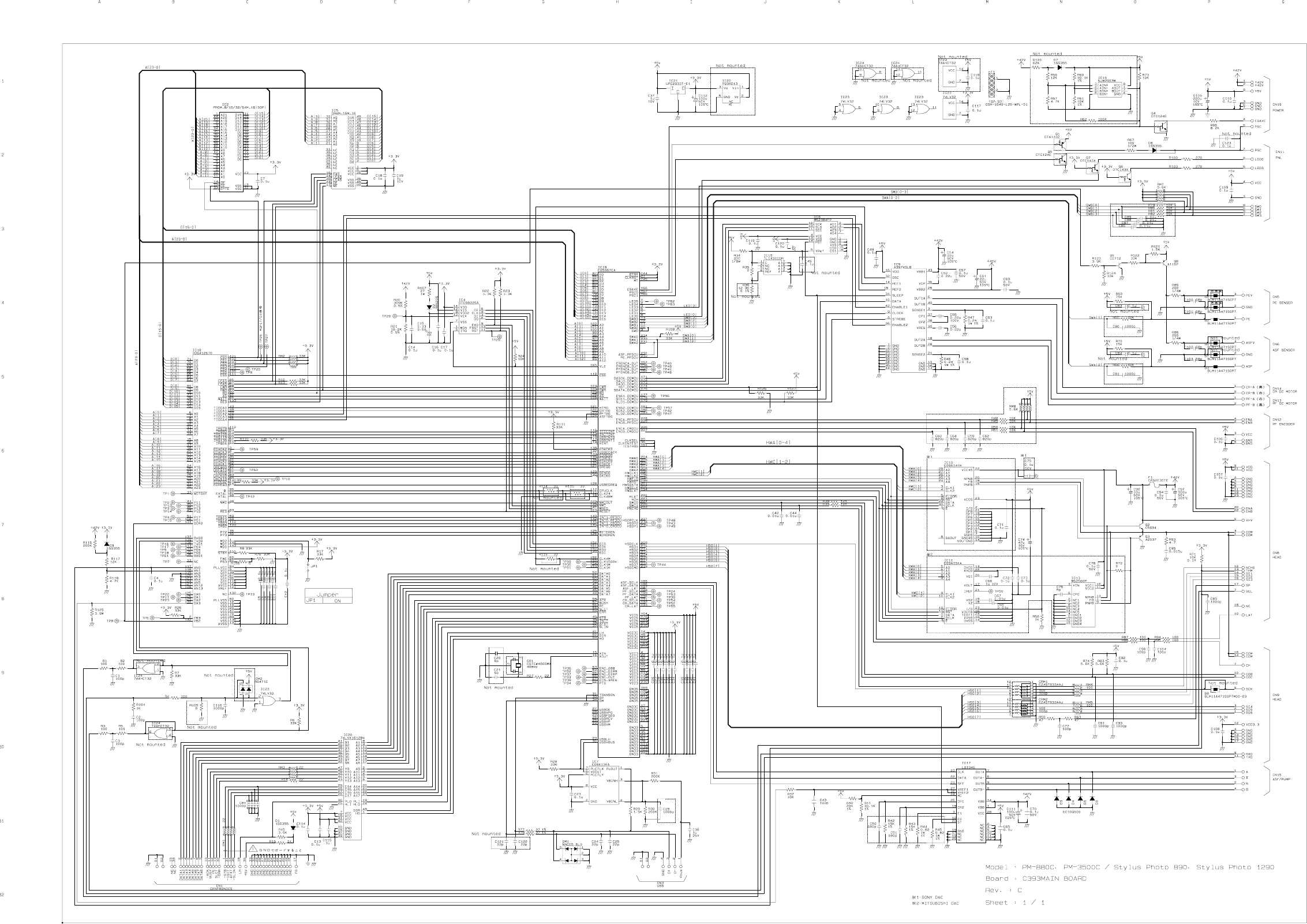
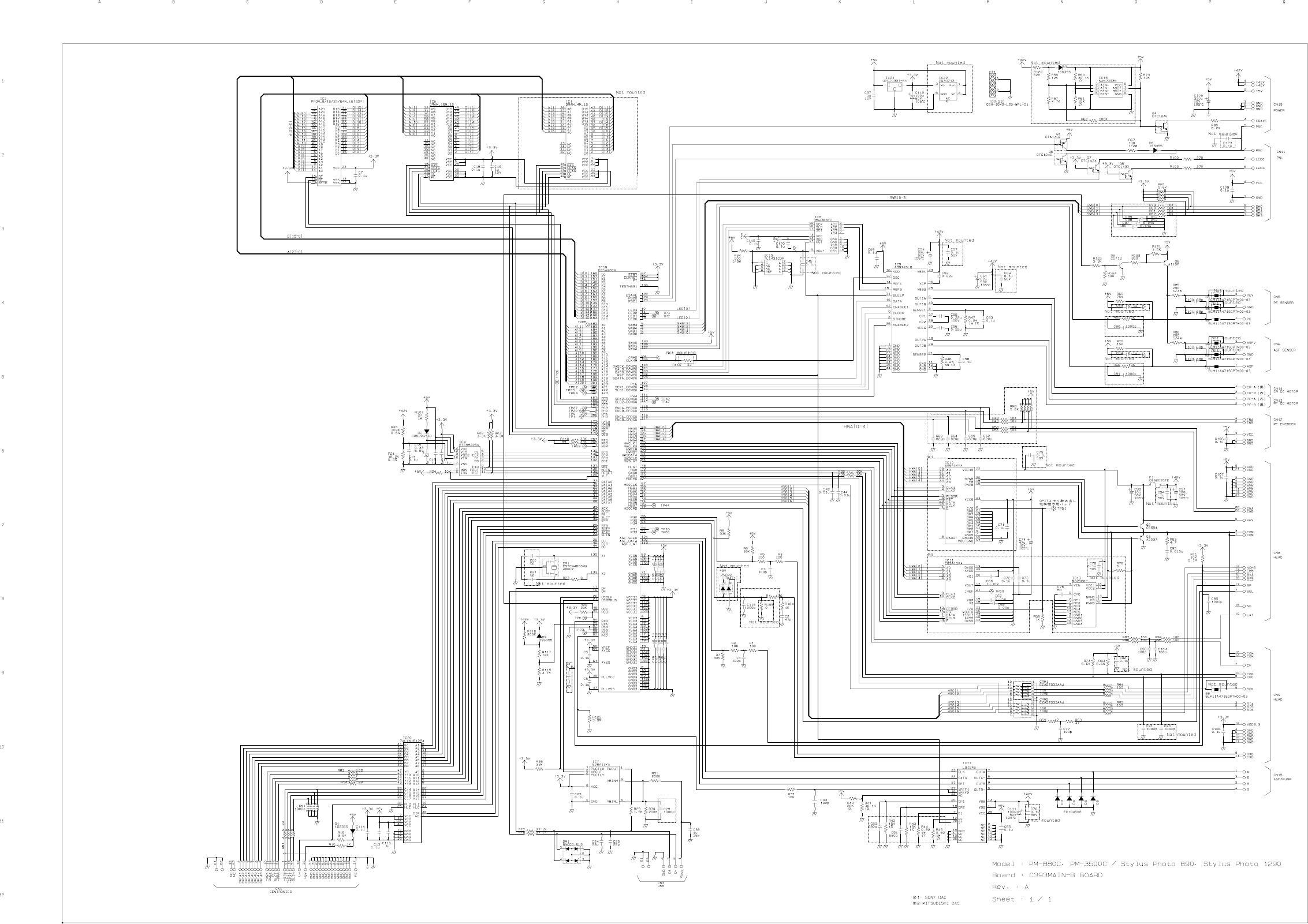
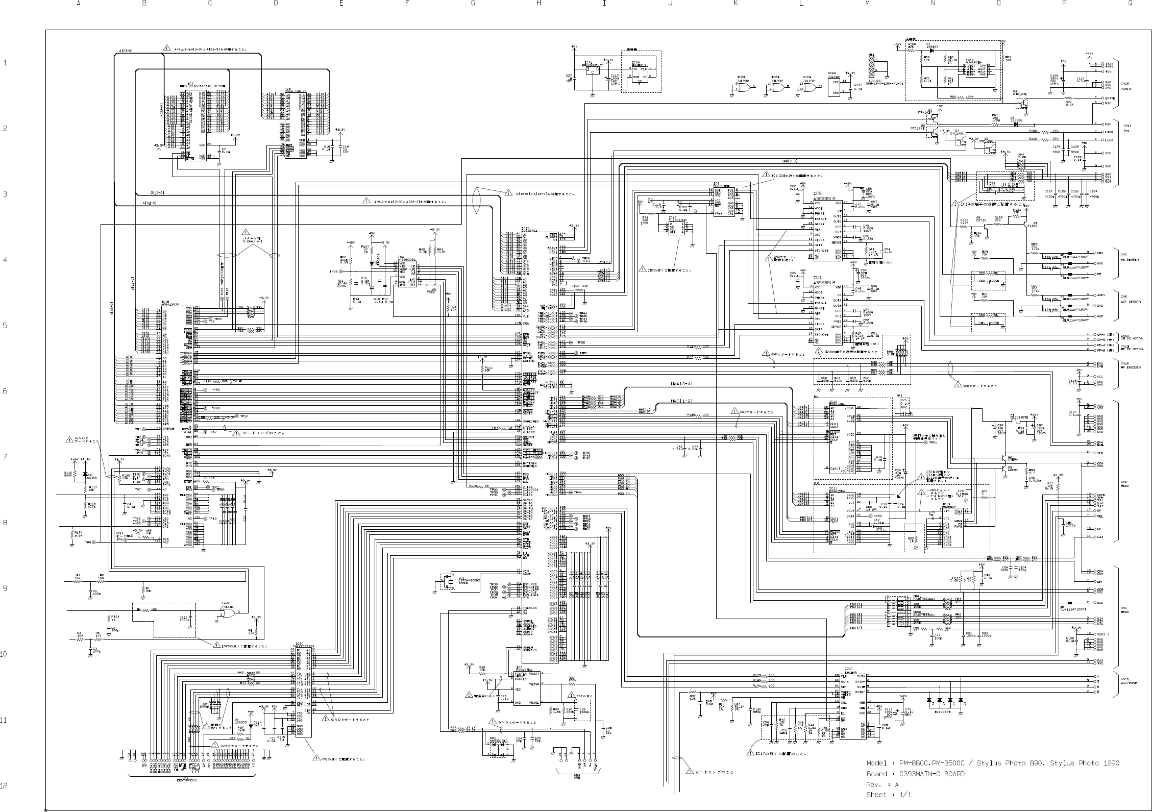
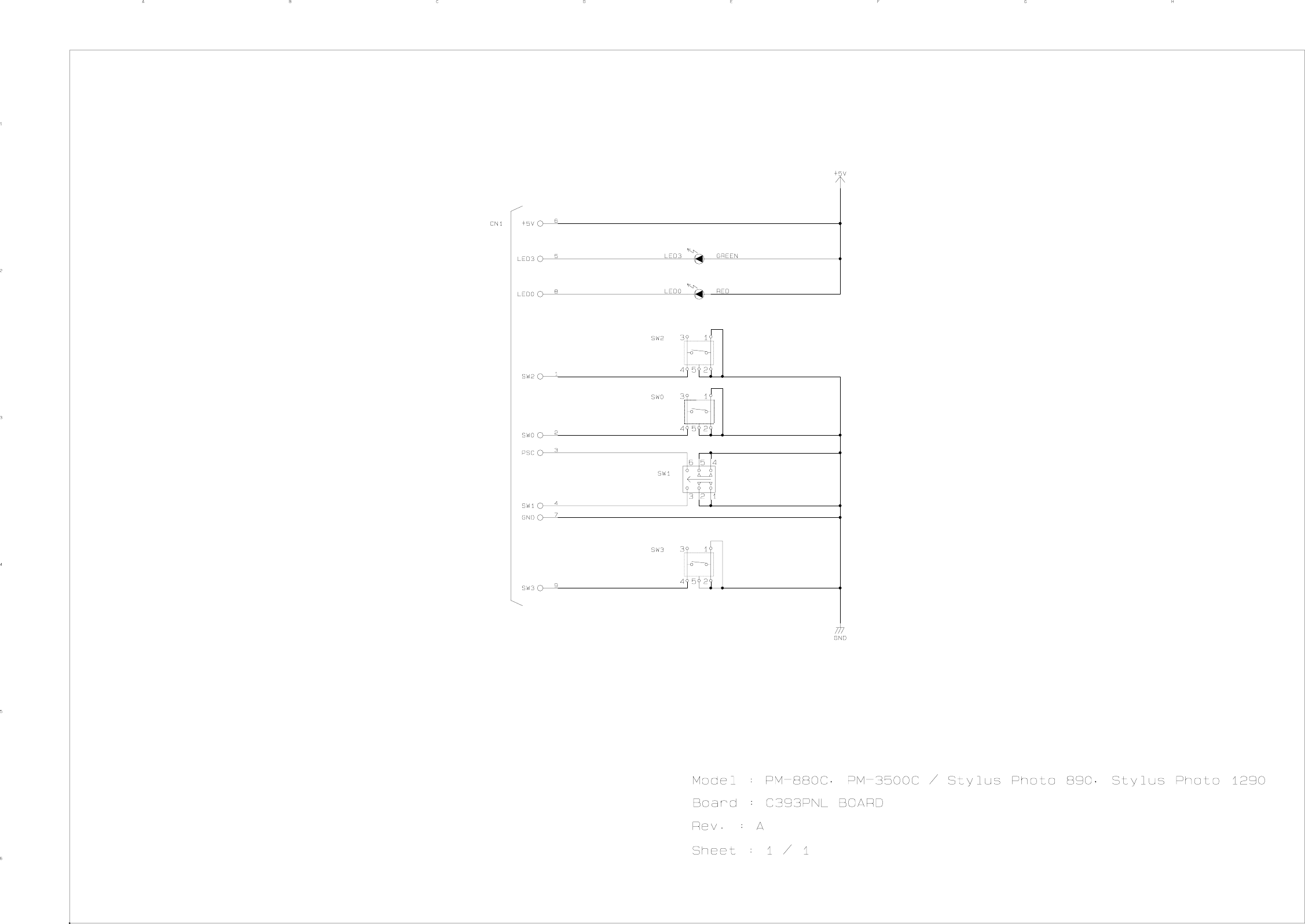
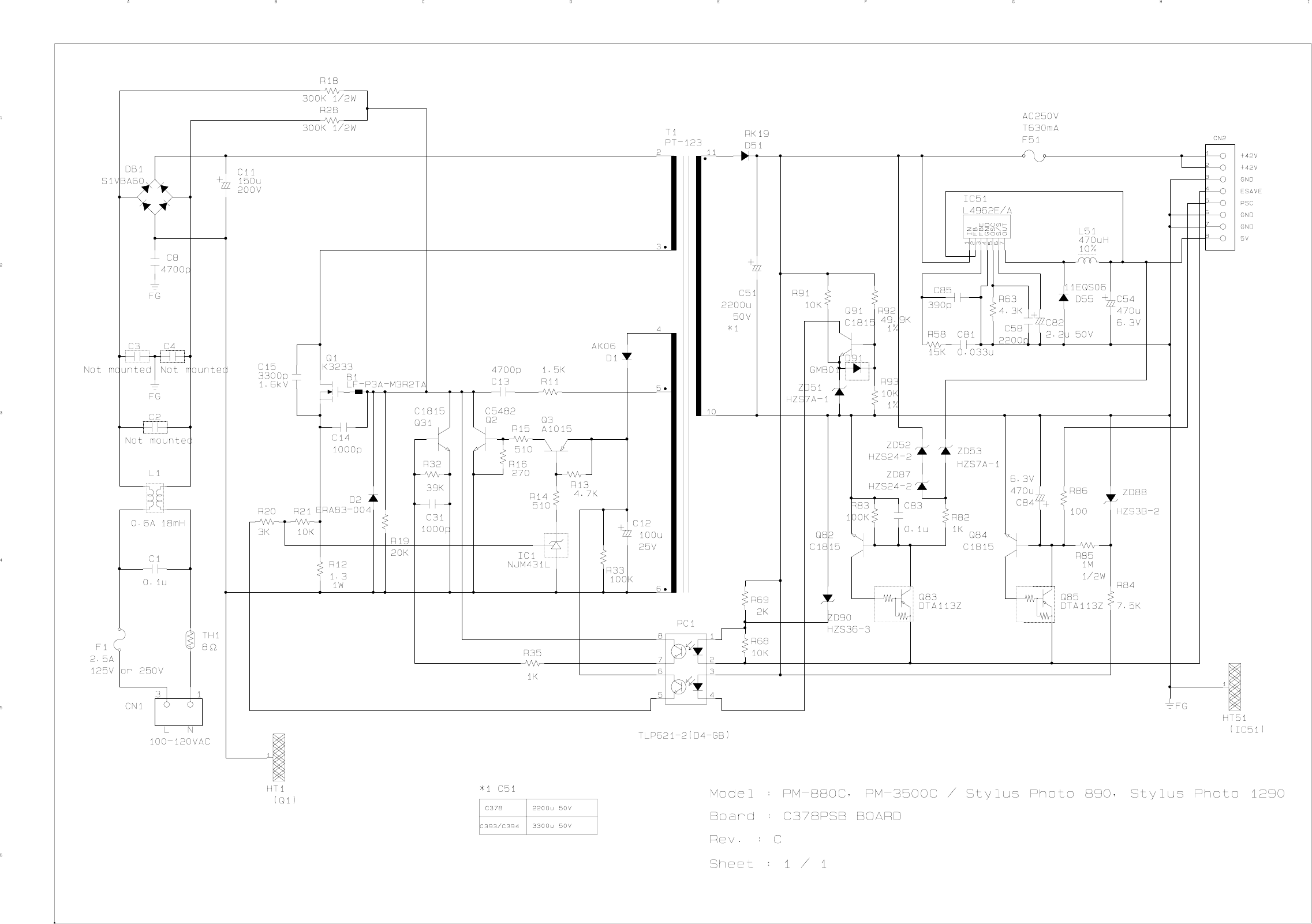
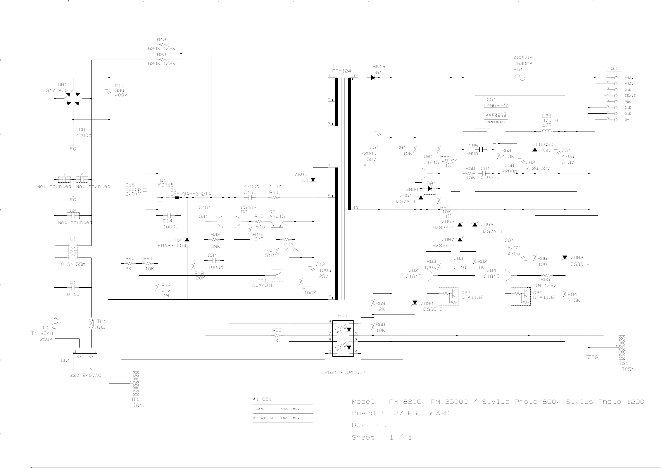
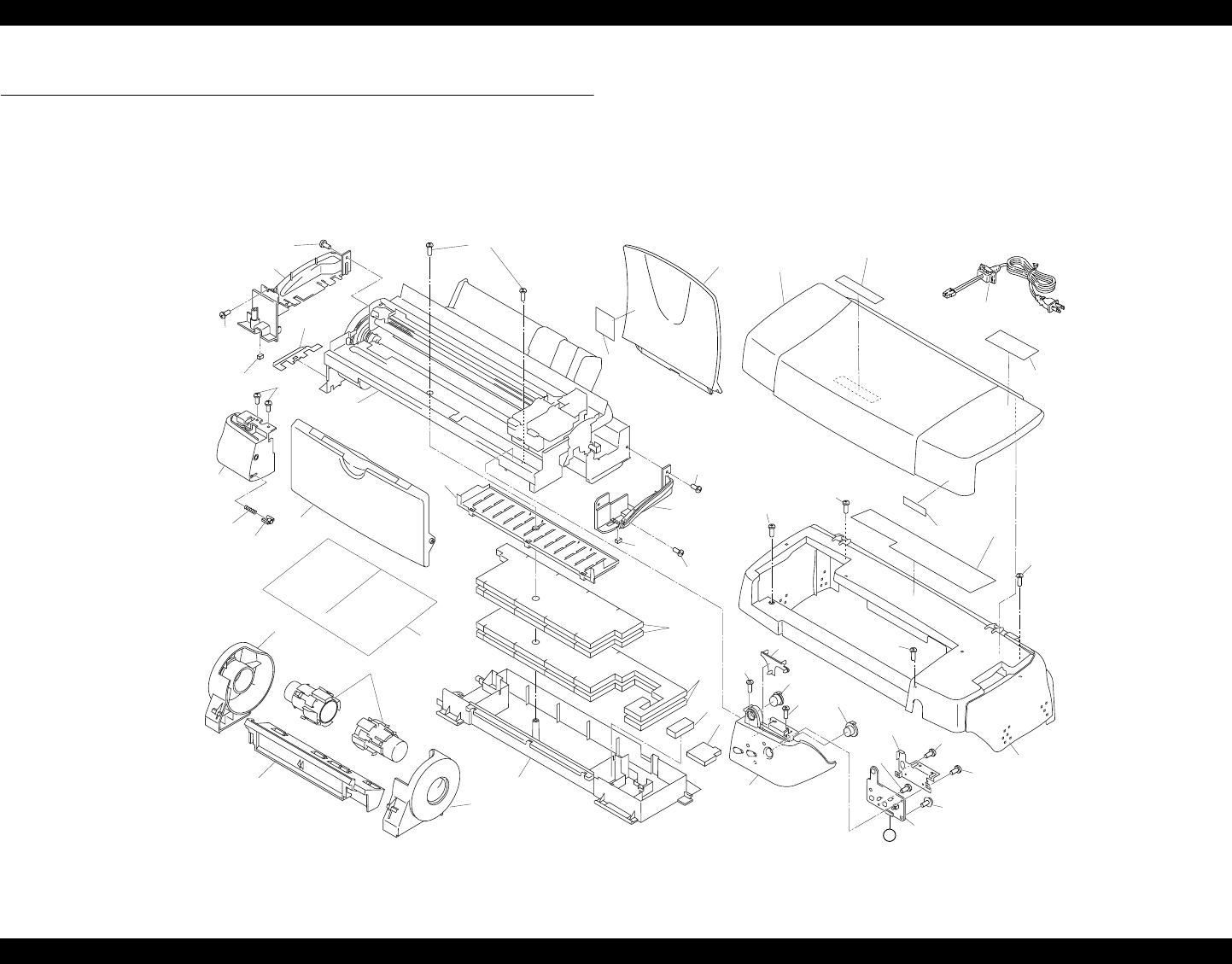
EPSON Stylus PHOTO 890/1280/1290 Revision C
APPENDIX Exploded Diagrams 186
7.4 Exploded Diagrams
7.4.1 Exploded Diagrams for Stylus PHOTO 890
See the following pages for exploded diagrams for Stylus PHOTO 890.
Figure 7-8. Stylus PHOTO 890 - 1
774
NO.1 Rev.01 10275
PM-880C/ EPSON STYLUS PHOTO 890
805
A
122
117
122 754
122
106
133
132
103
751
753
766
752
104
126
136
130
125
450
742
125
125
105 125
135
100
124
124
124
122
122
116
124
125
400
500
115
101
102
775
777
801
803
802
800
182
180
181
183
774
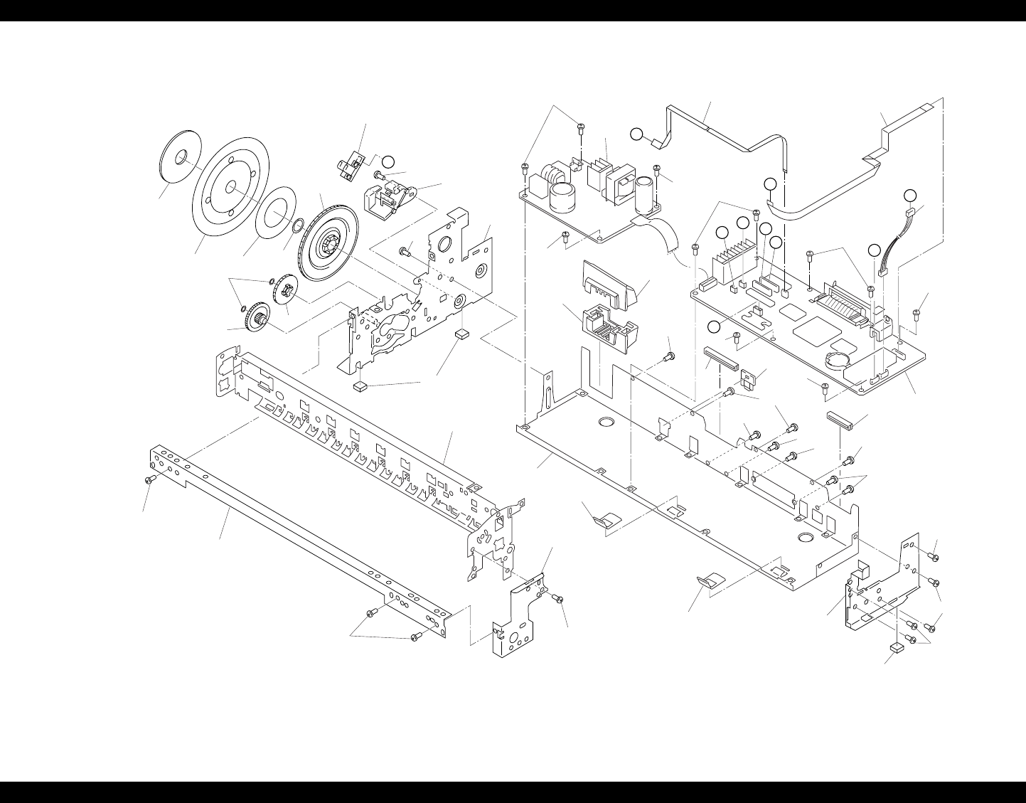
EPSON Stylus PHOTO 890/1280/1290 Revision C
APPENDIX Exploded Diagrams 187
Figure 7-9. Stylus PHOTO 890 - 2
PM-880C/EPSON STYLUS PHOTO 890 Rev.01NO.2 10275
B
A
C
F
E
G
H
D
D
I
330
608
580
122
200
122
122
122
122
109
122
131
122 111
121
122
121
122
122
112
113
122
122
300
604
591
613
524
594
603
534
532
574
119
501
114
122
606
607
587
512
587
108
505
587
108
587
12
2
58
7
119
614
506
122
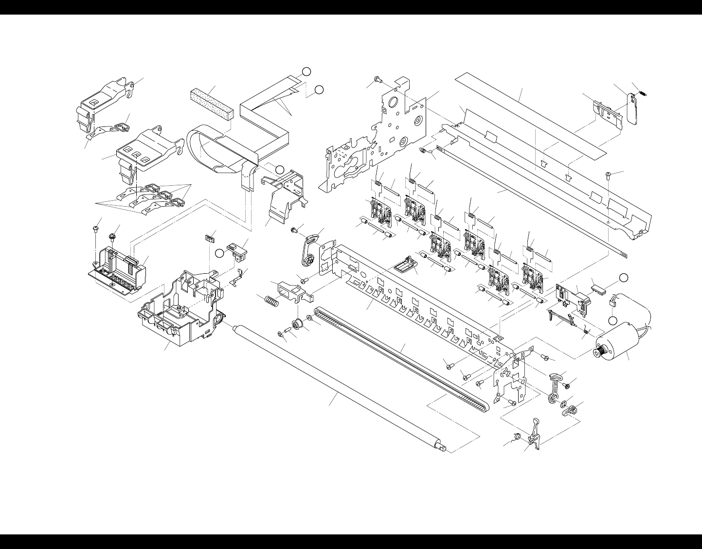
EPSON Stylus PHOTO 890/1280/1290 Revision C
APPENDIX Exploded Diagrams 188
Figure 7-10. Stylus PHOTO 890 - 3
PM-880C/EPSON STYLUS PHOTO 890 No.3 Rev.01 10275
761
H
B
E
J
F
J
748 513
587
568
575
567
577
575
546
506
705
706
569
566
588
588
565
572 570
571
589
748
507
514
551
549
552
553
501
587 558 756 757 758
605
609
548
550
550 550
550
549
550
549
550
550
550
549
550
549 550
550
549
550
551 548
551548
551
548
551
548
551
548
545x5
547
557
555
554
759
704
760
604
612
587
587
587
762
762
761
612
644
700
560
573
564
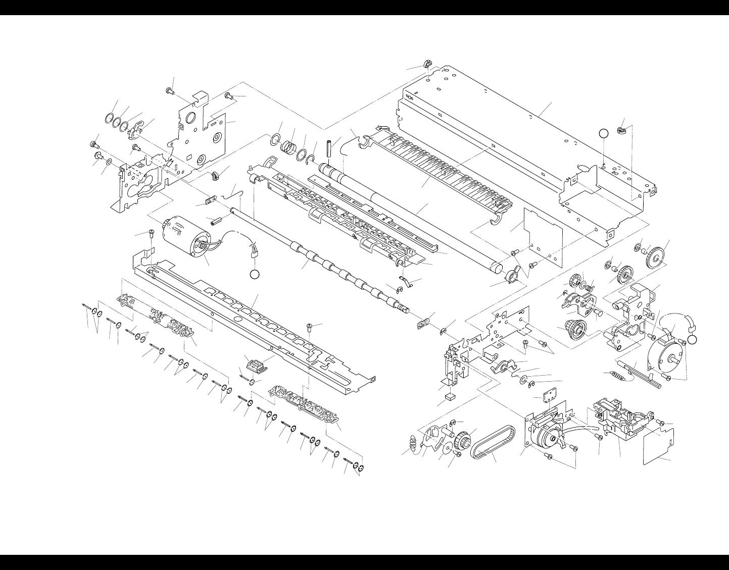
EPSON Stylus PHOTO 890/1280/1290 Revision C
APPENDIX Exploded Diagrams 189
Figure 7-11. Stylus PHOTO 890 - 4
645
PM-880C/ EPSON STYLUS PHOTO 890
587
No.4 Rev.01 10275
G
K
I
526
521
525
518
587
(501) 528517528527
610
536
587
559
639
590
530
611
529
587
587
538
540 541
544
543
5
44
542544
542
544542
539
531
530
119
599
616
624
621587
618 519
587
556
531
508 509
626
612
620
533
516
623
622
579
582
520
619
627
592
619
504
586
610
535
515
522
537
510
502
544542544542544542544
542544542544542544542544542544542544 542
531
628
628
610
531
587
587
765
585593
587
587
578
625
587
511
637
641
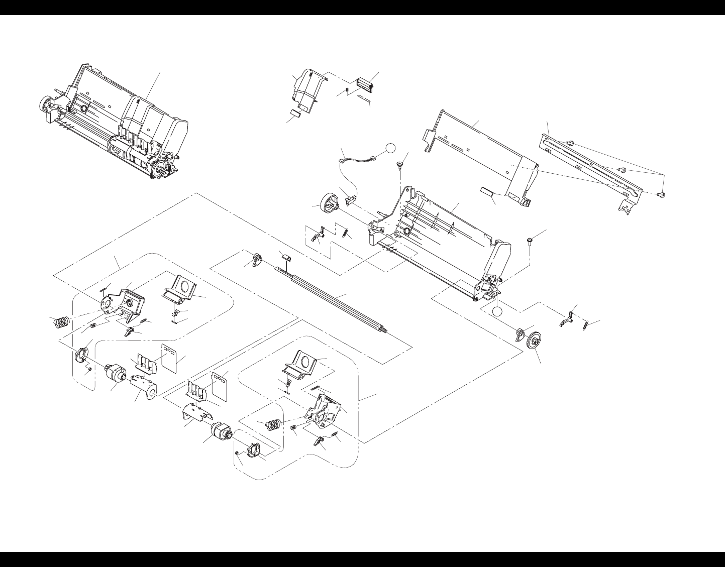
EPSON Stylus PHOTO 890/1280/1290 Revision C
APPENDIX Exploded Diagrams 190
Figure 7-12. Stylus PHOTO 890 - 5
PM-880C/ EPSON STYLUS PHOTO 890
No.5 Rev.01 10275
780 Without 747,748
K
C
738
70
3
714
708
710
736
737
739
707
711
713
712
737
755
764
709
739
736
740
716
721
719
723
720
722
725
724
735
7
35
720
724
730
726
723
729
721 728
731
733
745
746
734
732
746
745
727
717
718
718
581
763
715
748
747
782
781
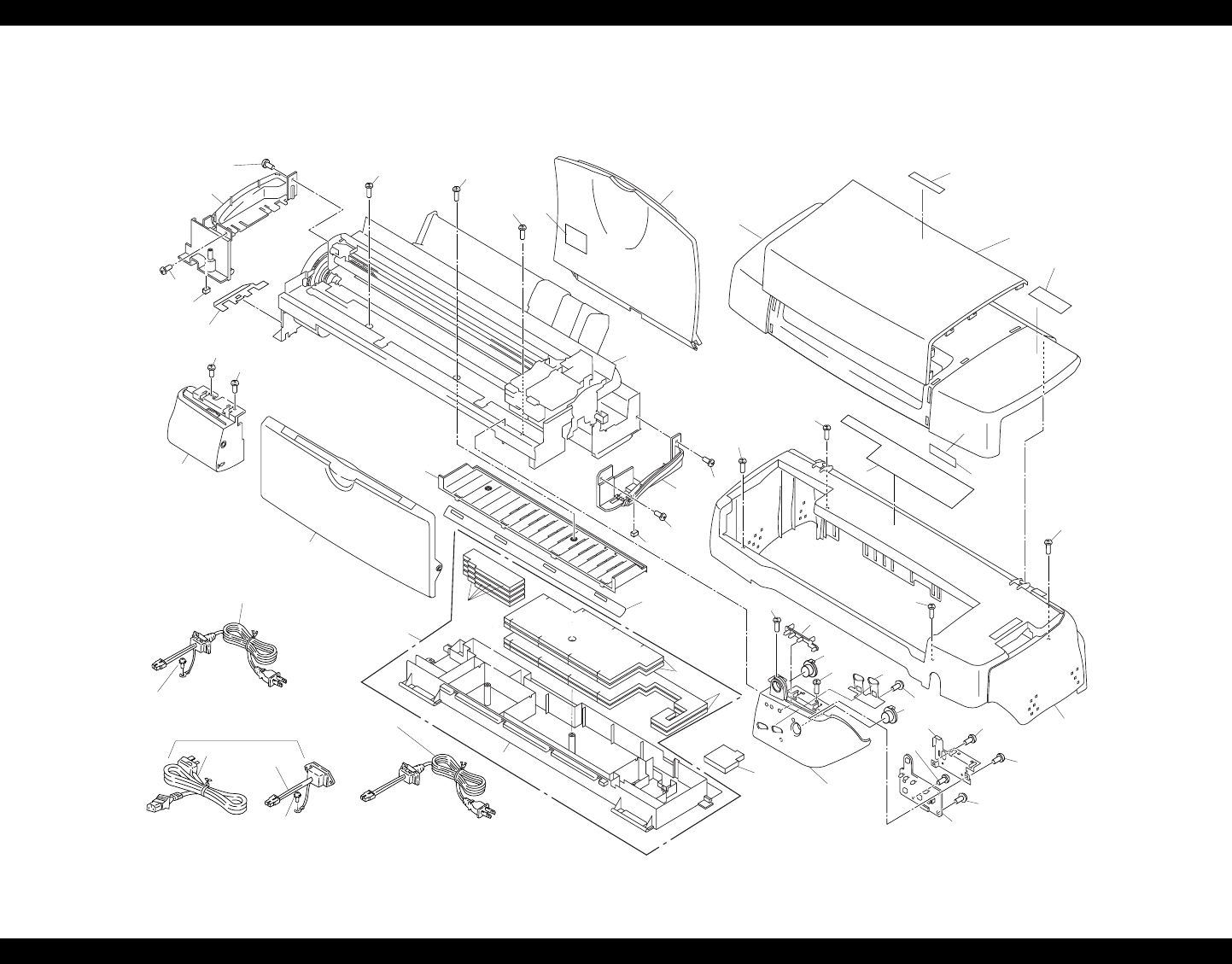
EPSON Stylus PHOTO 890/1280/1290 Revision C
APPENDIX Exploded Diagrams 191
7.4.2 Exploded Diagrams for Stylus PHOTO 1280/1290
See the following pages for exploded diagrams for Stylus PHOTO 1280/1290.
Figure 7-13. Stylus PHOTO 1280/1290 - 1
PM-3500C / EPSON STYLUS PHOTO 1290 No.1 Rev.01 10270
783
125
1
23
400 401
123
106
103
126 126
122
774
754
117
122 125 125
125
102
751
774 122
116 122
124
400
126
136
133
126
132
104
124
180
105 100
125
125
742
125
450
124
124
500
182
753
766 752
743
183
for JPN
110
115
101
775
400 for EAI,EUL(120V),ETT
For EAI(220V),EUR, S.E.ASIA,
EAL,EKL
776
181
130
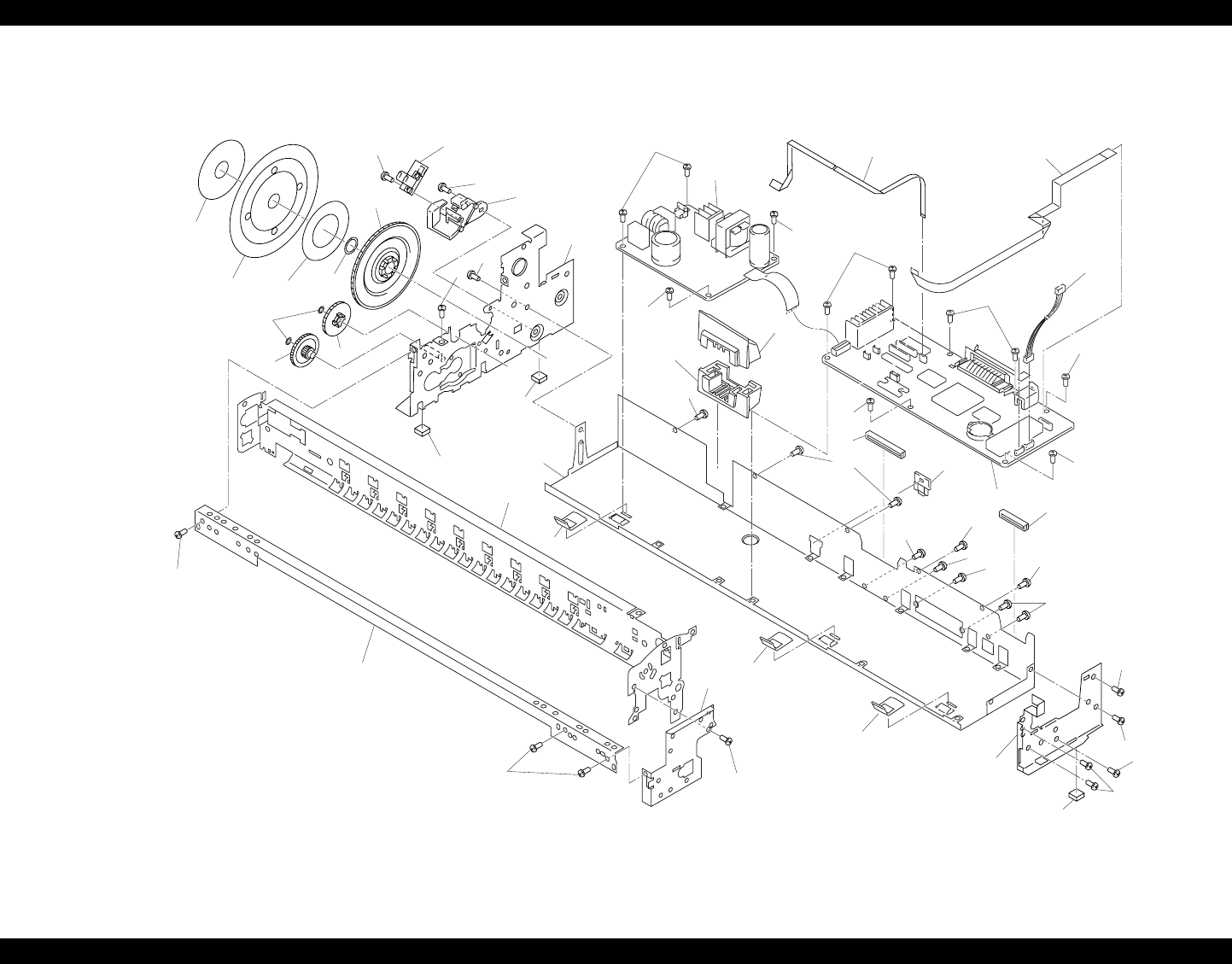
EPSON Stylus PHOTO 890/1280/1290 Revision C
APPENDIX Exploded Diagrams 192
Figure 7-14. Stylus PHOTO 1280/1290 - 2
PM-3500C / EPSON STYLUS PHOTO 1290 No.2 Rev.01 10270
512
607
606 603 594
524
587
534
574 532
604
591
613
587
122
501
119
119
122
122
300
608
122 122
113
112
122
122
131
122
330
580
122
122
122
200
109
111
122 122
122121 122
121
114
506
108
587
587
505
587
108
108
614
587
122
587
119
587
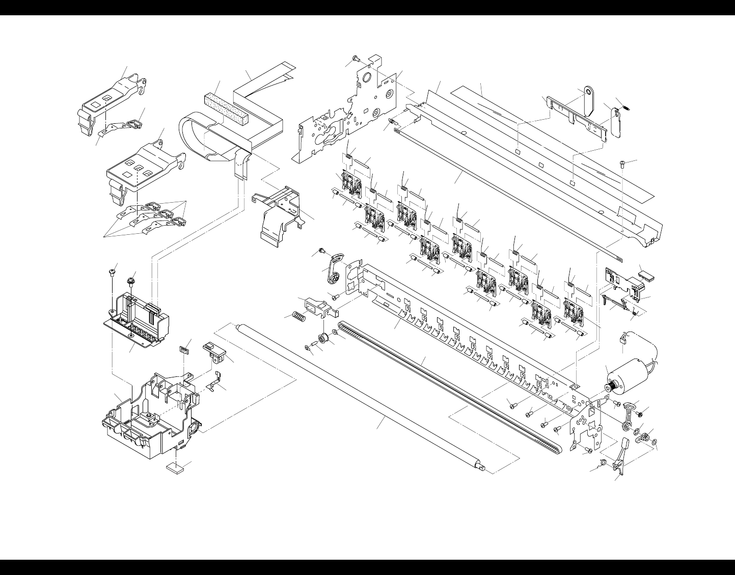
EPSON Stylus PHOTO 890/1280/1290 Revision C
APPENDIX Exploded Diagrams 193
Figure 7-15. Stylus PHOTO 1280/1290 - 3
PM-3500C / EPSON STYLUS PHOTO 1290 No.3 Rev.01 10270
513
568
575
567
577
575
(506)
706
569
566
587
565
572 570
571
507
514
551
549
552
553
609
548
550
550 550
550
549
550 549
550
550
550
550
549
550 549 550
550
549
551 548
551
548 551
548
551
548
551
548
555
554
550
550
550
549
550 549 550
550
549
551
548
551
548
551
548
545
X 5
704 (501) 557
605
761
760
762
629
587
705
759
761
762
587
587 612
561
588
589
587 629
587
598
573 583
558
584
630
769
612
700
560
564
604
562
563
547
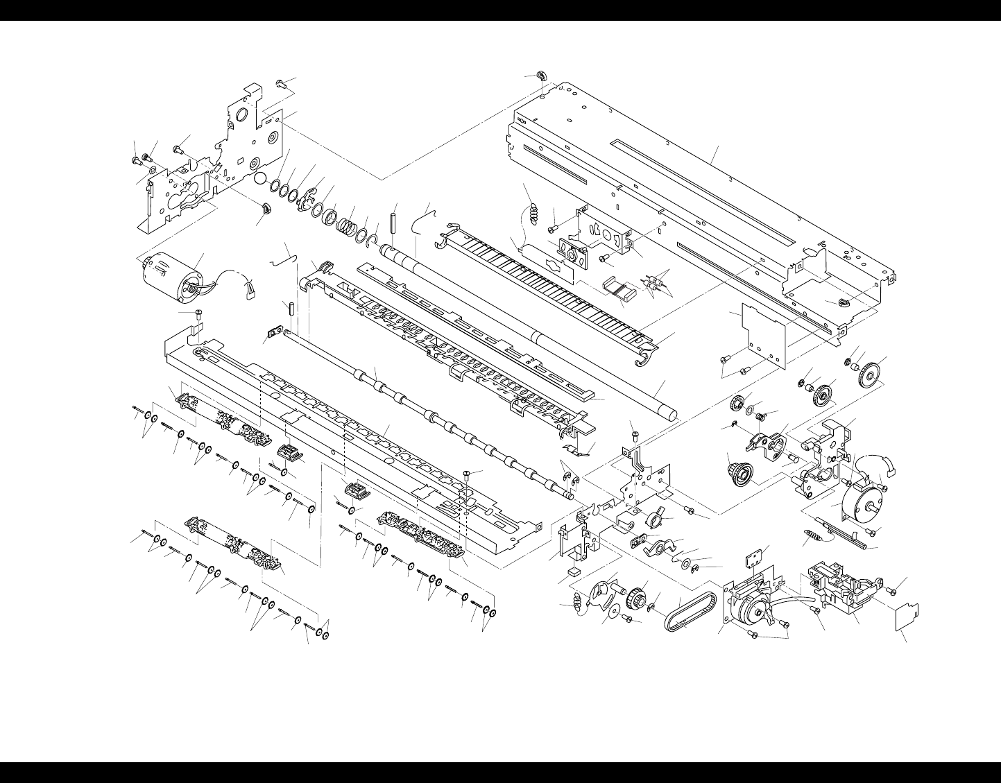
EPSON Stylus PHOTO 890/1280/1290 Revision C
APPENDIX Exploded Diagrams 194
Figure 7-16. Stylus PHOTO 1280/1290 - 4
535
503
531
PM-3500C / EPSON STYLUS PHOTO 1290 No.4 Rev.01 10270
J
587
(501)
587
559
588
5
90
502
526
525 521
518
528
523517
528
527
522 537
610
636
634
587
510
633
635
587
587
536
610
529
515
516
538
632
544
542
544
542
544
542
587
541
544
543
544
542
544
542
544
542
544
542
544
542
544 542
544
542
544
542
544
542
544
542
544
542
544
542
544542
544
542
544
542
544
542
544
542
599
119
616
621
618
587
624
587
587
531519
533
530 556
585
593
531
765
623
622
520
619
539
592
511
628
627
587
619
628 586
579 626
582 612
578
620
612
587 587 509
625
508
???
504
543
541
544
540
530
611
58
7
587
637
638
549
546
546
641
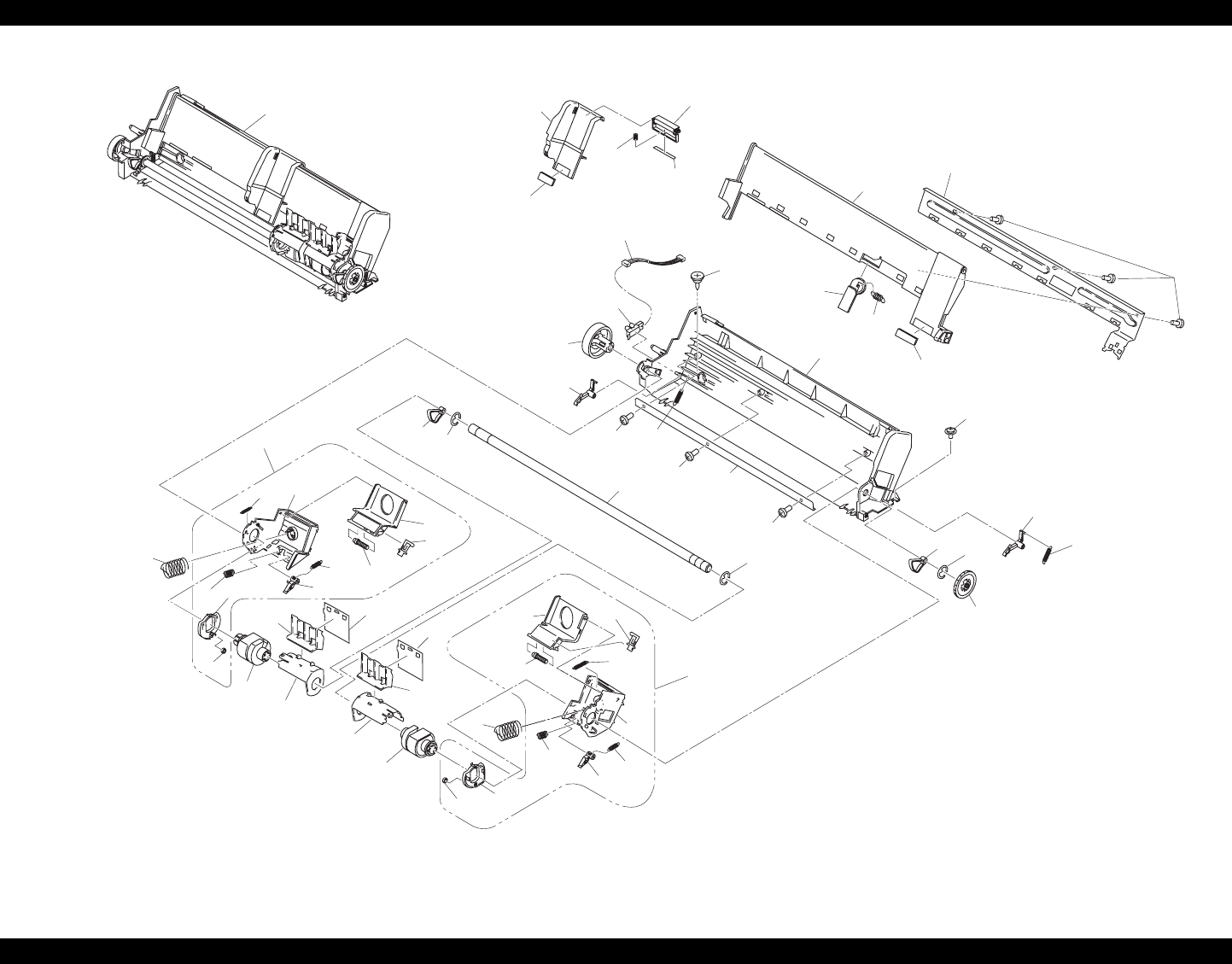
EPSON Stylus PHOTO 890/1280/1290 Revision C
APPENDIX Exploded Diagrams 195
Figure 7-17. Stylus PHOTO 1280/1290 - 5
PM-3500C / EPSON STYLUS PHOTO 1290 No.5
Rev.01 10270
735
730
720
724
731
733
734
732
724 725 722
720
735
718
719
721
717
716
738
701
739 701 703
780
764
739
703
737
741
701
715
736
737
736
740
763
749
709
712
711
750
708
714
707
758
710
748
723
721 728
729
746 745
745
718
727
726 703
70
3
747
723
713
746
781
782

EPSON Stylus PHOTO 890/1280/1290 Revision C
APPENDIX Parts List 196
7.5 Parts List
7.5.1 Parts List for Stylus PHOTO 890
Table 7-13. Stylus PHOTO 890 Parts List
Code Parts Name
100 HOUSING;B
101 COVER ASSY.
102 PAPER SUPPORT;B
103 STACKER ASSY.;C
104 PANEL ASSY.
105 "SHIELD PLATE,PANEL"
106 "HOUSING,PANEL,LEFT;B"
108 GROUNDING PLATE
109 "COVER,SHIELD PLATE,M/B,RIGHT"
111 "COVER,CABLE"
112 "COVER,INLET,UPPER;B"
113 "COVER,INLET,LOWER;B"
114 "SHIELD PLATE,M/B"
115 LOGO PLATE 10X40;C
116 "HOUSING,SUPPORT,RIGHT;B"
117 "HOUSING,SUPPORT,LEFT;B"
119 FOOT
121 C.P.SCREW
122 C.B.S. SCREW
123 "C.B.(O) SCREW,4X5,F/ZG"
124 C.B.S. SCREW
125 "C.B.P-TITE SCREW,3X8,F/ZN"
126 C.B.S. SCREW
130 "BUTTON,CSIC"
131 "COVER,CABLE;B"
132 "LOCK,STACKER"
133 "COMPRESSION SPRING,2.94"
135 "BUTTON,PS;B"
136 OPTICAL TUBE
180 "LABEL,CAUTION;B"
181 "LABEL,MODEL NAME;B"
184 "LABEL,ACCESSORY"
200 "BOARD ASSY., MAIN"
300 "BOARD ASSY., POWER SUPPLY"
330 HARNESS
400 POWER CABLE ASSY.
450 "BOARD ASSY.,PANEL"
500 PRINTER MECHANISM(ASP)M4T12-100
501 "FRAME ASSY,LEFT;B"
502 "MOTOR ASSY.,PF"
504 "COMBINATION GEAR,12,22.4"
505 "FRAME,RIGHT,FRONT"
506 "FRAME,UPPER"
507 "MOTOR ASSY.,CR"
508 "PUMP,ASSY."
509 CAP ASSY.
510 "FRAME,LOWER"
Table 7-13. Stylus PHOTO 890 Parts List
Code Parts Name

EPSON Stylus PHOTO 890/1280/1290 Revision C
APPENDIX Parts List 197
511 "SHEET,PROTECT,INK"
512 "FRAME,FRONT"
513 "BUSHING,PARALLELISM ADJUST,LEFT"
514 "BUSHING,PARALLELISM ADJUST,RIGHT"
515 "PAPER GUIDE,REAR"
516 "ROLLER,PF"
517 "COMPRESSION SPRING,5.85"
518 "BUSHING,12,LEFT"
519 "TENSION BELT,PUMP TRANSMISSION"
520 "SPUR GEAR,15.2"
521 "SPACER,C-RING"
522 "SCALLOP SPRING PIN-AW,2X16,F/B"
524 "SPUR GEAR,76"
525 "SPACER,FASTEN,ROLLER,PF"
526 "SPACER,FASTEN,ROLLER,PF;B"
527 C-RING
528 "PLANE WASHER,12.2X0.5X17"
529 "ROLLER ASSY.,EJ"
530 "BUSHING,6"
531 RETAINING RING
532 "SPUR GEAR,28"
533 "BUSHING,12,RIGHT"
534 "PLANE WASHER,4.1X0.5X6.5"
535 "PAPER GUIDE ASSY.,FRONT"
536 "GROUNDING WIRE,EJ"
Table 7-13. Stylus PHOTO 890 Parts List
Code Parts Name
537 "GROUNDING SPRING,PF"
538 "FRAME,PAPER EJECT"
539 "HOLDER,STAR WHEEL,RIGHT;B"
540 "HOLDER,STAR WHEEL,LEFT;B"
541 "HOLDER,STARWHEEL,FRONT"
542 "STARWHEEL ASSY.,8"
543 "STARHWEEL,8;B"
544 "RODSPRING,STARWHEEL;B"
545 "PAPER GUIDE,UPPER"
546 "PAPER GUIDE,LEFT"
547 "PAPER GUIDE,RIGHT"
548 "SHAFT,PAPER GUIDE,UPPER"
549 "SHAFT,ROLLER,DRIVEN"
550 "ROLLER,DRIVEN"
551 "TORSION SPRING,117.6"
552 "CIRCUIT ASSY,PE"
553 "HOLDER,PE"
554 "LEVER,PE"
555 "TORSION SPRING,0.22"
556 "LEVER,CR,LOCK"
557 "GUIDE PLATE,CR"
558 "SHEET,CABLE"
559 "SCREW,MOUNT,PF"
560 CARRIAGE
564 "SLIDER,CR"
Table 7-13. Stylus PHOTO 890 Parts List
Code Parts Name

EPSON Stylus PHOTO 890/1280/1290 Revision C
APPENDIX Parts List 198
565 TIMING BELT
566 "SHAET,CR"
567 "PULLEY,DRIVEN"
568 "HOLDER,PULLEY,DRIVEN"
569 "COMPRESSION SPRING,23.52"
570 "LEVER,PG;C"
571 "LEVER,PG,SUPPORT"
572 "TORSION SPRING,63.7"
573 "GROUNDING PLATE,HEAD"
574 "COMBINATION GEAR,13.5,30"
575 "BUSHING,PULLEY,DRIVEN"
577 "SHAFT,PULLEY,DRIVEN"
578 "EXTENSION SPRING,0.618"
579 "LEVER,PLANET"
580 "HARNESS,PE"
581 "HARNESS,ASF"
582 "SHAFT,SPUR GEAR,PLANET"
585 "U-TYPE SPRING,5.2X0.13X10,S/NA"
586 "COMBINATION GEAR,14,28"
587 C.B.S. SCREW
588 C.P.SCREW
589 LEAF SPRING
590 "PLAIN WASHER,3.3X0.5X8,F/UC"
591 "C.B.P-TITE,2.5X5,F/ZN"
592 "PLAIN WASHER,6.2*0.2*9,L/NA"
Table 7-13. Stylus PHOTO 890 Parts List
Code Parts Name
593 "PLAIN WASHER,5.1X0.7X11,S/NA"
594 "PLAIN WASHER,10.7X0.5X15.5,L/NA"
599 "FRAME,MIDDLE"
603 "TAPE,D50"
604 "BOARD ASSY.,ENCODER"
605 "SCALE,CR"
606 "SCALE,PF"
607 "MOUNTING PLATE,SCALE"
608 "FFC,ENCODER"
609 "EXTENSION SPRING,1.494"
610 "MINI CRAMP,UAMS-05SN"
611 "SCALLOP SPRING PIN-AW,2X10,F/B"
612 "C.B.P-TITE SCREW,3X8,F/ZN"
613 "MOUNTING PLATE,BOARD ASSY."
614 "FRAME,RIGHT,REAR"
616 "EXTENSION SPRING,7.37"
618 "LEVER ASSEMBLY,COMBINATION GEAR"
619 "SET RING,D8.8"
620 "MOTOR ASSY,ASF"
621 "P.W.,3.1X0.5X12,F/ZN"
622 RETAINING RING
623 "COMBINATION GEAR,17.19,25.6"
624 "COMBINATION GEAR,12,22.92"
625 "LEVER,DE,LOCK"
626 "MOUNTING PLATE,MOTOR,ASF"
Table 7-13. Stylus PHOTO 890 Parts List
Code Parts Name
EPSON Stylus PHOTO 890/1280/1290 Revision C
APPENDIX Parts List 199
627 "COMPRESSION SPRIN,3.944"
628 "FERUTO,D3.6"
637 "SHEET,INK STOPPER"
639 CUP SCREW
641 "POROUS PAD,PAPER GUIDE,FRONT"
644 "+,BIND B-TITE SEMS W2,2.5X6,F/ZB"
645 "GROUNDING PLATE,PAPER GUIDE,FRONT"
700 PRINT HEAD
703 "C.B.P-TITE SCREW,3X6,F/ZN"
704 "CABLE,HEAD"
705 "HOLDER,CABLE"
706 "SPACER,CABLE HEAD"
707 "FRAME,ASF;B"
708 HOPPER
709 EDGE GUIDE;E
710 CORK
711 "SLIDER,EDGEGUIDE"
712 "COMPRESSION SPRING,3.23"
713 "PAD,BREAK,EDGE GUIDE"
714 "REINFORCEMENT PLATE,HOPPER"
715 "SPUR GEAR,32"
716 "PAD ASSY.,RIGHT"
717 "LEVER,PAD,RELEASE,RIGHT"
718 "ROD SPRING,HOLDER,PAD"
719 "HOLDER,EDGEGUIDE,RIGHT"
Table 7-13. Stylus PHOTO 890 Parts List
Code Parts Name
720 "COMPRESSION SPRING,1.17"
721 "EXTENSION SPRING,0.62"
722 "LEVER,PAPERRETURN,RIGHT"
723 "EXTENSION SPRING,0.294"
724 "ROLLER,LD,SUPPORT"
725 "HOLDER,ROLLER,LD,SUPPORT,RIGHT"
726 "PAD ASSY.,LEFT"
727 "LEVER,PAD,RELEASE,LEFT"
728 "HOLDER,EDGEGUIDE,LEFT"
729 "LEVER,PAPERRETURN,LEFT"
730 "HOLDER, ROLLER,LD,SUPPORT,LEFT"
731 "ROLLER ASSY.,LD,LEFT"
732 "ROLLER ASSY.,LD,RIGHT"
733 "COVER,ROLLER,LD,LEFT"
734 "COVER,ROLLER,LD,RIGHT"
735 "COMPRESSION SPRING,1.961"
736 "LEVER,FASTEN,EDGEGUIDE;B"
737 "EXTENSION SPRING,0.088"
738 "SHAFT,ROLLER,LD"
739 "LEVER,HOPPER,RELEASE"
740 "WHEEL,DETECT"
742 "C.C.P-TITE SCREW,3X8,F/ZN"
745 "SHEET,PAPERFEED"
746 "HOLDER,SHEET,PAPERFEED"
747 "SHAFT,MOUNT,CR"
Table 7-13. Stylus PHOTO 890 Parts List
Code Parts Name
EPSON Stylus PHOTO 890/1280/1290 Revision C
APPENDIX Parts List 200
748 "C.B.S-TITE(P4),3X6,F/ZN"
751 "PAPER GUIDE,LOWER"
752 "POROUS PAD,INK EJECT,LARGE;B"
753 "TRAY,POROUS PAD"
754 "SPACER,TRAY"
755 "BUSHING,FASTEN,SHAFT,LEFT"
756 "PAPER SUPPORT,SUUPPORT,UPPER"
757 "HOLDER,PAPER SUPPORT,SUPPORT,UPPER"
758 "EXTENSION SPRING,0.29"
759 "COVER,CARTRIDGE,BK;B"
760 "COVER,CARTRIDGE,C;B"
761 "PLAT SPRING COVER,CARTRIDGE"
762 "COVER,PLAT SPRING,CARTRIDGE"
763 "DETECTOR,HP;E"
764 CORK;B
765 "CLEANER HEAD,ASP"
766 "POROUS PAD,INK EJECT,SMALL;B"
774 "DUMPER,SUPPORT;B"
775 "POROUS PAD,FRAME,MIDDLE"
777 "POROUS PAD,INK EJECT,PUMP;S"
780 ASF UNIT
781 "PAPER LOADING ASSY.,RIGHT"
782 "PAPER LOADING ASSY.,LEFT"
800 "MOUNTING PLATE,ROLL PAPER,HOLDER"
801 "FRAME,ROLL PAPER,LEFT"
Table 7-13. Stylus PHOTO 890 Parts List
Code Parts Name
802 "FRAME,ROLL PAPER,RIGHT"
803 "STOPPER,ROLL PAPER"
805 "SHEET,ROLL PAPER"
Table 7-13. Stylus PHOTO 890 Parts List
Code Parts Name
EPSON Stylus PHOTO 890/1280/1290 Revision C
APPENDIX Parts List 201
7.5.2 Parts List for Stylus PHOTO 1280/1290
Table 7-14. Stylus PHOTO 1280/1290 Parts List
Code Parts Name
100 HOUSING
101 "COVER,PRINTER"
102 "PAPER SUPPOT,ASSY"
103 STACKER ASSY.;C
104 "HOUSING,PANEL,RIGHT"
105 "SHIELD PLATE,PANEL"
106 "PANEL ASSY.,LEFT;C"
108 GROUNDING PLATE
109 "COVER,SHIELD PLATE,M/B,RIGHT"
110 "COVER,PRINTER,SUPPORT"
111 "COVER,CABLE"
112 "COVER,INLET,UPPER;B"
113 "COVER,INLET,LOWER;B"
114 "SHIELD PLATE,M/B"
115 LOGO PLATE 10X40;C
116 "HOUSING,SUPPORT,RIGHT;C"
117 "HOUSING,SUPPORT,LEFT;C"
119 FOOT
121 C.P.SCREW
122 C.B.S. SCREW
123 "C.B.(O) SCREW,4X5,F/ZG"
124 C.B.S. SCREW
125 "C.B.P-TITE SCREW,3X8,F/ZN"
126 C.B.S. SCREW
130 BUTTON;C
131 "COVER,CABLE;B"
132 "BUTTON,PS;B"
136 OPTICAL TUBE
133 "BUTTON,CSIC"
180 "LABEL,CAUTION;B"
181 "LABEL,MODEL NAME;C"
182 "LABEL,PAPER SET;B"
200 "BOARD ASSY., MAIN"
300 "BOARD ASSY., POWER SUPPLY"
330 HARNESS
400 POWER CABLE ASSY.
450 "BOARD ASSY.,PANEL"
500 "PRINTER MECHANISM(ASP),M4S61-100"
501 "FRAME ASSY.,LEFT;B"
502 "MOTOR ASSY.,PF"
503 "GROUNDING PLATE,PAPER GUIDE,FRONT"
504 "COMBINATION GEAR,12,22.4"
505 "FRAME,RIGHT,FRONT"
506 "FRAME,UPPER"
507 "MOTOR ASSY.,CR"
508 "PUMP,ASSY."
509 CAP ASSY.
510 "FRAME,LOWER"
511 "SHEET,PROTECT,INK"
Table 7-14. Stylus PHOTO 1280/1290 Parts List
Code Parts Name

EPSON Stylus PHOTO 890/1280/1290 Revision C
APPENDIX Parts List 202
512 "FRAME,FRONT"
513 "BUSHING,PARALLELISM ADJUST,LEFT"
514 "BUSHING,PARALLELISM ADJUST,RIGHT"
515 "PAPER GUIDE,REAR"
516 "ROLLER,PF"
517 "COMPRESSION SPRING,5.86"
518 "BUSHING,12,LEFT"
519 "TENSION BELT,PUMP TRANSMISSION"
520 "SPUR GEAR,15.2"
521 "SPACER,C-RING"
522 "SCALLOP SPRING PIN-AW,2X16,F/B"
523 "SLEEVE,ROLOR,PF"
524 "SPUR GEAR,76"
525 "SPACER,FASTEN,ROLLER,PF"
526 "SPACER,FASTEN,ROLLER,PF;B"
527 C-RING
528 "PLANE WASHER,12.2X0.5X17"
529 "ROLLER ASSY.,EJECT OUT"
530 "BUSHING,6"
531 RETAINING RING
532 "SPUR GEAR,28"
533 "BUSHING,12,RIGHT"
534 "PLANE WASHER,4.1X0.5X6.5"
535 "PAPER GUIDE ASSY.,FRONT"
536 "GROUNDING WIRE,EJ"
Table 7-14. Stylus PHOTO 1280/1290 Parts List
Code Parts Name
537 "GROUNDING SPRING,PF"
537 "GROUNDING SPRING,PF"
538 "FRAME,PAPER EJECT;B"
539 "HOLDER,STAR WHEEL,RIGHT;B"
540 "HOLDER,STAR WHEEL,LEFT;B"
541 "HOLDER,STARWHEEL,FRONT"
542 "STAR WHEEL,8;G"
543 "STARHWEEL,8;B"
544 "RODSPRING,STARWHEEL;B"
545 "PAPER GUIDE,UPPER"
546 "ROLLER,DRIVEN"
547 "PAPER GUIDE,RIGHT"
548 "SHAFT,PAPER GUIDE,UPPER"
549 "SHAFT,ROLLER,DRIVEN"
550 "ROLLER,DRIVEN;D"
551 "TORSION SPRING,117.6"
552 "CIRCUIT ASSY,PE"
553 "HOLDER,PE"
554 "LEVER,PE"
555 "TORSION SPRING,0.22"
556 "LEVER,CR,LOCK"
557 "GUIDE PLATE,CR"
558 "SHEET,CABLE"
559 "SCREW,MOUNT,PF"
560 CARRIAGE
Table 7-14. Stylus PHOTO 1280/1290 Parts List
Code Parts Name
EPSON Stylus PHOTO 890/1280/1290 Revision C
APPENDIX Parts List 203
561 CUP SCREW
562 "GROUNDING PLATE,HEAD"
563 OIL PAD
564 "SLIDER,CR"
565 TIMING BELT
566 "SHAFT ASSY.,CR,GUIDE"
567 "PULLEY,DRIVEN"
568 "HOLDER,PULLEY,DRIVEN"
569 "COMPRESSION SPRING,23.52"
570 "LEVER,PG;B"
571 "LEVER,PG,SUPPORT"
572 "TORSION SPRING,63.7"
573 "HOLDER,PAPER SUPPORT,SUPPORT,UPPER"
574 "COMBINATION GEAR,13.5,30"
575 "BUSHING,PULLEY,DRIVEN"
577 "SHAFT,PULLEY,DRIVEN"
578 "EXTENSION SPRING,0.618"
579 "LEVER,PLANET"
580 "HARNESS,PE"
582 "SHAFT,SPUR GEAR,PLANET"
583 "PAPER SUPPORT,SUPPORT,UPPER,LEFT;B"
584 "PAPER SUPPORT,SUUPPORT,UPPER"
585 "U-TYPE SPRING,5.2X0.13X10,S/NA"
586 "COMBINATION GEAR,14,28"
587 C.B.S. SCREW
Table 7-14. Stylus PHOTO 1280/1290 Parts List
Code Parts Name
588 C.P.SCREW
589 LEAF SPRING
590 "PLAIN WASHER,3.3X0.5X8,F/UC"
591 "C.B.P-TITE,2.5X5,F/ZN"
592 "PLAIN WASHER,6.2*0.2*9,L/NA"
593 "PLAIN WASHER,5.1X0.7X11,S/NA"
594 "PLAIN WASHER,10.7X0.5X15.5,L/NA"
598 "EXTENSION SPRING,0.29"
599 "FRAME,MIDDLE"
603 "TAPE,D50"
604 "BOARD ASSY.,ENCODER"
605 "SCALE,CR"
606 "SCALE,PF"
607 "MOUNTING PLATE,SCALE"
608 "FFC,ENCODER"
609 "EXTENSION SPRING,1.494"
610 "MINI CRAMP,UAMS-05SN"
611 "SCALLOP SPRING PIN-AW,2X10,F/B"
612 "C.B.P-TITE SCREW,3X8,F/ZN"
613 "MOUNTING PLATE,BOARD ASSY."
614 "FRAME,RIGHT,REAR"
616 "EXTENSION SPRING,7.37"
618 "LEVER ASSEMBLY,COMBINATION GEAR"
619 "SET RING,D8.8"
620 "MOTOR ASSY,ASF"
Table 7-14. Stylus PHOTO 1280/1290 Parts List
Code Parts Name

EPSON Stylus PHOTO 890/1280/1290 Revision C
APPENDIX Parts List 204
621 "P.W.,3.1X0.5X12,F/ZN"
622 RETAINING RING
623 "COMBINATION GEAR,17.19,25.6"
624 "COMBINATION GEAR,12,22.92"
625 "LEVER,DE,LOCK"
626 "MOUNTING PLATE,MOTOR,ASF"
627 "COMPRESSION SPRIN,3.944"
628 "FERUTO,D3.6"
629 "C.B.S-TITE(P4),3X6,F/ZN"
630 "PLANE WASHER,4.5X0.5X8,L/NA"
632 "HOLDER,STARWHEEL,SUPPORT;B"
633 "BUSHU,ROLLER PF,SUPPORT"
634 "LEVER,ROLLER PF,SUPPORT"
635 "MOUNTIN PLATE,LEVER,ROLLER PF,SUPPORT"
636 "EXTENSION SPRING,10.1"
637 "SHEET,INK STOPPER"
638 "HOLDER,ROLLER PF,SUPPORT"
641 "POROUS PAD,PAPER GUIDE,FRONT"
700 PRINT HEAD
701 RETAINING RING
703 "C.B.P-TITE SCREW,3X6,F/ZN"
704 "CABLE,HEAD"
705 "HOLDER,CABLE"
706 "SPACER,CABLE HEAD"
707 "FRAME,ASF"
Table 7-14. Stylus PHOTO 1280/1290 Parts List
Code Parts Name
708 HOPPER;C
709 EDGE GUIDE;E
710 CORK
711 "SLIDER,EDGEGUIDE"
712 "COMPRESSION SPRING,3.23"
713 "PAD,BREAK,EDGE GUIDE"
714 "SUPPORT PLATE,HOPPER;B"
715 "SPUR GEAR,32"
716 "PAD ASSY.,RIGHT"
717 "LEVER,PAD,RELEASE,RIGHT"
718 "ROD SPRING,HOLDER,PAD"
719 "HOLDER,EDGEGUIDE,RIGHT"
720 "COMPRESSION SPRING,1.17"
721 "EXTENSION SPRING,0.62"
722 "LEVER,PAPERRETURN,RIGHT"
723 "EXTENSION SPRING,0.294"
724 "ROLLER,LD,SUPPORT"
725 "HOLDER,ROLLER,LD,SUPPORT,RIGHT"
726 "PAD ASSY.,LEFT"
727 "LEVER,PAD,RELEASE,LEFT"
728 "HOLDER,EDGEGUIDE,LEFT"
729 "LEVER,PAPERRETURN,LEFT"
730 "HOLDER, ROLLER,LD,SUPPORT,LEFT"
731 "ROLLER ASSY,LD,LEFT"
732 "ROLLER ASSY,LD,RIGHT"
Table 7-14. Stylus PHOTO 1280/1290 Parts List
Code Parts Name
EPSON Stylus PHOTO 890/1280/1290 Revision C
APPENDIX Parts List 205
733 "COVER,ROLLER,LD,LEFT"
734 "COVER,ROLLER,LD,RIGHT"
735 "COMPRESSION SPRING,1.961"
736 "LEVER,FASTEN,EDGEGUIDE;B"
737 "EXTENSION SPRING,0.088"
738 "SHAFT,ROLLER,LD"
739 "LEVER,HOPPER,RELEASE"
740 "WHEEL,DETECT"
741 "STRENGTHEN PLATE,FRAME,ASF"
742 "C.C.P-TITE SCREW,3X8,F/ZN"
743 "POLUS PAD,FL"
745 "SHEET,PAPERFEED"
746 "HOLDER,SHEET,PAPERFEED"
747 "SHAFT,MOUNT,CR"
748 "C.B.S-TITE(P4),3X6,F/ZN"
749 "HARNESS,ASF"
750 "PAPER SUPPORT,HOPPER"
751 "PAPER GUIDE,LOWER"
752 "POLUS PAD,LARGE"
753 "TRAY,POROUS PAD"
754 "SPACER,TRAY"
758 "EXTENSION SPRING,0.29"
759 "COVER,CARTRIDGE,BK;B"
760 "COVER,CARTRIDGE,C;B"
761 "PLAT SPRING COVER,CARTRIDGE"
Table 7-14. Stylus PHOTO 1280/1290 Parts List
Code Parts Name
762 "COVER,PLAT SPRING,CARTRIDGE"
763 "DETECTOR,HP;E"
764 CORK;B
765 "CLEANER HEAD,ASP"
766 "POLUS PAD,SMALL"
769 "+,BIND B-TITE SEMS W2,2.5X6,F/ZB"
774 "DUMPER,SUPPORT;B"
775 "SEAT,PAPER EJECT"
776 "POROUS PAD,INK EJECT,PUMP;S"
780 ASF ASSY.;D
781 "PAPER LOADING ASSY.,LEFT"
782 "PAPER LOADING ASSY.,RIGHT"
783 "TRAY ASSEMBLY,POROUS PAD"
800 "MOUNTING PLATE,ROLL PAPER,HOLDER"
801 "FRAME,ROLL PAPER,LEFT"
802 "FRAME,ROLL PAPER,RIGHT"
803 "STOPPER,ROLL PAPER"
805 "SHEET,ROLL PAPER"
Table 7-14. Stylus PHOTO 1280/1290 Parts List
Code Parts Name

