Experimenters Guide For Metro
User Manual:
Open the PDF directly: View PDF ![]() .
.
Page Count: 314 [warning: Documents this large are best viewed by clicking the View PDF Link!]
- Guide Contents
- Intro
- Want to learn about the programming in Arduino but don't know where to start?
- Start with the Experimenters Guide for Metro!
- About The Experimenters Guides
- Electronics Primer
- Lead Clipping
- Identifying: TMP36 and NPN
- Parts Field Guide
- Programming Primer
- About Arduino Programming
- The Arduino IDE
- Structure
- Syntax
- { } (curly brackets)
- Variables
- Math
- Control Flow
- for() Loops
- Digital Input/Output
- Analog Input/Output
- Downloads
- What Board Do I Have?
- Setting up your Metro
- Power your Metro!
- Arduino Bootloader Check.
- Download the Arduino Software
- Windows Setup
- (Windows) Installing Arduino
- Mac Setup
- (macOS/OS X) Installing Arduino
- (macOS / OS X) Installing Drivers
- Linux Setup
- (Linux) Installing Arduino
- Configure Arduino for the Metro Express
- Using the Metro Express with Arduino IDE
- Install SAMD Support
- Install Adafruit SAMD
- CIRC01: Blinking LED
- What We're Doing
- Parts
- Wiring
- Breadboard Layout
- Code
- Make It Better
- Change the pin
- Change the Blink time
- Control the brightness
- Fading
- CIRC02: 8 LED Fun
- What We're Doing
- Parts
- Wiring
- Steps
- Code
- Not Working? CIRC02 not matching the GIF?
- Make It Better
- Switching to Loops
- Extra Animations
- Make your own animations
- CIRC03: Spin Motor Spin
- What We're Doing
- Parts
- Wiring
- Steps
- Code
- Having Trouble with CIRC03?
- Make It Better
- Controlling Speed
- Accelerating and Decelerating
- CIRC04: A Single Servo
- Parts
- Wiring
- Code
- Sweep
- Not Working?
- Make It Better
- Potentiometer Control
- Self-Timing
- Other fun servo ideas
- CIRC05: 8 More LEDs
- Parts
- Wiring
- Code
- Not Working?
- Make It Better
- Doing it the Hard Way
- Controlling Individual LEDs
- More Animations
- CIRC06: Music with Piezo
- Parts
- Wiring
- Code
- Not Working?
- Make It Better
- Playing with Speed
- Tuning the Notes
- Composing your own Melodies:
- CIRC07: Button Pressing
- Parts
- Wiring
- Code
- Not Working?
- Make It Better
- CIRC08: Twisting
- Parts
- Wiring
- Wiring for Metro Express
- Code
- Using the Arduino Serial Plotter
- Make It Better
- CIRC09: Light
- Parts
- Wiring
- Wiring for Metro Express
- Code
- Make It Better
- CIRC10: Temperature
- Parts
- Wiring
- Wiring for Metro Express
- Code
- Make It Better
- CIRC10.5: Temperature Alarm
- CIRC11: Larger Loads with Relays
- Parts
- Am I using a NPN Transistor or a TMP36 Temperature Sensor? (https://adafru.it/ytD)
- Wiring
- Code
- Make It Better
- Check out the Back-EMF Pulse
- Controlling a Motor
- Controlling Motor Direction
- Schematic Layout
- CIRC12: Colorful Light
- Parts
- Wiring
- Wiring for Metro Express
- Code
- Make It Better
- Analog Color Control
- CIRC13: Squeezing
- Parts
- Wiring
- Code
- Make It Better
- CIRC14: Character LCDs
- Parts
- Wiring
- Assembling your LCD
- Wiring Power and Backlight
- Code
- Not Working?
- Make It Better
- What's next?
- CIRC15: Thermometer
- Parts
- Wiring
- Code
- Make It Better
- Making your own Custom Character
- CIRC16: IR Sensor
- Parts
- IR (Infrared) Receiver Sensor
- Mini Remote Control
- Wiring
- Installing the IR Library
- Code
- Not Working?
- CIRC17: IR Replay
- Parts
- IR (Infrared) Receiver Sensor
- Super-bright 5mm IR LED
- Mini Remote Control (OPTIONAL)
- Wiring
- Code
- Not Working?
- Parts
- Wiring for Metro Express
- Code
- Having trouble?
- Make It Better
- Parts
- Wiring
- Code
- Using USB Blog Buddy
- Not Working?
- Parts
- Wiring
- Wiring for the Metro Express
- Wiring for Metro Express
- Code
- Code
- I'm having problems with this CIRC
- Make It Better
- PROJ01: Theremin
- Parts
- Wiring
- Wiring for Metro Express
- Code
- Wait...my PROJect doesn't work!
- Make It Better
- PROJ02: MetroPOV Display
- Parts
- Wiring
- Code
- I need help
- Using MetroPOV
- PROJ03: Music Box
- Parts
- Wiring
- Assembly
- Code
- Calibrating the Music Box
- Encountering Problems?
- Make It Better
- Music Composer
- Unconventional Enclosures
- Annoy-a-Box
- Secret Message Box
- PROJ04: Fidget Spinner Tachometer
- Parts
- Wiring
- Code
- Parts
- IR Sensor
- Mini Remote Control
- Mini-USB Cable
- Wiring
- Code
- I'm having trouble with this Project
- Make It Better
- PROJ06: IR Laser Pet Toy
- Parts
- Wiring
- Assembly
- Servo Wiring
- Base Assembly
- Code
- This project isn't working properly
- PROJ08: Analog Thermometer Gauge
- Parts
- Wiring
- Assembly
- Code
- Code
- Code

Experimenter's Guide for Metro
Created by Brent Rubell
Last updated on 2018-08-22 04:01:41 PM UTC

2
16
16
16
16
18
18
18
18
18
18
18
19
19
22
22
22
22
22
23
23
23
23
23
23
24
24
24
24
24
24
25
25
25
25
25
25
25
26
26
26
26
27
27
Guide Contents
Guide Contents
Intro
Want to learn about the programming in Arduino but don't know where to start?
Start with the Experimenters Guide for Metro!
About The Experimenters Guides
Electronics Primer
Identifying Resistors by Color Code
Lead Clipping
LEDs:
Resistors:
Other Components:
Identifying: TMP36 and NPN
Parts Field Guide
(all of these parts can be found in the Metro Experimenters kit, click the image to enlarge it)
Programming Primer
About Arduino Programming
The Arduino IDE
Structure
void setup() { }
void loop() { }
Syntax
// (single line comment)
/* */ (multi-line comment)
{ } (curly brackets)
; (the semicolon)
Variables
int (integer)
long
bool (boolean)
float
char (character)
Math
= (equals)
% (modulo)
+ (addition)
- (subtraction)
* (multiplication)
/ (division)
Control Flow
If Conditions
for() Loops
Digital Input/Output
pinMode(pin, mode)
digitalWrite(pin, value)
© Adafruit Industries https://learn.adafruit.com/experimenters-guide-for-metro Page 2 of 317

27
27
28
28
29
29
29
30
30
30
31
31
31
31
32
32
33
33
33
34
36
39
39
39
39
41
41
43
43
43
44
44
46
46
47
48
49
49
52
52
53
53
53
53
53
54
55
digitalRead(pin)
Analog Input/Output
analogWrite(pin, value)
analogRead(pin)
Downloads
Fritzing Diagrams
Code
What Board Do I Have?
I have a Metro
I have a Metro Express
Setting up your Metro
USB Micro Cable
Power your Metro!
Arduino Bootloader Check.
Download the Arduino Software
The image above says Arduino 1.8.3, but I see a different version.
Windows Setup
Downloading for Windows
(Windows) Installing Arduino
(Windows) Installing Drivers
(Windows) Find your Serial COM Port
Mac Setup
Downloading for macOS or OS X
(macOS/OS X) Installing Arduino
(macOS/OS X) Find your Serial Port
(macOS / OS X) Installing Drivers
Verifying macOS / OS X Drivers
Linux Setup
Downloading for Linux
(Linux) Installing Arduino
(Linux) Installing Drivers
(Linux) Find your Serial Port
Configure Arduino for the Metro Express
Metro Express Arduino IDE Setup
https://adafruit.github.io/arduino-board-index/package_adafruit_index.json
Using the Metro Express with Arduino IDE
Install SAMD Support
Install Adafruit SAMD
CIRC01: Blinking LED
What We're Doing
Parts
Let's begin by gathering our parts:
10mm Blue LED
560 Ohm Resistor
Breadboard Wiring Bundle
Adafruit Metro (or Metro Express) + Breadboard + Mounting Plate
Wiring
© Adafruit Industries https://learn.adafruit.com/experimenters-guide-for-metro Page 3 of 317

55
55
55
57
58
58
58
58
58
60
60
60
60
60
60
61
61
62
62
62
62
63
64
64
64
65
68
68
68
68
68
69
70
70
70
70
70
70
72
72
73
73
73
74
74
75
Breadboard Layout
Steps
Breadboard Layout Sheet
Code
Blink
Having issues with CIRC01?
LED Not Lighting Up?
Program Not Uploading?
Still No Success?
Make It Better
Congrats on building your first circuit with the Adafruit Metro!
Change the pin
Change the Blink time
Control the brightness
Fading
CIRC02: 8 LED Fun
What We're Doing
Parts
5mm Green LED
560 Ohm Resistor
Breadboard Wiring Bundle
Adafruit Metro (or Metro Express) + Breadboard + Mounting Plate
Wiring
Breadboard Layout
Steps
Code
Compile and Upload
Not Working? CIRC02 not matching the GIF?
Some LEDs Fail to Light
Operating out of sequence
Not working? Try again with a fresh slate!
Still not working?
Make It Better
Switching to Loops
After running the program, what changed?
What's the difference between the two procedures: oneAfterAnotherNoLoop() and oneAfterAnotherLoop()?
Extra Animations
Make your own animations
CIRC03: Spin Motor Spin
What We're Doing
Parts
DC Toy/Hobby Motor
Transistor (PN2222 or MPS2222)
Diode (1N4001)
Breadboard Wiring Bundle
Adafruit Metro (or Metro Express) + Breadboard + Mounting Plate
© Adafruit Industries https://learn.adafruit.com/experimenters-guide-for-metro Page 4 of 317

76
76
77
78
78
78
78
78
79
79
79
79
80
81
81
81
81
82
83
83
84
85
85
86
86
86
86
86
87
87
87
87
87
88
88
88
91
93
93
93
93
94
94
95
95
95
Wiring
Steps
Code
Having Trouble with CIRC03?
Motor Not Spinning?
Check Your Motor
Still having issues?
Tried the steps above? Still didn't resolve your issue?
Make It Better
Controlling Speed
Accelerating and Decelerating
Why stop at two speeds? Why not accelerate and decelerate the motor.
CIRC04: A Single Servo
Parts
Mini Servo
3-Pin Header
Breadboard Wiring Bundle
Adafruit Metro (or Metro Express) + Breadboard + Mounting Plate
Wiring
Connection details:
Breadboard Layout Sheet
Code
Sweep
Not Working?
Servo Not Twisting?
Twitching and a flashing LED on your metro?
My servo is not moving at all
Nothing is working, I need assistance
Make It Better
Potentiometer Control
Parts
Wiring the Potentiometer
Metro Breadboard Diagram
Loading the example code
Self-Timing
Other fun servo ideas
CIRC05: 8 More LEDs
Parts
5mm Red LED
74HC595 Shift Register
560 Ohm Resistor
Breadboard Wiring Bundle
Adafruit Metro (or Metro Express) + Breadboard + Mounting Plate
Wiring
Chip Orientation
Step 1: Connect Power/GND
© Adafruit Industries https://learn.adafruit.com/experimenters-guide-for-metro Page 5 of 317

96
97
98
99
100
100
100
100
101
101
101
101
101
102
103
103
103
103
104
104
105
105
105
105
105
106
106
106
106
106
106
108
109
109
109
109
109
110
110
111
112
113
114
114
114
115
Step 2: Connect Data Pins to the Metro
Step 3: Connect the LEDs
Breadboard Layout Sheet
Code
Not Working?
The Metro's Power LED goes out
Still not working?
Frustrated?
Make It Better
Doing it the Hard Way
Did you notice anything different when you ran it this time?
Controlling Individual LEDs
More Animations
CIRC06: Music with Piezo
Parts
Piezo Buzzer
Breadboard Wiring Bundle
Adafruit Metro (or Metro Express) + Breadboard + Mounting Plate
Wiring
Breadboard Layout Sheet
Code
Not Working?
No sound is coming out of the speaker
Can't Think While the Melody is Playing? Annoyed by the sound?
Tired of Twinkle Twinkle Little Star?
Make It Better
Playing with Speed
Tuning the Notes
Composing your own Melodies:
Twinkle Twinkle Little Star
Happy Birthday (First line)
CIRC07: Button Pressing
Parts
Pushbutton
Qty: x2
5mm Red LED
10K Ohm Resistor
560 Ohm Resistor
Breadboard Wiring Bundle
Adafruit Metro (or Metro Express) + Breadboard + Mounting Plate
Wiring
Breadboard Layout Sheet
Code
Code:
Not Working?
Light Not Turning On
© Adafruit Industries https://learn.adafruit.com/experimenters-guide-for-metro Page 6 of 317

115
115
116
116
116
117
118
119
119
119
119
120
120
121
121
122
123
123
124
124
124
125
127
127
127
127
129
130
130
130
130
131
131
132
133
133
134
135
135
135
135
135
136
136
136
136
137
137
The light is not fading
Feeling Underwhelmed?
Make It Better
Light Switch
Fading
Changing Fade Speed
CIRC08: Twisting
Parts
Breadboard Trim Potentiometer - 10k
5mm Red LED
560 Ohm Resistor
Breadboard Wiring Bundle
Adafruit Metro (or Metro Express) + Breadboard + Mounting Plate
Wiring
Printable Breadboard Sheet
Wiring for Metro Express
Code
Not Working?
Sporadically Working
Not Working?
Still Backwards?
Using the Arduino Serial Plotter
Make It Better
Threshold Switching
Fading
Controlling the servo
CIRC09: Light
Parts
5mm Red LED
Photo Sensor
10K Ohm Resistor
560 Ohm Resistor
Breadboard Wiring Bundle
Adafruit Metro (or Metro Express) + Breadboard + Mounting Plate
Wiring
Printable Breadboard Layout Sheet
Wiring for Metro Express
Code
Not Working?
LED Remains Dark
It Isn't Responding to Changes in Light.
Still not quite working?
Make It Better
Reverse the Response
Night Light
Light Controlled Servo
Using the full range of your servo
Learn More!
© Adafruit Industries https://learn.adafruit.com/experimenters-guide-for-metro Page 7 of 317

138
139
139
139
139
140
141
141
142
143
144
144
145
145
145
145
146
146
146
146
146
147
147
147
149
150
151
151
151
151
152
152
152
152
153
153
154
155
155
155
156
157
157
157
157
157
158
158
CIRC10: Temperature
Parts
Am I using a NPN Transistor or a TMP36 Temperature Sensor? (https://adafru.it/ytD)
Analog Temperature Sensor
Breadboard Wiring Bundle
Adafruit Metro (or Metro Express) + Breadboard + Mounting Plate
Wiring
Wire it up
Printable Breadboard Sheet
Wiring for Metro Express
Code
Using the Arduino Serial Monitor
Not Working?
Nothing Seems to Happen
Gibberish is Displayed
Temperature Value is Unchanging
Make It Better
Outputting Voltage
Outputting degrees Fahrenheit
More informative output
Changing the serial speed
CIRC10.5: Temperature Alarm
Running the Metro Express off a 9V Battery
Add a Piezo!
Changing the variables
CIRC11: Larger Loads with Relays
Parts
DPDT Relay
560 Ohm Resistor
2.2k Ohm Resistor
Am I using a NPN Transistor or a TMP36 Temperature Sensor? (https://adafru.it/ytD)
Transistor (PN2222 or MPS2222)
Diode (1N4001)
5mm Red LED
5mm Green LED
Breadboard Wiring Bundle
Adafruit Metro (or Metro Express) + Breadboard + Mounting Plate
Wiring
Wire it up:
Close-up of the relay wiring
Printable Breadboard Layout Sheet
Code
Not Working?
Nothing is happening
No clicking sound
Not quite working, or not working correctly
Make It Better
Check out the Back-EMF Pulse
© Adafruit Industries https://learn.adafruit.com/experimenters-guide-for-metro Page 8 of 317

158
158
158
158
160
161
161
161
161
162
163
163
163
164
165
166
166
166
166
166
167
167
167
167
168
169
169
169
169
170
170
171
172
172
173
173
173
173
173
174
174
174
174
176
177
178
178
Controlling a Motor
Controlling Motor Direction
Schematic Layout
Breadboard Layout
CIRC12: Colorful Light
Parts
RGB LED
560 Ohm Resistor
Breadboard Wiring Bundle
Adafruit Metro (or Metro Express) + Breadboard + Mounting Plate
Wiring
Wire according to the diagram below:
Printable Breadboard Layout Sheet
Wiring for Metro Express
Code
Having Trouble?
LED Remains Dark or Shows Incorrect Color
Green and Blue seem to be reversed
Seeing Red
Looking For More?
Make It Better
More Colors
Display a Random Color
Analog Color Control
CIRC13: Squeezing
Parts
Force Sensitive Resistor
10K Ohm Resistor
5mm Green LED
560 Ohm Resistor
Breadboard Wiring Bundle
Adafruit Metro (or Metro Express) + Breadboard + Mounting Plate
Wiring
Printable Breadboard Layout Sheet
Code
Not Working?
LED Not Lighting Up?
Fading to Fast/Slow
Looking For More?
Make It Better
Calibrating the Range
The RGB Strongperson Test
Diagram: RGB + Force Resistor
Other Applications
CIRC14: Character LCDs
Parts
16x2 Character LCD
© Adafruit Industries https://learn.adafruit.com/experimenters-guide-for-metro Page 9 of 317

178
178
179
180
180
180
180
180
181
182
184
189
190
190
191
191
192
192
192
192
192
193
194
195
196
196
196
196
197
197
198
199
200
200
201
201
201
201
201
202
202
202
202
202
203
205
206
206
Breadboard Trim Potentiometer - 10k
Breadboard Wiring Bundle
Adafruit Metro (or Metro Express) + Breadboard + Mounting Plate
Wiring
Assembling your LCD
Assembled Standard LCD 16x2 + extras - White on Blue
Standard LCD 16x2 + extras
Soldering your LCD
Wiring Power and Backlight
Wiring the Contrast Circuit
Wiring the Data Bus
Code
Not Working?
My Character LCD is not lighting up.
I only see black blocks on the LCD
I don't see anything at all
Make It Better
Writing to the second line
Writing the light sensor to the LCD
Photo Sensor
Wiring
Code
What's next?
CIRC15: Thermometer
Parts
16x2 Character LCD
Breadboard Trim Potentiometer - 10k
Am I using a TMP36 Temperature Sensor or a NPN Transistor (https://adafru.it/ytD)
Analog Temperature Sensor
Breadboard Wiring Bundle
Adafruit Metro (or Metro Express) + Breadboard + Mounting Plate
Wiring
Code
Code:
Having Trouble?
I don't see anything on the LCD
Text on the LCD is strange characters or garbled
The number on the LCD is not possible, it's too high/low
I'm still having trouble, I think the diagram is too complicated.
Make It Better
Using Fahrenheit
Printing new text to the LCD
Printing to the Second Row
Using Custom Characters
Making your own Custom Character
CIRC16: IR Sensor
Parts
IR (Infrared) Receiver Sensor
© Adafruit Industries https://learn.adafruit.com/experimenters-guide-for-metro Page 10 of 317

206
206
207
207
208
209
210
210
210
211
212
212
212
212
213
214
214
214
214
215
215
215
216
216
216
217
217
217
218
219
221
221
221
221
222
222
223
224
224
224
225
226
226
226
227
227
227
227
Mini Remote Control
5mm Red LED
560 Ohm Resistor
Breadboard Wiring Bundle
Adafruit Metro (or Metro Express) + Breadboard + Mounting Plate
Wiring
Installing the IR Library
Installing Arduino Libraries
Installing the IR Library
Code
Not Working?
I don't see the colors change
Fatal error: IRLibAll.h: No such file or directory #include
I still don't see anything
CIRC17: IR Replay
Parts
IR (Infrared) Receiver Sensor
Super-bright 5mm IR LED
Am I using a NPN Transistor or a TMP36 Temperature Sensor (https://adafru.it/ytD)
Transistor (PN2222 or MPS2222)
Pushbutton
Qty: x2
5mm Red LED
560 Ohm Resistor
10K Ohm Resistor
Mini Remote Control (OPTIONAL)
Breadboard Wiring Bundle
Adafruit Metro + Breadboard + Mounting Plate
Wiring
Code
Not Working?
I don't see the LED lighting up
I can receive but not send IR signals
I'm really frustrated with this circuit, I don't see any output after debugging
Parts
Adafruit Metro Express + Breadboard + Mounting Plate
Wiring for Metro Express
Code
Installing the NeoPixel Library
Code
Having trouble?
My Code Wont Compile
I don't see a NeoPixel on my board.
I still don't see anything
Make It Better
Dimming the NeoPixel
NeoPixel Glance Thermometer
Wiring
© Adafruit Industries https://learn.adafruit.com/experimenters-guide-for-metro Page 11 of 317

227
229
230
230
230
231
231
232
233
234
234
235
235
235
236
236
236
236
236
237
237
237
239
240
240
241
241
241
242
243
243
243
244
245
245
245
245
246
246
247
248
249
249
249
249
249
250
Code
Adding the NeoPixel to CIRCs
Parts
Breadboard Trim Potentiometer - 10k
Pushbutton
10K Ohm Resistor
Breadboard Wiring Bundle
Adafruit Metro Express + Breadboard + Mounting Plate
Wiring
Code
Using USB Blog Buddy
Not Working?
I don't see anything moving on my screen
Still not working?
Parts
If you're using a Metro Classic:
If you're using a Metro M0 Express:
Adafruit Metro (or Metro Express) + Breadboard + Mounting Plate
Breadboard Wiring Bundle
Wiring
Wiring for the Metro Classic
Wiring for the Metro Express
Wiring for Metro Express
Code
Code
I'm having problems with this CIRC
Not hearing anything?
Getting sensor readings of 0?
This isn't working at all.
Make It Better
Using Different Input Types
Adding Sensor Inputs
PROJ01: Theremin
Parts
Photo Sensor
Piezo Buzzer
560 Ohm Resistor
Breadboard Wiring Bundle
Adafruit Metro (or Metro Express) + Breadboard + Mounting Plate
Wiring
Wiring for Metro Express
Code
Setting Pins
Reading the photo light sensor
Creating the Pitch
Playing the Pitch
Wait...my PROJect doesn't work!
© Adafruit Industries https://learn.adafruit.com/experimenters-guide-for-metro Page 12 of 317

250
250
251
251
251
252
254
254
254
254
255
256
257
262
262
262
262
263
263
263
263
264
265
265
265
265
266
266
267
268
268
268
270
270
271
271
271
272
273
273
273
273
273
274
276
276
I don't hear anything
I can't get this working at all
Make It Better
Modifying the pitch
Stop the Music!
PROJ02: MetroPOV Display
Parts
5mm Red LED
560 Ohm Resistor
Breadboard Wiring Bundle
Adafruit Metro (or Metro Express) + Breadboard + Mounting Plate
Wiring
Code
I need help
I can't get a good photograph of the MetroPOV in action
I don't see the LEDs lighting up in different patterns
Nothing's working, I'm getting nowhere
Using MetroPOV
Taking Photos
GIF'ing your MetroPOV Text
Light Painting with MetroPOV
PROJ03: Music Box
Parts
Photo Sensor
16x2 Character LCD
Piezo Buzzer
10K Ohm Resistor
Breadboard Wiring Bundle
Adafruit Metro (or Metro Express) + Breadboard + Mounting Plate
Wiring
Diagram
Assembly
Code
Calibrating the Music Box
Encountering Problems?
My LCD is not displaying anything.
My music box is still too sensitive, or it's not sensitive enough.
It still doesn't work
Make It Better
Music Composer
Unconventional Enclosures
Annoy-a-Box
Secret Message Box
PROJ04: Fidget Spinner Tachometer
Parts
5mm Red LED
© Adafruit Industries https://learn.adafruit.com/experimenters-guide-for-metro Page 13 of 317

276
276
277
277
278
279
279
279
282
285
285
285
285
286
286
286
286
287
287
288
289
292
292
292
292
294
295
296
297
297
298
299
299
299
301
304
304
304
305
306
307
307
307
307
308
309
Photo Sensor
560 Ohm Resistor
10K Ohm Resistor
Breadboard Wiring Bundle
Adafruit Metro (or Metro Express) + Breadboard + Mounting Plate
Wiring
Diagram
Assembly Tips
Code
Not Working?
LCD is blank/garbled/glitchy
LED not turning on?
Still not working?
Parts
IR Sensor
Mini Remote Control
Mini-USB Cable
Breadboard Wiring Bundle
Adafruit Metro Express + Breadboard + Mounting Plate
Wiring
Code
I'm having trouble with this Project
Fatal error: IRLibAll.h: No such file or directory #include
My computer isn't responding to the remote
This project still isn't working
Make It Better
PROJ06: IR Laser Pet Toy
Parts
Breadboard Wiring Bundle
Adafruit Metro + Breadboard + Mounting Plate
Wiring
Assembly
Servo Wiring
Base Assembly
Code
This project isn't working properly
My Servo doesn't properly move
I'm using a different remote, should I be doing something differently?
This project still isn't working
PROJ08: Analog Thermometer Gauge
Parts
Mini Servo
Analog Temperature Sensor
Breadboard Wiring Bundle
Adafruit Metro (or Metro Express) + Breadboard + Mounting Plate
Wiring
© Adafruit Industries https://learn.adafruit.com/experimenters-guide-for-metro Page 14 of 317

Intro
Want to learn about the programming in Arduino but don't know where to start?
Start with the Experimenters Guide for Metro!
The Experimenters Guide for the Adafruit Metro and Metro Express is meant to serve as a quick-start for makers, artists, hackers,
students, educators, or anyone who wants to get started with the Metro or Metro M0 Express.
This guide has lots of circuits to get you comfortable with skills like learning about different types of electronic components (and
how they work), programming an Adafruit Metro or Metro Express, breadboarding, and modifying code.
Already have parts and a board that can be programmed by the Arduino IDE? This guide will work for you too!
As you progress through this guide in order, you'll be comfortable with the Adafruit Metro enough to work on your own projects
(or at least enough to try one of the thousands of projects in the Adafruit Learning System)
About The Experimenters Guides
The experimenters guide is an expanded version of Oomlout's awesome ARDX kit (https://adafru.it/y4b), but it's compatible the
Adafruit Metro Classic and Metro M0 Express. There are a lot of new circuits to take advantage of the Metro Classic and/or
Express, and a bunch of small projects to do on your own.
These guides were designed for use both with the 'classic' Metro (ATmega328) or Metro M0 Express (ATSAMD21) based
Metros
You can build all of the circuits with parts from the Adafruit Shop. We even provide links to the parts for each circuit in the parts
page.
You have come to the right place :)
© Adafruit Industries https://learn.adafruit.com/experimenters-guide-for-metro Page 16 of 317

© Adafruit Industries https://learn.adafruit.com/experimenters-guide-for-metro Page 17 of 317
Electronics Primer
No previous electronic experience is required to have fun with this kit. Here are a few details about each component to make
identifying, and perhaps understanding them, a bit easier. If at any point you are worried about how a component is used or why
it's not working the internet offers a treasure trove of advice, or you can get help on our community support
forums (https://adafru.it/dYq)
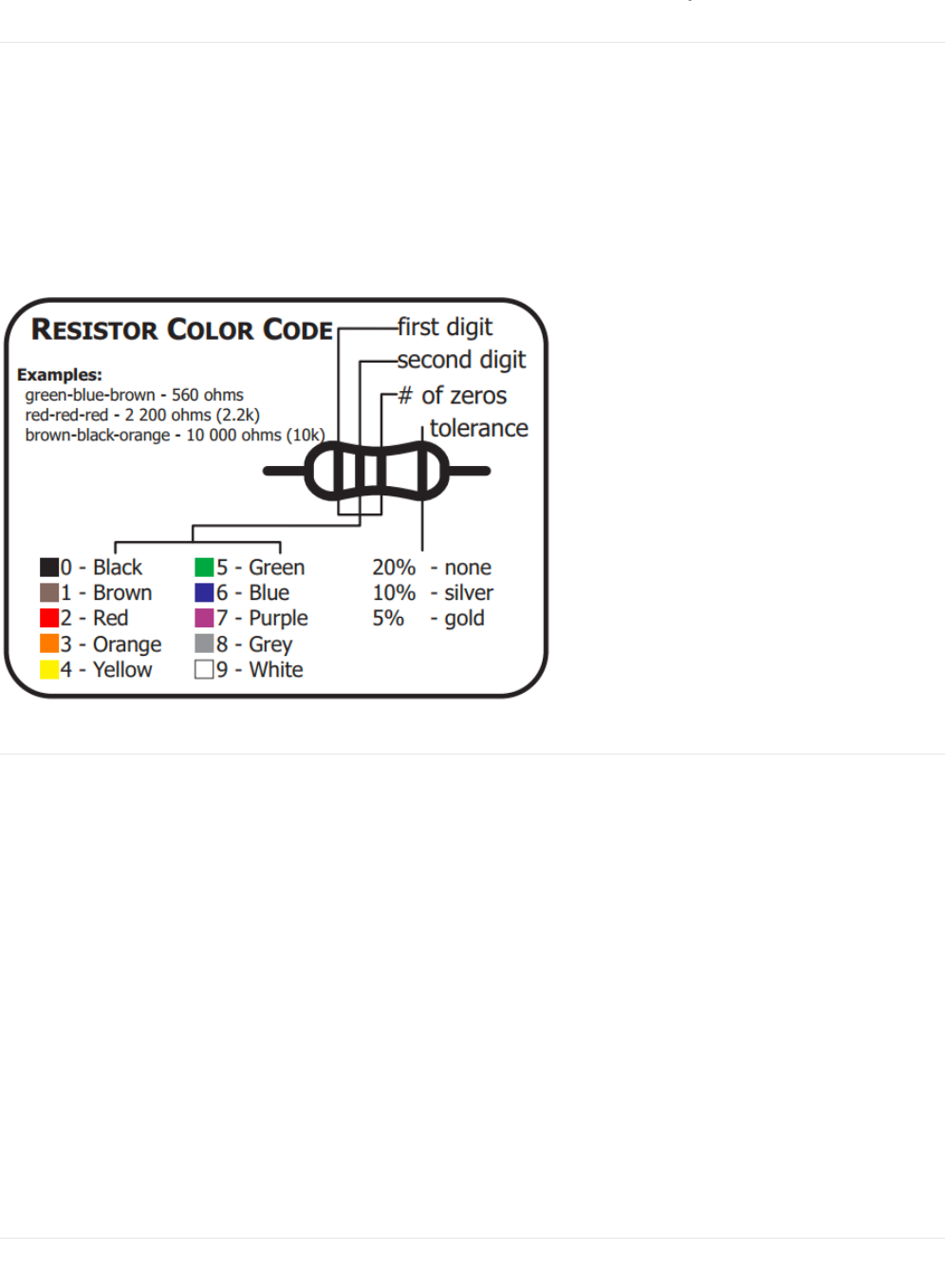
Identifying Resistors by Color Code
The graphic above is super useful for the Explorers guide - most CIRCs use them. Resistors have different values, consult this
graphic if you get stuck later. If you want to get
really good
at identifying resistors quickly, play our fun iOS Game: Mho's
Resistance (https://adafru.it/xrC)
Lead Clipping
Some components in this kit come with
very
long wire leads. To make them more compatible with a breadboard a couple of
changes can be made.
LEDs:
Clip the leads so the long lead is ~10mm (3/8”) long and the short one is ~7mm (9/32”). If you don't own clippers, you can pick up
the CHP17 Flush Diagonal Cutters in the Adafruit shop (https://adafru.it/dxQ)
Resistors:
Bend the leads down so they are 90 degrees to the cylinder. You can do this precisely with Pliers (https://adafru.it/nNf) or
bending it against a 90 degree desk corner.
Then snip them so they are ~6mm (1/4”) long.
Other Components:
Other components
may
need clipping. Use your discretion when doing so.
Identifying: TMP36 and NPN
While the TMP36 Analog Temperature Sensor and the NPN Transistor are similar, they perform very different tasks. To avoid
© Adafruit Industries https://learn.adafruit.com/experimenters-guide-for-metro Page 18 of 317
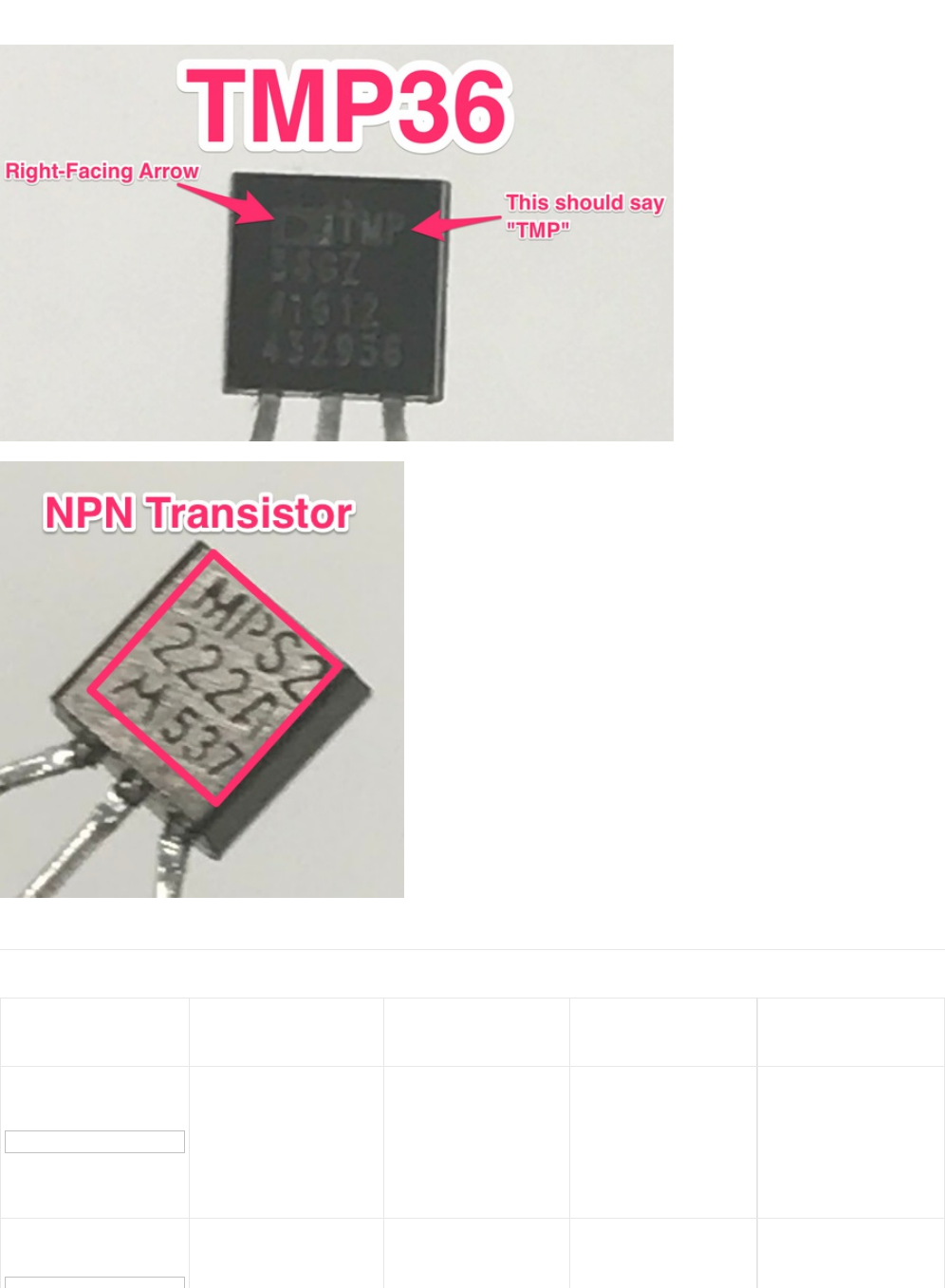
mixing them up in your circuit, use these two pictures to identify which part you have:
Parts Field Guide
(all of these parts can be found in the Metro Experimenters kit,
click
the image to enlarge it)
Part Picture Name & What does it
do? How to Identify No. of Leads What to look out for
LED: Emits light when a
small current is passed
through it. (only in one
direction)
Looks like a mini light
bulb.
2 (one longer, this one
connects to positive)
Will only work in one
direction.
Requires a current
limiting resistor
Diode: The electronic
equivalent of a one way
valve. Allowing current to
Usually a cylinder with
wires extending from
either end. (and an off 2
Will only work in one
direction (current will
flow if end with the line
© Adafruit Industries https://learn.adafruit.com/experimenters-guide-for-metro Page 19 of 317

valve. Allowing current to
flow in one direction but
not the other.
either end. (and an off
center line indicating
polarity)
2flow if end with the line
is connected to ground)
Resistor: Restricts the
amount of current that
can flow through a
circuit.
Cylinder with wires
extending from either
end. The value is
displayed using a color
coding system (for
details see the
"Identifying Resistors"
section)
2
Easy to grab the wrong
value (double check the
colors before using)
Transistor: Uses a small
current to switch or
amplify a much larger
current.
Comes in many
different packages but
you can read the part
number off the package
(P2N2222AG in this kit)
and find a datasheet
online.
3 (Base, Collector,
Emitter)
Plugging in the right
way round (also a
current limiting resistor
is often needed on the
base pin)
Servo: Takes a timed
pulse and converts it into
an angular position of
the output shaft.
A plastic box with 3
wires coming out one
side and a shaft with a
plastic horn out the top.
3
The plug is not
polarized so make sure
it is plugged in the right
way.
DC Motor: Spins when a
current is passed
through it.
This one is easy, it
looks like a motor.
Usually a cylinder with
a shaft coming out of
one end.
2
Using a transistor or
relay that is rated for
the size of motor you're
using.
Piezo: A pulse of current
will cause it to click. A
stream of pulses will
cause it to emit a tone.
In this kit it comes in a
little black barrel, but
sometimes they are just
a gold disk.
2 Difficult to misuse.
Integrated Circuit
(IC/"chip"): Packages any
range of complicated
electronics inside an
easy to use package.
The part ID is written on
the outside of the
package (this
sometimes requires a
light or a magnifying
glass to read)
2 to 100 (this kit has a
TMP36 with 3 leads and
a 74HC595 with 16
leads).
Proper orientation
(check the mark, usually
a half-moon, above pin
1.)
Push-button: Completes
a circuit when it is
pressed.
A little square with
leads out the bottom
and a button on the top.
4
These are almost
square so they can be
inserted 90 degrees off
angle.
Potentiometer: Produces
a variable resistance
dependent on the
angular position of the
shaft.
They can be packaged
in many different form
factors, look for a dial to
identify this part.
3Accidentally buying
logarithmic scale.
Light-Sensor: Produces Remember it needs to
© Adafruit Industries https://learn.adafruit.com/experimenters-guide-for-metro Page 20 of 317

Light-Sensor: Produces
a variable resistance
dependent on the
amount of incident light.
Usually a little disk with
a clear top and a curvy
line underneath.
2
Remember it needs to
be in a voltage
divider before it
provides a useful input.
Relay: an electrically-
controlled switch.
Tall rectangle with pins
underneath. Sizes
range from small to
very large (some relays
even control train
tracks!)
5 to 8 (automotive
relays usually have
5 pins, the relay
included in this kit has 8
pins)
Proper orientation.
Check the marking on
the relay, usually a
small rectangle above
the first two pins. The
bottom of the relay
sometimes
has markings indicating
coil location.
Produces a variable
resistance dependant on
the amount of infrared
light.
Usually a small
rectangle with a bump. 3Make sure not to put it
in backwards.
Emits infrared light when
a small current is passed
through it. (only in one
direction)
Looks like a small light
bulb. 2Only works in one
direction.
Emits pulses of infrared
light following the NEC
Infrared Transmission
Protocol.
Looks like a TV remote. 0 Difficult to misuse.
© Adafruit Industries https://learn.adafruit.com/experimenters-guide-for-metro Page 21 of 317

Programming Primer
About Arduino Programming
The Adafruit Metro is programmed in the C language. This is a quick little primer targeted at people who have a little bit of
programing experience and just need a briefing on the idiosyncrasies of C and the Arduino IDE. If you find the concepts a bit
daunting, don't worry, you can start going through the circuits and pick up most of it along the way.
For a more in-depth explanation of topics discussed both here and in the language, check out the Arduino.cc Reference
page. (https://adafru.it/oVb)
The Arduino IDE
Now that Arduino is installed and configured, we're going to take a peek at it. Double click the Arduino icon to open it. It'll open
up in a workspace, also called the IDE:
Don't feel overwhelmed - as you progress through the Experimenters Guide, you'll learn to use each part of the IDE.
Structure
You can think of the structure of an Arduino project like the scaffolding for a building. There's a specific structure that must be
adhered to, or it all falls apart (and doesn't compile).
void setup() { }
All the code between the two curly brackets { } will be run only once when your Metro program first runs.
© Adafruit Industries https://learn.adafruit.com/experimenters-guide-for-metro Page 22 of 317

void loop() { }
This function is run
after
void setup() has finished. After it has run once it will be run again, and again, forever, until power is
removed.
Syntax
One of the
slightly
frustrating
elements of C is its formatting requirements, or syntax. While frustrating, this also makes the
language very powerful. If you remember the following you should be alright:
// (single line comment)
When writing a new sketch, or looking over an old one, having a comment to mark what you were thinking is important. To do
this type two forward slashes and everything until the end of the line will be ignored by your program.
/* */ (multi-line comment)
If you have a lot to say, you can type on multiple lines using a multi-line comment. Everything between these two symbols will be
ignored in your program just like the single line comment.
{ } (curly brackets)
These are used to mark when a block of code begins and ends. You'll see it used in functions and loops.
; (the semicolon)
Each line of code must be ended with a semicolon. Missing a semicolon
will cause your code to refuse to compile
. It's often hard
to find these, think of them as the
hide and seek champion
of your code and they're harder to overlook and cause errors.
void setup() {
// put your setup code here, to run once
}
void loop() {
// put your main code here, to run repeatedly
}
// this is a comment, it won't get run by the compiller
this is not a comment, it will cause an error when run!!
/*
* Oh, hey!
* hi there!
*/
void serialPrintHello ()
{ // code begins
Serial.println("Hello");
} // code ends
© Adafruit Industries https://learn.adafruit.com/experimenters-guide-for-metro Page 23 of 317

Variables
A program is nothing more than instructions to move numbers around in an intelligent way. Variables are used to do the moving.
int (integer)
The main workhorse. The integer stores a number in 2 bytes (or, 16 bits). It has no decimal places and will store a value between
-32,768 and 32,767.
long
The long is used when an integer is not large enough. Takes 4 bytes (32 bits) of RAM and has a larger range than an integer:
between -2,147,483,648 and 2,147,483,647.
bool (boolean)
The boolean is a simple variable that can either be True or False. True corresponds to a bit '1' and False corresponds to '0', it's
only one bit.
float
Used for floating point math, like decimals. Pi is a super long decimal, 3.1415...but it can be represented as a float such that it has
more accurate precision (3.14 is more precise than just 3). It takes up 4 bytes (32 bits) of RAM and has a range between -
3.4028235E+38 and 3.4028235E+38.
char (character)
Stores one character using the ASCII code (ie 'A' = 65). Uses one byte (8 bits) of RAM. The Metro handles strings as an array of
char’s.
// this will compile
int servoPin = 5;
// this won't compile, it's missing a semicolon
int servoPin = 5
// this makes the variable i store the value 2
int i = 2;
// this makes the variable j store the value 2000083647
j = 2000083647
// let's make a boolean called openSource and
// set it to True
bool openSource = True;
// now let's make a variable called closedSource and
// set it to False
bool closeDSource = False;
// integers can't store decimal points
int pi = 3;
// so we use a float!
float pi = 3.14;
© Adafruit Industries https://learn.adafruit.com/experimenters-guide-for-metro Page 24 of 317

Math
Now that we can store numbers in variables, we are going to manipulate them:
= (equals)
Makes something equal to something else.
% (modulo)
Gives the remainder of a division operation.
+ (addition)
Adds two numbers together.
- (subtraction)
Subtracts one number from another.
* (multiplication)
Multiplies two numbers together.
/ (division)
Divides two numbers.
// mychar stores the letter A, represented by an ascii value of 65
char myChar = 'A';
// b equals one
int b = 1;
// now, the value stored in b equals b times 2, which is one
b = b * 2;
// 12 divided by 10 = 1.2, modulo (%) will give us the remainder only
int mod = 12%10
// the value stored in int mod now equals 2
int i = 2+2
// the value stored in int i now equals 4
int f = 4-2
// the value stored in int f now equals 2
int z = 5*2
// the value stored in int z now equals 10
int y = 10/2
// the value stored in int y now equals 5
© Adafruit Industries https://learn.adafruit.com/experimenters-guide-for-metro Page 25 of 317
Control Flow
Programs are able to control the flow of execution (what runs next). These are a couple basic elements that you should get
familiar with:
If Conditions
This will execute the code between the curly brackets if the condition is true, and if not it will test the else if condition if that is
also false the else code will execute.
for() Loops
Used when you would like to repeat a chunk of code a number of times (can count up i++ or down i-- or use any variable).
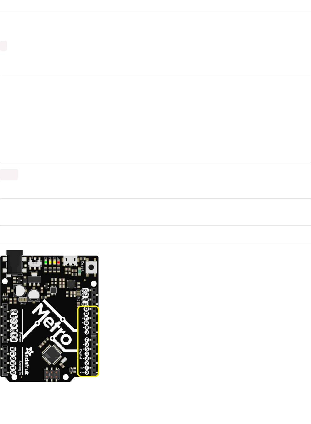
Digital Input/Output
The right side of your Metro (or Metro Express) has a header containing 13 digital pins. These pins can be set to digital values
ranging from 0 to 1023. The following commands pertain to these pins only:
int i = 0;
if(i > 5) {
// this code does not execute, i is not greater than 5
}
else if (i > 2) {
// this code also does not execute, i is not greater than 2
}
else {
// this code DOES execute, i is none of the above, so it falls into
// this category
}
for (int i = 1; i < 5; i++) {
// this code will run 4 times
}
© Adafruit Industries https://learn.adafruit.com/experimenters-guide-for-metro Page 26 of 317

pinMode(pin, mode)
Used to set a pin's mode.
Pin is the pin number you would like to address, Digital 0-19. You can also set digital pinModes on Analog pins 0-5. The
mapping for 0-5 is 14-19.
Mode can either be set as an INPUT or an OUTPUT
digitalWrite(pin, value)
If you set a pin as an OUTPUT using pinMode, you can then set it to either HIGH or LOW. Setting the pin HIGH will pull it up to
+3.3V or +5V. Setting it low will pull it to ground, or zero volts.
digitalRead(pin)
Once a pin is set as an INPUT, you can use this to return whether it is HIGH (pulled to +5 volts) or LOW (pulled to ground).
Analog Input/Output
// a red LED is connected on Pin #11
int redLedPin = 11;
void setup()
{
// set the red LED as an OUTPUT
pinMode(redLedPin, OUTPUT);
}
// this code will flash the LED on and off forever
void loop()
{
// set the pin high to turn ON the LED
digitalWrite(redLedPin, HIGH);
delay(500);
// set the pin low to turn OFF the LED
digitalWrite(redLedPin, LOW);
delay(500);
}
// this will store the value of sensorPin in an integer called sensorValue
int sensorValue = digitalRead(sensorPin);
© Adafruit Industries https://learn.adafruit.com/experimenters-guide-for-metro Page 27 of 317
While the Metro is a digital board, it's able to do analog operations. This is useful for getting precise sensor values. Here's how to
deal with things that aren't digital:
analogWrite(pin, value)
Through some "under the hood" tricks, the Metro is able to write analog values via Pulse Width Modulation. You can write any
value between 0 and 255.
analogRead(pin)
Reads the value of the analog pin. The value returned can be between 0 and 1024.
void loop()
{
// set the LED to full brightness
analogWrite(ledPin, 255);
// turn the LED off
analogWrite(ledPin, 0);
}
sensorVal = analogRead(sensorPin);
© Adafruit Industries https://learn.adafruit.com/experimenters-guide-for-metro Page 28 of 317

Downloads
The experimenters guide has available source code and breadboard diagrams freely available for download on our GitHub:
Fritzing Diagrams
We designed the breadboard layout diagrams you see in this guide using the Open Source tool Fritzing (https://adafru.it/Bvp). If
you’d like to view or modify any of these templates, click the button below:
Note: Most of the diagrams include components for Fritzing from the Adafruit Fritzing Parts/Boards Library. You'll need to
download and install this order to edit our diagrams. (https://adafru.it/ykd)
https://adafru.it/METROXFRITZING
https://adafru.it/METROXFRITZING
Code
https://adafru.it/ykf
https://adafru.it/ykf
We also have the newest version of all of this guide's code stored in github Github repository. Feel free to submit issues,
contributions, requests and modifications to this repository, we'll answer any questions you have in the community support
forums. (https://adafru.it/yke)
© Adafruit Industries https://learn.adafruit.com/experimenters-guide-for-metro Page 29 of 317
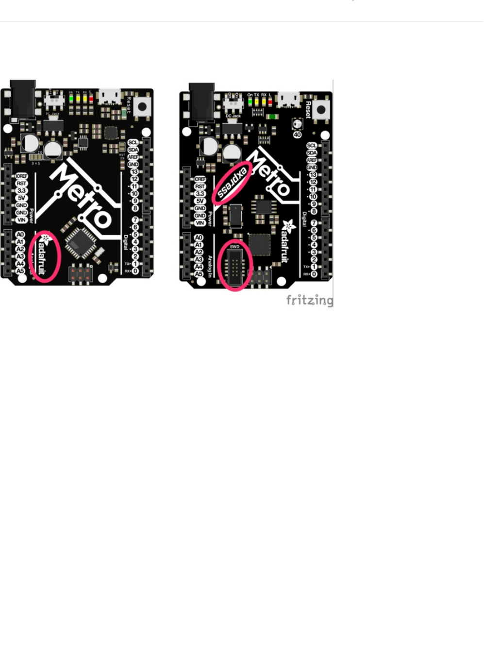
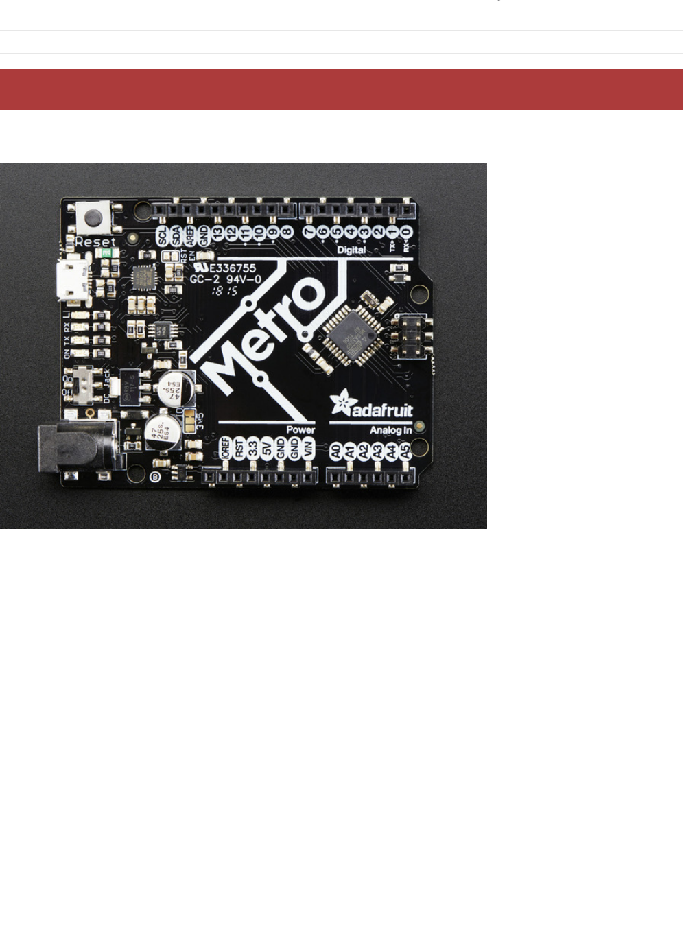
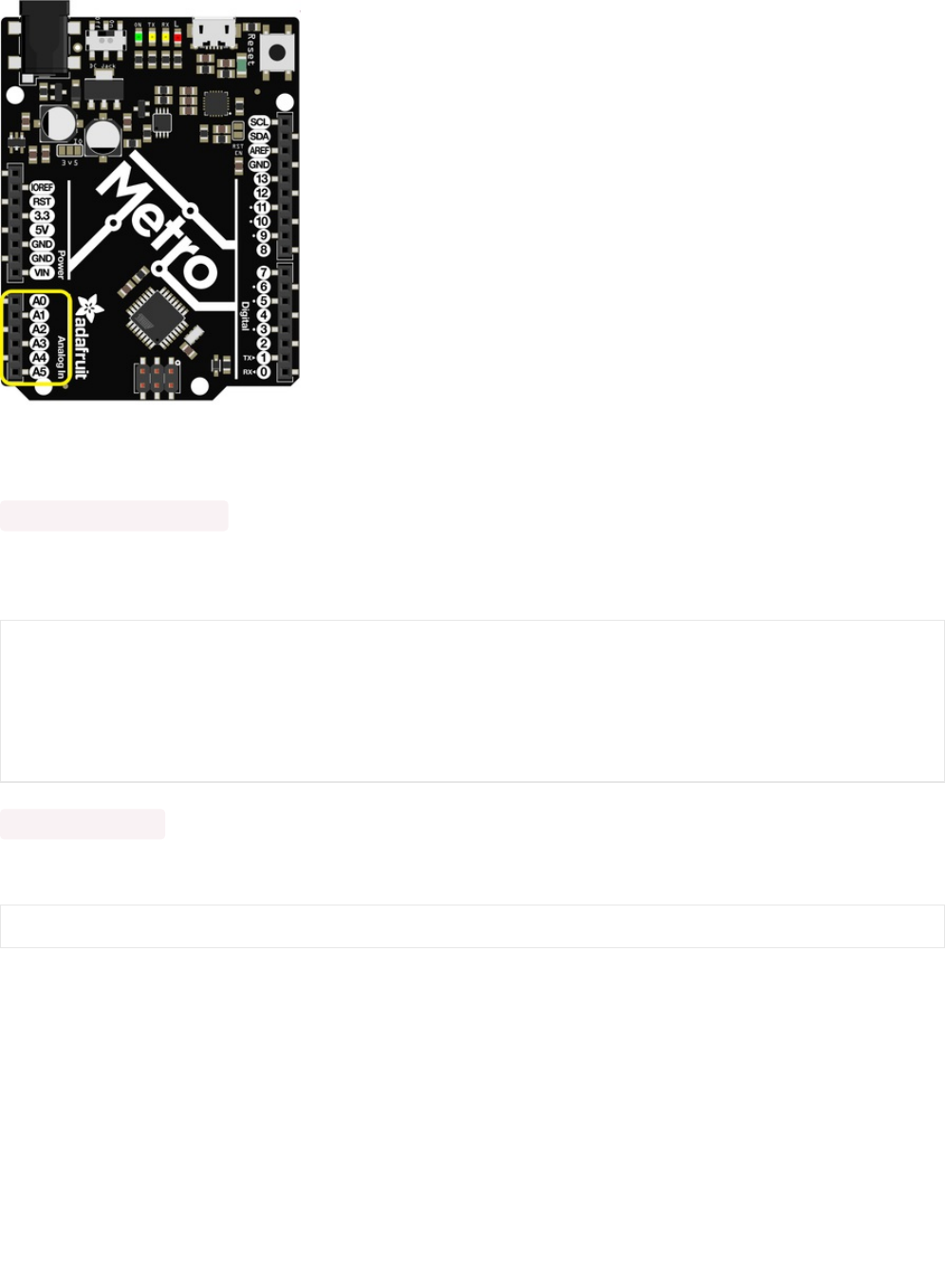
What Board Do I Have?
This guide was designed to work with both the Metro (https://adafru.it/METROXMETR) and the Metro
Express (https://adafru.it/METROXMETR). The main way to tell if your board is the express is if it says "express" on the board.
There's also a SWD port on the bottom of the Metro Express which isn't present on the Metro. The diagram below points these
two differences out:
I have a Metro
This guide will work without any modification, follow the regular steps and have fun!
I have a Metro Express
There are two things to look out for while you work through this guide:
1) Wiring: Some circuits have an extra wiring page called "Wiring for Metro Express" and some don't. If the circuit you are looking
at does not have this sub-page, use the regular Metro wiring. If you see the Metro Express Wiring page, use the wiring in that
page
instead
.
2) Code: If there needs to be a modification in code for Metro Express, instructions will be present to switch the code to a Metro
Express compatible code.
© Adafruit Industries https://learn.adafruit.com/experimenters-guide-for-metro Page 30 of 317
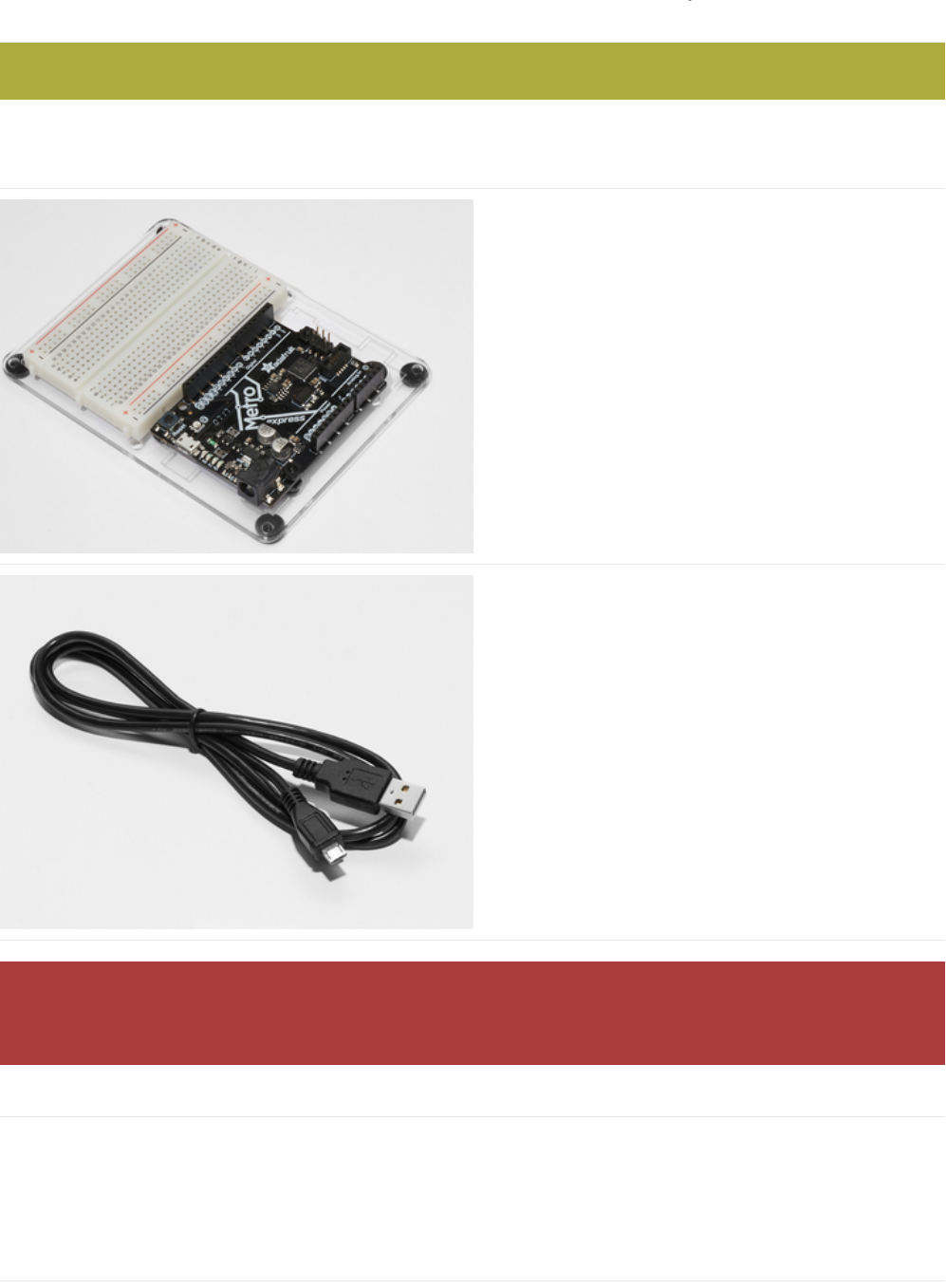
Setting up your Metro
If you haven't assembled your Metro or Metro Express, Half-Sized Breadboard and Mounting Plate yet, click here for
instructions (https://adafru.it/x2A)
You'll need an Adafruit
Metro (https://adafru.it/METROXMETR) or Metro Express.
If you did not purchase the Metro Experimenter's Kit, you
might want to purchase a Half-
size Breadboard (https://adafru.it/keP) and the Plastic
mounting plate for the breadboard. (https://adafru.it/x4F)It
holds everything you need to experiment with small circuits
nicely and keeps everything organized.
USB Micro Cable
I can't stress it enough. Make sure you have a good USB
cable. Naughty USB cables will really ruin your day, like a
stone in your shoe. Throw out bad cables and replace them
with a good one - they are designed to be disposable!
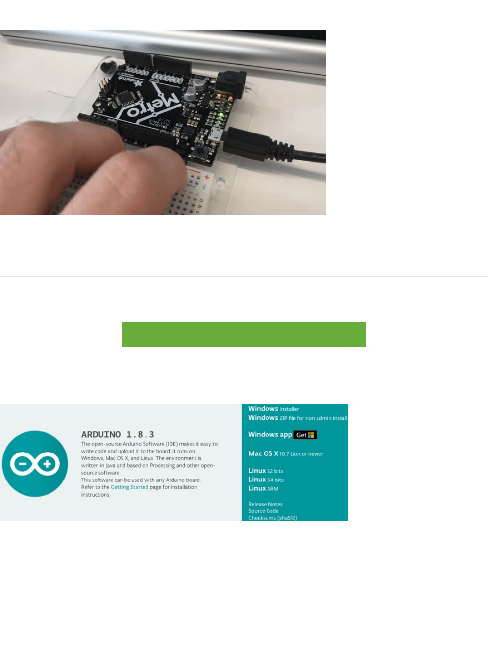
Power your Metro!
If you have a Metro, these next steps will get you set up with the Arduino environment. If you're not sure what board you have,
click here. (https://adafru.it/METROXBOARDCHECK)
Connect your USB Micro cable to the USB Port of the Metro. The On LED should turn a solid green and remain on.
Arduino Bootloader Check.
MetroX Classic/Express Kit Users: Have you set up your mounting plate yet?
A HUGE number of people have problems because they pick a 'charge-only' usb cable rather than a 'Data/Sync' cable.
Make absolutely sure you have a good quality syncing cable. If you're having issues, you most likely have a charge-
only cable.
© Adafruit Industries https://learn.adafruit.com/experimenters-guide-for-metro Page 31 of 317
Next you'll want to check if your Metro is programmed with the Arduino bootloader, which is required for use.
While plugged into power (make sure the On LED is turned on), quickly press the Reset button. You'll see it quickly flash three
times. It happens really fast so don't worry if you can't see all three flashes.
Download the Arduino Software
This is the
free
application you'll use to write programs and talk to your Metro. There are instructions below for installation in
most operating systems (and browser for Chromebook users running CodeBender!).
https://adafru.it/fvm
https://adafru.it/fvm
Click the button above to go to the official software page (https://www.arduino.cc/en/Main/Software (https://adafru.it/fvm)) and
you'll see a box that looks like this:
The image above says Arduino 1.8.3, but I see a different version.
Don't worry, the Arduino Software is under
constant
revisions and the screenshot above is not representative of the latest
version. Download the version for your platform.
© Adafruit Industries https://learn.adafruit.com/experimenters-guide-for-metro Page 32 of 317

Windows Setup
Downloading for Windows
Download and install with the Windows Installer. The .zip file (non-admin install) is not recommended unless you cannot run the
installer.
(Windows) Installing Arduino
Click on the Windows Installer link to download the installer, then double click to launch it
(https://adafru.it/ybu)
You may get a warning asking if you're sure you want to run the installer. It's ok, click YES
(https://adafru.it/ybv)
There is an open source license to click through. Install in the default location
(https://adafru.it/ybw)
© Adafruit Industries https://learn.adafruit.com/experimenters-guide-for-metro Page 33 of 317
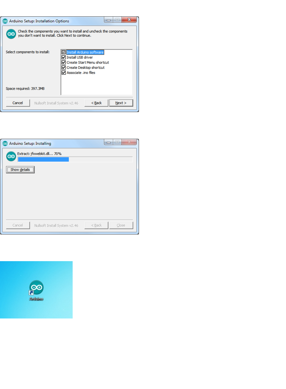
You can use the default setup installation options
(https://adafru.it/ybx)
Finally it will take a minute or two to install
(https://adafru.it/yby)
When done you'll have the software installed:
(https://adafru.it/ybz)
(Windows) Installing Drivers
Depending on your Arduino compatible you may need to install seperate drivers for the USB to serial converter
For all Adafruit compatibles, we have an
all in one
installer that will install all of the Adafruit board drivers. It will also install the
FTDI and CP210x drivers
© Adafruit Industries https://learn.adafruit.com/experimenters-guide-for-metro Page 34 of 317
Click below to download our Driver Installer:
https://adafru.it/AB0
https://adafru.it/AB0
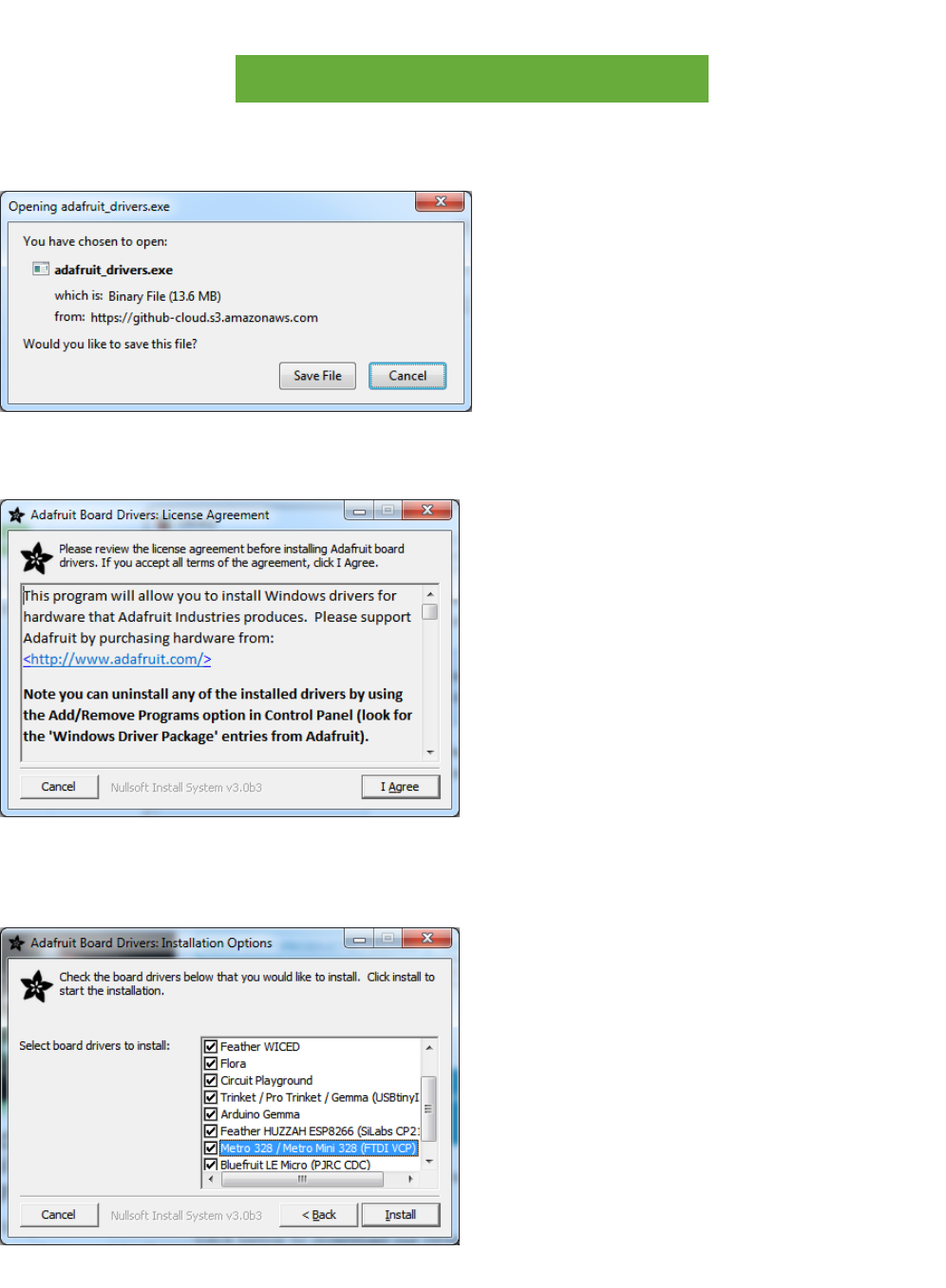
Download and run the installer
(https://adafru.it/ybA)
Run the installer! Since we bundle the SiLabs and FTDI drivers as well, you'll need to click through the license
(https://adafru.it/ybB)
Select which drivers you want to install (we suggest selecting all of them so you never have to worry about installing drivers
when you start to explore other Arduino-compatibles)
(https://adafru.it/ybC)
© Adafruit Industries https://learn.adafruit.com/experimenters-guide-for-metro Page 35 of 317
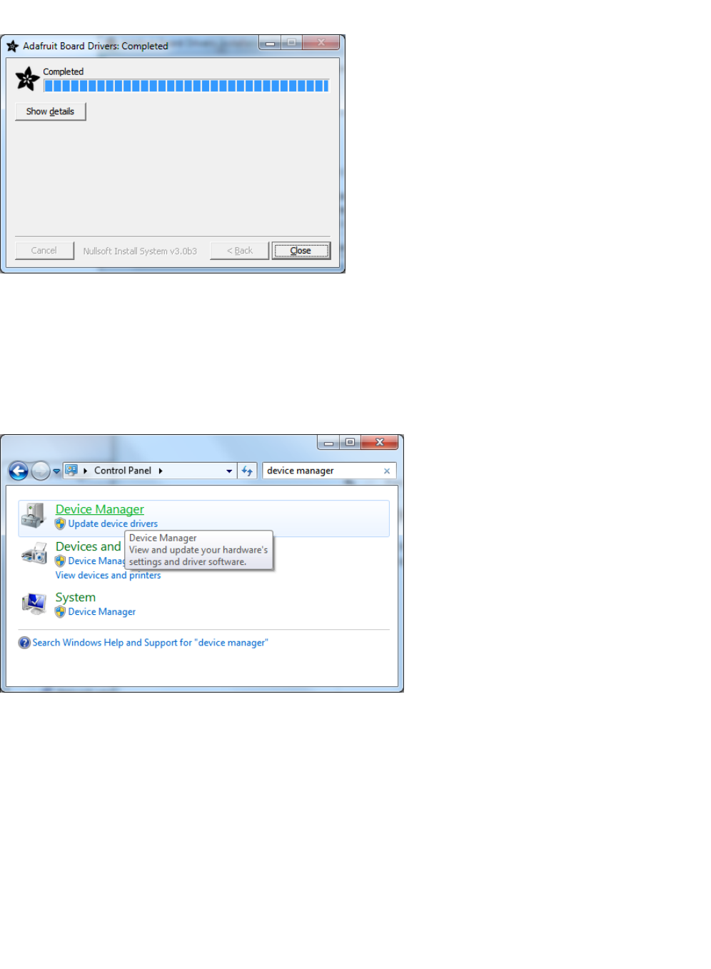
Click Install to do the installin'
(https://adafru.it/ybD)
You should not need to restart your computer but it's not a
bad
idea!
(Windows) Find your Serial COM Port
To verify your Arduino driver installed properly, plug it into USB and open up the Device Manager. You can find the Device
Manager in the Control Panel (search for Device Manager)
(https://adafru.it/ybE)
When you open the Device Manager, find the section called Ports and expand it:
© Adafruit Industries https://learn.adafruit.com/experimenters-guide-for-metro Page 36 of 317
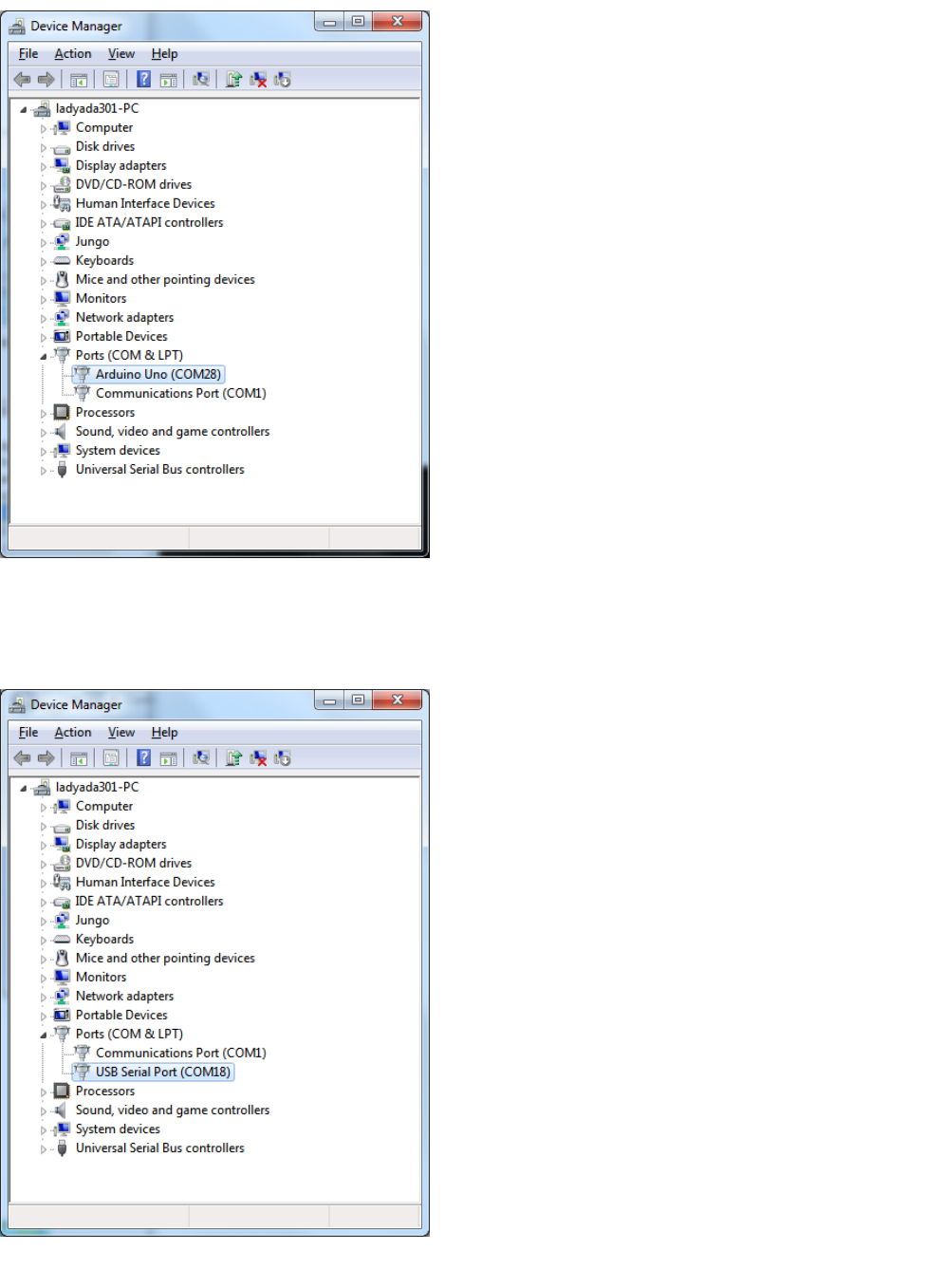
(https://adafru.it/ybF)
You'll see an icon next to some text that says Arduino UNO (COMxx) where xx is a number
If you have a Metro, it won't say Arduino UNO, just USB Serial Port (COMxx)
(https://adafru.it/ybG)
© Adafruit Industries https://learn.adafruit.com/experimenters-guide-for-metro Page 37 of 317

The COM number may vary but it should be something like COM3 or COM4. The COM stands for "communication", and each
one has a unique number, known as the COM Port number. In this case the COM Port number is COM18.
You can unplug your Arduino to see the COM port device disappear and re-appear when plugged in.
If you don't see the Arduino show up, check:
Is your cable a data cable or charge only? Try another USB cable
Try another USB port!
Verify you installed the drivers, you can always try installing them again (never hurts)
Check your Arduino does not need some other drivers, your vendor can point you at the right driver if necessary
© Adafruit Industries https://learn.adafruit.com/experimenters-guide-for-metro Page 38 of 317

Mac Setup
Downloading for macOS or OS X
Download the version for Mac OS X, uncompress the .zip file, and drag the Application out of the folder.
(macOS/OS X) Installing Arduino
Click on the Mac OS X Installer link to download the installer
(https://adafru.it/ybH)
Then double click to expand/launch it
(https://adafru.it/ybI)
it will automatically give you the Arduino app the teal icon:
(https://adafru.it/ybJ)
(macOS/OS X) Find your Serial Port
Now we want to ensure your Metro is properly communicating with your computer. In your Applications folder, find the Utilities
folder and double click it.
© Adafruit Industries https://learn.adafruit.com/experimenters-guide-for-metro Page 39 of 317
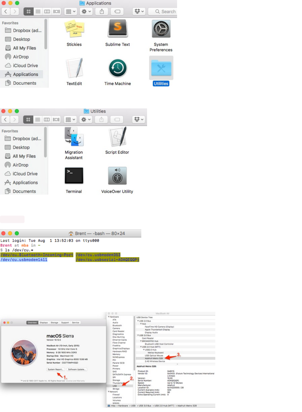
Then, find the application named "Terminal". Double click it to open:
Once Terminal is open, you'll be greeted by a prompt. Type the following into it:
ls /dev/cu*
Once that's typed in, you should see a line with the text
/dev/cu.usbmodemxxxx
OR
/dev/cu.usbserial-xxxxx.
The xxxx's can be
any letter or number. If you see this, the driver was installed properly and the Metro was found on your computer.
If you're not comfortable about using Terminal, there's another (easier) way to check if everything's been installed properly. Click
on the Apple Icon on your menubar. In the dropdown menu, click About This Mac.
© Adafruit Industries https://learn.adafruit.com/experimenters-guide-for-metro Page 40 of 317
Then, click on System Report. System Profiler will open, then click on USB in the Hardware drop-down menu. You should see
the Adafruit Metro 328 as one of your USB devices.
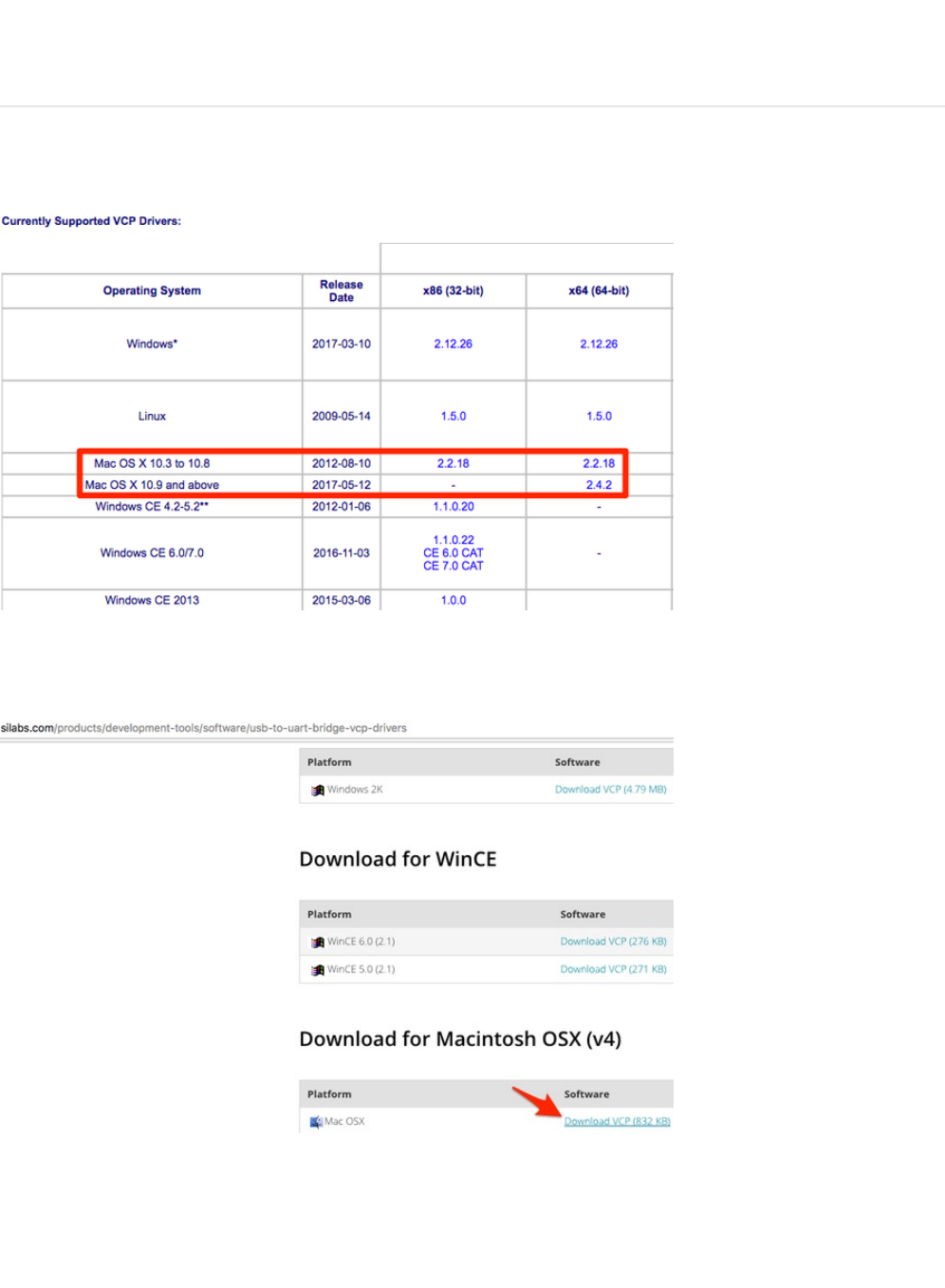
(macOS / OS X) Installing Drivers
Next, you'll want to grab and install the FTDI VCP Drivers and the SiLabs CP210x Drivers.
First, navigate to the FTDI VCP Site and grab the driver for your OS X version and platform. (https://adafru.it/aJv)
Then, unzip the file and install the .dmg file.
You'll also need the SiLabs CP210x Drivers. You can get them from the SiLabs site. (https://adafru.it/yfA)
Then, unzip the file and install the .dmg file.
Verifying macOS / OS X Drivers
We just want to verify that everything is correctly set up. Plug your Metro Classic in, then open the Arduino IDE and navigate
© Adafruit Industries https://learn.adafruit.com/experimenters-guide-for-metro Page 41 of 317

to Tools > Port.
You should see a device listed as /dev/cu.usbserial, followed by number and/or letters. This is your Metro Classic.
If you don't see this, ensure your FTDI and SILabs drivers are correctly installed (for both the right OS Version and Platform).
Then, check both the USB port you're using (try another port) or a cable (you might be using a charge-only cable).
© Adafruit Industries https://learn.adafruit.com/experimenters-guide-for-metro Page 42 of 317
Linux Setup
Downloading for Linux
There are download options available for both 32-bit and 64-bit Linux. Download the version for the system you're using,
manually decompress the .tar file, and install the software.
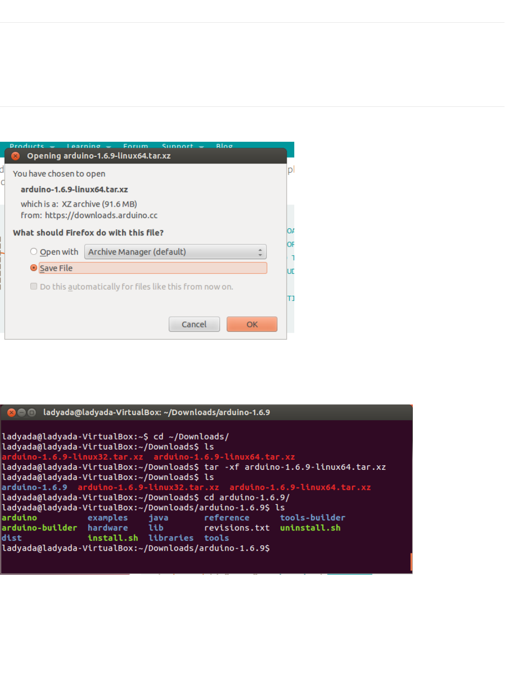
(Linux) Installing Arduino
Click on the matching Linux Installer link (32 bit, 64 bit or ARM) to download the installer - save the file to your Downloads folder
(https://adafru.it/ybL)
From within your Terminal program, cd to the Downloads directory, and untar the package with tar xf arduino*.xz then cd into
the arduino-n.n.n folder created:
(https://adafru.it/ybM)
Run ./install.sh to install the software. I've got an old Ubuntu install so I got warnings, but it did create that desktop icon for me!
© Adafruit Industries https://learn.adafruit.com/experimenters-guide-for-metro Page 43 of 317
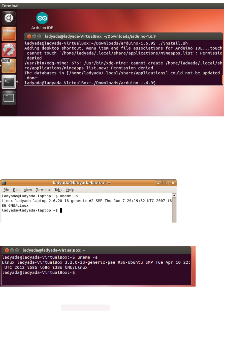
(https://adafru.it/ybN)
(Linux) Installing Drivers
Linux doesn't have any drivers to install, assuming you're running a v2.6 kernel or higher, which is almost certainly true. These
instructions assume you're running Ubuntu. Each Linux distribution is different, but the instructions should be basic enough to
follow for other distros.
You can verify your kernel version by running uname -a in a terminal window, note that this kernel is version 2.6.20
(https://adafru.it/ybO)
And this one is 3.2.0-23
(https://adafru.it/ybP)
Some older Linux distributions used to install brltty (braille device) which will conflict with the Arduino. You must uninstall brltty if
it is installed! Do so by running sudo apt-get remove brltty or equivalent In a terminal window. If it says it's not installed then thats
OK. If you're not running a Debian-derived installation use whatever tool is necessary to verify that you don't have brltty running
(Linux) Find your Serial Port
© Adafruit Industries https://learn.adafruit.com/experimenters-guide-for-metro Page 44 of 317

Plug in the Arduino, verify that the green LED is lit, and type ls /dev/ttyUSB* into a terminal window, you should see a device file
called something like ttyUSB0
(https://adafru.it/ybQ)
If you can't seem to find it, use dmesg | tail right after plugging in the Arduino and look for hints on where it may put the device
file. For example here is says Serial Device converter now attached to ttyUSB0
(https://adafru.it/ybR)
If you see something like this
[ 1900.712000] ftdi_sio 2-10:1.0: FTDI USB Serial Device converter detected
[ 1900.712000] drivers/usb/serial/ftdi_sio.c: Detected FT232BM
[ 1900.712000] usb 2-10: FTDI USB Serial Device converter now attached to ttyUSB0
[ 1901.868000] usb 2-10: usbfs: interface 0 claimed by ftdi_sio while 'brltty' sets config #1
[ 1901.872000] ftdi_sio ttyUSB0: FTDI USB Serial Device converter now disconnected from ttyUSB0
[ 1901.872000] ftdi_sio 2-10:1.0: device disconnected
That means you have not uninstalled brltty and you should try again.
© Adafruit Industries https://learn.adafruit.com/experimenters-guide-for-metro Page 45 of 317

Configure Arduino for the Metro Express
If you've followed the Setting up your Metro Express (https://adafru.it/Bvq) page, you should be ready to roll. We need to make
some modifications to Arduino to allow it to work with the Metro Express.
Metro Express Arduino IDE Setup
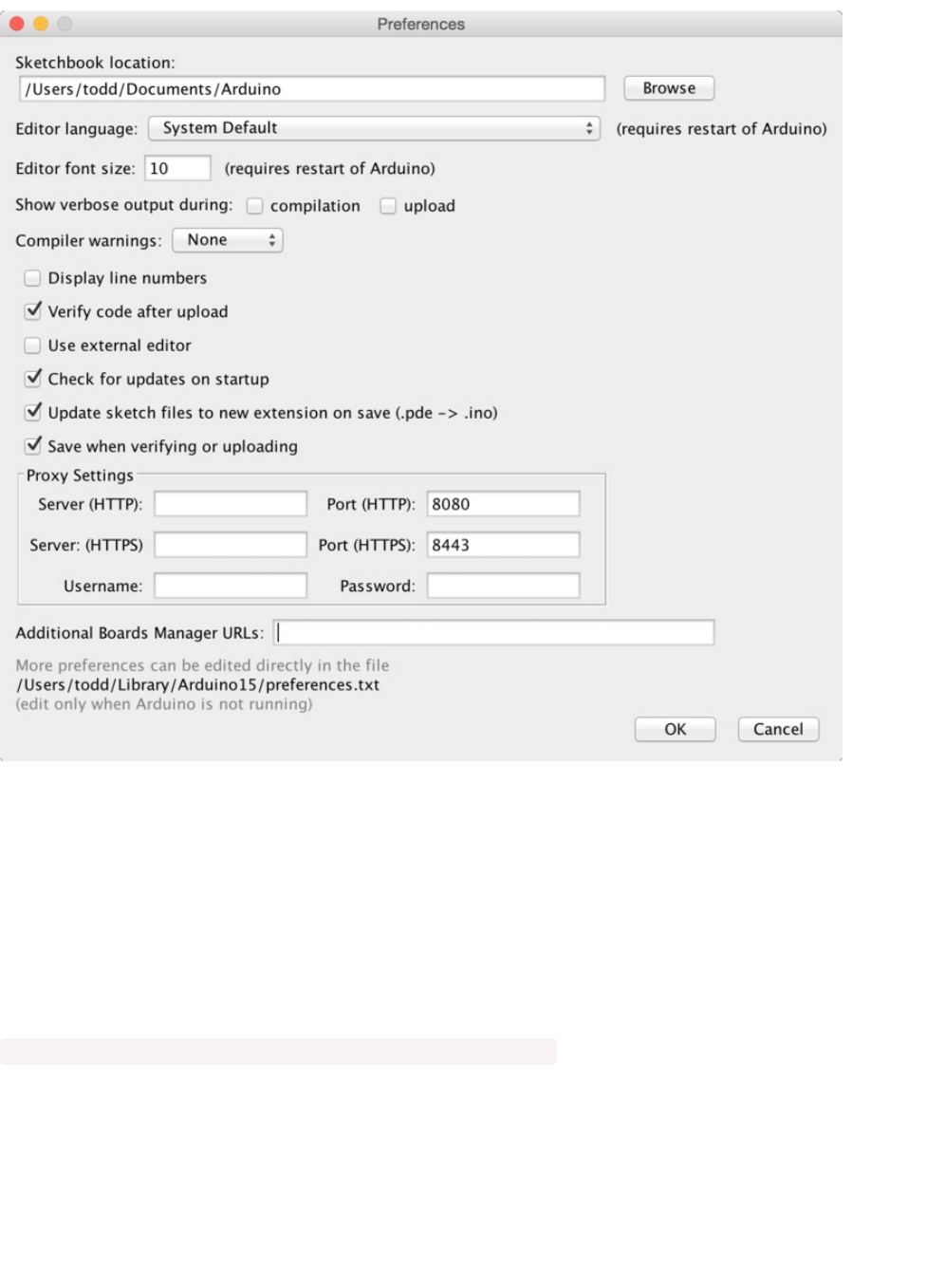
After you have downloaded and installed the latest version of Arduino IDE, you will need to start the IDE and navigate to the
Preferences menu. You can access it from the File menu in
Windows
or
Linux
, or the Arduino menu on
OS X
.
(https://adafru.it/yc6)
A dialog will pop up just like the one shown below.
This page is only for Metro EXPRESS users, if you have a regular Metro, you can ignore this page.
© Adafruit Industries https://learn.adafruit.com/experimenters-guide-for-metro Page 46 of 317
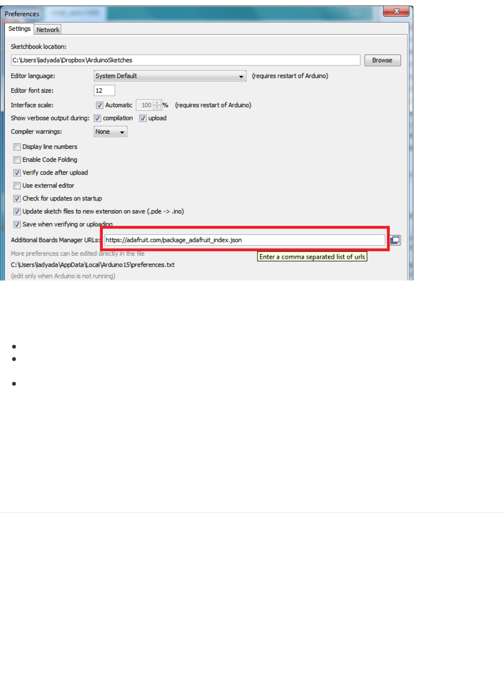
(https://adafru.it/yc7)
We will be adding a URL to the new Additional Boards Manager URLs option. The list of URLs is comma separated, and
you will
only have to add each URL once.
New Adafruit boards and updates to existing boards will automatically be picked up by the
Board Manager each time it is opened. The URLs point to index files that the Board Manager uses to build the list of available &
installed boards.
To find the most up to date list of URLs you can add, you can visit the list of third party board URLs on the Arduino IDE
wiki (https://adafru.it/f7U). We will only need to add one URL to the IDE in this example, but
you can add multiple URLS by
separating them with commas
. Copy and paste the link below into the Additional Boards Manager URLsoption in the Arduino
IDE preferences.
https://adafruit.github.io/arduino-board-index/package_adafruit_index.json
© Adafruit Industries https://learn.adafruit.com/experimenters-guide-for-metro Page 47 of 317
(https://adafru.it/yc8)
Here's a short description of each of the Adafruit supplied packages that will be available in the Board Manager when you add
the URL:
Adafruit AVR Boards - Includes support for Flora, Gemma, Feather 32u4, Trinket, & Trinket Pro.
Adafruit SAMD Boards - Includes support for Feather M0, Metro M0, Circuit Playground Express, Gemma M0 and Trinket
M0
Arduino Leonardo & Micro MIDI-USB - This adds MIDI over USB support for the Flora, Feather 32u4, Micro and Leonardo
using the arcore project (https://adafru.it/eSI).
If you have multiple boards you want to support, say ESP8266 and Adafruit, have both URLs in the text box separated by a
comma (,)
Once done click OK to save the new preference settings. Next we will look at installing boards with the Board Manager.
Now continue to the next step to actually install the board support package!
Using the Metro Express with Arduino IDE
Since the Metro Express M0 uses an ATSAMD21 chip running at 48 MHz, you can pretty easily get it working with the Arduino
IDE. Most libraries (including the popular ones like NeoPixels and display) will work with the M0, especially devices & sensors
that use i2c or SPI.
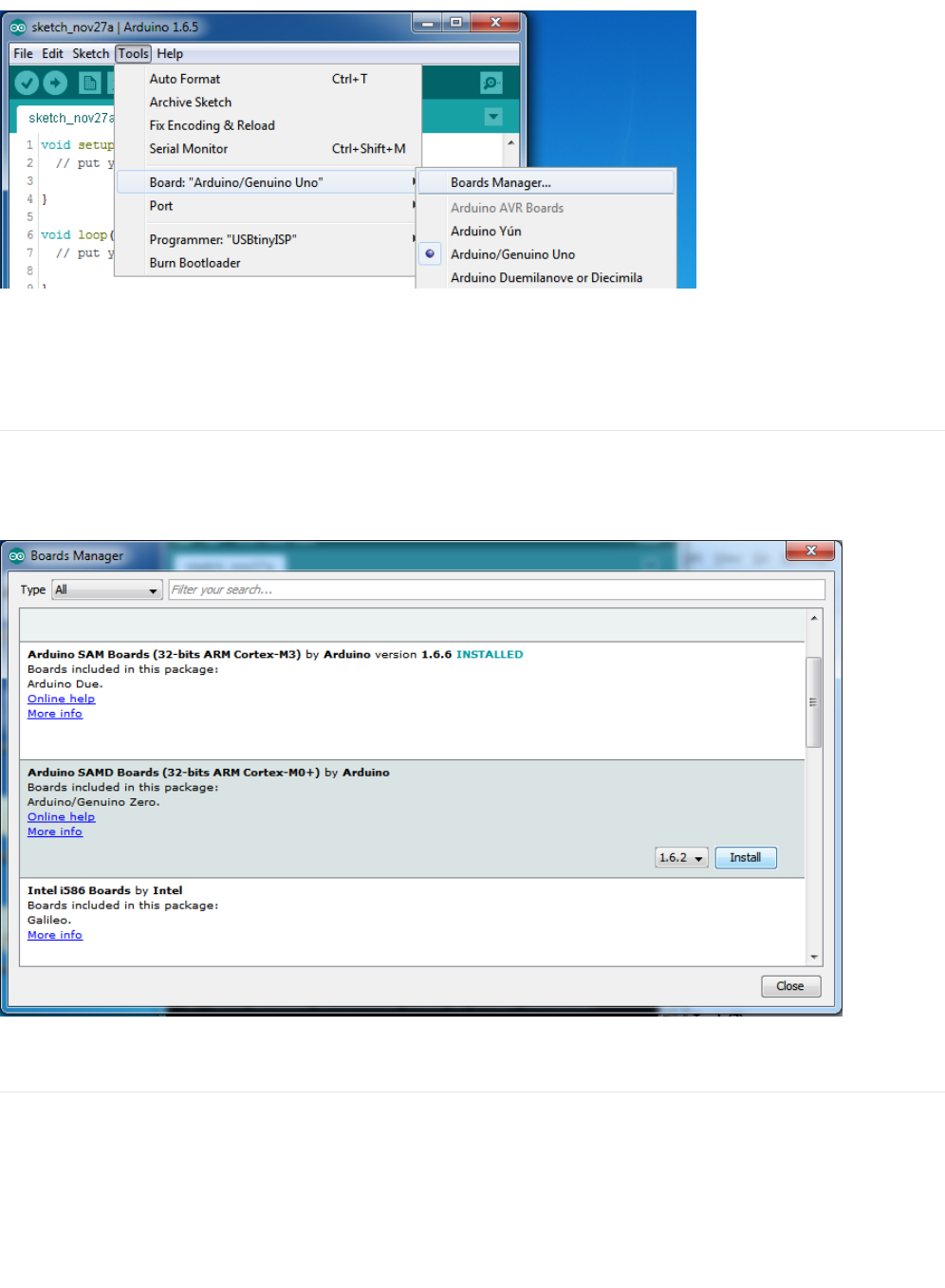
Now that you have added the appropriate URLs to the Arduino IDE preferences in the previous page, you can open the Boards
Manager by navigating to the Tools->Board menu.
© Adafruit Industries https://learn.adafruit.com/experimenters-guide-for-metro Page 48 of 317
(https://adafru.it/yc9)
Once the Board Manager opens, click on the category drop down menu on the top left hand side of the window and select
Contributed. You will then be able to select and install the boards supplied by the URLs added to the prefrences.
Install SAMD Support
First up, install the Arduino SAMD Boards version 1.6.15 or later
You can type Arduino SAMD in the top search bar, then when you see the entry, click Install
(https://adafru.it/yca)
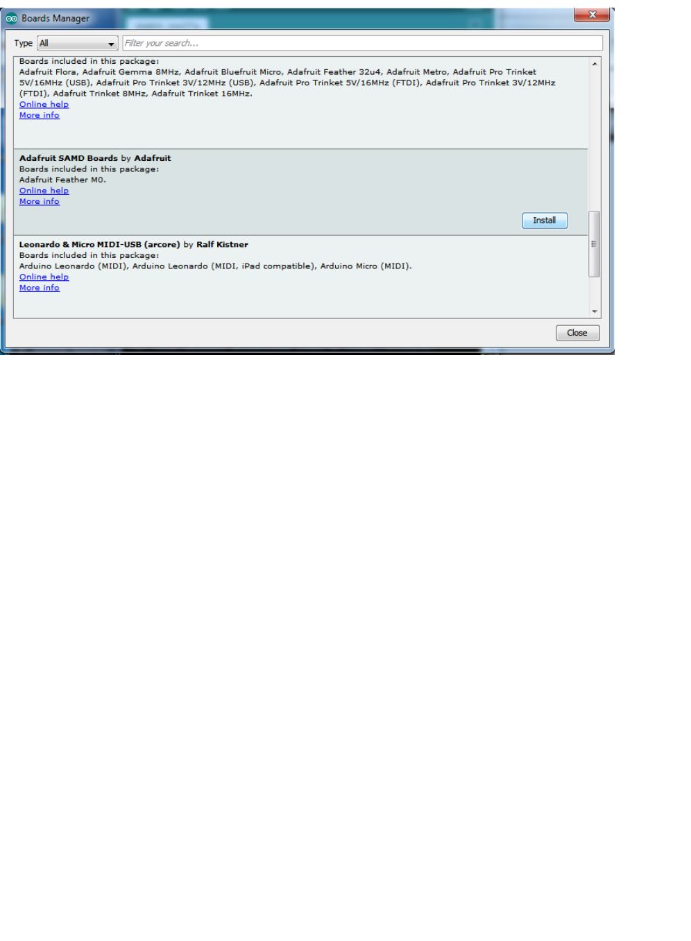
Install Adafruit SAMD
Next you can install the Adafruit SAMD package to add the board file definitions
You can type Adafruit SAMD in the top search bar, then when you see the entry, click Install
© Adafruit Industries https://learn.adafruit.com/experimenters-guide-for-metro Page 49 of 317
(https://adafru.it/ycb)
Even though in theory you don't need to - I recommend rebooting the IDE
Quit and reopen the Arduino IDE to ensure that all of the boards are properly installed. You should now be able to select and
upload to the new boards listed in the Tools->Board menu.
© Adafruit Industries https://learn.adafruit.com/experimenters-guide-for-metro Page 50 of 317
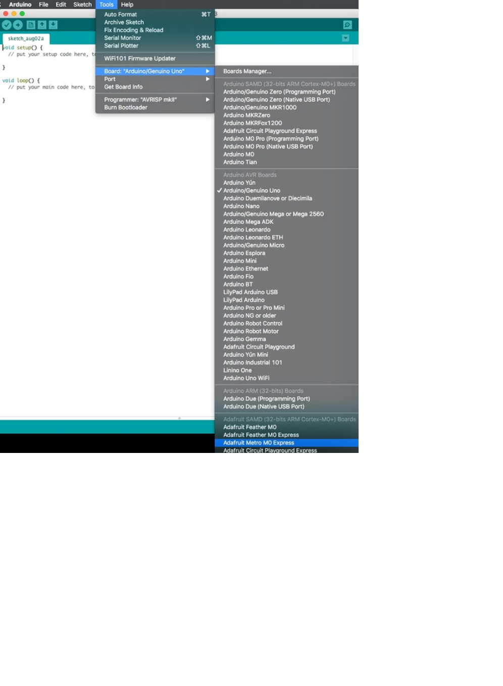
Select the Adafruit Metro M0 Express from the dropdown.
© Adafruit Industries https://learn.adafruit.com/experimenters-guide-for-metro Page 51 of 317
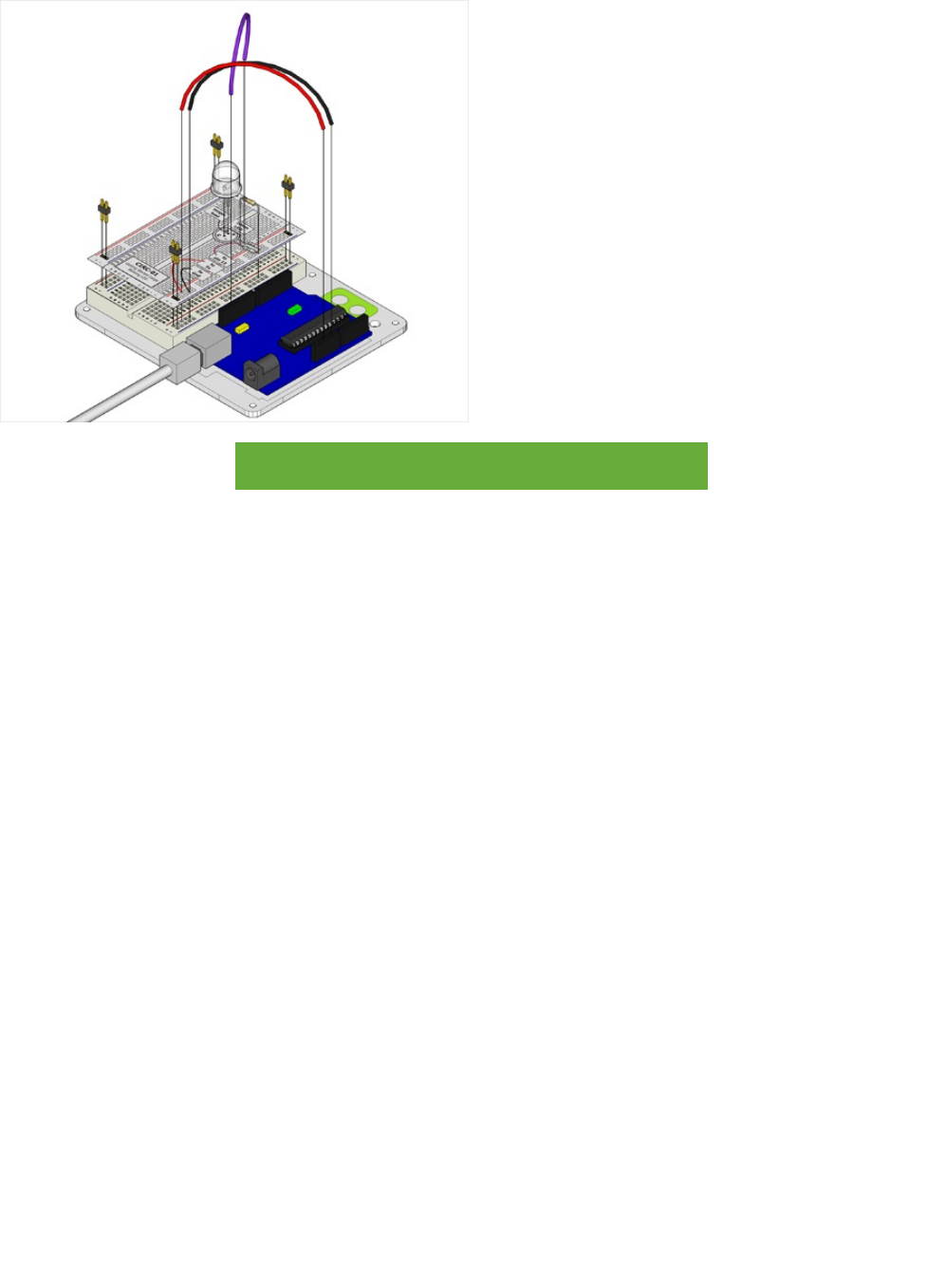
CIRC01: Blinking LED
What We're Doing
LEDs (light emitting diodes) are used in all sorts of clever things which is why we have included them in this guide. We will start
off with something very simple, turning one on and off, repeatedly, producing a pleasant blinking effect. To get started, grab the
parts from the parts page and then plug everything in according to the layout diagram.
© Adafruit Industries https://learn.adafruit.com/experimenters-guide-for-metro Page 52 of 317
Parts
Let's begin by gathering our parts:
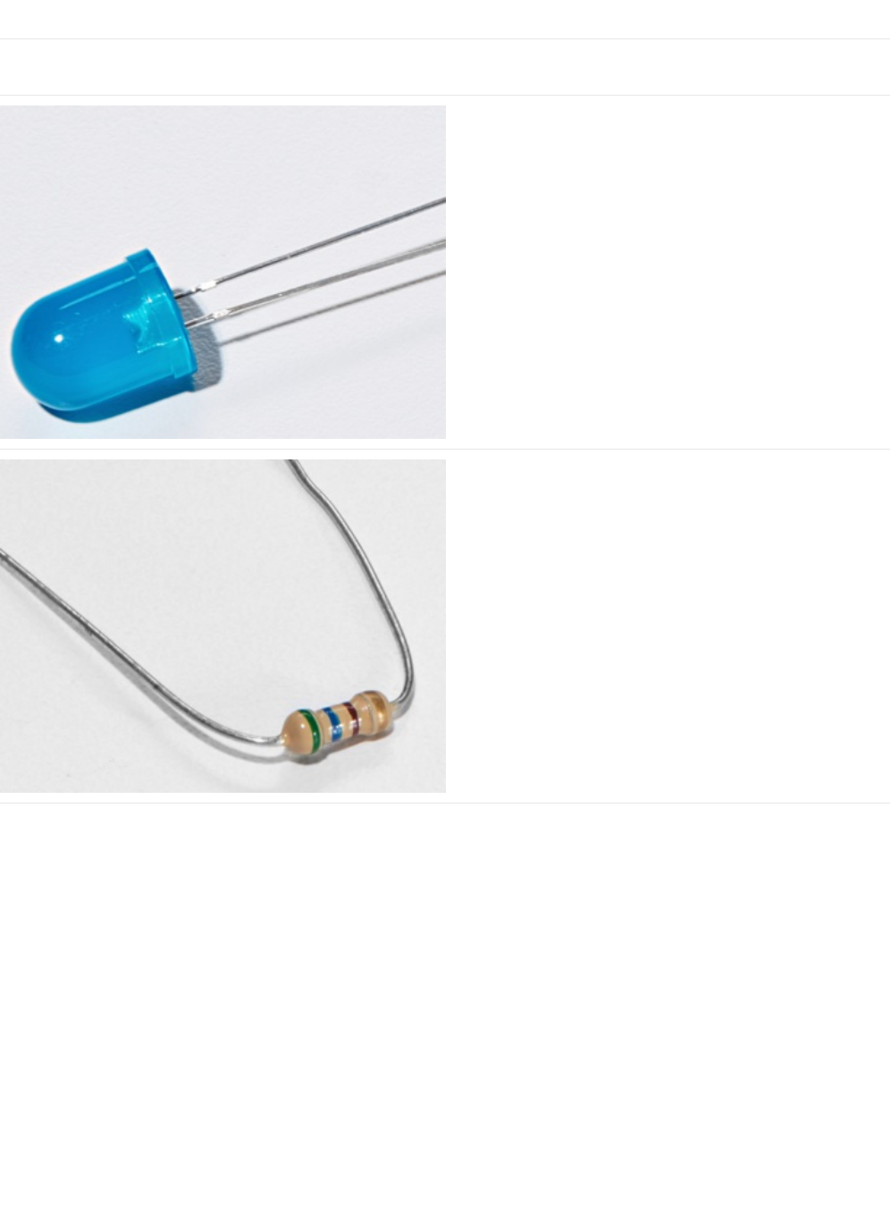
10mm Blue LED
If you'd like to order more of these 10mm LEDs from the
Adafruit shop click here! (https://adafru.it/AsB)
560 Ohm Resistor
Colors: Green > Blue > Brown
If you'd like to order more resistors from the Adafruit shop
click here! (they are 470ohm but they'll be
fine) (https://adafru.it/x4E)
© Adafruit Industries https://learn.adafruit.com/experimenters-guide-for-metro Page 53 of 317

Breadboard Wiring Bundle
If you'd like to order more wires from the Adafruit shop click
here! (https://adafru.it/fE2)
Adafruit Metro (or Metro Express) + Breadboard +
Mounting Plate
If you have not assembled this, we have a handy
guide! (https://adafru.it/x2A)
If you'd like to order an extra plastic mounting
plate (https://adafru.it/x4F), Adafruit
Metro (https://adafru.it/METROXMETR), Adafruit Metro
Express (https://adafru.it/xoa), or Mini-
Breadboard (https://adafru.it/keP) from the Adafruit Shop click
here!
© Adafruit Industries https://learn.adafruit.com/experimenters-guide-for-metro Page 54 of 317
Wiring
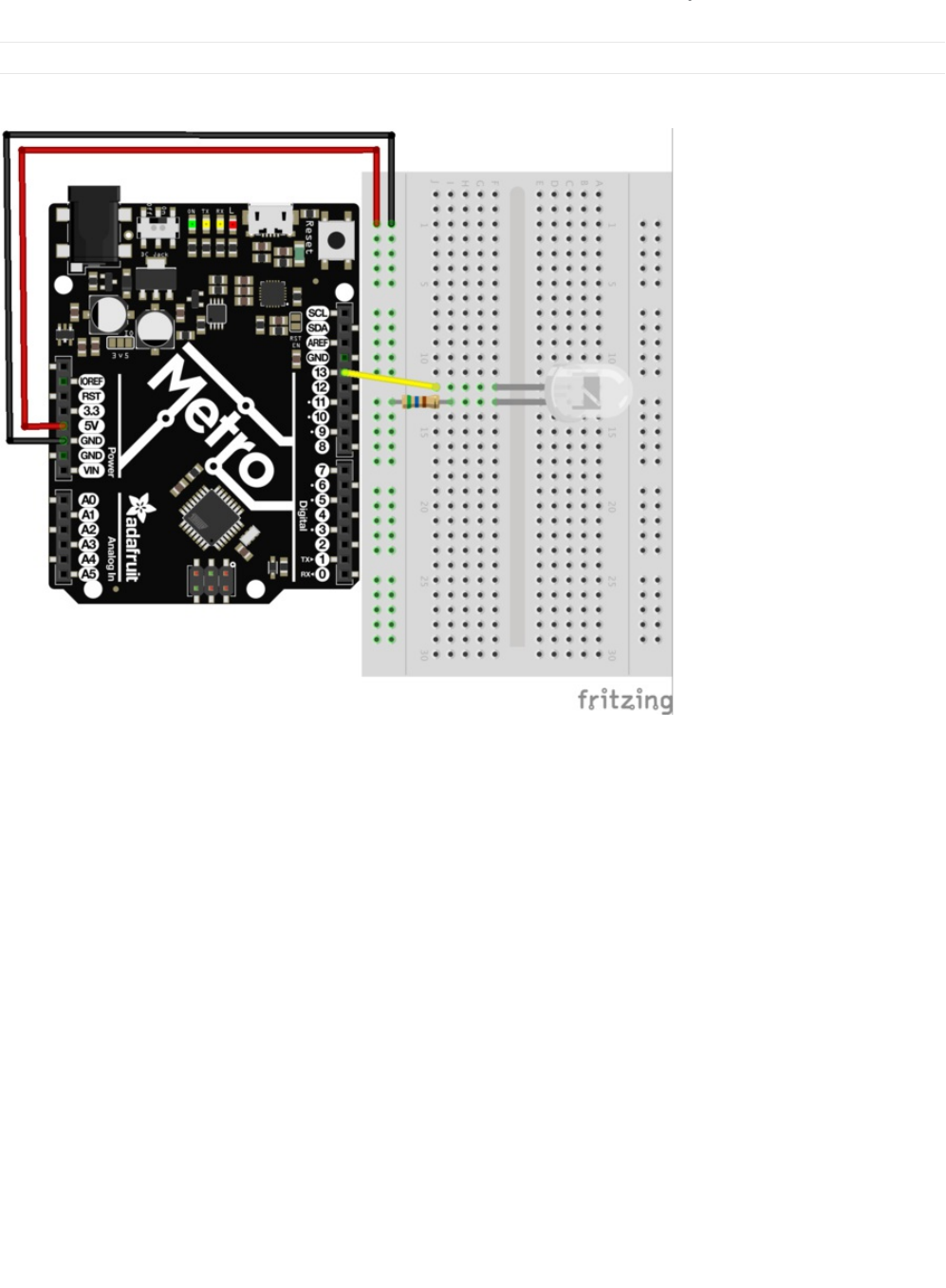
Breadboard Layout
Connect your parts to your breadboard as shown below.
Steps
1. Connect the longer leg of the LED to Pin 13 on the Metro. The shorter lead should be connected with a resistor to the
ground terminal.
2. The Metro is capable of supplying 5V to your breadboard. Use a red wire to connect the 5V Pin on the Metro to the left
power rail of the breadboard. Connect the GND Pin of the Metro to the rightmost part of the power rail.
3. Connect one leg of the 560 Ohm resistor to the shorter leg of the resistor. The other leg of this resistor is connected to the
rail with the black wire (this will be your ground rail).
4. Your completed circuit should be identical to the layout above. Make sure to verify all connections before moving on.
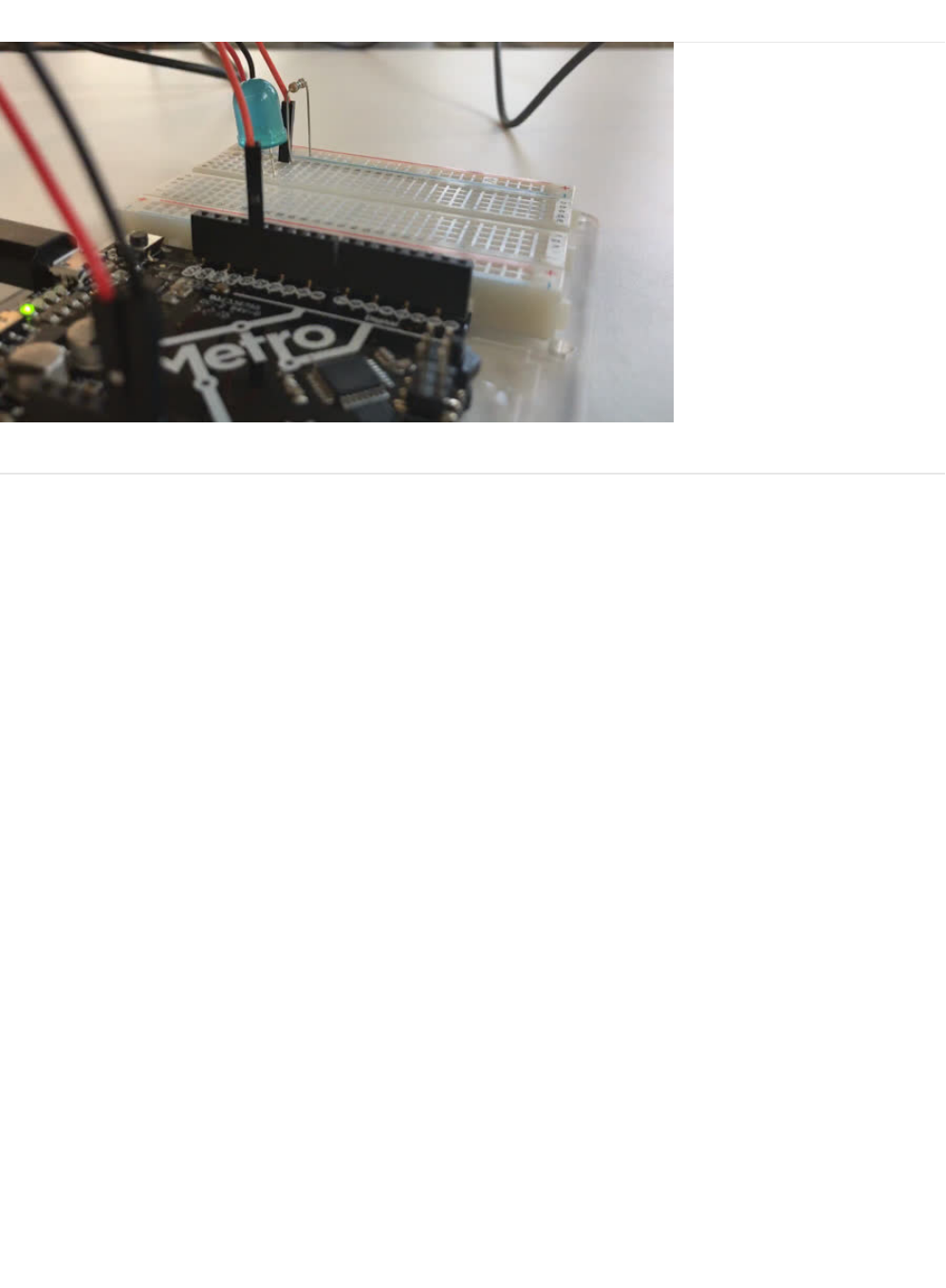
Breadboard Layout Sheet
Each circuit comes with a printable layout sheet to place on the mini-breadboard. You can hold them down with headers (or
tape) like this:
© Adafruit Industries https://learn.adafruit.com/experimenters-guide-for-metro Page 55 of 317

Code
The Arduino Editor provides a great example for blinking a LED. There's no need to type anything, just click in the following in
the Arduino Editor:
File > Examples > 1.Basic > Blink
Next, we want Arduino to know what Board is being used currently. To do this, navigate to Tools > Board > Arduino/Genuino
Uno
Lastly, we need to upload the program. To do this plug the Metro board into your USB port. Then select the proper port in Tools
© Adafruit Industries https://learn.adafruit.com/experimenters-guide-for-metro Page 57 of 317

> Serial Port > (the Serial/COM port of your metro). Next upload the program by going to File > Upload (or press ctrl+u on your
keyboard)
After uploading to the Metro, you should see the LED on both the Metro and the breadboard blinking.
Blink
If you have trouble loading the Blink Sketch from Arduino's examples, you can copy and paste the code below into the editor.
Having issues with CIRC01?
LED Not Lighting Up?
LEDs will only work in one direction. Try taking it out and twisting it 180 degrees. (no need to worry, installing it backwards
does no permanent harm).
Program Not Uploading?
This happens sometimes, the most likely cause is a confused serial port, you can change this in tools>serial port>
Still No Success?
A broken circuit is no fun, post up in the Adafruit Support Forums and we will get back to you as soon as we can.
/*
Blink
Turns on an LED on for one second, then off for one second, repeatedly.
Most Arduinos have an on-board LED you can control. On the UNO, MEGA and ZERO
it is attached to digital pin 13, on MKR1000 on pin 6. LED_BUILTIN is set to
the correct LED pin independent of which board is used.
If you want to know what pin the on-board LED is connected to on your Arduino model, check
the Technical Specs of your board at https://www.arduino.cc/en/Main/Products
This example code is in the public domain.
modified 8 May 2014
by Scott Fitzgerald
modified 2 Sep 2016
by Arturo Guadalupi
modified 8 Sep 2016
by Colby Newman
*/
// the setup function runs once when you press reset or power the board
void setup() {
// initialize digital pin LED_BUILTIN as an output.
pinMode(LED_BUILTIN, OUTPUT);
}
// the loop function runs over and over again forever
void loop() {
digitalWrite(LED_BUILTIN, HIGH); // turn the LED on (HIGH is the voltage level)
delay(1000); // wait for a second
digitalWrite(LED_BUILTIN, LOW); // turn the LED off by making the voltage LOW
delay(1000); // wait for a second
}
© Adafruit Industries https://learn.adafruit.com/experimenters-guide-for-metro Page 58 of 317

© Adafruit Industries https://learn.adafruit.com/experimenters-guide-for-metro Page 59 of 317

Make It Better
Congrats on building your first circuit with the Adafruit Metro!
Let's play around to make your circuit better and learn some more tricks/tips that will be useful later on.
Change the pin
The LED is connected to pin 13 but we can use any of the METRO’s pins. To change it take the wire plugged into pin 13 and
move it to a pin of your choice (from 0- 13)
You can also use analog 0-5, Analog #0 is 14, Analog #1 is 15, etc.
Then in the code change all occurrences of LED_BUILTIN ->
newpin
. That is, change every LED_BUILTIN to 8
Then Upload the sketch: by pressing ctrl+u
Change the Blink time
Unhappy with one second on one second off? In the code change the lines:
digitalWrite(LED_BUILTIN, HIGH);
delay(time on); //(seconds * 1000)
digitalWrite(LED_BUILTIN, LOW);
delay(time off); //(seconds * 1000)
Control the brightness
Along with digital (on/off) control the METRO can control some pins in an analog (brightness) fashion. (more details on this in
later circuits). To play around with it. Change the LED to pin 9: (also change the wire) by replacing all LED_BUILTIN with 9
Replace the code inside the
{ }
's of
loop()
with the following line:
analogWrite(9, new number);
Note that in the line above,
new number is any number between 0 and 255. 0 turns the LED completely off. 255 is the maximum brightness of the LED.
Anything between 0 and 255 is a varying brightness. Play around and find one that you like.
Fading
We will use another included example program. To open go to File > Examples > 3.Analog > Fading
Then upload to your board and watch as the LED fades in and then out.
© Adafruit Industries https://learn.adafruit.com/experimenters-guide-for-metro Page 60 of 317
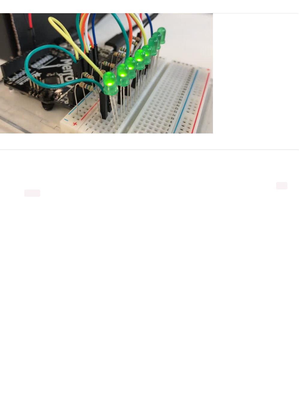
CIRC02: 8 LED Fun
What We're Doing
We have caused one LED to blink, now it's time to up the stakes. Lets connect eight. We'll also have an opportunity to stretch the
Metro a bit by creating various lighting sequences. This circuit is also a nice setup to experiment with writing your own programs
and getting a feel for how the Metro works.
Along with controlling the LEDs we start looking into a few simple programming methods to keep your programs small: for()
loops and array[] 's
© Adafruit Industries https://learn.adafruit.com/experimenters-guide-for-metro Page 61 of 317
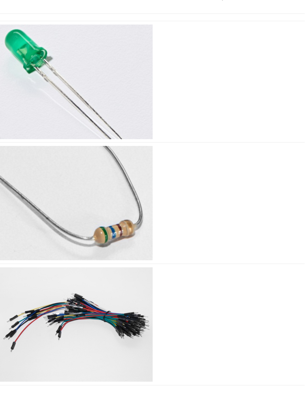
Parts
5mm Green LED
x8 (You'll need 8 of these for CIRC02)
If you'd like to order extra green LEDs from the Adafruit shop,
click here! (https://adafru.it/x5b)
560 Ohm Resistor
x8 (You'll need 8 of these for CIRC02)
(These are the same resistors that you used in CIRC01, the
colors go from: Green > Blue > Brown)
If you'd like to order more resistors from the Adafruit shop
click here! (they are 470ohm but they'll be
fine) (https://adafru.it/x4E)
Breadboard Wiring Bundle
If you'd like to order more wires from the Adafruit shop click
here! (https://adafru.it/fE2)
© Adafruit Industries https://learn.adafruit.com/experimenters-guide-for-metro Page 62 of 317
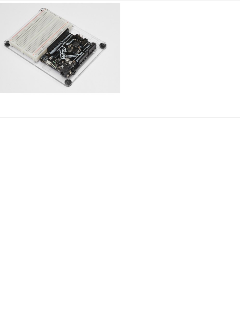
Adafruit Metro (or Metro Express) + Breadboard +
Mounting Plate
If you have not assembled this, we have a handy
guide! (https://adafru.it/x2A)
If you'd like to order an extra plastic mounting
plate (https://adafru.it/x4F), Adafruit
Metro (https://adafru.it/METROXMETR), Adafruit Metro
Express (https://adafru.it/xoa), or Mini-
Breadboard (https://adafru.it/keP) from the Adafruit Shop click
here!
© Adafruit Industries https://learn.adafruit.com/experimenters-guide-for-metro Page 63 of 317
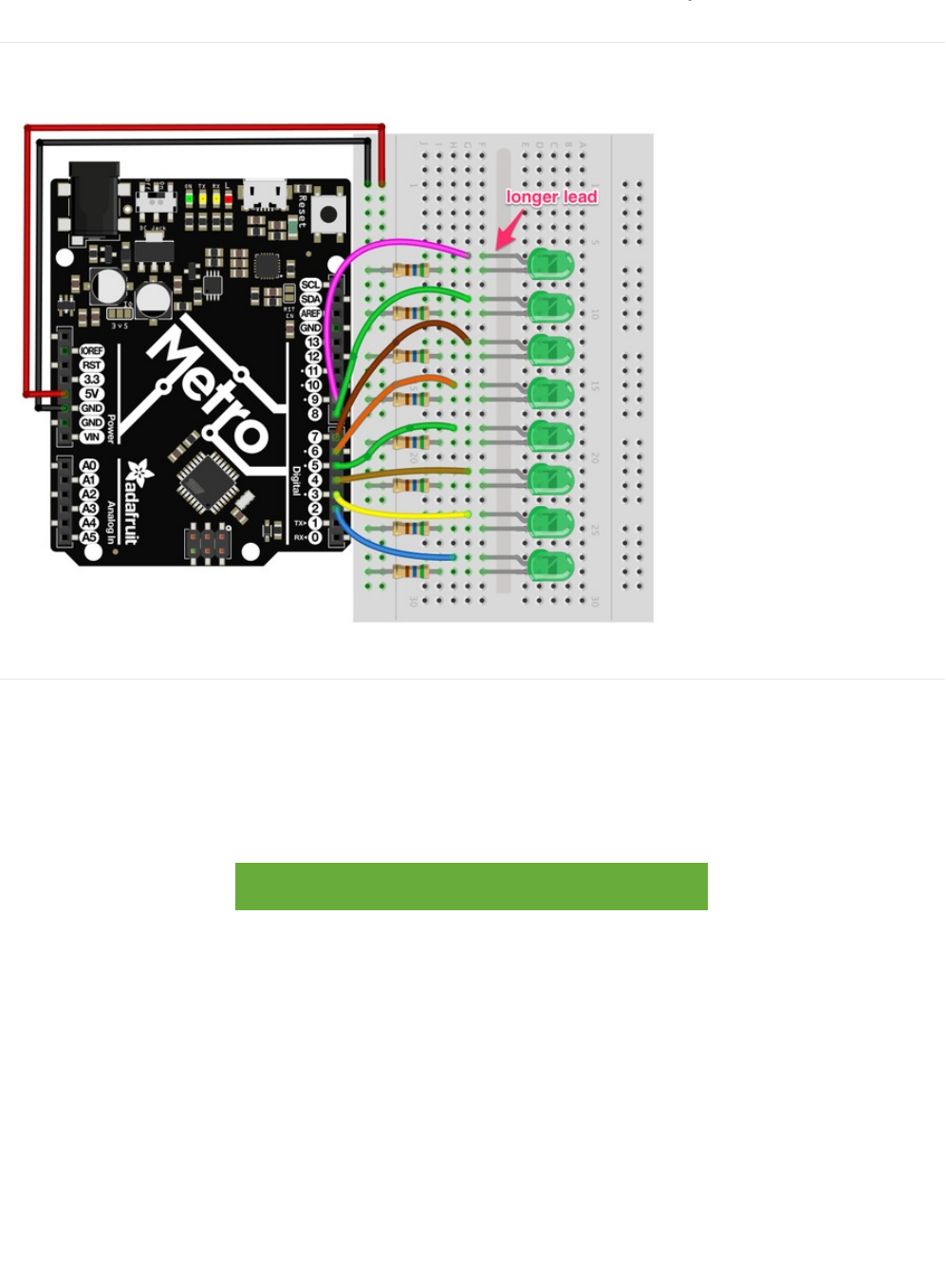
Wiring
Breadboard Layout
Steps
1. First, connect the 8 Green LEDs to the breadboard. It's useful to space them one hole apart as shown in the layout picture.
2. Next, starting with the green LED at the bottom, connect the longer side of the green LED to a digital pin on the metro.
Start with Pin 2 and work your way up until Pin 9. (tip: use different color wires to color-code your LEDs)
3. Then, connect the 8 (560ohm) resistors to the shorter side of the LED.
4. The Metro is capable of supplying 5V to your breadboard. Use a red wire to connect the 5V Pin on the Metro to the left
power rail of the breadboard. Connect the GND Pin of the Metro to the rightmost part of the power rail.
5. Your completed circuit should be identical to the layout above. Make sure to verify all connections before moving on.
https://adafru.it/Atb
https://adafru.it/Atb
© Adafruit Industries https://learn.adafruit.com/experimenters-guide-for-metro Page 64 of 317

Code
The CIRC02 code is not one of the default Arduino sketches. To use it, copy the code from below and paste it into a new
Arduino Sketch (ctrl+n/command+n)
/* ---------------------------------------------------------
* | Arduino Experimentation Kit Example Code |
* | CIRC-02 .: 8 LED Fun :. (Multiple LEDs) |
* ---------------------------------------------------------
*
* A few Simple LED animations
*
* For more information on this circuit http://tinyurl.com/d2hrud
*
*/
//LED Pin Variables
int ledPins[] = {2,3,4,5,6,7,8,9}; //An array to hold the pin each LED is connected to
//i.e. LED #0 is connected to pin 2, LED #1, 3 and so on
//to address an array use ledPins[0] this would equal 2
//and ledPins[7] would equal 9
/*
* setup() - this function runs once when you turn your Arduino on
* We the three control pins to outputs
*/
void setup()
{
//Set each pin connected to an LED to output mode (pulling high (on) or low (off)
for(int i = 0; i < 8; i++){ //this is a loop and will repeat eight times
pinMode(ledPins[i],OUTPUT); //we use this to set each LED pin to output
} //the code this replaces is below
/* (commented code will not run)
* these are the lines replaced by the for loop above they do exactly the
* same thing the one above just uses less typing
pinMode(ledPins[0],OUTPUT);
pinMode(ledPins[1],OUTPUT);
pinMode(ledPins[2],OUTPUT);
pinMode(ledPins[3],OUTPUT);
pinMode(ledPins[4],OUTPUT);
pinMode(ledPins[5],OUTPUT);
pinMode(ledPins[6],OUTPUT);
pinMode(ledPins[7],OUTPUT);
(end of commented code)*/
}
/*
* loop() - this function will start after setup finishes and then repeat
* we call a function called oneAfterAnother(). if you would like a different behaviour
* uncomment (delete the two slashes) one of the other lines
*/
void loop() // run over and over again
{
oneAfterAnotherNoLoop(); //this will turn on each LED one by one then turn each off
//oneAfterAnotherLoop(); //does the same as oneAfterAnotherNoLoop but with
//much less typing
//oneOnAtATime(); //this will turn one LED on then turn the next one
//on turning the
//former off (one LED will look like it is scrolling
//along the line
//inAndOut(); //lights the two middle LEDs then moves them out then back
© Adafruit Industries https://learn.adafruit.com/experimenters-guide-for-metro Page 65 of 317

//inAndOut(); //lights the two middle LEDs then moves them out then back
//in again
}
/*
* oneAfterAnotherNoLoop() - Will light one LED then delay for delayTime then light
* the next LED until all LEDs are on it will then turn them off one after another
*
* this does it without using a loop which makes for a lot of typing.
* oneOnAtATimeLoop() does exactly the same thing with less typing
*/
void oneAfterAnotherNoLoop(){
int delayTime = 100; //the time (in milliseconds) to pause between LEDs
//make smaller for quicker switching and larger for slower
digitalWrite(ledPins[0], HIGH); //Turns on LED #0 (connected to pin 2 )
delay(delayTime); //waits delayTime milliseconds
digitalWrite(ledPins[1], HIGH); //Turns on LED #1 (connected to pin 3 )
delay(delayTime); //waits delayTime milliseconds
digitalWrite(ledPins[2], HIGH); //Turns on LED #2 (connected to pin 4 )
delay(delayTime); //waits delayTime milliseconds
digitalWrite(ledPins[3], HIGH); //Turns on LED #3 (connected to pin 5 )
delay(delayTime); //waits delayTime milliseconds
digitalWrite(ledPins[4], HIGH); //Turns on LED #4 (connected to pin 6 )
delay(delayTime); //waits delayTime milliseconds
digitalWrite(ledPins[5], HIGH); //Turns on LED #5 (connected to pin 7 )
delay(delayTime); //waits delayTime milliseconds
digitalWrite(ledPins[6], HIGH); //Turns on LED #6 (connected to pin 8 )
delay(delayTime); //waits delayTime milliseconds
digitalWrite(ledPins[7], HIGH); //Turns on LED #7 (connected to pin 9 )
delay(delayTime); //waits delayTime milliseconds
//Turns Each LED Off
digitalWrite(ledPins[7], LOW); //Turns on LED #0 (connected to pin 2 )
delay(delayTime); //waits delayTime milliseconds
digitalWrite(ledPins[6], LOW); //Turns on LED #1 (connected to pin 3 )
delay(delayTime); //waits delayTime milliseconds
digitalWrite(ledPins[5], LOW); //Turns on LED #2 (connected to pin 4 )
delay(delayTime); //waits delayTime milliseconds
digitalWrite(ledPins[4], LOW); //Turns on LED #3 (connected to pin 5 )
delay(delayTime); //waits delayTime milliseconds
digitalWrite(ledPins[3], LOW); //Turns on LED #4 (connected to pin 6 )
delay(delayTime); //waits delayTime milliseconds
digitalWrite(ledPins[2], LOW); //Turns on LED #5 (connected to pin 7 )
delay(delayTime); //waits delayTime milliseconds
digitalWrite(ledPins[1], LOW); //Turns on LED #6 (connected to pin 8 )
delay(delayTime); //waits delayTime milliseconds
digitalWrite(ledPins[0], LOW); //Turns on LED #7 (connected to pin 9 )
delay(delayTime); //waits delayTime milliseconds
}
/*
* oneAfterAnotherLoop() - Will light one LED then delay for delayTime then light
* the next LED until all LEDs are on it will then turn them off one after another
*
* this does it using a loop which makes for a lot less typing.
* than oneOnAtATimeNoLoop() does exactly the same thing with less typing
*/
void oneAfterAnotherLoop(){
int delayTime = 100; //the time (in milliseconds) to pause between LEDs
//make smaller for quicker switching and larger for slower
//Turn Each LED on one after another
for(int i = 0; i <= 7; i++){
digitalWrite(ledPins[i], HIGH); //Turns on LED #i each time this runs i
delay(delayTime); //gets one added to it so this will repeat
© Adafruit Industries https://learn.adafruit.com/experimenters-guide-for-metro Page 66 of 317

delay(delayTime); //gets one added to it so this will repeat
} //8 times the first time i will = 0 the final
//time i will equal 7;
//Turn Each LED off one after another
for(int i = 7; i >= 0; i--){ //same as above but rather than starting at 0 and counting up
//we start at seven and count down
digitalWrite(ledPins[i], LOW); //Turns off LED #i each time this runs i
delay(delayTime); //gets one subtracted from it so this will repeat
} //8 times the first time i will = 7 the final
//time it will equal 0
}
/*
* oneOnAtATime() - Will light one LED then the next turning off all the others
*/
void oneOnAtATime(){
int delayTime = 100; //the time (in milliseconds) to pause between LEDs
//make smaller for quicker switching and larger for slower
for(int i = 0; i <= 7; i++){
int offLED = i - 1; //Calculate which LED was turned on last time through
if(i == 0) { //for i = 1 to 7 this is i minus 1 (i.e. if i = 2 we will
offLED = 7; //turn on LED 2 and off LED 1)
} //however if i = 0 we don't want to turn of led -1 (doesn't exist)
//instead we turn off LED 7, (looping around)
digitalWrite(ledPins[i], HIGH); //turn on LED #i
digitalWrite(ledPins[offLED], LOW); //turn off the LED we turned on last time
delay(delayTime);
}
}
/*
* inAndOut() - This will turn on the two middle LEDs then the next two out
* making an in and out look
*/
void inAndOut(){
int delayTime = 100; //the time (in milliseconds) to pause between LEDs
//make smaller for quicker switching and larger for slower
//runs the LEDs out from the middle
for(int i = 0; i <= 3; i++){
int offLED = i - 1; //Calculate which LED was turned on last time through
if(i == 0) { //for i = 1 to 7 this is i minus 1 (i.e. if i = 2 we will
offLED = 3; //turn on LED 2 and off LED 1)
} //however if i = 0 we don't want to turn of led -1 (doesn't exist)
//instead we turn off LED 7, (looping around)
int onLED1 = 3 - i; //this is the first LED to go on ie. LED #3 when i = 0 and LED
//#0 when i = 3
int onLED2 = 4 + i; //this is the first LED to go on ie. LED #4 when i = 0 and LED
//#7 when i = 3
int offLED1 = 3 - offLED; //turns off the LED we turned on last time
int offLED2 = 4 + offLED; //turns off the LED we turned on last time
digitalWrite(ledPins[onLED1], HIGH);
digitalWrite(ledPins[onLED2], HIGH);
digitalWrite(ledPins[offLED1], LOW);
digitalWrite(ledPins[offLED2], LOW);
delay(delayTime);
}
//runs the LEDs into the middle
for(int i = 3; i >= 0; i--){
© Adafruit Industries https://learn.adafruit.com/experimenters-guide-for-metro Page 67 of 317
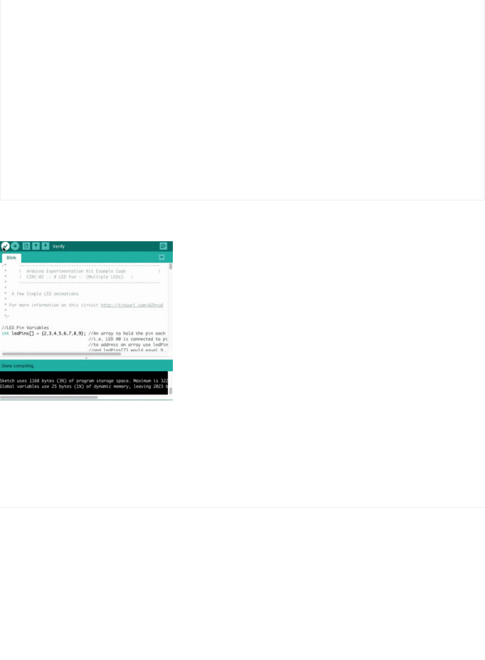
Compile and Upload
Before uploading, an important step is to verify that your code compiles. Click on the check button on the toolbar (or, on your
keyboard press control+r or command+r for mac users) to compile your code.
If you receive no errors compiling, upload the sketch to the board (click here for a refresher on how to do this from the previous
circuit (https://adafru.it/xae)). After uploading, you should see an animated LED light show like
this (https://adafru.it/METROXCIRC02).
Not Working? CIRC02 not matching the GIF?
Some LEDs Fail to Light
It is easy to insert an LED backwards. Check the LEDs that aren't working and ensure they the right way around.
Operating out of sequence
With eight wires it's easy to cross a couple. Double check that the first LED is plugged into pin 2 and each pin thereafter.
Not working? Try again with a fresh slate!
Its easy to accidentally misplace a wire without noticing. Pulling everything out and starting with a fresh slate is often easier
than trying to track down the problem.
int offLED = i + 1; //Calculate which LED was turned on last time through
if(i == 3) { //for i = 1 to 7 this is i minus 1 (i.e. if i = 2 we will
offLED = 0; //turn on LED 2 and off LED 1)
} //however if i = 0 we don't want to turn of led -1 (doesn't exist)
//instead we turn off LED 7, (looping around)
int onLED1 = 3 - i; //this is the first LED to go on ie. LED #3 when i = 0 and LED
//#0 when i = 3
int onLED2 = 4 + i; //this is the first LED to go on ie. LED #4 when i = 0 and LED
//#7 when i = 3
int offLED1 = 3 - offLED; //turns off the LED we turned on last time
int offLED2 = 4 + offLED; //turns off the LED we turned on last time
digitalWrite(ledPins[onLED1], HIGH);
digitalWrite(ledPins[onLED2], HIGH);
digitalWrite(ledPins[offLED1], LOW);
digitalWrite(ledPins[offLED2], LOW);
delay(delayTime);
}
}
© Adafruit Industries https://learn.adafruit.com/experimenters-guide-for-metro Page 68 of 317


Make It Better
Switching to Loops
Bored of watching the light show? Want to make your own animation, change the animation, or learn about looping functions?
Let's make CIRC02 better!
In the void loop() procedure, there are 4 lines. The last three all start with a // . This means the line is a comment (it won't run).
We can switch the program to use loops by deleting the comments (If you want to learn more about comments, we have a great
writeup (https://adafru.it/xag)!).
First, inside void loop() , add slashes to disable the oneAfterAnotherNoLoop() procedure from running:
oneAfterAnotherNoLoop();
->
//oneAfterAnotherNoLoop();
Next, we are going to delete comments (slashes) to enable the oneAfterAnotherLoop() procedure to run with loops:
//oneAfterAnotherLoop();
->
oneAfterAnotherLoop();
We should verify that our code compiles correctly now, click the check mark (or, ctrl/command+r). If everything compiles with no
errors, go ahead and Upload (ctrl+u) the new program to your metro.
After running the program, what changed?
There was no change! Both procedures run the same animation.There was no change! Both procedures run the same animation.
There was no change! Both procedures run the same animation. (click to reveal the answer)
What's the difference between the two procedures: oneAfterAnotherNoLoop() and oneAfterAnotherLoop()?
oneAfterAnotherNoLoop() runs the animation without using a loop which makes for a lot ofoneAfterAnotherNoLoop() runs the animation without using a loop which makes for a lot of
oneAfterAnotherNoLoop() runs the animation without using a loop which makes for a lot of
typing.typing.
typing.
Using oneAfterAnotherLoop() will require less typing to run the sameUsing oneAfterAnotherLoop() will require less typing to run the same
Using oneAfterAnotherLoop() will require less typing to run the same
animation!animation!
animation! (click to reveal the answer)
Extra Animations
Tired of this animation? There are more animations for you to play around with!
To enable them, uncomment (just delete the // ) row 3 and row 4 so that:
//oneOnAtATime(); -> oneOnAtATime();
//inAndOut(); -> inAndOut();
Then Upload the program (ctrl+u) to your board and enjoy the new light animations.
Make your own animations
Go ahead and jump into the included code and start changing things around.
To tell the Metro to turn a LED on,
digitalWrite(pinNumber, HIGH);
If you want to tell the Metro to turn a LED off,
digitalWrite(pinNumber, LOW);
© Adafruit Industries https://learn.adafruit.com/experimenters-guide-for-metro Page 70 of 317

Type away! Regardless of what you change you won't break anything.
© Adafruit Industries https://learn.adafruit.com/experimenters-guide-for-metro Page 71 of 317
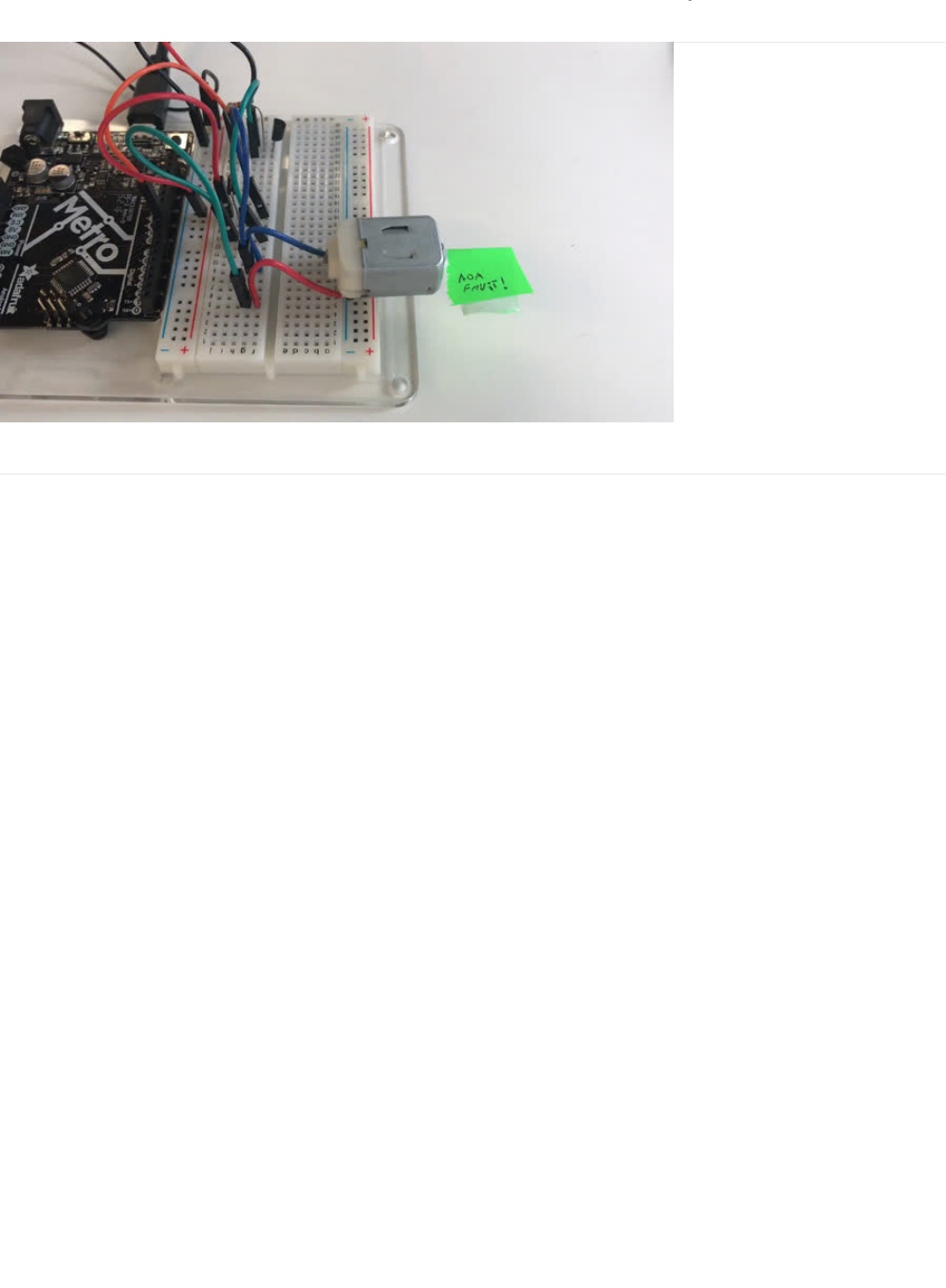
CIRC03: Spin Motor Spin
What We're Doing
The Metro's pins are great for directly controlling small electric items like LEDs. However, when dealing with larger items (like a
toy motor or washing machine), an external transistor is required.
A transistor is incredibly useful. It switches a lot of current using a much smaller current. A transistor has 3 pins. For a negative
type (
NPN
) transistor, you connect your load to collector and the emitter to ground. Then, when a small current flows from base
to the emitter, a current will flow through the transistor and your motor will spin (this happens when we set our Metro pins high).
For a more in-depth explanation about transistors, click here (https://adafru.it/xaj).
There are literally
thousands
of different types of transistors, allowing every situation to be perfectly matched. We have chosen a
P2N2222,
a rather common general purpose transistor. The important factors in our case are that its maximum voltage (
40v
) and
its maximum current (
600 milliamp
) are both high enough for our toy motor (full details can be found on its
datasheet (https://adafru.it/xak)).
© Adafruit Industries https://learn.adafruit.com/experimenters-guide-for-metro Page 72 of 317
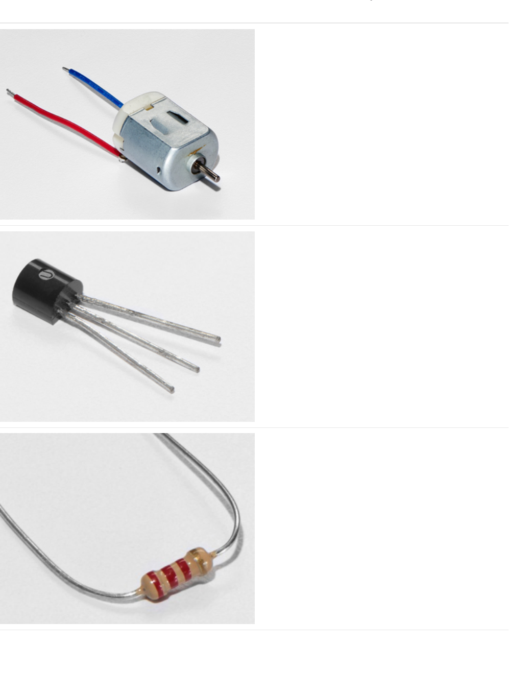
Parts
DC Toy/Hobby Motor
If you'd like to order another DC Motor from the Adafruit
shop, click here! (https://adafru.it/xan)
Transistor (PN2222 or MPS2222)
If you'd like to order extra NPN transistors from the Adafruit
shop, click here! (https://adafru.it/xam)
2.2k Ohm Resistor
Colors: Red > Red > Red
If you'd like to order extra 2.2k Ohm resistors from the
Adafruit shop, click here! (https://adafru.it/xao)
© Adafruit Industries https://learn.adafruit.com/experimenters-guide-for-metro Page 73 of 317
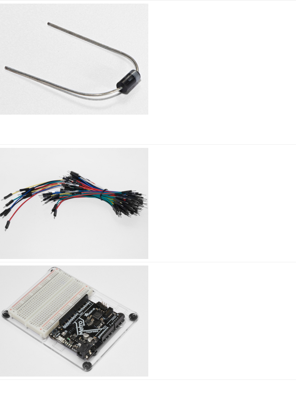
Diode (1N4001)
If you'd like to order more diodes from the Adafruit shop,
click here! (https://adafru.it/ijA)
Breadboard Wiring Bundle
If you'd like to order more wires from the Adafruit shop click
here! (https://adafru.it/fE2)
Adafruit Metro (or Metro Express) + Breadboard +
Mounting Plate
If you have not assembled this, we have a handy
guide! (https://adafru.it/x2A)
If you'd like to order an extra plastic mounting
plate (https://adafru.it/x4F), Adafruit
Metro (https://adafru.it/METROXMETR), Adafruit Metro
Express (https://adafru.it/xoa), or Mini-
Breadboard (https://adafru.it/keP) from the Adafruit Shop click
here!
© Adafruit Industries https://learn.adafruit.com/experimenters-guide-for-metro Page 74 of 317
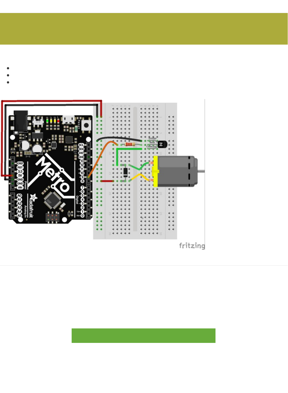
Wiring
Before beginning CIRC03, you should note the following things:
The flat side of the
transistor
should face the Metro.
The striped side of the
diode
should be facing towards the bottom of the Metro
The resistor used in this circuit is different from the past two (CIRC01/CIRC02). Make sure the color bands read red > red >
red.
Steps
1. Connect GND and 5V on the Metro to the red and blue power rails.
2. Ensure the flat side of the transistor faces towards the Metro. Connect the Emitter (labled on the diagram above) to
the GND rail. First connect the Base to the 2.2k Ohm resistor,
then
to the 5V rail. Leave the collector for now.
3. Connect the striped lead of the diode to the 5V rail, and the un-striped lead to the collector of the t
ransistor
.
4. The blue motor wire should be connected to the striped diode lead. Connect the red motor wire to the bottom (un-striped)
side of the diode.
5. Re-read the notes above the diagram to ensure you did not make any errors while connecting components. It does not
matter which way you connect the motor's leads for now.
https://adafru.it/Atc
https://adafru.it/Atc
The motor that comes with the MetroX kit does not draw more than 250mA but if you have a different motor, it could
easily draw 1000mA, more than a USB port can handle! If you aren't sure of a motor's current draw, power the Metro
from a wall adapter, not just USB.
© Adafruit Industries https://learn.adafruit.com/experimenters-guide-for-metro Page 75 of 317

Code
Just like we did in the previous circuit, copy and paste the code into a new Arduino sketch. Then compile and upload it to your
metro (https://adafru.it/xap).
/* -----------------------------------------------------------
* | Arduino Experimentation Kit Example Code |
* | CIRC-03 .: Spin Motor Spin :. (Transistor and Motor) |
* -----------------------------------------------------------
*
* The Arduinos pins are great for driving LEDs however if you hook
* up something that requires more power you will quickly break them.
* To control bigger items we need the help of a transistor.
* Here we will use a transistor to control a small toy motor
*
*
*/
int motorPin = 9; // define the pin the motor is connected to
// (if you use pin 9,10,11 or 3you can also control speed)
/*
* setup() - this function runs once when you turn your Arduino on
* We set the motors pin to be an output (turning the pin high (+5v) or low (ground) (-))
* rather than an input (checking whether a pin is high or low)
*/
void setup()
{
pinMode(motorPin, OUTPUT);
}
/*
* loop() - this function will start after setup finishes and then repeat
* we call a function called motorOnThenOff()
*/
void loop() // run over and over again
{
motorOnThenOff();
//motorOnThenOffWithSpeed();
//motorAcceleration();
}
/*
* motorOnThenOff() - turns motor on then off
* (notice this code is identical to the code we used for
* the blinking LED)
*/
void motorOnThenOff(){
int onTime = 2500; //the number of milliseconds for the motor to turn on for
int offTime = 1000; //the number of milliseconds for the motor to turn off for
digitalWrite(motorPin, HIGH); // turns the motor On
delay(onTime); // waits for onTime milliseconds
digitalWrite(motorPin, LOW); // turns the motor Off
delay(offTime); // waits for offTime milliseconds
}
/*
* motorOnThenOffWithSpeed() - turns motor on then off but uses speed values as well
* (notice this code is identical to the code we used for
* the blinking LED)
*/
© Adafruit Industries https://learn.adafruit.com/experimenters-guide-for-metro Page 76 of 317

Having Trouble with CIRC03?
Motor Not Spinning?
If you sourced your own transistor, double check with the data sheet that the pinout is compatible with a PN2222 (many are
reversed).
Check Your Motor
If you sourced your own motor, double check that it will work with 5 volts and that it does not draw too much power.
Still having issues?
Sometimes the Metro board will disconnect from the computer. Try un-plugging and then re-plugging it into your USB port.
Tried the steps above? Still didn't resolve your issue?
Have no fear, we'll help you out! Post up in the Adafruit Support Forums and we will get back to you as soon as we can.
*/
void motorOnThenOffWithSpeed(){
int onSpeed = 200; // a number between 0 (stopped) and 255 (full speed)
int onTime = 2500; //the number of milliseconds for the motor to turn on for
int offSpeed = 50; // a number between 0 (stopped) and 255 (full speed)
int offTime = 1000; //the number of milliseconds for the motor to turn off for
analogWrite(motorPin, onSpeed); // turns the motor On
delay(onTime); // waits for onTime milliseconds
analogWrite(motorPin, offSpeed); // turns the motor Off
delay(offTime); // waits for offTime milliseconds
}
/*
* motorAcceleration() - accelerates the motor to full speed then
* back down to zero
*/
void motorAcceleration(){
int delayTime = 50; //milliseconds between each speed step
//Accelerates the motor
for(int i = 0; i < 256; i++){ //goes through each speed from 0 to 255
analogWrite(motorPin, i); //sets the new speed
delay(delayTime); // waits for delayTime milliseconds
}
//Decelerates the motor
for(int i = 255; i >= 0; i--){ //goes through each speed from 255 to 0
analogWrite(motorPin, i); //sets the new speed
delay(delayTime); // waits for delayTime milliseconds
}
}
© Adafruit Industries https://learn.adafruit.com/experimenters-guide-for-metro Page 77 of 317

Make It Better
Controlling Speed
We played with the Metro's ability to control the brightness of an LED earlier. Now, we will use the same feature to control the
speed of our motor.
The Metro does this using something called Pulse Width Modulation (
PWM
). This relies on the METRO’s ability to operate
really,
really fast
. Rather than directly controlling the voltage coming from the pin, the Metro will switch the pin on and off very quickly.
In the computer world this is going from 0 to 5 volts many times a second, but in the human world we see it as a voltage. For
example: if the Metro is PWM'ing at
50%,
we see the light dimmed
50%
because our eyes are not quick enough to see it flashing
on and off. The same feature works with transistors. (if you want a visual explanation of this concept, click
here (https://adafru.it/xay))
Don't believe me? Try it out!
Copy and paste the code snippet below into the loop() function of your code:
Then Upload the program.
You can change the speeds by changing variables onSpeed and offSpeed to any number between
0
(stop the motor) and
255
(full power!)
Accelerating and Decelerating
Why stop at two speeds? Why not accelerate and decelerate the motor.
To do this simply change the loop() code to read:
Then Upload the program and watch as your motor
slowly accelerates up to full speed then slows down again
.
If you would like to change the speed of acceleration, change the variable delayTime (larger means a longer acceleration time)
to a different value.
// motorOnThenOff();
motorOnThenOffWithSpeed();
// motorAcceleration();
// motorOnThenOff();
// motorOnThenOffWithSpeed();
motorAcceleration();
© Adafruit Industries https://learn.adafruit.com/experimenters-guide-for-metro Page 78 of 317
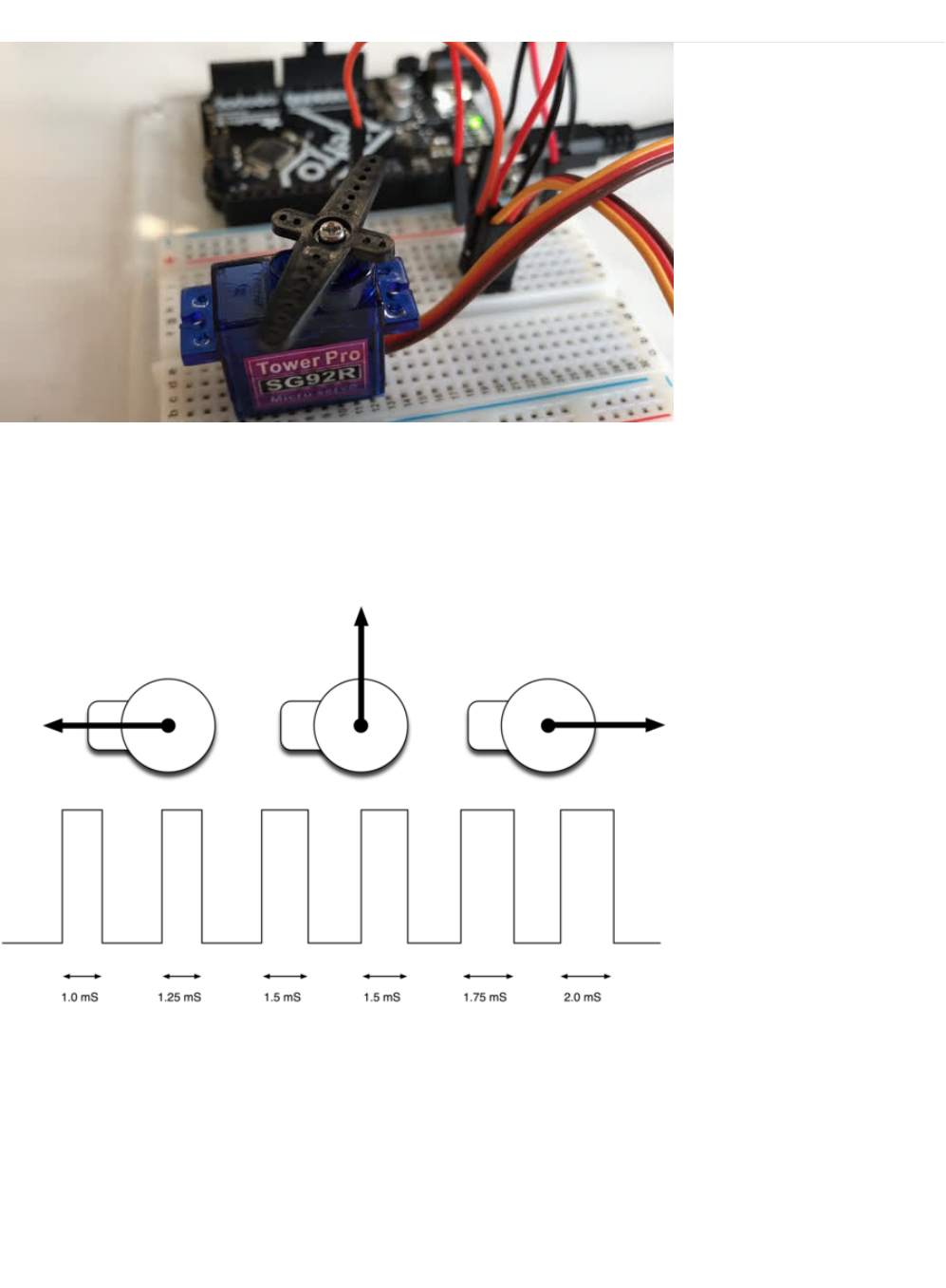
CIRC04: A Single Servo
Spinning a motor is good fun but when it comes to projects where motion control is required they tend to leave us wanting more.
The answer? Hobby servos. They are mass produced, widely available and cost anything from a couple of dollars to hundreds.
Inside is a small gearbox (to make the movement more powerful) and some electronics (to make it easier to control). A standard
servo is positionable from 0 to 180 degrees.
(Servo Positioning picture from Simon Monk's Arduino Lesson 14. Servo Motors (https://adafru.it/xgC))
Positioning is controlled through a timed pulse, between 1.25 milliseconds (0 degrees) and 1.75 milliseconds (180 degrees) (1.5
milliseconds for 90 degrees). Timing varies between manufacturer. If the pulse is sent every 25-50 milliseconds the servo will
run smoothly. One of the great features of the Adafruit Metro is it has a software library which can control servos using a single
line of code
© Adafruit Industries https://learn.adafruit.com/experimenters-guide-for-metro Page 79 of 317
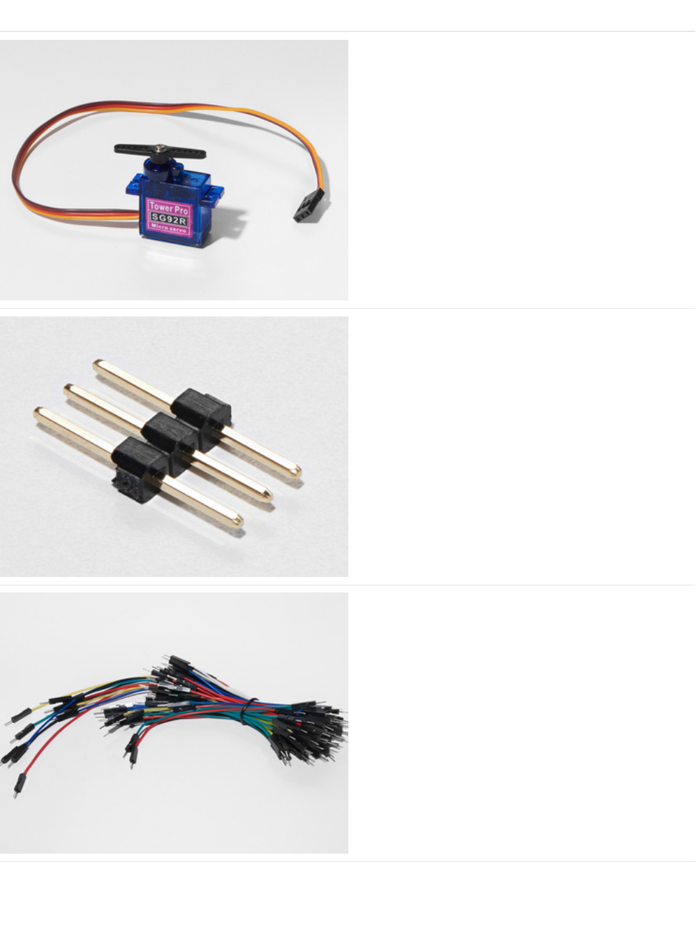
Parts
Mini Servo
If you'd like to order an extra mini servo from the Adafruit
shop, click here! (https://adafru.it/f1g)
There are many other servo sizes and types in the Adafruit
store, check out our offerings (https://adafru.it/xgD)
3-Pin Header
If you'd like to order extra headers from the Adafruit shop,
click here! (these are 40-pins but you can break them apart
easily) (https://adafru.it/xdS)
Breadboard Wiring Bundle
If you'd like to order more wires from the Adafruit shop click
here! (https://adafru.it/fE2)
© Adafruit Industries https://learn.adafruit.com/experimenters-guide-for-metro Page 80 of 317
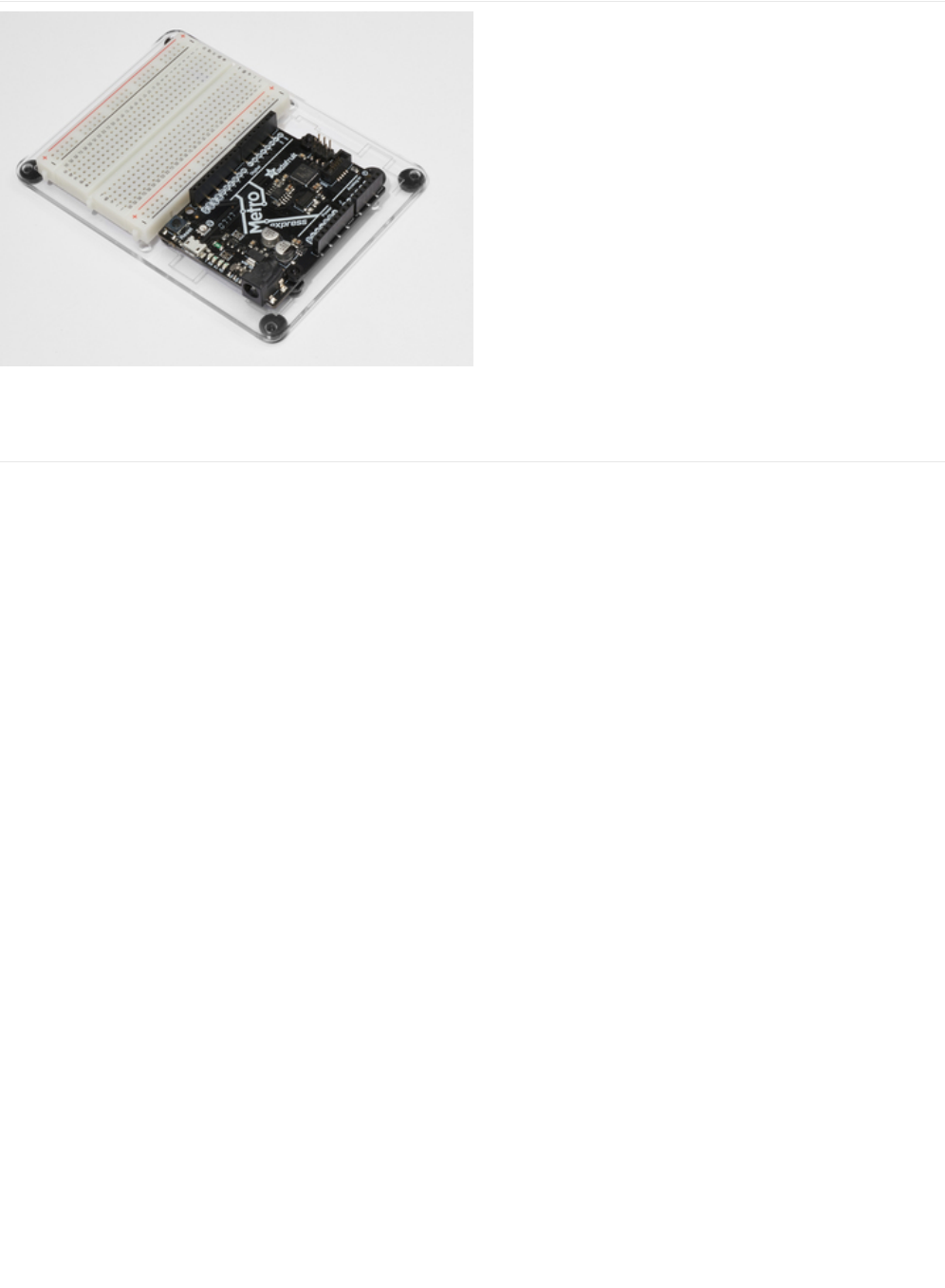
Adafruit Metro (or Metro Express) + Breadboard +
Mounting Plate
If you have not assembled this, we have a handy
guide! (https://adafru.it/x2A)
If you'd like to order an extra plastic mounting
plate (https://adafru.it/x4F), Adafruit
Metro (https://adafru.it/METROXMETR), Adafruit Metro
Express (https://adafru.it/xoa), or Mini-
Breadboard (https://adafru.it/keP) from the Adafruit Shop click
here!
© Adafruit Industries https://learn.adafruit.com/experimenters-guide-for-metro Page 81 of 317
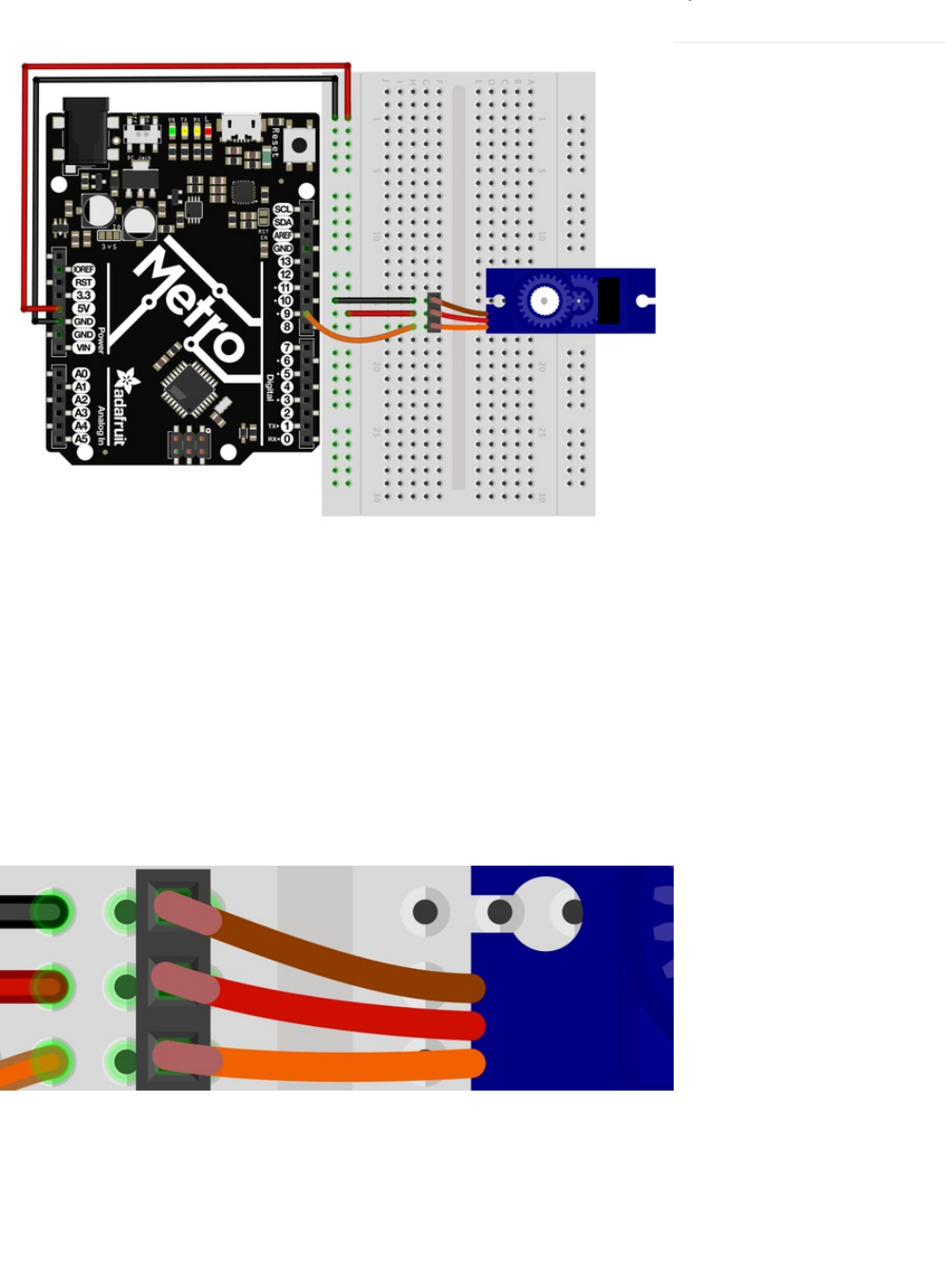
Wiring
The wiring for CIRC04 is much simpler than the last two circuits you made.
1. Connect the 5V pin on the Metro to the power rail on the breadboard.
2. Connect the GND pin on the Metro to the ground rail on the breadboard.
3. Connect the female end of the servo to the 3-Pin header.
4. Plug the 3-Pin header into any row on the breadboard.
5. Connect the ground rail to the brown servo wire.
6. Connect the power rail to the red servo wire.
7. Connect Metro Pin 9 to the orange servo wire (signal).
If you're having trouble, check the "Connection details" below for wiring help.
Connection details:
© Adafruit Industries https://learn.adafruit.com/experimenters-guide-for-metro Page 82 of 317

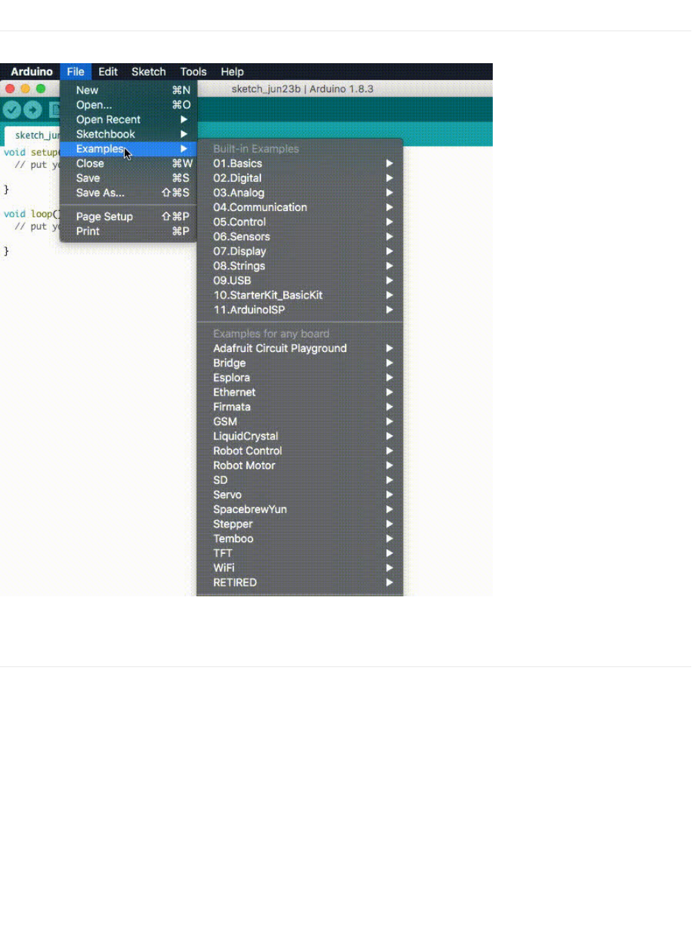
Code
The servo code we are going to use is included in Arduino (just like CIRC001) under: File > Examples > Servo > Sweep.
After loading the sketch, compile and upload it to your metro (https://adafru.it/xap) and watch the servo move!
Sweep
If you're having trouble loading Sweep from Arduino's included examples, the full source code is below to copy/paste into the
Arduino editor.
© Adafruit Industries https://learn.adafruit.com/experimenters-guide-for-metro Page 84 of 317

Not Working?
Servo Not Twisting?
Even with colored wires it is still shockingly easy to plug a servo in backwards. This might be the case. Check the connection
table if you need help.
Twitching and a flashing LED on your metro?
If the servo begins moving then twitches, and there's a flashing light on your METRO board, the power supply you are using is
not quite up to the challenge. Using a fresh battery instead of USB should solve this problem.
My servo is not moving at all
A mistake we made a time or two was simply forgetting to connect the power (red and brown wires) to +5 volts and ground.
Check your connections again for faults.
Nothing is working, I need assistance
We'll help you out! Post up in the Adafruit Support Forums and we will get back to you as soon as we can.
/* Sweep
by BARRAGAN <http://barraganstudio.com>
This example code is in the public domain.
modified 8 Nov 2013
by Scott Fitzgerald
http://www.arduino.cc/en/Tutorial/Sweep
*/
#include <Servo.h>
Servo myservo; // create servo object to control a servo
// twelve servo objects can be created on most boards
int pos = 0; // variable to store the servo position
void setup() {
myservo.attach(9); // attaches the servo on pin 9 to the servo object
}
void loop() {
for (pos = 0; pos <= 180; pos += 1) { // goes from 0 degrees to 180 degrees
// in steps of 1 degree
myservo.write(pos); // tell servo to go to position in variable 'pos'
delay(15); // waits 15ms for the servo to reach the position
}
for (pos = 180; pos >= 0; pos -= 1) { // goes from 180 degrees to 0 degrees
myservo.write(pos); // tell servo to go to position in variable 'pos'
delay(15); // waits 15ms for the servo to reach the position
}
}
© Adafruit Industries https://learn.adafruit.com/experimenters-guide-for-metro Page 85 of 317
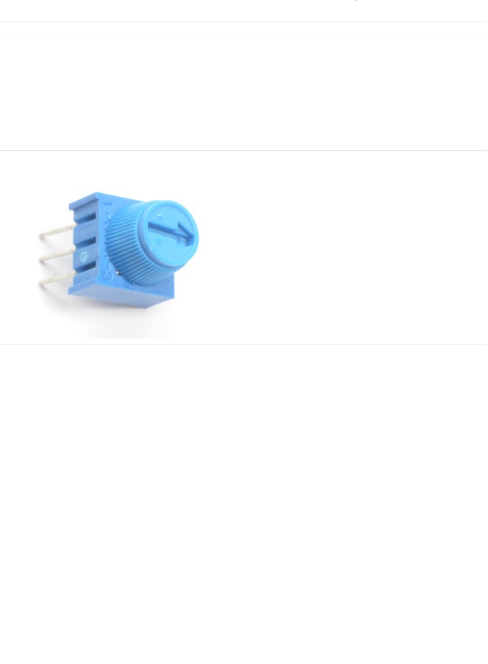
Make It Better
Potentiometer Control
We have yet to experiment with inputs but if you would like to control your motor, a potentiometer is a great choice and the
Arduino editor has a example program for it. We are going to learn about the potentiometer in CIRC08, but we can get our feet
wet with this type of input by modifying CIRC04.
Parts
You'll only need to add one part to this circuit: the blue trim potentiometer. You can find it in your box:
Breadboard Trim Potentiometer - 10k
If you'd like to buy an extra trimpot from the Adafruit store,
click here! (https://adafru.it/tba)
Wiring the Potentiometer
Wire it such that the two outermost pins go to the power and ground rail. The inner pin should go to the Metro's analog pin 0.
Note that we are using an analog pin instead of a digital pin this time, they are located on the left side of the Metro instead of
the right side.
Metro Breadboard Diagram
Be careful - the Trim Potentiometer connects to the 3.3v input on the Metro, not the 5V rail.
© Adafruit Industries https://learn.adafruit.com/experimenters-guide-for-metro Page 86 of 317
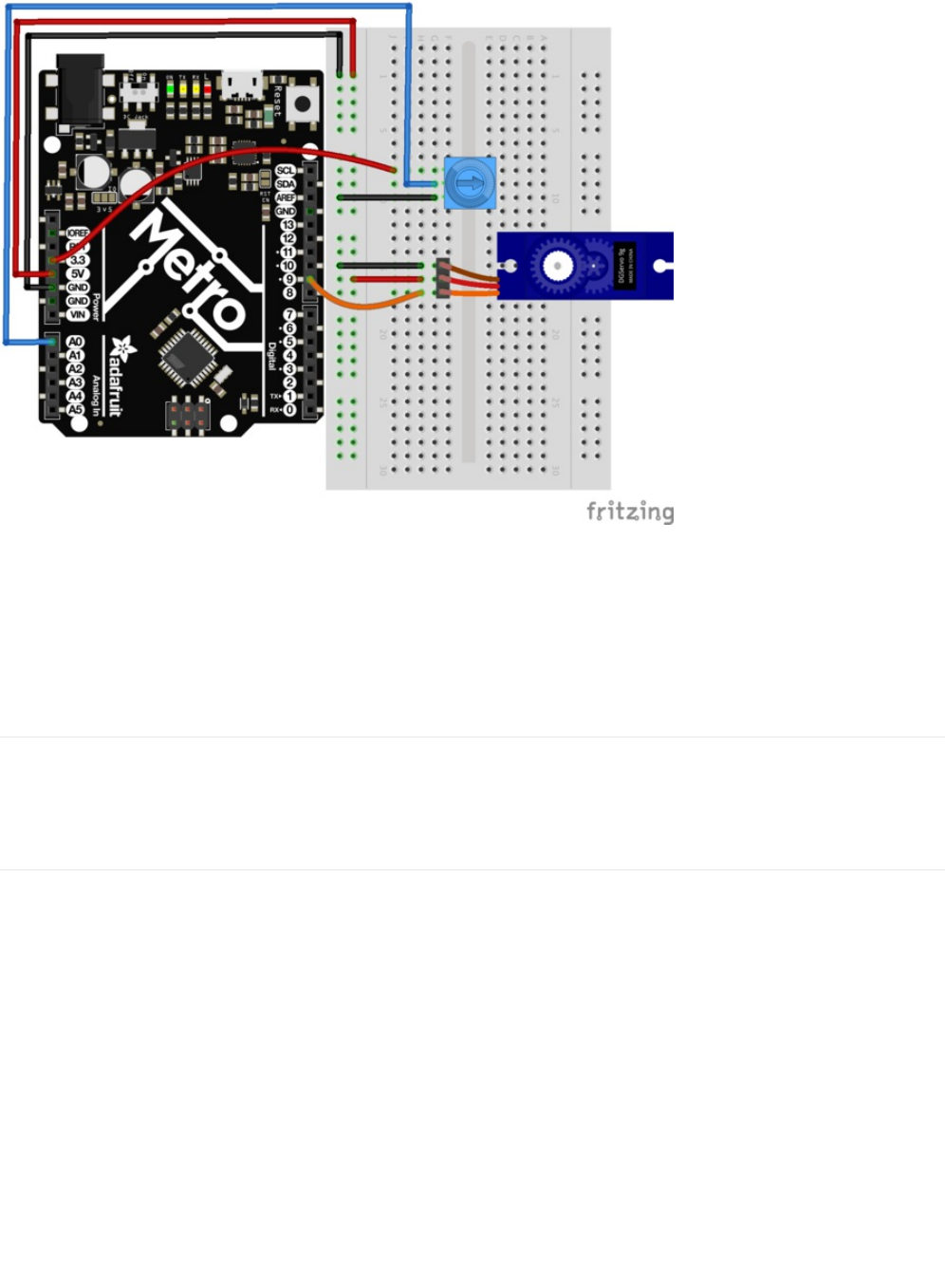
Loading the example code
The code to load potentiometer control onto your revised CIRC04 is provided by Arduino under
File > Servo > Knob. After loading the sketch, compile and upload it to your metro (https://adafru.it/xap). Move the potentiometer
left and right, you should see the servo move with it.
Self-Timing
While it is easy to control a servo using the Metro's included library, sometimes it is fun to figure out how to program something
yourself. Try it! Remember that we're controlling the pulse directly so you could use this method to control servos on any of the
Metro's 20 available pins (you need to highly optimize this code before doing that).
Other fun servo ideas
Servos can be used to do all sorts of things. The Adafruit Learning System is a great resource to find a fun project with
servos. (https://adafru.it/xeG)
Here are a few of our favorites:
© Adafruit Industries https://learn.adafruit.com/experimenters-guide-for-metro Page 87 of 317

Animatronic Servo Tail: Who hasn't imagined having a tail?
With a single servo and a little math, we can make this
real! (https://adafru.it/xeH)
Have you ever wanted to build a robot, but don't know where
to start? Or... are you looking for a project that you can cut-
your-teeth on? (https://adafru.it/ych)
This servo-controlled animatronic robot head uses two
servos for movement, two speakers for eyes and an LED
mouth for a friendly remote-controlled
robot. (https://adafru.it/ych)
© Adafruit Industries https://learn.adafruit.com/experimenters-guide-for-metro Page 88 of 317
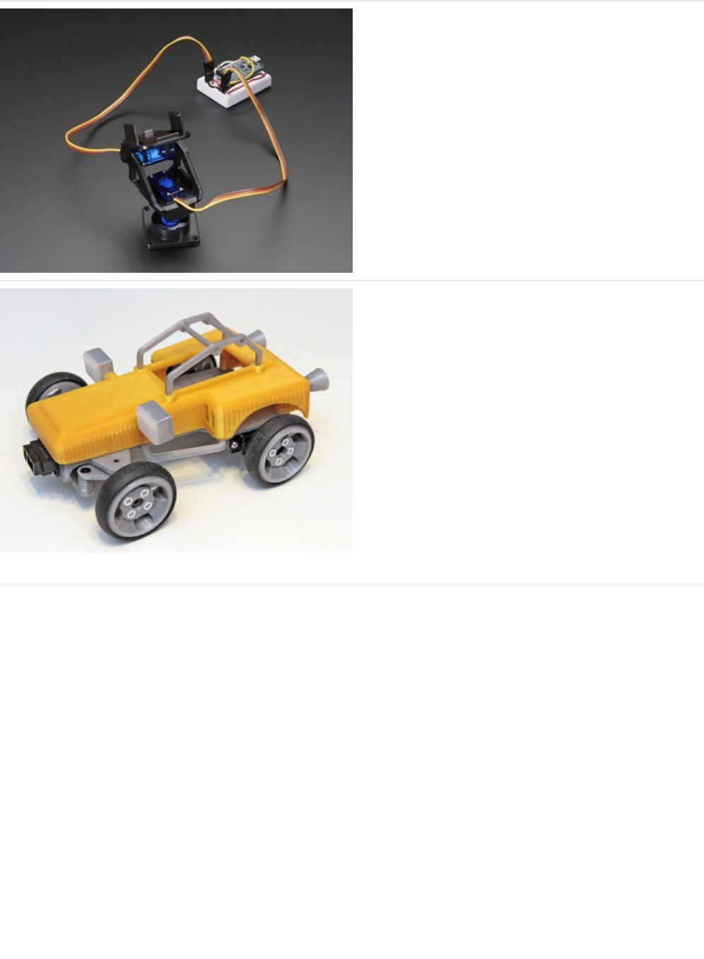
Our fully-assembled pan-tilt kit is the perfect way to give
your project full range motion with two micro servos. The
pan-tilt can rotate roughly 180° from side-to-side and can tilt
up&downwards around 150°. It also comes fully assembled
with two Micro Servos (SG-90 or SG-92 type) included and a
38mm x 36mm space to mount a camera or sensor or
whatever you like. (https://adafru.it/yci)
Sandblaster is a variation on Blue Buggy remixing the original
Cox International gas-powered sand buggy - scaled-down,
converted to electric, and 3D printable! (https://adafru.it/ycj)
You can use it to explore obstacle avoidance, autonomous
navigation, driverless vehicle design, or assisted Remote
Control. Or… build in the morning and race in the
afternoon! (https://adafru.it/ycj)
Crazy fun for your local hackerspace / makerspace or family
night! (https://adafru.it/ycj)
© Adafruit Industries https://learn.adafruit.com/experimenters-guide-for-metro Page 89 of 317
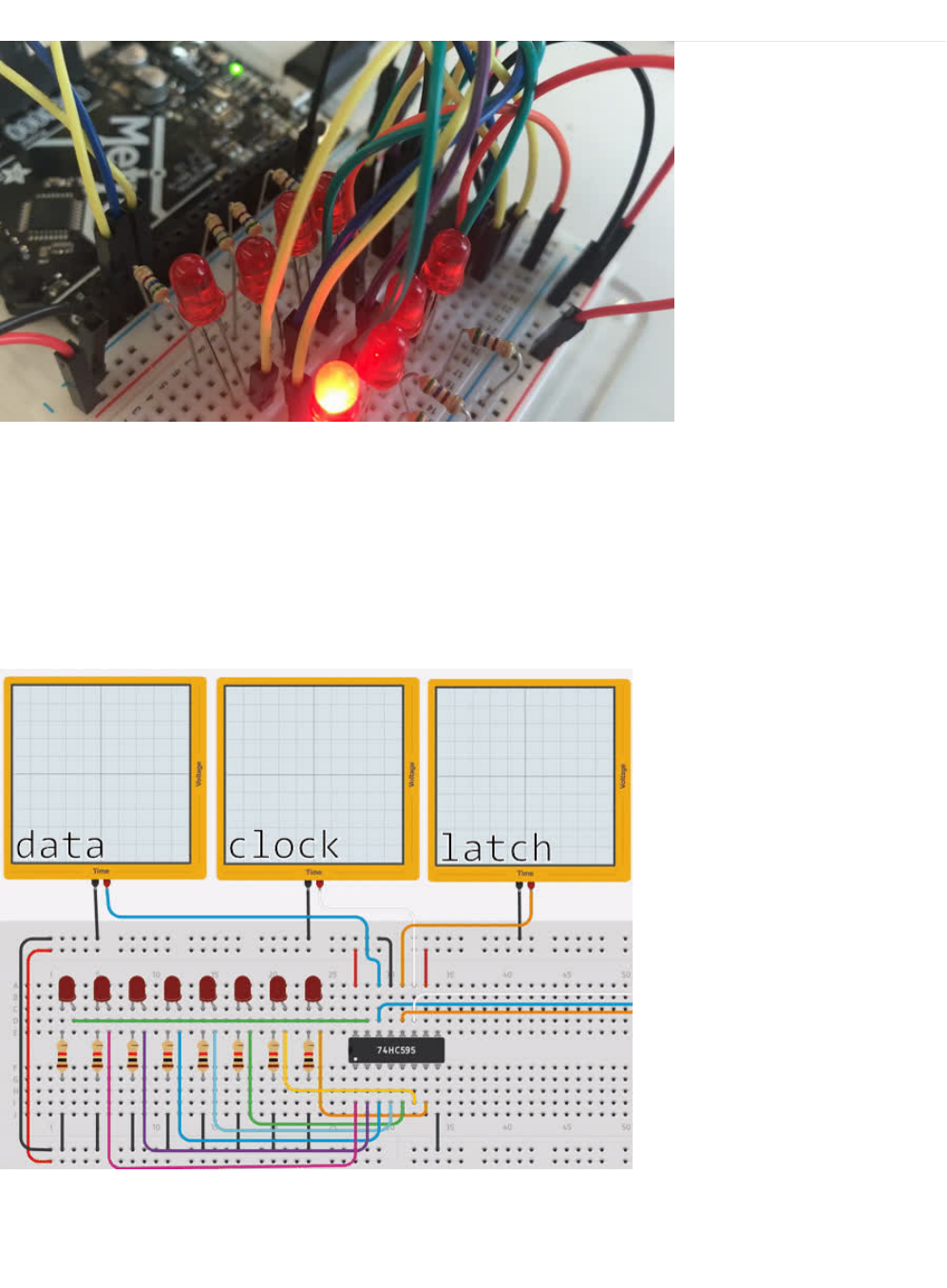
CIRC05: 8 More LEDs
Time to start playing with chips, or integrated circuits (ICs) as they like to be called. The external packaging of a chip can be very
deceptive. For example, the chip on the Metro board (a microcontroller) and the one we will use in this circuit (a shift register)
look very similar but are in fact rather different. The price of the Atmel 328p chip on the Metro board is a few dollars while the
74HC595 is a couple dozen cents. It's a good introductory chip, and once you're comfortable playing around with it and its
datasheet (), the world of chips will be your oyster.
The shift register (also called a serial to parallel converter), will give you an additional 8 outputs (to control LEDs and the like)
using only three Metro pins. They can also be linked together to give you a nearly unlimited number of outputs using the same
four pins. To use it you “clock in” the data and then lock it in (latch it).
To do this, you set the data pin to either
HIGH
or
LOW
, pulse the clock, then set the data pin again and pulse the clock
repeating until you have shifted out 8 bits of data. Then you pulse the latch and the 8 bits are transferred to the shift registers
pins. It sounds complicated but is
really
simple once you get the hang of it. (click here for a more in depth look at how a shift
register works) (https://adafru.it/METROX74HC595)
© Adafruit Industries https://learn.adafruit.com/experimenters-guide-for-metro Page 90 of 317

© Adafruit Industries https://learn.adafruit.com/experimenters-guide-for-metro Page 91 of 317
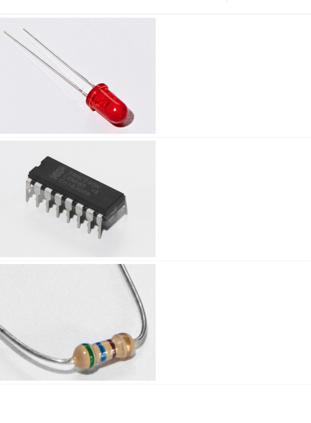
Parts
5mm Red LED
Qty: x8
If you'd like to order more red LEDs (they make great
indicator lights!) from the Adafruit shop, click
here! (https://adafru.it/xeV)
74HC595 Shift Register
If you'd like to order more shift registers from the Adafruit
shop, click here! (https://adafru.it/xeU)
560 Ohm Resistor
Qty: x8
Colors: Green > Blue > Brown
If you'd like to order more resistors from the Adafruit shop
click here! (they are 470ohm but they'll be
fine) (https://adafru.it/x4E)
© Adafruit Industries https://learn.adafruit.com/experimenters-guide-for-metro Page 92 of 317
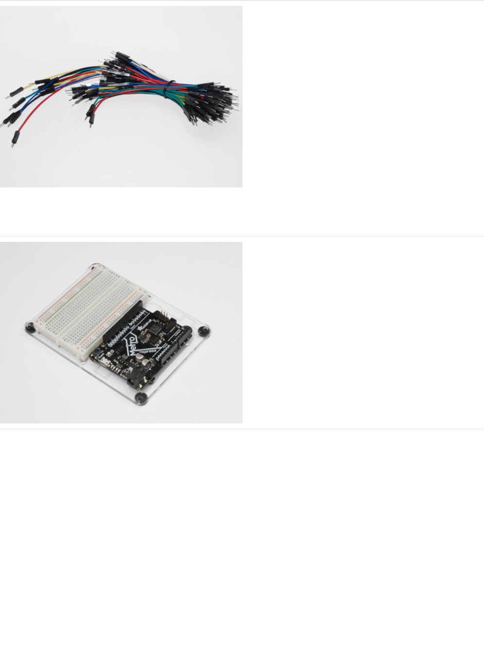
Breadboard Wiring Bundle
If you'd like to order more wires from the Adafruit shop click
here! (https://adafru.it/fE2)
Adafruit Metro (or Metro Express) + Breadboard +
Mounting Plate
If you have not assembled this, we have a handy
guide! (https://adafru.it/x2A)
If you'd like to order an extra plastic mounting
plate (https://adafru.it/x4F), Adafruit
Metro (https://adafru.it/METROXMETR), Adafruit Metro
Express (https://adafru.it/xoa), or Mini-
Breadboard (https://adafru.it/keP) from the Adafruit Shop click
here!
© Adafruit Industries https://learn.adafruit.com/experimenters-guide-for-metro Page 93 of 317
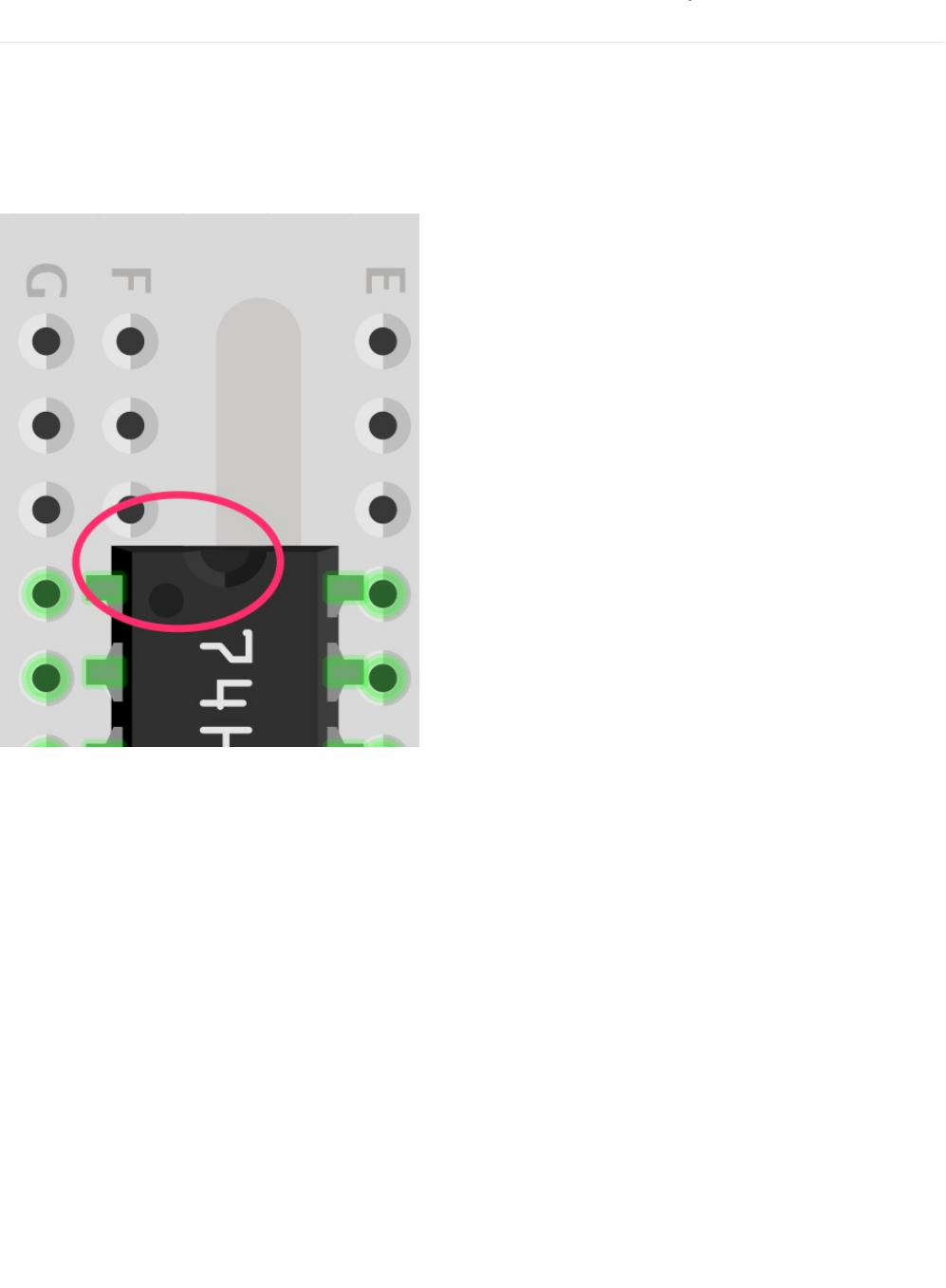
Wiring
CIRC05 is considerably more complex to wire than other circuits. However, it isn't impossible and just takes some time and
patience.
We broke down this into three larger steps, follow all of them in order and you'll be rewarded with a fun LED show!
Chip Orientation
The shift register should be placed such that the half moon circle on it should face the top of the breadboard.
Step 1: Connect Power/GND
© Adafruit Industries https://learn.adafruit.com/experimenters-guide-for-metro Page 94 of 317
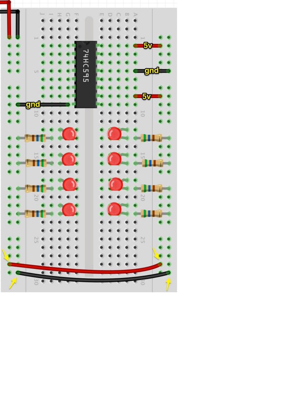
It's easier to see the diagram without the bulk of the wires in the way. Let's first start by connecting all power and ground points
on the circuit.
Note
that we are expanding the power and ground rails by connecting the left rails to the right rails. This is for
ease of access and to keep everything tidy.
We are also going to plug in our resistors. Resistors plug into the
cathode
(shorter end) of the LED, and then into ground.
Step 2: Connect Data Pins to the Metro
© Adafruit Industries https://learn.adafruit.com/experimenters-guide-for-metro Page 95 of 317
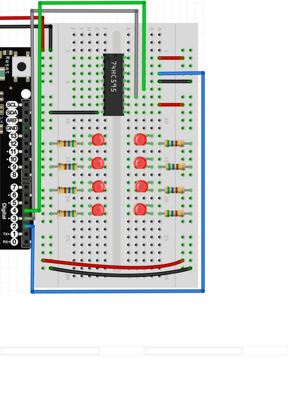
Pins 2, 3, and 4 on the metro correspond to the Data (pin 14), Latch (pin 12), and Clock (pin 11) on the shift register.
Step 3: Connect the LEDs
Next up is connecting the LEDs to the shift register. We have a handy pinout below to help you, along with the final diagram.
© Adafruit Industries https://learn.adafruit.com/experimenters-guide-for-metro Page 96 of 317

Once you complete the LED wiring,
double check
all your wiring against the final diagram. After that, move onto the Code
section.
Breadboard Layout Sheet
https://adafru.it/METROXBBLS05
https://adafru.it/METROXBBLS05
© Adafruit Industries https://learn.adafruit.com/experimenters-guide-for-metro Page 97 of 317

Code
Copy/Paste the code below into an empty arduino sketch. Then compile and upload it to your metro (https://adafru.it/xap).
/* ---------------------------------------------------------
* | Arduino Experimentation Kit Example Code |
* | CIRC-05 .: 8 More LEDs :. (74HC595 Shift Register) |
* ---------------------------------------------------------
*
* We have already controlled 8 LEDs however this does it in a slightly
* different manner. Rather than using 8 pins we will use just three
* and an additional chip.
*
*
*/
//Pin Definitions
//Pin Definitions
//The 74HC595 uses a serial communication
//link which has three pins
int data = 2;
int clock = 3;
int latch = 4;
//Used for single LED manipulation
int ledState = 0;
const int ON = HIGH;
const int OFF = LOW;
/*
* setup() - this function runs once when you turn your Arduino on
* We set the three control pins to outputs
*/
void setup()
{
pinMode(data, OUTPUT);
pinMode(clock, OUTPUT);
pinMode(latch, OUTPUT);
}
/*
* loop() - this function will start after setup finishes and then repeat
* we set which LEDs we want on then call a routine which sends the states to the 74HC595
*/
void loop() // run over and over again
{
int delayTime = 100; //the number of milliseconds to delay between LED updates
for(int i = 0; i < 256; i++){
updateLEDs(i);
delay(delayTime);
}
}
/*
* updateLEDs() - sends the LED states set in ledStates to the 74HC595
* sequence
*/
void updateLEDs(int value){
digitalWrite(latch, LOW); //Pulls the chips latch low
shiftOut(data, clock, MSBFIRST, value); //Shifts out the 8 bits to the shift register
© Adafruit Industries https://learn.adafruit.com/experimenters-guide-for-metro Page 98 of 317

Not Working?
The Metro's Power LED goes out
The chip is inserted backwards. Turn off the power to your Metro, then rotate the chip such that the half-moon cutout on the
chip faces the top of the breadboard.
Still not working?
Sorry to sound like a broken record, but make absolutely sure your wiring is correct. If you're unsure: pull everything out and
start fresh.
Frustrated?
This circuit is both simple and complex at the same time, let us know your frustration with it so we can address it in future
editions of the kit.
shiftOut(data, clock, MSBFIRST, value); //Shifts out the 8 bits to the shift register
digitalWrite(latch, HIGH); //Pulls the latch high displaying the data
}
/*
* updateLEDsLong() - sends the LED states set in ledStates to the 74HC595
* sequence. Same as updateLEDs except the shifting out is done in software
* so you can see what is happening.
*/
void updateLEDsLong(int value){
digitalWrite(latch, LOW); //Pulls the chips latch low
for(int i = 0; i < 8; i++){ //Will repeat 8 times (once for each bit)
int bit = value & B10000000; //We use a "bitmask" to select only the eighth
//bit in our number (the one we are addressing this time through
value = value << 1; //we move our number up one bit value so next time bit 7 will be
//bit 8 and we will do our math on it
if(bit == 128){digitalWrite(data, HIGH);} //if bit 8 is set then set our data pin high
else{digitalWrite(data, LOW);} //if bit 8 is unset then set the data pin low
digitalWrite(clock, HIGH); //the next three lines pulse the clock pin
delay(1);
digitalWrite(clock, LOW);
}
digitalWrite(latch, HIGH); //pulls the latch high shifting our data into being displayed
}
//These are used in the bitwise math that we use to change individual LEDs
//For more details http://en.wikipedia.org/wiki/Bitwise_operation
int bits[] = {B00000001, B00000010, B00000100, B00001000, B00010000, B00100000, B01000000, B10000000};
int masks[] = {B11111110, B11111101, B11111011, B11110111, B11101111, B11011111, B10111111, B01111111};
/*
* changeLED(int led, int state) - changes an individual LED
* LEDs are 0 to 7 and state is either 0 - OFF or 1 - ON
*/
void changeLED(int led, int state){
ledState = ledState & masks[led]; //clears ledState of the bit we are addressing
if(state == ON){ledState = ledState | bits[led];} //if the bit is on we will add it to ledState
updateLEDs(ledState); //send the new LED state to the shift register
}
© Adafruit Industries https://learn.adafruit.com/experimenters-guide-for-metro Page 99 of 317

Make It Better
Doing it the Hard Way
The Metro makes complex actions very simple. A perfect example of this is shifting and manipulating data. However, one of the
nice things about the Metro is that you can adjust the difficulty of what you are trying to achieve.
In the loop() , switch updateLEDs(i); to updateLEDsLong(i);
Did you notice anything different when you ran it this time?
You shouldn't have! There was no difference in the actions the code took. The code was changed to communicate with theYou shouldn't have! There was no difference in the actions the code took. The code was changed to communicate with the
You shouldn't have! There was no difference in the actions the code took. The code was changed to communicate with the
LEDs one bit at a time by using the serial peripheral interface.LEDs one bit at a time by using the serial peripheral interface.
LEDs one bit at a time by using the serial peripheral interface.
Controlling Individual LEDs
Just like CIRC02, you can individually control the LEDs on your breadboard. The current state of the eight LEDs are stored in
one 8-bit value (for more info on this subject, we have a great Collin's Lab video on Binary and Hex (https://adafru.it/xeN)). The
code provided already takes care of the bit manipulations (https://adafru.it/xeO).
To control individual LEDs, we replace the code within loop() with the following:
Then, compile and upload this to your Metro. The code will cause the LEDs to light up one after another and then turn off. Read
through the code and the links for a better understanding of how it works.
More Animations
If you did CIRC02, there was a part in the Make It Better section about adding additional animations (https://adafru.it/xeP). The
format of changing the LEDs in this circuit will be similar.
CIRC02 let you change the LEDs using
digitalWrite(LED, state)
CIRC05 uses the changeLED() routine to perform the same operation:
changeLED(LED, state)
You can repurpose the code from CIRC02's additional animations by first copying the animation code from CIRC02 into this
sketch and then changing all the digitalWrite() routines to changeLED() . You'll also need to change a few other things, just follow
the compiler errors and it works itself out.
int delayTime = 100; // # of ms to delay btween LED updates
for(int i=0; i<8; i++){
changeLED(i, ON);
delay(delayTime);
}
for(int i=0;i<8;i++){
changeLED(i,OFF);
delay(delayTime);
}
© Adafruit Industries https://learn.adafruit.com/experimenters-guide-for-metro Page 100 of 317
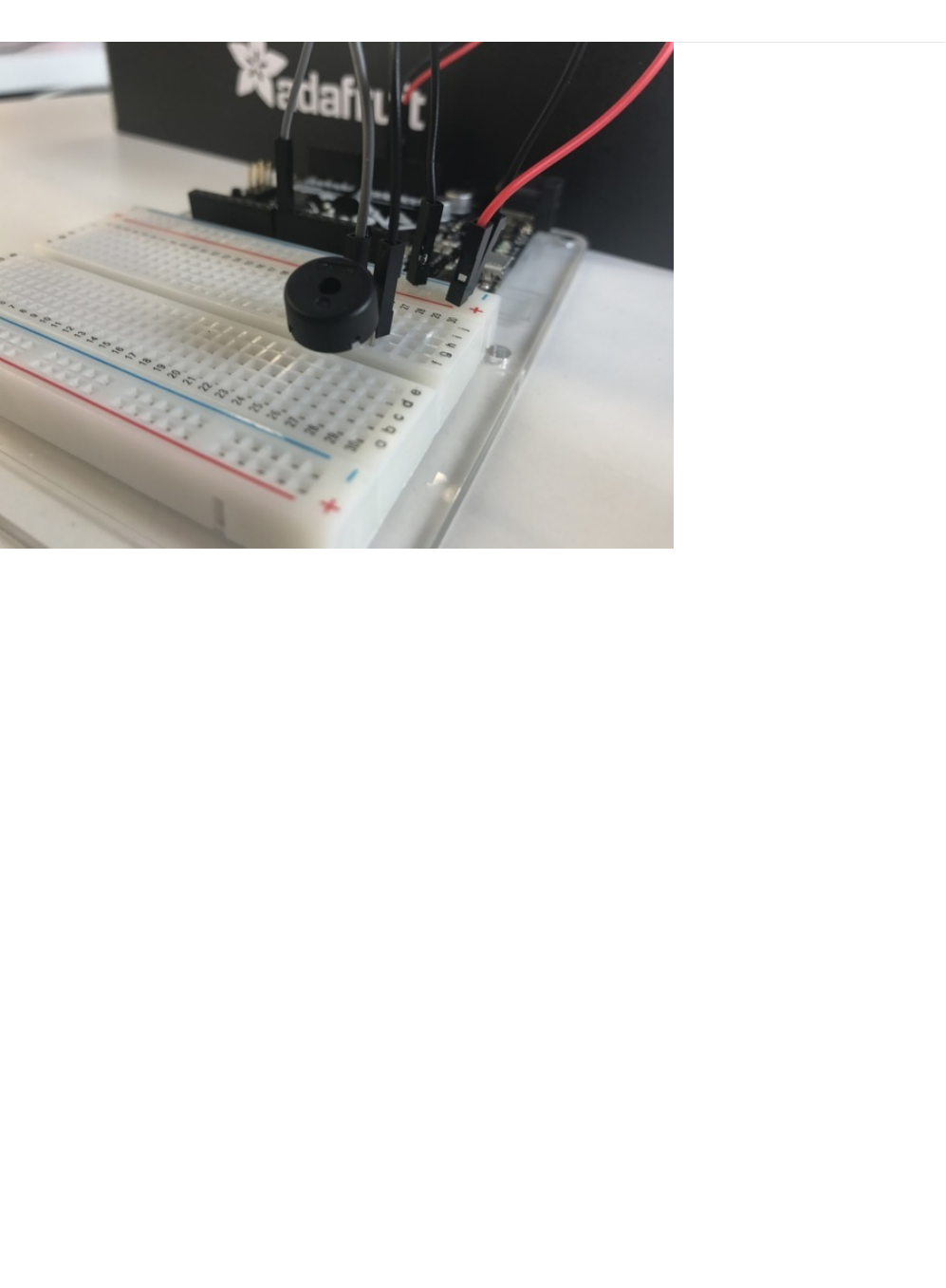
CIRC06: Music with Piezo
To this point we have controlled light, motion, and electrons. Let's tackle sound next. But sound is an
analog
phenomena, how
will our
digital
Metro cope? We will once again rely on its incredible speed which will let it mimic analog behavior.
We are going to attach a piezo element to one of the Metro's digital pins. A piezo element makes a clicking sound each time it is
pulsed with current. If we pulse it at the right frequency (for example 440 times a second to make the note
middle A
), these
clicks will run together to produce notes.
Let's get to experimenting and make your Metro play "Twinkle Twinkle Little Star"!
© Adafruit Industries https://learn.adafruit.com/experimenters-guide-for-metro Page 101 of 317
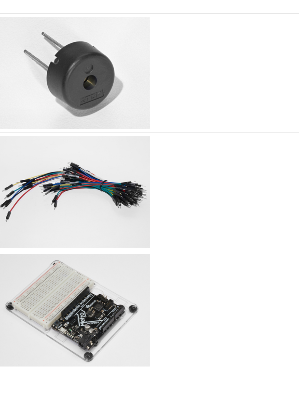
Parts
Piezo Buzzer
If you'd like to order another Pizeo Buzzer from the Adafruit
shop, click here! (https://adafru.it/dCD)
Breadboard Wiring Bundle
If you'd like to order more wires from the Adafruit shop click
here! (https://adafru.it/fE2)
Adafruit Metro (or Metro Express) + Breadboard +
Mounting Plate
If you have not assembled this, we have a handy
guide! (https://adafru.it/x2A)
If you'd like to order an extra plastic mounting
plate (https://adafru.it/x4F), Adafruit
Metro (https://adafru.it/METROXMETR), Adafruit Metro
Express (https://adafru.it/xoa), or Mini-
Breadboard (https://adafru.it/keP) from the Adafruit Shop click
here!
© Adafruit Industries https://learn.adafruit.com/experimenters-guide-for-metro Page 102 of 317

Wiring
Wiring this circuit is much easier than CIRC05:
1. Connect your GND and 5V rails.
2. Connect one side of the piezo to GND
3. Connect the other side of the piezo to the Metro's Digital Pin 9
Breadboard Layout Sheet
https://adafru.it/Ate
https://adafru.it/Ate
© Adafruit Industries https://learn.adafruit.com/experimenters-guide-for-metro Page 103 of 317

Code
Copy/Paste the code below into an empty arduino sketch. Then compile and upload it to your Metro (https://adafru.it/xap).
Not Working?
No sound is coming out of the speaker
Given the size and shape of the piezo element it is easy to miss the right holes on the breadboard. Try double checking its
placement.
Can't Think While the Melody is Playing? Annoyed by the sound?
Just pull up the piezo element whilst you think, upload your program then plug it back in.
Tired of Twinkle Twinkle Little Star?
The code is written so you can easily add your own songs, check out the Make It Better section for more info on modifying
the code.
// CIRC06 - Music with Piezo
int speakerPin = 9;
int length = 15; // the number of notes
char notes[] = "ccggaagffeeddc "; // a space represents a rest
int beats[] = { 1, 1, 1, 1, 1, 1, 2, 1, 1, 1, 1, 1, 1, 2, 4 };
int tempo = 300;
void playNote(char note, int duration) {
char names[] = { 'c', 'd', 'e', 'f', 'g', 'a', 'b', 'C' };
int tones[] = { 1915, 1700, 1519, 1432, 1275, 1136, 1014, 956 };
// play the tone corresponding to the note name
for (int i = 0; i < 8; i++) {
if (names[i] == note) {
tone(speakerPin, tones[i], duration);
}
}
}
void setup() {
pinMode(speakerPin, OUTPUT);
}
void loop() {
for (int i = 0; i < length; i++) {
if (notes[i] == ' ') {
delay(beats[i] * tempo); // rest
} else {
playNote(notes[i], beats[i] * tempo);
}
// pause between notes
delay(tempo / 2);
}
}
© Adafruit Industries https://learn.adafruit.com/experimenters-guide-for-metro Page 104 of 317

Make It Better
Playing with Speed
The timing for each note is calculated based on variables, as such we can tweak the sound of each note or the timing. To
change the speed of the melody, we only need to change one line:
int tempo = 300; --> int tempo = (new #);
Change new # to a larger number to slow the melody down, or a smaller number to speed it up!
Tuning the Notes
If you are worried about the notes being a little bit out of tune, this can be fixed as well. The notes have been calculated based
on a formula from the comment block at the top of the program. But to tune individual notes just adjust their values in the tones[]
array up or down until they sound right. Each note is matched by its name in the names[] array.
For example: If we want a
c (c=1915)
to be a higher pitch, we need to find it's initial value:
char names[] = { 'c', 'd', 'e', 'f', 'g', 'a', 'b', 'C' };
int tones[] = { 1915, 1700, 1519, 1432, 1275, 1136, 1014, 956 };
and then change the number within tones[] to something larger, let's go with 1975:
char names[] = { 'c', 'd', 'e', 'f', 'g', 'a', 'b', 'C' };
int tones[] = { 1975, 1700, 1519, 1432, 1275, 1136, 1014, 956 };
Composing your own Melodies:
While the program is pre-set to play 'Twinkle Twinkle Little Star', the program can easily be changed to play something else.
A song takes the format of one integer ( int length ) and two arrays ( char notes[] and int beats[] ).
int length - defines the number of notes
char notes[] - defines each note
int beat[] - defines how long each note will be played for
Twinkle Twinkle Little Star
Happy Birthday (First line)
To become familiar with how code works, it's always a good idea to look at examples. Above are two songs. Run them, and then
modify them to compose your own melody.
int length = 15;
char notes[] = {"ccggaagffeeddc"};
int beats[] = { 1, 1, 1, 1, 1, 1, 2, 1, 1, 1, 1, 1, 1, 2, 4 };
int length = 13;
char notes[] = {"ccdcfeccdcgf"};
int beats[] = {1,1,1,1,1,2,1,1,1,1,1,2,4};
© Adafruit Industries https://learn.adafruit.com/experimenters-guide-for-metro Page 105 of 317

© Adafruit Industries https://learn.adafruit.com/experimenters-guide-for-metro Page 106 of 317

CIRC07: Button Pressing
Up to this point we have focused entirely on outputs. It's time to get our Metro to listen, watch and feel. We'll start with a simple
pushbutton.
Wiring up the pushbutton is simple. There is one component, the pull up resistor, that might seem out of place. This is included
because a Metro doesn't sense the same way we do (i.e:
button pressed
,
button unpressed
). Instead it looks at the voltage on
the pin and decides whether it is
HIGH
or
LOW
. The button is set up to pull the Metro's pin
LOW
when it is pressed, however,
when the button is unpressed the voltage of the pin will float (causing occasional errors). To get the Metro to reliably read the
pin as HIGH when the button is unpressed, we add a pull up resistor into the circuit.
© Adafruit Industries https://learn.adafruit.com/experimenters-guide-for-metro Page 107 of 317
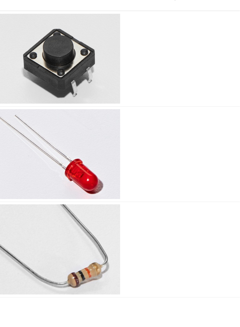
Parts
Pushbutton
Qty: x2
If you'd like to order more pushbuttons from the Adafruit
shop, click here! (https://adafru.it/eww)
5mm Red LED
If you'd like to order more red LEDs (they make great
indicator lights!) from the Adafruit shop, click
here! (https://adafru.it/xeV)
10K Ohm Resistor
Colors: Brown > Black > Orange
Qty: x2
If you'd like to order more 10k ohm pull-up resistors from the
Adafruit shop, click here! (https://adafru.it/xfm)
© Adafruit Industries https://learn.adafruit.com/experimenters-guide-for-metro Page 108 of 317
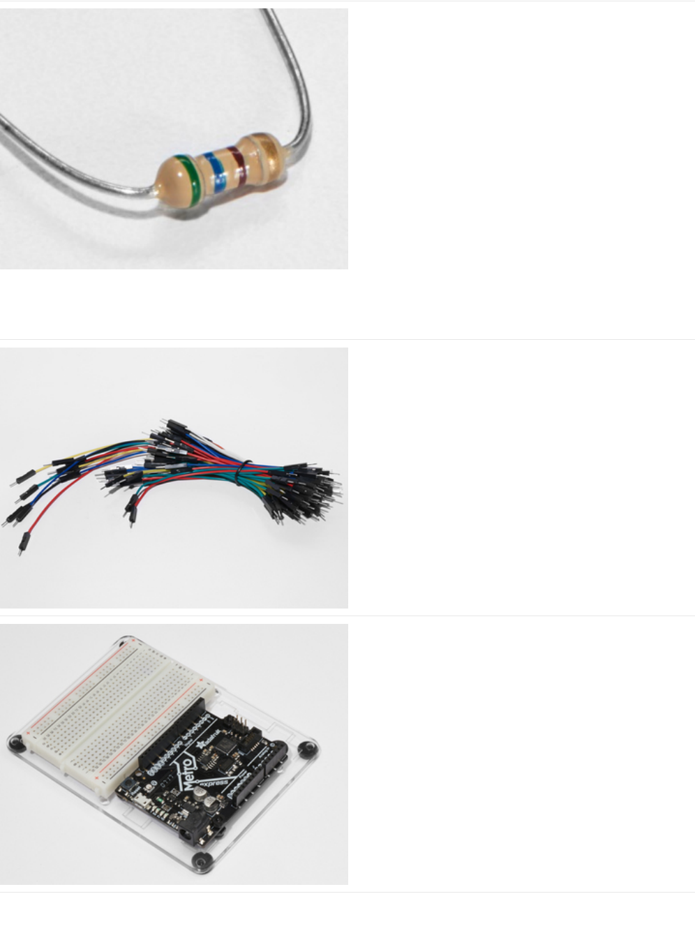
560 Ohm Resistor
Colors: Green > Blue > Brown
If you'd like to order more resistors from the Adafruit shop
click here! (they are 470ohm but they'll be
fine) (https://adafru.it/x4E)
Breadboard Wiring Bundle
If you'd like to order more wires from the Adafruit shop click
here! (https://adafru.it/fE2)
Adafruit Metro (or Metro Express) + Breadboard +
Mounting Plate
If you have not assembled this, we have a handy
guide! (https://adafru.it/x2A)
If you'd like to order an extra plastic mounting
plate (https://adafru.it/x4F), Adafruit
Metro (https://adafru.it/METROXMETR), Adafruit Metro
Express (https://adafru.it/xoa), or Mini-
Breadboard (https://adafru.it/keP) from the Adafruit Shop click
here!
© Adafruit Industries https://learn.adafruit.com/experimenters-guide-for-metro Page 109 of 317
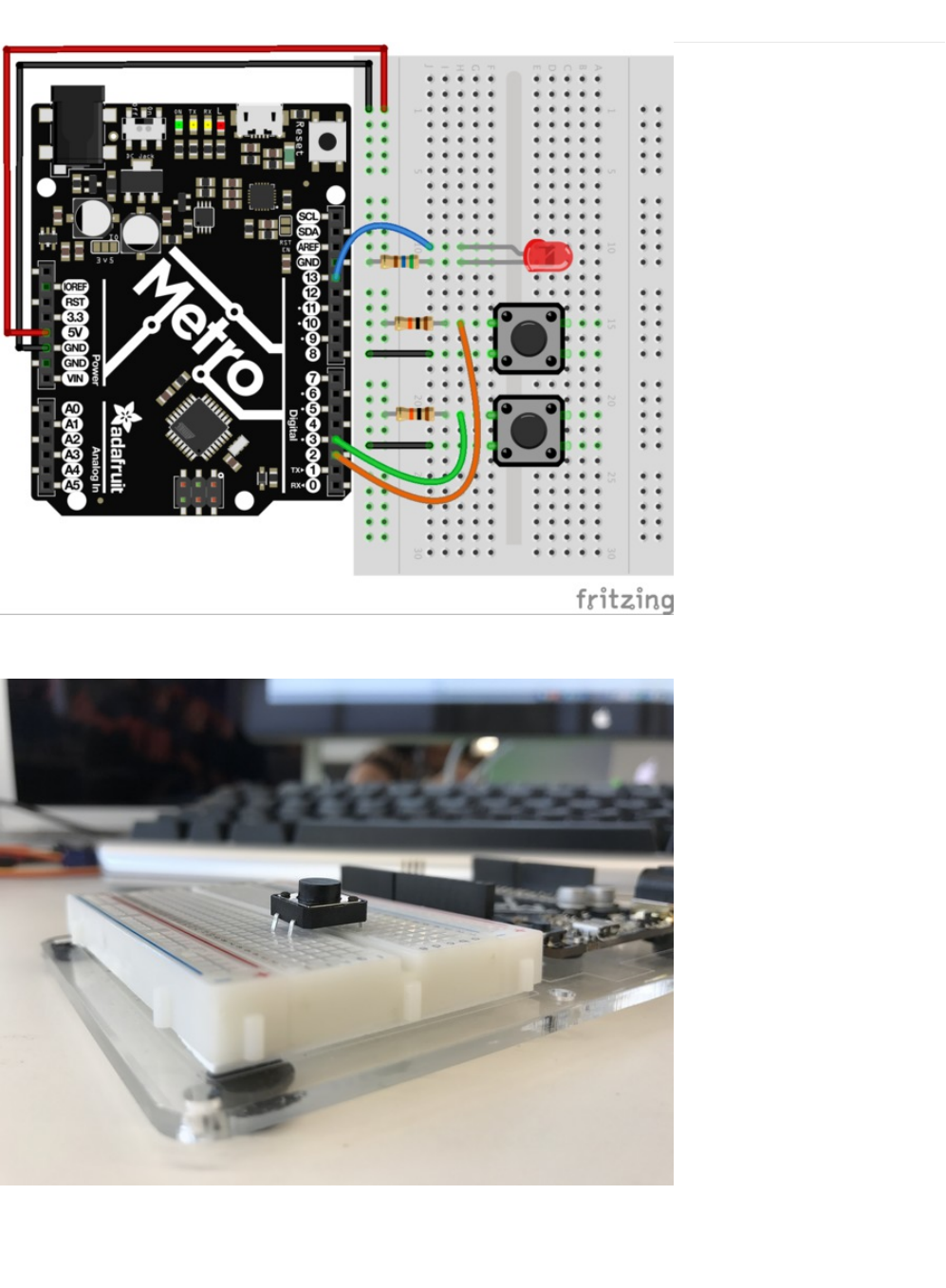
Wiring
The wiring for CIRC07 is simple - the wires going to the digital pins on the Metro sit between the switch terminal and the resistor.
Pro-Tip: When pushing the pushbutton into the breadboard, be careful not to bend the legs outwards too much or else it won't
make contact with the breadboard. Seat it in the gap in the breadboard.
© Adafruit Industries https://learn.adafruit.com/experimenters-guide-for-metro Page 110 of 317


Code
This code is provided for you in the Arduino editor under: File > Examples > 2. Digital > Button. Load it into the Arduino editor,
then compile and upload it to your Metro (https://adafru.it/xap).
Code:
Not Working?
/*
Button
Turns on and off a light emitting diode(LED) connected to digital pin 13,
when pressing a pushbutton attached to pin 2.
The circuit:
- LED attached from pin 13 to ground
- pushbutton attached to pin 2 from +5V
- 10K resistor attached to pin 2 from ground
- Note: on most Arduinos there is already an LED on the board
attached to pin 13.
created 2005
by DojoDave <http://www.0j0.org>
modified 30 Aug 2011
by Tom Igoe
This example code is in the public domain.
http://www.arduino.cc/en/Tutorial/Button
*/
// constants won't change. They're used here to set pin numbers:
const int buttonPin = 2; // the number of the pushbutton pin
const int ledPin = 13; // the number of the LED pin
// variables will change:
int buttonState = 0; // variable for reading the pushbutton status
void setup() {
// initialize the LED pin as an output:
pinMode(ledPin, OUTPUT);
// initialize the pushbutton pin as an input:
pinMode(buttonPin, INPUT);
}
void loop() {
// read the state of the pushbutton value:
buttonState = digitalRead(buttonPin);
// check if the pushbutton is pressed. If it is, the buttonState is HIGH:
if (buttonState == HIGH) {
// turn LED on:
digitalWrite(ledPin, HIGH);
} else {
// turn LED off:
digitalWrite(ledPin, LOW);
}
}
© Adafruit Industries https://learn.adafruit.com/experimenters-guide-for-metro Page 112 of 317

Light Not Turning On
The pushbutton is square and because of this it is easy to put it in the wrong way. Give it a 90 degree twist and see if it starts
working.
The light is not fading
A bit of a silly mistake we constantly made, when you switch from simple on off to fading remember to move the LED wire
from pin 13 to pin 9.
Feeling Underwhelmed?
No worries these circuits are all super stripped down to make playing with the components easy, but once you throw them
together the sky is the limit.
© Adafruit Industries https://learn.adafruit.com/experimenters-guide-for-metro Page 113 of 317
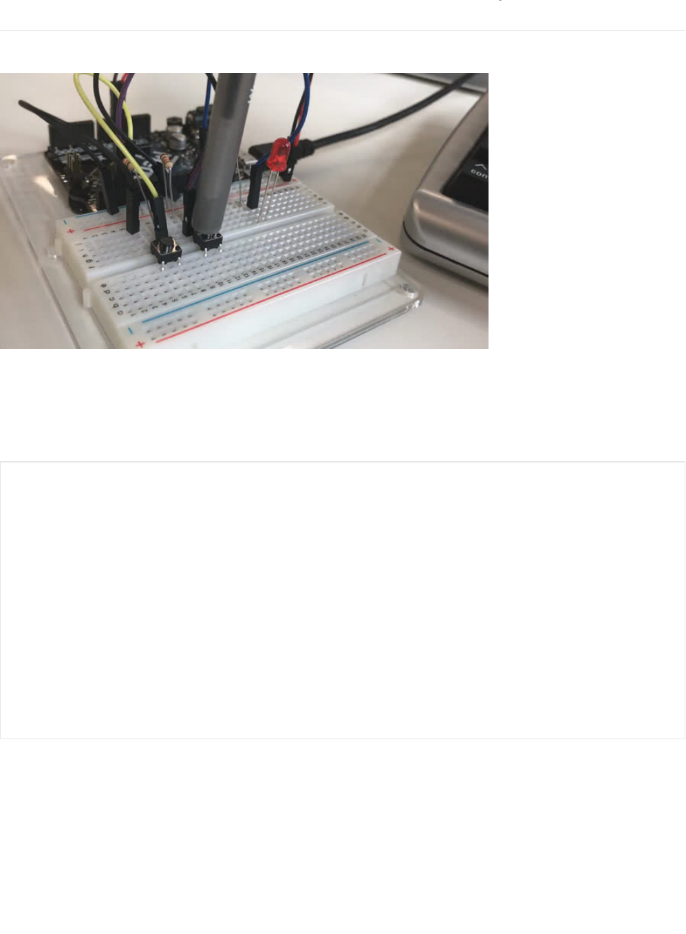
Make It Better
Light Switch
If you feel the initial example is a bit underwhelming ("I don't need a metro to do
this
!"), let's use the metro to do something a bit
more complicated. We are going to make a light-switch. One of the buttons on your breadboard is going to turn on the light, and
the other is going to turn it off!
This is super simple, we're just going to change a few lines of code:
Copy and paste the code into a blank sketch, upload it to the board, and start toggling the LED on and off.
Fading
int ledPin = 13; // choose the pin for the LED
int buttonPin1 = 3; // button 1
int buttonPin2 = 2; // button 2
void setup() {
pinMode(ledPin, OUTPUT); // declare LED as output
pinMode(buttonPin1, INPUT); // make button 1 an input
pinMode(buttonPin1, INPUT); // make button 2 an input
}
void loop() {
if (digitalRead(buttonPin1) == LOW) {
digitalWrite(ledPin, LOW); // turn LED OFF
}
else if (digitalRead(buttonPin2) == LOW) {
digitalWrite(ledPin, HIGH); // turn LED ON
}
}
© Adafruit Industries https://learn.adafruit.com/experimenters-guide-for-metro Page 114 of 317

Let's use the buttons to control an analog signal. To do this, you will need to change the wire connecting the LED from Pin 13 to
Pin 9.
In the code, change:
int ledPin = 13; -> int ledPin = 9;
Next, change the loop() code to read:
Changing Fade Speed
If you would like the LED to fade faster or slower, there is only one line of code that needs to be changed:
delay(10); -> delay(new #);
To fade
faster
: make the number
smaller
.
To fade
slower
: make the number
larger.
int value = 0;
void loop() {
if(digitalRead(buttonPin1) == LOW){
value--;
}
else if(digitalRead(buttonPin2) == LOW){
value++;
}
value = constrain(value, 0, 255);
analogWrite(ledPin, value);
delay(10);
}
© Adafruit Industries https://learn.adafruit.com/experimenters-guide-for-metro Page 115 of 317
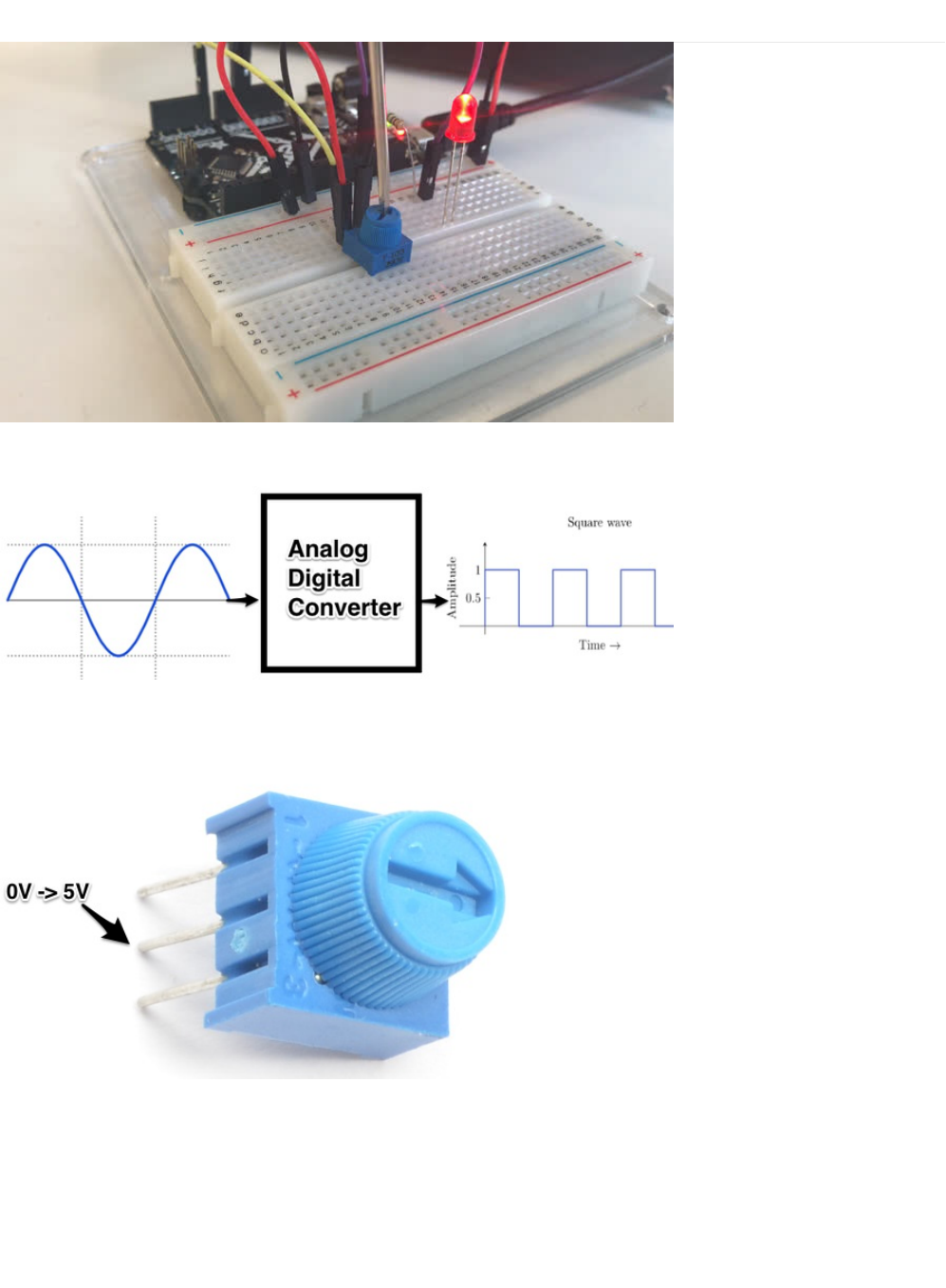
CIRC08: Twisting
Along with the digital pins, the Metro also has 6 pins which can be used for analog input.
These inputs take a voltage (from 0 to 5 volts) and convert it to a digital number between 0 (0 volts) and 1023 (5 volts) (10 bits of
resolution).
A very useful device that exploits these inputs is a potentiometer (also called a variable resistor). When it is connected with 5
volts across its outer pins the middle pin will read some value between 0 and 5 volts dependent on the angle to which it is
turned (ie. 2.5 volts in the middle). We can then use the returned values as a variable in our program.
© Adafruit Industries https://learn.adafruit.com/experimenters-guide-for-metro Page 116 of 317
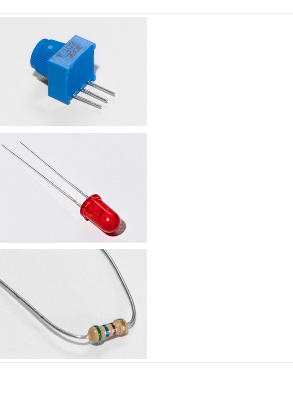
Parts
Breadboard Trim Potentiometer - 10k
If you'd like to buy an extra trimpot from the Adafruit store,
click here! (https://adafru.it/tba)
5mm Red LED
If you'd like to order more red LEDs (they make great
indicator lights!) from the Adafruit shop, click
here! (https://adafru.it/xeV)
560 Ohm Resistor
Colors: Green > Blue > Brown
If you'd like to order more resistors from the Adafruit shop
click here! (they are 470ohm but they'll be
fine) (https://adafru.it/x4E)
© Adafruit Industries https://learn.adafruit.com/experimenters-guide-for-metro Page 117 of 317
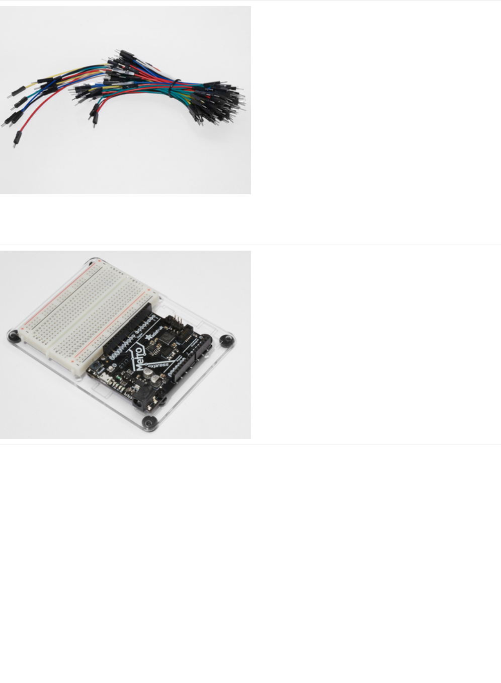
Breadboard Wiring Bundle
If you'd like to order more wires from the Adafruit shop click
here! (https://adafru.it/fE2)
Adafruit Metro (or Metro Express) + Breadboard +
Mounting Plate
If you have not assembled this, we have a handy
guide! (https://adafru.it/x2A)
If you'd like to order an extra plastic mounting
plate (https://adafru.it/x4F), Adafruit
Metro (https://adafru.it/METROXMETR), Adafruit Metro
Express (https://adafru.it/xoa), or Mini-
Breadboard (https://adafru.it/keP) from the Adafruit Shop click
here!
© Adafruit Industries https://learn.adafruit.com/experimenters-guide-for-metro Page 118 of 317
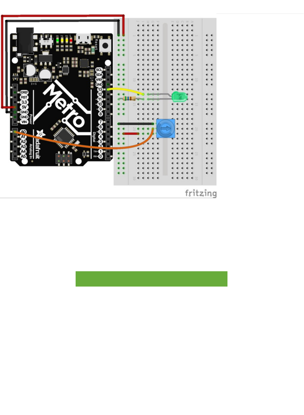
Wiring
CIRC08 is quick to wire up:
1. Longer end of the LED connects to a 560 ohm resistor, which connects to ground.
2. The shorter (cathode) end connects to the metro's digital Pin 13
3. The middle pin of the potentiometer connects to Analog Pin 0
4. Outer pins of the potentiometer connect to the 5V and GND rails.
Printable Breadboard Sheet
https://adafru.it/Atg
https://adafru.it/Atg
© Adafruit Industries https://learn.adafruit.com/experimenters-guide-for-metro Page 119 of 317
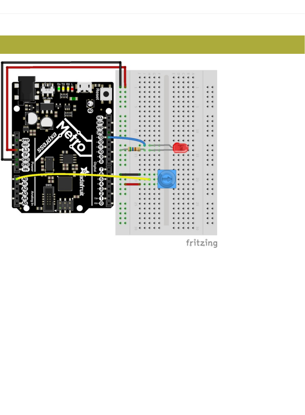
Wiring for Metro Express
If you are using the Adafruit Metro Express (https://adafru.it/xoa), the wiring below should be used. If you're not sure what board
you have, check this page. (https://adafru.it/METROXBOARDCHECK)
The power rail on your breadboard should connect to the 3.3V pin on the Metro Express
© Adafruit Industries https://learn.adafruit.com/experimenters-guide-for-metro Page 120 of 317

Code
Arduino includes this example, find it under: File > Examples > 3.Analog > Analog Input
Then compile and upload it to your metro (https://adafru.it/xap). Tweak the potentiometer to change the LEDs brightness.
If you are having trouble finding or loading the example, the code is below:
Not Working?
/*
Analog Input
Demonstrates analog input by reading an analog sensor on analog pin 0 and
turning on and off a light emitting diode(LED) connected to digital pin 13.
The amount of time the LED will be on and off depends on
the value obtained by analogRead().
The circuit:
* Potentiometer attached to analog input 0
* center pin of the potentiometer to the analog pin
* one side pin (either one) to ground
* the other side pin to +5V
* LED anode (long leg) attached to digital output 13
* LED cathode (short leg) attached to ground
* Note: because most Arduinos have a built-in LED attached
to pin 13 on the board, the LED is optional.
Created by David Cuartielles
modified 30 Aug 2011
By Tom Igoe
This example code is in the public domain.
http://www.arduino.cc/en/Tutorial/AnalogInput
*/
int sensorPin = A0; // select the input pin for the potentiometer
int ledPin = 13; // select the pin for the LED
int sensorValue = 0; // variable to store the value coming from the sensor
void setup() {
// declare the ledPin as an OUTPUT:
pinMode(ledPin, OUTPUT);
}
void loop() {
// read the value from the sensor:
sensorValue = analogRead(sensorPin);
// turn the ledPin on
digitalWrite(ledPin, HIGH);
// stop the program for <sensorValue> milliseconds:
delay(sensorValue);
// turn the ledPin off:
digitalWrite(ledPin, LOW);
// stop the program for for <sensorValue> milliseconds:
delay(sensorValue);
}
© Adafruit Industries https://learn.adafruit.com/experimenters-guide-for-metro Page 121 of 317

Sporadically Working
This is most likely due to a slightly dodgy connection with the potentiometer's pins. This can usually be fixed by taping the
potentiometer down.
Not Working?
Make sure you haven't accidentally connected the potentiometer's wiper to digital pin 0 rather than analog pin 0. (the row of
pins beneath the power pins)
Still Backwards?
You can try operating the circuit upside down. Sometimes this helps.
© Adafruit Industries https://learn.adafruit.com/experimenters-guide-for-metro Page 122 of 317

Using the Arduino Serial Plotter
We're going to start plotting...values! Arduino comes with a cool tool called the Serial Plotter. It can give you visualizations of
variables in real-time. This is super useful for visualizing data, troubleshooting your code, and visualizing your variables
as waveforms.
We are going to first need to modify the code for CIRC08. Copy and paste the code below into the Arduino Editor. Then compile
and upload.
When you call Serial.println(value) , the Serial Plotter will put that variable on the plot. The Y-Axis of the plot auto-resizes.
/*
Analog Input, but with Serial Plotter!
Demonstrates analog input by reading an analog sensor on analog pin 0 and
turning on and off a light emitting diode(LED) connected to digital pin 13.
The amount of time the LED will be on and off depends on
the value obtained by analogRead().
The circuit:
* Potentiometer attached to analog input 0
* center pin of the potentiometer to the analog pin
* one side pin (either one) to ground
* the other side pin to +5V
* LED anode (long leg) attached to digital output 13
* LED cathode (short leg) attached to ground
* Note: because most Arduinos have a built-in LED attached
to pin 13 on the board, the LED is optional.
Created by David Cuartielles
modified 30 Aug 2011
By Tom Igoe
This example code is in the public domain.
http://www.arduino.cc/en/Tutorial/AnalogInput
*/
int sensorPin = A0; // select the input pin for the potentiometer
int ledPin = 13; // select the pin for the LED
int sensorValue = 0; // variable to store the value coming from the sensor
void setup() {
// declare the ledPin as an OUTPUT:
pinMode(ledPin, OUTPUT);
// begin the serial monitor @ 9600 baud
Serial.begin(9600);
}
void loop() {
// read the value from the sensor:
sensorValue = analogRead(sensorPin);
Serial.println(sensorValue);
Serial.print(" ");
delay(20);
}
© Adafruit Industries https://learn.adafruit.com/experimenters-guide-for-metro Page 123 of 317
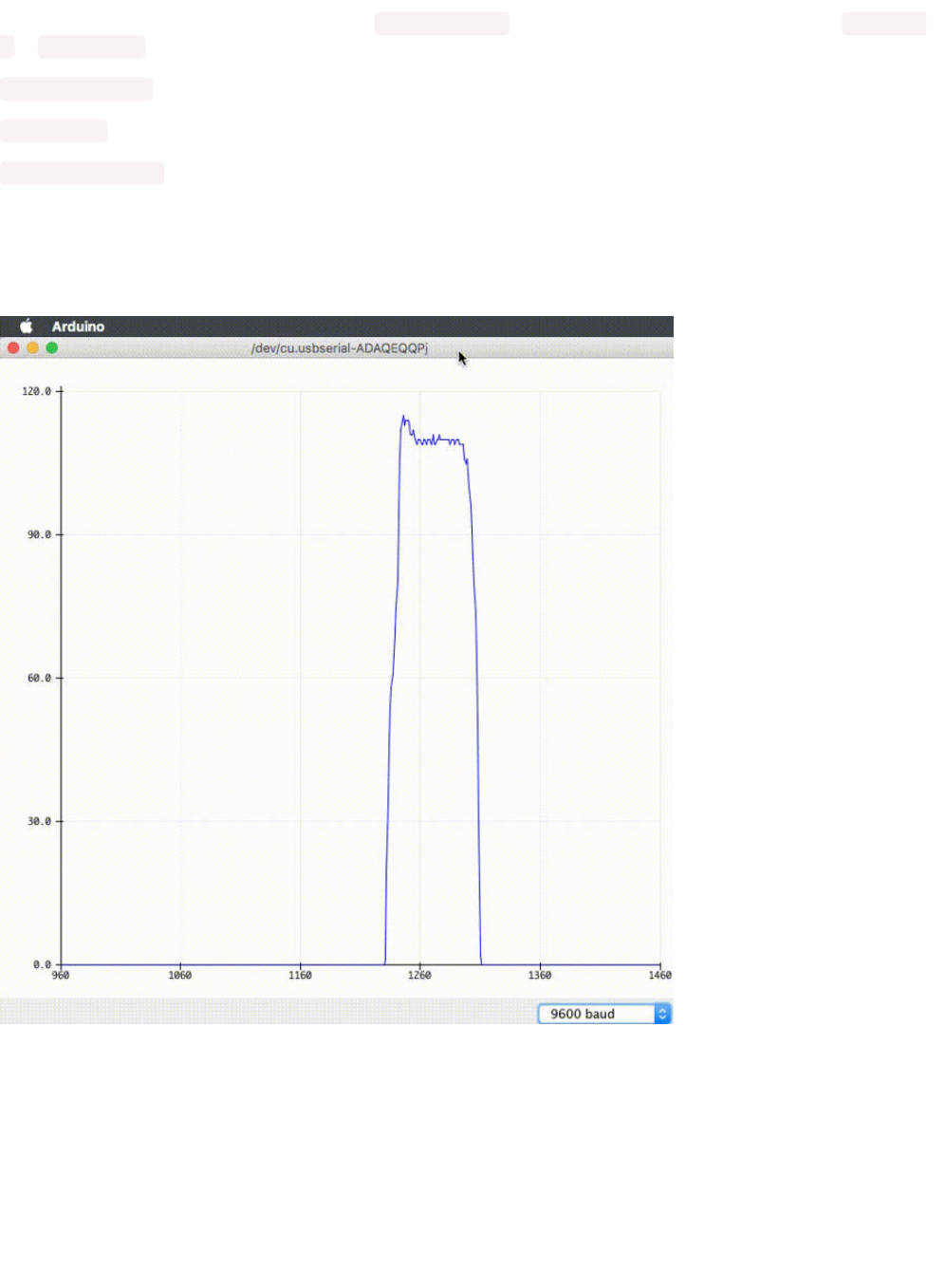
If you want to plot multiple variables, you'll need a Serial.println(value) call for each of the variables, separated by a Serial.print("
") or Serial.print("\t") :
Serial.print(variable1);
Serial.print(" ");
Serial.println(variable2);
Let's try it out with the new code above. Compile and upload the program above, then navigate to Tools > Serial Plotter. The
code uses a baud rate of 9600, make sure it's set in the serial monitor as 9600 too.
You should see something like this when you twist the trim potentiometer around:
© Adafruit Industries https://learn.adafruit.com/experimenters-guide-for-metro Page 124 of 317

Make It Better
Threshold Switching
Sometimes you will want to switch an output when a value exceeds a certain threshold.
To do this with a potentiometer, change the loop() code to:
This will cause the LED to turn on when the value is above 512 (halfway on the potentiometer dial), you can adjust the sensitivity
by changing the threshold value.
Fading
Let's control the brightness of an LED directly from the potentiometer. To do this we need to first change the pin the LED is
connected to.
Move the wire from Pin 13 to Pin 9 and change the following line in the code:
int ledPin = 13; -> int ledPin = 9;
Then, change the loop code to:
Upload the code and watch as your LED fades in relation to your potentiometer spinning. (
Note
: the reason we divide the value
by 4 is the analogRead() function returns a value from 0 to 1023 (10 bits), and analogWrite() takes a value from 0 to 255 (8 bits))
Controlling the servo
void loop() {
int threshold = 512;
if(analogRead(sensorPin) > threshold) {
digitalWrite(ledPin, HIGH);
}
else {
digitalWrite(ledPin, LOW);
}
}
void loop() {
int value = analogRead(potPin) / 4;
analogWrite(ledPin, value);
}
© Adafruit Industries https://learn.adafruit.com/experimenters-guide-for-metro Page 125 of 317
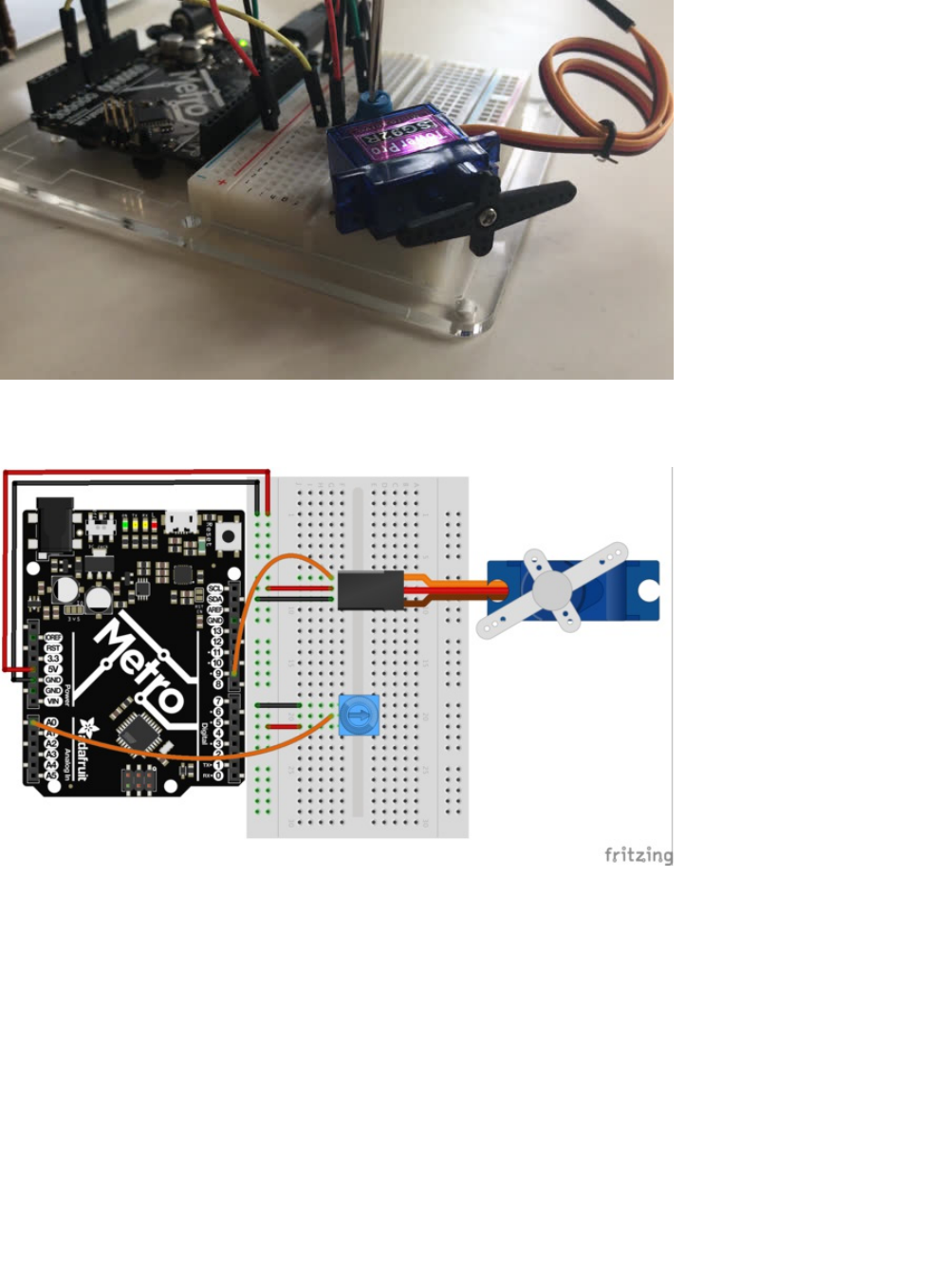
This is a really neat example and brings a couple of circuits changing the threshold value. Wire up the servo like you did in CIRC-
04:
Then, open the example program Knob (File > Examples > Servo > Knob). Upload to your METRO and then watch as the servo
shaft turns as you turn the potentiometer.
© Adafruit Industries https://learn.adafruit.com/experimenters-guide-for-metro Page 126 of 317
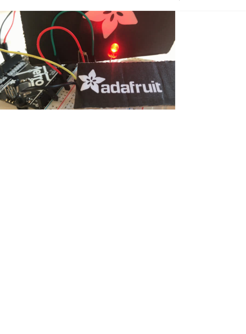
CIRC09: Light
Whilst getting input from a potentiometer can be useful for human controlled experiments, what do we use when we want an
environmentally controlled experiment?
We use exactly the same principles but instead of a potentiometer (twist based resistance) we use a photo resistor (light based
resistance). The Metro cannot directly sense resistance (it senses voltage) so we set up a voltage divider (). The exact voltage at
the sensing pin i
s calculable
, but for our purposes (just sensing relative light) we can experiment with the values and see what
works for us.
A low value will occur when the sensor is well lit
while a high value will occur when it is in darkness.
© Adafruit Industries https://learn.adafruit.com/experimenters-guide-for-metro Page 127 of 317
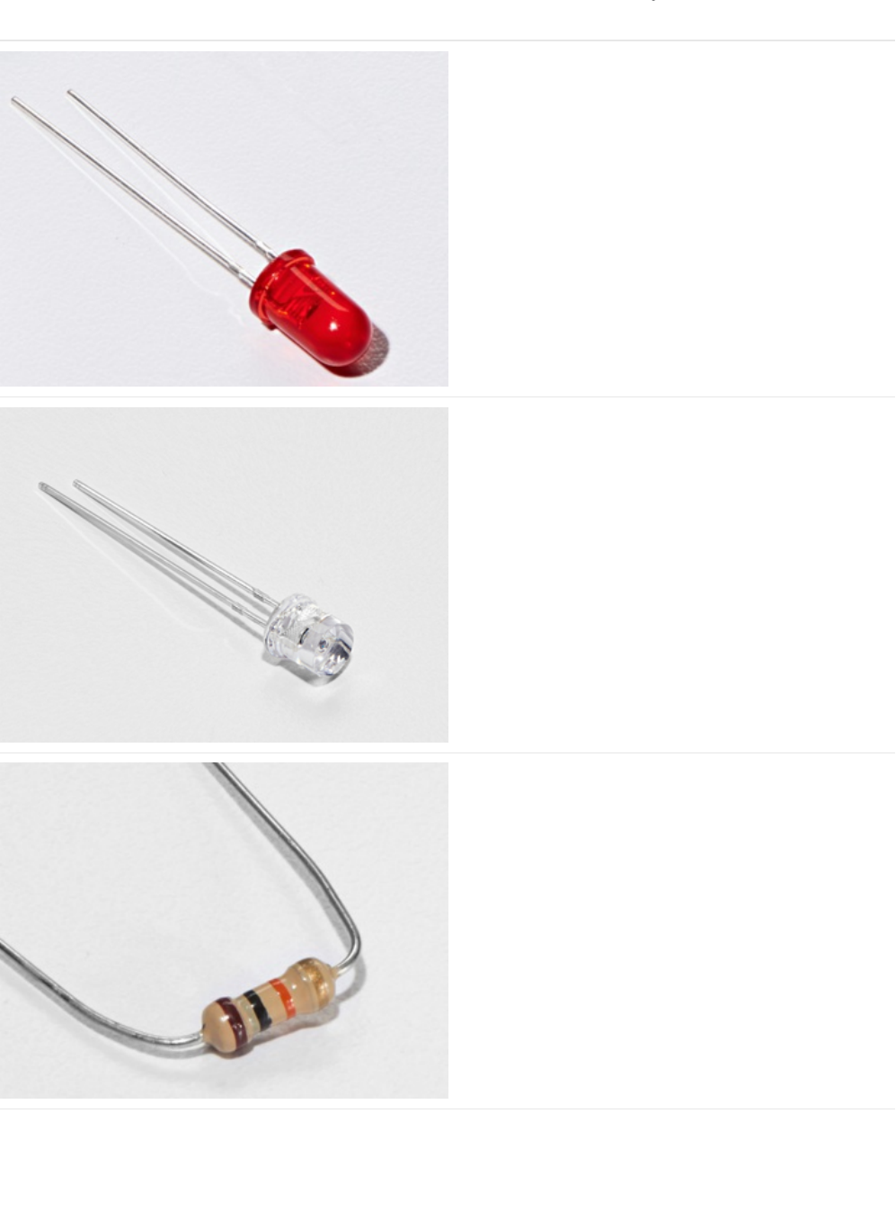
Parts
5mm Red LED
If you'd like to order more red LEDs (they make great
indicator lights!) from the Adafruit shop, click
here! (https://adafru.it/xeV)
Photo Sensor
If you'd like to order another photoresistor from the Adafruit
shop, click here! (https://adafru.it/xfo)
10K Ohm Resistor
Colors: Brown > Black > Orange
If you'd like to order more 10k ohm pull-up resistors from the
Adafruit shop, click here! (https://adafru.it/xfm)
© Adafruit Industries https://learn.adafruit.com/experimenters-guide-for-metro Page 128 of 317

560 Ohm Resistor
Colors: Green > Blue > Brown
If you'd like to order more resistors from the Adafruit shop
click here! (they are 470ohm but they'll be
fine) (https://adafru.it/x4E)
Breadboard Wiring Bundle
If you'd like to order more wires from the Adafruit shop click
here! (https://adafru.it/fE2)
Adafruit Metro (or Metro Express) + Breadboard +
Mounting Plate
If you have not assembled this, we have a handy
guide! (https://adafru.it/x2A)
If you'd like to order an extra plastic mounting
plate (https://adafru.it/x4F), Adafruit
Metro (https://adafru.it/METROXMETR), Adafruit Metro
Express (https://adafru.it/xoa), or Mini-
Breadboard (https://adafru.it/keP) from the Adafruit Shop click
here!
© Adafruit Industries https://learn.adafruit.com/experimenters-guide-for-metro Page 129 of 317
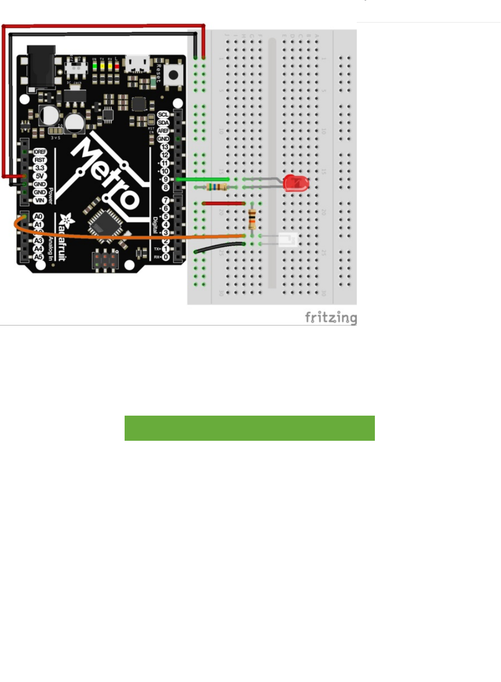
Wiring
1. Wire up the LED: anode to pin 9. Cathode to a 560 ohm resistor and then to ground.
2. Wire up the Photoresistor. Connect one end of the 10k ohm resistor to the power rail. Connect the other end of it to A0 and
one end of the the photoresistor. The other end of the resistor should be grounded.
Printable Breadboard Layout Sheet
https://adafru.it/Ath
https://adafru.it/Ath
© Adafruit Industries https://learn.adafruit.com/experimenters-guide-for-metro Page 130 of 317
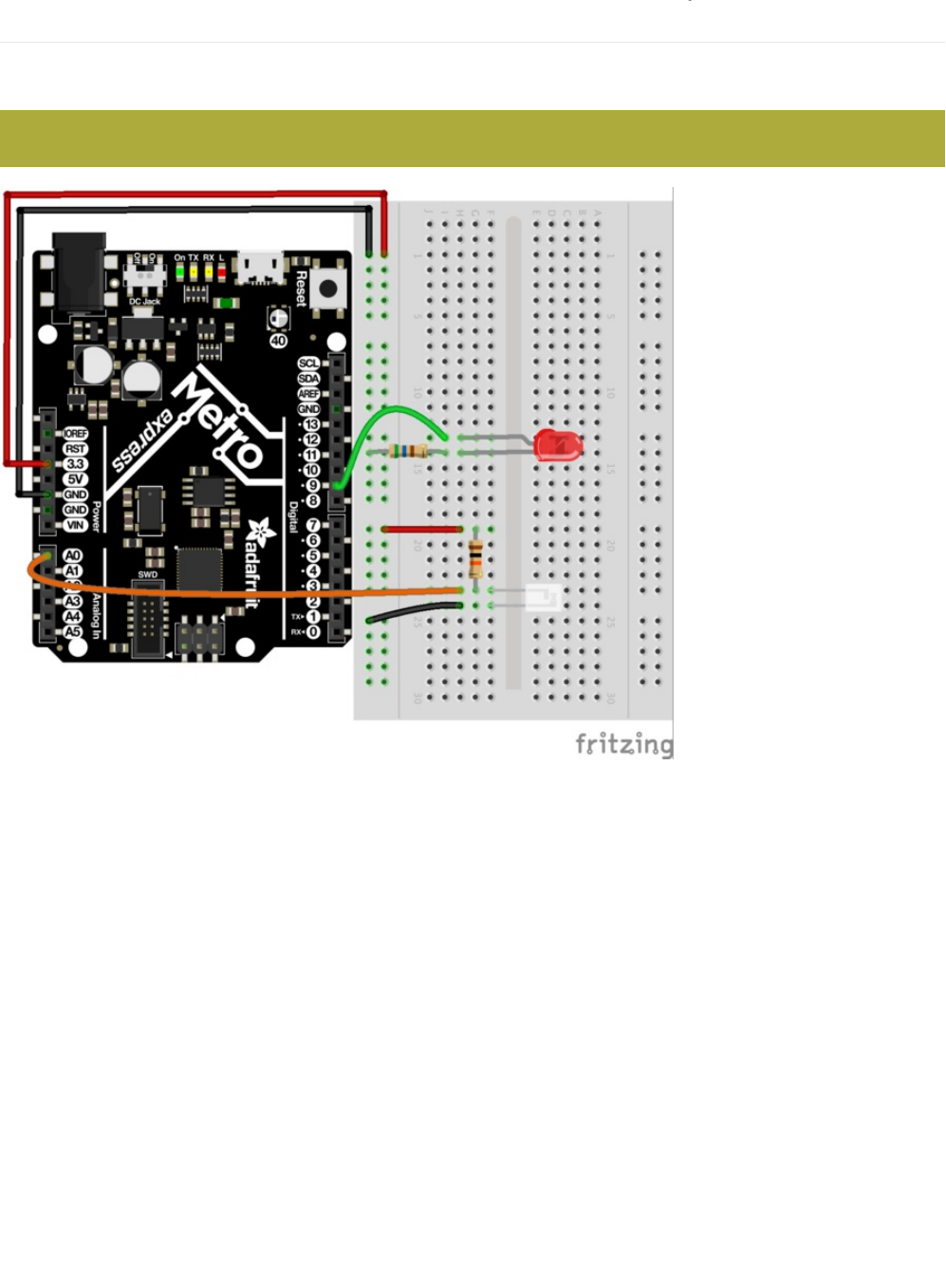
Wiring for Metro Express
If you are using the Adafruit Metro Express (https://adafru.it/xoa), the wiring below should be used. If you're not sure what board
you have, check this page. (https://adafru.it/METROXBOARDCHECK)
The power rail on your breadboard should connect to the 3.3V pin on the Metro Express
© Adafruit Industries https://learn.adafruit.com/experimenters-guide-for-metro Page 131 of 317

Code
Copy and paste the code below into a new Arduino sketch. Then, compile and upload it to your metro (https://adafru.it/xap).
Not Working?
LED Remains Dark
This is a mistake we continue to make time and time again, if only they could make an LED that worked both ways. Pull it up
and give it a twist.
It Isn't Responding to Changes in Light.
Given that the spacing of the wires on the photo-resistor is not standard, it is easy to misplace it. Double check its in the right
place.
Still not quite working?
You may be in a room which is either too bright or dark. Try turning the lights on or off to see if this helps. Or if you have a
flashlight near by give that a try.
// CIRC09 - Light
int lightPin = A0;
int ledPin = 9;
void setup()
{
pinMode(ledPin, OUTPUT);
}
void loop()
{
int lightLevel = analogRead(lightPin);
lightLevel = map(lightLevel, 0, 700, 0, 255);
analogWrite(ledPin, lightLevel);
}
If you're having issues with the Photo Sensor: flip it around, chances are the orientation is backwards.
© Adafruit Industries https://learn.adafruit.com/experimenters-guide-for-metro Page 132 of 317

Make It Better
Reverse the Response
Perhaps you would like the opposite response. Don't worry we can easily reverse this response just change:
analogWrite(ledPin, lightLevel); -> analogWrite(ledPin, 255 - lightLevel);
Upload your modified sketch and watch the response change.
Night Light
Rather than controlling the brightness of the LED in response to light, lets instead turn it on or off based on a threshold value.
Change the loop() code with:
Light Controlled Servo
Lets use our newly found light sensing skills to control a servo (and at the same time engage in a little bit of Arduino code
hacking). Wire up a servo connected to pin 9 (like in CIRC-04). Then open the Knob example program (the same one we used in
CIRC-08) File > Examples > Library-Servo > Knob. Upload the code to your board and watch as it works unmodified.
void loop(){
int threshold = 300;
if(analogRead(lightPin) > threshold){
digitalWrite(ledPin, HIGH);
}
else{
digitalWrite(ledPin, LOW);
}
}
This circuit uses the same wiring for both the Metro and the Metro Express. Make sure your power rail is plugged into
3V instead of 5V.
© Adafruit Industries https://learn.adafruit.com/experimenters-guide-for-metro Page 133 of 317

Using the full range of your servo
You'll notice that the servo will only operate over a limited portion of its range. This is because with the voltage dividing circuit
we use the voltage on analog pin 0 will not range from 0 to 5 volts but instead between two lesser values (these values will
change based on your setup). To fix this play with the line: val = map(val, 0, 1023, 0, 179); (For hints on what to do, click
here (https://adafru.it/aQm))
Learn More!
If you'd like to understand the magic behind the photo sensor, we have a learn guide explaining more about this
subject (https://adafru.it/xfX)
© Adafruit Industries https://learn.adafruit.com/experimenters-guide-for-metro Page 134 of 317
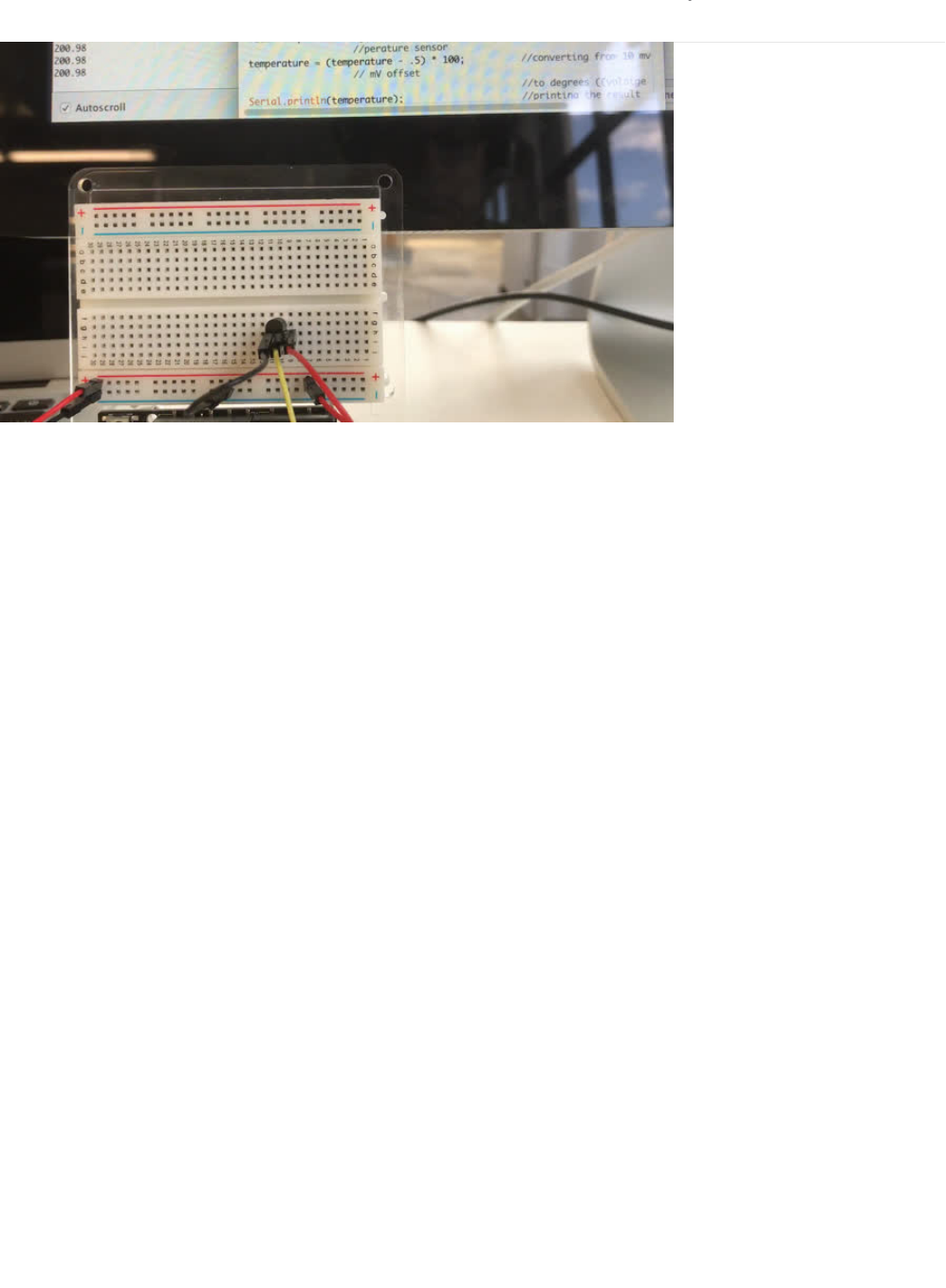
CIRC10: Temperature
What's the next phenomenon we will measure with our Metro? Temperature.
To do this we'll use a rather complicated IC (integrated circuit) hidden in a package identical to our P2N2222AG transistors, the
TMP36. It has three pin's, ground, signal and power..and is easy to use.
It outputs 10 millivolts per degree centigrade on the signal pin (to allow measuring temperatures below freezing there is a 500
mV offset eg. 25 degrees C = 750 mV, 0 degrees C = 500mV). To convert this from the digital value to degrees, we will use
some of the Arduino's math abilities. Then to display it we'll use one of the IDE's rather powerful features, the debug window.
We'll output the value over a serial connection to display on the screen. Let's get to it.
One extra note, this circuit uses the Arduino IDE's serial monitor. To open this, first upload the program then click the button
which looks like a square with an antennae.
© Adafruit Industries https://learn.adafruit.com/experimenters-guide-for-metro Page 135 of 317
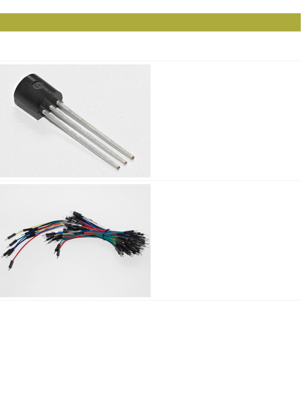
Parts
Am I using a NPN Transistor or a TMP36 Temperature Sensor? (https://adafru.it/ytD)
Analog Temperature Sensor
If you'd like an extra temperature sensor, you can grab one
from the Adafruit shop, click here (https://adafru.it/xfq)
Breadboard Wiring Bundle
If you'd like to order more wires from the Adafruit shop click
here! (https://adafru.it/fE2)
The Analog Temperature Sensor looks a LOT like the NPN Transistor, make sure it says "TMP36" on it!
© Adafruit Industries https://learn.adafruit.com/experimenters-guide-for-metro Page 136 of 317
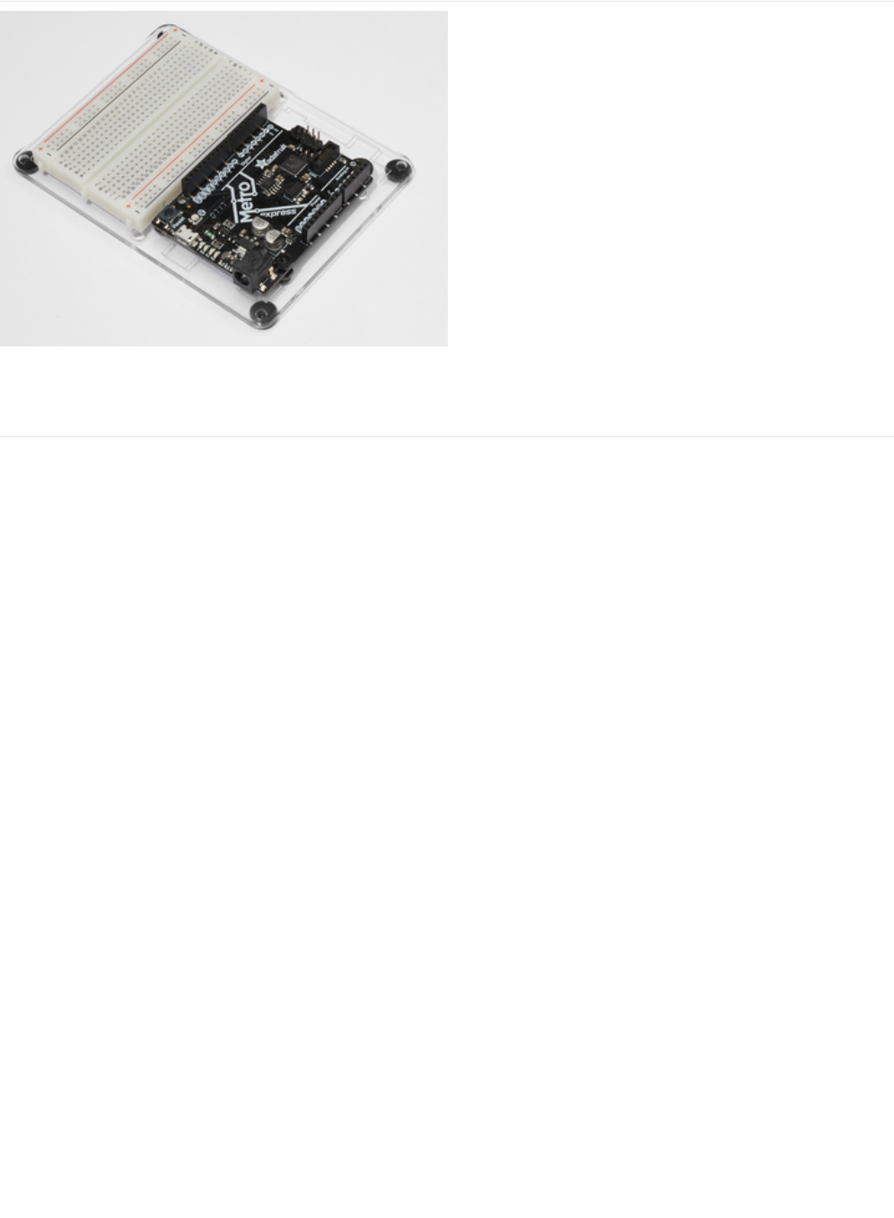
Adafruit Metro (or Metro Express) + Breadboard +
Mounting Plate
If you have not assembled this, we have a handy
guide! (https://adafru.it/x2A)
If you'd like to order an extra plastic mounting
plate (https://adafru.it/x4F), Adafruit
Metro (https://adafru.it/METROXMETR), Adafruit Metro
Express (https://adafru.it/xoa), or Mini-
Breadboard (https://adafru.it/keP) from the Adafruit Shop click
here!
© Adafruit Industries https://learn.adafruit.com/experimenters-guide-for-metro Page 137 of 317
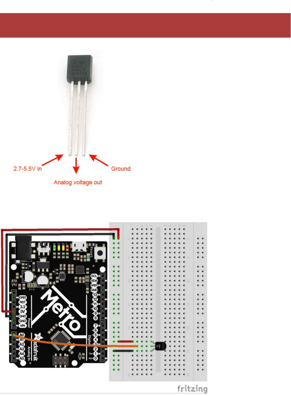
Wiring
Wire it up
Pay attention to the pinout of the Temperature Sensor. Wiring it incorrectly heat it up quickly. Unplug this the metro
from power BEFORE touching the sensor.
© Adafruit Industries https://learn.adafruit.com/experimenters-guide-for-metro Page 138 of 317

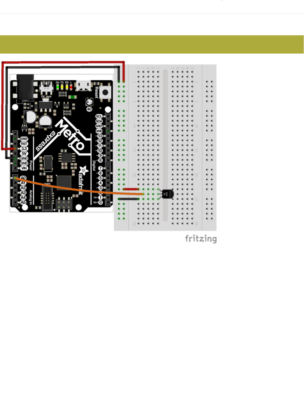
Wiring for Metro Express
If you are using the Adafruit Metro Express (https://adafru.it/xoa), the wiring below should be used. If you're not sure what board
you have, check this page. (https://adafru.it/METROXBOARDCHECK)
The power rail on your breadboard should connect to the 3.3V pin on the Metro Express
© Adafruit Industries https://learn.adafruit.com/experimenters-guide-for-metro Page 140 of 317

Code
Copy/Paste the code below.
Then compile and upload it to your metro (https://adafru.it/xap).
Using the Arduino Serial Monitor
/*
* CIRC10: Temperature
* for use with both the Metro and Metro Express
*
* by Brent Rubell for Adafruit Industries. Support Open Source, buy Adafruit!
*/
#define ANALOGREFVOLTAGE 5.555
//TMP36 Pin
int temperaturePin = A0;
void setup() {
// Start the Serial connection
Serial.begin(9600);
}
void loop() {
float temperature = 0;
temperature = getVoltage(temperaturePin);
Serial.println(temperature);
// Convert to degrees C
temperature = (temperature - .5) * 100;
Serial.println(temperature);
delay(1000);
}
float getVoltage(int pin) {
return(float(analogRead(pin))* float(ANALOGREFVOLTAGE/1023.000));
}
© Adafruit Industries https://learn.adafruit.com/experimenters-guide-for-metro Page 141 of 317
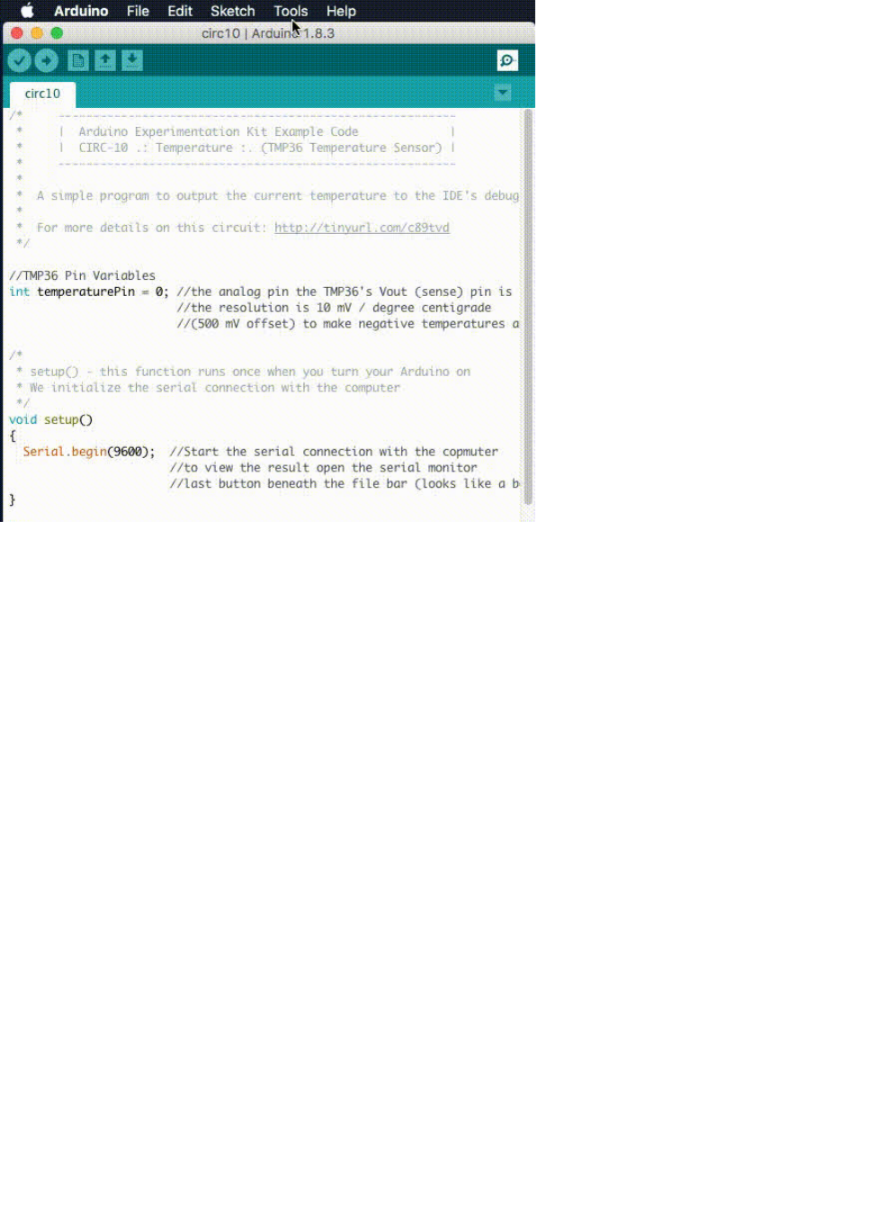
Click on the magnifying glass icon on the toolbar of the Arduino IDE. You should see the serial monitor pop up and start printing
out numbers.
Not Working?
Nothing Seems to Happen
This program has no outward indication it is working. To see the results you must open the Arduino IDE's serial monitor.
Gibberish is Displayed
This happens because the serial monitor is receiving data at a different speed than expected. To fix this, click the pull-down
box that reads "*** baud" and change it to "9600 baud".
Temperature Value is Unchanging
Try pinching the sensor with your fingers to heat it up or pressing a bag of ice against it to cool it down.
© Adafruit Industries https://learn.adafruit.com/experimenters-guide-for-metro Page 142 of 317

Make It Better
Outputting Voltage
This is a simple matter of changing
one
line. Our sensor outputs 10mv per degree centigrade so to get voltage we simply display
the result of getVoltage() . Delete the line:
temperature = (temperature - .5) * 100;
Outputting degrees Fahrenheit
Again this is a simple change requiring only math. to go degrees C
->
degrees F we use the formula:
( F = C * 1.8) + 32 )
Add the line:
temperature = (((temperature - .5) * 100)*1.8) + 32; before Serial.println(temperature);
More informative output
Lets add a message to the serial output to make what is appearing in the Serial Monitor more informative.
To do this, change this line:
Serial.println(temperature);
to:
Serial.print(temperature);
Then, we add another line with informative text about the temperature on a new line:
Serial.println(" degrees centigrade");
The change to the first line means when we next output it will appear on the same line.
Changing the serial speed
If you ever wish to output a lot of data over the serial line time is of the essence. We are currently transmitting at 9600 baud but
much faster speeds are possible.
To change this change the line:
Serial.begin(9600);
to:
Serial.begin(115200);
Upload the sketch turn on the serial monitor, then change the speed from 9600 baud to 115200 baud in the pull down menu.
You are now transmitting data
12 times faster.
© Adafruit Industries https://learn.adafruit.com/experimenters-guide-for-metro Page 143 of 317

CIRC10.5: Temperature Alarm
CIRC10 only works when you are connected to the serial monitor. Let's free your board from wires and make a free-standing
circuit!
This is a
bonus
circuit!! We are going to make a free-standing alarm to alert us if it's too hot/cold.
Running the Metro Express off a 9V Battery
One of the included parts in the Experimenter's Kit is the 9V battery clip (https://adafru.it/fkN).
If you have a 9V battery, snap it into the clip and plug the clip into the barel-jack of the Metro:
Our temperature sensor is now running off of a 9V battery. This is awesome, but we still have no way to be alerted of
temperatures getting too hot/cold.
Add a Piezo!
The Piezo element was first introduced in CIRC06. You send it digital output and it buzzes. Next up is buzzing the piezo when it
exceeds a certain temperature. The Piezo can be used as an alarm with minimal modifications to the circuit:
© Adafruit Industries https://learn.adafruit.com/experimenters-guide-for-metro Page 144 of 317
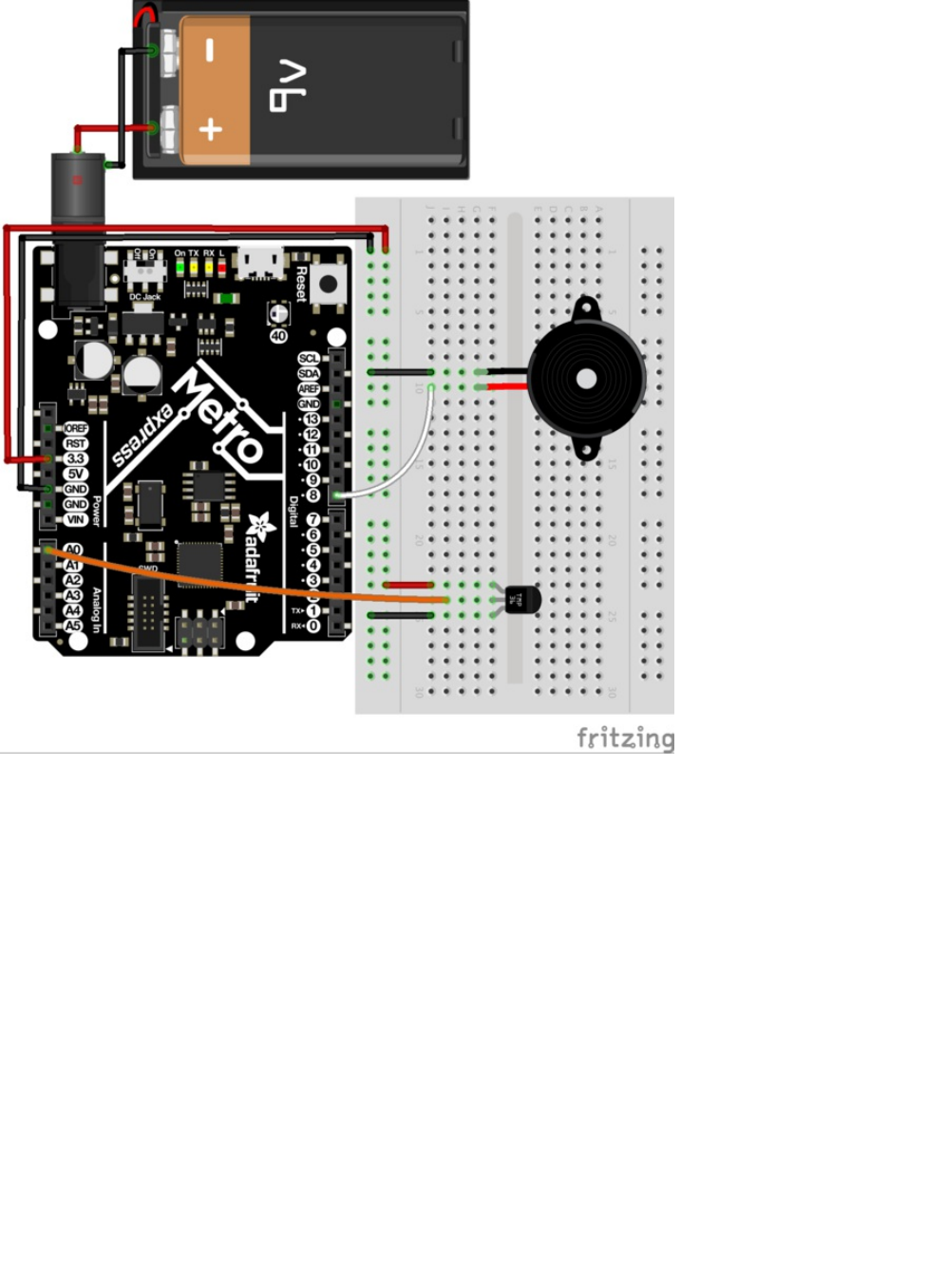
Code for the temperature alarm is below (copy and paste it into a blank Arduino sketch), compile and upload it to your Metro:
© Adafruit Industries https://learn.adafruit.com/experimenters-guide-for-metro Page 145 of 317

Changing the variables
We predefined freezing and boiling variables in Celsius, but if you want to use Fahrenheit (or kelvin (https://adafru.it/xxc) just
change the variables below to other values:
float freezeTemp = 0;
float boilTemp = 26;
/* CIRC10.5: Temperature Alarm
* (a bonus circuit for MetroX)
*
* by Brent Rubell for Adafruit Industries
*/
#define ANALOGREFVOLTAGE 5.555
// TMP36 Pin
int temperaturePin = A0;
// Piezo Pin
int piezoPin = 8;
// Freezing
float freezeTemp = 0;
// Boiling
float boilTemp = 26;
void setup()
{
// Start the Serial connection
Serial.begin(9600);
}
void loop()
{
float temperature = 0;
temperature = getVoltage(temperaturePin);
// Convert to degrees C
temperature = (temperature - .5) * 100;
Serial.println(temperature);
if(temperature < freezeTemp) {
tone(piezoPin, 1100, 1000);
}
else if(temperature > boilTemp) {
tone(piezoPin, 1100, 1000);
}
delay(1000);
}
float getVoltage(int pin) {
return(float(analogRead(pin))* float(ANALOGREFVOLTAGE/1023.000));
}
© Adafruit Industries https://learn.adafruit.com/experimenters-guide-for-metro Page 146 of 317
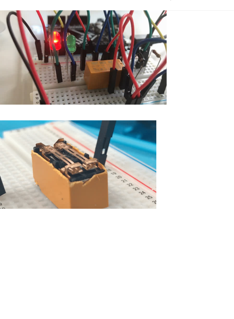
CIRC11: Larger Loads with Relays
This next circuit is a bit of a challenge. We combine what we learned about using transistors in CIRC03 to control a relay.
A relay is an electrically controlled mechanical switch. Inside the little plastic box is an electromagnet that, when energized,
causes a switch to trip (often with a very satisfying clicking sound). You can buy relays that vary in size from a quarter of the size
of the one in this kit up to as big as a fridge, each capable of switching a certain amount of current. They are immensely fun
because there is an element of the physical to them.
While all the silicon we've played with to this point is fun sometimes, you may just want to wire up a hundred switches to control
something magnificent. Relays give you the ability to dream it up then control it with your Arduino. Now onto using today's
technology to control the past. (The 1N4001 diode is acting as a flyback diode (https://adafru.it/xfs), click here for more info about
flyback diodes)
© Adafruit Industries https://learn.adafruit.com/experimenters-guide-for-metro Page 147 of 317
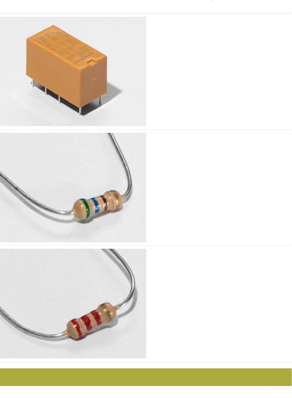
Parts
DPDT Relay
560 Ohm Resistor
QTY: x2
Colors: Green > Blue > Brown
If you'd like to order more resistors from the Adafruit shop
click here! (they are 470ohm but they'll be
fine) (https://adafru.it/x4E)
2.2k Ohm Resistor
Colors: Red > Red > Red
If you'd like to order extra 2.2k Ohm resistors from the
Adafruit shop, click here! (https://adafru.it/xao)
This circuit uses a NPN Transistor, NOT a TMP36 Sensor.
© Adafruit Industries https://learn.adafruit.com/experimenters-guide-for-metro Page 148 of 317
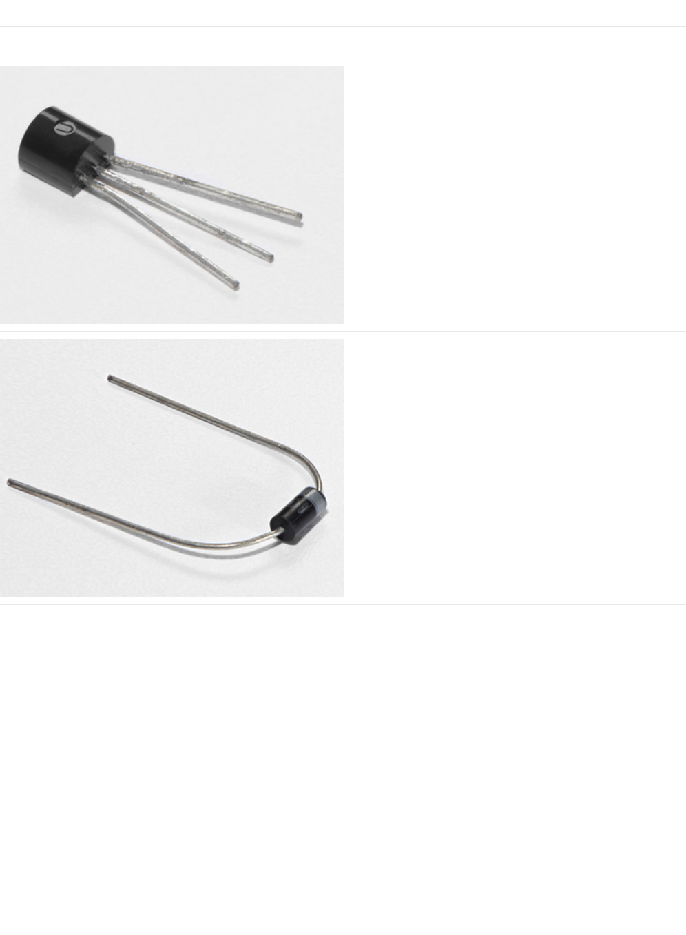
Am I using a NPN Transistor or a TMP36 Temperature Sensor? (https://adafru.it/ytD)
Transistor (PN2222 or MPS2222)
If you'd like to order extra NPN transistors from the Adafruit
shop, click here! (https://adafru.it/xam)
Diode (1N4001)
If you'd like to order more diodes from the Adafruit shop,
click here! (https://adafru.it/ijA)
© Adafruit Industries https://learn.adafruit.com/experimenters-guide-for-metro Page 149 of 317
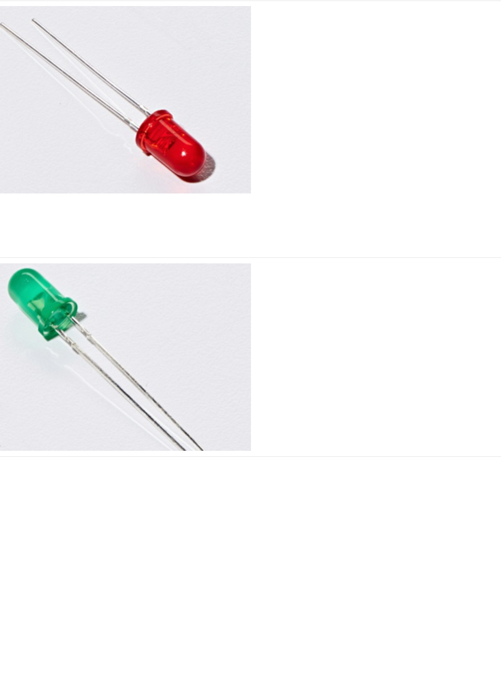
5mm Red LED
If you'd like to order more red LEDs (they make great
indicator lights!) from the Adafruit shop, click
here! (https://adafru.it/xeV)
5mm Green LED
If you'd like to order extra green LEDs from the Adafruit shop,
click here! (https://adafru.it/x5b)
© Adafruit Industries https://learn.adafruit.com/experimenters-guide-for-metro Page 150 of 317
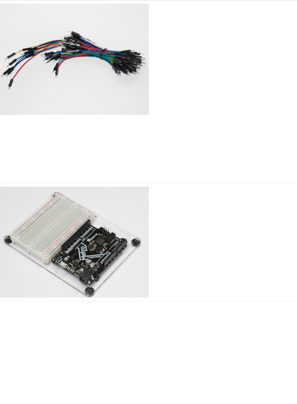
Breadboard Wiring Bundle
If you'd like to order more wires from the Adafruit shop click
here! (https://adafru.it/fE2)
Adafruit Metro (or Metro Express) + Breadboard +
Mounting Plate
If you have not assembled this, we have a handy
guide! (https://adafru.it/x2A)
If you'd like to order an extra plastic mounting
plate (https://adafru.it/x4F), Adafruit
Metro (https://adafru.it/METROXMETR), Adafruit Metro
Express (https://adafru.it/xoa), or Mini-
Breadboard (https://adafru.it/keP) from the Adafruit Shop click
here!
© Adafruit Industries https://learn.adafruit.com/experimenters-guide-for-metro Page 151 of 317
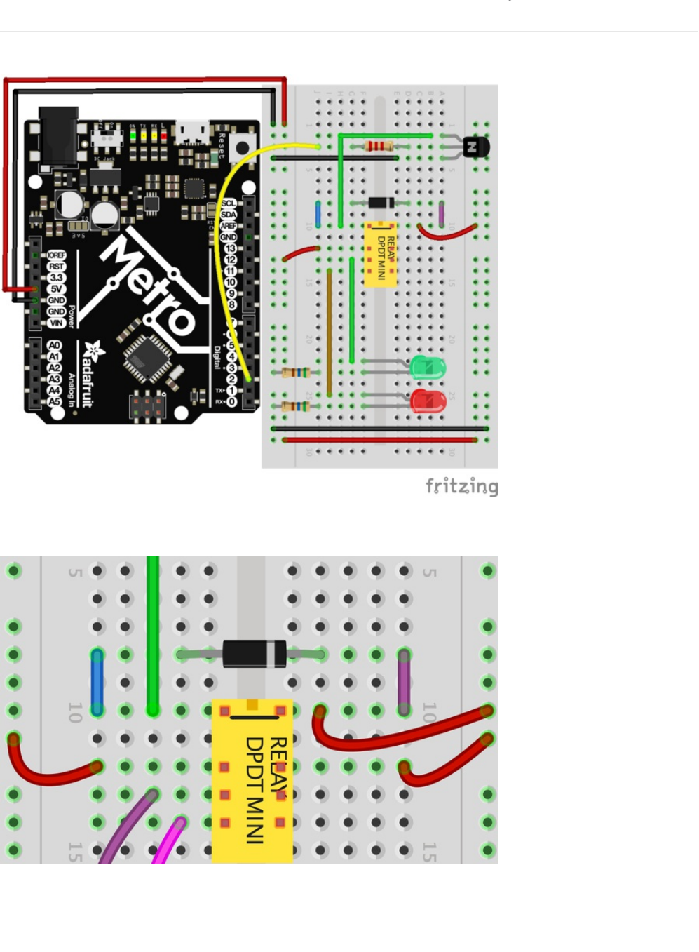
Wiring
Wire it up:
Close-up of the relay wiring
Make sure the small square at the top of the DPDT Relay faces the top of the breadboard. Also, ensure the stripe on the diode
faces the right side of the DPDT Relay.
© Adafruit Industries https://learn.adafruit.com/experimenters-guide-for-metro Page 152 of 317


Code
Copy and paste the code below into a blank Arduino sketch. Then compile and upload it to your Metro (https://adafru.it/xap).
Not Working?
Nothing is happening
The example code uses pin 13 and we have the relay connected to pin 2. Make sure you made this change in the code:
LED_BUILTIN -> 2
No clicking sound
The transistor or coil portion of the circuit isn't quite working. Check the transistor is plugged in the right way.
Not quite working, or not working correctly
The included relays are designed to be soldered rather than used in a breadboard. As such you may need to press it in to
ensure it works (and it may pop out occasionally).
// CIRC11 - Relay
int relayPin = 2;
void setup() {
pinMode(relayPin, OUTPUT);
}
void loop() {
digitalWrite(relayPin, HIGH);
delay(1000);
digitalWrite(relayPin, LOW);
delay(1000);
}
© Adafruit Industries https://learn.adafruit.com/experimenters-guide-for-metro Page 154 of 317
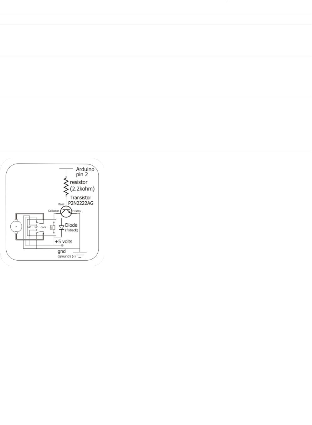
Make It Better
Check out the Back-EMF Pulse
Replace the diode with an LED. You'll see it blink each time it "snubs" the coil voltage spike when it turns off.
Controlling a Motor
In CIRC-03 we controlled a motor using a transistor. However if you want to control a larger motor a relay is a good option. To do
this, simply remove the red LED and connect the motor in its place.
Controlling Motor Direction
A bit of a complicated improvement to finish. To control the direction of spin of a DC motor we must be able to reverse the
direction of current flow through it. To do this manually we reverse the leads. To do it electrically we require something called an
h-bridge. This can be done using a DPDT relay to control the motor's direction, wire up the following circuit. It looks complicated
but can be accomplished using only a few extra wires. Give it a try.
Schematic Layout
Breadboard Layout
© Adafruit Industries https://learn.adafruit.com/experimenters-guide-for-metro Page 155 of 317
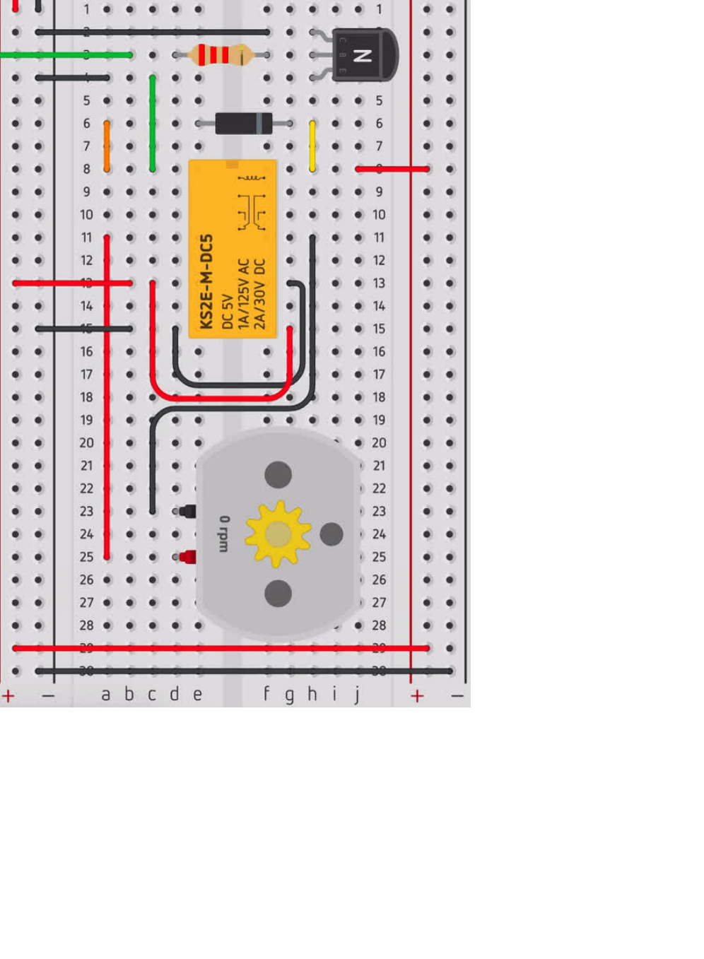
© Adafruit Industries https://learn.adafruit.com/experimenters-guide-for-metro Page 156 of 317
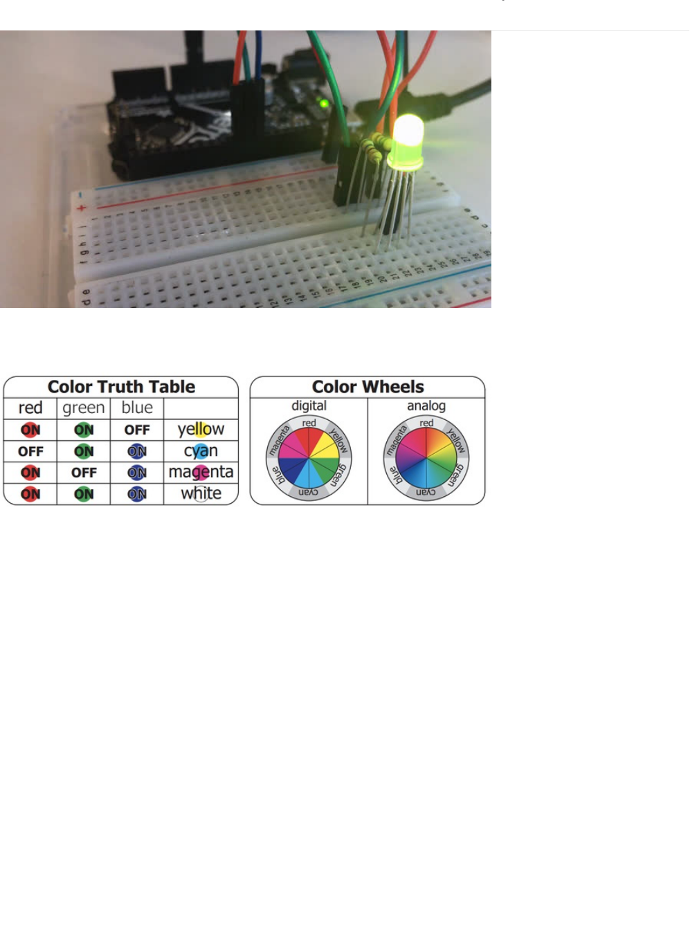
CIRC12: Colorful Light
We've blinked an LED and controlled eight in sequence. Now it's time to control color. Using an RGB LED (actual 3 LEDs in a
single housing) we can generate any color our heart desires.
We do this through color mixing, what’s required is delving back to your elementary art days of playing with colored cellophane
to produce different colors (if you can’t remember that far back don’t worry here’s a color wheel to help you out).
© Adafruit Industries https://learn.adafruit.com/experimenters-guide-for-metro Page 157 of 317
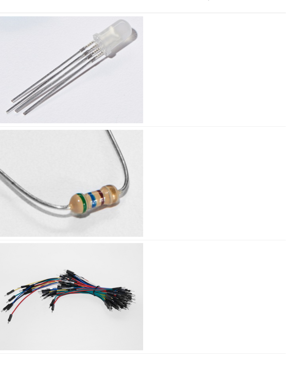
Parts
RGB LED
If you'd like to pick up another RGB LED from the Adafruit
Shop, click here. (https://adafru.it/xfQ)
560 Ohm Resistor
QTY: x3
Colors: Green > Blue > Brown
If you'd like to order more resistors from the Adafruit shop
click here! (they are 470ohm but they'll be
fine) (https://adafru.it/x4E)
Breadboard Wiring Bundle
If you'd like to order more wires from the Adafruit shop click
here! (https://adafru.it/fE2)
© Adafruit Industries https://learn.adafruit.com/experimenters-guide-for-metro Page 158 of 317
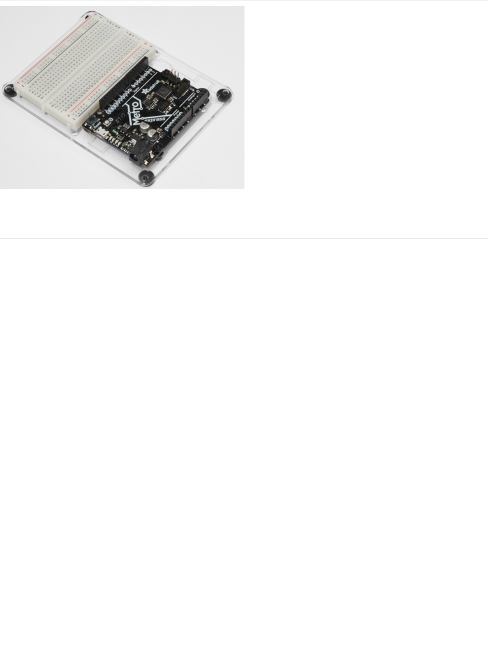
Adafruit Metro (or Metro Express) + Breadboard +
Mounting Plate
If you have not assembled this, we have a handy
guide! (https://adafru.it/x2A)
If you'd like to order an extra plastic mounting
plate (https://adafru.it/x4F), Adafruit
Metro (https://adafru.it/METROXMETR), Adafruit Metro
Express (https://adafru.it/xoa), or Mini-
Breadboard (https://adafru.it/keP) from the Adafruit Shop click
here!
© Adafruit Industries https://learn.adafruit.com/experimenters-guide-for-metro Page 159 of 317
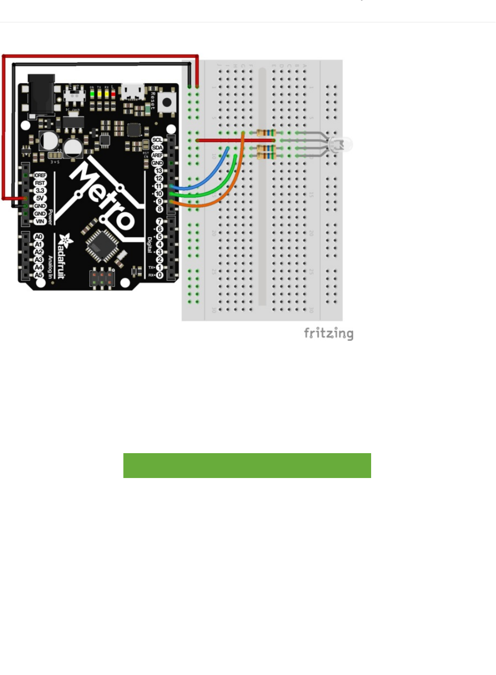
Wiring
Wire according to the diagram below:
1. Connect the first RGB LED leg to a 560 ohm resistor, then Pin 9
2. Connect the second RGB LED leg to a 560 ohm resistor, then Pin 10
3. Connect the first RGB LED leg to a 560 ohm resistor, then Pin 11
Note that the longest leg of the RGB LED connects to the power rail, 5V.
Printable Breadboard Layout Sheet
https://adafru.it/Atk
https://adafru.it/Atk
© Adafruit Industries https://learn.adafruit.com/experimenters-guide-for-metro Page 160 of 317
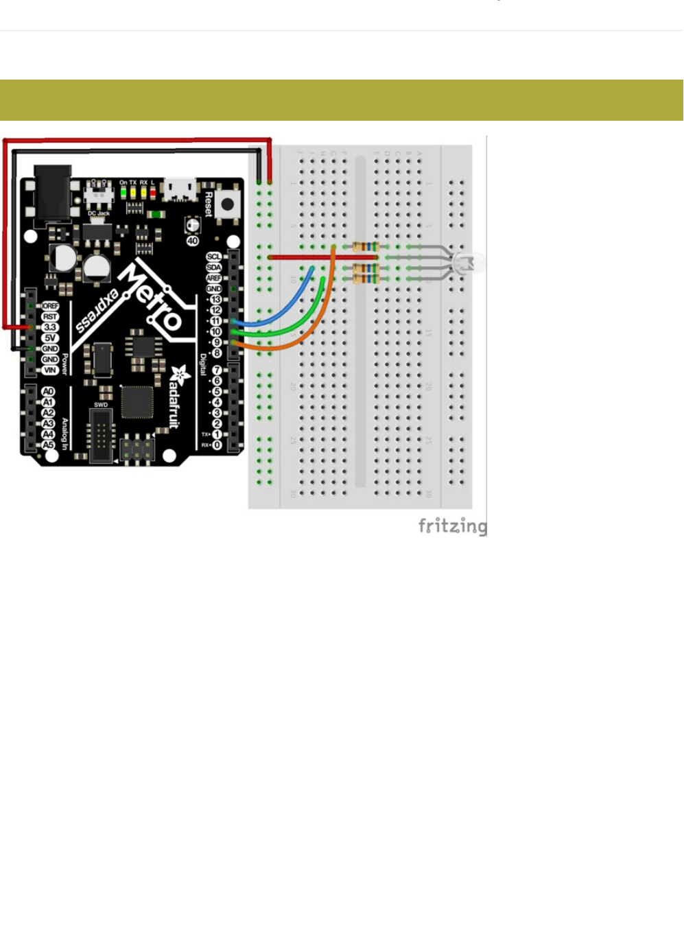
Wiring for Metro Express
If you are using the Adafruit Metro Express (https://adafru.it/xoa), the wiring below should be used. If you're not sure what board
you have, check this page. (https://adafru.it/METROXBOARDCHECK)
The power rail on your breadboard should connect to the 3.3V pin on the Metro Express
© Adafruit Industries https://learn.adafruit.com/experimenters-guide-for-metro Page 161 of 317

Code
Copy and paste the code below into a blank Arduino sketch. Then compile and upload it to your Metro (https://adafru.it/xap).
// CIRC12 - RGB LED
// RGB LED PINS
// three pins:
// 9 = RED
// 10 = GREEN
// 11 = BLUE
int ledDigitalOne[] = {9, 10, 11};
// define on as low
// (because you use a common anode RGB LED)
const boolean ON = LOW;
// define off as high
const boolean OFF = HIGH;
// Predefined Colors
const boolean RED[] = {ON, OFF, OFF};
const boolean GREEN[] = {OFF, ON, OFF};
const boolean BLUE[] = {OFF, OFF, ON};
const boolean YELLOW[] = {ON, ON, OFF};
const boolean CYAN[] = {OFF, ON, ON};
const boolean MAGENTA[] = {ON, OFF, ON};
const boolean WHITE[] = {ON, ON, ON};
const boolean BLACK[] = {OFF, OFF, OFF};
//An Array that stores the predefined colors
const boolean* COLORS[] =
{RED, GREEN, BLUE,YELLOW, CYAN, MAGENTA,
WHITE, BLACK};
void setup() {
for(int i = 0; i < 3; i++){
// set the 3 pins as outputs
pinMode(ledDigitalOne[i], OUTPUT);
}
}
void loop() {
// set the color of the LED
setColor(ledDigitalOne, CYAN);
// randomize it
// randomColor();
}
void randomColor(){
// get random number within range of colors
int rand = random(0, sizeof(COLORS) / 2);
setColor(ledDigitalOne, COLORS[rand]);
delay(1000);
}
void setColor(int* led, const boolean* color) {
for(int i = 0; i < 3; i++){
digitalWrite(led[i], color[i]);
}
}
© Adafruit Industries https://learn.adafruit.com/experimenters-guide-for-metro Page 162 of 317

Having Trouble?
LED Remains Dark or Shows Incorrect Color
With the four pins of the LED so close together, it’s sometimes easy to misplace one. Try double checking each pin is where it
should be.
Green and Blue seem to be reversed
Some RGB LEDs have green and blue swapped, change your code so the pins are swapped and re-upload!
Seeing Red
The red diode within the RGB LED may be a bit brighter than the other two. To make your colors more balanced, try using a
higher ohm resistor (or two resistors in series).
Looking For More?
If you’re looking to do more why not check out all the lovely extra bits and bobs available from the Adafruit Shop.
© Adafruit Industries https://learn.adafruit.com/experimenters-guide-for-metro Page 163 of 317

Make It Better
More Colors
I imagine you are less than impressed by the cyan glowing LED before you. To display a different color, change the color in the
code to one of the others:
setColor(ledDigitalOne, CYAN); -> setColor(ledDigitalOne, newColor)
Display a Random Color
Of course we can do more than display a constant color. To see how we can cycle through random colors, change the loop()
code to:
Analog Color Control
While switching between colors is good fun, RGB LEDs really come into their own when mixed with analog control. Using PWM
(pulse width modulation), it's possible to produce nearly any color and fade between them. Sadly, the code for this is a bit too
long for the section above, so click below to see the code:
https://adafru.it/BbX
https://adafru.it/BbX
void loop() {
//setColor(ledDigitalOne, CYAN);
randomColor();
}
© Adafruit Industries https://learn.adafruit.com/experimenters-guide-for-metro Page 164 of 317
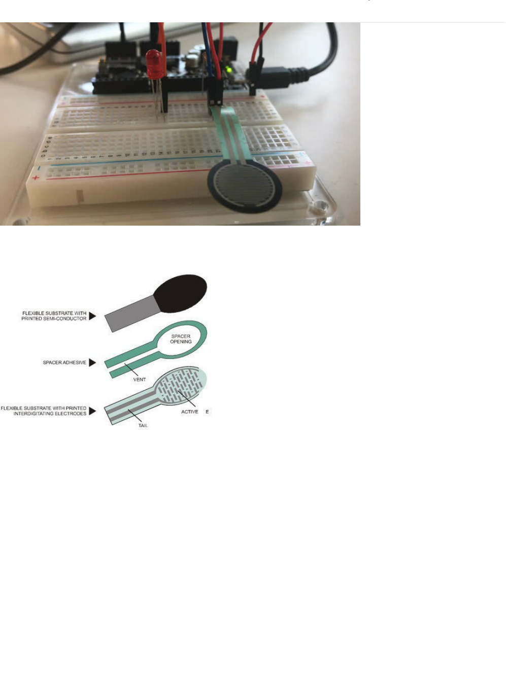
CIRC13: Squeezing
Force Sensitive Resistors (FSRs) are sensors that allow you to detect the pressure exerted on them. They're similar to a
potentiometer (like in CIRC08), except instead of varying resistance by twisting, the FSR's resistance varies with pressure.
The FSR is made of 2 layer separated by a spacer. The more you press, the more dots on the active element touch the
semiconductor, and that makes the resistance go down. They're not good for detecting exact weight, but they're great for
detecting squeezing and pushing and poking. If you'd like to dive a bit deeper into how FSRs exactly work, ladyada has a great
learn guide which goes over more technical details. (https://adafru.it/yd0)
© Adafruit Industries https://learn.adafruit.com/experimenters-guide-for-metro Page 165 of 317

Parts
Force Sensitive Resistor
If you'd like to order a force sensitive resistor from the
Adafruit shop, click here! (https://adafru.it/xfR)
10K Ohm Resistor
Colors: Brown > Black > Orange
If you'd like to order more 10k ohm pull-up resistors from the
Adafruit shop, click here! (https://adafru.it/xfm)
5mm Green LED
If you'd like to order extra green LEDs from the Adafruit shop,
click here! (https://adafru.it/x5b)
© Adafruit Industries https://learn.adafruit.com/experimenters-guide-for-metro Page 166 of 317
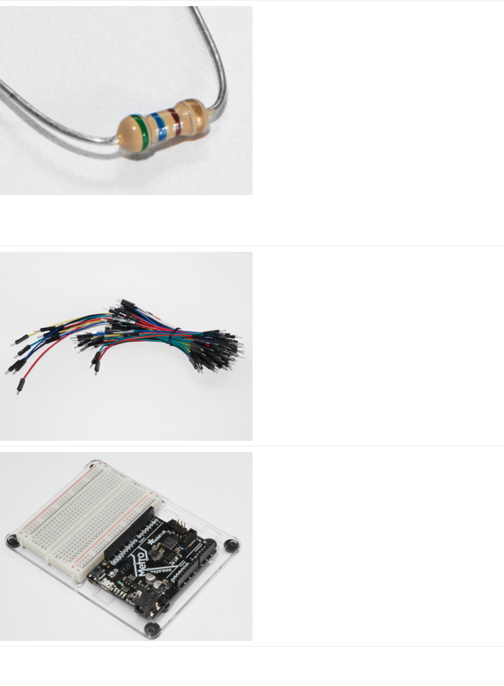
560 Ohm Resistor
Colors: Green > Blue > Brown
If you'd like to order more resistors from the Adafruit shop
click here! (they are 470ohm but they'll be
fine) (https://adafru.it/x4E)
Breadboard Wiring Bundle
If you'd like to order more wires from the Adafruit shop click
here! (https://adafru.it/fE2)
Adafruit Metro (or Metro Express) + Breadboard +
Mounting Plate
If you have not assembled this, we have a handy
guide! (https://adafru.it/x2A)
If you'd like to order an extra plastic mounting
plate (https://adafru.it/x4F), Adafruit
Metro (https://adafru.it/METROXMETR), Adafruit Metro
Express (https://adafru.it/xoa), or Mini-
Breadboard (https://adafru.it/keP) from the Adafruit Shop click
here!
© Adafruit Industries https://learn.adafruit.com/experimenters-guide-for-metro Page 167 of 317
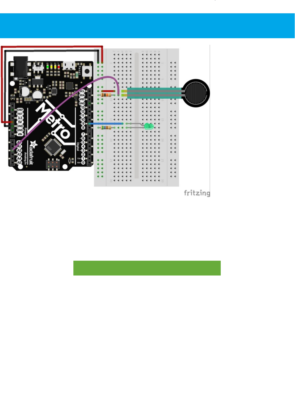
Wiring
The last circuit is easy to build, but really fun to use:
1. One end of the Force Sensitive Resistor (FSR) connects to the power rail.
2. The other end of the FSR connects to analog pin 2 and a 10k ohm pull-up resistor.
3. Connect a red LED to pin 9 and a 560 ohm current-limiting resistor.
Printable Breadboard Layout Sheet
https://adafru.it/Atl
https://adafru.it/Atl
The wiring for this circuit is the same for the Metro and the Metro Express. Note that the power rail is connected to 3V
instead of 5V.
© Adafruit Industries https://learn.adafruit.com/experimenters-guide-for-metro Page 168 of 317

Code
Copy and paste the code below into a blank Arduino sketch. Then compile and upload it to your Metro (https://adafru.it/xap).
Not Working?
LED Not Lighting Up?
LEDs will only work in one direction. Try taking it out and twisting it 180 degrees. (no need to worry, installing it backwards
does no permanent harm).
Fading to Fast/Slow
This is a result of the FSR’s response to pressure not being quite linear. But do not fear it can be changed in code (check out
the details in the Making it Better section)
Looking For More?
You're in luck - this guide has extra CIRCuits and a few PROJects included! Check the sidebar on the left for a full listing.
/*
* Force Sensitive Resistor Test Code
*
* The intensity of the LED will vary with the amount of pressure on the sensor
*/
int sensePin = 2; // the pin the FSR is attached to
int ledPin = 9; // the pin the LED is attached to (use one capable of PWM)
void setup() {
Serial.begin(9600);
pinMode(ledPin, OUTPUT); // declare the ledPin as an OUTPUT
}
void loop() {
int value = analogRead(sensePin) / 4; //the voltage on the pin divded by 4 (to
//scale from 10 bits (0-1024) to 8 (0-255)
analogWrite(ledPin, value); //sets the LEDs intensity proportional to
//the pressure on the sensor
Serial.println(value); //print the value to the debug window
}
© Adafruit Industries https://learn.adafruit.com/experimenters-guide-for-metro Page 169 of 317

Make It Better
Calibrating the Range
While the light is now fading, chances are its response isn't quite perfect. To adjust the response, we need to add one more line
to our code:
map(value, fromLow, fromHigh, toLow, toHigh)
To calibrate our sensor, we can use the serial monitor like in CIRC-11. Open the serial monitor, then replace the fromLow value
with the value display when the sensor is fully pressed.
Then, replace the fromHigh value with the unpressed value.
Finally, fill in the range toLow = 0 and toHigh = 255
The result will look something like this:
The RGB Strongperson Test
Step right up to test your strength against the Adafruit Metro High Striker Game! (https://adafru.it/xAA) Only the strongest will
succeed! Let's quickly modify the circuit with a RGB LED to indicate strength-level and modify the code to display how hard
someone is pressing the force-sensitive resistor.
Diagram: RGB + Force Resistor
The code below will need to be first run, and then modified. After running it, open the Serial Monitor and press the force
sensitive resistor as hard as possible. The value printed is the maxForce that someone could press on the FSR on your circuit.
int value = analogRead(sensePin);
map(value, 125, 854, 0, 255);
analogWrite(ledPin, value);
© Adafruit Industries https://learn.adafruit.com/experimenters-guide-for-metro Page 170 of 317

Set maxForce to the value in your serial monitor:
// set maxForce
int maxForce = FORCEVALUE;
After setting the maxForce, try your luck! We've included a serial printout to show how hard you're depressing the FSR.
/*
FSR Strongperson Test for Metro (and Metro Express)
Utilizes a FSR and a RGB LED to test how strong you are.
Created 7 July 2017
By Brent Rubell for Adafruit Industries
Support Open Source ~ buy Adafruit
*/
// fsr pin
int sensePin = A2;
// rgb led pins
int rgbLED[] = {9, 10, 11};
// common cathode rgbleds
const boolean ON = LOW;
const boolean OFF = HIGH;
// predefined colors
const boolean BLUE[] = {ON, OFF, OFF};
const boolean RED[] = {OFF, OFF, ON};
const boolean GREEN[] = {OFF, ON, OFF};
void setup() {
Serial.begin(9600);
// set all rgb pins as outputs
for(int i = 0; i<3; i++){
pinMode(rgbLED[i], OUTPUT);
}
}
void loop() {
// scale voltage down to 255 from 1023
int force = analogRead(sensePin) / 4;
// check maximum force by squeezing the FSR
Serial.println(force);
// set maxForce
int maxForce = 160;
// calculate regions
int lowForce = maxForce / 3;
int medForce = (maxForce / 3) * 2;
// check force regions
if(force < lowForce) {
Serial.println("easy");
setColor(rgbLED, RED);
}
else if (force > lowForce && force < medForce) {
Serial.println("medium");
setColor(rgbLED, BLUE);
}
else {
© Adafruit Industries https://learn.adafruit.com/experimenters-guide-for-metro Page 171 of 317

Other Applications
With sensors, the real fun comes in how you use them in neat and unexpected ways. So get thinking about how and where
sensing force could enhance your life (or the life of others).
Serial.println("hard");
setColor(rgbLED, GREEN);
}
}
// rgb color mixing
void setColor(int* led, const boolean* color) {
for(int i = 0; i < 3; i++){
digitalWrite(led[i], color[i]);
}
}
© Adafruit Industries https://learn.adafruit.com/experimenters-guide-for-metro Page 172 of 317
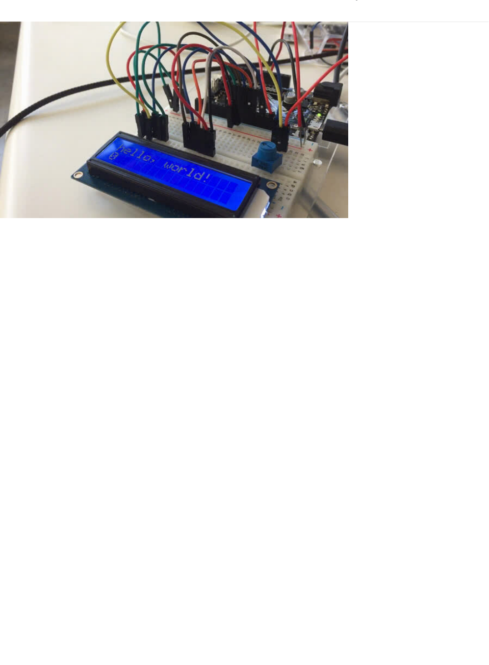
CIRC14: Character LCDs
We carry a slew of different types of Character LCDs in the Adafruit Store (https://adafru.it/aIT). The Experimenter's kit provides
one, but if you don't have one, the 16x2 variety is used (https://adafru.it/yd5) in the Experimenter's guide.
Character LCDs are super useful for displaying text, data, variable information or providing an interface to interact with. You've
already used the Serial Monitor in previous learn guides. While it's useful to display data from the Metro, it needs to be tethered
to the computer via USB. The character LCD lets you have a free-standing display for whatever you want to print - text, data, and
even small icons (5px x 7px)
© Adafruit Industries https://learn.adafruit.com/experimenters-guide-for-metro Page 173 of 317
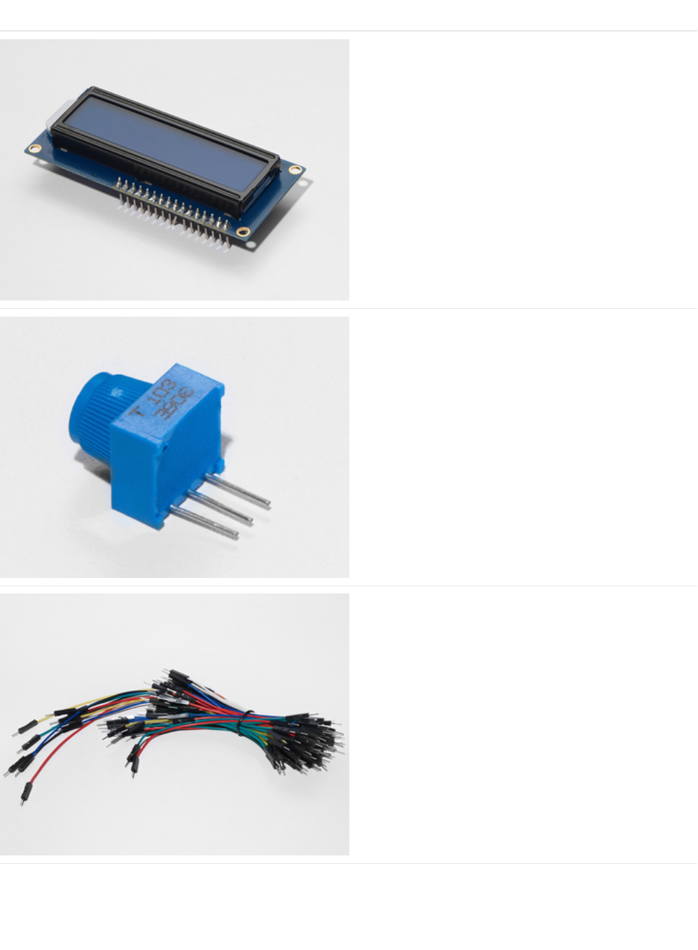
Parts
16x2 Character LCD
If you'd like to buy a white-on-blue 16x2 character lcd from
the Adafruit shop, click here! (https://adafru.it/tUe)
Breadboard Trim Potentiometer - 10k
If you'd like to buy an extra trimpot from the Adafruit store,
click here! (https://adafru.it/tba)
Breadboard Wiring Bundle
If you'd like to order more wires from the Adafruit shop click
here! (https://adafru.it/fE2)
© Adafruit Industries https://learn.adafruit.com/experimenters-guide-for-metro Page 174 of 317
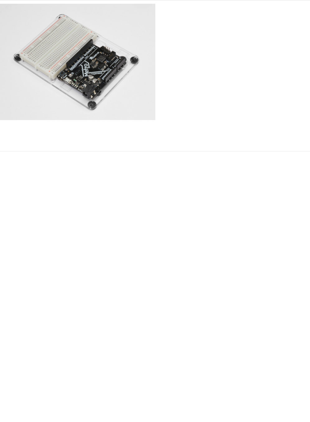
Adafruit Metro (or Metro Express) + Breadboard +
Mounting Plate
If you have not assembled this, we have a handy
guide! (https://adafru.it/x2A)
If you'd like to order an extra plastic mounting
plate (https://adafru.it/x4F), Adafruit
Metro (https://adafru.it/METROXMETR), Adafruit Metro
Express (https://adafru.it/xoa), or Mini-
Breadboard (https://adafru.it/keP) from the Adafruit Shop click
here!
© Adafruit Industries https://learn.adafruit.com/experimenters-guide-for-metro Page 175 of 317
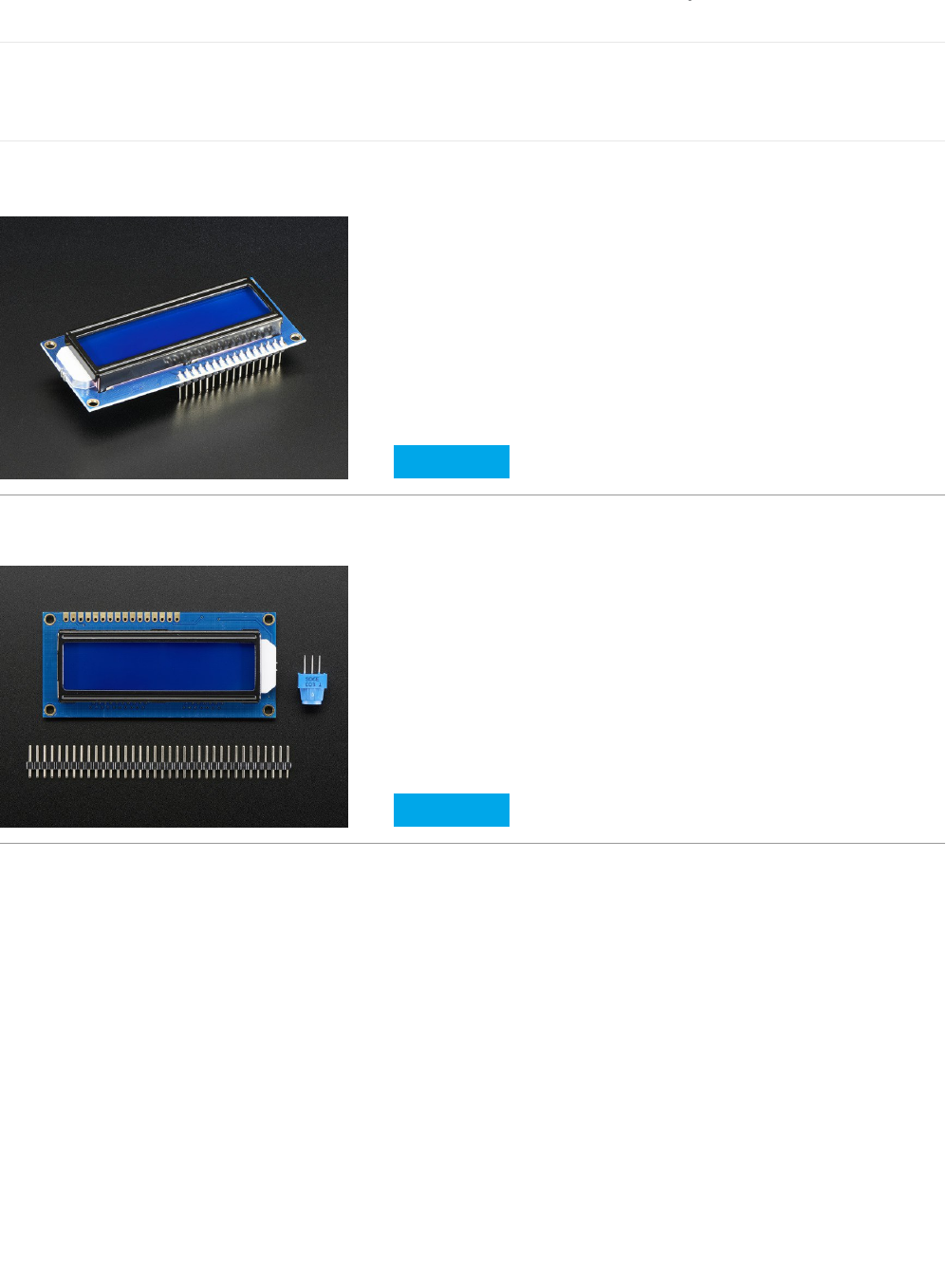
Wiring
The instructions and wiring on this page is based off of ladyada's wonderful Character LCD wiring guide, (https://adafru.it/yd4)
but updated for Fritzing.
Assembling your LCD
Some 16x2 LCDs may come assembled, meaning the header is already soldered on:
We also have some that are unassembled with an unsoldered header:
If your LCD is assembled, you can skip these next steps and proceed directly to wiring it up. Otherwise, follow along below.
Soldering your LCD
Soldering is a very useful skill in the realm of electronics. It's the process of joining two metals together, using another piece of
metal (also known as solder) between them. If you have never done this before, Bill Earl wrote an awesome visual guide
entitled
Adafruit Guide To Excellent Soldering
which will get you off the ground, fast. If you would prefer to watch a video,
Collin's Lab covers soldering, too:
The 16x2 LCD is not that hard to solder, but it does have a lot of pins. We have some advice for soldering these like a pro:
Start by plugging your 16x2 LCD and header into your breadboard.
Assembled Standard LCD 16x2 + extras - White on Blue
$10.95
IN STOCK
ADD TO CART
Standard LCD 16x2 + extras
$9.95
IN STOCK
ADD TO CART
© Adafruit Industries https://learn.adafruit.com/experimenters-guide-for-metro Page 176 of 317
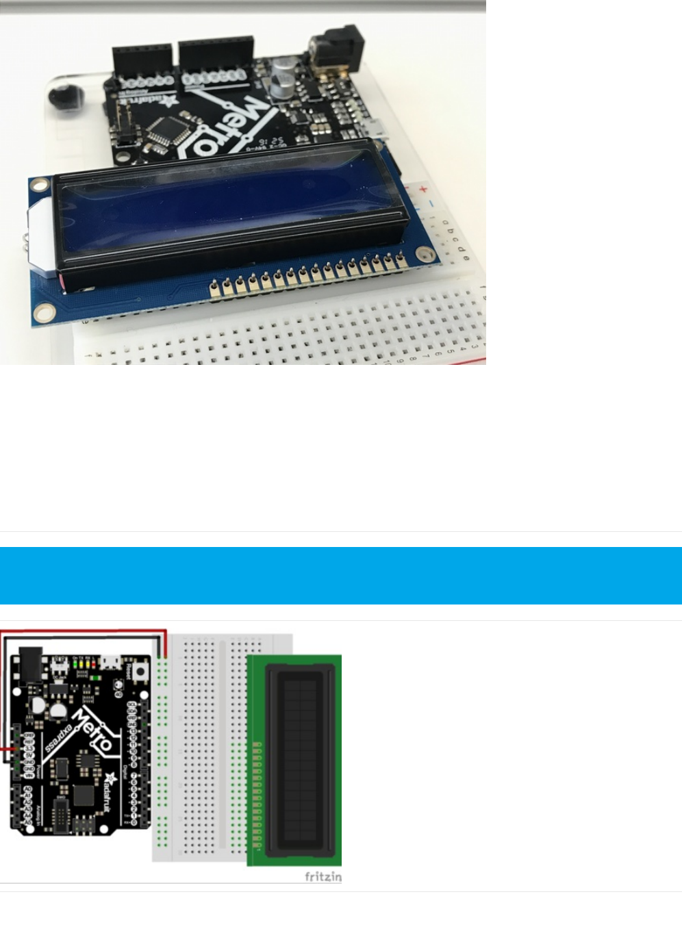
Then, (with a medium-level of heat,
dont make your iron too hot!
) start soldering Pin 1 to the header. Next solder Pin 16. This will
"tack" the header to the LCD, making soldering the rest of the pins easier.
Now, go solder all the other pins!
Messed up? Issues with your header? Soldering is very fix-able. It'll just take time. Check this guide for your mistakes, and
correct them before moving on.
Wiring Power and Backlight
First, plug your LCD into the breadboard. Then, connect the
+5V Pin to the power rail and the GND Pinto the ground rail.
If these photos are too small, you can right click on them -> "copy image address", then paste the address into the URL
bar of your browser for a full-resolution screenshot.
© Adafruit Industries https://learn.adafruit.com/experimenters-guide-for-metro Page 177 of 317
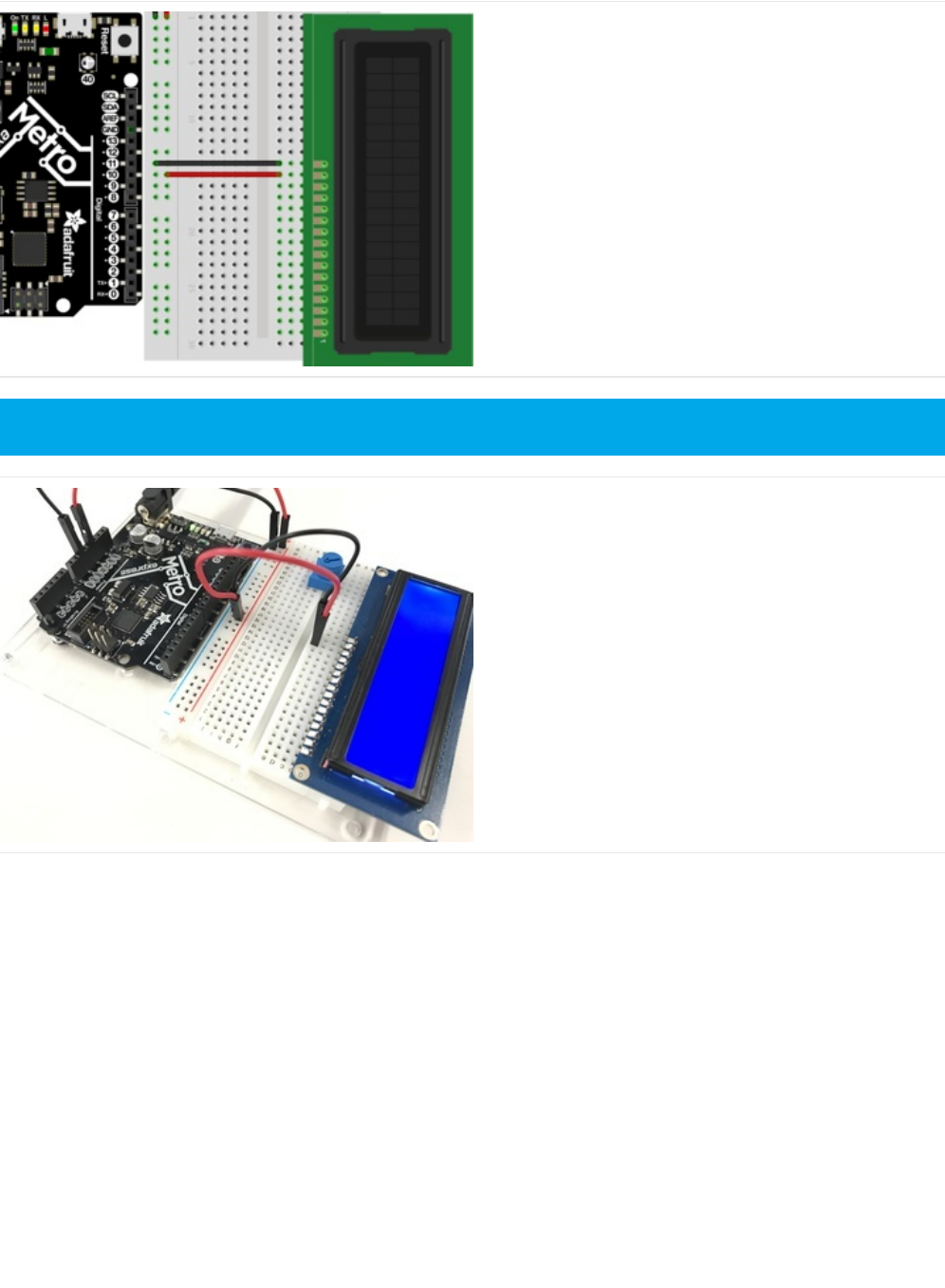
Next, connect LCD Pin 16 to the GND rail, and LCD Pin 15 to
the power rail.
Let's check it's power. Connect your Metro or Metro Express
to power. You should see the LCD light up. Some low-cost
LCDs don't come with a backlight.
If you have one with a backlight and if you don't see it
lighting up, go back and check over your wiring.
Wiring the Contrast Circuit
Do not move on until you perform a Power Check
© Adafruit Industries https://learn.adafruit.com/experimenters-guide-for-metro Page 178 of 317
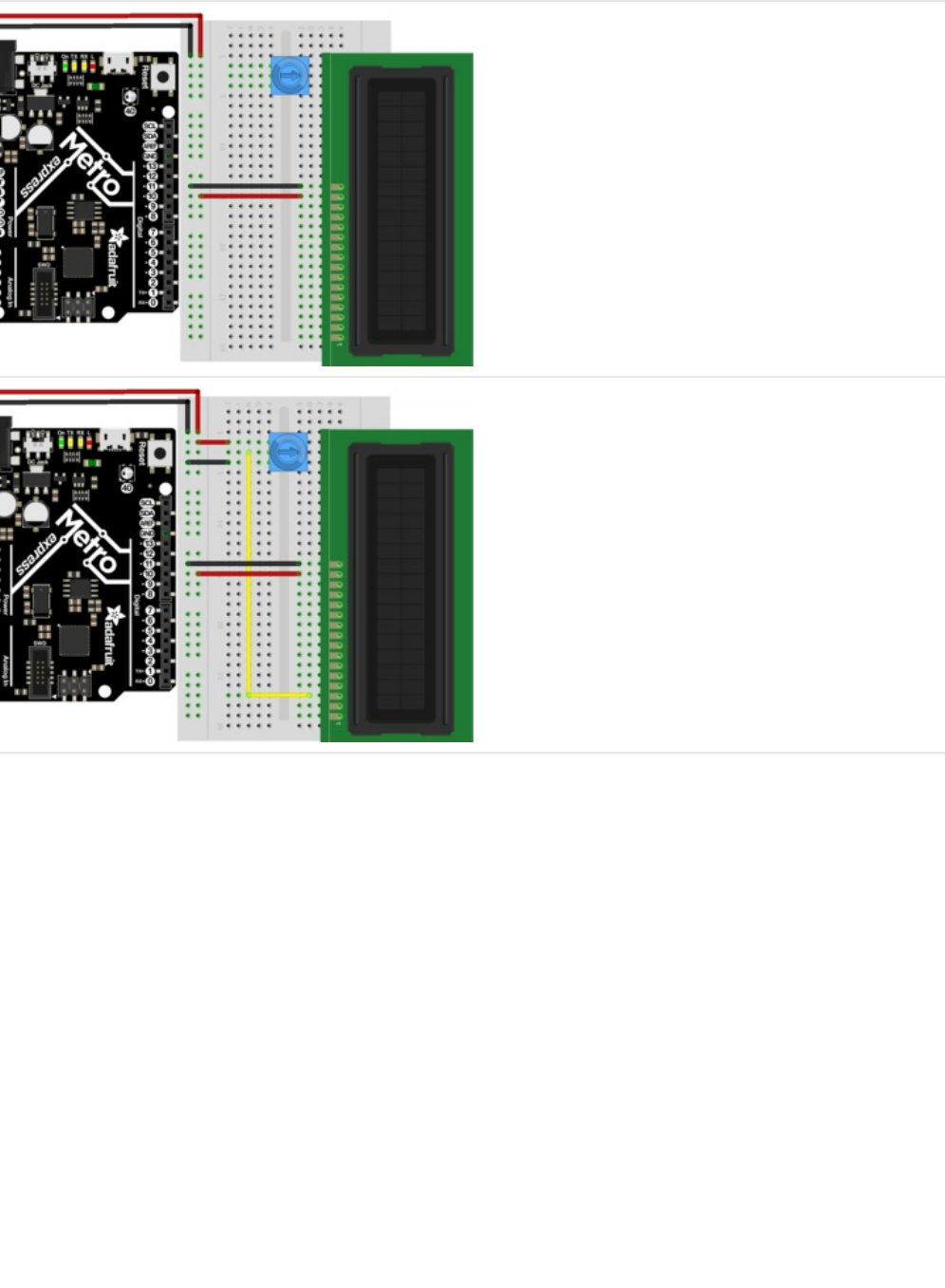
Next, let's place the contrast potentiometer to the left of
LCD Pin 16. You can place it anywhere on the breadboard
you'd like, but the next CIRC has it placed to the left of LCD
Pin 16
Connect one of the outer pins of the potentiometer to the
power rail. Connect the other outer pin to the ground rail. It
doesn't matter which goes where, the other pins are
interchangeable as long as one goes to power and one goes
to ground.
The middle of the potentiometer (the wiper) connects to LCD
Pin 3
© Adafruit Industries https://learn.adafruit.com/experimenters-guide-for-metro Page 179 of 317
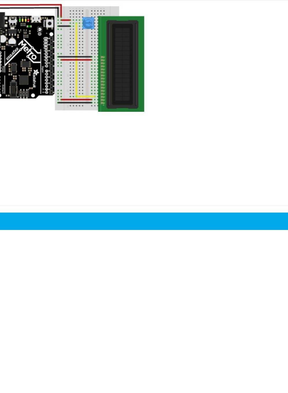

Before moving on, we'll perform a small test to make sure the
wiring is correct. Plug in your Metro or Metro express and
twist the potentiometer. You should see black rectangles
appear on the first line of the LCD. If you don't see this,
check your wiring before moving on.
Wiring the Data Bus
© Adafruit Industries https://learn.adafruit.com/experimenters-guide-for-metro Page 181 of 317

The RW Pin is not required for this guide, as we are only
writing to the display. Connect LCD Pin 5 to the ground rail.
Next, we are going to connect the RS Pin. We used a blue
wire to connect LCD Pin 4 to Metro Digital Pin 7
The EN Pin is next. We used a green wire to connect LCD
Pin 6 to Metro Digital Pin 8
© Adafruit Industries https://learn.adafruit.com/experimenters-guide-for-metro Page 182 of 317

Next is the first of the data pins, DB7. We used a white wire
to connect LCD Pin 14 to Metro Digital Pin 12
DB6 is up next. We used an orange wire to connect LCD Pin
13 to Metro Digital Pin 11
Connect DB5 (we used a purple wire)from LCD Pin
12 to Metro Digital Pin 10.
© Adafruit Industries https://learn.adafruit.com/experimenters-guide-for-metro Page 183 of 317
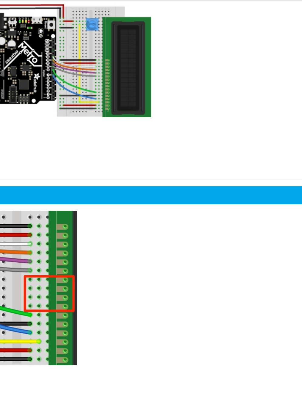
Finally, we connect DB4 with a gray wire from LCD Pin
11 to Metro Digital Pin 9
This is what you should have on your desk, proceed to the code section after double-checking your wiring:
Check that you have a 4-wire gap between your data pins like this:
© Adafruit Industries https://learn.adafruit.com/experimenters-guide-for-metro Page 184 of 317
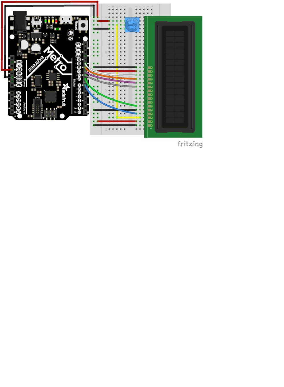
© Adafruit Industries https://learn.adafruit.com/experimenters-guide-for-metro Page 185 of 317

Code
Copy and paste the code below into a new Arduino sketch. Then, compile and upload it to your Metro or Metro Express.
Do NOT take this CIRC apart just yet...CIRC15 uses the LCD and you don't want to wire it up again.
© Adafruit Industries https://learn.adafruit.com/experimenters-guide-for-metro Page 186 of 317

Not Working?
My Character LCD is not lighting up.
Double-check the wiring connections you made to the power and backlight pins of the Character LCD is correct. Check your
/*
LiquidCrystal Library - Hello World
Demonstrates the use a 16x2 LCD display. The LiquidCrystal
library works with all LCD displays that are compatible with the
Hitachi HD44780 driver. There are many of them out there, and you
can usually tell them by the 16-pin interface.
This sketch prints "Hello World!" to the LCD
and shows the time.
The circuit:
* LCD RS pin to digital pin 12
* LCD Enable pin to digital pin 11
* LCD D4 pin to digital pin 5
* LCD D5 pin to digital pin 4
* LCD D6 pin to digital pin 3
* LCD D7 pin to digital pin 2
* LCD R/W pin to ground
* LCD VSS pin to ground
* LCD VCC pin to 5V
* 10K resistor:
* ends to +5V and ground
* wiper to LCD VO pin (pin 3)
Library originally added 18 Apr 2008
by David A. Mellis
library modified 5 Jul 2009
by Limor Fried (http://www.ladyada.net)
example added 9 Jul 2009
by Tom Igoe
modified 22 Nov 2010
by Tom Igoe
This example code is in the public domain.
http://www.arduino.cc/en/Tutorial/LiquidCrystal
*/
// include the library code:
#include <LiquidCrystal.h>
// initialize the library with the numbers of the interface pins
// modified for Metro Explorers Guide
LiquidCrystal lcd(7, 8, 9, 10, 11, 12);
void setup() {
// set up the LCD's number of columns and rows:
lcd.begin(16, 2);
// Print a message to the LCD.
lcd.print("hello, world!");
}
void loop() {
}
© Adafruit Industries https://learn.adafruit.com/experimenters-guide-for-metro Page 187 of 317

soldering joints, maybe they are problematic.
Also check that you are using the 5v Pin instead of the 3.3V Pin.
I only see black blocks on the LCD
Try twisting your potentiometer. It's also possible that your data bus is not hooked up correctly.
I don't see anything at all
Re-wiring your LCD is a good way to get rid of any issues, it takes a lot of time but ensures everything is correct. If all else
fails, post up in the Adafruit Support Forums and we will get back to you as soon as we can.
© Adafruit Industries https://learn.adafruit.com/experimenters-guide-for-metro Page 188 of 317

Make It Better
Writing to the second line
If we want to write to the second line, we can use lcd.setCursor(COLUMN, LINE) such that the column is 0 and the line is 1:
lcd.setCursor(0,1);
Writing the light sensor to the LCD
Let's try writing the output of the light sensor to the character LCD.
This will require an extra part:
Photo Sensor
If you'd like to order another photoresistor from the Adafruit
shop, click here! (https://adafru.it/xfo)
Wiring
void loop() {
// set the cursor to column 0, line 1
// (note: line 1 is the second row, since counting begins with 0):
lcd.setCursor(0, 1);
// print the number of seconds since reset:
lcd.print(millis() / 1000);
}
Do NOT take apart this CIRC yet, CIRC15 uses the LCD and you don't want to wire it up again.
The wiring for this Make It Better is the same for both the Metro and Metro Express. Make sure the rail is connected to
5V.
© Adafruit Industries https://learn.adafruit.com/experimenters-guide-for-metro Page 189 of 317
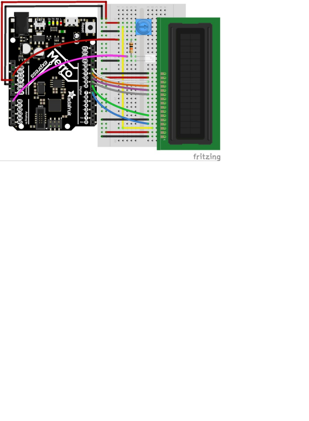
Note: While the rail is connected to 5V, the light sensor is connected to 3V.
Code
Copy and paste the code below into the Arduino editor. Then, compile and upload it to your board.
© Adafruit Industries https://learn.adafruit.com/experimenters-guide-for-metro Page 190 of 317

What's next?
The Thermometer (CIRC15) gets into the nitty-gritty of the character LCD. You'll learn how to display custom characters, full
strings of text, and multi-line data output!
/* CIRC14 - Make It Better
* Character LCD + TMP36
*
* by Brent Rubell for Adafruit Industries. Support Open Source, buy Adafruit!
*/
// include the library code:
#include <LiquidCrystal.h>
// modified wiring for Metro Explorers Guide
LiquidCrystal lcd(7, 8, 9, 10, 11, 12);
// photo light sensor
int lightPin = A0;
void setup() {
// set up the LCD's number of columns and rows:
lcd.begin(16, 2);
// print to the first line of the LCD
lcd.print("Light Value:");
}
void loop() {
// read the light level
int lightLevel = analogRead(lightPin);
// map and constrain the light sensor values
lightLevel = map(lightLevel, 0, 900, 0, 255);
lightLevel = constrain(lightLevel, 0, 255);
// set the cursor to column 0, line 1
lcd.setCursor(0, 1);
// write lightLevel to the LCD
lcd.print(lightLevel);
}
© Adafruit Industries https://learn.adafruit.com/experimenters-guide-for-metro Page 191 of 317
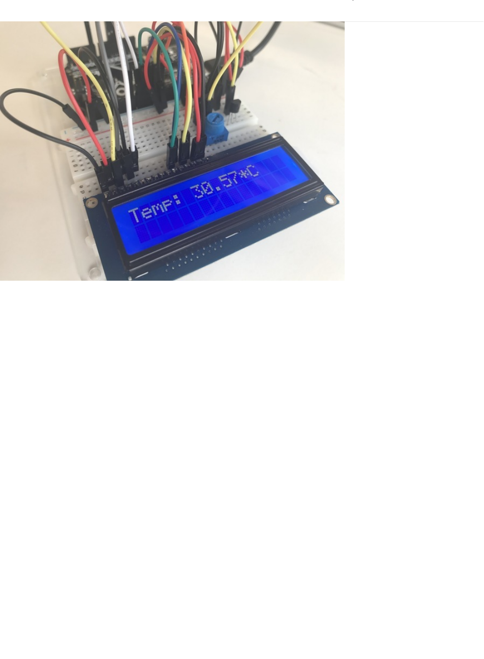
CIRC15: Thermometer
What if you want to show more output than a bunch of LEDs can handle? Sure, you could set up a bunch of LEDs to display
numbers. But what if there was another way...
Character LCDs are super robust and great for output.
Anything
you can fit onto the 16 (lines) by 2 (rows) screen can be output
by your code when you drop in the
LiquidCrystal
library, a collection of code that let's you add new functionality to your circuits.
We are going to re-create CIRC10. But instead of printing to a serial monitor, we are going to print to an external character LCD.
© Adafruit Industries https://learn.adafruit.com/experimenters-guide-for-metro Page 192 of 317
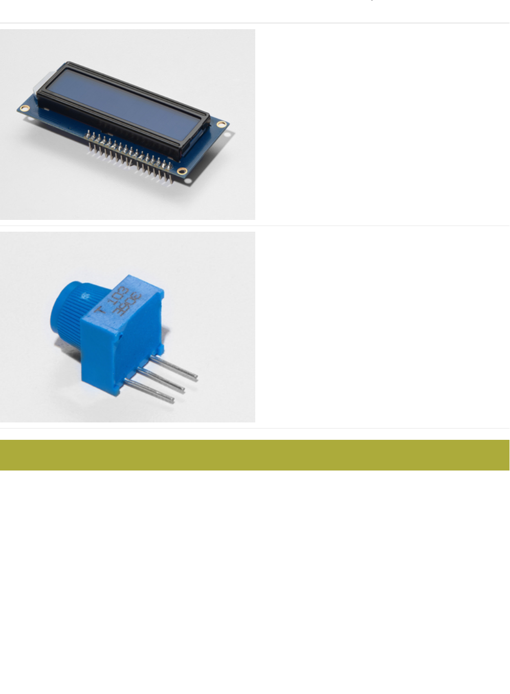
Parts
16x2 Character LCD
If you'd like to buy a white-on-blue 16x2 character lcd from
the Adafruit shop, click here! (https://adafru.it/tUe)
Breadboard Trim Potentiometer - 10k
If you'd like to buy an extra trimpot from the Adafruit store,
click here! (https://adafru.it/tba)
Am I using a TMP36 Temperature Sensor or a NPN Transistor (https://adafru.it/ytD)
This circuit uses the TMP36, NOT the NPN Transistor.
© Adafruit Industries https://learn.adafruit.com/experimenters-guide-for-metro Page 193 of 317
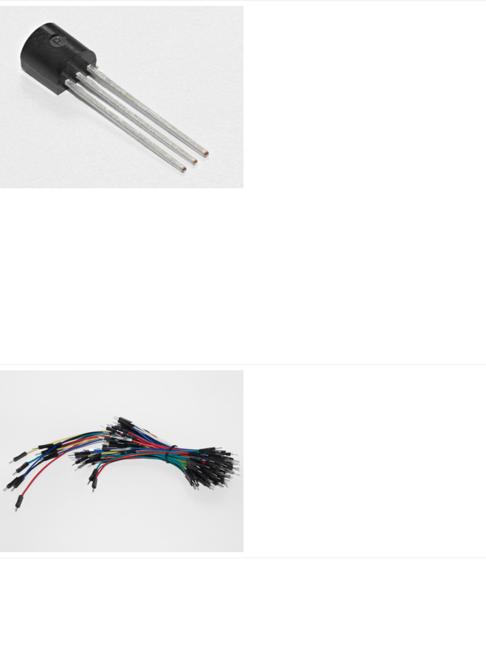
Analog Temperature Sensor
If you'd like an extra temperature sensor, you can grab one
from the Adafruit shop, click here (https://adafru.it/xfq)
Breadboard Wiring Bundle
If you'd like to order more wires from the Adafruit shop click
here! (https://adafru.it/fE2)
© Adafruit Industries https://learn.adafruit.com/experimenters-guide-for-metro Page 194 of 317

Adafruit Metro (or Metro Express) + Breadboard +
Mounting Plate
If you have not assembled this, we have a handy
guide! (https://adafru.it/x2A)
If you'd like to order an extra plastic mounting
plate (https://adafru.it/x4F), Adafruit
Metro (https://adafru.it/METROXMETR), Adafruit Metro
Express (https://adafru.it/xoa), or Mini-
Breadboard (https://adafru.it/keP) from the Adafruit Shop click
here!
© Adafruit Industries https://learn.adafruit.com/experimenters-guide-for-metro Page 195 of 317
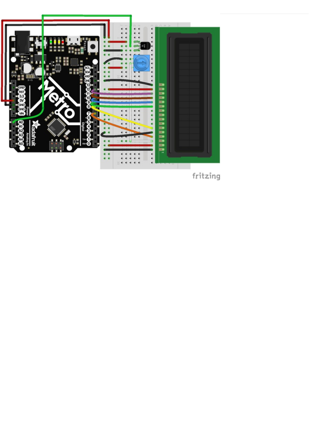
Wiring
The wiring for the character LCD may be tricky. There's a learn guide that walks through each individual
wire. (https://adafru.it/xgc) If you want to work along with it, be sure to place the LCD on the right side of the breadboard to
ensure you can fit the potentiometer and the TMP36 sensor on the breadboard too.
© Adafruit Industries https://learn.adafruit.com/experimenters-guide-for-metro Page 196 of 317

Code
CIRC15 uses code that will work for both the Metro and the Metro Express. You'll need to make a
tiny
modification to it to get it
working with the Metro you own. (If you're not sure what board you have, click here!) (https://adafru.it/METROXBOARDCHECK).
Code:
If you're using a Metro EXPRESS, change #define ANALOGREFVOLTAGE to #define ANALOGREFVOLTAGE 3.333
/*
* CIRC15: Digital Thermometer
* Experimenter's Guide for Metro (and Metro Express!)
* by Brent Rubell for Adafruit Industries ~ Support Open Source, buy adafruit!
*/
// If you're using a METRO EXPRESS, change this value to 3.333
#define ANALOGREFVOLTAGE 5.000
// include the lcd library code:
#include <LiquidCrystal.h>
// initialize the library with the numbers of the interface pins
LiquidCrystal lcd(7, 8, 9, 10, 11, 12);
// TMP36 Pin
int temperaturePin = 0;
void setup() {
Serial.begin(9600);
// set up the LCD's number of columns and rows:
lcd.begin(16, 2);
}
void loop() {
float temperature = 0;
temperature = getVoltage(temperaturePin);
/* Output: Degrees C */
temperature = (temperature - .5) * 100;
/* Output: Degrees F */
// temperature = (((temperature - .5) * 100)*1.8) + 32;
/* Output: Voltage */
// temperature = (temperature - .5) * 100; d
// Write temperature to the LCD
lcd.print("Temp: ");
lcd.setCursor(6,0);
lcd.print(temperature);
lcd.setCursor(11,0);
lcd.print("*C");
// Wait 1s
delay(1000);
// Refresh the LCD
lcd.clear();
}
float getVoltage(int pin) {
return(float(analogRead(pin))* float(ANALOGREFVOLTAGE/1023.000));
}
© Adafruit Industries https://learn.adafruit.com/experimenters-guide-for-metro Page 197 of 317

Having Trouble?
I don't see anything on the LCD
Try twisting the potentiometer. If that doesn't work, re-check your wiring.
Text on the LCD is strange characters or garbled
Make sure the pins of the LCD are flush with the breadboard. If that doesn't work, re-upload the sketch from Arduino.
The number on the LCD is not possible, it's too high/low
The included code has a line that uses the serial monitor. Pop open the serial monitor and check the number in there against
what you think the current temperature is. If the number seems off, double check wiring to Analog Pin A0.
I'm still having trouble, I think the diagram is too complicated.
The character LCD has a
lot
of wires and it's hard to keep track. We have a great guide that takes you step-by-step. Check it
out!
After uploading this code, make sure the backlight is lit up and twist the potentiometer until you can clearly see the
text/numbers.
© Adafruit Industries https://learn.adafruit.com/experimenters-guide-for-metro Page 198 of 317

Make It Better
Using Fahrenheit
We are going to convert the degrees displayed by the example code to in Celsius to Fahrenheit. In loop() , change the following
lines:
Then, compile and upload the sketch to your metro and observe the number change.
Printing new text to the LCD
Did you notice that even though the number changed, the *C was still printed to your display? This is because the *C is hard-
coded into the display.
To change *C to *F, change the following line:
lcd.print("*C"); -> lcd.print("*F");
Then, compile and upload to the Metro. Your temperature should display the Fahrenheit unit and temperature symbol.
Printing to the Second Row
The intro mentioned this LCD was 16x2. It has two rows you can print to, but we are only using one. Let's print the *F symbol to
the same spot in the second row. To do this, modify the following code in your loop() :
Using Custom Characters
The LiquidCrystal library contains a command called createchar()
which can create a custom character (a glyph!) for printing to
the LCD. Our code uses an asterisk instead of a degrees symbol. Let's complete the thermostat and have a
real
degrees
symbol.
To do this, add the following code above your setup() loop:
In the setup() loop, add the following line:
// Degrees C
//temperature = (temperature - .5) * 100;
// Degrees F
temperature = (((temperature - .5) * 100)*1.8) + 32;
lcd.setCursor(11,1); // instead of (11,0), we are printing to (11,1), the 2nd row
lcd.print("*F");
// Custom Degree Symbol
byte degree[8] = {
0x7,
0x5,
0x7,
0x0,
0x0,
0x0,
0x0,
};
© Adafruit Industries https://learn.adafruit.com/experimenters-guide-for-metro Page 199 of 317
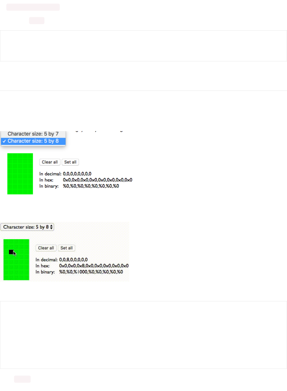
lcd.createChar(0,degree);
Finally, in the loop() , modify the following lines:
After compiling and uploading, you should see the degree symbol next to the F.
Making your own Custom Character
If you want to add more custom characters, or different ones, there's a great online generator we like. You can add in your own
icons, for whatever you want. Let's learn how to do this:
First, visit the HD44780 graphic generator site (https://adafru.it/xge). Then, change the character size to 5 by 8
Click the boxes to set pixels. When a pixel is set, it'll turn from green to black. You can un-set pixels by clicking on a black pixel
(on) to turn it green (off).
Once you have your custom character, copy the values from "In Hex" and paste them into an Arduino sketch as a byte array:
In the setup() loop, add the following line:
lcd.setCursor(11,1);
lcd.write(byte(0)); // custom degrees character
lcd.setCursor(12,1);
lcd.print("F");
// smiley face
byte smile[8] = {
0x0,
0x0,
0x8,
0x0,
0x0,
0x0,
0x0,
};
© Adafruit Industries https://learn.adafruit.com/experimenters-guide-for-metro Page 200 of 317

lcd.createChar(0,smile);
Then, in loop() add the following to write your custom character to the LCD:
lcd.write(byte(0)); // custom degrees character
© Adafruit Industries https://learn.adafruit.com/experimenters-guide-for-metro Page 201 of 317
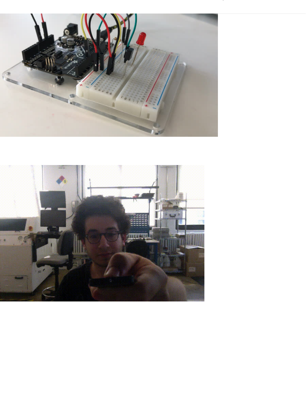
CIRC16: IR Sensor
IR Receiver Sensors are photocells tuned to receive IR frequencies. The IR frequency is not visible to the human eye, but can be
picked up by a webcam or cell phone.
Try pressing a button on the Mini Remote Control (https://adafru.it/xck) or a TV/DVD-player remote and shining it at your
webcam. The light you see emitted by the remote is Infrared light. These Infrared Signals are PWM signals carrying pulses
(
marks
) and intervals (
spaces
) carrying 32 bits of data.
The Experimenters Guide uses IRLib, an easy-to-understand Arduino library that de-mystifies the infrared light receiver. In the
code section, we will go over installing this library and use it with this circuit.
© Adafruit Industries https://learn.adafruit.com/experimenters-guide-for-metro Page 202 of 317
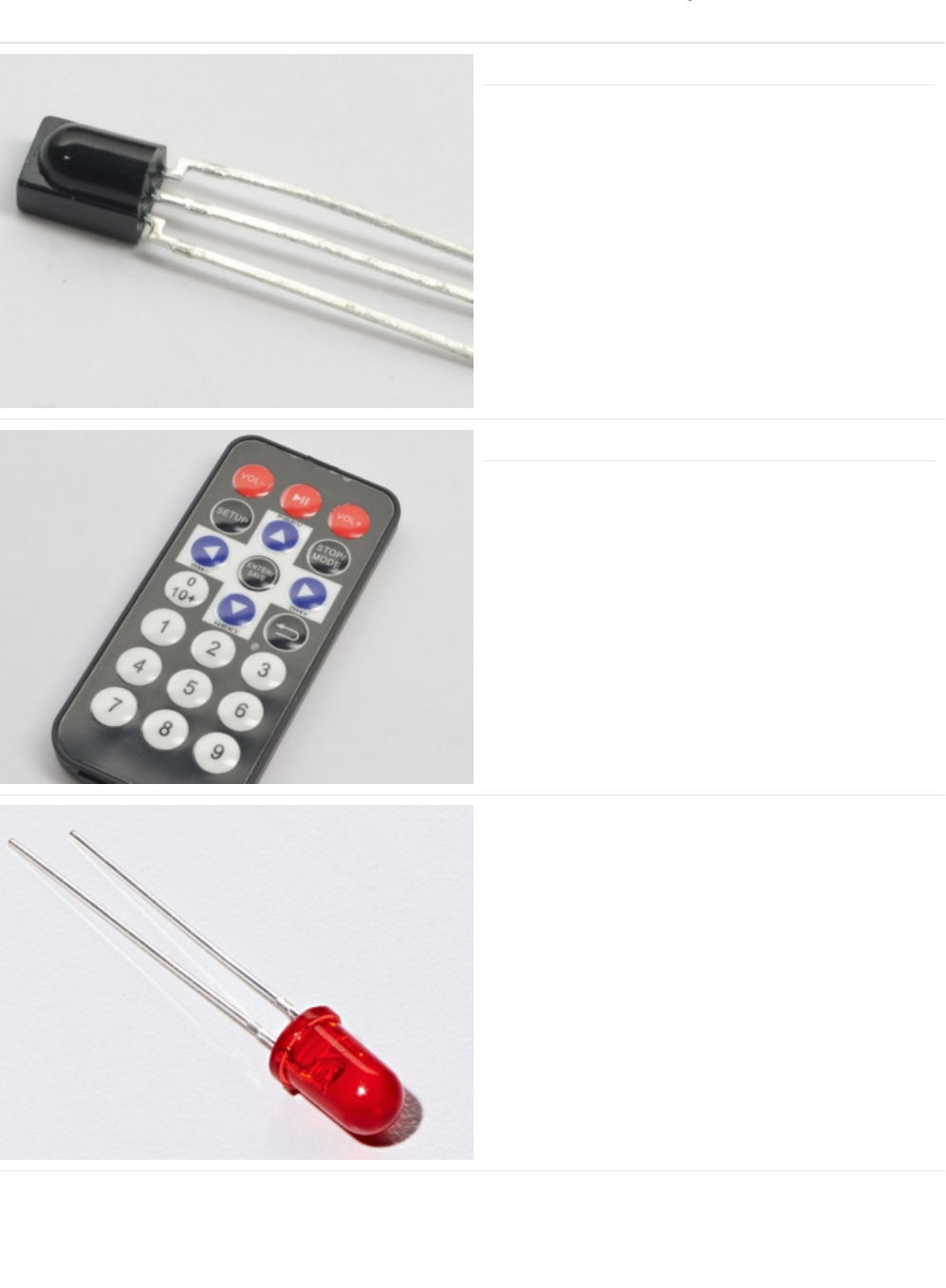
Parts
IR (Infrared) Receiver Sensor
If you'd like to order an extra IR receiver sensor from the
Adafruit shop, click here! (https://adafru.it/xcl)
Mini Remote Control
We suggest using this remote with CIRC15, but you can use
any remote
If you'd like to order an extra Mini Remote Control from the
Adafruit Shop, click here! (https://adafru.it/xck)
5mm Red LED
If you'd like to order more red LEDs (they make great
indicator lights!) from the Adafruit shop, click
here! (https://adafru.it/xeV)
© Adafruit Industries https://learn.adafruit.com/experimenters-guide-for-metro Page 203 of 317
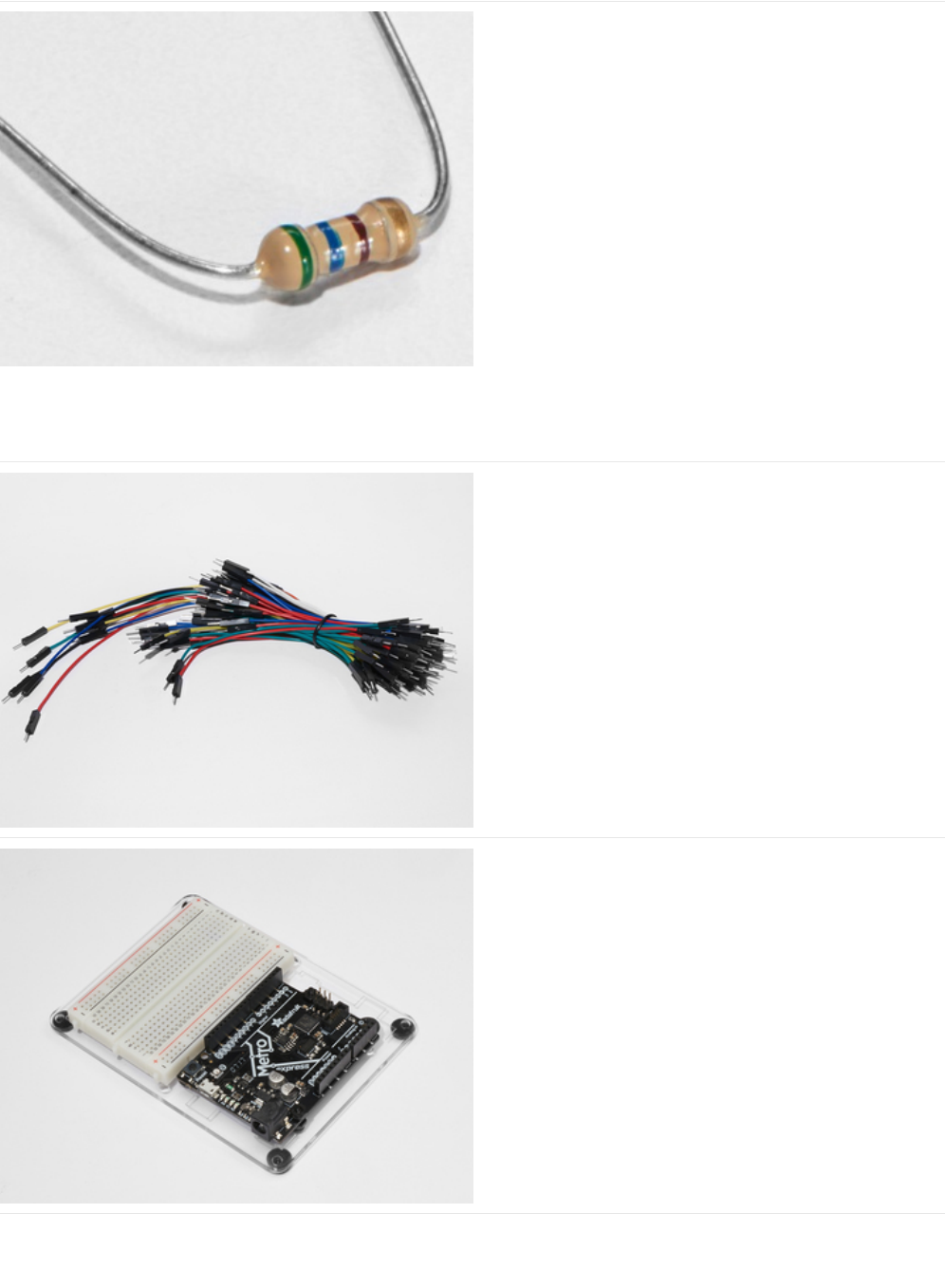
560 Ohm Resistor
Colors: Green > Blue > Brown
If you'd like to order more resistors from the Adafruit shop
click here! (they are 470ohm but they'll be
fine) (https://adafru.it/x4E)
Breadboard Wiring Bundle
If you'd like to order more wires from the Adafruit shop click
here! (https://adafru.it/fE2)
Adafruit Metro (or Metro Express) + Breadboard +
Mounting Plate
If you have not assembled this, we have a handy
guide! (https://adafru.it/x2A)
If you'd like to order an extra plastic mounting
plate (https://adafru.it/x4F), Adafruit
Metro (https://adafru.it/METROXMETR), Adafruit Metro
Express (https://adafru.it/xoa), or Mini-
Breadboard (https://adafru.it/keP) from the Adafruit Shop click
here!
© Adafruit Industries https://learn.adafruit.com/experimenters-guide-for-metro Page 204 of 317
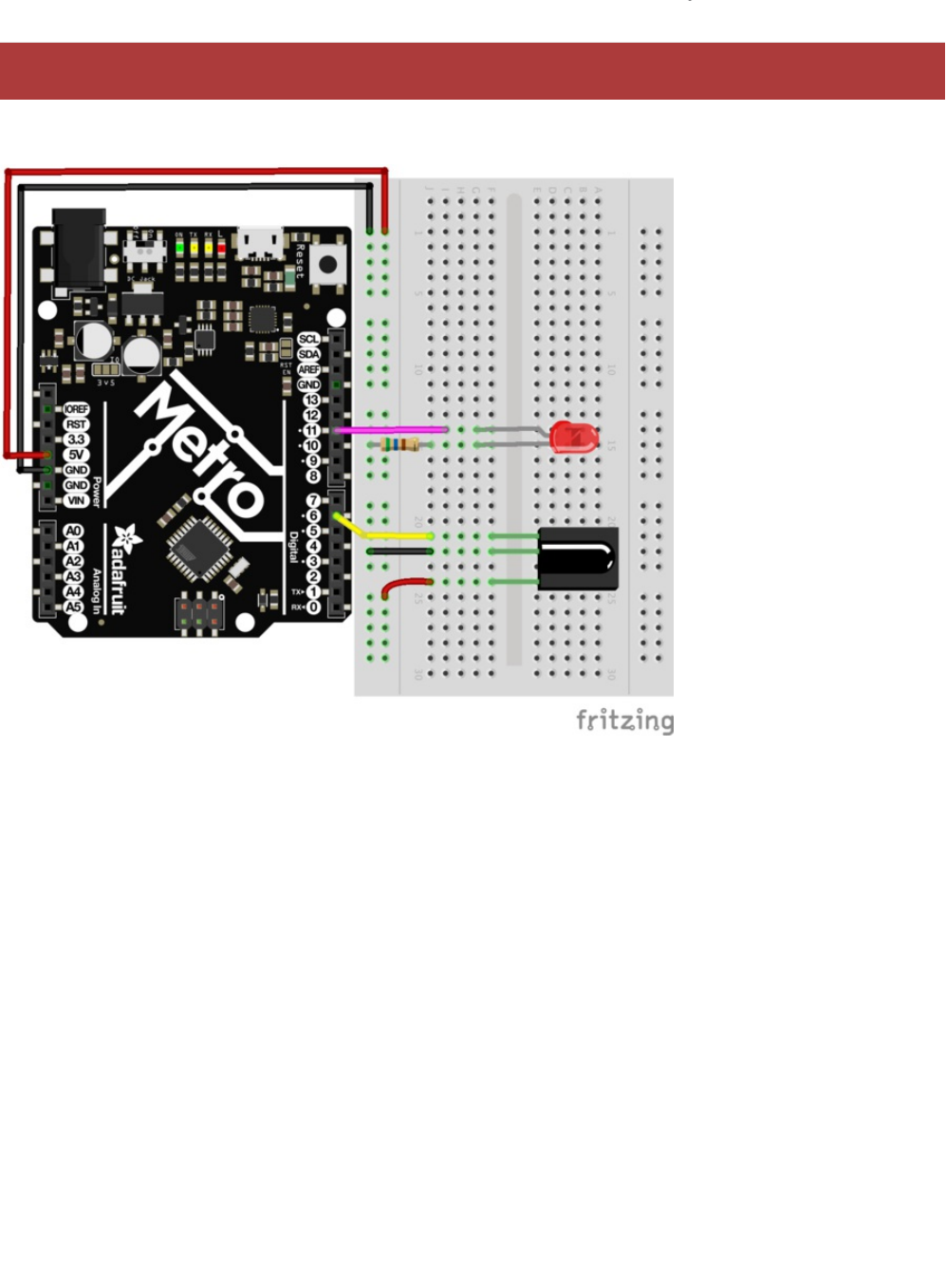
Wiring
The wiring for this circuit is the same for the Metro and the Metro Express.
Do NOT use any other digital pin except for Digital Pin 6 for the IR Sensor.
© Adafruit Industries https://learn.adafruit.com/experimenters-guide-for-metro Page 205 of 317

Installing the IR Library
The Experimenters Guide uses IRLib2 (https://adafru.it/vwF), an easy-to-understand Arduino library that de-mystifies the infrared
light receiver. It makes writing code for IR Reciever and IR LED much easier.
Installing Arduino Libraries
There is an excellent primer on the Adafruit Learning System written by Bill Earl covering Installing Arduino Libraries on all OS
Platforms: (https://adafru.it/dit) Windows (https://adafru.it/dit), Mac (https://adafru.it/dit), and Linux (https://adafru.it/dit)
Keep the learn guide section for your operating system open while following along with the IR Library instructions. It'll make your
first-time installation easier.
Installing the IR Library
https://adafru.it/vxa
https://adafru.it/vxa
To install the IR Library:
1. Download the IR Library by clicking the button above, or download it directly from the IRLib 2.x Library from
Github. (https://adafru.it/vwF)
2. Uncompress the ZIP file after it’s finished downloading.
3. Check that the uncompressed folder contains five separate folders. IRLib 2.x contains multiple libraries that work together.
4. Copy all five into your Arduino Library folder root directory. The path will typically be in
(home)/Documents/Arduino/Libraries. If you do not see the /Libraries/ folder, you may need to create this yourself.
5. Restart the Arduino IDE.
© Adafruit Industries https://learn.adafruit.com/experimenters-guide-for-metro Page 206 of 317

Code
Ensure you followed the
Installing the IR Library
Page. Copy and paste the code below into a blank Arduino Sketch. Then,
compile and upload the code to your Metro.
Press button 1 and the LED should turn on. Any other button will turn the LED off.
/*
* Metro Explorers Guide
* CIRC16: IR Sensor
*
* Desc: Turns on and off a 5mm Red LED with Mini Remote (NEC)
* by Brent Rubell for Adafruit Industries. Support Open Source, buy Adafruit!
*
* Note: this sketch requires IRLIB2.x
*/
// include all IRLib 2.x libraries
#include <IRLibAll.h>
// These values are for the Adafruit Mini Remote (using the NEC Protocol)
#define MY_PROTOCOL NEC
// Handles NEC repeat codes
uint32_t Previous;
// button(s)
#define BUTTON_0 0xfd30cf
#define BUTTON_1 0xfd08f7
#define BUTTON_2 0xfd8877
#define BUTTON_3 0xfd48b7
#define BUTTON_4 0xfd28d7
#define BUTTON_5 0xfda857
#define BUTTON_6 0xfd6897
#define BUTTON_7 0xfd18e7
#define BUTTON_8 0xfd9867
#define BUTTON_9 0xfd58a7
// pin for the reciever
IRrecv myReceiver(6);
// decoder class
IRdecode myDecoder;
// LED PIN
int ledPin = 13;
void setup() {
// set the ledPin as an output
pinMode(ledPin, OUTPUT);
// enable the receiver
myReceiver.enableIRIn();
}
void loop() {
// if the receiver gets a signal
if(myReceiver.getResults()) {
// decode the signal
myDecoder.decode();
// set the decoder's protocol to the set protocol
if(myDecoder.protocolNum == MY_PROTOCOL) {
// if there
if(myDecoder.value == 0xFFFFFFFF) {
// keep the led set to the last button value
myDecoder.value = Previous;
}
// based on myDecoder.value, switch between button codes
© Adafruit Industries https://learn.adafruit.com/experimenters-guide-for-metro Page 207 of 317

Not Working?
I don't see the colors change
Is your RGB LED wired correctly? Are you using a different remote than the one included in the MetroX or MetroX Express
Kit? If so, check out CIRC17 for examples of using different infrared sources.
Fatal error: IRLibAll.h: No such file or directory #include
The IRLib 2.x library was improperly installed. Go back a step and make sure you have it installed.
I still don't see anything
A broken circuit is no fun, post up in the Adafruit Support Forums and we will get back to you as soon as we can.
switch(myDecoder.value) {
// Turn on the LED
case BUTTON_1:
digitalWrite(ledPin, HIGH);
break;
// otherwise, turn off the LED
default:
digitalWrite(ledPin, LOW);
break;
}
// keep the LED set to the last button value
Previous = myDecoder.value;
}
// enable the IR receiver
myReceiver.enableIRIn();
}
}
// sets the color of the RGB LED
void setColor(int* led, const boolean* color) {
for(int i = 0; i < 3; i++) {
digitalWrite(led[i], color[i]);
}
}
© Adafruit Industries https://learn.adafruit.com/experimenters-guide-for-metro Page 208 of 317
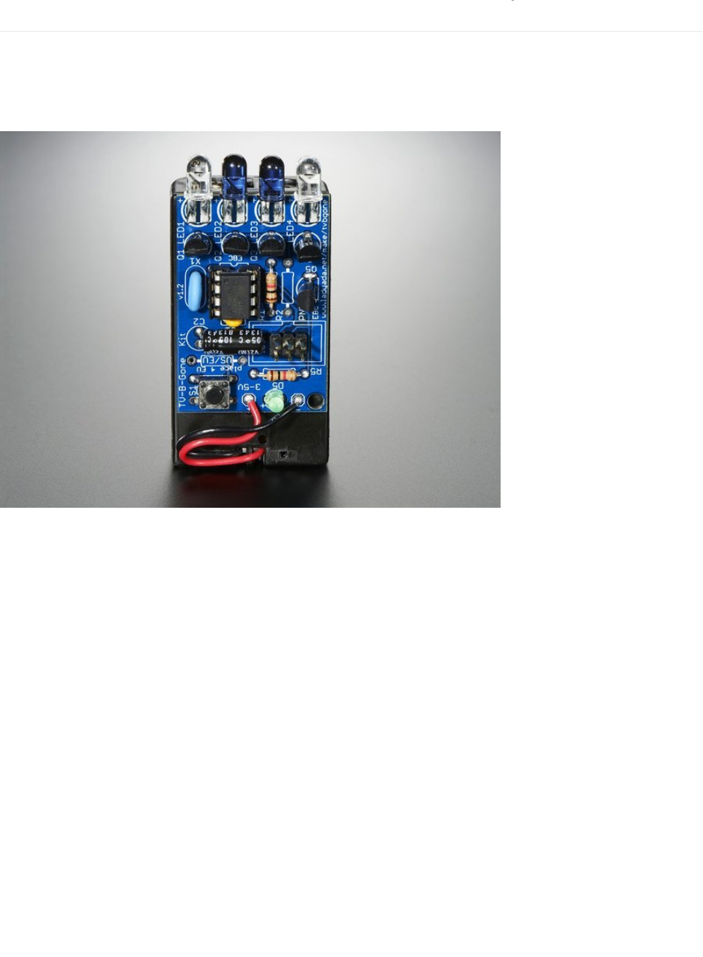
CIRC17: IR Replay
We are going to build an IR Replay circuit. This circuit uses both the IR LED and the IR Sensor (you used this in CIRC15) to
construct a circuit that can record and play back infrared signals from any remote control.
A great (and
really
fun) application of this is the Adafruit TV-B-Gone Kit, (https://adafru.it/xNF) a way to turn off those
annoying televisions in bars, stores, or doctors offices.
The concept of replaying an infrared signal is also super useful in other areas. Some garage door openers open the
garage when a specific IR signal is received. Do some exploring to find out which devices you own are operated by an infrared
signal, and take control of them.
Another application would be building an assistive device, a device to assist someone not able to perform everyday actions.
You can create a great assistive device by combining this circuit, and the FSR, to make a pedal/press operated remote control
for anything operated by IR.
You can even combine this circuit and the relay used in CIRC11 to receive a signal from a nearby remote and control the relay to
switch the power on a DC-powered appliance (like a fan or a lamp).
© Adafruit Industries https://learn.adafruit.com/experimenters-guide-for-metro Page 209 of 317
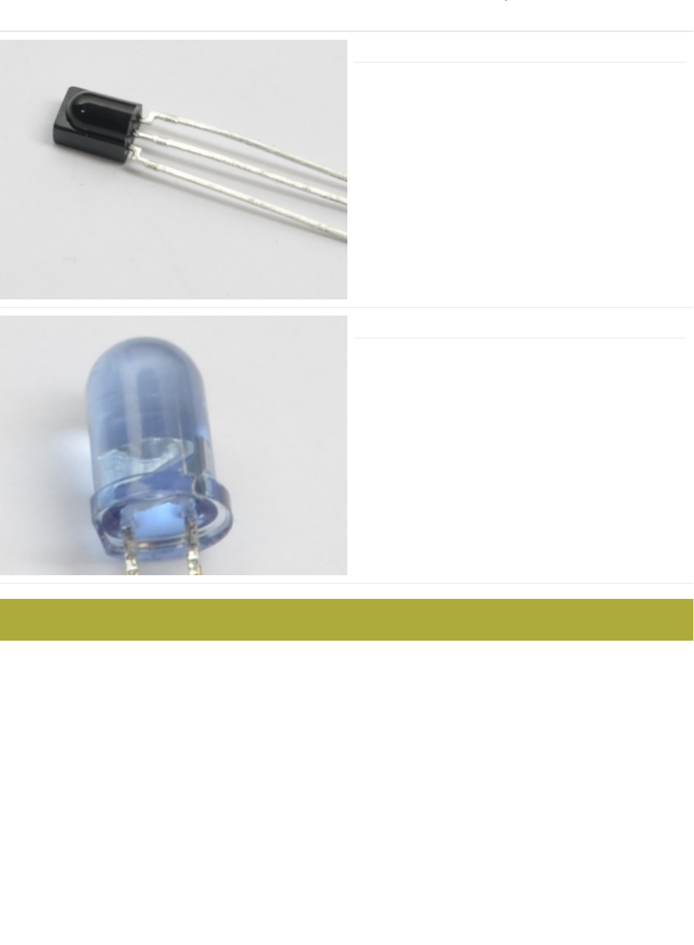
Parts
IR (Infrared) Receiver Sensor
If you'd like to order an extra IR reciver sensor from the
Adafruit shop, click here! (https://adafru.it/xcl)
Super-bright 5mm IR LED
If you'd like to order an extra 5mm IR LED from the Adafruit
shop, click here (https://adafru.it/xNE)
Am I using a NPN Transistor or a TMP36 Temperature Sensor (https://adafru.it/ytD)
This CIRC uses the NPN Transistor, not the TMP36.
© Adafruit Industries https://learn.adafruit.com/experimenters-guide-for-metro Page 210 of 317
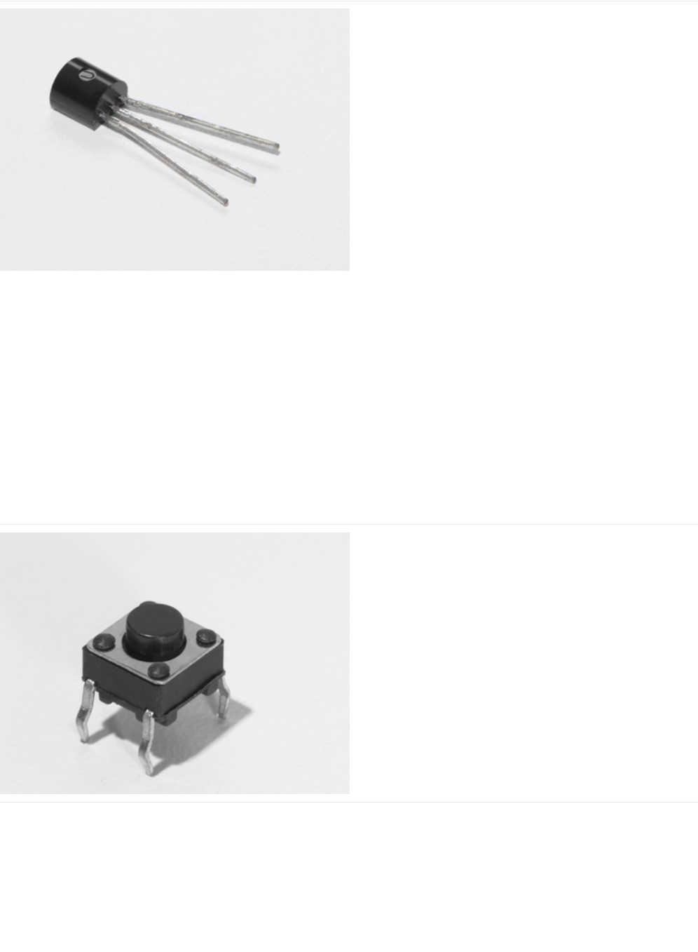
Transistor (PN2222 or MPS2222)
If you'd like to order extra NPN transistors from the Adafruit
shop, click here! (https://adafru.it/xam)
Pushbutton
Qty: x2
If you'd like to order more pushbuttons from the Adafruit
shop, click here! (https://adafru.it/eww)
© Adafruit Industries https://learn.adafruit.com/experimenters-guide-for-metro Page 211 of 317

5mm Red LED
If you'd like to order more red LEDs (they make great
indicator lights!) from the Adafruit shop, click
here! (https://adafru.it/xeV)
560 Ohm Resistor
Colors: Green > Blue > Brown
Qty: x2
If you'd like to order more resistors from the Adafruit shop
click here! (they are 470ohm but they'll be
fine) (https://adafru.it/x4E)
10K Ohm Resistor
Colors: Brown > Black > Orange
Qty: x2
If you'd like to order more 10k ohm pull-up resistors from the
Adafruit shop, click here! (https://adafru.it/xfm)
© Adafruit Industries https://learn.adafruit.com/experimenters-guide-for-metro Page 212 of 317
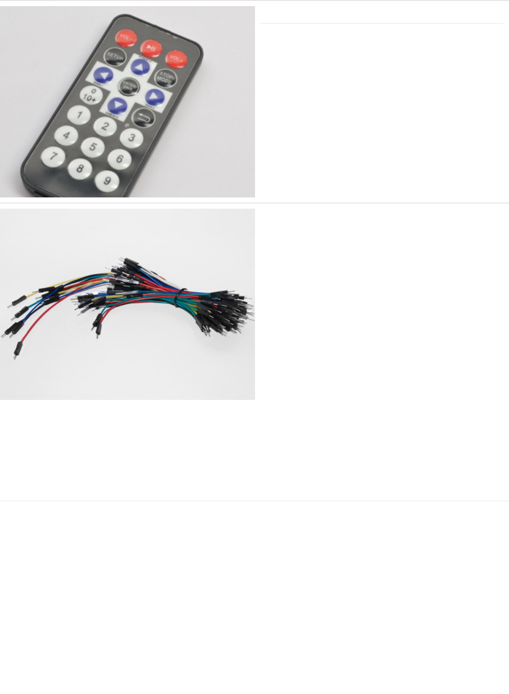
Mini Remote Control (OPTIONAL)
You can use any remote for this circuit. We will use the Mini
Remote for this example, though.
If you'd like to order an extra Mini Remote Control from the
Adafruit Shop, click here! (https://adafru.it/xck)
Breadboard Wiring Bundle
If you'd like to order more wires from the Adafruit shop click
here! (https://adafru.it/fE2)
© Adafruit Industries https://learn.adafruit.com/experimenters-guide-for-metro Page 213 of 317

Adafruit Metro + Breadboard + Mounting Plate
If you have not assembled this, we have a handy
guide! (https://adafru.it/x2A)
If you'd like to order an extra plastic mounting
plate (https://adafru.it/x4F), Adafruit
Metro (https://adafru.it/METROXMETR), or Mini-
Breadboard (https://adafru.it/keP) from the Adafruit Shop click
here!
© Adafruit Industries https://learn.adafruit.com/experimenters-guide-for-metro Page 214 of 317
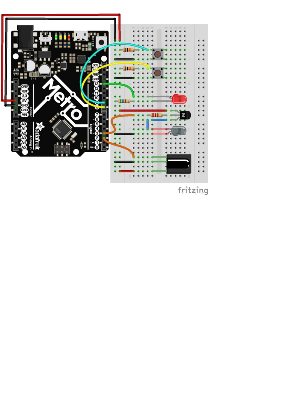
Wiring
We spaced a lot of the components out such that they don't overlap on the breadboard. Be careful while wiring up the
NPN transistor - it has a specific orientation which must be followed.
© Adafruit Industries https://learn.adafruit.com/experimenters-guide-for-metro Page 215 of 317

Code
You'll need the IRLIB2.x Library installed to use CIRC17. If you need to install it, click here! (https://adafru.it/xF0)
Copy and paste the code below into the Arduino Editor, then compile and upload it to your board.
/* CIRC17 - IR Replay
* Requires: IRLib 2.x Library
*
* record.ino by Chris Young
* modified by Brent Rubell for Adafruit Industries for the for the Metro (and Metro Express) Experimenters Guide. Support Open Source, buy Adafruit!
*/
/* IRLib */
#include <IRLibDecodeBase.h> //We need both the coding and
#include <IRLibSendBase.h> // sending base classes
#include <IRLib_P01_NEC.h> //Lowest numbered protocol 1st
#include <IRLib_P02_Sony.h> // Include only protocols you want
#include <IRLib_P03_RC5.h>
#include <IRLib_P04_RC6.h>
#include <IRLib_P05_Panasonic_Old.h>
#include <IRLib_P07_NECx.h>
#include <IRLib_HashRaw.h> //We need this for IRsendRaw
#include <IRLibCombo.h> // After all protocols, include this
// All of the above automatically creates a universal decoder
// class called "IRdecode" and a universal sender class "IRsend"
// containing only the protocols you want.
// Now declare instances of the decoder and the sender.
IRdecode myDecoder;
IRsend mySender;
// Include a receiver either this or IRLibRecvPCI or IRLibRecvLoop
#include <IRLibRecv.h>
IRrecv myReceiver(2); //pin number for the receiver
// Storage for the recorded code
uint8_t codeProtocol; // The type of code
uint32_t codeValue; // The data bits if type is not raw
uint8_t codeBits; // The length of the code in bits
//These flags keep track of whether we received the first code
//and if we have have received a new different code from a previous one.
bool gotOne, gotNew;
/* Buttons */
// button -> pin number
const int playBtn = 8;
const int recBtn = 9;
// hold the button states
int playBtnState = 0;
int recBtnState = 0;
// status LED
const int ledPin = 13;
void setup() {
gotOne=false; gotNew=false;
codeProtocol=UNKNOWN;
codeValue=0;
/* BTNS AND LED */
pinMode(ledPin, OUTPUT);
digitalWrite(ledPin, LOW);
pinMode(playBtn, INPUT);
pinMode(recBtn, INPUT);
© Adafruit Industries https://learn.adafruit.com/experimenters-guide-for-metro Page 216 of 317

pinMode(recBtn, INPUT);
Serial.begin(9600);
Serial.println(F("Send a code from your remote and we will record it."));
Serial.println(F("Type any character and press enter. We will send the recorded code."));
Serial.println(F("Type 'r' special repeat sequence."));
myReceiver.enableIRIn(); // Start the receiver
}
// Stores the code for later playback
void storeCode(void) {
gotNew=true; gotOne=true;
codeProtocol = myDecoder.protocolNum;
Serial.print(F("Received "));
Serial.print(Pnames(codeProtocol));
if (codeProtocol==UNKNOWN) {
Serial.println(F(" saving raw data."));
myDecoder.dumpResults();
codeValue = myDecoder.value;
}
else {
if (myDecoder.value == REPEAT_CODE) {
// Don't record a NEC repeat value as that's useless.
Serial.println(F("repeat; ignoring."));
} else {
codeValue = myDecoder.value;
codeBits = myDecoder.bits;
}
Serial.print(F(" Value:0x"));
Serial.println(codeValue, HEX);
}
}
void sendCode(void) {
if( !gotNew ) {//We've already sent this so handle toggle bits
if (codeProtocol == RC5) {
codeValue ^= 0x0800;
}
else if (codeProtocol == RC6) {
switch(codeBits) {
case 20: codeValue ^= 0x10000; break;
case 24: codeValue ^= 0x100000; break;
case 28: codeValue ^= 0x1000000; break;
case 32: codeValue ^= 0x8000; break;
}
}
}
gotNew=false;
if(codeProtocol== UNKNOWN) {
//The raw time values start in decodeBuffer[1] because
//the [0] entry is the gap between frames. The address
//is passed to the raw send routine.
codeValue=(uint32_t)&(recvGlobal.decodeBuffer[1]);
//This isn't really number of bits. It's the number of entries
//in the buffer.
codeBits=recvGlobal.decodeLength-1;
Serial.println(F("Sent raw"));
}
mySender.send(codeProtocol,codeValue,codeBits);
if(codeProtocol==UNKNOWN) return;
Serial.print(F("Sent "));
Serial.print(Pnames(codeProtocol));
Serial.print(F(" Value:0x"));
Serial.println(codeValue, HEX);
}
© Adafruit Industries https://learn.adafruit.com/experimenters-guide-for-metro Page 217 of 317
Not Working?
I don't see the LED lighting up
Try opening the Arduino Serial Monitor. There are Serial.print() statements in this code to help you debug.
I can receive but not send IR signals
Make sure your NPN Transistor is hooked up correctly, it is required for this circuit.
I'm really frustrated with this circuit, I don't see any output after debugging
This circuit is especially tricky because the Infrared Sensor and Receiver are kinda finicky, post up in the Adafruit Support
Forums and we will get back to you as soon as we can.
void loop() {
recBtnState = digitalRead(recBtn);
playBtnState = digitalRead(playBtn);
if(recBtnState == HIGH ) {
digitalWrite(ledPin, LOW);
myDecoder.decode();
// Re-enable receiver
myReceiver.enableIRIn();
digitalWrite(ledPin, HIGH);
}
if(playBtnState == HIGH) {
// check for stored signal
if(gotOne) {
// send the IR Code
sendCode();
// re-enable receiver
myReceiver.enableIRIn();
digitalWrite(ledPin, LOW);
}
}
}
© Adafruit Industries https://learn.adafruit.com/experimenters-guide-for-metro Page 218 of 317

Parts
Adafruit Metro
Express
+ Breadboard + Mounting
Plate
If you have not assembled this, we have a handy
guide! (https://adafru.it/x2A)
Need an extra plastic mounting plate (https://adafru.it/x4F),
Adafruit Metro Express (https://adafru.it/xoa), or Mini-
Breadboard (https://adafru.it/keP) from the Adafruit Shop?
This CIRCuit only works with the Metro EXPRESS, not the Metro Classic
© Adafruit Industries https://learn.adafruit.com/experimenters-guide-for-metro Page 219 of 317
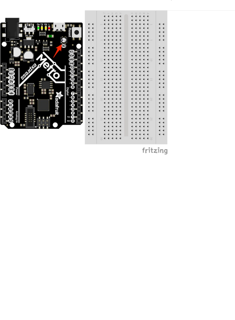
Wiring for Metro Express
There's nothing to breadboard! The Metro Express has all the circuit required on the board (including the NeoPixel!). The
NeoPixel is assigned to Digital Pin 40 on the Metro Express
© Adafruit Industries https://learn.adafruit.com/experimenters-guide-for-metro Page 220 of 317
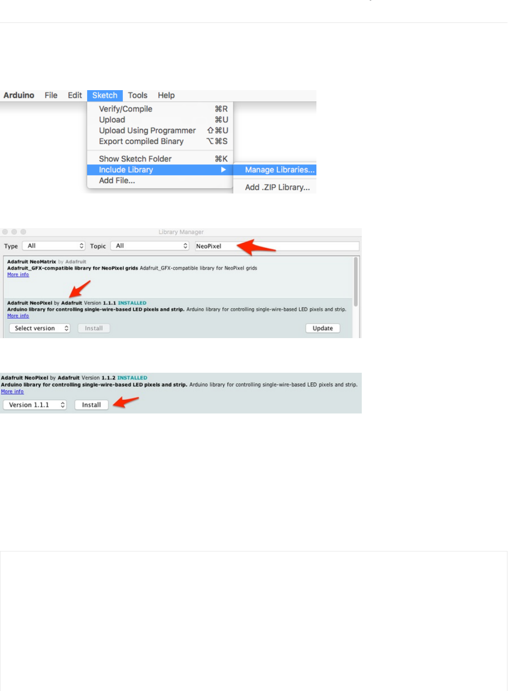
Code
Installing the NeoPixel Library
Before copying and pasting the code, you'll need to install the NeoPixel Library. This is much easier than the installation of the IR
Library - you can install the NeoPixel library directly from the IDE!
In Arduino, go to Sketch > Include Library > Manage Libraries.
In the library manager, search for NeoPixel.
Then, find the latest version (1.1.1 at time of writing) and click install.
Once the status bar is finished, restart the Arduino IDE. The NeoPixel library has been installed.
Code
Copy/Paste the code below. Then, compile and upload it to your metro (https://adafru.it/xap).
You should see your Metro's NeoPixels light up red, white, and blue.
/*
* (CIRC18) Metro Express NeoPixel
* this circuit was designed for use with the Metro Explorers Guide on Learn.Adafruit.com
*
* note: this code does NOT run on the Metro, only the Metro EXPRESS.
*
* by Brent Rubell for Adafruit Industries.
*/
// Include the Adafruit Neopixel Library
#include <Adafruit_NeoPixel.h>
// The default pin for the NeoPixel on the Metro Express is Pin #40
© Adafruit Industries https://learn.adafruit.com/experimenters-guide-for-metro Page 221 of 317

Having trouble?
// The default pin for the NeoPixel on the Metro Express is Pin #40
#define METROPIXELPIN 40
// metroPixel takes in both the number of pixels (1, the built-in) and the pin)
Adafruit_NeoPixel metroPixel = Adafruit_NeoPixel(1, METROPIXELPIN);
/* Colors */
// note: the max. of colors in these arrays is 220 instead of 255 (super-bright!!)
const int RED[ ] = {155, 0, 0};
const int WHITE[ ] = {155, 155, 155};
const int BLUE[ ] = {0, 0, 255};
const int BLACK [ ] = {0, 0, 0};
void setup() {
// init. the NeoPixel library
metroPixel.begin();
}
void loop() {
// display red on the Metro Express neopixel
pixelWrite(RED);
delay(1000);
// display white on the Metro Express neopixel
pixelWrite(WHITE);
delay(1000);
// display blue on the Metro Express neopixel
pixelWrite(BLUE);
delay(1000);
// Sparkle the Neopixel
// pixelSparkle();
}
// takes in a pre-defined color (integer array) and sets the pixel to that color
void pixelWrite(const int* color) {
metroPixel.setPixelColor(0, metroPixel.Color(color[0],color[1],color[2]));
// write the pixel color to the Metro's Neopixel
metroPixel.show();
}
// flashes the neopixel on and off rapidly
void pixelSparkle() {
for(int i = 0; i < 5; i++) {
pixelWrite(BLACK);
delay(50);
pixelWrite(WHITE);
delay(50);
}
}
© Adafruit Industries https://learn.adafruit.com/experimenters-guide-for-metro Page 222 of 317

My Code Wont Compile
Make sure that the NeoPixel library was correctly installed to the right location.
I don't see a NeoPixel on my board.
You must have a Metro, not a Metro Express. This circuit only works with the Metro Express.
I still don't see anything
Post up in the Adafruit Support Forums and we will get back to you as soon as we can.
© Adafruit Industries https://learn.adafruit.com/experimenters-guide-for-metro Page 223 of 317
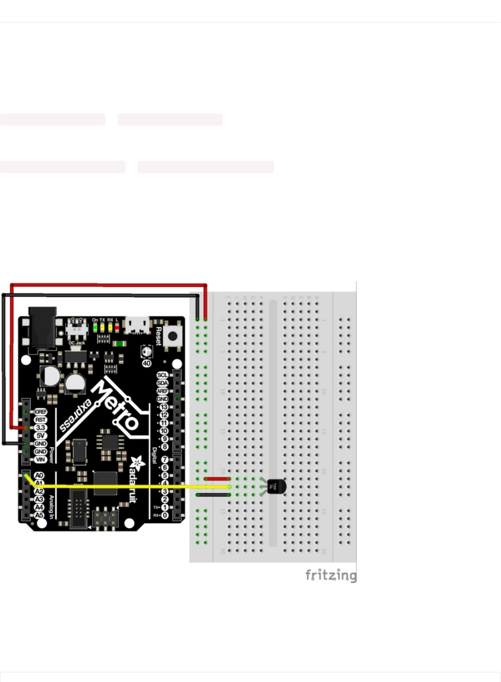
Make It Better
Dimming the NeoPixel
Wow that NeoPixel sure is bright, huh? There is a really simple way to dim it. The NeoPixel takes a value from 0 to 255, 255
being the brightest.
Let's dim it by 100. In your code, change:
const int RED[ ] = {255, 0, 0}; to const int RED[ ] = {155, 0, 0};
Still too bright? Let's cut it by 1/3rd by changing:
const int GREEN[ ] = {128, 255, 0}; to const int GREEN[ ]= {128/3, 255/3, 0};
NeoPixel Glance Thermometer
We're going to modify the thermometer circuit to use the NeoPixel to assemble a color-coded thermometer. Glance over at this
circuit and see the color which corresponds to a specific temperature.
Wiring
The wiring for this circuit is easy - just wire up the temperature sensor.
Code
Copy/paste the code below. Then, compile and upload it to your Metro Express!
/*
© Adafruit Industries https://learn.adafruit.com/experimenters-guide-for-metro Page 224 of 317

/*
* CIRC18 Make It Better
* NeoPixel Glance Thermometer - check the weather super quickly!
*
* by Brent Rubell for Adafruit Industries
*/
// Include the Adafruit Neopixel Library
#include <Adafruit_NeoPixel.h>
// The default pin for the NeoPixel on the Metro Express is Pin #40
#define METROPIXELPIN 40
// Temperature Sensor
const int temperaturePin = A0;
// metroPixel takes in both the number of pixels (1, the built-in) and the pin)
Adafruit_NeoPixel metroPixel = Adafruit_NeoPixel(1, METROPIXELPIN);
float temperature = 0;
/* Temperature Colors */
const int RED[ ] = {255, 0, 0};
const int ORANGE[ ] = {255, 153, 51};
const int YELLOW[ ] = {255, 255, 0};
const int LIGHTGREEN[ ] = {128, 255, 0};
const int DARKGREEN[ ] = {76, 153, 0};
const int DARKBLUE[ ] = {0, 0, 255};
const int DARKPURPLE[ ] = {51, 0, 102};
const int BLACK[ ] = {0, 0, 0};
void setup()
{
// Start the Serial at 9600 baud
Serial.begin(9600);
// init the neopixel library
metroPixel.begin();
}
void loop()
{
temperature = getVoltage3V(temperaturePin);
// Convert to degrees C
temperature = (temperature - .5) * 100;
// print the temperature in C to the serial
Serial.println(temperature);
// temp <-> color picker
if (temperature > 40) {
// red
pixelWrite(RED);
}
else if (temperature > 35) {
// orange
pixelWrite(ORANGE);
}
else if (temperature > 30) {
// yellow
pixelWrite(YELLOW);
}
else if (temperature > 25) {
// yellow
pixelWrite(LIGHTGREEN);
}
else if (temperature > 20) {
// dark green
pixelWrite(DARKGREEN);
© Adafruit Industries https://learn.adafruit.com/experimenters-guide-for-metro Page 225 of 317

Adding the NeoPixel to CIRCs
The Glance Thermometer is a modification of the temperature circuit. Which CIRCs have you completed? How would you add a
NeoPixel to the circuit to increase functionality, utility or aesthetic?
pixelWrite(DARKGREEN);
}
else if (temperature > 5) {
// dark blue
pixelWrite(DARKBLUE);
}
else {
// dark purple
pixelWrite(DARKPURPLE);
}
delay(1000);
}
// takes in a pre-defined color (integer array) and sets the pixel to that color
void pixelWrite(const int* color) {
metroPixel.setPixelColor(0, metroPixel.Color(color[0],color[1],color[2]));
// write the pixel color to the Metro's Neopixel
metroPixel.show();
}
// Voltage to temperature if Vs= 3.3V
float getVoltage3V(int pin){
// 3.3V/1023
return (analogRead(pin) * 0.003225806452);
}
© Adafruit Industries https://learn.adafruit.com/experimenters-guide-for-metro Page 226 of 317
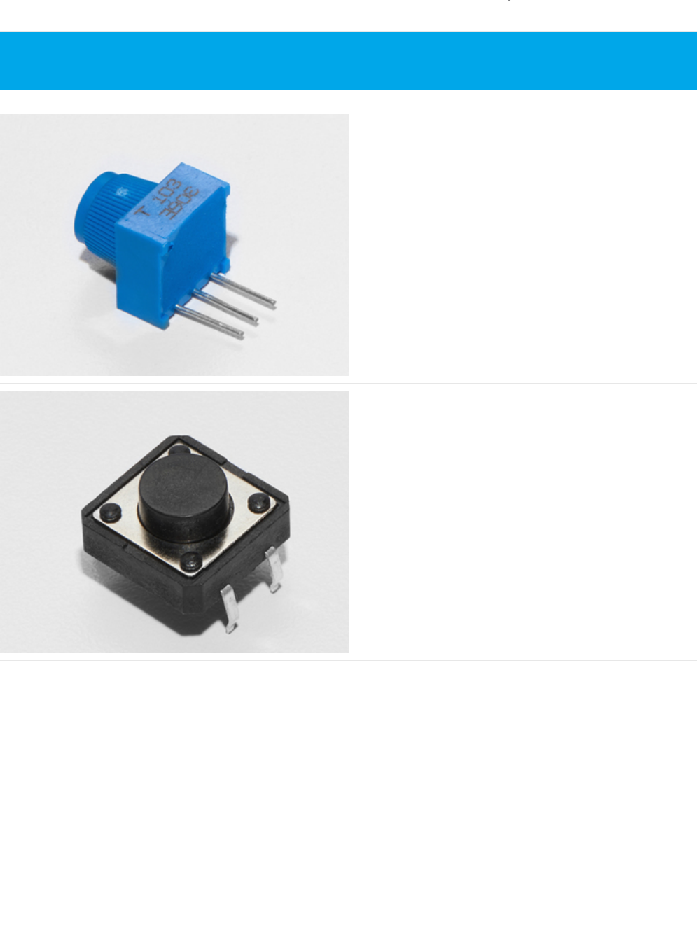
Parts
Breadboard Trim Potentiometer - 10k
If you'd like to buy an extra trimpot from the Adafruit store,
click here! (https://adafru.it/tba)
Pushbutton
If you'd like to order more pushbuttons from the Adafruit
shop, click here! (https://adafru.it/eww)
This CIRC only works with the Metro EXPRESS, not the Metro. Please confirm you are using a Metro Express before
assembling this CIRC.
© Adafruit Industries https://learn.adafruit.com/experimenters-guide-for-metro Page 227 of 317

10K Ohm Resistor
Colors: Brown > Black > Orange
If you'd like to order more 10k ohm pull-up resistors from the
Adafruit shop, click here! (https://adafru.it/xfm)
Breadboard Wiring Bundle
If you'd like to order more wires from the Adafruit shop click
here! (https://adafru.it/fE2)
© Adafruit Industries https://learn.adafruit.com/experimenters-guide-for-metro Page 228 of 317
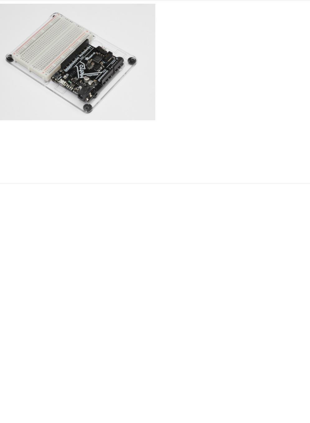
Adafruit Metro
Express
+ Breadboard + Mounting
Plate
If you have not assembled this, we have a handy
guide! (https://adafru.it/x2A)
Need an extra plastic mounting plate (https://adafru.it/x4F),
Adafruit Metro Express (https://adafru.it/xoa), or Mini-
Breadboard (https://adafru.it/keP) from the Adafruit Shop?
© Adafruit Industries https://learn.adafruit.com/experimenters-guide-for-metro Page 229 of 317
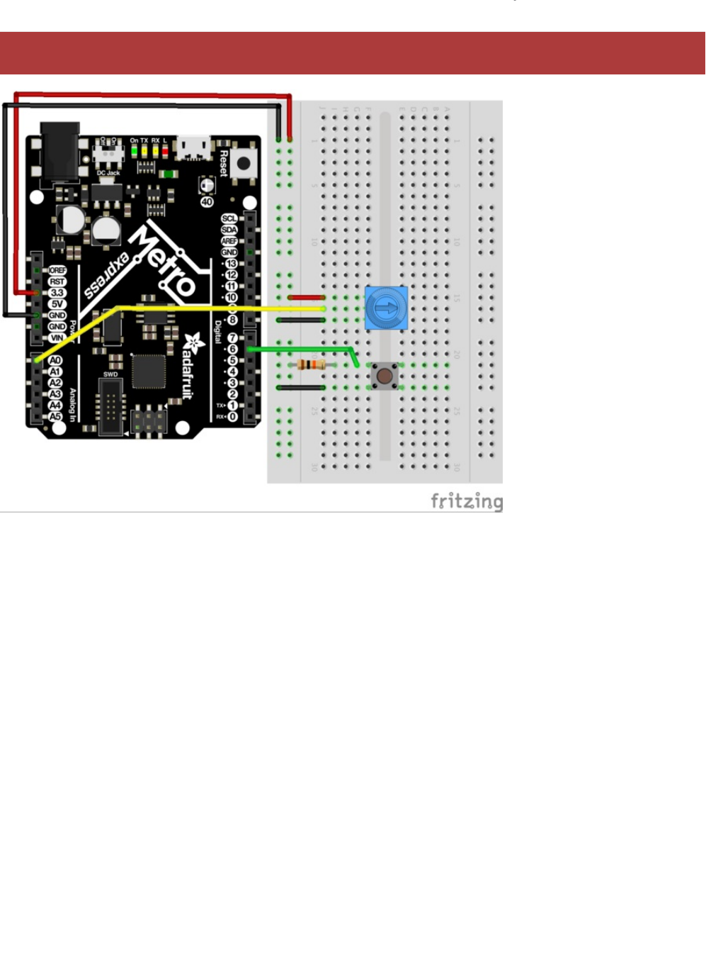
Wiring
This is a circuit on the Express line, it will only work with the Metro Express.
© Adafruit Industries https://learn.adafruit.com/experimenters-guide-for-metro Page 230 of 317

Code
The USB-HID Library is built into Arduino, there is no external installation required. Verify that you have a Metro Express, then
copy and paste the code below into the Arduino Editor. Then, compile and upload.
Using USB Blog Buddy
/*
* USB Blog Buddy
* a USB-HID Scroll Wheel for Metro Express
*
* by Brent Rubell for Adafruit Industries. Support Open Source, buy Adafruit!
*/
// include the mouse library
#include <Mouse.h>
// trimpot pin
const int trimPin = A0;
// button pin
const int buttonPin = 2;
// reduces scrolling speed (ms)
const int scrollDelay = 100;
// trimpot value
int trimValue = 0;
// button state
int buttonState = 0;
void setup() {
// start serial monitor at 9600 baud
Serial.begin(9600);
// start the mouse
Mouse.begin();
}
void loop() {
// read the button state
buttonState = digitalRead(buttonPin);
if (buttonState == HIGH) {
// stop the mouse if button not pressed
Mouse.end();
}
else {
// start the mouse (if stopped)
Mouse.begin();
// read the trimpot value
trimValue = analogRead(trimPin);
// map the trimValues to scroll wheel down (-neg values) and up (+pos values)
trimValue = map(trimValue, 0, 1023, -5, 5);
// move the mouse wheel (dont change cursor position)
Mouse.move(0, 0, trimValue);
// reduce the scrolling speed
delay(scrollDelay);
}
}
© Adafruit Industries https://learn.adafruit.com/experimenters-guide-for-metro Page 231 of 317

Head over to the Adafruit Blog to test your circuit out! (https://adafru.it/otd)
When you press the push button, the Metro Express will take control of your mouse and start scrolling the mouse wheel.
Scroll Page Up: Move the potentiometer such that the arrow on it faces towards the top of the breadboard
Scroll Page Down: Move the potentiometer such that the arrow on it faces towards the bottom of the breadboard
Not Working?
I don't see anything moving on my screen
Check your wiring, the library for USB interfacing is built into Arduino and should automatically start when you upload this
code.
Still not working?
Post up in the Adafruit Support Forums and we will get back to you as soon as we can.
© Adafruit Industries https://learn.adafruit.com/experimenters-guide-for-metro Page 232 of 317
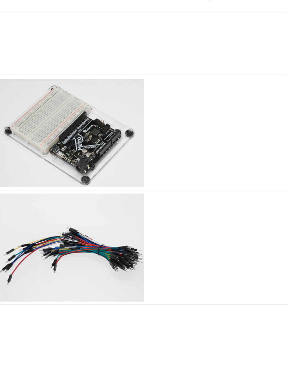
Parts
If you're using a Metro Classic:
You'll need a 1M Ohm Resistor.
If you're using a Metro M0 Express:
You're dont need any new parts, the M0 Express the capacitive sensor stuff managed completely inside the chip!
Adafruit Metro (or Metro Express) + Breadboard +
Mounting Plate
If you have not assembled this, we have a handy
guide! (https://adafru.it/x2A)
If you'd like to order an extra plastic mounting
plate (https://adafru.it/x4F), Adafruit
Metro (https://adafru.it/METROXMETR), Adafruit Metro
Express (https://adafru.it/xoa), or Mini-
Breadboard (https://adafru.it/keP) from the Adafruit Shop click
here!
Breadboard Wiring Bundle
If you'd like to order more wires from the Adafruit shop click
here! (https://adafru.it/fE2)
© Adafruit Industries https://learn.adafruit.com/experimenters-guide-for-metro Page 233 of 317
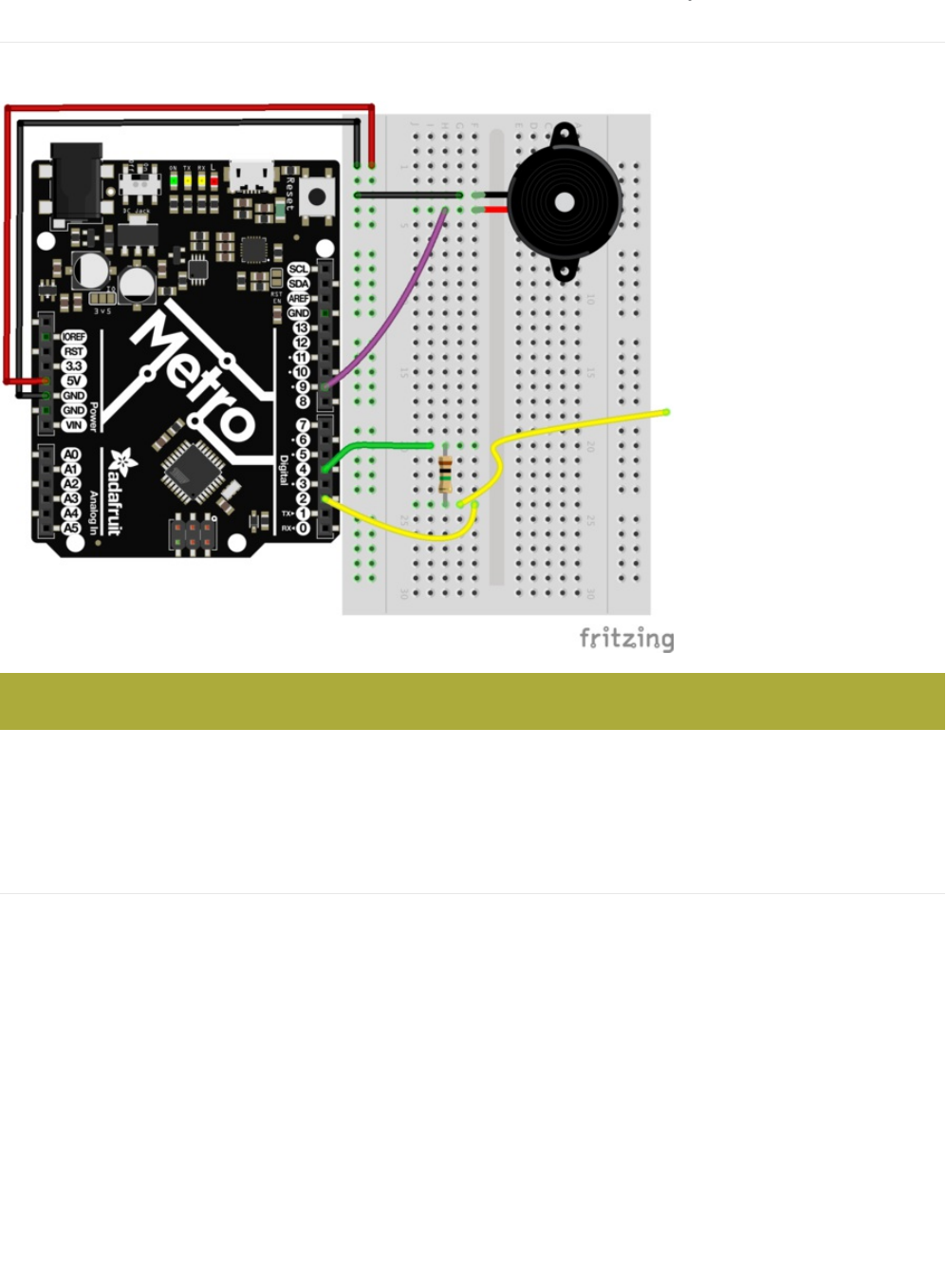
Wiring
Wiring for the Metro Classic
You'll want to be using a 1M Ohm Resistor for this Circuit. The pin extending from the sensor pin (in our case, it's Digital Pin 2),
should ideally be a short pin from the Breadboarding Bundle.
1M Ohm Resistor Color Band: Brown > Black > Green > Silver
Wiring for the Metro Express
Pay attention to the resistor value!
© Adafruit Industries https://learn.adafruit.com/experimenters-guide-for-metro Page 234 of 317
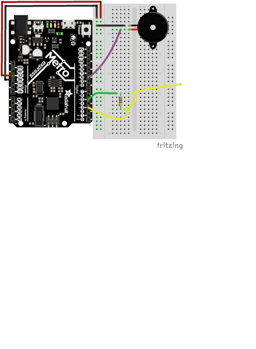
You don't need a 1M Ohm resistor for this circuit, just a smaller value (like the 560 ohm included in the MetroX Classic and
MetroX Express kits). The Metro Express has 1M Ohm pull-up resistor values on-board.
© Adafruit Industries https://learn.adafruit.com/experimenters-guide-for-metro Page 235 of 317

Wiring for Metro Express
© Adafruit Industries https://learn.adafruit.com/experimenters-guide-for-metro Page 236 of 317

Code
You'll need to download install the CapacitiveSensor Library:
https://adafru.it/yBn
https://adafru.it/yBn
If you need a referesher on how to install Arduino Libraries, re-read over the
Installing Arduino Libraries
Section in in
CIRC16 (https://adafru.it/xF0)
Code
After downloading and installing the CapacitiveSensor Library, copy and paste the code below into the Arduino IDE. Then,
compile and upload it to your Metro (or Metro Express).
© Adafruit Industries https://learn.adafruit.com/experimenters-guide-for-metro Page 237 of 317

I'm having problems with this CIRC
Not hearing anything?
Open up the Arduino Serial Monitor. What do you see as the largest sensor value when you press the pin? The smallest? In
the lien below, replace the values for MIN_SENSOR_VALUE and MAX_SENSOR_VALUE with the two
numeric
values you
found:
long mapTone = map(pinTone, MIN_SENSOR_VALUE, MAX_SENSOR_VALUE, 500, 2000);
Getting sensor readings of 0?
When you open the Arduino Serial Monitor, do you see values of 0 or -2? The resistor you're using might be too small. We
advise using a 1M Ohm resistor, not the 10K Ohm Resistor. That's one million ohms. If you don't have any 1M Ohm resistors,
/*
* CIRC20 - Capacitive Sensing with the Metro and Metro M0 Express
*
* by Brent Rubell for Adafruit Industries. Support Open Source Hardware, Buy Adafruit!
*/
#include <CapacitiveSensor.h>
// piezo speaker pin
int piezoPin = 9;
// 10M resistor between pins 4 & 2, pin 2 is sensor pin, add a wire and or foil if desired
// put a 10M resistor between pins 4 & 2, pin 2 is the sensor pin, 4 is the receiver
CapacitiveSensor cs_4_2 = CapacitiveSensor(4,2);
void setup()
{
cs_4_2.set_CS_AutocaL_Millis(0xFFFFFFFF);
Serial.begin(9600);
// set the piezo as an output
pinMode(piezoPin, OUTPUT);
}
void loop()
{
long start = millis();
long pinTone = cs_4_2.capacitiveSensor(30);
Serial.print("sensor value: "); // check on performance in milliseconds
Serial.print("\t"); // tab character for debug windown spacing
Serial.print(pinTone); // print sensor output 1
Serial.print("\n");
// map the tone value to frequencies between 500 and 2000
long mapTone = map(pinTone, 0, 40, 500, 2000);
// play the mapped tone
playTone(int(mapTone), 100);
delay(10);
}
void playTone(int tone, int duration) {
for (long i = 0; i < duration * 1000L; i += tone * 2) {
digitalWrite(piezoPin, HIGH);
delayMicroseconds(tone);
digitalWrite(piezoPin, LOW);
delayMicroseconds(tone);
}
}
© Adafruit Industries https://learn.adafruit.com/experimenters-guide-for-metro Page 238 of 317

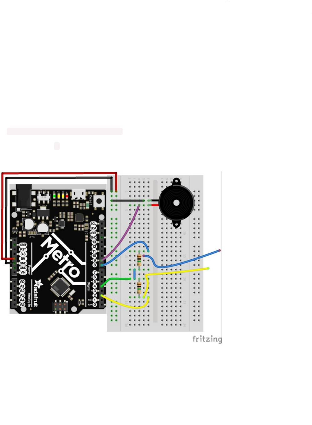
Make It Better
Using Different Input Types
You can use many different types of inputs for the capacitive sensor. Among these are everything from Apples, salt water, and
utensils (depending on the material). You can also use some of the different conductive materials from the Adafruit shop like
Conductive Rubber, (https://adafru.it/yBl) Woven Conductive fabric (try using this for wearable projects) (https://adafru.it/yBm), or
even conductive paint pens to turn any material into a conductive one (https://adafru.it/fKf).
Adding Sensor Inputs
Need more inputs? You can continue using Digital Pin 4 for your receiver pin and any other digital pin can be used to create a
capacitive sensor.
To do this, just add a line in your code:
CapacitiveSensor cs_4_# = CapacitiveSensor(4,#);
You'll need to replace # with the Digital Pin Number you want used as a sensor.
We're using Digital Pin 4 as the Receiver and Digital Pin 8 as the new sensor, so here's is how your breadboard should look:
© Adafruit Industries https://learn.adafruit.com/experimenters-guide-for-metro Page 240 of 317
PROJ01: Theremin
You are going to become a Thereminist! One of the stranger instruments out there is a Theremin (https://adafru.it/pFU), an
electronic instrument where you can wave your hands and make music! You are going to make one of your own, using your
knowledge from previous CIRCs to guide you.
© Adafruit Industries https://learn.adafruit.com/experimenters-guide-for-metro Page 241 of 317
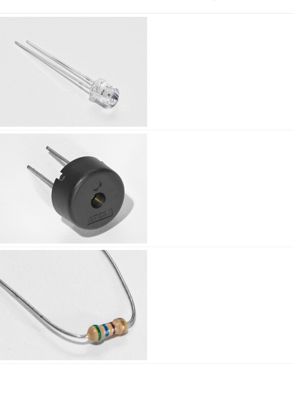
Parts
Photo Sensor
If you'd like to order another photoresistor from the Adafruit
shop, click here! (https://adafru.it/xfo)
Piezo Buzzer
If you'd like to order another Pizeo Buzzer from the Adafruit
shop, click here! (https://adafru.it/dCD)
560 Ohm Resistor
Colors: Green > Blue > Brown
If you'd like to order more resistors from the Adafruit shop
click here! (they are 470ohm but they'll be
fine) (https://adafru.it/x4E)
© Adafruit Industries https://learn.adafruit.com/experimenters-guide-for-metro Page 242 of 317
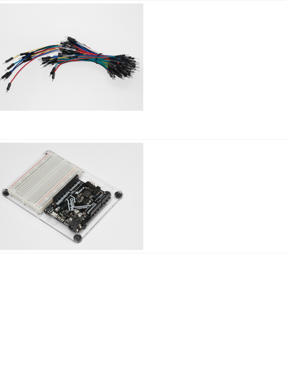
Breadboard Wiring Bundle
If you'd like to order more wires from the Adafruit shop click
here! (https://adafru.it/fE2)
Adafruit Metro (or Metro Express) + Breadboard +
Mounting Plate
If you have not assembled this, we have a handy
guide! (https://adafru.it/x2A)
If you'd like to order an extra plastic mounting
plate (https://adafru.it/x4F), Adafruit
Metro (https://adafru.it/METROXMETR), Adafruit Metro
Express (https://adafru.it/xoa), or Mini-
Breadboard (https://adafru.it/keP) from the Adafruit Shop click
here!
© Adafruit Industries https://learn.adafruit.com/experimenters-guide-for-metro Page 243 of 317
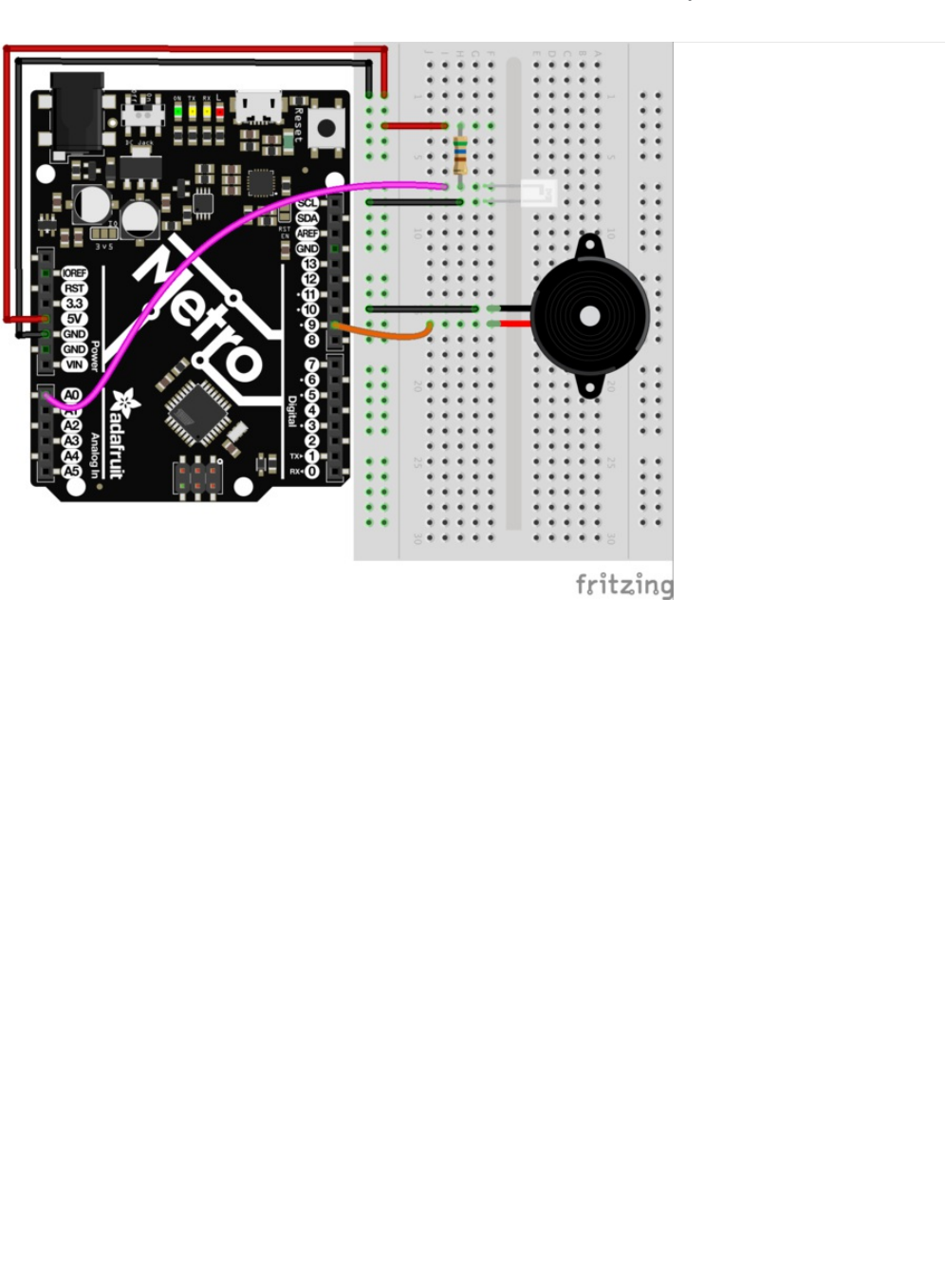
Wiring
© Adafruit Industries https://learn.adafruit.com/experimenters-guide-for-metro Page 244 of 317

Wiring for Metro Express
© Adafruit Industries https://learn.adafruit.com/experimenters-guide-for-metro Page 245 of 317

Code
Setting Pins
The pins for both the piezo and the photo light sensor are both declared as
integer
types. The A in front of the photo light
sensor stands for
analog.
Reading the photo light sensor
The photo light sensor is read within the loop(). We restricted the photoVal to integer values only (no decimal points). Then, an
analogRead() was called on the photo light sensor pin to read pin data.
Creating the Pitch
The pitch variable is created to store the resulting pitch. Then, map() is called. This function takes in photoVal and photoVal's
lower and upper values. Then, it maps that range to a range within 150Hz and 1500Hz
Playing the Pitch
Tone() is passed both the pin with the Piezo and the pitch integer generated before.
The complete theremin code is below. Copy and paste it into a blank Arduino sketch, then compile and upload!
int piezoPin = 9;
int photoLightSensorPin = A0;
void loop() {
// get photo sensor value
int photoVal = analogRead(photoLightSensorPin);
}
int pitch = map(photoVal, 190, 1100, 150, 1500);
// play tone
tone(piezoPin, pitch);
© Adafruit Industries https://learn.adafruit.com/experimenters-guide-for-metro Page 246 of 317

Move your hand around the circuit to play music with your theremin! Congrats, you just built your first quest circuit.
Bored of this theremin? Let's Make It Better!
Wait...my PROJect doesn't work!
I don't hear anything
Check the wiring of both the piezo and the light sensor. You might find flipping the light sensor around will fix it.
I can't get this working at all
We'll help you out! Post up in the Adafruit Support Forums and we will get back to you as soon as we can.
/*
* (PROJ01) Metro (and Metro Express) Theremin
* Desc: Super basic theremin using a light sensor and a piezo element
*
* by Brent Rubell for Adafruit Industries.
*/
int piezoPin = 9;
int photoLightSensorPin = A0;
void setup() {
Serial.begin(9600);
}
void loop() {
// get photo sensor value
int photoVal = analogRead(photoLightSensorPin);
/* Create the pitch
* map() the photolightsensor value to
* a frequency from 150Hz to 1500Hz
* more info about map() - https://www.arduino.cc/en/Reference/Map
*/
int pitch = map(photoVal, 190, 1100, 150, 1500);
// play tone
tone(piezoPin, pitch);
}
© Adafruit Industries https://learn.adafruit.com/experimenters-guide-for-metro Page 247 of 317
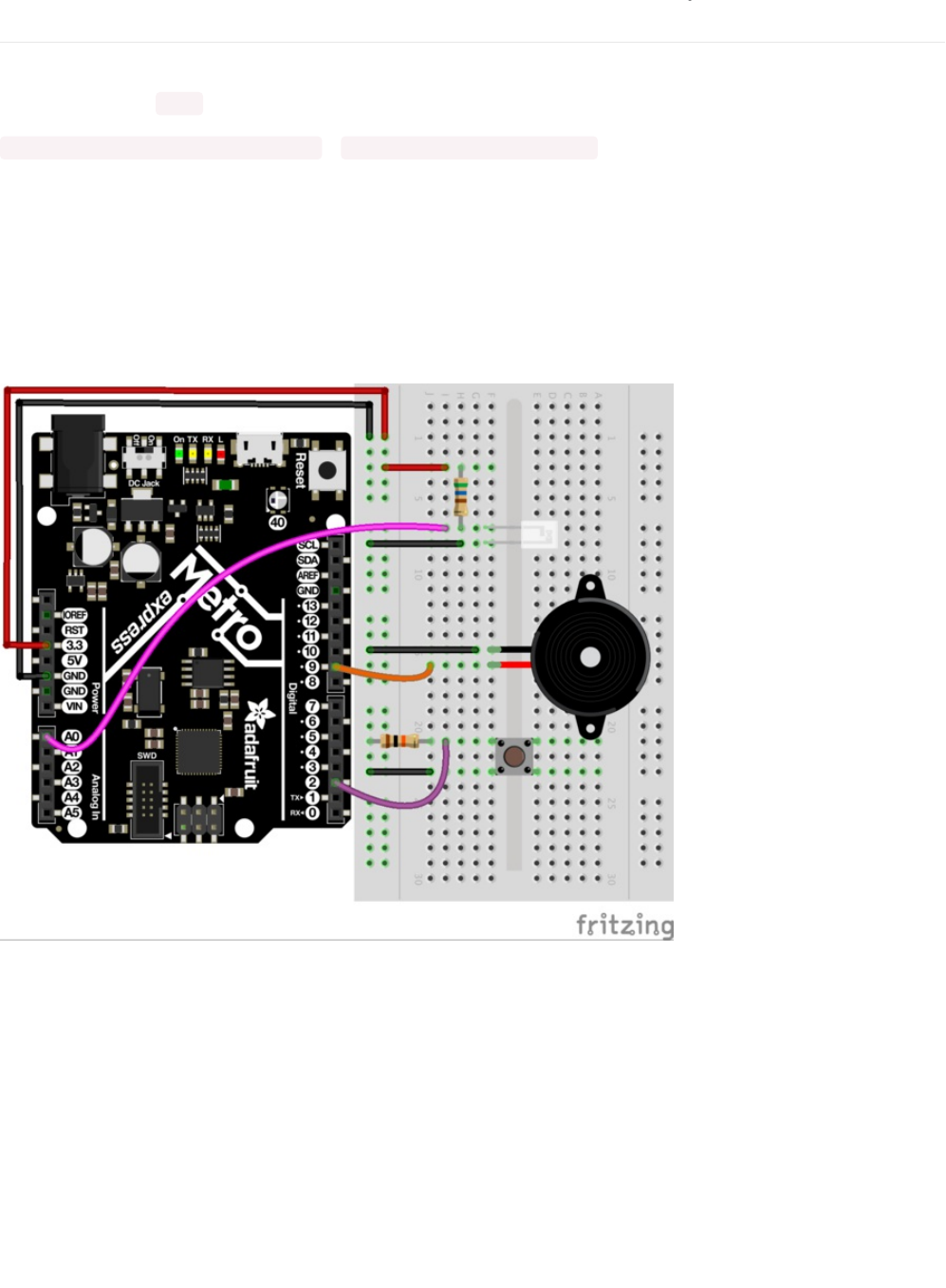
Make It Better
Modifying the pitch
Taking a look at how map() works in the Theremin quest circuit, you can start to understand how map works:
map(value, fromLow, fromHigh, toLow, toHigh); to map(photoVal, 190, 1100, 150, 1500);
The first two values correspond to the photo light sensor, while the last two are the pitch. Try modifying the last two values (150
and 1500) up and down. You'll get different sounds every time!
Stop the Music!
You may have gotten annoyed with the spooky sounds coming out of your theremin. There are two ways to stop this sound.
One way to do this is with a push-button. Plug one into your breadboard and wire it up to Digital Pin 2:
Next, modify the Arduino code to call NoTone() when the button is pressed. We'll leave this up to you to figure out. One hint is to
look at both the NoTone() documentation (https://adafru.it/xwF) and CIRC07's code.
© Adafruit Industries https://learn.adafruit.com/experimenters-guide-for-metro Page 248 of 317
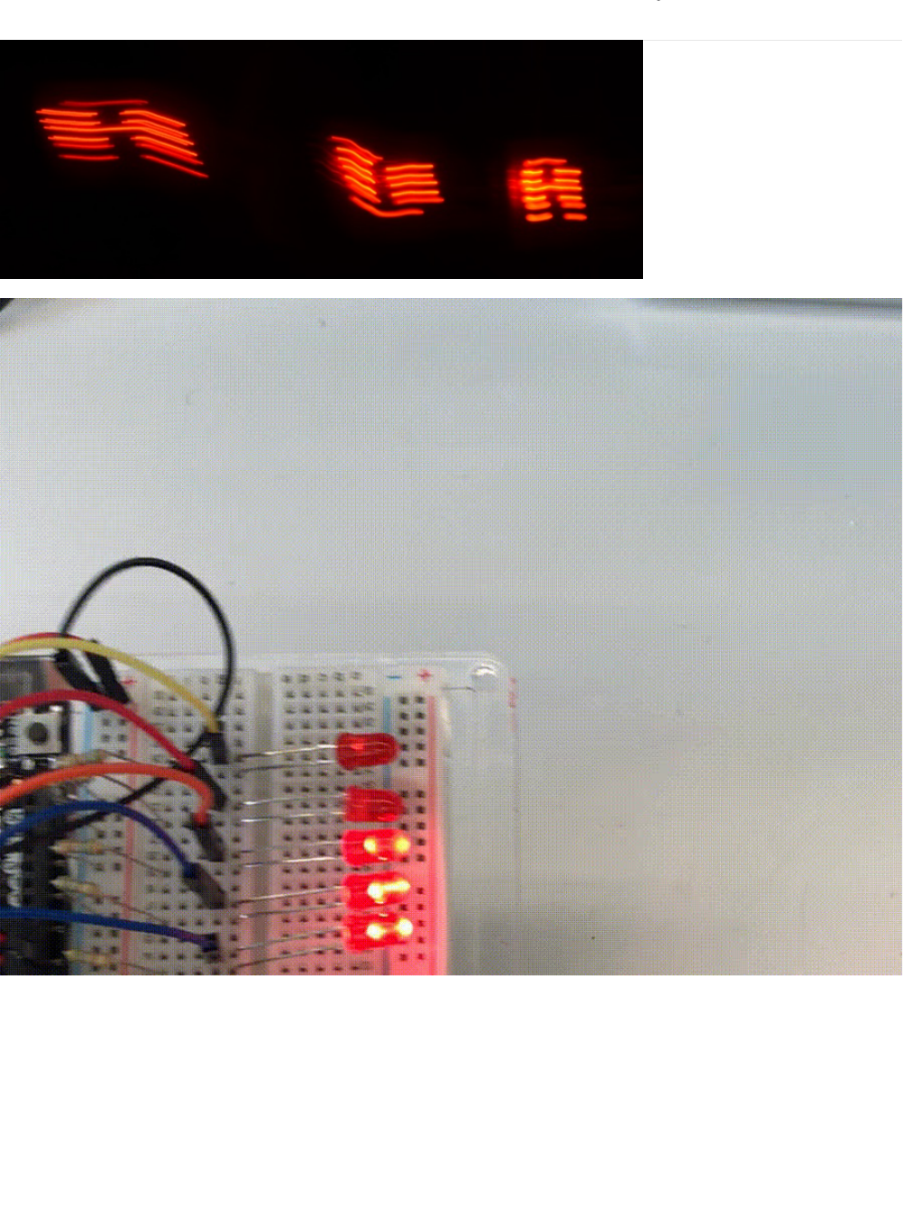
PROJ02: MetroPOV Display
Persistence of vision refers to the optical illusion that occurs when visual perception of an object does not cease for some time
after the rays of light proceeding from it have ceased to enter the eye (more about persistence of vision
here (https://adafru.it/xCS)).
One of the cool kits made by Adafruit is the MiniPOV 4 (https://adafru.it/drK), a DIY Full-Color POV Display. The MiniPOV
creates this illusion and allows you to paint with light in mid-air. In this quest, you are going to create the MetroPOV, a circuit
that uses Persistence of Vision and the Adafruit Metro. You'll learn about persistence-of-vision, optical illusions, and create your
own drawings.
Let's paint the sky with the Metro!
© Adafruit Industries https://learn.adafruit.com/experimenters-guide-for-metro Page 249 of 317

© Adafruit Industries https://learn.adafruit.com/experimenters-guide-for-metro Page 250 of 317

Parts
5mm Red LED
If you'd like to order more red LEDs (they make great
indicator lights!) from the Adafruit shop, click
here! (https://adafru.it/xeV)
560 Ohm Resistor
Colors: Green > Blue > Brown
If you'd like to order more resistors from the Adafruit shop
click here! (they are 470ohm but they'll be
fine) (https://adafru.it/x4E)
Breadboard Wiring Bundle
If you'd like to order more wires from the Adafruit shop click
here! (https://adafru.it/fE2)
© Adafruit Industries https://learn.adafruit.com/experimenters-guide-for-metro Page 251 of 317
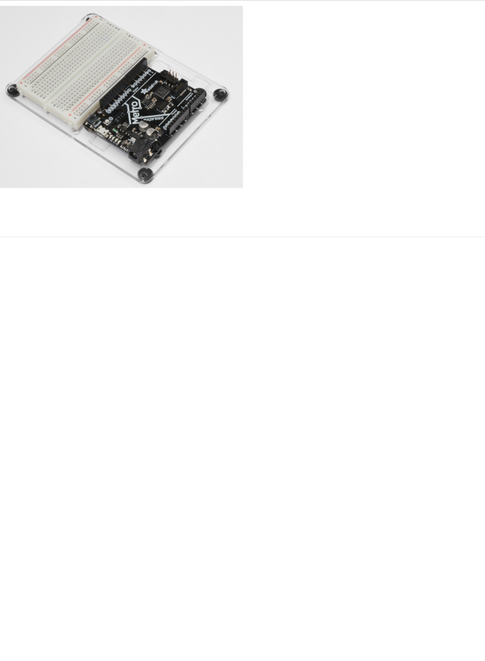
Adafruit Metro (or Metro Express) + Breadboard +
Mounting Plate
If you have not assembled this, we have a handy
guide! (https://adafru.it/x2A)
If you'd like to order an extra plastic mounting
plate (https://adafru.it/x4F), Adafruit
Metro (https://adafru.it/METROXMETR), Adafruit Metro
Express (https://adafru.it/xoa), or Mini-
Breadboard (https://adafru.it/keP) from the Adafruit Shop click
here!
© Adafruit Industries https://learn.adafruit.com/experimenters-guide-for-metro Page 252 of 317
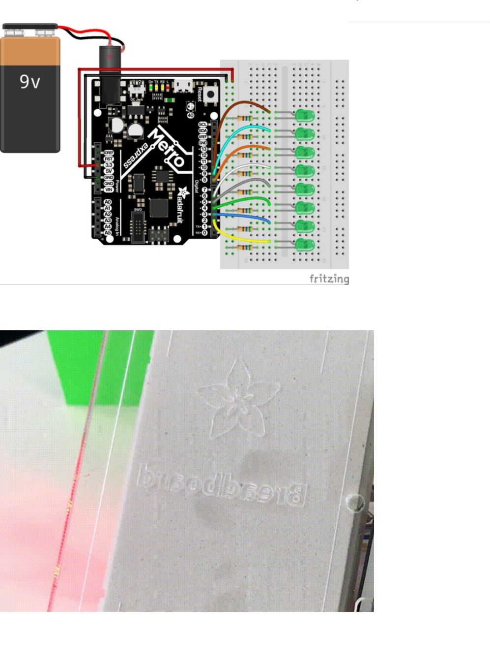
Wiring
The breadboard circuitry is similar to CIRC02's layout. We suggest either using the Red 5mm LEDs or Green 5mm LEDs. Pick
your favorite color and use that!
The 9V battery + clip is very handy for this circuit. You can stick it on the back of the mounting plate with double-sided tape.
© Adafruit Industries https://learn.adafruit.com/experimenters-guide-for-metro Page 253 of 317

Code
Copy and paste the code below into the Arduino IDE. Then, compile and upload it to your metro (https://adafru.it/xap).
/*
* (PROJ03) Metro (and Metro Express) Persistence of Vision Display
* Desc: POV display for Metro & Metro Express using 7x LEDs and 7x 560ohm Resistors
*
* by Brent Rubell for Adafruit Industries. Support Open Source, buy Adafruit!
*/
int spacer[8][5] = {
{0, 0, 0, 0, 0},
{0, 0, 0, 0, 0},
{0, 0, 0, 0, 0},
{0, 0, 0, 0, 0},
{0, 0, 0, 0, 0},
{0, 0, 0, 0, 0},
{0, 0, 0, 0, 0},
{0, 0, 0, 0, 0}
};
int A[8][5] = {
{0, 1, 1, 1, 0},
{1, 1, 0, 1, 1},
{1, 1, 0, 1, 1},
{1, 1, 1, 1, 1},
{1, 1, 0, 1, 1},
{1, 1, 0, 1, 1},
{1, 1, 0, 1, 1},
{0, 0, 0, 0, 0}
};
int B[8][5] = {
{1, 1, 1, 1, 0},
{1, 1, 0, 1, 1},
{1, 1, 0, 1, 1},
{1, 1, 1, 1, 0},
{1, 1, 0, 1, 1},
{1, 1, 0, 1, 1},
{1, 1, 1, 1, 0},
{0, 0, 0, 0, 0}
};
int C[8][5] = {
{0, 1, 1, 1, 0},
{1, 1, 0, 1, 1},
{1, 1, 0, 0, 0},
{1, 1, 0, 0, 0},
{1, 1, 0, 0, 0},
{1, 1, 0, 1, 1},
{0, 1, 1, 1, 0},
{0, 0, 0, 0, 0}
};
int D[8][5] = {
{1, 1, 1, 0, 0},
{1, 1, 0, 1, 1},
{1, 1, 0, 1, 1},
{1, 1, 0, 1, 1},
{1, 1, 0, 1, 1},
{1, 1, 0, 1, 1},
{1, 1, 1, 1, 0},
{0, 0, 0, 0, 0}
© Adafruit Industries https://learn.adafruit.com/experimenters-guide-for-metro Page 254 of 317

{0, 0, 0, 0, 0}
};
int E[8][5] = {
{1, 1, 1, 1, 1},
{1, 1, 0, 0, 0},
{1, 1, 0, 0, 0},
{1, 1, 1, 1, 0},
{1, 1, 0, 0, 0},
{1, 1, 0, 0, 0},
{1, 1, 1, 1, 1},
{0, 0, 0, 0, 0}
};
int F[8][5] = {
{1, 1, 1, 1, 1},
{1, 1, 0, 0, 0},
{1, 1, 0, 0, 0},
{1, 1, 1, 1, 0},
{1, 1, 0, 0, 0},
{1, 1, 0, 0, 0},
{1, 1, 0, 0, 0},
{0, 0, 0, 0, 0}
};
int G[8][5] = {
{0, 1, 1, 1, 0},
{1, 1, 0, 1, 1},
{1, 1, 0, 0, 0},
{1, 1, 0, 1, 1},
{1, 1, 0, 1, 1},
{1, 1, 0, 0, 1},
{0, 1, 1, 1, 1},
{0, 0, 0, 0, 0}
};
int H[8][5] = {
{1, 1, 0, 1, 1},
{1, 1, 0, 1, 1},
{1, 1, 0, 1, 1},
{1, 1, 1, 1, 1},
{1, 1, 0, 1, 1},
{1, 1, 0, 1, 1},
{1, 1, 0, 1, 1},
{0, 0, 0, 0, 0}
};
int I[8][5] = {
{0, 0, 0, 0, 0},
{1, 1, 1, 1, 1},
{0, 0, 1, 0, 0},
{0, 0, 1, 0, 0},
{0, 0, 1, 0, 0},
{0, 0, 1, 0, 0},
{1, 1, 1, 1, 1},
{0, 0, 0, 0, 0}
};
int J[8][5] = {
{0, 0, 0, 1, 1},
{0, 0, 0, 1, 1},
{0, 0, 0, 1, 1},
{0, 0, 0, 1, 1},
{1, 0, 0, 1, 1},
{1, 0, 0, 1, 1},
© Adafruit Industries https://learn.adafruit.com/experimenters-guide-for-metro Page 255 of 317

{1, 0, 0, 1, 1},
{0, 1, 1, 0, 0},
{0, 0, 0, 0, 0}
};
int K[8][5] = {
{0, 0, 0, 0, 0},
{1, 0, 0, 1, 0},
{1, 0, 1, 0, 0},
{1, 1, 0, 0, 0},
{1, 1, 0, 0, 0},
{1, 0, 1, 0, 0},
{1, 0, 0, 1, 0},
{0, 0, 0, 0, 0}
};
int L[8][5] = {
{1, 1, 0, 0, 0},
{1, 1, 0, 0, 0},
{1, 1, 0, 0, 0},
{1, 1, 0, 0, 0},
{1, 1, 0, 0, 0},
{1, 1, 1, 1, 1},
{1, 1, 1, 1, 1},
{0, 0, 0, 0, 0}
};
int M[8][5] = {
{1, 0, 0, 0, 1},
{1, 1, 0, 1, 1},
{1, 0, 1, 0, 1},
{1, 0, 1, 0, 1},
{1, 0, 1, 0, 1},
{1, 0, 1, 0, 1},
{1, 0, 1, 0, 1},
{0, 0, 0, 0, 0}
};
int N[8][5] = {
{1, 0, 0, 0, 1},
{1, 1, 0, 0, 1},
{1, 0, 1, 0, 1},
{1, 0, 0, 1, 1},
{1, 0, 0, 0, 1},
{1, 0, 0, 0, 1},
{1, 0, 0, 0, 1},
{0, 0, 0, 0, 0}
};
int O[8][5] = {
{1, 1, 1, 1, 1},
{1, 0, 0, 0, 1},
{1, 0, 0, 0, 1},
{1, 0, 0, 0, 1},
{1, 0, 0, 0, 1},
{1, 0, 0, 0, 1},
{1, 1, 1, 1, 1},
{0, 0, 0, 0, 0}
};
int P[8][5] = {
{1, 1, 1, 1, 0},
{1, 0, 0, 0, 1},
{1, 0, 0, 0, 1},
{1, 1, 1, 1, 0},
{1, 0, 0, 0, 0},
© Adafruit Industries https://learn.adafruit.com/experimenters-guide-for-metro Page 256 of 317

{1, 0, 0, 0, 0},
{1, 0, 0, 0, 0},
{1, 0, 0, 0, 0},
{0, 0, 0, 0, 0}
};
int Q[8][5] = {
{0, 1, 1, 1, 0},
{1, 0, 0, 0, 1},
{1, 0, 0, 0, 1},
{1, 0, 0, 0, 1},
{1, 0, 1, 0, 1},
{1, 0, 0, 1, 0},
{0, 1, 1, 0, 1},
{0, 0, 0, 0, 0}
};
int R[8][5] = {
{1, 1, 1, 1, 0},
{1, 0, 0, 1, 0},
{1, 0, 0, 1, 0},
{1, 1, 1, 1, 0},
{1, 1, 0, 0, 0},
{1, 0, 1, 0, 0},
{1, 0, 0, 1, 0},
{0, 0, 0, 0, 0}
};
int S[8][5] = {
{0, 1, 1, 1, 1},
{0, 1, 0, 0, 1},
{0, 1, 0, 0, 0},
{0, 0, 1, 0, 0},
{0, 0, 0, 1, 0},
{1, 0, 0, 1, 0},
{1, 1, 1, 1, 0},
{0, 0, 0, 0, 0}
};
int T[8][5] = {
{1, 1, 1, 1, 1},
{1, 0, 1, 0, 1},
{1, 0, 1, 0, 1},
{0, 0, 1, 0, 0},
{0, 0, 1, 0, 0},
{0, 0, 1, 0, 0},
{0, 0, 1, 0, 0},
{0, 0, 0, 0, 0}
};
int U[8][5] = {
{1, 0, 0, 0, 1},
{1, 0, 0, 0, 1},
{1, 0, 0, 0, 1},
{1, 0, 0, 0, 1},
{1, 0, 0, 0, 1},
{1, 0, 0, 0, 1},
{1, 1, 1, 1, 1},
{0, 0, 0, 0, 0}
};
int V[8][5] = {
{1, 0, 0, 0, 1},
{1, 0, 0, 0, 1},
{1, 0, 0, 0, 1},
© Adafruit Industries https://learn.adafruit.com/experimenters-guide-for-metro Page 257 of 317

{1, 0, 0, 0, 1},
{1, 0, 0, 0, 1},
{1, 0, 0, 0, 1},
{0, 1, 0, 1, 0},
{0, 0, 1, 0, 0},
{0, 0, 0, 0, 0}
};
int W[8][5] = {
{1, 0, 0, 0, 1},
{1, 0, 0, 0, 1},
{1, 0, 0, 0, 1},
{1, 0, 0, 0, 1},
{1, 0, 1, 0, 1},
{1, 0, 1, 0, 1},
{1, 1, 1, 1, 1},
{0, 0, 0, 0, 0}
};
int X[8][5] = {
{1, 0, 0, 0, 1},
{0, 1, 0, 1, 0},
{0, 0, 1, 0, 0},
{0, 0, 1, 0, 0},
{0, 1, 0, 1, 0},
{1, 0, 0, 0, 1},
{0, 0, 0, 0, 0},
{0, 0, 0, 0, 0}
};
int Y[8][5] = {
{0, 0, 0, 0, 0},
{0, 0, 0, 0, 0},
{0, 1, 0, 1, 0},
{0, 1, 0, 1, 0},
{0, 1, 1, 1, 0},
{0, 0, 1, 0, 0},
{0, 0, 1, 0, 0},
{0, 0, 0, 0, 0}
};
int Z[8][5] = {
{0, 0, 0, 0, 0},
{1, 1, 1, 1, 1},
{0, 0, 0, 1, 1},
{0, 0, 1, 1, 0},
{0, 1, 1, 0, 0},
{1, 1, 0, 0, 0},
{1, 1, 1, 1, 1},
{0, 0, 0, 0, 0}
};
// LED pins
int LEDPins[] = {2, 3, 4, 5, 6, 7, 8, 9};
// space between the letters
float letterSpacing = 0.5;
void setup() {
// start serialmon.
Serial.begin(9600);
// set all leds to output mode
for (int pin = 0; pin < 8; pin++) {
© Adafruit Industries https://learn.adafruit.com/experimenters-guide-for-metro Page 258 of 317

I need help
I can't get a good photograph of the MetroPOV in action
Try checking the next section of this guide. We suggest some techniques, and even an app.
I don't see the LEDs lighting up in different patterns
Check your wiring, the led's are connected to pins 2, 3, 4, 5, 6, 7, 8, and 9 on the Metro or Metro Express
Nothing's working, I'm getting nowhere
Don't fear, post up in the Adafruit Support Forums and we will get back to you as soon as we can.
pinMode(LEDPins[pin], OUTPUT);
}
}
void loop() {
printLetter(M);
printLetter(spacer);
printLetter(E);
printLetter(spacer);
printLetter(T);
printLetter(spacer);
printLetter(R);
printLetter(spacer);
printLetter(O);
printLetter(spacer);
// delay 2s
delay(2);
}
// outputs a letter to the POV Display
void printLetter(int letter[8][5]) {
// row of letter array
for (int j = 0; j < 5; j++)
{
Serial.print("\nRow # ");
Serial.print(j);
Serial.println(".");
// column of letter array
for (int i = 0; i < 8; i++) {
// check for 1 within column6
if (letter[i][j] == 1) {
Serial.println("1 detected");
digitalWrite(LEDPins[i], HIGH);
}
else {
Serial.println("0 detected");
digitalWrite(LEDPins[i], LOW);
}
}
delay(letterSpacing);
}
}
© Adafruit Industries https://learn.adafruit.com/experimenters-guide-for-metro Page 259 of 317
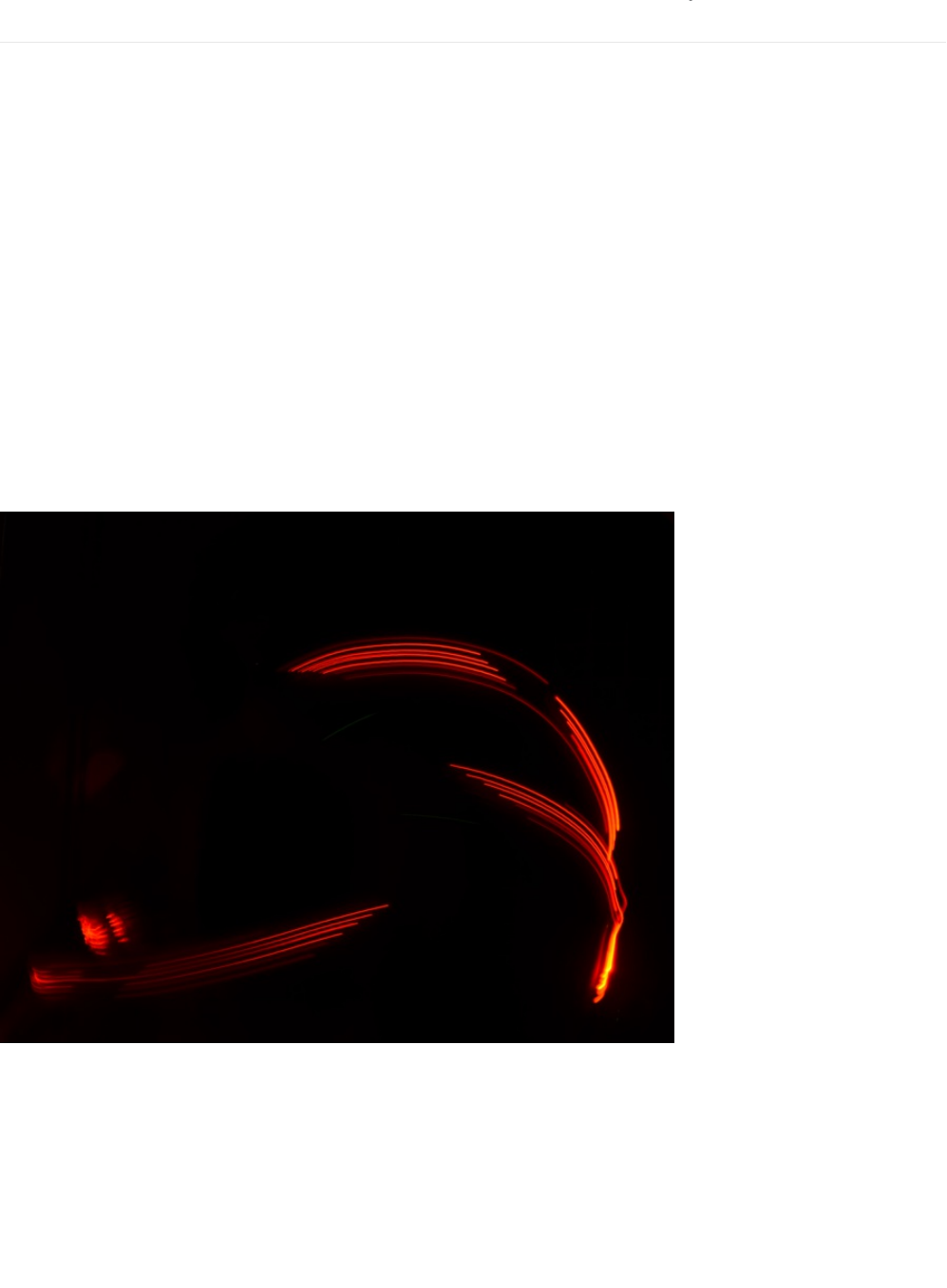
Using MetroPOV
Taking Photos
It's a bit tricky to get photos of the MetroPOV in-action. We have a few tricks and tips to help photograph your MetroPOV:
Stability and Shutter Speed: Leave the shutter open (we found 2" to 4" is a good time-frame) or look for long-exposure apps on
the app store. Since your camera's sensor/shutter is open, it's important to keep the camera stable. Use a tripod, or leave it on a
sturdy desk.
Keep the light down: It's very hard to get good photos of the MetroPOV operating in a bright environment. Wait for night-time or
find a dark room (we used a room with all of the lights off when taking photos for this guide).
GIF'ing your MetroPOV Text
You can make animated GIFS by combining multiple long-exposure pictures together in the photo editor of your choice. We also
found success using Pablo, a fantastic light-painting application for iOS (https://adafru.it/xCT) and Android (https://adafru.it/xCU).
Tinker around with settings (specifically shutter speed and exposure) until you find one that looks great.
Light Painting with MetroPOV
Mistakes while taking photos can often produce beautiful art. Try drawing letters with the MetroPOV and move it around. Ride a
skateboard while someone takes a picture of you, spin in a chair. Experiment and try different techniques and ideas!
© Adafruit Industries https://learn.adafruit.com/experimenters-guide-for-metro Page 260 of 317
PROJ03: Music Box
Music boxes are clockwork mechanical instruments that play music when opened. You are going to take the Music Box into the
21st Century - instead of programming the music box by modifying a metal cylinder, you will be programming a beautiful song to
the Metro. When opened, the music box will play a song and the LCD will show the notes as they play.
This project is customizable in a few ways: you can use your own box (maybe you have a jewelry box, an old cigar box, or an
Adafruit box) and/or program your own music.
© Adafruit Industries https://learn.adafruit.com/experimenters-guide-for-metro Page 261 of 317
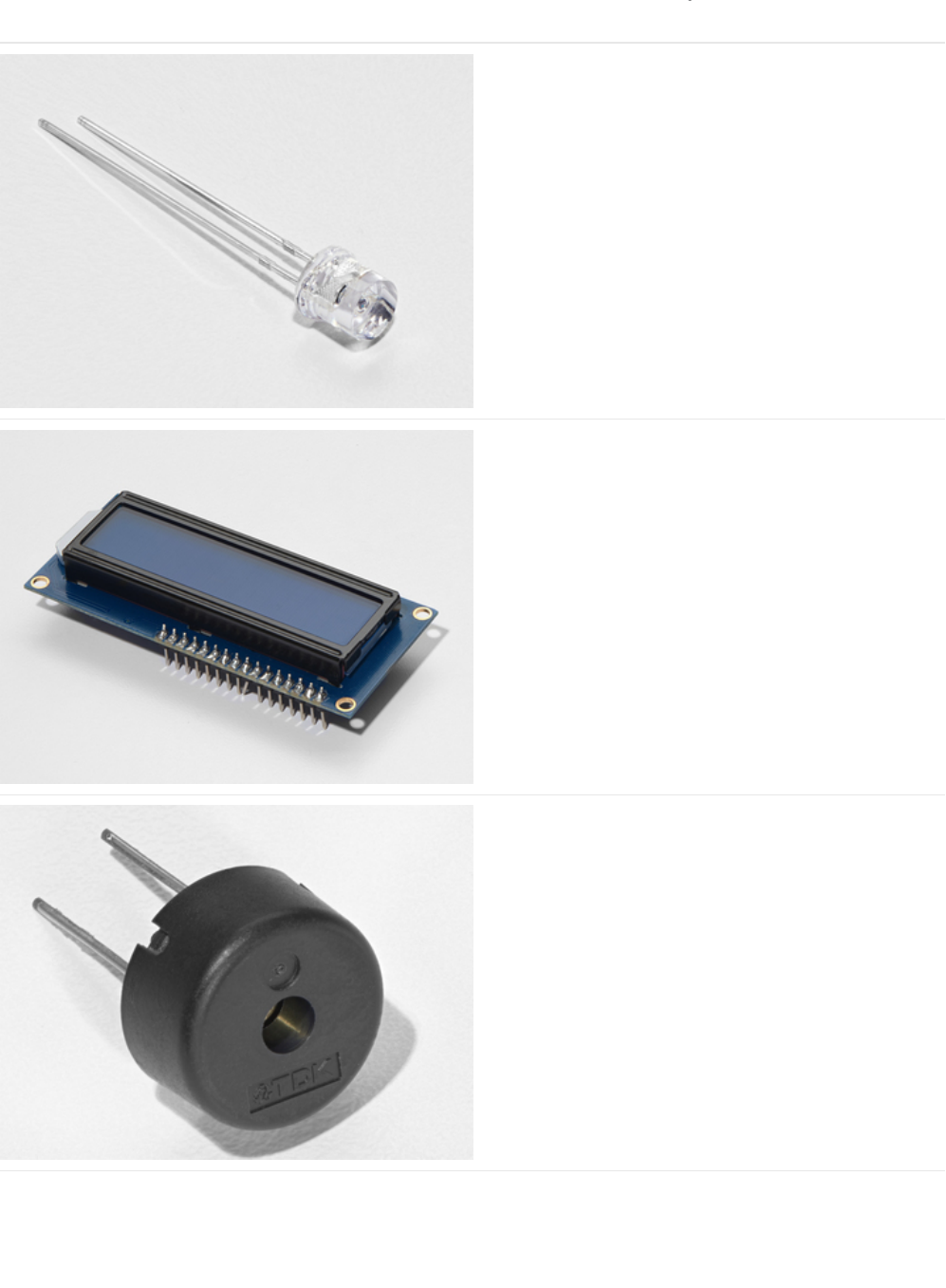
Parts
Photo Sensor
If you'd like to order another photoresistor from the Adafruit
shop, click here! (https://adafru.it/xfo)
16x2 Character LCD
If you'd like to buy a white-on-blue 16x2 character lcd from
the Adafruit shop, click here! (https://adafru.it/tUe)
Piezo Buzzer
If you'd like to order another Pizeo Buzzer from the Adafruit
shop, click here! (https://adafru.it/dCD)
© Adafruit Industries https://learn.adafruit.com/experimenters-guide-for-metro Page 262 of 317
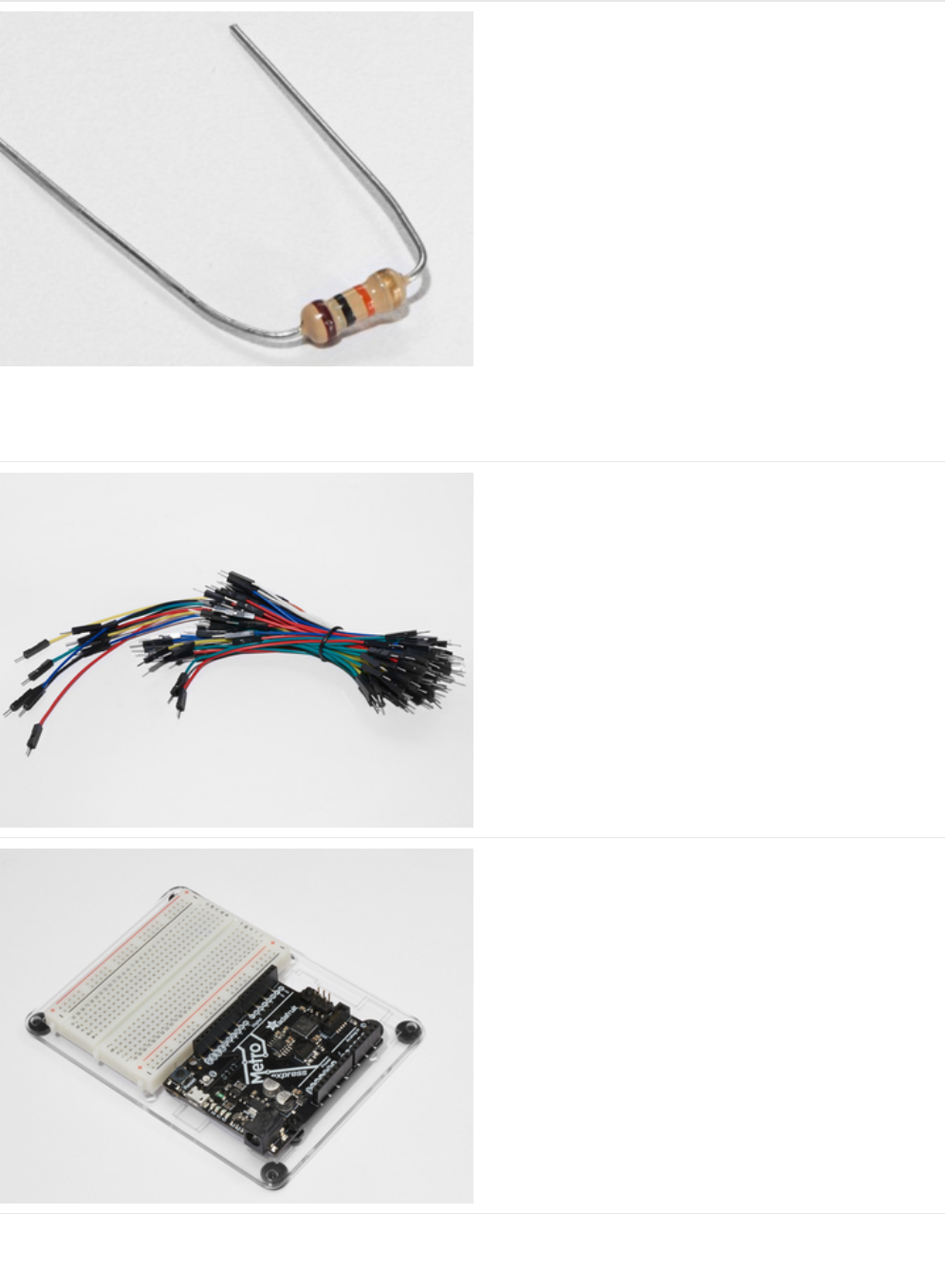
10K Ohm Resistor
Colors: Brown > Black > Orange
If you'd like to order more 10k ohm pull-up resistors from the
Adafruit shop, click here! (https://adafru.it/xfm)
Breadboard Wiring Bundle
If you'd like to order more wires from the Adafruit shop click
here! (https://adafru.it/fE2)
Adafruit Metro (or Metro Express) + Breadboard +
Mounting Plate
If you have not assembled this, we have a handy
guide! (https://adafru.it/x2A)
If you'd like to order an extra plastic mounting
plate (https://adafru.it/x4F), Adafruit
Metro (https://adafru.it/METROXMETR), Adafruit Metro
Express (https://adafru.it/xoa), or Mini-
Breadboard (https://adafru.it/keP) from the Adafruit Shop click
here!
© Adafruit Industries https://learn.adafruit.com/experimenters-guide-for-metro Page 263 of 317
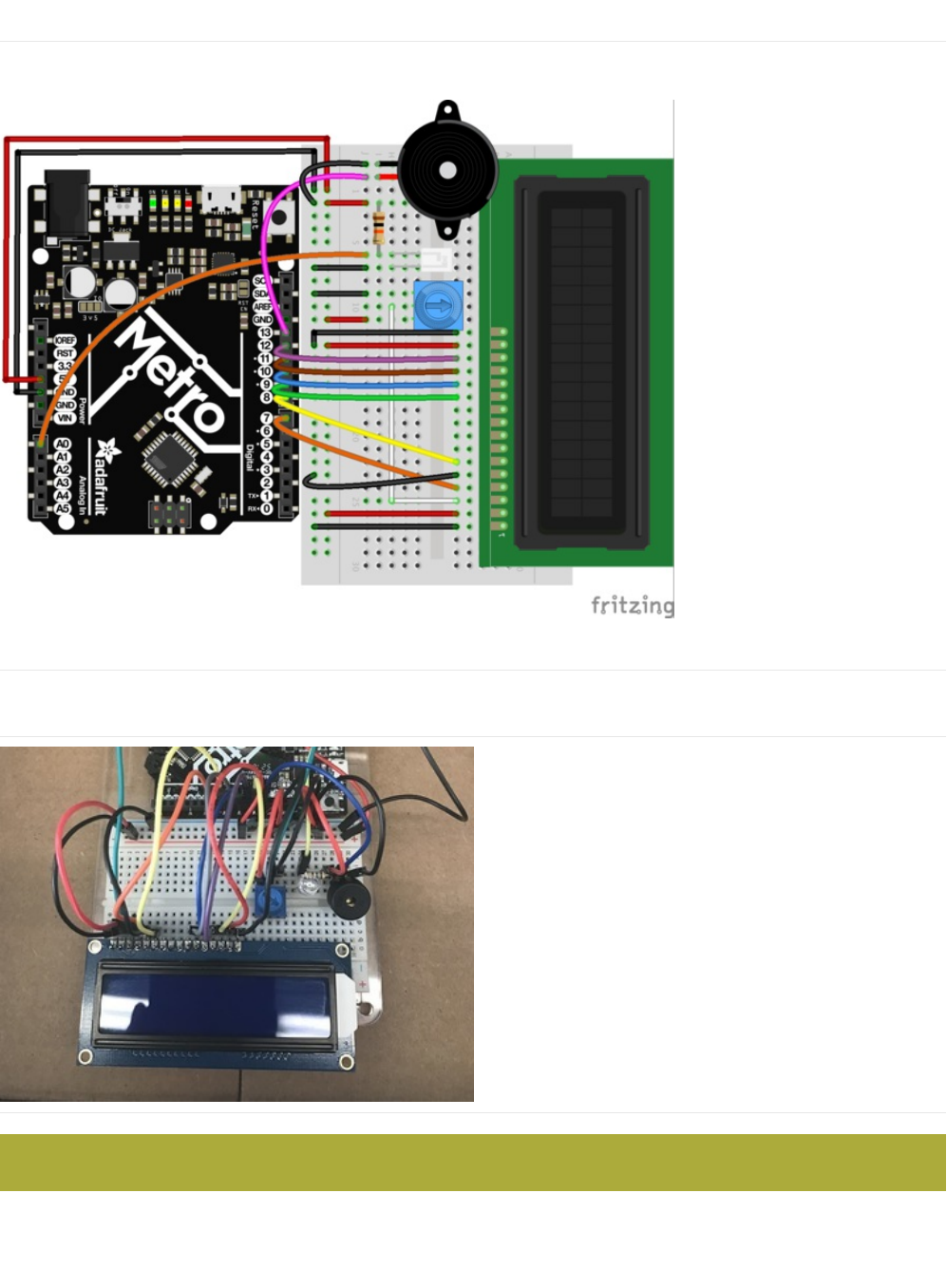
Wiring
Diagram
Assembly
If you want to use an Adafruit box (or any other cardboard box), there are modifications to make your circuit fit better.
First, place the circuit in the center of the box. You can tape it
down to temporarily keep it in place.
Make sure the photo light sensor is not blocked by wires. Move wires around if you need to.
© Adafruit Industries https://learn.adafruit.com/experimenters-guide-for-metro Page 264 of 317
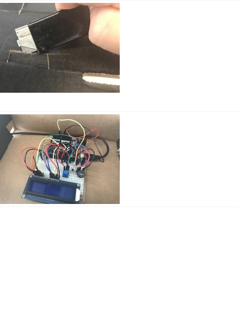

Code
Calibrating the Music Box
In order to get an accurate reading, close the music box and run the code below. Then, open your serial monitor. It should output
the light level, this is the darkest the box will get so we'll calibrate this value.
In your code, change the following line:
int dark = 650; -> int dark = your measured value
When you re-run the code, the serial monitor should print
"box closed.."
when the box is closed. If you wired the backlight to Pin
13, the LCD backlight should also turn off.
/*
* (PROJ03) Metro (and Metro Express!) Music Box
* Desc: 21st century music box: Plays a melody when the box is open.
* Circuit: Piezo, 16x2 LCD, Photo Light Sensor
*
* by Brent Rubell for Adafruit Industries. Support Open Source Hardware, buy Adafruit!
*
*/
// include the lcd library code
#include <LiquidCrystal.h>
// initialize the library with the numbers of the interface pins
LiquidCrystal lcd(7, 8, 9, 10, 11, 12);
// Piezo code.
int speakerPin = 5;
int length = 15; // the number of notes
char notes[] = "ccggaagffeeddc "; // a space represents a rest
int beats[] = { 1, 1, 1, 1, 1, 1, 2, 1, 1, 1, 1, 1, 1, 2, 4 };
int tempo = 300;
// Photo Light Sensor Pin
int lightPin = 0;
// Measured Darkness
int dark = 650;
// LCD Backlight Pin
int backlightPin = 13;
void playTone(int tone, int duration) {
for (long i = 0; i < duration * 1000L; i += tone * 2) {
digitalWrite(speakerPin, HIGH);
delayMicroseconds(tone);
digitalWrite(speakerPin, LOW);
delayMicroseconds(tone);
}
}
void playNote(char note, int duration) {
char names[] = { 'c', 'd', 'e', 'f', 'g', 'a', 'b', 'C' };
int tones[] = { 1915, 1700, 1519, 1432, 1275, 1136, 1014, 956 };
// play the tone corresponding to the note name
for (int i = 0; i < 8; i++) {
if (names[i] == note) {
playTone(tones[i], duration);
}
}
© Adafruit Industries https://learn.adafruit.com/experimenters-guide-for-metro Page 266 of 317

Encountering Problems?
My LCD is not displaying anything.
Check the LCD Wiring guide in CIRC14 to double-check everything is wired correctly.
My music box is still too sensitive, or it's not sensitive enough.
int dark directly controls how dark or bright the environment inside your music box is. If you find it triggering too easily,
}
}
void setup() {
// set up the serial monitor
Serial.begin(9600);
// set up the LCD's cols/rows
lcd.begin(16, 2);
// set speaker as an output
pinMode(speakerPin, OUTPUT);
// set lcd backlight as an output
pinMode(backlightPin, OUTPUT);
}
void loop() {
// read the lightLevel
int lightLevel = analogRead(lightPin);
Serial.println("Light Level -> ");
Serial.println(lightLevel);
// check lightLevel against dark level (should be set manually by the user, check serial mon.)
if(lightLevel < dark)
{
// Box is OPEN!
digitalWrite(backlightPin, HIGH);
lcd.clear();
Serial.println("Box open, playing music!");
for (int i = 0; i < length; i++) {
if(notes[i] == ' ') {
// rest
delay(beats[i] * tempo);
// print a space to indicate a rest
lcd.print(" ");
}
else {
// play notes in notes[]
playNote(notes[i], beats [i] * tempo);
// display current note on the lcd
lcd.print(notes[i]);
}
// pause between notes
delay(tempo/2);
}
}
else{
// box is closed
// turn LCD off
digitalWrite(backlightPin, LOW);
lcd.clear();
lcd.print("box closed...");
Serial.println("Box closed, don't play music.");
}
}
© Adafruit Industries https://learn.adafruit.com/experimenters-guide-for-metro Page 267 of 317


Make It Better
Bored of your Music Box? Want to go add onto this circuit? Here's some ideas for you to springboard off of and learn new skills
in the process
Music Composer
Write your own melody and become a composer, or adapt an older song to play on the piezo. (
tip
: Check CIRC06's Make It
Better section for more details on the piezo speaker)
Unconventional Enclosures
There are
thousands
of ways to enclose your electronics projects! Using non-conventional enclosures, such as cigar boxes, are a
way to both protect your project and make it look nicer. Try using a different box to hold your music box.
Hint: What should you change in order to use a new box with a light sensor? Take a look at the code section.
Answer:
Re-calibrating the light sensor is required. Change the value of int dark to the new darkness value.Re-calibrating the light sensor is required. Change the value of int dark to the new darkness value.
Re-calibrating the light sensor is required. Change the value of int dark to the new darkness value.
Annoy-a-Box
Want to annoy your friends and family with this circuit? Change the code to use a high pitched whine, or make the whine go
between pitches like a bee. Make it portable and throw it under a couch.
Secret Message Box
You need to deliver a secret message to somebody, but writing too permanent. The time-sensitive box is a box to deliver to a
friend, classmate, or an international spy containing a secret message on the character lcd.
How it works: Once the box is opened, the timer starts to count down the time remaining on the second line of the LCD while
the message is displayed. Once the timer runs out, the character lcd clears the message and you cant show the message again.
© Adafruit Industries https://learn.adafruit.com/experimenters-guide-for-metro Page 269 of 317
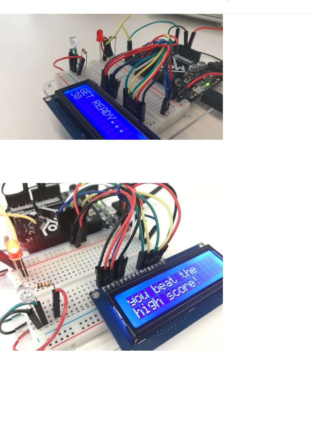
PROJ04: Fidget Spinner Tachometer
Fidget spinners are fun toys that help relieve stress. They spin on a bearing, and can reach
really
high
revolutions per minute
(RPM). We are going to build a
Tachometer
, an instrument which measures RPM, for your fidget spinner.
We included some fun features into Tony D's original Circuit Playground fidget spinner code (https://adafru.it/xDw)
Like a RPM high score game to compete with your friends (or to pit different spinners against each other)
© Adafruit Industries https://learn.adafruit.com/experimenters-guide-for-metro Page 270 of 317
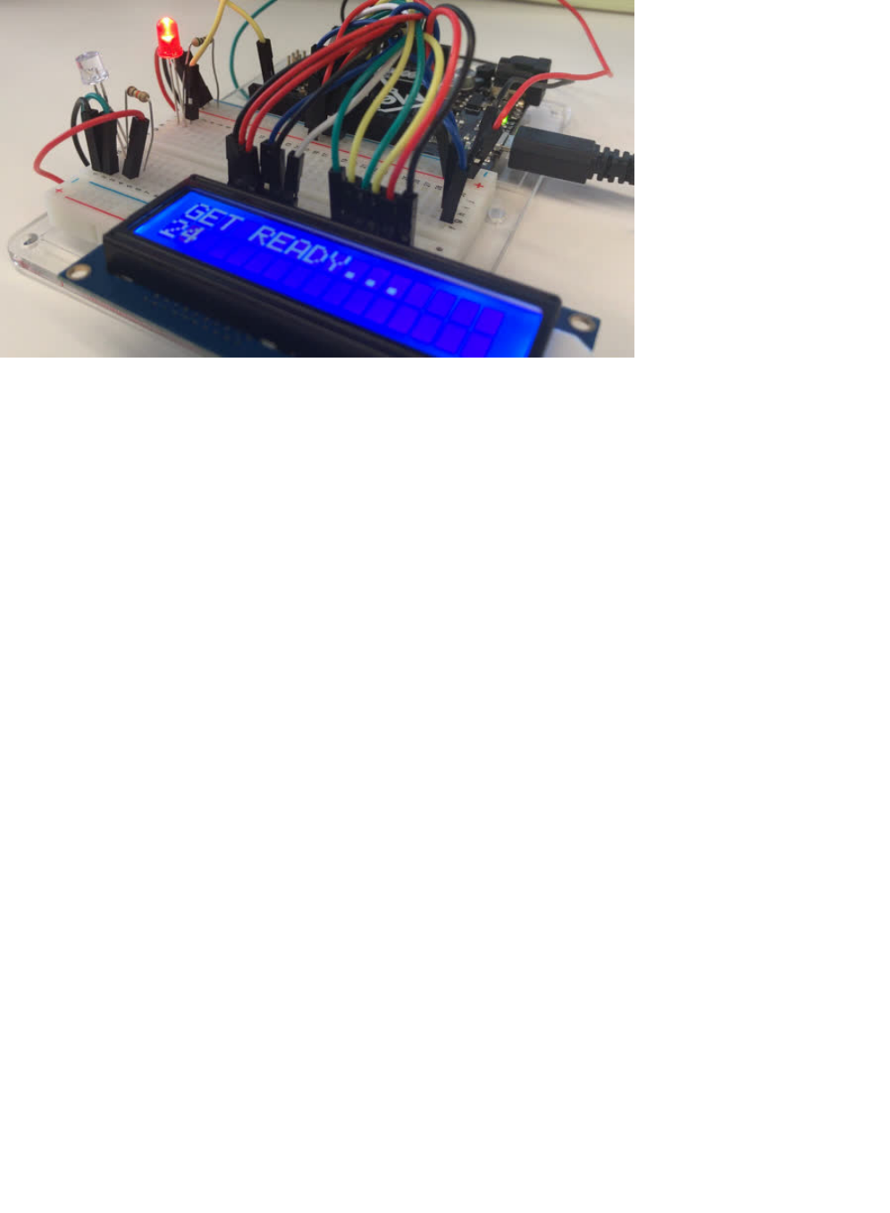
And a countdown clock to let you time your spins better.
© Adafruit Industries https://learn.adafruit.com/experimenters-guide-for-metro Page 271 of 317
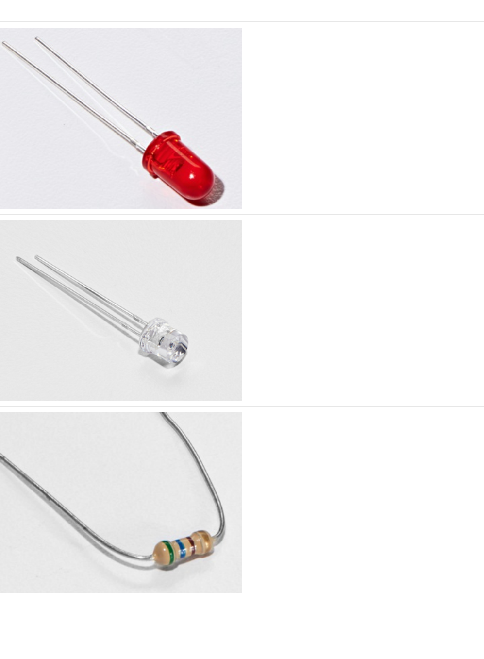
Parts
5mm Red LED
If you'd like to order more red LEDs (they make great
indicator lights!) from the Adafruit shop, click
here! (https://adafru.it/xeV)
Photo Sensor
If you'd like to order another photoresistor from the Adafruit
shop, click here! (https://adafru.it/xfo)
560 Ohm Resistor
Colors: Green > Blue > Brown
If you'd like to order more resistors from the Adafruit shop
click here! (they are 470ohm but they'll be
fine) (https://adafru.it/x4E)
© Adafruit Industries https://learn.adafruit.com/experimenters-guide-for-metro Page 272 of 317
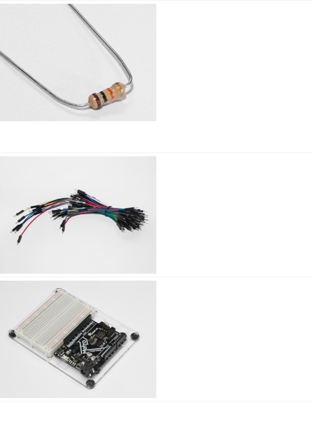
10K Ohm Resistor
Colors: Brown > Black > Orange
If you'd like to order more 10k ohm pull-up resistors from the
Adafruit shop, click here! (https://adafru.it/xfm)
Breadboard Wiring Bundle
If you'd like to order more wires from the Adafruit shop click
here! (https://adafru.it/fE2)
Adafruit Metro (or Metro Express) + Breadboard +
Mounting Plate
If you have not assembled this, we have a handy
guide! (https://adafru.it/x2A)
If you'd like to order an extra plastic mounting
plate (https://adafru.it/x4F), Adafruit
Metro (https://adafru.it/METROXMETR), Adafruit Metro
Express (https://adafru.it/xoa), or Mini-
Breadboard (https://adafru.it/keP) from the Adafruit Shop click
here!
© Adafruit Industries https://learn.adafruit.com/experimenters-guide-for-metro Page 273 of 317
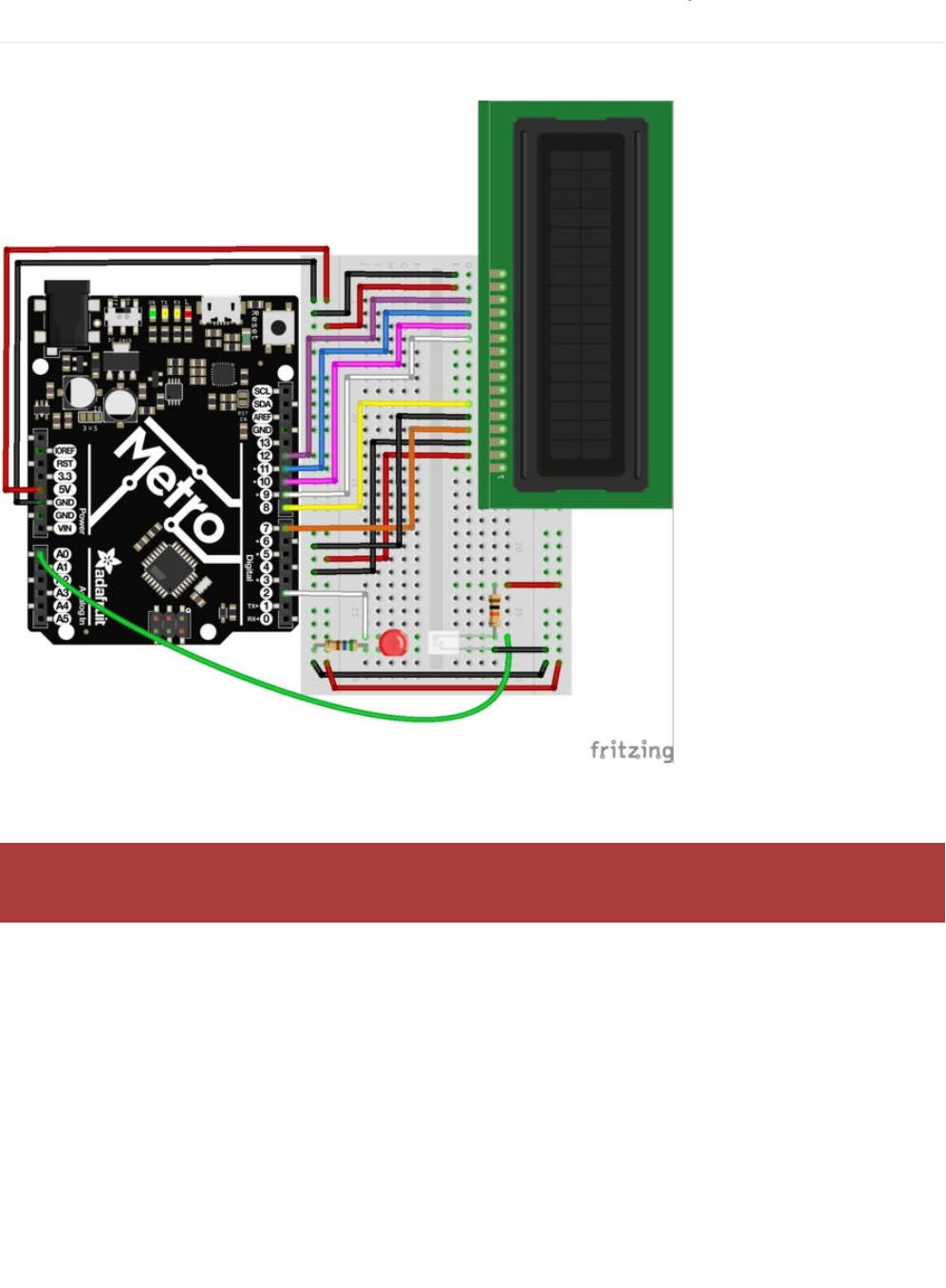
Wiring
Diagram
Assembly Tips
Fidget spinners love to rip wires out of breadboards at high RPM. This section details how to avoid that from
happening.
© Adafruit Industries https://learn.adafruit.com/experimenters-guide-for-metro Page 274 of 317
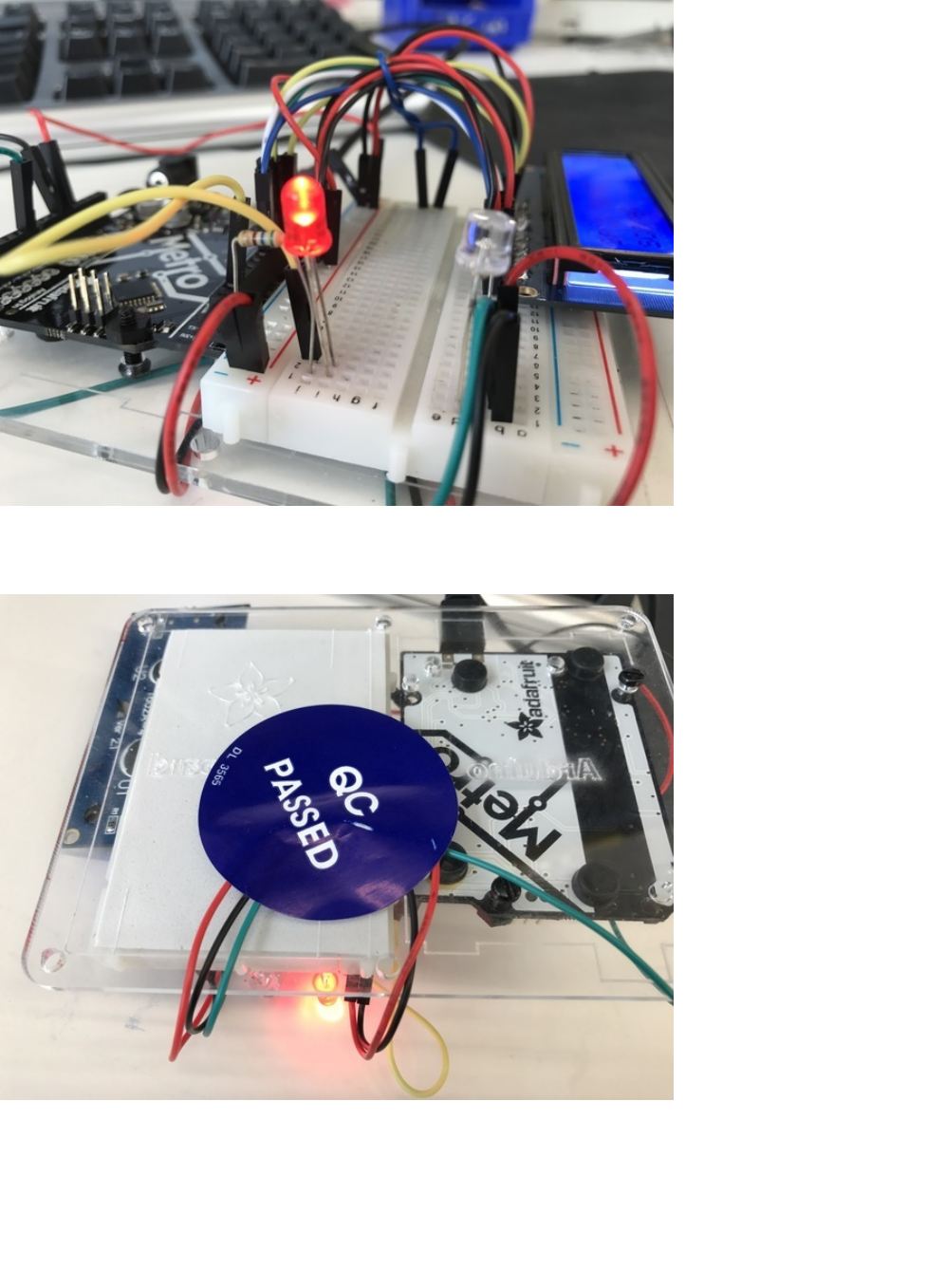
There is a bit of clean-up involved with this wiring. Spinners snag onto wires. We tried to make the clean-up as simple as
possible by utilizing the parts from your kit.
First, let's clean up the Spin Zone. The area in-between the light-sensor and the LED is the area for the spinner to move around.
We suggest using the long wires included in the breadboard wiring bundle. Tuck the wires in underneath the board and use a
piece of tape (or in our case, a quality control sticker) to pin them down.
© Adafruit Industries https://learn.adafruit.com/experimenters-guide-for-metro Page 275 of 317
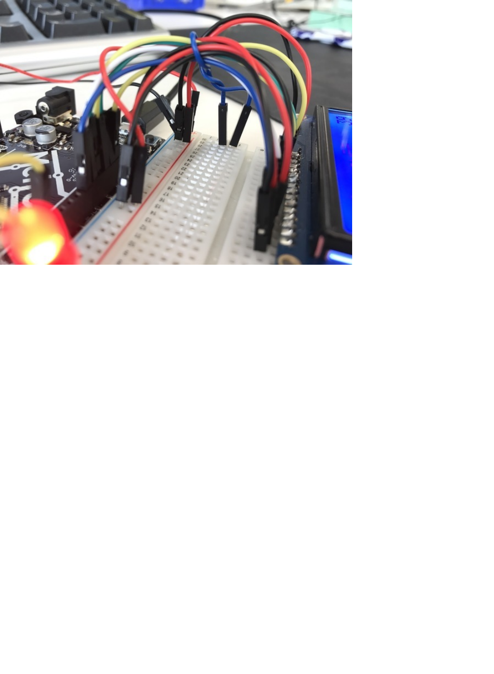
Next, take a shorter breadboarding wire and wrap it around the wires for the LCD. You can also use a zip-tie for a more
permanent hold. Plug the ends of this wire into the breadboard.
© Adafruit Industries https://learn.adafruit.com/experimenters-guide-for-metro Page 276 of 317

Code
Copy/Paste the following code into a blank Arduino sketch. Then, compile and upload it to your Metro. If you see the LED
running through the script, continue to the next page. If you're not seeing it work properly, check the FAQ below for help.
/*
* (PROJ04) Metro (and Metro Express!) Fidget Spinner Tachometer
* Desc: Count fidget spinner RPMs (and beat your high scores)
*
* Original code by Tony Dicola for Adafruit Industries
* by Brent Rubell and Asher Lieber for the Metro Explorers Guide
*/
// include the LCD library code:
#include <LiquidCrystal.h>
// initialize the library with the numbers of the interface pins
LiquidCrystal lcd(7, 8, 9, 10, 11, 12);
// How many arms does the spinner have?
#define SPINNER_ARMS 3
// 1kB sample size
#define SAMPLE_DEPTH 256
// delay between light samples
#define SAMPLE_PERIOD_US 150
// min. speed, depends on reflective-ness of spinner, noise thresh.
//#define THRESHOLD 127
// wait 2s between measurements
#define MEASURE_PERIOD_MS 2000
// rpm high score
float rpmHighScore = 0.00;
// threshold value
int threshold;
// photo light sensor pin
int photoSensor = A0;
// led pin
int led = 2;
void setup() {
// Init. serial monitor @ 115200 baud
Serial.begin(9600);
// set up the LCD's number of columns and rows:
lcd.begin(16, 2);
lcd.print("Metro Tachometer");
// set up LED
pinMode(led, OUTPUT);
}
void loop() {
int sensorCalibrate = 0;
// Set depending on light balance
threshold = 40;
// PAUSE between measurements
lcd.clear();
lcd.print("GET READY...");
analogWrite(led, 255);
// pause between sampling sensor
// shown as a countdown on the screen!
for (int i = 3500; i > 0; i--) {
lcd.setCursor(0,1);
lcd.print(i/100);
}
© Adafruit Industries https://learn.adafruit.com/experimenters-guide-for-metro Page 277 of 317

}
// init. empty sample array
uint16_t samples[SAMPLE_DEPTH] = {0};
// start time
uint32_t start = micros();
// lcd during spin
lcd.clear();
lcd.print("SPIN IT");
lcd.setCursor(0,1);
lcd.print("score: ");
lcd.setCursor(10,1);
lcd.print(rpmHighScore);
for (int i = 0; i < SAMPLE_DEPTH; i++) {
// sample the photo light sensor
samples[i] = analogRead(photoSensor);
// serial output
Serial.print("\nSample: ");
Serial.print(samples[i]);
// keep the player occupied while sampling
if (i == int(SAMPLE_DEPTH/4)) {
lcd.clear();
lcd.print("keep going!");
lcd.setCursor(10,1);
lcd.print(rpmHighScore);
}
else if (i == int(SAMPLE_DEPTH/3)) {
lcd.clear();
lcd.print("almost there!");
lcd.setCursor(10,1);
lcd.print(rpmHighScore);
}
delayMicroseconds(SAMPLE_PERIOD_US);
}
// time elapsed (uS)
uint32_t elapsed_uS = micros() - start;
// time elapsed (sec)
float elapsed = elapsed_uS / 1000000.0;
// Find the min and max values in the collected samples.
uint16_t minval = samples[0];
uint16_t maxval = samples[0];
for (int i=1; i<SAMPLE_DEPTH; ++i) {
minval = min(minval, samples[i]);
maxval = max(maxval, samples[i]);
}
// Serial Monitor Values
Serial.print("\n Samples taken, : ");
Serial.print(elapsed, 3);
Serial.print(" seconds");
Serial.print("\n Max Sample Val: ");
Serial.print(maxval);
Serial.print("\n Min Sample Val: ");
Serial.print(minval);
// Check the amplitude of the signal (difference between min and max)
// is greater than the threshold to continue detecting speed.
uint16_t amplitude = maxval - minval;
© Adafruit Industries https://learn.adafruit.com/experimenters-guide-for-metro Page 278 of 317

uint16_t amplitude = maxval - minval;
if (amplitude < threshold) {
// Didn't make it past the threshold so start over with another measurement attempt.
lcd.clear();
lcd.println("didnt spin fast enough, re-spin!");
Serial.print("\n DIDNT PASS THRESHOLD, RE-TAKING MEASUREMENT..");
return;
}
// Compute midpoint of the signal (halfway between min and max values).
uint16_t midpoint = minval + (amplitude/2);
// Count how many midpoint crossings were found in the signal.
// These are instances where two readings either straddle or land on
// the midpoint. The midpoint crossings will happen twice for every
// complete sine wave cycle (once going up and again coming down).
int crossings = 0;
for (int i=1; i<SAMPLE_DEPTH; ++i) {
uint16_t p0 = samples[i-1];
uint16_t p1 = samples[i];
if ((p1 == midpoint) ||
((p0 < midpoint) && (p1 > midpoint)) ||
((p0 > midpoint) && (p1 < midpoint))) {
crossings += 1;
}
}
// Compute signal frequency, RPM, and period.
// The period is the amount of time it takes for a complete
// sine wave cycle to occur. You can calculate this by dividing the
// amount of time that elapsed during the measurement period by the
// number of midpoint crossings cut in half (because each complete
// sine wave cycle will have 2 midpoint crossings). However since
// fidget spinners have multiple arms you also divide by the number
// of arms to normalize the period into a value that represents the
// time taken for a complete revolution of the entire spinner, not
// just the time between one arm and the next.
Serial.print("\n MP Crossings: ");
Serial.print(crossings);
Serial.print("\n Elapsed: ");
Serial.print(elapsed);
float period = elapsed / (crossings / 2.0 / SPINNER_ARMS);
Serial.print("\n Period: ");
Serial.print(period);
// Once the period is calculated it can be converted into a frequency
// value (i.e revolutions per second, how many times the spinner spins
// around per second) and more common RPM value (revolutions per minute,
// just multiply frequency by 60 since there are 60 seconds in a minute).
float frequency = 1.0 / period;
float rpm = frequency * 60.0;
// Print out the measured values!
Serial.print("Frequency: ");
Serial.print(frequency, 3);
Serial.print(" (hz)\t\tRPM: ");
Serial.print(rpm, 3);
Serial.print("\t\tPeriod: ");
Serial.print(period, 3);
Serial.println(" (seconds)");
© Adafruit Industries https://learn.adafruit.com/experimenters-guide-for-metro Page 279 of 317

Not Working?
LCD is blank/garbled/glitchy
Make sure all your wires are both plugged in correctly and not loose. During the assembly step where you tied everything
together, make sure everything is snugly plugged into both the Metro and the breadboard.
LED not turning on?
Check the LED wiring. Possibly you have a wrong resistor value.
Still not working?
Post up on our community support forums!
lcd.clear();
lcd.setCursor(1,0);
lcd.print(rpm);
delay(2000);
// high score checker
if(rpm > rpmHighScore) {
rpmHighScore = rpm;
lcd.clear();
lcd.setCursor(0,0);
lcd.print("you beat the");
lcd.setCursor(0,1);
lcd.print("high score!");
delay(2000);
}
}
© Adafruit Industries https://learn.adafruit.com/experimenters-guide-for-metro Page 280 of 317
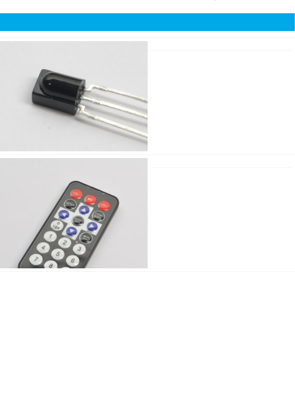
Parts
IR Sensor
How it's used: The IR Sensor receives and decodes
incoming infrared signals from the Adafruit Mini Remote.
If you'd like to order an extra IR receiver sensor from the
Adafruit shop, click here! (https://adafru.it/xcl)
Mini Remote Control
How it's used: The Mini Remote control will send ir signals to
the ir sensor connected to the Metro M0 Express.
If you'd like to order an extra Mini Remote Control from the
Adafruit Shop, click here! (https://adafru.it/xck)
This is a Metro EXPRESS PROJect. It will NOT work with the regular Metro.
© Adafruit Industries https://learn.adafruit.com/experimenters-guide-for-metro Page 281 of 317
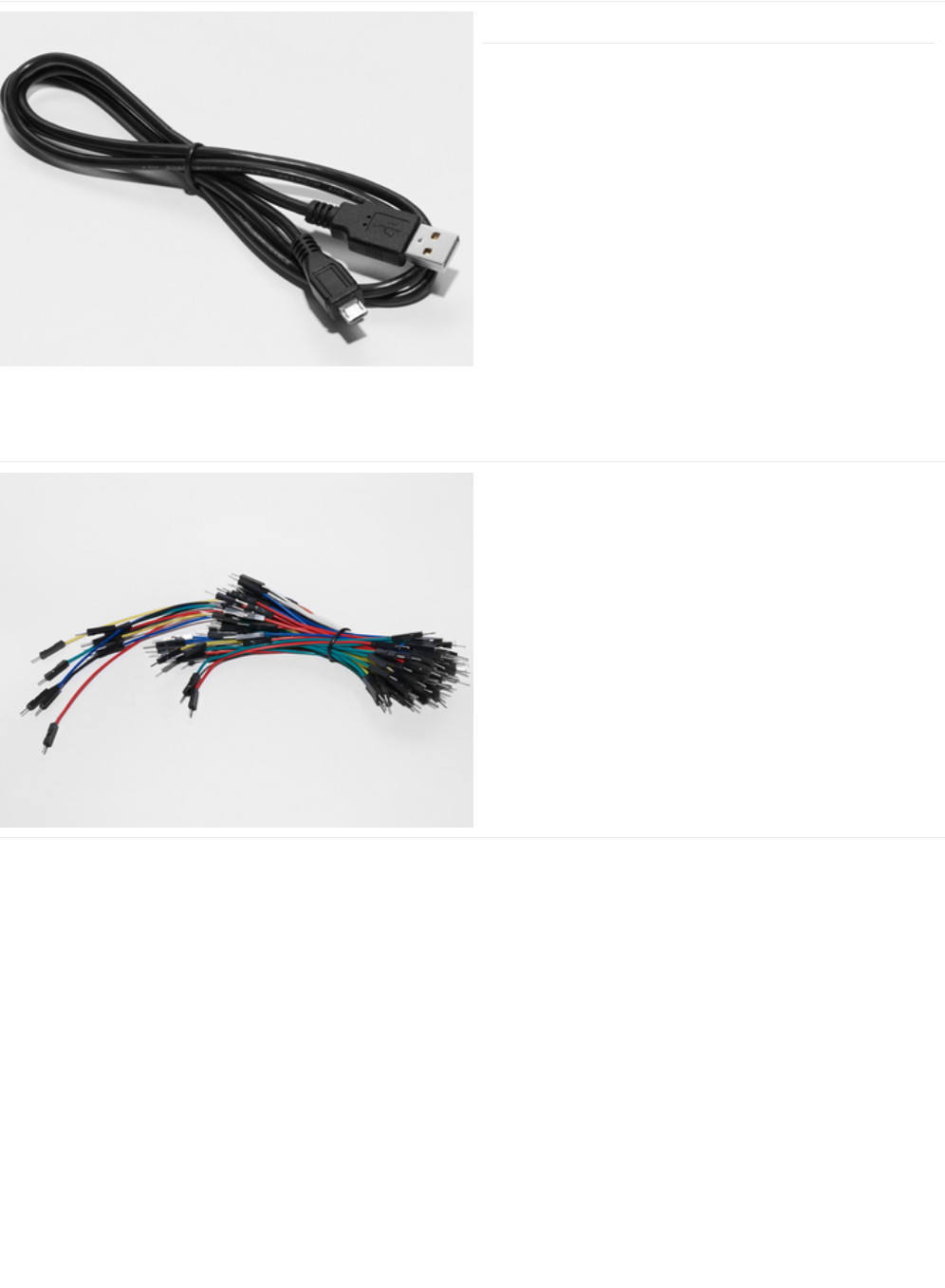
Mini-USB Cable
Make sure the Mini-USB cable you're using is charge +
data and not just charge only.
If you'd like to order a Mini-USB Cable from the Adafruit shop
click here (https://adafru.it/iia)
Breadboard Wiring Bundle
How it's used: We are going to connect a power, ground,
and data wire to the 3 pins on the IR sensor.
If you'd like to order more wires from the Adafruit shop click
here! (https://adafru.it/fE2)
© Adafruit Industries https://learn.adafruit.com/experimenters-guide-for-metro Page 282 of 317
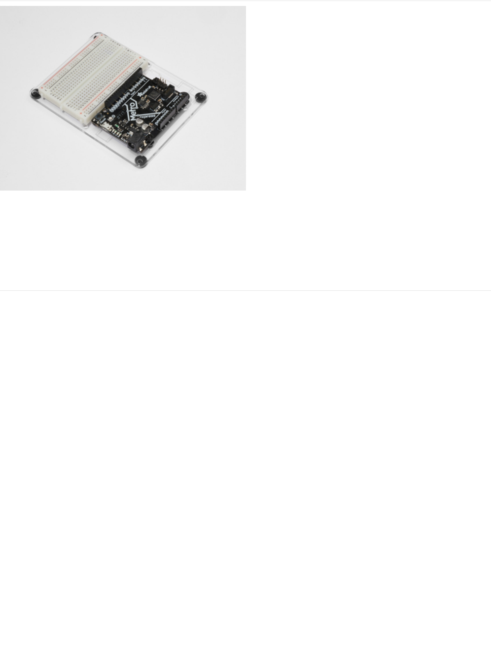
Adafruit Metro
Express
+ Breadboard + Mounting
Plate
If you have not assembled this, we have a handy
guide! (https://adafru.it/x2A)
Need an extra plastic mounting plate (https://adafru.it/x4F),
Adafruit Metro Express (https://adafru.it/xoa), or Mini-
Breadboard (https://adafru.it/keP) from the Adafruit Shop?
© Adafruit Industries https://learn.adafruit.com/experimenters-guide-for-metro Page 283 of 317

Wiring
© Adafruit Industries https://learn.adafruit.com/experimenters-guide-for-metro Page 284 of 317

Code
We are going to use both the IRLib and Keyboard libraries for this project, so let's figure out how to combine them. This section
is self-guided, as in we are going to give you the code piece-by-piece and you can follow along.
First, we want to include both the IRLibAll and Keyboard Libraries:
Then, we are going to include the button codes. Since these are long numbers, they are encoded as hexadecimal values - Colin
has a great video about this topic here (https://adafru.it/yab).
We are going to define NEC as the protocol used by the Adafruit Mini remote, then create a receiver on digital pin 2. After that,
create a decoder object and an integer to hold the previous code for NEC repeat codes.
Lastly, we are going to create a LED object on Pin #13, which is the builtin LED. We are going to use this a way to visually debug
our circuit without printing out to the serial monitor.
In the setup() loop, we are going to tell the Metro to begin control over the keyboard, start the IR Receiver, and configure the
led as an output.
The loop() is quite complicated, but we'll break it down to make it easier. We are going to first detect if the receiver gets an input
from the remote with myReceiver.getResults() . Then, we are going to decode it with a call to myDecoder.decode() .
Next, we want to check if the protocol is the same as what's used by the Mini Remote, NEC, by checking
if(myDecoder.protocolNum==MY_PROTOCOL) . Finally, we are going to detect the repeat codes, and set the current value to the
#include <IRLibAll.h>
#include <Keyboard.h>
/* Remote Codes */
#define VOLUMEUP 0xfd40bf
#define VOLUMEDOWN 0xfd00ff
#define RIGHT_ARROW 0xfd50af
#define LEFT_ARROW 0xfd10ef
#define PLAYPAUSE 0xfd807f
#define SELECT_BUTTON 0xfd906f
// Adafruit Mini-Remote uses NEC, change this if you're using a different remote
#define MY_PROTOCOL NEC
// receiver on pin 2
IRrecv myReceiver(2);
// Decoder object
IRdecode myDecoder;
// NEC repeat codes for Adafruit Mini-Remote
uint32_t Previous;
const int ledPin = 13;
void setup() {
// initialize control over the keyboard
Keyboard.begin();
// start the IR receiver
myReceiver.enableIRIn();
// configure status LED
pinMode(LED_BUILTIN, OUTPUT);
}
© Adafruit Industries https://learn.adafruit.com/experimenters-guide-for-metro Page 285 of 317

previous decoded value if(myDecoder.value==0xFFFFFFFF {myDecoder.value=Previous;}
Phew, now the fun part begins. We are going to use a programming concept called a SwitchCase (https://adafru.it/yac). This will
let us take in one value (the value decoded by the decoder - myDecode.value ) and perform different actions depending on what
the value is.
In our case, we are going to switch based on myDecoder.value . The first case will be if the PLAYPAUSE button is detected
(already #define'd above). We want to send the spacebar key to pause VLC playback.
We are going to send 0x20, the spacebar ascii value, to the keyboard with Keyboard.write(). Then, we are going to turn the LED
to signal the key was sent (a
really easy
way to visually debug your code). Next, we are going to delay, then call
Keyboard.releaseAll(); to release the key(s) pressed. Then, we are going to break; out of that case and finish execution.
Now that you get the idea, we are going to provide you with the code. Try the
Make It Better
section if you'd like to try your hand
at understanding this project better.
void loop()
{
if (myReceiver.getResults()) {
myDecoder.decode();
if(myDecoder.protocolNum==MY_PROTOCOL) {
if(myDecoder.value==0xFFFFFFFF)
myDecoder.value=Previous;
// handle everything in here
switch(myDecoder.value) {
case PLAYPAUSE:
// key-play-pause
// send the spacebar key
Keyboard.write((char)0x20);
digitalWrite(LED_BUILTIN, HIGH);
delay(100);
// release the keys pressed
Keyboard.releaseAll();
break;
/* PROJ05: Metro Media Remote
* Desc: Control VLC with your Adafruit Metro M0 Express!
* by Brent Rubell and Asher Liber for Adafruit Industries
* Requires IRLib2.x Library
*/
#include <IRLibAll.h>
#include <Keyboard.h>
/* Remote Codes */
#define VOLUMEUP 0xfd40bf
#define VOLUMEDOWN 0xfd00ff
#define RIGHT_ARROW 0xfd50af
#define LEFT_ARROW 0xfd10ef
#define PLAYPAUSE 0xfd807f
#define SELECT_BUTTON 0xfd906f
// These are some extra button codes...not used in the PROJ.
// if you want to create more functions in VLC or any other app, use these!
#define UP_ARROW 0xfda05f
#define DOWN_ARROW 0xfdb04f
#define BUTTON_0 0xfd30cf
© Adafruit Industries https://learn.adafruit.com/experimenters-guide-for-metro Page 286 of 317

#define BUTTON_0 0xfd30cf
#define BUTTON_1 0xfd08f7
#define BUTTON_2 0xfd8877
#define BUTTON_3 0xfd48b7
#define BUTTON_4 0xfd28d7
#define BUTTON_5 0xfda857
#define BUTTON_6 0xfd6897
#define BUTTON_7 0xfd18e7
#define BUTTON_8 0xfd9867
#define BUTTON_9 0xfd58a7
// Adafruit Mini-Remote uses NEC, change this if you're using a different remote
#define MY_PROTOCOL NEC
// receiver on pin 2
IRrecv myReceiver(2);
// Decoder object
IRdecode myDecoder;
// NEC repeat codes for Adafruit Mini-Remote
uint32_t Previous;
// use this option for OSX:
char ctrlKey = KEY_LEFT_GUI;
// use this option for Windows and Linux:
// char ctrlKey = KEY_LEFT_CTRL;
const int ledPin = 13;
void setup() {
// monitor the serial at 9600baud
Serial.begin(9600);
// initialize control over the keyboard
Keyboard.begin();
// start the IR receiver
myReceiver.enableIRIn();
// configure status LED
pinMode(LED_BUILTIN, OUTPUT);
Serial.println("Listening to IR...");
}
void loop()
{
if (myReceiver.getResults()) {
myDecoder.decode();
if(myDecoder.protocolNum==MY_PROTOCOL) {
if(myDecoder.value==0xFFFFFFFF)
myDecoder.value=Previous;
// We used VLC for this example, but you can use any keyboard shortcuts!
// (src: https://wiki.videolan.org/Hotkeys_table/)
switch(myDecoder.value) {
case PLAYPAUSE:
// key-play-pause
// send the spacebar key
Keyboard.write((char)0x20);
digitalWrite(LED_BUILTIN, HIGH);
delay(100);
// release the keys pressed
Keyboard.releaseAll();
break;
case VOLUMEUP:
// key-vol-up
// vlc shortcut: ctrl + up arrow
Keyboard.press(ctrlKey);
Keyboard.press(KEY_UP_ARROW);
digitalWrite(LED_BUILTIN, HIGH);
© Adafruit Industries https://learn.adafruit.com/experimenters-guide-for-metro Page 287 of 317

I'm having trouble with this Project
Fatal error: IRLibAll.h: No such file or directory #include
The IRLib 2.x library was improperly installed. Check CIRC16's "Installing the IR Library" page for correct installation
instructions.
My computer isn't responding to the remote
If you're using the Adafruit Mini-Remote, make sure you un-comment (remove the slashes) the char ctrlKey variable for which
operating system you're using:
// use this option for OSX:
char ctrlKey = KEY_LEFT_GUI;
// use this option for Windows and Linux:
// char ctrlKey = KEY_LEFT_CTRL;
If you're using your own remote control, you'll need to make modifications to the code. Check out this guide on Sending IR
Codes for more info.
This project still isn't working
digitalWrite(LED_BUILTIN, HIGH);
delay(100);
Keyboard.releaseAll();
break;
case VOLUMEDOWN:
// key-vol-down
// vlc shortcut: ctrl + down arrow
Keyboard.press(ctrlKey);
Keyboard.press(KEY_DOWN_ARROW);
digitalWrite(LED_BUILTIN, HIGH);
delay(100);
Keyboard.releaseAll();
break;
case RIGHT_ARROW:
// key-faster
// vlc shortcut: +
Keyboard.press('+');
digitalWrite(LED_BUILTIN, HIGH);
delay(100);
Keyboard.releaseAll();
break;
case LEFT_ARROW:
// key-faster
// vlc shortcut: -
Keyboard.press('-');
digitalWrite(LED_BUILTIN, HIGH);
delay(100);
Keyboard.releaseAll();
break;
default:
// if nothing else matches, do the default
// default is optional
break;
}
Previous=myDecoder.value;
}
digitalWrite(LED_BUILTIN, LOW);
myReceiver.enableIRIn();
}
}
© Adafruit Industries https://learn.adafruit.com/experimenters-guide-for-metro Page 288 of 317


Make It Better
We added in some extra buttons for you in the code provided on the last page:
If you'd like to use these for different commands within VLC, or maybe control Netflix or Youtube, check out the Arduino Modifier
Keys Documentation (https://adafru.it/yad). Implement new keys, or modify your pre-existing cases within the SwitchCase to use
different keys.
// These are some extra button codes...not used in the PROJ.
// if you want to create more functions in VLC or any other app, use these!
#define UP_ARROW 0xfda05f
#define DOWN_ARROW 0xfdb04f
#define BUTTON_0 0xfd30cf
#define BUTTON_1 0xfd08f7
#define BUTTON_2 0xfd8877
#define BUTTON_3 0xfd48b7
#define BUTTON_4 0xfd28d7
#define BUTTON_5 0xfda857
#define BUTTON_6 0xfd6897
#define BUTTON_7 0xfd18e7
#define BUTTON_8 0xfd9867
#define BUTTON_9 0xfd58a7
© Adafruit Industries https://learn.adafruit.com/experimenters-guide-for-metro Page 290 of 317
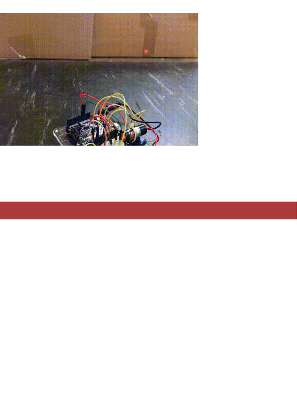
PROJ06: IR Laser Pet Toy
Do you want to annoy your (or your family's) pets? Maybe you want to exercise your pet in the laziest way possible? You are
going to build a laser pet toy controlled by your IR remote and the Adafruit Metro.
Here's how it's going to work: a cheap-o laser pointer is affixed to the servo horn. You'll mount the servo to your breadboard
with double-sided tape to give it a solid base. Then, you'll wire up your infrared sensor along with the servo and code a program
that lets you annoy/exercise your pets from a safe distance
The laser pointer dot can drive both cats and dogs towards obsessive behavior because it can seek out the "prey" instinct in
your pet. We strongly suggest hiding a few food treats around the room, and then letting the IR Laser Pet Toy move in the
direction of the food. Your dog/cat needs to be rewarded for chasing what they consider to be their prey.
We also advise both you and your pet to avoid any direct eye exposure with the laser. Keep the laser on during play with the
animal to avoid them looking at the light (switching it off/turning it on will make them turn around quickly).
What to know about lasers and your pet
© Adafruit Industries https://learn.adafruit.com/experimenters-guide-for-metro Page 291 of 317

Parts
This PROJect requires a laser pointer. We do not recommend using the Laser Diodes we sell in the Adafruit shop. Your corner
store, or Amazon, sells a very low-powered laser pointer.
The IR Receiver is used to receive infrared signals from the
remote. These signals will then be sent to the Metro, which
will tell the servo where to move.
The Mini Remote contains an IR LED to transmit signals to
the IR Receiver connected to the Metro M0.
This project requires an external part.
© Adafruit Industries https://learn.adafruit.com/experimenters-guide-for-metro Page 292 of 317
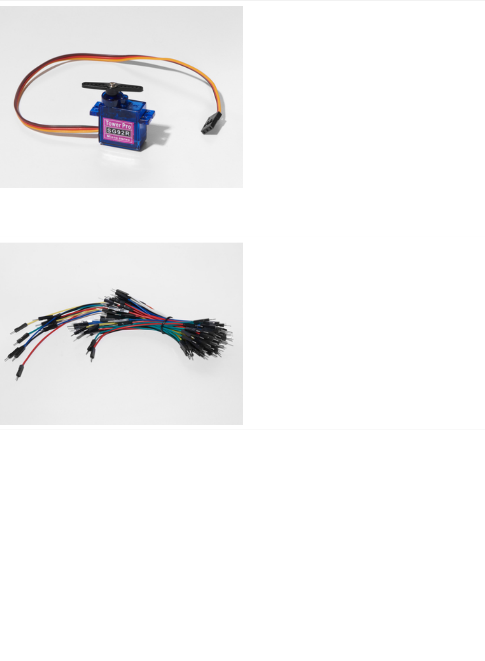
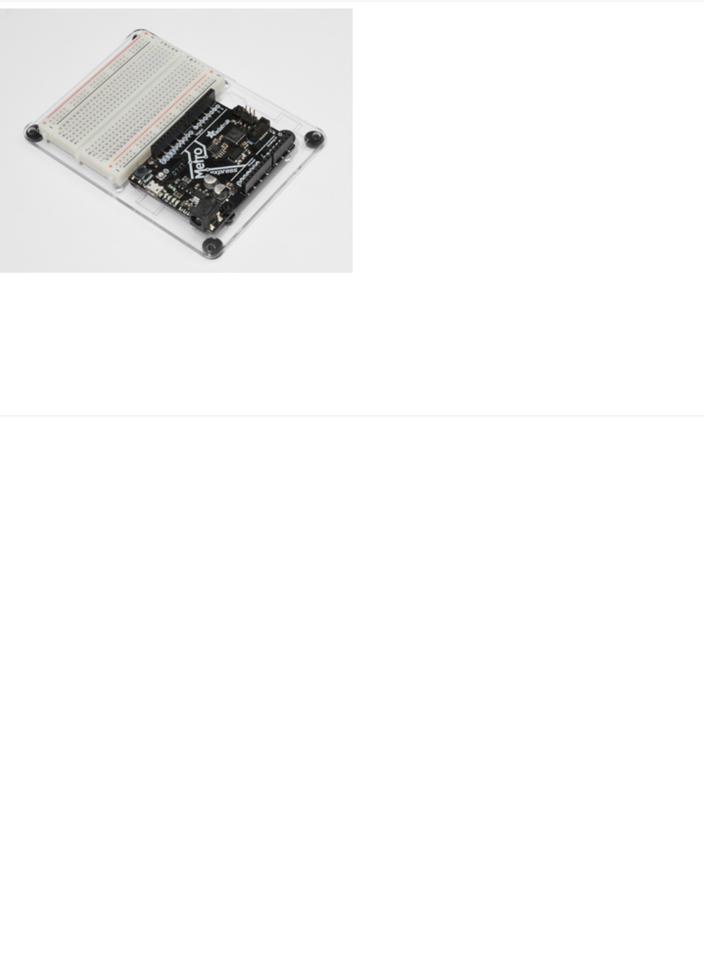
Adafruit Metro + Breadboard + Mounting Plate
If you have not assembled this, we have a handy
guide! (https://adafru.it/x2A)
If you'd like to order an extra plastic mounting
plate (https://adafru.it/x4F), Adafruit
Metro (https://adafru.it/METROXMETR), or Mini-
Breadboard (https://adafru.it/keP) from the Adafruit Shop click
here!
© Adafruit Industries https://learn.adafruit.com/experimenters-guide-for-metro Page 294 of 317
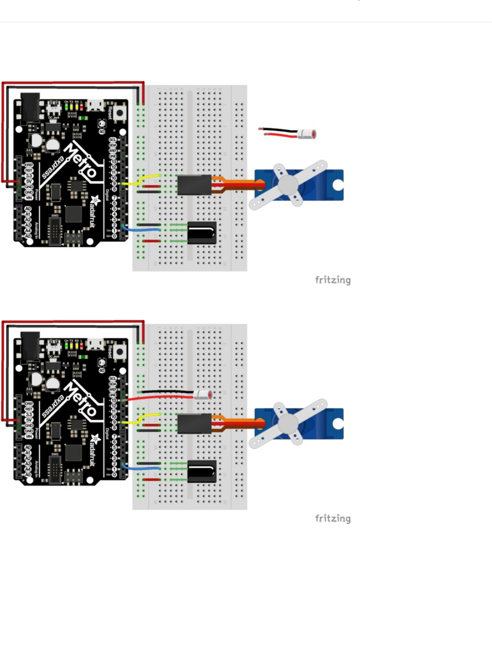
Wiring
There are two routes for assembly: we can either put a laser pointer on top of the servo and tape the button to turn it on, or we
can disassemble it and solder some leads on it so it can be controlled by the Metro.
This wiring is for the first option (non-controlled laser).
This wiring is for the laser controlled by the IR Remote. We are controlling the laser by sending it a voltage from Pin #13.
© Adafruit Industries https://learn.adafruit.com/experimenters-guide-for-metro Page 295 of 317
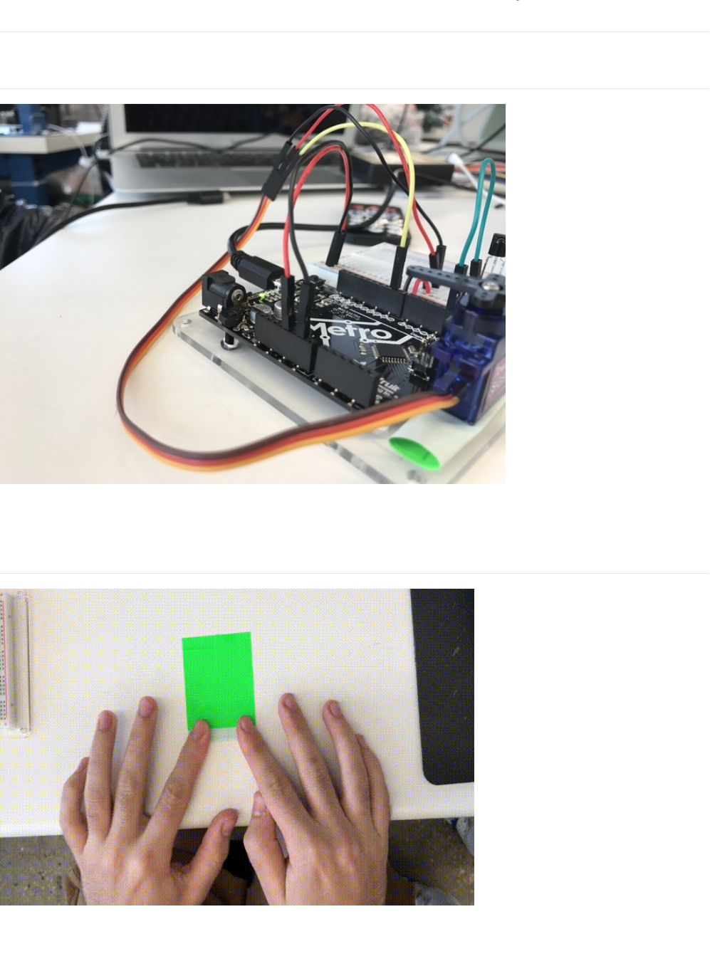
Assembly
This project requires some assembly (like the music box) for you to get really good performance out of it.
Servo Wiring
We are going to wire the servo such that the longer wires in your breadboard wiring bundle are used. We want to mount the
Servo on
Base Assembly
Take a piece of tape and fold it into itself (or roll it up).
© Adafruit Industries https://learn.adafruit.com/experimenters-guide-for-metro Page 296 of 317
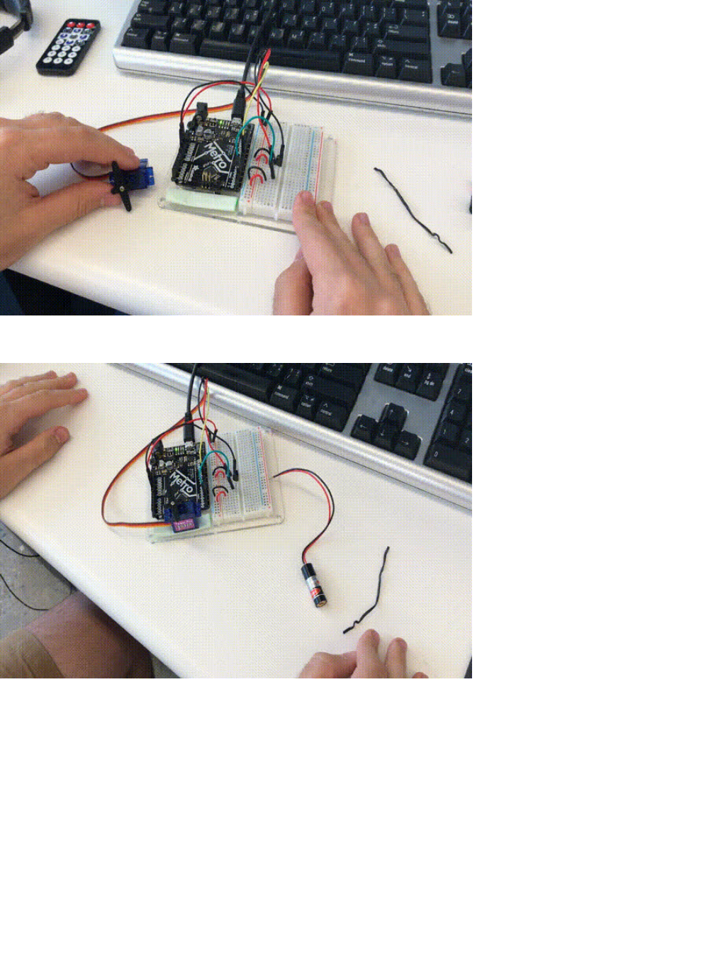
Then, place it on the mounting plate. Press down so it retains a firm grip (servos move really forcefully).
Take a twist-tie (like the ones you can get at your local supermarket) or a zip-tie and affix the Laser Pointer to the horn of the
servo. We like using zip-ties and twist-ties because they're super inexpensive and non-permanent.
© Adafruit Industries https://learn.adafruit.com/experimenters-guide-for-metro Page 297 of 317

Code
The code for this is going to look very similar to PROJ05 - it uses a similar structure to handle IR remote button presses, but with
the servo instead of USB HID. We are also going to introduce three new concepts that you might've seen in previous CIRCs -
random() , min() and max() .
First, let's import both IRLib and Servo:
Then, we are going to include all of the remote-specific code. This is going to include #define's for remote values, the receiver
pin assignment, the decoder object, and the ir protocol used.
Next, we are going to create a servo object myServo, a variable to store the servo position and a variable to hold the angle (in
degrees) of the servo.
(Optional) If you're using a laser and are able to control it from the metro (see:
assembly
), we are going to connect the power to
pin 11. We are also going to make a boolean, laserToggle , to turn the laser on and off. laserToggle holds one of two values -
true
or
false
. Depending on the button pressed and the current state, we can easily toggle the laser.
#include <IRLibAll.h>
#include <Servo.h>
/* Adafruit Mini Remote */
#define MY_PROTOCOL NEC
#define RIGHT_ARROW 0xfd50af
#define LEFT_ARROW 0xfd10ef
#define SELECT_BUTTON 0xfd906f
#define BUTTON_0 0xfd30cf
#define BUTTON_1 0xfd08f7
#define BUTTON_2 0xfd8877
#define BUTTON_3 0xfd48b7
#define BUTTON_4 0xfd28d7
#define BUTTON_5 0xfda857
#define BUTTON_6 0xfd6897
#define BUTTON_7 0xfd18e7
#define BUTTON_8 0xfd9867
#define BUTTON_9 0xfd58a7
// pin number for the receiver
IRrecv myReceiver(2);
IRdecode myDecoder;
// handles nec repeat codes
uint32_t Previous;
/* Servo */
// create a servo object
Servo myServo;
// stores the servo position
int16_t pos;
// angle (degrees) to move the servo left/right
int16_t Speed;
© Adafruit Industries https://learn.adafruit.com/experimenters-guide-for-metro Page 298 of 317

Our setup() code needs to set the laser pin as an output, attach a servo to pin 9, set the initial pos to 90, the initial pos to 90
and the initial Speed to 5. Then, we are going to write pos to the servo and start the IR receiver.
As previously mentioned, this code is similar to PROJ05:
The loop() is quite complicated, but we'll break it down to make it easier. We are going to first detect if the receiver gets an input
from the remote with myReceiver.getResults() . Then, we are going to decode it with a call to myDecoder.decode() .
Next, we want to check if the protocol is the same as what's used by the Mini Remote, NEC, by checking
if(myDecoder.protocolNum==MY_PROTOCOL) . Finally, we are going to detect the repeat codes, and set the current value to the
previous decoded value if(myDecoder.value==0xFFFFFFFF {myDecoder.value=Previous;}
This time, though, we are going to
set the position of the servo
before writing to it. Hobby servos are incredibly particular with
how far they can rotate, and can break if you rotate them too far. Let's prevent this with the min() (https://adafru.it/yan) function.
This function will set the position of the servo to
pos+Speed
, but it'll keep the value underneath or at 180 degrees so that it won't
go past that point.
Similarly if we want to constrain the right side, we set pos to max(0, pos-Speed). Max is the opposite of min, it constrains the
/* Laser */
// connect laser PWR to a pin 11
const int laserPin = 11;
// toggle the laser
bool laserToggle = false;
void setup() {
// randomizes a seed for random() calls
randomSeed(analogRead(0));
// set the laser pin as an output
pinMode(laserPin, OUTPUT);
// attach servo to pin 9
myServo.attach(9);
// set initial position
pos = 90;
// set initial speed
Speed = 5;
// write initial pos to servo at startup
myServo.write(pos);
// Start the IR receiver
myReceiver.enableIRIn();
}
void loop()
{
if (myReceiver.getResults()) {
myDecoder.decode();
if(myDecoder.protocolNum==MY_PROTOCOL) {
if(myDecoder.value==0xFFFFFFFF)
myDecoder.value=Previous;
switch(myDecoder.value) {
case LEFT_ARROW:
// move servo
pos=min(180,pos+Speed);
break;
© Adafruit Industries https://learn.adafruit.com/experimenters-guide-for-metro Page 299 of 317

lower-ends of the value.
One of the cool things Arduino lets you do is generate a random number. (https://adafru.it/t9A) We can generate a random
number between 0 and 180 if we call random(0, 180) . Let's set one of the buttons to set the pos to call to random.
After the case statements, you'll want to:
1. Write to the servo,
2. Handle the NEC repeat code: Previous=myDecoder.value;
3. Re-enable the IR Receiver
The full code is below
case RIGHT_ARROW:
pos=max(0,pos-Speed);
break;
case BUTTON_0:
pos=random(0,180);
break;
myServo.write(pos);
Previous=myDecoder.value;
myReceiver.enableIRIn();
/*
Metro Explorers Guide
PROJ06 - IR Laser Pet Toy
by Brent Rubell and Asher Lieber for Adafruit Industries. Support Open Source, buy Adafruit!
Note: this sketch requires IRLIB2.x
*/
#include <IRLibAll.h>
#include <Servo.h>
/* Adafruit Mini Remote */
#define MY_PROTOCOL NEC
#define RIGHT_ARROW 0xfd50af
#define LEFT_ARROW 0xfd10ef
#define SELECT_BUTTON 0xfd906f
#define BUTTON_0 0xfd30cf
#define BUTTON_1 0xfd08f7
#define BUTTON_2 0xfd8877
#define BUTTON_3 0xfd48b7
#define BUTTON_4 0xfd28d7
#define BUTTON_5 0xfda857
#define BUTTON_6 0xfd6897
#define BUTTON_7 0xfd18e7
#define BUTTON_8 0xfd9867
#define BUTTON_9 0xfd58a7
// pin number for the receiver
IRrecv myReceiver(2);
IRdecode myDecoder;
// handles nec repeat codes
uint32_t Previous;
© Adafruit Industries https://learn.adafruit.com/experimenters-guide-for-metro Page 300 of 317

This project isn't working properly
My Servo doesn't properly move
Make sure your servo is attached to Digital Pin 9 on your Metro or Metro Express. Also make sure you have the servo library
included in your sketch (at the top of your sketch, you should see #include ).
I'm using a different remote, should I be doing something differently?
The code for this project only works with the Adafruit Mini Remote. If you want to use another remote, please check this guide
/* Servo */
// create a servo object
Servo myServo;
// stores the servo position
int16_t pos;
// angle (degrees) to move the servo left/right
int16_t Speed;
void setup() {
// randomizes a seed for random() calls
randomSeed(analogRead(0));
// set the laser pin as an output
//pinMode(laserPin, OUTPUT);
// attach servo to pin 9
myServo.attach(9);
// set initial position
pos = 90;
// set initial speed
Speed = 5;
// write initial pos to servo at startup
myServo.write(pos);
// Start the IR receiver
myReceiver.enableIRIn();
}
void loop()
{
if (myReceiver.getResults()) {
myDecoder.decode();
if (myDecoder.protocolNum == MY_PROTOCOL) {
if (myDecoder.value == 0xFFFFFFFF)
myDecoder.value = Previous;
switch (myDecoder.value) {
case LEFT_ARROW:
// move servo
pos = min(180, pos + Speed);
break;
case RIGHT_ARROW:
pos=max(0,pos-Speed);
break;
case BUTTON_0:
pos=random(0,180);
break;
}
// tell servo 'move to variable pos'
myServo.write(pos);
Previous=myDecoder.value;
}
myReceiver.enableIRIn();
}
}
© Adafruit Industries https://learn.adafruit.com/experimenters-guide-for-metro Page 301 of 317

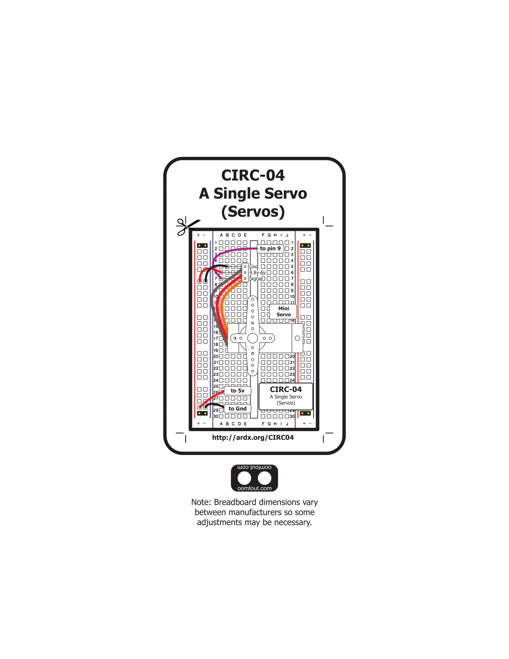
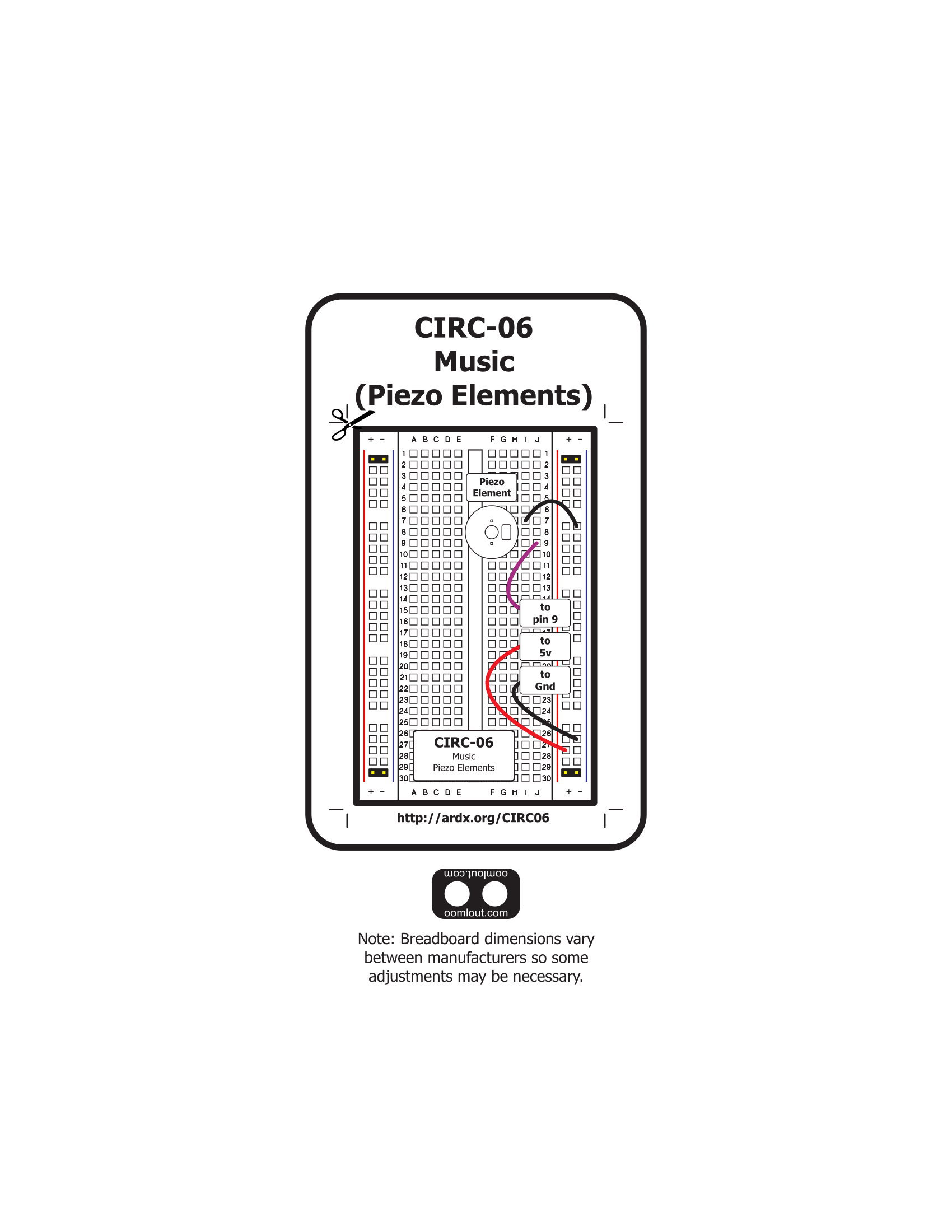
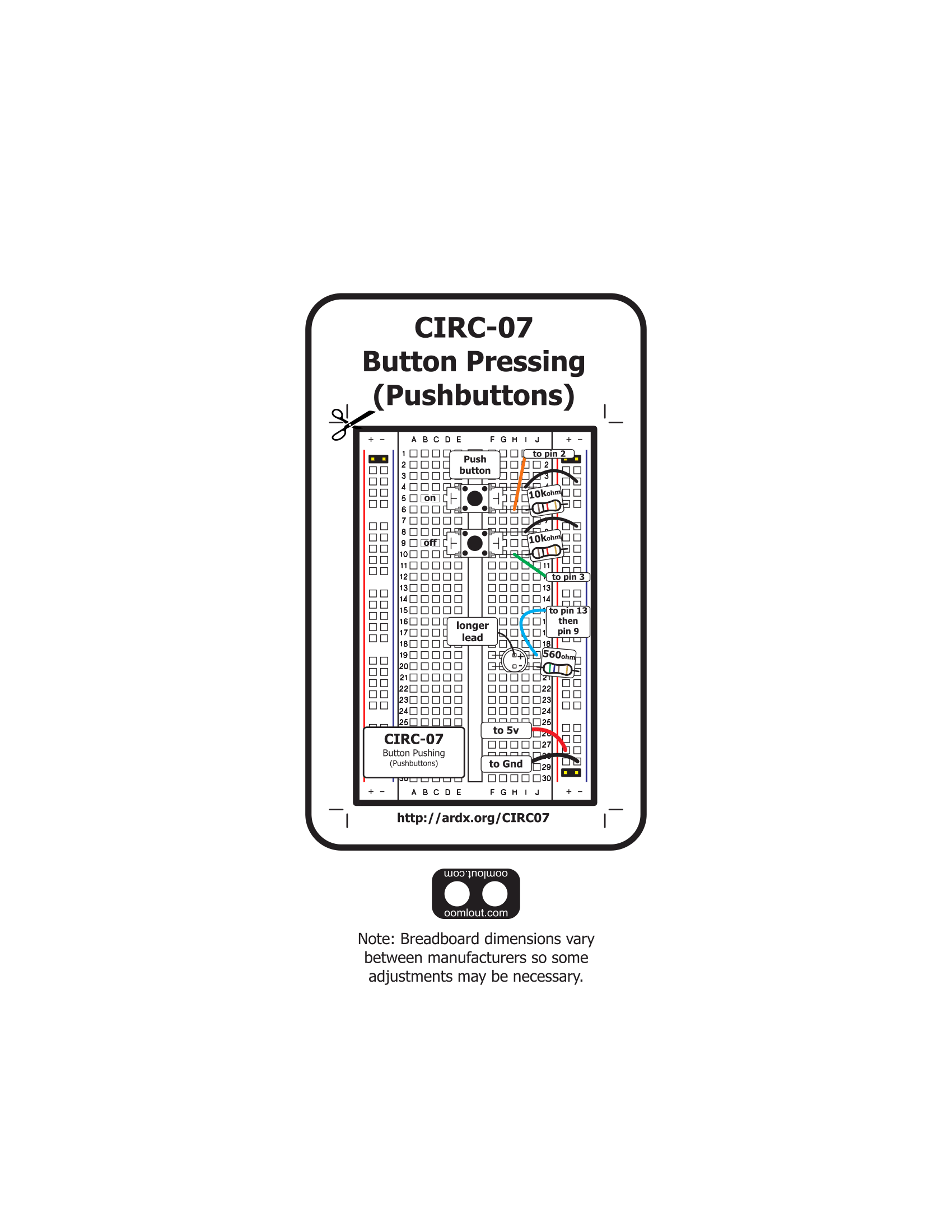
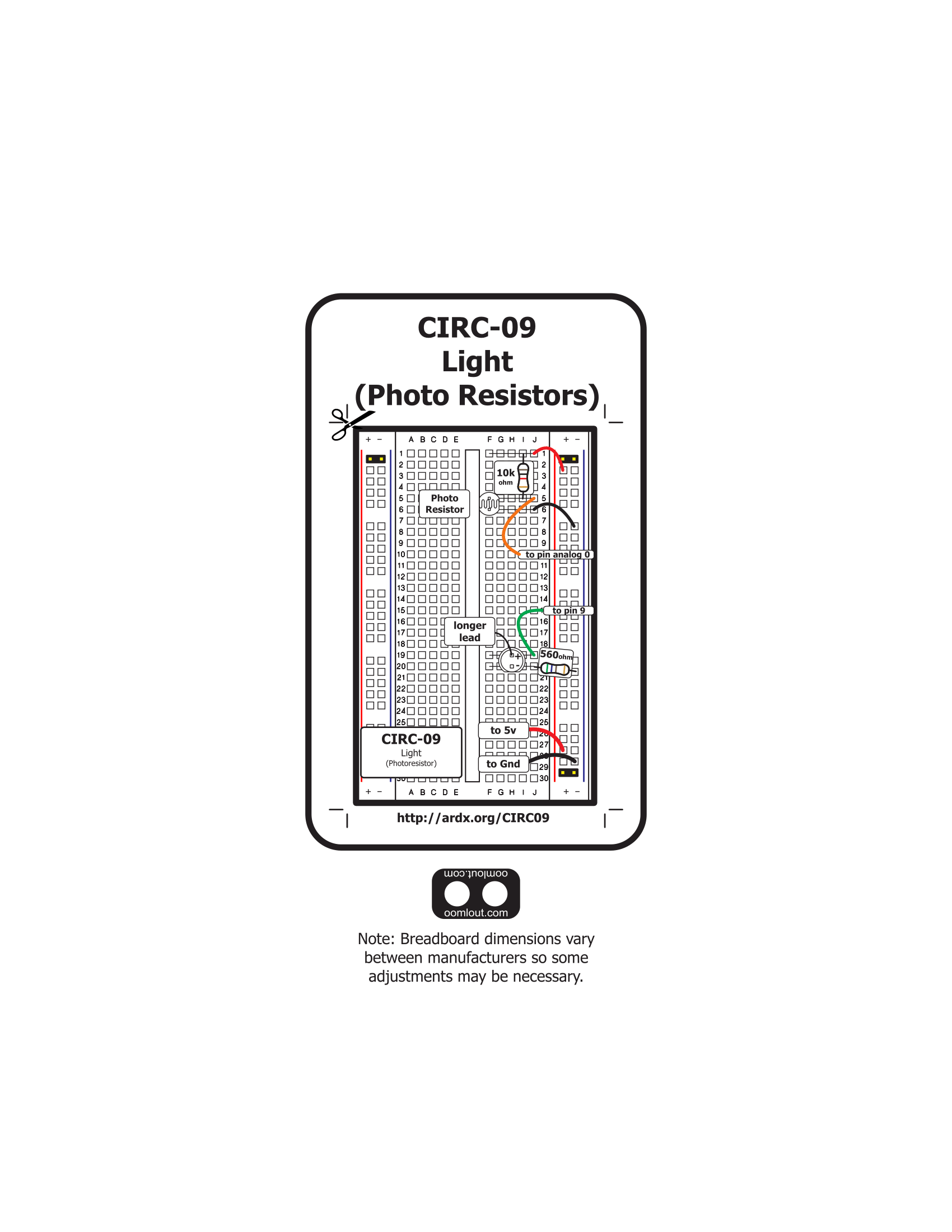
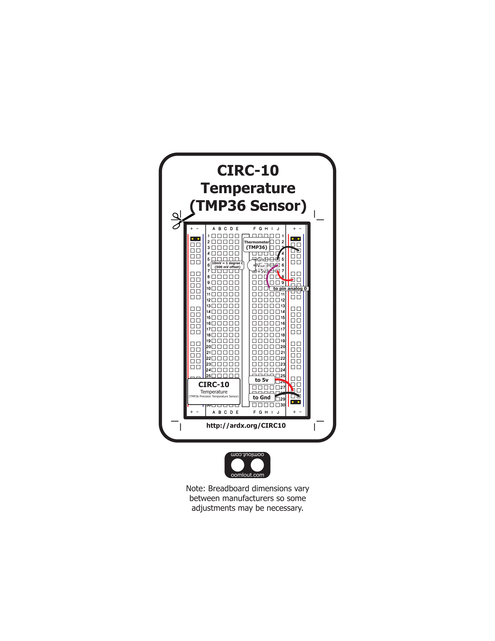
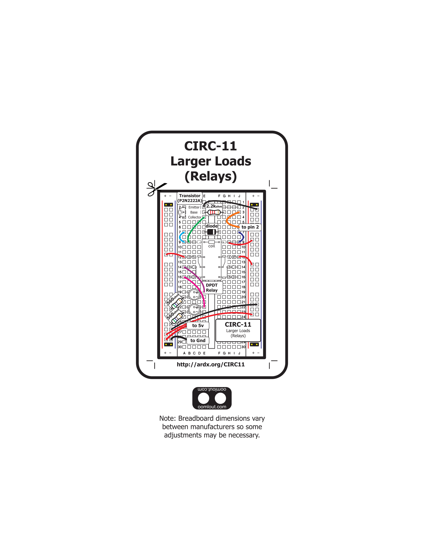
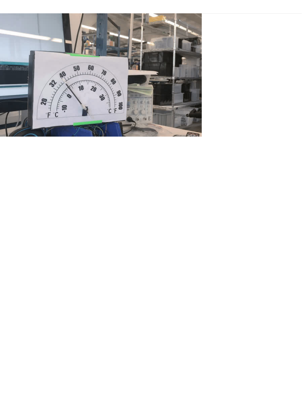
PROJ08: Analog Thermometer Gauge
One of the cool products in the Adafruit Store is the Automotive Gauge Stepper Motor (https://adafru.it/yhe), a stepper motor
with a needle indicator attached to it. This gauge can be used for a physical-feel, similar to a tachometer on a car.
Since we already have a Servo motor, we can build an analog gauge to measure temperature. This PROJ can also be re-
purposed to create a physical output gauge for anything you can measure!
© Adafruit Industries https://learn.adafruit.com/experimenters-guide-for-metro Page 303 of 317
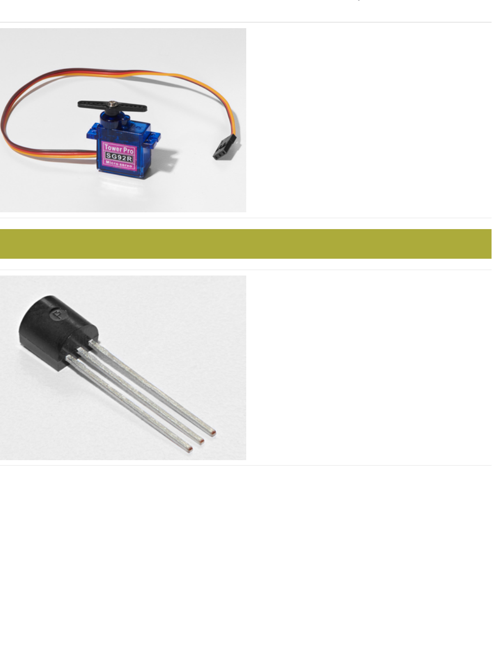
Parts
Mini Servo
If you'd like to order an extra mini servo from the Adafruit
shop, click here! (https://adafru.it/f1g)
There are many other servo sizes and types in the Adafruit
store, check out our offerings (https://adafru.it/xgD)
Analog Temperature Sensor
If you'd like an extra temperature sensor, you can grab one
from the Adafruit shop, click here (https://adafru.it/xfq)
The Analog Temperature Sensor looks a LOT like the NPN Transistor, make sure it says "TMP36" on it!
© Adafruit Industries https://learn.adafruit.com/experimenters-guide-for-metro Page 304 of 317
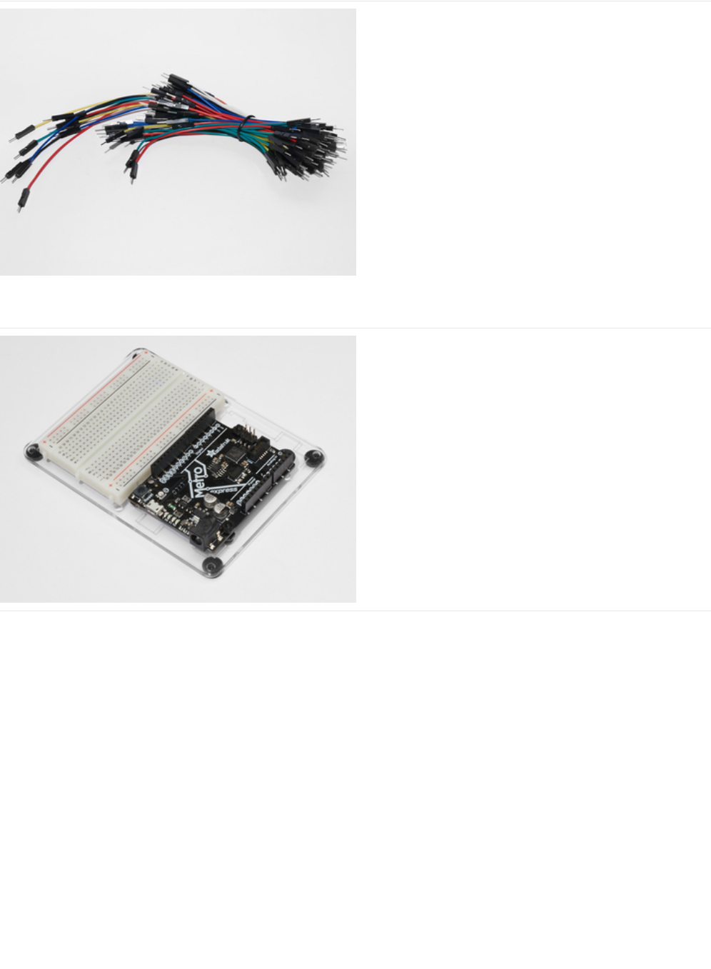
Breadboard Wiring Bundle
If you'd like to order more wires from the Adafruit shop click
here! (https://adafru.it/fE2)
Adafruit Metro (or Metro Express) + Breadboard +
Mounting Plate
If you have not assembled this, we have a handy
guide! (https://adafru.it/x2A)
If you'd like to order an extra plastic mounting
plate (https://adafru.it/x4F), Adafruit
Metro (https://adafru.it/METROXMETR), Adafruit Metro
Express (https://adafru.it/xoa), or Mini-
Breadboard (https://adafru.it/keP) from the Adafruit Shop click
here!
© Adafruit Industries https://learn.adafruit.com/experimenters-guide-for-metro Page 305 of 317
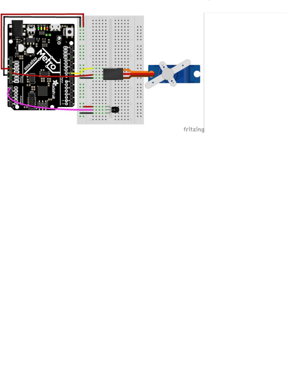
Wiring
Note there are two power connections: the TMP36 is connected to 3.3V Pin and the Servo is connected to the 5V Pin. If you're
using a regular metro, both can be connected to the 5V pin and controlled in code.
© Adafruit Industries https://learn.adafruit.com/experimenters-guide-for-metro Page 306 of 317
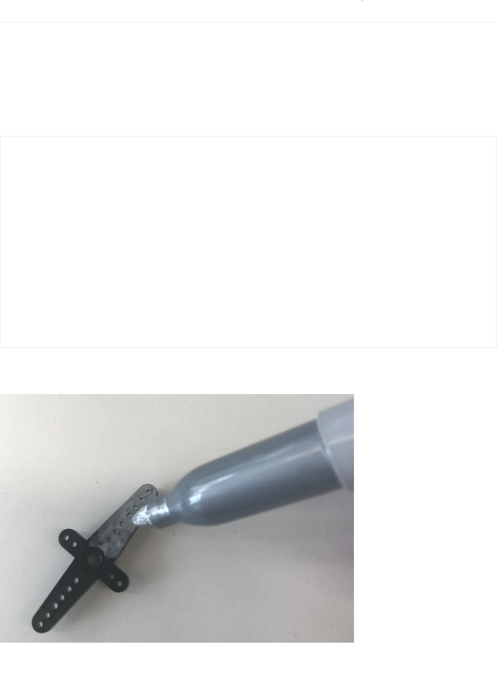
Assembly
Our assembly process for this can differ for how you want to make your circuit. The enclosure can be different, and you might
even want to try other servos from the Adafruit store (https://adafru.it/xgD). The calibration, though, is very important and you'll
want to "dial in" your servo to make sure it's going to display perfectly.
Dialing in your Servo
First, we should move our servo to its center location. Download and run this small Arduino code. It'll move the servo to it's
center location:
You should see your servo horn move to the center. Take the horn off your servo (if you screwed it on, you'll have to unscrew it),
and mark the tip of it with a marker. This will be your indicator:
Reattach the horn onto your servo (which should now be in the 90 degrees position) and you're ready to roll!
/*
* Servo Centering Script
*
*/
#include <Servo.h>
Servo myservo;
void setup() {
myservo.attach(9);
}
void loop() {
// change this depending on where you're centering
myservo.write(90);
delay(15);
}
© Adafruit Industries https://learn.adafruit.com/experimenters-guide-for-metro Page 307 of 317
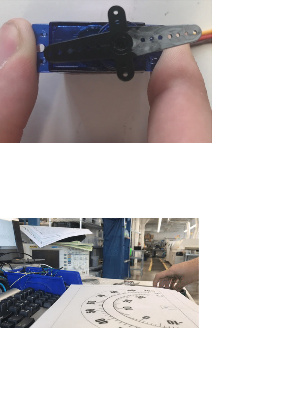
Assembling an enclosure
Let's build an enclosure so that you can use this on your desk at work, or somewhere in a room. The ever so talented Dano
Wall (https://adafru.it/yA4)whipped up a printable, cut-out, design which fits on top of the box that your metroX kit came in. It's a
dual-dial design that works both with Fahrenheit and Celsius . You can download the design below (it's open-source and totally
modifiable):
Test-fit the printed dial against your MetroX box, then cut it out along the outer black line
Tape the four corners (we only taped two in the gif below) of the paper to the inside of the box. Use transparent tape if you can,
it'll look much cleaner:
© Adafruit Industries https://learn.adafruit.com/experimenters-guide-for-metro Page 308 of 317
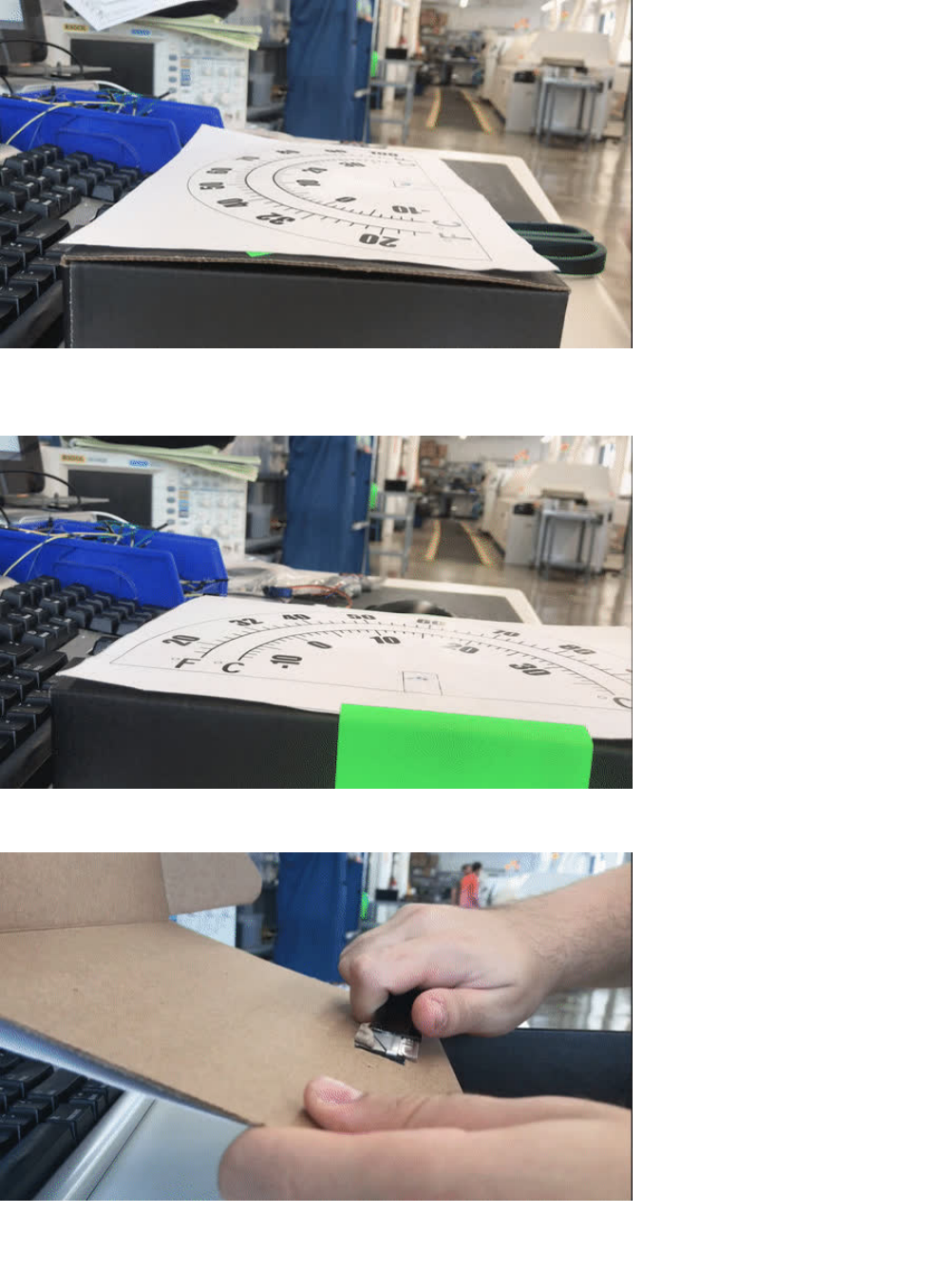
Use a box-cutter or the edge of a pair of scissors to cut out the servo cut-out (the rectangle) on your printed design. It might take
a few cuts to get through the box completely:
Clean up any residual cardboard from the hole you cut. Tape the servo in the rectangular hole, facing outward:
Finally, you'll need a pointing device. We used the inside of a disposable pen since they're inexpensive, and a lot of people have
them lying around:
© Adafruit Industries https://learn.adafruit.com/experimenters-guide-for-metro Page 309 of 317

Great job! Close up the box and get ready to program:
© Adafruit Industries https://learn.adafruit.com/experimenters-guide-for-metro Page 310 of 317

Code
The code for this is a mix between code for CIRC04: Servo and CIRC10: Temperature. What we're doing is attaching the value
for the temperature, to a value of the servo. Let's walk through some parts of it:
Inside, the loop, we're going to read in a voltage from the pin using the getVoltage() function from CIRC04. We are then going to
pass this value to a new function, convertToF() , which is generated from the voltage value, to convert the voltage to a degrees
Fahrenheit temperature:
Then, we're going to constrain the temperature values. This is totally up to you, you can use any number, but we are using -10F
and 100F as our minimum and maximum temperature accepted by the TMP36:
map((int(temperature)), -10, 100
We still need to map the temperature values to servo values. The minimum degrees a servo can move is 0 degrees and the
maximum degrees is 180, so let's set the servo to map: -10 to 0 and 100 to 180:
Then, write servoPos to the servo!
Here's the full code, with all the helpers built in:
Code
// read the voltage from the pin
float voltage = getVoltage(temperaturePin);
// convert the voltage to a temperature value
float temperature = convertToF(voltage);
servoPos = map((int(temperature)), -10, 100, 0, 180);
// write servoPos to the servo
metroServo.write(servoPos);
// poll every 0.5sec
delay(500);
/*
* PROJ07 - RGB Color Mixer
*
* by Brent Rubell for Adafruit Industries
*/
// RGB LED Pins
int rgbLED[] = {9, 10, 11};
// trim potentiometer pin
int trimPin = A0;
// button pin
const int buttonPin = 12;
// button state
int buttonState = 0;
// trim pot. value
int trimValue = 0;
int colorIdx = 0;
int red = 0;
int green = 0;
© Adafruit Industries https://learn.adafruit.com/experimenters-guide-for-metro Page 311 of 317

int green = 0;
int blue = 0;
boolean CURRENTRGB[] = {0, 0, 0};
void setup() {
// Setup Serial
Serial.begin(9600);
// set the 3 pins as output pins
for(int i = 0; i < 3; i++) {
pinMode(rgbLED[i], OUTPUT);
}
// initialize the push-button as an input
pinMode(buttonPin, INPUT);
}
void loop() {
// read the value of the push-button
buttonState = digitalRead(buttonPin);
if(buttonState == LOW) {
delay(2);
// reset the colorIdx if it goes past Blue (colorIdx = 3)
if(colorIdx == 3) {
colorIdx = 0;
}
colorIdx++;
switch(colorIdx) {
case 1:
trimValue = analogRead(trimPin);
red = map(trimValue, 0, 670, 0, 255);
CURRENTRGB[0] = red;
break;
case 2:
trimValue = analogRead(trimPin);
green = map(trimValue, 0, 670, 0, 255);
CURRENTRGB[1] = green;
break;
case 3:
trimValue = analogRead(trimPin);
blue = map(trimValue, 0, 670, 0, 255);
CURRENTRGB[2] = blue;
break;
default:
break;
}
Serial.println("red:");
Serial.print(CURRENTRGB[0]);
Serial.println(" ");
Serial.println("green:");
Serial.print(CURRENTRGB[1]);
Serial.println(" ");
Serial.println("blue:");
Serial.print(CURRENTRGB[2]);
Serial.println(" ");
setColor(rgbLED, CURRENTRGB);
delay(1000);
}
© Adafruit Industries https://learn.adafruit.com/experimenters-guide-for-metro Page 312 of 317

}
void setColor(int* led, const boolean* color) {
for(int i = 0; i < 3; i++){
digitalWrite(led[i], color[i]);
}
}
© Adafruit Industries https://learn.adafruit.com/experimenters-guide-for-metro Page 313 of 317

Code
© Adafruit Industries https://learn.adafruit.com/experimenters-guide-for-metro Page 314 of 317
