Ezgo RXV Danaher Codes T Shoot Guide 2
User Manual:
Open the PDF directly: View PDF ![]() .
.
Page Count: 44
- 2pages.pdf
- Slide Number 1
- Slide Number 2
- Vehicle Operation
- Slide Number 4
- Slide Number 5
- Slide Number 6
- Slide Number 7
- Slide Number 8
- Slide Number 9
- Slide Number 10
- Slide Number 11
- Slide Number 12
- Slide Number 13
- Slide Number 14
- Slide Number 15
- Slide Number 16
- Slide Number 17
- Slide Number 18
- Slide Number 19
- Slide Number 20
- Slide Number 21
- Slide Number 22
- Slide Number 23
- Slide Number 24
- Slide Number 25
- Slide Number 26
- Slide Number 27
- Slide Number 28
- Slide Number 29
- Slide Number 30
- Slide Number 31
- Slide Number 32
- Slide Number 33
- Slide Number 34
- Slide Number 35
- Slide Number 36
- Slide Number 37
- Slide Number 38
- Slide Number 39
- Slide Number 40
- Slide Number 41
- Slide Number 42

Customer Care
RXV-E Advanced Trouble-Shooting
Guide
610873
Customer Care
Table of Contents
Safety 1
Hand Held Diagnostic Tool 2
Special Tool List 3
Wiring Diagrams4-6
Symptoms 7
Error Codes 8
8976 AC Over Current 9
9024 AC Short Circuit 10
12576 DC Bus Timeout 11-12
12817 DC Bus High – Software Detected 13-14
12818 DC Bus High – Hardware Detected 15-16
12833 DC Bus Low 17-19
16912 Motor temp High 20
17168 Heat Sink Temp High 21
20753 15V Supply Low Voltage 22
20755 5V Supply Low or High Voltage 23-25
21008 Current Sensor Offset Calibration 26
21520 Open Drain Output Current High 27-28
33024 CAN Time Out 29
25104 Direction Error 30
25105 Throttle Sensor Error 31
25106 Reverse Alarm Test Failed 32
25107 Mechanical Brake Test Failed 33-34
25108 Brake Sensor Error 35
Additional Component Testing 36-38
Warnings 39
Page

Customer Care
Vehicle Operation
Understanding the Power-up Sequence
• The car will perform the following checks during the first
second of initial key – on.
• Electric brake check – Controller tries to rotate the motor
¼ turn in both directions.
• Park brake check – Controller disengages and reengages
the park brake.
• Reverse alarm check – Controller sounds the alarm for
100ms.
• Charger inhibit check – Controller checks the charge
receptacle for connection to the charger.
• Throttle switch check – Throttle switch must be open to
pass the start up test.
• Throttle position sensor – Controller checks the TPS for 0%
throttle. .38-.56 volt
• Throttle operation check – Controller checks the TPS for the
correct open and closed range. .5-4.8v
The car will not run if the controller detects a problem
with any of the circuits above.
Customer Care
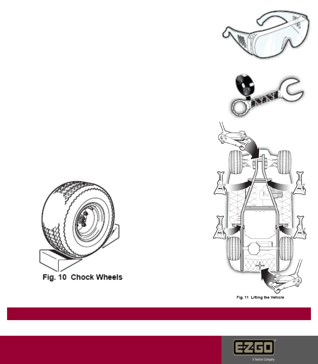
Safety
Always wear personal protective equipment
Wrap battery wrenches to prevent accidental
connection.
Use a 2X4X12” to spread the load between the jack pad and the composite bumper!
Always properly lift the vehicle
and chock the wheels to prevent
accidental drive away.
Page 1
Customer Care
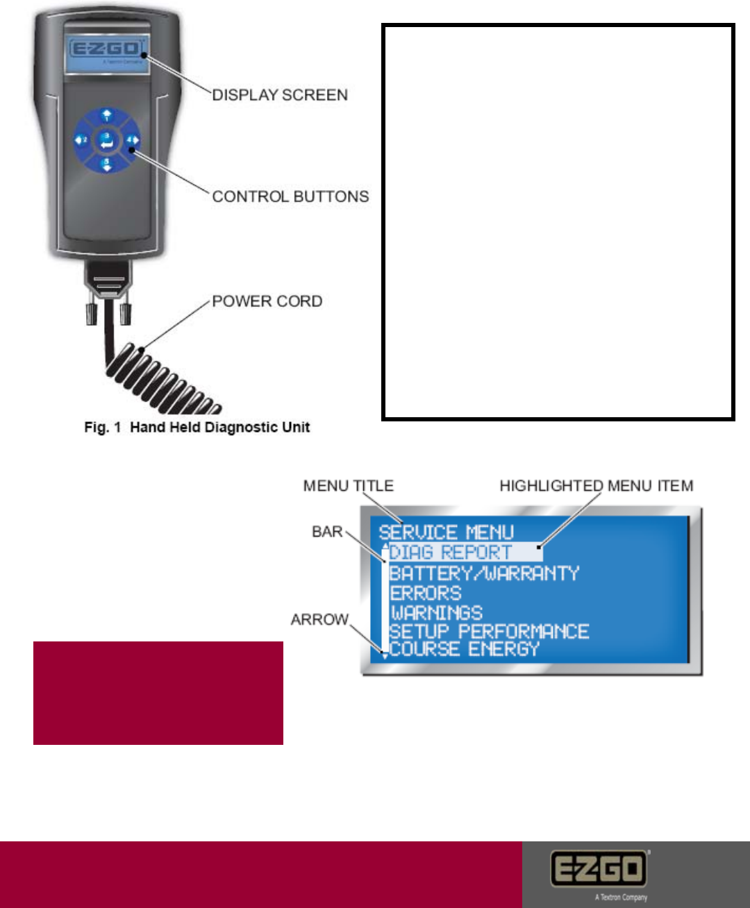
Hand Held Diagnostic Tool
Using The Hand Held Tool
•Turn the key switch off.
•Insert the diagnostic tool plug into the
CAN port under the cup holder / console.
•Turn the key on.
•The diagnostic tool screen will
illuminate.
•The #1 & #5 arrows control upward and
downward movement of the cursor.
•The #4 button breaks down each menu
item to a sub-menu
•The #5 button returns the user to the
previous screen.
•The #3 button is used to enter / reset
selections.
The three primary functions used for
electric trouble-shooting are:
•Diagnostic Report
•Errors
•Warnings
Page 2
The Hand Held diagnostic
Unit is required for all
testing and warranty
reporting!
Customer Care
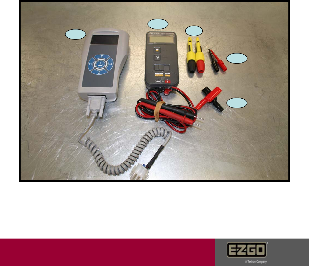
Tools
The following tools will be required to perform advanced trouble shooting procedures:
1. Handheld diagnostic tool PN# 606215
2. Digital volt ohm meter (DVOM)
3. Wire insulation piercing tools 3A. Grainger PN# 1RK18 or 3B. Radio Shack
PN# 270-334B or equivalent.
4. Alligator adapter clamps for meter leads Radio Shack PN#270-354 or equivalent.
1
2
3A.
3B.
4
Page 3
Customer Care
Page 4
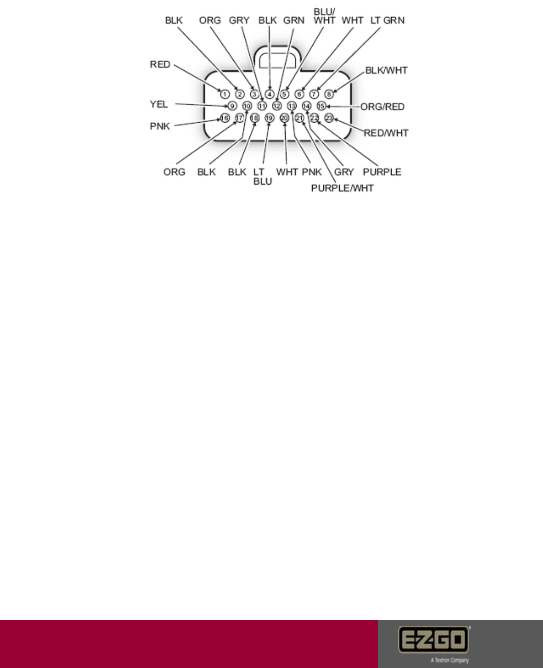
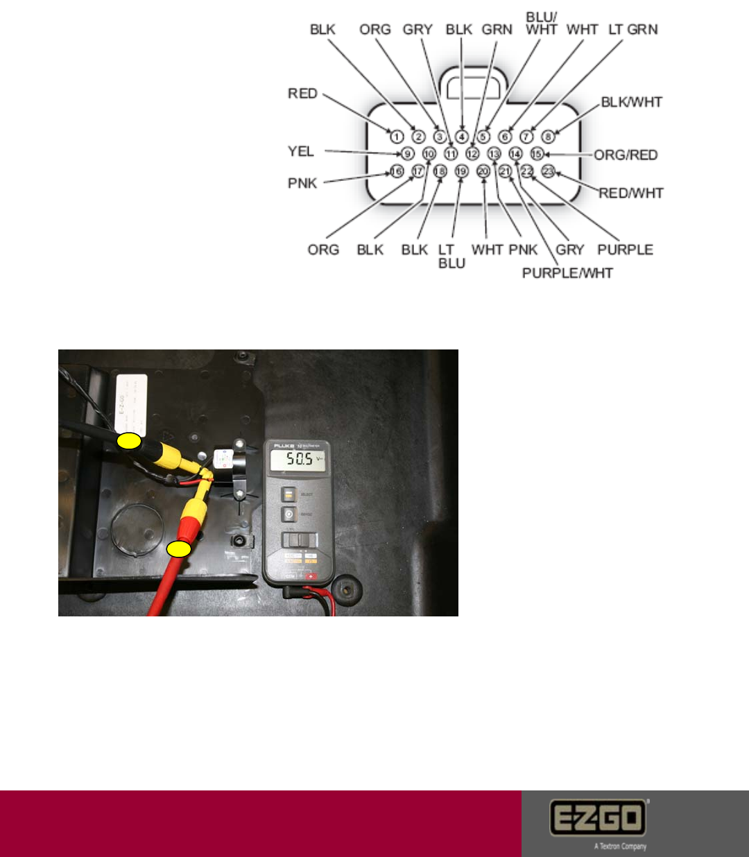
Controller 23 pin connector pin listing with voltages
Pin 1- 48 volt input when key switch is in any position other than off. (FWD, N, REV)
Pin 2- 48v switched ground output for electric motor brake.
Pin 3- 5v positive output for sensor circuit.
Pin 4- 5v ground output for sensor circuit.
Pin 5- 5v signal input from the motor encoder. 0-5 volt variable
Pin 6- 5v signal input from the motor encoder. 0-5 volt variable
Pin 7- 5v signal input from the brake sensor. 0-.35v is a fault, .36-3.78 is linear braking, 3.78-4.8
is 100% braking, >4.8v is a fault.
Pin 8- 48v can ground, internal 48v ground.
Pin 9- 5v signal input for the accelerator sensor. 0-.35v is a fault, .36-.56 is 0% throttle, .5-4.1v is
acceleration range, 4.1-4.8 is 100% throttle, >4.8v is a fault.
Pin 10- 48v ground output from controller for the reverse buzzer. active in reverse and during start
up only.
Pin 11- 5v signal wire output for SOC meter. .5v at empty, 4.5v at full reading.
Pin 12- 48v positive input from key switch for forward.
Pin 13- 48v input for run/tow switch.
Pin 14- 48v positive input for resistor circuit.
Pin 15- Output CAN low.
Pin 16- 5v positive for motor temp sensor.
Pin 17- 48v positive input for charger interlock. 0v with charger plugged in. 21-28v with charger
unplugged.
Pin 18- 48v output ground circuit for the solenoid.
Pin 19- 48v positive input from accelerator switch.
Pin 20- 48v input from key switch for reverse.
Pin 21- 48v ground for the resistor control circuit.
Pin 22- 15v output for the brake light circuit.
Pin 23- Can buss high for hand held.
CBA
D
C
BA
AB
3
21
4
5
6
987
B
A
2
9
35678
15
1
13
1211
10
16 17 18 19 20 21 22 23
E
DC
B
A
F
AB
CBA
ABCD
A
B
C
BA
C
B
A
C
B
A
CBA
RED
RED
RED
RED
RED
RED
BLK
BLK BLK
RED/WHT
BLK/WHT
BLK/WHT
RED
RED
RED
RED
RED
RED
WHT
LT.BLUE
LT.BLUE
RED
RED
WHT
GRN
RED PINK
ORG
BLU/WHT
BLK
RED
ORG
YEL
YEL
YEL
YEL
YEL
LT.GRN
BLK
BLK
BLK
BLK
RED
RED
GRAY
PURPLE
ORG/RED
RED
BLK/WHT
WHT
BLK
GRN/BLK
BLK
BLK
GRAY
BLK
BLK
ORG
ORG
THW/ELPRUP
RESISTOR
CONTROL
BI-METAL
SWITCH
SOLENOID
COIL TEMP
SENSOR
MOTOR
SENSOR
B-
BATTERY
BRK (-)
BRK (+)
BRAKE
BRAKE
LIGHTS
REVERSE
BUZZER
TOW
SWITCH
CHARGER
RECEPTACLE
SOC
METER
THROTTLE
SWITCH
B+
SOLENOID
THROTTLE
SENSOR
BRAKE
SENSOR KEY SWITCH
INLINE
FUSE #1
POWER
BRAKE
LIGHT
RELAY
BRAKE
SWITCH
RESISTOR
INLINE
FUSE #2
B+
BATTERY
BLK/WHT
LT GREEN
ORG/RED
RED/WHT
PURPLE
GRAY
GRAY
BLK
BLK
BLK BLK
BLK
GRN
BLUE/WHT
WHT
ORG
PNK
YEL
RED
LT . BLUE
LT . BLUE
WHT PURPLE/WHT
12
9
35678
5
3
1211
10
6789 20 21 22 23
3
21
4
5
6
98
7
BLK/WHT
BLK/WHT
RED/WHT
ORG/RED
RED
RED
RED
BLK
BLK
CAN
INTERFACE
FRONT VIEW
OF CONNECTOR
B
A
CN
8
4
2
456
9
8
7
RED
GRN/BLK
RUN
PLUG
FRONT VIEW
OF CONNECTOR
Customer Care
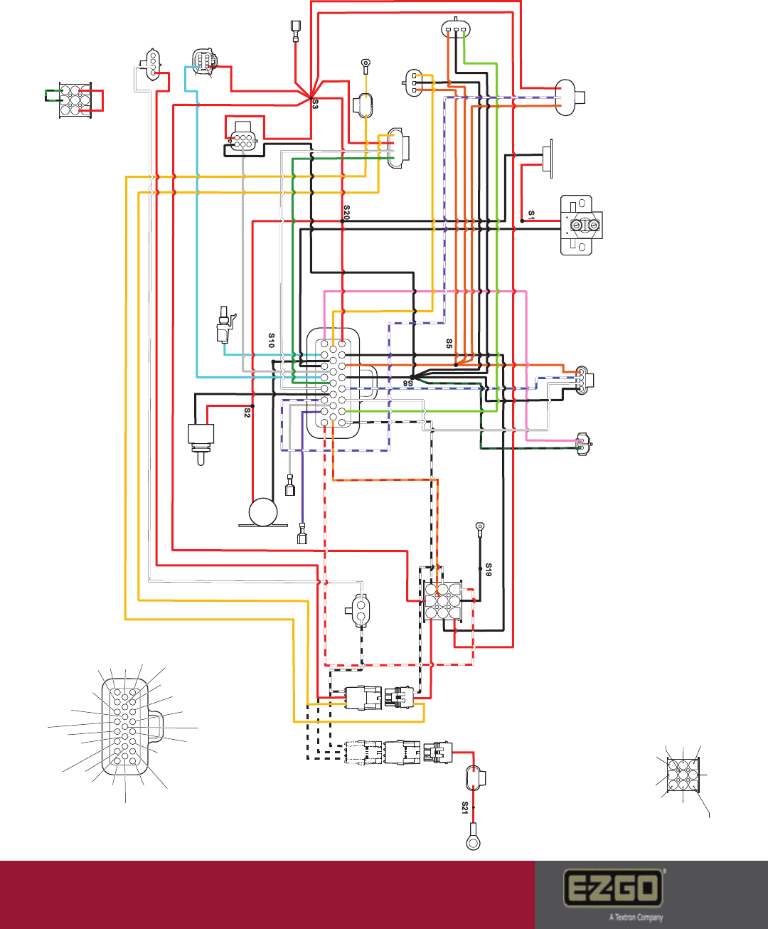
RXV – E Wiring Diagram
Page 5
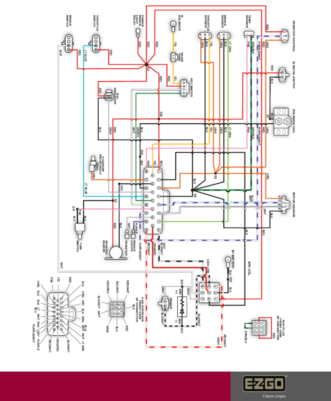
Customer Care
RXV – E Wiring Diagram
Page 6

Customer Care
Symptoms
Crawling: Vehicle runs extremely slow. Slower than limp home. Check motor encoder. See
pages 24 - 25
Rapid solenoid engage – disengage: Occurs when the key is on and the charger is
plugged in. Check key switch and charger receptacle for failed interlock. See pages 30 & 36
Motor shuttering: Check for loose connections on the V,U,&W. Check encoder
connections and park brake harness connections. Verify throttle sensor. Inspect for dragging
park brake. Compare command speed with actual speed on the hand held. RPM should
almost be the same. If not suspect the motor or a mechanical blockage. Compare DC amp
draw and AC current. AC current should be around 50% lower than DC. If not, suspect
motor or mechanical blockage. See pages 9,10, 23, 24, 25, 33, & 34
Metallic Motor noise: Inspect for dragging park brake or failed motor bearing.
See pages 33 & 34.
No park brake disengage even in tow position: Verify power to the park brake, solenoid,
tow switch, or the brake coil driver. See pages 17,18, 33 & 34
Roll freely in the run position then lock after a few feet: Verify brake coil driver and
alignment. See pages 33 & 34
Excessively loud reverse alarm: Check for DC Bus High. See pages 13 - 16
Excessively soft reverse alarm: Check for DC Bus Low or a failed reverse buzzer. See
pages 17,18 & 32
Car goes into limp home mode: Check for DC Bus Low. See pages 17 - 19
Solenoid engages once then disengages: Happens as a result of damage in 5V circuit.
Verify brake & throttle sensors, motor encoder, SOC meter, controller. See pages 23 - 25
Charger does not turn on: Verify charge receptacle, DC cord, AC power or charger.
Vehicle does not run or engage solenoid: Check the fuse, charge receptacle, and key
switch. See pages 30 & 36
Vehicle does not run and the hand held tool will not turn on – Verify key switch voltage
and can plug connections. See page 29 & 30
Page 7
Customer Care
Error Codes
Notes:
•If the car is experiencing an error at the time of diagnostics, the error can
be viewed on the error status screen.
•If the car is not currently experiencing the error, but has in the past; the
error can be viewed in the error log screen.
•If the failure is electrical in nature, an error will appear in the status or log
screen.
•If the fault is mechanical in nature or a design function of the vehicle; an
error code may not be observed on either screen.
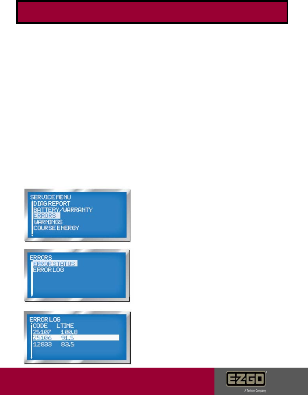
Error codes can be accessed using the
diagnostic hand held tool. Scroll down to
the error code screen then press the 4
key to view sub menu codes.
Error status will show current active faults.
Example codes: Shown are examples of
error codes stored in the error log. The
log can hold up to 7 entries. Errors will
remain in the log after a repair has been
made. LTIME represents when a fault
occurred in vehicle life time minutes which
is listed as CPU time n the battery status
screen. LTime is the last time this error occured.
Only the Ltime will update if the code is already
listed on this screen.
Page 8
Customer Care
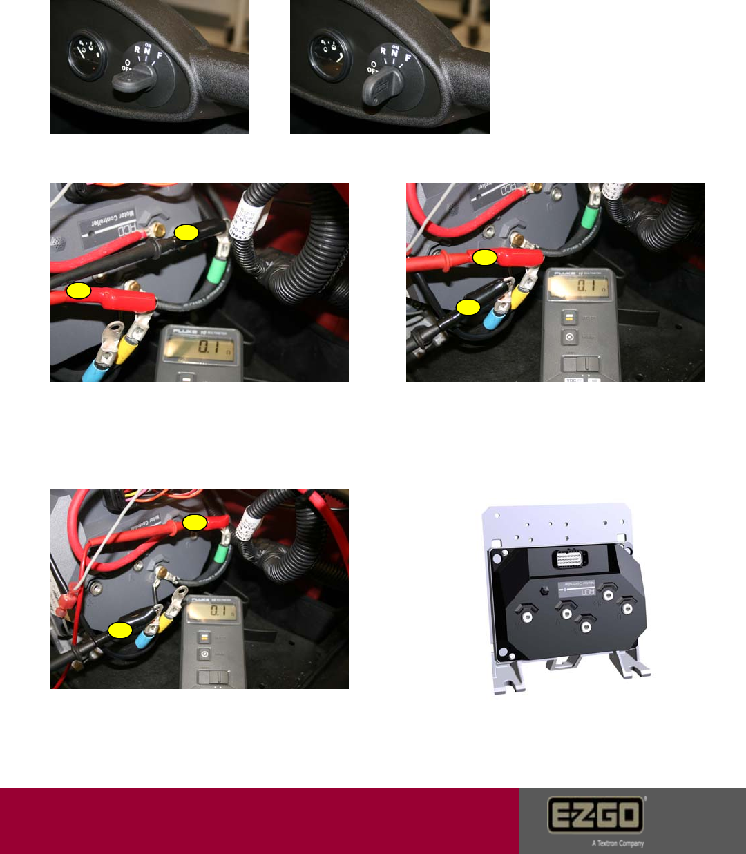
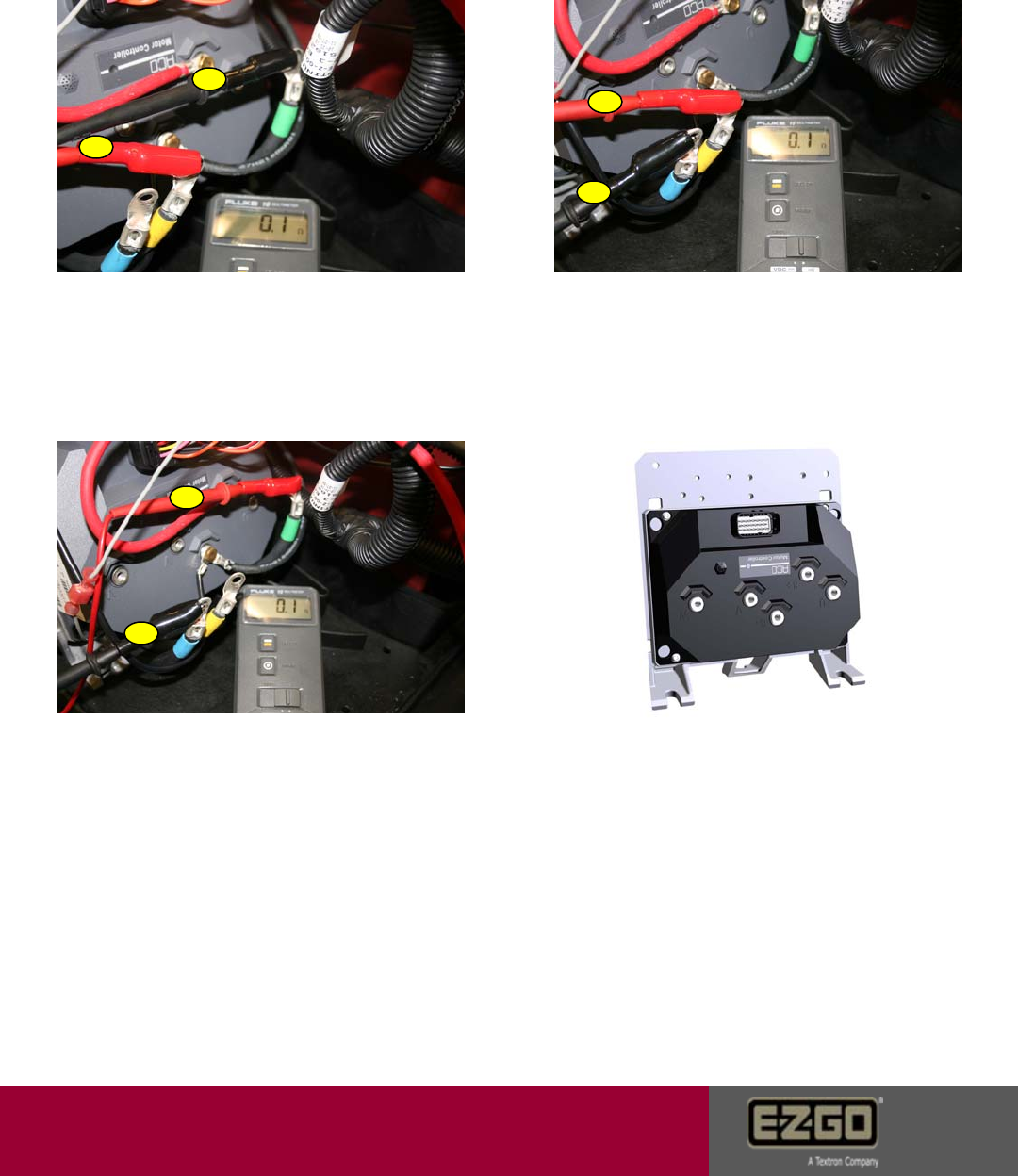
8976 AC Over Current
Caused By: Software detects motor current 50% higher than controller
peak rated current.
5. Try a known good controller if error is
gone, warranty controller. Error remains,
reinstall controller and contact Customer
Care.
1. Turn key off and back on
to reset the controller. If car
runs, return to service. If
not, proceed to remaining
steps.
2. Disconnect all three motor wires.
Contact the V wire lug to the pos. meter
terminal A. Contact the U lug to the
negative terminal B. Meter ohm resistance
should be 0.0 – 0.2. If not, replace motor.
3. Contact the V wire lug to the pos. meter
terminal A. Contact the W lug to the
negative terminal B. Meter ohm resistance
should be 0.0 – 0.2. If not, replace motor.
4. Contact the U wire lug to the pos. meter
terminal A. Contact the W lug to the
negative terminal B. Meter ohm resistance
should be 0.0 – 0.2. If not, replace motor.
A
B
A
B
B
A
Page 9
Customer Care
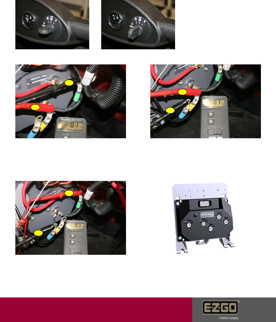
9024 AC Short Circuit
Caused by: Short circuit detected in controller, motor cables, motor, or failed solenoid.
1. Turn key off and back on
to reset the controller. If car
runs, return to service. If
not, proceed to remaining
steps.
2. Disconnect all three motor wires.
Contact the V wire lug to the pos. meter
terminal. Contact the U lug to the
negative terminal. Meter ohm resistance
should be 0.0 – 0.2. If not, replace motor.
3. Contact the V wire lug to the pos.
meter terminal. Contact the W lug to the
negative terminal. Meter ohm resistance
should be 0.0 – 0.2. If not, replace motor.
4. Contact the U wire lug to the pos.
meter terminal. Contact the W lug to the
negative terminal. Meter ohm resistance
should be 0.0 – 0.2. If not, replace motor.
5. Try a known good controller if error is
gone, warranty controller. Error remains,
reinstall controller and contact Customer Care.
A
A
A
B
B
B
Page 10
Customer Care
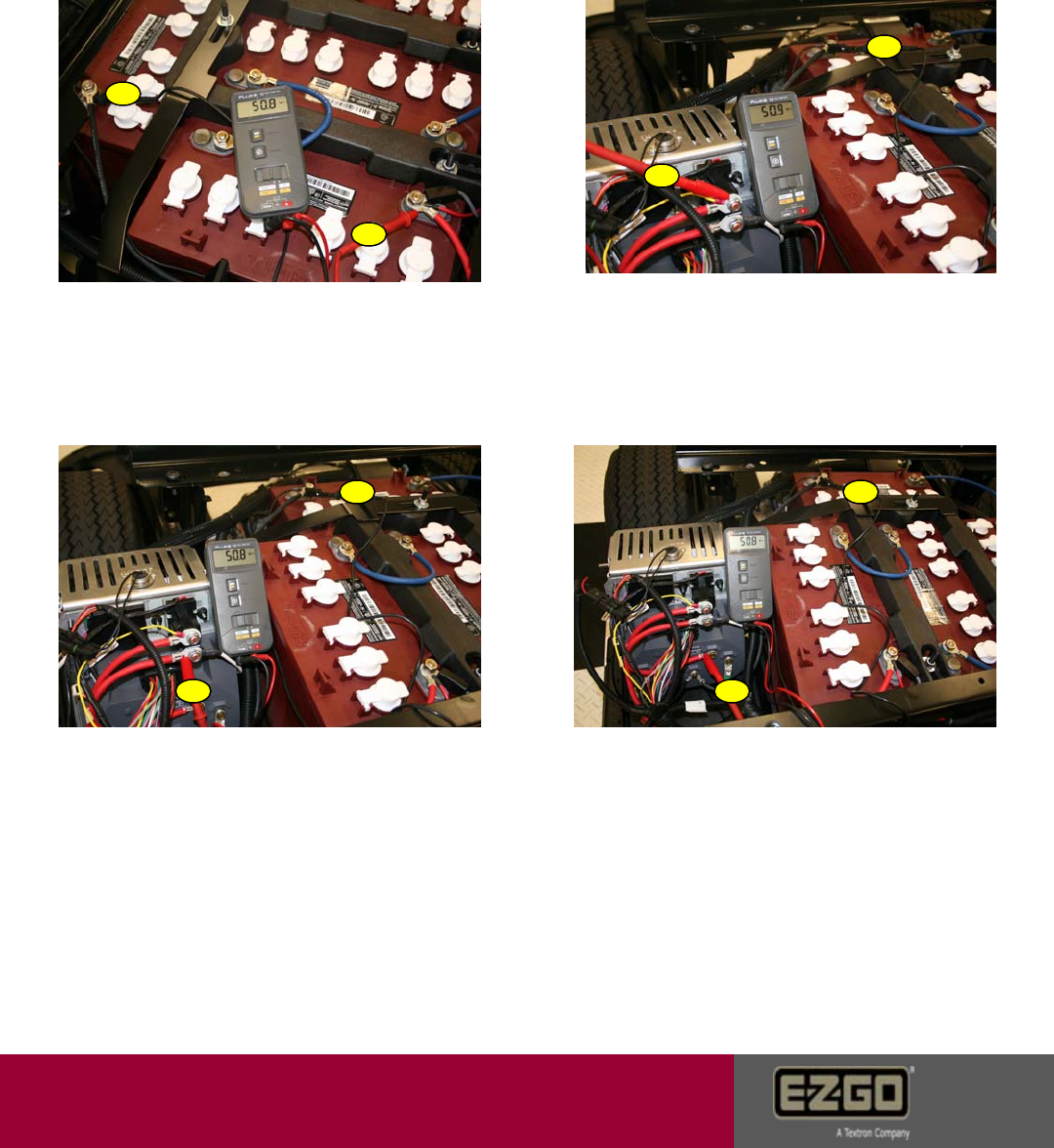
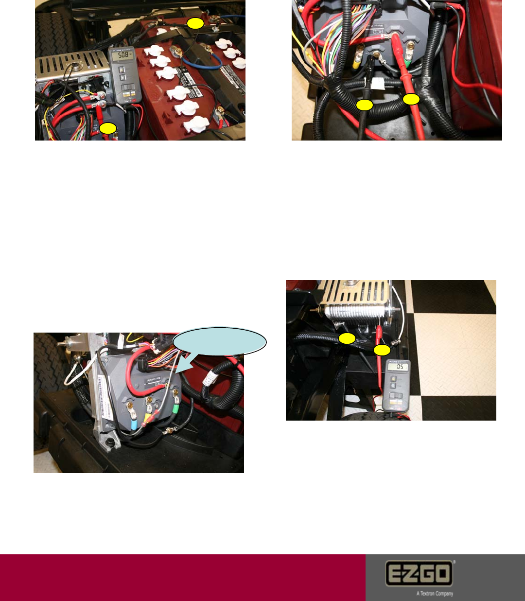
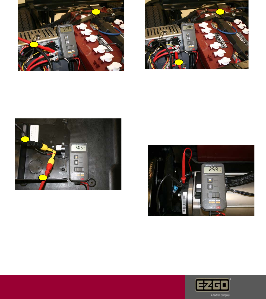
127576 DC Bus Timeout
Caused by: DC voltage has not reached 24 volts within 10 seconds after
key switch start.
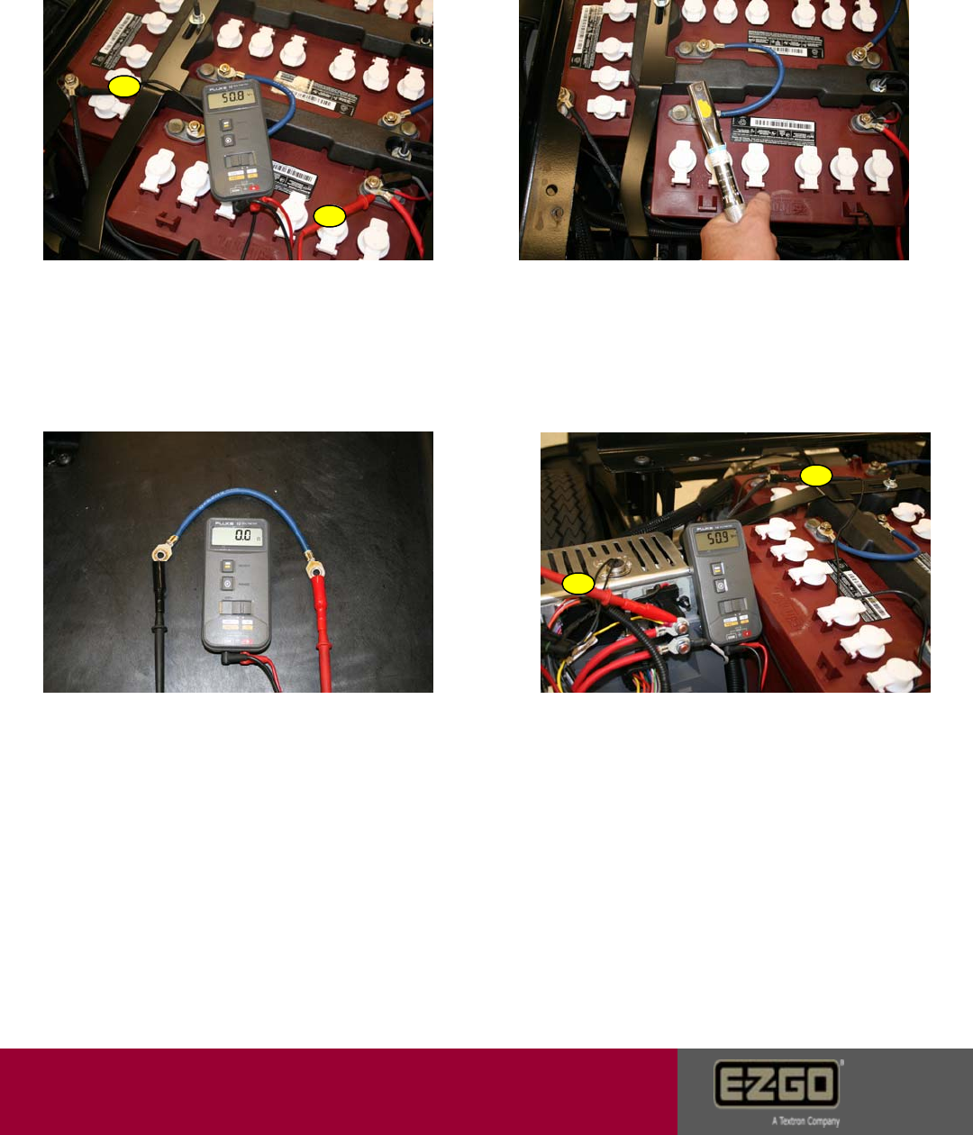
1. Place pos. meter probe A on +48V
battery terminal. Place neg. meter probe B
on -48V battery terminal. Voltage should
read 42V minimum. If not, charge batteries.
If good, proceed to the following steps.
2. Place pos. meter probe A on top
solenoid post. Place neg. meter probe
B on -48V battery terminal. Voltage
should be the same as the battery set.
If not, replace battery to solenoid wire.
3. Turn key switch to the on position. The
solenoid should click. Place pos. meter
probe A on bottom solenoid post. Place
neg. meter probe B on -48V battery
terminal. Voltage should be the same as
the battery set and the top solenoid post. If
voltage is >1V different between large
posts, replace the solenoid. If voltage is
1-2 volts controller has disconnected solenoid.
Voltage good proceed to step 4.
4. Place pos. meter probe A on
controller terminal B+. Place neg.
meter probe B on -48V battery
terminal. Voltage should be the same
as the battery set. If not, replace the
solenoid to controller wire.
A
A
A A
BB
B
B
Page 11
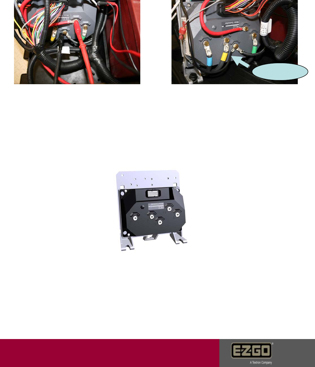
Customer Care
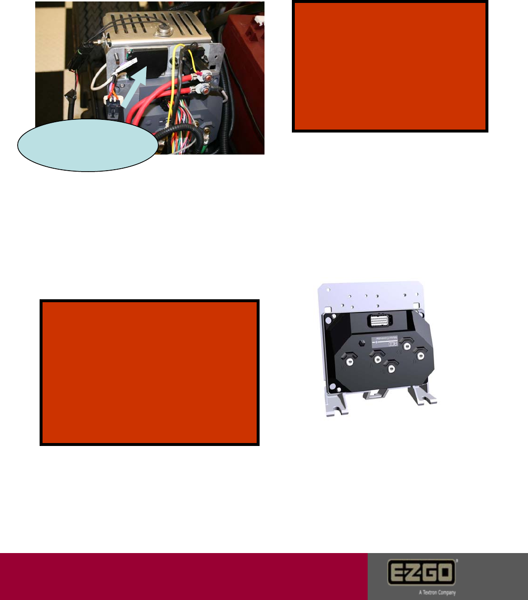
127576 DC Bus Timeout
Continued
5. Place pos. meter probe A on
controller terminal B+. Place neg.
meter probe B on controller B-.
Voltage should be the same as the
battery set. If not, replace -48V battery
wire to B-. If voltage is still not the
same verify steps 2 – 4.
6. Disconnect resistor control module
black wire from B- on the controller. If
error status changes, replace the
resistor module. If error continues, see
step 7.
Resistor control wire
7. Try a known good controller if error is gone warranty
controller. Error remains reinstall controller and
contact Customer Care.
Page 12

Customer Care
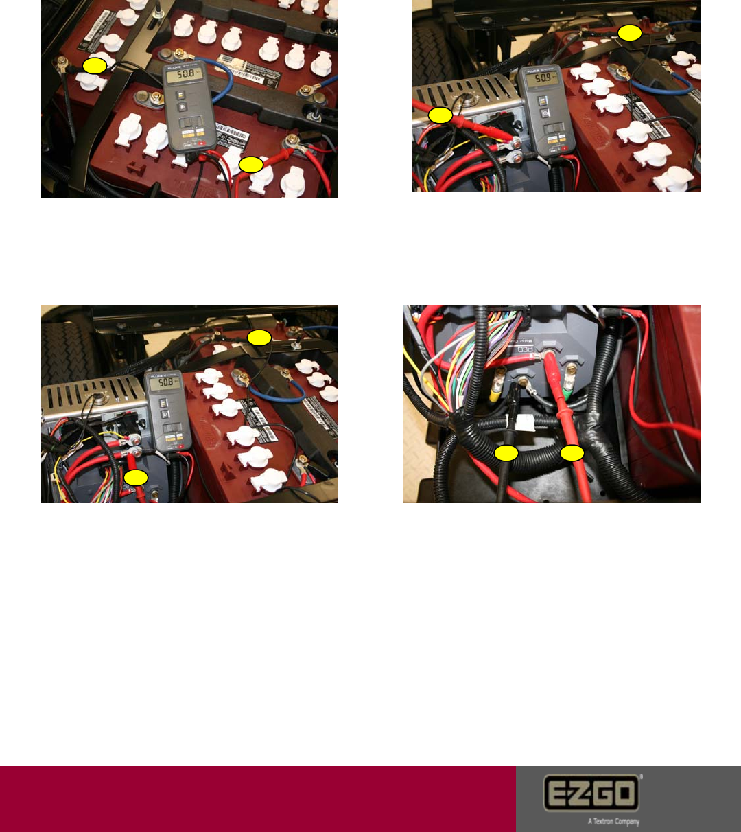
2. Place pos. meter probe A on top
solenoid post. Place neg. meter probe
B on -48V battery terminal. Voltage
should be the same as the battery set.
If not, replace battery to solenoid wire.
3. Turn key switch to the on position. The
solenoid should click. Place pos. meter
probe A on bottom solenoid post. Place
neg. meter probe B on -48V battery
terminal. Voltage should be the same as
the battery set and the top solenoid post. If
voltage is less than 1V different between large
posts, replace the solenoid. between 1-2v
controller has disconnected solenoid.
If voltage is good go to step 4.
A
A
A
B
B
B
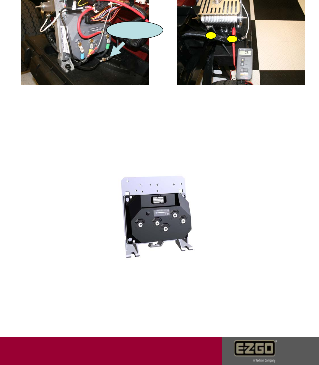
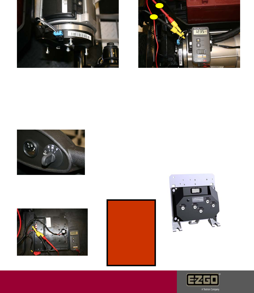
12817 DC Bus High – Software Detected
Caused by: Battery pack voltage is over 67 volts. Field faults come from
excessive regenerative energy not being controlled by the resistor circuit.
1. Verify battery pack voltage at the
time of fault. Voltage should be <63V.
Also verify charger output is not over
67.2V
4. Place pos. meter probe A on
controller terminal B+. Place neg.
meter probe B on controller B-.
Voltage should be the same as the
battery set. If not, replace -48V battery
wire to B-. If voltage is still not the
same verify steps 2 – 4.
AB
Page 13
Customer Care
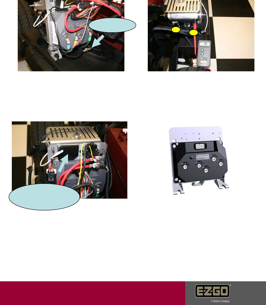
6. Place pos. meter probe A on one
resistor tab and neg. meter probe B
on the remaining tab. Verify 0.2 – 0.5
ohms. If resistance is out of spec.
replace resistor. If resistance is good,
go to step 7.
12817 DC Bus High – Software Detected
Continued
A
B
5. Disconnect resistor control module
black wire from B- on the controller. If
error status changes, replace the
resistor module. If error continues, see
step 6.
7.Try a known good controller if error is gone, warranty
controller. Error remains, reinstall controller and
contact Customer Care.
Resistor control wire
Page 14
Customer Care
2. Place pos. meter probe A on top
solenoid post. Place neg. meter probe
B on -48V battery terminal. Voltage
should be the same as the battery set.
If not, replace battery to solenoid wire.
3. Turn key switch to the on position. The
solenoid should click. Place pos. meter
probe A on bottom solenoid post. Place
neg. meter probe B on -48V battery
terminal. Voltage should be the same as
the battery set and the top solenoid post. If
voltage is less than 1V different between large
posts, replace the solenoid. If voltage is 1-2v
difference controller has disconnected solenoid
due to error or warning. Voltage is good go to step 4.
A
A
A
B
B
B
1. Verify battery pack voltage at the
time of fault. Voltage should be <63V.
Also verify charger output is not over
67.2V
4. Place pos. meter probe A on
controller terminal B+. Place neg.
meter probe B on controller B-.
Voltage should be the same as the
battery set. If not, replace -48V battery
wire to B-. If voltage is still not the
same verify steps 2 – 4.
AB
12 818 DC Bus High – Hardware Detected
Caused by: Battery Pack voltage is over 67 volts.
Page 15
Customer Care
6. Place pos. meter probe A on one
resistor tab and neg. meter probe B
on the remaining tab. Verify 0.2 – 0.5
ohms. If resistance is out of spec.
replace resistor. If resistance is good,
go to step 7.
A
B
5. Disconnect resistor control module
black wire from B- on the controller. If
error status changes, replace the
resistor module. If error continues, see
step 6.
7. Try a known good controller if error
is gone, warranty controller. Error
remains, reinstall controller and
contact Customer Care.
Resistor control wire
12 818 DC Bus High – Hardware Detected
Continued
Resistor Control Module
Page 16
Customer Care
12833 DC Bus Low – Software Detected
Caused by: Controller DC Bus voltage has dropped below 18 volts.
1. Verify proper open circuit battery
voltage. Should be 48V or higher at the
time of testing. Verify loaded voltage by
performing a discharge test. Check for
12V accessory taps and verify accessory
usage.
2. Check all battery terminal
connections. Torque to 95 – 105 in-
lbs.
3. Check for less than 0.1 ohms
resistance on each battery wire.
4. Place pos. meter probe A on top
solenoid post. Place neg. meter probe
B on -48V battery terminal. Voltage
should be the same as the battery set.
If not, replace battery to solenoid wire.
A
A
B
B
Page 17
Customer Care
12833 DC Bus Low – Software Detected
Continued
5. Turn key switch to the on position. The
solenoid should click. Place pos. meter
probe A on bottom solenoid post. Place
neg. meter probe B on -48V battery
terminal. Voltage should be the same as
the battery set and the top solenoid post. If
voltage is less than 1V between large
posts, replace the solenoid. If voltage drop
is 1-2v controller has disconnected solenoid.
Voltage is good go to step 6.
6. Place pos. meter probe A on
controller terminal B+. Place neg.
meter probe B on controller B-.
Voltage should be the same as the
battery set. If not, replace -48V battery
wire to B-. If voltage is still not the
same verify steps 2 – 5.
Resistor control wire
7. Disconnect resistor control module
black wire from B- on the controller. If
error status changes, replace the
resistor module. If error continues, see
step 8.
8. Place pos. meter probe A on one
resistor tab and neg. meter probe B
on the remaining tab. Verify 0.2 – 0.5
ohms. If resistance is out of spec.
replace resistor. If resistance is good,
go to step 9.
A
A
A
B
B
B
Page 18
Customer Care
12833 DC Bus Low – Software Detected
Continued
Resistor Control Module
9. Replace resistor control module with
known good unit. Module may be
staying “on” which causes a drain on
the battery set. Resistor coil will be hot
if the module is on. If module checks
good, go to step 10.
10. Try a known good controller if error is
gone, warranty controller. Error remains,
reinstall controller and contact Customer
Care.
Tech Tip:
Always verify accessories and
usage. Warranty requires a 48-
12v DC to DC converter for all
accessories. The converter will
allow equal accessory draw on
all four batteries.
Tech Tip: V56 eliminates this feature
The RXV-E car is designed to
default to the “Limp home mode” at
25% SOC. The vehicle will shut
down completely at 20% SOC. If
this happens in operation, perform
a discharge test on the batteries
and check the charge history on
the hand held tool.
Page 19
Customer Care
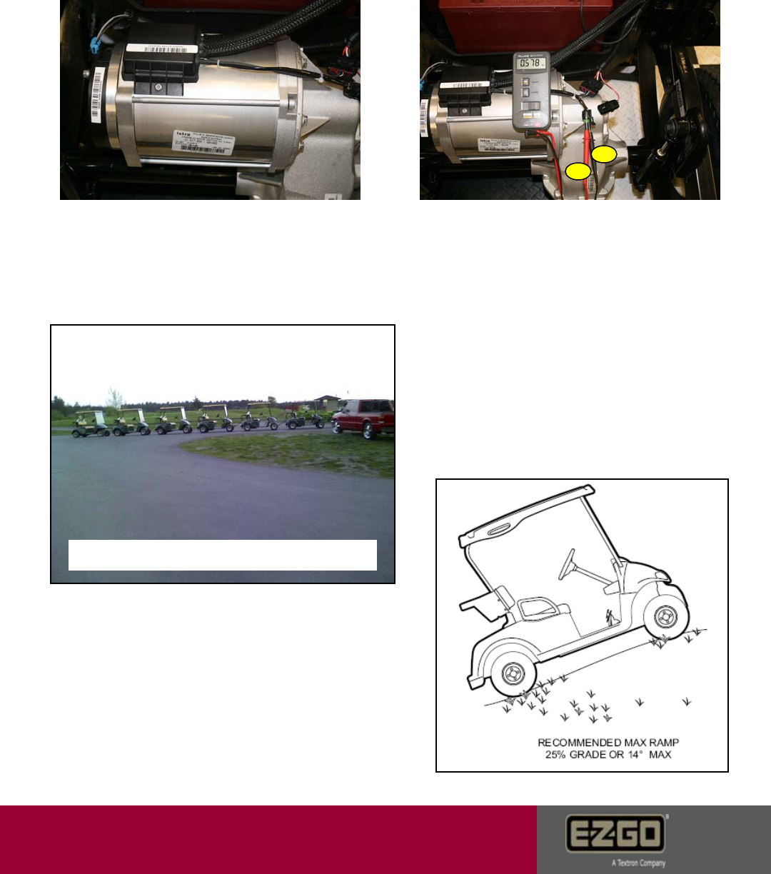
16912 Motor Temp High
Caused by: Overloaded vehicle or motor temp reaching 120 Celsius or
higher.
1. Check motor surface temperature
for 120 Celsius. (248 Fahrenheit) If
cold, go to step 2. If hot, reduce
loading.
2. Verify thermo-coupler resistance.
Place pos. meter probe A on the pink
wire terminal. Place neg. meter probe
on the green / black wire terminal.
Resistance should be >400 ohms and
<1300 ohms. If faulty, replace the
motor. If good, and the fault still
appears in Error Status, Try a known good
controller, if error is gone warranty
controller. Error remains, reinstall controller
and contact Customer Care.
Maximum allowed 1 leading 3 trailing
A
B
Page 20
Customer Care
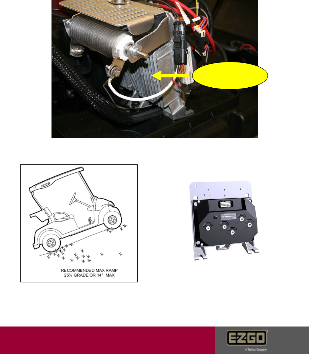
17168 Heat Sink Temp High
Caused by: Overloaded vehicle or controller reaching 100 Celsius or higher.
1. Verify controller heat sink surface temperature. The
temperature should be <80 Celsius. (176 Fahrenheit)
Take temperature here.
2. Reduce payload or loading. 3. Try a known good controller, if error
is gone, warranty controller. Error
remains, reinstall controller and contact
Customer Care.
Page 21
Customer Care
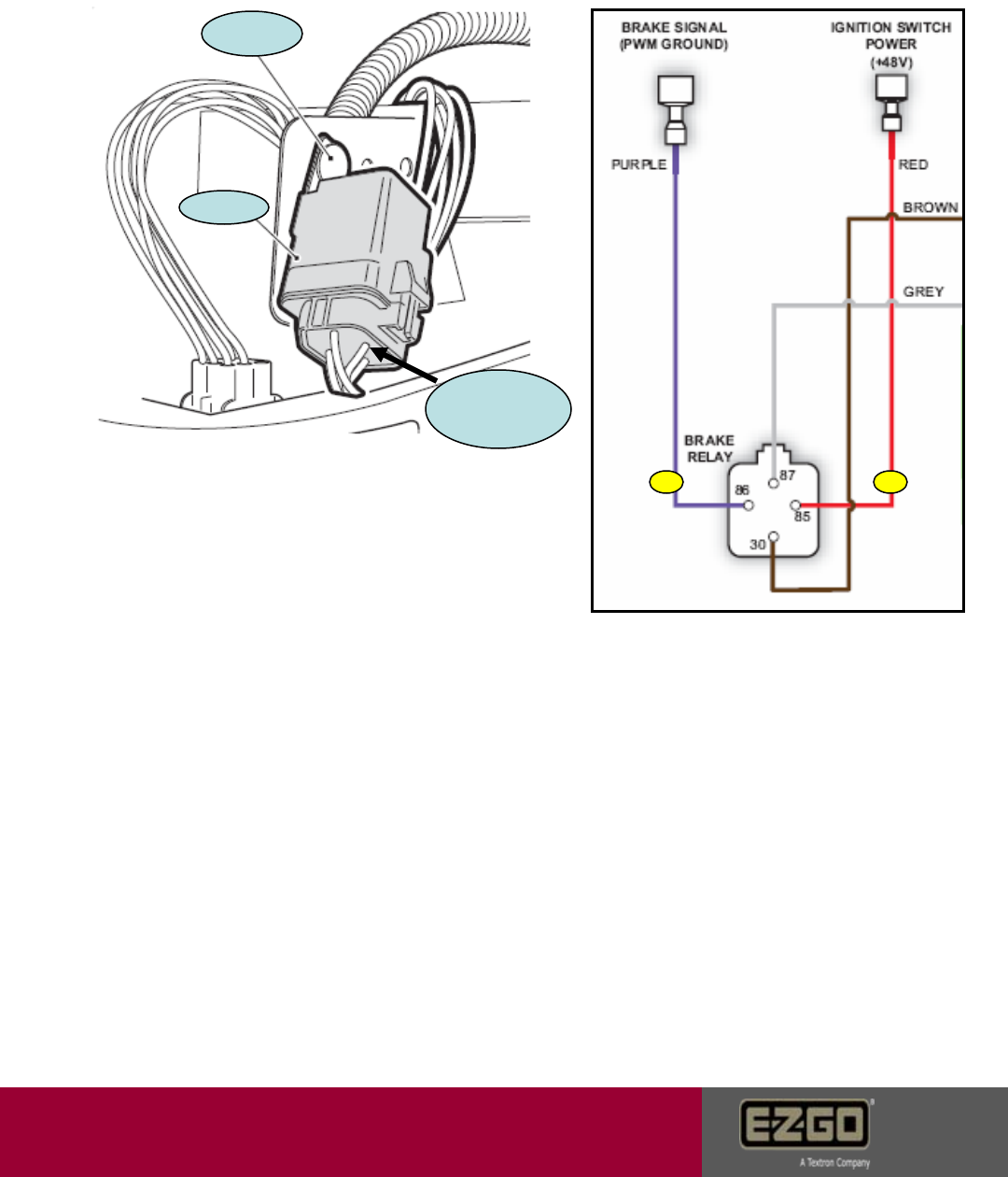
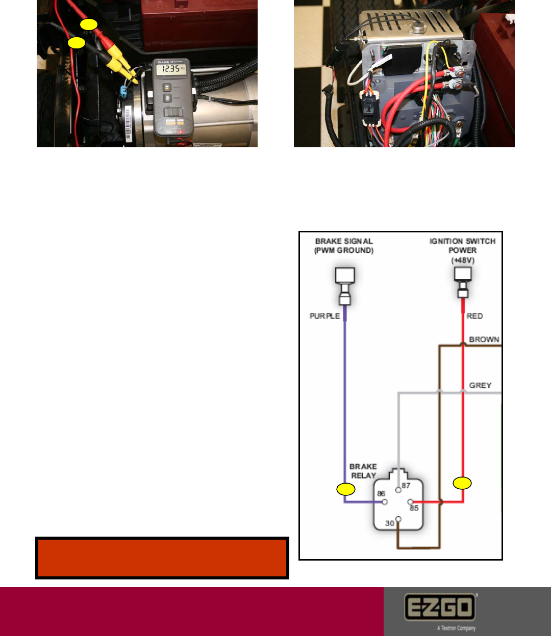
20753 15 Volt Supply Low Voltage
Caused by: Problem with the controller’s internal 15V supply for brake light circuit.
1. Verify that the brake relay is properly
plugged into the vehicle harness. If yes
proceed to step 2.
2. Unplug relay from harness. Place
pos. probe of meter on the 85
terminal. Place neg. probe of meter
on 86 terminal. Verify 1-50 ohms
resistance. If not replace the relay.
(Shorted) If good, go to step 3.
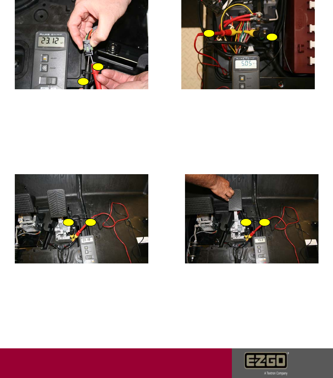
3. Place pos. probe of meter on the red
wire terminal of the relay harness. Place
neg. probe on the purple wire terminal.
Depress brake pedal. Should observe
12 – 15 VDC. If good, replace relay. If
bad go to step 4.
4. Check continuity between the 86 terminal
on the harness and pin #22 (Purple wire) of
the controller 23 pin connector 1st. Check
continuity between 85 terminal of harness
and pin #1 (Red wire) of the controller 23 pin
connector 2nd. If continuity is not found,
replace the harness. If a short is found
between 85 and 86 with the controller 23 pin
connector unplugged, replace the harness.
If continuity is good in the harness; Try a known
good controller if error is gone, warranty
controller. Error remains, reinstall controller and
contact Customer Care.
Relay
Fastener
Harness Plug
AB
Page 22
Customer Care
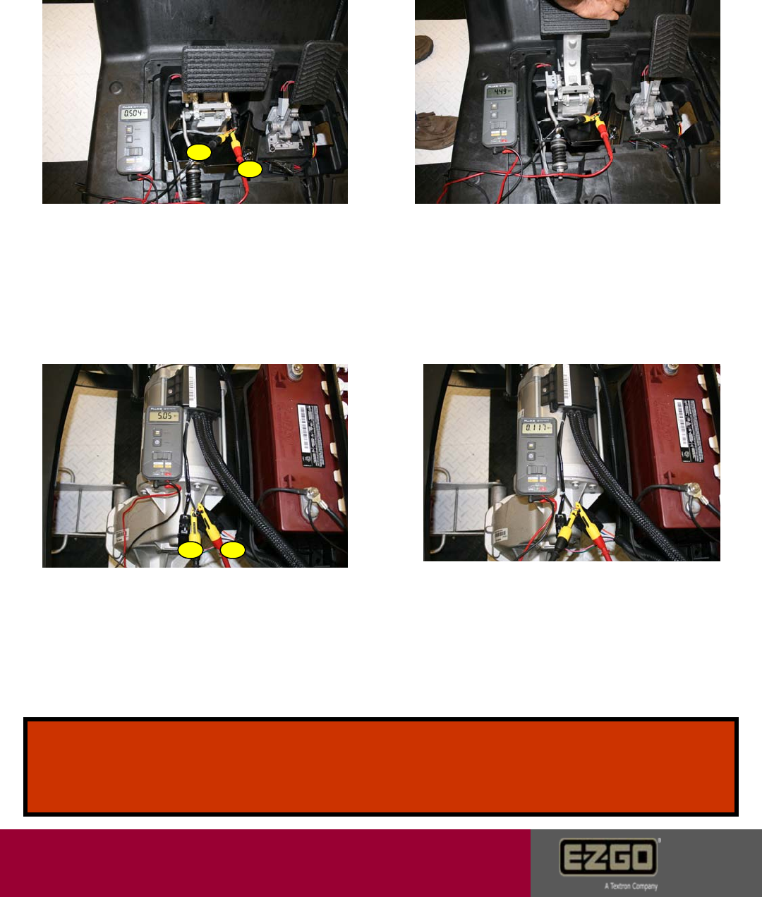
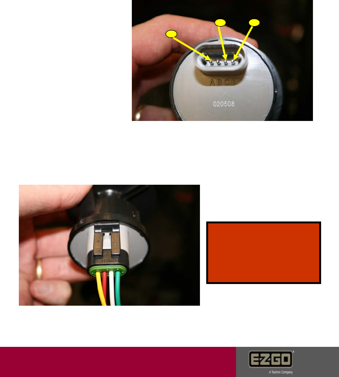
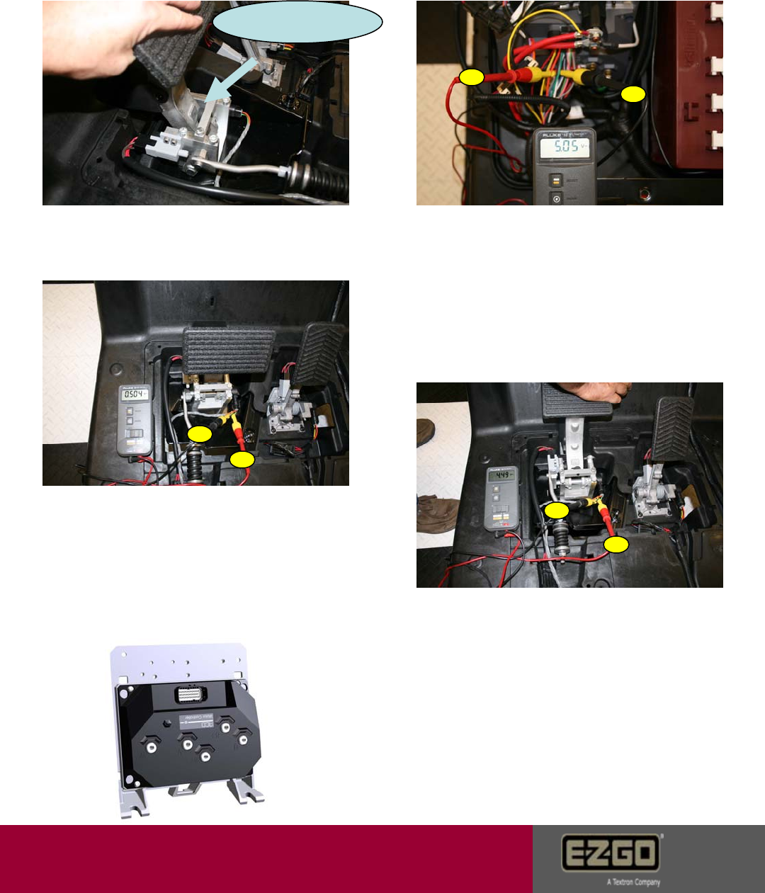
20755 5 Volt Supply Low or High Voltage
Caused by: Short in the 5V wire harness, malfunction in the 5V sensor
supply, shorted SOC meter, or a shorted resistor control module.
1. Disconnect the 23 pin controller
connector. Place pos meter probe A on
orange wire terminal of either sensor
connector. (Throttle or Brake position)
Place neg. meter probe B on the black
wire terminal. The reading should be
>10K ohms. If bad, replace the control
harness. If good, go to step 2.
2. Plug all connectors back in. Place
pos. meter probe A on the orange wire
at the #3 position on the controller
plug. Place neg. probe B on the black
wire at the #4 position on the controller
23 pin connector. 5V should be observed.
If bad, check all 5V components first, then
try a known good controller. If good, go to
step 3.
3. Place pos. meter probe A on the
yellow wire of the accel sensor and place neg.
meter probe B on the black wire at the pedal
position sensor. Leave harness connected to
the sensor. Voltage value should be between
0.38V and 0.56V. If good, go to step 4. If
bad, verify harness.
4. Leave meter probes in place. slowly
depress the pedal to the floor. Voltage value
should increase from .5v to between 4.5V
and 4.8V. Above 4.8v is a fault. If good, go
to step 5. If bad, replace sensor.
A
A
A A
B
B
B B
Page 23
Customer Care
20755 5 Volt Supply Low or High Voltage
Continued
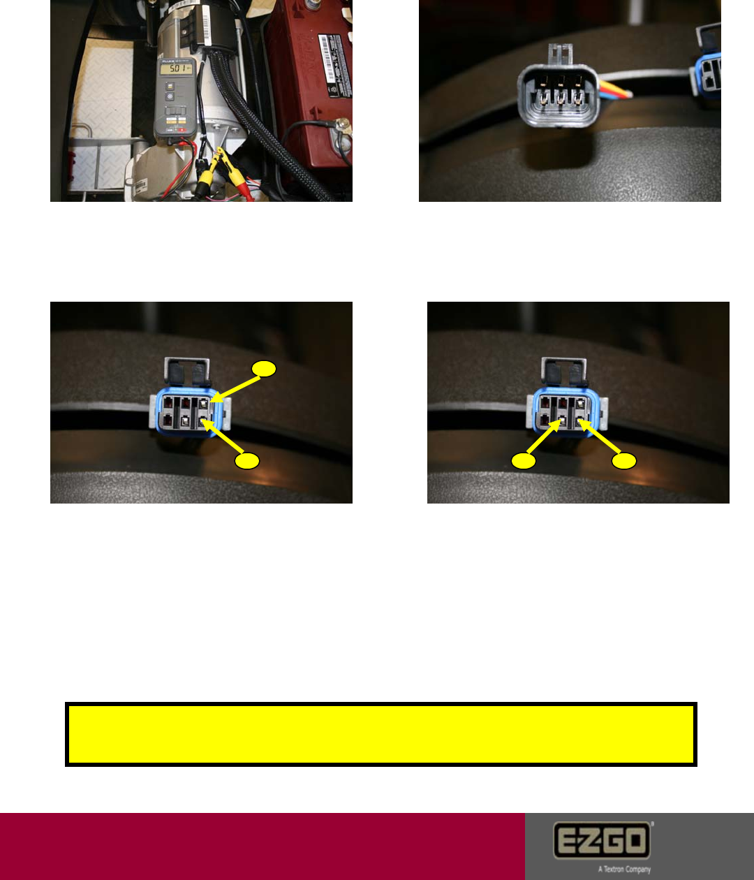
5. Place pos. meter probe A on the green
wire of the brake sensor. Place neg. meter
probe B on the black wire at the pedal
position sensor. Leave harness connected
to the sensor. Voltage value should be
between 0.38V and 0.56V. If good, go to
step 6. If bad, verify harness.
6. Leave meter probes in place. Slowly
depress the pedal to the floor. Voltage
should steadily increase from .5v to
between 4.5V and 4.8V. If good, go to
step 7. If bad, replace sensor.
7. Place the pos. probe A on the
small red wire of the encoder
harness. Place the neg. probe on the
small black wire of the encoder
harness. 5V should be observed. If
bad, replace harness. If good, go to
step 8.
8. Place the pos. meter probe on the
small red encoder wire. Place the
neg. probe on the white or blue wire.
Rotate the back tires with the car in
neutral and the tow switch in tow.
Close to 0V should be observed. Go
to step 9.
A
A
B
B
Tech Tip: The motor encoder can be tested with an encoder tester available through
Customer Care. The only other accurate test is with a multimeter that has "hertz" test
capability.
Page 24
Customer Care
20755 5 Volt Supply Low or High Voltage
Continued
9. Leave probes in position. Continue
to rotate the tires until around 5V is
observed. If bad, replace the motor. If
good, go to step 10.
10. Inspect SOC meter plug for
damage or tampering. If damaged,
replace the SOC meter. If good, go to
step 11.
11. Check SOC harness plug for
voltage. Place pos. meter probe A
on the red wire terminal. Place neg.
meter probe B on the black wire
terminal. 48V should be observed
with the key on. If bad, replace the
harness. If good, go to step 12.
12. Check 5V circuit. Place pos.
meter probe A on the gray wire
terminal. Place the neg. probe B on
the black wire terminal. .5V at empty
and 4.5v at full should be observed
based on state of charge. If good,
replace the SOC meter. If bad, go
back to step 2.
Caution: Do not short any 5V circuit wire to any 48V circuit wire
or component. The controller and/or sensors will be destroyed!
A
AB B
Page 25
Customer Care
21008 Current Sensor Offset Calibration Error
Caused by: Error detected in the controller current measurement hardware.
1. Disconnect all three motor wires.
Contact the V wire lug to the pos. meter
terminal A. Contact the U lug to the
negative terminal B. Meter ohm
resistance should be 0.0 – 0.2. If not,
replace motor.
2. Contact the V wire lug to the pos. meter
terminal A. Contact the W lug to the
negative terminal B. Meter ohm resistance
should be 0.0 – 0.2. If not, replace motor.
3. Contact the U wire lug to the pos.
meter terminal A. Contact the W lug to
the negative terminal B. Meter ohm
resistance should be 0.0 – 0.2. If not,
replace motor.
4. Try a known good controller if
error is gone, warranty controller.
Error remains, reinstall controller
and contact Customer Care.
A
A
A
B
B
B
Page 26
Customer Care
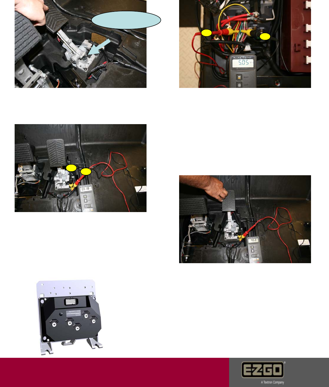
21520 Open Drain Outputs Current High
Caused by: Open drains (stuck closed or shorted) reverse buzzer,
solenoid, park brake, resistor control module, or brake relay.
1. Place pos. meter probe A on top
solenoid post. Place neg. meter probe
B on -48V battery terminal. Voltage
should be the same as the battery set.
If not, replace battery to solenoid wire.
2. Turn key switch to the on position. The
solenoid should click. Place pos. meter
probe A on bottom solenoid post. Place neg.
meter probe B on -48V battery terminal.
Voltage should be the same as the top
solenoid post. If voltage is less than 1V
different between large posts, replace
the solenoid. Voltage should bleed down
slowly when the key is turned off. If not,
replace solenoid.
3. Place pos. meter probe on the red
wire of the buzzer. Place neg. meter
probe on the black wire. Battery voltage
should be observed while the car is in the
reverse direction and the buzzer will
sound. Voltage should diminish in the
forward direction. If voltage is good and
no sound, replace the buzzer. If voltage
is bad, check key switch and harness.
4. Check the brake coil driver for the
correct ohm range. The range should
be 27+/- 3ohms. If wrong, replace
brake coil driver. If good, go to step 5.
A
A
A
B B
B
Page 27
Customer Care
21520 Open Drain Outputs Current High
Continued
5. Place pos. meter probe A. on the
gray wire of the brake coil harness.
Place the neg. probe B on the black
wire. Voltage should read around
12V-18V when the tow switch is in
the tow position. If bad, verify
harness. If good, go to step 6.
6. Disconnect resistor control module
black wire from B- on the controller. If
error status changes, replace the
resistor module. If error continues, see
step 7.
8. Check continuity between the 86 terminal
on the harness and pin #22 (Purple wire) of
the controller23 pin connector 1st. Check
continuity between 85 terminal of harness
and pin #1 (Red wire) of the controller 23 pin
connector 2nd. If continuity is not found,
replace the harness. If a short is found
between 85 and 86 with the controller 23 pin
connector unplugged, replace the harness.
If continuity is good in the harness; Try a known
good controller.
7. Unplug relay from harness. Place
pos. probe of meter on the 85
terminal. Place neg. probe of meter
on 86 terminal. Verify 1-50 ohms
resistance. If not replace the relay.
(Shorted) If good, go to step 8.
Attention: If all devices check out, Try
a known good controller.
A
A
B
B
Page 28
Customer Care
33024 CAN Timeout
Caused by: The controller and the hand held diagnostic tool stop
communicating.
1. Turn key off and back on
to reset the controller. If the
hand held screen returns,
continue to diagnose. If
screen does not return, got
to step 2.
2. Check connection to hand held tool.
Verify hand held tool function with a
known good unit.
3. Check wire connections to the
CAN plug be removing the cup holder
and inspecting wires. If bad, re-insert
or replace harness.
Tech Tip: Intermittent car
operation can come from
loose wire connections
on the CAN plug and
harness. This condition
will not show a fault
code on the hand held
diagnostic unit.
Page 29
Customer Care
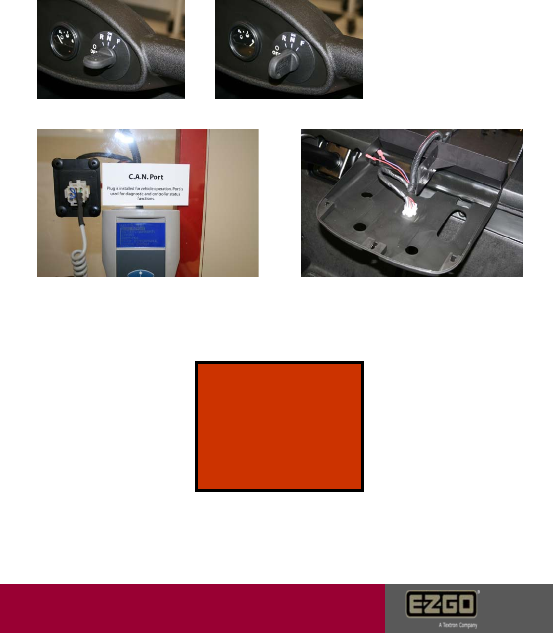
25104 Direction Error
Caused by: Shorts in the key switch or wiring. Forward and Reverse directions
may be energized simultaneously.
1. Remove the key switch
and turn the key to the
forward position. Place pos.
meter probe A on the A pin of
the switch. Place the neg.
meter probe B on the C pin.
Full continuity should be
observed on the multi-meter.
Go to step 2.
2. Now place the neg. meter
probe B on the D pin of the
switch. The meter should
now read full continuity with
the key turned in the
opposite direction. If
continuity can be read on all
three pins in the same key
direction (Forward), then
replace the switch.
Tech Tip: This test can also
be performed using the
hand held tool and scrolling
down to the direction
functions in the Diagnostics
Menu
A
BB
Page 30
Customer Care
25105 Throttle Sensor Error
Caused by: The throttle position sensor is out of operational range.
3. Place pos. meter probe A on the
yellow wire of the accel position sensor.
Place neg. meter probe B on the black wire
at the pedal position sensor. Leave harness
connected to the sensor. Voltage value should
be between 0.38V and 0.56V. If good, go to
step 4. If bad, verify harness. 4. Leave meter probes in place. Slowly
depress the pedal to the floor. Voltage
should steadily increase from .5v to between
4.5V and 4.8V. Above 4.8v is a fault. If good,
go to step 4. If bad, replace sensor.
1. Verify the pedal stop bumper is in
the correct position. If not, correct and
secure in place.
5. Try a known good controller if error is gone, warranty controller.
Error remains, reinstall controller and contact Customer Care.
2. Plug all connectors back in. Place
pos. meter probe A on the orange wire
at the #3 position on the controller
plug. Place neg. probe B on the black
wire at the #4 position on the controller
plug. 5V should be observed. If bad,
check all 5V components first, then try a
known good controller. If good, go to
step 3.
A
AB
B
Pedal stop bumper
Page 31
Customer Care
25106 Reverse Alarm Test Failed
Caused by: The reverse alarm failed at start up check or an incomplete
reverse alarm circuit.
1. Unplug the 23 pin
connector at the speed
controller. Check the
resistance value
between pin 10 and
13. Value should be
<0.01 ohms. If out of
range, replace the
harness or the alarm.
2. Place the pos. meter
probe A on the red wire of
the buzzer harness. Place
the neg. probe B on the
black wire. 48V should be
present when the car is in
the reverse direction. If not,
verify key switch then try a
known good controller. If error
is gone warranty controller.
Error remains reinstall controller
and contact Customer Care.
A
B
Page 32
Customer Care
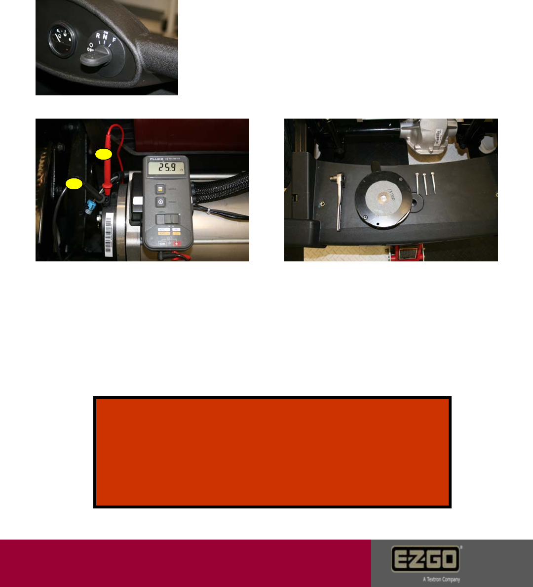
25107 Mechanical Brake Test Failed
Caused by: Park brake failed to prevent the motor from rotating during the
start up test. Can be caused by turning the key switch off and back to drive
while the vehicle is moving.
1. Turn the key switch off and try to push the vehicle.
The tow switch must be in the run position. If the car
can be pushed, got to step 2.
2. Verify the brake coil driver by placing
the pos. meter probe A on one driver
terminal and the neg. meter probe B on
the remaining terminal. Resistance
should be 27 ohms +/- 3 ohms. If out of
range, replace the coil driver. If good,
go to step 3.
3. Verify friction disk alignment.
Remove the park brake and inspect
the friction disk. Go to step 4.
Tech Tip: With the key switch in the on position, flip to tow
switch to tow. An audible noise should be heard and the car
should roll freely. If not, check for power leaving the controller
and activation of the coil driver. The handheld diagnostic tool
will show this on the diagnostic report screen. Check
“E Brake Cur” for .497-.501 Amps. If bad, check the harness and
then try a known good controller. If good, see step 5.
A
B
Page 33
Customer Care
25107 Mechanical Brake Test Failed
Continued
4. After inspection, reinstall the park
brake and leave the bolts loose. Turn the
key switch to on and the tow switch to
tow. The coil driver should electronically
disengage. Torque the three bolts to 53
-71 in-lbs in small equal increments.
Flip the tow switch back and forth from tow
to run. This will align the friction disk.
5. See the Tech tip on the previous
page. Verify energy leaving the
controller with the hand held diagnostic
tool. Now verify voltage to the coil
driver by placing the pos. meter probe
A on the gray wire. Place the neg.
meter probe B on the black wire. 12 –
18V should be observed in the tow
position with the key on. If good, go
back to step 1. If voltage appears in
the run position, replace the tow
switch. If no voltage appears in the tow
position with the key on, replace the
harness.
6. Turn key to the on
position with the tow switch
in the run position. Go to
step 7.
7. If the car can be pushed verify
step 3. Then try a known good
controller, if error is gone, warranty
controller. Error remains, reinstall
controller and contact Customer Care.
Tech Tip: The
tow switch
should show
full resistance
in the run
position and the
23 pin
connector
disconnected.
A
B
Page 34
Customer Care
25108 Brake Sensor Error
Caused by: The brake pedal position sensor is out of operating range.
1. Verify the pedal stop bumper is in
the correct position. If not, correct and
secure in place.
2. Place pos. meter probe A on the
orange wire at the #3 position on the
controller plug. Place neg. probe B on
the black wire at the #4 position on the
controller plug. 5V should be observed.
If bad, check all 5V components first,
then try a known good controller. If good
go to step 3.
3. Place pos. meter probe A on the green
wire of the brake position sensor and place
neg. meter probe B on the black wire of the
brake position sensor. Leave harness connected
to the sensor. Voltage should be between
0.38V and 0.56V. If good, go to step 4. If bad,
verify harness.
4. Leave meter probes in place. Slowly
depress the pedal to the floor. Voltage
should steadily increase from .5v to between
4.5V and 4.8V. Above 4.8v is a fault. If good
go to step 5. If bad, replace sensor.
5. Try a known good controller if error is gone,
warranty controller. Error remains, reinstall
controller and contact Customer Care.
Page 35
A
A
A
B
B
B
Brake Pedal Bumper
Customer Care
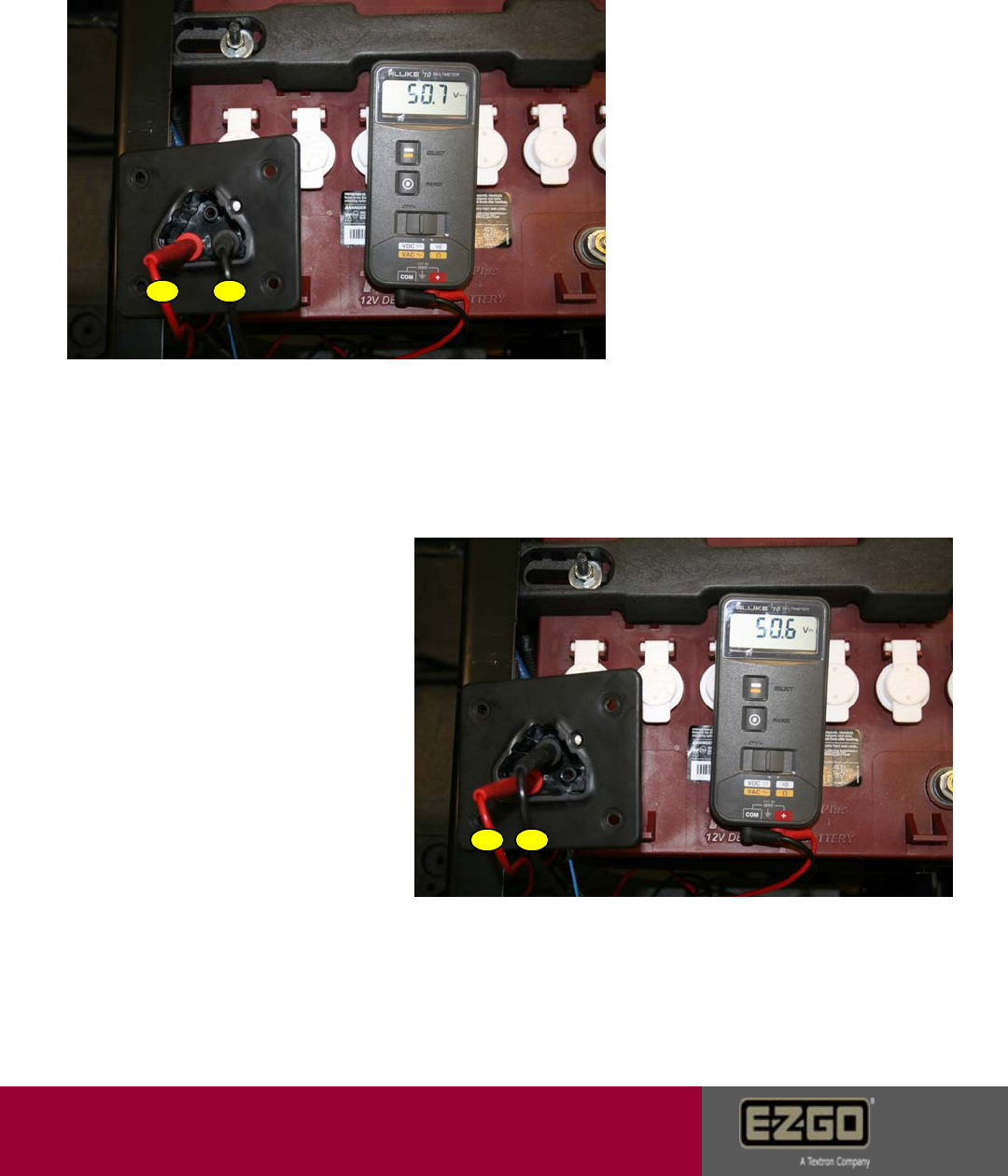
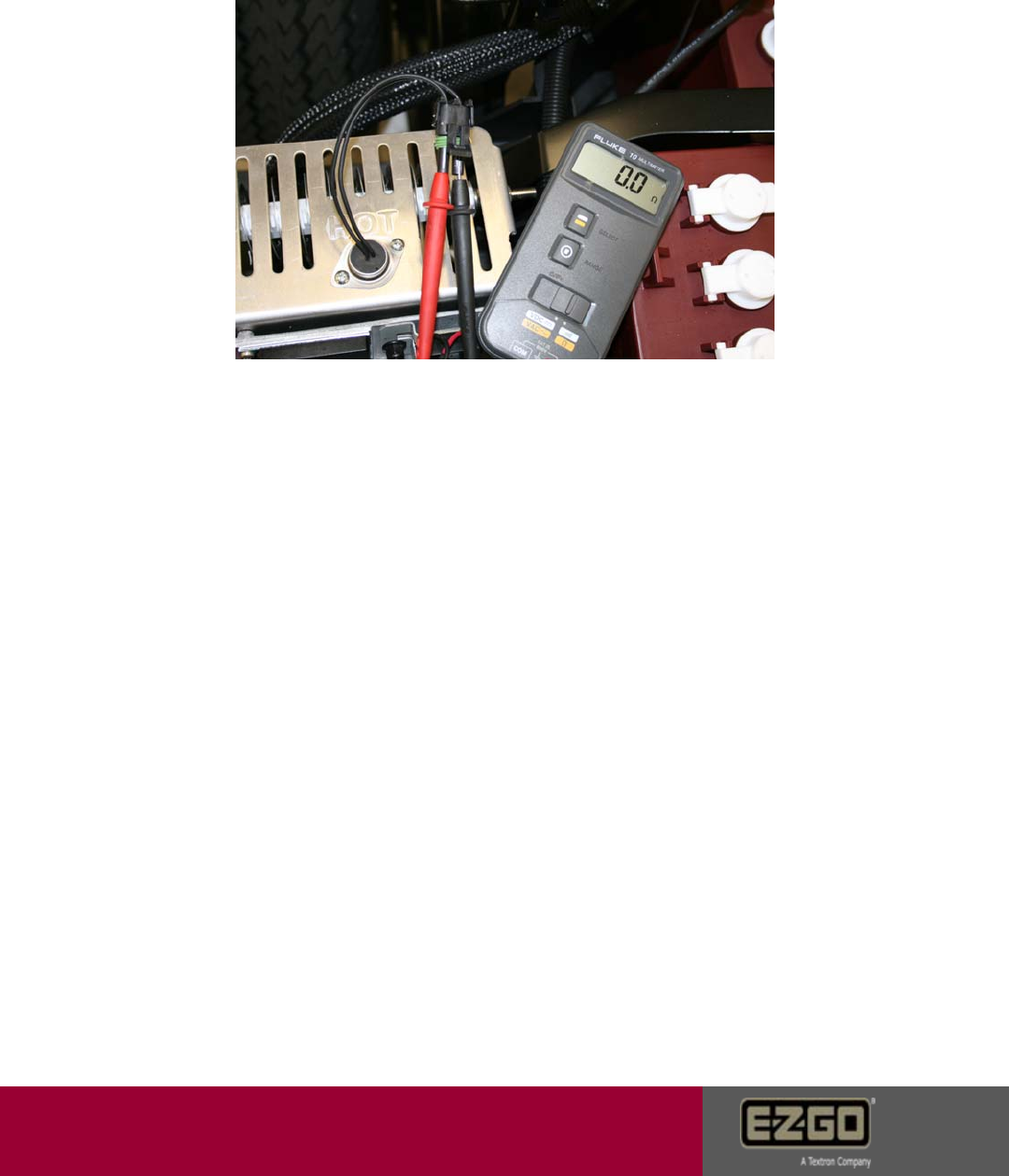
Charger Receptacle Test
1. Place the pos. meter probe A
on the lower left terminal of the
charge receptacle. Place the
neg. probe B on the lower right
terminal. Battery voltage should
be observed. If not, check
loaded battery pack voltage
then replace the charge
receptacle.
2. Place the pos. meter
probe A on the lower left
terminal of the charge
receptacle. Place the neg.
meter probe B on the upper
terminal. Battery voltage
should be observed. If not,
replace the receptacle.
Page 36
A
A
B
B
Customer Care
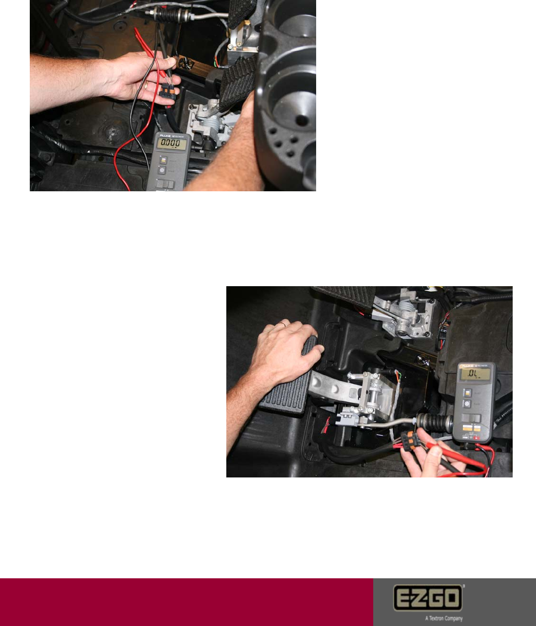
Throttle & Brake Switch Test
1. Throttle switch is normally open.
Disconnect the throttle switch
harness. Place the pos. meter
probe on one red wire. Place the
neg. meter probe on the other
red wire. An open circuit should
be observed when the pedal is
released. Full continuity should
be observed with the pedal
depressed. If continuity is wrong,
replace the accelerator switch.
2. Brake switch is normally closed
Disconnect the brake switch
harness. Place the pos. meter
probe on one red wire. Place the
neg. meter probe on the other
red wire. An open circuit should
be observed when the pedal is
depressed. Full continuity should
be observed with the pedal
released. If continuity is wrong,
replace the brake switch.
Page 37
Customer Care
Resistor Temp Sensor Test
1. Unplug the resistor temperature sensor from the harness.
Place one meter probe in one terminal and the remaining probe
in the other terminal. 0.0 – 0.2 should be observed. If not,
replace the sensor.
Page 38

Customer Care
Warnings
May occur in conjunction with error codes.
Warnings may not necessarily cause the
vehicle to stop. Warnings may cause a
loss in vehicle performance.
Warning List:
1. Drive Fault – Indicates the current error is the result of a condition internal to the controller. Trouble shoot
according to the error message displayed. If no errors are displayed, replace the controller.
2. DC Bus Low – DC Bus voltage is <24 volts. See pages 17 - 19
3. DC Bus High – DC Bus voltage is >67 volts. See pages 13 - 16
4. BDI Calibration – The DC Bus measurement system is not calibrated. Replace the controller.
5. Motor Temp High – Motor temperature is >140 C but less than 150 C. See page 20
6. Motor Temp Sensor – Motor temp sensor not connected. See page 20
7. Heat Sink Temp Low – Controller heat sink temp is < - 20C. Reduced speed may go away after controller
warms up.
8. Heat Sink Temp High – Measured heat sink temp is >85C but less than 115C. See page 21
9. Heat Sink Temp Sens – Heat sink temp sensor is shorted or not connected. Warm vehicle or replace the
controller.
10. Default Parameter – This warning is normal when the controller is first powered up. Any time after this
replace the controller.
11. Power Reduction – This warning occurs in conjunction with motor and heat sink temp warnings. This
warning indicates that max torque current reduction is in affect.
12. Cur Meas Cal – The controller’s AC current measurement system is not calibrated. Replace the
controller.
13. Speed Sensor – Indicates sensor or wire failure. See page 31
14. OD Current High – The current in an open drain (park brake, resistor control, or brake relay) is >2.5
amps. See pages 27 - 28
15. Charger Connected – The battery charger is connected to the car preventing accidental drive away. Verify
charger handle insertion. See page 36
16. Brake Slipping – The controller has detected motor rotation while the park brake is engaged. Can occur
when the key is turned off while the vehicle is in motion. See pages 33 - 34
17. Throttle Switch Closed – If this warning occurs with the key switch on: The throttle switch is closed at key
start. Switch must be opened briefly before driving is permitted. If this warning occurs any other time:
Energy dump monitoring detects the energy dump circuit is continuously on for >30 seconds. See page
37
18. Brake Switch Open – Current in the brake circuit is <100 mamps with the park brake energized. This
warning can occur in panic stop situations. See page 37
19. BDI Low – Battery pack voltage is below 25% SOC. See pages 17- 19
Page 39

Customer Care
Page 40
Notes
______________________________________________________________________
______________________________________________________________________
______________________________________________________________________
______________________________________________________________________
______________________________________________________________________
______________________________________________________________________
______________________________________________________________________
______________________________________________________________________
______________________________________________________________________
______________________________________________________________________
______________________________________________________________________
______________________________________________________________________
______________________________________________________________________
______________________________________________________________________
______________________________________________________________________
______________________________________________________________________
______________________________________________________________________
______________________________________________________________________
______________________________________________________________________
______________________________________________________________________
______________________________________________________________________
______________________________________________________________________
______________________________________________________________________
______________________________________________________________________
______________________________________________________________________
______________________________________________________________________
______________________________________________________________________
______________________________________________________________________
______________________________________________________________________
______________________________________________________________________
______________________________________________________________________
______________________________________________________________________
______________________________________________________________________
______________________________________________________________________
______________________________________________________________________
______________________________________________________________________
______________________________________________________________________
______________________________________________________________________
______________________________________________________________________
______________________________________________________________________

Copyrighted Material
This manual may not be reproduced in whole or
in part without the express permission of
E-Z-GO Division of Textron, Inc.
Technical Communications Department
E-Z-GO Division of Textron, Inc.,
1451 Marvin Griffin Road, Augusta, Georgia 30906 - 3852 USA
