D F4 16PID M F416pidm
User Manual: F4-16PID-M Online ation - AutomationDirect
Open the PDF directly: View PDF ![]() .
.
Page Count: 41

Automationdirect.com™
D i r e c t L o g i c 4 0 5
1 6 L o o p P I D C o p r o c e s s o r
F 4 - 1 6 P I D
Order Number: F4-16PID-M

™Automationdirect.com is a Trademark of Automationdirect.com
™CoProcessor is a Trademark of FACTS Engineering, Inc.
Copyright 1994, FACTS Engineering Inc., 8049 Photonics Dr., New Port Richey,
Florida, 34655.. World rights reserved. No part of this publication may be stored in a
retrieval system, transmitted, or reproduced in any way, including but not limited to
photocopy photograph, magnetic or other recording media, without the prior agreement
and written permission of FACTS Engineering, Inc.
TRADEMARKS
COPYRIGHT
Last Issued Date: January 1994
Current Issued Date: December 1999

Thank you for purchasing automation equipment from FACTS Engineering. We want
your new FACTS Engineering automation equipment to operate safely. Anyone who
installs or uses this equipment should read this publication (and any other relevant
publications) before installing or operating the equipment.
To minimize the risk of potential safety problems, you should follow all applicable local
and national codes that regulate the installation and operation of your equipment.
These codes vary from area to area and usually change with time. It is your
responsibility to determine which codes should be followed, and to verify that the
equipment, installation, and operation is in compliance with the latest revision of these
codes.
At a minimum, you should follow all applicable sections of the National Fire Code,
National Electrical Code, and the codes of the National Electrical Manufacturers
Association (NEMA). There may be local regulatory or government offices that can
help determine which codes and standards are necessary for safe installation and
operation.
Equipment damage or serious injury to personnel can result from the failure to follow all
applicable codes and standards. We do not guarantee the products described in this
publication are suitable for your particular application, nor do we assume any
responsibility for your product design, installation, or operation.
If you have any questions concerning the installation or operation of this equipment, or
if you need additional information, please call us at 1-800-783-3225.
This document is based on information available at the time of its publication. While
efforts have been made to be accurate, the information contained herein does not
purport to cover all details or variations in hardware and software, nor to provide for
every possible contingency in connection with installation, operation, and maintenance.
Features may be described herein which are not present in all hardware and software
systems. FACTS Engineering assumes no obligation of notice to holders of this
document with respect to changes subsequently made. FACTS Engineering retains the
right to make changes to hardware and software at any time, without notice. FACTS
Engineering makes no representation or warranty, expressed, implied, or statutory with
respect to, and assumes no responsibility for the accuracy, completeness, sufficiency,
or usefulness of the information contained herein. No warranties of merchantability of
fitness for purpose shall apply.
WARNING

CHAPTER 1: INTRODUCTION .................................................... 1.1
General Description ....................................................... 1.1
Transmitters ............................................................. 1.1
Actuators ............................................................... 1.1
Easy Loop Programming .................................................... 1.1
Simple Setpoint Adjustment ................................................. 1.1
Operation Specifications .................................................... 1.2
Alarm Specifications ....................................................... 1.3
Hardware Specifications .................................................... 1.3
CHAPTER 2: PID COMMANDER™ LOOP PROGRAMMING ............................. 2.1
PID COMMANDER ........................................................ 2.1
INSTALLATION .......................................................... 2.1
RUNNING PID COMMANDER ............................................... 2.1
CONFIGURING LOOPS .................................................... 2.2
PRINTING LOOPS ........................................................ 2.2
TUNING LOOPS .......................................................... 2.2
OPERATING LOOPS ...................................................... 2.2
CHAPTER 3: SUPPORTING LADDER LOGIC ......................................... 3.1
AUTO/MANUAL MODE CONTROL ........................................... 3.1
ALARM WORD DECODING ................................................. 3.1
READING THE PV AND WRITING THE LOOP OUTPUT ........................... 3.1
CASCADING LOOPS ...................................................... 3.2
SETPOINT RAMP AND SOAK ............................................... 3.2
Setpoint Ramp ..................................................... 3.2
Setpoint Soak ...................................................... 3.4
TIME PROPORTIONING CONTROL LOOPS ................................... 3.6
POSITIONING ACTUATOR CONTROL LOOPS .................................. 3.7
ENCODING THE ALARM WORD ............................................. 3.9
LOOP ALGORITHMS ...................................................... 4.1
Loop Variables ..................................................... 4.1
PID Control ....................................................... 4.1
Position Form of the PID equation ...................................... 4.2
Reset Windup Protection ............................................. 4.3
Freeze Bias ....................................................... 4.3
Adjusting the Bias ................................................... 4.3
Step Bias Proportional to Step Change in SP .............................. 4.4
Eliminating Proportional, Integral, or Derivative Action ....................... 4.4
Eliminating Integral Action ........................... 4.4
Eliminating Derivative Action ................................. 4.4
Elimination Proportional Action .................................. 4.4
Velocity Form of the PID Equation ...................................... 4.5
Bumpless Transfer of Control .......................................... 4.5
LOOP ALARMS .......................................................... 4.5
PV Limit .......................................................... 4.5
PV Deviation ...................................................... 4.5
Rate-of-Change .................................................... 4.5
Broken Xmitter ..................................................... 4.6
Deadband ......................................................... 4.6
LOOP OPERATING MODES ................................................ 4.6
Manual ........................................................... 4.6
Automatic ......................................................... 4.6
Cascade .......................................................... 4.6
TABLE OF CONTENTS
SPECIAL LOOP CALCULATIONS ............................................ 4.6
Reverse Acting Loop ................................................ 4.6
Square Root of the Process Variable .................................... 4.6
Error Squared Control ............................................... 4.7
Error Deadband Control .............................................. 4.7
Derivative Gain Limiting .............................................. 4.7
SPECIAL FUNCTION PROGRAMMING ........................................ 4.7
APPENDIX A: V-MEMORY MAP .................................................... 5.1
DEDICATED V-MEMORY MAP .............................................. 5.1
PIDCOP Configuration Memory Map .......................................... 5.1
PID Parameter Loop Table Memory Map ....................................... 5.2
Bit Mapped Registers - Mode Word ........................................... 5.3
Extended Mode Word (V5031) ............................................. 5.4
Alarm Word ............................................................. 5.5
PID LOOP TABLE V-MEMORY MAP .......................................... 5.6
APPENDIX B: Application Example - 4 Loops .......................................... 6.1
I/O Listing ............................................................... 6.1
Ladder Logic ............................................................. 6.3

1.1
General Description
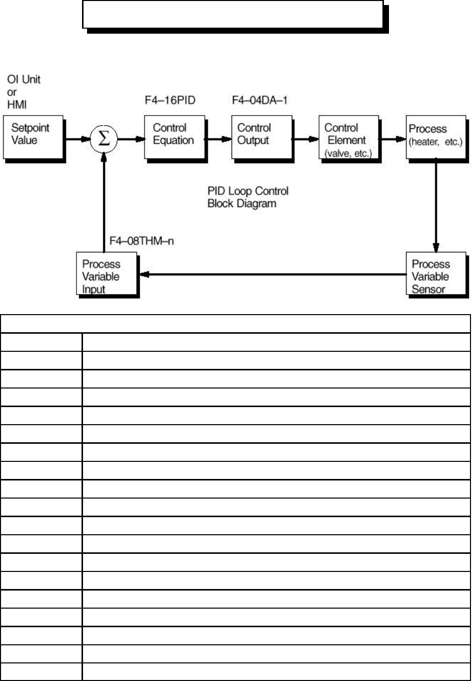
The Direct Logic 405 Proportional Integral Derivative CoProcessor (PIDCOP) executes up to 16 PID
loops independent of the DL405 CPU. Using the high speed parallel dual port RAM (intelligent module
shared RAM) interface, the PIDCOP reads the Process Variable (PV) and directly writes the PID output
into V-Memory.
Since minimal supporting ladder logic is required, the floating point math intensive PID calculations in
the CoProcessor will have little effect on CPU scan time.
Transmitters
Using standard DL405 I/O modules to interface to field transmitters maintains application flexibility
without additional cost burden in the PIDCOP. Normally the PV is obtained from a 4-20 mA current loop
or an analog voltage (various ranges). Specialty modules are available for direct connection of both T/C
and RTD’s. Rate and pulse type PV inputs (flow) are within the capabilities of the 405 High Speed
Counter.
Actuators
Output of the PID algorithm may be used to directly control an actuator such as a current loop controlled
valve. Using minimal additional ladder logic both time proportioning (eg. heaters for temperature
control) and position actuator (e.g. reversible motor on a valve) type control schemes are easily
implemented.
Easy Loop Programming
Since all loop parameters are stored in V-Memory, programming may be accomplished in several ways.
An intelligent Operator Interface Terminal (OIT) or industrial computer connected to either port on a 405
CPU can load loop parameters into V-Memory. A single OIT can service one or several 405 systems
using the 25 pin DirectNET network port on the 405 CPU.
Simple Setpoint Adjustment
The setpoint in V-Memory may be changed via the MIU or an attached OIT. Using minimal additional
ladder logic, both ramp and soak may be implemented for setpoint changes.
CHAPTER 1: INTRODUCTION

INTRODUCTION
1.2
PV
Operation Specifications
V-Memory Block A unique V-Memory location specifies the starting address of the block of V-
Memory to be used by the PIDCOP. Up to 5 PIDCOPs may be used with a
single 405 CPU. PIDCOPs must be installed in the CPU base.
Number of Loops Up to 16 independent PID loops for each PIDCOP. A unique V-Memory
location specifies the number of loops which are enabled for each PIDCOP.
PID Algorithm Position or velocity form of the PID equation. Optionally specify direct or
reverse acting, square root of the error, and error squared control.
Sample Rate Specify the time interval between PV samples, .1 to 999.9 in units of seconds
or minutes.
Auto / Manual A control relay, CR, which when energized places the corresponding loop into
automatic mode. PV alarm monitoring continues when loops are in manual or
off mode.
Specify a square root of the PV for a flow control application.
Limit SP Specify a high and low limit for allowable setpoint changes.
Scaling Conversion of the PV value to engineering units is done in an operator
interface program such as PID Commander™.
Gain Specify proportional gain of 0.00 to 100.0. A value of 0 disables the
proportional term.
Reset Specify reset time of 000.1 to 999.9 minutes, seconds, milliseconds or
microseconds. A value of 999.9 disables the integral term when the reset
units is minutes.
Bumpless Transfer I Bias and setpoint are initialized automatically when the PIDCOP is switched
from manual to automatic. This provides for a bumpless transfer.
Setpoint = PV
Bias = Output
Bumpless Transfer II Bias is set equal to the Output when the PIDCOP is switched from manual to
automatic. This allows switching in and out of automatic mode without having
to reenter the setpoint.
Bias = Output
Limit Output Optionally specify maximum and minimum output values.
Step Bias Provides proportional bias adjustment for large setpoint changes. This may
stabilize the loop faster and reduce the chance of the output going out of
range. Step bias should be use in conjunction with the normal adjusted bias
operation.
Anti-windup If the position form of the PID equation is specified, the reset action is
stopped when the PID output reaches 0 or 100%. Select adjusted bias or
freeze bias operation.
Rate Specify the derivative time, 0 to 99.99 in units of minutes or seconds. A
value of 0 disables the derivative term.

INTRODUCTION 1.3
Rate Limiting Specify a derivative gain limiting coefficient to filter the PV used in calculating
the derivative term (99.99 to 00.01).
Error Deadband Specify an incremental value above and below the setpoint in which no
change in output is made. Deadband around the setpoint does not need to be
uniform and may be different than the PV yellow deviation.
Error Squared Squaring the error minimizes the effect a small error has on the Loop Output,
however, both Error Squared and Error Deadband control may be enabled.
20% Offset of PV Specify a 20% Offset of the PV to input a 4-20 mA transmitter using a 0-20
mA analog input module range. This is normally used to permit Broken
Transmitter monitoring. A 20% Offset of the PV is also specified when 0-5 V
dc and 4-20 mA signals are input with the same analog module.
Alarm Specifications
Deadband Specify .1% to 5% alarm deadband on all alarms except Rate of Change.
PV Alarm Points A Y output or CR may be activated based on four PV alarm points (Low Low,
Low, High, and High High alarm points).
PV Deviation A Y output or CR may be activated based on four PV deviation points.
Specify an alarm for PV deviation above or below the setpoint (Yellow
Deviation) and an alarm for greater PV deviation from the setpoint (Orange
Deviation).
Rate-of-Change A Y output or CR may be activated when the PV changes faster than a
specified rate-of-change limit.
Broken Transmitter Monitor the PV for a broken transmitter. The Broken Transmitter Alarm is set
if the PV is less than 2.4 mA. This alarm is effective when a 4-20 mA
transmitter is used with a 0-20 mA analog input range and the 20% Offset of
PV operation is selected.
Hardware Specifications
Mounting
Requirement Single slot in CPU base, up to five modules per system
Environment 0oC to 60oC (32oF to 140oF), 5 to 95% humidity (non-condensing)
Power Required 160 mA at +5 V dc Maximum from base power supply (no external)
INTRODUCTION
1.4

2.1
PID COMMANDER
PID Commander for DOS is an easy to use Operator Interface program for PCs and compatible
industrial work stations. PID Commander greatly simplifies PID CoProcessor configuration, tuning and
operation.
PID Commander directly accesses the PID CoProcessor loop tables in V-Memory. The PID Commander
software is used for loop configuration, documentation, tuning and operation. PID Commanders other
features include scaling of the Process Variable to engineering units and documentation generation.
INSTALLATION
1. Insert the PID Commander disk into either the A: or B: drive.
2. At the DOS prompt enter:
A: or B: INSTALL
RUNNING PID COMMANDER
1. Connect a cable to the 405 CPU. This may be either a programming type cable connected to
the 15 pin DIRECT programming port, or a networking type cable connected to the 25 pin
HOSTLINK or DirectNET network port.
2. Change to the PID Commander directory.
C: CD\PID
3. For a monochrome monitor, enter PIDMONO. If you have a EGA or VGA color graphics adapter
and a color monitor, enter PIDCOLOR.
4. To display additional command line switch options enter PIDCMDR ?.
5. If PID Commander fails to establish communication with the PLC CPU, go to OFFLINE mode
and edit the PORT SETUP. You must have the correct PROTOCOL (see step 1 above) and
NETWORK ADDRESS selected. PID Commander will determine the other parameters
automatically. To display the 405 CPUs NETWORK ADDRESS:
Using an MIU press AUX 56 ENT ENT.
Using PLC CPU programming software, enter the AUXILIARY FUNCTIONS page and
view SETUP SECONDARY ADDRESS.
Once the PORT SETUP is correct, retry communication by selecting STATUS, ONLINE and
then press ESC.
6. If prompted for the MODULE SETUP information, enter the slot number in the CPU base where
the PID CoProcessor is installed (0-7). Enter the starting V-Memory address of the loop table.
The example ladder logic provided on the PID Commander disk works with an address of V5000.
Any user V-Memory location may be specified.
CHAPTER 2: PID COMMANDER™ LOOP PROGRAMMING
PID COMMANDER™ LOOP PROGRAMMING
2.2
CONFIGURING LOOPS
1. Press the Enter key to edit the loop title. Press ESC or Enter again when done.
2. Use a password if you wish to restrict access to the loop tuning when using the run time version
of PID Commander, PIDCRUN.EXE.
3. Cursor down through the configuration screen and press Enter to edit any of the items shown in
the top center box. Help text for the items shown is displayed in the bottom center box.
4. Press page down to access additional ALGORITHM DATA.
5. At any time press either F4 or F5 to view the values for other loops.
PRINTING LOOPS
Changes made to the SETUP PRINTER screen are saved to disk by repeatedly pressing the ENTER key
until the main menu returns. Pressing the ESC key will cancel any changes made.
Configuration: Specify the number of rows per page in the range 50-999.
Specify the number of columns per page in the range 80-132.
Specify if a form feed character or multiple carriage return/line feeds are to be sent to
the printer at the end of a page.
If your printer automatically adds a line feed character after each carriage return then
select no for LF with CR.
Specify a file name without a path if the print out is directed to a file.
Optionally, use the last line to send an ESC sequence or other control characters to the
printer. Values are entered in hexadecimal.
Execution: Select EXECUTE PRINT to print out the loop data for all loops defined in the currently
selected loop file.
TUNING LOOPS
Use F4 and F5 or the arrow keys to highlight the loop you wish to tune. Changes made on the loop
tuning page are immediately made in the PLC as well. Only PV alarms which have been enabled may
be edited. The values displayed are continually read from the PLC.
OPERATING LOOPS
The loop operation page simultaneously displays the PV, SP, OUTPUT and alarm status for four loops.
Use F4 and F5 or the arrow keys to highlight the loop you wish to edit. Press F2 or ENTER to edit the
currently selected loop. To change the loop OUTPUT, the loop must be in manual mode. The ASCII
character based bar graphs provide a convenient visualization, however, for greater accuracy, refer to
the digital values.
3.1
CHAPTER 3: SUPPORTING LADDER LOGIC
Minimal ladder logic is required in most applications. The following ladder logic examples extend the
capabilities of the PIDCOP.
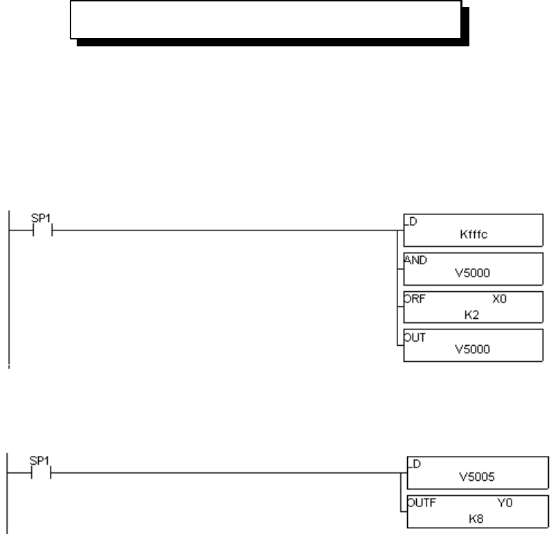
AUTO/MANUAL MODE CONTROL
The rung of ladder logic below simply masks X0 into the manual mode and X1 into the automatic mode
bit position of the mode word for loop 1 (V5000).
ALARM WORD DECODING
The rung below copies the alarm bits for loop 1 (V5005) into Y0-Y7.
Y0 Low Low PV Alarm
Y1 Low PV Alarm
Y2 High High PV Alarm
Y3 High PV Alarm
Y4 PV Orange Deviation (Orange > Yellow)
Y5 PV Yellow Deviation
Y6 Rate-of-Change Alarm
Y7 Broken Transmitter Alarm
READING THE PV AND WRITING THE LOOP OUTPUT
The Process Variable (PV) may be written from an analog input module directly into the loop table. The
Loop Output may be written directly to an analog output module. Please see Appendix B for examples
of reading and writing FACTS analog modules, F4-08AD and F4-04DA.
SUPPORTING LADDER LOGIC
3.2
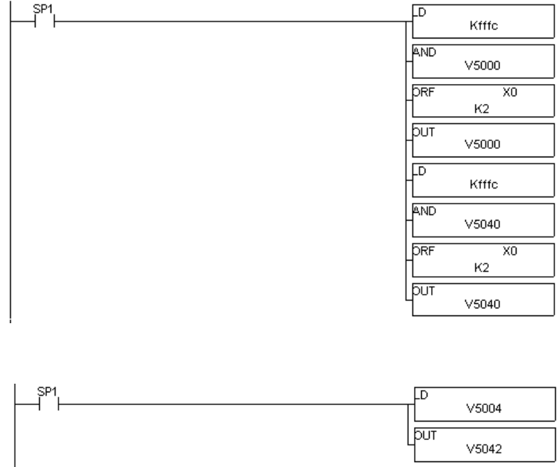
CASCADING LOOPS
A Cascaded loop has a setpoint which is the output of another loop.
If any loop in a cascade is placed in Manual mode, then all other loops in the cascade must be placed in
Manual to prevent reset windup.
The following example cascades loops 1 and 2. More than two loops may be cascaded by extending the
example. The example is for a loop table beginning at V-Memory address V5000.
A single input, X0, is used to place both loops in MANUAL mode. Turning on X1 with X0 off will place
both loops in AUTOMATIC mode.
The output of loop 1 is written to the Setpoint location for loop 2.
SETPOINT RAMP AND SOAK
For each loop the user can program a Ramp or Soak of the Setpoint as shown in the following examples.
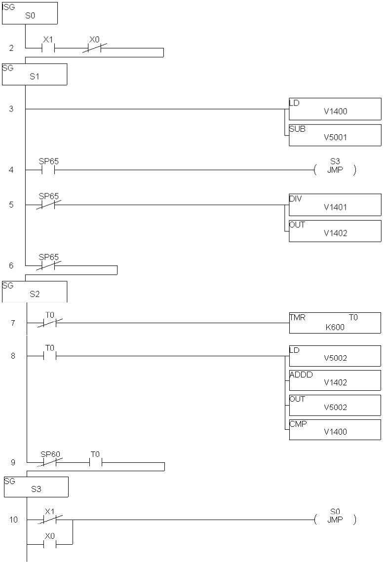
Setpoint Ramp
A Ramp of the setpoint is the changing from the current Setpoint to a specified final Setpoint over a
specified period of time.
In this example, the PV is used as the initial Setpoint. It is obtained from the PID parameter table for
loop 1, V5001. The final Setpoint is in V1400 and the ramp time, in minutes, is stored in V1401. The
loop should be configured so that the SP is automatically initialized to the PV when the loop is first but
into Automatic mode.
SUPPORTING LADDER LOGIC 3.3
The holding time at each step is fixed at one minute. The size of the ramp step is calculated when the
loop is first switched into Automatic mode, X1. The calculated ramp step is stored in V1402. The
setpoint is increased from the initial PV value to the final Setpoint value. The example could easily be
modified to ramp the Setpoint down to some lower final value.
Wait for the loop to be put into Automatic Mode
Subtract the PV from the final SP value
If a borrow has occurred we don’t need to ramp up
If no borrow, divide the SP change by the number of minutes to ramp
Ramp the setpoint (V5002) up in steps of V1402 once each minute
The setpoint has reached the final value for the ramp.
SUPPORTING LADDER LOGIC
3.4
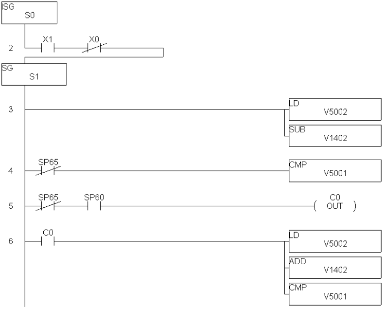
Setpoint Soak
A Soak of the setpoint is the changing from the current Setpoint to a specified final Setpoint in specified
steps with each step maintained for a specified time. If guaranteed soaking is programmed, at each step
change in the Setpoint, the Process Variable must be within a specified band around the Setpoint in
order for the Soak time to be measured.
In this example, the step change in the Setpoint is stored in V1400. The Soak time, in minutes, is stored
in V1401 and the PV band around the Setpoint is stored in V1402. The final Setpoint is stored in V1403.
Wait for the loop to be put into Automatic Mode.
C1 is turned ON when: SF - Band < PV < SP + Band
(V5002 - V1402) < V5001 < (V5001 + V1402)
C1 ON starts the soak.
If the PV falls out of the soak band, the soak timer is reset.
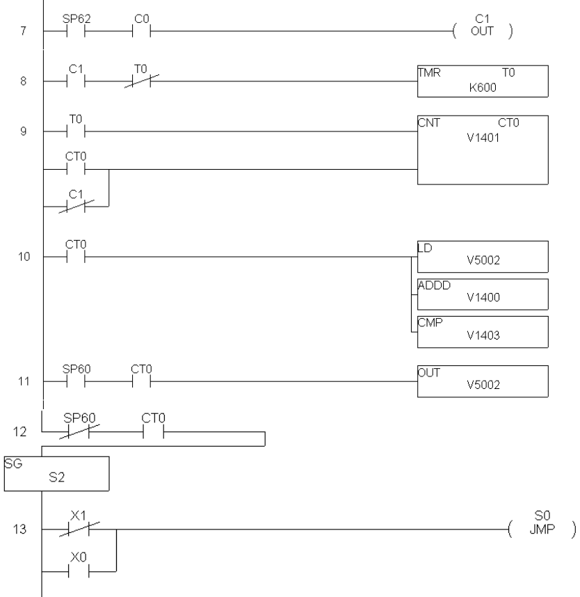
SUPPORTING LADDER LOGIC 3.5
1 minute timer
Number of minutes to soak at each setpoint step
Add the soak step to the setpoint and compare to final setpoint value.
Bump the setpoint up to next soak
The setpoint has reached the final value for the soak.
SUPPORTING LADDER LOGIC
3.6
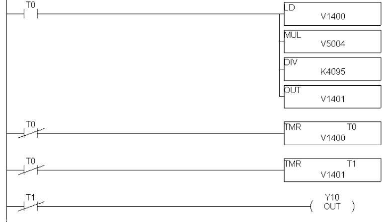
TIME PROPORTIONING CONTROL LOOPS
Time proportioning control permits a proportional PID output to be used with an ON/OFF device such as
a discrete output connected to a heater element.
The following example implements time proportioning of an output, Y10.
The time proportioning cycle time (V1400 in this example) is the time the output would remain on for a
loop output of 99.99%. The cycle time should be specified such that it is short compared to the
dynamics of the process. Fast timers are used in the example for greater resolution, however, a normal
timer could be used for a very slow process. In the example, a value of 1000 stored in V1400 would give
a cycle time of 10 seconds.
The on time (V1401) is the cycle time multiplied by the percent of loop output.
V1401 = V1400 * V5004 (output of loop 1) / 4095
SUPPORTING LADDER LOGIC 3.7
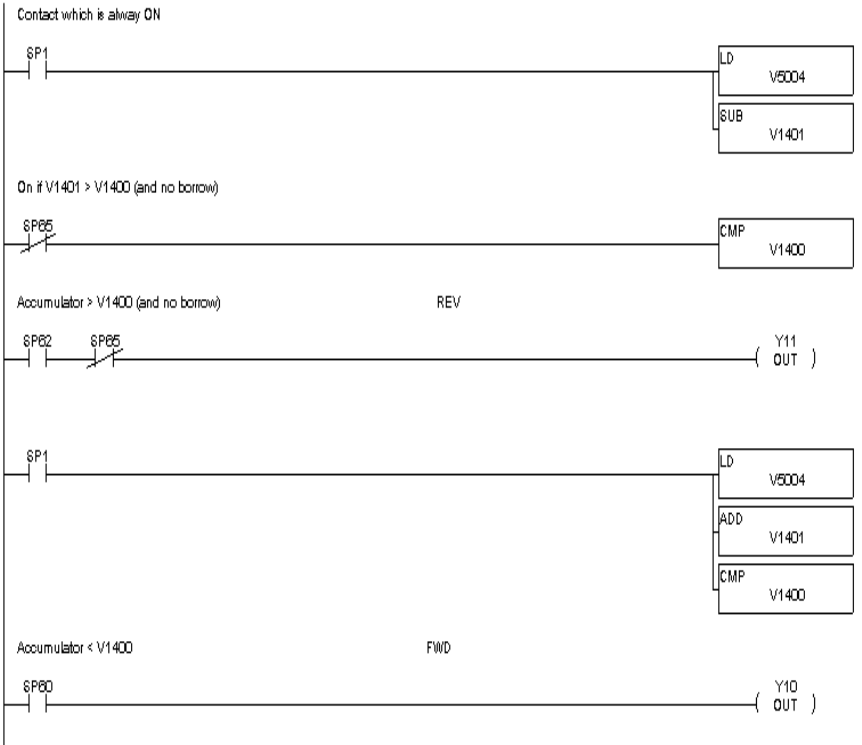
POSITIONING ACTUATOR CONTROL LOOPS
A reversible electric motor used to operate a valve is an example of a positioning actuator. This
example will use the PID loop output in V5004 to position an actuator controlled by forward and reverse
contacts. Y11 will run the motor in reverse and Y10 will turn the motor in the forward direction.
Feedback is required to correctly position the actuator. The actuator position could be input via a 4-20
mA signal derived from a slidewire connected to the actuator mechanism. A scaled BCD output of an
absolute encoder connected to the motor might also be used to determine the actuator position. In this
example, the actuator position is assumed to be in V1400. A value of 4095 (20 mA) in V1400 indicates
that the actuator is 100% forward. A value of 0 (4 mA) in V1400 indicates that the actuator is at the
reverse limit.
A tolerance is applied to the actuator position to prevent chattering of the outputs when the actuator is
near the desired position. In this example, the deadband of the actuator positioning is specified in
V1401.
SUPPORTING LADDER LOGIC
3.8
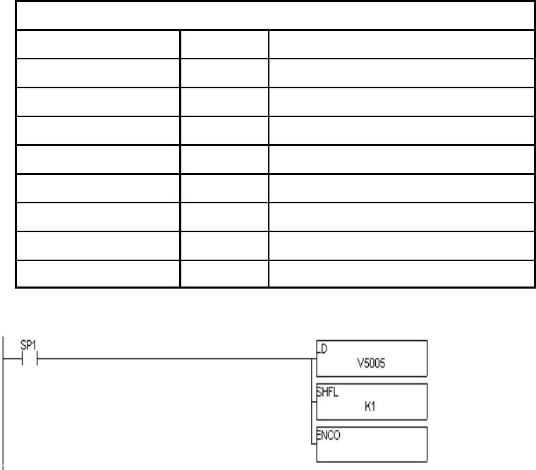
ENCODING THE ALARM WORD
Some operator interface software packages do not permit examining discrete bits in user V-Memory.
The following example converts the bits in the Alarm Word into a corresponding BCD number.
If more than one alarm is on then the BCD number for the least significant bit in the Alarm Word will be
returned. Thus a "Low Low PV Alarm" will override a "Low PV Alarm", a deviation and a rate-of-change
alarm. A "Broken Transmitter Alarm" will always be recognized since in this case the PIDCOP disables
all other alarms and loop processing.
Alarm Word
Encoded BCD Number Bit Number Description
1 0 Low Low PV Alarm
2 1 Low PV Alarm
3 2 High High PV Alarm
4 3 High PV Alarm
5 4 PV Orange Deviation (Orange - Yellow)
6 5 PV Yellow Deviation
7 6 Rate of Change Alarm
8 7 Broken transmitter Alarm
Load Alarm Word for Loop 1 in
Accumulator
Shift bits 1 position to the left
for ENCODE
Position of the 1st bit is put into
Accumulator

4.1
M(t)'Kc e(t)%1
Timt
0e(x)dx %Td d
dt e(t)%M0
LOOP ALGORITHMS
Loop Variables
The input to 405 PID CoProcessor (PIDCOP) loops is called the Process Variable (PV). The result of the
loop calculation is call the Output. Both the PV and Output are typically analog values and must be in
the range 0-4095. PID Commander provides scaling of the PV to engineering units such as PSI.
When the PIDCOP reads the Process Variable for a loop, it will automatically convert it from a BCD
number (0-4095) to a floating point number in the range of 0.0 to 1.0 (0.0 represents PV Low Range; 1.0
represents PV High Range). These values are referred to as normalized real numbers. All loop
calculations are performed using normalized reals. The output from the loop is also a normalized real,
which will be converted to a BCD number (0-4095) when stored to V-memory.
PID Control
The PIDCOP provides feedback loops using the PID (Proportional-Integral-Derivative) algorithm. The
controller Output is computed from the measured process variable PV as follows:
Let Kc = Proportional gain.
Ti = Reset or integral time.
Td = Derivative time or rate.
SP = Setpoint.
PV(t) = Process Variable at time "t".
e(t) = SP - PV(t) = PV deviation from Setpoint at time "t" or PV error
Then M(t) = Controller output at time "t"
With the appropriate choice of Ti and Td values, the integral and derivative action may be eliminated
resulting in the other common types of loops (P, PI, and PD).
CHAPTER 4: LOOP OPERATION
LOOP OPERATION
4.2
Mn'Kc (en%Ki j
n
i'1
ei%Kr (en&en&1)%M0
Mn'Kc (en%Ki j
n
i'1
ei%Kr (PVn&PVn&1)%M0
Position Form of the PID equation
The PIDCOP approximates the output M(t) using a discrete position form of the PID equation.
Let Ts = Sample rate.
Kc = Proportional gain.
Ki = Kc * (Ts / Ti) = Coefficient of the integral term
Kr = Kc * (Td / Ts) = Coefficient of the derivative term
Ti = Reset or integral time.
Td = Derivative time or rate.
SP = Setpoint.
PVn = Process Variable at nth sample.
en = SP - PVn = Error at nth sample.
MO = Value to which the controller output has been initialized
Then
Mn = Controller output at nth sample.
This form of the PID equation is referred to as the position form since the actual actuator position is
computed. The PIDCOP also provides a velocity form of the PID equation which computes the change
in actuator position. The PIDCOP modifies the standard equation slightly to use the derivative of the
Process Variable instead of the error as follows:
These two forms are equivalent unless the setpoint is changed. In the original equation, a large step
change in the setpoint will cause a correspondingly large change in the error resulting in a bump to the
process due to derivative action. This bump is not present in the second form of the equation.
The PIDCOP also combines the integral sum and the initial output into a single term called the bias (Mx).
This results in the following set of equations:
Mx0 = M0
Mx = Ki * eN + Mxn-1
Mn = Kc * en - Kr (PVn - PVn-1) + Mxn
The PIDCOP by default will keep the normalized output M in the range 0.0 to 1.0. This is done by
clamping M to the nearer of 0.0 or 1.0 whenever the calculated output falls outside this range. The
PIDCOP also allows you to specify the minimum and maximum output clamp values (within the range 0
to 4095 in BCD).
LOOP OPERATION 4.3
Reset Windup Protection
Reset windup can occur if reset action (integral term) is specified and the computation of the bias term
Mx is:
Mx = Ki * en + Mxn-1
For example, assume the output is controlling a valve and the PV remains at some value greater than
the Setpoint. The negative error (en) will cause the bias term (Mx) to constantly decrease until the output
M goes to 0 closing the valve. However, since the error term is still negative, the bias will continue to
decrease becoming ever more negative. When the PV finally does come back down below the SP, the
valve will stay closed until the error is positive for long enough to cause the bias to become positive
again. This will cause the controller to overshoot.
One way to solve the problem is to simply clamp the normalized bias between 0.0 and 1.0. The PIDCOP
does this. However, if this is the only thing that is done then the output will not move off 0.0 (thus
opening the valve) until the PV has become less than the SP. This will also cause the controller to
undershoot.
The PIDCOP is programmed to solve the overshoot problem by either freezing the bias term, or by
adjusting the bias term.
Freeze Bias
If the "Freeze Bias" option is selected when programming the PIDCOP then the PIDCOP simply stops
changing the bias (Mx) whenever the computed normalized output (M) goes outside the interval 0.0 to
1.0. Mx = Ki * en + Mxn-1
M = Kc * en - Kr(PVn - PVn-1) + Mx
Mn = 0 if M < 0
Mn = M if 0 # M # 1
Mn = 1 if M > 1
Mxn = Mx if 0 # M # 1
Mxn = Mxn-1 otherwise
Thus in our example, the bias will probably not go all the way to zero so that, when the PV does begin to
come down, the loop will begin to open the valve sooner than it would have if the bias had been allowed
to go all the way to zero. This action has the effect of reducing the amount of overshoot.
Adjusting the Bias
The normal action of the PIDCOP is to adjust the bias term when the output goes out of range as shown
below. Mx = Ki * en + Mxn-1
M = Kc * en - Kr(PVn - PVn-1) + Mx
Mn = 0 if M < 0
Mn = M if 0 # M # 1
Mn = 1 if M > 1
Mxn = Mx if 0 # M # 1
Mxn = Mn - Kc * en - Kr(PVn - PVn-1) otherwise
LOOP OPERATION
4.4
By adjusting the bias, the valve will begin to open as soon as the PV begins to come down. If the loop is
properly tuned, overshoot can be eliminated entirely. If the output went out of range due to a setpoint
change, then the loop probably will oscillate because we must wait for the bias term to stabilize again.
The choice of whether to use the default loop action or to freeze the bias is dependent on the application.
If large, step changes to the setpoint are anticipated, then it is probably better to select the freeze
bias option.
Step Bias Proportional to Step Change in SP
This option can be selected to reduce oscillation caused by a step change in setpoint when the adjusting
the bias option is used.
Mx = Mx * SPn / SPn-1 if the loop is direct acting
Mx = Mx * SPn-1 / SPn if the loop is reverse acting
Mxn = 0 if Mx < 0
Mxn = Mx if 0 # Mx # 1
Mxn = 1 if Mx > 1
Eliminating Proportional, Integral, or Derivative Action
Normally it is not necessary to run a full three mode PID control loop. Most loops require only the PI
terms or just the P term. Parts of the PID equation may be eliminated by choosing appropriate values
for the gain (Kc), reset (Ti), and rate (Td) yielding a P, PI, PD, I, and even an ID and a D loop.
Eliminating Integral Action The effect of integral action on the output may be eliminated by
setting Ti = 9999. When this is done, the user may then
manually control the bias term (Mx) to eliminate any steady-
state offset.
Eliminating Derivative Action The effect of derivative action on the output may be eliminated
by setting Td = 0.
Elimination Proportional Action Although rarely done, the effect of the proportional term on the
output may be eliminated by setting Kc = 0. Since Kc is also
normally a multiplier of the integral coefficient (Ki) and the
derivative coefficient (Kr), the PIDCOP makes the computation
of these values conditional on the value of Kc as follows:
Ki = Kc * (Ts/Ti) if Kc … 0
Ki = Ts/Ti if Kc = 0 (I or ID only)
Kr = Kc * (Td/Ts) if Kc … 0
Kr = Td/Ts if Kc = 0 (ID or D only)
LOOP OPERATION 4.5
Velocity Form of the PID Equation
The standard position form of the PID equation computes the actual actuator position. An alternative
form of the PID equation computes the change in actuator position. This form of the equation is referred
to as the velocity PID equation and is obtained by subtracting the equation at time "n" from the equation
at time "n-1".
The velocity equation is given by:
)Mn = M - Mn-1
)Mn = Kc * (en - en-1) + Ki * en - Kr * (PVn - 2 * PVn-1 + PVn-2)
Bumpless Transfer of Control
The PID CoProcessor provides for bumpless mode changes. A bumpless transfer from manual mode to
automatic mode is achieved by preventing the controller output from changing immediately after the
mode change.
When a loop is switched from Manual to Automatic mode, the Setpoint and Bias are initialized as
follows:
Position PID Algorithm Velocity PID Algorithm
SP = PV SP = PV
Mx = M
You can disable bumpless transfer of the Setpoint (3rd bit in mode word). This would be the same as
using the Remote Setpoint option in the Series 505.
LOOP ALARMS
The PIDCOP allows the user to specify alarm conditions that are to be monitored for each loop. Alarm
conditions are reported to the 405 CPU by the PIDCOP by setting bits in an "Alarm Word" located in the
V-Memory parameter table. You may program a Y output or CR (control relay) to be activated based on
an alarm condition. Please see the example on page 1.
PV Limit Specify up to four PV alarm points.
High-High PV rises above the programmed High-High Alarm Limit.
High PV rises above the programmed High Alarm Limit.
Low PV falls below the Low Alarm Limit.
Low-Low PV falls below the Low-Low Alarm Limit.
PV Deviation Specify an alarm for High and Low PV deviation from the setpoint (Yellow
Deviation). An alarm for High High and Low Low PV deviation from the setpoint
(Orange Deviation) may also be specified. When the PV is further from the
Setpoint than the programmed Yellow or Orange Deviation Limit corresponding
alarm bit is activated.
Rate-of-Change This alarm is set when the PV changes faster than a specified rate-of-change
limit.
LOOP OPERATION
4.6
Broken Xmitter This alarm is set when the PV is less than 2.4 mA. It is effective when a
4-20 mA transmitter is used with a 0-20 mA analog input range and the
20% offset of PV operation is selected.
Deadband Specify .1% to 5% alarm deadband on all alarms except Rate-of-Change. The
loop will not exit the alarm condition until the PV has come inside the alarm limit
minus the deadband. Alarm deadband prevents alarm chatter.
LOOP OPERATING MODES
The PIDCOP operates in one of two modes, either Manual or Automatic.
Manual
In Manual mode, the loop output is determined by the operator, not the PIDCOP. While in manual
mode, the PID CoProcessor will still monitor all of the alarms including Broken Transmitter, High-High,
High, Low, Low-Low, Yellow deviation , Orange deviation and Rate-of-Change.
Automatic
In Automatic mode, the PIDCOP computes the loop output based on the programmed parameters stored
in V-Memory. All alarms are monitored while in automatic.
Cascade
Loops may be cascaded using minimal additional ladder logic as described on page 11.
SPECIAL LOOP CALCULATIONS
Reverse Acting Loop
The PIDCOP allows a loop to be programmed as reverse acting. With a reverse acting loop, the output
is driven in the opposite direction of the error. For example, if SP>PV then a reverse acting controller
will decrease output to increase the PV.
Mx = -Ki * en + Mxn-1
M = -Kc * en + Kr(PVn - PVn-1) + Mx
Square Root of the Process Variable
Select square root if the PV is from a device such as an orifice meter which requires this calculation.

LOOP OPERATION 4.7
Yn'Yn&1%Ts
TS%(Td
Kd)
((PVn&Yn&1)
Error Squared Control
When error squared control is selected, the error is calculated as:
en = (SP - PVn) * ABS(SP - PVn)
A loop using the error squared is less responsive than a loop using just the error. The smaller the error,
the less responsive the loop. Error squared control would typically be used in a PH control application.
Error Deadband Control
With error deadband control, no control action is taken if the PV is within the specified deadband area
around the setpoint. The error deadband need not be the same above (e.g. V5023) and below (e.g.
V5022) the setpoint.
Once the PV is outside of the error deadband around the Setpoint, the entire error is used in the loop
calculation.
en = 0 SP - Deadband_Below_SP < PV < SP - Deadband_Above_SP
en = SP - PVn otherwise
The error will be squared first if both Error Squared and Error Deadband Control is selected.
Derivative Gain Limiting
When the coefficient of the derivative term, Kr, is a large value, noise introduced into the PV can result
in erratic loop output. This problem is corrected by specifying a derivative gain limiting coefficient, Kd.
Derivative gain limiting is a first order filter applied to the derivative term computation, Yn, as shown
below.
Position Algorithm
Mx = Ki * en + Mxn-1
M = Kc * en - Kr * (Yn - Yn-1) + Mx
Velocity Algorithm
)M = Kc * (en - en-1) + Ki * en - Kr * (Yn - 2 * Yn-1 + Yn-2)
SPECIAL FUNCTION PROGRAMMING
Using a BASIC CoProcessor, ladder logic, or Machine Stage, the user may perform additional
computations on the SP, PV, Output or other loop parameters and variables.
Typical special function programming examples are:
Computations on the Process variable such as filtering.
Computations on the Setpoint for a ratio-control application.
Computations on the loop Output before it is written to an analog output module.
LOOP OPERATION
4.8

5.1
There can be up to 5 PIDCOPs per base. Each PIDCOP has three dedicated V-Memory locations
associated with it to specify the starting address of the loop parameters table, the number of PID loops
enabled (scanned) for that module, and a location for the module to return configuration error codes.
DEDICATED V-MEMORY MAP
The dedicated V-Memory locations are only read by the PIDCOP at power-up or when the PLC mode is
switched from program to run.
Each PID loop parameter table is 32 V-Memory locations long. The number of loops enabled controls
the size of the block of V-Memory used by each PIDCOP. The beginning address of the PIDCOP's loop
parameter table is specified by a V-Memory pointer stored in the modules Table Beginning Address
location (see below). Normally the Table Beginning Address will be in retentive V-Memory, V2000 -
V7377.
The dedicated V-Memory Error Code location for each PIDCOP contains a configuration error code plus
firmware revision level.
High Byte = Version Number
Low Byte = Configuration Error Codes
0 = Valid configuration
1 = Starting table address below user v-memory
2 = Starting table address too high
3 = More than 16 loops enabled
4 = Starting address is too low for number of loops
Example: A BCD Error Code of 1002 indicates the starting table address is too high and the
PIDCOP firmware version is 1.0.
PIDCOP Configuration Memory Map
Slot Number Table Beginning Address Number of Loops Enabled Error Code
0V7350 V7351 V7352
1V7353 V7354 V7355
2V7356 V7357 V7360
3V7361 V7362 V7363
4V7364 V7365 V7366
5V7367 V7370 V7371
6V7372 V7373 V7374
7V7375 V7376 V7377
Example: To specify V5000 as the loop parameter table beginning address for a PIDCOP in slot 4,
V7364 would contain the BCD number 5000. To enable all 16 loops for this module,
V7365 would contain the BCD number 16. Thus the module will use all V-Memory
locations from V5000 to V5777.
APPENDIX A: V-MEMORY MAP

V-MEMORY MAP
5.2
PID Parameter Loop Table Memory Map
Decimal
Offset Example
V - Memory Description PIDCOP Usage
0V5000 Mode Word (bit mapped) 0 - 2 Read Continually
1V5001 PV (Process Variable)
2V5002 SP (SetPoint)
3V5003 Bias Write (Read if Proportional Control Only)
4V5004 Output (0 - 4095) 4 - 5 Write after each loop update
5V5005 Alarm Word (bit mapped)
6V5006 Sample Rate (nnn.d) 6 -31 Read if Mode Word bit 15 is set
7V5007 Gain (nn.dd) (P)
8V5010 Reset (nnn.d min., sec, msec, usec) (I) (default in Min.)
9V5011 Rate (nn.dd) (D)
10 V5012 PV Low Low Alarm (Note 1)
11 V5013 PV Low Alarm (Note 1)
12 V5014 PV High High Alarm (Note 1)
13 V5015 PV High Alarm (Note 1)
14 V5016 PV Yellow Deviation Limit (Note 1)
15 V5017 PV Orange Deviation Limit (Orange > Yellow) (Note 1)
16 V5020 PV Rate of Change Limit (Note 1)
17 V5021 Alarm Deadband (Range 0.1 - 5.0%)
18 V5022 Error Deadband Below SP (Note 1)
19 V5023 Error Deadband Above SP (Note 1)
20 V5024 Derivative Gain Limiting Coefficient
21 V5025 SetPoint Low Limit (Note 1)
22 V5026 SetPoint High Limit (Note 1)
23 V5027 Maximum Output Clamp
24 V5030 Minimum Output Clamp
25 V5031 Extended Mode Word (bit mapped)
26 V5032 Reserved for Future use
27 V5033 Reserved for Future use
28 V5034 Reserved for Future use
29 V5035 Reserved for Future use
30 V5036 Reserved for Future use
31 V5037 Reserved for Future use
Note 1: Range is 0 - 4095. If 20% offset is selected in Extended Mode Word then Range is 819 - 4095. All values except bit mapped
words are in BCD.

V-MEMORY MAP 5.3
Bit Mapped Registers - Mode Word
Hexadecimal
Weight Bit
Number Description
1 0 1 = Manual Mode (Overrides Automatic)
2 1 1 = Automatic Mode
4 2 1 = Disable Bumpless Transfer of SP, 0 = Manual - Automatic SP = PV
8 3 1 = Reverse Acting, 0 = Direct Acting
10 4 0 = Position, 1 = Velocity PID Alogorithm
20 5 1 = Square Root of PV
40 6 1 = High / Low Error Deadband Operation
80 7 1 = Error Squared
100 8 1 = Sample Rate and Derivative Time units = Minutes 0 = Seconds
200 9 1 = Derivative Gain Limiting
400 10 1 = Freeze Bias when Output goes out of range
800 11 1 = Step Bias Proportional to Step change in SP
1000 12 1 = Monitor PV for Low Low / High High and Low / High Limits
2000 13 1 = Monitor PV Deviation
4000 14 1 = Monitor PV Rate of Change
8000 15 1 = Set by user so PIDCOP will read fixed loop data
0 = PIDCOP clears after fixed loop data is read

V-MEMORY MAP
5.4
The Extended Mode Word is at V - Memory offset address 25 decimal. This is V5031 in the example.
Extended Mode Word (V5031)
Hexadecimal
Weight Bit
Number Description
1 0 1 = 20% offset of PV for input of 4 - 20 mA on 0 - 20mA range
2 1 1 = Monitor Broken Transmitter - Alarm set if PV < 2.4mA
4 2 1 = Reset units is seconds, nnn.d (See Note: 1)
8 3 1 = Reset units is milliseconds, nnn.d (See Note: 1)
10 4 1 = Reset units is microseconds, nnn.d (See Note: 1)
20 5 Reserved for future feature enhancements
40 6 Reserved for future feature enhancements
80 7 Reserved for future feature enhancements
100 8 Reserved for future feature enhancements
200 9 Reserved for future feature enhancements
400 10 Reserved for future feature enhancements
800 11 Reserved for future feature enhancements
1000 12 Reserved for future feature enhancements
2000 13 Reserved for future feature enhancements
4000 14 Reserved for future feature enhancements
8000 15 Reserved for future feature enhancements
Note: 1 - reset units is minutes, nnn.d , if bits 2,3and 4 are off. If more than one of these bits is on, then the smallest unit selected
is activated.

V-MEMORY MAP 5.5
The Alarm Word is at V-Memory offset address 5 decimal. This is V5005 in the example.
Alarm Word
Hexadecimal
Weight Bit
Number Description
1 0 1 = Low Low PV Alarm
2 1 1 = Low PV Alarm
4 2 1 = High High PV Alarm
8 3 1 = High Alarm
10 4 1 = PV Orange Deviation (Orange > Yellow)
20 5 1 = PV Yellow Deviation
40 6 1 = Rate-of-Change Alarm
80 7 1 = Broken Transmitter Alarm
100 8 1 = Reserved for future feature enhancements
200 9 1 = Reserved for future feature enhancements
400 10 1 = Reserved for future feature enhancements
800 11 1 = Reserved for future feature enhancements
1000 12 1 = Reserved for future feature enhancements
2000 13 1 = Reserved for future feature enhancements
4000 14 1 = Reserved for future feature enhancements
8000 15 Watch-Dog Bit, Toggles every loop update

V-MEMORY MAP
5.6
PID LOOP TABLE V-MEMORY MAP
Any V-Memory address may be specified as the loop table starting address for a given module.
Normally retentive V-Memory is used to store loop parameters (V2000-V7377). The following V-Memory
map shows the addressing for the maximum number of PIDCOPs permitted in a single 405 system
(5 PIDCOPs, 80 loops with 256 non-retentive and 232 retentive V-Memory locations unused).
1st PIDCOP 2ND PIDCOP 3rd PIDCOP 4th PIDCOP 5th PIDCOP
V-Memory
Address
of Mode
Word
PID Loop
Number V-Memory
Address
of Mode
Word
PID
Loop
Number
V-
Memory
Address
of Mode
Word
PID
Loop
Number
V-Memory
Address
of Mode
Word
PID
Loop
Number
V-Memory
Address
of Mode
Word
PID
Loop
Number
V2000 1V3000 1V4000 1V5000 1V6000 1
V2040 2V3040 2V4040 2V5040 2V6040 2
V2100 3V3100 3V4100 3V5100 3V6100 3
V2140 4V3140 4V4140 4V5140 4V6140 4
V2200 5V3200 5V4200 5V5200 5V6200 5
V2240 6V3240 6V4240 6V5240 6V6240 6
V2300 7V3300 7V4300 7V5300 7V6300 7
V2340 8V3340 8V4340 8V5340 8V6340 8
V2400 9V3400 9V4400 9V5400 9V6400 9
V2440 10 V3440 10 V4440 10 V5440 10 V6440 10
V2500 11 V3500 11 V4500 11 V5500 11 V6500 11
V2540 12 V3540 12 V4540 12 V5540 12 V6540 12
V2600 13 V3600 13 V4600 13 V5600 13 V6600 13
V2640 14 V3640 14 V4640 14 V5640 14 V6640 14
V2700 15 V3700 15 V4700 15 V5700 15 V6700 15
V2740 16 V3740 16 V4740 16 V5740 16 V6740 16
6.1
APPENDIX B: Application Example - 4 Loops
This application example describes hardware and ladder logic programming for a typical 4 loop PID
control using the F4-16PID coprocessor.
I/O Listing
Symbol Description
X0 Loop 1 Manual Mode
X1 Loop 1 Automatic Mode
X2 Loop 2 Manual Mode
X3 Loop 2 Automatic Mode
X4 Loop 3 Manual Mode
X5 Loop 3 Automatic Mode
X6 Loop 4 Manual Mode
X7 Loop 4 Automatic Mode
X10-X17 Spare
X20-X33 12 bit Data from Analog Input Module
X34-X37 Analog Input module channel Identification
Y0-Y13 12 bit Data for Analog output module
Y14-Y17 Analog output module channel select
Y20 Loop1 Low Low PV Alarm
Y21 Low PV Alarm
Y22 High High PV Alarm
Y23 High PV Alarm
Y24 PV Orange Deviation

Application Example - 4 Loops
6.2
Y25 PV Yellow Deviation
Y26 Rate of Change Alarm
Y27 Broken Transmitter Alarm
Y30 Loop2 Low Low PV Alarm
Y31 Low PV Alarm
Y32 High High PV Alarm
Y33 High PV Alarm
Y34 PV Orange Deviation
Y35 PV Yellow Deviation
Y36 Rate of Change Alarm
Y37 Broken Transmitter Alarm
Y40 Loop3 Low Low PV Alarm
Y41 Low PV Alarm
Y42 High High PV Alarm
Y43 High PV Alarm
Y44 PV Orange Deviation
Y45 PV Yellow Deviation
Y46 Rate of Change Alarm
Y47 Broken Transmitter Alarm
Y50 Loop4 Low Low PV Alarm
Y51 Low PV Alarm
Y52 High High PV Alarm
Y53 High PV Alarm
Y54 PV Orange Deviation
Y55 PV Yellow Deviation
Y56 Rate of Change Alarm
Y57 Broken Transmitter Alarm
Application Example - 4 Loops 6.3
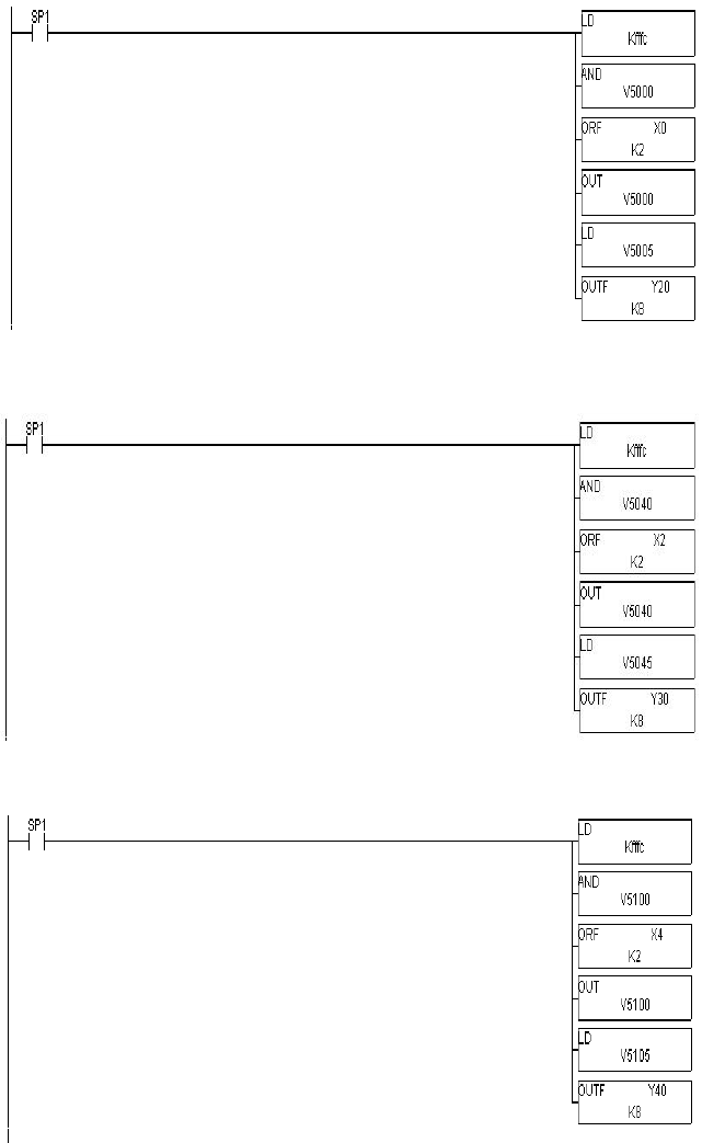
Ladder Logic
Loop 1 Mode control and alarming
Load bit Mask
Load all Mode bits
except Auto/Man.
Add the Auto/Man. Inputs
to mode control
Put back the loop1 mode control word
Get the alarm word to the accumulator
Write the 8 alarm bits to the
annunciators
Loop 2 Mode control and alarming
Load bit mask
Load all mode bits
except Auto/Man.
Add the Auto/Man. Inputs
to mode control
Put back the loop2 mode control word
Get the alarm word to the accumulator
Write the 8 alarm bits to the
annunciators
Loop 3 Mode control and alarming
Load bit mask
Load all mode bits
except Auto/Man.
Add the Auto/Man. Inputs
to the mode control
Put back the loop 3 mode control word
Get the alarm word to the accumulator
Write the 8 alarm bits to the
annunciators
Application Example - 4 Loops
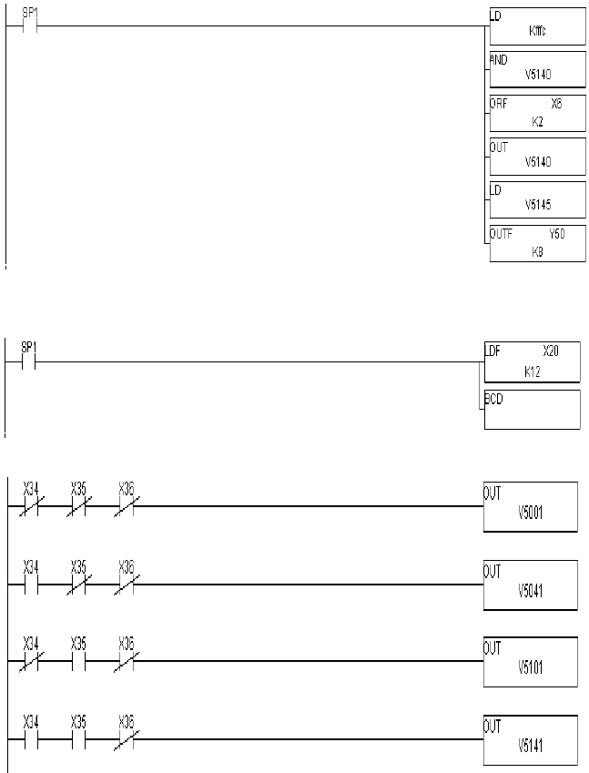
6.4
Loop 4 Mode control and alarming
Load bit mask
Load all mode bits
except Auto/Man.
Add the Auto/Man. Inputs
to the mode control
Put back the loop 3 mode control word
Get the alarm word to the accumulator
Write the 8 alarm bits to the
annunciators
Load Analog input 0-FFF and convert to BCD 0-4095 value in accumulator
Move 12 bits of data into accumulator
Convert binary value in accumulator to
BCD
Copy Analog Inputs to the process variable locations
Process Variable Loop 1
Process Variable Loop 2
Process Variable Loop 3
Process Variable Loop 4
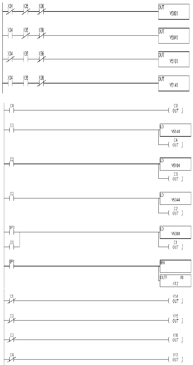
Application Example - 4 Loops 6.5
Copy Analog inputs to the Process Variable location
Loop 4 output
Loop 3 output
Loop 2 output
Loop 1 output
Copy loop outputs to the analog outputs which control the process
Loop 4 output
Loop 3 output
Loop 2 output
Loop 1 output
Analog output data
