Falcon 1 User's Guide Rev 7
User Manual:
Open the PDF directly: View PDF ![]() .
.
Page Count: 50
Falcon 1 Launch Vehicle
Payload User’s Guide
Rev 7

TABLEOFCONTENTS
1.Introduction 4
1.1.RevisionHistory4
1.2.Purpose6
1.3.CompanyDescription6
1.4.FalconProgramOverview6
1.5.MissionManagement7
2.Falcon1LaunchVehicles 8
2.1.Overview8
2.1.1.Falcon19
2.1.2.Falcon1e11
2.2.Availability12
2.3.Reliability13
2.4.Performance15
2.5.Pricing16
2.6.StandardServices16
2.7.Non‐standardServices16
2.8.VehicleAxes/AttitudeDefinitions17
3.Requirements&Environments 18
3.1.MassProperties18
3.2.PayloadInterfaces19
3.2.1.FalconPayloadAttachFittings19
3.2.2.TestFittingsandFitcheckPolicy19
3.2.3.ElectricalDesignCriteria19
3.3.DocumentationRequirements21
3.4.PayloadEnvironments23
3.4.1.TransportationEnvironments23
3.4.2.Humidity,CleanlinessandThermalControl23
3.4.3.PayloadAirConditioning24
3.4.4.LaunchandFlightEnvironments24
4.Facilities 32
4.1.Headquarters–Hawthorne,California32
4.2.Washington,DC32
4.3.TestFacility‐CentralTexas32
4.4.LaunchSite–KwajaleinAtoll33
4.4.1.ProcessingServicesandEquipment33
5.LaunchOperations 36
5.1.LaunchControlOrganization36
5.2.MissionIntegration37
5.2.1.PayloadTransporttoLaunchSite38
5.2.2.PayloadIntegration38
5.2.3.ExampleFlightProfiles41
D000973 Rev

Falcon1User’sGuide‐D000973Rev.7Page|4
Copyright–2008
1. INTRODUCTION
1.1. REVISIONHISTORY
Revision7,publishedinMay2008,containssignificantupdates,revisionsandorganizationalchanges.Notethat
Falcon1eisnowplannedforflightsinQ22010andlater.Thefollowingtablesprovidefurtherinformationon
notablechangesinthisversion.
Table1‐1mapskeyorganizationalchangesbetweenRevision6andRevision7.Table1‐2providesalistoftables
andfiguresthathavebeenupdatedinRevision7.
TABLE1‐1:ORGANIZATIONALCHANGESTOFALCON1USER'SGUIDE
PreviousVersion(Revision6)CurrentVersion (Revision7)
1.6.1Availability2.2Availability
1.6.2Reliability2.3Reliability
1.6.3Pricing2.5Pricing
2.VehicleOverview2.Falcon1LaunchVehicles
2.2Guidance,ControlandNavigationSystem2.1.1.3Guidance,NavigationandControl
2.3VehicleAxes/AttitudeDefinitions2.8VehicleAxes/AttitudeDefinitions
3.FacilitiesOverview4.Facilities
3.1.1WesternRange:VandenbergAirForceBaseremoved1
3.1.3EasternRange:CapeCanaveralAirForceStationremoved1
3.2OtherFacilities4.1,4.2,and4.3
4.PerformanceCapability2.4Performance
4.2SampleMissionProfile5.2.3ExampleFlightProfiles
4.3MassProperties3.1MassProperties
4.4MissionAccuracyData2.1.1.7MissionAccuracy
5.1PayloadFairingscontainedwithinSection2.Falcon1LaunchVehicles
5.1.3.1PayloadSeparation2.1.1.5PayloadSeparation
5.1.3.2CollisionAvoidance2.1.1.6CollisionAvoidance
5.2PayloadEnvironments3.4Environments&Requirements
5.3.4StandardServices2.6StandardServices
5.3.5Non‐StandardServices2.7Non‐StandardServices
6.LaunchOperations5.LaunchOperations
7.Safety6.Safety
8.PayloadQuestionnaire7.PayloadQuestionnaire
9.QuickReference8.QuickReference
1 Inthefuture,SpaceXintendstoofferadditionallaunchsites,howevertherearenofirmplansatthistime.Further,SpaceXis
willingtolaunchfromanylocationcustomerschose,providedthebusinesscaseforestablishingtherequestedlaunchsite
exists.Toinquireaboutperformancefromaspecificlaunchsite,pleasecontactSpaceX.
Falcon1User’sGuide‐D000973Rev.7Page|5
TABLE1‐2:UPDATEDTABLESANDFIGURES
PreviousVersion(Revision6)CurrentVersion (Revision7)
Table2‐1:Falcon1LaunchVehicleFamily
Characteristics
Table2‐1:Falcon1LaunchVehicleFamily
Characteristics
Figure3‐2:OmelekHangarLayoutFigure4‐4:OmelekHangarLayout
Figure4‐1:Falcon1&1eDirectandTwo‐burn
Performance,to9.1°InclinationfromKwajalein
Figure2‐3:Falcon1&1eDirect&Two‐Burn
Performance,to9.1°Inclination
Figure4‐2:Falcon1&1eTwo‐burnPerformanceto
LEOfromKwajalein
Figure2‐4:Falcon1&1eTwo‐BurntoLEO
Figure4‐3:Falcon1&1eDirectandTwo‐burn
PerformancetoSunSynchronousOrbitfromVAFB
containedin Figure2‐4
Table4‐1:LaunchVehicleMassPropertyLimitations Table3‐1:LaunchVehicleMassPropertyLimitations
Figure5‐1:Falcon1StandardFairingandDynamic
Envelope
Figure2‐1Falcon1StandardFairingandDynamic
Envelope
Figure5‐2:Falcon1eStandardFairingandDynamic
Envelope
Figure2‐2Falcon1eStandardFairingandDynamic
Envelope
Figure5‐3:NominalSteadyStateAxialAcceleration
TimeHistoryforFalcon1
Figure3‐4ExampleSteadyStateAxialAcceleration
TimeHistoryforFalcon1
Falcon5‐4:Falcon1PayloadInterfaceRandom
Vibration
Figure3‐5Falcon1PayloadInterfaceRandom
Vibration
Table5‐5:Falcon1RandomVibrationPSDValues Table3‐6Falcon1RandomVibrationMaximum
PredictedEnvironmentPSDValues
Table5‐6:Falcon1PayloadAcousticEnvironment
Assumingnominal5cmacousticblankets
Table3‐7‐ Falcon1PayloadAcousticEnvironment
Assumingnominal5cmacousticblankets
Figure5‐6:SoundPressureLevel(SPL)spectrafor
Falcon1assuming2inchacousticblankets
Figure3‐7SoundPressureLevel(SPL)spectrafor
Falcon1assuming2inchacousticblankets
Figure5‐9:Falcon1ElectricalInterfacetoPayload
RemoteLaunchCenters,Blockhouse‐to‐Spacecraft
Wiring
Figure3‐3:Falcon1ElectricalInterfacetoPayload
RemoteLaunchCenters,Blockhouse‐to‐Spacecraft
Wiring
Table6‐2:ServicesandEquipmentforSatellite
Processing
Table4‐1:ServicesandEquipmentforSatellite
Processing
Copyright–2008
Falcon1User’sGuide‐D000973Rev.7Page|6
Copyright–2008
1.2. PURPOSE
TheFalcon1User’sGuideisaplanningdocumentprovidedforpotentialandcurrentcustomersofSpaceX.This
documentisnotintendedfordetaileddesignuse.Datafordetaileddesignpurposeswillbeexchangeddirectly
betweenaSpaceXMissionManagerandthePayloadProvider.
1.3. COMPANYDESCRIPTION
Inanerawhenmosttechnology‐basedproductsfollowapathofever‐increasingcapabilityandreliabilitywhile
simultaneouslyreducingcosts,launchvehiclestodayarelittlechangedfromthoseof40yearsago.SpaceXis
changingthisparadigmbydevelopingandmanufacturingafamilyoflaunchvehiclesthatwillultimatelyreducethe
costandincreasethereliabilityofaccesstospacebyafactoroften.
SpaceXwasfoundedwiththephilosophythatsimplicity,reliabilityandlow‐costarecloselycoupled.Thus,we
approachallelementsoflaunchserviceswithafocusonsimplicitytobothincreasereliabilityandlowercost.The
SpaceXcorporatestructureisflatandourbusinessprocessesarelean,whichresultsinfastdecisionmakingand
delivery.Productsaredesignedtorequirelow‐infrastructurefacilities(productionandlaunch)withlow
maintenanceoverhead.Vehicledesignteamsareco‐locatedwithproductionandqualityassurancestafftotighten
thiscriticalfeedbackloop,resultinginhighlyproducibleandlowcostdesignswithqualityembedded.Tobetter
understandhowSpaceXcanachievelowcostwithoutsacrificingreliability;pleaseseetheFrequentlyAsked
Questions2sectionoftheCompanypageontheSpaceXwebsite.
Establishedin2002byElonMusk,thefounderofPayPalandtheZip2Corporation,SpaceXhasalreadydeveloped
andlaunchedalightliftlaunchvehicle‐‐Falcon1,nearlycompleteddevelopmentoftheFalcon9,anddeveloped
stateofthearttestingandlaunchlocations.Ourdesignandmanufacturingfacilitiesareconvenientlylocatednear
theLosAngelesInternational(LAX)airport.Thislocationallowsustoleveragethedeepandrichaerospacetalent
poolavailableinSouthernCalifornia.Ourstateoftheartpropulsionandstructuraltestfacilitiesarelocatedin
CentralTexas.
SpaceXhasbuiltanimpressivelaunchmanifestthatincludesabroadarrayofcommercial,government,and
internationalsatellitemissions.ItisalsobolsteredbyaNASALaunchServices(NLS)contractandselectionto
demonstratedeliveryandreturnofcargototheInternationalSpaceStationforNASA’sCommercialOrbital
TransportationServices(COTS)program.Basedonthesecontracts,SpaceXisonsoundfinancialfooting.
1.4. FALCONPROGRAMOVERVIEW
Drawinguponarichhistoryofpriorlaunchvehicleandengineprograms,SpaceXisprivatelydevelopingtheFalcon
familyofrocketsfromthegroundup,includingmainandupperstageengines,thecryogenictankstructure,
avionics,guidance&controlsoftwareandgroundsupportequipment.
WiththeFalcon1,Falcon1e,Falcon9andFalcon9Heavylaunchvehicles,SpaceXisabletodeliverspacecraftinto
anyinclinationandaltitude,fromlowEarthorbit(LEO)togeosynchronousorbit(GEO)toplanetarymissions.The
Falcon9andFalcon9HeavyaretheonlyUSlaunchvehicleswithtrueengineoutreliability.Theyarealso
designedsuchthatallstagesmaybereusable.OurDragoncrewandcargocapsule,currentlyunderdevelopment,
willrevolutionizeaccesstospacebyprovidingefficientandreliabletransportofcrewandcargototheISSand
otherLEOdestinations.
2http://www.spacex.com/company.php#frequently_asked_questions

Falcon1User’sGuide‐D000973Rev.7Page|7
1.5. MISSIONMANAGEMENT
Tofacilitateandstreamlinecommunication,eachcustomerworkswithasinglepointofcontactatSpaceX.The
MissionManagerworkscloselywiththecustomer,SpaceXtechnicalexecutionstaffandallassociatedlicensing
agenciesinordertoachieveasuccessfulmission,andisresponsibleforcoordinatingmissionintegrationanalysis
anddocumentationdeliverables,planningintegrationmeetingsandreportsandcoordinatingallintegrationand
testactivitiesassociatedwiththemission.
Duringthelaunchcampaign,theMissionManagerwillalsofacilitatecustomerinsightintothelaunchoperations.
ThoughthelaunchoperationsteamisultimatelyresponsibleforcustomerhardwareandassociatedGround
SupportEquipment(GSE),theMissionManagerwillcoordinatealllaunchsiteactivitiestoensurecustomer
satisfactionduringthiscriticalphase.
Copyright–2008
Falcon1User’sGuide‐D000973Rev.7Page|8
2. FALCON1LAUNCHVEHICLES
2.1. OVERVIEW
Falcon1LaunchVehiclesaredesignedtoprovidebreakthroughadvancesinreliability,cost,andtimetolaunch.
Theprimarydesigndriverisandwillremainreliability.SpaceXrecognizesthatnothingismoreimportantthan
gettingourcustomer’sspacecraftsafelytoitsintendeddestination.
TheFalcon1LaunchVehicleFamilyincludestheFalcon1andanenhancedversion,Falcon1e.ThestandardFalcon
1isavailableuntilmid‐2010,uponwhichtimetheFalcon1ewillbecomethevehiclefortransportingsmall
payloads.
Table2‐1offersaside‐by‐sidecomparisonofFalcon1andFalcon1e.
Forclarification,inthisdocumentthephrases‘Falcon1LaunchVehicles’and‘Falcon1LaunchVehicleFamily’refer
inclusivelytobothFalcon1andFalcon1e.However,thetitles‘Falcon1‘and‘Falcon1e’refertotherespective
vehiclesonly.
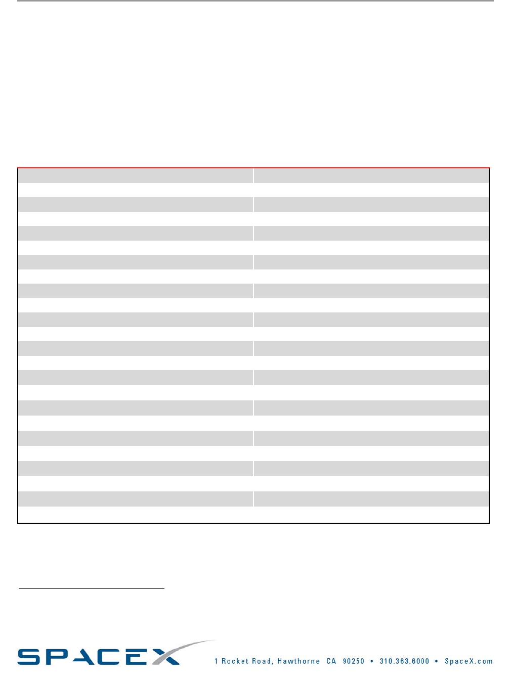
TABLE2‐1:FALCON1LAUNCHVEHICLEFAMILYCOMPARISONCHART
Falcon1e‐Stage1
(2010+)
Falcon1‐Stage1
(2006‐2010)
Stage2‐common
Length 90feet70feet(bothstageswithfairing&interstage)
Diameter5.5feet5.5feetStage5.5feet;Fairing5feet
DryMass5680lb3000lb1200lb
UsablePropellantMass87000lb47380lb8900lb
FairingCompositeogive:
300lb(approximate)
Aluminumskin&stringer,biconic:320lb
StructureTypeMonocoqueMonocoqueMonocoque
MaterialAluminumAluminumAluminum‐Lithium
EngineLiquid,
Pressurefedongas
generatorcycle
Liquid,
Pressurefedongas
generatorcycle
Liquid,
Pressurefed
EngineDesignationMerlin1C Merlin1CKestrel2
NumberofEngines111
PropellantLOX/KeroseneLOX/KeroseneLOX/Kerosene
Thrust125klbf(SL)78klbf(SL)6.9klbf(vac)
ISP(vac)304s300s317s
PropellantFeedSystemTurbo‐pumpTurbo‐pumpPressure‐fed
RestartCapabilityNoNoYes
TankPressurizationHeatedHeliumHeatedHeliumHeatedHelium
AttitudeControl:
Pitch,Yaw
HydraulicTVCHydraulicTVCElectro‐mechanicalActuatorTVC
AttitudeControl:RollTurbo‐pumpexhaustTurbo‐pumpexhaustColdgasthrusters
NominalBurnTime169s169s418s
ShutdownProcessBurntodepletionBurntodepletionPredeterminedvelocity
StageSeparationExplosiveboltswith
pneumaticpushers
Explosiveboltswith
pneumaticpushers
Marmonclampwithpneumatic
pushers
Copyright–2008

Falcon1User’sGuide‐D000973Rev.7Page|9
2.1.1. FALCON1
Falcon1isatwo‐stage,liquidoxygen(LOX)androcketgradekerosene(RP‐1)poweredlaunchvehicle.Itis
designedfromthegroundupforcostefficientandreliabletransportofsatellitestolowEarthorbit.
2.1.1.1. FIRSTSTAGE
Theprimarystructureismadeofaspacegradealuminumalloyinapatentpending,graduatedmonocoque,
commonbulkhead,flightpressurestabilizedarchitecturedevelopedbySpaceX.Thedesignisablendbetweena
fullypressurestabilizeddesign,suchasAtlasIIandaheavierisogriddesign,suchasDeltaII.Asaresult,wehave
beenabletocapturethemassefficiencyofpressurestabilization,butavoidthegroundhandlingdifficultiesofa
structureunabletosupportitsownweight.
AsingleSpaceXMerlinenginepowerstheFalcon1firststage.Afterenginestart,Falcon1ishelddownuntilall
vehiclesystemsareverifiedtobefunctioningnormallybeforereleaseforliftoff.
Heliumtankpressurizationisprovidedbycompositeover‐wrappedinconeltanksfromArdeCorporation,thesame
modelusedinBoeing’sDeltaIVrocket.
Stageseparationoccursviadualinitiatedseparationboltsandapneumaticpushersystem.Allcomponentsare
spacequalifiedandhaveflownbeforeonotherlaunchvehicles.
Thefirststagereturnsbyparachutetoawaterlanding,whereitispickedupbyshipinaproceduresimilartothat
oftheSpaceShuttlesolidrocketboosters.TheparachuterecoverysystemisbuiltforSpaceXbyAirborneSystems
Corporation,whoalsobuildstheShuttleboosterrecoverysystem.
2.1.1.2. SECONDSTAGE
Thesecondstagetankstructureismadeofaluminum‐lithium,analloypossessingthehigheststrengthtoweight
ratioofanyaluminumandcurrentlyusedbytheSpaceShuttleExternalTank.Althoughweintendtocontinue
researchingalternativesinthelongterm,forthisparticularapplicationithasthelowesttotalsystemmassforany
materialwehaveexamined,includingliquidoxygencompatiblesuper‐alloysandcomposites.
Thetanksareprecisionmachinedfromthickplatewithintegralflangesandports,minimizingthenumberofwelds
necessary.Themajorcircumferentialweldsarealldonebyanautomatedweldingmachine,reducingthepotential
forerrorandensuringconsistentquality.
2.1.1.3. GUIDANCE,NAVIGATIONANDCONTROL
TheGuidance,NavigationandControl(GNC)SystemincludesaruggedizedflightcomputerandanInertial
MeasurementUnit(IMU).TheflightcomputerisaPC/104basedPentiumclass586(Geode)withanalogand
digitalinputandoutput.Itprovidesaninterfacetothepayloadonthegroundandtheenginecomputer(onthe
firststage)inflightviaEthernet.AGPSreceiverisflownfornavigationupdates,supportingtheIMU.TheGNC
systemalsoincludesanS‐bandtelemetrysystem,anS‐Bandvideodownlink,aC‐Bandtransponder,abang‐bang
controllerfortankpressureregulation,batteriesandpowerdistribution.
2.1.1.4. FAIRING
Thelaunchvehiclewillprovideasignaltothepayloadatseparationtoinitiatepayloadpower‐up.Alternate
configurationsforseparationsignals(break‐wires,separationswitchesmonitoreddirectlybythepayload,orother
configurations)canbeaccommodatedasoptions.
Copyright–2008
Falcon1User’sGuide‐D000973Rev.7Page|10
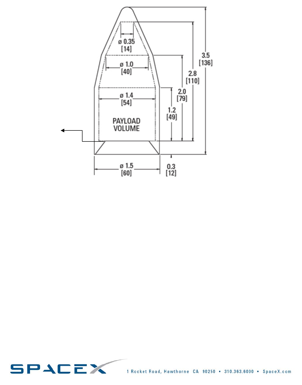
A0.2m(8in)diameteraccessdoorisincludedinthefairingforcontingencypurposesonly.Undernominal
operatingconditions,allprocessingthatrequiresaccesstothepayloadmustbecompletedpriortofairing
installation.TheFalcon1fairingis1.54mindiameterandshownbelowinFigure2‐1:Falcon1StandardFairing
andDynamicEnvelope*,meters[inches].
SEPARATION
PLANE
FIGURE2‐1:FALCON1STANDARDFAIRINGANDDYNAMICENVELOPE*,METERS[INCHES]
*Dynamicenvelope(shownasPayloadVolumeabove)indicatesthevolumethatthespacecraftcanmovewithin.
2.1.1.5. PAYLOADSEPARATION
SpaceXisfamiliarwithmanypayloadseparationsystems,includingclampband,non‐explosiveattach‐bolt,and
Lightband®motorizedseparationsystems.Asastandardservice,SpaceXwilleithersupplyandintegratea38inch
(0.9652m)marmonbandpayloadseparationsystemorintegrateaseparationsystemchosenandprovidedbythe
PayloadProvider. Alternatively,asanon‐standardservice,SpaceXcanprocureaseparationsystemforthe
PayloadProvider.
Payloadseparationisatimedeventreferencedtothesecondstageburnout.Separationisinitiatednon‐
explosivelybyseparationspringsthatimpartseparationvelocity.Thesystemmaintainstipoffratesbelow1
degreepersecond.Oncethe2halvesofthesystemseparate,asignalissenttothepayloadusingeithera
breakwireormicroswitch.Ifthecustomerdesires,thepayloadcanbespunuptoapproximately6RPMat
separation.
Thelaunchvehiclewillprovideasignaltothepayloadatseparationtoinitiatepayloadpower‐up.Alternate
configurationsforseparationsignals(break‐wires,separationswitchesmonitoreddirectlybythepayload,orother
configurations)canbeaccommodatedasoptions.
Copyright–2008

Falcon1User’sGuide‐D000973Rev.7Page|11
Almostanyattitudecanbeaccommodatedatseparation.However,itmaytakeupto15minutestoobtainsome
attitudespriortoseparation.Inaddition,multipleseparationscanbeachieved.Thesecondstageattitudeand
rateaccuraciesatseparationare:
• Roll ±2°
• Pitch/Yaw±0.5°
• Bodyrates±0.1°/sec/axis
2.1.1.6. COLLISIONAVOIDANCE
IfanalysisshowsaCollisionAvoidanceManeuver(CAM)isnecessary,aCAMwillbeprovidedasastandardservice.
TensecondspostpayloadseparationtheCAMwillbeperformedusingtheheatedheliumpressurantandtheRCS
thrusters.Thethrustersaretiltedforwardby20°andpositionedtominimizegasimpingementonthespacecraft
whilestillprovidingadequateseparation.
2.1.1.7. MISSIONACCURACY
Asaliquidpropellantvehiclewithre‐startcapability,Falcon1LaunchVehiclesprovideflexibilityrequiredfor
payloadinsertionintoorbitwithhighereccentricityandfordeployingmultiplepayloadsintoslightlydifferent
orbits.Untilverifiedbyactualoperations,SpaceXexpectstoachievethefollowingminimumtargetorbital
insertionaccuracy:
• Inclination±0.1°
• Perigee ±5km
• Apogee ±15km
2.1.2. FALCON1e
BeginninginQ22010,Falcon1ewillofferenhancedperformancecapabilitiesbymakinguseofthefullcapacity
andperformanceofanupgradedMerlinengine.Falcon1ewillhaveanextendedfirststagetanktosupportthe
propellantconsumptionneedsofthisenginewhilealsobeingstrengthenedtodealwiththelargeraxialloads.In
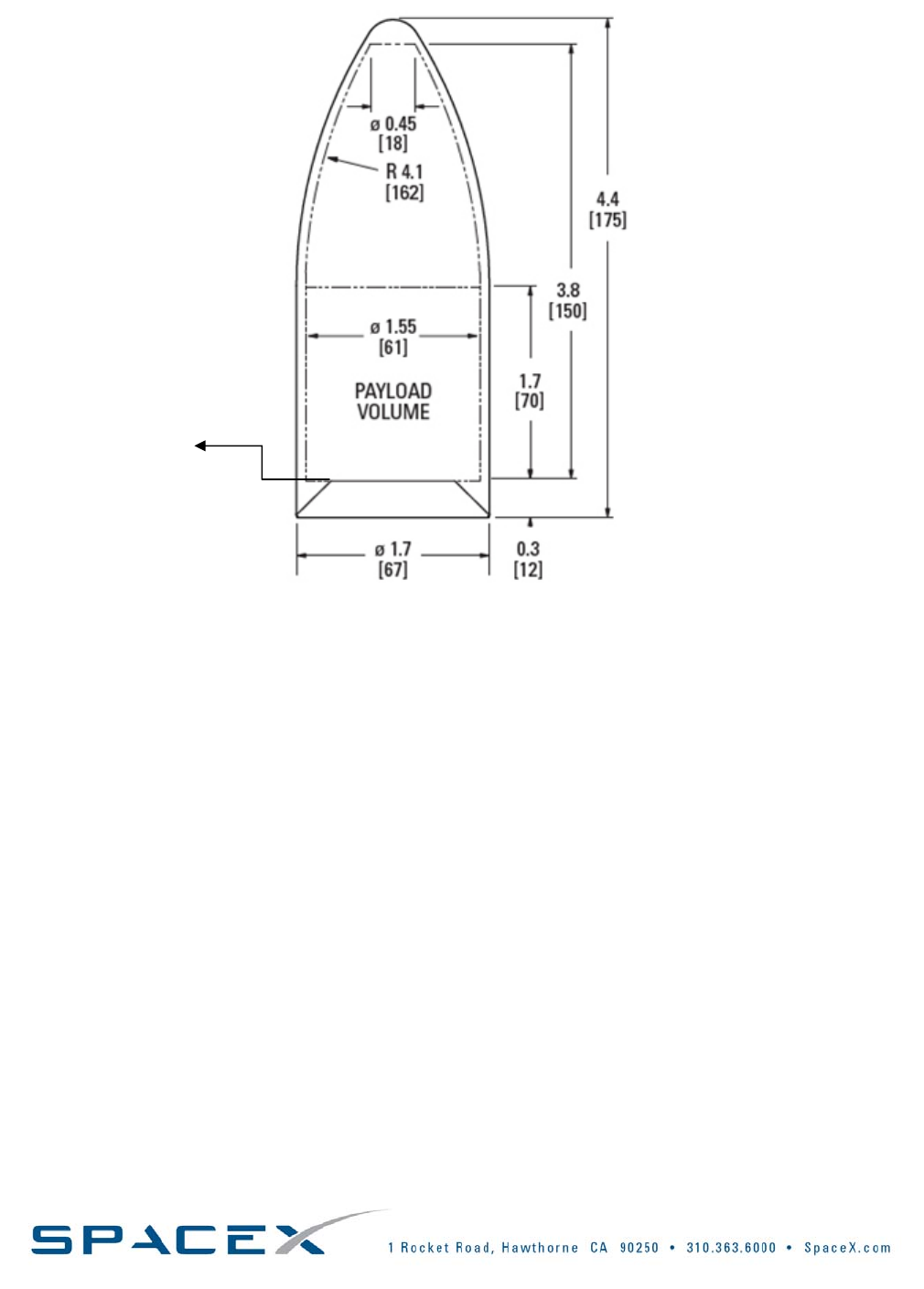
addition,Falcon1ewillhavealarger,lighter1.7mfairing.Thedesignisacompositeogiveversusthestandard
aluminumskinandstringerdesign.
TheenhancedfairingfortheFalcon1eisshownbelowinFigure2‐2.Twoaccessdoorsareprovidedasastandard
service.
Copyright–2008
Falcon1User’sGuide‐D000973Rev.7Page|12
SEPARATIONPLANE
FIGURE2‐2:FALCON1eSTANDARDFAIRINGANDDYNAMICENVELOPE*,METERS[INCHES]
*Dynamicenvelope(shownasPayloadVolumeabove)indicatesthevolumethatthespacecraftcanmovewithin.
2.2. AVAILABILITY
Falconhasthehighestpredictedlaunchavailabilityofanycurrentvehicle.Asevidencedbyourmanifest,thereisa
strongmarketforFalcon1LaunchVehicles.Thisallowsforvehicleproductionoperationsratherthanbuildingone
atatimeonaperorderbasis.SpaceXproductionsupportsmanylaunchesperyearincludingsparehardware.
Highavailabilityisalsofacilitatedbyrigorousdesignmarginsresultinginrobustnesstowindandotherweather
conditions.SpaceX’sabilitytolaunchrapidlyalsosupportshighavailability.Oureighteen‐daylaunchcampaign,
shortcountdownsequenceandrobustnesstoweathersupportlowinterferencewithrangescheduling.
Copyright–2008
Falcon1User’sGuide‐D000973Rev.7Page|13
Copyright–2008
2.3. RELIABILITY
Thevastmajorityoflaunchvehiclefailuresinthepasttwodecadescanbeattributedtothreecauses:engine,
avionicsandstageseparationfailures.AnanalysisbyAerospaceCorporation3showedthat91%ofknownfailures
canbeattributedtothosesubsystems.
Withthisinmind,Falcon1LaunchVehiclesaredesignedtohaverobustpropulsionsystemsandtheminimum
numberofseparationevents:Merlin1Cisaman‐ratedenginewithhighstructuralmarginsandahighlyreliable,
redundantignitionsystem,andFalcon1isatwostagevehiclewhichminimizesseparationevents.Similarlywith
thevehicleavionicssystem,SpaceXhasgonetheextramileinbuildingastate‐of‐the‐artsystemusing21stcentury
electronicsthatwillfeedforwardintolargervehicledevelopmentsfollowingFalcon1.
Falcon1LaunchVehiclesaredesignedforhighreliabilitystartingatthearchitecturallevel.Manydesignchoices
weremadetoensurereliabilitywasnotcompromised.Thesechoicesinclude:
• ROBUSTSTRUCTURALDESIGNMARGINS
Thefirststageisdesignedtoberecoveredandreused,andtherefore,musthavesignificantlyhigher
marginsthananexpendablestage.Todate,wehavetakenaflightfirststagethroughover190cryogenic
pressurecycleswithnoevidenceoffatigue.
• PROPULSIONANDSEPARATIONEVENTDESIGN
Propulsionandseparationeventsaretheprimarycausesoffailuresinlaunchvehicles.Therefore,we
havedesignedFalcon1withtheminimumnumberofengines,inserial,requiredforthemission:onlyone
engineperstageandonlyoneenginethatisstartedoutsideofoperatorcontrol.Wehavealsominimized
thenumberofstages(2)tominimizeseparationevents.Inaddition,asapartofourlaunchoperations,
weholddownthefirststageafterignition,butpriortoreleasetowatchenginetrends.Ifanoff‐nominal
conditionexists,thenanautonomousabortisconducted.Thishelpspreventanengineperformance
issuefromcausingafailureinflight.
• PUMP‐FEDPROPULSION
Althoughapressure‐fedsystemhasthefewestnumberofparts,itreliesoncryogenictankstructuresand
technologythathaveneverbeenproveninfullscaletesting.Therefore,thetradewasmadethatthefirst
stageshouldbepump‐fed,butwiththesimplestpossibleturbopumpdesign:asingleshaftforboththe
LOXandRP,agasgeneratorcycleversusthemorecomplexstagedcombustionandfinally,anablative
chamber.Inaddition,thepintleinjectorwasselectedforbothenginestagesforitsinherentcombustion
stability.
• ETHERNETBACKBONE
SpaceXeliminatedthedesignandintegrationcomplexityandopportunityforhumanerrorassociated
withlargeserialcablebundleswiththeuseoftheEthernetbus.
• FAILUREMODEMINIMIZATION
SpaceXminimizedthenumberoffailuremodesbyminimizingthenumberofseparatesubsystems.Our
firststagethrustvectorcontrol(TVC)systemmakesuseofthepressurizedfuel,rocket‐gradekerosene
(RP‐1),throughalinetappedoffofthehighpressureRPsideofthepumptopowertheTVC.This
eliminatestheseparatehydraulicsystem.Inadditioniteliminatesthefailuremodeassociatedwith
runningoutofpressurizedfluid.Anotherexampleisthefirststagerollcontrolsystem—aredundant
gimbalactuatestheexhaustgasforrollcontrol,again,eliminatingaseparatesystem.
3http://www.aero.org/publications/crosslink/winter2001/03.html.Ahardcopyofthisreferencecanbemadeavailableupon
request.

Falcon1User’sGuide‐D000973Rev.7Page|14
• RIGOROUSTESTING
Inadditiontothesedesigndecisions,Falcon1willundergoanexhaustiveseriesoftestsfromthe
componenttothevehiclesystemlevel.Thisincludescomponentlevelqualificationandworkmanship
testing,structuresloadandprooftesting,flightsystemandpropulsionsubsystemleveltesting,fullfirst
andsecondstagetestinguptofullsystemtesting,includinga5secondstaticfiring.Inadditiontotesting
environmentalextremes(plusmargin),allhardwaremustbetestedtoaccountforoffnominalconditions.
Forexample,bothourstageandfairingseparationtestsrequiretestingforoff‐nominalcaseswithrespect
togeometricalmisalignment,anomalouspyrotechnictimingandsequencing.
• LAUNCHOPERATIONS
Amajorcontributortoareliablesystemisitsoperations.Tosupportrobustlaunchoperations,our
countdownisfullyautomatedwiththousandsofchecksmadepriortovehiclerelease.Afterfirststage
ignition,thevehicleisnotreleaseduntilthefirststageengineisconfirmedtobeoperatingnormally.A
safeshutdownisexecutedshouldanyoffnominalconditionsbedetected.Falcon1designandour
operationscrewcanaccommodateveryrapidrecycletorecoverdependinguponthecauseoftheabort.
Copyright–2008
Falcon1User’sGuide‐D000973Rev.7Page|15
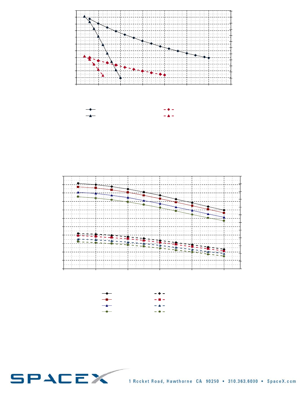
2.4. PERFORMANCE
TheFalcon1LaunchVehicleFamilyincludestheFalcon1andanenhancedversion,Falcon1e.BeginninginQ2
2010,Falcon1ewillofferenhancedperformancecapabilitiesandpayloadvolume.
0
200
400
600
800
1000
1200
1400
1600
1800
2000
2200
2400
0
100
200
300
400
500
600
700
800
900
1000
1100
0 500 1000 1500 2000 2500 3000 3500
Payload Mass (lbm)
Payload Mass (kg)
Orbit Altitude (km
)
Falcon 1e - Two Burn Insertion Falcon 1 - Two Burn Insertion
Falcon 1e - Direct Insertion Falcon 1 - Direct Insertion
F1E87 200SBM0 NB 02/14/08
REVDP 100SBM0 NB 02/14/08
FIGURE2‐3:FALCON1&1eDIRECT&TWO‐BURNPERFORMANCETO9.1°INCLINATION
0
200
400
600
800
1000
1200
1400
1600
1800
2000
2200
2400
0
100
200
300
400
500
600
700
800
900
1000
1100
0 20406080100
Payload Mass (lbm)
Payload Mass (kg)
Inclination (deg)
Falcon 1e - 185 km Falcon 1 - 185 km
Falcon 1e - 300 km Falcon 1 - 300 km
Falcon 1e - 500 km Falcon 1 - 500 km
Falcon 1e - 700 km Falcon 1 - 700 km
F1E87 200SBM0 NB 02/14/08
REVDP 100SBM0 NB 02/14/08
FIGURE2‐4:FALCON1&1eTWO‐BURNPERFORMANCETOLEO
Copyright–2008

Falcon1User’sGuide‐D000973Rev.7
Page|16
Copyright–2008
PricingandPerformance
2.5. PRICING
ThestandardpriceperlaunchforFalcon1LaunchVehiclescanbefoundinthe4section
oftheFalcon1pageontheSpaceXwebsite.Thispricingincludesrange,standardpayloadintegrationandthird
partyliabilityinsurance.Pleaseseebelowforadescriptionofthestandardservicesandexamplenon‐standard
services.Ifnonstandardservicesarerequired,pleaseidentifytheseinthePayloadQuestionnairefoundinSection
ofthisGuide.7
2.6. STANDARDSERVICES
Aspartofanystandardlaunchservice,SpaceXprovidesthefollowing:
• Launchofthepayloadintothespecifiedorbitwithinthespecifiedenvironmentalconstraints
• Personnel,services,hardware,equipment,documentation,reviews,analysesandfacilitiesnecessaryto
supportmissionplanning,launcherproduction,missionandpayloadintegrationandlaunch
• Asingleflightsetofelectricalconnectors
• Class100Kcleanroomintegrationspaceforthespacecraftpriortothescheduledlaunchdateonthe
launchrangewithadditionalfloorspaceforGSEandpersonnel
• Processing,integrationandencapsulationofthepayloadwithinthefairing,testingofelectricalandsignal
interfaceswiththespacecraftatthelaunchsite
• Conditionedairintothepayloadfairing
• Asimple,pyrotechnicmarmonclampseparationsystem
• OneaccessdoorintheFalcon1payloadfairingor2intheFalcon1epayloadfairing
• AMissionSimulationTestexercisingoperationalreadiness,vehicleequipmentandgroundsystems
• AMissionDressRehearsalsimilartothemissionsimulationtestforkeylaunchteammembers
• Provisionofallrangeandsafetyinterfacesincludingrequirementsdocumenttemplatesforthespacecraft
providertocomplete
• Facilitationofrangeandrangesafetyintegrationprocess
• Collisionavoidanceanalysisandmaneuver(asrequired)
• Post‐flightanalysistoverifysuccessfulseparationfromthelaunchvehicleandidentificationofthe
spacecraftorbit
• Provisionofpost‐flightlaunchservices,includingdeliveryofthePostFlightReport,whichshallinclude
payloadseparationconfirmation,ephemeris,payloadenvironment,significanteventsandanomalies
• GenerationofallmissionrequiredlicensingincludingFAAandStateDepartment,withinputfromthe
payloadcustomer
2.7. NON‐STANDARDSERVICES
• Modifyingthelocationorincreasingthequantityofthefairingaccessdoor(s).
• AdditionofaGN2purge
• Class10Kcleanroomprocessingandairinthefairing
• VisiblycleanLevel1
• Accommodationforspacecraftfuelinginpayloadprocessingfacility
• Non‐standardelectricalinterfaceservicesarenotedinFigure3‐3
• Othernon‐standardservicescanbeprovidedonacase‐by‐casebasis.
Formoreinformationorinquiriesaboutaspecificnon‐standardserviceyourequire,contactSpaceXor
includetheinformationinthePayloadQuestionnairefoundinSection7ofthisGuide.
4http://www.spacex.com/falcon1.php#pricing_and_performance
Falcon1User’sGuide‐D000973Rev.7Page|17
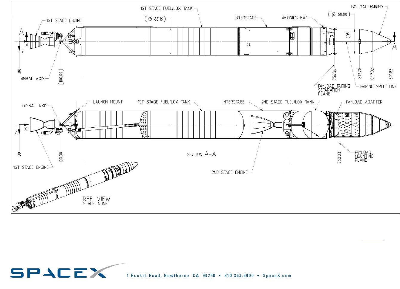
2.8. VEHICLEAXES/ATTITUDEDEFINITIONS
FIGURE2‐5:FALCON1LAUNCHVEHICLELAYOUTANDCOORDINATESYSTEM(ALLSTATIONLOCATIONANDDIMENSIONUNITSARESHOWNININCHES)
Falcon1elayoutandcoordinatesystemdrawingsareinwork.Tobeaddedtothedistributionlistforimmediatenotificationofavailability,clickhere.
Copyright–2008
Falcon1User’sGuide‐D000973Rev.7Page|18
Copyright–2008
3. REQUIREMENTS&ENVIRONMENTS
3.1. MASSPROPERTIES
ThePayloadProviderwillneedtoprovidetheCenterofGravitylocationwithin±¼inchinthePayload
QuestionnaireinSection7.Falcon1canreadilyaccommodatepayloadswiththefollowingmassproperties:
TABLE3‐1:LAUNCHVEHICLEMASSPROPERTYLIMITATIONS
Characteristic Value
MassUpto1010kg(2200lbs)
CGoffsetFromcenterlineFromseparationplane
SeeFigure3‐1 SeeFigure3‐2
StiffnessAxialLateral
>25Hz>25Hz
0
0.5
1
1.5
2
2.5
0 200 400 600 800 1000 1200 1400 1600
Payload Weight(lb)
CGlOffset (In)
FIGURE3‐1:ALLOWABLECGOFFSETFROMCENTERLINE
0
20
40
60
80
100
120
0 200 400 600 800 1000 1200 1400 1600
Payload Weight(lb)
CGOffset (In)
FIGURE3‐2:ALLOWABLECGOFFSETFROMSEPARATIONPLANE
Payloadswithlowernaturalfrequenciescanlikelybeaccommodated,butmayrequireanadditionalloadcycleand
enhancedguidancesoftware.
Falcon1emasspropertiesaretobedetermined,butwillbesimilartothoseofFalcon1.

Falcon1User’sGuide‐D000973Rev.7
Page|19
Copyright–2008
3.2. PAYLOADINTERFACES
Thelaunchvehiclewillprovideasignaltothepayloadatseparationtoinitiatepayloadpower‐up.Alternate
configurationsforseparationsignals(break‐wires,separationswitchesmonitoreddirectlybythepayload,orother
configurations)canbeaccommodatedasoptions.
An8in(0.2m)diameteraccessdoorisincludedinthefairingforcontingencypurposesonly.Undernominal
operatingconditions,allprocessingthatrequiresaccesstothepayloadmustbecompletedpriortofairing
installation.
Payloadswithconsumablesmustincludetheabilitytode‐tankthroughthefairingaccessdoorwhileonthelaunch
pad.
3.2.1. FALCONPAYLOADATTACHFITTINGS
PayloadsinterfacewiththelaunchvehiclebymeansofaPayloadAttachFitting(PAF).Falcon1LaunchVehicles
offerastandardandmodifiablePAFtoaccommodatecustomerneeds.Themechanicalinterfaceforthestandard
serviceis38.81in(0.986m)boltcirclewith60attachpoints.
3.2.2. TESTFITTINGSANDFITCHECKPOLICY
Amechanicalfitcheck(includingelectricalconnectorlocations)maybeconductedwiththespacecraftora
representativespacecrafttemplateusingamechanicaltemplate.Thisistypicallydonepriortoshipmentofthe
spacecrafttothelaunchsite.SpaceXpersonnelwillbeavailabletoconductthisactivityattheSpaceXfacility.
SpecificrequirementsforthefitcheckwillbeworkedwiththeSpaceXMissionManagerduringtheintegration
process.
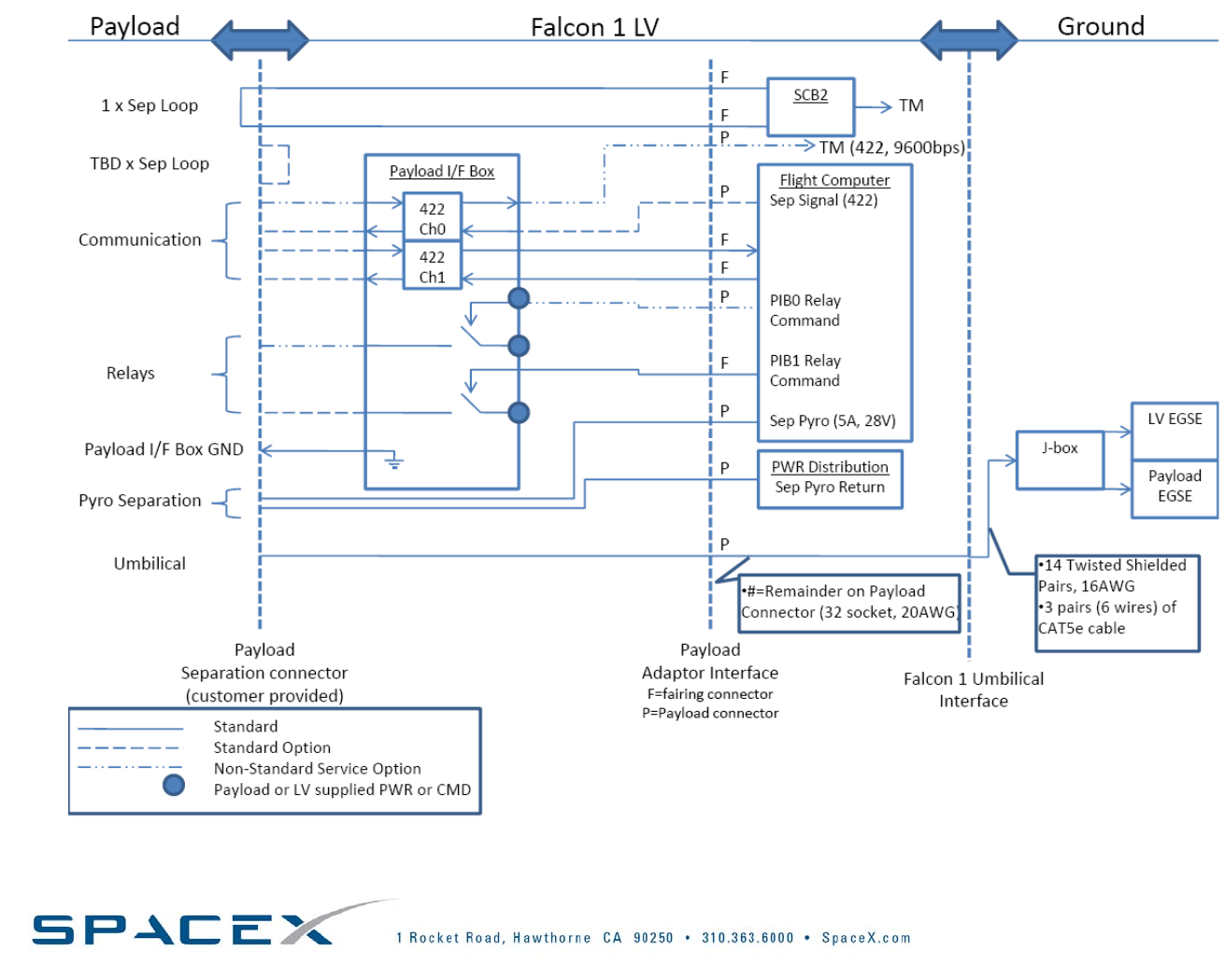
3.2.3. ELECTRICALDESIGNCRITERIA
TheelectricalinterfaceforgroundandflightoperationsisshowninFigure3‐3.Itispreferredthatthesatelliteis
poweredOFFduringlaunch.Ifthesatelliteison,itmaynottransmitandspecialprecautionsmustbetakento
eliminatethepotentialforinterference.
TheelectricalinterfaceprovidesflexibilityonthegroundthroughEthernetorpassthroughcables.TheEthernetis
asharedresourceandthepayloadshouldthereforenotsaturatethenetwork.Notethatthedistancebetween
MissionControlandthevehicleissignificantandthattheEthernetdatalineservesastheonlyconnectionbetween
MissionControlandthelaunchpad.
Forremotecontrolofbatterychargerslocatedatthelaunchpadandothergroundequipment,upto4relaysare
available(withamaximumloadof3Aat28V)throughthepadcomputer.
Grounding‐Thesatellitemountinginterfacemustbeconductive.Theelectricalresistancewillbeverifiedtobe
<0.1Ωpriortotheassemblyofthepayloadontotheseparationsystem.
Withthestandardinterface,theconnectortypesandpindesignationwillbedeterminedduringtheintegration
process.Asanoptionalservice,anenhancedtelemetrysystemcanbesupplied.
Falcon1User’sGuide‐D000973Rev.7Page|20
FIGURE3‐3:FALCON1ELECTRICALINTERFACETOPAYLOADREMOTELAUNCHCENTERS,BLOCKHOUSE‐TO‐SPACECRAFTWIRING
Copyright–2008
Falcon1User’sGuide‐D000973Rev.7Page|21
3.3. DOCUMENTATIONREQUIREMENTS
Thefollowingtablesprovideanoverviewofstandardrequiredinformationanddocuments.Theselistsrepresent
minimumrequirementsandmaynotbeinclusive,dependingonthepayload.Inadditiontothefollowingspecific
documents,inputisrequiredtosupportdevelopmentoftheICD,launchcountdownprocedures,andtheLRR
package.
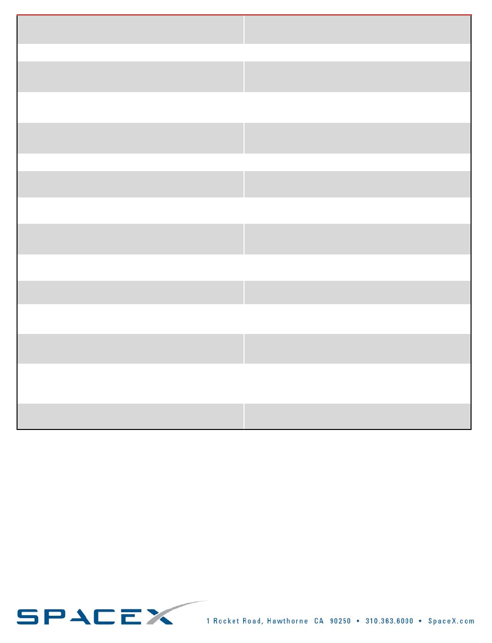
TABLE3‐2:REQUIREDDOCUMENTSFORALLPAYLOADS
ItemDescription
Payload
Questionnaire
ThePayloadQuestionnaire,Section7,isdesignedtoprovideinitialinformationaboutthePayloadto
SpaceXsothatmissionfeasibilitymaybeassessedandinitialrequirementsdefined.
Mathematical
Modelfor
Dynamic
Analysis
ApayloadmathematicalmodelisrequiredforuseinaCoupledLoadsAnalysis(CLA).Requiredmodel
informationsuchasspecificformat,degrees‐of‐freedomrequirementsandothernecessaryinformation
willbesuppliedaspartofthestandardmissionintegrationprocess.
Inputto
InterfaceControl
Document
TheInterfaceControlDocumentdescribesallmission‐specificrequirements.Whilethisdocumentis
generatedandconfigurationcontrolledbySpaceX,inputisrequiredfromtheCustomer.
Environmental
Statement
TheEnvironmentalstatementdefinesthePayloadProvider’sapproachforqualificationandacceptance
tests.Itshouldcontaingeneraltestphilosophy,testingtobeperformed,testobjectives,testspecimen
configuration,testmethodsandaschedule,butdoesnotneedtoincludeactualtestprocedures.
RadioFrequency
(RF)Applications
ThePayloadContractorisrequiredtospecifytheRFtransmittedbythePayloadduringgroundprocessing
andlaunchoperations.AnRFdatasheetspecifyingindividualfrequencies,namesandqualificationsof
personnelwhowilloperatePayloadRFsystems,transmissionfrequencybandwidths,frequencies,
radiateddurationsandwattagewillbeprovidedtoSpaceX.SpaceXwillprovidethisinformationtothe
appropriateagenciesforapproval.
LaunchVehicle
Insignia
Ifmission‐specificinsigniaistobeplacedonthelaunchvehicle,theCustomershouldsubmitthe
proposeddesignnotlaterthan5monthsbeforelaunchforreviewandapproval.Followingapproval,
SpaceXwillhavetheinsigniapreparedandplacedonthelaunchvehicle.
PayloadDesign
Overviewwith
Graphicsand
Models
AdescriptionofthePayloaddesignandassociatedgraphics,configurationdrawings,andsolidmodels
arerequiredasearlyaspossible.Thedrawingsshouldshowexpectedandmaximumdimensions.Any
solidmodelsshouldbedeliveredtoSpaceXinSTEPformat.Detailcanberemovedsolongasouter
dimensionsareaccurate.
LaunchSite
OperationsPlans
andProcedures
LaunchSiteOperationsPlansanddetailedproceduresmustbesubmittedsoSpaceXcanprovideall
governmentagencieswithadetailedunderstandingoflaunchsiteactivitiesandoperationsplannedfor
eachmission.Thedocumentshoulddescribeallaspectsoftheprogramtobeperformedatthelaunch
site.Operatingproceduresmustbesubmittedforalloperationsthatareaccomplishedatthelaunch
site.(Note:HazardousproceduresmustbeapprovedbyRangeSafety.)
Safety
Documentation
Safetydocumentationincludinghazardanalysesandreports,vehiclebreakupmodels(debrisdata)and
detaileddesignandtestinformationforallhazardoussystems(batteries,pressurizedsystemsorother
hazardousorsafetycriticalmaterials,propellantdata)mustbesubmitted.
Copyright–2008
Falcon1User’sGuide‐D000973Rev.7Page|22
TABLE3‐3:ADDITIONALREQUIREDDOCUMENTSFORNON‐USPAYLOADS
ItemDescription
Applicationfor
Payload
Determination
Non‐USPayloadsmustsubmitanApplicationforPayloadDetermination.
LaunchSite
VisitorDetails
Toobtainappropriatepermissions,SpaceXrequiresinformationforCustomerpersonnelthatwillvisitthe
launchsite.
LaunchSiteGSE
Details
DetailsonGroundSupportEquipment(GSE)thattheCustomerwillbringtothelaunchsiteisrequiredfor
submittalofimport/exportpaperwork,partofthestandardmissionintegrationprocessfornon‐US
payloads.
Copyright–2008
Falcon1User’sGuide‐D000973Rev.7Page|23
3.4. PAYLOADENVIRONMENTS
Falcon1LaunchVehiclesuseallliquidpropellantwithasinglestagingevent,lowthrust‐to‐weight,andlow
dynamicpressureflight.Theenvironmentspresentedhereareintendedtoreflecttypicalmissionlevels;mission
specificanalysesaretobeperformedanddocumentedintheInterfaceControlDocument(ICD)perpayloadneeds.
Specificindividualenvironmentsaredefinedinthefollowingsections.
Throughoutpre‐flightandflightoperations,variousenvironmentalcontributionsmaybecomemoreorless
important.Certainevents,suchaspyrotechnicfiringsandstageburnout,addspecificquasi‐staticordynamic
loadsforspecifieddurations,whichmayormaynotneedtobeaddedtootherenvironmentsexperiencedatthe
sametime.
3.4.1. TRANSPORTATIONENVIRONMENTS
SpaceXisintheprocessofquantifyingthetransportationenvironmentsthataspacecraftwillencounterwhile
beingtransportedfromthepayloadreceivingsitetothepayloadprocessinghangarandlaunchpad.Forlaunches
fromReaganTestSite,transportationwillbebybothwheeledvehicleandoceanvessel.Untilthetransportation
environmentsarefullyquantified,SpaceXrecommendsthatallpayloadsusetheTransportationEnvironment
GuidelinesasspecifiedinMIL‐STD‐810.
Theambienttemperature,humidity,andcleanlinessenvironmentswillnotbecontrolledduringtransportationto
thelaunchsite.Allpayloadtransportationcontainersshouldbedesignedtoprotectthepayloaduntilitisfinally
removedfromthecontainerintheenvironmentallycontrolledpayloadprocessingfacility.
3.4.2. HUMIDITY,CLEANLINESSANDTHERMALCONTROL
Thepayloadwillbeexposedtothermalenvironmentsandcleanlinesslevelsforthevariousmissionphases,as
summarizedinTable3‐4.Allbulkmaterialinthepayloadcompartmentmeetstotalmassloss(TML)oflessthan
1.0%andacollectedvolatilecondensablemass(CVCM)oflessthan0.1%.StandardcleanlinessisVCII,butVC1
canbeaccommodated.Thetemperaturesofthecylindricalsectionofthefairingwillnotexceed93.3°C(200°F).
TABLE3‐4:SUMMARYOFTHERMALANDHUMIDITYENVIRONMENTS
Temperature
HeatingLevelCleanlinessLevel
Humidity
Level
Encapsulated
during
transport*
Airpurgeat21°C±5.5°CVisiblyclean30‐60%RH
Encapsulated
andstacked
Airpurgeat21°C±5.5°CVisiblyclean
Filtered(3micron)purified
airpurge
Positivepressurewillkeep
fairingenvironmentclean.
30‐60%RH
LaunchRadiatedenvironment:15‐150°CTBD
Conductedenvironment:15‐150°CTBD
Timehistorywillbeprovided.
Positivepressurewillkeep
fairingenvironmentclean.
N/A
Fairing
Separation
Fairingseparatedwhenaero‐thermalheatingis
lessthan1135W/m2.
N/A
N/A
*Conditionedairmaybedisconnectedfornomorethan2hrsduringlaunchvehicleerectionprocedures
Copyright–2008
Falcon1User’sGuide‐D000973Rev.7Page|24
Copyright–2008
3.4.3. PAYLOADAIRCONDITIONING
Bothwithinthecleanroomandafterencapsulation,thepayloadwillbeprovidedwithconditionedairmaintained
at21degC+/‐ 5.5deg,andbetween30‐60%humidity.Conditionedairwillbefilteredto3microns.After
encapsulation,conditionedairwillbeprovidedviaaflexibleductsystemtoafairingportconfiguredtodirectthe
airintothefairing.Adiverterwillpreventdirectimpingementonthepayload.Thisflexibleductwillprovide
conditionedairwhilestillresidentinthecleanroom,andaftermatingtothelaunchvehicle.Theremaybeashort
breakinconditionedairduringthemovementoftheencapsulatedpayloadformthecleanroomtothevehicleof
notmorethan2hour.Conditionedairwillalsobeprovidedcontinuouslyonceatthepad.SpaceX’spayload
conditioningsystemisredundanttoensureminimalinterruptionintheeventofafailure.
3.4.4. LAUNCHANDFLIGHTENVIRONMENTS
Thissectionprovidesdetailsonthemaximumpredictedenvironments(MPE)thepayloadwillexperienceduring
Falcon1LaunchVehiclegroundoperations,integration,flight,andinitialorbitaloperations.Theenvironmental
designandtestcriteriapresentedherehavebeencalculatedusingthemostsophisticatedandaccuratemethods
availableand,wherepossible,havebeencorrelatedwithlaunchdataand/orscaledwithdatafromvehicleswith
similarenginetypes,materials,construction,andsize.Becausethedataisprimarilybasedoncalculationand
verifiedthroughgroundandflighttesting,appropriatemarginsareaddedandindicated.(Additionalmarginsover
thosepresentedherearenotrecommended,butareuptouserdiscretion).
Launchloadsexperiencedinthefirsttenminutesofapayload’slifedriveitsstructuraldesignanditsmass.After
separation,thesatellitespendstherestofitstimeinmicrogravityanddoesnottypicallyexperiencesuchloads
againduringitsusefullife.Asaresult,SpaceXhasgonetogreatlengthstominimizelaunchloads.Amongother
importantfactors,Falcon1LaunchVehiclesusenosolidfuelboosters,havelowthrustlevels,andalowthrust‐to‐
weightratio.Table3‐5,below,specifiestherelativeperiodsofloadingeventsanddetailedinformationabout
specificloadscanbefoundinsubsequentsections.BecausetheFalcon1LaunchVehicleFamilyisstillintheearly
stage,theseenvironmentswillbeupdatedasnewdatabecomesavailable.Tobeupdatedwhenthisinformation
isavailable,clickhere5.
TABLE3‐5:SUMMARYOFENVIRONMENTALCONDITIONSATVARIOUSFLIGHTEVENTS
FlightEvent
TypicalFlight
Time(s)
Steady/Quasi‐
StaticLoading
Transientor
ShockLoadsAcousticLoads
Random
Vibration
Liftoff0‐5LowYes Yes Yes
Subsonic5‐50YesVeryLow VeryLowVeryLow
Transonic50‐65YesVeryLow Yes Yes
Maxq65‐80YesVeryLow Yes Yes
Stage1Burnout170YesYes Low Low
StageSeparation172LowYes VeryLowVeryLow
Stage2Burn174‐540YesLow No Low
Stage2Burnout542YesLow No VeryLow
PayloadSeparation560YesYes No No
5Email:Lauren@spacex.com
Falcon1User’sGuide‐D000973Rev.7Page|25
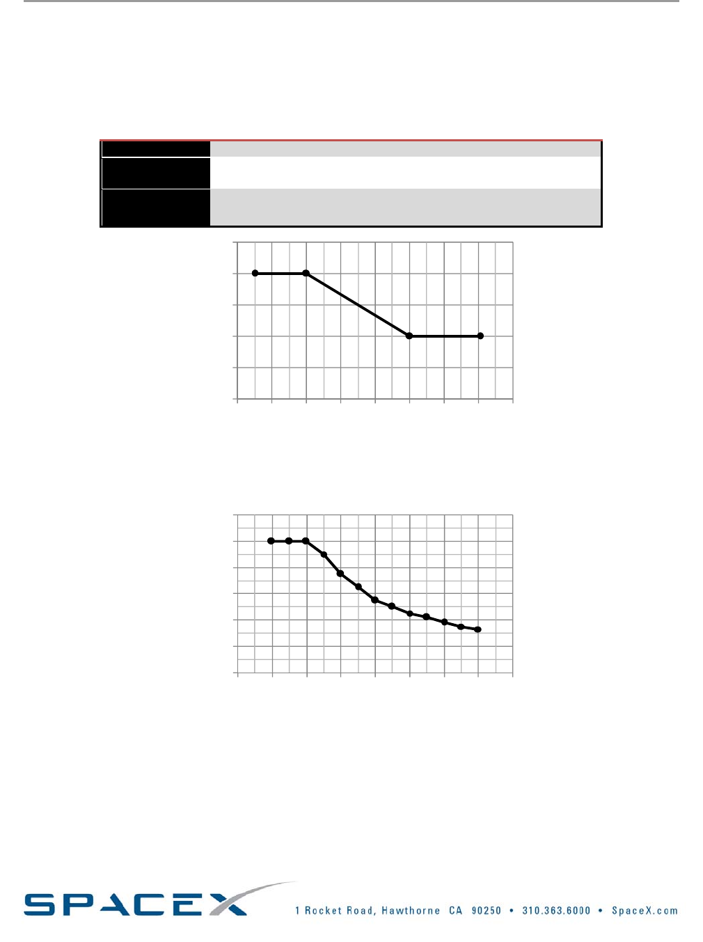
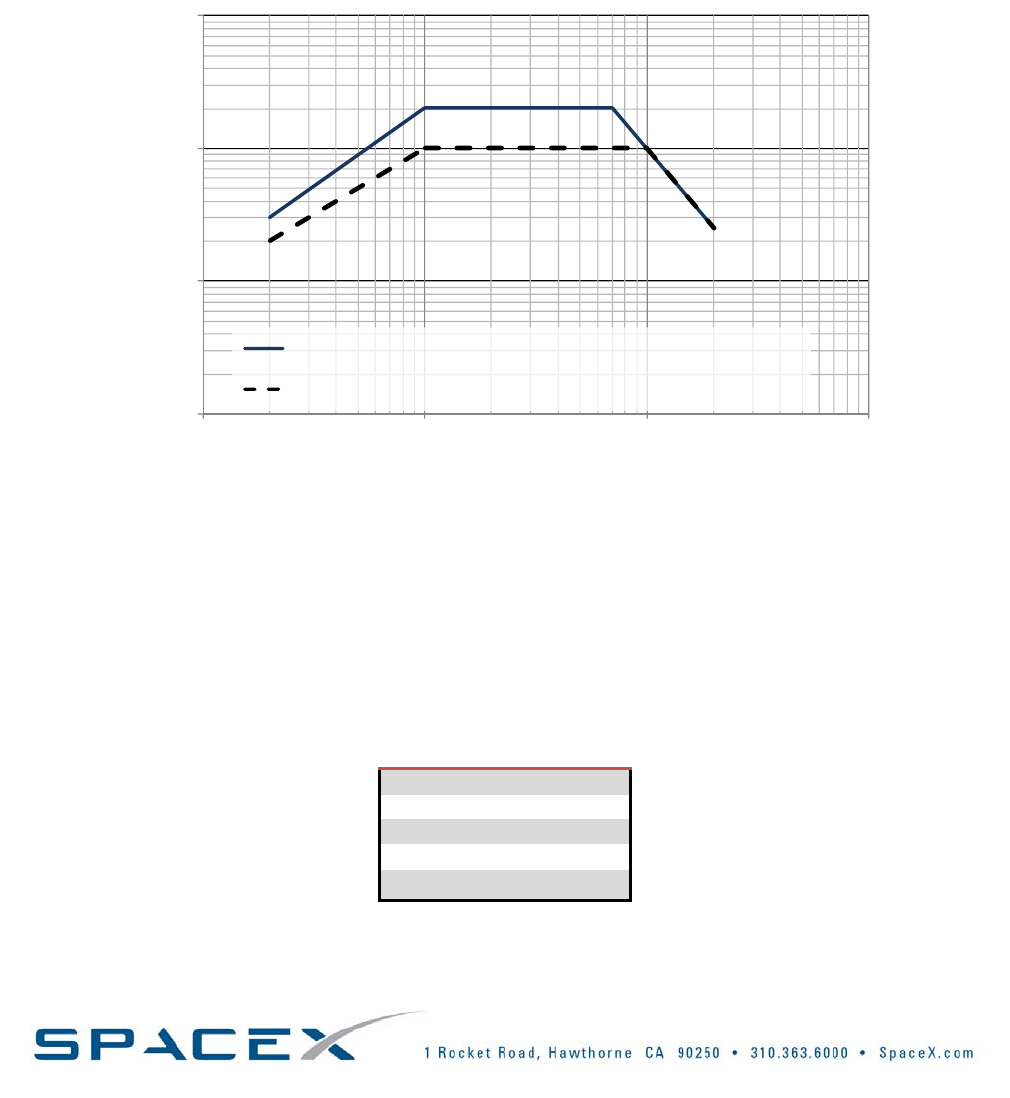
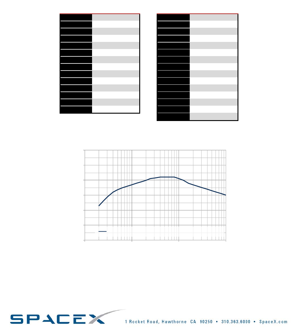
3.4.4.1. QUASISTATICLOADS
Duringflight,thepayloadwillexperiencearangeofaxialandlateralacceleration.Axialaccelerationisdetermined
bythevehiclethrusthistoryanddrag,whilemaximumlateralaccelerationsareprimarilydeterminedbywind
gusts,enginegimbalmaneuversandothershort‐durationevents.Conservativeloadsusedforpayloaddesignare
summarizedinTable3‐6,andanexampletrajectorytimehistoryaxialaccelerationisshowninFigure3‐4.These
loadfactorsweredevelopedforapayloadwithfirstfundamentalfrequenciesat25Hzorabovewhenmountedto
theseparationplane.Forspacecraftthataremoreflexible,thedesignlimitloadfactorswillbehigher.
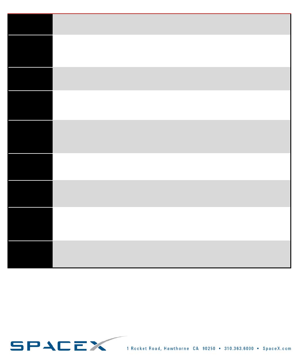
TABLE3‐6:SUMMARYOFPAYLOADDESIGNCGLIMITLOADFACTORS,NOMINALFALCON1MISSION
FlightEvent
Quasi‐staticLoadFactors
Axial(g):Steady±Dynamic(Total)Lateral(g)
GroundHandling0.52.0
LiftOff1.2±0.4(0.8/1.6)0.50
Maxqα2.0±1.0(3.0/1.0)0.75
Stage1burnout6.4±1.25(7.7/5.2)0.75
Stage2Ignition3.2±.25(3.0/3.4)to6.0±.25(5.75/6.25)0.25
Stage2burnout4.5±0.5(5.0/4.0)to6.5±0.5(7.0/6.0)0.25
0
1
2
3
4
5
6
7
0 100 200 300 400 500 600
Acceleration(g)
Time(s)
FIGURE3‐4:EXAMPLESTEADYSTATEAXIALACCELERATIONTIMEHISTORYFORFALCON1
Notethataccelerationsarepayloadweightandtrajectorydependentandwillvary.
Copyright–2008
Falcon1User’sGuide‐D000973Rev.7Page|26
TheprocesstodetermineloadsforanyspecificpayloadistoexecuteaCoupledLoadsAnalysis(CLA).Formore
flexiblespacecraft,SpaceXwillcompleteacoupledloadscycleasearlyaspossibletoidentifyanyissuesassociated
withdynamiccoupling.Theanalysisshouldbedonewithamodelverifiedbytest(sinesweep,modalsurvey,etc.)
Ifcouplingexists,thendesignsolutionsmustbeidentifiedtoreduceoreliminatetheimpactofthecoupling.The
newlydesignedsystemwillbecharacterizeddynamicallybyupdatingstructuraldynamicsmodelsandrunning
anotherloadscycle.Thisprocesscontinuesuntilasolutionisidentifiedandproventohaveadequatestructural
strength.ThefollowingmodeshavebeendeterminedfortheFalcon1LaunchVehicles:
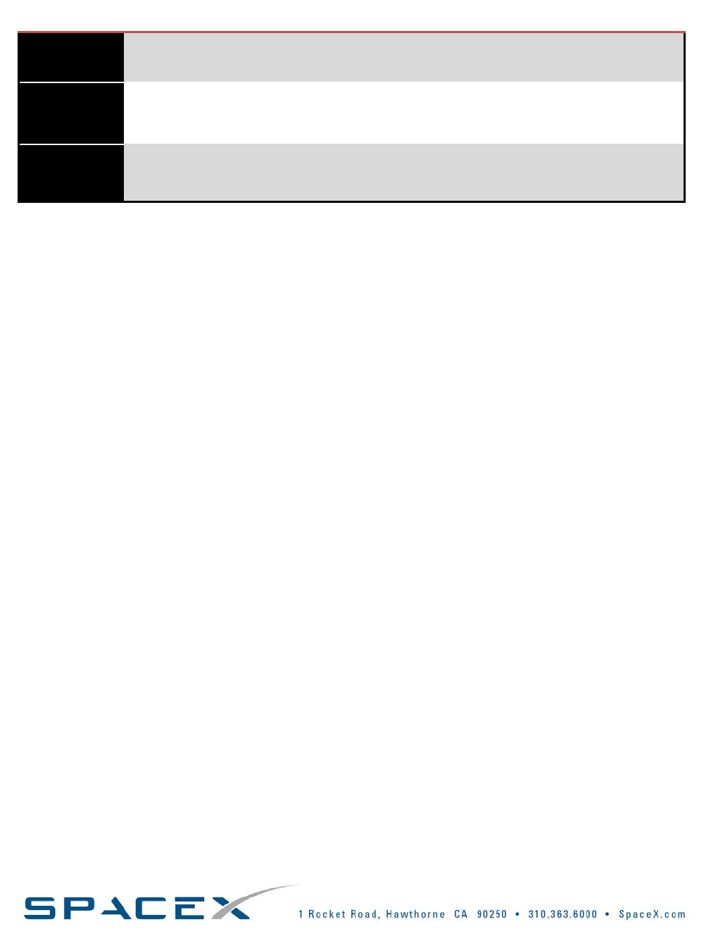
TABLE3‐7:FALCON1MODES
LiftoffMaxQ@73.5secBurnout@168.1s
1stBending~5Hz~6Hz~13Hz
2ndBending~14.5Hz~20Hz~27Hz
Axial~16&~17Hz~17&~22Hz~35&~43Hz
Inadditiontostructuralimpacts,theguidanceandcontrolassociatedwithamoreflexiblesystemmustbe
addressed. Inthiscase,oncethecombinedbendingmodesareidentified,aguidancesimulationwillberunto
ensureadequatecontrolauthorityexistsforthedynamicsystem.
Copyright–2008
Falcon1User’sGuide‐D000973Rev.7Page|27
3.4.4.2. RANDOMVIBRATIONENVIRONMENT
Thepayloadvibrationenvironmentisgeneratedbyacousticnoiseinthefairingandbyengineandaero‐induced
vibrationthatistransmittedthroughthevehiclestructure.Themaximumpredictedenvironment(MPE)was
derivedfrommeasurementsrecordedatthepayloadinterfaceduringthefull‐scalefairingacoustictestandduring
thefirstFalcon1flight.Variouspayloadweightswereusedduringtheacoustictesttoquantifythevibrationlevel
dependenceonpayloadmass.ThepayloadMPEwassubsequentlyverifiedwithdatafromthesecondFalcon1
flight.TherandomvibrationMPEforFalcon1isshownbelowinFigure3‐5. Notethatthesevaluesinclude
appropriatemarginsduetouncertaintyandthatthisdatawillbecontinuouslyrefinedasadditionalflightdatais
collected.ThecornerfrequenciesaresummarizedinTable3‐8.
.
0.0001
0.001
0.01
0.1
10 100 1000 10000
Falcon 1 Payload Interface Random Vibration MPE, 4.7 grms (g^2/Hz)
MIL-STD-1540E Minimum Vibration ATP for Spacecraft (3.8 grms)
Frequency (Hz)
PSD(g
2
/HZ)
FIGURE3‐5:FALCON1PAYLOADINTERFACERANDOMVIBRATION
NotethatPSDvaluesaremassdependentandthoseshownherecorrespondtoapayloadwithamassof1000lbs
(454kg).PleasecontactSpaceXforpayloadspecificPSDvalues.
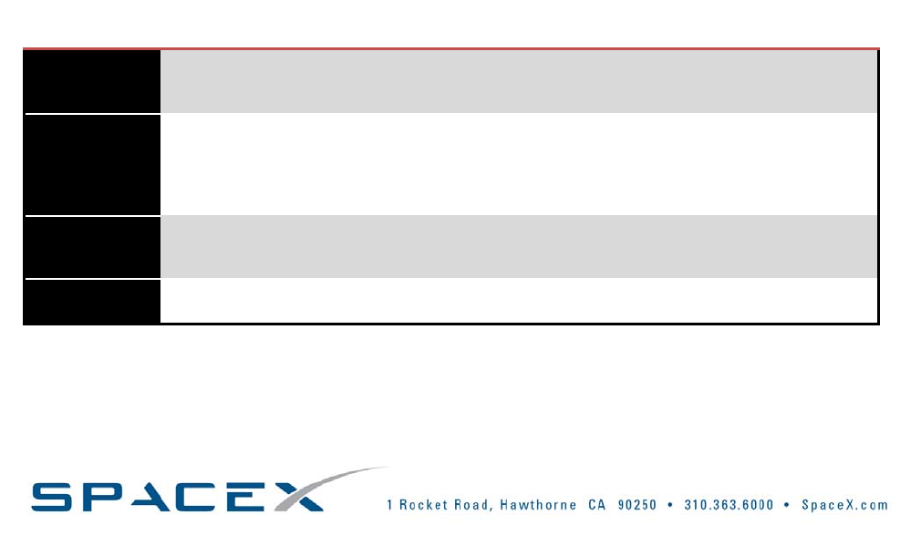
TABLE3‐8:FALCON1RANDOMVIBRATIONMAXIMUMPREDICTEDENVIRONMENTPSDVALUES
Frequency
(Hz)
PSD*
(g2/Hz)
20 0.003
100 0.02
700 0.02
2000 0.0025
Grms4.7
*PSDvaluescorrespondtoapayloadwithamassof1000lbs(454kg).
Copyright–2008
Falcon1User’sGuide‐D000973Rev.7Page|28
3.4.4.3. SHOCKENVIRONMENT
Therearefoureventsduringflightthatarecharacterizedasshockloads:
1)Vehiclehold‐downreleaseatlift‐off
2)Stageseparation
3)Fairingseparation
4)Payloadseparation
Oftheshockevents,(1)and(2)arenegligibleforthepayloadrelativeto(3)duetothelargedistanceandnumber
ofjointsoverwhichshocks(1)and(2)willtravelanddissipate.Maxshockloading(3)and(4)ismeasuredand
scaledforvariouspayloadweightsusingindustrystandardpractices.Theresultingmaximumshockenvironment
predictedatpayloadinterfaceisshowninFigure3‐6.Note:Enginestart‐upandshut‐downtransientsaresmallin
magnitudecomparedto(1)–(4).
10
100
1000
100 1000 10000
Frequency(Hz)
SRS (g‐peak)
FIGURE3‐6:FALCON1BASELINESHOCKRESPONSEATSEPARATIONPLANEDUETOFAIRINGSEPARATION
Note:TheSRSvaluesaremassdependentandthoseshownherecorrespondstoapayloadwithamassof1000lbs
(454kg).PleasecontactSpaceXforpayloadspecificSRSvalues.Also,Figure3‐6doesnotincludeshockassociated
withpayloadseparationbecausemultipleseparationsystemsareaccommodated.IfastandardSpaceXseparation
systemisused,SpaceXcanprovidepayloadseparationshocklevels.
Copyright–2008
Falcon1User’sGuide‐D000973Rev.7Page|29
3.4.4.4. ACOUSTICENVIRONMENT
Duringflight,thepayloadwillbesubjectedtoavaryingacousticenvironment.Levelsarehighestatliftoffand
duringtransonicflightduetoaerodynamicexcitation.Falcon1willmakeuseofacousticblanketingtoreducethe
acousticenvironmentandanominal(minimal)5cmthickblanketconfigurationisassumedforthepredicted
environment.Flightdatawereusedtopredicttheworst‐caseacousticenvironmentbelow.Asummaryof
acousticMPEisshowninTable3‐9andplottedinFigure3‐7.
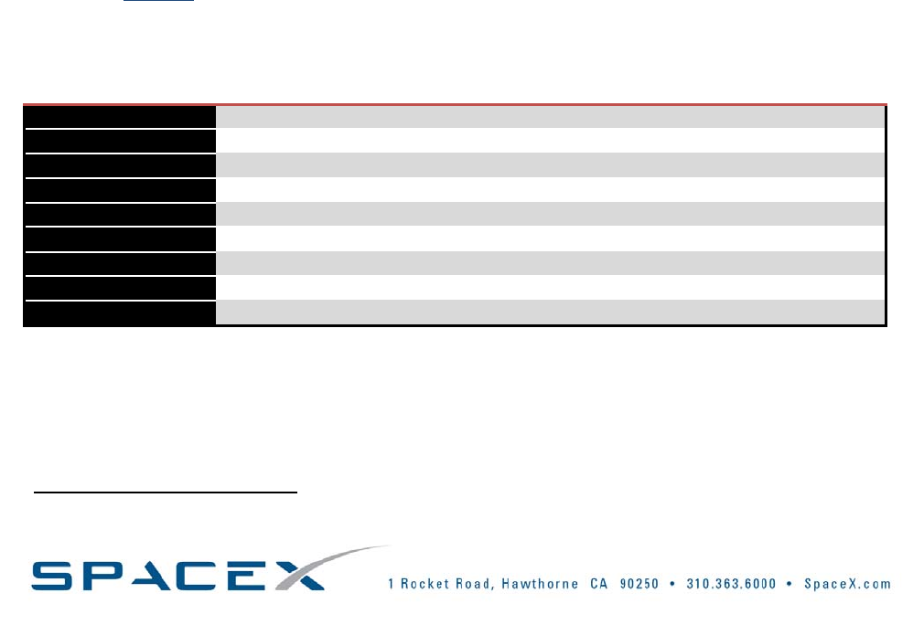
TABLE3‐9:FALCON1PAYLOADACOUSTICENVIRONMENTASSUMINGNOMINAL5CMACOUSTICBLANKETS
Frequency
(Hz)
Falcon1Payload
AcousticMPE*
Frequency
(Hz)
Falcon1Payload
AcousticMPE*
20103 500122
25106 630122
31109 800122
40112 1000121
50113.5 1250120
63115 1600118
80116 2000117
100117 2500116
125118 3150115
160119 4000114
200120 5000113
250121 6300112
315121.5 8000111
400122 10000110
OASPL132.6
*EmptyFairing(133dBOASPL)
80
90
100
110
120
130
140
10 100 1000 10000
Falcon 1 Payload Acoustic MPE - Empty Fairing (133 dB OASPL)
SPL(dB,ref20uPa)
Frequency(Hz)
FIGURE3‐7:SOUNDPRESSURELEVEL(SPL)SPECTRAFORFALCON1ASSUMING2INCHACOUSTICBLANKETS
Copyright–2008
Falcon1User’sGuide‐D000973Rev.7Page|30
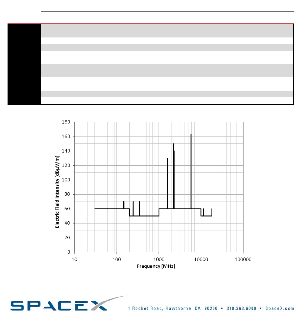
3.4.4.5. RFENVIRONMENT
PayloadcustomersmustensurethatspacecraftmaterialsorcomponentssensitivetoanRFenvironmentare
compatiblewithboththelaunchpadenvironmentandtheRFenvironmentduringflight.
TheFalcon1fairingattenuatesthelaunchvehicletransmissionsduringlaunchpadoperationsandflight,upto
fairingseparation.Afterfairingseparation,theC‐bandtransmissionswillnotexceed3.38dbm(pulsed)atthe
CenterofGravity(CG)ofthefairing.TheS‐bandtransmissionsatthistimewillnotexceed‐4.87dbm(continuous)
attheCGofthefairing.WerecommendpoweringthepayloadOFFduringlaunchtominimizetheriskof
interferenceanddamagetothepayload.ThespacecraftRFcharacteristicsshouldbesuchthatthereisno
interferencewiththelaunchvehicleRFsystemslistedinTable3‐10.
TABLE3‐10:LAUNCHVEHICLERFSYSTEMCHARACTERISTICS
Source
1234567
FunctionCommand
Destruct
Tracking
Transponder
Tracking
Transponder
Stg1Launch
VehicleTelem
Stg2Launch
VehicleTelem
Launch
VehicleVideo
GPS
RoleReceiveTransmitReceive Transmit Transmit TransmitReceive
BandUHFC‐BandC‐Band S‐Band S‐Band S‐BandL‐Band
Frequency
(MHz)
416.5
or425
57655690 2221.5 2213.5 2251.51575.42
BandwidthN/AN/A14MHz@
3dB
0.6MHz@
3dB
1.2MHz@
3dB
8MHz@3dB20.46MHz
Power
Output
N/A400WpeakN/A 5W 10W 10WN/A
Sensitivity‐107dBmN/A‐70dBm N/A N/A N/AN/A
ModulationTonePulseCodePulseCode PCM/FM PCM/FM FM/FMPRNCode
FIGURE3‐8:FALCON1WORSTCASERADIATEDENVIRONMENT
Copyright–2008
Falcon1User’sGuide‐D000973Rev.7
Page|31
Copyright–2008
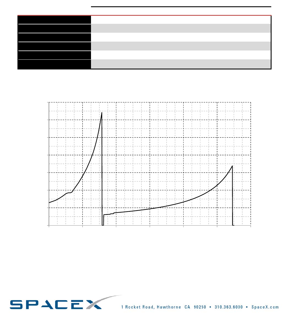
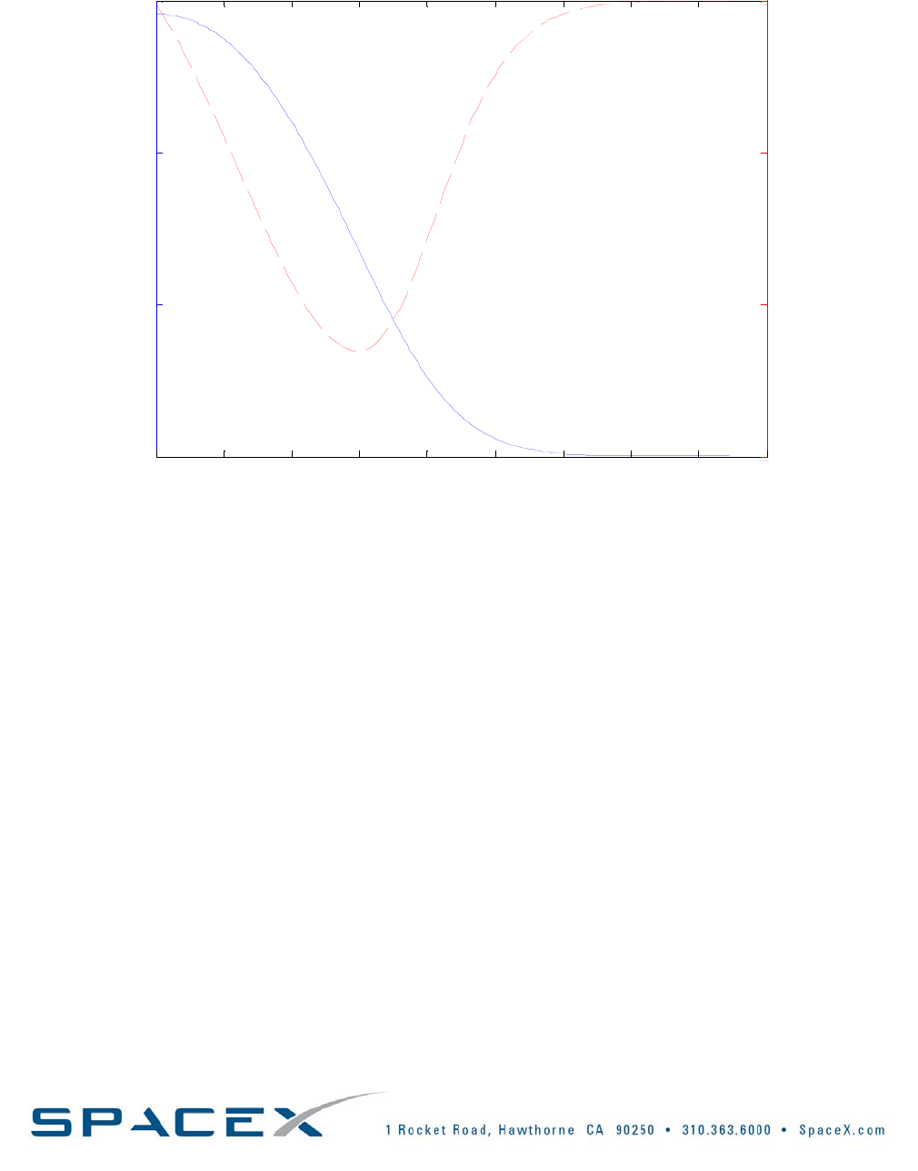
3.4.4.6. FAIRINGINTERNALPRESSUREENVIRONMENT
ThefairingflightpressureprofileisdefinedintheFigure3‐9.Theascentpressuredecayratewillnotexceed0.23
psi/sec.
020 40 60 80 100 120 140 160 180
0
5
10
15
Pressure (psi)
020 40 60 80 100 120 140 160 180
-0.3
-0.2
-0.1
0
Time since Lift-Off (sec)
Depressurization Rate (psi/sec)
Rev K vb002
FIGURE3‐9:EXAMPLEDEPRESSURIZATIONENVIRONMENTSANDDEPRESSURIZATIONRATES
Falcon1User’sGuide‐D000973Rev.7Page|32
Copyright–2008
4. FACILITIES
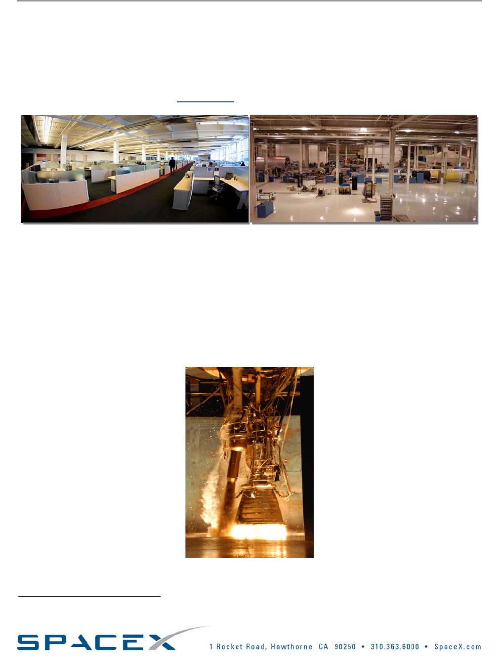
4.1. HEADQUARTERS–HAWTHORNE,CALIFORNIA
SpaceXheadquartersareconvenientlylocatedinHawthorne,California,afewmilesinlandfromLosAngeles
InternationalAirport.The500,000+squarefootdesignandmanufacturingfacilitymeasuresoverhalfamillion
squarefeet–rankingamongthelargestmanufacturingfacilitiesinCalifornia.TwocompleteFalcon9swillfitend
toendalongtheshortlengthofthebuilding.Forproduction,therearethreeFalcon1lines,threeparallelFalcon9
lines,nearlytwodozenMerlinengineassemblystations,andDragoncapsuleproductionareas.Currentand
potentialcustomersareencouragedtoarrangeatour6whenintheLosAngelesarea.
FIGURE4‐1:HAWTHORNE,CALIFORNIAHEADQUARTERS
4.2. WASHINGTON,DC
SpaceX’sgovernmentoutreachandlicensingteamislocatedinWashington,DC.
4.3. TESTFACILITY‐CENTRALTEXAS
Structuralandpropulsiontestsareconductedattherapidlygrowingandexpandingtestfacilitylocatedin
McGregor,Texas,justwestofWaco.Convenientlylocated2hoursfrombothAustinandDallas,thesiteisfully
staffedwithtestengineers,techniciansandmanagementpersonnel.Duringpreparationandtesting,thesitealso
playshosttoengineersfromCaliforniaandmissionassurancepersonnel.
FIGURE4‐2:MERLINENGINEINTESTINGATSPACEX’STEXASTESTFACILITY
6 Email:Lauren@spacex.com
Falcon1User’sGuide‐D000973Rev.7Page|33
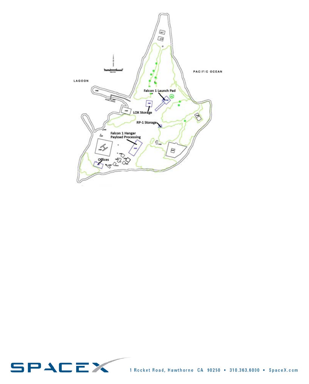
4.4. LAUNCHSITE–KWAJALEINATOLL
SpaceXiswillingtolaunchfromanylocationcustomerschoose,providedthebusinesscaseforestablishingthe
requestedlaunchsiteexists.SpaceXhasanoperationalFalcon1launchsiteattheKwajaleinAtoll,about2500
milessouthwestofHawaii.TheFalcon1launchfacilitiesaresituatedonOmelekIsland,partoftheRonaldReagan
BallisticMissileDefenseTestSite(RTS)atUnitedStatesArmyKwajaleinAtoll(USAKA).Agenerallayoutofthe
launchfacilityispresentedinFigure4‐3,below.
FIGURE4‐3:OMELEKISLANDLAUNCHFACILITIESATREAGANTESTSITE
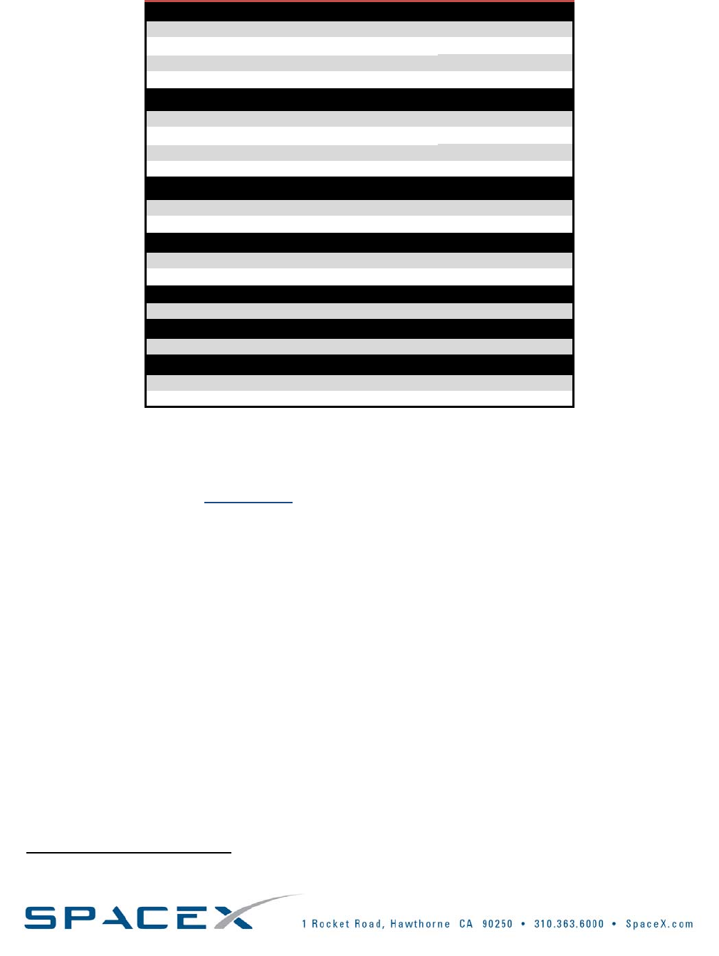
4.4.1. PROCESSINGSERVICESANDEQUIPMENT
TheservicesandequipmentprovidedforsatelliteprocessinginthecleanroomareaareshowninTable4‐1.
Spacecraftlimitationsfortheprocessingfacilityrequirethatnomonoorbi‐propellantsbeonboard.SpaceX
baselinesa100,000classcleanroomfacilityforpayloadprocessing.HangaronOmelekhousesthePayload
ProcessingFacility(PPF).TheinteriordimensionsaregiveninTable4‐1.
NearthePPF,acustomerofficeareawillbeprovidedthatcontainsdesks,officechairs,oneclassAtelephoneline,
andhighspeedinternetconnectivity.Faxserviceisalsoavailable.Portableunitswillsupplysanitationneedsfor
bothSpaceXandpayloadsupportpersonnelatthelaunchpad.Payloadsupportpersonnelarewelcometoshare
smallamountsofrefrigeratorspace,coffeemachines,microwaves,andotherconveniencesthatmaybeavailable.
Copyright–2008
Falcon1User’sGuide‐D000973Rev.7
Page|34
Copyright–2008
TABLE4‐1:SERVICESANDEQUIPMENTFORSATELLITEPROCESSINGATREAGANTESTSITE
CleanRoom
Dimensions(HxDxW)–(m)5.1x5.4x3.0
Class100k
Temperature(°C)21.0+/‐5.5
Humidity(%RH)30‐60
OverheadCrane
Hookheight(m)4
Capacity(ton)1
Liftrate(m/min)<3.0
HydrosetavailableYes
Electrical(groundingperMIL‐STD1542)
110VAC8
208VAC1
OfficeSpace
Desks2
Ethernet/Internet120Kbps
ShopAir
Yes
Security
LockingFacilityYes
Communications
AreaWarningSystemYes
AdministrativePhoneYes
4.4.1.1. FUELING
SpacecraftfuelingisnotprovidedasastandardserviceintheSpaceXpayloadprocessingareafortheFalcon1
LaunchVehicleFamily.PleasecontactSpaceX7ifthisnon‐standardserviceisrequired.
4.4.1.2. ELECTRICALPOWERSUPPLY
TheelectricalpowersuppliedinthepayloadprocessingareaisshowninTable4‐1.ThePayloadProvidershall
providethenecessarycablestointerfaceGSEtopayloadprocessingroompower.ThePayloadProvidershallalso
definethepowerrequirementsforthepayloadinthelaunchvehicleICD.
4.4.1.3. PAYLOADMONITORINGANDCONTROLSPACE
Formonitoringofspacecrafttelemetryduringtestandlaunchoperations,oneconsoleisprovidedforthePayload
ProviderintheSpaceXcommandcenter,andstationsforuptofiveotherpayloadsupportpersonnelwillbe
available(duringlaunchoperations,eitherinthepayloadprocessingareaorinotherfacilities).Theseadditional
stationswillconsistofaconnectiontotheSpaceXtelemetryserver–PayloadProvidersshouldbringcomputersfor
thesestations(PCsystems).AllstationswillbeabletomonitoranytelemetryreceivedthroughtheFalcon1
VehicleFamily’svehicletelemetrystreamorviathepayloadEthernetconnection.Currently,twostationsinoff
padlocationswillincludecommunicationsconsoles,aswilltheconsoleinthecontrolcenter.Ifpayloadcommand
controlcapabilityisrequiredbythePayloadProvider,itwillbeprovisionedforbySpaceXonacase‐by‐casebasis.
7Lauren@spacex.com
Falcon1User’sGuide‐D000973Rev.7Page|35
FIGURE4‐4:OMELEKHANGARLAYOUT
Copyright–2008
Falcon1User’sGuide‐D000973Rev.7Page|36
5. LAUNCHOPERATIONS
5.1. LAUNCHCONTROLORGANIZATION
Themaindecisionmakingcomponentsofthelaunchcontrolorganizationareshowninthetablebelow.Notethat
thisisnotaninclusivelistofparticipants,butonlythosethathaveinputtothedecision‐makingprocess.
TABLE5‐1:LAUNCHCONTROLORGANIZATION
PositionAbbrev.ResponsibleOrganization
MissionDirectorMDSpaceX(standard)
Customer(non‐standardservice)
MissileFlightControlOfficerorFlight
SafetyOfficer
MFCO/FSOLaunchRange
OperationsSafetyManagerorGround
SafetyOfficer
OSM/GSOLaunchRange
LaunchDirectorLDSpaceX
PayloadManagerPMPayloadCustomer
FlowDirector(PadOperations)FDSpaceX
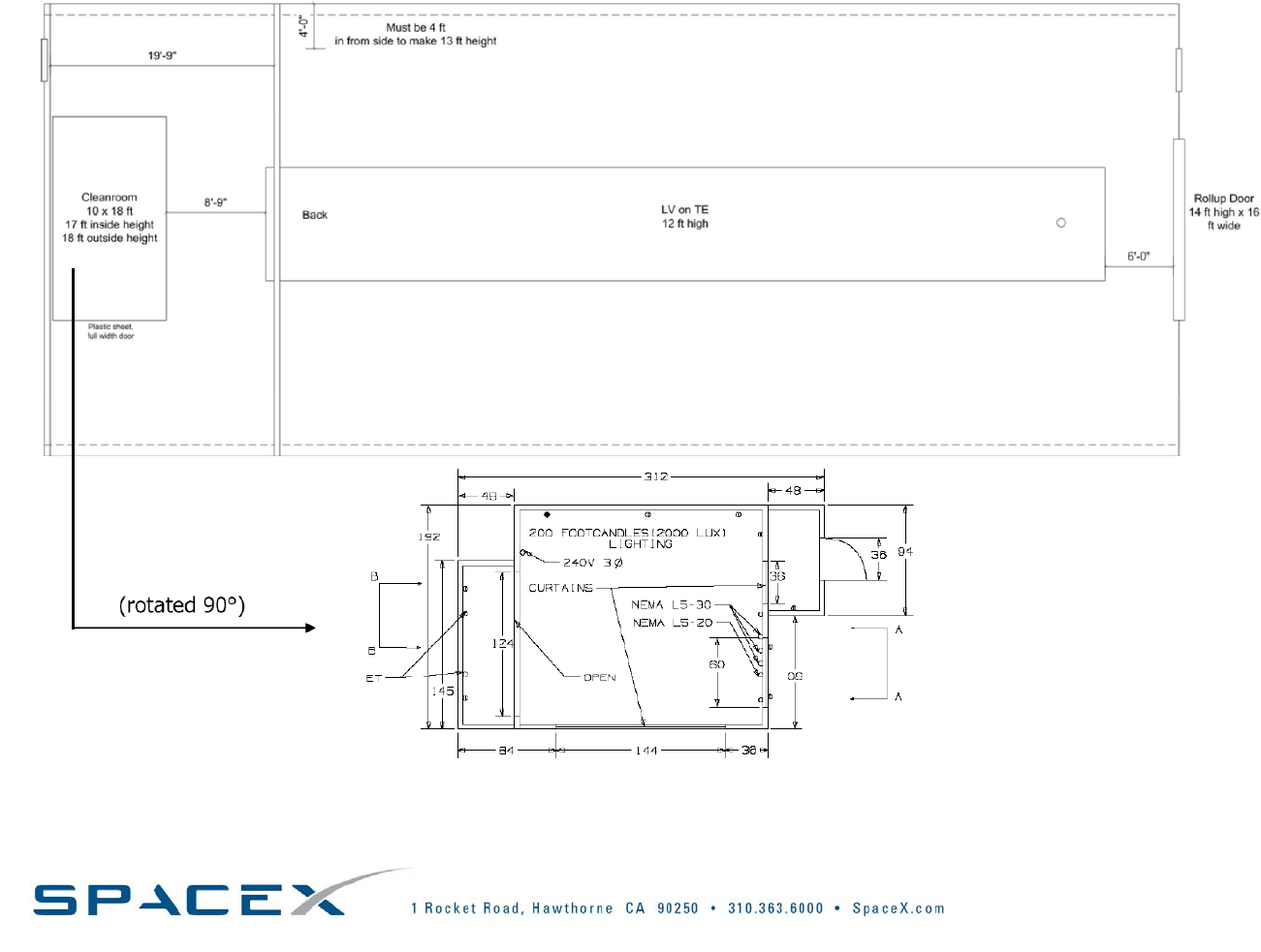
Thelaunchcontrolorganizationanditslinesofdecisionmakingareshowninthefigurebelow.Pleasenotethat
thisorganizationmayvaryslightlybaseduponthemissionandcustomer.Thepayloadmanagerorhis/her
representativewillsitatthePayloadStationintheSpaceXcontrolcenter.
LVSupport
Stations
LaunchDirector
PadSupervisorLaunch
Conductor
PayloadSupport
Stations
Operations
SafetyManager
MFCO
MissionDirector
PayloadManager
DashedLines–CommunicationsPaths
Solidlines–DecisionTree
FIGURE5‐1:LAUNCHCONTROLORGANIZATION
Copyright–2008
Falcon1User’sGuide‐D000973Rev.7Page|37
5.2. MISSIONINTEGRATION
TheLaunchVehicletopayloadinterfaces,payloadenvironmentalconditions,andgeneralcapabilitiesaredescribed
inthisUserGuide.SpaceXwillsupplyasinglePointofContact,theMissionManager,fromcontractaward
throughlaunch..TheMissionManagerwillassessthelaunchvehiclecapabilitiesagainstpayloadrequirements.
Throughouttheintegrationprocess,thecapabilitieswillbemergedwithpayloadrequirements.Thisprocesswill
beaccomplishedbyteleconferences,integrationmeetingsandmissionuniquedesignreviews,asrequired.The
resultofthisprocessisdocumentedintheLaunchVehicletoSpacecraftICD—theMasterdocumentforanySpaceX
mission.FollowingsignatureapprovaloftheICD,configurationcontrolismaintainedbySpaceX.SpaceXalso
coordinatesallaspectsofthelaunchvehicleproduction,rangeandrangesafetyintegration,andallmission
requiredlicensing.TheMissionManagerfacilitatestheseinterfacesforthePayloadProvider.Oncethepayload
arrivesatthelaunchsite,thephysicalaccommodationforthespacecraftisturnedovertothePayloadIntegration
Manager—partoftheoperationscrew.TheMissionManagerwillcontinuetomanagethecustomerinterfaceat
thelaunchsite.
TABLE5‐2:STANDARDLAUNCHINTEGRATIONPROCESS
Launch–8monthsormoreContract signingandauthoritytoproceed
• Estimatedpayloadmass,volume,mission,operationsandinterface
requirements
• Safetyinformation(SafetyProgramPlan;Designinformation:
battery,ordnance,propellants,andoperations)
• MissionanalysissummaryprovidedtotheCustomerwithin30days
ofcontract
Launch–6monthsFinalpayloaddesign,including:mass,volume,structuralcharacteristics,
mission,operations,andinterfacerequirements
• Payloadtoprovidetestverifiedstructuraldynamicmodel
Launch–4monthsPayloadreadinessreview forRangeSafety
• Launchsiteoperationsplan
• Hazardanalyses
Launch–3monthsVerification
• ReviewofpayloadtestdataverifyingcompatibilitywithFalcon1
environments
• CoupledpayloadandFalcon1loadsanalysiscompleted
• ConfirmpayloadinterfacesasbuiltarecompatiblewithFalcon1
• Missionsafetyapproval
Launch–4‐6weeksSystemReadinessReview(SRR)
• Pre‐shipmentreviewshaveoccurred,orareabouttooccur.
• Verifylaunchsite,Range,Regulatoryagencies,launchvehicle,
payload,peopleandpaperareallinplaceandreadytobegin
launchcampaign
Launch–2weeksPayloadarrivalatlaunchlocation
Launch–8‐9daysPayloadmating toLaunchVehicleandfairingencapsulation
Launch–7daysFlightReadinessReview(FRR)
• ReviewofLVandpayloadcheckoutsinhangar.Confirmationof
readinesstoproceedwithVehiclerollout.
Launch–1dayLaunchReadinessReview (LRR)
Launch
Launch+4hoursPost‐LaunchReports‐Quicklook
Launch+4weeksPost‐LaunchReport‐FinalReport
Copyright–2008

Falcon1User’sGuide‐D000973Rev.7
Page|38
Copyright–2008
5.2.1. PAYLOADTRANSPORTTOLAUNCHSITE
UponarrivalofthePayloadatKwajalein,thepayloadcontainerandallassociatedtest/supportequipmentareoff‐
loadedfromtheplanebyKwajaleinAirportcargohandlers.SpaceXarrangesfortransportationfromtheairportto
thelaunchsiteontheislandofOmelek.Thistransporttakesplacebyboat.
Boththepayloadandequipmentwillmakethreemajormovesbetweenfacilities:
o FromKwajaleinAirporttotheKwajaleinmarinaviatruck
o FromtheKwajaleinmarinatotheOmelekIslandloadingrampviacargoship
o FromtheOmelekIslandloadingramptothevehicleassemblyhangarcleanroomviaforklift
IfshipmenttoOmelekIslandcannotbecompletedonthesamedayasSCandequipmentarrivalonKwajalein(due
tolateplanearrival,seastate,orotherwise)thentheequipmentandSCwilleitherstayovernightintheplaneor
betransportedviatrucktoadesignatedSpaceXstoragefacility.Thisfacilitywillbeprovidedwithstandardoffice
gradeairconditioning,buttheconditioningisnotguaranteed.TheSCwillbetransportedinitsownshipping
containeruntilitreachesthevehicleassemblyhangaronOmelekIsland.
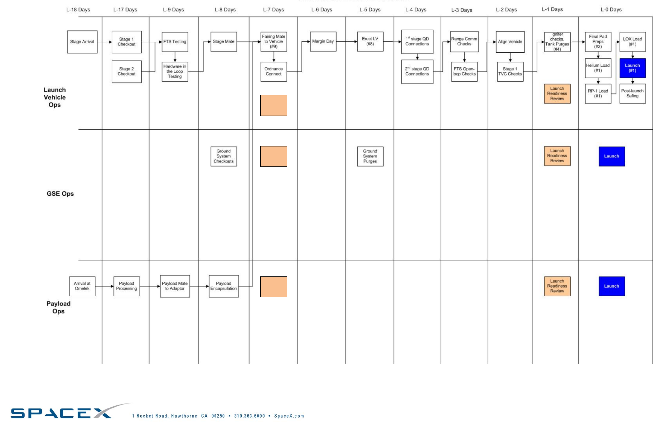
5.2.2. PAYLOADINTEGRATION
SpaceXmakespre‐launchoperationsassimpleandstreamlinedaspossible.Figure5‐3showsnominallaunch
operationsflowforLaunchVehicleOperations,GSEOperationsandPayloadOperations,beginningatL‐18days.
SpaceXrequiresthatthepayloadbebroughttothelaunchsiteonlytwoweekspriortolaunch.Forcustomer
convenience,SpaceXprovidesClass100Kcleanroomfacilitiesfornon‐hazardousprocessingforuptothreeweeks
asastandardservice.Oncethepayloadarrivesatthelaunchsite,attachmentandfairingencapsulationcanbe
completedinlessthantwenty‐fourhours.
SpaceXintegratesthepayloadontheadapterintheverticalconfiguration,followedcloselybyfairing
encapsulation.Oncefullyencapsulated,thesystemisrotatedhorizontallyandthenintegratedtothesecond
stage.Post‐matecheckoutsareconductedfollowedbyaFlightReadinessReview(FRR).OncetheFRRis
completed,thevehicleisrolledouttothepad.Notethattheintegratedpayloadandlaunchvehiclegovertical
withinsixdaysofliftoff.Accessuntilrolloutisavailableasastandardservice.
Falcon1LaunchVehiclemissionsandassociatedoperationshavebeendesignedforminimalcomplexityand
minimaltimeatthepad.Thepayloadwillbeintegratedhorizontallytothelauncherapproximatelysevendays
priortolaunch.Onceintegrated,thevehicleismovedtothepadandiserectedusingtheFalcon1LaunchVehicle
transporter.Finalsystemclose‐out,fuelingandtestingisthencompleted.Twenty‐fourhourspriortolaunch,the
LaunchReadinessReview(LRR)isheld.Oncethelaunchapprovalisgiven,thetwenty‐fourhourcountdownbegins.
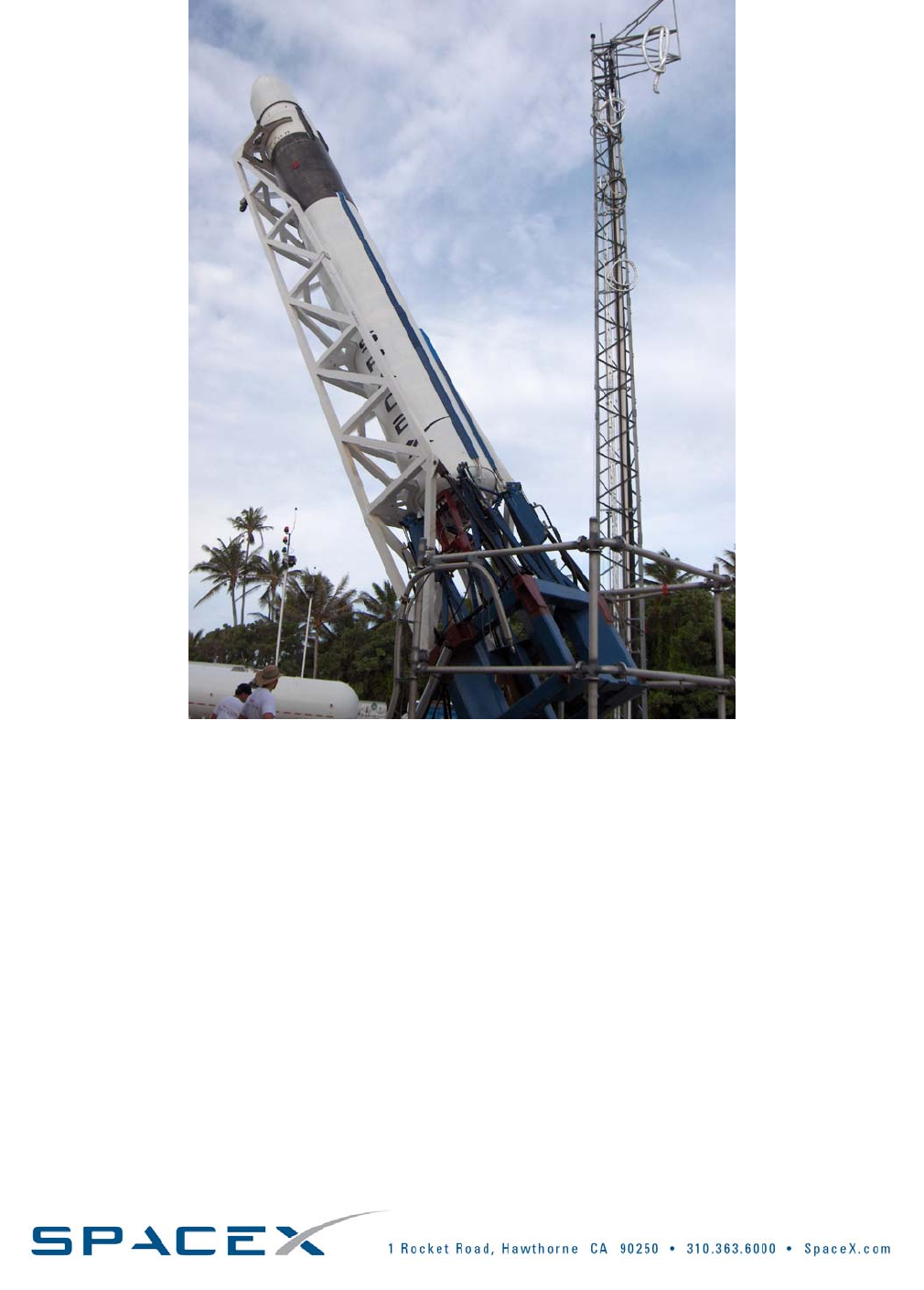
Falcon1User’sGuide‐D000973Rev.7Page|39
FIGURE5‐2:ERECTIONOPERATIONONOMELEKISLANDWITHLAUNCHVEHICLEANDTRANSPORTERERECTOR
Copyright–2008
Falcon1User’sGuide‐D000973Rev.7Page|40
Flight
Readiness
Review
Flight
Readiness
Review
Flight
Readiness
Review
FIGURE5‐3:NOMINALKWAJALEINLAUNCHOPERATIONSFLOW
Copyright–2008
Falcon1User’sGuide‐D000973Rev.7Page|41
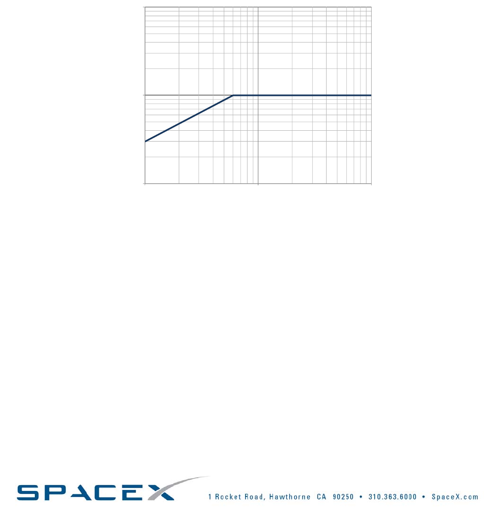
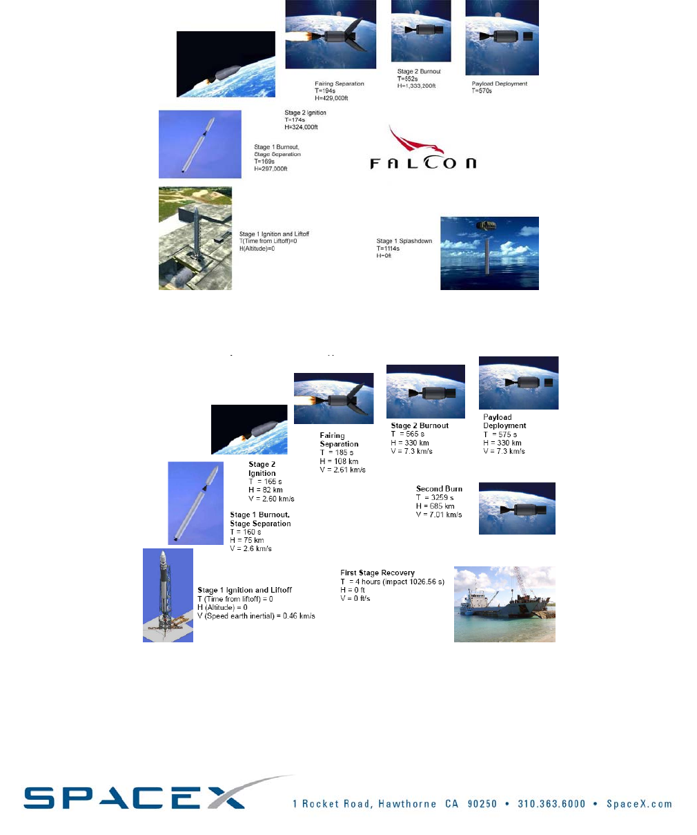
5.2.3. EXAMPLEFLIGHTPROFILES
OnceFalcon1islauncheditfollowsaprofilesimilartothosedescribedinFigure5‐4orFigure5‐5,below.(Note:
eachflightprofileisuniqueandwillvarydependingonthetrajectory.)Fordirectinjectedmissions,payload
separationoccursatapproximately570seconds.Fortwoburnmissions,thepayloadisreleasedapproximately
3270secondsintothemission.
FIGURE5‐4:FALCON1SAMPLEFLIGHTPROFILE,DIRECTINSERTIONMISSION
FIGURE5‐5:FALCON1SAMPLEFLIGHTPROFILE,TWO‐BURNMISSION
Copyright–2008

Falcon1User’sGuide‐D000973Rev.7
Page|42
Copyright–2008
6. SAFETY
6.1. SAFETYREQUIREMENTS
Falcon1customersarerequiredtomeetAFSPC91‐710RangeSafetyManualrequirementsinthedesignand
operationoftheirflightandgroundsystems.Theserequirementsencompassmechanicaldesign,electricaldesign,
fluidandpressurantsystems,liftingandhandlingsystems,ordnanceandRFsystems,groundsupportequipment,
andotherdesignandoperationalfeatures.SpaceXcanassistthecustomerindeterminingwhichrequirementsin
particularpertaintothecustomerssystems,andcanalsoassistincompletingrequireddocumentation.
6.2. HAZARDOUSSYSTEMSANDOPERATIONS
Mostrangesconsiderhazardoussystemsoroperationstoincludeordnanceoperations,pressurizedsystemsthat
operatebelowa4to1safetyfactor,liftingoperations,operationsorsystemsthatincludetoxicorhazardous
materials,highpowerRFsystems,lasersystems,andavarietyofothersystemsandoperations.Thedetailsofthe
systemdesignanditsoperationwilldeterminewhetherthesystemoritsoperationareconsideredhazardous.
Typically,additionalprecautionsarerequiredforoperatingsystemsthatareconsideredhazardous–thesewillbe
determinedduringthesafetyapprovalprocesswithSpaceXandthelaunchrange.Allhazardousoperationswill
requireproceduresthatareapprovedbybothSpaceXandthelaunchrangepriortoexecution.Ordnance
operationsinparticularrequirecoordinationtoprovidereducedRFenvironments,clearedareas,safetysupport,
andotherrequirements.
6.3. WAIVERS
Forsystemsoroperationsthatarenotabletomeetsafetyrequirementsandyetarebelievedtobeacceptablefor
groundoperationsandlaunch,awaiveristypicallyproducedforapprovalbythelaunchrangesafetyauthority.
Waiversarealastresortsolutionandrequireconsiderablecoordinationandshouldnotbeconsideredastandard
practice.SpaceXwillassistthecustomerindeterminingwhetheranissueshouldbeelevatedtorequireawaiver
astheintegrationprocessevolves.

Falcon1User’sGuide‐D000973Rev.7Page|43
7. PAYLOADQUESTIONNAIRE
CompletionofthefollowingPayloadQuestionnaireisnecessaryforuseinevaluatingthecompatibilityofanynew
payloadwithFalcon1LaunchVehicles.IfyouareconsideringusingFalcon1LaunchVehicles,thenplease
completeasmuchofthequestionnaireaspossibleandreturnitto:
SpaceX
ATTN:LaurenDreyer
1RocketRd.
Hawthorne,CA90250
Lauren@spacex.com
PleaseNote:SpaceXwilltreatallcustomersupplieddataasproprietaryinformationandwillnotdiscloseor
retransmitanypartoftheinformationcontainedhereintoanyoutsideentitywithouttheexpressedwritten
consentofyourorganization.
Copyright–2008

PayloadInformation
PayloadName/Title/Acronym
PayloadContractororSponsor
PointsofContactandContactInformation
PayloadMissionInformation
DesiredLaunchDate/Timeframe
MissionTimelineDescription
LaunchWindowConstraints
Item StowedConfigurationTolerance
CenterofGravity
(mm)
X±
Y±
Z±
MomentofInertia
(kg.mm2)
IXX±
IYY±
IZZ±
ProductofInertia
(kg.mm2)
IXY±
IYZ±
IXZ±

PayloadTrajectoryRequirements
ParameterValueSIUnits
DesiredOrbitApogeekm
Accuracykm
DesiredOrbitPerigeekm
Accuracykm
DesiredOrbitInclinationdeg
Accuracydeg
DesiredRightAscensionofAscendingNodedeg
Accuracydeg
DesiredArgumentofPerigeedeg
Accuracydeg
PayloadOrbitalInjectionConditions
SIUnits
MaximumAllowableTip‐OffRatedeg/sec
DesiredSpin‐UpRaterpm
PointingRequirement(PleaseSpecify)
MaximumAllowablePointingErrordeg
PayloadMassProperties
SIUnits
SpacecraftMass(Maximum)kg
SpacecraftCoordinateSystem
PayloadMechanicalInterface
SIUnits
SpacecraftHeight(Maximum)mm
SpacecraftDiameter(Maximum)mm
FairingAccessDoorLocationPreference
MechanicalAttachmentBoltCircleDiametermm

DoyouhaveaSpacecraftSeparationSystem?Ifso,providedetailshere:
Note:SpaceXcandesign/providetheSpacecraftSeparationSystemifdesired.
PayloadThermalEnvironment
SIUnits
Pre‐launchTemperatureRange°C
Pre‐launchAllowableWaterVaporinAirgrains/lb
dr
y
air
MaximumPre‐launchGasImpingementVelocitym/sec
MaximumAscentHeatFluxW/m2
MaximumFree‐MolecularHeatFluxW/m2
MaximumFairingAscentDepressurizationRatembar/sec
PayloadContaminationControl
SIUnits
DesiredPayloadProcessingCapabilitiesClass
DesiredFairingAirCleanlinessClass
PayloadDynamicEnvironment
SIUnits
MaximumAllowableAcousticSoundPressureLeveldB
OASPL
MaximumAllowableSineVibrationGrms
MaximumAllowableShockg
MaximumLateralAccelerationg
MaximumAxialAccelerationg
FundamentalFrequency‐LateralHz
FundamentalFrequency‐LongitudinalHz
AdditionalData:
1. Pleaseprovideadescriptionofthepayloadtestingplannedduringpayloadprocessingat
thelaunchsite,aswellasanytestingplannedwhileencapsulated.Pleasedescribeeach
testintermsofpersonnelrequired,durationoftest,tools/GSErequired,andanypossible
safetyconcernsthatshouldbeconsidered.
2. Pleasedescribeanysafetyissuesassociatedwiththespacecraft.
3. Pleasedescribethepropulsionsystemstobeusedonthespacecraft.
4. Pleasedescribethepressurevesselstobeusedonthespacecraft.
5. Pleasedescribethepowersystems(batteries,solarcells,etc).

6. PleasedescribetheRFsystemstobeusedonthespacecraft.PleasedetaileachRF
transmitterorreceiver,itsfunction,frequency,sensitivity,poweroutput,andbandwidth.
7. Pleaseprovidethespacecraftallowableortestacousticprofile,randomvibration
spectrum,shockspectrum,andsinevibrationcurve.
8. PleaseprovideDimensionalDrawingsand/orCADmodelsofthespacecraftifavailable.
Thesedrawings/modelsshouldincludethespacecraftseparationsystem.Ratherthan
attachingtothisPDF,ifyouprefertosendtheseviaemail,pleasesubmitto
Lauren@spacex.com.
9. Pleasedescribeanysecurityconcernsorrequirementsyouhave.
10. Pleasedescribeanyadditionalspacecraftrequirementsthatweshouldbemadeawareof.

Falcon1User’sGuide‐D000973Rev.7
Page|44
Copyright–2008
8. QUICKREFERENCE
8.1. LISTOFFIGURES
Figure2‐1:Falcon1StandardFairingandDynamicEnvelope*,meters[inches]........................................................10
Figure2‐2:Falcon1eStandardFairingandDynamicEnvelope*,meters[inches]......................................................12
Figure2‐3:Falcon1&1eDirect&Two‐BurnPerformanceto9.1°Inclination...........................................................15
Figure2‐4:Falcon1&1eTwo‐BurnPerformancetoLEO...........................................................................................15
Figure2‐5:Falcon1LaunchVehicleLayoutandCoordinateSystem(allstationlocationanddimensionunits
areshownininches).................................................................................................................................17
Figure3‐1:AllowableCGOffsetfromCenterline........................................................................................................18
Figure3‐2:AllowableCGOffsetfromSeparationPlane..............................................................................................18
Figure3‐3:Falcon1ElectricalInterfacetoPayloadRemoteLaunchCenters,Blockhouse‐to‐Spacecraft
Wiring........................................................................................................................................................20
Figure3‐4:ExampleSteadyStateAxialAccelerationTimeHistoryforFalcon1.........................................................26
Figure3‐5:Falcon1PayloadInterfaceRandomVibration..........................................................................................27
Figure3‐6:Falcon1BaselineShockResponseatSeparationPlaneduetoFairingSeparation..................................28
Figure3‐7:SoundPressureLevel(SPL)SpectraforFalcon1Assuming2inchAcousticBlankets...............................29
Figure3‐8:Falcon1WorstCaseRadiatedEnvironment.............................................................................................30
Figure3‐9:ExampleDepressurizationEnvironmentsandDepressurizationRates.....................................................31
Figure4‐1:Hawthorne,CaliforniaHeadquarters........................................................................................................32
Figure4‐2:MerlinEngineinTestingatSpaceX’sTexasTestFacility...........................................................................32
Figure4‐3:OmelekIslandLaunchFacilitiesatReaganTestSite.................................................................................33
Figure4‐4:OmelekHangarLayout..............................................................................................................................35
Figure5‐1:LaunchControlOrganization.....................................................................................................................36
Figure5‐2:ErectionoperationonOmelekIslandwithlaunchvehicleandtransportererector.................................39
Figure5‐3:NominalKwajaleinLaunchOperationsFlow.............................................................................................40
Figure5‐4:Falcon1SampleFlightProfile,DirectInsertionMission...........................................................................41
Figure5‐5:Falcon1SampleFlightProfile,Two‐BurnMission....................................................................................41
8.2. LISTOFTABLES
Table1‐1:OrganizationalChangestoFalcon1User'sGuide........................................................................................4
Table1‐2:UpdatedTablesandFigures.........................................................................................................................5
Table2‐1:Falcon1LaunchVehicleFamilyComparisonChart......................................................................................8
Table3‐1:LaunchVehicleMassPropertyLimitations.................................................................................................18
Table3‐2:RequiredDocumentsforAllPayloads........................................................................................................21
Table3‐3:AdditionalRequiredDocumentsforNon‐USPayloads...............................................................................22
Table3‐4:SummaryofThermalandHumidityEnvironments....................................................................................23
Table3‐5:SummaryofEnvironmentalConditionsatVariousFlightEvents...............................................................24
Table3‐6:Falcon1Modes...........................................................................................................................................26
Table3‐7:SummaryofPayloadDesignCGLimitLoadFactors,NominalFalcon1Mission........................................26
Table3‐8:Falcon1RandomVibrationMaximumPredictedEnvironmentPSDValues..............................................27
Table3‐9:Falcon1PayloadAcousticEnvironmentassumingNominal5cmAcousticBlankets................................29
Table3‐10:LaunchVehicleRFSystemCharacteristics................................................................................................30
Table4‐1:ServicesandEquipmentforSatelliteProcessingatReaganTestSite........................................................34
Table5‐1:LaunchControlOrganization......................................................................................................................36
Table5‐2:StandardLaunchIntegrationProcess.........................................................................................................37

Falcon1User’sGuide‐D000973Rev.7
Page|45
Copyright–2008
8.3. LISTOFACRONYMS
CAM................................................................................................................................CollisionAvoidanceManeuver
CVCM.................................................................................................CollectedVolatileCondensableMass(Material?)
FAA................................................................................................................................FederalAviationAdministration
FRR............................................................................................................................................FlightReadinessReview
GN2......................................................................................................................................................GaseousNitrogen
GPS.........................................................................................................................................GlobalPositioningSystem
GSE......................................................................................................................................GroundSupportEquipment
ICD......................................................................................................................................InterfaceControlDocument
LRR..........................................................................................................................................LaunchReadinessReview
LV.............................................................................................................................................................LaunchVehicle
MPE..........................................................................................................................MaximumPredictedEnvironments
OASPL...............................................................................................................................OverallSoundPressureLevel
PPF........................................................................................................................................PayloadProcessingFacility
RTS........................................................................................................................................................ReaganTestSite
SLC3W..................................................................................................................................SpaceLaunchComplex3W
SpaceX..........................................................................................................................SpaceExplorationTechnologies
SPL.................................................................................................................................................SoundPressureLevel
SRR..........................................................................................................................................SystemReadinessReview
TML.........................................................................................................................................................TotalMassLoss
