Congratulations On Your Purchase Of The THERMALWAVE 5M Truck Mount Cleaning Unit 49 022 MANUAL,SUPER EXTRACTION SYSTEM &file=49
User Manual: 49-022 MANUAL,SUPER EXTRACTION SYSTEM
Open the PDF directly: View PDF ![]() .
.
Page Count: 50
- Congratulations on your purchase of the Super Extraction System ® truck mount unit. This instruction/parts manual is a guide for operating and servicing your BLUELINE unit.
- Record your units serial number here for future reference or if you should need to contact the factory in the future for any reason.
- LIMITED WARRANTY
- SECTION 1:
- GENERAL INFORMATION
- 1. SAFETY
- 2. RECEIVING YOUR TRUCK MOUNT UNIT
- !
- 1. Read the operator's manual before starting this unit.
- 2. Operate this unit and equipment only in a well ventilated area.
- 3. Gasoline is extremely flammable and its vapors can explode if ignited.
- SECTION 2:
- INSTALLATION
- 49-022 CoverSUPER EXTRACTION SYSTEM.pdf
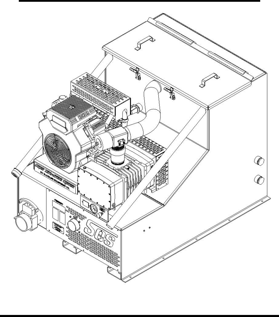
SUPER EXTRACTION SYSTEM
Service and Operation Manual
BLUELINE Equipment Co. LLC
2604 Liberator Dr., Prescott, AZ 86301 1-928-445-3030

Congratulations on your purchase of the
Super Extraction System ® truck
mount unit. This instruction/parts manual is
a guide for operating and servicing your
BLUELINE unit.
Proper operation and service are necessary to
ensure the outstanding performance of this unit.
When properly maintained, your truck mount
extraction unit will have a long and trouble free
life.
The following service methods outlined in this
manual are detailed in a manner that operation and
servicing may be performed properly and safely.
Because service levels vary due to the skill of the
mechanic, tools and parts availability, ensure that
prior to attempting any repair, you are familiar with
this equipment and have the proper tools. Any
questions regarding the operation, service, or repair
of this unit should be directed to your nearest
BLUELINE dealer.
The headings WARNING and CAUTION are
utilized to warn you that steps must be taken to
prevent personal injury or damage to the
equipment. Please make sure that you have read
and understand these instructions entirely before
proceeding with the operation of this unit.
THIS UNIT MUST BE INSTALLED BY THE
DEALER THAT YOU PURCHASED IT FROM
IN ACCORDANCE WITH THE BLUELINE
INSTALLATION PROCEDURES.
PLEASE ENSURE THAT THE WARRANTY
CARD IS FILLED OUT BY THE
INSTALLATION SERVICE CENTER THAT
INSTALLED THIS UNIT AND IS RETURNED
TO BLUELINE EQUIPMENT LLC.
Record your units serial number here for future
reference or if you should need to contact the
factory in the future for any reason.
S/N:
This service and operations manual is written
specifically for Super Extraction System
®
truck mount extraction units manufactured by:
BLUELINE EQUIPMENT LLC
2604 Liberator Drive
Prescott, AZ 86301 USA
The information contained in this document is
subject to change without notice and does not
represent a commitment on the part of
BLUELINE EQUIPMENT LLC.
All rights reserved. Copyright 2005 by
BLUELINE EQUIPMENT LLC. No part of this
work may be used or reproduced in any form or
means without the express written consent and
permission of BLUELINE EQUIPMENT LLC.
Published by BLUELINE EQUIPMENT LLC.
First printing:
Printed in USA
BLUELINE
Super Extraction
System ® MANUAL
PART# 49-022
December, 2005
Super Extraction System® I

LIMITED WARRANTY
BLUELINE warrants your machine to be free of defects in material and workmanship. This
warranty shall extend to the designated parts for the specific period of time listed from the date
of delivery to the user. If BLUELINE receives notice of any defects during the warranty period,
BLUELINE will either, at its option, repair or replace products that prove to be defective. Any
transportation, related service labor, normal maintenance and diagnostic calls are not included.
Gasoline Engine (Through manufacturer or local dealer)_______1 year
Vacuum Pump (Through manufacturer or local dealer) ________18 months
Waste Tank __________________________________________1 year
Battery (pro-rated) ____________________________________1 year
All Other Components__________________________________1 year
This warranty shall not apply to defects caused by improper installation or operation, inadequate
maintenance by the customer, unauthorized modification or misuse, improper repair, freezing or
damage due to hard water scaling.
Electrical components, disposable filters, belts, hoses, fittings, o-rings and other service
maintenance items are not under warranty. Components supplied by BLUELINE, but provided
by other manufacturers, will only be warranted to the extent that they are warranted to
BLUELINE.
To receive warranty service, products must be returned to a BLUELINE designated service
facility. The customer shall prepay shipping charges for products returned to BLUELINE for
warranty evaluation and BLUELINE shall pay for the return of products to the customer.
BLUELINE makes no other warranty, expressed or implied, with respect to this product.
BLUELINE disclaims the implied warranties of merchantability and fitness for a particular
purpose. Any implied warranty of merchantability or fitness is limited to the specific duration of
this limited warranty.
This warranty gives the customer specific legal rights, and you may also have other rights that
may vary from state to state, or province to province.
The remedies provided herein are the customer’s sole and exclusive remedies. In no event shall
BLUELINE be liable for any direct, indirect, special, incidental, or consequential damages,
whether based on contract, tort, or any other legal theory.
Super Extraction System®
II

Table of Contents
SECTION ONE: GENERAL INFORMATION 1
1. SAFETY 2
Safety, Specifications, Installation, Fuel, Engine Oil
2. RECEIVING YOUR TRUCK MOUNT UNIT 7
Dealer Responsibility, Acceptance of Shipment, Equipment Listing, Optional Equipment
SECTION TWO: INSTALLATION 8
3. INSTALLATION 9
Lifting the Unit into the Vehicle, Positioning the Unit into the Vehicle, Fastening Down the
Unit, Dimensional Diagrams, Installation of Fuel Lines, Trailer Fuel Tank and Fuel Line
Installation, Battery Connection, Fire Extinguisher
SECTION THREE: OPERATION 12
4. SYSTEMS 13
Vacuum System
5. OPERATION 14
Equipment setup, Instrumentation, Starting Your Unit, Waste Pump, Extraction Process, Shut
Down and Daily Maintenance, Freeze Protection.
SECTION FOUR: MAINTENANCE and SERVICE 17
MAINTENANCE CHART 18
6. MAINTENANCE 19
7. GENERAL SERVICE ADJUSTMENTS 21
8. TROUBLESHOOTING 22
SECTION FIVE: PARTS and ACCESSORIES 27
9. ILLUSTRATED PARTS LISTINGS 28
10. ACCESSORIES 35
Super Extraction System®
III
SECTION 1:
GENERAL INFORMATION
1. SAFETY
Safety 2
Specifications 5
Installation requirements 6
Fuel requirements 6
Engine oil requirements 6
2. RECEIVING YOUR TRUCK MOUNT UNIT
Dealer responsibility 7
Acceptance of shipment 7
Equipment listing 7
Optional equipment 7
Super Extraction System®
1
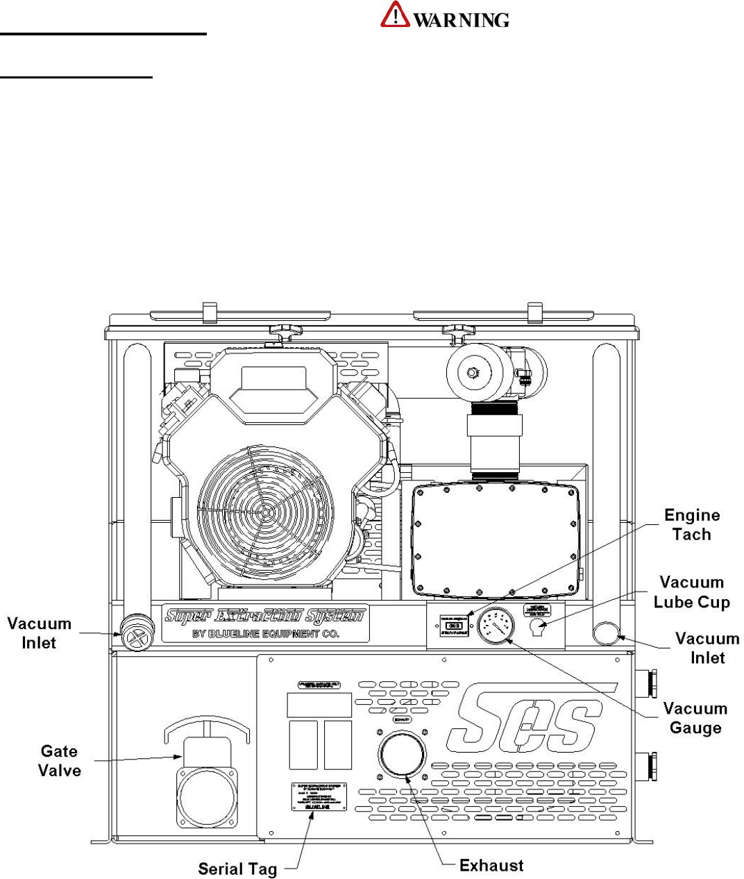
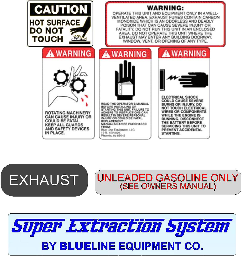
1. SAFETY
For Your Safety!
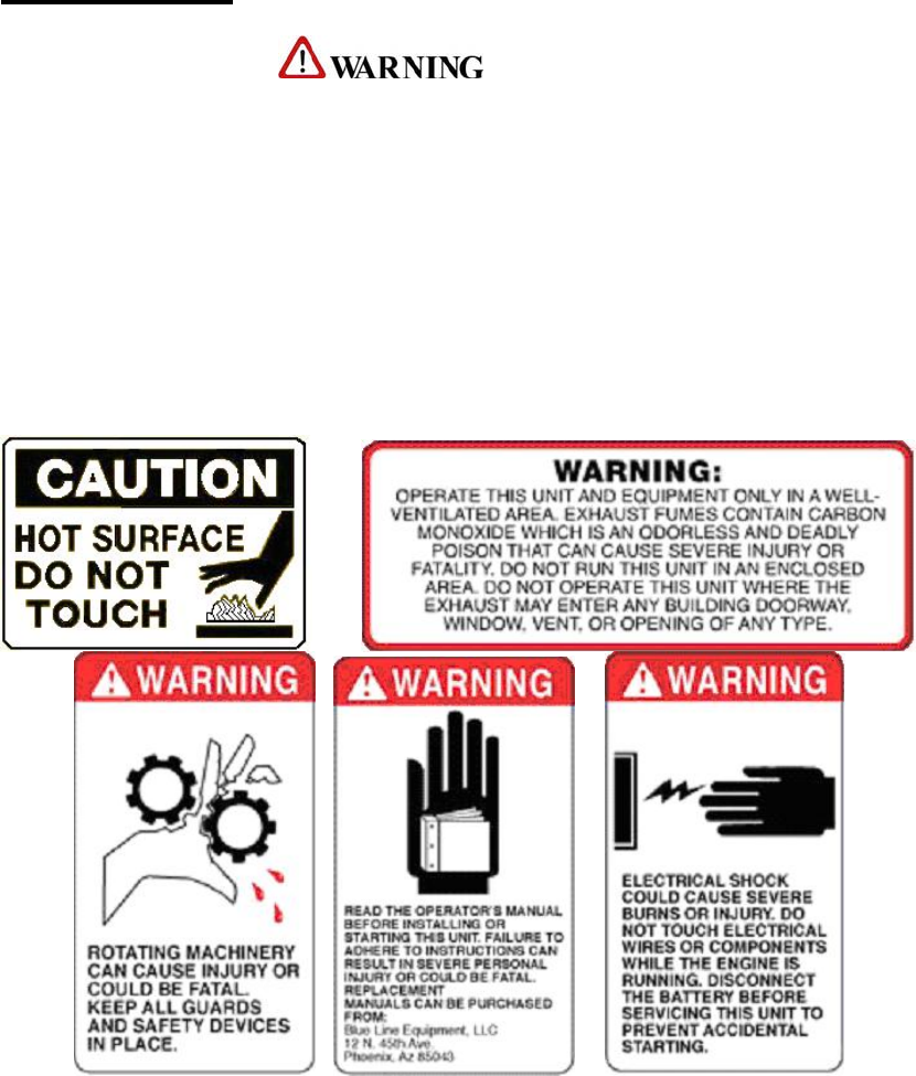
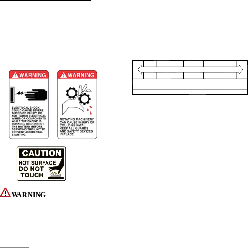
The following WARNING labels are on your BLUELINE Super Extraction
System® console. These labels point out important WARNINGS and CAUTIONS, which
must be followed at all times. Failure to follow warnings could result in personal injury,
fatality, to yourself and/or others or property damage. Please follow these instructions
carefully!
DO NOT remove these decals.
Super Extraction System®
2

SECTION 1
!
1. Read the operator's manual before
starting this unit.
Failure to adhere to instructions could
result in severe personal injury or could
be fatal.
2. Operate this unit and equipment
only in a well ventilated area.
Exhaust fumes contain carbon
monoxide, which is an odorless and
deadly poison that can cause severe
injury or death. DO NOT run this unit in
an enclosed area. DO NOT operate this
unit where the exhaust may enter a
building doorway, window, vent or other
opening.
3. Gasoline is extremely flammable
and its vapors can explode if ignited.
Store gasoline only in approved
containers, in well ventilated,
unoccupied buildings and away from
sparks or flames. Never carry gasoline or
any flammable materials in the vehicle.
Fumes could accumulate inside of the
vehicle and ignite, causing an explosion.
4. This unit must be operated with the
vehicle doors open in order to ensure
adequate ventilation to the engine.
5. DO NOT operate unit if gasoline is
spilled. Do not turn ignition switch until
the gasoline has been cleaned up. Never
use gasoline for cleaning purposes.
6. DO NOT place hands, feet, hair,
clothing or any body parts near rotating
or moving parts. Rotating machinery can
cause severe injury or death.
7. NEVER operate this unit without belt
and safety guards. High speed moving
parts, such as belts and pulleys, should
be avoided while the unit is running.
Severe injury, fatality or damage may
result.
8. NEVER service this unit while it is
running. High speed mechanical parts as
well as high temperature components
may result in injury or severed limbs.
9. Engine components will be extremely
hot from operation. To prevent severe
burns, DO NOT touch these areas while
the unit is running or shortly after the
unit is shut off.
10. DO NOT touch any part of the
exhaust system while the system is
running or for 20 minutes after the unit
is shut off. Severe burns could result.
11. NEVER leave the vehicle engine
running while the unit is in operation.
12. Battery acid contains sulfuric acid.
To prevent acid burns, avoid contact
with skin, eyes and clothing. Batteries
also produce explosive hydrogen gases
while charging. To prevent fire or
explosion, charge batteries only in a well
ventilated area. Keep sparks, open
flames, as well as other sources of
ignition away from battery at all times.
Remove all jewelry prior to servicing
batteries. Keep batteries out of the reach
of children.
Before disconnecting the negative (-)
ground cable, ensure that all switches are
in the off position. If on, a spark could
occur at the ground connection terminal
which could cause an explosion if
hydrogen gas or gasoline vapors are
present. ALWAYS disconnect the
negative (-) terminal first.
Super Extraction System®
3
13. DO NOT smoke around the
machine. Gas fumes could accumulate
and ignite. Battery gases are extremely
flammable. This will prevent possible
explosions.
14. DO NOT damage the vehicle in any
way during the installation. When
routing fuel lines DO NOT configure
the hose in any locations where the hose
or vehicle could be damaged. Avoid
contact with moving parts, areas of high
temperature, brake lines, fuel lines,
catalytic converters, exhaust pipes,
mufflers or sharp objects.
15. NEVER cut or splice any of the
vehicle fuel lines during fuel line
installation. This will result in fuel leaks
and potentially dangerous conditions.
Use only the provided fuel hose for fuel
lines. When going through the vehicle
floor with fuel lines, always utilize
bulkhead adaptors. This will prevent fuel
leaks and ensure that hoses are not
punctured by vehicle vibration abrasion.
16. DO NOT exceed your vehicles
weight limit. The console with waste
tank and accessories weighs
approximately 625 pounds. Make certain
that the vehicle has the correct axle
rating. This will prevent unsafe or
hazardous driving conditions.
17. High back seats are required for all
vehicles that units are to be installed for
head and neck protection. Metal
partitions between the seats and
equipment are strongly recommended.
18. Always keep your vehicle clean and
orderly. Wands, tools and accessories
must be securely stowed while driving
the vehicle.
19. Ensure that you have received proper
training from the distributor that you
purchased the unit from prior to
operation.
22. DO NOT modify this unit in any
manner. Any modification could result
in serious injury or fatality.
25. California Proposition 65
WARNING: Engine exhaust from this
product contains chemicals known by
the State of California to cause cancer,
birth defects, or other reproductive harm.
Super Extraction System®
4

SECTION 1
SPECIFICATIONS
Engine Speed 3000 rpm (High Speed No Load)
1400 rpm (Idle No Load)
Vacuum Pump RPM 3000 rpm
Vacuum Relief Valve 13 in. HG
Waste Tank Capacity 120 Gallons at shutoff
Console Weight (with waste tank
& accessories) 625 lbs.
TORQUE VALUES
Engine Hub 720 inch/lbs. 60 ft/lbs.
Vacuum Pump Hub 192 inch/lbs. 16 ft/lbs.
Super Extraction System®
5
INSTALLATION REQUIREMENTS FUEL REQUIREMENTS
Use unleaded fuel ONLY. NEVER use any Prior to beginning the installation, read the
ENTIRE “Installation” section of this manual.
Since the BLUELINE Super Extraction
System® truck mount unit weighs (with
accessories) approximately 625 lbs., please adhere
to the following recommendations prior to
installing the unit.
gasoline additives. Use only fresh, clean unleaded
gasoline intended for normal automotive use. DO
NOT use high-octane gasoline with this unit.
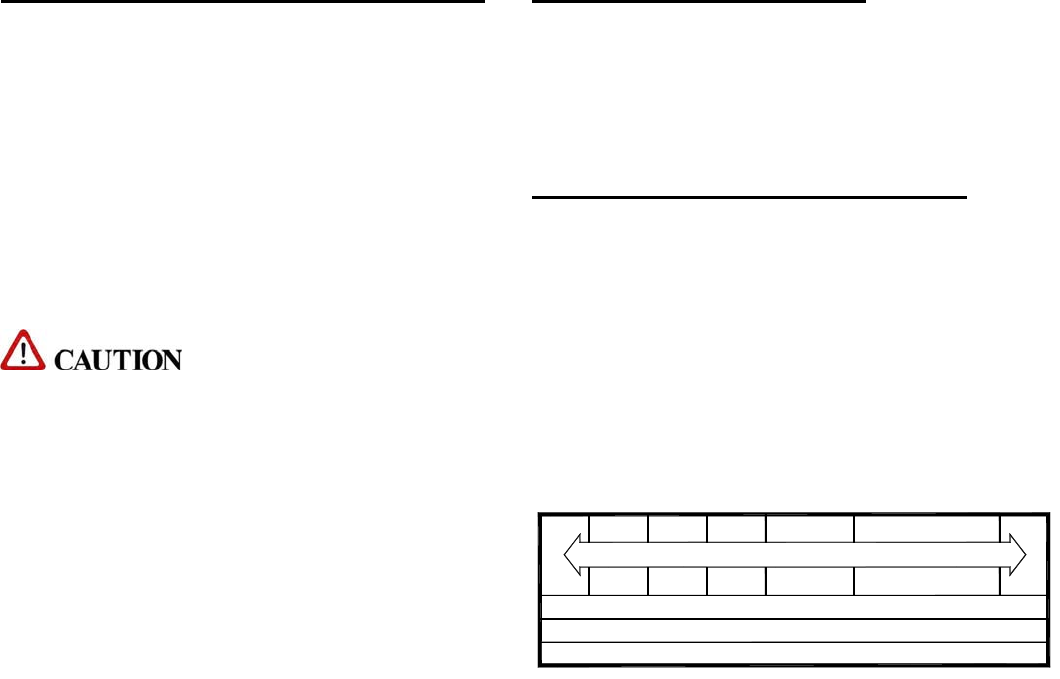
ENGINE OIL REQUIREMENTS
The engine is shipped with Castrol Syntec Blend®
SAE 10W-30 motor oil. We recommend that you
use high quality synthetic oil that meets at least
API (American Petroleum Institute) service class
SG, SH, SJ or higher.
1. The unit should NOT be installed in any motor
vehicle of less than ½ ton capacity.
!
The console and waste tank with accessories
must NOT exceed the vehicles axle weight limit. NOTE: the use of less than service class SG, SH
or SJ oil or extending oil change intervals longer
than recommended can cause engine damage.
2. If mounting the unit in a trailer, ensure that the
trailer is rated for the total weight of the unit and
trailer. Electric or hydraulic brakes must be
provided, and strict compliance with all State and
Federal laws must be maintained.
3. If mounting in a trailer, the BLUELINE Super
Extraction System® console must be
positioned so that it balances properly with respect
to the trailer axle. Ten percent (10%) of the units
total overall weight (w/o accessories or water)
should be on the tongue.
4. The vehicle tires must have a load rating in
excess of the combined unit and vehicle weight.
TEMPERATURE RANGE EXPECTED BEFORE NEXT OIL CHANGE
°C
°F -22
-30
-4
-20 -10
14 32
0
59
15
104
40
USE 10W-30 API SG,SH,SJ OR HIGHER
5. BLUELINE does not recommend using any
type of flooring materials that absorb water. This
condition will result in rust and corrosion of the
vehicle floor.
6. Insulation under rubber mats should be removed
prior to installation of the unit.
Super Extraction System®
6

SECTION 1
2. RECEIVING YOUR
TRUCK MOUNT UNIT
G. 100 ft. of 2 in. vacuum hose
H. 1 vacuum hose connector
OPTIONAL EQUIPMENT
A. Additional lengths of vacuum hose
DEALER RESPONSIBILITY Part # 18-003
B. Additional vacuum hose connectors
THE BLUELINE DEALER THAT YOU
PURCHASED THIS TRUCK MOUNT
CLEANING UNIT FROM IS RESPONSIBLE
FOR THE PROPER INSTALLATION OF THIS
MACHINE. THE DEALER IS ALSO
RESPONSIBLE FOR THE PROPER INITIAL
TRAINING OF YOUR OPERATORS AND
MAINTENANCE PERSONNEL.
Part # 21-003
C. Automatic waste pump kit
Part # 68-003
D. KIT, FUEL HOOKUP CHEVY 97 & NWR. FI
Part # 69-003FI
E. KIT, FUEL HOOKUP CHEVY/DODGE FI
Part # 69-004FI
F. KIT, FUEL HOOKUP FORD FI
Part # 69-005 FI
ACCEPTANCE OF SHIPMENT G. KIT, FUEL HOOKUP 2003 CHEVY FI
Part #69-018FI
H. KIT, 2004 TF ADAPTER CHEVY
Your BLUELINE Super Extraction
System® truck mount unit was thoroughly tested,
checked and inspected in its entirety prior to
leaving our manufacturing facility. When
receiving your unit, please make the following
acceptance check:
Part # 69-032
I. KIT, 2004 TF FUEL INJ. CHEVY
Part # 69-033
J. ADAPTOR, 2004 FORD FUEL
Part # 69-041
K. ADAPTOR, 2004 FUEL INJ. FORD
Part #69-047
1. The unit should not show any signs of damage.
If there is damage, notify the common carrier
immediately.
2. Carefully check your equipment and packing
list. The standard BLUELINE Super
Extraction System® truck mount unit should
arrive with the following items as well as any
optional accessories:
EQUIPMENT LISTING
A. BLUELINE Super Extraction
System® console.
B. Operation and Service manual
C. Installation mounting plates and bolt down kit
D. Hose clamps for vacuum and fuel hoses
E. Waste tank with shutoff switch
F. Waste tank filter and stainless steel strainer
baskets.
Super Extraction System®
7

SECTION 2:
INSTALLATION
3 INSTALLATION
Lifting the unit into the vehicle 9
Positioning the unit into the vehicle 9
Fastening down the unit 9
Dimensional diagrams 10
Installation of fuel lines 11
Trailer fuel tank and fuel line installation 11
Battery Connection 11
Fire extinguisher 11
Super Extraction System®
8
SECTION 2
3. INSTALLATION FASTENING DOWN THE UNIT
AND WASTE TANK
!!! !!!
This unit must be bolted to the floor of the
vehicle by an authorized BLUELINE
DISTRIBUTOR.
Prior to drilling any holes in the vehicle floor,
ensure that while drilling, you will not damage
the fuel tank, fuel lines, or any other vital
components, which could affect the safety and
or operation of the vehicle.
LIFTING THE UNIT INTO THE
VEHICLE
The BLUELINE SUPER EXTRACTION
SYSTEM® weighs approximately 625 lbs., a
forklift is necessary to place the unit into the
vehicle. Make CERTAIN that the forks are spread
to the maximum width of the unit.
A. The waste tank mounting holes will serve as a
template. Drill ten (10) 13/32 in. diameter holes for
the waste tank.
B. Using the provided mounting hardware kit:
POSITIONING THE UNIT INTO
THE VEHICLE 1. Insert ten (10) 3/8-16 x 2 ½ in. hex head
cap screws with flat washers through the
waste tank mounting holes.
Vehicles vary in size and openings. Owners have
different preferences on where in the vehicle they
want their units positioned. BLUELINE strongly
recommends a side door installation for the SUPER
EXTRACTION SYSTEM®. We DO NOT
recommend a rear door installation.
2. Install the provided mounting plates
underneath the vehicle floor.
3. Screw the provided 3/8-16 hex head lock
nuts on to the mounting bolts and tighten
until the waste tank is firmly attached to the
vehicle floor.
1.Ensure that enough space is provided to assure
adequate engine ventilation as well as room for
service and maintenance.
2. The complete unit and accessories MUST NOT
exceed the vehicle’s axle weight limit.
3. NEVER position the console closer than 12
inches from the bottom rear of the driver and
passenger seats.
Super Extraction System®
9
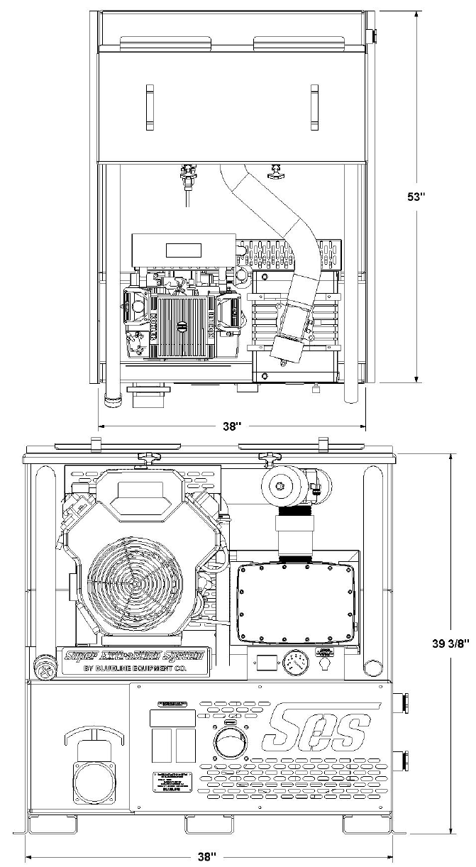
DIMENSIONAL DIAGRAM
Super Extraction System®
10
SECTION 2
INSTALLATION OF FUEL LINES
!!!
READ THESE INSTRUCTIONS IN THEIR
ENTIRETY PRIOR TO PROCEEDING.
!
The Vehicle fuel lines should NOT be spliced
under ANY circumstances. Severe injury or
fatality could result.
DO NOT damage the vehicle in any way during
the installation. When routing fuel lines DO NOT
configure the hoses in any location where the hoses
or vehicle could be damaged. Avoid contact with
moving parts, areas of high temperature, brake
lines, fuel lines, catalytic converters, exhaust pipes,
mufflers or sharp objects.
TRAILER FUEL TANK AND FUEL
LINE INSTALLATION
The following are recommendations for trailer
installations:
A. Strict compliance with all federal and state laws
must be maintained.
B. Use only fuel tanks that are manufactured
specifically for gasoline, have proper vented filling
caps, and outlet connections that are the same size
as the inlet and return connections on the unit.
C. DO NOT install fuel tanks inside any type of
enclosed trailer or vehicle.
!
NEVER carry gasoline or flammable materials in
an enclosed trailer or vehicle.
NEVER store any type of flammable material in
an enclosed trailer or vehicle.
D. Always mount fuel tanks where they will be
protected from any vehicle collision.
E. When installing fuel lines from the fuel tank to
the unit, use the proper size fuel line.
BATTERY CONNECTION
!
Explosive gases, Dangerous gases!
Batteries contain sulfuric acid. To prevent acid
burns, avoid contact with skin, eyes and
clothing. Batteries also produce explosive
hydrogen gases while charging. To prevent fire
or explosion, charge batteries only in a well
ventilated area. Keep sparks, open flames, as
well as any other sources of ignition away from
batteries at all times. Remove all jewelry prior
to servicing batteries. Keep batteries out of the
reach of children.
Before disconnecting the negative (-) ground
cable, ensure that all switches are in the OFF
position. If ON, a spark could occur at the
ground connection terminal, which could cause
an explosion if hydrogen gas or gasoline vapors
are present. ALWAYS disconnect the negative
(-) terminal first.
A. Attach the red positive (+) battery cable from
the starter solenoid on the console to the positive
(+) terminal on the battery and tighten down the
nut.
B. Attach the black negative (-) battery cable from
the ground on the console to the negative (-)
terminal on the battery and tighten down the nut.
FIRE EXTINGUISHER
BLUELINE, and many government agencies,
recommend that a fire extinguisher rated for A, B,
and C type fires be installed into any commercial
vehicle.
Super Extraction System®
11

SECTION 3:
OPERATION
4. SYSTEMS
Vacuum system 13
5. OPERATION
Preparation 14
Starting the unit 15
Automatic waste pump 15
Extraction process 15
Shut down and daily maintenance 15
Freeze protection 16
Super Extraction System®
12
SECTION 3
4. SYSTEMS
NOTE: Read and understand this section of the
manual entirely before proceeding.
Prior to proceeding into the operations and
maintenance sections of this manual it is
recommended that you acquire a basic
understanding of how the unit functions.
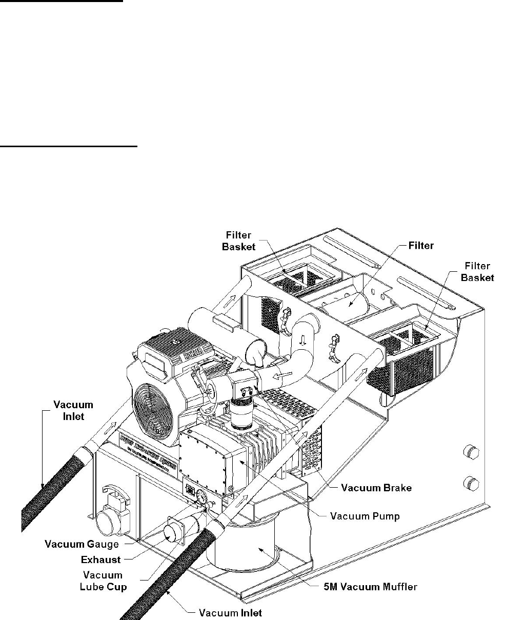
VACUUM SYSTEM
See figures 3-1 and 5-2. The vacuum flow is
initiated by the vacuum pump, or blower. An air
and water mixture is drawn into the vacuum inlet
on the front of the console. The mixture flows
through a strainer basket in the waste tank. The air
exits the waste tank through a 100 mesh filtration
system, into the vacuum pump. A vacuum pump
relief valve is installed for vacuum pump
protection.
The air is discharged from the vacuum pump
through a spiral silencer.
A level shut off sensor is located on the front of the
waste tank and will shut down the unit before the
tank is at full capacity. This protects the vacuum
pump from water damage. Note: Waste tank level
shut off will not shut the unit off due to high levels
of foam.
3-1
Super Extraction System®
13
5. OPERATION
PREPARATION
This section of the operator’s manual explains
how to prepare, start, operate, shut down and
maintain your BLUELINE Super
Extraction System® truck mount unit. The
BLUELINE Super Extraction System®
unit is easy to operate. However only trained
operator’s should proceed.
!
Operate this unit and equipment only in a well
ventilated area. Exhaust fumes contain carbon
monoxide, which is an odorless and deadly
poison that can cause severe injury or death.
DO NOT run this unit in an enclosed area.
DO NOT operate this unit where the exhaust
may enter a building doorway, window, vent
or any other opening.
Super Extraction System®
14
SECTION 3
ENSURE THERE IS ADEQUATE
FUEL
Check the fuel tank to ensure there is adequate
fuel to complete the job and transport the
vehicle. This unit consumes approximately .95
US gallons of fuel per hour, when unit is run
under full load.
REMOVE TOOLS FROM THE
VEHICLE
Remove any tools, accessories or hoses from
the vehicle that you will require.
VACUUM HOSE
Connect the vacuum hose to the vacuum inlet
connection at the front of the console. Connect
the opposite end of the vacuum hose to the
extraction tool.
STARTING THE UNIT
1. Set the throttle control lever to the idle
position (right).
2. Set the choke lever to the full choke
position (left).
3. Turn the ignition switch to the right
intermediate position. Hold the switch in this
position for approximately 3 seconds,
allowing the fuel pump to pump fuel.
4. Turn the ignition switch to the furthest right
position. This will engage the starter and start
the engine.
5. After starting the engine, return choke lever
to the run position (right).
6. After the engine is running at its idle
setting, set the throttle control lever to the fast
position (left).
AUTOMATIC WASTE PUMP
1. If your unit is equipped with an optional
automatic waste pump, connect one end of the
5/8 inch or larger garden hose to the pump-out
connection and the other end to an acceptable
waste disposal.
2. The waste pump will now operate
automatically throughout the extraction
process.
DO NOT use an outlet hose that is smaller
than 5/8 in. I.D.
!
NEVER dispose of waste water in a storm
drain, water way or on ground areas.
Always dispose of waste in accordance with
Local, State and Federal laws.
EXTRACTION PROCESS
After you have completed the previous steps,
proceed with the extraction process. Place the
throttle control lever to the fast speed for
extraction. A float shut-off switch is located
inside of the waste tank. It will automatically
shut down the unit if the tank reaches its full
capacity. If this occurs, empty the waste tank
before continuing.
SHUT DOWN AND DAILY
MAINTENANCE
1. Remove as much moisture from the vacuum
hoses as possible. This will prevent spillage of
wastewater in your vehicle when returning
hoses.
2. Disconnect the vacuum hose from the front
of the console.
Super Extraction System®
15

3. Push the throttle control lever to the slow
position.
4. Allow the unit to run for at least 2 minutes.
This will help remove any moisture from the
vacuum pump.
NOTE: If shutting down for the day: Plug the
vacuum inlets, and set the throttle control to
fast speed. Spray WD-40 (or equivalent) into
the blower lubrication cup, located on the
front of the console for 5 seconds. This will
lubricate the vacuum pump. Next, return the
throttle control lever to the slow position, and
continue step 4.
5. Turn the ignition switch to the OFF
position.
6. Drain the waste tank, disposing of
wastewater in a suitable and proper location.
!
NEVER dispose of wastewater in a storm
drain, water way or on ground areas.
Always dispose of waste in accordance with
Local, State, and Federal laws.
7. Remove the strainer basket from the waste
tank. Clean out any debris and re-install.
NOTE: Damage may occur to the vacuum
pump.
Replacement and maintenance of the filters
will prevent rust and corrosion from entering
the vacuum pump.
8. Inspect the vacuum inlet filters inside the
waste tank weekly. Remove and clean the
filters if there is any lint or debris present.
NOTE: To remove the vacuum inlet filter,
grip the plastic hexagon section of the filter.
Gripping the filter by the screen will collapse
or destroy the filter. Replace the filter after
cleaning until hand tight.
NEVER operate this unit with the filter
removed, damaged or improperly installed.
9. At the end of the work day, rinse out the
waste tank with fresh water. A deodorizer may
be added to prevent bacterial growth.
10. Clean the vehicle interior, unit, tools,
hoses etc., as needed. Inspect ALL equipment
and accessories for any damage, leaks, wear,
etc.
FREEZE PROTECTION
!
If the unit is exposed to freezing weather
conditions, the water inside of the unit may
freeze, resulting in SERIOUS DAMAGE to
the unit. The following is recommended to
prevent this from occurring during the cold
weather season:
1. Always park the unit in a heated building
when not in use.
2. While out in operation, avoid long periods
of shut down.
3. Completely drain the waste tank and leave
gate valve open.
Super Extraction System®
16
SECTION 4:
SERVICE & MAINTENANCE
6. MAINTENANCE
Maintenance Chart 18
Engine 19
Vacuum Pump 20
Vacuum Inlet Filter 20
Drive Belts, Pulleys and Hubs 20
Strainer Basket 21
Vacuum Hoses 21
Battery 21
7. GENERAL SERVICE ADJUSTMENTS
Engine 21
Vacuum Relief Valve 22
Vacuum Pump Drive Belts 21
8. TROUBLESHOOTING
Blower / Vacuum Pump 23
Engine Will Not Start 24
Engine Does Not Crank 25
Engine Runs for 5 Seconds 25
Super Extraction System®
17

MAINTENANCE CHART
Engine Daily
Check engine oil level.** Fill to proper level.
Vacuum Pump Daily Spray WD-40 (or Equivalent) into the lubrication cup for 5 seconds.
Vacuum Inlet Filter Daily* Inspect filter, clean and or replace if required.
Strainer Basket Daily Empty and clean stainless steel basket.
Vacuum Hoses Daily Rinse with fresh water.
Waste Pump-Out (Optional) Daily* Inspect and remove any debris or sediment.
Engine Weekly
Check air cleaner for damaged, dirty, or loose parts.
Engine Weekly Inspect air intake and cooling areas. Clean if required.
Vacuum Pump Weekly* Check vacuum pump oil level. Fill to proper level. Do not overfill.
Vacuum Inlet Filter Weekly Remove filter and clean.
Battery Weekly* Check fluid level. Fill with distilled water only. Do not overfill.
Engine Monthly
Inspect drive belts for wear. Replace as needed.
Engine 100 Hours
Change engine oil and filter.
Vacuum Pump 100 Hours Grease bearings with extreme pressure bearing grease.
Battery 100 Hours
Clean battery terminals.
Engine 200 Hours
Check spark plugs and clean if necessary.
Engine 200 Hours
Clean engine air filter.
Engine 500 Hours
Replace in-line fuel filter.***
Pulleys and Hubs 500 Hours Check pulley and hub set screws for proper torque.**
Engine 1000 Hours
Replace spark plugs.
Vacuum Pump 1000 Hours Drain, flush, and replace oil.****
Engine 2000 Hours
Replace air filter element.
To maximize the operating life and performance, use only recommended oils, filters and greases.
*Or as often as required.
**Change engine oil and oil filter after first 50 hours of operation.
**Check pulley and hub set screws after first 50 hours of operation, and again at 100 hours of operation.
***Or every 6 Months. Whichever comes first.
****Or Yearly. Whichever comes first.
Super Extraction System®
18
SECTION 4
6. MAINTENANCE
This section of the operator’s manual contains the
service and maintenance information for the
BLUELINE Super Extraction System®.
A planned preventative maintenance program will
ensure that your BLUELINE Super
Extraction System® has optimum
performance, long operating life, and a minimum
amount of down time.
!
DO NOT attempt to service this unit while it is
running. High speed parts as well as high
temperature components may result in severe
injury, severed limbs, or fatality.
ENGINE
1. Check the engine oil level daily. Ensure that the
proper oil level is maintained. NEVER overfill.
2. Change the oil after the first 50 hours of
operation, after the “break-in” period. Thereafter,
change oil every 100 hours of operation.
USE ONLY KOHLER BRAND OIL FILTERS.
USE OF ANY OTHER TYPE OF OIL FILTER
WILL VOID ENGINE WARRANTY.
Oil Recommendation. The engine is shipped with
Castrol Syntec Blend® SAE 10W-30 synthetic
motor oil. Use only high quality synthetic oil of at
least API (American Petroleum Institute) service
class SG, SH, SJ or higher.
TEMPERATURE RANGE EXPECTED BEFORE NEXT OIL CHANGE
°C
°F -22
-30
-4
-20 -10
14 32
0
59
15
104
40
USE 10W-30 API SG,SH,SJ OR HIGHER
NOTE: The use of less than service class SG, SH,
SJ or higher, or extending the oil change intervals
longer than recommended can result in engine
damage.
3. Check the spark plugs every 200 hours and
clean if necessary. Replace spark plugs every 1000
hours. NEVER sandblast spark plugs. Spark plugs
should be cleaned only by scraping or wire
brushing.
4. Clean the engine air filter element every 200
hours. Replace the element every 2000 hours.
Replace the in-line fuel filter yearly.
NOTE: Additional engine service information can
be obtained from the provided Kohler Operation
and Maintenance manual. If service or repair is
required, contact an authorized Kohler Service
Center. They will require the serial number of the
engine.
Super Extraction System®
19

VACUUM PUMP
NOTE: Refer to the provided Vacuum Pump
Operation and Service Manual for specific
instructions.
Lubrication: BLUELINE recommends that you
use only AEON PD Synthetic Blower Lubricant in
the gear end of the vacuum pump for all operating
temperatures. AEON PD is formulated specifically
for positive displacement blower service to provide
maximum blower protection at any temperature.
One filling of AEON PD will last a minimum of
twice as long as a premium mineral oil.
NOTE: AEON PD (Part # 13-004) is the only oil
that BLUELINE puts in the vacuum pump at the
factory. Adding petroleum oil to synthetic oil is
NOT recommended.
1. Check the oil level weekly to ensure the proper
level. Too little oil will damage and ruin the
bearings and gears. Too much oil will result in
overheating.
2. A lubrication cup has been provided at the front
of the console, to prevent rust from building up
inside of the vacuum pump. Run the unit for at
least 2 minutes to remove any moisture from the
vacuum pump. Then, spray WD-40 (or Equivalent)
into the lubrication cup for 5 seconds while the
unit is running and the vacuum inlet ports are
sealed. This procedure should be done at the end of
every working day.
3. Drain, flush and replace the oil every 1000
hours or yearly, whichever comes first.
VACUUM INLET FILTER
1. The vacuum inlet filter in the waste tank should
be inspected daily, and removed and cleaned
weekly. The filter will last for a long period of
time if this is done.
2. Inspect the vacuum filter inside the waste tank.
Remove and clean the filter if there is any lint or
debris present.
!
When removing the vacuum inlet filter(s), grip
the plastic hexagon section of the filter(s).
Grasping filter(s) by the screen will damage or
destroy the filter(s).
DRIVE BELTS, PULLEYS & HUBS
1. Check pulley set screws and hub screws after the
first 50 hours of operation and again at 100 hours.
Re-torque these screws with a torque wrench.
Follow the torque values on the following table.
Check pulley set screws and hub screws every 500
hours thereafter.
!
Ensure that when you re-torque the screws, you
use a clockwise pattern and continue until the
proper torque is achieved.
TORQUE VALUES
Component Inch/lbs Foot/lbs
Engine Hub 720 60
Vacuum Pump Hub 192 16
Super Extraction System®
20
SECTION 4
STRAINER BASKETS
The strainer baskets located in the waste tank
should be emptied and cleaned on a daily basis.
VACUUM HOSES
To ensure maximum hose life, BLUELINE
recommends that you wash out the hoses with
fresh water daily.
BATTERY
!
Explosive gases, Dangerous acid!
Batteries contain sulfuric acid. To prevent acid
burns, avoid contact with skin, eyes and
clothing. Batteries also produce explosive
hydrogen gases while charging. To prevent fire
or explosion, charge batteries only in a well
ventilated area. Keep sparks, open flames, as
well as any other sources of ignition away from
batteries at all times. Remove all jewelry prior
to servicing batteries. Keep batteries out of the
reach of children.
Before disconnecting the negative (-) ground
cable, ensure that all switches are in the OFF
position. If ON, a spark could occur at the
ground connection terminal, which could cause
an explosion if hydrogen gas or gasoline vapors
are present. ALWAYS disconnect the negative
(-) terminal first.
1. Check the fluid level in the battery at least once
a week. If low, fill to the recommended level
ONLY with distilled water. DO NOT overfill the
battery. Early failure or poor performance will
result due to loss of electrolyte.
2. Keep cables, terminals and external surfaces of
the battery clean and dry. A buildup of corrosive
acid or grime on the external surfaces could cause
the battery to self-discharge.
3. Battery terminals should be cleaned every 100
hours to prevent corrosion buildup. Wash the
cables, terminals and external surfaces with a mild
baking soda and water solution. Rinse thoroughly
with fresh water. DO NOT allow baking soda to
enter the battery cells, as this will destroy the
electrolyte, resulting in battery failure.
7. GENERAL SERVICE
ADJUSTMENTS
!
DO NOT attempt to service this unit while it is
running. High speed parts as well as high
temperature components may result in severe
injury, severed limbs, or fatality.
ENGINE SPEED
1. To adjust the engine RPM, refer to the Kohler
Engine Operation and Service Manual for specific
instructions.
!
DO NOT attempt to adjust without a tachometer
and NEVER adjust the engine above 2800 RPM.
VACUUM RELIEF VALVE
With the unit running at full RPM, block off the
airflow at the vacuum inlet ports and read the
vacuum gauge. If adjustment is required, shut the
unit down and adjust the locking nut tension on the
vacuum relief valve. Re-start the unit and read the
vacuum gauge. Repeat this process until the
vacuum relief valve opens at 13” Hg.
VACUUM PUMP DRIVE BELTS
Super Extraction System®
21

The BLUELINE SUPER EXTRACTION
SYSTEM® is equipped with an adjustable belt
tensioning system. To adjust belts, loosen nuts on
engine mounting plate and adjust belt tension by
turning the tensioning bolt located on the left side
of engine mounting plate. Retighten engine bolts
after proper belt tension is achieved
(approximately 1/2” deflection). Periodically check
the belts and pulleys condition. Repair and or
replace as needed.
8. TROUBLESHOOTING
!
DO NOT attempt to service this unit while it is
running. High-speed parts as well as high
temperature components may result in severe
injury, severed limbs or fatality.
This section of the operator’s manual describes
how to look for and repair malfunctions, which
may occur.
Accurate troubleshooting is based on a thorough
and complete understanding of the VACUUM,
SAFETY and WIRING systems featured in this
unit.
If there are malfunctions occurring on this unit
which you do not understand, refer back to the
OPERATION section of this manual and review
SYSTEM or TROUBLESHOOTING
Super Extraction System®
22
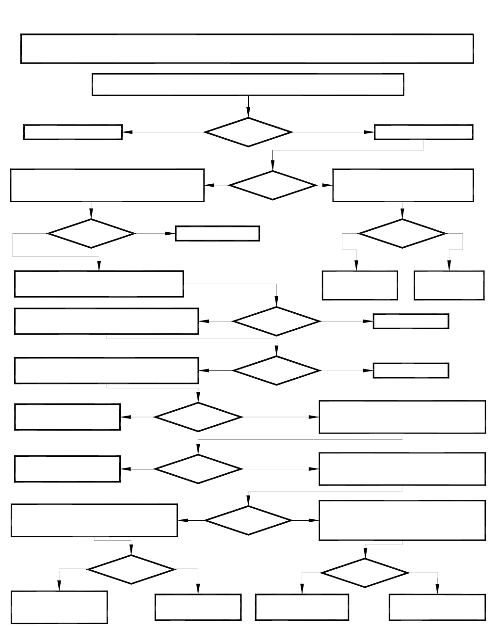
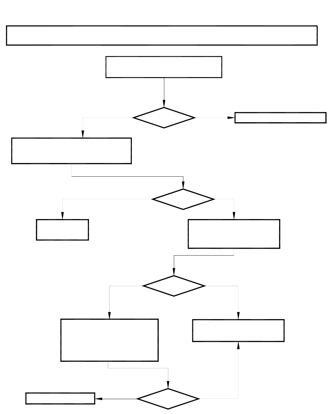
Blower/Vacuum
Note: Make sure the blower has oil, the waste tank is empty and their filters are clean.
Note: Anytime you have a Blower/Vacuum problem, you are actually looking for an air volume problem.
Do you have any vacuum reading on the vacuum gauge when the machine is turned off?
YES NO Does the Engine Crank?
YES NO
NOYES
Replace or rebuild
blower.
Replace Vacuum Gauge.
YES Remove the blower belts. Can you spin
the blower pulley with your hand?
Check the condition of the blower belts.
Are the belts in good condition and properly tensioned?
NOYES Replace blower belts.
Are the dump valves closed on the waste tank?
Close dump valves.
Are the gaskets in the waste tank in good condition?
Replace Gaskets.
NOYES
Are there any cracks or splits in the waste tank?
Repair or replace waste tank. NOYES When you start the machine, does the vacuum
feel normal but the gauge reads different?
Replace vacuum gauge. YES When you start the machine, does the vacuum
feel different than the vacuum gauge reads?
Start the machine and set throttle to high speed.
Seal the vacuum ports.
Does the vacuum gauge read 13" HG?
NOYES
Remove the filters on the waste tank.
Are the filters clean and not crushed?
YES NO YES NO
There is a blockage
between the vacuum inlet
and the waste tank. Clean or replace filters. Vacuum system is normal.. Adjust vacuum relief valve.
NO
See Engine Cranks
but Does Not Start..
NO
Super Extraction System®
23
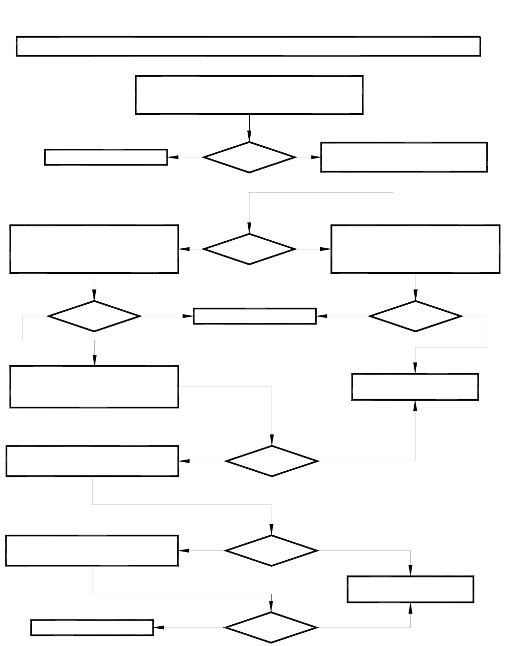
Engine Will Not Start
Note: Make sure the engine has oil, waste tank is empty, and you have at least a half tank of gasoline.
YES NO When you turn the key to the RUN position,
do you hear the fuel pump turn on?
YES NO
See Engine Runs for 5 Seconds.
YES NO
Take engine to an authorized
KOHLER repair center.
Replace air filter.
Does the engine start and run for 5 seconds?
Disconnect the fuel hose from the
machine. Run the hose to a seperate
container. Turn the key to the RUN
position. Is there gasoline being pumped?
With an electrical meter, turn the key to
the RUN position. Do you have at least
12.6 volts or higher at the fuel pump?
YES NOYES NO Replace fuel pump and filter.
When the engine is cold, test each cylinder
with a compression gauge. Does each
cylinder measure within 10% of each other?
When the engine is cold, test for spark at each
spark plug. Do you have spark at each plug?
NOYES
When the engine is cold, remove air filter.
Is the air filter clean and undamaged?
NOYES
Take engine to an authorized
KOHLER repair center.
Super Extraction System®
24
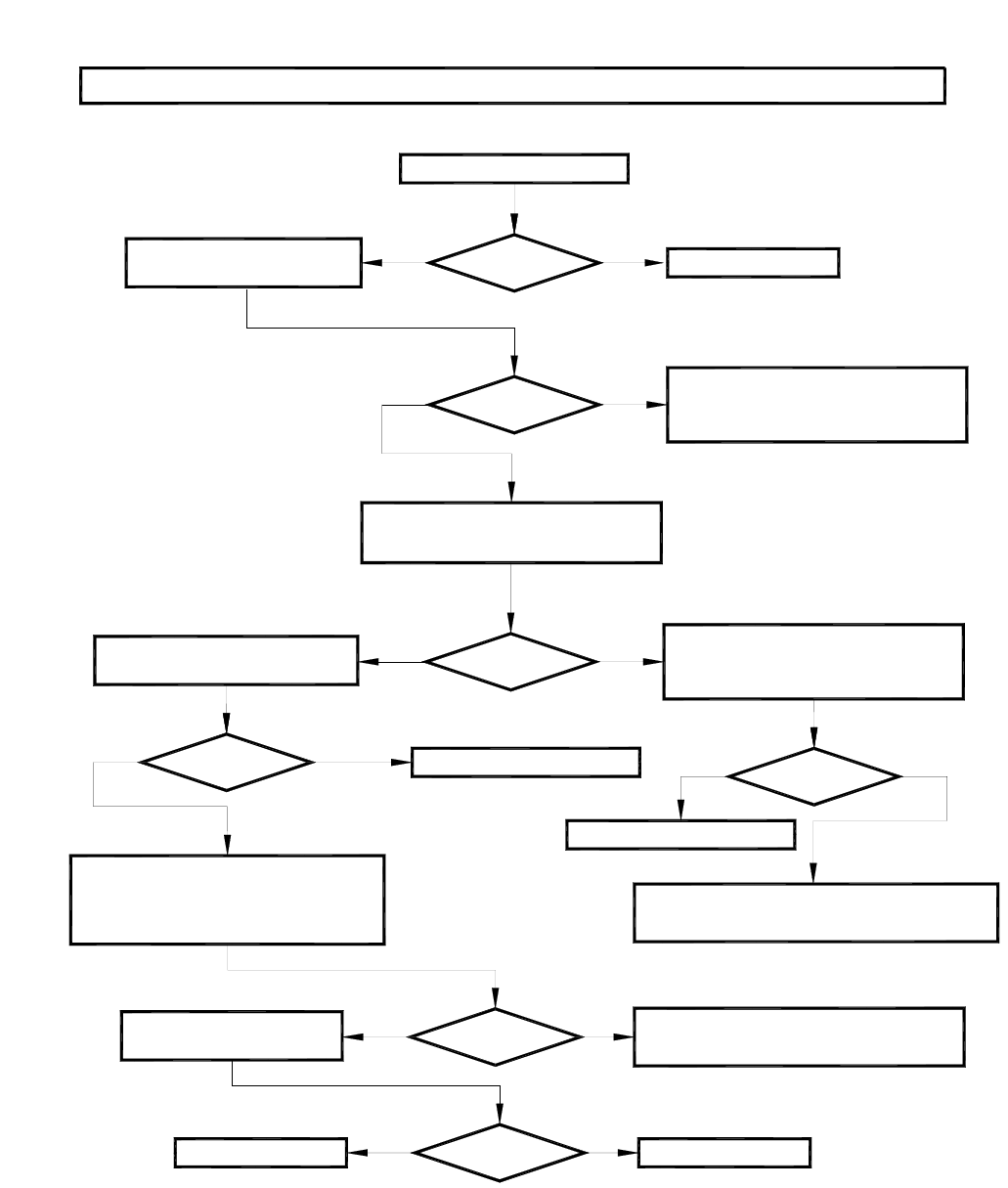
Engine Does Not Crank
Note: Make sure the engine has oil, waste tank is empty, and you have at least a half tank of gasoline.
YES NO
YES NO
Is the battery fully charged
(12.6 volts or higher)?
Install new battery. Note: Check to see
that alternator is charging properly and
cables are clean and undamaged.
Is the battery connected?
Reconnect batterty.
YES NO With an electrical meter do you have at
least 12.6 volts or higher at the ignition
switch (BAT +) terminal?
Is the wire to the starter undamaged
and tightly connected to the starter?
Replace fuel pump and filter.
YES NO
Disconnect the wire from the starter. With an
electrical meter do you have 12.6 volts or
higher when the ignition switch is turned
to the start position?
YES NO
Replace ignition switch.
Repair or replace wire from starter/battery terminal
on the starter to the (BAT +) on the Ignition Switch.
YES NO Repair or replace wire from the (ST) terminal
on the Ignition Switch to the starter.
Remove the blower belts.
Does the engine start?
YES NO
See Blower/Vacuum. Replace starter.
When you turn the key to the RUN
position do you hear the fuel pump run?
Super Extraction System®
25
Super Extraction System®
26
Engine Runs for 5 Seconds
Note: Make sure the engine has oil, waste tank is empty, and you have at least a half tank of gasoline.
YES NO See Engine Cranks But Won't Start.
Disconnect the waste tank float.
Does the engine run for more than 5 seconds?
YES NO
Start the engine and verify that the
engine builds oil pressure.
Does the engine build oil pressure?
Repair or replace
waste tank float.
NOYES
Take the engine to an authorized
KOHLER engine repair center.
Connect a continuity meter to the
green wire termial on the KOHLER
engine plug and the engine ground.
Start the engine.
Does the oil sentry switch open?
YES NO
Inspect and repair wiring.
Does the engine start and run for 5 seconds?
SECTION 5:
SERVICE & MAINTENANCE
9. ILLUSTRATED PARTS LISTINGS
Engine 28
Vacuum-Exhaust System 29
Waste Tank 32
Decals 33
Electrical Diagrams 34
10. ACCESSORIES
Accessories 35
Super Extraction System®
27

5-1
ENGINE INSTALLATION
Item No. Part Number Qty Description
1 45-012 1 ENGINE, KOHLER 25HP
2 36-025 1 GUARD, FLYWL KOHLER#4731402-S
3 36-019 1 FILTER, OIL KOHLER#1205001
4 21-046 1 NIP, 3/8 IN. HEX BRASS
5 21-073 1 COUPLING, 3/8 STD BRASS
6 18-004 1 HOSE, HP 3/8 X 10 IN. OIL DRAIN KOH
7 21-027 1 PLUG, 1/2 T BRASS
8 36-097 1 FILTER, FUEL KUBOTA
9 16-034 1 HOSE, FUEL 1/4" 30R7
10 14-007 5 CLAMP, HOSE # 4
11 21-006 2 FTTG, BRB 1/4PX5/16H BR
12 21-039 1 ELL, 1/4 IN LG STREET BRASS
13 61-018 1 BRKT, FIN FUEL RETURN THERMAL
14 61-176 1 ASSY, ENGINE ADJUSTMENT PLATE
15 61-123 1 BOLT, PUMP ADJUSTMENT BW
16 12-013 5 WASHER, FLAT 3/8 SAE
17 11-006 4 NUT, 3/8-16 ZINC
18 68-030 1 ASSY,FUEL PUMP HOUSING
19 35-004 1 BATTERY, 12 VOLT LAWN & GARDEN
20 40-004 1 BOX, BATTERY HOLDER
21 47-002 1 ASSY, BATTERY CABLE BLK THERMAL
22 47-001 1 ASSY, BATTERY CABLE RED THERMAL
Super Extraction System®
28
SECTION 5
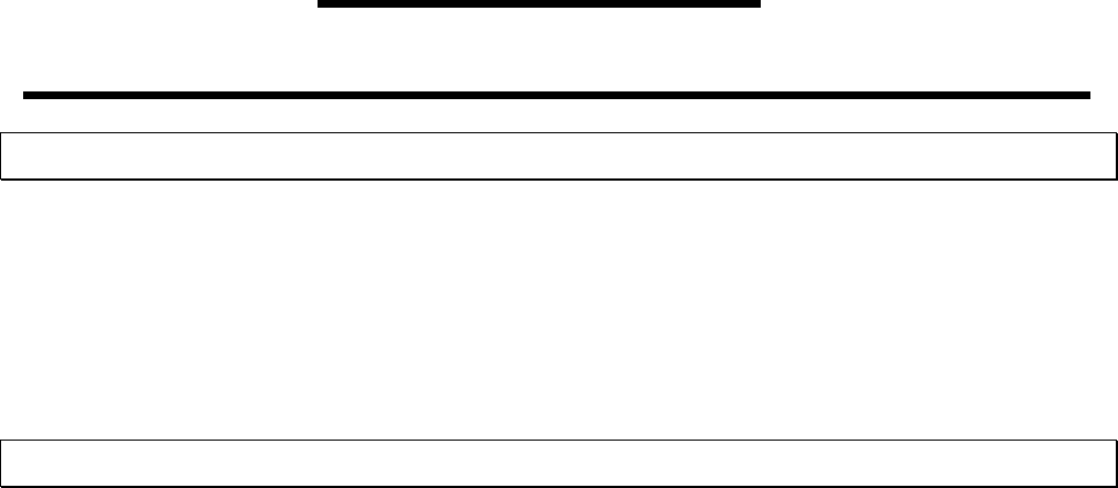
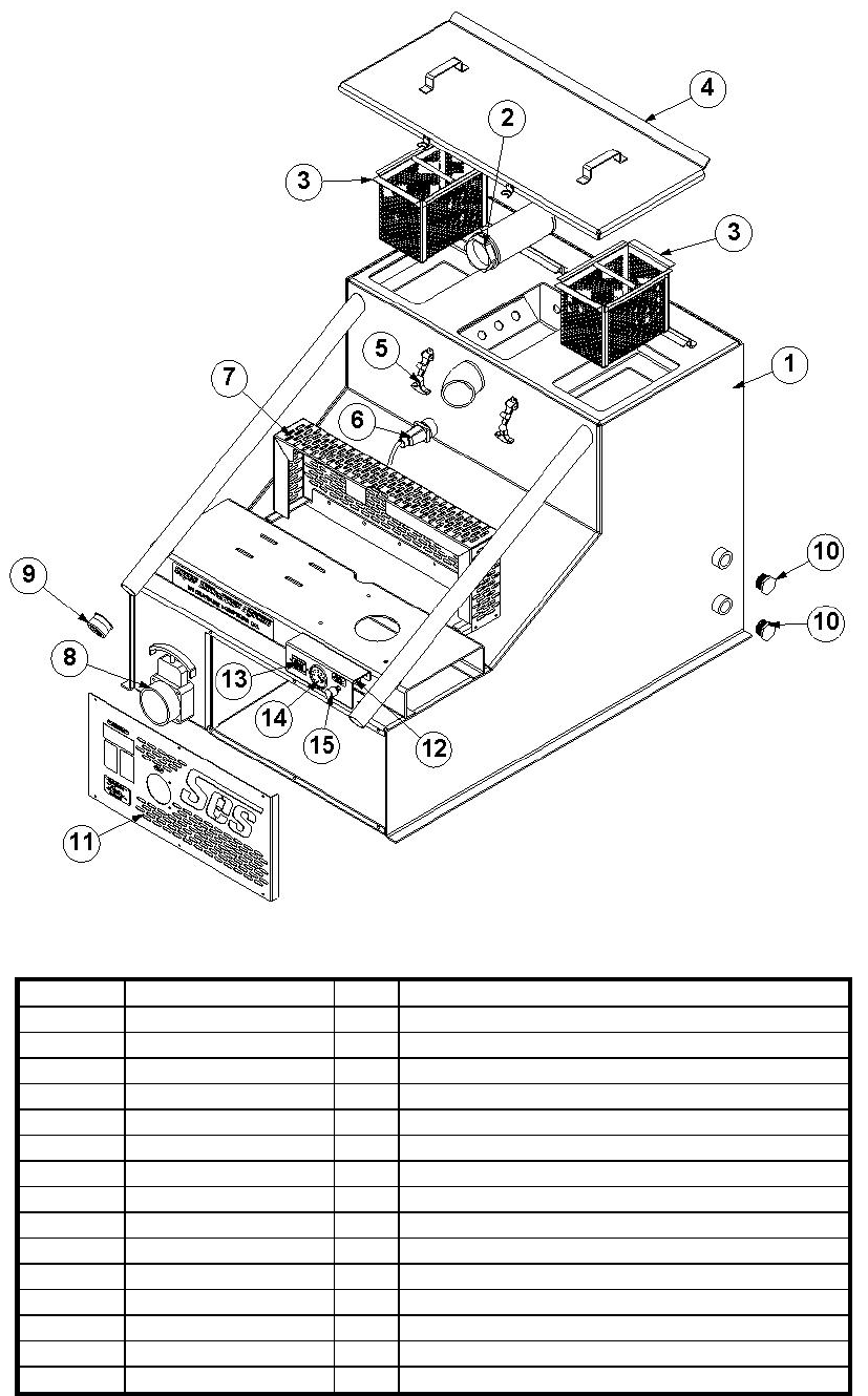
5-2
VACUUM-EXHAUST SYSTEM
Item No. Part Number Qty Description
1 46-030 1 VACUUM PUMP TI-408 HOR(LH)
2 61-187 1 ASSY, ADAPTOR VAC STAN PIPE SES
3 69-040 1 ASSY,VAC BRAKE 5M
4 16-014 24 HOSE, INT VAC 3-1/2 IN 50 FT BULK
5 64-002 1 NIP, HALF BLOWER OUTLET
6 14-008 2 CLAMP, HOSE #72
7 16-013 4.5 HOSE, INT VAC 3-1/4 IN 12-1/2 FTBLK
8 63-059 1 MUFFLER, VACUUM SES 3.5
9 63-057 1 TUBE, MUFFLER EXHAUST SES
10 61-188 1 ASSY, GUARD MUFFLER SES
11 63-060 1 MUFFLER, ENGINE EXHAUST SES
12 14-001 2 CLAMP, MUFFLER 1-1/4 IN..
13 55-050 1 TBG, FLEX 1-1/4ID X 1-3/8OD SS
14 10-007 4 SCREW, MACH 1/4-20 X 1/2 SOCHD SS
Super Extraction System®
29
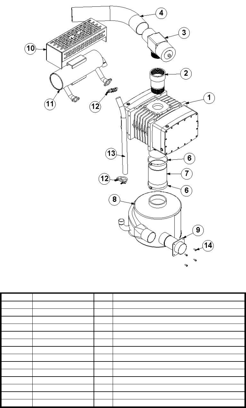
5-3
69-040 ASSY, VAC BRAKE 5M
Item No. Part Number Qty Description
1 61-035 1 STEM, VACUUM RELIEF VLV 4L,5M
2 41-009 1 DIAPHRAGM, VAC RELIEF VLV 4L, 5M
3 66-001 1 VAC BRAKE, MACHINED 4L
4 58-106 1 SPACER, .125 X .688 X 1.625
5 58-108 1 SCREEN, SILENCER THERMAL
6 15-002 1 SPRING, VAC RELIEF VALVE
7 50-000 1 SILENCER, VAC BRAKE FOAM
8 58-077 1 WASHER,VAC SILENCER
9 11-012 2 NUT, 7/16-14 ZINC
10 21-011 2 ELL, 1/8 P X 1/4 POLY BR
Super Extraction System®
30

SECTION 5
5-4
IDLER PULLEY ASSEMBLY
1 37-041 2 BELT, 5VX550
2 38-027 2 PULLEY, 5V630SK 2G
3 38-032 1 HUB, SK 1-1/4
4 38-034 1 HUB, 1-7/16 4JTU56
5 6 5/16-18 HEX BOLT
6 6 5/16 LOCK WASHER
7 64-005 2 KEYSTOCK, 1/4 SQUARE X 2 IN
1 37-041 2 BELT, 5VX550
Super Extraction System®
31
5-5
WASTE TANK SUPER EXTRACTION SYSTEM®
Item No. Part Number Qty Description
1 61-174 1 ASSY, WASTE TANK SES
2 20-021 1 STRAINER, FILTER BLUEWAVE
3 61-002 2 BASKET, STRAINER WASTE TANK
4 61-177 1 ASSY, LID WASTE TANK SES
5 40-003 2 LATCH, PRE-FILTER BOX
6 69-000 1 WIRING , LEVEL SENSOR SHUTOFF
7 61-175 1 ASSY, BELT GUARD SES
8 23-036 1 VALVE,3" STAINLESS PADDLE
9 19-009 1 CAP, WASTE TANK INLET
10 21-097 2 PLUG, 1-1/4 IN PVC
11 58-137 1 PNL, FRONT SUPER EXTRACTION
12 58-140 1 PNL, GAUGE MOUNT SES
13 26-012 1 GAUGE, TINY TACH
14 26-004 1 GUAGE, VAC 30in.HG DUALSCALE
15 28-000 1 CUP, OILFILL 1/8P
Super Extraction System®
32
SECTION 5
44-000 DECAL SHEET, WARNING & CONTROLS
44-040 DECAL, SUPER EXTRACTION SYSTEM®
5-6
Super Extraction System®
33
ELECTRICAL DIAGRAM
Super Extraction System®
34
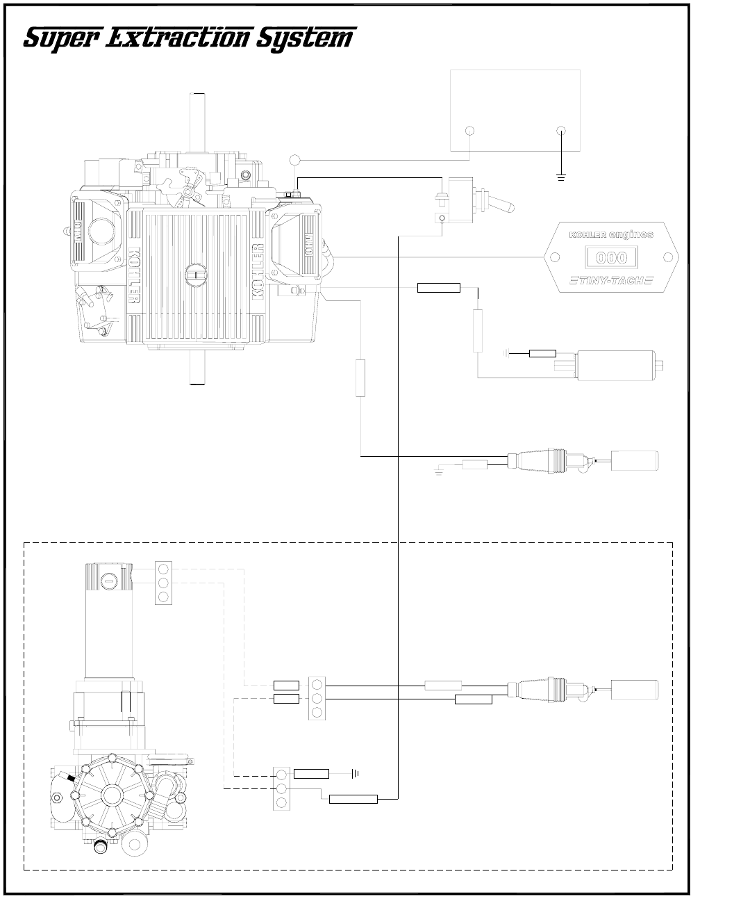
SECTION 5
WHITE
BLACK
BLACK
SHUT-OFF
SWITCH
69-000
BLK/WHT
WASTE
PUMP-OUT
BROWN
-
+
BLK/WHT
FUEL PUMP
36-125
KOHLER
STARTER
YELLOW
09/28/06
WHITE
PURPLE
TINY-TACH
26-012
+
12 VOLT BATTERY
35-004
+-
OPTIONAL WASTE
PUMP OUT KIT
68-003
WASTE
PUMP ON
SWITCH
69-002
WHITE
BLACK
TOGGLE
SWITCH
29-001
Super Extraction System®
35
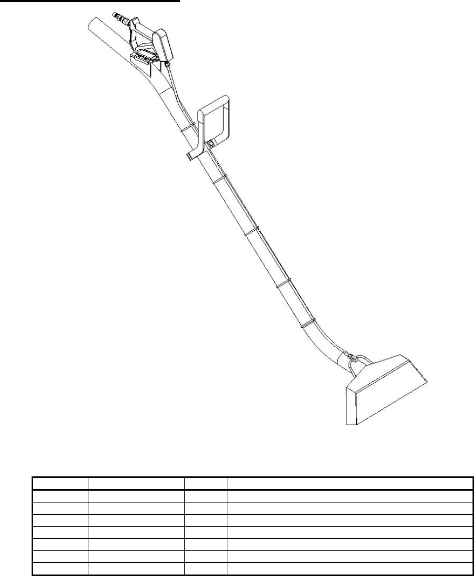
10. ACCESSORIES
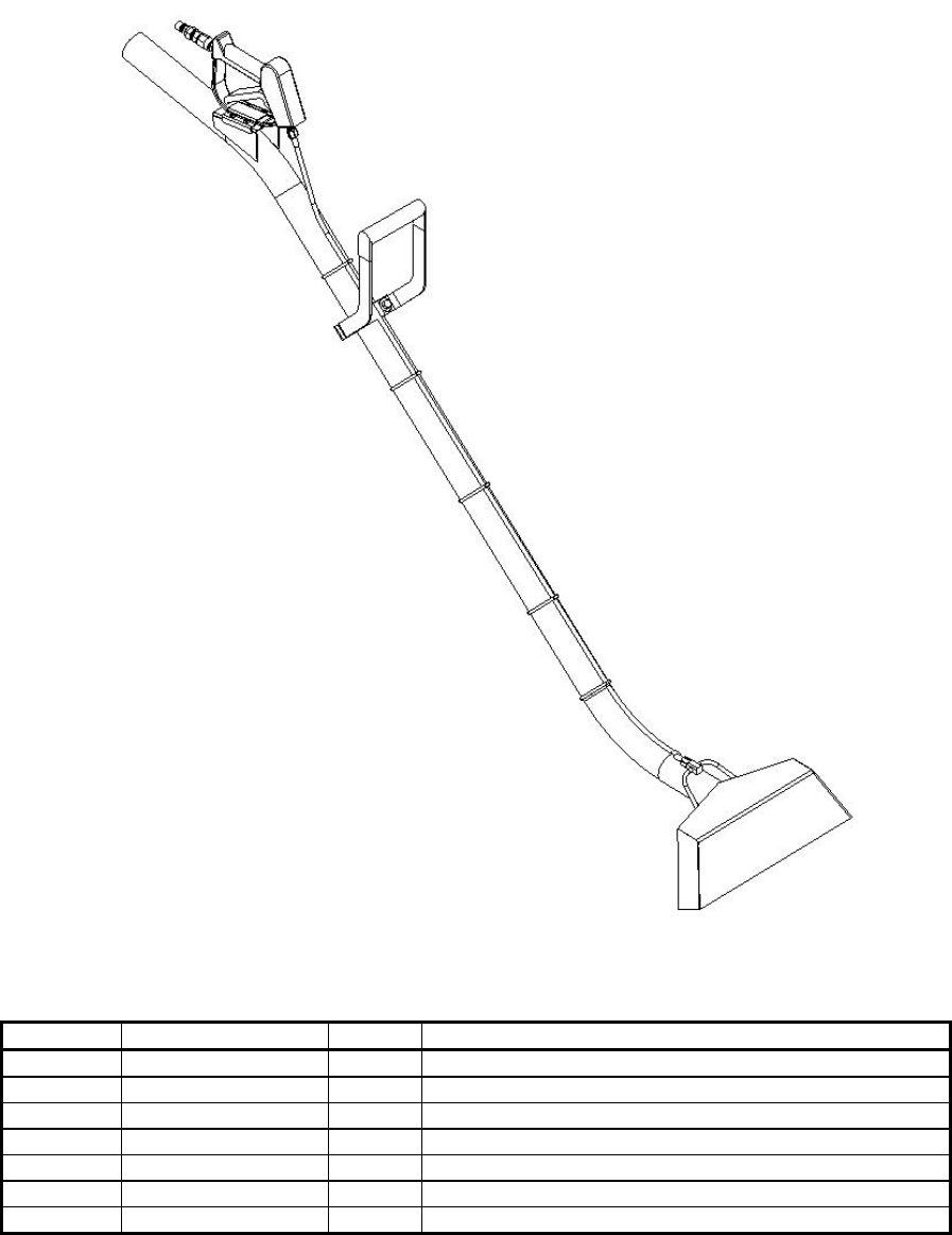
67-003 WAND, ERGO W/PISTOL GRIP 14"
Item No. Part Number Qty Description
1 67-003 1 WAND,ERGONOMIC W /SPRAYER
2 25-000 1 DSC, 1/4M X 1/4FP BR
3 23-035 1 VLV,SPRAYER HYPRO 3381-0032
4 21-050 1 CONN, 1/4 P X 1/4 T BRASS
5 18-021 1 HOSE, 3/16 X 51 1/4FT X 1/4FT
6 24-000 4 TIP, SPRAY 95015X1/8P SST
7 40-009 1 HANDLE, ERGO WAND COATED
Super Extraction System®
36
SECTION 5
WAND, ERGONOMIC 11 IN. WIDE
Item No. Part Number Qty Description
1 67-005 1 WAND,ERGONOMIC 11 IN. WIDE
2 25-000 1 DSC, 1/4M X 1/4FP BR
3 23-035 1 VLV,SPRAYER HYPRO 3381-0032
4 21-050 1 CONN, 1/4 P X 1/4 T BRASS
5 18-021 1 HOSE, 3/16 X 51 1/4FT X 1/4FT
6 24-000 4 TIP, SPRAY 95015X1/8P SST
7 40-009 1 HANDLE, ERGO WAND COATED
Super Extraction System®
37
5-31
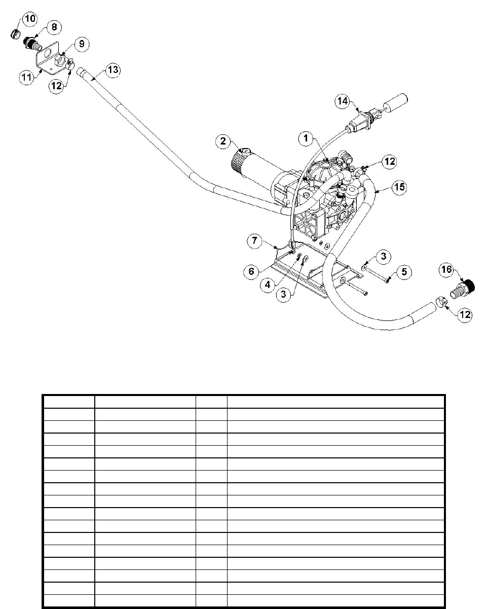
68-003 KIT, WASTE PUMP EXTERNAL
Item No. Part Number Qty Description
1 46-016 1 PUMP, DIAPHRAGM, PUMP OUT
2 45-008 1 MOTOR, GEAR BISON PUMPOUT
3 12-017 4 WASHER, FLAT 5/16 SAE
4 12-016 2 LKWSR, 5/16 ZINC
5 10-040 2 SCREW, MACH 5/16-18 X 3-1/2 SOCHD
6 11-005 2 NUT, 5/16-18 ZINC
7 61-003 1 MOUNT, EXTERNAL PUMPOUT
8 66-022 1 ADAPTOR, HOSE WASTE PUMP
9 66-023 1 NUT, ADPTR. HOSE WASTE PUMP
10 21-071 1 CAP, GARDEN HOSE 3/4 BRASS
11 58-006 1 BRKT, HOSE CONN WASTE PUMP
12 14-006 4 CLAMP, HOSE #20
13 16-004 72” HOSE, WTR. 3/4 IN HRZ. 500FT BULK
14 69-000 1 WIRING , LEVEL SENSOR SHUTOFF
15 16-018 24” HOSE, WTR. 1 IN HRZ. 100FT BULK
16 21-036 1 FTTG, BRB 1-1/4 P X 1 IN. BARB
Super Extraction System®
38
SECTION 5
5-36
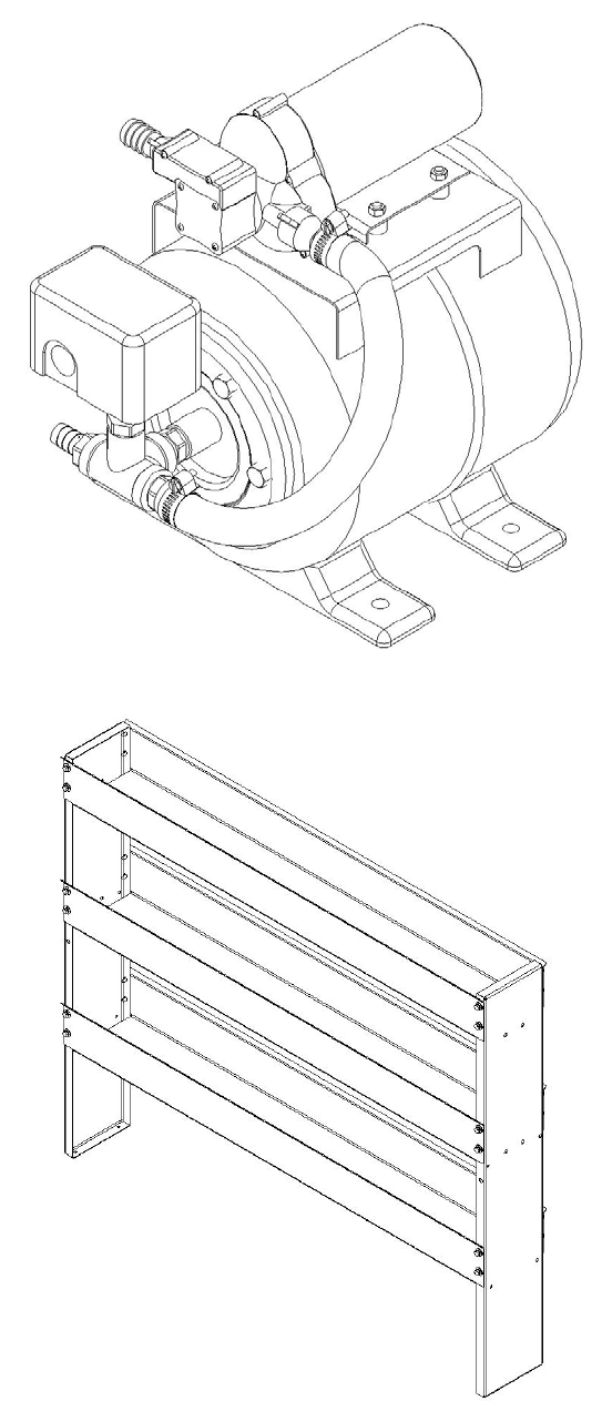
68-002 KIT, DEMAND PUMP W/PLUMBING SS
5-37
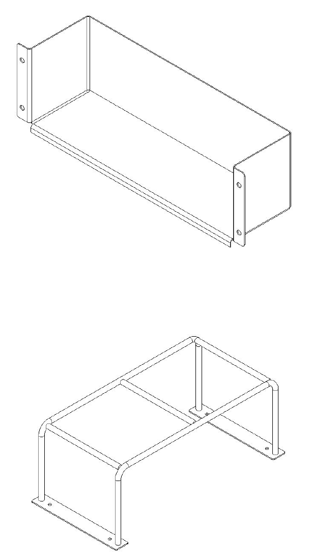
68-013 ASSY, VAN STORAGE UNIT SS
Super Extraction System®
39

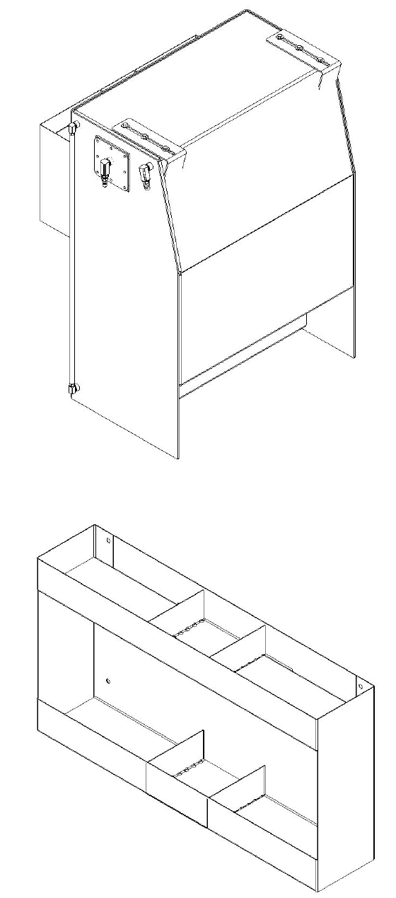
5-38
68-014 ASSY, SINGLE 5 GAL JUG HOLDER
5-40
68-016 RACK, DOUBLE CHEMICAL
Super Extraction System®
40
SECTION 5
5-41
68-017 ASSY, FIN 120 GAL WTR TNK
5-42
68-018 ASSY, 10 GAL CHEM RACK S.S.
Super Extraction System®
41
5-43
68-019 SPRAY BOTTLE HOLDER SS
5-44
68-022 ASSY, DBL PMP UP SPRAY RK, SS
Super Extraction System®
42
SECTION 5
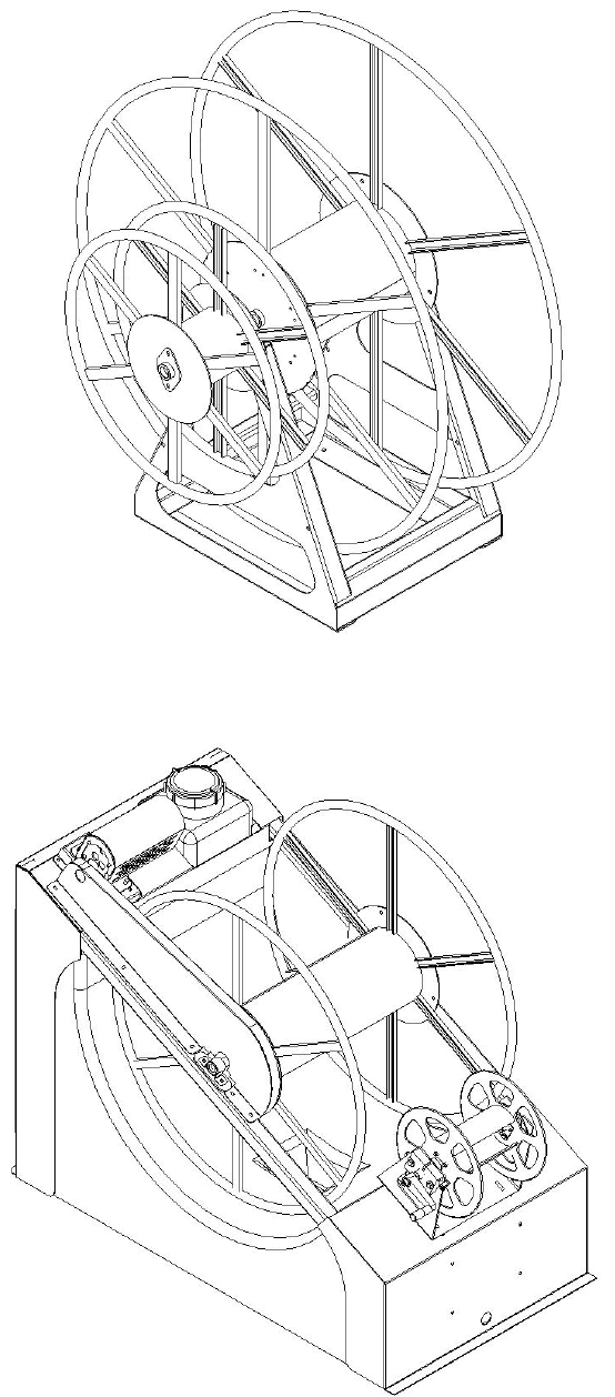
5-47
68-025 ASSY, HOSE REEL HIGH PROFILE
5-48
68-032 ASSY, H-REEL MOTORIZED W-H2O TNK
Super Extraction System®
43
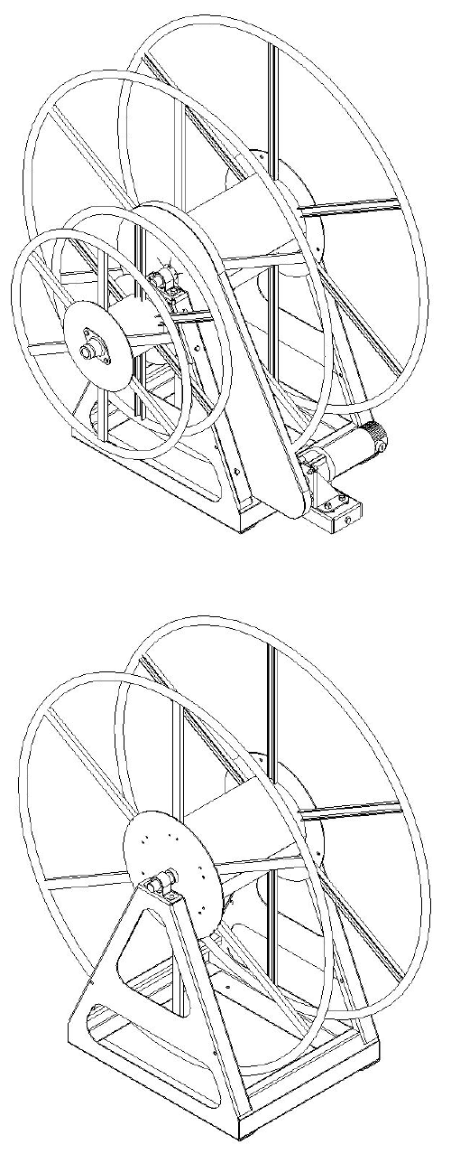
5-49
68-033 ASSY, HOSE REEL H. PROFILE W-MTR
68-037 ASSY, HOSE REEL VAC ONLY
Super Extraction System®
44

SECTION 5
68-043 ASSY, HOSE REEL LAY DOWN KIT
Super Extraction System®
45
