Hyundai ZPP 416 ENGINE DOHC &file=Hyundai
User Manual: Hyundai ZPP 416 ENGINE DOHC
Open the PDF directly: View PDF ![]() .
.
Page Count: 79
ZPP 416 - Engine DOHC
GENERAL
TIMING SYSTEM
TIMING BELT
CYLINDER HEAD ASSEMBLY
CYLINDER HEAD
MAIN MOVING SYSTEM
CAM SHAFT
CRANK SHAFT
FLY WHEEL
PISTON
COOLING SYSTEM
ENGINE COOLANT HOSE/PIPES
ENGINE COOLANT PUMP
RADIATOR
RADIATOR CAP
THERMOSTAT
LUBRICATION SYSTEM
OIL PUMP
ENGINE BLOCK
ENGINE BLOCK
INTAKE AND EXHAUST SYSTEM
EXHAUST MANIFOLD
INTAKE MANIFOLD

EM -2 ENGINE DOHC
GENERAL
SPECIFICATION E5EC07D6
Description Specification Limit
General
Type
Number of cylinders
Bore
Stroke
Total displacement
Compression ratio
Firing order
In-line, Double Over Head Camshaft
4
76.5mm (3.0118 in)
87mm (3.4252 in)
1599 cc (97.54 cu.in)
10
1-3-4-2
Valve timing
Intake valve
Opens (BTDC)
Closes (ABDC)
Exhaust valve
Opens (BBDC)
Closes (ATDC)
Valve overlap
5
35
43
5
10
Cylinder head
Flatness of cylinder head surface
Flatness of mainfold mounting surface
Oversize rework dimension of valve seat hole
Intake
0.3mm (0.012 in.) O.S.
0.6mm (0.024 in.) O.S.
Exhaust
0.3mm (0.012 in.) O.S.
0.6mm (0.024 in.) O.S
Max. 0.03mm (0.0012 in.)
0.15mm (0.0059 in.)
30.7 ~ 30.721 mm (1.2087 ~ 1.2095 in.)
31.0 ~ 31.021 mm (1.2205 ~ 1.2213 in.)
27.3 ~ 27.321mm (1.0748 ~ 1.0756 in.)
27.6 ~ 27.621mm (1.0866 ~ 1.0874 in.)
0.1 mm (0.0039in.)
0.2mm (0.008in.)
Oversize rework dimensions of valve
Guide hole
0.05mm (0.002 in.) O.S.
0.25mm (0.010 in.) O.S.
0.50mm (0.020 in.) O.S.
11.05 ~ 11.068mm (0.435 ~ 0.4357 in.)
11.25 ~ 11.268mm (0.443 ~ 0.4436 in.)
11.50 ~ 11.518mm (0.453 ~ 0.4535 in.)
Camshaft
Cam lobe height
Intake
Exhaust
Joumal O.D
Bearing oil clearance
End play
43.4484mm (1.7106 in.)
43.8489mm (1.7263 in.)
ø27mm (1.0630 in.)
0.035 ~ 0.072mm (0.0014 ~ 0.0028 in.)
0.1 ~ 0.2mm (0.004 ~ 0.008 in.)
42.9484mm
(1.6909in.)
43.3489mm
(1.7.66in.)
ZENITH POWER PRODUCTS - 416

GENERAL EM -3
Description Specification Limit
Valve
Valve length
Intake
Exhaust
Stem O.D.
Intake
Exhaust
Face angle thickness of valve head (Margin)
Intake
Exhaust
Valve stem to valve guide clearance
Intake
Exhaust
91.7mm (3.6102 in.)
92.3mm (3.6339 in.)
5.955 ~ 5.97mm (0.2344 ~ 0.2350 in.)
5.935 ~ 5.95mm (0.2337 ~ 0.2343 in.)
1.1mm (0.0433 in.)
1.3mm (0.0512 in.)
0.03 ~ 0.06mm (0.0012 ~ 0.0024 in.)
0.05 ~ 0.08mm (0.0020 ~ 0.0031 in.)
0.8mm (0.031in.)
1.0mm (0.039in.)
0.10mm (0.0039in.)
0.15mm (0.0059in.)
Valve guide
Installed dimension O.D.
Intake
Exhaust
Service size
12.8mm (0.504 in.)
12.8mm (0.504 in.)
0.05, 0.25, 0.50mm
(0.002, 0.010, 0.020 in.) oversize
Valve seat
Width of seat contact
Intake
Exhaust
Seat angle
Oversize
0.8 ~ 1.2mm (0.031 ~ 0.047 in.)
1.3 ~ 1.7mm (0.051 ~ 0.066 in.)
45
0.3, 0.6mm (0.012, 0.024 in.) oversize
Valve spring
Free length
Load
Squareness
44.00mm (1.7323 in.)
21.6kg/ 35mm (47.6lb/1.3780 in.)
45.1kg/ 27.2mm (99.4lb/1.071 in.)
1.5 or less
Cylinder block
Cylinder bore
Out- of- round and taper of cylinder bore
Clearance with piston
76.50 ~ 76.53mm (3.0118 ~ 3.0130 in.)
Less than 0.01mm (0.0004 in.)
0.025 ~ 0.045mm (0.0009 ~ 0.0017 in.)
Piston
O.D.
Service size 76.465 ~ 76.495mm (3.0104 ~ 3.0116 in.)
0.25 mm (0.010 in.) oversize
Piston ring
Side clearance
No. 1
No. 2
Endgap
No. 1
No. 2
Oil ring side rail
Service size
0.04 ~ 0.085 mm (0.0015 ~ 0.0033 in.)
0.04 ~ 0.085 mm (0.0015 ~ 0.0033 in.)
0.15 ~ 0.30 mm (0.0059 ~ 0.012 in.)
0.30 ~ 0.45 mm (0.012 ~ 0.0177 in.)
0.2 ~ 0.7 mm (0.0078 ~ 0.0275 in.)
0.25 mm (0.010 in.) oversize
0.1 mm (0.004 in.)
0.1 mm (0.004 in.)
1.0 mm (0.039 in.)
1.0 mm (0.039 in.)
1.0 mm (0.039 in.)
ZENITH POWER PRODUCTS - 416

EM -4 ENGINE DOHC
Description Specification Limit
Connecting rod
Bend
Twist
Connecting rod big end to crankshaft
side clearance
Connecting rod bearing oil clearance
Undersize
0.05mm (0.0020 in.) or less
0.1mm (0.0039 in.) or less
0.100-0.250mm (0.0039-0.0098 in.)
0.018-0.036mm (0.0007-0.0014 in.)
0.25, 0.50, 0.75mm
(0.010, 0.020, 0.030 in.)
0.4mm (0.0157in.)
Crankshaft
Pin O.D.
Journal O.D.
Bend
Out- of- round, taper of journal and pin
End play
45 mm (1.77 in.)
50 mm (1.97 in.)
0.03 mm (0.0012 in.) or less
0.005 mm (0.0002 in.) or less
0.05- 0.175 mm (0.0019- 0.0068 in.)
Undersize rework dimension of pin
0.25mm (0.010 in.)
0.50mm (0.020 in.)
0.75mm (0.030 in.)
44.725 ~ 44.74mm (1.7608 ~ 1.7614 in.)
44.475 ~ 44.49mm (1.7509 ~ 1.7516 in.)
44.225 ~ 44.24mm (1.7411 ~ 1.7417 in.)
Undersize rework dimension of journal
0.25mm (0.010 in.)
0.50mm (0.020 in.)
0.75mm (0.030 in.)
49.727 ~ 49.742mm (1.9577 ~ 1.9583 in.)
49.477 ~ 49.492mm (1.9479 ~ 1.9485 in.)
49.227 ~ 49.242mm (1.9380 ~ 1.9386 in.)
Flywheel
Runout 0.1mm (0.0039 in.) 0.13mm (0.0051in.)
Oil pump
Clearance between outer circumference
and front case (body clearance)
Front case tip clearance
Side clearance
Inner gear
Outer gear
0.12 ~ 0.18mm (0.0047 ~ 0.0070 in.)
0.025 ~ 0.069mm (0.001 ~ 0.0027 in.)
0.04 ~ 0.085mm (0.0016 ~ 0.0033 in.)
0.04 ~ 0.09mm (0.0016 ~ 0.0035 in.)
Engine oil pressure
Engine at idle [Oil temperature is 90 to
100 C(194to215F)] 147KPa (1.5 kg/ cm², 21.33psi)
Relief spring
Free height
Load 46.6mm (1.8346 in.)
6.1kg at 40.1mm (13.42lb/ 1.578 in.)
Cooling method Water-cooled, pressurized, forced circulation
with electrical fan
Coolant
Quantity
Radiator
Type
6.5 liter
Pressurized corrugated fin type
Radiator cap
Main valve opening pressure
Vacuum valve opening pressure
81.4 ~ 108 kpa (11.8 ~ 15.6 psi.,0.83
~1.1kg/cm²)
-6.86 kpa (-1.00 psi, -0.07 kg/cm² or less
Coolant pump Centrifugal type impeller
ZENITH POWER PRODUCTS - 416
GENERAL EM -5
Description Specification Limit
Thermostat
Type
Valve opening temperature
Full-opening temperature
Waxpellettypewithjigglevalve
82 C (180 F)
95 C (203 F)
Engine coolant temperature sensor
Type
Resistance Heat-sensitive thermistor type
2.31 ~ 2.59k at 20 C(68 F)
146.9 ~ 147.3 at 110 C(230 F)
Air cleaner
Type
Element Dry type
Un woven cloth type
Exhaust pipe
Muffler
Suspension system Expansion resonance type
Rubber hangers
NOTE
O.D. = Outer Diameter
I.D. = Inner Diameter
O.S. = Oversize Diameter
U.S. = Undersize Diameter
ZENITH POWER PRODUCTS - 416

EM -6 ENGINE DOHC
TIGHTENING TORQUE
Item Nm Kg.cm Ib.ft
Cylinder Block
Front engine support bracket bolt and nut
Engine suppot bracket stay bolt
Oil pressure switch
45 ~ 55
45 ~ 55
13 ~ 15
450 ~ 550
450 ~ 550
130 ~ 150
33 ~ 41
33 ~ 41
10 ~ 11
Cylinder head
Cylinder head bolt
Intake manifold bolts or nuts
Exhaust manifold nut
Cylinder head cover bolt
Camshaft bearing cap bolt
Rear plate bolt
30+(90 )+Release
all bolts+30+(90 )
15 ~ 20
25 ~ 30
8~10
12 ~ 14
32 ~ 35
300+(90 )+Release all
bolts+300+(90 )
150 ~ 200
250 ~ 300
80 ~ 100
120 ~ 140
320 ~ 350
22+(90 )+Release
all bolts+22+(90 )
11 ~ 15
18 ~ 22
6~7
9~10
24 ~ 26
Main Moving system
Connecting rod cap nut
Crankshaft bearing cap bolt
Fly wheel M/T bolt
Drive plate A/T bolt
32 ~ 35
55 ~ 60
120 ~ 130
120 ~ 130
320 ~ 350
550 ~ 600
1200 ~ 1300
1200 ~ 1300
24 ~ 26
41 ~ 44
89 ~ 96
89 ~ 96
Timing system
Crankshaft pulley bolt
Camshaft sprocket bolt
Timing belt tensioner bolt
Timing belt idle bolt
Timing belt cover bolt
Front case bolt
140 ~ 150
80 ~ 100
20 ~ 27
43 ~ 55
8~10
20 ~ 27
1400 ~ 1500
800 ~ 1000
200 ~ 270
430 ~ 550
80 ~ 100
200 ~ 270
103 ~ 111
59 ~ 74
15 ~ 20
32 ~ 41
6~7
15 ~ 20
Engine Mounting
Right mounting insulator (large) bolt
Right mounting insulator (small) nut
Transmission mount insulator bolt
Transmission insulator bracket to side
member bolts
Front roll stopper insulator bolt
Front roll stopper bracket to sub frame bolt
Rear roll stopper insulator bolt
Rear roll stopper bracket to sub frame bolt
90 ~ 110
50 ~ 65
90 ~ 110
30 ~ 40
45 ~ 60
30 ~ 40
45 ~ 60
30 ~ 40
900 ~ 1100
500 ~ 650
900 ~ 1100
300 ~ 400
450 ~ 600
300 ~ 400
450 ~ 600
300 ~ 400
66 ~ 81
37 ~ 48
66 ~ 81
22 ~ 30
33 ~ 44
22 ~ 30
33 ~ 44
22 ~ 30
Oil filter
Oil pan bolts
Oil pan drain plug
Oil screen bolts
12 ~ 16
10 ~ 12
40 ~ 45
15 ~ 22
120 ~ 160
100 ~ 120
400 ~ 450
150 ~ 220
9~12
7~9
30 ~ 33
11 ~ 16
ZENITH POWER PRODUCTS - 416

GENERAL EM -7
Item Nm Kg.cm Ib.ft
Alternator support bolt and nut
Alternator lock bolt
Alternator brace mounting bolt
Coolant pump pulley
Coolant pump bolt
Coolant temperature sensor
Coolant inlet fitting bolt
Thermostat housing bolt
20 ~ 25
12 ~ 15
20 ~ 27
8~10
12 ~ 15
25 ~ 30
17 ~ 20
15 ~ 20
200 ~ 250
120 ~ 150
200 ~ 270
80 ~ 100
120 ~ 150
250 ~ 300
170 ~ 200
150 ~ 200
15 ~ 18
9~11
15 ~ 20
6~7
9~11
18 ~ 22
13 ~ 14
11 ~ 14
Air cleaner body mounting bolts
Resonator mounting bolts
Intake manifold to cylinder head nuts and bolts
Surge tank stay to cylinder block bolts
Throttle body to surge tank bolts
Exhaust manifold to cylinder head nuts
Exhaust manifold cover to exhaust
manifold bolts
Oxygen sensor to exhaust manifold
Front exhaust pipe to exhaust manifold nuts
Front exhaust pipe bracket bolts
Front exhaust pipe to catalytic converter bolts
8~10
4~6
15 ~ 20
18 ~ 25
15 ~ 20
25 ~ 30
15 ~ 20
50 ~ 60
30 ~ 40
30 ~ 40
40 ~ 60
[80 ~ 100
40 ~ 60
150 ~ 200
180 ~ 250
150 ~ 200
250 ~ 300
150 ~ 200
500 ~ 600
300 ~ 400
300 ~ 400
400 ~ 600
6~7
3~4
11 ~ 14
13 ~ 18
11 ~ 14
18 ~ 22
11 ~ 14
37 ~ 44
22 ~ 30
22 ~ 30
30 ~ 44
SERVICE STANDARD
Standard value
Antifreeze Mixture ratio of anti-freeze in coolant
ETHYLENE GLYCOL BASE FOR ALUMINUM 50%
ZENITH POWER PRODUCTS - 416
EM -8 ENGINE DOHC
MAINTENANCE
CHECKING ENGINE OIL
1. Position the vehicle on a level surface.
2. Warm up the engine.
NOTE
If a vehicle has been out of service for a prolonged
period of time, warm up the engine for approximately
20 minutes.
3. Turn off the engine, and wait 2 or 3 minutes, then
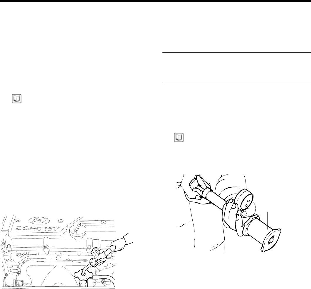
check the oil level.
4. Check that the engine oil level is within the level range
indicated on the oil dipstick If the oil level is found to
have fallen to the lower limit (the L mark), refill to the
"F" mark.
LF
Lower limit Upper limit
ECDA001A
NOTE
When refilling, use the same type of engine oil.
5. Check that the oil is not dirty or contaminated with
coolant or gasoline, and that it has the proper viscos-
ity.
CHANGING ENGINE OIL
CAUTION
Be careful not to burn yourself, as the engine oil
is hot.
1. Run the engine until it reaches normal operating tem-
perature.
2. Turn off the engine
3. Remove the oil filler cap and the drain plug (on the oil
pan). Drain the engine oil.
KCPC001B
4. Install and tighten the drain plug to the specified
torque.
Tightening torque
Drain plug : 40 ~ 45 Nm (400 ~ 450 kg.cm, 30 ~ 33 lb.ft)
5. Fill the crankcase with fresh engine oil through the oil
filler cap opening.
Drain and Refill Without oil filter :
3.0 liter (3.17 U.S.qts, 2.64 lmp.quts)
Draing and Refill With oil filter :
3.3 liter (3.48 U.S.qts, 2.64 lmp.quts)
6. Install the oil filler cap.
7. Start and run the engine.
8. Turn off the engine and then check the oil level. Add
oil if necessary.
ZENITH POWER PRODUCTS - 416
GENERAL EM -9
FILTER SELECTION
All Hyundai engines are equipped with a high quality, dis-
posable oil filter. This filter is recommended as a replace-
ment filter on all vehicles. The quality of replacement fil-
ters varies considerably. Only high quality filters should
be used to assure the most efficient service. Make sure
that the rubber gasket from the old oil filter is completely
removed from the contact surface on the engine block be-
fore installing the new filter.
Part number
EDDA063A
PROCEDURE FOR REPLACING THE OIL FILTER
CAUTION
Be careful not to burn yourself, as the engine and
engine oil are hot.
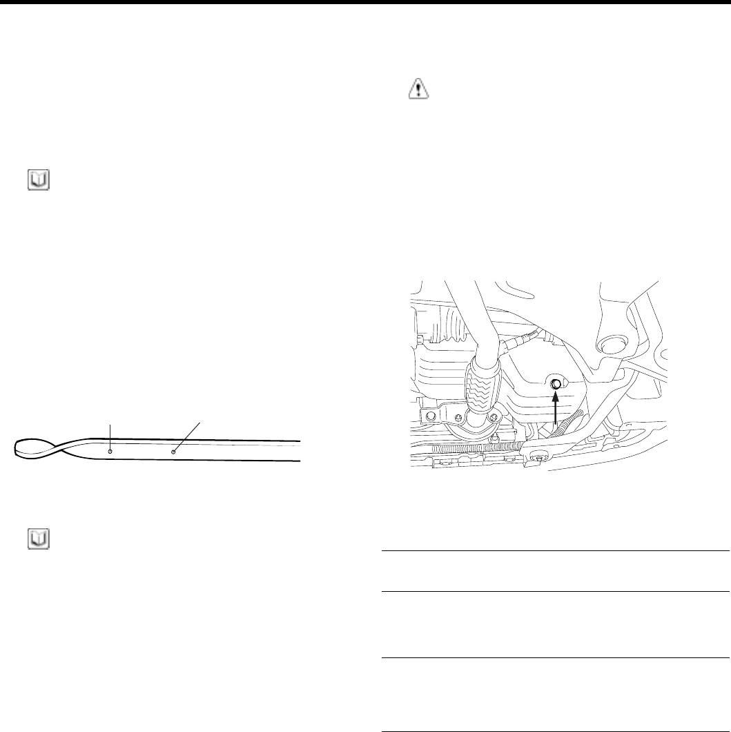
1. Use a filter wrench to remove the oil filter.
2. Before installing the new oil filter on the engine, apply
clean engine oil to the surface of the rubber gasket.
Apply engine oil
to the surface
EDDA063B
3. Tighten the oil filter to the specified torque.
KCPC001C
Tightening torque
Oil filter : 12 ~ 16 Nm (120 ~ 160 kg.cm, 9 ~ 12 lb.ft)
4. Run the engine to check for engine oil leaks.
5. After turning off the engine, check the oil level and add
oil as necessary.
ZENITH POWER PRODUCTS - 416
EM -10 ENGINE DOHC
SELECTION OF ENGINE OIL
Recommended API classification : SH OR ABOVE
Recommended SAE viscosity grades :
Recommended SAE viscosity number
Temperature range
anticipated before
next oil change
*1 Restricted by driving condition and environment.
*2 Not recommended for sustained high speed vehicle operation
20
10
-10
-15
-25 -13
5
14
50
68
˚C
40 ˚F
104 15W
-50
-40
10W
-50
-40
20W
-50
-40
10W
-30
5W
-20
5W
-30 *1
*2
*1
5W
-40 *1
EDA9990B
NOTE
For best performance and maximum protection of all
types of operation, select only those lubricants which:
1. Satisfy the requirements of the API classification.
2. Have proper SAE grade number for expected am-
bient temperature range.
Lubricant that does not have both an SAE grade number
and an API service classification on the container should
not be used.
ZENITH POWER PRODUCTS - 416
GENERAL EM -11
CHECKING COOLANT LEAK
1. Wait until the engine is cool, then carefully remove the
radiator cap.
2. Confirm that the coolant level is up to the filler neck.
3. Install a radiator cap tester to the radiator filler neck
and apply 140 KPa (1.4 kg/cm², 20psi ) pressure.
Hold it for two minutes in that condition, while check-
ing for leakage from the radiator, hoses or connec-
tions.
NOTE
1. Radiator coolant may be extremely hot. Do not
open the system because hot, or scalding water
could gush out causing personal injury. Allow the
vehicle to cool before servicing this system.
2. Be sure to clean away any moisture from the
places checked completely.
3. When the tester is removed, be careful not to spill
any coolant from it.
4. Be careful, when installing and removing the
tester and when testing, not to deform the filler
neck of the radiator.
4. If there is leakage, repair or replace with the apropri-
ate part.
KDPC001F
RADIATOR CAP PRESSURE TEST
1. Remove the radiator cap, wet its seal with engine
coolant, then install it on the tester.
2. Increase the pressure until the gauge stops moving.
Main valve opening pressure :
83 ~ 110 kPa (0.83 ~ 1.1 kg/cm², 12 ~ 16 psi)
Vacuum valve opening pressure :
-7 kPa (-0.07 kg/cm², -1.0 psi)
3. Check that the pressure level is maintained at or
above the limit.
4. Replace the radiator cap if the reading does not re-
main at or above the limit.
NOTE
Be sure that the cap is clean before testing, since rust
or other foreign material on the cap seal will cause an
incorrect reading.
Adapter
ECA9090A
ZENITH POWER PRODUCTS - 416
EM -12 ENGINE DOHC
SPECIFIC GRAVITY TEST
1. Measure the specific gravity of the coolant with a hy-
drometer.
2. Measure the coolant temperature and calculate the
concentration from the relation between the specific
gravity and temperature, using the following table for
reference.
KDPC001E
RELATION BETWEEN COOLANT CONCENTRATION AND SPECIFIC GRAVITY
Coolant temperatur C(F) and specific gravity
10 (50) 20 (68) 30 (86) 40 (104) 50 (122)
Freezing
temperature
C(F)
Safe operating
temperature
C(F)
Coolant
concentration
(Specific
volume)
1.054 1.050 1.046 1.042 1.036 -16 (3.2) -11 (12.2) 30%
1.063 1.058 1.054 1.049 1.044 -20 (-4) -15 (5) 35%
1.071 1.067 1.062 1.057 1.052 -25 (-13) -20 (-4) 40%
1.079 1.074 1.069 1.064 1.058 -30 (-22) -25(-13) 45%
1.087 1.082 1.076 1.070 1.064 -36 (-32.8) -31 (-23.8) 50%
1.095 1.090 1.084 1.077 1.070 -42 (-44) -37 (-35) 55%
1.103 1.098 1.092 1.084 1.076 -50 (-58) -45 (-49) 60%
Example
The safe operating temperature is -15 C(5F) when the
measured specific gravity is 1.058 at coolant temperature
of 20 C(68F)
CAUTION
•If the concentration of the coolant is below
30%, its anti-corrosion properties will be ad-
versely affected.
•If the concentration is above 60%, both the
anti-freeze and engine cooling property will
decrease, affecting the engine adversely. For
these reasons, be sure to maintain the con-
centration level within the specified ragne.
•Do not use together with another brank’s
product.
RECOMMENDED COOLANT
Antifreeze Mixture ratio of anti freeze in coolant
ETHYLENE GLYCOL BASE FOR ALUMINUM 50% [Except tropical areas]
40% [Tropical areas]
ZENITH POWER PRODUCTS - 416
GENERAL EM -13
CHANGING ENGINE COOLANT
CAUTION
When pouring engine coolant, be sure to shut the
relay box lid and not to let coolant spill on electri-
cal parts or the paint. If any coolant spills, rinse it
off immediately.
1. Slide the heater temperature control lever to maxi-
mum heat. Make sure the engine and radiator are
cool to the touch.
2. Remove the radiator cap.
3. Loosen the drain plug, and drain the coolant.
KDDC008B
4. Tighten the radiator drain plug securely.
5. Remove, drain and reinstall the reservior.
Fill the tank halfway to the MAX mark with water, then
up to the MAX mark with antifreeze.
6. Pour coolant into the radiator up to the base of the
filler neck, and install the radiator cap loosely.
7. Start the engine and let it run until it warms up (the
radiator fan comes on at least twice).
8. Turn off the engine.
Check the level in the radiator, add coolant if needed.
9. Put the radiator cap on tightly, then run the engine
again and check for leaks.
CHECKING COMPRESSION PRESSURE
1. Before checking engine compression, check the en-
gine oil level. Also check that the starter motor and
battery are all in normal operating condition.
2. Check the DTC and note it. Use the scan tool to clear
the ECM’S memory.
3. Start the engine and wait until engine coolant temper-
ature reaches 80 ~ 95 C (176 ~ 205 F).
4. Disconnect the fule pump connector.
5. Turn off engine and disconnect the spark plug cables.
KCDC002B
6. Remove the spark plugs.
7. Disonnect the I.G. connector.
8. Crank the engine to remove any foreign material in
the cylinders.
9. Insert the compression gauge into the spark plug
hole.
KDPC001B
10. Depress the accelerator pedal to open the throttle
fully.
ZENITH POWER PRODUCTS - 416
EM -14 ENGINE DOHC
11. Crank the engine and read the gauge.
Standard value : 1500kpa (15Kg/cm², 218 psi)
Limit : 1400kpa (14Kg/cm², 203 psi)
12. Repeat steps 9 to 11 over all cylinders, ensuring that
the pressure differential for each of the cylinders is
within the specified limit.
Limit
Max 100 kpa (1.0 kg/cm², 14 psi) between cylinders
13. If a cylinder’s compression or pressure differential is
outside the specification, add a small amount of oil
through the spark plug hole, and repeat steps 9 to 12.
1) If the addition of oil makes the compression to
rise, it is likely that there may be wear between
the piston ring and cylinder wall.
2) If compression remains the same, valve seizure,
poor valve seating or a compression leak from
the cylinder head gasket are all possible causes.
Tightening torque
Spark plug : 20 ~ 30 Nm (200 ~ 300 kg.cm, 14 ~ 22 lb.ft)
ADJUSTING TIMING BELT TENSION
1. Rotate the steering wheel counter-clockwise
throughly.
NOTE
Do watch not to over load.
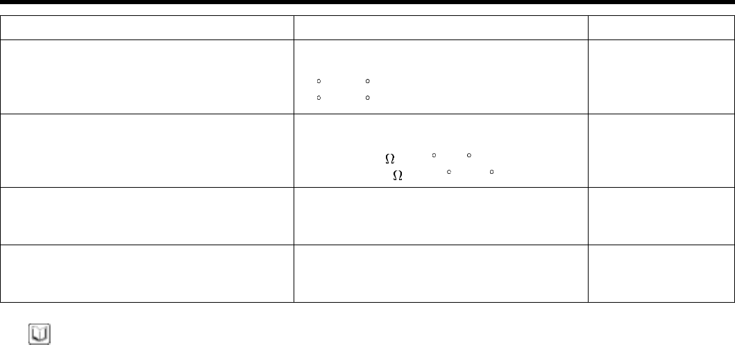
2. Lift the vehicle by using of jack.
KCDA125K
3. Remove the engine support bracket. (14mm bolt and
2nuts, 17mm bolt)
KDDC003B
4. Remove the drive belts and the water pump pulley.
(10 mm 4 bolts)
KDDC004B
5. Remove the timing belt upper cover. (10 mm 4 bolts)
KCDC002C
ZENITH POWER PRODUCTS - 416
GENERAL EM -15
6. Remove the crankshaft pulley.
KDDC007B
7. Remove the timing belt lower cover.
8. Place the pistion of No. 1 cylinder to TDC of the com-
pression stroke by rotating the crankshaft clockwise.
NOTE
Crankshaft is to be rotated clockwise otherwise, the
tension is inadequately adjusted.
Tensioner
pulley
Idler pulley
EDDB091A
9. Loosen the tensioner bolt of pivot side and slotside.
EDDA092A
10. Rotate the crankshaft clockwise as many as 2 teeth
of camshaft sprocket.
11. Check that the teeth of the sprocket and belt coincide
with each other.
12. Tighten the slot side bolt first and then tighten the bolt
of pivot side.
13. Check the tension of the timing belt.
When the tensioner and the tension side of the timing
belt are pushed in horizontally with a moderate force
[approx. 49N (11 lb)], the the timing belt log end is ap-
prox. half of the tensioner mounting bolt head radius
(cross flats) away from the bolt head center.
EDKE108A
14. Rotate the crankshaft pulley two turns clockwise so
that the timing belt positions on the pulleys.
15. Install the timing belt lower cover.
16. Install the crankshaft pulley.
17. Install the timing belt upper cover.
18. Install the water pump pulley and engine support
bracket.
ZENITH POWER PRODUCTS - 416
EM -16 ENGINE DOHC
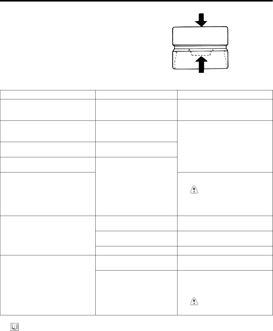
ADJUSTING DRIVE BELT TENSION
1. Check that the belts are not damaged and are prop-
erly fit for the pulley grooves.
2. Apply 100 N (22 lbs.) force to the back and midway
portion of the belt between the pulleys as shown in
the illustration, measure the amount of deflection with
atens
ion gauge.
CAUTION
1. When installing the V-ribbed belt, check that
the V-ribs are properly aligned.
2. If noise or slippage is detected, check the belt
for wear, damage, or breakage on the pul-
ley contact surface, and check the pulley for
scoring. Also check the amount that the belt
is deflected.
Pulley
V-ribbed belt
Wrong Wrong
Right
ECA9980A
STANDARD VALUE:
Adjustment
Itmes Inspection New Used
Deflection mm (in.) 5.1~6.0(0.200~0.236) 4.0~4.4(0.157~0.173) 5.0~5.7(0.200~0.224)
For alternator Tension N (lb) 350~500(79~112 650~750(143~165) 400~500(88~110)
Deflection mm (in.) 8(0.31) 5.0~5.5(0.20~0.22) 6.0~7.0(0.24~0.28)
For air conditioner Tension N (lb) 250~500(56~112) 470~570(106~128) 320~400(72~90)
For power steering Deflection mm (in.) 6.0~9.0(0.24~0.35) - -
ZENITH POWER PRODUCTS - 416
GENERAL EM -17
NOTE
1. The belt tension must be measured half - way
between the specified pulleys.
2. When a new belt is installed, adjust the tension to
the central value of the standard range indicated
under "New" in the above table. Let the engine
idle for 5 minutes or more, and check the stan-
dard value indicated under "Inspection."
3. When adjusting a belt which has been used,or
newly installed, after 5 minutes or more of oper-
ation, refer to the standard value indicated under
"Used" in the above table.
4. Refer to the standard value indicated under "In-
spection" for periodic inspections.
Power steering oil
pump pulley
Coolant pump pulley
Alternator
Crankshaft pulley
Air conditioning compressor pulley
Tensioner pulley
ECPD001B
TYPEATENSIONGAUGE
Do not let the dial section of the tension gauge contact
other objects during measurement.
Typ A Indicated value
Dial
Spindle
V-ribbed belt
Hook
Spindle Hook
ECA9980C
TYPE B TENSION GAUGE
1. When measuring, turn the reset button in the direction
of the arrow and set the gauge needle to the RESET
position.
2.If the tension gauge is removed from the belt, the nee-
dle will still indicate the tension. Read the tension
value after removing the gauge.
Typ B
Spindle
V-ribbed belt
Hook
RESET button
RESET position
ECA9980D
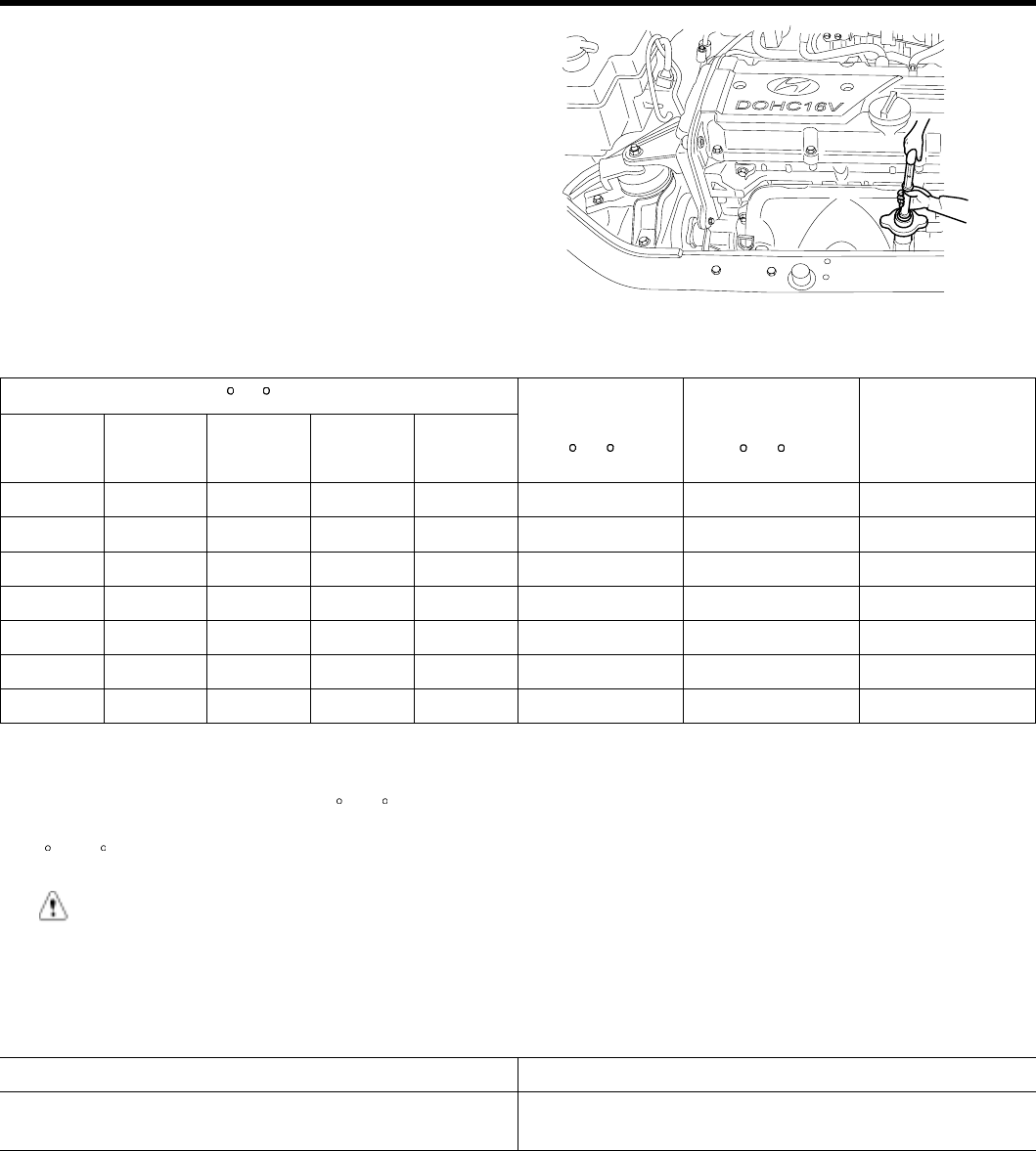
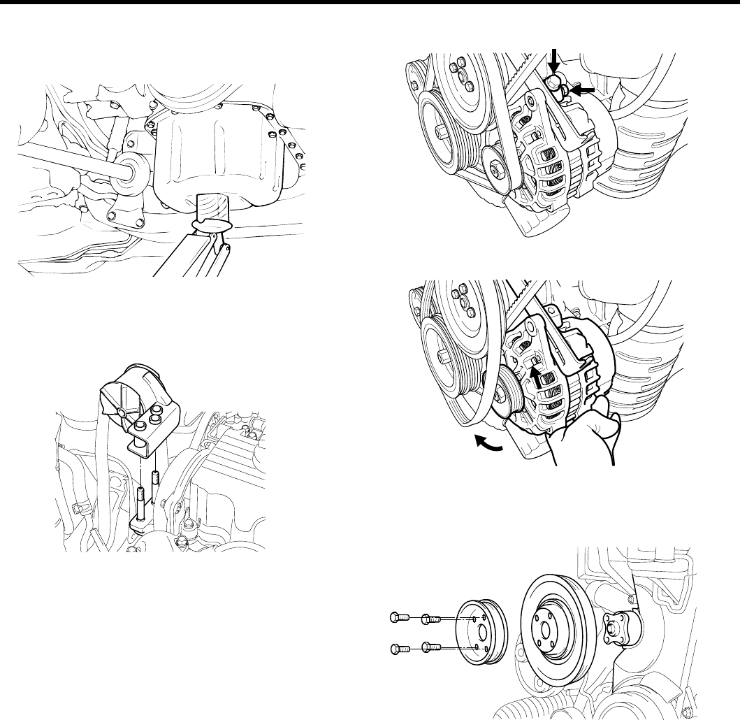
ADJUSTING THE ALTERNATOR BELT
CAUTION
If the belt is too loose, it will cause noise or sud-
den wear.
If the belt is too tight, the engine coolant pump
bearing or the alternator can get damaged.
1. Loosen the alternator nut "A" and the tension adjuster
lock bolt "B".
2. Using the tension adjuster bolt, adjust the belt tension
to the specification.
3. Tighten the adjuster lock bolt "B".
4. Tighten the alternator nut "A".
5. Check the tension or the deflection of belt, readjust if
necessary.
Tightening torque
Alternator support bolt and nut :
20 ~ 25 Nm (200 ~ 250 kg.cm, 14 ~ 18 lb.ft)
Alternator lock bolt B :
12 ~ 15 Nm (120 ~ 150 kg.cm, 9 ~ 11 lb.ft)
Alternator brace mounting bolt :
20 ~ 27 Nm (200 ~ 270 kg.cm, 15 ~ 20 lb.ft)
A
B
1
Alternator brace
Coolant pump
pulley
Crankshaft
pulley
ECKA010H
ZENITH POWER PRODUCTS - 416
EM -18 ENGINE DOHC
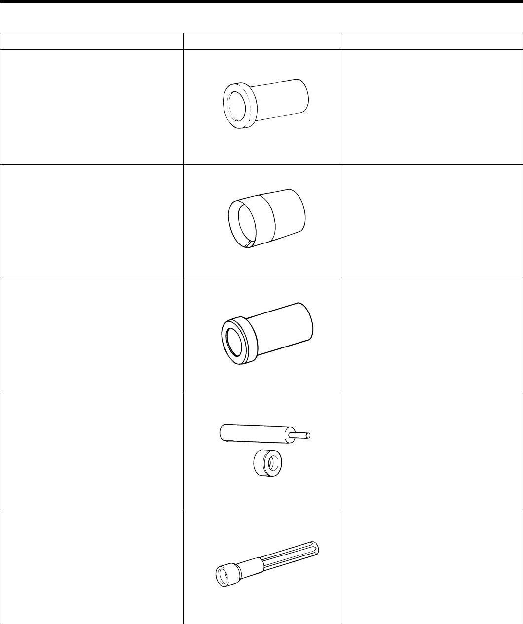
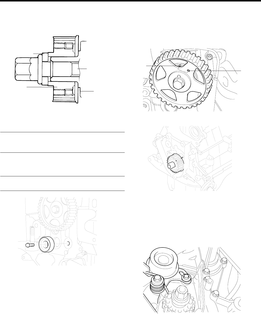
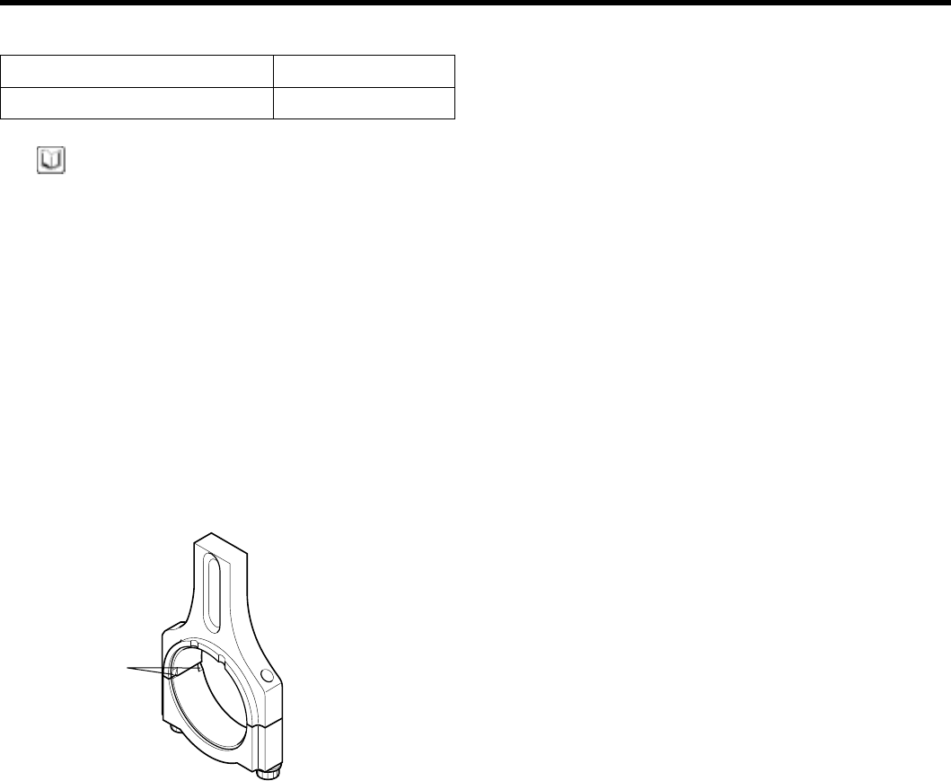
SPECIAL TOOLS E0845550
Tool (Number and name) Illustration Use
Crankshaft front oil seal installer
(09231 - 22000)
ECKA010C
Installation of the front oil seal
Crankshaft front oil seal guide
(09231 - 22100)
ECKA010D
Guide of oil seal
Camshaft oil seal installer
(09221 - 21000)
EDDA005B
Installation of the camshaft oil seal
Valve guide installer
(09221 - 3F100 A/B)
ECKA010B
Removal and installation of valve guides
Valve stem oil seal installer
(09222 - 22001)
ECKA010A
Installation of valve stem oil seals
ZENITH POWER PRODUCTS - 416
GENERAL EM -19
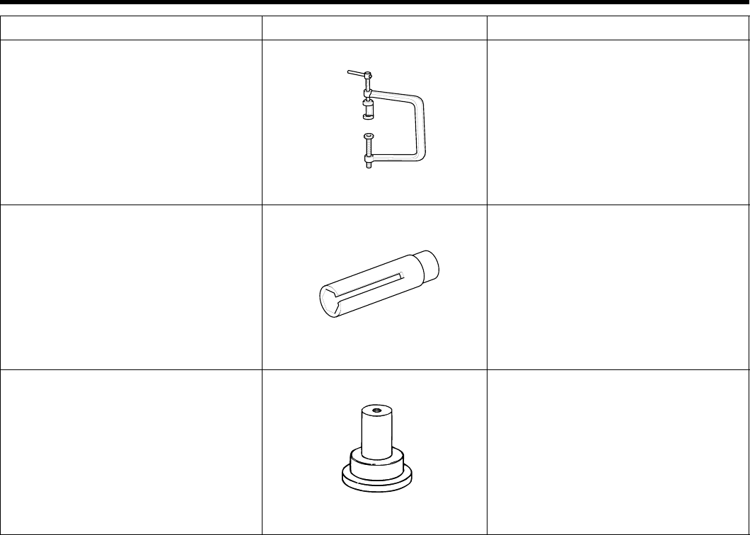
Tool (Number and name) Illustration Use
Valve spring compressor
(09222 - 28000)
Valve spring compressor holder
(09222 - 28100)
EDDA005C
Removal and installation of intake
and exhaust valves
Water temperature sensor socket
wrench
(09221 - 25100)
EDKD101B
Removal and installation of the water
temperature sensor
Crankshaft rear oil seal installer
(09231 - 21000)
EDDA005F
Installation of engine real oil seal
and crankshaft rear oil seal
ZENITH POWER PRODUCTS - 416

EM -20 ENGINE DOHC
TROUBLESHOOTING E6712BDA
Symptom Probable cause Remedy
Blown cylinder head gasket Replace gasket
Worn or damaged piston rings Replace rings
Worn piston or cylinder Repair or replace piston and/or
cylinder block
Low compression
Worn or damaged valve seat Repair or replace valve and/or
seat ring
Low engine oil level Check engine oil level
Faulty oil pressure switch Replace
Clogged oil filter Replace
Worn oil pump gears or cover Replace
Thin or diluted engine oil Change and determine cause
Oil relief valve stuck (open) Repair
Low oil pressure
Excessive bearing clearance Replace
High oil pressure Oil relief valve sutck (closed) Repair
Loose engine roll stopper (front, rear) Re-tighten
Loose transaxle mount bracket Re-tighten
Loose engine mount bracket Re-tighten
Loose center member Re-tighten
Broken transaxle mount insulator Replace
Broken engine mount insulator Replace
Excessive engine vibration
Broken engine roll stopper insulator Replace
Thin or diluted engine oil (low
oil pressure) Change
Worn or damaged valve stem
or valve guide Replace
Noisy valves
HLA abnormal operation Speed the engine up (for venting)
or Replace the HLA
Insufficient oil supply Check engine oil level
Thin or diluted engine oil Change and determine cause
Connecting rod and/or main
bearing noise
Excessive bearing clearance Replace
Timing belt noise Incorrect belt tension Adjust belt tension
Leakage of coolant
1. Heater or radiator hose Repair or replace parts
2. Faulty radiator cap Tighten or replace clamps
3. Thermostat housing Replace gasket or housing
4. Radiator Repair or replace
Low coolant level
5. Engine coolant pump Replace parts
Clogged radiator Foreign material in coolant Replace coolant
ZENITH POWER PRODUCTS - 416

GENERAL EM -21
Symptom Probable cause Remedy
Faulty thermostat Replaceparts
Faulty radiator cap Replace parts
Restricted flow in cooling system Clear restriction or replace parts
Loose or missing drive belt Adjust or replace
Faulty water pump Replace
Faulty electric fan Repair or replace
Abnormally high coolant temperature
Insufficient coolant Refill coolant
Faulty thermostat ReplaceAbnormally low coolant temperature
Faulty temperature sensor wiring Repair or replace
Inoperative electrical cooling fan Damaged thermo sensor, electrical
motor, radiator fan relay and
wiring, fuse
Replace or repair
Loose connections RetightenExhaust gas leakage
Broken pipe or muffler Repair or replace
Detached baffle plate in muffler Replace
Broken rubber hanger Replace
Pipe or muffler contacting
vehuicle body Correct
Abnormal noise
Broken pipe or muffler Repair or replace
ZENITH POWER PRODUCTS - 416
EM -22ENGINE DOHC
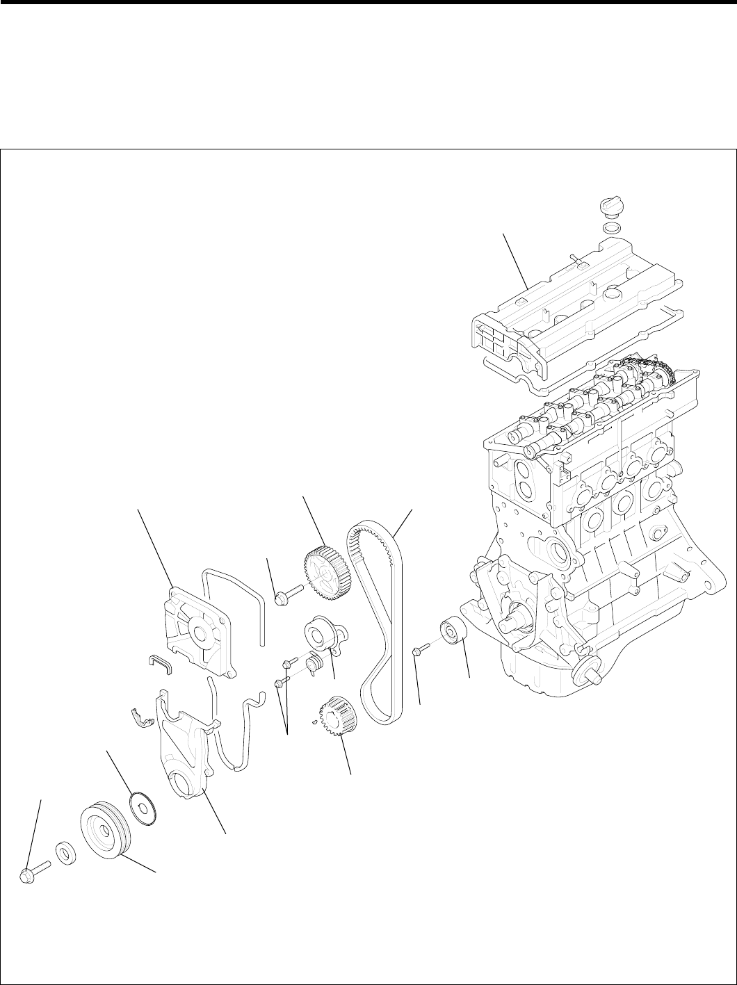
TIMING SYSTEM
TIMING BELT
COMPONENTS E4B24FDE
Cylinder head cover
Timing belt
Idler
43 ~ 55 (430 ~ 550, 32 ~ 40)
Crankshaft sprocket
Ten sioner
20 ~ 27
(200 ~ 270,
15 ~ 20)
Timing belt lower cover
Crankshaft pulley
140 ~ 150
(1400 ~ 1500,
103 ~ 111)
Flange
Timing belt upper cover
80 ~ 100
(800 ~ 1000,
59 ~ 74)
Camshaft sprocket
TORQUE : Nm (kgf·cm, lbf·ft)
EDKD100A
ZENITH POWER PRODUCTS - 416
TIMING SYSTEM EM -23
DISASSEMBLY EE695E6A
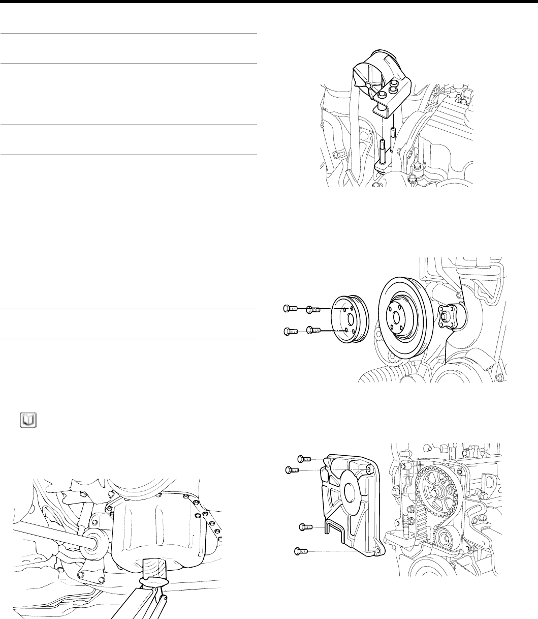
1. Lift the vehicle by using of jack.
KCDA125K
2. Remove the engine support bracket. (14 mm bolt and
2nut
s, 17 mm bolt)
KDDC003B
3. Remove the power steering belt.
4. Remove the air conditioning compressor belt.
5. Remove the alternator belt.
KBPD160A
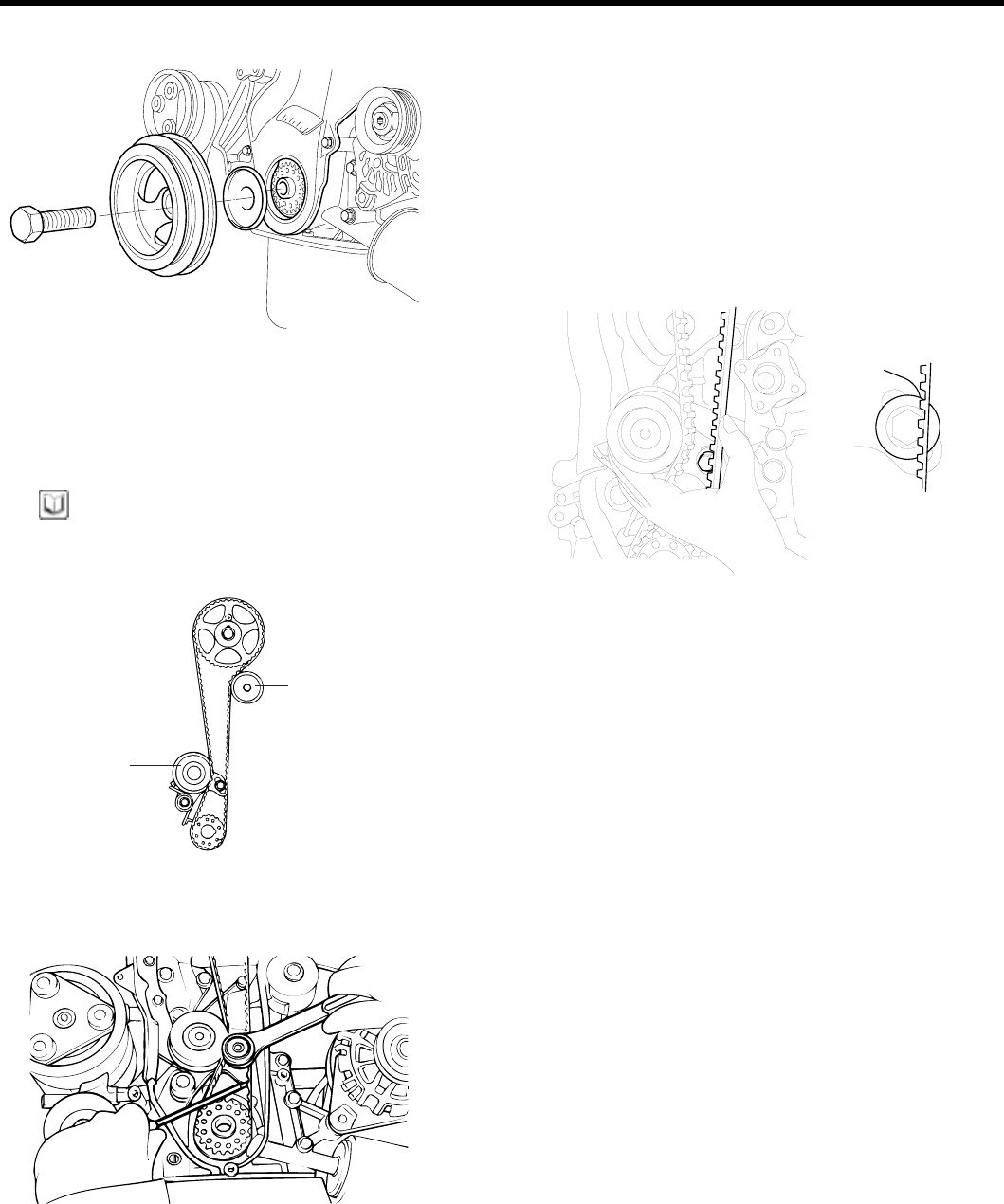
KBPD160B
6. Remove the coolant pump pulley.
KDDC004B
ZENITH POWER PRODUCTS - 416
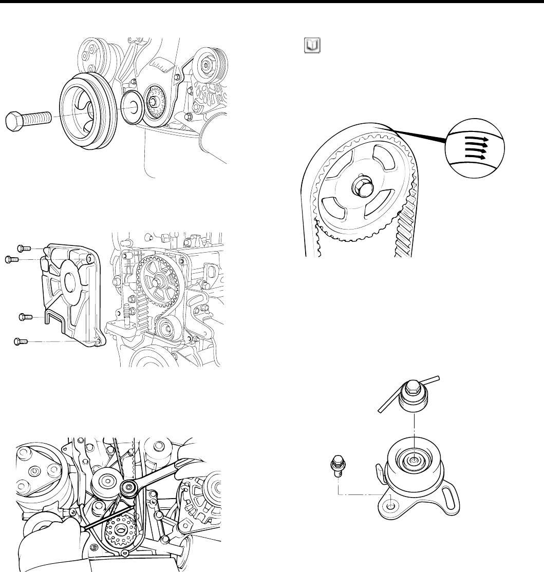
EM -24 ENGINE DOHC
7. Remove the crankshaft pulley.
KDDC007B
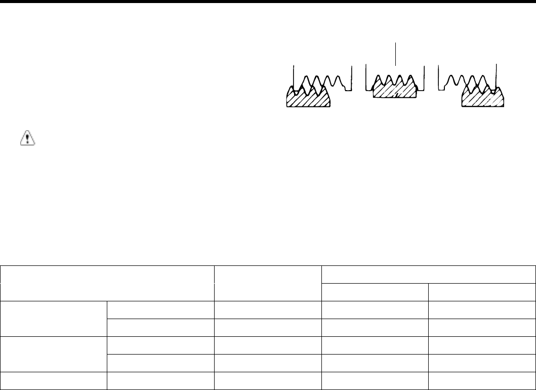
8. Remove the timing belt cover.
KCDC002C
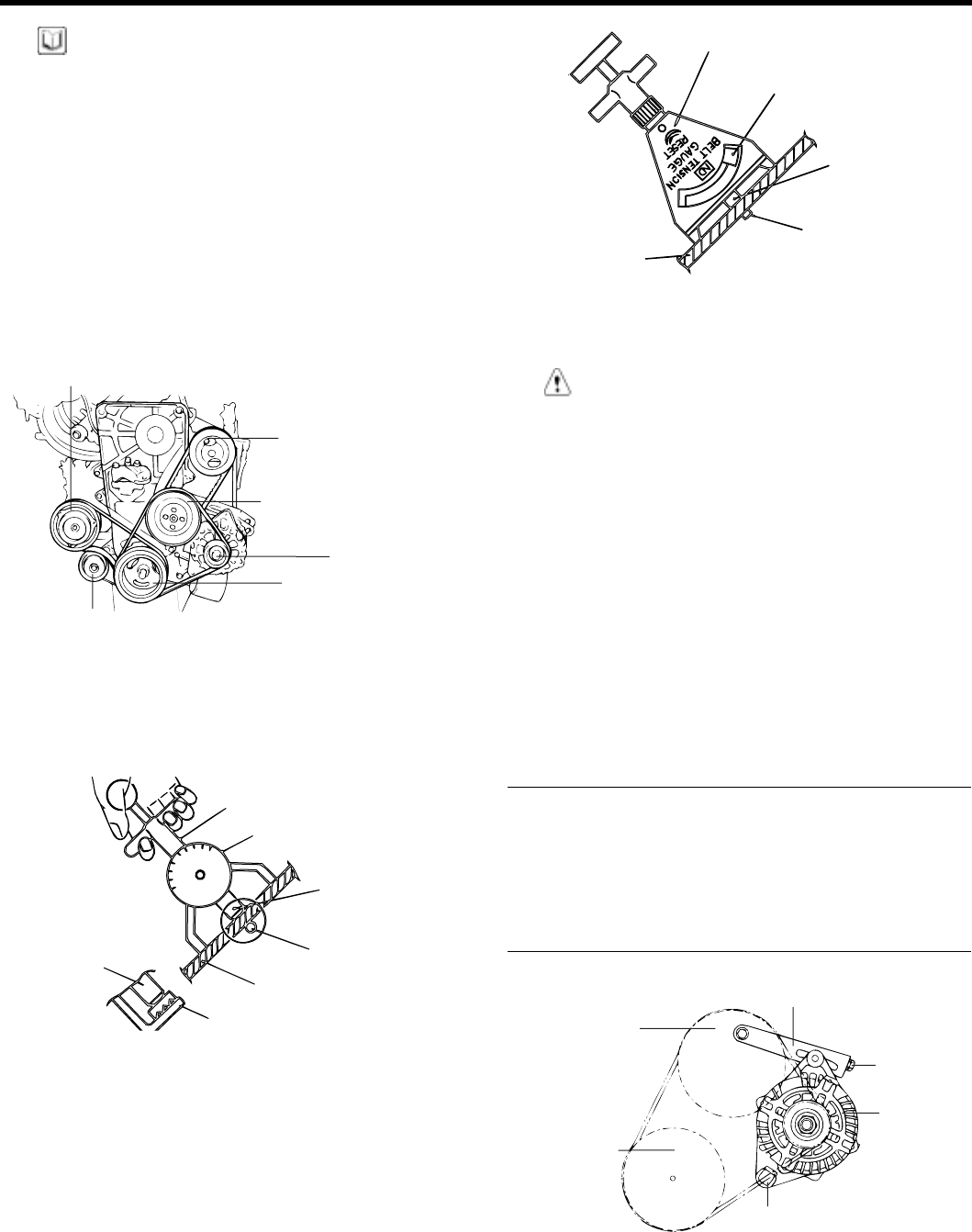
9. Move the timing belt tensioner pulley toward the
coolant pump and temporarily secure it.
EDDA092A
10. Remove the timing belt.
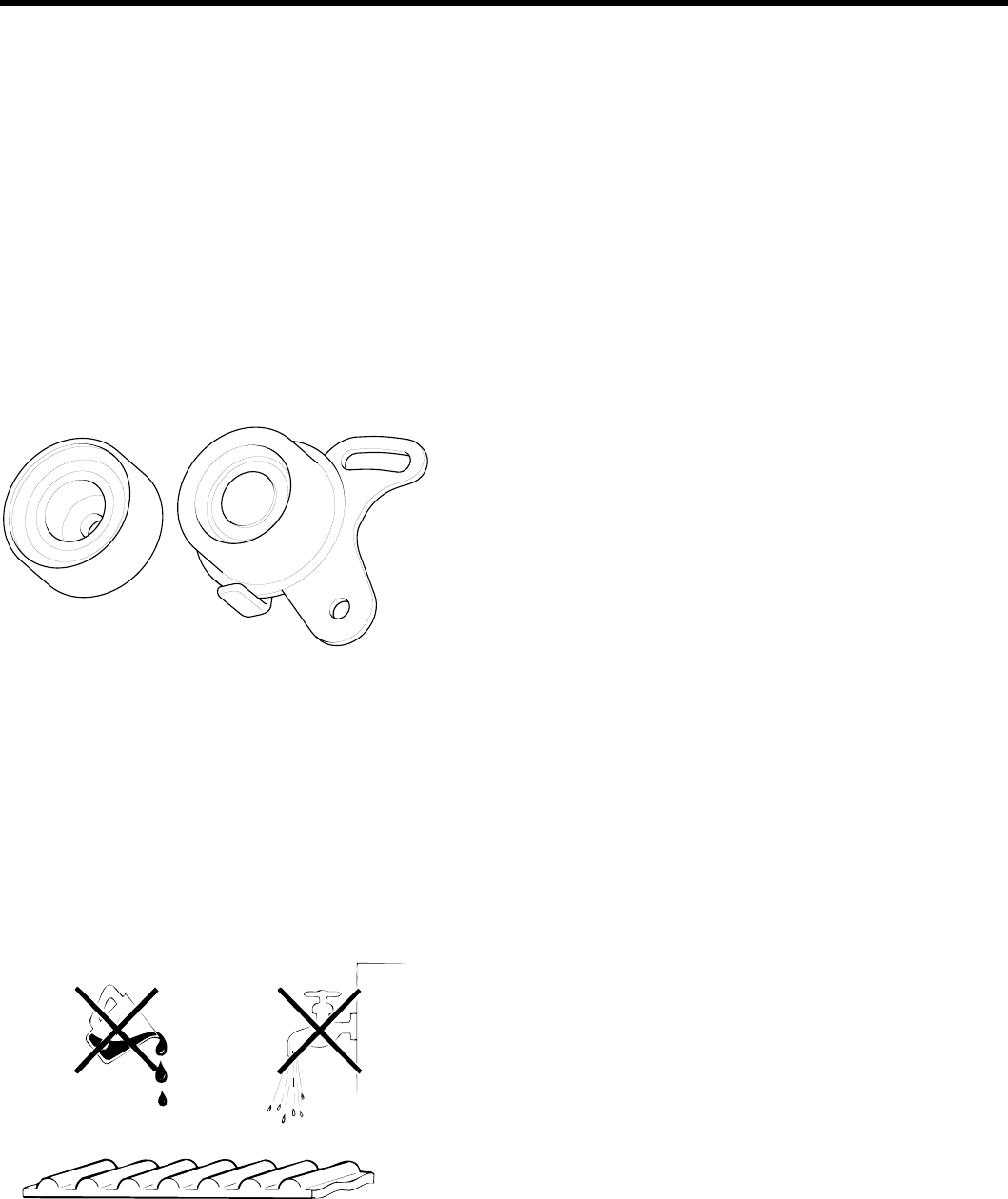
NOTE
If the timing belt is reused, mark with an arrow to in-
dicate direction of rotation (on the front of the engine)
to make sure that the belt is reinstalled in the same
direction as before.
ECDA121B
11. Remove the camshaft from the camshaft sprocket.
12. Remove the crankshaft sprocket and flange.
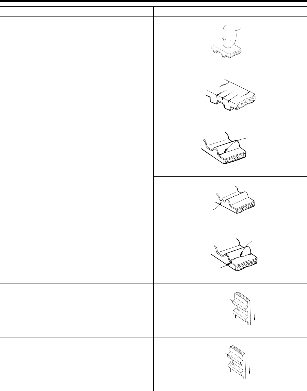
13. Remove the timing belt idler.
14. Remove the timing belt tensioner.
KDPC008C
ZENITH POWER PRODUCTS - 416
TIMING SYSTEM EM -25
INSPECTION E193FC6F
SPROCKETS TENSIONER PULLEY, AND IDLER
PULLEY
1. Check the camshaft sporcket, crankshaft sprocket,
tensioner pulley, and idler pulley for abnormal wear,
cracks, or damage.
Replace as necessary.
2. Inspect the tensioner pulley and the idler pulley for
easy and smooth rotation and check for play or noise.
Replace as necessary.
3. Replace the pulley if there is a grease leak from its
bearing.
EDKD106A
TIMING BELT
1. Check the belt for oil or dust deposits. Replace, if
necessary.
Small deposits should be wiped away with a dry cloth
or paper. Do not clean with solvent.
2. When the engine is overhauled or belt tension ad-
justed, check the belt carefully. If any of the following
flaws are evident, replace the belt with a new one.
OIL WATER
EDDA093B
ZENITH POWER PRODUCTS - 416
EM -26 ENGINE DOHC
Description Flaw conditions
1. Hardened back surface
•Back surface is glossy, non-elastic and so
hard that when your fingernail is pressed into
it. no mark is produced.
EDDA093C
2. Cracked back surface rubber
EDDA093D
Crack
EDDA093E
Separation
EDDA093F
3. Cracked or separating canvas
Crack
Separation
EDDA093G
4. Badly worn teeth (initial stages)
•Canvas on load side of tooth flank worn (Fluffy
canvas fibers, rubber gone and color changed
to white, and unclear canvas texture)
Flank worn
(On load side)
EDDA093H
5. Badly worn teeth (last stage)
•Canvas on load side of tooth flank worn down and
rubber exposed (tooth width reduced) Rubber
exposed
EDDA093I
ZENITH POWER PRODUCTS - 416
TIMING SYSTEM EM -27
Description Flaw conditions
6. Cracked tooth bottom
Crack
EDDA093J
7. Missing tooth Tooth missing and
canvas fiber exposed
EDDA093K
8. Side of belt badly worn
NOTE
Normal belt shluld have precisely cut sides as if cut by
asharpknife.
9. Side of belt cracked
ZENITH POWER PRODUCTS - 416
EM -28 ENGINE DOHC
REASSEMBLY E6A34B7C
1. Install the flange and crankshaft sprocket as shown.
Pay close attention to their mounting directions.
Special washer
Crankshaft
Flange
Crankshaft
sprocket
ECNC094B
2. Install the camshaft sprocket and tighten the bolt to
the specified torque.
Tightening torque
Camshaftsprocketbolt:
80 ~ 100 Nm (800 ~ 1000 kg.cm, 59 ~74 lb.ft)
3. Install the idler and tighten the idler bolt to the speci-
fied torque.
Tightening torque
Idler bolt : 43 ~ 55 Nm (430 ~ 550 kg.cm, 32 ~ 41 lb.ft)
EDKE103A
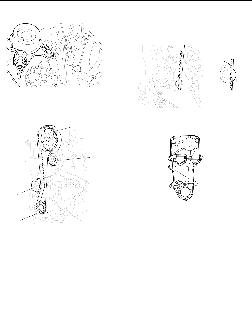
4. Align the timing marks of the camshaft sprocket (A)
and camshaft bearing cap (B).
Then align the timing marks of crankshaft sprocket
andfrontcasewiththeNo.1pistonplacedattopdead
center on its compression stroke as shown in the illus-
tration.
A
B
ECDD008F
EDKE107A
5. To install the timing belt tensioner, first mount the ten-
sioner, spring, and spacer. Temporarily tighten the
bolts. Next, temporarily tighten the tensioner long
hole side washer and bolts. Install the bottom end
of the spring against the front case as shown in the
illustration.
KDPC008D
ZENITH POWER PRODUCTS - 416
TIMING SYSTEM EM -29
6. Secure the tensioner, positioned towards the water
pump.
KDPC008E
7. Install the timing belt on the crankshaft sprocket.
(1) Crankshaft sprocket →(2) Timing belt idler →(3)
Camshaft sprocket →(4) Timing belt tensioner.
3
2
1
4
EDKE109A
8. Install the timing belt on the camshaft sprocket. When
the timing belt is installed on the camshaft sprocket,
make sure that the tension side is tight. Then, check
to ensure that when the tension side is tightened by
turning the camshaft sprocket in a reverse direction
and all timing marks are in line.
9. Tighten the tensioner bolts.
Tightening torque
Tensioner attaching bolt :
20 ~ 27 Nm (200 ~ 270 kg.cm, 15 ~ 20 lb.ft)
10. Turn the crankshaft two turns in its operating direction
(clock-wise) and realign the camshaft sprocket timing
mark with the top dead center position.
11. Then recheck the belt tension Verify that when the
tensioner and the tension side of the timing belt are
pushed in horizontally with a moderate force [approx.
49N (11lb)], the timing belt cog end is aprox. 1/2 of
the tensioner monting bolt head radius (across flats)
away from the bolt head center.
EDKE108A
12. Install the timing belt cover.
EDDA094F
Tightening torque
Timing belt cover bolt :
8 ~10 Nm (80 ~ 100 kg.cm, 6 ~ 7 lb.ft)
13. Install the crankshaft pulley. Make sure that the crank-
shaft sprocket pin fits the small hole in the pulley.
Tightening torque
Crankshaft pulley bolt :
140 ~ 150 Nm (1400 ~ 1500 kg.cm, 103 ~ 111 lb.ft)
ZENITH POWER PRODUCTS - 416
EM -30 ENGINE DOHC
14. Install the water pump pulley.
KDDC004B
15. Install the alternator belt and adjust the belt tension.
16. Install the air conditioning compressor belt and adjust
the belt tension.
17. Install the power steering belt and adjust the belt ten-
sion.
ZENITH POWER PRODUCTS - 416
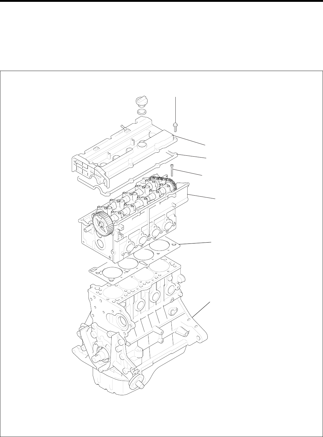
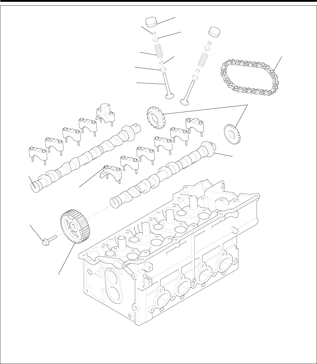
CYLINDER HEAD ASSEMBLY EM -31
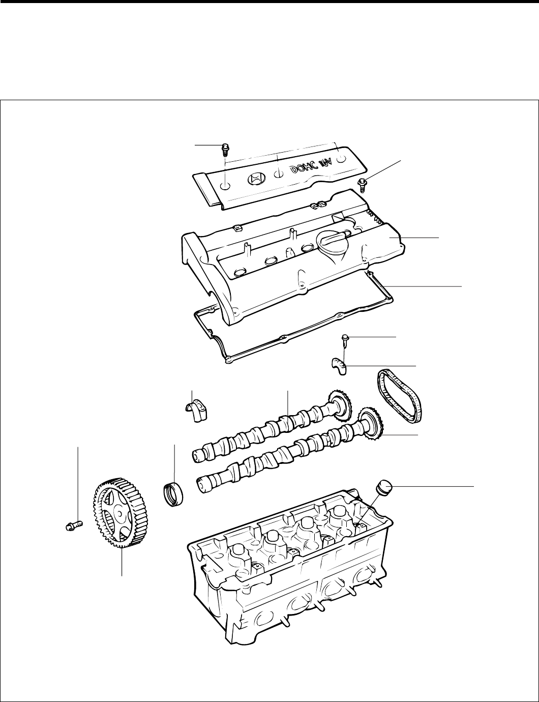
CYLINDER HEAD
ASSEMBLY
CYLINDER HEAD
COMPONENTS E804EE47
Cylinder head cover
Gasket
Cylinder head bolt
30(300, 22) + 90˚ → Release all bolts →
30(300, 22) + 90˚
8 ~ 10 (80 ~ 100, 6 ~ 7.4)
Cylinder head
Cylinder head gasket
Cylinder block
TORQUE : Nm (kgf.cm, lbf.ft)
EDKD110A
ZENITH POWER PRODUCTS - 416
EM -32ENGINE DOHC
HLA
Retainer
Retainer
lock
Valve spring
Spring seat
Valve
Stem seal Timing chain
Chain sprocket
Exhaust camshaft
Camshaft
sprocket
80 ~ 100 (800 ~ 100,
59 ~ 74)
12 ~ 14
(120 ~ 140, 9 ~ 10)
Intake
camshaft
TORQUE : Nm (kgf·cm, lbf·ft)
EDKD111A
ZENITH POWER PRODUCTS - 416
CYLINDER HEAD ASSEMBLY EM -33
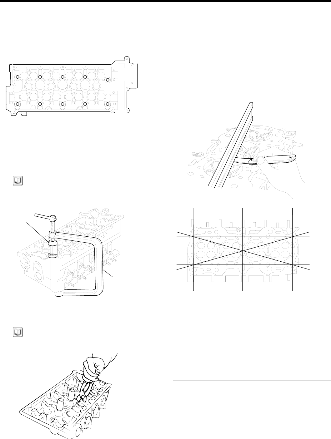
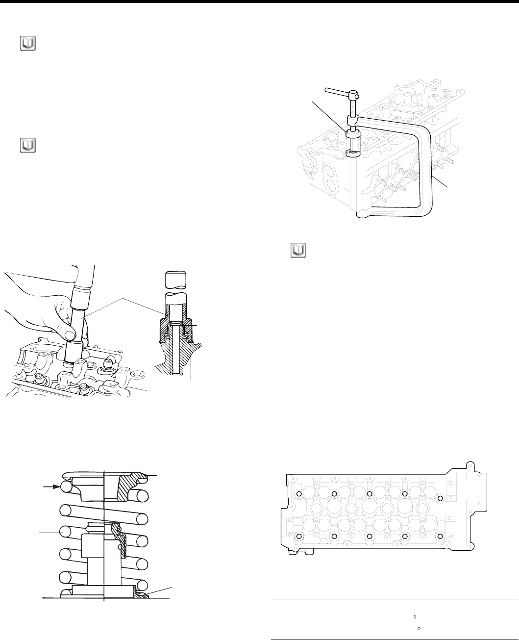
DISASSEMBLY EBCFA4C6
1. Using a tool remove the cylinder head bolts in the
order shown in the illustration.
3 5 10 8 2
1 7 9 6 4
EDKD115A
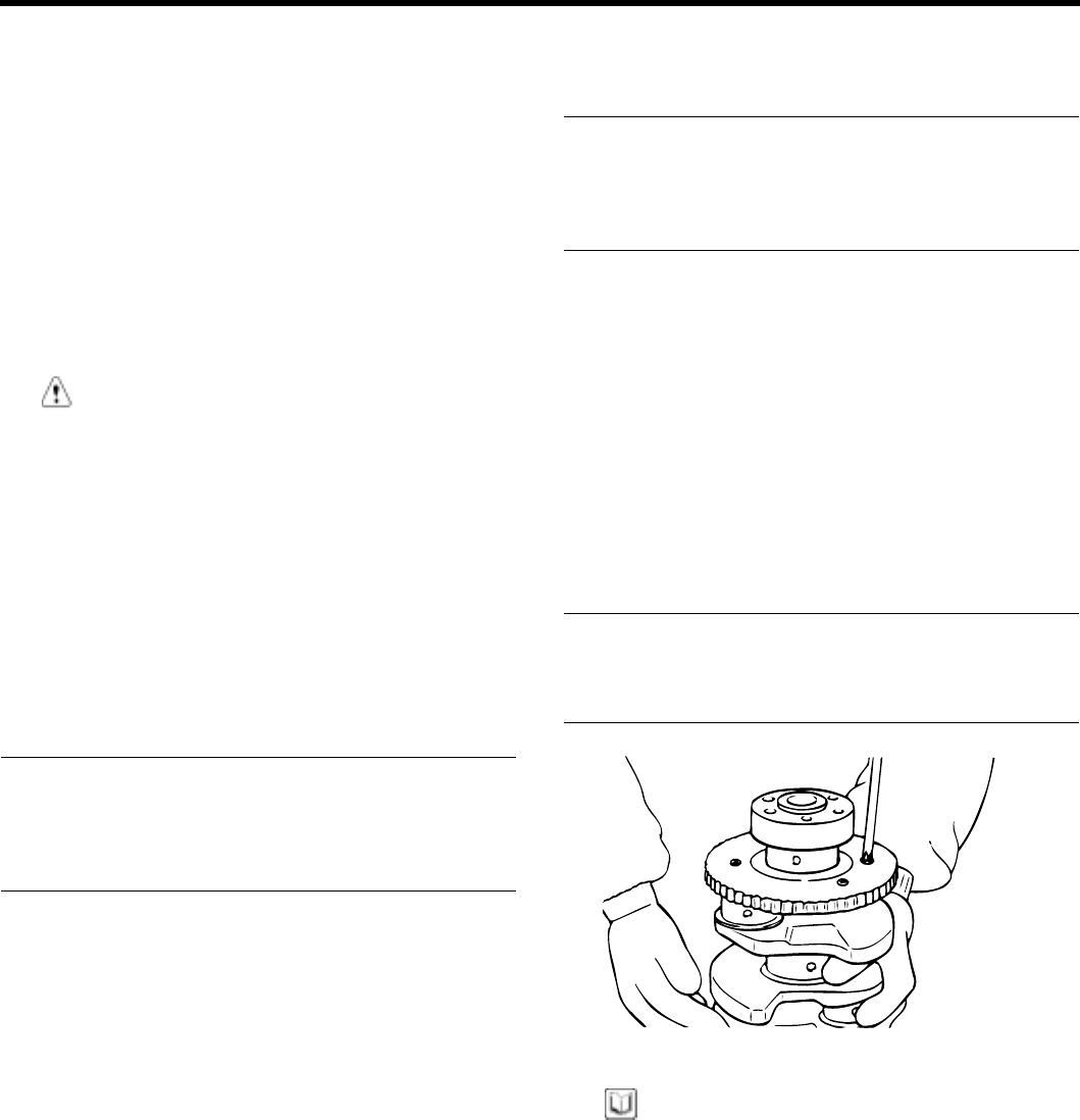
2. Using the special tool (09222-28000, 09222-28100),
remove the valve retainer lock. Next remove the
spring retainer, valve spring, spring seat and valve.
NOTE
Arrange these parts so that they can be reinstalled in
their original positions.
09222-28100
09222-28000
EDKD116A
3. Remove the valve stem seals with pliers.
NOTE
Do not reuse the valve stem seals.
EDDE088B
INSPECTION EE4FDB50
CYLINDER HEAD
1. Check the cylinder head for cracks, damage and
coolant leakage. If cracked, replace the cylinder
head.
2. Remove scale, sealing compound and carbon deop-
sits completely. After cleaning the oil passages, ap-
ply compressed air to verify that the passages are not
clogged.
ECKD001H
3.Check the cylinder head surface for flatness in the di-
rection as shown in the illustration. If flatness exceeds
the service limit in any direcftion, either replace the
cylinder head or machine the cylinder head matching
surface lightly.
Flatness of cylinder head gasket surface
Standard : Less than 0.03 mm (0.0012 in.)
Limit : 0.05 mm (0.002 in.)
ZENITH POWER PRODUCTS - 416
EM -34 ENGINE DOHC
VALVES
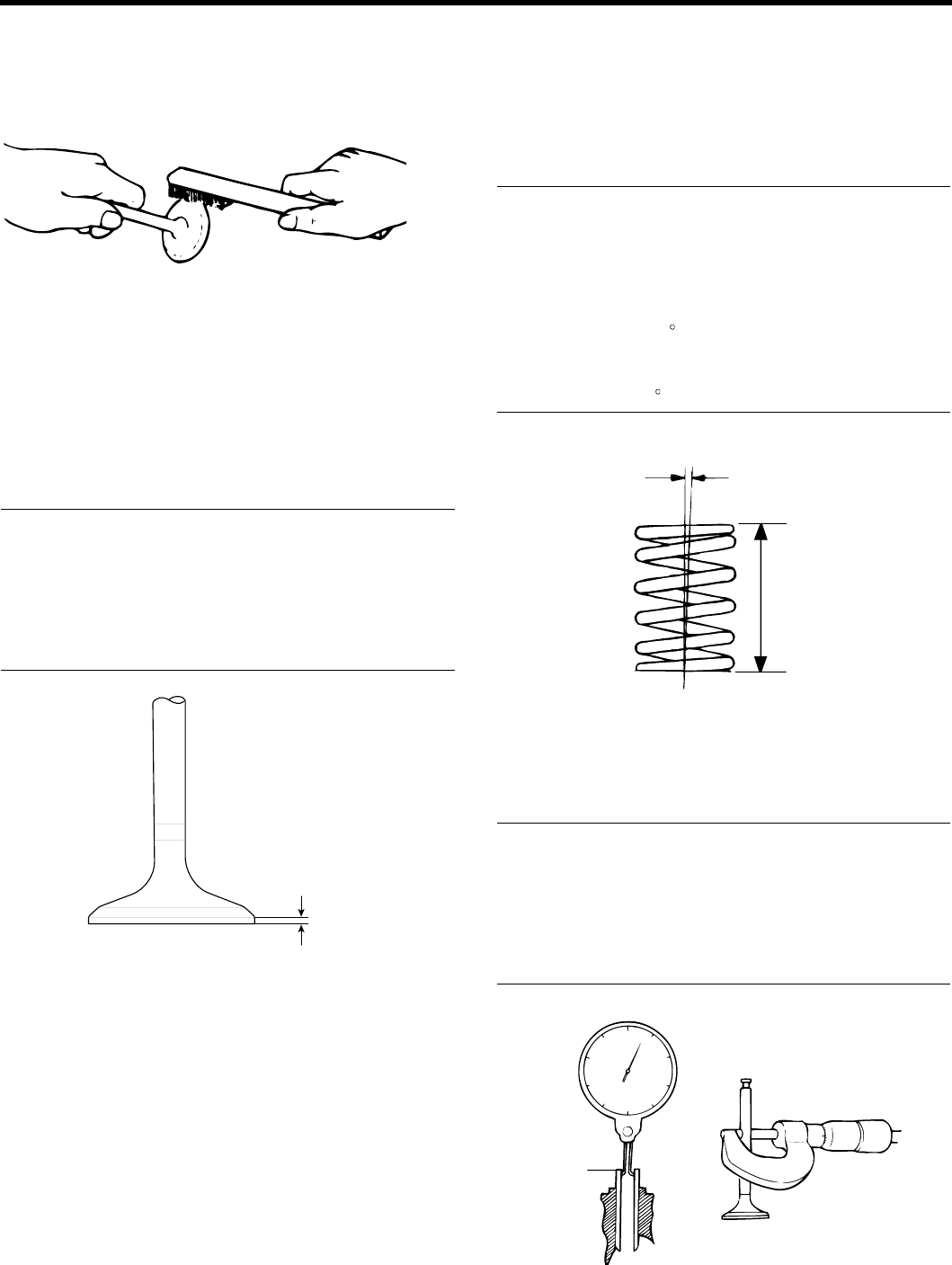
1. Using a wire brush, clean the valve thoroughly.
ECA9281A
2. Check each valve for wear, damage and distortion of
the head and the stem at B position. Replace, if nec-
essary. If stem end, A, is hollowed out or worn, resur-
face as necessary. This correction must be limited to
amin
imum. Also resurface the valve face.
Replace the valve if the margin has decreased to less
than the service limit.
Margin
[Standard]
Intake : 1.1 mm (0.043 in.)
Exhaust : 1.3 mm (0.051 in.)
[Limit]
Intake : 0.8 mm (0.028 in.)
Exhaust : 1.0 mm (0.040 in.)
Margin
ECKD221A
VALVE SPRINGS
1. Check the free height of each valve spring. If they
exceed the servicd limit, replace the springs.
2. Using a square, test the squareness of each spring.
If a spring is excessively out - of - square, replace it.
Valve spring
[Standard]
Free height : 44 mm (1.7323 in.)
Load :
21.6 kg/35 mm (47.6 lb/1.3780 in.)
45.1 kg/27.2 mm (99.4 lb/1.0709 in.)
Outofsquare: 1.5
[Limit]
Free height : - 1.0 mm (- 0.039 in.)
Out of square : 3
2˚
Free
height
Out-of-square
ECA9281C
Check the valve stem-to-guide clearance. If the clearance
exceeds the service limit, replace the valve guide with the
next oversize part.
Valve stem-to-clearance
[Standard]
Intake : 0.03 ~ 0.06 mm (0.0012 ~ 0.0024 in.)
Exhaust : 0.05 ~ 0.08 mm (0.0020 ~ 0.0031 in.)
[Limit]
Intake : 0.1 mm (0.0040 in.)
Exhaust : 0.15 mm (0.0059 in.)
Valve guide
Guide inside diameter
Stem diameter
ECA9281D
ZENITH POWER PRODUCTS - 416
CYLINDER HEAD ASSEMBLY EM -35
REPLACING THE VALVE SEAT RING
1. Cut away the inner face of the valve seat to reduce
the wall thickness.
0.3 - 0.6 mm
(0.0118 - 0.0236 in.)
0.3 mm (0.012 in. R)
0.15 - 0.3 mm
(0.006 - 0.0118 in.)
Old hole
AB
Remove
D∅
New hole
H
ECA9281F
2. Enlarge the diameter of the valve seat so that it
matches the specified oversize hole diameter of the
new valve seat ring.
3. Heat the cylinder head to about 250 C(480F) and
press - fit an oversize seat ring for the bore in the
cylinder head.
4. Using lapping compound, lap the valve to the new
seat.
Valve seat contact width
Intake : 0.8 ~ 1.2 mm (0.0315 ~ 0.0472 in.)
Exhaust : 1.3 ~ 1.7 mm (0.0512 ~ 0.0670 in.)
VALVE SEAT INSERT OVERSIZES
Description Size mm (in.) Size
mark Seat ring height H
mm (in.) Oversize hole diameter
I.D. mm (in.)
0.3 (0.012) O.S. 30 5.1~5.3(0.2008~0.2087) 30.7~30.721 (1.2087~1.2095
Intake valve
Seat ring 0.6 (0.024) O.S. 60 5.4~5.6(0.2126~0.2205) 31.0~31.021(1.2205~1.2213)
0.3 (0.012) O.S. 30 6.2~6.4(0.2441~0.2520) 27.3~27.321(1.0748~1.0756)
Exhaust valve
Seat ring 0.6 (0.024) O.S. 60 6.5~6.7(0.2560~0.2638) 27.6~27.621(1.0866~1.0874)
REPLACING VALVE GUIDE
1. Using the special tool (09221-3F100 A/B), withdraw
the old valveguide toward the bottom of cylinder head.
2. Recondition the valve guide hole so that it can match
the newly press-fitted oversize valve guide.
Valve guide
Valve guide installer
(09221-3F100A)
Cylinder head
Valve guide installer
(09221-3F100B)
Valve guide installer
adapter
14mm (0.5512 in.)
ECDE109C
ZENITH POWER PRODUCTS - 416

EM -36 ENGINE DOHC
3. Using the special tool (09221-3F100 A/B), press-fit
the valve guide. The valve guide must be press-fitted
from the upper side of the cylinder head.
4. After the valve guide is press-fitted, insert a new valve
and check for proper the clearance
5. After the valve guide is replaced, check that the valve
is seated properly. Recondition the valve seats as
necessary.
VALVE GUIDE OVERSIZES
Over size mm (in.) Size mark Oversize valve guide hole size mm (in.)
0.05 (0.002) 511.05~11.068 (0.4350~0.4357)
0.25 (0.010) 25 11.25~11.268 (0.4429~0.4436)
0.50 (0.020) 50 11.50~11.518 (0.4528~0.4535)
ZENITH POWER PRODUCTS - 416
CYLINDER HEAD ASSEMBLY EM -37
REASSEMBLY EC46B95A
NOTE
1. Clean each part before assembly.
2. Apply engine oil to the sliding and rotating parts.
1. Install the spring seats.
Using a special tool (09222-22001), tap the seal in
position lightly.
NOTE
•Do not reuse old valve stem seals.
•Incorrect installation of the seal could result in oil
leakage past the valve guides.
2. Apply engine oil to each valve. Insert the valve into
the valve guide.
Avoid pushing the valve into the seal by force. After
inserting the valve, check that it moves smoothly.
09222-22001
Valve
stem
seal
Valve
spring seat
ECHB930A
3. Place valve springs so that the side coated with
enamel faces toward the valve spring retainer and
then install the retainer.
Enamel
coated
side
Spring
Spring Retainer
Stem seal
Spring seat
ECA9290B
4. Using the special tool (09222-28000, 09222-28100),
compress the spring and install the retainer locks. Af-
ter installing the valves, ensure that the retainer locks
are correctly in place before releasing the valve spring
compressor.
09222-28100
09222-28000
EDKD116A
NOTE
When the spring is compressed, Check that the valve
stem seal is not pressed against the bottom of the
retainer.
5. Clean both gasket surfaces of the cylinder block and
cylinder head.
6. Verify the identification marks on the cylinder head
gasket.
7. Install the gasket so that the surface with the identifi-
cation mark faces toward the cylinder head.
8. Tighten the bolts to the specified torque in the se-
quence shown.
8 6 1 3 9
10 4 2 5 7
EDKD700A
Cylinder head bolt
30 Nm (300 kg.cm, 22 lb.ft)+90 +Release all bolts
+ 30 Nm(300kg.cm, 22 lb.ft)+90
ZENITH POWER PRODUCTS - 416
EM -38 ENGINE DOHC
MAIN MOVING SYSTEM
CAM SHAFT
COMPONENTS EE8F4E76
TORQUE : Nm (kg.cm, lb.ft)
5 ~ 8 (50 ~ 80, 4 ~ 6)
8 ~ 10 (80 ~ 100, 6 ~ 7)
12 ~ 14 (50 ~ 80, 4 ~ 6)
Bearing cap (rear)
Exhaust camshaft
HLA
80 ~ 100
(800 ~ 1000, 59 ~ 74) Camshaft oil seal
Bearing cap (front) Intake camshaft
Cylinder head
Gasket
Camshaft sprocket
EDDA018A
ZENITH POWER PRODUCTS - 416
MAIN MOVING SYSTEM EM -39
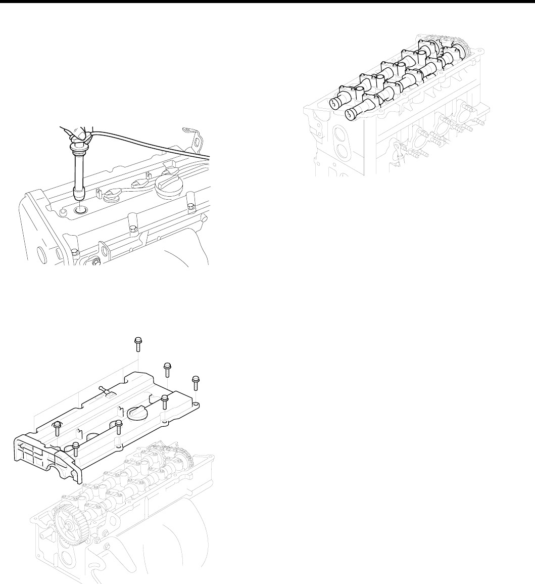
DISASSEMBLY EBF99CFA
1. Disconnect the breather hose and the P.C.V. hose.
2. Loosen the center cover bolts and then remove the
center cover.
3. Remove the ignition coil assembly and the spark plug
cables.
KCDC002B
4. Loosen the cylinder head cover bolts and then remove
the cylinder head cover.
EDKE104A
5. Remove the camshaft sprocket.
6. Remove the camshaft bearing caps and timing chain.
EDKE124A
7. Remove the camshaft.
8. Remove the HLA.
ZENITH POWER PRODUCTS - 416
EM -40ENGINE DOHC
INSPECTION ECDFFBF8
1. Check the camshaft journals for wear. If the journals
are badly worn, replace the camshaft.
2. Check the cam lobes for damage. If the lobe is dam-
aged or worn excessively, replace the camshaft.
Standard value
Intake : 43.4484 mm (1.7106 in.)
Exhaust : 43.8489 mm (1.7263 in.)
Limit
Intake : 42.9484 mm (1.6909 in.)
Exhaust : 43.3489 mm (1.7066 in.)
ECKD223A
3. Check the cam surface for abnormal wear or damage,
and replace if necessary.
4. Check each bearing for damage. If the bearing
surface is excessively damaged, replace the cylinder
head assembly or camshaft bearing cap, as neces-
sary.
Camshaft end play : 0.1 - 0.2 mm (0.0039 - 0.0079 in.)
OIL SEAL
1. Check the lips for wear. If the lip threads are worn,
replace.
2. Check the oil seal lip contacting surface of the
camshaft. If it is worn, replace the camshaft.
ZENITH POWER PRODUCTS - 416
MAIN MOVING SYSTEM EM -41
HLA ( HYDRAULIC LASH ADJUSTER)
With the HLA filled with engine oil, hold A and press B by
hand. If B moves, replace the HLA.
For other specific trouleshooting regarding HLA, refer to
the table below.
B
A
EDDA020B
Problem Possible cause Action
Temporary noise on starting a
cold engine. Normal This noise will disappear after
the oil in the engine has reached
normal pressure.
Continuous noise when engine is
running after sitting more than 48 hours. Oil leakage of the high pressure
chamber on HLA, allowing
air to get in.
Continuous noise when engine is first
started after rebuilding cylinder head. Insufficient oil in cylinder
head oil gallery.
Continuous noise when engine is
running after excessive cranking.
Noise will disappear within 15 minutes
when engine runs at 2000~3000 rpm
If it doesn’t disappear, refer to
item 7 below
Continuous noise when engine is
running after changing HLA.
Oil drain out of the high-pressure
chamber in HLA, allowing
air to get in.
Insufficient oil in HLA.
CAUTION
Do not run engine at a speed
higher than 3000 rpm as this
may damage HLA.
Engine oil level too high or too low. Check oil level.
Drain or add oil as necessary.
Excessive amount of air in the
oil at high engine speed. Check oil supply system
Continuous noise during idle after
high speed running.
Deteriorated oil Check oil quality.
Low oil pressure Check oil pressure and oil supply
system of each part of engine
Noise continuous for more than
15 minutes.
Faulty HLA. Remove the cylinder head cover and
press down on the HLA by hand.
If it move, replace HLA.
CAUTION
Be careful of hot HLA.
NOTE
HLA noise could occur to your engine due to malfunc-
tion of HLA if you use additives besides engine oil reg-
ulated to HMC.
ZENITH POWER PRODUCTS - 416
EM -42ENGINE DOHC
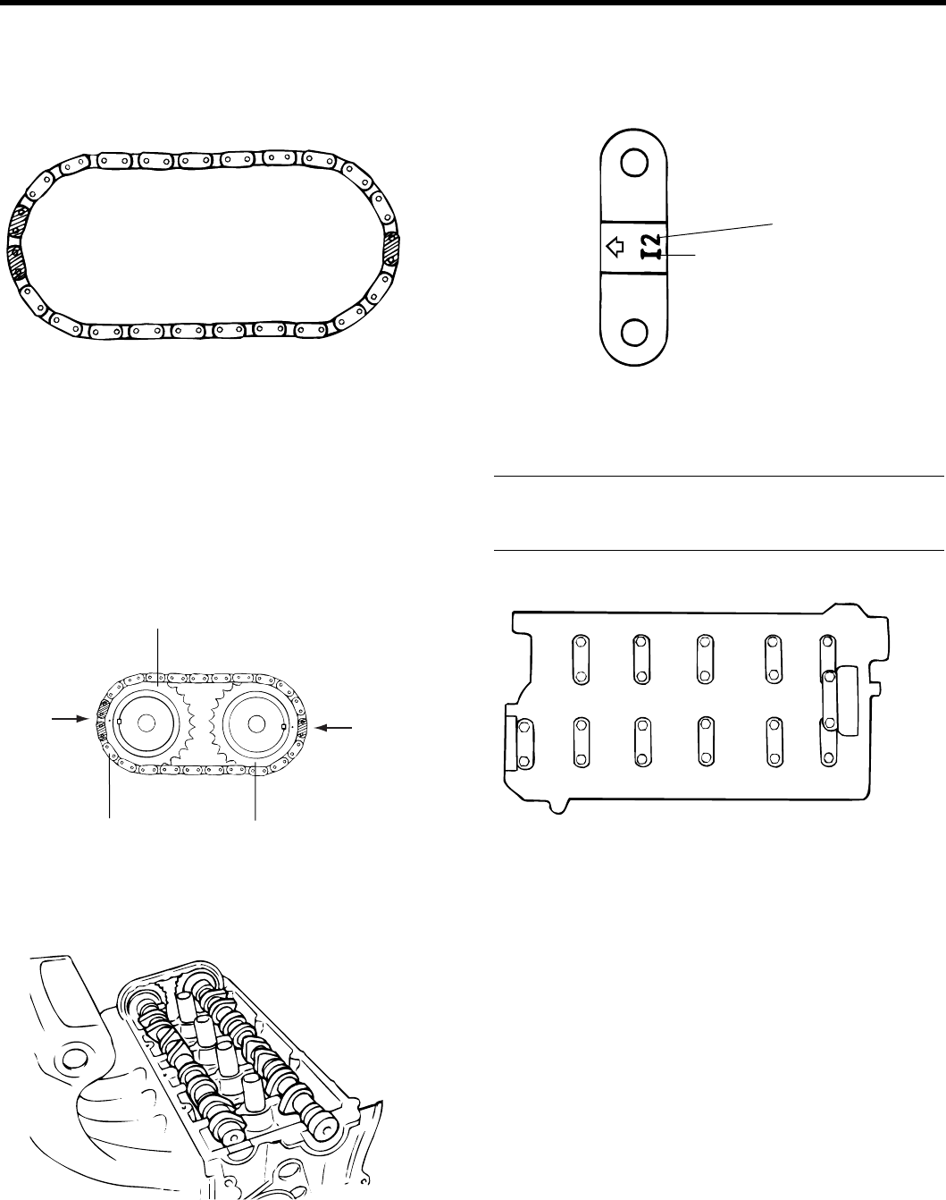
TIMING CHAIN
Check the bushing and plate of timing chain for wear. Re-
place if wear is severe.
EDDA020C
REASSEMBLY E1337F9D
1. Install the HLA.
2. Align the camshaft timing chain with intake timing
chain sprocket and exhaust timing chain sprocket as
shown.
Exhaust timing chain sprocket
Intake timing chain sprocket
Timing
mark
Timing
mark
Timing chain
EDDA021A
3. Install the camshaft after lubricating the camshaft
journals with engine oil.
EDDA021B
4. Install the bearing caps. The markings on the caps
are for intake/exhaust identification.
I: Intake camshaft
E: Exhaust camshaft
Symbol identifying intake
Cap number
EDDA021C
5. Tighten the bearing caps to the specified torque in two
or three steps as shown.
Tightening torque
Bearing cap bolt :
12 ~ 14 Nm (120 ~ 140 kg.cm, 9 ~ 10 lb.ft)
Camshaft sprocket side
I1
I2
I3
I4
I5
E1
E2
E3
E1
E5
EDDA021D
ZENITH POWER PRODUCTS - 416
MAIN MOVING SYSTEM EM -43
6. Using the special tool, camshaft oil seal installer
(09221 - 21000), press fit the camshaft oil seal. Be
susre to apply engine oil to the oil seal lip. Insert the
oil seal along the camshaft front end and install by
driving the installer with a hammer until the oil seal
is fully seated.
09221-21000
EDKD125A
7. Install the camshaft sprocket bolts to the specified
torque.
Tightening torque
Camshaft sprocket bolt :
80 ~ 100Nm (800 ~ 1000 kg.cm, 59 ~ 74 lb.ft)
EDKE105A
8. Align the camshaft sprocket and crankshaft sprocket
timing marks. Place the poston in the No.1 cylinder to
top dead center on the compression strokie. (Refer to
the timing belt)
9. Install the cylinder head cover.
Tightening torque
Cylinder head cover bolts :
8~10Nm(80~100kg.cm,6~7lb.ft)
EDKE104A
10. Install the spark plug cables, ignition coil assembly
and cylinder head center cover.
11. Install the timing belt and then tighten the timing belt
tensioner pulley.
12. Install the timing belt cover.
Tightening torque
Timing belt cover : 8 ~ 10Nm (80 ~ 100 kg.cm, 6 ~ 7 lb.ft)
ZENITH POWER PRODUCTS - 416
EM -44 ENGINE DOHC
CRANK SHAFT
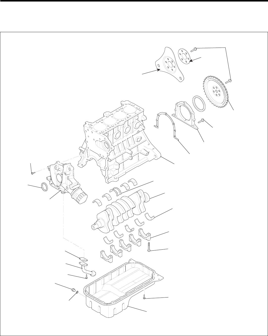
COMPONENTS ED67A7AC
(ATA)
(MTA)
120 ~ 130
(1200 ~ 1300,
88 ~ 95)
Washer
Drive plate
Flywheel
10 ~ 12 (100 ~ 120,
7.3 ~ 8.8)
Rear oil seal case
Gasket
Cylinder block
Center bearing
Crankshaft
Main bearing
Main bearing cap
55 ~ 60 (550 ~ 600, 41 ~ 44)
10 ~ 12 (100 ~ 120, 7.3 ~ 8.8)
Oil pan
Drain plug
40 ~ 45
(400 ~ 450,
30 ~ 33) Gasket
15 ~ 22 (150 ~ 220, 11 ~ 16)
Oil screen
Gasket
Front case
Oil seal
20 ~ 27 (200 ~ 270,
14.7 ~ 20)
TORQUE : Nm (kgf.cm, lbf.ft)
EDKD140A
ZENITH POWER PRODUCTS - 416
MAIN MOVING SYSTEM EM -45
DISASSEMBLY EA7E6C0F
1. Remove the timing belt, front case, flywheel, cylinder
head assembly and oil pan. For details, refer to the
respective chapters.
2. Remove the rear plate and the rear oil seal.
3. Remove the connecting rod caps.
4. Remove the main bearing caps and remove the crank-
shaft.
5. Remove the crankshaft position sensor wheel.
CAUTION
Mark the main bearing caps to permit reassembly
in the original position and direction.
INSPECTION E76DB219
CRANKSHAFT
1. Check the crankshaft journals and pins for damage,
uneven wear, and cracks. Also check oil holes for
clogging. Correct or replace any defective part.
2. Inspect the crankshaft journal for taper and out - of -
round.
Standard value
Crankshaft journal O.D : 50 mm (1.9685 in.)
Crankshaft pin O.D : 45 mm (1.7717 in.)
Crankshaft journal, pin out-of-roundness and taper :
0.005 mm (0.0002 in.) or less
MAIN BEARINGS AND CONNECTING ROD
BEARINGS
Visually inspect each bearing for peeling, melting, seizure,
and improper contact. Replace the defective bearings.
OIL CLEARANCE MEASUREMENT
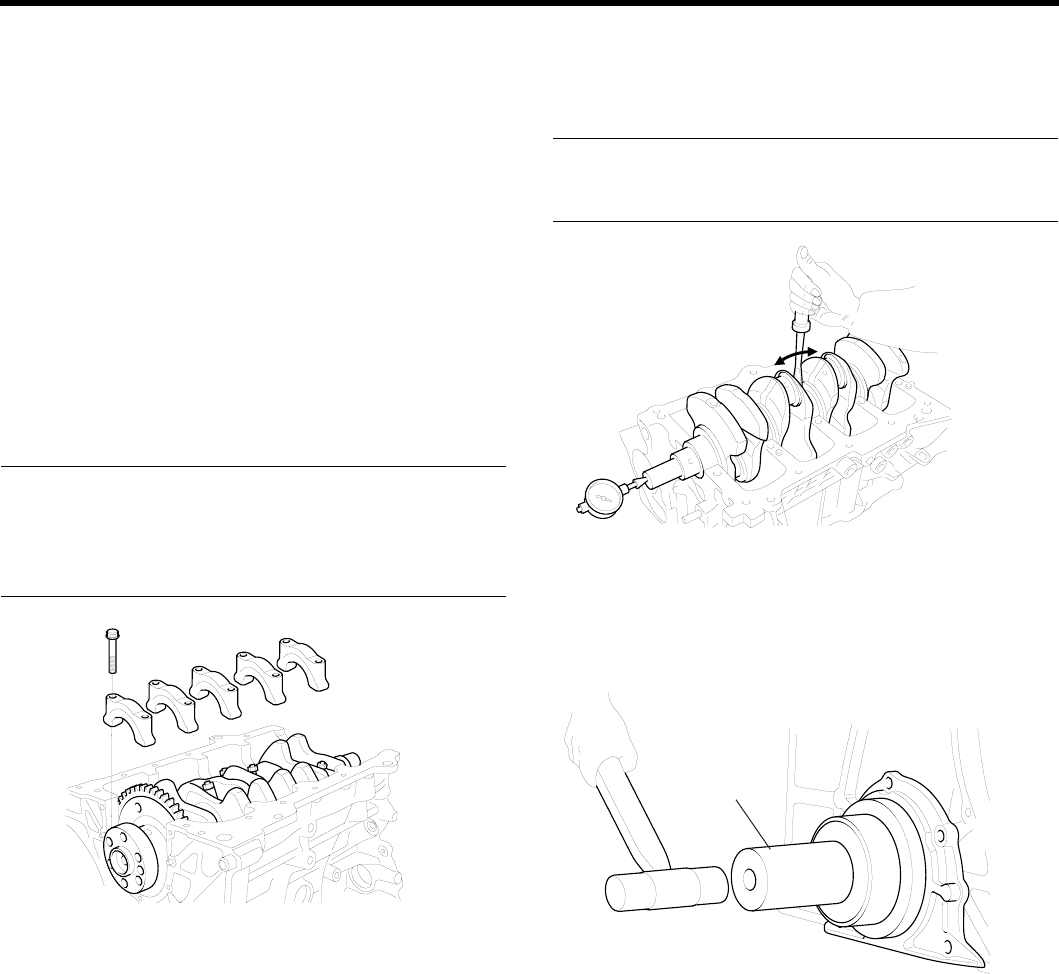
1. Measure the diameter of the crankshaft journal and
pin.
2. Measure the diameter of the crankshaft bore and con-
necting rod bore.
3. Measure the thickness of the crankshaft bearing and
connecting rod bearing.
4. Measure the clearance by the value that subtract the
diameter of journal and pin and the thickness of bear-
ing from the diameter of bore.
Connecting rod bearing oil clearance :
0.018 ~ 0.036 mm (0.0007 ~ 0.0014 in.)
Crankshaft main bearing oil clearance
NO. 1,2,4,5 : 0.022 ~ 0.040 mm (0.0009 ~ 0.0018 in.)
NO.3 : 0.028 ~ 0.046 mm (0.0011 ~ 0.0018 in.)
OIL SEAL
Check front and rear oil seals for damage or wear. Replace
any seal that is defective.
CRANKSHAFT SENSOR WHEEL
1. Remove the sensor wheel.
2. Check the sensor wheel for damage, cracks and wear,
and replace if necessary.
3. Check the clearance between the sensor wheel and
the crank position sensor with a depth gage.
Standard value
Clearance between sensor wheel and crank
position sensor :
0.5 ~ 1.1 mm (0.020 ~ 0.043 in.)
EDDA028C
NOTE
1. Measure the depth of the top of sensor wheel
tooth and the cylinder block mounting block.
2. Measure the difference between sensor length
and depth.
3. Sensor length is the distance between the end of
the sensor and the inner point of the contacting
face.
ZENITH POWER PRODUCTS - 416
EM -46 ENGINE DOHC
REPLACEMENT E8EBDEBC
1. Check the cylinder block crankshaft bore size code.
Crankshaft bore size code
EDPC004C
NOTE
Record the cylinder block crankshaft bore size code
letters on cylinder block as shown.
Reading order is from left to right with front crankshaft
bore size code shown first.
Class Crankshaft bore diameter Size
code
a54~54.006mm (2.1259~2.1262in.) A
b54.006~54.012mm
(2.1262~2.1264in.) B
c54.012~54.016mm
(2.1264~2.1266in.) C
2. Check the crankshaft main journal size code.
NOTE
Record the main journal size code letters on the
crankshaft balance weight.
Reading order is from left to right as shown, with No.1
main journal size code shown first.
Main journal size code
ECPC004B
CRANKSHAFT MAIN JOURNAL DIAMETER
Class Main journal diameter Size
code
I49.968 ~ 49.962 mm
(1.9672 ~ 1.9670 in.) Λ
II 49.962 ~ 49.956 mm
(1.9670 ~ 1.9667 in.) b
III 49.956 ~ 49.950 mm
(1.9667 ~ 1.9665 in.) c
MAIN JOURNAL BEARING THICKNESS
No.1,2,4,5(MAINBEARING)
Color Main journal bearing thinckness
Yellow 2.002 ~ 2.005 mm (0.0788 ~ 0.0789 in.)
Green 2.005 ~ 2.008 mm (0.0789 ~ 0.0790 in.)
No color 2.008 ~ 2.011 mm (0.0790 ~ 0.0791 in.)
Black 2.011 ~ 2.014 mm (0.0791 ~ 0.0793 in.)
Blue 2.014 ~ 2.017 mm (0.0793 ~ 0.0794 in.)
NO.3 (CENTER BEARING)
Color Main journal bearing thickness
Yellow 1.999 ~ 2.002 mm (0.0787 ~ 0.0788 in.)
Green2.002 ~ 2.005 mm (0.0788 ~ 0.0789 in.)
No color 2.005 ~ 2.008 mm (0.0788 ~ 0.0790 in.)
Black 2.008 ~ 2.011 mm (0.0790 ~ 0.0791 in.)
Blue 2.011 ~ 2.014 mm (0.0791 ~ 0.0793 in.)
3. Choose proper main journal bearing in table.
ZENITH POWER PRODUCTS - 416
MAIN MOVING SYSTEM EM -47
REASSEMBLY E0ABCAB2
1. Install the upper main bearing inserts in the cylinder
block.
When reusing the main bearings, remember to in-
stall them by referring to the location marks made
at the time of disassembly.
2. Install the crankshaft. Apply engine oil to the journals.
3. Install bearing caps and tighten cap bolts to the spec-
ified torque in the following sequence; center, No.2,
No.4, front, and rear caps.
Cap bolts should be tightened evenly in 2 to 3 stages
before they are tightened to the specified torque.
The caps should be installed with the arrow mark di-
rected toward the crank pulley side of engine. Cap
numbers must be correct.
Tightening torque
Main bearing cap bolt :
55 ~ 60 Nm (550 ~ 600 kg.cm, 41 ~ 44 lb.ft)
Connecting rod cap bolt :
32 ~ 35 Nm (320 ~ 350 kg.cm, 24 ~ 26 lb.ft)
EDKE151A
4. Make certain that the crankshaft turns freely and has
the proper clearance between the center main bear-
ing thrust flange and the connecting rod big end bear-
ing.
Standard value
Crankshaft end play :
0.05 ~ 0.175 mm (0.0019 ~ 0.0068 in.)
ECKD001B
5. Install the oil seal in the crankshaft rear oil seal case.
Use the Special Tool, Crankshaft Rear Oil Seal In-
staller (09231 - 21000) as shown. Press fit the oil seal
all the way in, being careful not to misalign it.
09231-21000
ECKD326A
6. Install the rear plate and tighten the bolts.
7. Install the connecting rod caps.
8. Install the flywheel, front case, oil pan and timing belt.
For further details, refer to the respective chapters.
ZENITH POWER PRODUCTS - 416
EM -48 ENGINE DOHC
FLY WHEEL
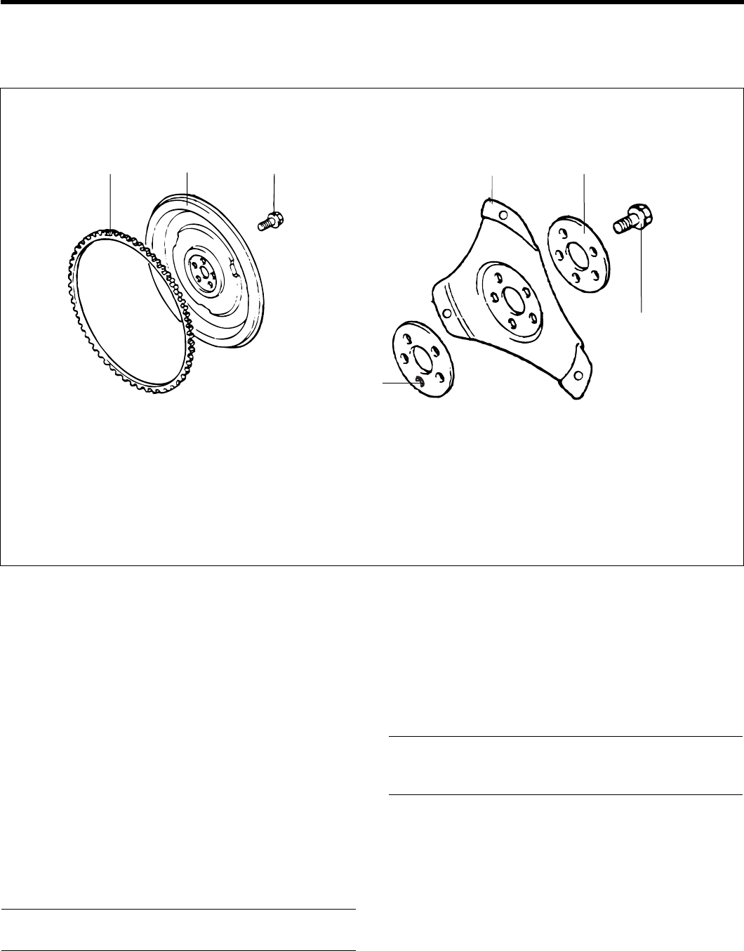
COMPONENTS E3FB04C9
Ring gear Flywheel 120 ~ 130 (1200 ~ 1300, 89 ~ 96) Drive plate Adaptor plate
120-130
(1200-1300, 89-96)
Adaptor plate
TORQUE : Nm (kg.cm, lb.ft)
M/T A/T
EDDA030A
M/T : Manual Transmission Vehicles
A/T : Automatic Transmission Vehicles
DISASSEMBLY E543FBCD
1. Remove the Transmission and clutch.
2. Remove the flywheel.
INSPECTION EB2E8F43
1. Check the clutch disc contacting surface of the fly-
wheel for damage and wear. Replace the flywheel if
excessively damaged or worn.
2. Check the clutch disc contacting surface of the fly-
wheel for runout.
Standard value
Flywheel run - out : 0.1 mm (0.0039 in.)
3. Check the ring gear for damage, cracks, and wear,
and replace if necessary.
REASSEMBLY E650BE51
Install the flywheel assembly and tighten the bolts to the
specified torque.
Tightening torque
Flywheel bolt :
120 ~ 130 Nm (1200 ~ 1300 kg.cm, 89 ~ 96 lb.ft)
ZENITH POWER PRODUCTS - 416
MAIN MOVING SYSTEM EM -49
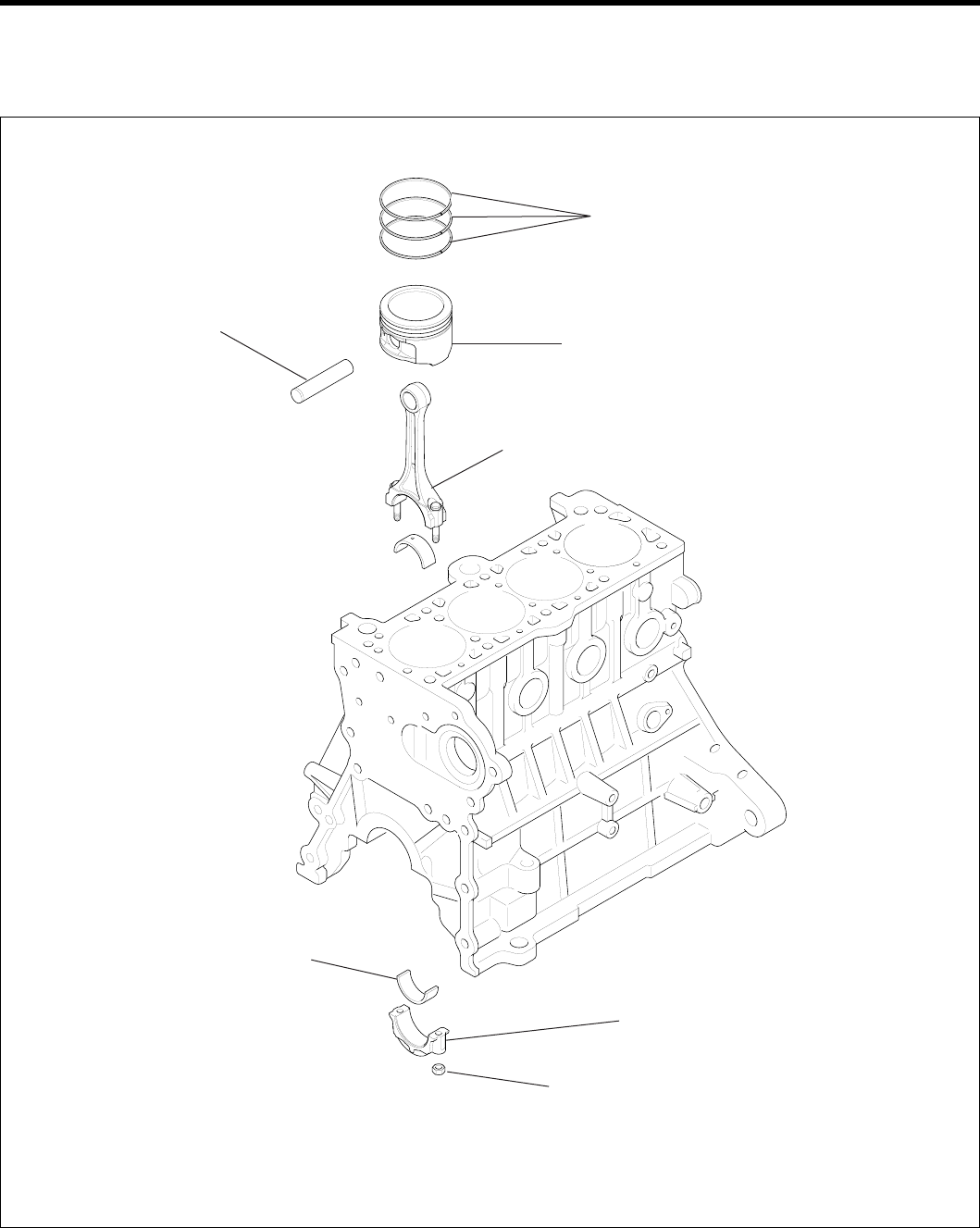
PISTON
COMPONENTS E1D1ECDE
Piston ring
Piston
Connecting rod
Piston pin
Connecting rod bearing
Connecting rod bearing cap
32 ~ 35 (320 ~ 350, 24 ~ 26)
TORQUE : Nm (kgf.cm, lbf.ft)
EDKD141A
ZENITH POWER PRODUCTS - 416
EM -50 ENGINE DOHC
DISASSEMBLY EEDFC26E
CONNECTING ROD CAP
CAUTION
Keep the bearings in order with their correspond-
ing connecting rods (according to cylinder num-
bers) for proper reassembly.
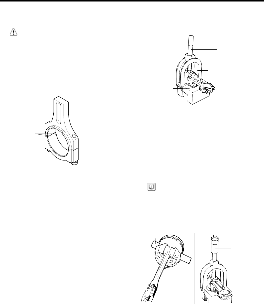
1. Remove the connecting rod cap bolts, then remove
the caps and the big end lower bearing.
2. Push each piston connecting rod assembly toward the
top of the cylinder.
Notches
KFW3049A
DISASSEMBLY AND REASSEMBLY OF THE
PISTON PIN
1. Using the special tools, disassemble and reassemble
the piston and connecting rod.
2. The piston pin is press fit into the rod little end, and
thepistonfloatsonthepin.
3. The tool consists of a support fixture with fork inserts,
guides, adapters, an installer and a remover. The
piston is supported in the support fixture while the pin
is being installed or removed. Guides help position
the pin as it is installed or removed, while the rod is
supported by fork inserts.
4. To remove the pin from the piston, place the piston
in the support fixture with the rod resting on the fork
inserts. Pass the remove tool through the top of the
support fixture and use it to press out the pin.
Remover
Support fixture
Support fork
EDA9048A
5. To install a new pin, the proper fork inserts must be in
place to support the rod.
6. Position the rod inside the piston. Insert the proper
pin guide through one side of the piston and through
the rod.
Hand tap the pin guide so it is held by the piston.
Insert the new pin into the piston from the other side
and set the assembly into the support fixture with the
pin guide facing down.
NOTE
The pin guide should be centered on the connecting
rod through the piston. If assembled correctly, the pin
guide will sit exactly under the center of the hole in the
tool’s arch, and rest evenly on the fork inserts. If the
wrong size pin guide is used, the piston and pin will
not line up with the support fixture.
Pin guide
Installer
Piston pin
ECA9361C
ZENITH POWER PRODUCTS - 416
MAIN MOVING SYSTEM EM -51
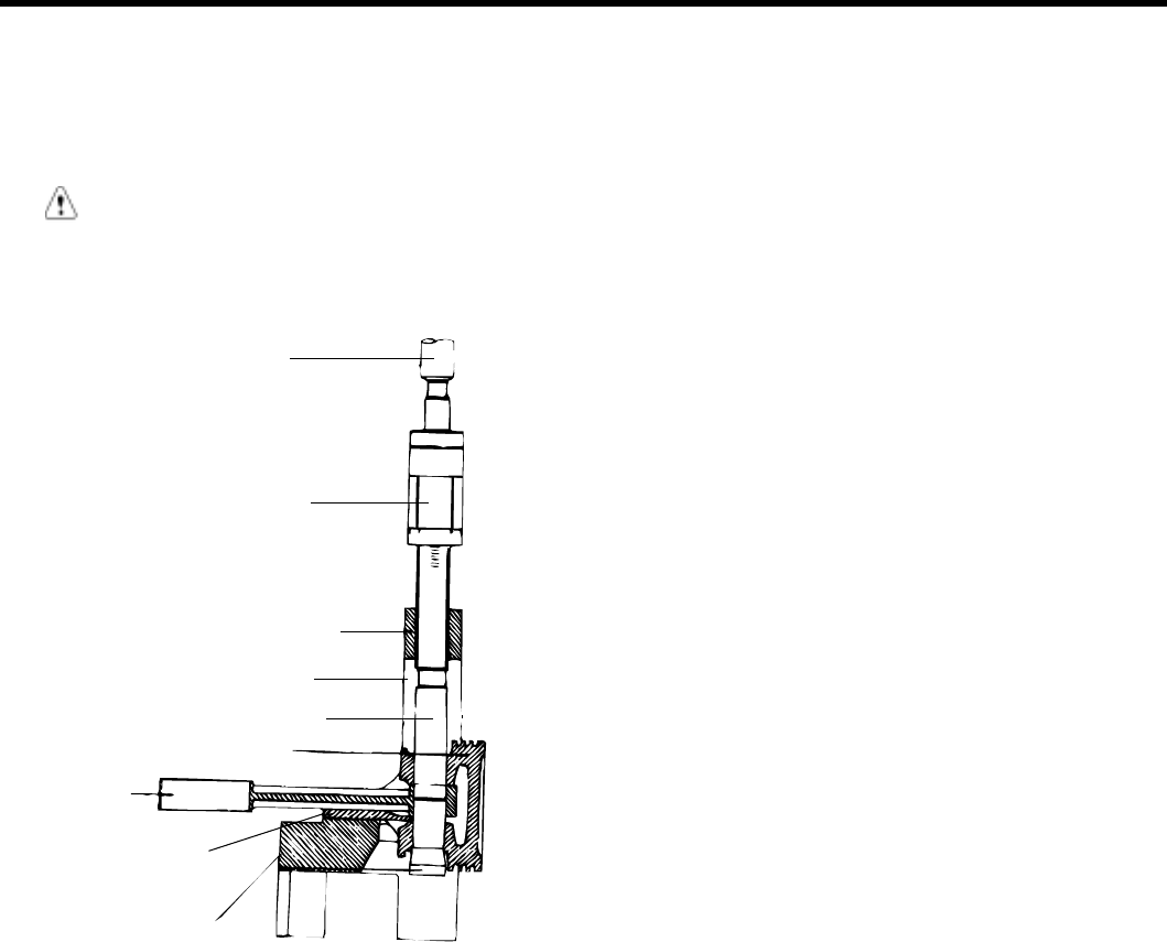
7. Insert the installer tool through the hole in the arch of
the support fixture and use an hydraulic press to force
the piston pin through the rod little end. Continue
pressing until the pin guide falls free and the installer
tool seats against the top of the arch.
CAUTION
Do not exceed 1250 ± 500 kg (2765 ± 1102 lb) of
force when the installing tool seats against the top
of the arch.
Press
Installer
Support fix
Adapter
Piston pin
Piston
Connecting
rod
Universal fork insert
Pin guide
HEW20A55
ZENITH POWER PRODUCTS - 416
EM -52ENGINE DOHC
INSPECTION E005DAEA
PISTONS AND PISTON PINS
1. Check each piston for scuffing, scoring, wear and
other defects. Replace any piston that is defective.
2. Check each piston ring for breakage, damage and
abnormal wear. Replace the defective rings.
When the piston requires replacement, its rings
should also be replaced.
3. Check that the piston pin fits in the piston pin hole.
Replace any piston and pin assembly that is defective.
The piston pin must be smoothly pressed by hand into
the pin hole (at room temperature).
PISTON RINGS
1. Measure the piston ring side clearance. If the mea-
sured value exceeds the service limit, insert a new
ring in the ring groove to measure the side clearance.
If the clearance still exceeds the service limit, replace
the piston and rings together. If it is less than the
service limit, replace the piston rings only.
Piston ring side clearance
No.1 : 0.04 ~ 0.085 mm (0.0016 ~ 0.0033 in.)
No. 2 : 0.04 ~ 0.085 mm (0.0016 ~ 0.0033 in.)
Limit
No. 1 : 0.1 mm (0.004 in.)
No. 2 : 0.1 mm (0.004 in.)
ECKD001G
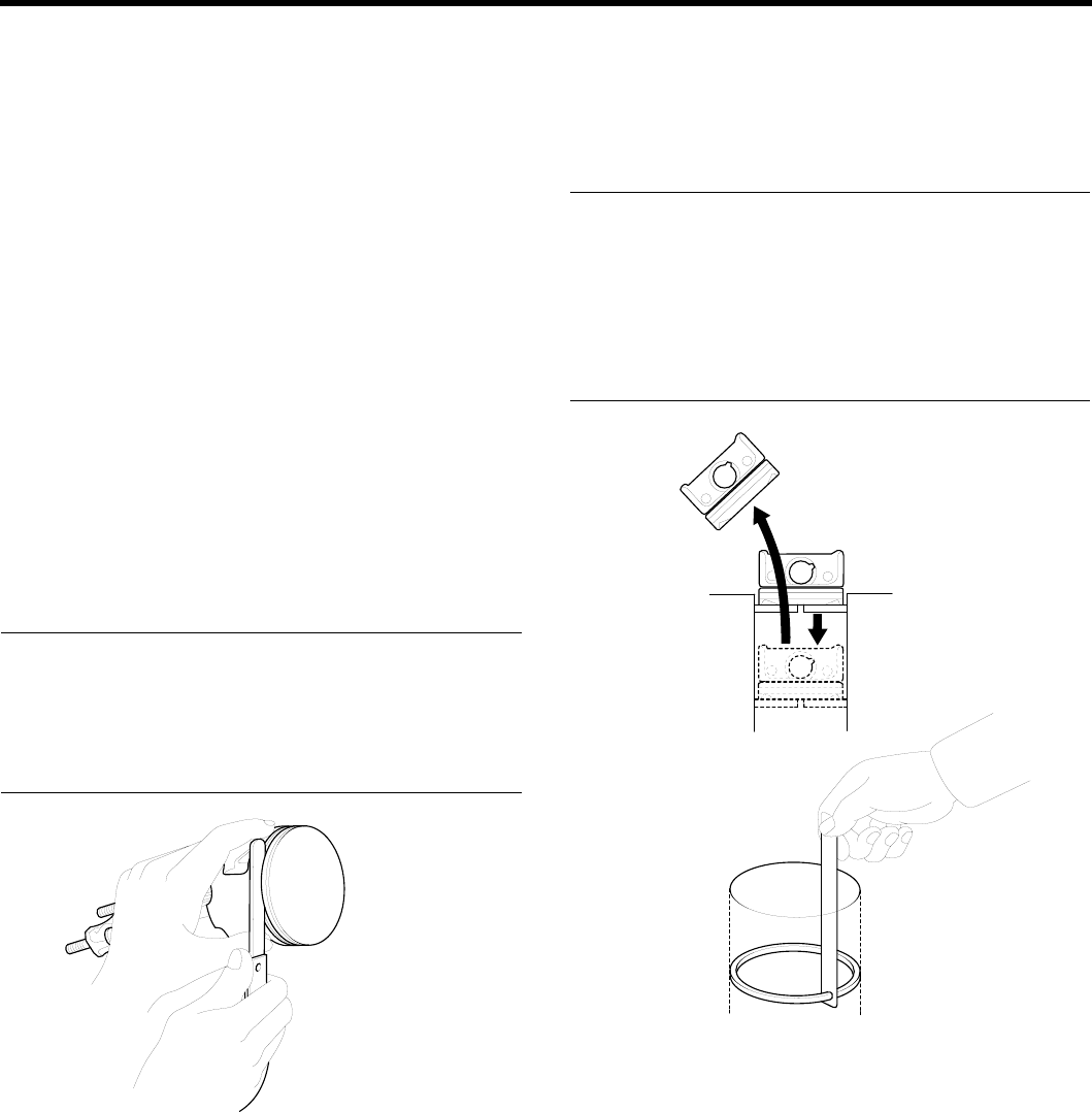
2. To measure the piston ring end gap, insert a piston
ring into the cylinder bore. Position the ring at right
angles in the cylinder wall by gently pressing it down
with a piston. Measure the gap with a feeler gauge. If
the gap exceeds the service limit, replace the piston
ring.
Pistonringendgap
[Standard dimensions]
No. 1 : 0.15 ~ 0.30 mm (0.0059 ~ 0.012 in.)
No. 2 : 0.30 ~ 0.45 mm (0.012 ~ 0.018 in.)
Oil ring side rail : 0.2 ~ 0.7 mm (0.0079 ~ 0.0276 in.)
[Limit]
No. 1, No. 2 : 1.0 mm (0.039 in.)
Oil ring side rail : 1.0 mm (0.0.39 in.)
ECKD001K
When replacing the ring without correcting the cylin-
der bore, check the gap with the ring situated at the
low part of cylinder that is less worn out.
ZENITH POWER PRODUCTS - 416
MAIN MOVING SYSTEM EM -53
PISTON RING SERVICE SIZE AND MARK
Standard None
0.25 mm (0.010 in.) O.S 25
NOTE
The mark can be found on the upper side of the ring
next to the end.
CONNECTING RODS
1. When the connecting rod cap is installed, make sure
that the cylinder numbers, marked on rod end cap at
disassembly, match.
When a new connecting rod is installed, make sure
that the notches holding the bearing in place are on
thesameside.
2. Replace the connecting rod if it is damaged at either
end of the thrust faces. If it has a stratified wear in, or
if the surface of the inside diameter of the small end
is severely rough, replace the rod.
Notches
KFW3049A
ZENITH POWER PRODUCTS - 416
EM -54 ENGINE DOHC
REPLACEMENT EF4FCD8C
1. Check the cylinder bore size code on the cylinder
block bottom face.
Cylinder bore side code
EDPE004B
1.6 L
Class Cylinder bore inner diameter Size
code
A76.5~76.51mm (3.0118~3.0121in.) A
B76.51~76.52mm (3.0121~3.0126in.) B
C76.52~76.53mm (3.0126~3.0129in.) C
2. Check the piston size code on the piston top face.
KDPC005Z
NOTE
Stamp the grade mark of basic diameter with rubber
stamp.
1.6 L
Class Piston outer diameter Size
code
A76.465~76.475mm
(3.0104~3.0108in.) A
B76.475~76.485mm
(3.0108~3.0112in.) B
C76.485~76.495mm
(3.0112~3.0116in.) C
3. Select the piston related to cylinder bore class.
Oil clearance
0.025 ~ 0.045mm (0.00098 ~ 0.00177in.)
ZENITH POWER PRODUCTS - 416
MAIN MOVING SYSTEM EM -55
REASSEMBLY ECCF87EF
1. Install the spacer.
Piston upper
Piston lower
Side rail
Spacer
ECA9082A
Upper side rail
45˚
45˚
45˚
45˚
Lower side rail
90˚ Position
from the gap
of No. 2 ring
Gap position of
lower side rail
Gap position of spacer
Gap position
of upper
spacer Spacer
EDJA490A
2. Install the upper side rail. To install the side rail, first
put one end of the side rail between the piston ring
groove and spacer, hold it firmly, and press down with
a finger on the portion to be inserted into the groove
(as illustrated).
CAUTION
Do not use a piston ring expander when installing
side rail.
3. Install the lower side rail by the same procedure de-
scribedinStep2.
ECA9380B
4. Apply engine oil around the piston and piston grooves.
5. Using a piston ring expander, install the No.2 piston
ring.
6. Install the No. 1 piston ring.
No.1
No.2
Berrel type
Inside bevel
Taper type
EDDA037B
7. Position each piston ring end gap as far away from
its neighboring gaps as possible. Make sure that the
gaps are not positioned in the thrust and pin direc-
tions.
ZENITH POWER PRODUCTS - 416
EM -56 ENGINE DOHC
8. Hold the piston rings firmly with a piston ring compres-
sor as they are inserted into cylinder.
Gap of upper
side rail
No.1 ring
gap
Front of
engine
No.2 ring gap
and spacer
expander gap
Gap of lower
side rail
ECA9380D
9. Install the upper main bearings in the cylinder block.
10. Install the lower main bearings in the main bearing
caps.
11. Make sure that the front mark of the piston and the
front mark (identification mark) of the connecting rod
are directed toward the front of the engine.
12. When a new connecting rod is installed, make sure
that the notches for holding the bearing in place are
on the same side.
13. When assembling, bolts should be fastened by the
angle - torque controlled method as the following.
1) Apply oil to the thread of nuts and spot areas.
2) Tighten the connecting rod bolt.
Tightening torque
Connecting rod cap nut :
32 ~ 35 Nm (320 ~ 350 kg.cm, 24 ~ 26 lb.ft)
CAUTION
After removing the connecting rod bolt, do not
use if again.
When using a new bolt, do not tighten the bolt
more than 3 times.
14. Check the connecting rod side clearance.
Connecting rod side clearance
Standard : 0.10 ~ 0.25 mm (0.0039 ~ 0.0098 in.)
Limit : 0.4 mm (0.0157 in.)
EDKD145A
15. Install the oil screen.
16. Install the oil pan.
17. Install the cylinder head.
ZENITH POWER PRODUCTS - 416
COOLING SYSTEM EM -57
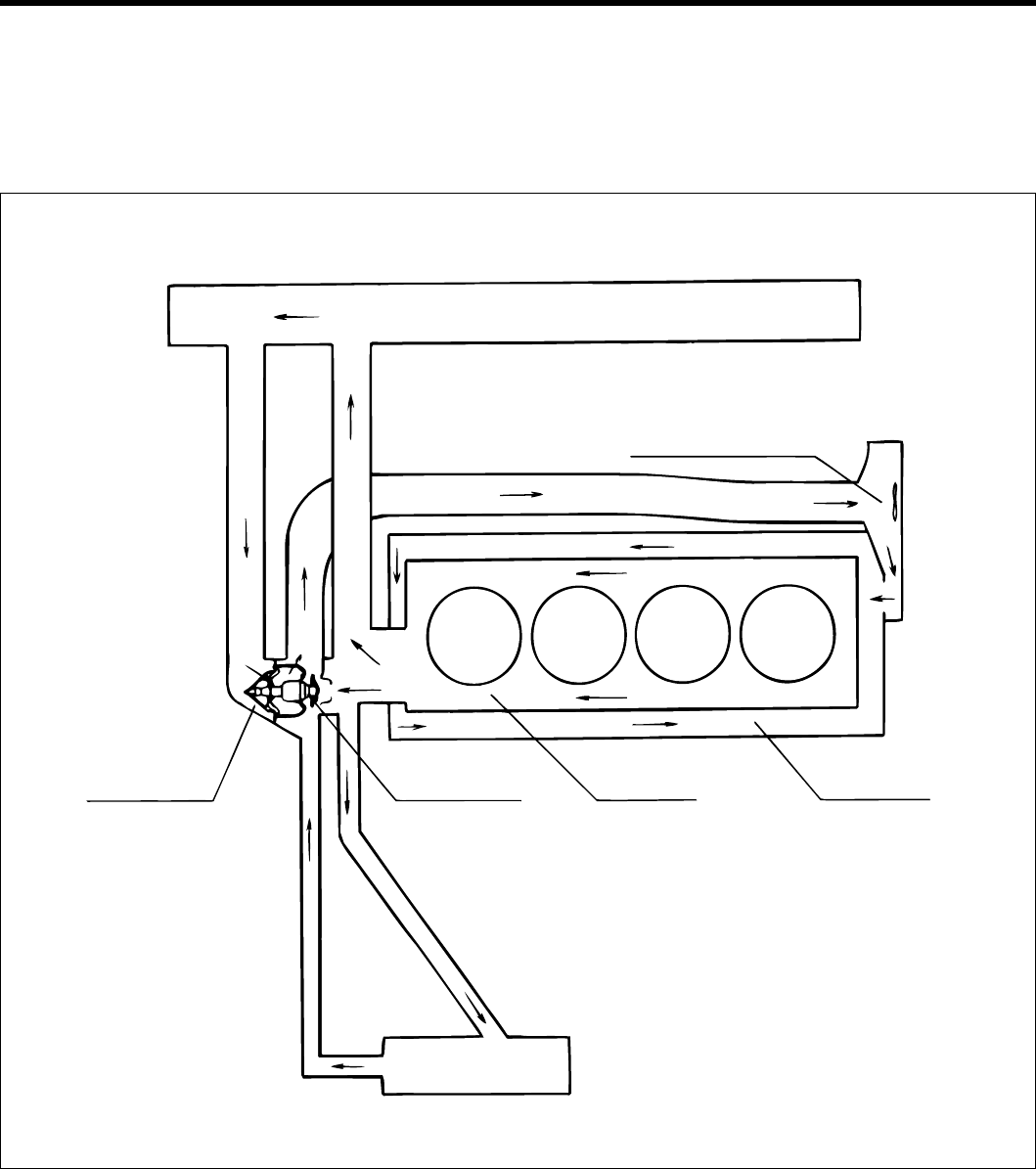
COOLING SYSTEM
ENGINE COOLANT HOSE/PIPES
COMPONENTS E2BAF9FA
RADIATOR
CYL/HEAD CYL/BLCOK
BYPASS VALVE
HEATER
THERMOSTAT
COOLANT PUMP
ECKB001I
ZENITH POWER PRODUCTS - 416
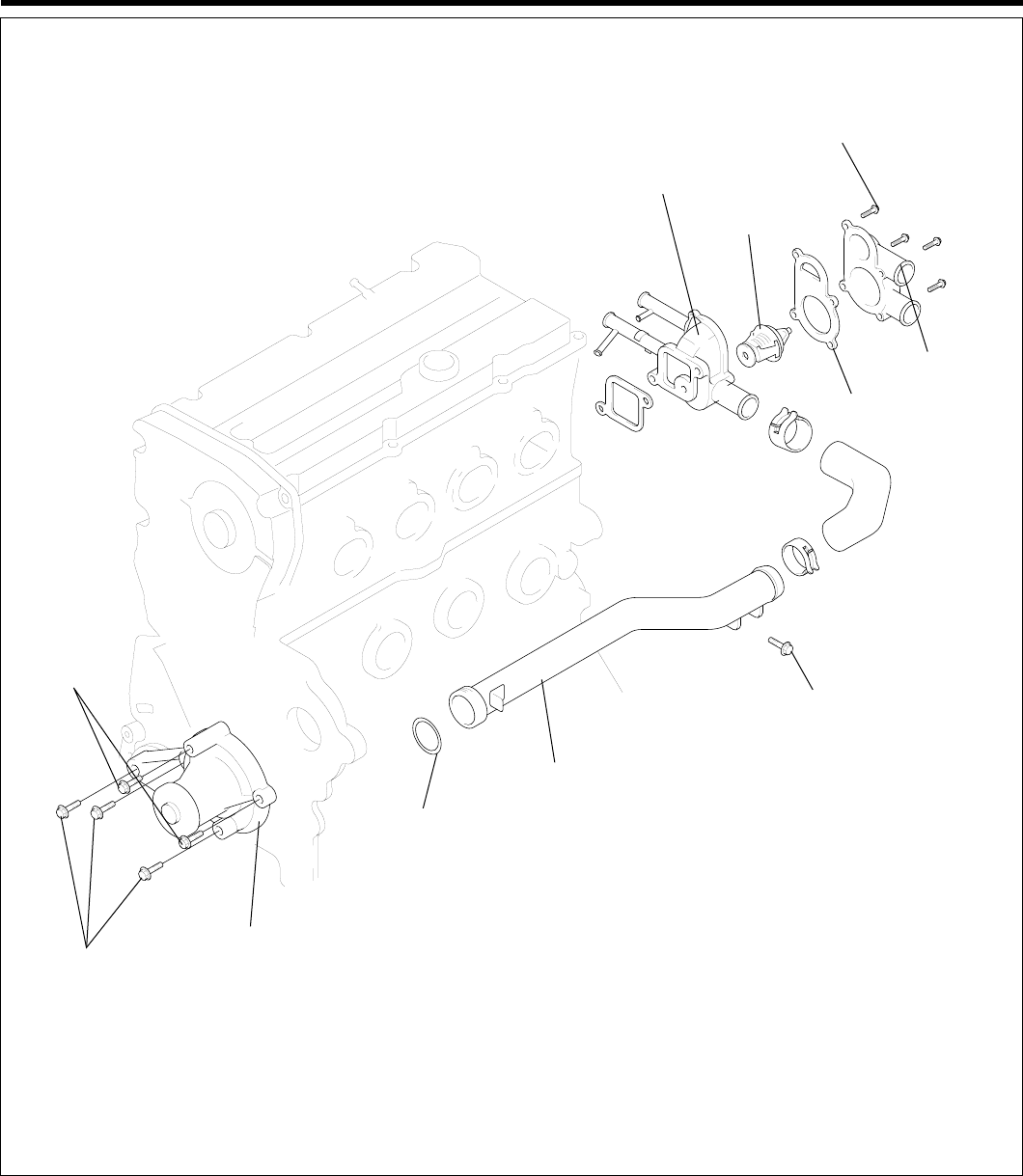
EM -58 ENGINE DOHC
Thermostat housing
Thermostat
15 ~ 20 (150 ~ 200,
9 ~ 14)
Coolant inlet
fitting
Gasket
10 ~ 15 (100 ~ 150, 7 ~ 9)
Coolant inlet pipe
O-ring
Water pump
12 ~ 15
(120 ~ 150, 8.8 ~ 11)
20 ~ 27
(200 ~ 270,
12 ~ 20)
TORQUE : Nm (kgf.cm, lbf.ft)
EDKD180A
ZENITH POWER PRODUCTS - 416
COOLING SYSTEM EM -59
INSPECTION E6CC2E0F
Check the coolant pipe and hoses for cracks, damage, or
restrictions.
Replace if necessary.
REASSEMBLY E1DCE4A4
Fit on O-Ring in the groove provided at the coolant inlet
pipe end, wet the O-ring with coolant and insert the coolant
inlet pipe.
NOTE
1. Do not apply oil or grease to the coolant pipe
O-ring.
2. Keep the coolant pipe connections free of sand,
dust, etc.
3. Insert the coolant pipe fully into the cylinder
block.
4. Do not reuse the O-ring. Replace it with a new
part.
Cylinder block
Coolant inlet pipe
Coolant pump assembly
ECKA040A
ZENITH POWER PRODUCTS - 416
EM -60ENGINE DOHC
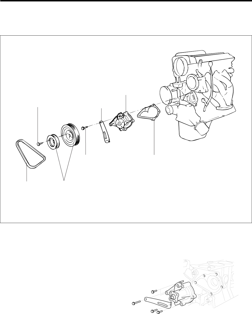
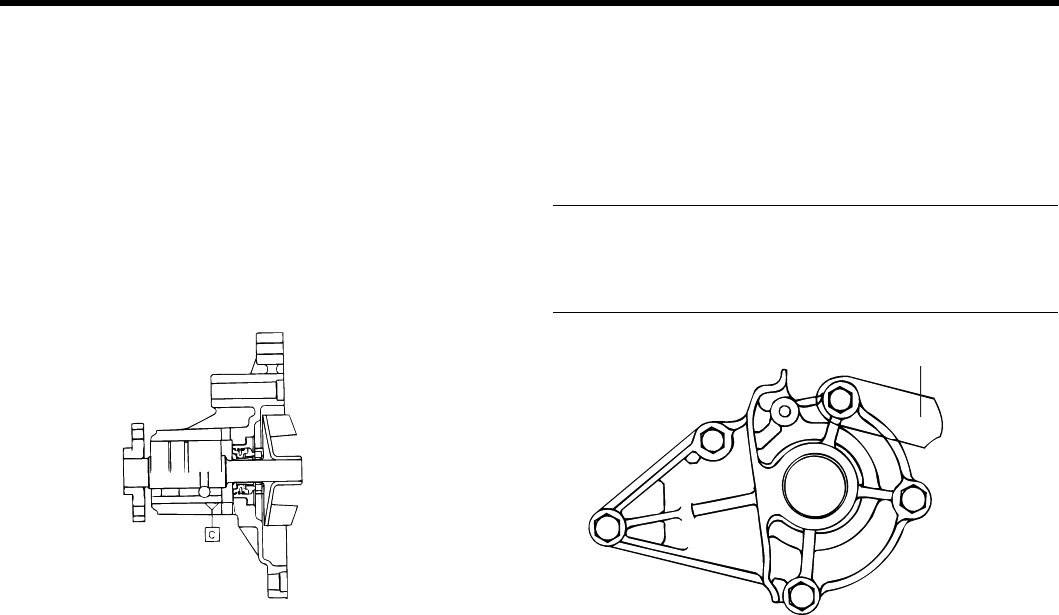
ENGINE COOLANT PUMP
COMPONENTS E8D2CBAD
Coolant pump
Coolant pump
Alternator brace
Coolant pump pulley
Belt
8 - 10 (80 - 100, 6 - 7)
20 - 27 (200 - 270, 15 - 20)
TORQUE : Nm (kg.cm, lb.ft)
EDDA046A
DISASSEMBLY EA98DF28
1. Drain the coolant and disconnect the coolant inlet pipe
connection hose from the coolant pump.
2. Remove the drive belt and engine coolant pump pul-
ley.
3. Removethetimingbeltcoversandthetimingbelt
idler.
4. Remove the coolant pump mounting bolts, then re-
move the alternator brace.
EDKE181A
5. Remove the coolant pump assembly from the cylinder
block.
ZENITH POWER PRODUCTS - 416
COOLING SYSTEM EM -61
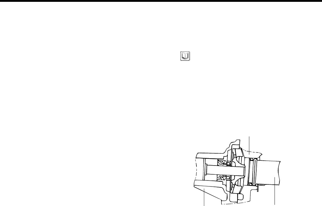
INSPECTION E5229EB7
1. Check each part for cracks, damage or wear, and re-
place the coolant pump assembly if necessary.
2. Check the bearing for damage, abnormal noise and
sluggish rotation, and replace the coolant pump as-
sembly if necessary.
3. Check for coolant leakage. If coolant leaks then the
seal is defective. Replace the coolant pump assem-
bly.
EDKB051A
REASSEMBLY E0C24D31
1. Clean the gasket surfaces of the coolant pump body
and the cylinder block.
2. Install a new coolant pump gasket to the coolant pump
and tighten the bolts to the specified torque.
Tightening torque
Coolant pump to cylinder block :
A : 12 ~ 15 Nm (120 ~ 150 kg.cm, 9 ~ 11 lb.ft)
B : 20 ~ 27 Nm (200 ~ 270 kg.cm, 15 ~ 20 lb.ft)
A
A
A
A
Alternatorstrebe
B
ECKA040B
3. Install the timing tensioner and timing belt. Adjust the
timing belt tension.
4. Install the timing belt covers.
5. Install the coolant pump pulley and drive belt, and
then adjust the belt tension.
6. Refill the system with clean coolant.
7. Run the engine and check for leaks.
ZENITH POWER PRODUCTS - 416
THIS PAGE
INTENTIONALLY LEFT
BLANK
ZENITH POWER PRODUCTS - 416
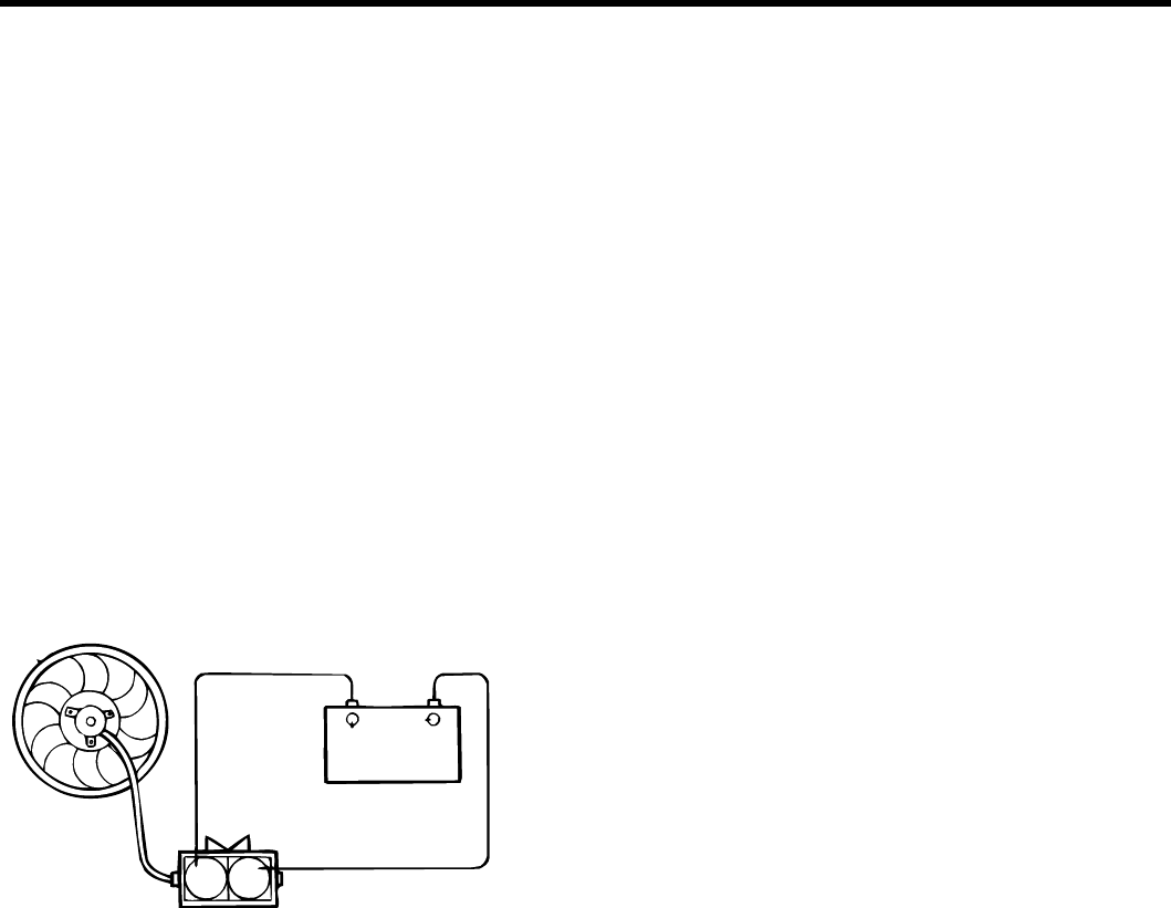
COOLING SYSTEM EM -63
INSPECTION EC662470
1. Check the radiator for bent, broken or plugged fins.
2. Check the radiator for corrosion, damage, rust or
scale.
3. Check the radiator hoses for cracks, damage or dete-
rioration.
4. Check the reservoir tank for damage.
5. Check the radiator cap spring for damage.
6. Test thepressureofthecapusingacoolingsystem
checker.
7. Check the radiator cap seal for cracks or damage.
RADIATOR FAN MOTOR
1. Check that the radiator fan rotates when the battery
voltage is applied to the terminals.
ECDA064A
2. Check that abnormal noises are not produced while
the motor is turning.
REASSEMBLY EF7E7B75
1. Fill the radiator and reservoir tank with clean coolant
mixture.
2. Run the engine until the thermostat opens, and then
stop the engine.
3. Remove the radiator cap, and add coolant up to the
filler neck of the radiator, and then fill the reservoir
tank to the upper level. Replace the radiator cap.
4. Check that there are no leaks from the radiator, hoses
or connections.
ZENITH POWER PRODUCTS - 416
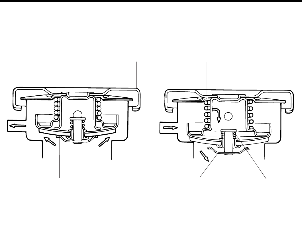
EM -64 ENGINE DOHC
RADIATOR CAP
COMPONENTS EA37EA8B
High - pressure valve High - pressure valve Vacuum spring
When the pressure is peduced to the specified level
[81.4 - 1.8 Kpa (0.83 - 1.1 kg/cm, 11.8 - 15.6 psi)]
When the pressure is peduced to the specified level
[-6.86 Kpa (- 0.07 kg/cm, -1.00 psi)]
Radiator Cap Spring
ECDA066A
ZENITH POWER PRODUCTS - 416
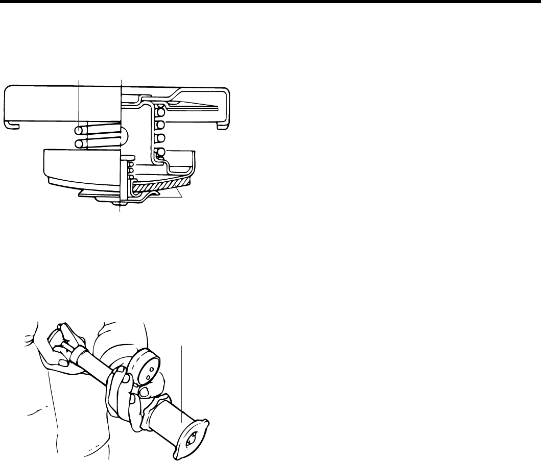
COOLING SYSTEM EM -65
INSPECTION E7AA67F9
1. Check the radiator cap for damage, cracks and dete-
rioration.
Deterioration
Deterioration
ECDA068A
2. Attach a radiator cap tester to the radiator
3. Pump the tester until the pointer stabilizes.
4. If the pointer stays constant for 10 sec. at a point
exceeding the service limit, the radiator cap is good.
Adapter
ECDA068B
ZENITH POWER PRODUCTS - 416
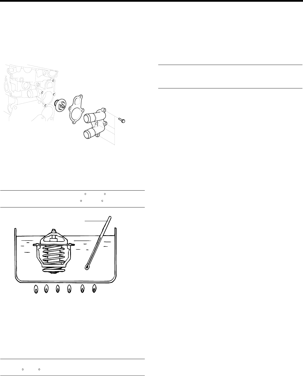
EM -66 ENGINE DOHC
THERMOSTAT
INSPECTION EE55C20B
1. Drain the coolant so its level is below thermostat.
2. Remove the inlet fitting and gasket.
EDKE182A
3. Remove the thermostat.
4. Immerse thermostat in hot coolant to check proper
valve opening temperature. Replace if necessary.
Valve opening temperature : 82 C(177C)
Full opening temperature : 95 C(205 F)
Thermometer
Water
ECDA070A
COOLANT TEMPERATURE SENSOR
1. Heat the sensor by submerging it in hot engine
coolant.
2. Check that the resistance is within the specified
range.
Resistance
At : 20 C(68F) : 2.31 ~ 2.59 kΩ
REASSEMBLY E342AFA3
1. Check that the flange of the thermostat is correctly
seated in the socket of the thermostat housing.
2. Install a new gasket and the coolant inlet fitting.
3. Refill the system with clean coolant.
Tightening torque
Coolant temperature sensor :
25 ~ 30 Nm (250 ~ 300 kg.cm, 18 ~ 22 lb.ft)
ZENITH POWER PRODUCTS - 416
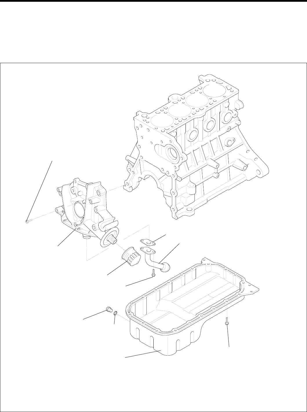
LUBRICATION SYSTEM EM -67
LUBRICATION SYSTEM
OIL PUMP
COMPONENTS EDF9B71D
20 ~ 27 (200 ~ 270, 15 ~ 20)
Front case
Filter
15 ~ 22 (150 ~ 220,
11 ~ 16)
Gasket
Oil screen
Drain plug
40 ~ 45 (400 ~450,
30 ~ 33 ) Gasket
Oil pan
10 ~ 12 (100 ~ 120, 7.3 ~ 8.8)
TORQUE : Nm (kgf.cm, lbf.ft)
EDKD200A
ZENITH POWER PRODUCTS - 416
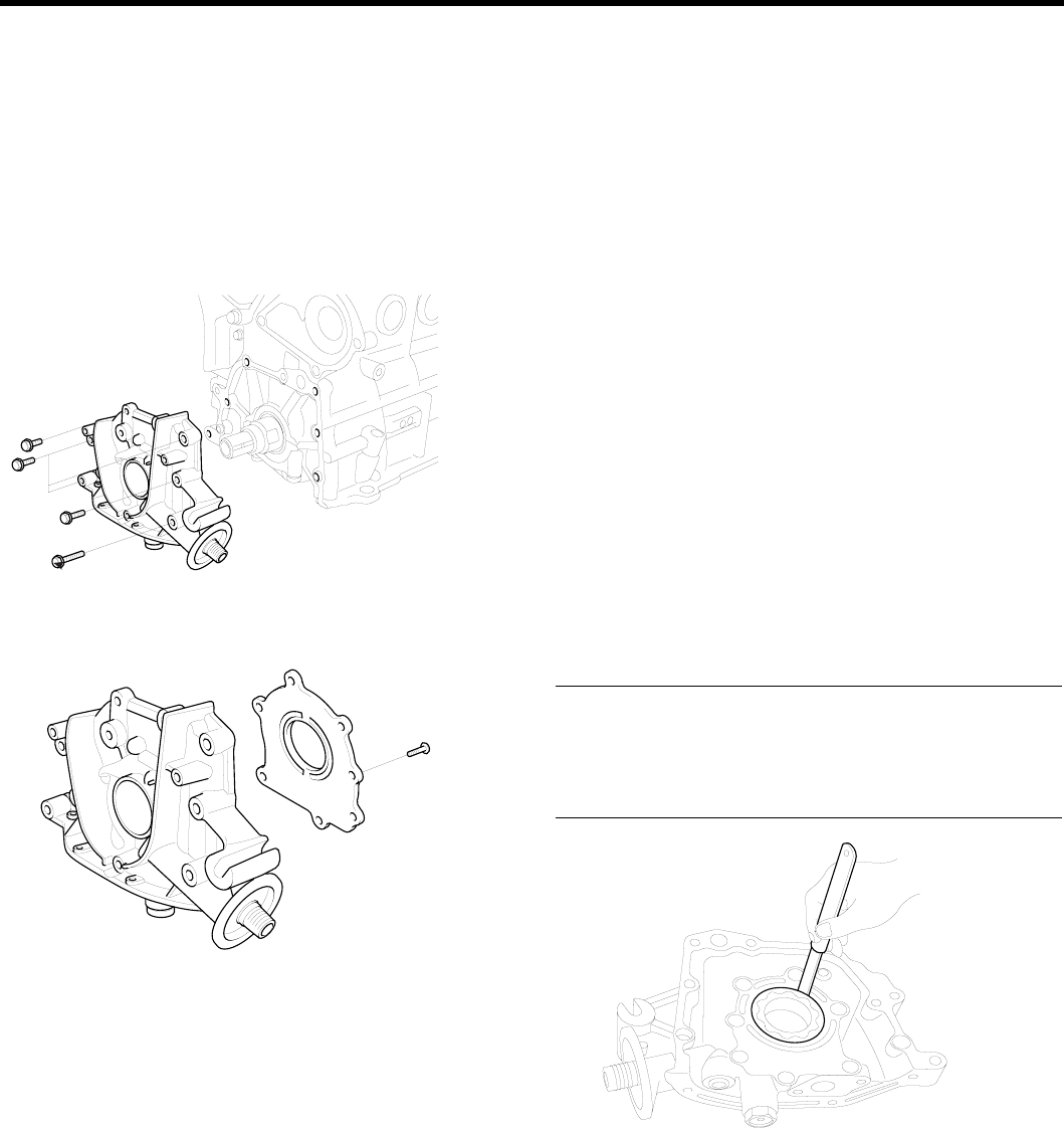
EM -68 ENGINE DOHC
DISASSEMBLY E450CC2F
1. Remove the timing belt.
2. Remove all the oil pan bolts.
3. Remove the oil pan.
4. Remove the oil screen.
5. Remove the front case assembly.
EDKE208A
6. Remove the oil pump cover.
EDKE202A
7. Remove the inner and outer gears from the front case.
The matching marks on the inner and outer gears in-
dicate the direction of installation.
INSPECTION E9D08BBC
FRONT CASE
1. Check the front case for cracks or damage. Replace
as necessary.
2. Check the front oil seal for worn or damaged lips. Re-
place if defective.
OIL PAN AND OIL SCREEN
1. Check the oil pan for failure, damage or cracks. Re-
place if defective.
2. Check the oil screen for failure, damage and cracks
and replace if defective.
FRONT CASE AND OIL PUMP COVER
Check the surfaces contacting the gears for damage or
wear.
OIL PUMP GEARS
1. Check the gear tooth surfaces for wear or damage.
2. Measure the clearance between outer gear and front
case.
Body clearance : 0.12 ~ 0.185 mm (0.0047 ~ 0.0073 in.)
Tip clearance : 0.025 ~ 0.069 mm (0.0010 ~ 0.0027 in.)
Side clearance
Inner gear : 0.06 ~ 0.11 mm (0.0023 ~ 0.0043 in.)
Outer gear : 0.04 ~ 0.085 mm (0.0016 ~ 0.0033 in.)
EDKD207A
ZENITH POWER PRODUCTS - 416
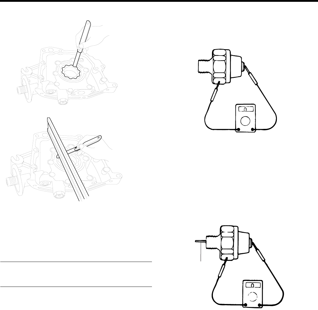
LUBRICATION SYSTEM EM -69
3. Check the tip clearance on the pump roter.
EDKD206A
EDKD205A
RELIEF VALVE AND SPRING
1. Check sliding condition of the relief valve inserted in
the front case.
2. Inspect for distorted or broken relief valve spring.
Standard value
Free height : 46.6 mm (1.8346 in.)
Load : 6.1 kg/40.1 mm (13.42 lb/1.578 in.)
OIL PRESSURE SWITCH (Normally Closed type STD.)
1. Use an ohmmeter to check the continuity between the
terminal and the body. If there is no continuity, replace
the oil pressure switch.
EDDA061A
2. Check the continuity between the terminal and the
body when the fine wire is pushed. If there is con-
tinuity even when the fine wire is pushed, replace the
switch.
3. If there is no continuity when a 50 kPa (7 psi) pressure
is applied through the oil hole, the switch is operating
properly.
Check for air leaks. If air does leak, the diaphragm is
broken. Replace the switch.
Fine wire
EDDA061B
ZENITH POWER PRODUCTS - 416
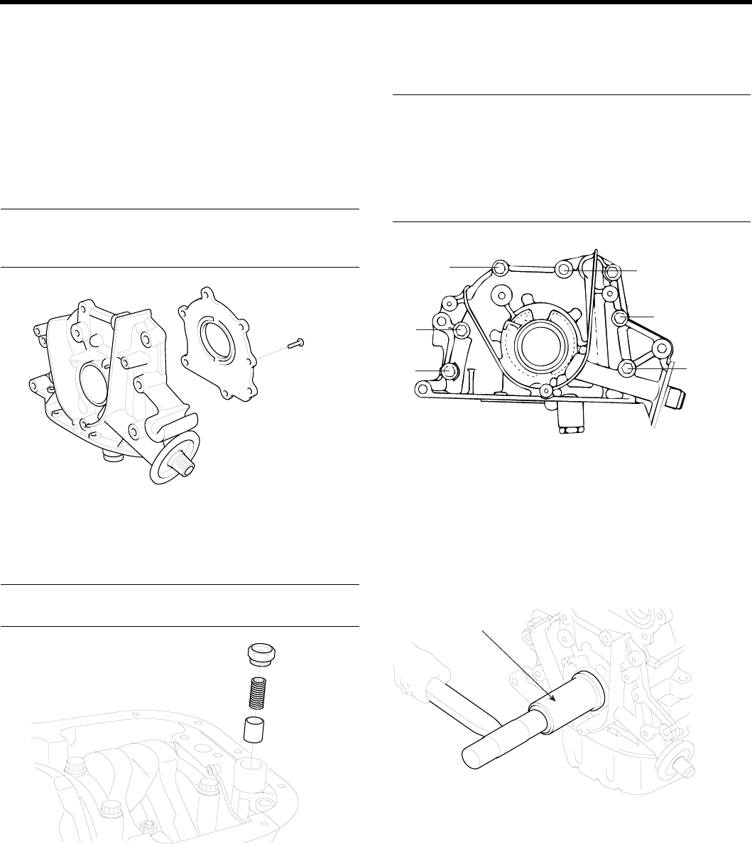
EM -70ENGINE DOHC
REASSEMBLY E1BA8FB0
OIL PUMP
1. Install the outer and inner gears into the front case
Make sure that the inner and outer gears are installed
in the same direction as shown.
2. Install the oil pump cover and tighten the bolts to the
specified torque. After the bolts have been tightened,
check to ensure that the gear turns smoothly.
Tightening torque
Oil pump cover bolt :
8~ 12 Nm (80 ~ 120 kg.cm, 6 ~ 9 lb.ft)
EDKE202A
3. Install the relief valve and spring. Tighten the plug
to the specified torque. Apply engine oil to the relief
valve.
Relief valve plug
40 ~ 50 Nm (400 ~ 500 kg.cm, 30 ~ 37 lb.ft)
EDKE204A
FRONT CASE
1. Install the front case assembly with a new gasket, and
tighten the bolts to the specified torque.
Tightening torque
20 ~ 27 Nm (200 ~ 270 kg.cm, 15 ~ 20 lb.ft)
Length
A : 30 mm (1.18 in.)
B : 45 mm (1.77 in.)
C:60mm(2.36in.)
D:22mm(0.89in.)
D
A
A
A
B
C
ECKA020E
OIL SEAL
1. Using the special tool, Crankshaft oil seal
guide(09231 - 22100), install the oil seal.
2. Using the special tool, Crankshaft front oil seal in-
staller (09231-22000), install the oil seal.
09231-22000
EDKE209A
3. Install the oil screen.
4. Clean both gasket surfaces of the oil pan and the
cylinder block.
5. Apply sealant into the groove of the oil pan flange as
shown.
ZENITH POWER PRODUCTS - 416
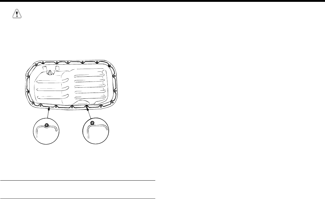
LUBRICATION SYSTEM EM -71
CAUTION
•Apply sealant approx. 4mm (0.16 in.) in thick-
ness.
•After application of sealant, do not exceed 15
minutes before installing the oil pan.
ECDA018D
6. Install the oil pan and tighten the bolts to the specified
torque.
Tightening torque
Oil pan bolt : 10 ~ 12 Nm (100 ~ 120 kg.cm, 7 ~ 9 lb.ft)
ZENITH POWER PRODUCTS - 416
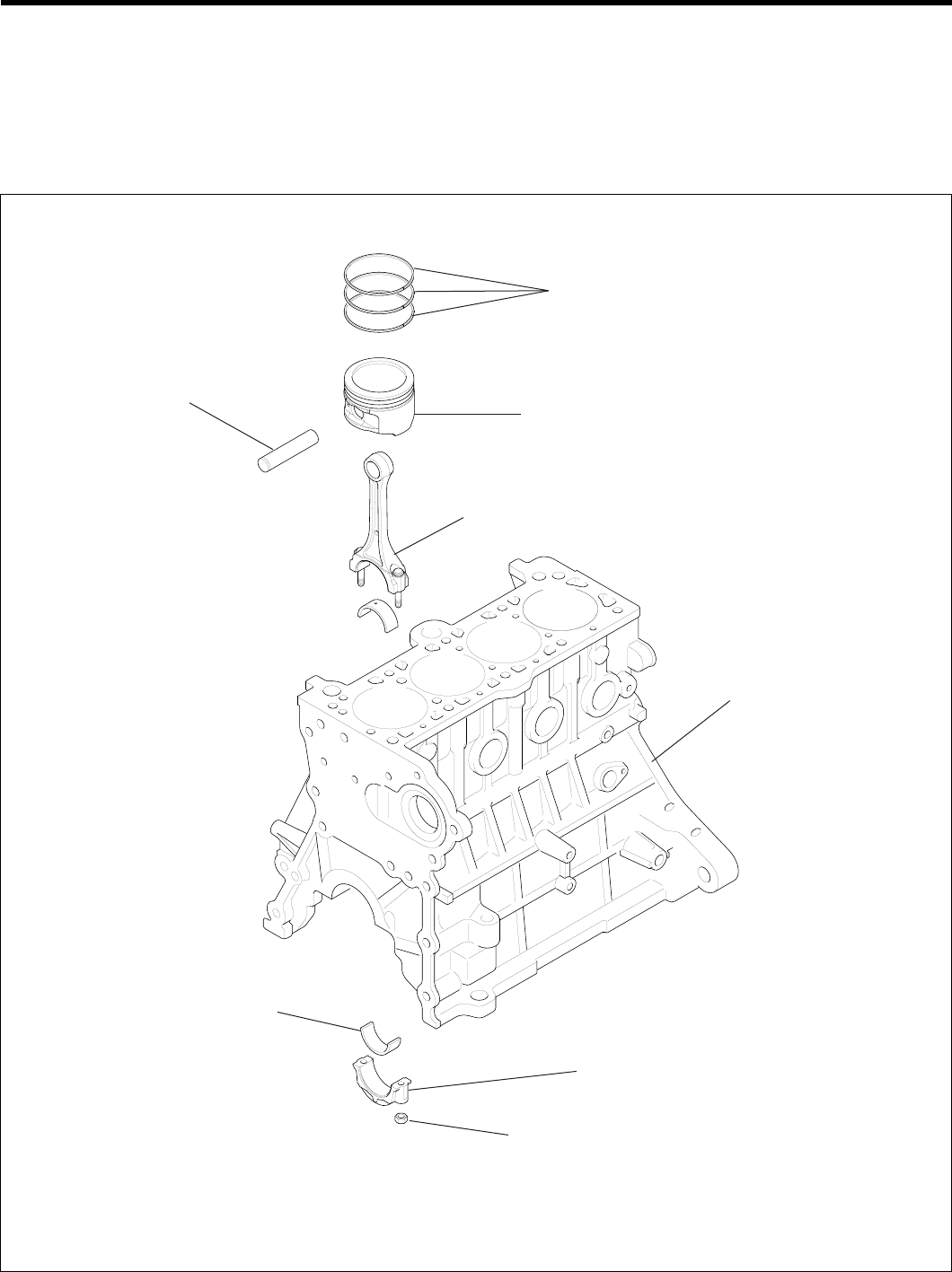
EM -72ENGINE DOHC
ENGINE BLOCK
ENGINE BLOCK
COMPONENTS E362FF2F
Piston ring
Piston
Connecting rod
Piston pin
Connecting rod bearing
Connecting rod bearing cap
32 ~ 35 (320 ~ 350, 24 ~ 26)
TORQUE : Nm (kgf.cm, lbf.ft)
Cylinder block
ECDE141A
ZENITH POWER PRODUCTS - 416
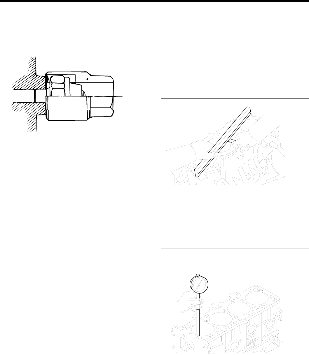
ENGINE BLOCK EM -73
DISASSEMBLY EE96372F
1. Remove the timing belt, cylinder head, front case, fly-
wheel, pistons and crankshaft.
2. Remove the oil pressure switch.
Adapter
EDDA008A
INSPECTION EBADEC3C
1. Check the engine block for scores, rust and corrosion.
Also check for cracks or any other defects. Replace
the block if defective.
2. Using a straight edge and feeler gauge, check the
top surface of the block for warpage. Make sure that
the surface is free from gasket chips or other foreign
material.
Standard : 0.03 mm (0.0012 in.) or less
Limit : 0.06 mm (0.0024 in.) or less
ECKD001L
3. Measure the cylinder bore with a cylinder gauge at
three levels in the direction of A and B. If the cylinder
bores show more than the specified out-of-round
or taper or if the cylinder walls are badly scuffed or
scored, the cylinder block should be rebored and
honed. Oversize pistons and rings must be fitted.
Cylinder I.D : 76.5 ~ 76.53 mm (3.0118 ~ 3.0130 in.)
Cylinder I.D taper : 0.01 mm (0.0004 in.) or less
ECKD318A
ZENITH POWER PRODUCTS - 416
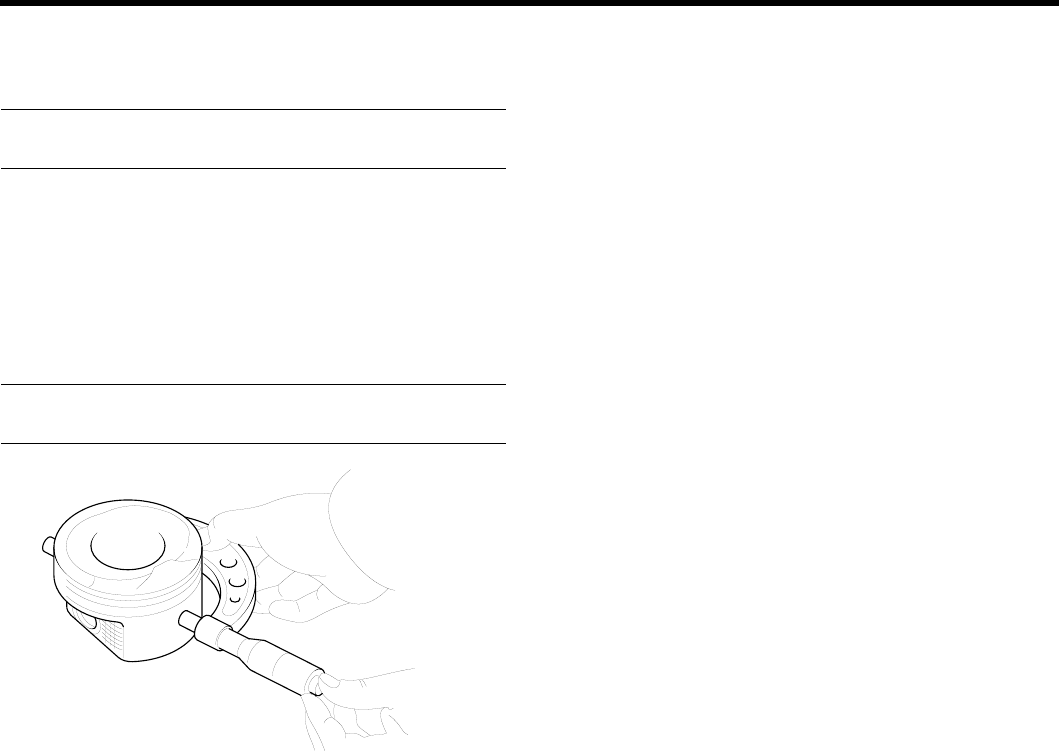
EM -74 ENGINE DOHC
4. If a cylinder ridge exists, cut away with a ridge reamer.
5. Oversize pistons are available in four sizes.
Pistom service size and mark mm (in.)
0.25 (0.010) O.S. : 0.25
6. When boring the cylinder to the oversize, maintain the
specified clearance between the oversize piston and
the bore, and make sure that all pistons used are the
same oversize.
The standard measurment of the piston’s outside di-
ameter is taken 39.35 mm (1.55 in.) from the top land
of the piston.
Piston - to - cylinder clearance
0.025 ~ 0.045 mm (0.0010 ~ 0.0018 in.)
ECKD001D
ZENITH POWER PRODUCTS - 416
THIS PAGE
INTENTIONALLY LEFT
BLANK
ZENITH POWER PRODUCTS - 416
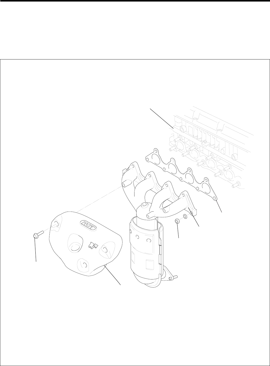
EM -76 ENGINE DOHC
INTAKE AND EXHAUST
SYSTEM
EXHAUST MANIFOLD
COMPONENTS E6FBC7D4
15 ~ 20 (150 ~ 200,
11 ~ 15)
30 ~ 35 (300 ~ 350,
22 ~ 26)
Heat protector
Exhaust manifold
Gasket
Cylinder head
TORQUE : Nm (kgf.cm, lbf.ft)
EDKD251A
ZENITH POWER PRODUCTS - 416
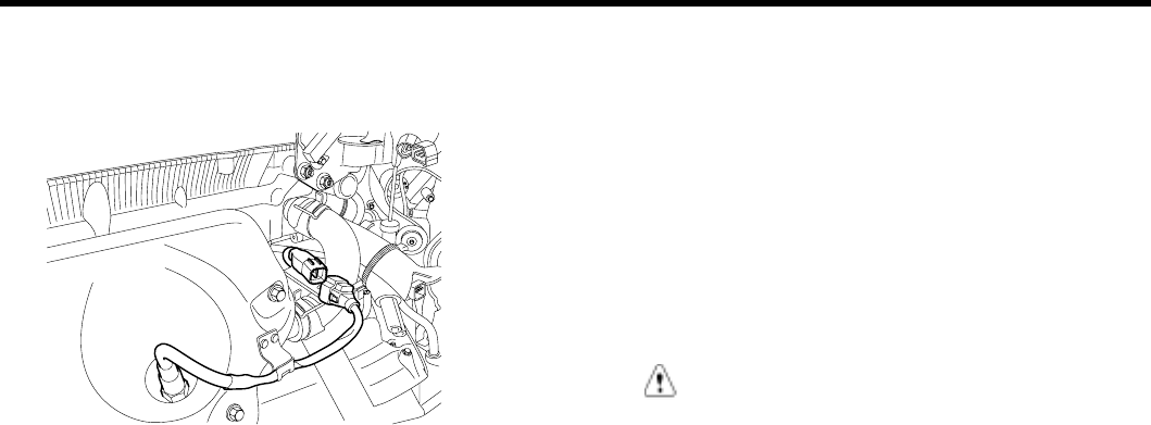
INTAKE AND EXHAUST SYSTEM EM -77
DISASSEMBLY EAA67563
1. Disconnect the oxygen sensor connect.
KDPC007D
2. Remove the exhaust manifold heat protector.
3. Remove the exhaust manifold assembly from the
cylinder head.
4. Remove the exhaust manifold gasket.
INSPECTION ED2622EE
EXHAUST MANIFOLD
1. Check for damage or cracking.
2. Check for damage or cracking of welding between ex-
haust manifold and converter.
REASSEMBLY E1BC9FEF
Install the exhaust manifold in the reverse order of removal.
CAUTION
Replace the exhaust manifold gasket and lock nut
when reassembling.
ZENITH POWER PRODUCTS - 416
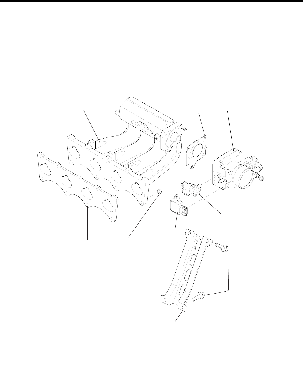
EM -78 ENGINE DOHC
INTAKE MANIFOLD
COMPONENTS EF98EE9D
Intake manifold Gasket Throttle body
ISA
TPS
15 ~ 20 (150 ~ 200,
11 ~ 15)
Gasket
Intake manifold stay
18 ~ 25 (180 ~ 250,
13 ~ 18)
TORQUE : Nm (kg.cm, lb.ft)
ECDE087A
ZENITH POWER PRODUCTS - 416
