Fircmp 2401combenglA1 Fire Lite.cmp 2401b.cmp 2402b
User Manual: fire-lite.cmp-2401b.cmp-2402b
Open the PDF directly: View PDF ![]() .
.
Page Count: 36
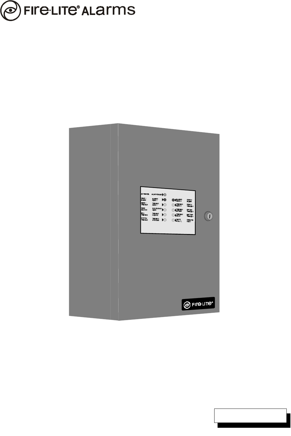
CMP-2401B/CMP-2402B
Fire Alarm Control Panel
Installation, Maintenance and Operating
Instruction Manual
10 Whitmore Road
Woodbridge, Ontario L4L 7Z4
Phone (905) 856-8733
FAX (905) 856-9687
P/N 50907:A1 ECN 02-606
A
Document #50907
12/03/02 Rev.
© 2002 Fire•Lite
LimWarLg.p65 01/10/2000
An automatic fire alarm system–typically made up of smoke
detectors, heat detectors, manual pull stations, audible warn-
ing devices, and a fire alarm control with remote notification
capability–can provide early warning of a developing fire.
Such a system, however, does not assure protection against
property damage or loss of life resulting from a fire.
The Manufacturer recommends that smoke and/or heat detec-
tors be located throughout a protected premise following the
recommendations of the current edition of the National Fire
Protection Association Standard 72 (NFPA 72),
manufacturer's recommendations, State and local codes, and
the recommendations contained in the Guide for Proper Use
of System Smoke Detectors, which is made available at no
charge to all installing dealers. A study by the Federal Emer-
gency Management Agency (an agency of the United States
government) indicated that smoke detectors may not go off in
as many as 35% of all fires. While fire alarm systems are de-
signed to provide early warning against fire, they do not guar-
antee warning or protection against fire. A fire alarm system
may not provide timely or adequate warning, or simply may not
function, for a variety of reasons:
Smoke detectors may not sense fire where smoke cannot
reach the detectors such as in chimneys, in or behind walls, on
roofs, or on the other side of closed doors. Smoke detectors
also may not sense a fire on another level or floor of a build-
ing. A second-floor detector, for example, may not sense a
first-floor or basement fire.
Particles of combustion or "smoke" from a developing fire
may not reach the sensing chambers of smoke detectors be-
cause:
• Barriers such as closed or partially closed doors, walls, or
chimneys may inhibit particle or smoke flow.
• Smoke particles may become "cold," stratify, and not reach
the ceiling or upper walls where detectors are located.
• Smoke particles may be blown away from detectors by air
outlets.
• Smoke particles may be drawn into air returns before
reaching the detector.
The amount of "smoke" present may be insufficient to alarm
smoke detectors. Smoke detectors are designed to alarm at
various levels of smoke density. If such density levels are not
created by a developing fire at the location of detectors, the
detectors will not go into alarm.
Smoke detectors, even when working properly, have sensing
limitations. Detectors that have photoelectronic sensing
chambers tend to detect smoldering fires better than flaming
fires, which have little visible smoke. Detectors that have ion-
izing-type sensing chambers tend to detect fast-flaming fires
better than smoldering fires. Because fires develop in differ-
ent ways and are often unpredictable in their growth, neither
type of detector is necessarily best and a given type of detec-
tor may not provide adequate warning of a fire.
Smoke detectors cannot be expected to provide adequate
warning of fires caused by arson, children playing with
matches (especially in bedrooms), smoking in bed, and violent
explosions (caused by escaping gas, improper storage of
flammable materials, etc.).
Heat detectors do not sense particles of combustion and
alarm only when heat on their sensors increases at a prede-
termined rate or reaches a predetermined level. Rate-of-rise
heat detectors may be subject to reduced sensitivity over time.
For this reason, the rate-of-rise feature of each detector
should be tested at least once per year by a qualified fire pro-
tection specialist.
Heat detectors are designed to protect
property, not life.
IMPORTANT!
Smoke detectors must be installed in the
same room as the control panel and in rooms used by the sys-
tem for the connection of alarm transmission wiring, communi-
cations, signaling, and/or power.
If detectors are not so lo-
cated, a developing fire may damage the alarm system, crip-
pling its ability to report a fire.
Audible warning devices such as bells may not alert people
if these devices are located on the other side of closed or
partly open doors or are located on another floor of a building.
Any warning device may fail to alert people with a disability or
those who have recently consumed drugs, alcohol or medica-
tion. Please note that:
•Strobes can, under certain circumstances, cause seizures
in people with conditions such as epilepsy.
•Studies have shown that certain people, even when they
hear a fire alarm signal, do not respond or comprehend the
meaning of the signal. It is the property owner's responsibil-
ity to conduct fire drills and other training exercise to make
people aware of fire alarm signals and instruct them on the
proper reaction to alarm signals.
•In rare instances, the sounding of a warning device can
cause temporary or permanent hearing loss.
A fire alarm system will not operate without any electrical
power. If AC power fails, the system will operate from standby
batteries only for a specified time and only if the batteries
have been properly maintained and replaced regularly.
Equipment used in the system may not be technically com-
patible with the control. It is essential to use only equipment
listed for service with your control panel.
Telephone lines needed to transmit alarm signals from a
premise to a central monitoring station may be out of service
or temporarily disabled. For added protection against tele-
phone line failure, backup radio transmission systems are rec-
ommended.
The most common cause of fire alarm malfunction is inade-
quate maintenance. To keep the entire fire alarm system in
excellent working order, ongoing maintenance is required per
the manufacturer's recommendations, and UL and NFPA stan-
dards. At a minimum, the requirements of Chapter 7 of NFPA
72 shall be followed. Environments with large amounts of
dust, dirt or high air velocity require more frequent mainte-
nance. A maintenance agreement should be arranged
through the local manufacturer's representative. Maintenance
should be scheduled monthly or as required by National and/
or local fire codes and should be performed by authorized pro-
fessional fire alarm installers only. Adequate written records
of all inspections should be kept.
While a fire alarm system may lower insurance
rates, it is not a substitute for fire insurance!
Fire Alarm System Limitations

LimWarLg.p65 01/10/2000
WARNING -
Several different sources of power can be con-
nected to the fire alarm control panel.
Disconnect all sources
of power before servicing. Control unit and associated equip-
ment may be damaged by removing and/or inserting cards,
modules, or interconnecting cables while the unit is energized.
Do not attempt to install, service, or operate this unit until this
manual is read and understood.
CAUTION -
System Reacceptance Test after Software
Changes.
To ensure proper system operation, this product
must be tested in accordance with NFPA 72 Chapter 7 after
any programming operation or change in site-specific soft-
ware. Reacceptance testing is required after any change, ad-
dition or deletion of system components, or after any modifica-
tion, repair or adjustment to system hardware or wiring.
All components, circuits, system operations, or software func-
tions known to be affected by a change must be 100% tested.
In addition, to ensure that other operations are not inadvert-
ently affected, at least 10% of initiating devices that are not
directly affected by the change, up to a maximum of 50 de-
vices, must also be tested and proper system operation veri-
fied.
This system meets NFPA requirements for operation at
0-49° C/32-120° F and at a relative humidity of 85% RH (non-
condensing) at 30° C/86° F. However, the useful life of the
system's standby batteries and the electronic components
may be adversely affected by extreme temperature ranges
and humidity. Therefore, it is recommended that this system
and all peripherals be installed in an environment with a nomi-
nal room temperature of 15-27° C/60-80° F.
Verify that wire sizes are adequate for all initiating and
indicating device loops. Most devices cannot tolerate more
than a 10% I.R. drop from the specified device voltage.
Like all solid state electronic devices, this system may
operate erratically or can be damaged when subjected to light-
ning-induced transients. Although no system is completely
immune from lightning transients and interferences, proper
grounding will reduce susceptibility.
Overhead or outside
aerial wiring is not recommended, due to an increased sus-
ceptibility to nearby lightning strikes.
Consult with the Techni-
cal Services Department if any problems are anticipated or
encountered.
Disconnect AC power and batteries prior to removing or in-
serting circuit boards. Failure to do so can damage circuits.
Remove all electronic assemblies prior to any drilling, filing,
reaming, or punching of the enclosure. When possible, make
all cable entries from the sides or rear. Before making modifi-
cations, verify that they will not interfere with battery, trans-
former, and printed circuit board location.
Do not tighten screw terminals more than 9 in-lbs.
Over-tightening may damage threads, resulting in reduced
terminal contact pressure and difficulty with screw terminal
removal.
Though designed to last many years, system components
can fail at any time. This system contains static-sensitive
components. Always ground yourself with a proper wrist strap
before handling any circuits so that static charges are re-
moved from the body. Use static-suppressive packaging
to protect electronic assemblies removed from the unit.
Follow the instructions in the installation, operating, and
programming manuals. These instructions must be followed
to avoid damage to the control panel and associated
equipment. FACP operation and reliability depend upon
proper installation by authorized personnel.
Adherence to the following will aid in problem-free
installation with long-term reliability:
WARNING: This equipment generates, uses, and can
radiate radio frequency energy and if not installed and
used in accordance with the instruction manual, may
cause interference to radio communications. It has
been tested and found to comply with the limits for class
A computing device pursuant to Subpart B of Part 15 of
FCC Rules, which is designed to provide reasonable
protection against such interference when operated in a
commercial environment. Operation of this equipment in
a residential area is likely to cause interference, in which
case the user will be required to correct the interference
at his own expense.
Canadian Requirements
This digital apparatus does not exceed the Class A
limits for radiation noise emissions from digital
apparatus set out in the Radio Interference Regulations
of the Canadian Department of Communications.
Le present appareil numerique n'emet pas de bruits
radioelectriques depassant les limites applicables aux
appareils numeriques de la classe A prescrites dans le
Reglement sur le brouillage radioelectrique edicte par le
ministere des Communications du Canada.
FCC Warning
Installation Precautions
4 Document #50907 Rev.A1 12/03/02 P/N 50907:A1
Notes
Document 50907 Rev. A1 12/03/02 P/N: 50907:A1 5
CHAPTER 1: Product Description .........................................................................................................................9
1.1: Product Features..........................................................................................................................................9
FIGURE 1-1: CMP-2401B/CMP-2402B.............................................................................................10
1.2: Specifications ..............................................................................................................................................11
1.3: Controls, Indicators and Operation .............................................................................................................12
1.3.1: Front Panel Slide Switches ..............................................................................................................12
FIGURE 1-2: CMP-2401B/CMP-2402B Control Switches ................................................................12
1.3.2: LED Indicators .................................................................................................................................13
FIGURE 1-3: LED Indicators (CMP-2402B Illustrated).....................................................................13
1.3.3: Local Sounder ...................................................................................................................................14
1.3.4: Normal Standby Operation ...............................................................................................................14
1.3.5: Alarm Condition ...............................................................................................................................14
1.3.6: Trouble Condition .............................................................................................................................14
1.4: Circuits ........................................................................................................................................................15
1.5: Components.................................................................................................................................................15
1.6: Optional Modules and Accessories .............................................................................................................16
CHAPTER 2: Installation.........................................................................................................................................17
2.1: Mounting Options .......................................................................................................................................17
FIGURE 2-1: CMP-2401B/CMP-2402B Mounting ............................................................................17
2.2: Backbox Mounting......................................................................................................................................17
FIGURE 2-2: Cabinet Dimensions and Knockout Locations..............................................................18
FIGURE 2-3: FACP Backbox..............................................................................................................19
2.3: Operating Power..........................................................................................................................................20
FIGURE 2-4: Operating Power Connections.......................................................................................20
2.4: Input Circuits...............................................................................................................................................21
FIGURE 2-5: CMP-2402B Style B Initiating Device Circuit Connections ........................................21
2.5: Output Circuits ............................................................................................................................................22
FIGURE 2-6: Auxiliary Power Connection.........................................................................................22
FIGURE 2-7: Notification Appliance Circuit Connections.................................................................22
FIGURE 2-8: Relay Terminals ............................................................................................................23
2.6: UL Power-limited Wiring Requirements ....................................................................................................23
FIGURE 2-9: Typical Wiring Diagram for UL Power-limited Requirements ....................................23
2.7: Installation of Optional Module ..................................................................................................................24
2.7.1: 4XTMF Transmitter Module.............................................................................................................24
FIGURE 2-10: 4XTMF Module Connections .....................................................................................24
2.7.2: RTB - Remote Trouble Buzzer..........................................................................................................25
FIGURE 2-11: RTB Remote Trouble Buzzer Connection ..................................................................25
CHAPTER 3: Programming Options......................................................................................................................26
3.1: Earth Ground Fault Detection .....................................................................................................................26
FIGURE 3-1: Ground Fault Detection Circuit.....................................................................................26
3.2: Optional 4XTMF Transmitter Module Placement Supervision ..................................................................26
FIGURE 3-2: 4XTMF Module Placement Supervision ......................................................................26
CHAPTER 4: Periodic Testing and Maintenance..................................................................................................27
CHAPTER 5: Battery Calculations.........................................................................................................................28
TABLE 5-1: Battery Calculations........................................................................................................28
5.1: The Main Power Supply..............................................................................................................................29
TABLE 5-2: Load in Standby..............................................................................................................29
TABLE 5-3: Load in Alarm.................................................................................................................30
Table of Contents
6 Document #50907 Rev.A1 12/03/02 P/N 50907:A1
Notes

This control panel has been designed to comply with standards set forth by the following regulatory agencies:
• Underwriters Laboratories Standard UL 864
• NFPA 72 National Fire Alarm Code
• CAN/ULC - S527M Standard for Control Units for Fire Alarm Systems
NFPA Standards
This Fire Alarm Control Panel complies with the following NFPA Standards:
NFPA 72 National Fire Alarm Code for Local Fire Alarm Systems and
Remote Station Fire Alarm Systems (requires an optional Remote Station Output Module).
Underwriters Laboratories Canada Documents:
CAN/ULC - S524M Standard for Installation of Fire Alarm Systems
CAN/ULC - S527-M87 Standard for Control Units for Fire Alarm Systems
Other:
Applicable Local and State Building Codes
C22.1 Canadian Electrical Code, Part I
C22.2 No. 0, General Requirements - Canadian Electrical Code, Part II
C22.2 No. 0.4, Bonding and Grounding of Electrical Equipment (Protective Grounding) - Canadian
C282, Emergency Electrical Power Supply for Buildings - Canadian
Requirements of the Local Authority Having Jurisdiction (LAHJ)
Fire•Lite Documents
Fire•Lite Device Compatibility Document Document #15384
Before proceeding, the installer should be familiar with the following documents.
Document #50907 Rev. A1 12/03/02 P/N 50907:A1 7
8 Document #50907 Rev.A1 12/03/02 P/N 50907:A1
CMP-2401B/CMP-2402B Main Circuit Board
J3
F2
J1
J1
F2
J4
J4
J5
TB3
TB3
TB1
TB1
GND
GND
+24V
REG
RES
+24V
REG
RES
BUZ
BUZ
TROUBLE
TROUBLE
NEUTRAL
NEUTRAL
EARTH
EARTH
HOT
HOT
SIGNAL
OUTPUT
SIGNAL
OUTPUT
CUT IF 4X
OPTION
BOARD IS
PRE SENT
CUT TO
DISABLE
EARTH
FAULT
IN ITIAT
ZONE 1
INITIAT
ZONE 2
IN ITIAT
ZONE 2
INITIAT
ZONE 1
ALARM
ALARM
J3
BATTERY
TB L SI LEN C E
SIG SI LENCE
ZONE 1
SIG SI LENCE
ZONE 2
SYST EM RES ET
NC
NC
NC
NC
C
C
C
C
-
-
-
-
-
-
+
+
+
+
+
+
NO
NO
NO
NO
TBL
TBL
AC
AC
TB2
TB2
R72
R72
R14
R14
SW4
SW2
SW1
SW3
+
+
+
CMP-2402B
Only
Transformer
2402LAYO.CDR
System Reset
Signal Silence
Zone 1
Signal Silence
Zone 2
(CMP-2402B Only)
Trouble Silence
Cut if
Option
Board is
Present
Cut to
Disable
Earth
FAult
Option Module
Connectors
Battery
(7.0 AH, 12 VDC)
AC Power Fuse
2 AMP 3AG
Slow Blow
Connections to Remote
Trouble Buzzer
Document #50907 Rev. A1 12/03/02 P/N 50907:A1 9
Product Description
CHAPTER 1 Product Description
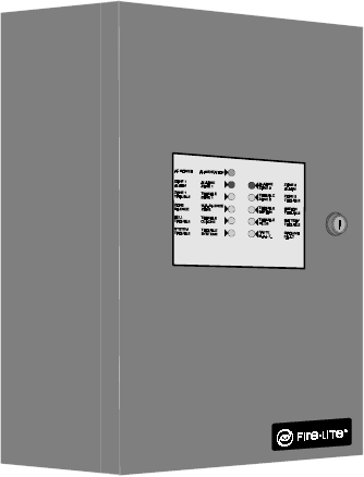
The CMP-2401B is a one zone FACP (Fire Alarm Control Panel) and the CMP-2402B is a two zone FACP. This
manual will use the term FACP to refer to both the CMP-2401B and CMP-2402B where features are identical. These
control panels provide reliable fire signaling protection for small to medium sized commercial, industrial and institu-
tional buildings. The FACPs use conventional input devices such as two-wire smoke detectors, four-wire smoke
detectors, pull stations, waterflow devices and other normally-open contact devices. Outputs include one NAC (Noti-
fication Appliance Circuit) and 24 volt resettable power. The FACP also supervises all wiring, AC voltage and bat-
tery level.
Activation of a compatible smoke detector or any normally open fire alarm initiating device will activate audible and
visual signaling devices, illuminate an indicating LED and sound the piezo at the FACP, activate the FACP alarm
relay and operate an optional module used to notify a remote station or initiate a supplementary control function.
1.1 Product Features
• Style B (Class B) Initiating Device Circuit (IDC)
✓CMP-2401B - one IDC
✓CMP-2402B - two IDCs
• One NFPA Style Y (Class B) Notification Appliance Circuit (NAC)
• Form-C Alarm Relay
• Form-C Trouble Relay
• Control switches
✓Reset
✓Trouble Silence
✓Signal Silence - Zone One
✓Signal Silence - Zone Two (CMP-2402B only)
• LED Indicators
✓AC Power
✓Zone Alarm and Trouble
✓Bell Trouble
✓Option Module Trouble
✓System Trouble
✓Zone Silence
✓Ground Fault
✓Battery Trouble
• Piezo Sounder for alarm and trouble signal
• Dress Panel coverplate
• 24 volt operation
• Small backbox size
• Low AC voltage sense
• Silence Inhibit Notification Appliance Circuit
• Automatic Battery Float Charger
• Battery Deep Discharge Protection
• Optional Remote Trouble Buzzer
Product Features
10 Document #50907 Rev.A1 12/03/02 P/N 50907:A1
J3
J1
F2
J4
J5
TB3
TB1
GND +24V
REG
RES
B UZ T RO UB L E
NEUTRAL EARTH HOT
SIGNAL
OUT PU T
CUT IF 4X
OPTI ON
BOARD IS
PRESENT
CUT TO
DISABLE
EARTH
FAULT
INITIAT
ZONE 1
INITIAT
ZONE 2
ALARM
TBL SILENCE
SIG SI LENCE
ZO N E 1
SIG SILEN CE
ZONE 2
SYSTEM R ESET
NC NCCC
---
+++
NO NO
TBL
AC
TB2
R72
R14
SW4
SW2
SW1
SW3
CAUTION!
HIGH VOLTAGE
BATTERY
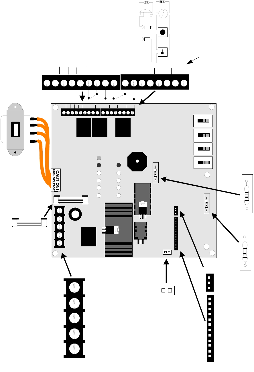
FIGURE 1-1: CMP-2401B/CMP-2402B
Transformer
Holds up to two 7 AH Batteries
System
Reset *
Signal
Silence
Zone 1*
Signal
Silence Zone
2 * (CMP-
2402B)
Tr ou ble
Silence *
Cut to
Disable
Earth Fault
4X Option
Module
Connectors
Cut if 4X
Option Module
is Installed
Remote
Trouble Buzzer
+24 Volt
Resettable
Power
Alarm Relay
Trouble Relay
Notification
Appliance
Circuit
Input Zones
(2 on CMP-2402B
only)
* Note that all switches are illustrated in the normal position.
2401INBX.CDR

Document #50907 Rev. A1 12/03/02 P/N 50907:A1 11
Specifications
1.2 Specifications
AC Power - TB3
120 VAC, 60 Hz, 0.5 amps
Fuse F2 - 2 Amp, 3AG Slow Blow
Wire size: minimum #14 AWG (2.0 mm2) with 600V insulation
Battery (lead acid only) - J3
Maximum Charging Circuit: Normal Flat Charge - 27.6V @ 0.8 amp
Maximum Charger Capacity: 7.0 Amp Hour battery which can be housed in the FACP cabinet
Battery Deep Discharge Protection:
In order to protect the battery, the deep discharge circuit disconnects the battery from the FACP when
the battery voltage drops below 15 VDC. The FACP will restart and the battery will begin recharging
only after primary AC power is restored.
Initiating Device Circuit(s) - TB2
Zone 1 - TB2 Terminals Initiating Zone 1 (-) & (+)
Zone 2 - TB2 Terminals Initiating Zone 2 (-) & (+) (CMP-2402B only)
Power-limited circuitry
Operation: NFPA Style B (Class B)
Normal Operating Voltage: Nominal 24 VDC , ripple 2.0 VP-P
Alarm Current: 20 mA minimum
Short Circuit Current: 40 mA maximum
Maximum Loop Resistance: 100 ohms per side (200 ohms total zone resistance)
End-of-Line Resistor: 3.9K ohm, ½ watt
Detector Loop Current is sufficient to ensure operation of two alarmed detectors per zone
Standby Current: 9 mA (includes ELR and 3 mA maximum detector current)
Smoke Detector Identifier A
Refer to Fire•Lite Device Compatibility Document for listed compatible devices
Notification Appliance Circuit - TB2, Terminals Signal Output (-) and Signal Output (+)
Operation: NFPA Style Y (Class B)
Power-limited circuitry
Normal Operating Voltage: Nominal 24 VDC
Current Limit: via PTC
Maximum signaling current: 1.25 amps
End-of-Line Resistor: 3.9K ohm, ½ watt
Refer to Fire•Lite Device Compatibility Document for listed compatible devices
Two Form-C Relays - Terminals Alarm (NC, C, NO) and Trouble (NC, C, NO)
Relay contact ratings: 2.0 amps @ 30 VDC (resistive), 2.0 amps @ 30 VAC (resistive)
Resettable Power - TB1, Terminals Ground and +24V Resettable
Operating Voltage: Nominal 24 VDC
Up to 85 mA is available for powering 4-wire smoke detectors
Power-limited circuitry
Refer to Fire•Lite Device Compatibility Document for compatible listed devices
Controls, Indicators and Operation
12 Document #50907 Rev.A1 12/03/02 P/N 50907:A1
1.3 Controls, Indicators and Operation
1.3.1 Front Panel Slide Switches
All switches are illustrated in their normal position. The function of each switch is listed below.
System Reset
The function of this nonlatching switch is:
1. to reset the FACP and the smoke detectors provided the alarm condition has been cleared and 60 seconds has
elapsed since the first alarm
2. LED test
Signal Silence - Zone 1
Placing the switch in the Silence position will silence the Notification Appliance Circuit if 60 seconds has elapsed
since the first alarm. A trouble condition is indicated while the switch is in the Silence position. If an alarm
occurs on the silenced zone, the alarm LED will indicate the alarm condition and the alarm relay will transfer.
Signal Silence - Zone 2 (CMP-2402B only)
Placing the switch in the Silence position will silence the Notification Appliance Circuit if 60 seconds has elapsed
since the first alarm. A trouble condition is indicated while the switch is in the Silence position. If an alarm
occurs on the silenced zone, the alarm LED will indicate the alarm condition and the alarm relay will transfer.
Trouble Silence
This latching, two-position switch, will silence the piezo sounder. The trouble LED will continue to indicate a
trouble condition. An intermittent tone will sound when the trouble is cleared to indicate that this switch should
be returned to its normal position.
SIGNAL
OUTPUT
CUT IF 4X
OPTION
BOARD IS
PRE SENT
INI TIAT
ZONE 1
INI TIAT
ZONE 2
TBL SI LE NCE
SIG SILENCE
ZONE 1
SIG SILENCE
ZONE 2
SYSTEM RES ET
---
+++
TB2
R14
SW4
SW2
SW1
SW3
FIGURE 1-2:CMP-2401B/CMP-2402B Control Switches
System Reset
Signal Silence Zone 1
Signal Silence Zone 2
(CMP-2402B only)
Trouble Silence
2402SWTC.CDR
Document #50907 Rev. A1 12/03/02 P/N 50907:A1 13
Controls, Indicators and Operation
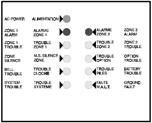
1.3.2 LED Indicators
The LED indicators for the CMP-2401B/CMP-2402B are labeled in English and French. The purpose of each indica-
tor is listed below:
AC Power (Alimentation) - green LED
The green LED is on when the FACP is operating from normal AC power. The LED turns off to indicate a below
normal AC voltage (brownout) or complete loss of AC power. The System Trouble LED will also turn on.
Option Trouble (Trouble Option) - yellow LED
This yellow LED turns on to indicate the removal of the optional supervised 4XTMF Transmitter Module or a
trouble with the module.
Zone 1 Alarm (Alarme Zone 1) - red LED
This red LED turns on to indicate an alarm condition, even if the Zone Silence switch is in the Silence position.
Zone 2 Alarm (Alarme Zone 2) - red LED (CMP-2402B only)
This red LED turns on to indicate an alarm condition, even if the Zone Silence switch is in the Silence position.
Zone 1 Trouble (Trouble Zone 1) - yellow LED
This yellow LED turns on to indicate a trouble condition, such as an open in the field wiring, on the IDC (Initiat-
ing Device Circuit) zone 1.
Zone 2 Trouble (Trouble Zone 2) - yellow LED (CMP-2402B only)
This yellow LED turns on to indicate a trouble condition, such as an open in the field wiring on the IDC (Initiating
Device Circuit) zone 2.
Zone Silence (M.S. Silence Zone) - yellow LED
This yellow LED turns on to indicate that the Notification Appliance Circuit has been silenced.
Bell Trouble (Trouble Cloche) - yellow LED
This yellow LED turns on to indicate a trouble condition, such as an open or short in the field wiring, on the
Notification Appliance Circuit.
Battery Trouble (Trouble Piles) - yellow LED
This yellow LED turns on to indicate a low battery/no battery condition or battery charger fault.
FIGURE 1-3:LED Indicators (CMP-2402B Illustrated)
2401DISP.CDR
Controls, Indicators and Operation
14 Document #50907 Rev.A1 12/03/02 P/N 50907:A1
System Trouble (Trouble Systeme) - yellow LED
This yellow LED turns on for all faults or abnormal operating conditions.
Ground Fault (Faute M.A.L.T.) - yellow LED
This yellow LED turns on to indicate a ground fault condition (low impedance to ground) on any field wiring or
battery connections.
1.3.3 Local Sounder
A piezo sounder provides distinct signals for alarm and trouble conditions:
•Alarm - steady
• Trouble - pulse
1.3.4 Normal Standby Operation
Normal standby operation indicates that there are no alarms or trouble conditions present on the FACP and that
the IDC zone(s) have not been Silenced. In Normal Operation:
• All switches must be in their normal positions. Refer to Figure 1-1, “CMP-2401B/CMP-2402B,” on page 10.
• The green AC power LED is on steady
• The red alarm LED(s) are off
• All yellow trouble LEDs are off
1.3.5 Alarm Condition
Alarm condition indicates that an IDC (input) zone has detected an alarm (active smoke detector, pull station
activation, etc.). In Alarm Operation:
• The zone alarm LED will turn on
• The notification appliances are activated
• The optional 4XTMF Transmitter Module is activated
• Piezo sounder turns on steady
• The alarm relay will transfer
1.3.6 Trouble Condition
Trouble condition indicates that one or more faults have been detected by the FACP. Contact the local service
representative for immediate correction of the fault since FACP operation may be impaired. A Trouble condition will
cause the following:
• The yellow System Trouble LED will light steady
• Additional trouble LEDs may turn on
• The piezo sounder will pulse
Document #50907 Rev. A1 12/03/02 P/N 50907:A1 15
Circuits
1.4 Circuits
Input Circuits
The CMP-2401B has one IDC (Initiating Device Circuit) and the CMP-2402B has two IDCs. Input circuit(s) pro-
vide Style B (Class B) configuration and accept 2-wire smoke detectors and normally-open contact devices.
Output Circuits
• 24 Volt Resettable Power Output 85 mA
• 24 Volt Battery Charger (up to two 7 AH batteries)
Notification Appliance Circuit
One Style Y (Class B) Notification Appliance Circuit @ 1.25 amps maximum
Relays
Two dry Form-C relays for system alarm and system trouble are provided standard. Contacts are rated 2.0 amps
@ 30 VDC (resistive), 2.0 amps @ 30 VAC (resistive).
Battery Charger
The battery charger will charge up to two 7 AH batteries. The FACP cabinet holds a maximum of two 7 AH
batteries.
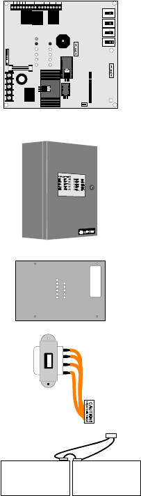
1.5 Components
Main Circuit Board
The main circuit board contains power supply, alarm and trouble
relays, control switches, LED indicators, option jumpers, wiring
interface connectors and other primary components. The option
module plugs in and is mounted to the main circuit board. The
main circuit board is delivered premounted in the cabinet.
Cabinet
The cabinet is red. The backbox measures 14.5" (36.83 cm)
high X 12.5" (31.75 cm) wide X 2.875" (7.303 cm) deep and
provides space for two batteries (up to 7.0 Amp Hours each).
Also supplied is a blue dress panel which mounts inside the
cabinet.
Dress Panel
A blue dress panel, which is required for Canadian
installations, is provided with the cabinet. The dress panel
restricts access to the system wiring while allowing access to
the control switches.
Transformer Assembly
One transformer is provided standard with the panel. The
transformer plugs into connector J5 on the main circuit board.
Batteries
The cabinet provides space for two 7 Amp Hour batteries
which must be ordered separately.
J1
F2
J4
J5
TB3
TB1
GND +24V
REG
RES
BUZ TROUBLE
NEUTRAL EARTH HO T
SIGNAL
OUTPUT
CUT IF 4 X
OPTION
BOARD IS
PRESENT
CUT TO
DISABLE
EARTH
FAULT
INITI AT
ZONE 1 IN IT IAT
ZONE 2
ALARM
J3
BATTERY
TBL SILE NCE
SIG SILE NCE
ZONE 1 SIG SILE NCE
ZONE 2
SYSTEM RESET
NC NCCC
---
+++
NO NO
TBLAC
TB2
R72
R14
SW4
SW2
SW1
SW3
2402BORD.CDR
MP2401DR.CDR DP-2401.CDR
2401XFOR.CDR
2401BATT.CDR
Optional Modules and Accessories
16 Document #50907 Rev.A1 12/03/02 P/N 50907:A1
1.6 Optional Modules and Accessories
4XTMF Transmitter Module
The 4XTMF Transmitter Module provides a supervised output for local energy municipal box transmitter and
alarm and trouble reverse polarity. It includes a disable switch and disable trouble LED on the module. A jumper
option on the module allows the reverse polarity circuit to open with a system trouble condition if no alarm
condition exists.
Remote Trouble Buzzer
One Remote Trouble Buzzer can be connected to the FACP using four wires. The remote unit includes an AC
LED, System Trouble LED and piezo sounder which are controlled by the control panel. It mounts to a single-
gang electrical box.
Document #50907 Rev. A1 12/03/02 P/N 50907:A1 17
Installation
CHAPTER 2 Installation
2.1 Mounting Options
The cabinet may be either semi-flush or surface mounted.
The door is removable during the installation period by open-
ing and lifting the door off the hinges. The cabinet mounts
using two key slots and two additional 0.250” (0.635 cm)
diameter holes located in the backbox. The key slots are
located at the top of the backbox and the two securing holes
at the bottom.
Carefully unpack the system and check for shipping damage.
Mount the cabinet in a clean, dry, vibration-free area where
extreme temperatures are not encountered. The area should
be readily accessible with sufficient room to easily install and
maintain the panel. Locate the top of the cabinet approxi-
mately five feet above the floor with the hinge mounting on
the left. Determine the number of conductors required for the
devices to be installed. Sufficient knockouts are provided for
wiring convenience. Select the appropriate knockout(s) and
pull the required conductors into the box. Note that there are
no knockouts on the left (hinged) side of the cabinet. All
wiring should be in accordance with the National and/or
Local codes for fire alarm systems.
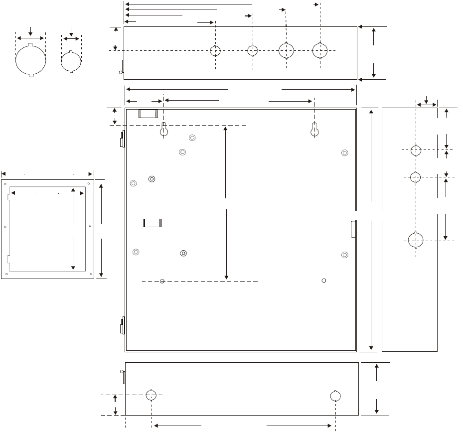
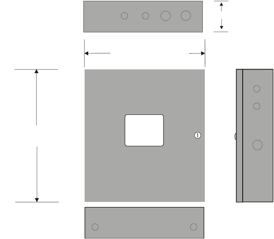
2.2 Backbox Mounting
1. Open the door.
2. Remove the main PC board assembly by unscrewing the four screws in the corners of the board. Set the board
aside in a safe, clean place. Avoid static discharge which may damage the board.
3. Mark and predrill holes for the top two keyhole mounting bolts using the dimensions illustrated in Figure 2-2.
4. Install two upper fasteners in the wall with the screw heads protruding.
5. Using the upper keyholes, mount the backbox over the two screws.
6. Mark and drill the lower two holes.
7. Mount the backbox, install the remaining fasteners and tighten.
8. When the location is dry and free of construction dust, reinstall the main PC board.
FIGURE 2-1:CMP-2401B/CMP-2402B Mounting
MP2401DR.CDR
Backbox Mounting
18 Document #50907 Rev.A1 12/03/02 P/N 50907:A1
Draw wires through the respective knockout locations.
12.625"
(32.068 cm)
14.625“ (37.148 cm)
16.625" (42.228 cm)
17.625"
(44.768 cm)
3.000“
(7.620 cm)
3.000“
(7.620 cm)
1.250“ (3.175 cm)
10.000“ (25.400 cm)
1.250“
(3.175 cm)
1.25“
(3.175 cm)
1.25“
(3.175 cm)
1.125“
(2.858 cm)
0.875“
(2.223 cm)
14.5“
(36.83 cm)
3.25“
(8.255 cm)
1.75“
(4.445 cm)
3.5“
(8.89 cm)
12.5“ (31.75 cm)
4.125“ (10.478 cm)
6.125“ (15.558 cm)
8.125“ (20.638 cm)
10.125“ (25.718 cm)
1.000“ (2.540 cm)
6.5“ (16.51 cm)
9.500“ (24.130 cm)
(7.62 cm)
3.0“
Bottom
Top
Right Side
FIGURE 2-2:Cabinet Dimensions and Knockout Locations
5024JRBB.CDR
TR-3-R Trim Ring
Document #50907 Rev. A1 12/03/02 P/N 50907:A1 19
Backbox Mounting
Door=14.714" (37.374 cm)
Backbox=14.5" (36.83 cm)
Door=12.714" (32.294 cm)
Backbox=12.5“ (31.75 cm)
Right side
Depth=3.000” (7.620 cm)
Top
Bottom
FIGURE 2-3:FACP Backbox
2401CABB.CDR
Operating Power
20 Document #50907 Rev.A1 12/03/02 P/N 50907:A1
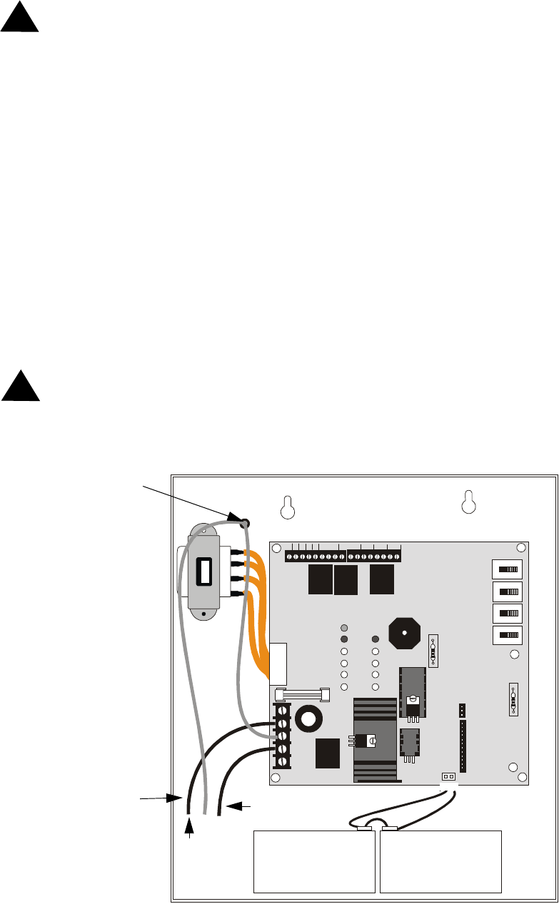
2.3 Operating Power
WARNING: Several different sources of power can be connected to this panel. Disconnect all sources of power
before servicing. The panel and associated equipment may be damaged by removing and/or inserting modules,
interconnecting cables or wiring while this unit is energized.
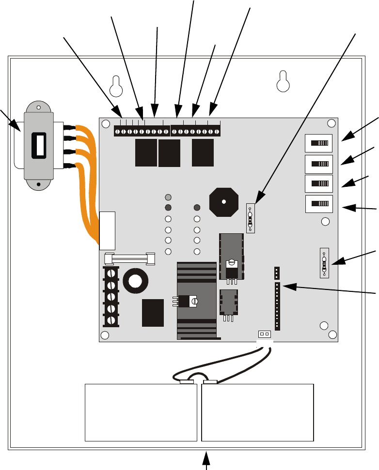
Primary Power Source (AC) and Earth Ground Connections
AC power connections are made inside the control panel cabinet. The AC input circuit is limited by fuse F2 (2 amp,
3AG Slow Blow). The primary power source for the FACP is 120 VAC, 60 Hz, 0.5 amps. Run a pair of wires (with
ground conductor) from the protected premises main breaker box to TB3 of the main circuit board. As per the
National and Canadian Electric Code, use 14 AWG (2.00 mm2, 1.6 mm O.D.) or heavier gauge wire with 600V insu-
lation. No other equipment may be connected to this circuit. In addition, this circuit must be provided with overcur-
rent protection and may not contain any power disconnect devices. A separate Earth Ground connection must be
made to ensure proper panel operation and lightning and transient protection. Connect the Earth Ground wire [mini-
mum 14 AWG (2.00 mm2)] to the grounding stud on the backbox. Do not use conduit for the Earth Ground connec-
tion since this does not provide reliable protection.
Secondary Power Source (Batteries)
Observe polarity when connecting the battery. Connect the battery cable to J3 on the main circuit board using the
plug-in connector and cable provided. The battery charger is current-limited and capable of recharging sealed lead
acid type batteries. The charger shuts off when the system is in alarm. See Battery Calculations for calculation of the
correct battery rating.
WARNING: Battery contains sulfuric acid which can cause severe burns to the skin and eyes and can destroy fabrics.
If contact is made with sulfuric acid, immediately flush the skin or eyes with water for 15 minutes and seek immediate
medical attention.
!
!
J3
J1
F2
J4
J5
TB3
TB1
GND +24V
REG
RES
BUZ T ROUB L E
NEUTRAL EARTH HOT
SIGNAL
OUTPU T
CUT IF 4X
OPTION
BOARD IS
PRESENT
CUT TO
DISABLE
EARTH
FAULT
INITIAT
ZONE 1
INITIAT
ZONE 2
ALARM
TBL SILENCE
SIG SILENCE
ZO NE 1
SIG SIL ENCE
ZONE 2
SYSTEM RESET
NC NCCC
---
+++
NO NO
TBL
AC
TB2
R72
R14
SW4
SW2
SW1
SW3
CAUTION!
HIGH VOLTAGE
BATTERY
FIGURE 2-4:Operating Power Connections
Neutral
Earth
Hot
AC
Grounding Stud
2402ACBX.CDR
Document #50907 Rev. A1 12/03/02 P/N 50907:A1 21
Input Circuits
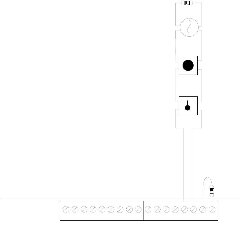
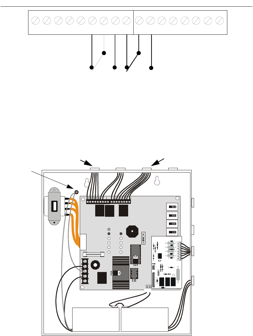
2.4 Input Circuits
The CMP-2401B has one IDC (Initiating Device Circuit) and the CMP-2402B has two IDCs. The maximum total
loop resistance limit for each input circuit is 200 ohms. The field wiring is supervised for opens, shorts and ground
faults. All conditions are visually and audibly annunciated.
The zone(s) is a Style B (Class B) Initiating Device Circuit designed to accept any normally-open contact devices and
conventional 2-wire or 4-wire, 24 VDC smoke detectors. Resettable power is provided via TB1 Terminals 24V
Resettable (+) and Ground (-). Remove the End-of Line resistor from the FACP and install it on the IDC wiring after
the last device in the circuit. Refer to the Fire•Lite Device Compatibility Document for a list of compatible smoke
detectors.
It is allowable to mix an assortment of device types (i.e. smoke detectors, heat detectors, pull stations, etc.) on the
same zone.
TB1 TB2
REMOTE
GND AC TBL BUZ
++++
---
NC NCCCNO NO
ALARM TROUBLE+24 VDC
RESET
SIGNAL
OUTPUT
INITIATING
ZONE 1
INITIATING
ZONE 2
FIGURE 2-5:CMP-2402B Style B Initiating Device Circuit Connections
UL listed compatible 2-wire smoke detector
Manual Pull Station
Heat Detector
Dummy load unused circuit
Style B (Class B) Initiating Device Circuit (supervised
and power-limited).
3.9K ohm, ½ watt
2402IDC.CDR
Output Circuits
22 Document #50907 Rev.A1 12/03/02 P/N 50907:A1
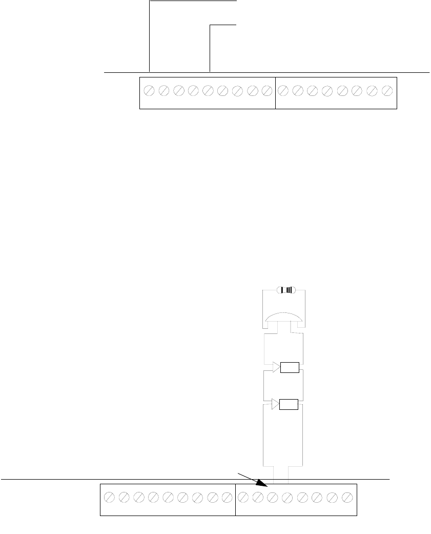
2.5 Output Circuits
DC Power Output Connections
Notification Appliance Circuit
The FACP provides one supervised Notification Appliance Circuit as Style Y (Class B). The circuit is capable of
1.25 amps of current. Observe polarity when connecting polarized devices to the NAC. Remove the End-of-Line
resistor from the FACP and install it on the Notification Appliance Circuit wiring after the last device. Refer to
the Fire•Lite Device Compatibility Document for a listing of compatible notification appliances.
TB1 TB2
GND AC TBL BUZ
++++
---
NC NCNO NOCC
REMOTE +24 VDC
RESET
ALARM TROUBLE SIGNAL
OUTPUT
INITIATING
ZONE 1
INITIATING
ZONE 2
FIGURE 2-6:Auxiliary Power Connection
4-Wire Smoke Detector Power (85 mA)
24 VDC filtered, resettable power for 4-wire
smoke detectors can be obtained from TB1
Terminals 24V Resettable (+) and Ground (-)
2402TERM.CDR
TB1 TB2
+
REMOTE
GNDACTBLBUZ
++++
---
NC NCNO NOCC
ALARM TROUBLE SIGNAL
OUTPUT
INITIATING
ZONE1
INITIATING
ZONE2
+24 VDC
RESET
+
+
FIGURE 2-7:Notification Appliance Circuit Connections
Polarized Bell
Polarized Horn
Polarized Horn
Note: Notification Appliance
polarities shown in alarm state
Note: Terminal polarity shown in
alarm state
Style Y (Class B) Notification Appliance Circuit (supervised).
3.9 K ohm, ½ watt
2402NAC.CDR
Document #50907 Rev. A1 12/03/02 P/N 50907:A1 23
UL Power-limited Wiring Requirements
Standard Relays
The FACP provides two Form-C relays rated for 2.0 amps @ 30 VDC (resistive) and 2.0 amps @ 30 VAC
(resistive).
2.6 UL Power-limited Wiring Requirements
Power-limited and nonpower-limited circuit wiring must remain separated in the cabinet. All power-limited circuit
wiring must remain at least 0.25" (6.35 mm) away from any nonpower-limited circuit wiring. Furthermore, all
power-limited and nonpower-limited circuit wiring must enter and exit the cabinet through different knockouts and/or
conduits. A typical wiring diagram for the FACP is illustrated below.
TB1 TB2
GND AC TBL BUZ
ALARM TROUBLE
++++
---
NC NCCCNO NO
SIGNAL
OUTPUT
INITIATING
ZONE 1
INITIATING
ZONE 2
FIGURE 2-8:Relay Terminals
Relay connections may be power-limited or nonpower-limited, provided that a minimum of 0.25"
is maintained between conductors of power-limited and nonpower-limited circuits.
M2401REL.CDR
J3
J1
F2
J4
J5
TB3
TB1
GND +24V
REG
RES
BUZ TROUBLE
NEUT RA L EART H HOT
SIGNAL
OUTPUT
CUT IF 4X
OPTION
BOARD IS
PRESENT
CUT TO
DISABLE
EARTH
FAULT
INITIAT
ZONE 1
INITIAT
ZONE 2
ALARM
TBL SILENCE
SIG SILENCE
ZONE 1
SIG SILENCE
ZONE 2
SYSTEM RESET
NC NCCC
---
+++
NO NO
TBLAC
TB2
R72
R14
SW4
SW2
SW1
SW3
CAUTION!
HIGH VOLTAGE
BATTERY
FIGURE 2-9:Typical Wiring Diagram for UL Power-limited Requirements
Power-limited
Circuit
Power-limited
Circuit
Nonpower-limited
Circuit
Power-limited
Circuit
AC Power
Grounding Stud
2401PWRL.CDR
Document #50907 Rev. A1 12/03/02 P/N 50907:A1 25
Installation of Optional Module
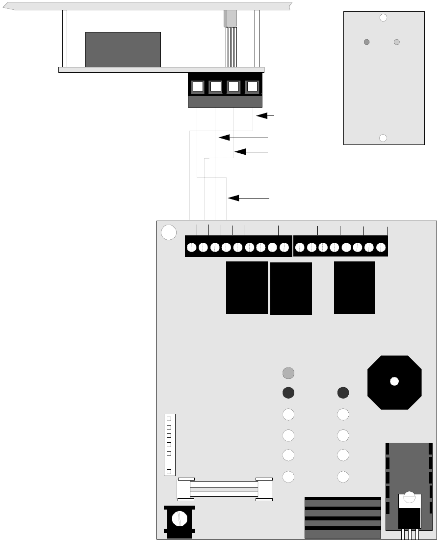
2.7.2 RTB - Remote Trouble Buzzer
The RTB is a Remote Trouble Buzzer which provides a green AC Power LED and a yellow Trouble LED along
with a piezo sounder, all of which mimic the condition of the control panel. The RTB can be mounted remotely in
a single-gang electrical box. Four wires are required to connect the RTB to the CMP-2401B/CMP-2402B control
panel as illustrated in Figure 2-11.
F2
J5
TB1
GND +24V
REG
RES
BUZ TROUBLE SIGNAL
OUTPUT
INI TIAT
ZONE 1
INI TIAT
ZONE 2
ALARM
NC NCCC
---
+++
NO NO
TBLAC
TB2
FIGURE 2-11:RTB Remote Trouble Buzzer Connection
Ground
Trouble LED
AC Power LED
Buzzer
CMP-2401B/CMP-2402B
RTB Remote Trouble Buzzer
2402RTB.CDR
RTBBUZZ.CDR
Programming Options
26 Document #50907 Rev.A1 12/03/02 P/N 50907:A1
CHAPTER 3 Programming Options
This chapter describes the programming options available by cutting resistors on the FACP main circuit board.
Options should be selected (resistors cut if necessary) prior to applying power to the control panel.
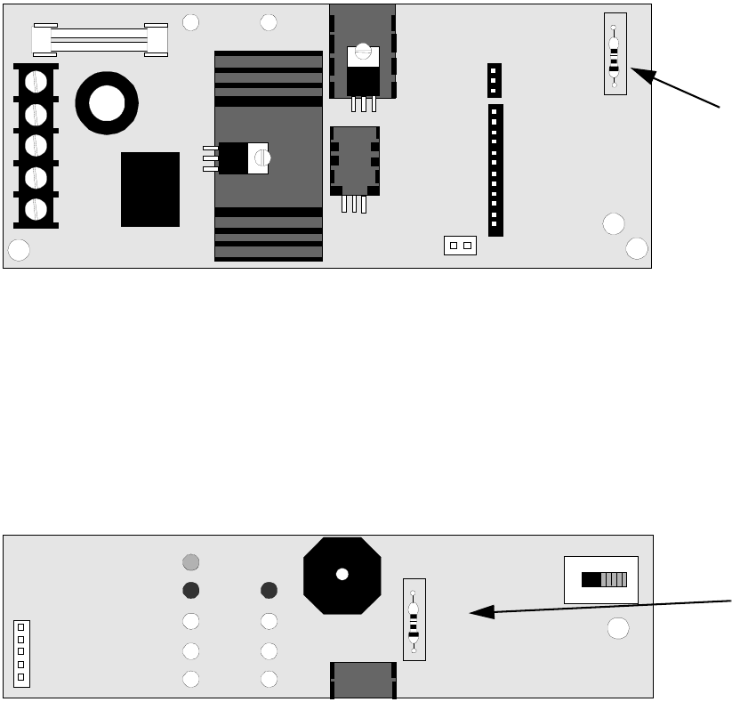
3.1 Earth Ground Fault Detection
The FACP is factory configured to automatically detect ground fault conditions. A ground fault occurs when a low
resistance is detected between an FACP circuit and earth ground. This condition will cause the System Trouble LED
and Ground Fault LED to turn on and the piezo sounder to pulse.
The Ground Fault Detection circuit can be disabled by cutting resistor R72 on the main circuit board. Refer to the
local codes and consult the local Authority Having Jurisdiction before disabling the Ground Fault Detection circuit.
3.2 Optional 4XTMF Transmitter Module Placement Supervision
The 4XTMF module can be used to connect the FACP to a City Box or Reverse Polarity Remote Station. To super-
vise placement and operation of the module, cut resistor R14. Refer to the local codes and consult the local Authority
Having Jurisdiction before installing the 4XTMF Transmitter Module.
J1
J4
TB3
NEUTRAL EARTH HOT
CUT TO
DISABLE
EARTH
FAULT
J3
BAT TERY
R72
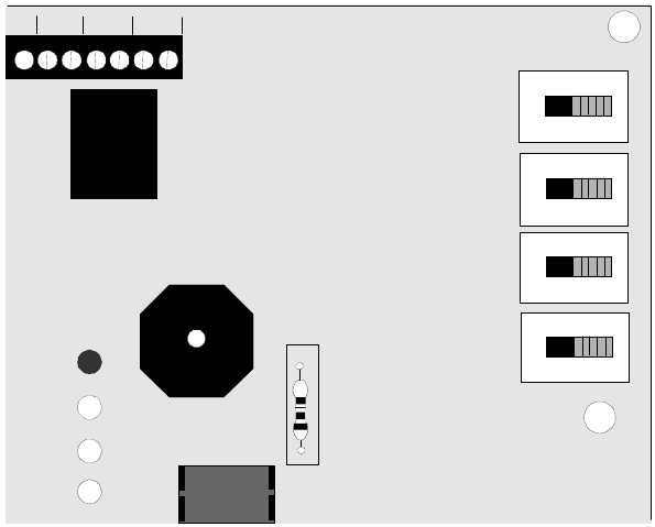
FIGURE 3-1:Ground Fault Detection Circuit
R72
Cut to Disable Ground
Fault Detection
2402BRD3.CDR
J5
CUT IF 4X
OPTION
BOARD IS
PRESENT
TBL SILE NCE
R14
SW4
FIGURE 3-2:4XTMF Module Placement Supervision
R14
Cut to Supervise Placement
of 4XTMF Module when
installed
2402BRD4.CDR
Document #50907 Rev. A1 12/03/02 P/N 50907:A1 27
Periodic Testing and Maintenance
CHAPTER 4 Periodic Testing and Maintenance
To ensure proper and reliable operation, it is recommended that system inspection and testing be scheduled monthly
or as required by national and/or local fire codes. Testing should be done by a qualified service representative if a
malfunction is encountered.
Before Testing:
1. Notify the fire department and/or central alarm receiving station if an alarm condition will be transmitted.
2. Notify the facility personnel of a test so that alarm sounding devices are ignored during the test period.
3. When necessary, activation of notification appliances can be prevented by using the Signal Silence switch to
silence the zone.
Test in g:
1. Activate a zone via an alarm initiating device and check that active notification appliances sound and the
alarm LED lights. Reset the system and repeat the procedure for each zone*.
2. Momentarily activate the following switches (one at a time) and check for a trouble signal:
✓Reset (all LEDs should illuminate for Lamp Test)
✓Signal Silence
3. Depress the Trouble Silence switch and check for an intermittent audible signal. Return the Trouble Silence
switch to the normal position.
4. Momentarily open the following circuits one at a time and check for a trouble signal:
✓Notification Appliance (bell) Circuit
✓Initiating Device Circuit Zone 1
✓Initiating Device Circuit Zone 2 (CMP-2402B only)
5. If new batteries were installed, wait 48 hours before completing this step. Remove AC power, activate a zone
and check that:
✓The Alarm LED lights
✓All active notification appliances sound
Measure battery voltage while the notification appliances are sounding. Replace any battery with
terminal voltage less than 85% of rating. Reapply AC power and press the Reset switch*.
6. Return all switches to their normal positions. Notify the fire department, central station and/or building
personnel that testing is completed.
*Note that the Reset and Signal Silence switches will not operate for one minute following activation of an alarm.

Battery Calculations
28 Document #50907 Rev.A1 12/03/02 P/N 50907:A1
CHAPTER 5 Battery Calculations
Use the Total Standby and Alarm Load Currents calculated in Table 5-2 and Table 5-3 for the following battery
calculation.
Note:
1. 7 Ampere Hour battery can be located in the backbox.
TABLE 5-1: Battery Calculations
Standby Load
Current (amps)
[ ]
X
Required Standby Time in
Hours (24 or 60 Hours)
[ ]
= __________
Alarm Load
Current (amps)
[ ]
X
Required Alarm Time in Hours
(i.e. 5 minutes = 0.084
10 minutes = 0.167)
[ ]
= __________
Add Standby and Alarm Load for Required Ampere Hour Battery =
Multiply by the Derating Factor of 1.2 X1.2
Total Ampere Hours (AH) Required =

Document #50907 Rev. A1 12/03/02 P/N 50907:A1 29
The Main Power Supply
5.1 The Main Power Supply
The FACP provides filtered power for operating the fire alarm control panel, external devices and the standby battery.
The power for operating external devices is limited. Use Table 5-2 (standby or nonalarm) and Table 5-3 (alarm) to
determine if external loading is within the capabilities of the power supply.
For 4-wire smoke detectors, be sure to power them from TB1 Terminals (+24V Resettable) and (-Ground).
1. Refer to the Device Compatibility Document for 2-wire smoke detector standby current.
2. Must use compatible listed Power Supervision Relay.
3. The total standby current must include the resettable power from TB1. Caution must be taken to ensure that
current drawn from this output during alarm does not exceed maximum ratings specified (see Table 5-3 )
TABLE 5-2: Load in Standby
Device Type # of Devices
Current
(amps)
Total Current
(amps)
Main Circuit Board 1 X 0.075 = 0.075
4XTMF (1 max.) X 0.005 =
Remote Trouble Unit (1 max.) X 0.020 =
2-wire Detector Heads [ ] X [ ]1=
4-wire Detector Heads [ ] X [ ]1=
Power Supervision Relays2[ ] X [ ] =
Additional Current Draw
from TB1 (nonalarm)3=
Sum Column for Standby Load = amps

The Main Power Supply
30 Document #50907 Rev.A1 12/03/02 P/N 50907:A1
1. The current shown represents the CMP-2401B control panel in alarm. If both zones of the CMP-2402B con-
trol panel are in alarm, the current draw increases to 0.175 amps.
2. Current limitations of terminals:
TB1, Terminals Ground and +24V Resettable = 0.085 amps, filtered, 24 VDC +/-5%, ripple @ 10mVRMS.
3. Must use compatible listed Power Supervision Relay
4. Enter current draw of each device. Current limitation of TB2 Notification Appliance Circuit is 1.25 amps.
TABLE 5-3: Load in Alarm
Device Type # of Devices
Current
(amps)
Total Current
(amps)
Main Circuit Board 1 X 0.1251=
4XTMF (1 max.) X 0.045 =
Remote Trouble Unit (1 max.) X 0.050 =
4-wire Detector Heads2[ ] X [ ] =
Power Supervision Relays3[ ] X [ ] =
Notification Appliances4[ ] X [ ] =
Additional Current Draw
from TB1 (nonalarm)2=
Sum Column for Alarm Load = amps
Document #50907 Rev. A1 12/03/02 P/N 50907:A1 31
Numerics
4XTMF
see Transmitter Module
A
Alarm 14
B
Backbox 19
Battery 15
Alarm 30
Calculations 28
Charger 15
see also Power - Battery
Standby 29
Trouble 13
C
Cabinet 15
Dimensions 18
Knockouts 18
see also Backbox
D
Description 9
Discharge Protection 11
Dress Panel 15
E
Earth Ground 20
Fault Detection 26
F
Form-C Relays
See also Relays
G
Ground Fault
see also Earth Ground - Fault Detection
I
Indicators 13
AC Power 13
Battery Trouble 13
Bell Trouble 13
Ground Fault 14
Option Trouble 13
System Trouble 14
see also Trouble
Zone Alarm 13
see also Alarm
Zone Silence 13
Zone Trouble 13
Initiating Device Circuit
Current
Alarm 11
Short Circuit 11
Standby 11
End-of-Line Resistor 11
Style Y 11
Voltage 11
Input Circuits 15, 21
L
LED
see Indicators
M
Maintenance 27
Mounting 17
N
Notification Appliance Circuit 11, 15, 22
Current 11
End-of-Line Resistor 11
Style Y 11
Vo l t a g e 1 1
O
Operational Power 20
Primary 20
see Battery
Output Circuits 22
Resettable Power 15
see’ Battery’ - ’Charger’
P
Piezo
see Sounder
Power
AC 11
AC fuse 11
see also Operational Power - Primary
Battery 11
Charger Capacity 11
charging circuit 11
Deep Discharge Protection 11
Programming 26
R
Relays 11, 15, 23
Contact Rating 11
Remote Trouble Buzzer 16, 25
Resettable Power
Current 11
voltage 11
Resistor, End-of-Line
Initiating Device Circuit 11
Notification Appliance Circuit 11
RTB
see Remote Trouble Buzzer
S
Sounder
Alarm 14
Trouble 14
Standby 14
Style B 9
Style Y 9
Switches 12
Reset 12
Signal Silence 12
Trouble Silence 12
T
Testing 27
Transformer Assembly 15
Transmitter Module 16, 24
Placement Supervision 26
Trouble 14
U
UL Power-limited Wiring 23
Index
32 Document #50907 Rev.A1 12/03/02 P/N 50907:A1
Notes
Document #50907 Rev.A1 12/03/02 P/N 50907:A1 33
Notes
34 Document #50907 Rev.A1 12/03/02 P/N 50907:A1
Notes
LimWarLg.p65 01/10/2000
The manufacturer warrants its products to be free from defects in materials and workmanship
for eighteen (18) months from the date of manufacture, under normal use and service. Products
are date-stamped at time of manufacture. The sole and exclusive obligation of the manufacturer
is to repair or replace, at its option, free of charge for parts and labor, any part which is
defective in materials or workmanship under normal use and service. For products not under
the manufacturer's date-stamp control, the warranty is eighteen (18) months from date of
original purchase by the manufacturer's distributor unless the installation instructions or catalog
sets forth a shorter period, in which case the shorter period shall apply. This warranty is void
if the product is altered, repaired, or serviced by anyone other than the manufacturer or its
authorized distributors, or if there is a failure to maintain the products and systems in which
they operate in a proper and workable manner. In case of defect, secure a Return Material
Authorization form from our customer service department. Return product, transportation
prepaid, to the manufacturer.
This writing constitutes the only warranty made by this manufacturer with respect to its
products. The manufacturer does not represent that its products will prevent any loss by fire
or otherwise, or that its products will in all cases provide the protection for which they are
installed or intended. Buyer acknowledges that the manufacturer is not an insurer and assumes
no risk for loss or damages or the cost of any inconvenience, transportation, damage, misuse,
abuse, accident, or similar incident.
THE MANUFACTURER GIVES NO WARRANTY, EXPRESSED OR IMPLIED, OF
MERCHANTABILITY, FITNESS FOR ANY PARTICULAR PURPOSE, OR OTHERWISE
WHICH EXTEND BEYOND THE DESCRIPTION ON THE FACE HEREOF. UNDER
NO CIRCUMSTANCES SHALL THE MANUFACTURER BE LIABLE FOR ANY LOSS
OF OR DAMAGE TO PROPERTY, DIRECT, INCIDENTAL, OR CONSEQUENTIAL,
ARISING OUT OF THE USE OF, OR INABILITY TO USE THE MANUFACTURER'S
PRODUCTS. FURTHERMORE, THE MANUFACTURER SHALL NOT BE LIABLE FOR
ANY PERSONAL INJURY OR DEATH WHICH MAY ARISE IN THE COURSE OF, OR
AS A RESULT OF, PERSONAL, COMMERCIAL, OR INDUSTRIAL USE OF ITS
PRODUCTS.
This warranty replaces all previous warranties and is the only warranty made by the
manufacturer. No increase or alteration, written or verbal, of the obligation of this warranty
is authorized.
Limited Warranty

World Headquarters
One Fire-Lite Place, Northford, CT 06472-1653 USA
203-484-7161 • Fax 203-484-7118
www.firelite.com
