Flexi Installation
User Manual: flexi-installation
Open the PDF directly: View PDF ![]() .
.
Page Count: 27

Flexi Installation Procedure
➢Tools required
➢7mm Spanner or Socket
➢Pozi/Philips screwdriver
➢Flat screwdriver
!
➢Parts required
➢Flexi unit installation template
➢Deadlatching Mortice Nightlatch to Din 18250
➢Anti-Bump Single Sided Euro Profile Cylinder!
size 40/10 < 47mm dr thickness, 45/10 > 47mm dr thickness
!!
Rev A
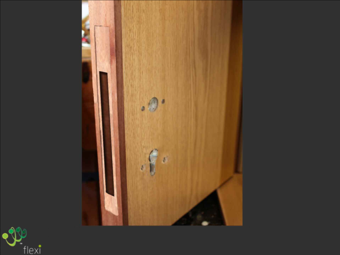
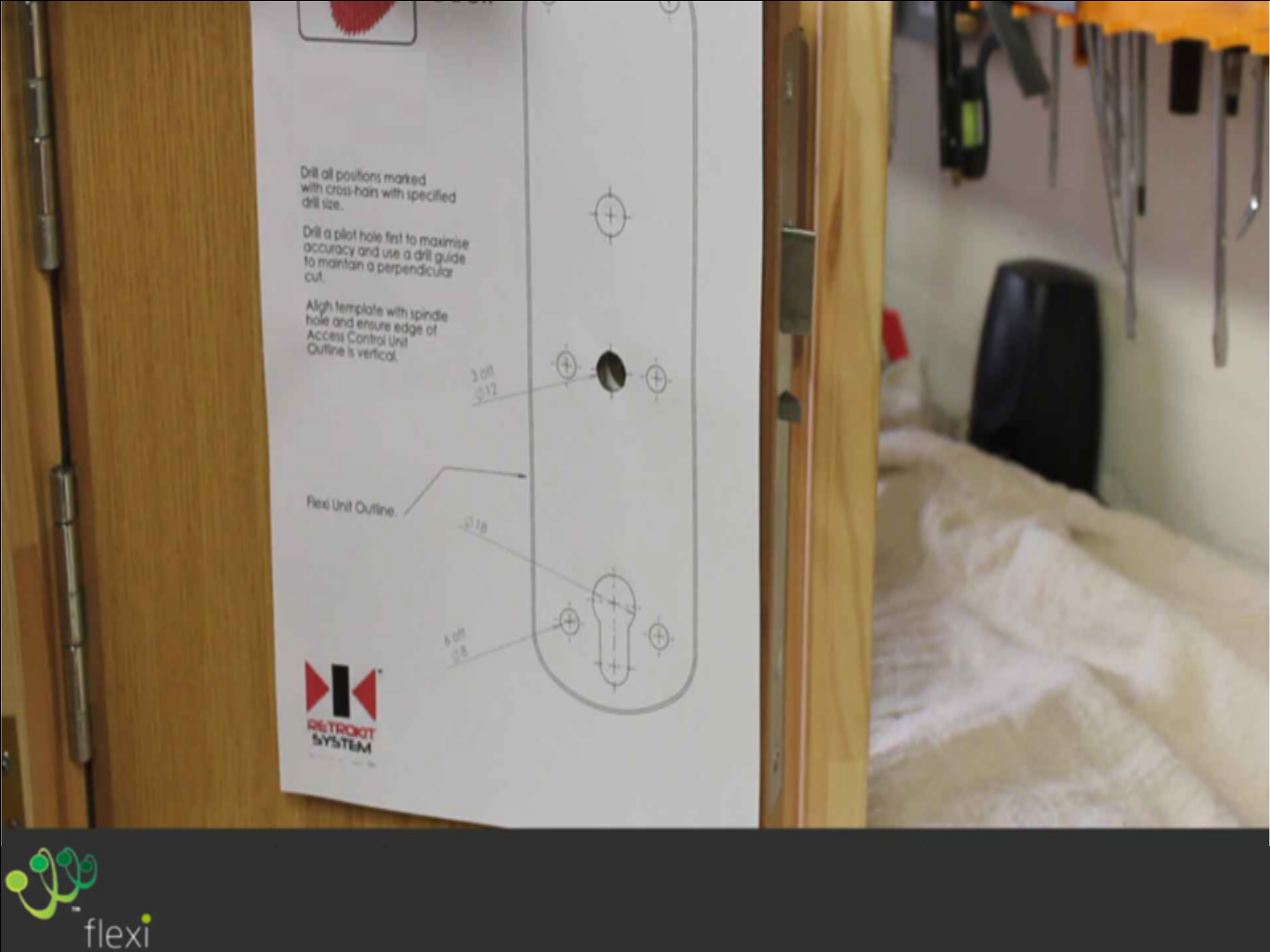
Drill holes and cut door as per latch and cylinder
Manufactures instructions
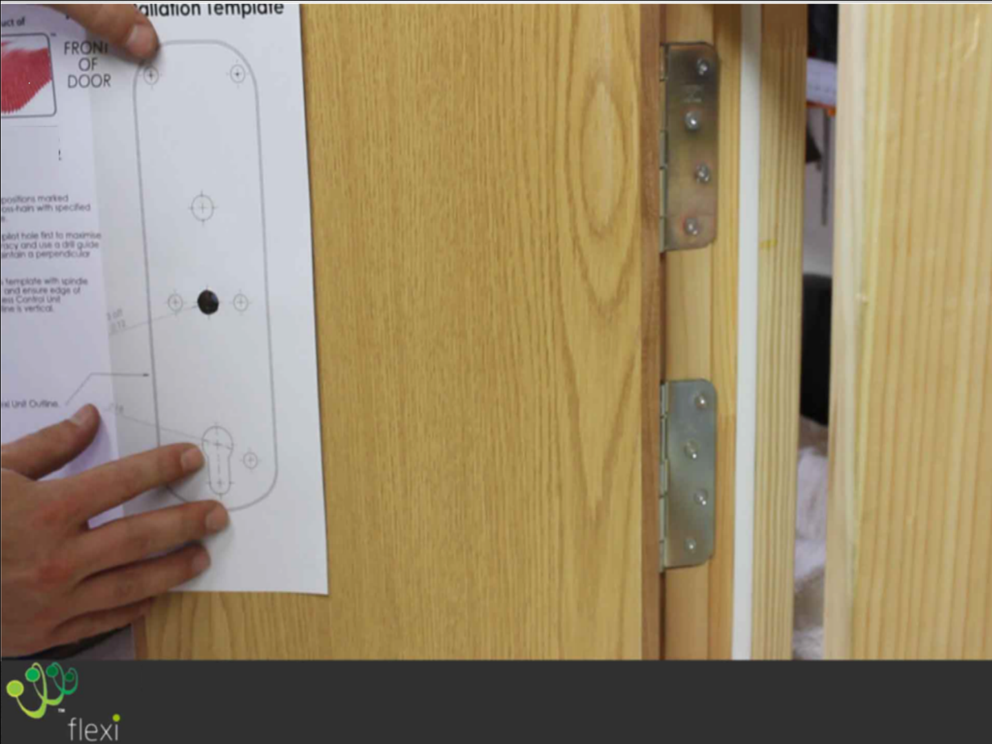
On the outside of the door align template with
Spindle hole, ensuring template is parallel to door
edge
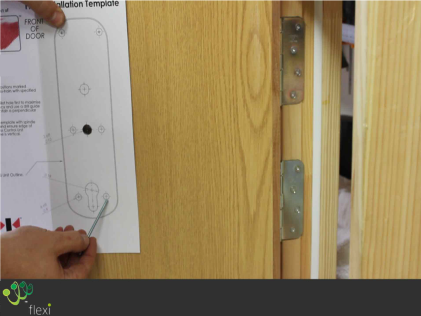
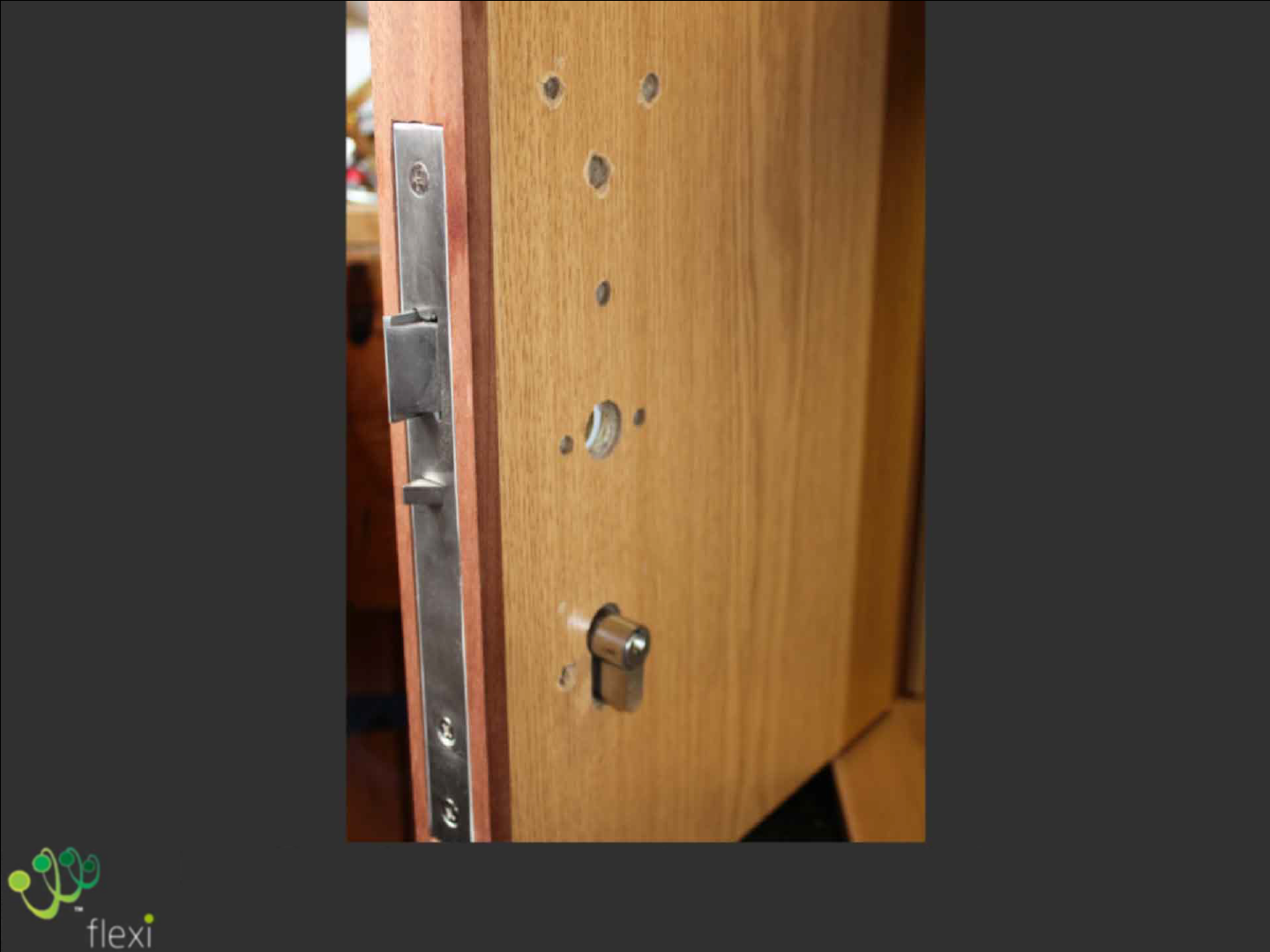
Drill holes indicated to ¾ depth of the door,
Diameter as stated on the template
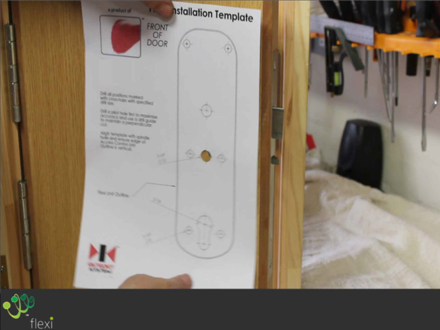
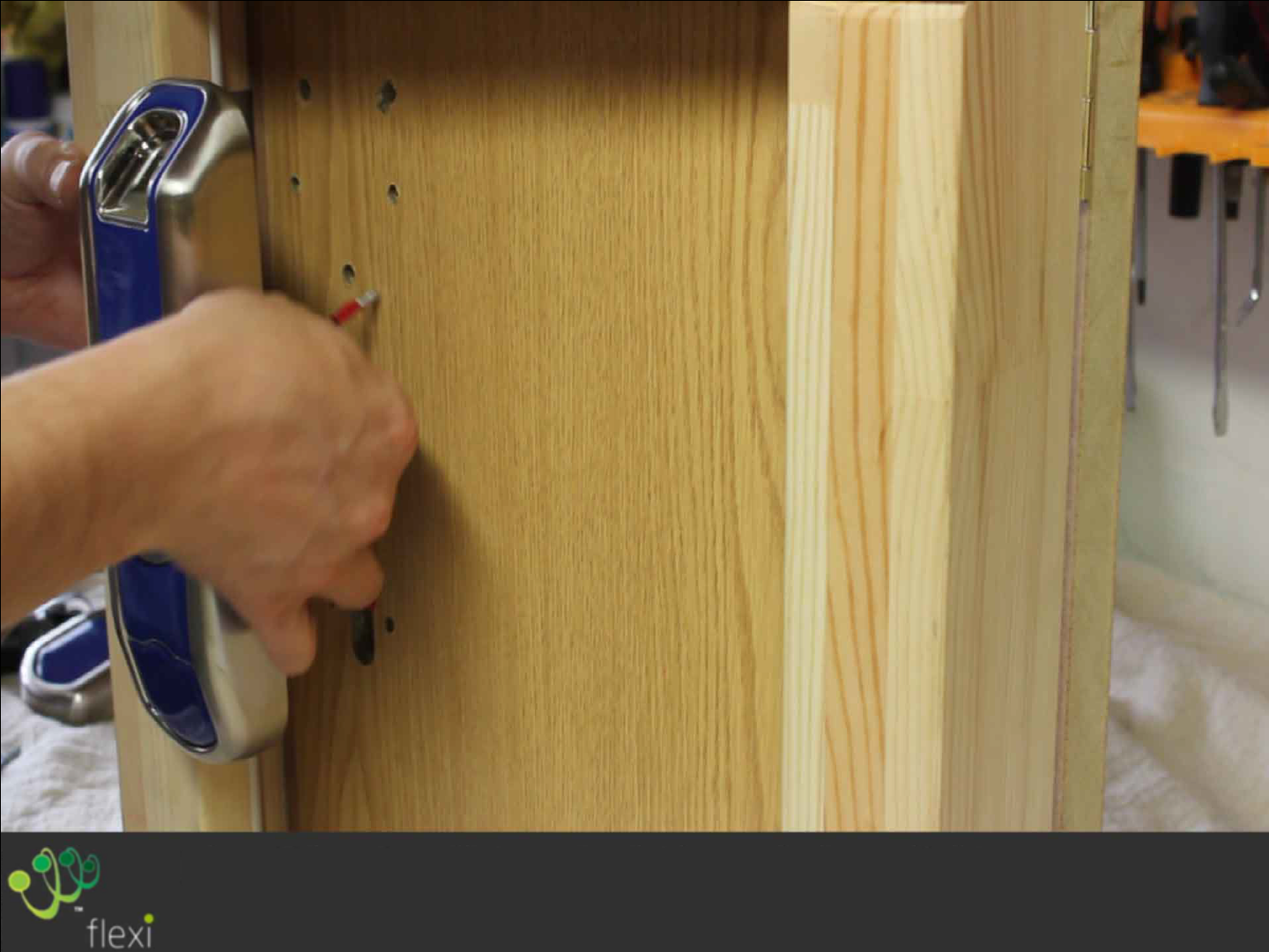
On the inside of the door align template with
Spindle and edge of door again
Drill indicated holes through to the pre-drilled holes.
DO NOT DRILL OUT OF CYLINDER KEYHOLE SLOT
Install the night latch and cylinder as per
manufactures instructions
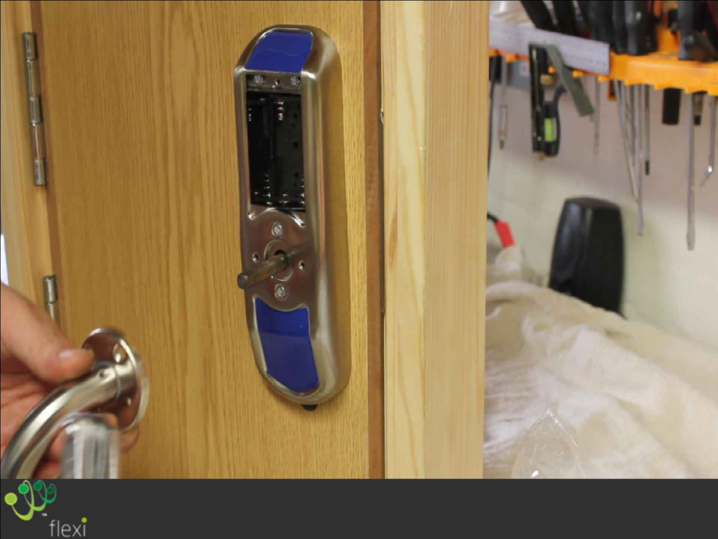
Place the spindle in the hole and thread the two
power cables through the hole identified above
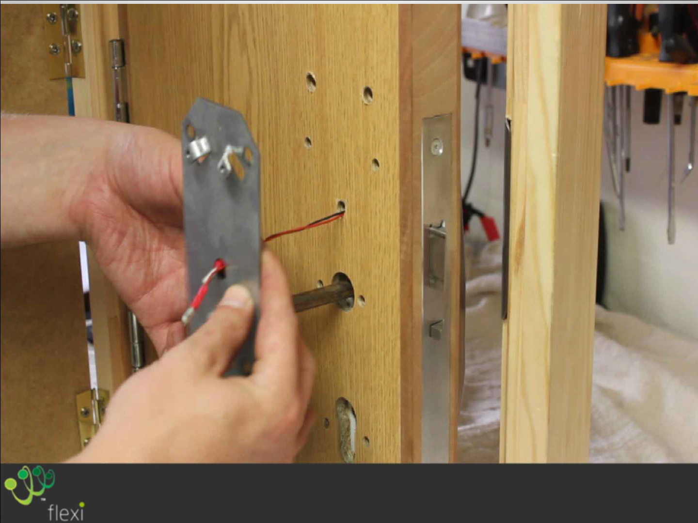
Pull the power leads through the hole shown and
place the rear housing Mounting Plate over the spindle
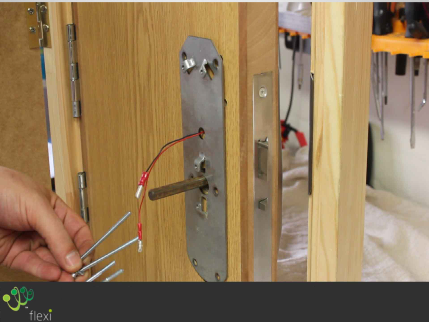
Thread an M4 Spring Washer and the Plain Washer
onto the two M4x60 & M4x70 bolts.
Thread the M4x70 bolts through the holes at the
base of the plate and the M4x60 bolts at the
top . . .as shown
The main Spindle should be aligned with the
Nightlatch
Check the De-clutching Spindle rotates freely . . . .
If resistance is felt rotating the spindle, lift the
unit up to ensure correct alignment and tighten
bolts to hold
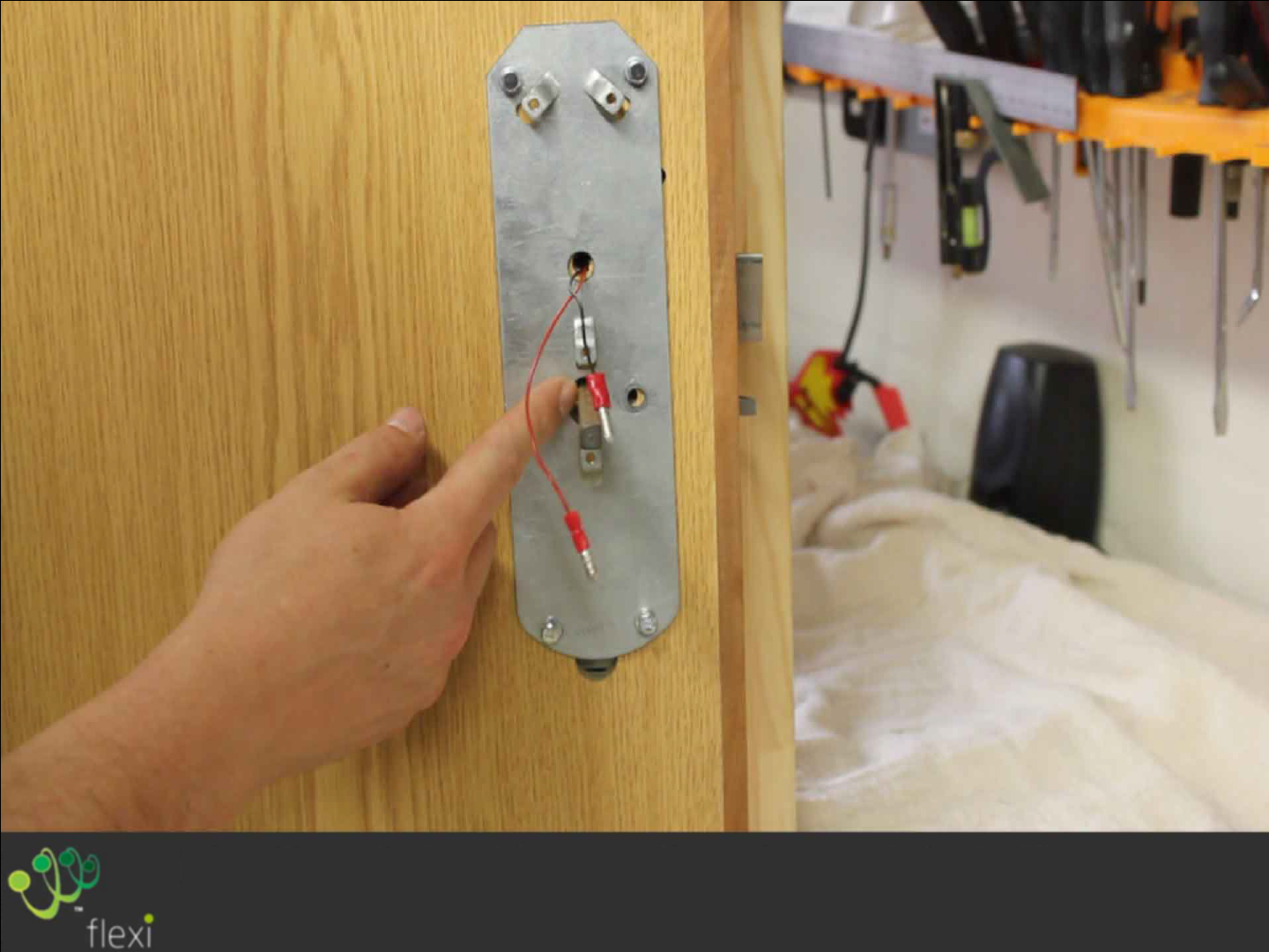
Also ensure that the spindle is located
centrally in the rear Mounting Plates hole,
adjust if necessary
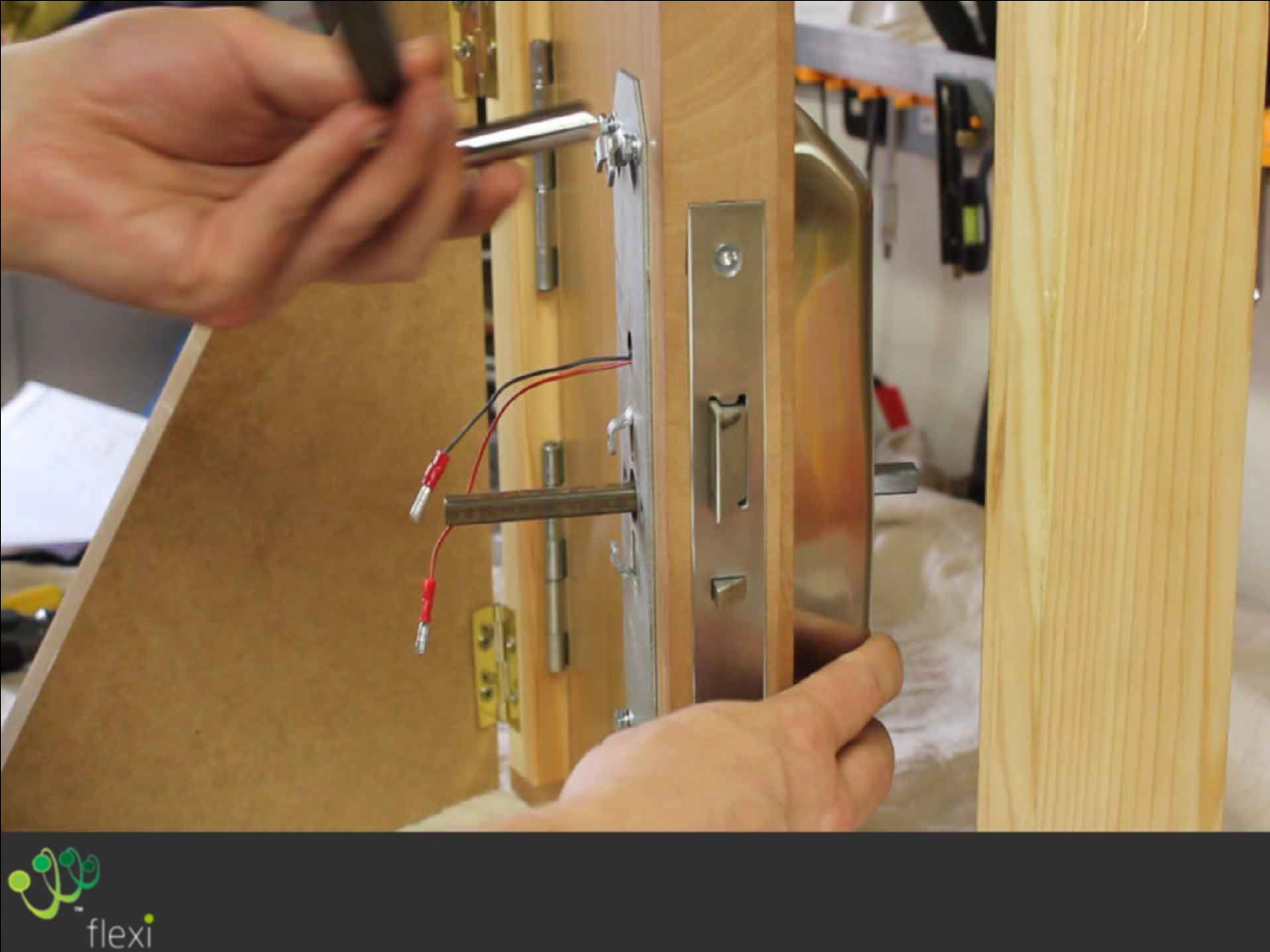
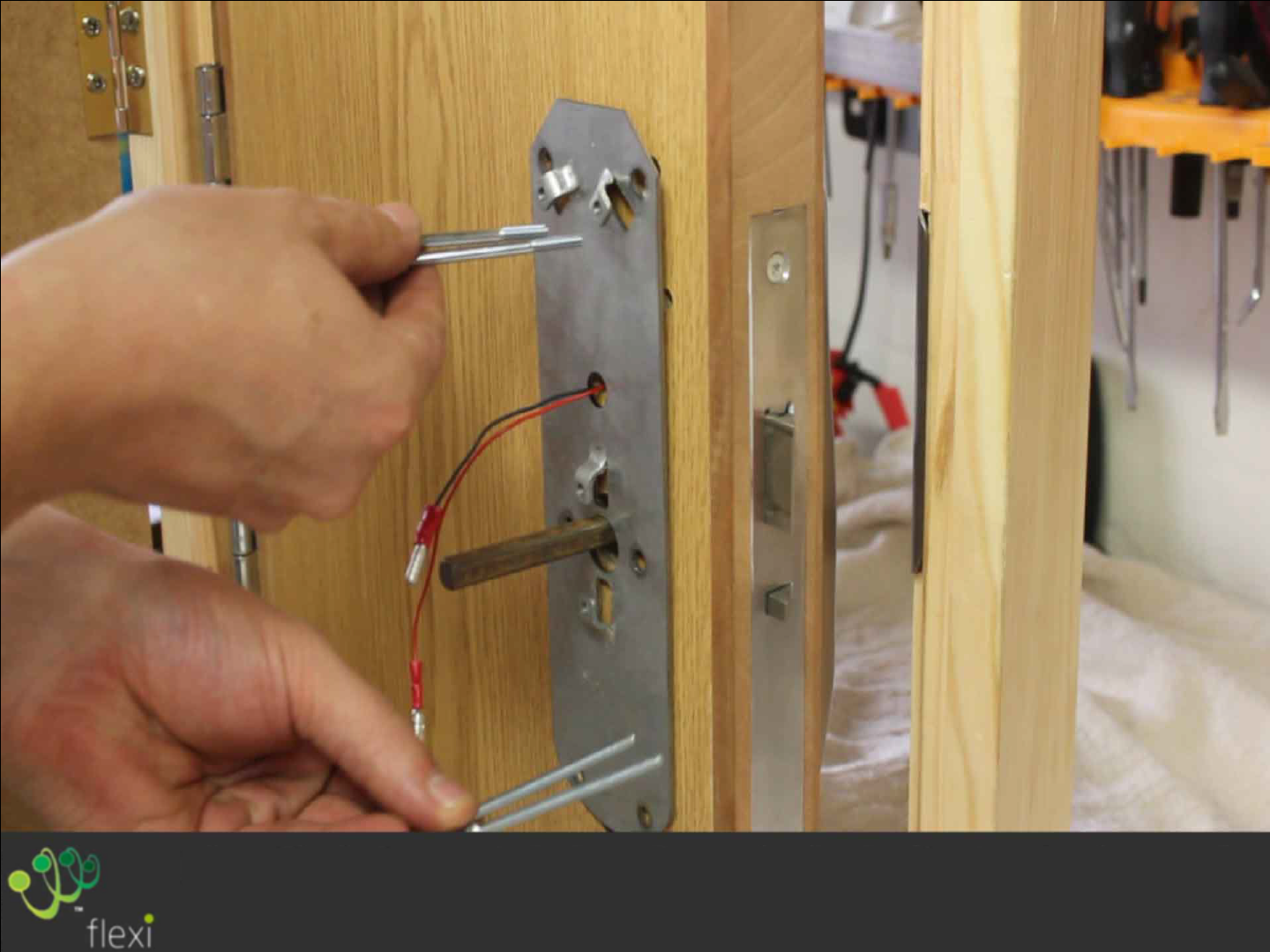
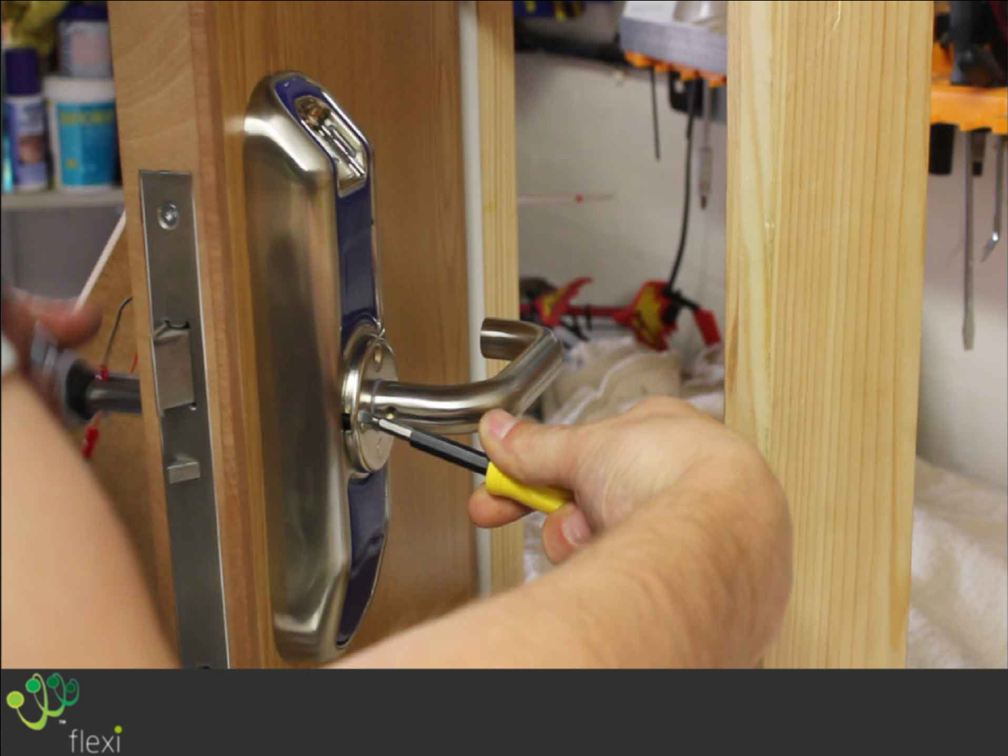
Tighten up all 4 bolts using 7mm Spanner or
Socket.
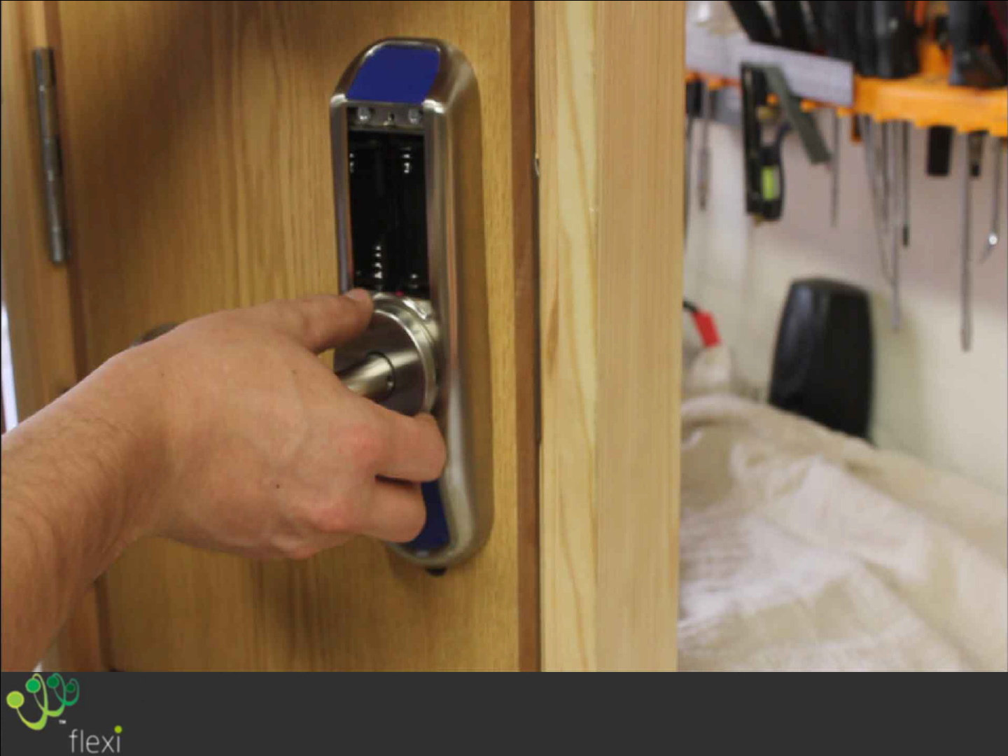
Locate two M4x100 countersunk screws through
the rose and carefully push them into the housing
and door
Thread an M4 washer and Nyloc Nut on to the
exposed threads
Tighten the nuts using a 7mm Spanner or
Socket and screwdriver.
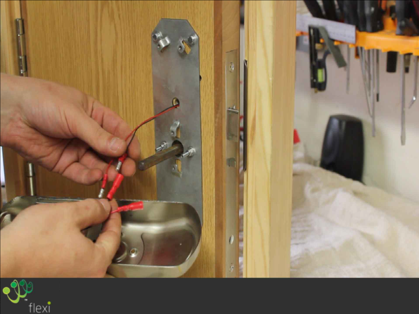
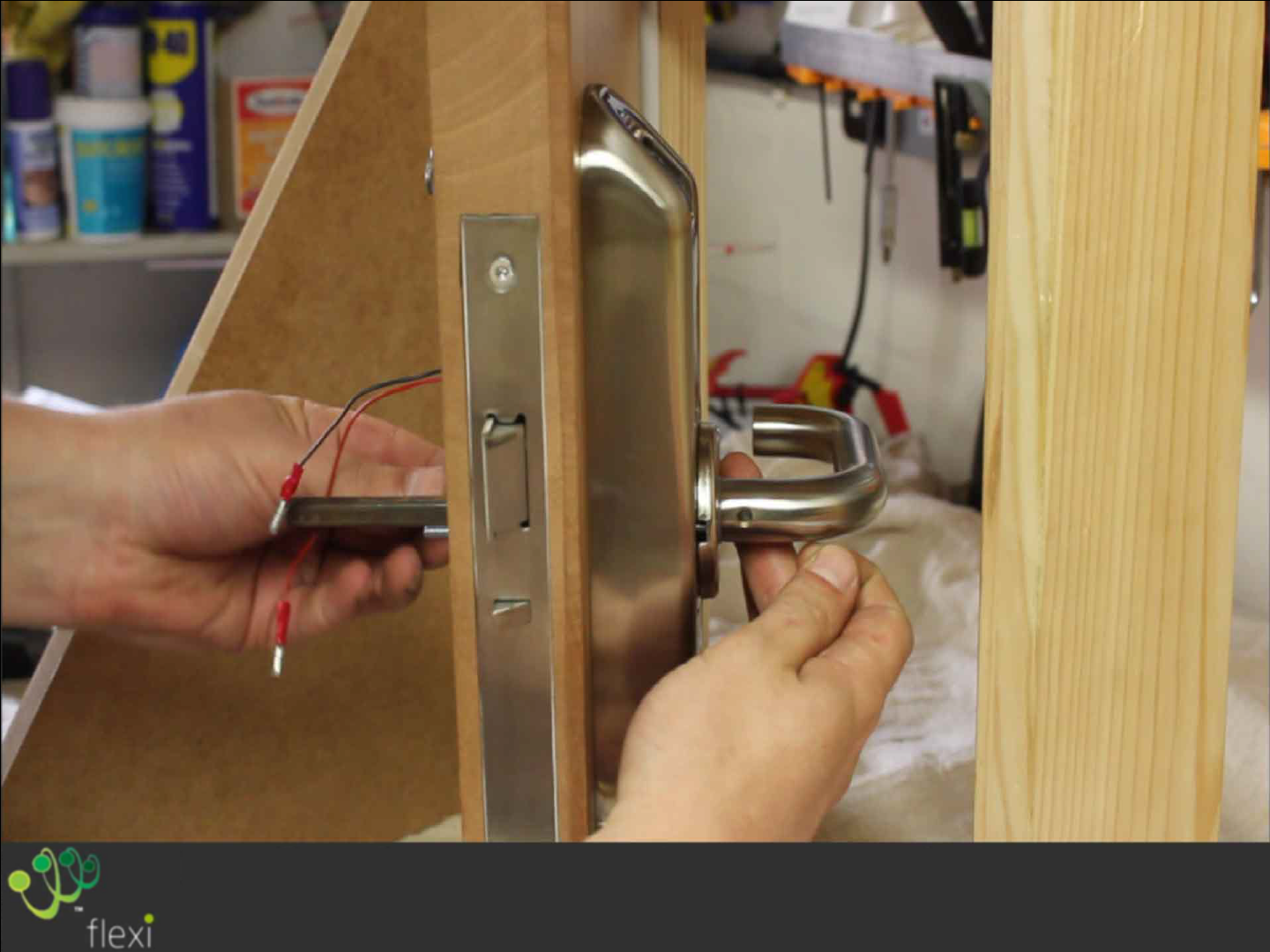
Connect the power leads from the Rear
Housing,
Ensuring correct polarity red-red, black-black.
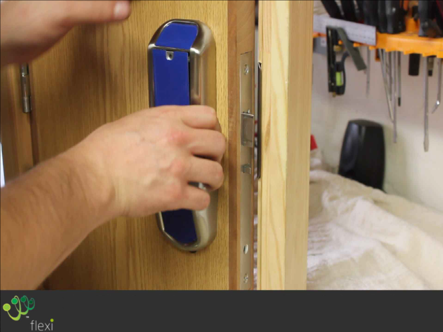
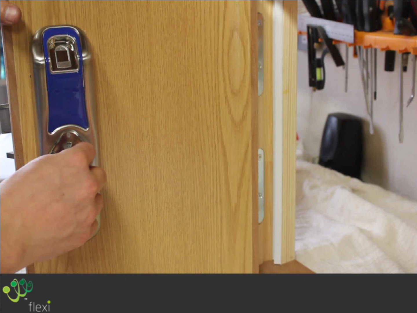
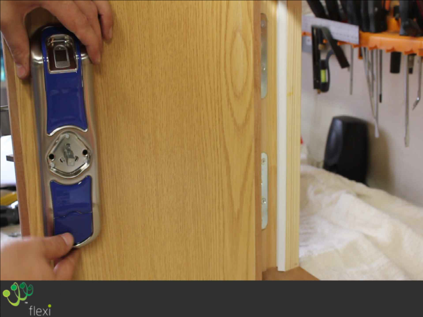
Place the housing into position, aligning the
spindle and hole. Remove Battery Hatch
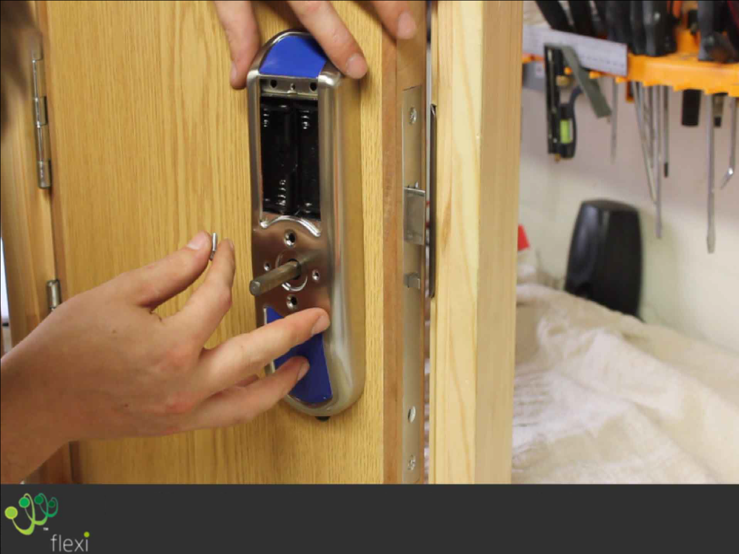
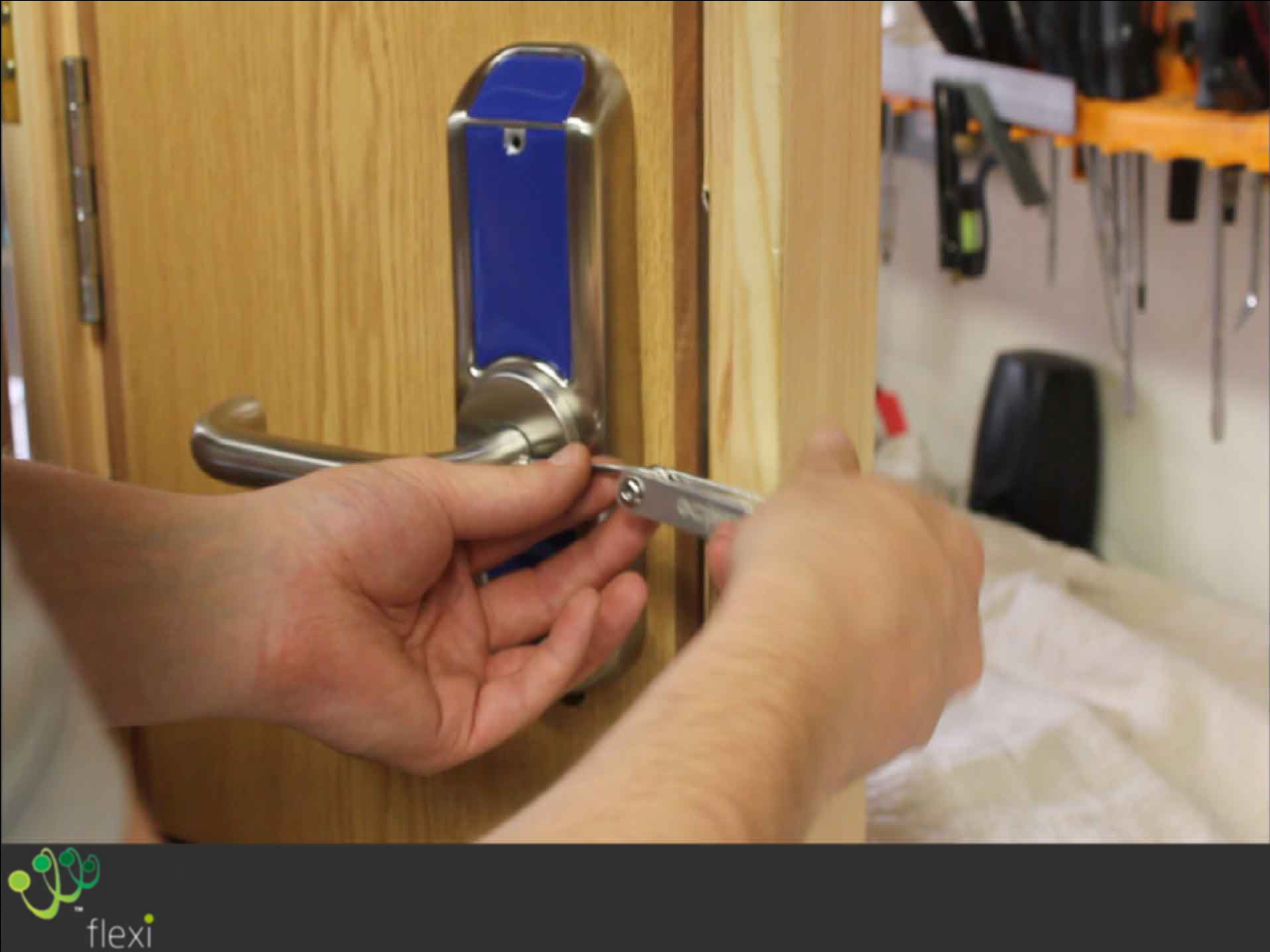
Fix the rear Housing into position using
4 M4x25 countersunk screws
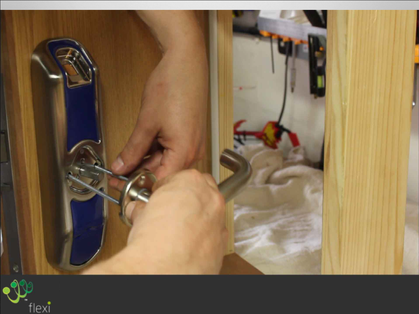
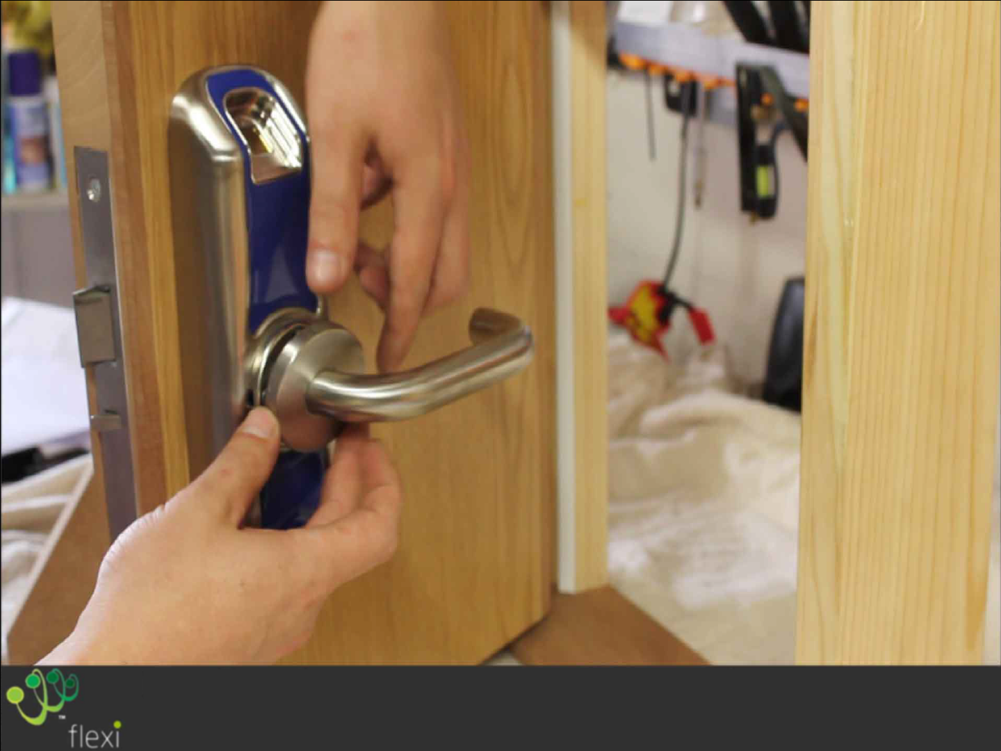
Unpack the handle and fix into the place using
two M4x12 countersunk screws.
Push Rose fascia into place, gently tap into
position with a rubber mallet if a little tight
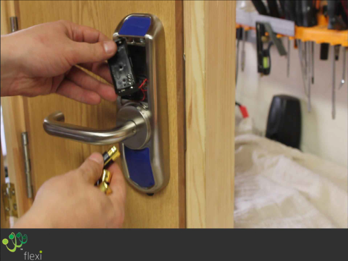
Install AA batteries ensuring correct
polarity.
Replace Battery Hatch and secure with M3x8
screw.
Replace the Handle grub screw.
Replace the Rose fascia and grub screw on the
front
of the door
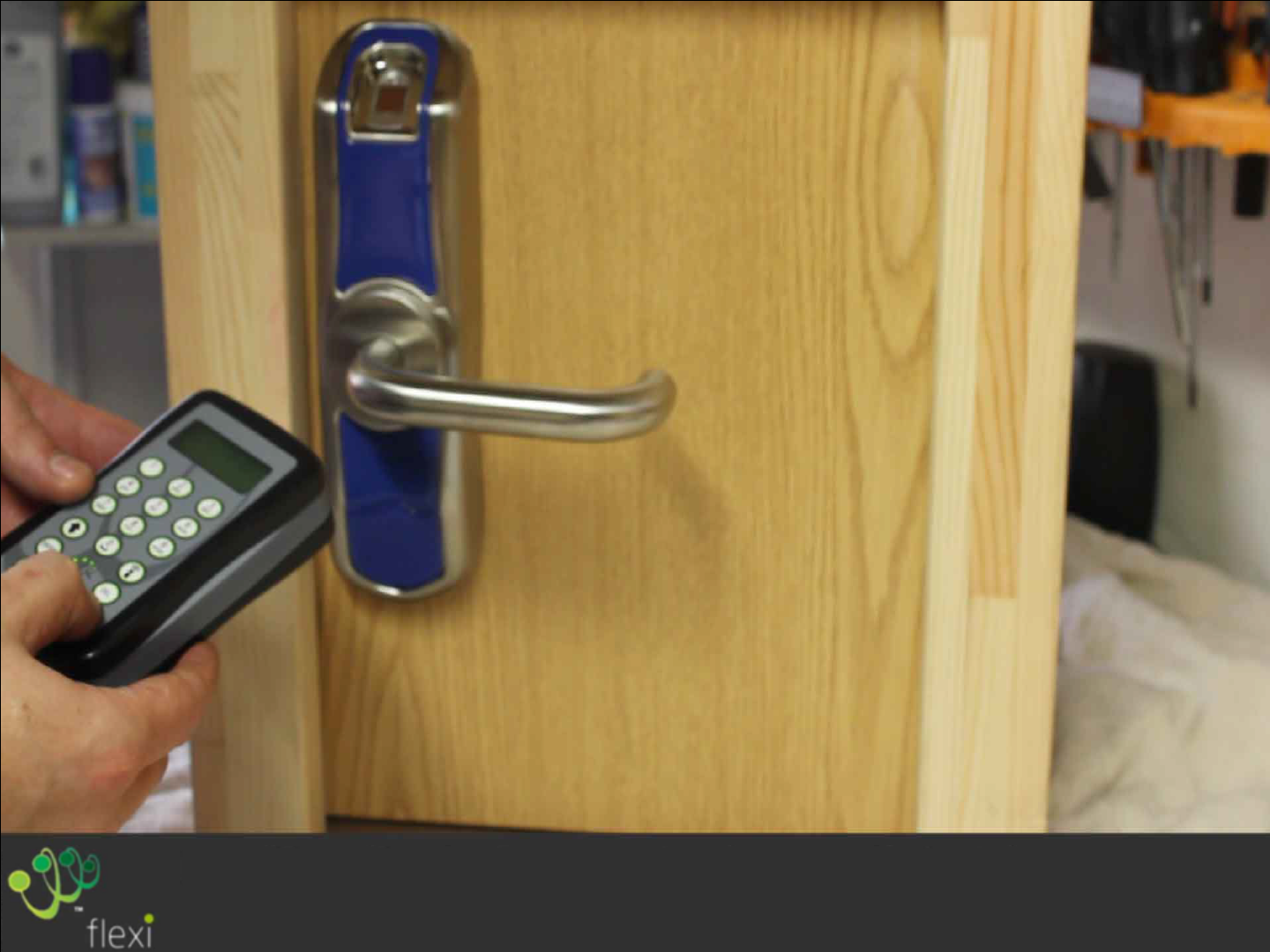
Enrol on to Flexi to ensure the
installation
has been successful.
