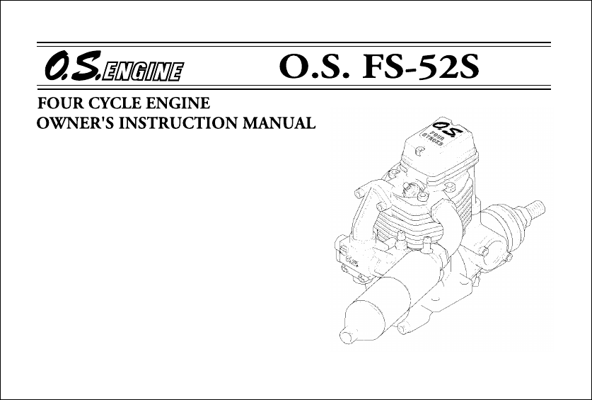
FS 52S Fs52s
User Manual: fs52s
Open the PDF directly: View PDF ![]() .
.
Page Count: 28
It is of vital importance, before attempting to
operate your engine, to read the general
'SAFETY INSTRUCTIONS AND WARNINGS'
section on pages 2-6 of this booklet and to strictly
adhere to the advice contained therein.
●Also, please study the entire contents of this
instruction manual, so as to familiarize yourself
with the controls and other features of the
engine.
Keep these instructions in a safe place so that
you may readily refer to them whenever
necessary.
It is suggested that any instructions supplied
with the aircraft, radio control equipment, etc.,
are accessible for checking at the same time.
●
●

2
~
6
7
8
9
11
13
14
~
15
15
~
16
22
23
24
25
26
10
12
SAFETY INSTRUCTIONS AND WARNINGS
ABOUT YOUR O.S. ENGINE
INTRODUCTION,BASIC ENGINE PARTS
INSTALLATION
EXHAUST HEADER PIPE AND SILENCER,
THROTTLE LINKAGE, NEEDLE-VALVE EXTENSION
PROPELLERS, FUEL
GLOWPLUG
FUEL AND PRESSURE LINES,
PROPELLER AND SPINNER ATTACHMENT
TYPE 40N CARBURETTOR,
CONTROL LOCATIONS
STARTING
CONTENTS
RUNNING -IN
IDLING MIXTURE ADJUSTMENT
VALVE ADJUSTING
CARE AND MAINTENANCE
ENGINE EXPLODED VIEW
ENGINE PARTS LIST
CARBURETTOR EXPLODED
VIEW & PARTS LIST
GENUINE PARTS & ACCESSORIES
THREE VIEW DRAWING
16
~
17
17
~
20
20
~
21
1
Remember that your engine is not a "toy", but a highly efficient internal-
combustion machine whose power is capable of harming you, or others, if it is
misused.
As owner, you, alone, are responsible for the safe operation of your engine, so act
with discretion and care at all times.
If at some future date, your O.S. engine is acquired by another person, we would
respectfully request that these instructions are also passed on to its new owner.
SAFETY INSTRUCTIONS AND WARNINGS ABOUT YOUR O.S. ENGINE
The advice which follows is grouped under two headings according to the
degree of damage or danger which might arise through misuse or neglect.
WARNINGS NOTES
These cover events which
might involve serious (in
extreme circumstances, even
fatal) injury.
These cover the many other
possibilities, generally less obvious
sources of danger, but which, under
certain circumstances, may also
cause damage or injury.
2
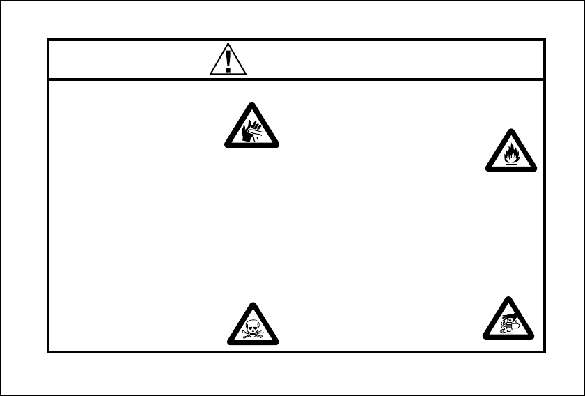
WARNINGS
Model engine fuel is poisonous. Do not
allow it to come into contact with the eyes
or mouth. Always store it in a
clearly marked container and
out of the reach of children.
Never operate your engine in an en-
closed space. Model engines, like auto-
mobile engines, exhaust deadly carbon-
monoxide. Run your engine only in an
open area.
Model engines generate considerable
heat. Do not touch any part of your
engine until it has cooled. Contact with
the muffler (silencer),
cylinder head or exhaust
header pipe, in particular,
may result in a serious burn.
•
•
•
•
Never touch, or allow any object to come
into contact with, the rotating
propeller and do not crouch
over the engine when it is
running.
A weakened or loose propeller may
disintegrate or be thrown off and, since
propeller tip speeds with powerful
engines may exceed 600 feet(180 metres)
per second, it will be understood that
such a failure could result in serious
injury, (see 'NOTES' section relating to
propeller safety).
•
Model engine fuel is also highly
flammable. Keep it away from open flame,
excessive heat, sources of sparks, or
anything else which might
ignite it. Do not smoke or allow
anyone else to smoke, near to it.
•
3

NOTES
•
•
•
•
•
This engine was designed for model
aircraft. Do not attempt to use it for any
other purpose.
Mount the engine in your model securely,
following the manufacturers' recommenda-
tions, using appropriate screws and lock-
nuts.
Be sure to use the silencer (muffler)
supplied with the engine. Frequent
exposure to an open exhaust may
eventually impair your hearing.
Such noise is also likely to cause
annoyance to others over a wide area.
Fit a top-quality propeller of the diameter
and pitch specified for the engine and
aircraft. Locate the propeller on the shaft so
that the curved face of the blades faces
forward-i.e. in the direction of flight. Firmly
tighten the propeller nut, using the correct
size wrench.
If you remove the glowplug from the engine
and check its condition by connecting the
battery leads to it, do not hold the plug with
bare fingers.Use an appropriate tool or a
folded piece of cloth.
4
NOTES
•
•
Always check the tightness of the propeller
nut and retighten it, if necessary, before
restarting the engine, particularly in the
case of four-stroke-cycle engines. If a
safety locknut assembly is provided with
your engine, always use it. This will prevent
the propeller from flying off in the event of a
"backfire", even if it loosens.
If you fit a spinner, make sure that it is a
precision made product and that the slots
for the propeller blades do not cut into the
blade roots and weaken them.
Preferably, use an electric starter. The
wearing of safety glasses is also strongly
recommended.
•
•Discard any propeller which has become
split, cracked, nicked or otherwise rendered
unsafe. Never attempt to repair such a
propeller: destroy it. Do not modify a propeller
in any way, unless you are highly experienced
in tuning propellers for specialized
competition work such as pylon-racing.
Take care that the glow plug clip or battery
leads do not come into contact with the
propeller. Also check the linkage to the
throttle arm. A disconnected linkage could
also foul the propeller.
After starting the engine, carry out any
needle-valve readjustments from a safe
position behind the rotating propeller. Stop
the engine before attempting to make other
adjustments to the carburettor.
•
•
5

NOTES
•
•
•
•
•
Adjust the throttle linkage so that the engine
stops when the throttle stick and trim lever
on the transmitter are fully retarded.
Alternatively, the engine may be stopped by
cutting off the fuel supply. Never try to stop
the engine physically.
Take care that loose clothing (ties, shirt
sleeves, scarves, etc.)do not come into
contact with the propeller.Do not carry loose
objects (such as pencils, screwdrivers, etc.)
in a shirt pocket from where they could fall
through the propeller arc.
Do not start your engine in an area
containing loose gravel or sand.
The propeller may throw such material in
your face and eyes and cause injury.
For their safety, keep all onlookers
(especially small children) well back (at
least 20 feet or 6 meters) when preparing
your model for flight. If you have to carry
the model to the take-off point with the
engine running, be especially cautious.
Keep the propeller pointed away from you
and walk well clear of spectators.
Warning! Immediately after a glowplug-
ignition engine has been run and is still
warm, conditions sometimes exist whereby
it is just possible for the engine to abruptly
restart if the propeller is casually flipped
over compression WITHOUT the glowplug
battery being reconnected. Remember this
if you wish to avoid the risk of a painfully
rapped knuckle!
6
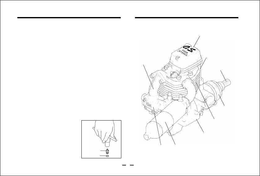
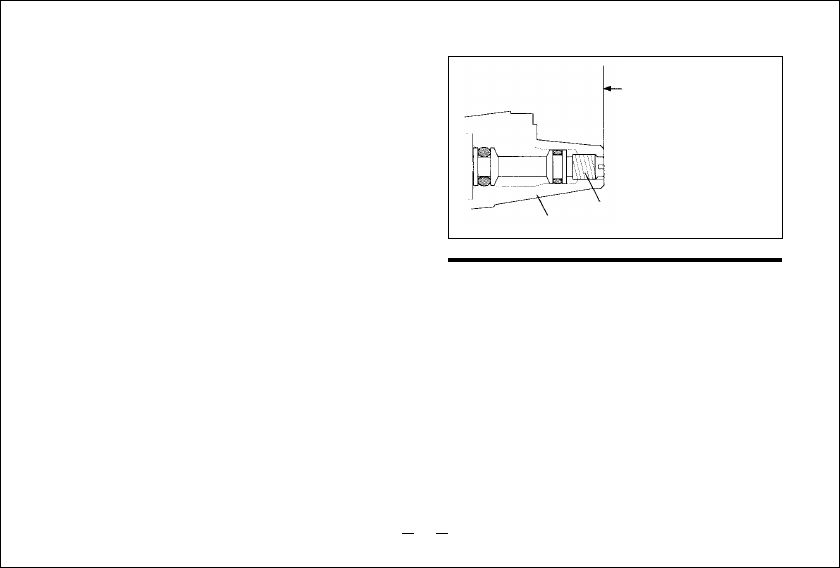
INSTALLING THE GLOWPLUG
Carburettor
Fit washer to glowplug and
insert carefully into cylinder-
head, making sure that it is
not cross-threaded
before tightening firmly.
BASIC ENGINE PARTS
Having pioneered the development of four-
stroke cycle model aircraft engines in 1976,
O.S. has maintained a continuing program of
technological advancement, examples of
which, would include the line of beautiful
multi-cylinder engines, with many new
engine designs continually under
development. One of the latter is this new FS-
52S model. Closely resembling the FS-48S
externally, the FS-52S combines increased
performance and improved durability at
virtually no increase in overall dimensions or
weight.
Crankshaft
Glow plug
Washer
Drive Hub
Crankcase
Beam Mount
Silencer
Rocker Cover
INTRODUCTION
Push Rod Cover
Intake Pipe
7
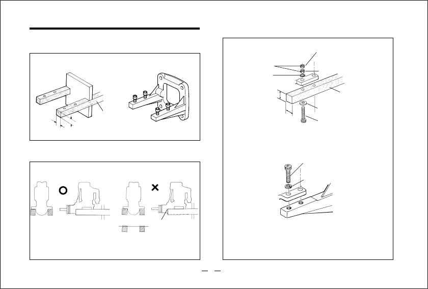
INSTALLATION How to fasten the mounting screws.
Hardwood mounting beams
O.S. radial motor mount
(cast aluminum)
Tighten second nut firmly
down onto first nut.
Tighten this nut first.
Steel washer
3.5mm steel nuts
3.5mm steel screw
Spring washer or
lock washer
15mm min.
15mm min.
Hardwood such as
cherry or maple.
Spring washer
3.5mm steel Allen screw
Front view
CORRECT
Side view
Top surfaces are in the same plane.
Re-align the surfaces
as necessary
INCORRECT
Top surfaces are not
in the same plane. Opposite beam
Top surfaces
are not in the
same plane.
Engine does
not rest firmly.
Rigid hardwood
(e.g. maple)
At least
15mm(19/32")
At least
15mm(19/32")
Installation in the model
A typical method of beam
mounting is shown below,left.
O.S. radial motor mount
(Available as an optional extra part.
See parts list)
Make sure that the mounting beams are parallel
and that their top surfaces are in the same plane.
8

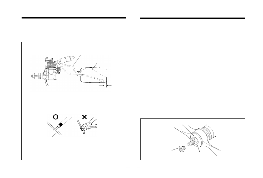
NEEDLE-VALVE EXTENSION
The needle-valve supplied with this engine is
designed to accept an extension so that, when the
engine is enclosed in a cowling, the needle-valve may
be adjusted from the outside.
An L-shaped rod, of appropriate length, may be
inserted in the needle-valve knob center hole and
secured by tightening the set-screw with a 1.5mm
Allen key.
Before connecting the throttle to the servo, make sure
that the throttle arm and linkage safely clear any
adjacent part of the airframe structure, etc., as the
throttle is opened and closed.
Connect the linkage so that the throttle is fully closed
when the transmitter throttle stick and its trim lever
are at their lowest settings and fully open when the
throttle stick is in its fully-open position..
Carefully align the appropriate holes in the throttle
arm and servo horn so that they move symmetrically
and smoothly through their full travel.
Fit these in the following sequence.
Screw the header pipe into the cylinder head until it
bottoms, then unscrew sufficiently to achieve the
desired exhaust angle and tighten the locknut securely
with a 14mm wrench. Screw the silencer onto the outer
end of the header pipe and tighten the second locknut.
The application of a heatproof silicone sealant to the
threads of the exhaust system is recommended to
reduce the risk of joints loosening and the leakage of
exhaust gases and oil residue.
Reminder:
Model engines generate considerable heat and
contact with the header pipe or silencer may result in
a serious burn. If you need to tighten the silencer
joints, which may loosen when they are hot, use a
thick folded cloth for protection.
EXHAUST HEADER PIPE & SILENCER
THROTTLE LINKAGE
9

Model engine fuel is poisonous. Do not
allow it to come into contact with the eyes or
mouth. Always store it in a clearly marked
container and out of the reach of children.
Reminder!
FUEL
The FS-52S is should be operated on a methanol
based fuel containing not less than 18% castor-oil, or
a top quality synthetic lubricant (or a mixture of both),
plus a small percentage (5-15%) of nitromethane for
improved flexibility and power. The carburettor is
adjusted at the factory for a fuel containing 20%
lubricant and 10% nitromethane. Some commercial
fuels also contain color additives as an aid to fuel
level visibility. In some cases, these additives have
indicated slightly negative effects on performance.
We would suggest that you use such fuels only if you
are satisfied that they do not adversely affect running
qualities when compared with familiar standard fuels.
When changing to a fuel brand or formula that is
different from the one to which you are accustomed, it
is a wise precaution to temporarily revert to in-flight
running-in procedures, until you are sure that the
engine is running entirely satisfactorily.
The choice of propeller depends on the design and
weight of the aircraft and on the type of flying in which
you will be engaged. Determine the best size and type
after practical experimentation. As a starting point,
refer to the props listed in the accompanying table.
Slightly larger, or even slightly smaller, props than
those shown in the table may be used, but remember
that propeller noise will increase if the blade tip
velocity is increased or a larger-diameter / smaller-
pitch prop used.
PROPELLERS
Type Size (DxP)
Stunt planes 10x9-10, 10.5x8-9, 11x7-8
11x7-8, 12x6, 12.5x6
Scale models
Make sure that the propeller is well balanced. An
unbalanced propeller and / or spinner can cause
serious vibration which may weaken parts of the
airframe or affect the safety of the radio-control
system.
Warning:
10

Model engine fuel is also highly flammable.
Keep it away from open flame, excessive heat,
sources of sparks, or anything else which
might ignite it.
GLOWPLUG
The role of the glowplug
Glowplug life
Particularly in the case of very high performance
engines,
glowplugs must be regarded as expendable
Install a plug suitable for the engine.
Use fuel containing a moderate percentage of
nitromethane unless more is essential for racing
events.
Do not run the engine too lean and do not leave the
battery connected while adjusting the needle.
However, plug life can be extended and engine
performance maintained by careful use, i.e.:
With a glowplug engine, ignition is initiated by the
application of a 1.5-volt power source. When the
battery is disconnected, the heat retained within the
combustion chamber remains sufficient to keep the
plug filament glowing, thereby continuing to keep the
engine running. Ignition timing is 'automatic' : under
reduced load, allowing higher rpm, the plug becomes
hotter and, appropriately, fires the fuel/air charge
earlier; conversely, at reduced rpm, the plug become
cooler and ignition is retarded.
Apart from when actually burned out, a plug may
need to be replaced because it no longer delivers its
best performance, such as when:
When to replace the glowplug
Filament surface has roughened and turned white.
Filament coil has become distorted.
Foreign matter has adhered to filament or plug
body has corroded.
Engine tends to cut out when idling.
Starting qualities deteriorate.
•
•
•
•
•
•
•
The FS-52S is supplied with an O.S. Type F glowplug,
specially designed for O.S. four-stroke engines.
•
11
FUEL AND PRESSURE LINES
Fuel level
Muffler to tank pressure line
Connect suitable lengths of silicone tubing, as
illustrated, after installing the engine.
Attention to tank height
Note: When cutting silicone tubing···
Locate the fuel tank so the top of the tank is
5-10mm(1/4-3/8") above the level of theneedle-valve.
5-10mm
Silicone tubing
Use knife or razor blade
Do not use wire cutters
or pliers.
*If you should need to clean out silicone tubes, use methanol
or glow-fuel, not gasoline or kerosene.
PROPELLER & SPINNER ATTACHMENT
Fit the prop to the engine shaft, followed by the
retaining washer and prop nut and tighten firmly
with a 14mm wrench.
Add the special tapered and slotted locknut and
secure with a 12mm wrench while holding the
prop nut with the 14mm wrench.
There is a risk, particularly with powerful four-stroke
engines, of the propeller flying off if the prop nut
loosens due to detonation ("knocking") in the
combustion chamber when the engine is operated
too lean, or under an excessively heavy load.
Obviously, this can be very hazardous. To eliminate
such dangers, the O.S. Safety Locknut Assembly was
devised. Fit this as follows:
Lock Nut
Propeller Washer
Propeller Nut
1.
2.
12
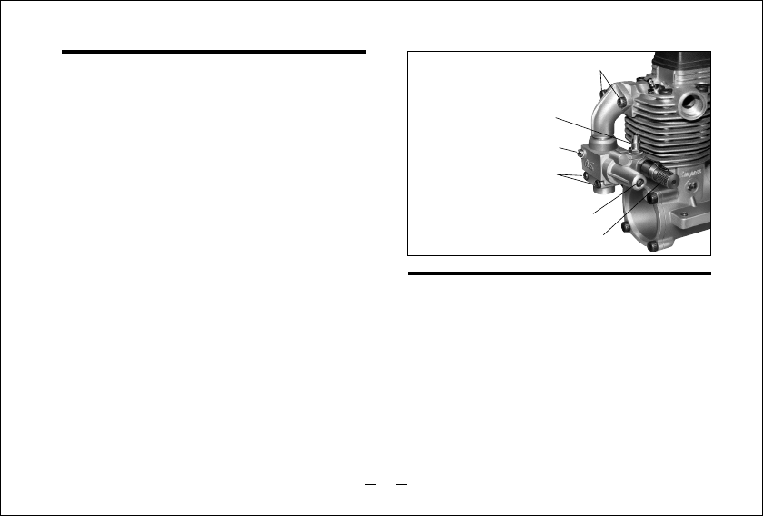
Two adjustable controls are provided on this
carburettor.
They are as follows:
TYPE 40N CARBURETTOR
The Needle Valve
This is used to establish the fuel/air mixture strength
required for full power when the throttle is fully
open.
The Idle Mixture Control Screw
This is used to establish the mixture strength
required for steady idling and a smooth transition to
medium speeds. (The varying mixture strength
required between part-throttle and full-throttle
running is automatically adjusted by coupled
movement of the throttle.)
The sequence in which these controls are adjusted is
explained in the succeeding sections, under Starting,
Running-in and Idling Adjustment.
•
•
Intake pipe retaining screws
Rotor Guide screw
Fuel Inlet
Carburetor retaining screw
Idle Mixture Control Valve
Needle Valve
CONTROL LOCATIONS
The needle-valve and throttle locations, left and right,
are interchangeable by reversing the carburettor. This
can be done as follows. Carefully free the carburettor
by removing the two screws that join the carburettor
body to the crankcase cover-plate and by loosening
the two screws securing the intake pipe flange to the
cylinderhead. Gently rotate the carburettor,180
degrees, on the intake pipe, taking care not to
damage the O-ring then Replace the screws.
13

STARTING
The FS-52S is not fitted with a manual choke control,
since it has been designed for use with an electric
starter only.
A high-torque electric starter not only makes starting the
engine much easier, it dispenses with the need for a
choke valve by rotating the engine fast enough to cause
the fuel pump to prime the cylinder automatically.
Check that the current to the glowplug is switched
off.
Check that the polarity of the starter battery leads
rotates the engine counter-clockwise when viewed
from the front.
Open the needle-valve 2-2.5 turns from the fully
closed position and temporarily set the throttle in the
fully open position.
Apply the starter and press the starter switch for 5-
6 seconds, or until fuel is seen to emerge from the
exhaust outlet, indicating that the cylinder is now
primed.
Close the throttle-arm to within
15-20°of the fully closed
position and slowly turn the
prop "backwards" (clockwise)
by hand approximately 1.5
turns until it is arrested by
compression.This is to enable
the kinetic energy of the prop
to subsequently assist the starter through the
compression stroke to start the engine.
1.
2.
3.
4.
5.
6.
Check these conditions and, instead of pressing
the starter button after applying the starter, have
the starter spinning before applying it to the
engine, to give it a "running start".
When the engine starts, slowly open the throttle,
leaving the needle-valve at its rich starting setting
to promote cool running conditions.
However, if the engine slows down because the
mixture is excessively rich, the needle-valve may
be closed a little to speed it up until it runs evenly.
7.
Close Open
1/4 Starting position
Energize the glowplug and apply the starter. If the
starter fails to rotate the engine completely, this
may be due to the cylinder being over-primed, or to
the starter battery being insufficiently charged.
14

8.Now disconnect current to the glowplug and
gradually close the needle-valve so that the rpm
increases. Make adjustments to the needle in small
steps. Abrupt changes at this stage are likely to
cause the engine to stall. Restart the engine by
simply applying the starter with the glowplug re-
energized and the throttle at its starting setting.
RUNNING-IN ("Breaking-in")
For long life expectancy and maximum performance
every engine requires a break-in period under
controlled conditions in order to avoid over-heating
that could damage the internal parts while they are
being smoothed and polished together.
With some engines, this can require a tediously
protracted period of bench running, but, as O.S.
engines are manufactured to fine tolerances and from
the finest quality materials, a relatively brief running-
in period is sufficient and can be completed with the
engine installed in the aircraft.
Start and adjust the engine as detailed in the starting
instructions.
Now open the throttle fully and run the engine for no
more than 5 seconds with the needle-valve tuned to
produce near maximum r.p.m., then, immediately,
slow the engine down again by opening the needle-
valve approximately 1/2 turn. The rich mixture, will
cool the engine, at the same time providing ample
lubrication.
Allow the engine to run like this for about 10
seconds, then close the needle-valve again to
speed it up to near maximum speed for another 5
seconds.
Repeat this process, alternately running the engine
fast and slow by means of the needle-valve, while
keeping the throttle fully open, then begin to extend
the short periods of high-speed operation until two
full tanks of fuel have been consumed.
WARNING:
When ground running the engine, avoid dusty or
sandy locations. If dust or grit is drawn into the
engine, this can have a damaging effect, drastically
shortening engine life in a matter of minutes.
1.
2.
3.
4.
The recommended procedure is as follows :
15

Following the initial running-in session, check for
any looseness in the installation due to vibration,
then allow the engine a period of moderately rich
operation in flight.
For the first flight, have the needle-valve set on the
rich side and adjust the throttle trim on the
transmitter so that the engine does not stop when
the throttle is closed to the idling setting.
5.
6.
RUNNING-IN (continued)
With each successive flight, close the needle-valve
very slightly until, at the end of about 10 flights, the
needle is set for full power. Do not "over-lean" the
mixture in an attempt to extract more power.
If overheating should be suspected at any time
during flight (i.e.if the engine begins to labor)
reduce power by partially closing the throttle and
land the aircraft and reset the needle valve for a
richer setting.
7.
8.
Once the engine has demonstrated that it can be
safely operated at full power, the carburettor can
be adjusted for optimum throttle response,
following the instructions given in the next section.
Note:
Remember that, when the engine is not yet fully
run-in, the carburettor cannot be expected to give
its best response in flight. Abrupt operation of the
throttle, for example, may cause the engine to
stall.
9.
Therefore, at this time ,the aircraft should, as far
as is possible, be flown at an altitude sufficient to
enable an emergency landing to be safely made if
the engine stops.
Start the engine, open the throttle fully and set the
needle-valve slightly rich (30-45°) from the highest
r.p.m. setting.
Close the throttle to the idling position. Allow the
engine to idle for about 5 seconds, then reopen the
throttle. The engine should accelerate smoothly
back to full speed.
If, instead, the engine responds sluggishly and
emits an excess of white smoke from the exhaust,
the idling mixture is too rich. Turn the mixture
control screw approx. 45° clockwise to lean the
idling mixture.
IDLING MIXTURE ADJUSTMENT
1.
2.
3.
16
In paragraphs 3 and 4 above, the 45° total
movements are, of course, approximate. It will be
necessary to fine-tune the mixture control screw
10-15° at a time to reach the best setting for
optimum throttle response.
Continue re-checking the idling mixture setting until
the engine responds smoothly and positively to
operation of the throttle at all times.
4.
5.
6.
On the other hand, if the engine hesitates before
picking up speed or even ceases firing completely,
the idling mixture is likely to be too lean. Turn the
mixture control valve 90° counter-clockwise to
substantially richen the mixture, then back again
45° clockwise.
In the course of making readjustments, it is just
possible that the mixture control screw may be
inadvertently screwed in or out too far and thereby
moved beyond its effective range.
Its basic position can be found by first rotating the
Mixture Control Valve unit its slotted head is flush
with the carburettor body. The valve is then screwed
in exactly 1 turn to re-establish the original setting.
Realignment of Mixture Control Screw
First rotate the Mixture
Control Valve until its
slotted head is flush
with the carburettor body.
Mixture Control Valve
Carburettor Body
VALVE ADJUSTING
ALL O.S. four-stroke engines have their valve(tappet)
clearances correctly set before they leave the factory.
However, if, after many hours of running time have
been logged, a loss of power is detected, or if the
engine has to be disassembled or repaired as a result
of an accident, valve clearances should be checked
and readjusted, as necessary an O.S. Valve Adjusting
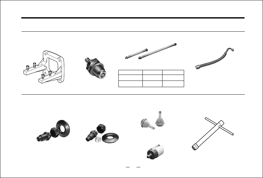
Tool Kit is available as an optional accessory.
17
• Feeler gauge 0.04mm
The kit comes in a plastic case and includes:
(Code No.72200060)
• Feeler gauge 0.1mm
• Hex. key 1.5mm
• Wrench 5mm
Note:
Valve clearances of all O.S. four-stroke-cycle
engines must be checked and reset ONLY WHEN
THE ENGINE IS COLD.
Procedure is as follows:
Remove the cover from the rocker-box on top of the
cylinderhead, using the correct size Allen hex key.
1.
(1)
Turn the propeller counter-clockwise until
compression is first felt, then turn it futher quarter
turn. At this point, both valves should be closed. (If
the prop driver ('drive hub') of your engine is
engraved with a letter 'T', this mark should now be
at the top.)
2.
The standard valve clearance, on both inlet and
exhaust valves, is between 0.04mm and
0.10mm(0.0015-0.004 inch), measured between
valve stem and rocker arm. Use the 0.04mm and
0.10mm feeler gauges to check clearances.
(See Fig.1.)
3.
Note:
If the gap is found to be less than 0.04mm, it is
not necessary to readjust the clearance if the
engine has good compression and starts easily.
Equally, if the gap exceeds 0.10mm but is not
more than 0.14mm (i.e. the thickness of both
feeler gauges inserted together), it is not
necessary to readjust the clearance if the engine
runs satisfactorily.
Fig.1
0.04mm
Feeler Gauge
Rocker Arm
Valve
18
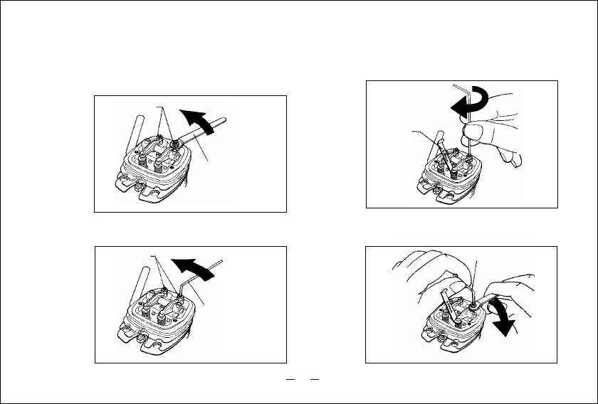
If a clearance is found to be outside either of
these limits, it should be reset as follows.
Carefully loosen the locknut on rocker-arm 1/4-1/2
turn with 5mm wrench. (Fig.2.)
1.
2.
3.
Wrench
Slacken approx.
1/4 to 1/2 turn.
Turn adjusting-screw approx. 1/2 turn counter-clockwise
to open gap, using appropriate tool -i.e. Allen hex key.
(Fig.3.)
Fig.2
Fig.3
Fig.4
Adjusting
Screw Turn approx.
1/2 turn.
Allen Key
Insert 0.04mm feeler gauge between valve stem
and rocker-arm and gently turn adjusting screw
clockwise until it stops.(Fig.4.)
0.04mm Feeler
Gauge
Turn with fingers
until it stops.
Locknut
Re-tighten locknut while holding adjusting screw
stationary. (Fig.5.)
4.
Hold at the screw head.
Fig.5 Tighten Locknut.
19
(2)

Remove 0.04mm feeler, rotate prop through two
revolutions and recheck gap.
5.
If clearance is correct, loosen the locknut on the
other rocker-arm and repeat steps 1 to 5 above.
Finally, replace rocker box cover.
6.
Remember:
Excessive valve clearance will cause loss of
power, due to valve (s) not opening sufficiently.
On the other hand, a total loss of clearance may
cause difficult starting due to valves not closing
properly, resulting in loss of compression.
CARE AND MAINTENANCE
Please pay attention to the matters described below
to ensure that your engine serves you well in regard
to performance, reliability and long life.
As previously mentioned, it is vitally important to
avoid operating the engine in conditions where dust,
stirred up by the propeller will be ingested into the
engine resulting in damage to the internal parts. Also,
remember to keep your fuel container closed to
prevent foreign matter from contaminating the fuel.
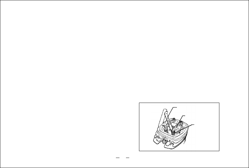
Do not forget to clean the fuel filters periodically and,
from time to time, unscrew the complete needle-valve
assembly from the carburettor and remove any
foreign matter that has accumulated in this area. (See
photo.) If these precautions are neglected, restriction
of fuel flow may cause the engine to cut out, or the
fuel/air mixture to become too lean, causing the
engine to overheat. The use of modern high-
performance alcohol based model engine fuels, while
promoting cooler running, improved anti-detonation
combustion and increased power, have the
disadvantage in four-stroke engines, of a tendency to
cause bottom end corrosion if not checked. This is
because the acidic by-products of combustion, some
of which contaminate the oil in the crankcase, are not,
in a four-stroke, diluted and flushed out by the flow of
fresh fuel mixture through the crankcase as in the case
of a two-stroke engine. Such contamination (made
worse if the fuel also contains a high proportion of
power boosting nitromethane) can cause rusting of
steel parts. As noted earlier, the FS-52S has its most
vulnerable internal parts protected against such attack
but, as a primary defence, users are advised, once
again, to avoid running the engine on too lean a
mixture and by making sure that the engine is flushed
20

of contaminants as much as possible.
Do not leave unused fuel in the engine at the
conclusion of a day's flying. Accepted practice is to
cut off the fuel supply while the engine is still running
- at full throttle - then, to eliminate as much residue
as possible rotate the engine for 5-10 seconds with
the electric starter.
Finally, inject some after-run oil through the glowplug
hole and turn the engine over several times by hand.
When the engine is not to be used for some months
(for example, as between flying seasons) a
worthwhile precaution is to remove it from the
airframe and, after washing off the exterior with
alcohol (not gasoline or kerosene) to carefully remove
the fuel pump, carburettor with intake pipe and all
silicone tubing and put them safely aside.
Make sure that the engine is reasonably clean
externally, then remove the glowplug and immerse
the engine in a container of kerosene. Rotate the
crankshaft while the engine is immersed. If foreign
matter is visible in the kerosene, rinse the engine
again in clean kerosene, shake off the excess and
wipe it dry.
CARE & MAINTENANCE (continued)
The fuel pump assembly, carburettor/pressure-
regulator and silicone tubing must be cleansed
separately in methanol or glow fuel. On no account
must they come into contact with kerosene.
Before completely reassembling the engine, make
sure that no kerosene remains inside that could find
its way into the pump unit, carburettor, etc. Inject,
sparingly, after-run oils, rust inhibitors, etc. unless
approved for silicone-rubber products.
An appropriate alternative here may be one of the
high-quality synthetic lubricating oils.
Finally, seal the engine in a heavy polyethylene bag
until required for future use.
Debris tends to
accumulate in
this area
21
ENGINE EXPLODED VIEW
✽Type of screw
C…Cap Screw B…Binding Head Screw M…Oval Fillister-Head Screw
F…Flat Head Screw N…Round Head Screw S…Set Screw
i
u
y
t
r
e
w
q
=
-
0
9
8
1
3
2
1
o
o
p
[
]
\
a
sd
5-3 5-2
5-1
1-2
1-1
3-2
3-1
5
7
6-4
6-3
6-2
6-1
7-1
0-2
0-1
f
\-1
\-2
\-2
5-4
6
d-1
(C.M3X12)
C.M3X18
C.M2.6X12
C.M2.6X7
N.+M2.6X19
C.M3X8
C.M2.6X7
22

Specifications are subject to alteration for improvement without notice.
2 6531 005
4 5664 000
2 4881 824
4 5866 110
4 5866 100
4 4266 000
4 5801 100
4 4262 000
4 5231 100
2 2681 953
4 4201 000
i
4 4230 000
u
4 4202 000
4 4207 000
y
4 5803 100
t
r
4 5205 000
e
w
4 5806 000
q
4 5803 200
=
4 4203 400
-
2 2025 807
0
4 5115 000
9
4 4281 000
4 4204 000
8
4 5814 100
7
4 4261 100
6
4 4261 000
5
-4
4 6160 400
5
-3
4 5060 309
5
-2
4 4260 200
5
-1
4 4260 100
5
4 4260 000
4
-2
4 5761 200
4
-1
4 5261 110
4
4 5261 010
3
-2
4 5761 600
3
-1
4 5261 410
3
4 5261 400
2
4 4204 200
1
4 5813 000
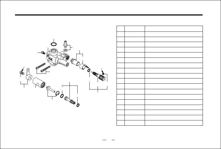
No. Description
Code No.
o
p
[
]
\
a
s
d
f
4 4260 200
4 5060 309
4 6160 400
4 4269 400
-1
-2
4 5808 000
2 7708 200
4 5810 100
0
-1
4 4204 100
Screw Set
Rocker Cover
Rocker Support Assembly
Rocker Support
Rocker Arm Retainer (2pcs.)
Rocker Arm Assembly (1pair)
Rocker Arm (1pc.)
Tappet Adjusting Screw
Intake Valve Assembly (1pair)
Intake Valve (1pc.)
Valve Spring (1pc.)
Valve Spring Seat (1pc.)
Valve Spring Retainer (2ps.)
Exhaust Valve Assembly(1pair.)
Exhaust Valve(1pc.)
Valve Spring(1pc.)
Valve Spring Seat(1pc.)
Valve Spring Retainer(1pc.)
Cylinder Head
Cylinder Head Gasket
Cylinder Head Assembly
Intake Pipe Assembly
Carburetor Complete Type 40N
Carburetor Gasket
Carburetor Retaining Screw (2pcs.)
Piston Ring
Piston
Piston Pin
Connecting Rod
Cylinder Liner
Cover Plate
Crankshaft
Crankshaft Ball Bearing (Rear)
Crankcase
Breather Nipple
Camshaft Bearing(1pc.)
Camshaft
Cam Cover
Push Rod (2pcs.)
Push Rod Cover Assembly (2pcs.)
Push Rod Cover (1pcs.)
Push Rod Cover “O“Ring (2pcs.)
Cam Follower (2pcs.)
Crankshaft Ball Bearing (Front)
Drive Hub
Woodruff Key
Lock Nut Set
Glow Plug Type F
Silencer Assembly Type F-3020
Silencer Body
Pressure Fitting
Exhaust Header Pipe Assembly
6
-1
6
-2
6
-3
6
-4
7
-1
0
-2
\
\
-1
d
7 1615 009
4 4225 000
4 4225 100
2 2681 957
4 4226 000
PARTS LIST
23
✽Type of screw
C
…
Cap Screw B
…
Binding Head Screw M
…
Oval Fillister-Head Screw
F
…
Flat Head Screw N
…
Round Head Screw S
…
Set Screw
-
0
9
8
4
3
2
14-1
5
7
0-2
0-1
6
1-1
4-2
9-1
0-3
N.+M3X6 S.M3X3
CARBURETOR EXPLODED VIEW & PARTS LIST
2 2681 953
6
7
8
9
9-1
0
0-1
0-2
0-3
-
4 5115 000
4 4281 100
2 4881 824
5
4 6066 319
44 4281 600
34 4281 960
24 4281 200
1-1 2 2081 313
12 2081 408
2 1285 220
Specifications are subject to alteration for improvement without notice.
No. Description
Code No.
Throttle Lever Assembly
Throttle Lever Retaining Screw
Carburetor Rotor
Nozzle Assembly
Mixture Control Screw Assembly
"O" Ring(L)(2pcs.)
"O" Ring(S)(2pcs.)
Rotor Guide Screw
Carburetor Body
Carburetor Rubber Gasket
Fuel Inlet
Needle-valve Holder Assembly
Ratchet Spring
Needle-valve Assembly
Needle
"O" Ring(2pcs.)
Set Screw
Carburetor Retaining Screw(2pcs.)
4-1
4-2
2 7381 940
2 6711 305
4 4281 900
4 4281 970
2 4981 837
2 6381 501
2 2025 807
24
■
■
■
(458102000) (71521000)
■
(45810300)
■
PARTS & ACCESSORIES
Locknut Set for Spinner
Radial Mount Set
Long Socket Wrench With
Plug Grip
1/4"-M5
Locknut Set
Bubble Eliminating
Tank Weight
(71615009)
O.S.Glow Plug
TYPE F
(71531000)
■
(71913000)
■
(45226000)
Exhaust Header Pipe
Assembly
■Flexible Exhaust Pipes
72108300
72108310
1010A
1010B
120
240
Type Length (mm)
Code.No.
■
(72108400)
Exhaust Header
Pipe 52S(IN-COWL)
■Super Filter(L)
(72403050)
25
THREE VIEW DRAWING
■
■
■
■
■
■
8.56cc (0.523cu.in.)
23.0mm (0.906in.)
20.6mm (0.811in.)
2,300
~
13,000r.p.m.
0.9bhp/12,000r.p.m.
434g (15.31oz.)
Dimension(mm)
Specification
Displacement
Bore
Stroke
Practical R.P.M.
Power output
Weight
26

C
Copyright 2000 by O.S.Engines Mfg. Co., Ltd. All rights reserved. Printed in Japan.
U
N
E
Q
U
A
L
L
E
D
Q
U
A
L
I
T
Y
P
R
E
C
I
S
I
O
N
&
P
E
R
F
O
R
M
A
N
C
E
E
S
T
A
B
L
I
S
H
I
N
G
T
H
E
S
T
A
N
D
A
R
D
S
O
F
E
X
C
E
L
L
E
N
C
E
100101
TEL. (06) 6702-0225
FAX. (06) 6704-2722
6-15 3-Chome Imagawa Higashisumiyoshi-ku
Osaka 546-0003, Japan
URL : http://www.os-engines.co.jp
