5HP Cyclone G0442 M
User Manual: 5HP Cyclone G0442
Open the PDF directly: View PDF ![]() .
.
Page Count: 60
COPYRIGHT © APRIL, 2010 BY GRIZZLY INDUSTRIAL, INC., REVISED NOVEMBER, 2017 (HE)
WARNING: NO PORTION OF THIS MANUAL MAY BE REPRODUCED IN ANY SHAPE
OR FORM WITHOUT THE WRITTEN APPROVAL OF GRIZZLY INDUSTRIAL, INC.
#TS12622 PRINTED IN TAIWAN
MODEL G0442/G0601
5 HP CYCLONE DUST
COLLECTOR
OWNER'S MANUAL
(For models manufactured since 03/12)
V3.11.17

This manual provides critical safety instructions on the proper setup,
operation, maintenance, and service of this machine/tool. Save this
document, refer to it often, and use it to instruct other operators.
Failure to read, understand and follow the instructions in this manual
may result in fire or serious personal injury—including amputation,
electrocution, or death.
The owner of this machine/tool is solely responsible for its safe use.
This responsibility includes but is not limited to proper installation in
a safe environment, personnel training and usage authorization,
proper inspection and maintenance, manual availability and compre-
hension, application of safety devices, cutting/sanding/grinding tool
integrity, and the usage of personal protective equipment.
The manufacturer will not be held liable for injury or property damage
from negligence, improper training, machine modifications or misuse.
Some dust created by power sanding, sawing, grinding, drilling, and
other construction activities contains chemicals known to the State
of California to cause cancer, birth defects or other reproductive
harm. Some examples of these chemicals are:
• Lead from lead-based paints.
• Crystalline silica from bricks, cement and other masonry products.
• Arsenic and chromium from chemically-treated lumber.
Your risk from these exposures varies, depending on how often you
do this type of work. To reduce your exposure to these chemicals:
Work in a well ventilated area, and work with approved safety equip-
ment, such as those dust masks that are specially designed to filter
out microscopic particles.
Table of Contents
INTRODUCTION ............................................... 2
Manual Accuracy ........................................... 2
Contact Info.................................................... 2
Machine Description ...................................... 2
Identification ................................................... 3
G0442 Machine Data Sheet .......................... 4
G0601 Machine Data Sheet .......................... 6
SECTION 1: SAFETY ....................................... 8
Safety Instructions for Machinery .................. 8
Additional Safety for Dust Collectors ........... 10
SECTION 2: POWER SUPPLY ...................... 11
Availability .................................................. 11
Full-Load Current Rating ........................... 11
Circuit Requirements ................................. 11
G0442 Circuit Requirements for 220V ...... 11
G0601 Circuit Requirements for 220V ...... 12
G0601 Circuit Requirements for 440V ...... 12
Connection Type ....................................... 12
Grounding Instructions .............................. 12
Extension Cords ........................................ 12
G0601 440V Conversion ........................... 13
Correcting Phase Polarity (G0601 Only) ... 14
SECTION 3: SETUP ....................................... 15
Needed for Setup ......................................... 15
Unpacking .................................................... 15
Inventory ...................................................... 16
Site Considerations ...................................... 18
Mounting to Shop Floor ............................... 19
Bolting to Concrete Floors ......................... 19
Assembly ..................................................... 20
Power Connection........................................ 28
G0442 Power Connection ......................... 28
G0601 Power Connection ......................... 28
Test Run ...................................................... 29
For Model G0601 Only .............................. 29
SECTION 4: DESIGNING THE SYSTEM ....... 30
General ........................................................ 30
Duct Material ................................................ 30
Metal Duct ................................................. 31
Flexible Duct .............................................. 31
System Design ............................................. 32
Decide Who Will Design ............................ 32
Sketch Your Shop Layout .......................... 32
Sketch a Basic Duct Layout ...................... 32
Determine Required CFMs ........................ 33
Determining Main Line Duct Size .............. 34
Determining Branch Line Duct Size .......... 34
Planning Drop Downs ................................ 35
Calculating Duct Resistance ..................... 35
Example Materials List .............................. 37
System Grounding ....................................... 38
SECTION 5: OPERATIONS ........................... 39
General ........................................................ 39
Remote Control ............................................ 39
Control Box Panel ........................................ 40
SECTION 6: ACCESSORIES ......................... 41
SECTION 7: MAINTENANCE ......................... 43
Schedule ...................................................... 43
Emptying Drum ............................................ 43
Cleaning Filters ............................................ 43
Rinsing Filter ................................................ 44
Removing/Replacing Filter ........................... 44
SECTION 8: SERVICE ................................... 46
Troubleshooting ........................................... 46
SECTION 9: WIRING ...................................... 48
Wiring Safety Instructions ............................ 48
G0442 Wiring Diagram ................................ 49
G0601 220V Wiring Diagram ....................... 50
G0601 440V Wiring Diagram ....................... 51
SECTION 10: PARTS ..................................... 52
Main ............................................................. 52
WARRANTY AND RETURNS ........................ 57
-2- Model G0442/G0601 (Mfg Since 3/12)
INTRODUCTION
Machine Description
We stand behind our machines! If you have ques-
tions or need help, contact us with the information
below. Before contacting, make sure you get the
serial number
and manufacture date
from the
machine ID label. This will help us help you faster.
Grizzly Technical Support
1815 W. Battlefield
Springfield, MO 65807
Phone: (570) 546-9663
Email: techsupport@grizzly.com
We want your feedback on this manual. What did
you like about it? Where could it be improved?
Please take a few minutes to give us feedback.
Grizzly Documentation Manager
P.O. Box 2069
Bellingham, WA 98227-2069
Email: manuals@grizzly.com
Contact Info
We are proud to provide a high-quality owner’s
manual with your new machine!
We
made every effort to be exact with the
instruc-
tions, specifications, drawings, and photographs
in this manual. Sometimes we make mistakes, but
our policy of continuous improvement also means
that
sometimes the machine
you receive is
slightly different than shown in the manual
.
If you find this to be the case, and the difference
between the manual and machine leaves you
confused or unsure about something
,
check our
website for an updated version. W
e post
current
manuals and
manual updates for free
on our web-
site at
www.grizzly.com.
Alternatively, you can call our Technical Support
for help. Before calling, make sure you write down
the
Manufacture Date and Serial Number
from
the machine ID label (see below). This information
is required for us to provide proper tech support,
and it helps us determine if updated documenta-
tion is available for your machine.
Manufacture Date
Serial Number
Manual Accuracy
The Model G0442/G0601 is a 2-stage cyclone
wood dust collector capable of collecting dust
from multiple machines running simultaneously.
Cyclonic action separates the heavy dust and
chips from the fine particles and drops them into
the steel collection drum. Any remaining fine dust
travels past the impeller and is trapped by the
pleated cartridge filter made of spun-bond polyes-
ter. With the use of the cable and pulley system on
the outside of the filter assembly, the caked dust
is forced down into the collection bag.
The machine is controlled directly by the remote
magnetic switch mounted to it or by the IR remote
controller—each control includes timer options.
Model G0442/G0601 (Mfg Since 3/12) -3-
Identification
To reduce the risk of
serious injury when using
this machine, read and
understand this entire
manual before beginning
any operations.
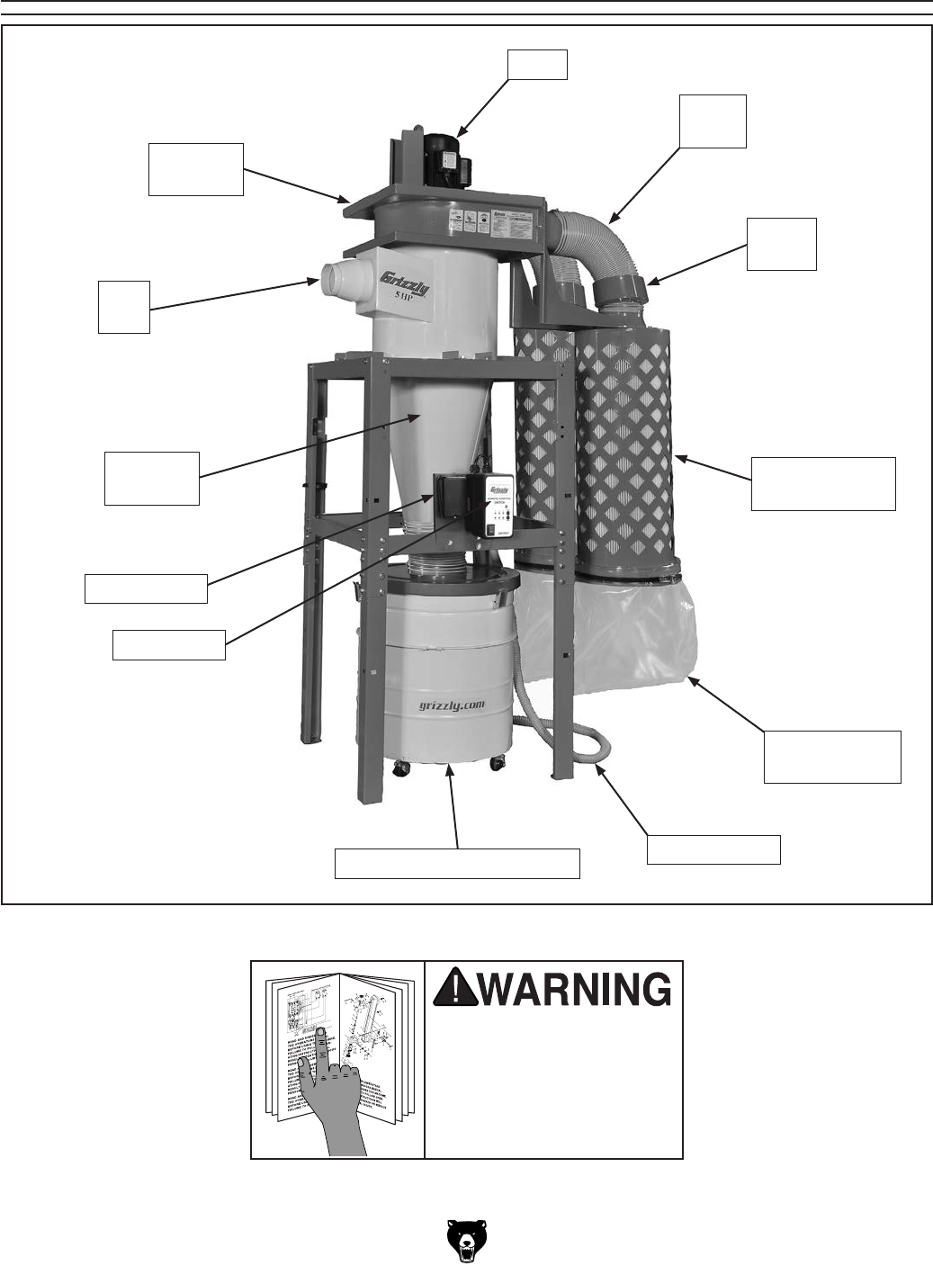
Figure 1. Identification (Model G0442 shown).
Blower
Assembly
Motor
Outlet
Hose
Noise
Muffler
Canister
Filter Assembly
Canister
Collection Bag
Vacuum Hose
Collection Drum w/Casters
Control Box
Cyclone
Assembly
Inlet
Port
Junction Box

-4- Model G0442/G0601 (Mfg Since 3/12)
The information contained herein is deemed accurate as of 11/19/2017 and represents our most recent product specifications.
Due to our ongoing improvement efforts, this information may not accurately describe items previously purchased. PAGE 1 OF 3
Model G0442
MACHINE DATA
SHEET
Customer Service #: (570) 546-9663 · To Order Call: (800) 523-4777 · Fax #: (800) 438-5901
MODEL G0442 5 HP CYCLONE DUST COLLECTOR
Product Dimensions:
Weight.............................................................................................................................................................. 517 lbs.
Width (side-to-side) x Depth (front-to-back) x Height............................................................. 63 x 56-7/8 x 111-1/2 in.
Footprint (Length x Width)..................................................................................................................... 63 x 56-7/8 in.
Shipping Dimensions:
Carton #1
Type........................................................................................................................................... Cardboard Box
Content................................................................................................................................................. Machine
Weight.................................................................................................................................................... 456 lbs.
Length x Width x Height............................................................................................................. 61 x 30 x 37 in.
Must Ship Upright......................................................................................................................................... Yes
Carton #2
Type........................................................................................................................................... Cardboard Box
Content......................................................................................................................................... Canister Filter
Weight...................................................................................................................................................... 44 lbs.
Length x Width x Height............................................................................................................. 49 x 22 x 22 in.
Must Ship Upright.......................................................................................................................................... No
Carton #3
Type........................................................................................................................................... Cardboard Box
Content......................................................................................................................................... Canister Filter
Weight...................................................................................................................................................... 44 lbs.
Length x Width x Height............................................................................................................. 22 x 49 x 22 in.
Must Ship Upright.......................................................................................................................................... No
Carton #4
Type........................................................................................................................................... Cardboard Box
Content...................................................................................................................................................... Stand
Weight...................................................................................................................................................... 88 lbs.
Length x Width x Height............................................................................................................... 41 x 15 x 8 in.
Must Ship Upright.......................................................................................................................................... No
Electrical:
Power Requirement........................................................................................................... 220V, Single-Phase, 60 Hz
Prewired Voltage.................................................................................................................................................. 220V
Full-Load Current Rating..................................................................................................................................... 22.4A
Minimum Circuit Size.............................................................................................................................................. 40A
Connection Type........................................................................................... Permanent (Hardwire to Shutoff Switch)
Switch Type......................................................................... Remote Control Magnetic Switch w/Overload Protection
Motors:
Main
Horsepower................................................................................................................................................ 5 HP
Phase............................................................................................................................................ Single-Phase
Amps......................................................................................................................................................... 22.4A
Speed................................................................................................................................................ 3450 RPM
Type.................................................................................................. TEFC Capacitor-Start Induction (Class F)
Power Transfer ............................................................................................................................... Direct Drive
Bearings..................................................................................................... Shielded & Permanently Lubricated
G0442 Machine Data Sheet

Model G0442/G0601 (Mfg Since 3/12) -5-
The information contained herein is deemed accurate as of 11/19/2017 and represents our most recent product specifications.
Due to our ongoing improvement efforts, this information may not accurately describe items previously purchased. PAGE 2 OF 3
Model G0442
Main Specifications:
Operation
Dust Collector Type.......................................................................................................... Two-Stage (Cyclone)
Approved Dust Types................................................................................................................................ Wood
Filter Type............................................................................................................................... Pleated Cartridge
Airflow Performance..................................................................................................... 2184 CFM @ 1.9 in. SP
Max Static Pressure (at 0 CFM)................................................................................................................ 14 in.
Main Inlet Size........................................................................................................................................... 10 in.
Inlet Adapter Included.................................................................................................................................... No
Machine Collection Capacity At One Time....................................................................................................... 4
Maximum Material Collection Capacity................................................................................................ 7.4 cu. ft.
Filtration Rating............................................................................................................................ 0.2 – 2 Micron
Filter Surface Area............................................................................................................................. 226 sq. ft.
Bag Information
Number of Lower Bags..................................................................................................................................... 2
Lower Bag Diameter............................................................................................................................ 19-3/4 in.
Canister Information
Number of Canister Filters................................................................................................................................ 2
Canister Filter Diameter................................................................................................................... 19-11/16 in.
Canister Filter Length.......................................................................................................................... 39-3/8 in.
Collection Drum Size......................................................................................................................... 55 Gallons
Impeller Information
Impeller Type...................................................................................................................................... Radial Fin
Impeller Size.............................................................................................................................................. 16 in.
Construction
Lower Bag...................................................................................................................................... Clear Plastic
Canister............................................................................................................................ Spun Bond Polyester
Frame....................................................................................................................... Steel Sheet Metal (14 ga.)
Impeller....................................................................................................................................................... Steel
Paint Type/Finish....................................................................................................................... Powder Coated
Blower Housing......................................................................................................................... 11 Gauge Steel
Body.......................................................................................................................................... 14 Gauge Steel
Collection Drum..................................................................................................................................... Steel
Other Specifications:
Country of Origin .............................................................................................................................................. Taiwan
Warranty ........................................................................................................................................................... 1 Year
Approximate Assembly & Setup Time ............................................................................................................. 4 Hours
Serial Number Location .................................................................................................................................. ID Label
Sound Rating ............................................................................................................................................. 83 – 86 dB
ISO 9001 Factory .................................................................................................................................................... No
Certified by a Nationally Recognized Testing Laboratory (NRTL) ......................................................................... Yes

-6- Model G0442/G0601 (Mfg Since 3/12)
The information contained herein is deemed accurate as of 11/19/2017 and represents our most recent product specifications.
Due to our ongoing improvement efforts, this information may not accurately describe items previously purchased. PAGE 1 OF 3
Model G0601
MACHINE DATA
SHEET
Customer Service #: (570) 546-9663 · To Order Call: (800) 523-4777 · Fax #: (800) 438-5901
MODEL G0601 5 HP 3‐PHASE CYCLONE DUST COLLECTOR
Product Dimensions:
Weight.............................................................................................................................................................. 517 lbs.
Width (side-to-side) x Depth (front-to-back) x Height............................................................. 63 x 56-7/8 x 111-1/2 in.
Footprint (Length x Width)..................................................................................................................... 63 x 56-7/8 in.
Shipping Dimensions:
Carton #1
Type........................................................................................................................................... Cardboard Box
Content................................................................................................................................................. Machine
Weight.................................................................................................................................................... 443 lbs.
Length x Width x Height............................................................................................................. 61 x 30 x 37 in.
Must Ship Upright......................................................................................................................................... Yes
Carton #2
Type........................................................................................................................................... Cardboard Box
Content......................................................................................................................................... Canister Filter
Weight...................................................................................................................................................... 46 lbs.
Length x Width x Height............................................................................................................. 49 x 22 x 22 in.
Must Ship Upright.......................................................................................................................................... No
Carton #3
Type........................................................................................................................................... Cardboard Box
Content......................................................................................................................................... Canister Filter
Weight...................................................................................................................................................... 46 lbs.
Length x Width x Height............................................................................................................. 49 x 22 x 22 in.
Must Ship Upright.......................................................................................................................................... No
Carton #4
Type........................................................................................................................................... Cardboard Box
Content...................................................................................................................................................... Stand
Weight...................................................................................................................................................... 90 lbs.
Length x Width x Height............................................................................................................... 41 x 15 x 7 in.
Must Ship Upright.......................................................................................................................................... No
Electrical:
Power Requirement..................................................................................................... 220V or 440V, 3-Phase, 60 Hz
Prewired Voltage.................................................................................................................................................. 220V
Full-Load Current Rating................................................................................................ 13.7A at 220V, 6.9A at 440V
Minimum Circuit Size.......................................................................................................... 30A at 220V, 15A at 440V
Connection Type........................................................................................... Permanent (Hardwire to Shutoff Switch)
Switch Type......................................................................... Remote Control Magnetic Switch w/Overload Protection
Voltage Conversion Kit............................................................................................................... G440V0601 for 440V
Recommended Phase Converter...................................................................... Rotary Only (Not Approved for Static)
G0601 Machine Data Sheet

Model G0442/G0601 (Mfg Since 3/12) -7-
The information contained herein is deemed accurate as of 11/19/2017 and represents our most recent product specifications.
Due to our ongoing improvement efforts, this information may not accurately describe items previously purchased. PAGE 2 OF 3
Model G0601
Motors:
Main
Horsepower................................................................................................................................................ 5 HP
Phase.................................................................................................................................................... 3-Phase
Amps................................................................................................................................................. 13.7A/6.9A
Speed................................................................................................................................................ 3450 RPM
Type........................................................................................................................... TEFC Induction (Class F)
Power Transfer ............................................................................................................................... Direct Drive
Bearings..................................................................................................... Shielded & Permanently Lubricated
Main Specifications:
Operation
Dust Collector Type.......................................................................................................... Two-Stage (Cyclone)
Approved Dust Types................................................................................................................................ Wood
Filter Type............................................................................................................................... Pleated Cartridge
Airflow Performance..................................................................................................... 2184 CFM @ 1.9 in. SP
Max Static Pressure (at 0 CFM)................................................................................................................ 14 in.
Main Inlet Size........................................................................................................................................... 10 in.
Inlet Adapter Included.................................................................................................................................... No
Machine Collection Capacity At One Time....................................................................................................... 4
Maximum Material Collection Capacity................................................................................................ 7.4 cu. ft.
Filtration Rating............................................................................................................................ 0.2 – 2 Micron
Filter Surface Area.............................................................................................................................. 226 sq. ft.
Bag Information
Number of Lower Bags..................................................................................................................................... 2
Lower Bag Diameter............................................................................................................................ 19-3/4 in.
Canister Information
Number of Canister Filters................................................................................................................................ 2
Canister Filter Diameter................................................................................................................... 19-11/16 in.
Canister Filter Length.......................................................................................................................... 39-3/8 in.
Collection Drum Size......................................................................................................................... 55 Gallons
Impeller Information
Impeller Type...................................................................................................................................... Radial Fin
Impeller Size.............................................................................................................................................. 16 in.
Construction
Lower Bag...................................................................................................................................... Clear Plastic
Canister............................................................................................................................ Spun Bond Polyester
Frame....................................................................................................................... Steel Sheet Metal (14 ga.)
Impeller....................................................................................................................................................... Steel
Paint Type/Finish....................................................................................................................... Powder Coated
Blower Housing......................................................................................................................... 11 Gauge Steel
Body.......................................................................................................................................... 14 Gauge Steel
Collection Drum..................................................................................................................................... Steel
Other Specifications:
Country of Origin .............................................................................................................................................. Taiwan
Warranty ........................................................................................................................................................... 1 Year
Approximate Assembly & Setup Time ............................................................................................................. 3 Hours
Serial Number Location .................................................................................................................................. ID Label
Sound Rating ............................................................................................................................................. 83 – 86 dB
ISO 9001 Factory .................................................................................................................................................... No
Certified by a Nationally Recognized Testing Laboratory (NRTL) ......................................................................... Yes
-8- Model G0442/G0601 (Mfg Since 3/12)
ELECTRICAL EQUIPMENT INJURY RISKS. You
can be shocked, burned, or killed by touching live
electrical components or improperly grounded
machinery. To reduce this risk, only allow qualified
service personnel to do electrical installation or
repair work, and always disconnect power before
accessing or exposing electrical equipment.
DISCONNECT POWER FIRST.
Always discon-
nect machine from power supply BEFORE making
adjustments, changing tooling, or servicing machine.
This prevents an injury risk from unintended startup
or contact with live electrical components.
EYE PROTECTION. Always wear ANSI-approved
safety glasses or a face shield when operating or
observing machinery to reduce the risk of eye
injury or blindness from flying particles. Everyday
eyeglasses are NOT approved safety glasses.
OWNER’S MANUAL. Read and understand this
owner’s manual BEFORE using machine.
TRAINED OPERATORS ONLY. Untrained oper-
ators have a higher risk of being hurt or killed.
Only allow trained/supervised people to use this
machine. When machine is not being used, dis-
connect power, remove switch keys, or lock-out
machine to prevent unauthorized use—especially
around children. Make your workshop kid proof!
DANGEROUS ENVIRONMENTS. Do not use
machinery in areas that are wet, cluttered, or have
poor lighting. Operating machinery in these areas
greatly increases the risk of accidents and injury.
MENTAL ALERTNESS REQUIRED. Full mental
alertness is required for safe operation of machin-
ery. Never operate under the influence of drugs or
alcohol, when tired, or when distracted.
For Your Own Safety, Read Instruction
Manual Before Operating This Machine
The purpose of safety symbols is to attract your attention to possible hazardous conditions.
This manual uses a series of symbols and signal words intended to convey the level of impor-
tance of the safety messages. The progression of symbols is described below. Remember that
safety messages by themselves do not eliminate danger and are not a substitute for proper
accident prevention measures. Always use common sense and good judgment.
Indicates a potentially hazardous situation which, if not avoided,
MAY result in minor or moderate injury. It may also be used to alert
against unsafe practices.
Indicates a potentially hazardous situation which, if not avoided,
COULD result in death or serious injury.
Indicates an imminently hazardous situation which, if not avoided,
WILL result in death or serious injury.
This symbol is used to alert the user to useful information about
proper operation of the machine.
NOTICE
Safety Instructions for Machinery
SECTION 1: SAFETY

Model G0442/G0601 (Mfg Since 3/12) -9-
WEARING PROPER APPAREL. Do not wear
clothing, apparel or jewelry that can become
entangled in moving parts. Always tie back or
cover long hair. Wear non-slip footwear to reduce
risk of slipping and losing control or accidentally
contacting cutting tool or moving parts.
HAZARDOUS DUST. Dust created by machinery
operations may cause cancer, birth defects, or
long-term respiratory damage. Be aware of dust
hazards associated with each workpiece mate-
rial. Always wear a NIOSH-approved respirator to
reduce your risk.
HEARING PROTECTION. Always wear hear-
ing protection when operating or observing loud
machinery. Extended exposure to this noise
without hearing protection can cause permanent
hearing loss.
REMOVE ADJUSTING TOOLS. Tools left on
machinery can become dangerous projectiles
upon startup. Never leave chuck keys, wrenches,
or any other tools on machine. Always verify
removal before starting!
USE CORRECT TOOL FOR THE JOB. Only use
this tool for its intended purpose—do not force
it or an attachment to do a job for which it was
not designed. Never make unapproved modifica-
tions—modifying tool or using it differently than
intended may result in malfunction or mechanical
failure that can lead to personal injury or death!
AWKWARD POSITIONS. Keep proper footing
and balance at all times when operating machine.
Do not overreach! Avoid awkward hand positions
that make workpiece control difficult or increase
the risk of accidental injury.
CHILDREN & BYSTANDERS. Keep children and
bystanders at a safe distance from the work area.
Stop using machine if they become a distraction.
GUARDS & COVERS. Guards and covers reduce
accidental contact with moving parts or flying
debris. Make sure they are properly installed,
undamaged, and working correctly BEFORE
operating machine.
FORCING MACHINERY. Do not force machine.
It will do the job safer and better at the rate for
which it was designed.
NEVER STAND ON MACHINE. Serious injury
may occur if machine is tipped or if the cutting
tool is unintentionally contacted.
STABLE MACHINE. Unexpected movement dur-
ing operation greatly increases risk of injury or
loss of control. Before starting, verify machine is
stable and mobile base (if used) is locked.
USE RECOMMENDED ACCESSORIES. Consult
this owner’s manual or the manufacturer for rec-
ommended accessories. Using improper acces-
sories will increase the risk of serious injury.
UNATTENDED OPERATION. To reduce the
risk of accidental injury, turn machine OFF and
ensure all moving parts completely stop before
walking away. Never leave machine running
while unattended.
MAINTAIN WITH CARE. Follow all maintenance
instructions and lubrication schedules to keep
machine in good working condition. A machine
that is improperly maintained could malfunction,
leading to serious personal injury or death.
DAMAGED PARTS. Regularly inspect machine
for damaged, loose, or mis-adjusted parts—or
any condition that could affect safe operation.
Immediately repair/replace BEFORE operating
machine. For your own safety, DO NOT operate
machine with damaged parts!
MAINTAIN POWER CORDS. When disconnect-
ing cord-connected machines from power, grab
and pull the plug—NOT the cord. Pulling the cord
may damage the wires inside. Do not handle
cord/plug with wet hands. Avoid cord damage by
keeping it away from heated surfaces, high traffic
areas, harsh chemicals, and wet/damp locations.
EXPERIENCING DIFFICULTIES. If at any time
you experience difficulties performing the intend-
ed operation, stop using the machine! Contact our
Technical Support at (570) 546-9663.

-10- Model G0442/G0601 (Mfg Since 3/12)
INTENDED USE.Thisdustcollectorisonly
intendedforcollectingwooddustandchipsfrom
woodworking machines. DONOTusethisdust
collectortocollectmetal,dirt,pebbles,drywall,
asbestos, leadpaint,silica,liquids,aerosols,or
anyflammable,combustible,orhazardousmateri-
als.
hazarDoUS DUST. Dust created while using
machinery may cause cancer, birth defects, or
long-termrespiratorydamage. Beawareof dust
hazardsassociatedwitheachworkpiecematerial,
andalwayswearaNIOSH-approvedrespiratorto
reduceyourrisk.
DUST aLLErGIES.Dustfromcertainwoods
maycauseanallergicreactioninpeopleandani-
mals.Makesureyouknowwhattypeofwooddust
youwillbeexposedtoincasethereisapossibility
ofanallergicreaction.
WEar rESPIraTor.Finedustthatistoo
smalltobecaughtin thefilterwillbeblowninto
the ambientairduringoperation.Alwayswear a
NIOSHapprovedrespiratorduringoperationand
forashorttimeaftertoreduceyourriskofperma-
nentrespiratorydamage.
EMPTYING DUST.Whenemptyingdustfromthe
collectioncontainer,weararespiratorandsafety
glasses. Emptydustawayfromignition sources
andintoanapprovedcontainer.
DISCoNNECTING PoWEr SUPPLY.Turn the
switchOFF, disconnect the dustcollectorfrom
thepowersupply,andallowtheimpellertocome
to a completestopbeforeleaving the machine
unattendedordoinganyservice,cleaning,main-
tenance,oradjustments.
rEGULar CLEaNING.Regularly check/empty
the collectionbagsordrumtoavoid the buildup
offinedustthatcanincreasetheriskoffire.Make
suretoregularlycleanthesurroundingareawhere
themachineisoperated—excessivedustbuildup
onoverheadlights,heaters,electrical panels, or
otherheatsourceswillincreasetheriskoffire.
SUSPENDED DUST ParTICLES aND IGNITIoN
SoUrCES.DONOToperatethedustcollectorin
areaswereexplosionrisksarehigh.Areasofhigh
riskinclude,butarenotlimitedto,areasnearpilot
lights,openflames,orotherignitionsources.
FIrE SUPPrESSIoN.Onlyoperatethedustcol-
lectorinlocationsthatcontainafiresuppression
systemorhaveafireextinguishernearby.
IMPELLEr hazarDS.DONOTplaceyour
handsortoolsneartheopeninletduringoperation
foranyreason.Thepowerfulsuctioncouldeasily
causeaccidentalcontactwiththeimpellerwhich
willcauseseriouspersonalinjuryordamageto
themachine.Alwayskeepsmallanimalsandchil-
drenawayfromopendustcollectioninlets.
aVoIDING SParKS.DONOTallowsteelor
rockstostrike the impeller—this mayproduce
sparks.Sparkscansmolderinwooddustfor a
longtimebeforeafireisdetected.Ifyouacciden-
tallycutintowoodcontainingtrampmetal(nails,
staples,spikes,etc.), immediately turnOFF the
dustcollector,disconnectitfrompower,andwait
for the impeller to stop—then empty the collec-
tioncontainerintoanapprovedairtightmetal
container.
oPEraTING LoCaTIoN.Toreduce respira-
toryexposuretofinedust,locatepermanently
installeddustcollectorsawayfrom the working
area,orinanotherroomthatisequippedwitha
smokedetector.DONOToperatethedustcollec-
torinrainyorwetlocations—exposuretowater
maycreateanshockhazardordecreasethelife
ofthemachine.
STaTIC ELECTrICITY.Plasticdustlinesgener-
atehighamountsofstaticelectricityasdustchips
passthroughthem.Althoughrare,sparkscaused
bystaticelectricitycancauseexplosionsorfire.
Toreducethisrisk,makesurealldust lines are
thoroughlygroundedbyusingagroundingwire.
Additional Safety for Dust Collectors
Model G0442/G0601 (Mfg Since 3/12) -11-
SECTION 2: POWER SUPPLY
Availability Circuit Requirements
Before installing the machine, consider the avail-
ability and proximity of the required power supply
circuit. If an existing circuit does not meet the
requirements for this machine, a new circuit must
be installed. To minimize the risk of electrocution,
fire, or equipment damage, installation work and
electrical wiring must be done by an electrician or
qualified service personnel in accordance with all
applicable codes and standards.
Serious injury could occur if you connect
machine to power before completing setup
process. DO NOT connect to power until
instructed later in this manual.
Full-Load Current Rating
The full-load current rating is the amperage a
machine draws at 100% of the rated output power.
On machines with multiple motors, this is the
amperage drawn by the largest motor or sum of all
motors and electrical devices that might operate
at one time during normal operations.
The full-load current is not the maximum amount
of amps that the machine will draw. If the machine
is overloaded, it will draw additional amps beyond
the full-load rating.
If the machine is overloaded for a sufficient length
of time, damage, overheating, or fire may result—
especially if connected to an undersized circuit.
To reduce the risk of these hazards, avoid over-
loading the machine during operation and make
sure it is connected to a power supply circuit that
meets the specified circuit requirements.
G0442 Current Rating ..................... 22.4 Amps
G0601 Current Rating at 220V ....... 13.7 Amps
G0601 Current Rating at 440V ......... 6.9 Amps
A power supply circuit includes all electrical
equipment between the breaker box or fuse panel
in the building and the machine. The power sup-
ply circuit used for this machine must be sized to
safely handle the full-load current drawn from the
machine for an extended period of time. (If this
machine is connected to a circuit protected by
fuses, use a time delay fuse marked D.)
For your own safety and protection of
property, consult an electrician if you are
unsure about wiring practices or electrical
codes in your area.
Note: Circuit requirements in this manual apply to
a dedicated circuit—where only one machine will
be running on the circuit at a time. If machine will
be connected to a shared circuit where multiple
machines may be running at the same time, con-
sult an electrician or qualified service personnel to
ensure circuit is properly sized for safe operation.
G0442 Circuit Requirements for
220V
The Model G0442 is prewired to operate on a
220V power supply circuit that has a verified
ground and meets the following requirements:
Nominal Voltage ........................................220V
Cycle ..........................................................60 Hz
Phase ........................................... Single-Phase
Circuit Rating ...................................... 40 Amps
Connection ......Hardwire with Locking Switch
-12- Model G0442/G0601 (Mfg Since 3/12)
G0601 Circuit Requirements for
220V
The Model G0601 is prewired to operate on a
220V power supply circuit that has a verified
ground and meets the following requirements:
Nominal Voltage ........................................220V
Cycle ..........................................................60 Hz
Phase .................................................... 3-Phase
Circuit Rating ................. Time Delay 30 Amps
Connection ......Hardwire with Locking Switch
G0601 Circuit Requirements for
440V
The Model G0601 can be converted to operate on
a 440V power supply. G0601 440V Conversion
instructions are provided on Page 13. The intend-
ed 440 circuit must have a verified ground and
meet the requirements that follow:
Nominal Voltage ........................................440V
Cycle ..........................................................60 Hz
Phase .................................................... 3-Phase
Rated Size .......................Time Delay 20 Amps
Connection ......Hardwire with Locking Switch
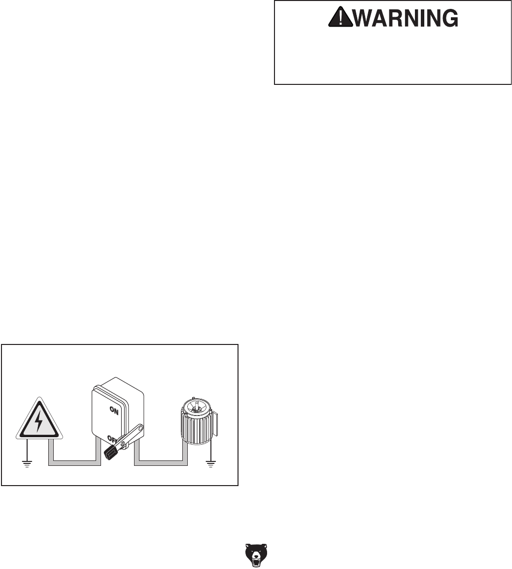
Connection Type
Figure 2. Typical setup of a permanently
connected machine.
Power
Source
Locking
Disconnect Switch
Machine
Ground Ground
ConduitConduit
A permanently connected (hardwired) power sup-
ply is typically installed with wires running through
mounted and secured conduit. A disconnecting
means, such as a locking switch (see following
figure), must be provided to allow the machine
to be disconnected (isolated) from the power
supply when required. This installation must be
performed by an electrician in accordance with all
applicable electrical codes and ordinances.
Extension Cords
Since this machine must be permanently con-
nected to the power supply, an extension cord
cannot be used.
Serious injury could occur if you connect
machine to power before completing setup
process. DO NOT connect to power until
instructed later in this manual.
Grounding Instructions
In the event of a malfunction or breakdown,
grounding provides a path of least resistance
for electrical current to reduce the risk of electric
shock. A permanently connected machine must
be connected to a grounded metal permanent wir-
ing system; or to a system having an equipment-
grounding conductor. All grounds must be verified
and rated for the electrical requirements of the
machine. Improper grounding can increase the
risk of electric shock!
Model G0442/G0601 (Mfg Since 3/12) -13-
G0601 440V Conversion
The Model G0601 can be converted for 440V
operation. This conversion job consists of dis-
connecting the machine from the power source,
replacing the control box assembly and the motor
cord, and rewiring the motor for 440V operation.
The necessary conversion kit (Part P0601003-1V2)
for this procedure can be purchased by calling
Grizzly Customer Service at (800) 523-4777.
All wiring changes must be inspected by a quali-
fied electrician before the machine is connected
to the power source. If you need help at any time
during this procedure, call Grizzly Tech Support at
(570) 546-9663.
To rewire the Model G0601 for 440V opera-
tion:
1. DISCONNECT MACHINE FROM POWER!
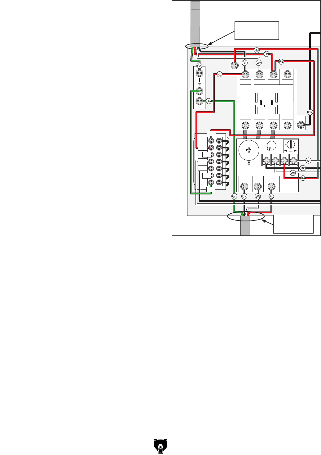
2. Record the wire colors and connections of
the four incoming power wires and the four
outgoing motor wires inside the 220V con-
trol box (see illustration in Figure 3 for a
reference). You can also refer to the G0601
Wiring Diagrams on Pages 50–51 for more
complete wiring illustrations.
3. Disconnect these eight wires, then replace
the 220V control box with the 440V control
box.
4. Replace the old motor cord with the new, and
reconnect the wires as recorded in Step 2.
5. Remove the old motor cord from the motor.
6. Rewire the motor as shown inside the motor
junction cover and attach the new motor cord.
Note: The reference wiring diagram on
Pages 50–51 were current at the time of
printing, but always use the wiring diagram
provided inside the motor junction box, as it
will reflect any changes to the motor shipped
with the machine.
A1
Ground
30VA
Transformer
2T1 6T3 14NO
4T2
1L1 5L3 13NO
3L2
NHD C-09D
2T1 4T2 6T3
98 97
A2
96
O R
95
6
8
NTH-8
ON/OFF
Switch
A2
OL_NO AC
OUT
AC
IN
440V
Circuit Board
0
0
E
440
460
220
230
Figure 3. G0601 440V control box wiring.
4 Incoming
Power Wires
4 Outgoing
Motor Wires
-14- Model G0442/G0601 (Mfg Since 3/12)
Correcting Phase Polarity (G0601
Only)
This subsection is only provided for troubleshoot-
ing. If you discover during the test run that the
machine will not operate, or that the impeller spins
backward, the power connections may be wired
out-of-phase. Without the proper test equipment
to determine the polarity of the power source legs,
wiring machinery to 3-phase power may require
trial-and-error. Correcting phase polarity is simply
a matter of reversing the positions where two of
the incoming power source wires are connected
inside the control box.
NOTICE
If this machine is wired out-of-phase, the
motor and impeller will spin in the wrong
direction. The efficiency of the dust col-
lector will be greatly reduced and will not
provide the rated CFM. You must make
sure the motor is spinning in the correct
direction before placing the machine into
full operation. Perform Step 10 of the test
run on Page 29 to make sure the machine
is correctly wired.
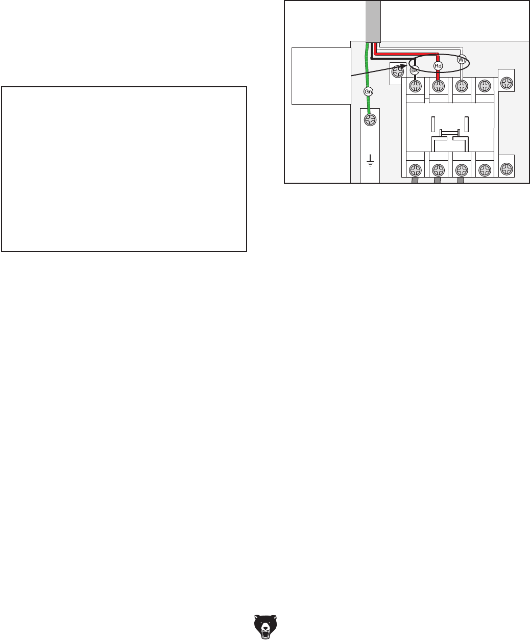
To correct phase polarity:
1. DISCONNECT MACHINE FROM POWER!
2. Open the control box and swap the connec-
tions of any two incoming hot wires from the
power source (see Figure 4).
A1
Ground
2T1 6T3 14NO
4T2
1L1 5L3 13NO
3L2
NHD C-18D
2T1 4T2 6T3
98 97
A2
96
O R
95
11
12
13
14
NHD NTH-14
A2
Figure 4. Wire connections to swap to correct
phase polarity.
Swap Any
Two
of These
Wires
3. Secure the control box cover, then re-connect
the machine to power.
4. Perform Step 10 of the test run on Page 29
to confirm that the power connections are
correct.
— If the motor and impeller are still rotating
in the wrong direction, contact our Tech
Support at (570) 546-9663 for assistance.
Model G0442/G0601 (Mfg Since 3/12) -15-
Wear safety glasses dur-
ing the entire setup pro-
cess!
This machine presents
serious injury hazards
to untrained users. Read
through this entire manu-
al to become familiar with
the controls and opera-
tions before starting the
machine!
SECTION 3: SETUP
Needed for Setup
Your machine was carefully packaged for safe
transportation. Remove the packaging materials
from around your machine and inspect it. If you
discover the machine is damaged, please imme-
diately call Customer Service at (570) 546-9663
for advice.
Save the containers and all packing materials for
possible inspection by the carrier or its agent.
Otherwise, filing a freight claim can be difficult.
When you are completely satisfied with the condi-
tion of your shipment, inventory the contents.
Unpacking
This machine and its com-
ponents are very heavy.
Get lifting help or use
power lifting equipment
such as a forklift to move
heavy items.
SUFFOCATION HAZARD!
Keep children and pets away
from plastic bags or packing
materials shipped with this
machine. Discard immediately.
The following are needed to complete the setup
process, but are not included with the machine.
Description Qty
• Safety Glasses ........................................... 1
• Forklift ......................................................... 1
• Additional People ....................................... 1
• Wrench/Socket 1⁄2" ...................................... 2
• Wrench/Socket 9⁄16" ..................................... 2
• Square ........................................................ 1
-16- Model G0442/G0601 (Mfg Since 3/12)
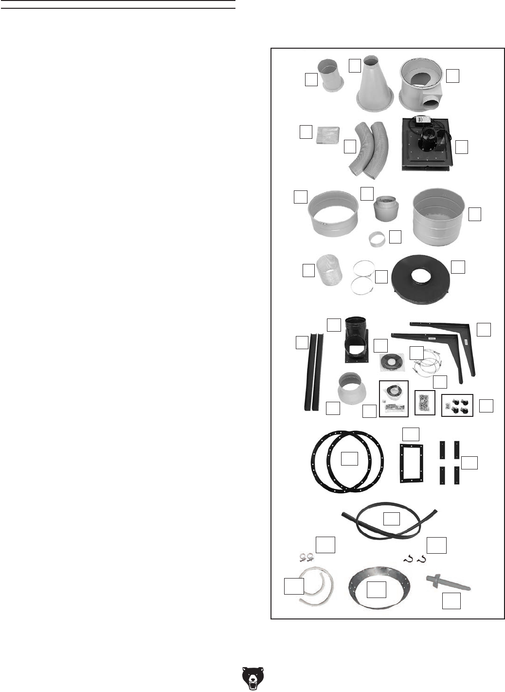
Inventory
The following is a description of the main compo-
nents shipped with the machine. Lay the compo-
nents out to inventory them.
Collector Box Contents (Figure 5): Qty
A. Intake Cylinder ........................................... 1
B. Cyclone Funnel .......................................... 1
C. Intake Barrel ............................................... 1
D. Collection Bags
— Canister Filter ....................................... 2
— Collection Drum ................................... 1
E. Gray Flexible Hoses 8" x 25" ..................... 2
F. Motor/Blower Housing Assembly ............... 1
G. Upper Collection Drum & Clamp Assy ....... 1
H. Noise Mufflers ............................................ 2
I. Gray Flexible Hoses 8" x 5" ....................... 2
J. Lower Collection Drum ............................... 1
K. Clear Flexible Hose 9" x 10" ...................... 1
L. Hose Clamps 9" ......................................... 2
M. Collection Drum Lid .................................... 1
N. Filter Cross Braces ..................................... 2
O. Outlet Port .................................................. 1
P. Filter L-Braces ............................................ 2
Q. Foam Tape 3 x 6 x 1800mm ..................... 2
R. Hose Clamps 8" ......................................... 8
S. Reducer ...................................................... 1
T. Hardware Box
—Phillips Head Screws #10-24 x 3⁄8" ........ 12
—Hex Nuts #10-24 ................................... 12
—Drum Latches ......................................... 3
—Foam Tape 3 x 15 x 700mm ................... 8
U. Hardware Box
—Hex Bolts 5⁄16"-18 x 1" ............................ 22
—Hex Bolts 5⁄16"-18 x 3⁄4" ........................... 28
—Hex Bolts 3⁄8"-16 x 3⁄4" .............................. 7
—Flat Washers 3⁄8" ................................... 14
—Flat Washers 5⁄16" .................................. 64
—Fender Washers 5⁄16" ............................... 8
—Hex Nuts 5⁄16"-18 .................................... 22
—Hex Nuts 3⁄8"-16 ....................................... 7
—Sheet Metal Screws M4 x 12 .................. 3
V. Hardware Box
—Casters ................................................... 4
—Hex Nuts 3⁄8"-16 ....................................... 4
—Lock Washers 3⁄8" .................................... 4
—Flat Washers 3⁄8" ..................................... 8
W. Barrel Gaskets ............................................ 2
X. Outlet Gasket ............................................. 1
Y. Brace Gaskets ............................................ 4
Z. Drum Lid PVC Rubber Seal 2M ................. 1
AA. Remote Control (not shown) ...................... 1
Figure 5. Contents of collector box.
F
C
B
A
D
E
K
G
I
H
J
N
M
L
P
O
QR
ST
U
V
W
X
Y
Z
AB AC
AD AE
AF
AB. Vacuum Hose Clamps 1
1⁄4" ........................ 2
AC. Vacuum Hose Clips .................................... 2
AD. Vacuum Hose 1
1⁄4" x 98" ............................ 1
AE. Collection Drum Vacuum Ring ................... 1
AF. Cyclone Vacuum Port ................................. 1
Model G0442/G0601 (Mfg Since 3/12) -17-
SUFFOCATION HAZARD!
Immediately discard all plas-
tic bags and packing materi-
als to eliminate choking/suf-
focation hazards for children
and animals.
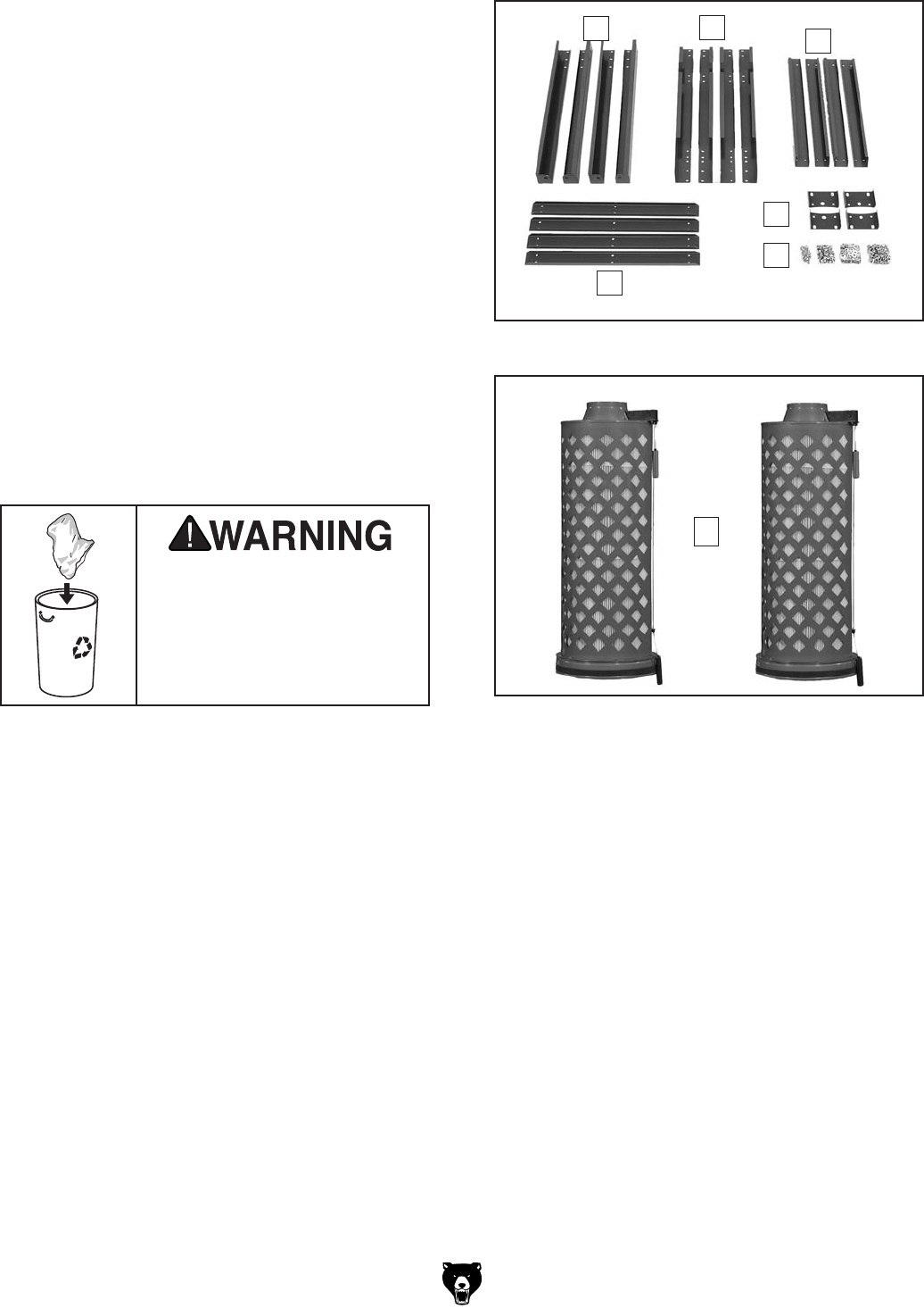
Stand Box Contents (Figure 6): Qty
A. Lower Stand Legs ...................................... 4
B. Upper Stand Legs ...................................... 4
C. Upper Stand Braces ................................... 4
D. Lower Stand Braces ................................... 4
E. Collector Mounting Brackets ...................... 4
F. Hardware Bags
—Hex Bolts 3⁄8"-16 x 3⁄4" ............................ 64
—Lock Nuts 3⁄8"-16 .................................... 64
—Flat Washers 3⁄8" ................................. 128
—Hex Bolts 5⁄16"-18 x 1" .............................. 8
—Lock Nuts 5⁄16"-18 ..................................... 8
—Flat Washers 5⁄16" .................................. 16
Contents of Filter Boxes (Figure 7): Qty
G. Canister Filter Assemblies .......................... 2
If any nonproprietary parts are missing (e.g. a
nut or a washer), we will gladly replace them; or
for the sake of expediency, replacements can be
obtained at your local hardware store.
Figure 6. Contents of stand box.
ABC
D
E
F
Figure 7. Contents of filter boxes.
G
-18- Model G0442/G0601 (Mfg Since 3/12)
Site Considerations
Weight Load
Refer to the
Machine Data Sheet for the weight
of your machine. Make sure that the surface upon
which the machine is placed will bear the weight
of the machine, additional equipment that may be
installed on the machine, and the heaviest work-
piece that will be used. Additionally, consider the
weight of the operator and any dynamic loading
that may occur when operating the machine.
Space Allocation
Consider the largest size of workpiece that will
be processed through this machine and provide
enough space around the machine for adequate
operator material handling or the installation of
auxiliary equipment. With permanent installations,
leave enough space around the machine to open
or remove doors/covers as required by the main-
tenance and service described in this manual.
See below for required space allocation.
Physical Environment
The physical environment where the machine is
operated is important for safe operation and lon-
gevity of machine components. For best results,
operate this machine in a dry environment that is
free from excessive moisture, hazardous chemi-
cals, airborne abrasives, or extreme conditions.
Extreme conditions for this type of machinery are
generally those where the ambient temperature
range exceeds 41°–104°F; the relative humidity
range exceeds 20%–95% (non-condensing); or
the environment is subject to vibration, shocks,
or bumps.
Electrical Installation
Place this machine near an existing power source.
Make sure all power cords are protected from
traffic, material handling, moisture, chemicals, or
other hazards. Make sure to leave enough space
around machine to disconnect power supply or
apply a lockout/tagout device, if required.
Lighting
Lighting around the machine must be adequate
enough that operations can be performed safely.
Shadows, glare, or strobe effects that may distract
or impede the operator must be eliminated.
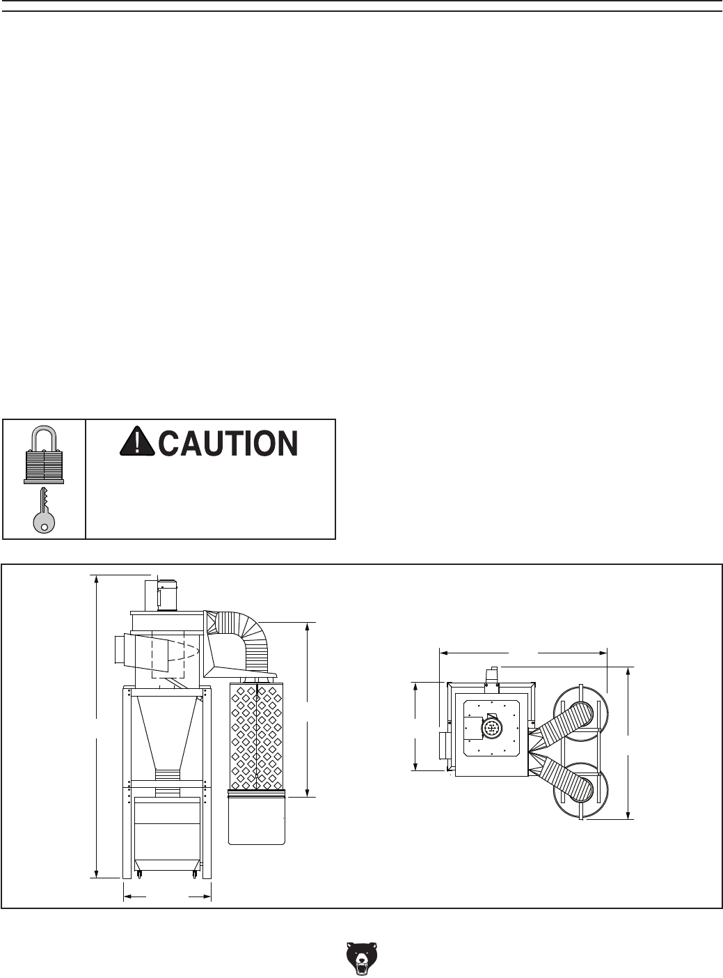
Children or untrained people
may be seriously injured by
this machine. Only install in an
access restricted location.
327⁄8"
567⁄8"
651⁄4"
327⁄8"
1111⁄2"
63"
Figure 8. Machine dimensions.
Model G0442/G0601 (Mfg Since 3/12) -19-
Since your dust collector will be hardwired to the
power source, we strongly recommend secur-
ing your machine to the floor. Consult with your
electrician to ensure compliance with applicable
codes. Because floor materials may vary, floor
mounting hardware is not included.
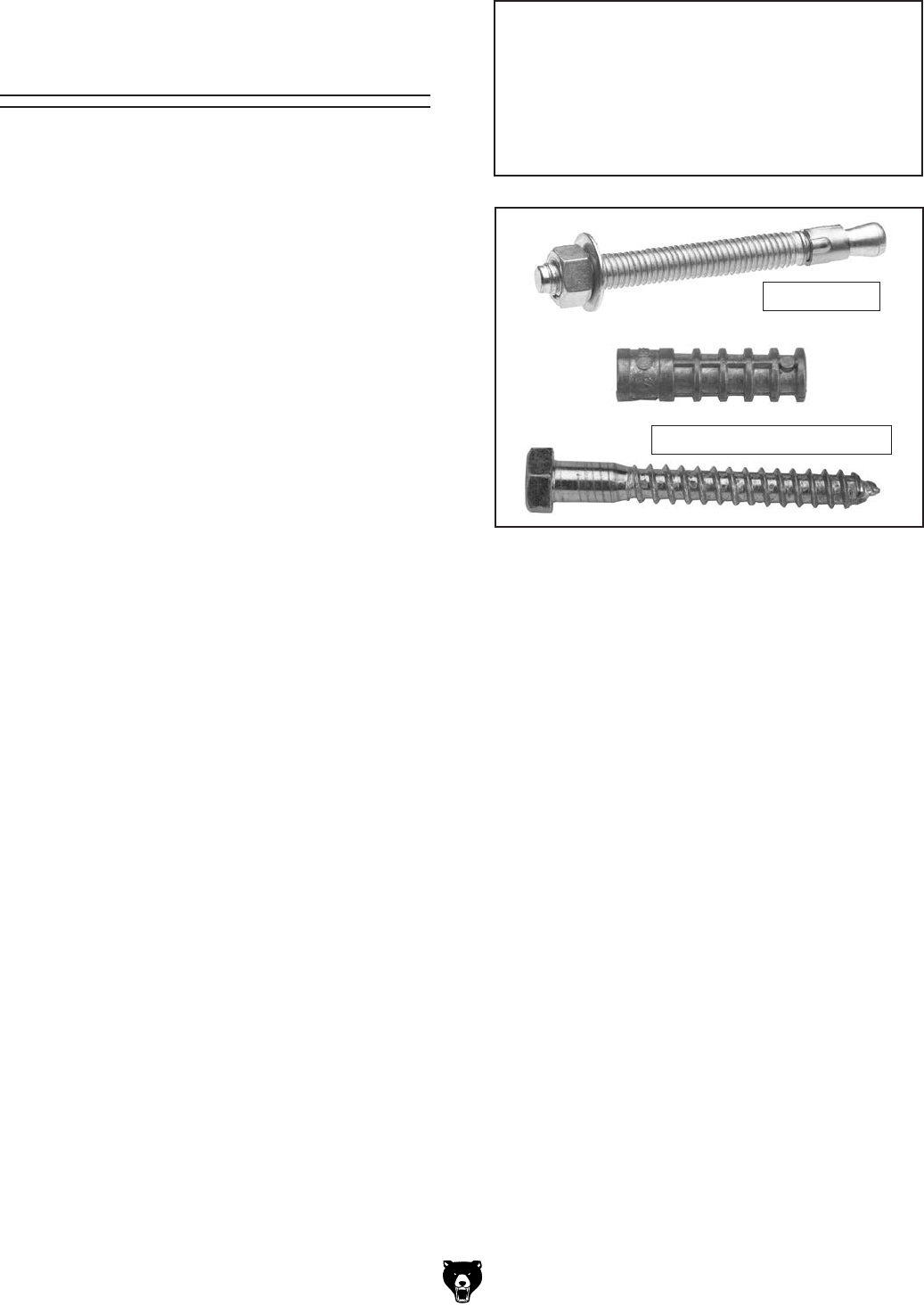
Bolting to Concrete Floors
Lag shield anchors with lag bolts and anchor
studs (Figure 9) are two popular methods for
anchoring an object to a concrete floor. We sug-
gest you research the many options for mounting
your machine and choose the one that best fits
your specific application.
Mounting to Shop
Floor
Figure 9. Typical fasteners for mounting to
concrete floors.
NOTICE
Anchor studs (see Figure 9) are stronger
and more permanent alternatives to lag
shield anchors; however, they will stick out
of the floor, presenting a tripping hazard if
you decide to move your machine.
Anchor Stud
Lag Shield and Lag Screw
-20- Model G0442/G0601 (Mfg Since 3/12)
Assembly
The Model G0442/G0601
is a heavy machine.
Serious personal injury
may occur if safe moving
methods are not used. To
be safe, get assistance
and use power equip-
ment to move the ship-
ping crate and remove
the machine from the
crate.
To assemble the dust collector:
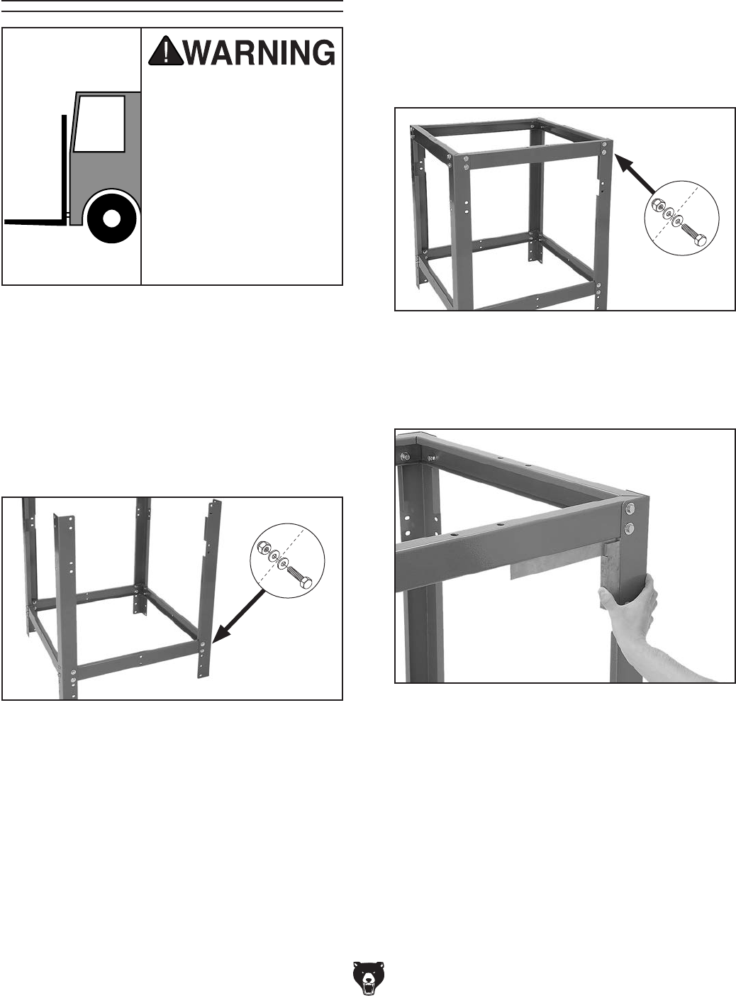
1. Connect the upper stand legs with the lower
stand braces, using (16) 3⁄8"-16 x 3⁄4" hex bolts,
(32) 3⁄8" flat washers, and (16) 3⁄8"-16 lock nuts
(see Figure 10).
Note: Do not fully tighten the fasteners for
now.
Figure 10. Initial assembly of upper stand legs
connected to lower stand braces.
x 16
2. Attach the upper stand braces to the top of
the assembly from Step 1, using (16) 3⁄8"-16
x 3⁄4" hex bolts, (32) 3⁄8" flat washers, and (16)
3⁄8"-16 lock nuts, as shown in Figure 11.
Note: Do not fully tighten the fasteners for
now.
Figure 11. Upper braces attached to stand
assembly.
x 16
3. Square up the stand, as shown in Figure 12,
then tighten all the bolts.
Figure 12. Squaring stand assembly before
tightening stand hardware.
Model G0442/G0601 (Mfg Since 3/12) -21-
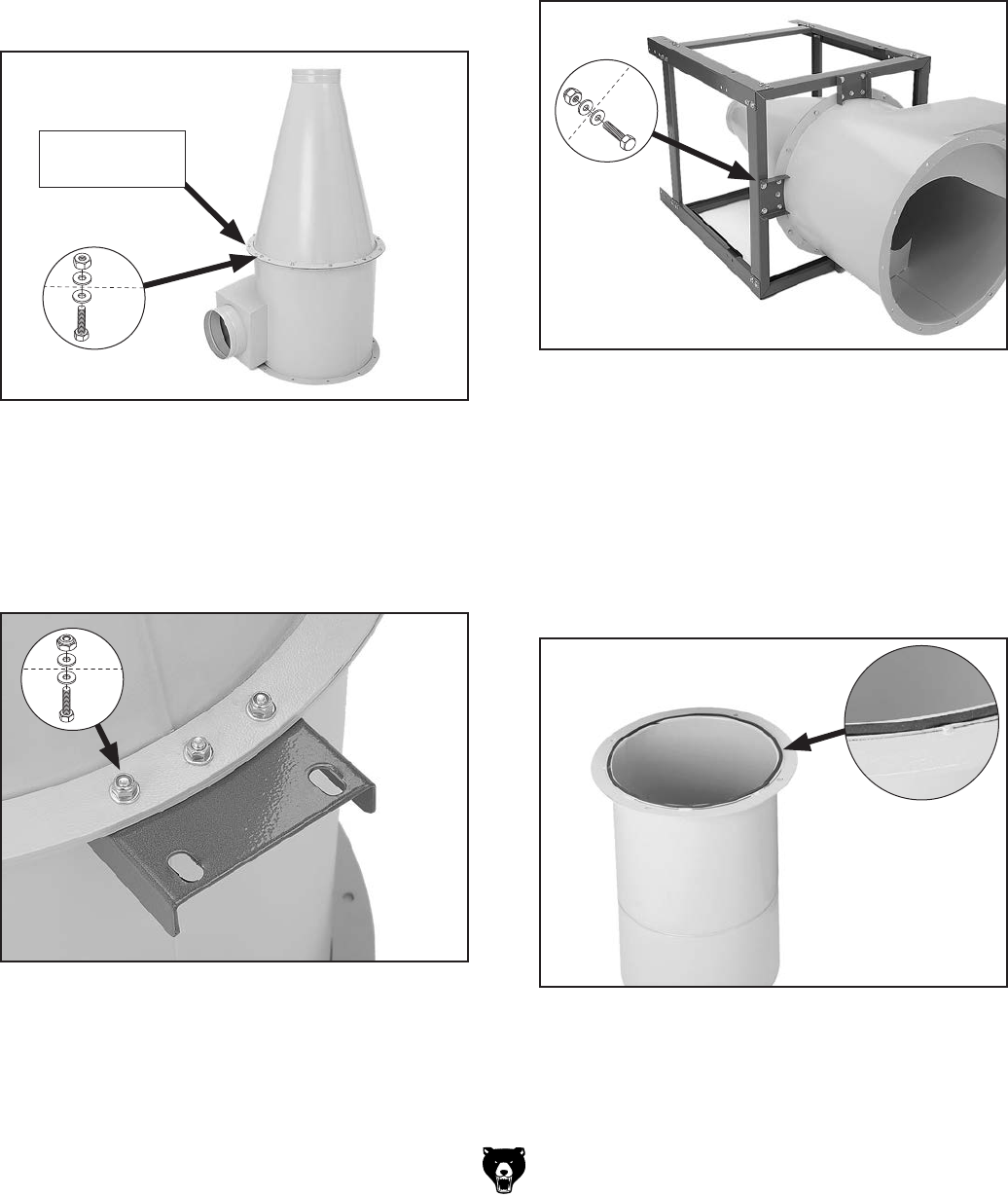
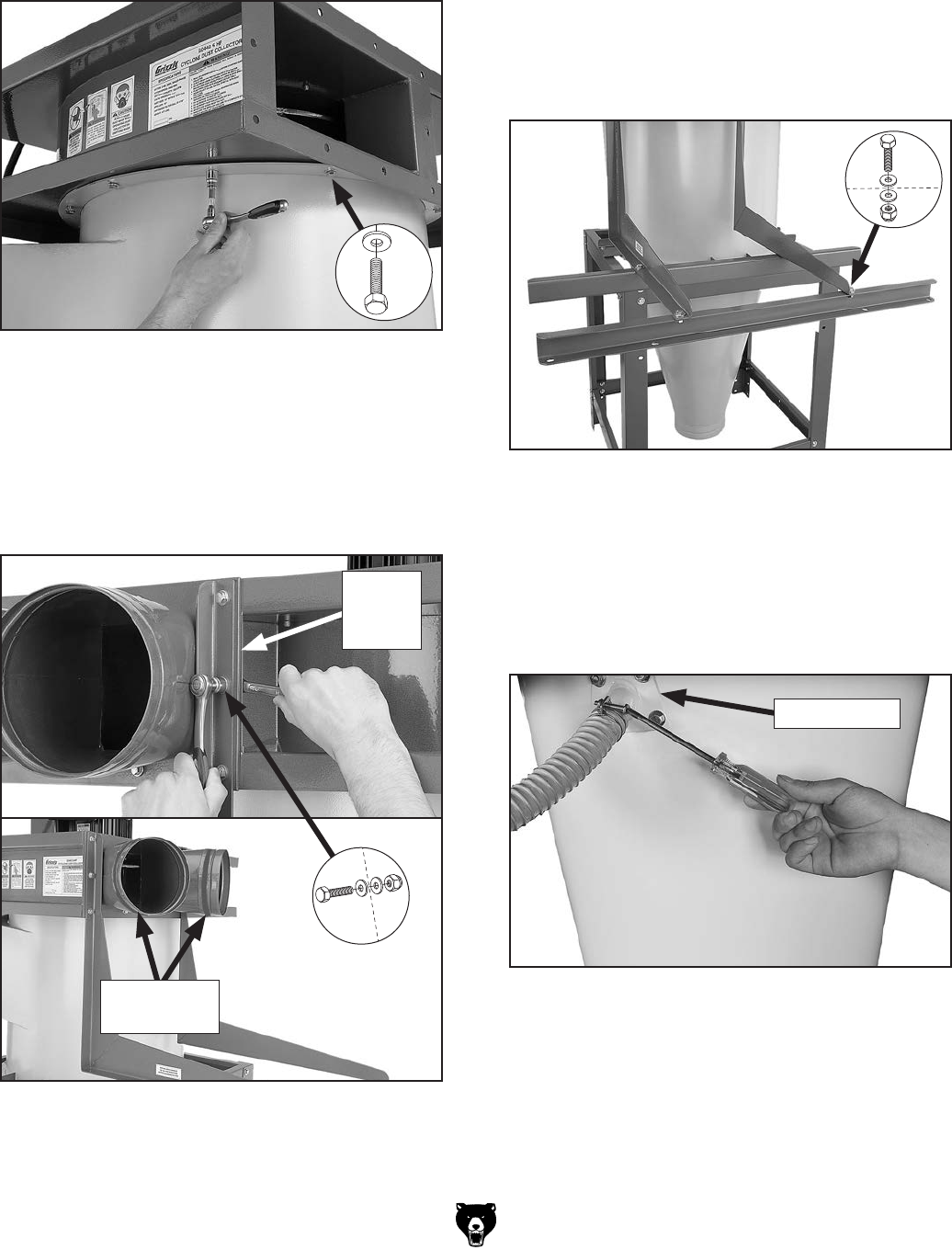
4. Attach the cyclone funnel to the intake barrel
with a barrel gasket between them, as shown
in Figure 13, with (12) 5⁄16"-18 x 1" hex bolts,
(24) 5⁄16" flat washers, and (12) 5⁄16"-18 hex
nuts.
Note: At the places where you see three
holes close together as shown in Figure 14,
only use the center hole for this step. The two
outside holes will be used in the next step.
5. Attach the collector mounting brackets to
the intake assembly, as shown in Figure 14,
using (8) 5⁄16"-18 x 1" hex bolts, (16) 5⁄16" flat
washers, and (8) 5⁄16"-18 lock nuts.
Figure 13. Cyclone funnel attached to intake
barrel.
Barrel Gasket
Here
x 12
6. Place a large piece of cardboard on the
ground to prevent scraping the parts on the
bare floor during the next steps.
7. With the help of another person, lay the stand
assembly on its side on the cardboard and
slide the collector assembly into the stand
assembly, as shown in Figure 15.
8. Fasten the collector assembly to the stand
with (8) 3⁄8"-16 x 3⁄4" hex bolts, (16) 3⁄8" flat
washers, and (8) 3⁄8"-16 lock nuts, as shown
in Figure 15.
9. Attach the 3 x 6mm foam tape on the intake
cylinder, as shown in Figure 16.
Figure 15. Collector assembly fastened to the
stand.
x 8
Figure 16. Foam tape attached to the intake
cylinder.
Figure 14. Collector mounting brackets attached
to intake assembly (collector shown upside down
in this photo).
x 8
-22- Model G0442/G0601 (Mfg Since 3/12)
10. Lift the assembly upright and rotate it so the
inlet/outlet directions are suitable for your
shop.
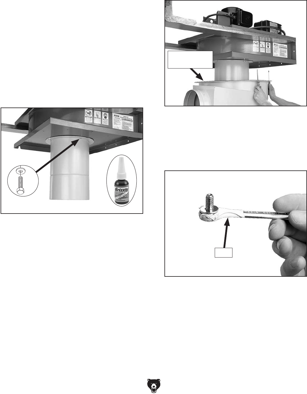
11. Lift the motor/blower housing assembly with
a forklift and attach the intake cylinder to the
bottom of the housing, as shown Figure 17,
using (4) 5⁄16"-18 x 3⁄4" hex bolts and (4) 5⁄16"
flat washers.
Note: Because this part of the dust collec-
tor is not accessible after the assembly is
complete, consider using Medium Strength
Blue Thread Locker (Grizzly Model T21854)
on the bolts that secure the intake cylinder
to the motor/blower housing assembly to
ensure that the fasteners won't come loose
with vibration.
Figure 17. Intake cylinder attached to the bottom
of motor/blower housing.
x 4
13. Using two punches or Phillips screwdriv-
ers, align the mounting holes, as shown in
Figure 18, and lower the assembly onto the
intake barrel.
Figure 18. Aligning the mounting holes.
Barrel Gasket
Here
Note: In the next step, when installing the two
bolts above the intake port, use duct tape on
the bottom of your wrench to hold the bolts
in place, as shown in Figure 19. This will
enable you to start the bolts easier.
12. Place the remaining barrel gasket on top of
the intake barrel, then carefully lower the
motor/blower housing assembly on top of it
approximately 1" away from the intake barrel.
Figure 19. Using tape on wrench in tight spot.
Tape
Model G0442/G0601 (Mfg Since 3/12) -23-
14. Attach the assembly to the intake barrel, as
shown in Figure 20, with (12) 5⁄16"-18 x 3⁄4"
hex bolts and (12) 5⁄16" flat washers.
Figure 20. Securing blower on intake barrel.
x 12
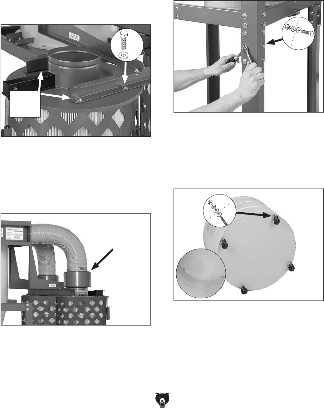
15. Place the outlet gasket between the motor/
blower housing and outlet port, then attach
the outlet port and filter L-braces to the hous-
ing, as shown in Figure 21, using (10) 5⁄16"-18
x 1" hex bolts, (20) 5⁄16" flat washers, and (10)
5⁄16"-18 hex nuts.
Figure 21. Attaching the outlet ports and filter
L-braces to the blower housing.
x 10
Outlet
Gasket
Here
Foam Tape
Here
16. Attach one roll of 3 x 15 x 700mm foam
tape to the outside lip of each outlet port, as
shown in Figure 21.
17. Attach the two filter cross braces to the
L-braces, as shown in Figure 22, using (4)
3⁄8"-16 x 3⁄4" hex bolts, (8) 3⁄8" flat washers, and
(4) 3⁄8"-16 hex nuts.
Figure 22. Attaching filter cross braces to
L-braces.
x 4
Figure 23. Cyclone vacuum tube and hose
attachment.
Vacuum Port
18. Apply the 3 x 6 x 300mm foam tape to the
mating surface of the cyclone vacuum port,
then attach it to the cyclone funnel with (4)
5⁄16"-18 x 3⁄4" hex bolts and (4) 5⁄16" flat washers
(see Figure 23).
-24- Model G0442/G0601 (Mfg Since 3/12)
19. Using the forklift, lift the entire assembly
approximately 2" off the ground to gain clear-
ance for filter installation.
20. Mount the two filters to the braces with
brace gaskets between them, as shown in
Figure 24, using (8) 5⁄16"-18 x 3⁄4" hex bolts
and (8) 5⁄16" fender washers.
Figure 24. Canister filters mounted to the long
support braces.
Rubber
Gaskets
Here
x 8
21. Attach one roll of 3 x 15 x 700mm foam tape
to both ends of each noise muffler, then
connect them between the outlet ports and
the canisters with the 8" flexible hoses and
clamps, as shown in Figure 25.
Figure 25. Noise mufflers connected between
the outlet ports and the canisters.
Noise
Muffler
22. Using the forklift, raise the assembly up and
attach the lower stand legs to the upper stand
legs, as shown in Figure 26, using (24) 3⁄8"-16
x 3⁄4" hex bolts, (48) 3⁄8" flat washers, and (24)
3⁄8"-16 lock nuts.
Figure 26. Attaching lower legs to the initial
stand assembly.
x 24
23. Attach the casters to the bottom of the lower
collection drum, as shown in Figure 27, using
the (4) 3⁄8"-16 hex nuts, (8) 3⁄8" flat washers,
and (4) 3⁄8" lock washers included in the box
with the casters.
Figure 27. Casters attached to the lower
collection drum.
x 4
Model G0442/G0601 (Mfg Since 3/12) -25-
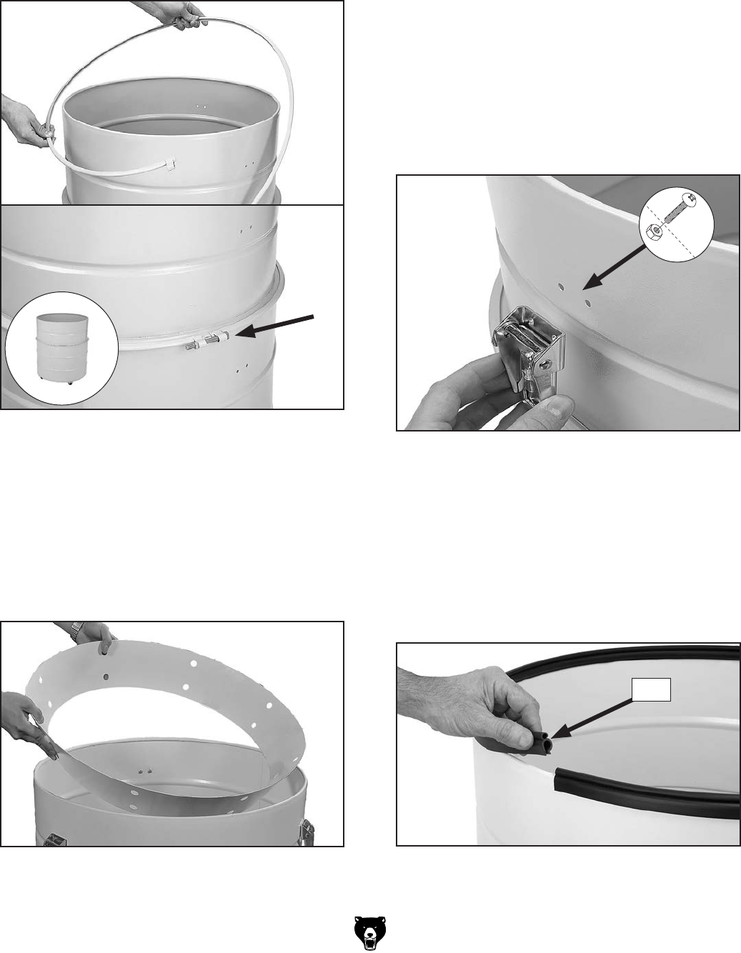
24. Connect the upper and lower collection drums
together with the included metal clamp and
the provided hex bolt and nut, as shown in
Figure 28.
Figure 28. Installing metal clamp around
collection drum.
25. Place the collection drum vacuum ring on the
bottom of the collection drum (see Figure 29).
Note: During operation, this ring and the
vacuum connection to the cyclone funnel will
prevent the collection bag from collapsing.
Figure 29. Inserting collection drum vacuum
ring.
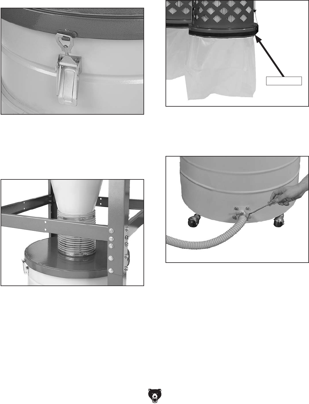
26. Install the three drum latches, as shown in
Figure 30, with the (6) 10-24 x 3⁄8" Phillips
head screws and (6) 10-24 hex nuts included
in the box with the drum latches.
Use the remaining (6) 10-24 x 3⁄8" Phillips
head screws and (6) 10-24 hex nuts to plug
the lower latch mounting holes.
Note: To avoid bag snags, face the screw
heads inside of the drum with the shanks fac-
ing outward.
Figure 30. Installing the latches onto the
collector drum.
x 6
27. Slide the rubber seal over the top lip of the
collection drum rim. Pay special attention
to the direction of the seal, as shown in the
Figure 31.
Tip: Use an adhesive to keep the seal in
place.
Figure 31. Installing drum lid seal.
Seal
-26- Model G0442/G0601 (Mfg Since 3/12)
28. Install the larger plastic collection bag into the
drum, place the lid on it and hook the latch
over the lid, as shown in Figure 32, then
clamp it in place.
Figure 32. Latch hooked over the lid for
clamping.
29. Move the collector drum under the cyclone
assembly and connect it with the clear flex-
ible hose and the two 9" hose clamps, as
shown in Figure 33.
Figure 33. Drum attached to cyclone funnel with
clear 9" hose.
30. Fit the plastic collection bags over the bottom
of the filters and clamp them in place with the
metal bag clamps, as shown in Figure 34.
Figure 34. Canister filter collection bag installed.
Bag Clamp
31. Connect the vacuum hose to the cyclone fun-
nel and collection drum vacuum ports with (2)
1
1⁄4" hose clamps (see Figure 35).
Figure 35. Connecting the vacuum hose.
Model G0442/G0601 (Mfg Since 3/12) -27-
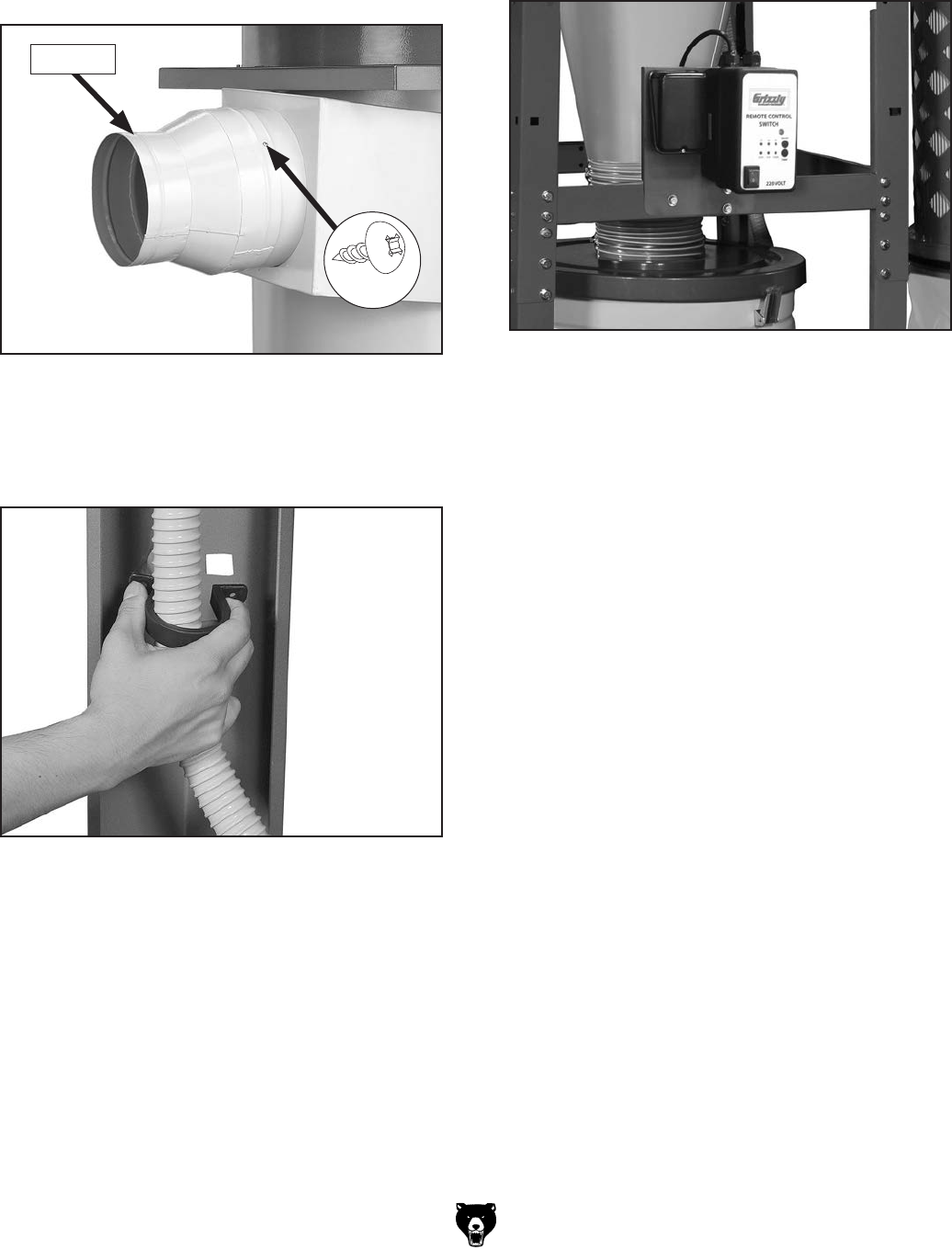
32. Slide the reducer over the inlet port on the
barrel (Figure 36), line up the mounting
holes, and secure it in place with the (3) M4 x
12 sheet metal screws.
Figure 36. Reducer installed.
x 3
Reducer
Note: The hand-held remote control uses IR
(infrared) to communicate with the control
box receiver port, and must have direct line-
of-sight to the control box face. Locate the
control box with this in mind.
Figure 38. Switch mounted to stand.
34. Mount the switch on the stand, as shown in
Figure 38, with (3) 3⁄8"-16 x 3⁄4" hex bolts, (6)
3⁄8" flat washers, and (3) 3⁄8"-16 hex nuts.
33. Secure the vacuum hose inside the upper
and lower stand legs with the (2) U-shaped
clips (see Figure 37).
Figure 37. Securing the vacuum hose to the
stand legs.
-28- Model G0442/G0601 (Mfg Since 3/12)
Power Connection
Due to the complexity required for planning,
bending, and installing the conduit necessary
for a code-compliant hardwire setup, an electri-
cian or other qualified person MUST perform
this type of installation. Hardwire setups typically
require power supply wires to be enclosed inside
of a solid or flexible conduit, which is securely
mounted at both ends with the appropriate con-
duit fittings. All work must adhere to the required
electrical codes.
The hardwire setup for this machine must include
a locking disconnect switch (see Figure 39)
between the power source and the machine. This
switch serves as the means to completely discon-
nect the machine from power to prevent elec-
trocution accidental startup during adjustments,
maintenance, or service to the machine.
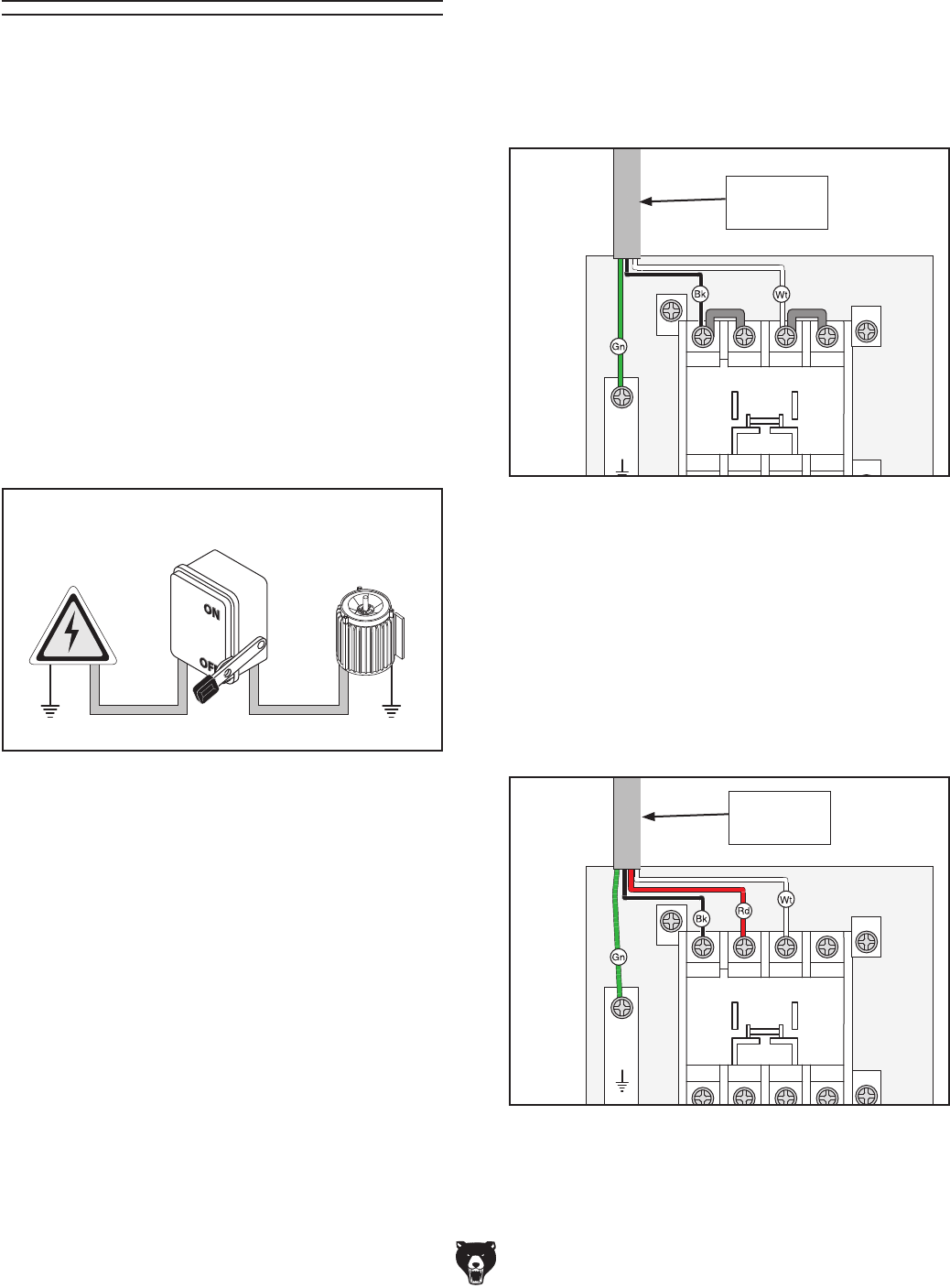
G0442 Power Connection
The incoming power wires must be connected to
the two terminals on the contactor marked 1L1
and 5L3, and the incoming ground wire must be
connected the ground terminal, as illustrated in
Figure 40. All wires must have adequate slack
and be clear of sharp objects.
Figure 40. G0442 mag switch to power supply
connection.
A1
Ground
2T1 6T3 14NO
4T2
1L1 5L3 13NO
3L2
NHD C-18D
2T1 4T2 6T3
98 97 96
O R
95
11
12
13
14
NHD NTH-14
A2
To Power
Supply
To Power
Supply
G0601 Power Connection
The incoming power wires must be connected to
the three terminals on the master power switch
marked 1L1, 3L2, and 5L3, and the incoming
ground wire must be connected the ground ter-
minal shown in Figure 41. All wires must have
adequate slack and be clear of sharp objects.
Figure 41. G0601 mag switch to power supply
connection.
A1
Ground
2T1 6T3 14NO
4T2
1L1 5L3 13NO
3L2
NHD C-18D
2T1 4T2 6T3
98 97
A2
96
O R
95
11
12
13
14
NHD NTH-14
A2
Figure 39. Typical hardwire setup with a locking
disconnect switch.
Power
Source
Locking
Disconnect Switch
Machine
Ground Ground
ConduitConduit

Model G0442/G0601 (Mfg Since 3/12) -29-
Test Run
When the assembly is complete, test run the dust
collection system to make sure it operates prop-
erly.
If, during the test run, you cannot easily locate
the source of an unusual noise or vibration, stop
using the machine immediately, then review the
Troubleshooting on Page 46.
If you still cannot remedy a problem, contact our
Tech Support at (570) 546-9663 for assistance.
To test run the dust collection system:
1. Make sure you have read the safety instruc-
tions at the beginning of the manual and that
the machine is set up properly.
2. Make sure all tools and objects used during
setup are cleared away from the machine.
3. Review the Circuit Requirements section
beginning on Page 11 and connect the
machine to the power source.
4. Flip the main power switch at the lower left
hand corner of the control box to the ON ("l")
position to enable power to the switch.
5. Press the ON/OFF button to turn the machine
ON. Make sure your hand stays poised over
the switch in case you need to quickly turn
the machine OFF.
6. Listen and watch for abnormal noises or
actions. The machine should run smoothly
with little or no vibration or rubbing noises.
— If you suspect any problems, immedi-
ately turn the machine OFF, then discon-
nect the machine from power. Refer to
Troubleshooting on Page 46 to identify
and fix any problems.
—If you cannot solve the problem with the
use of the Troubleshooting guide, contact
our Tech Support at (570) 546-9663 for
assistance.
7. Press the TIMER button on the control box
and cycle through each of the times to make
sure the indicators light.
8. Press the TIMER button on the remote con-
trol and cycle through the times in the same
manner as Step 7.
9. Toggle the ON/OFF button on both the con-
trol box and the remote control to make sure
they are working properly.
For Model G0601 Only
The Model G0601 uses a 3-phase motor. For
proper operation, the impeller inside the blow-
er housing must rotate counterclockwise when
viewed from above. Since the motor and impeller
are directly connected, you must verify that the
motor rotates in the correct direction.
10. Use a ladder to safely observe the motor fan
through the top motor cover as another per-
son turns the machine ON and OFF.
— If the motor fan rotates counterclockwise
when viewed from above, the rotation
direction is correct.
— If the motor fan rotates clockwise when
viewed from above, the rotation direction
is incorrect and the motor is wired out-of-
phase. Perform the Correcting Phase
Polarity procedure on Page 14 to correctly
wire the machine to the power source so
that the motor and impeller spin counter-
clockwise when viewed from above.
If any part of your body contacts the spin-
ning impeller, severe cutting or amputation
injuries will occur. Always keep yourself
and tools away from the impeller when the
machine is connected to power.
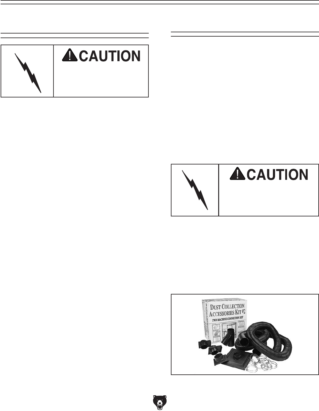
-30- Model G0442/G0601 (Mfg Since 3/12)
The Model G0442/G0601 is designed to be a
central dust collector system. The large suction
capacity of the Model G0442/G0601 allows great
flexibility in planning and designing of the dust col-
lection duct layout.
Note: Check local codes concerning the use
of dust collecting machines before deciding the
placement of the machine.
Grizzly offers a complete line of dust collection
accessories for setting up a stationary system.
Additionally, Grizzly offers a complete guide book
titled Dust Collection Basics.
Whatever system design you choose, always
make sure there are no open flames (including
pilot lights) in the same room as the dust col-
lector; otherwise you risk an explosion if dust is
dispersed into the air.
SECTION 4: DESIGNING THE
SYSTEM
General Duct Material
You have many choices regarding main line and
branch line duct material. For best results, use
metal duct for the main line and branch lines, then
use short lengths of flexible hose to connect each
machine to the branch lines.
Plastic duct is also a popular material for home
shops. However, be aware that there is a fire or
explosion hazard if plastic duct material is used
for dust collection without being grounded against
static electrical charge build-up. This topic will be
discussed later in this section. Another problem
with using plastic is that it is less efficient per foot
than metal.
Plastic duct generates static
electrical buildup that can
cause fire or shock. Properly
ground it to reduce this risk.
Plastic Duct
Figure 42. Examples of plastic ducting
components.
The popularity of plastic duct is due to the fact
that it is an economical and readily available
product. It is also simple to assemble and easily
sealed against air loss. The primary disadvantage
of plastic duct for dust collection is the inherent
danger of static electrical build-up.
Always guard against stat-
ic electrical build up by
grounding all dust collec-
tion lines.
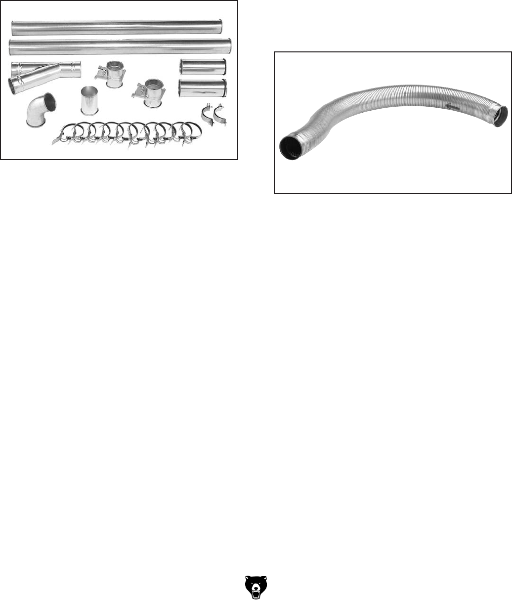
Model G0442/G0601 (Mfg Since 3/12) -31-
There are a number of options when it comes to
metal duct, but metal duct that is specially manu-
factured for dust collection is the best choice.
When selecting your metal duct, choose high
quality metal duct with smooth welded internal
seams that will minimize airflow resistance. This
type of duct usually connects to other ducts
or elbows with a simple, self-sealing clamp, is
very quick and easy to assemble, and can be
readily dismantled and re-installed. This is espe-
cially important if you ever need to change things
around in your shop or add more tools.
Avoid inferior metal duct that requires you to cut it
to length and snap it together. This type of duct is
time consuming to install because it requires you
to seal all the seams with silicone and screw the
components on the ends with sheet metal screws.
Another disadvantage is the rough internal seams
and crimped ends that unavoidably increase static
pressure loss.
There are also many kinds of pure plastic flexible
hose, such as non-perforated drainage type hose
and dryer vent hose. Drainage type hose, while
being economical, does not quite have the flex-
ibility required for dust collection. The inside of the
duct is also deeply corrugated and can increase
the static pressure loss by as much as 50% over
smooth wall duct. Dryer vent hose, while being
completely flexible, is non-resistant to abrasion
and has a tendency to collapse in a negative
pressure system. We DO NOT recommend using
dryer vent hose in your dust collection system.
If using flex-hose, you should choose one of the
many types that are designed specifically for the
movement of solid particles, i.e. dust, grains,
and plastics. However, the cost of specifically
designed flexible duct can vary greatly. Grizzly
offers polyethylene hose, which is well suited for
the removal of particulate matter, especially saw-
dust, since it is durable and completely flexible.
Polyethylene is also very economical and avail-
able in a wide variety of diameters and lengths for
most applications.
Figure 44. Example of flexible metal duct.
Flexible Duct
Flexible hose is generally used for short runs,
small shops and at rigid duct-to-tool connections.
There are many different types of flex hose on
the market today. These are manufactured from
materials such as polyethylene, PVC, cloth hose
dipped in rubber and even metal, including steel
and aluminum.
The superior choice here is metal flex hose that is
designed to be flexible, yet be as smooth as pos-
sible to reduce static pressure loss.
Metal Duct
Advantages of metal duct is its conductivity and
that it does not contribute to static electrical
charge build-up. However, static charges are still
produced when dust particles strike other dust
particles as they move through the duct. Since
metal duct is a conductor, it can be grounded quite
easily to dissipate any static electrical charges.
Figure 43. Examples of metal pipe and
components.
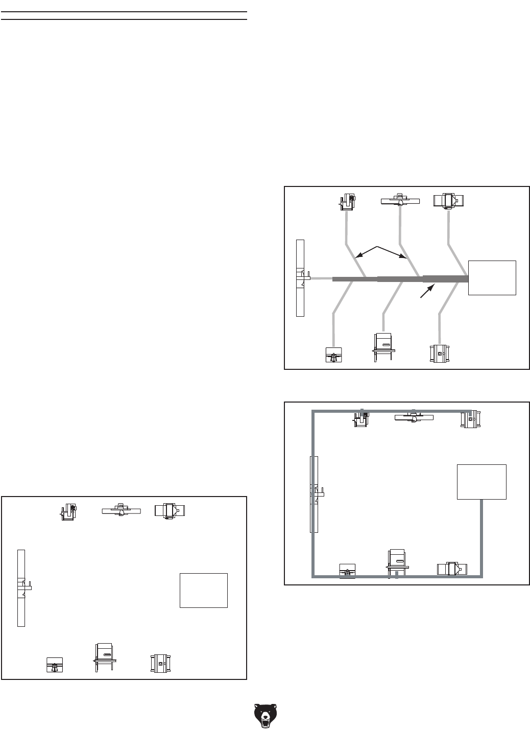
-32- Model G0442/G0601 (Mfg Since 3/12)
System Design
Decide Who Will Design
For most small-to-medium sized shops, you can
design and build the dust collection system your-
self without hiring engineers or consultants. We
have included some basic information here to get
you started on a basic design.
If you have a large shop or plan to design a com-
plicated system, we recommend doing additional
research beyond this manual or seeking the help
of an expert.
Dust
Collector
Figure 45. Basic sketch of shop layout.
Sketch Your Shop Layout
When designing a successful dust collection sys-
tem, planning is the most important step. In this
step, sketch a basic layout of your shop, including
space requirements of different machines.
Before you get out your pencil and paper, we rec-
ommend you visit our FREE
Workshop Planner
,
at
http://www.grizzly.com/workshopplanner.
Our
Workshop Planner will allow you to quickly
and easily design and print a basic shop layout.
Don't worry, non-Grizzly brand machines can be
substituted with Grizzly machines for layout pur-
poses.
Note:
After you're finished, make sure to
save your layout for later modification.
Your sketch only needs the basic details of the
shop layout, similar to
the figure below, includ-
ing all your current/planned machines and your
planned placement of the dust collector
.
Figure 47. Inefficient duct layout.
BAD
Dust
Collector
Figure 46. Efficient duct layout.
Main
Line Duct
Branch
Line
Ducts
GOOD
Dust
Collector
Sketch a Basic Duct Layout
For the next step, sketch how you will connect
your machines to the dust collector. Consider
these general guidelines for an efficient system:
1.
Machines that produce the most saw dust
should be placed nearest to the dust collector
(i.e. planers and sanders).
2.
Ideally, you should design the duct system to
have the shortest possible main line and sec-
ondary branch ducts. See the figures
below
for ideas of efficient versus inefficient duct
layouts.
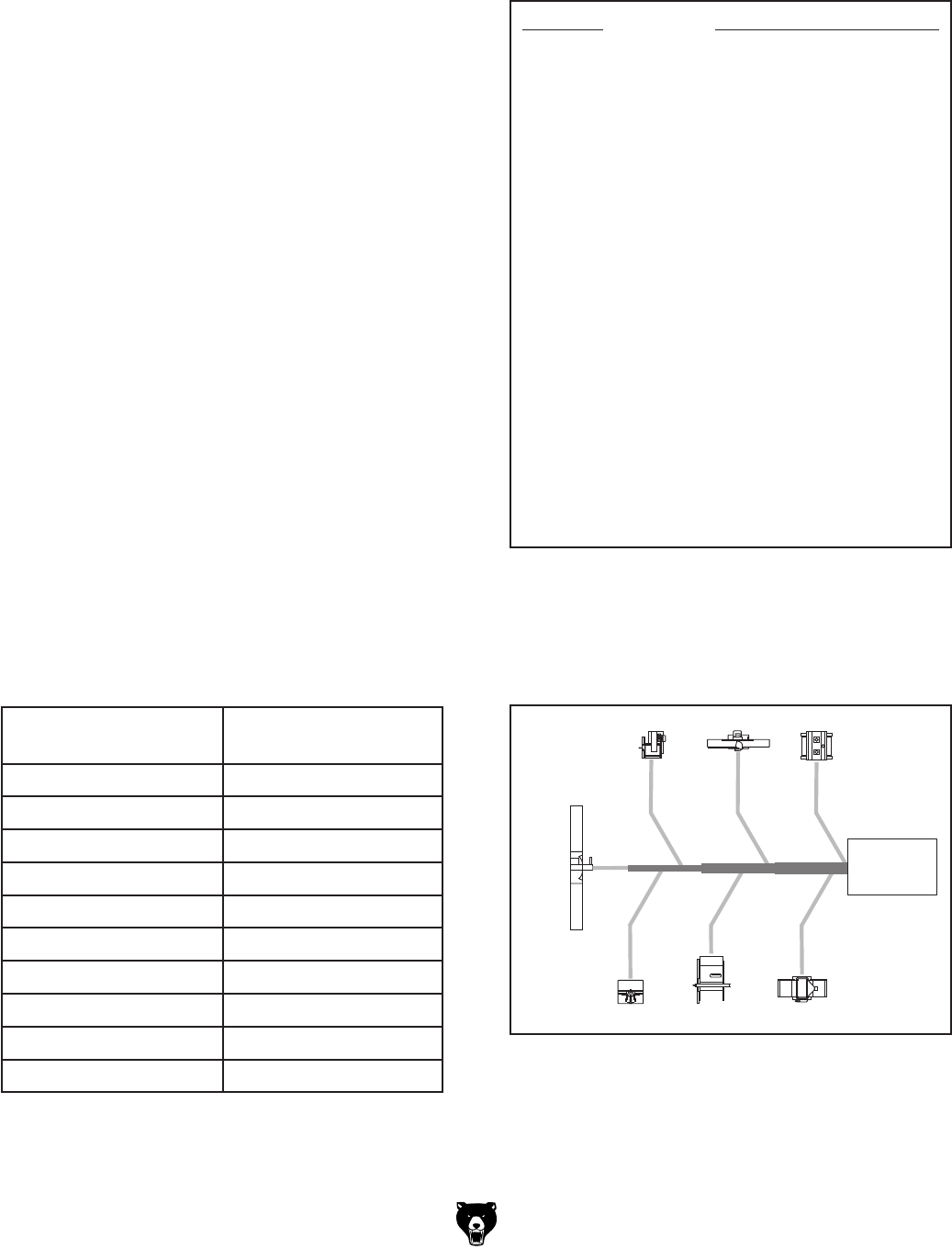
Model G0442/G0601 (Mfg Since 3/12) -33-
3. Directional changes should be kept to a mini-
mum. The more directional change fittings
you use directly increases the overall resis-
tance to airflow.
4.
Gradual directional changes are more effi-
cient than sudden directional changes (i.e.
use the largest corner radius possible when
changing hose or pipe direction).
5.
Each individual branch line should have a
blast gate immediately after the branch to
control suction from one machine to another.
6.
The simpler the system, the more efficient
and less costly it will be.
Determine Required CFMs
Since each machine produces a different amount
of sawdust, the requirements for the minimum
amount of CFM to move that sawdust is unique
to the machine (for example, a planer produces
more sawdust than a table saw). Knowing this
required CFM is important to gauging which size
of duct to use.
Refer to the
figure
below for a close estimation of
the airflow each machine requires. Keep in mind
that machines that generate the most sawdust
should be placed closest to the dust collector.
If the machine has multiple dust ports, the total
CFM required is the sum of all ports.
Figure 48. Approximate required airflow for
machines, based on dust port size.
Machine
Dust Port Size
Approximate
Required CFM
2" 98
2.5" 150
3" 220
4" 395
5" 614
6" 884
7" 1203
8" 1570
9" 1990
10" 2456
If the machine does not have a built-in dust port,
use
the following table
to determine which size of
dust port to install.
Figure 49. Dust port size and quantity per
average machine.
Machine Average Dust Port Size
Table Saw ......................................................4"
Miter/Radial-Arm Saw ....................................2"
Jointer (6" and smaller) .................................4"
Jointer (8"-12") ...............................................5"
Thickness Planer (13" and smaller) ...............4"
Thickness Planer (14"-20") ............................6"
Shaper ...........................................................4"
Router (mounted to table) ..............................2"
Bandsaw ........................................................4"
Lathe ..............................................................4"
Disc Sander (12" and smaller) .......................2"
Disc Sander (13-18") ......................................4"
Belt Sander (6" and smaller) .........................2"
Belt Sander (7"-9") ........................................3"
Edge Sander (6" x 80" and smaller) ..............4"
Edge Sander (6" x 80" and larger) ................ 5"
Drum Sander (24" and smaller) ...............2 x 4"
Drum Sander (24" and larger) .................4 x 4"
Widebelt Sander (18" and smaller) ................5"
Widebelt Sander (24"-37" single head) ...2 x 6"
Widebelt Sander (24"-51" double head) ..5 x 4"
Figure 50. CFM requirements labeled for each
machine.
395
395
614
790395
220
98
Table Saw
Planer/
Moulder
Miter
Saw
Jointer Sander
PlanerShaper
Dust
Collector
Write the required CFM for each machine on your
sketch, as shown in the figure below.
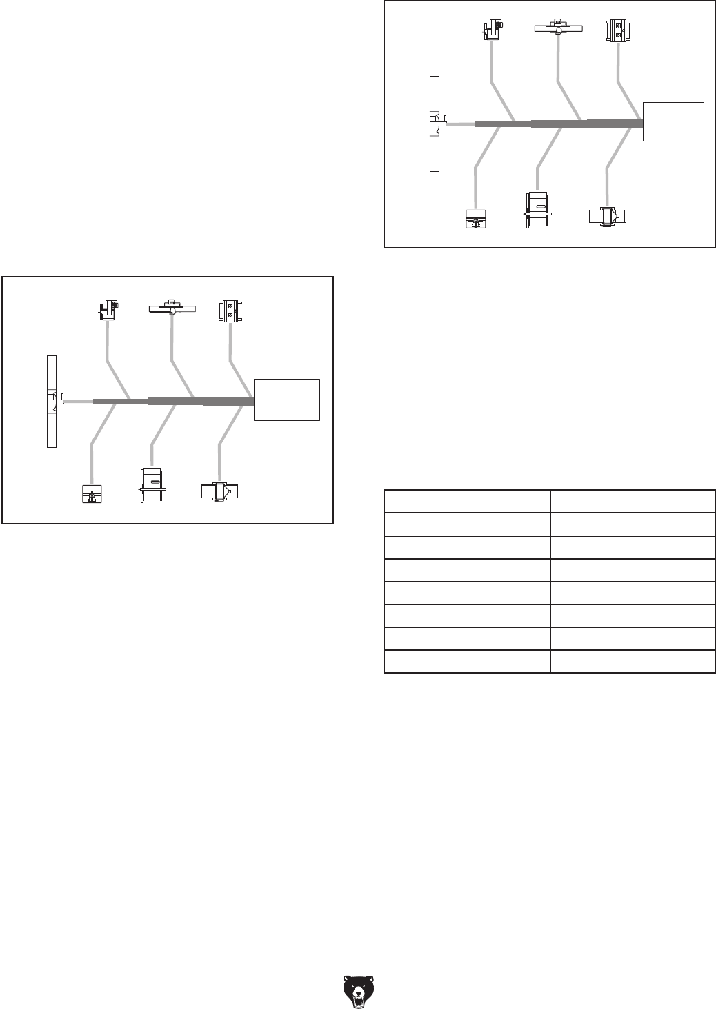
-34- Model G0442/G0601 (Mfg Since 3/12)
Figure 52. Branch line duct sizes labeled.
395
395
614
790
395
220
98
4"
4"
4" 6"
4" 4" 5"
5" 6" 7"
Table Saw
Miter
Saw
Jointer Sander
PlanerShaper
Planer/
Moulder
Dust
Collector
Figure 51. Main line size labeled on sketch.
395
395
614
790395
220
98
Dust
Collector
5" 6" 7"
Table Saw
Planer/
Moulder
Miter
Saw
Jointer Sander
PlanerShaper
Determining Main Line Duct Size
The general rule of thumb for a main line duct is
that the velocity of the airflow must not fall below
3500 FPM.
For small/medium sized shops, using the inlet size
of the dust collector as the main line duct size
will usually keep the air velocity above 3500 FPM
and, depending on your system, will allow you to
keep multiple branches open at one time.
Mark your drawing, as shown in the
figure
below,
but using the inlet size for your dust collector as
the main line.
The general rule of thumb for a branch line duct is
that the velocity of the airflow must not fall below
4000 FPM.
For small/medium sized shops, using the dust
port size from the machine as the branch line duct
size will achieve the correct velocity in most appli-
cations. However, if the dust port on the machine
is smaller than 4", make the branch line 4" and
neck the line down right before the dust port.
Note: Systems with powerful dust collectors work
better if multiple blast gates are left open. This
also allows you to run two machines at once.
Experiment with different combinations of blast
gates open/closed to find the best results for your
system.
Write your determined branch line sizes on your
drawing, as shown in the following figure.
Determining Branch Line Duct Size
Total CFM Branch Line Size
400 4"
500 4"
600 5"
700 5"
800 6"
900 6"
1000 6"
If two machines will connect to the same branch
line and both will operate at the same time, then
add the required CFM for each machine together
and
find the closest total CFM in the table below
to determine the correct branch size
.
If both machines will never run at the same time,
reference the machine with the biggest dust port
in the table
below and add blast gates after the
Y-branch to open/close the line to each machine.
Figure 53. Sizing chart for multiple machines on
the same branch line.
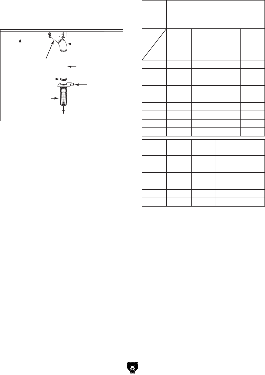
Model G0442/G0601 (Mfg Since 3/12) -35-
Figure 55. Static pressure loss charts.
Duct
Dia.
Approximate
Static Pressure
Loss Per Foot of
Rigid Pipe
Approximate
Static Pressure
Loss Per Foot
of Flex Pipe
Main
Lines
at 3500
FPM
Branch
Lines
at 4000
FPM
Main
Lines
at 3500
FPM
Branch
Lines
at 4000
FPM
2" 0.091 0.122 0.35 0.453
2.5" 0.08 0.107 0.306 0.397
3" 0.071 0.094 0.271 0.352
4" 0.057 0.075 0.215 0.28
5" 0.046 0.059 0.172 0.225
6" 0.037 0.047 0.136 0.18
7" 0.029 0.036 0.106 0.141
8" 0.023 0.027 0.08 0.108
9" 0.017 0.019 0.057 0.079
Fitting
Dia.
90˚
Elbow
45˚
Elbow
45˚
Wye(Y)
90˚
Wye(Y)
3" 0.47 0.235 0.282 0.188
4" 0.45 0.225 0.375 0.225
5" 0.531 0.266 0.354 0.236
6" 0.564 0.282 0.329 0.235
7" 0.468 0.234 0.324 0.216
8" 0.405 0.203 0.297 0.189
In most small/medium shops it is only necessary
to calculate the line with the longest duct length or
the most fittings (operating under the assumption
that if the line with the highest resistance works,
the others will be fine).
To calculate the static pressure of any given
line in the system, follow these steps:
1.
Make a list of each size duct in the line,
including the length, and multiply those num-
bers by the static pressure value given in
the
previous table.
2.
List each type of elbow or branch and multiply
the quantity (if more than one) by the static
pressure loss given in the previous table.
Adding duct work, elbows, branches and any
other components to a duct line increases airflow
resistance (static pressure loss). This resistance
can be minimized by using rigid (smooth) pipe and
gradual curves, as opposed to flexible pipe and
90˚ elbows.
To help you think about this resistance, imagine
riding a bicycle in a tunnel that is an exact replica
of your duct work. If the inside of the tunnel is very
bumpy (flexible pipe) and has a lot of sharp turns
(90˚ elbows), it will take a lot more effort to travel
from one end to the other.
The purpose of calculating the resistance is to
determine if it is low enough from the machine to
the dust collector to meet the given CFM require-
ment for the machine. Use the
following tables
to
calculate the resistance of duct work.
Calculating Duct Resistance
To Planer
Blast Gate
Flex Pipe
Rigid Pipe
Rigid Pipe
(Main Line)
Elbow
Clamp
Y Branch
Figure 54. Drop down setup.
Planning Drop Downs
Plan the drop downs for each machine, using
blast gates wherever possible to control airflow.
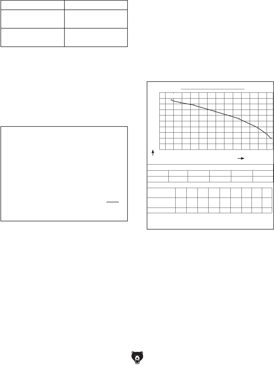
-36- Model G0442/G0601 (Mfg Since 3/12)
Figure 56. Additional factors affecting static
pressure.
Additional Factors Static Pressure
Seasoned (well used)
Dust Collection Filter 1"
Entry Loss at Large
Machine Hood 2"
Figure 57. Totaling static pressure numbers.
Main Line
6" Rigid Pipe (0.037) at 20' ................ 0.740
Branch Line
4" Rigid Pipe (0.075) at 10' ................ 0.750
4" Flex Pipe (0.28) at 5' ........................ 1.400
Elbows/Branches
6" 45˚ Y-Branch ................................ 0.329
4" 45˚ Elbow ........................................ 0.225
Additional Factors
Seasoned Filter ................................ 1.000
Total Static Pressure Loss ................ 4.444
4. Total your list as shown in the example below
to come up with your overall static pressure
loss number for that line.
Note:
Always account for a seasoned filter,
so you don't end up with a system that only
works right when the filter is clean.
Note: When calculating static pressure loss
to determine if multiple lines can be left open
at the same time, only include the main line
numbers once.
3. Add the additional factors from the following-
table to your list.
5. Compare the total static pressure loss for that
line to the closest CFM given in Figure 58.
Example: The G0442/G0601 Data Sheet
Performance Curve is illustrated in Figure
58. Find 4.6 on the Static Pressure axis (the
amount of total static pressure loss calcu-
lated in Figure 57), then refer to the closest
value on the CFM axis—approximately 1953
CFM.
The 1953 CFM for the static pressure loss of
the line connected to the router is well above
the 220 CFM requirement of that machine.
— If the CFM for your static pressure loss
is above the requirement of the machine
connected to the end of that branch line,
then dust collection will most likely be
successful. Congratulations! You've just
designed your own dust system. Refer to
the Accessories section on Page 41 to
start buying the components necessary to
make your system a reality.
Figure 58. G0442/G0601 performance curve
chart and data.
Performance Curve
2500
2250
2000
1750
1500
1250
1000
750
500
250
0
0.0 1.0 2.0 3.0 4.0 5.0 6.0 7.0 8.0 9.0 10.0 11.0 12.0 13.0
2184
CFM STATIC PRESSURE (Inch/H2O)
5 HP GRIZZLY DUST COLLECTOR PERFORMANCE RESULTS
Max CFM Max SP HP Volts Inlet Impeller
2184 14.0 5 HP 220V 10" 16"
Restrictor plate
(inch)
Dia
10"
Dia
9"
Dia.
8"
Dia.
7"
Dia.
6"
Dia.
5"
Dia.
4"
Dia.
3"
Dia.
2"
Static pressure
(Inch/H2O)
1.9 2.1 3.0 4.6 7.0 9.8 12.1 13.2 13.7
CFM 2184 2129 2072 1953 1692 1381 977 691 488
The airflow test probe is located 1.5x duct diameter upstream from
the air inlet. Test pipe length is a minimum of 10x duct diameter.

Model G0442/G0601 (Mfg Since 3/12) -37-
Description Model Quantity
6" Rigid Pipe at 20' G7364 4
4" Rigid Pipe at 10' G6162 2
4" Flex Hose at 5' H7215 6
6" 45° Y-Branch G7353 6
4" 45° Elbow G6167 6
Example Materials List
After the system is designed, create a materials
list of all the items you will need to build your dust
collection system. This will make it easy when it
comes time to purchase the materials.
Below is an example of some items that might be
needed. Refer to
Accessories
for dust collection
components available through grizzly.com.
—If the CFM for your static pressure loss is
below the requirement of the machine, then
that line will not effectively collect the dust.
You must then modify some of the factors
in that line to reduce the static pressure
loss. Some of the ways to do this include 1)
installing larger duct, 2) reducing amount of
flexible duct used, 3) increasing machine
dust port size, 4) moving machine closer to
dust collector to eliminate duct length, and
5) reducing 90˚ elbows or replacing them
with 45˚ elbows.
Figure 59. Example of dust collection system
material list.
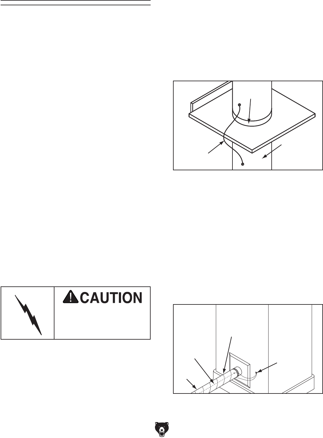
-38- Model G0442/G0601 (Mfg Since 3/12)
System Grounding
Since plastic hose is abundant, relatively inex-
pensive, easily assembled and air tight, it is a
very popular material for conveying dust from
woodworking machines to the dust collector. We
recommend using flexible hose (flex-hose) to
connect the woodworking machine to the dust
collector. However, plastic flex-hose and plastic
duct are an insulator, and dust particles moving
against the walls of the plastic duct create a static
electrical build up. This charge will build until it
discharges to a ground. If a grounding medium
is not available to prevent static electrical build
up, the electrical charge will arc to the nearest
grounded source. This electrical discharge may
cause an explosion and subsequent fire inside
the system.
To protect against static electrical build up inside
a non-conducting duct, a bare copper wire should
be placed inside the duct along its length and
grounded to the dust collector. You must also
confirm that the dust collector is continuously
grounded through the electrical circuit to the elec-
tric service panel.
If you connect the dust collector to more than one
machine by way of a non-conducting branching
duct system and blast gates, the system must still
be grounded as mentioned above. We recom-
mend inserting a continuous bare copper ground
wire inside the entire duct system and attaching
the wire to each grounded woodworking machine
and dust collector.
Be sure that you extend the bare copper wire
down all branches of the system. Do not forget
to connect the wires to each other with wire nuts
when two branches meet at a “Y” or “T” connec-
tion.
Ensure that the entire system is grounded. If using
plastic blast gates to direct air flow, the ground-
ing wire must be jumped (see the figure
below)
around the blast gate without interruption to the
grounding system.
We also recommend wrapping the outside of all
plastic ducts with bare copper wire to ground the
outside of the system against static electrical build
up. Wire connections at Y’s and T’s should be
made with wire nuts.
Attach the bare ground wire to each stationary
woodworking machine and attach to the dust
collector frame with a ground screw as shown
in the figure below. Ensure that each machine is
continuously grounded to the grounding terminal
in your electric service panel.
External
Ground Wire
Internal
Ground Wire
Flex-Hose
Ground
Screw
Figure 61. Flex-hose grounded to machine.
Plastic Blast
Gate
Copper
Ground Wire
Metal Duct
Figure 60. Ground jumper wire when using
plastic blast gates and metal duct.
Always guard against stat-
ic electrical build up by
grounding all dust collec-
tion lines.
Model G0442/G0601 (Mfg Since 3/12) -39-
SECTION 5: OPERATIONS
Do NOT put hands or
small objects near inlet
openings during opera-
tion. Objects sucked
into the inlet will meet
with the impeller blade.
Failure to heed this
warning could result in
property damage or per-
sonal injury.
General
Operating the Model G0442/G0601 is simple and
straightforward. Blast gates located at each of the
machines controls the air flow from the woodwork-
ing machine to the dust collector. If a machine
is not being used, keep the blast gate closed to
maintain higher levels of efficiency throughout the
system.
Damage to your eyes, lungs, and ears could
result from using this machine without
proper protective gear. Always wear safety
glasses, a respirator, and hearing protection
when operating this machine.
DO NOT use the dust collector for any
other purpose besides collecting dust from
connected woodworking machines. A dust
collector should NEVER be used as a shop
vacuum and IS NOT a substitute for an air
filter system. For safest use, wear a respira-
tor and use an air cleaner in addition to the
dust collector.
Remote Control
The remote control for the Model G0442/G0601
is IR (infrared) rather than RF (radio frequency) to
prevent accidental startups by other common RF
items such as garage door openers.
Because this remote system is IR, the remote
control must be pointing directly at the control box
with an unobstructed line-of-sight view.
If you place the dust collector in a different room or
outside of your shop, you must mount the switch
in the shop and wire it through the wall to the dust
collector to make use of the remote control.
Note: The remote control requires two "AA" batter-
ies for operation.
NOTICE
If you have never used this type of machine
or equipment before, WE STRONGLY REC-
OMMEND that you read books, trade maga-
zines, or get formal training before begin-
ning any projects. Regardless of the con-
tent in this section, Grizzly Industrial will
not be held liable for accidents caused by
lack of training.
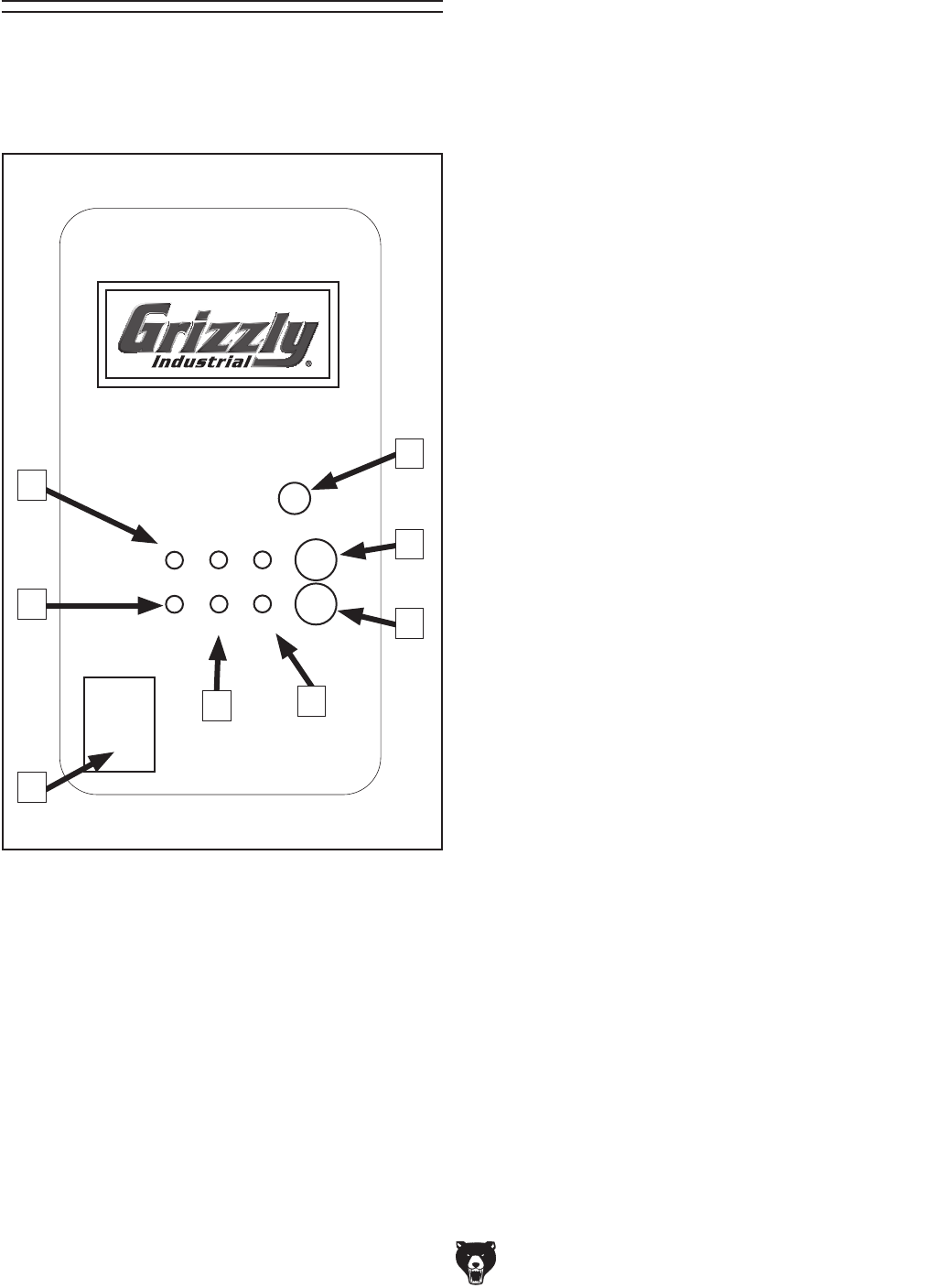
-40- Model G0442/G0601 (Mfg Since 3/12)
Control Box Panel
Use the illustration of the control box panel in
Figure 62 and the descriptions that follow to
become familiar with the functions of the buttons
on the control box.
A. Timer Indicator Lights: Turns ON when a
timer setting is selected.
B. Infrared Port: Receives infrared communica-
tion from the remote control.
C. ON/OFF Button: Starts/stops the dust collec-
tor motor.
D. Timer Button: Cycles through the available
timer settings.
E. Power Light: Indicates when there is power
to the control box.
F. Run Light: Illuminates when the dust collec-
tor motor is operating.
G. Main Switch: Enables/disables the power
flow to the control box and must be turned
ON before using ON/OFF button.
H. Overload Light: Turns ON when the dust
collector is overloaded and the motor has
stopped.
Note: If the overload light illuminates and the
motor stops, you must turn the machine OFF
and allow the motor to cool. The overload
relay should reset automatically and the light
will go out.
If this is a persistent problem, refer to the
Troubleshooting section on Page 46 for
additional help.
ON/OFF
TIMER
2H 4H 8H
RUN POWEROVER
REMOTE CONTROL
SWITCH
220 VOLT
MAIN
SWITCH
Figure 62. Control box panel.
A
B
C
D
E
F
H
G
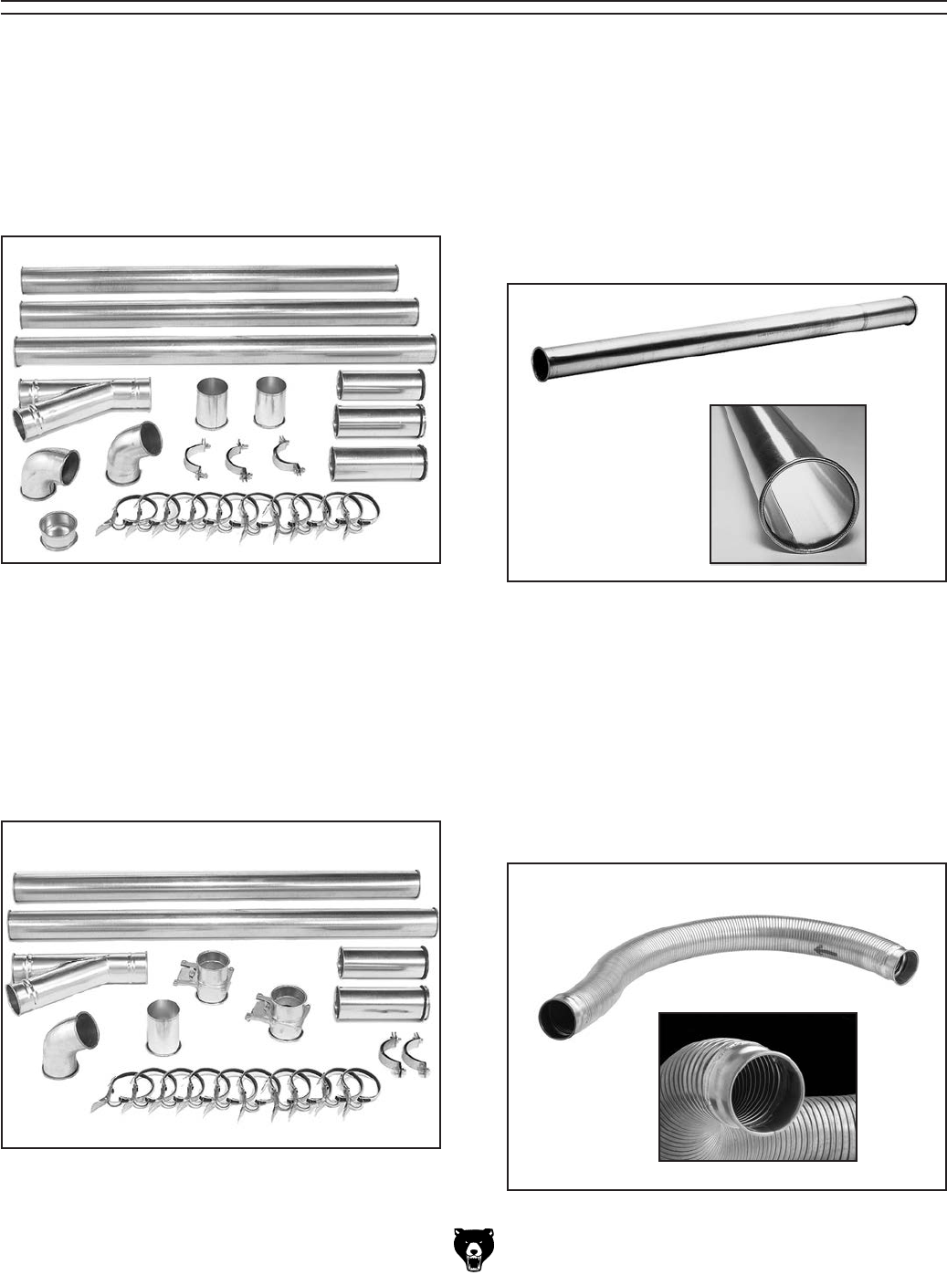
Model G0442/G0601 (Mfg Since 3/12) -41-
SECTION 6: ACCESSORIES
ACCESSORIES
Figure 66. Rigid Metal Flex Hose.
H7216—5" x 5' Rigid Metal Flex Hose
H7217—6" x 5' Rigid Metal Flex Hose
H7218—7" x 5' Rigid Metal Flex Hose
H7219—8" x 5' Rigid Metal Flex Hose
H7220—9" x 5' Rigid Metal Flex Hose
This flex hose provides just enough flexibility
to make difficult connections while still keep-
ing the inside wall as smooth as possible to
minimize static pressure loss.
H5293—4" Metal Duct Starter Kit
H5295—5" Metal Duct Starter Kit
H5297—6" Metal Duct Starter Kit
Save over 20% with this great starter kit.
Includes: (2) machine adapters, (10) pipe
clamps, (3) 5' straight pipes, (1) branch, (3)
pipe hangers, (1) end cap, (3) adjustable
nipples, (1) 90˚ elbow, and (1) 60˚ elbow.
H5294—4" Metal Duct Machine Addition Kit
H5296—5" Metal Duct Machine Addition Kit
H5298—6" Metal Duct Machine Addition Kit
Save over 20% with this great machine addi-
tion kit. Includes: (2) blast gates, (1) machine
adapter, (10) pipe clamps, (2) pipe hangers,
(2) 5' straight pipes, (2) adjustable nipples, (1)
branch, and (1) 60˚ elbow.
Figure 64. Metal Duct Machine Addition Kit.
G6162—4" x 5' Straight Metal Pipe
G7346—5" x 5' Straight Metal Pipe
G7364—6" x 5' Straight Metal Pipe
H5227—7" x 5' Straight Metal Pipe
H5237—8" x 5' Straight Metal Pipe
H5252—9" x 5' Straight Metal Pipe
These laser welded straight pipes ensure
a super smooth internal seam. Ends easily
clamp together for a sealed fit without screws
or silicone.
Figure 63. Metal Duct Starter Kit. Figure 65. Straight Metal Pipe.
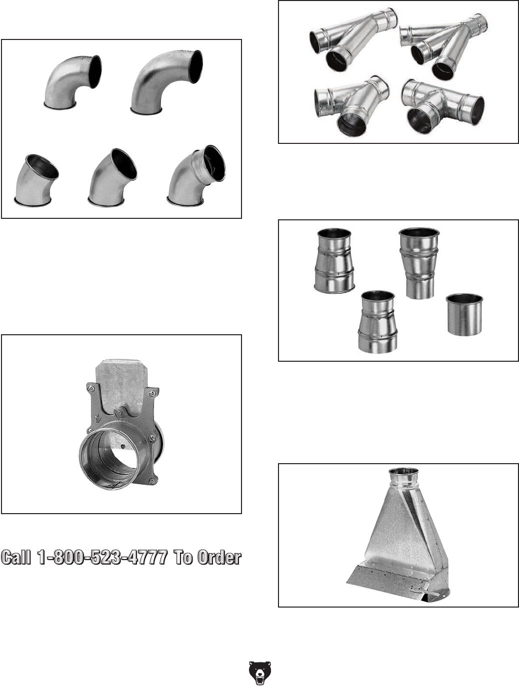
-42- Model G0442/G0601 (Mfg Since 3/12)
Metal Elbows
These industrial metal elbows are available
from 4"–8" with 90˚, 60˚, 45˚, or 30˚ curves.
Also, available with a 90˚ long radius curve.
Call (800) 523-4777 or visit www.grizzly.
com for more information and pricing.
Figure 67. Metal elbow examples.
45° 60°
30°
90° Long Radius
90°
G6177—4" Metal Blast Gate
G7340—5" Metal Blast Gate
G7358—6" Metal Blast Gate
H5234—7" Metal Blast Gate
H5249—8" Metal Blast Gate
H5259—9" Metal Blast Gate
Figure 68. Metal Blast Gate.
Metal Branches
We carry many different branches, all
designed to minimize airflow resistance.
Figure 69. Metal Branches.
Reducers & Adapters
We carry a multitude of reducers and elbows
to cover most applications from 4" through 9".
Figure 70. Metal Reducers & Adapters.
G6252—4" Floor Sweep
G7341—5" Floor Sweep
G7342—6" Floor Sweep
Great for cleaning up around the shop, these
metal floor sweeps close tight when not in use.
Figure 71. Industrial Floor Sweep.
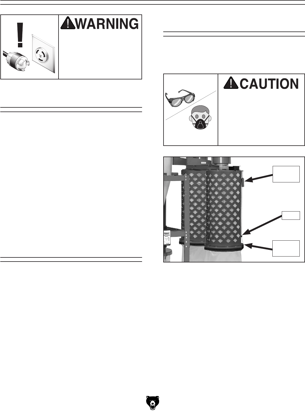
Model G0442/G0601 (Mfg Since 3/12) -43-
SECTION 7: MAINTENANCE
Always disconnect power
to the machine before
performing maintenance.
Failure to do this may
result in serious person-
al injury.
Schedule
For optimum performance from your machine,
check the following items during operation. If you
notice a problem, resolve it before continuing
operation. At the end of the day, make sure the
machine is turned OFF and disconnected from
power.
During Operations:
• Dust collection drums and bags.
• Check/repair loose mounting bolts.
• Pressure leaks.
• Worn or damaged wires.
• Any other condition that would hamper the
safe and efficient operation of this machine.
Emptying Drum
Empty the collection drum when it is no more than
3⁄4 full. If the drum becomes overfilled, the chips
will be sucked back into the intake barrel and
passed through to the canister filters.
How quickly the drum will fill up is based on the
type of work being done at the time.
When first using the machine, check the drum
regularly to get an idea of how often it needs to
be emptied.
The Model G0442/G0601 dust collector has
a gentle brush system inside the canisters for
removing any built-up dust from the filter pleats.
Cleaning Filters
To clean the filters, pull the red handles down all
the way, then pull the black handles down and
hook them in place.
Note: Always make sure to leave the red handles
in the up position to ensure that the brushes return
to their proper position and do not restrict the fil-
ter.
To avoid injury to your
eyes and lungs from fine
airborne particles, always
wear safety glasses and
a respirator when working
with the dust collection
bags.
Figure 72. Brush handles for cleaning canister
filters.
Black
Handle
Hook
Red
Handle
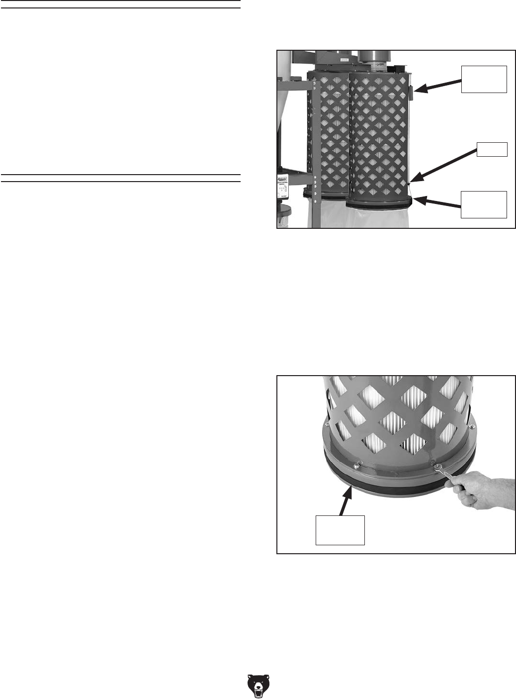
-44- Model G0442/G0601 (Mfg Since 3/12)
Rinsing Filter
For a thorough cleaning, the filter can be removed
and rinsed off. However, make sure to clean the
filter with the brush system first. Allow the filter to
air dry. Do not use compressed air on the pleated
filter or leave it in the sun to dry—this could dam-
age it.
Removing/Replacing
Filter
The filter for the Model G0442/G0601 manufac-
tured since November, 2009, can be removed
from the assembly for replacement or rinsing.
Removing/installing the filter requires discon-
necting the canister filter assembly from the dust
collector and disassembling it. Follow the instruc-
tions below to perform this procedure.
Refer to the parts breakdown diagrams and list-
ings beginning on Page 52 to order the correct
filter from Grizzly at 800-523-4777.
Tools Needed Qty
Open-End Wrench 10mm .................................. 1
Wrench or Socket 12mm ................................... 2
To replace the canister filter:
1. DISCONNECT MACHINE FROM POWER!
2. Use the brush handles to knock the built-up
dust from the filter pleats, then remove the
bag clamp and collection bag from the canis-
ter assembly.
3. Pull the black handle all the way down and
secure the cable into the handle hook at the
bottom of the canister assembly, as shown in
Figure 73, to hold it in place during the fol-
lowing steps.
4. Remove the canister assembly from the
dust collector and place it right-side up on a
stable, flat surface.
5. Remove the six hex bolts, hex nuts, and flat
washers from the rim of the canister base, as
shown in Figure 74.
Figure 74. Removing the hex nuts and flat
washers from the rim of the canister base.
Canister
Base
Figure 73. Brush handles in correct position for
filter removal.
Black
Handle
Hook
Red
Handle
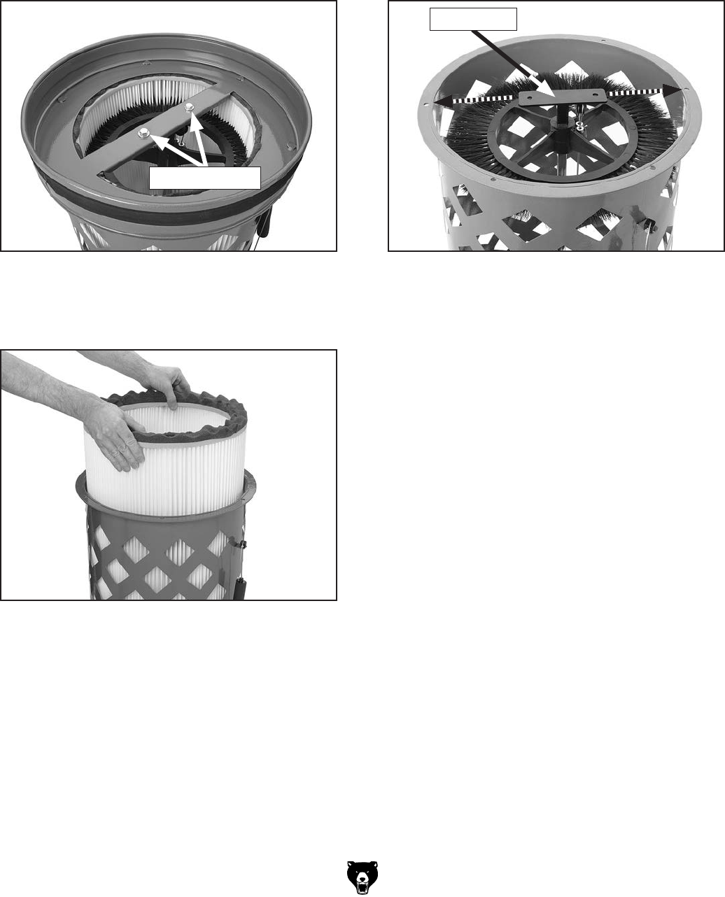
Model G0442/G0601 (Mfg Since 3/12) -45-
6. With help from another person to steady the
canister assembly, turn it upside down and
remove the two hex bolts, hex nuts, and flat
washers from the cross support (see Figure
75), then remove the canister base from the
assembly.
Figure 75. Cross support fasteners.
Remove These
7. Carefully lift the filter from the canister assem-
bly, as shown in Figure 76.
Figure 76. Removing the filter from the canister
assembly.
8. Before re-inserting the filter into the assem-
bly, make sure that the filter brush base is
aligned with two of the fastener holes around
the base of the assembly (see Figure 77).
This will allow the canister base to align with
the fastener holes around the brush base.
9. Re-insert the filter into the canister assem-
bly.
Note: Make sure the bristles of the brush are
pointed straight into the pleats to ensure effi-
cient cleaning of the filter when needed.
10. Attach the canister base in the reverse order
from which you removed it in Step 6.
11. Attach the canister assembly to the dust col-
lector, then secure a new collection bag to it
with the bag clamp.
Figure 77. Filter brush base aligned with
assembly fastener holes.
Brush Base
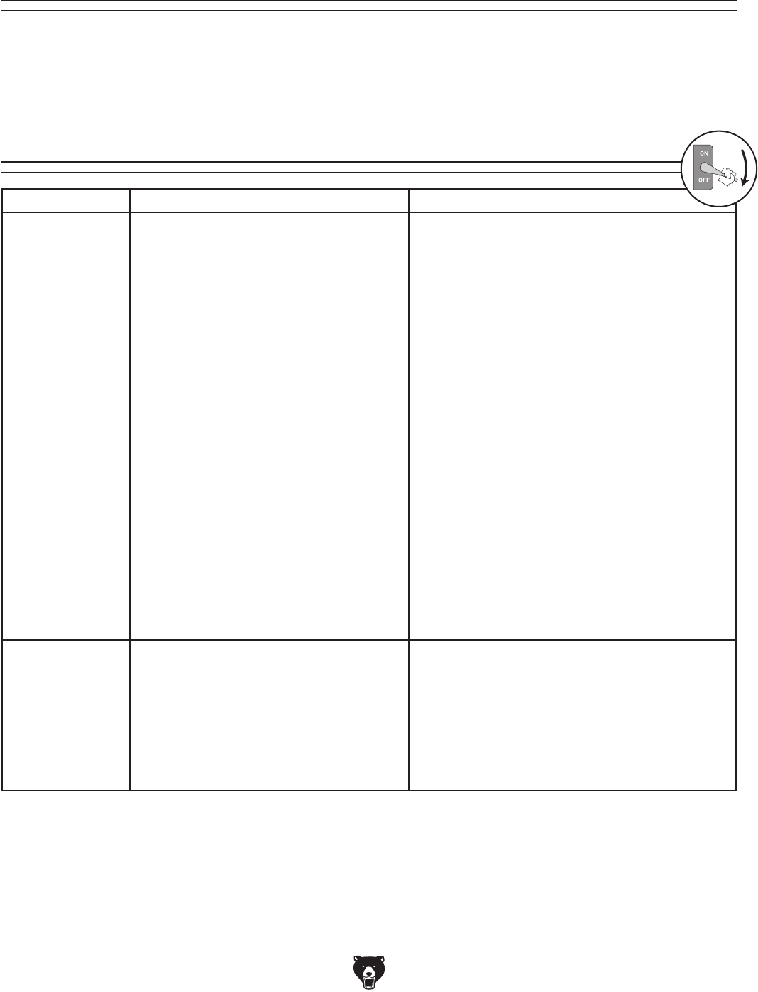
-46- Model G0442/G0601 (Mfg Since 3/12)
Review the troubleshooting and procedures in this section to fix or adjust the machine if a problem devel-
ops. If you need replacement parts or you are unsure of your repair skills, then feel free to call our Technical
Support at (570) 546-9663.
SECTION 8: SERVICE
Troubleshooting
Symptom Possible Cause Possible Solution
Machine does
not start or a
breaker trips.
1. Wall fuse/circuit breaker is blown/tripped.
2. Power supply switched OFF or is at fault.
3. Fuse has blown.
4. Hand-held remote controller is at fault.
5. (G0442) Start capacitor at fault.
6. Receiver is at fault.
7. Motor connection wired incorrectly.
8. Thermal overload relay has tripped.
9. Contactor not getting energized/has
burnt contacts.
10. Wiring is open/has high resistance.
11. Motor start switch or ON/OFF button is
at fault.
12. Circuit board is at fault.
13. Motor is at fault.
1. Ensure circuit size is suitable for this machine;
replace weak breaker.
2. Ensure power supply is switched on; ensure
power supply has the correct voltage.
3. Correct short/replace fuse in control box.
4. Replace batteries in hand-held remote
controller; stay in line-of-sight view and signal
range.
5. Replace start capacitor.
6. Inspect receiver computer board; replace if faulty.
7. Correct motor wiring connections (Pages 49 & 50).
8. Turn cut-out dial to increase working amps and
push the reset pin. Replace if tripped multiple
times (weak relay).
9. Test for power on all legs and contactor
operation. Replace unit if faulty.
10. Check for broken wires or disconnected/
corroded connections, and repair/replace as
necessary.
11. Replace faulty ON button or ON/OFF switch.
12. Inspect circuit board; replace if faulty.
13. Test/repair/replace.
Machine has
vibration or
noisy operation.
1. Motor or component is loose.
2. Machine is incorrectly mounted or sits
unevenly.
3. Motor fan is rubbing on fan cover.
4. Motor bearings are at fault.
1. Inspect/replace stripped or damaged bolts/
nuts, and re-tighten with thread locking fluid.
2. Tighten/replace anchor studs in floor; relocate/
shim machine.
3. Replace dented fan cover; replace loose/
damaged fan.
4. Test by rotating shaft; rotational grinding/loose
shaft requires bearing replacement.
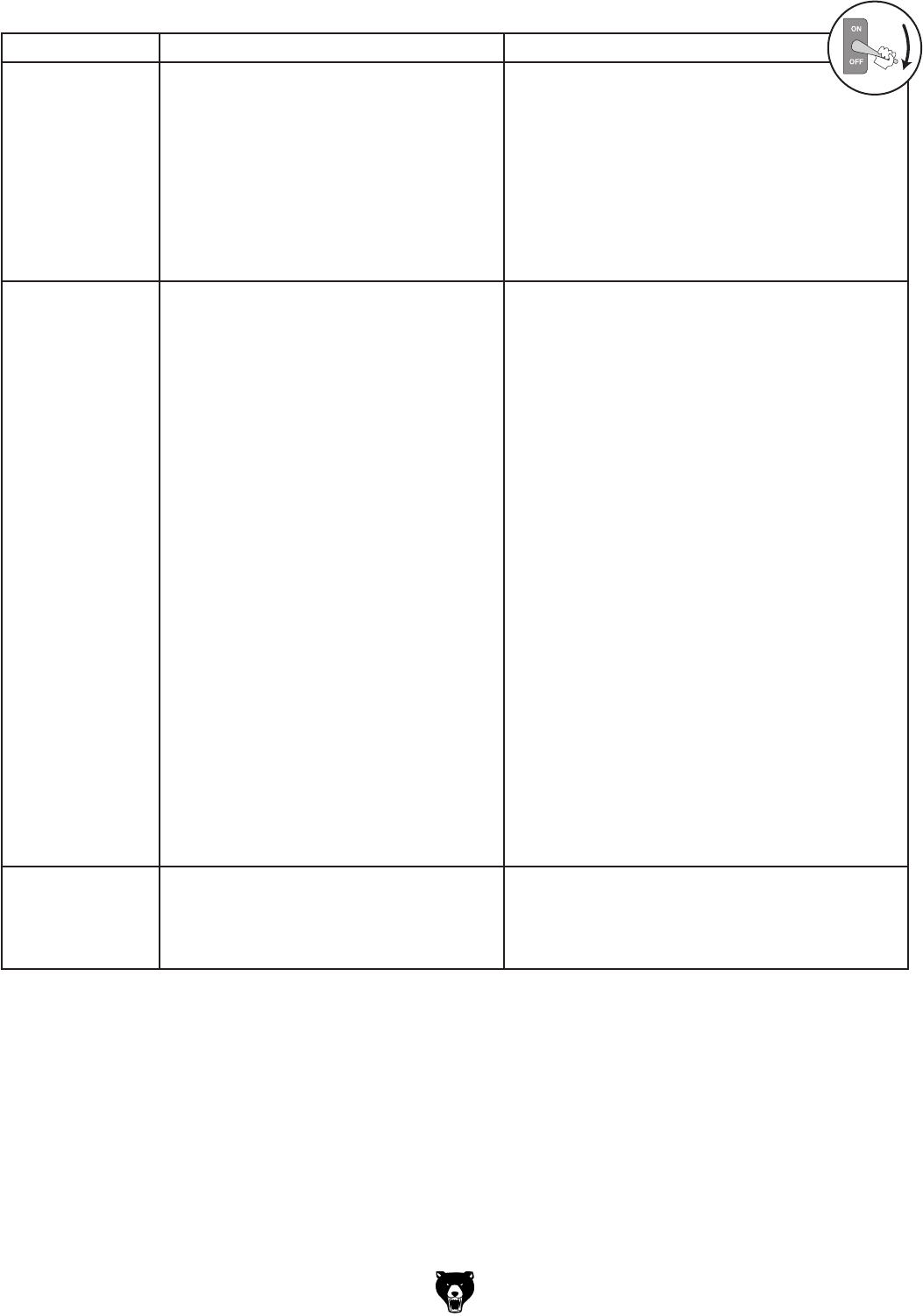
Model G0442/G0601 (Mfg Since 3/12) -47-
Symptom Possible Cause Possible Solution
Loud, repetitious
noise, or excessive
vibration coming
from dust collector.
1. Dust collector is not on a flat surface and
wobbles.
2. Impeller is loose or damaged and
unbalanced.
3. The motor mounting or housing
connections are loose.
4. Impeller is loose on the motor shaft.
5. Motor fan cover is dented, causing the
motor fan to hit the cover while spinning.
1. Stabilize the dust collector.
2. Disconnect dust collector from power, and inspect
the impeller for dents, bends, loose fins. Replace
impeller if any damage is found.
3. Make sure all fasteners on the dust collector are
tight.
4. Replace the motor and impeller as a set if the
motor shaft and the impeller hub are damaged.
5. Replace motor fan cover.
Dust collector does
not adequately
collect dust
or chips; poor
performance.
1. Dust collection bags are full.
2. Filters are dirty.
3. (G0601) Motor is wired out of phase
and the impeller is rotating in the
wrong direction (clockwise).
4. There is a restriction in the duct line.
5. The dust collector is too far away from
the point of suction, or there are too many
sharp bends in the ducting.
6. The lumber is wet and dust is not flowing
through the ducting smoothly.
7. There is a leak in the ducting, or a series
of small leaks, or too many open ports.
8. There are not enough open branch lines at
one time, thereby causing a velocity drop
in the main line.
9. The ducting and ports are incorrectly
sized.
10. The machine dust collection design is
inadequate.
11. The dust collector is too small for the dust
collection system.
1. Empty collection bags.
2. Clean filters.
3. (G0601) Motor is receiving power out-of-phase.
Disconnect the machine from power, then
swap any two of the incoming hot power leads
terminated inside the control box (see Step 10
on Page 29).
4. Remove dust line from dust collector inlet and
unblock the restriction in the duct line. A plumbing
snake may be necessary.
5. Relocate the dust collector closer to the point of
suction, and rework ducting without sharp bends.
Refer to Designing Ducting System, beginning
on Page 32.
6. Process lumber with less than 20% moisture
content.
7. Rework the ducting to eliminate all leaks. Close
dust ports for lines not being used. Refer to
Designing Ducting System beginning on Page
32 for more solutions.
8. Open 1 or 2 more blast gates to different branch
lines to allow the velocity in the main line to
increase.
9. Reinstall correctly sized ducts and fittings. Refer
to Designing Ducting System beginning on Page
32 for more solutions.
10. Use a dust collection nozzle on a stand.
11. Install a larger dust collector to power your dust
collection system.
Sawdust being
blown into the
air from the dust
collector.
1. Duct clamps or dust collection bags are
not properly clamped and secured.
2. Cylinder or funnel seals are loose or
damaged.
1. Re-secure ducts and dust collection bag, making
sure duct and bag clamps are tight and completely
over the ducts and bags.
2. Retighten all mounting and sealing points, replace
damaged gaskets.
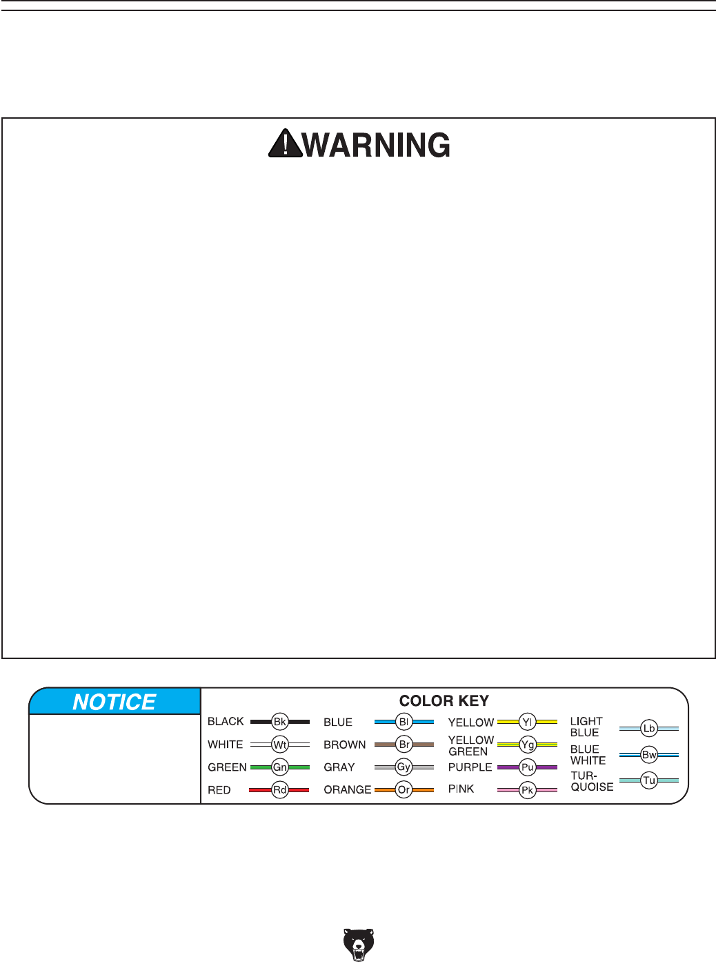
-48- Model G0442/G0601 (Mfg Since 3/12)
These pages are current at the time of printing. However, in the spirit of improvement, we may make chang-
es to the electrical systems of future machines. Study this section carefully. If there are differences between
your machine and what is shown in this section, call Technical Support at (570) 546-9663 for assistance
BEFORE making any changes to the wiring on your machine.
SECTION 9: WIRING
SHOCK HAZARD. Working on wiring that is con-
nected to a power source is extremely dangerous.
Touching electrified parts will result in personal
injury including but not limited to severe burns,
electrocution, or death. Disconnect the power
from the machine before servicing electrical com-
ponents!
MODIFICATIONS. Modifying the wiring beyond
what is shown in the diagram may lead to unpre-
dictable results, including serious injury or fire.
This includes the installation of unapproved after-
market parts.
WIRE CONNECTIONS. All connections must
be tight to prevent wires from loosening during
machine operation. Double-check all wires dis-
connected or connected during any wiring task to
ensure tight connections.
CIRCUIT REQUIREMENTS. You MUST follow
the requirements at the beginning of this manual
when connecting your machine to a power source.
WIRE/COMPONENT DAMAGE. Damaged wires
or components increase the risk of serious per-
sonal injury, fire, or machine damage. If you notice
that any wires or components are damaged while
performing a wiring task, replace those wires or
components.
MOTOR WIRING. The motor wiring shown in
these diagrams is current at the time of printing
but may not match your machine. If you find this
to be the case, use the wiring diagram inside the
motor junction box.
CAPACITORS/INVERTERS. Some capacitors
and power inverters store an electrical charge for
up to 10 minutes after being disconnected from
the power source. To reduce the risk of being
shocked, wait at least this long before working on
capacitors.
EXPERIENCING DIFFICULTIES. If you are expe-
riencing difficulties understanding the information
included in this section, contact our Technical
Support at (570) 546-9663.
Wiring Safety Instructions
The photos and diagrams
included in this section are
best viewed in color. You
can view these pages in
color at www.grizzly.com.
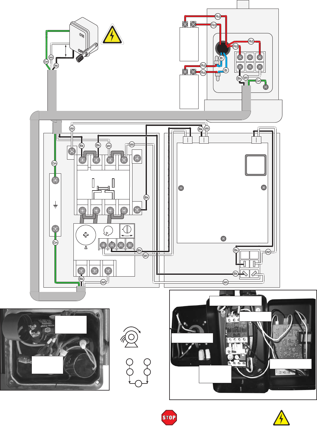
Model G0442/G0601 (Mfg Since 3/12) -49-
READ ELECTRICAL SAFETY
ON PAGE 48!
G0442 Wiring Diagram
Figure 78. Model G0442 motor
wiring. Figure 79. Model G0442 control box wiring.
Start
Capacitor
Run
Capacitor
g0442 wiring
A1
Ground
2T1 6T3 14NO
4T2
1L1 5L3 13NO
3L2
NHD C-18D
2T1 4T2 6T3
98 97
A2
96
O R
95
21
22
23
25
ON/OFF
Switch
A2
Start
Capacitor
400MFD
250VAC
Run
Capacitor
40µF
450VAC
220V Motor
220V Magnetic Contactor
Switch and Overload Relay
Ground
Hot
Hot
DISCONNECT
SWITCH
(as recommended)
1-PHASE
220 VAC
NTH-25
OL_NO AC
OUT
AC
IN
Circuit Board
Contactor
Overload
Relay
Circuit Board
Magnetic Switch
Junction Box
65
1 2
~
CW
D.E.
CONNECTION
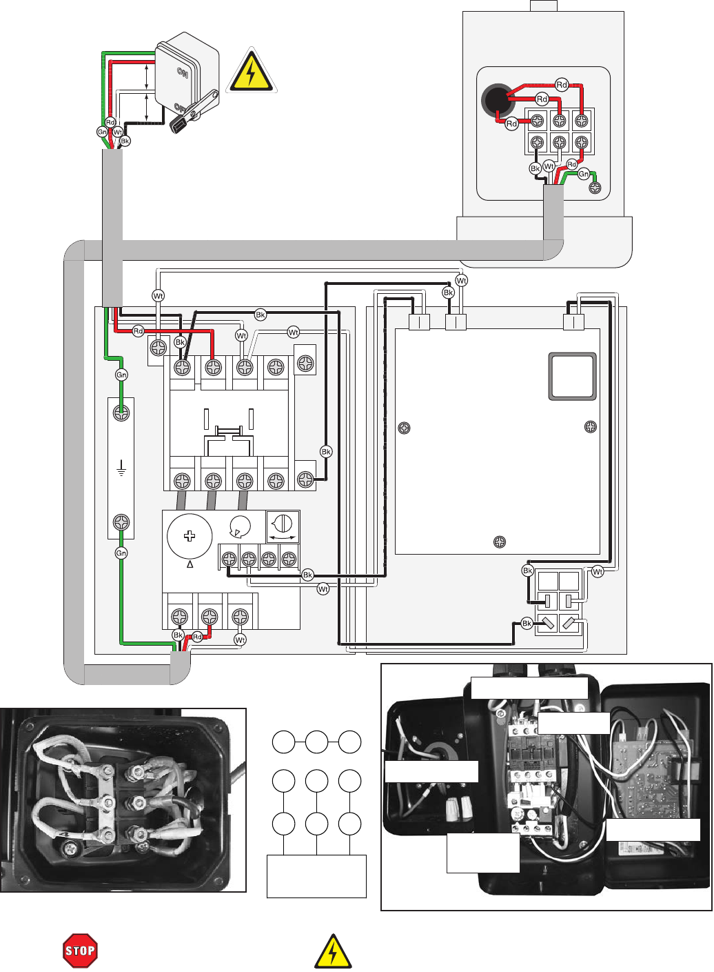
-50- Model G0442/G0601 (Mfg Since 3/12)
READ ELECTRICAL SAFETY
ON PAGE 48!
A1
Ground
2T1 6T3 14NO
4T2
1L1 5L3 13NO
3L2
NHD C-18D
2T1 4T2 6T3
98 97
A2
96
O R
95
10
11
13
15
NTH-1 5 ON/OFF
Switch
A2
220V Motor
220V Magnetic Contactor
Switch and Overload Relay
Ground
Hot
Hot
Hot
DISCONNECT
SWITCH
(as recommended
)
3-PHASE
220 VAC
Circuit Board
OL_NO AC
OUT
AC IN
G0601 220V Wiring Diagram
g0601 wiring
Figure 81. Model G0601 220V control box.
Contactor
Overload
Relay
Circuit Board
Magnetic Switch
Junction Box
Figure 80. Model G0601 motor
wiring.
4 5 6
7 8 9
1 2 3
440V
VOLTAGE
HIGH
4 5 6
7 8 9
1 2 3
220V
VOLTAGE
LOW
Control Box Wiring Motor Wiring
1L1 3L2 5L3 NO13
2T1 4T2 6T3 NO14
98 97 96 95
ON
OFF
IC(220V)
AC2 S
AC1 COM
GROUND
Overload Relay Contactor
A1
A2
220 VOLT POWER SOURCE
THREE-PHASE
Circuit Board
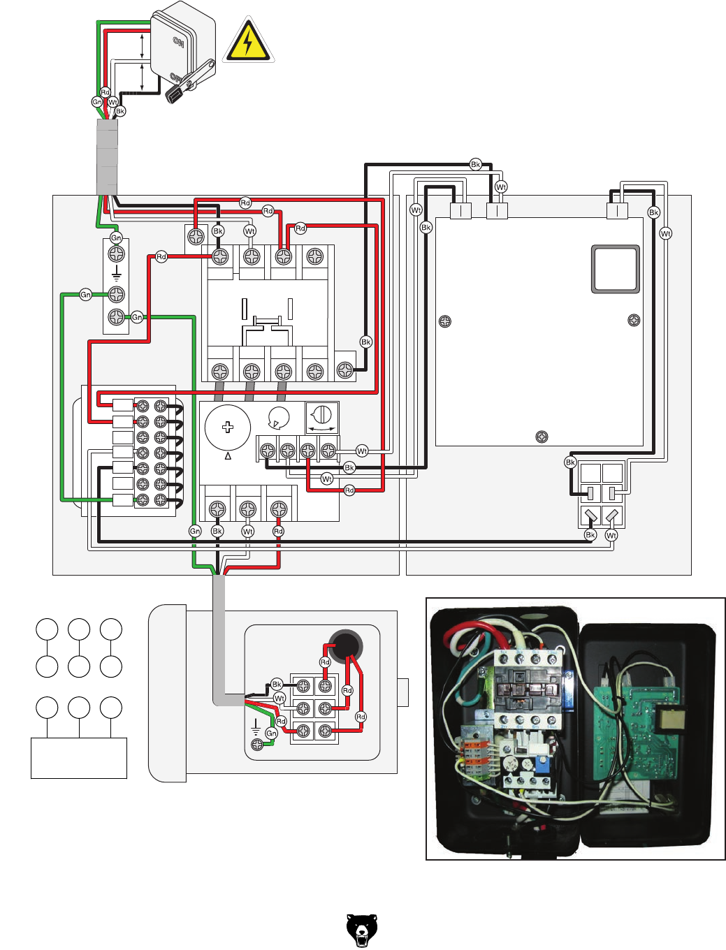
Model G0442/G0601 (Mfg Since 3/12) -51-
G0601 440V Wiring Diagram
A1
Ground
30VA
Transformer
2T1 6T3 14NO
4T2
1L1 5L3 13NO
3L2
NHD C-09D
2T1 4T2 6T3
98 97
A2
96
O R
95
NTH-8 ON/OFF
Switch
A2
440V Magnetic Contactor
Switch and Overload Relay
Ground
Hot
Hot
Hot DISCONNECT
SWITCH
(as recommended)
3-PHASE
440 VAC
440V
Motor
OL_NO AC
OUT
AC
IN
0
0
440
460
220
230
E
6
8
Circuit Board
Figure 82. G0601 440V control box.
4 5 6
7 8 9
1 2 3
440V
VOLTAGE
HIGH
4 5 6
7 8 9
1 2 3
220V
VOLTAGE
LOW
Control Box Wiring Motor Wiring
1L1 3L2 5L3 NO13
2T1 4T2 6T3 NO14
98 97 96 95
ON
OFF
IC(220V)
AC2 S
AC1 COM
GROUND
Overload Relay Contactor
A1
A2
220 VOLT POWER SOURCE
THREE-PHASE
Circuit Board
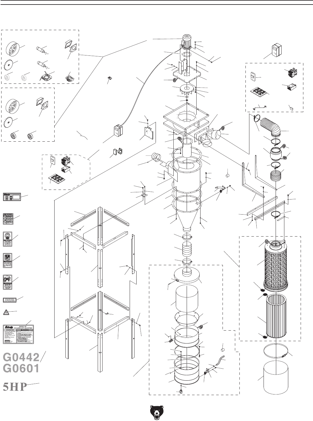
-52- Model G0442/G0601 (Mfg Since 3/12)
92
93
94
95
96
97
98
99V2
101
102
DUTY
Grizzly Cyclone Induction Motor
Connections:
Manufactured for Grizzly in Taiwan
HEAT
WEIGHT
CLASS
DATE
HZ
SER. NO.
VOLT
OUTPUT
AMP
RPM
PHASE
G0601 440V
Conversion Kit
3-1V2
2
4
5
6
7
8
9
10
11
12
13
14
15
16
17
18
19
20
21
22
23
24
25 27V3
27-1V3
28
29
30
30-1
31
32
33
34
35
36AV2
36V2
36-1V2
36-4V2
37V2
38V2
39
40
41
42
43
44
45
46
47V2
48
49
50
51
52
53
54
54-1
54-2
55V2
56
57V2
58
59
60
61
62
63
64
65
66
67
68
69
70
71
72
73
74
75
76
77
78V2
79
80 81
82
83
84
85
86V2
87
88
89
90
91
104
105
106
107
108
109 110 111
112
113
114
115116
117
118
119
120
121 122
123
19
6
26
26
105
26
30
32
100V2
126
125
24
105
107
69
57AV2
52
50
72
74
75
75
67
75
88
1-2
1-1 1-4
1-6
1-5
1-2
1-1
1-3
G0442
G0601
1
1-7 1-8 1-9 1-10
1-4 1-5
3V2
3V2-1
3V2-2
3V2-3
3V2-4
3-1V2-2
3-1V2-3
3-1V2-4
3-1V2-1
3-1V2-5 3-1V2-6
SECTION 10: PARTS
Main
Parts Breakdown

Model G0442/G0601 (Mfg Since 3/12) -53-
G0442 Only Parts List
REF PART # DESCRIPTION REF PART # DESCRIPTION
1 P0442001 MOTOR 5HP 220V 1-PH 3V2 P0442003V2 CONT BOX ASSY 220V 1-PH V2.4.12
1-1 P0442001-1 MOTOR FAN COVER 3V2-1 P0442003V2-1 CONTACTOR NHD C-18D 220V V2.04.12
1-2 P0442001-2 MOTOR FAN 3V2-2 P0442003V2-2 OL RELAY NHD NTH-25 21-25A
1-4 P0442001-4 S CAPACITOR 400M 250V 1-3/4 X 3-3/4 3V2-3 P0442003V2-3 CIRCUIT BOARD
1-5 P0442001-5 R CAPACITOR 40M 450V 3V2-4 P0442003V2-4 ON/OFF SWITCH 220V
1-6 P0442001-6 JUNCTION BOX 99V2 P0442099V2 MACHINE ID LABEL CSA V2.01.12
1-7 P0442001-7 BALL BEARING 6207ZZ 100V2 P0442100V2 SWITCH BRACKET CSA V2.03.12
1-8 P0442001-8 BALL BEARING 6205ZZ 101 P0442101 MODEL NUMBER LABEL
1-9 P0442001-9 CONTACT PLATE 125 P0442125 GREEN GROUNDING WIRE 12G 6"
1-10 P0442001-10 CENTRIFUGAL SWITCH 3450 RPM 126 P0442126 JUNCTION BOX
2 P0442002 MOTOR CORD 12G 3W
G0601 Only Parts List
REF PART # DESCRIPTION REF PART # DESCRIPTION
1 P0601001 MOTOR 5HP 220/440V 3-PH 3-1V2 P0601003-1V2 CONT BOX ASSY 440V V2.04.12
1-1 P0601001-1 MOTOR FAN COVER 3-1V2-1 P0601003-1V2-1 CONTACTOR NHD C-09D 440V
1-2 P0601001-2 MOTOR FAN 3-1V2-2 P0601003-1V2-2 OL RELAY NHD NTH-08 6–8A
1-3 P0601001-3 JUNCTION BOX 3-1V2-3 P0601003-1V2-3 CIRCUIT BOARD
1-4 P0601001-4 FRONT MOTOR BEARING 3-1V2-4 P0601003-1V2-4 ON/OFF SWITCH 440V
1-5 P0601001-5 REAR MOTOR BEARING 3-1V2-5 P0601003-1V2-5 MOTOR CORD 12G 4W 600V
2 P0601002 MOTOR CORD 12G 4W 300V 3-1V2-6 P0601003-1V2-6 SWITCH TRANSFORMER 30VA
3V2 P0601003V2 CONT BOX ASSY 220V 3-PH V2.04.12 99V2 P0601099V2 MACHINE ID LABEL CSA V2.01.12
3V2-1 P0601003V2-1 CONTACTOR NHD C-18D 220V 100V2 P0601100V2 SWITCH BRACKET CSA V2.03.12
3V2-2 P0601003V2-2 OL RELAY NHD NTH-15 10–15A 101 P0601101 MODEL NUMBER LABEL
3V2-3 P0601003V2-3 CIRCUIT BOARD 125 P0601125 GREEN GROUNDING WIRE 12G 6"
3V2-4 P0601003V2-4 ON/OFF SWITCH 220V 126 P0601126 JUNCTION BOX
G0442/G0601 Common Parts List
REF PART # DESCRIPTION REF PART # DESCRIPTION
4 P0442004 REMOTE CONTROLLER 20 P0442020 HEX BOLT 5/16-18 X 3/4
5 P0442005 HEX BOLT 3/8-16 X 1-1/2 21 P0442021 OUTLET GASKET 456 X 226MM
6 P0442006 FLAT WASHER 3/8 22 P0442022 OUTLET PORT
7 P0442007 LOCK WASHER 3/8 23 P0442023 HEX BOLT 5/16-18 X 1
8 P0442008 HEX NUT 3/8-16 24 P0442024 FLAT WASHER 5/16
9 P0442009 BLOWER COVER 25 P0442025 HEX NUT 5/16-18
10 P0442010 HEX BOLT 1/2-13 X 1-1/2 26 P0442026 HOSE CLAMP 8"
11 P0442011 FENDER WASHER 1/2" 27V3 P0442027V3 FLEXIBLE HOSE 8" X 23-1/2" V3.11.09
12 P0442012 LOCK WASHER 1/2 27-1V3 P0442027-1V3 FLEXIBLE HOSE 8" X 4-3/4" V3.11.09
13 P0442013 HEX NUT 1/2-13 28 P0442028 LEFT FILTER L-BRACE
14 P0442014 IMPELLER 16" 29 P0442029 RIGHT FILTER L-BRACE
15 P0442015 FLAT WASHER 3/4 30 P0442030 FILTER CROSS BRACE
16 P0442016 HEX NUT 3/4-16 LH 30-1 P0442030-1 BRACE GASKET 240 X 32MM
17 P0442017 FOAM TAPE 3 X 6 X 1800MM 31 P0442031 HEX BOLT 3/8-16 X 3/4
18 P0442018 IMPELLER HOUSING 32 P0442032 FLAT WASHER 3/8
19 P0442019 FLAT WASHER 5/16 33 P0442033 HEX NUT 3/8-16

-54- Model G0442/G0601 (Mfg Since 3/12)
G0442/G0601 Common Parts List
REF PART # DESCRIPTION REF PART # DESCRIPTION
34 P0442034 HEX BOLT 5/16-18 X 3/4 74 P0442074 HEX BOLT 3/8-16 X 3/4
35 P0442035 FLAT WASHER 5/16 75 P0442075 FLAT WASHER 3/8
36AV2 P0442036AV2 CANISTER ASSEMBLY, GREEN V2.11.09 76 P0442076 LOCK NUT 3/8-16
36V2 P0442036V2 CANISTER OUTER CAGE V2.11.09 77 P0442077 UPPER STAND BRACE
36-1V2 P0442036-1V2 GASKET 3 X 25 X 1700MM V2.11.09 78V2 P0442078V2 UPPER STAND LEG V2.08.10
36-4V2 P0442036-4V2 CANISTER FILTER 486 X 995MM W/TAPE V2.11.09 79 P0442079 HEX BOLT 3/8-16 X 3/4
37V2 P0442037V2 FILTER BAG CLAMP 545MM V2.11.09 80 P0442080 FLAT WASHER 3/8
38V2 P0442038V2 PLASTIC BAG 570 X 600MM V2.11.09 81 P0442081 LOCK NUT 3/8-16
39 P0442039 FOAM TAPE 3 X 6 X 1800MM 82 P0442082 LOWER STAND BRACE
40 P0442040 INTAKE CYLINDER 12" 83 P0442083 HEX BOLT 3/8-16 X 3/4
41 P0442041 FLAT WASHER 5/16 84 P0442084 FLAT WASHER 3/8
42 P0442042 HEX BOLT 5/16-18 X 3/4 85 P0442085 LOCK NUT 3/8-16
43 P0442043 BARREL GASKET 686MM DIA. 86V2 P0442086V2 LOWER STAND LEG V2.08.10
44 P0442044 HEX BOLT 5/16-18 X 3/4 87 P0442087 HEX BOLT 3/8-16 X 3/4
45 P0442045 FLAT WASHER 5/16 88 P0442088 FLAT WASHER 3/8
46 P0442046 BARREL GASKET 686MM DIA. 89 P0442089 LOCK NUT 3/8-16
47V2 P0442047V2 CYCLONE FUNNEL V2.08.10 90 P0442090 REDUCER 10" TO 8"
48 P0442048 HEX BOLT 5/16-18 X 1 91 P0442091 TAP SCREW M4 X 12
49 P0442049 INTAKE BARREL 92 P0442092 MOTOR SPEC LABEL
50 P0442050 FLAT WASHER 5/16 93 P0442093 MOTOR WARNING LABEL
51 P0442051 HEX NUT 5/16-18 94 P0442094 GLASSES/RESPIRATOR DC LABEL
52 P0442052 HOSE CLAMP 9" 95 P0442095 READ MANUAL 2W X 3.3H
53 P0442053 CLEAR FLEXIBLE PIPE 9" X 10" 96 P0442096 HANDS/INLET LABEL
54 P0442054 COLLECTION DRUM LID V2.08.06 97 P0442097 RETURN RED HANDLE LABEL
54-1 P0442054-1 DRUM LID HOOK 98 P0442098 ELECTRICITY 1.4W X 1.2H
54-2 P0442054-2 HOOK RIVET 102 P0442102 HORSEPOWER LABEL
55V2 P0442055V2 DRUM SEAL TYPE-R 2M V2.11.09 104 P0442104 EXT TOOTH WASHER 1/2
56 P0442056 UPPER DRUM 25GAL 105 P0442105 FOAM TAPE 3 X 15 X 700MM
57AV2 P0442057AV2 COLLECTION DRUM ASSY 55GAL V2.11.09 106 P0442106 NOISE MUFFLER 8"
57V2 P0442057V2 COLLECTION DRUM 35GAL V2.08.10 107 P0442107 GASKET 35 X 38 X 1570MM V2.11.09
58 P0442058 DRUM CLAMP 108 P0442108 MOTOR GASKET
59 P0442059 HEX BOLT 5/16-18 X 3 109 P0442109 CYCLONE VACUUM PORT
60 P0442060 HEX NUT 5/16-18 110 P0442110 FLAT WASHER 5/16
61 P0442061 DRUM LID LATCH 111 P0442111 HEX BOLT 5/16-18 X 3/4
62 P0442062 PHLP HD SCR 10-24 X 3/8 112 P0442112 PORT PLUG 1-1/4"
63 P0442063 HEX NUT 10-24 113 P0442113 FOAM TAPE 3 X 6 X 300MM
64 P0442064 PHLP HD SCR 10-24 X 3/8 114 P0442114 VACUUM HOSE 1-1/4" X 98"
65 P0442065 HEX NUT 10-24 115 P0442115 COLLECTION DRUM VACUUM PORT
66 P0442066 CASTER 2" 116 P0442116 FLAT WASHER 5/16
67 P0442067 HEX NUT 3/8-16 117 P0442117 HEX BOLT 5/16-18 X 3/4
68 P0442068 LOCK WASHER 3/8 118 P0442118 HOSE CLAMP 1-1/4"
69 P0442069 FLAT WASHER 3/8 119 P0442119 PORT PLUG 1-1/4"
70 P0442070 COLLECTOR MOUNTING BRACKET 120 P0442120 FOAM TAPE 3 X 6 X 300MM
71 P0442071 HEX BOLT 5/16-18 X 1 121 P0442121 VACUUM HOSE CLIP 2-1/2"
72 P0442072 FLAT WASHER 5/16 122 P0442122 COLLECTION DRUM VACUUM RING
73 P0442073 LOCK NUT 5/16-18 123 P0442123 DRUM COLLECTION BAG 640 X 1200MM

CUT ALONG DOTTED LINE
Name _____________________________________________________________________________
Street _____________________________________________________________________________
City _______________________ State _________________________ Zip _____________________
Phone # ____________________ Email _________________________________________________
Model # ____________________ Order # _______________________ Serial # __________________
WARRANTY CARD
The following information is given on a voluntary basis. It will be used for marketing purposes to help us develop
better products and services. Of course, all information is strictly confidential.
1. How did you learn about us?
____ Advertisement ____ Friend ____ Catalog
____ Card Deck ____ Website ____ Other:
2. Which of the following magazines do you subscribe to?
3. What is your annual household income?
____ $20,000-$29,000 ____ $30,000-$39,000 ____ $40,000-$49,000
____ $50,000-$59,000 ____ $60,000-$69,000 ____ $70,000+
4. What is your age group?
____ 20-29 ____ 30-39 ____ 40-49
____ 50-59 ____ 60-69 ____ 70+
5. How long have you been a woodworker/metalworker?
____ 0-2 Years ____ 2-8 Years ____ 8-20 Years ____20+ Years
6. How many of your machines or tools are Grizzly?
____ 0-2 ____ 3-5 ____ 6-9 ____ 10+
7. Do you think your machine represents a good value? _____Yes _____No
8. Would you recommend Grizzly Industrial to a friend? _____Yes _____No
9. Would you allow us to use your name as a reference for Grizzly customers in your area?
Note: We never use names more than 3 times. _____Yes _____No
10. Comments: _____________________________________________________________________
_________________________________________________________________________________
_________________________________________________________________________________
_________________________________________________________________________________
____ Cabinetmaker & FDM
____ Family Handyman
____ Hand Loader
____ Handy
____ Home Shop Machinist
____ Journal of Light Cont.
____ Live Steam
____ Model Airplane News
____ Old House Journal
____ Popular Mechanics
____ Popular Science
____ Popular Woodworking
____ Precision Shooter
____ Projects in Metal
____ RC Modeler
____ Rie
____ Shop Notes
____ Shotgun News
____ Today’s Homeowner
____ Wood
____ Wooden Boat
____ Woodshop News
____ Woodsmith
____ Woodwork
____ Woodworker West
____ Woodworker’s Journal
____ Other:

TAPE ALONG EDGES--PLEASE DO NOT STAPLE
FOLD ALONG DOTTED LINE
FOLD ALONG DOTTED LINE
GRIZZLY INDUSTRIAL, INC.
P.O. BOX 2069
BELLINGHAM, WA 98227-2069
Place
Stamp
Here
Name_______________________________
Street_______________________________
City______________State______Zip______
Send a Grizzly Catalog to a friend:

WARRANTY AND RETURNS
Grizzly Industrial, Inc. warrants every product it sells for a period of 1 year to the original purchaser from
the date of purchase. This warranty does not apply to defects due directly or indirectly to misuse, abuse,
negligence, accidents, repairs or alterations or lack of maintenance. This is Grizzly’s sole written warranty
and any and all warranties that may be implied by law, including any merchantability or fitness, for any par-
ticular purpose, are hereby limited to the duration of this written warranty. We do not warrant or represent
that the merchandise complies with the provisions of any law or acts unless the manufacturer so warrants.
In no event shall Grizzly’s liability under this warranty exceed the purchase price paid for the product and
any legal actions brought against Grizzly shall be tried in the State of Washington, County of Whatcom.
We shall in no event be liable for death, injuries to persons or property or for incidental, contingent, special,
or consequential damages arising from the use of our products.
To take advantage of this warranty, contact us by mail or phone and give us all the details. We will then
issue you a “Return Number,’’ which must be clearly posted on the outside as well as the inside of the
carton. We will not accept any item back without this number. Proof of purchase must accompany the
merchandise.
The manufacturers reserve the right to change specifications at any time because they constantly strive to
achieve better quality equipment. We make every effort to ensure that our products meet high quality and
durability standards and we hope you never need to use this warranty.
Please feel free to write or call us if you have any questions about the machine or the manual.
Thank you again for your business and continued support. We hope to serve you again soon.
WARRANTY AND RETURNS