G0504 Manual M
User Manual: G0504
Open the PDF directly: View PDF ![]() .
.
Page Count: 74
COPYRIGHT © SEPTEMBER, 2016 BY GRIZZLY INDUSTRIAL, INC.
WARNING: NO PORTION OF THIS MANUAL MAY BE REPRODUCED IN ANY SHAPE
OR FORM WITHOUT THE WRITTEN APPROVAL OF GRIZZLY INDUSTRIAL, INC.
#BL18354 PRINTED IN TAIWAN
1104V3
MAGNETIC CONTACTOR
LC1-D40A FOR 440V
440V CONVERSION KIT
95
NC
LR3D 07 1.6~2.5A
○
○
T3
LC1-D09
97
98
○○
NONO
T1 T2
○ ○
NO
96
NC
○
A2
○
L3
NO
L1 L2
○○
A1
2313V2
2314V2
2321V3 ○ ○ ○
NC
NC
NO
LC1-D09
T1 T3
T2
A2
NO
L1
A1
L2 L3
NC
NC
2319V3
OVERLOAD RELAY
LR3D-350 37/50A FOR 440V
1338V3
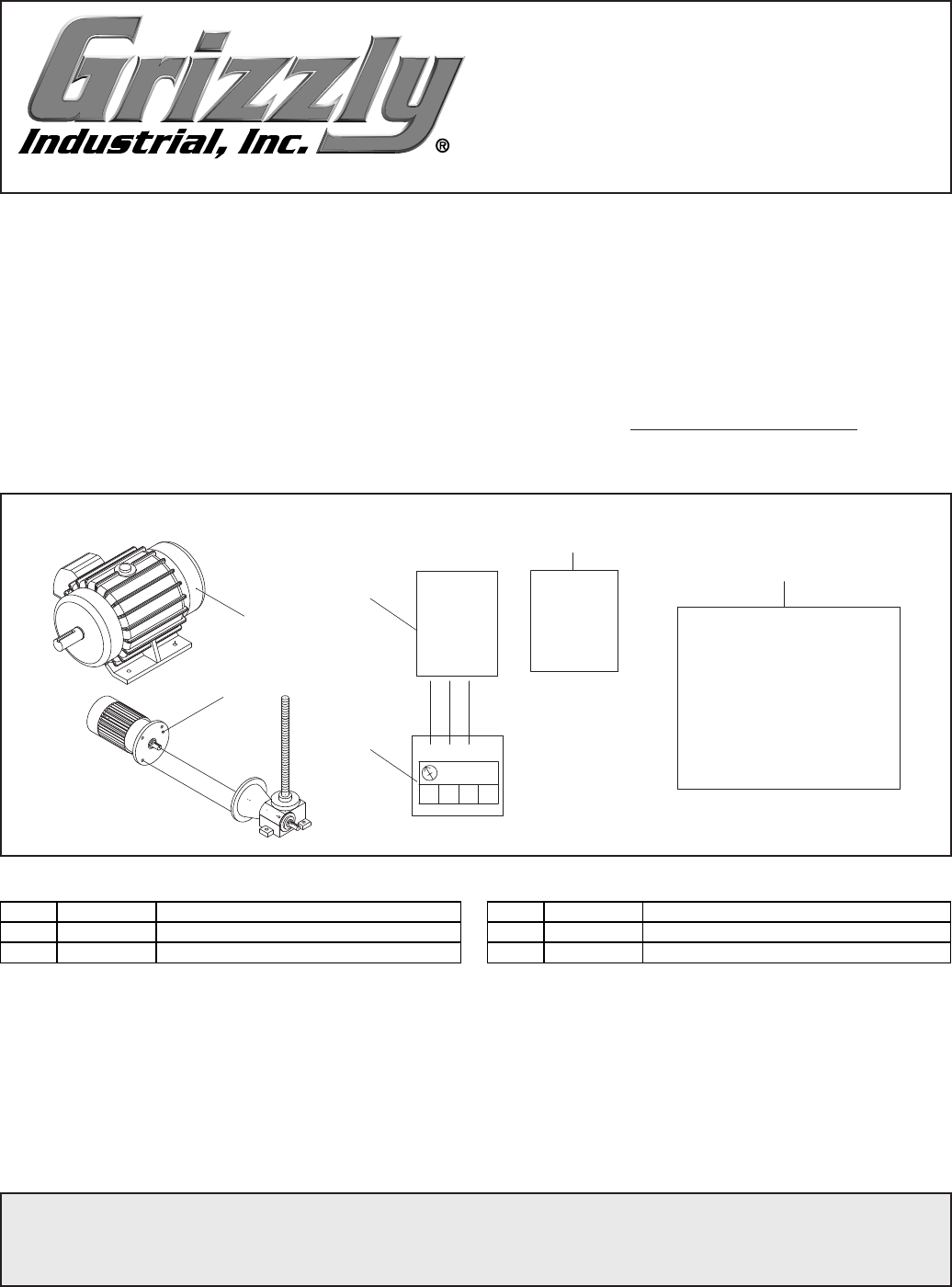
New Parts
REF PART # DESCRIPTION REF PART # DESCRIPTION
1104V3 P05041104V3 MOTOR 30HP 220V/440V 3-PH V3.11.14 2314V2 P05042314V2 CONTACTOR TE LCI-D09 V2.11.14
1338V3 P05041338V3 GEAR BOX & MOTOR V3.11.14 2319V3 P05042319V3 440V CONVERSION KIT FOR G0504 V3.11.14
2313V2 P05042313V2 CONTACTOR TE LCI-D09 220V V2.11.14 2321V3 P05042321V3 OL RELAY TE LR3D-07 1.6-2.5A V3.11.14
The following changes were recently made to this machine since the owner's manual was printed:
• Changed elevation motor, main motor, and various electrical components.
Aside from this information, all other content in the owner's manual applies and MUST be read and under-
stood for your own safety. IMPORTANT: Keep this update with the owner's manual for future reference.
For questions or help, contact our Tech Support at (570) 546-9663 or techsupport@grizzly.com.
READ THIS FIRST
For questions or help with this product contact Tech Support at (570) 546-9663 or techsupport@grizzly.com
Model G0504
***IMPORTANT UPDATE***
For Machines Mfd. Since 11.14
and Owner's Manual Revised 11.07
-2- G0504 Update (Mfd. Since 11/14)
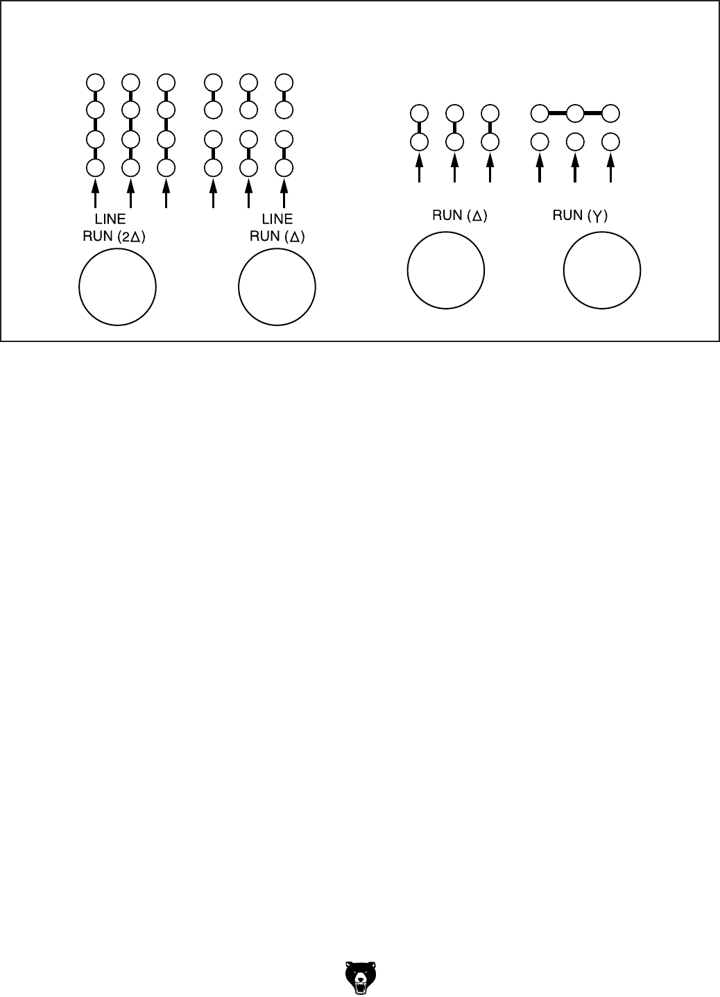
MAIN
MOTOR
W5 U5 V5
W6 U6 V6
W2 U2 V2
U1 V1 W1
440 VOLTS
W2 U2 V2
W6 U6 V6
U1 V1 W1
U5 V5 W5
220 VOLTS
OL Relay
Set to
75A
OL Relay
Set to
42A
ELEVATION
MOTOR
W2 U2 V2
U1 V1 W1
U1 V1 W1
W2 U2 V2
440 VOLTS220 VOLTS
L1 L2 L3 L1 L2 L3
OL Relay
Set to
2.5A
OL Relay
Set to
1.6A
New Motor Wiring
New Specifications
Electrical
Full-Load Current Rating ....................................................................................75A at 220V, 37.5A at 440V
Minimum Circuit Size ...........................................................................................100A at 220V, 50A at 440V
Voltage Conversion Kit .............................................................................................. P05042319V3 for 440V
Motors:
Main
Amps ..............................................................................................................................................72.9/36.4A
Elevation
Amps ..............................................................................................................................................1.94/0.97A
Speed .............................................................................................................................................1680 RPM
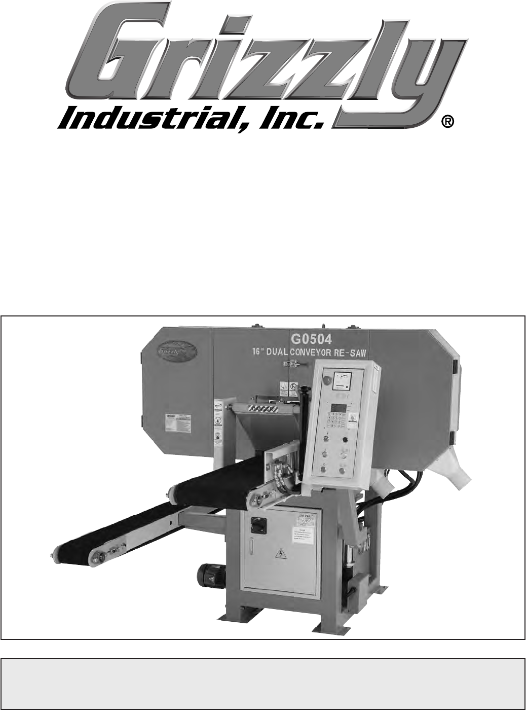
MODEL G0504
16" HORIZONTAL
RESAW BANDSAW
Owner's Manual
COPYRIGHT © MAY, 2003 BY GRIZZLY INDUSTRIAL, INC. REVISED NOVEMBER, 2007.
WARNING: NO PORTION OF THIS MANUAL MAY BE REPRODUCED IN ANY SHAPE
OR FORM WITHOUT THE WRITTEN APPROVAL OF GRIZZLY INDUSTRIAL, INC.
#TR5063 PRINTED IN TAIWAN

Table of Contents
SECTION 1: GENERAL INFORMATION ......................................................................................... 3
Commentary ............................................................................................................................... 3
Machine Data Sheet ................................................................................................................. 4
SECTION 2: SAFETY ....................................................................................................................... 5
Additional Safety Instructions for Bandsaws .............................................................................. 7
Additional Safety Instructions for Hydraulics .............................................................................. 8
SECTION 3: CIRCUIT REQUIREMENTS ........................................................................................ 9
3-Phase Power
........................................................................................................................... 9
Grounding ................................................................................................................................. 10
Converting to 440V .................................................................................................................. 10
SECTION 4: MACHINE FEATURES .............................................................................................. 12
Main Features .......................................................................................................................... 12
Control Panel ........................................................................................................................... 14
SECTION 5: SET UP ...................................................................................................................... 15
About this Section .................................................................................................................... 15
Unpacking ................................................................................................................................ 15
Piece Inventory ........................................................................................................................ 15
Hardware Recognition Chart .................................................................................................... 16
Clean Up .................................................................................................................................. 17
Site Considerations .................................................................................................................. 17
Removing Resaw from Crate Pallet ......................................................................................... 18
Mounting Resaw to the Floor ................................................................................................... 18
Installing & Tensioning Blade ................................................................................................... 19
Adjusting Blade Guides ............................................................................................................ 20
Connecting to Dust Collector ................................................................................................... 22
Connecting to Power Source ................................................................................................... 22
Test Run
................................................................................................................................... 23
SECTION 6: OPERATIONS ........................................................................................................... 24
Operation Safety ...................................................................................................................... 24
Conveyor Controls ................................................................................................................... 24
Setting Blade Height ................................................................................................................ 25
Calibrating Digital Display ........................................................................................................ 25
Setting Memory Button
............................................................................................................. 26
Using Memory Preset Keys ..................................................................................................... 26
Resawing .................................................................................................................................. 27
Blade Information ..................................................................................................................... 28
Accessories .............................................................................................................................. 29
SECTION 7: MAINTENANCE ........................................................................................................ 30
Cleaning ................................................................................................................................... 30
Miscellaneous ........................................................................................................................... 30
V-Belts ...................................................................................................................................... 30
Bearings ................................................................................................................................... 30
Grease Fittings
......................................................................................................................... 31
Hydraulic Fluid Schedule ......................................................................................................... 32
Hydraulic System Minor Service .............................................................................................. 32
Hydraulic System Major Service .............................................................................................. 33
SECTION 8: SERVICE ADJUSTMENTS ....................................................................................... 35
About Service ........................................................................................................................... 35
Adjusting Lower Blade Guides ................................................................................................. 35
Adjusting V-Belt Tension .......................................................................................................... 36
Replacing V-Belts
..................................................................................................................... 37
Adjusting Main Conveyor Table ............................................................................................... 37
Tracking Conveyors ................................................................................................................. 38
Replacing Conveyors ............................................................................................................... 39
Blade Tracking and Wheel Alignment ...................................................................................... 41
Troubleshooting ........................................................................................................................ 44
SECTION 9: Parts .......................................................................................................................... 46
Housing Parts
........................................................................................................................... 46
Frame Parts ............................................................................................................................. 48
Elevation Parts ......................................................................................................................... 49
Blade Guide Parts .................................................................................................................... 51
Tensioning Wheel Parts ........................................................................................................... 53
Drive Wheel Parts .................................................................................................................... 55
Hydraulic Pump Parts .............................................................................................................. 56
Main Conveyor Table Parts ..................................................................................................... 57
Return Conveyor Table Parts .................................................................................................. 59
Rear Hold Down Parts ............................................................................................................. 60
Front Hold Down Parts ............................................................................................................. 61
Hydraulic System Parts ............................................................................................................ 62
Electrical System Parts 1 ......................................................................................................... 64
Electrical System Parts 2 ......................................................................................................... 65
WARRANTY AND RETURNS ........................................................................................................ 69

G0504 16" Horizontal Resaw Bandsaw -3-
Grizzly Industrial, Inc. is proud to offer the Model
G0504 16" Horizontal Resaw Bandsaw. This
resaw bandsaw is part of Grizzly’s growing fam-
ily of fine woodworking machinery. When used
according to the guidelines stated in this manual,
you can expect years of trouble-free, enjoyable
operation, and proof of Grizzly’s commitment to
customer satisfaction.
We are also pleased to provide this manual for
the Model G0504. It was written to guide you
through assembly, review safety considerations,
and cover general operating procedures. It repre-
sents our latest effort to produce the best docu-
mentation possible.
If you have any comments or criticisms that
you feel we should address in our next printing,
please contact us at:
Grizzly Industrial, Inc.
C⁄O Technical Documentation
P.O. Box 2069
Bellingham, WA 98227
Email: manuals@grizzly.com
Most important, we stand behind our machines.
We have excellent regional service departments
at your disposal should the need arise.
If you have any service questions or parts
requests, please call or write to us at the location
listed below.
Grizzly Industrial, Inc
1203 Lycoming Mall Circle
Muncy, PA 17756
Phone:(570) 546-9663
Fax:(800) 438-5901
E-Mail: techsupport@grizzly.com
Web Site: http://www.grizzly.com
The specifications, drawings, and photographs
illustrated in this manual represent the Model
G0504 as supplied when the manual was pre-
pared. However, owing to Grizzly’s policy of con-
tinuous improvement, changes may be made at
any time with no obligation on the part of Grizzly.
For your convenience, we always keep current
Grizzly manuals available on our website at
www.grizzly.com. Any updates to your machine
will be reflected in these manuals as soon as
they are complete.
Read this entire manu-
al before operating the
machine, or you will
greatly increase your
chances of serious per-
sonal injury!
Commentary
SECTION 1: GENERAL INFORMATION

-4- G0504 16" Horizontal Resaw Bandsaw
Machine Data Sheet
The information contained herein is deemed accurate as of 11/14/2007 and represents our most recent product specifications.
Due to our ongoing improvement efforts, this information may not accurately describe items previously purchased. PAGE 1 OF 3Model G0504
MACHINE DATA
SHEET
Customer Service #: (570) 546-9663 · To Order Call: (800) 523-4777 · Fax #: (800) 438-5901
MODEL G0504 16" DUAL CONVEYOR HORIZONTAL RE-SAW
BANDSAW
Product Dimensions:
Weight............................................................................................................................................................ 3740 lbs.
Length/Width/Height..................................................................................................................... 108 x 85 x 83-1/2 in.
Foot Print (Length/Width)................................................................................................................. 45-1/4 x 32-1/4 in.
Shipping Dimensions:
Type....................................................................................................................................................Wood Slat Crate
Content............................................................................................................................................................ Machine
Weight............................................................................................................................................................ 4325 lbs.
Length/Width/Height........................................................................................................................... 85 x 114 x 89 in.
Electrical:
Switch........................................................................................................ Magnetic with Thermal Overload Protector
Switch Voltage...................................................................................................................................................... 220V
Recommended Breaker Size.......................................................................................................................... 100 amp
Plug.......................................................................................................................................................................... No
Conversion To 440V...................................................................................................................................P0504919A
Motors:
Main
Type........................................................................................................................................... TEFC Induction
Horsepower...............................................................................................................................................30 HP
Voltage.................................................................................................................................................220/440V
Prewired......................................................................................................................................................220V
Phase.........................................................................................................................................................Three
Amps........................................................................................................................................................72/41A
Speed.................................................................................................................................................1725 RPM
Cycle..........................................................................................................................................................60 Hz
Number Of Speeds........................................................................................................................................... 1
Power Transfer ................................................................................................................................... Belt Drive
Bearings....................................................................................................................... Shielded and Lubricated
Elevation
Type........................................................................................................................................... TEFC Induction
Horsepower..............................................................................................................................................1/2 HP
Voltage.................................................................................................................................................220/440V
Prewired......................................................................................................................................................220V
Phase.........................................................................................................................................................Three
Amps......................................................................................................................................................2.2/1.1A
Speed.................................................................................................................................................1725 RPM
Cycle..........................................................................................................................................................60 Hz
Number Of Speeds........................................................................................................................................... 1
Power Transfer ................................................................................................................................... Belt Drive
Bearings....................................................................................................................... Shielded and Lubricated
4180 lbs.
114" x 92" x 85"
90 Amp

G0504 16" Horizontal Resaw Bandsaw -5-
The information contained herein is deemed accurate as of 11/14/2007 and represents our most recent product specifications.
Due to our ongoing improvement efforts, this information may not accurately describe items previously purchased. PAGE 2 OF 3Model G0504
Main Specifications:
Operation
Blade Speeds..................................................................................................................................... 7300 FPM
Feed Speed.......................................................................................................................................0 - 61 FPM
Cutting Capacities
Height Capacity At Blade........................................................................................................................... 10 in.
Maximum Workpiece Width........................................................................................................................16 in.
Blade Information
Standard Blade Length.............................................................................................................................180 in.
Blade Width Range...................................................................................................................................... 1 in.
Upper Blade Guides.............................................................................................................................. Ceramic
Lower Blade Guides.............................................................................................................................. Ceramic
Table Information
Floor to Table Height..................................................................................................................................40 in.
Conveyor Information
Distance from Blade to Conveyor Table............................................................................................ 1/4 - 10 in.
Conveyor Table Width................................................................................................................................16 in.
Conveyor Table Length............................................................................................................................ 106 in.
Conveyor Table Thickness.....................................................................................................................4-3/4 in.
Floor to Back Roller Height........................................................................................................................ 30 in.
Feed Belt Length................................................................................................................................215-3/4 in.
Feed Belt Width....................................................................................................................................15-1/4 in.
Return Belt Length.................................................................................................................................. 215-3/4
Return Belt Width........................................................................................................................................7-1/4
Construction
Base Construction.......................................................................................................................................Steel
Body Construction.......................................................................................................................................Steel
Upper Wheel............................................................................................................................................... Steel
Lower Wheel............................................................................................................................................... Steel
Wheel Cover .......................................................................................................................... Pre-Formed Steel
Conveyor Belt .........................................................................................................................................Rubber
Conveyor Table ..........................................................................................................................................Steel
Pressure Roller ......................................................................................................... Cast Iron w/ Polyurethune
Paint.......................................................................................................................................................... Epoxy
Other Related Information
Wheel Diameter..........................................................................................................................................28 in.
Wheel Width.............................................................................................................................................. 7/8 in.
Hydraulic Pressure............................................................................................................................... 1000 PSI
Pressure Roller Diameter............................................................................................................................. 4 in.
Number of Dust Ports........................................................................................................................................2
Dust Port Size.............................................................................................................................................. 4 in.
Other Specifications:
Country Of Origin ..............................................................................................................................................Taiwan
Warranty ............................................................................................................................................................ 1 Year
Serial Number Location .............................................................................................................Label on Blade Guard
Assembly Time ........................................................................................................................................... 30 minutes
Left Wheel
Right Wheel

-6- G0504 16" Horizontal Resaw Bandsaw
The information contained herein is deemed accurate as of 11/14/2007 and represents our most recent product specifications.
Due to our ongoing improvement efforts, this information may not accurately describe items previously purchased. PAGE 3 OF 3Model G0504
Features:
Digital Position Controller for Accurate Saw Wheel Positioning
Powered Saw Wheel Elevation
Return Conveyor
Automatic Hydraulic Blade Tension Control and Indicator
Lifting Wheel Guard
Bi-fold Doors

G0504 16" Horizontal Resaw Bandsaw -7-
SECTION 2: SAFETY
safety

-8- G0504 16" Horizontal Resaw Bandsaw

G0504 16" Horizontal Resaw Bandsaw -9-
Additional Safety Instructions for Bandsaws
9. THIS MACHINE IS NOT DESIGNED TO
CUT METAL or other material except
wood.
10. DO NOT MANUALLY STOP OR SLOW
BLADE after turning the saw off. Allow
it to come to a complete stop before you
leave it unattended.
11. ALL INSPECTIONS, ADJUSTMENTS,
AND MAINTENANCE MUST BE DONE
WITH THE POWER OFF and the circuit
breaker shut off. Wait for all moving parts
to come to a complete stop.
12. HABITS – GOOD AND BAD – ARE
HARD TO BREAK. Develop good habits
in your shop and safety will become sec-
ond-nature to you.
13. IF AT ANY TIME YOU ARE EXPERIENC-
ING DIFFICULTIES PERFORMING THE
INTENDED OPERATION, STOP USING
THE BANDSAW! Then contact our ser-
vice department or ask a qualified expert
how the operation should be performed.
14. MAKE SURE BLADE IS PROPERLY
TENSIONED BEFORE OPERATING
MACHINE.
15. KEEP LOOSE CLOTHING AND LONG
HAIR AWAY FROM MOVING CONVEY-
ORS!
1. DO NOT OPERATE WITH DULL OR
BADLY WORN BLADES. Dull blades
require more demand on the motor and are
less likely to cut precisely. Inspect blades
before each use.
2. NEVER POSITION
FINGERS OR THUMBS
IN LINE WITH THE CUT. Serious personal
injury could occur.
3. DO NOT OPERATE THIS BANDSAW
WITHOUT WHEEL GUARDS, PULLEY
GUARDS, AND BLADE GUARDS IN
PLACE.
4. WHEN REPLACING BLADES, make sure
the teeth face toward the front of the saw.
5. CUTS SHOULD ALWAYS BE FULLY
SUPPORTED against the side of the con-
veyor table and by the pressure rollers.
6. DO NOT BACK WORKPIECE AWAY
from the blade while the saw is running.
If you need to back the work out, stop the
bandsaw and wait for the blade to stop. DO
NOT twist or put excessive stress on blade
while backing work away.
7. BLADE SHOULD BE RUNNING AT FULL
SPEED before beginning a cut.
8. ALWAYS FEED STOCK EVENLY AND
SMOOTHLY. DO NOT change conveyor
speeds during a cut.
No list of safety guidelines can be com-
plete. Every shop environment is different.
Always consider safety first, as it applies
to your individual working conditions. Use
this and other machinery with caution and
respect. Failure to do so could result in
serious personal injury, damage to equip-
ment, or poor work results.
Like all machines there is danger associ-
ated with the Model G0504. Accidents are
frequently caused by lack of familiarity or
failure to pay attention. Use this machine
with respect and caution to lessen the pos-
sibility of operator injury. If normal safety
precautions are overlooked or ignored, seri-
ous personal injury may occur.

-10- G0504 16" Horizontal Resaw Bandsaw
Additional Safety Instructions for Hydraulics
4. STOP THE MACHINE IF YOU NOTICE
A HYDRAULIC LEAK. Allowing the
machine to continue running with a leak
may increase the hazard of the situation.
5. DEPRESSURIZE THE HYDRAULIC
SYSTEM BEFORE ATTEMPTING TO
ADJUST ANY HYDRAULIC LINES OR
FITTINGS. Stop the resaw, open the con-
veyor speed valves, and make sure the
pressure gauge reads 0 PSI.
6. DEPRESSURIZE THE HYDRAULIC
SYSTEM BEFORE ATTEMPTING ANY
MAINTENANCE OR SERVICE. Stop the
resaw, open the conveyor speed valves,
and make sure the pressure gauge reads
0 PSI.
7. REGULARLY INSPECT AND PER-
FORM THE PROPER MAINTENANCE
ON THE HYDRAULIC SYSTEM. A well-
maintained hydraulic system will have
much fewer problems and hazards than
a neglected system.
8. MAKE SURE ANY HYDRAULIC SYS-
TEM MAINTENANCE IS PERFORMED
IN A CLEAN AND DUST-FREE WORK
AREA. Remove any sawdust, grime or
water from hydraulic system openings or
components before maintenance. Always
use lint-free rags when wiping compo-
nents.
9. ONLY USE HIGH PRESSURE HYDRAU-
LIC HOSE AND STEEL HYDRAULIC
FITTINGS WHEN REPLACING COM-
PONENTS IN THE HYDRAULIC SYS-
TEM. DO NOT use brass or aluminum.
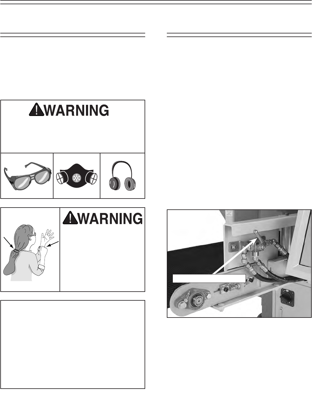
1. BE FAMILIAR WITH THE HAZARDS OF
HYDRAULIC INJECTION INJURIES.
— Leaking hydraulic fluid may have
enough pressure to penetrate skin.
Never use your hands to check for
suspected hydraulic leaks.
— Hydraulic fluid that is injected into
skin is a medical emergency that
may cause infection, disability,
amputation or death.
— The average injection injury may
be a small wound that has barely
broken the skin. DO NOT be fooled
by this type of injury. Immediately
get to an emergency medical facil-
ity!
— Minimizing the time between the
injury and when the injected mate-
rial is removed is critical to mini-
mizing the seriousness of the inju-
ry.
2. USE A PIECE OF CARDBOARD TO
CHECK FOR SUSPECTED HYDRAU-
LIC LEAKS. Pressurized hydraulic fluid
may cause injection injuries and can be
extremely hot. Never use your hands to
check for suspected hydraulic leaks.
3. PROTECT YOUR EYES AROUND
HYDRAULIC SYSTEMS. Safety glasses
may not always protect your eyes from
hot, pressurized fluid. The best way to
protect yourself is to stay away from leaks
until you can depressurize the system.
G0504 16" Horizontal Resaw Bandsaw -11-
A fire may occur if your particular electrical
configuration does not comply with local and
state codes. The best way to ensure compli-
ance is to check with your local municipality
or a qualified electrician.
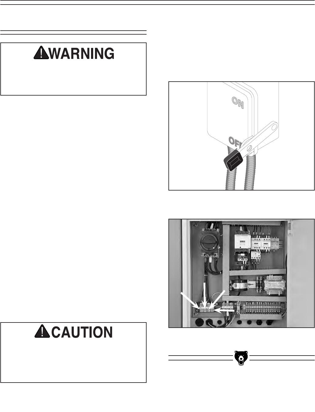
Figure 1. A power disconnect is preferable to
high current plugs and receptacles.
Serious personal injury could occur if you
allow power to the machine before complet-
ing the setup process. DO NOT allow power
to the machine until instructed to do so.
Amperage Draw
The Model G0504 features a 220/440V motors
that are prewired for 220V and draw the following
amps under full load:
Main Motor at 220V .............................. 72 Amps
Main Motor at 440V .............................. 41 Amps
Elevation Motor at 220V ....................... 2.2 Amps
Elevation Motor at 440V ....................... 1.1 Amps
Circuit Requirements
We recommend connecting your machine to
a dedicated and grounded circuit that is rated
for the amperage given below. Never replace
a circuit breaker on an existing circuit with one
of higher amperage without consulting a quali-
fied electrician to ensure compliance with wir-
ing codes. If you are unsure about the wiring
codes in your area or you plan to connect
your machine to a shared circuit, consult a
qualified electrician.
Minimum 220V Circuit ........................... 90 Amps
Minimum 440V Circuit ........................... 60 Amps
3-Phase Power
SECTION 3: CIRCUIT REQUIREMENTS
Connection Type
This machine is intended to be installed in a
semi-permanent location and hardwired to the
power source by a qualified electrician, using a
supply circuit disconnect device with the capa-
bility of being locked in the OFF (open) position
(see Figure 1).
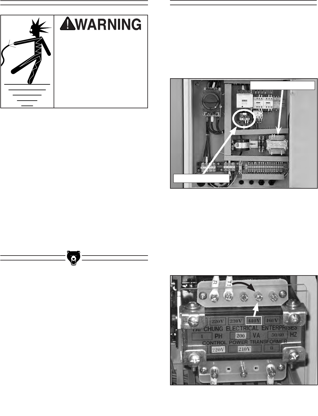
Figure 2. Power connection points inside the
electrical box.
-12- G0504 16" Horizontal Resaw Bandsaw
Converting the Model G0504 to 440V operation
consists of 1) wiring the voltage transformer, 2)
replacing the overload relays with those provided
in the G0504 440V conversion kit, and 3) rewiring
the main motor and the elevation motor. A quali-
fied electrician must inspect all electrical modifi-
cations before connecting to power.
Figure 3. Inside of electrical box.
In the event of an electrical malfunction or break-
down, grounding provides a path of least resis-
tance for electric current to reduce the risk of
electric shock. This machine must be equipped
with an electric cord that has an equipment
grounding conductor. This conductor must be
grounded in accordance with all local codes and
ordinances.
Improper connections of the electrical-grounding
conductor can result in the risk of electric shock.
Check with a qualified electrician or one of our
service personnel if the grounding instructions
are not completely understood, or if you are in
doubt as to whether the machine is properly
grounded.
Electrocution or fire could
result if this machine is
not grounded correctly.
Make sure all electrical cir-
cuits are grounded before
you connect them to the
machine. DO NOT use the
Model G0504 if it is not
grounded.
Converting to 440VGrounding
To convert the Model G0504 to 440V:
1. Disconnect the resaw from the power
source!
2. At the voltage transformer, move the T1 wire
from the 220V terminal to the 440V terminal.
Voltage Transformer
Main Motor Relay
Figure 4. Location on voltage transformer to
move the T1 wire for 440V operation.
G0504 16" Horizontal Resaw Bandsaw -13-
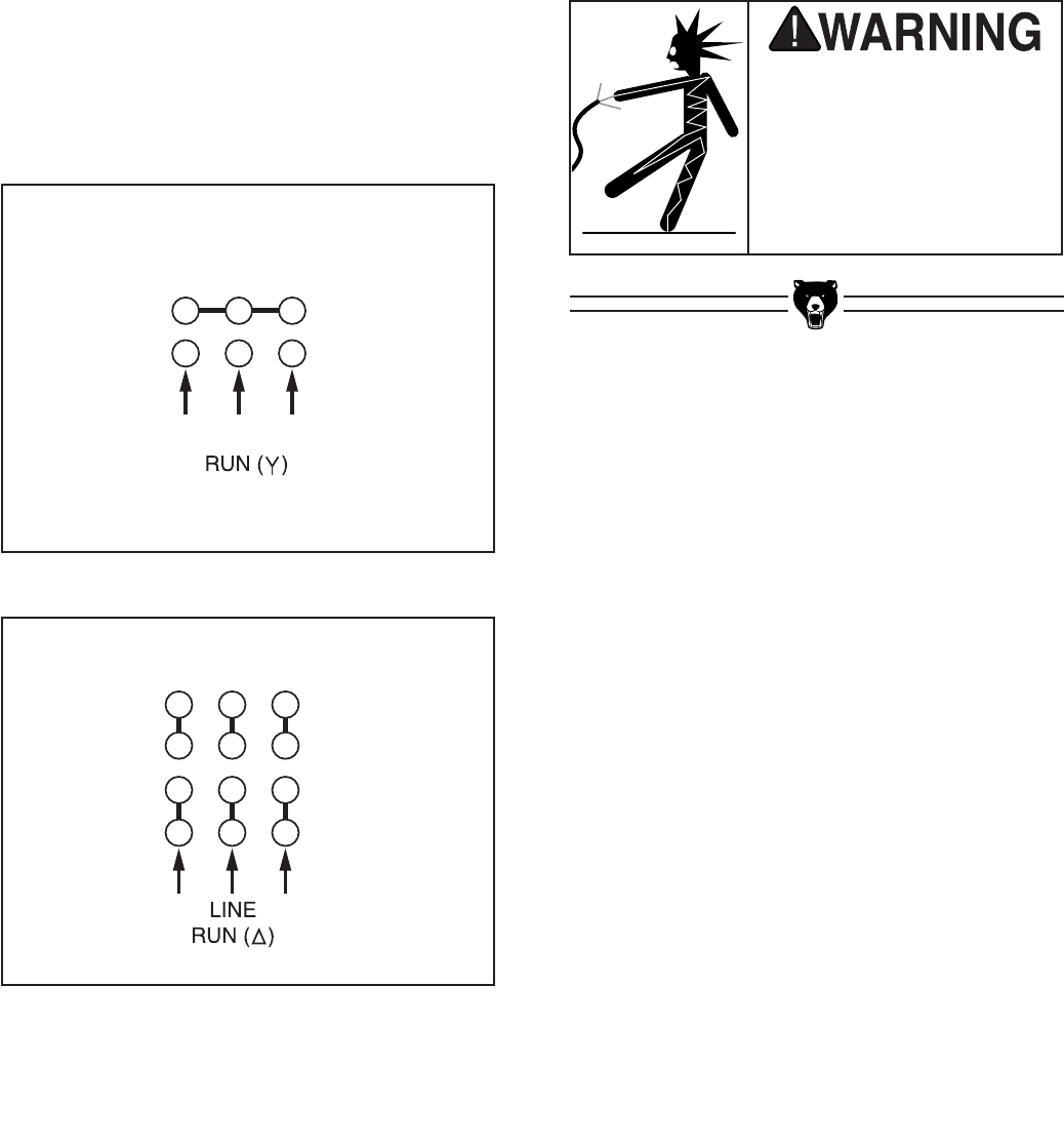
3. Remove the wiring box covers on the main
motor and elevation motor.
4. Wire the main motor and elevation motor as
shown on the diagrams on the inside of each
motor wiring box cover. (The circled refer-
ences on the diagrams represent labels on
the wires.)
Note: Figures 5 & 6 below have been pro-
vided for your reference and are current
at the time that this manual was written.
However, always use the diagram on the
wire cover that comes with your motor! Also,
the electrical system on this machine is setup
for the "RUN" diagrams shown on the wire
cover. Ignore the "START" diagrams for this
machine.
Figure 5. 30 HP main motor 440V wiring.
Figure 6. 1⁄2 HP elevation motor 440V wiring.
5. Replace the main motor relay (LR3D-3363
63/80A) with the relay from kit (LR3D-3357
37/50A) and set the dial to “47.”
6. Set the dial on the elevation motor relay to
"1.5."
7. Replace any wire duct covers and motor
wiring box covers you might have removed
during this procedure, and close the electrical
box door.
To avoid electrocution or
fire, ensure all wiring mod-
ifications are inspected
and approved by a quali-
fied electrician before con-
necting the machine to the
power source.
-14- G0504 16" Horizontal Resaw Bandsaw
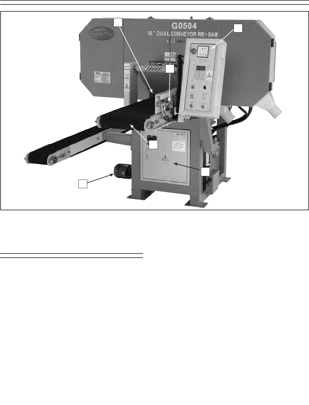
1. Infeed Pressure Rollers—Maintain down-
ward pressure on the board to keep it sturdy
during cutting.
2. Head Elevation Motor—Responsible for
moving the head (the part of the saw that
contains the wheels and blade) up or down
as needed.
3. Electrical Control Box—Main area for wir-
ing, rewiring, and changing the fuses. Should
never be opened when the machine is con-
nected to the power source!
4. Infeed Conveyor—Moves the board through
the bandsaw blade during cutting.
5. Infeed Conveyor Engagement Lever—
Allows the operator to stop and start the
infeed conveyor while the blade is moving.
6. Control Panel—The part of the resaw where
the operator can control the starting and
stopping of the motor, the various height
changes, and the calibration of the blade
height to the conveyor. The control panel
also houses a load meter that allows the
operator to monitor the load being placed on
the resaw during operation. For more details,
see Page 14.
Figure 7. Main view of machine features and controls.
2
4
5
3
6
1
Main Features
SECTION 4: MACHINE FEATURES
G0504 16" Horizontal Resaw Bandsaw -15-
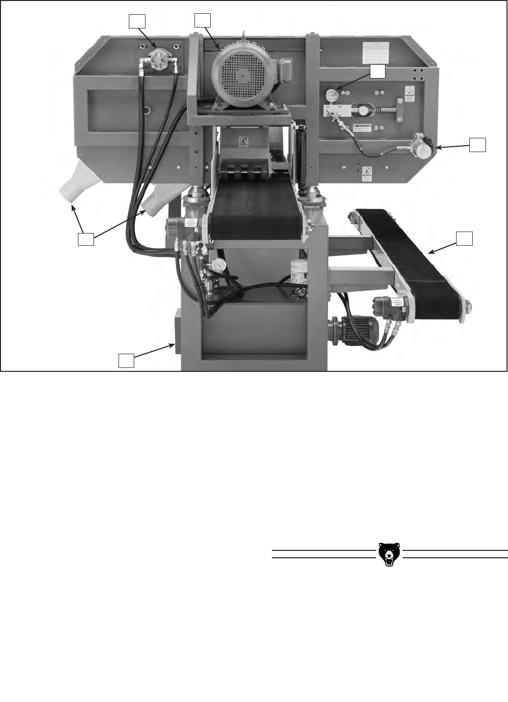
7. Main Motor—Powers the saw wheels for
blade movement and drives the hydraulic
pump for conveyor movement.
8. Dust Ports—Allows the resaw to be con-
nected to a dust collection system.
9. Hydraulic Pump—Creates hydraulic oil flow
which drives the conveyor motors.
10. Hydraulic Tank—Holds and cools the
hydraulic fluid for the hydraulic system.
11. Return Conveyor—Allows the person
receiving the newly cut board to return it
to the operator without walking around the
saw.
12. Blade Tension Gauge—Shows the current
blade tension.
13. Blade Tensioner—Provides hydraulic blade
tension and easy tension release.
Figure 8. Rear view of machine features and controls.
12
13
11
7
10
9
8
-16- G0504 16" Horizontal Resaw Bandsaw
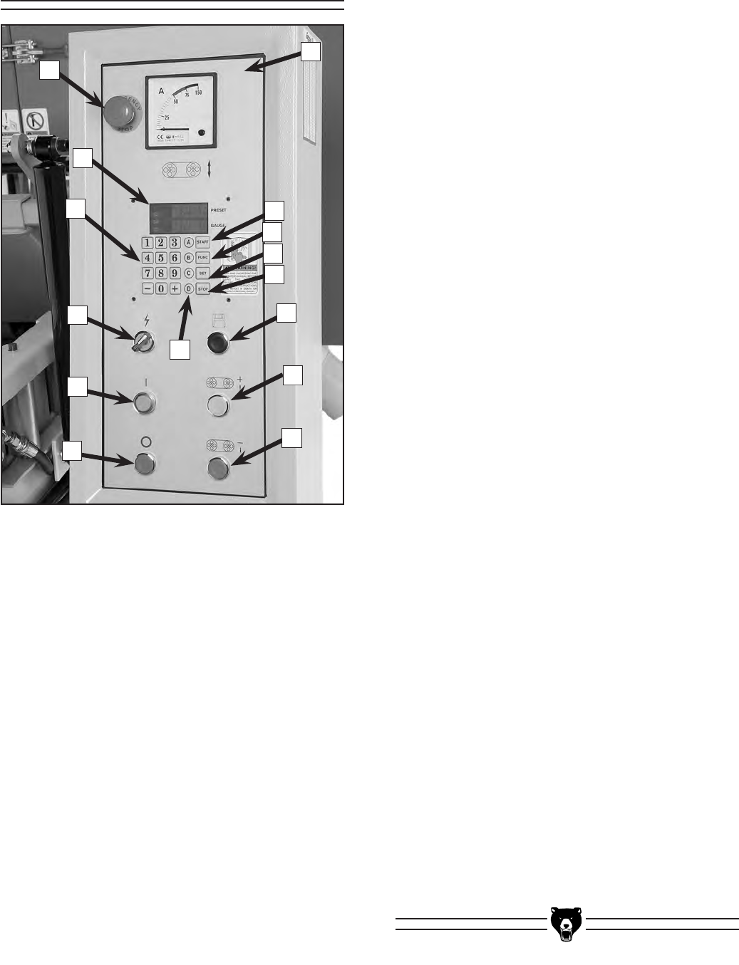
Control Panel
A. EMERGENCY STOP Button—Cuts power
to the main motor to stop the blade and
hydraulic pump. (Caution—It takes approxi-
mately 30 seconds for the blade to come to
a complete stop.)
B. Display—Shows the distance from the con-
veyor belt to the blade. Also used to enter
and change settings, move blade height, and
program the memory function.
C. Keypad—Inputs height values. The + and
- keys manually jog the height up or down.
D. POWER ON Switch—Engages power to the
control panel.
E. MOTOR START Button—Starts the main
motor, which is responsible for the blade and
conveyor movement.
A
M
L
K
J
H
I
B
G
C
D
E
F
N
F. MOTOR STOP Button—Stops the main
motor, blade, and conveyors.
G. DOWN Button—Moves the head (blade)
down toward the infeed conveyor.
H. UP Button—Moves the head (blade) up
toward the infeed conveyor.
I. Memory Button—Moves blade to a preset
height change. For example, if you want to
produce multiple 1⁄4" boards from a 5" board,
you can set the memory to X inches (X=1⁄4"
+ your blade kerf). After every cut, the head
will automatically move down X inches when
you press the memory button. You can then
repeat this procedure until the 5" board is
reduced to the last 1⁄4" that can be cut from
that board.
J. STOP Key—Stops the elevation motor from
its current movement.
K. SET Key—Calibrates the height of the blade
from the table, or can be used in combina-
tion with the FUNC key to set the memory.
L. FUNC Key—Prepares the control panel for
special functions. Can be used in combina-
tion with the START key to manually type in
a numeric height on the keypad, or can be
used in combination with the SET key to set
the memory.
M. START Key—Moves the blade to the height
that is entered in the keypad. Must be used
in conjunction with the FUNC key.
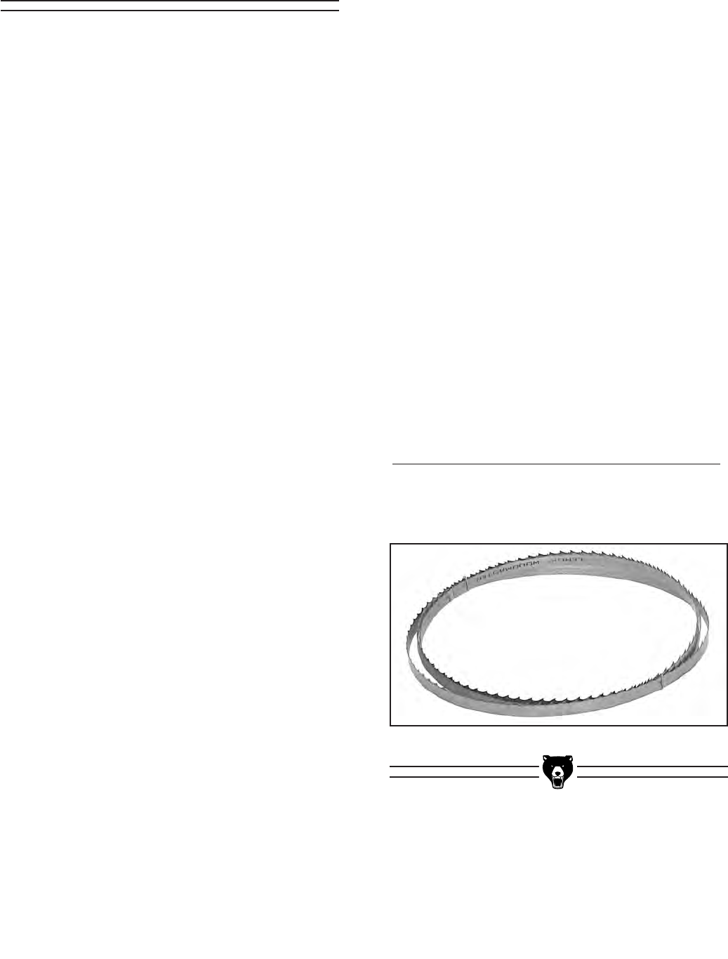
N. Load Meter—Displays the current load
placed on the machine. The load meter is
used to determine the appropriate conveyor
feed rate for each species of wood and each
blade being used.
O. Memory Preset Keys (A, B, C, D)—Allows
multiple dimension sizes to be saved and
recalled. For example, if you have 500 piec-
es to resaw and the starting size is 2" thick
on all of them, then you can save 2" in the A
memory key. After cutting down each piece,
press A to return to the starting height.
Figure 9. Control panel close-up.
O
G0504 16" Horizontal Resaw Bandsaw -17-
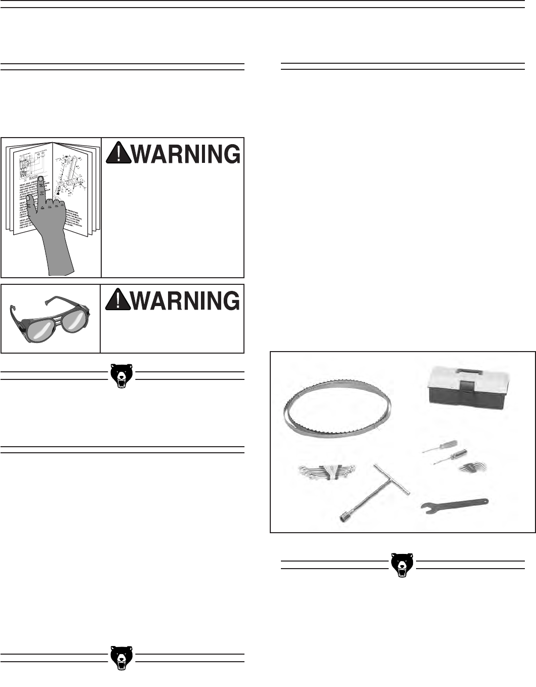
After all the parts have been removed from
the shipping crate, you should have:
• Resaw Bandsaw Machine
• Bandsaw Blade 180" x 1" x 0.035"
• Tool Box
• T-Handle Wrench 19mm
• 7 pc. Combination Wrench Set
—10, 12, 13, 14, 17, 19, 21 mm
• 7 pc. Hex Wrench Set
—2.5, 3, 4, 5, 6, 8, 10 mm
• Phillips Head Screwdriver
• Flat Head Screwdriver
• Adjustment Wrench 30 x 32 mm
In the event that any non-proprietary parts are
missing (e.g. nuts or washers), we would be glad
to replace them, or for the sake of expediency,
replacements can be obtained at your local hard-
ware store.
The Model G0504 is shipped from the manu-
facturer in a carefully built crate. If you discover
the machine is damaged after you have signed
for delivery, please immediately call Customer
Service at (570) 546-9663 for advice.
Save the containers and all packing materials
for possible inspection by the carrier or its agent.
Otherwise, filing a freight claim can be difficult.
When you are completely satisfied with the con-
dition of your shipment, you should inventory the
equipment from the shipping crate.
The purpose of this section is to guide you
through the required steps to get your machine
out of its crate and into operating condition.
Wear safety glasses
during the entire set up
process!
This machine presents
serious injury hazards
to untrained users. Read
through this entire man-
ual to become familiar
with the controls and
operations before start-
ing the machine!
Figure 10. Piece inventory from packing crate.
Piece Inventory
Unpacking
About this Section
SECTION 5: SET UP
-18- G0504 16" Horizontal Resaw Bandsaw
Removing Resaw
from Crate Pallet
To remove the resaw from the crate pallet:
1. Remove the lag bolts from the stand feet that
secure the resaw to the crate pallet.
2. Using a forklift, lift the resaw from the frame
location shown in Figure 11, and move it to
your predetermined location.
Figure 11. Lifting points for moving the resaw
with a forklift.
The Model G0504 is a
heavy machine that
weighs approximately
3300 lbs. Serious per-
sonal injury may occur if
safe moving methods are
not followed. To be safe,
you will need assistance
and power equipment
when moving the ship-
ping crate and remov-
ing the machine from the
crate.
Mounting Resaw to
the Floor
Although not required, we recommend that you
mount your new machine to the floor. Because
this is an optional step and floor materials may
vary, floor mounting hardware is not included.
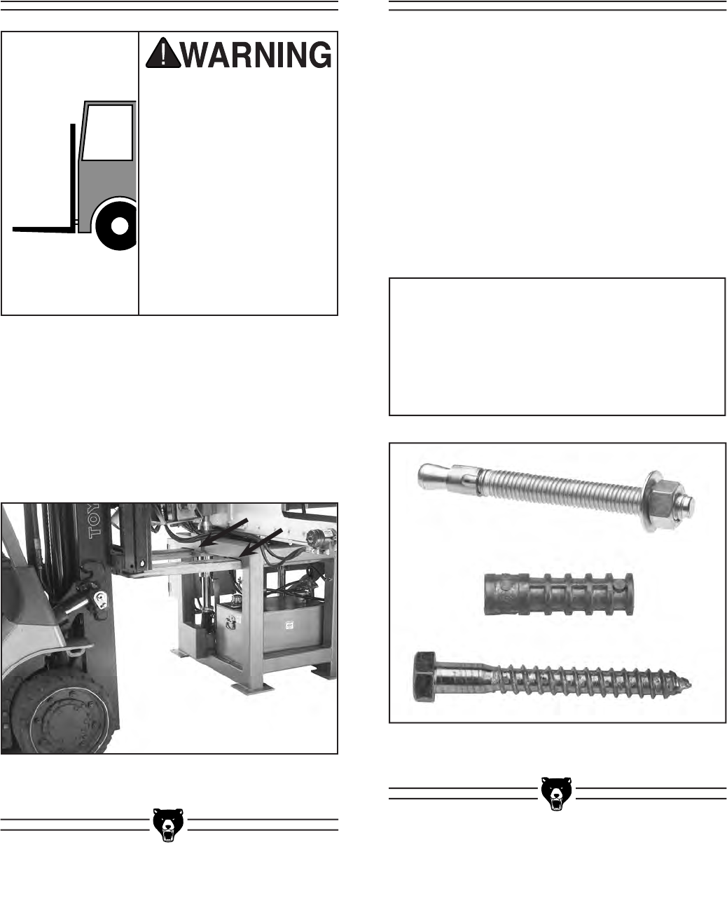
Bolting to Concrete Floors
Lag shield anchors with lag bolts and anchor
studs (Figure 12) are two popular methods for
anchoring an object to a concrete floor. We sug-
gest you research the many options and methods
for mounting your machine and choose the best
that fits your specific application.
NOTICE
Anchor studs are stronger and more per-
manent alternatives to lag shield anchors;
however, they will stick out of the floor,
which may cause a tripping hazard if you
decide to move your machine.
Figure 12. Typical fasteners for mounting to
concrete floors.
G0504 16" Horizontal Resaw Bandsaw -19-
Blade installation can be done by one person but
is easiest if done with two people.
To install and tension the blade:
1. Put on safety glasses and heavy leather
gloves.
2. Open the wheel cover to gain access to the
wheels.
3. Hold the blade from each side, and position
it in front of the wheels so the blade teeth are
facing the front of the machine.
4. Carefully fit the blade over each wheel,
and position it between the blade guides
as shown in Figure 13. Make sure the
teeth point toward the right-hand side of the
machine, as you are facing the front.
These instructions are
hazardous if done while
the machine is connect-
ed to power. Disconnect
power during this entire
procedure!
Installing &
Tensioning Blade
Figure 13. Blade positioned between
blade guides.
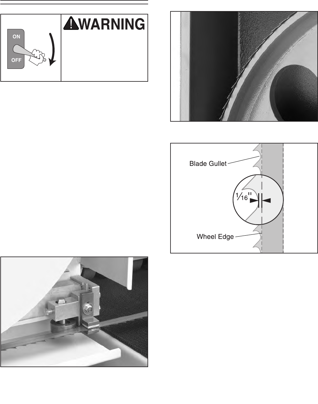
Figure 14. Blade positioned on wheel.
Figure 15. Illustration of proper blade position.
5. Position the blade on the wheels so that the
tooth gullet is approximately 1⁄16" over the
edge of the wheel, as shown in Figure 14.
Also, see the blade illustration in Figure 15
for more details.
-20- G0504 16" Horizontal Resaw Bandsaw
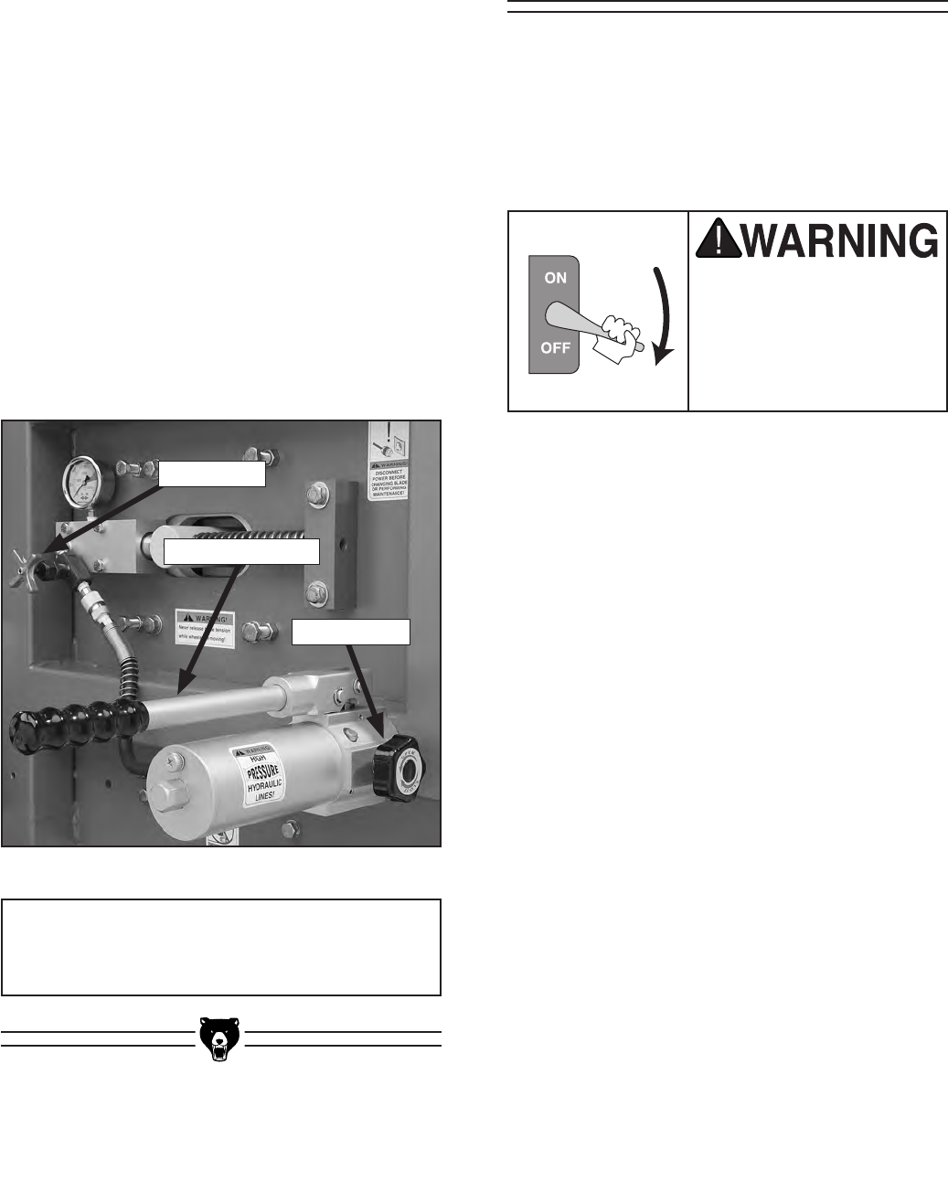
Figure 16. Blade tensioner controls.
6. Loosen the stop valve (Figure 16) and tight-
en the pump valve.
7. Tighten the blade with the blade tensioner
shown in Figure 16. Use the colored area on
the tension gauge as a proper tension guide
for your specific blade material.
Carbon Steel ......................................Yellow
Bi-metal ............................................ Orange
Note—Always adjust the pressure to the
lowest rating of each colored area and then
increase tension as needed (blades stretch
as they warm up).
8. Tighten the stop valve and loosen the pump
valve.
Note—To loosen the blade tension, loosen
the stop valve.
NOTICE
Always de-tension blade after use.
Each blade guide assembly consists of Guide
Blocks and a Support Bearing.
The blade guides keep the blade stable dur-
ing operation, so make sure they are properly
adjusted before starting the bandsaw.
Adjusting Blade
Guides
These instructions are
hazardous if done while
the machine is connect-
ed to power. Disconnect
power during this entire
procedure!
Guide Blocks
Each guide block consists of an upper and lower
ceramic block that stabilizes the blade from up/
down movement during operation.
The lower block is designed to remain in a fixed
position, and the upper block is designed to be
adjusted during each blade change. When the
machine is new, the lower block is set at the
factory and should not need to be adjusted (see
Section 8: Service Adjustments for more infor-
mation about the lower guide). The upper block,
however, should be adjusted every time you
install a new blade or re-install an old blade.
Stop Valve
Blade Tensioner
Pump Valve
G0504 16" Horizontal Resaw Bandsaw -21-
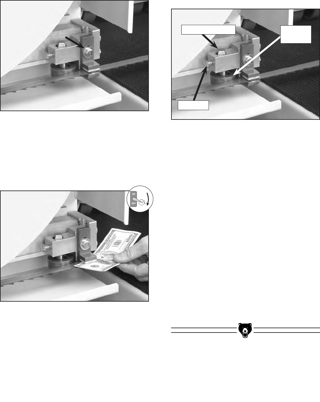
Figure 19. Support bearing components.
To adjust the support bearings:
1. Loosen the lock bolt approximately 1⁄4 turn.
Note—If you loosen the lock bolt too much,
the support bearing will fall out of place.
2. Turn the adjustment shaft until the support
bearing is positioned approximately 0.016"
behind the back of the blade. Use a feeler
gauge or four thicknesses of a dollar bill to
check this.
3. Tighten the lock bolt, and repeat with the
other support bearing.
4. Test the adjustment of the support bearings
by spinning the wheels by hand, at full blade
tension, in the same direction of operation.
While you are spinning the wheels, the sup-
port bearings should not turn. (The support
bearings should only turn during cutting
operations.)
Support Bearing
The support bearing is positioned behind the
blade to brace it from pushing backwards during
a cut. Figure 19 shows the support bearing com-
ponents to clarify the adjustment instructions.
Figure 17. Guide block adjustment bolt.
Figure 18. Dollar bill between upper guide block
and blade.
2. Slide the upper guide block up, place a dollar
bill (as a quick gauge for 0.004" clearance)
underneath the upper guide block, then let
the upper guide block slide down to sand-
wich the dollar between the blade and the
upper guide block as shown in Figure 18.
3. Keep the dollar bill in place and tighten the
upper guide block.
4. Remove the dollar bill.
5. Repeat Steps 1-4 with the blade guide on
the other side of the conveyor.
To adjust the upper guide block:
1. Loosen the guide block adjustment bolt
shown in Figure 17.
Adjustment Shaft
Lock Bolt
Support
Bearing
-22- G0504 16" Horizontal Resaw Bandsaw
If you have performed all of the previous set up
instructions, the resaw can now be connected to
the power source by a qualified electrician.
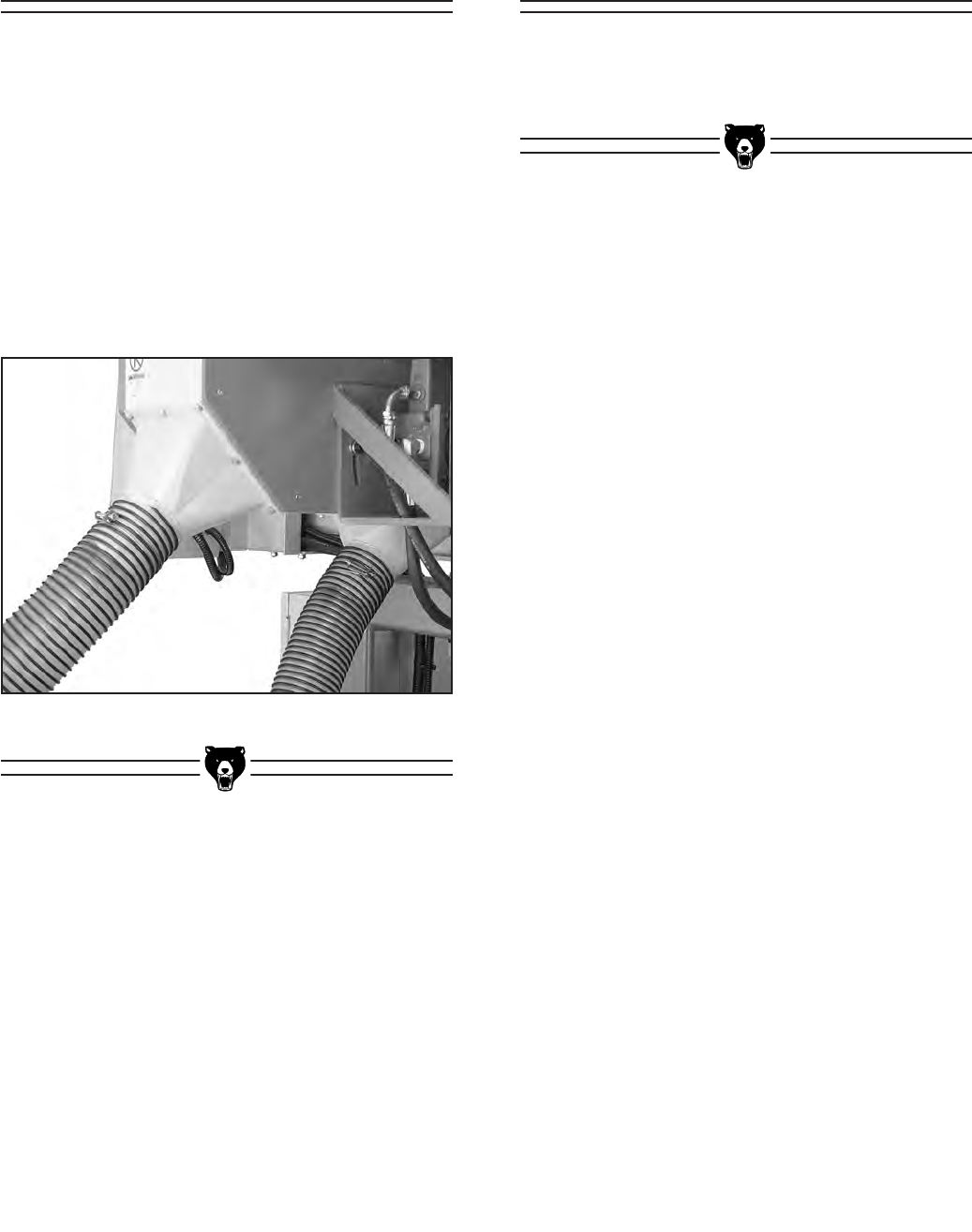
Figure 20. Dust hose connected to dust port.
To be effective, the dust collection system that
you connect to the resaw must be able draw a
combined total of at least 1000 CFM at the dust
ports. Note—This number is an approximation
and has been provided for estimation purposes
only.
To connect the resaw to a dust collector:
1. Attach two 4" dust hoses to the dust ports as
shown in Figure 20, and be sure to tighten
the hose clamp to ensure a snug fit.
Connecting to
Power Source
Connecting to Dust
Collector
G0504 16" Horizontal Resaw Bandsaw -23-
6. Press the UP and DOWN buttons to make
sure the resaw head moves in the proper
direction.
— If the resaw head moves in the opposite
direction as indicated, then the machine
has been wired out of phase. To cor-
rect this, disconnect the power to the
machine, open the electrical box, and
switch any two current carrying wires (R,
S, or T) that connect the machine to the
power source.
7. Push the emergency stop button in, then
twist it clockwise until it pops out.
8. Once you have performed Steps 1-4 and
everything is okay with the machine and
set up, press the MOTOR START button.
As you are standing in front of the machine,
make sure that the blade is moving from left
to right.
9. Press the conveyor lever forward to test the
conveyor belt.
— If any problems occur, press the
EMG STOP button. Investigate and cor-
rect the problem before operating the
machine further. If you need help, refer to
the troubleshooting section in the back of
this manual.
— If you cannot easily locate the source of
an unusual noise or vibration by yourself,
please contact our service department at
(570) 546-9663.
To test run the resaw:
1. Make sure the wheel cover and electrical
box is closed and all tools or other objects
are cleared away from the machine.
2. Put on safety glasses and make sure any
bystanders are out of the way and also wear-
ing safety glasses.
3. Tension the blade.
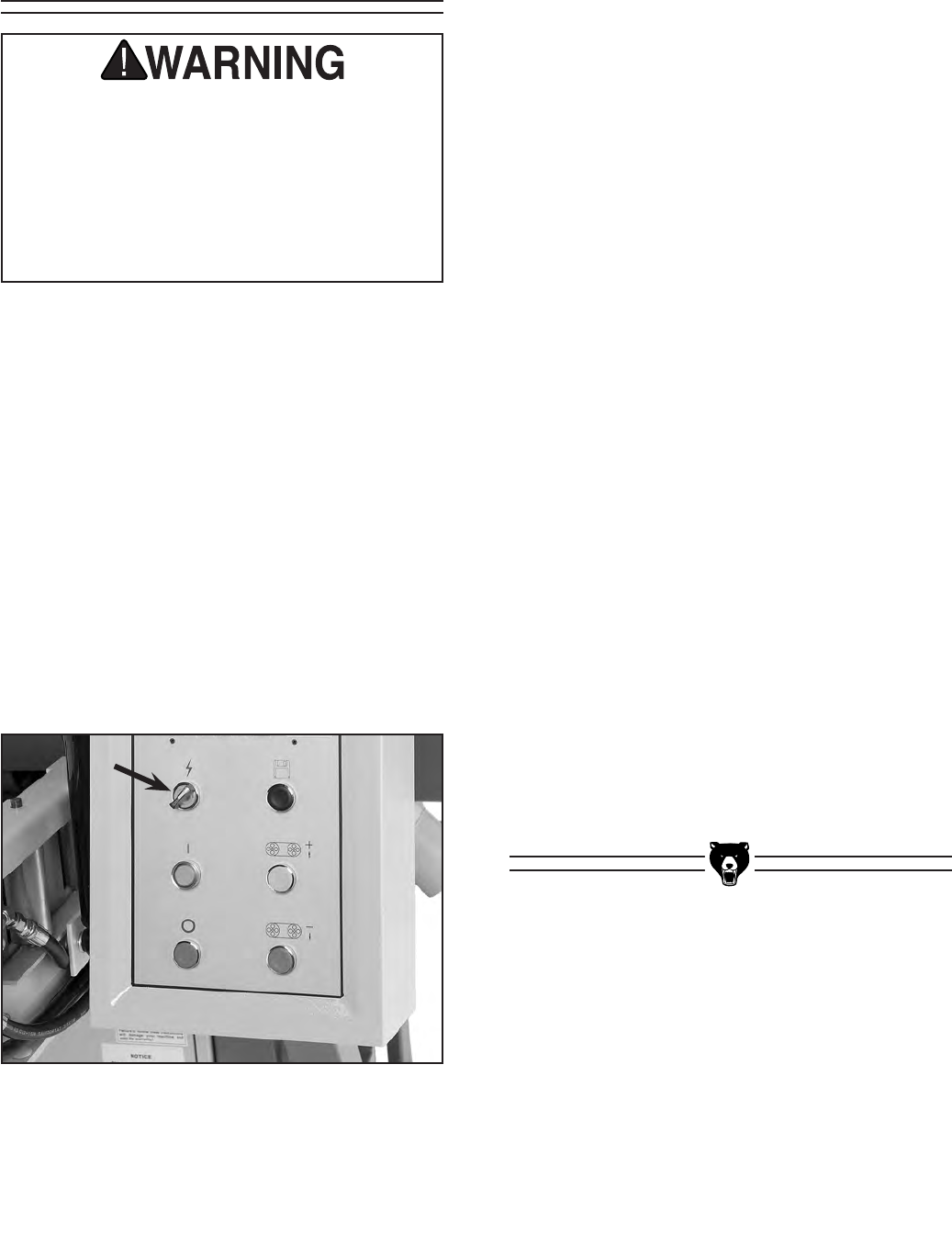
4. Turn ON the master switch that is located on
the outside of the electrical box.
5. Turn the POWER ON switch (shown in
Figure 21) clockwise.
Test Run
Before starting the resaw, make sure you
have performed the preceding assembly
and adjustment instructions, and you have
read through the rest of the manual and
are familiar with the various functions and
safety issues associated with this machine.
Failure to follow this warning could result
in serious personal injury or even death!
Figure 21. POWER ON switch.
-24- G0504 16" Horizontal Resaw Bandsaw
NOTICE
The following section was designed to give
instructions on the basic operations of this
machine. However, it is in no way compre-
hensive of all of the machine’s applica-
tions. WE STRONGLY RECOMMEND that
you read books, trade magazines, or get
formal training to maximize the potential of
your machine.
Damage to your eyes, lungs, and ears could
result from failure to wear safety glasses,
a dust mask, and hearing protection while
using this machine.
Loose hair and cloth-
ing could get caught in
machinery and cause
serious personal inju-
ry. Keep loose clothing
rolled up and long hair
tied up and away from
moving machinery.
All operators of this machine must be familiar
with the Section 2: Safety before operating
this machine. However, no safety list can cover
every hazard for every working environment, so
common sense must be used at all times in all
situations.
Operation Safety
SECTION 6: OPERATIONS
Conveyor Controls
The Model G0504 features an infeed conveyor
and a return conveyor. The speed and engage-
ment controls of the conveyors are controlled by
the conveyor control lever. The farther the control
lever is pushed forward, the faster the conveyors
will move.
To operate the infeed conveyor:
1. Read the subsection titled “Control Panel”
on Page 14 to become familiar with the con-
trol panel functions.
2. With the saw running, push the infeed con-
veyor engagement lever (Figure 22) foward
to engage the conveyor belts. Push the lever
farther foward to make the conveyors run
faster, or pull the lever backwards to make
the conveyors run slower. Pull the lever all
the way back to stop the conveyors.
Figure 22. Conveyor controls.
Conveyor Control Lever

G0504 16" Horizontal Resaw Bandsaw -25-
The blade height is defined as the distance
between the conveyor table and the bottom face
of the bandsaw blade. There is an internal limit
switch that will not allow the blade to be adjusted
closer than 1⁄4" to the conveyor table. Note—Use
the “Blade Memory Function” described in the
next subsection when you want to make resaw
cuts thinner than 1⁄4", and be sure to cut from the
top of the workpiece.
The blade height can be adjusted by using the
keypad, or by pressing the UP and DOWN con-
trol panel buttons. After using either method of
adjustment, the digital display will indicate the
current blade height.
To set the blade height with the UP and DOWN
control panel buttons:
1. Turn the control panel POWER ON switch
clockwise to supply power to the control
panel.
2. Press the UP button to move the blade up
and press the DOWN button to move the
blade down. Watch the digital display to
gauge the blade height.
To set the blade height with the keypad:
1. Turn the control panel POWER ON switch
clockwise to supply power to the control
panel.
2. Press the FUNC key.
3. Enter the desired blade height to the nearest
hundredth's place. For example, if you want
the blade height to be 2", press 2, 0, 0 on
the keypad. If you want the blade height to
be 3⁄4", press 7, 5.
4. After the blade height has been entered,
press the START key.
Setting Blade Height
The digital display indicates the distance between
the conveyor table and the bottom face of the
bandsaw blade. The digital display needs to be
calibrated to ensure that the displayed blade
height and the actual blade height are the same.
To calibrate the digital display:
1. Resaw a
piece of scrap wood. See “Resawing”
on Page 27 for more information.
2. Measure the thickness of the workpiece that
was cut off between the conveyor table and
the blade. Note—Use a precise measuring
tool such as calipers or a micrometer.
3. Press the SET key.
4. Enter the thickness value of the cut-off
piece measured in Step 2. For example, if
the thickness is 1", press 1, 0, 0 on the key
pad.
5. Press and hold the SET key for approxi-
mately 5 seconds or until the display stops
flashing.
The digital display is now calibrated and all blade
height values displayed will be the same as the
actual distance between the conveyor table and
the bottom face of the bandsaw blade.
Calibrating Digital
Display

-26- G0504 16" Horizontal Resaw Bandsaw
The blade memory button lowers the blade a pre-
determined distance each time it is pressed. This
allows you to make a series of cuts from the top
side of the workpiece, all of the same thickness.
Be sure to add the blade kerf to the desired
thickness of the cut-off pieces when setting the
memory function. For example, if you want your
cut-off pieces to be 1" thick and the kerf of the
blade is 0.06", the memory function needs to be
set to 1.06".
The blade memory function is also used when
you want to make resaw cuts thinner than 1⁄4".
Because the blade cannot be adjusted closer than
1⁄4" to the table, resaw cuts thinner than 1⁄4" need
to be cut from the top side of the workpiece.
To set the memory function:
1. Turn the control panel POWER ON switch
clockwise to supply power to the control
panel.
2. Press the FUNC key.
3. Enter the distance, to the nearest hun-
dredth's place, that you want the blade to
lower. For example, if you want the blade to
lower 2.06", press 2, 0, 6 on the key pad. If
you want the blade to lower 0.56", press 5,
6.
4. Press and hold the SET key for approxi-
mately 5 seconds or until the display stops
flashing.
5. Press the MEMORY button and the blade
will automatically lower the distance set into
the memory function.
Note—For best results, make a few cuts while using
the MEMORY button, measure the workpiece,
and adjust the memory setting according to the
measurements of the cut-off workpiece.
Setting Memory
Button
The memory preset keys (A, B, C, D) allow four
dimension sizes to be saved and recalled.
For example, if you have 500 pieces to resaw and
the starting size is 2" thick on all of them, then
you can save 2" in one of the memory keys. After
cutting down each piece, press that memory pre-
set key to return to the starting height of 2" for the
next whole piece.
To store a height in the A memory preset
key:
1. Press the A key. The current preset height
flashes on the display.
2. Enter the height you wish to store. For exam-
ple if you want to store 2" as the height",
press 2, 0, 0 on the key pad.
3. Press and hold the A key for 3 seconds. The
display zeros out and stops flashing.
To use the stored memory preset in the A
key:
1. Press the A key. The current preset height
flashes on the display.
2. Press the START key on the key pad. The
blade moves to the stored height dimen-
sion.
Note—To stop a stored memory preset from
moving to its stored height, press the STOP
key on the key pad AFTER you have pressed
the memory preset key (A in this example).
Using Memory
Preset Keys
G0504 16" Horizontal Resaw Bandsaw -27-
To perform a resawing operation:
1. Make sure the blade is installed and ten-
sioned correctly. See “Installing Blade” on
Page 19 for more information.
2. Make sure the blade is tracking correctly.
See “Adjusting Blade Guides” on Page 20
for more information.
3. Turn the control panel POWER ON switch
clockwise to supply power to the machine.
4. Set the blade height at the control panel.
See “Setting Blade Height” on Page 25.
Note—The accuracy of the blade height
shown on the digital display can only be
assured if the calibration process has been
performed. See Page 25 for more informa-
tion on calibrating the digital display.
5. Press the MOTOR START button to start the
bandsaw blade.
6. Push the infeed conveyor engagement lever
forward to start the infeed conveyor. Turn
the infeed conveyor speed dial counter-
clockwise to increase the speed and clock-
wise to decrease the speed. See “Conveyor
Controls” on Page 24 for more information.
7. Recheck the blade tension.
8. Make sure the workpiece has two sides
that are relatively flat and parallel with each
other.
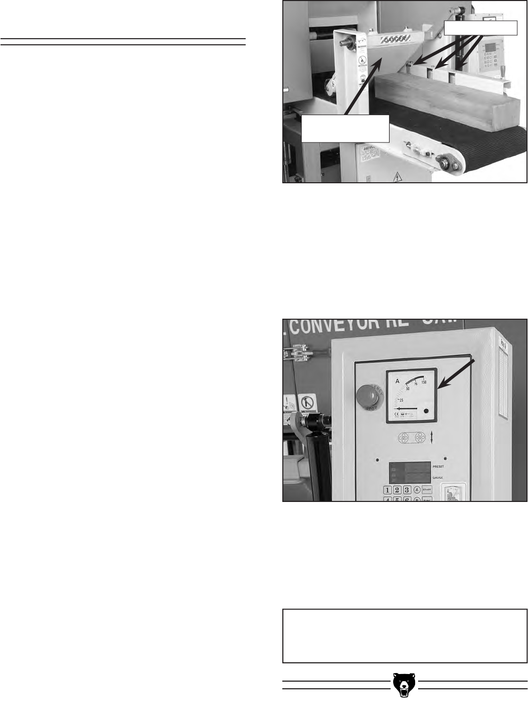
9. Begin feeding the workpiece under the front
pressure rollers with the jointed edge against
the guide rollers, as shown in Figure 23.
Resawing
10. Watch the load meter (Figure 24) at the top
of the control panel. The meter displays the
amperage load that is being placed on the
machine. Adjust the infeed conveyor feed
rate until the meter reads between 25-30
Amps during the cutting operation.
11. Receive the workpiece on the outfeed side
of the machine. Note—If a second person
is receiving the workpieces, use the return
conveyor to send them back to the person
on the infeed side.
Figure 23. Feeding the workpiece through the
bandsaw.
Figure 24. Load meter.
NOTICE
Always de-tension blade after use.
Front Pressure
Roller Assembly
Guide Rollers
-28- G0504 16" Horizontal Resaw Bandsaw
Blade Information
Blade choices are limited due to the specialized
nature of the Model G0504. The only variables
when selecting a blade are the type of cutting
tooth and the number of teeth-per-inch (Tooth
Pitch).
Blade Tooth Type
Carbon Steel—The least expensive type, car-
bon steel blades are adequate for most cutting
applications; however, they dull quickly and for
economical reasons they are usually replaced
rather than resharpened.
Carbide-Tipped—The most expensive type, car-
bide-tipped blades are designed for continuous
use in production shops. They hold a sharp
edge longer than carbon steel and they can be
resharpened many times before needing to be
replaced.
Tooth Pitch (TPI)
Tooth pitch refers to the number of teeth-per-
inch. The more teeth-per-inch, the smoother the
resulting cut, but the feed rate must be relatively
slow. The less teeth-per-inch, the rougher the
resulting cut, but the feed rate can be set faster.
Some trial and error may be necessary to find
the right combination of cut quality, tooth pitch
and feed rate.
Blade Care
The resaw blade is a delicate piece of steel that
is subjected to tremendous strain. You can obtain
longer use from the blade if you give it fair treat-
ment and always use the appropriate feed rate
for your operation.
A clean blade will perform much better than a
dirty blade. A dirty blade passes through the
cutting material with much more resistance than
a clean blade. This extra resistance will also
cause unnecessary heat. Maintain your blades
with a cutting blade lubricant like SLIPIT® (Model
G5562/3 in the Grizzly Catalog).
Blade Length
The required blade length for the Model G0504
is 180".
Blade Width
The required blade width for the Model G0504
is 1".
Blade Breakage
Blade breakage is unavoidable, in some cases,
since it is the natural result of the peculiar stress-
es placed on the blade. Blade breakage is also
due to avoidable circumstances, which is most
often the result of poor care or judgement on the
part of the operator when mounting or adjusting
the blade or support guides.
The most common causes of blade breakage
are:
• Not releasing blade tension after use.
• Faulty alignment or adjustment of the
guides.
• Using a blade with a lumpy or improperly
finished braze or weld.
• Feeding the workpiece too fast.
• Tooth dullness or absence of sufficient set.
• Excessive or too little blade tension.
• Running the bandsaw excessively when not
resawing.
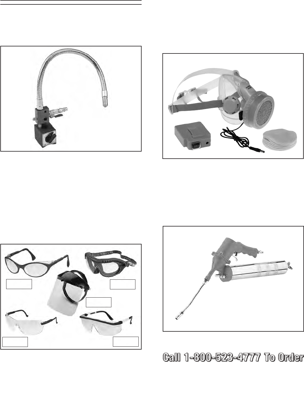
Blades Available from Grizzly
MODEL TYPE WIDTH GAUGE TPI
H4874 Carbon 1" 0.035" 1.3
H4875 Carbide Tip 1" 0.035" 2-3
H4876 Carbide Tip 1" 0.035" 3-4
Figure 25. Lenox® bandsaw blade.
G0504 16" Horizontal Resaw Bandsaw -29-
Accessories
Figure 26. H4959 Coolant Dispenser.
H4959—Coolant Dispenser
Delivers a small amount of lubricant to the cutting
surface to improve tool life and cutting efficiency.
An absolute must for large resawing operations.
Figure 28. H6175 Power Respirator.
H6175—Power Respirator
H6892—3M Pre-Filter, 10-Pack
H6893—Filter Cartridge, 10-Pack
Say goodbye to foggy safety glasses and labored
breathing, this battery powered respirator sup-
plies a constant breeze of fresh air all day long.
Comes with its own plastic case for clean, sealed
storage. Finally, a respirator you can look forward
to wearing—at an affordable price!
Figure 29. H0580 Pneumatic Grease Gun.
H0580—Pneumatic Grease Gun
Greasing fittings is a breeze with this pneumatic
grease gun—and it's one of the most affordable
on the market. Requires 90 PSI and consumes 4
CFM. Kiss that old hand pump grease gun good-
bye!
G7984—Face Shield
H1298—Dust Sealed Safety Glasses
H1300—UV Blocking, Clear Safety Glasses
H2347—Uvex® Spitfire Safety Glasses
H0736—Shop Fox® Safety Glasses
Safety Glasses are essential to every shop. If
you already have a pair, buy extras for visitors
or employees. You can't be too careful when it
comes to shop safety!
Figure 27. Our most popular safety glasses.
G7984
H1298
H1300
H2347 H0736
-30- G0504 16" Horizontal Resaw Bandsaw
To ensure optimum power transmission from the
motor to the blade and to the hydraulic pump,
the V-belts must be in good condition (free from
cracks, fraying and wear) and operate under
proper tension. Check the V-belts at least every 3
months; more often if the bandsaw is used daily.
See Section 8: Service Adjustments for instruc-
tions on properly tensioning the belts or for
replacing the belts, if needed.
Inside Wheel Cover
To keep the bandsaw working properly, regularly
open the wheel cover and vacuum sawdust.
Conveyor Belts
Use compressed air to clean the built-up sawdust
from the conveyor belts. Eye injuries frequently
occur when cleaning with compressed air—wear
safety glasses to protect yourself! Also wear a
dust mask or respirator to protect your lungs from
airborne dust particles.
Elevation Columns
Use a dry rag to remove sawdust from the eleva-
tion columns and wipe the them down with a light
coat of oil.
Painted Surfaces
These areas may be cleaned with a dry or damp
rag; however, make sure you DO NOT clean
bare metal surfaces with a damp rag or they may
rust.
Motor
Vacuum dust off of the motor on a regular basis.
Built up dust acts as an insulator, making it dif-
ficult for the motor to dissipate heat.
Hydraulic Components
Keep hydraulic components free of sawdust,
especially before working on them, to avoid con-
tamination of the hydraulic system.
Always be aware of the condition of your machine.
Routinely check the condition of the following
items and repair or replace as necessary:
• Loose mounting bolts
• Worn switch
• Worn or damaged blade
• Worn or damaged support bearings or guide
bearings
Always disconnect
power to the machine
before performing main-
tenance. Failure to do
this may result in seri-
ous personal injury.
Except for the bearings that are fitted with grease
fittings, the other bearings are sealed and pre-
lubricated and require no lubrication during their
usable life. All bearings are standard sizes, and
replacements can be purchased from our parts
department or a bearing supply store.
Bearings
V-Belts
Miscellaneous
Cleaning
SECTION 7: MAINTENANCE
G0504 16" Horizontal Resaw Bandsaw -31-
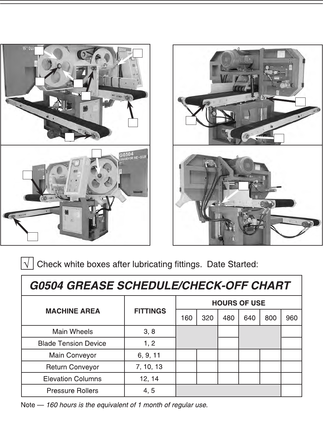
Wipe clean and lubricate the grease fittings with two pumps of high-temp bearing grease. The proper
greasing intervals are indicated by the boxes on the chart below. Note—This page was designed to be
copied and used as a check-off chart to help maintain a regular lubrication schedule.
Grease Fittings
1
2
3
4
5
9
8
11
12
6
7
10
13
14
-32- G0504 16" Horizontal Resaw Bandsaw
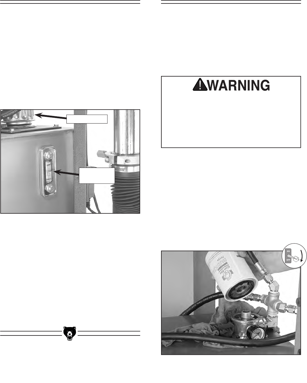
Breather Cap
Fluid Sight
Window
Figure 30. Hydraulic reservoir components.
Check the hydraulic fluid level daily.
The hydraulic system controls the movement
of the conveyor belts. In order for this system
to function properly and operate at the correct
temperature, the hydraulic fluid level in the tank
should be 2⁄3 full between the fill lines on the fluid
sight window, which is located on the front of the
tank (see Figure 30).
To add hydraulic fluid, remove the breather
cap shown in Figure 30. Use an ISO VG 10—
Antiwear 10 Hydraulic Fluid or equivalent.
The hydraulic system minor service consists of
changing the fluid filter, cleaning the breather
cap and filler screen, and inspecting the hydraulic
fluid for signs of thermal breakdown, dust con-
tamination, and water contamination.
Perform a “Minor Service” every 960 hours or
every 6 months of regular use.
Figure 31. Removing filter.
To change the filter:
1. Read and understand the hydraulic safe-
ty instructions on Page 6 before continu-
ing!
2. Thoroughly clean the entire area around the
filter to remove all dust. (Getting dust into the
hydraulic system will contaminate it.)
3. Remove the filter by unscrewing it from the
housing (Figure 31).
Inspect and clean the breather cap and filler
screen every 40 hours of regular use.
The breather cap is vented to allow the hydraulic
system to breathe during operation. Below the
breather cap is a plastic filler screen.
Visually inspect both the breather cap and the
plastic filler screen. If there is visual contami-
nation, clean both items with solvent and com-
pressed air. Allow them to completely dry before
installing back in the tank.
The hydraulic system on this machine cre-
ates very high pressure and the hydraulic
fluid gets hot. Always stop the resaw, open
the conveyor speed valves, make sure the
pressure gauge reads 0 PSI, and make sure
the fluid cools down before removing any
lines or servicing the hydraulic system.
Hydraulic System
Minor Service
Hydraulic Fluid
Schedule
G0504 16" Horizontal Resaw Bandsaw -33-
4. Rub clean hydraulic fluid along the O-ring on
the bottom of the new filter.
5. Thread the new filter into the filter housing
and tighten by hand.
To inspect the hydraulic fluid:
1. Look at the color of the hydraulic fluid in the
sight window.
— If the fluid is milky in appearance, then the
hydraulic fluid is contaminated with water.
Repair leaks or fix the source of the prob-
lem and perform a major service.
— If the fluid is dark brown or opaque, then
the hydraulic fluid is severely contaminat-
ed or thermal breakdown has occurred.
Correct the source of the contamination
or which component is causing thermal
breakdown, and perform a major service.
2. Smell the hydraulic fluid (remove breather
cap).
— If the fluid smells rancid or burnt, then ther-
mal breakdown has most likely occurred.
Correct the component that is causing
thermal breakdown and perform a major
service.
The hydraulic tank, when filled correctly at the
sight window, holds approximately 13.5 gallons
of hydraulic fluid. Before draining the hydraulic
fluid, make sure you have a drain pan that will
hold that much fluid or make sure that you are
prepared to drain the tank, plug the tank, empty
your drain pan, drain the tank, and so forth.
To drain the hydraulic fluid:
1. Read and understand the hydraulic safety
instructions on Page 8!
2. Place your drain pan under the drain plug
(Figure 32) and remove the drain plug.
Figure 32. Drain plug for hydraulic tank.
Hydraulic System
Major Service
The hydraulic system major service consists of
performing a complete “Minor Service,” draining
the old hydraulic fluid, cleaning the tank screen,
cleaning the tank, and adding new fluid.
The hydraulic system on this machine cre-
ates very high pressure and the hydraulic
fluid gets hot. Always stop the resaw, open
the conveyor speed valves, make sure the
pressure gauge reads 0 PSI, and make sure
the fluid cools down before removing any
lines or servicing the hydraulic system.
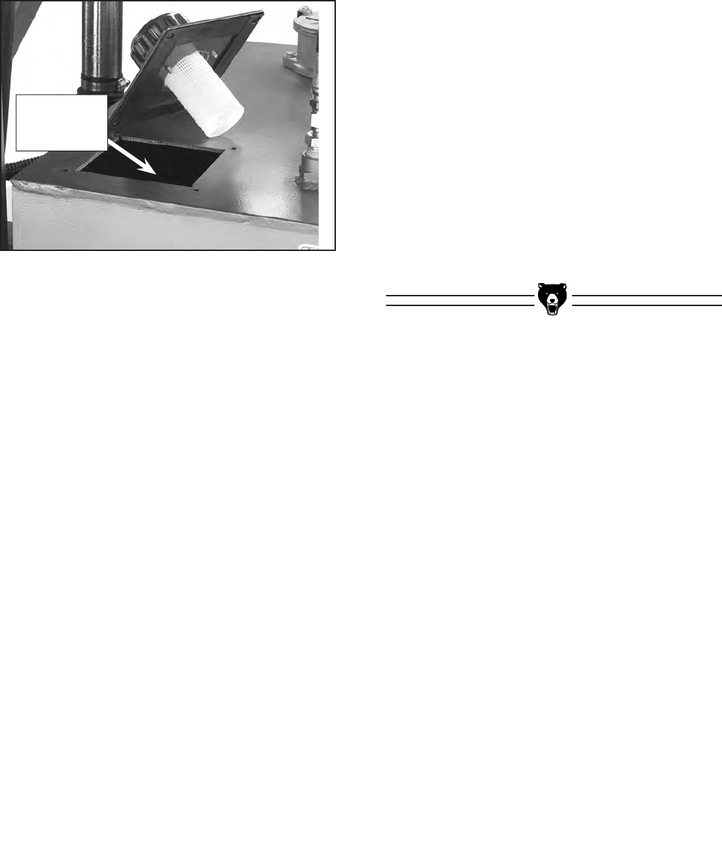
-34- G0504 16" Horizontal Resaw Bandsaw
3. Replace the drain plug after the hydraulic
tank is completely drained.
To clean the tank screen:
1. Remove the access plate on top of the
hydraulic tank as shown in Figure 33.
Figure 33. Access plate removed from tank.
2. Remove the tank screen, clean it with solvent
and compressed air, and allow it to dry. (Re-
install the tank screen AFTER you clean the
bottom of the tank.)
Tank Screen
Located
Inside Tank
To clean the bottom of the tank:
1. Use a lint free rag to wipe up and remove any
sludge from the bottom of the tank.
2. Use clean hydraulic fluid on a clean rag to
wipe up additional contaminants from the bot-
tom and sides of the tank.
3. Replace the tank screen and access plate.
To fill the tank with new fluid:
1. Make sure that you have re-installed the tank
screen, that the drain plug is tight, and that
you have replaced the access plate on top of
the tank.
2. Using an ISO VG 10—Antiwear 10 Hydraulic
Fluid, fill the tank until the sight window is
2
⁄
3
full between the hi and low marks on the sight
window. Note—This will take approximately
13.5 gallons.
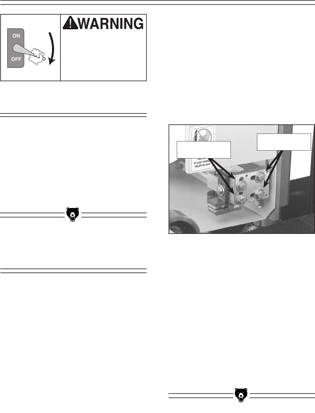
G0504 16" Horizontal Resaw Bandsaw -35-
This section is designed to help the operator with
adjustments that were made at the factory and
that might also need to be made during the life
of the machine.
This section is provided for your convenience—
it is not a substitute for the Grizzly Service
Department. If any adjustments arise that are not
described in this manual, then feel free to call the
Grizzly Technical Support at (570) 546-9663.
To adjust the lower blade guides:
1. Disconnect the resaw from the power
source!
2. Open the wheel cover for easy access to the
blade guide assemblies.
3. Make sure the blade is tensioned in the same
manner that will be used for operation.
4. Loosen the lateral adjustment bolts (shown
in Figure 34).
Always disconnect
power to the machine
before performing ser-
vice adjustments. Failure
to do this may result in
serious personal injury.
Figure 34. Lower guide block adjustment bolts.
5. Adjust the assembly so the blade guides are
approximately 1⁄16" behind the gullets of the
blade teeth, and tighten the lateral bolts.
6. Loosen the vertical adjustment bolts.
7. Adjust the lower blade guide so it barely
touches the bottom of the blade, then tighten
the vertical adjustment bolts.
8. Repeat Steps 4-5 on the other blade guide.
9. Adjust the upper guide blocks and the sup-
port bearings.
10. Close the wheel cover.
The instructions on adjusting the upper guide
blocks and support bearing are given in Section
5: Set Up. This section focuses on adjusting
the lower blade guides, which is a non-routine
adjustment that would typically be done before
the upper blade guide and support bearing would
be adjusted.
Vertical
Adjustment Bolts
Lateral
Adjustment Bolts
Adjusting Lower
Blade Guides
About Service
SECTION 8: SERVICE ADJUSTMENTS
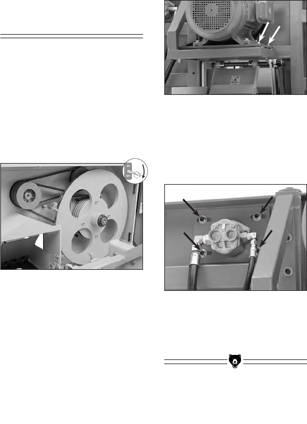
-36- G0504 16" Horizontal Resaw Bandsaw
Figure 36. Large pulley cover attachment bolts.
Adjusting V-Belt
Tension
Properly tensioned V-belts help the Model G0504
operate at its best. However, adjusting the V-
belts is not an exact science and does require
personal judgement. Adjusting the belts too loose
will decrease the performance of the machine
and adjusting the belts too tight may cause pre-
mature wear of the bearings and other compo-
nents attached to the belts.
On the Model G0504 there is a triple-drive V-belt
system that connects the motor to the wheel
pulley and a single-drive V-belt system that con-
nects the wheel pulley to the hydraulic pump
(Figure 35).
Figure 35. G0504 V-belts.
To adjust the V-belt tension for the saw
wheels:
1. Disconnect the resaw from the power
source!
2. Adjust the belt tension by using the motor
mount hex bolts shown in Figure 36.
3. When the belts are properly tightened, lock
the bolts in place with the jam nuts.
To adjust the tension for the hydraulic pump
V-belt:
1. Remove the small pulley cover from the
pump seat.
2. Adjust the belt tension by loosening the cap
screws shown in Figure 37.
Figure 37. Pump seat cap screws.
3. Slide the pump left/right as needed until the
belt has the proper tension.
4. Tighten the cap screws to lock the pump
seat in place.
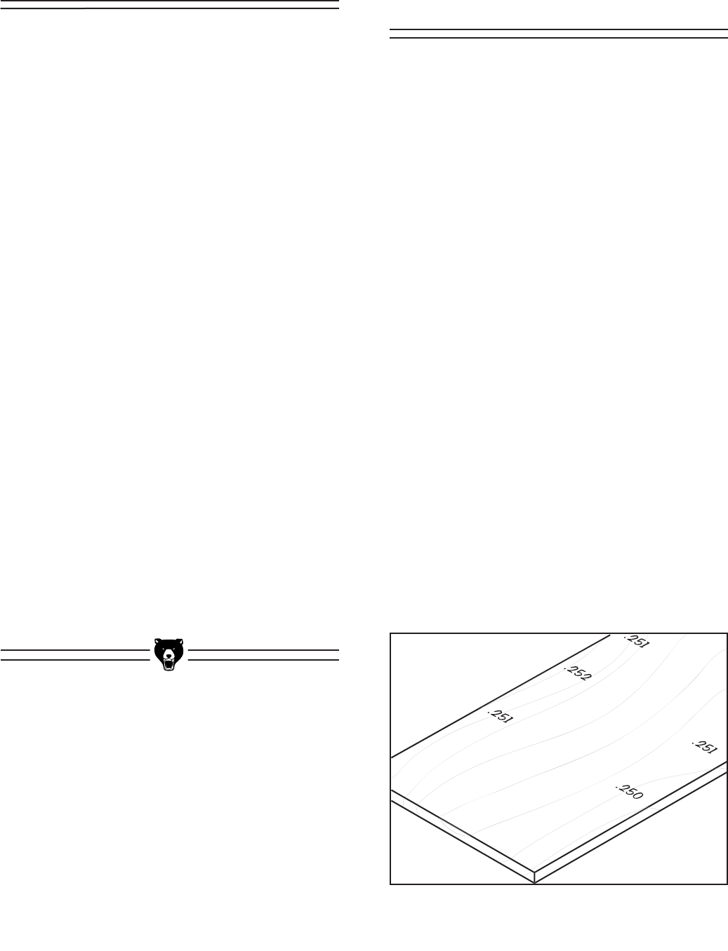
G0504 16" Horizontal Resaw Bandsaw -37-
Replacing V-Belts
If the belts deteriorate or break, they will need
to be replaced. When replacing one belt, you
should replace all of them at the same time to
ensure uniform belt tension and save time.
To replace the V-belts:
1. Disconnect the resaw from the power
source!
2. Read the previous subsection titled “Adjusting
V-Belt Tension” to become familiar with the
V-belt tension controls.
3. Adjust the motor mount nuts down as far as
they will go.
4. Remove all three V-belts that connect the
motor to the wheel pulley. (The easiest way
to take the belts on/off is to roll them on/off
the pulley one at a time. The belts can then
be fit over the wheel.)
5. Remove and replace the hydraulic pump
V-belt. (Refer to Page 35 for information on
how to loosen/tension this V-belt.)
6. Replace the three V-belts as a matching set.
Matching sets can be identified by the batch
number on the belt—NOT to be confused
with the size markings of the belt.
7. Tension the newly installed V-belts.
Figure 38. Test board with measurements.
The main conveyor table height can be adjusted
left-to-right and front-to-back to make the table
parallel to the blade in both directions. This is an
involved procedure that requires you to cut up a
piece of test stock and make many repeat adjust-
ments. Because of the complexity of this proce-
dure, we will first give instructions on checking
the table, so that you can be sure you need to
perform the adjustment.
Before attempting these procedures, you need
to have a perfectly squared up piece of stock
that is as wide as possible and is at least two
feet long. The wider the stock, the more accurate
your procedure will be (we recommend using the
maximum width that the resaw will allow). Also,
you need to make sure that your blade is in good
condition, the blade is tracked/tensioned properly
and the blade guides are properly adjusted.
To check the main conveyor table alignment:
1. Cut a 1⁄4" slice off of your squared-up test
stock.
2. Using a dial caliper, measure the thickness
of the cut piece at all four corners and in
even locations along the edges of the stock.
As you take these measurements, write them
directly on the stock, near the location where
you took the measurement (see Figure 38).
Adjusting Main
Conveyor Table
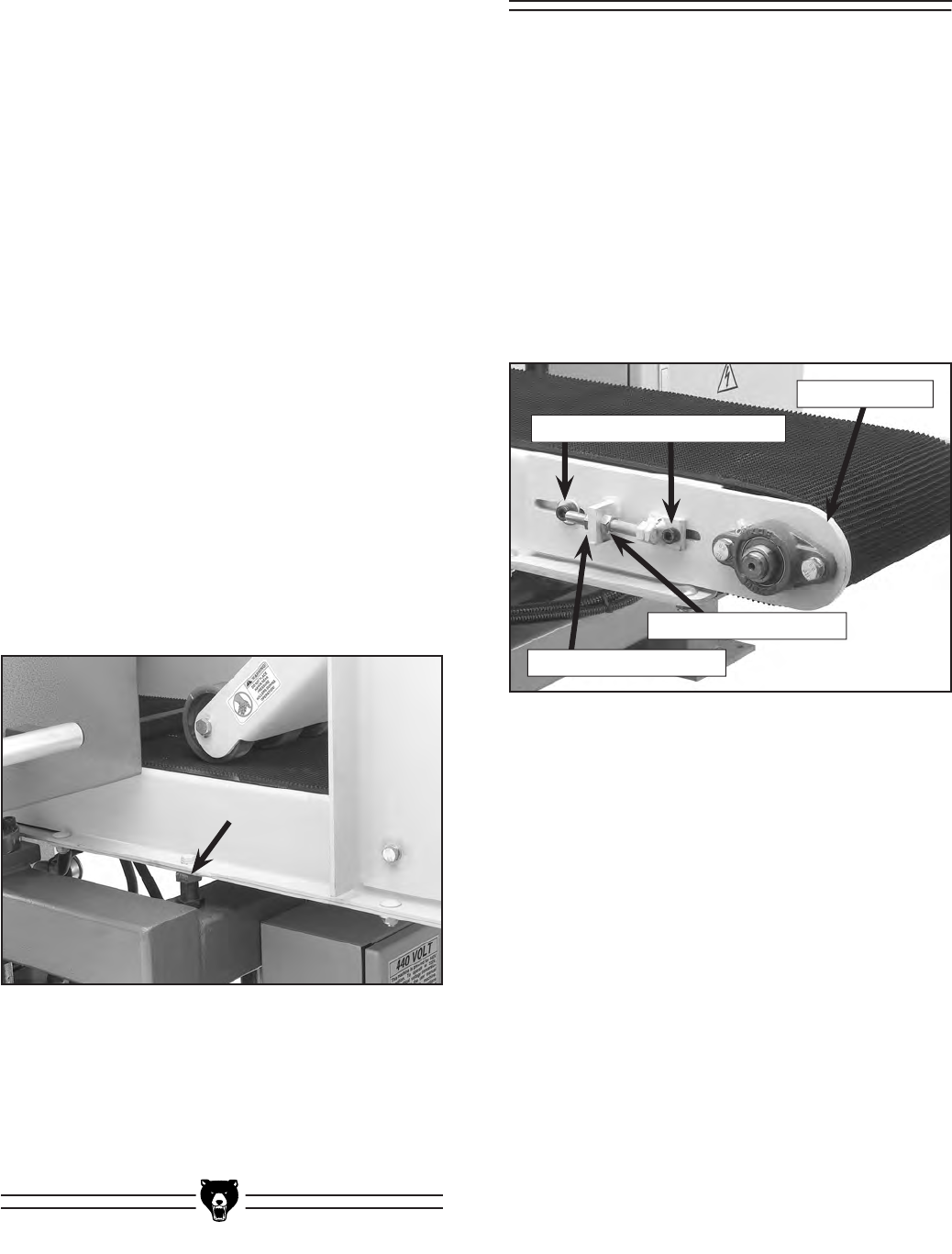
-38- G0504 16" Horizontal Resaw Bandsaw
3. Study the written measurements on your
test piece. Note—DO NOT place too much
importance on the first and last six inches of
the board, because the board will only have
been under one pressure roller during that
part of the cut.
— If the measurements are more than 0.030"
different from one side to the other, you
should adjust the conveyor table.
To adjust the conveyor table:
1. Disconnect the resaw from the power
source!
2. Use your test board to determine which
direction the conveyor table needs to be
moved. For example, if the right side of the
board was thicker than the left side—you
will need to move either the right side of the
conveyor up or move the left side of the con-
veyor down.
3. Adjust the four adjustment bolts that control
the conveyor table height as determined
from Step 2. Note—For adjustment bolt
locations see the adjustment bolt shown in
Figure 39.
Figure 39. Conveyor table adjustment bolts
(1 of 4 shown).
4. Tighten the lock nuts on the adjustment
bolts, connect the resaw to the power, and
repeat the checking and adjusting Steps
until the measurements on your cut piece
are within 0.030".
Tracking Conveyors
“Tracking” the conveyor belts means balancing
the way they ride on the end rollers. The convey-
ors are tracking correctly when they are centered
between the roller brackets on each side of the
conveyor. If the conveyor belts start rubbing
against the roller brackets, then you need to track
them as described.
To set the conveyor tracking:
1. Loosen the two roller bracket cap screws
(shown in Figure 40) about 3⁄4 of a turn. Do
this on the both sides of the conveyor.
2. Loosen the rear adjustment nuts away from
the bracket plates on both sides of the con-
veyor.
3. Start the conveyor belt.
4. On the side that the belt tracks toward, turn
the front adjustment nut counter-clockwise
half of a turn, and watch the belt tracking.
Note—The effect of the adjustment can
sometimes take two minutes before the
results are fully apparent.
— If the tracking was not corrected by this
adjustment, proceed to Step 5. If the
tracking was corrected, skip to Step 6.
Figure 40. Roller bracket cap screws and
adjustment nuts.
Roller Bracket Cap Screws
Rear Adjustment Nut
Front Adjustment Nut
Roller Bracket
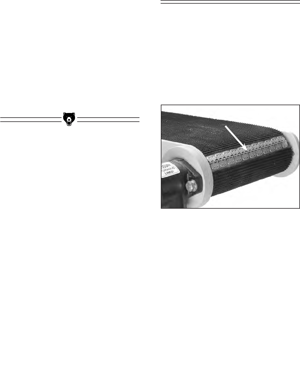
G0504 16" Horizontal Resaw Bandsaw -39-
5. On the side that the belt tracks away from,
turn the front adjustment nut clockwise half
of a turn, and watch the belt tracking.
— If the tracking was not corrected by this
adjustment, repeat Step 4.
6. When the conveyor belt is tracking in the
center of the roller brackets, run the con-
veyor for at least two minutes to ensure that
it will remain tracking correctly.
7. Tighten the rear adjustment nuts against the
bracket plates, then tighten the front adjust-
ment nuts against the bracket plates to make
sure that the tracking adjustment will not
slowly change during normal operation.
Replacing Conveyors
Although the conveyor belts have slight differenc-
es in size and access, the replacement instruc-
tions are the same.
To replace the conveyor belts:
1. Start the conveyor belt that you want to
replace.
2. Stop the conveyor belt when the conveyor
belt seam (see Figure 41) is accessible.
Figure 41. Conveyor belt seam.
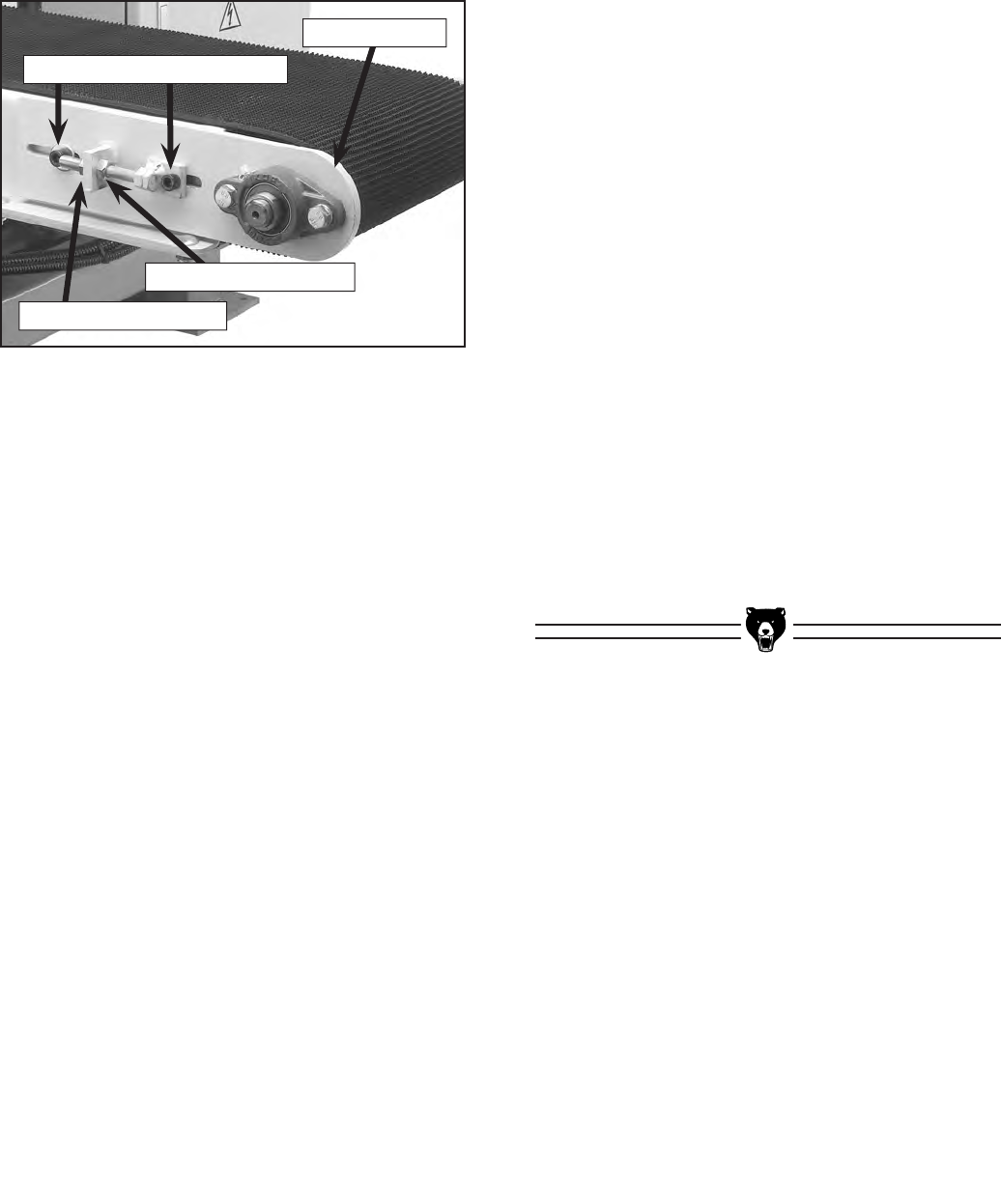
-40- G0504 16" Horizontal Resaw Bandsaw
3. Disconnect the resaw from the power
source!
4. Loosen the roller bracket (see Figure 42) by
turning the roller bracket cap screws 3⁄4 of a
turn.
Figure 42. Roller bracket cap screws and
adjustment nuts.
Roller Bracket Cap Screws
Rear Adjustment Nut
Front Adjustment Nut
Roller Bracket
5. Loosen the rear adjustment nuts away from
the bracket plate.
6. Mark the front adjustment nut with a felt-
tipped pen or a piece of tape, and thread
the front adjustment nut all the way up, while
keeping track of the number of full turns that
you moved the nut.
Note—Write the number of turns down, so
you do not forget. Remembering this number
is an important part of the re-assembly pro-
cess.
7. Slide the roller brackets toward the body of
the resaw to loosen the belt.
8. Remove the stiff cable from the center of the
seam to separate it.
9. Remove the old conveyor belt from the con-
veyor table, and replace the new conveyor
belt in its place.
10. Mesh the seam “teeth” together on the new
belt, and insert the stiff cable into the center
of the seam to lock it together.
11. Slide the roller brackets away from the body
of the resaw to tighten the belt.
12. Turn the front adjustment bolts the exact
number of rotations that you turned them
when you loosened them.
Note—The new belt may be tighter than the
old one because it has not been broken-in. If
this is the case, deduct one or two turns from
your original number of turns.
13. Run the conveyor belt to check the tracking.
If the belt starts tracking to one side, stop the
resaw and perform the “Tracking Conveyors”
instructions that are located on Pages 38.
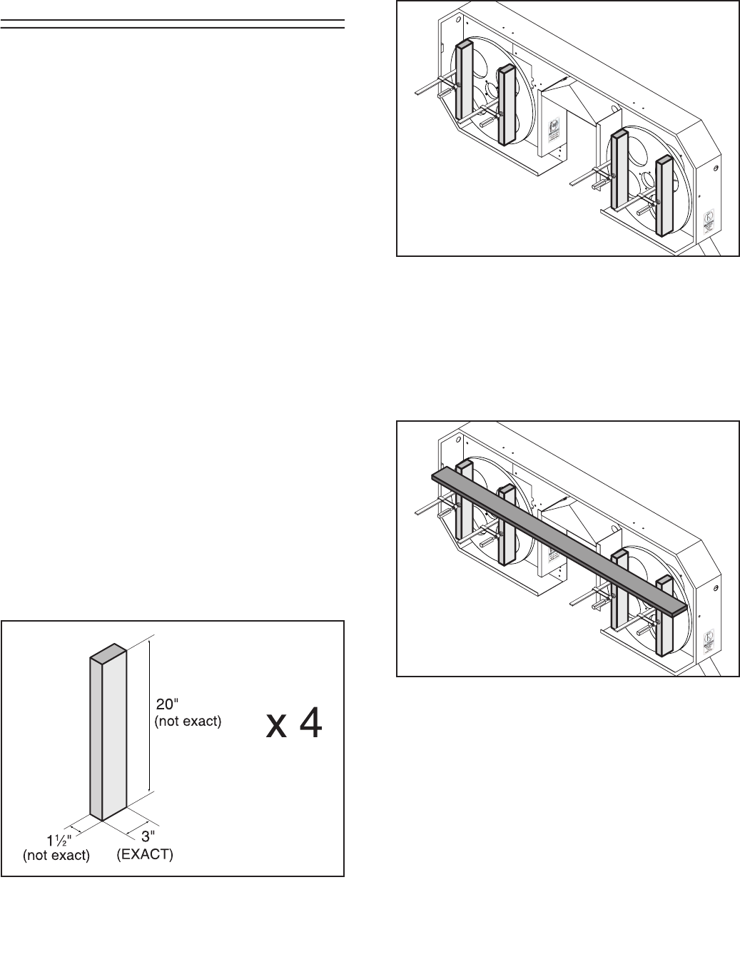
G0504 16" Horizontal Resaw Bandsaw -41-
Blade Tracking and
Wheel Alignment
Blade tracking on the Model G0504 consists
of adjusting the wheels to be nearly coplanar
(coplanar=both wheels even and parallel), but
having the outside edge of the wheel approxi-
mately 0.020"-0.040" behind the inside edge of
the wheel to compensate for wheel toe-in when
the blade is fully tensioned.
Because of the large size of this machine and
the wheel toe-in factor, this procedure is time
consuming and requires a great deal of trial and
error. Make sure you really need to perform this
procedure before attempting it.
Also, to complete this procedure you will need to
make four precision gauge blocks and have a 6'
long straightedge.
To adjust the wheels to be coplanar:
1. Disconnect the resaw from the power
source!
2. Open the wheel cover.
3. Remove the blade.
4. Using 2x4’s, make four precision gauge
blocks to the specifications shown in Figure
43.
Figure 43. Precision gauge block dimensions.
Figure 44. Precision gauge blocks clamped in
position on wheels.
Figure 45. Straightedge placement when check-
ing the upper portion of the wheels.
5. Clamp the gauge blocks to the wheels as
shown in Figure 44.
6. Place the straightedge across the top of the
gauge blocks, as shown in Figure 45, and
examine how the wheels line up with each
other.
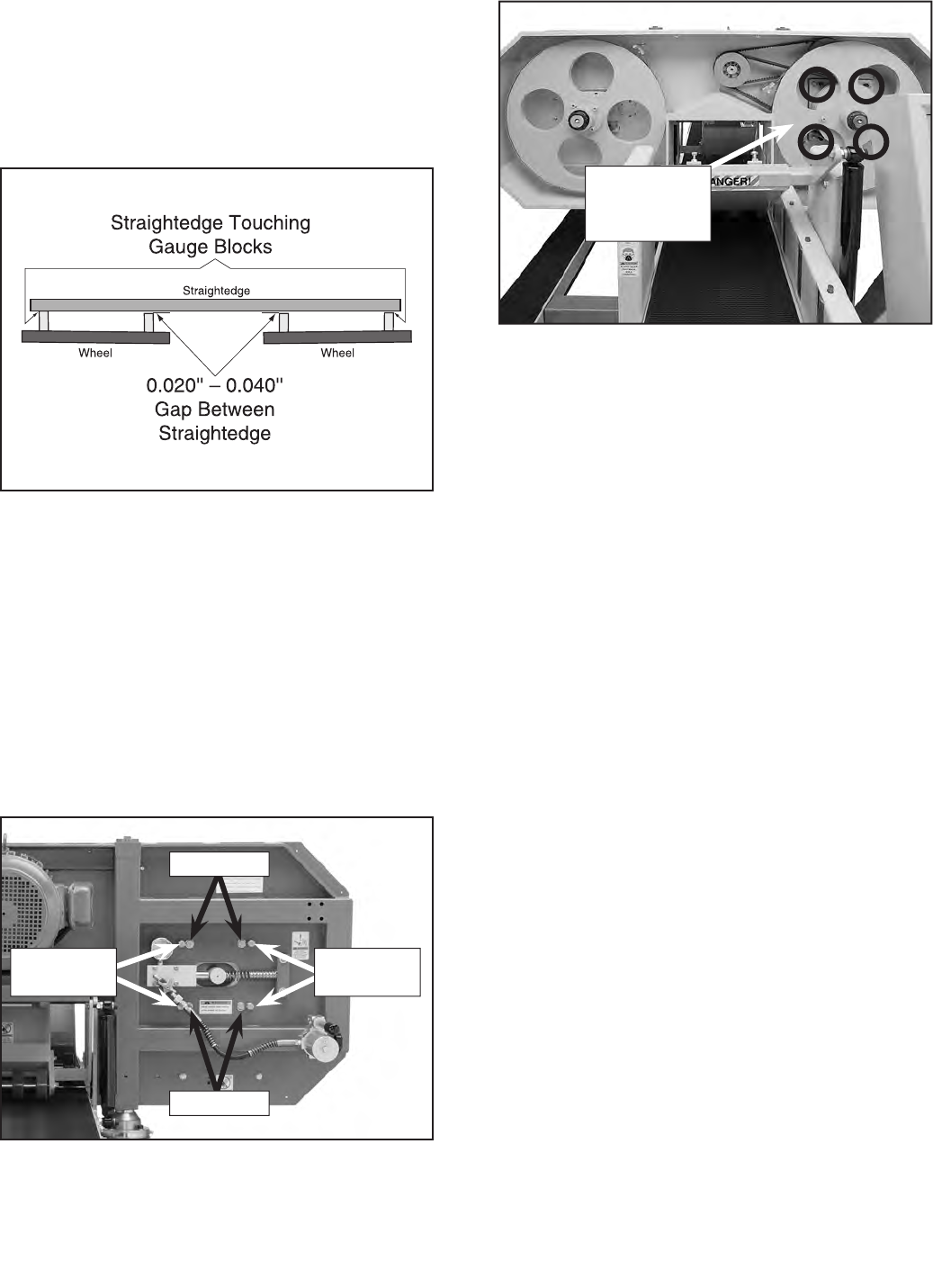
-42- G0504 16" Horizontal Resaw Bandsaw
Figure 46. Overhead view of straightedge on
blade wheel gauge blocks.
Figure 47. Tension wheel adjustment bolts.
Figure 48. Drive wheel adjustment controls
(fourth bolt hidden in this picture).
— If the wheels are properly aligned, the
straightedge will touch both inside gauge
blocks and there will be a 0.020"–0.040"
gap between the straightedge and the
outside gauge blocks, as shown in Figure
46. If this is the case, skip to Step 9.
— If the wheels are not positioned as shown
above, determine which direction they
need to move in order to be correct, then
proceed to Step 7 to begin the adjustment
process.
7. Look at the backside of the wheel guard and
learn the controls shown in Figures 47 & 48
by reading the text that follows.
Adjustment
Screws
Drive Wheel
Adjustment
Bolts
Movement Direction—The bolt position
around the wheel shaft determines the part
of the wheel that will move when that bolt is
turned.
Moving Forward—To move part of the
wheel forward, loosen the appropriate lock
bolts the same amount that you will tight-
en their neighboring adjustment bolts. (By
“appropriate” we mean the bolts that control
the direction that your wheel needs to be
moved.) In the case of the main drive wheel
adjustments, always loosen the jam nuts
before moving the adjustment bolts, and
always tighten the jam nuts after moving the
adjustment bolts.
Moving Backward—To move part of the
wheel backward, loosen the appropriate
adjustment bolt, then tighten the neighboring
lock bolt.
8. Adjust the wheels as necessary until the
wheel position is correct when checked with
the straightedge and continue to Step 9.
Adjustment
Screws
Lock Bolts
Lock Bolts
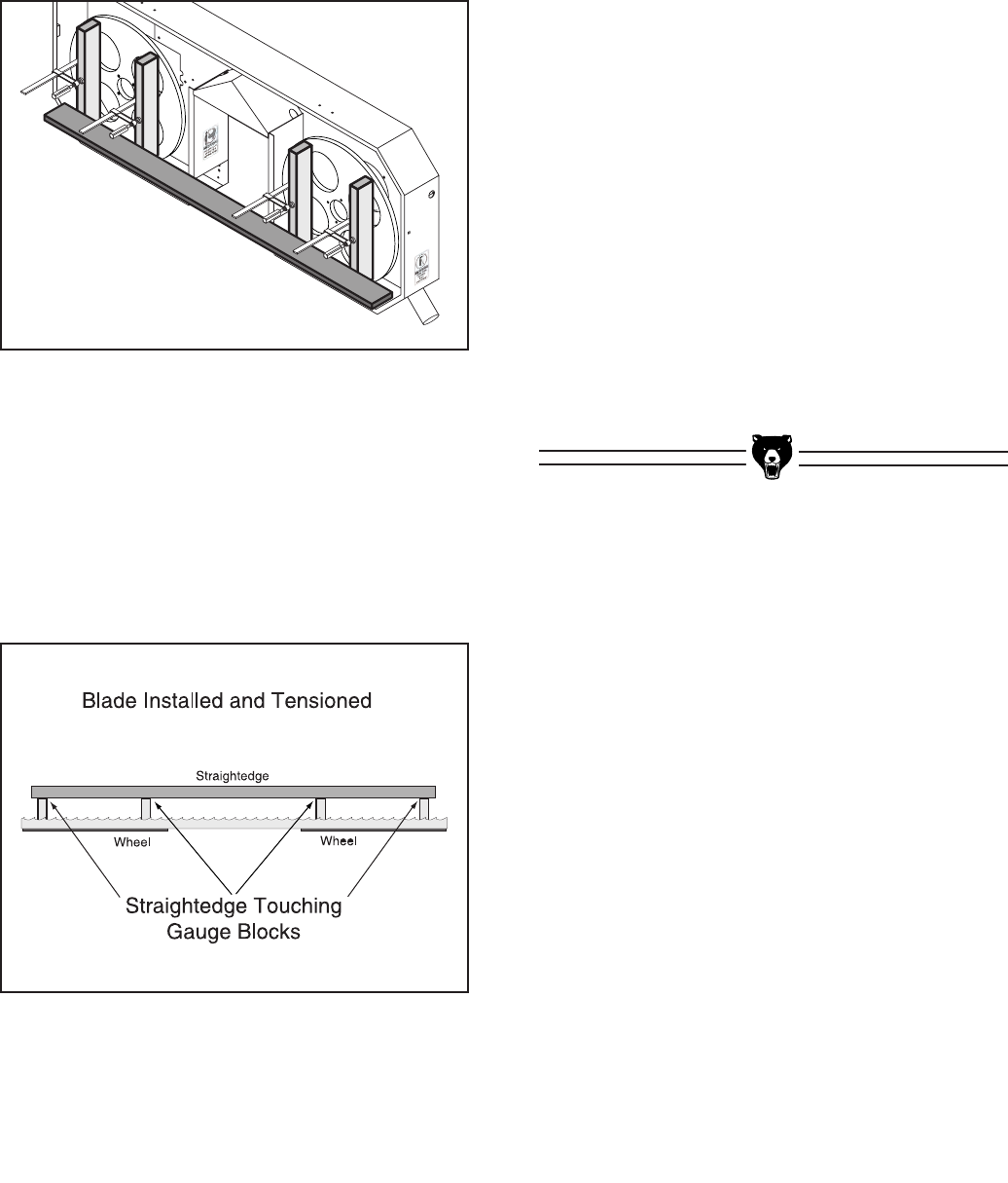
G0504 16" Horizontal Resaw Bandsaw -43-
Figure 49. Straightedge placement when
checking the lower portion of the wheels.
Figure 50. Overhead view of wheel position
when checking with a straightedge and the
blade is installed and tensioned.
9. Place the straightedge across the bottom of
the gauge blocks, as shown in Figure 49.
The wheels should line up in the same man-
ner as described in Step 6.
— If they do not, follow Steps 7–8 to correct
them.
10. After the wheels are positioned correctly,
install and tension the blade, and adjust the
guide bearings out of the way of the blade.
11. Check the new position of the wheels. Ideally
the gauge blocks will all be perfectly aligned
with each other, as illustrated in Figure 50.
— If the gauge blocks are aligned within
0.040" of each other, continue to Step
12.
— If the gauge blocks are positioned more
than 0.040" from each other, repeat Steps
6 & 9, and make the new adjustments
according to the change you noticed after
tensioning the blade.
12. Remove the gauge blocks and clamps, and
spin the wheels by hand in the direction of
normal operation to check the blade track-
ing. You can fine tune the blade tracking by
adjusting the blade tension up or down—just
make sure to stay in the color range on the
tension scale for your particular blade.
13. After the blade is tracking correctly, prepare
the saw for a test run by adjusting the guide
bearings, closing the wheel cover, and con-
necting the machine to the power source.
14. Test run the resaw and repeat this entire
section if the blade does not track correctly.

-44- G0504 16" Horizontal Resaw Bandsaw
Troubleshooting
Symptom Possible Cause Possible Solution
Machine does not
start or a breaker
trips.
1. Emergency stop button is engaged.
2. Electrical box door switch is OFF.
3. Machine is wired to power source out of
phase.
4. Electrical box door is open/door safety
switch is at fault.
5. Motor connection wired incorrectly.
6. Fuse has blown.
7. Phase reversal relay is at fault.
8. Computer board is at fault.
9. Thermal overload relay has tripped.
10. Contactor not getting energized/has
burnt contacts.
11. Blown/tripped wall fuse/circuit breaker.
12. Power supply is at fault/switched OFF.
13. Motor ON switch is at fault.
14. Head elevation limit switch depressed;
faulty.
15. Wiring is open/has high resistance.
16. Motor is at fault.
1. Disengage emergency stop button.
2. Turn electrical box door switch ON with the door closed.
3. Switch any two current carrying wires at the power source
connection.
4. Close door/replace faulty safety switch.
5. Correct motor wiring connections; check power source wire
connections to ensure hot lines are "in phase" by reversing
any two hot lines.
6. Correct short/replace fuse.
7. Replace phase reversal relay.
8. Inspect computer board; replace if faulty.
9. Turn cut-out dial to increase working amps and push the
reset pin. Replace if tripped multiple times.
10. Test for power on all legs and contactor operation. Replace
unit if faulty.
11. Replace weak breaker; ensure correct size circuit.
12. Ensure hot lines have correct voltage on all legs and main
power supply is switched ON.
13. Replace switch.
14. Adjust head height to correct working range; replace faulty
limit switch.
15. Check for broken wires or disconnected/corroded connec-
tions, and repair/replace as necessary.
16. Test/repair/replace.
Machine
stalls or is
underpowered.
1. Wrong workpiece material (wood).
2. Belt(s) slipping.
3. Motor connection is wired incorrectly.
4. Blade is slipping on wheels.
5. Motor bearings are at fault.
6. Machine is undersized for the task.
7. Machine is undersized for the task.
8. Motor has overheated.
9. Contactor not getting energized or has
poor contacts.
10. Motor is at fault.
11. Start delay module is at fault.
1. Use wood with correct moisture content and low resins.
2. Replace bad belt(s), align pulleys, and re-tension.
3. Correct motor wiring connections.
4. Adjust blade tracking and tension to factory specs.
5. Test by rotating shaft; rotational grinding/loose shaft requires
bearing replacement.
6. Use sharp blade w/lower TPI; reduce the feed rate.
7. Use sharp blade with lower TPI; reduce the feed rate/depth
of cut; use cutting fluid if possible.
8. Clean off motor, let cool, and reduce workload.
9. Fix contacts or replace contactor.
10. Test/repair/replace.
11. Adjust to correct delay; replace module.
Review the troubleshooting and procedures in this section to fix your machine if a problem develops. If you
need replacement parts or you are unsure of your repair skills, then feel free to call our Technical Support
at (570) 546-9663.

G0504 16" Horizontal Resaw Bandsaw -45-
Symptom Possible Cause Possible Solution
Machine has
excessive vibra-
tion or noisy oper-
ation.
1. Motor or component is loose.
2. Blade weld at fault or teeth are broken.
3. V-belt(s) worn or loose.
4. Motor fan is rubbing on fan cover.
5. Pulley is loose.
6. Machine incorrectly mounted.
7. Motor bearings are at fault.
8. Blade is at fault.
1. Retighten/replace stripped or damaged bolts/nuts.
2. Replace blade.
3. Inspect/replace belts (refer to Page 37).
4. Replace dented fan cover; replace loose/damaged fan.
5. Realign/replace shaft, pulley, setscrew, or key.
6. Tighten/replace floor mounts; relocate/shim machine.
7. Replace bearings.
8. Replace warped, bent, or twisted blade; resharpen dull
blade.
Machine slows
when cutting.
1. Feed rate is too fast.
2. Wood has a high moisture content.
3. V-belt does not have enough tension
and is slipping on the pulleys.
4. V-belt is worn out.
1. Slow down the feed rate.
2. Only cut properly dried wood.
3. Tighten the V-belt (Page 36).
4. Replace V-belt (Page 37).
Blade does not
run evenly on
the wheels.
1. Blade support bearings set incorrectly.
2. Wheels have built up pitch or dust.
3. Wheels are not coplanar.
4. Shape of wheels has changed from
long term use and wear.
1. Adjust blade support bearings (Page 21).
2. Clean wheels of all pitch and dust.
3. Call the Grizzly Service Department at (570) 546-9663 for
help determining if your wheels really are NOT coplanar;
adjust wheels to be coplanar as described on Page 41.
4. Replace wheels.
Blade does not
cut evenly.
1. Blade is not properly tensioned.
2. Wheels are not coplanar.
3. Tooth set is uneven.
4. Teeth are sharper on one side than the
other.
1. Adjust blade tension (Page 19).
2. Call the Grizzly Service Department at (570) 546-9663 for
help determining if your wheels really are NOT coplanar;
adjust wheels to be coplanar as described on Page 41.
3. Replace blade.
4. Replace blade.
Blade makes a
squealing noise,
especially on
startup.
1. V-belt is loose.
2. V-belt is worn out.
1. Tighten the V-belt (Page 36).
2. Replace V-belt (Page 37).
Ticking sound
when the saw is
running.
1. Blade weld is contacting the guide
blocks or support bearing.
1. Use the Model G2516 stone to smooth the blade weld.
Hydraulic pump is
noisy or hydraulic
system operates
erratically.
1. Pump is restricted.
2. Filter is clogged.
3. Tank screen is clogged.
4. Damaged hydraulic pump or motor.
1. Inspect and clean breather cap, filter, and tank screen.
2. Perform minor service (Page 32).
3. Perform major service (Page 33).
4. Replace pump or motor. See hydraulic specialist.
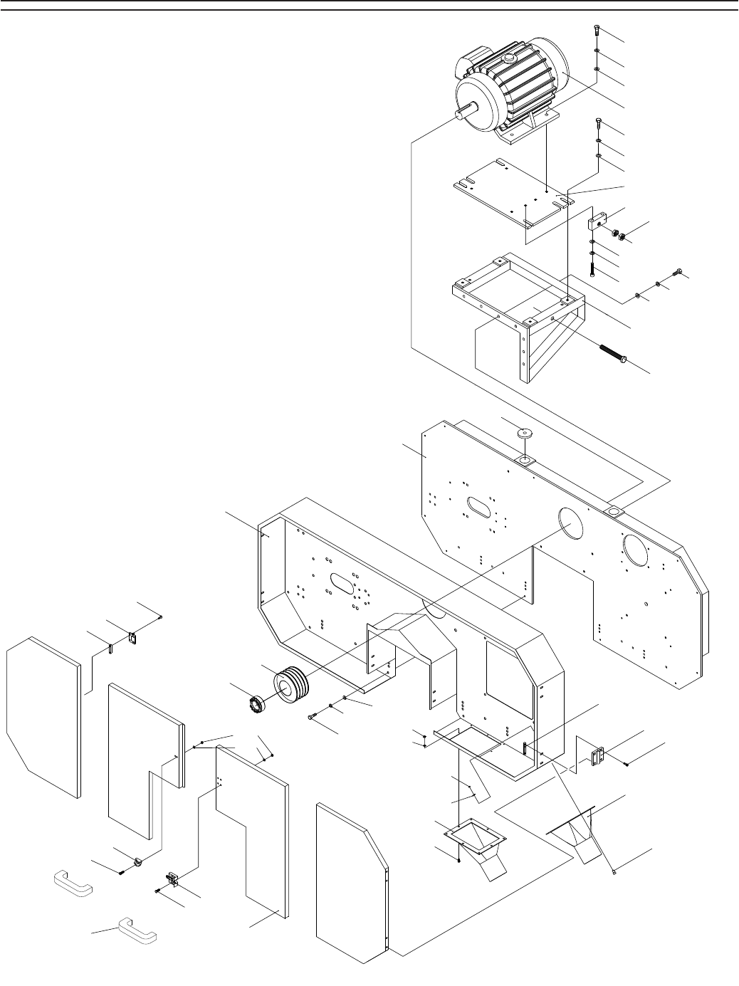
-46- G0504 16" Horizontal Resaw Bandsaw
SECTION 9: Parts
Housing Parts

G0504 16" Horizontal Resaw Bandsaw -47-
Housing Parts List
REF PART # DESCRIPTION
1101 PB27M HEX BOLT M12-1.75 X 30
1102 PLW05M LOCK WASHER 12MM
1103 PW06M FLAT WASHER 12MM
1104A P05041104A MOTOR 30 HP
1105 PB24M HEX BOLT M12-1.75 X 45
1107 P05041107 ADJUSTMENT BLOCK
1108 PN28M HEX NUT M20-2.5
1109 PB125M HEX BOLT M12-1.75 X 65
1110 PB25M HEX BOLT M12-1.75 X 25
1113 P05041113 SAW WHEEL FRAME
1114 P05041114 SAW WHEEL GUARD
1115 P05041115 MOTOR PULLEY
1116 P05041116 LOCKING SLEEVE
1117 PW01M FLAT WASHER 8MM
1118 PLW04M LOCK WASHER 8MM
1119 PB87M HEX BOLT M8-1.25 X 15
1120 PN01M HEX NUT M6-1
1121 PLW03M LOCK WASHER 6MM
1122 P05041122 DUST PORT B
1123 PB02M HEX BOLT M6-1 X 12
1124 P05041124 BUTTON BRACKET
1125 P05041125 BUTTON DH-75
1126 PB08M HEX BOLT M6-1 X 20
1127 P05041127 DUST PORT A
1128 PB95M HEX BOLT M5-.8 X 16
1129 P05041129 BUTTON DK-50
1130 P05041130 BUTTON BRACKET
1131 P05041131 KNOB BRACKET
1132 PB08M HEX BOLT M6-1 X 20
1133 P05041133 KNOB SEAT
1134 P05041134 DOOR PLATE
1135 P05041135 HEX BOLT M20-2.5 X 150
1136 P05041136 MOTOR BRACKET
1137 P05041137 MOTOR BRACKET
1138 P05041138 WHEEL COVER HANDLE
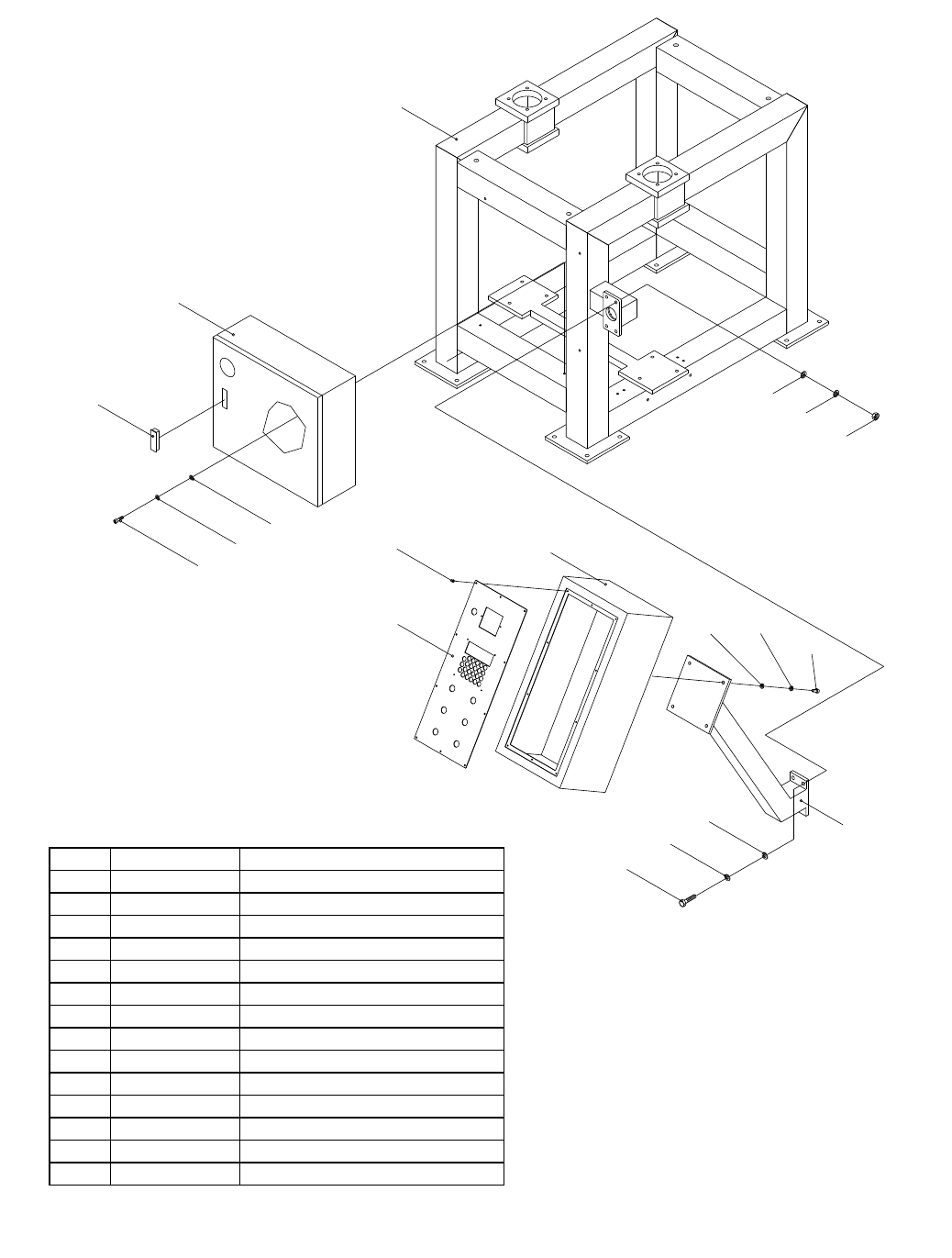
-48- G0504 16" Horizontal Resaw Bandsaw
Frame Parts
REF PART # DESCRIPTION
1201 P05041201 FRAME
1202 P05041202 ELECTRIC BOX
1203 P05041203 DOOR HINGE
1204 PW01M FLAT WASHER 8MM
1205 PLW04M LOCK WASHER 8MM
1206 PB09M HEX BOLT M8-1.25 X 20
1207 PS07M PHLP HD SCR M4-.7 X 8
1208 P05041208 CONTROL PANEL
1209 P05041209 CONTROL BOX
1210 PB07M HEX BOLT M8-1.25 X 25
1211 P05041211 CONTROL BOX SUPPORT
1212 PW04M FLAT WASHER 10MM
1213 PLW06M LOCK WASHER 10MM
1214 PB31M HEX BOLT M10-1.5 X 40
1215 PN02M HEX NUT M10-1.5
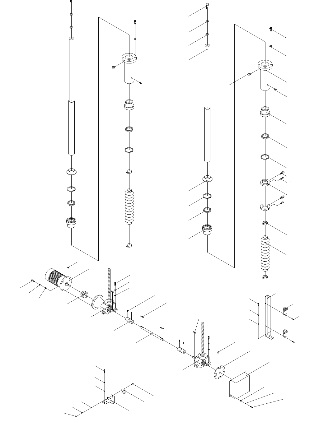
G0504 16" Horizontal Resaw Bandsaw -49--49- G0504 16" Horizontal Resaw Bandsaw
Elevation Parts

-50- G0504 16" Horizontal Resaw BandsawG0504 16" Horizontal Resaw Bandsaw -50-
Elevation Parts List
REF PART # DESCRIPTION
1301 PB110M HEX BOLT M16-2 X 25
1302 PLW10M LOCK WASHER 16MM
1303 PW08M FLAT WASHER 16MM
1304 P0504204 COLUMN
1305 P0504205 CHIP COVER
1306 PR50M INT RETAINING RING 80MM
1307 P0504207 OIL SEAL 60 X 80 X 10
1308 P0504208 BRASS SLEEVE
1309 PSB73M CAP SCREW M12-1.75 X 50
1310 PLW05M LOCK WASHER 12MM
1311 P0504211 ELEVATION HOUSING
1312 PZERK2 GREASE FITTING PT 1/8
1313 PSS30M SET SCREW M10-1.5 X 10
1314 P0504214 LIMIT DOG
1315 PB15M HEX BOLT M8-1.25 X 40
1316 P0504213 LOCK RING
1317 P0504216 TIGHTEN RING
1318 P0504217 DUST GUARD BELLOW
1319 PS65M PHLP HD SCR M4-.7 X 40
1320 P0504219 LIMIT SWITCH AV8104
1321 P0504220 SWITCH BRACKET
1322 PSB02M CAP SCREW M6-1 X 20
1323 PLW03M LOCK WASHER 6MM
1324 PW03M FLAT WASHER 6MM
1325 P0504224 COVER
1326 P0504225 INDEX RING
1327 PSS01M SET SCREW M6-1 X 10
1328 P0504245 GEAR BOX 40# 1/30 VTW
1329 PK74M KEY 6 X 6 X 35
1330 P0504244 CONNECT ROD
1331 PK11M KEY 6 X 6 X 40
1332 P0504243 UNIVERSAL JOINT
1333 PSS64M SET SCREW M6-1 X 15
1334 PLW04M LOCK WASHER 8MM
1335 PW01M FLAT WASHER 8MM
1336 P0504242 GEAR BOX A 40# 1/30 VTWM
1337 P0504241 SHAFT COUPLINGS
1338 P0504235 GEAR BOX & MOTOR
1339 PK12M KEY 5 X 5 X 30
1340 PSB14M CAP SCREW M8-1.25 X 20
1341 PSB99M CAP SCREW M3-.5 X 30
1342 P0504250 SENSOR QL-1805NB
1343 P0504251 SENSOR BRACKET
1344 PW07M FLAT WASHER 3MM
1345 PLW09M LOCK WASHER 3MM
1346 PN07M HEX NUT M3-.5
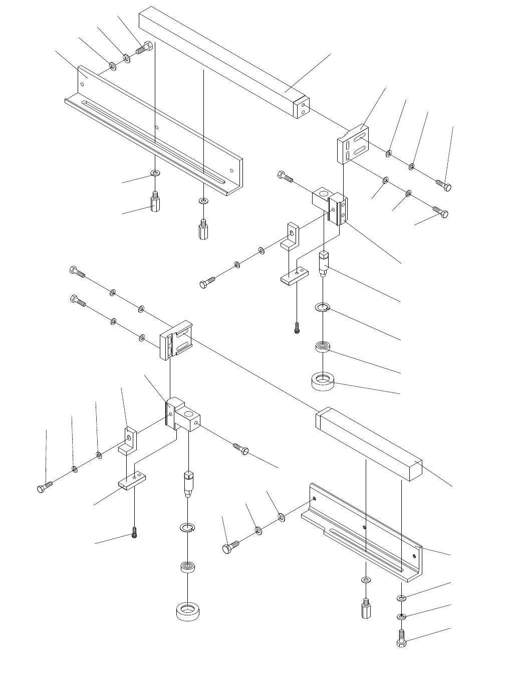
G0504 16" Horizontal Resaw Bandsaw -51--51- G0504 16" Horizontal Resaw Bandsaw
1401
1402
1403
1404
1403
1405
1406
1407
1408
1409
1410
1408
1409
1411
1412
1413
1414
1415
1416
1409
1417
1408
1418
1419
1420
1421
1422
1403
1402
1418
1423
1424
1402
1403
1404
Blade Guide Parts

-52- G0504 16" Horizontal Resaw BandsawG0504 16" Horizontal Resaw Bandsaw -52-
Blade Guide Parts
REF PART # DESCRIPTION
1401 P0504309 ADJUSTMENT ROD BRACKET
1402 PW04M FLAT WASHER 10MM
1403 PLW06M LOCK WASHER 10MM
1404 PB74M HEX BOLT M10-1.5 X 20
1405 P0504310 ADJUSTMENT SCREW
1406 P0504305 GUIDE POST
1407 P0504304 ADJUSTMENT BRACKET
1408 PW01M FLAT WASHER 8MM
1409 PLW04M LOCK WASHER 8MM
1410 PB15M HEX BOLT M8-1.25 X 40
1411 PB26M HEX BOLT M8-1.25 X 30
1412 P0504314 GUIDE POST BASE
1413 P0503404 ECCENTRIC SHAFT
1414 PR35M INT RETAINING RING 30MM
1415 P6200LLB BALL BEARING 6200LLB
1416 P0504318 SUPPORT ROLLER
1417 PB09M HEX BOLT M8-1.25 X 20
1418 P0504355 UPPER GUIDE (CERAMIC)
1419 P0504321 GUIDE POST BASE (R)
1420 P0504336 LOWER GUIDE (CERAMIC)
1421 PSB02M CAP SCREW M6-1 X 20
1422 PB40M HEX BOLT M10-1.5 X 15
1423 P0504319 GUIDE POST
1424 P0504320 POST BRACKET
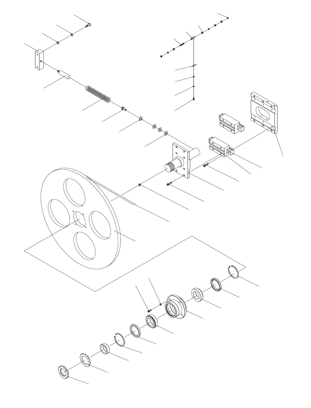
G0504 16" Horizontal Resaw Bandsaw -53--53- G0504 16" Horizontal Resaw Bandsaw
Tensioning Wheel Parts

-54- G0504 16" Horizontal Resaw BandsawG0504 16" Horizontal Resaw Bandsaw -54-
Tensioning Wheel Parts List
REF PART # DESCRIPTION
1501 P0504428A LOCK NUT AN11
1502 PTLW08M EXT TOOTH WASHER 10MM
1503 P0504429A LOCK RING
1504 P0504455 INT RETAINING RING 90MM
1505 P0504456 OIL SEAL TC-70 X 90 X 8
1506 P32011 BEARING 32011
1507 P0504461 LEFT BEARING HOUSING
1508 PB35M HEX BOLT M12-1.75 X 40
1509 PLW05M LOCK WASHER 12MM
1510 P0504433 LEFT BLADE WHEEL
1511 P0504434 SAW BLADE 1" X 180"
1512 PZERK2 GREASE FITTING PT 1/8
1513 PSB100M CAP SCREW M8-1.25 X 15
1514 P0504442A LEFT WHEEL SHAFT
1515 PSB13M CAP SCREW M8-1.25 X 30
1516 P0504437 SLIDER
1517 P0504437 LINER GUIDE
1518 P0504438 LINER WAY BRACKET
1519 PW01M FLAT WASHER 8MM
1520 PLW04M LOCK WASHER 8MM
1521 PB26M HEX BOLT M8-1.25 X 30
1522 P0504443 SPRING
1523 P0504444 SPRING ROD
1524 P0504445 SPRING SEAT
1525 PW04M FLAT WASHER 10MM
1526 PLW06M LOCK WASHER 10MM
1527 PB73M HEX BOLT M10-1.5 X 50
1528 PSB52M CAP SCREW M8-1.25 X 10
1529 P0504415 WHEEL SCRAPE
1530 PS66M PHLP HD SCR M10-1.5 X 150
1531 P0504417 CLEANER BASE
1532 PN02M HEX NUT M10-1.5
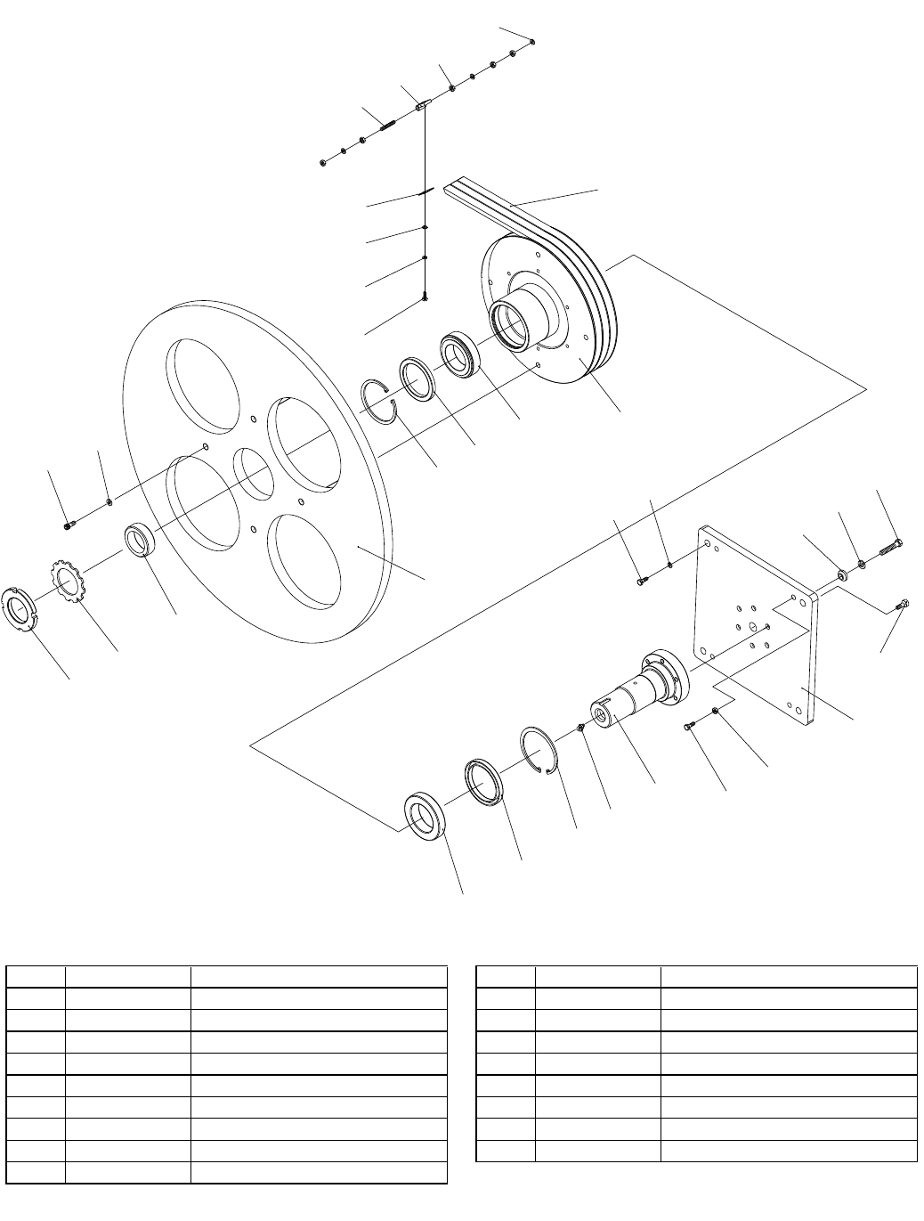
G0504 16" Horizontal Resaw Bandsaw -55--55- G0504 16" Horizontal Resaw Bandsaw
Drive Wheel Parts
REF PART # DESCRIPTION REF PART # DESCRIPTION
1601 P0504428A LOCK NUT AN11 1611 P05041611 BELT 5V X 740
1602 PTLW08M EXT TOOTH WASHER 10MM 1612 P32012 TAPER ROLLER BEARING 32012
1603 P0504429A LOCK RING 1613 P05041613 OIL SEAL TC-75 X 95 X 10
1604 PSB73M CAP SCREW M12-1.75 X 50 1614 P05041614 INT RETAINING RING 95MM
1605 PLW05M LOCK WASHER 12MM 1615 PZERK2 GREASE FITTING PT 1/8
1606 P0504403 RIGHT BLADE WHEEL 1616 P05041616 RIGHT WHEEL SHAFT
1607 P0504455 INT RETAINING RING 90MM 1617 PB25M HEX BOLT M12-1.75 X 25
1608 P0504456 OIL SEAL TC-70 X 90 X 8 1618 PN09M HEX NUT M12-1.75
1609 P32011 BEARING 32011 1619 P05041619 WHEEL ADJUSTMENT PLATE
1610 P05041610 BEARING SEAT-LEFT
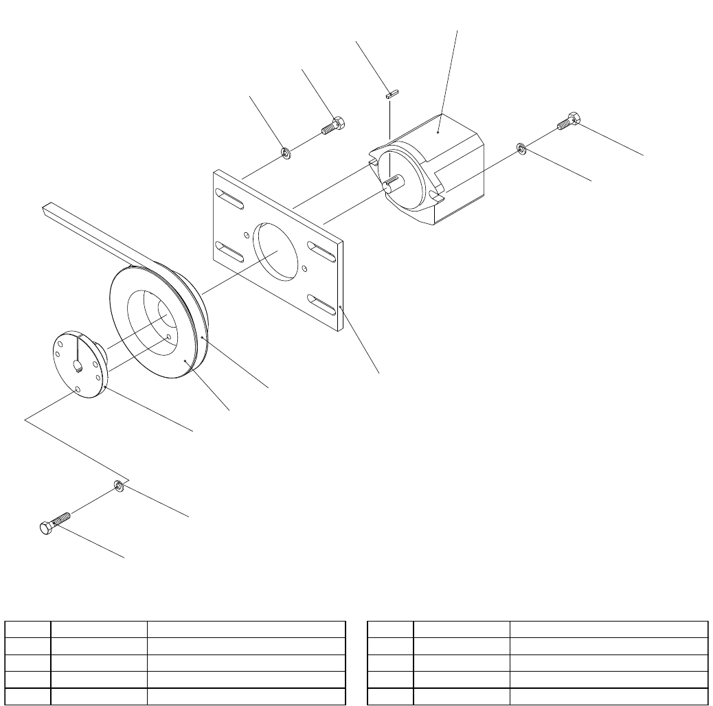
Hydraulic Pump Parts
REF PART # DESCRIPTION REF PART # DESCRIPTION
1701 PB09M HEX BOLT M8-1.25 X 20 1706 P05041706 MOTOR BRACKET
1702 PLW04M LOCK WASHER 8MM 1707 PLW06M LOCK WASHER 10MM
1703 P05041703 PULLEY SLEEVE 1708 PB74M HEX BOLT M10-1.5 X 20
1704 P05041704 PULLEY 1709 PK47M KEY 4 X 4 X 15
1705 P05041705 V-BELT B X 53 1710 P05041710 HYDRAULIC PUMP
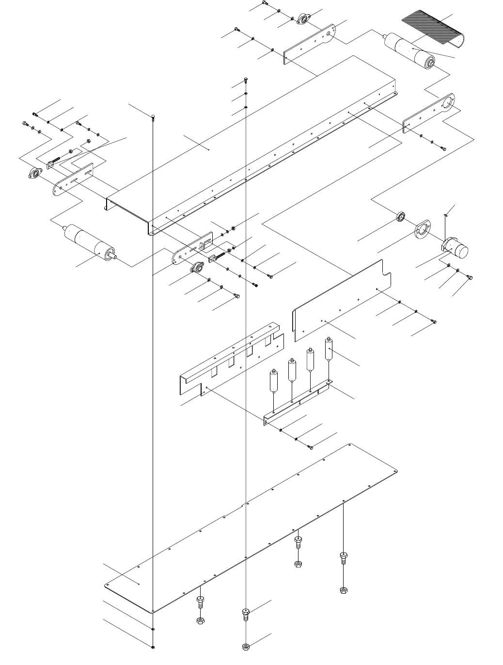
G0504 16" Horizontal Resaw Bandsaw -57--57- G0504 16" Horizontal Resaw Bandsaw
Main Conveyor Table Parts

-58- G0504 16" Horizontal Resaw BandsawG0504 16" Horizontal Resaw Bandsaw -58-
Main Conveyor Table Parts List
REF PART # DESCRIPTION
1801 PLN05M LOCK NUT M10-1.5
1802 PW04M FLAT WASHER 10MM
1803 P0504603 CONVEYOR LOWER PLATE
1804 PN33M HEX NUT M24-2
1805 P0504605 ADJUSTMENT BOLT
1806 PB01M HEX BOLT M10-1.5 X 30
1807 PLW06M LOCK WASHER 10MM
1808 P0504609 ROLLER SEAT
1809 P0504610 ROLLER
1810 P0504611B ROLLER PLATE (REAR)
1811 PB33M HEX BOLT M12-1.75 X 50
1812 PLW05M LOCK WASHER 12MM
1813 PW06M FLAT WASHER 12MM
1814 P05041814 HYDRAULIC MOTOR OMP250
1815 P0504618A MOTOR BEARING SEAT
1816 P6008LLB BALL BEARING 6008LLB
1817 PK13 KEY 1/4 X 1/4 X 1-1/2
1818 P0504621 REAR ROLLER BRACKET R
1819 P0504622 REAR ROLLER
1820 P0504623 CONVEYOR BELT 400
1821 P0504624 REAR ROLLER BRACKET L
1822 P0504625 FLANGE BEARING UCFL205
1823 PB25M HEX BOLT M12-1.75 X 25
1824 P0504636 CONVEYOR PLATEN
1825 PCB09M CARRIAGE BOLT M10-1.5 X 25
1826 PB01M HEX BOLT M10-1.5 X 30
1827 P0504637 ADJUSTMENT SCREW
1828 PN02M HEX NUT M10-1.5
1829 PB32M HEX BOLT M10-1.5 X 25
1830 P0504649 FRONT ROLLER SUPPORT
1831 P0504650 FRONT ROLLER
1832 P0504611A ROLLER PLATE (FRONT)
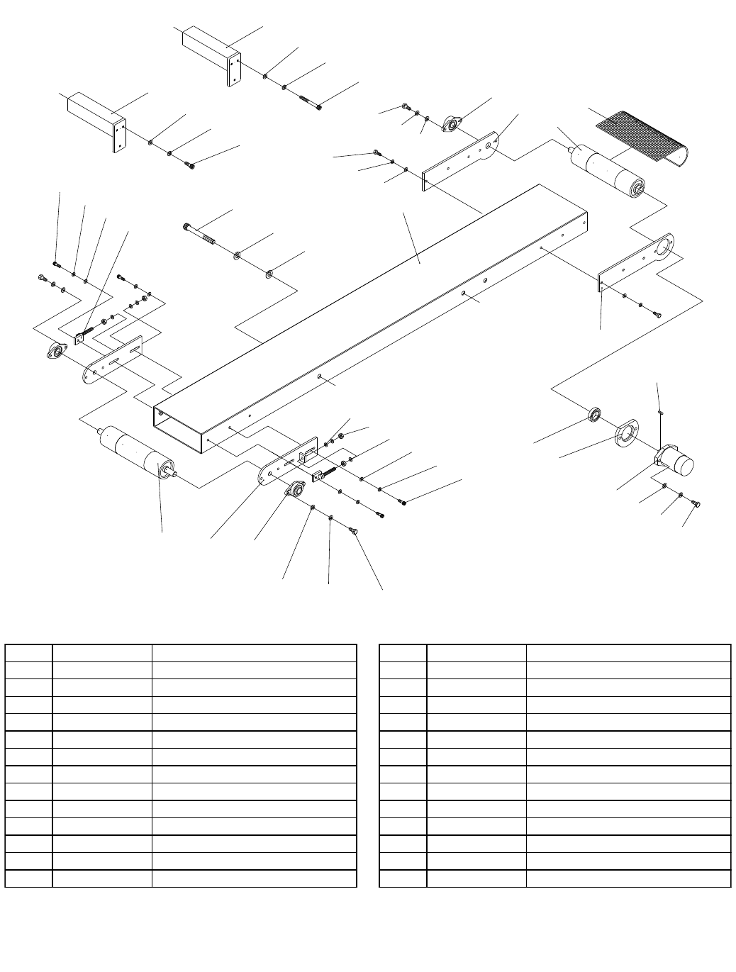
G0504 16" Horizontal Resaw Bandsaw -59--59- G0504 16" Horizontal Resaw Bandsaw
Return Conveyor Table Parts
REF PART # DESCRIPTION REF PART # DESCRIPTION
1901 PSB72M CAP SCREW M10-1.5 X 30 1915 P05041915 REAR ROLLER
1902 PLW06M LOCK WASHER 10MM 1916 P05041916 CONVEYOR BELT 185 X 5480
1903 PW04M FLAT WASHER 10MM 1917 P05041917 FRONT ROLLER
1904 P0504827 ADJUSTMENT BOLT 1918 P0504649 FRONT ROLLER BRACKET
1905 P05041905 HEX BOLT M20-2.5 X 230 1919 PN02M HEX NUT M10-1.5
1906 PLW06M LOCK WASHER 10MM 1920 PB32M HEX BOLT M10-1.5 X 25
1907 PW04M FLAT WASHER 10MM 1921 P6008LLB BALL BEARING 6008LLB
1908 PB01M HEX BOLT M10-1.5 X 30 1922 P05041922 OIL PUMP FLANGE
1909 P05041909 CONVEYOR SEAT 1923 P05041923 HYDRAULIC MOTOR OMP160
1910 PB25M HEX BOLT M12-1.75 X 25 1924 PK42M KEY 6 X 6 X 30
1911 PLW05M LOCK WASHER 12MM 1925 PB33M HEX BOLT M12-1.75 X 50
1912 PW06M FLAT WASHER 12MM 1926 P0504621A REAR ROLLER BRACKET R
1913 P0504625 FLANGE BEARING UCFL205 1927 P05041927 CONVEYOR SUPPORT
1914 P0504624 REAR ROLLER BRACKET L 1928 PB143M HEX BOLT M12-1.75 X 120
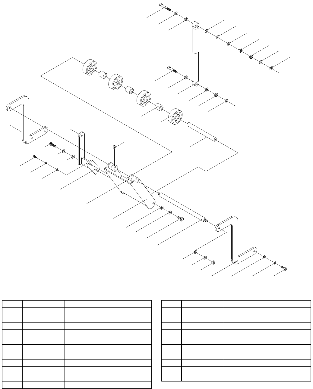
Rear Hold Down Parts
REF PART # DESCRIPTION REF PART # DESCRIPTION
2001 PB01M HEX BOLT M10-1.5 X 30 2013 P05042013 FIXED SEAT
2002 PLW06M LOCK WASHER 10MM 2014 PSB14M CAP SCREW M8-1.25 X 20
2003 PW04M FLAT WASHER 10MM 2015 PLW04M LOCK WASHER 8MM
2004 P0504753 REAR ROLLER SUPPORT 2016 PW01M FLAT WASHER 8MM
2005 PN09M HEX NUT M12-1.75 2017 PSB77M CAP SCREW M12-1.75 X 30
2006 PLW05M LOCK WASHER 12MM 2018 P05042018 REAR ROLLER SHAFT
2007 PW06M FLAT WASHER 12MM 2019 P0504747 PRESSURE ROLLER WHEEL
2008 P05042008 REAR ROLLER SHAFT 2020 P0504763 COLLAR
2009 PSB129M CAP SCREW M12-1.75 X 20 2021 P05042021 SHOCK ABSORBER
2010 P0504757 REAR PRESSURE PLATE 2022 PB125M HEX BOLT M12-1.75 X 65
2011 P0504758 COLLAR 2023 PB141M HEX BOLT M12-1.75 X 80
2012 PSS30M SET SCREW M10-1.5 X 10
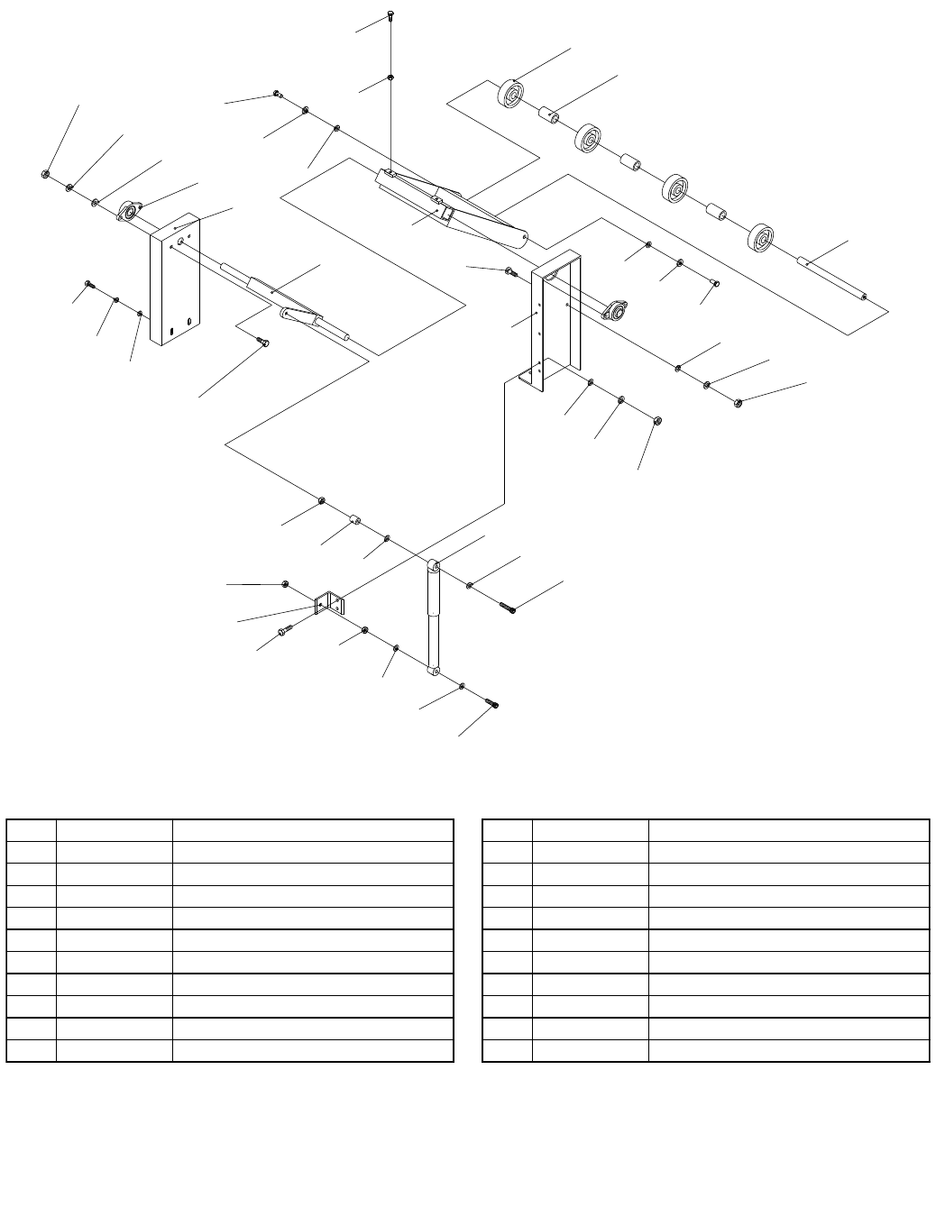
G0504 16" Horizontal Resaw Bandsaw -61-
Front Hold Down Parts
REF PART # DESCRIPTION REF PART # DESCRIPTION
2101 PN09M HEX NUT M12-1.75 2112 P0504748 COLLAR
2102 PLW05M LOCK WASHER 12MM 2113 P0504749 FRONT ROLLER SHAFT
2103 PW06M FLAT WASHER 12MM 2114 P0504742 FRONT PRESSURE PLATE
2104 P0504625 FLANGE BEARING UCFL205 2115 PB01M HEX BOLT M10-1.5 X 30
2105 P0504721 PRESSURE ROLLER SUPPORT (L) 2116 P0504731 PRESSURE ROLLER SUPPORT (R)
2106 P0504727 UPPER SHAFT 2117 PN02M HEX NUT M10-1.5
2107 PB32M HEX BOLT M10-1.5 X 25 2118 P0504716 COLLAR
2108 PLW06M LOCK WASHER 10MM 2119 P0504709 SHOCK ABSORBER
2109 PW04M FLAT WASHER 10MM 2120 PSB101M CAP SCREW M12-1.75 X 90
2110 PB49M HEX BOLT M12-1.75 X 20 2121 P0504713 IRON PLATE
2111 P0504747 PRESSURE ROLLER WHEEL 2122 PSB63M CAP SCREW M12-1.75 X 60
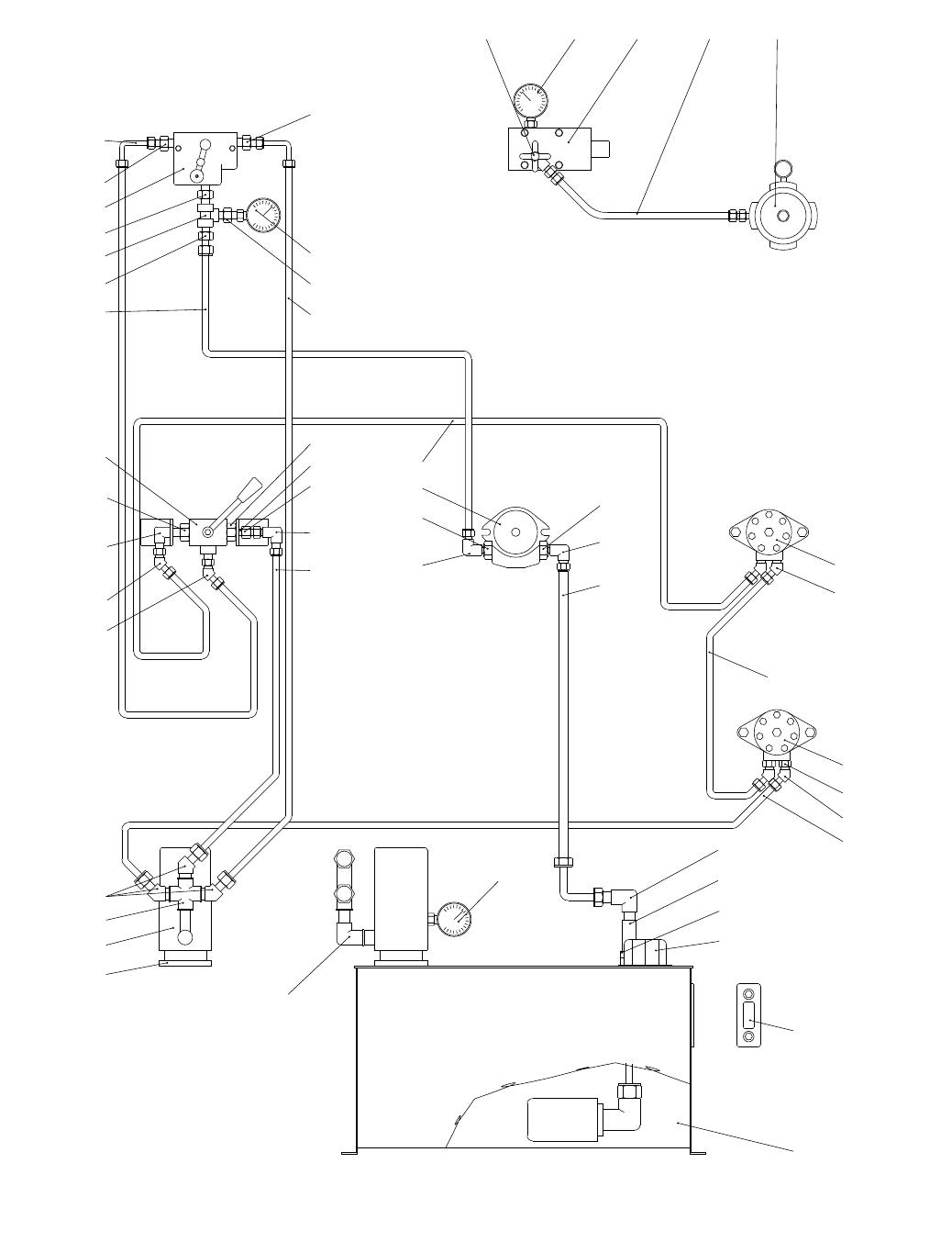
-62- G0504 16" Horizontal Resaw Bandsaw
Hydraulic System Parts

G0504 16" Horizontal Resaw Bandsaw -63-
Hydraulic System Parts List
REF PART # DESCRIPTION
2201 P05042201 FUEL TANK
2202 P05042202 MANOMETER
2203 P05042203 OIL FILLER
2204 P05042204 CONNECTOR 3/4T X 3/4T
2205 P05042205 REVERSE VALVE 3/4"
2206 P05042206 CONNECTOR 3/4T X 3/4H X 45°
2207 P05042207 HYDRAULIC GAUGE
2208 P05042208 CONNECTOR 3/4T X 1/2T X 90¢ X
2209 P05042209 FILTER BRACKET
2210 P05042210 FILTER
2211 P05042211 CONNECTOR 1/2T
2212 P05042212 CONNECTOR 1/2T X 3/8H X 45°
2213 P05042213 OIL PIPE 3/4" X 63"
2214 P05042204 CONNECTOR 3/4T X 3/4T
2215 P05041710 HYDRAULIC PUMP
2216 P05042216 CONNECTOR 1/2T X 5/8T
2217 P05042217 CONNECTOR 1/2T X 3/8H
2218 P05042218 OIL PIPE 3/8" X 122"
2219 P05042219 CONNECTOR 3/8T X 3/8T
2220 P05042220 HEX OIL PUMPER 3/8T X 3/8T
2221 P05042221 CONNECTOR 3/8T X 3/8H
2222 P05042222 CONNECTOR 3/8H X 3/8H
2223 P05042223 OIL PIPE 3/8" X 75"
2224 P05042224 CONNECTOR 3/8T X 3/8H X 45°
2225 P05042225 CONNECTOR 3/8H X 3/8H X 45°
2226 P05042221 CONNECTOR 3/8T X 3/8H
2227 P05042227 BALL VALVE 3/8"
2228 P05042228 OIL PIPE 3/8" X 78-3/4"
2229 P05042229 HEX OIL PUMPER 3/8T X 3/8H
2230 P05042230 CONNECTOR 3/8T
2231 P05042231 CONTROL VALVE FC51-3/8
2232 P05042232 OIL PIPE 3/8" X 82-5/8"(90)
2233 P05042233 OIL PIPE 1/4" X 39-1/2"(90)
2234 P05042234 CONNECTOR 3/8T X 1/4T
2235 P05042235 HYDRAULIC GAUGE
2236 P05041814 HYDRAULIC MOTOR OMP250
2237 P05042237 OIL PIPE 3/8" X 94-1/2"
2238 P05041923 HYDRAULIC MOTOR OMP160
2239 P05042239 CONNECTOR 7/8-14UNF X 3/8T
2240 P05042240 OIL PIPE 3/8" X 39-1/2"
2241 P05042241 STOP VALVE
2242 P05042242 HYDRAULIC GAUGE
2243 P05042243 OIL PARTITION
2244 P05042244 OIL PIPE 1/4" X 240
2245 P05042245 PUMP
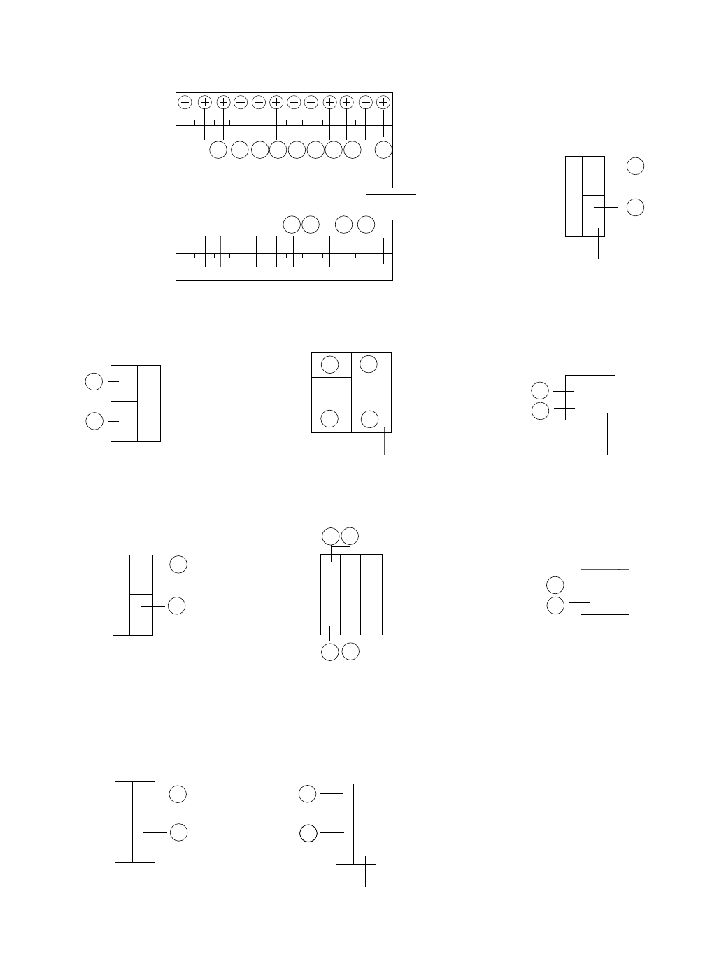
-64- G0504 16" Horizontal Resaw Bandsaw
Electrical System Parts 1
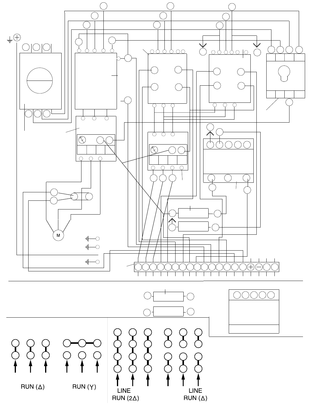
G0504 16" Horizontal Resaw Bandsaw -65-
Electrical System Parts 2

-66- G0504 16" Horizontal Resaw Bandsaw
REF PART # DESCRIPTION
2301 P05042301 DIMENSION SET METER FPC-525/INCH
2302 P05042302 MEMORY BUTTON N/S
2303 P05042303 EMERGENCY BUTTON N/S
2304 P05042304 POWER ON BUTTON N/S
2305 P05042305 UP/LIMIT SWITCH
2306 P05042306 UP BUTTON N/S
2307 P05042307 MOTOR START/GREEN N/S
2308 P05042308 DOWN/LIMIT SWITCH
2309 P05042309 DOWN BUTTON N/S
2310 P05042310 MOTOR STOP/RED N/S
2311 P05042311 NO FUSE SWITCH 3P 100AMP
2312A P05042312A MAG.CONTACTOR LCI-D080 (TE)
2313 P05042313 MAG.CONTACTOR LCI-D096 (TE)
2314 P05042313 MAG.CONTACTOR LCI-D096 (TE)
2315 P05042315 TRANSFORMER 200VA
2316 P05042316 FUSE 5A FUSE
2317 P05042317 ELECTRIC SET 10A/1P
2318 P05042318 POWER SAFETY SWITCH
2319A P05042319A 440V CONVERSION KIT (TE 30HP)
2320A P05042320A OL RELAY 220V LR3D-3363 63/80A
2321A P05042321A UP OL RELAY LR3D-076 2.5A
2322 P05042322 PHASE REVERSAL RELAY
Electrical System Parts List


WARRANTY AND RETURNS