(WEB)General TruSeal IOM GENERAL VALVE Tru Seal
User Manual: GENERAL VALVE Tru Seal IOM Resource Library
Open the PDF directly: View PDF ![]() .
.
Page Count: 16
®
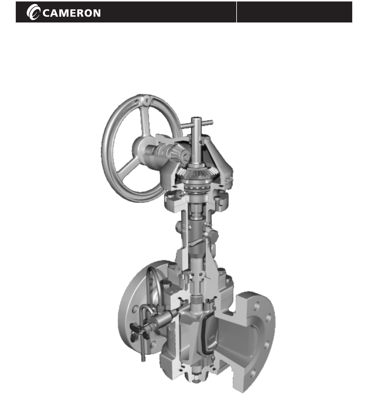
GENERAL VALVE
Installation, Operation, and Maintenance Manual GENERAL VALVE TRUSEAL / IOM-GEN-TRUSEAL
GENERAL9$/9(
TUX6HDO70
Installation, Operation, and Maintenance Manual
©Cameron’s Valves & Measurement Group Revised 10/07 IOM-GEN-TRUSEAL
Installation, Operation, and Maintenance Manual
7$%/(2)&217(176
*(1(5$/9$/9(7586($/9$/9(6
,QVWDOODWLRQ
9DOYH2SHUDWLRQ
2SHUDWLQJ,QVWUXFWLRQV
3DUWV/LVW
%OHHG6\VWHPV
5HSDLUV
)LHOG6HUYLFH*XLGH
2SHUDWRU,QVSHFWLRQ
GENERAL VALVE TRUSEAL / IOM-GEN-TRUSEAL

INSTALLATION
Installation, Operation, and Maintenance Manual
1
GENERAL VALVE TRUSEAL / IOM-GEN-TRUSEAL
ORIENTATION
GENERAL 9$/9(TUX6HDO valves may be
installed in any position.
FLOW DIRECTION
The GENERAL 9$/9(TUXSHDO valve
design is symmetrical. Flow shut-off is achieved
equally on both sides, independent of flow
direction.
Note: Read the section on Thermal
Relief Accessories, on pages 6-7, which
DO result in a preferred flow direction.
CLEARANCE FOR REPAIR
For easy repair, space should be allowed
below the valve for removal of the lower
plate and withdrawal of the seating slips.
See Table 1 for dimensions. Sufficient clear
space is required above the GENERAL 9$/9(
TUX6HDO valve, to allow free movement of
the position indicator flag and for removal
of the operator mechanism.
TABLE 1
CLEARANCE REQUIRED BELOW THE
VALVE FOR SLIP REMOVAL
Note: Allowing more than the specified
minimum amount of clearance will make
servicing easier.
Minimum Clearance
Valve ASME ASME ASME
Size 150 300 600
2" 3" 3" 3"
3" 3" 3" 3"
4" 5" 5" 4"
6" 8" 9" 8"
8" 10" 9" 7"
10" 12" 12" 11"
12" 15" 14" 14"
14" 16" 16" -
16" 18" 18" -
18" 18" 18" -
20" 22" 24" -
24" 26" - -
30" 30" - -
FLANGE FASTENERS
Certain *(1(5$/9$/9(7UX6HDO flange holes are drilled and tapped,
when there is no possibility of fitting a hexagonal nut behind the flange.
The quantity and size of these tapped holes is shown on Table 2.
CapscrewsWor stud bolts may be used in these holes.
TABLE 2
FLANGE FASTENERS
Valve Size Number of Length Required
Tapped Holes Thread Capscrews or Stud Bolts
inch ASME Class Per Flange UNC inch inch
6 150 4 3/4"-10 2 3
8 150 4 3/4"-10 2 3
10 150 4 7/8"-9 2 1/4 3 1/2
12 150 4 7/8"-9 2 1/4 3 1/2
14 150 4 1"- 8 2 1/2 3 3/4
16 150 8 1"-8 2 1/2 3 3/4
18 150 8 1 1/8"-8 2 3/4 4
8 300 4 7/8"-9 2 3/4 4
10 300 4 1"-8 3 5
PRESSURE TEST
GENERAL9$/9( TUX6HDO valves can be hydrostatically pressure-tested after
installation, to full API 6D limits as defined below.
TABLE 3
PRESSURE TEST
Valve Figure No. 211 221 241 Comments
ASME Class 150 300 600
Shell Test Pressure (psig) 500 1200 2250 No leakage permitted
(Valve Open) (kg/cm2) 35 85 158
Seat Test Pressure (psig) 300 800 1600 Test upstream and downstream
(Valve Closed) (kg/cm2) 21 56 113 seats. No leakage permitted.
Supplemental (API 598) (psig) 80 80 80 Test upstream and downstream
Air Seat Test Pressure (psig) 6 6 6 seats. No leakage permitted.
(Valve Closed)
GEAR-HEAD ORIENTATION
When GENERAL 9$/9(TUX6HDO gear operators are used, the orientation of
the handwheel shaft can be changed to suit operational requirements.
Follow these instructions to change gear-head orientation.
(See page 4 for parts reference).
a. Remove all the gear housing bolts (part no. 42), but support the
weight of the handwheel and shaft.
b. Turn the handwheel so that the gear housing rotates to the desired
position.
c. Align the bolt holes and replace the gear housing bolts.
ICE WARNING: Water in the bottom of the GENERAL VALVE TruSeal
valve must be drained before freezing conditions occur.
Ice below the plug can exert enough force to destroy the operator
mechanism. Drain any water from plugged holes in the lower plate.
The valve must be in the closed position before removing plugs.
Installation, Operation, and Maintenance Manual
2
P
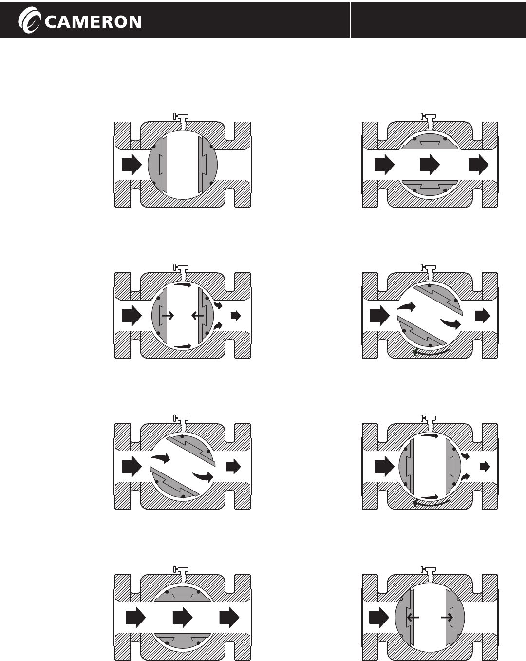
VALVE OPERATION
GENERAL VALVE TRUSEAL / IOM-GEN-TRUSEAL
1.
Valve fully closed,
plug is down with
the resilient seals
compressed
against the valve
body.
2.
Plug raised with
seals retracted
from the body
contact by
dovetail
connection.
3.
Plug turning to
open position.
No seal to body
contact.
Line load carried
on plug trunnions.
4.
Valve is fully open
with seals
protected from
flow path.
5.
Valve is fully
open with seals
protected from
flow path.
6.
Plug turning
toward the
closed position.
Resilient seals
held away from
body by dovetail
connections.
7.
Plug turned a full
90°, positioning
the seals over
both the upstream
and downstream
ports.
8.
Plug down,
seals expanded
outward against
body.
Valve fully closed.
BODY BLEED
BODY BLEED
OPENING CLOSING
OPERATION INSTRUCTIONS
Installation, Operation, and Maintenance Manual
3
GENERAL VALVE TRUSEAL / IOM-GEN-TRUSEAL
LIFT AND TURN
7KHGENERAL 9$/9(TUX6HDO is a
lift-and-turn plug valve. The valve
operator mechanism converts thH
rotary actionof the handwheel into
the thrust andturn movement of theplug.
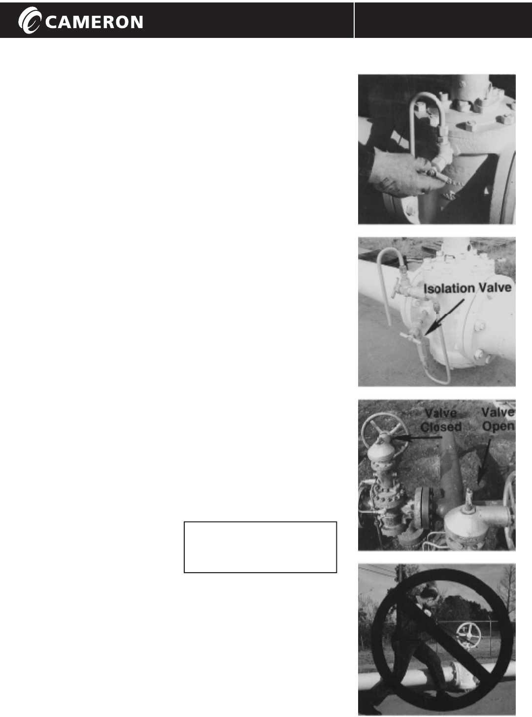
BEFORE USE
Before operational use, check that the
isolation valve on the thermal relief or
automatic body bleed, if applicable, is
fully open to allow the system to
function. If the valve is equipped with
a manual body bleed only, then open
and close the manual bleed valve to
relieve the internal body pressure,
before attempting to open a closed
GENERAL9$/9(7UX6HDO.
OPERATION
Clockwise turning of the handwheel
will close the valve.
Counter-clockwise turning of the
handwheel will open the valve.
CLOSING
Close the GENERAL TRUSEAL valve
until resistance is felt. The soft seals
have made contact with the body.
Turn the handwheel further to
compress the soft seals until there
is a definite feel of "end of travel".
Now the soft seals are fully
compressed, metal-against-metal,
giving fire safe seating. Firm, positive
turning of the handwheel is sufficient
to seal the valve. Verity tight sealing
by opening the manual body bleed
valve or by observing any other bleed
system fitted. Pressure release is
normal. Constant dripping is normal.
See page 11, if dripping continues.
OPENING
If a manual bleed alone is fitted, open
it and close it, to release any thermal
pressure build up. Turn the GENERAL
9$/9(7UX6HDOhandwheel counter
clockwise until definite "end of travel"
can be felt. Do not force or slam the
handwheel fully open. The end of
travel is pre-set to ensure port
alignment. Do not "back-off" a partial
turn from fully open.
INDICATOR FLAG
The indicator flag shows the position
of the plug port at all times. Positioned
at right angles to the pipeline and
down, shows the GENERAL 9$/9(
7UX6HDOis closed. In-line with the
pipeline and up, shows the GENERAL
9$/9(7UX6HDOis open.
CAUTION
Do not throttle with a GENERAL
9$/9(7UX6HDO valve. Even though
GENERAL9$/9(7UX6HDO valves cannot
slam shut, they should only be open
or closed. Never leave a GENERAL
9$/9(7UX6HDO valve in a half-way
position. The soft resilient seals can be
eroded by high velocity flow that occurs
if the valve is used in the partially open
position.
ROUTINE ATTENTION
GENERAL 9$/9(7UX6HDOvalves require
no routine maintenance for positive
sealing performance. Occasional
injection of bearing grease,
depending on the frequency of
operations, will keep the turning
action smooth. A grease point is
located near the handwheel.
MANUAL BODY BLEED (MBV)
MANUAL BLEED WITH THERMAL RELIEF (MTR)
INDICATOR FLAG
DO NOT USE FORCE!
N
or extension poles on
the valve handwheels.
ever use wheelkeys, cheaters,
Installation, Operation, and Maintenance Manual
4
PROCESS VALVES
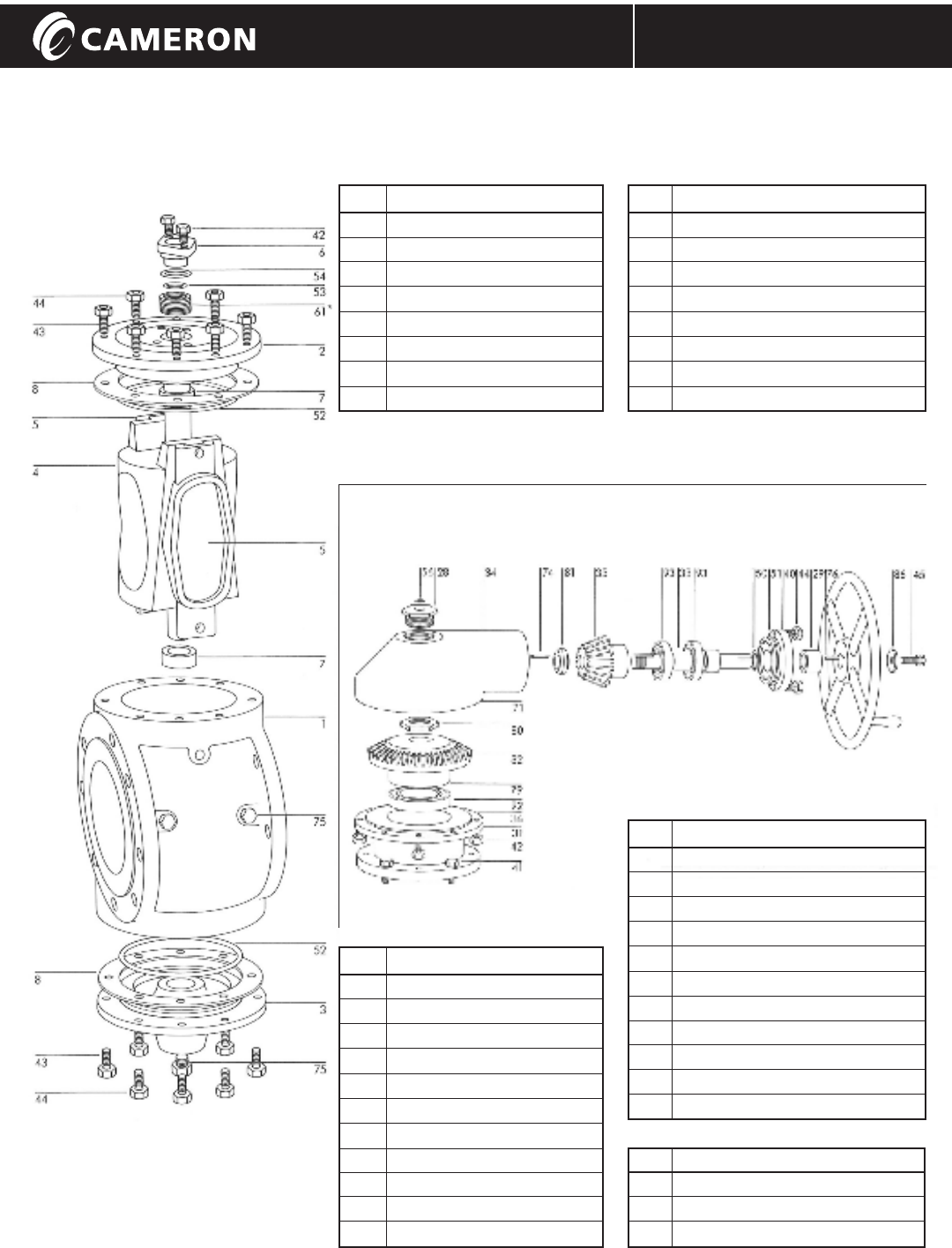
PARTS LIST
Valve Body Section
Gear System Operator
GENERAL VALVE TRUSEAL / IOM-GEN-TRUSEAL
No. Description
45 Handwheel Bolt
50 Bearing Retainer O-Ring-Inner
51 Bearing Retainer O-Ring-Outer
56 Dust Cap O-Ring
74 Pinion Key
76 Handwheel Key
80 Gear Locknut
81 Pinion Locknut
86 Washer
92 Ball Bearing
93 Ball Bearing
No. Not Shown
36 Shim Set
71 Grease Fitting
79 Gear Key
No. Description
28 Dust Plug
29 Handwheel Spacer
31 Bearing Spool
32 Gear
33 Pinion Shaft
34 Gear Housing
35 Pinion
40 Bearing Retainer
41 Bearing Spool Bolt
42 Gear Housing Bolt
44 Bearing Retainer Bolt
No. Description
1 Body
2 Bonnet
3 Lower Plate
4 Plug
5 Slip
6 Packing Gland
7 Bushing
8* Gasket (flat or spiral wound)
No. Description
42 Packing Gland Bolt
43 Body Stud
44 Body Nut
52 Body O-Ring
53 Inner Gland O-Ring
54 Outer Gland O-Ring
61* V-Packing Set or Graphite Rings
75 Body Drain Pipe Plug
*
when ordering parts.
Specify valve serial number
PROCESS VALVES
Installation, Operation, and Maintenance Manual
5
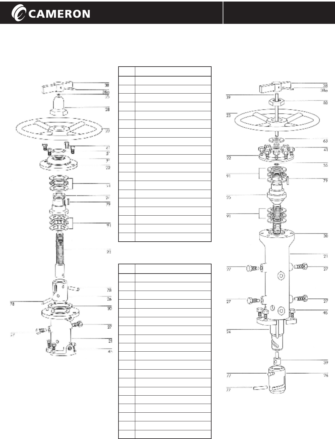
PARTS LIST
GENERAL VALVE TRUSEAL / IOM-GEN-TRUSEAL
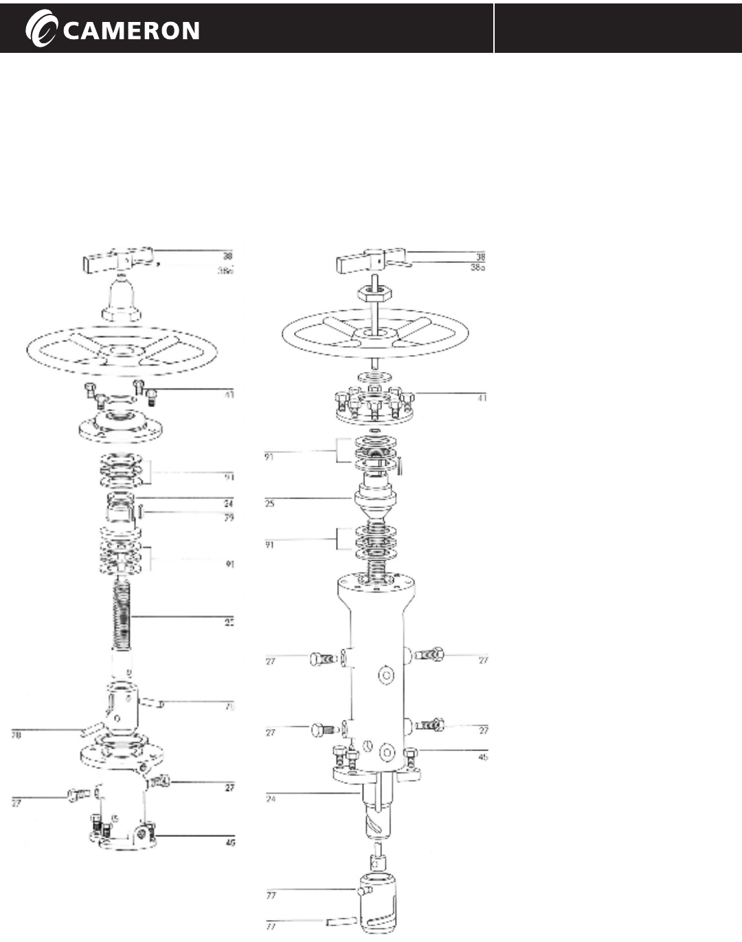
200 Series 400 Series Operator200 Series Operator
No. Description
21 Operator Housing
22 Bearing Cap
23 Handwheel
24 Drive Nut
25 Stem
26 Coupling Cam
27 Cam Pins
28 Dust Cap
30 Shim Set
38 Indicator Flag
38a Indicator Flag Pin
41 Bearing Cap Bolt
45 Operator Housing Bolt
51 Bearing Cap O-Ring
56 Dust Cap O-Ring
78 Coupling Pins
79 Handwheel Key
91 Thrust Bearing Assembly
71 Grease Fitting (not shown)
No. Description
21 Operator Housing
22 Bearing Cap
23 Handwheel
24 Drive Cam
25 Stem
26 Coupling Cam
27 Cam Pins
38 Indicator Flag
38a Indicator Flag Pin
39 Indicator Flag Rod
41 Bearing Cap Bolt
45 Operator Housing Bolt
55 Stem Seal O-Ring
63 Bearing Cap O-Ring
77 Coupling Pins
79 Handwheel Key
80 Handwheel Retaining Nut
91 Thrust Bearing
30 Shim Set (not shown)
400 Series
Installation, Operation, and Maintenance Manual
6
PROCESS VALVES
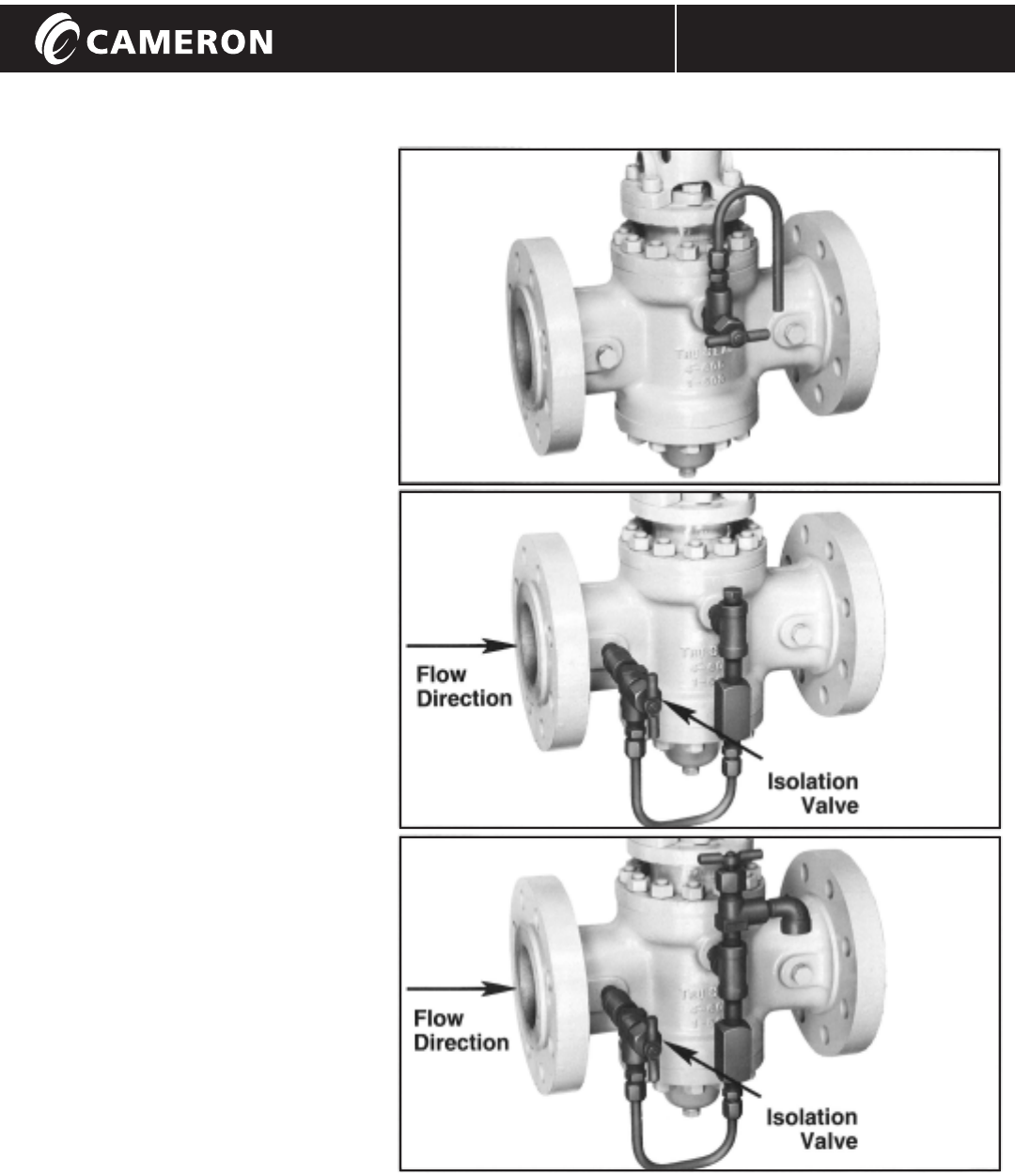
BLEED SYSTEMS
GENERAL VALVE TRUSEAL / IOM-GEN-TRUSEAL
1
MANUAL BLEED VALVE (MBV)
The simplest bleed valve for hand operated
GENERAL VALVE TruSeal valves.
When GENERAL VALVE TruSeal is closed,
open body bleed valve to check drop tight
sealing. Close MBV before opening the
GENERAL VALVE TruSeal. Bleed outlet
should be properly piped to suitable drainage
sump.
Note: the "goose neck" pipe to prevent
drainage of the body liquid.
THERMAL RELIEF**
TO BODY (TRB)
With the GENERAL VALVE TruSeal closed the
thermal relief valve releases any thermal
expansion of the body liquid, back safely and
automatically, to the line. Relief set at 25 psi.*
THERMAL RELIEF TO
ATMOSPHERE** (TRA), (See Page 10)
Similar to TRB except thermal relief valve is
set at 50 psi above pipeline rated pressure
and is vented to atmosphere.
1
MANUAL BLEED VALVE WITH
THERMAL RELIEF** (MTR)
The manual bleed proves drop tight sealing.
The Thermal Relief Valve releases any
thermal expansion of the body liquid, back
safely and automatically to the line.
Relief set at 25 psi.*
1When a manual bleed or automatic bleed is
fitted, the vent pipe should always be above
the highest point of the valve body cavity.
This will prevent liquid in the body cavity
from dripping out. Leakage past either seal
would expel liquid from the already-full body
cavity.
*The relief valve is set to open at 25 psi
on all valves, regardless of their working
pressure. With the valve closed, the relief
valve will open at 25 psi above upstream
pressure. This system functions only when
the GENERAL TRUSEAL valve is closed
and the isolation valve is open.
CAUTION
A thermal relief system, piped back to the valve throat, converts the
GENERAL VALVE TruSeal to a "DIRECTIONAL" valve. Thermal relief should
always be piped back to the upstream side. If it were piped to the
downstream, any leakage past the main seal on the "up" side would be
permitted to by-pass the "down" seal, by way of the directional check valve.
PROCESS VALVES
BLEED SYSTEMS
Installation, Operation, and Maintenance Manual
7
GENERAL VAVE TRUSEAL / IOM-GEN-TRUSEAL
TRUSEAL
Valve
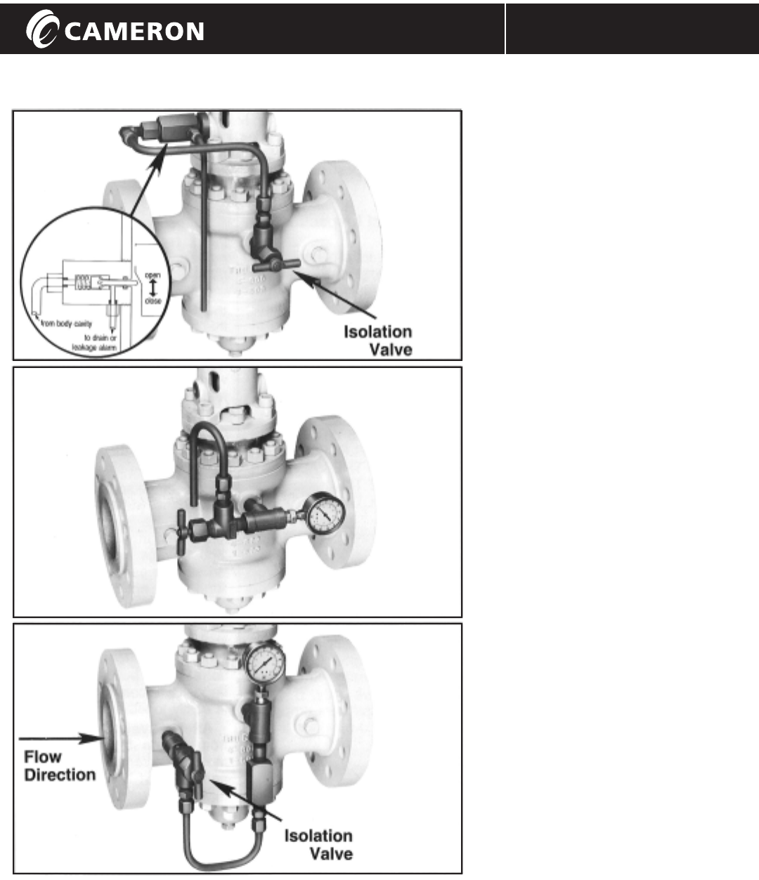
CAUTION
In normal service, the Manual Bleed is kept closed, unless to check for
GENERAL VALVE TruSeal tightness or to vent thermal pressure rise. With
automatic bleed or thermal relief back-to-line, the manual isolation valve
that is attached to the GENERAL VALVE TruSeal body must always be open,
except for maintenance. If the isolation valve is closed, the relief system
cannot operate.
AUTOMATIC BODY BLEED
1
VALVE (ABV)
A plunger actuated check valve is opened
by the coupling cam as the GENERAL VALVE
TruSeal is closed (either manually or by
power actuator). This system removes the
human element from seal checking,
making it completely automatic.
The isolation valve may be padlocked
"open" to ensure total double block and
bleed integrity, avoiding any risk of human
error in sealing verification.***
1
MANUAL BLEED VALVE
WITH GAUGE (MBG)
The manual bleed valve is combined with
a gauge when emission to atmosphere is
undesirable. The closing action of a
GENERAL VALVE TruSeal valve automatically
reduces body cavity pressure due to the
expanding seating segments. The gauge
alone will indicate tight seals. (After a
period of time, body pressure may again
increase due to thermal expansion of fluid
in the body cavity).
THERMAL RELIEF** VALVE
WITH GAUGE (TRG)
A thermal relief valve, to relieve any body
pressure which may build up due to
thermal change, is combined with a gauge
to indicate tight seals. No emissions to
atmosphere.
No sump system required.
Relief set at 25 psi*.
**Thermal relief systems are designed to
relieve excess pressure rise in the body
cavity of a closed valve due to ambient
temperature causing expansion of the
liquid in the valve.
*** Some fluid is emitted at each actuation.
A sump system is important as fluid will
spurt out as the GENERAL VALVE TruSeal
approaches the closed position and the
cam opens the ABV. The spurting will
cease as GENERAL VALVE TruSeal is fully
closed for positive verification of double
sealing.
Note: All automated TruSeal valves
require some form of body pressure
relief. TRB/TRA/MTR/ABV/TRG
Installation, Operation, and Maintenance Manual
8
REPAIRS
GENERAL VALVE TRUSEAL / IOM-GEN-TRUSEAL
These instructions are written assuming the valve is installed in a horizontal line,
with plug stem vertical, handwheel above the pipeline. Should there be any
difficulty interpreting these guidelines for other mounting positions, consult your
nearest GENERAL VALVE TruSeal representative.
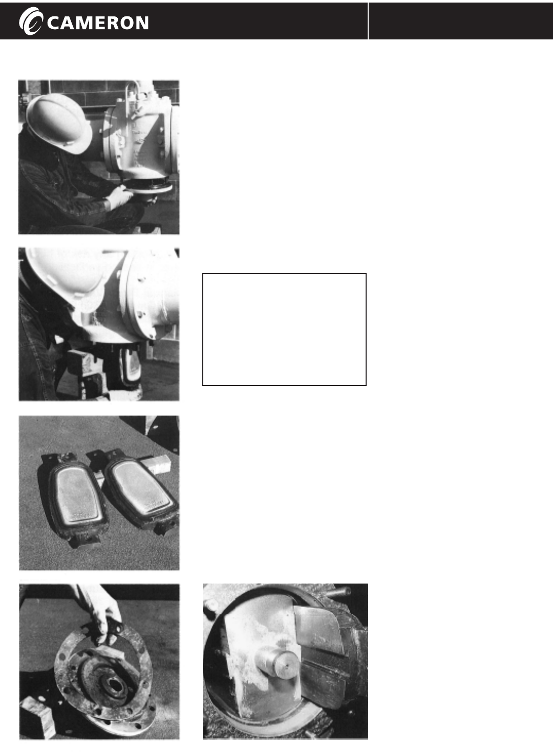
LOWER PLATE REMOVAL
SUPPORT ONE SLIP, REMOVE THE OTHER
SEATING SLIPS
LOWER PLATE GASKET
SEATING SEAL
INSPECTION OR CHANGE
Seating seals are bonded to metal
segments called "slips". Slips can be
factory re-bonded, if the metal has
not been damaged.
WARNING:
NEVER ATTEMPT TO CHANGE
SLIPS WITH VALVE UNDER
PRESSURE.
DAMAGE TO THE VALVE AND
INJURY TO PERSONNEL
COULD RESULT.
Leave the GENERAL VALVE TruSeal
mounted in line, in the open position
and drain the line before proceeding.
Check by means of the body bleed
and lower plate drain, that the pipe is
empty. Close the GENERAL VALVE
TrusSeal, to wedge the slips against
the valve body. This will prevent the
slips from dropping out when the lower
plate is removed.
With support under the lower plate,
remove the lower plate nuts
(part no. 44) and the lower plate.
If necessary, use jack-bolts in the
tapped holes provided for this
purpose.
With support under the slips, turn
the GENERAL VALVE TruSeal
handwheel towards "open". Keep
hands and feet out from under the
slips.
The slips (part no. 5) will slide off
the plug.
Be sure that the spaces left by
removal of the slips are clean.
Inspect the seals for evidence of
damage. Substitute with new slips
if there is any cut or missing
section in the soft seal.
Reassemble in reverse order.
Be sure to use a new body O-ring
(part no. 52) and a new gasket
(part no. 8).
Do not force any part. Slips should
fit freely on plug dovetails.
Check for sediment or corrosion or
build-up of foreign deposits, if
components do not fit easily
together.
Alternatively, slip removal from the
top is possible, by removing the
bonnet.
Consult your local Cameron
representative for detailed
instructions.
SLIPS FIT ON PLUG DOVETAILS
PROCESS VALVES
REPAIRS
Installation, Operation, and Maintenance Manual
9
GENERAL VALVE TRUSEAL / IOM-GEN-TRUSEAL
CHANGING
THE STEM PACKING
WARNING:
NEVER ATTEMPT TO CHANGE
PACKING WITH VALVE UNDER
PRESSURE.
DAMAGE TO THE VALVE AND
INJURY TO PERSONNEL
COULD RESULT.
If the packing is to be changed, the
pipeline must be drained and checked
by venting the body bleed.
Only proceed after you are certain the
valve and line do not contain pressure.
Remove the operator as decribed in
the next column. ("Operator Change").
Remove the packing gland bolts
(part no. 42, Page 4).
Remove the packing gland (part no. 6).
Remove the V-packing set (part no. 61).
Carefully install new V-packing, one
ring at a time, taking care that lips are
not damaged and that lips face into
the valve.
Install new gland O-rings (part no. 53 &
54) and scraper ring, if originally fitted.
Install packing gland and retaining bolts.
Torque the bolts until the gland is tight,
metal/metal, against the bonnet surface.
Install operator with coupling pin and
fixing bolts.
Use only GENERAL VALVE TruSeal
approved parts, as dimensions are
critical to good operation.
CAM PIN CHANGE (See Page 12)
Worn or damaged cam pins (part no. 27)
can cause the GENERAL VALVE TruSeal
to malfunction, (i.e. stiff turning or failure to
seal tight).
Remove one pin at a time, to inspect
for wear or damage. Replace that pin
before removing another cam pin,
to avoid realignment difficulty of pins
in their guide slots.
When installing cam pins, do not use
excessive torque. The cam pins only
require a "snug" metal-to-metal fit.
A slightly polished wear-spot is normal.
Severe "D" shape, flat spot, or bending
of the pin is not normal. Replace with
a new cam pin if wear is evident and
investigate the cause.
Use only genuine GENERAL VALVE
TruSeal parts. Dimensions and material
hardness are critical for good operation.
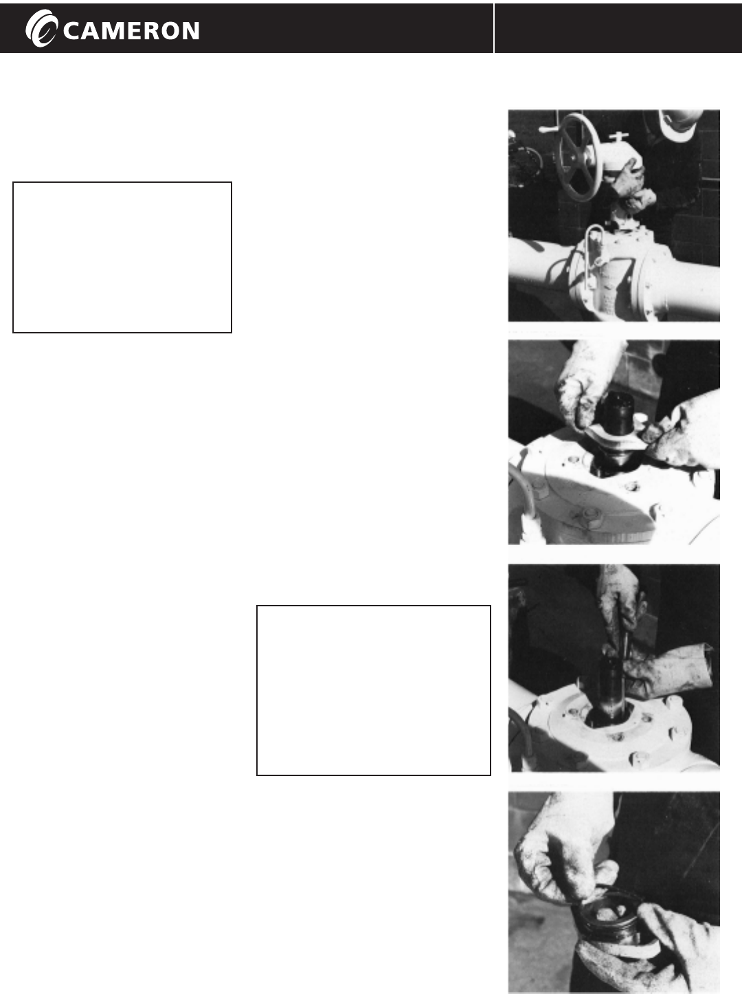
OPERATOR CHANGE
OR REMOVAL
1. Close the GENERAL VALVE TruSeal
valve.
2. Remove the yoke housing bolts
(part no. 45, Page 13).
3. Drive out the lower coupling pin
(part no. 77 or 78).
4. Lift off the whole operator.
5. Install an operator in reverse order.
CAUTION:
If the operator has been removed
from a GENERAL VALVE TruSeal
valve, the lower plate MUST NOT BE
REMOVED without first ensuring
that the plug is firmly held by its
upper stem. There is a coupling
hole through the upper stem, to
which support may be attached.
OPERATOR REMOVAL
PACKING GLAND REMOVAL
V-PACKING REMOVAL
REPLACING GLAND O-RINGS
Installation, Operation, and Maintenance Manual
10
REPAIRS
GENERAL VALVE TRUSEAL / IOM-GEN-TRUSEAL
THERMAL RELIEF
BLEED SYSTEM
(TRA, TRB, TRG or MTR -
See pages 6-7).
Malfunction of the thermal relief
system can be diagnosed if a manual
bleed is also installed. If any dripping
from the manual bleed is stopped by
closing the isolation valve in the throat
of the GENERAL TRUSEAL, then the
GENERAL TRUSEAL elastomer seals
are in good condition. The leak path
is through the thermal relief system.
THERMAL RELIEF
SYSTEM REPAIR
1. Close the GENERAL 9$/9(7UX6HDO
valve.
2. Open the manual bleed valve, (if
fitted), to verify that line pressure
is not present in the vent system.
If no manual bleed has been fitted,
line pressure must be removed
from the pipeline before the relief
couplings are loosened.
3. Close the isolation valve in the
throat of the GENERAL 9$/9(
TUX6HDO, (if fitted),
4. Only proceed further when liquid
run-off has stopped. The thermal
relief element is now isolated and
can be uncoupled from its pipework.
5. Clean out the relief valve or replace
it with a new part. Check for tight
sealing with an airline and soap
bubble test before installation.
6. Reassemble the pipework, taking
care to install the relief valve with
the correct flow direction, FROM
the body TO the line (TRB, TRG or
MTR Assembly). FROM the body
TO atmosphere (TRA Assembly).
AUTOMATIC BLEED VALVE
(ABV) - REPLACEMENT
If it is necessary to remove the ABV,
first close the GENERAL9$/9(7UX6HDO.
Verify that the body pressure has
vented by observing discharge from
the bleed drain pipe. Close the
isolation valve on the body cavity and
then disconnect the bleed pipes from
the ABV.
Loosen the locknut on the ABV and
unscrew the ABV body from the
operator housing. Clean it or replace
it with a new ABV. To reinstall the ABV,
screw the ABV into the operator
housing until the plunger-end just
touches the cam. Blow through the
ABV ports and continue to turn the
ABV to find the point where the seat
begins to lift. Then rotate the ABV an
additional 1/2 turn clockwise and
tighten the locknut.
Reconnect the bleed lines to the ABV
and open the isolation valve on the
body cavity.
Cycle the GENERAL 9$/9(7UX6HDO open
and closed to check for proper
operation of the ABV. A spurt of liquid
should come from the ABV drain pipe
just before the GENERAL 9$/9(7UX6HDO
reaches "fully closed".
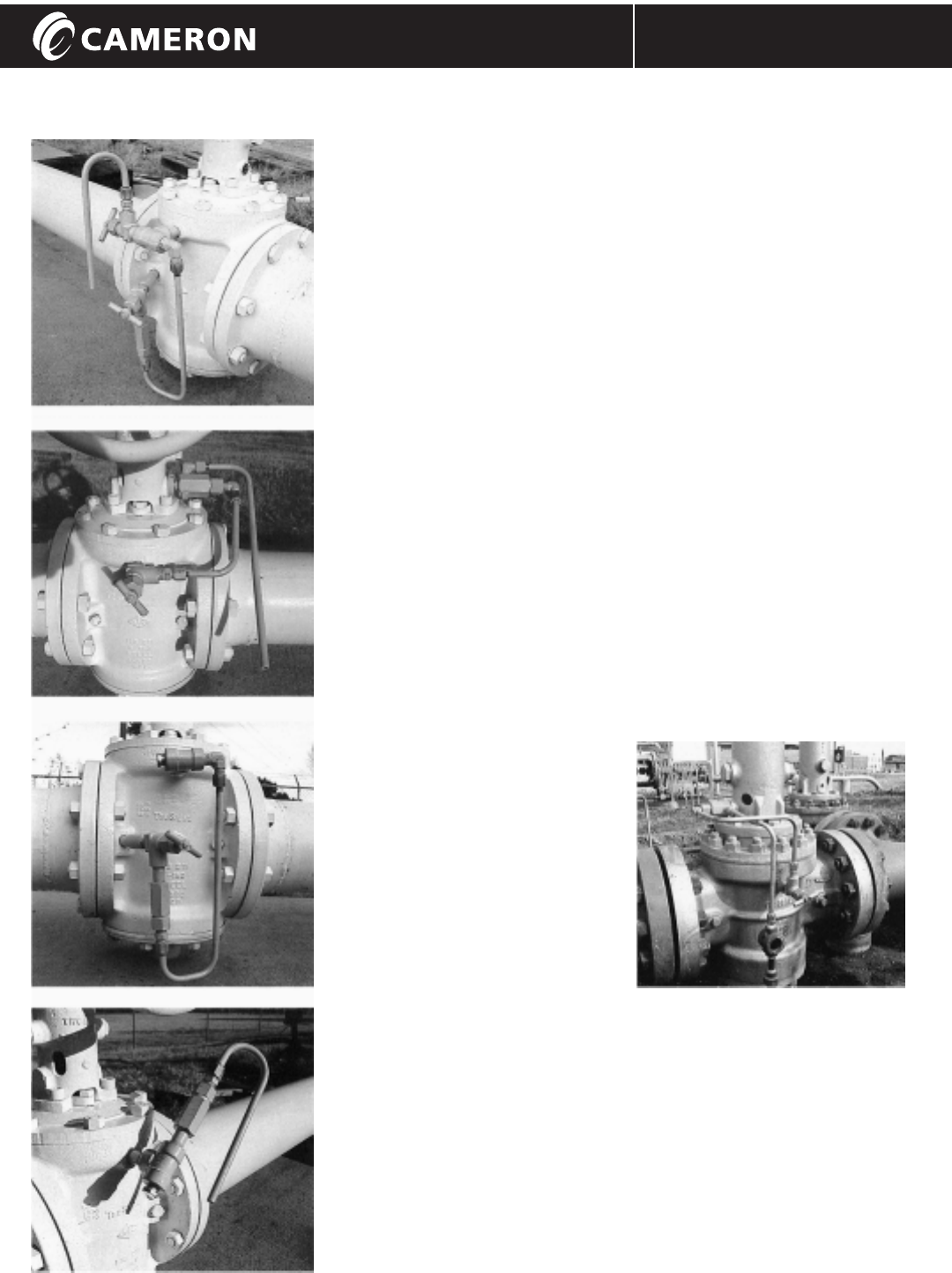
MANUAL BLEED WITH THERMAL RELIEF (MTR)
AUTOMATIC BLEED VALVE (ABV)
THERMAL RELIEF TO BODY (TRB)
THERMAL RELIEF TO ATMOSPHERE (TRA)
AUTOMATIC BLEED WITH SIGHT GLASS

PROCESS VALVES
FIELD SERVICE GUIDE
Installation, Operation, and Maintenance Manual
11
GENERAL VALVE TRUSEAL / IOM-GEN-TRUSEAL
OBSERVATION
LEAKAGE
FROM
BODY BLEED
(GENERAL TRUSEAL valve in
CLOSED position)
SUGGESTED PROCEDURE
1Check for the possibility that the
GENERAL TRUSEAL valve is not
fully closed. Do not use excessive
force to close, as this may cause
damage to the GENERAL 9$/9(
TUX6HDO.
2The dripping may be due to
thermal expansion of the liquid or
trapped vapor in the valve body,
caused by temperature rise.
If this is the case, leakage will
stop when temperature stabilizes.
3If a thermal relief and manual
bleed system is fitted, venting
back to the line, isolate the relief
valve by closing the manual
isolation valve in the GENERAL
9$/9(7UX6HDO throat. If leakage from
the manual bleed stops, refer to
instructions for the repair of a
thermal relief system on page 10.
4Close the body bleed, then fully
open and close the GENERAL
9$/9(7UX6HDO two or three times to
flush out any dirt that may have
accumulated in the valve.
5If none of the above procedures
stop the leakage, remove the
seating slips. (See instructions
on page 8). Inspect for
accumulated dirt or ice, or
damage to the soft seals.
Inspect the spaces left by the
removal of the slips to ensure
they are clean. If the seals are
cut or damaged, replace with
new slips. Install the cleaned or
new slips and fit a new gasket
and body O-ring before
replacing the lower plate.
OBSERVATION
LEAKAGE FROM
AUTOMATIC BLEED
VALVE (ABV)
(GENERAL TRUSEAL valve in
OPEN position)
SUGGESTED PROCEDURE
1Close the isolation valve on the
GENERAL 9$/9(7UX6HDO body.
2Check to see if the plunger of
the ABV is free to move.
A screwdriver blade can be
inserted through the cut-out hole
in some operators to depress
the ABV plunger. Otherwise,
continue with steps 3-5 below.
3Open the isolation valve on the
GENERAL 9$/9(7UX6HDO body.
4Stroke the GENERAL9$/9(7UX6HDO
open and closed two or three
times to flush out any dirt that
may have accumulated in the
ABV seal area.
5If the ABV still does not operate
properly, remove the ABV and
clean or replace it. Refer to
instructions on page 10.
OBSERVATION
GENERAL
TRUSEAL VALVE
WILL NOT OPEN
(DO NOT USE
EXCESSIVE FORCE!)
SUGGESTED PROCEDURE
1Check for a "pressure lock" condition
by venting the body cavity, relieving
excess pressure.
2If a thermal relief is fitted, check that
the isolation valve on the throat of
the GENERAL 9$/9(7UX6HDO is open,
allowing the thermal relief system to
operate.
3Drive out the coupling pin (part
no. 77 or 78). Try to actuate the
operator only. If the handwheel still
does not move, there is a problem
with the operator mechanism.
Read the instructions on operator
inspection, page 13. If the
handwheel moves easily, the
stiffness is in the valve body section.
4Remove line pressure and vent the
GENERAL9$/9(7UX6HDO body cavity
pressure. Refit the coupling pin.
Remove the yoke housing bolts
(part no. 45), the flag indicator
(part no. 38) and the cam pins (part
no. 27). Now turning the handwheel
will lift the operator housing upwards,
exposing the packing gland. Lift the
housing enough to allow a wrench
to fit onto the packing gland bolts.
Loosen the packing gland bolts one
turn. Reassemble the operator and
turn the handwheel. If it now moves
easily, the stiffness could have been
caused by excessive swelling of the
stem packing, resulting in the tight
gripping of the plug stem.
Consult Cameron for advice on
suitable stem packing material, if
packing swelling appears to be a
problem. Do not restore line
pressure to the valve until the
packing gland bolts are tightened.
5If there is no release of stiffness,
the valve must be isolated from
service. Remove the lower plate
and slips (refer to instructions on
page 8) to determine the cause of
the stiffness inside the valve body.
See "CAUTION", page 9.
12
Installation, Operation, and Maintenance Manual
FIELD SERVICE GUIDE
GENERAL VALVE TRUSEAL / IOM-GEN-TRUSEAL
2%6(59$7,21
*(1(5$/9$/9(
7586($/9$/9(
:,//127&/26(
(DO NOT USE
EXCESSIVE FORCE!)
SUGGESTED PROCEDURE
1Remove the operator yoke housing
bolts (part no 45). If handwheel
rotation now causes the housing to
lift upwards easily, then the operator
is functioning correctly. If the operator
handwheel does not rotate easily,
then skip to procedure number 8.
2Look for stiffness in the body section.
Restore the bolts to the yoke housing,
then follow the seal inspection
instruction on page 8. Omit the
instruction to close the valve. Take
special care to support the weight of
the lower plate and slips, as lower
plate nuts are removed.
3Look for dirt accumulated below the
plug that could prevent downward
movement.
4Look for compacted sand and
pipe-scale on the face of the seating
slips that could prevent the soft seals
from touching the body.
5Look for accumulated sand or scale
or ice in the trunnion hole of the
lower plate.
6Look for corrosion or excessive
deposits of hard material in the
dovetail region between slips and
plug. Remove any deposits with
a wire brush and investigate the
cause of the deposit.
7Look for blockage of the relief
holes in plug trunnion bushing
(part no. 7, page 4).
8If the removal of yoke housing bolts
(in section 1 this page), did not free
the handwheel movement, do not
remove the operator, or the plug
may drop while in the "Open"
position. With the operator still
mounted on the valve, follow the
instructions for "Operator Inspection",
page 13, to determine the cause of
stiffness.
CAUTION:
WHEN DISMANTLING ANY
MECHANICAL ASSEMBLY,
TAKE CARE TO KEEP
HANDS AWAY FROM ANY
PARTS THAT MAY
SUDDENLY MOVE WHEN
THE RETAINING FORCE
IS REMOVED.
USE SUPPORTS FOR ANY
PARTS THAT COULD MOVE.
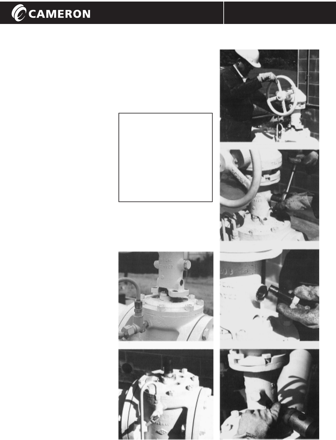
OPERATOR BOLTS REMOVED HOUSING LIFTED
CAM PIN REMOVAL
CAM PIN INSPECTION
COUPLING PIN REMOVAL
PACKING GLAND BOLTS EXPOSED
VALVE WITH OPERATOR REMOVED
PROCESS VALVES
OPERATOR INSPECTION
Installation, Operation, and Maintenance Manual
13
GENERAL VALVE TRUSEAL / IOM-GEN-TRUSEAL
1Look for ice, dirt, or foreign objects
that may interfere with free
movement.
2Remove the cam pins (part no. 27)
one at a time and inspect for
damage or excessive wear. See
information on cam pin change on
page 9. Replace each pin before
removing another one.
3Replace with new pins if necessary
and investigate the cause of
damage. Excessive force at the
handwheel may be the cause.
4Remove the handwheel and
bearing assembly from the top of
the operator. Take special care
when slackening thrust bearing
retainer bolts (part no. 41), in case
the bearing is under a load
condition. Check that the threads
of the stem (part no. 25) turn freely
in the matching threads of the
drive nut or cam (part no. 24).
If there has been any thread
damage, replace both stem and
drive nut or cam.
5Inspect thrust bearing (part no.91)
for possible damage. Replace if
necessary.
6Gear housing, stem threads and
guide pin slots are grease packed
during manufacture. Re-packing
with grease, after dismantling, is
required.
7When the operator has been
removed from a GENERAL
9$/9(7UX6HDO valve, the lower plate
MUST NOT BE REMOVED without
first ensuring that the plug is firmly
held by its upper stem. There is
a coupling hole through the upper
stem, to which support may be
attached.
Operators can be safely removed
from GENERAL9$/9(7UX6HDO valves
while the pipeline system is under
full rated pressure and the valve is
in the closed position.
If the Field Service Procedures
indicate a stiffness in the
operator, follow this sequence
of inspections until the problem
is identified.
200 Series Operator 400 Series Operator

®
GENERAL VALVE
© Cameron’s Valves & Measurement Group Printed in Canada Revised 10/07-NP-3M IOM-GEN-TRUSEAL
3250 Briarpark Drive, Suite 300
Houston, Texas 77042
USA Tel 281 499 8511
For the more information on GENERAL VALVE: www.c-a-m.com/GENERALVALVE
Contact your Cameron’s Valves & Measurement group representative for a Repair Manual
I
PROCESS VALVES
Installation, Operation, and Maintenance Manual GENERAL VALVE TRUSEAL / IOM-GEN-TRUSEAL
