P MU GK S Gk300 User Guide
gk300-UserGuide gk300-UserGuide
gk300-UserGuide gk300-UserGuide
User Manual: gk300-User Guide
Open the PDF directly: View PDF ![]() .
.
Page Count: 2
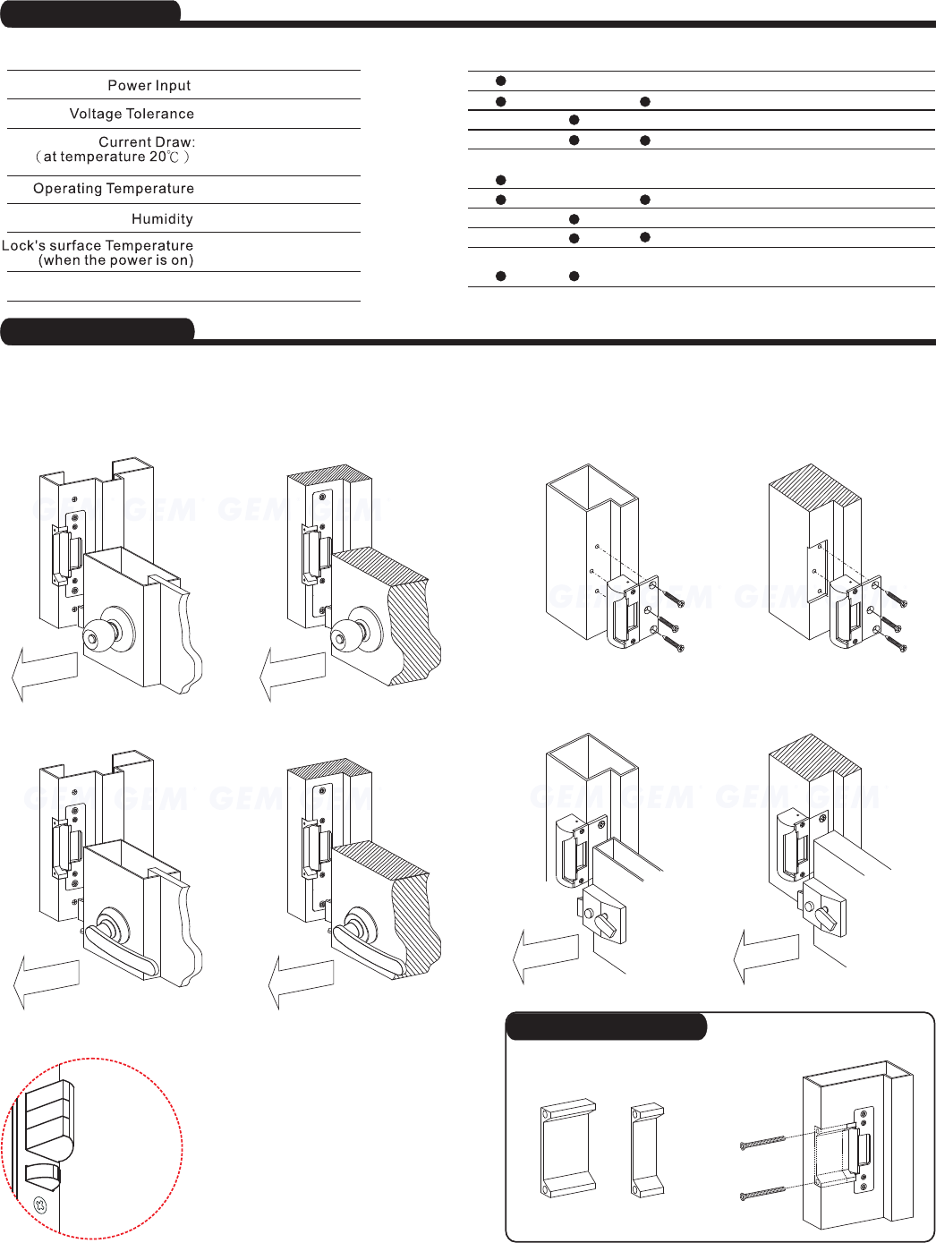
Electric Strikes Installation Instruction
GK-300 Series ANSI Sized Electric Strikes
Specifications
Important Notes
Copyright Gianni Industries, Inc. All Rights Reserved.
Ver. G Publish:2008.07.30P-MU-GK-S
12VDC ( or 24VDC )
LP-025, LP-050
15%±
250mA@12VDC
150mA@24VDC
-10~+45℃
Hollow metal
Frames
Wood
Frames
Flush Mounting Spring latch
Spring latch
Spring latch
Spring latch
Nib
Nib
Nib
Nib
Night Latch
Flush Mounting
Flush Mounting
Flush Mounting
Flush Mounting
Flush Mounting
Flush Mounting
Flush Mounting
Surface Mounting
GK-300
GK-300M
GK-301
GK-301M
GK-310
GK-310M
GK-311
GK-311M
GK-350
Optional
Switch
Monitored
Application
Locksets
Installation
0~95%
≦
℃
current
temp. +20
GK-300, GK-300M GK-350
What's Latch bolt lock ?
GK-301, GK-301M GK-350
GK-311, GK-311M
Wood Frames Wood Frames
Wood Frames
Hollow Metal Frames Hollow Metal Frames
The GK-300 series electric strikes are designed for use with cylindrical locks and mortise locksets (without deadbolt) having up to
12mmthrowlatchbolt.
In-swinging
In-swinging
In-swinging
In-swinging
In-swinging
In-swinging
GK-310, GK-310M
Hollow Metal Frames
dead-latch dead-latch
Night Latch
Night Latch
Latch bolt
Nib
A latch-bolt lock that is a lock
equipped with a Nib and a latch bolt.
When the door is closed, the Nib will
make the latch bolt a dead latch, and
latch bolt will slide from door into
frame and momentarily fills into the
cavity of strike keeper that
preventing the door from opening or
the latch bolt from jimmying. The Nib
This security feature is more suitable
for outward opening doors.
Lip extension brackets for wide jamb
LP-050 LP-025
Optional Bracket
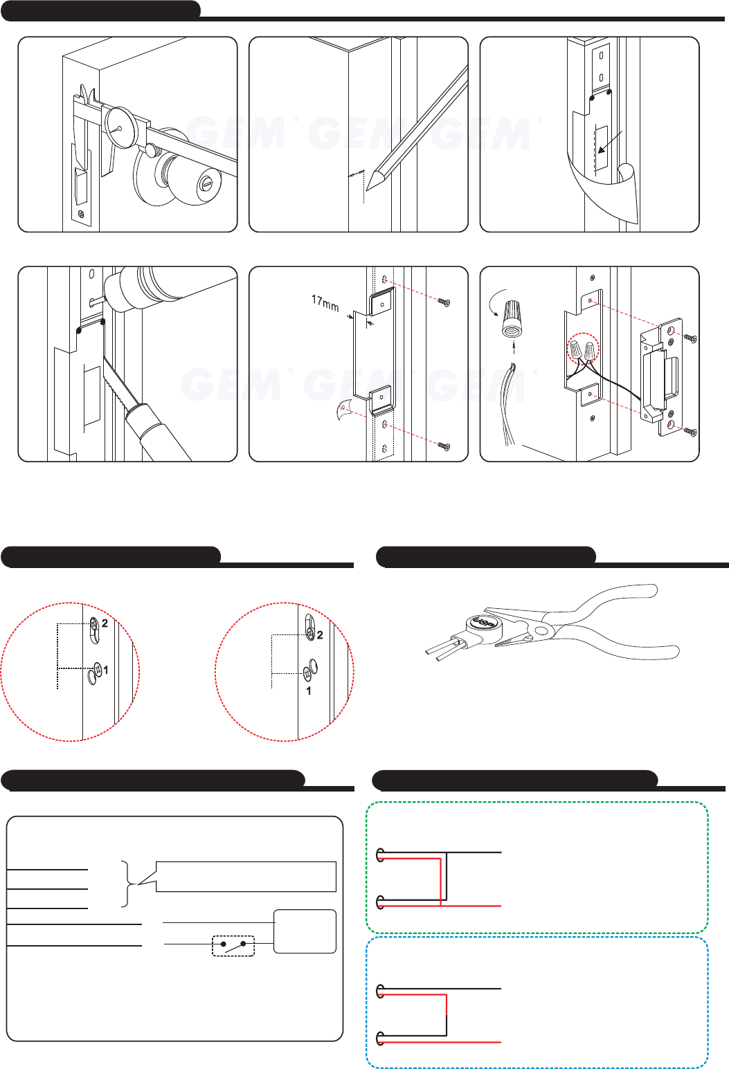
Installation Instructions
(2)
Mark latch position line
(3)
Stick template align to marked latch line
(4)
Hole cut using template
(5)
Fixing plug
(6)
Connect wires and insulate
before install strike.
Measure latch position
(1)
(Polarity Free)
Caution:
Strike is not re-locking or is not unlocking, please check for proper alignment between strike keeper and latch bolt,
realign faceplate if necessary.
How to Change Version ? Butt Splice(IDC) Connector
+
+
-
-
N.C.
COM.
N.O.
Power
supply
Control Device
N.C. contact or Access Relay for "Fail-safe" setting
N.O. contact or Access Relay for "Fail-security" setting
Sensor Switch monitoring output
, rating 2Amp@125V~
Green
Yellow
Blue
White, Red(24VDC)
White, Red(24VDC)
Field reverse by changing position of screws
Using crimper or pliers and pressing the header
connector down to even positionof
"Fail-Safe"
(Power to Lock)
"Fail-Secure"
(Power to Open)
12V DC
(Power input is polarity free)
24V DC
(Power input is polarity free)
For the 12 VDC operation, the electric strikes have to
connect .in Parallel
For the 24 VDC operation, the electric strikes have to
connect .in series
Black
Black
Black
Black
Black
Black
Red
Red
Red
Red
Red
Red
Dual voltage Connecting DiagramSingle voltage Connecting Diagram
Copyright Gianni Industries, Inc. All Rights Reserved.
Ver. G Publish:2008.07.30P-MU-GK-S
