GROVE B8 Fully Welded Body Ball Valves Valve Brochure
User Manual: Resource Library
Open the PDF directly: View PDF ![]() .
.
Page Count: 34

GROVE B8
Fully Welded Body Ball Valves


2
Table of Contents
GROVE B8 FULLY WELDED BODY BALL VALVES
Overview and Applications ............................................................................1
Range of Production .....................................................................................1
GROVE B8, B8a AND B8.1
Design Features ......................................................................................2
Body, Ball and Stem Construction ..........................................................3
Seat Design ............................................................................................4
Additional Standard Features and Maintenance ......................................5
Optional Features ...................................................................................6
Special Applications ................................................................................7
GROVE B8.1
Materials Selection .................................................................................8
Valve Assembly and Cross Section ..........................................................9
Dimensions and Weights ........................................................................10
GROVE B8 AND B8a
Materials Selection ..................................................................................14
Valve Assembly and Cross Section ...........................................................15
GROVE B8 Dimensions and Weights .......................................................16
GROVE B8a Dimensions and Weights .....................................................23
QUALITY SYSTEM AND QUALIFICATION TESTING ..........................................27
CAMSERV SERVICES FOR VALVES AND ACTUATION......................................28
TRADEMARK INFORMATION .........................................................................29

3
GROVE B8 Fully Welded Body Ball Valves
OVERVIEW AND APPLICATIONS
RANGE OF PRODUCTION
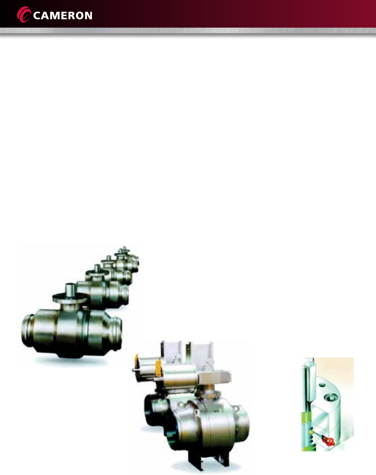
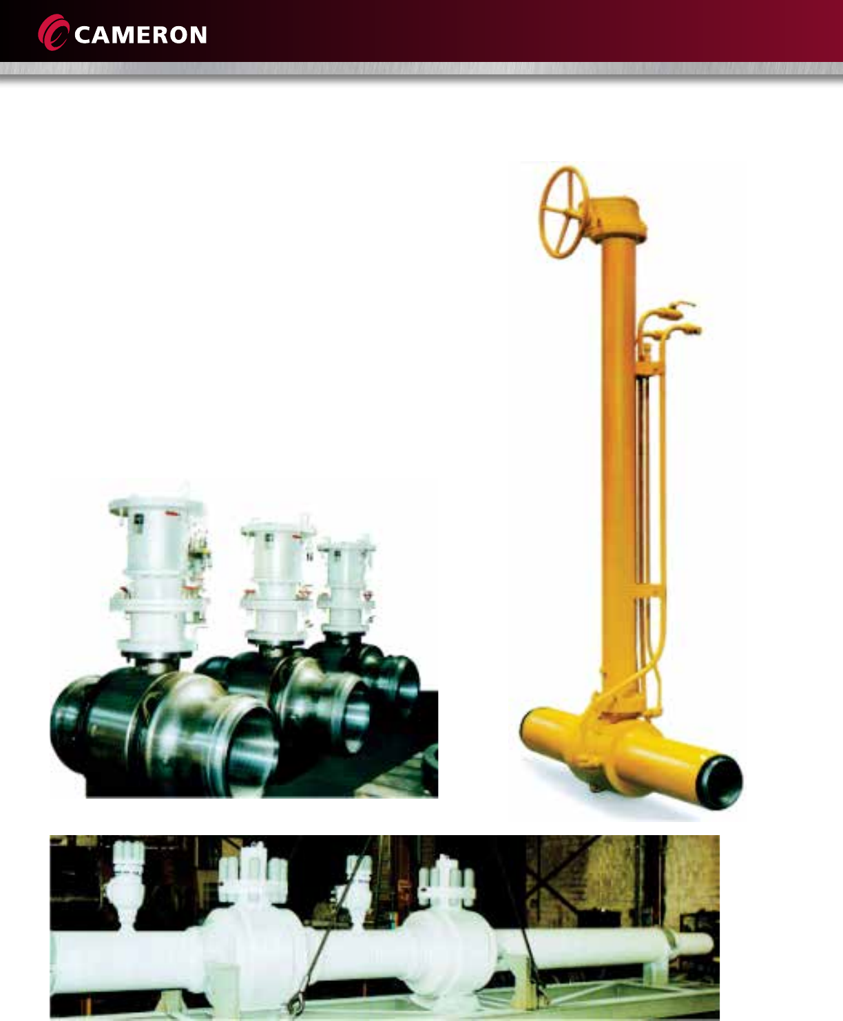
Cameron’s GROVE® B8 valve is a fully welded body design
which reduces the number of potential leak paths and is
fully compliant with ISO 14313/API 6D.
The welded body configuration allows for considerable
reduction in weight, especially in short pattern (B8a) weld
end by weld end (WE x WE) configurations. The B8
design is well-suited for several applications and is
available in optional high-alloy trims. The B8 ring forged
design is ideal for severe applications in high-pressure and
corrosive service and can be trimmed to meet exact
customer specifications. The B8a is the same as the B8,
except it indicates a WE x WE configuration with end-to-
end length shorter than standard ISO 14313/API 6D WE x
WE published dimensions.
The B8 fully welded body ball valve is engineered for
heavy-duty, maintenance-free performance.
It is commonly selected for a number of applications,
including:
• Gas transmission
• Gas separation systems
• Compressor stations
• Products pipeline
• Natural gas storage
• CO2 services
• Measurements skids
• Dryer Service
• Offshore and subsea applications
• Dehydration systems
• NGL plants and pipelines
The B8 family of valves includes the B8.1 for valves 4"
(100 mm) and smaller in diameter. The B8 and B8a are
used for valves 6" (150 mm) in diameter and larger.
Differences in this catalog will be indicated.
Size ASME CLASS
(in.) (mm) 150
300 400 600 900 1500 2500
2(50) ●●●●●●●
3(80) ●●●●●●●
4(100) ●●●●●●●
6(150) ■■■■■■●
8(200) ■■■■■■
■
10 (250) ■■■■■■
■
12 (300) ■■■■■■
■
14 (350) ■■■■■■
■
16 (400) ■■■■■■
■
18 (450) ■■■■■■
■
20 (500)
■■■■■■
■
22 (550)
■■■■■■
■
24 (600)
■■■■■■
■
26 (650)
■■■■■■
28 (700) ■■■■■■
30 (750) ■■■■■■
32 (800) ■■■■■■
34 (850) ■■■■■■
36 (900) ■■■■■■
38 (950) ■■■■■
40 (1000) ■■■■■
42 (1050) ■■■■■
48 (1200) ■■■■■
54 (1350) ■■■■
56 (1400) ■■■■
60 (1500) ■■■■
B8.1
●
B8
■
4
DESIGN FEATURES
Standard Features
The B8.1 is a welded-body, forged-steel trunnion valve,
covering sizes 2" (50 mm) through 6" (150 mm) (reduced
bore) in ASME pressure classes 150 through 2500.
The B8 is a welded-body, forged-steel, trunnion bearing
block valve, covering sizes 6" (150 mm) through 60"
(1500 mm) in ASME pressure classes 150 through 2500.
• Body construction – Body is made from three forged
parts, and the all-welded construction reduces leak
paths to the environment and is available in a wide
selection of materials
• Trunnion mounted ball
• Triple-barrier stem seals
• Stem separate from ball
• Anti blowout stem design
• Low-friction, metal-backed, self-lubricating PTFE
sleeve bearings and thrust washers reduce torque and
extend service life
• Primary metal, secondary soft (PMSS) – Metal-to-
metal seat to ball seal and secondary protected
O-ring seal in the B8 and B8a
• Plastic polymer insert for soft sealing in the B8.1
• Double piston effect (DPE) – Double-barrier sealing in
both directions in the B8 and B8a
• Single piston effect (SPE) – Provides sealing from
pipeline direction in the B8.1
• Block-and-bleed and double block-and-bleed
• Cavity-relief valve for overpressure due to liquid
thermal expansion in the B8 and B8a
• Stem and seat sealant injection system
• Factory-positioned external stops
• Integral stop in the adapter plate for a permanent
reference to open and closed positions
• Electroless nickel plating (ENP) on pressure-controlling
parts and stem
• Bearing block trunnion design on B8 and B8a
Optional Features
• Self-relieving seat rings for B8 and B8a
• Soft seats (polymer inserts) for B8 and B8a
• Spring-energized gaskets, made of PTFE with various
grades of fillers, for stem and seats (lip seals for DPE
seats)
• Metal-to-metal seat sealing
• Stainless or Inconel overlay in critical sealing areas
• Antistatic device
• Cavity-relief valve for overpressure due to liquid
thermal expansion in the B8.1
• Stem extensions
• Transition pieces
• Fully welded bonnet
Standards of Compliance
• ISO 14313/API 6D
• ASME B16.34
• ISO 17423/API 6DSS
• API 6FA and API 607*
• ISO 15156/NACE MR0175**
* Contact Cameron for specific information.
** Materials of construction are in compliance within the limits of use
defined by ISO 15156
NACE MR0175.
GROVE B8, B8a and B8.1
5
BODY, BALL AND STEM CONSTRUCTION
Body Construction
The body utilizes rolled ring forgings, which are available
in a large array of materials, making the B8 well-suited
for special applications as well as standard service. The
body is made from three forged parts, and its all-welded
construction has fewer leak paths than traditional ball
valves. A cavity-relief valve is installed in the body to
relieve any overpressurization encountered during service
or testing (optional in the B8.1). Integrity of sealing
surfaces can be monitored without pressure in the
pipeline by pressurizing the body cavity (optional in the
B8.1).
All welding processes for the body are suited to the
materials of construction and are qualified and performed
according to ASME Section IX. Non-destructive tests
(NDTS) are performed per ASME VIII Division 1, App. 12
on the circumferential weld joints of the body.
The compact shape of the body allows for the easy
absorption of the bending loads coming from the
pipeline.
Trunnion Mounted Ball Construction
The B8 and B8a (>4" or 100 mm) have a bearing block
design that absorbs the pressure end load (side load) for
the stem, reducing torques and allowing gearboxes and
actuators to be sized smaller than competing valves of
the same size and working pressure.
The B8.1 (2" to 4" or 50 to 100 mm) utilizes a traditional
trunnion mounted ball with torques significantly less than
floating ball valves. The ball rotates on a pair of self-
lubricated bearings.
The side load, produced from the line pressure against
the closed ball, is totally absorbed by the body through
the upper and lower bearing retainers.
The slot and tongue connection between the ball and
stem is designed to reduce stresses in the stem and ball.
Stem Construction
The stem of the GROVE B8 has an anti-blowout design
that prevents ejection of the stem when the valve is under
pressure. The combination of the rugged stem and ball
design provides this in compliance with ISO 14313/API 6D
requirements. The stem features triple-barrier seals to
isolate the stem from line pressure and to seal from the
atmosphere.
Low-friction, metal-backed, self-lubricating PTFE sleeve
bearings and thrust washers reduce stem torque and
extend service life of the valve. The stem function by
design is to only transmit torque required to operate the
valve.
The absence of a side load on the stem ensures low
operating torque and long life.
6
SEAT DESIGN
Seat Seal
The floating seats are free
to move slightly along the
longitudinal axis of the
bi-directional valve. The
initial seal at extremely
low pressure differential,
or vacuum conditions, is
obtained through the
force of the springs acting
on the floating seats. Line
pressure, behind the seat ring, supplements the seat
spring load to force the seat tightly against the ball.
The sealing is performed by PMSS seat to ball in the B8
and B8a. The soft sealing between the seat and the ball is
achieved by an elastomeric O-ring, plastic O-ring, or
insert, depending on the service conditions. In the B8.1,
the seat seal is a soft polymeric seal.
A secondary sealant injection system is provided for
emergency seat sealing. In addition to the seat injection
fittings, a check valve installed in the body prevents
escape of the internal fluid.
Double Piston Effect (DPE) Seat Design
The GROVE B8 seat design allows for both seats to seal
with pressure acting from the same side of the valve.
With line pressure in the body cavity, or in the event of
one seat becoming damaged, the user has the added
advantage of the opposite seat sealing.
There is a double barrier in both directions. Sealing is
ensured regardless of the direction of flow through the
valve. The upstream seat (1) becomes damaged and leaks,
and pressures entering the body cavity act on the
downstream seat (2), sealing the downstream seat tightly
against the ball.
NOTE: The DPE feature and the double block-and-bleed
(DBB) feature are not to be confused with one another.
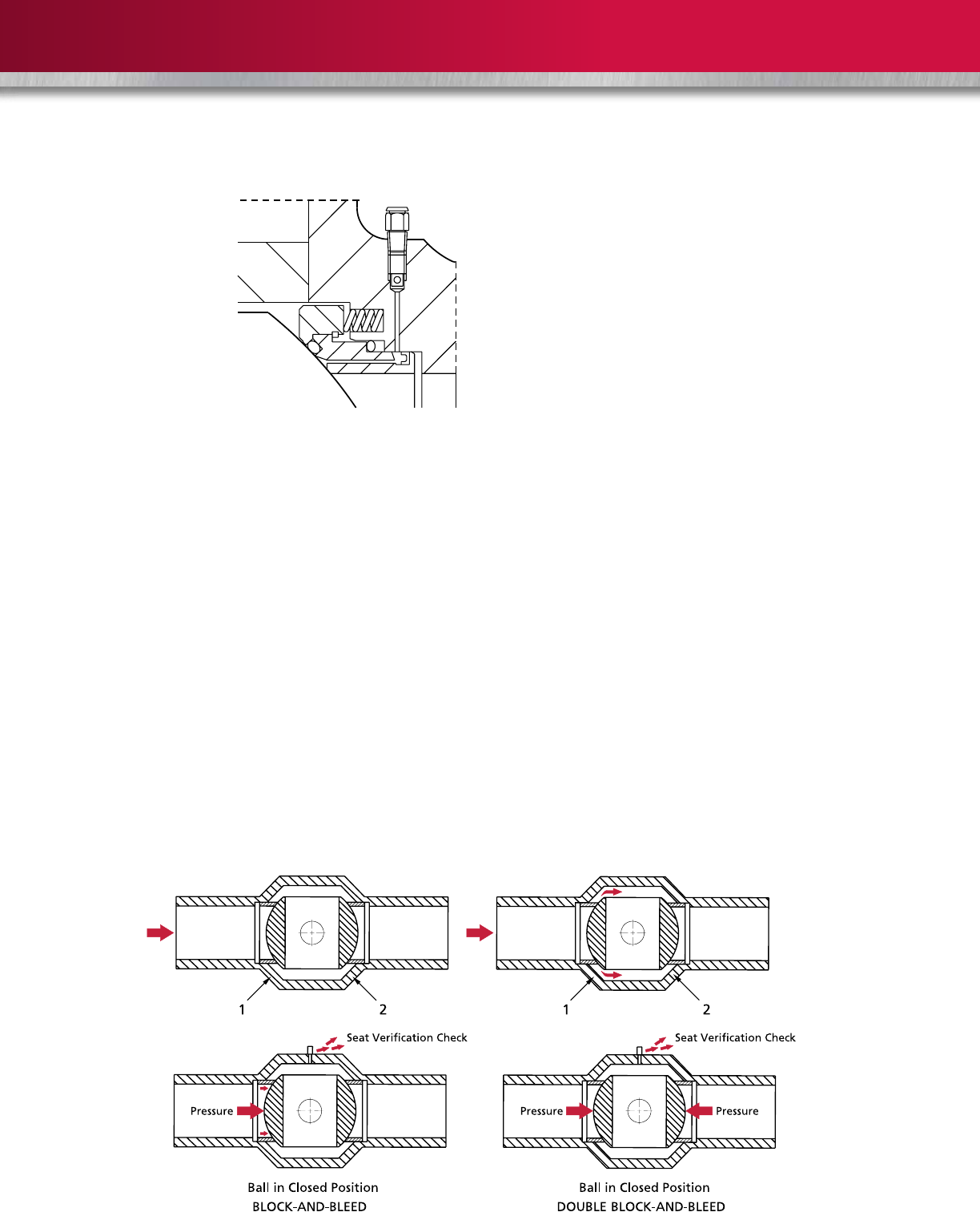
Double Block-and-Bleed/Block-and-Bleed
The double block-and-bleed and block-and-bleed features
are used to ensure valve integrity and to safeguard
downstream work.
Block-and-Bleed – With the ball in a closed position and
the pressure applied to one side of the ball, the liquid/gas
can be relieved through the drain valve in the body shell.
The block-and-bleed feature is standard on the B8, B8a
and B8.1 valves.
Double Block-and-Bleed – A single valve with two
seating surfaces that, in the closed position, provides a
seal against pressure from both ends of the valve with a
means of venting/bleeding the cavity between the seating
surfaces (ISO 14313/API 6D). The double block-and-bleed
feature is standard on the B8, B8a and B8.1 valves.
Double Isolation-and-Bleed – A single valve with two
seating surfaces, each of which, in the closed position,
provides a seal against pressure from a single source, with
a means of venting/bleeding the cavity between the
seating surfaces (ISO 14313/API 6D). The double isolation-
and-bleed feature is standard on the B8 and B8a with
DPE seats.

7
ADDITIONAL STANDARD FEATURES ADN MAINTENANCE
Ball Position
The ball open and closed positions are ensured by
factory-positioned stops and provide clear indication of
ball position. A valve provided with a manual gearbox or
actuator assembled to the valve will utilize the actuator
stops as primary stops.
Actuation
All GROVE B8 and B8a valves are manufactured with an
adapter plate to enable fitting of electric, hydraulic or
pneumatic actuators. The mounting of actuators on new
valves is performed at the manufacturing plant, ensuring
the integrity of the completed assembly. However, it can
be performed in the field, if required. A B8 or B8a manual
valve can be converted to accept an actuator.
Coating Processes
Internal trim parts (balls, seats and stem) are plated with
an electroless nickel plating (ENP) as a standard. The
process provides corrosion resistance and low wear to the
parts during operation.
Cameron operates its own in-house ENP facility, and strict
quality control procedures for critical process conditions
and for plated components maintain plating consistency.
Depending on the type of fluid, Cameron offers a variety
of corrosion-resistant and hard overlays that can be
applied in the critical sealing areas. All coating and plating
procedures are supported by detailed procedures.
Fire Safe
Standard GROVE B8 fully welded body ball valves are fire
safe to API 6FA and API 607. Contact Cameron for
specific information.
Maintenance
Even if the welded body construction precludes job site
disassembly, some maintenance operations can be
performed. A complete replacement of the stem, gland
plate and stem seals can be achieved with the valve
installed in the line without pressure.
Secondary sealant injection fittings are standard on the
B8 and B8a welded body valve and are to be used to
provide emergency seat sealing. Sealant also can be
injected into the stem sealing area through a standard
injection fitting to allow for temporary sealing.
Flushing through the relief valve port and drain valve
connections is possible, provided that there is no pressure
in the line.
Note: Sealant is not required for the normal operation of
the valve.
8
OPTIONAL FEATURES
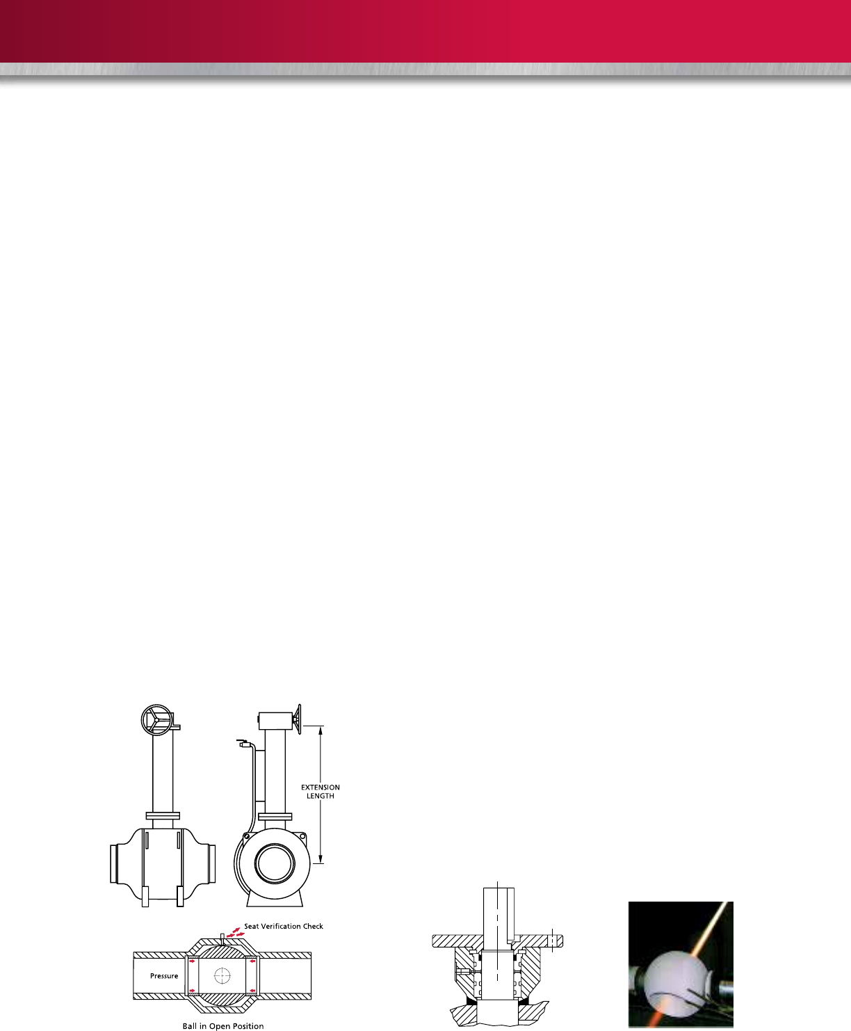
Stem Extensions
Stem extensions are easily fitted to GROVE B8 fully
welded body ball valves, making the valve suitable for
inaccessible areas or buried service.
The drain and secondary sealant injection system are, as a
standard, piped to the top of the extension for ease of
operation. When ordering extensions, specify the distance
required from the valve centerline to the top of the
mounting flange.
Double Block-and-Bleed (Fully Open Position)
This option is required to give the field operator the ability
to test the seat’s sealing condition.
With the ball in the open position and the pressure in the
line, the liquid/gas trapped in the body cavity can be
drained/relieved through the drain valve. Once fully
drained, the seat sealing can be evaluated.
ATTENTION: This is an optional feature; the request must
be specified at the bid stage.
Transition Pieces
Cameron can weld transition pieces to the valve during
the manufacturing process. Transition pieces can be
supplied by the customer or provided by Cameron to
meet customer requirements. Qualified weld procedures
are used to weld transition pieces to the valve end
connection(s).
Fully Welded Bonnet
If requested, the GROVE B8 fully welded body ball valve
can be supplied with the fully welded bonnet. This design
further reduces possible leak paths.
Metal-to-Metal Seats
The sealing surfaces between the seat and ball can be
completely metallic. This trim is recommended whenever
the standard seating is not suitable because of the
unfavorable combination of pressure, temperature,
chemical composition of the fluid, or when solids or
abrasive particles are present.
Metal-to-metal seats utilize a coating on the ball and
seats that is applied by means of high-velocity oxygen
fueled (HVOF) using tungsten carbide or Stellite powders.
The most suitable materials are selected based on the
specific service the valve is intended for.
Cameron operates its own in-house HVOF process for the
supply of quality metal-to-metal seated valves.
Additional Optional Features
The following additional options also are offered on the
GROVE B8 fully welded body ball valve:
• Self-relieving seats (B8 and B8a)
• Soft seats (polymer inserts) for B8 and B8a
• Spring-energized gaskets, made of PTFE with various
grades of fillers, for stem and seats (lip seals for DPE
seats)
• Stainless or Inconel overlay in critical sealing areas
• Antistatic devices
• Cavity-relief valve for overpressure due to liquid
thermal expansion on the B8.1
9
SPECIAL APPLICATIONS
Subsea Service
A valve specified for subsea service accounts for the
critical need for corrosion protection of both internal and
external surfaces, as well as providing a rugged and
durable product designed to withstand the harsh service
conditions expected in subsea service.
Cameron has the capability to provide a valve package,
including the valve, actuator and transition pieces fully
assembled, tested and inspected.
Sour Gas Service
A careful selection of materials is provided: carbon steel
with low sulfur content, weld metal and heat affected
zone (HAZ) hardness within ISO 15156/NACE MR0175
limits, UT and LP non-destructive examination and
appropriate selection of seal materials.

10
Pressure Retaining Parts
Body A350 LF2, A182 F316L, A182 F51
Stem / Tru nnion AISI 4140, A564 Gr. 630 (17-4 PH), Alloy 718, Duplex and Superduplex
Capscrews A193 B7, A193 B7M, A320 L7, A320 L7M
Internal Parts
Ball A350 LF2, A105, AISI 4140, A182 F316, 17-4 PH, Duplex and Superduplex, Alloy 625, Alloy 718
Seats A350 LF2, A105, AISI 4140, A182 F316, 17-4 PH, Duplex and Superduplex, Alloy 625, Alloy 718
Springs AISI 302, Inconel (Different Grades), Elgiloy
Sealing Materials
Stem Gasket NBR (Nitrile)
FKM (Viton, Various Grades Available)
HNBR (Hydrogenated Nitrile)
Seat/Body Gasket NBR (Nitrile)
FKM (Viton, Various Grades Available)
HNBR (Hydrogenated Nitrile)
Seat/Ball Gasket PTFE
Nylon
PEEK
PCTFE
Plating/Coating
25 microns (0.001") Electroless Nickel Plating (ENP)
75 microns (0.003") Electroless Nickel Plating (ENP)
120 microns (0.0045") Tungsten Carbide Coating
Alloy Overlay
Seal Area AISI 316L, Alloy 625
Sour Service (NACE) Requirements
GROVE B8.1 fully welded body ball valves can be supplied in accordance with the material requirements of ISO 15156/NACE MR0175.
MATERIALS SELECTION
The GROVE B8.1 fully welded body ball valve has been designed
for use with various combinations of materials which are
selected depending on the customer’s service conditions.
The following is a typical listing of materials for valves in ASME
Classes 150 through 2500 for standard applications.
GROVE B8.1
11
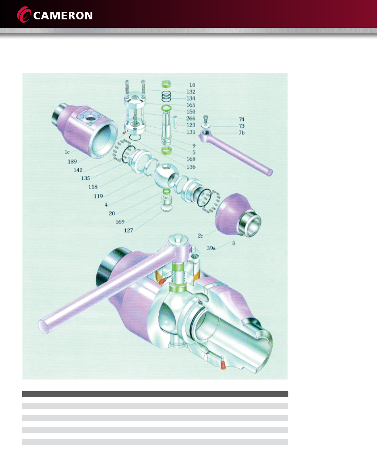
VALVE ASSEMBLY AND CROSS SECTION
Item Description Item Description Item Description
1c Body 39a Drain 136 Gland Plate O-ring
2c Closure 118 Seat Ring 142 Seat Spring
4Ball 119 Seat Insert 150 Upper Thrust Washer
5Stem 123 Stem Key 165 Bearing Housing
7b Wrench 127 Lower Trunnion Plate 168 Stem Bearing
9Top Cover 131 Gland Plate Capscrew 169 Lower Trunnion
10 Gland Bushing 132 Adapter Plate Capscrew 189 Stem Grease Fitting
20 Trunnion Bearing 134 Stem O-ring 266 Stop Pin
135 Seat Gasket O-ring
12
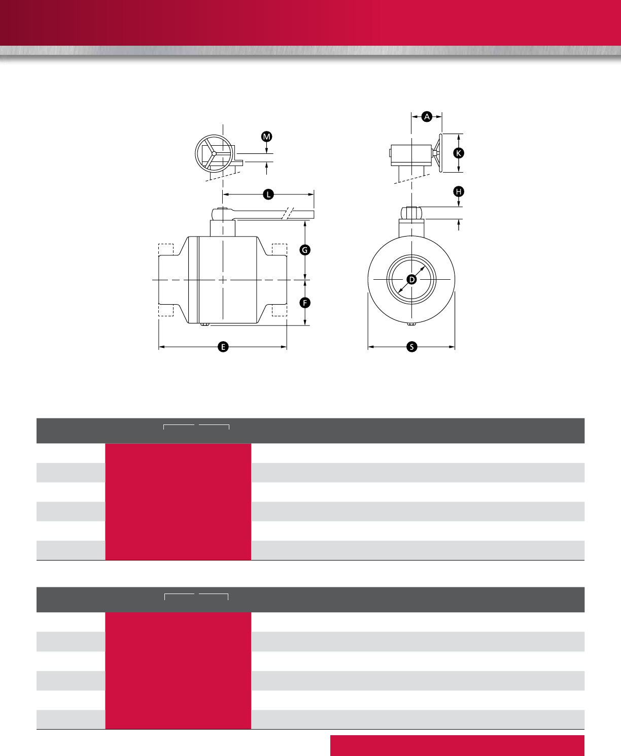
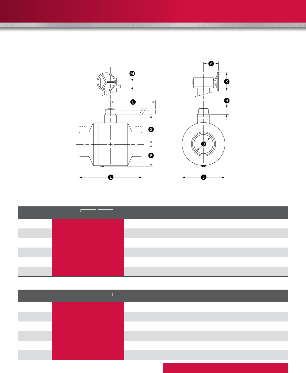
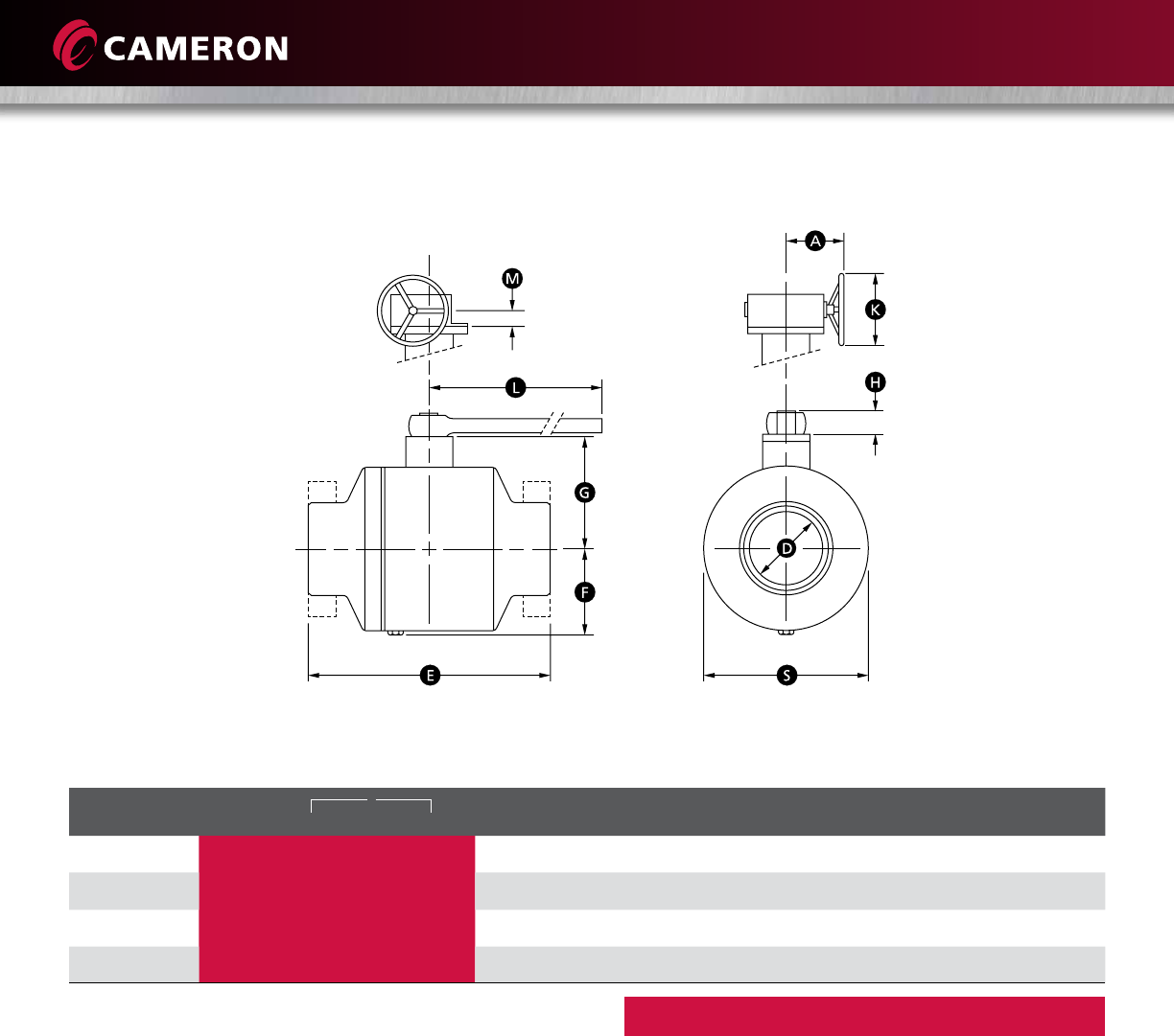
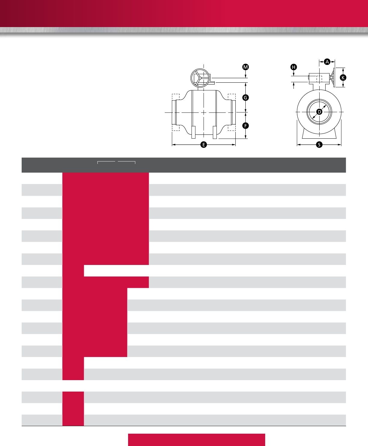
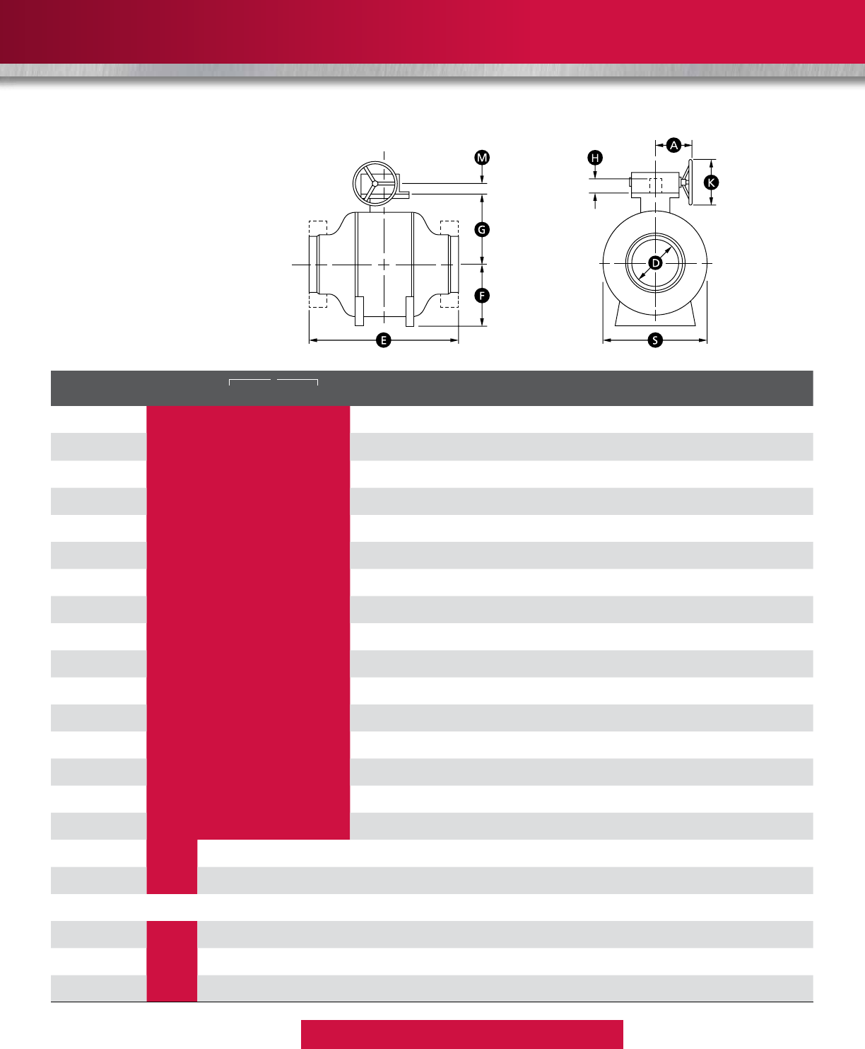
DIMENSIONS AND WEIGHTS
ASME CLASS 150
ASME CLASS 300
Flanges in accordance with ASME B16.5
Butt welding ends according to ASME B16.25
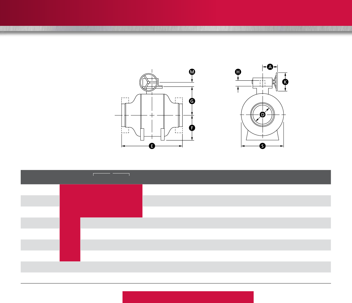
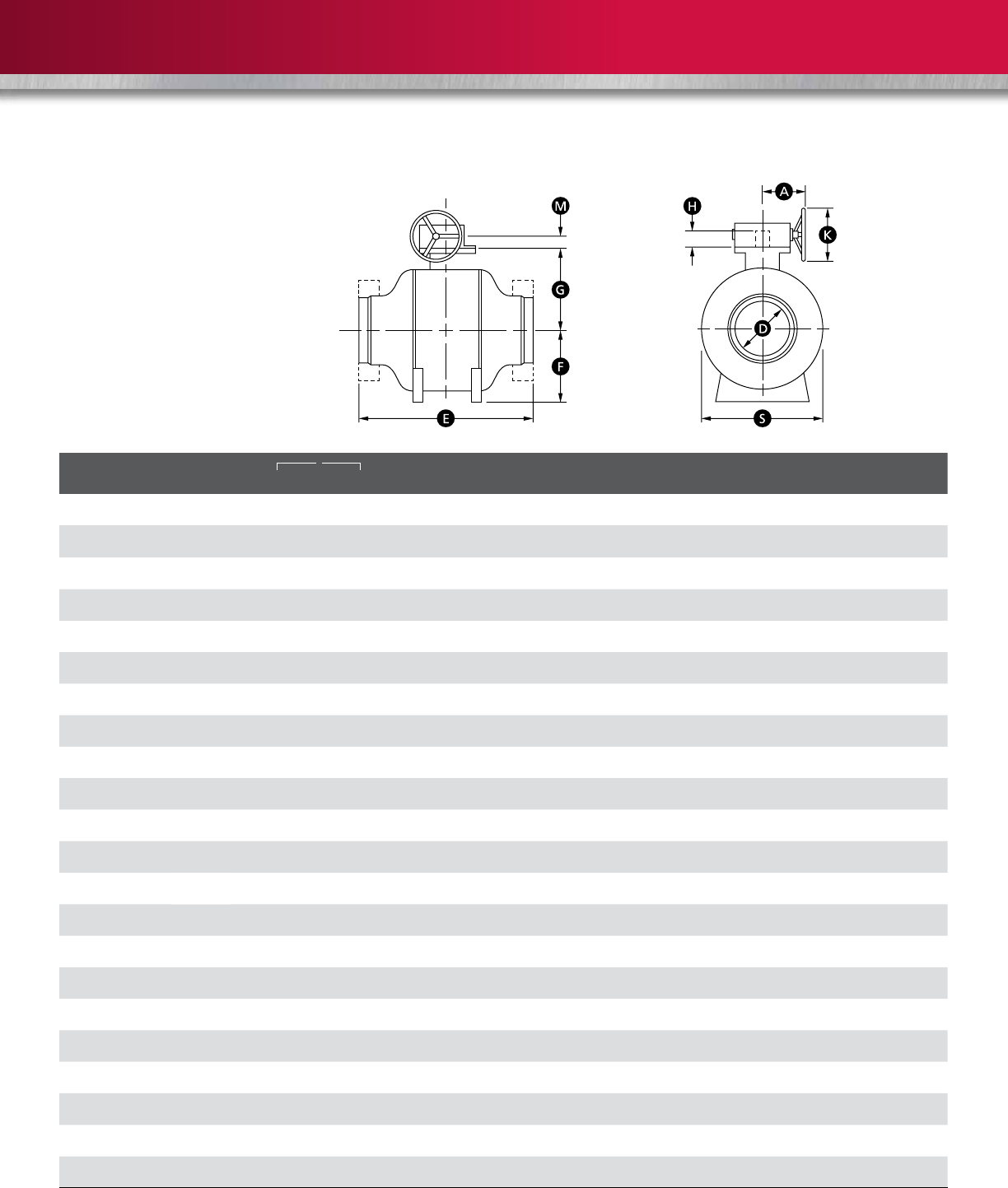
SIZE in.
D E F G S H L A K M WEIGHT lb (kg)
(mm)
WE RF RTJ WE RF/RTJ
228-1/ 2 77-1/2 3-1/4 4-1/8 6-1/4 1-3/4 12 --- 37 49
(50) (51) (216) (178) (191) (83) (105) (160) (44) (305) --- (17) (22)
3 x 2 x 3 211-1/ 8 88-1/2 3-1/4 4 -1/8 6-1/4 1-3/4 12 --- 44 55
(80 x 50 x 80) (51) (283) (203) (216) (83) (105) (160) (44) (305) --- (20) (25)
3311-1/ 8 88-1/2 4-5/8 5-1/4 8-5/8 217-3/4 --- 62 77
(80) (76) (283) (203) (216) (117 ) (133) (219) (51) (451) --- (28) (35)
4 x 3 x 4 312 99-1/2 4-5/8 5-1/4 8-5/8 217-3/4 --- 73 90
(100 x 80 x 100) (76) (305) (229) (241) (117) (133) (219) (51) (451) --- (33) (41)
4412 99-1/2 5-1/2 6-1/4 9-5/8 2-3/8 36 --- 110 139
(100) (102) (305) (229) (241) (140) (159) (244) (60) (914) --- (50) (63)
6 x 4 x 6 418 15-1/ 2 16 5-1/2 6-1/4 9-5/8 2-3/8 36 --- 132 165
(150 x 100 x 150) (102) (457) (394) (406) (140) (159) (244) (60) (914) --- (60) (75)
SIZE in.
D E F G S H L A K M WEIGHT lb (kg)
(mm)
WE RF RTJ WE RF/RTJ
228-1/ 2 8-1/ 2 9-1/8 3-1/4 4-1/8 6-3/8 1-3/4 17-3/4 --- 42 53
(50) (51) (216) (216) (232) (83) (105) (162) (44) (451) --- (19) (24)
3 x 2 x 3 211-1/ 8 11-1/ 8 11-3/4 3-1/4 4-1/8 6-3/8 1-3/4 17-3/4 --- 53 66
(80 x 50 x 80) (51) (283) (283) (298) (83) (105) (162) (44) (451) --- (24) (30)
3311-1/ 8 11-1/ 8 11-3/4 4-5/8 5-1/4 8-3/4 236 --- 75 93
(80) (76) (283) (283) (298) (117) (133) (222) (51) (914) --- (34) (42)
4 x 3 x 4 312 12 12-5/8 4-5/8 5-1/4 8-3/4 236 --- 99 123
(100 x 80 x 100) (76) (305) (305) (321) (117) (133) (222) (51) (914) - - - (45) (56)
4412 12 12-5/8 5-1/2 6-1/4 9-5/8 2-3/8 36 --- 150 187
(100) (102) (305) (305) (321) (140) (159) (244) (60) (914) --- (68) (85)
6 x 4 x 6 418 18 16-1/2 5-1/2 6-1/4 9-5/8 2-3/8 36 --- 194 243
(150 x 100 x 150) (102) (457) (457) (419) (140) (159) (244) (60) (914) --- (88) (110)
Shaded bore sizes (D) according to ISO 14313/API 6D
Shaded end-to-end dimensions (E) according to ISO 14313/API 6D
ASME CLASSES 150 AND 300
13
ASME CLASS 400
ASME CLASS 600
* Dimension on request
Flanges in accordance with ASME B16.5
Butt welding ends according to ASME B16.25
SIZE in.
D E F G S H L A K M WEIGHT lb (kg)
(mm)
WE RF RTJ WE RF/RTJ
22***3-1/4 4-1/8 6-3/8 1-3/4 17-3/4 - - - 44 55
(50) (51) ***(83) (105) (162) (44) (451) - - - (20) (25)
3 x 2 x 3 2***3-1/4 4-1/8 6-3/8 1-3/4 17-3/4 --- 55 71
(80 x 50 x 80) (51) ***(83) (105) (162) (44) (451) - - - (25) (32)
33***4-5/8 5-1/4 8-3/4 236 --- 93 117
(80) (76) ***(117) (133) (222) (51) (914) - - - (42) (53)
4 x 3 x 4 316 16 16-1/8 4-5/8 5-1/4 8-3/4 236 --- 106 132
(100 x 80 x 100) (76) (406) (406) (410) (117 ) (133) (222) (51) (914) - - - (48) (60)
4416 16 16-1/8 5-5/8 6-1/4 9-3/4 2-3/8 - * * * 168 209
(100) (102) (406) (406) (410) (143) (159) (248) (60) - * * * (76) (95)
6 x 4 x 6 419-1/2 19-1/2 19-5/8 5-5/8 6 -1/4 9-3/4 2-3/8 - * * * 212 265
(150 x 100 x 150) (102) (495) (495) (498) (143) (159) (248) (60) - * * * (96) (120)
SIZE in.
D E F G S H L A K M WEIGHT lb (kg)
(mm)
WE RF RTJ WE RF/RTJ
2211-1 / 2 11-1 / 2 11- 5 /8 3-3/8 4-1/8 6-1/2 1-3/4 24 --- 46 60
(50) (51) (292) (292) (295) (86) (105) (165) (44) (610) --- (21) (27)
3 x 2 x 3 214 14 14-1/8 3-3/8 4-1/8 6-1/2 1-3/4 24 --- 64 79
(80 x 50 x 80) (51) (356) (356) (359) (86) (105) (165) (44) (610) --- (29) (36)
3314 14 14-1/8 4-3/4 6 -1/8 8-7/8 2-3/8 - * * * 108 137
(80) (76) (356) (356) (359) (121) (156) (225) (60) - * * * (49) (62)
4 x 3 x 4 317 17 17-1/8 4-3/4 6-1/8 8-7/8 2-3/8 - * * * 150 187
(100 x 80 x 100) (76) (432) (432) (435) (121) (156) (225) (60) - * * * (68) (85)
4417 17 17-1/8 5-3/4 7-1/2 9-7/8 2-3/8 - * * * 209 262
(100) (102) (432) (432) (435) (146) (191) (251) (60) - * * * (95) (119)
6 x 4 x 6 422 22 22-1/8 5-3/4 7-1/2 9-7/8 2-3/8 - * * * 247 309
(150 x 100 x 150) (102) (559) (559) (562) (146) (191) (251) (60) - * * * (112) (140)
Shaded bore sizes (D) according to ISO 14313/API 6D
Shaded end-to-end dimensions (E) according to ISO 14313/API 6D
ASME CLASSES 400 AND 600
14
DIMENSIONS AND WEIGHTS (continued)
ASME CLASS 900
ASME CLASS 1500
* Dimension on request
Flanges in accordance with ASME B16.5
Butt welding ends according to ASME B16.25
SIZE in.
D E F G S H L A K M WEIGHT lb (kg)
(mm)
WE RF RTJ WE RF/RTJ
2214-1/2 14-1/2 14-5/8 3-1/2 4-5/8 6-7/8 2-3/8 24 - - - 88 110
(50) (51) (368) (368) (371) (89) (117) (175) (60) (610) - - - (40) (50)
3 x 2 x 3 215 15 15-1/8 3-1/2 4-5/8 6-7/8 2-3/8 24 - - 106 134 55
(80 x 50 x 80) (51) (381) (381) (384) (89) (117) (175) (60) (610) - - - (48) (61)
3315 15 15-1/8 4-7/8 6-1/8 9-3/8 2-3/8 - * * * 134 170
(80) (76) (381) (381) (384) (124) (156) (238) (60) - * * * (61) (77)
4 x 3 x 4 318 18 18-1/8 4-7/8 6 -1/8 9-3/8 2-3/8 - * * * 170 214
(100 x 80 x 100) (76) (457) (457) (460) (124) (156) (238) (60) - * * * (77) (97)
4418 18 18-1/8 67-1/2 10-3/8 2-3/8 - * * * 236 295
(100) (102) (457) (457) (460) (152) (191) (264) (60) - * * * (107) (134)
6 x 4 x 6 424 24 24-1/8 67-1/2 10-3/8 2-3/8 - * * * 335 419
(150 x 100 x 150) (102) (610) (610) (613) (152) (191) (264) (60) - * * * (152) (190)
SIZE in.
D E F G S H L A K M WEIGHT lb (kg)
(mm)
WE RF RTJ WE RF/RTJ
2214-1/2 14-1/2 14-5/8 4-1/4 4-5/8 8-3/4 2-3/8 - * * * 99 126
(50) (51) (368) (368) (371) (108) (117 ) (222) (60) - * * * (45) (57)
3 x 2 x 3 218-1/2 18-1/2 18-5/8 4-1/4 4-5/8 8-3/4 2-3/8 - * * * 128 161
(80 x 50 x 80) (51) (470) (470) (473) (108) (117 ) (222) (60) - * * * (58) (73)
3318-1/2 18-1/2 18-5/8 6-1/8 6-1/8 11-7/ 8 2-3/8 - * * * 196 247
(80) (76) (470) (470) (473) (156) (156) (302) (60) - * * * (89) (112)
4 x 3 x 4 321-1/2 21-1/2 21-5/8 6 -1/8 6-1/8 11-7/ 8 2-3/8 - * * * 229 287
(100 x 80 x 100) (76) (546) (546) (549) (156) (156) (302) (60) - * * * (104) (130)
4421-1/2 21-1/2 21-5/8 7-3/8 7-1/ 2 13-1/4 2-3/8 - * * * 335 419
(100) (102) (546) (546) (549) (187) (191) (337) (60) - * * * (152) (190)
6 x 4 x 6 427-3/4 27-3/4 28 7-3/8 7-1/2 13-1/4 2-3/8 - * * * 511 639
(150 x 100 x 150) (102) (705) (705) ( 711) (187) (191) (337) (60) - * * * (232) (290)
Shaded bore sizes (D) according to ISO 14313/API 6D
Shaded end-to-end dimensions (E) according to ISO 14313/API 6D
ASME CLASSES 900 AND 1500
15
ASME CLASS 2500
* Dimension on request
** For this data, contact Cameron
Flanges in accordance with ASME B16.5
Butt welding ends according to ASME B16.25
SIZE in.
D E F G S H L A K M WEIGHT lb (kg)
(mm)
WE RF RTJ WE RF/RTJ
21-3/4 17-3/4 17-3/4 17-7/8 4-1/4 6-1/4 7-7/8 2-1/2 36 --- ** **
(50) (44) (451) (451) (454) (110) (160) (200) (65) (915) --- ** **
32-1/2 22-3/4 22-3/4 23 5-1/2 7-1/8 9-7/8 2-1/2 - * * * ** **
(80) (64) (578) (578) (584) (140) (181) (250) (65) - * * * ** **
43-1/2 26-1/2 26-1/2 26-7/8 7-7/8 10-3/8 14-1/2 3 - * * * ** **
(100) (89) (673) (673) (683) (200) (265) (370) (75) - * * * ** **
65-1/8 36 36 36 -1/ 2 9-1/4 11-3/8 17 4-3/4 - * * * ** **
(150) (131) (914) (914) (927) (235) (290) (430) (120) - * * * ** **
Shaded bore sizes (D) according to ISO 14313/API 6D
Shaded end-to-end dimensions (E) according to ISO 14313/API 6D
ASME CLASS 2500

16
Pressure Retaining Parts
Body A350 LF2, A182 F51, A350 LF2 Fully Clad with Alloy 625
Stem / Tru nnion AISI 4140, A564 Gr. 630 (17-4 PH), Alloy 718, Duplex and Superduplex
Capscrews A193 B7, A193 B7M, A320 L7, A320 L7M
Internal Parts
Ball A350 LF2, A105, A694 F65, A182 F316, 17-4 PH, Duplex and Superduplex, Alloy 625, Alloy 718, A350 LF2/A694 F65 fully clad with Alloy 625
Seats A350 LF2, A105, A694 F65, A182 F316, 17-4 PH, Duplex and Superduplex, Alloy 625, Alloy 718
Springs AISI 302, Inconel (Different Grades), Elgiloy
Sealing Materials
Stem Gasket NBR (Nitrile)
FKM (Viton, Various Grades Available)
HNBR (Hydrogenated Nitrile)
Seats/Body Gasket NBR (Nitrile)
FKM (Viton, Various Grades Available)
HNBR (Hydrogenated Nitrile)
Seats/Ball Gasket
For ASME Class 150 to 900, elastomer O-ring is used. The material selections are:
NBR (Nitrile)
FKM (Viton, Various Grades Available)
HNBR (Hydrogenated Nitrile)
For ASME Class 1500 to 2500, plastic O-ring or insert is used. The material selections are:
Nylon
PEEK
PCTFE
PlatingCoating
25 microns (0.001") Electroless Nickel Plating (ENP)
75 microns (0.003") Electroless Nickel Plating (ENP)
120 microns (0.0045") Tungsten Carbide Coating
Alloy Overlay
Seal Area AISI 316L, Alloy 625
Sour Service (NACE) Requirements
GROVE B8 and B8a fully welded body ball valves can be supplied in accordance with the material requirements of ISO 15156/NACE MR0175.
MATERIALS SELECTION
The GROVE B8 and B8a fully welded body ball valves have been
designed for use with various combinations of materials which
are selected dependent on the customer’s service conditions.
The following is a typical listing of materials for valves in ASME
Classes 150 through 2500 for standard applications.
GROVE B8 and B8a
17
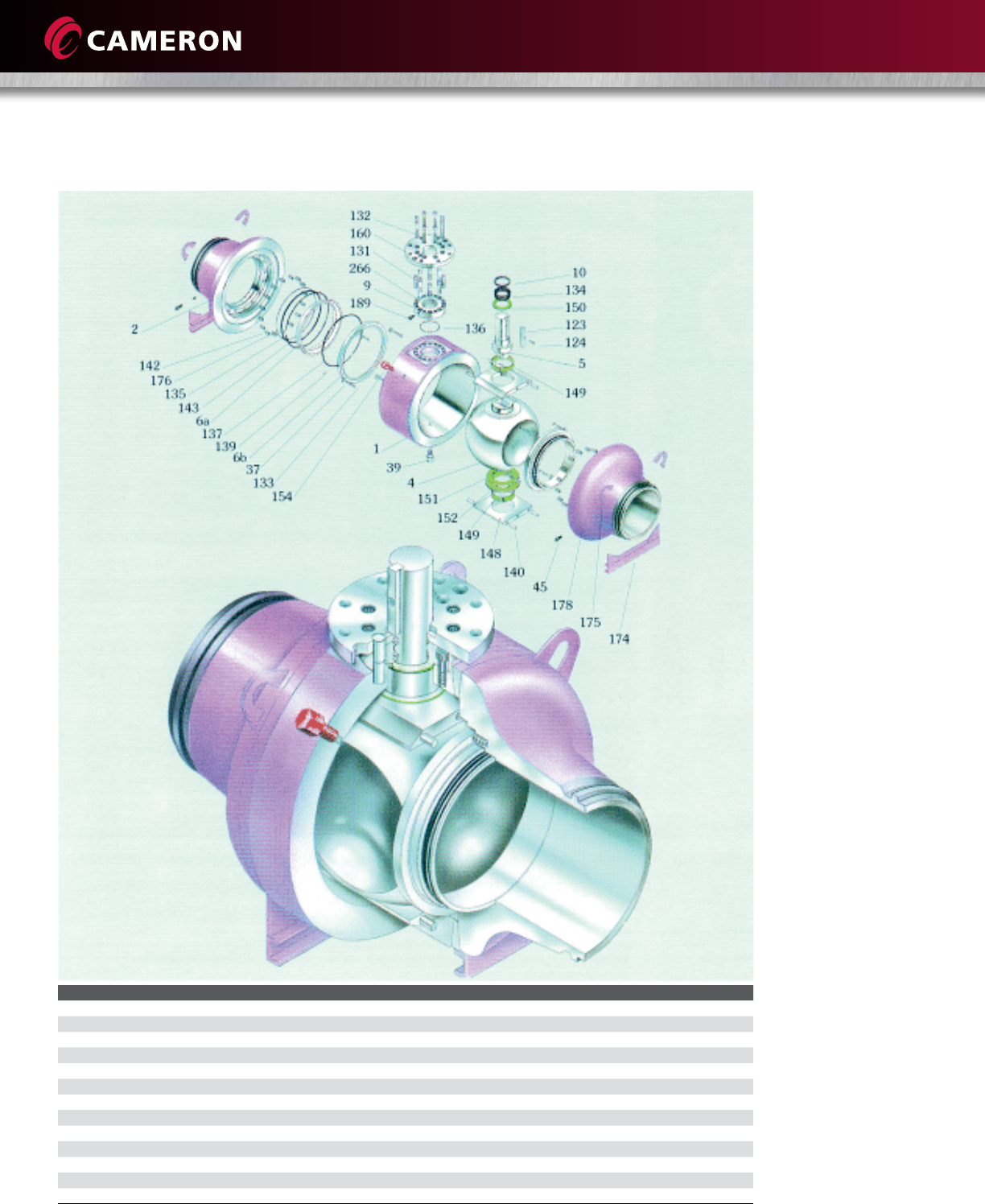
VALVE ASSEMBLY AND CROSS SECTION
Item Description Item Description Item Description
1Body 123 Stem Key 148 Bearing Retainer
2Closure 124 Stem Key Capscrew 149 Bearing
4Ball 131 Gland Plate Capscrew 150 Upper Thrust Washer
5Stem 132 Adapter Plate Capscrew 151 Lower Thrust Washer
6b Outer Seat Ring 133 Puller Bushing Capscrew 152 Spacer
6a Inner Seat Ring 134 Stem O-ring 154 Relief Valve
9Top Cover 135 Seat Gasket O-ring 160 Adapter Plate
10 Gland Bushing 136 Gland Plate O-ring 174 Support Legs
37 Seat Stop Washer 137 Seal O-ring 175 Lifting Lugs
39 Drain Valve 139 Seat Spring Pin 176 Grease U-gasket
45 Seat Grease Fitting 140 Bearing Retainer Pin 178 Check Valve
142 Cylindrical Spring 189 Stem Grease Fitting
143 Seat Lock Ring 266 Stop Pin
18
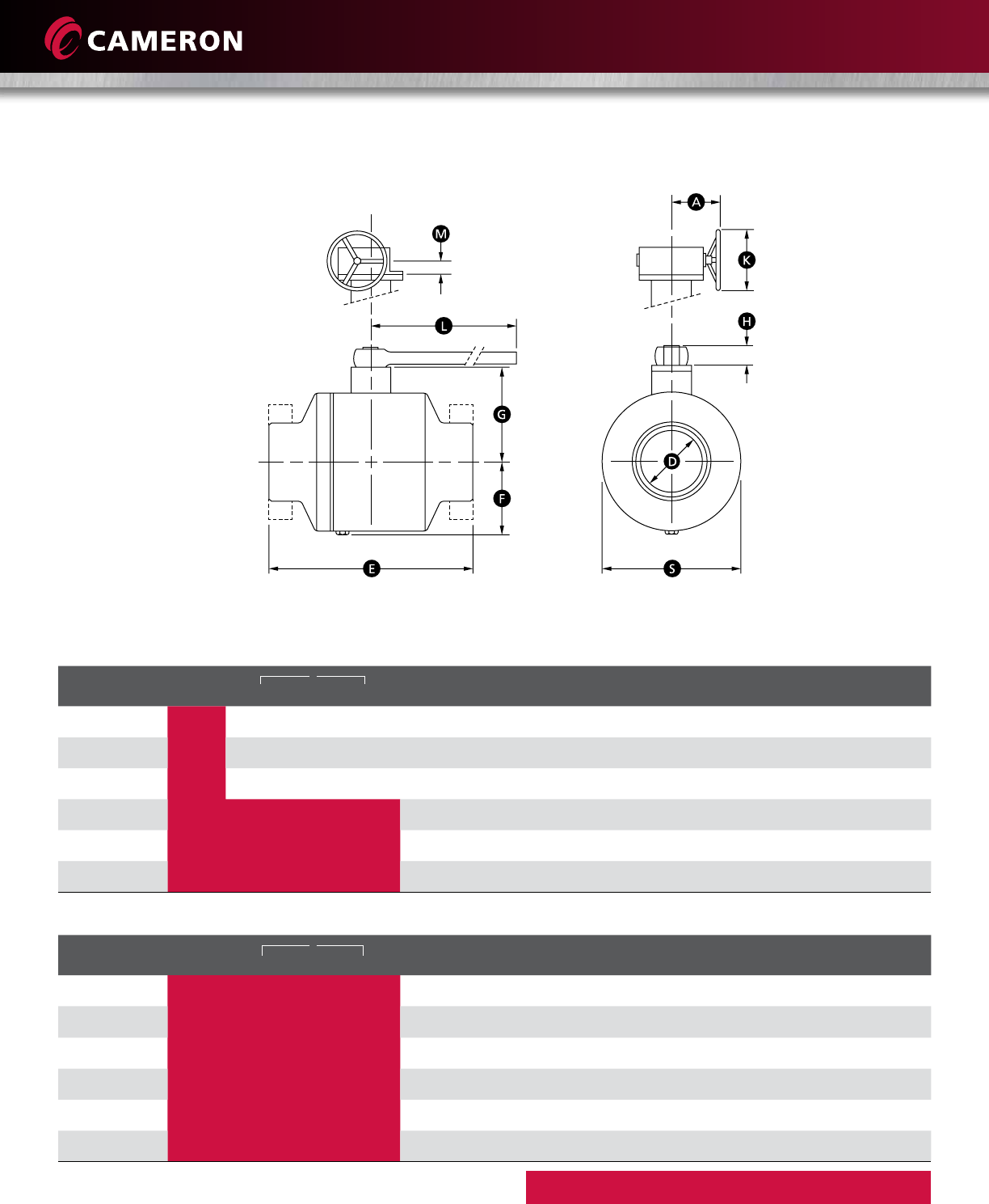
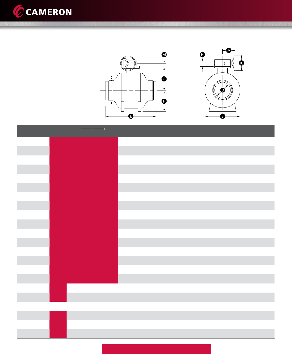
GROVE B8 DIMENSIONS AND WEIGHTS
ASME CLASS 150
*Dimension on request
Flanges in accordance with ASME B16.5
Butt welding ends according to ASME B16.25
Larger sizes available on request.
Reduced-bore valves also available.
Shaded bore sizes (D) according to ISO 14313
Shaded end-to-end dimensions (E) according to ISO 14313/API 6D
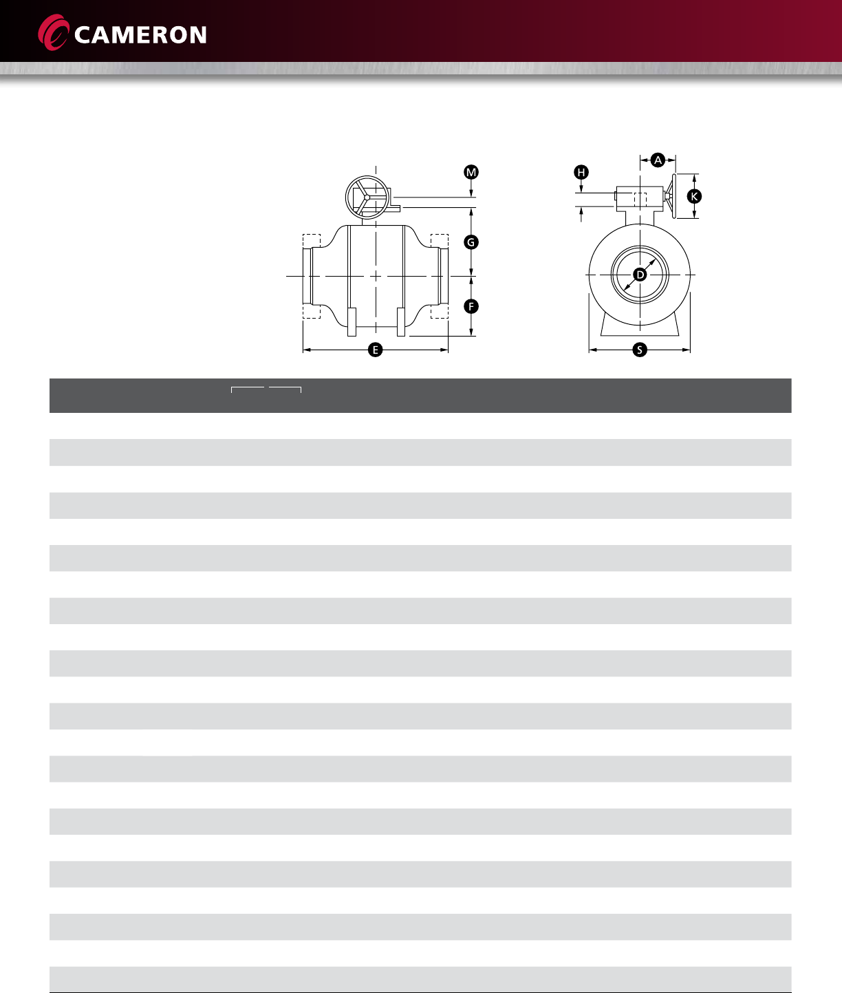
SIZE in.
D E F G S H A K M WEIGHT lb (kg)
(mm)
WE RF RTJ WE RF/RTJ
6618 15-1/ 2 16 11-7/ 8 8-1/ 2 11-7/ 8 2-3/4 * * * 397 507
(150) (152) (457) (394) (406) (302) (216) (302) (70) * * * (180) (230)
8820-1/2 18 18-1/2 13-3/8 9-7/8 15-5/8 2-3/4 * * * 441 551
(200) (203) (521) (457) (470) (340) (251) (397) (70) * * * (200) (250)
10 10 22 21 21-1/2 14-7/8 11-5 / 8 18-1/4 2-3/4 * * * 573 705
(250) (254) (559) (533) (546) (378) (295) (464) (70) * * * (260) (320)
12 12 25 24 24-1/2 16-3/8 13-1/ 2 21-5/8 2-3/4 * * * 882 1080
(300) (305) (635) (610) (622) (416) (343) (549) (70) * * * (400) (490)
14 13-1/4 30 27 27-1/ 2 18-3/8 14-5/8 23 3-3/4 * * * 1301 1587
(350) (337) (762) (686) (699) (467) (371) (584) (95) * * * (590) (720)
16 15-1/4 33 30 30-1/2 19-7/8 16-1/4 26-3/8 3-3/4 * * * 1962 2381
(400) (387) (838) (762) (775) (505) (413) (670) (95) * * * (890) (1080)
18 17-1/4 36 34 34 -1/2 21-1/2 18 29-7/8 4-1/2 * * * 2690 3219
(450) (438) (914) (864) (876) (546) (457) (759) (114) * * * (1220) (1460)
20 19-1/4 39 36 36 -1/2 23-1/8 19-3/8 32-7/8 4-1/2 * * * 3439 4056
(500) (489) (991) (914) (927) (587) (492) (835) (114) * * * (1560) (1840)
22 21-1/4 ***24-7/8 21-1/8 36-1/4 4-1/2 * * * 4541 5379
(550) (540) ***(632) (537) (921) (114) * * * (2060) (2440)
24 23-1/4 45 42 42-1/2 26-3/8 22-1/2 38-7/8 7-1/8 * * * 5710 6746
(600) (591) (1143) (1067) (1080) (670) (572) (987) (181) * * * (2590) (3060)
26 25 49 45 *28-1/4 24-1/2 41-3/4 7-1/8 * * * 7033 8245
(650) (635) (1245) (1143) *(718) (622) (1060) (181) * * * (3190) (3740)
28 27 53 49 * 29-5/8 25-7/8 44-3/4 7-1/8 * * * 8488 9943
(700) (686) (1346) (1245) *(752) (657) (1137) (181) * * * (3850) (4510)
30 29 55 51 *31-3/4 27-1/2 48-5/8 7-1/8 * * * 9810 11,4 6 4
(750) (737) (1397) (1295) *(806) (699) (1235) (181) * * * (4450) (5200)
32 30-3/4 60 54 *33-1/4 29 51 8-1/8 * * * 11,6 8 4 13,426
(800) (781) (1524) (1372) *(845) (737) (1295) (206) * * * (5300) (6090)
34 32-3/4 64 58 *34-3/8 30-7/8 53-3/8 8-1/8 * * * 13,933 15,917
(850) (832) (1626) (1473) *(873) (784) (1356) (206) * * * (6320) (7220)
36 34-1/2 68 60 *35-3/4 32-3/8 56-3/4 8-1/8 * * * 16,138 18,298
(900) (876) (1727) (1524) *(908) (822) (14 41) (206) * * * (7320) (8300)
40 38-1/2 ***39-3/8 35-5/8 63-7/8 8-1/8 * * * 22,134 24,802
(1000) (978) ***(1000) (905) (1622) (206) * * * (10,040) (11, 250)
42 40-1/4 ***40-3/4 38-1/8 67-3/8 8-1/8 * * * 25,375 28,241
(1050) (1022) ***(1035) (968) (1711) (206) * * * (11,510) (12,810)
46 44 ***44-5/8 42-1/2 74 -1/2 8-1/8 * * * 32,518 35,692
(1150) (1118) ***(1133) (1080) (1892) (206) * * * (14,750) (16,19 0)
48 46 ***46-3/8 44-3/8 77-1/2 8-1/8 * * * 36,508 39,815
(1200) (116 8) ***(1178) (1127 ) (1969) (206) * * * (16,560) (18,060)
56 55 ***52-3/4 50-3/8 89-3/4 9-5/8 - - - 54,652 58,047
(1400) (1397) ***(1340) (1280) (2280) (244) - - - (24,790) (26,330)
60 57-1/2 ***56-3/8 55-1/8 96-3/8 9-5/8 - - - 65,013 68,14 4
(1500) (1461) ***(1432) (1400) (2448) (244) - - - (29,490) (30,910)
ASME CLASS 150

19
Larger sizes available on request.
Reduced-bore valves also available.
GROVE B8 DIMENSIONS AND WEIGHTS (continued)
ASME CLASS 300
*Dimension on request
Flanges in accordance with ASME B16.5
Butt welding ends according to ASME B16.25
Shaded bore sizes (D) according to ISO 14313
Shaded end-to-end dimensions (E) according to ISO 14313/API 6D
SIZE in.
D E F G S H A K M WEIGHT lb (kg)
(mm)
WE RF RTJ WE RF/RTJ
6618 18 16-1/2 11-7/ 8 8-1/2 12 2-3/4 * * * 419 529
(150) (152) (457) (457) (419) (302) (216) (305) (70) * * * (190) (240)
8820-1/2 19-3/4 20-3/8 13-3/8 9-7/8 15-7/8 2-3/4 * * * 463 573
(200) (203) (521) (502) (518) (340) (251) (403) (70) * * * (210) (260)
10 10 22 22-3/8 23 14-7/8 11-5 / 8 18-3/8 3-3/4 * * * 617 750
(250) (254) (559) (568) (584) (378) (295) (467) (95) * * * (280) (340)
12 12 25 25-1/2 26-1/8 16-3/8 13-1/2 21-3/4 3-3/4 * * * 926 1124
(300) (305) (635) (648) (664) (416) (343) (552) (95) * * * (420) (510)
14 13-1/4 30 30 30-5/8 18-3/8 14-5/8 23-1/4 4 -1/2 * * * 1367 1675
(350) (337) (762) (762) (778) (467) (371) (591) (114) * * * (620) (760)
16 15-1/4 33 33 33-5/8 19-7/8 16-1/4 26-3/4 4-1/ 2 * * * 2072 2491
(400) (387) (838) (838) (854) (505) (413) (679) (114) * * * (940) (1130 )
18 17-1/4 36 36 36-5/8 21-1/2 18 30-1/4 4-1/2 * * * 2822 3373
(450) (438) (914) (914) (930) (546) (457) (768) (114) * * * (1280) (1530)
20 19-1/4 39 39 39-3/4 23-1/8 16-7/8 33-1/4 7-1/8 * * * 3616 4277
(500) (489) (991) (991) (1010) (587) (429) (845) (181) * * * (1640) (1940)
22 21-1/4 43 43 43-7/8 24-7/8 21-1/8 36-5/8 7-1/8 * * * 4784 5644
(550) (540) (1092) (1092) (1114) (632) (537) (930) (181) * * * (2170) (2560)
24 23-1/4 45 45 45-7/8 26-3/8 22-1/2 39-1/4 7-1/8 * * * 6019 7099
(600) (591) (1143) (1143) (1165) (670) (572) (997) (181) * * * (2730) (3220)
26 25 49 49 50 28-1/4 24-1/2 42-1/8 8-1/8 * * * 7385 8686
(650) (635) (1245) (1245) (1270) (718) (622) (1070) (206) * * * (3350) (3940)
28 27 53 53 54 29-5/8 25-7/8 45-1/4 8-1/8 * * * 8929 10,450
(700) (686) (1346) (1346) (1372) (752) (657) (1149) (206) * * * (4050) (4740)
30 29 55 55 56 31-3/4 27-1/2 49-1/8 8-1/8 * * * 10,317 12,059
(750) (737) (1397) (1397) (1422) (806) (699) (1248) (206) * * * (4680) (5470)
32 30-3/4 60 60 61-1/8 33-1/4 29 51-1/2 8-1/8 * * * 12,280 14,109
(800) (781) (1524) (1524) (1553) (845) (737) (1308) (206) * * * (5570) (6400)
34 32-3/4 64 64 65-1/8 34-3/8 30-7/8 53-7/8 8-1/8 * * * 14,660 16,733
(850) (832) (1626) (1626) (1654) (873) (784) (1368) (206) * * * (6650) (7590)
36 34-1/2 68 68 69 -1/8 35-3/4 32-3/8 57-3/8 8-1/8 * * * 16,975 19,246
(900) (876) (1727) (1727) (1756) (908) (822) (1457) (206) * * * (7700) (8730)
40 38-1/2 ***39-3/8 35-5/8 64-1/2 8-1/8 * * * 23,280 26,080
(1000) (978) ***(1000) (905) (1638) (206) * * * (10,560) (11,8 30)
42 40-1/4 ***40-3/4 38-1/8 68-1/8 9-5/8 * * * 26,698 29,718
(1050) (1022) ***(1035) (968) (1730) (244) * * * (12,110) (13,480)
46 44 ***44-5/8 42-1/2 75-1/4 9-5/8 * * * 34,193 37, 5 4 4
(1150) (1118) ***(1133) (1080) (1911) (244) * * * (15,510) (17,03 0)
48 46 ***46-3/8 44-3/8 78-1/4 9-5/8 * * * 38,404 41,887
(1200) (116 8) ***(1178) (1127 ) (1988) (244) * * * (17,420) (19,000)
56 55 ***52-3/4 50-3/8 90-3/4 9-5/8 - - - 57, 49 6 61,067
(1400) (1397) ***(1340) (1280) (2305) (244) - - - (26,080) (27,70 0)
60 57-1/2 ***56-3/8 55-1/8 97-1/2 9-5/8 - - - 68,386 71,671
(1500) (1461) ***(1432) (1400) (2477) (244) - - - (31,020) (32,510)
ASME CLASS 300
20
ASME CLASS 400
*Dimension on request
Flanges in accordance with ASME B16.5
Butt welding ends according to ASME B16.25
Larger sizes available on request.
Reduced-bore valves also available.
Shaded bore sizes (D) according to ISO 14313
Shaded end-to-end dimensions (E) according to ISO 14313/API 6D
SIZE in.
D E F G S H A K M WEIGHT lb (kg)
(mm)
WE RF RTJ WE RF/RTJ
6619-1/2 19-1/2 19-5/8 12-1/8 8-1/2 12-1/8 2-3/4 * * * 485 617
(150) (152) (495) (495) (498) (308) (216) (308) (70) * * * (220) (280)
8823-1/ 2 23-1/ 2 23-5/8 13-5/8 9-7/8 16 3-3/4 * * * 529 661
(200) (203) (597) (597) (600) (346) (251) (406) (95) * * * (240) (300)
10 10 26 -1/2 26 -1/2 26-5/8 15-1/4 11-5 / 8 18-5/8 3-3/4 * * * 705 860
(250) (254) (673) (673) (676) (387) (295) (473) (95) * * * (320) (390)
12 12 30 30 30 -1/8 16-3/4 13-1/2 22 3-3/4 * * * 1058 1301
(300) (305) (762) (762) (765) (425) (343) (559) (95) * * * (480) (590)
14 13-1/4 32-1/2 32-1/2 32-5/8 18-3/4 14-5/8 23-1/2 4-1/2 * * * 1587 1918
(350) (337) (826) (826) (829) (476) (371) (597) (114) * * * (720) (870)
16 15-1/4 35-1/2 35-1/2 35-5/8 20-3/8 16-1/4 27 4-1/2 * * * 2381 2866
(400) (387) (902) (902) (905) (518) (413) (686) (114) * * * (1080) (1300)
18 17-1/4 38-1/2 38-1/2 38-5/8 21-7/8 18 30-1/2 7-1/8 * * * 3241 3880
(450) (438) (978) (978) (981) (556) (457) (775) (181) * * * (1470) (1760)
20 19-1/4 41-1/2 41-1/2 41-3/4 23-1/2 19-3/8 33-1/2 7-1/8 * * * 4145 4894
(500) (489) (1054) (1054) (1060) (597) (492) (851) (181) * * * (1880) (2220)
22 21-1/4 45 45 45-3/8 25-3/8 21-1/8 37 7-1/8 * * * 5489 6481
(550) (540) (1143) (1143) (1153) (645) (537) (940) (181) * * * (2490) (2940)
24 23-1/4 48-1/2 48-1/2 48-7/8 26-7/8 22-1/2 39-5/8 8-1/8 * * * 6900 8135
(600) (591) (1232) (1232) (1241) (683) (572) (1006) (206) * * * (3130) (3690)
26 25 51-1/2 51-1/ 2 52 28-7/8 24-1/2 42-1/2 8-1/8 * * * 8488 9965
(650) (635) (1308) (1308) (1321) (733) (622) (1080) (206) * * * (3850) (4520)
28 27 55 55 55-1/2 30 -1/4 25-7/8 45-5/8 8-1/8 * * * 10,251 12,015
(700) (686) (1397) (1397) (1410) (768) (657) (1159) (206) * * * (4650) (5450)
30 29 60 60 60 -1/2 32-3/8 27-1/2 49-5/8 8-1/8 * * * 11, 861 13,845
(750) (737) (1524) (1524) (1537) (822) (699) (1260) (206) * * * (5380) (6280)
32 30-3/4 65 65 65-5/8 33-7/8 29 52 8-1/8 * * * 14,109 16,204
(800) (781) (1651) (1651) (1667) (860) (737) (1321) (206) * * * (6400) (7350)
34 32-3/4 70 70 70-5/8 35-1/8 30-7/8 54-1/2 8-1/8 * * * 16,843 19,224
(850) (832) (1778) (1778) (1794) (892) (784) (1384) (206) * * * (7640) (8720)
36 34-1/2 74 74 74-5/8 36-1/2 32-3/8 58 8-1/8 * * * 19,489 22,112
(900) (876) (1880) (1880) (1895) (927) (822) (1473) (206) * * * (8840) (10,030)
40 38-1/2 ***40-1/8 35-5/8 65-1/8 9-5/8 * * * 26,742 29,938
(1000) (978) ***(1019) (905) (1654) (244) * * * (12,130) (13,580)
42 40-1/4 ***41-1/2 38-1/8 68-3/4 9-5/8 * * * 30,644 34,105
(1050) (1022) ***(1054) (968) (1746) (244) * * * (13,90 0) (15,470)
46 44 ***45-5/8 42-1/2 76 9-5/8 * * * 39,264 43,100
(1150) (1118) ***(1159) (1080) (1930) (244) * * * (17,810) (19,550)
48 46 ***47-3/8 44-3/8 79 9-5/8 * * * 44,092 48,082
(1200) (116 8) ***(1203) (1127) (2007) (244) * * * (20,000) (21,810)
56 55 ***53-3/4 50-3/8 91-5/8 11 - - - 66,027 70,106
(1400) (1397) ***(1365) (1280) (2327) (279) - - - (29,950) (31,800)
60 57-1/2 ***57-1/2 55-1/8 98-3/8 11 - - - 78,527 82,297
(1500) (1461) ***(1461) (1400) (2499) (279) - - - (35,620) (37,330)
ASME CLASS 400
21
GROVE B8 DIMENSIONS AND WEIGHTS (continued)
Larger sizes available on request.
Reduced-bore valves also available.
ASME CLASS 600
*Dimension on request
Flanges in accordance with ASME B16.5
Butt welding ends according to ASME B16.25
Shaded bore sizes (D) according to ISO 14313
Shaded end-to-end dimensions (E) according to ISO 14313/API 6D
SIZE in.
D E F G S H A K M WEIGHT lb (kg)
(mm)
WE RF RTJ WE RF/RTJ
6622 22 22-1/8 12-1/4 8-1/ 2 12-1/4 2-3/4 * * * 529 661
(150) (152) (559) (559) (562) (311) (216) (311) (70) * * * (240) (300)
8826 26 26 -1/8 13-3/4 9-7/8 16-1/8 3-3/4 * * * 573 705
(200) (203) (660) (660) (664) (349) (251) (410) (95) * * * (260) (320)
10 10 31 31 31-1/8 15-3/8 11-5 / 8 18-7/8 3-3/4 * * * 750 926
(250) (254) (787) (787) (791) (391) (295) (479) (95) * * * (340) (420)
12 12 33 33 33-1/8 16-7/8 13-1/ 2 22-1/4 3-3/4 * * * 1146 1389
(300) (305) (838) (838) (841) (429) (343) (565) (95) * * * (520) (630)
14 13-1/4 35 35 35-1/8 18-7/8 14-5/8 23-3/4 4-1/2 * * * 1698 2050
(350) (337) (889) (889) (892) (479) (371) (603) (114) * * * (770) (930)
16 15-1/4 39 39 39-1/8 20-1/2 16-1/4 27-1/4 4-1/2 * * * 2557 3086
(400) (387) (991) (991) (994) (521) (413) (692) (114) * * * (116 0) (1400)
18 17-1/4 43 43 43-1/8 22-1/8 18 30 -7/8 7-1/8 * * * 3483 4167
(450) (438) (1092) (1092) (1095) (562) (457) (784) (181) * * * (1580) (1890)
20 19-1/4 47 47 47-1/4 23-3/4 19-3/8 33-7/8 7-1/8 * * * 4453 5269
(500) (489) (1194) (119 4) (1200) (603) (492) (860) (181) * * * (2020) (2390)
22 21-1/4 51 51 51-3/8 25-5/8 21-1/8 37-3/8 8-1/8 * * * 5908 6966
(550) (540) (1295) (1295) (1305) (651) (537) (949) (206) * * * (2680) (3160)
24 23-1/4 55 55 55-3/8 27-1/8 22-1/2 40-1/8 8-1/8 * * * 7429 8752
(600) (591) (1397) (1397) (1407) (689) (572) (1019) (206) * * * (3370) (3970)
26 25 57 57 57-1/2 29-1/8 24-1/2 43 8-1/8 * * * 9127 10,714
(650) (635) (1448) (1448) (1461) (740) (622) (1092) (206) * * * (4140) (4860)
28 27 61 61 61-1/2 30-1/2 25-7/8 46-1/8 8-1/8 * * * 11,023 12,919
(700) (686) (1549) (1549) (1562) (775) (657) (1172) (206) * * * (5000) (5860)
30 29 65 65 65-1/2 32-5/8 27-1/2 50-1/8 9-5/8 * * * 12,743 14,881
(750) (737) (1651) (1651) (1664) (829) (699) (1273) (244) * * * (5780) (6750)
32 30-3/4 70 70 70-5/8 34 -1/4 29 52-1/2 9-5/8 * * * 15,168 17,43 8
(800) (781) (1778) (1778) (1794) (870) (737) (1334) (244) * * * (6880) (7910)
34 32-3/4 76 76 76-5/8 35-3/8 30 -7/8 55 9-5/8 * * * 18,100 20,679
(850) (832) (1930) (1930) (1946) (899) (784) (1397) (244) * * * (8210) (9380)
36 34-1/2 82 82 82-5/8 36-7/8 32-3/8 58-1/2 9-5/8 * * * 20,944 23,765
(900) (876) (2083) (2083) (2099) (937) (822) (1486) (244) * * * (9500) (10,780)
40 38-1/2 ***40-1/2 35-5/8 65-7/8 9-5/8 * * * 28,748 32,187
(1000) (978) ***(1029) (905) (1673) (244) * * * (13,040) (14,600)
42 40-1/4 ***42 38-1/8 69-1/2 9-5/8 * * * 32,959 36,684
(1050) (1022) ***(1067) (968) (1765) (244) * * * (14,950) (16,640)
46 44 ***46 -1/8 42-1/2 76-3/4 9-5/8 * * * 42,218 46,362
(1150) (1118) ***(1172) (1080) (1949) (244) * * * (19,150) (21,030)
48 46 85-7/8 85-7/8 *47-7/8 44-3/8 79-7/8 9-5/8 * * * 47, 399 51,720
(1200) (116 8) (2181) (2181) *(1216) (1127) (2029) (244) * * * (21,500) (23,460)
56 55 ***54-3/8 50-3/8 92-5/8 11 - - - 70,988 75,397
(1400) (1397) ***(1381) (1280) (2353) (279) - - - (32,200) (34,200)
60 57-1/2 ***58-1/8 55-1/8 99-3/8 11 - - - 84,436 88,492
(1500) (1461) ***(1476) (1400) (2524) (279) - - - (38,300) (40,140)
ASME CLASS 600
22
ASME CLASS 900
*Dimension on request
Flanges in accordance with ASME B16.5
Butt welding ends according to ASME B16.25
Larger sizes available on request.
Reduced-bore valves also available.
Shaded bore sizes (D) according to ISO 14313
Shaded end-to-end dimensions (E) according to ISO 14313/API 6D
SIZE in.
D E F G S H A K M WEIGHT lb (kg)
(mm)
WE RF RTJ WE RF/RTJ
6624 24 24-1/8 9-7/8 9-1/2 13-1/4 3-3/4 * * * 640 800
(150) (152) (610) (610) (613) (251) (241) (337) (95) * * * (290) (363)
88 29 29 29-1/8 11-3/ 8 10-7/8 16-1/2 3-3/4 * * * 694 854
(200) (203) (737) (737) (740) (289) (276) (419) (95) * * * (315) (387)
10 10 33 33 33-1/8 13-5/8 12-1/ 2 20-1/8 4-1/2 * * * 907 1120
(250) (254) (838) (838) (841) (346) (318) (511) (114) * * * (411) (508)
12 12 38 38 38-1/8 15-3/8 14-3/8 23-5/8 4-1/2 * * * 1387 1681
(300) (305) (965) (965) (968) (391) (365) (600) (114) * * * (629) (762)
14 12-3/4 40-1/2 40-1/2 40-7/8 17-3/4 15 -3/8 26-3/4 4 -1/2 * * * 2054 2481
(350) (324) (1029) (1029) (1038) (451) (391) (679) (114) * * * (932) (1125)
16 14-3/4 4 4-1/2 44-1/2 44-7/8 19-5/8 16-7/8 30-3/8 7-1/8 * * * 3094 3735
(400) (375) (1130 ) (1130 ) (114 0) (498) (429) (772) (181) * * * (1404) (1694)
18 16-3/4 48 48 48-1/2 21-5/8 19-1/8 33-1/2 7-1/8 * * * 4215 5042
(450) (425) (1219) (1219) (1232) (549) (486) (851) (181) * * * (1912) (2287)
20 18-5/8 52 52 52-1/2 23-1/4 20-7/8 36 -1/4 8 -1/8 * * * 5388 6375
(500) (473) (1321) (1321) (1334) (591) (530) (921) (206) * * * (2444) (2892)
22 20-5/8 ***25-3/4 21-7/8 40-1/2 8-1/8 * * * 7149 8429
(550) (524) ***(654) (556) (1029) (206) * * * (3243) (3824)
24 22-1/2 61 61 61-3/4 27-1/2 24-3/8 43-3/4 9-5/8 * * * 8990 10,590
(600) (572) (1549) (1549) (1568) (699) (619) (1111) (244) * * * (4078) (4804)
26 24-3/8 ***29-7/8 26 -1/4 47-1/4 9-5/8 * * * 11, 04 4 12,964
(650) (619) ***(759) (667) (1200) (244) * * * (5009) (5881)
28 26 -1/4 ***31-7/8 27-7/8 50-3/4 9-5/8 * * * 13,338 15,632
(700) (667) ***(810) (708) (1289) (244) * * * (6050) (7091)
30 28-1/8 ***32-3/4 29-5/8 53-3/8 9-5/8 * * * 15,418 18,006
(750) (714) ***(832) (752) (1356) (244) * * * (6994) (8168)
32 30 ***35-7/8 31-7/8 57-1/2 9-5/8 * * * 18,353 21,10 0
(800) (762) * * *(911) (810) (1461) (244) * * * (8325) (9571)
34 31-7/8 ***37-3/4 33-3/8 61 9-5/8 * * * 21,901 25,022
(850) (810) ***(959) (848) (1549) (244) * * * (9934) (11,350)
36 33-3/4 ***40-1/8 34-3/4 64-3/8 11 * * * 25,342 28,756
(900) (857) ***(1019) (883) (1635) (279) * * * (11, 495) (13,044)
40 37-5/8 ***44-1/8 38-1/4 71-1/4 11 * * * 34,785 38,946
(1000) (956) ***(1121) (972) (1810) (279) * * * (15,778) (17,666)
42 39-5/8 ***47-1/4 41-3/4 74 -3/4 11 * * * 39,880 44,388
(1050) (1006) ***(1200) (1060) (1899) (279) * * * (18,090) (20,134)
46 43-3/8 ***50-3/8 43-3/4 81-1/2 11 * * * 51,084 56,099
(1150) (1102) ***(1280) (1111) (2070) (279) * * * (23,172) (25,446)
48 45-1/4 ***52-3/8 45-1/4 85 11 * * * 57,352 62581
(1200) (1149) ***(1330) (1149) (2159) (279) * * * (26,015) (28,387)
ASME CLASS 900
23
GROVE B8 DIMENSIONS AND WEIGHTS (continued)
Larger sizes available on request.
Reduced-bore valves also available.
ASME CLASS 1500
*Dimension on request
Flanges in accordance with ASME B16.5
Butt welding ends according to ASME B16.25
Shaded bore sizes (D) according to ISO 14313
Shaded end-to-end dimensions (E) according to ISO 14313/API 6D
SIZE in.
D E F G S H A K M WEIGHT lb (kg)
(mm)
WE RF RTJ WE RF/RTJ
65-3/4 27-3/4 27-3/4 28 12-5/8 11 16-7/8 3-3/4 * * * 767 959
(150) (146) (705) (705) ( 711) (321) (279) (429) (95) * * * (348) (435)
87-5/8 32-3/4 32-3/4 33-1/8 14-5/8 12-7/8 21-1/8 4-1/2 * * * 831 1023
(200) (194) (832) (832) (841) (371) (327) (537) (114) * * * (377) (464)
10 9-1/2 39 39 39-3/8 17-3/8 15-3/8 25-3/4 4-1/2 * * * 1087 1343
(250) (241) (991) (991) (1000) (441) (391) (654) (114) * * * (493) (609)
12 11-3/8 44-1/ 2 44-1/2 45-1/8 19-5/8 16-5/8 30 -1/4 4-1/2 * * * 1662 2014
(300) (289) (1130 ) (1130) (114 6) (498) (422) (768) (114) * * * (754) (914)
14 12-1/ 2 49-1/2 49 -1/2 50-1/4 22-5/8 19-5/8 34-1/4 7-1/8 * * * 2461 2973
(350) (318) (1257) (1257) (1276) (575) (498) (870) (181) * * * (1117) (1349)
16 14-1/4 54-1/2 54-1/2 55-3/8 25-1/4 22 38-3/4 7-1/8 * * * 3708 4475
(400) (362) (1384) (1384) (1407) (641) (559) (984) (181) * * * (1682) (2030)
18 16-1/4 ***27-3/4 23-1/4 42-7/8 8-1/8 * * * 5051 6042
(450) (413) ***(705) (591) (1089) (206) * * * (2291) (2741)
20 18 ***29-7/8 28-1/2 46-3/8 9-5/8 * * * 6457 7640
(500) (457) ***(759) (724) (1178) (244) * * * (2929) (3466)
22 19-3/4 ***33 30-1/4 51-7/8 9-5/8 * * * 8567 10,101
(550) (502) ***(838) (768) (1318) (244) * * * (3886) (4582)
24 21-5/8 ***35-1/8 32 55-7/8 9-5/8 * * * 10,773 12,691
(600) (549) ***(892) (813) (1419) (244) * * * (4887) (5757)
26 23-1/ 2 ***38-1/4 35-1/2 60-1/2 11 * * * 13,234 15,536
(650) (597) ***(972) (902) (1537) (279) * * * (6003) (7047)
28 25-1/4 ***40-7/8 37 65 11 * * * 15,983 18,732
(700) (641) ***(1038) (940) (1651) (279) * * * (7250) (8497)
30 27 ***42 40-3/4 68-3/8 11 * * * 18,477 21,577
(750) (686) ***(1067) (1035) (1737) (279) * * * (8381) (9788)
32 28-3/4 ***45-7/8 41-3/4 73-5/8 11 * * * 21,993 25,285
(800) (730) * * *(1165) (1060) (1870) (279) * * * (9976) (11,470)
34 30 -1/2 ***48-3/8 44-7/8 78-1/8 11 * * * 26,244 29,985
(850) (775) ***(1229) (114 0) (1984) (279) * * * (11,9 05) (13,601)
36 32-1/4 ***51-3/8 46 -1/2 82-3/8 11 * * * 30,368 34,460
(900) (819) ***(1305) (1181) (2092) (279) * * * (13,775) (15,631)
ASME CLASS 1500
24
ASME CLASS 2500
*Dimension on request
Flanges in accordance with ASME B16.5
Butt welding ends according to ASME B16.25
Larger sizes available on request.
Reduced-bore valves also available.
Shaded bore sizes (D) according to ISO 14313
Shaded end-to-end dimensions (E) according to ISO 14313/API 6D
SIZE in.
D E F G S H A K M WEIGHT lb (kg)
(mm)
WE RF RTJ WE RF/RTJ
87-1/8 40-1/4 40 -1/4 40-7/8 15-1/8 15-1/2 26 5-1/2 * * * - -
(200) (181) (1022) (1022) (1038) (385) (393) (660) (140) * * * - -
10 8-7/8 50 50 50-7/8 17-1/8 18-1/4 31-1/8 5-1/2 * * * - -
(250) (225) (1270) (1270) (1292) (435) (465) (790) (140) * * * - -
12 10-1/2 56 56 56-7/8 19-5/8 20 -1/2 34-1/4 5-1/2 * * * - -
(300) (267) (1422) (1422) (1445) (500) (521) (870) (140) * * * - -
14 11-1 / 2 * * * * * * * * * * * *
(350) (292) * * * * * * * * * * * *
16 13-1/8 * * * * * * * * * * * *
(400) (333) * * * * * * * * * * * *
18 14-3/4 * * * * * * * * * * * *
(450) (374) * * * * * * * * * * * *
20 16-1/2 * * * * * * * * * * * *
(500) (419) * * * * * * * * * * * *
22 *********** * *
(550) *********** * *
24 *********** * *
(600) *********** * *
ASME CLASS 2500

25
Larger sizes available on request.
Reduced-bore valves also available.
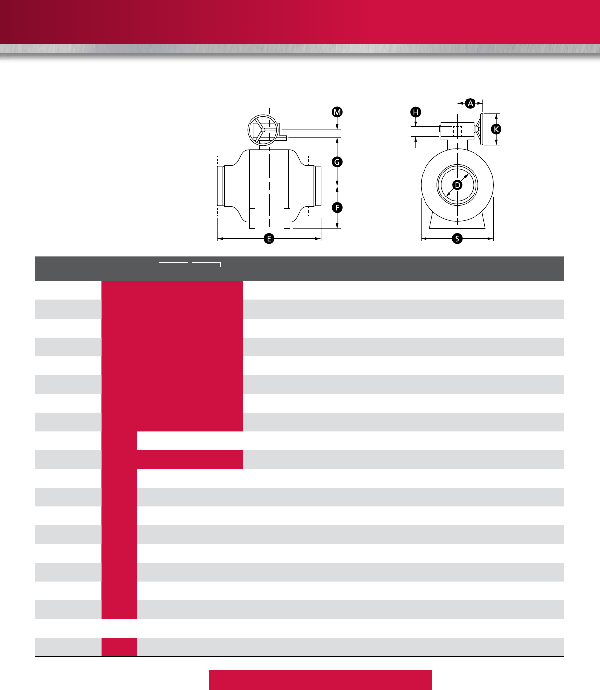
GROVE B8a DIMENSIONS AND WEIGHTS
ASME CLASS 150
*Dimension on request
Flanges in accordance with ASME B16.5
Butt welding ends according to ASME B16.25
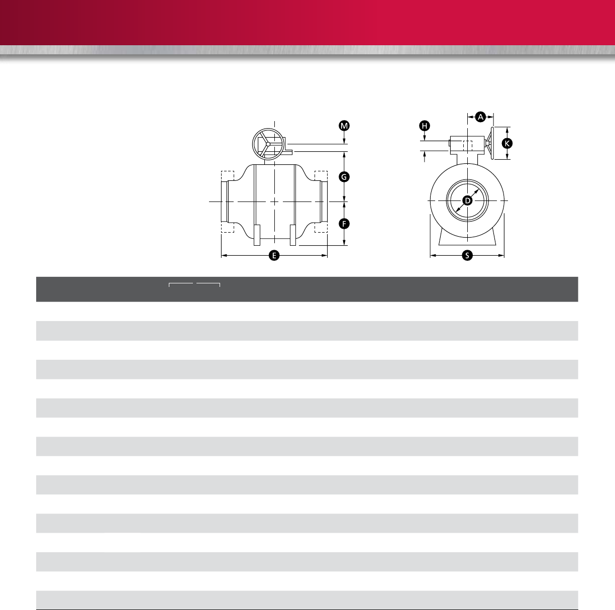
SIZE in.
D E F G S H A K M WEIGHT lb (kg)
(mm)
WE RF RTJ WE RF/RTJ
6 6 18 * * 11-7/8 8-1/2 11-7/ 8 2-3/4 * * * 397 507
(150) (152) (457) * * (302) (216) (302) (70) * * * (180) (230)
8 8 20-1/2 * * 13-3/8 9-7/8 15-5/8 2-3/4 * * * 441 551
(200) (203) (521) * * (340) (251) (397) (70) * * * (200) (250)
10 10 22 * * 14-7/8 11-5/ 8 18 -1/4 2-3/4 * * * 573 705
(250) (254) (559) * * (378) (295) (464) (70) * * * (260) (320)
12 12 25 * * 16-3/8 13-1/2 21-5/8 2-3/4 * * * 882 1080
(300) (305) (635) * * (416) (343) (549) (70) * * * (400) (490)
14 13-1/4 28 -1/2 * * 18-3/8 14-5/8 23 3-3/4 * * * 1301 1587
(350) (337) (724) * * (467) (371) (584) (95) * * * (590) (720)
16 15-1/4 30-1/2 * * 19-7/8 16 -1/4 26-3/8 3-3/4 * * * 1962 2381
(400) (387) (775) * * (505) (413) (670) (95) * * * (890) (1080)
18 17-1/4 33-1/2 * * 21-1/2 18 29-7/8 4-1/2 * * * 2690 3219
(450) (438) (851) * * (546) (457) (759) (114) * * * (1220) (1460)
20 19-1/4 35-1/2 * * 23-1/8 19-3/8 32-7/8 4-1/2 * * * 3439 4056
(500) (489) (902) * * (587) (492) (835) (114) * * * (1560) (1840)
22 21-1/4 38-1/2 * * 24-7/8 21-1/8 36-1/4 4-1/2 * * * 4541 5379
(550) (540) (978) * * (632) (537) (921) (114) * * * (2060) (2440)
24 23-1/4 42 * * 26-3/8 22-1/2 38-7/8 7-1/8 * * * 5710 6746
(600) (591) (1067) * * (670) (572) (987) (181) * * * (2590) (3060)
26 25 44-1/2 * * 28-1/4 24-1/2 41-3/4 7-1/8 * * * 7033 8245
(650) (635) (113 0) * * (718) (622) (1060) (181) * * * (3190) (3740)
28 27 47 * * 29-5/8 25-7/8 44-3/4 7-1/8 * * * 8488 9943
(700) (686) (119 4) * * (752) (657) (1137) (181) * * * (3850) (4510)
30 29 49 * * 31-3/4 27-1/2 48-5/8 7-1/8 * * * 9810 11,4 6 4
(750) (737) (1245) * * (806) (699) (1235) (181) * * * (4450) (5200)
32 30-3/4 51-1/2 * * 33-1/4 29 51 8-1/8 * * * 11, 6 8 4 13,426
(800) (781) (1308) **(845) (737) (1295) (206) * * * (5300) (6090)
34 32-3/4 54-1/2 * * 34-3/8 30-7/8 53-3/8 8-1/8 * * * 13,933 15,917
(850) (832) (1384) * * (873) (784) (1356) (206) * * * (6320) (7220)
36 34-1/2 56-1/2 * * 35-3/4 32-3/8 56-3/4 8 -1/8 * * * 16,138 18,298
(900) (876) (1435) * * (908) (822) (14 41) (206) * * * (7320) (8300)
40 38-1/2 65 * * 39-3/8 35-5/8 63-7/8 8-1/8 * * * 22,134 24,802
(1000) (978) (1651) * * (1000) (905) (1622) (206) * * * (10,040) (11,250 )
42 40-1/4 66-1/2 * * 40-3/4 38-1/8 67-3/8 8-1/8 * * * 25,375 28,241
(1050) (1022) (1689) * * (1035) (968) (1711) (206) * * * (11,510) (12,810)
46 44 73 * * 44-5/8 42-1/2 74-1/2 8-1/8 * * * 32,518 35,692
(1150) (1118) (1854) * * (1133) (1080) (1892) (206) * * * (14,750) (16,190)
48 46 76 * * 46-3/8 44-3/8 77-1/2 8-1/8 * * * 36,508 39,815
(1200) (116 8) (1930) * * (1178) (1127) (1969) (206) * * * (16,560) (18,060)
56 55 87 * * 52-3/4 50-3/8 89-3/4 9-5/8 - - - 54,652 58,047
(1400) (1397) (2210) * * (1340) (1280) (2280) (244) - - - (24,790) (26,330)
60 57-1/2 92-1/2 * * 56-3/8 55-1/8 96-3/8 9-5/8 - - - 65,013 68,144
(1500) (1461) (2350) * * (1432) (1400) (2448) (244) - - - (29,490) (30,910)
ASME CLASS 150
26
Larger sizes available on request.
Reduced-bore valves also available.
ASME CLASS 300
*Dimension on request
Flanges in accordance with ASME B16.5
Butt welding ends according to ASME B16.25
SIZE in.
D E F G S H A K M WEIGHT lb (kg)
(mm)
WE RF RTJ WE RF/RTJ
6 6 18 * * 11-7/8 8-1/2 12 2-3/4 * * * 419 529
(150) (152) (457) * * (302) (216) (305) (70) * * * (190) (240)
8 8 20-1/2 * * 13-3/8 9-7/8 15-7/8 2-3/4 * * * 463 573
(200) (203) (521) * * (340) (251) (403) (70) * * * (210) (260)
10 10 22 * * 14-7/8 11-5/ 8 18-3/8 3-3/4 * * * 617 750
(250) (254) (559) * * (378) (295) (467) (95) * * * (280) (340)
12 12 25 * * 16-3/8 13-1/2 21-3/4 3-3/4 * * * 926 1124
(300) (305) (635) * * (416) (343) (552) (95) * * * (420) (510)
14 13-1/4 28 -1/2 * * 18-3/8 14-5/8 23-1/4 4-1/2 * * * 1367 1675
(350) (337) (724) * * (467) (371) (591) (114) * * * (620) (760)
16 15-1/4 30-1/2 * * 19-7/8 16 -1/4 26-3/4 4-1/2 * * * 2072 2491
(400) (387) (775) * * (505) (413) (679) (114) * * * (940) (113 0)
18 17-1/4 33-1/2 * * 21-1/2 18 30-1/4 4-1/ 2 * * * 2822 3373
(450) (438) (851) * * (546) (457) (768) (114) * * * (1280) (1530)
20 19-1/4 35-1/2 * * 23-1/8 16-7/8 33-1/4 7-1/8 * * * 3616 4277
(500) (489) (902) * * (587) (429) (845) (181) * * * (1640) (1940)
22 21-1/4 38-1/2 * * 24-7/8 21-1/8 36-5/8 7-1/8 * * * 4784 5644
(550) (540) (978) * * (632) (537) (930) (181) * * * (2170) (2560)
24 23-1/4 42 * * 26-3/8 22-1/2 39-1/4 7-1/8 * * * 6019 7099
(600) (591) (1067) * * (670) (572) (997) (181) * * * (2730) (3220)
26 25 44-1/2 * * 28-1/4 24-1/2 42-1/8 8-1/8 * * * 7385 8686
(650) (635) (113 0) * * (718) (622) (1070) (206) * * * (3350) (3940)
28 27 47 * * 29-5/8 25-7/8 45-1/4 8-1/8 * * * 8929 10,450
(700) (686) (119 4) * * (752) (657) (1149) (206) * * * (4050) (4740)
30 29 49 * * 31-3/4 27-1/2 49-1/8 8-1/8 * * * 10,317 12,059
(750) (737) (1245) * * (806) (699) (1248) (206) * * * (4680) (5470)
32 30-3/4 51-1/2 * * 33-1/4 29 51-1/2 8-1/8 * * * 12,280 14,109
(800) (781) (1308) **(845) (737) (1308) (206) * * * (5570) (6400)
34 32-3/4 54-1/2 * * 34-3/8 30-7/8 53-7/8 8-1/8 * * * 14,660 16,733
(850) (832) (1384) * * (873) (784) (1368) (206) * * * (6650) (7590)
36 34-1/2 56-1/2 * * 35-3/4 32-3/8 57-3/8 8-1/8 * * * 16,975 19,246
(900) (876) (1435) * * (908) (822) (1457) (206) * * * (7700) (8730)
40 38-1/2 65 * * 39-3/8 35-5/8 64-1/2 8-1/8 * * * 23,280 26,080
(1000) (978) (1651) * * (1000) (905) (1638) (206) * * * (10,560) (11, 830)
42 40-1/4 66-1/2 * * 40-3/4 38-1/8 68-1/8 9-5/8 * * * 26,698 29,718
(1050) (1022) (1689) * * (1035) (968) (1730) (244) * * * (12,110) (13,480)
46 44 73 * * 44-5/8 42-1/2 75-1/4 9-5/8 * * * 34,193 37,5 4 4
(1150) (1118) (1854) * * (1133) (1080) (1911) (244) * * * (15,510) (17,03 0)
48 46 76 * * 46-3/8 44-3/8 78-1/4 9-5/8 * * * 38,404 41,887
(1200) (116 8) (1930) * * (1178) (1127) (1988) (244) * * * (17, 420) (19,000)
56 55 87 * * 52-3/4 50-3/8 90-3/4 9-5/8 - - - 57, 49 6 61,067
(1400) (1397) (2210) * * (1340) (1280) (2305) (244) - - - (26,080) (27,70 0)
60 57-1/2 92-1/2 * * 56-3/8 55-1/8 97-1/ 2 9-5/8 - - - 68,386 71,671
(1500) (1461) (2350) * * (1432) (1400) (2477) (244) - - - (31,020) (32,510)
ASME CLASS 300
27
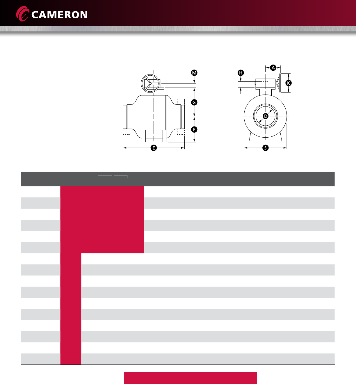
GROVE B8a DIMENSIONS AND WEIGHTS (continued)
Larger sizes available on request.
Reduced-bore valves also available.
ASME CLASS 600
*Dimension on request
Flanges in accordance with ASME B16.5
Butt welding ends according to ASME B16.25
SIZE in.
D E F G S H A K M WEIGHT lb (kg)
(mm)
WE RF RTJ WE RF/RTJ
6 6 18 * * 12-1/4 8-1/2 12-1/4 2-3/4 * * * 529 661
(150) (152) (457) * * (311) (216) (311) (70) * * * (240) (300)
8 8 21-1/2 * * 13-3/4 9-7/8 16-1/8 3-3/4 * * * 573 705
(200) (203) (546) * * (349) (251) (410) (95) * * * (260) (320)
10 10 23-1/2 * * 15-3/8 11-5 / 8 18-7/8 3-3/4 * * * 750 926
(250) (254) (597) * * (391) (295) (479) (95) * * * (340) (420)
12 12 26 -1/2 * * 16-7/8 13-1/2 22-1/4 3-3/4 * * * 1146 1389
(300) (305) (673) * * (429) (343) (565) (95) * * * (520) (630)
14 13-1/4 28 -1/2 * * 18-7/8 14-5/8 23-3/4 4-1/2 * * * 1698 2050
(350) (337) (724) * * (479) (371) (603) (114) * * * (770) (930)
16 15-1/4 30-1/2 * * 20-1/2 16-1/4 27-1/4 4-1/2 * * * 2557 3086
(400) (387) (775) * * (521) (413) (692) (114) * * * (116 0) (1400)
18 17-1/4 33-1/2 * * 22-1/8 18 30-7/8 7-1/8 * * * 3483 4167
(450) (438) (851) * * (562) (457) (784) (181) * * * (1580) (1890)
20 19-1/4 35-1/2 * * 23-3/4 19-3/8 33-7/8 7-1/8 * * * 4453 5269
(500) (489) (902) * * (603) (492) (860) (181) * * * (2020) (2390)
22 21-1/4 38-1/2 * * 25-5/8 21-1/8 37-3/8 8-1/8 * * * 5908 6966
(550) (540) (978) * * (651) (537) (949) (206) * * * (2680) (3160)
24 23-1/4 42 * * 27-1/8 22-1/2 40-1/8 8-1/8 * * * 7429 8752
(600) (591) (1067) * * (689) (572) (1019) (206) * * * (3370) (3970)
26 25 44-1/2 * * 29-1/8 24-1/2 43 8-1/8 * * * 9127 10,714
(650) (635) (113 0) * * (740) (622) (1092) (206) * * * (4140) (4860)
28 27 47 * * 30-1/2 25-7/8 46-1/8 8 -1/8 * * * 11, 023 12,919
(700) (686) (119 4) * * (775) (657) (1172) (206) * * * (5000) (5860)
30 29 49 * * 32-5/8 27-1/ 2 50-1/8 9-5/8 * * * 12,743 14,881
(750) (737) (1245) * * (829) (699) (1273) (244) * * * (5780) (6750)
32 30-3/4 51-1/2 * * 34-1/4 29 52-1/2 9-5/8 * * * 15,168 17, 438
(800) (781) (1308) **(870) (737) (1334) (244) * * * (6880) (7910)
34 32-3/4 54-1/2 * * 35-3/8 30-7/8 55 9-5/8 * * * 18,100 20,679
(850) (832) (1384) * * (899) (784) (1397) (244) * * * (8210) (9380)
36 34-1/2 56-1/2 * * 36-7/8 32-3/8 58-1/2 9-5/8 * * * 20,944 23,765
(900) (876) (1435) * * (937) (822) (1486) (244) * * * (9500) (10,780)
40 38-1/2 65 * * 40-1/2 35-5/8 65-7/8 9-5/8 * * * 28,748 32,187
(1000) (978) (1651) * * (1029) (905) (1673) (244) * * * (13,040) (14,600)
42 40-1/4 66-1/2 * * 42 38-1/8 69-1/2 9-5/8 * * * 32,959 36,684
(1050) (1022) (1689) * * (1067) (968) (1765) (244) * * * (14,950) (16,640)
46 44 73 * * 46-1/8 42-1/2 76-3/4 9-5/8 * * * 42,218 46,362
(1150) (1118) (1854) * * (1172) (1080) (1949) (244) * * * (19,150) (21,030)
48 46 76 * * 47-7/8 44-3/8 79-7/8 9-5/8 * * * 47,39 9 51,720
(1200) (116 8) (1930) * * (1216) (1127) (2029) (244) * * * (21,500) (23,460)
56 55 87 * * 54-3/8 50-3/8 92-5/8 11 - - - 70,988 75,397
(1400) (1397) (2210) * * (1381) (1280) (2353) (279) - - - (32,200) (34,200)
60 57-1/2 92-1/2 * * 58-1/8 55-1/8 99-3/8 11 - - - 84,436 88,492
(1500) (1461) (2350) * * (1476) (1400) (2524) (279) - - - (38,300) (40,140)
ASME CLASS 600
28
Larger sizes available on request.
Reduced-bore valves also available.
ASME CLASS 900
*Dimension on request
Flanges in accordance with ASME B16.5
Butt welding ends according to ASME B16.25
SIZE in.
D E F G S H A K M WEIGHT lb (kg)
(mm)
WE RF RTJ WE RF/RTJ
6 6 20 * * 9-7/8 9-1/2 13-1/4 3-3/4 * * * 640 800
(150) (152) (508) * * (251) (241) (337) (95) * * * (290) (363)
8 8 23-1/ 2 * * 11-3/ 8 10-7/8 16-1/2 3-3/4 * * * 694 854
(200) (203) (597) * * (289) (276) (419) (95) * * * (315) (387)
10 10 25-1/2 * * 13-5/8 12-1/ 2 20-1/8 4-1/2 * * * 907 1120
(250) (254) (648) * * (346) (318) (511) (114) * * * (411) (508)
12 12 29-1/2 * * 15-3/8 14-3/8 23-5/8 4-1/2 * * * 1387 1681
(300) (305) (749) * * (391) (365) (600) (114) * * * (629) (762)
14 12-3/4 31-1/2 * * 17-3/4 15-3/8 26-3/4 4-1/2 * * * 2054 2481
(350) (324) (800) * * (451) (391) (679) (114) * * * (932) (1125)
16 14-3/4 33-1/2 * * 19-5/8 16-7/8 30-3/8 7-1/8 * * * 3094 3735
(400) (375) (851) * * (498) (429) (772) (181) * * * (1404) (1694)
18 16-3/4 36-1/2 * * 21-5/8 19-1/8 33-1/2 7-1/8 * * * 4215 5042
(450) (425) (927) * * (549) (486) (851) (181) * * * (1912) (2287)
20 18-5/8 38-1/2 * * 23-1/4 20-7/8 36 -1/4 8 -1/8 * * * 5388 6375
(500) (473) (978) * * (591) (530) (921) (206) * * * (2444) (2892)
22 20-5/8 42 * * 25-3/4 21-7/8 40 -1/2 8-1/8 * * * 7149 8429
(550) (524) (1067) * * (654) (556) (1029) (206) * * * (3243) (3824)
24 22-1/2 45 * * 27-1/2 24-3/8 43-3/4 9-5/8 * * * 8990 10,590
(600) (572) (1143) * * (699) (619) (1111) (244) * * * (4078) (4804)
26 24-3/8 47-1/2 * * 29-7/8 26-1/4 47-1/4 9-5/8 * * * 11, 04 4 12,964
(650) (619) (1207) * * (759) (667) (1200) (244) * * * (5009) (5881)
28 26 -1/4 50 * * 31-7/8 27-7/8 50-3/4 9-5/8 * * * 13,338 15,632
(700) (667) (1270) * * (810) (708) (1289) (244) * * * (6050) (7091)
30 28-1/8 52 * * 32-3/4 29-5/8 53-3/8 9-5/8 * * * 15,418 18,006
(750) (714) (1321) * * (832) (752) (1356) (244) * * * (6994) (8168)
32 30 54 -1/2 * * 35-7/8 31-7/8 57-1/2 9-5/8 * * * 18,353 21,100
(800) (762) (1384) **(911) (810) (1461) (244) * * * (8325) (9571)
34 31-7/8 57 * * 37-3/4 33-3/8 61 9-5/8 * * * 21,901 25,022
(850) (810) (1448) * * (959) (848) (1549) (244) * * * (9934) (11,350)
36 33-3/4 59-1/2 * * 40-1/8 34-3/4 64-3/8 11 * * * 25,342 28,756
(900) (857) (1511) * * (1019) (883) (1635) (279) * * * (11, 495) (13,044)
ASME CLASS 900
29
Quality Assurance Program
Cameron runs a high-level quality control program to
ensure all products are manufactured to the highest
standards using the latest technology. Cameron’s quality
system is based on ISO 9000 and API Q1 codes.
All valves are designed in accordance with the most
stringent industry procedures and standards and are
built according to the European directives PED and ATEX,
upon request. Cameron monitors and controls all phases
of valve production, inspection and testing to maintain
compliance to quality requirements.
R&D Laboratory
GROVE valves are designed in accordance with applicable
industry specifications. Cameron can design valves in
accordance with customer codes and specifications
upon request. All designs are subjected to full in-house
qualification testing. Cameron’s in-house testing facilities
and participation with the major oil and gas companies’
R&D programs allow Cameron to supply products
featuring advanced technology.
Hydraulic and gas sealing testing, functional testing,
cycling and torque testing are carried out on prototype
valves. This testing validates the valve design and verifies
the maximum allowable seat leakage rate and the
expected service life.
High-pressure Gas Testing
Customer specifications may require more detailed testing
in addition to conventional hydrostatic testing. Cameron
is fully equipped to carry out enhanced gas testing at
ambient, low or high temperatures using our in-house,
specially equipped, state-of-the-art test bunkers.
External leakage rates (if any) are detected by means of a
mass spectrometer. Leakage through the seats (if any) is
measured by means of calibrated flow meters.
For low- or high-temperature service, gas testing can be
performed to customer-specified critical conditions.
Cameron’s facilities are capable of testing a wide range of
valve sizes and pressure classes.
Inspection and Testing
Cameron monitors and verifies all phases of valve
production from material receipt to final inspection,
including a liaison with third-party inspectors and
certifying authorities.
All products are supplied with certified test reports, which
include the chemical and physical analyses of pressure-
containing components, as well as hydrostatic pressure
test reports. NDE and other specified examinations are
included in the final certification if requested.
All valves are hydrostatically pressure-tested in accordance
with ISO 14313/API 6D. A complete range of equipment
and instrumentation is available to perform both standard
and special test requirements.
Quality System and Qualification Testing

30
CAMSERV™ Services for Valves and Actuation
Global Network and Local Support
Cameron is well-positioned to deliver total aftermarket
support, quickly and efficiently, with unmatched OEM
expertise. Our highly skilled engineers and technicians are
available around the clock, seven days a week to respond
to customer queries, troubleshoot problems and offer
reliable solutions.
Easily Accessible Parts and Spare Valves
• OEM spare valves, actuators and parts (including
non-Cameron brands)
• Handling, storage, packaging and delivery
• Dedicated stocking program
Comprehensive Aftermarket Services Portfolio
• Parts and spare valves
• Repair
• Field services
• Preventative maintenance
• Equipment testing and diagnostics
• Remanufacturing
• Asset preservation
• Customer property management
• Training and recertification services
• Warranty
Customized Total Valve CareSM (TVC) Programs
Customized asset management plans that optimize
uptime, availability and dedicated services.
• Engineering consultancy
• Site management
• Flange management
• Startup and commissioning
• Spare parts and asset management
• Operational support
WE BUILD IT. WE BACK IT.
USA • CANADA • LATIN AMERICA • EUROPE • RUSSIA • AFRICA • MIDDLE EAST • ASIA PACIFIC

31
Trademark Information
GROVE is a registered trademark of Cameron. CAMSERV is a trademark of Cameron.
This document contains references to registered trademarks or product designations,
which are not owned by Cameron.
Trademark
Owner Common Name
Comparable Cameron
Abbreviated Name
(in trim charts)
Inconel Special Metals Corporation
Stellite Stoody Deloro Stellite, Inc.
Teflon E.I. DuPont De Nemours & Company

32

©2013 Cameron. | GROVE is a registered trademark of Cameron. CAMSERV is a trademark of Cameron. | Printed in USA, SWP, 2.5M | 05/13, AD00470V
3250 Briarpark Drive, Suite 300
Houston, TX 77042
USA
Toll Free 1 800 323 9160
For more information, visit
www.c-a-m.com/valves
H
E
A
L
T
H
S
A
F
E
T
Y
S
E
C
U
R
I
T
Y
A
N
D
E
N
V
I
R
O
N
M
E
N
T
A
L
E
X
C
E
L
L
E
N
C
E
C
A
M
E
R
O
N
HSSE Policy Statement
At Cameron, we are committed ethically, financially and personally to a
working environment where no one gets hurt and nothing gets harmed.
