CT GRO BT1_BT2 03 Grove Bt1 And Bt2 Ball Valve Brochure
User Manual: Resource Library
Open the PDF directly: View PDF ![]() .
.
Page Count: 32
®
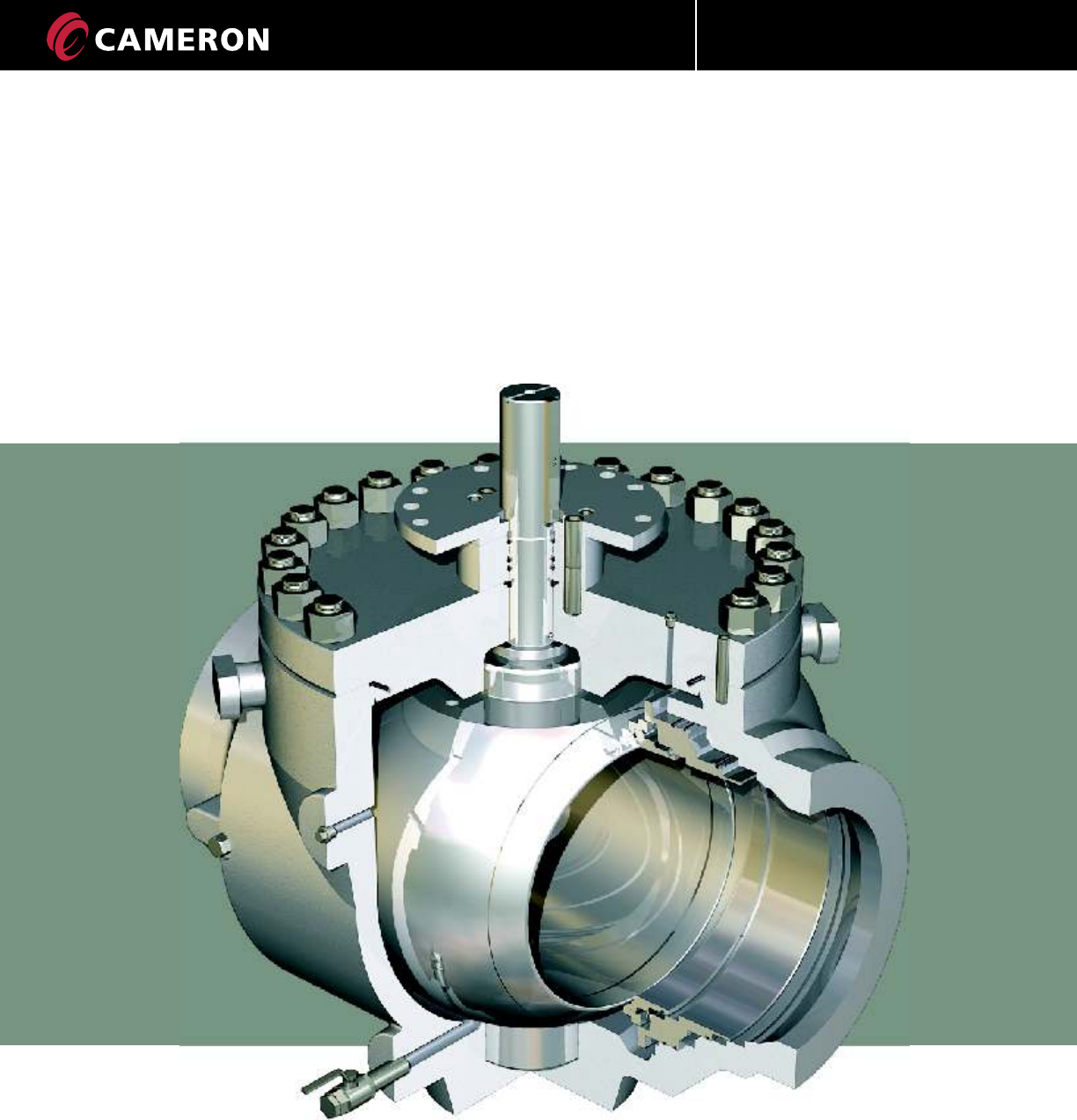
GROVE BT1 & BT2
Top Entry Ball Valves
ENGINEERED VALVES
®
GROVE

ENGINEERED VALVES
TABLE OF CONTENTS
GROVE BT1 & BT2
TOP ENTRY BALL VALVES
The Company 1
Applications 1
BT1 & BT2
Design Features 2
BT1 & BT2
Optional Features 5
BT1 & BT2
Special Applications 7
Special Process and Materials for Special Application 8
BT1
Material Selection 9
Valve Assembly and Cross Section 10
Dimensions and Weights 11
BT2
Material Selection 18
Valve Assembly and Cross Section 19
Dimensions and Weights 20
BT1 & BT2
Quality System 27
BT1 & BT2
Qualification and Testing 28
TRADEMARK INFORMATION 29
CT-GRO-BT1/BT2-03
08/10 NP-5M
®
GROVE
ENGINEERED VALVES
1
CT-GRO-BT1/BT2-03
08/10 NP-5M
®
GROVE
The BT1 and BT2 valves are full in-line field repairable,
thus eliminating long down times.
BT1 and BT2 valves have complete flexibility in the use
of materials for body, trim and seal gasket selections.
For this reason, they can be trimmed to meet your
most severe applications.
The BT1 and BT2 valves are sized to withstand the
external loads from the pipeline or from the manifolds
even when the bonnet, the ball and the seats are
removed for maintenance. They can also be welded
directly onto the pipeline or the manifold assembly.
The bonnet-body construction allows the use of
various grades of carbon steel, stainless steel and
other alloys thus complying with most severe service
conditions.
The GROVE BT1 and BT2 valves can also be adapted
for special applications such as abrasive fluids, low
temperature service, sequencing service (low and high
temperature), subsea installations and LNG plants.
RANGE OF PRODUCTION
THE COMPANY
Cameron's Valves & Measurement (V&M) group is a
leading provider of valves and measurement systems to
the Oil and Gas industry.
The Engineered Valves division provides large-diameter
valves for use in natural gas, LNG, crude oil and refined
products transmission lines as well as in many other
general industrial applications.
Rigorously tested, field-proven and backed by superior
aftermarket service, Cameron's GROVE valves are among
the best known valves in the world.
APPLICATIONS
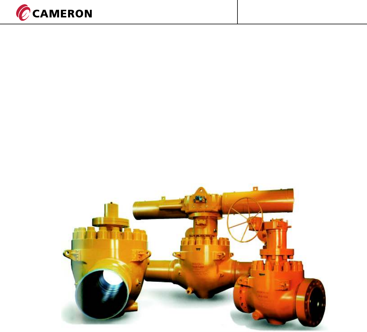
The GROVE BT1 and BT2 valves are an advanced design
of Top Entry ball valves, manufactured in a wide range
of diameters and pressure classes.
In the standard versions the valves are suitable for
transmission pipelines, pumping, compression and
re-injection units, offshore platforms, onshore terminals,
pig traps, measuring stations and surge relief skids.
Whenever ball valves are used in critical service
applications, in-situ field repairability with quick
turnaround is often needed.
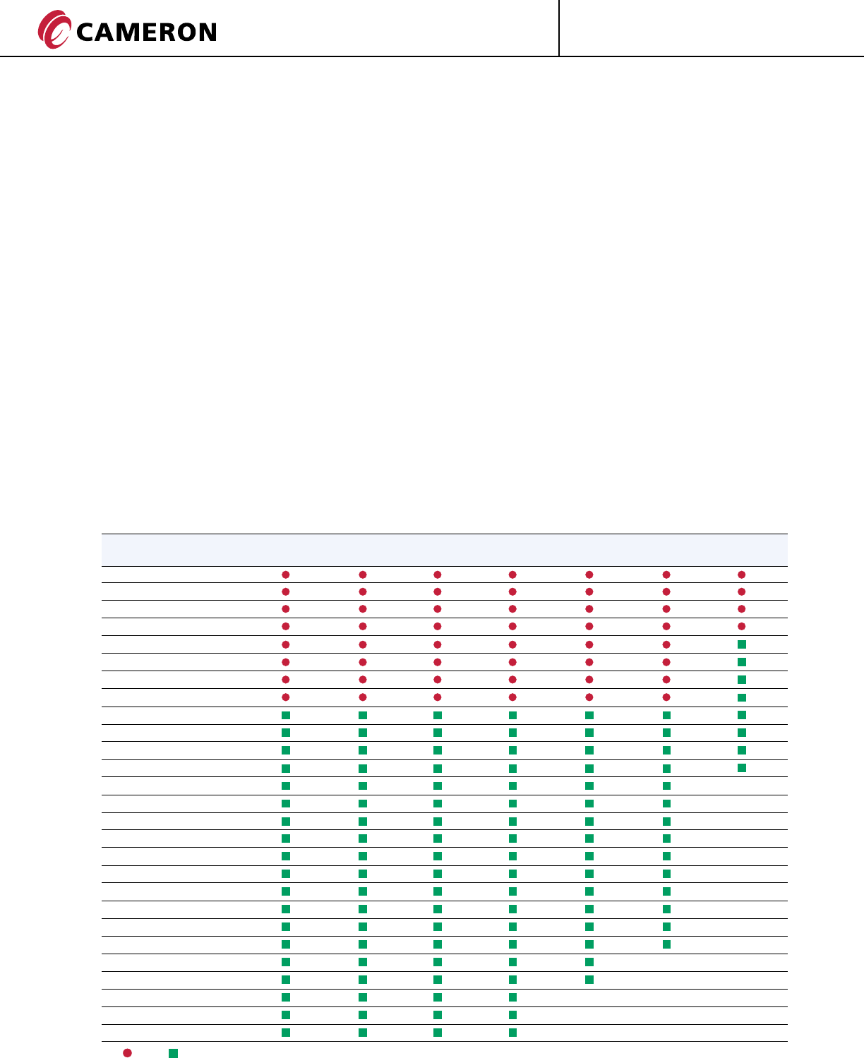
BT1 & BT2 TOP ENTRY BALL VALVES
SIZE ASME CLASS
in. (mm) 150 300 400 600 900 1500 2500
1 1/2 (40)
2 (50)
3 (80)
4 (100)
6 (150)
8 (200)
10 (250)
12 (300)
14 (350)
16 (400)
18 (450)
20 (500)
22 (550)
24 (600)
26 (650)
28 (700)
30 (750)
32 (800)
34 (850)
36 (900)
40 (1000)
42 (1050)
46 (1150)
48 (1200)
54 (1300)
56 (1400)
60 (1500)
BT1 BT2

ENGINEERED VALVES
®
GROVE
2
STANDARD FEATURES
• Triple barrier stem seals
• Anti-Blow Out stem design
• Stem emergency grease fitting
• Low friction metal-backed self lubricating
PTFE sleeve bearing and thrust washers
• Trunnion mounted ball
• Plastic polymer insert for seat sealing
• Double Piston Effect seats (DPE)
• Relief valve in the body cavity
• Nickel plating on pressure controlling parts and
stem in function of the trim material
• Body thickness in accordance with ASME B16.34
• End Flange dimensions in accordance with
API Standard 6D
• Adapter plate with integral position indicator
• In-line maintainable
• API 6FA Fire Safe Design
• Standard Design as per API 6D
FEATURES UPON REQUEST
• Self-relieving seats and duel seat design
• Lubricated seats
• Features for vertical installation
• Special Flanges or End Connections in accordance
with customer requirements
• Special Face-to-Face and bore sizes
• PTFE spring energized lip seals for stem sealing
• Anti-static device
• Metal-to-Metal seat sealing
• Double-Block-and-Bleed
• AISI 316 and Inconel 625 overlay on all sealing areas
• AISI 316 and Inconel 625 overlay on all wetted areas
• Explosive decompression resistant seals
• Explosive decompression resistant seals
• NACE MR0175 / ISO 15156
BT1 DESIGN FEATURES
STANDARD FEATURES
• Triple barrier stem seals
• Anti-Blow Out stem design
• Stem and seats emergency grease fittings
• Low friction metal-backed self lubricating
PTFE sleeve bearing and thrust washers
• Trunnion mounted ball
• Primary Metal-to-Metal seal and protected
secondary O-ring seal up to ASME Class 900, for
the higher classes Plastic Polymer insert for seat
sealing
• Double Piston Effect seats (DPE)
• Pressure relief valve in the body cavity
• Nickel plating on pressure controlling parts and
stem in function of the trim material
• Body thickness in accordance with ASME B16.34
• End Flange dimensions in accordance with
API Standard 6D
• Adapter plate with integral position indicator
• Factory positioned external stops
• In-line maintainable
• API 6FA Fire Safe Design
• Standard Design as per API 6D
FEATURES UPON REQUEST
• Self-relieving seats and dual seat design
• Lubricated seats
• Special flanges or end connections in accordance
with customer requirements
• Special Face-to-Face and bore sizes
• PTFE spring energized lip seals for sealing
• Anti-static device
• Metal-to-Metal seat sealing
• Double-Block-and-Bleed
• Features for vertical pipe installation
• AISI 316 and Inconel 625 overlay on sealing areas
• AISI 316 and Inconel 625 overlay on all overllay
on all wetted areas
• Explosive decompression resistant seals
• NACE MR0175 / ISO 15156
BT2 DESIGN FEATURES
CT-GRO-BT1/BT2-03
08/10 NP-5M
3
ENGINEERED VALVES
®
GROVE
SEAT SEAL
STEM CONSTRUCTION
The stem construction can either be integral with the
ball or separate from the ball depending upon the
type of service, valve size and trim material selected.
In either case, the stem anti-blow out configuration
of the GROVE Top Entry Valves prevents stem ejection
by internal pressure.
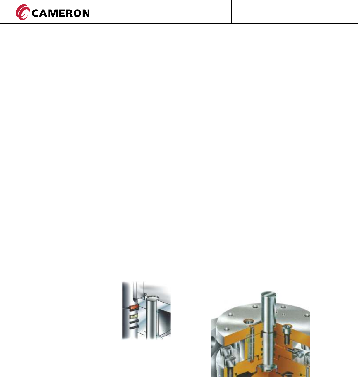
TRIPLE STEM SEALS
The standard design includes a
triple barrier sealing system the
configurations are the follows:
Up to 4" N.: 2 O-Rings plus
N.: 1 graphite Ring from 6"
and above N.: 3 O-Rings.
The outer seal can be replaced with the line under
pressure provided that the body cavity is fully vented
(please adhere to the procedure in the Maintenance
Manual).
BALL POSITION
For lever-operated valves, the open and closed positions
are assured by corresponding stops on the bearing
housing. When the valve is with gearbox or actuated
these stops are considered secondary stops, as primary
stops will be set the stops onto the gear/actuator.
“OPEN” and “CLOSED” indicators are also provided.
The Double Piston Effect (DPE) seat design allows each
seat to seal with pressure acting from each direction.
DPE seats are standard on the Top Entry Valves, hence,
in the event that the upstream seat is damaged, the
downstream seat provides a seal (double barrier in both
directions). Due to this seat configuration, the double
barrier is assured regardless of the flow direction.
Whenever required, the valve can be supplied with Self
Relieving Seats (SRS) that provide a single barrier. This
independent sealing on the upstream and downstream
seats is available upon request.
Under customer request, the valve can be supplied with
dual seats design, upstream seat self relieving down-
stream seat double piston effect to provide a double
barrier in one direction and to avoid the presence of the
body cavity relief valve. This configuration is available
upon request.
The standard design of the seating surface of the BT1
features a plastic insert which ensure low friction and
effective performances throughout the life of the valve.
The BT2 sealing is achieved by a primary Metal-to-Metal
seal and secondary protected O-Ring seal up to ASME
Class 900 for higher classes a plastic O-Ring or plastic
insert is used.
The Block-and-Bleed and Double-Block-and-Bleed
features are available on all size and classes.
Provision for the injection of
sealant can be provided to achieve temporary sealing
until required maintenance is carried out.
BT1 & BT2 DESIGN FEATURES
BODY/BONNET CONSTRUCTION
The typical shape of the body as well as the cast
construction allow for an optimization of material
distribution which is particularly suitable for high
pressure classes.
The body to bonnet joint design is in compliance
with ASME VIII Div. 1, and the ASME B16.34 body
thickness make the structure of the pressure
containing parts extremely robust, allowing for a
convenient selection of gasket types to be utilized
whenever required (i.e. low temperature, sour gas).
It also allows for the inclusion of additional
graphite seals to further guarantee the tightness
under fire conditions.
The body drain is located in the lowest part of the
body cavity and features an NPT drain valve with a
safety plug.
Unless otherwise specified the valve ends comply
with:
• Flanged Ends in accordance with
API 6D/ISO 14313
• Welded Ends in accordance with ASME 16.25.
The bolts threads are per ISO metric.
TORQUE
The low operating torque and the long trouble-free
service life of the GROVE Top Entry Valves are the
result of:
• The design of the stem which is not loaded by
side thrust;
• Two (upper and lower) rigid, large diameter,
short coupled trunnions which support the ball
side load due to differential pressure;
• Self lubricating sleeve bearing and thrust
washers.
The GROVE Top Entry Valves are suited for almost
any kind of powered operators and are able to
meet most severe operating and test conditions
such as those required of Emergency Shut Down
Valves or HIPPS Valves.
CT-GRO-BT1/BT2-03
08/10 NP-5M
ENGINEERED VALVES
®
GROVE
4
BT1 & BT2 DESIGN FEATURES
FULL IN-LINE MAINTENANCE
The GROVE Top Entry ball valve is designed to
be maintained in line.
The bolted construction allows disassembly
on-site for inspection and possible repair.
Removal of the bolted bonnet from the valve body
allows access to the ball and seats which can be
removed with special maintenance tools, designed
by GROVE.
The standard valve utilizes a DPE seat design
and therefore the tightness of the seating
surfaces can be assessed by pressurizing the
body cavity only, before any re-pressurization
of the pipeline.
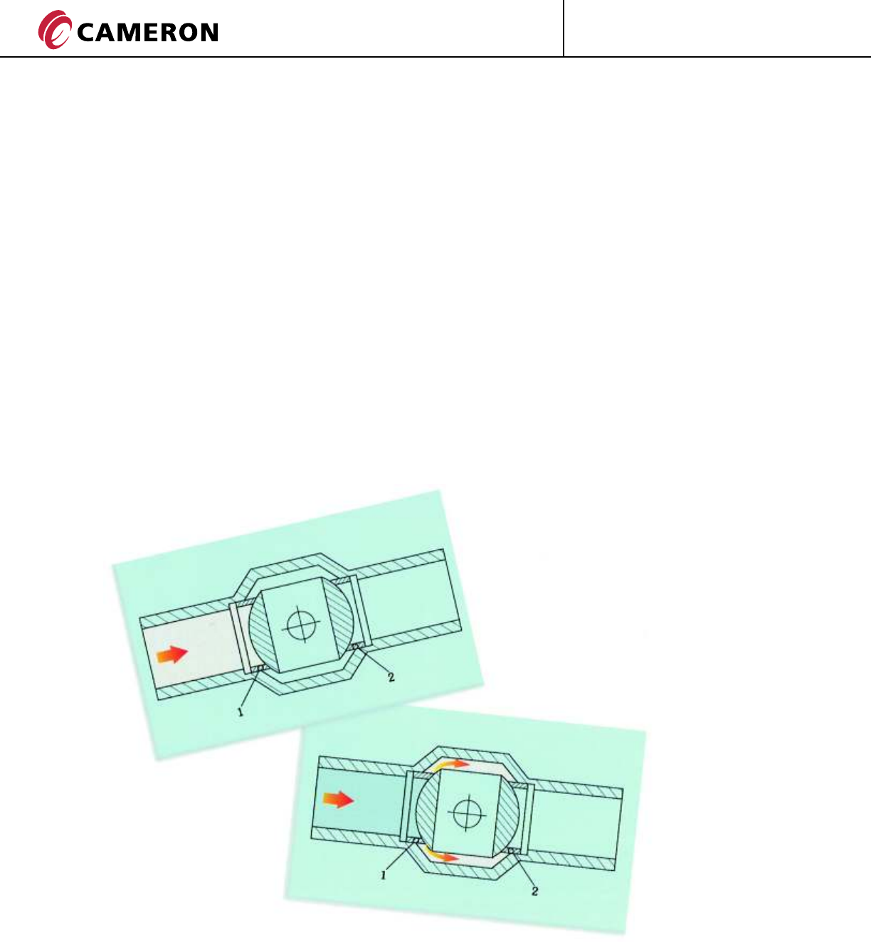
DOUBLE PISTON EFFECT (DPE)
Spring loaded seats are able to float along the
flow axis.
Line pressure behind the seat ring supplements
the seat spring load and pushes the seats tightly
against the ball. (Piston Effect).
Seat (2) sealing the downstream seat tightly against the ball.
If the upstream seat (1) is damaged and leaks,
the pressure entering the body cavity acts on
the downstream seat or ball.
CT-GRO-BT1/BT2-03
08/10 NP-5M
ENGINEERED VALVES
5
®
GROVE CT-GRO-BT1/BT2-03
08/10 NP-5M
BT1 & BT2 OPTIONAL FEATURES
STEM EXTENSIONS
GROVE ball valves can be
provided with optional stem
extensions suitable for buried
installations.
When used on a buried valve,
the stem extension can be
furnished “water-tight” and
both the grease injection
system and drain system will
be extended.
The length of the extension is
measured from the center-line
of the valve to the center-line
of the handwheel. This distance
must be specified at the order
stage.
Upon request; wrenches,
manual operators and powered
actuators can be supplied with
locking devices to suit the
customer’s specification.
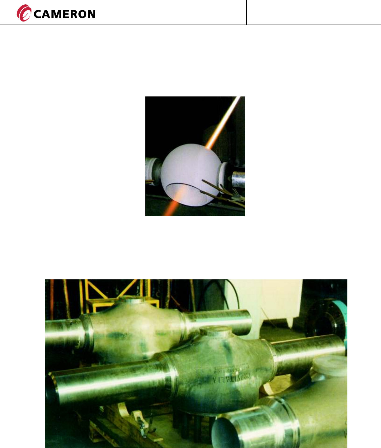
METAL-TO-METAL SEATS
The seating surfaces between the
seat and the ball can be completely
metallic.
This trim is recommended
whenever the standard soft
sealing is not suitable because of
the unfavorable combination of
pressure, temperature, chemical
composition of the fluid, or when
solid or abrasive particles are
present.
Metal-to-Metal seats utilize a
coating on the ball and seats
that is applied by means of
“High Velocity Oxy-Fuel” (HVOF)
using Tungsten Carbide.
GROVE operates its own in-house
HVOF process for the supply of
high quality Metal-to-Metal
seated valves.
TRANSITION PIECES
Transition pieces can be welded on to the valves during the manufacturing process.
Transition pipes can be made available free-issue to GROVE by the customer or can be procured
by GROVE to suit the customer’s specifications.
GROVE offers a wide variety of weld procedures in accordance with most international standards.
ENGINEERED VALVES
®
GROVE
6CT-GRO-BT1/BT2-03
08/10 NP-5M
BT1 & BT2 OPTIONAL FEATURES
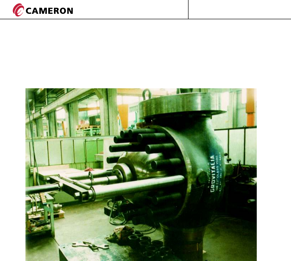
INSTALLATION ON VERTICAL PIPE
Top Entry ball valves to be installed on vertical pipelines are supplied together
with special equipment which permits the ball and the seats to be supported
during lateral disassembly.
The clearance required to carry out this operation will be provided upon request.
INTERNAL SLEEVE
When severe commissioning
conditions are foreseen, in the
presence of pipeline construction
residuals and when the integrity
of the internals is to be
guaranteed the option for
Top Entry ball valves to have
a customized temporary sleeve
is available.
ACTUATORS
All BT Series valves are designed
with an adapter plate to enable
the fitting of powered actuators
(electric, hydraulic, pneumatic).
The assembly of the actuator on a
new valve is usually carried out at
the factory thus guaranteeing the
full functionality of the completed
assembly.
Should a valve require modification
to enable an actuator to be fitted
on-site, qualified personnel are
available to supervise the
modification.
BT2 in vertical position, with special tools, during the ball assembly/disassembly operations.
ENGINEERED VALVES
7
®
GROVE CT-GRO-BT1/BT2-03
08/10 NP-5M
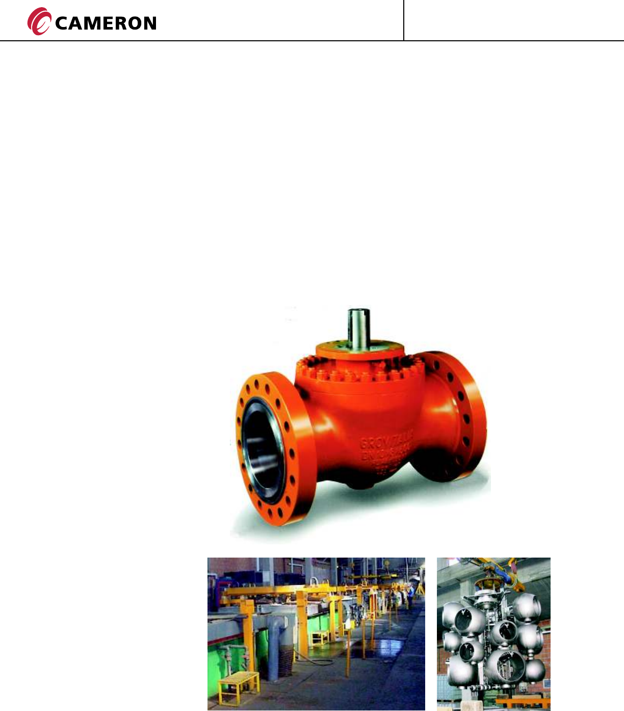
BT1 & BT2 SPECIAL APPLICATION
“S” DESIGN FOR
SUBSEA SERVICE
The BT Series S-type valve is the
subsea version of the GROVE Top
Entry ball valve, specifically
designed to suit subsea service
conditions.
The BT Series S-type valve is a very
reliable product and is designed to
provide optimum service without
maintenance.
The S-type design meets the
restrictive criteria usually adopted
for pressure retaining and drive
train components, making the
S-type valve suitable also for
Emergency Shutdown Service (ESD).
Full consideration has been given to
mitigate the possibility of galvanic
corrosion in critical sealing areas by
means of weld overlay in stainless
steel or nickel alloys. Upon customer
request, or if required by the service
conditions, the weld overlay can be
extended to all wetted areas.
The corrosion resistance of the
overlay can be verified by chemical
analysis of test specimens and
components.
The stem and external sealing areas
are protected with additional
gaskets sealing against sea water
ingress.
The body and the bolts are coated
with special paint or coatings for
corrosion resistance. In addition
bonnet bolts feature special
sealing caps for protection.
A protective cap can also be
provided onto the stem to
prevent sea water ingress and
allows for deployment of either
manual or powered actuators.
“P” DESIGN FOR HIGH
TEMPERATURE SERVICE
The BT Series P-type valve is the
high temperature version of the
GROVE Top Entry ball valve and is
suitable for service temperatures
up to 716°F (380°C).
“L” DESIGN FOR LOW
TEMPERATURE SERVICE
The BT Series L-type is the low
temperature version of the
GROVE Top Entry ball valve and
is suited for temperature down
to -193°F (-125°C).
The L-type valves utilize special
materials, parts dimensions,
surface finishing, gaskets and
stem connections that are
specifically designed to suit low
temperature conditions.
The BT Series L-type valves are
supplied with an extended
bonnet allowing the stem seal to
be positioned away from the low
temperature zone, enhancing the
sealing performance.
The valves are fitted with special
lip gaskets specifically designed
for low temperature application.
Seat insert materials are selected
in accordance with the process
conditions and testing
parameters.
Body and trim are usually made of
austenitic stainless steel grades.
Bonnet bolting is made of
ASTM A320/194 grade B8M/8MA
or A453 grade 660.
The valves are suited to
heavy cycling under alternating
conditions of temperatures and
pressures (for example sequencing
service). Sealing performance is
ensured by metal/graphite gaskets
and metal to metal seats.
Valves are provided with stem
extensions which allows the stem
seal to lie far from the high
temperature zone.
The drive train is designed to
withstand high torque values
resulting from the Metal-to-Metal
seats in high temperature
conditions. Trim and bolting are
suited to high temperature service.
ENGINEERED VALVES
®
GROVE
8CT-GRO-BT1/BT2-03
08/10 NP-5M
MATERIALS SELECTION
The quality of the valve depends
on the materials selection.
The BT Series valves are designed
in accordance with material
requirements in API Standard 6D
and allows for the selection of
various combinations. After
reviewing the service conditions,
the selection is carried out to suit
the mechanical and chemical
characteristics of the materials.
A complete bill of materials is
submitted at the quotation stage
addressing each component.
IN HOUSE SPECIAL PROCESS
GROVE has in-house special
process capabilities to produce
valves for most critical
applications.
Elecroless Nickel Plating (ENP)
capability. ASTM B733 is the
standard used for plating
control.
Strict quality control procedures
for critical process conditions
and for the plated components
maintain plating consistency.
High Velocity Oxy Fuel (HVOF)
capability to provide Tungsten
Carbide coating and provide
wear and corrosion resistance
to the Metal-to-Metal valves.
WELD OVERLAYS
In case of corrosive service,
sealing surfaces or other
critical parts of the valve can
be robotically overlaid.
Commonly used materials for
weld overlay are AISI 316
and Inconel 625.
The process is qualified so
that the final thickness after
machining can guarantee the
chemical composition per the
relevant ASTM standard.
Non-Descructive testing (NDT)
is then carried out using the
dye penetrant method.
BT1 & BT2 SPECIAL PROCESS AND MATERIALS FOR SPECIAL APPLICATIONS
NACE REQUIREMENTS
On request GROVE Top Entry ball
valves can be supplied in accordance
with NACE MR0175 & ISO 15156
requirements.
SEVERE WET SOUR GAS SERVICE
In addition to compliance with
requirements in NACE MR0175, for
resistance to sulfide stress cracking,
the following specifications can be
met:
• NACE TM0284 (stepwise cracking
induced by hydrogen adsorption)
• NACE TM0177 (sulfide stress
cracking at 720 hours)
DUPLEX
STAINLESS STEELS
METALLURGY
For Duplex (22Cr 2Ni) and Super
Duplex (25Cr 5Ni) stainless steel
the following requirements are
met:
• Pitting corrosion
PRE = 33 min. for Duplex,
40 min. for Super Duplex
• Ferrite content 40 to 60%
per ASTM E 562
In addition the following
corrosion resistance
qualification tests are
available:
• Chloride corrosion per
ASTM G48
(104°F (40°C), 72 hours)
• Cracking per ASTM G36
(302°F (150°C), 500 hours)

9
ENGINEERED VALVES
®
GROVE CT-GRO-BT1/BT2-03
08/10 NP-5M
MATERIALS SELECTION
The GROVE BT1 Ball Valve has been designed for use
with various materials or combinations of materials
depending on the service conditions.
The following is a typical listing of materials for valves
ASME Class 150 - 2500 for standard applications.
BT1 MATERIALS SPECIFICATION
PRESSURE RETAINING PARTS
Body A216 WCB, A216 WCC, A352 LCB, A352 LCC
Bonnet A350 LF2
Stem AISI 4140, A564 Gr. 630 (17-4 PH
Bolting A193 B7, A194 2H, A193 B7M, A194 2HM, A320 L7, A194 Gr.7, A320 L7M, A194 Gr. 7M
INTERNAL PARTS
Ball AISI 4140, A350 LF2, A694 F65, AISI 316, A564 Gr 630 (17-4 PH)
Seats AISI 4140, A350 LF2, A694 F65, AISI 316, A564 Gr 630 (17-4 PH)
Springs AISI 302, Inconel (different grades), Elgiloy
SEALING MATERIALS
Stem Gasket: NBR (Nitrile)
FKM (Viton different grades)
HNBR (Hydrogenated Nitrile)
Seat/ Bonnet Gasket: NBR (Nitrile)
FKM (Viton different grades)
HNBR (Hydrogenated Nitrile)
PLATING/COATING
0.001 inch 25 microns
ENP Electroless Nickel Plating
0.003 inch 75 microns
ENP Electroless Nickel Plating
NACE REQUIREMENTS
GROVE BT1 Ball Valves can be supplied in accordance with NACE MR0175 / ISO 15156
ENGINEERED VALVES
®
GROVE
10 CT-GRO-BT1/BT2-03
08/10 NP-5M
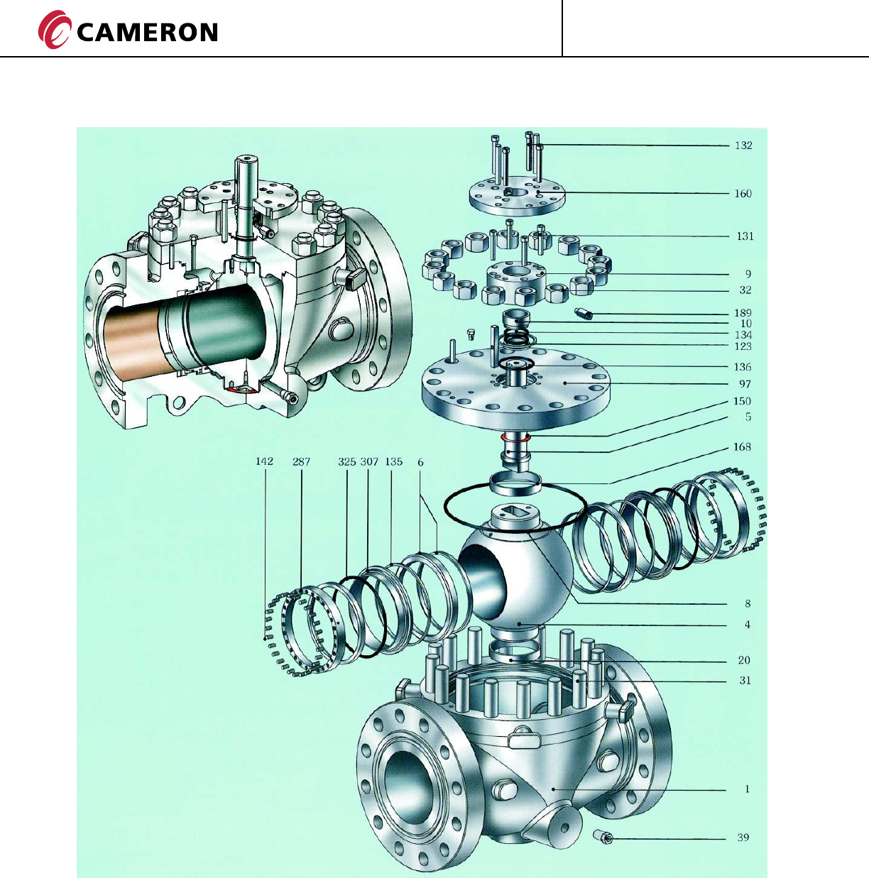
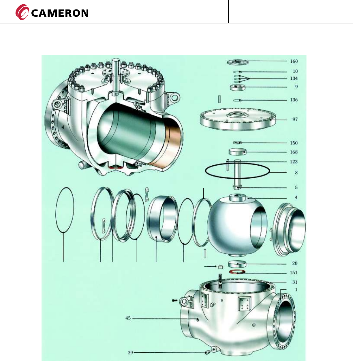
BT1 VALVE ASSEMBLY & CROSS SECTION
Item Description
1 Body
4 Ball
5 Stem
6 Seat Ring with Insert
8 Body O-Ring
9 Bonnet Cover
10 Bushing
20 Lower Bearing
32 Body Nut
39 Drain Valve
97 Bonnet
123 Stem Key
131 Bonnet Cover Capscrew
132 Adapter Plate Capscrew
134 Stem O-Ring
135 Seat O-Ring
31 Body Stud 142 Spring
150 Upper Washer
160 Adapter Plate
168 Upper Bearing
189 Stem Grease Fitting
287 Spring Holder Ring
307 Seat Thrust Ring
325 Seat Thrust Ring Gasket
136 Bonnet Cover O-Ring
11
ENGINEERED VALVES
®
GROVE CT-GRO-BT1/BT2-03
08/10 NP-5M
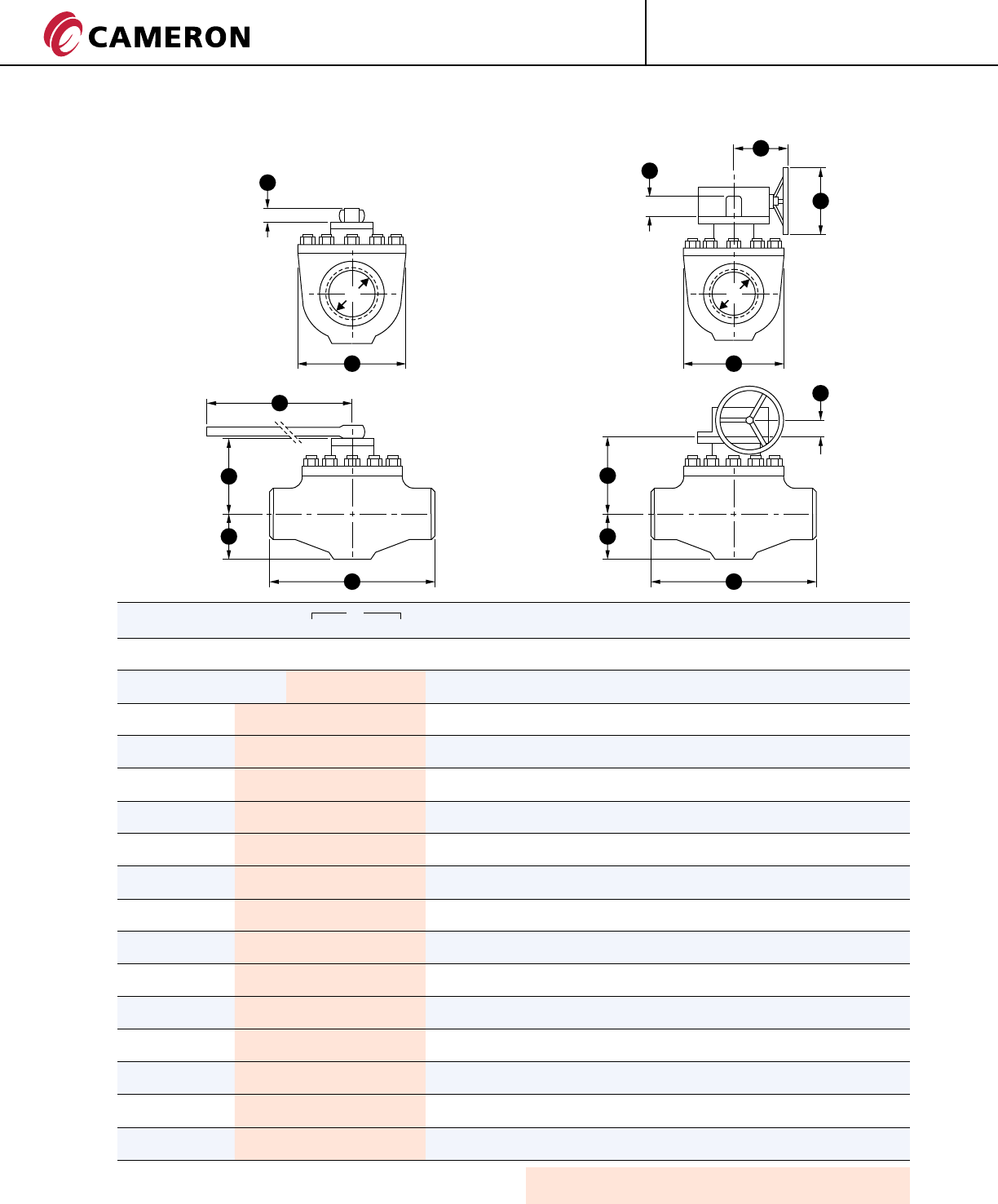
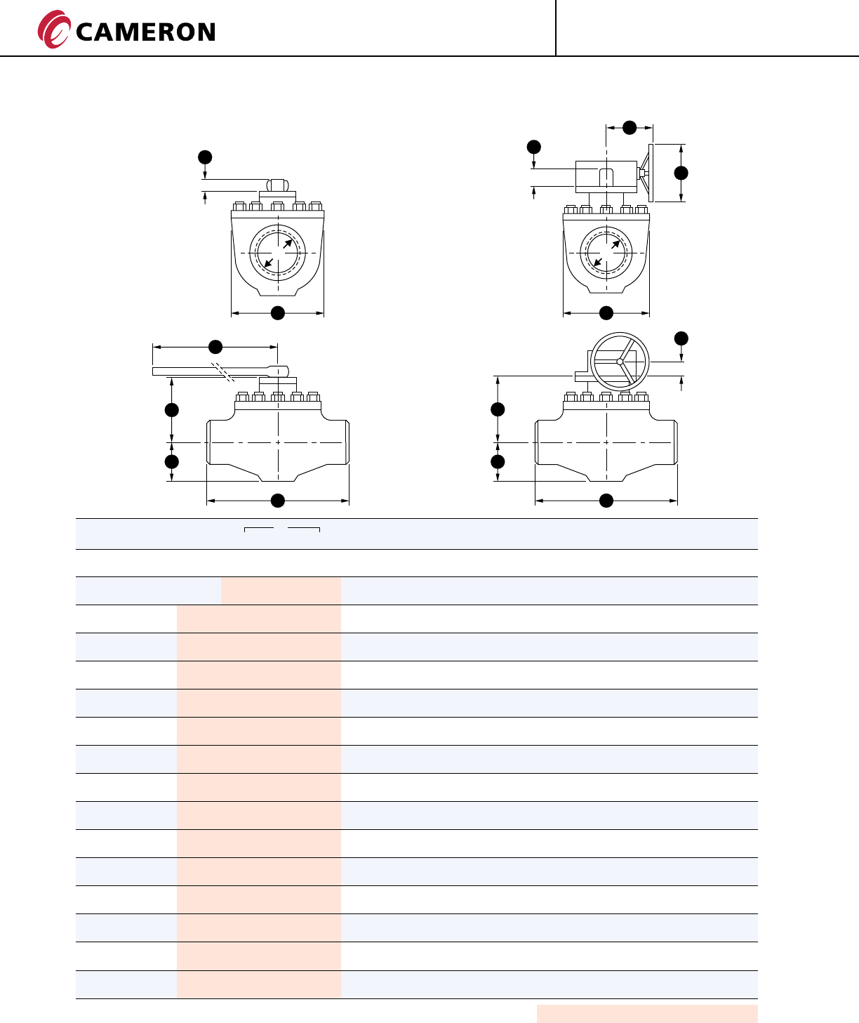
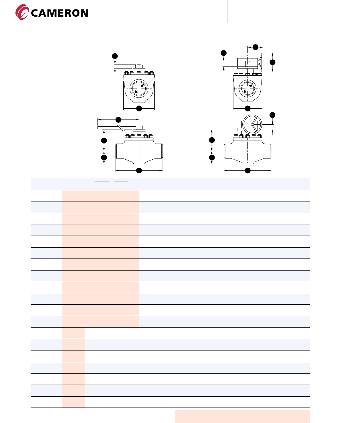
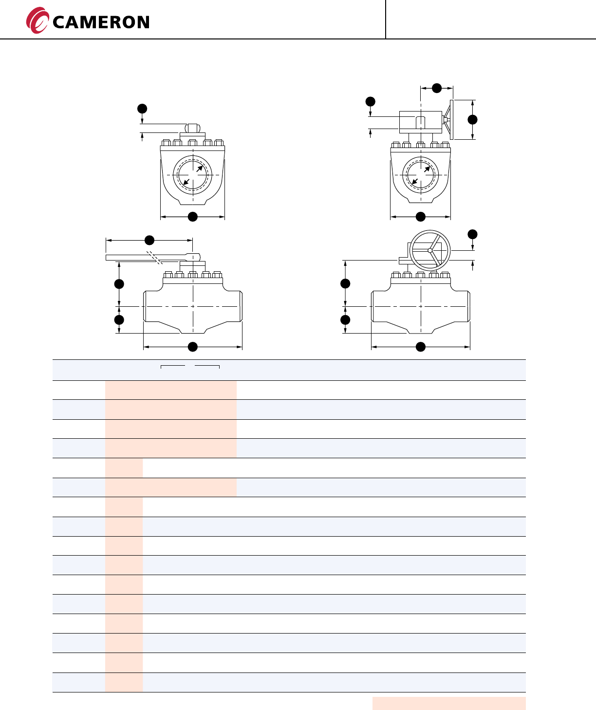
BT1 DIMENSIONS AND WEIGHTS
ASME CLASS 150
DD
HH
S S
K
A
E E
M
L
G
F
G
F
Flanges in accordance with ASME B16.5.
Butt Welding Ends according to ASME B16.25.
Dimensions and Weights are indicative and will be confirmed at the time of the order.
SIZE in. D E F G S H L A K M WEIGHT lb. (kg)
(mm) WE RF RTJ WE RF/RTJ
1 1/2 1 1/2 10 1/4 10 1/4 10 3/8 2 1/2 5 3/4 6 1/2 2 3/8 12 - - - 35 62
(40) (38) (260) (260) (264) (63) (145) (165) (61) (305) - - - (16) (28)
2 x 1 1/2 x 2 1 1/2 11 1/2 11 1/2 11 5/8 2 1/2 5 3/4 6 1/2 2 3/8 12 - - - 55 66
(50 x 40 x 50) (38) (292) (292) (295) (63) (145) (165) (61) (305) - - - (25) (30)
2 2 11 1/2 11 1/2 11 5/8 3 1/8 6 3/4 7 1/4 2 3/8 12 - - - 62 88
(50) (51) (292) (292) (295) (78) (170) (185) (61) (305) - - - (28) (40)
3 x 2 x 3 2 14 14 14 1/8 3 1/8 6 3/4 7 1/4 2 3/8 12 - - - 90 110
(80 x 50 x 80) (51) (356) (356) (359) (78) (170) (185) (61) (305) - - - (41) (50)
3 3 14 14 14 1/8 3 7/8 8 3/8 9 1/2 2 3/8 17 3/4 - - - 99 143
(80) (76) (356) (356) (359) (100) (212) (240) (61) (450) - - - (45) (65)
4 x 3 x 4 3 17 17 17 1/8 3 7/8 8 3/8 9 1/2 2 3/8 17 3/4 - - - 150 176
(100 x 80 x 100) (76) (432) (432) (435) (100) (212) (240) (61) (450) - - - (68) (80)
4 4 17 17 17 1/8 4 3/4 9 1/4 11 5/8 2 3/8 36 - - - 187 243
(100) (102) (432) (432) (435) (120) (236) (296) (61) (915) - - - (85) (110)
6 x 4 x 6 4 22 22 22 1/8 4 3/4 9 1/4 11 5/8 2 3/8 36 - - - 220 287
(150 x 100 x 150) (102) (559) (559) (562) (120) (236) (296) (61) (915) - - - (100) (130)
6 6 22 22 22 1/8 6 3/8 10 5/8 15 3/8 3 1/8 - 8 3/4 13 3/4 2 5/8 430 463
(150) (152) (559) (559) (562) (162) (271) (390) (80) - (223) (350) (67) (195) (210)
8 x 6 x 8 6 26 26 26 1/8 6 3/8 10 5/8 15 3/8 3 1/8 - 8 3/4 13 3/4 2 5/8 459 511
(200 x 150 x 200) (152) (660) (660) (664) (162) (271) (390) (80) - (223) (350) (67) (208) (232)
8 8 26 26 26 1/8 8 1/8 12 1/8 18 1/2 3 1/8 - 8 3/4 13 3/4 2 5/8 772 827
(200) (203) (660) (660) (664) (207) (308) (470) (80) - (223) (350) (67) (350) (375)
10 x 8 x 10 8 31 31 31 1/8 8 1/8 12 1/8 18 1/2 3 1/8 - 8 3/4 13 3/4 2 5/8 849 930
(250 x 200 x 250) (203) (787) (787) (791) (207) (308) (470) (80) - (223) (350) (67) (385) (422)
10 10 31 31 31 1/8 9 5/8 13 3/4 22 1/4 4 1/8 - 8 3/4 13 3/4 2 5/8 882 1019
(250) (254) (787) (787) (791) (244) (348) (566) (105) - (223) (350) (67) (400) (462)
12 x 10 x 12 10 33 33 33 1/8 9 5/8 13 3/4 22 1/4 4 1/8 - 8 3/4 13 3/4 2 5/8 970 1091
(300 x 250 x 300) (254) (838) (838) (841) (244) (348) (566) (105) - (223) (350) (67) (440) (495)
12 12 33 33 33 1/8 11 3/8 15 1/8 24 3/4 4 1/8 - 8 3/4 13 3/4 2 5/8 1213 1455
(300) (305) (838) (838) (841) (290) (385) (630) (105) - (223) (350) (67) (550) (660)
16 x 12 x 16 12 39 39 39 1/8 11 3/8 15 1/8 24 3/4 4 1/8 - 8 3/4 13 3/4 2 5/8 1543 1764
(400 x 300 x 400) (305) (991) (991) (994) (290) (385) (630) (105) - (223) (350) (67) (700) (800)
Shaded bore sizes (D) according to ISO 14313.
Shaded End-to-End Dimensions (E) according to ISO 14313 Class 600.
ENGINEERED VALVES
®
GROVE
12 CT-GRO-BT1/BT2-03
08/10 NP-5M
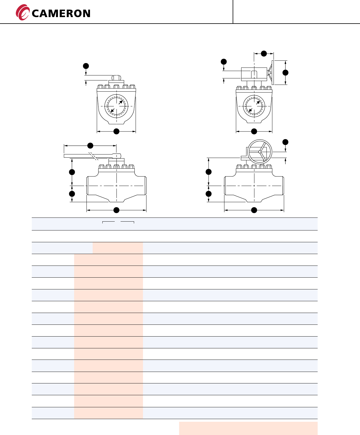
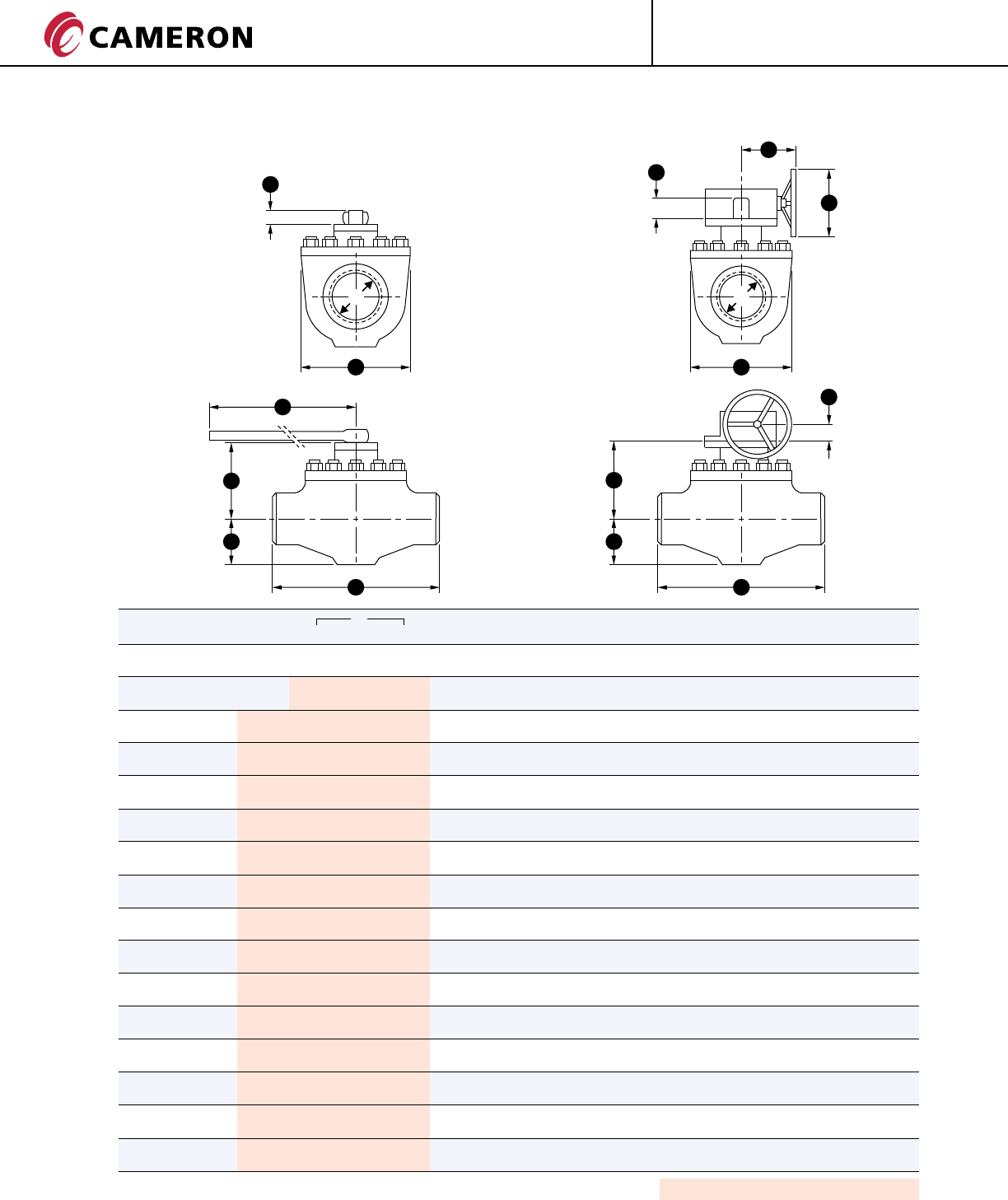
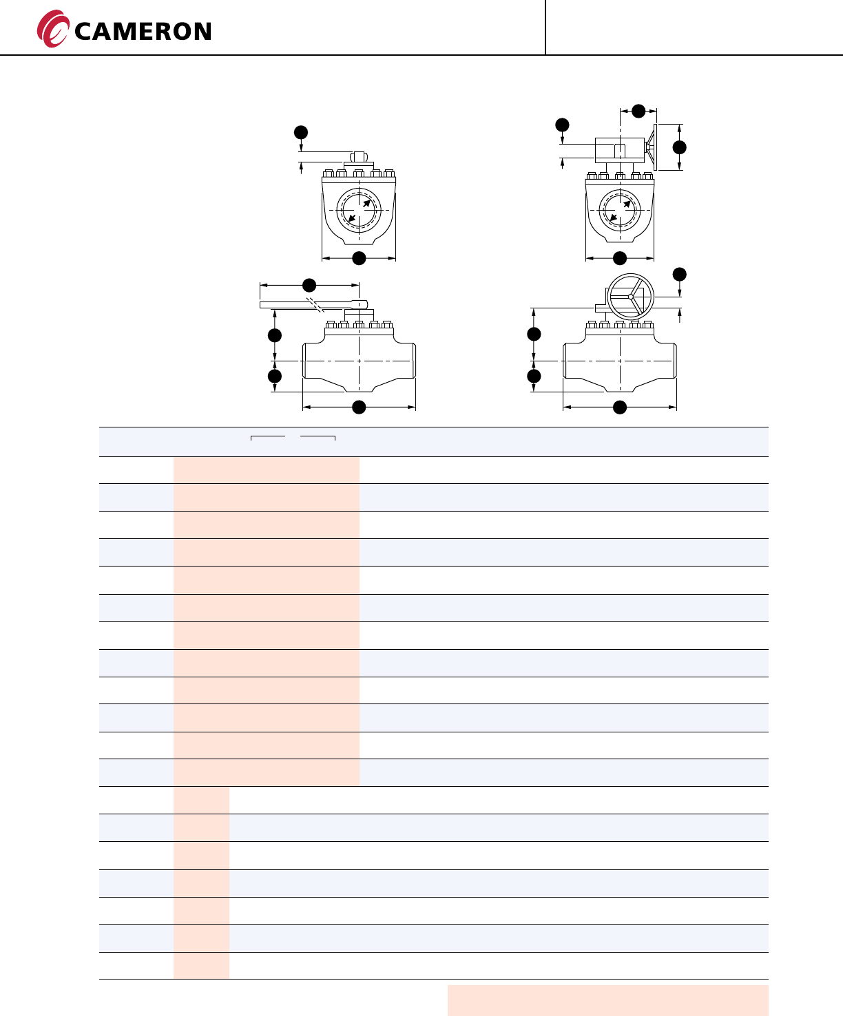
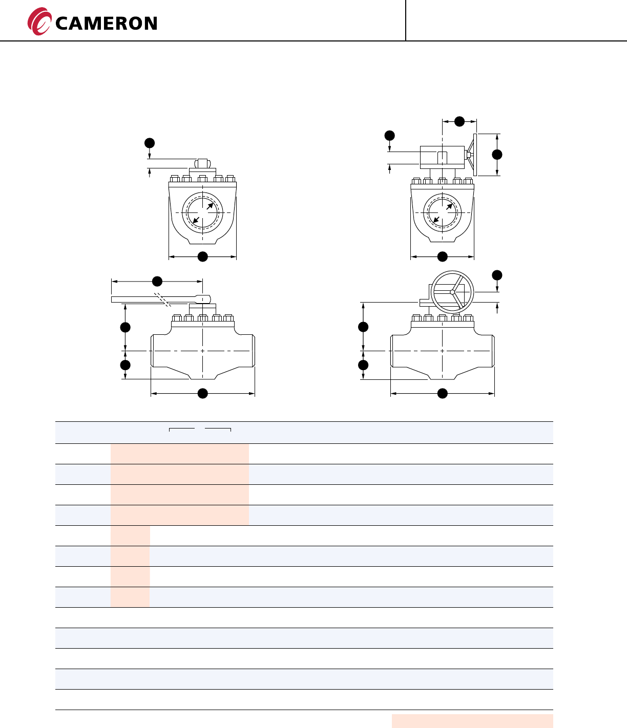
BT1 DIMENSIONS AND WEIGHTS
ASME CLASS 300
DD
HH
S S
K
A
E E
L
G
F
G
F
SIZE in. D E F G S H L A K M WEIGHT lb. (kg)
(mm) WE RF RTJ WE RF/RTJ
1 1/2 1 1/2 10 1/4 10 1/4 10 3/8 2 1/2 5 3/4 6 1/2 2 3/8 12 - - - 40 66
(40) (38) (260) (260) (264) (63) (145) (165) (61) (305) - - - (18) (30)
2 x 1 1/2 x 2 1 1/2 11 1/2 11 1/2 11 5/8 2 1/2 5 3/4 6 1/2 2 3/8 12 - - - 62 71
(50 x 40 x 50) (38) (292) (292) (295) (63) (145) (165) (61) (305) - - - (28) (32)
2 2 11 1/2 11 1/2 11 5/8 3 1/8 6 3/4 7 1/4 2 3/8 17 3/4 - - - 68 88
(50) (51) (292) (292) (295) (78) (170) (185) (61) (450) - - - (31) (40)
3 x 2 x 3 2 14 14 14 1/8 3 1/8 6 3/4 7 1/4 2 3/8 17 3/4 - - - 93 108
(80 x 50 x 80) (51) (356) (356) (359) (78) (170) (185) (61) (450) - - - (42) (49)
3 3 14 14 14 1/8 3 7/8 8 3/8 9 1/2 2 3/8 36 - - - 110 143
(80) (76) (356) (356) (359) (100) (212) (240) (61) (915) - - - (50) (65)
4 x 3 x 4 3 17 17 17 1/8 3 7/8 8 3/8 9 1/2 2 3/8 36 - - - 161 187
(100 x 80 x 100) (76) (432) (432) (435) (100) (212) (240) (61) (915) - - - (73) (85)
4 4 17 17 17 1/8 4 3/4 9 1/4 11 5/8 2 3/8 51 1/8 - - - 209 276
(100) (102) (432) (432) (435) (120) (236) (296) (61) (1300) - - - (95) (125)
6 x 4 x 6 4 22 22 22 1/8 4 3/4 9 1/4 11 5/8 2 3/8 51 1/8 - - - 258 320
(150 x 100 x 150) (102) (559) (559) (562) (120) (236) (296) (61) (1300) - - - (117) (145)
6 6 22 22 22 1/8 6 3/8 10 5/8 15 3/8 4 1/8 - 8 3/4 13 3/4 2 5/8 481 611
(150) (152) (559) (559) (562) (162) (271) (390) (105) - (223) (350) (67) (218) (277)
8 x 6 x 8 6 26 26 26 1/8 6 3/8 10 5/8 15 3/8 4 1/8 - 8 3/4 13 3/4 2 5/8 518 622
(200 x 150 x 200) (152) (660) (660) (664) (162) (271) (390) (105) - (223) (350) (67) (235) (282)
8 8 26 26 26 1/8 8 1/8 12 1/8 18 1/2 4 1/8 - 8 3/4 13 3/4 2 5/8 794 897
(200) (203) (660) (660) (664) (207) (308) (470) (105) - (223) (350) (67) (360) (407)
10 x 8 x 10 8 31 31 31 1/8 8 1/8 12 1/8 18 1/2 4 1/8 - 8 3/4 13 3/4 2 5/8 904 966
(250 x 200 x 250) (203) (787) (787) (791) (207) (308) (470) (105) - (223) (350) (67) (410) (438)
10 10 31 31 31 1/8 9 5/8 13 3/4 21 5/8 5 1/8 - 11 1/2 13 3/4 3 904 1067
(250) (254) (787) (787) (791) (244) (348) (550) (130) - (292) (350) (75) (410) (484)
12 x 10 x 12 10 33 33 33 1/8 9 5/8 13 3/4 21 5/8 51/8 - 11 1/2 13 3/4 3 1036 1243
(300 x 250 x 300) (254) (838) (838) (841) (244) (348) (550) (130) - (292) (350) (75) (470) (564)
12 12 33 33 33 1/8 11 3/8 15 1/8 24 3/4 5 1/8 - 11 1/2 13 3/4 3 1243 1464
(300) (305) (838) (838) (841) (290) (385) (630) (130) - (292) (350) (75) (564) (664)
16 x 12 x 16 12 39 39 39 1/8 11 3/8 15 1/8 24 3/4 5 1/8 - 11 1/2 13 3/4 3 1984 2280
(400 x 300 x 400) (305) (991) (991) (994) (290) (385) (630) (130) - (292) (350) (75) (900) (1034)
Flanges in accordance with ASME B16.5.
Butt Welding Ends according to ASME B16.25.
M
Shaded bore sizes (D) according to ISO 14313.
Shaded End-to-End Dimensions (E) according to ISO 14313 Class 600.
Dimensions and Weights are indicative and will be confirmed at the time of the order.
13
ENGINEERED VALVES
®
GROVE CT-GRO-BT1/BT2-03
08/10 NP-5M
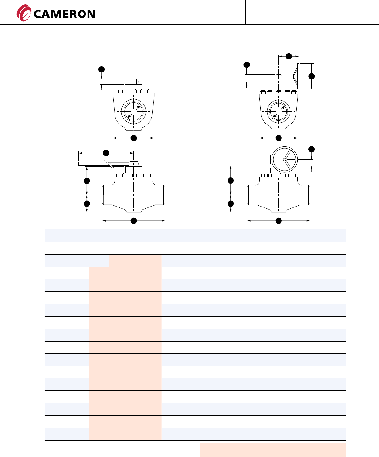
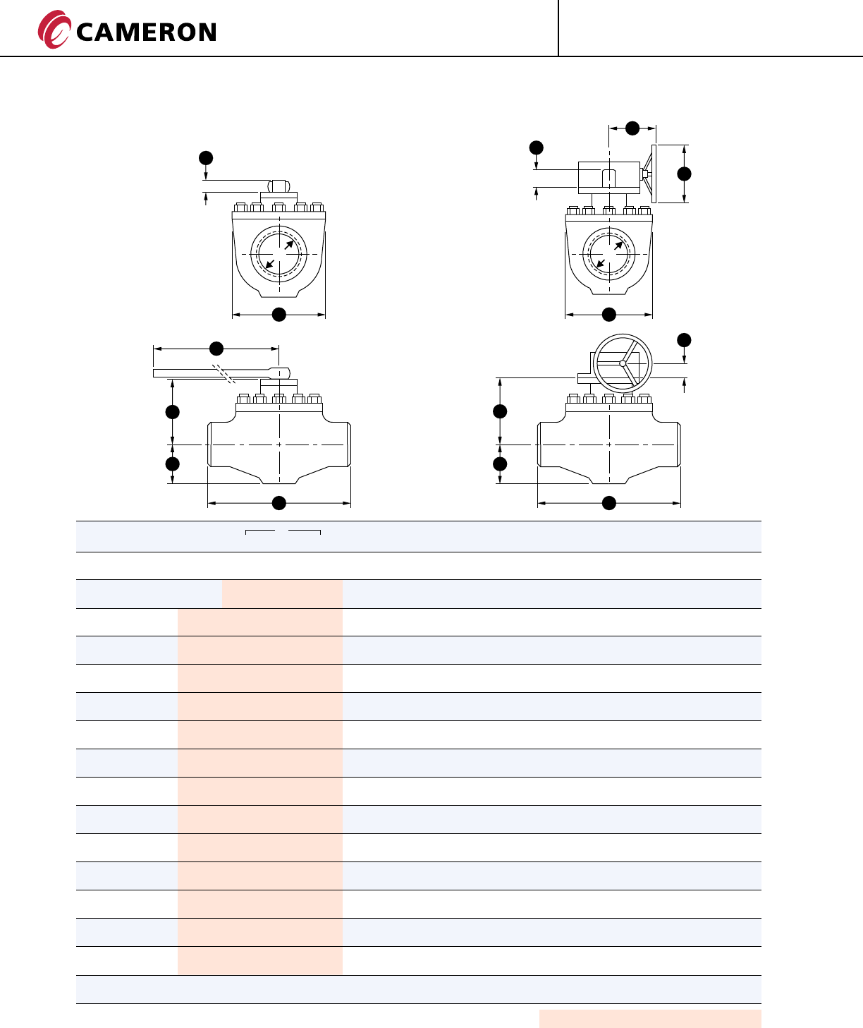
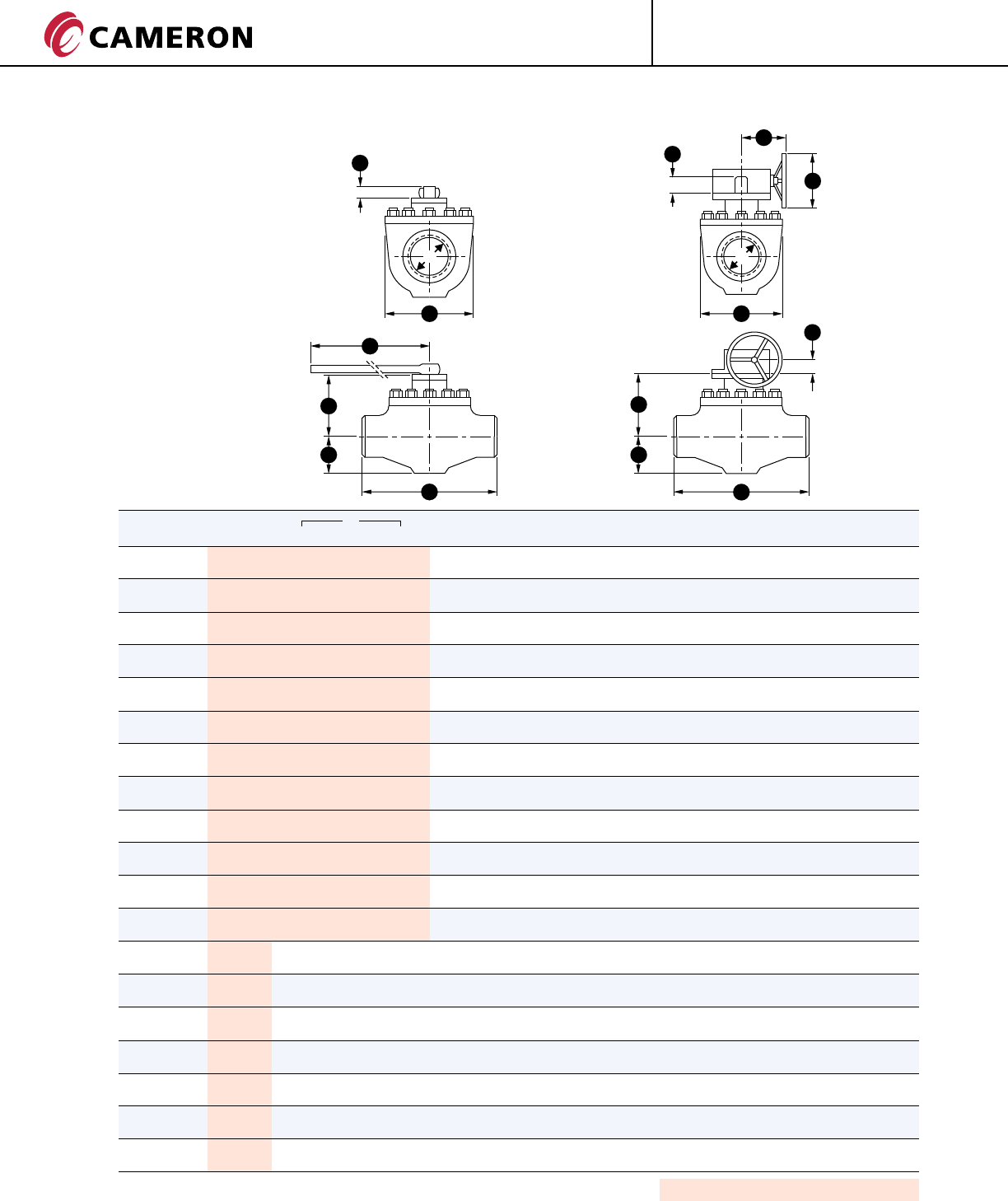
BT1 DIMENSIONS AND WEIGHTS
ASME CLASS 400
DD
HH
S S
K
A
E E
L
G
F
G
F
SIZE in. D E F G S H L A K M WEIGHT lb. (kg)
(mm) WE RF RTJ WE RF/RTJ
1 1/2 1 1/2 10 1/4 10 1/4 10 3/8 2 1/2 5 3/4 6 1/2 2 3/8 12 - - - 44 71
(40) (38) (260) (260) (264) (63) (145) (165) (61) (305) - - - (20) (32)
2 x 1 1/2 x 2 1 1/2 11 1/2 11 1/2 11 5/8 2 1/2 5 3/4 6 1/2 2 3/8 12 - - - 62 75
(50 x 40 x 50) (38) (292) (292) (295) (63) (145) (165) (61) (305) - - - (28) (34)
2 2 11 1/2 11 1/2 11 5/8 3 1/8 6 3/4 7 1/4 2 3/8 17 3/4 - - - 71 93
(50) (51) (292) (292) (295) (78) (170) (185) (61) (450) - - - (32) (42)
3 x 2 x 3 2 14 14 14 1/8 3 1/8 6 3/4 7 1/4 2 3/8 17 3/4 - - - 95 123
(80 x 50 x 80) (51) (356) (356) (359) (78) (170) (185) (61) (450) - - - (43) (56)
3 3 14 14 14 1/8 3 7/8 8 3/8 9 1/4 2 3/8 36 - - - 121 154
(80) (76) (356) (356) (359) (100) (212) (240) (61) (915) - - - (55) (70)
4 x 3 x 4 3 17 17 17 1/8 3 7/8 8 3/8 9 1/4 2 3/8 36 - - - 170 203
(100 x 80 x 100) (76) (432) (432) (435) (100) (212) (240) (61) (915) - - - (77) (92)
4 4 17 17 17 1/8 4 3/4 9 1/4 11 5/8 2 3/8 51 1/8 - - - 238 291
(100) (102) (432) (432) (435) (120) (236) (296) (61) (1300) - - - (108) (132)
6 x 4 x 6 4 22 22 22 1/8 4 3/4 9 1/4 11 5/8 2 3/8 51 1/8 - - - 287 337
(150 x 100 x 150) (102) (559) (559) (562) (120) (236) (296) (61) (1300) - - - (130) (153)
6 6 22 22 22 1/8 6 3/8 10 5/8 15 3/8 4 1/8 - 8 3/4 13 3/4 2 5/8 518 522
(150) (152) (559) (559) (562) (162) (271) (390) (105) - (223) (350) (67) (235) (237)
8 x 6 x 8 6 26 26 26 1/8 6 3/8 10 5/8 15 3/8 4 1/8 - 8 3/4 13 3/4 2 5/8 553 681
(200 x 150 x 200) (152) (660) (660) (664) (162) (271) (390) (105) - (223) (350) (67) (251) (309)
8 8 26 26 26 1/8 8 1/8 12 1/8 18 1/2 5 1/8 - 11 1/2 13 3/4 3 807 935
(200) (203) (660) (660) (664) (207) (308) (470) (130) - (292) (350) (75) (366) (424)
10 x 8 x 10 8 31 31 31 1/8 8 1/8 12 1/8 18 1/2 5 1/8 - 11 1/2 13 3/4 3 941 1116
(250 x 200 x 250) (203) (787) (787) (791) (207) (308) (470) (130) - (292) (350) (75) (427) (506)
10 10 31 31 31 1/8 9 5/8 13 3/4 21 5/8 5 1/8 - 11 1/2 13 3/4 3 1131 1305
(250) (254) (787) (787) (791) (244) (348) (550) (130) - (292) (350) (75) (513) (592)
12 x 10 x 12 10 33 33 33 1/8 9 5/8 13 3/4 21 5/8 51/8 - 11 1/2 13 3/4 3 1252 1508
(300 x 250 x 300) (254) (838) (838) (841) (244) (348) (550) (130) - (292) (350) (75) (568) (684)
12 12 33 33 33 1/8 11 3/8 15 1/8 24 3/4 5 1/8 - 11 1/2 13 3/4 3 1484 1739
(300) (305) (838) (838) (841) (290) (385) (630) (130) - (292) (350) (75) (673) (789)
16 x 12 x 16 12 39 39 39 1/8 11 3/8 15 1/8 24 3/4 5 1/8 - 11 1/2 13 3/4 3 2094 2458
(400 x 300 x 400) (305) (991) (991) (994) (290) (385) (630) (130) - (292) (350) (75) (950) (1115)
Flanges in accordance with ASME B16.5.
Butt Welding Ends according to ASME B16.25.
Dimensions and Weights are indicative and will be confirmed at the time of the order.
M
Shaded bore sizes (D) according to ISO 14313.
Shaded End-to-End Dimensions (E) according to ISO 14313 Class 600.
ENGINEERED VALVES
®
GROVE
14 CT-GRO-BT1/BT2-03
08/10 NP-5M
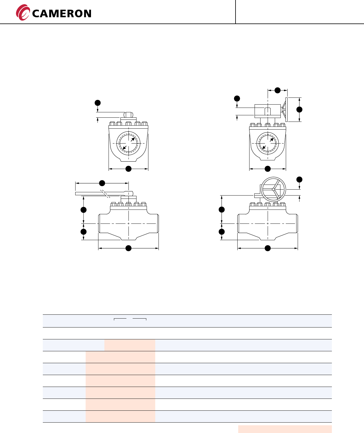
BT1 DIMENSIONS AND WEIGHTS
ASME CLASS 600
DD
HH
S S
K
A
E E
L
G
F
G
F
SIZE in. D E F G S H L A K M WEIGHT lb. (kg)
(mm) WE RF RTJ WE RF/RTJ
1 1/2 1 1/2 10 1/4 10 1/4 10 3/8 2 1/2 5 3/4 6 1/2 2 3/8 12 - - - 55 77
(40) (38) (260) (260) (264) (63) (145) (165) (61) (305) - - - (25) (35)
2 x 1 1/2 x 2 1 1/2 11 1/2 11 1/2 11 5/8 2 1/2 5 3/4 6 1/2 2 3/8 12 - - - 66 93
(50 x 40 x 50) (38) (292) (292) (295) (63) (145) (165) (61) (305) - - - (30) (42)
2 2 11 1/2 11 1/2 11 5/8 3 1/8 6 3/4 7 1/4 2 3/8 17 3/4 - - - 75 110
(50) (51) (292) (292) (295) (78) (170) (185) (61) (450) - - - (34) (50)
3 x 2 x 3 2 14 14 14 1/8 3 1/8 6 3/4 7 1/4 2 3/8 17 3/4 - - - 99 130
(80 x 50 x 80) (51) (356) (356) (359) (78) (170) (185) (61) (450) - - - (45) (59)
3 3 14 14 14 1/8 3 7/8 8 3/8 9 1/2 2 3/8 36 - - - 132 165
(80) (76) (356) (356) (359) (100) (212) (240) (61) (915) - - - (60) (75)
4 x 3 x 4 3 17 17 17 1/8 3 7/8 8 3/8 9 1/2 2 3/8 36 - - - 183 220
(100 x 80 x 100) (76) (432) (432) (435) (100) (212) (240) (61) (915) - - - (83) (100)
4 4 17 17 17 1/8 4 3/4 9 1/4 11 5/8 3 1/8 - 8 3/4 13 3/4 2 5/8 265 342
(100) (102) (432) (432) (435) (120) (236) (296) (80) - (223) (350) (67) (120) (155)
6 x 4 x 6 4 22 22 22 1/8 4 3/4 9 1/4 11 5/8 3 1/8 - 8 3/4 13 3/4 2 5/8 386 441
(150 x 100 x 150) (102) (559) (559) (562) (120) (236) (296) (80) - (223) (350) (67) (175) (200)
6 6 22 22 22 1/8 6 3/8 10 5/8 15 3/8 4 1/8 - 8 3/4 13 3/4 2 5/8 551 639
(150) (152) (559) (559) (562) (162) (271) (390) (105) - (223) (350) (67) (250) (290)
8 x 6 x 8 6 26 26 26 1/8 6 3/8 10 5/8 15 3/8 4 1/8 - 8 3/4 13 3/4 2 5/8 595 750
(200 x 150 x 200) (152) (660) (660) (664) (162) (271) (390) (105) - (223) (350) (67) (270) (340)
8 8 26 26 26 1/8 8 1/8 12 1/8 18 1/2 4 1/8 - 8 3/4 13 3/4 3 882 1058
(200) (203) (660) (660) (664) (207) (308) (470) (105) - (223) (350) (75) (400) (480)
10 x 8 x 10 8 31 31 31 1/8 8 1/8 12 1/8 18 1/2 4 1/8 - 8 3/4 13 3/4 3 1036 1279
(250 x 200 x 250) (203) (787) (787) (791) (207) (308) (470) (105) - (223) (350) (75) (470) (580)
10 10 31 31 31 1/8 9 5/8 13 3/4 21 5/8 5 1/8 - 11 1/2 13 3/4 3 1146 1565
(250) (254) (787) (787) (791) (244) (348) (550) (130) - (292) (350) (75) (520) (710)
12 x 10 x 12 10 33 33 33 1/8 9 5/8 13 3/4 21 5/8 51/8 - 11 1/2 13 3/4 3 1565 1874
(300 x 250 x 300) (254) (838) (838) (841) (244) (348) (550) (130) - (292) (350) (75) (710) (850)
12 12 33 33 33 1/8 11 3/8 15 1/8 24 3/4 5 1/8 - 11 1/2 13 3/4 3 1984 2315
(300) (305) (838) (838) (841) (290) (385) (630) (130) - (292) (350) (75) (900) (1050)
16 x 12 x 16 12 39 39 39 1/8 11 3/8 15 1/8 24 3/4 5 1/8 - 11 1/2 13 3/4 3 2315 2646
(400 x 300 x 400) (305) (991) (991) (994) (290) (385) (630) (130) - (292) (350) (75) (1050) (1200)
M
Flanges in accordance with ASME B16.5.
Butt Welding Ends according to ASME B16.25. Shaded Dimensions according to ISO 14313.
Dimensions and Weights are indicative and will be confirmed at the time of the order.
15
ENGINEERED VALVES
®
GROVE CT-GRO-BT1/BT2-03
08/10 NP-5M
BT1 DIMENSIONS AND WEIGHTS
ASME CLASS 900
DD
HH
S S
K
A
E E
L
G
F
G
F
SIZE in. D E F G S H L A K M WEIGHT lb. (kg)
(mm) WE RF RTJ WE RF/RTJ
1 1/2 1 1/2 14 1/4 14 1/4 14 3/8 2 5/8 6 3/4 7 1/2 2 3/8 17 3/4 - - - 68 99
(40) (38) (362) (362) (365) (68) (173) (190) (61) (450) - - - (25) (35)
2 x 1 1/2 x 2 1 1/2 14 1/2 14 1/2 14 5/8 2 5/8 6 3/4 7 1/2 2 3/8 17 3/4 - - - 88 132
(50 x 40 x 50) (38) (368) (368) (371) (68) (173) (190) (61) (450) - - - (40) (60)
2 2 14 1/2 14 1/2 14 5/8 3 1/4 7 1/2 8 5/8 2 3/8 24 - - - 104 148
(50) (51) (368) (368) (371) (83) (190) (218) (61) (610) - - - (47) (67)
3 x 2 x 3 2 15 15 15 1/8 3 1/4 7 1/2 8 5/8 2 3/8 24 - - - 117 165
(80 x 50 x 80) (51) (381) (381) (384) (83) (190) (218) (61) (610) - - - (53) (75)
3 3 15 14 15 1/8 4 3/8 8 7/8 10 3 1/8 51 1/8 - - - 143 198
(80) (76) (381) (356) (384) (110) (225) (255) (80) (1300) - - - (65) (90)
4 x 3 x 4 3 18 18 18 1/8 4 3/8 8 7/8 10 3 1/8 51 1/8 - - - 254 265
(100 x 80 x 100) (76) (457) (457) (460) (110) (225) (255) (80) (1300) - - - (83) (120)
4 4 18 18 18 1/8 5 10 1/2 12 1/8 3 1/8 - 8 3/4 13 3/4 2 5/8 287 408
(100) (102) (457) (457) (460) (127) (268) (308) (80) - (223) (350) (67) (130) (185)
6 x 4 x 6 4 24 24 24 1/8 5 10 1/2 12 1/8 3 1/8 - 8 3/4 13 3/4 2 5/8 331 595
(150 x 100 x 150) (102) (610) (610) (613) (127) (268) (308) (80) - (223) (350) (67) (150) (270)
6 6 24 24 24 1/8 6 3/4 12 5/8 15 3/4 5 1/8 - 11 1/2 13 3/4 3 595 838
(150) (152) (610) (610) (613) (170) (321) (400) (130) - (292) (350) (75) (270) (380)
8 x 6 x 8 6 29 29 29 1/8 6 3/4 12 5/8 15 3/4 5 1/8 - 11 1/2 13 3/4 3 728 1014
(200 x 150 x 200) (152) (737) (737) (740) (170) (321) (400) (130) - (292) (350) (75) (330) (460)
8 8 29 29 29 1/8 8 7/8 14 1/4 20 3/8 5 1/8 - 11 1/2 13 3/4 3 1036 1367
(200) (203) (737) (737) (740) (225) (361) (516) (130) - (292) (350) (75) (470) (620)
10 x 8 x 10 8 33 33 33 1/8 8 7/8 14 1/4 20 3/8 5 1/8 - 11 1/2 13 3/4 3 1499 1631
(250 x 200 x 250) (203) (838) (838) (841) (225) (361) (516) (130) - (292) (350) (75) (455) (740)
10 10 33 33 33 1/8 10 1/4 14 1/2 23 7/8 7 1/8 - 11 1/2 13 3/4 3 1653 1940
(250) (254) (838) (838) (841) (260) (368) (608) (180) - (292) (350) (75) (620) (880)
12 x 10 x 12 10 38 38 38 1/8 10 1/4 14 1/2 23 7/8 7 1/8 - 11 1/2 13 3/4 3 1874 2469
(300 x 250 x 300) (254) (965) (965) (968) (260) (368) (608) (180) - (292) (350) (75) (850) (1120)
12 12 38 38 38 1/8 12 1/4 18 1/8 27 7/8 7 1/8 - 11 1/2 13 3/4 3 2833 2998
(300) (305) (965) (965) (968) (310) (460) (708) (180) - (292) (350) (75) (900) (1360)
16 x 12 x 16 12 44 1/2 44 1/2 44 7/8 12 1/4 18 1/8 27 7/8 7 1/8 - 11 1/2 13 3/4 3 2756 3616
(400 x 300 x 400) (305) (1130) (1130) (1140) (310) (460) (708) (180) - (292) (350) (75) (1250) (1640)
Flanges in accordance with ASME B16.5.
Butt Welding Ends according to ASME B16.25.
Dimensions and Weights are indicative and will be confirmed at the time of the order.
M
Shaded Dimensions according to ISO 14313.
ENGINEERED VALVES
®
GROVE
16 CT-GRO-BT1/BT2-03
08/10 NP-5M
BT1 DIMENSIONS AND WEIGHTS
ASME CLASS 1500
DD
HH
S S
K
A
E E
L
G
F
G
F
SIZE in. D E F G S H L A K M WEIGHT lb. (kg)
(mm) WE RF RTJ WE RF/RTJ
1 1/2 1 1/2 14 1/4 14 1/4 14 3/8 2 5/8 6 3/4 7 1/2 2 3/8 24 - - - 79 110
(40) (38) (362) (362) (365) (68) (173) (190) (61) (610) - - - (36) (50)
2 x 1 1/2 x 2 1 1/2 14 1/2 14 1/2 14 5/8 2 5/8 6 3/4 7 1/2 2 3/8 24 - - - 93 132
(50 x 40 x 50) (38) (368) (368) (371) (68) (173) (190) (61) (610) - - - (42) (60)
2 2 14 1/2 14 1/2 14 5/8 3 1/4 7 1/2 8 5/8 2 3/8 36 - - - 104 148
(50) (51) (368) (368) (371) (83) (190) (218) (61) (915) - - - (47) (67)
3 x 2 x 3 2 18 1/2 18 1/2 18 5/8 3 1/4 7 1/2 8 5/8 2 3/8 36 - - - 132 183
(80 x 50 x 80) (51) (470) (470) (473) (83) (190) (218) (61) (915) - - - (60) (83)
3 3 18 1/2 18 1/2 18 5/8 4 3/8 9 5/8 10 7/8 3 1/8 - 8 3/4 13 3/4 2 5/8 220 287
(80) (76) (470) (470) (473) (110) (243) (275) (80) - (223) (350) (67) (100) (130)
4 x 3 x 4 3 21 1/2 21 1/2 21 5/8 4 3/8 9 5/8 10 7/8 3 1/8 - 8 3/4 13 3/4 2 5/8 254 397
(100 x 80 x 100) (76) (546) (546) (549) (110) (243) (275) (80) - (223) (350) (67) (115) (180)
4 4 21 1/2 21 1/2 21 5/8 5 5/8 11 3/8 13 3/4 4 1/8 - 8 3/4 13 3/4 2 5/8 397 573
(100) (102) (546) (546) (549) (142) (290) (350) (105) - (223) (350) (67) (180) (260)
6 x 4 x 6 4 27 3/4 27 3/4 28 5 5/8 11 3/8 13 3/4 4 1/8 - 8 3/4 13 3/4 2 5/8 507 816
(150 x 100 x 150) (102) (705) (705) (711) (142) (290) (350) (105) - (223) (350) (67) (230) (370)
6 5 3/4 27 3/4 27 3/4 28 7 3/8 14 1/4 17 5/8 5 1/8 - 11 1/2 13 3/4 3 882 1235
(150) (146) (705) (705) (711) (188) (361) (448) (130) - (292) (350) (75) (400) (560)
8 x 6 x 8 5 3/4 32 3/4 32 3/4 33 1/8 7 3/8 14 1/4 17 5/8 5 1/8 - 11 1/2 13 3/4 3 1058 1477
(200 x 150 x 200) (146) (832) (832) (841) (188) (361) (448) (130) - (292) (350) (75) (480) (670)
8 7 5/8 32 3/4 32 3/4 33 1/8 9 7/8 16 7/8 21 1/4 7 1/8 - 11 1/2 13 3/4 3 1455 1918
(200) (194) (832) (832) (841) (250) (430) (540) (180) - (292) (350) (75) (660) (870)
10 x 8 x 10 7 5/8 39 39 39 3/8 9 7/8 16 7/8 21 1/4 7 1/8 - 11 1/2 13 3/4 3 1786 2381
(250 x 200 x 250) (194) (991) (991) (1000) (250) (430) (540) (180) - (292) (350) (75) (810) (1080)
10 9 1/2 39 39 39 3/8 11 3/4 19 3/8 25 1/4 7 1/8 - 11 1/2 13 3/4 3 2227 3042
(250) (241) (991) (991) (1000) (300) (493) (640) (180) - (292) (350) (75) (1010) (1380)
12 x 10 x 12 9 1/2 44 1/2 44 1/2 45 1/8 11 3/4 19 3/8 25 1/4 7 1/8 - 11 1/2 13 3/4 3 2668 3924
(300 x 250 x 300) (241) (1130) (1130) (1146) (300) (493) (640) (180) - (292) (350) (75) (1210) (1780)
12 11 3/8 44 1/2 44 1/2 45 1/8 13 3/4 21 3/4 29 1/8 7 1/8 - 15 3/4 23 5/8 4 3/8 3682 5049
(300) (289) (1130) (1130) (1146) (350) (553) (740) (180) - (400) (600) (110) (1670) (2290)
16 x 12 x 16 11 3/8 54 1/2 54 1/2 55 3/8 13 3/4 21 3/4 29 1/8 7 1/8 - 15 3/4 23 5/8 4 3/8 4343 6393
(400 x 300 x 400) (289) (1384) (1384) (1407) (350) (5553) (740) (180) - (400) (600) (110) (1970) (2900)
M
Flanges in accordance with ASME B16.5.
Butt Welding Ends according to ASME B16.25. Shaded Dimensions according to ISO 14313.
Dimensions and Weights are indicative and will be confirmed at the time of the order.
17
ENGINEERED VALVES
®
GROVE CT-GRO-BT1/BT2-03
08/10 NP-5M
BT1 DIMENSIONS AND WEIGHTS
ASME CLASS 2500
DD
HH
S S
K
A
E E
L
G
F
G
F
SIZE in. D E F G S H L A K M WEIGHT lb. (kg)
(mm) WE RF RTJ WE RF/RTJ
1 1/2 1 1/2 15 1/8 15 1/8 15 1/4 3 8 1/4 8 5/8 2 3/8 24 - - - 108 150
(40) (38) (384) (384) (387) (75) (208) (220) (61) (610) - - - (49) (68)
2 x 1 1/2 x 2 1 1/2 17 3/4 17 3/4 17 7/8 3 8 1/4 8 5/8 2 3/8 24 - - - 119 179
(50 x 40 x 50) (38) (451) (451) (454) (75) (208) (220) (61) (610) - - - (54) (81)
2 1 3/4 17 3/4 17 3/4 17 7/8 3 3/4 9 10 2 3/8 36 - - - 247 212
(50) (44) (451) (451) (454) (95) (230) (255) (61) (915) - - - (112) (96)
3 x 2 x 3 1 3/4 22 3/4 22 3/4 23 3 3/4 9 10 2 3/8 36 - - - 276 353
(80 x 50 x 80) (44) (578) (578) (584) (95) (230) (255) (61) (915) - - - (125) (160)
3 2 1/2 22 3/4 22 3/4 23 5 11 1/8 12 1/2 3 1/8 - 8 3/4 13 3/4 2 5/8 298 388
(80) (64) (578) (578) (584) (128) (282) (319) (80) - (223) (350) (67) (135) (176)
4 x 3 x 4 2 1/2 26 1/2 26 1/2 26 7/8 5 11 1/8 12 1/2 3 1/8 - 8 3/4 13 3/4 2 5/8 342 536
(100 x 80 x 100) (64) (673) (673) (683) (128) (282) (319) (80) - (223) (350) (67) (155) (243)
4 3 1/2 26 1/2 26 1/2 26 7/8 6 1/2 13 1/4 16 4 1/8 - 11 1/2 13 3/4 3 536 774
(100) (89) (673) (673) (683) (165) (336) (406) (105) - (292) (350) (75) (243) (351)
6 x 4 x 6 3 1/2 36 36 36 1/2 6 1/2 13 1/4 16 4 1/8 - 11 1/2 13 3/4 3 686 1102
(150 x 100 x 150) (89) (914) (914) (927) (165) (336) (406) (105) - (292) (350) (75) (311) (500)
M
Flanges in accordance with ASME B16.5.
Butt Welding Ends according to ASME B16.25.
Dimensions and Weights are indicative and will be confirmed at the time of the order.
Shaded Dimensions according to ISO 14313.

ENGINEERED VALVES
®
GROVE
18 CT-GRO-BT1/BT2-03
08/10 NP-5M
MATERIALS SELECTION
The GROVE BT2 Ball Valve has been designed for use
with various materials or combination of materials
depending on the service conditions.
The following is a typical listing of materials for valves
ASME Class 150 - 2500 for standard applications.
BT2 MATERIALS SPECIFICATION
PRESSURE RETAINING PARTS
Body A216 WCB, A216 WCC, A352 LCB, A352 LCC
Bonnet A350 LF2
Stem AISI 4140, A564 Gr. 630 (17-4 PH)
Bolting A193 B7, A194 2H, A193 B7M, A194 2HM, A320 L7, A194 Gr.7, A320 L7M, A194 Gr. 7M
INTERNAL PARTS
Ball A350 LF2, A694 F65, AISI 316, A564 Gr 630 (17-4 PH)
Seats A350 LF2, A694 F65, AISI 316, A564 Gr 630 (17-4 PH)
Springs AISI 302, Inconel (different grades), Elgiloy
SEALING MATERIALS
Stem Gasket: NBR (Nitrile)
FKM (Viton different grades)
HNBR (Hydrogenated Nitrile)
Seat/ Bonnet Gasket: NBR (Nitrile)
FKM (Viton different grades)
HNBR (Hydrogenated Nitrile)
PLATING/COATING
0.001 inch 25 microns
ENP Electroless Nickel Plating
0.003 inch 75 microns
ENP Electroless Nickel Plating
NACE REQUIREMENTS
GROVE BT2 Ball Valves can be supplied in accordance with NACE MR0175 / ISO 15156
ENGINEERED VALVES
19
®
GROVE CT-GRO-BT1/BT2-03
08/10 NP-5M
BT2 VALVE ASSEMBLY & CROSS SECTION
Item Description
1 Body
4 Ball
5 Stem
6B Outer Seat Ring
6J Inner Seat Ring
8 Body O-Ring
9 Bonnet Cover
10 Gland Bushing
31 Body Stud
32 Body Nut
39 Drain Valve
45 Grease Fitting
97 Bonnet
123 Stem Key
134 Stem O-Rings
135 Seat Gasket O-Ring
20 Lower Bearing 137 Seal O-Ring
150 Upper Thrust Washer
151 Lower Thrust Washer
160 Adapter Plate
168 Upper Bearing
176A Grease Seal O-Ring
287 Spring Holder Ring
294 Sector Spacer
136 Bonnet Cover O-Ring
176A 294 135 6J 137
6B
287 32
ENGINEERED VALVES
®
GROVE
20 CT-GRO-BT1/BT2-03
08/10 NP-5M
BT2 DIMENSIONS AND WEIGHTS
ASME CLASS 150
DD
HH
SS
K
A
EE
L
G
F
G
F
M
* Dimensions on request.
Flanges up to 24 inch (except 22 inch) in accordance with ASME B16.5;
22 inch and sizes above 24 inch in accordance with MSS-SP-44.
Butt Welding Ends according to ASME B16.25. Larger sizes available on request. Reduced bore valves also available.
Shaded bore sizes (D) according to ISO 14313.
Shaded End-to-End Dimensions (E) according to ISO 14313 Class 600.
Dimensions and Weights are indicative and will be confirmed at the time of the order.
SIZE in. D E F G S H A K M WEIGHT lb. (kg)
(mm) WE RF RTJ WE RF/RTJ
14 13 1/4 35 35 35 1/8 14 5/8 15 5/8 26 3/8 3 3/4 11 1/2 13 3/4 3 1962 2050
(350) (337) (889) (889) (893) (370) (398) (670) (95) (292) (350) (75) (890) (930)
16 15 1/4 39 39 39 1/8 16 16 5/8 28 3/8 3 3/4 11 1/2 13 3/4 3 2853 2985
(400) (387) (991) (991) (994) (405) (423) (720) (95) (292) (350) (75) (1294) (1354)
18 17 1/4 43 43 43 1/8 17 1/2 18 1/2 31 7/8 4 1/2 11 1/2 13 3/4 3 4431 4630
(450) (438) (1093) (1093) (1096) (445) (470) (810) (115) (292) (350) (75) (2010) (2100)
20 19 1/4 47 47 47 1/4 21 1/4 20 3/4 37 4 1/2 11 1/2 13 3/4 3 5578 5908
(500) (489) (1194) (1194) (1201) (540) (528) (940) (115) (292) (350) (75) (2530) (2680)
22 21 1/4 51 51 51 3/8 21 5/8 22 3/4 39 7/8 7 1/8 15 3/4 23 5/8 4 3/8 7275 7496
(550) (540) (1296) (1296) (1305) (550) (578) (1012) (180) (400) (600) (110) (3300) (3400)
24 23 1/4 55 55 55 3/8 23 3/8 24 3/4 42 3/4 7 1/8 21 5/8 31 1/2 4 3/8 8554 9215
(600) (591) (1397) (1397) (1407) (595) (630) (1085) (180) (549) (800) (112) (3880) (4180)
26 25 57 57 57 1/2 25 1/4 25 45 1/4 7 1/8 21 5/8 31 1/2 4 3/8 10075 10692
(650) (635) (1448) (1448) (1461) (640) (635) (1150) (180) (549) (800) (112) (4570) (4850)
28 27 61 61 61 1/2 26 3/4 27 48 7 1/8 21 5/8 31 1/2 4 3/8 12346 12897
(700) (686) (1550) (1550) (1563) (680) (685) (1220) (180) (549) (800) (112) (5600) (5850)
30 29 65 65 65 1/2 29 3/8 28 3/4 51 1/8 7 1/8 21 5/8 31 1/2 4 3/8 13492 14198
(750) (737) (1651) (1651) (1664) (745) (720) (1300) (180) (549) (800) (112) (6120) (6440)
32 30 3/4 70 70 70 5/8 30 3/8 29 7/8 55 1/8 7 1/8 21 3/4 23 5/8 5 3/8 16270 17306
(800) (781) (1778) (1778) (1794) (770) (760) (1400) (180) (552) (600) (136) (7380) (7850)
34 32 3/4 76 76 76 5/8 31 1/2 31 1/8 58 1/4 7 1/8 21 3/4 23 5/8 5 3/8 17968 18960
(850) (832) (1931) (1931) (1947) (800) (790) (1480) (180) (552) (600) (136) (8150) (8600)
36 34 1/2 82 82 82 5/8 32 1/4 31 7/8 60 3/8 7 1/8 21 3/4 23 5/8 5 3/8 20304 21716
(900) (876) (2083) (2083) (2099) (820) (810) (1535) (180) (552) (600) (136) (9210) (9850)
40 38 1/2 92 92 * 33 1/2 35 3/8 66 1/8 8 1/8 21 3/4 23 5/8 5 3/8 29718 31967
(1000) (978) (2337) (2337) * (850) (900) (1680) (205) (552) (600) (136) (13480) (14500)
42 40 1/4 * * * 35 36 5/8 70 7/8 8 1/8 21 3/4 23 5/8 5 3/8 33576 35605
(1050) (1022) * * * (890) (930) (1800) (205) (552) (600) (136) (15230) (16150)
46 44 98 3/8 98 3/8 * 37 40 1/4 80 3/8 8 1/8 22 7/8 23 5/8 6 1/4 45812 48722
(1150) (1118) (2499) (2499) * (940) (1022) (2040) (205) (580) (600) (160) (20780) (22100)
48 46 * * * 38 1/4 42 81 1/8 8 1/8 22 7/8 23 5/8 6 1/4 50706 55115
(1200) (1168) * * * (970) (1067) (2060) (205) (580) (600) (160) (23000) (25000)
54 51 3/4 * * * 42 7/8 46 1/2 91 3/8 9 5/8 - - - 66138 77161
(1350) (1314) * * * (1090) (1180) (2320) (245) - - - (30000) (35000)
56 53 3/4 * * * 44 1/8 48 94 1/2 9 5/8 - - - 70547 83775
(1400) (1365) * * * (1120) (1220) (2400) (245) - - - (32000) (38000)
60 57 1/2 * * * 46 7/8 51 1/8 100 3/8 9 5/8 - - - 83775 97002
(1500) (1461) * * * (1190) (1300) (2550) (245) - - - (38000) (44000)
ENGINEERED VALVES
21
®
GROVE CT-GRO-BT1/BT2-03
08/10 NP-5M
BT2 DIMENSIONS AND WEIGHTS
ASME CLASS 300
DD
HH
SS
K
A
EE
L
G
F
G
F
* Dimensions on request.
Flanges up to 24 inch (except 22 inch) in accordance with ASME B16.5;
22 inch and sizes above 24 inch in accordance with MSS-SP-44.
Butt Welding Ends according to ASME B16.25. Larger sizes available on request. Reduced bore valves also available.
Shaded bore sizes (D) according to ISO 14313.
Shaded End-to-End Dimensions (E) according to ISO 14313 Class 600.
Dimensions and Weights are indicative and will be confirmed at the time of the order.
M
SIZE in. D E F G S H A K M WEIGHT lb. (kg)
(mm) WE RF RTJ WE RF/RTJ
14 13 1/4 35 35 35 1/8 14 5/8 15 5/8 26 3/8 4 1/2 11 1/2 13 3/4 3 2050 2337
(350) (337) (889) (889) (893) (370) (398) (670) (115) (292) (350) (75) (930) (1060)
16 15 1/4 39 39 39 1/8 16 17 1/8 28 3/8 4 1/2 11 1/2 13 3/4 3 2844 3197
(400) (387) (991) (991) (994) (405) (436) (720) (115) (292) (350) (75) (1290) (1450)
18 17 1/4 43 43 43 1/8 17 1/2 18 7/8 31 7/8 4 1/2 15 1/2 23 5/8 4 3/8 4542 4850
(450) (438) (1093) (1093) (1096) (445) (478) (810) (115) (400) (600) (75) (2060) (2200)
20 19 1/4 47 47 47 1/4 21 1/8 21 1/8 37 4 1/2 21 5/8 31 1/2 4 3/8 6967 7496
(500) (489) (1194) (1194) (1201) (537) (536) (940) (115) (549) (800) (112) (3160) (3400)
22 21 1/4 51 51 51 3/8 21 5/8 23 5/8 39 7/8 7 1/8 21 5/8 31 1/2 4 3/8 7716 8708
(550) (540) (1296) (1296) (1305) (550) (600) (1012) (180) (549) (800) (112) (3500) (3950)
24 23 1/4 55 55 55 3/8 23 3/8 25 3/8 42 3/4 7 1/8 21 5/8 31 1/2 4 3/8 8818 9700
(600) (591) (1397) (1397) (1407) (595) (645) (1085) (180) (549) (800) (112) (4000) (4400)
26 25 57 57 57 1/2 25 1/4 25 5/8 45 1/4 7 1/8 21 3/4 23 5/8 5 3/8 10780 11927
(650) (635) (1448) (1448) (1461) (640) (650) (1150) (180) (552) (600) (136) (4890) (5410)
28 27 61 61 61 1/2 26 3/4 27 7/8 48 7 1/8 21 3/4 23 5/8 5 3/8 13228 14639
(700) (686) (1550) (1550) (1563) (680) (708) (1220) (180) (552) (600) (136) (6000) (6640)
30 29 65 65 65 1/2 29 3/8 29 7/8 51 1/8 8 1/8 21 3/4 23 5/8 5 3/8 15476 17152
(750) (737) (1651) (1651) (1664) (745) (720) (1300) (205) (552) (600) (136) (7020) (7780)
32 30 3/4 70 70 70 5/8 30 3/8 30 7/8 55 1/8 8 1/8 21 3/4 23 5/8 5 3/8 19004 21054
(800) (781) (1778) (1778) (1794) (770) (785) (1400) (205) (552) (600) (136) (8620) (9550)
34 32 3/4 76 76 76 5/8 31 1/2 32 1/8 58 1/4 8 1/8 21 3/4 23 5/8 5 3/8 22575 24758
(850) (832) (1931) (1931) (1947) (800) (815) (1480) (205) (552) (600) (136) (10240) (11230)
36 34 1/2 82 82 82 5/8 31 1/2 33 3/8 60 3/8 8 1/8 22 7/8 23 5/8 6 1/4 26213 29057
(900) (876) (2083) (2083) (2099) (800) (848) (1535) (205) (580) (600) (160) (11890) (13180)
40 38 1/2 * * * 33 1/2 36 3/4 66 1/8 8 1/8 22 7/8 23 5/8 6 1/4 34392 38162
(1000) (978) * * * (850) (935) (1680) (205) (580) (600) (160) (15600) (17310)
42 40 1/4 * * * 35 38 70 7/8 9 5/8 22 7/8 23 5/8 6 1/4 38933 43210
(1050) (1022) * * * (890) (965) (1800) (245) (580) (600) (160) (17660) (19600)
46 44 98 3/8 98 3/8 * 37 44 1/4 80 3/8 9 5/8 22 7/8 23 5/8 6 1/4 48921 54322
(1150) (1118) (2499) (2499) * (940) (1125) (2040) (245) (580) (600) (160) (22190) (24640)
48 46 * * * 38 1/4 44 1/2 81 1/8 9 5/8 - - - 52910 57320
(1200) (1168) * * * (970) (1130) (2060) (245) - - - (24000) (26000)
54 51 3/4 * * * 42 7/8 50 91 3/8 9 5/8 - - - 72752 88184
(1350) (1314) * * * (1090) (1270) (2320) (245) - - - (33000) (40000)
56 53 3/4 * * * 44 1/8 51 5/8 94 1/2 9 5/8 - - - 81570 99207
(1400) (1365) * * * (1120) (1310) (2400) (245) - - - (37000) (45000)
60 57 1/2 * * * 46 7/8 55 1/8 100 3/8 9 5/8 - - - 97002 121253
(1500) (1461) * * * (1190) (1400) (2550) (245) - - - (44000) (55000)

ENGINEERED VALVES
®
GROVE
22 CT-GRO-BT1/BT2-03
08/10 NP-5M
BT2 DIMENSIONS AND WEIGHTS
ASME CLASS 400
DD
HH
SS
K
A
EE
L
G
F
G
F
M
* Dimensions on request.
Flanges up to 24 inch (except 22 inch) in accordance with ASME B16.5;
22 inch and sizes above 24 inch in accordance with MSS-SP-44.
Butt Welding Ends according to ASME B16.25. Larger sizes available on request. Reduced bore valves also available.
Shaded bore sizes (D) according to ISO 14313.
Shaded End-to-End Dimensions (E) according to ISO 14313 Class 600.
Dimensions and Weights are indicative and will be confirmed at the time of the order.
SIZE in. D E F G S H A K M WEIGHT lb. (kg)
(mm) WE RF RTJ WE RF/RTJ
14 13 1/4 35 35 35 1/8 14 5/8 16 1/4 26 3/8 4 1/2 11 1/2 13 3/4 3 2161 2535
(350) (337) (889) (889) (893) (370) (413) (670) (115) (292) (350) (75) (980) (1150)
16 15 1/4 39 39 39 1/8 16 18 29 7/8 4 1/2 11 1/2 13 3/4 3 2954 3329
(400) (387) (991) (991) (994) (405) (458) (760) (115) (292) (350) (75) (1340) (1510)
18 17 1/4 43 43 43 1/8 17 3/4 20 5/8 32 1/4 4 1/2 21 5/8 31 1/2 4 3/8 4674 5181
(450) (438) (1093) (1093) (1096) (450) (525) (820) (115) (549) (800) (75) (2120) (2350)
20 19 1/4 47 47 47 1/4 20 7/8 22 1/2 37 7 1/8 21 5/8 31 1/2 4 3/8 7275 7915
(500) (489) (1194) (1194) (1201) (530) (570) (940) (180) (549) (800) (75) (3300) (3590)
22 21 1/4 51 51 51 3/8 22 23 7/8 40 1/2 7 1/8 21 5/8 31 1/2 4 3/8 8598 9480
(550) (540) (1296) (1296) (1305) (560) (605) (1030) (180) (549) (800) (75) (3900) (4300)
24 23 1/4 55 55 55 3/8 23 3/8 26 1/8 42 3/4 8 1/8 21 3/4 23 5/8 5 3/8 9149 10318
(600) (591) (1397) (1397) (1407) (595) (663) (1085) (205) (552) (600) (136) (4150) (4680)
26 25 57 57 57 1/2 27 1/21 26 3/4 45 7/8 8 1/8 21 3/4 23 5/8 5 3/8 11486 12588
(650) (635) (1448) (1448) (1461) (650) (678) (1165) (205) (552) (600) (136) (5210) (5710)
28 27 61 61 61 1/2 30 3/8 29 1/8 48 3/8 8 1/8 21 3/4 23 5/8 5 3/8 14021 15366
(700) (686) (1550) (1550) (1563) (700) (740) (1230) (205) (552) (600) (136) (6360) (6970)
30 29 65 65 65 1/2 31 1/2 31 1/2 52 8 1/8 21 3/4 23 5/8 5 3/8 17306 18695
(750) (737) (1651) (1651) (1664) (800) (800) (1320) (205) (552) (600) (136) (7850) (8480)
32 30 3/4 70 70 70 5/8 33 1/8 32 1/2 56 1/8 8 1/8 22 7/8 23 5/8 6 3/8 20613 22553
(800) (781) (1778) (1778) (1794) (840) (827) (1425) (205) (580) (600) (136) (9350) (10230)
34 32 3/4 76 76 76 5/8 34 1/4 33 1/2 60 5/8 8 1/8 22 7/8 23 5/8 6 3/8 23545 25838
(850) (832) (1931) (1931) (1947) (870) (850) (1540) (205) (580) (600) (136) (10680) (11720)
36 34 1/2 82 82 82 5/8 36 5/8 34 1/2 63 8 1/8 22 7/8 23 5/8 6 1/4 27227 29894
(900) (876) (2083) (2083) (2099) (930) (875) (1600) (205) (580) (600) (160) (12350) (13560)
40 38 1/2 * * * 38 5/8 37 3/4 69 1/4 8 1/8 22 7/8 23 5/8 6 1/4 35516 39021
(1000) (978) * * * (980) (960) (1760) (205) (580) (600) (160) (16110) (17700)
42 40 1/4 * * * 40 1/8 41 72 9 5/8 22 7/8 23 5/8 6 1/4 40080 44048
(1050) (1022) * * * (890) (1040) (1830) (245) (580) (600) (160) (18180) (19980)
46 44 98 3/8 98 3/8 * 41 3/8 44 1/4 80 3/8 9 5/8 22 7/8 23 5/8 6 1/4 52735 59084
(1150) (1118) (2499) (2499) * (1020) (1125) (2040) (245) (580) (600) (160) (23920) (26800)
48 46 100 100 * 46 7/8 45 1/8 82 5/8 9 5/8 - - - 57320 63933
(1200) (1168) (2540) (2540) * (1050) (1145) (2100) (245) - - - (26000) (29000)
54 51 3/4 * * * 42 7/8 50 3/8 93 1/4 11 - - - 77161 92593
(1350) (1314) * * * (1190) (1280) (2370) (280) - - - (35000) (42000)
56 53 3/4 * * * 48 3/8 52 96 1/2 11 3/4 - - - 83775 103616
(1400) (1365) * * * (1230) (1320) (2450) (300) - - - (38000) (47000)
60 57 1/2 * * * 51 1/8 55 1/8 103 1/8 11 3/4 - - - 101412 123458
(1500) (1461) * * * (1300) (1400) (2620) (300) - - - (46000) (56000)
BT2 DIMENSIONS AND WEIGHTS
ASME CLASS 600
DD
HH
SS
K
A
EE
L
G
F
G
F
Shaded Dimensions according to ISO 14313.
* Dimensions on request.
Flanges up to 24 inch (except 22 inch) in accordance with ASME B16.5;
22 inch and sizes above 24 inch in accordance with MSS-SP-44. Larger sizes available on request. Reduced bore valves also available.
Butt Welding Ends according to ASME B16.25.
M
ENGINEERED VALVES
23
®
GROVE CT-GRO-BT1/BT2-03
08/10 NP-5M
Dimensions and Weights are indicative and will be confirmed at the time of the order.
SIZE in. D E F G S H A K M WEIGHT lb. (kg)
(mm) WE RF RTJ WE RF/RTJ
14 13 1/4 35 35 35 1/8 14 3/8 16 3/4 26 3/8 4 1/2 11 1/2 13 3/4 3 2954 3373
(350) (337) (889) (889) (893) (365) (425) (670) (115) (292) (350) (75) (1340) (1530)
16 15 1/4 39 39 39 1/8 16 7/8 19 3/8 29 7/8 4 1/2 15 3/4 23 5/8 4 3/8 4079 4365
(400) (387) (991) (991) (994) (430) (493) (760) (115) (400) (600) (112) (1850) (1980)
18 17 1/4 43 43 43 1/8 18 3/4 20 7/8 32 1/4 7 1/8 21 5/8 31 1/2 4 3/8 4806 5423
(450) (438) (1093) (1093) (1096) (475) (530) (820) (180) (549) (800) (112) (2180) (2460)
20 19 1/4 47 47 47 1/4 21 1/4 23 1/8 37 7 1/8 21 5/8 31 1/2 4 3/8 6570 7540
(500) (489) (1194) (1194) (1201) (540) (588) (940) (180) (549) (800) (112) (2980) (3420)
22 21 1/4 51 51 51 3/8 22 7/8 25 3/8 40 1/2 7 1/8 21 3/4 23 5/8 5 3/8 7870 8885
(550) (540) (1296) (1296) (1305) (580) (645) (1030) (180) (549) (600) (136) (3570) (4030)
24 23 1/4 55 55 55 3/8 24 3/8 26 3/4 44 1/8 8 1/8 21 3/4 23 5/8 5 3/8 9789 11045
(600) (591) (1397) (1397) (1407) (620) (679) (1120) (205) (552) (600) (136) (4440) (5010)
26 25 57 57 57 1/2 25 3/4 29 3/4 45 7/8 8 1/8 22 7/8 23 5/8 6 1/4 12412 13977
(650) (635) (1448) (1448) (1461) (655) (755) (1165) (205) (580) (600) (160) (5630) (6340)
28 27 61 61 61 1/2 28 3/4 30 3/8 48 3/8 8 1/8 22 7/8 23 5/8 6 1/4 15873 17813
(700) (686) (1550) (1550) (1563) (730) (770) (1230) (205) (580) (600) (160) (7200) (8080)
30 29 65 65 65 1/2 31 1/2 34 1/4 52 9 5/8 22 7/8 23 5/8 6 1/4 17835 20172
(750) (737) (1651) (1651) (1664) (800) (870) (1320) (245) (580) (600) (160) (8090) (9150)
32 30 3/4 70 70 70 5/8 32 5/8 35 1/4 56 1/8 9 5/8 22 7/8 23 5/8 6 1/4 20944 23721
(800) (781) (1778) (1778) (1794) (830) (895) (1425) (245) (580) (600) (160) (9500) (10760)
34 32 3/4 76 76 76 5/8 34 1/4 37 1/4 60 5/8 9 5/8 22 7/8 23 5/8 6 1/4 24515 28109
(850) (832) (1931) (1931) (1947) (870) (945) (1540) (245) (580) (600) (160) (11120) (12750)
36 34 1/2 82 82 82 5/8 35 3/8 40 1/8 63 9 5/8 22 7/8 23 5/8 6 1/4 29674 33510
(900) (876) (2083) (2083) (2099) (900) (1020) (1600) (245) (580) (600) (160) (13460) (15200)
40 38 1/2 92 92 93 1/8 37 3/4 45 7/8 69 1/4 9 5/8 22 7/8 23 5/8 6 1/4 37302 42350
(1000) (978) (2337) (2337) (2366) (960) (1165) (1760) (245) (580) (600) (160) (16920) (19210)
42 40 1/4 96 96 97 1/8 40 1/2 47 1/2 72 9 5/8 - - - 43806 48171
(1050) (1022) (2439) (2439) (2467) (1030) (1205) (1830) (245) - - - (19870) (21850)
46 44 109 1/2 109 1/2 * 42 1/2 49 7/8 80 3/8 11 - - - 57100 65124
(1150) (1118) (2782) (2782) * (1080) (1267) (2041) (280) - - - (25900) (29540)
48 46 * * * 44 1/2 51 1/2 82 5/8 11 - - - 61729 72752
(1200) (1168) * * * (1130) (1307) (2100) (280) - - - (28000) (33000)
54 51 3/4 * * * 51 1/8 557 1/2 94 1/2 11 3/4 - - - 90389 105821
(1350) (1314) * * * (1300) (1460) (2400) (300) - - - (41000) (48000)
56 53 3/4 * * * 52 3/4 59 1/2 98 11 3/4 - - - 99207 116844
(1400) (1365) * * * (1340) (1510) (2490) (300) - - - (45000) (53000)
60 57 1/2 * * * 56 1/4 63 105 1/8 11 3/4 - - - 121253 143299
(1500) (1461) * * * (1430) (1600) (2670) (300) - - - (55000) (65000)
ENGINEERED VALVES
®
GROVE
24 CT-GRO-BT1/BT2-03
08/10 NP-5M
BT2 DIMENSIONS AND WEIGHTS
ASME CLASS 900
DD
HH
S S
K
A
E E
L
G
F
G
F
M
* Dimensions on request.
Flanges up to 24 inch (except 22 inch) in accordance with ASME B16.5;
22 inch and sizes above 24 inch in accordance with MSS-SP-44. Larger sizes available on request. Reduced bore valves also available.
Butt Welding Ends according to ASME B16.25. Dimensions and Weights are indicative and will be confirmed at the time of the order.
Shaded Dimensions according to ISO 14313.
SIZE in. D E F G S H A K M WEIGHT lb. (kg)
(mm) WE RF RTJ WE RF/RTJ
14 12 3/4 40 1/2 40 1/2 40 7/8 15 1/2 17 1/4 27 3/4 4 1/2 15 3/4 23 5/8 4 3/8 3902 4211
(350) (324) (1029) (1029) (1039) (395) (438) (704) (115) (400) (600) (112) (1770) (1910)
16 14 3/4 44 1/2 44 1/2 44 7/8 17 3/4 19 3/4 32 1/4 7 1/8 21 5/8 31 1/2 4 3/8 5512 6151
(400) (375) (1131) (1131) (1140) (450) (503) (820) (180) (549) (800) (112) (2500) (2790)
18 16 3/4 48 48 48 1/2 19 7/8 23 1/4 34 5/8 7 1/8 21 5/8 31 1/2 4 3/8 7385 8245
(450) (425) (1220) (1220) (1232) (505) (590) (880) (180) (549) (800) (112) (3350) (3740)
20 18 5/8 52 52 52 1/2 22 1/4 26 1/8 38 1/4 8 1/8 21 3/4 23 5/8 5 3/8 9259 10141
(500) (473) (1321) (1321) (1334) (565) (665) (970) (205) (552) (600) (136) (4200) (4600)
22 20 5/8 56 56 56 5/8 24 3/8 29 1/2 42 1/2 8 1/8 22 7/8 23 5/8 6 1/4 12214 13558
(550) (524) (1423) (1423) (1439) (620) (750) (1080) (205) (580) (600) (160) (5540) (6150)
24 22 1/2 61 61 61 3/4 26 31 1/4 46 1/8 9 5/8 22 7/8 23 5/8 6 1/4 15498 17306
(600) (572) (1550) (1550) (1569) (660) (793) (1170) (245) (580) (600) (160) (7030) (7850)
26 24 3/8 65 65 65 7/8 27 35 1/4 51 1/8 9 5/8 22 7/8 23 5/8 6 1/4 18695 24030
(650) (619) (1651) (1651) (1674) (685) (895) (1300) (245) (580) (600) (160) (8480) (10900)
28 26 1/4 69 69 69 7/8 25 1/4 33 1/4 53 1/2 9 5/8 22 7/8 23 5/8 6 1/4 22267 27558
(700) (667) (1753) (1753) (1775) (640) (843) (1360) (245) (580) (600) (160) (10100) (12500)
30 28 1/8 74 74 74 7/8 32 5/8 37 3/8 56 3/4 9 5/8 22 7/8 23 5/8 6 1/4 25904 28990
(750) (714) (1880) (1880) (1902) (830) (950) (1440) (245) (580) (600) (160) (11750) (13150)
32 30 80 80 81 3/8 34 5/8 39 3/8 61 3/8 9 5/8 22 7/8 23 5/8 6 1/4 30578 41667
(800) (762) (2032) (2032) (2067) (880) (1000) (1560) (245) (580) (600) (160) (13870) (18900)
34 31 7/8 85 85 87 36 5/8 41 1/8 64 1/8 9 5/8 22 7/8 23 5/8 6 1/4 36156 38603
(850) (810) (2159) (2159) (2210) (930) (1043) (1630) (245) (580) (600) (160) (16400) (17510)
36 33 3/4 90 90 91 1/8 37 3/4 43 1/8 65 3/8 11 - - - 41778 46297
(900) (857) (2286) (2286) (2315) (960) (1096) (1660) (280) - - - (18950) (21000)
40 37 5/8 * * * 42 7/8 48 7/8 74 3/8 11 - - - 50706 57320
(1000) (956) * * * (1090) (1240) (1890) (280) - - - (23000) (26000)
42 39 5/8 * * * 44 7/8 51 1/8 78 11 - - - 57320 66138
(1050) (1006) * * * (1140) (1300) (1980) (280) - - - (26000) (30000)
46 43 3/8 * * * 48 7/8 55 7/8 85 11 3/4 - - - 70547 79366
(1150) (1102) * * * (1240) (1420) (2160) (300) - - - (32000) (36000)
48 45 1/4 * * * 50 3/4 58 1/4 88 5/8 11 3/4 - - - 77161 88184
(1200) (1149) * * * (1290) (1480) (2250) (300) - - - (35000) (40000)

25
ENGINEERED VALVES
®
GROVE CT-GRO-BT1/BT2-03
08/10 NP-5M
BT2 DIMENSIONS AND WEIGHTS
ASME CLASS 1500
DD
HH
S S
K
A
E E
L
G
F
G
F
M
* Dimensions on request.
Flanges up to 24 inch (except 22 inch) in accordance with ASME B16.5;
22 inch and sizes above 24 inch in accordance with MSS-SP-44. Larger sizes available on request. Reduced bore valves also available.
Butt Welding Ends according to ASME B16.25.
Dimensions and Weights are indicative and will be confirmed at the time of the order.
Shaded Dimensions according to ISO 14313.
SIZE in. D E F G S H A K M WEIGHT lb. (kg)
(mm) WE RF RTJ WE RF/RTJ
14 12 1/2 49 1/2 49 1/2 50 1/4 17 3/4 23 3/8 33 1/8 7 1/8 21 5/8 31 1/2 4 3/8 5247 6371
(350) (318) (1258) (1258) (1277) (440) (593) (840) (180) (549) (800) (112) (2380) (2890)
16 14 1/4 54 1/2 54 1/2 55 3/8 18 1/8 25 3/8 35 7 1/8 21 5/8 31 1/2 4 3/8 8267 10362
(400) (362) (1385) (1385) (1407) (460) (643) (890) (180) (549) (800) (112) (3750) (4700)
18 16 60 1/2 69 1/2 61 3/8 22 28 1/8 37 3/4 8 1/8 21 3/4 23 5/8 5 3/8 10604 13195
(450) (406) (1537) (1537) (1559) (560) (713) (960) (205) (552) (600) (136) (4810) (5985)
20 17 7/8 65 1/2 65 1/2 66 3/8 24 1/4 31 3/4 42 3/8 9 5/8 21 3/4 23 5/8 5 3/8 14088 17130
(500) (454) (1664) (1664) (1686) (615) (805) (1075) (245) (552) (600) (136) (6390) (7770)
22 19 5/8 71 5/8 71 5/8 72 1/2 27 3/4 33 1/4 47 1/4 9 5/8 22 7/8 23 5/8 6 1/4 18563 22575
(550) (500) (1820) (1820) (1842) (695) (845) (1200) (245) (580) (600) (160) (8420) (10240)
24 21 1/2 80 3/8 80 3/8 81 1/2 24 3/4 34 5/8 50 3/4 9 5/8 22 7/8 23 5/8 6 1/4 23479 28616
(600) (546) (2042) (2040) (2071) (620) (878) (1290) (245) (580) (600) (160) (10650) (12980)
26 23 1/2 * * * 31 1/2 39 56 1/4 9 5/8 22 7/8 23 5/8 6 1/4 28660 35274
(650) (597) * * * (800) (990) (1430) (245) (580) (600) (160) (13000) (16000)
28 25 1/4 * * * 33 1/8 41 3/4 60 1/4 11 - - - 35274 41887
(700) (641) * * * (840) (1060) (1530) (280) - - - (16000) (19000)
30 27 1/8 * * * 34 1/4 45 1/4 66 7/8 11 - - - 39683 50706
(750) (689) * * * (870) (1150) (1700) (280) - - - (18000) (23000)
32 29 * * * 37 3/8 47 1/4 68 1/8 11 - - - 48501 59524
(800) (737) * * * (950) (1200) (1730) (280) - - - (22000) (27000)
34 30 3/4 * * * 39 3/8 49 1/4 71 5/8 11 - - - 55115 70547
(850) (781) * * * (1000) (1250) (1820) (280) - - - (25000) (32000)
36 32 5/8 * * * 41 3/8 52 3/8 76 3/8 11 3/4 - - - 63933 79366
(900) (829) * * * (1050) (1330) (1940) (300) - - - (29000) (36000)
40 36 1/2 * * * 45 5/8 57 1/2 84 5/8 11 3/4 - - - 79366 103616
(1000) (927) * * * (1160) (1460) (2150) (300) - - - (36000) (47000)
42 40 114 1/8 * * 47 1/48 60 88 5/8 11 3/4 - - - 90389 119048
(1050) (1016) (2900) * * (1200) (1525) (2250) (300) - - - (41000) (54000)
ENGINEERED VALVES
®
GROVE
26 CT-GRO-BT1/BT2-03
08/10 NP-5M
BT2 DIMENSIONS AND WEIGHTS
ASME CLASS 2500
DD
HH
S S
K
A
E E
L
G
F
G
F
M
* Dimensions on request.
Flanges up to 24 inch (except 22 inch) in accordance with ASME B16.5;
22 inch and sizes above 24 inch in accordance with MSS-SP-44. Larger sizes available on request. Reduced bore valves also available.
Butt Welding Ends according to ASME B16.25. Dimensions and Weights are indicative and will be confirmed at the time of the order.
Shaded Dimensions according to ISO 14313.
SIZE in. D E F G S H A K M WEIGHT lb. (kg)
(mm) WE RF RTJ WE RF/RTJ
65 1/5 36 36 36 1/2 9 5/8 14 3/4 19 1/4 5 1/8 15 3/4 23 5/8 4 3/8 1709 2094
(150) (133) (914) (914) (927) (245) (375) (490) (130) (400) (600) (112) (775) (950)
8 7 1/8 40 1/4 40 1/4 40 7/8 12 3/8 18 1/8 24 1/4 5 1/2 15 3/4 23 5/8 4 3/8 3219 3946
(200) (181) (1022) (1022) (1038) (315) (460) (615) (140) (400) (600) (112) (1460) (1790)
10 8 7/8 50 50 50 7/8 13 3/4 20 1/4 28 3/8 5 1/2 21 5/8 31 1/2 4 3/8 4740 5842
(250) (225) (1270) (1270) (1292) (350) (513) (720) (140) (549) (600) (112) (2150) (2650)
12 10 1/2 56 56 56 7/8 16 1/8 23 30 3/8 5 7/8 21 5/8 31 1/2 4 3/8 6261 7694
(300) (267) (1422) (1422) (1445) (410) (583) (770) (150) (549) (800) (112) (2840) (3490)
14 12 1/4 * * * 16 3/4 23 7/8 31 1/2 8 1/8 21 3/4 23 5/8 5 3/8 8157 10582
(350) (292) * * * (425) (605) (800) (205) (552) (600) (136) (3700) (4800)
16 13 1/8 * * * 20 1/2 28 3/4 40 1/2 9 5/8 21 3/4 23 5/8 5 3/8 10362 13228
(400) (333) * * * (520) (730) (1030) (245) (552) (600) (136) (4700) (6000)
18 14 3/4 * * * 22 7/8 31 1/2 44 7/8 9 5/8 22 7/8 23 5/8 6 1/4 12125 16535
(450) (374) * * * (580) (800) (1140) (245) (580) (600) (160) (5500) (7500)
20 16 1/2 * * * 25 5/8 34 1/4 49 1/4 9 5/8 22 7/8 23 5/8 6 1/4 14330 19400
(500) (419) * * * (650) (870) (1250) (245) (580) (600) (160) (6500) (8800)
22 * * * * * * * * * * * * *
(550) * * * * * * * * * * * * *
24 * * * * * * * * * * * * *
(600) * * * * * * * * * * * * *
26 * * * * * * * * * * * * *
(650) * * * * * * * * * * * * *
28 * * * * * * * * * * * * *
(700) * * * * * * * * * * * * *
30 * * * * * * * * * * * * *
(750) * * * * * * * * * * * * *
27
ENGINEERED VALVES
®
GROVE
BT1 & BT2 QUALITY SYSTEM
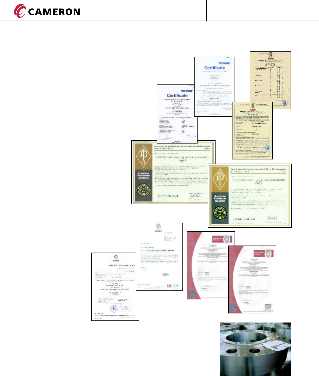
QUALITY ASSURANCE PROGRAM
Cameron runs a high level quality control
program to insure all products are
manufactured to the highest standards
available using the latest technology.
INTERNATIONAL APPROVALS
Cameron is an authorized licensee of the
American Petroleum Institute (API) and is
approved to monogram products for
specifications API 6D and API 6A at its
Voghera, Italy operations.
THE Quality Assurance Program
encompasses the entire operation, from
order entry to final inspection and field
service.
The Quality Assurance Program
conforms to:
ISO 9001
API Q1
API 6D
API 6A
94/9/EC (ATEX Directive)
97/23/EC (PED Directive)
EN 729-2 (Quality Requirement
for Welding)
SIL Approved to IEC 61508
(Functional Safety of Electrical/
Electronic/Programmable
Electronic Safety
Related Systems).
INSPECTION
The Quality Assurance Program is based on the Quality Manual.
The Quality Control Department verifies all processes from material receipt
to final customer inspection, including the liaison with approved inspection
and certifying authorities.
All products can be supplied with certified test reports which include
pressure testing, NDT and chemical and physical analysis, along with any
other specified special test certification.
The material certification of the valve parts can be furnished in accordance
with EN 10204 - 3.1 (as a standard) or 3.2.
CT-GRO-BT1/BT2-03
08/10 NP-5M
ENGINEERED VALVES
®
GROVE
28 CT-GRO-BT1/BT2-03
08/10 NP-5M
BT1 & BT2 QUALIFICATION AND TESTING
QUALIFICATION & TESTING LAB
GROVE valves are designed in accordance with the
most stringent industry procedures and are subjected
to full in-house qualification testing.
In-house testing facilities together with the
participation of major Oil and Gas Companie’s
testing programs allow GROVE to supply products
reflecting state-of-the-art technology.
Hydrostatic and high pressure gas tests, functional
tests, cycling tests, bending tests, are all carried out
on prototype valves.
This test program ensures that the design safety
factors and the leak tightness are met.
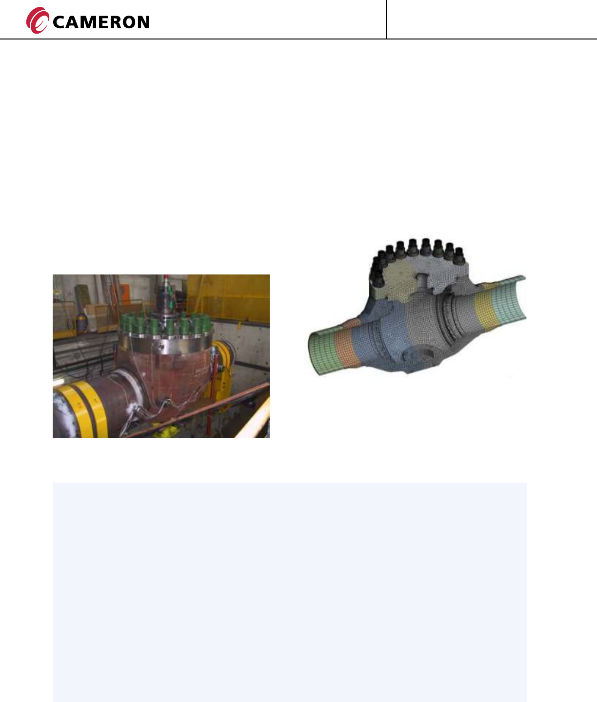
STRUCTURAL VERIFICATION
The GROVE Engineering department operates the
most advanced 3D computerized graphic system
(CAD) and conducts Finite Element Analysis (FEA)
to simulate various load conditions to determine
the suitability of the components for the intended
service.
On request the GROVE Engineering department can
carry out the seismic analysis on extended valves
through a modal analysis and spectrum load analysis
using the most advance FEA programs.
BT2 38 in. (950 mm) API 5000 cladded in all wetted
parts during bending test.
These tools are routinely used throughout the design
process to allow an effective evaluation of the
possible alternatives (sensitivity analyses).
Stress test by strain gauges are also systematically
carried out to validate FEA models.
HIGH PRESSURE GAS TESTING
Customer specifications may dictate more severe testing in addition to conventional hydrostatic testing.
GROVE is fully equipped to carry enhanced gas tests at ambient, low and high temperature
using specially equipped bunkers.
Testing can be performed at temperature ranging from -196 °C to 400 °C (-320 °F to 752 °F).
External leakages are assessed by means of mass-spectrometers; leakages through the seats are verified
by calibrated flow meters.
CYCLING TESTS
Grove is fully equipped to carry out PR2 tests as per API 6A code or others cycling tests as per customer
requirements, also Fugitive Emission tests with 100% of helium can be carried out upon request.
FIRE SAFE TESTS AND CERTIFICATION
GROVE conducts in-house Fire Safe Testing and GROVE valves are certified in accordance with
API Standard 6FA and BS 6755 part 2 as well as with API standard 607.
A complete list of qualified and certified valves can be made available upon request.

29
ENGINEERED VALVES
®
GROVE
TRADEMARK INFORMATION
®
GROVE is a registered trademark which is owned by Cameron.
This document contains references to registered trademarks or product designations,
which are not owned by Cameron.
Trademark Owner
CELCON Hoechst Celanese Corporation
DELRIN E.I. DuPont De Nemours & Company
FLUOREL Minnesota Mining and Manufacturing Company
HASTELLOY Haynes International, Inc.
HYCAR Hydrocarbon Chemical and Rubber Company
HYPALON E.I. DuPont De Nemours & Company
INCONEL INCO Nickel Sales, Inc.
MONEL INCO Alloys International, Inc.
NORDEL E.I. DuPont De Nemours & Company
STELLITE Stoody Deloro Stellite, Inc.
TEFLON E.I. DuPont De Nemours & Company
VITON E.I. DuPont De Nemours & Company
CT-GRO-BT1/BT2-03
08/10 NP-5M

ENGINEERED VALVES
Printed in Canada Revised 08/10-NP-5M CT-GRO-BT1/BT2-03
For the most current contact and location information go to: www.c-a-m.com/valvesandmeasurement
VALVES & MEASUREMENT
3250 Briarpark Drive, Suite 300
Houston, Texas 77042
USA Toll Free 800 323 9160
