Ya337 Hd61fh96
User Manual: hd61fh96
Open the PDF directly: View PDF ![]() .
.
Page Count: 42
SERVICE MANUAL
COPYRIGHT © 2005 Victor Company of Japan, Limited No.YA337
2005/12
D-ILA PROJECTION TELEVISION
YA337200512
HD-56FH96,
HD-61FH96,
HD-70FH96
TABLE OF CONTENTS
1 PRECAUTION. . . . . . . . . . . . . . . . . . . . . . . . . . . . . . . . . . . . . . . . . . . . . . . . . . . . . . . . . . . . . . . . . . . . . . . . . 1-3
2 SPECIFIC SERVICE INSTRUCTIONS . . . . . . . . . . . . . . . . . . . . . . . . . . . . . . . . . . . . . . . . . . . . . . . . . . . . . . 1-7
3 DISASSEMBLY . . . . . . . . . . . . . . . . . . . . . . . . . . . . . . . . . . . . . . . . . . . . . . . . . . . . . . . . . . . . . . . . . . . . . . 1-10
4 ADJUSTMENT . . . . . . . . . . . . . . . . . . . . . . . . . . . . . . . . . . . . . . . . . . . . . . . . . . . . . . . . . . . . . . . . . . . . . . . 1-31
5 TROUBLESHOOTING . . . . . . . . . . . . . . . . . . . . . . . . . . . . . . . . . . . . . . . . . . . . . . . . . . . . . . . . . . . . . . . . . 1-39
BASIC CHASSIS
RA
[HD-70FH96]
1-2 (No.YA337)
SPECIFICATION
Design & specifications are subject to change without notice.
Items Contents
HD-56FH96 HD-61FH96 HD-70FH96
Dimensions ( W × H × D ) 131.8 cm × 96.7 cm × 43.4 cm
(52" × 38-1/8" × 17-1/8")
145.6 cm × 104.3 cm × 46.7 cm
(57-3/8" × 41-1/8" × 18-3/8")
162.6 cm × 116.8 cm × 51.9 cm
(64-1/8" × 46" × 20-1/2")
Mass 43 kg (95 lbs) 47 kg (104 lbs) 72 kg (159 lbs)
TV RF System (Analog
/ Digital)
Analog
Digital
CCIR (M)
ATSC terrestrial / Digital cable
Color System (Analog) NTSC
Stereo System (Analog) BTSC (Multi Channel Sound)
Teletext System (Analog) Closed caption (T1-T4 / CC1-CC4)
TV Receiving Channels
and Frequency
(Analog)
VHF Low
VHF High
UHF
CATV
02ch - 06ch : 54MHz - 88MHz
07ch - 13ch : 174MHz - 216MHz
14ch - 69ch : 470MHz - 806MHz
54MHz - 804MHz
Low Band : 02 - 06
High Band : 07 - 13
Mid Band : 14 - 22
Super Band : 23 - 36
Hyper Band : 37 - 64
Ultra Band : 65 - 94, 100 - 135
Sub Mid Band : 01, 96 - 99
TV / CATV Total Channel 191 Channels
Intermediate Frequen-
cy (Analog)
Video IF
Sound IF
45.75 MHz
41.25 MHz (4.5MHz)
Color Sub Carrier Frequency (Analog) 3.58 MHz
Power Input AC120V, 60Hz
Power Consumption 215W 220W
Projection Source 110W High-pressure mercury lamp
Projection Device D-ILA device (Reflection active matrix type LCD) x 3(R / G /B)
Resolution Total=H:1952 × V:1088 [ Effective =H:1920 × V:1080 ]
Screen Transparent screen (unitized fresnel lens / lenticular lens), aspect ratio 16:9
Screen Size
56" (142cm) Measured diagonally
H:124 cm
×
V:69.7cm
61" (155cm) Measured diagonally
H:135 cm
×
V:76.0cm
70" (178cm) Measured diagonally
H:155.5 cm
×
V:87.2cm
Audio Power Output 10W + 10W
Speaker 10cm round type × 2 (Oblique corn)
Antenna Terminal (VHF/UHF, ATSC / DIGITAL CABLE IN)
F-type connector, 75Ω unbalanced, coaxial × 2
Video / Audio Input
[INPUT-1/2/3/4]
Component Video
[INPUT-1/2]
1125i / 750p
525p / 525i
S-Video
[INPUT-1/3/4]
Video
Audio
RCA pin jack × 6
Y : 1V (p-p) (Sync signal: 0.35V(p-p), 3-value sync.), 75 Ω
Pb/Pr : ±0.35V(p-p), 75 Ω
Y : 1V (p-p), positive (Negative sync provided), 75 Ω
Pb/Pr : 0.7V(p-p), 75 Ω
Mini-DIN 4 pin × 3
Y: 1V (p-p), positive (Negative sync provided), 75 Ω
C: 0.286V (p-p) (Burst signal), 75 Ω
1V (p-p), positive (Negative sync provided), 75 Ω, RCA pin jack × 4
500mV (rms), high impedance, RCA pin jack × 8
Digital Input Video
Audio
HDMI 2-row 19pin connector × 2
(Digital-input terminal is not compatible with picture signals of personal computer)
Digital: HDMI 2-row 19pin connector × 21
Anarog: 500mV(rms) (-4dBs), high impedance, RCA pin jack × 2
PC (RGB) Input D-sub 3-row 15pin × 1
R/G/B : 0.7V (p-p), 75Ω
HD / VD : 1V (p-p) to 5V (p-p), high impedance
< Available signal >
VGA : 640 pixels × 480 pixels (Horizontal : 31.5kHz / Vertical : 60Hz)
XGA : 1024 pixels × 768 pixels (Horizontal : 48.4kHz / Vertical : 60Hz)
Center Channel Input 500mV(rms) (-4dBs), high impedance, RCA pin jack × 1
Monitor / Recording
Output
S-Video
Video
Audio
Mini-DIN 4pin × 1
Y: 1V (p-p), 75Ω
C: 0.286V(p-p) (burst signal), 75Ω
1V (p-p), 75Ω, RCA pin jack × 1
250mV(rms) (-10dBs), Fs-18dB low impedance, RCA pin jack × 2
Audio Output
Variable
Fix
RCA pin jack × 2
More than 0 to 1000mV (rms) (+2.2dBs)
500mV(rms) (-4dBs), low impedance (1000Hz when modulated 100%)
iLink Input/Output TS In/Out (4-pin, S400) × 2, IEEE1394 compliant DTCP digital copy protection compatible
Digital Audio Optical Output Digital SPDIF × 1
AV COMPULINK lll 3.5mm mini jack × 1
RS-232C D-sub 2-row 9 pin [External control for TV set]
Remote Control Unit RM-C14G (AA/R6 / UM-3 battery × 2)
(No.YA337)1-3
SECTION 1
PRECAUTION
1.1 SAFETY PRECAUTIONS
(1) The design of this product contains special hardware,
many circuits and components specially for safety
purposes. For continued protection, no changes should be
made to the original design unless authorized in writing by
the manufacturer. Replacement parts must be identical to
those used in the original circuits. Service should be
performed by qualified personnel only.
(2) Alterations of the design or circuitry of the products should
not be made. Any design alterations or additions will void
the manufacturer's warranty and will further relieve the
manufacturer of responsibility for personal injury or
property damage resulting therefrom.
(3) Many electrical and mechanical parts in the products have
special safety-related characteristics. These
characteristics are often not evident from visual inspection
nor can the protection afforded by them necessarily be
obtained by using replacement components rated for
higher voltage, wattage, etc. Replacement parts which
have these special safety characteristics are identified in
the parts list of Service manual. Electrical components
having such features are identified by shading on the
schematics and by ( ) on the parts list in Service
manual. The use of a substitute replacement which does
not have the same safety characteristics as the
recommended replacement part shown in the parts list of
Service manual may cause shock, fire, or other hazards.
(4) Don't short between the LIVE side ground and
ISOLATED (NEUTRAL) side ground or EARTH side
ground when repairing.
Some model's power circuit is partly different in the GND.
The difference of the GND is shown by the LIVE : ( ) side
GND, the ISOLATED (NEUTRAL) : ( ) side GND and
EARTH : ( ) side GND.
Don't short between the LIVE side GND and ISOLATED
(NEUTRAL) side GND or EARTH side GND and never
measure the LIVE side GND and ISOLATED (NEUTRAL)
side GND or EARTH side GND at the same time with a
measuring apparatus (oscilloscope etc.). If above note will
not be kept, a fuse or any parts will be broken.
(5) When service is required, observe the original lead dress.
Extra precaution should be given to assure correct lead
dress in the high voltage circuit area. Where a short circuit
has occurred, those components that indicate evidence of
overheating should be replaced. Always use the
manufacturer's replacement components.
(6) Isolation Check (Safety for Electrical Shock Hazard)
After re-assembling the product, always perform an
isolation check on the exposed metal parts of the cabinet
(antenna terminals, video/audio input and output terminals,
Control knobs, metal cabinet, screw heads, earphone jack,
control shafts, etc.) to be sure the product is safe to operate
without danger of electrical shock.
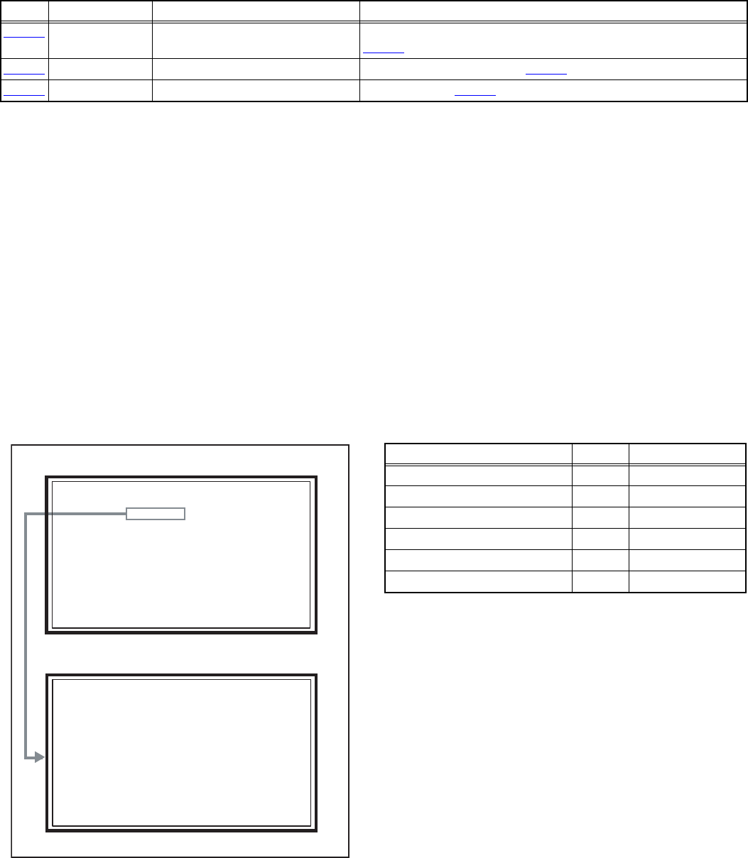
a) Dielectric Strength Test
The isolation between the AC primary circuit and all metal
parts exposed to the user, particularly any exposed metal
part having a return path to the chassis should withstand a
voltage of 3000V AC (r.m.s.) for a period of one second. (.
. . . Withstand a voltage of 1100V AC (r.m.s.) to an
appliance rated up to 120V, and 3000V AC (r.m.s.) to an
appliance rated 200V or more, for a period of one second.)
This method of test requires a test equipment not generally
found in the service trade.
b) Leakage Current Check
Plug the AC line cord directly into the AC outlet (do not use
a line isolation transformer during this check.). Using a
"Leakage Current Tester", measure the leakage current
from each exposed metal part of the cabinet, particularly
any exposed metal part having a return path to the chassis,
to a known good earth ground (water pipe, etc.). Any
leakage current must not exceed 0.5mA AC (r.m.s.).
However, in tropical area, this must not exceed 0.2mA AC
(r.m.s.).
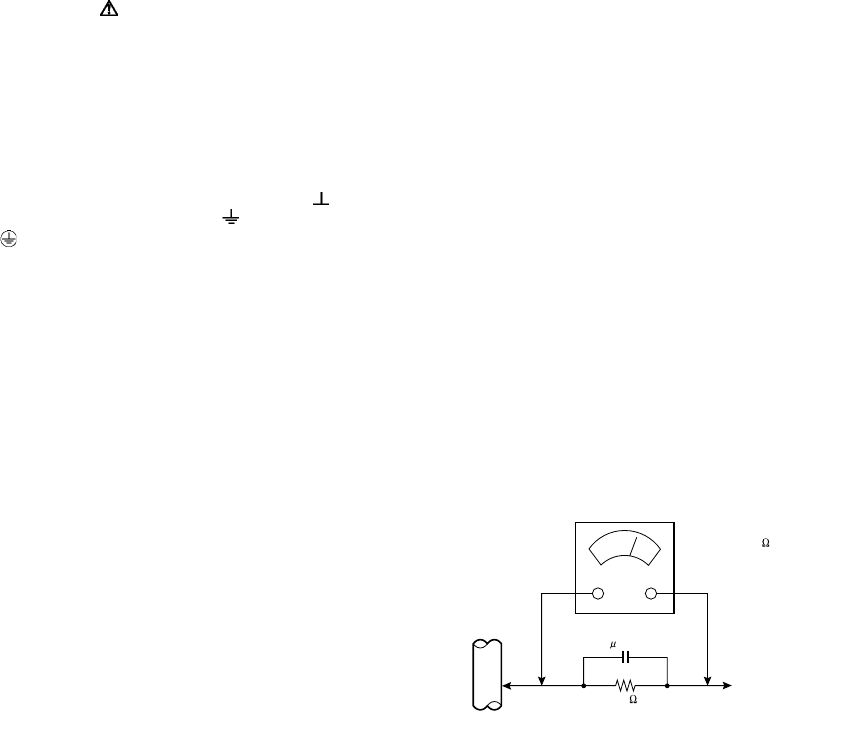
Alternate Check Method
Plug the AC line cord directly into the AC outlet (do not
use a line isolation transformer during this check.). Use
an AC voltmeter having 1000Ω per volt or more
sensitivity in the following manner. Connect a 1500Ω
10W resistor paralleled by a 0.15µF AC-type capacitor
between an exposed metal part and a known good earth
ground (water pipe, etc.). Measure the AC voltage
across the resistor with the AC voltmeter. Move the
resistor connection to each exposed metal part,
particularly any exposed metal part having a return path
to the chassis, and measure the AC voltage across the
resistor. Now, reverse the plug in the AC outlet and
repeat each measurement. Any voltage measured must
not exceed 0.75V AC (r.m.s.). This corresponds to
0.5mA AC (r.m.s.).
However, in tropical area, this must not exceed 0.3V AC
(r.m.s.). This corresponds to 0.2mA AC (r.m.s.).
AC VOLTMETER
(HAVING 1000 /V,
OR MORE SENSITIVITY)
PLACE THIS PROBE
ON EACH EXPOSED
METAL PART
1500 10W
0.15 F AC-TYPE
GOOD EARTH GROUND
1-4 (No.YA337)
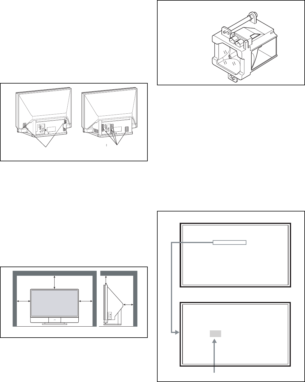
1.2 INSTALLATION
1.2.1 HEAT DISSIPATION
If the heat dissipation vent behind this unit is blocked, cooling
efficiency may deteriorate and temperature inside the unit will
rise. The temperature sensor that protects the unit will be
activated when internal temperature exceeds the predetermined
level and power will be turned off automatically.
Therefore, please make sure pay attention not to block the heat
dissipation vent as well as the ventilation outlet behind the unit
and ensure that there is room for ventilation around it.
Do not put foreign objects near the ventilation holes as this
can result in fire or electrical hazards.
Do not block the ventilation holes as this may cause the
internal temperature to rise and possibly result fire.
1.2.2 INSTALLATION REQUIREMENTS
Ensure that the minimal distance is maintained, as specified
fingure, between the unit with and the surrounding walls, as well
as the floor etc.
Install the unit on stable flooring.
Take precautionary measures to prevent the unit from tipping in
order to protect against accidents and earthquakes.
CAUTION FOR INSTALLATION
• Do not tilt the TV towards the left or right, or toward the back.
• Install the TV in a corner on the floor so as to keep cords out
of the way.
• The TV will generate a slight amount of heat during
operation. Ensure that sufficient space is available around
the TV to allow satisfactory cooling.
1.3 LAMP UNIT HANDLING CAUTION
1.3.1 PRECAUTION FOR LAMP UNIT
The lamp emits high intensity white, ultraviolet and infrared
light. Do not look directly at the light during service.
Also, do not touch the lamp directly as it presents a burn
hazard.
Handle with extra care. This lamp emits high heat and
contains high-pressure during use.
Do not give any impact as this may cause the broken lamp.
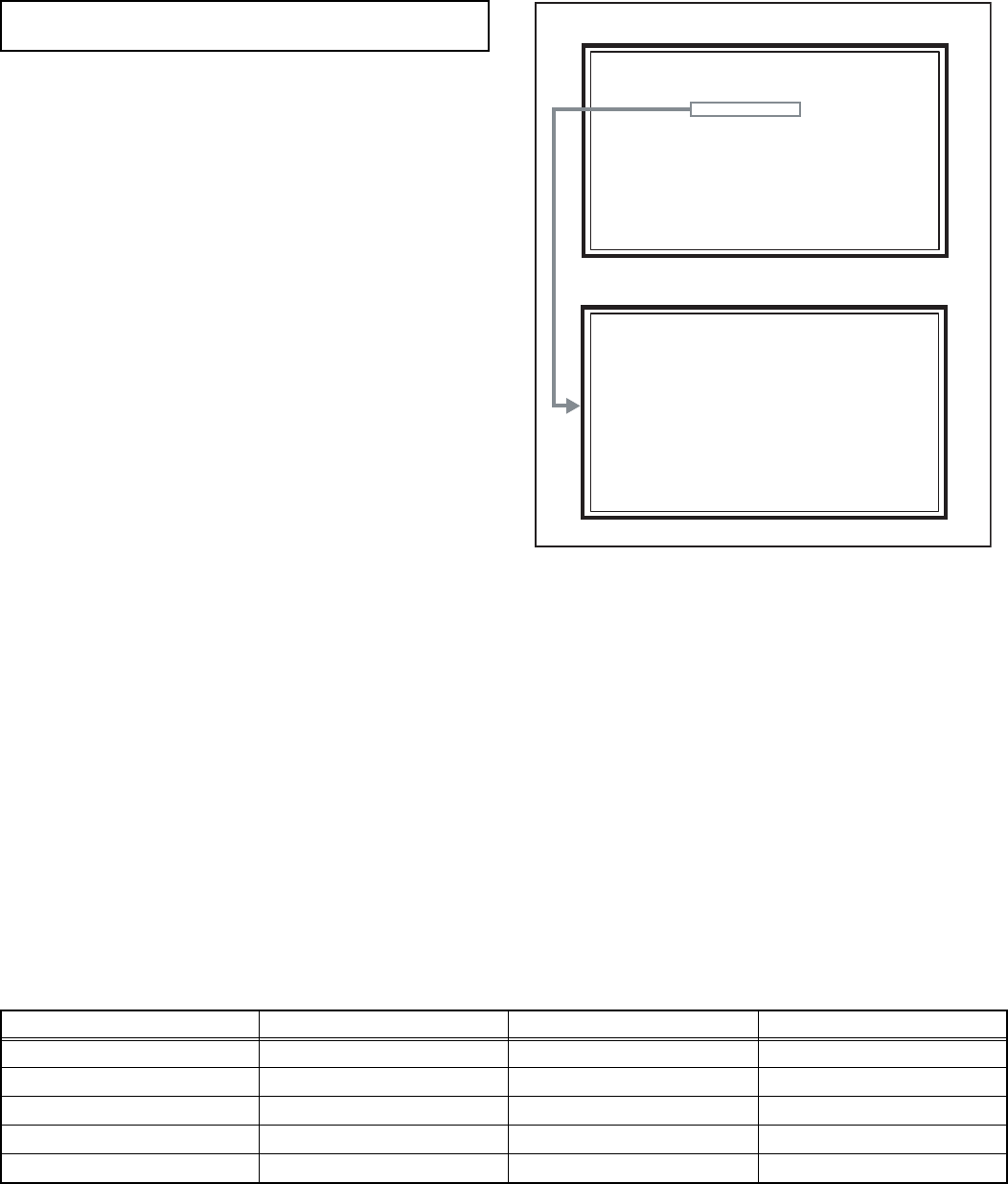
1.3.2 HOW TO CONFIRM LAMP OPERATING TIME
• MAXIMUM COUNT TIME= 65535 hours
(1) Set to "0 minutes" using the [SLEEP TIMER] key.
(2) Press the [VIDEO STATUS] key and [DISPLAY] key
simultaneously, then enter the SERVICE MODE.
(3) When the Main Menu is displayed, press [2] key to enter
the SELF CHECK MODE.
(4) The use time of a lamp is displayed on middle of the screen
by the hexadecimal number of 4 figures.
Intake hole Exhaust hole
*Diagram differs from actual appearance.
200mm 200mm
150mm
50mm
150mm
*Diagram differs from actual appearance.
LAMP UNIT : TS-CL110UAA
Lamp operation time
SERVICE MENU SCREEN
SELF CHECK MODE SCREEN (Page 1)
SERVICE MENU
SERVICE MENU
1. ADJUST
1. ADJUST
2. SELF CHECK
2. SELF CHECK
3. I2C STOP
3. I2C STOP
LOB 0 FAN 0
LOB 0 FAN 0
AUD 0
AUD 0
ANA 9 DIG 9
ANA 9 DIG 9
0000 0
0000 0
0
0

(No.YA337)1-5
1.3.3 LAMP UNIT REPLACEMENT
(1) The lamp replacement message will appear when need to
change the lamp. After replace the lamp, need to reset the
timer which is built into TV.
(2) Life of the lamp unit is about 6000 hours over. Lamp use
time can be check at the lamp message MENU.
(3) If Fig.1 message appears when turn the TV on, need to
replace the lamp.
(4) Use the lamp timer reset only after replacing the lamp.
NOTE:
• This message will appear every time turn on the TV, when
the lamp needs to be replaced. Press the [OK] key to make
the message disappear, or replace the lamp.
Fig.1
1.3.4 HOW TO REPLACE THE LAMP UNIT
• Refer to the "USERS GUIDE" for a detailed operating
description.
(1) Turn off the TV power.
(2) After the LAMP LED light has stopped blinking, disconnect
the power cord from the AC outlet.
(3) Loosen 1 screw then take out the lamp cover below the left
side of the TV.
(4) Loosen 2 screws then take out the lamp unit.
(5) Install the new lamp unit.
(6) Re-install the lamp cover.
NOTE:
• After installing the new lamp unit, do not forget to reset the
lamp timer.
1.3.5 HOW TO RESET THE LAMP TIMER
• Refer to the "USERS GUIDE" for a detailed operating
description.
(1) Press the [MENU] key to select CLOCK / TIMERS.
(2) Select the <LAMP TIMER RESET> with [] / [] keys.
(3) Enter the <LAMP TIMER RESET> mode the message will
appears.
(4) Press the [OK] key while the above message appears on
the screen.
(5) Turn off the power, then turn on the power.
(6) The lamp timer has now been reset, as before the HOW TO
CONFIRM LAMP OPERATING TIME.
1.3.6 PRECAUTION FOR REPLACEMENT
• Do not replace the LAMP UNIT immediately after the projector
has been used.
• The temperature of the LAMP UNIT is still high and could
cause a burn.
• Allow a cooling period of 1 hour or more before performing
replacement.
• Before starting LAMP UNIT replacement work, turn off the
MAIN POWER switch, and disconnect the AC power cord plug
from the wall outlet.
• If touched, the lamp glass surface may rupture and burns may
result. Do not touch the glass portion or metal portion. Handle
only plastic handle.
• The replaced old lamp can be discarded in the same manner
as a fluorescent lamp. Check local ordinances and dispose of
the used lamp as prescribed.
LAMP NEEDS TO BE REPLACED.
REFER TO OWNER'S MANUAL FOR
REPLACEMENT INSTRUCTIONS.
AFTER REPLACING THE LAMP,
PLEASE RESET TIMER IN THE TV
MENU.
PRESS OK, IF YOU DO NOT WANT
TO SEE THIS MESSAGE AGAIN.
LAMP REPLACEMENT MESSAGE
1-6 (No.YA337)
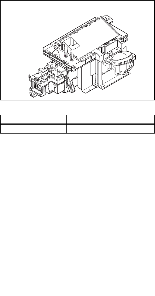
1.4 SERVICE PARTS KIT INSTRUCTIONS
Due to the character of this product, these OPTICAL /DRIVE
ASS'Y are prepared.
Please note these OPTICAL/DRIVE ASS'Y when replacing or
ordering the parts.
1.4.1 PART NUMBER AND CONSTRUCTION
1.4.2 OPTICAL / DRIVE ASS'Y CONSTRUCTION
(1) OPTICAL BLOCK
(Included D-ILA DEVICE, PROJECTION LENS)
(2) OPTICAL BASE
(3) DRIVE PWB ASS'Y
This PWB is mounted with 1 memory IC saved with
adjustment, setting data of the drive circuit.
(4) SHIELD COVER
*The following parts without the kits part.
• REMOTE SENSOR PWB ASS'Y
• LAMP UNIT
• LAMP FAN DUCT
• THERMOSTAT
1.4.3 PRECAUTION FOR USING
(1) In the case of the following defects/problems, replace this
kit (OPTICAL/DRIVE ASS'Y)
a) Picture defect caused by optical system/D-ILA device
related parts.
b) Picture defect caused by drive circuit.
(2) The DRIVE PWB ASS'Y is mounted with a memory IC
[IC3753] saved with adjustment/setting data (GAMMA,
SHADING, etc.) of the drive circuit.
The data of this memory IC is in the optimal state according
to individual D-ILA devices and each section of the
OPTICAL BLOCK.
(3) When replace the DRIVE PWB ASS'Y, take off the 1
memory IC from the original board and replace with new
one. When replace the DRIVE PWB ASS'Y, do same
manner. Replace 1 memory IC.
(4) After the replacement of the OPTICAL BLOCK, projection
lens focus adjustment and drive convergence / projection
adjustment are required.
1.5 SCREEN HANDLING CAUTIONS
1.5.1 SCREEN STORAGE
Store the SCREEN ASS'Y in a standing position in order to avoid
deformation. If the screen is stored horizontally, there is risk of
deforming the screen face.
When necessary to place the SCREEN ASS'Y horizontally,
position the screen side upwards and sure to place spacers
between the screen and resting site (floor or stand etc.) to
prevent the screen from sagging.
1.5.2 SCREEN SURFACE
Since the screen surface is easily scratched or soiled, use ample
care when handling.
1.5.3 PRECAUTIONS FOR CLEANING AND REPLACEMENT
• The SCREEN ASS'Y is made from the lenticular lens and
fresnel lens. The anti static proceeding and the surface of the
lenticular lens. Rubbing the surface with something hard, the
coating may peel off.
• When the screen is dirty, gently wipe it with a soft cloth.
If the screen is very dirty, wipe it down with a cloth dipped in a
diluted kitchen cleaner (neutrality detergent) and thoroughly
wrung-out. Then wipe immediately after with clean, dry cloth.
Never use the organic solvent such as the alcohol or benzine.
• The SCREEN ASS'Y replacement is required if the coating
was peel off. Alkaline detergent or acidity detergent can not be
be used.
• The notched side of the lenticular lens and the fresnel lens are
faced each other.
• Do not rub the screen when cleaning it or replaceing it.
Rubbing the screen may cause of the scratch of the screen by
its notch.
Kit parts number Kit part name
TS-COP8A-SAA OPTICAL / DRIVE ASS'Y
OPTICAL/DRIVE ASS'Y
(No.YA337)1-7
SECTION 2
SPECIFIC SERVICE INSTRUCTIONS
2.1 SYSTEM SETTEING
(1) Set to "0 minutes" using the [SLEEP TIMER] key.
(2) While "0 minutes" is displayed, press the [VIDEO
STATUS] key and [DISPLAY] key simultaneously, then
enter the SERVICE MODE.
(3) When the SERVICE MENU SCREEN is displayed, press
[2] key to enter the self check mode.
(4) Turn off the power by pressing the [POWER] key on the
remote control unit.
2.2 FEATURES
Built in ATSC (Advanced Television Systems Committee)
TUNER
This TV can receive both Digital broadcasting (ATSC) and
Analogue broadcasting.
D.I.S.T. (Digital Image Scaling Technology)
This system uses line interpolation to double the number of
scanning lines and achieve high resolution, flicker-free picture.
SMART CAPTION
Smart caption will appear when you press the MUTING button,
only on channels where the broadcast contains CLOSED
CAPTION information.
VIDEO STATUS
Expression of a favorite screen can be chosen by the VIDEO
STATUS function.
DIGITAL INPUT
Digital-in will display when any picture signal in Digital-in is
displayed.
V-CHIP
Since the V-CHIP is built in, it can choose, view and listen to a
healthy program.
MTS STEREO
The voice multiplex function of the MTS system is built in.
(MTS = Multi channel Television Sound system)
NATURAL CINEMA
Watching the movie or animation, press the Natural Cinema to
adjust the out line of the images to make thin more sharp.
VIDEO INPUT LABEL
This function is used to label video input connections for the
onscreen displays.
2.3 MAIN DIFFRENCE LIST
Be sure to carry out the following operation at the end of
the procedure.
SERVICE MENU SCREEN
SELF CHECK MODE SCREEN
SERVICE MENU
SERVICE MENU
1. ADJUST
1. ADJUST
2. SELF CHECK
2. SELF CHECK
3. I2C STOP
3. I2C STOP
LOB 0 FAN 0
LOB 0 FAN 0
AUD 0
AUD 0
ANA 9 DIG 9
ANA 9 DIG 9
0000 0
0000 0
0
0
Item HD-56FH96 HD-61FH96 HD-70FH96
MEDIA CARD VIEWER NO NO YES
DIGITAL PWB SRA0D003A-M2 SRA0D002A-M2 SRA0D001A-M2
ANALOG PWB SRA-1002A-M2 ←SRA-1001A-M2
POWER PWB SRA-9002A-M2 ←SRA-9001A-M2
CARD VIEWER PWB -------- -------- SRP-8511A-M2
1-8 (No.YA337)
2.4 TECHNICAL INFORMATION
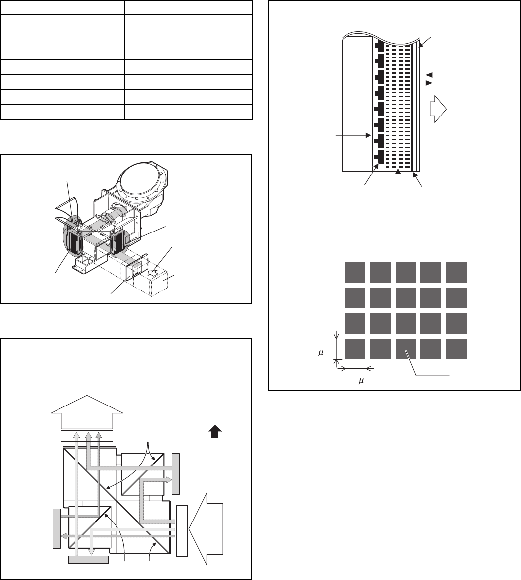
2.4.1 D-ILA DEVICE SPECIFICATION
2.4.2 PROJECTION UNIT
2.4.3 IMAGE LIGHT FLOW
2.4.4 D-ILA DEVICE STRUCTURE
Item Content
Resolution H: 1952 × V:1088
Pixel number about 2123776
Pixel size H : 8.1µm × V :8.1µm
Aspect ratio 16 : 9
Contrast ratio 5000 : 1
Aperture ratio 89% or more
Effective pixel measurement 0.7 inch
R DEVICE
G DEVICE
OPTICAL IRIS
B DEVICE
Lamp unit
Incident light
Device
BRG
B
BRG
R
Projection
light
G
Mirror
MirrorMirror
FRONT
DEVICE UNIT SECTION (TOP VIEW)
Device
Device
Incident
light
Pixel
FRONT
Incident light
Projection light
Glass
substrate
Transparent
electrode
Reflective pixel
electrode
Back
Plane
Liquid
crystal
Flat film
R / G / B DEVICE (SIDE VIEW)
8.1 m
PIXEL VIEW (FRONT VIEW)
8.1 m

(No.YA337)1-9
2.4.5 MAIN CPU PIN FUNCTION [IC7601 : DIGITAL PWB ASS'Y]
Pin Pin name I/O Function Pin Pin name I/O Function
1 VHOLD1 I Data slice for main screen closed caption 51 NC O Not used
2 HFLT1 I/O LPF for main screen closed caption video input 52 NC O Not used
3 NC O Not used 53 NC O Not used
4 NC O Not used 54 NC O Not used
5 DIGR0 O R [0] for OSD 55 NC O Not used
6 TB1in I AC power for timer clock 56 NC O Not used
7 REMO I Remote control 57 NC O Not used
8 BYTE I Data bus width select [L = 16bit (fixed)] 58 NC O Not used
9 CNVss I CPU programming mode select [Normal = L] 59 NC O Not used
10 DIGG0 O G [0] for OSD 60 NC O Not used
11 DIGB0 O B [0] for OSD 61 NC O Not used
12 RESET I Reset for main CPU [Reset = L] 62 HSYNC I H. sync for OSD
13 Xout O System clock osillation (crystal) : 16MHz 63 NC O Not used
14 Vss - GND 64 VSYNC I V. sync for OSD
15 Xin I System clock osillation (crystal) : 16MHz 65 NC O Not used
16 VccI I 3.3V stand-by power supply 66 NC O Not used
17 OSC1 I Clock for OSD 67 NC O Not used
18 OSC2 O Not used : Clock for OSD 68 NC O Not used
19 INT1 I AV COMPULINK control 69 NC O Not used
20 INT0 I
Request for sub(chassis) CPU communication (serial data)
70 NC O Not used
21 OUT1 O Ys (blanking) for OSD 71 P2.1 O Clock for Inter IC (serial) bus control
22 OUT2 O YM (transparence) for OSD 72 P2.0 I/O Data for Inter IC (serial) bus control
23 NC O Not used 73 NC O Not used
24 NC O Not used 74 NC O Not used
25 NC O Not used 75 NC O Not used
26 NC O Not used 76 NC O Not used
27 CTA2/RTS2 O Not used 77 NC O Not used
28 CLK2 O Not used 78 NC O Not used
29 RxD2 I Digital tuner control 79 NC O Not used
30 TxD2 O Digital tuner control 80 P1.0 O Function LED lighting
31 SDA2 I/O Not used 81 P0.7 O Communication LED lighting
32 DIGR1 O R [1] for OSD 82 P0.6 O Test point
33 DIGG1 O G [1] for OSD 83 NC O Not used
34 DIGB1 O B [1] for OSD 84 WAKE O Reset for sub(chassis) CPU
35 TxD0 I Data receive (serial) for external programming 85 CARD_DET I Not used
36 RxD0 O Data transmission (serial) for external programming 86
POWER_SW
I Power switch (mechanical) detection
37 CLK0 I Clock for external programming 87 SDA I/O Data for Inter IC (serial) bus control : memory
38 RTS0 O Busy for external programming [Operation = H] 88 SLC O Clock for Inter IC (serial) bus control : memory
39 P5.7 I Not used 89 DIGR2 O R [2] for OSD
40 P5.6 O Not used 90 DIGG2 O G [2] for OSD
41 HOLD I CPU programming mode select [Normal = H] 91 DIGB2 O B [2] for OSD
42 P5.4 O Not used 92 NC O Not used
43 P5.3 O Not used 93 KEY2 I
Key scan data for front control button (MENU/CH+/CH-) KEY2
44 P5.2 O Not used 94 KEY1 I
Key scan data for front control button (INPUT/VOL+/VOL-) KEY1
45 P5.1 O Not used 95 VHOLD2 I Data slice for sub screen closed caption
46 WR O CPU programming mode select [Normal = L] 96 HLF2 I/O LPF for sub screen closed caption video input
47 P4.7 O
Data transmission for sub(chassis) CPU communication (serial)
97 CVIN2 I Video(Y) for sub screen closed caption
48 P4.6 I
Data receive for sub(chassis) CPU communication (serial)
98 TVSETB I Test terminal [L Fixed]
49 P4.5 I Clock for sub(chassis) CPU communication (serial) 99 VCCE I 5V stand-by power supply
50 P4.4 O Not used 100 CVIN1 I Video(Y) for main screen closed caption
1-10 (No.YA337)
SECTION 3
DISASSEMBLY
3.1 DISASSEMBLY PROCEDURE
CAUTION AT DISASSEMBLY:
•Be sure to perform the SYSTEM SETTEING, at the end of the procedure.
• Make sure that the power cord is disconnected from the outlet.
• Pay special attention not to break or damage the parts.
• When removing each board, remove the connectors as required. Taking notes of the connecting points (connector numbers)
makes service procedure manageable.
• Make sure that there is no bent or stain on the connectors before inserting, and firmly insert the connectors.
• Wait until the LAMP UNIT has cool down is completely.
• While not in repair service, place the chassis back its original position.
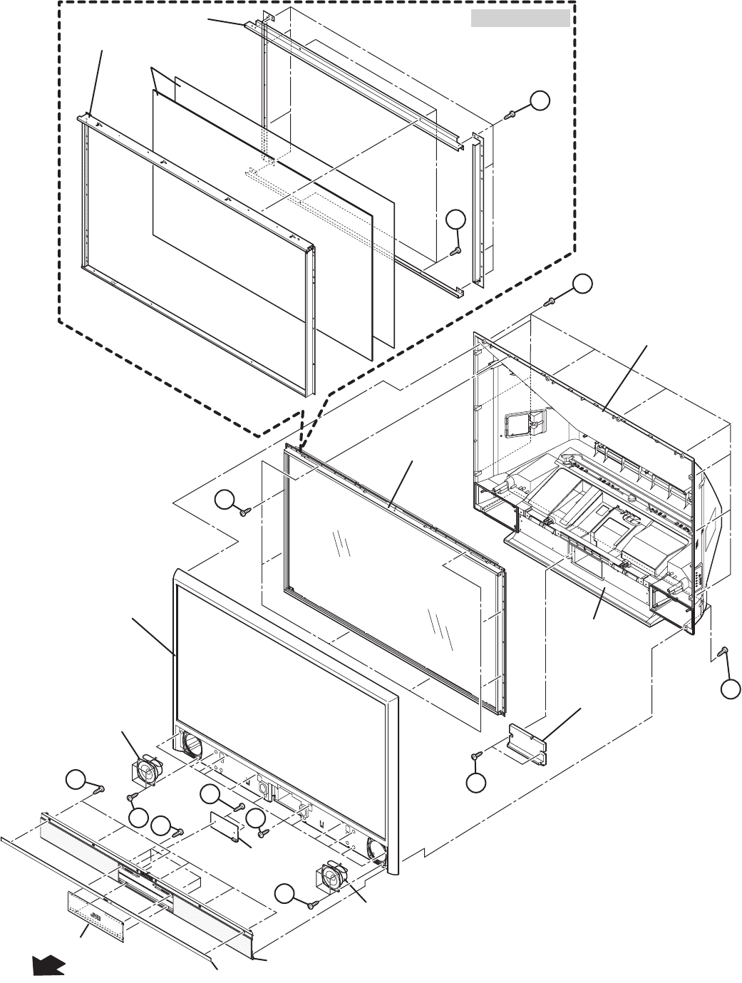
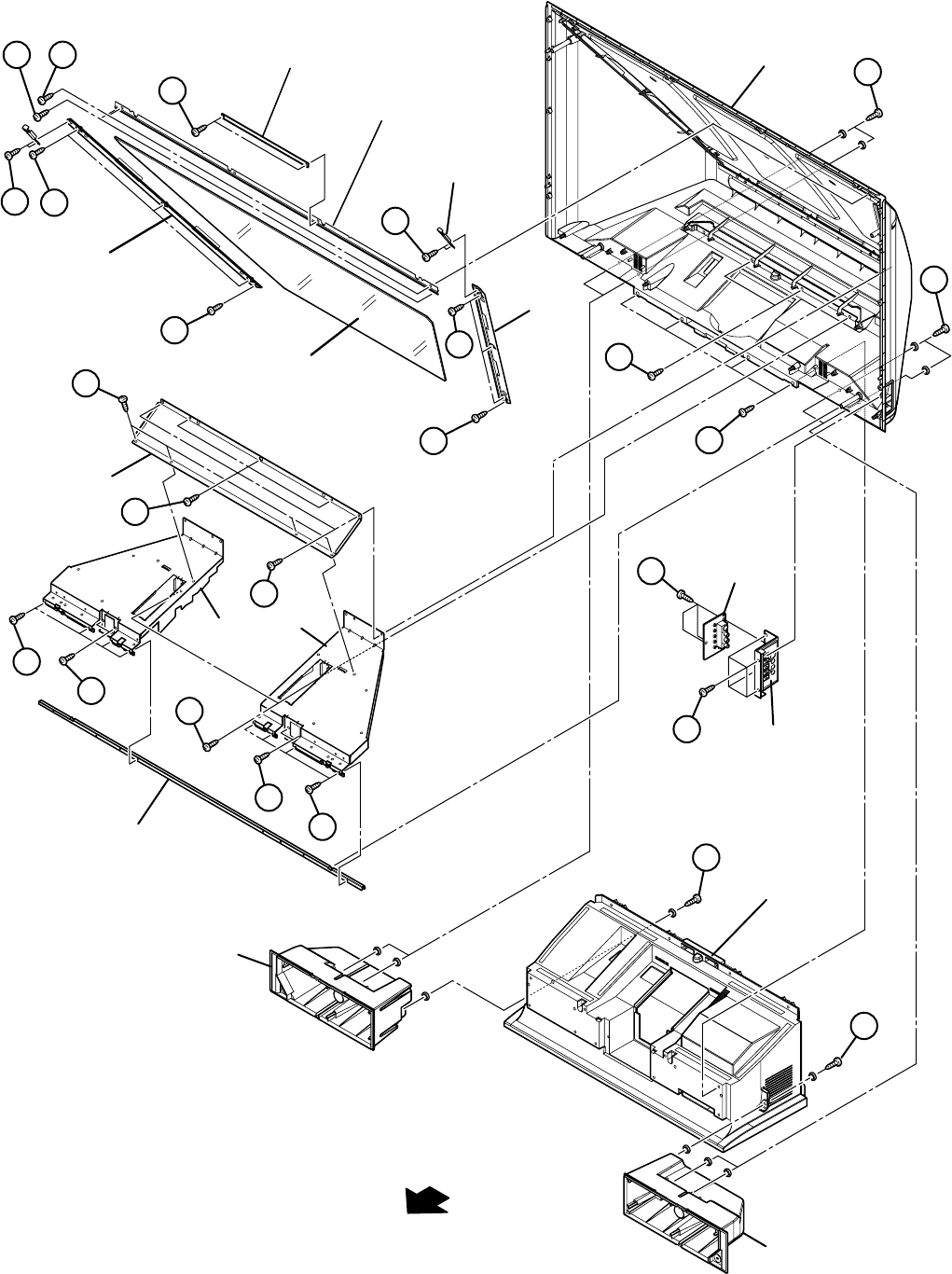
3.1.1 FRONT SIDE DISASSEMBLY [HD-56FH96]
3.1.1.1 REMOVING THE SPEAKER GRILL (Fig.1)
(1) Remove the 2 screws [A].
(2) Remove the SPEAKER GRILL.
NOTE:
As a speaker grille is depressed downward, it is removed.
3.1.1.2 REMOVING THE ORNAMENT PANEL (Fig.1)
• Remove the SPEAKER GRILL.
(1) Remove the 6 screws [B].
(2) Remove the ORNAMENT PANEL.
3.1.1.3 REMOVING THE CENTER PANEL (Fig.1)
• Remove the SPEAKER GRILL.
(1) Remove the 4 screws [C].
(2) Remove the CENTER PANEL.
3.1.1.4 REMOVING THE FRONT LED PWB (Fig.1)
• Remove the SPEAKER GRILL.
(1) Remove the 2 screws [D].
(2) Remove the FRONT LED PWB.
NOTE:
Remove the earth wire connected to the FRONT LED PWB
simultaneously.
3.1.1.5 REMOVING THE SPEAKER (Fig.1)
• Remove the SPEAKER GRILL.
(1) Remove the 4 screws [E].
(2) Remove the SPEAKER.
(3) Remove the opposite SPEAKER same steps.
3.1.1.6 REMOVING THE CENTER COVER (Fig.1)
• Remove the SPEAKER GRILL.
(1) Remove the 2 screws [F].
(2) Remove the CENTER COVER.
3.1.1.7 REMOVING THE FRONT PANEL (Fig.1)
• Remove the SPEAKER GRILL.
(1) Remove the 10 screws [G].
(2) Remove the 12 screws [H].
(3) Remove the FRONT PANEL.
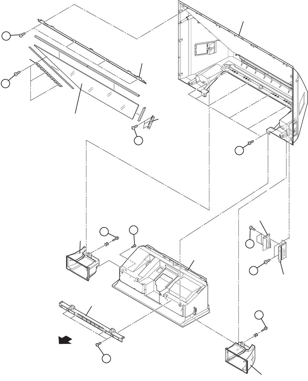
3.1.1.8 REMOVING THE SCREEN BLOCK (Fig.1)
• Remove the SPEAKER GRILL.
• Remove the FRONT PANEL.
(1) Remove the 8 screws [J].
(2) Remove the FRONT PANEL.
CAUTION :
• Place the SCREEN BLOCK on a flat table without fail.
• Because of the large size, at least 2 persons are
recommended for removal and reassemble.
• Use care not to scratch the screen during work.
• During assembly, be sure to engage the left and right tabs
with the cabinet mounting positions.
• When supporting the SCREEN BLOCK, avoid grasping the
top of the screen panel, instead grasp the left and right
areas.
• Do not leave the SCREEN BLOCK removed for long time to
prevent soiling from dust.
3.1.1.9 REMOVING THE SCREEN ASS'Y (Fig.1)
• Remove the SPEAKER GRILL.
• Remove the FRONT PANEL.
• Remove the SCREEN BLOCK.
(1) Remove the 12 screws [K].
(2) Remove the SCREEN ASS'Y.
(No.YA337)1-11
Fig.1
FRONT
SCREEN BLOCK
SCREEN BRACKET
SCREEN ASS'Y
FRONT BRACKET
SPEAKER
BACK COVER
SPEAKER
CENTER COVER
FRONT PANEL
SCREEN BLOCK
MAIN BODY
FRONT
LED PWB
SPEAKER GRILL
ORNAMENT PANEL
CENTER
PANEL
B
F
E
B
C
E
J
G
H
K
K
A
1-12 (No.YA337)
3.1.1.10 REMOVING THE MIRROR (Fig.2)
• Remove the SPEAKER GRILL.
• Remove the FRONT PANEL.
• Remove the SCREEN BLOCK.
(1) Remove the 4 screws [A] attaching the MIRROR HOLDER
of the upper side.
(2) Remove the 6 screws [B] attaching the MIRROR HOLDER
of left and right side.
(3) Raise slightly to disengage of the MIRROR from the bottom
holder
(4) Remove the MIRROR.
NOTE :
• Do not touch the front of the MIRROR.
• Do not shock the the MIRROR.
• Because of the large size, at least 2 persons are
recommended for removal and reassemble.
3.1.1.11 REMOVING THE SIDE CONTROL PWB (Fig.2)
• Remove the SPEAKER GRILL.
• Remove the FRONT PANEL.
• Remove the SCREEN BLOCK.
(1) Remove the 2 screws [C].
(2) Remove the SIDE CONTROL BASE.
(3) Remove the 2 screws [D].
(4) Remove the SIDE CONTROL PWB.
3.1.1.12 REMOVING THE SUPPORT HOLDER (Fig.2)
• Remove the SPEAKER GRILL.
• Remove the FRONT PANEL.
• Remove the SCREEN BLOCK.
(1) Remove the 2 screws [E].
(2) Remove the SUPPORT HOLDER.
3.1.1.13 REMOVING THE BACK COVER (Fig.2)
• Remove the SPEAKER GRILL.
• Remove the FRONT PANEL.
• Remove the SCREEN BLOCK.
• Remove the SUPPORT HOLDER.
(1) Remove the 6 screws [F] and the 2 screws [G].
(2) Remove the BACK COVER
CAUTION :
• Because of the large size, at least 2 persons are
recommended for removal and reassemble.
3.1.1.14 REMOVING THE SPEAKER BOX (Fig.2)
• Remove the SPEAKER GRILL.
• Remove the FRONT PANEL.
• Remove the SCREEN BLOCK.
• Remove the SUPPORT HOLDER.
• Remove the BACK COVER.
(1) Remove the 2 screws [H].
(2) Remove the SPEAKER BOX.
(3) Remove the opposite SPEAKER BOX same steps.
(No.YA337)1-13
Fig.2
MAIN BODY
SUPPORT HOLDER
SIDE CONTROL
PWB
SIDE CONTROL
BASE
SPEAKER
BOX
SPEAKER
BOX
MIRROR
MIRROR HOLDER
MIRROR HOLDER
MIRROR HOLDER
BACK COVER
FRONT
D
C
E
H
G
H
B
A
B
F
1-14 (No.YA337)
3.1.2 FRONT SIDE DISASSEMBLY [HD-61FH96]
3.1.2.1 REMOVING THE SPEAKER GRILL (Fig.3)
(1) Remove the 2 screws [A].
(2) Remove the SPEAKER GRILL.
NOTE :
As a speaker grille is depressed downward, it is removed.
3.1.2.2 REMOVING THE ORNAMENT PANEL (Fig.3)
• Remove the SPEAKER GRILL.
(1) Remove the 6 screws [B].
(2) Remove the ORNAMENT PANEL.
3.1.2.3 REMOVING THE CENTER PANEL (Fig.3)
• Remove the SPEAKER GRILL.
(1) Remove the 4 screws [C].
(2) Remove the CENTER PANEL.
3.1.2.4 REMOVING THE FRONT LED PWB (Fig.5)
• Remove the SPEAKER GRILL.
(1) Remove the 2 screws [D].
(2) Remove the FRONT LED PWB.
NOTE :
Remove the earth wire connected to the FRONT LED PWB
simultaneously.
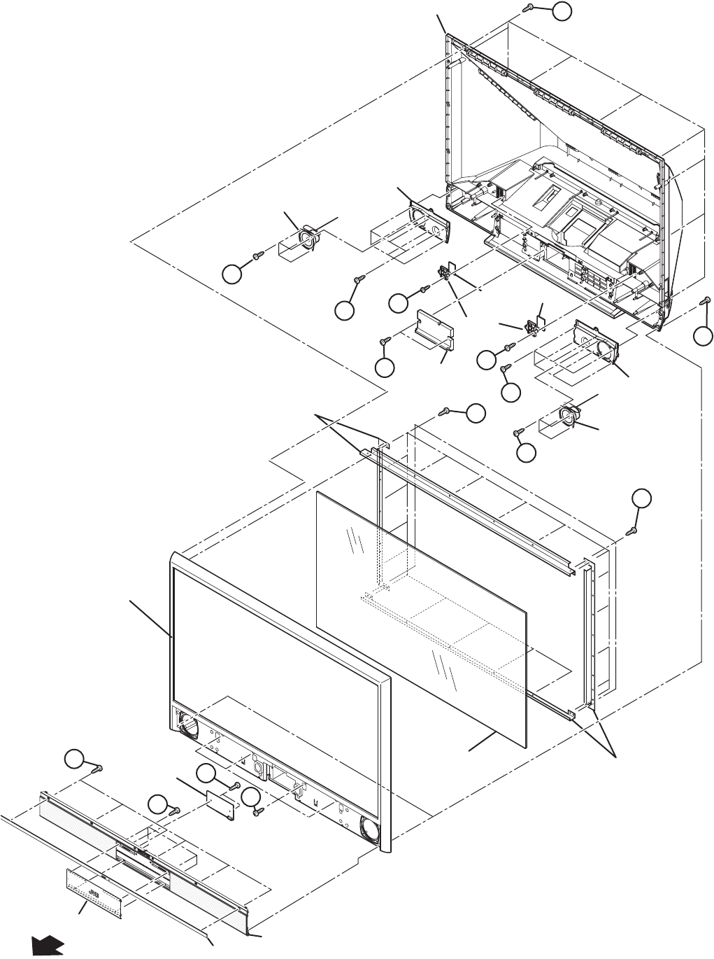
3.1.2.5 REMOVING THE FRONT PANEL WITH SCREEN
ASS'Y (Fig.3)
• Remove the SPEAKER GRILL.
(1) Remove the 10 screws [E] and 4 screws [F].
(2) Remove the FRONT PANEL with SCREEN ASS'Y.
CAUTION :
• Place the FRONT PANEL with SCREEN ASS'Y on a flat
table without fail.
• Because of the large size, at least 2 persons are
recommended for removal and reassemble.
• Use care not to scratch the screen during work.
• Do not leave the FRONT PANEL with SCREEN ASS'Y
removed for long time to prevent soiling from dust.
3.1.2.6 REMOVING THE SCREEN ASS'Y (Fig.3)
• Remove the SPEAKER GRILL.
• Remove the FRONT PANEL with SCREEN ASS'Y.
(1) Remove the 20 screws [G] and 4 screws [H].
(2) Remove the SCREEN BRACKET.
(3) Remove the SCREEN ASS'Y from the FRONT PANEL.
3.1.2.7 REMOVING THE CENTER COVER (Fig.3)
• Remove the SPEAKER GRILL.
• Remove the FRONT PANEL with SCREEN ASS'Y.
(1) Remove the 2 screws [J].
(2) Remove the CENTER COVER.
3.1.2.8 REMOVING THE SPEAKER (Fig.3)
• Remove the SPEAKER GRILL.
• Remove the FRONT PANEL with SCREEN ASS'Y.
(1) Remove the 4 screws [K].
(2) Remove the SPEAKER.
(3) Remove the opposite SPEAKER same steps.
3.1.2.9 REMOVING THE SPEAKER PLATE (Fig.3)
• Remove the SPEAKER GRILL.
• Remove the FRONT PANEL with SCREEN ASS'Y.
• Remove the SPEAKER.
(1) Remove the 6 screws [L].
(2) Remove the SPEAKER PLATE.
3.1.2.10 REMOVING THE BACK COVER FILTER (Fig.3)
• Remove the SPEAKER GRILL.
• Remove the FRONT PANEL with SCREEN ASS'Y.
(1) Remove the 1 screw [M].
(2) Remove the FILTER COVER with BACK COVER FILTER.
(3) Remove the BACK COVER FILTER from FILTER COVER.
(No.YA337)1-15
Fig.3
FRONT
SCREEN ASS'Y
SCREEN BRACKET
SPEAKER
FILTER
COVER
CENTER
COVER
BACK COVER
FILTER
SPEAKER
PLATE
SPEAKER
SPEAKER
PLATE
BACK COVER
FRONT PANEL
FRONT
LED PWB
SPEAKER GRILL
ORNAMENT PANEL
CENTER
PANEL
SCREEN BRACKET
D
B
C
J
E
H
K
K
L
L
M
M
G
E
A
1-16 (No.YA337)
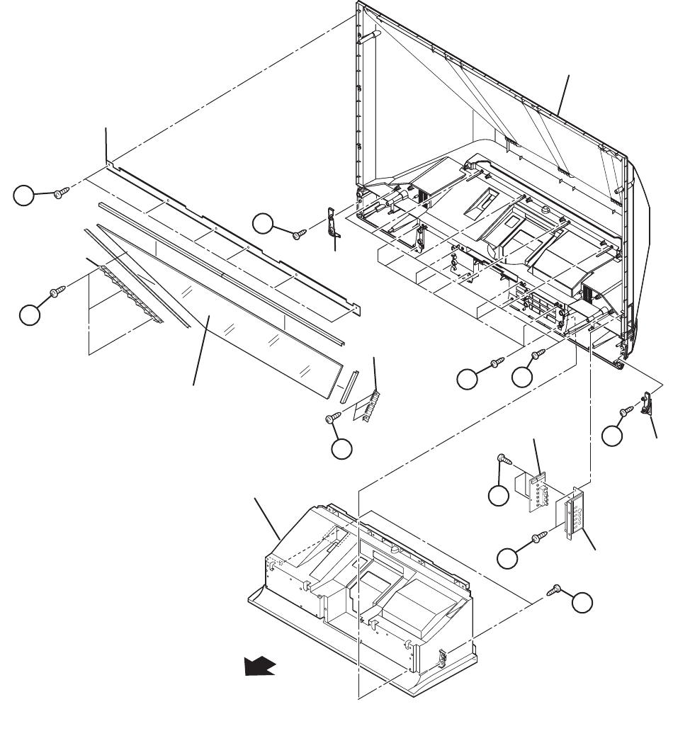
3.1.2.11 REMOVING THE MIRROR (Fig.4)
• Remove the SPEAKER GRILL.
• Remove the FRONT PANEL.
(1) Remove the 6 screws [A] attaching the MIRROR HOLDER
of the upper side.
(2) Remove the 6 screws [B] attaching the MIRROR HOLDER
of left and right side.
(3) Raise slightly to disengage of the MIRROR from the bottom
holder
(4) Remove the MIRROR.
NOTE :
• Do not touch the front of the MIRROR.
• Do not shock the MIRROR.
• Because of the large size, at least 2 persons are
recommended for removal and reassemble.
3.1.2.12 REMOVING THE SIDE CONTROL PWB (Fig.4)
• Remove the SPEAKER GRILL.
• Remove the FRONT PANEL.
(1) Remove the 2 screws [C].
(2) Remove the SIDE CONTROL BASE.
(3) Remove the 2 screws [D].
(4) Remove the SIDE CONTROL PWB.
3.1.2.13 REMOVING THE CORNER COVER (Fig.4)
• Remove the SPEAKER GRILL.
• Remove the FRONT PANEL.
(1) Remove the 1 screw [E].
(2) Remove the CORNER COVER.
(3) Remove the opposite CORNER COVER same steps.
3.1.2.14 REMOVING THE BACK COVER (Fig. 4)
• Remove the SPEAKER GRILL.
• Remove the FRONT PANEL.
• Remove the SPEAKER and SPEAKER PLATE.
(1) Remove the 2 screws [F], 9 screws [G] and 6 screws [H].
(2) Remove the BACK COVER from MAIN BODY.
CAUTION :
• Because of the large size, at least 2 persons are
recommended for removal and reassemble.
(No.YA337)1-17
Fig.4
MAIN BODY
SIDE CONTROL
PWB
SIDE CONTROL
BASE
MIRROR
MIRROR HOLDER
MIRROR HOLDER
CORNER
COVER
CORNER
COVER
MIRROR HOLDER
FRONT
BACK COVER
D
C
F
B
A
B
H
E
E
F
1-18 (No.YA337)
3.1.3 FRONT SIDE DISASSEMBLY [HD-70FH96]
3.1.3.1 REMOVING THE SPEAKER GRILL (Fig.5)
(1) Remove the 2 screws [A].
(2) Remove the SPEAKER GRILL.
NOTE :
As a speaker grille is depressed downward, it is removed.
3.1.3.2 REMOVING THE ORNAMENT PANEL (Fig.5)
• Remove the SPEAKER GRILL.
(1) Remove the 6 screws [B].
(2) Remove the ORNAMENT PANEL.
3.1.3.3 REMOVING THE CENTER PANEL (Fig.5)
• Remove the SPEAKER GRILL.
(1) Remove the 4 screws [C].
(2) Remove the CENTER PANEL.
3.1.3.4 REMOVING THE FRONT LED PWB (Fig.5)
• Remove the SPEAKER GRILL.
(1) Remove the 2 screws [D].
(2) Remove the FRONT LED PWB.
NOTE :
Remove the earth wire connected to the FRONT LED PWB
simultaneously.
3.1.3.5 REMOVING THE SPEAKER (Fig.5)
• Remove the SPEAKER GRILL.
(1) Remove the 4 screws [E].
(2) Remove the SPEAKER.
(3) Remove the opposite SPEAKER same steps.
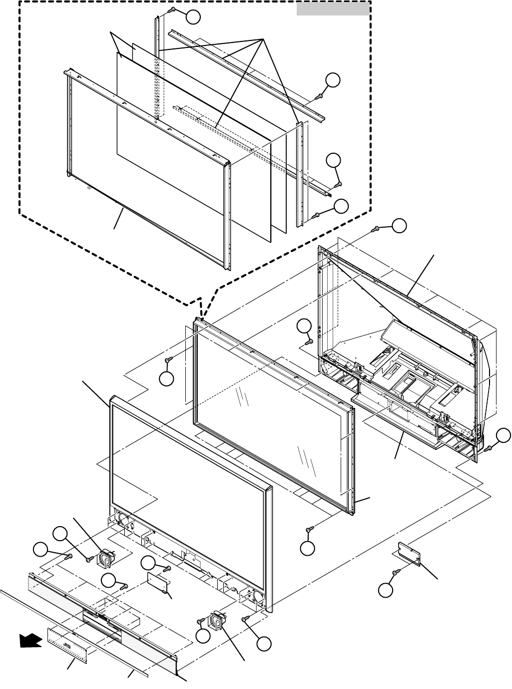
3.1.3.6 REMOVING THE FRONT PANEL (Fig.5)
• Remove the SPEAKER GRILL.
• Remove the SPEAKER.
(1) Remove the 10 screws [F] from rear side.
(2) Remove the 20 screws [G] from front side.
(3) Remove the FRONT PANEL.
3.1.3.7 REMOVING THE SCREEN BLOCK (Fig.5)
• Remove the SPEAKER GRILL.
• Remove the SPEAKER.
• Remove the FRONT PANEL.
(1) Remove the 6 screws [H] and 8 screws [J].
(2) Remove the SCREEN BLOCK.
CAUTION :
• Place the SCREEN BLOCK on a flat table without fail.
• Because of the large size, at least 2 persons are
recommended for removal and reassemble.
• Use care not to scratch the screen during work.
• During assembly, be sure to engage the left and right tabs
with the cabinet mounting positions.
• When supporting the SCREEN BLOCK, avoid grasping the
top of the screen panel, instead grasp the left and right
areas.
• Do not leave the SCREEN BLOCK removed for long time to
prevent soiling from dust.
3.1.3.8 REMOVING THE SCREEN ASS'Y (Fig.5)
• Remove the SPEAKER GRILL.
• Remove the SPEAKER.
• Remove the FRONT PANEL.
• Remove the SCREEN BLOCK.
(1) Remove the 12 screws [K].
(2) Remove the SCREEN BRACKET and SCREEN ASS'Y.
3.1.3.9 REMOVING THE CENTER COVER (Fig.5)
• Remove the SPEAKER GRILL.
• Remove the FRONT PANEL.
(1) Remove the 2 screws [L].
(2) Remove the CENTER PANEL.
(No.YA337)1-19
Fig.5
F
E
C
B
D
G
A
E
A
L
FRONT SPEAKER
SPEAKER
CENTRE COVER
BACK COVER
FRONT PANEL H
SCREEN BRACKET
SCREEN BRACKET
SCREEN BLOCK
K
K
K
K
SCREEN ASS'Y
SCREEN BLOCK
MAIN BODY
J
FRONT
LED PWB
ORNAMENT PANEL
CENTER PANEL
SPEAKER GRILL
1-20 (No.YA337)
3.1.3.10 REMOVING THE MIRROR (Fig.6)
• Remove the SPEAKER GRILL.
• Remove the SPEAKER.
• Remove the FRONT PANEL.
• Remove the SCREEN BLOCK.
(1) Remove the 2 screws [A] attaching the MIRROR HOLDER
STOPPER.
(2) Remove the 2 screws [B] and 2 screws [C] attaching the
MIRROR HOLDER upper side.
(3) Remove the 2 screws [D], 6 screws [E] and 2 screws [F]
attaching the MIRROR HOLDER of left and right side.
(4) Raise slightly to disengage of the MIRROR from the bottom
holder
NOTE :
• Do not touch the front of the MIRROR.
• Do not shock the MIRROR.
• Because of the large size, at least 2 persons are
recommended for removal and reassemble.
3.1.3.11 REMOVING THE BACK COVER BRACKET (Fig.6)
• Remove the SPEAKER GRILL.
• Remove the SPEAKER.
• Remove the FRONT PANEL.
• Remove the SCREEN BLOCK.
(1) Remove the 6 screws [G] and 3 screws [H].
(2) Remove the rear side BACK COVER BRACKET.
(3) Remove the 4 screws [J], 1 screw [K] and 1 screw [L].
(4) Remove the left side BACK COVER BRACKET.
(5) Remove the righ side BACK COVER BRACKET same
step.
3.1.3.12 REMOVING THE SIDE CONTROL PWB (Fig.6)
• Remove the SPEAKER GRILL.
• Remove the SPEAKER.
• Remove the FRONT PANEL.
• Remove the SCREEN BLOCK.
(1) Remove the 4 screws [M].
(2) Remove the SIDE CONTROL BASE.
(3) Remove the 2 screws [N].
(4) Remove the SIDE CONTROL PWB.
3.1.3.13 REMOVING THE SPEAKER BOX (Fig.6)
• Remove the SPEAKER GRILL.
• Remove the SPEAKER.
• Remove the FRONT PANEL.
• Remove the SCREEN BLOCK.
• Remove the BACK COVER BRACKET.
(1) Remove the 3 screws [P].
(2) Remove the SPEAKER BOX.
(3) Remove the opposite SPEAKER BOX same steps.
3.1.3.14 REMOVING THE BACK COVER (Fig.6)
• Remove the SPEAKER GRILL.
• Remove the SPEAKER.
• Remove the FRONT PANEL.
• Remove the SCREEN BLOCK.
• Remove the BACK COVER BRACKET.
• Remove the SPEAKER BOX.
(1) Remove the 4 screws [Q] and 2 screws [R].
(2) Remove the BACK COVER.
(No.YA337)1-21
Fig.6
F
DE
CB
A
E
D
FRONT
MIRROR
BACK COVER
MIRROR HOLDER STOPPER
MIRROR HOLDER(top)
MIRROR
HOLDER
(side)
MIRROR HOLDER
BRACKET(top)
MIRROR
HOLDER
(side)
M
N
SIDE
CONTROL
PWB
SIDE
CONTROL
BASE
P
P
SPEAKER BOX
SPEAKER BOX
MAIN BODY
P
P
Q
R
F
K
L
K
H
G
J
BACK COVER
BRACKET
(L/R)
BACK COVER
BRACKET
(REAR)
J
BACK COVER
BRACKET
(FRONT)
G
1-22 (No.YA337)
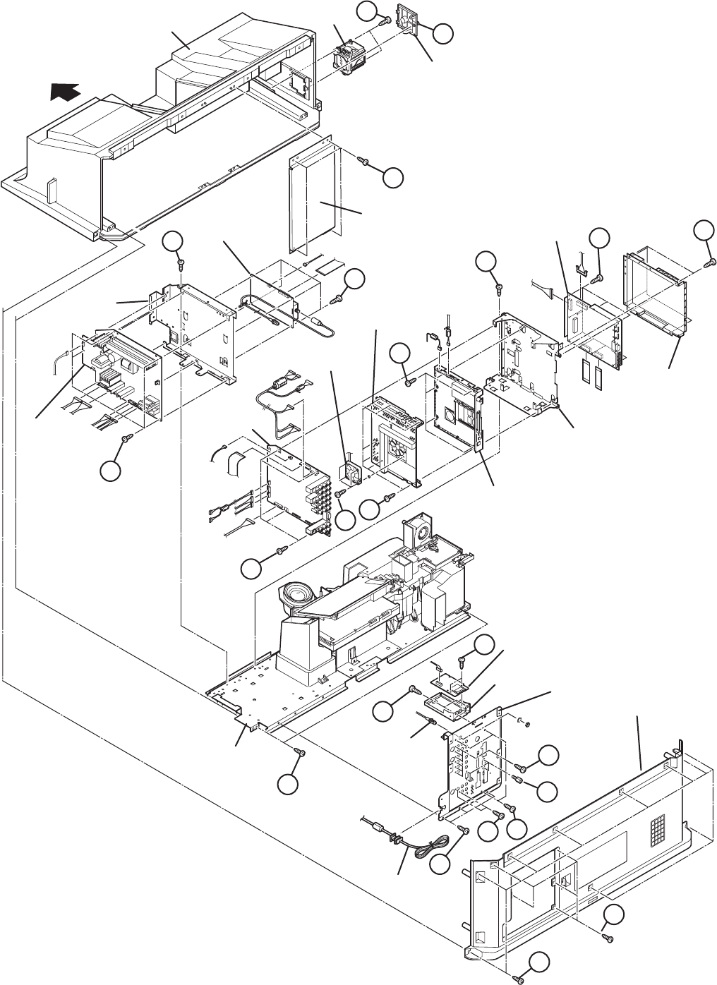
3.1.4 REAR SIDE DISASSEMBLY
3.1.4.1 REMOVING THE LAMP UNIT (Fig.7)
(1) Remove the 1 screw [A].
(2) Remove the LAMP COVER.
(3) Remove the 2 screws [B]
(4) Pull out the LAMP UNIT.
NOTE :
• Do not leave the LAMP COVER removed for long time to
prevent dirt and dust form covering the lens.
• Make sure that the LAMP COVER is completely installed.
3.1.4.2 REMOVING THE BODY COVER (Fig.7)
(1) Remove the 11 screws [C] and the 5 screws [D]
(2) Remove the BODY COVER.
NOTE :
• Do not leave the BODY COVER removed for long time to
prevent soiling from dust.
3.1.4.3 REMOVING THE MAIN UNIT (Fig.7)
• Remove the LAMP COVER.
• Remove the BODY COVER.
(1) Remove the 4 screws [E]
(2) Remove the BODY BRACKET.
(3) Remove the 2 screws [F]
(4) The MAIN UNIT is pulled out to the back side.
CAUTION :
• Except for confirmation of projection images on the screen
and audio output through the speakers, the removed MAIN
UNIT is still workable in the same state as if it is still built-in
the TV set. Therefore, the MAIN UNIT can be removed, if
necessary, for board diagnosis, electric testing, etc. apart
from confirmation of screen images and audio output. Do not
leave the MAIN UNIT removed for long time to prevent
soiling from dust.
• Because of the large size, at least 2 persons are
recommended for removal and reassemble.
• When carrying the MAIN UNIT, use care not to drop, shock
or shake it.
• Do not stain or damage the projection lens.
• Do not look directly at the light during service.
• Do not touch the lamp directly as it presents a burn hazard.
NOTE :
• When not performing repair work, attach the cap on the lens
to preventing dust from covering.
• When mounting to the set, make sure the front of the lens is
in contact with the cushion on the set (body) side.
• Make sure that FRONT LED PWB connector is completely
connect to the ANALOG PWB connector.
• When wire clamps are removed during work, use care to
restore them precisely to their original positions.
Performance can be affected if these are not returned to the
original positions.
3.1.4.4 REMOVING THE AV TERMINAL BOARD (Fig.7)
• Remove the LAMP COVER.
• Remove the BODY COVER.
• Remove the BODY BRACKET.
• Remove the MAIN UNIT.
(1) Remove the 3 screws [G], 2 screws [H], 6 screws [J], 3
screws [K].
(2) Remove the 4 hex screws [L].
(3) Remove the nut attaching the ANTENNA TERMINAL.
(4) Remove the AV TERMINAL BOARD.
3.1.4.5 REMOVING THE POWER PWB (Fig.7)
• Remove the LAMP COVER.
• Remove the BODY COVER.
• Remove the BODY BRACKET.
• Remove the MAIN UNIT.
(1) Remove the POWER CORD.
(2) Remove the 5 screws [M].
(3) Remove the POWER PWB.
3.1.4.6 REMOVING THE TUNER PWB (Fig.7)
• Remove the LAMP COVER.
• Remove the BODY COVER.
• Remove the BODY BRACKET.
• Remove the MAIN UNIT.
(1) Remove the 1 screw [N].
(2) Remove the HANGER BRACKET with TUNER PWB.
(3) Remove the 4 screws [P].
(4) Remove the TUNER PWB.
3.1.4.7 REMOVING THE ANALOG PWB (Fig.7)
• Remove the LAMP COVER.
• Remove the BODY COVER.
• Remove the BODY BRACKET.
• Remove the MAIN UNIT.
• Remove the POWER PWB and TUNER PWB.
• Remove the AV TERMINAL BOARD.
(1) Remove the 4 screws [Q].
(2) Remove the ANALOG PWB.
3.1.4.8 REMOVING THE DIGITAL PWB (Fig.7)
• Remove the LAMP COVER.
• Remove the BODY COVER.
• Remove the BODY BRACKET.
• Remove the MAIN UNIT.
• Remove the POWER PWB and TUNER PWB.
(1) Remove the 1 screw [R].
(2) Remove the DIGITAL PWB BRACKET with DIGITAL PWB
and ATSC TUNER MODULE.
(3) Remove the 4 screws [S].
(4) Remove the DIGITAL PWB SHIELD COVER.
(5) Remove the 9 screws [T].
(6) Remove the DIGITAL PWB.
CAUTION :
Make sure to perform the "SYSTEM SETTEING", when
DIGITAL PWB is replaced.
(No.YA337)1-23
3.1.4.9 REMOVING THE ATSC TUNER MODULE PWB (Fig.7)
• Remove the LAMP COVER.
• Remove the BODY COVER.
• Remove the BODY BRACKET.
• Remove the MAIN UNIT.
• Remove the POWER PWB and TUNER PWB.
(1) Remove the 1 screw [R].
(2) Remove the DIGITAL PWB BRACKET with ATSC TUNER
MODULE PWB.
(3) Remove the 4 screws [U].
(4) Remove the ATSC TUNER COOLING FAN.
(5) Remove the 8 screws [V].
(6) Remove the ATSC TUNER SHIELD COVER.
(7) Remove the 5 screws [W].
(8) Remove the ATSC TUNER MODULE PWB.
3.1.4.10 REMOVING THE SD CARD PWB (Fig.7)
• Remove the LAMP COVER.
• Remove the BODY COVER.
• Remove the BODY BRACKET.
• Remove the MAIN UNIT.
• Remove the AV TERMINAL BOARD.
(1) Remove the 2 screws [X].
(2) Remove the SD CARD BRACKET with SD CARD PWB.
(3) Remove the 2 screws.
(4) Remove the SD CARD PWB.
3.1.4.11 REMOVING THE IRIS PWB (Fig.7)
• Remove the LAMP COVER.
• Remove the BODY COVER.
• Remove the BODY BRACKET.
• Remove the MAIN UNIT.
• Remove the POWER PWB and TUNER PWB.
(1) Remove the 2 screws [Z].
(2) Remove the IRIS PWB.
3.1.4.12 REMOVING THE REMOCON PWB (Fig.7)
• Remove the LAMP COVER.
• Remove the BODY COVER.
• Remove the BODY BRACKET.
• Remove the MAIN UNIT.
• Remove the POWER PWB and TUNER PWB.
(1) Remove the 1 screw [a].
(2) Remove the REMOCON PWB.
1-24 (No.YA337)
Fig.7
MAIN BODY
BODY BRACKE
MAIN UNIT
AV TERMINAL BOARD
POWER CORD
BODY COVER
SD CARD PWB
SD CARD
BRACKET
ANTENNA
TERMINAL
LAMP COVER
LAMP UNIT
FRONT
POWER
PWB
ANALOG PWB
ATSC TUNER
COOLING FAN
ATSC TUNER
SHIELD COVER
DIGITAL PWB
SHIELD COVER
DIGITAL PWB
BRACKET
DIGITAL PWB
HANGER
BRACKET
TUNER PWB
ATSC TUNER MODULE PWB
E
D
C
F
G
K
L
J
Y
X
H
M
N
P
W
S
T
R
UV
Q
B
A
(No.YA337)1-25
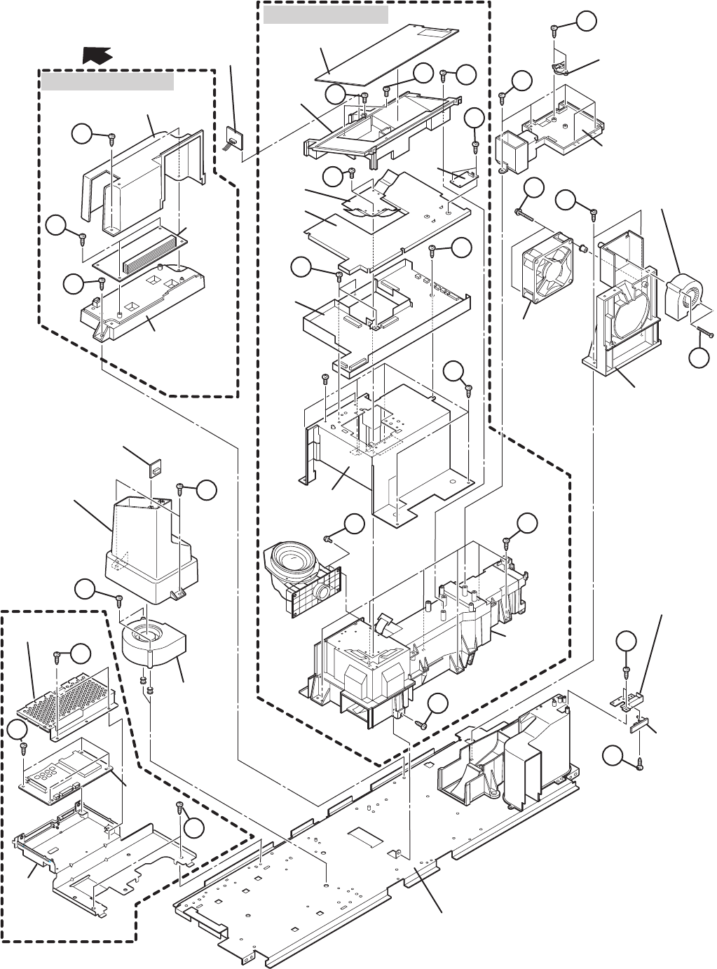
3.1.4.13 REMOVING THE LAMP COVER SW PWB (Fig.8)
• Remove the LAMP COVER.
• Remove the BODY COVER.
• Remove the BODY BRACKET.
• Remove the MAIN UNIT.
(1) Remove the 2 screws [A].
(2) Remove the LAMP COVER SW BRACKET with LAMP
COVER SW PWB.
(3) Remove the 1 screw [B].
(4) Remove the LAMP COVER SW PWB.
3.1.4.14 REMOVING THE LAMP FAN DUCT (Fig.8)
• Remove the LAMP COVER.
• Remove the BODY COVER.
• Remove the BODY BRACKET.
• Remove the MAIN UNIT.
(1) Remove the 2 screws [C].
(2) Remove the THERMOSTAT.
(3) Remove the 5 screws [D].
(4) Remove the LAMP FAN DUCT.
3.1.4.15 REMOVING THE LAMP COOLING FAN (Fig.8)
• Remove the LAMP COVER.
• Remove the BODY COVER.
• Remove the BODY BRACKET.
• Remove the MAIN UNIT.
(1) Remove the 2 screws [E].
(2) Remove the COOLING FAN BRACKET by pulling
transversally
(3) Remove the 2 screws [F].
(4) Remove the LAMP COOLING FAN.
3.1.4.16 REMOVING THE BALLAST UNIT COOLING FAN
(Fig.8)
• Remove the LAMP COVER.
• Remove the BODY COVER.
• Remove the BODY BRACKET.
• Remove the MAIN UNIT.
• Remove the COOLING FAN BRACKET.
(1) Remove the 2 screws [G].
(2) Remove the BALLAST UNIT COOLING FAN.
3.1.4.17 REMOVING THE LAMP BALLAST BLOCK (Fig.8)
• Remove the LAMP COVER.
• Remove the BODY COVER.
• Remove the BODY BRACKET.
• Remove the MAIN UNIT..
(1) Remove the 1 screw [H].
(2) Remove the LAMP BALLAST BLOCK.
(3) Remove the 2 screws [I].
(4) Remove the LAMP BALLAST DUCT.
(5) Remove the 2 screws [J].
(6) Remove the LAMP BALLAST UNIT.
3.1.4.18 REMOVING THE IRIS PWB (Fig.8)
• Remove the LAMP COVER.
• Remove the BODY COVER.
• Remove the BODY BRACKET.
• Remove the MAIN UNIT.
(1) Remove the 2 screws [K].
(2) Remove the IRIS PWB.
3.1.4.19 REMOVING THE REMOCON PWB(Fig.8)
• Remove the LAMP COVER.
• Remove the BODY COVER.
• Remove the BODY BRACKET.
• Remove the MAIN UNIT.
(1) Remove the 1 screws [a].
(2) Remove the REMOCON PWB.
3.1.4.20 REMOVING THE OPTICAL / DRIVE ASS'Y (Fig.8)
• Remove the LAMP COVER.
• Remove the BODY COVER.
• Remove the BODY BRACKET.
• Remove the MAIN UNIT.
• Remove the LAMP FAN DUCT.
(1) Remove the 5 screw [L], 6 screw [M] and 1 screw [N].
(2) Remove the OPTICAL / DRIVE ASS'Y.
NOTE :
• The OPTICAL / DRIVE ASS'Y contains precision
opticalcomponents.
• Handle carefully and avoid imparting strong shock.
• OPTICAL / DRIVE ASS'Y construction
(1) OPTICAL BLOCK:
(D-ILA device, PBS, Field lens, Integrater, Mirror etc.)
(2) PROJECTION LENS
(3) OPTICAL BASE
(4) DRIVE PWB
(5) IRIS PWB
(6) TOP DUCT
(7) SHIELD COVER
• When not performing repair work, attach the cap on the lens to
preventing dust from covering.
• When mounting to the set, make sure the front of the lens side
is in contact with the cushion on the body side.
• Do not leave the OPTICAL / DRIVE ASS'Y removed for long
time to prevent soiling from dust.
3.1.4.21 REMOVING THE DRIVE PWB (Fig.8)
• Remove the LAMP COVER.
• Remove the BODY COVER.
• Remove the BODY BRACKET.
• Remove the MAIN UNIT.
(1) Slide the TOP DUCT PLATE and remove it.
(2) Remove the 1 screw [P] and the 1 screw [Q].
(3) Remove the TOP DUCT.
(4) Remove the SHIELD TOP CASE.
(5) Remove the 2 screws [R].
(6) Remove the DEVICE SHIELD.
(7) Remove the 3 screws [S] and the 1 screw [T].
(8) Remove the DRIVE PWB.
1-26 (No.YA337)
3.1.4.22 REMOVING THE OPTICAL BLOCK COOLING FAN
(Fig.8)
• Remove the LAMP COVER.
• Remove the BODY COVER.
• Remove the BODY BRACKET.
• Remove the MAIN UNIT.
• Remove the LAMP FAN DUCT.
• Remove the OPTICAL / DRIVE ASS'Y
(1) Remove the 2 screws [U].
(2) Remove the SIROCCO TOP CASE.
(3) Remove the 2 screws [V].
(4) Remove the OPTICAL BLOCK COOLING FAN.
3.1.4.23 REMOVING THE PROJECTION LAMP(Fig.8)
• Remove the LAMP COVER.
• Remove the BODY COVER.
• Remove the BODY BRACKET.
• Remove the MAIN UNIT.
(1) Remove the 4 screws [W].
(2) Remove the PROJECTION LAMP.
3.1.4.24 REMOVING THE CARD VIEWER PWB [HD-70FH96]
(Fig.8)
• Remove the LAMP COVER.
• Remove the BODY COVER.
• Remove the BODY BRACKET.
• Remove the MAIN UNIT..
(1) Remove the 2 screws [X].
(2) Remove the CARD VIEWER BRACKET.
(3) Remove the 2 screws [Y].
(4) Remove the CARD VIEWER SHIELD COVER.
(5) Remove the 4 screws [Z].
(6) Remove the CARD VIEWER PWB.
(No.YA337)1-27
Fig.8
FRONT
TOP DUCT PLATE
DRIVE
PWB
SHIELD COVER
DEVICE
SHIELD
IRIS
PWB
REMOCON
PWB
OPTICAL / DRIVE ASS'Y
LAMP BALLAST BLOCK
SIROCCO TOP
CASE
THERMO PWB
UNIT BASE
LAMP COVER
SW PWB
LAMP COVER SW
BRACKET
THERMOSTAT
LAMP
BALLAST
UNIT
LAMP BALLAST
DUCT
LAMP BALLAST
BRACKET
LAMP FAN DUCT
COOLING FAN
BRACKET
SHIELD
TOP
CASE
TOP DUCT
OPTICAL
BLOCK
COOLING FAN
CARD VIEWER
SHIELD COVER
CARD
VIEWER
BRACKET
CARD
VIEWER
PWB
BALLAST UNIT
COOLING FAN
OPTICAL
BLOCK
(Only HD-70FH96)
LAMP
COOLING FAN
J
C
D
E
G
A
B
V
X
Y
Z
U
F
K
I
H
S
M
T
L
R
a
Q
P
N
W
1-28 (No.YA337)
3.2 MEMORY IC REPLACEMENT
• This model uses the memory IC.
• This memory IC stores data for proper operation of the video and drive circuits.
• When replacing, be sure to use an IC containing this (initial value) data.
3.2.1 MEMORY IC TABLE
3.2.2 MEMORY IC REPLACEMENT PROCEDURE
1. Power off
Switch off the power and disconnect the power plug from the AC outlet.
2. Replace the memory IC
Be sure to use the memory IC written with the initial setting values.
3. Power on
Connect the power plug to the AC outlet and switch on the power.
4. Receiving channel setting
Refer to the OPERATING INSTRUCTIONS and set the receive channels (Channels Preset) as described.
5. User setting
Check the user setting items according to the given in page later. Where these do not agree, refer to the OPERATING
INSTRUCTIONS and set the items as described.
6. SERVICE MODE setting
Verify what to set in the SERVICE MODE, and set whatever is necessary (Fig.1). Refer to the SERVICE ADJUSTMENT for setting.
3.2.3 SERVICE MODE SETTING
SERVICE MODE SCREEN
Fig.1
SETTING ITEM
Simbol Number of pins Mounting PWB Main content of data
IC3753 8-pin DRIVE PWB Adjustment and setting data (GAMMA, SHADING, etc.) of
IC3701(DRIVE CPU) are memorized.
IC7201 48-pin DIGITAL PWB Progaram(Video process) of IC6001(System CPU) is memorized.
IC7602 8-pin DIGITAL PWB Setting value of IC7601(MAIN CPU) is memorized.
ADJUSTMENT MODE SCREEN
SERVICE MENU SCREEN
SERVICE MENU
SERVICE MENU
1. ADJUST
1. ADJUST
2. SELF CHECK
2. SELF CHECK
3. I2C STOP
3. I2C STOP
S001 R DRIVE137
S001 R DRIVE137
NTSC3 FULL STD LOW
NTSC3 FULL STD LOW
Setting items Settings Item No.
Video system setting Adjust S001 - S009
Audio system setting Adjust T001 - T003
Main CPU system setting Fixed M001 - M224
Drive system setting Fixed F001 - F002
(NOT USED) Fixed D001
(NOT USED) Fixed Z001
(No.YA337)1-29
3.2.4 SETTINGS OF FACTORY SHIPMENT
3.2.4.1 BUTTON OPERATION 3.2.4.2 REMOTE CONTROL DIRECT OPERATION
3.2.4.3 REMOTE CONTROL MENU OPERATION
PICTURE ADJUST
Customers can adjust the picture setting of menu screen as their
own like but the picture standard value during factory shipment is as
below.
[NTSC MODE]
[HD MODE]
SOUND ADJUST
CLOCK / TIMERS
INITIAL SETUP
Setting item Setting position
POWER Off
CHANNEL CABLE-02
VOLUME 10
INPUT TV
Setting item Setting position
INPUT TV
CHANNEL CABLE-02
VOLUME 10
MUTING OFF
DISPLAY OFF
ASPECT NTSC Reguler
HD FULL
SLEEP TIMER OFF
THEATER PRO OFF
NATURAL CINEMA AUTO
C.C. OFF
MTS STEREO
TWIN
SOURCE
LEFT SIDE CABLE-02
RIGHT SIDE INPUT-1
SOUND
A.H.S
OFF
BBE ON
SMART SOUND OFF
HYPER BASS OFF
Setting item
DYNAMIC
STANDARD
GAME
THEATER
TINT +15 00 -10 00
COLOR 00000000
PICTURE 00 00 00 00
BRIGHT 00 00 00 00
DETAIL +05 00 00 00
COLOR TEMPERATURE
HIGH HIGH HIGH HIGH
COLOR MANAGEMENT
ON ON ON ON
DYNAMIC GAMMA ON ON ON ON
SMART PICTURE OFF ON ON ON
DIGITAL VNR AUTO AUTO AUTO AUTO
MPEG NR OFF OFF OFF OFF
Setting item
DYNAMIC
STANDARD
GAME
THEATER
PICTURE +15 00 -10 00
BRIGHT 00 00 00 00
COLOR 00000000
TINT 00 00 00 00
DETAIL +05 00 00 00
COLOR TEMPERATURE
HIGH LOW HIGH LOW
COLOR MANAGEMENT
ON ON ON ON
DYNAMIC GAMMA ON ON ON ON
SMART PICTURE OFF ON ON ON
DIGITAL VNR AUTO AUTO AUTO AUTO
MPEG NR OFF OFF OFF OFF
Setting item Setting position
BASS 00
TREBLE 00
BALANCE 00
Setting item Setting position
ON / OFF TIMER NO
Setting item Setting position
VIDEO-1 MONITOR OUT OFF
TV SPEAKER ON
AUDIO OUT FIX
DIGITAL-IN AUTO
DIGITAL-IN AUDIO AUTO
CENTER CH INPUT OFF
NOISE MUTING ON
FRONT PANEL LOCK OFF
V1 SMART INPUT OFF
VIDEO INPUT LABEL All blank
POSITION ADJUSTMENT Center
POWER INDICATOR HIGH
LANGUAGE ENG.
CLOSED CAPTION OFF
AUTO SHUT OFF OFF
XDS ID ON
AUTO TUNER SETUP Unnecessary to set
V-CHIP OFF
1-30 (No.YA337)
3.3 REPLACEMENT OF CHIP COMPONENT
3.3.1 CAUTIONS
(1) Avoid heating for more than 3 seconds.
(2) Do not rub the electrodes and the resist parts of the pattern.
(3) When removing a chip part, melt the solder adequately.
(4) Do not reuse a chip part after removing it.
3.3.2 SOLDERING IRON
(1) Use a high insulation soldering iron with a thin pointed end of it.
(2) A 30w soldering iron is recommended for easily removing parts.
3.3.3 REPLACEMENT STEPS
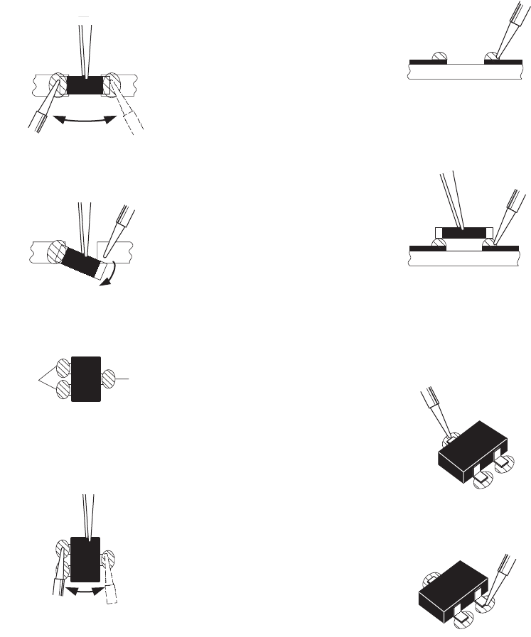
1. How to remove Chip parts
[Resistors, capacitors, etc.]
(1) As shown in the figure, push the part with tweezers and
alternately melt the solder at each end.
(2) Shift with the tweezers and remove the chip part.
[Transistors, diodes, variable resistors, etc.]
(1) Apply extra solder to each lead.
(2) As shown in the figure, push the part with tweezers and
alternately melt the solder at each lead. Shift and remove
the chip part.
NOTE :
After removing the part, remove remaining solder from the
pattern.
2. How to install Chip parts
[Resistors, capacitors, etc.]
(1) Apply solder to the pattern as indicated in the figure.
(2) Grasp the chip part with tweezers and place it on the
solder. Then heat and melt the solder at both ends of the
chip part.
[Transistors, diodes, variable resistors, etc.]
(1) Apply solder to the pattern as indicated in the figure.
(2) Grasp the chip part with tweezers and place it on the
solder.
(3) First solder lead A as indicated in the figure.
(4) Then solder leads B and C.
SOLDER SOLDER
A
B
C
A
B
C

(No.YA337)1-31
SECTION 4
ADJUSTMENT
4.1 ADJUSTMENT PREPARATION
(1) There are 2 ways of adjusting this TV : One is with the
REMOTE CONTROL UNIT and the other is the
conventional method using adjustment parts and
components.
(2) The adjustment using the REMOTE CONTROL UNIT is
made on the basis of the initial setting values. The
setting values which adjust the screen to the optimum
condition can be different from the initial setting
values.
(3) Make sure that connection is correctly made AC to AC
power source.
(4) Turn on the power of the TV and measuring instruments for
warning up for at least 30 minutes before starting
adjustments.
(5) If the receive or input signal is not specified, use the most
appropriate signal for adjustment.
(6) Never touch the parts (such as variable resistors,
transformers and condensers) not shown in the adjustment
items of this service adjustment.
4.2 PRESET SETTING BEFORE ADJUSTMENTS
Unless otherwise specified in the adjustment items, preset the
following functions with the REMOTE CONTROL UNIT.
4.3 MEASURING INSTRUMENT AND FIXTURES
• Oscilloscope
• Signal generator (Pattern generator)
[NTSC / 525i / 525p / 750p / 1125i]
• TV audio multiplex signal generator
• Remote control unit
4.4 ADJUSTMENT ITEMS
FOCUS
• LENS FOCUS adjustment
DRIVE CIRCUIT
• DRIVE CONVERGENCE adjustment
• DRIVE CENTER POSITION adjustment
VIDEO CIRCUIT
• WHITE BALANCE (HIGHLIGHT) adjustment
MTS CIRCUIT
• MTS INPUT LEVEL adjustment
• MTS SEPARATION adjustment
Setting item Settings
VIDEO STATUS STANDARD
Picture adjustments 00
COLOR TEMPERATURE LOW
COLOR MANAGEMENT ON
DYNAMIC GAMMA ON
SMART PICTURE OFF
DIGITAL VNR OFF
MPEG NR OFF
NATURAL CINEMA AUTO
Sound adjustments 00
A.H.S
OFF
BBE OFF
SMART SOUND OFF
ASPECT FULL
1-32 (No.YA337)
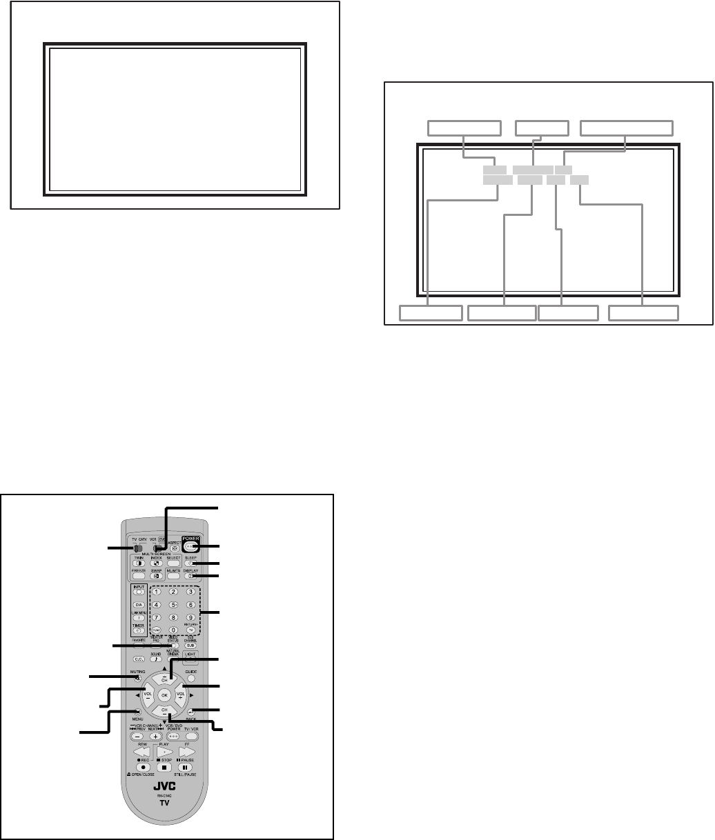
4.5 BASIC OPERATION OF SERVICE MODE
4.5.1 HOW TO ENTER THE SERVICE MODE
(1) Set to "0 minutes" using the [SLEEP TIMER] key.
(2) While "0 minutes" is displayed, press the [VIDEO STA-
TUS] key and [DISPLAY] key simultaneously, then enter
the SERVICE MODE (Fig.1)
Fig.1
NOTE:
• Before entering the SERVICE MODE, confirm that the
setting of TV/CATV switch of the REMOTE CONTROL UNIT
is at the "TV" side and the setting of VCR/DVD switch is at
the "VCR" side. If the switches have not been properly set,
you cannot enter the SERVICE MODE.
• When a number key other than the [1] or [9] keys is pressed
in the SERVICE MENU SCREEN, the other relevant screen
may be displayed.
This is not used in the adjustment procedure. Press the
[MENU] key to return to the SERVICE MENU SCREEN.
4.5.2 HOW TO EXIT THE SERVICE MODE
Press the [ BACK ] key to exit the Service mode.
4.5.3 SERVICE MODE SELECT KEY LOCATION
4.5.4 ADJUSTMENT MODE
This mode is used to adjust the VIDEO CIRCUIT and the MTS
CIRCUIT.
4.5.4.1 HOW TO ENTER THE ADJUSTMENT MODE
When the SERVICE MENU SCREEN of SERVICE MODE is
displayed, press [1] key to enter the ADJUSTMENT MODE
(Fig.2).
4.5.4.2 DESCRIPTION OF STATUS DISPLAY OF
ADJUSTMENT MODE
Fig.2
(1) SIGNAL SYSTEM
The signal displayed on the screen is displayed.
(2) SCREEN MODE
State of the SCREEN SIZE or MULTI PICTURE is displayed.
SINGLE SCREEN
MULTI SCREEN
SERVICE MENU SCREEN
SERVICE MENU
SERVICE MENU
1. ADJUST
1. ADJUST
2. SELF CHECK
2. SELF CHECK
3. I2C STOP
3. I2C STOP
POWER
VCR/DVD switch
NUMBER
DISPLAY
TV/CATV switch
MENU
SLEEP TIMER
VIDEO STATUS
MUTING
CHANNEL +
CHANNEL -
VOLUME +
VOLUME - BACK
NTSC3 : 525i (Composite / S-video input)
525I : 525i (Component input)
525P : 525p
1125I6 : 1125i
750P : 750p
PCVGA : PC (VGA)
PCXGA : PC (XGA)
H525I : HDMI 525i
H525P : HDMI 525p
H125I6 : HDMI 1125i
H750P : HDMI 750p
D525I : ATSC 525i
D525P : ATSC 525p
D125I6 : ATSC 1125i
FULL : FULL
1609 : CINEMA, CINEMA ZOOM
PANO : PANORAMA, HD PANORAMA
REGU : REGULAR
M2 : TWIN, FREEZE screen
M12 : INDEX screen
ADJUSTMENT MODE
SIGNAL SYSTEM
SCREEN MODE
VIDEO STATUS
SETTING VALUE (DATA)
SETTING ITEM No.
SETTING ITEM
WHITE BALANCE
S001 R DRIVE137
S001 R DRIVE137
NTSC3 FULL STD LOW
NTSC3 FULL STD LOW
(No.YA337)1-33
(3) VIDEO STATUS
(4) WHITE BALANCE
(5) SETTING ITEM NAME
Setting item name are displayed. The setting item numbers to
be displayed are listed below.
(6) SETTING ITEM NO.
Setting item numbers are displayed. For the setting item
names to be displayed, refer to "Initial setting value of
adjustment mode".
(7) SETTING VALUE (DATA)
The SETTING VALUE is displayed.
4.5.4.3 CHANGE AND MEMORY OF SETTING VALUE
SELECTION OF SETTING ITEM
• [CH+] / [CH-] key.
Change the setting items up/ down.
• [SLEEP TIMER] key.
Switches to the next items.
CHANGE OF SETTING VALUE (DATA)
• [VOL+] / [VOL-] key.
Change the setting values up/down.
MEMORY OF SETTING VALUE (DATA)
Changed setting value is memorized by pressing [MUTING]
key.
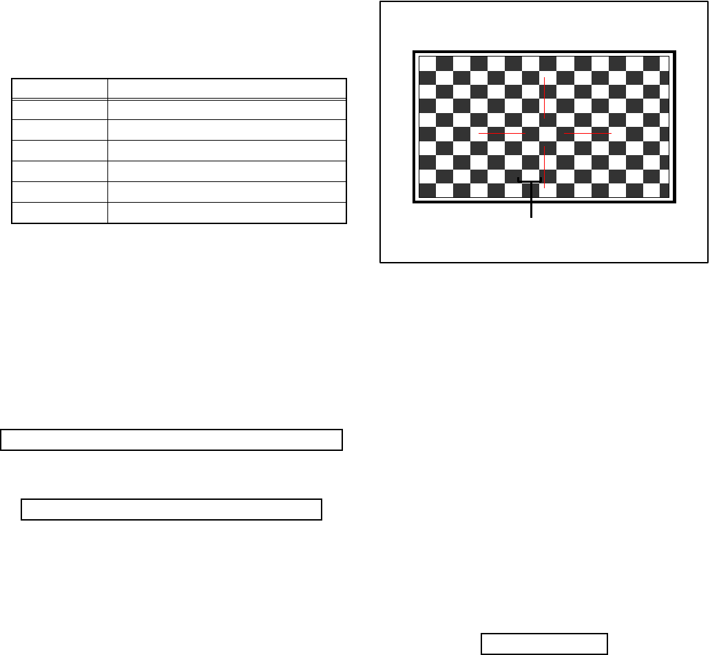
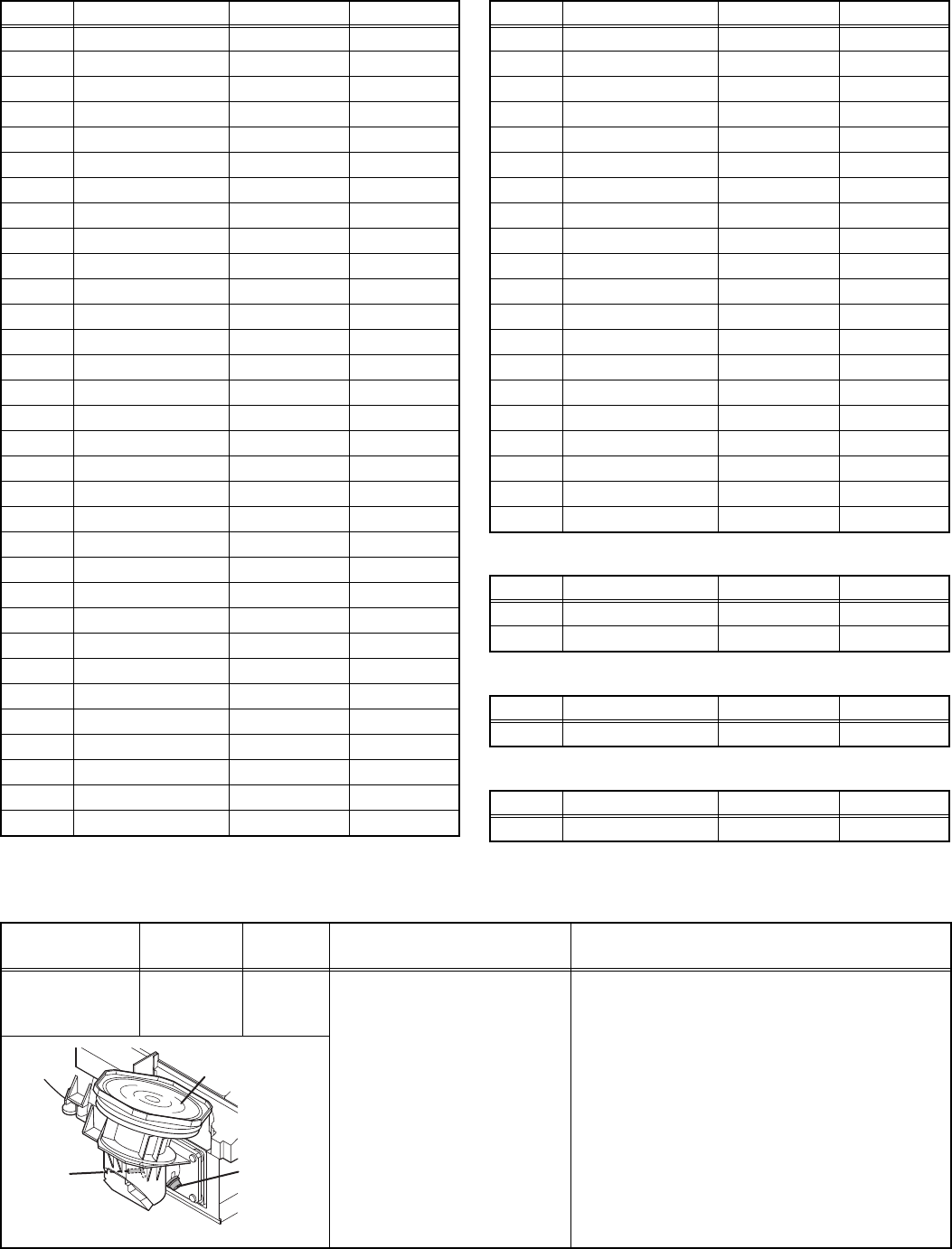
4.5.5 RGB BOX PATTERN MODE
This mode is used to adjust the DRIVE CIRCUIT.
4.5.5.1 HOW TO ENTER THE RGB BOX PATTERN MODE
When the SERVICE MENU SCREEN of SERVICE MODE is
displayed, press [9] key to enter the RGB BOX PATTERN
MODE (Fig3).
4.5.5.2 DESCRIPTION OF STATUS DISPLAY OF RGB BOX
PATTERN MODE
Fig.3
(1) RGB BOX PATTERN
The checkered pattern is displayed. White is a synthesis of
RGB.
(2) ADJUSTMENT COLOR MODE
Presently selected ADJUSTMENT COLOR MODE is
displayed.
SELECTION OF SETTING ITEM
• [CH+] / [CH-] key.
Move the selected RGB BOX PATTERN up/ down pixel by
pixel.
• [VOL+] / [VOL-] key.
Move the selected RGB BOX PATTERN left/ right pixel by
pixel.
• [SLEEP TIMER] key.
Adjusts the data reset.
• [DISPLAY] key.
Adjusts the selected COLOR BOX PATTERN.
• [BACK] key.
Returns to the SERVICE MENU SCREEN from the RGB
BOX PATTERN MODE.
MEMORY OF SETTING VALUE (DATA)
With the RGB BOX PATTERN MODE, the changed date is
written in the MEMORY instantly.
STD : STANDARD
DYN : DYNAMIC
TH : THEATER
GAME : GAME
HIGH : HIGH
LOW : LOW
Item No. Setting item
S001 - S009 Video system setting
T001 - T003 Audio system setting
M001 - M224 Main CPU system setting
F001 - F002 Drive system setting
D001 (NOT USED)
Z001 (NOT USED)
S001... ↔ T001... ↔ M001... ↔ F001... ↔ D001... ↔ Z001...
S001 → T001 → M001... → F001... → D001 → Z001
R → B → RGB
ADJUSTMENT COLOUR MODE
RGB
RGB BOX PATTERN MODE
1-34 (No.YA337)
4.6 INITIAL SETTING VALUES IN THE SERVICE MODE
• Perform fine-tuning based on the "initial values" using the remote control when in the Service mode.
• The "initial values" serve only as an indication rough standard and therefore the values with which optimal display can be achieved
may be different from the default values. But, don't change the values that are not written in "ADJUSTMENT PROCEDURE". They
are fixed values.
4.6.1 VIDEO SYSTEM SETTING
4.6.2 AUDIO SYSTEM SETTING
4.6.3 MAIN CPU SYSTEM SETTING (Fixed values)
Item No. Item Variable range Setting value
S001 R DRIVE 000 - 255 136
S002 G DRIVE 000 - 255 138
S003 B DRIVE 000 - 255 138
S004 RESREV 000 - 255 000
S005 RESREV 000 - 255 002
S006 RESREV 000 - 255 002
S007 RESREV 000 - 255 002
S008 RESREV 000 - 255 002
S009 RESREV 000 - 255 002
Item No. Item Variable range Setting value
T001 INPLEVEL 000 - 015 006
T002 LOWSEPA 000 - 063 020
T003 HIGHSEPA 000 - 063 038
Item No. Item Variable range Setting value
M001 1E00 00 - FF 00
M002 1E01 00 - FF 00
M003 1E02 00 - FF 0A
M004 1E03 00 - FF 3B
M005 1E04 00 - FF 10
M006 1E05 00 - FF 00
M007 1E06 00 - FF 00
M008 1E07 00 - FF 00
M009 1E08 00 - FF 10
M010 1E09 00 - FF 00
M011 1E0A 00 - FF 05
M012 1E0B 00 - FF 00
M013 1E0C 00 - FF 01
M014 1E0D 00 - FF 00
M015 1E0E 00 - FF 00
M016 1E0F 00 - FF 00
M017 1E10 00 - FF 00
M018 1E11 00 - FF 00
M019 1E12 00 - FF 00
M020 1E13 00 - FF 01
M021 1E14 00 - FF 01
M022 1E15 00 - FF 00
M023 1E16 00 - FF 00
M024 1E17 00 - FF 00
M025 1E18 00 - FF 00
M026 1E19 00 - FF 00
M027 1E1A 00 - FF 00
M028 1E1B 00 - FF 00
M029 1E1C 00 - FF 00
M030 1E1D 00 - FF 00
M031 1E1E 00 - FF 00
M032 1E1F 00 - FF 00
M033 1E20 00 - FF 00
M034 1E21 00 - FF 00
M035 1E22 00 - FF 00
M036 1E23 00 - FF 00
M037 1E24 00 - FF 00
M038 1E25 00 - FF 00
M039 1E26 00 - FF 00
M040 1E27 00 - FF 00
M041 1E28 00 - FF 00
M042 1E29 00 - FF 00
M043 1E2A 00 - FF 00
M044 1E2B 00 - FF 00
M045 1E2C 00 - FF 00
M046 1E2D 00 - FF 00
M047 1E2E 00 - FF 00
M048 1E2F 00 - FF 00
M049 1E30 00 - FF 00
M050 1E31 00 - FF 00
M051 1E32 00 - FF 00
M052 1E33 00 - FF 00
M053 1E34 00 - FF 00
M054 1E35 00 - FF 00
M055 1E36 00 - FF 02
M056 1E37 00 - FF 00
M057 1E38 00 - FF 01
M058 1E39 00 - FF 06
M059 1E3A 00 - FF 10
M060 1E3B 00 - FF 83
M061 1E3C 00 - FF 00
M062 1E3D 00 - FF 00
M063 1E3E 00 - FF 00
M064 1E3F 00 - FF 00
M065 1E40 00 - FF 00
M066 1E41 00 - FF 00
M067 1E42 00 - FF 02
M068 1E43 00 - FF 03
M069 1E44 00 - FF 04
M070 1E45 00 - FF 03
M071 1E46 00 - FF 02
M072 1E47 00 - FF 00
Item No. Item Variable range Setting value

(No.YA337)1-35
M073 1E48 00 - FF 00
M074 1E49 00 - FF 00
M075 1E4A 00 - FF 00
M076 1E4B 00 - FF 00
M077 1E4C 00 - FF 00
M078 1E4D 00 - FF 00
M079 1E4E 00 - FF 00
M080 1E4F 00 - FF 00
M081 1E50 00 - FF 00
M082 1E51 00 - FF 00
M083 1E52 00 - FF 00
M084 1E53 00 - FF 00
M085 1E54 00 - FF 00
M086 1E55 00 - FF 00
M087 1E56 00 - FF 00
M088 1E57 00 - FF 00
M089 1E58 00 - FF 00
M090 1E59 00 - FF 00
M091 1E5A 00 - FF 00
M092 1E5B 00 - FF 00
M093 1E5C 00 - FF 01
M094 1E5D 00 - FF 00
M095 1E5E 00 - FF 00
M096 1E5F 00 - FF 00
M097 1E60 00 - FF 00
M098 1E61 00 - FF 00
M099 1E62 00 - FF 00
M100 1E63 00 - FF 00
M101 1E64 00 - FF 00
M102 1E65 00 - FF 00
M103 1E66 00 - FF 00
M104 1E67 00 - FF 00
M105 1E68 00 - FF 00
M106 1E69 00 - FF 00
M107 1E6A 00 - FF 02
M108 1E6B 00 - FF 00
M109 1E6C 00 - FF 00
M110 1E6D 00 - FF 00
M111 1E6E 00 - FF 00
M112 1E6F 00 - FF 00
M113 1E70 00 - FF 00
M114 1E71 00 - FF 00
M115 1E72 00 - FF 00
M116 1E73 00 - FF 00
M117 1E74 00 - FF 00
M118 1E75 00 - FF 00
M119 1E76 00 - FF 00
M120 1E77 00 - FF 00
M121 1E78 00 - FF 03
M122 1E79 00 - FF 00
Item No. Item Variable range Setting value
M123 1E7A 00 - FF 00
M124 1E7B 00 - FF 00
M125 1E7C 00 - FF 00
M126 1E7D 00 - FF 00
M127 1E7E 00 - FF 01
M128 1E7F 00 - FF 00
M129 1E80 00 - FF 01
M130 1E81 00 - FF 00
M131 1E82 00 - FF 01
M132 1E83 00 - FF 00
M133 1E84 00 - FF 00
M134 1E85 00 - FF 00
M135 1E86 00 - FF 00
M136 1E87 00 - FF 00
M137 1E88 00 - FF 00
M138 1E89 00 - FF 00
M139 1E8A 00 - FF 00
M140 1E8B 00 - FF 00
M141 1E8C 00 - FF 00
M142 1E8D 00 - FF 00
M143 1E8E 00 - FF 00
M144 1E8F 00 - FF 00
M145 1E90 00 - FF 00
M146 1E91 00 - FF 00
M147 1E92 00 - FF 00
M148 1E93 00 - FF 00
M149 1E94 00 - FF 00
M150 1E95 00 - FF 00
M151 1E96 00 - FF 00
M152 1E97 00 - FF 00
M153 1E98 00 - FF 00
M154 1E99 00 - FF 00
M155 1E9A 00 - FF 01
M156 1E9B 00 - FF 00
M157 1E9C 00 - FF 03
M158 1E9D 00 - FF 00
M159 1E9E 00 - FF 00
M160 1E9F 00 - FF 00
M161 1EA0 00 - FF 00
M162 1EA1 00 - FF 00
M163 1EA2 00 - FF 01
M164 1EA3 00 - FF 00
M165 1EA4 00 - FF 00
M166 1EA5 00 - FF 00
M167 1EA6 00 - FF 00
M168 1EA7 00 - FF 00
M169 1EA8 00 - FF 00
M170 1EA9 00 - FF 00
M171 1EAA 00 - FF 00
M172 1EAB 00 - FF 00
Item No. Item Variable range Setting value
1-36 (No.YA337)
4.6.4 DRIVE SYSTEM SETTING (Fixed values)
4.6.5 NOT USED (Fixed values)
4.6.6 NOT USED (Fixed values)
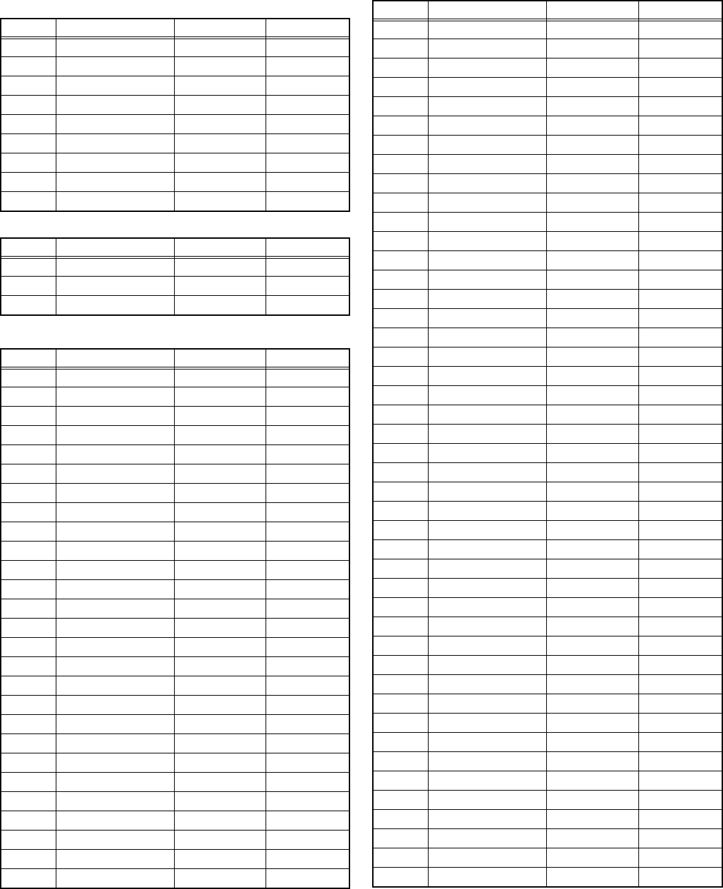
4.7 ADJUSTMENT PROCEDURE
4.7.1 FOCUS
M173 1EAC 00 - FF 09
M174 1EAD 00 - FF 00
M175 1EAE 00 - FF 00
M176 1EAF 00 - FF 00
M177 1EB0 00 - FF 0A
M178 1EB1 00 - FF 00
M179 1EB2 00 - FF 01
M180 1EB3 00 - FF 00
M181 1EB4 00 - FF 00
M182 1EB5 00 - FF 00
M183 1EB6 00 - FF 00
M184 1EB7 00 - FF 00
M185 1EB8 00 - FF 00
M186 1EB9 00 - FF 00
M187 1EBA 00 - FF 00
M188 1EBB 00 - FF 00
M189 1EBC 00 - FF 00
M190 1EBD 00 - FF 00
M191 1EBE 00 - FF 00
M192 1EBF 00 - FF 00
M193 1EC0 00 - FF 00
M194 1EC1 00 - FF 00
M195 1EC2 00 - FF 00
M196 1EC3 00 - FF 00
M197 1EC4 00 - FF 00
M198 1EC5 00 - FF 00
M199 1EC6 00 - FF 00
M200 1EC7 00 - FF 00
M201 1EC8 00 - FF 00
M202 1EC9 00 - FF 00
M203 1ECA 00 - FF 00
M204 1ECB 00 - FF 00
Item No. Item Variable range Setting value
M205 1ECC 00 - FF 02
M206 1ECD 00 - FF 00
M207 1ECE 00 - FF 00
M208 1ECF 00 - FF 00
M209 1ED0 00 - FF 00
M210 1ED1 00 - FF 00
M211 1ED2 00 - FF 00
M212 1ED3 00 - FF 00
M213 1ED4 00 - FF 00
M214 1ED5 00 - FF FF
M215 1ED6 00 - FF 00
M216 1ED7 00 - FF 00
M217 1ED8 00 - FF 00
M218 1ED9 00 - FF 00
M219 1EDA 00 - FF 00
M220 1EDB 00 - FF 00
M221 1EDC 00 - FF 00
M222 1EDD 00 - FF 00
M223 1EDE 00 - FF 00
M224 1EDF 00 - FF 00
Item No. Item Variable range Setting value
F001 DD 000 - 001 000
F002 RAM REF 000 - 001 000
Item No. Item Variable range Setting value
D001 RESREV 000 - 255 002
Item No. Item Variable range Setting value
Z001 RESREV 000 - 255 002
Item No. Item Variable range Setting value
Item Measuring
instrument Test point Adjustment part Description
LENS FOCUS
Hexagon
wrench
(2.5mm)
FOCUS knob
[PROJECTION LENS]
(1) Remove the SPEAKER GRILL and CENTER
PANEL.
(2) Display the MENU screen.
(3) Loosen the focus lock screw.
(4) Adjust the FOCUS knob so that the center
screen may become the best focus.
(5) Fix the focus lock screw by using the Hexagon
wrench.
• On this occasion, hold the FOCUS knob with
your left hand.
(6) Confirm the whole focus of the best screen.
(7) Install the CENTER PANEL and SPEAKER
GRILL.
Focus lock
screw
FOCUS
knob
Projection lens
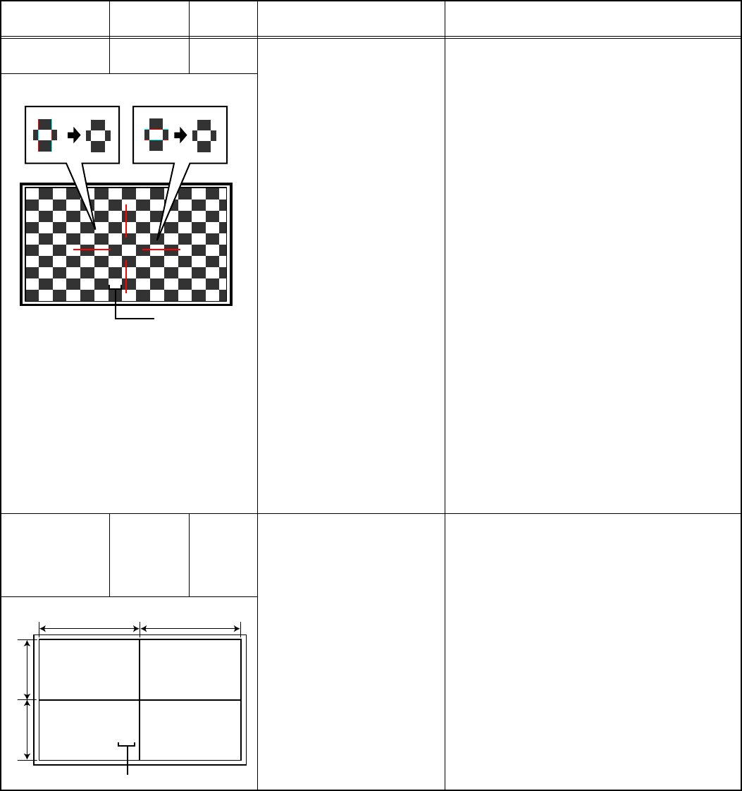
(No.YA337)1-37
4.7.2 DRIVE CIRCUIT
Item Measuring
instrument Test point Adjustment part Description
DRIVE
CONVERGENCE
Remote
control unit
[9.RGB BOX PATTERN] (1) Set to "0 minutes" using the [SLEEP TIMER]
key.
(2) Press the [VIDEO STATUS] key and
[DISPLAY] key simultaneously, to enter the
SERVICE MODE.
(3) Press the [9] key, to select "RGB BOX
PATTERN MODE" from the SERVICE MODE.
(4) Set the adjustment color mode to "R" to set the
red color adjustment mode.
(5) At Horizontal RGB box pattern, adjust the top
edge position as same or less than 0.5 pixel
hight as green.
(6) At Vertical RGB box pattern, adjust the right
edge position as same or less than 0.5 pixel
hight as green.
(7) Set the adjustment color mode to "B" to set the
blue color adjustment mode.
(8) At Horizontal RGB box pattern, adjust the top
edge position as same or less than 0.5 pixel
hight as green.
(9) At Vertical RGB box pattern, adjust the right
edge position as same or less than 0.5 pixel
hight as green.
(10) Check to see that the cross pattern is white. If
the cross pattern is not white, repeat the step
4. to 9. as abobe.
NOTE:
• Green is a fixed. (It can not be removed.)
• With this adjustment mode, the changed data is
written in the MEMORY instantly.
DRIVE CENTER
POSITION
Remote
control unit
Signal
generator
[9.RGB BOX PATTERN] (1) Receive a center cross (or crosshatch) pattern.
(2) Set to "0 minutes" using the [SLEEP TIMER]
key.
(3) Press the [VIDEO STATUS] key and
[DISPLAY] key simultaneously, to enter the
SERVICE MODE.
(4) Press the [9] key, to select "RGB BOX
PATTERN MODE" from the SERVICE MODE.
(5) Set the adjustment color mode to "RGB" to set
the display position adjustment mode.
(6) Adjust the top and the bottom width to make A
and A" even.
(7) Adjust the left and the right width to make B
and B" even.
NOTE:
• With this adjustment mode, the changed data is
written in the MEMORY instantly.
R
Adjustment color
Horizontal RGB box patternVertical RGB box pattern
Adjustment color
A
BB"
A
"
RGB
(B=B")
(A=A")
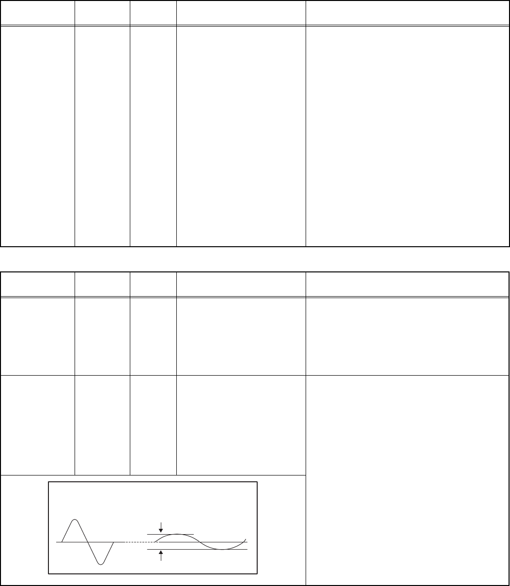
1-38 (No.YA337)
4.7.3 VIDEO CIRCUIT
4.7.4 MTS CIRCUIT
Item Measuring
instrument Test point Adjustment part Description
WHITE
BALANCE
(HIGHLIGHT)
Remote
control unit
Signal
generator
[1.ADJUST]
S001: R DRIVE (Red drive)
S002: G DRIVE (Green drive)
S003: B DRIVE (Blue drive)
(1) Receive a NTSC 75% all white pattern.
(2) Set "VIDEO STATUS" to "STANDARD".
(3) Set "ASPECT" to "FULL".
(4) Select "COLOR TEMPERATURE" to "LOW".
(5) Select "1.ADJUST" from the SERVICE
MODE.
(6) Adjust to keep one of < S001 > (Red drive),
< S002 > (Green drive) or < S003 > (Blue
drive) unchanged, then lower the other two
so that the all-white screen is equally white
throughout.
NOTE:
Set one or more of < S001 >, < S002 >, and
< S003 > to "128".
(7) Check that white balance is properly tracked
from low light to high light. If the white balance
tracking is deviated, adjust to correct it.
(8) Press the [MUTING] key to memoirze the set
value.
Item Measuring
instrument Test point Adjustment part Description
MTS INPUT
LEVEL
Remote
control unit
[1.ADJUST]
T001: IN LEVEL
(1) Receive the any broadcast.
(2) Select "1.ADJUST" from the SERVICE
MODE.
(3) Verify that the < T001 > (IN LEVEL) is set at its
initial setting value.
(4) Press the [MUTING] key to memorize the set
value.
MTS
SEPARATION
TV audio
multiplex
signal
generator
Oscilloscope
Remote
control unit
L OUT
R OUT
[1.ADJUST]
T002: LOW SEP
T003: HI SEP
(1) Input the stereo L signal (300Hz) from the TV
audio multiplex signal generator to the antenna
terminal.
(2) Connect an oscilloscope to L OUT pin of the
AUDIO OUT, and display one cycle portion of
the 300Hz signal.
(3) Change the connection of the oscilloscope to
R OUT pin of the AUDIO OUT, and enlarge the
voltage axis.
(4) Select "1.ADJUST" from the SERVICE
MODE.
(5) Set the initial setting value of the < T002 >
(LOW SEP).
(6) Adjust the < T002 > so that the stroke element
of the 300Hz signal will become minimum.
(7) Change the signal to 3kHz, and similarly
adjust the < T003> (HI SEP).
(8) Press the [MUTING] key to memorize the set
value.
L-Channel
signal waveform
R-Channel
crosstalk portion
Minimum
1 cycle
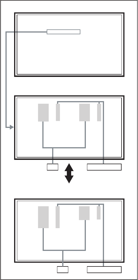
(No.YA337)1-39
SECTION 5
TROUBLESHOOTING
5.1 SELF CHECK FEATURE
5.1.1 OUTLINE
This unit comes with the "Self check" feature, which checks the
operational state of the circuit and displays/saves it during
failure.Diagnosis is performed when power is turned on, and
information input to the main microcomputer is monitored at all
time.Diagnosis is displayed in 2 ways via screen display and LED
flashes. Failure detection is based on input state of I2C bus and
the various control lines connected to the main microcomputer.
5.1.2 HOW TO ENTER THE SELF CHECK MODE
Before entering the Self check Display mode, confirm that the
setting of TV/CATV SW of the REMOTE CONTROL UNIT is at
the "TV" side and the setting of VCR/DVD SW is at the "VCR"
side. If the switches have not been properly set, you cannot enter
the Self check Display mode.
(1) Set to "0 minutes" using the [SLEEP TIMER] key.
(2) While "0 minutes" is displayed, press the [VIDEO STATUS]
key and [DISPLAY] key simultaneously, then enter the
service mode.
(3) Press the [2] key (SELF CHECK) before the service mode
screen disappears.
(4) Press the [SLEEP TIMER] key to enter Page 2 of the SELF
CHECK MODE.
• When the [RETURN+] key pressed, the first page
change screen.
NOTE:
When a number key other than the [2] key is pressed in
the SERVICE MENU SCREEN, the other relevant
screen may be displayed.
This is not used in the SELF CHECK. Press the [MENU]
key to return to the SERVICE MENU SCREEN.
5.1.3 HOW TO EXIT THE SELF CHECK MODE
TO SAVE FAILURE HISTORY:
Turn off the power by unplugging the AC power cord plug when
in the Self check display mode.
TO CLEAR (RESET) FAILURE HISTORY:
Turn off the power by pressing the [POWER] key on the remote
control unit when in the Self check display mode.
5.1.4 FAILURE HISTORY
Failure history can be counted up to 9 times for each item. When
the number exceeds 9, display will remain as 9. Failure history
will be stored in the memory unless it has been deleted.
NOTE:
Only SYNC (with/without sync signals) will be neither counted
nor stored.
5.1.5 POINTS TO NOTE WHEN USING THE SELF CHECK
FEATURE
In addition to circuit failures (abnormal operation), the following
cases may also be diagnosed as "Abnormal" and displayed and
counted as "NG".
(1) Temporary defective transmissions across circuits due to
pulse interruptions
(2) Misalignment in the on/off timing of power for I2C bus
(VCC) when turning on/off the main power.
Diagnosis may be impeded if a large number of items are
displayed as "NG". As such, start Self check check only after 3
seconds in the case of receivers and 5 seconds in the case of
panels upon turning on the power. If recurrences are expected,
ensure to clear (reset) the failure history and record the new
diagnosis reults.
Fig.1
SERVICE MENU SCREEN
SELF CHECK MODE SCREEN (Page 1)
SELF CHECK MODE SCREEN (Page 2)
Item Failure history
Failure history
Item
TMP 0 L 1 0
TMP 0 L 1 0
L 2 0 DDT 0
L 2 0 DDT 0
FAN 0 L C 0
FAN 0 L C 0
IRS 0
IRS 0
SERVICE MENU
SERVICE MENU
1. ADJUST
1. ADJUST
2. SELF CHECK
2. SELF CHECK
3. I2C STOP
3. I2C STOP
LOB 0 FAN 0
LOB 0 FAN 0
AUD 0
AUD 0
ANA 9 DIG 9
ANA 9 DIG 9
0000 0
0000 0
0
0
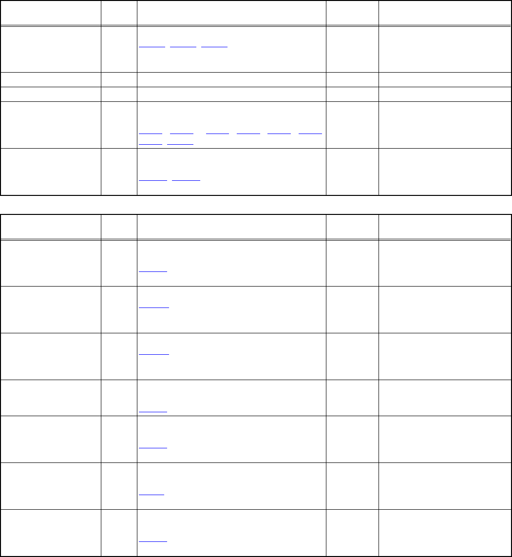
1-40 (No.YA337)
5.1.6 DETAILS
Self check is performed for the following items:
< Page 1 of screen >
< Page 2 of screen >
Detection item Display Detection content Diagnosis
signal (line) Detection timing
Low bias line short
protection
LOB Detection of the low bias line(5V/9V/12V) short.
Q9821, Q9831, Q9861 [POWER PWB]
LB_PRO Detection starts 3 seconds after
the power is turned on. If error
continues between 200ms the
power is turned off.
Fan lock FAN Not used ---- ----
Audio AUD Not used ---- ----
Devices on the ANALOG
PWB
ANA Confirmation of reply of ACK signal which uses
I2C communication.
IC101, IC102, IC281, IC381, IC601, IC606,
IC061, TU001 [ANALOG PWB]
SDA If it checks whenever I2C
communication is performed and
no reply of ACK signal an error
will be counted.
Devices on the DIGITAL
PWB
DIG Confirmation of reply of ACK signal which uses
I2C communication.
IC6401, IC8831 [DIGITAL PWB]
SDA If it checks whenever I2C
communication is performed and
no reply of ACK signal an error
will be counted.
Detection item Display Detection content Diagnosis
signal (line) Detection timing
Temp. sensor TMP Confirmation of the abnormal inner cabinet
temperature. (53°C)
IC2001 [THERMO PWB]
TXD It will count if the serial
communication from a DD
MICOM is always supervised and
an error occurs.
Lamp does not light up L1 Confirm that the lamp dose not light up.
CNBCT [DRIVE PWB]
TXD It will count if the serial
communication from a DD
MICOM is always supervised and
an error occurs.
Lamp goes out L2 Confirm that the lamp dose not goes out.
CNBCT [DRIVE PWB]
TXD It will count if the serial
communication from a DD
MICOM is always supervised and
an error occurs.
Abnormal DD CPU
circuit
DDT Confirmation of the serial communication error
between DRIVE PWB and DIGITAL PWB.
IC3701 [DRIVE PWB]
TXD It will count if the serial
communication error is error
occurs.
Fan lock FAN Confirmation of the lock signals outputting the
operation(circuit) status of the cooling fan.
IC8005 [DRIVE PWB]
TXD It will count if the serial
communication from a DD
MICOM is always supervised and
an error occurs.
Lamp cover open LC Confirmation of the interlock switch status for the
lamp cover.
S0861 [LAMP COVER SW PWB]
TXD It will count if the serial
communication from a DD
MICOM is always supervised and
an error occurs.
Abnormal of optical iris IRS Confirmation of the abnormal optical iris
operation.
IC5005 [IRIS PWB]
TXD It will count if the serial
communication from a DD
MICOM is always supervised and
an error occurs.
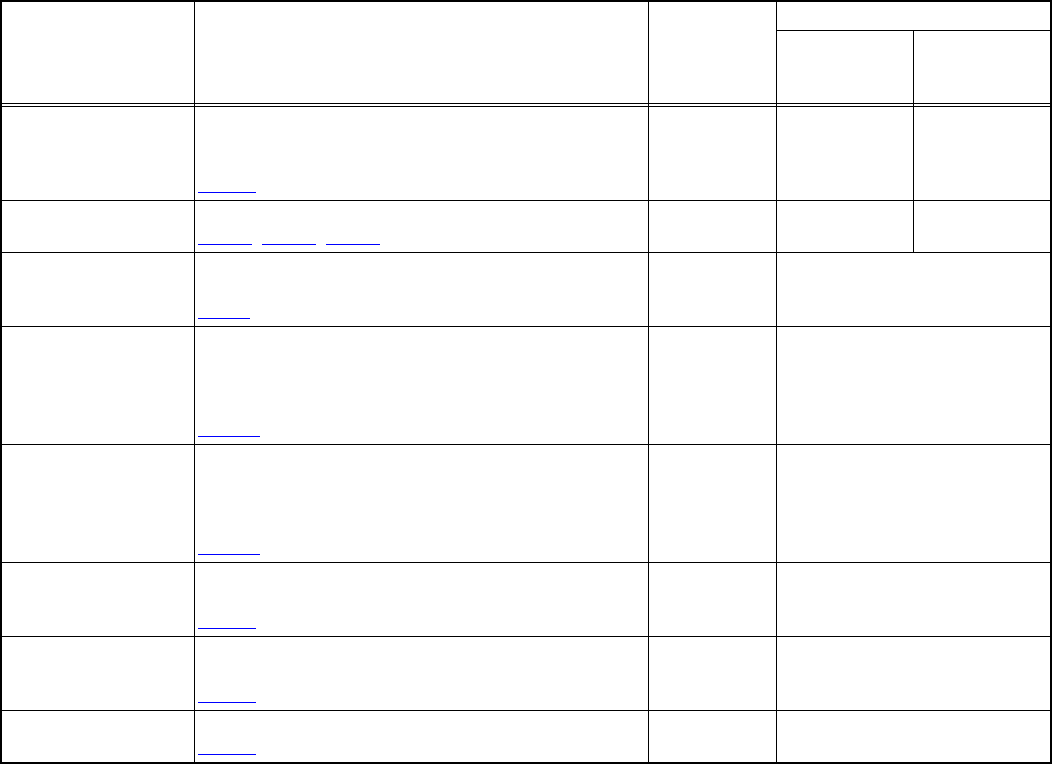
(No.YA337)1-41
5.1.7 DISPLAY METHOD WHEN RASTER IS NOT AVAILABLE
In a state where a display screen does not appear due to the failure of this unit, the POWER LED (blue) and LAMP/PROGRAM LED
(orange) can be flushing and display a trouble mode.
The factors in case the power is forcibly shut down at the time of failure are memorized and those are displayed.
EXPLANATION ON ACTION
If NG is detected on an item being diagnosed, turn off the power on this unit. As soon as the power goes off, turn on and off POWER
LED and LAMP LED immediately. After the power is shut down, it becomes impossible to turn on the power until the power cable
is either plugged in or unplugged from the AC outlet.
• When the error of [1] or [2] occur, [3], [4], [5], [6], [7] are no longer recognized.
Check item Contents
Classifications
LED flash cycle
POWER LED
(BLUE)
LAMP/
PROGRAM LED
(ORANGE)
Fan lock (stop) and
CABLE CARD error for
ATSC tuner
MAIN CPU detects the command of the Fan lock (stop)
and CABLE CARD error which ATSC TUNER MODULE
has detected.
IC7601 [DIGITAL PWB]
1 --- 2 sec interval
Low bias line short
protection
Detection of the low bias line(5V/9V/12V) short.
Q9821, Q9831, Q9861 [POWER PWB]2 --- 1 sec interval
Lamp cover open Detection of the interlock switch status for the lamp
cover. (H = Abnormal)
S0861 [LAMP COVER SW PWB]
3 0.1 sec interval Simultaneously
Lamp goes out Detection of lamp return (LAMP_RTN) signals output
depending on the status of the lamp supply electric
current monitored constantly within the lamp ballast unit.
(H = Off)
CNBCT [DRIVE PWB]
6 0.1 sec interval Simultaneously
Lamp does not light up Detection of lamp return (LAMP_RTN) signals output
depending on the status of the lamp supply electric
current monitored constantly within the lamp ballast unit.
(H = Off)
CNBCT [DRIVE PWB]
6 0.1 sec interval Simultaneously
Fan lock (stop) for
optical system
Detection of LOCK signals outputting the operation
(circuit) status of the cooling fan. (H=Abnormal)
IC8005 [DRIVE PWB]
4 0.5 sec interval Alternately
Abnormal DD CPU
circuit
Detection of serial communication error between MAIN
DRIVE PWB and RECEIVER PWB.
IC3701 [DRIVE PWB]
5 0.5 sec interval Alternately
Abnormal D-ILA
DEVICE temperature
Detection of abnormal inner cabinet temperature. (53°C)
IC2001 [THERMO PWB] 7 0.5 sec interval Alternately

(No.YA337)
ILA Display Category 12, 3-chome, Moriya-cho, Kanagawa-ku, Yokohama-city, Kanagawa-prefecture, 221-8528, Japan
Victor Company of Japan, Limited
VPT
Printed in Japan
