Hdl Survival Guide
User Manual:
Open the PDF directly: View PDF ![]() .
.
Page Count: 7

HDL Survival Guide
by Mark Armbrust
This guide is designed to help you understand and write HDL programs in the context of
Nand2Tetris courses. It was written in order to answer recurring issues that came up in many posts
in the Q&A forum of the nand2tetris web site. These posts were made by people who worked on
the course's hardware projects and got stuck for one reason or another.
Terminology
Throughout this document, we use the terms "HDL file", "HDL program", and "HDL
implementation" interchangeably. Likewise, we use the terms "build a chip", "construct a chip", and
"implement a chip" interchangeably. The term "HDL file stub" refers to a file that contains the HDL
definition of a chip interface. That is, a stub file contains the chip name and the names of all the
chip's input and output pins, without the chip's implementation, also known as the "PARTS" section
of the HDL program. A stub file also contains the chip's documentation -- a succinct description of
what the chip is supposed to do.
Project Files
If you've downloaded the nand2tetris software, then there are now 13 directories (folders) on your
computer, named
projects/01
...,
projects/13
. Each directory contains all the files necessary to
complete the respective project. The projects themselves are described in the
Course
page of the
nand2tetris web site. Projects 1-5 focus on building the hardware platform of the Hack computer.
Each project walks you through the construction of a certain subset of the Hack chip-set. The
directory (folder) that accompanies each project contains stub HDL files for all the chips you need
to build, as well as all the test scripts required to test your HDL implementations .The "only" thing
that you have to do is extend the supplied stub HDL files into working chip implementations, i.e.
chips that run in the supplied hardware simulator and successfully pass all the tests listed in the
supplied test scripts.
Other useful resources to help you complete the projects are the lecture slides given in the
"Lecture" column of the
Course
page, as well as the relevant book chapters.
Chip Implementation Order
Each project directory contains a set of HDL stub files, one for each chip that you have to build. It's
important to understand that all the supplied HDL files contain no implementations (building these
implementations is what the project is all about). For example, consider the construction of a Xor
chip. If your
Xor.hdl
program will include, say, And and Or chip-parts, and you have not yet
implemented the And and Or chips, your tests will fail even if your Xor implementation is correct.
Note however that if the project directory included no
And.hdl
and
Or.hdl
files at all, your
Xor.hdl
program will work properly. This sounds surprising, so here is the explanation. The hardware
simulator, which is a Java program, features working Java implementations of all the chips
http://www.nand2tetris.org/software/HDL Survival Guide.html
1 of 7 08/28/2015 03:52 PM

necessary to build the Hack computer. When the simulator has to execute the logic of some
chip-part, say And, taken from the Hack chip-set, it looks for an
And.hdl
file in the current project
directory. At this point there are three possibilities:
No HDL file is found. In this case, the Java implementation of the chip kicks in and "covers"
for the missing HDL implementation.
A stub HDL file is found. The simulator tries to execute it. But since a stub file contains no
implementation, the execution fails.
A "normal" HDL file is found. The simulator executes it, reporting errors to the best of its
ability.
Therefore, to avoid chip order implementation troubles, you can do one of two things. First, you
can implement your chips in the order presented in the book and in the project descriptions. Since
the chips are presented "bottom-up", from basic chips to more complex ones, you will encounter
no chip order implementation troubles.
A recommended alternative is to create a subdirectory called "stubs" and move all the supplied
HDL stub files into that directory. You can then move them into your working directory as needed.
Note that the
.hdl
file that you are working on and its associated
.tst
file must be in the same
directory. If you will look at the header code of the supplied test script, you will see that it includes
a command that loads the HDL file that it is supposed to test from the same working directory.
Thus, if you load your HDL file into the simulator and then load the test script from a different
directory, the test script will load and test a different HDL file. Proper usage is to load into the
simulator either an
.hdl
file or a
.tst
file, not both.
HDL syntax and the meaning of
"a=a"
HDL statements are used to describe how chip-parts are connected to each other, as well as to the
input and output pins of the constructed chip. The syntax of these statements can be confusing,
especially when pin names like
in
,
out
,
a
and
b
are used both by the chip-parts as well as by the
constructed chip. This leads to statements like
And(a=a, b=b, out=r)
. This particular statement
instructs to (i) connect the
a
and
b
input pins of the And chip-part to the
a
and
b
input pins of the
constructed chip, (ii) create an internal pin ("wire") named
r
, and (iii) connect the output pin of the
And chip-part to
r
.
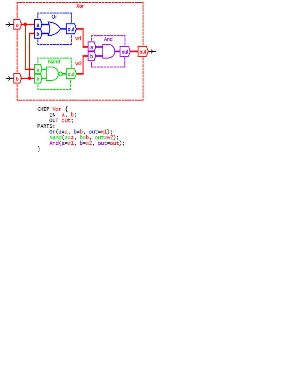
Here is a simple rule that helps sort things out: the symbol on the left hand side of each "=" symbol
is always the name of a pin in a chip-part, and the symbol on the right hand side is always the
name of a pin or a wire in the constructed chip (the chip that you are building).
The following figure shows a diagram and HDL code of a Xor chip. The diagram uses color coding
to highlight which symbols "belong" to which chips. (Note that there are several different ways to
implement Xor; this is just one of them.)
http://www.nand2tetris.org/software/HDL Survival Guide.html
2 of 7 08/28/2015 03:52 PM
HDL Syntax Errors
The hardware simulator displays errors on the status bar at the bottom of its window. On some
computers with small screens these messages are off the bottom of the screen and are not visible.
If you load your HDL and nothing show up in the HDL window in the simulator and you don't see
an error message, this is probably what's happening.
Your computer should have a way to move the window to see the message using the keyboard.
For example, on Windows use Alt+Space, M, and the arrow keys.
Unconnected Pins
The Hardware Simulator does not consider unconnected pins to be errors. It defaults any
unconnected input or output to be
false
(0). This can cause mysterious errors in your chip
implementations.
If the output of your chip is always 0, make sure that your chip's output pin is connected to the
output pin of one of the chip-parts you are using. Double-check the names of the wires involved in
the chip's output. Typographic errors are particularly bad here since the simulator doesn't throw
errors on disconnected wires. For example, if you write
SomeChip(..., sum=sun);
the simulator
will happily make a wire named
sun
and your chip's output will always be 0 (because, quite likely,
the
sun
pin will not be connected to any other chip-part in your implementation, so nothing will be
piped further from
SomeChip
onward).
If the output of a chip-part in your implementation does not appear to be working correctly, check
that all of its input pins are connected to something.
For a complete list of all the chips that you need in all the hardware projects, see the Hack
http://www.nand2tetris.org/software/HDL Survival Guide.html
3 of 7 08/28/2015 03:52 PM

Chip-Set API at the end of this document.
Canonical Representation
The book introduces you to the canonical representation of a Boolean function. This representation
can be very useful for chips with small numbers of inputs. As the number of inputs grows, the
complexity of the canonical representation grows exponentially.
For example, the canonical representation of Mux has 4 three-variable terms; that of a Mux8Way
would have 1024 11-variable terms. Large canonical representations can be reduced with algebra,
usually by computer programs. In the case of Mux8Way it can be reduced to 8 four-input terms.
Clearly, this is not a practical approach for nand2tetris. You need to think about how to use the
chips you have already made to make the next chip (assuming you're following the recommended
order). The projects are organized in such a way that often you need the chip that you have just
made.
Tests Are More Than Pass/Fail
For every
chip
.hdl
file, your working directory also includes a test script, named
chip
.tst
, and a
compare file, named
chip
.cmp
. Once your chip starts generating outputs, your directory will also
include an output file named
chip
.out
. When your chip fails the test script, don't forget to consult
the
.out
file. Inspect the listed output values, and seek clues to the failure. If you can't see the
output file in the simulator environment (reported bug on some Macs), you can look at it in a text
editor.
If you need to, you can copy the
chip
.tst
file to
myChip
.tst
and change it to give you more
information about the behavior of your chip. Change the output file name in the
output-file
line
and delete the
compare-to
line. This will cause the test to always run to completion.
You can also modify the
output-list
line to show the outputs of your internal wires. The output
format specifier is fairly obvious. The format letters are
B
for binary,
D
for decimal, and
X
for
hexadecimal.
Testing A Chip In Isolation
At some point you may become convinced that your chip is correct, but it is still failing the test. The
problem may be with one of the chip-parts used in your chip implementation.
You can diagnose which chip-part is causing the problem as follows. Create a test subdirectory
and copy into it only the three
.hdl
,
.tst
, and
.out
files related to the chip that you are building. If
your chip implementation passes its test in this subdirectory as-is (letting the simulator use the
default Java implementation of the missing chip-parts), there must be a subtle problem with one of
your chip-parts implementations, i.e. with one of the chips that you've built earlier in this project.
Copy your other chips into this test directory one by one, repeating the test, until you find the
problematic chip.
Note also that the supplied tests, especially for more complex chips, cannot guarantee that the
http://www.nand2tetris.org/software/HDL Survival Guide.html
4 of 7 08/28/2015 03:52 PM

tested chips are 100% correct.
HDL Is Not A Programming Language
Go back to one of your chips that uses 3 or 4 parts. Reverse the order of the HDL statements that
describe some of the chip-parts.
Will the chip still work?
You may be surprised that the answer is
yes
.
The reason that the chip still works is that HDL is a hardware
description
language (also known as
a "declarative" language). It describes the wiring connections that are needed to make the chip,
not how it operates once power is applied. It makes no difference what order the parts are put into
a circuit board. As long as all the parts get placed and connected together correctly, the circuit
board will function.
The Hardware Simulator "applies the power" and tests how the chip functions.
An important aspect of this is that there is no such thing as an "uninitialized variable" in HDL. If a
wire is connected to an output somewhere in the HDL, it can be connected to any input. This is
particularly important to understand for Chapter 3.
Bit Numbering and Bus Syntax
Hardware bits are numbered from right to left, starting with 0. When a bus is carrying a number, bit
n
is the bit with weight 2
n
.
For example, when the book says
sel=110
, it means that a bus named
sel
receives the inputs
110
. That means
sel[2]=1
,
sel[1]=1
and
sel[0]=0
. Read Appendix A.5.3 in the book to learn
about bus syntax.
Sub-busing
Sub-busing can only be used on buses that are named in the IN and OUT statements of an HDL
file, or inputs and outputs of the chip-parts used in the PARTS section. If you need a sub-bus of an
internal bus, you must create the narrower bus as an output from a chip-part. For example:
CHIP Foo {
IN in[16];
OUT out;
PARTS:
Something16 (in=in, out=notIn);
Or8Way (in=notIn[4..11], out=out);
}
This implementation causes an error on the Or8Way statement. This needs to be coded as:
Something16 (in=in, out[4..11]=notIn);
Or8Way (in=notIn, out=out);
Multiple Outputs
http://www.nand2tetris.org/software/HDL Survival Guide.html
5 of 7 08/28/2015 03:52 PM

Sometimes you need more than one sub-bus connected to the output of a chip-part. Simply add
more than one
out=
connection to the chip-part definition.
CHIP Foo {
IN in[16];
OUT out[8];
PARTS:
Not16 (in=in, out[0..7]=low8, out[8..15]=high8);
Something8 (a=low8, b=high8, out=out);
}
This also works if you want to use an output of a chip in further computations.
CHIP Foo {
IN a, b, c;
OUT out1, out2;
PARTS:
Something (a=a, b=b, out=x, out=out1);
Whatever (a=x, b=c, out=out2);
}
The Hack chip-set API
Below is a list of all the chip interfaces in the Hack chip-set, prepared by Warren Toomey. If you
need to use a chip-part, you can copy-paste the chip interface and proceed to fill in the missing
data. This is a very useful list to have bookmarked or printed.
Add16(a= ,b= ,out= );
ALU(x= ,y= ,zx= ,nx= ,zy= ,ny= ,f= ,no= ,out= ,zr= ,ng= );
And16(a= ,b= ,out= );
And(a= ,b= ,out= );
ARegister(in= ,load= ,out= );
Bit(in= ,load= ,out= );
CPU(inM= ,instruction= ,reset= ,outM= ,writeM= ,addressM= ,pc= );
DFF(in= ,out= );
DMux4Way(in= ,sel= ,a= ,b= ,c= ,d= );
DMux8Way(in= ,sel= ,a= ,b= ,c= ,d= ,e= ,f= ,g= ,h= );
DMux(in= ,sel= ,a= ,b= );
DRegister(in= ,load= ,out= );
FullAdder(a= ,b= ,c= ,sum= ,carry= );
HalfAdder(a= ,b= ,sum= , carry= );
Inc16(in= ,out= );
Keyboard(out= );
Memory(in= ,load= ,address= ,out= );
Mux16(a= ,b= ,sel= ,out= );
Mux4Way16(a= ,b= ,c= ,d= ,sel= ,out= );
Mux8Way16(a= ,b= ,c= ,d= ,e= ,f= ,g= ,h= ,sel= ,out= );
Mux(a= ,b= ,sel= ,out= );
Nand(a= ,b= ,out= );
Not16(in= ,out= );
Not(in= ,out= );
Or16(a= ,b= ,out= );
Or8Way(in= ,out= );
http://www.nand2tetris.org/software/HDL Survival Guide.html
6 of 7 08/28/2015 03:52 PM

Or(a= ,b= ,out= );
PC(in= ,load= ,inc= ,reset= ,out= );
RAM16K(in= ,load= ,address= ,out= );
RAM4K(in= ,load= ,address= ,out= );
RAM512(in= ,load= ,address= ,out= );
RAM64(in= ,load= ,address= ,out= );
RAM8(in= ,load= ,address= ,out= );
Register(in= ,load= ,out= );
ROM32K(address= ,out= );
Screen(in= ,load= ,address= ,out= );
Xor(a= ,b= ,out= );
http://www.nand2tetris.org/software/HDL Survival Guide.html
7 of 7 08/28/2015 03:52 PM
