HN200 Helicoflexcatalog
User Manual: HN200
Open the PDF directly: View PDF ![]() .
.
Page Count: 12
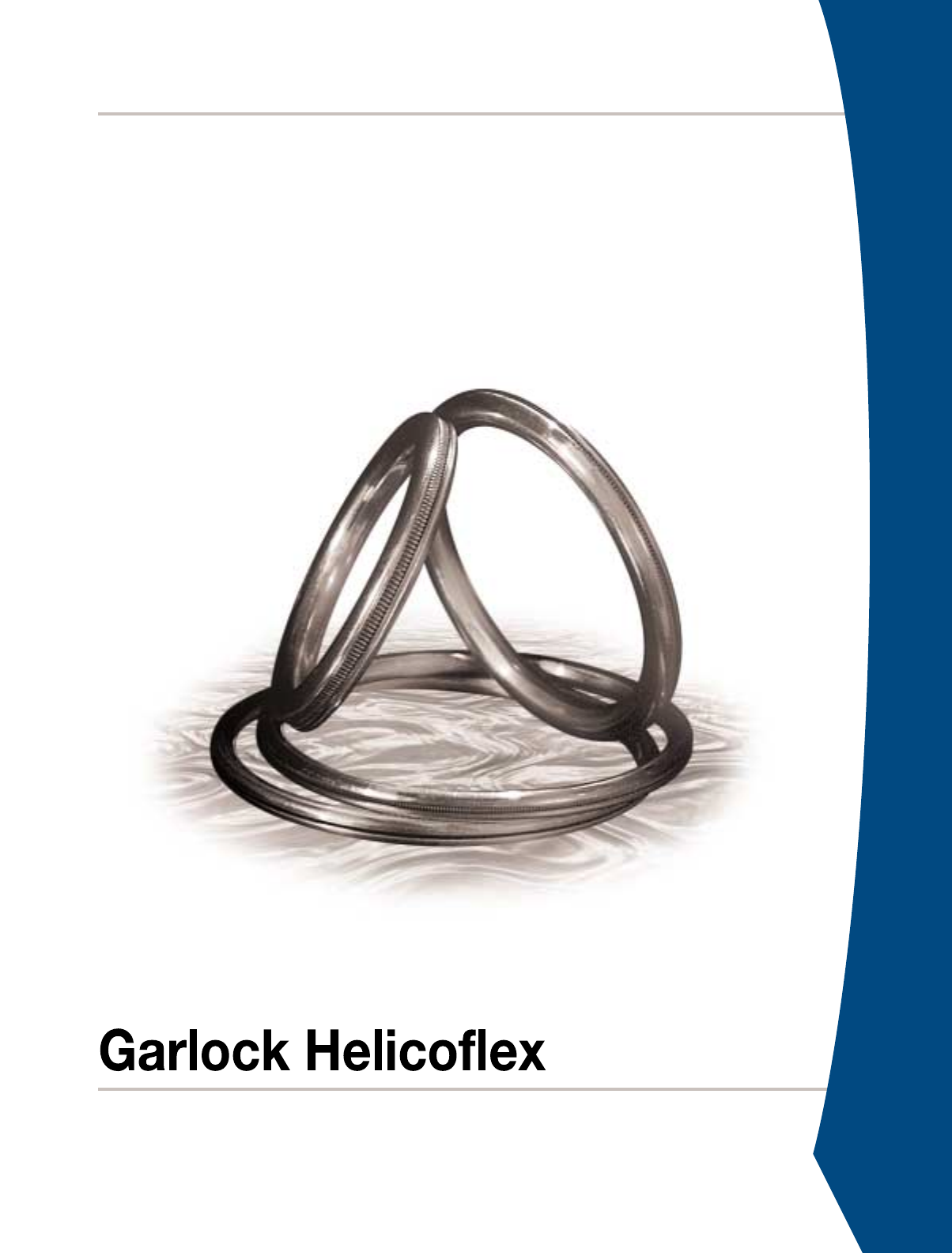
HELICOFLEX®
High Performance Seals and Sealing Systems
2For Additional Information, Please Consult Our Engineering Staff
1-800-233-1722
The Helicoflex®seal represents the leading edge in seal technology for high performance sealing
applications. Today’s extreme sealing requirements have rendered traditional seals & gaskets obsolete.
If you can’t afford the lost time associated with leaks, put your trust in the leader: Helicoflex®.
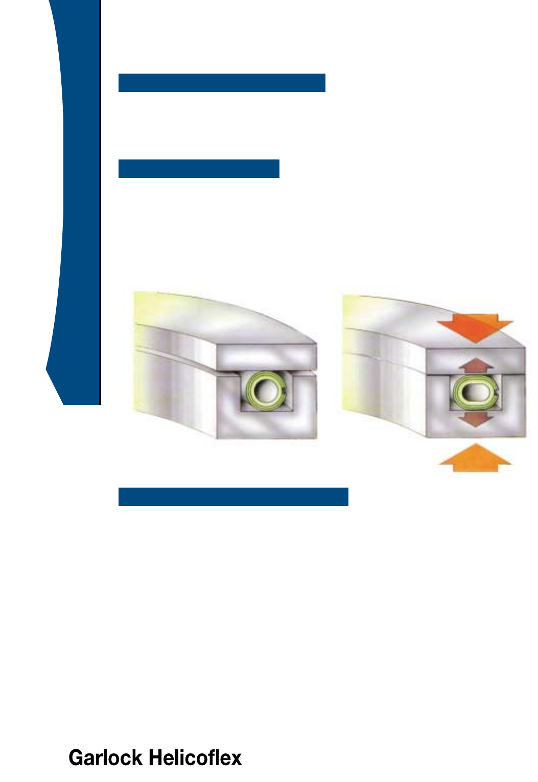
The sealing principle of the Helicoflex®family of seals is based upon the plastic deformation of a jacket of
greater ductility than the flange materials. This occurs between the sealing face of a flange and an elastic
core composed of a close-wound helical spring. The spring is selected to have a specific compression
resistance. During compression, the resulting specific pressure forces the jacket to yield and fill the flange
imperfections while ensuring positive contact with the flange sealing faces. Each coil of the helical spring acts
independently and allows the seal to conform to surface irregularities on the flange surface. This combination
of elasticity and plasticity makes the Helicoflex seal the best overall performing seal in the industry.
•Wide range of applications:
Dimensional: Diameters from 0.250 inches (6.3 mm) to over 300 inches (7.6 m)
Cross sections from 0.063 inches (1.6 mm) to over 0.625 inches (15.9 mm)
Temperature: Cryogenic to 1800°F (982°C)
Pressure: Ultra High Vacuum to 50,000 PSI (100,000 PSI under special conditions)
•Excellent springback: the spring energized Helicoflex is capable of compensating for flange
distortions due to temperature and pressure cycling.
•Adaptable to a majority of standard flanges: ANSI, ISO, KF, ASA
•Suited to different types of assemblies: -metal/metal with groove
-flat flanges with limiter/retainer
-3 face contact
•Extended shelf life
•Excellent resistance to corrosion and radiation
•Minimum relaxation: the Helicoflex’s resilient spring
compensates for relaxation ensuring positive seal contact.
Helicoflex Spring Energized Seals
GENERAL INFORMATION
SEALING CONCEPT
GENERAL CHARACTERISTICS
Free State In Compression
3For Additional Information, Please Consult Our Engineering Staff
1-800-233-1722
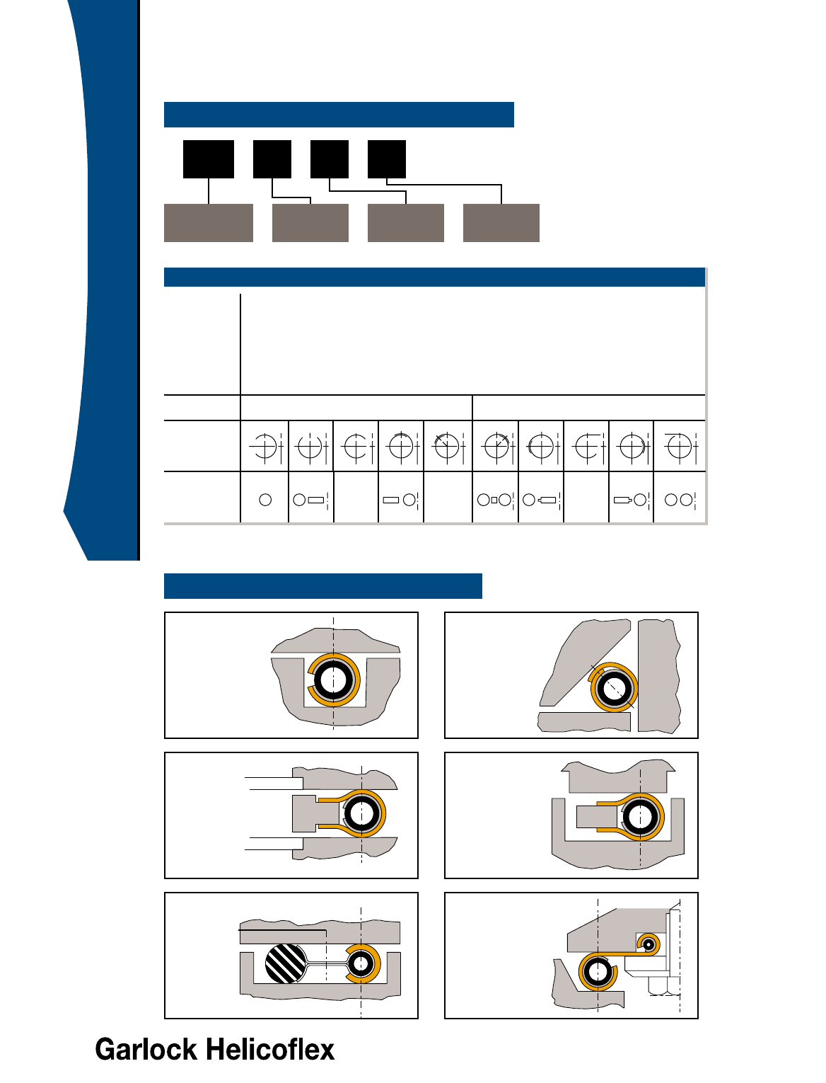
Seal Configurations
CLASSIFICATION OF SEAL TYPE
TYPICAL CONFIGURATIONS
HN 02 8
#Jackets/
Linings
Cross Section
Type Jacket
Orientation Section
Orientation
HN single section
HNR ground spring for precise load control (Beta Spring)
HNV low load (Delta Seal)
HND tandem Helicoflex seals
HNDE tandem Helicoflex and elastomer seals
note: “L” indicates internal limiter (ex: HLDE)
Jacket/Lining 1 = jacket only 2 = jacket with inner lining
Jacket
Orientation
Section
Orientation
CONFIGURATION GUIDE
Cross
Section
Type
01234 56789
01234 56789
HN200
Groove
assemblies
HN208
Raised
face
flanges -
ANSI
B16.5
HNDE290
Leak
check -
inert gas
purge
HN240
3 face
compression
HN203
Tongue &
groove
HND229
Valve
seats
4For Additional Information, Please Consult Our Engineering Staff
1-800-233-1722
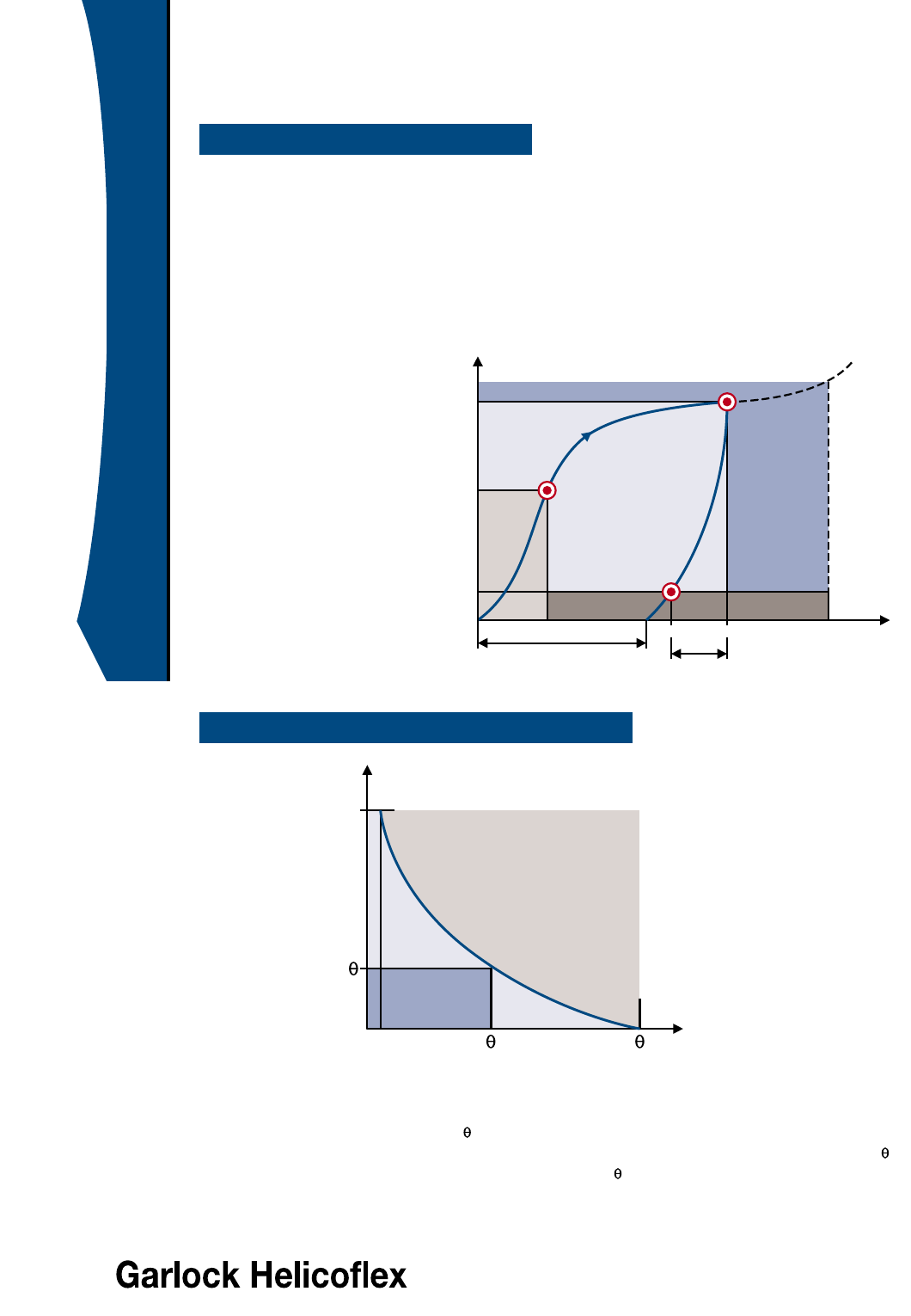
The resilient characteristic of the Helicoflex®seal ensures useful elastic recovery during service. This
elastic recovery permits the Helicoflex®seal to accommodate minor distortions in the flange assembly due
to temperature and pressure cycling. For most sealing applications the Y0value will occur early in the
compression curve and the Y1value will occur near the end of the decompression curve.
The compression and decompression cycle of the Helicoflex®seal is characterized by the gradual
flattening of the compression curve. The decompression curve, which is distinct from the compression
curve, is the result of a hysteresis effect and permanent deformation of the spring and jacket.
DEFINITION OF TERMS
Y0= load on the compression
curve above which leak
rate is at required level
Y2= load required to reach
optimum compression e2
Y1= load on the decompression
curve below which leak
rate exceeds required level
e2= optimum compression
ec= compression limit beyond
which there is risk of
damaging the spring
The intrinsic power of the Helicoflex seal reflects its ability to maintain and hold system pressure for a
given temperature at Y2and e2. This value is expressed as a specific pressure and is noted by the
symbols
Pu
(room temperature) and
Pu
(at operating temperature). The influence of temperature on Pu
is shown in the graph above. The tables on pages 10 and 11 give the values of
Pu
at 68°F (20°C),
Pu
at
a given temperature and the maximum temperature where
Pu
=0.
Helicoflex Seal Characteristics
CHARACTERISTIC CURVE
INTRINSIC POWER OF THE SEAL
Pu
Pu
68°(maximum)
Temperature (°F)
PSI
D
e
c
o
m
p
r
e
s
s
i
o
n
Y
2
Y
0
Y
1
e0e1e2ec
Permanent deformation Useful elastic recovery
Compression
(inches)
Linear load (lbs/in)
C
o
m
p
r
e
s
s
i
o
n

5For Additional Information, Please Consult Our Engineering Staff
1-800-233-1722
Dj Mean reaction diameter of the seal. (For a double section seal, Dj = Dj1+ Dj2)
Y2Linear load corresponding to e2compression
Y1Linear load on the seal to maintain sealing in service at low pressure (=Ym1)
Pu
Intrinsic power of the seal under pressure at 68°F (20°C) when the reaction force
of the seal is maintained at Y2, regardless of the operating conditions.
Pu
Value of Pu at temperature
POperating or proof pressure
Note: if P>1, the definition of the seal must be modified
This ratio must never exceed 1.
Ym2 Linear tightening load on the seal at room temperature to maintain sealing
under pressure.
Ym2= Y2P
Ym2 Value of Ym2 at temperature . Ym2 = Y2P
Et Young’s modulus of bolt material at 68°F (20°C)
EtsYoung’s modulus of bolt material at operating temperature
Fj Total tightening load to compress the seal to the operating point (Y2; e2)
Fj = πx Dj x Y2
FFTotal hydrostatic end force FF= π/
4Dj12x P (Dj1= Dj in case of a single section seal)
Fm Minimum total load to be maintained on the seal in service to preserve sealing,
i.e. Fm = πDj Ym where: Ym = the greater of the two values: Ym1 or Ym2
(see note 1 below)
Fs Total load to be applied on the bolts to maintain sealing in service.
FS= FF+ Fm
Fs* Increased value of FSto compensate for Young’s modulus at temperature
Fs* = Fs Et / Ets
FBLOAD TO BE APPLIED: If Fs* > Fj then Fb = Fs*
If Fj > Fs* then Fb = Fj
Note 1: wherever the working pressure is high and/or seal diameter is big, to such an extent that P•Dj
≥32 Ym, in order to remain on the safe side, whatever the inaccuracy on the tightening load may be,
it is recommended to take the Fj value in lieu of Fm for the calculation of Fs so that Fs = FF+ Fj.
Note 2: this information is provided as a reference only.
Helicoflex Seal Specifications
DEFINITION OF CHARACTERISTIC VALUES
LOAD CALCULATIONS
Pu
Pu or Pu
____________ inches
____________ lbs/inch
____________ lbs/inch
____________ PSI
____________ PSI
____________ PSI
____________ lbs/inch
____________ lbs/inch
____________ PSI
____________ PSI
____________ lbs
____________ lbs
____________ lbs
____________ lbs
____________ lbs
____________ lbs
Pu
CALCULATIONS
6For Additional Information, Please Consult Our Engineering Staff
1-800-233-1722
Groove Design - Radial Pressure
Dimensions in inches Dimensions in mm
CLEARANCE AND MINIMUM GROOVE WIDTH
SURFACE FINISH
-
0.000
+ h
At
+
-
f
+
-
C
J/2
e2
g
F
Groove Depth (F) = Cross Section (CS)-e2
Depth Tolerance (f) = e2X 0.12
Groove Width (g) = See table below
Seal OD (A) = Groove OD (C) - Clearance (J)
Groove Finish = See table below
Flatness = See table below
Groove Design: Contact our
engineering staff for assistance in
designing non-circular grooves.
Groove Finish: Most applications will
require a finish of 16-32 RMS (0.4 to
0.8 Ra µm). All machining & polishing
marks must follow seal circumference.
Min. Seal Radius: The minimum
seal bending radius is six times the
seal cross section (CS).
Seating Load: The load (Y2) to seat
the seal is approximately 30% higher
due to a slightly stiffer spring design.
Nr. LCA-CEA N10 N9 N8 N7 N6 N5 N4
Ra in µm 12.5 6.3 3.2 1.6 0.8 0.4 0.2
Rt in µm 50 37 21 11 6.2 3.4 1.9
RMS 500 250 125 63 32 16 8
Aluminum
Silver, copper, iron
Nickel, stainless steel
consult our engineering staff Note: Machining/polishing
marks must follow seal
circumference
recommended
SHAPED SEALS
FLATNESS
Seal Diameter Range Amplitude Tangential Slope Radial Slope
0.350 to 20.000 10 to 500 0.008 0.2 1:1000 1:100
20.001 to 80.000 500 to 2000 0.016 0.4 2:1000 2:100
Seal Cross Section Pressure < 300 psi (20 bar) Pressure
≥
300 psi (20 bar)
Clearance Min Groove Width Clearance Min Groove Width
CS J g J g
0.059 to 0.134 1.5 to 3.4 J = e2g > CS + 2e2J = 0.012 J = 0.3 g > CS + 2 e2
0.138 to 0.272 3.5 to 6.9 J = e2g > CS + 2e2J = 0.020 J = 0.5 g > CS + 2 e2
0.276 to 0.390 7.0 to 9.9 J = e2g > CS + 2e2J = 0.028 J = 0.7 g > CS + 2 e2
Seal Diameter Pressure < 300 psi (20 bar) Pressure
≥
300 psi (20 bar)
Range Seal Tolerance Groove Tolerance Seal Tolerance Groove Tolerance
t h t h
0.350 to 2.000 3.8 to 50.0 0.005 0.13 0.005 0.13 0.004 0.10 0.004 0.10
2.001 to 12.000 50.0 to 305.0 0.010 0.25 0.010 0.25 0.004 0.10 0.004 0.10
12.001 to 25.000 305.0 to 635.0 0.010 0.25 0.010 0.25 0.006 0.15 0.006 0.15
25.001 to 48.000 635.0 to 1220.0 0.015 0.38 0.015 0.38 0.008 0.20 0.008 0.20
48.001 to 72.000 1220.0 to 1830.0 0.020 0.51 0.015 0.38 0.010 0.25 0.008 0.20
> 72.000 > 1830.0 Consult our engineering staff Consult our engineering staff
SEAL / GROOVE TOLERANCES
7For Additional Information, Please Consult Our Engineering Staff
1-800-233-1722
Cavity Design - Axial Pressure
+ 0.000 + 0.00
— 0.002 — 0.05
E=Shaft OD + 0.002 + 0.05
— 0.000 — 0.00
A=Seal D
CALCULATIONS
Axial Load (Ya) = K • Y2
Shaft OD (E) = Seal ID (A)
Clearance (J) < CS / 10
Axial Compression (e) = a • e2
Cavity Finish < 32 RMS (0.8 um)
COEFFICIENT VALUES
Coefficient 30°45°60°
a 2 1.4 1.15
K 0.9 1.2 1.4
J30°
e
h
Seal ID (A)
Shaft OD (E)
J
60°
e
h
Seal ID (A)
Shaft OD (E)
J45°
e
h
Seal ID (A)
Shaft OD (E)
30°Type HN 140 - 240 45°Type HN 140 - 240 60°Type HN 100 - 200
Cross Section
CS
“h” VALUES
30°45°60°
Cross Section Aluminum Other Aluminum Other Aluminum Other
CS Jacket Jackets Jacket Jackets Jacket Jackets
in mm in mm in mm in mm in mm in mm in mm
0.102 2.6 0.130 3.30 0.126 3.20 0.163 4.15 0.157 4.00 0.126 3.20 0.134 3.40
0.126 3.2 0.157 4.00 0.157 4.00 0.199 5.05 0.199 5.05 0.157 4.00 0.165 4.20
0.165 4.2 0.207 5.25 0.207 5.25 0.260 6.60 0.260 6.60 0.213 5.40 0.220 5.60
0.205 5.2 0.260 6.60 0.260 6.60 0.327 8.30 0.327 8.30 0.272 6.90 0.280 7.10
0.252 6.4 0.321 8.15 0.321 8.15 0.402 10.20 0.402 10.20 0.339 8.60 0.346 8.80
Dimensions in inches Dimensions in mm
THREE FACE COMPRESSION
TARGET SEALING CRITERIA
The ultimate leak rate of a joint is a function of the seal design, flange design, bolting, surface finish and other
factors. Helicoflex seals are designed to provide two levels of service: Helium Sealing or Bubble Sealing.
Helium Sealing: These Helicoflex seals are designed with a target Helium leak rate not to exceed 1x10⁻⁹
cc/sec.atm under a ∆P of 1 atmosphere. The ultimate leak rate will depend on the factors listed above.
Bubble Sealing: These Helicoflex seals are designed with a target air leak rate not to exceed 1x10⁻⁴
cc/sec.atm under a ∆P of 1 atmosphere.
8For Additional Information, Please Consult Our Engineering Staff
1-800-233-1722
Code Calculations
CALCULATIONS ACCORDING TO CODES
EQUIVALENT SYMBOLS
Operating
load
Hydrostatic
force
Minimum
service
load
Minimum
tightening
load to
apply
on bolts
FDV = π.dD.kO.KDV Wm2 = π.b.G.y FA= π.Dj.JE.PAFj = π.Dj.Y2
FP= π.(dD)2.P H = π.G2.P FF= π.(Dj)2.P FF= π.(Dj)2.P
4444
Fm = π.Dj.Ym
Ym = Ym1= Y1P
FDB = π.dD.kB.P HP= 2.b.π.G.m.P Fj = 2.π.Dj.JE.m.P Ym2= Y2Pu
Use the greater
of the two
FSO =(1) FDV W = (1) Wm2 FS=(1) FAFB= (1) Fj
(2) FP+ FBD (2) H + Hp = Wm1 (2) FF+ Fj (2) FF + Fj= FS
Use the greater Use the greater Use the greater Use the greater
of the two (1) or (2) of the two (1) or (2) of the two (1) or (2) of the two (1) or (2)
D.I.N. 2505 A.S.M.E. Section VIII CODAP Garlock Helicoflex
1990 Division 1 1995 CEFILAC
Operating
load
Hydrostatic
force
Minimum
service
load
Minimum
bolt load
FDV = Fj Wm2 = Fj FA= Fj
dD= Dj b = 1 Dj = Dj
kO.KDV = Y2G = Dj JE= 1
Y = Y2PA=Y
2
FDV = π.Dj.Y2Wm2 = π.Dj.Y2FA= π.Dj.Y2
FP= FFH = FFFA= FF
dD= Dj G = Dj Dj = Dj
FP= π.(Dj)2.P H = π.(Dj)2.P FF= π.(Dj)2.P
444
FDB = FmHp = FmFj = Fm
dD= Dj b = 1 Dj = Dj
kB.P = YmG = Dj JE= 1
2.m.P = Ym2.m.P = Ym
m = Ymm = Ym
2.P 2.P
FDB = π.Dj.YmHP= π.Dj.YmFj = π.Dj.Ym
FSO =FB W =F
BFS=F
B
FSO = (1) Fj W = (1) Fj FS= (1) Fj
(2) FF+ Fm= FS (2) FF+ Fm= FS(2) FF+ Fm= FS
Use the greater Use the greater Use the greater
of the two (1) or (2) of the two (1) or (2) of the two (1) or (2)
D.I.N. 2505 A.S.M.E. Section VIII CODAP Garlock Helicoflex
1990 Division 1 1995 CEFILAC
Note: Due to its circular cross section, the Helicoflex seal exhibits a “line” load instead of an “area load” typical of
traditional gaskets. As a result, “m”, “b” and “y” factors are not pertinent when applied to the Helicoflex seal. The
above equivalent equations were developed to assist flange designers with their calculations.
9For Additional Information, Please Consult Our Engineering Staff
1-800-233-1722
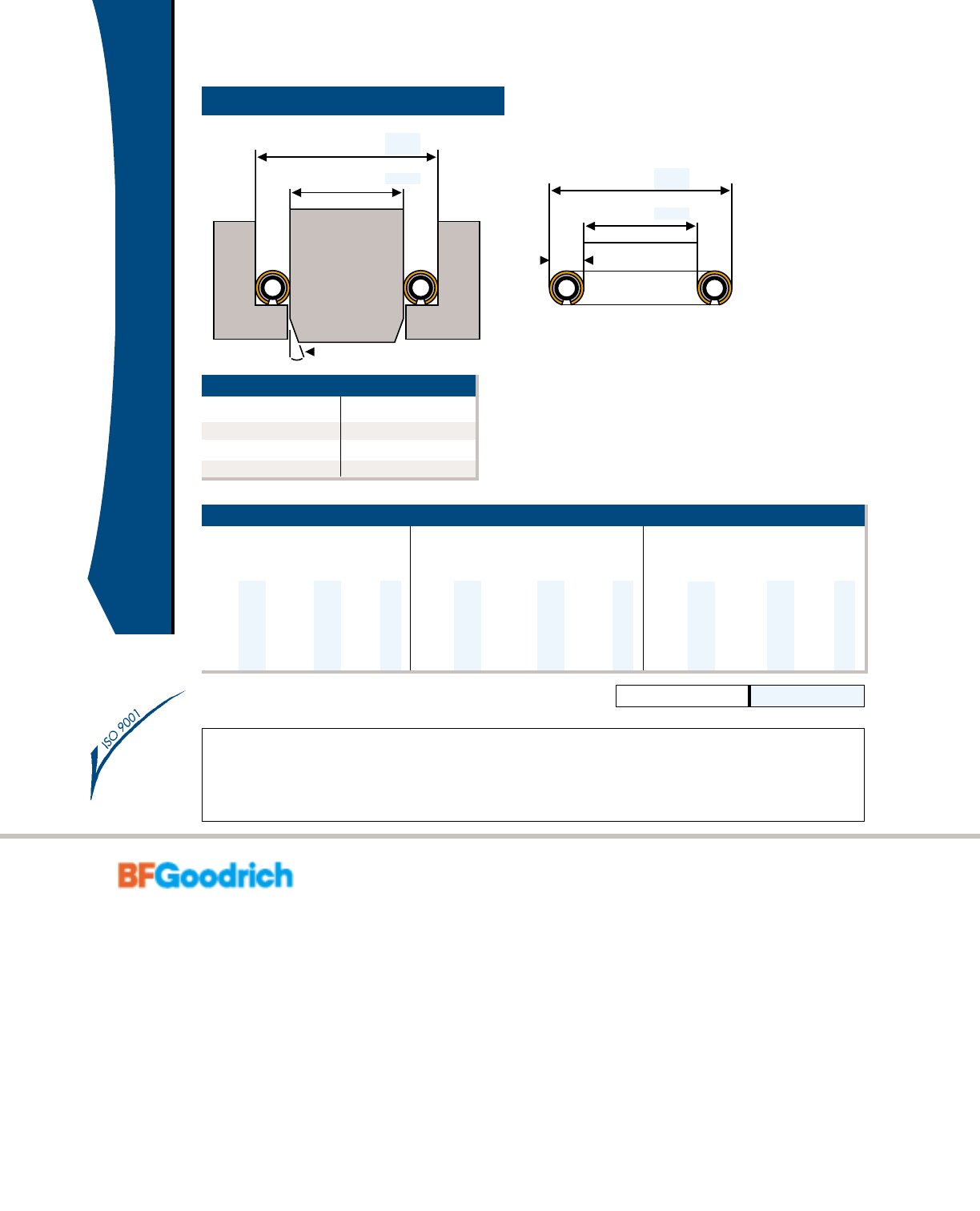
Standard Flanges
The Helicoflex®HN208a is ideally suited for standard raised face flanges. The resilient nature of the seal
allows it to compensate for the extremes of high temperature and pressure where traditional spiral
wounds and double jacketed seals fail. The jacket and spring combination can be modified to meet most
requirements of temperature and pressure. In addition, a large selection of jacket materials ensures
chemical compatibility in corrosive and caustic media.
ANSI B16.5 RAISED FACE FLANGE
Mean Diameter (d)Seal OD (A)
0.120"
SEAL TYPE: HN208a
Cross Seating Recommended
Section Load Flange
Jacket Availability (inches) (lbs/in)* Finish (RMS)
Aluminum Standard 0.160 1150 63 - 125
Silver Standard 0.160 1725 63 - 125
Copper Standard 0.155 2250 63 - 125
Soft Iron Optional 0.155 2250 32 - 63
Nickel Standard 0.150 2800 32 - 63
Monel Optional 0.150 2800 32 - 63
Hastelloy C Optional 0.150 2800 32 - 63
Stainless Steel Standard 0.150 3800 32 - 63
Alloy 600 Optional 0.150 3800 32 - 63
Alloy X750 Optional 0.150 4000 32 - 63
Titanium Optional 0.150 4000 32 - 63
SEAL DIMENSIONS
Nominal Mean Seal OD (A)
Diameter Diameter (d) 150lb 300lb 400lb 600lb 900lb 1500lb 2500lb
1/2 0.827 1.874 2.126 2.126 2.126 2.500 2.500 2.752
3/4 1.102 2.252 2.626 2.626 2.626 2.752 2.752 3.000
1 1.417 2.626 2.874 2.874 2.874 3.122 3.122 3.374
1-1/4 1.890 3.000 3.252 3.252 3.252 3.500 3.500 4.126
1-1/2 2.283 3.374 3.752 3.752 3.752 3.874 3.874 4.626
2 2.913 4.126 4.374 4.374 4.374 5.626 5.626 5.752
2-1/2 3.425 4.874 5.126 5.126 5.126 6.500 6.500 6.626
3 4.173 5.374 5.874 5.874 5.874 6.626 6.874 7.752
3-1/2 4.685 6.374 6.500 6.500 6.374 N/A N/A N/A
4 5.256 6.874 7.126 7.000 7.626 8.126 8.252 9.252
5 6.378 7.752 8.500 8.374 9.500 9.752 10.000 11.000
6 7.500 8.752 9.874 9.752 10.500 11.413 11.126 12.500
8 9.567 10.996 12.126 12.000 12.626 14.126 13.874 15.252
10 11.693 13.374 14.252 14.126 15.752 17.126 17.126 18.760
12 13.858 16.126 16.626 16.500 18.000 19.626 20.500 21.626
14 15.098 17.752 19.126 19.000 19.374 20.500 22.752 N/A
16 17.205 20.252 21.252 21.126 22.252 22.626 25.252 N/A
18 19.567 21.626 23.500 23.374 24.126 25.126 27.752 N/A
20 21.575 23.874 25.752 25.500 26.874 27.500 29.752 N/A
24 25.728 28.252 30.500 30.252 31.126 32.996 35.500 N/A
Note: Consult our engineering staff for other available sizes and materials.
* Note: Seating load only! Does not allow for hydrostatic
end force. See page 5 for calculations.
10 For Additional Information, Please Consult Our Engineering Staff
1-800-233-1722
Calculation Data - U.S. Customary
Cross Max
Section e2eCY2Y1Pu68°F
Pu
392°FY
2Y1Pu68°F
Pu
392°F Temp
In in in lbs/inch lbs/inch PSI PSI lbs/inch lbs/inch PSI PSI °F
0.063 0.024 0.028 857 114 7250 N/A 514 114 5075 N/A 302
0.075 0.028 0.033 914 114 7540 N/A 571 114 5800 N/A 302
0.087 0.028 0.035 942 114 7685 N/A 600 114 5800 N/A 356
0.098 0.028 0.035 999 114 7 975 7 25 6 57 114 6090 725 428
0.118 0.031 0.039 1056 143 7975 1450 742 114 6 525 14 5 0 482
0.138 0.031 0.039 1085 143 7975 2030 799 114 6815 2030 4 82
0.157 0.035 0.043 1142 143 8700 2465 857 114 7250 24 6 5 536
0.177 0.035 0.047 1199 143 8700 2900 914 114 7540 2900 536
0.197 0.035 0.055 1256 171 9135 3190 971 143 7975 3190 572
0.217 0.035 0.063 1313 171 9425 3480 1028 143 8265 3480 608
0.236 0.039 0.071 1399 200 9715 3625 1113 171 87 0 0 3625 6 4 4
0.276 0.039 0.087 1542 228 10150 4060 1171 200 9425 4060 644
0.315 0.039 0.102 1656 286 10440 4640 1285 228 9860 4495 680
Pu 482°FPu482°F
0.063 0.020 0.024 1142 171 9425 N/A 857 171 5800 N/A 464
0.075 0.024 0.028 1256 171 9425 N/A 857 171 5800 N/A 464
0.087 0.024 0.031 1313 200 10150 N/A 914 171 5800 580 536
0.098 0.028 0.035 1370 257 10875 116 0 971 2 28 6525 725 536
0.118 0.031 0.039 1485 286 12325 2030 1028 257 7250 1305 572
0.138 0.031 0.039 1599 286 13775 3190 1085 257 7975 1885 572
0.157 0.031 0.043 1713 314 15225 3915 1142 286 8700 2320 662
0.177 0.031 0.043 1827 343 16675 4495 1256 286 10150 2755 698
0.197 0.031 0.051 1941 343 18125 5220 1313 286 11600 3190 698
0.217 0.031 0.055 2056 371 19575 5800 1428 343 13050 3625 752
0.236 0.035 0.067 2284 400 21750 6815 1542 343 15950 4350 842
0.276 0.035 0.079 2512 457 23200 7830 1713 371 18125 5220 842
0.315 0.035 0.094 2798 514 24650 8700 1999 400 20300 6090 932
Pu 572°FPu572°F
0.063 0.020 0.024 1485 228 7250 1450 1085 171 5075 725 662
0.075 0.024 0.028 1599 286 7250 1595 1142 228 5075 870 662
0.087 0.024 0.031 1713 343 7975 1885 1256 286 5075 116 0 68 0
0.098 0.028 0.035 1827 400 8700 2465 1313 343 5800 1450 716
0.118 0.028 0.039 1999 457 9425 2900 1428 400 5800 1740 716
0.138 0.028 0.039 2227 457 10150 3335 1542 400 6525 2175 752
0.157 0.031 0.043 2455 514 10150 3915 1656 457 6525 2465 788
0.177 0.031 0.043 2684 571 11600 4350 1827 457 6525 2755 842
0.197 0.031 0.051 2912 628 12325 4785 1884 514 7250 3045 842
0.217 0.031 0.055 3141 685 13050 5220 2056 571 7250 3335 896
0.236 0.035 0.067 3597 799 13775 5800 2284 571 7975 3770 968
0.276 0.035 0.079 4225 914 14500 6525 2627 628 8700 4205 968
0.315 0.035 0.094 4911 1085 15950 7105 3026 742 9425 4640 1022
Pu 662°FPu662°F
0.063 0.016 0.020 1827 457 10150 1595 114 2 3 4 3 58 0 0 1015 716
0.075 0.020 0.024 1999 457 10440 2320 1256 343 6090 1305 716
0.087 0.020 0.028 2227 514 11020 3045 1313 400 6380 1740 788
0.098 0.024 0.031 2512 571 1189 0 3915 15 4 2 4 0 0 6815 2320 8 42
0.118 0.024 0.035 2512 628 12615 4930 1713 457 7250 2900 896
0.138 0.024 0.035 2798 685 13485 5800 1941 514 7830 3335 932
0.157 0.028 0.039 3312 799 13920 6525 2170 571 8265 3915 1022
0.177 0.028 0.039 4111 857 15225 7540 2398 628 8700 4350 1112
0.197 0.028 0.043 4454 1028 15950 8265 2627 628 9425 4785 1202
0.217 0.028 0.051 4625 1142 16675 8990 2855 685 9715 5365 1202
0.236 0.031 0.063 N/A N/A N/A N/A 3198 742 10440 5945 1202
0.276 0.031 0.071 N/A N/A N/A N/A 3712 857 11310 6525 1202
0.315 0.031 0.083 N/A N/A N/A N/A 4168 914 12035 7250 1202
Pu 752°FPu752°F
0.063 0.016 0.020 1999 571 13050 3625 1713 457 6815 870 788
0.075 0.020 0.024 2284 571 13195 3915 1827 457 7250 116 0 7 88
0.087 0.020 0.028 2570 628 13340 4205 1999 514 7540 1595 896
0.098 0.024 0.031 2855 685 14065 4640 2170 571 8265 2175 932
0.118 0.024 0.035 3283 742 14500 5220 2427 628 8990 2900 932
0.138 0.024 0.035 3769 857 15080 5655 2684 742 9715 3625 1022
0.157 0.028 0.039 4283 971 15515 6090 2969 857 10440 4350 1112
0.177 0.028 0.039 4711 1256 15950 6525 3198 1028 1116 5 493 0 1202
0.197 0.028 0.043 N/A N/A N/A N/A 3426 1085 11890 5365 1292
0.217 0.028 0.051 N/A N/A N/A N/A 3712 1142 12615 6090 1292
0.236 0.031 0.063 N/A N/A N/A N/A 4111 1256 13630 6815 1292
0.276 0.031 0.071 N/A N/A N/A N/A 4568 1485 14790 7540 1292
0.315 0.031 0.083 N/A N/A N/A N/A 5139 1656 15660 8410 1292
Aluminum
Silver
Copper,
Soft Iron,
Mild Steels
Nickel,
Monel,
Tantalum
Stainless
Steel,
Inconel,
Titanium
Jacket
Material
HELIUM SEALING BUBBLE SEALING
11For Additional Information, Please Consult Our Engineering Staff
1-800-233-1722
Calculation Data - Metric
Cross Max
Section e2eCY2Y1
Pu20°CPu200°C
Y2Y1
Pu20°CPu200°C
Temp
mm mm mm
daN/cm daN/cm daN/cm
2
daN/cm
2
daN/cm daN/cm daN/cm
2
daN/cm
2°C
1.6 0.6 0.7 150 20 50 N/A 90 20 35 N/A 150
1.9 0.7 0.85 160 20 52 N/A 100 20 40 N/A 150
2.2 0.7 0.9 165 20 53 N/A 105 20 40 N/A 180
2.5 0.7 0.9 175 20 55 5 115 20 4 2 5 2 2 0
3.0 0.8 1.0 185 25 55 10 130 20 45 10 250
3.5 0.8 1.0 190 25 55 14 140 20 47 14 250
4.0 0.9 1.1 200 25 60 17 150 20 50 17 280
4.5 0.9 1.2 210 25 60 20 160 20 52 20 280
5.0 0.9 1.4 220 30 63 22 170 25 55 22 300
5.5 0.9 1.6 230 30 65 24 180 25 57 24 320
6.0 1.0 1.8 245 35 67 25 195 30 60 25 340
7.0 1.0 2.2 270 40 70 28 205 35 65 28 340
8.0 1.0 2.6 290 50 72 32 225 40 68 31 360
Pu 250°CPu250°C
1.6 0.5 0.6 200 30 65 N/A 150 30 40 N/A 240
1.9 0.6 0.7 220 30 65 N/A 150 30 40 N/A 240
2.2 0.6 0.8 230 35 70 6 160 30 40 4 280
2.5 0.7 0.9 240 45 75 8 170 40 45 5 280
3.0 0.8 1.0 260 50 85 14 180 45 50 9 300
3.5 0.8 1.0 280 50 95 22 190 45 55 13 300
4.0 0.8 1.1 300 55 105 27 200 50 60 16 350
4.5 0.8 1.1 320 60 115 31 220 5 0 7 0 19 3 7 0
5.0 0.8 1.3 340 60 125 36 230 50 80 22 370
5.5 0.8 1.4 360 65 135 40 250 60 90 25 400
6.0 0.9 1.7 400 70 150 47 270 60 110 30 450
7.0 0.9 2.0 440 80 160 54 300 65 125 36 450
8.0 0.9 2.4 490 90 170 60 350 70 140 42 500
Pu 300°CPu300°C
1.6 0.5 0.6 260 40 50 10 190 30 35 5 350
1.9 0.6 0.7 280 50 50 11 200 40 35 6 350
2.2 0.6 0.8 300 60 55 13 220 50 35 8 360
2.5 0.7 0.9 320 70 60 17 230 60 40 10 380
3.0 0.7 1.0 350 80 65 20 250 70 40 12 380
3.5 0.7 1.0 390 80 70 23 270 70 45 15 400
4.0 0.8 1.1 430 90 70 27 290 80 45 17 420
4.5 0.8 1.1 470 100 80 30 320 80 45 19 450
5.0 0.8 1.3 510 110 85 33 330 90 50 21 450
5.5 0.8 1.4 550 120 90 36 360 100 50 23 480
6.0 0.9 1.7 630 140 95 40 400 100 55 26 520
7.0 0.9 2.0 740 160 100 45 460 110 60 29 520
8.0 0.9 2.4 860 190 110 49 530 130 65 32 550
Pu 350°CPu350°C
1.6 0.4 0.5 320 80 70 11 200 60 40 7 380
1.9 0.5 0.6 350 80 72 16 220 60 42 9 380
2.2 0.5 0.7 390 80 76 21 230 70 44 12 420
2.5 0.6 0.8 440 100 82 27 270 70 47 16 450
3.0 0.6 0.9 440 110 87 34 300 80 50 20 480
3.5 0.6 0.9 490 120 93 40 340 90 54 23 500
4.0 0.7 1.0 580 140 96 45 380 100 57 27 550
4.5 0.7 1.0 720 150 105 52 420 110 60 30 600
5.0 0.7 1.1 780 180 110 57 460 110 65 33 650
5.5 0.7 1.3 810 200 115 62 500 120 67 37 650
6.0 0.8 1.6 N/A N/A N/A N/A 560 130 72 41 650
7.0 0.8 1.8 N/A N/A N/A N/A 650 150 78 45 650
8.0 0.8 2.1 N/A N/A N/A N/A 730 160 83 50 650
Pu 400°CPu400°C
1.6 0.4 0.5 350 100 90 25 300 80 47 6 420
1.9 0.5 0.6 400 100 91 27 320 80 50 8 420
2.2 0.5 0.7 450 110 92 29 350 90 52 11480
2.5 0.6 0.8 500 120 97 32 380 100 57 15 500
3.0 0.6 0.9 575 130 100 36 425 110 62 20 500
3.5 0.6 0.9 660 150 104 39 470 130 67 25 550
4.0 0.7 1.0 750 170 107 42 520 150 72 30 600
4.5 0.7 1.0 825 220 110 45 560 180 77 34 650
5.0 0.7 1.1 N/A N/A N/A N/A 600 190 82 37 700
5.5 0.7 1.3 N/A N/A N/A N/A 650 200 87 42 700
6.0 0.8 1.6 N/A N/A N/A N/A 720 220 94 47 700
7.0 0.8 1.8 N/A N/A N/A N/A 800 260 102 52 700
8.0 0.8 2.1 N/A N/A N/A N/A 900 290 108 58 700
Aluminum
Silver
Copper,
Soft Iron,
Mild Steels
Nickel,
Monel,
Tantalum
Stainless
Steel,
Inconel,
Titanium
Jacket
Material
HELIUM SEALING BUBBLE SEALING
Cavity Design - Axial Pressure
Note: For best results, the cavity should be
lubricated with a product that is compatible
with the medium to be sealed.
RADIAL COMPRESSION
6°
G
E
±
0.002
-
0.000
+ 0.002
±
0.51
-
0.00
+ 0.51
CS
B
A
±
0.002
-
0.002
+ 0.000
±
0.51
-
0.51
+ 0.00
CALCULATIONS
Cavity OD (G) = Seal OD (B)
Shaft OD (E) = Seal ID (A) +2 e3
Cavity Finish < 32 RMS (0.8 um)
Axial Load = Ya
Dimensions in inches Dimensions in mm
CHARACTERISTIC VALUES
Aluminum Jacket Silver Jacket Nickel Jacket
CS e3Ya CS e3Ya CS e3Ya
daN/daN/daN/
in mm in mm lb/in cm in mm in mm lb/in cm in mm in mm lb/in cm
0.063 1.60 0.012 0.30 109 19 0.063 1.60 0.010 0.25 170 30 0.063 1.60 0.008 0.20 228 40
0.102 2.60 0.014 0.35 137 24 0.102 2.60 0.012 0.30 195 34 0.102 2.60 0.010 0.25 308 54
0.118 3.00 0.016 0.40 154 27 0.122 3.10 0.014 0.35 206 36 0.126 3.20 0.012 0.30 343 60
0.157 4.00 0.020 0.50 183 32 0.165 4.20 0.018 0.45 228 40 0.165 4.20 0.016 0.40 434 76
0.200 5.10 0.020 0.50 206 36 0.205 5.20 0.018 0.45 263 46 0.205 5.20 0.016 0.40 525 92
0.260 6.60 0.024 0.60 235 41 0.244 6.20 0.020 0.50 308 54 0.252 6.40 0.018 0.45 640 112
Garlock Helicoflex
PO Box 9889
2770 The Boulevard
Columbia, SC 29290 USA
Phone: 1-803-783-1880
Toll Free: 1-800-233-1722
Fax: 1-803-783-4279
www.helicoflex.com
www.garlock.net
Cefilac, S.A.
90 rue de la Roche-du-Geai
42029 Saint-Etienne, FRANCE
Phone: 011-33-4-77-43-51-00
Fax: 011-33-4-77-43-51-52
Garlock Sealing Technologies
Palmyra, NY, USA 1-315-597-4811 Fax: 1-315-597-3216
Paragould, AR, USA 1-870-239-4051 Fax: 1-870-239-4054
Houston, TX USA 1-281-459-7200 Fax: 1-281-458-0502
Sydney, Australia 61-2-9793-2511 Fax: 61-2-9793-2544
S~
ao Paulo, Brazil 55-11-884-9680 Fax: 55-11-884-9680
Oakville, Canada 1-905-829-3200 Fax: 1-905-829-3333
Berkshire, England 44-1635-38509 Fax: 44-1635-569573
Neuss, Germany 49-2131-3490 Fax: 49-2131-349-222
Seoul, Korea 822-554-6341 Fax: 822-554-6343
Mexico City, Mexico 52-5-567-7011 Fax: 52-5-368-0418
Singapore 65-284-7873 Fax: 65-284-6089
Catalog Reference: HEL 1
The technical data contained herein is by way of example
and should not be relied on for any specific application.
Garlock Helicoflex will be pleased to provide specific technical
data or specifications with respect to any customer’s particular
applications. Use of the technical data or specifications
contained herein without the express written approval of
Garlock Helicoflex is at user’s risk and Garlock Helicoflex
expressly disclaims responsibility for such use and the situations
which may result therefrom.
Garlock Helicoflex makes no warranty, express or implied, that
utilization of the technology or products disclosed herein will not
infringe any industrial or intellectual property rights of third parties.
Garlock Helicoflex is constantly involved in engineering
and development. Accordingly, Garlock Helicoflex reserves the
right to modify, at any time, the technology and product
specifications contained herein.
All technical data, specifications and other information
contained herein is deemed to be the proprietary intellectual
property of Garlock Helicoflex. No reproduction, copy or
use thereof may be made without the express written consent
of Garlock Helicoflex.
