Cisco UBR10012 Universal Broadband Router Hardware Installation Guide U BR10012 Hig
User Manual: Universal Broadband Router Cisco uBR10012
Open the PDF directly: View PDF ![]() .
.
Page Count: 272 [warning: Documents this large are best viewed by clicking the View PDF Link!]
- Cisco uBR10012 Universal Broadband Router Hardware Installation Guide
- Contents
- Preface
- Cisco uBR10012 Universal Broadband Router Overview
- Cisco uBR10012 Router Features
- Comparisons with Other Cisco CMTS Platforms
- Cisco uBR10012 Router Functional Overview
- Cisco uBR10012 Router and Cisco IOS Software
- NEBS Level 3 Compliance
- Cisco uBR10012 Universal Broadband Router Hardware
- Cisco uBR10012 Universal Broadband Router Modules
- DOCSIS Timing, Communication, and Control Card
- Cable Interface Line Cards
- Network Uplink Cards
- Optical Connectors and Cables
- Cisco uBR10012 Router FRU Resources
- Preparing for Installation
- Installing the Cisco uBR10012 Router
- Installation Methods
- Preparing the Cisco uBR10012 Router for Rack-Mounting
- Removing the Chassis Components Before Installation
- Attaching the Mounting Brackets
- Installing the Cable Management Brackets (Optional)
- Mounting the Chassis in the Rack
- Attaching Ferrite Beads on the Cables
- Connecting the Chassis to Ground
- Connecting the External AC-input Power Shelf to the Cisco uBR10012 Router
- Connecting DC Power to the Cisco uBR10012 Router
- Connecting Alarm Indicators
- Installing the Modules
- Installing the Slot Splitter and Half-Height Gigabit Ethernet Line Card
- Connecting the Console Port and Auxiliary Port
- Connecting Network Management Cables
- Connecting Cable Interface Line Cards and Network Uplink Cards
- Replacing the Front Cover
- Powering On the System
- Configuring the Cisco uBR10012 Router at Startup
- Formatting PC Media Cards
- Troubleshooting the Installation
- Troubleshooting Methods
- Troubleshooting Installation Problems
- Troubleshooting Ethernet Connections
- Troubleshooting the Console Port Serial Connection
- Identifying Startup Problems
- Troubleshooting the Power Subsystem
- Troubleshooting the Processor Subsystem
- Troubleshooting the Cooling Subsystem
- Troubleshooting the Line Cards
- Troubleshooting the HHGE Installation
- Maintaining the Cisco uBR10012 Router
- Shutting Down the System
- Removing and Replacing the Front Cover
- Replacing the Air Filter
- Removing and Replacing the Fan Assembly Module
- Removing and Replacing DC Power Entry Modules
- Connecting Alarm Indicators
- Removing and Replacing AC PEM Modules
- Removing and Replacing the PRE Module
- Removing and Installing a PC Media Card
- Removing and Replacing a Timing, Communication, and Control Plus Card
- Removing and Replacing a Network Line Card
- Removing the Half-Height Gigabit Ethernet Line Card and the Slot Splitter
- Replacing the Slot Splitter and Half-Height Gigabit Ethernet Line Card
- Removing and Replacing an SFP Module
- Upgrading to a Half-Height Gigabit Ethernet Line Card
- Removing and Replacing a Cable Interface Line Card
- Technical Specifications
- Cable Specifications
- Frequency Allocation
- Standards Comparisons
- NTSC Cable Television Channels and Relative Frequencies
- NTSC (M) Cable Television Channel Frequencies for Japan
- NTSC Cable Television Channel Frequencies for the Republic of Korea
- PAL/SECAM Cable Television Channels and Relative Frequencies
- PAL SECAM (D/K) Cable Television Channel Frequencies for the People’s Republic of China
- Manufacturers for Hardware Components

THE SPECIFICATIONS AND INFORMATION REGARDING THE PRODUCTS IN THIS MANUAL ARE SUBJECT TO CHANGE WITHOUT NOTICE. ALL
STATEMENTS, INFORMATION, AND RECOMMENDATIONS IN THIS MANUAL ARE BELIEVED TO BE ACCURATE BUT ARE PRESENTED WITHOUT
WARRANTY OF ANY KIND, EXPRESS OR IMPLIED. USERS MUST TAKE FULL RESPONSIBILITY FOR THEIR APPLICATION OF ANY PRODUCTS.
THE SOFTWARE LICENSE AND LIMITED WARRANTY FOR THE ACCOMPANYING PRODUCT ARE SET FORTH IN THE INFORMATION PACKET THAT
SHIPPED WITH THE PRODUCT AND ARE INCORPORATED HEREIN BY THIS REFERENCE. IF YOU ARE UNABLE TO LOCATE THE SOFTWARE LICENSE
OR LIMITED WARRANTY, CONTACT YOUR CISCO REPRESENTATIVE FOR A COPY.
The following information is for FCC compliance of Class A devices: This equipment has been tested and found to comply with the limits for a Class A digital device, pursuant
to part 15 of the FCC rules. These limits are designed to provide reasonable protection against harmful interference when the equipment is operated in a commercial
environment. This equipment generates, uses, and can radiate radio-frequency energy and, if not installed and used in accordance with the instruction manual, may cause
harmful interference to radio communications. Operation of this equipment in a residential area is likely to cause harmful interference, in which case users will be required
to correct the interference at their own expense.
The following information is for FCC compliance of Class B devices: The equipment described in this manual generates and may radiate radio-frequency energy. If it is not
installed in accordance with Cisco’s installation instructions, it may cause interference with radio and television reception. This equipment has been tested and found to
comply with the limits for a Class B digital device in accordance with the specifications in part 15 of the FCC rules. These specifications are designed to provide reasonable
protection against such interference in a residential installation. However, there is no guarantee that interference will not occur in a particular installation.
Modifying the equipment without Cisco’s written authorization may result in the equipment no longer complying with FCC requirements for Class A or Class B digital
devices. In that event, your right to use the equipment may be limited by FCC regulations, and you may be required to correct any interference to radio or television
communications at your own expense.
You can determine whether your equipment is causing interference by turning it off. If the interference stops, it was probably caused by the Cisco equipment or one of its
peripheral devices. If the equipment causes interference to radio or television reception, try to correct the interference by using one or more of the following measures:
• Turn the television or radio antenna until the interference stops.
• Move the equipment to one side or the other of the television or radio.
• Move the equipment farther away from the television or radio.
• Plug the equipment into an outlet that is on a different circuit from the television or radio. (That is, make certain the equipment and the television or radio are on circuits
controlled by different circuit breakers or fuses.)
Modifications to this product not authorized by Cisco Systems, Inc. could void the FCC approval and negate your authority to operate the product.
The Cisco implementation of TCP header compression is an adaptation of a program developed by the University of California, Berkeley (UCB) as part of UCB’s public
domain version of the UNIX operating system. All rights reserved. Copyright © 1981, Regents of the University of California.
NOTWITHSTANDING ANY OTHER WARRANTY HEREIN, ALL DOCUMENT FILES AND SOFTWARE OF THESE SUPPLIERS ARE PROVIDED “AS IS” WITH
ALL FAULTS. CISCO AND THE ABOVE-NAMED SUPPLIERS DISCLAIM ALL WARRANTIES, EXPRESSED OR IMPLIED, INCLUDING, WITHOUT
LIMITATION, THOSE OF MERCHANTABILITY, FITNESS FOR A PARTICULAR PURPOSE AND NONINFRINGEMENT OR ARISING FROM A COURSE OF
DEALING, USAGE, OR TRADE PRACTICE.
IN NO EVENT SHALL CISCO OR ITS SUPPLIERS BE LIABLE FOR ANY INDIRECT, SPECIAL, CONSEQUENTIAL, OR INCIDENTAL DAMAGES, INCLUDING,
WITHOUT LIMITATION, LOST PROFITS OR LOSS OR DAMAGE TO DATA ARISING OUT OF THE USE OR INABILITY TO USE THIS MANUAL, EVEN IF CISCO
OR ITS SUPPLIERS HAVE BEEN ADVISED OF THE POSSIBILITY OF SUCH DAMAGES.
Cisco and the Cisco logo are trademarks or registered trademarks of Cisco and/or its affiliates in the U.S. and other countries. To view a list of Cisco trademarks, go to this
URL: www.cisco.com/go/trademarks. Third-party trademarks mentioned are the property of their respective owners. The use of the word partner does not imply a partnership
relationship between Cisco and any other company. (1110R)
Cisco uBR10012 Universal Broadband Router Hardware Installation Guide
© 2009-2015 Cisco Systems, Inc. All rights reserved.

iii
Cisco uBR10012 Universal Broadband Router Hardware Installation Guide
CONTENTS
Preface xi
Document Revision History xi
Purpose xii
Audience xii
Document Organization xii
Related Documentation xiii
Conventions xiv
Safety Information Referral Warning xiv
Terms and Acronyms xv
Obtaining Documentation and Submitting a Service Request xvi
CHAPTER
1Cisco uBR10012 Universal Broadband Router Overview 1-1
Cisco uBR10012 Router Features 1-2
Comparisons with Other Cisco CMTS Platforms 1-3
Cisco uBR10012 Router Functional Overview 1-3
Upstream Data Path 1-4
Downstream Data Path 1-4
Cisco uBR10012 Router and Cisco IOS Software 1-5
DOCSIS and EuroDOCSIS Data Rates and Modulation Schemes 1-5
NEBS Level 3 Compliance 1-7
Cisco uBR10012 Universal Broadband Router Hardware 1-7
Cisco uBR10012 Router 1-7
Cisco uBR10012 Router Slot Numbering 1-11
Cisco uBR10012 Universal Broadband Router Modules 1-13
Fan Assembly Module 1-13
AC Power Entry Modules 1-13
DC Power Entry Modules 1-14
Supported External AC-Input Power Shelves 1-15
Lineage AC-DC Power Shelf 1-15
LCD Module 1-17
LCD Cable 1-19
Performance Routing Engine 1-19

Contents
iv
Cisco uBR10012 Universal Broadband Router Hardware Installation Guide
PRE Modules and PRE1 Modules 1-19
PRE2 Modules 1-20
PRE4 Modules 1-20
Redundant PRE Modules 1-21
PRE Module Description 1-21
Connector Ports 1-22
PC Media Card Slots 1-22
LCD Screens 1-22
PRE LED Indicators and Buttons 1-22
PRE Module Disposal 1-23
SIP and SPA Compatibility 1-24
Timing, Communication, and Control Plus Card 1-24
DOCSIS Timing, Communication, and Control Card 1-26
Cable Interface Line Cards 1-27
Cisco uBR-MC5X20S/U/H Cable Interface Card 1-27
Cisco uBR10-MC5X20S 1-27
Cisco uBR10-MC5X20U and H 1-27
Cisco UBR-MC20X20V Cable Interface Card 1-28
Cisco uBR-MC3GX60V Cable Interface Card 1-28
Cisco uBR-MC3GX60V-RPHY Cable Interface Card 1-28
Network Uplink Cards 1-30
Cisco Single Port Gigabit Ethernet Line Card 1-30
Cisco Gigabit Ethernet Line Card LEDs 1-31
GBIC Specifications 1-32
Cisco Half-Height Gigabit Ethernet Line Card 1-32
Cisco OC-12 POS Line Card 1-32
Cisco OC-12 POS Line Card LEDs 1-33
Cisco uBR10-SRP-OC12SML DPT WAN Line Card 1-34
Cisco uBR10012 OC-48 DPT/POS Interface Module 1-34
Optical Connectors and Cables 1-35
Cisco uBR10012 Router FRU Resources 1-35
FRU Modules and Order Numbers 1-35
FRU Documentation 1-38
CHAPTER
2Preparing for Installation 2-1
Safety 2-1
Preventing Electrostatic Discharge Damage 2-2
Chassis-Lifting Guidelines 2-3
Electrical Safety 2-4

Contents
v
Cisco uBR10012 Universal Broadband Router Hardware Installation Guide
Site Requirements 2-4
Environmental Site Requirements 2-5
Temperature and Humidity Requirements 2-7
Power Guidelines 2-7
Power Connection Guidelines for DC-Powered Systems 2-8
Plant Wiring Guidelines 2-9
Interference Considerations 2-9
Cabling Guidelines 2-9
Ethernet and Fast Ethernet Connections 2-10
Fiber-Optic Connections 2-10
Rack-Mounting Considerations 2-11
Mounting Guidelines 2-11
Using Power Strips with a Rack-Mount Installation 2-12
CHAPTER
3Installing the Cisco uBR10012 Router 3-1
Installation Methods 3-2
Preparing the Cisco uBR10012 Router for Rack-Mounting 3-2
General Rack Installation Guidelines 3-3
Removing the Chassis Components Before Installation 3-4
Before You Begin 3-4
Removing the Half-Height Gigabit Ethernet Line Card and the Slot Splitters 3-4
Removing a Half-Height Gigabit Ethernet Line Card 3-4
Removing the Slot Splitter 3-7
Attaching the Mounting Brackets 3-9
Installing the Cable Management Brackets (Optional) 3-13
Installing First-Generation Cable Management Brackets 3-13
Installing the Second-Generation Cable Management Bracket 3-14
Attaching Cable Management Bracket on the Rear Flush-Mounted Chassis 3-14
Attaching Cable Management Bracket on the Rear Offset-Mounted Chassis 3-17
Mounting the Chassis in the Rack 3-19
Recommended Tools and Supplies 3-19
Installing the Cisco uBR10012 Chassis in the Rack 3-20
Attaching Ferrite Beads on the Cables 3-22
Attaching Ferrite Beads on Grounding and Alarm Cables 3-22
Attaching Ferrite Beads on DC Power Cables 3-23
Attaching Ferrite Beads on the Lineage Power Shelf 3-24
Connecting the Chassis to Ground 3-25
Recommended Tools and Supplies 3-25
Attaching the Grounding Cable 3-26

Contents
vi
Cisco uBR10012 Universal Broadband Router Hardware Installation Guide
Connecting the External AC-input Power Shelf to the Cisco uBR10012 Router 3-28
Cabling the Lineage AC-DC Power Shelf 3-28
Prerequisites 3-28
Required Tools and Equipment 3-28
Steps 3-28
Connecting the Lineage AC-DC Power Shelf to the Cisco uBR10012 Router 3-29
Connecting the Lineage Power Shelf to the UBR-PWR-DC= Module 3-30
Connecting the Lineage Power Shelf to the UBR-PWR-DC-PLUS= Module 3-32
Connecting the Alarm Monitor Cable 3-36
Prerequisites 3-36
Required Tools and Equipment 3-36
Steps 3-36
Disconnecting Cables from the Lineage AC-DC Power Shelf and the Cisco uBR10012 Router 3-39
Connecting DC Power to the Cisco uBR10012 Router 3-39
Recommended Tools and Supplies 3-40
Connecting the Cisco uBR10012 Chassis to a DC Power Source 3-41
Connecting Alarm Indicators 3-41
Recommended Tools and Supplies 3-41
Installing the Modules 3-44
Installing the Line Cards and Uplink Cards 3-44
Installing the Slot Splitter and Half-Height Gigabit Ethernet Line Card 3-47
Installing the Slot Splitter 3-48
Installing the Half-Height Gigabit Ethernet Line Card 3-52
Connecting the Console Port and Auxiliary Port 3-55
Recommended Tools and Supplies 3-55
Connecting to the Console Port 3-56
Connecting to the Auxiliary Port 3-57
Connecting Network Management Cables 3-58
Ethernet Network Management Cable Connections 3-58
Connecting to a 10Base-T Ethernet Network 3-58
Connecting to a 100Base-T Ethernet Network 3-59
Connecting Cable Interface Line Cards and Network Uplink Cards 3-61
Cable Interface Line Card Connections 3-61
Network Uplink Cable Connections 3-61
Connecting a Single-Port Gigabit Ethernet Line Card 3-62
Replacing the Front Cover 3-65
Powering On the System 3-66
Configuring the Cisco uBR10012 Router at Startup 3-66
Startup Display 3-66

Contents
vii
Cisco uBR10012 Universal Broadband Router Hardware Installation Guide
Basic Configuration Using the Setup Facility 3-67
System Configuration Dialog 3-67
Configuring the System Using System Configuration Dialog 3-68
Setting Up the Interface 3-69
Basic Configuration in Global Configuration Mode 3-70
Formatting PC Media Cards 3-71
CHAPTER
4Troubleshooting the Installation 4-1
Troubleshooting Methods 4-2
Before You Call for Technical Assistance 4-2
Problem Solving Using a Subsystems Approach 4-2
Troubleshooting Installation Problems 4-3
General Troubleshooting Tips 4-3
Troubleshooting Ethernet Connections 4-4
Troubleshooting the Console Port Serial Connection 4-5
Identifying Startup Problems 4-6
Troubleshooting the Power Subsystem 4-7
Troubleshooting the AC Power Subsystem 4-7
Troubleshooting the DC Power Subsystem 4-9
Troubleshooting the 2400 W AC-Input Power Shelf 4-12
Troubleshooting the Processor Subsystem 4-13
Troubleshooting the Cooling Subsystem 4-14
Troubleshooting the Line Cards 4-16
Troubleshooting the HHGE Installation 4-17
CHAPTER
5Maintaining the Cisco uBR10012 Router 5-1
Shutting Down the System 5-2
Required Maintenance Tools 5-2
Removing and Replacing the Front Cover 5-2
Removing the Front Cover 5-3
Replacing the Front Cover 5-3
Replacing the Air Filter 5-4
Removing and Replacing the Fan Assembly Module 5-6
Removing and Replacing DC Power Entry Modules 5-7
Connecting Alarm Indicators 5-7
Attaching the Alarm Wires 5-8
Removing and Replacing AC PEM Modules 5-9

Contents
viii
Cisco uBR10012 Universal Broadband Router Hardware Installation Guide
Removing and Replacing the PRE Module 5-10
Removing the PRE Module 5-10
Replacing the PRE Module 5-14
Removing and Installing a PC Media Card 5-16
Removing and Replacing a Timing, Communication, and Control Plus Card 5-18
Removing and Replacing a Network Line Card 5-21
Removing the Network Line Card 5-21
Installing the Network Line Card 5-25
Removing the Half-Height Gigabit Ethernet Line Card and the Slot Splitter 5-27
Removing a Half-Height Gigabit Ethernet Line Card 5-27
Removing the Slot Splitter 5-30
Replacing the Slot Splitter and Half-Height Gigabit Ethernet Line Card 5-32
Installing the Slot Splitter 5-32
Installing the Half-Height Gigabit Ethernet Line Card 5-35
Removing and Replacing an SFP Module 5-38
Types of SFP Modules 5-38
Removing an SFP Module 5-38
Inserting an SFP Module 5-40
Upgrading to a Half-Height Gigabit Ethernet Line Card 5-41
Removing and Replacing a Cable Interface Line Card 5-41
Removing the Cable Interface Line Card 5-42
Installing a Cable Interface Line Card 5-45
APPENDIX
ATechnical Specifications A-1
Cisco uBR10012 Chassis and Chassis Components A-1
Network Uplink Cards and Cable Interface Line Cards A-8
SIP and SPA A-12
APPENDIX
BCable Specifications B-1
Coaxial Cables B-1
Console and Auxiliary Port Cables and Pinouts B-2
How to Identify an RJ-45 Rollover Cable B-3
Console Port Cables and Pinouts B-4
Auxiliary Port Cables and Pinouts B-4
Fast Ethernet Port Cables and Pinouts B-5
How to Identify an RJ-45 Crossover Cable B-5
How to Identify an RJ-45 Straight-Through Cable B-6
Connecting a Cable to an RJ-45 Connector B-7

Contents
ix
Cisco uBR10012 Universal Broadband Router Hardware Installation Guide
Fiber-Optic Cables and Connectors B-8
APPENDIX
CFrequency Allocation C-1
Standards Comparisons C-2
NTSC Cable Television Channels and Relative Frequencies C-3
NTSC (M) Cable Television Channel Frequencies for Japan C-8
NTSC Cable Television Channel Frequencies for the Republic of Korea C-10
PAL/SECAM Cable Television Channels and Relative Frequencies C-14
PAL SECAM (D/K) Cable Television Channel Frequencies for the People’s Republic of China C-18
APPENDIX
DManufacturers for Hardware Components D-1
North American Channel Plans D-1
European Channel Plans D-3
Cable Kits and Tools D-4
External AC-Input Power Shelves D-5

Contents
x
Cisco uBR10012 Universal Broadband Router Hardware Installation Guide

xi
Cisco uBR10012 Universal Broadband Router Hardware Installation Guide
Preface
This section describes the purpose, audience, organization, and conventions used in this guide. This
section also provides a revision history and a list of related documents as well as instructions for
obtaining technical assistance and additional information.
Document Revision History
Date Revision Reason
February 16, 2015 —Updated information about the Cisco 6 Gbps Wideband
Shared Port Adapter.
September 08, 2014 —Added information about the Cisco 6 Gbps Wideband Shared
Port Adapter.
August 4, 2014 —Added Cisco uBR-MC3GX60V-RPHY Line Card information.
July 6, 2012 OL-18259-10 Added information about the second-generation cable
management bracket on the Cisco uBR10012 router.
October 11, 2011 OL-18259-09 Added instructions on cabling and connecting the Lineage
power shelf to the UBR10-PWR-DC-PLUS= power entry
module on the Cisco uBR10012 router.
June 20, 2011 OL-18259-08 Added the SFP modules supported on the 1-Port 10-Gigabit
Ethernet SPA.
April 29, 2011 OL-18259-07 Added information about Lineage power shelf for
UBR10-PWR-DC PEM— brief overview and instructions on
cabling the shelf to the Cisco uBR10012 chassis.
Updated the ferrite beads to be used with the Lineage power
shelf.
March 10, 2011 OL-18259-06 Added information about fan assembly module
(UBR10012-FAN-PLUS=), 3300 W AC PEM
(UBR10-PWR-AC-PLUS=), and 3300 W DC PEM module.
November 29, 2010 OL-18259-05 Added Cisco UBR-MC3GX60V cable interface line card
information.
September 01, 2010 OL-18259-04 Updated for DC PEM Requalification. Added table 2-2 and
Table A-1 with the updated DC PEM power specifications.
xii
Cisco uBR10012 Universal Broadband Router Hardware Installation Guide
Purpose
This installation guide explains the initial hardware installation and basic configuration procedures for
the Cisco uBR10012 universal broadband router. It contains procedures for installing the router
hardware, creating a basic software configuration file, and starting up the router. After you complete the
installation and basic configuration procedures covered in this guide, use the appropriate companion
publications to more completely configure your system. See the documents listed in the “Related
Documentation” section on page xiii.
Audience
To use this publication, you should be familiar not only with Cisco router hardware and cabling, but also
with electronic circuitry and wiring practices. You should be able to perform basic network configuration
procedures, and preferably have experience as an electronic or electromechanical technician.
Warning
Only trained and qualified personnel should be allowed to install, replace, or service this equipment.
Statement 1030.
Document Organization
This publication is organized as follows:
May10, 2010 OL-18259-03 Added information about the 10 and 15 downstream channel
licenses.
November 16, 2009 OL-18259-02 Added Cisco UBR-MC20X20V cable interface line card
information.
December 15, 2008 OL-18259-01 Updated with PRE4 information. Moved the document to
online only.
April 05, 2006 78-11450-03
Rev.B0
Updated Table 3-6.
June 28, 2005 OL-5000-03 Added HHGE line card information.
October18, 2004 OL-5000-02 Updated with PRE2 information.
December 20, 2003 OL-5000-01 Moved document to online only, updated format, added AC
PEM specifications, and corrected PEM information,
corrected PRE information, revised line card installation
procedure.
March 20, 2001 78-11450-03 Original publication and updates.
Date Revision Reason

xiii
Cisco uBR10012 Universal Broadband Router Hardware Installation Guide
Related Documentation
The following is a list of documents and URLs for the Cisco uBR10012 router:
•Cisco uBR10012 Universal Broadband Router Software Configuration Guide
http://www.cisco.com/web/techdoc/cable/Config/Sw_conf.html
•Regulatory Compliance and Safety Information for the Cisco uBR10012 Universal Broadband
Router
http://www.cisco.com/en/US/docs/cable/cmts/ubr10012/regulatory/compliance/ub10rcsi.html
Additional documentation can be found here:
•For information on installing and replacing field-replaceable units (FRUs), such as the flash memory
on Cisco uBR10012 routers, see the document for each FRU or go to the following URL:
http://www.cisco.com/en/US/products/hw/cable/ps2209/prod_installation_guides_list.html
•For detailed Cisco IOS software configuration information and support, refer to the modular
configuration and modular command reference publications in the Cisco IOS software configuration
documentation set that corresponds to the software release installed on your Cisco hardware at the
following URL:
http://www.cisco.com/en/US/products/ps6350/tsd_products_support_series_home.html
Specifically, you should refer to the following publications:
Chapter Title Description
Chapter 1 Cisco uBR10012 Universal
Broadband Router Overview
Describes the physical properties of the
Cisco uBR10012 components and a functional
overview of the system.
Chapter 2 Preparing for Installation Describes safety considerations, tools required, site
requirements, and procedures you should perform
before the installation.
Chapter 3 Installing the
Cisco uBR10012 Router
Provides information for installing the router hardware,
connecting system cables, initial system startup, and
verifying system operation.
Chapter 4 Troubleshooting the
Installation
Provides basic troubleshooting procedures for the
hardware installation.
Chapter 5 Maintaining the
Cisco uBR10012 Router
Describes the procedures required to perform routine
maintenance and to remove and replace field
replaceable units (FRUs) in the Cisco uBR10012 router.
Appendix A Technical Specifications Contains the electrical and physical specifications for
the Cisco uBR10012 router.
Appendix B Cable Specifications Provides cabling information and pinout information
for the router.
Appendix C Frequency Allocation Provides the standard frequency allocation channel
plans for cable networks.
Appendix D Manufacturers for Hardware
Components
Lists vendors for the auxiliary equipment that is
normally required for a headend installation.

xiv
Cisco uBR10012 Universal Broadband Router Hardware Installation Guide
–
For information on setting up quality of service (QoS), refer to the Quality of Service Solutions
Configuration Guide and Quality of Service Solutions Command Reference publications.
–
For information on encryption, refer to the Security Configuration Guide and the Security
Command Reference publications.
–
For information on interfaces, refer to the Cisco IOS Interface Configuration Guide and the
Cisco IOS Interface Command Reference publications.
–
For information on IP, refer to the Network Protocols Configuration Guide, Part 1 and the
Network Protocols Command Reference, Part 1 publications.
You can also refer to the Cisco IOS software release notes for the version of software you are using
on your Cisco uBR10012 router. Release notes for the Cisco uBR10012 router are found at the
following URL:
http://www.cisco.com/en/US/products/hw/cable/ps2209/prod_release_notes_list.html
•For information about cleaning fiber-optic connections, go to the following URL:
http://www.cisco.com/en/US/tech/tk482/tk876/technologies_white_paper09186a0080254eba.shtm
l
Conventions
Note Means reader take note. Notes contain helpful suggestions or references to materials not contained in
this publication.
Tip Means the following information might help you solve a problem.
Caution Means reader be careful. In this situation, you might do something that could result in equipment
damage or loss of data.
Safety Information Referral Warning
See the following URL for the foreign language translations of all the warnings used in this guide:
http://www.cisco.com/en/US/docs/cable/cmts/ubr10012/regulatory/compliance/ub10rcsi.html
Warning
IMPORTANT SAFETY INSTRUCTIONS
This warning symbol means danger. You are in a situation that could cause bodily injury. Before you
work on any equipment, be aware of the hazards involved with electrical circuitry and be familiar
with standard practices for preventing accidents. Use the statement number provided at the end of
each warning to locate its translation in the translated safety warnings that accompanied this device.
Statement 1071
SAVE THESE INSTRUCTIONS

xv
Cisco uBR10012 Universal Broadband Router Hardware Installation Guide
Terms and Acronyms
To fully understand the content of this guide, you should be familiar with the following terms and
acronyms:
Note A complete list of terms and acronyms is available in the Internetworking Terms and Acronyms guide,
available on Cisco.com and the Documentation CD-ROM. Also see the Glossary section at the end of
this guide.
•ABR—Available bit rate
•AAL5—ATM adaptation layer 5
•AWG—American wire gauge
•CoS—Class of service
•CPE—Customer premises equipment
•CRC—Cyclic redundancy check
•CSU—Channel service unit
•CTS—Clear To Send
•DCD—Data Carrier Detect
•DCE—Data communications equipment
•DIMM—Dual in-line memory module
•DSR—Data set ready
•DSU—Data service unit
•DTE—Data terminal equipment
•DTR—Data terminal ready
•EMC—Electromagnetic compliance
•EMI—Electromagnetic interference
•ESD—Electrostatic discharge
•FRU—Field-replaceable unit (router components that do not require replacement by a
Cisco-certified service provider)
•FTP—Foil twisted-pair
•HDLC—High-Level Data Link Control
•HHGE—Half-Height Gigabit Ethernet
•IPSec—IP Security Protocol
•MAC—Media Access Control
•MB—Megabyte
•MM—Multimode
•nrt-VBR—Non-real time variable bit rate
•NVRAM—Nonvolatile random-access memory
•OAM AIS—Operation, Administration, and Maintenance alarm indication signal

xvi
Cisco uBR10012 Universal Broadband Router Hardware Installation Guide
•OIR—Online insertion and removal
•PCI—Peripheral Component Interconnect
•PCMCIA—Personal Computer Memory Card International Association
•PPP—Point-to-Point Protocol
•QoS—Quality of service
•rcp—remote copy protocol
•RFI—Radio frequency interference
•RIP—Routing Information Protocol
•RISC—Reduced Instruction Set Computing
•RTS—Request To Send
•SDRAM—Synchronous dynamic random-access memory
•SIMM—Single in-line memory module
•SMI—Single-mode intermediate reach
•SNMP—Simple Network Management Protocol
•TCP/IP—Transmission Control Protocol/Internet Protocol
•TDM—Time-division multiplexing
•TFTP—Trivial File Transfer Protocol
•UBR—Unspecified bit rate
•UDP—User Datagram Protocol
•UNI—User-Network Interface
•UTP—Unshielded twisted-pair
•VC—Virtual circuit
•VPN—Virtual Private Network
Obtaining Documentation and Submitting a Service Request
For information on obtaining documentation, submitting a service request, and gathering additional
information, see the monthly What’s New in Cisco Product Documentation, which also lists all new and
revised Cisco technical documentation, at:
http://www.cisco.com/en/US/docs/general/whatsnew/whatsnew.html
Subscribe to the What’s New in Cisco Product Documentation as a Really Simple Syndication (RSS) feed
and set content to be delivered directly to your desktop using a reader application. The RSS feeds are a free
service and Cisco currently supports RSS Version 2.0.

CHAPTER
1-1
Cisco uBR10012 Universal Broadband Router Hardware Installation Guide
1
Cisco uBR10012 Universal Broadband Router
Overview
The Cisco uBR10012 universal broadband router provides a high-end, high-performance, high-capacity
Cable Modem Termination System (CMTS) solution. The Cisco uBR10012 router is an aggregation
platform that places a new level of intelligence and performance at the edge of the network, enabling
cable service providers to maximize their revenues by delivering more feature-rich services to their
customers. The system can provide high-speed data, broadband entertainment, and IP telephony services
to residential and commercial subscribers using cable modems or digital set-top boxes (STBs).
The Cisco uBR10012 router is based on the Data-over-Cable Service Interface Specifications
(DOCSIS), which were developed by a cable industry initiative to ensure the reliable and secure
operation of cable data networks. The router can interoperate with cable modems or STBs that support
the DOCSIS 1.0, DOCSIS 1.1, EuroDOCSIS 1.1, DOCSIS 2.0, DOCSIS 3.0 and EuroDOCSIS 2.0
versions of the DOCSIS specification.
DOCSIS supports the 6 MHz North American channel plans using the ITU J.83 Annex B RF standard.
The downstream uses a 6 MHz channel width in the 85 to 860 MHz frequency range, and the upstream
supports the 5 to 42 MHz frequency range. Each chassis can support multiple standards and multiple
interfaces, allowing operators to choose the appropriate services and devices that optimize their capital
investment with a single CMTS platform.
The Cisco uBR10012 router supports data and digitized voice connectivity over a bidirectional cable
television and IP backbone network, using advanced quality of service (QoS) techniques to ensure that
real-time traffic such as voice can be reliably delivered, while still transmitting other traffic on a
best-effort basis. The Cisco uBR10012 router concentrates traffic from two-way DOCSIS-based cable
modems and STBs that is transmitted over the coaxial cable television (CATV) network, and presents
that traffic to local and remote Internet Protocol (IP) hosts over its high-speed network uplink interfaces.
The Cisco uBR10012 universal broadband router uses the same Parallel Express Forwarding (PXF)
technology used by the Cisco ESR10000 edge services router. The combination of PXF technology with
Cisco's CMTS solutions creates a cost-effective, scalable, and industry-proven CMTS that provides
consistent, high-performance throughput that is optimized for high-volume traffic over a cable network.
Based on the Cisco IOS networking software, the router supports the most advanced networking and
routing options. Also, with access to current and future software enhancements, the router ensures
investment protection as standards and customer needs continue to evolve.
Warning
Only trained and qualified personnel should be allowed to install, replace, or service this equipment.
Statement 1030.

1-2
Cisco uBR10012 Universal Broadband Router Hardware Installation Guide
Chapter 1 Cisco uBR10012 Universal Broadband Router Overview
Cisco uBR10012 Router Features
Cisco uBR10012 Router Features
The Cisco uBR10012 router has the following features:
•19-inch rack mount, 22.75-inch depth. See “Cisco uBR10012 Router”.
•31.5-inch height, 18 Rack Units (RU)—2 chassis per 7-foot rack
•Twelve card slots:
–
8 cable interface line cards
–
4 network uplink line cards
•LCD module, see “LCD Module”.
•64,000 subscribers—Supports up to a maximum of 64,0001 subscribers in a basic configuration.
•Performance routing engine (PRE1, PRE2 and PRE4) modules, see “Performance Routing Engine”.
–
PRE1 modules support error checking and correction (ECC) for all onboard memory, replacing
the simpler parity error algorithm of the original PRE module.
–
PRE2 modules are designed to address Internet-service-provider (ISP) requirements. The PRE2
provides 6.2 mpps of processing power and has a 500-MHz RM7000 mips processor with
integrated 16-KB data and 16-KB instruction Level 1 caches integrated 256-KB Level 2 cache,
and 4-MB Level 3 cache. Cisco IOS Release 12.3(9)BC.
–
The PRE4 is the fifth generation Parallel Express Forwarding (PXF) packet processing and
scheduling engine for the Cisco uBR10012 router. The PRE4 provides 10 mpps of processing
power and has a 800-MHz dual processor with a 512-MB packet buffer and a 128-MB control
memory with error-correcting code. Cisco IOS Release 12.3(33)SB.
Note When replacing a PRE1 module with a PRE2 module, you must also install EMI gaskets and RF
absorber material, for more information, go to the following URL:
http://www.cisco.com/en/US/docs/cable/cmts/ubr10012/installation/field_replaceable_units/pr
e2gkit.html
•AC and DC power supply options:
–
Dual –48/–60 VDC hot-swappable and redundant power entry modules (DC PEMs). See “DC
Power Entry Modules”.
–
Dual 200–240 VAC hot-swappable and redundant power entry modules (AC PEMs). See
“Timing, Communication, and Control Plus Card”.
–
External AC-input power shelf with redundant power supply support. See Supported External
AC-Input Power Shelves.
•Alarm relays: minor, major, and critical.
•Two timing, communication, and control plus (TCC+) modules —each TCC+ card provides a
connector for an external clock reference source, with a second connector for a backup clock source.
See “Timing, Communication, and Control Plus Card”.
1. This is for reference only. The total number of subscribers for specific systems might vary depending on
whether high availability is deployed, network or service loading, traffic, features deployed, and other
parameters. A high availability N+1 enabled system with more than 50,000 subscribers is not recommended.

1-3
Cisco uBR10012 Universal Broadband Router Hardware Installation Guide
Chapter 1 Cisco uBR10012 Universal Broadband Router Overview
Comparisons with Other Cisco CMTS Platforms
•Fan module—Forced-air convection cooling, see “Fan Assembly Module”.
–
Variable speed levels. The operating speed of the fan is determined by the temperature of the
facility.
–
Multiple fans in the fan assembly provide redundancy to support single failure.
–
Status LEDs on the fan assembly indicate single or multiple fan failure.
–
Replacing the fan assembly module does not interrupt service (within certain time limits).
Comparisons with Other Cisco CMTS Platforms
The Cisco uBR10012 router is a next-generation CMTS platform with the following significant
differences from the other Cisco CMTS platforms (Cisco uBR7100 series and Cisco uBR7200 series
universal broadband routers):
•The Cisco uBR10012 router supports a larger form factor for cable interface line cards. The existing
cable interface line cards for the Cisco uBR7200 series routers cannot be used with the
Cisco uBR10012 router.
•The Cisco uBR10012 router uses high-performance PRE modules as its processor cards. It does not
use any of the network processor cards used on the Cisco uBR7200 series router.
•The Cisco uBR10012 router is a high-performance, high-throughput CMTS router that requires
high-performance network uplink line cards for its WAN connectivity to the Internet and other
connected networks. It does not use any of the port adapters that are available for the Cisco uBR7100
series and Cisco uBR7200 series router.
•The Cisco uBR10012 router does not use the Cisco cable clock card because the TCC+ cards include
national clock support.
•To accommodate the new architecture of the Cisco uBR10012 chassis, slot numbering on the router
has been expanded to include a card and subcard numbering system (1/0, 2/0, and so forth). See
Figure 1-4 for a diagram of the slot numbering on the Cisco uBR10012 chassis.
Cisco uBR10012 Router Functional Overview
The Cisco uBR10012 router is a cable modem termination system (CMTS) that provides Internet, LAN,
and WAN access for cable modems and set-top-boxes (STBs) over a coaxial cable connection. The router
enables high-speed data services to be packaged like they are in basic cable television service or video
programming.
The path from the CMTS to the cable modem or STB is the downstream, which carries the majority of
traffic over the cable interface. The path from the cable modem or STB to the CMTS is the upstream,
and it typically carries approximately 10 percent of the traffic that is sent over the downstream. A large
number of users can be assigned to the same downstream, and for efficient use of bandwidth, those users
can be split among several different upstreams.
The following sections provide a high-level overview of the data path over the upstream and the
downstream.

1-4
Cisco uBR10012 Universal Broadband Router Hardware Installation Guide
Chapter 1 Cisco uBR10012 Universal Broadband Router Overview
Cisco uBR10012 Router Functional Overview
Upstream Data Path
The following example describes the upstream data path.
1. A request for service is generated by a subscriber. The modem transmits the request as a series of
packets to the CMTS on the upstream.
2. The cable line card receives the packets on its upstream interface and forwards them to its onboard
processor.
3. The line card’s processor verifies the header check sequence (HCS), frame check sequence (FCS),
and system identification number (SID), processes all fields in the DOCSIS MAC header, and then
removes the header.
a. The line card examines and processes the extended headers (Request, Acknowledgement,
Privacy, PHSs and Unsolicited Grand Synchronization header elements). If Baseline Privacy
Interface (BPI) is used, the processor also decrypts the Privacy EH frames using the appropriate
key.
b. Bandwidth requests, acknowledgment (ACK) requests, and unsolicited grant syncs are
reformatted and passed to the request ring of the Cisco cable line card.
c. The DOCSIS MAC header is removed and another header is added, which includes the SID, the
upstream port information, and status bits that indicate whether any errors were detected.
4. The packet is sent across the backplane to the forwarding processor (FP) or the routing processor
(RP) on the PRE.
5. The PRE performs packet operations such as access list processing, classification, switching, and
QoS. It is also where major routing and IOS management functions (filtering) are run.
6. The packet is moved to the correct output queue and transmitted over the backplane to the network
uplink card (OC-48 DPT/POS, GigE) or another cable interface line card.
7. The output card forwards the packet to the next interface point.
Downstream Data Path
The following example describes the downstream data path.
1. Data packets from the Internet are received by the network uplink cards (OC-48 DPT/ POS, GigE).
2. The packets are forwarded to the file processor (FP) on the PRE module.
3. The FP performs MAC classification to determine the type of frame or packet to be processed.
4. The PRE performs access list filtering, policing, and marking.
5. A forwarding information base (FIB) lookup and rewrite happens.
a. The rewrite consists of a downstream header and 802.3 MAC header.
b. The downstream header contains destination primary SID, physical DS port number, PHS rule
index, and some control bits and other fields.
c. The packet is policed, shaped and prepared for queueing. Queueing is based on the priority of
the queue and the state of the flow bits from the card. The destination card address (port) is
prepended on the header of the packet being transmitted.
6. The packet is transmitted over the backplane to the appropriate cable interface line card.
7. The cable interface line card receives the packet and forwards it to all the ASICs on the line card.

1-5
Cisco uBR10012 Universal Broadband Router Hardware Installation Guide
Chapter 1 Cisco uBR10012 Universal Broadband Router Overview
Cisco uBR10012 Router and Cisco IOS Software
a. Each ASIC decodes the header to determine if the packet is destined for one of the downstream
ports on that card. If so, the downstream header is removed and the 802.3 MAC header is saved.
b. The MAC header is processed to determine how to build the DOCSIS MAC header and what
operations to perform on the packet. These might include prepending the DOCSIS MAC header,
computing the HCS and FCS, performing Packet Header Suppression, and BPI encryption.
8. Once the packet is ready, it is immediately transmitted on the downstream.
Cisco uBR10012 Router and Cisco IOS Software
The Cisco uBR10012 router runs the Cisco IOS software, which is stored on the Type II PCMCIA flash
memory disks stored in the two PCMCIA slots in the primary PRE module. A PCMCIA flash memory
disk in either slot can store a Cisco IOS image or configuration file.
In addition to the flash memory disks, each PRE module contains onboard flash memory that is used to
store a boot loader. The loader executes following a system reset to reload and execute the Cisco IOS
software on the flash memory disks.
The PRE module also stores the system configuration in the onboard flash memory. The configuration
information read from the flash memory is buffered in operational memory following initialization, and
is written to the flash memory device when the configuration is saved.
Each line card also contains onboard flash memory that is used to store a boot loader, similar in function
to that used on the PRE module. However, the line card loader executes following a system reset, line
card reset, or line card insertion to reload and execute any code that must run on the line card.
Software images may also be stored on an external TFTP server. If the Cisco uBR10012 router is so
configured, it then downloads the proper image from the TFTP server and executes it.
DOCSIS and EuroDOCSIS Data Rates and Modulation Schemes
Cisco cable interface line cards can be configured in a number of different upstream combinations based
on the card used, your cable network, and the anticipated subscription and service levels. Table 1-1 lists
the data rates and modulation schemes for both DOCSIS1.1 and EuroDOCSIS 1.1 standards. Table 1-2
lists the data rates and modulation schemes for DOCSIS 2.0 and EuroDOCSIS 2.0 standards. Table 1-3
lists the downstream data rates.
Table 1-1 DOCSIS and EuroDOCSIS 1.1 Upstream Data Rates
Upstream Channel Width
Modulation Scheme,
bit/symbol
Baud Rate,
symbol/sec
Raw Bit Rate,
Mb/sec
Throughput (Bit Rate - Overhead),
Mb/sec
3.2 MHz 16-QAM (4)
QPSK (2)
2.56 M 10.24
5.12
9.0
4.6
1.6 MHz 16-QAM (4)
QPSK (2)
1.28 M 5.12
2.56
4.5
2.3
800 kHz 16-QAM (4)
QPSK (2)
640 K 2.56
1.28
2.3
1.2
400 kHz 16-QAM (4)
QPSK (2)
320 K 1.28
0.64
1.2
0.6
200 kHz 16-QAM (4)
QPSK (2)
160 K 0.64
0.32
0.6
0.3

1-6
Cisco uBR10012 Universal Broadband Router Hardware Installation Guide
Chapter 1 Cisco uBR10012 Universal Broadband Router Overview
Cisco uBR10012 Router and Cisco IOS Software
Table 1-2 DOCSIS and EuroDOCSIS 2.0 Upstream Data Rates
Upstream Channel Width
Modulation Scheme,
bit/symbol
Baud Rate,
symbol/sec
Raw Bit Rate,
Mb/sec
Throughput (Bit Rate - Overhead),
Mb/sec
6.4 MHz 64-QAM
32-QAM
16-QAM
8-QAM
QPSK
5.12M 30.96
25.80
20.54
15.48
10.30
27.2
22.3
19.8
13.3
8.9
3.2 MHz 64-QAM
32-QAM
16-QAM
8-QAM
QPSK
2.56 M 15.48
12.90
10.30
7.68
5.12
13.3
11
8.9
6.6
4.4
1.6 MHz 64-QAM
32-QAM
16-QAM
8-QAM
QPSK
1.28 M 7.68
6.45
5.12
3.84
2.56
6.6
5.5
4.4
3.3
2.2
800 kHz 64-QAM
32-QAM
16-QAM
8-QAM
QPSK
640 K 3.84
3.20
2.56
1.92
1.28
3.3
2.75
2.2
1.65
1.1
400 kHz 64-QAM
32-QAM
16-QAM
8-QAM
QPSK
320 K 1.92
1.60
1.28
0.96
0.64
1.65
1.38
1.1
0.83
0.54
200 kHz 64-QAM
32-QAM
16-QAM
8-QAM
QPSK
160 K 0.96
0.80
0.64
0.48
0.32
0.83
0.63
0.54
0.40
0.27
Table 1-3 DOCSIS and EuroDOCSIS Downstream Data Rates
Downstream Channel Width,
MHz
Modulation Scheme,
bit/symbol
Baud Rate,
MSym/sec
Raw Bit Rate,
Mb/sec
Throughput (Bit Rate - Overhead),
Mb/sec
664 QAM (6)
256 QAM (8)
5.056
5.360
30.34
42.88
27
39
864 QAM (6)
256 QAM (8)
6.592
6.592
39.55
52.74
36
51

1-7
Cisco uBR10012 Universal Broadband Router Hardware Installation Guide
Chapter 1 Cisco uBR10012 Universal Broadband Router Overview
NEBS Level 3 Compliance
NEBS Level 3 Compliance
The Cisco uBR10012 router is Network Equipment Building System (NEBS) Level 3 compliant. This
includes the following categories:
•Filtration and front to back airflow
•Transportation and storage
•Operating temperature and humidity
•Heat dissipation and fire spread
•Packaged equipment shock
•Earthquake, office, and transportation vibration
•Airborne contaminants and acoustic noise
•Lightning immunity
•Electrical safety
•EMI emissions and immunity
Cisco uBR10012 Universal Broadband Router Hardware
This section describes the Cisco uBR10012 router and router components.
Cisco uBR10012 Router
The Cisco uBR10012 router is installed in a standard 19-inch equipment or telco rack. A rack-mount kit
ships from the Cisco factory with each router. The rack-mount kit includes the hardware needed to mount
the router in a standard 19-inch equipment rack or telco-type rack. Mounting in 23-inch equipment racks
is possible with optional third-party mounting hardware.
The Cisco uBR10012 chassis is designed for front and rear access. The two AC or DC power entry
modules (PEM)s, two Performance Routing Engine (PRE) modules, the LCD panel, and the fan
assembly module are accessed from the front of the chassis, see Figure 1-2. The eight slots for cable
interface line cards, four full-slots for network uplink line cards, and two slots for the Timing,
Communication, and Control Plus (TCC+) cards, and DOCSIS Timing, Communication, and Control
Plus (DTCC) cards are accessed from the rear of the chassis, see Figure 1-3.
Note If the only available power supply source is 100-120 VAC, you can use the auxiliary AC-input power
shelf. The AC-input power shelf converts AC to DC power for the Cisco uBR10012 router. See
“Supported External AC-Input Power Shelves” for more information.
1-8
Cisco uBR10012 Universal Broadband Router Hardware Installation Guide
Chapter 1 Cisco uBR10012 Universal Broadband Router Overview
Cisco uBR10012 Universal Broadband Router Hardware
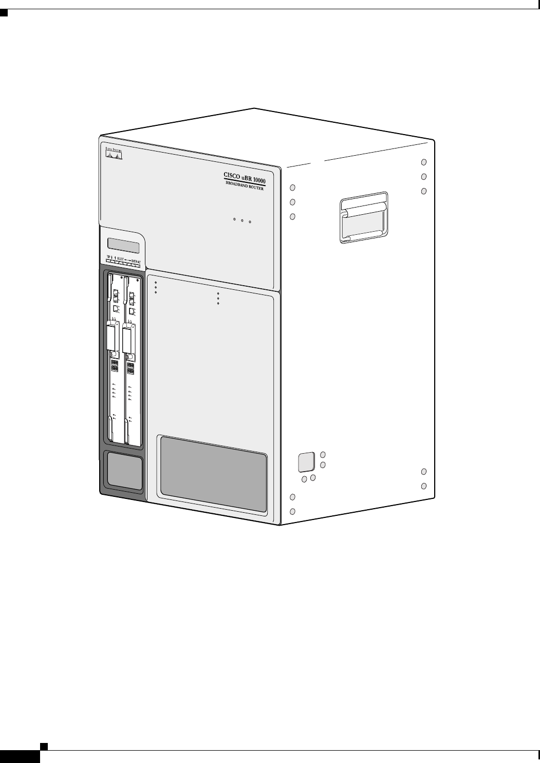
Figure 1-1 shows the front of the Cisco uBR10012 router with the front cover installed.
Figure 1-1 Cisco uBR10012 Universal Broadband Router—Front View with Front Cover
56300
POWER
MISWIRE
FAULT
POWER
MISWIRE
FAULT
ALARMS
CISCO
10000
FAIL
PERFORMANCE ROUTING ENGINE
CONSOLE
ST
A
TUS
ACO
CRITICAL
MINOR
MAJOR
ETHERNET
LINK
ACTIVITY
AUX
SLOT 0
SLOT 1
ALARMS
CISCO
10000
FAIL
PERFORMANCE ROUTING ENGINE
CONSOLE
ST
A
TUS
ACO
CRITICAL
MINOR
MAJOR
ETHERNET
LINK
ACTIVITY
AUX
SLOT 0
SLOT 1
IPSUM
IPSUM SANCT
IPSU SA TUS
1-9
Cisco uBR10012 Universal Broadband Router Hardware Installation Guide
Chapter 1 Cisco uBR10012 Universal Broadband Router Overview
Cisco uBR10012 Universal Broadband Router Hardware
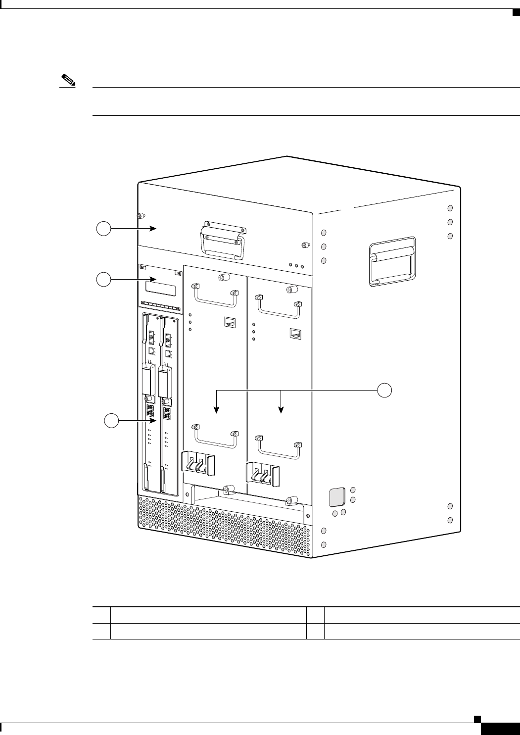
Figure 1-2 shows the front of a fully loaded chassis without the front cover.
Note Figure 1-2 is a sample representation of the Cisco uBR10012 chassis with the DC PEM
(UBR10-PWR-DC=) modules.
Figure 1-2 Cisco uBR10012 Router Chassis—Front View without the Front Cover
1Fan assembly module 3Two PRE modules
2LCD module 4Two DC PEM modules
ALARMS
CISCO
10000
FAIL
PERFORMANCE ROUTING ENGINE
CONSOLE
STATUS
ACO
CRITICAL
MINOR
MAJOR
ETHERNET
LINK
ACTIVITY
AUX
SLOT 0
SLOT 1
ALARMS
CISCO
10000
FAIL
PERFORMANCE ROUTING ENGINE
CONSOLE
STATUS
ACO
CRITICAL
MINOR
MAJOR
ETHERNET
LINK
ACTIVITY
AUX
SLOT 0
SLOT 1
88670
POWER
MISWIRE
FAULT
POWER
MISWIRE
FAULT
1
2
3
4
1-10
Cisco uBR10012 Universal Broadband Router Hardware Installation Guide
Chapter 1 Cisco uBR10012 Universal Broadband Router Overview
Cisco uBR10012 Universal Broadband Router Hardware
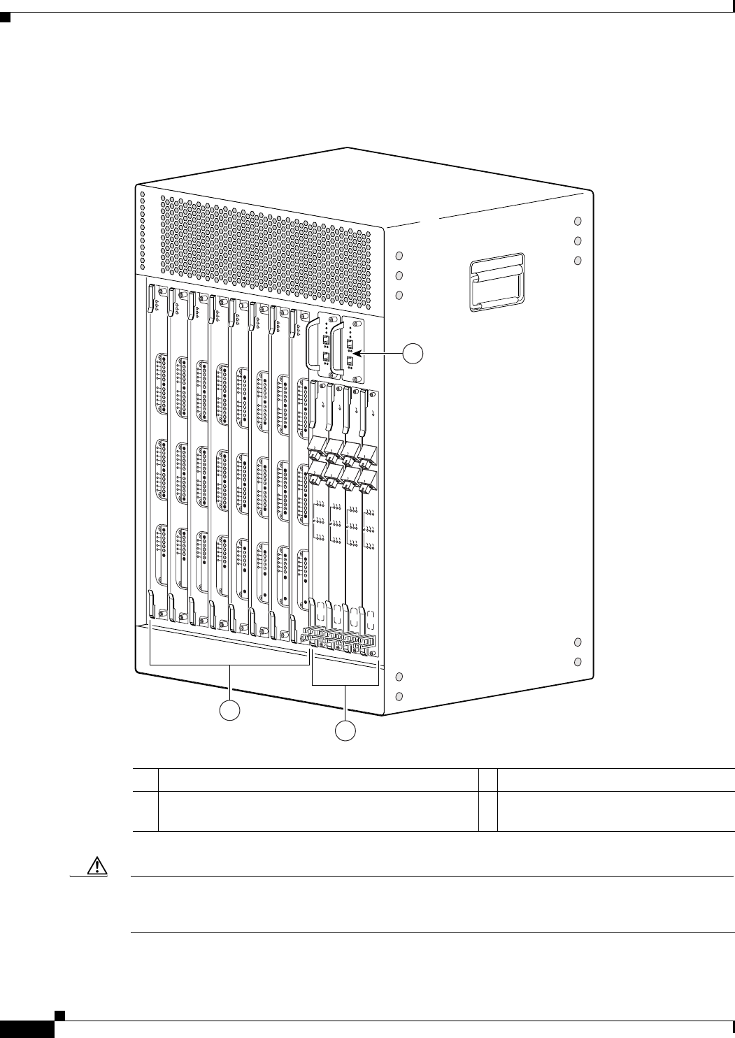
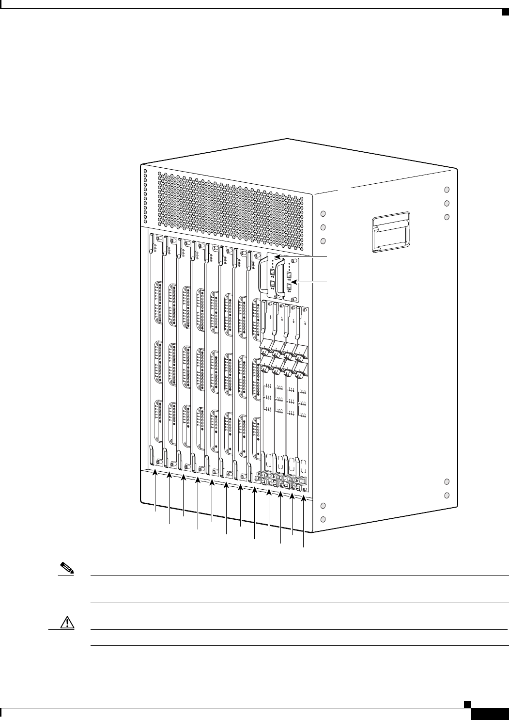
Figure 1-3 shows the rear of a fully-loaded Cisco uBR10012 router.
Figure 1-3 Cisco uBR10012 Router Chassis—Rear View
Caution The handles shown on the left and right sides of the chassis should be used only when lifting a
depopulated chassis that does not have any PEMs, fan assembly module, or line cards installed. See
“Chassis-Lifting Guidelines” for more information.
1Two TCC+ cards 3Eight cable interface line cards
2Four high-speed, high-performance network uplink
line cards (HHGE line cards not shown)
—
111008
US0
US1
US2
US3
US4
US5
US6
US7
US8
US9
US10
US11
US12
US13
US14
US15
US16
US17
US18
US19
DS0
DS1
DS2
DS3
DS4
RF
RF
RF
RF
RF
uBR10-MC5x20S-D
POWER
ST
ATUS
MAINT
US0
US1
US2
US3
US4
US5
US6
US7
US8
US9
US10
US11
US12
US13
US14
US15
US16
US17
US18
US19
DS0
DS1
DS2
DS3
DS4
RF
RF
RF
RF
RF
uBR10-MC5x20S-D
POWER
ST
ATUS
MAINT
US0
US1
US2
US3
US4
US5
US6
US7
US8
US9
US10
US11
US12
US13
US14
US15
US16
US17
US18
US19
DS0
DS1
DS2
DS3
DS4
RF
RF
RF
RF
RF
uBR10-MC5x20S-D
POWER
STA
TUS
MAINT
US0
US1
US2
US3
US4
US5
US6
US7
US8
US9
US10
US11
US12
US13
US14
US15
US16
US17
US18
US19
DS0
DS1
DS2
DS3
DS4
RF
RF
RF
RF
RF
uBR10-MC5x20S-D
POWER
STA
TUS
MAINT
US0
US1
US2
US3
US4
US5
US6
US7
US8
US9
US10
US11
US12
US13
US14
US15
US16
US17
US18
US19
DS0
DS1
DS2
DS3
DS4
RF
RF
RF
RF
RF
uBR10-MC5x20S-D
POWER
STATUS
MAINT
US0
US1
US2
US3
US4
US5
US6
US7
US8
US9
US10
US11
US12
US13
US14
US15
US16
US17
US18
US19
DS0
DS1
DS2
DS3
DS4
RF
RF
RF
RF
RF
uBR10-MC5x20S-D
POWER
ST
ATUS
MAINT
US0
US1
US2
US3
US4
US5
US6
US7
US8
US9
US10
US11
US12
US13
US14
US15
US16
US17
US18
US19
DS0
DS1
DS2
DS3
DS4
RF
RF
RF
RF
RF
uBR10-MC5x20S-D
POWER
STA
TUS
MAINT
US0
US1
US2
US3
US4
US5
US6
US7
US8
US9
US10
US11
US12
US13
US14
US15
US16
US17
US18
US19
DS0
DS1
DS2
DS3
DS4
RF
RF
RF
RF
RF
uBR10-MC5x20S-D
POWER
STATUS
MAINT
CISCO
10000
ENABLE
POS
SRP
FAIL
OC–48/STM–16 POS/SRP SM–LR
CD
TX
RX
SYNC
WRAP
P
ASS
THRU
TX
RX
CISCO
10000
ENABLE
POS
SRP
FAIL
OC–48/STM–16 POS/SRP SM–LR
CD
TX
RX
SYNC
WRAP
P
ASS
THRU
TX
RX
CISCO
10000
ENABLE
POS
SRP
FAIL
OC–48/STM–16 POS/SRP SM–LR
CD
TX
RX
SYNC
WRAP
P
ASS
THRU
TX
RX
CISCO
10000
ENABLE
POS
SRP
FAIL
OC–48/STM–16 POS/SRP SM–LR
CD
TX
RX
SYNC
WRAP
P
ASS
THRU
TX
RX
1
3
2
1-11
Cisco uBR10012 Universal Broadband Router Hardware Installation Guide
Chapter 1 Cisco uBR10012 Universal Broadband Router Overview
Cisco uBR10012 Universal Broadband Router Hardware
Cisco uBR10012 Router Slot Numbering
Figure 1-4 shows the slot numbering for the line cards and TCC+ cards in the rear of the chassis. The
Cisco uBR5X20S/U cable interface line cards are used in this Figure 1-4.
Figure 1-4 Cisco uBR10012 Chassis Slot Numbering—Rear View
Note Half-height Gigabit Ethernet (HHGE) line cards use slot 3 and slot 4 only. These cards are used with a
slot splitter that subdivides the slots so that they become slots 3/0/0, 3/0/1, and slots 4/0/0, 4/0/1.
Caution If you place a slot splitter and HHGE line card in slot 1/0 or slot 2/0, these slots shut down.
111007
US0
US1
US2
US3
US4
US5
US6
US7
US8
US9
US10
US11
US12
US13
US14
US15
US16
US17
US18
US19
DS0
DS1
DS2
DS3
DS4
RF
RF
RF
RF
RF
uBR10-MC5x20S-D
POWER
ST
ATUS
MAINT
US0
US1
US2
US3
US4
US5
US6
US7
US8
US9
US10
US11
US12
US13
US14
US15
US16
US17
US18
US19
DS0
DS1
DS2
DS3
DS4
RF
RF
RF
RF
RF
uBR10-MC5x20S-D
POWER
STA
TUS
MAINT
US0
US1
US2
US3
US4
US5
US6
US7
US8
US9
US10
US11
US12
US13
US14
US15
US16
US17
US18
US19
DS0
DS1
DS2
DS3
DS4
RF
RF
RF
RF
RF
uBR10-MC5x20S-D
POWER
STATUS
MAINT
US0
US1
US2
US3
US4
US5
US6
US7
US8
US9
US10
US11
US12
US13
US14
US15
US16
US17
US18
US19
DS0
DS1
DS2
DS3
DS4
RF
RF
RF
RF
RF
uBR10-MC5x20S-D
POWER
STA
TUS
MAINT
US0
US1
US2
US3
US4
US5
US6
US7
US8
US9
US10
US11
US12
US13
US14
US15
US16
US17
US18
US19
DS0
DS1
DS2
DS3
DS4
RF
RF
RF
RF
RF
uBR10-MC5x20S-D
POWER
STA
TUS
MAINT
US0
US1
US2
US3
US4
US5
US6
US7
US8
US9
US10
US11
US12
US13
US14
US15
US16
US17
US18
US19
DS0
DS1
DS2
DS3
DS4
RF
RF
RF
RF
RF
uBR10-MC5x20S-D
POWER
ST
ATUS
MAINT
US0
US1
US2
US3
US4
US5
US6
US7
US8
US9
US10
US11
US12
US13
US14
US15
US16
US17
US18
US19
DS0
DS1
DS2
DS3
DS4
RF
RF
RF
RF
RF
uBR10-MC5x20S-D
POWER
STATUS
MAINT
US0
US1
US2
US3
US4
US5
US6
US7
US8
US9
US10
US11
US12
US13
US14
US15
US16
US17
US18
US19
DS0
DS1
DS2
DS3
DS4
RF
RF
RF
RF
RF
uBR10-MC5x20S-D
POWER
ST
ATUS
MAINT
8/0 7/0 6/0 5/0
8/1 7/1 6/1 5/1 4/0
3/0 1/0
1/1
2/1
2/0
CISCO
10000
ENABLE
POS
SRP
FAIL
OC–48/STM–16 POS/SRP SM–LR
CD
TX
RX
SYNC
WRAP
P
ASS
THRU
TX
RX
CISCO
10000
ENABLE
POS
SRP
FAIL
OC–48/STM–16 POS/SRP SM–LR
CD
TX
RX
SYNC
WRAP
P
ASS
THRU
TX
RX
CISCO
10000
ENABLE
POS
SRP
FAIL
OC–48/STM–16 POS/SRP SM–LR
CD
TX
RX
SYNC
WRAP
P
ASS
THRU
TX
RX
CISCO
10000
ENABLE
POS
SRP
FAIL
OC–48/STM–16 POS/SRP SM–LR
CD
TX
RX
SYNC
WRAP
P
ASS
THRU
TX
RX
1-12
Cisco uBR10012 Universal Broadband Router Hardware Installation Guide
Chapter 1 Cisco uBR10012 Universal Broadband Router Overview
Cisco uBR10012 Universal Broadband Router Hardware
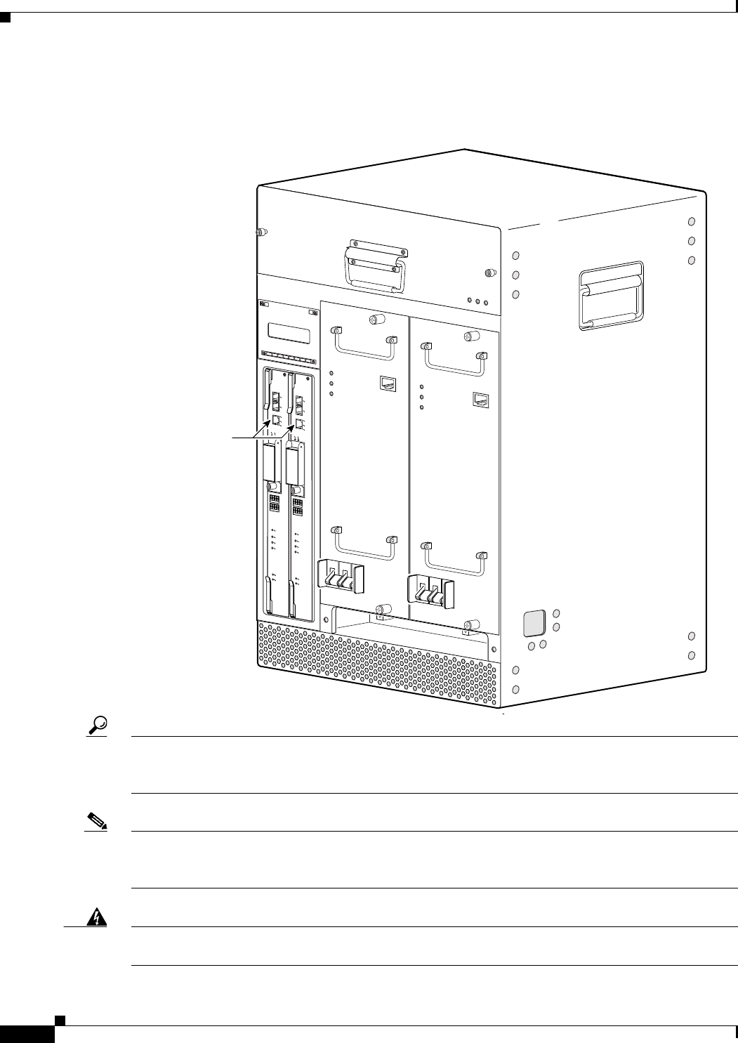
Figure 1-5 shows the slot numbering for the Fast Ethernet interface on the active PRE module.
Figure 1-5 Cisco uBR10012 Chassis Slot Numbering—Front View
Tip The Fast Ethernet interface on the backup PRE is not used unless the primary PRE fails and the backup
PRE is activated. When the backup PRE becomes the active PRE module, its Fast Ethernet interface
automatically becomes the active Fast Ethernet interface at slot 0/0.
Note The Cisco uBR10012 router also has an internal Ethernet interface, Ethernet 0/0/0, which PRE
processors and line cards use to transfer packets between cards. This interface is not user-configurable,
although you can see the configuration and run-time information using the show interface command.
Warning
Ultimate disposal of this product should be handled according to all national laws and regulations.
Statement 1040
FastEthernet slot 0/0
(on active PRE1)
56470
ALARMS
CISCO
10000
FAIL
PERFORMANCE ROUTING ENGINE
CONSOLE
ST
A
TUS
ACO
CRITICAL
MINOR
MAJOR
ETHERNET
LINK
ACTIVITY
AUX
SLOT 0
SLOT 1
ALARMS
CISCO
10000
FAIL
PERFORMANCE ROUTING ENGINE
CONSOLE
ST
A
TUS
ACO
CRITICAL
MINOR
MAJOR
ETHERNET
LINK
ACTIVITY
AUX
SLOT 0
SLOT 1
POWER
MISWIRE
FAULT
POWER
MISWIRE
FAULT

1-13
Cisco uBR10012 Universal Broadband Router Hardware Installation Guide
Chapter 1 Cisco uBR10012 Universal Broadband Router Overview
Cisco uBR10012 Universal Broadband Router Modules
Cisco uBR10012 Universal Broadband Router Modules
The following section describes the modules used in the Cisco uBR10012 router. For a list of field
replaceable units (FRUs) used in this chassis, see “Cisco uBR10012 Router FRU Resources”.
Fan Assembly Module
The Cisco uBR10012 chassis uses a fan assembly module containing fans to supply cooling air to the
chassis. The fan assembly connects to the chassis through a blind mate connector that plugs into the
cable assembly and then into the chassis backplane. The fan assembly modules can be identified by the
product part numbers. The fan assembly module supported on the Cisco uBR10012 chassis is:
•Fan Assembly Module (UBR10-FAN-ASSY=)
•Fan Assembly Module (UBR10012-FAN-PLUS=)
For information on installing, removing and replacing the fan assembly module, see Cisco uBR10012
Universal Broadband Router Fan Assembly Module.
AC Power Entry Modules
The Cisco uBR10012 router is shipped with two AC power entry modules (AC PEMs) that provide
power supply to the system. One AC PEM module is sufficient to provide power for a fully configured
chassis. However, if one AC PEM module fails, the other AC PEM module automatically begins
providing power to the entire chassis, without impacting the system operation.
The AC PEM modules use a standard 200–240 VAC (50 or 60 Hz) input power obtained through power
receptacles on the front panel of each PEM. The two AC PEMs convert the AC power to provide filtered,
redundant, and load shared DC power to the Cisco uBR10012 chassis. The AC PEM modules can be
identified by their product part numbers.
The AC PEM modules supported on the Cisco uBR10012 chassis are:
•AC PEM Module (UBR10-PWR-AC=)
•AC PEM Module (UBR10-PWR-AC-PLUS=)
For information on installing, removing and replacing the 2400 W AC PEM module, see AC Power Entry
Module for the Cisco uBR10012 Universal Broadband Router.
For information on installing, removing, replacing the 3300 W AC PEM module, and migrating from the
2400 W AC PEM to the 3300 W AC PEM, see 3300 W AC Power Entry Module for the Cisco uBR10012
Universal Broadband Router.
1-14
Cisco uBR10012 Universal Broadband Router Hardware Installation Guide
Chapter 1 Cisco uBR10012 Universal Broadband Router Overview
Cisco uBR10012 Universal Broadband Router Modules
DC Power Entry Modules
The Cisco uBR10012 router is shipped with two DC power entry modules (DC PEMs) that provide
power to the system. One DC PEM can provide sufficient power for a fully configured chassis. However,
if one DC PEM fails, the other automatically begins providing power to the entire chassis, without
impacting the system operation.
The two DC PEMs provide filtered, redundant, and load shared DC power to the
Cisco uBR10012 chassis. The DC PEM modules can be identified by their product part numbers.
The DC PEM modules supported on the Cisco uBR10012 chassis are:
•DC PEM Module (UBR10-PWR-DC=)
•DC PEM Module (UBR10-PWR-DC-PLUS=)
Table 4 summarizes the specifications of the DC PEM modules.
For information on installing, removing and replacing the 2400 W or the 3000 W DC PEM module, see
DC Power Entry Module for the Cisco uBR10012 Universal Broadband Router.
For information on installing, removing, replacing the 3300 W DC PEM module, and migrating from the
2400 W or the 3000 W DC PEM to the 3300 W DC PEM, see 3300 W DC Power Entry Module for the
Cisco uBR10012 Universal Broadband Router.
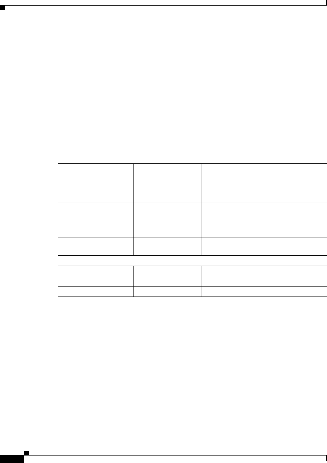
Table 4 Specifications of the DC PEM modules
Component UBR10-PWR-DC-PLUS= UBR10-PWR-DC=
Cisco DC PEM (Part
Number)1
1. The 34- part number is listed on compliance label of the DC PEM.
341-0388-01 34-1651-04 and
34-1651-05
34-1651-05
Power output 3300 W 2400 W 3000 W
DC-input Voltage –48 to –60 VDC
nominal
–48 to –60 VDC
nominal
–55 to –60 VDC nominal
DC-output Voltage
(nominal)
–57.5 V See footnote2
2. For the 34-1651-04 and 34-1651-05 DC PEM modules, the DC-output voltage varies according to the DC-input voltage with
a drop in voltage between 1 V and 1.85 V. The allowable DC-input range is -40.5 V to -72 V. The DC-output voltage is not
constant for these DC PEM modules. For the 341-0388-01 DC PEM module, the DC-output voltage is regulated and is
constant.
DC-input Current
Connections
50 A + 50 A 50 A 56 A
Physical Differences
LEDs 5 3 3
Weight 16 lbs (7.25 kg) 10 lbs (4.54 kg) 10 lbs (4.54 kg)
PRODUCT ID LED/switch Yes No No
1-15
Cisco uBR10012 Universal Broadband Router Hardware Installation Guide
Chapter 1 Cisco uBR10012 Universal Broadband Router Overview
Cisco uBR10012 Universal Broadband Router Modules
Supported External AC-Input Power Shelves
If 100–120 VAC is the only available power source at the facility, then use the external AC-input power
shelf with the Cisco uBR10012 router The AC-input power shelf converts AC power from an external
AC power supply source into DC power that is suitable for powering on the Cisco uBR10012 router.
The external power shelves supported on the Cisco uBR10012 router are:
•2400 W AC-Input Power Shelf
•Lineage AC-DC Power Shelf
Table 1-5 lists the specifications of the external power shelves on the Cisco uBR10012 chassis.
For information about the 2400 W AC-input power shelf, see the 2400 W AC-Input Power Shelf for the
Cisco uBR10012 Universal Broadband Router at the following URL:
We recommend you use the external Lineage AC-DC power shelf in conjunction with the
Cisco uBR10012 router chassis. For an overview of the Lineage AC-DC power shelf, see the “Lineage
AC-DC Power Shelf” section on page 1-15. For information on connecting the Lineage AC-DC power
shelf with the Cisco uBR10012 router, see “Connecting the External AC-input Power Shelf to the
Cisco uBR10012 Router” section on page 3-28.
Table 1-6 lists the number of Lineage power shelves that are required to supply power to the DC PEM
modules.
For information on installation, power shelf safety features, safety warnings, and troubleshooting the
Lineage power shelf, see the product documentation available at http://www.lineagepower.com/.
Lineage AC-DC Power Shelf
This external AC-DC power shelf from Lineage (part number J85480S1 L30) with AC module
(CP2000AC54PE) is 1-rack unit high (1.75 inch) and can be mounted on a standard 19-inch 4-post
equipment rack or telco-type rack. We recommend installing the Lineage power shelf in the rack in a
Table 1-5 Supported External Power Shelves for Cisco uBR10012 Router Specifications
Lineage AC-DC Power Shelf 2400 W AC-Input Power Shelf
Part Number J85480S1 L301UBR10-PWR-AC-EXT
Output Power supplied to the
Cisco uBR10012 chassis 3300 W 2400 W
DC Output Voltage -54 V -54 V
1. For more information on ordering the Lineage kit, see Table D-6.
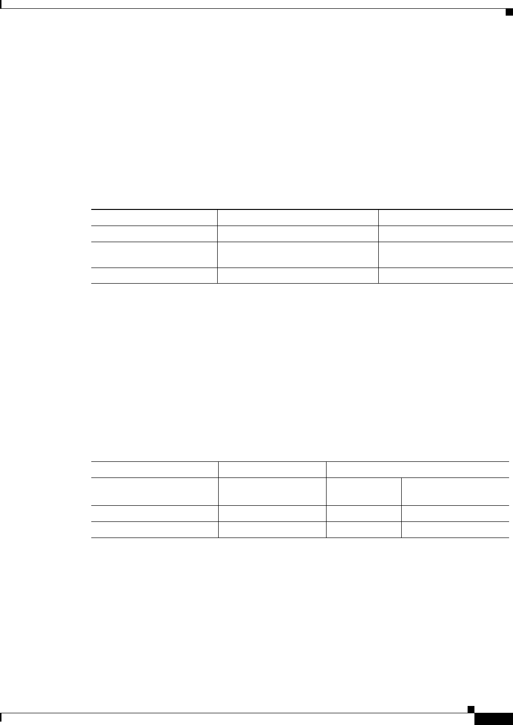
Table 1-6 Cisco uBR10012 Router DC PEM Modules and Lineage Shelves
Component UBR10-PWR-DC-PLUS= UBR10-PWR-DC=
Cisco DC PEM (Part
Number)1
1. The 34- part number is listed on the compliance label of the DC PEM.
341-0388-01 34-1651-04 and
34-1651-05
34-1651-05
Power Output 3300 W 2400 W 3000 W
No. of Lineage Shelves 2 1 1
1-16
Cisco uBR10012 Universal Broadband Router Hardware Installation Guide
Chapter 1 Cisco uBR10012 Universal Broadband Router Overview
Cisco uBR10012 Universal Broadband Router Modules
way that the power connections reside facing inside the rack when viewed from the front. This allows
the DC output terminals of the external AC-input power shelf to be on the same side as the DC-input
terminals of the Cisco uBR10012 chassis.
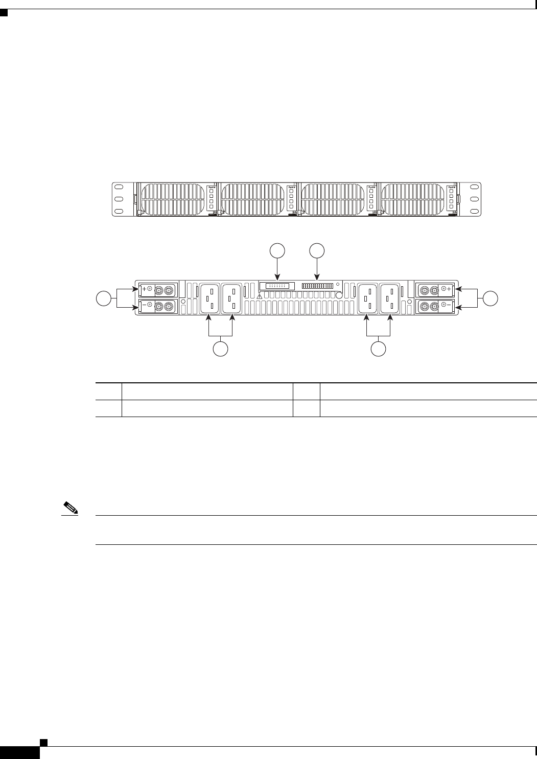
The Lineage AC-DC power shelf has two DC power sources, four AC-input power supply sources, and
J1 and J2 connectors. Each AC-input power supply module is automatically powered on when it is
plugged into the wall socket. (See Figure 1-6).
Figure 1-6 Lineage AC-DC Power Shelf - Front and Rear View
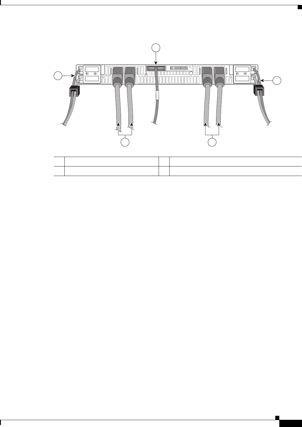
All cable connections for AC-input power, DC-output power, and status signals are made from the rear
of the power shelf. Each AC power supply module has an individual AC facility cord attachment. All
four AC-input cords must be attached to the facility for all four AC power modules to function. Two
DC-interconnect cables provide DC-output power to the DC PEM (UBR10-PWR-DC=) modules on the
Cisco uBR10012 chassis. (See Figure 1-7).
Note The AC-input power cables, DC-output power cables, and alarm monitor cable are supplied along with
Lineage. We recommend that you use these cables for cabling the shelf to the Cisco uBR10012 router.
278055
3 4
2 2
11
Front view
Rear view
1DC power source terminal blocks 3J2 connector
2AC input power connectors 4J1 connector / alarm cable interface
1-17
Cisco uBR10012 Universal Broadband Router Hardware Installation Guide
Chapter 1 Cisco uBR10012 Universal Broadband Router Overview
Cisco uBR10012 Universal Broadband Router Modules
Figure 1-7 Rear View of the Lineage AC-DC Power Shelf with Cables
To meet compliance standards, use the DC power cables (3 m cable supplied along with Lineage power
shelf), while cabling the Lineage AC-DC power shelf to the Cisco uBR10012 chassis. Ensure proper
rating and fit in the chassis when connecting the cables into the input DC terminal block on the backplane
of the Cisco uBR10012 chassis.
To meet the Class A emission compliance requirements, ferrite beads must be used with Lineage AC-DC
power shelf when used to power on the Cisco uBR10012 router. For information on ferrite beads, see
“Attaching Ferrite Beads on DC Power Cables” section on page 3-23.
For information on connecting the Lineage power shelf see, Connecting the External AC-input Power
Shelf to the Cisco uBR10012 Router, page 3-28.
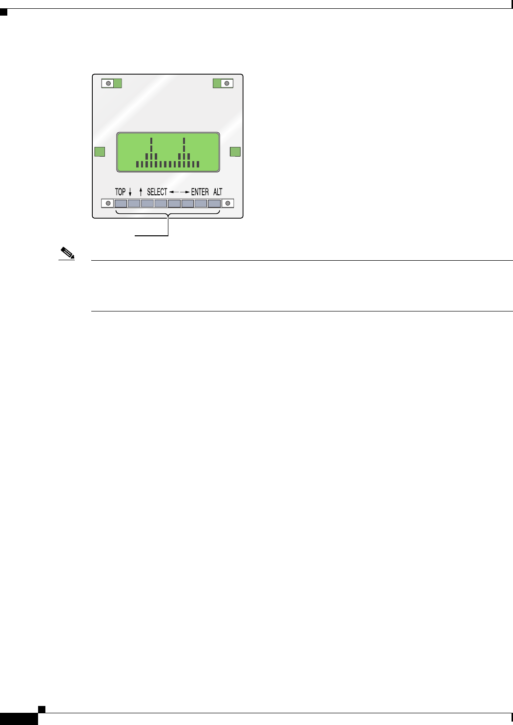
LCD Module
The LCD module provides real-time operating status and configuration information for the chassis and
line cards. The buttons below the screen provide a menu system that allows you to display different parts
of the system configuration without using a terminal. Figure 1-8 shows the Cisco LCD module without
the chassis front cover.
1DC power supply cables 3Alarm monitor cable
2AC power supply cables —
278056
3
1
1
22
1-18
Cisco uBR10012 Universal Broadband Router Hardware Installation Guide
Chapter 1 Cisco uBR10012 Universal Broadband Router Overview
Cisco uBR10012 Universal Broadband Router Modules
Figure 1-8 LCD Module Display Panel
Note The LCD module functions depend on the release of the Cisco IOS software running on your
Cisco uBR10012 router. Refer to the release notes for the Cisco IOS release you are using, and the
Cisco uBR10012 Software Configuration Guide, for details. See the “Obtaining Documentation and
Submitting a Service Request” section on page xvi.
62391
Keypads
1-19
Cisco uBR10012 Universal Broadband Router Hardware Installation Guide
Chapter 1 Cisco uBR10012 Universal Broadband Router Overview
Cisco uBR10012 Universal Broadband Router Modules
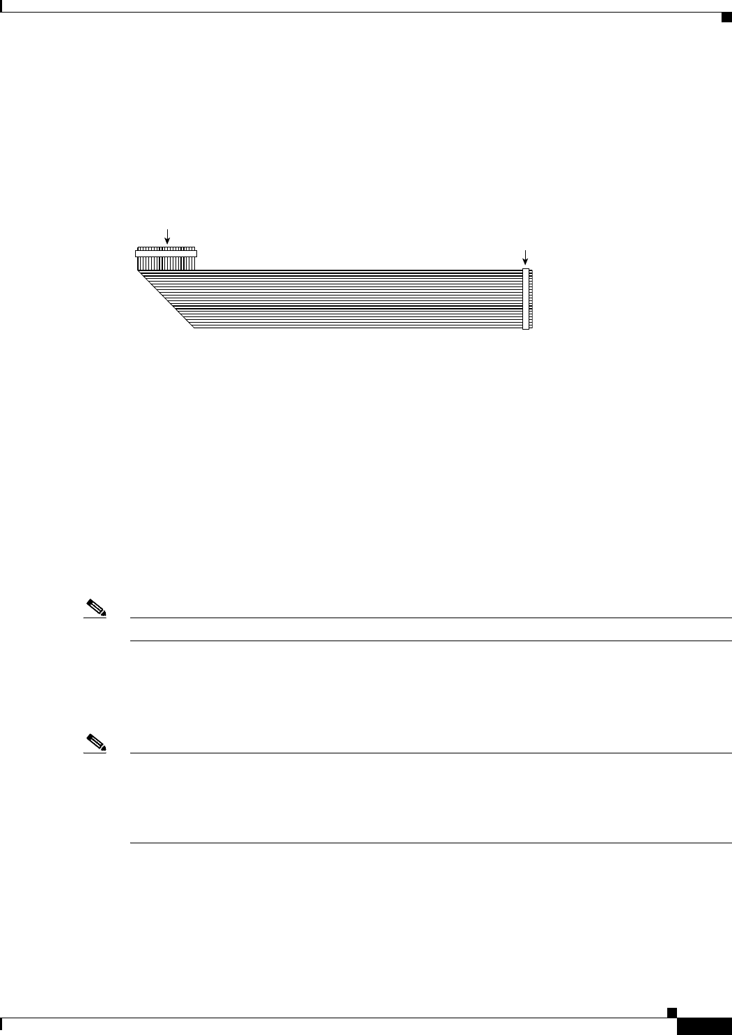
LCD Cable
The LCD ribbon cable connects the LCD module to the backplane. The folded end is connected to the
LCD module. See Figure 1-9.
Figure 1-9 LCD Cable
Performance Routing Engine
There are four models of PREs, the original PRE module that was initially shipped with the
Cisco uBR10012 router, the PRE1 module that began shipping with Cisco IOS Release 12.2(4)XF, the
PRE2 module that is shipping with Cisco IOS Release 12.3(9)BC, and the PRE4 module that is shipping
with Cisco IOS Release 12.2(33)SB.
•PRE1 functionality was introduced in Cisco IOS Release 12.2(4)XF.
•PRE2 functionality was introduced in Cisco IOS Release 12.3(9a)BC.
•PRE4 functionality was introduced in Cisco IOS Release 12.2(33)SCB.
You can use the CLI show version command to determine whether a PRE, PRE1, PRE2, or PRE4
module is installed in your system.
Note The PRE3 is not supported on the Cisco uBR10012 router
The PRE is a single-slot module used with the Cisco uBR10012 routers. The PRE performs all Layer 2
and Layer 3 packet routing and forwarding using an advanced parallel processing architecture called
Parallel eXpress Forwarding (PXF). This process separates the control plane from the data plane. The
PXF architecture supports high-performance throughput with IP services enabled on every port.
Note When replacing a PRE1 module with a PRE2 module, you must also install EMI gaskets and RF absorber
material. For more information, go to the following URL:
http://www.cisco.com/en/US/docs/cable/cmts/ubr10012/installation/field_replaceable_units/pre2gkit.h
tml
PRE Modules and PRE1 Modules
PRE1 modules support error checking and correction (ECC) for all onboard memory, replacing the
simpler parity error algorithm of the original PRE module. A general-purpose RISC processor (262–300
MHz MIPS RISCMark RM7000) support high performance Layer 3 forwarding of traffic. The
62395
LCD module
end Back plane
end
Fold

1-20
Cisco uBR10012 Universal Broadband Router Hardware Installation Guide
Chapter 1 Cisco uBR10012 Universal Broadband Router Overview
Cisco uBR10012 Universal Broadband Router Modules
combination of a general purpose RISC processor with advanced programmable PXF network
processors provides the capacity to support the aggregation of thousands of active connections in a single
Cisco uBR10012 chassis when supporting IP applications such as access policy filtering, rate-based
queuing, and QoS.
PRE2 Modules
PRE2 modules are designed to address Internet service provider (ISP) requirements. The PRE2 has four
PFX network processors (containing 64 individual processors) with two independent 32-MB SDRAM
control memories on each processor set. The PRE2 provides 6.2 Mpps of processing power and has a
500-MHz RM 7000 mips processor with integrated 16-KB data and 16-KB instruction Level 1 caches,
an integrated 256-KB Level 2 cache, and a 4-MB Level 3 cache.
Cisco IOS Release 12.3(9a)BC automatically enables the following features:
•Route Processor Redundancy Plus (RPR+)
•6.2 mpps processing power
•Software features available with PRE2 and Cisco IOS Release 12.3(9a)BC:
–
EtherChannel
–
TLS 802.1q
–
NetFlow
PRE4 Modules
The Performance Routing Engine 4 (PRE4) is the fifth-generation Parallel Express Forwarding (PXF)
packet processing and scheduling engine for the Cisco uBR10012 router.
PRE4 enhances the performance capability of the Cisco uBR10012 router to 10 Mpps by providing
increased density Gigabit Ethernet (GE) and higher throughput of the 10GE SPA interface.
The PRE4 runs Cisco IOS Release 12.2(33)SCB and later releases. Benefits of the PRE4 include:
•800-MHz dual processor
•64 PXF network processors arranged as 8 columns and 8 rows
•512-MB packet buffer and 128-MB control memory with error-correcting code
•4-GB ECC-protected Route Processor (RP) memory
•10 million packets per second (Mpps) forwarding performance through the PXF complex
•5.6-Gbps backplane bandwidth for each full-height backplane slot
•11.2 Gbps backplane bandwidth to each SPA interface processor (SIP)
•Maximum transmission unit (MTU) support of 9216 bytes
•An external CompactFlash Disk slot (disk0)
•A 100/1000 Megabit Ethernet interface for communication between redundant PRE4s
Note Unless otherwise indicated, all references in this document to the PRE refer to the PRE, the PRE1, the
PRE2, or the PRE4 modules. The PRE is now end-of-life (EOL) and is replaced by the PRE1, PRE2, or
PRE4.
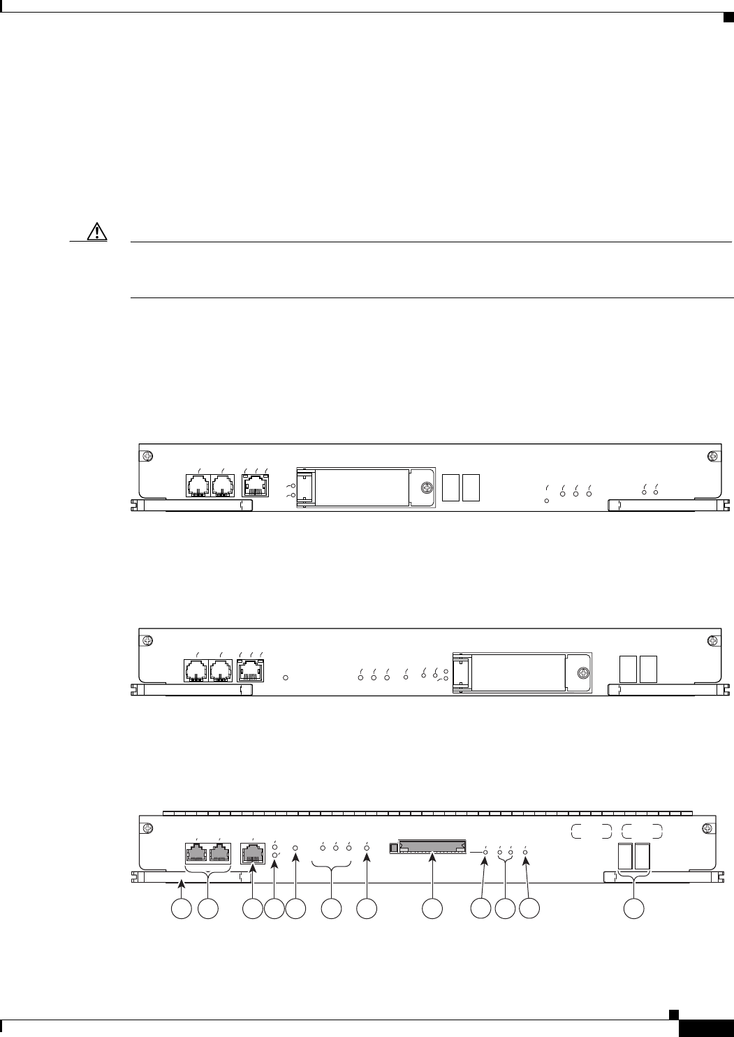
1-21
Cisco uBR10012 Universal Broadband Router Hardware Installation Guide
Chapter 1 Cisco uBR10012 Universal Broadband Router Overview
Cisco uBR10012 Universal Broadband Router Modules
Redundant PRE Modules
The PRE module supports redundant operation (two PRE modules in a Cisco uBR10012 chassis). If the
primary PRE fails, the secondary PRE automatically takes over operation of the chassis. Because all
Cisco uBR10012 line cards are physically connected to both the primary and secondary PRE modules,
a switchover of PRE modules does not require human intervention to reset the line cards, as they
automatically fail over to the redundant PRE. The PRE module is hot-swappable if there is a redundant
PRE module in the chassis.
Caution You cannot use different models of the PRE in the same chassis. If you have PRE2 modules and you wish
to upgrade, you must upgrade both of your PREs to the PRE4s. You cannot use a PRE1 or a PRE2 and
a PRE4 in the same system.
PRE Module Description
The PRE1 contains two PC media card two slots and 64 MB of onboard flash memory. Figure 1-10
shows the PRE 1 faceplate.
Figure 1-10 PRE1 Faceplate
The PRE2 contains two PC media card slots and 128 MB of onboard flash memory. Figure 1-11 shows
the PRE2 faceplate.
Figure 1-11 PRE2 Faceplate
The PRE4 contains a CompactFlash Disk slot (disk0) and 128 MB of onboard flash memory. Figure 1-12
shows the PRE4 faceplate.
Figure 1-12 PRE4 Faceplate
87430
CISCO
10000
ALARMS
FAIL
CONSOLE
STATUS
ACO
CRITICAL
MINOR
MAJOR
ETHERNET
LINK
ACTIVITY
AUX
SLOT 0
SLOT 1
PERFORMANCE ROUTING ENGINE ESR-PRE1
76995
PERFORMANCE ROUTING ENGINE ESR-PRE2
ALARMS
CISCO
10000
FAIL
STATUS
ACO
CRITICAL
MINOR
MAJOR
ETHERNET
LINK
ACTIVITY
CONSOLE
AUX
SLOT
1
0
211327
PERFORMANCE ROUTING ENGINE
ALARMS
CISCO
10000
ACTIVITY
LINK
CRITICAL
MAJOR
MINOR
ACO
SLOT 0
STATUS
FAIL
BITS
ETHERNET
AUX
CONSOLE
P/N ESR-PRE4
1 3 7 8 9
2 106 12
11
54

1-22
Cisco uBR10012 Universal Broadband Router Hardware Installation Guide
Chapter 1 Cisco uBR10012 Universal Broadband Router Overview
Cisco uBR10012 Universal Broadband Router Modules
Connector Ports
The faceplate on the PRE contains three ports with RJ-45 connectors:
•Console port—This asynchronous EIA/TIA-232 serial port is used to connect a terminal to the PRE
for local administrative access.
•Auxiliary port (AUX)—This asynchronous EIA/TIA-232 serial port is used to connect a modem to
the PRE for remote administrative access.
•Fast Ethernet port—This Fast Ethernet port is used to connect the PRE to a 10/100Base-T network
management LAN.
Note The Fast Ethernet interface on the PRE module is intended for network management access
and should not be used for WAN connectivity purposes. For WAN connections, use the
appropriate network uplink cards, which take full advantage of the system's
high-performance PXF processing subsystem.
PC Media Card Slots
Two PC media card slots (one CompactFlash Disk slot for the PRE4) can store the Cisco IOS image or
a system configuration file on a PC media card or CompactFlash Disk. The system can also boot from
the software stored on the PC media card or CompactFlash Disk. The PC media card slots support Type
I or Type II cards. See the “Removing and Installing a PC Media Card” section on page 16 for more
information about inserting and removing PC media cards from the PRE.
LCD Screens
The two LCD screens below the PC media card slots display alphanumeric information about the status
of the of the PRE module.
PRE LED Indicators and Buttons
LEDs on the faceplate of the PRE provide a visual indication of the status of PRE operation (see
Figure 1-10). The LEDs are separated into three categories: alarms, status, and failure.
•ALARM—Alarm relay contacts on the Cisco uBR10012 router connect the router to a site alarm
maintenance system. This allows critical, major, and minor alarms generated by the
Cisco uBR10012 router to be displayed on the PRE faceplate and also translated to external visual
or audible alarms connected to the system. See the “Connecting Alarm Indicators” section on
page 3-41 for more information about alarm connections. Pressing the alarm cutoff (ACO) button
1Ejector levers 7ACO (Alarm Cut-off) button
2Console and Auxiliary ports 8CompactFlash Disk slot, disk0
3Network Management Ethernet (NME) port 9Slot 0 (disk0) LED
4NME Activity and Link LEDs 10 Status, Fail LEDs
5Reset button 11 Building Internal Timing Source (BITS) LED
6Alarms: Critical, Major, Minor LEDs 12 Alphanumeric display

1-23
Cisco uBR10012 Universal Broadband Router Hardware Installation Guide
Chapter 1 Cisco uBR10012 Universal Broadband Router Overview
Cisco uBR10012 Universal Broadband Router Modules
on the (primary) PRE during an alarm condition shuts off the external alarm, but does not deactivate
the alarm LEDs on the PRE faceplate. Alarm LEDs on the faceplate are deactivated only after the
condition that caused the alarm is corrected.
•STATUS—Indicates the status of the PRE.
•FAIL—Indicates that a major failure has disabled the PRE.
Table 1-7 describes the LEDs and switch on the PRE.
PRE Module Disposal
The PRE module contains a small lithium battery. Some jurisdictions restrict the ways in which you can
dispose of items containing lithium batteries. In particular, never dispose of lithium batteries or products
containing lithium batteries in an unregulated fire. Other restrictions might apply in your area.
Warning
Ultimate disposal of this product should be handled according to all national laws and regulations.
Statement 1040.
Table 1-7 Cisco PRE LEDs and Cutoff Switch
LEDs/Switch Status Description
ACTIVITY Green Packets are being transmitted and received.
Off No packet activity.
LINK Green Carrier detected; the port is able to pass traffic.
Off No carrier detected; the port is not passing traffic.
Reset button – Resets the PRE4.
Alarm cutoff (ACO) button – Pressing this button disables an audible alarm.
CRITICAL, MAJOR, and
MINOR LEDs
Off No alarm.
Yellow Alarm condition.
STATUS Green PRE is ready and active as the primary PRE.
Off No power to the PRE or the PRE is acting as the secondary PRE.
Flashing
Yellow
System is booting.
Flashing Green PRE4 is standby.
FAIL Off PRE is operating properly.
Yellow A major failure has disabled the PRE.
CompactFlash slot 0 Green Disk0 is active.
PC media card slot 0 Green Flash card in Slot 0 is active1.
1. The Cisco uBR10012 router supports PCMCIA flash memory cards of 64 MB or above.
PC media card slot 1 Green Flash card in Slot 1 is active.
BITS Green BITS input to the PRE is configured and functioning normally.
Yellow BITS input to the PRE is configured, but not functional. For example,
the framer may have detected a Loss of Signal (LOS).
Off BITS input to the PRE4 is not configured.

1-24
Cisco uBR10012 Universal Broadband Router Hardware Installation Guide
Chapter 1 Cisco uBR10012 Universal Broadband Router Overview
Cisco uBR10012 Universal Broadband Router Modules
SIP and SPA Compatibility
The Cisco uBR10012 router currently supports the following SIPs:
•Cisco Wideband SIP for the Cisco Wideband SPA
Note Effective with Cisco IOS Release 12.2(33)SCH, the Cisco Wideband SIP is not supported on the
Cisco uBR10012 router.
•Cisco 10000 Series SPA Interface Processor-600
The Cisco Wideband SIP can support up to two Cisco Wideband SPAs. The Cisco uBR10012 router can
support up to eight SPAs. For more information about the introduction of support for different SIPs and
SPAs, refer to the Cisco uBR10012 Universal Broadband Router SIP and SPA Software Configuration
Guide at the following location:
http://www.cisco.com/en/US/docs/interfaces_modules/shared_port_adapters/configuration/ubr10012/1
2.3_23_bc/sipsp_d3.html
Timing, Communication, and Control Plus Card
On the Cisco uBR10012 router, the Timing, Communication, and Control Plus (TCC+) card acts as a
secondary processor that performs the following functions:
•Generates and distributes 10.24 MHz clock references to each of the cable interface line cards.
•Generates and distributes 32-bit time-stamp references to each of the cable interface line cards.
•Allows software to power off independently any or all of the cable interface line cards.
•Drives the LCD module used to display system configuration and status information.
•Monitors the supply power used by the chassis.
•Provides two redundant RJ-45 ports for external timing clock reference inputs such as a Global
Positioning System (GPS) or building integrated timing supplies (BITS) clock.
When two TCC+ cards are installed, they are configured as active and backup (redundant). If the TCC+
card in the first slot is working at system power-up, it automatically becomes the active card and the
TCC+ card in the second slot becomes the backup card. The TCC+ cards monitor each other’s priority
information so that if the active card fails, the active card role is transferred to the redundant backup card
without lose of data.
Figure 1-13 shows the faceplate of the TCC+ card. The handle provides for the insertion and removal of
the card from the chassis.
Caution Do not attempt to lift the chassis using one of these handles.
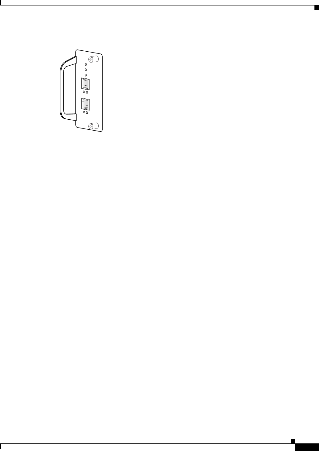
1-25
Cisco uBR10012 Universal Broadband Router Hardware Installation Guide
Chapter 1 Cisco uBR10012 Universal Broadband Router Overview
Cisco uBR10012 Universal Broadband Router Modules
Figure 1-13 TCC+ Card Faceplate
The faceplate on the TCC+ card has seven LEDs labeled POWER, STATUS, MAINT, PRESENT, and
ACTIVE. Separate PRESENT and ACTIVE LEDs are associated with the primary and secondary
external clock reference inputs.
For more information, see Cisco uBR10012 Universal Broadband Router TCC+ Card.
56418
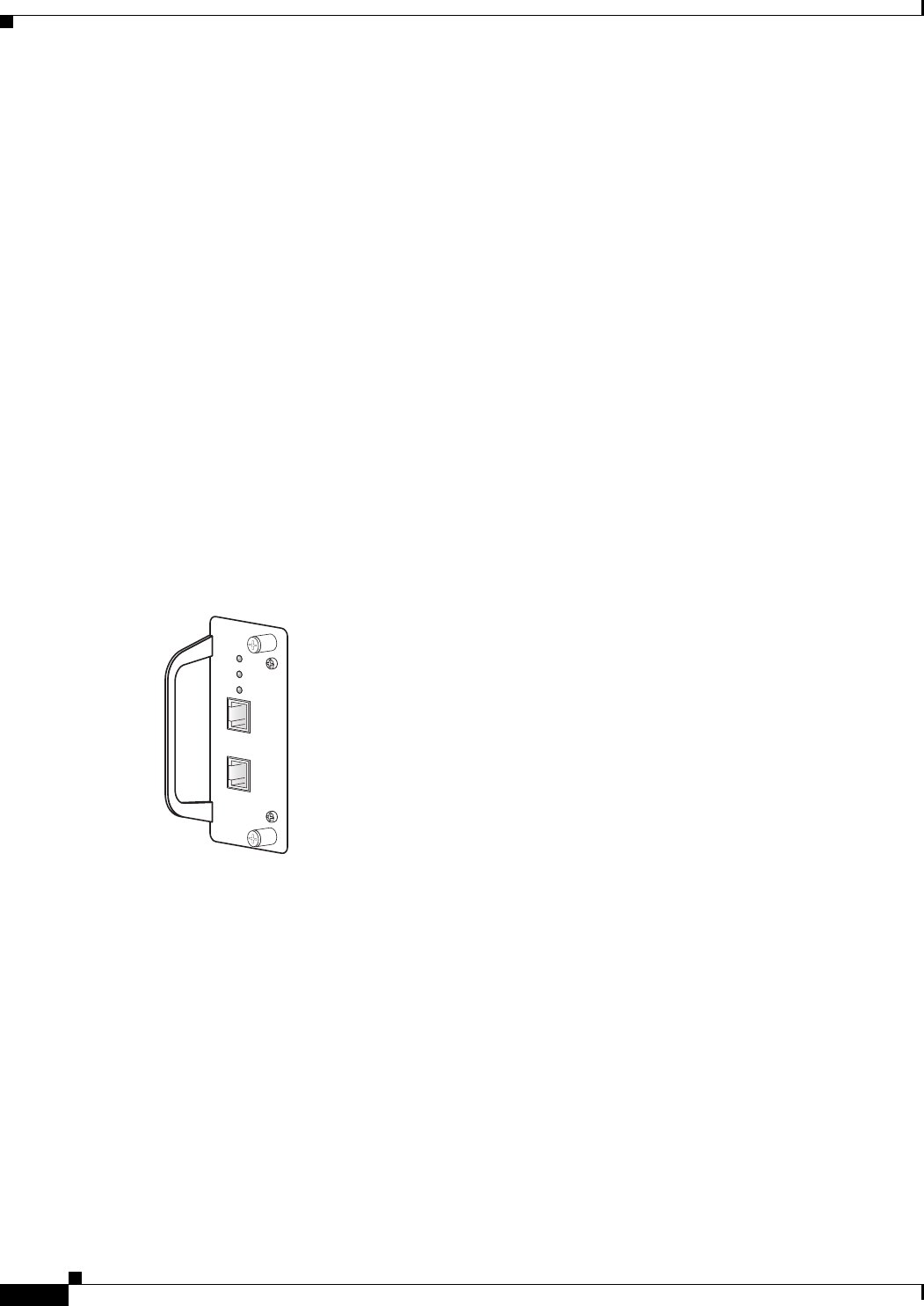
1-26
Cisco uBR10012 Universal Broadband Router Hardware Installation Guide
Chapter 1 Cisco uBR10012 Universal Broadband Router Overview
DOCSIS Timing, Communication, and Control Card
DOCSIS Timing, Communication, and Control Card
On the Cisco uBR10012 universal broadband router, the DTCC card acts as a secondary processor that
performs the following functions:
•In the default DTI mode, a 10.24 MHz clock and 32-bit DOCSIS timestamp are generated by the
DTI Server, propagated to DTI client using DTI protocol, and distributed by DTI client to each cable
interface line card.
•Allows software to independently power off any or all cable interface line cards.
•Drives the LCD panel used to display system configuration and status information.
•Monitors the supply power usage of the chassis.
•Two RJ-45 cables with the DTI server, which, in turn, can generate the clock using its own oscillator
or external timing reference inputs such as GPS or network clock.
Two DTCC cards are installed and configured as active (primary) and backup (redundant). If the DTCC
card in the first slot is working at system power-up, it automatically becomes the active card and the
DTCC card in the second slot becomes the backup card. The DTCC cards monitor each other’s priority
information, so that if the active card fails, the active card role is transferred to the redundant backup
card without loss of data.
Figure 1-13 shows the faceplate of the DTCC card.
Figure 1-14 Cisco DTCC Front Panel
The front panel on the DTCC card has seven LEDs. They are labeled POWER, STATUS,
MAINTENANCE, PRESENT, and ACTIVE. The second set of PRESENT and ACTIVE LEDs are
associated with the primary and secondary external clock reference inputs.
For more information, see Cisco uBR10012 Universal Broadband Router DTCC Card.
231862
POWER
STATUS
MAINT
uBR10-DTCC
ACT
DTI2
LNK
ACT
DTI1
LNK

1-27
Cisco uBR10012 Universal Broadband Router Hardware Installation Guide
Chapter 1 Cisco uBR10012 Universal Broadband Router Overview
Cable Interface Line Cards
Cable Interface Line Cards
The following section describes the cable interface line cards used in the Cisco uBR10012 universal
broadband router.
•Cisco uBR-MC5X20S/U/H Cable Interface Card, page 1-27
•Cisco UBR-MC20X20V Cable Interface Card, page 1-28
•Cisco uBR-MC3GX60V Cable Interface Card, page 1-28
•Cisco uBR-MC3GX60V-RPHY Cable Interface Card, page 1-28
Cisco uBR-MC5X20S/U/H Cable Interface Card
The Cisco uBR10-MC5X20S, U and H cable interface line cards are 20 by 16 inch cards designed
specifically for the Cisco uBR10012 router. These cards transmit and receive RF signals between the
subscriber and the headend over hybrid fiber-coaxial (HFC) system.
Upstream data, from the subscriber, comes through the upstream ports (US0-US19) on the Cisco
uBR10-MC5X20S/U/H cable interface line card. The line card processes and configures the data and
sends it across the backplane to the WAN/backhaul card and out to the Internet.
Downstream data, to the subscriber, comes from the Internet through the WAN/backhaul card, and across
the backplane to the Cisco uBR10-MC5X20S/U/H cable interface line card. The Cisco
uBR10-MC5X20S/U/H card processes and configures the data and sends it out through the appropriate
downstream port (DS0-DS4) to be combined with the rest of the downstream signals in the headend.
The Cisco uBR10-MC5X20S/U line cards use burst receivers that report unequalized Modulation Error
Ratio (MER). The Cisco uBR10-MC5X20H line cards use burst receivers that report equalized MER.
Equalized MER will almost always be at least a few decibels (dB) higher than an unequalized MER
measurement of the same signal under identical conditions.
Cisco uBR10-MC5X20S
The Cisco uBR10-MC5X20S cable interface line card supports downstream and upstream traffic over
Data-over-Cable Service Interface Specification (DOCSIS)-based cable modem networks. The card
supports downstream channels in the 70 to 860 MHz range, and upstream channels in the 5 to 42 MHz
range. Each downstream port includes an onboard integrated upconverter. The Cisco uBR10-MC5X20S
cable interface line card supports Annex B radio frequency (RF) data rates, channel widths, and
modulation schemes and has DOCSIS MAC management and spectrum management capabilities.
DOCSIS 2.0, Asynchronous Time Division Multiple Access (A-TDMA) rates are also supported.
Cisco uBR10-MC5X20U and H
The Cisco uBR10-MC5X20U/H cable interface line card supports both DOCSIS and EuroDOCSIS cable
modem networks. The card supports downstream channels in the 70 to 860 MHz range, and upstream
channels in the 5 to 65 MHz range. Each downstream port includes an onboard integrated upconverter.
The Cisco uBR10-MC5X20U/H cable interface line card supports Annex B and Annex A radio
frequency (RF) data rates, channel widths, and modulation schemes and has DOCSIS MAC management
and spectrum management capabilities. DOCSIS 2.0, A-TDMA rates are also supported.
For more information, see Cisco uBR10-MC5X20S/U/H Cable Interface Line Card Hardware
Installation Guide.

1-28
Cisco uBR10012 Universal Broadband Router Hardware Installation Guide
Chapter 1 Cisco uBR10012 Universal Broadband Router Overview
Cable Interface Line Cards
Cisco UBR-MC20X20V Cable Interface Card
The Cisco UBR-MC20X20V cable interface line card is a 20 by 16 inch card designed specifically for
the Cisco uBR10012 universal broadband router. This card transmits and receives RF signals between
the subscriber and the headend over hybrid fiber-coaxial (HFC) system. It has five downstream (DS)
ports and twenty upstream (US) ports. The line card supports five cable MAC domains (cable interfaces),
and the 20 DS and 20 US channels are dynamically associated with any of these five MAC domains. The
card has twenty US spigots and five DS spigots. Each of the US spigots supports either two-frequency
stacked US channels across ten ports or a single US channel across twenty ports. Each of the DS spigots
supports four-frequency stacked channels across five ports.
Note You must ensure that two DOCSIS Timing, Communication and Control (DTCC) cards are configured
on the Cisco uBR10012 router before installing the Cisco UBR-MC20X20V cable interface line card.
For more information, refer to Cisco UBR-MC20X20V Cable Interface Line Card Hardware Installation
Guide.
Cisco uBR-MC3GX60V Cable Interface Card
The Cisco uBR-MC3GX60V cable interface line card is a DOCSIS 3.0 compliant line card designed
specifically for the Cisco uBR10012 universal broadband router. This line card conforms to the Modular
CMTS (M- CMTS) architecture and has the capacity to support up to 72 downstream (DS) and 60
upstream (US) channels.
The Cisco uBR-MC3GX60V cable interface line card has 20 US spigots for RF connectivity, which are
organized into 5 groups of 4 connectors each. Each connector group supports up to 12 frequency-stacked
US channels, with a default configuration of 3 US channels per RF connector.
The Cisco uBR-MC3GX60V cable interface line card has six Gigabit Ethernet (GE) interface ports
organized into three pairs for DS connectivity. Each pair supports 1+1 redundancy and supports 24 DS
channels in Annex B mode by default. The GE interfaces connect to an external Edge Quadrature
Amplitude Modulation (EQAM) device and provide M-CMTS compliant Downstream External PHY
Interface (DEPI) data.
Another unique feature of the Cisco uBR-MC3GX60V cable interface line card is the use of a front panel
display (FPD) to show the licensing status information of the US and DS channels.
For detailed information, refer to Cisco uBR-MC3GX60V Cable Interface Line Card Hardware
Installation Guide.
Cisco uBR-MC3GX60V-RPHY Cable Interface Card
The Cisco uBR-MC3GX60V-RPHY line card is DOCSIS 3.0 compliant and is designed for the Cisco
uBR10012 universal broadband router. This line card conforms to the Modular CMTS (M-CMTS)
architecture and has the capacity to support up to 72 downstream (DS) and 60 upstream (US) channels.
The Cisco uBR-MC3GX60V-RPHY line card has six Gigabit Ethernet interface ports organized into
three pairs, which connect to the Cisco Coaxial Media Converter device via EPON, GPON, or Metro
Ethernet. Each pair supports 1+1 redundancy for the Metro Ethernet ports. The

1-29
Cisco uBR10012 Universal Broadband Router Hardware Installation Guide
Chapter 1 Cisco uBR10012 Universal Broadband Router Overview
Cable Interface Line Cards
Cisco uBR-MC3GX60V-RPHY line card supports 24 downstream RF channels and 20 upstream RF
channels per Gigabit Ethernet port. It has a front panel display (FPD) to show the licensing status
information of the US and DS channels. For detailed information, refer to Cisco Remote-PHY Solution
Work flow.
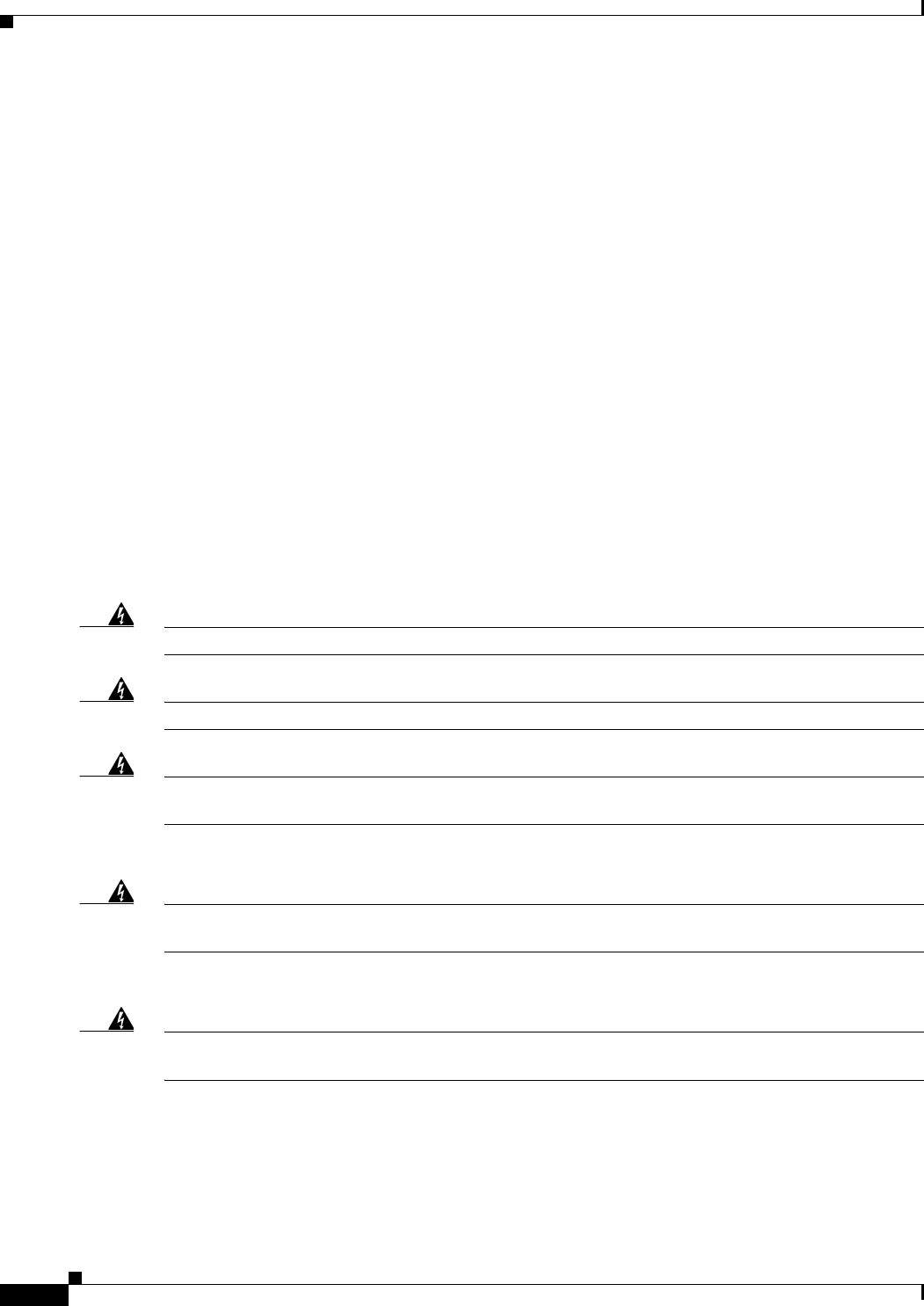
1-30
Cisco uBR10012 Universal Broadband Router Hardware Installation Guide
Chapter 1 Cisco uBR10012 Universal Broadband Router Overview
Network Uplink Cards
Network Uplink Cards
The following sections describe the network uplink cards used in the Cisco uBR10012 universal
broadband router:
•Cisco Single Port Gigabit Ethernet Line Card, page 1-30
•Cisco Half-Height Gigabit Ethernet Line Card, page 1-32
•Cisco OC-12 POS Line Card, page 1-32
•Cisco uBR10-SRP-OC12SML DPT WAN Line Card, page 1-34
•Cisco uBR10012 OC-48 DPT/POS Interface Module, page 1-34
Cisco Single Port Gigabit Ethernet Line Card
The single-port Gigabit Ethernet (GE) line card provides a trunk uplink to devices such as GSRs, as well
as connections to content servers and Web caches. The GE line card provides the Cisco uBR10012 router
with an IEEE 802.3z compliant Ethernet interface running at 1 Gbps in full duplex mode.
The port uses a Gigabit Interface Converter (GBIC) that supports Gigabit Ethernet rates on a variety of
Gigabit Ethernet interface types (SX, LX/LH, ZX) which can be changed or upgraded at any time (see
Table 1-9). The Cisco uBR10012 router supports multiple GE line cards to support connectivity to
multiple destinations and to provide network layer redundancy.
Warning
Class 1 laser product.
Statement 1008.
Warning
Invisible laser radiation present.
Statement 1016.
Warning
Because invisible radiation may be emitted from the aperture of the port when no fiber cable is
connected, avoid exposure to radiation and do not stare into open apertures.
Statement 1056.
Warning Statement for Sweden
Warning
Osynlig laserstrålning när denna del är öppen och förregleringen är urkopplad. Rikta inte blicken in
mot strålen.
Statement 36.
Warning Statement for Finland
Warning
Alleviates ja suojalukitus ohitettaessa olet alttiina näkymättömälle lasersäteilylle. Äjä katso
säteeseen.
Statement 35
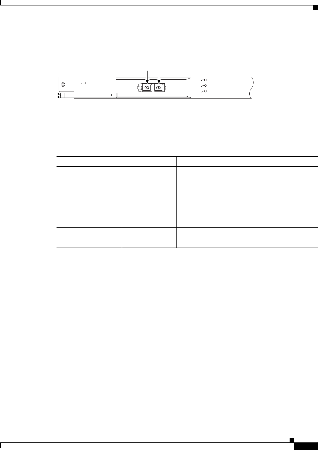
1-31
Cisco uBR10012 Universal Broadband Router Hardware Installation Guide
Chapter 1 Cisco uBR10012 Universal Broadband Router Overview
Network Uplink Cards
Figure 1-15 shows the faceplate for the Gigabit Ethernet line card.
Figure 1-15 Gigabit Ethernet Line Card Faceplate
Cisco Gigabit Ethernet Line Card LEDs
Table 1-8 describes the LEDs on the Gigabit Ethernet line card.
30005
CISCO
10000
LINK
TX
RX
FAIL
GIGABIT ETHERNET
Tx
Rx
Table 1-8 Gigabit Ethernet Line Card LEDs and Their Functions
LED Color/Status Description
FAIL Yellow
Off
A major failure has disabled the line card
The line card is operating properly
RX (receive) Green
Off
Receiving traffic
Not receiving traffic
TX (transmit) Green
Off
Transmitting traffic
Not transmitting traffic
LINK Green
Off
Carrier detected; the port is able to pass traffic
No carrier detected; the port is not able to pass traffic
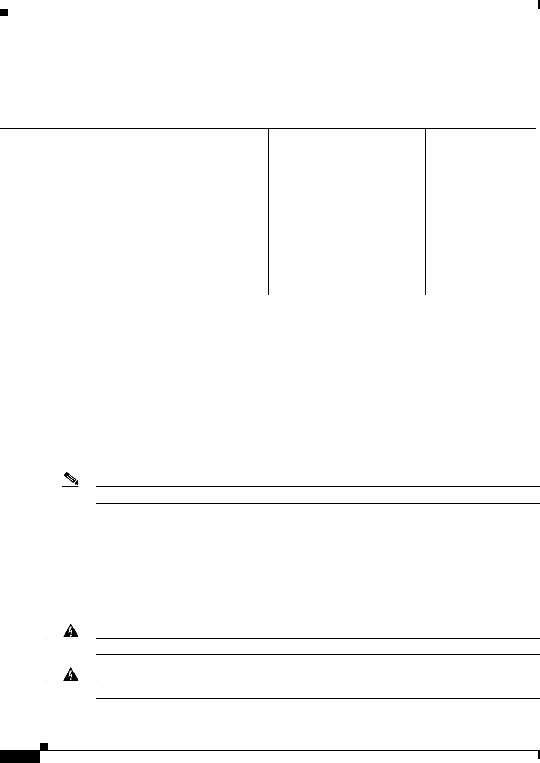
1-32
Cisco uBR10012 Universal Broadband Router Hardware Installation Guide
Chapter 1 Cisco uBR10012 Universal Broadband Router Overview
Network Uplink Cards
GBIC Specifications
Table 1-9 lists the GE line card GBICs and their respective cable types and lengths.
Cisco Half-Height Gigabit Ethernet Line Card
The Cisco HHGE line card contains a single Gigabit Ethernet port that provides a trunk uplink to
switches and core routers. The Cisco HHGE line card provides an IEEE 802.3z compliant Ethernet
interface that can run up to 1 Gbps in full duplex mode. The line card uses a Small Form-factor Pluggable
(SFP) Gigabit interface converter (GBIC) module that supports a variety of Gigabit Ethernet interface
types (SX LX/LH, and ZX), which you can change or upgrade at any time.
Note Only SFP GBIC modules purchased from Cisco work with the Gigabit Ethernet line card software.
For more information, see Cisco uBR10012 Universal Broadband Router Gigabit Ethernet Half-Height
Line Card Installation.
Cisco OC-12 POS Line Card
The OC-12 POS card provides a trunk uplink that supports up to 622 Mbps over a standard SONET/SDH
interface using a single-mode fiber intermediate reach SC connector.
Warning
Class 1 laser product.
Statement 1008.
Warning
Invisible laser radiation present.
Statement 1016.
Table 1-9 GBIC Port Cabling Specifications
GBIC
Wavelength
(nm) Fiber Type
Core Size,
microns
Modal Bandwidth,
MHz/km
Cable Distance,
feet/meters
1000Base-SX
ESR-GBIC-SX
850 MMF 62.5
62.5
50.0
50.0
160
200
400
500
722 ft (220 m)
902 ft (275 m)
1640 ft (500 m)
1804 ft (550 m)
1000Base-LX/LH
ESR-GBIC-LH
1300 MMF1
SMF
1. Mode-conditioning patch cord (CAB-GELX-625 or equivalent) is required. If you use an ordinary patch cord with MMF, 1000Base-LX/LH GBICs, and
a short link distance (tens of meters), this can cause transceiver saturation, resulting in a elevated bit error rate (BER). In addition, when you use the
LX/LH GBIC with 62.5-micron diameter MMF, you must install a mode-conditioning patch cord between the GBIC and the MMF cable on both the
transmit and receive ends of the link. The mode-conditioning patch cord is required for link distances greater than 984 ft (300 m).
62.5
50.0
50.0
8 to 10
500
400
500
—
1804 ft (550 m)
1804 ft (550 m)
1804 ft (550 m)
32,808 ft (10 km)
1000Base-ZX
ESR-GBIC-ZX
1550 SMF Not
conditional
N/A 43.5 miles (70 km) to
62 miles (100 km)2
2. 100 km over premium single-mode fiber or dispersion shifted singe-mode fiber.
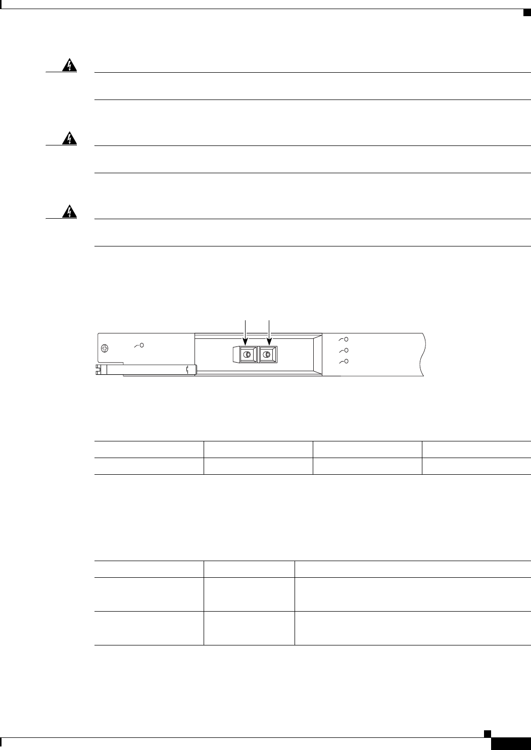
1-33
Cisco uBR10012 Universal Broadband Router Hardware Installation Guide
Chapter 1 Cisco uBR10012 Universal Broadband Router Overview
Network Uplink Cards
Warning
Because invisible radiation may be emitted from the aperture of the port when no fiber cable is
connected, avoid exposure to radiation and do not stare into open apertures.
Statement 1056.
Warning Statement for Sweden
Warning
Osynlig laserstrålning när denna del är öppen och förregleringen är urkopplad. Rikta inte blicken in
mot strålen.
Statement 36.
Warning Statement for Finland
Warning
Alleviates ja suojalukitus ohitettaessa olet alttiina näkymättömälle lasersäteilylle. Äjä katso
säteeseen.
Statement 35
Figure 1-16 shows the faceplate for the Cisco OC-12 POS line card.
Figure 1-16 Cisco OC-12 POS Line Card Faceplate
Table 1-10 lists the cable specifications for the Cisco OC12 POS card.
Cisco OC-12 POS Line Card LEDs
Table 1-11 describes the LEDs and their functions on the Cisco OC-12 POS line card.
30006
CISCO
10000
CARRIER
TX
RX
FAIL
OC–12/STM–4 POS SM–IR
Tx Rx
Table 1-10 Cisco OC-12 POS Line Card Cable Specifications
Fiber Type Wavelength, nm Core Size, microns Cable Distance
Single Mode Fiber 1300 8 to 10 49,213 ft (15 km)
Table 1-11 Cisco OC-12 POS Line Card LEDs and Their Functions
LED Color/Status Description
FAIL Yellow
Off
A major failure has disabled the line card
The line card is operating properly
RX (receive) Green
Off
Receiving traffic
Not receiving traffic

1-34
Cisco uBR10012 Universal Broadband Router Hardware Installation Guide
Chapter 1 Cisco uBR10012 Universal Broadband Router Overview
Network Uplink Cards
Cisco uBR10-SRP-OC12SML DPT WAN Line Card
The Cisco uBR10 Spatial Reuse Protocol (SRP) OC12 single-mode fiber, long-reach (SML) dynamic
packet transport (DPT) WAN line card provides shared IP over SONET capability for the
Cisco uBR10012 router platform.
For more information, see Cisco uBR10-SRP-OC12SML/SMI DPT Adapter Card for the Cisco
uBR10012 Universal Broadband Router.
Cisco uBR10012 OC-48 DPT/POS Interface Module
The Cisco uBR10012 OC-48 dynamic packet transport (DPT) and packet-over-SONET interface module
is a full-height line card for the Cisco uBR10012 universal broadband router. This card provides trunk
uplink capabilities that support up to 1.4 Gbps full duplex throughput over a standard SONET/ITU-T
Synchronous Digital Hierarchy (SDH) interface, using a single mode fiber with SC connectors.
Two versions of the Cisco uBR10012 OC-48 DPT/POS interface module are available— short reach
(SR) or long reach (LR). Both versions work with the performance routing engine (PRE).
The Cisco uBR10012 OC-48 DPT/POS interface module provides a point-to-point connection to a
backbone router and encapsulates IP Packets with byte-wise HDLC framing, placing them directly into
the OC-48 SONET (or SDH) payload.
The Cisco uBR10012 OC-48 DPT/POS interface module is a standard implementation of packet over
SONET switching, and supports the following features:
•OC-48 bandwidth between the line card and the PRE.
•North American (SONET) and European (SDH) formats
•Automatic protection switching (APS)
•Alarm processing
Note Two Cisco uBR10012 OC-48 DPT/POS interface modules are required when using the card when using
the card in DPT mode in a Cisco uBR10012 universal broadband router.
For more information, see Cisco uBR10012 OC-48 DPT/POS Interface Module.
TX (transmit) Green
Off
Transmitting traffic
Not transmitting traffic
CARRIER Green
Off
Carrier detected; the port is able to pass traffic
No carrier detected; the port is not able to pass traffic
Table 1-11 Cisco OC-12 POS Line Card LEDs and Their Functions (continued)
LED Color/Status Description
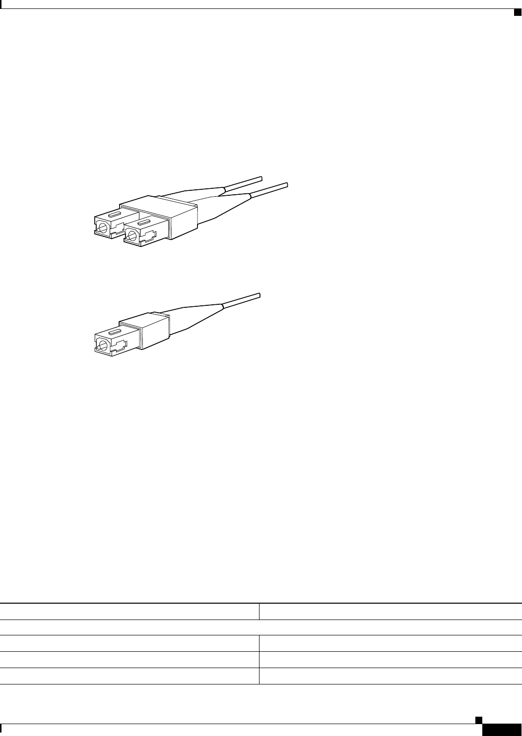
1-35
Cisco uBR10012 Universal Broadband Router Hardware Installation Guide
Chapter 1 Cisco uBR10012 Universal Broadband Router Overview
Optical Connectors and Cables
Optical Connectors and Cables
For single-mode optical fiber connections, use one duplex SC-type cable (see Figure 1-17), or two
simplex SC-type cables (see Figure 1-18), one for transmit (Tx) and one for receive (Rx).
For optical connector and cable cleaning information, go to the following URL:
http://www.cisco.com/en/US/tech/tk482/tk876/technologies_white_paper09186a0080254eba.shtml
Figure 1-17 Duplex SC-Type Cable and Connector
Figure 1-18 Simplex SC-Type Cable and Connector
These tables list the proper single-mode or multimode optical fiber cables to use to connect your router
to a network:
•Table 1-9, for the Gigabit Ethernet line card
•Table 1-10, for the OC-12 POS line card
Cisco uBR10012 Router FRU Resources
The following section lists the field-replaceable units (FRUs), FRU product order numbers, and provides
links to specific FRU documentation.
FRU Modules and Order Numbers
Table 1-12 lists the major FRUs used in the Cisco uBR10012 router.
38548
38547
Table 1-12 Cisco uBR10012 Field-Replaceable Units and Product Order Numbers
Field-Replaceable Unit Product Order Number
Chassis Components
Performance routing engine (PRE) with 512 MB DRAM End of life (EOL), replace with ESR-PRE
PRE 512 MB DRAM (spare) EOL, replace with ESR-PRE/R
PRE1 (primary and redundant) ESR-PRE1

1-36
Cisco uBR10012 Universal Broadband Router Hardware Installation Guide
Chapter 1 Cisco uBR10012 Universal Broadband Router Overview
Cisco uBR10012 Router FRU Resources
PRE1 (spare) ESR-PRE1/R=
PRE2 (primary and redundant) ESR-PRE2/R
PRE2 (spare) ESR-PRE2=
PRE4 (primary and redundant) ESR-PRE4
PRE4 (spare) ESR-PRE4/R=
PRE PC media card—64 MB (default) 10000-PREMEMFD64=
PRE PCM media card—128 MB ESR-PRE-MEM-FD128=
Blank PRE1 slot cover ESR-PRE-Cover=
TCC+ card UBR10-TCC+-T1=
Blank TCC+ card slot cover UBR10-TCC+-COVER=
DC power entry module (2400 W or 3000 W) UBR10-PWR-DC=
DC power entry module (3300 W) UBR10-PWR-DC-PLUS=
AC power entry module (2400 W UBR10-PWR-AC=
AC power entry module (3300 W) UBR10-PWR-AC-PLUS=
Fan assembly module (spare) UBR10-FAN-ASSY=
Fan assembly module (spare) UBR10012-FAN-PLUS=
Fan assembly filter (spare) UBR10-FAN-FILTER=
Front cover (spare) UBR10-CHAS-COVER=
Power supply monitoring cable for the AC power shelf alarm UB10-PWR-MON-CAB=
Cable Interface Line Cards
Line Card Processor (spare) UBR10-LCP2=
Cisco uBR10-MC5X20S cable interface line card UBR10-MC5X20S=
Cisco uBR10-MC5X20U cable interface line card UBR10-MC5X20U=
Cisco UBR-MC20X20V cable interface line card UBR-MC20X20V-20D=, UBR-MC20X20V-5D=,
UBR-MC20X20V-0D=
Cisco uBR-MC3GX60V cable interface line card UBR-MC3GX60V=
Cisco uBR-MC3GX60V-RPHY cable interface line card UBR-MC3GX60V-RPHY, UBR-MC3GX60V-RPHY=
Blank cable interface line card cover UBR10-MC-COVER=
Network Line Cards
Cisco Single Port Gigabit Ethernet line card (GigE)
1000Base-SX—pluggable transceiver
1000Base-LX/LH—pluggable transceiver
1000Base-ZX— pluggable transceiver
UBR10-1GE, UBR10-1GE=
ESR-GBIC-SX
ESR-GBIC-LH
ESR-GBIC-ZX
Table 1-12 Cisco uBR10012 Field-Replaceable Units and Product Order Numbers (continued)
Field-Replaceable Unit Product Order Number

1-37
Cisco uBR10012 Universal Broadband Router Hardware Installation Guide
Chapter 1 Cisco uBR10012 Universal Broadband Router Overview
Cisco uBR10012 Router FRU Resources
Note The output of the show inventory command does not display the serial numbers for the fan assembly
modules (UBR10-FAN-ASSY and UBR10012-FAN-PLUS), AC PEMs (UBR10-PWR-AC and
UBR10-PWR-AC-PLUS), and DC PEMs (UBR10-PWR-DC and UBR10-PWR-DC-PLUS). Visually
inspect the serial number labels printed on these FRUs to locate the serial number.
Cisco Half-Height Gigabit Ethernet line card
Slot splitter card
Half height slot blank cover
Full height slot blank cover
1000Base-SX—pluggable transceiver
1000Base-LX/LH—pluggable transceiver
1000Base-TX—pluggable transceiver
1000Base-ZX— pluggable transceiver
ESR-HH-1GE
ESR-HH-CARRIER
ESR-HH-COVER
ESR-COVER
SFP-GE-S
SFP-GE-L
SFP-GE-T
GLC-ZX-SM
Cisco OC12/STS12c/STM4 POS, single mode, intermediate
reach line card
UBR10-OC12/P-SMI=
Cisco uBR10-SRP-OC12SML DPT WAN adapter card UBR-SRP-OC12SML=
Cisco uBR10012 OC-48 DPT/POS Interface Module
Single mode1, short reach modules
Single spare2
Single mode1, long reach modules
Single spare2
UBR10-SRP-OC48SMS
ESR1OC48/P/SRPSMS=
UBR10-SRP-OC48SML=
ESR1OC48/P/SRPSML=
Blank network line card cover ESR-LC-COVER=
1. Use this number to order the dual interface modules.
2. Use this number to order a single interface module.
Table 1-12 Cisco uBR10012 Field-Replaceable Units and Product Order Numbers (continued)
Field-Replaceable Unit Product Order Number

1-38
Cisco uBR10012 Universal Broadband Router Hardware Installation Guide
Chapter 1 Cisco uBR10012 Universal Broadband Router Overview
Cisco uBR10012 Router FRU Resources
FRU Documentation
Table 1-13 lists the Cisco field replaceable unit (FRU) documentation for the modules and interface line
cards that are used in the Cisco uBR10012 router and the corresponding URL where that documentation
can be found. Refer to the FRU documentation for more detailed information and installation
instructions for each module or card.
Table 1-13 Cisco FRU Document Title and URL
Document title
URL
2400W AC-Input Power Shelf for the Cisco uBR10012 Universal Broadband Router
http://www.cisco.com/en/US/docs/cable/cmts/ubr10012/installation/field_replaceable_units/ub1
0acsh.html
Document title
URL
AC Power Entry Module for the Cisco uBR10012 Universal Broadband Router
http://www.cisco.com/en/US/docs/cable/cmts/ubr10012/installation/field_replaceable_units/ub1
0acpm.html
Document title
URL
3300 W AC Power Entry Module for the Cisco uBR10012 Universal Broadband Router
http://www.cisco.com/en/US/docs/cable/cmts/ubr10012/installation/field_replaceable_units/ub1
0acpem_HornBill.html
Document title
URL
DC Power Entry Module for the Cisco uBR10012 Universal Broadband Router
http://www.cisco.com/en/US/docs/cable/cmts/ubr10012/installation/field_replaceable_units/ub1
0pem.html
Document title
URL
3300 W DC Power Entry Module for the Cisco uBR10012 Universal Broadband Router
http://www.cisco.com/en/US/partner/docs/cable/cmts/ubr10012/installation/field_replaceable_un
its/ub10dcpem_Hornbill.html
Document title
URL
Cisco uBR10012 Universal Broadband Router Fan Assembly Module
http://www.cisco.com/en/US/docs/cable/cmts/ubr10012/installation/field_replaceable_units/fan5
093.html
Document title
URL
Cisco LCD Module for the Cisco uBR10012 Universal Broadband Router
http://www.cisco.com/en/US/docs/cable/cmts/ubr10012/installation/field_replaceable_units/lcd5
090.html
Document title
URL
Cisco uBR10012 Universal Broadband Router TCC+ Card
http://www.cisco.com/en/US/docs/interfaces_modules/cable/installation/tcc5094.html
Document title
URL
Cisco uBR10012 Universal Broadband Router DTCC Card
http://www.cisco.com/en/US/partner/docs/interfaces_modules/cable/installation/dtcccard.html
Document title
URL
Cisco uBR10-SRP-OC12SML DPT WAN Line Card for the Cisco uBR10012 Router
http://www.cisco.com/en/US/docs/interfaces_modules/cable/line_cards/ubr_srp_oc12sml_dpt_w
an/quick/start/ub10oc12.html
Document title
URL
Performance Routing Engine Module for the Cisco uBR10012 Universal Broadband Router
http://www.cisco.com/en/US/docs/interfaces_modules/cable/performance_routing_engine/install
ation/guide/pre5096.html

1-39
Cisco uBR10012 Universal Broadband Router Hardware Installation Guide
Chapter 1 Cisco uBR10012 Universal Broadband Router Overview
Cisco uBR10012 Router FRU Resources
Document title
URL
Installing EMI Gaskets and RF Absorber Material on the Cisco uBR10012 Universal Broadband
Router
http://www.cisco.com/en/US/docs/cable/cmts/ubr10012/installation/field_replaceable_units/pre2
gkit.html
Document title
URL
Cisco uBR10-MC5X20S/U Cable Interface Line Card
http://www.cisco.com/en/US/docs/interfaces_modules/cable/broadband_processing_engines/ubr
10_mc5x20s_u_h/installation/guide/ubrmc520.html
Document title
URL
Cisco UBR-MC20X20V Cable Interface Line Card Hardware Installation Guide
http://www.cisco.com/en/US/docs/interfaces_modules/cable/broadband_processing_engines/ubr
_mc20x20v/installation/guide/mc20x20v_hig.html
Document title
URL
Cisco UBR-MC3GX60V Cable Interface Line Card Hardware Installation Guide
http://www.cisco.com/en/US/docs/interfaces_modules/cable/broadband_processing_engines/ubr
_mc3gx60v/installation/guides/b_3g60_lchig.html
Document title
URL
Cisco Remote-PHY Solution Workflow
http://www.cisco.com/web/techdoc/cable/cisco-remote-phy/index.html
Document title
URL
Cisco Half-Height Gigabit Ethernet Line Card
http://www.cisco.com/en/US/docs/interfaces_modules/cable/line_cards/ubr_hh_ge/quick/start/ub
r_hhge.html
Document title
URL
Inspection and Cleaning Procedures for Fiber-Optic Connections
http://www.cisco.com/en/US/tech/tk482/tk876/technologies_white_paper09186a0080254eba.sht
ml
Table 1-13 Cisco FRU Document Title and URL (continued)

1-40
Cisco uBR10012 Universal Broadband Router Hardware Installation Guide
Chapter 1 Cisco uBR10012 Universal Broadband Router Overview
Cisco uBR10012 Router FRU Resources

CHAPTER
2-1
Cisco uBR10012 Universal Broadband Router Hardware Installation Guide
2
Preparing for Installation
Before you install the Cisco uBR10012 universal broadband router, consider:
•The power and cabling requirements that must be in place at your installation sites
•The equipment required to install the router
•The environmental conditions your installation site must meet to maintain normal operation
This chapter guides you through the process of preparing for your router installation.
Do not unpack the system until you are ready to install it. Keep the chassis in the shipping container to
prevent accidental damage until you determine an installation site.
Note The Cisco uBR10012 router (using DC power supplies) is not shipped with wiring to connect to a DC
power source. You must provide input, return, and earthing (grounding) wiring at the site, and install and
protect the wiring in accordance with local and national wiring regulations (see Table 3-4).
Safety
When you install the Cisco uBR10012 router, observe all of the following caution and warning
statements. For warning translations, refer to the regulatory compliance and safety documentation at the
following URL:
http://www.cisco.com/en/US/docs/cable/cmts/ubr10012/regulatory/compliance/ub10rcsi.html
The following guidelines will help ensure your safety and protect the equipment. However, these
guidelines may not cover all potentially hazardous situations you may encounter during system
installation, so be alert.
•The installation of your Cisco uBR10012 router must comply with national and local electrical
codes. In the United States, this means the National Fire Protection Association (NFPA) 70, United
States National Electrical Code. In Canada, Canadian Electrical Code, part I, CC22.1. In other
countries, International Electrotechnical Commission (IEC) 364, part 1 through part 7.
•Review the safety warnings listed in the regulatory compliance and safety documentation before
installing, configuring, or performing maintenance on the product.
•Always disconnect power at the source before you install or remove a chassis.
•Never attempt to lift an object that might be too heavy to lift safely by yourself.
•Keep the chassis area clear and as dust free as possible during and after installation.
•Keep tools and chassis components away from walk areas.

2-2
Cisco uBR10012 Universal Broadband Router Hardware Installation Guide
Chapter 2 Preparing for Installation
Preventing Electrostatic Discharge Damage
•Do not wear loose clothing, jewelry (including rings and chains), or other items that could get caught
in the chassis.
•The Cisco uBR10012 router operates safely when it is used in accordance with its marked electrical
ratings and product usage instructions.
Warning
Only trained and qualified personnel should be allowed to install, replace, or service this equipment.
Statement 1030.
Preventing Electrostatic Discharge Damage
Electrostatic discharge (ESD) damage, which occurs when electronic cards or components are
improperly handled, can result in complete or intermittent failures. The performance routing engine
(PRE), and all line cards consist of a printed circuit card that is fixed in a metal carrier. Electromagnetic
interference (EMI) shielding and connectors are integral components of the carrier. Although the metal
carrier helps to protect the cards from ESD, use an antistatic strap each time you handle the modules.
Handle the carriers by the edges only; never touch the cards or connector pins.
Caution Always tighten the captive installation screws on all system components when you are installing them.
These screws prevent accidental removal of the module, provide proper grounding for the system, and
help to ensure that the bus connectors are properly seated in the backplane.
Following are guidelines for preventing ESD damage:
•Always use an ESD-preventive wrist or ankle strap and ensure that it makes good skin contact.
Before removing a card from the chassis, connect the equipment end of the strap to a bare metal,
unpainted surface on the chassis or rackmount.
•Handle line cards by the faceplates and carrier edges only; avoid touching the card components or
any connector pins.
•When removing a line card, place the removed module component-side-up on an antistatic surface
or in a static-shielding bag. If the module will be returned to the factory, immediately place it in a
static-shielding bag.
•Avoid contact between the modules and clothing. The wrist strap protects the card from ESD
voltages on the body only; ESD voltages on clothing can still cause damage.
Caution For safety, periodically check the resistance value of the antistatic strap. The measurement should be
between 1 and 10 megohms.

2-3
Cisco uBR10012 Universal Broadband Router Hardware Installation Guide
Chapter 2 Preparing for Installation
Chassis-Lifting Guidelines
Chassis-Lifting Guidelines
The Cisco uBR10012 chassis is not intended to be moved frequently. When fully populated, the
Cisco uBR10012 system weighs approximately 230 pounds. A depopulated chassis weighs
approximately 55 pounds.
When moving the chassis, use the following guidelines to prevent injury and damage to the equipment:
•Before you install the system, ensure that your site is properly prepared so you can avoid having to
move the chassis later to accommodate power sources and network connections.
•A fully populated chassis should be moved only with a hydraulic lift or forklift. Do not attempt to
manually lift a populated chassis.
•Two people are required to safely move a depopulated chassis. This should be done by using the
handles on each side of the chassis.
Warning
To prevent personal injury or damage to the chassis, never attempt to lift or tilt the chassis using the
handles on modules (such as power supplies, fans, or cards); these types of handles are not designed
to support the weight of the unit.
Statement 1032
•Never attempt to lift even a depopulated chassis by yourself. Because of the size and weight of the
chassis, use at least two people to safely lift and move it without causing injury or damaging the
equipment.
•To prevent injury, keep your back straight and lift with your legs, not your back.
•Ensure that your footing is solid, and balance the weight of the chassis between your feet.
•Lift the chassis slowly; never move suddenly or twist your body as you lift.
•Keep your back straight and lift with your legs, not your back. If you must bend down to lift the
chassis, bend at the knees, not at the waist, to reduce the strain on your back muscles.
•If you have to move a fully populated chassis and you do not have a hydraulic lift or forklift
available, you must first remove the following components from the chassis:
–
Fan assembly module
–
AC or DC power entry modules (PEMs)
–
Cable interface line cards
–
Network uplink line cards
In a fully loaded chassis, these components weigh approximately 170 pounds, so removing them
allows the chassis to be safely moved with two people. The components can then be reinserted after
the chassis has been moved and installed. See Chapter 5, “Maintaining the Cisco uBR10012 Router”
for instructions on removing these components.
Caution When removing and reinstalling these modules, be certain to follow the precautions given in the
“Preventing Electrostatic Discharge Damage” section on page 2-2.
•Always disconnect all external cables before lifting or moving the chassis.In particular, verify that
all power to the chassis has been removed. Do not try to move a chassis that is connected to power
or that is powered on.
2-4
Cisco uBR10012 Universal Broadband Router Hardware Installation Guide
Chapter 2 Preparing for Installation
Electrical Safety
Electrical Safety
All system components are hot-swappable. They are designed to be removed and replaced while the
system is operating without presenting an electrical hazard or damage to the system.
Follow these basic guidelines when you are working with any electrical equipment:
•Before beginning any procedures requiring access to the chassis interior, locate the emergency
power-off switch for the room in which you are working.
•Disconnect all power and external cables before installing or removing a chassis.
•Do not work alone when potentially hazardous conditions exist.
•Never assume that power has been disconnected from a circuit; always check.
•Do not perform any action that creates a potential hazard to people or makes the equipment unsafe.
Never install equipment that appears damaged.
•Carefully examine your work area for possible hazards such as moist floors, ungrounded power
extension cables, and missing safety grounds.
Warning
When installing or replacing the unit, the ground connection must always be made first and
disconnected last.
Statement 1046
Warning
Do not work on the system or connect or disconnect cables during periods of lightning activity.
Statement 1001
Warning
Read the installation instructions before you connect the system to its power source.
Statement 1004
Site Requirements
This section provides information for environmental, power, cabling, and rack mounting requirements.
Be sure that you have met all of these requirements before you install your Cisco uBR10012 router.
Caution The Cisco uBR10012 router installation must comply with all applicable codes and is approved for use
with copper conductors only. The ground bond fastening hardware should be of compatible material and
preclude loosening, deterioration, and electrochemical corrosion of hardware and joined material.
Attachment of the chassis ground to a central office or other interior ground system should be made with
a 6-AWG, copper ground conductor at a minimum.
Warning
This unit is intended for installation in restricted access areas. A restricted access area can be
accessed only through the use of a special tool, lock and key, or other means of security.
Statement 1017

2-5
Cisco uBR10012 Universal Broadband Router Hardware Installation Guide
Chapter 2 Preparing for Installation
Site Requirements
Environmental Site Requirements
The environmental monitoring functionality in the Cisco uBR10012 router protects the system and
components from potential damage from excessive voltage and temperature conditions. To ensure
normal operation and avoid unnecessary maintenance, plan your site configuration and prepare your site
before installation. After installation, make sure the site maintains an ambient temperature of 41°F
through 104°F (5°C through 40°C), and keep the area around the chassis as free from dust as is practical.
Planning a proper location for the Cisco uBR10012 router and the layout of your equipment rack or
wiring closet is essential for successful system operation. Equipment placed too close together or
inadequately ventilated can cause system excessive temperature conditions. In addition, chassis panels
made inaccessible by poor equipment placement can make system maintenance difficult.
When you plan the location and layout of your equipment rack or wiring closet, you need to consider
how air flows through your router. The Cisco uBR10012 router draws cooling air in through the intake
vent on the front of the chassis and moves the air across the internal components and out the exhaust
vents on the top rear of the chassis (see Figure 2-1 on page 2-6).
Temperature sensors on the PRE monitor the internal air temperature and send warning messages and an
alarm condition when the internal air temperature approaches a specified threshold.
The front bottom and top rear of the chassis must remain unobstructed to ensure adequate airflow and
prevent overheating inside the chassis. Maintain a minimum clearance of 3 in. (7.62 cm) from the vents
on the front and back of the chassis to allow for adequate airflow. Do not place the chassis where heated
exhaust air from other systems could enter the air intake vent at the bottom front, as this could cause
overheating of the system.
In addition, allow for approximately 3 to 4 ft (91.44 cm to 121.92 cm) clearance at the front and rear of
the chassis for cabling and normal system maintenance.
Warning
Blank faceplates and cover panels serve three important functions: they prevent exposure to
hazardous voltages and currents inside the chassis; they contain electromagnetic interference (EMI)
that might disrupt other equipment; and they direct the flow of cooling air through the chassis. Do not
operate the system unless all cards, faceplates, front covers, and rear covers are in place.
Statement
1029
To avoid problems during installation and ongoing operation, follow these general precautions when you
plan the equipment locations and connections:
•Use the show environment command regularly to check the internal system status. The
environmental monitor continually checks the interior chassis environment; it provides warnings for
high temperature and creates reports on any occurrences. If warning messages are displayed, take
immediate action to identify the cause and correct the problem.
•Keep the Cisco uBR10012 router off of the floor and out of areas that collect dust.
•Follow ESD prevention procedures (see “Preventing Electrostatic Discharge Damage” section on
page 2-2) to avoid damage to equipment. Damage from static discharge can cause immediate or
intermittent equipment failure.
•Ensure that the PRE modules, line cards, blank covers, power supplies, and any power supply covers
are in place and secure. The fans direct cooling air throughout the chassis interior; a loose
component or empty slot can redirect the airflow away from active components.
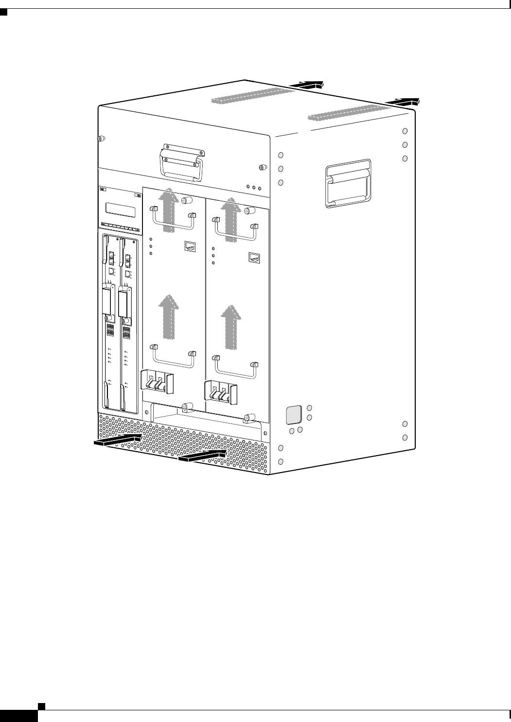
2-6
Cisco uBR10012 Universal Broadband Router Hardware Installation Guide
Chapter 2 Preparing for Installation
Site Requirements
Figure 2-1 Cooling Air Path for the Cisco uBR10012
56430
ALARMS
CISCO
10000
FAIL
PERFORMANCE ROUTING ENGINE
CONSOLE
STATUS
ACO
CRITICAL
MINOR
MAJOR
ETHERNET
LINK
ACTIVITY
AUX
SLOT 0
SLOT 1
ALARMS
CISCO
10000
FAIL
PERFORMANCE ROUTING ENGINE
CONSOLE
STATUS
ACO
CRITICAL
MINOR
MAJOR
ETHERNET
LINK
ACTIVITY
AUX
SLOT 0
SLOT 1
POWER
MISWIRE
FAULT
POWER
MISWIRE
FAULT

2-7
Cisco uBR10012 Universal Broadband Router Hardware Installation Guide
Chapter 2 Preparing for Installation
Site Requirements
Temperature and Humidity Requirements
Table 2-1 lists the operating and nonoperating environmental site requirements. The ranges listed are
those within which the Cisco uBR10012 router continues to operate; however, a measurement that is
approaching the minimum or maximum of a range indicates a potential problem. You can maintain
normal operation by anticipating and correcting environmental anomalies before they approach a
maximum operating range.
Power Guidelines
Caution The Cisco uBR10012 router installation must comply with all applicable codes and is approved for use
only with copper conductors. The ground bond fastening hardware should be of compatible material and
preclude loosening, deterioration, and electrochemical corrosion of hardware and joined material.
Attachment of the chassis ground to a central office or other interior ground system should be made with
a minimum of a 6-AWG, copper ground conductor.
Follow these precautions and recommendations when planning power connections to the
Cisco uBR10012 router:
•Ensure that you are using proper cables and have circuit breakers installed.
•Check the power at your site before installation and periodically after installation to ensure that you
are receiving clean power. Install a power conditioner if necessary.
•Provide proper grounding to avoid damage from lightning and power surges.
•Use a 6-AWG, copper ground conductor (minimum requirement) when attaching the chassis ground
to a central office or other interior ground system. An insulation rating of 167° Fahrenheit (75°
Celsius) is required for the 6-AWG wire for 3000 W of power.
Warning
This product requires short-circuit (overcurrent) protection, to be provided as part of the building
installation. Install only in accordance with national and local wiring regulations.
Statement 1045
Warning
A readily accessible two-poled disconnect device must be incorporated in the fixed wiring.
Statement
1022
Table 2-1 Specifications for Operating and Nonoperating Environments
Specification Minimum Maximum
Temperature, ambient operating 41°F (5°C) 104°F (40°C)
Temperature, ambient nonoperating and storage –40°F (–40°C) 158°F (70°C)
Humidity, ambient (noncondensing) operating 5% 85%
Humidity, ambient (noncondensing) nonoperating and
storage
5% 95%
Altitude, operating (over allowable temperature) 32°F
–200 ft (–60.9 m)
104°F (40°C)
10,000 ft (3048 m)
Altitude, nonoperating (over allowable temperature) –200 ft (–60.9 m) 30,000 ft (9144 m)
2-8
Cisco uBR10012 Universal Broadband Router Hardware Installation Guide
Chapter 2 Preparing for Installation
Site Requirements
Power Connection Guidelines for DC-Powered Systems
The DC-input power supply allows the Cisco uBR10012 router to operate on either –48 or –60 VDC
systems. Both these power supplies can operate with an input from –40.5 to —72 VDC with no harm;
however, the input should be restricted to the nominal ranges defined in Table 2-2 to maintain safety
extra-low voltage (SELV) compliance, and to deliver the rated power at the allowed current levels.
Table 2-2 summarizes the power output, DC-input voltage, and DC-input current values for the DC
PEM.
Table 2-2 Power Output, DC-input Voltage, and DC-input Current Values for the DC PEM
Warning
Connect the unit only to DC power source that complies with the safety extra-low voltage (SELV)
requirements in IEC 60950 based safety standards.
Statement 1033
Note The Cisco uBR10012 router (using DC power supplies) is not shipped with wiring to connect to a DC
power source. You must provide input, return, and earthing (grounding) wiring at the site, and install and
protect the wiring in accordance with local and national wiring regulations. The Cisco uBR10012 router
input DC terminal block accepts a minimum of 6-AWG wire. An insulation rating of 167° Fahrenheit
(75° Celsius) is required for the 6-AWG wire for 3000W of power.
See Appendix A, “Technical Specifications,” for system power specifications, including input voltage
and operating frequency ranges.
Warning
Connect the unit only to DC power source that complies with the safety extra-low voltage (SELV)
requirements in IEC 60950 based safety standards.
Statement 1033
Cisco Product Part Number
Cisco DC PEM
(Part Number)1
1. The 34- part number is listed on the compliance label of the DC PEM.
Power Output DC-input Voltage DC-input Current
UBR10-PWR-DC= 34-1651-04 2400W maximum –48 to –60 VDC nominal 50A
34-1651-05 2400W maximum –48 to –60 VDC nominal 50A
3000W maximum –55 to –60 VDC nominal 56A
UBR10-PWR-DC-PLUS= 341-0388-01 3300 W maximum –48 to –60 VDC nominal 50 A + 50 A

2-9
Cisco uBR10012 Universal Broadband Router Hardware Installation Guide
Chapter 2 Preparing for Installation
Site Requirements
Plant Wiring Guidelines
When planning the location of the new system, consider the distance limitations for signaling, EMI, and
connector compatibility, as described in the following sections.
Warning
This product requires short-circuit (overcurrent) protection, to be provided as part of the building
installation. Install only in accordance with national and local wiring regulations.
Statement 1045
Interference Considerations
When wires are run for any significant distance in an electromagnetic field, interference can occur
between the field and the signals on the wires. This fact has two implications for the construction of plant
wiring:
•Bad wiring practice can result in radio interference emanating from the plant wiring.
•Strong EMI, especially when it is caused by lightning or radio transmitters, can destroy the signal
drivers and receivers in the Cisco uBR10012 router, and can even create an electrical hazard by
conducting power surges through lines and into equipment. (Review the safety warnings in the
“Preventing Electrostatic Discharge Damage” section on page 2-2.)
Note To predict and remedy strong EMI, you may also need to consult experts in radio frequency
interference (RFI).
If you use twisted-pair cable in your plant wiring with a good distribution of grounding conductors, the
plant wiring is unlikely to emit radio interference. If you exceed the recommended distances, use a
high-quality twisted-pair cable with one ground conductor for each data signal when applicable.
If wires exceed recommended distances, or if wires pass between buildings, give special consideration
to the effect of a lightning strike in your vicinity. The electromagnetic pulse caused by lightning or other
high-energy phenomena can easily couple enough energy into unshielded conductors to destroy
electronic devices. If you have had problems of this sort in the past, you may want to consult experts in
electrical surge suppression and shielding.
Cabling Guidelines
The size of your networks and the distances between connections depend on the type of signal, the signal
speed, and the transmission media (the type of cabling used to transmit the signals). For example,
standard coaxial cable has a greater channel capacity than twisted-pair cabling. The distance and rate
limits in the following descriptions are the IEEE recommended maximum speeds and distances for
signaling; however, you can usually get good results at speeds and distances far greater than these. For
example, the recommended maximum rate for V.35 is 2 Mbps, but it is commonly used at 4 Mbps
without any problems. If you understand the electrical problems that might arise and can compensate for
them, you should get good results with rates and distances greater than those shown here; however, do
so at your own risk.
When preparing your site for network connections to the Cisco uBR10012 router, you must consider a
number of factors related to each type of interface:
•The type of cabling required for each type (fiber, thick or thin coaxial, foil twisted-pair, or
unshielded twisted-pair cabling)
2-10
Cisco uBR10012 Universal Broadband Router Hardware Installation Guide
Chapter 2 Preparing for Installation
Site Requirements
•Distance limitations for each signal type
•The specific cables you need to connect each interface
•Any additional interface equipment you need, such as transceivers, hubs, switches, modems,
channel service units (CSUs), or data service units (DSUs)
The extent of your network and the distances between network interface connections depend in part on
the following factors:
•Signal type
•Signal speed
•Transmission medium
The distance and rate limits referenced in the following sections are the IEEE-recommended maximum
speeds and distances for signaling purposes. Use this information as a guideline in planning your
network connections prior to installing the Cisco uBR10012 router.
Ethernet and Fast Ethernet Connections
The maximum distances for Ethernet and Fast Ethernet network segments and connections depend on
the type of transmission cable being used. The terms 10Base-T and 100Base-T are industry shorthand
nomenclature for the following:
•10 Mbps transmission rate (10), or 100 Mbps transmission rate (100)
•Using baseband technology (Base)
•By means of twisted pair wires (T)
Table 2-3 shows the maximum transmission distances between stations for Ethernet and Fast Ethernet
connections.
Fiber-Optic Connections
The specifications for single-mode, fiber-optic transmissions are outlined in Table 2-4.
Caution Do not exceed the specified distance limits.
Table 2-3 Ethernet and Fast Ethernet Maximum Transmission Distances
Transceiver
Speed Cable Type Transmission Mode Maximum Distance between Stations
10 Mbps Category 3 Full and half duplex 328 ft (100 m)
100 Mbps Category 5 Full and half duplex 328 ft (100 m)
Ta b l e 2 - 4 F i b e r- O p t i c Tr a n s m ission Characteristics
Characteristic Permissible Value Characteristic Permissible Value
Transmitter output power –15 to –8 dBm Wavelength 1261 to 1360 nm
Receiver sensitivity –28 to –8 dBm Maximum span 9 miles (14.5 km)
2-11
Cisco uBR10012 Universal Broadband Router Hardware Installation Guide
Chapter 2 Preparing for Installation
Site Requirements
Rack-Mounting Considerations
The Cisco uBR10012 router should be rack-mounted for proper operation and maintenance. The
rack-mounting hardware included with chassis is suitable for standard 19-inch equipment racks and
telco-type racks. Optional hardware is available from third-party vendors for mounting in a 23-inch
equipment rack.
Mounting Guidelines
Warning
The chassis should be mounted on a rack that is permanently affixed to the building.
Statement 1049
When planning your rack installation, consider the following guidelines:
•Install the Cisco uBR10012 router in an open rack whenever possible.
Caution To prevent overheating, never install the chassis in an enclosed rack or room that is not properly
ventilated or air conditioned.
•Allow sufficient clearance around the rack for maintenance. You need 24 in. (61 cm) of clearance to
remove and replace system components.
Caution To prevent the rack from tipping when installing the router in telco racks, ensure that the rack is bolted
to the floor and, if necessary, anchored with appropriate fixtures.
•If the rack is provided with stabilizing devices, install the stabilizers before mounting or servicing
the unit in the rack.
•Always install heavier equipment in the lower half of a rack to maintain a low center of gravity and
prevent the rack from falling over.
•When mounting this unit in a partially filled rack, load the rack from the bottom to the top, with the
heaviest component at the bottom of the rack.
Note This unit should be mounted at the bottom of the rack if it is the only unit in the rack.
•If you plan to use an equipment shelf, ensure that the shelf is constructed to support the weight and
dimensions of the chassis. Use the rack-mount kit designed for the Cisco uBR10012 router.
•To mount the chassis between two 19-inch posts or rails, the inner clearance (the width between the
inner sides of the two posts or rails) must be at least 17.3 in. (44 cm).
Note The height of the chassis is 31.25 in. (79.4 cm).
•When mounting the chassis in 4-post or telco racks, be sure to use all the screws and brackets
provided to secure the chassis to the rack posts.
•Install the forward rack-mount brackets before you install the chassis in the rack; and then install
the rear brackets.
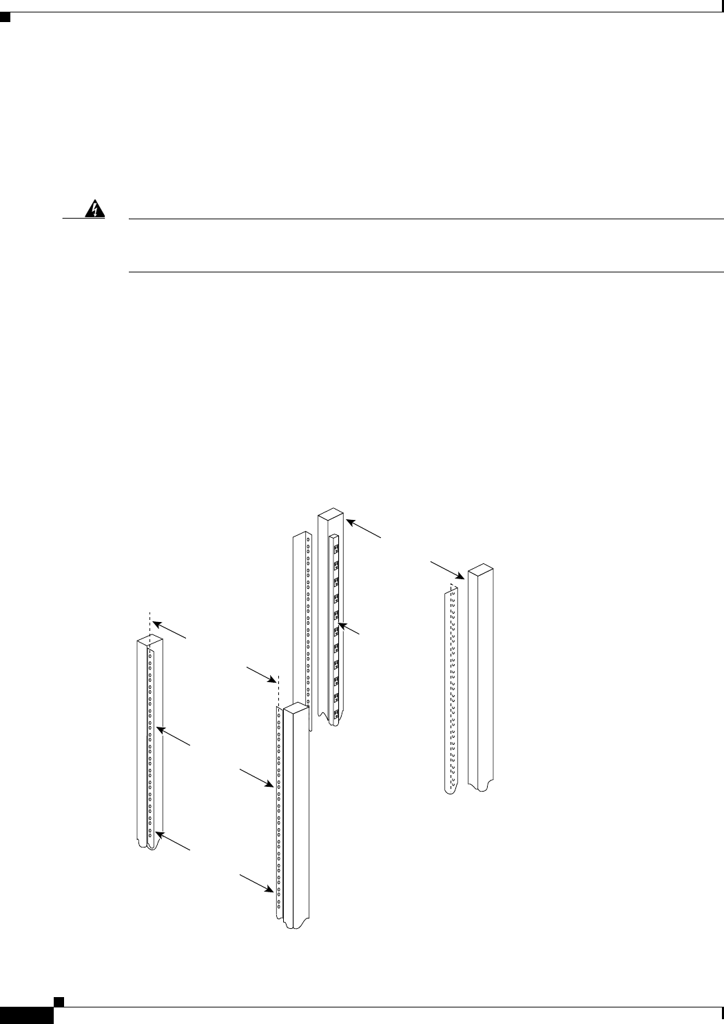
2-12
Cisco uBR10012 Universal Broadband Router Hardware Installation Guide
Chapter 2 Preparing for Installation
Site Requirements
•If you are also using the optional AC-input power shelf, it should be installed immediately below
the Cisco uBR10012 chassis for power cabling convenience. However, install the AC-input power
shelf after you install the chassis.
•Ensure that the router is connected to earth ground during normal use.
•Frame ground should be tied to the single building point ground, or the closest return point to
building ground.
Warning
This equipment must be grounded. Never defeat the ground conductor or operate the equipment in the
absence of a suitably installed ground conductor. Contact the appropriate electrical inspection
authority or an electrician if you are uncertain that suitable grounding is available.
Statement 1024
Using Power Strips with a Rack-Mount Installation
Some equipment racks provide a power strip along the length of one of the mounting strips. If your rack
has a power strip, consider the position of the strip when planning fastener points to ensure that you can
slide cards straight out of their respective slots. If the power strip does impair a rack-mount installation,
remove the power strip before installing the chassis in the rack, and then replace it after the chassis is
installed. See the “General Rack Installation Guidelines” section on page 3-3 for additional information
about rack-mounting your system.
Figure 2-2 shows a typical 19-inch, 4-post equipment rack with a power strip along one of the back posts.
Figure 2-2 Typical 19-Inch Equipment Rack Posts and Mounting Strips
18.31 in.
(46.48 cm)
hole
center-to-center
17.5 in.
(44.45 cm)
min.
Rack posts
Mounting strips
110 VAC
outlets
10327

CHAPTER
3-1
Cisco uBR10012 Universal Broadband Router Hardware Installation Guide
3
Installing the Cisco uBR10012 Router
This chapter describes the procedures for installing the Cisco uBR10012 universal broadband router in
an equipment rack. It also describes how to connect interface and power cables, the proper way to power
on the system, and installation troubleshooting procedures.
Installation involves doing the following tasks in the following order:
•Preparing the Cisco uBR10012 Router for Rack-Mounting, page 3-2
•Removing the Chassis Components Before Installation, page 3-4
•Attaching the Mounting Brackets, page 3-9
•Installing the Cable Management Brackets (Optional), page 3-13
•Mounting the Chassis in the Rack, page 3-19
•Attaching Ferrite Beads on the Cables, page 3-22
•Connecting the Chassis to Ground, page 3-25
•Connecting the External AC-input Power Shelf to the Cisco uBR10012 Router, page 3-28
•Connecting DC Power to the Cisco uBR10012 Router, page 3-39
•Connecting Alarm Indicators, page 3-41
•Connecting the Console Port and Auxiliary Port, page 3-55
•Installing the Modules, page 3-44
•Installing the Slot Splitter and Half-Height Gigabit Ethernet Line Card, page 3-47
•Connecting the Console Port and Auxiliary Port, page 3-55
•Connecting Network Management Cables, page 3-58
•Connecting Cable Interface Line Cards and Network Uplink Cards, page 3-61
•Replacing the Front Cover, page 3-65
•Powering On the System, page 3-66
•Configuring the Cisco uBR10012 Router at Startup, page 3-66
•Formatting PC Media Cards, page 3-71
Warning
This equipment must be installed and maintained by service personnel as defined by AS/NZS 3260.
Incorrectly connecting this equipment to a general-purpose outlet could be hazardous. The
telecommunications lines must be disconnected 1) before unplugging the main power connector or 2)
while the housing is open, or both.
Statement 1043

3-2
Cisco uBR10012 Universal Broadband Router Hardware Installation Guide
Chapter 3 Installing the Cisco uBR10012 Router
Installation Methods
Installation Methods
For stability and ease of use, the Cisco uBR10012 router chassis should be mounted in an equipment
rack. The chassis can be mounted in a 19-inch (standard) equipment rack (either the 4-post equipment
rack or the telco-type equipment rack) or in a 23-inch rack.
Note For 23-inch racks, optional mounting brackets must be ordered from third-party vendors.
Caution The Cisco uBR10012 router chassis should always be secured in the equipment rack for normal use and
operations.
The rack-mount kit that is shipped with the Cisco uBR10012 router includes four mounting brackets for
mounting the chassis in a standard 19-inch wide equipment rack (4-post equipment rack or telco-type).
One set of mounting brackets is sufficient to properly secure the router chassis, but an additional set can
also be ordered for mounting the chassis from the front and the back.
Note Although installing the chassis in a rack-mount is preferred for permanent installations, you can mount
the router in an alternate location, such as on an equipment shelf or on a tabletop for testing or diagnostic
purposes.
Preparing the Cisco uBR10012 Router for Rack-Mounting
The Cisco uBR10012 router chassis can be installed in a standard 19-inch equipment rack or telco rack,
either front or rear mounted, and either flush or offset from the rack.
This section describes the following guidelines and steps that must be followed before rack-mounting
the Cisco uBR10012 router:
•General Rack Installation Guidelines, page 3-3
•Removing the Chassis Components Before Installation, page 3-4
•Attaching the Mounting Brackets, page 3-9
•Installing the Cable Management Brackets (Optional), page 3-13
Caution Before performing any of the steps in this section, be certain you have read and understood the guidelines
given in Chapter 2, “Preparing for Installation.”

3-3
Cisco uBR10012 Universal Broadband Router Hardware Installation Guide
Chapter 3 Installing the Cisco uBR10012 Router
Preparing the Cisco uBR10012 Router for Rack-Mounting
General Rack Installation Guidelines
When planning your rack installation, consider the following guidelines:
•The Cisco uBR10012 router chassis requires a minimum of 18 rack units (31.5 in. or 80 cm) of
vertical rack space. Measure the proposed rack location before mounting the chassis in the rack.
•Before using a particular rack, check for obstructions (such as a power strip) that could impair
rack-mount installation. If a power strip does impair a rack-mount installation, remove the power
strip before installing the chassis, and then replace it after the chassis is installed.
•Allow sufficient clearance around the rack for maintenance. If the rack is mobile, you can push it
back near a wall or cabinet for normal operation and pull it out for maintenance (installing or moving
line cards, connecting cables, or replacing or upgrading components). Otherwise, allow 19 in. (48.3
cm) of clearance to remove FRUs.
•Maintain a minimum clearance of 3 in. (7.62 cm) on the front and back of the chassis for the cooling
air inlet and exhaust ports, respectively. Avoid placing the chassis in an overly congested rack or
directly next to another equipment rack; otherwise, the heated exhaust air from other equipment can
enter the inlet air vents and cause an overtemperature condition inside the router.
Caution To prevent chassis overheating, never install a Cisco uBR10012 router in an enclosed rack or room that
is not properly ventilated or air conditioned.
•If also installing the optional AC-input power shelf, allow at last two rack units below the
Cisco uBR10012 chassis for the power shelf installation. Install the AC-input power shelf after you
have installed the Cisco uBR10012 chassis to avoid the possibility of accidentally crushing the
power shelf during the router’s installation.
•Cisco recommends installing an optional equipment shelf in the rack for the Cisco uBR10012
chassis because it simplifies installation, but this is not required.
•Always install heavier equipment in the lower half of a rack to maintain a low center of gravity to
prevent the rack from falling over. However, if you are also installing an AC-power shelf, leave
enough space for the power shelf plus 2 rack units (RUs) underneath the Cisco uBR10012 chassis.
•Ensure that cables from other equipment already installed in the rack do not impair access to the
cards, or require you to disconnect cables unnecessarily to perform equipment maintenance or
upgrades.
•Install rack stabilizers (if available) before you mount the chassis.
•Provide an adequate chassis ground (earth) connection for your router chassis.
In addition to the preceding guidelines, review the precautions for avoiding excessive temperature
conditions in the “Temperature and Humidity Requirements” section on page 2-7.

3-4
Cisco uBR10012 Universal Broadband Router Hardware Installation Guide
Chapter 3 Installing the Cisco uBR10012 Router
Removing the Chassis Components Before Installation
Removing the Chassis Components Before Installation
The Cisco uBR10012 router is shipped with all ordered components already installed in the chassis.
When fully configured, the Cisco uBR10012 chassis weighs approximately 230 lbs (104.3 kg).
Caution You must use a hydraulic lift or forklift to move a fully populated chassis.
If you have to move a fully populated chassis and you do not have a hydraulic lift or forklift available,
you must first remove the following components from the chassis:
•AC or DC power entry modules (PEMs)
•Fan assembly module
•Cable interface line cards
•Network uplink line cards, Slot splitter, and half-height Gigabit Ethernet line cards
In a fully loaded chassis, these components weigh approximately 170 lbs (77.11 kg), removing the
components allows the chassis to be moved ssfely using two people. Reinstall the components after the
chassis has been moved and installed. Use the following procedures to remove these components.
Before You Begin
•Make sure that you have an antistatic surface available for the components that you are removing
from the chassis.
•Make sure that you are wearing antistatic protection such as a wrist strap or heel strap and are
properly grounded.
Removing the Half-Height Gigabit Ethernet Line Card and the Slot Splitters
This section describes how to properly remove HHGE line cards and the slot splitter from the chassis.
This section includes the following tasks:
•Removing a Half-Height Gigabit Ethernet Line Card, page 3-4
•Removing the Slot Splitter, page 3-7
Removing a Half-Height Gigabit Ethernet Line Card
Use the following procedure to remove the HHGE line card from the slot splitter:
Step 1 Verify that you are properly grounded.
Step 2 Disconnect any network cables connected to the line card port.

3-5
Cisco uBR10012 Universal Broadband Router Hardware Installation Guide
Chapter 3 Installing the Cisco uBR10012 Router
Removing the Chassis Components Before Installation
Figure 3-1 Captive Screw Locations
Step 3 Use a screwdriver to loosen the top and bottom captive screws until they disengage and spring away from
the face plate (Figure 3-1).
Step 4 Simultaneously pivot both ejector levers away from each other to disengage the line card from the
backplane (Figure 3-2).
Step 5 Slide the line card out of the slot splitter and place it on an antistatic surface or in an antistatic bag.
Step 6 If you are not installing a replacement line card, install a blank faceplate in the slot.
135154
US0
US1
US2
US3
US4
US5
US6
US7
US8
US9
US10
US11
US12
US13
US14
US15
US16
US17
US18
US19
DS0
DS1
DS2
DS3
DS4
RF
RF
RF
RF
RF
uBR10-MC5x20S-D
POWER
STATUS
MAINT
US0
US1
US2
US3
US4
US5
US6
US7
US8
US9
US10
US11
US12
US13
US14
US15
US16
US17
US18
US19
DS0
DS1
DS2
DS3
DS4
RF
RF
RF
RF
RF
uBR10-MC5x20S-D
POWER
STATU S
MAINT
US0
US1
US2
US3
US4
US5
US6
US7
US8
US9
US10
US11
US12
US13
US14
US15
US16
US17
US18
US19
DS0
DS1
DS2
DS3
DS4
RF
RF
RF
RF
RF
uBR10-MC5x20S-D
POWER
ST
ATUS
MAINT
US0
US1
US2
US3
US4
US5
US6
US7
US8
US9
US10
US11
US12
US13
US14
US15
US16
US17
US18
US19
DS0
DS1
DS2
DS3
DS4
RF
RF
RF
RF
RF
uBR10-MC5x20S-D
POWER
STATUS
MAINT
US0
US1
US2
US3
US4
US5
US6
US7
US8
US9
US10
US11
US12
US13
US14
US15
US16
US17
US18
US19
DS0
DS1
DS2
DS3
DS4
RF
RF
RF
RF
RF
uBR10-MC5x20S-D
POWER
STATUS
MAINT
US0
US1
US2
US3
US4
US5
US6
US7
US8
US9
US10
US11
US12
US13
US14
US15
US16
US17
US18
US19
DS0
DS1
DS2
DS3
DS4
RF
RF
RF
RF
RF
uBR10-MC5x20S-D
POWER
STATUS
MAINT
US0
US1
US2
US3
US4
US5
US6
US7
US8
US9
US10
US11
US12
US13
US14
US15
US16
US17
US18
US19
DS0
DS1
DS2
DS3
DS4
RF
RF
RF
RF
RF
uBR10-MC5x20S-D
POWER
STATUS
MAINT
US1
US2
US3
US4
US5
US6
US7
US8
US9
US10
US11
US12
US13
US14
US15
US16
US17
US18
US19
DS0
DS1
DS2
DS3
DS4
RF
RF
RF
RF
RF
uBR10-MC5x20S-D
POWER
STA
TUS
MAINT
CISCO
10000
CISCO
10000
FAIL
LINK
CISCO
10000
ENABLE
POS
SRP
FAIL
OC–48/STM–16 POS/SRP SM–LR
CD
TX
RX
SYNC
WRAP
P
ASS
THRU
TX
RX
CISCO
10000
ENABLE
POS
SRP
FAIL
OC–48/STM–16 POS/SRP SM–LR
CD
TX
RX
SYNC
WRAP
P
ASS
THRU
TX
RX
Captive screw
Captive screw
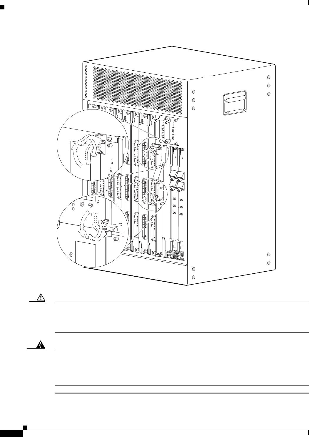
3-6
Cisco uBR10012 Universal Broadband Router Hardware Installation Guide
Chapter 3 Installing the Cisco uBR10012 Router
Removing the Chassis Components Before Installation
Figure 3-2 Opening the Ejector Levers
Caution Do not operate the system unless all slots contain a line card or a blank faceplate. Always install a
full-slot blank faceplate into an empty slot. Half-height blank faceplates do not have air dams, and the
empty slot will rob cooling air from the other slots. A slot splitter with one half-height line card and one
blank faceplate is allowed.
Warning
Blank faceplates and cover panels serve three important functions: they prevent exposure to
hazardous voltages and currents inside the chassis; they contain electromagnetic interference (EMI)
that might disrupt other equipment; and they direct the flow of cooling air through the chassis. Do not
operate the system unless all cards, faceplates, front covers, and rear covers are in place.
Statement 1029
135156
US0
US1
US2
US3
US4
US5
US6
US7
US8
US9
US10
US11
US12
US13
US14
US15
US16
US17
US18
US19
DS0
DS1
DS2
DS3
DS4
RF
RF
RF
RF
RF
uBR10-MC5x20S-D
POWER
STATUS
MAINT
US0
US1
US2
US3
US4
US5
US6
US7
US8
US9
US10
US11
US12
US13
US14
US15
US16
US17
US18
US19
DS0
DS1
DS2
DS3
DS4
RF
RF
RF
RF
RF
uBR10-MC5x20S-D
POWER
STA
TUS
MAINT
US0
US1
US2
US3
US4
US5
US6
US7
US8
US9
US10
US11
US12
US13
US14
US15
US16
US17
US18
US19
DS0
DS1
DS2
DS3
DS4
RF
RF
RF
RF
RF
uBR10-MC5x20S-D
POWER
STATUS
MAINT
US0
US1
US2
US3
US4
US5
US6
US7
US8
US9
US10
US11
US12
US13
US14
US15
US16
US17
US18
US19
DS0
DS1
DS2
DS3
DS4
RF
RF
RF
RF
RF
uBR10-MC5x20S-D
POWER
STATUS
MAINT
US0
US1
US2
US3
US4
US5
US6
US7
US8
US9
US10
US11
US12
US13
US14
US15
US16
US17
US18
US19
DS0
DS1
DS2
DS3
DS4
RF
RF
RF
RF
RF
uBR10-MC5x20S-D
POWER
STATUS
MAINT
US0
US1
US2
US3
US4
US5
US6
US7
US8
US9
US10
US11
US12
US13
US14
US15
US16
US17
US18
US19
DS0
DS1
DS2
DS3
DS4
RF
RF
RF
RF
RF
uBR10-MC5x20S-D
POWER
ST
ATUS
MAINT
US0
US1
US2
US3
US4
US5
US6
US7
US8
US9
US10
US11
US12
US13
US14
US15
US16
US17
US18
US19
DS0
DS1
DS2
DS3
DS4
RF
RF
RF
RF
RF
uBR10-MC5x20S-D
POWER
STA
TUS
MAINT
US0
US1
US2
US3
US4
US5
US6
US7
US8
US9
US10
US11
US12
US13
US14
US15
US16
US17
US18
US19
DS0
DS1
DS2
DS3
DS4
RF
RF
RF
RF
RF
uBR10-MC5x20S-D
POWER
STATUS
MAINT
CISCO
10000
CISCO
10000
FAIL
LINK
CISCO
10000
ENABLE
POS
SRP
FAIL
OC–48/STM–16 POS/SRP SM–LR
CD
TX
RX
SYNC
WRAP
P
ASS
THRU
TX
RX
CISCO
10000
ENABLE
POS
SRP
FAIL
OC–48/STM–16 POS/SRP SM–LR
CD
TX
RX
SYNC
WRAP
P
ASS
THRU
TX
RX
CISCO
10000
CISCO
10000
FAI L
LINK
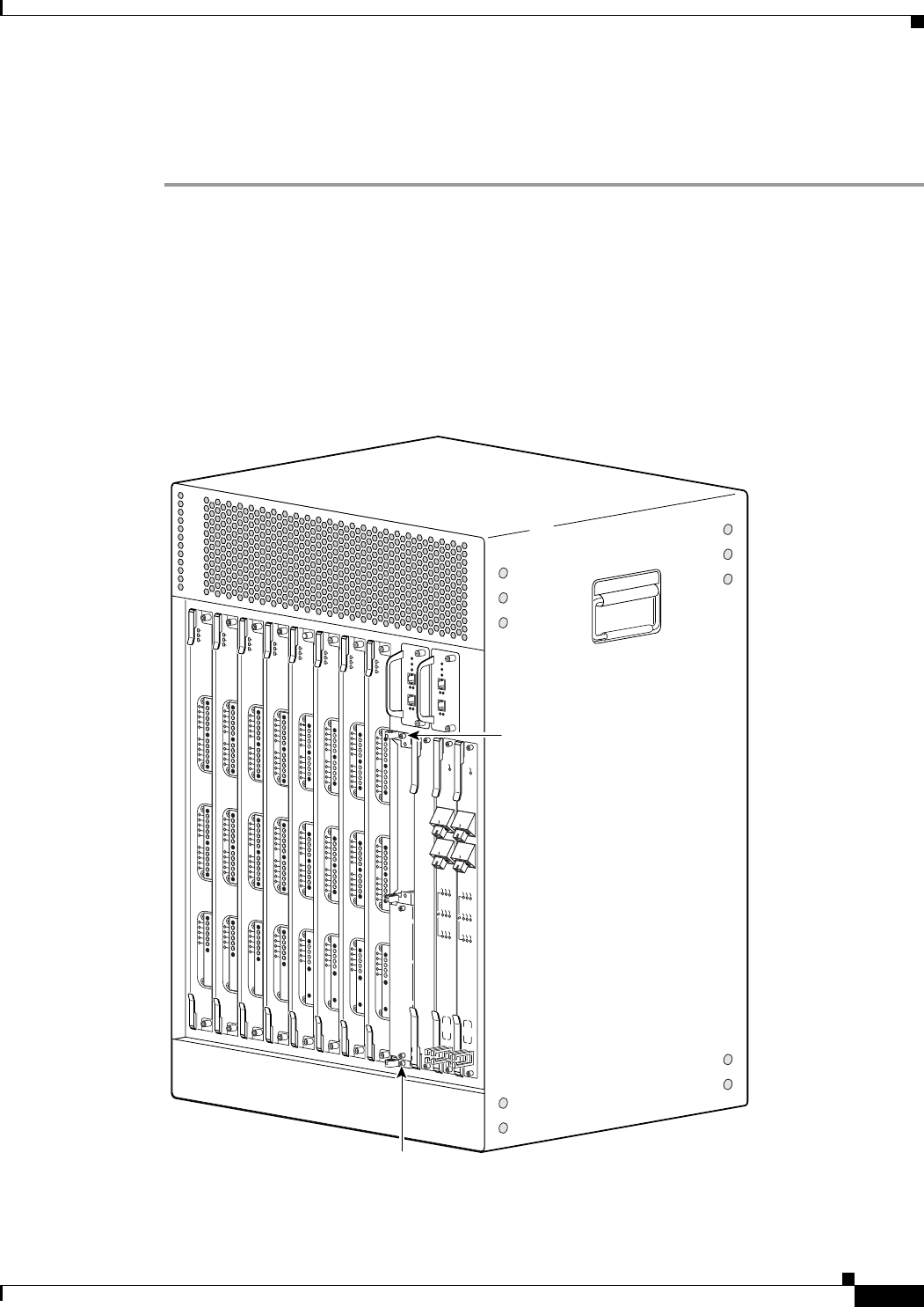
3-7
Cisco uBR10012 Universal Broadband Router Hardware Installation Guide
Chapter 3 Installing the Cisco uBR10012 Router
Removing the Chassis Components Before Installation
Removing the Slot Splitter
Use the following procedure to remove a slot splitter from the chassis:
Step 1 Attach an antistatic wrist strap to your wrist and to the ESD socket on the chassis, or to a bare metal
surface on the chassis or frame).
Step 2 Remove any line cards from the splitter, see the “Removing a Half-Height Gigabit Ethernet Line Card”
section on page 3-4.
The slot splitter does not have ejector levers to disengage cards from the backplane, so you must remove
any line cards before you remove the splitter.
Step 3 Loosen the top and bottom captive screws on the slot splitter (Figure 3-3).
Figure 3-3 Captive Screw Locations
135150
US0
US1
US2
US3
US4
US5
US6
US7
US8
US9
US10
US11
US12
US13
US14
US15
US16
US17
US18
US19
DS0
DS1
DS2
DS3
DS4
RF
RF
RF
RF
RF
uBR10-MC5x20S-D
POWER
STATUS
MAINT
US0
US1
US2
US3
US4
US5
US6
US7
US8
US9
US10
US11
US12
US13
US14
US15
US16
US17
US18
US19
DS0
DS1
DS2
DS3
DS4
RF
RF
RF
RF
RF
uBR10-MC5x20S-D
POWER
STATUS
MAINT
US0
US1
US2
US3
US4
US5
US6
US7
US8
US9
US10
US11
US12
US13
US14
US15
US16
US17
US18
US19
DS0
DS1
DS2
DS3
DS4
RF
RF
RF
RF
RF
uBR10-MC5x20S-D
POWER
STATU S
MAINT
US0
US1
US2
US3
US4
US5
US6
US7
US8
US9
US10
US11
US12
US13
US14
US15
US16
US17
US18
US19
DS0
DS1
DS2
DS3
DS4
RF
RF
RF
RF
RF
uBR10-MC5x20S-D
POWER
ST
ATUS
MAINT
US0
US1
US2
US3
US4
US5
US6
US7
US8
US9
US10
US11
US12
US13
US14
US15
US16
US17
US18
US19
DS0
DS1
DS2
DS3
DS4
RF
RF
RF
RF
RF
uBR10-MC5x20S-D
POWER
STA
TUS
MAINT
US0
US1
US2
US3
US4
US5
US6
US7
US8
US9
US10
US11
US12
US13
US14
US15
US16
US17
US18
US19
DS0
DS1
DS2
DS3
DS4
RF
RF
RF
RF
RF
uBR10-MC5x20S-D
POWER
STATUS
MAINT
US0
US1
US2
US3
US4
US5
US6
US7
US8
US9
US10
US11
US12
US13
US14
US15
US16
US17
US18
US19
DS0
DS1
DS2
DS3
DS4
RF
RF
RF
RF
RF
uBR10-MC5x20S-D
POWER
STATUS
MAINT
US0
US1
US2
US3
US4
US5
US6
US7
US8
US9
US10
US11
US12
US13
US14
US15
US16
US17
US18
US19
DS0
DS1
DS2
DS3
DS4
RF
RF
RF
RF
RF
uBR10-MC5x20S-D
POWER
STATUS
MAINT
CISCO
10000
CISCO
10000
ENABLE
POS
SRP
FAIL
OC–48/STM–16 POS/SRP SM–LR
CD
TX
RX
SYNC
WRAP
P
ASS
THRU
TX
RX
CISCO
10000
ENABLE
POS
SRP
FAIL
OC–48/STM–16 POS/SRP SM–LR
CD
TX
RX
SYNC
WRAP
P
ASS
THRU
TX
RX
Captive
screw
Captive
screw
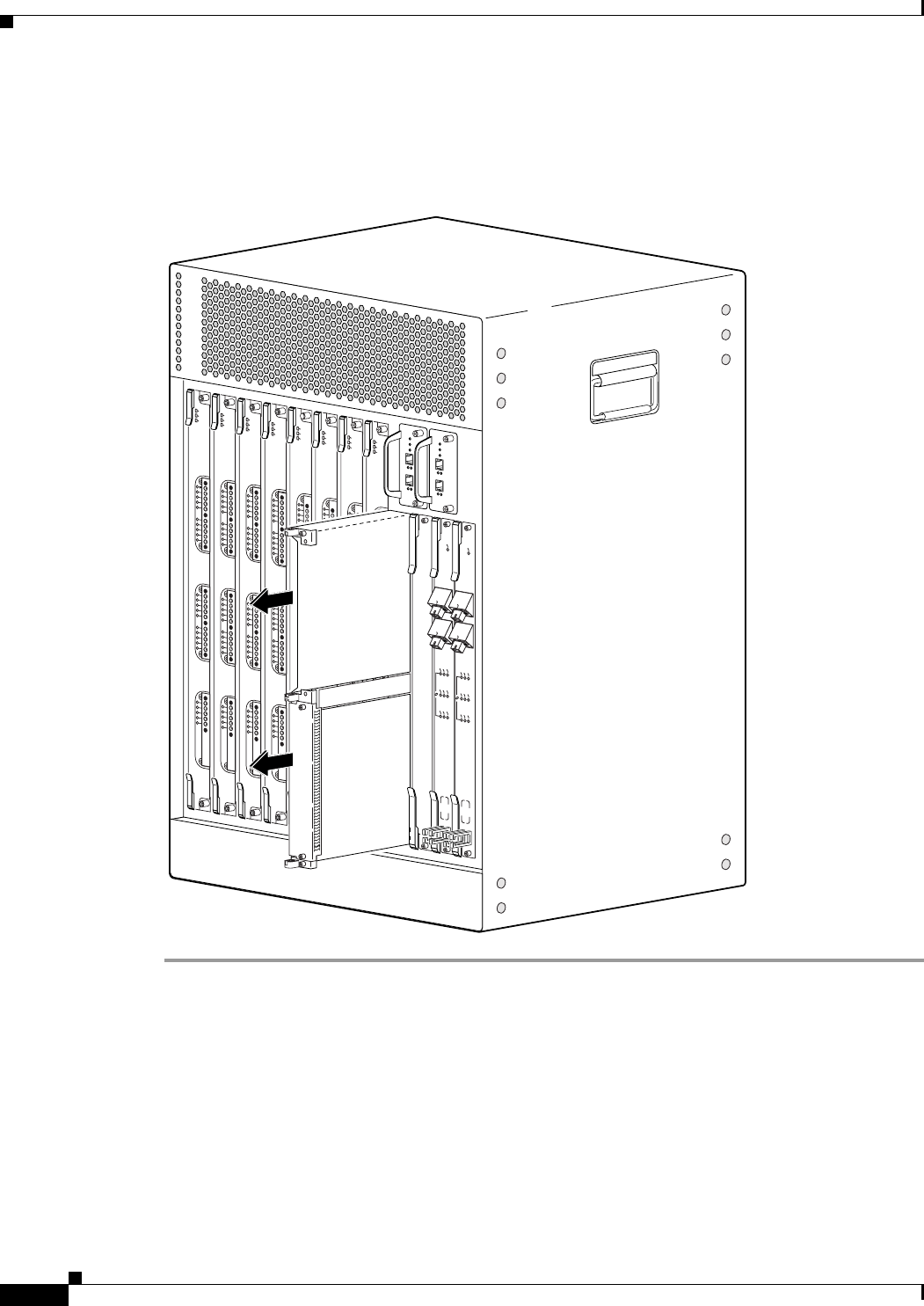
3-8
Cisco uBR10012 Universal Broadband Router Hardware Installation Guide
Chapter 3 Installing the Cisco uBR10012 Router
Removing the Chassis Components Before Installation
Step 4 Slide the splitter out of the slot (Figure 3-4).
Step 5 If you are not installing a replacement splitter or a line card, install a full-slot blank faceplate in the slot.
Figure 3-4 Removing the Slot Splitter
135157
US0
US1
US2
US3
US4
US5
US6
US7
US8
US9
US10
US11
US12
US13
US14
US15
US16
US17
US18
US19
DS0
DS1
DS2
DS3
DS4
RF
RF
RF
RF
RF
uBR10-MC5x20S-D
POWER
STA
TUS
MAINT
US0
US1
US2
US3
US4
US5
US6
US7
US8
US9
US10
US11
US12
US13
US14
US15
US16
US17
US18
US19
DS0
DS1
DS2
DS3
DS4
RF
RF
RF
RF
RF
uBR10-MC5x20S-D
POWER
STATUS
MAINT
US0
US1
US2
US3
US4
US5
US6
US7
US8
US9
US10
US11
US12
US13
US14
US15
US16
US17
US18
US19
DS0
DS1
DS2
DS3
DS4
RF
RF
RF
RF
RF
uBR10-MC5x20S-D
POWER
ST
ATUS
MAINT
US0
US1
US2
US3
US4
US5
US6
US7
US8
US9
US10
US11
US12
US13
US14
US15
US16
US17
US18
US19
DS0
DS1
DS2
DS3
DS4
RF
RF
RF
RF
RF
uBR10-MC5x20S-D
POWER
STA
TUS
MAINT
US0
US1
US2
US3
US4
US5
US6
US7
US8
US9
US10
US11
US12
US13
US14
US15
US16
US17
US18
US19
DS0
DS1
DS2
DS3
DS4
RF
RF
RF
RF
RF
uBR10-MC5x20S-D
POWER
STATUS
MAINT
US0
US1
US2
US3
US4
US5
US6
US7
US8
US9
US10
US11
US12
US13
US14
US15
US16
US17
US18
US19
DS0
DS1
DS2
DS3
DS4
RF
RF
RF
RF
RF
uBR10-MC5x20S-D
POWER
ST
ATUS
MAINT
US0
US1
US2
US3
US4
US5
US6
US7
US8
US9
US10
US11
US12
US13
US14
US15
US16
US17
US18
US19
DS0
DS1
DS2
DS3
DS4
RF
RF
RF
RF
RF
uBR10-MC5x20S-D
POWER
STATUS
MAINT
US0
US1
US2
US3
US4
US5
US6
US7
US8
US9
US10
US11
US12
US13
US14
US15
US16
US17
US18
US19
DS0
DS1
DS2
DS3
DS4
RF
RF
RF
RF
RF
uBR10-MC5x20S-D
POWER
STATUS
MAINT
CISCO
10000
CISCO
10000
ENABLE
POS
SRP
FAIL
OC–48/STM–16 POS/SRP SM–LR
CD
TX
RX
SYNC
WRAP
P
ASS
THRU
TX
RX
CISCO
10000
ENABLE
POS
SRP
FAIL
OC–48/STM–16 POS/SRP SM–LR
CD
TX
RX
SYNC
WRAP
P
ASS
THRU
TX
RX
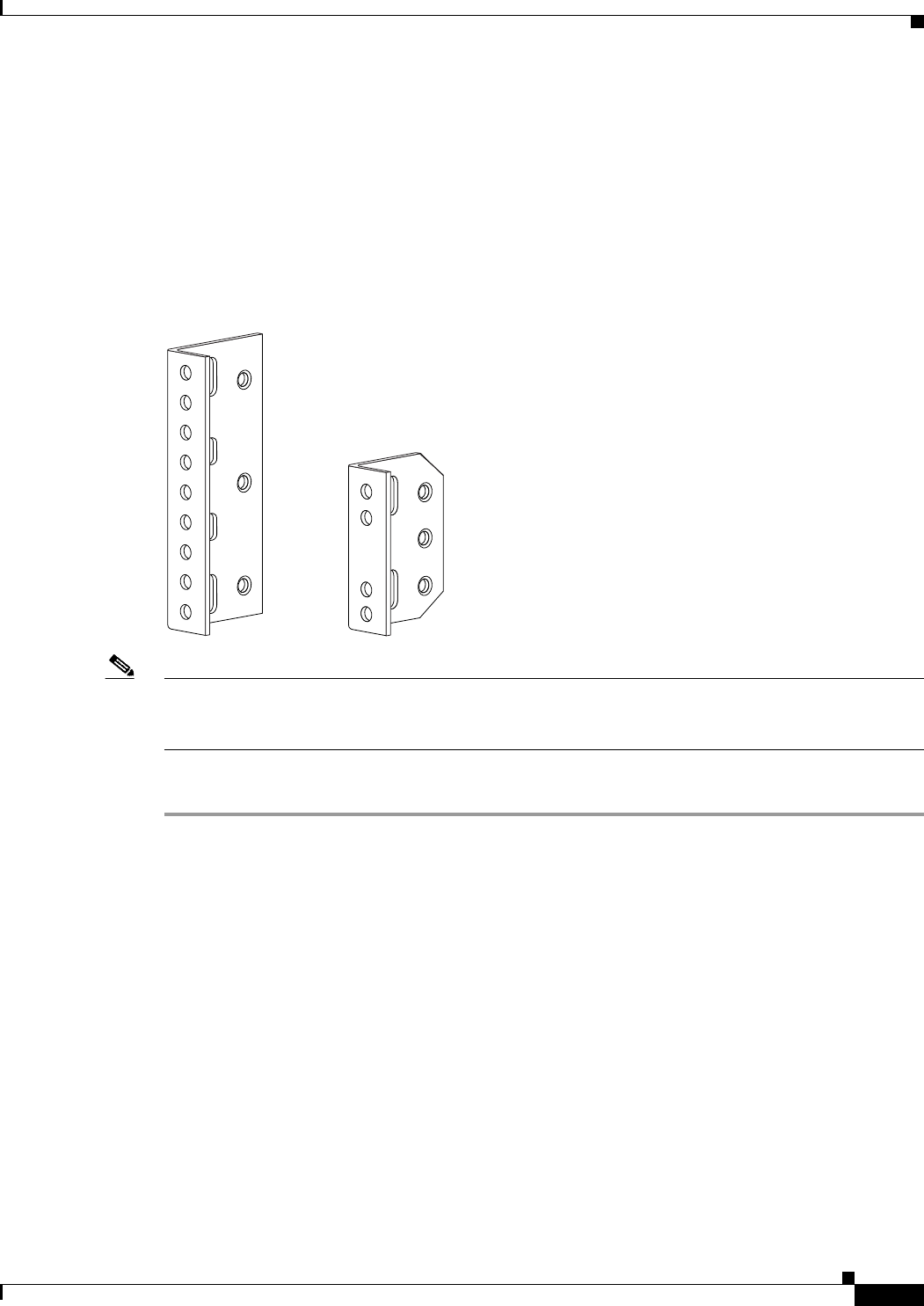
3-9
Cisco uBR10012 Universal Broadband Router Hardware Installation Guide
Chapter 3 Installing the Cisco uBR10012 Router
Attaching the Mounting Brackets
Attaching the Mounting Brackets
The Cisco uBR10012 router is shipped with four mounting brackets that can be attached to either the
front or rear of the chassis, depending on your mounting preferences. The brackets can be mounted either
flush with the edge of the chassis or set back to allow the chassis to be offset mounted in the rack.
Figure 3-5 shows the mounting brackets shipped with the Cisco uBR10012 chassis for use with a
standard 19-inch equipment or telco rack:
Figure 3-5 Mounting Brackets for the Cisco uBR10012 Router
Note The four mounting brackets shipped with the Cisco uBR10012 router are for a standard 19-inch
equipment rack or telco rack. Optional mounting brackets are orderable separately from third-party
vendors to install the chassis in a 23-inch rack.
Use the following procedure to attach the mounting brackets to the chassis.
Step 1 Determine whether you will be mounting the chassis with the front or rear facing forwards.
Step 2 Determine whether you will flush-mount or offset-mount the chassis. Typically, flush-mounting is used
for most equipment racks except for telco racks that require offset-mounting. If either style can be used,
choose the one that is most convenient for your site.
Step 3 Attach two mounting brackets to each side of the chassis in the appropriate locations. The large
mounting bracket is attached to the top of the chassis, and the smaller bracket is attached to the bottom
of the chassis.
Attach the brackets as shown in the following figures, using the screws that are supplied with the
brackets:
•Figure 3-6 shows how to attach the brackets to flush-mount the chassis with the front forwards.
•Figure 3-7 shows how to attach the brackets to flush-mount the chassis with the rear forwards.
•Figure 3-8 shows how to attach the brackets to offset-mount the chassis with the front forwards.
58697
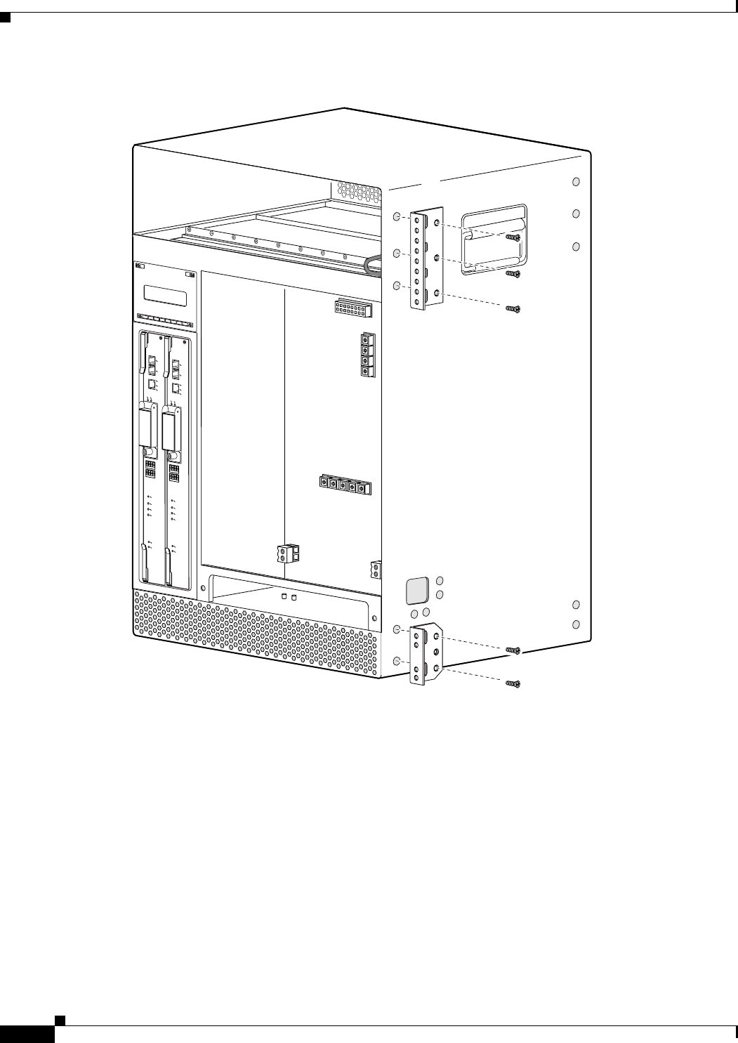
3-10
Cisco uBR10012 Universal Broadband Router Hardware Installation Guide
Chapter 3 Installing the Cisco uBR10012 Router
Attaching the Mounting Brackets
Figure 3-6 Bracket Location for Flush Front-Mounting the Chassis
72311
ALARMS
CISCO
10000
FAIL
PERFORMANCE ROUTING ENGINE
CONSOLE
STATUS
ACO
CRITICAL
MINOR
MAJOR
ETHERNET
LINK
ACTIVITY
AUX
SLOT 0
SLOT 1
ALARMS
CISCO
10000
FAIL
PERFORMANCE ROUTING ENGINE
CONSOLE
STATUS
ACO
CRITICAL
MINOR
MAJOR
ETHERNET
LINK
ACTIVITY
AUX
SLOT 0
SLOT 1
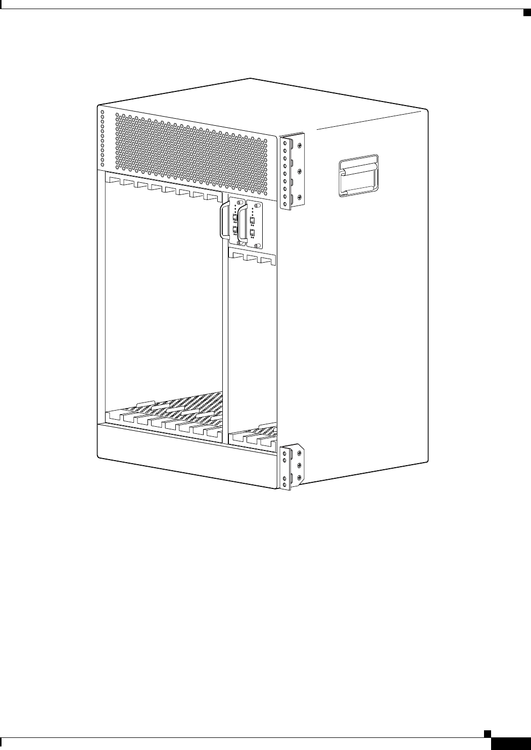
3-11
Cisco uBR10012 Universal Broadband Router Hardware Installation Guide
Chapter 3 Installing the Cisco uBR10012 Router
Attaching the Mounting Brackets
Figure 3-7 Bracket Location for Flush Rear-Mounting the Chassis
72312
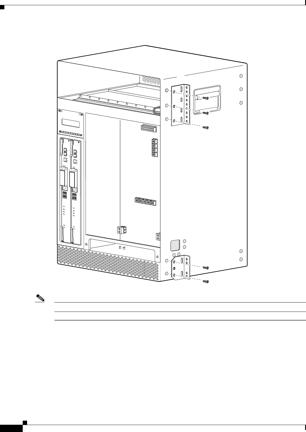
3-12
Cisco uBR10012 Universal Broadband Router Hardware Installation Guide
Chapter 3 Installing the Cisco uBR10012 Router
Attaching the Mounting Brackets
Figure 3-8 Bracket Location for Offset Front-Mounting the Chassis
Note You must use three screws to install each large bracket and two screws to install each small bracket.
To install the optional cable management brackets, proceed to the next section. Otherwise, proceed to
the “Mounting the Chassis in the Rack” section on page 3-19 for instructions on mounting the
Cisco uBR10012 chassis in the equipment or telco rack.
72313
ALARMS
CISCO
10000
FAIL
PERFORMANCE ROUTING ENGINE
CONSOLE
STATUS
ACO
CRITICAL
MINOR
MAJOR
ETHERNET
LINK
ACTIVITY
AUX
SLOT 0
SLOT 1
ALARMS
CISCO
10000
FAIL
PERFORMANCE ROUTING ENGINE
CONSOLE
STATUS
ACO
CRITICAL
MINOR
MAJOR
ETHERNET
LINK
ACTIVITY
AUX
SLOT 0
SLOT 1
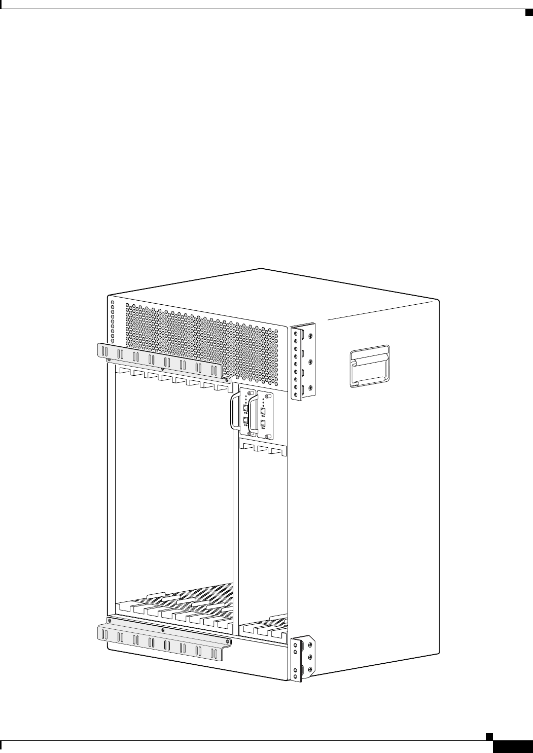
3-13
Cisco uBR10012 Universal Broadband Router Hardware Installation Guide
Chapter 3 Installing the Cisco uBR10012 Router
Installing the Cable Management Brackets (Optional)
Installing the Cable Management Brackets (Optional)
The Cisco uBR10012 router is shipped with two cable management brackets that can be installed on the
rear of the router’s chassis to route the cables connected to the cable interface line cards.
For installing first-generation cable management brackets see “Installing First-Generation Cable
Management Brackets” section on page 3-13 and for installing second-generation cable management
bracket see “Installing the Second-Generation Cable Management Bracket” section on page 3-14.
Installing First-Generation Cable Management Brackets
Figure 3-9 shows the rear of Cisco uBR10012 chassis with the two first-generation cable management
brackets installed.
Figure 3-9 Installing the Optional First-Generation Cable Management Brackets
72314

3-14
Cisco uBR10012 Universal Broadband Router Hardware Installation Guide
Chapter 3 Installing the Cisco uBR10012 Router
Installing the Cable Management Brackets (Optional)
Use the following procedure to install the optional first-generation cable management brackets on the
rear of the Cisco uBR10012 chassis:
Step 1 Position the first mounting bracket immediately above the cable interface line card installation slots.
Make sure that the portion of the bracket with the slots is above the mounting holes, so that the bracket
will not interfere with the insertion and removal of the line cards. See Figure 3-9.
Step 2 Align the mounting holes on the far left and far right on the bracket first, so that the center mounting
hole will be aligned properly.
Step 3 Use the three screws that are provided in the accessory kit to attach the bracket to the chassis.
Step 4 Attach the bottom cable management bracket in a similar manner, making sure that the slot edge of the
bracket is pointing down. See Figure 3-9.
Note Make sure that the slot edge on the bracket is pointed downward, otherwise the bracket interferes
with the insertion and removal of the cable interface line cards.
Step 5 Insert cable ties through the slots on the top and bottom of the brackets and use the cable ties as needed
to secure the cables for the line card interfaces along the top and bottom of the chassis.
Installing the Second-Generation Cable Management Bracket
•You can install the cable management bracket above or below the line card slots. The procedures
and illustrations used in this section shows the installation of cable management bracket above the
line card slot. You can attach the cable management bracket below the line card slot in a similar way.
•If the chassis is installed in a rack-rail on rear flush-mounted style, as in Figure 3-11, see “Attaching
Cable Management Bracket on the Rear Flush-Mounted Chassis” section on page 3-14 or if the
chassis is installed in a rack-rail on rear offset-mounted style, as in Figure 3-13, see “Attaching
Cable Management Bracket on the Rear Offset-Mounted Chassis” section on page 3-17.
Note The Cisco uBR10012 chassis now ships with only one second-generation cable management bracket.
Attaching Cable Management Bracket on the Rear Flush-Mounted Chassis
To install the optional second-generation cable management bracket on the rear-side (line-card side) of
the flush-mounted Cisco uBR10012 chassis:
Step 1 Attach the cable management bracket rack-rail mounting left adaptor to the left side of the cable
management bracket, using two of the four M5 attachment thumb screws supplied with the bracket. See
Figure 3-10.
Step 2 Attach the cable management bracket rack-rail mounting right adaptor to the right side of the cable
management bracket, using the remaining two M5 attachment thumb screws supplied with the bracket.
See Figure 3-10.
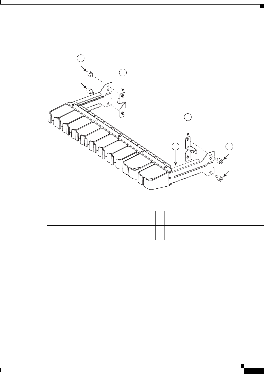
3-15
Cisco uBR10012 Universal Broadband Router Hardware Installation Guide
Chapter 3 Installing the Cisco uBR10012 Router
Installing the Cable Management Brackets (Optional)
Figure 3-10 shows the second-generation cable management bracket and the cable management rack-rail
mounting adaptors used when the Cisco uBR10012 chassis is rear flush-mounted.
Figure 3-10 Second-Generation Cable Management Bracket and Rack-Rail Mounting Adaptors
Step 3 Attach the cable management assembly to the rack-rails, using screws. See Figure 3-11.
246830
4
1
2
2
3
1Second-generation cable management bracket
rack-rail mounting right adaptor
3Second-generation cable management bracket
2M5 attachment thumb screws 4Second-generation cable management bracket
rack-rail mounting left adaptor
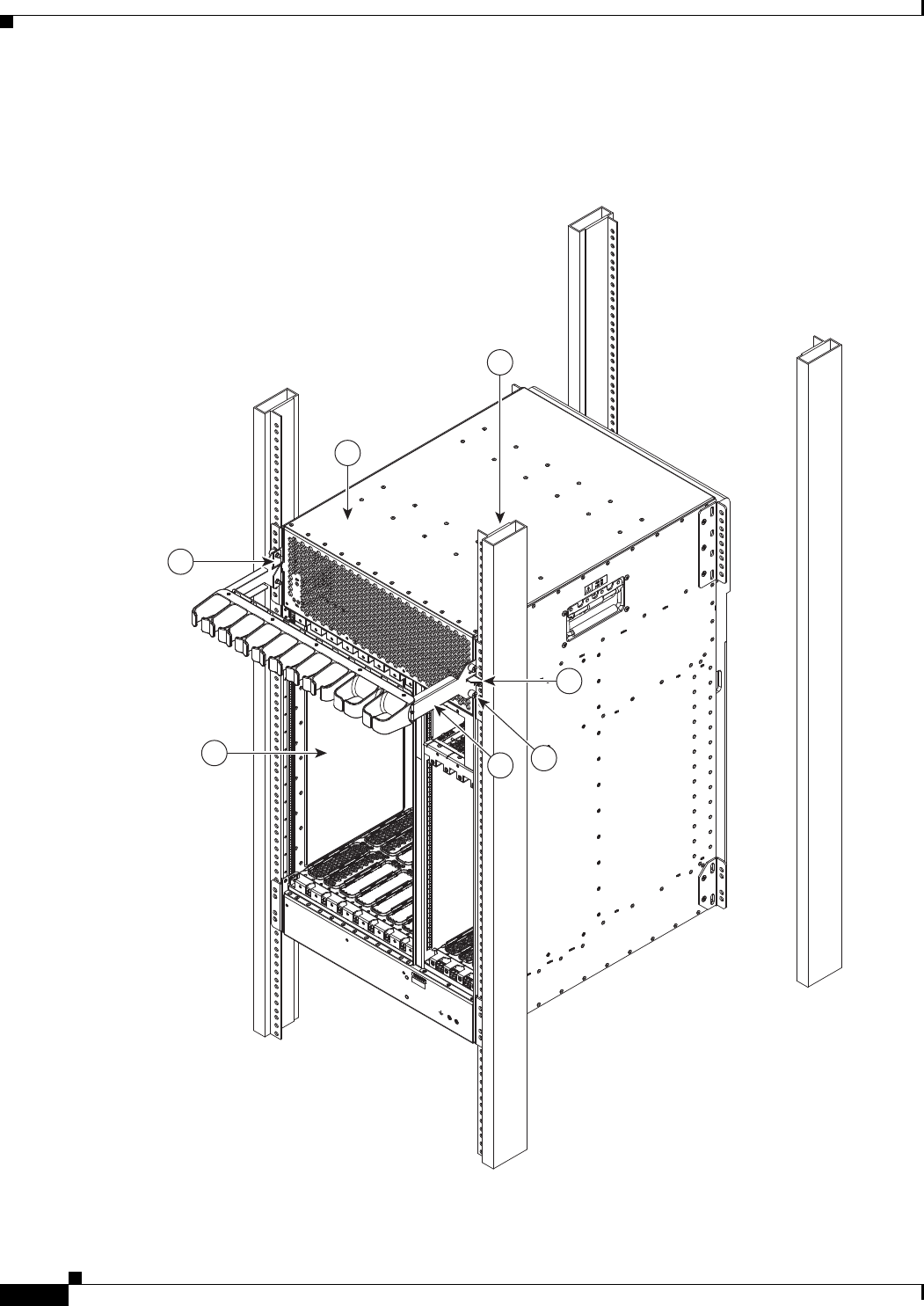
3-16
Cisco uBR10012 Universal Broadband Router Hardware Installation Guide
Chapter 3 Installing the Cisco uBR10012 Router
Installing the Cable Management Brackets (Optional)
Figure 3-11 shows the rear flush-mounted Cisco uBR10012 chassis in rack-rails with a
second-generation cable management bracket installed above the line card slots.
Figure 3-11 Second-Generation Cable Management Bracket on the Rear Flush-Mounted Chassis
246833
2
3
4
5
6
1
1

3-17
Cisco uBR10012 Universal Broadband Router Hardware Installation Guide
Chapter 3 Installing the Cisco uBR10012 Router
Installing the Cable Management Brackets (Optional)
Attaching Cable Management Bracket on the Rear Offset-Mounted Chassis
To install the optional second-generation cable management bracket on the rear-side (line-card side) of
the offset-mounted Cisco uBR10012 chassis:
Step 1 Align the holes of the cable management bracket with holes meant for the mounting bracket on the left
and right side of the chassis. See Figure 3-12.
Step 2 Attach the cable management bracket to the chassis, using the four M5 attachment thumb screws that are
supplied with the bracket. See Figure 3-12.
1Second-generation cable management bracket
rack-rail mounting adaptors
4M5 attachment thumb screws
2Cisco uBR10012 chassis 5Second-generation cable management bracket
3Rack pole 6Line card slots
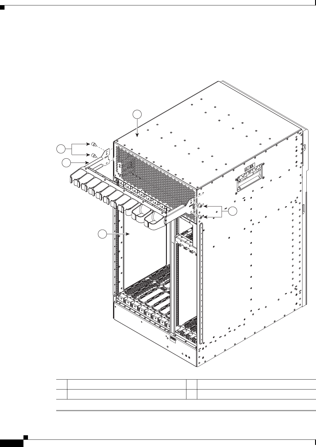
3-18
Cisco uBR10012 Universal Broadband Router Hardware Installation Guide
Chapter 3 Installing the Cisco uBR10012 Router
Installing the Cable Management Brackets (Optional)
Figure 3-12 shows the rear offset-mounted Cisco uBR10012 chassis with a second-generation cable
management bracket installed above the line card slot.
Figure 3-12 Installing the Second-Generation Cable Management Bracket on the Rear
Offset-Mounted Chassis
1Cisco uBR10012 chassis 3Cable management bracket
2M5 attachment thumb screws 4Line card slots
246831
1
4
3
2
2

3-19
Cisco uBR10012 Universal Broadband Router Hardware Installation Guide
Chapter 3 Installing the Cisco uBR10012 Router
Mounting the Chassis in the Rack
Mounting the Chassis in the Rack
With the fan assembly, PEMs, and line cards removed from the chassis and the mounting brackets
installed on the chassis, the Cisco uBR10012 chassis is ready for installation in a 19-inch equipment rack
or telco rack. Use the following procedure to install the chassis.
Tip (Optional) Install a shelf in the rack to support the Cisco uBR10012 router chassis. This simplifies
installation and provides additional support for the chassis. If you are installing an equipment shelf, it
must be able to support the weight of a fully loaded chassis which is approximately 230 lbs (104.3 kg).
Tip If you are installing the chassis in an equipment rack, it is helpful to have a third person available to
maneuver the chassis into position and attach the brackets to the rack.
Recommended Tools and Supplies
Table 3-1 lists the tools, equipment, and supplies necessary to connect the system ground to the chassis.
Warning
To prevent bodily injury when mounting or servicing this unit in a rack, you must take special
precautions to ensure that the system remains stable. The following guidelines are provided to
ensure your safety:
• This unit should be mounted at the bottom of the rack if it is the only unit in the rack.
• When mounting this unit in a partially filled rack, load the rack from the bottom to the top with the heaviest
component at the bottom of the rack.
• If the rack is provided with stabilizing devices, install the stabilizers before mounting or servicing the unit in
the rack.
Statement 1006
Table 3-1 Tools and Supplies
Quantity Description Comments
1 Number 2 Phillips screwdriver —
1 A 3/16-inch flat-blade screwdriver s —
1 A 1/4-inch flat-blade screwdriver —
12 Mounting bracket screws Included in accessory kit
1 ESD-preventive wrist strap —
— Tape measure (optional) —
— Level (optional) —
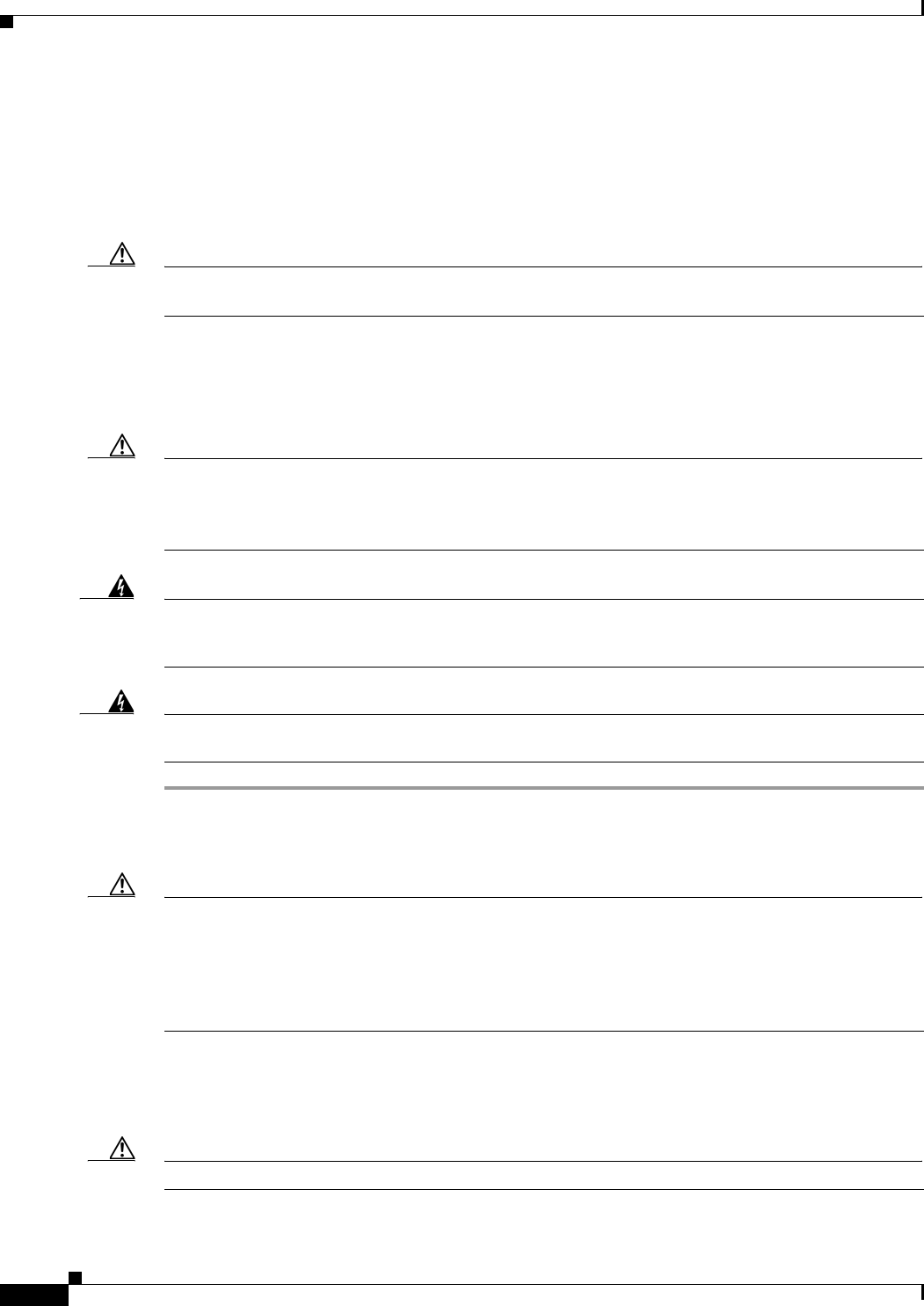
3-20
Cisco uBR10012 Universal Broadband Router Hardware Installation Guide
Chapter 3 Installing the Cisco uBR10012 Router
Mounting the Chassis in the Rack
Installing the Cisco uBR10012 Chassis in the Rack
When you are installing the chassis in a rack, please be aware of the following issues.
•AC power shelf installation precautions
•Loaded and unloaded chassis weight
Caution If you are using the optional AC-input power shelf, do not install the shelf until after you have installed
the Cisco uBR10012 chassis to avoid the possibility of crushing the shelf during the router’s installation.
For more information about installing the power shelf, see 2400W AC-Input Power Shelf for the
Cisco uBR10012 Universal at the following URL:
http://www.cisco.com/en/US/docs/cable/cmts/ubr10012/installation/field_replaceable_units/ub10acsh.
html
Caution A fully populated chassis weighs approximately 230 lbs (104.3 kg) and should be lifted only with a
forklift or hydraulic lift. A depopulated chassis weighs approximately 55 lbs(24.95 kg) and should be
lifted by two people. When handling the chassis, always follow proper lifting practices, as outlined in
the “Chassis-Lifting Guidelines” section on page 2-3
Warning
Two people are required to lift the chassis. Grasp the chassis underneath the lower edge and lift with
both hands. To prevent injury, keep your back straight and lift with your legs, not your back.
Statement
210
Warning
At least three people are required to mount the shelf in the equipment rack: two people are needed to
hold the shelf in place while a third person tightens the mounting screws.
Statement 336
Step 1 Verify that you have removed the fan assembly module, DC PEMs, cable interface line cards, and
network uplink line cards before attempting to move the chassis (see “Removing the Chassis
Components Before Installation” section on page 3-4).
Caution Do not attempt to lift even a depopulated chassis by yourself. Have at least two people to lift the chassis.
Three people might be needed to position the chassis into a rack, depending on whether you are using
an equipment shelf and on how high you are mounting it.
If you have to lift the chassis to a higher location, have a third person present who can lift the middle of
the chassis as the other two people lift it straight up.
Step 2 With each person standing on a side of the chassis, bend straight down at the knees, and grab one of the
handles on the side of the chassis.
Step 3 Carefully lift the chassis straight up and walk with slow, deliberate steps to your destination.
Caution To prevent injury, keep your back straight and lift with your legs, not your back.
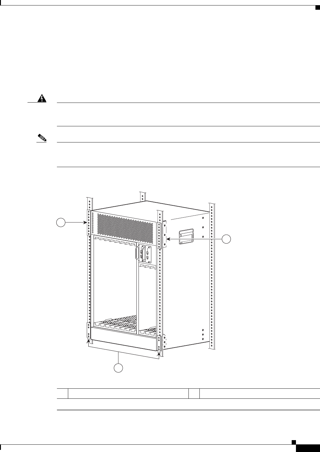
3-21
Cisco uBR10012 Universal Broadband Router Hardware Installation Guide
Chapter 3 Installing the Cisco uBR10012 Router
Mounting the Chassis in the Rack
Step 4 When you reach your destination, bend at the knees to lower the chassis to the ground.
Step 5 Lift the chassis up to the height that it will be positioned in the rack.
Step 6 Maneuver the chassis into position in the rack.
Step 7 Align the mounting bracket holes with the rack post holes (Figure 3-13) and attach the chassis to the rack
with the appropriate-sized screws (performed by the third person unless the chassis is resting on a shelf).
Step 8 Go to the Connecting the Chassis to Ground section to continue the installation.
Warning
This equipment must be grounded. Never defeat the ground conductor or operate the equipment in the
absence of a suitably installed ground conductor. Contact the appropriate electrical inspection
authority or an electrician if you are uncertain that suitable grounding is available.
Statement 1024
Note Figure 3-13 shows the chassis flush-mounted at the rear. The procedure is identical for the other
mounting methods. This figure also shows two sets of mounting brackets being used, one set at the front
and one set at the rear of the chassis. Only one set of brackets is necessary to support the chassis.
Figure 3-13 Installing the Chassis in a Rack using the Rear Mounting Brackets
1Rear mounting brackets —
281782
1
1
1

3-22
Cisco uBR10012 Universal Broadband Router Hardware Installation Guide
Chapter 3 Installing the Cisco uBR10012 Router
Attaching Ferrite Beads on the Cables
Attaching Ferrite Beads on the Cables
Ferrite beads can be clamped on where the beads are attached without wrapping the wires. Two ferrite
beads (part number 36-0219-01) are included in the Cisco uBR10012 router accessory kit, and one ferrite
bead is shipped with the spare of AC and DC power entry modules.
Attaching Ferrite Beads on Grounding and Alarm Cables
For Class B emission compliance requirements, one ferrite bead must be installed on the alarm port and
chassis ground wire exiting the chassis. This is applicable for UBR10-PWR-AC,
UBR10-PWR-AC-PLUS=, and UBR10-PWR-DC-PLUS= PEM modules. The ferrite bead should be
installed (within 3 inches) close to the notch where the cables exit the chassis.
3-23
Cisco uBR10012 Universal Broadband Router Hardware Installation Guide
Chapter 3 Installing the Cisco uBR10012 Router
Attaching Ferrite Beads on the Cables
Figure 3-14 Ferrite Beads on Ground Cable and Alarm Cable
Attaching Ferrite Beads on DC Power Cables
For Class B emission compliance requirements, two ferrite beads must be installed on the DC-input
power cables. This is applicable for UBR10-PWR-DC= PEMs. These ferrite beads should be installed
(within 6 inches) close to the DC-input power connector (DC-input terminal connector).
Figure 3-15 shows the ferrite beads attached to the DC-input power cables connected to the DC-input
terminal connector located beneath the UBR10-PWR-DC= module on the midplane of the chassis.
1Alarm cable 3Ferrite bead attached to both the ground and alarm cable
2Ground cable —
281703
1
3
2
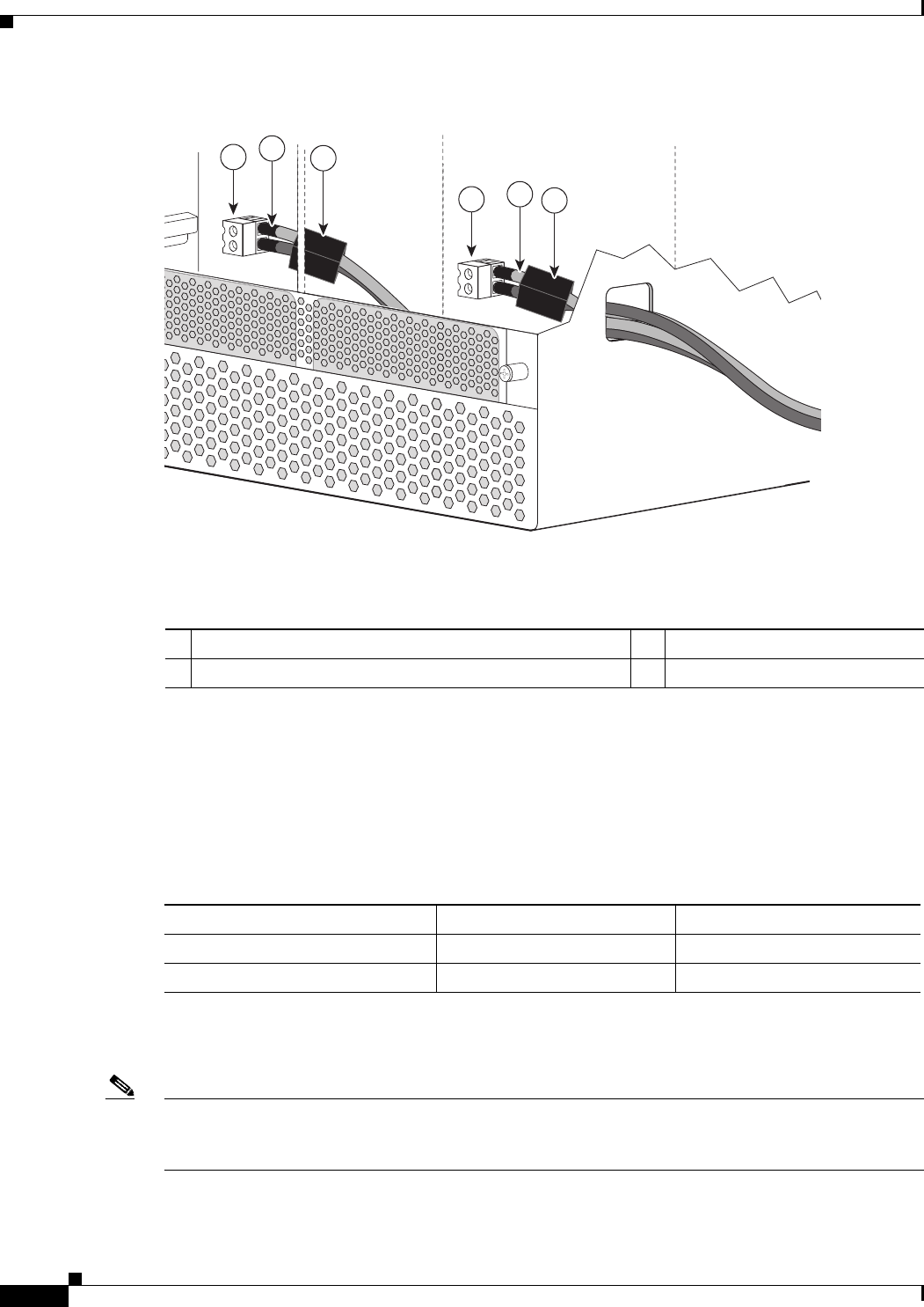
3-24
Cisco uBR10012 Universal Broadband Router Hardware Installation Guide
Chapter 3 Installing the Cisco uBR10012 Router
Attaching Ferrite Beads on the Cables
Figure 3-15 Ferrite Beads Attached on DC-input Power Cables
Attaching Ferrite Beads on the Lineage Power Shelf
An additional set of ferrite beads are required if you are using the external Lineage power shelf to supply
power to the Cisco uBR10012 router. These ferrite beads must be installed on the DC power cables that
are provided in the Lineage accessory kit to meet the Class A compliance requirements. Table 3-2 lists
the ferrite beads that should be installed on the different DC power cables.
The ferrite beads should be installed within 6 inches of the DC terminal blocks on the Lineage power
shelf. (See Figure 3-16.)
Note The ferrite beads must be installed on both sides of the DC power cables (DC-input and DC-output) when
Lineage power shelf is connected to the DC PEM modules (UBR-PWR-DC=) on the Cisco uBR10012
router.
1Ferrite beads attached to DC-input power cables 3DC power cables
2DC-input terminal connector on midplane of the chassis —
279320
249813
2
2
1
1
3
3
Table 3-2 Ferrite Beads, DC Power Cables, and DC PEM Modules
Ferrite Beads (Type / Part Number) DC Power Cable DC PEM Module (Part Number)
Steward 28A5776-0A2 4 DC power cables UBR-PWR-DC=
Steward 28A5131-0A2 2 DC “Y” power cables UBR-PWR-DC-PLUS=
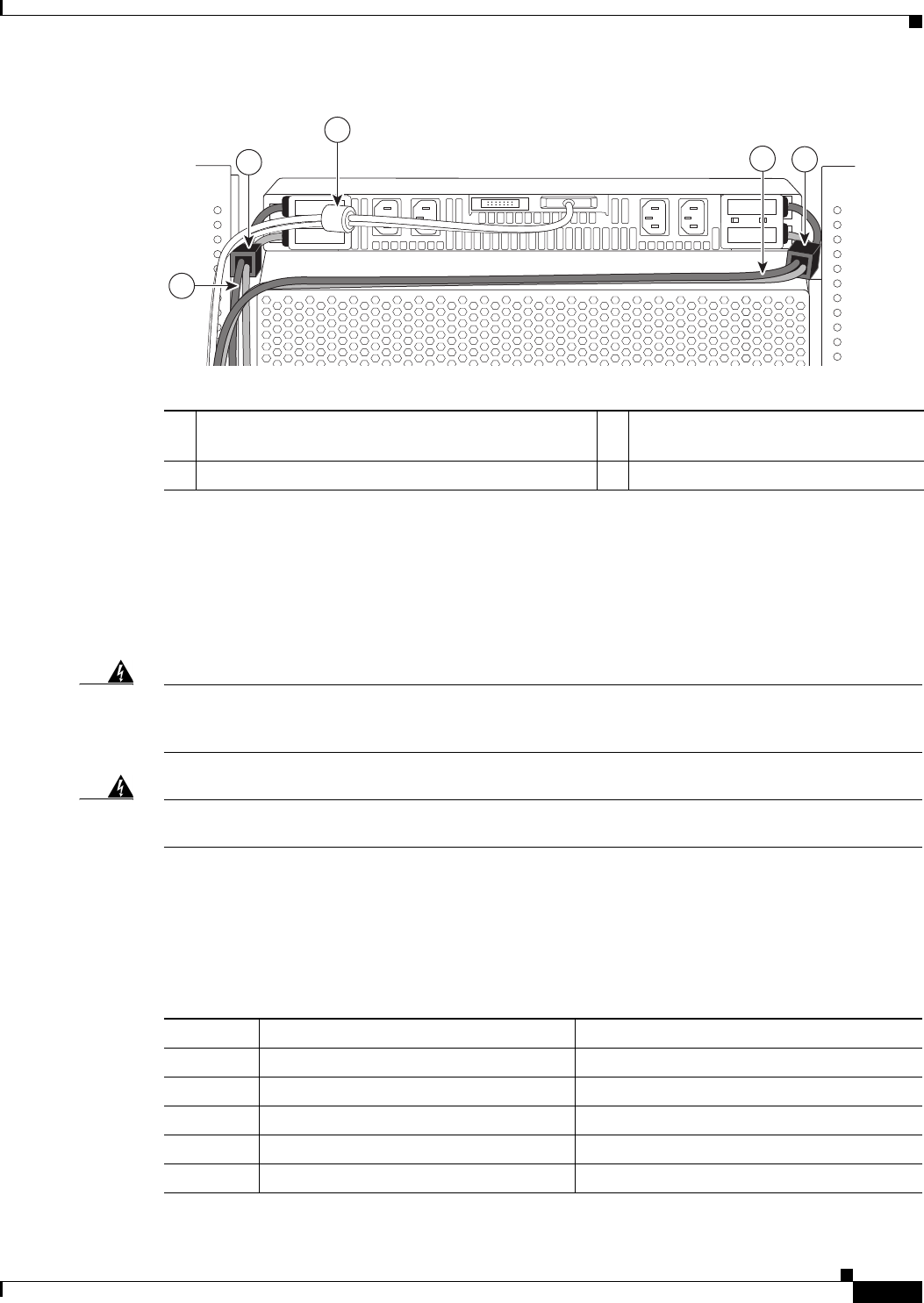
3-25
Cisco uBR10012 Universal Broadband Router Hardware Installation Guide
Chapter 3 Installing the Cisco uBR10012 Router
Connecting the Chassis to Ground
Figure 3-16 Ferrite Beads on the Lineage Power Shelf
Connecting the Chassis to Ground
Connecting the Cisco uBR10012 router chassis to earth ground is required for all DC powered
installations. Have the recommended tools and supplies available before you begin this procedure (see
Table 3-3).
Warning
The importance of proper grounding cannot be overemphasized. It will minimize the potential for
damage to your system and maximize safety at the system site. We recommend you consult a licensed
electrician or your local electric utility company if you have any questions.
Statement 269
Warning
When installing or replacing the unit, the ground connection must always be made first and
disconnected last.
Statement 1046
Recommended Tools and Supplies
Table 3-3 lists the tools, equipment, and supplies necessary to connect the system ground to the chassis.
279321
22
1
3
1
1DC power cables connected on the Lineage power
shelf
3Alarm cable connected to the J1
connector with built-in ferrite bead
2Ferrite beads attached on the DC power cables —
Table 3-3 Tools and Supplies
Quantity Description Comments
1 Number 2 Phillips screwdriver —
1 Wire stripping tool —
1 Crimping tool Must fit diameter of grounding lugs.
1 2-hole grounding lug Included in the accessory kit
1 Grounding wire 6 AWG (16 mm2), customer provided.
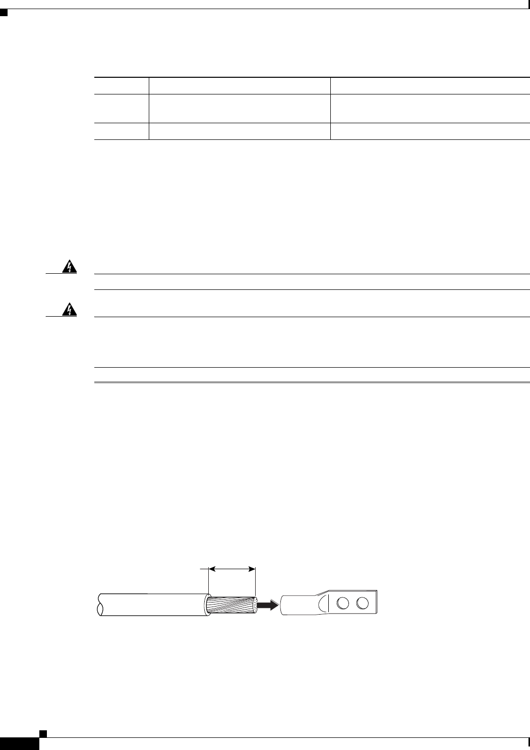
3-26
Cisco uBR10012 Universal Broadband Router Hardware Installation Guide
Chapter 3 Installing the Cisco uBR10012 Router
Connecting the Chassis to Ground
Attaching the Grounding Cable
The following procedure describes how to attach:
•The grounding lug to the grounding cable.
•The grounding cable to the chassis.
•The grounding cable to the earth grounding point.
Warning
Use copper conductors only.
Statement 1025
Warning
Before performing any of the following procedures, ensure that power is removed from the DC circuit.
To ensure that all power is OFF, locate the circuit breaker on the panel board that services the DC
circuit, switch the circuit breaker to the OFF position, and tape the switch handle of the circuit
breaker in the OFF position.
Statement 7
Step 1 Verify that there is no power going to the Cisco uBR10012 chassis and the PEMs are not installed.
Step 2 Strip about 3/4 inch (2 cm) of the covering from the end of the grounding wire).
Step 3 Insert the stripped end of the grounding wire into the open end of the grounding lug and crimp the
grounding lug securely to the wire.
Step 4 Using the two M5 screws provided in the accessory kit, fasten the grounding lug firmly to the bottom of
the chassis. Fasten the lug to the chassis. See the location marked “Grounding points” in Figure 3-18).
Step 5 Attach the other end of the ground cable to a suitable grounding location in accordance with local
practice at your site.
Step 6 Proceed to the next section, Connecting DC Power to the Cisco uBR10012 Router, page 3-39.
Figure 3-17 Attaching Grounding Wire to the Grounding Lug
2 M5 Pan Head screws with captive, lock
washers
Included in accessory kit.
Antistatic mat and ESD-wrist strap —
Table 3-3 Tools and Supplies (continued)
Quantity Description Comments
0.75 in.
(2 cm)
Grounding lugWire
30020
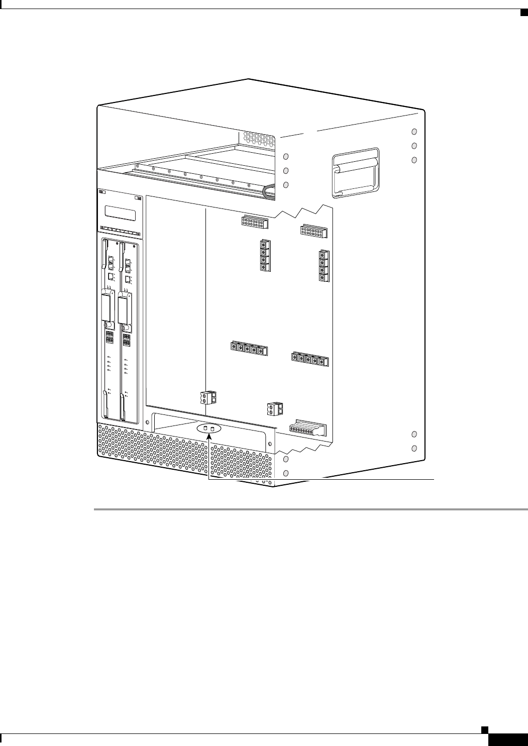
3-27
Cisco uBR10012 Universal Broadband Router Hardware Installation Guide
Chapter 3 Installing the Cisco uBR10012 Router
Connecting the Chassis to Ground
Figure 3-18 Location of the Ground Lug Connectors
103479
ALARMS
CISCO
10000
FAIL
PERFORMANCE ROUTING ENGINE
CONSOLE
STATUS
ACO
CRITICAL
MINOR
MAJOR
ETHERNET
LINK
ACTIVITY
AUX
SLOT 0
SLOT 1
ALARMS
CISCO
10000
FAIL
PERFORMANCE ROUTING ENGINE
CONSOLE
STATUS
ACO
CRITICAL
MINOR
MAJOR
ETHERNET
LINK
ACTIVITY
AUX
SLOT 0
SLOT 1
Grounding lug
points

3-28
Cisco uBR10012 Universal Broadband Router Hardware Installation Guide
Chapter 3 Installing the Cisco uBR10012 Router
Connecting the External AC-input Power Shelf to the Cisco uBR10012 Router
Connecting the External AC-input Power Shelf to the
Cisco uBR10012 Router
The following sections describe how to connect the Lineage AC-DC power shelf to the Cisco uBR10012
router:
•Cabling the Lineage AC-DC Power Shelf, page 3-28
•Connecting the Lineage AC-DC Power Shelf to the Cisco uBR10012 Router, page 3-29
•Connecting the Alarm Monitor Cable, page 3-36
•Disconnecting Cables from the Lineage AC-DC Power Shelf and the Cisco uBR10012 Router,
page 3-39
For information on cabling, and installation of the external 2400 W AC-input power shelf, see the
2400 W AC-input Power Shelf Installation Guide.
Cabling the Lineage AC-DC Power Shelf
Prerequisites
•To meet compliance standards, it is recommended that you use the AC-input cables, DC power
cables, and alarm monitor cable that are provided in the Lineage AC-DC power shelf accessory kit.
•To meet Class A compliance standards, the ferrite beads provided in the Lineage AC-DC power shelf
accessory kit must be installed on the DC power cables. For more details, see Attaching Ferrite
Beads on the Lineage Power Shelf, page 3-24.
Required Tools and Equipment
•Lineage AC-DC power shelf
•Alarm monitor cable, provided in Lineage accessory kit
•DC power cables, provided in Lineage accessory kit
•AC-input power cables, provided in Lineage accessory kit
•Ferrite beads, provided in Lineage accessory kit
•10 mm hex socket driver
Steps
To attach the cables to the Lineage AC-DC power shelf:
Warning
Before performing any of the following procedures, ensure that power is removed from the DC circuit.
Statement 1003
Caution Do not connect the AC power cables to the facility power source until the DC power cables and the alarm
monitor cables are connected to the power shelf, and to the Cisco uBR10012 router.

3-29
Cisco uBR10012 Universal Broadband Router Hardware Installation Guide
Chapter 3 Installing the Cisco uBR10012 Router
Connecting the External AC-input Power Shelf to the Cisco uBR10012 Router
Step 1 Open the safety cover from above the DC terminal blocks by rotating the safety cover up and off of the
DC terminal blocks of the power shelves.
Step 2 Loosen and remove the M6 nuts.
Step 3 Install the DC power cables to both the DC power terminal blocks on the power shelf using the removed
M6 nuts, and close the safety cover.
Note If you are connecting two Lineage power shelves to the Cisco uBR10012 router, then connect the DC
“Y” power cables only to the left DC terminals block on the two power shelves.
Step 4 Attach the ferrite beads to the DC power cables pairs exiting the power shelf within 6 inches from the
DC terminal blocks on the power shelf. See “Attaching Ferrite Beads on the Lineage Power Shelf”
section on page 3-24.
Step 5 Connect the alarm monitor cable to the power shelf, see Connecting the Alarm Monitor Cable, page 3-36
Step 6 Proceed to connecting the Lineage power shelf to the Cisco uBR10012 router.
•UBR-PWR-DC= module—If you are using this module, see “Connecting the Lineage Power Shelf
to the UBR-PWR-DC= Module” section on page 3-30.
•UBR-PWR-DC-PLUS= module—If you are using this module, see “Connecting the Lineage Power
Shelf to the UBR-PWR-DC-PLUS= Module” section on page 3-32.
Step 7 Connect the un-energized AC power cables to the power shelf.
Caution The AC power cables must not be connected to the wall socket until, all the DC power cables and alarm
monitor cables are connected between the power shelf and the Cisco uBR10012 router.
Step 8 Connect the AC power cables to the facility wall socket to energize the power shelf.
Caution Exercise caution while connecting the AC power cables to the an energized wall socket as the power
shelf will start supplying power to the Cisco uBR10012 router.
Connecting the Lineage AC-DC Power Shelf to the Cisco uBR10012 Router
The Lineage power shelves are used with the DC PEM modules on the Cisco uBR10012 router. Two DC
PEM modules are supported on the Cisco uBR10012 router:
•DC PEM module (UBR10-PWR-DC=)
•DC PEM module (UBR10-PWR-DC-PLUS=)
The following sections explain how to connect the Lineage power shelves to the Cisco uBR10012 router:
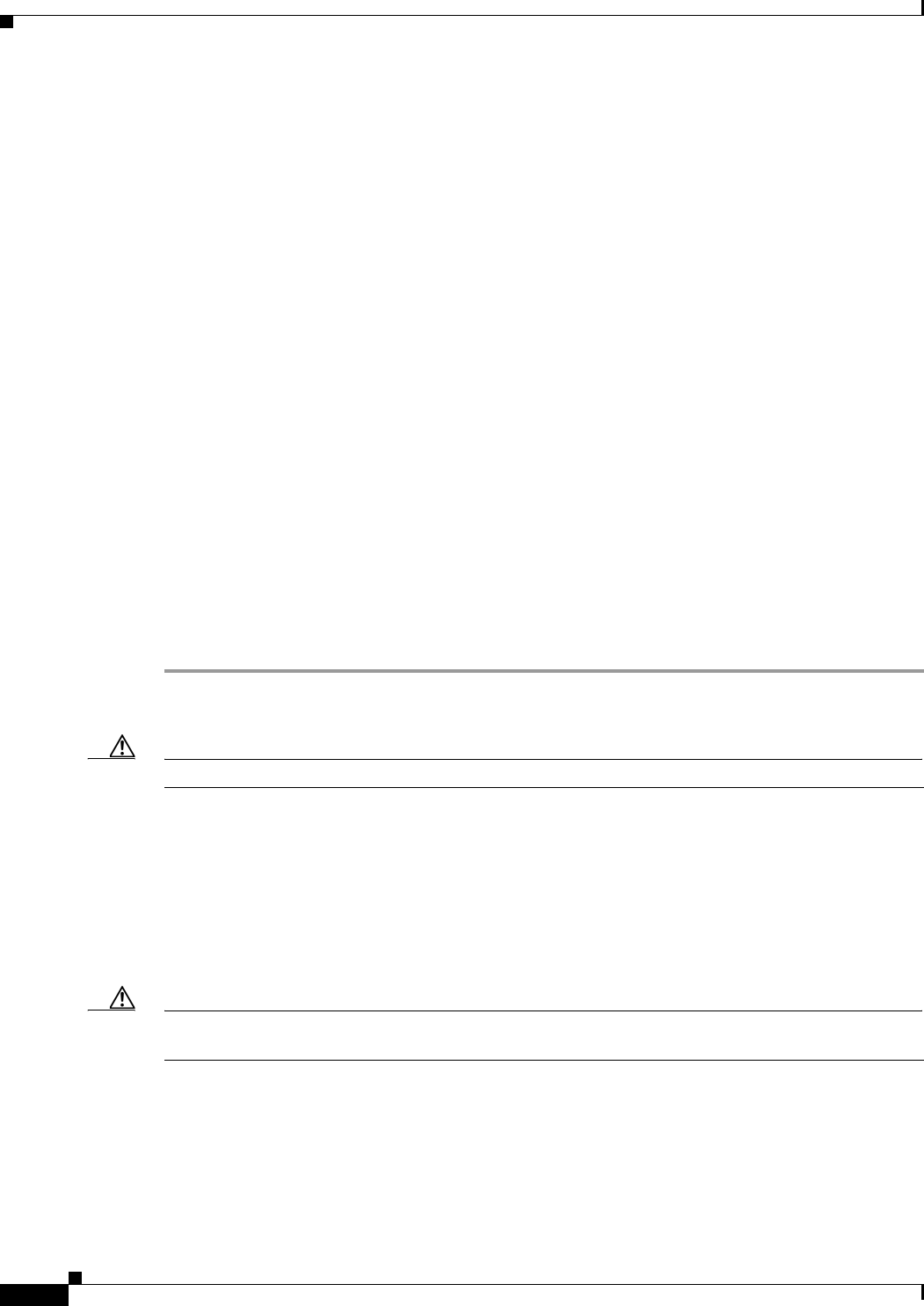
3-30
Cisco uBR10012 Universal Broadband Router Hardware Installation Guide
Chapter 3 Installing the Cisco uBR10012 Router
Connecting the External AC-input Power Shelf to the Cisco uBR10012 Router
Connecting the Lineage Power Shelf to the UBR-PWR-DC= Module
Prerequisites
•Connect the DC power cables, alarm cables, and the AC-input cables to the Lineage power shelf, see
“Cabling the Lineage AC-DC Power Shelf” section on page 3-28.
•To meet Class A compliance standards, install the ferrite beads on the DC power cables exiting the
Lineage power shelf within 6 inches from the DC terminal blocks of the shelf. For more details, see
Attaching Ferrite Beads on the Lineage Power Shelf, page 3-24.
Required Tools and Equipment
•2400 W DC PEM module (UBR-PWR-DC=)
•One Lineage AC-DC power shelf
•Four DC power cables, provided in Lineage accessory kit
•One alarm monitor cable, provided in Lineage accessory kit
•Ferrite beads (part number 36-0219-01), provided in Cisco uBR10012 router accessory kit
•Ferrite beads, provided in Lineage accessory kit
•Flat-head screwdriver
Steps
To connect the power shelf to the UBR-PWR-DC= module:
Step 1 Cable the Lineage AC-DC power shelf, see “Cabling the Lineage AC-DC Power Shelf” section on
page 3-28.
Caution Do not connect the AC power cables to the standard wall socket.
Step 2 Connect the alarm monitor cable to the Cisco uBR10012 router, see “Connecting the Alarm Monitor
Cable” section on page 3-36.
Step 3 Attach the pair of the ferrite beads to the ends of DC power cables that connect to the Cisco uBR10012
router. See “Attaching Ferrite Beads on DC Power Cables” section on page 3-23.
Step 4 Connect into the DC power cables into DC-input terminal connectors at the backplane of the
Cisco uBR10012 router. For information connecting the DC power cables to the Cisco uBR10012 router,
see DC Power Entry Module for the Cisco uBR10012 Universal Broadband Router.
Caution The DC power cables have joggles at the ends of the cables. While connecting these joggled ends to the
Cisco uBR10012 router, ensure that the ends face away from each other. (See Figure 3-19.)
Figure 3-19 shows the Lineage power shelf connected to the UBR-PWR-DC= PEM module on
Cisco uBR10012 router.
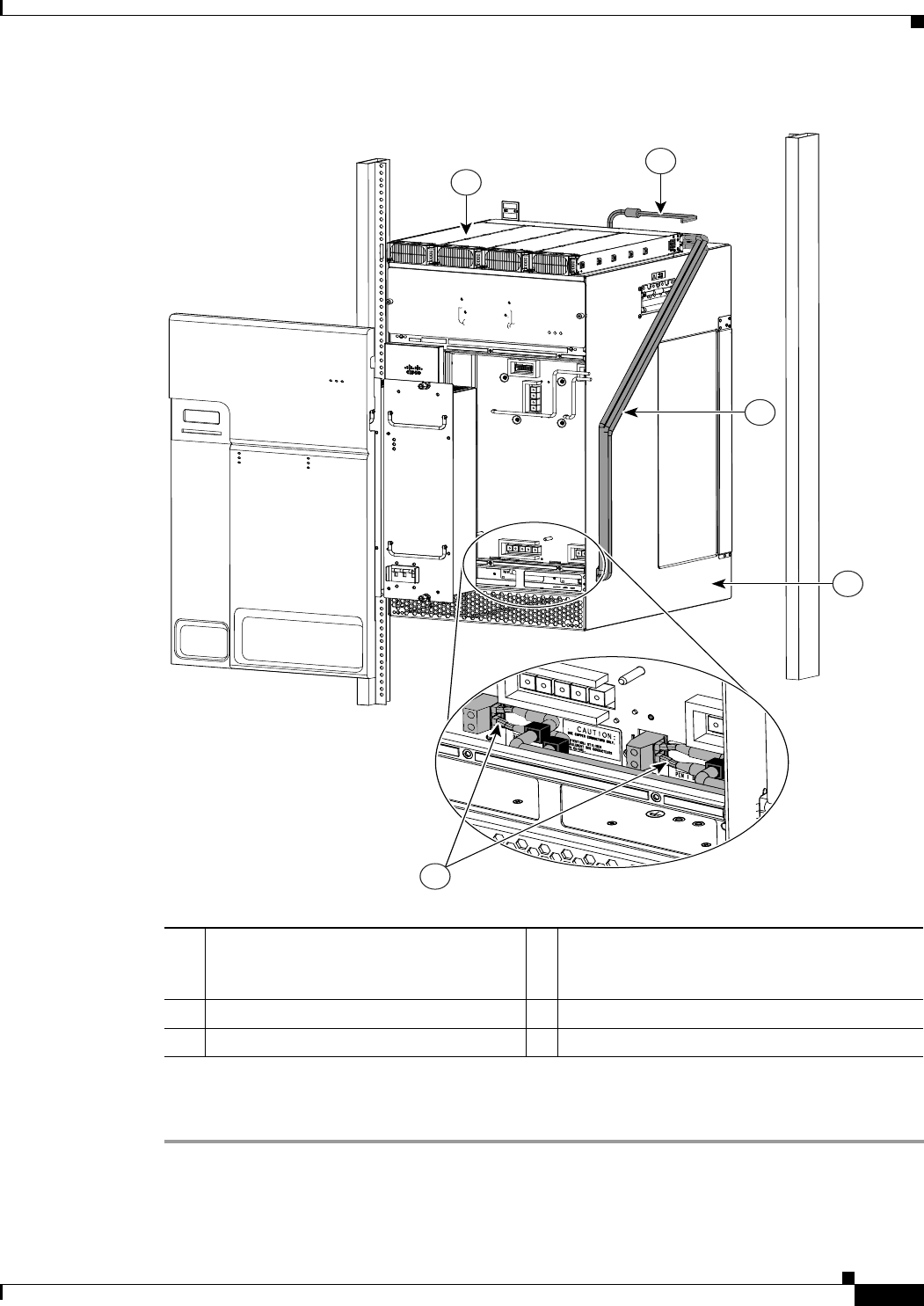
3-31
Cisco uBR10012 Universal Broadband Router Hardware Installation Guide
Chapter 3 Installing the Cisco uBR10012 Router
Connecting the External AC-input Power Shelf to the Cisco uBR10012 Router
Figure 3-19 Lineage AC-DC Power Shelf Connected to UBR-PWR-DC= PEM Module
Step 5 Connect the AC power cables to a standard wall socket (facility power source) to provide power to the
Cisco uBR10012 router.
278057
1
2
5
3
4
1
DC power cables connected from the
Lineage power shelf to the backplane of
the router 4
Joggled ends of the DC-input power cables
connected DC-input terminal blocks at the
backplane of the router
2Cisco uBR10012 router 5Alarm monitor cable
3Lineage AC-DC power shelf —

3-32
Cisco uBR10012 Universal Broadband Router Hardware Installation Guide
Chapter 3 Installing the Cisco uBR10012 Router
Connecting the External AC-input Power Shelf to the Cisco uBR10012 Router
Connecting the Lineage Power Shelf to the UBR-PWR-DC-PLUS= Module
Prerequisites
•Two Lineage AC-DC power shelves are required to supply power to the UBR-PWR-DC-PLUS=
modules to power on the Cisco uBR10012 router.
•To meet Class A compliance standards, the ferrite beads must be installed on the DC “Y” power
cables exiting the Lineage power shelf within 6 inches from the DC terminal blocks. For more
details, see Attaching Ferrite Beads on the Lineage Power Shelf, page 3-24.
Required Tools and Equipment
•3300 W DC PEM module (UBR-PWR-DC-PLUS=)
•Two Lineage AC-DC power shelves
•Two DC “Y” power cables (Amphenol), provided in Lineage accessory kit
•Two alarm monitor cables, provided in Lineage accessory kit
•Ferrite beads, provided in Lineage accessory kit
•Flat-screw driver
•10 mm hex socket driver
Note We recommend that you use the DC “Y” power cables provided in the Lineage accessory kit. If you are
using a 4 AWG cable, use a high-flex high strand count power cable for optimal routing of the cables
under the front cover of the Cisco uBR10012 router. The 2 AWG wire is not supported on the
UBR-DC-PWR-PLUS= DC PEM module.
Steps
To connect the power shelf to the UBR-PWR-DC-PLUS= DC PEM module:
Caution Do not have the AC power cables attached from the Lineage power shelves to the facility power sources,
while attempting to connect the DC power cables from the power shelves to the UBR-PWR-DC-PLUS=
modules of the Cisco uBR10012 router.
Step 1 Follow the steps to connect cables to the two Lineage power shelves, see Figure 3-21:
a. Open the safety cover from above the DC terminal blocks by rotating the safety cover up and off of
the DC terminal blocks of the shelves
b. Loosen and remove the M6 nuts.
c. Attach the lugged ends of the DC “Y” power cables to left DC power terminal blocks of the two
power shelves. Secure the cables with the removed M6 nuts using a 10 mm hex socket driver with
an installation torque of 45-in lbs. (See Figure 3-20.)
d. Close the safety cover on the DC terminal blocks.
e. Attach the ferrite beads (Steward 28A5131-0A2) to the DC “Y” power cables pairs (both -48 V and
RTN cables) exiting the Lineage power shelves within 6 inches from the DC terminal blocks. See
“Attaching Ferrite Beads on the Lineage Power Shelf” section on page 3-24.
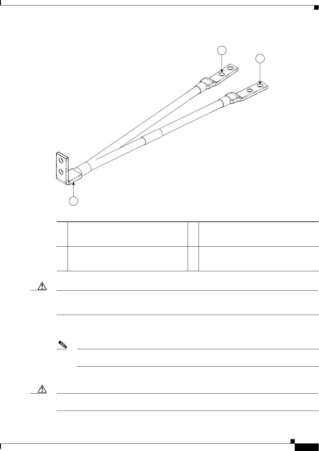
3-33
Cisco uBR10012 Universal Broadband Router Hardware Installation Guide
Chapter 3 Installing the Cisco uBR10012 Router
Connecting the External AC-input Power Shelf to the Cisco uBR10012 Router
Figure 3-20 DC Y Power Cable with Lugged Ends
Caution Only the left DC power terminals of the two Lineage shelves are used with UBR-PWR-DC-PLUS=
modules on the Cisco uBR10012 router. Ensure that the right DC power terminals on the Lineage shelves
are covered with the provided plastic covers.
f. Attach the alarm monitor cables to the two Lineage power shelves, see “Connecting the Alarm
Monitor Cable” section on page 3-36.
Note Only one cable of alarm monitor cable is connected to each Lineage power shelf. The other end
of the cable is unused. (See Figure 3-21.)
g. Connect the un-energized AC power cables to the power shelf.
Caution Do not connect the AC power cables to the facility power sources until the DC power cables and the
alarm monitor cables are connected to the power shelf, and to the Cisco uBR10012 router.
1Lugged end of DC Y power cable that
connects to Lineage power shelves
3Lugged end of DC Y power cable that
connects to the DC terminal blocks on the
UBR-PWR-DC-PLUS= modules.
2Lugged end of DC Y power cable that
connects to the DC terminal blocks on the
UBR-PWR-DC-PLUS= modules.
—
282975
2
3
1
3-34
Cisco uBR10012 Universal Broadband Router Hardware Installation Guide
Chapter 3 Installing the Cisco uBR10012 Router
Connecting the External AC-input Power Shelf to the Cisco uBR10012 Router
Figure 3-21 Cabling Two Lineage Power Shelves with DC Y Power Cables and Alarm Cables
Step 2 Connect the DC “Y” power cables to the DC-input terminal blocks on the UBR-PWR-DC-PLUS=
modules on the Cisco uBR10012 router. For information on connecting the cables, see 3300 W DC PEM
Module for Cisco UBR10012 Broadband Router Chassis.
Step 3 Connect the alarm monitor cables to the external alarm input connectors on the UBR-PWR-DC-PLUS=
modules.
Step 4 Route the DC “Y” power cables through the front of the chassis through the three power cord clips.
Figure 3-22 shows the DC “Y” power cables—Black cables are connected to RTN terminals and the red
cables are connected to –48 V terminals on the DC PEMs. The alarm monitor cables (marked in grey)
are connected to the alarm input connectors on each PEM module.
1Left DC power terminal blocks 8Cisco uBR10012 router
2Alarm monitor cable connected to the J1
connector that connects to external alarm
input connector on DC PEM 1
9Ferrite beads installed on DC power cables
3Unused end of the alarm monitor cables 10 Red Y cables that connects to –48 V terminals
on DC PEM 0
4Alarm monitor cable connected to the J1
connector that connects to external alarm
input connector on DC PEM 0
11 Black Y cables that connects to RTN
terminals on DC PEM 0
5Built-in ferrite beads on alarm cable 12 Red Y cables that connects to –48 V terminals
on DC PEM 1
6Unused right DC power terminal blocks 13 Black Y cables that connects to RTN
terminals on DC PEM 1
7Lineage power shelves —
282974
1 5
9
6 7
4
8
11
12
13
10
32
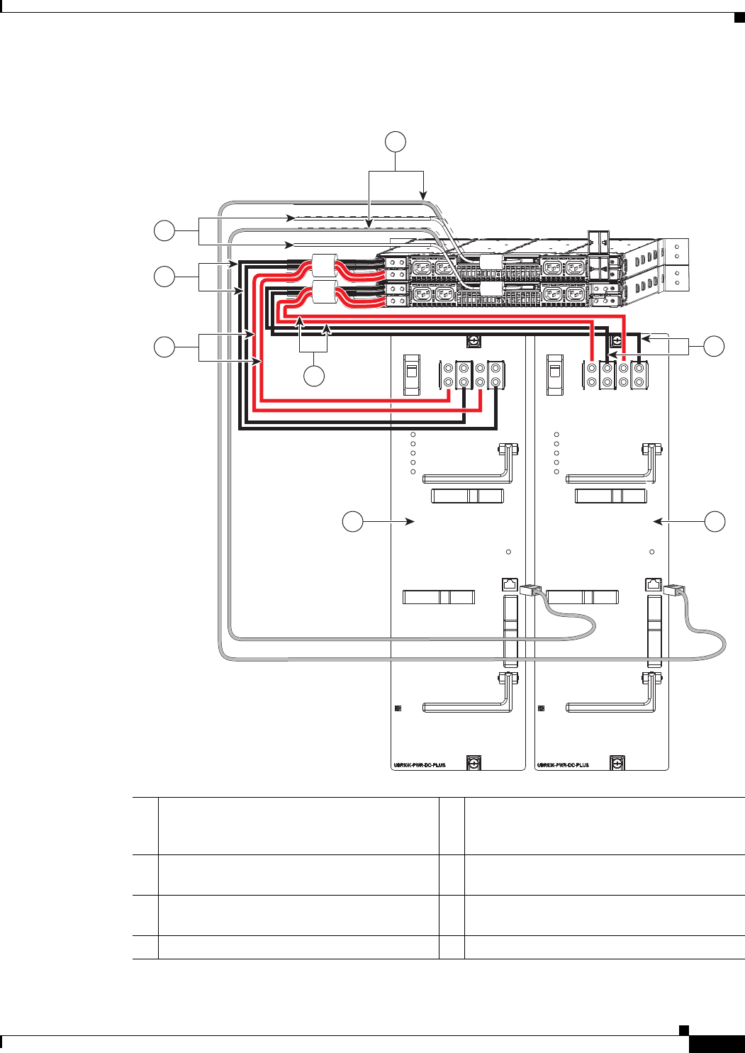
3-35
Cisco uBR10012 Universal Broadband Router Hardware Installation Guide
Chapter 3 Installing the Cisco uBR10012 Router
Connecting the External AC-input Power Shelf to the Cisco uBR10012 Router
Figure 3-22 DC Y Power Cables and Alarm Cables Connected from Lineage Power Shelves to
UBR-PWR-DC-PLUS= Modules
1Alarm monitor cables connected to J1
connectors, which in turn are connected to
external alarm input connectors on DC PEMs
5Red Y cables connected to –48 V terminals on
DC PEM 0
2Black Y cables connected to RTN terminals
on DC PEM 0
6Red Y cables connected to –48 V terminals on
DC PEM 1
3DC PEM 0 7Black Y cables connected to RTN terminals
on DC PEM 1
4DC PEM 1 8Unused end of the alarm monitor cables
POWER
V1 POWER
V2 POWER
MISWIRE
FAULT
ENABLE
PRODUCT ID
EXT.
MON
INPUT
INPUT 1
-48/-60V/48A
INPUT 2
-48/-60V/48A
-48V V1
-48V V2
RTN
RTN
POWER
V1 POWER
V2 POWER
MISWIRE
FAULT
ENABLE
PRODUCT ID
EXT.
MON
INPUT
INPUT 1
-48/-60V/48A
INPUT 2
-48/-60V/48A
-48V V1
-48V V2
RTN
RTN
283359
1
2
8
7
6
5
3
4

3-36
Cisco uBR10012 Universal Broadband Router Hardware Installation Guide
Chapter 3 Installing the Cisco uBR10012 Router
Connecting the External AC-input Power Shelf to the Cisco uBR10012 Router
Note Ensure that you lift the handles and route the cables underneath the handles and through the power cord
clips of the PEM modules so that the front cover fits on the Cisco uBR10012 chassis.
Step 5 Connect the AC power cables to a standard wall socket (facility power source) to provide power to the
Cisco uBR10012 router.
Connecting the Alarm Monitor Cable
The alarm monitor cable when connected to the Cisco uBR10012 router provides information on
whether a power module in the power shelf is missing, reporting a fault, experiencing an
over-temperature condition, or is not receiving AC-input power. This alarm monitor cable is connected
from the power shelf to the external alarm input connectors on the DC PEM faceplates of the
Cisco uBR10012 router. (See Figure 3-23.)
Figure 3-23 Alarm Monitor Cable
Prerequisites
•Install the Lineage power shelf in the rack in a way that the power connections reside facing inside
the rack when viewed from the front.
•Use the alarm monitor cables provided in the Lineage accessory kit.
Required Tools and Equipment
•Alarm monitor cable, provided in Lineage accessory kit
•Lineage power shelf
Steps
To connect the alarm monitor cable from the Lineage power shelf to the Cisco uBR10012 router:
1. Connect the PIN end of the alarm monitor cable to the JI housing on the power shelf. (See
Figure 3-24.)
277799
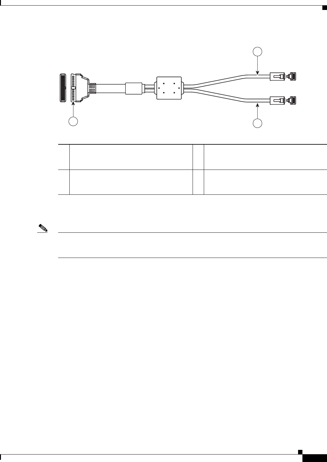
3-37
Cisco uBR10012 Universal Broadband Router Hardware Installation Guide
Chapter 3 Installing the Cisco uBR10012 Router
Connecting the External AC-input Power Shelf to the Cisco uBR10012 Router
Figure 3-24 Alarm Monitor Cable with PIN and RJ-45 connectors
2. Connect the two RJ-45 connector ends of the alarm monitor cable into the alarm input connectors
on the DC PEM modules of the Cisco uBR10012 router. (See Figure 3-25.)
Note Two alarm monitor cables are required when connecting two Lineage power shelves with the
UBR-PWR-DC-PLUS= PEM modules. Use one RJ-45 connector end of each alarm monitor cable to
connect to the alarm input connectors on each UBR-PWR-DC-PLUS= PEM modules. (See Figure 3-21).
1PIN end of Alarm monitor cable that connects
to the Lineage power shelves.
3RJ-45 connector end that connects to the
alarm input connector on the DC PEM
modules.
2RJ-45 connector end that connects to the
alarm input connector on the DC PEM
modules.
—
282976
P1
P2
P3
8
1
8
1
2
30
1
29
2
13
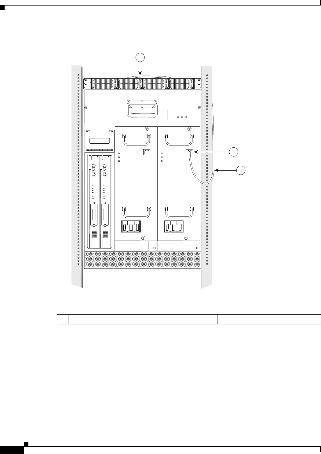
3-38
Cisco uBR10012 Universal Broadband Router Hardware Installation Guide
Chapter 3 Installing the Cisco uBR10012 Router
Connecting the External AC-input Power Shelf to the Cisco uBR10012 Router
Figure 3-25 Alarm Monitor Cable Connected From the Lineage AC-DC Power Shelf to
UBR-PWR-DC= Module
276473
CISCO
10000
PERFORMANCE ROUTING ENGINE
ALARMS
ACO
CRITICAL
MINOR
MAJOR
SLOT 0
SLOT 1
CONSOLE
ETHERNET
LINK
ACTIVITY
AUX
FAIL
STATUS
CISCO
10000
PERFORMANCE ROUTING ENGINE
ALARMS
ACO
CRITICAL
MINOR
MAJOR
SLOT 0
SLOT 1
CONSOLE
ETHERNET
LINK
ACTIVITY
AUX
FAIL
STATUS
POWER
MISWIRE
FAU LT
EXT.
ALARM
INPUT
POWER
MISWIRE
FAU LT
EXT.
ALARM
INPUT
1
2
2
1Alarm input connector on the UBR-PWR-DC= module 2Alarm monitor cable

3-39
Cisco uBR10012 Universal Broadband Router Hardware Installation Guide
Chapter 3 Installing the Cisco uBR10012 Router
Connecting DC Power to the Cisco uBR10012 Router
Disconnecting Cables from the Lineage AC-DC Power Shelf and the
Cisco uBR10012 Router
To disconnect cables from the Lineage AC-DC power shelf and the Cisco uBR10012 router:
Caution Ensure that the power is turned off on the power shelf by disconnecting the power supply at the facility
before proceeding to disconnect the other cables.
1. Power off the power shelf by disconnecting the power supply at the facility. Wait a few minutes
before disconnecting the power cables so that they discharge.
1. Disconnect the AC cables from the standard wall socket. Disconnect the AC power cables from each
of the AC-input power supply sources on the power shelf.
2. Disconnect the alarm monitor cable from the J1 housing on the power shelf, and from the alarm input
connectors on the DC PEM modules of the Cisco uBR10012 router.
3. Disconnect the DC power cables on each side of the DC power sources, on the power shelf.
4. Disconnect the other ends of the DC power cable from the DC power terminal blocks of the
Cisco uBR10012 router.
Connecting DC Power to the Cisco uBR10012 Router
This section describes how to connect the Cisco uBR10012 router to the two –48/–60 VDC power
sources that provide its operating power. The DC power sources can either be already present at the site,
or they can be provided by the external AC-input power shelves. If using the external 2400 W AC-input
power shelf, be certain you have already installed it, as described in the 2400 W AC-Input Power Shelf
Installation Guide.
Note For full power redundancy, each terminal block on the external power shelf must be connected to a
separate power source. If using the optional 2400 W AC-input power shelf, full power redundancy also
requires that each of the AC power supplies in the shelf be connected to AC power sources that are on
separate circuit breakers.
Warning
A readily accessible two-poled disconnect device must be incorporated in the fixed wiring.
Statement
91
Warning
Connect the unit only to DC power source that complies with the safety extra-low voltage (SELV)
requirements in IEC 60950 based safety standards.
Statement 1033
Warning
Secure all power cabling when installing this unit to avoid disturbing field-wiring connections.
Statement 38
3-40
Cisco uBR10012 Universal Broadband Router Hardware Installation Guide
Chapter 3 Installing the Cisco uBR10012 Router
Connecting DC Power to the Cisco uBR10012 Router
Warning
Care must be given to connecting units to the supply circuit so that wiring is not overloaded.
Statement 51
Warning
This product requires short-circuit (overcurrent) protection, to be provided as part of the building
installation. Install only in accordance with national and local wiring regulations.
Statement 1045
Warning
Before performing any of the following procedures, ensure that power is removed from the DC circuit.
To ensure that all power is OFF, locate the circuit breaker on the panel board that services the DC
circuit, switch the circuit breaker to the OFF position, and tape the switch handle of the circuit
breaker in the OFF position.
Statement 7
Caution Be sure that you have connected the chassis to earth ground as described in the previous section before
beginning this procedure.
Recommended Tools and Supplies
Table 3-4 lists the tools and supplies that you need to connect the Cisco uBR10012 router to DC power
sources.
Table 3-4 Tools and Supplies for Connecting DC Power
Quantity Description Comments
1 Flat-blade screwdriver —
1Number 2 Phillips Screwdriver —
1 Wire stripping tool —
110 mm hex socket driver —
4 (length
varies)
6 AWG (16 mm2) wire cables Cables must reach from the Cisco uBR10012 router to
the DC power source. The end of the cable intended to
be connected to the chassis needs to have insulation
stripped back not more than 5/16-in. (8 mm).
Note The UBR10-PWR-DC-PLUS= module accepts
a maximum of 6 AWG wire or 4 AWG
high-flex wire for the DC-input cables. If you
are using the 4 AWG wire, use a high-flex high
strand count power cable for optimal routing of
the cables under the front cover. The 2 AWG
wire is not supported on the
UBR10-PWR-DC-PLUS= module.
4 0.625-inch dual-hole lugs Prepare the DC-input cables by attaching 0.625-inch
center to center dual-hole lugs.
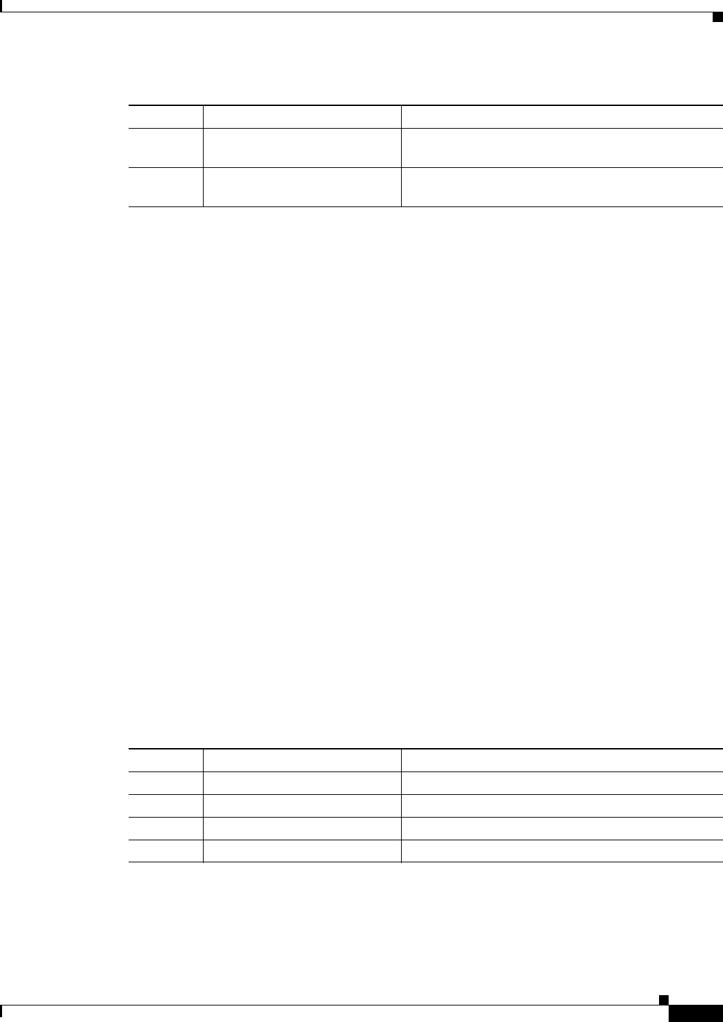
3-41
Cisco uBR10012 Universal Broadband Router Hardware Installation Guide
Chapter 3 Installing the Cisco uBR10012 Router
Connecting Alarm Indicators
Connecting the Cisco uBR10012 Chassis to a DC Power Source
The DC power sources can be present at the site, or they can be provided by an external AC-input power
shelf. If you are using the 2400 W AC-input power shelf, ensure that you have already installed it, as
described in the 2400 W AC-input Power Shelf Installation Guide.
For information on connecting the DC-input power cables for the UBR10-PWR-DC= module to the
Cisco uBR10012 router, see DC Power Entry Module for the Cisco uBR10012 Universal Broadband
Router.
For information on connecting the DC-input power cables for the UBR10-PWR-DC-PLUS= DC PEM
module to the Cisco uBR10012 router, see 3300 W DC Power Entry Module for the Cisco uBR10012
Universal Broadband Router.
Connecting Alarm Indicators
The Cisco uBR10012 router provides relay contacts for optional (customer-supplied) audible or visual
alarm indicators. Relay contacts are provided for three levels of severity:
•Minor—This is an informational alarm and does not affect the system operation.
•Major—A condition that affects system operation and should be investigated as soon as possible.
•Critical—A condition that affects system operation and requires immediate attention.
Recommended Tools and Supplies
Table 3-5 lists the tools and supplies that you need to connect the alarm indicators.
2 Tie wraps The tie wraps bind the cables together and also bind
the cables to the side of the chassis.
Antistatic mat and ESD-wrist
strap
If necessary
Table 3-4 Tools and Supplies for Connecting DC Power
Quantity Description Comments
Table 3-5 Tools and Supplies for Connecting Alarm Indicators
Quantity Description Comments
1 Flat-blade screwdriver —
1 Wire stripping tool —
6 14 AWG wire cables —
ESD-preventive wrist strap If necessary
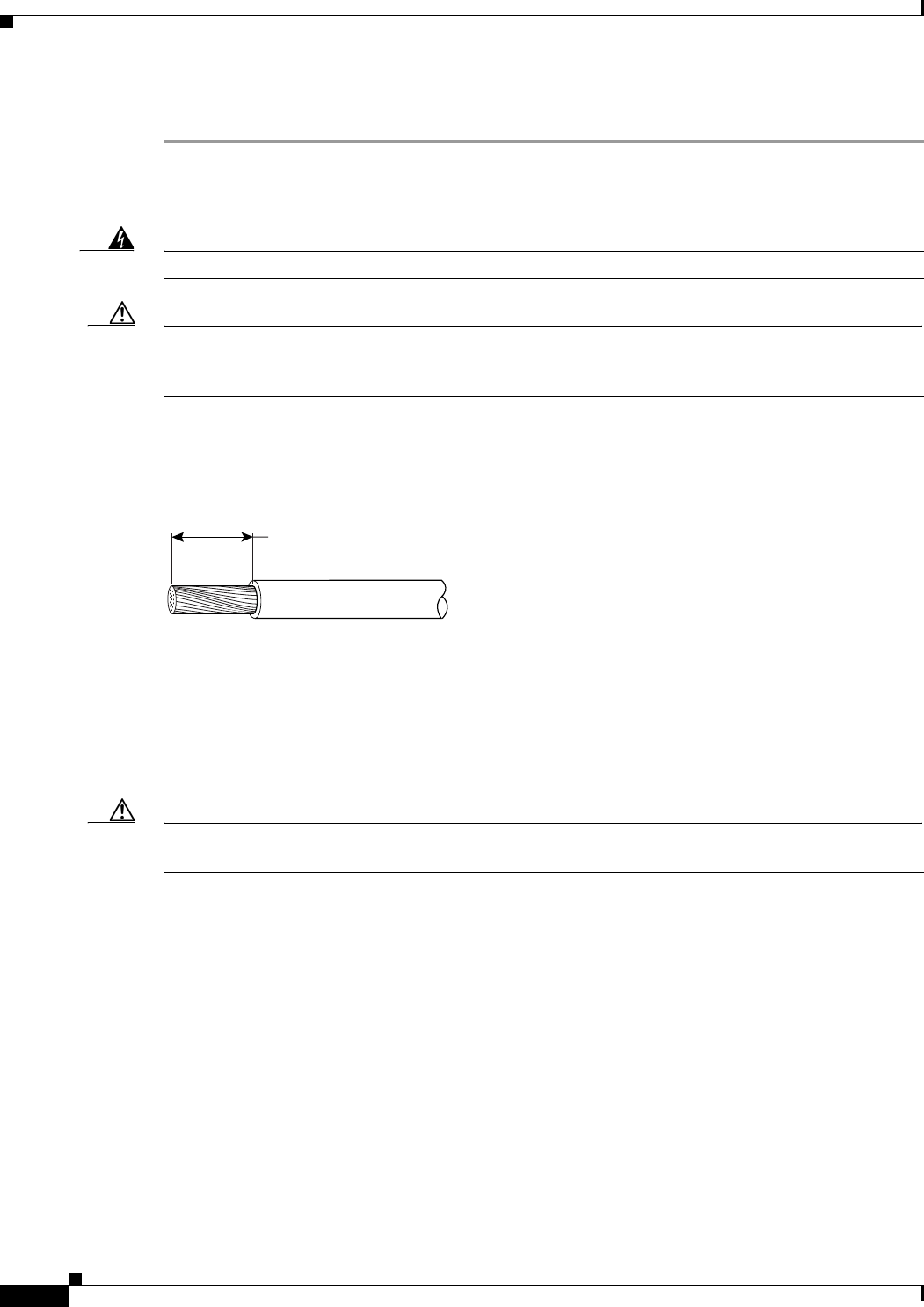
3-42
Cisco uBR10012 Universal Broadband Router Hardware Installation Guide
Chapter 3 Installing the Cisco uBR10012 Router
Connecting Alarm Indicators
Use the following procedure to connect an alarm indicator to the chassis:
Step 1 Obtain sufficient wire for the desired connections. You will need two wires for each set of relays, or six
separate wires to connect all three relay contacts. Use the gauge of wire required by the audible or visual
alarm indicator equipment you are using (14 AWG maximum gauge).
Warning
Use copper conductors only.
Statement 1025
Caution The alarm contacts on the Cisco uBR10012 router are only relays and do not provide any power from
the unit. These relays are rated for 60 VDC, 1 A maximum—ensure that the connected alarm equipment
does not exceed these voltage and current ratings.
Step 2 Strip approximately 0.31 in. (8 mm) of insulation off the ends of the alarm indicator wire (see
Figure 3-26).
Figure 3-26 Stripping Insulation
Step 3 Connect one set of alarm indicator wires to the alarm terminal block as follows (see Figure 3-27):
a. Connect one lead to the common (COM) terminal.
b. If you are wiring the router in with other equipment for the alarm indicators, wire the other lead to
the normally closed (NC) terminal.
c. If you are wiring the router in parallel with other equipment for the alarm indicators, wire the other
lead to the normally open (NO) terminal.
Caution Figure 3-27 shows the wiring configuration for NO alarm relays. The wiring configuration for NC alarm
relays is similar but uses the NC contacts.
Step 4 Repeat step 3 for the remaining alarm indicators.
Step 5 Secure the power cabling to the chassis by feeding a tie wrap through the square slot on the left front
side of the chassis (next to the alarm indicator terminal block) and binding the wires.
58688
8 mm max
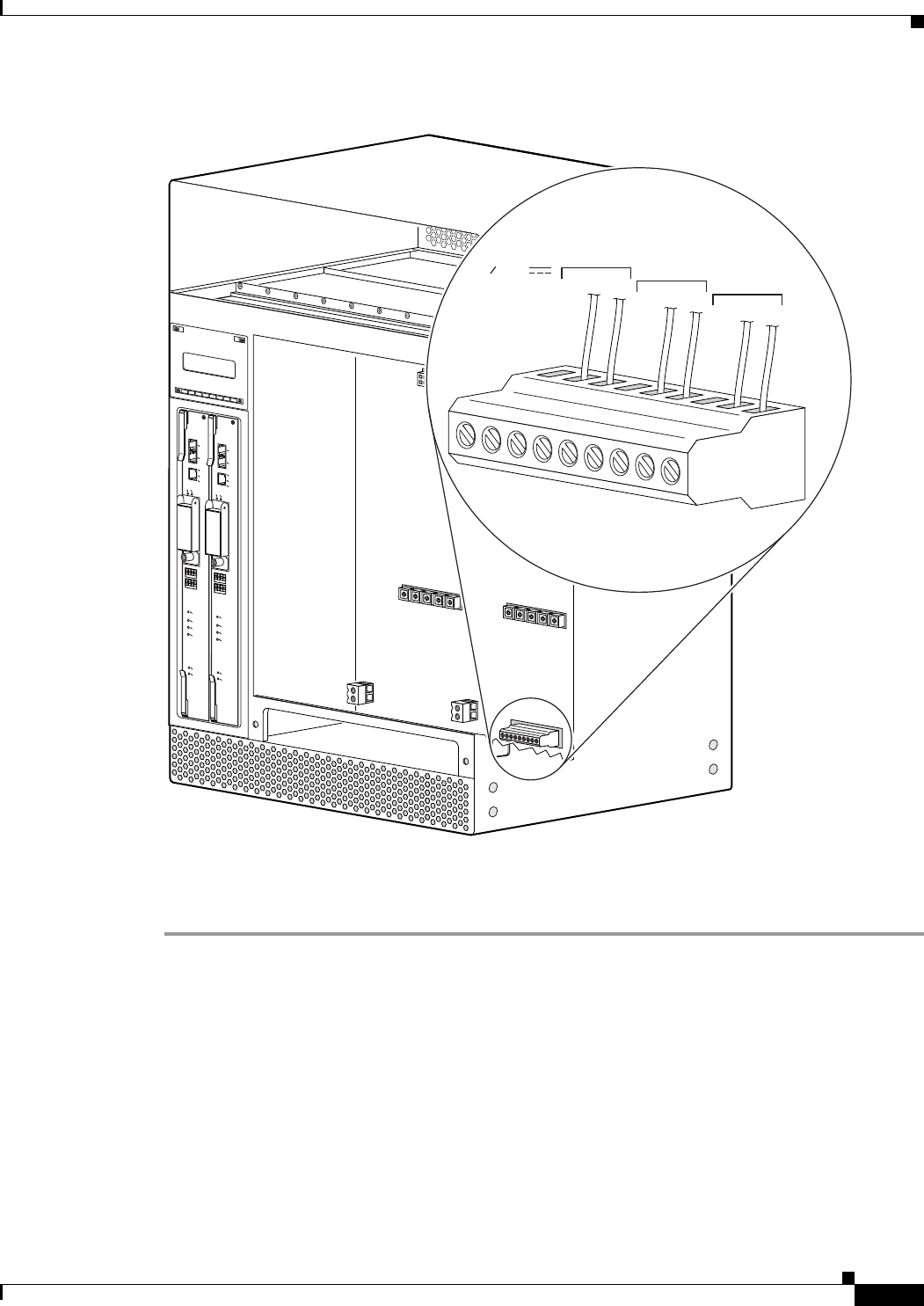
3-43
Cisco uBR10012 Universal Broadband Router Hardware Installation Guide
Chapter 3 Installing the Cisco uBR10012 Router
Connecting Alarm Indicators
Figure 3-27 Alarm Terminal Block Connections
Step 6 Go to the next section, Connecting the Console Port and Auxiliary Port, page 3-55, to continue the
installation.
103482
ALARMS
CISCO
10000
FAIL
PERFORMANCE ROUTING ENGINE
CONSOLE
STAT U S
ACO
CRITICAL
MINOR
MAJOR
ETHERNET
LINK
ACTIVITY
AUX
SLOT 0
SLOT 1
ALARMS
CISCO
10000
FAIL
PERFORMANCE ROUTING ENGINE
CONSOLE
STATUS
ACO
CRITICAL
MINOR
MAJOR
ETHERNET
LINK
ACTIVITY
AUX
SLOT 0
SLOT 1
ALARMS
60 VDC
1A MAX
MINOR
NC NOCOM
MAJOR
NC NOCOM
CRITICAL
NC NOCOM

3-44
Cisco uBR10012 Universal Broadband Router Hardware Installation Guide
Chapter 3 Installing the Cisco uBR10012 Router
Installing the Modules
Installing the Modules
To install the modules in the Cisco uBR10012 router:
Step 1 Remove the front cover by pulling the cover towards you and carefully set it aside.
•Fan assembly module—Align the module with the slot in the chassis. Push the fan module back
firmly into the chassis, making sure that the module securely connects to the backplane. Tighten the
captive screws on each side of the fan assembly module.
Note To tighten the captive screws on the fan assembly modules, the installation torque used should
be 8 in-lbs.
Caution The total service window for removal and replacement of the fan tray is 3 minutes before possible system
shutdown. Ensure that you complete the replacement procedure within this time limit.
For more information on installing the fan assembly module, see Cisco uBR10012 Universal
Broadband Router Fan Assembly Module.
•DC power entry module—Position the DC PEM in the power bay and slide it all the way in and
ensure it makes a secure connection with the backplane.
For information on installing the UBR10-PWR-DC= module, see DC Power Entry Module for the
Cisco uBR10012 Universal Broadband Router.
For information on installing the UBR10-PWR-DC-PLUS= module, see 3300 W DC Power Entry
Module for the Cisco uBR10012 Universal Broadband Router.
•AC power entry module—Position the AC PEM in the power bay and slide it all the way in and
ensure it makes a secure connection with the backplane.
For information on installing the UBR10-PWR-AC= module, see AC Power Entry Module for the
Cisco uBR10012 Universal Broadband Router.
For information on installing the UBR10-PWR-AC-PLUS= module, see 3300 W AC Power Entry
Module for the Cisco uBR10012 Universal Broadband Router.
Installing the Line Cards and Uplink Cards
After the chassis has been firmly attached to the rack, reinstall the cards in the chassis (also see
Removing and Replacing a Cable Interface Line Card, page 5-41 for details).
Caution The Cisco uBR10012 router supports only the Cisco uBR10-LCP2-MC28C cable interface line card or
Cisco uBR10-LCP2-MC16x cable interface line card bundles. Do not install the Cisco uBR10-LCP2
adapter card in the Cisco uBR10012 chassis without either the Cisco MC16x or the Cisco MC28C
installed in the adapter card.

3-45
Cisco uBR10012 Universal Broadband Router Hardware Installation Guide
Chapter 3 Installing the Cisco uBR10012 Router
Installing the Modules
Also, do not attempt to remove the Cisco MC28C card or the Cisco MC16x card from their carriers
(adapter cards) while the they are installed in the chassis. See the “Removing and Replacing a Cable
Interface Line Card” section on page 5-41 for information on this procedure.
Step 1 Grasp the faceplate of the first line card with one hand and place your other hand under the card carrier
(to support the weight of the card) and position the card in front of the appropriate card cage slot.
Step 2 Carefully align the upper and lower edges of the line card with the upper and lower guides in the chassis,
and slide the cable interface line card into the slot until you can feel it begin to seat in the backplane
connectors (Figure 3-28).
Step 3 Simultaneously pivot both ejector levers toward each other (until they are parallel to the faceplate) to
firmly seat the card in the backplane (Figure 3-29).
Step 4 Finger tighten the captive screws to secure the card in the chassis.
Caution Do not tighten the captive screws until after you insert all the additional cards. Tightening the captive
screws before all the line cards are installed, can cause the installation slot for the last line card to be
restricted and make it difficult to install the card.
Step 5 Repeat Step 1through Step 4 for each cable interface line card and network uplink card.
Step 6 After all the line cards and network uplink cards are inserted, tighten the captive screws. (Torque 5 to
7in-lbs.)
Tip Tighten line card 1, then tighten line card 8, tighten line card 2 then line card 7. Alternate back
and forth between the line cards until all of them are secure in the chassis.
Tip These screws prevent accidental removal and provide proper grounding for electromagnetic
interference (EMI) shielding.
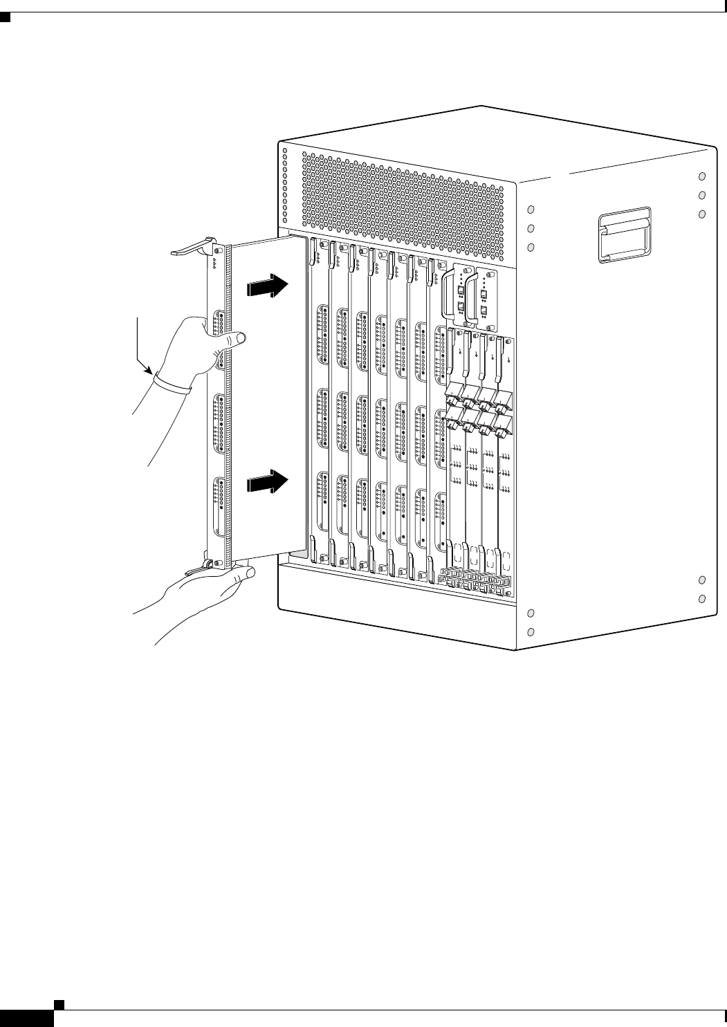
3-46
Cisco uBR10012 Universal Broadband Router Hardware Installation Guide
Chapter 3 Installing the Cisco uBR10012 Router
Installing the Modules
Figure 3-28 Inserting the Cable Interface Line Card
72325
US0
US1
US2
US3
US4
US5
US6
US7
US8
US9
US10
US11
US12
US13
US14
US15
US16
US17
US18
US19
DS0
DS1
DS2
DS3
DS4
RF
RF
RF
RF
RF
POWER
ST
A
TUS
MAINT
US0
US1
US2
US3
US4
US5
US6
US7
US8
US9
US10
US11
US12
US13
US14
US15
US16
US17
US18
US19
DS0
DS1
DS2
DS3
DS4
RF
RF
RF
RF
RF
uBR10-MC5x20S-D
POWER
ST
ATUS
MAINT
US0
US1
US2
US3
US4
US5
US6
US7
US8
US9
US10
US11
US12
US13
US14
US15
US16
US17
US18
US19
DS0
DS1
DS2
DS3
DS4
RF
RF
RF
RF
RF
uBR10-MC5x20S-D
POWER
ST
A
TUS
MAINT
US0
US1
US2
US3
US4
US5
US6
US7
US8
US9
US10
US11
US12
US13
US14
US15
US16
US17
US18
US19
DS0
DS1
DS2
DS3
DS4
RF
RF
RF
RF
RF
uBR10-MC5x20S-D
POWER
ST
A
TUS
MAINT
US0
US1
US2
US3
US4
US5
US6
US7
US8
US9
US10
US11
US12
US13
US14
US15
US16
US17
US18
US19
DS0
DS1
DS2
DS3
DS4
RF
RF
RF
RF
RF
uBR10-MC5x20S-D
POWER
ST
A
TUS
MAINT
US0
US1
US2
US3
US4
US5
US6
US7
US8
US9
US10
US11
US12
US13
US14
US15
US16
US17
US18
US19
DS0
DS1
DS2
DS3
DS4
RF
RF
RF
RF
RF
uBR10-MC5x20S-D
POWER
ST
A
TUS
MAINT
CISCO
10000
ENABLE
POS
SRP
FAIL
OC–48/STM–16 POS/SRP SM–LR
CD
TX
RX
SYNC
WRAP
PASS
THRU
TX
RX
CISCO
10000
ENABLE
POS
SRP
FAIL
OC–48/STM–16 POS/SRP SM–LR
CD
TX
RX
SYNC
WRAP
PASS
THRU
TX
RX
CISCO
10000
ENABLE
POS
SRP
FAIL
OC–48/STM–16 POS/SRP SM–LR
CD
TX
RX
SYNC
WRAP
PAS S
THRU
TX
RX
CISCO
10000
ENABLE
POS
SRP
FAIL
OC–48/STM–16 POS/SRP SM–LR
CD
TX
RX
SYNC
WRAP
PASS
THRU
TX
RX
SD-preventive
strap
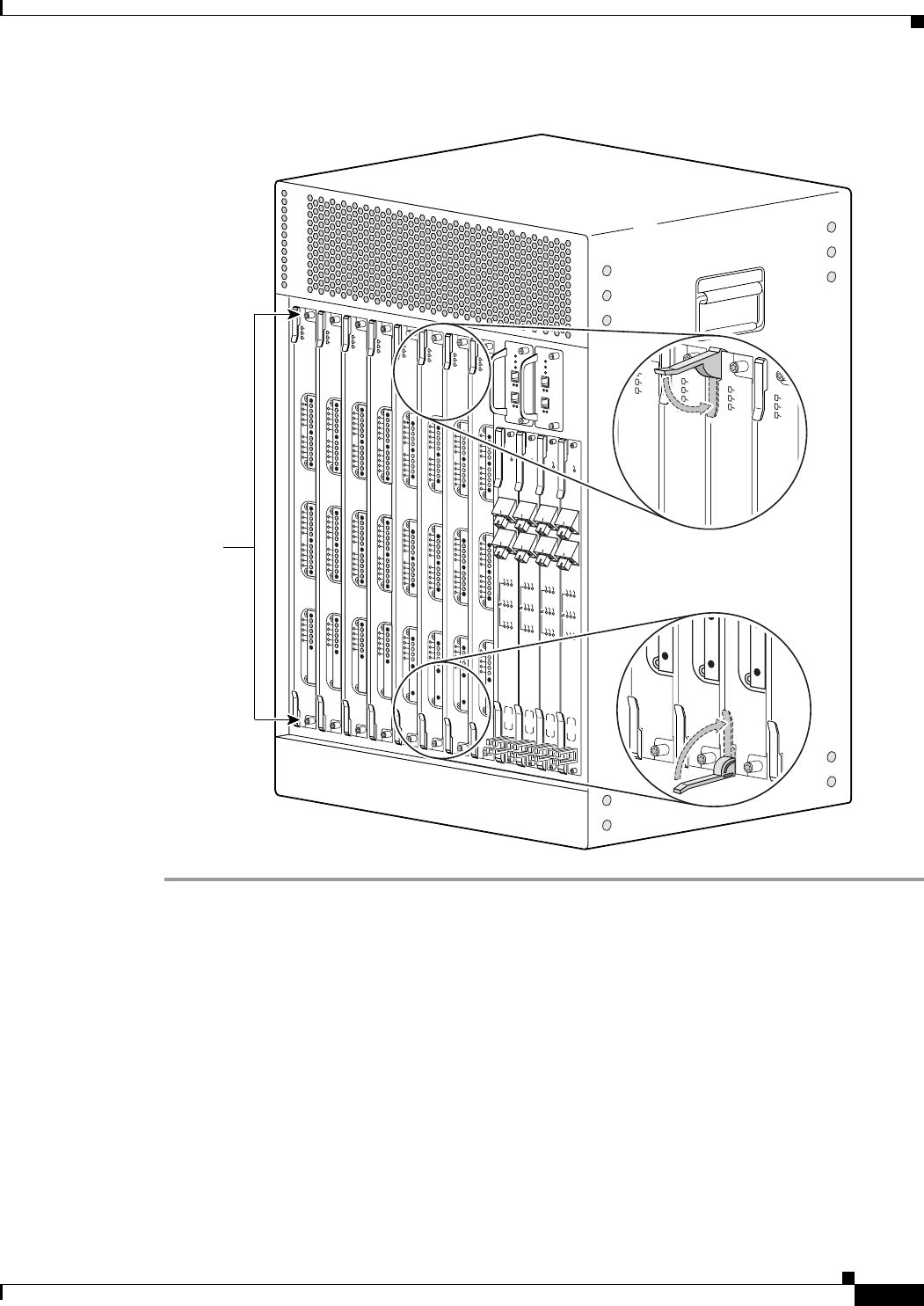
3-47
Cisco uBR10012 Universal Broadband Router Hardware Installation Guide
Chapter 3 Installing the Cisco uBR10012 Router
Installing the Slot Splitter and Half-Height Gigabit Ethernet Line Card
Figure 3-29 Closing the Ejector Levers
Installing the Slot Splitter and Half-Height Gigabit Ethernet Line
Card
This section describes how to install the line card in the Cisco uBR10012 router. This section includes
the following tasks:
•Installing the Slot Splitter, page 3-48
•Installing the Half-Height Gigabit Ethernet Line Card, page 3-52
72326
US0
US1
US2
US3
US4
US5
US6
US7
US8
US9
US10
US11
US12
US13
US14
US15
US16
US17
US18
US19
DS0
DS1
DS2
DS3
DS4
RF
RF
RF
RF
RF
uBR10-MC5x20S-D
POWER
STATUS
MAINT
US0
US1
US2
US3
US4
US5
US6
US7
US8
US9
US10
US11
US12
US13
US14
US15
US16
US17
US18
US19
DS0
DS1
DS2
DS3
DS4
RF
RF
RF
RF
RF
uBR10-MC5x20S-D
POWER
ST
ATUS
MAINT
US0
US1
US2
US3
US4
US5
US6
US7
US8
US9
US10
US11
US12
US13
US14
US15
US16
US17
US18
US19
DS0
DS1
DS2
DS3
DS4
RF
RF
RF
RF
RF
uBR10-MC5x20S-D
POWER
ST
A
TUS
MAINT
US0
US1
US2
US3
US4
US5
US6
US7
US8
US9
US10
US11
US12
US13
US14
US15
US16
US17
US18
US19
DS0
DS1
DS2
DS3
DS4
RF
RF
RF
RF
RF
uBR10-MC5x20S-D
POWER
STATUS
MAINT
CISCO
10000
ENABLE
POS
SRP
FAIL
OC–48/STM–16 POS/SRP SM–LR
CD
TX
RX
SYNC
WRAP
P
ASS
THRU
TX
RX
CISCO
10000
ENABLE
POS
SRP
FAIL
OC–48/STM–16 POS/SRP SM–LR
CD
TX
RX
SYNC
WRAP
P
ASS
THRU
TX
RX
CISCO
10000
ENABLE
POS
SRP
FAIL
OC–48/STM–16 POS/SRP SM–LR
CD
TX
RX
SYNC
WRAP
P
ASS
THRU
TX
RX
CISCO
10000
ENABLE
POS
SRP
FAIL
OC–48/STM–16 POS/SRP SM–LR
CD
TX
RX
SYNC
WRAP
P
ASS
THRU
TX
RX
US0
US1
US2
US3
US4
US5
US6
US7
US8
US9
US10
US11
US12
US13
US14
US15
US16
US17
US18
US19
DS0
DS1
DS2
DS3
DS4
RF
RF
RF
RF
RF
uBR10-MC5x20S-D
POWER
ST
ATUS
MAINT
US0
US1
US2
US3
US4
US5
US6
US7
US8
US9
US10
US11
US12
US13
US14
US15
US16
US17
US18
US19
DS0
DS1
DS2
DS3
DS4
RF
RF
RF
RF
RF
uBR10-MC5x20S-D
POWER
STATUS
MAINT
US0
US1
US2
US3
US4
US5
US6
US7
US8
US9
US10
US11
US12
US13
US14
US15
US16
US17
US18
US19
DS0
DS1
DS2
DS3
DS4
RF
RF
RF
RF
RF
uBR10-MC5x20S-D
POWER
ST
A
TUS
MAINT
US0
US1
US2
US3
US4
US5
US6
US7
US8
US9
US10
US11
US12
US13
US14
US15
US16
US17
US18
US19
DS0
DS1
DS2
DS3
DS4
RF
RF
RF
RF
RF
uBR10-MC5x20S-D
POWER
STA
TUS
MAINT
uBR10-MC5x20S-F
POWER
STATUS
MAINT
US0
uBR10-MC5x20S-F
POWER
STATUS
MAINT
uBR10-MC5x20S-F
POWER
STATUS
MAINT
uBR10-MC5x20S-F
POWER
STATUS
MAINT
DS4 RF
Captive
screws

3-48
Cisco uBR10012 Universal Broadband Router Hardware Installation Guide
Chapter 3 Installing the Cisco uBR10012 Router
Installing the Slot Splitter and Half-Height Gigabit Ethernet Line Card
Caution You must use slot 3 or slot 4 when installing the slot splitter and HHGE line card in the Cisco uBR10012
router, using slot 1 or slot 2 will cause the router to shut down those slots.
Caution Do not install two half-height blank faceplates into the same slot in the slot splitter. Instead, install a
full-slot blank faceplate into the slot. The half-height blank faceplates do not have air dams, and the
empty slot will rob cooling air from the other slots. A slot splitter with one half-height line card and one
blank faceplate is allowed.
Caution Do not install a line card into the slot splitter before installing the splitter into the chassis. The slot
splitter does not have ejector levers that allow you to seat the line card in the backplane.
Installing the Slot Splitter
You must install the half-height line card into a slot that contains a slot splitter, which can hold two
half-height line cards. If both slots of the slot splitter are not used, then you must install a blank faceplate
in the empty slot.
Follow these steps to install a slot splitter into slot 3 or slot 4 (Figure 3-30) of the Cisco uBR10012
chassis.
Step 1 Attach an antistatic wrist strap to your wrist and to an ESD socket on the chassis, or to a bare metal
surface on the chassis or frame.
Step 2 Grasp the front of the slot splitter with one hand and place your other hand under the splitter. Position
the splitter in front of the card cage slot.
Step 3 Carefully align the upper and lower edges of the slot splitter with the upper and lower guides in the
chassis, and slide the splitter into the slot until the front is flush with the chassis.
Note The slot splitter shown in Figure 3-31 has one open slot (top) and one slot with a slot cover
(bottom)
Secure the slot splitter to the chassis by tightening the top and bottom captive screws (Figure 3-32).
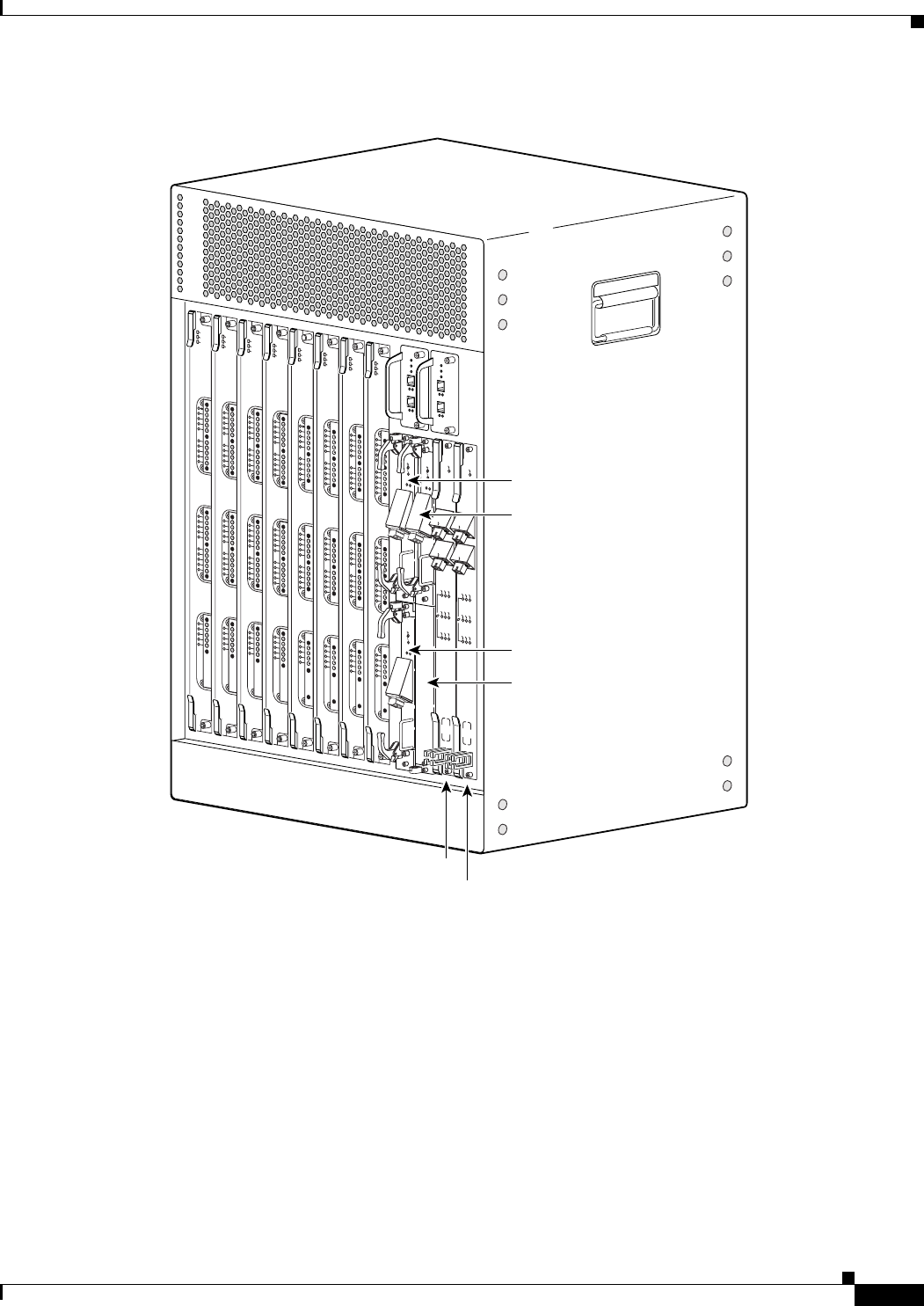
3-49
Cisco uBR10012 Universal Broadband Router Hardware Installation Guide
Chapter 3 Installing the Cisco uBR10012 Router
Installing the Slot Splitter and Half-Height Gigabit Ethernet Line Card
Figure 3-30 HHGE Line Card Locations
135149
US0
US1
US2
US3
US4
US5
US6
US7
US8
US9
US10
US11
US12
US13
US14
US15
US16
US17
US18
US19
DS0
DS1
DS2
DS3
DS4
RF
RF
RF
RF
RF
uBR10-MC5x20S-D
POWER
ST
ATUS
MAINT
US0
US1
US2
US3
US4
US5
US6
US7
US8
US9
US10
US11
US12
US13
US14
US15
US16
US17
US18
US19
DS0
DS1
DS2
DS3
DS4
RF
RF
RF
RF
RF
uBR10-MC5x20S-D
POWER
STATUS
MAINT
US0
US1
US2
US3
US4
US5
US6
US7
US8
US9
US10
US11
US12
US13
US14
US15
US16
US17
US18
US19
DS0
DS1
DS2
DS3
DS4
RF
RF
RF
RF
RF
uBR10-MC5x20S-D
POWER
STA
TUS
MAINT
US0
US1
US2
US3
US4
US5
US6
US7
US8
US9
US10
US11
US12
US13
US14
US15
US16
US17
US18
US19
DS0
DS1
DS2
DS3
DS4
RF
RF
RF
RF
RF
uBR10-MC5x20S-D
POWER
ST
A
TUS
MAINT
US0
US1
US2
US3
US4
US5
US6
US7
US8
US9
US10
US11
US12
US13
US14
US15
US16
US17
US18
US19
DS0
DS1
DS2
DS3
DS4
RF
RF
RF
RF
RF
uBR10-MC5x20S-D
POWER
ST
ATUS
MAINT
US0
US1
US2
US3
US4
US5
US6
US7
US8
US9
US10
US11
US12
US13
US14
US15
US16
US17
US18
US19
DS0
DS1
DS2
DS3
DS4
RF
RF
RF
RF
RF
uBR10-MC5x20S-D
POWER
STA
TUS
MAINT
US0
US1
US2
US3
US4
US5
US6
US7
US8
US9
US10
US11
US12
US13
US14
US15
US16
US17
US18
US19
DS0
DS1
DS2
DS3
DS4
RF
RF
RF
RF
RF
uBR10-MC5x20S-D
POWER
STA
TUS
MAINT
US0
US1
US2
US3
US4
US5
US6
US7
US8
US9
US10
US11
US12
US13
US14
US15
US16
US17
US18
US19
DS0
DS1
DS2
DS3
DS4
RF
RF
RF
RF
RF
uBR10-MC5x20S-D
POWER
ST
ATUS
MAINT
1/0
2/0
CISCO
10000
FAIL
CISCO
10000
FAIL
LINK
CISCO
10000
FAIL
CISCO
10000
FAIL
LINK
CISCO
10000
CISCO
10000
FAIL
CISCO
10000
FAIL
LINK
CISCO
10000
ENABLE
POS
SRP
FAIL
OC–48/STM–16 POS/SRP SM–LR
CD
TX
RX
SYNC
WRAP
P
ASS
THRU
TX
RX
CISCO
10000
ENABLE
POS
SRP
FAIL
OC–48/STM–16 POS/SRP SM–LR
CD
TX
RX
SYNC
WRAP
P
ASS
THRU
TX
RX
3/1/0
4/1/0
3/0/0
4/0/0
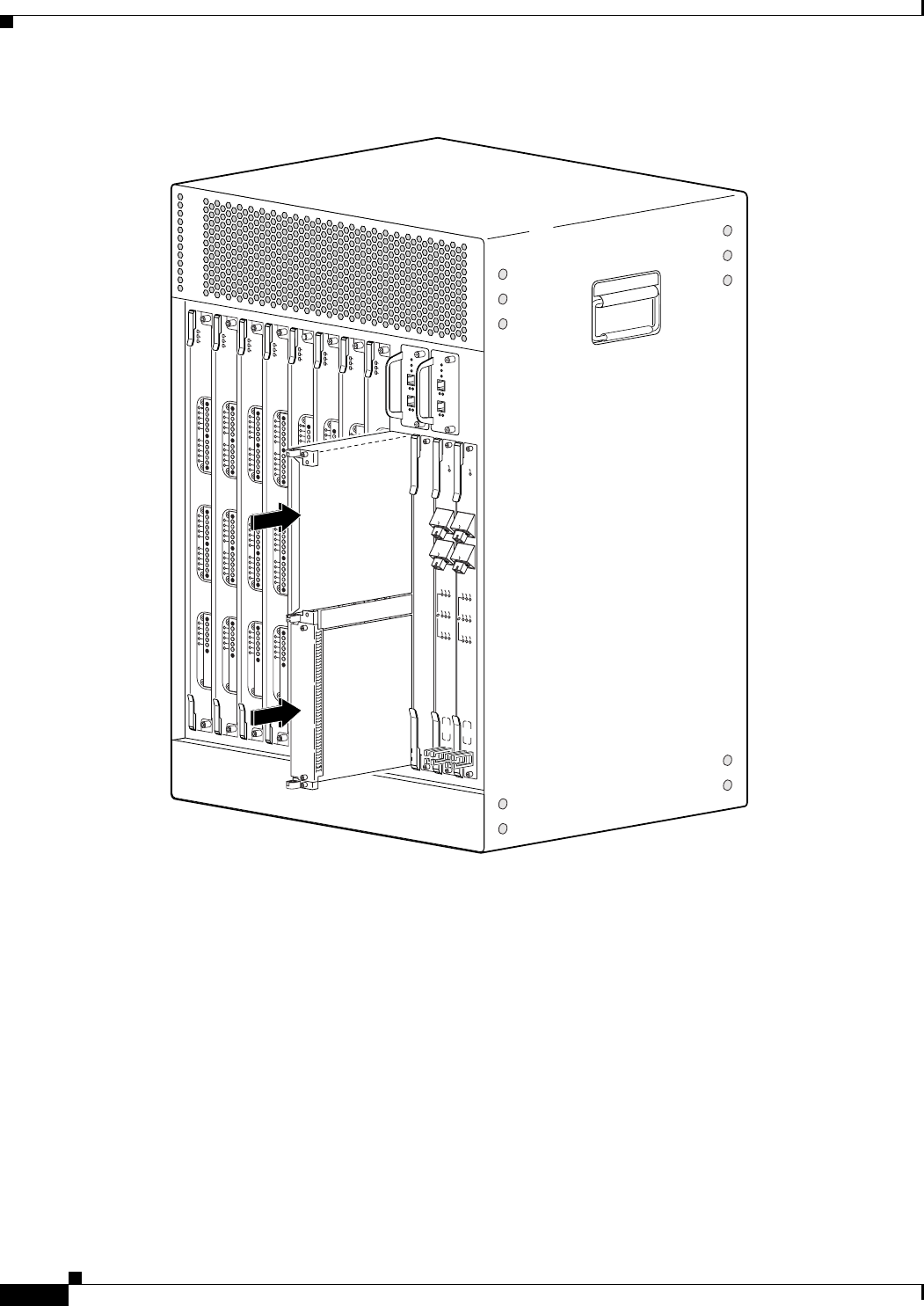
3-50
Cisco uBR10012 Universal Broadband Router Hardware Installation Guide
Chapter 3 Installing the Cisco uBR10012 Router
Installing the Slot Splitter and Half-Height Gigabit Ethernet Line Card
Figure 3-31 Inserting the Slot Splitter
135151
US0
US1
US2
US3
US4
US5
US6
US7
US8
US9
US10
US11
US12
US13
US14
US15
US16
US17
US18
US19
DS0
DS1
DS2
DS3
DS4
RF
RF
RF
RF
RF
uBR10-MC5x20S-D
POWER
STA
TUS
MAINT
US0
US1
US2
US3
US4
US5
US6
US7
US8
US9
US10
US11
US12
US13
US14
US15
US16
US17
US18
US19
DS0
DS1
DS2
DS3
DS4
RF
RF
RF
RF
RF
uBR10-MC5x20S-D
POWER
STATUS
MAINT
US0
US1
US2
US3
US4
US5
US6
US7
US8
US9
US10
US11
US12
US13
US14
US15
US16
US17
US18
US19
DS0
DS1
DS2
DS3
DS4
RF
RF
RF
RF
RF
uBR10-MC5x20S-D
POWER
STATUS
MAINT
US0
US1
US2
US3
US4
US5
US6
US7
US8
US9
US10
US11
US12
US13
US14
US15
US16
US17
US18
US19
DS0
DS1
DS2
DS3
DS4
RF
RF
RF
RF
RF
uBR10-MC5x20S-D
POWER
STATUS
MAINT
US0
US1
US2
US3
US4
US5
US6
US7
US8
US9
US10
US11
US12
US13
US14
US15
US16
US17
US18
US19
DS0
DS1
DS2
DS3
DS4
RF
RF
RF
RF
RF
uBR10-MC5x20S-D
POWER
ST
ATUS
MAINT
US0
US1
US2
US3
US4
US5
US6
US7
US8
US9
US10
US11
US12
US13
US14
US15
US16
US17
US18
US19
DS0
DS1
DS2
DS3
DS4
RF
RF
RF
RF
RF
uBR10-MC5x20S-D
POWER
STATUS
MAINT
US0
US1
US2
US3
US4
US5
US6
US7
US8
US9
US10
US11
US12
US13
US14
US15
US16
US17
US18
US19
DS0
DS1
DS2
DS3
DS4
RF
RF
RF
RF
RF
uBR10-MC5x20S-D
POWER
STATUS
MAINT
US0
US1
US2
US3
US4
US5
US6
US7
US8
US9
US10
US11
US12
US13
US14
US15
US16
US17
US18
US19
DS0
DS1
DS2
DS3
DS4
RF
RF
RF
RF
RF
uBR10-MC5x20S-D
POWER
STATUS
MAINT
CISCO
10000
CISCO
10000
ENABLE
POS
SRP
FAIL
OC–48/STM–16 POS/SRP SM–LR
CD
TX
RX
SYNC
WRAP
P
ASS
THRU
TX
RX
CISCO
10000
ENABLE
POS
SRP
FAIL
OC–48/STM–16 POS/SRP SM–LR
CD
TX
RX
SYNC
WRAP
P
ASS
THRU
TX
RX

3-51
Cisco uBR10012 Universal Broadband Router Hardware Installation Guide
Chapter 3 Installing the Cisco uBR10012 Router
Installing the Slot Splitter and Half-Height Gigabit Ethernet Line Card
Figure 3-32 Captive Screw Locations
Warning
Blank faceplates and cover panels serve three important functions: they prevent exposure to
hazardous voltages and currents inside the chassis; they contain electromagnetic interference (EMI)
that might disrupt other equipment; and they direct the flow of cooling air through the chassis. Do not
operate the system unless all cards, faceplates, front covers, and rear covers are in place.
Statement 1029
135150
US0
US1
US2
US3
US4
US5
US6
US7
US8
US9
US10
US11
US12
US13
US14
US15
US16
US17
US18
US19
DS0
DS1
DS2
DS3
DS4
RF
RF
RF
RF
RF
uBR10-MC5x20S-D
POWER
STATUS
MAINT
US0
US1
US2
US3
US4
US5
US6
US7
US8
US9
US10
US11
US12
US13
US14
US15
US16
US17
US18
US19
DS0
DS1
DS2
DS3
DS4
RF
RF
RF
RF
RF
uBR10-MC5x20S-D
POWER
STATUS
MAINT
US0
US1
US2
US3
US4
US5
US6
US7
US8
US9
US10
US11
US12
US13
US14
US15
US16
US17
US18
US19
DS0
DS1
DS2
DS3
DS4
RF
RF
RF
RF
RF
uBR10-MC5x20S-D
POWER
STATUS
MAINT
US0
US1
US2
US3
US4
US5
US6
US7
US8
US9
US10
US11
US12
US13
US14
US15
US16
US17
US18
US19
DS0
DS1
DS2
DS3
DS4
RF
RF
RF
RF
RF
uBR10-MC5x20S-D
POWER
STA
TUS
MAINT
US0
US1
US2
US3
US4
US5
US6
US7
US8
US9
US10
US11
US12
US13
US14
US15
US16
US17
US18
US19
DS0
DS1
DS2
DS3
DS4
RF
RF
RF
RF
RF
uBR10-MC5x20S-D
POWER
STA
TUS
MAINT
US0
US1
US2
US3
US4
US5
US6
US7
US8
US9
US10
US11
US12
US13
US14
US15
US16
US17
US18
US19
DS0
DS1
DS2
DS3
DS4
RF
RF
RF
RF
RF
uBR10-MC5x20S-D
POWER
ST
A
TUS
MAINT
US0
US1
US2
US3
US4
US5
US6
US7
US8
US9
US10
US11
US12
US13
US14
US15
US16
US17
US18
US19
DS0
DS1
DS2
DS3
DS4
RF
RF
RF
RF
RF
uBR10-MC5x20S-D
POWER
STATUS
MAINT
US0
US1
US2
US3
US4
US5
US6
US7
US8
US9
US10
US11
US12
US13
US14
US15
US16
US17
US18
US19
DS0
DS1
DS2
DS3
DS4
RF
RF
RF
RF
RF
uBR10-MC5x20S-D
POWER
STATUS
MAINT
CISCO
10000
CISCO
10000
ENABLE
POS
SRP
FAIL
OC–48/STM–16 POS/SRP SM–LR
CD
TX
RX
SYNC
WRAP
P
ASS
THRU
TX
RX
CISCO
10000
ENABLE
POS
SRP
FAIL
OC–48/STM–16 POS/SRP SM–LR
CD
TX
RX
SYNC
WRAP
P
ASS
THRU
TX
RX
Captive
screw
Captive
screw
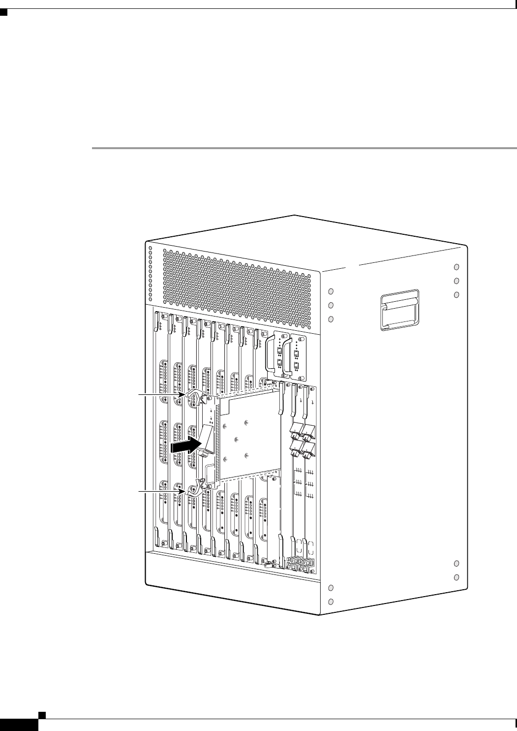
3-52
Cisco uBR10012 Universal Broadband Router Hardware Installation Guide
Chapter 3 Installing the Cisco uBR10012 Router
Installing the Slot Splitter and Half-Height Gigabit Ethernet Line Card
Installing the Half-Height Gigabit Ethernet Line Card
Use the following procedure to install a HHGE line card into an installed slot splitter. See the “Installing
the Slot Splitter” section on page 3-48 to install the slot splitter.
If you are replacing a line card, see the “Removing a Half-Height Gigabit Ethernet Line Card” section
on page 3-4 before you begin this procedure.
Step 1 Attach an antistatic wrist strap to your wrist and to an ESD socket on the chassis, or to a bare metal
surface on the chassis or frame.
Figure 3-33 Inserting the Line Card
Step 2 Grasp the faceplate of the line card with one hand and place your other hand under the card carrier (to
support the weight of the card). Position the card in front of the slot splitter.
Step 3 Carefully align the upper and lower edges of the line card with the upper and lower guides in the slot
splitter, and slide the line card about half-way into the splitter.
135152
US0
US1
US2
US3
US4
US5
US6
US7
US8
US9
US10
US11
US12
US13
US14
US15
US16
US17
US18
US19
DS0
DS1
DS2
DS3
DS4
RF
RF
RF
RF
RF
uBR10-MC5x20S-D
POWER
ST
ATUS
MAINT
US0
US1
US2
US3
US4
US5
US6
US7
US8
US9
US10
US11
US12
US13
US14
US15
US16
US17
US18
US19
DS0
DS1
DS2
DS3
DS4
RF
RF
RF
RF
RF
uBR10-MC5x20S-D
POWER
ST
ATUS
MAINT
US0
US1
US2
US3
US4
US5
US6
US7
US8
US9
US10
US11
US12
US13
US14
US15
US16
US17
US18
US19
DS0
DS1
DS2
DS3
DS4
RF
RF
RF
RF
RF
uBR10-MC5x20S-D
POWER
STATUS
MAINT
US0
US1
US2
US3
US4
US5
US6
US7
US8
US9
US10
US11
US12
US13
US14
US15
US16
US17
US18
US19
DS0
DS1
DS2
DS3
DS4
RF
RF
RF
RF
RF
uBR10-MC5x20S-D
POWER
STATUS
MAINT
US0
US1
US2
US3
US4
US5
US6
US7
US8
US9
US10
US11
US12
US13
US14
US15
US16
US17
US18
US19
DS0
DS1
DS2
DS3
DS4
RF
RF
RF
RF
RF
uBR10-MC5x20S-D
POWER
STA
TUS
MAINT
US0
US1
US2
US3
US4
US5
US6
US7
US8
US9
US10
US11
US12
US13
US14
US15
US16
US17
US18
US19
DS0
DS1
DS2
DS3
DS4
RF
RF
RF
RF
RF
uBR10-MC5x20S-D
POWER
STATUS
MAINT
US0
US1
US2
US3
US4
US5
US6
US7
US8
US9
US10
US11
US12
US13
US14
US15
US16
US17
US18
US19
DS0
DS1
DS2
DS3
DS4
RF
RF
RF
RF
RF
uBR10-MC5x20S-D
POWER
STATUS
MAINT
US0
US1
US2
US3
US4
US5
US6
US7
US8
US9
US10
US11
US12
US13
US14
US15
US16
US17
US18
US19
DS0
DS1
DS2
DS3
DS4
RF
RF
RF
RF
RF
uBR10-MC5x20S-D
POWER
STATUS
MAINT
CISCO
10000
CISCO
CISCO
10000
10000
FAIL
AIL
LINK
LINK
Ejector
lever
CISCO
10000
FAIL
LINK
CISCO
10000
ENABLE
POS
SRP
FAIL
OC–48/STM–16 POS/SRP SM–LR
CD
TX
RX
SYNC
WRAP
P
ASS
THRU
TX
RX
CISCO
10000
ENABLE
POS
SRP
FAIL
OC–48/STM–16 POS/SRP SM–LR
CD
TX
RX
SYNC
WRAP
P
ASS
THRU
TX
RX
Ejector
lever
Ejector
lever
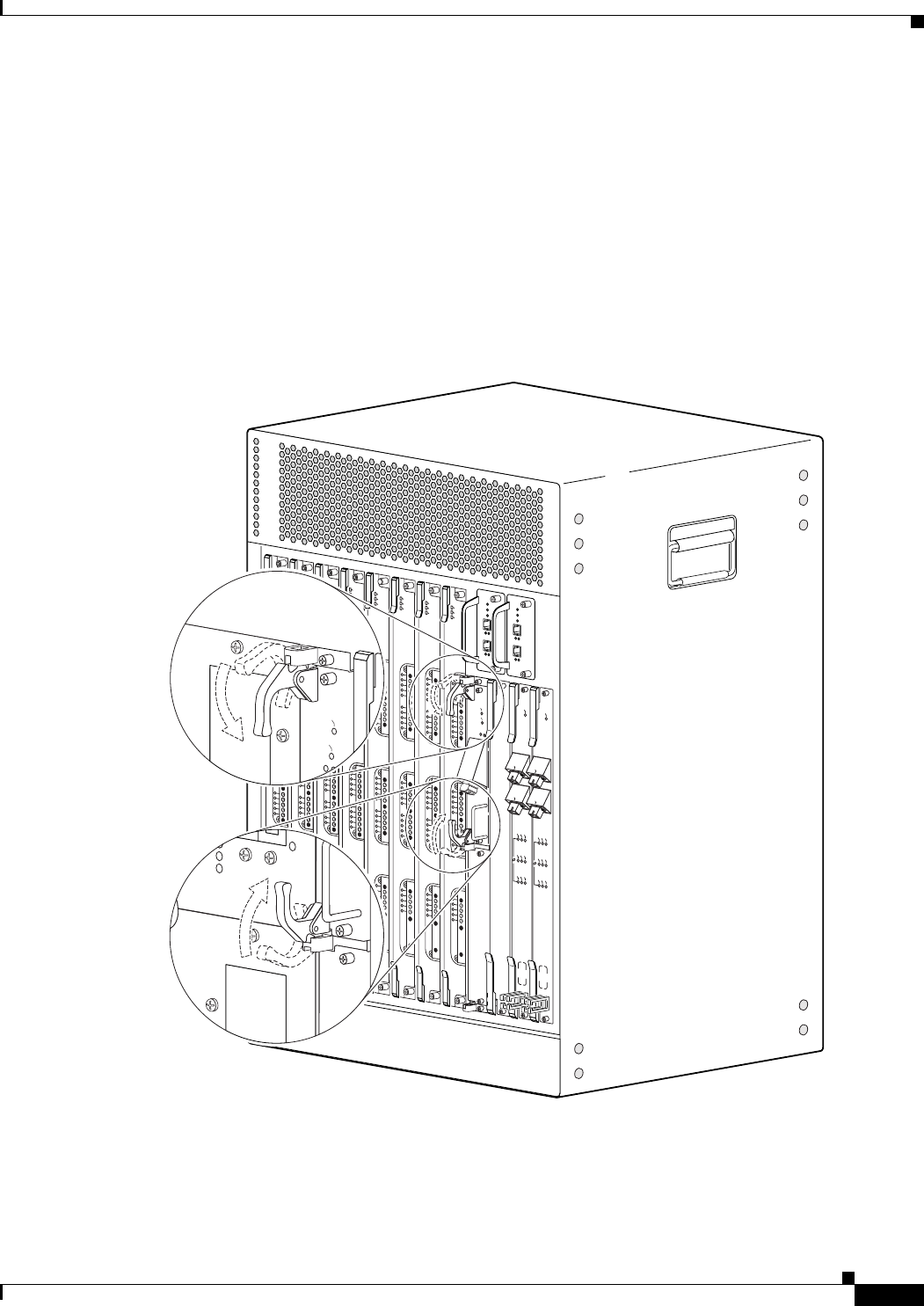
3-53
Cisco uBR10012 Universal Broadband Router Hardware Installation Guide
Chapter 3 Installing the Cisco uBR10012 Router
Installing the Slot Splitter and Half-Height Gigabit Ethernet Line Card
Step 4 Be sure the ejectors are in the open position (as shown) and continue to push the line card into the splitter
until you can feel it begin to seat in the backplane connectors.
Step 5 Verify that the captive screws are properly aligned with the captive screw holes in the splitter. If the
captive screws are not properly aligned, the card will not seat properly in the backplane.
Step 6 Simultaneously pivot both ejector levers toward each other (until they are parallel to the faceplate) to
firmly seat the card in the backplane (Figure 3-34).
The line card cycles through its power-on self-test. The FAIL LED lights during portions of the POST
(Power-On Self Test), but remains off after POST on a properly working line card. If the FAIL LED
remains on, go to the “Troubleshooting the HHGE Installation” section on page 4-17.
Figure 3-34 Closing the Ejector Levers
135153
US0
US1
US2
US3
US4
US5
US6
US7
US8
US9
US10
US11
US12
US13
US14
US15
US16
US17
US18
US19
DS0
DS1
DS2
DS3
DS4
RF
RF
RF
RF
RF
uBR10-MC5x20S-D
POWER
STA
TUS
MAINT
US0
US1
US2
US3
US4
US5
US6
US7
US8
US9
US10
US11
US12
US13
US14
US15
US16
US17
US18
US19
DS0
DS1
DS2
DS3
DS4
RF
RF
RF
RF
RF
uBR10-MC5x20S-D
POWER
STA
TUS
MAINT
US0
US1
US2
US3
US4
US5
US6
US7
US8
US9
US10
US11
US12
US13
US14
US15
US16
US17
US18
US19
DS0
DS1
DS2
DS3
DS4
RF
RF
RF
RF
RF
uBR10-MC5x20S-D
POWER
STATUS
MAINT
US0
US1
US2
US3
US4
US5
US6
US7
US8
US9
US10
US11
US12
US13
US14
US15
US16
US17
US18
US19
DS0
DS1
DS2
DS3
DS4
RF
RF
RF
RF
RF
uBR10-MC5x20S-D
POWER
STATUS
MAINT
US0
US1
US2
US3
US4
US5
US6
US7
US8
US9
US10
US11
US12
US13
US14
US15
US16
US17
US18
US19
DS0
DS1
DS2
DS3
DS4
RF
RF
RF
RF
RF
uBR10-MC5x20S-D
POWER
STATUS
MAINT
US0
US1
US2
US3
US4
US5
US6
US7
US8
US9
US10
US11
US12
US13
US14
US15
US16
US17
US18
US19
DS0
DS1
DS2
DS3
DS4
RF
RF
RF
RF
RF
uBR10-MC5x20S-D
POWER
ST
ATUS
MAINT
US0
US1
US2
US3
US4
US5
US6
US7
US8
US9
US10
US11
US12
US13
US14
US15
US16
US17
US18
US19
DS0
DS1
DS2
DS3
DS4
RF
RF
RF
RF
RF
uBR10-MC5x20S-D
POWER
STATUS
MAINT
US0
US1
US2
US3
US4
US5
US6
US7
US8
US9
US10
US11
US12
US13
US14
US15
US16
US17
US18
US19
DS0
DS1
DS2
DS3
DS4
RF
RF
RF
RF
RF
uBR10-MC5x20S-D
POWER
STATUS
MAINT
CISCO
10000
CISCO
10000
FAIL
LINK
CISCO
10000
ENABLE
POS
SRP
FAIL
OC–48/STM–16 POS/SRP SM–LR
CD
TX
RX
SYNC
WRAP
P
ASS
THRU
TX
RX
CISCO
10000
ENABLE
POS
SRP
FAIL
OC–48/STM–16 POS/SRP SM–LR
CD
TX
RX
SYNC
WRAP
P
ASS
THRU
TX
RX
CISCO
10000
CISCO
10000
FAI L
LINK

3-54
Cisco uBR10012 Universal Broadband Router Hardware Installation Guide
Chapter 3 Installing the Cisco uBR10012 Router
Installing the Slot Splitter and Half-Height Gigabit Ethernet Line Card
Figure 3-35 Captive Screw Locations
Step 7 Secure the line card in the slot splitter by tightening the top and bottom captive screws (Figure 3-35).
Caution To ensure that there is adequate space for additional line cards, always tighten the captive screws on each
newly installed line card before you insert any additional line cards. These screws prevent accidental
removal and provide proper grounding for electromagnetic interference (EMI) shielding.
135154
US0
US1
US2
US3
US4
US5
US6
US7
US8
US9
US10
US11
US12
US13
US14
US15
US16
US17
US18
US19
DS0
DS1
DS2
DS3
DS4
RF
RF
RF
RF
RF
uBR10-MC5x20S-D
POWER
STATUS
MAINT
US0
US1
US2
US3
US4
US5
US6
US7
US8
US9
US10
US11
US12
US13
US14
US15
US16
US17
US18
US19
DS0
DS1
DS2
DS3
DS4
RF
RF
RF
RF
RF
uBR10-MC5x20S-D
POWER
STATUS
MAINT
US0
US1
US2
US3
US4
US5
US6
US7
US8
US9
US10
US11
US12
US13
US14
US15
US16
US17
US18
US19
DS0
DS1
DS2
DS3
DS4
RF
RF
RF
RF
RF
uBR10-MC5x20S-D
POWER
STATUS
MAINT
US0
US1
US2
US3
US4
US5
US6
US7
US8
US9
US10
US11
US12
US13
US14
US15
US16
US17
US18
US19
DS0
DS1
DS2
DS3
DS4
RF
RF
RF
RF
RF
uBR10-MC5x20S-D
POWER
STATUS
MAINT
US0
US1
US2
US3
US4
US5
US6
US7
US8
US9
US10
US11
US12
US13
US14
US15
US16
US17
US18
US19
DS0
DS1
DS2
DS3
DS4
RF
RF
RF
RF
RF
uBR10-MC5x20S-D
POWER
STATUS
MAINT
US0
US1
US2
US3
US4
US5
US6
US7
US8
US9
US10
US11
US12
US13
US14
US15
US16
US17
US18
US19
DS0
DS1
DS2
DS3
DS4
RF
RF
RF
RF
RF
uBR10-MC5x20S-D
POWER
STA
TUS
MAINT
US0
US1
US2
US3
US4
US5
US6
US7
US8
US9
US10
US11
US12
US13
US14
US15
US16
US17
US18
US19
DS0
DS1
DS2
DS3
DS4
RF
RF
RF
RF
RF
uBR10-MC5x20S-D
POWER
STATUS
MAINT
US1
US2
US3
US4
US5
US6
US7
US8
US9
US10
US11
US12
US13
US14
US15
US16
US17
US18
US19
DS0
DS1
DS2
DS3
DS4
RF
RF
RF
RF
RF
uBR10-MC5x20S-D
POWER
ST
ATUS
MAINT
CISCO
10000
CISCO
10000
FAIL
LINK
CISCO
10000
ENABLE
POS
SRP
FAIL
OC–48/STM–16 POS/SRP SM–LR
CD
TX
RX
SYNC
WRAP
P
ASS
THRU
TX
RX
CISCO
10000
ENABLE
POS
SRP
FAIL
OC–48/STM–16 POS/SRP SM–LR
CD
TX
RX
SYNC
WRAP
P
ASS
THRU
TX
RX
Captive screw
Captive screw
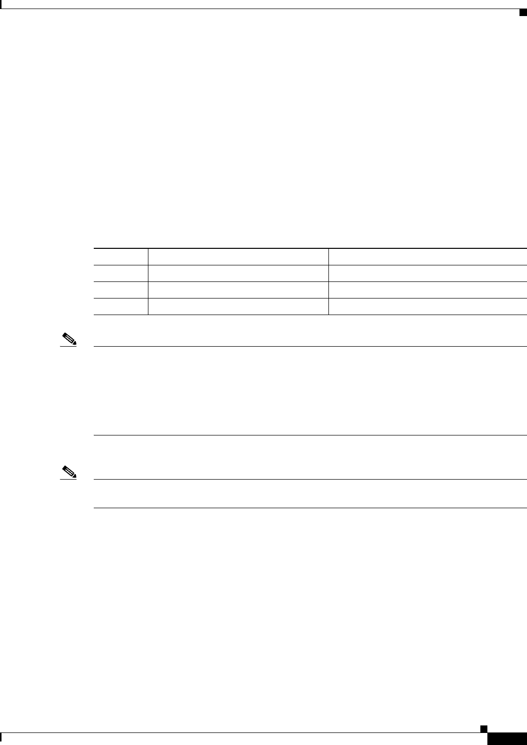
3-55
Cisco uBR10012 Universal Broadband Router Hardware Installation Guide
Chapter 3 Installing the Cisco uBR10012 Router
Connecting the Console Port and Auxiliary Port
Connecting the Console Port and Auxiliary Port
The PRE module on the Cisco uBR10012 router has two asynchronous serial (EIA/TIA-232) RJ-45 ports
that provide connections for a console (an ASCII terminal or PC running terminal emulation software)
and modem for remote access.
Recommended Tools and Supplies
The Cisco uBR10012 router arrives with a console and auxiliary cable kit, which contains the cable and
adapters you need for the most common connections to these devices.
Table 3-6 lists the tools and supplies that you need to connect the Console and auxiliary ports.
Note A crossover cable reverses pin connections from one end to the other. In other words, it connects pin 1
(at one end) to pin 8 (at the other end), pin 2 to pin 7, pin 3 to pin 6, and so on. You can identify a
crossover cable by comparing the two modular ends of the cable. Hold the cable ends in your hand,
side-by-side, with the tabs at the back. Ensure that the wire connected to the outside (left) pin of the left
plug (pin 1) is the same color as the wire connected to the outside (right) pin of the right plug (pin 8).
Also see “How to Identify an RJ-45 Crossover Cable” section on page B-5.
Use the following procedures to connect to the console and auxiliary ports on a PRE module.
Note For more information about the console port and auxiliary port connectors, see the “Console and
Auxiliary Port Cables and Pinouts” section on page B-2.
Table 3-6 Tools and Supplies for Connecting the Console Port and Auxiliary Port
Quantity Description Comments
— RJ-45 to RJ-45 crossover cable —
— RJ-45-to-DB-25 male DCE adapter labeled MODEM
— ESD-preventive wrist strap —
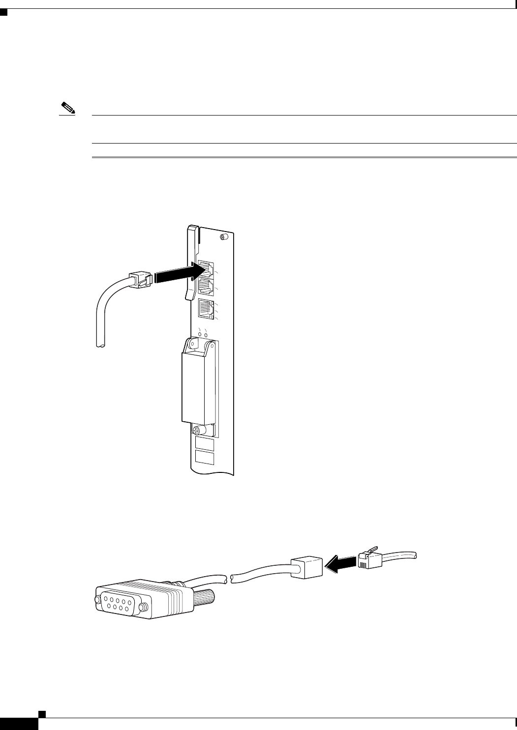
3-56
Cisco uBR10012 Universal Broadband Router Hardware Installation Guide
Chapter 3 Installing the Cisco uBR10012 Router
Connecting the Console Port and Auxiliary Port
Connecting to the Console Port
The console port provides local administrative access to the router and its command-line interface (CLI).
Note Each PRE module must have a console port connection (typically to a terminal server) when running a
redundant configuration in the chassis.
Step 1 Connect one end of the RJ-45 crossover cable to the serial RJ-45 port (labelled CONSOLE) on the PRE
module (Figure 3-36).
Figure 3-36 Console Port Connection on the PRE Module
Step 2 Run the other end of the crossover cable through the square hole at the left front side of the chassis, and
connect it to the RJ-45-to-DB-9 adapter (see Figure 3-37):
Figure 3-37 Connecting an RJ-45-to-DB-9 Console Cable Adapter
Step 3 Connect the adapter to the appropriate serial port on the PC or terminal to complete the console port
cable connection.
Step 4 Power on the PC or terminal.
Step 5 Configure the PC terminal emulation software or the terminal for the following default settings:
30027
CONSOLE
ETHERNET
LINK
AUX
SLOT 0
SLOT 1
CISCO
10000
LINK
30028
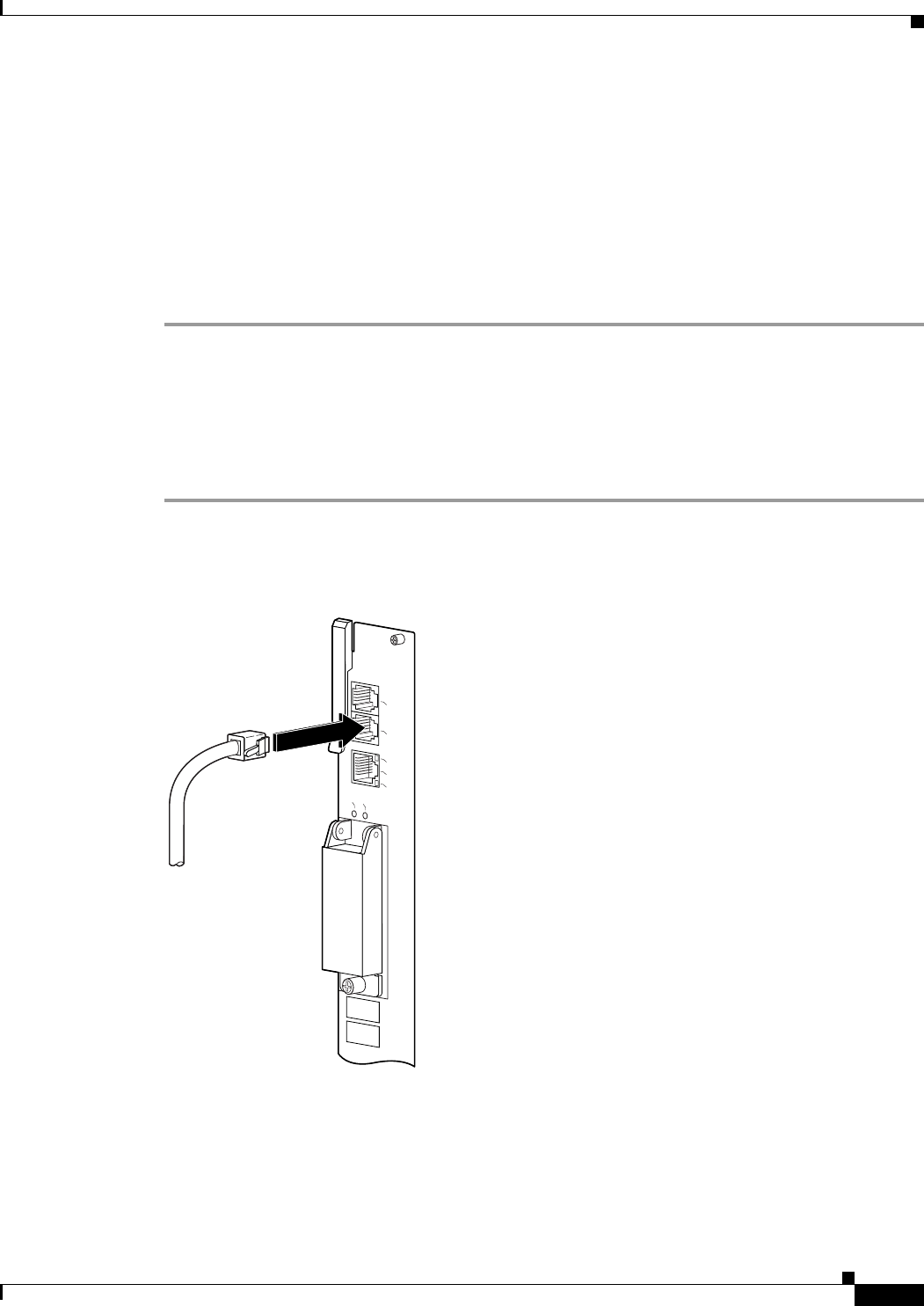
3-57
Cisco uBR10012 Universal Broadband Router Hardware Installation Guide
Chapter 3 Installing the Cisco uBR10012 Router
Connecting the Console Port and Auxiliary Port
•9600 baud
•8 data bits
•No parity generation or checking
•1 stop bit
•No flow control
Step 6 If also connecting a modem to the auxiliary port, go to the next section, “Connecting to the Auxiliary
Port.” Otherwise, go to the “Connecting Network Management Cables” section on page 3-58 to continue
the installation.
Connecting to the Auxiliary Port
The auxiliary port provides a connection for a modem to allow remote access to the router and its
command-line interface (CLI).
Step 1 Connect one end of the RJ-45 crossover cable to the serial RJ-45 port (labelled AUX) on the PRE module
(Figure 3-38).
Figure 3-38 Auxiliary Port Connection on the PRE Module
Step 2 Run the other end of the crossover cable through the square hole at the left front side of the chassis, and
connect it to the RJ-45-to-DB-25 adapter.
Step 3 Connect the adapter to the serial port on the modem to complete the auxiliary port cable connection.
Step 4 Power on the modem.
CONSOLE
ETHERNET
LINK
AUX
SLOT 0
SLOT 1
CISCO
10000
LINK
33357

3-58
Cisco uBR10012 Universal Broadband Router Hardware Installation Guide
Chapter 3 Installing the Cisco uBR10012 Router
Connecting Network Management Cables
Step 5 Make sure that the modem and auxiliary port on the router are configured for the same transmission
speed (38.4 Kbps and 56 Kbps are typical). Configure the modem for auto-answer and for hardware flow
control using the Data Carrier Detect (DCD) and Data Terminal Ready (DTR) signals.
Step 6 Go to the “Connecting Network Management Cables” section on page 3-58 to continue the installation.
Connecting Network Management Cables
The Cisco uBR10012 router has connections to both the internal Ethernet management network and the
external data network. The internal Ethernet management network connections are made through an
Ethernet port on the front panel of the PRE module.These connections are described in the Ethernet
Network Management Cable Connections.
Keep the following guidelines in mind when connecting external cables to the Cisco uBR10012 router:
•To reduce the chance of interference, avoid crossing power lines with any interface cables.
•Verify all cabling limitations (particularly distance) before powering on the system.
Ethernet Network Management Cable Connections
The PRE module provides an Ethernet port to a LAN for a 10Base-T or 100Base-T connection for
network management. Use the following procedures to connect the Cisco uBR10012 router to an
Ethernet network.
Note Each PRE module must have an Ethernet port connection (typically to the same Ethernet hub) if you are
running a redundant configuration in the chassis. However, only the active PRE module has an active
Ethernet connection to the network.
Connecting to a 10Base-T Ethernet Network
To make a 10Base-T Ethernet LAN connection, you need the following additional equipment (not
included):
•An Ethernet hub (such as a Cisco Micro Hub)
•An Ethernet cable that meets the following specifications:
–
RJ-45 (male) to RJ-45 (male) straight-through cable
–
100-ohm category 3, 4, or 5, no longer than 328 feet (100 meters)
You can identify a straight-through Ethernet cable either by using a cable tester or by making a visual
inspection. To make a visual inspection, hold the two ends of a cable side by side, with the tab for each
at the back.
•The wire connected to the left-most pin (pin 1) on one connector should be the same color as the
wire connected to the left-most pin on the other connector.
•The same rule applies to pins 2 through 8 on each connector. The color of the wire attached to a pin
on one connector should match the color of the wire attached to the corresponding pin on the other
connector.
Follow these steps to connect the PRE to a 10Base-T Ethernet LAN.
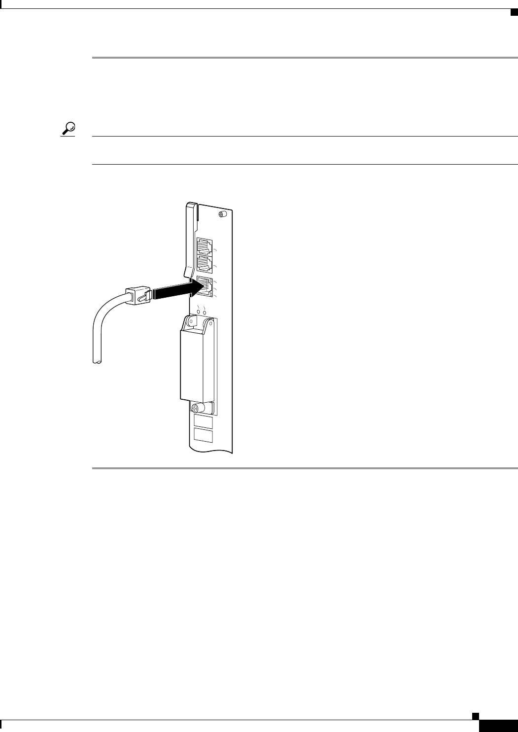
3-59
Cisco uBR10012 Universal Broadband Router Hardware Installation Guide
Chapter 3 Installing the Cisco uBR10012 Router
Connecting Network Management Cables
Step 1 Connect one end of the Ethernet cable to the RJ-45 port on the primary PRE, labeled Ethernet (see
Figure 3-39).
Step 2 Run the other end of the Ethernet cable through the square hole at the left front side of the chassis, and
connect this end of the cable to any unoccupied port on the Ethernet hub.
Tip When power is applied to the chassis, check the LNK (Link) LED on the PRE faceplate port next to the
Ethernet port. This LED lights (green) if the PRE is correctly connected to the 10Base-T Ethernet LAN.
Figure 3-39 Connecting 10Base-T to an Ethernet Port
Connecting to a 100Base-T Ethernet Network
To make a 100Base-T Ethernet LAN connection, you need the following additional equipment (not
included):
•An Ethernet hub (such as a Cisco Micro Hub)
•An Ethernet UTP cable that meets the following specifications:
–
RJ-45 (male) to RJ-45 (male) straight-through cable.
–
100-ohm category 5 cable not longer than 328 feet (100 meters).
You can identify a straight-through Ethernet cable either by using a cable tester or by making a visual
inspection. To make a visual inspection, hold the two ends of a cable side by side, with the tab for each
at the back.
•The wire connected to the left-most pin (pin 1) on one connector should be the same color as the
wire connected to the left-most pin on the other connector.
30036
CONSOLE
ETHERNET
LINK
AUX
SLOT 0
SLOT 1
CISCO
10000
LINK
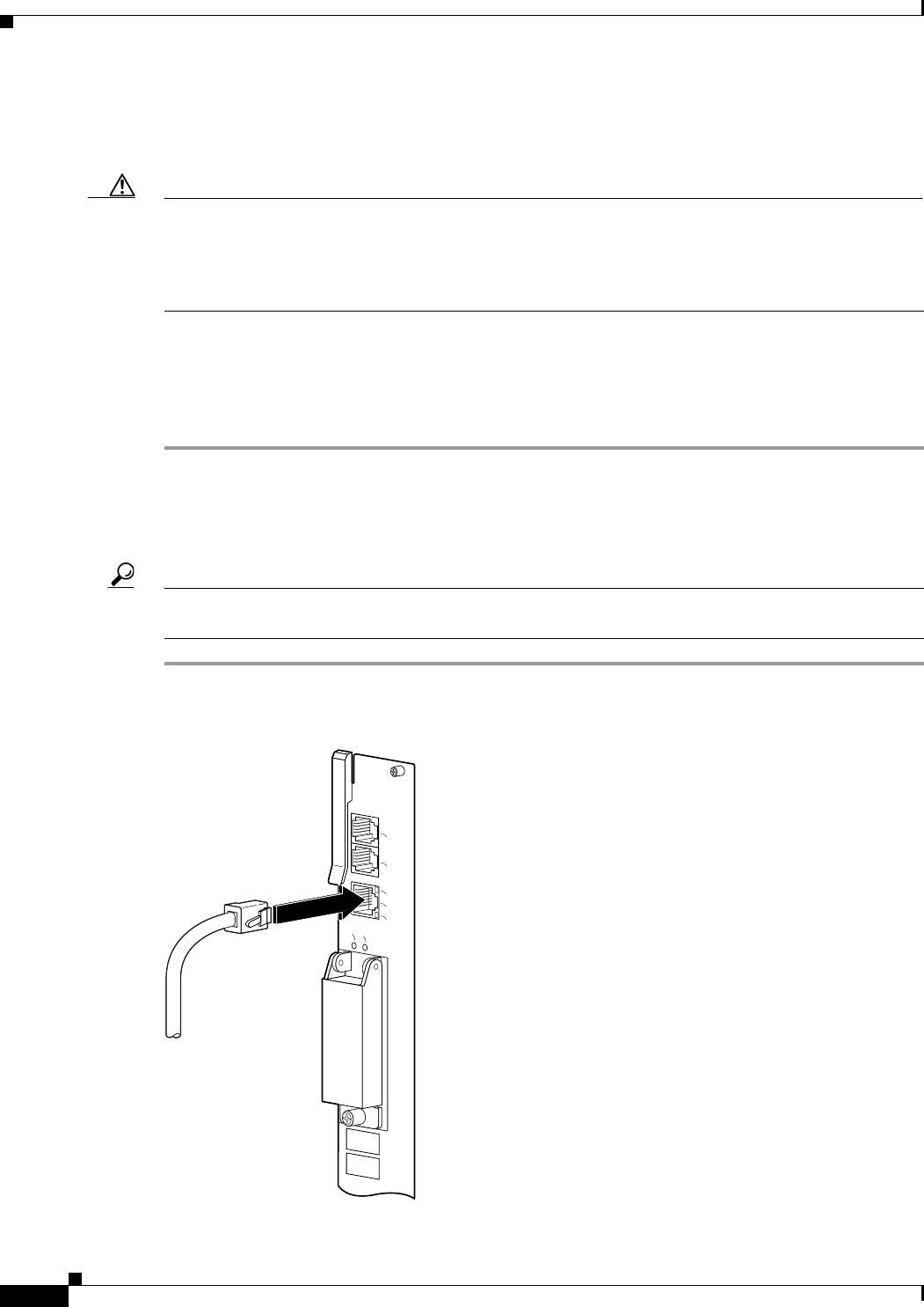
3-60
Cisco uBR10012 Universal Broadband Router Hardware Installation Guide
Chapter 3 Installing the Cisco uBR10012 Router
Connecting Network Management Cables
•The same rule applies to pins 2 through 8 on each connector. The color of the wire attached to a pin
on one connector should match the color of the wire attached to the corresponding pin on the other
connector.
Caution If the Cisco uBR10012 router is used in an environment in which lightning-induced transients are likely
to couple to the signal lines, use of shielded interconnection cables for the 100Base-T ports is highly
recommended. In addition, use of shielded interconnection cables for the 100Base-T ports is required to
meet Telcordia (formerly Bellcore) GR1089 CORE Section 4.5.9 and ETSI Section 5.2.2.2
(intrabuilding lightning surge).
The RJ-45 port on the PRE is configurable for 100-Mbps full-duplex or half-duplex operation
(half-duplex is the default) and supports IEEE 802.3, Ethernet, and IEEE 802.3u interfaces compliant
with 100Base-T specifications.
Follow these steps to connect the PRE to a 100Base-T Ethernet LAN.
Step 1 Connect one end of the Ethernet cable to the RJ-45 port on the primary PRE, labeled Ethernet
(Figure 3-40).
Step 2 Run the cable up and through the cable management bracket and connect the other end of the Ethernet
cable to any unoccupied port on the Ethernet hub.
Tip When power is applied to the chassis, check the LNK (Link) LED on the PRE faceplate port next to the
Ethernet port. This LED lights (green) if the PRE is correctly connected to the 100Base-T Ethernet LAN.
Figure 3-40 Connecting 100Base-T to Ethernet Port
30036
CONSOLE
ETHERNET
LINK
AUX
SLOT 0
SLOT 1
CISCO
10000
LINK
3-61
Cisco uBR10012 Universal Broadband Router Hardware Installation Guide
Chapter 3 Installing the Cisco uBR10012 Router
Connecting Cable Interface Line Cards and Network Uplink Cards
Connecting Cable Interface Line Cards and Network Uplink
Cards
Because there are very specific requirements for cabling the different line cards and uplink cards used
with the Cisco uBR10012 CMTS, please review the documentation for the cards that you are installing
in your system.
Cable Interface Line Card Connections
For cabling instructions, refer to the appropriate cable interface line card documentation at the following
URL:
http://www.cisco.com/en/US/products/hw/cable/ps2209/prod_installation_guides_list.html
Network Uplink Cable Connections
These cards use fiber optic connections which require specific cleaning and preparation before they are
cabled. For cleaning and inspecting instructions for the fiber optic connections, see Inspection and
Cleaning Procedures for Fiber-Optic Connections at the following URL:
http://www.cisco.com/en/US/tech/tk482/tk876/technologies_white_paper09186a0080254eba.shtml
For cabling instructions, refer to the appropriate network uplink card documentation at the following
URL:
http://www.cisco.com/en/US/products/hw/cable/ps2209/prod_installation_guides_list.html
Warning
Class 1 laser product.
Statement 1008
Warning
Invisible laser radiation present.
Statement 1016.
Warning
Because invisible laser radiation may be emitted from the aperture of the port when no cable is
connected, avoid exposure to laser radiation and do not stare into open apertures.
Statement 1056.
Warning Statement for Sweden
Warning
Osynlig laserstrålning när denna del är öppen och förregleringen är urkopplad. Rikta inte blicken in
mot strålen.
Statement 36.
Warning Statement for Finland
Warning
Alleviates ja suojalukitus ohitettaessa olet alttiina näkymättömälle lasersäteilylle. Äjä katso
säteeseen.
Statement 35
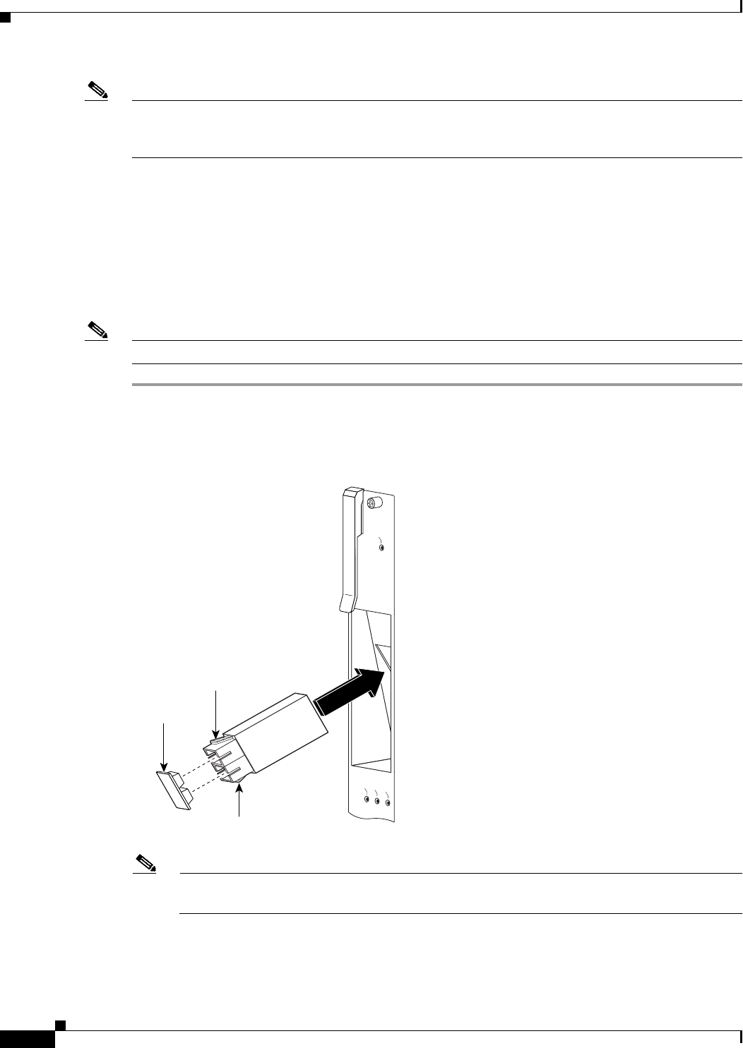
3-62
Cisco uBR10012 Universal Broadband Router Hardware Installation Guide
Chapter 3 Installing the Cisco uBR10012 Router
Connecting Cable Interface Line Cards and Network Uplink Cards
Note If you have completed all cable connections, go to the “Replacing the Front Cover” section on page 3-65
to continue the installation. If you are using Gigabit Ethernet line cards, go to “Connecting a Single-Port
Gigabit Ethernet Line Card” section on page 3-62.
Connecting a Single-Port Gigabit Ethernet Line Card
The single-port Gigabit Ethernet (GE) line card provides a trunk uplink running at 1 Gbps in full duplex
mode to devices such as content servers and Web caches. The port uses a Gigabit Interface Converter
(GBIC) that supports Gigabit Ethernet rates on a variety of Gigabit Ethernet interface types (SX, LX/LH,
ZX). For a list of qualified GBICs and cable lengths, see Table 1-9.
Use the following procedure to install a GBIC and then connect a fiber cable to the GBIC.
Note If a GBIC is already installed in the GE line card, begin this procedure at Step 2.
Step 1 Review the warnings at the start of the network uplink section.
Step 2 Insert the GBIC into the GE line card port until the tabs lock into place (Figure 3-41).
Figure 3-41 Inserting the GBIC
Note The GBIC is “keyed” and can only be fully inserted one way. If you can only insert the GBIC
one quarter of the way into the port, remove it, turn it over, and reinsert it into the port.
Step 3 Remove the protective plug from the GBIC by pulling it off.
30031
Locking
tab
Locking
tab
Protective
Plug
CISCO
10000
LINK
TX
RX
FAIL
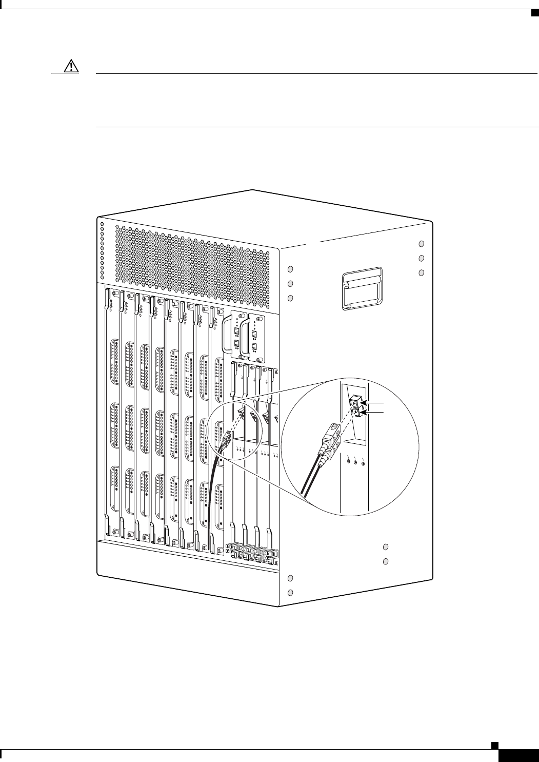
3-63
Cisco uBR10012 Universal Broadband Router Hardware Installation Guide
Chapter 3 Installing the Cisco uBR10012 Router
Connecting Cable Interface Line Cards and Network Uplink Cards
Caution Make sure your fiber optic connectors are clean and debris free. Refer to Inspection and Cleaning
Procedures for Fiber-Optic Connections at the following URL:
http://www.cisco.com/en/US/tech/tk482/tk876/technologies_white_paper09186a0080254eba.shtml
Step 4 Attach the fiber optic cable to the GBIC port (Figure 3-42).
Figure 3-42 Connecting the Cable to the GBIC Port
Step 5 Run the cable through the cable bracket on the bottom of the line card and then out to the left or right of
the chassis (Figure 3-43).
103474
CISCO
10000
CARRIER
ALARM
LOOP
FAIL
CH OC-12-DSO SM-IR
CISCO
10000
CARRIER
ALARM
LOOP
FAIL
CH OC-12-DSO SM-IR
CISCO
10000
CARRIER
ALARM
LOOP
FAIL
CH OC-12-DSO SM-IR
CISC
100
CARRIER
ALARM
L
FAIL
US0
US1
US2
US3
US4
US5
US6
US7
US8
US9
US10
US11
US12
US13
US14
US15
US16
US17
US18
US19
DS0
DS1
DS2
DS3
DS4
RF
RF
RF
RF
RF
uBR10-MC5x20S-D
POWER
STATUS
MAINT
US0
US1
US2
US3
US4
US5
US6
US7
US8
US9
US10
US11
US12
US13
US14
US15
US16
US17
US18
US19
DS0
DS1
DS2
DS3
DS4
RF
RF
RF
RF
RF
uBR10-MC5x20S-D
POWER
STATUS
MAINT
US0
US1
US2
US3
US4
US5
US6
US7
US8
US9
US10
US11
US12
US13
US14
US15
US16
US17
US18
US19
DS0
DS1
DS2
DS3
DS4
RF
RF
RF
RF
RF
uBR10-MC5x20S-D
POWER
STATUS
MAINT
US0
US1
US2
US3
US4
US5
US6
US7
US8
US9
US10
US11
US12
US13
US14
US15
US16
US17
US18
US19
DS0
DS1
DS2
DS3
DS4
RF
RF
RF
RF
RF
uBR10-MC5x20S-D
POWER
STATUS
MAINT
US0
US1
US2
US3
US4
US5
US6
US7
US8
US9
US10
US11
US12
US13
US14
US15
US16
US17
US18
US19
DS0
DS1
DS2
DS3
DS4
RF
RF
RF
RF
RF
uBR10-MC5x20S-D
POWER
STATU S
MAINT
US0
US1
US2
US3
US4
US5
US6
US7
US8
US9
US10
US11
US12
US13
US14
US15
US16
US17
US18
US19
DS0
DS1
DS2
DS3
DS4
RF
RF
RF
RF
RF
uBR10-MC5x20S-D
POWER
ST
ATUS
MAINT
US0
US1
US2
US3
US4
US5
US6
US7
US8
US9
US10
US11
US12
US13
US14
US15
US16
US17
US18
US19
DS0
DS1
DS2
DS3
DS4
RF
RF
RF
RF
RF
uBR10-MC5x20S-D
POWER
STATUS
MAINT
US0
US1
US2
US3
US4
US5
US6
US7
US8
US9
US10
US11
US12
US13
US14
US15
US16
US17
US18
US19
DS0
DS1
DS2
DS3
DS4
RF
RF
RF
RF
RF
uBR10-MC5x20S-D
POWER
STATU S
MAINT
TX
RX
CARRIER
TX
RX
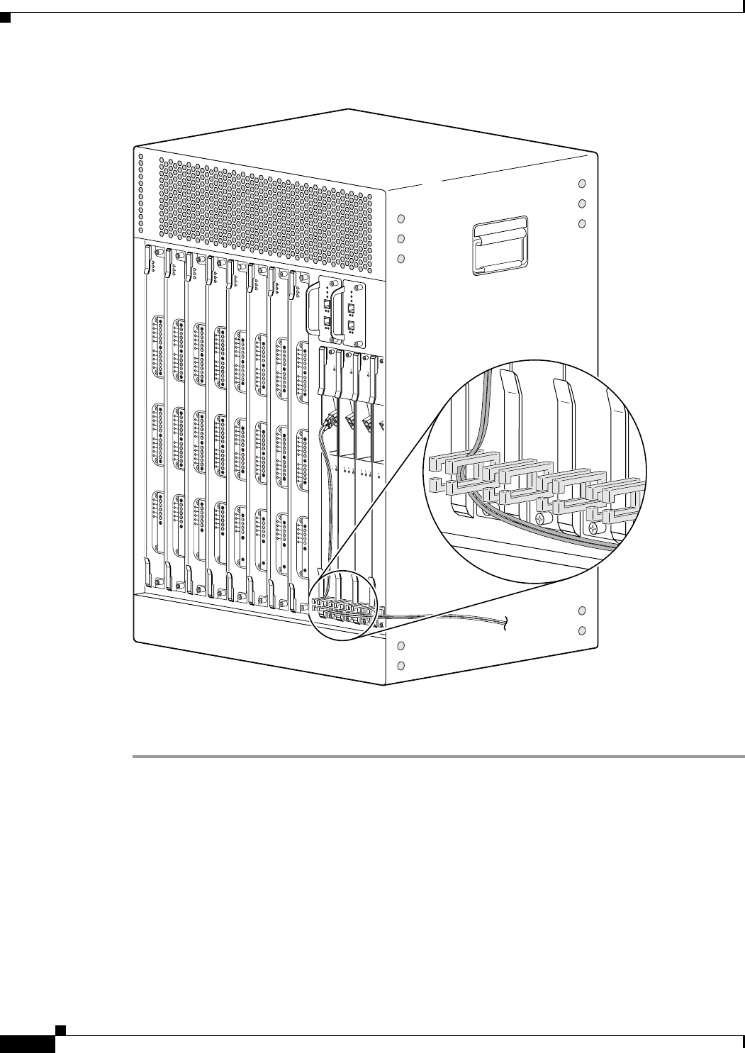
3-64
Cisco uBR10012 Universal Broadband Router Hardware Installation Guide
Chapter 3 Installing the Cisco uBR10012 Router
Connecting Cable Interface Line Cards and Network Uplink Cards
Figure 3-43 Gigabit Ethernet Cable Management
Step 6 If you have completed all cable connections, go to the next section, “Replacing the Front Cover” to
continue the installation.
103475
CISCO
10000
CARRIER
ALARM
LOOP
FAIL
CH OC-12-DSO SM-IR
CISCO
10000
CARRIER
ALARM
LOOP
FAIL
CH OC-12-DSO SM-IR
CISCO
10000
CARRIER
ALARM
LOOP
FAIL
CH OC-12-DSO SM-IR
CISC
100
CARRIER
L
FAIL
M-IR
O SM-IR
US0
US1
US2
US3
US4
US5
US6
US7
US8
US9
US10
US11
US12
US13
US14
US15
US16
US17
US18
US19
DS0
DS1
DS2
DS3
DS4
RF
RF
RF
RF
RF
uBR10-MC5x20S-D
POWER
ST
ATUS
MAINT
US0
US1
US2
US3
US4
US5
US6
US7
US8
US9
US10
US11
US12
US13
US14
US15
US16
US17
US18
US19
DS0
DS1
DS2
DS3
DS4
RF
RF
RF
RF
RF
uBR10-MC5x20S-D
POWER
STATU S
MAINT
US0
US1
US2
US3
US4
US5
US6
US7
US8
US9
US10
US11
US12
US13
US14
US15
US16
US17
US18
US19
DS0
DS1
DS2
DS3
DS4
RF
RF
RF
RF
RF
uBR10-MC5x20S-D
POWER
ST
ATUS
MAINT
US0
US1
US2
US3
US4
US5
US6
US7
US8
US9
US10
US11
US12
US13
US14
US15
US16
US17
US18
US19
DS0
DS1
DS2
DS3
DS4
RF
RF
RF
RF
RF
uBR10-MC5x20S-D
POWER
STATUS
MAINT
US0
US1
US2
US3
US4
US5
US6
US7
US8
US9
US10
US11
US12
US13
US14
US15
US16
US17
US18
US19
DS0
DS1
DS2
DS3
DS4
RF
RF
RF
RF
RF
uBR10-MC5x20S-D
POWER
STA
TUS
MAINT
US0
US1
US2
US3
US4
US5
US6
US7
US8
US9
US10
US11
US12
US13
US14
US15
US16
US17
US18
US19
DS0
DS1
DS2
DS3
DS4
RF
RF
RF
RF
RF
uBR10-MC5x20S-D
POWER
STATU S
MAINT
US0
US1
US2
US3
US4
US5
US6
US7
US8
US9
US10
US11
US12
US13
US14
US15
US16
US17
US18
US19
DS0
DS1
DS2
DS3
DS4
RF
RF
RF
RF
RF
uBR10-MC5x20S-D
POWER
STATU S
MAINT
US0
US1
US2
US3
US4
US5
US6
US7
US8
US9
US10
US11
US12
US13
US14
US15
US16
US17
US18
US19
DS0
DS1
DS2
DS3
DS4
RF
RF
RF
RF
RF
uBR10-MC5x20S-D
POWER
STATU S
MAINT
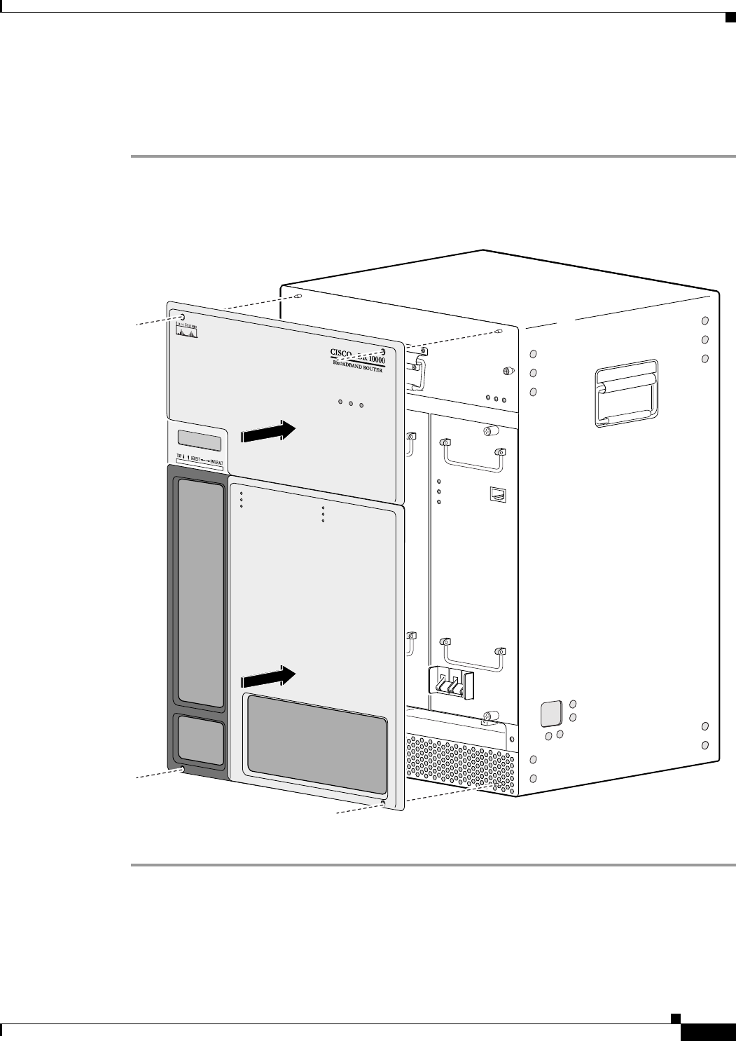
3-65
Cisco uBR10012 Universal Broadband Router Hardware Installation Guide
Chapter 3 Installing the Cisco uBR10012 Router
Replacing the Front Cover
Replacing the Front Cover
Use the following procedure to replace the front cover on the chassis:
Step 1 Slide the cover onto the four corner posts of the chassis and then push down so that the posts are seated
in the grooves above the cover holes (Figure 3-44).
Figure 3-44 Attaching the Cover to the Chassis
Step 2 Continue with the “Powering On the System” section to continue the installation.
56423
POWER
MISWIRE
FAULT
ALARMS
CISCO
10000
FAIL
PERFORMANCE ROUTING ENGINE
CONSOLE
STATUS
ACO
CRITICAL
MINOR
MAJOR
ETHERNET
LINK
ACTIVITY
AUX
SLOT 0
SLOT 1
ALARMS
CISCO
10000
FAIL
PERFORMANCE ROUTING ENGINE
CONSOLE
ST
A
TUS
ACO
CRITICAL
MINOR
MAJOR
ETHERNET
LINK
ACTIVITY
AUX
SLOT 0
SLOT 1
POWER
MISWIRE
FAULT
POWER
MISWIRE
FAULT
POWER
MISWIRE
FAULT
POWER
MISWIRE
FAULT
IPSUM
IPSUM SANCT
IPSU SA TUS
POWER
MISWIRE
FAULT

3-66
Cisco uBR10012 Universal Broadband Router Hardware Installation Guide
Chapter 3 Installing the Cisco uBR10012 Router
Powering On the System
Powering On the System
After all of the interfaces and other cables are connected, perform a visual check of all connections and
then check that:
•The ejector levers on each line card are in the locked position.
•All top and bottom line card captive screws are tight.
•All network interface cables are connected.
•The console terminal is turned on.
•A PC media card is installed in the PRE module.
For information on powering up the Cisco uBR10012 router using the UBR10-PWR-DC= DC PEM
module, see DC Power Entry Module for the Cisco uBR10012 Universal Broadband Router.
For information on powering up the Cisco uBR10012 router using the UBR10-PWR-DC-PLUS= DC
PEM module, see 3300 W DC Power Entry Module for the Cisco uBR10012 Universal Broadband
Router.
For information on powering up the Cisco uBR10012 router using the UBR10-PWR-AC= AC PEM
module, see AC Power Entry Module for the Cisco uBR10012 Universal Broadband Router.
For information on powering up the Cisco uBR10012 router using the UBR10-PWR-AC-PLUS= AC
PEM module, see 3300 W AC Power Entry Module for the Cisco uBR10012 Universal Broadband
Router.
Configuring the Cisco uBR10012 Router at Startup
This section explains how to create a basic running configuration for your Cisco uBR10012 router using
the Cisco uBR10012 router setup facility or the IOS command line interface (CLI). For information on
modifying the configuration after you create it, refer to:
•The online Cisco uBR10012 Router Useful Links document
•Cisco IOS configuration and command reference guides
To configure a Cisco uBR10012 router from the console, you must connect a terminal or terminal server
to the router's console port. To configure the Cisco uBR10012 router over your management Ethernet,
you must have available the router’s IP address.
Startup Display
When you power on your Cisco uBR10012 router or execute the reload command, the console screen
displays a message similar to the following:
Restricted Rights Legend
Use, duplication, or disclosure by the Government is
subject to restrictions as set forth in subparagraph
(c) of the Commercial Computer Software - Restricted
Rights clause at FAR sec. 52.227-19 and subparagraph
(c) (1) (ii) of the Rights in Technical Data and Computer
Software clause at DFARS sec. 252.227-7013.
cisco Systems, Inc.

3-67
Cisco uBR10012 Universal Broadband Router Hardware Installation Guide
Chapter 3 Installing the Cisco uBR10012 Router
Configuring the Cisco uBR10012 Router at Startup
170 West Tasman Drive
San Jose, California 95134-1706
Cisco Internetwork Operating System Software
IOS (tm) 10012 Software (UBR10K-P6-M), Released Version 12.2(1)
Copyright (c) 1986-2001 by cisco Systems, Inc.
Compiled Thu 19-Apr-01 13:47 by samants
Image text-base: 0x60008960, data-base: 0x612B0000
ROM: System Bootstrap, Version 12.0(9r)SL1, RELEASE SOFTWARE (fc1)
BOOTFLASH: 10012 Software (C10K-EBOOT-M), Released Version 12.1(5)
System returned to ROM by reload at 12:59:35 PDT Thu Apr 19 2001
System restarted at 13:00:51 PDT Thu Apr 19 2001
cisco C10012 (PRE-RP) processor with 98304K/32768K bytes of memory.
Processor board ID ABCDEFEDCBA
R7000 CPU at 262Mhz, Implementation 39, Rev 2.1, 256KB L2, 2048KB L3 Cache
Backplane version 1.0, 16 slot
Last reset from unexpected value
Toaster processor tmc0 is running.
Toaster processor tmc1 is running.
1 Ethernet/IEEE 802.3 interface(s)
1 FastEthernet/IEEE 802.3 interface(s)
1 Gigabit Ethernet/IEEE 802.3 interface(s)
3 Cable Modem network interface(s)
509K bytes of non-volatile configuration memory.
16384K bytes of Flash PCMCIA card at slot 1 (Sector size 128KB).
32768K bytes of Flash internal SIMM (Sector size 256KB).
Press RETURN to get started!
Basic Configuration Using the Setup Facility
The first time you power on a Cisco uBR10012 router, the setup facility starts. You can also initiate the
facility by running the setup command in privileged EXEC mode. This facility helps you enhance a
default configuration that already exists on the Cisco uBR10012 router. The setup facility uses a
question and answer sequence called the System Configuration Dialog to walk you through configuring
the router.
You do not have to configure the interfaces immediately; however, you cannot enable the interfaces or
connect them to any networks until you have configured them.
Tip Basic configuration setup is often used as a quick way to achieve network connectivity, allowing you to
retrieve a configuration file from a TFTP server.
System Configuration Dialog
Use the System Configuration Dialog to help you perform a basic configuration. Proceed through the
dialog by answering questions and then pressing the Enter key. In most cases, you can get additional
information by entering a question mark (?). Throughout the dialog, default values are shown in square
brackets [ ].

3-68
Cisco uBR10012 Universal Broadband Router Hardware Installation Guide
Chapter 3 Installing the Cisco uBR10012 Router
Configuring the Cisco uBR10012 Router at Startup
Tip If you have experience using Cisco routers, consider configuring the router by using the procedure
described in the “Basic Configuration in Global Configuration Mode” section on page 3-70.
To cancel the configuration dialog, press Ctrl-C, or you can let the dialog help you perform one of two
configuration types:
•Basic configuration setup configures only enough connectivity for management of the system.
•Extended setup asks you to configure each interface and is not appropriate for configuring the
Cisco uBR10012 router. For more information, see the Cisco IOS Configuration Fundamentals
Configuration Guide.
You can run the setup facility any time you are at the enable prompt (#) by entering the command setup.
Configuring the System Using System Configuration Dialog
Use the following procedure to perform a basic configuration using the System Configuration Dialog:
Step 1 The dialog starts by asking if you want to continue with the configuration dialog. Enter Yes. To return
to the enable prompt, enter No.
--- System Configuration Dialog ---
Continue with configuration dialog? [yes/no]: yes
Step 2 Enter Yes to perform a basic management setup. Enter No to perform an extended configuration setup.
Would you like to enter basic management setup? [yes/no]: yes
Step 3 Specify a hostname. The hostname becomes part of the IOS prompt.
Enter host name [Router]: my-router
Step 4 Specify a secret password. It appears in encrypted form in the configuration file.
Enter enable secret: my_secret
Step 5 Specify the enable password. It is used if you did not assign a secret one.
Enter enable password: my_password
Step 6 Specify the password to use for telnet sessions.
Enter virtual terminal password: my_vt
Step 7 At the configure system management prompt, enter No.
Configure System Management? [yes/no]: no
Step 8 If you want to access the router using SNMP, enter Ye s at the prompt:
Configure SNMP Network Management? [yes]: yes
Step 9 Specify an SNMP community string.
Community string [public]: public

3-69
Cisco uBR10012 Universal Broadband Router Hardware Installation Guide
Chapter 3 Installing the Cisco uBR10012 Router
Configuring the Cisco uBR10012 Router at Startup
Setting Up the Interface
After you respond to the SNMP questions, the setup script lists the interfaces. The following table lists
typical interfaces found on a Cisco uBR10012 router.
Tip Interfaces that are not okay (NO) do not have a valid configuration.
To set up an interface on the Cisco uBR10012 router:
Step 1 Enter the interface for the FastEthernet interface to achieve network connectivity.
Enter interface name used to connect to the management network from the above interface
summary: FastEthernet0/0/0
Step 2 Accept the default value for the type of connector. RJ-45 is the only connector that can be used on the
Cisco uBR10012 router Ethernet port.
Configuring interface FastEthernet0/0/0:
Use the 100 Base-TX (RJ-45) connector? [yes]: yes
Step 3 Configure both the Cisco uBR10012 router and the remote device to use the same mode.
Operate in full-duplex mode? [no]: no
Step 4 Enter the IP address to achieve network connectivity.
Configure IP on this interface? [yes]: yes
Step 5 Specify the IP address.
IP address for this interface: 172.27.48.209
Step 6 Enter the subnet mask for the IP address.
Subnet mask for this interface [255.255.0.0]: 255.255.0.0
The system displays the information you entered as well as several default commands, such as the no
shutdown command. For example:
The following configuration command script was created:
hostname c10012
enable secret 5 $$1$uror$EFU0hKOBQXhk975qKFZlL0
enable password <xxx>
line vty 0 4
password <xxx>
no snmp-server
!
no ip routing
!
Interface IP-Address OK? Method Status Protocol
Ethernet0/0/0 unassigned YES unset up up
FastEthernet0/0/0 unassigned NO unset up up
GigabitEthernet3/0/0 unassigned NO unset up up
Cable6/1/0 unassigned NO unset up up
Cable6/1/1 unassigned NO unset up up
Cable7/0/0 unassigned NO unset up up

3-70
Cisco uBR10012 Universal Broadband Router Hardware Installation Guide
Chapter 3 Installing the Cisco uBR10012 Router
Configuring the Cisco uBR10012 Router at Startup
interface FastEthernet0/0/0
no shutdown
media-type 100BaseX
half-duplex
ip address 172.27.48.209 255.255.0.0
!
end
Step 7 Exit the setup script without saving, start the setup script, or save the configuration file:
[0] Go to the IOS command prompt without saving this config.
[1] Return back to the setup without saving this config.
[2] Save this configuration to nvram and exit.
Enter your selection [2]:
Step 8 Enter global configuration mode after you complete the configuration, and enable ip routing by entering
the ip routing command:
router(config)#ip routing
Basic Configuration in Global Configuration Mode
The following command sequence allows you to perform a configuration similar to that generated by the
setup command.
Router>configure terminal
Router(config) #hostname c10012
Router(config) #enable secret <my_router>
Router(config) #enable password <my_rtr>
Router(config) #snmp-server community public
Router(config) #ip routing
Router(config) #interface FastEthernet0/0/0
Router(config-if) #no shutdown
Router(config-if) #media-type 100BaseX
Router(config-if) #half-duplex
Router(config-if) #ip address 192 255.255.0.0
Router #copy running-config startup-config
You can now configure the line cards. For specific information on system and interface configuration,
refer to the Cisco uBR10012Universal Broadband Router Software Configuration Guide at the following
URL:
http://www.cisco.com/en/US/docs/cable/cmts/ubr10012/configuration/guide/scg.html

3-71
Cisco uBR10012 Universal Broadband Router Hardware Installation Guide
Chapter 3 Installing the Cisco uBR10012 Router
Formatting PC Media Cards
Formatting PC Media Cards
The PC media card that shipped with your PRE contains the default Cisco IOS image for booting your
router. This section explains how to format a PC media card, modify its contents, or resolve a problem
with the card.
Caution The formatting procedure erases all information on the PC media card.
Note The Cisco uBR10012 router uses PC media cards that are a minimum of 64 MB in size.
Flash memory ATA disks and Flash memory cards use similar commands. The primary syntax change is
that disk0: or disk1: refers to Flash memory ATA disks while slot0: or slot1: refers to Flash memory
cards.
Use the following procedure to format a Flash memory disk:
Step 1 Ensure there is a PC media card in slot 0 or slot 1 of the PRE.
Step 2 Enter the format diskn: command at the privileged EXEC mode prompt to format the card. The example
shows the display after you enter the format disk0: command:
Router# format disk0:
All sectors will be erased, proceed? [confirm]
Enter volume id (up to 30 characters): MyNewdisk
Formatting sector 1
Format device slot0 completed
The PC media card is ready for use.

3-72
Cisco uBR10012 Universal Broadband Router Hardware Installation Guide
Chapter 3 Installing the Cisco uBR10012 Router
Formatting PC Media Cards

CHAPTER
4-1
Cisco uBR10012 Universal Broadband Router Hardware Installation Guide
4
Troubleshooting the Installation
This chapter provides basic troubleshooting information to solve the most common installation problems
with the Cisco uBR10012 universal broadband router. Your Cisco uBR10012 router went through
extensive testing before leaving the factory. However, if you encounter problems starting the router, use
the information in this chapter to help isolate the cause of the problems.
This chapter contains the following sections:
•Troubleshooting Methods, page 4-2
•Troubleshooting Installation Problems, page 4-3
•Troubleshooting Ethernet Connections, page 4-4
•Troubleshooting the Console Port Serial Connection, page 4-5
•Identifying Startup Problems, page 4-6
•Troubleshooting the Power Subsystem, page 4-7
•Troubleshooting the Processor Subsystem, page 4-13
•Troubleshooting the Cooling Subsystem, page 4-14
•Troubleshooting the Line Cards, page 4-16
•Troubleshooting the HHGE Installation, page 4-17
Note The procedures in this chapter assume that you are troubleshooting the initial system startup, and that
your router is in the original factory configuration. If you have removed or replaced components or
changed any default settings, the recommendations in this chapter might not apply.
Make sure to review the safety warnings listed in this manual, especially in Chapter 2, “Preparing for
Installation,” before using the troubleshooting procedures in this chapter.

4-2
Cisco uBR10012 Universal Broadband Router Hardware Installation Guide
Chapter 4 Troubleshooting the Installation
Troubleshooting Methods
Troubleshooting Methods
This section describes the troubleshooting methods used in this chapter and describes how
Cisco uBR10012 routers are divided into subsystems for more efficient problem solving.
Before You Call for Technical Assistance
If you are unable to easily solve the problem, contact a customer service representative for assistance
and further instructions. Provide the representative with the following information:
•Date you received the router
•Chassis serial number
•Type of software and release number
•Brief description of the problem you are having
•Brief explanation of the steps you have taken to isolate and resolve the problem
•Maintenance agreement or warranty information
Problem Solving Using a Subsystems Approach
The key to solving problems with the system is isolating the problem to a specific subsystem. Because
a startup problem is usually caused by a single component, it is more efficient to first isolate the problem
to a subsystem rather than troubleshoot each component in the system. For these troubleshooting
procedures, consider the following subsystems:
•Power subsystem—Includes the power supply and the external power cable.
•Processor subsystem—Includes the network processing card, the modular port adapter, the service
module, and the fixed RF ports. The system memory and management functions reside on the
network processing card, and the enabled LED on each port indicates if the port is initialized. A port
adapter that is partially installed in the router can cause the system to hang and crash.
•Cooling subsystem—Includes the fans.
The following sections help you isolate a problem to one of these subsystems and direct you to the
appropriate troubleshooting section.

4-3
Cisco uBR10012 Universal Broadband Router Hardware Installation Guide
Chapter 4 Troubleshooting the Installation
Troubleshooting Installation Problems
Troubleshooting Installation Problems
This section contains general troubleshooting information to help you solve any problems you might
encounter during the installation of the system.
General Troubleshooting Tips
All Cisco uBR10012 router FRUs (field replaceable units) are hot-swapable. Procedures for removing
and replacing the FRUs can be found in Chapter 5, “Maintaining the Cisco uBR10012 Router.”
List of FRU modules:
•Fan module
•TCC+ modules
•Power entry modules (PEM)
•PRE modules
•Cable interface cards and uplink cards
Table 4-1 lists general FRU fault symptoms and recommendations.
Table 4-1 General Troubleshooting Tips
Symptom Steps to Take
System fails to power on Check that:
•All power cords are properly connected to the Cisco uBR10012 router and at the power
connection end.
•The DC PEM power switches are turned on and the POWER LED is illuminated (green).
•The AC PEM power switches are turned on and the POWER LED is illuminated (green).
•The fan assembly module is fully inserted, and the FANS OK LED is lighted (green).
System fails to boot up
properly
If the system has power, check the FAIL LED on the PRE and any information on the
alphanumeric display. If the FAIL LED is on, see Troubleshooting the Power Subsystem,
page 4-7
DC PEM problem •If the FAULT LED is illuminated, see Troubleshooting the Power Subsystem, page 4-7.
•If the MISWIRE LED is on, the –48/-60VDC and return (RTN+) wires are reversed. Power
off the PEM and reconnect the wires correctly (see the “Connecting DC Power to the
Cisco uBR10012 Router” section on page 3-39).
AC PEM problem •If the power LED on the AC PEM is off, check the AC power source.
•If the fault LED is illuminated (yellow), check to see if the PEM is properly inserted in the
chassis.
•Check the Cisco IOS Release version that you are using. Versions earlier than Cisco IOS
Release 12.2(4)XFI, 12.2(4)BC1, or later do not correctly identify the AC PEM’s error
messages.
System experiences a
critical alarm (Critical LED
on the PRE is on)
Enter the show facility-alarm status command at the console.

4-4
Cisco uBR10012 Universal Broadband Router Hardware Installation Guide
Chapter 4 Troubleshooting the Installation
Troubleshooting Ethernet Connections
Troubleshooting Ethernet Connections
If an Ethernet connection to your Cisco uBR10012 router fails to work properly, and the corresponding
LNK (Link) LED is not illuminated, check for the following problems:
•Visually check that an Ethernet cable is connected to the correct Ethernet port on the PRE, and that
the other end of the cable is connected to an Ethernet hub that is powered on and functioning
properly.
•Check to see if you are using the correct type of cable. The cable must meet the specifications given
in the “Connecting to a 10Base-T Ethernet Network” section on page 3-58.
•The cable might be bad or broken. Replace the cable with a known, reliable straight-through
Ethernet cable, checking to be sure the LNK LED comes on (green).
–
If the LNK LED is still not illuminated, it is possible that the Ethernet port might be functioning
properly, but the LED is not working. Check the Ethernet port (by trying to ping over it, for
example) to determine if the problem is due to a bad LED or if the Ethernet link is bad.
•Make sure the PRE has booted up properly as follows:
–
The Status LED should be illuminated (green).
–
If the Fail LED is illuminated (yellow), refer to Troubleshooting the Processor Subsystem,
page 4-13.
System experiences a major
alarm (Major LED on the
PRE is on)
Enter the show facility-alarm status command at the console.
System experiences a minor
alarm (Minor LED on the
PRE is on)
Enter the show facility-alarm status command at the console.
You cannot establish a
console or Telnet connection
to the system.
For information about troubleshooting Ethernet connections, see the “Troubleshooting
Ethernet Connections” section on page 4-4.
For information about troubleshooting the console port serial connections, see the
“Troubleshooting the Console Port Serial Connection” section on page 4-5.
Fan failure Perform the following if the fan failure LEDs illuminate:
•Reseat the fan assembly module (see the “Removing and Replacing the Fan Assembly
Module” section on page 5-6).
•Remove the rear safety cover and be sure that the fan assembly module cable is connected
securely (see the “Removing and Replacing the Fan Assembly Module” section on
page 5-6).
System overheats This may be due to a failure in the fan assembly module (see Fan Failure above), insufficient
ventilation, or high ambient temperature. See the “Troubleshooting the Cooling Subsystem”
section on page 4-14 for additional information.
Table 4-1 General Troubleshooting Tips (continued)
Symptom Steps to Take

4-5
Cisco uBR10012 Universal Broadband Router Hardware Installation Guide
Chapter 4 Troubleshooting the Installation
Troubleshooting the Console Port Serial Connection
•Check the hub:
–
Is the cable connected into the correct hub port (for example, the hub LED is illuminated, but
the LNK LED on the PRE is not illuminated).
–
Be sure that the cable is not connected to an uplink port.
•If the LNK LED is illuminated (green), but the Ethernet port does not seem to be working properly,
make sure that the port in question is configured properly and is not administratively shut down. If
you have a working console connection, perform the following steps:
–
At the router prompt, enter show int fast0/0/0. If the port is administratively down, enter these
commands to enable it:
router# configure terminal
Enter configuration commands, one per line. End with CNTL/Z.
router(config)# int fast0/0/0
router(config-if)# no shut
router(config-if)# exit
router(config)# exit
–
Check that the Ethernet port in question has a valid IP address assigned to it.
Note The Cisco uBR10012 router also has an internal Ethernet interface, Ethernet0/0/0, which PRE
processors and line cards use to transfer packets between cards. This interface is not user-configurable,
although you can see the configuration and run-time information using the show interface command.
For more information about configuring Ethernet ports, refer to the Cisco uBR10012 Router Software
Configuration Guide at the following URL:
http://www.cisco.com/en/US/docs/cable/cmts/ubr10012/configuration/guide/scg.html
If the cable, connections, power, and configuration all check out, and you still cannot connect to the
Ethernet port on the module, you probably need to replace the PRE. Contact the Cisco TAC for further
assistance.
Troubleshooting the Console Port Serial Connection
If the terminal connected to the Cisco uBR10012 router console port appears frozen or fails to work
properly, check for the following problems:
•Check the console cable and make sure it is properly connected to the correct console port on the
PRE, and to your terminal equipment at the other end.
•Verify that you are using the right type of cable and adapter. For additional information about cable
pin-outs, refer to the “Connecting the Console Port and Auxiliary Port” section on page 3-55.
•To be sure the cable is not defective or broken, replace the cable with another high quality cable if
possible.
•Check that your terminal equipment is working properly and configured with the correct settings for
the console port. The default console port settings are:
–
9600 baud
–
8 data bits
–
1 stop bit

4-6
Cisco uBR10012 Universal Broadband Router Hardware Installation Guide
Chapter 4 Troubleshooting the Installation
Identifying Startup Problems
–
No parity
–
No flow control
•Check the LEDs on the PRE to make sure that it is powered up properly.
•If the cable, connections, power, and terminal settings all check out and you still cannot connect to
the console port on the module, you probably need to replace the PRE. Contact the Cisco TAC for
further assistance. See the “Obtaining Documentation and Submitting a Service Request” section on
page xvi.
Identifying Startup Problems
Startup problems are commonly due to the source power or to a line card that is not properly seated in
the router. Although an overtemperature condition is unlikely at initial startup, the environmental
monitoring functions are included in this chapter because they also monitor internal voltages.
When you start up the router for the first time, observe the startup sequence described in the “Powering
On the System” section on page 3-66. This provides a detailed description of a normal startup sequence.
LEDs indicate all system states in the startup sequence. By checking the state of the LEDs, you can
determine when and where the system failed in the startup sequence. Use the following descriptions to
isolate the problem to a subsystem, and then proceed to the appropriate sections to try to resolve the
problem.
When you start up the system by turning the power supply switch to the on (|) position, the following
should occur:
1. Fans—the fans start operating. The FAN OK LED on the fan assembly module turns green. You
should be able to feel the air being taken in at the bottom front of the router and blown out at the top
rear of the router.
If not, proceed to the “Troubleshooting the Cooling Subsystem” section on page 4-14.
2. DC PEM—the POWER LED on each DC PEM turns green to indicate that the PEM is connected to
an active DC power source and is supplying power to the chassis.
–
If the FAULT LED is illuminated (yellow), it indicates that the PEM is connected to an active
DC power source but is not providing power to the chassis.
–
If the MISWIRE LED is illuminated (yellow), it indicates that the wires from the DC power
source to this DC PEM are reversed.
–
Proceed to the “Troubleshooting the Power Subsystem” section on page 4-7.
3. PREs—the FAIL LED on the PRE modules briefly lights during the power-on sequence and then it
turns off. If the FAIL LED remains on, try removing and reseating the PRE module, and verify that
the card is fully inserted and that both locking levers are fully down in the locked position.
If the FAIL LED remains on, make a note of the failure code that appears in the PRE module’s LCD
screen and call TAC for instructions.
4. Line cards—Verify the line card “Enabled” LEDs.
Each line card has an enabled LED that goes on initially at power-on and then goes off. The LED
then goes on and remains on when the corresponding port is enabled and configured for operations.
If an enabled LED fails to go on at initial power-on, or if the LED fails to go on and remain on after
the port is enabled and configured, proceed to the “Troubleshooting the Cooling Subsystem” section
on page 4-14.

4-7
Cisco uBR10012 Universal Broadband Router Hardware Installation Guide
Chapter 4 Troubleshooting the Installation
Troubleshooting the Power Subsystem
Note The slot 0 and slot 1 LEDs only go on when the PC media card slot is being accessed by the system.
These LEDs remain off during normal operation of the router and do not indicate startup problems.
5. The initial system banner displays on the console screen.
If it is not displayed, see the “Connecting Network Management Cables” section on page 3-58 to
verify that the terminal is set up correctly and that it is properly connected to the router’s console
port.
Troubleshooting the Power Subsystem
The AC power entry modules, DC power entry modules, or an AC power shelf combined with the DC
power modules are used to power on the Cisco uBR10012 router.
Troubleshooting the AC Power Subsystem
The following troubleshooting steps are applicable to both the AC PEM (UBR10-PWR-AC= and
UBR10-PWR-AC-PLUS=) modules.
Use the following steps to isolate a problem with the AC power subsystem.
Step 1 Use the show environment command to display the general health of the power system.
Router# show environment
Temperature information:
Temperature normal: Inlet sensor measured at 30C/86F
Temperature normal: Outlet sensor measured at 40C/104F
Voltage information:
RP Voltage readings :
Channel Margin ADC Value
======================================
2.5v Normal 2.47v
1.8v N/A 1.80v
1.5v Normal 1.48v
1.8vFPGA Normal 1.78v
1.2v Normal 1.18v
3.3v Normal 3.26v
Fan: OK
Power Entry Module 0 type AC status: OK
Power Entry Module 0 Power: 3692w
Power Entry Module 0 Voltage: 71v
Power Entry Module 0 Power Last Successful Timestamp: 15:16:20 13 Dec 2012
Router#
Note The show environment command provides accurate information on the AC PEM only when using
Cisco IOS Release 12.2(4)XF1, 12.2(4)BC1a, or a later release. If using and earlier release, the show
environment command does not correctly identify the AC PEM error messages.
Starting Cisco IOS Release 12.2(33)SCG2 and later, the show environment command output has been
modified to display the latest valid power and voltage values of the PEM module with timestamp.

4-8
Cisco uBR10012 Universal Broadband Router Hardware Installation Guide
Chapter 4 Troubleshooting the Installation
Troubleshooting the Power Subsystem
Step 2 Verify that the temperatures are within the valid operating ranges, and that the fan assembly and both
AC PEM modules are present and OK.
a. If this is not the case, check for the following issues:
–
Fan is reported MISSING—Insert the fan assembly or shut down the router immediately to
avoid running the router beyond its operating temperature range.
–
AC PEM is not listed—Verify that both AC PEMs are present, and if so, that each PEM is fully
inserted into the chassis.
–
The “Input/Output Voltage Fault” message indicates that the output voltage from one of the AC
PEMs is not within the correct range. This can occur when the input AC voltage to the AC PEM
is either too low or too high. Measure the input AC voltage, and if it is correct, the AC PEM has
failed and should be replaced.
Note Wall input voltage for the AC PEM must be 200 - 240 VAC at 50/60Hz.
b. Verify if the UBR10-PWR-AC-PLUS= AC PEM show environment command output displays a DC
PEM module instead of AC PEM.
Router# show environment
Temperature information:
Temperature normal: Inlet sensor measured at 31C/87F
Temperature normal: Outlet sensor measured at 35C/95F
Voltage information:
RP Voltage readings:
Channel Margin ADC Value
======================================
2.5v Normal 2.49v
1.8v N/A 1.81v
1.5v Normal 1.49v
1.8vFPGA Normal 1.79v
1.2v Normal 1.20v
3.3v Normal 3.29v
Fan: OK
Power Entry Module 0 type DC status: OK // DC PEM is displayed //
Power Entry Module 1 type AC status: OK
Power Entry Module 0 Power Last Successful Timestamp: 15:16:20 13 Dec 2012
–
Upgrade to a supported Cisco IOS Release and then press the PRODUCT ID LED/switch.
–
Reload the software or physically remove the AC PEM module for at least 1 minute and then
reinsert it.
Note The show environment command provides accurate information on the 3300 W AC PEM if the
Cisco uBR10012 router is running a supported Cisco IOS Release. If using an earlier Cisco IOS
release, the show environment command will not correctly identify the error messages of the
3300 W AC PEM.
Step 3 Verify if the AC power cables are installed into the AC PEM receptacles and the facility power source is
turned on. The AC power enable switch is set to the Standby (0) position.
a. Check if the AC PEM is receiving power.

4-9
Cisco uBR10012 Universal Broadband Router Hardware Installation Guide
Chapter 4 Troubleshooting the Installation
Troubleshooting the Power Subsystem
–
The V1 POWER and V2 POWER LEDs on the UBR10-PWR-AC-PLUS= AC PEM should
illuminate (green).
If these LEDs are not illuminated, check the external wiring and facility power source. If the
fans are working and are audible, it indicates that the AC PEM is receiving power, so there could
be a possibility that the LEDs are not working.
–
The FAULT LED should illuminate (yellow).
If this LED is not illuminated, there could be a possibility that the LED is not working, therefore
the LED cannot indicate a valid fault on the PEM.
b. If the above LEDs do not illuminate but you are confident that PEM is receiving power, you can
proceed to power on the PEM, see AC Power Entry Module for the Cisco uBR10012 Universal
Broadband Router. Ensure that the POWER LED is not illuminated (green). If this LED is
illuminated, the AC PEM should be replaced. See the “Obtaining Documentation and Submitting a
Service Request” section on page xvi.
Step 4 Verify if the UBR10-PWR-AC-PLUS= AC PEM is powered on, and the V1 POWER and V2 POWER
LEDs are illuminated (unless they may not be working, as above). The AC power enable switch on the
AC PEM is set to the ENABLE (|) position.
a. The FAULT LED should stop illuminating. If it remains illuminated, the AC PEM should be
replaced because this is a valid fault. See the “Obtaining Documentation and Submitting a Service
Request” section on page xvi.
b. The POWER LED should illuminate (green). If this LED does not illuminate, and the FAULT LED
is not illuminated, there might be a possibility that the POWER LED is not working. You may need
to verify if the PEM is providing valid power to the system by checking the AC PEM voltage and
current using the Cisco IOS Release running on the router. Contact technical support for assistance,
see the “Obtaining Documentation and Submitting a Service Request” section on page xvi.
Step 5 The FAULT LED is illuminated (yellow).
a. The FAULT LED illuminates when the PEM module detects an over-voltage or over-current
condition, or when the PRE issues the command to shut down the PEM module (this could occur
due to overheating). Ensure that none of these conditions exist in the system, and then try to switch
the PEM module off and switch it on again.
b. If another PEM module exists in the system that powers up the chassis, and the FAULT LED is not
illuminated on that module, then ensure that the PRE does not issue the command to shut down the
PEM module.
c. If the problem persists, try another working unit. Else, see the “Obtaining Documentation and
Submitting a Service Request” section on page xvi.
Step 6 If none of the above suggestions correct the problem, the AC PEM could be faulty. Contact a service
representative for further instructions. See the “Obtaining Documentation and Submitting a Service
Request” section on page xvi.
Troubleshooting the DC Power Subsystem
The following troubleshooting steps are applicable to both the DC PEM (UBR10-PWR-DC= and
UBR10-PWR-DC-PLUS=) modules.
Use the following steps to isolate a problem with the DC power subsystem.

4-10
Cisco uBR10012 Universal Broadband Router Hardware Installation Guide
Chapter 4 Troubleshooting the Installation
Troubleshooting the Power Subsystem
Step 1 The DC-input power cables are installed into the DC PEM terminal blocks and the facility power source
is turned on. The DC power enable switch is set to the Standby (0) position.
Check if the DC PEM is receiving power.
a. The MISWIRE LED should not be illuminated. If it is illuminated (yellow), it indicates that the
DC-input power cables are reversed, or one DC-input power cable was probably not connected.
Correct the situation by reconnecting the power cables see, “Connecting DC Power to the
Cisco uBR10012 Router” section on page 3-39.
b. The V1 POWER and V2 POWER LEDs on the UBR10-PWR-DC-PLUS= DC PEM should
illuminate (green).
If these LEDs are not illuminated, check the external wiring and facility power source. If the fans
are working and are audible, it indicates that the DC PEM is receiving power, so there could be a
possibility that the LEDs are not working.
c. The FAULT LED should illuminate (yellow).
If this LED is not illuminated, there could be a possibility that the LED is not working, therefore the
LED cannot indicate a valid fault on the PEM.
If the above LEDs do not illuminate but you are confident that PEM is receiving power, you can proceed
to power on the PEM. Ensure that the POWER LED is not illuminated (green). If this LED is illuminated,
the DC PEM should be replaced. See the “Obtaining Documentation and Submitting a Service Request”
section on page -xvi.
Step 2 The UBR10-PWR-DC-PLUS= DC PEM is powered on, and the V1 POWER and V2 POWER LEDs are
illuminated (unless they may not be working, as above). The DC power enable switch on the DC PEM
is set to the ENABLE (|) position.
a. The FAULT LED should stop illuminating. If it remains illuminated, the DC PEM should be
replaced because this is a valid fault. See the “Obtaining Documentation and Submitting a Service
Request” section on page -xvi.
b. The POWER LED should illuminate (green). If this LED does not illuminate, and the FAULT LED
is not illuminated, there might be a possibility that the POWER LED is not working. You may need
to verify if the PEM is providing valid power to the system by checking the DC PEM voltage and
current using the Cisco IOS Release running on the router. Contact technical support for assistance,
see the “Obtaining Documentation and Submitting a Service Request” section on page -xvi.
Step 3 The FAULT LED is illuminated (yellow).
a. The FAULT LED illuminates when the PEM module detects an over-voltage or over-current
condition, or when the PRE issues the command to shut down the PEM module (this could occur
due to overheating). Ensure that none of these conditions exist in the system, and then try to switch
the PEM module off and switch it on again.
b. If another PEM module exists in the system that powers up the chassis, and the FAULT LED is not
illuminated on that module, then ensure that the PRE does not issue the command to shut down the
PEM module.
c. If the problem persists, try another working unit. Else, see the “Obtaining Documentation and
Submitting a Service Request” section on page -xvi.
Step 4 The MISWIRE LED is illuminated (yellow).
If the MISWIRE LED is illuminated, the –48/–60 VDC and return (RTN+) wires are reversed. Ensure
that the facility power source is turned off immediately, see “Connecting DC Power to the
Cisco uBR10012 Router” section on page 3-39 to reconnect the wires correctly before powering on the
PEM module.

4-11
Cisco uBR10012 Universal Broadband Router Hardware Installation Guide
Chapter 4 Troubleshooting the Installation
Troubleshooting the Power Subsystem
Step 5 The show environment command output on the UBR10-PWR-DC-PLUS= DC PEM module (shown
below) displays AC PEM instead of DC PEM.
Router# show environment
Temperature information:
Temperature normal: Inlet sensor measured at 31C/87F
Temperature normal: Outlet sensor measured at 35C/95F
Voltage information:
RP Voltage readings:
Channel Margin ADC Value
======================================
2.5v Normal 2.49v
1.8v N/A 1.81v
1.5v Normal 1.49v
1.8vFPGA Normal 1.79v
1.2v Normal 1.20v
3.3v Normal 3.29v
Fan: OK
Power Entry Module 0 type AC status: OK // AC PEM is displayed //
Power Entry Module 1 type DC status: OK
Power Entry Module 0 Power Last Successful Timestamp: 15:16:20 13 Dec 2012
Try one of the following:
•Upgrade to a supported Cisco IOS Release and then press the PRODUCT ID LED/switch.
•Reload the software or physically remove the DC PEM module for at least 1 minute and then reinsert
it.
Step 6 Use the show environment command to display the general health of the power system:
Router# show environment
Temperature normal: chassis inlet measured at 29C/84F
Temperature normal: chassis core measured at 42C/107F
Fan: OK
Power Entry Module 0 type DC status: OK
Power Entry Module 1 type DC status: OK
Power Entry Module 0 Power Last Successful Timestamp: 15:16:20 13 Dec 2012
Router#
Note Starting Cisco IOS Release 12.2(33)SCG2 and later, the show environment command output has been
modified to display the latest valid power and voltage values of the PEM module with timestamp.
Verify that the temperatures are within the valid operating ranges, and that the fan assembly and both
DC PEM modules are present and OK. If this is not the case, check for the following actions:
a. Fan is reported MISSING—Insert the fan assembly or shut down the router immediately to avoid
running the router beyond its operating temperature range.
b. DC PEM is not listed—Verify that both DC PEMs are present, and if so, that each PEM is fully
inserted into the chassis.
c. An “External AC Supply Fault” message indicates that one of the power modules in the external
power supply is reporting either a fault, an over-temperature condition, or is missing. Check the
LEDs on the front panels of the power modules on the external power supply to discover which
module has the fault.

4-12
Cisco uBR10012 Universal Broadband Router Hardware Installation Guide
Chapter 4 Troubleshooting the Installation
Troubleshooting the Power Subsystem
Note When using the external AC-input power shelf, the show environment command provides information
on whether a power module in the power shelf is missing, is reporting a fault, is experiencing an
over-temperature condition, or is not receiving AC-input power. For information on the external
AC-input power shelf and on connecting it to the DC PEM, see Cisco uBR10012 Universal Broadband
Router Hardware Installation Guide.
Step 7 Check to see if the DC power source supplying the proper power to the DC PEMs? (If you are using the
2400W AC-input power shelf, look to verify that the AC OK and DC OK LEDs are illuminated for each
of the AC power supplies.)
a. If no, and if the DC power source is connected to a valid power outlet, troubleshoot the DC power
source.
b. If yes, turn off the DC power source and remove the DC PEM from the chassis. Verify that the DC
power source is correctly wired to the terminal blocks underneath each PEM. See the “Connecting
DC Power to the Cisco uBR10012 Router” section on page 3-39 for details.
Step 8 If none of the above suggestions correct the problem, the DC PEM could be faulty. Contact a service
representative for further instructions. See the “Obtaining Documentation and Submitting a Service
Request” section on page xvi.
Troubleshooting the 2400 W AC-Input Power Shelf
Check the following to isolate a problem to the AC-input power shelf.
Step 1 Check to see which version of the PEM you have in the chassis.
a. If the Cisco uBR10012 router is running Cisco IOS Release 12.2(4)XF or a later release, you can
use the show environment command to monitor the AC-input power shelf.
Router# show environment
Temperature normal: chassis inlet measured at 29C/84F
Temperature normal: chassis core measured at 42C/107F
Fan: OK
Power Entry Module 0 type DC status: OK
Power Entry Module 1 type DC status: OK
Router#
b. If the DC PEM status is either “External AC Supply Fault” or “Input/Output Voltage Fault,” a
problem exists with the AC-input power shelf.
–
The “External AC Supply Fault” message indicates that one of the power modules is reporting
either a fault, an over-temperature condition, or is missing. Check the LEDs on the front panels
of the power modules on the external power supply to discover which module has the fault.
c. If the “Input/Output Voltage Fault” message indicates that one of the power modules is not receiving
AC-input power then, check the LEDs on each power module, check that each power module is
plugged into an AC-input power outlet, and that those outlets are providing power.
Step 2 Verify that the DC and AC OK LEDs are illuminated.
a. If yes, then the power shelf is operational.
b. If not, do the following:

4-13
Cisco uBR10012 Universal Broadband Router Hardware Installation Guide
Chapter 4 Troubleshooting the Installation
Troubleshooting the Processor Subsystem
–
Make sure that the AC power cord is correctly plugged in to both the AC-output wall outlet and
in to the back of the AC-input power shelf. (A separate power cord is used for each power
supply.)
–
Make sure that the AC power supply is properly inserted, seated, and locked. If necessary,
remove the AC power supply and reinsert it.
–
Check the external AC power source.
–
Swap the AC power supply with one of the others. If the failure follows the power supply,
replace the power supply. If the failure remains in that particular power bay, double-check the
external AC power source and the power cord connections; if they are correct, contact the
Cisco TAC for additional troubleshooting information.
c. If only DC OK LED is not illuminated, then check the wiring to the Cisco uBR10012 router
DC-input terminal blocks.
Step 3 Check to see if the FAULT LED is illuminated (yellow), if it is then:
–
Check that the external AC power source is supplying consistent AC voltage at the proper levels,
without spikes or brownouts.
–
Flip the circuit-breaker for the external AC power source.
–
Replace the power supply with a known good replacement.
Step 4 If none of these measures work, contact a service representative for instructions. See the “Obtaining
Documentation and Submitting a Service Request” section on page xvi.
Troubleshooting the Processor Subsystem
The processor subsystem on the Cisco uBR10012 router consists of the performance routing engine
(PRE) modules and the timing, communication, and control plus (TCC+) cards. At system startup, the
following sequence should appear on the primary PRE.
1. The FAIL LED briefly comes on (yellow), turn off, and the STATUS LED starts flashing (yellow).
2. A series of messages appear on the PRE alphameric display indicating the progress of the boot-up
sequence.
3. Upon successful completion of the boot-up sequence, the message IOS RUN appears on the
alphanumeric display.
4. The STATUS LED comes on (green) to indicate this is the primary PRE.
The sequence on the redundant PRE is similar, except that the STATUS LED remains OFF and the
messages on the alphanumeric display are slightly different. The final message upon a successful
boot-up sequence is IOS STBY to indicate that this is the redundant PRE operating in stand-by mode.
Use the following procedure to troubleshoot the PRE modules.
Step 1 Check the following if a problem appears on one of the PRE modules.
a. Did the STATUS LED on the primary PRE light solid (green) at the end of the boot-up sequence?
b. If no, check the other LEDs on other modules in the chassis. If no other LEDs are lit, check for a
problem in the power subsystem, as described in the “Troubleshooting the Power Subsystem”
section on page 4-7.

4-14
Cisco uBR10012 Universal Broadband Router Hardware Installation Guide
Chapter 4 Troubleshooting the Installation
Troubleshooting the Cooling Subsystem
c. If no, and no other LEDs on the PRE are lit but LEDs on other modules are lit, remove the PRE from
the slot, check for any bent or broken pins on the backplane connectors, and reinsert it, ensuring it
makes solid contact with the backplane and is securely locked in by firmly closing both locking
levers.
d. If no, but the FAIL LED is lit (yellow), remove the PRE and reinsert it. If that fails, insert a new
PRE. If that fails, contact TAC for assistance.
Step 2 Repeat the above steps for the redundant PRE, except that its STATUS LED should be OFF and its
alphanumeric display should read IOS STBY if it is operating correctly.
a. If both PREs are operating correctly, check the Power LEDs on each TCC+ card. Are the POWER
LEDs on each TCC+ card lighted (green)?
b. If no, remove the TCC+ card and reinsert it, making it sure it firmly connects to the backplane and
that both captive screws are tightly connected.
c. If yes, proceed to the next step.
Step 3 Verify the Status LEDs on the TCC+ card.
a. Is the STATUS LED on the primary TCC+ on (solid green) indicating that it is the primary card?
b. Is the STATUS LED on the secondary TCC+ flashing (green) indicating that it is the redundant card?
c. If no, verify that the version of Cisco IOS on the router supports the TCC+ card.
Step 4 Contact TAC for assistance if necessary. See the “Obtaining Documentation and Submitting a Service
Request” section on page xvi.
Troubleshooting the Cooling Subsystem
The following troubleshooting steps are applicable to both the fan assembly (UBR10-FAN-ASSY= and
UBR10012-FAN-PLUS=) modules.
Check the following to help isolate a problem with the cooling system.
Step 1 When you start up the system, do the fans start operating?
When the fans are operating, you should be able to hear them. You should also be able to feel air being
drawn in at the bottom front and expelled at the top rear of the chassis.
a. Check for fan failure by checking the fan status LEDs and running the show environment
command.
Router# show environment
Temperature normal: chassis inlet measured at 29C/84F
Temperature normal: chassis core measured at 42C/107F
Fan: OK
Power Entry Module 0 type DC status: OK
Power Entry Module 1 type DC status: OK
Power Entry Module 0 Power Last Successful Timestamp: 15:16:20 13 Dec 2012
Router#
b. Ensure that no alarms are triggered on the fan assembly module.
c. Check if there is sufficient ventilation on the chassis intake and chassis exhaust.
d. Verify if the ambient temperature is within the specified range.

4-15
Cisco uBR10012 Universal Broadband Router Hardware Installation Guide
Chapter 4 Troubleshooting the Installation
Troubleshooting the Cooling Subsystem
If the problem persists, see the “Obtaining Documentation and Submitting a Service Request” section
on page -xvi.
Step 2 Are the two LEDs —SINGLE FAN FAIL and MULTI FAN FAIL—illuminated (yellow)?
Remove the fan assembly module and reinsert it. If this does not help, examine the LED that is
illuminated. Else see, “Obtaining Documentation and Submitting a Service Request” section on
page -xvi.
Step 3 Are the following messages displayed?
These messages indicate that the system has detected a critical over-temperature condition or
out-of-tolerance power inside the chassis.
Queued messages:
00:01:19:%ENVM-4-ENVWARN:+2.5 V measured at +2.59
00:01:19:%ENVM-4-ENVWARN:+5.15 V measured at +5.31
00:00:19:%ENVM-2-ENVCRIT:chassis core measured at 31C/87F
00:00:19:%ENVM-2-ENVCRIT:chassis inlet measured at 27C/80F
00:00:19:%ENVM-2-ENVCRIT:chassis outlet 1 measured at 30C/86F
00:00:19:%ENVM-2-ENVCRIT:chassis outlet 2 measured at 30C/86F
Although an over-temperature condition is unlikely at initial startup, ensure that heated exhaust air from
other equipment is not entering the inlet vent of the router and that there is sufficient clearance around
the sides of the chassis to allow cooling air to flow.
Note The message could also indicate a faulty component or temperature sensor. Use the show environment
or show environment table command to display the internal chassis environment.
Step 4 Is the PRODUCT ID LED/switch on fan assembly module illuminated (green) and a FAN-MISSING
alarm is randomly being triggered?
If you are running a Cisco IOS Release that does not support the PRODUCT ID LED/switch feature,
then ensure that the PRODUCT ID LED/switch is not pressed and is not illuminated. Upgrade to a
supported Cisco IOS Release on the chassis.
Note If you cannot upgrade to a supported Cisco IOS Release, then ensure that the PRODUCT ID
LED/switch is not pressed and not illuminated (green).
If you are running a Cisco IOS Release that supports this feature, but the FAN-MISSING alarm is still
being triggered, then follow the steps below to clear the alarm so that the software recognizes the fan
module:
a. Ensure that the PRODUCT ID LED/switch is pressed and illuminated (green).
b. Remove the fan assembly module.
c. Wait for 1 minute and reinsert the fan assembly module.
If the alarm is still being triggered, and the software still does not recognize the fan, then the fan
may be faulty, you may have to replace the fan module.
If none of the above solves the problem, see the “Obtaining Documentation and Submitting a
Service Request” section on page -xvi.

4-16
Cisco uBR10012 Universal Broadband Router Hardware Installation Guide
Chapter 4 Troubleshooting the Installation
Troubleshooting the Line Cards
If you experience trouble with the startup, and the issue is not resolved with these procedures, manually
power off the router and contact a service representative for assistance and further instructions, see the
“Obtaining Documentation and Submitting a Service Request” section on page -xvi.
Troubleshooting the Line Cards
Check the following to help isolate a problem to a line card.
Step 1 Ver if y t ha t all the “Enabled” LEDs are on.
If yes, the system is operational.
Step 2 Check to see if any “Enabled” LEDs are off.
a. If the enabled LED on a line card is off, first verify that the line card has been enabled and configured
for operations. The enabled LED remains off when a line card has not been configured and enabled.
b. If a port has been enabled but its corresponding enabled LED is still off, reseat the line card in its
slot (you do not have to turn off the system power when removing or replacing line card). After the
system reinitializes the interfaces, the enabled LED on the line card should go on.
c. If the enabled LED remains off after the above checks, it is likely that the system has detected a
processor hardware failure. Contact a service representative for instructions. See the “Obtaining
Documentation and Submitting a Service Request” section on page xvi.
Step 3 For all fiber optic connections, verify that the connections are clean. See Cleaning and Checking the
Bulkhead Optical Connectors and Cleaning and Inspecting the Fiber Optic Connections at the following
URL:
http://www.cisco.com/en/US/docs/cable/cmts/ubr10012/installation/field_replaceable_units/ub_oc48.h
tml
Note Refer to the FRU documentation for the different cards at the following URL:
http://www.cisco.com/en/US/products/hw/cable/ps2209/prod_installation_guides_list.html

4-17
Cisco uBR10012 Universal Broadband Router Hardware Installation Guide
Chapter 4 Troubleshooting the Installation
Troubleshooting the HHGE Installation
Troubleshooting the HHGE Installation
To troubleshoot the HHGE installation, follow the instructions in Table 4-2.
Table 4-2 Line Card Installation Troubleshooting
Symptom Possible Cause Corrective Action
Error message appears on the console
every time the line card requests an
image download. The error message
is echoed and the PRE2 will not load
the line card image.
1. HHGE card is inserted in slot 1 or
slot 2.
1. Remove the HHGE from the illegal slot
and place the card in any of the following
slots:
•3/0/0 or 3/1/0
•4/0/0 or 4/1/0.
The PRE2 software shuts down the
card. The reset line is asserted and the
running configuration is updated
with this slot in the shutdown state.
1. HHGE card is inserted in slot 1 or
slot 2, subslot 1.
1. Remove the line card from the illegal slot
and place it in slot 3 or slot 4.
2. Use the no hardware module shut
command to reset the slot
no hardware 2/0/0 shut
Power entry modules (PEMs), fans,
and other line cards do not operate
1. Disconnected power cord.
2. Power switch is in the Off
position.
1. Check that all power cords are properly
connected to both the Cisco uBR10012
system and at the power connection end.
2. Set the PEM power switches to the On
position.
The yellow FAIL LED does not light
during portions of the POST
1. The line card is not properly
seated.
2. Bad line card slot or backplane
connector.
1. Be sure the ejector levers are fully closed
and that the captive screws have been
tightened.
2. Remove the line card and install it in
another chassis slot.
The yellow FAIL LED blinks 1. The SFP GBIC has been rejected
because:
–
An internal fault is detected.
–
Not a Gigabit Ethernet SFP.
–
Not a Cisco SFP.
–
Two SFPs with identical
serial numbers are present in
the system.
–
There is a hardware shut down
1. Replace with a Cisco SFP GBIC.

4-18
Cisco uBR10012 Universal Broadband Router Hardware Installation Guide
Chapter 4 Troubleshooting the Installation
Troubleshooting the HHGE Installation
The green LINK LED does not light
when you plug in the Ethernet cable
1. No Ethernet connection to
upstream device.
2. The SFP GBIC was not fully
inserted or seated properly.
3. Negotiation is not configured
properly.
4. Hardware shut down for that port.
5. Improper SFP GBIC (FAIL LED
should blink).
6. Bad cable.
1. Make sure the upstream device has an
active Ethernet connection.
2. Reinstall the SFP GBIC.
3. Reconfigure negotiation.
4. Enable the port.
5. Replace with a Cisco SFP GBIC.
6. Replace the cable.
The green LINK LED is on, but does
not pass traffic
1. Negotiation is off, but set to on at
the remote end.
2. Internal loopback is enabled.
1. Set local and remote negotiation settings
to the same value.
2. Disable loopback.
3. ARP incomplete
4. IP address not configured
Table 4-2 Line Card Installation Troubleshooting (continued)
Symptom Possible Cause Corrective Action

CHAPTER
5-1
Cisco uBR10012 Universal Broadband Router Hardware Installation Guide
5
Maintaining the Cisco uBR10012 Router
The Cisco uBR10012 universal broadband router is configured to your order and ready for installation
when it arrives. After you install the system, you may have to perform specific maintenance procedures
to ensure the router is operating properly. These procedures can include routine maintenance such as
replacing the filter, upgrading system components, or replacing components with field replaceable units
(FRUs).
This chapter contains the information necessary to perform the following maintenance operations for the
Cisco uBR10012 router:
•Shutting Down the System, page 5-2
•Removing and Replacing the Front Cover, page 5-2
•Replacing the Air Filter, page 5-4
•Removing and Replacing the Fan Assembly Module, page 5-6
•Removing and Replacing DC Power Entry Modules, page 5-7
•Connecting Alarm Indicators, page 5-7
•Removing and Replacing AC PEM Modules, page 5-9
•Removing and Replacing the PRE Module, page 5-10
•Removing and Installing a PC Media Card, page 5-16
•Removing and Replacing a Timing, Communication, and Control Plus Card, page 5-18
•Removing and Replacing a Network Line Card, page 5-21
•Removing the Half-Height Gigabit Ethernet Line Card and the Slot Splitter, page 5-27
•Replacing the Slot Splitter and Half-Height Gigabit Ethernet Line Card, page 5-32
•Removing and Replacing an SFP Module, page 5-38
•Upgrading to a Half-Height Gigabit Ethernet Line Card, page 5-41
Tip Before beginning any FRU procedure, be sure you are familiar with the safety precautions outlined in
Chapter 2, “Preparing for Installation.”
System components fall into two categories: hot-swappable components that do not require you to power
off the system before replacing them, and those components that do require you to power off the system
before you replace them. For example, all line cards are hot-swappable and can be replaced without
powering off the system, but you must power off the system before replacing a single power entry
module (PEM) or a single performance routing engine (PRE).

5-2
Cisco uBR10012 Universal Broadband Router Hardware Installation Guide
Chapter 5 Maintaining the Cisco uBR10012 Router
Shutting Down the System
Caution Cisco recommends that you create a duplicate PC media card that contains the current boot software
image and the current software configuration. You can use the backup card to quickly recover from a
major system failure. You can also use a backup card to load a new PRE module and avoid the
time-consuming reconfiguration process. For instructions to create a backup PC media card, refer to the
Cisco uBR10012 Router Software Configuration Guide.
Shutting Down the System
Although most components in the Cisco uBR10012 router are hot-swappable, you may have to shut
down the system under certain circumstances. Use the following procedure to shut down the system.
Step 1 Notify appropriate personnel that you plan to shut down the system and that the shutdown results in total
loss of service. Appropriate personnel includes the regional alarm or network monitoring center, central
office personnel, and key customers.
Step 2 Before you shut down the router, use the copy command to save any configuration changes to the
NVRAM, and also, if you want, to a PC media card. For instructions on using the copy command, see
Cisco uBR10012 Universal Broadband Router Software Configuration Guide.
Step 3 Power down the system by setting the power switch on all PEMs to the Standby (0) position.
Step 4 If you are also using the optional AC-input power shelf, also disconnect the AC power cord for each of
the AC-input power modules from the power outlet.
Warning
This unit has more than one power supply connection; all connections must be removed completely
to completely remove power from the unit.
Statement 102
Required Maintenance Tools
The only tools required to perform the maintenance procedures described in this chapter are:
•A Number 2 Phillips screwdriver
•A flat-blade screwdriver
•An electrostatic discharge (ESD) grounding strap
Removing and Replacing the Front Cover
The Cisco uBR10012 router is equipped with a plastic front cover that ensures proper airflow through
the system and protects the cables and connectors from damage. The following procedures describe how
to remove and replace the front cover.
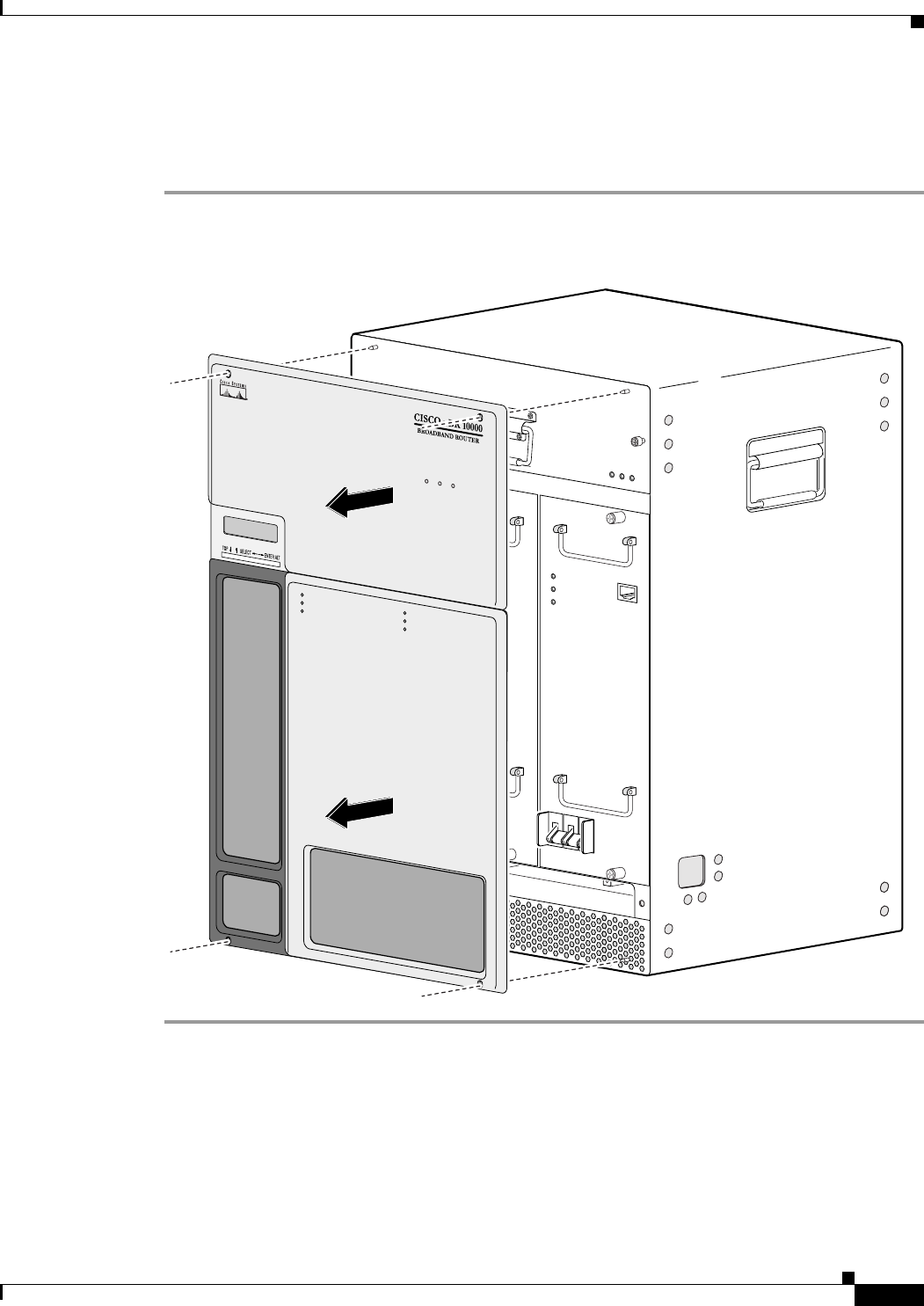
5-3
Cisco uBR10012 Universal Broadband Router Hardware Installation Guide
Chapter 5 Maintaining the Cisco uBR10012 Router
Removing and Replacing the Front Cover
Removing the Front Cover
Use the following procedure to remove the front cover from the chassis.
Step 1 Remove the cover by lifting it up slightly and then pulling it toward you (see Figure 5-1).
Figure 5-1 Removing the Front Cover
Replacing the Front Cover
Use the following procedure to replace the front cover on the chassis.
56422
POWER
MISWIRE
FAULT
ALARMS
CISCO
10000
FAIL
PERFORMANCE ROUTING ENGINE
CONSOLE
ST
ATUS
ACO
CRITICAL
MINOR
MAJOR
ETHERNET
LINK
ACTIVITY
AUX
SLOT 0
SLOT 1
ALARMS
CISCO
10000
FAIL
PERFORMANCE ROUTING ENGINE
CONSOLE
ST
ATUS
ACO
CRITICAL
MINOR
MAJOR
ETHERNET
LINK
ACTIVITY
AUX
SLOT 0
SLOT 1
POWER
MISWIRE
FAULT
POWER
MISWIRE
FAULT
POWER
MISWIRE
FAULT
POWER
MISWIRE
FAULT
IPSUM
IPSUM SANCT
IPSU SA TUS
POWER
MISWIRE
FAULT
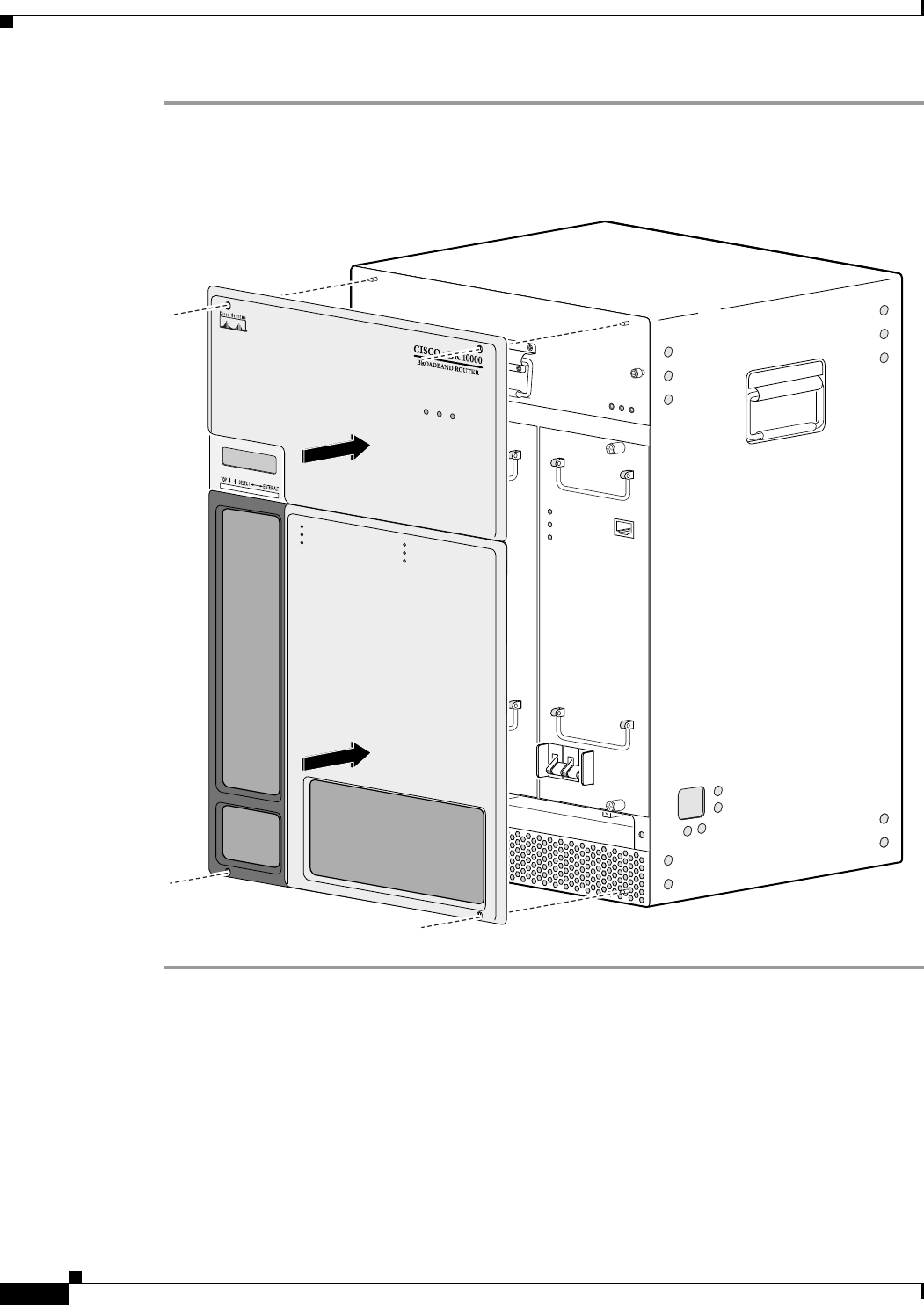
5-4
Cisco uBR10012 Universal Broadband Router Hardware Installation Guide
Chapter 5 Maintaining the Cisco uBR10012 Router
Replacing the Air Filter
Step 1 Slide the cover onto the four corner posts of the chassis and then push down so that the posts are seated
in the grooves above the cover holes (see Figure 5-2).
Figure 5-2 Attaching the Cover to the Chassis
Replacing the Air Filter
If the air filter is dirty or clogged, the fan assembly module could have a problem providing sufficient
cooling airflow throughout the chassis, causing the system to overheat. To prevent a potential
overheating problem, you should replace the air filter approximately every 6 to 12 months, depending
on how clean and dust-free your operating environment is normally. In certain environments where the
air quality is poor, you may have to replace the filter more frequently.
56423
POWER
MISWIRE
FAULT
ALARMS
CISCO
10000
FAIL
PERFORMANCE ROUTING ENGINE
CONSOLE
ST
A
TUS
ACO
CRITICAL
MINOR
MAJOR
ETHERNET
LINK
ACTIVITY
AUX
SLOT 0
SLOT 1
ALARMS
CISCO
10000
FAIL
PERFORMANCE ROUTING ENGINE
CONSOLE
STATUS
ACO
CRITICAL
MINOR
MAJOR
ETHERNET
LINK
ACTIVITY
AUX
SLOT 0
SLOT 1
POWER
MISWIRE
FAULT
POWER
MISWIRE
FAULT
POWER
MISWIRE
FAULT
POWER
MISWIRE
FAULT
IPSUM
IPSUM SANCT
IPSU SA TUS
POWER
MISWIRE
FAULT
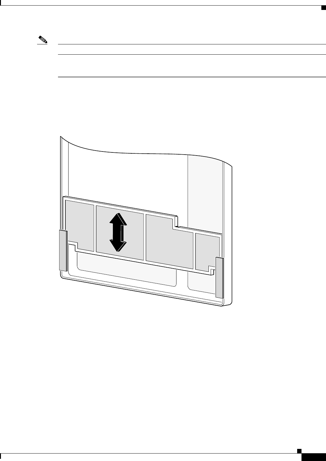
5-5
Cisco uBR10012 Universal Broadband Router Hardware Installation Guide
Chapter 5 Maintaining the Cisco uBR10012 Router
Replacing the Air Filter
Note The product order number for a replacement air filter is UBR10-FAN-FILTER=.
Use the following procedure to replace the air filter:
Step 1 Remove the front cover (see “Removing the Front Cover” section on page 5-3).
Step 2 Slide the air filter out of its slot.
Step 3 Discard the old filter.
Figure 5-3 Removing and Inserting the Air Filter
Step 4 Position the new air filter above the tabs on the inside of the front cover and slide it down into the slot.
When fully inserted, it should appear as shown in Figure 5-4.
56393
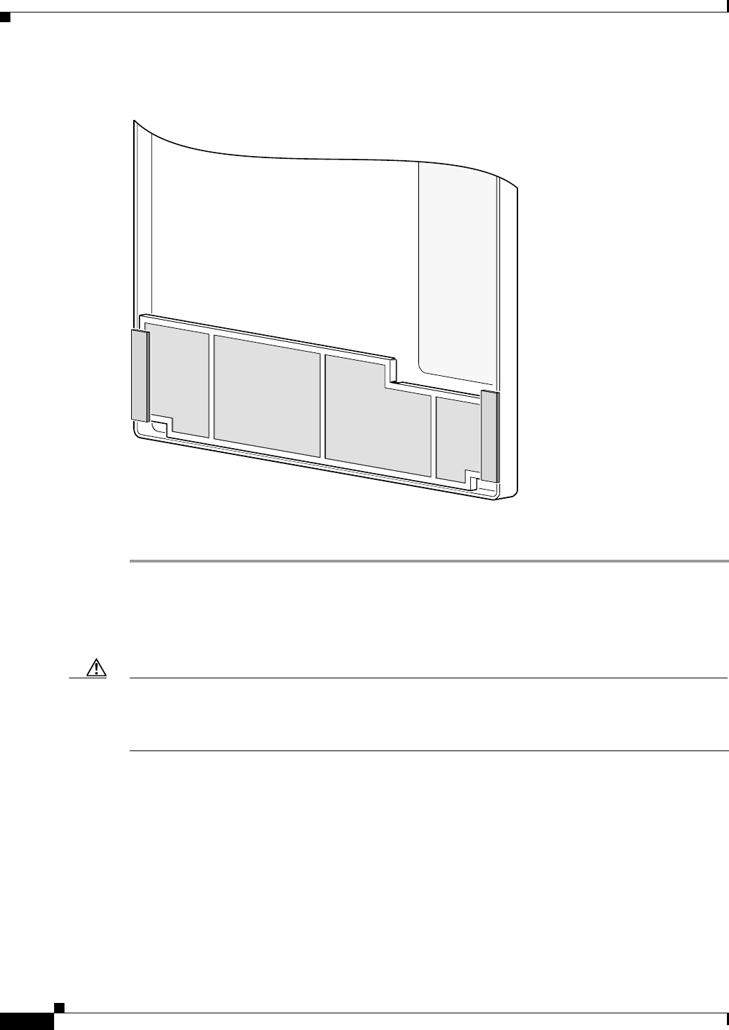
5-6
Cisco uBR10012 Universal Broadband Router Hardware Installation Guide
Chapter 5 Maintaining the Cisco uBR10012 Router
Removing and Replacing the Fan Assembly Module
Figure 5-4 Air Filter Inserted into the Front Cover
Step 5 Replace the front cover (see “Replacing the Front Cover”).
Removing and Replacing the Fan Assembly Module
Caution The Cisco uBR10012 chassis should not be run without a working fan assembly module for more than
three minutes. To prevent the possibility of the system overheating, be sure that the replacement fan
assembly module is out of its box and packaging, so it is ready to install as soon as the defective module
is removed.
The fan assembly module does not need to be replaced when it is operating normally. However, if either
of the two failure LEDs come on, the fan assembly module should be replaced:
•SINGLE FAN FAILURE—This yellow LED indicates that one of the four fans in the module has
failed. The module can still provide enough cooling to safely operate the Cisco uBR10012 chassis,
but it might begin operating the fans in its high-speed mode to do so. If this LED lights, the fan
assembly module should be replaced as soon as is conveniently possible.
•MULTIPLE FAN FAILURE—This yellow LED indicates that two or more fans in the module have
failed, and that the module is no longer able to consistently cool the Cisco uBR10012 chassis. To
prevent overheating the chassis and possible damage to the line cards and other modules, the fan
assembly module should be replaced immediately.
56392

5-7
Cisco uBR10012 Universal Broadband Router Hardware Installation Guide
Chapter 5 Maintaining the Cisco uBR10012 Router
Removing and Replacing DC Power Entry Modules
If the failure LEDs—SINGLE FAN FAILURE and MULTIPLE FAN FAILURE—are illuminated,
remove and reinsert the fan assembly module. If the failure LEDs are still illuminated, replace the fan
assembly module. The fan assembly module supports hot-swapping and can be replaced without
interrupting system operation.
For more information about removing and replacing the fan assembly module, see Cisco uBR10012
Universal Broadband Router Fan Assembly Module.
Removing and Replacing DC Power Entry Modules
The Cisco uBR10012 router is shipped with two DC power entry modules (PEM) that provide a
redundant power supply to the system. One DC PEM can provide sufficient power for a fully configured
chassis, so that if one DC PEM fails, the other automatically begins providing power for the entire
system. However, the system should not be run for an extended period time with only one DC PEM. If
a DC PEM fails, install a replacement DC PEM as soon as possible.
Note You do not need to shut down the Cisco uBR10012 router to replace a redundant DC PEM. And, if you
are replacing both DC PEMs, you can replace one, bring it online, and then replace the other one to avoid
shutting down the entire system.
The DC PEM is operating correctly when its POWER LED lights (green). Replace a DC PEM if either
of the PEM failure LEDs light (yellow):
•MISWIRE—This LED indicates that the wires connecting the PEM to DC power source were wired
incorrectly. The DC PEM therefore needs to be removed so that the wiring can be corrected. After
the wiring has been corrected, the same DC PEM can be reinserted. See “Connecting Alarm
Indicators” section on page 5-7 for more information.
•FAULT—This LED indicates that the DC power source is supplying power but that the DC PEM is
not providing power to the system.ced.
Warning
Before performing any of the following procedures, ensure that power is removed from the DC circuit.
To ensure that all power is OFF, locate the circuit breaker on the panel board that services the DC
circuit, switch the circuit breaker to the OFF position, and tape the switch handle of the circuit
breaker in the OFF position.
Statement 7
For more information on removing and replacing the DC PEM module, see DC Power Entry Module for
the Cisco uBR10012 Universal Broadband Router.
For more information on removing and replacing the 3300 W DC PEM, see 3300 W DC Power Entry
Module for the Cisco uBR10012 Universal Broadband Router.
Connecting Alarm Indicators
The Cisco uBR10012 router provides relay contacts for optional (customer-supplied) audible or visual
alarm indicators. Relay contacts are provided for three levels of severity:
•Minor—This is an informational alarm and does not affect the system operation.
•Major—A condition that affects system operation and should be investigated as soon as possible.
•Critical—A condition that affects system operation and requires immediate attention.
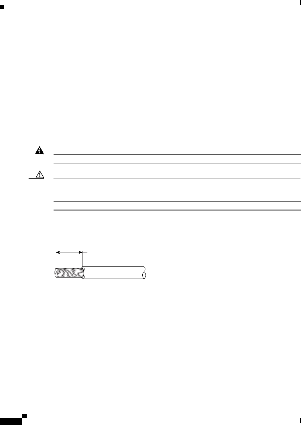
5-8
Cisco uBR10012 Universal Broadband Router Hardware Installation Guide
Chapter 5 Maintaining the Cisco uBR10012 Router
Connecting Alarm Indicators
If you did not connect the alarm indicators when you originally installed the Cisco uBR10012 chassis,
use the following procedure to connect an alarm indicator to the system. For safety and convenience
reasons, you need to remove power from the DC PEM on the right side (DC PEM “B”) and remove that
DC PEM for easier access to the alarm indicators terminal block.
For more information on removing and replacing the DC PEM module, see DC Power Entry Module for
the Cisco uBR10012 Universal Broadband Router.
For more information on removing and replacing the 3300 W DC PEM, see 3300 W DC Power Entry
Module for the Cisco uBR10012 Universal Broadband Router.
Attaching the Alarm Wires
For each alarm indicator being connected (minor, major, or critical), use two wires that are long enough
to reach between the Cisco uBR10012 chassis and the alarm indicator equipment. Use the gauge of wire
required by the audible or visual alarm indicator equipment you are using (14 AWG maximum gauge).
Warning
Use copper conductors only.
Statement 1025
Caution The alarm contacts on the Cisco uBR10012 router are only relays and do not provide any power from
the unit. These relays are rated for 60 VDC, 1 A maximum—ensure that the connected alarm equipment
does not exceed these voltage and current ratings.
Step 1 For each pair of wires, strip not more than 0.3 inches (8 mm) of insulation off of the ends of each wire
(see Figure 5-5).
Figure 5-5 Stripping Insulation
Step 2 Connect one end of each pair of alarm indicator wires to the alarm terminal block as follows:
a. Connect one lead to the common (COM) terminal.
b. If you are wiring the router in series with other equipment for the alarm indicators, wire the other
lead to the normally closed (NC) terminal.
c. If you are wiring the router in parallel with other equipment for the alarm indicators, wire the other
lead to the normally open (NO) terminal.
Figure 5-6 shows the wiring configuration for normally open (NO) alarm relays.
Step 3 Connect the other end of this pair of alarm indicator wires to the appropriate connectors on the alarm
indicator equipment. Route these cables through the square hole on the bottom right side of the chassis,
as you face the front of the chassis.
Step 4 Repeat steps through 3 for the remaining alarm indicators.
Step 5 Secure the cabling to the chassis by feeding a tie wrap through one of the round holes next to the large
hole on the side of the chassis. Then use the tie wrap to bind the cables to the chassis.
58688
8 mm max
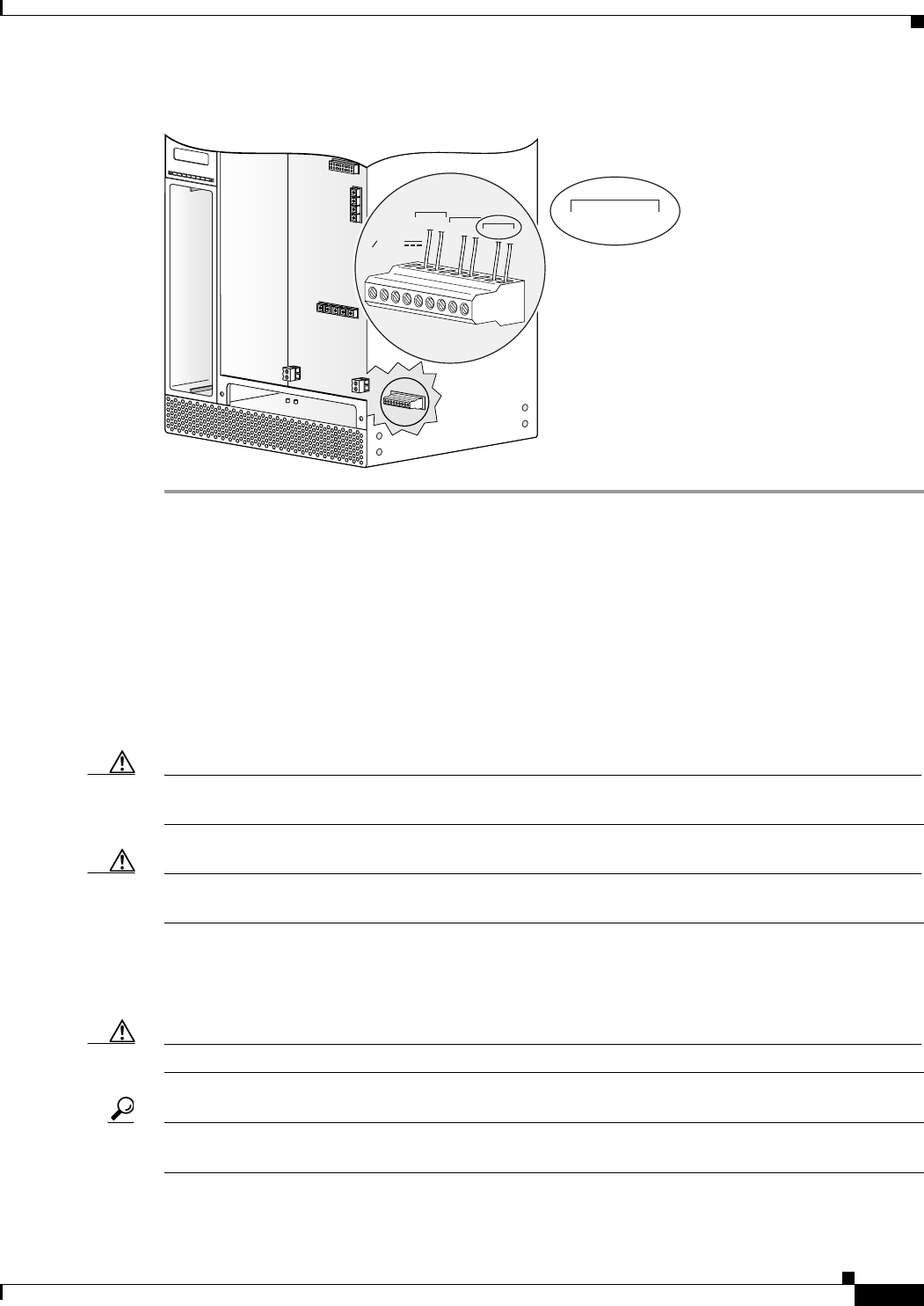
5-9
Cisco uBR10012 Universal Broadband Router Hardware Installation Guide
Chapter 5 Maintaining the Cisco uBR10012 Router
Removing and Replacing AC PEM Modules
Figure 5-6 Alarm Terminal Block Connections
Removing and Replacing AC PEM Modules
The Cisco uBR10012 router ships with two AC power entry modules (PEMs). In this redundant system,
(2 power supplies), one AC PEM provides sufficient power for a fully configured chassis. If one AC PEM
fails, the other automatically begins providing power for the entire router, without impacting system
operations. However, even though one AC PEM provides sufficient power for a fully configured
Cisco uBR10012 chassis, the system should not be run for extended periods of time with only one AC
PEM. Always install the replacement AC PEM as soon as possible and order a spare for backup.
Caution For proper airflow, cooling, and safety, do not remove the failed unit until the replacement unit is
available for installation.
Caution The Cisco uBR10012 router supports using either the AC PEM or the DC PEM, but it does not support
mixing AC and DC PEMs. Both PEMs must be either AC PEMs or DC PEMs.
The AC PEMs use standard 200–240 VAC (50/60 Hz) input power obtained through power receptacles
on the front panel of each PEM. The two AC PEMs convert the AC power to provide filtered, redundant,
and load shared DC power to the Cisco uBR10012 chassis.
Caution The AC PEMs cannot be used with a 100–120 VAC input power source.
Tip For fully redundant power protection, use either an uninterruptible power supply (UPS) or a separate
AC-input power source for each AC PEM.
98749
ALARMS
60 VDC
1A MAX
MINOR
NC NOCOM
MAJOR
NC NOCOM
CRITICAL
NC NOCOM
MINOR
NC NOCOM

5-10
Cisco uBR10012 Universal Broadband Router Hardware Installation Guide
Chapter 5 Maintaining the Cisco uBR10012 Router
Removing and Replacing the PRE Module
Note You do not need to shut down the Cisco uBR10012 router to replace a redundant AC PEM. If you are
replacing both AC PEMs, you can replace one, bring it online, and then replace the other one to avoid
shutting down the system.
For information on removing and replacing the AC PEM, see AC Power Entry Module for the Cisco
uBR10012 Universal Broadband Router.
For information on removing and replacing the 3300 W AC PEM, see 3300 W AC Power Entry Module
for the Cisco uBR10012 Universal Broadband Router.
Removing and Replacing the PRE Module
It is not necessary to configure the PRE module if you are installing or replacing a second PRE. The
system automatically downloads the necessary configuration information from the primary PRE.
Removing the PRE Module
Use the following procedure to install a new PRE module, or to replace an existing PRE module.
Step 1 Be sure you are properly grounded.
Step 2 If necessary, remove the blank cover from the PRE module slot and discard.
Step 3 Disconnect any interface cables from the PRE module if necessary.
Step 4 Remove the PC media card from the PRE module (see the “Removing and Installing a PC Media Card”
section on page 5-16).
Step 5 Unscrew the top and bottom captive screws on the PRE module (see Figure 5-7).
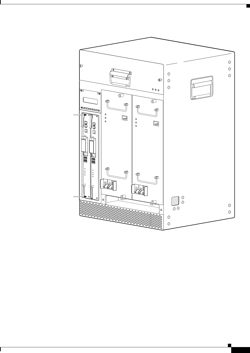
5-11
Cisco uBR10012 Universal Broadband Router Hardware Installation Guide
Chapter 5 Maintaining the Cisco uBR10012 Router
Removing and Replacing the PRE Module
Figure 5-7 Loosening the Captive Screws
Step 6 Simultaneously pivot both ejector levers away from each other to disengage the PRE module from the
backplane (see Figure 5-8).
56424
ALARMS
CISCO
10000
FAIL
PERFORMANCE ROUTING ENGINE
CONSOLE
STATUS
ACO
CRITICAL
MINOR
MAJOR
ETHERNET
LINK
ACTIVITY
AUX
SLOT 0
SLOT 1
ALARMS
CISCO
10000
FAIL
PERFORMANCE ROUTING ENGINE
CONSOLE
STATUS
ACO
CRITICAL
MINOR
MAJOR
ETHERNET
LINK
ACTIVITY
AUX
SLOT 0
SLOT 1
Captive screw
Captive screw
POWER
MISWIRE
FAULT
POWER
MISWIRE
FAULT
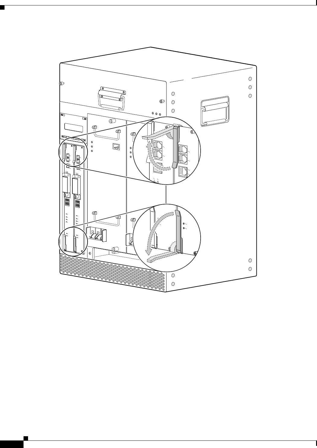
5-12
Cisco uBR10012 Universal Broadband Router Hardware Installation Guide
Chapter 5 Maintaining the Cisco uBR10012 Router
Removing and Replacing the PRE Module
Figure 5-8 Opening the Ejector Levers
Step 7 Slide the PRE module out of the slot and place it on an antistatic surface, or in an antistatic bag (see
Figure 5-9).
ALARMS
CISCO
10000
FAIL
PERFORMANCE ROUTING ENGINE
CONSOLE
STATUS
ACO
CRITICAL
MINOR
MAJOR
ETHERNET
LINK
ACTIVITY
AUX
SLOT 0
SLOT 1
ALARMS
CISCO
10000
FAIL
PERFORMANCE ROUTING ENGINE
CONSOLE
STATUS
ACO
CRITICAL
MINOR
MAJOR
ETHERNET
LINK
ACTIVITY
AUX
SLOT 0
SLOT 1
POWER
MISWIRE
FAULT
POWER
MISWIRE
FAULT
56425
FAIL
STATUS
FAIL
STATUS
C10000
PRE
CONSOLE
ETHERNET
LINK
ACTIVITY
AUX
SLOT 1
CONSOLE
AUX
CISCO
10000
CISCO
10000
SLOT 0
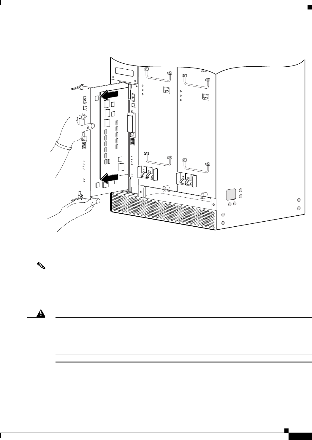
5-13
Cisco uBR10012 Universal Broadband Router Hardware Installation Guide
Chapter 5 Maintaining the Cisco uBR10012 Router
Removing and Replacing the PRE Module
Figure 5-9 Removing the PRE Module from the Chassis
Step 8 If you are installing a new or replacement PRE module, proceed to the next step. Otherwise, install a
blank cover over the slot and screw down its captive screws to conclude this procedure.
Note For proper cooling and airflow, a blank PRE module cover should always be installed when a second
PRE module is not installed.
The product order number for the blank PRE module cover is ESR-PRE-COVER=.
Warning
Blank faceplates and cover panels serve three important functions: they prevent exposure to
hazardous voltages and currents inside the chassis; they contain electromagnetic interference (EMI)
that might disrupt other equipment; and they direct the flow of cooling air through the chassis. Do not
operate the system unless all cards, faceplates, front covers, and rear covers are in place.
Statement
1029
56292
ALARMS
CISCO
10000
FAIL
PERFORMANCE ROUTING ENGINE
CONSOLE
ST
A
TUS
ACO
CRITICAL
MINOR
MAJOR
ETHERNE
LINK
ACTIVITY
AUX
SLOT 0
SLOT 1
PERFORMANCE ROUTING ENGINE
ALARMS
CISCO
10000
FAIL
PERFORMANCE ROUTING ENGINE
CONSOLE
STATUS
ACO
CRITICAL
MINOR
MAJOR
ETHERNET
LINK
ACTIVITY
AUX
SLOT 0
SLOT 1
POWER
MISWIRE
FAULT
POWER
MISWIRE
FAULT
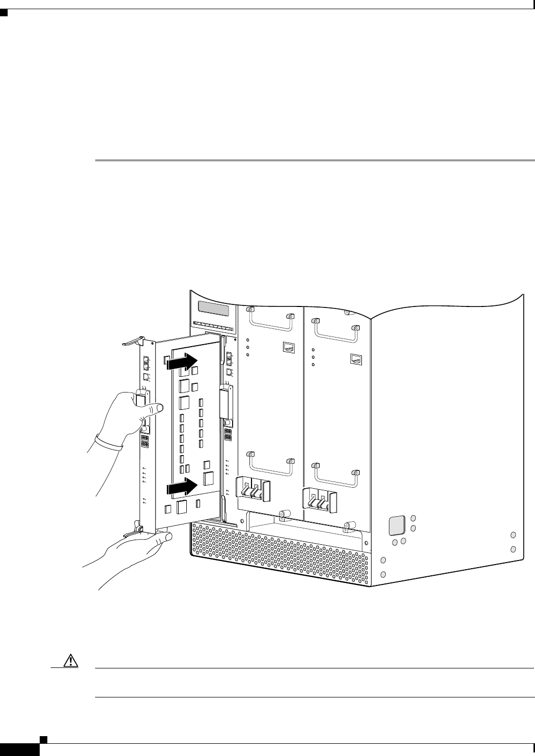
5-14
Cisco uBR10012 Universal Broadband Router Hardware Installation Guide
Chapter 5 Maintaining the Cisco uBR10012 Router
Removing and Replacing the PRE Module
Replacing the PRE Module
When replacing a PRE1 module with a PRE2 module, you must also install EMI gaskets and RF absorber
material, for more information, go to the following URL:
http://www.cisco.com/en/US/docs/cable/cmts/ubr10012/installation/field_replaceable_units/pre2gkit.h
tml
Step 1 Grasp the faceplate of the new PRE module with one hand and place your other hand under the card
carrier (to support the weight of the module) and position the card in front of the card cage slot.
Step 2 Carefully align the upper and lower edges of the PRE module with the upper and lower guides in the
chassis, and slide the module into the slot until you can feel it begin to seat in the backplane connectors
(see Figure 5-10).
Figure 5-10 Inserting the PRE Module in the Chassis
Step 3 Simultaneously pivot both ejector levers toward each other (until they are parallel to the faceplate) to
firmly seat the PRE module in the backplane (see Figure 5-11).
Step 4 Secure the PRE module in the chassis by tightening the top and bottom captive screws (see Figure 5-7).
Caution Always tighten the captive screws on each newly installed PRE module. These screws prevent accidental
removal and provide proper grounding for electromagnetic interference (EMI) shielding.
56427
ALARMS
CISCO
10000
FAIL
PERFORMANCE ROUTING ENGINE
CONSOLE
ST
A
TUS
ACO
CRITICAL
MINOR
MAJOR
ETHERNE
LINK
ACTIVITY
AUX
SLOT 0
SLOT 1
PERFORMANCE ROUTING ENGINE
ALARMS
CISCO
10000
FAIL
PERFORMANCE ROUTING ENGINE
CONSOLE
STATUS
ACO
CRITICAL
MINOR
MAJOR
ETHERNET
LINK
ACTIVITY
AUX
SLOT 0
SLOT 1
POWER
MISWIRE
FAULT
POWER
MISWIRE
FAULT
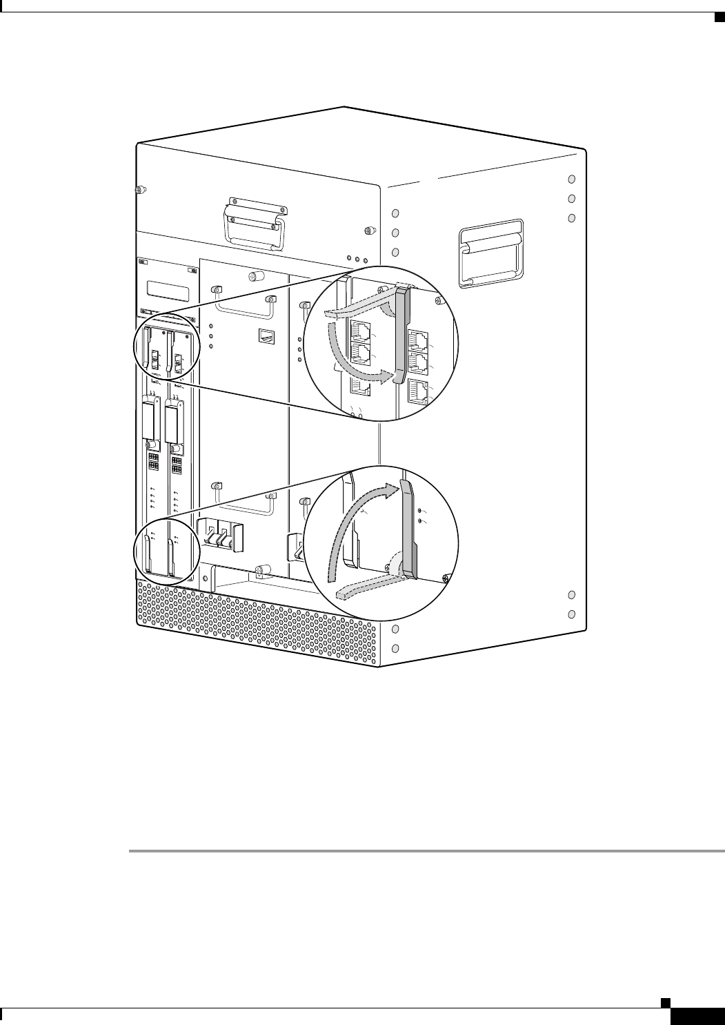
5-15
Cisco uBR10012 Universal Broadband Router Hardware Installation Guide
Chapter 5 Maintaining the Cisco uBR10012 Router
Removing and Replacing the PRE Module
Figure 5-11 Closing the Ejector Levers
Step 5 When fully inserted, the PRE module cycles through its power-on self-test. The FAIL LED stays on
briefly (about 5 to 6 seconds) and then shuts off. If the FAIL LED remains on or is flashing, go to the
“Troubleshooting Installation Problems” section on page 4-3.
Step 6 Reconnect any interface cables to the PRE module if necessary. Route the cables through the square hole
in the front left side on the chassis.
Step 7 Install the PC media card in the PRE module, if necessary (see the Removing and Installing a PC Media
Card).
ALARMS
CISCO
10000
FAIL
PERFORMANCE ROUTING ENGINE
CONSOLE
STATUS
ACO
CRITICAL
MINOR
MAJOR
ETHERNET
LINK
ACTIVITY
AUX
SLOT 0
SLOT 1
ALARMS
CISCO
10000
FAIL
PERFORMANCE ROUTING ENGINE
CONSOLE
STATUS
ACO
CRITICAL
MINOR
MAJOR
ETHERNET
LINK
ACTIVITY
AUX
SLOT 0
SLOT 1
POWER
MISWIRE
FAULT
POWER
MISWIRE
FAULT
56426
FAIL
STATUS
FAIL
STATUS
C10000
PRE
CONSOLE
ETHERNET
LINK
ACTIVITY
AUX
SLOT 1
CONSOLE
AUX
CISCO
10000
CISCO
10000
SLOT 0
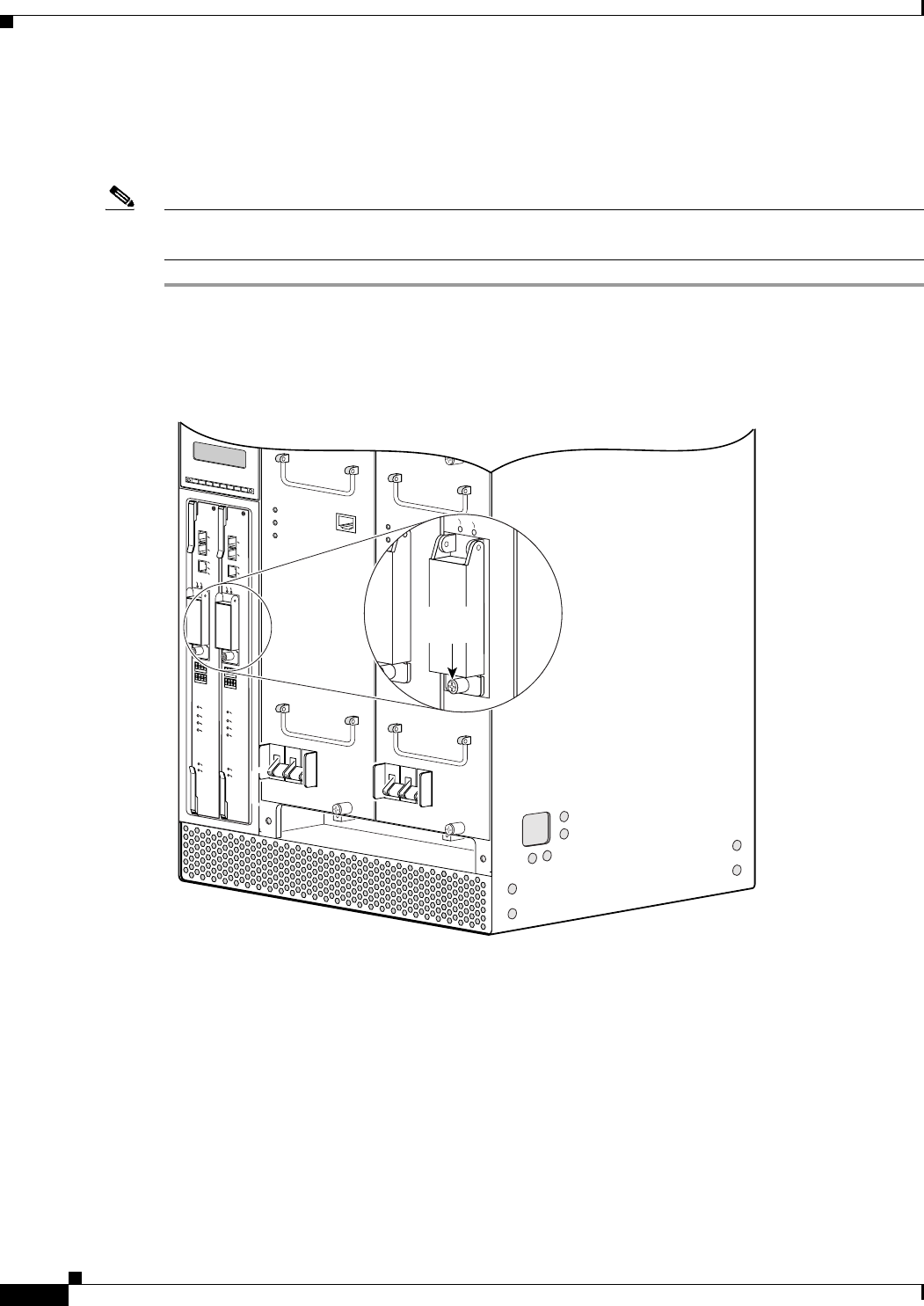
5-16
Cisco uBR10012 Universal Broadband Router Hardware Installation Guide
Chapter 5 Maintaining the Cisco uBR10012 Router
Removing and Installing a PC Media Card
Removing and Installing a PC Media Card
Use the following procedure to remove and install a PC media card.
Note The Cisco uBR10012 router uses PC media cards that are a minimum of 64 MB in size. For information
about formatting media cards and disks, see the “Formatting PC Media Cards” section on page 3-71.
Step 1 Loosen the captive screw on the PC media card cover on the PRE (see Figure 5-12).
Figure 5-12 PC Media Card Cover Captive Screws
Step 2 Lift the cover, push the proper eject button, and pull the Flash card out of its slot (see Figure 5-13).
56428
POWER
MISWIRE
FAULT
POWER
MISWIRE
FAULT
ALARMS
CISCO
10000
FAIL
PERFORMANCE ROUTING ENGINE
CONSOLE
STATUS
ACO
CRITICAL
MINOR
MAJOR
ETHERNET
LINK
ACTIVITY
AUX
SLOT 0
SLOT 1
ALARMS
CISCO
10000
FAIL
PERFORMANCE ROUTING ENGINE
CONSOLE
STATUS
ACO
CRITICAL
MINOR
MAJOR
ETHERNET
LINK
ACTIVITY
AUX
SLOT 0
SLOT 1
Captive
screw
1
0
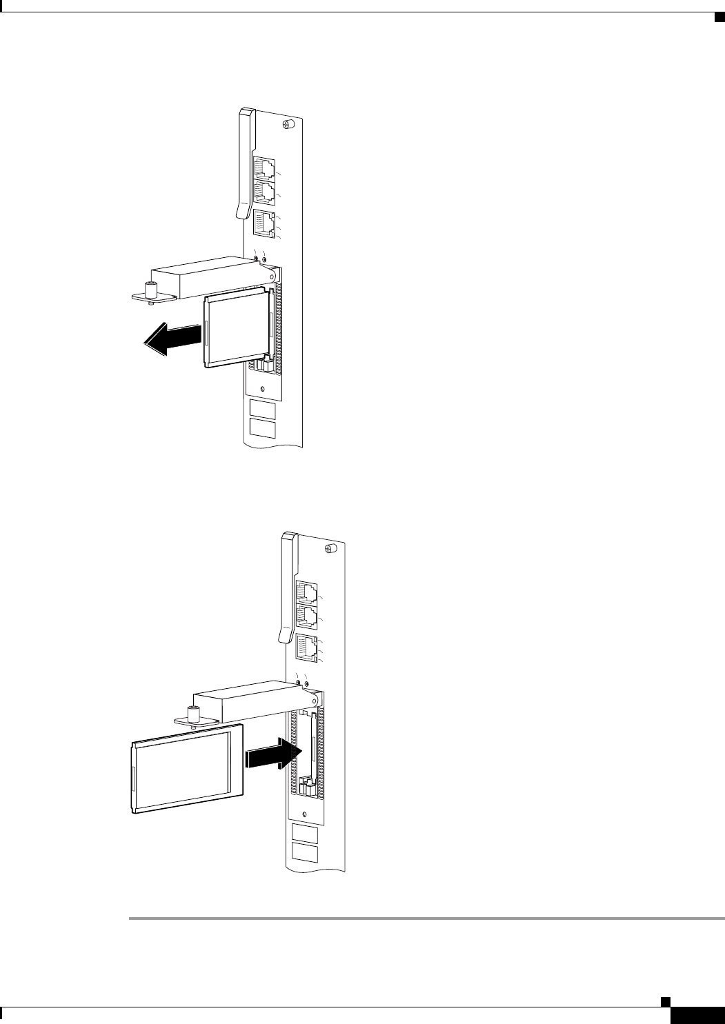
5-17
Cisco uBR10012 Universal Broadband Router Hardware Installation Guide
Chapter 5 Maintaining the Cisco uBR10012 Router
Removing and Installing a PC Media Card
Figure 5-13 Removing the PC Media Card
Step 3 Insert the new PC media card into one of the card slots on the PRE (see Figure 5-14).
Figure 5-14 Inserting the PC Media Card
Step 4 Close the cover and tighten the captive screw to maintain proper EMI emissions levels (see Figure 5-12).
32690
CONSOLE
ETHERNET
LINK
ACTIVITY
AUX
SLOT 0
SLOT 1
CISCO
10000
32691
CONSOLE
ETHERNET
LINK
ACTIVITY
AUX
SLOT 0
SLOT 1
CISCO
10000
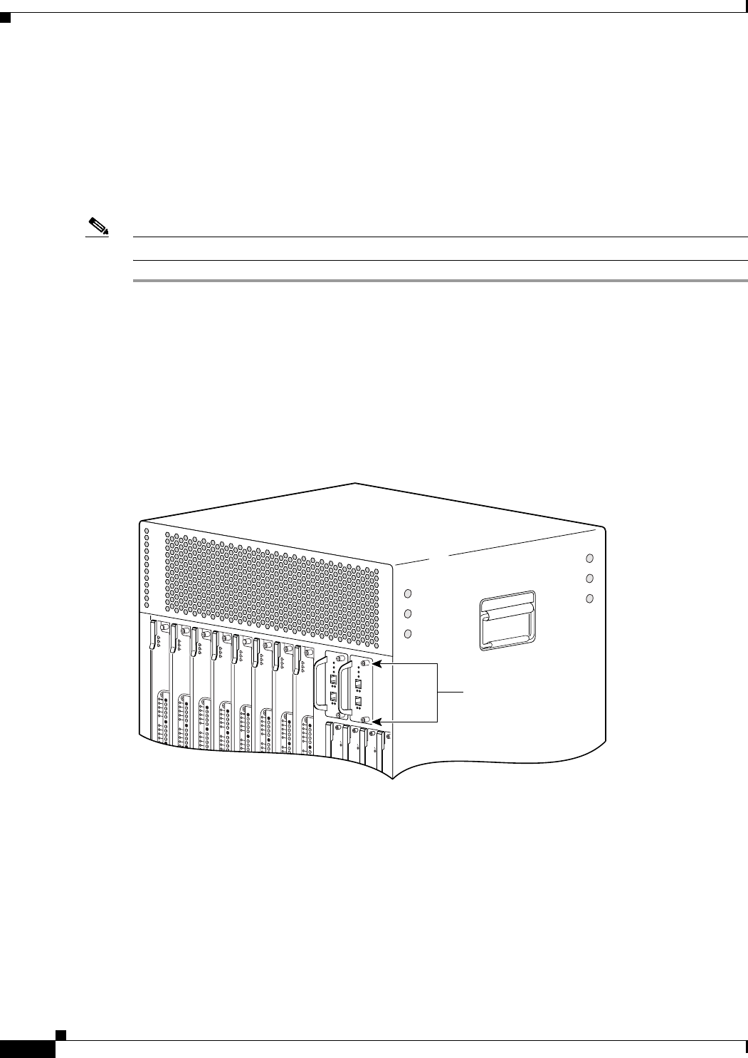
5-18
Cisco uBR10012 Universal Broadband Router Hardware Installation Guide
Chapter 5 Maintaining the Cisco uBR10012 Router
Removing and Replacing a Timing, Communication, and Control Plus Card
Removing and Replacing a Timing, Communication, and Control
Plus Card
Use the following procedure to install a new Timing, Communication, and Control Plus (TCC+) card or
to replace an existing TCC+ card. If two TCC+ cards are installed for redundant operation, one of the
cards can be removed and replaced without interrupting system operations.
Note The product order number for the TCC+ card is UBR10-TCC+=
Step 1 Attach an antistatic wrist strap to your wrist and to a bare metal, unpainted surface on the chassis or
frame.
Step 2 Face the back of the Cisco uBR10012 chassis. If necessary, clear aside enough interface and power
cables to allow sufficient space to work.
Step 3 If installing a new TCC+ card, remove the blank slot cover and discard, and then proceed to step 8.
Otherwise, disconnect the clock cables from the TCC+ card being replaced.
Step 4 Loosen the top and bottom captive screws on the TCC+ card (see Figure 5-15).
Figure 5-15 TCC+ Card Captive Screws
Step 5 Verify that the maintenance LED is lighted on the TCC+ card you are removing. This LED indicates that
the card can be removed from the chassis without interrupting systems operations.
Step 6 Using the handle, pull the TCC+ card out of the slot and place it on an antistatic surface, or in an
antistatic bag (see Figure 5-16).
CISCO
10000
FAIL
CISCO
10000
FAIL
CISCO
10000
FAIL
CISC
100
FAIL
US0
US1
US2
US3
US4
US5
US6
US7
US8
US9
uBR10-MC5x20S-D
POWER
STATU S
MAINT
US0
US1
US2
US3
US4
US5
US6
US7
US8
US9
uBR10-MC5x20S-D
POWER
STATUS
MAINT
US0
US1
US2
US3
US4
US5
US6
US7
US8
US9
uBR10-MC5x20S-D
POWER
STATUS
MAINT
US0
US1
US2
US3
US4
US5
US6
US7
US8
US9
uBR10-MC5x20S-D
POWER
STATU S
MAINT
US0
US1
US2
US3
US4
US5
US6
US7
US8
US9
uBR10-MC5x20S-D
POWER
STATUS
MAINT
US0
US1
US2
US3
US4
US5
US6
US7
US8
US9
uBR10-MC5x20S-D
POWER
STATU S
MAINT
US0
US1
US2
US3
US4
US5
US6
US7
US8
US9
uBR10-MC5x20S-D
POWER
STATUS
MAINT
US0
US1
US2
US3
US4
US5
US6
US7
US8
US9
uBR10-MC5x20S-D
POWER
ST
ATUS
MAINT
56456
Captive
screws
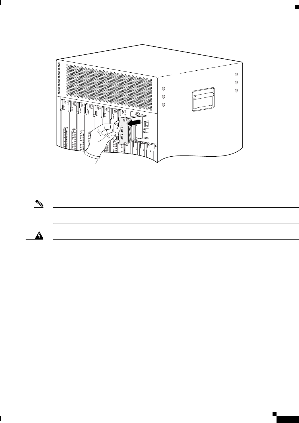
5-19
Cisco uBR10012 Universal Broadband Router Hardware Installation Guide
Chapter 5 Maintaining the Cisco uBR10012 Router
Removing and Replacing a Timing, Communication, and Control Plus Card
Figure 5-16 Removing the TCC+ card
Step 7 If you are installing a replacement card, proceed to the next step. Otherwise, install a blank cover over
the slot and screw down its captive screws to conclude this procedure.
Note For proper cooling and airflow, a cover must always be installed in a blank TCC+ card slot. The product
order number for the blank TCC+ card cover is UBR10-TCC+-COVER=.
Warning
Blank faceplates (filler panels) serve three important functions: they prevent exposure to hazardous
voltages and currents inside the chassis; they contain electromagnetic interference (EMI) that might
disrupt other equipment; and they direct the flow of cooling air through the chassis. Do not operate
the system unless all cards and faceplates are in place.
Statement 1029
Step 8 Pick up the replacement TCC+ card and position it in front of the card cage slot.
Step 9 Carefully align the upper and lower edges of the line card with the upper and lower guides in the chassis,
and slide the line card into the slot so that it firmly seats in the backplane connectors (see Figure 5-17).
CISCO
10000
FAIL
CISCO
10000
FAIL
CISCO
10000
FAIL
CISC
100
FAIL
US0
US1
US2
US3
US4
US5
US6
US7
US8
US9
uBR10-MC5x20S-D
POWER
STATUS
MAINT
US0
US1
US2
US3
US4
US5
US6
US7
US8
US9
uBR10-MC5x20S-D
POWER
STATUS
MAINT
US0
US1
US2
US3
US4
US5
US6
US7
US8
US9
uBR10-MC5x20S-D
POWER
STATUS
MAINT
US0
US1
US2
US3
US4
US5
US6
US7
US8
US9
uBR10-MC5x20S-D
POWER
STATUS
MAINT
US0
US1
US2
US3
US4
US5
US6
US7
US8
US9
uBR10-MC5x20S-D
POWER
STA
TUS
MAINT
US0
US1
US2
US3
US4
US5
US6
US7
US8
US9
uBR10-MC5x20S-D
POWER
ST
ATUS
MAINT
US0
US1
US2
US3
US4
US5
US6
US7
US8
US9
uBR10-MC5x20S-D
POWER
ST
ATUS
MAINT
US0
US1
US2
US3
US4
US5
US6
US7
US8
US9
uBR10-MC5x20S-D
POWER
STA
TUS
MAINT
56457
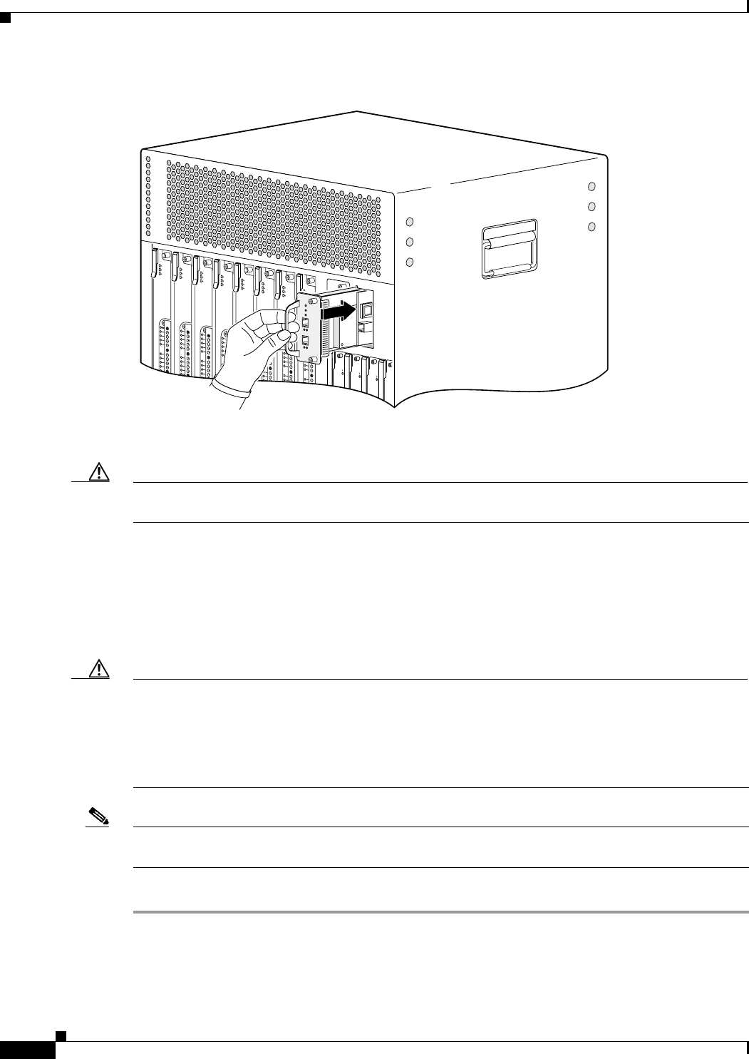
5-20
Cisco uBR10012 Universal Broadband Router Hardware Installation Guide
Chapter 5 Maintaining the Cisco uBR10012 Router
Removing and Replacing a Timing, Communication, and Control Plus Card
Figure 5-17 Inserting the TCC+ Card
Step 10 Secure the line card in the chassis by tightening the top and bottom captive screws (see Figure 5-15).
Caution Always tighten the captive screws on each TCC+ card. These screws prevent accidental removal and
provide proper grounding for electromagnetic interference (EMI) shielding.
Step 11 When fully inserted, the TCC+ card cycles through its power-on self-test. The Power LED lights (green)
and the Status LED then briefly lights (yellow). If this is the primary (or only) TCC+ card, the Status
LED then lights a solid green. On the backup TCC+ card, the Status LED should start flashing green
after a few moments. If these LEDs do not operate as described, go to the “Troubleshooting Installation
Problems” section on page 4-3.
Step 12 Connect the clock cables to the TCC+ card.
Caution The TCC+ card can connect only to a national clock source such as a GPS receiver or Building Integrated
Timing Supply (BITS) clock. The Cisco uBR10012 router does not support directly connecting the
RJ-45 connectors on the TCC+ cards to an outside plant line or telco-provided T1/E1 clock source. You
can use an outside or telco-provided T1/E1 clock source only by connecting the source to the TCC+
cards using a CSU/DSU or other equipment that is approved to FCC part 68 and ANSI/UL1950 for the
connection to the Public Switched Telephone Network (PSTN).
Note It is not necessary to configure the TCC+ card if you are installing a replacement card in the same slot.
The system automatically downloads the necessary configuration information from the PRE module.
Step 13 Configure the TCC+ card if necessary (see the “Formatting PC Media Cards” section on page 3-71.
CISCO
10000
FAIL
CISCO
10000
FAIL
CISCO
10000
FAIL
CISC
100
FAIL
US0
US1
US2
US3
US4
US5
US6
US7
US8
US9
uBR10-MC5x20S-D
POWER
ST
ATUS
MAINT
US0
US1
US2
US3
US4
US5
US6
US7
US8
US9
uBR10-MC5x20S-D
POWER
STATUS
MAINT
US0
US1
US2
US3
US4
US5
US6
US7
US8
US9
uBR10-MC5x20S-D
POWER
ST
ATUS
MAINT
US0
US1
US2
US3
US4
US5
US6
US7
US8
US9
uBR10-MC5x20S-D
POWER
STA
TUS
MAINT
US0
US1
US2
US3
US4
US5
US6
US7
US8
US9
uBR10-MC5x20S-D
POWER
ST
A
TUS
MAINT
US0
US1
US2
US3
US4
US5
US6
US7
US8
US9
uBR10-MC5x20S-D
POWER
STATUS
MAINT
US0
US1
US2
US3
US4
US5
US6
US7
US8
US9
uBR10-MC5x20S-D
POWER
STA
TUS
MAINT
US0
US1
US2
US3
US4
US5
US6
US7
US8
US9
uBR10-MC5x20S-D
POWER
STATUS
MAINT
56458
5-21
Cisco uBR10012 Universal Broadband Router Hardware Installation Guide
Chapter 5 Maintaining the Cisco uBR10012 Router
Removing and Replacing a Network Line Card
Removing and Replacing a Network Line Card
Use the following procedure to install a new network line card, or to remove or replace an existing
network line card in the Cisco uBR10012 chassis. The following cards are supported:
•Cisco OC-12/STS12c/STM4 POS (UBR10-OC12/P-SMI=)
•Cisco uBR10-SRP-OC12SML-DPT WAN (UBR10-SRP-OC12SML=)
•Cisco Single Port Gigabit Ethernet line card (UBR10-1GE=)
•Cisco uBR10012 OC-48 DPT/POS interface module
Tip To prevent alarms from activating, you can administratively shut down a line card before hot-swapping
it. Otherwise, inform the network administrator that this portion of the network will be temporarily
interrupted.
Removing the Network Line Card
Warning
Class 1 laser product.
Statement 1008
Warning
Invisible laser radiation present.
Statement 1016
Warning
Because invisible radiation may be emitted from the aperture of the port when no fiber cable is
connected, avoid exposure to radiation and do not stare into open apertures.
Statement 1056
Warning Statement for Sweden
Warning
Osynlig laserstrålning när denna del är öppen och förregleringen är urkopplad. Rikta inte blicken in
mot strålen.
Statement 1036
Warning Statement for Finland
Warning
Alleviates ja suojalukitus ohitettaessa olet alttiina näkymättömälle lasersäteilylle. Äjä katso
säteeseen.
Statement 1035
Step 1 Attach an antistatic wrist strap to your wrist and to a bare metal surface on the chassis or frame.
Step 2 Face the back of the Cisco uBR10012 chassis. Clear aside enough interface and power cables to allow
sufficient space to work.
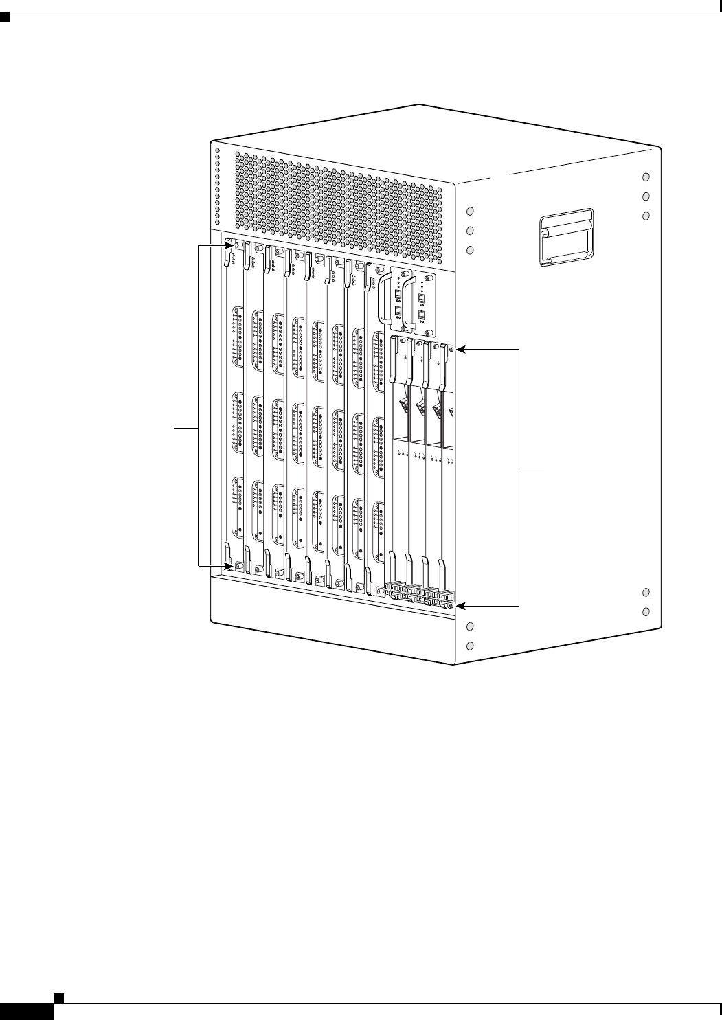
5-22
Cisco uBR10012 Universal Broadband Router Hardware Installation Guide
Chapter 5 Maintaining the Cisco uBR10012 Router
Removing and Replacing a Network Line Card
Figure 5-18 Loosening the Captive Screws
Step 3 If installing a new line card in a blank slot, remove the blank slot cover and discard. Otherwise,
disconnect the cables from the network line card.
Step 4 Unscrew the top and bottom captive screws on the card (see Figure 5-18).
Step 5 Simultaneously pivot both ejector levers away from each other to disengage the line card from the
backplane (see Figure 5-19).
103491
CISCO
10000
CARRIER
ALARM
LOOP
FAIL
CH OC-12-DSO SM-IR
CISCO
10000
CARRIER
ALARM
LOOP
FAIL
CH OC-12-DSO SM-IR
CISCO
10000
CARRIER
ALARM
LOOP
FAIL
CH OC-12-DSO SM-IR
CISC
100
CARRIER
ALARM
L
FAIL
Captive
screws
US0
US1
US2
US3
US4
US5
US6
US7
US8
US9
US10
US11
US12
US13
US14
US15
US16
US17
US18
US19
DS0
DS1
DS2
DS3
DS4
RF
RF
RF
RF
RF
uBR10-MC5x20S-D
POWER
STATUS
MAINT
US0
US1
US2
US3
US4
US5
US6
US7
US8
US9
US10
US11
US12
US13
US14
US15
US16
US17
US18
US19
DS0
DS1
DS2
DS3
DS4
RF
RF
RF
RF
RF
uBR10-MC5x20S-D
POWER
ST
A
TUS
MAINT
US0
US1
US2
US3
US4
US5
US6
US7
US8
US9
US10
US11
US12
US13
US14
US15
US16
US17
US18
US19
DS0
DS1
DS2
DS3
DS4
RF
RF
RF
RF
RF
uBR10-MC5x20S-D
POWER
STATUS
MAINT
US0
US1
US2
US3
US4
US5
US6
US7
US8
US9
US10
US11
US12
US13
US14
US15
US16
US17
US18
US19
DS0
DS1
DS2
DS3
DS4
RF
RF
RF
RF
RF
uBR10-MC5x20S-D
POWER
ST
A
TUS
MAINT
Captive
screws
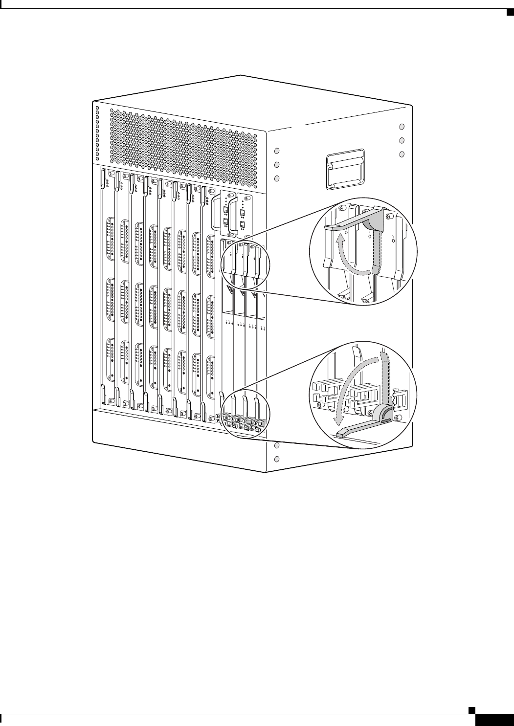
5-23
Cisco uBR10012 Universal Broadband Router Hardware Installation Guide
Chapter 5 Maintaining the Cisco uBR10012 Router
Removing and Replacing a Network Line Card
Figure 5-19 Opening the Ejector Levers
Step 6 Slide the card out of the slot and place it on an antistatic surface, or in an antistatic bag (see Figure 5-20).
103492
CISCO
10000
CARRIER
ALARM
LOOP
FAIL
CH OC-12-DSO SM-IR
CISCO
10000
CARRIER
ALARM
LOOP
FAIL
CH OC-12-DSO SM-IR
CISCO
10000
CARRIER
ALARM
LOOP
FAIL
CH OC-12-DSO SM-IR
CISC
100
CARRIER
ALARM
L
FAIL
CISCO
10000
FAIL
CISCO
10000
FAI L
CISCO
10000
FAI L
CISCO
10000
FAI L
US0
US1
US2
US3
US4
US5
US6
US7
US8
US9
US10
US11
US12
US13
US14
US15
US16
US17
US18
US19
DS0
DS1
DS2
DS3
DS4
RF
RF
RF
RF
RF
uBR10-MC5x20S-D
POWER
STATUS
MAINT
US0
US1
US2
US3
US4
US5
US6
US7
US8
US9
US10
US11
US12
US13
US14
US15
US16
US17
US18
US19
DS0
DS1
DS2
DS3
DS4
RF
RF
RF
RF
RF
uBR10-MC5x20S-D
POWER
STATUS
MAINT
US0
US1
US2
US3
US4
US5
US6
US7
US8
US9
US10
US11
US12
US13
US14
US15
US16
US17
US18
US19
DS0
DS1
DS2
DS3
DS4
RF
RF
RF
RF
RF
uBR10-MC5x20S-D
POWER
STATUS
MAINT
US0
US1
US2
US3
US4
US5
US6
US7
US8
US9
US10
US11
US12
US13
US14
US15
US16
US17
US18
US19
DS0
DS1
DS2
DS3
DS4
RF
RF
RF
RF
RF
uBR10-MC5x20S-D
POWER
STATUS
MAINT
US0
US1
US2
US3
US4
US5
US6
US7
US8
US9
US10
US11
US12
US13
US14
US15
US16
US17
US18
US19
DS0
DS1
DS2
DS3
DS4
RF
RF
RF
RF
RF
uBR10-MC5x20S-D
POWER
STATU S
MAINT
US0
US1
US2
US3
US4
US5
US6
US7
US8
US9
US10
US11
US12
US13
US14
US15
US16
US17
US18
US19
DS0
DS1
DS2
DS3
DS4
RF
RF
RF
RF
RF
uBR10-MC5x20S-D
POWER
STATU S
MAINT
US0
US1
US2
US3
US4
US5
US6
US7
US8
US9
US10
US11
US12
US13
US14
US15
US16
US17
US18
US19
DS0
DS1
DS2
DS3
DS4
RF
RF
RF
RF
RF
uBR10-MC5x20S-D
POWER
ST
ATUS
MAINT
US0
US1
US2
US3
US4
US5
US6
US7
US8
US9
US10
US11
US12
US13
US14
US15
US16
US17
US18
US19
DS0
DS1
DS2
DS3
DS4
RF
RF
RF
RF
RF
uBR10-MC5x20S-D
POWER
STATUS
MAINT
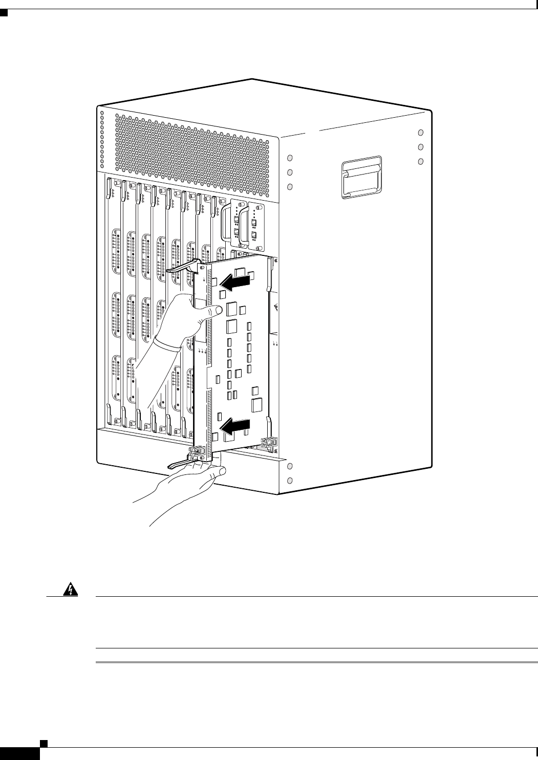
5-24
Cisco uBR10012 Universal Broadband Router Hardware Installation Guide
Chapter 5 Maintaining the Cisco uBR10012 Router
Removing and Replacing a Network Line Card
Figure 5-20 Removing the Network Line Card
Step 7 If you are installing a new or replacement card, proceed to the next step. Otherwise, install a blank cover
over the slot and screw down its captive screws to conclude this procedure.
Warning
Blank faceplates (filler panels) serve three important functions: they prevent exposure to hazardous
voltages and currents inside the chassis; they contain electromagnetic interference (EMI) that might
disrupt other equipment; and they direct the flow of cooling air through the chassis. Do not operate
the system unless all cards and faceplates are in place.
Statement 1029
103493
CISCO
10000
CARRIER
ALARM
LOOP
FAIL
CH OC-12-DSO SM-IR
CISCO
10000
CARRIER
ALARM
LOOP
FAIL
CH OC-12-DSO SM-IR
CISC
100
ALARM
L
FAIL
US0
US1
US2
US3
US4
US5
US6
US7
US8
US9
US10
US11
US12
US13
US14
US15
US16
US17
US18
US19
DS0
DS1
DS2
DS3
DS4
RF
RF
RF
RF
RF
uBR10-MC5x20S-D
POWER
STATU S
MAINT
US0
US1
US2
US3
US4
US5
US6
US7
US8
US9
US10
US11
US12
US13
US14
US15
US16
US17
US18
US19
DS0
DS1
DS2
DS3
DS4
RF
RF
RF
RF
RF
uBR10-MC5x20S-D
POWER
STATUS
MAINT
US0
US1
US2
US3
US4
US5
US6
US7
US8
US9
US10
US11
US12
US13
US14
US15
US16
US17
US18
US19
DS0
DS1
DS2
DS3
DS4
RF
RF
RF
RF
RF
uBR10-MC5x20S-D
POWER
STATUS
MAINT
US0
US1
US2
US3
US4
US5
US6
US7
US8
US9
US10
US11
US12
US13
US14
US15
US16
US17
US18
US19
DS0
DS1
DS2
DS3
DS4
RF
RF
RF
RF
RF
uBR10-MC5x20S-D
POWER
STATUS
MAINT
US0
US1
US2
US3
US4
US5
US6
US7
US8
US9
US10
US11
US12
US13
US14
US15
US16
US17
US18
US19
DS0
DS1
DS2
DS3
DS4
RF
RF
RF
RF
RF
uBR10-MC5x20S-D
POWER
STATU S
MAINT
US0
US1
US2
US3
US4
US5
US6
US7
US8
US9
US10
US11
US12
US13
US14
US15
US16
US17
US18
US19
DS0
DS1
DS2
DS3
DS4
RF
RF
RF
RF
RF
uBR10-MC5x20S-D
POWER
STATU S
MAINT
US0
US1
US2
US3
US4
US5
US6
US7
US8
US9
US10
US11
US12
US13
US14
US15
US16
US17
US18
US19
DS0
DS1
DS2
DS3
DS4
RF
RF
RF
RF
RF
uBR10-MC5x20S-D
POWER
STATU S
MAINT
US0
US1
US2
US3
US4
US5
US6
US7
US8
US9
US10
US11
US12
US13
US14
US15
US16
US17
US18
US19
DS0
DS1
DS2
DS3
DS4
RF
RF
RF
RF
RF
uBR10-MC5x20S-D
POWER
STATUS
MAINT
CONSOLE
ETHERNET
LINK
ACTIVITY
AUX
SLOT 0
SLOT 1
CARRIER
ALARM
LOOP
0
5
4
3
2
1
CARRIER
ALARM
LOOP
0
5
4
3
2
1
CISCO
10000
CARRIER
ALARM
LOOP
FAIL
CH OC-12-DSO SM-IR
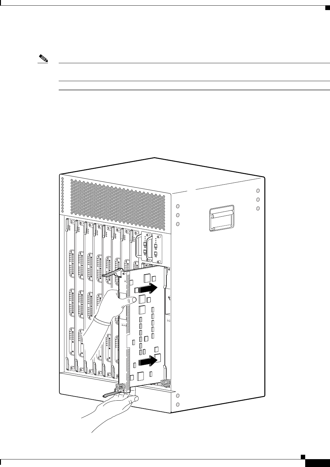
5-25
Cisco uBR10012 Universal Broadband Router Hardware Installation Guide
Chapter 5 Maintaining the Cisco uBR10012 Router
Removing and Replacing a Network Line Card
Installing the Network Line Card
Note For proper cooling and airflow, a blank card cover must always be installed in a blank line card slot. The
product order number for the blank card cover is ESR-LC-Cover=.
Step 1 Grasp the faceplate of the new card with one hand and place your other hand under the card carrier (to
support the weight of the card) and position the card in front of the card cage slot.
Step 2 Carefully align the upper and lower edges of the line card with the upper and lower guides in the chassis,
and slide the line card into the slot until you can feel it begin to seat in the backplane connectors (see
Figure 5-21).
Figure 5-21 Inserting the Network Line Card
103494
CISCO
10000
CARRIER
ALARM
LOOP
FAIL
CH OC-12-DSO SM-IR
CISCO
10000
CARRIER
ALARM
LOOP
FAIL
CH OC-12-DSO SM-IR
CISC
100
ALARM
L
FAIL
US0
US1
US2
US3
US4
US5
US6
US7
US8
US9
US10
US11
US12
US13
US14
US15
US16
US17
US18
US19
DS0
DS1
DS2
DS3
DS4
RF
RF
RF
RF
RF
uBR10-MC5x20S-D
POWER
STATUS
MAINT
US0
US1
US2
US3
US4
US5
US6
US7
US8
US9
US10
US11
US12
US13
US14
US15
US16
US17
US18
US19
DS0
DS1
DS2
DS3
DS4
RF
RF
RF
RF
RF
uBR10-MC5x20S-D
POWER
STATUS
MAINT
US0
US1
US2
US3
US4
US5
US6
US7
US8
US9
US10
US11
US12
US13
US14
US15
US16
US17
US18
US19
DS0
DS1
DS2
DS3
DS4
RF
RF
RF
RF
RF
uBR10-MC5x20S-D
POWER
STA
TUS
MAINT
US0
US1
US2
US3
US4
US5
US6
US7
US8
US9
US10
US11
US12
US13
US14
US15
US16
US17
US18
US19
DS0
DS1
DS2
DS3
DS4
RF
RF
RF
RF
RF
uBR10-MC5x20S-D
POWER
STA
TUS
MAINT
US0
US1
US2
US3
US4
US5
US6
US7
US8
US9
US10
US11
US12
US13
US14
US15
US16
US17
US18
US19
DS0
DS1
DS2
DS3
DS4
RF
RF
RF
RF
RF
uBR10-MC5x20S-D
POWER
STATUS
MAINT
US0
US1
US2
US3
US4
US5
US6
US7
US8
US9
US10
US11
US12
US13
US14
US15
US16
US17
US18
US19
DS0
DS1
DS2
DS3
DS4
RF
RF
RF
RF
RF
uBR10-MC5x20S-D
POWER
STATUS
MAINT
US0
US1
US2
US3
US4
US5
US6
US7
US8
US9
US10
US11
US12
US13
US14
US15
US16
US17
US18
US19
DS0
DS1
DS2
DS3
DS4
RF
RF
RF
RF
RF
uBR10-MC5x20S-D
POWER
STATU S
MAINT
US0
US1
US2
US3
US4
US5
US6
US7
US8
US9
US10
US11
US12
US13
US14
US15
US16
US17
US18
US19
DS0
DS1
DS2
DS3
DS4
RF
RF
RF
RF
RF
uBR10-MC5x20S-D
POWER
STATUS
MAINT
CONSOLE
ETHERNET
LINK
ACTIVITY
AUX
SLOT 0
SLOT 1
CARRIER
ALARM
LOOP
0
5
4
3
2
1
CARRIER
ALARM
LOOP
0
5
4
3
2
1
CISCO
10000
CARRIER
ALARM
LOOP
FAIL
CH OC-12-DSO SM-IR
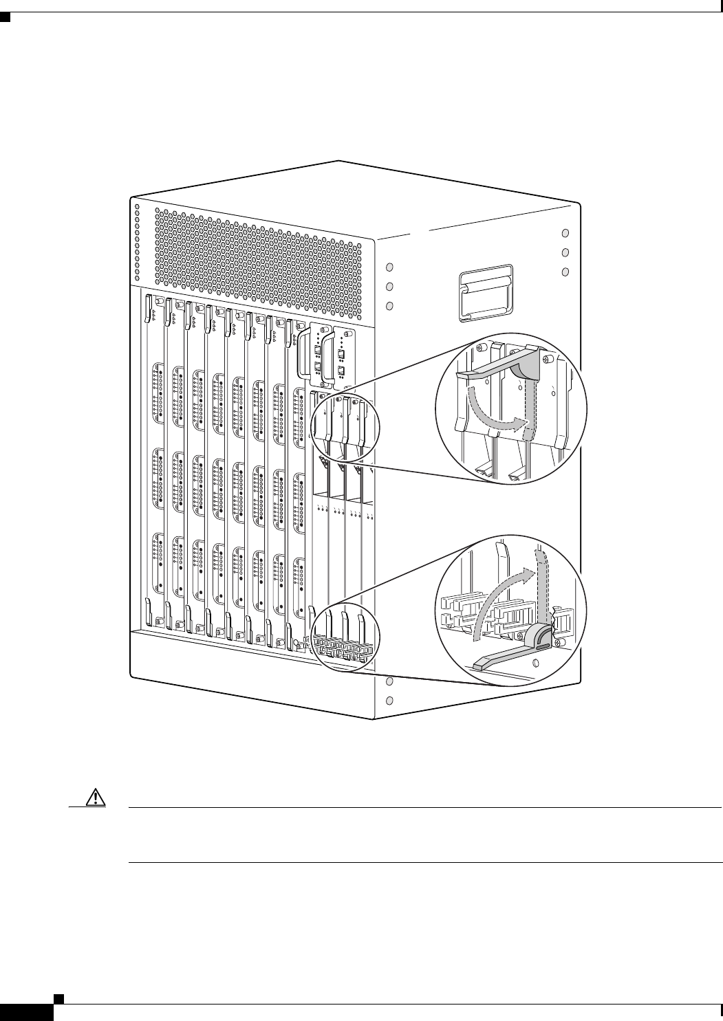
5-26
Cisco uBR10012 Universal Broadband Router Hardware Installation Guide
Chapter 5 Maintaining the Cisco uBR10012 Router
Removing and Replacing a Network Line Card
Step 3 Simultaneously pivot both ejector levers toward each other (until they are parallel to the faceplate) to
firmly seat the card in the backplane (see Figure 5-22).
Figure 5-22 Closing the Ejector Levers
Step 4 Secure the network line card in the chassis by tightening the top and bottom captive screws (see
Figure 5-18).
Caution To ensure that there is adequate space for additional line cards, always tighten the captive screws on each
newly installed line card before you insert any additional line cards. These screws prevent accidental
removal and provide proper grounding for electromagnetic interference (EMI) shielding.
US0
US1
US2
US3
US4
US5
US6
US7
US8
US9
US10
US11
US12
US13
US14
US15
US16
US17
US18
US19
DS0
DS1
DS2
DS3
DS4
RF
RF
RF
RF
RF
uBR10-MC5x20S-D
POWER
STATU S
MAINT
US0
US1
US2
US3
US4
US5
US6
US7
US8
US9
US10
US11
US12
US13
US14
US15
US16
US17
US18
US19
DS0
DS1
DS2
DS3
DS4
RF
RF
RF
RF
RF
uBR10-MC5x20S-D
POWER
STATU S
MAINT
US0
US1
US2
US3
US4
US5
US6
US7
US8
US9
US10
US11
US12
US13
US14
US15
US16
US17
US18
US19
DS0
DS1
DS2
DS3
DS4
RF
RF
RF
RF
RF
uBR10-MC5x20S-D
POWER
STATU S
MAINT
US0
US1
US2
US3
US4
US5
US6
US7
US8
US9
US10
US11
US12
US13
US14
US15
US16
US17
US18
US19
DS0
DS1
DS2
DS3
DS4
RF
RF
RF
RF
RF
uBR10-MC5x20S-D
POWER
STATUS
MAINT
US0
US1
US2
US3
US4
US5
US6
US7
US8
US9
US10
US11
US12
US13
US14
US15
US16
US17
US18
US19
DS0
DS1
DS2
DS3
DS4
RF
RF
RF
RF
RF
uBR10-MC5x20S-D
POWER
STATU S
MAINT
US0
US1
US2
US3
US4
US5
US6
US7
US8
US9
US10
US11
US12
US13
US14
US15
US16
US17
US18
US19
DS0
DS1
DS2
DS3
DS4
RF
RF
RF
RF
RF
uBR10-MC5x20S-D
POWER
STATU S
MAINT
US0
US1
US2
US3
US4
US5
US6
US7
US8
US9
US10
US11
US12
US13
US14
US15
US16
US17
US18
US19
DS0
DS1
DS2
DS3
DS4
RF
RF
RF
RF
RF
uBR10-MC5x20S-D
POWER
STATUS
MAINT
US0
US1
US2
US3
US4
US5
US6
US7
US8
US9
US10
US11
US12
US13
US14
US15
US16
US17
US18
US19
DS0
DS1
DS2
DS3
DS4
RF
RF
RF
RF
RF
uBR10-MC5x20S-D
POWER
STATUS
MAINT
103495
CISCO
10000
CARRIER
ALARM
LOOP
FAIL
CH OC-12-DSO SM-IR
CISCO
10000
CARRIER
ALARM
LOOP
FAIL
CH OC-12-DSO SM-IR
CISCO
10000
CARRIER
ALARM
LOOP
FAIL
CH OC-12-DSO SM-IR
CISC
100
CARRIER
ALARM
L
FAIL
CISCO
10000
FAIL
CISCO
10000
FAIL
CISCO
10000
FAIL
CISCO
10000
FAIL

5-27
Cisco uBR10012 Universal Broadband Router Hardware Installation Guide
Chapter 5 Maintaining the Cisco uBR10012 Router
Removing the Half-Height Gigabit Ethernet Line Card and the Slot Splitter
Step 5 When fully inserted, the card cycles through its power-on self-test. The Fail LED stays on briefly (about
5 to 6 seconds) and then shuts off. If the Fail LED remains on or is flashing, go to the “Troubleshooting
the Line Cards” section on page 4-16.
Step 6 Reconnect any network interface cables to the card.
Step 7 Configure the network line card if necessary (see the “Formatting PC Media Cards” section on
page 3-71, or refer to the Cisco uBR10012 Router Software Configuration Guide, for information about
configuring the card).
Note It is not necessary to configure the network card if you are installing a replacement card in the
same slot. The system automatically downloads the necessary configuration information from
the PRE module.
Removing the Half-Height Gigabit Ethernet Line Card and the
Slot Splitter
This section describes how to properly remove and replace HHGE line cards and the slot splitter from
the chassis. This section includes the following tasks:
•Removing a Half-Height Gigabit Ethernet Line Card, page 5-27
•Removing the Slot Splitter, page 5-30
Removing a Half-Height Gigabit Ethernet Line Card
Use the following procedure to remove the HHGE line card from the slot splitter:
Step 1 Verify that you are properly grounded.
Step 2 Disconnect any network cables connected to the line card port.
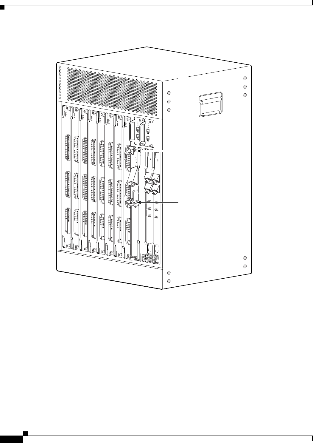
5-28
Cisco uBR10012 Universal Broadband Router Hardware Installation Guide
Chapter 5 Maintaining the Cisco uBR10012 Router
Removing the Half-Height Gigabit Ethernet Line Card and the Slot Splitter
Figure 5-23 Captive Screw Locations
Step 3 Loosen the top and bottom captive screws until they disengage and spring away from the face plate
(Figure 5-23).
Step 4 Simultaneously pivot both ejector levers away from each other to disengage the line card from the
backplane (Figure 5-24).
Step 5 Slide the line card out of the slot splitter and place it on an antistatic surface or in an antistatic bag.
Step 6 If you are not installing a replacement line card, install a blank faceplate in the slot.
135154
US0
US1
US2
US3
US4
US5
US6
US7
US8
US9
US10
US11
US12
US13
US14
US15
US16
US17
US18
US19
DS0
DS1
DS2
DS3
DS4
RF
RF
RF
RF
RF
uBR10-MC5x20S-D
POWER
STATUS
MAINT
US0
US1
US2
US3
US4
US5
US6
US7
US8
US9
US10
US11
US12
US13
US14
US15
US16
US17
US18
US19
DS0
DS1
DS2
DS3
DS4
RF
RF
RF
RF
RF
uBR10-MC5x20S-D
POWER
STATUS
MAINT
US0
US1
US2
US3
US4
US5
US6
US7
US8
US9
US10
US11
US12
US13
US14
US15
US16
US17
US18
US19
DS0
DS1
DS2
DS3
DS4
RF
RF
RF
RF
RF
uBR10-MC5x20S-D
POWER
STATUS
MAINT
US0
US1
US2
US3
US4
US5
US6
US7
US8
US9
US10
US11
US12
US13
US14
US15
US16
US17
US18
US19
DS0
DS1
DS2
DS3
DS4
RF
RF
RF
RF
RF
uBR10-MC5x20S-D
POWER
STA
TUS
MAINT
US0
US1
US2
US3
US4
US5
US6
US7
US8
US9
US10
US11
US12
US13
US14
US15
US16
US17
US18
US19
DS0
DS1
DS2
DS3
DS4
RF
RF
RF
RF
RF
uBR10-MC5x20S-D
POWER
ST
ATUS
MAINT
US0
US1
US2
US3
US4
US5
US6
US7
US8
US9
US10
US11
US12
US13
US14
US15
US16
US17
US18
US19
DS0
DS1
DS2
DS3
DS4
RF
RF
RF
RF
RF
uBR10-MC5x20S-D
POWER
ST
ATUS
MAINT
US0
US1
US2
US3
US4
US5
US6
US7
US8
US9
US10
US11
US12
US13
US14
US15
US16
US17
US18
US19
DS0
DS1
DS2
DS3
DS4
RF
RF
RF
RF
RF
uBR10-MC5x20S-D
POWER
ST
ATUS
MAINT
US1
US2
US3
US4
US5
US6
US7
US8
US9
US10
US11
US12
US13
US14
US15
US16
US17
US18
US19
DS0
DS1
DS2
DS3
DS4
RF
RF
RF
RF
RF
uBR10-MC5x20S-D
POWER
ST
ATUS
MAINT
CISCO
10000
CISCO
10000
FAIL
LINK
CISCO
10000
ENABLE
POS
SRP
FAIL
OC–48/STM–16 POS/SRP SM–LR
CD
TX
RX
SYNC
WRAP
P
ASS
THRU
TX
RX
CISCO
10000
ENABLE
POS
SRP
FAIL
OC–48/STM–16 POS/SRP SM–LR
CD
TX
RX
SYNC
WRAP
P
ASS
THRU
TX
RX
Captive screw
Captive screw
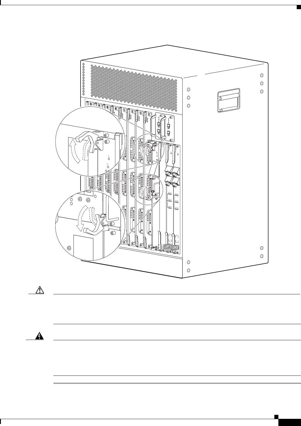
5-29
Cisco uBR10012 Universal Broadband Router Hardware Installation Guide
Chapter 5 Maintaining the Cisco uBR10012 Router
Removing the Half-Height Gigabit Ethernet Line Card and the Slot Splitter
Figure 5-24 Opening the Ejector Levers
Caution Do not operate the system unless all slots contain a line card or a blank faceplate. Always install a
full-slot blank faceplate into an empty slot. Half-height blank faceplates do not have air dams, and the
empty slot will rob cooling air from the other slots. A slot splitter with one half-height line card and one
blank faceplate is allowed.
Warning
Blank faceplates and cover panels serve three important functions: they prevent exposure to
hazardous voltages and currents inside the chassis; they contain electromagnetic interference (EMI)
that might disrupt other equipment; and they direct the flow of cooling air through the chassis. Do not
operate the system unless all cards, faceplates, front covers, and rear covers are in place.
Statement 1029
135156
US0
US1
US2
US3
US4
US5
US6
US7
US8
US9
US10
US11
US12
US13
US14
US15
US16
US17
US18
US19
DS0
DS1
DS2
DS3
DS4
RF
RF
RF
RF
RF
uBR10-MC5x20S-D
POWER
ST
ATUS
MAINT
US0
US1
US2
US3
US4
US5
US6
US7
US8
US9
US10
US11
US12
US13
US14
US15
US16
US17
US18
US19
DS0
DS1
DS2
DS3
DS4
RF
RF
RF
RF
RF
uBR10-MC5x20S-D
POWER
STATUS
MAINT
US0
US1
US2
US3
US4
US5
US6
US7
US8
US9
US10
US11
US12
US13
US14
US15
US16
US17
US18
US19
DS0
DS1
DS2
DS3
DS4
RF
RF
RF
RF
RF
uBR10-MC5x20S-D
POWER
STATUS
MAINT
US0
US1
US2
US3
US4
US5
US6
US7
US8
US9
US10
US11
US12
US13
US14
US15
US16
US17
US18
US19
DS0
DS1
DS2
DS3
DS4
RF
RF
RF
RF
RF
uBR10-MC5x20S-D
POWER
STA
TUS
MAINT
US0
US1
US2
US3
US4
US5
US6
US7
US8
US9
US10
US11
US12
US13
US14
US15
US16
US17
US18
US19
DS0
DS1
DS2
DS3
DS4
RF
RF
RF
RF
RF
uBR10-MC5x20S-D
POWER
ST
ATUS
MAINT
US0
US1
US2
US3
US4
US5
US6
US7
US8
US9
US10
US11
US12
US13
US14
US15
US16
US17
US18
US19
DS0
DS1
DS2
DS3
DS4
RF
RF
RF
RF
RF
uBR10-MC5x20S-D
POWER
ST
A
TUS
MAINT
US0
US1
US2
US3
US4
US5
US6
US7
US8
US9
US10
US11
US12
US13
US14
US15
US16
US17
US18
US19
DS0
DS1
DS2
DS3
DS4
RF
RF
RF
RF
RF
uBR10-MC5x20S-D
POWER
STA
TUS
MAINT
US0
US1
US2
US3
US4
US5
US6
US7
US8
US9
US10
US11
US12
US13
US14
US15
US16
US17
US18
US19
DS0
DS1
DS2
DS3
DS4
RF
RF
RF
RF
RF
uBR10-MC5x20S-D
POWER
ST
ATUS
MAINT
CISCO
10000
CISCO
10000
FAIL
LINK
CISCO
10000
ENABLE
POS
SRP
FAIL
OC–48/STM–16 POS/SRP SM–LR
CD
TX
RX
SYNC
WRAP
P
ASS
THRU
TX
RX
CISCO
10000
ENABLE
POS
SRP
FAIL
OC–48/STM–16 POS/SRP SM–LR
CD
TX
RX
SYNC
WRAP
P
ASS
THRU
TX
RX
CISCO
10000
CISCO
10000
FAI L
LINK
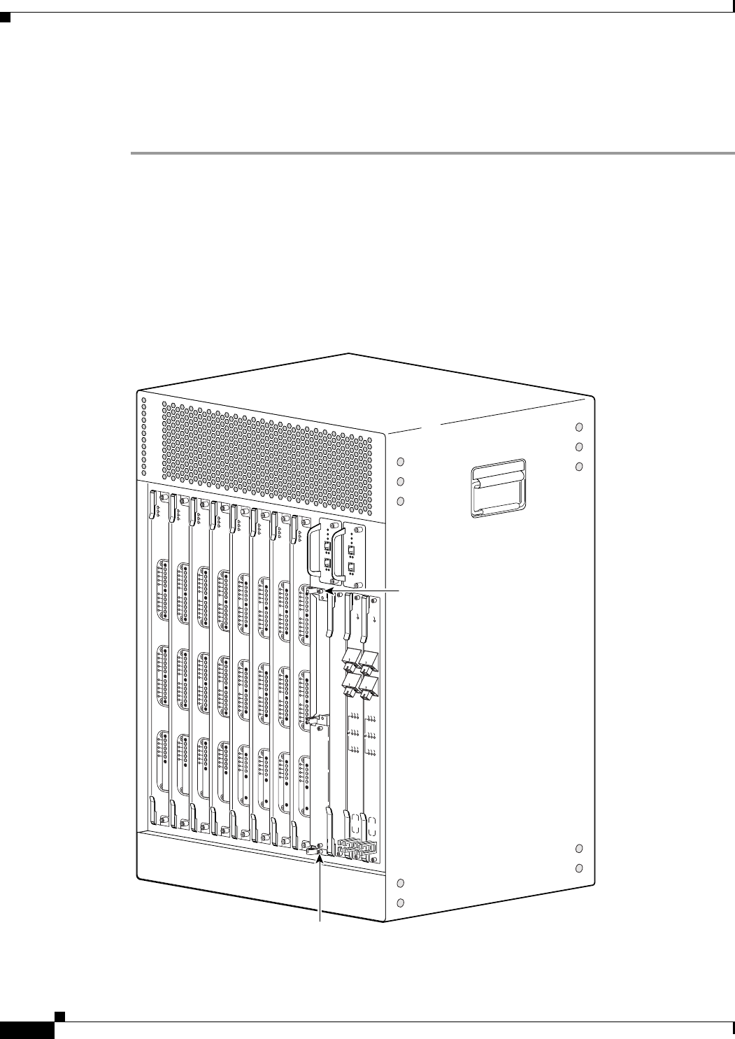
5-30
Cisco uBR10012 Universal Broadband Router Hardware Installation Guide
Chapter 5 Maintaining the Cisco uBR10012 Router
Removing the Half-Height Gigabit Ethernet Line Card and the Slot Splitter
Removing the Slot Splitter
Use the following procedure to remove a slot splitter from the chassis:
Step 1 Attach an antistatic wrist strap to your wrist and to the ESD socket on the chassis, or to a bare metal
surface on the chassis or frame).
Step 2 Remove any line cards from the splitter according to the “Removing a Half-Height Gigabit Ethernet Line
Card” section on page 5-27.
The slot splitter does not have ejector levers to disengage cards from the backplane, so you must remove
any line cards before you remove the splitter.
Step 3 Loosen the top and bottom captive screws on the slot splitter (Figure 5-25).
Figure 5-25 Captive Screw Locations
135150
US0
US1
US2
US3
US4
US5
US6
US7
US8
US9
US10
US11
US12
US13
US14
US15
US16
US17
US18
US19
DS0
DS1
DS2
DS3
DS4
RF
RF
RF
RF
RF
uBR10-MC5x20S-D
POWER
STATUS
MAINT
US0
US1
US2
US3
US4
US5
US6
US7
US8
US9
US10
US11
US12
US13
US14
US15
US16
US17
US18
US19
DS0
DS1
DS2
DS3
DS4
RF
RF
RF
RF
RF
uBR10-MC5x20S-D
POWER
STATU S
MAINT
US0
US1
US2
US3
US4
US5
US6
US7
US8
US9
US10
US11
US12
US13
US14
US15
US16
US17
US18
US19
DS0
DS1
DS2
DS3
DS4
RF
RF
RF
RF
RF
uBR10-MC5x20S-D
POWER
STATU S
MAINT
US0
US1
US2
US3
US4
US5
US6
US7
US8
US9
US10
US11
US12
US13
US14
US15
US16
US17
US18
US19
DS0
DS1
DS2
DS3
DS4
RF
RF
RF
RF
RF
uBR10-MC5x20S-D
POWER
STATUS
MAINT
US0
US1
US2
US3
US4
US5
US6
US7
US8
US9
US10
US11
US12
US13
US14
US15
US16
US17
US18
US19
DS0
DS1
DS2
DS3
DS4
RF
RF
RF
RF
RF
uBR10-MC5x20S-D
POWER
STATUS
MAINT
US0
US1
US2
US3
US4
US5
US6
US7
US8
US9
US10
US11
US12
US13
US14
US15
US16
US17
US18
US19
DS0
DS1
DS2
DS3
DS4
RF
RF
RF
RF
RF
uBR10-MC5x20S-D
POWER
ST
ATUS
MAINT
US0
US1
US2
US3
US4
US5
US6
US7
US8
US9
US10
US11
US12
US13
US14
US15
US16
US17
US18
US19
DS0
DS1
DS2
DS3
DS4
RF
RF
RF
RF
RF
uBR10-MC5x20S-D
POWER
STATUS
MAINT
US0
US1
US2
US3
US4
US5
US6
US7
US8
US9
US10
US11
US12
US13
US14
US15
US16
US17
US18
US19
DS0
DS1
DS2
DS3
DS4
RF
RF
RF
RF
RF
uBR10-MC5x20S-D
POWER
ST
ATUS
MAINT
CISCO
10000
CISCO
10000
ENABLE
POS
SRP
FAIL
OC–48/STM–16 POS/SRP SM–LR
CD
TX
RX
SYNC
WRAP
P
ASS
THRU
TX
RX
CISCO
10000
ENABLE
POS
SRP
FAIL
OC–48/STM–16 POS/SRP SM–LR
CD
TX
RX
SYNC
WRAP
P
ASS
THRU
TX
RX
Captive
screw
Captive
screw
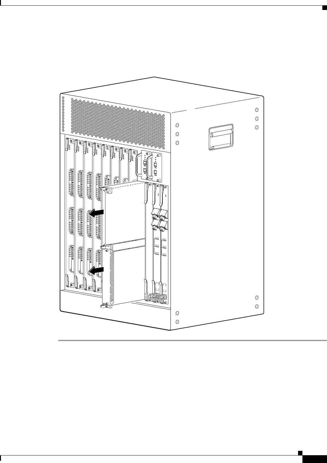
5-31
Cisco uBR10012 Universal Broadband Router Hardware Installation Guide
Chapter 5 Maintaining the Cisco uBR10012 Router
Removing the Half-Height Gigabit Ethernet Line Card and the Slot Splitter
Step 4 Slide the splitter out of the slot (Figure 5-26).
Step 5 If you are not installing a replacement splitter or a line card, install a full-slot blank faceplate in the slot.
Figure 5-26 Removing the Slot Splitter
135157
US0
US1
US2
US3
US4
US5
US6
US7
US8
US9
US10
US11
US12
US13
US14
US15
US16
US17
US18
US19
DS0
DS1
DS2
DS3
DS4
RF
RF
RF
RF
RF
uBR10-MC5x20S-D
POWER
ST
A
TUS
MAINT
US0
US1
US2
US3
US4
US5
US6
US7
US8
US9
US10
US11
US12
US13
US14
US15
US16
US17
US18
US19
DS0
DS1
DS2
DS3
DS4
RF
RF
RF
RF
RF
uBR10-MC5x20S-D
POWER
STATUS
MAINT
US0
US1
US2
US3
US4
US5
US6
US7
US8
US9
US10
US11
US12
US13
US14
US15
US16
US17
US18
US19
DS0
DS1
DS2
DS3
DS4
RF
RF
RF
RF
RF
uBR10-MC5x20S-D
POWER
ST
A
TUS
MAINT
US0
US1
US2
US3
US4
US5
US6
US7
US8
US9
US10
US11
US12
US13
US14
US15
US16
US17
US18
US19
DS0
DS1
DS2
DS3
DS4
RF
RF
RF
RF
RF
uBR10-MC5x20S-D
POWER
STATUS
MAINT
US0
US1
US2
US3
US4
US5
US6
US7
US8
US9
US10
US11
US12
US13
US14
US15
US16
US17
US18
US19
DS0
DS1
DS2
DS3
DS4
RF
RF
RF
RF
RF
uBR10-MC5x20S-D
POWER
STATUS
MAINT
US0
US1
US2
US3
US4
US5
US6
US7
US8
US9
US10
US11
US12
US13
US14
US15
US16
US17
US18
US19
DS0
DS1
DS2
DS3
DS4
RF
RF
RF
RF
RF
uBR10-MC5x20S-D
POWER
ST
ATUS
MAINT
US0
US1
US2
US3
US4
US5
US6
US7
US8
US9
US10
US11
US12
US13
US14
US15
US16
US17
US18
US19
DS0
DS1
DS2
DS3
DS4
RF
RF
RF
RF
RF
uBR10-MC5x20S-D
POWER
ST
ATUS
MAINT
US0
US1
US2
US3
US4
US5
US6
US7
US8
US9
US10
US11
US12
US13
US14
US15
US16
US17
US18
US19
DS0
DS1
DS2
DS3
DS4
RF
RF
RF
RF
RF
uBR10-MC5x20S-D
POWER
STA
TUS
MAINT
CISCO
10000
CISCO
10000
ENABLE
POS
SRP
FAIL
OC–48/STM–16 POS/SRP SM–LR
CD
TX
RX
SYNC
WRAP
P
ASS
THRU
TX
RX
CISCO
10000
ENABLE
POS
SRP
FAIL
OC–48/STM–16 POS/SRP SM–LR
CD
TX
RX
SYNC
WRAP
P
ASS
THRU
TX
RX

5-32
Cisco uBR10012 Universal Broadband Router Hardware Installation Guide
Chapter 5 Maintaining the Cisco uBR10012 Router
Replacing the Slot Splitter and Half-Height Gigabit Ethernet Line Card
Replacing the Slot Splitter and Half-Height Gigabit Ethernet Line
Card
This section describes how to install the line card in the Cisco uBR10012 router. This section includes
the following tasks:
•Installing the Slot Splitter, page 5-32
•Installing the Half-Height Gigabit Ethernet Line Card, page 5-35
Caution You must use slot 3 or slot 4 when installing the slot splitter and HHGE line card in the Cisco uBR10012
router, using slot 1 or slot 2 will cause the router to shut down those slots.
Caution Do not install two half-height blank faceplates into the same slot in the slot splitter. Instead, install a
full-slot blank faceplate into the slot. The half-height blank faceplates do not have air dams, and the
empty slot will rob cooling air from the other slots. A slot splitter with one half-height line card and one
blank faceplate is allowed.
Caution Do not install a line card into the slot splitter before installing the splitter into the chassis. The slot
splitter does not have ejector levers that allow you to seat the line card in the backplane.
Installing the Slot Splitter
You must install the half-height line card into a slot that contains a slot splitter, which can hold two
half-height line cards. If both slots of the slot splitter are not used, then you must install a blank faceplate
in the empty slot.
Follow these steps to install a slot splitter into slot 3 or slot 4 of the Cisco uBR10012 chassis.
Step 1 Attach an antistatic wrist strap to your wrist and to an ESD socket on the chassis, or to a bare metal
surface on the chassis or frame (Figure 5-21).
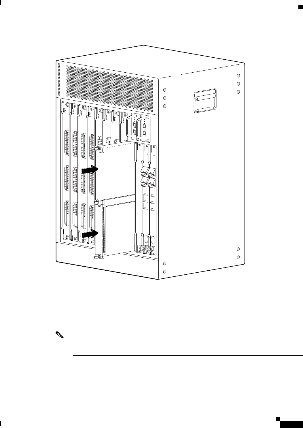
5-33
Cisco uBR10012 Universal Broadband Router Hardware Installation Guide
Chapter 5 Maintaining the Cisco uBR10012 Router
Replacing the Slot Splitter and Half-Height Gigabit Ethernet Line Card
Figure 5-27 Inserting the Slot Splitter
Step 2 Grasp the front of the slot splitter with one hand and place your other hand under the splitter. Position
the splitter in front of the card cage slot.
Step 3 Carefully align the upper and lower edges of the slot splitter with the upper and lower guides in the
chassis, and slide the splitter into the slot until the front is flush with the chassis.
Note The slot splitter shown in Figure 5-21 has one open slot (top) and one slot with a slot cover
(bottom).
135151
US0
US1
US2
US3
US4
US5
US6
US7
US8
US9
US10
US11
US12
US13
US14
US15
US16
US17
US18
US19
DS0
DS1
DS2
DS3
DS4
RF
RF
RF
RF
RF
uBR10-MC5x20S-D
POWER
STA
TUS
MAINT
US0
US1
US2
US3
US4
US5
US6
US7
US8
US9
US10
US11
US12
US13
US14
US15
US16
US17
US18
US19
DS0
DS1
DS2
DS3
DS4
RF
RF
RF
RF
RF
uBR10-MC5x20S-D
POWER
STATUS
MAINT
US0
US1
US2
US3
US4
US5
US6
US7
US8
US9
US10
US11
US12
US13
US14
US15
US16
US17
US18
US19
DS0
DS1
DS2
DS3
DS4
RF
RF
RF
RF
RF
uBR10-MC5x20S-D
POWER
STATUS
MAINT
US0
US1
US2
US3
US4
US5
US6
US7
US8
US9
US10
US11
US12
US13
US14
US15
US16
US17
US18
US19
DS0
DS1
DS2
DS3
DS4
RF
RF
RF
RF
RF
uBR10-MC5x20S-D
POWER
STATUS
MAINT
US0
US1
US2
US3
US4
US5
US6
US7
US8
US9
US10
US11
US12
US13
US14
US15
US16
US17
US18
US19
DS0
DS1
DS2
DS3
DS4
RF
RF
RF
RF
RF
uBR10-MC5x20S-D
POWER
STATUS
MAINT
US0
US1
US2
US3
US4
US5
US6
US7
US8
US9
US10
US11
US12
US13
US14
US15
US16
US17
US18
US19
DS0
DS1
DS2
DS3
DS4
RF
RF
RF
RF
RF
uBR10-MC5x20S-D
POWER
STATUS
MAINT
US0
US1
US2
US3
US4
US5
US6
US7
US8
US9
US10
US11
US12
US13
US14
US15
US16
US17
US18
US19
DS0
DS1
DS2
DS3
DS4
RF
RF
RF
RF
RF
uBR10-MC5x20S-D
POWER
STATUS
MAINT
US0
US1
US2
US3
US4
US5
US6
US7
US8
US9
US10
US11
US12
US13
US14
US15
US16
US17
US18
US19
DS0
DS1
DS2
DS3
DS4
RF
RF
RF
RF
RF
uBR10-MC5x20S-D
POWER
STA
TUS
MAINT
CISCO
10000
CISCO
10000
ENABLE
POS
SRP
FAIL
OC–48/STM–16 POS/SRP SM–LR
CD
TX
RX
SYNC
WRAP
P
ASS
THRU
TX
RX
CISCO
10000
ENABLE
POS
SRP
FAIL
OC–48/STM–16 POS/SRP SM–LR
CD
TX
RX
SYNC
WRAP
P
ASS
THRU
TX
RX
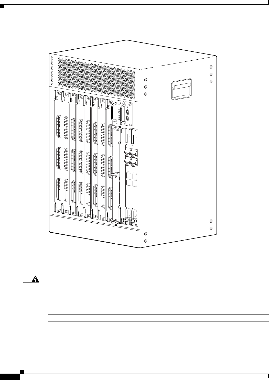
5-34
Cisco uBR10012 Universal Broadband Router Hardware Installation Guide
Chapter 5 Maintaining the Cisco uBR10012 Router
Replacing the Slot Splitter and Half-Height Gigabit Ethernet Line Card
Figure 5-28 Captive Screw Locations
Step 4 Secure the slot splitter to the chassis by tightening the top and bottom captive screws (Figure 5-28).
Warning
Blank faceplates and cover panels serve three important functions: they prevent exposure to
hazardous voltages and currents inside the chassis; they contain electromagnetic interference (EMI)
that might disrupt other equipment; and they direct the flow of cooling air through the chassis. Do not
operate the system unless all cards, faceplates, front covers, and rear covers are in place.
Statement 1029
135150
US0
US1
US2
US3
US4
US5
US6
US7
US8
US9
US10
US11
US12
US13
US14
US15
US16
US17
US18
US19
DS0
DS1
DS2
DS3
DS4
RF
RF
RF
RF
RF
uBR10-MC5x20S-D
POWER
ST
ATUS
MAINT
US0
US1
US2
US3
US4
US5
US6
US7
US8
US9
US10
US11
US12
US13
US14
US15
US16
US17
US18
US19
DS0
DS1
DS2
DS3
DS4
RF
RF
RF
RF
RF
uBR10-MC5x20S-D
POWER
STATUS
MAINT
US0
US1
US2
US3
US4
US5
US6
US7
US8
US9
US10
US11
US12
US13
US14
US15
US16
US17
US18
US19
DS0
DS1
DS2
DS3
DS4
RF
RF
RF
RF
RF
uBR10-MC5x20S-D
POWER
STATUS
MAINT
US0
US1
US2
US3
US4
US5
US6
US7
US8
US9
US10
US11
US12
US13
US14
US15
US16
US17
US18
US19
DS0
DS1
DS2
DS3
DS4
RF
RF
RF
RF
RF
uBR10-MC5x20S-D
POWER
ST
ATUS
MAINT
US0
US1
US2
US3
US4
US5
US6
US7
US8
US9
US10
US11
US12
US13
US14
US15
US16
US17
US18
US19
DS0
DS1
DS2
DS3
DS4
RF
RF
RF
RF
RF
uBR10-MC5x20S-D
POWER
ST
ATUS
MAINT
US0
US1
US2
US3
US4
US5
US6
US7
US8
US9
US10
US11
US12
US13
US14
US15
US16
US17
US18
US19
DS0
DS1
DS2
DS3
DS4
RF
RF
RF
RF
RF
uBR10-MC5x20S-D
POWER
STATUS
MAINT
US0
US1
US2
US3
US4
US5
US6
US7
US8
US9
US10
US11
US12
US13
US14
US15
US16
US17
US18
US19
DS0
DS1
DS2
DS3
DS4
RF
RF
RF
RF
RF
uBR10-MC5x20S-D
POWER
ST
ATUS
MAINT
US0
US1
US2
US3
US4
US5
US6
US7
US8
US9
US10
US11
US12
US13
US14
US15
US16
US17
US18
US19
DS0
DS1
DS2
DS3
DS4
RF
RF
RF
RF
RF
uBR10-MC5x20S-D
POWER
ST
A
TUS
MAINT
CISCO
10000
CISCO
10000
ENABLE
POS
SRP
FAIL
OC–48/STM–16 POS/SRP SM–LR
CD
TX
RX
SYNC
WRAP
P
ASS
THRU
TX
RX
CISCO
10000
ENABLE
POS
SRP
FAIL
OC–48/STM–16 POS/SRP SM–LR
CD
TX
RX
SYNC
WRAP
P
ASS
THRU
TX
RX
Captive
screw
Captive
screw
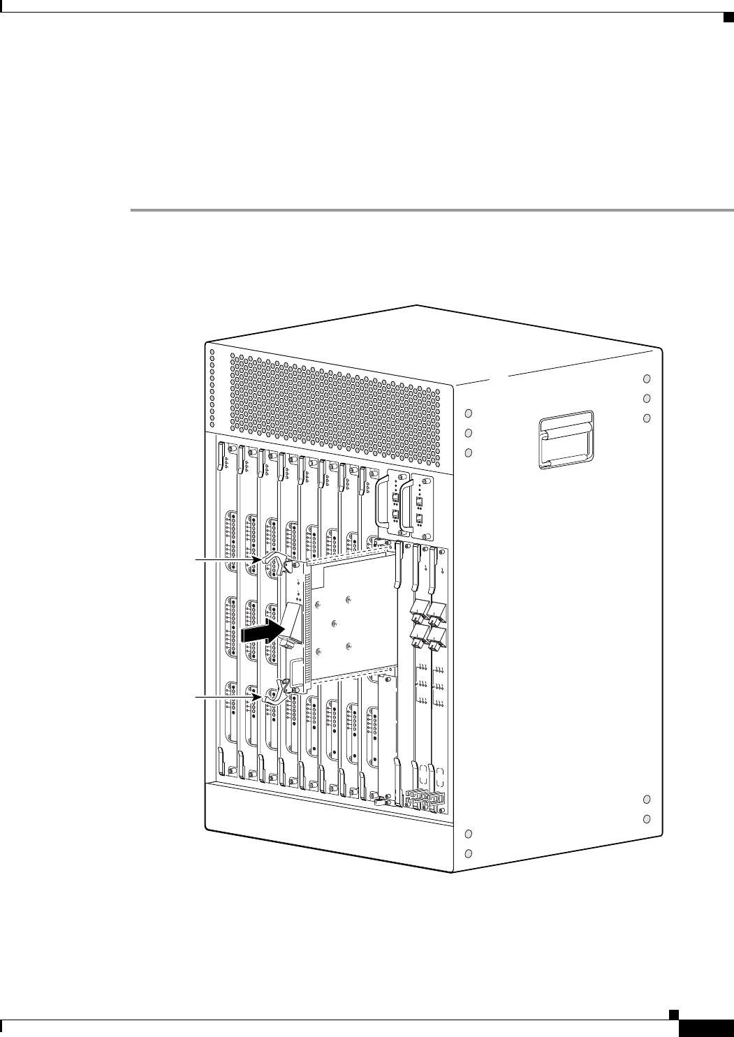
5-35
Cisco uBR10012 Universal Broadband Router Hardware Installation Guide
Chapter 5 Maintaining the Cisco uBR10012 Router
Replacing the Slot Splitter and Half-Height Gigabit Ethernet Line Card
Installing the Half-Height Gigabit Ethernet Line Card
Use the following procedure to install a HHGE line card into an installed slot splitter. See the “Installing
the Slot Splitter” section on page 5-32 to install the slot splitter.
If you are replacing a line card, see the “Removing a Half-Height Gigabit Ethernet Line Card” section
on page 5-27 before you begin this procedure.
Step 1 Attach an antistatic wrist strap to your wrist and to an ESD socket on the chassis, or to a bare metal
surface on the chassis or frame.
Figure 5-29 Inserting the Line Card
Step 2 Grasp the faceplate of the line card with one hand and place your other hand under the card carrier (to
support the weight of the card). Position the card in front of the slot splitter.
Step 3 Carefully align the upper and lower edges of the line card with the upper and lower guides in the slot
splitter, and slide the line card about half-way into the splitter.
135152
US0
US1
US2
US3
US4
US5
US6
US7
US8
US9
US10
US11
US12
US13
US14
US15
US16
US17
US18
US19
DS0
DS1
DS2
DS3
DS4
RF
RF
RF
RF
RF
uBR10-MC5x20S-D
POWER
STATUS
MAINT
US0
US1
US2
US3
US4
US5
US6
US7
US8
US9
US10
US11
US12
US13
US14
US15
US16
US17
US18
US19
DS0
DS1
DS2
DS3
DS4
RF
RF
RF
RF
RF
uBR10-MC5x20S-D
POWER
STA
TUS
MAINT
US0
US1
US2
US3
US4
US5
US6
US7
US8
US9
US10
US11
US12
US13
US14
US15
US16
US17
US18
US19
DS0
DS1
DS2
DS3
DS4
RF
RF
RF
RF
RF
uBR10-MC5x20S-D
POWER
STATUS
MAINT
US0
US1
US2
US3
US4
US5
US6
US7
US8
US9
US10
US11
US12
US13
US14
US15
US16
US17
US18
US19
DS0
DS1
DS2
DS3
DS4
RF
RF
RF
RF
RF
uBR10-MC5x20S-D
POWER
STATUS
MAINT
US0
US1
US2
US3
US4
US5
US6
US7
US8
US9
US10
US11
US12
US13
US14
US15
US16
US17
US18
US19
DS0
DS1
DS2
DS3
DS4
RF
RF
RF
RF
RF
uBR10-MC5x20S-D
POWER
STATUS
MAINT
US0
US1
US2
US3
US4
US5
US6
US7
US8
US9
US10
US11
US12
US13
US14
US15
US16
US17
US18
US19
DS0
DS1
DS2
DS3
DS4
RF
RF
RF
RF
RF
uBR10-MC5x20S-D
POWER
ST
ATUS
MAINT
US0
US1
US2
US3
US4
US5
US6
US7
US8
US9
US10
US11
US12
US13
US14
US15
US16
US17
US18
US19
DS0
DS1
DS2
DS3
DS4
RF
RF
RF
RF
RF
uBR10-MC5x20S-D
POWER
STATUS
MAINT
US0
US1
US2
US3
US4
US5
US6
US7
US8
US9
US10
US11
US12
US13
US14
US15
US16
US17
US18
US19
DS0
DS1
DS2
DS3
DS4
RF
RF
RF
RF
RF
uBR10-MC5x20S-D
POWER
ST
ATUS
MAINT
CISCO
10000
CISCO
CISCO
10000
10000
FAIL
AIL
LINK
LINK
Ejector
lever
CISCO
10000
FAIL
LINK
CISCO
10000
ENABLE
POS
SRP
FAIL
OC–48/STM–16 POS/SRP SM–LR
CD
TX
RX
SYNC
WRAP
P
ASS
THRU
TX
RX
CISCO
10000
ENABLE
POS
SRP
FAIL
OC–48/STM–16 POS/SRP SM–LR
CD
TX
RX
SYNC
WRAP
P
ASS
THRU
TX
RX
Ejector
lever
Ejector
lever
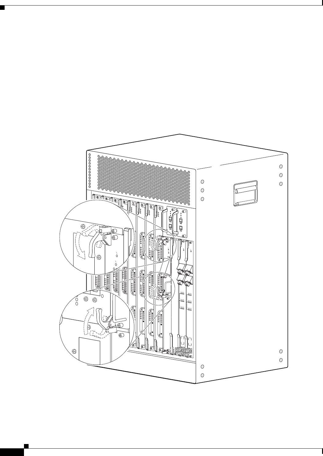
5-36
Cisco uBR10012 Universal Broadband Router Hardware Installation Guide
Chapter 5 Maintaining the Cisco uBR10012 Router
Replacing the Slot Splitter and Half-Height Gigabit Ethernet Line Card
Step 4 Be sure the ejectors are in the open position (as shown) and continue to push the line card into the splitter
until you can feel it begin to seat in the backplane connectors.
Step 5 Verify that the captive screws are properly aligned with the captive screw holes in the splitter. If the
captive screws are not properly aligned, the card will not seat properly in the backplane.
Step 6 Simultaneously pivot both ejector levers toward each other (until they are parallel to the faceplate) to
firmly seat the card in the backplane (Figure 5-22).
The line card cycles through its power-on self-test. The FAIL LED lights during portions of the POST
(Power-On Self Test), but remains off after POST on a properly working line card. If the FAIL LED
remains on, go to the “Troubleshooting the HHGE Installation” section on page 4-17.
Figure 5-30 Closing the Ejector Levers
135153
US0
US1
US2
US3
US4
US5
US6
US7
US8
US9
US10
US11
US12
US13
US14
US15
US16
US17
US18
US19
DS0
DS1
DS2
DS3
DS4
RF
RF
RF
RF
RF
uBR10-MC5x20S-D
POWER
ST
ATUS
MAINT
US0
US1
US2
US3
US4
US5
US6
US7
US8
US9
US10
US11
US12
US13
US14
US15
US16
US17
US18
US19
DS0
DS1
DS2
DS3
DS4
RF
RF
RF
RF
RF
uBR10-MC5x20S-D
POWER
STATUS
MAINT
US0
US1
US2
US3
US4
US5
US6
US7
US8
US9
US10
US11
US12
US13
US14
US15
US16
US17
US18
US19
DS0
DS1
DS2
DS3
DS4
RF
RF
RF
RF
RF
uBR10-MC5x20S-D
POWER
STATUS
MAINT
US0
US1
US2
US3
US4
US5
US6
US7
US8
US9
US10
US11
US12
US13
US14
US15
US16
US17
US18
US19
DS0
DS1
DS2
DS3
DS4
RF
RF
RF
RF
RF
uBR10-MC5x20S-D
POWER
STA
TUS
MAINT
US0
US1
US2
US3
US4
US5
US6
US7
US8
US9
US10
US11
US12
US13
US14
US15
US16
US17
US18
US19
DS0
DS1
DS2
DS3
DS4
RF
RF
RF
RF
RF
uBR10-MC5x20S-D
POWER
ST
ATUS
MAINT
US0
US1
US2
US3
US4
US5
US6
US7
US8
US9
US10
US11
US12
US13
US14
US15
US16
US17
US18
US19
DS0
DS1
DS2
DS3
DS4
RF
RF
RF
RF
RF
uBR10-MC5x20S-D
POWER
ST
ATUS
MAINT
US0
US1
US2
US3
US4
US5
US6
US7
US8
US9
US10
US11
US12
US13
US14
US15
US16
US17
US18
US19
DS0
DS1
DS2
DS3
DS4
RF
RF
RF
RF
RF
uBR10-MC5x20S-D
POWER
STATUS
MAINT
US0
US1
US2
US3
US4
US5
US6
US7
US8
US9
US10
US11
US12
US13
US14
US15
US16
US17
US18
US19
DS0
DS1
DS2
DS3
DS4
RF
RF
RF
RF
RF
uBR10-MC5x20S-D
POWER
STATUS
MAINT
CISCO
10000
CISCO
10000
FAIL
LINK
CISCO
10000
ENABLE
POS
SRP
FAIL
OC–48/STM–16 POS/SRP SM–LR
CD
TX
RX
SYNC
WRAP
P
ASS
THRU
TX
RX
CISCO
10000
ENABLE
POS
SRP
FAIL
OC–48/STM–16 POS/SRP SM–LR
CD
TX
RX
SYNC
WRAP
P
ASS
THRU
TX
RX
CISCO
10000
CISCO
10000
FAI L
LINK
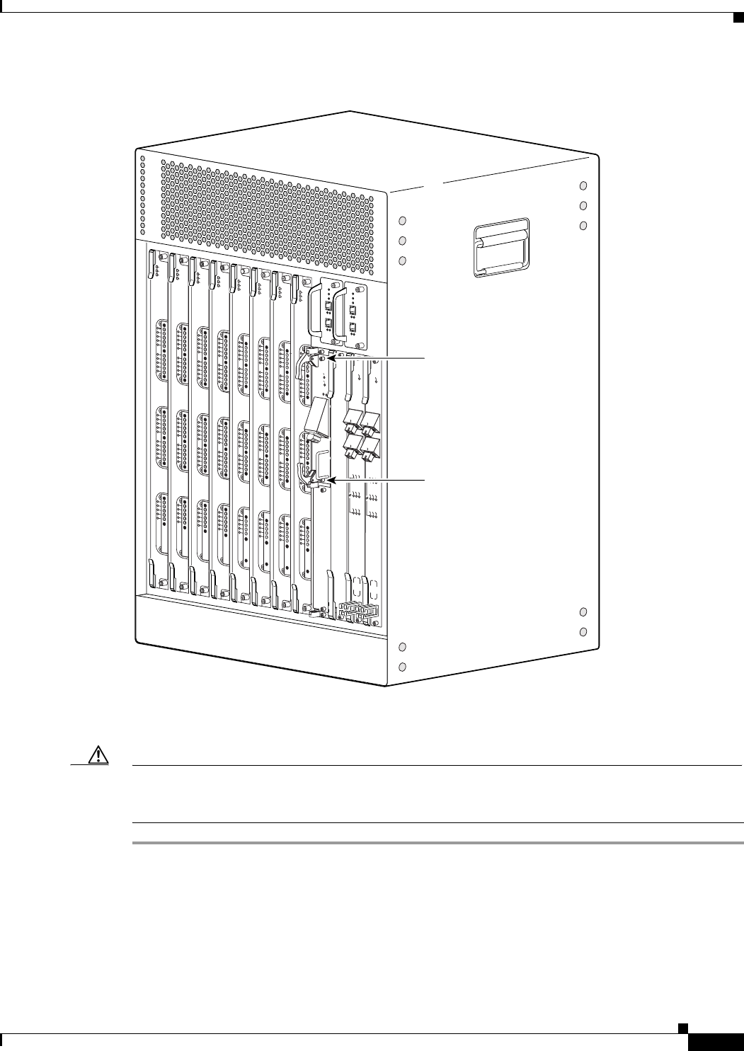
5-37
Cisco uBR10012 Universal Broadband Router Hardware Installation Guide
Chapter 5 Maintaining the Cisco uBR10012 Router
Replacing the Slot Splitter and Half-Height Gigabit Ethernet Line Card
Figure 5-31 Captive Screw Locations
Step 7 Secure the line card in the slot splitter by tightening the top and bottom captive screws (Figure 5-31).
Caution To ensure that there is adequate space for additional line cards, always tighten the captive screws on each
newly installed line card before you insert any additional line cards. These screws prevent accidental
removal and provide proper grounding for electromagnetic interference (EMI) shielding.
135154
US0
US1
US2
US3
US4
US5
US6
US7
US8
US9
US10
US11
US12
US13
US14
US15
US16
US17
US18
US19
DS0
DS1
DS2
DS3
DS4
RF
RF
RF
RF
RF
uBR10-MC5x20S-D
POWER
STATUS
MAINT
US0
US1
US2
US3
US4
US5
US6
US7
US8
US9
US10
US11
US12
US13
US14
US15
US16
US17
US18
US19
DS0
DS1
DS2
DS3
DS4
RF
RF
RF
RF
RF
uBR10-MC5x20S-D
POWER
STATUS
MAINT
US0
US1
US2
US3
US4
US5
US6
US7
US8
US9
US10
US11
US12
US13
US14
US15
US16
US17
US18
US19
DS0
DS1
DS2
DS3
DS4
RF
RF
RF
RF
RF
uBR10-MC5x20S-D
POWER
STATUS
MAINT
US0
US1
US2
US3
US4
US5
US6
US7
US8
US9
US10
US11
US12
US13
US14
US15
US16
US17
US18
US19
DS0
DS1
DS2
DS3
DS4
RF
RF
RF
RF
RF
uBR10-MC5x20S-D
POWER
STATUS
MAINT
US0
US1
US2
US3
US4
US5
US6
US7
US8
US9
US10
US11
US12
US13
US14
US15
US16
US17
US18
US19
DS0
DS1
DS2
DS3
DS4
RF
RF
RF
RF
RF
uBR10-MC5x20S-D
POWER
ST
ATUS
MAINT
US0
US1
US2
US3
US4
US5
US6
US7
US8
US9
US10
US11
US12
US13
US14
US15
US16
US17
US18
US19
DS0
DS1
DS2
DS3
DS4
RF
RF
RF
RF
RF
uBR10-MC5x20S-D
POWER
ST
ATUS
MAINT
US0
US1
US2
US3
US4
US5
US6
US7
US8
US9
US10
US11
US12
US13
US14
US15
US16
US17
US18
US19
DS0
DS1
DS2
DS3
DS4
RF
RF
RF
RF
RF
uBR10-MC5x20S-D
POWER
STATUS
MAINT
US1
US2
US3
US4
US5
US6
US7
US8
US9
US10
US11
US12
US13
US14
US15
US16
US17
US18
US19
DS0
DS1
DS2
DS3
DS4
RF
RF
RF
RF
RF
uBR10-MC5x20S-D
POWER
ST
ATUS
MAINT
CISCO
10000
CISCO
10000
FAIL
LINK
CISCO
10000
ENABLE
POS
SRP
FAIL
OC–48/STM–16 POS/SRP SM–LR
CD
TX
RX
SYNC
WRAP
P
ASS
THRU
TX
RX
CISCO
10000
ENABLE
POS
SRP
FAIL
OC–48/STM–16 POS/SRP SM–LR
CD
TX
RX
SYNC
WRAP
P
ASS
THRU
TX
RX
Captive screw
Captive screw
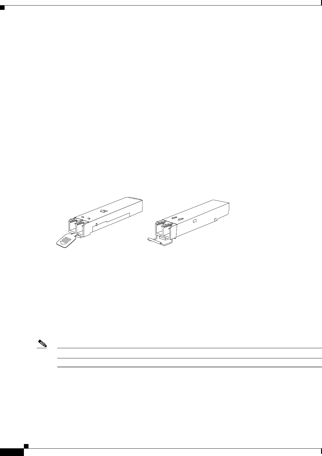
5-38
Cisco uBR10012 Universal Broadband Router Hardware Installation Guide
Chapter 5 Maintaining the Cisco uBR10012 Router
Removing and Replacing an SFP Module
Removing and Replacing an SFP Module
Your HHGE line card is shipped with an SFP module installed. Use the procedures in this section if you
need to change the SFP module:
•Removing an SFP Module, page 5-38
•Inserting an SFP Module, page 5-40
Use only SFP modules supplied by Cisco with your HHGE line card. Each SFP module contains an
internal serial EEPROM that is security-programmed by the SFP manufacturer with information that
provides a way for Cisco (through Cisco IOS software) to identify and validate the SFP module as a
module type that is tested and qualified by Cisco to operate properly with your line card. Unapproved
SFP modules (those not purchased directly from Cisco) do not work with the HHGE line card.
Types of SFP Modules
SFP modules from different manufacturers provide different methods for freeing the locking pin and
removing the SFP module. Figure 5-32 shows two available module types.
Figure 5-32 Mylar Tab SFP Module and Bale Clasp SFP Module
•Mylar Tab SFP—Pulling the mylar tab simultaneously releases the locking pin and pulls the SFP
module out of its receptacle.
•Bale Clasp SFP—Opening the bale clasp releases the locking pin so you can remove the SFP module
from its receptacle.
Removing an SFP Module
Use the following procedure to remove an SFP module from the HHGE line card.
Note You can remove an SFP module while the system is powered on, but the interface shuts down.
Step 1 Attach an antistatic wrist strap to your wrist and to an ESD socket on the chassis, or to a bare metal
surface on the chassis or frame.
Mylar tab Bale clasp
76415
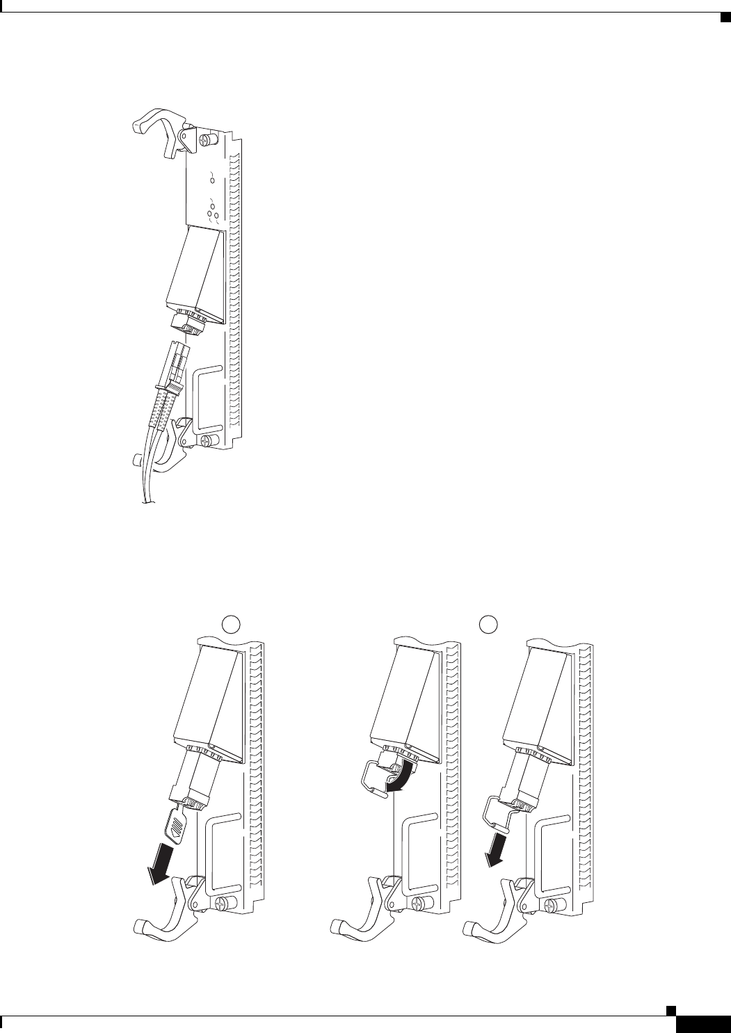
5-39
Cisco uBR10012 Universal Broadband Router Hardware Installation Guide
Chapter 5 Maintaining the Cisco uBR10012 Router
Removing and Replacing an SFP Module
Figure 5-33 Disconnecting the LC-type Fiber-Optic Cable
Step 2 Disconnect the fiber-optic cable connector from the SFP module (Figure 5-33).
Note which cable connector plug is TX and which is RX for reattachment.
Figure 5-34 Removing an SFP Module
CISCO
10000
FAI L
LINK
TX
0
RX
GIGABIT ETHERNET
76416
GIGABIT ETHERNET
GIGABIT ETHERNET
GIGABIT ETHERNET
135155
1 2
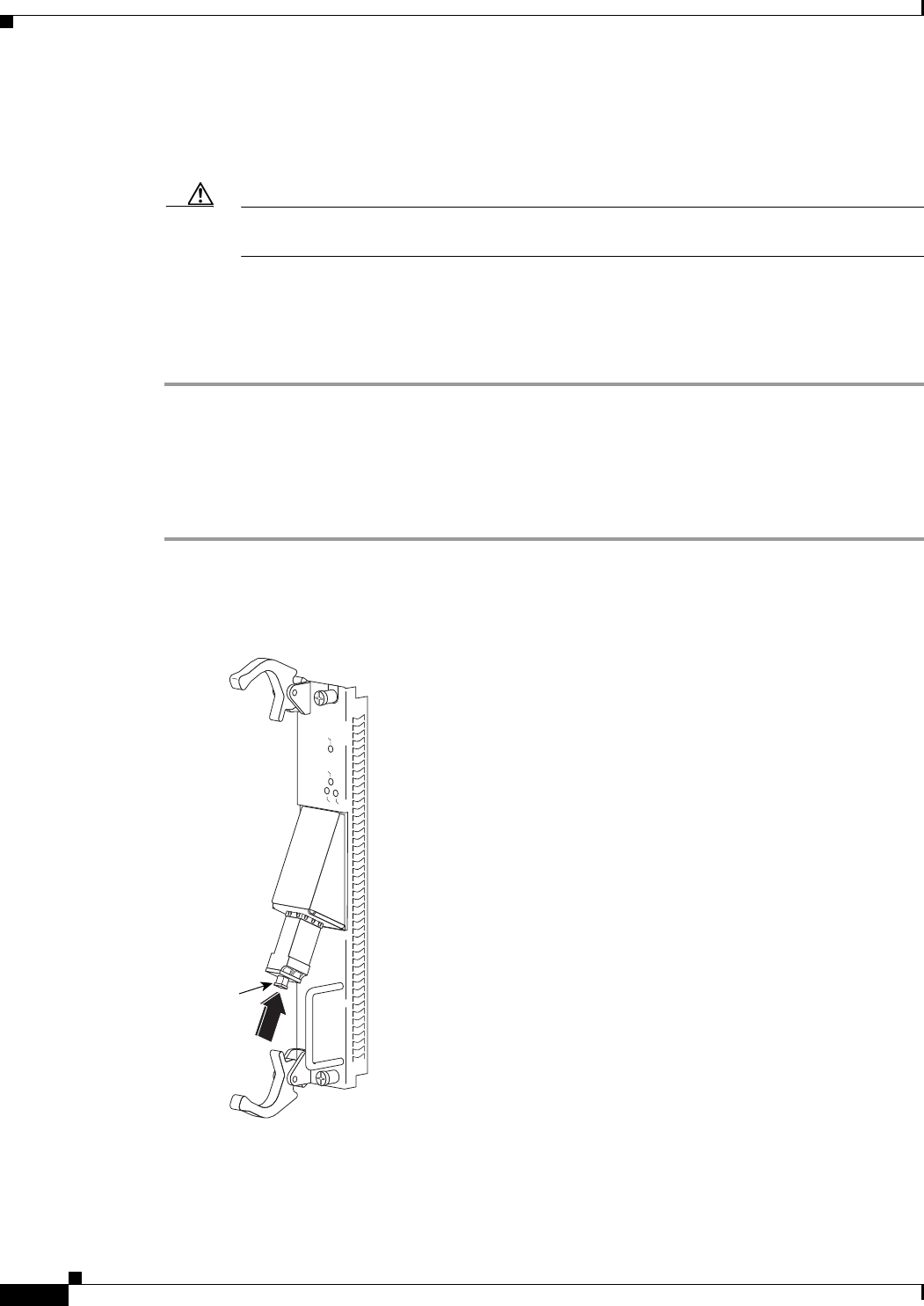
5-40
Cisco uBR10012 Universal Broadband Router Hardware Installation Guide
Chapter 5 Maintaining the Cisco uBR10012 Router
Removing and Replacing an SFP Module
Step 3 Unlock and remove the SFP module as follows:
a. Mylar Tab SFP Modules—Gently, but firmly pull the plastic tab to free the locking pin and
remove the SFP module (Figure 5-34).
Caution Do not twist the Mylar tab when you remove the SFP module. Twisting the tab may disconnect
it from the module.
b. Bale Clasp Modules—Open the bale clasp to release the locking pin and remove the SFP
module (Figure 5-34).
Step 4 Insert a dust plug into the optical ports of the removed SFP module to keep the optical interfaces clean,
and place the module in an antistatic bag or other protective environment.
Inserting an SFP Module
Use the following procedure to insert an SFP module into the HHGE line card.
Step 1 Attach an antistatic wrist strap to your wrist and to an ESD socket on the chassis, or to a bare metal
surface on the chassis or frame.
Figure 5-35 Inserting the SFP Module
CISCO
10000
FAI L
LINK
TX
0
RX
GIGABIT ETHERNET
76419
Dust plug

5-41
Cisco uBR10012 Universal Broadband Router Hardware Installation Guide
Chapter 5 Maintaining the Cisco uBR10012 Router
Upgrading to a Half-Height Gigabit Ethernet Line Card
Step 2 Gently insert the SFP module into the line card port until the edge connector is fully seated in the
connector. You will hear a click as the triangular pin on the bottom of the SFP module snaps into place
(Figure 5-35).
Step 3 Remove the dust plug from the SFP module optical ports and plug the LC-type fiber-optic cable
connector into the SFP module (see Figure 5-35).
Upgrading to a Half-Height Gigabit Ethernet Line Card
This section provides instructions for upgrading from two full height Gigabit Ethernet line cards to
half-height Gigabit Ethernet line cards.
Note Verify that you have a PRE2 installed in the router and that you are using the latest IOS software, IOS
software release 12.3(13)BC or later.
To upgrade from the full-height GigE line card to the HHGE line card, perform the following steps:
Step 1 Verify traffic is passing through slot 3 and slot 4.
Step 2 Administratively shut down the line card in slot 3 and let traffic reroute through slot 4.
Step 3 Remove the full height line card in slot 3.
Step 4 Install the slot splitter into slot 3.
Step 5 Install the half height card in the slot splitter 3/0/0 or slot 3/1/0.
Step 6 Configure and bring up the ethernet card in slot 3/0/0 or slot 3/1/0.
Refer to Configuring the Half-Height Gigabit Ethernet Line Card for the Cisco uBR10012 Universal
Broadband Router at the following URL:
http://www.cisco.com/en/US/docs/interfaces_modules/cable/line_cards/ubr_hh_ge/configuration/guide
/hhgefm10.html
Step 7 Repeat this procedure for the GigE line card in slot 4.
Removing and Replacing a Cable Interface Line Card
Use the following procedure to install a new cable interface line card, or to remove or replace an existing
cable interface line card in the Cisco uBR10012 chassis. The following cable interface line cards are
supported:
•Cisco uBR10-MC5X20S/U, UBR10-MC5X20S=, UBR10-MC5X20U=
•Cisco UBR-MC20X20V, UBR-MC20X20V-20D=, UBR-MC20X20V-5D=, UBR-MC20X20V-0D=
•Cisco uBR-MC3GX60V, uBR-MC3GX60V=

5-42
Cisco uBR10012 Universal Broadband Router Hardware Installation Guide
Chapter 5 Maintaining the Cisco uBR10012 Router
Removing and Replacing a Cable Interface Line Card
Tip To prevent alarms from activating, you must administratively shut down a cable interface line card before
hot-swapping it. Otherwise, inform the network administrator that this portion of the network will be
temporarily interrupted. If the maintenance LED is lighted, you can remove the line card without
affecting systems operations.
Removing the Cable Interface Line Card
Step 1 Attach an antistatic wrist strap to your wrist and to a bare metal, unpainted surface on the chassis or
frame.
Step 2 Face the back of the Cisco uBR10012 chassis. Clear aside enough interface and power cables to allow
sufficient space to work.
Step 3 If installing a new cable interface line card in a blank slot, remove the blank slot cover and discard.
Otherwise, disconnect all coaxial cables from the cable interface line card being replaced or removed.
Step 4 Unscrew the top and bottom captive screws on the cable interface line card (see Figure 5-36).
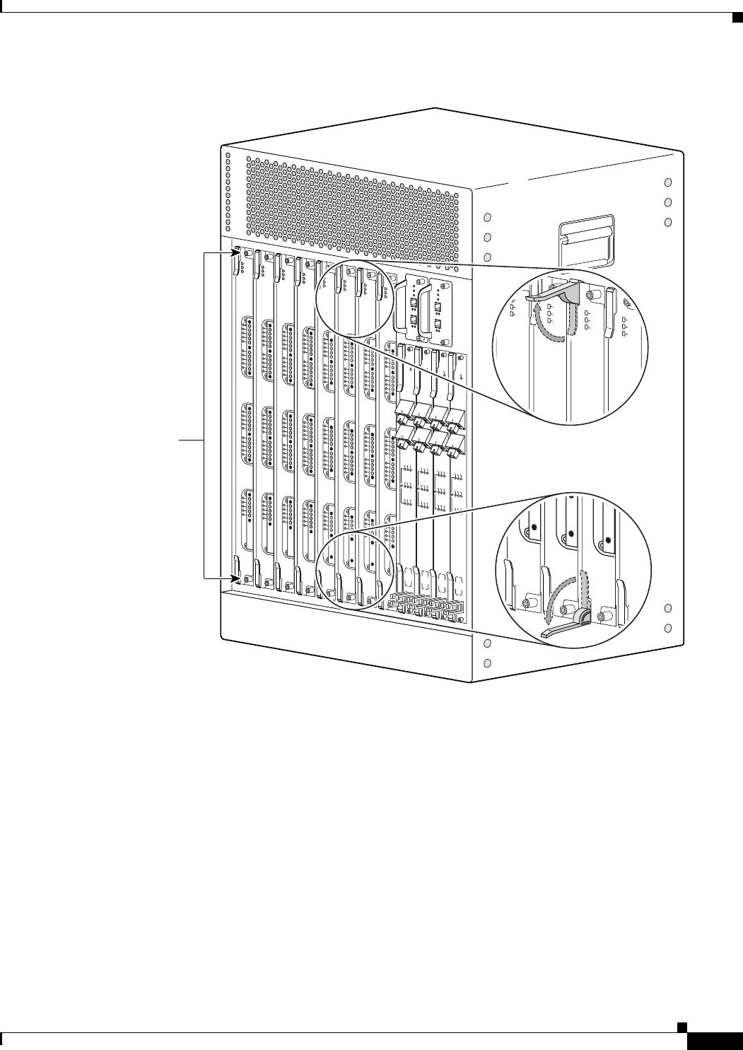
5-43
Cisco uBR10012 Universal Broadband Router Hardware Installation Guide
Chapter 5 Maintaining the Cisco uBR10012 Router
Removing and Replacing a Cable Interface Line Card
Figure 5-36 Captive Screws, Ejector Levers
Step 5 Simultaneously pivot both ejector levers away from each other to disengage the cable interface line card
from the backplane.
Step 6 Slide the cable interface line card out of the slot and place it on an antistatic surface, or in an antistatic
bag (see Figure 5-37).
72508
US0
US1
US2
US3
US4
US5
US6
US7
US8
US9
US10
US11
US12
US13
US14
US15
US16
US17
US18
US19
DS0
DS1
DS2
DS3
DS4
RF
RF
RF
RF
RF
uBR10-MC5x20S-D
POWER
ST
ATUS
MAINT
US0
US1
US2
US3
US4
US5
US6
US7
US8
US9
US10
US11
US12
US13
US14
US15
US16
US17
US18
US19
DS0
DS1
DS2
DS3
DS4
RF
RF
RF
RF
RF
uBR10-MC5x20S-D
POWER
STA
TUS
MAINT
US0
US1
US2
US3
US4
US5
US6
US7
US8
US9
US10
US11
US12
US13
US14
US15
US16
US17
US18
US19
DS0
DS1
DS2
DS3
DS4
RF
RF
RF
RF
RF
uBR10-MC5x20S-D
POWER
ST
A
TUS
MAINT
US0
US1
US2
US3
US4
US5
US6
US7
US8
US9
US10
US11
US12
US13
US14
US15
US16
US17
US18
US19
DS0
DS1
DS2
DS3
DS4
RF
RF
RF
RF
RF
uBR10-MC5x20S-D
POWER
ST
ATUS
MAINT
CISCO
10000
ENABLE
POS
SRP
FAIL
OC–48/STM–16 POS/SRP SM–LR
CD
TX
RX
SYNC
WRAP
P
ASS
THRU
TX
RX
CISCO
10000
ENABLE
POS
SRP
FAIL
OC–48/STM–16 POS/SRP SM–LR
CD
TX
RX
SYNC
WRAP
P
ASS
THRU
TX
RX
CISCO
10000
ENABLE
POS
SRP
FAIL
OC–48/STM–16 POS/SRP SM–LR
CD
TX
RX
SYNC
WRAP
P
ASS
THRU
TX
RX
CISCO
10000
ENABLE
POS
SRP
FAIL
OC–48/STM–16 POS/SRP SM–LR
CD
TX
RX
SYNC
WRAP
P
ASS
THRU
TX
RX
US0
US1
US2
US3
US4
US5
US6
US7
US8
US9
US10
US11
US12
US13
US14
US15
US16
US17
US18
US19
DS0
DS1
DS2
DS3
DS4
RF
RF
RF
RF
RF
uBR10-MC5x20S-D
POWER
ST
A
TUS
MAINT
US0
US1
US2
US3
US4
US5
US6
US7
US8
US9
US10
US11
US12
US13
US14
US15
US16
US17
US18
US19
DS0
DS1
DS2
DS3
DS4
RF
RF
RF
RF
RF
uBR10-MC5x20S-D
POWER
STA
TUS
MAINT
US0
US1
US2
US3
US4
US5
US6
US7
US8
US9
US10
US11
US12
US13
US14
US15
US16
US17
US18
US19
DS0
DS1
DS2
DS3
DS4
RF
RF
RF
RF
RF
uBR10-MC5x20S-D
POWER
ST
ATUS
MAINT
US0
US1
US2
US3
US4
US5
US6
US7
US8
US9
US10
US11
US12
US13
US14
US15
US16
US17
US18
US19
DS0
DS1
DS2
DS3
DS4
RF
RF
RF
RF
RF
uBR10-MC5x20S-D
POWER
ST
ATUS
MAINT
uBR10-MC5x20S-F
POWER
STATUS
MAINT
US0
uBR10-MC5x20S-F
POWER
STATUS
MAINT
uBR10-MC5x20S-F
POWER
STATUS
MAINT
uBR10-MC5x20S-F
POWER
STATUS
MAINT
DS4 RF
Captive
screws
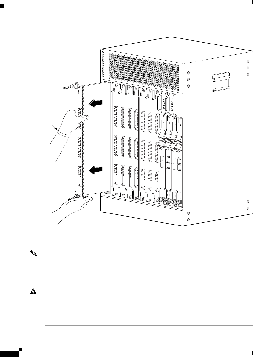
5-44
Cisco uBR10012 Universal Broadband Router Hardware Installation Guide
Chapter 5 Maintaining the Cisco uBR10012 Router
Removing and Replacing a Cable Interface Line Card
Figure 5-37 Removing the Cable Interface Line Card
Step 7 If you are installing a new or replacement cable interface line card, proceed to the next step. Otherwise,
install a blank cover over the slot and screw down its captive screws to conclude this procedure.
Note For proper cooling and airflow, a blank cable interface line card cover must always be installed in a blank
line card slot.
The product order number for the blank cable interface line card cover is UBR10-MC-Cover=.
Warning
Blank faceplates (filler panels) serve three important functions: they prevent exposure to hazardous
voltages and currents inside the chassis; they contain electromagnetic interference (EMI) that might
disrupt other equipment; and they direct the flow of cooling air through the chassis. Do not operate
the system unless all cards and faceplates are in place.
Statement 1029
72324
US0
US1
US2
US3
US4
US5
US6
US7
US8
US9
US10
US11
US12
US13
US14
US15
US16
US17
US18
US19
DS0
DS1
DS2
DS3
DS4
RF
RF
RF
RF
RF
POWER
STATUS
MAINT
US0
US1
US2
US3
US4
US5
US6
US7
US8
US9
US10
US11
US12
US13
US14
US15
US16
US17
US18
US19
DS0
DS1
DS2
DS3
DS4
RF
RF
RF
RF
RF
uBR10-MC5x20S-D
POWER
STATUS
MAINT
US0
US1
US2
US3
US4
US5
US6
US7
US8
US9
US10
US11
US12
US13
US14
US15
US16
US17
US18
US19
DS0
DS1
DS2
DS3
DS4
RF
RF
RF
RF
RF
uBR10-MC5x20S-D
POWER
ST
ATUS
MAINT
US0
US1
US2
US3
US4
US5
US6
US7
US8
US9
US10
US11
US12
US13
US14
US15
US16
US17
US18
US19
DS0
DS1
DS2
DS3
DS4
RF
RF
RF
RF
RF
uBR10-MC5x20S-D
POWER
STATUS
MAINT
US0
US1
US2
US3
US4
US5
US6
US7
US8
US9
US10
US11
US12
US13
US14
US15
US16
US17
US18
US19
DS0
DS1
DS2
DS3
DS4
RF
RF
RF
RF
RF
uBR10-MC5x20S-D
POWER
ST
A
TUS
MAINT
US0
US1
US2
US3
US4
US5
US6
US7
US8
US9
US10
US11
US12
US13
US14
US15
US16
US17
US18
US19
DS0
DS1
DS2
DS3
DS4
RF
RF
RF
RF
RF
uBR10-MC5x20S-D
POWER
ST
A
TUS
MAINT
US0
US1
US2
US3
US4
US5
US6
US7
US8
US9
US10
US11
US12
US13
US14
US15
US16
US17
US18
US19
DS0
DS1
DS2
DS3
DS4
RF
RF
RF
RF
RF
uBR10-MC5x20S-D
POWER
ST
A
TUS
MAINT
US0
US1
US2
US3
US4
US5
US6
US7
US8
US9
US10
US11
US12
US13
US14
US15
US16
US17
US18
US19
DS0
DS1
DS2
DS3
DS4
RF
RF
RF
RF
RF
uBR10-MC5x20S-D
POWER
ST
A
TUS
MAINT
CISCO
10000
ENABLE
POS
SRP
FAIL
OC–48/STM–16 POS/SRP SM–LR
CD
TX
RX
SYNC
WRAP
PASS
THRU
TX
RX
CISCO
10000
ENABLE
POS
SRP
FAIL
OC–48/STM–16 POS/SRP SM–LR
CD
TX
RX
SYNC
WRAP
PASS
THRU
TX
RX
CISCO
10000
ENABLE
POS
SRP
FAIL
OC–48/STM–16 POS/SRP SM–LR
CD
TX
RX
SYNC
WRAP
PAS S
THRU
TX
RX
CISCO
10000
ENABLE
POS
SRP
FAIL
OC–48/STM–16 POS/SRP SM–LR
CD
TX
RX
SYNC
WRAP
PASS
THRU
TX
RX
ESD-preventive
strap
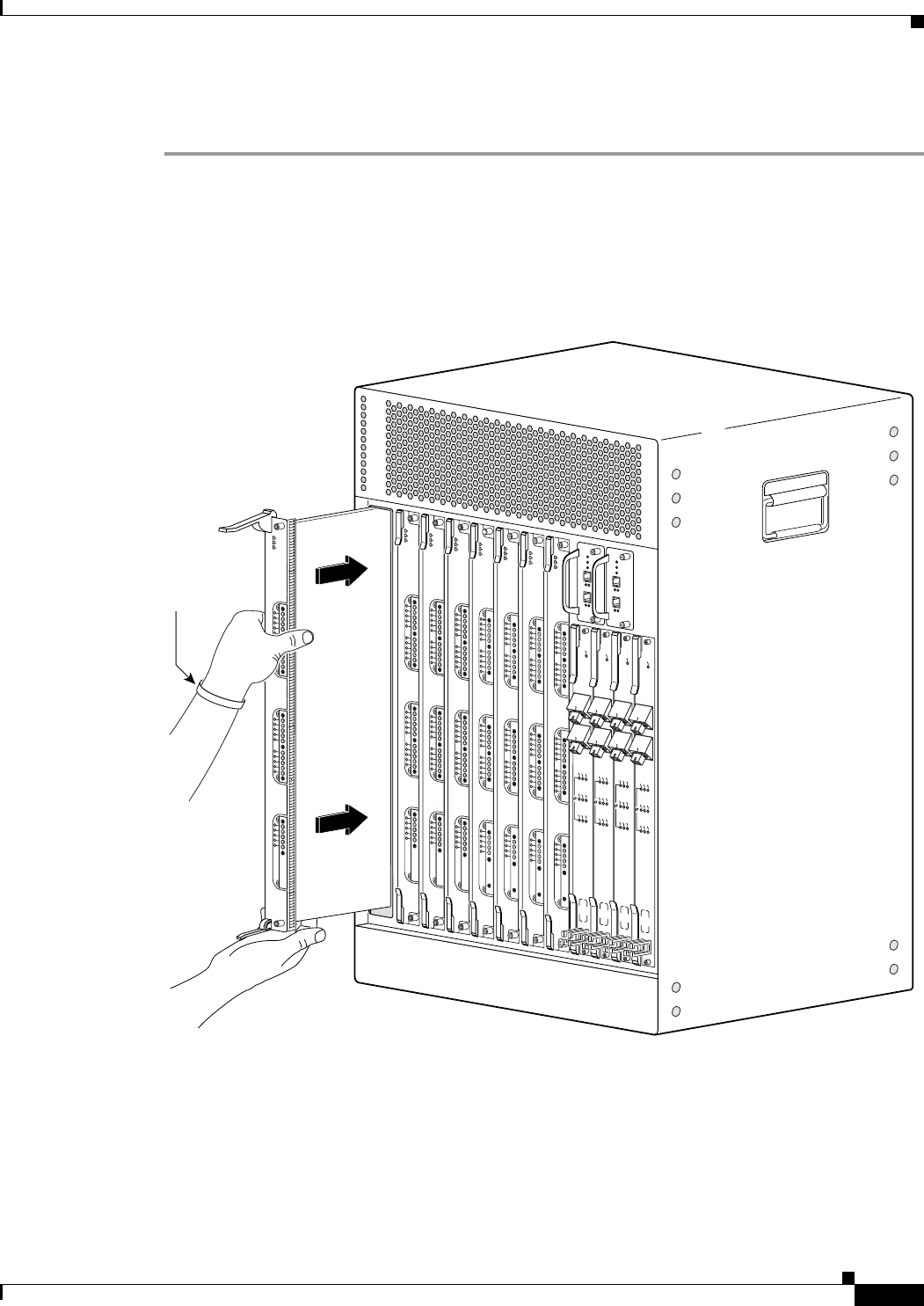
5-45
Cisco uBR10012 Universal Broadband Router Hardware Installation Guide
Chapter 5 Maintaining the Cisco uBR10012 Router
Removing and Replacing a Cable Interface Line Card
Installing a Cable Interface Line Card
Step 1 Grasp the faceplate of the new cable interface line card with one hand and place your other hand under
the card carrier (to support the weight of the card) and position the card in front of the card cage slot.
Step 2 Carefully align the upper and lower edges of the cable interface line card with the upper and lower guides
in the chassis, and slide the cable interface line card into the slot until you can feel it begin to seat in the
backplane connectors (see Figure 5-38).
Figure 5-38 Inserting the Cable Interface Line Card
Step 3 Simultaneously pivot both ejector levers toward each other (until they are parallel to the faceplate) to
firmly seat the card in the backplane (see Figure 5-39).
72325
US0
US1
US2
US3
US4
US5
US6
US7
US8
US9
US10
US11
US12
US13
US14
US15
US16
US17
US18
US19
DS0
DS1
DS2
DS3
DS4
RF
RF
RF
RF
RF
POWER
ST
ATUS
MAINT
US0
US1
US2
US3
US4
US5
US6
US7
US8
US9
US10
US11
US12
US13
US14
US15
US16
US17
US18
US19
DS0
DS1
DS2
DS3
DS4
RF
RF
RF
RF
RF
uBR10-MC5x20S-D
POWER
ST
ATUS
MAINT
US0
US1
US2
US3
US4
US5
US6
US7
US8
US9
US10
US11
US12
US13
US14
US15
US16
US17
US18
US19
DS0
DS1
DS2
DS3
DS4
RF
RF
RF
RF
RF
uBR10-MC5x20S-D
POWER
STATUS
MAINT
US0
US1
US2
US3
US4
US5
US6
US7
US8
US9
US10
US11
US12
US13
US14
US15
US16
US17
US18
US19
DS0
DS1
DS2
DS3
DS4
RF
RF
RF
RF
RF
uBR10-MC5x20S-D
POWER
STATUS
MAINT
US0
US1
US2
US3
US4
US5
US6
US7
US8
US9
US10
US11
US12
US13
US14
US15
US16
US17
US18
US19
DS0
DS1
DS2
DS3
DS4
RF
RF
RF
RF
RF
uBR10-MC5x20S-D
POWER
ST
A
TUS
MAINT
US0
US1
US2
US3
US4
US5
US6
US7
US8
US9
US10
US11
US12
US13
US14
US15
US16
US17
US18
US19
DS0
DS1
DS2
DS3
DS4
RF
RF
RF
RF
RF
uBR10-MC5x20S-D
POWER
ST
A
TUS
MAINT
US0
US1
US2
US3
US4
US5
US6
US7
US8
US9
US10
US11
US12
US13
US14
US15
US16
US17
US18
US19
DS0
DS1
DS2
DS3
DS4
RF
RF
RF
RF
RF
uBR10-MC5x20S-D
POWER
ST
A
TUS
MAINT
US0
US1
US2
US3
US4
US5
US6
US7
US8
US9
US10
US11
US12
US13
US14
US15
US16
US17
US18
US19
DS0
DS1
DS2
DS3
DS4
RF
RF
RF
RF
RF
uBR10-MC5x20S-D
POWER
ST
A
TUS
MAINT
CISCO
10000
ENABLE
POS
SRP
FAIL
OC–48/STM–16 POS/SRP SM–LR
CD
TX
RX
SYNC
WRAP
PAS S
THRU
TX
RX
CISCO
10000
ENABLE
POS
SRP
FAIL
OC–48/STM–16 POS/SRP SM–LR
CD
TX
RX
SYNC
WRAP
PAS S
THRU
TX
RX
CISCO
10000
ENABLE
POS
SRP
FAIL
OC–48/STM–16 POS/SRP SM–LR
CD
TX
RX
SYNC
WRAP
PASS
THRU
TX
RX
CISCO
10000
ENABLE
POS
SRP
FAIL
OC–48/STM–16 POS/SRP SM–LR
CD
TX
RX
SYNC
WRAP
PASS
THRU
TX
RX
SD-preventive
strap

5-46
Cisco uBR10012 Universal Broadband Router Hardware Installation Guide
Chapter 5 Maintaining the Cisco uBR10012 Router
Removing and Replacing a Cable Interface Line Card
Figure 5-39 Closing the Ejector Levers
Step 4 Secure the cable interface line card in the chassis by tightening the top and bottom captive screws (see
Figure 5-36).
Tip If you are installing more then one card, wait until all the cards are installed before tightening the captive
screws.
Tip Captive screws prevent accidental removal and provide proper grounding for electromagnetic
interference (EMI) shielding.
Step 5 When fully inserted, the cable interface line card cycles through its power-on self-test. The POWER
LED lights (green) and the STATUS LED lights (yellow). If the card is operating correctly, the STATUS
LED then starts lighting green. If these LEDs do not operate as described, see the “Troubleshooting the
Line Cards” section on page 4-16.
72326
US0
US1
US2
US3
US4
US5
US6
US7
US8
US9
US10
US11
US12
US13
US14
US15
US16
US17
US18
US19
DS0
DS1
DS2
DS3
DS4
RF
RF
RF
RF
RF
uBR10-MC5x20S-D
POWER
STATUS
MAINT
US0
US1
US2
US3
US4
US5
US6
US7
US8
US9
US10
US11
US12
US13
US14
US15
US16
US17
US18
US19
DS0
DS1
DS2
DS3
DS4
RF
RF
RF
RF
RF
uBR10-MC5x20S-D
POWER
ST
ATUS
MAINT
US0
US1
US2
US3
US4
US5
US6
US7
US8
US9
US10
US11
US12
US13
US14
US15
US16
US17
US18
US19
DS0
DS1
DS2
DS3
DS4
RF
RF
RF
RF
RF
uBR10-MC5x20S-D
POWER
ST
ATUS
MAINT
US0
US1
US2
US3
US4
US5
US6
US7
US8
US9
US10
US11
US12
US13
US14
US15
US16
US17
US18
US19
DS0
DS1
DS2
DS3
DS4
RF
RF
RF
RF
RF
uBR10-MC5x20S-D
POWER
STATUS
MAINT
CISCO
10000
ENABLE
POS
SRP
FAIL
OC–48/STM–16 POS/SRP SM–LR
CD
TX
RX
SYNC
WRAP
P
ASS
THRU
TX
RX
CISCO
10000
ENABLE
POS
SRP
FAIL
OC–48/STM–16 POS/SRP SM–LR
CD
TX
RX
SYNC
WRAP
P
ASS
THRU
TX
RX
CISCO
10000
ENABLE
POS
SRP
FAIL
OC–48/STM–16 POS/SRP SM–LR
CD
TX
RX
SYNC
WRAP
P
ASS
THRU
TX
RX
CISCO
10000
ENABLE
POS
SRP
FAIL
OC–48/STM–16 POS/SRP SM–LR
CD
TX
RX
SYNC
WRAP
P
ASS
THRU
TX
RX
US0
US1
US2
US3
US4
US5
US6
US7
US8
US9
US10
US11
US12
US13
US14
US15
US16
US17
US18
US19
DS0
DS1
DS2
DS3
DS4
RF
RF
RF
RF
RF
uBR10-MC5x20S-D
POWER
ST
ATUS
MAINT
US0
US1
US2
US3
US4
US5
US6
US7
US8
US9
US10
US11
US12
US13
US14
US15
US16
US17
US18
US19
DS0
DS1
DS2
DS3
DS4
RF
RF
RF
RF
RF
uBR10-MC5x20S-D
POWER
ST
ATUS
MAINT
US0
US1
US2
US3
US4
US5
US6
US7
US8
US9
US10
US11
US12
US13
US14
US15
US16
US17
US18
US19
DS0
DS1
DS2
DS3
DS4
RF
RF
RF
RF
RF
uBR10-MC5x20S-D
POWER
STATUS
MAINT
US0
US1
US2
US3
US4
US5
US6
US7
US8
US9
US10
US11
US12
US13
US14
US15
US16
US17
US18
US19
DS0
DS1
DS2
DS3
DS4
RF
RF
RF
RF
RF
uBR10-MC5x20S-D
POWER
STA
TUS
MAINT
uBR10-MC5x20S-F
POWER
STATUS
MAINT
US0
uBR10-MC5x20S-F
POWER
STATUS
MAINT
uBR10-MC5x20S-F
POWER
STATUS
MAINT
uBR10-MC5x20S-F
POWER
STAT U S
MAINT
DS4 RF
Captive
screws

5-47
Cisco uBR10012 Universal Broadband Router Hardware Installation Guide
Chapter 5 Maintaining the Cisco uBR10012 Router
Removing and Replacing a Cable Interface Line Card
Step 6 Connect all downstream and upstream coaxial cables to the cable interface line card as necessary.
Step 7 Configure the cable interface line card if necessary (refer to the Cisco uBR10012 Router Software
Configuration Guide for information about configuring the line card).
Note It is not necessary to configure the cable interface line card if you are installing a replacement
card in the identical slot. The system automatically downloads the necessary configuration
information from the PRE.

5-48
Cisco uBR10012 Universal Broadband Router Hardware Installation Guide
Chapter 5 Maintaining the Cisco uBR10012 Router
Removing and Replacing a Cable Interface Line Card

A-1
Cisco uBR10012 Universal Broadband Router Hardware Installation Guide
APPENDIX
A
Technical Specifications
This appendix provides specifications information about the Cisco uBR10012 router, router
components, and cards used in the router.
•Cisco uBR10012 Chassis and Chassis Components, page A-1
•Network Uplink Cards and Cable Interface Line Cards, page A-8
Cisco uBR10012 Chassis and Chassis Components
Table A-1 lists the physical specifications for the Cisco uBR10012 universal broadband router and its
components.
Table A-1 Cisco uBR10012 Router and Router Components Physical Specifications
Description Specifications
Chassis specifications •Weight: 235 lb (106.6 kg) fully configured chassis
•Height: 31.25 in. (79.4 cm)—18 Rack Units (RU)
•Width: 17.2 in. (43.7 cm)
•Depth: 22.75 in. (57.8 cm)
•Mounting: 19 in. rack mountable (front or rear),
2 units per 7 ft. rack
Note Mounting in 23 in. racks is possible with optional third-party hardware.
Temperature range •Operating: 41°F to 104°F (5 to 40°C)
•Storage: −40°F to 158°F (−40 to 70°C)
Relative humidity •Operating—nominal: 5% to 85%
•Storage: 5% to 95% percent
Operating altitude –197 to 13,123 ft. (–60 to 4000 m)
Airflow 280 cfm1 (approximately) through the system fan assembly module (low speed, normal
operating temperatures, with clean air filter)
450 cfm (approximately) through the system fan assembly module (high speed, chassis
temperature at air outlet exceeds 40°C, with clean air filter)
Operating vibrations 5 to 200 Hz, 1 g (1 octave/min), 200 to 500 Hz, 2 g (1 octave/min)
Chassis power consumption Not to exceed 2400 W2 (8189btu3)

A-2
Cisco uBR10012 Universal Broadband Router Hardware Installation Guide
Appendix A Technical Specifications
Cisco uBR10012 Chassis and Chassis Components
DC Power entry modules
(PEM)— 34-1651-04,
34-1651-05
Power supply monitoring
cable
Supports two separate input
feeds (–48 to –60VDC) by
means of built-in two-position
terminal blocks.
Part Number: UBR10-PWR-DC (Primary)
Part Number: UBR10-PWR-MON-CAB
Part Number: UBR10-PWR-MON-CAB= (Spare)
•Dimensions
Height: 19.25 in (48.894 cm)
Width: 6 in. (15.24 cm)
Depth: 5 in. (12.4 cm)
•Weight: 10 lbs. (4.54 kg)
•Temperature range
Operating: 41° F to 104° F (5° C to 40° C)
Storage: -40° F to 158° F (-40° C to 70° C)
The Power output, DC input voltage and DC input current vary for the Cisco DC PEM entry
modules. See Table 2-2 on page 2-8.
DC Power entry modules
(PEM)—341-0388-01
Part Number: UBR10-PWR-DC-PLUS (Primary)
Part Number: UBR10-PWR-DC-PLUS= (Spare)
•Dimensions:
Height: 19.25 in. (48.894 cm)
Width: 6 in. (15.24 cm)
Depth: 5 in. (12.4 cm)
•Weight: 16 lbs. (7.25 kg)
•DC-input Voltage: –48 to –60 VDC nominal
–40.5 to –72 VDC minimum to maximum
•DC-input Current Connections: 50 A + 50 A
•Power Output: 3300 W maximum
•Temperature range:
Operating: 41° F to 104° F (5° C to 40° C)
Storage: -40° F to 158° F (-40° C to 70° C)
•Relative Humidity:
Operating: 5% to 85%, non-condensing
Storage: 5% to 95%, non-condensing
•Operating Altitude: –197 to 13,693 feet (–60 to 4000 m)
Table A-1 Cisco uBR10012 Router and Router Components Physical Specifications (continued)
Description Specifications

A-3
Cisco uBR10012 Universal Broadband Router Hardware Installation Guide
Appendix A Technical Specifications
Cisco uBR10012 Chassis and Chassis Components
AC Power entry modules
(PEM) 34-1966-02
100—120 VAC operation is
not supported
Part Number: UBR10-PWR-AC (Primary)
Part Number: UBR10-PWR-AC= (Spare)
•Dimensions:
Height: 19.25 in. (48.89 cm)
Width: 6 in. (15.24 cm)
Depth: 5 in. (12.4 cm)
•Weight: 14.7 lbs (6.65 kg)
•AC input voltage rating: 200-240 VAC @ 50/60Hz
•AC operating voltage rating: 180-255 VAC @ 50/60Hz
•AC input power connections: 13 A
•DC output voltage: 54 VDC maximum
•DC output current: 45.3 A maximum
•Power output: 2650W maximum
•Temperature range:
Operating: 23 to 122 F (-5 to 50 C)
Storage: -13 to 158 F (-25 to 70 C)
Table A-1 Cisco uBR10012 Router and Router Components Physical Specifications (continued)
Description Specifications

A-4
Cisco uBR10012 Universal Broadband Router Hardware Installation Guide
Appendix A Technical Specifications
Cisco uBR10012 Chassis and Chassis Components
AC Power entry modules
(PEM) 341-0387-01
100—120 VAC operation is
not supported
Part Number: UBR10-PWR-AC-PLUS (Primary)
Part Number: UBR10-PWR-AC-PLUS= (Spare)
•Dimensions:
Height: 19.4 in. (49.3 cm)
Width: 6 in. (15.2 cm)
Depth: 5 in. (12.7 cm)
•Weight: 19 lbs (8.64 kg)
•AC input voltage rating: 200-240 VAC @ 50 or 60Hz
•AC operating voltage rating: 180-255 VAC @ 50 or 60Hz
•AC input power connections: 13 A + 13 A
•DC output voltage:
57.5 VDC nominal
59.0 VDC maximum
•DC output current:
58 A nominal
59 A maximum
•Power output: 3300 W maximum
•Temperature range:
Operating: 41° to 104°F (5° to 40°C)
Storage: –40° to 158°F (–40° to 70°C)
•Relative Humidity:
Operating: 5% to 85%, non-condensing
Storage: 5% to 95%, non-condensing
•Operating Altitude: –197 to 13,693 feet (–60 to 4000 m)
Table A-1 Cisco uBR10012 Router and Router Components Physical Specifications (continued)
Description Specifications

A-5
Cisco uBR10012 Universal Broadband Router Hardware Installation Guide
Appendix A Technical Specifications
Cisco uBR10012 Chassis and Chassis Components
AC power shelf
2400W AC-input power shelf
and DC PEM bundle
UBR10-PWR-AC-EXT=
•Chassis dimensions
Height: 3.46 in. (87.9 cm)
Width: 19 in. (482.26 cm)
Depth: 12.00 in. (304.2 cm)
Mounting: 19-inch rack mountable (2 rack units)
•Weight
Shelf only: 7 lb. (3.2 kg)
Each power module only: 7 lb. (3.2 kg)
Fully configured shelf: 28 lb. (12.8 kg)
•AC-input voltage and frequency:100,120 to 200,240 VAC, 50/60 Hz
•AC voltage and current:
110 VAC at 15A maximum with power factor correction (PFC)
240 VAC at 7.4 A maximum with power factor correction (PFC)
•AC power cable receptacle: IEC-320 15A receptacle that accepts right-angle cords
•Temperature range:
Operating: 41 F to 104 F (5 C to 40 C)
Storage: -40 F to 158 F (-40 C to 70 C)
Visual alarm indicator relay
contacts
Rated for a maximum of 60 VDC and 1 A.
Timing, Communication, and
Control Plus (TCC+) Card
Part Number:UBR10-TCC+-T1
•Power consumption: 40 W2 (136.5 BTU3) per hour
•Weight:1.5 lb (0.5636 kg)
•Height: 4.73 in (12.01 cm)
Depth: 10.00 in (25.4 cm)
Width: 1.55 in (3.937 cm)
•MTBF: 431,348 hours
DOCSIS Timing & Control
Card (DTCC)
Part Number: UBR10-DTCC
•Power consumption: 12 Watts (40.94 BTU1 per hour)
•Weight:1.5 lb. (.68 kg)
•Height: 4.73 in. (12.0142 cm)
Depth: 10 in. (25.4 cm)
Width: 1.548 in. (3.93192 cm)
•MTBF: 431,348 hours
Table A-1 Cisco uBR10012 Router and Router Components Physical Specifications (continued)
Description Specifications

A-6
Cisco uBR10012 Universal Broadband Router Hardware Installation Guide
Appendix A Technical Specifications
Cisco uBR10012 Chassis and Chassis Components
Fan assembly module Part Number: UBR10-FAN-ASSY (Primary)
Part Number: UBR10-FAN-ASSY= (Spare)
•Product number (cable): UBR10-FAN-CAB=
•Power consumption: 250 W 2—4 amps, not to exceed 6 amps at startup (1365 BTU3) per
hour
•Weight: 30 lb (13.61 kg)
•Height: 5.60 in. (14.22 cm)
Depth: 16.15 in. (41.02 cm)
Width: 19.00 in. (48.26 cm)
•Temperature range:
Operating: 41° to 104°F (5° to 40°C)
Storage: –40° to 158°F (–40° to 70°C)
•Relative humidity:
Operating: 5% to 85%
Storage: 5% to 95%
•Operating altitude: –197 to 13,123 ft (–60 to 4000 m)
Fan assembly module Part Number: UBR10012-FAN-PLUS (Primary)
Part Number: UBR10012-FAN-PLUS= (Spare)
•Product number (cable): UBR10-FAN-CAB=
•Power consumption: 224 W max (4 amps, not to exceed 6 amps at startup)Weight: 22 lbs
(10 kg)
•Height: 5.85 in. (14.9 cm)
Width: 17 in. (43.2 cm)
Depth: 20 in. (50.8 cm)
•Acoustic: Sound Power (dB [re 1E-12] watts) < 78 dB up to 80.6°F (27°C)
•Temperature range:
Operating: 41° to 104°F (5° to 40°C)
Storage: –40° to 158°F (–40° to 70°C)
•Relative humidity:
Operating: 5% to 85%
Storage: 5% to 95%
•Operating altitude: –197 to 13,123 ft (–60 to 4000 m)
Table A-1 Cisco uBR10012 Router and Router Components Physical Specifications (continued)
Description Specifications

A-7
Cisco uBR10012 Universal Broadband Router Hardware Installation Guide
Appendix A Technical Specifications
Cisco uBR10012 Chassis and Chassis Components
LCD module Part number: module–UBR10-DSPL=
Part number: cable–UBR10-DSPL-CAB=
•Power consumption: 2W2 (6.824 BTU3) per hour
•Weight: 0.4 lb (0.1814 kg)
•Height: 4.0 in. (10.16 cm)
Depth: 4.8 in. (12.19 cm)
Width: 1.4 in. (3.56 cm)
•MTBF: module–231,576 hours
•MTBF: cable–N/A
Performance routing engine
(PRE)
PRE1 modules:
•ESR-PRE1 (Primary and redundant)
ESR-PRE1= (Spare)
PRE2 modules
•ESR-PRE2 (Primary and redundant)
ESR-PRE2/R= (Spare)
PRE4 modules
•ESR-PRE4 (Primary and redundant)
ESR-PRE4/R= (Spare)
Max per chassis: 2
Power consumption:
•PRE and PRE1: 80 Watts (273 BTU per hour)
PRE2: 200 Watts (682.4 BTU1 per hour)
PRE4: 210 Watts (716.5 BTU1 per hour)
Weight:
•PRE and PRE1: 7.5 lb (3.41 kg)
PRE2: 8.45 lb (3.84 kg)
PRE4: 9.0 lb (4.09 kg)
•Height: 16.0 in. (40.64 cm)
Depth: 9.97 in. (25.32 cm)
Width: 1.91 in. (4.84 cm)
MTBF:
•PRE and PRE1: 116,904 hours
PRE2: 122,426 hours
PRE4: 106,574 hours
Three interface ports:
•RJ-45 IEEE 802.3 Ethernet 100Base-T
RJ-45 auxiliary (AUX) port for modem access
RJ-45 console (CON) port for terminal access
Table A-1 Cisco uBR10012 Router and Router Components Physical Specifications (continued)
Description Specifications

A-8
Cisco uBR10012 Universal Broadband Router Hardware Installation Guide
Appendix A Technical Specifications
Network Uplink Cards and Cable Interface Line Cards
Network Uplink Cards and Cable Interface Line Cards
Table A-2 lists the physical specifications for the cards used with the Cisco uBR10012 router.
PRE PC media card options
PRE4 CompactFlash Disk
options
PRE DRAM memory options
•Slot 0, Slot 1
•Disk0
512 MB—Part Number: ESR-PRE-CF-512MB(=)
1 GB—Part Number: ESR-PRE-CF-1GB(=)
•40 MB—Part Number: ESR-PRE-MEM-FD40
128 MB—Part Number: ESR-PRE-MEM-FD128
512 MB—Part Number: ESR-PRE-MEM-512M
1. cfm = Cubic feet per minute
2. W = Watts
3. BTU = British thermal units
Table A-1 Cisco uBR10012 Router and Router Components Physical Specifications (continued)
Description Specifications
Table A-2 Cards Used in the uBR10012 Router
Description Specifications
Cisco Gigabit Ethernet line card •UBR10-1GE and UBR10-1GE=
•Power consumption:25 W1 (85.3 BTU2)
•Weight: 4.75 lb (2.16 kg)
•Height: 16.0 in. (40.64 cm)
Depth: 9.97 in. (25.32 cm)
Width: 1.12 in. (2.83 cm)
•MTBF: 183,4431 hours
Gigabit Ethernet Converter (GBIC) Types:
•1000Base-SX (SFP-GE-S), multimode
•1000Base-LX/LH (SFP-GE-L), single mode
•1000Base-ZX (GLC-ZX-SM), single-mode

A-9
Cisco uBR10012 Universal Broadband Router Hardware Installation Guide
Appendix A Technical Specifications
Network Uplink Cards and Cable Interface Line Cards
Cisco Half-Height Gigabit Ethernet line card •ESR-HH-1GE and ESR-HH-1GE=
•Power consumption:15.98 W (54.53 BTU2)
•Weight: 2 lb (0.9 kg)
•Height: 7.8 in. (19.8 cm)
Depth: 11.0 in. (27.9 cm)
Width: 1.3 in. (3.3 cm)
•MTBF: 449,330 hours
Gigabit Ethernet Converter (GBIC) Types:
•1000Base-SX (SFP-GE-S)
•1000Base-LX/LH (SFP-GE-L)
•1000Base-ZX (GLC-ZX-SM)
•1000Base-T (GLC-T)
Slot splitter card •ESR-HH-CARRIER
•Weight: 2.28 lb (1.05 kg)
•Height: 16.0 in. (40.64 cm)
Depth: 10.50 in. (26.67 cm)
Width: 1.80 in. (3.00 cm)
Half-height slot blank cover •ESR-HH-COVER
Full-height slot blank cover •ESR-COVER
SFP optical power budget—1000Base-SX GBIC •Power budget: 7.5 dB
•Transmit power: –9.5 to 0 dBm
•Receive power: –17 to 0 dBm
SFP optical power budget—1000Base-LX/LH GBIC •Power budget: 7.5 dB (multimode fiber), 8 dB (single mode)
•Transmit power: –11.5 to -3 dBm (multimode fiber), –11 to –3
dBm (single mode)
•Receive power: –19 to –3 dBm (multimode and single mode
fiber)
SFP optical power budget—1000Base-ZX GBIC •Power budget: 23 dB
•Transmit power: 0 to 4.77 dBm
•Receive power: –23 to 0 dBm
Cisco OC-12 Packet Over SONET (POS) line card •UBR10-1OC12/P-SMI, UBR10-1OC12/P-SMI=
•Power: 28W1 (95.54 BTU2)
•Weight: 4.75 lb (2.16 kg)
•Height: 16.0 in. (40.64 cm)
Depth: 9.97 in. (25.32 cm)
Width: 1.12 in. (2.83 cm)
•MTBF:329,349 hours
Table A-2 Cards Used in the uBR10012 Router (continued)
Description Specifications

A-10
Cisco uBR10012 Universal Broadband Router Hardware Installation Guide
Appendix A Technical Specifications
Network Uplink Cards and Cable Interface Line Cards
Cisco OC12SML-DPT WAN line card •USB-SRP-OC12SML, USB-SRP-OC12SML=
•Power consumption: 110 W1 (375.3 BTU2)
•Weight: 6 lb (2.72 kg)
•Height: 16 in. (40.64 cm)
Depth: 10.56 in. (26.82 cm)
Width: 2.38 in. (6.05 cm)
•MTBF: 153,624 hours
Cisco uBR10012-OC48 DPT/POS interface module
Single-mode, short-reach modules
Single-mode, long-reach modules
•Spares (2)—UBR10-SRP-OC48SMS=
Spare (1)—ESR1048/P/SRPMS=
•Spares (2)—UBR10-SRP-OC48SML=
Spare (1)—ESR1048/P/SRPML=
•Power consumption: 28 W1 (95.54 BTU2)
•Weight: 4.75 lb (2.16 kg)
•Height: 16 in. (40.64 cm)
Depth: 9.87 in. (25.32 cm)
Width: 1.12 in. (2.83 cm)
MTBF:
•SMS—216,018 hours
•SML—215,068 hours
Cisco uBR10-MC5X20S/U cable interface line cards •Cisco UBR10-MC5X20S=
•Cisco UBR10-MC5X20U=
•Power consumption: 185W1 (631.2 BTU2/hr)
•Weight:16 lb (7.26 kg)
•Width: 1.36 in (3.55 cm)
Height: 20 in. (50.80 cm)
Depth: 16 in. (10.64 cm)
•Cisco UBR10-MC5X20S MTBF: 38, 922 hours
•Cisco UBR10-MC5X20U MTBF: 40,256 hours
Cisco UBR-MC20X20V cable interface line card •UBR-MC20X20V-20D=
•UBR-MC20X20V-5D=
•UBR-MC20X20V-0D=
•Power consumption: 250W1 (853 BTU/hr2)
•Weight:16 lb (7.26 kg)
•Width: 1.36 in (3.45 cm)
Height: 20 in. (50.80 cm)
Depth: 16 in. (40.64 cm)
•MTBF: Supports 5 9s availability
Table A-2 Cards Used in the uBR10012 Router (continued)
Description Specifications

A-11
Cisco uBR10012 Universal Broadband Router Hardware Installation Guide
Appendix A Technical Specifications
Network Uplink Cards and Cable Interface Line Cards
Cisco uBR-MC3GX60V cable interface line card •UBR-MC3GX60V=
•Power consumption: 246W (839 BTU/hr)
•Weight:11.6 lb (5.26 kg)
•Width: 1.38 in (3.50 cm)
Height: 21.5 in. (54.61 cm)
Depth: 17 in. (43.18 cm)
•MTBF: Supports 5 9s availability
Cable kit (3m MCX to F cables)
Cable kit with pre configured cables
Cable extraction tool
Universal cable holder
MCX connector strip tool
F connector strip tool
MCX connector crimper tool
F connector crimper tool
MCX fixed pin connector
F connector
MCX connector to F connector adapter
75–ohm precision miniature video cable
Shrink tubing
•PN-74-2984-01, White Sands Engineering (or Asheridge
Communications Limited)2
•PN-74-2984-01-DNS, White Sands Engineering (or Asheridge
Communications Limited)
•RTOOLWSE, White Sands Engineering (or Asheridge
Communications Limited)
•PN–133-8447-026, Johnson Components3
PN-29-4442-02, White Sands Engineering (or Asheridge
Communications Limited)
•PN-CPT-7538-125, White Sands Engineering (or Asheridge
Communications Limited)
•PN-CPT-753, White Sands Engineering (or Asheridge
Communications Limited)
•PN-C47-10120, White Sands Engineering (or Asheridge
Communications Limited)
•PN-ACT-270, White Sands Engineering (or Asheridge
Communications Limited)
•PN-MCXFP, White Sands Engineering (or Asheridge
Communications Limited)
•PN-ASFP, White Sands Engineering (or Asheridge
Communications Limited)
•PN-53140137, White Sands Engineering (or Asheridge
Communications Limited)
•PN–YR46940/WS940, Belden4, single strand bonded foil
1855A type
•Size:1/4 inch
Shrink ratio:2:1
Recovered wall thickness: 0.025 inch
Inside diameter after recovery: 0.125 inch
1. W = Watts
2. Whitesands Engineering at the following URL: http://www.whitesandsengineering.com/ (Asheridge Communications Limited is the European and
Middle Eastern partner for White Sands Engineering and their URL is http://www.ashcatv.com)
3. Johnson Components at the following URL: http://www.johnsoncomponents.com/
4. Belden Electronics division at the following URL: http://www.belden.com/
Table A-2 Cards Used in the uBR10012 Router (continued)
Description Specifications

A-12
Cisco uBR10012 Universal Broadband Router Hardware Installation Guide
Appendix A Technical Specifications
SIP and SPA
SIP and SPA
Table A-3 lists the SPAs used with the Cisco uBR10012 router.
Table A-3 SPA used with the Cisco uBR10012 router
Description Specifications
Cisco 6 Gbps Wideband Shared Port Adapter •Part number: Effective with
Cisco IOS Release 12.2(33)SCI1, the part number is
SPA-UBR10-DS-6G
Note In Cisco IOS Release 12.2(33)SCI, the part number is
SPA-UBR10-DS-HD and the field programmable
device (FPD) image of the Cisco 3 Gbps Wideband
Shared Port Adapter must be upgraded to use it as
Cisco 6 Gbps Wideband Shared Port Adapter.
•Per port bandwidth: 6 Gbps
•Number of ports: 1+1 redundant
•Total bandwidth: 6 Gbps
•Power consumption: 30
•MTBF: 1,240,020 hours
SFP+ Modules
•SFP-10G-SR-X
•SFP-10G-LR-X
Cisco 3 Gbps Wideband Shared Port Adapter •Part number: SPA-UBR10-DS-HD
•Per port bandwidth: 1 Gbps
•Number of ports: 3
•Total bandwidth: 3 Gbps
•Power consumption: 30
•MTBF: 1,240,020 hours
SFP and SFP+ Modules
•GLC-SX-MMD
•GLC-LH-SMD
•GLC-ZX-SMD
•SFP-GE-T
•SFP-10G-SR-X
•SFP-10G-LR-X

A-13
Cisco uBR10012 Universal Broadband Router Hardware Installation Guide
Appendix A Technical Specifications
SIP and SPA
Cisco Wideband SPA •Part Number: SPA-24XDS-SFP
•Per port Bandwidth: 1 Gbps
•Number of ports: 1+1 redundant
•Total Bandwidth: 1 Gbps
•Power consumption: 20
•MTBF: 500,000 hours
SFP Modules
•GLC-SX-MM
•GLC-LH-SM
•GLC-ZX-SM
1-Port 10-Gigabit Ethernet SPA •Part Number: SPA-1X10GE-L-V2
•Per port Bandwidth: 10 Gbps
•Number of ports: 1
•Total Bandwidth: 10 Gbps
•Power consumption: 25
•MTBF: 411, 892 hours
SFP Modules
•XFP-10GLR-OC192SR
•XFP-10GER-OC192IR
•XFP-10GZR LR-2
•XFP-10G-MM-SR
•DWDM-XFP-xx.xx
5-Port Gigabit Ethernet SPA •Part Number: SPA-5X1GE-V2
•Per port Bandwidth: 1 Gbps
•Number of ports: 5
•Total Bandwidth: 1 Gbps
•Power consumption: 18.1
•MTBF: 674,351 hours
SFP Modules
•SFP-GE-T
•SFP-GE-S
•SFP-GE-L
•SFP-GE-Z
Table A-3 SPA used with the Cisco uBR10012 router
Description Specifications

A-14
Cisco uBR10012 Universal Broadband Router Hardware Installation Guide
Appendix A Technical Specifications
SIP and SPA
Table A-4 lists the SIPs used with the Cisco uBR10012 router
Table A-4 SIP used with the Cisco uBR10012 router
Description Specification
Cisco Wideband SIP •Part Number: UBR10-2XDS-SIP
•Power consumption: 115
•Weight: 10 lb (4.54 kg)
•MTBF: 380,625 hours
Cisco SIP-600 •Part Number: 10000-SIP-600
•Power consumption: 1602
•Weight: 10 lb (4.6 kg)
•Height: 16 inches (41.5 cm)
Width: 2.44 inches (6.32 cm)
Depth: 10.4 inches (27 cm)
•MTBF: 280, 449 hours

B-1
Cisco uBR10012 Universal Broadband Router Hardware Installation Guide
OL-18259-10
APPENDIX
B
Cable Specifications
This appendix provides the following cabling and pinout information for the Cisco uBR10012 routers.
•Coaxial Cables, page B-1
•Console and Auxiliary Port Cables and Pinouts, page B-2
•Fast Ethernet Port Cables and Pinouts, page B-5
•Connecting a Cable to an RJ-45 Connector, page B-7
•Fiber-Optic Cables and Connectors, page B-8
Note This appendix specifies pinouts only for the pins used. Pins not listed in the tables are not connected.
For more information about cables and connectors, refer to the Cabling Guide for Console and AUX
Ports at the following URL:
http://www.cisco.com/en/US/products/hw/routers/ps332/products_tech_note09186a0080094ce6.shtml
Coaxial Cables
The coaxial cable used to connect the Cisco uBR10012 universal broadband routers at the headend
should be very high-quality cable.
Cisco recommends that you use a headend-grade coaxial cable or a quad-shield coaxial cable to connect
the cable modem cards to the HFC network. The center conductor must be straight and extend 1/8 in.
(3.2 mm) beyond the end of the connector, and the connector should be securely crimped to the cable.
The following headend cables are recommended:
•59-series cable (preferred) —20 AWG (0.032 in./0.81 mm diameter) silver plated, copper-clad, steel
center conductor; bonded foil inner shield; 95% braid second shield; non-bonded foil third shield;
95% braid fourth shield.
•59-series quad shield—20 AWG (0.032 in./0.81 mm diameter) copper-clad steel center conductor;
bonded foil inner shield; 53% braid second shield; non-bonded foil third shield; 34%-35% braid
fourth shield.
•6-series quad shield—18 AWG (0.0359 in./0.91 mm diameter) copper-clad steel center conductor;
bonded foil inner shield; 60% braid second shield; non-bonded foil third shield; 40%-42% braid
fourth shield.
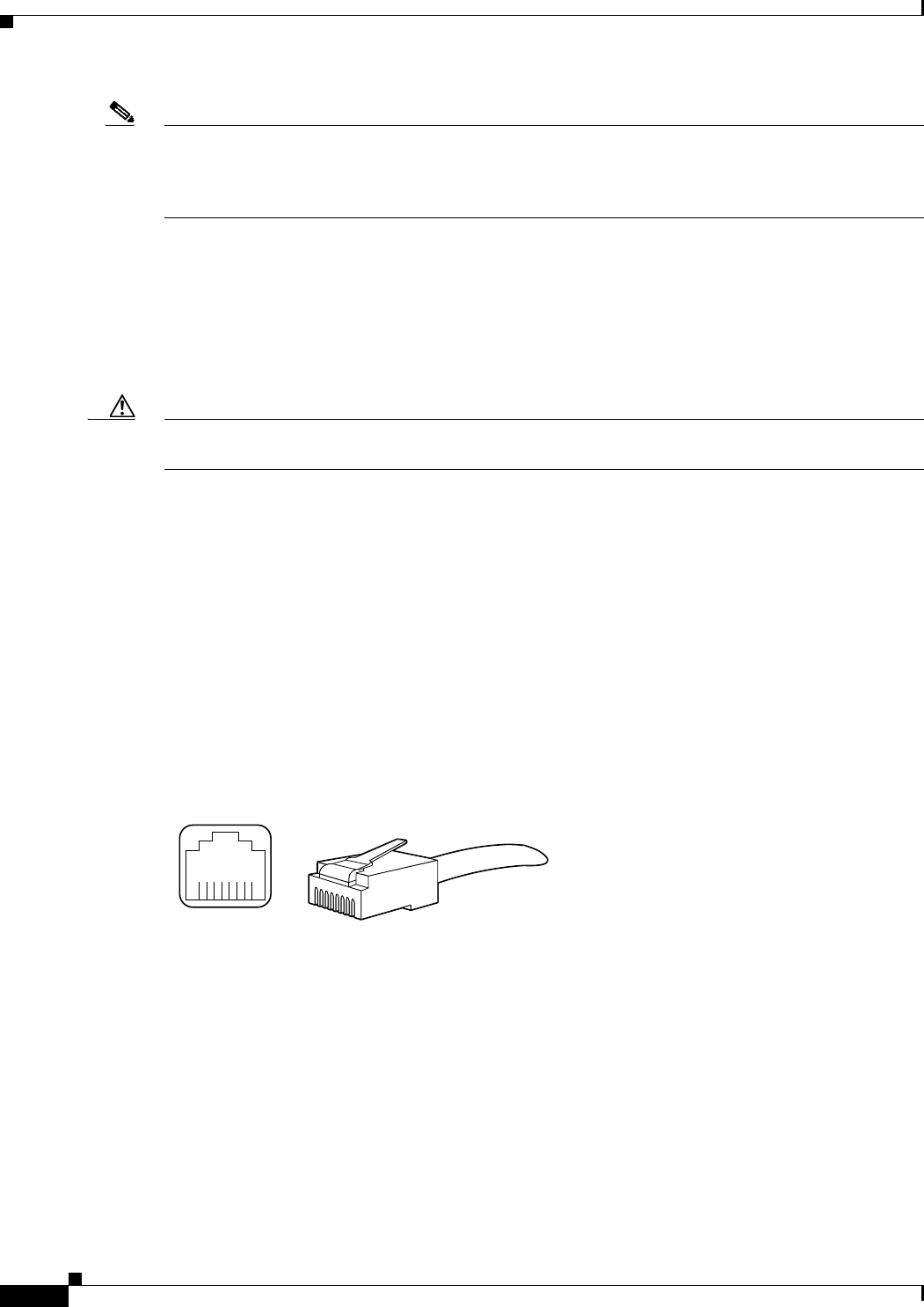
B-2
Cisco uBR10012 Universal Broadband Router Hardware Installation Guide
OL-18259-10
Appendix B Cable Specifications
Console and Auxiliary Port Cables and Pinouts
Note Any of the three of the coaxial cables listed can be used to connect a Cisco cable interface card to the
HFC network; however, the consistent use of 59-series cable is preferred. If you connect an 59-series
cable to a cable interface card that was previously connected using 6-series cable, the difference in the
center connector diameter might cause intermittent connectivity loss.
If you use different types of coaxial cable, the following problems can appear:
•Damage to Cisco uBR10012 router cable interface card connectors—Cable interface card
connectors are designed for 59-series or 6-series cable and connectors. Larger cables can damage
the connectors.
•Poor return loss—High quality cable and correct connectors help to ensure an optimal return loss of
16 dB or more.
Caution Poorly shielded coaxial cable may result in undesired signal leakage (egress), interference from
over-the-air signals (ingress), or crosstalk between cables in close physical proximity.
Console and Auxiliary Port Cables and Pinouts
The router arrives with a console and auxiliary cable kit, which contains the cable and adapters you need
to connect a console (an ASCII terminal or PC running terminal emulation software) or modem to the
router. The console and auxiliary cable kit includes:
•RJ-45-to-RJ-45 rollover cable
•RJ-45-to-DB-9 female data terminal equipment (DTE) adapter labeled TERMINAL
•RJ-45-to-DB-25 male data communications equipment (DCE) adapter labeled MODEM
Figure B-1 shows the RJ-45 cable connector.
Figure B-1 RJ-45 Plug and Receptacle
H2936
8 7 6 5 4 3 2 1
RJ-45 connector
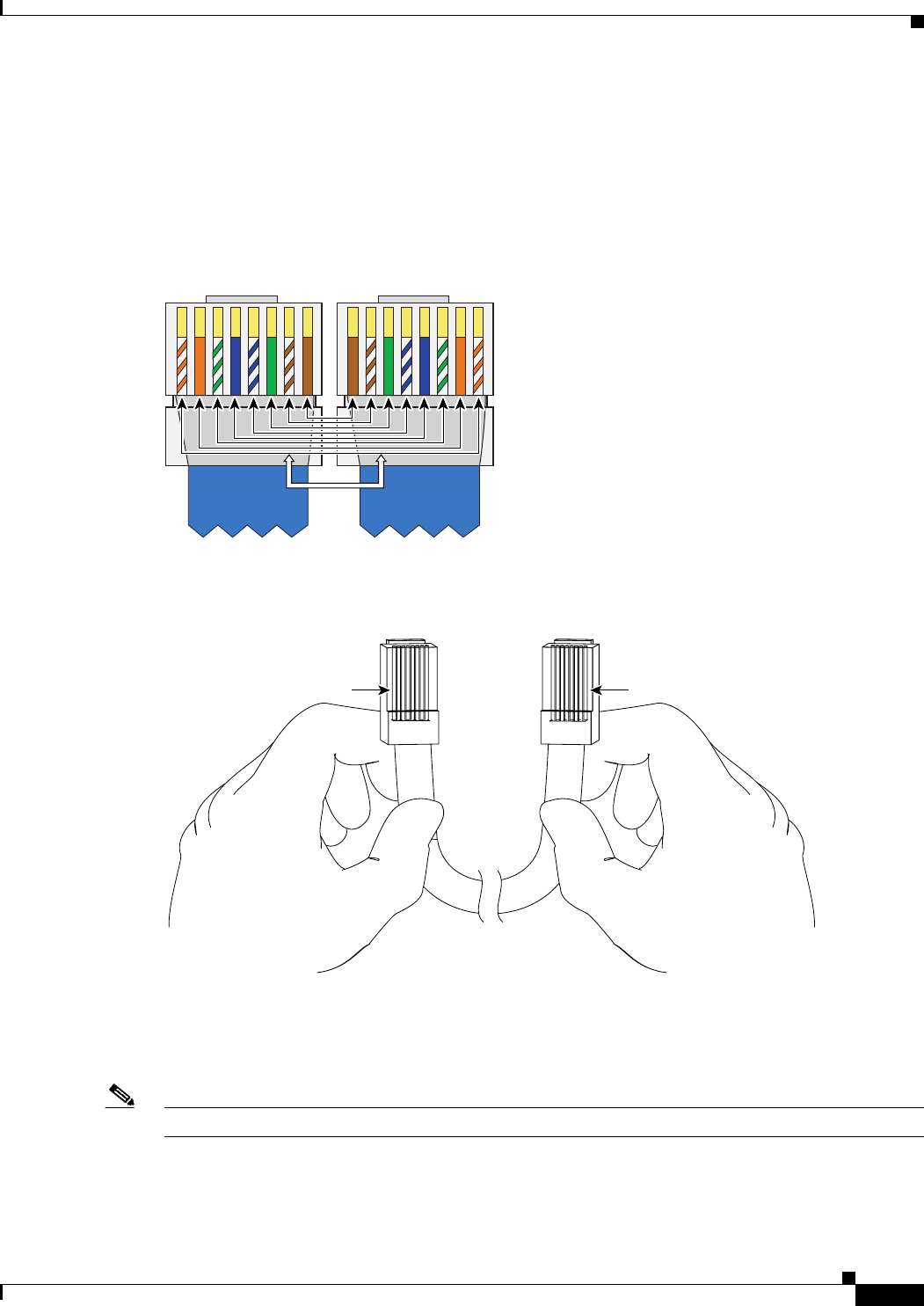
B-3
Cisco uBR10012 Universal Broadband Router Hardware Installation Guide
OL-18259-10
Appendix B Cable Specifications
Console and Auxiliary Port Cables and Pinouts
How to Identify an RJ-45 Rollover Cable
You can identify a rollover cable by holding the two ends of the cable next to each other, with the tab at
the back. The wire connected to the pin on the outside of the left hand plug should be the same color as
as the wire connected to the pin on the right hand plug, as shown in Figure B-3.
Figure B-2 Rollover Cable
Figure B-3 RJ-45 Rollover Cable Identification
The colored wires at one connector are in the reverse order at the other connector (reverses pins 1 and 8,
2 and 7, 3 and 6, 4 and 5, 5 and 4, 6 and 3, 7 and 2, 8 and 1).
A straight-through cable wires are in the same sequence at both ends of the cable.
Note If your cable was purchased from Cisco Systems, pin 8 is white.
12345678
127840
12345678
Roll overRoll over
Pin 1 Pin 8
H3824
Pin 1 and pin 8
should be the
same color
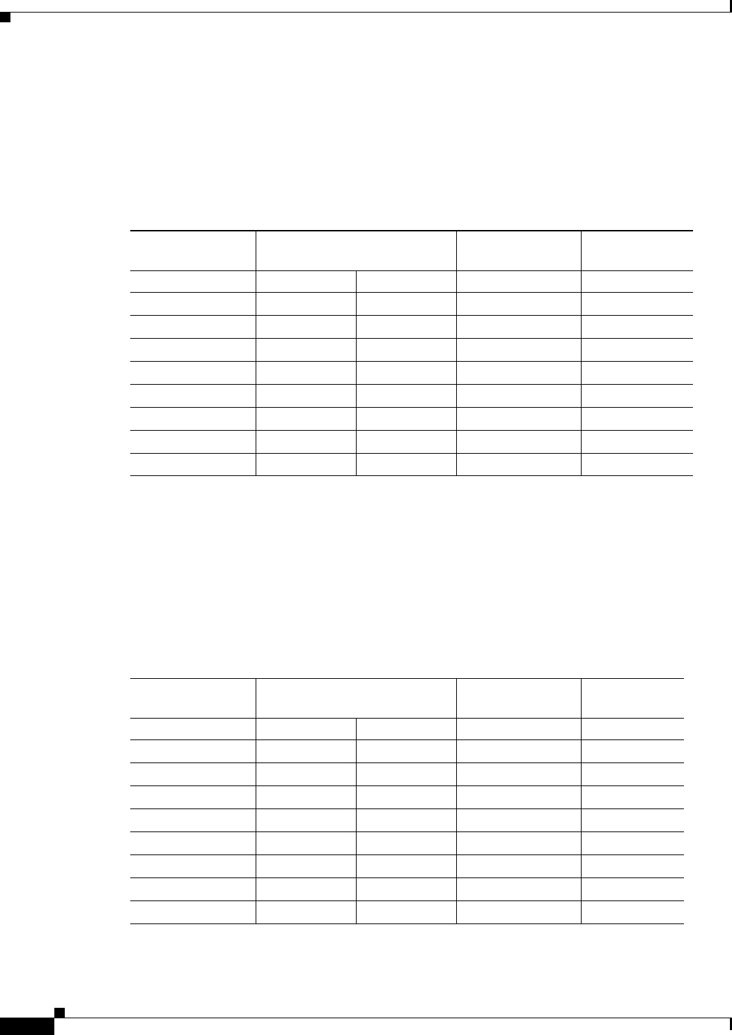
B-4
Cisco uBR10012 Universal Broadband Router Hardware Installation Guide
OL-18259-10
Appendix B Cable Specifications
Console and Auxiliary Port Cables and Pinouts
Console Port Cables and Pinouts
Use the RJ-45-to-RJ-45 rollover cable and RJ-45-to-DB-9 female DTE adapter (labeled TERMINAL) to
connect the console port to a PC running terminal emulation software. Table B-1 lists the signals and
pinouts for the asynchronous serial console port, the RJ-45-to-RJ-45 rollover cable, and the
RJ-45-to-DB-9 female DTE adapter.
Auxiliary Port Cables and Pinouts
Use the RJ-45-to-RJ-45 rollover cable and RJ-45-to-DB-25 male DCE adapter (labeled MODEM) to
connect the auxiliary port to a modem. Table B-2 lists the signals and pinouts for the asynchronous serial
auxiliary port, the RJ-45-to-RJ-45 rollover cable, and the RJ-45-to-DB-25 male DCE adapter (labeled
MODEM).
Table B-1 Console Port Signaling and Cabling Using a DB-9 Adapter
Console Port (DTE) RJ-45-to-RJ-45 Rollover Cable
RJ-45-to-DB-9
Terminal Adapter Console Device
Signal RJ-45 Pin RJ-45 Pin DB-9 Pin Signal
RTS 11
1. Pin 1 is connected internally to pin 8.
88 CTS
DTR 276 DSR
TxD 362 RxD
GND455 GND
GND545 GND
RxD 633 TxD
DSR 724 DTR
CTS 8117 RTS
Table B-2 Auxiliary Port Signaling
AUX Port (DTE) RJ-45-to-RJ-45 Rollover Cable
RJ-45-to-DB-25
Modem Adapter Modem (DCE)
Signal RJ-45 Pin RJ-45 Pin DB-25 Pin Signal
RTS 1 8 4 RTS
DTR 2720 DTR
TxD 363 TxD
GND 4 5 7 GND
GND 5 4 7 GND
RxD 6 3 2 RxD
DSR 7 2 8 DCD
CTS 8 1 5 CTS
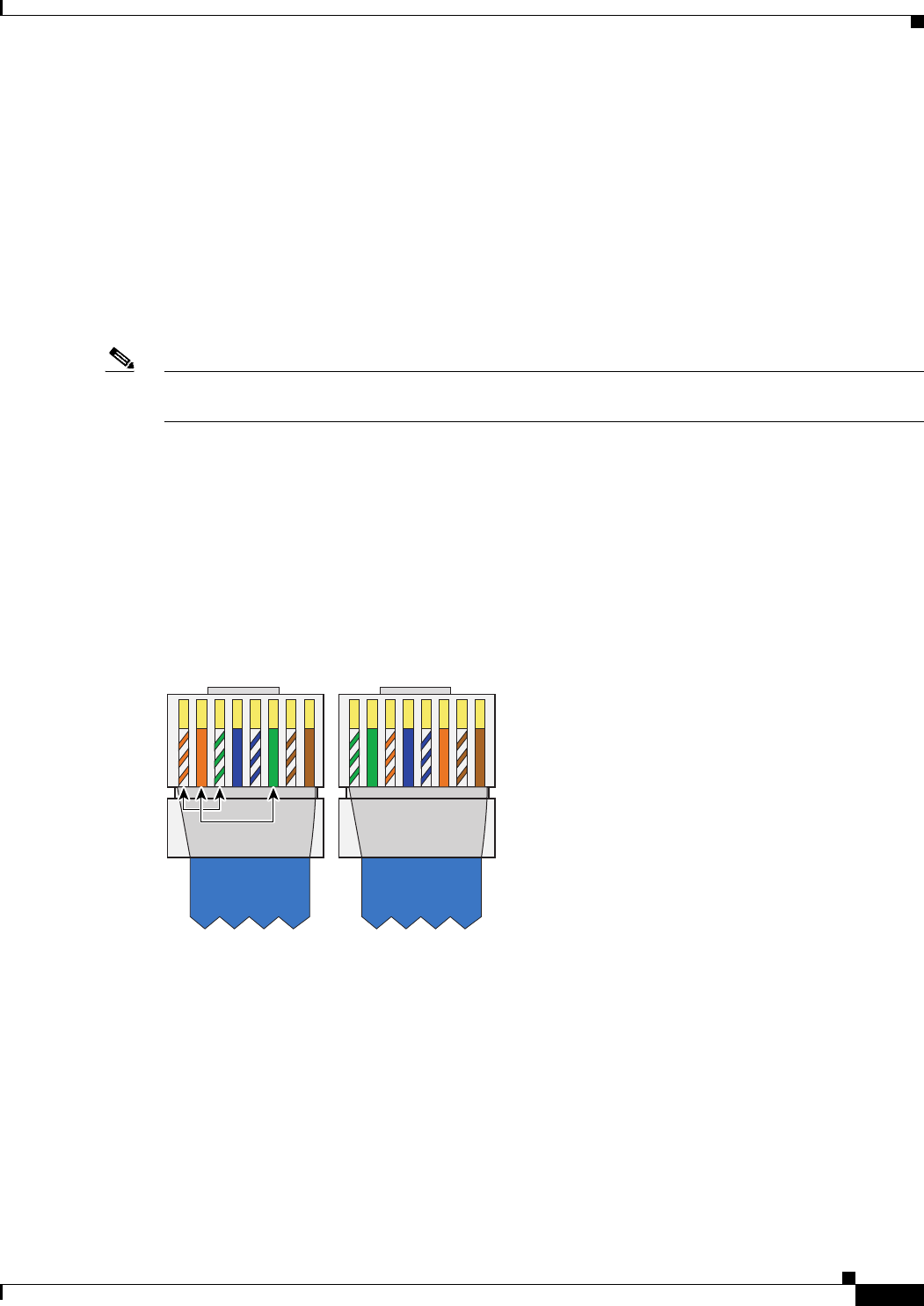
B-5
Cisco uBR10012 Universal Broadband Router Hardware Installation Guide
OL-18259-10
Appendix B Cable Specifications
Fast Ethernet Port Cables and Pinouts
Fast Ethernet Port Cables and Pinouts
The 10Base-T/100Base-TX Fast Ethernet ports support IEEE 802.3 and IEEE 802.3u specifications for
10-Mbps and 100-Mbps transmission over unshielded twisted-pair (UTP) cables. Each Fast Ethernet port
on the router has an RJ-45 connector to attach to Category 3 or Category 5 UTP cables.
•Use a Category 3 UTP crossover cable when connecting 10Base-T port to a hub.
•Use a Category 3 UTP straight-through cable when connecting to a PC or other Ethernet device.
•Use a Category 5 UTP crossover cable when connecting 100Base-TX to a hub.
•Use a Category 5 UTP straight-through cable when connecting to a PC or other Ethernet device.
Note Cisco Systems does not supply Category 3 or Category 5 UTP RJ-45 cables; these cables are available
commercially.
How to Identify an RJ-45 Crossover Cable
You can identify a crossover cable by comparing the two modular ends of the cable. Hold the cables
side-by-side with the tab at the back. The first (far left) colored wire (pin 1) at one end of the cable is
the third colored wire (pin 3) at the other end of the cable. The second colored wire (pin 2) at one end
of the cable is the sixth colored wire (pin 6) at the other end of the cable. See Figure B-4.
Figure B-4 Crossover Cable
12345678
127839
12345678
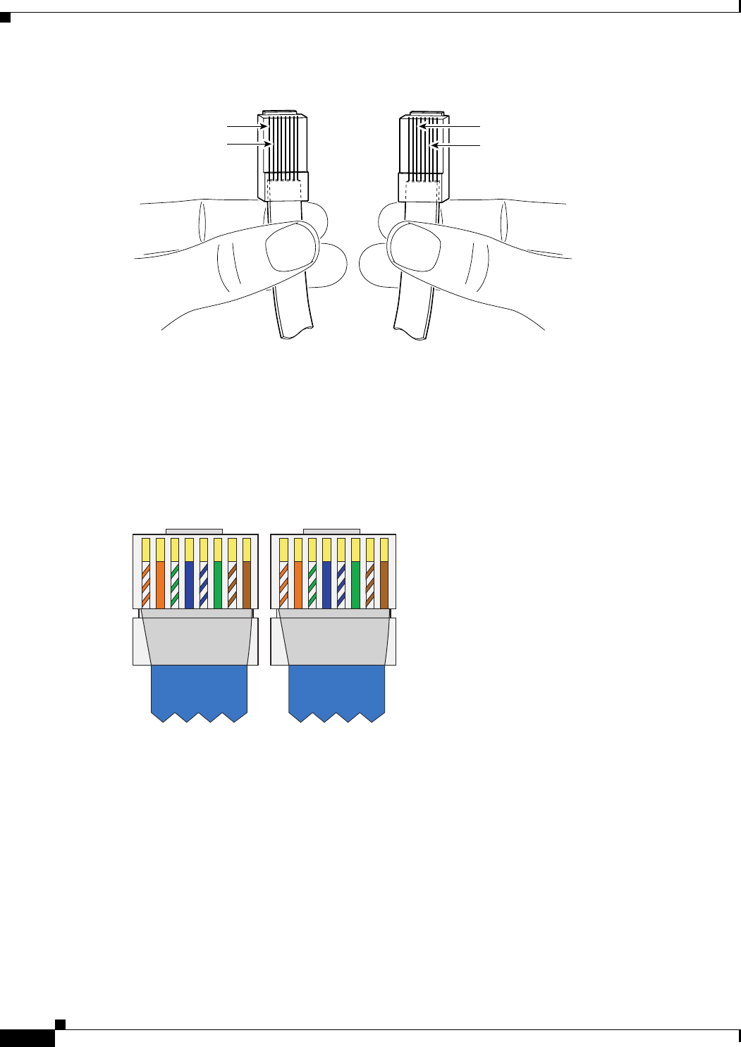
B-6
Cisco uBR10012 Universal Broadband Router Hardware Installation Guide
OL-18259-10
Appendix B Cable Specifications
Fast Ethernet Port Cables and Pinouts
Figure B-5 RJ-45 Crossover Cable Identification
How to Identify an RJ-45 Straight-Through Cable
You can identify a Straight-through cable by comparing the two modular ends of the cable. Hold the
cables side-by-side with the tab at the back. A straight-through cable wires are in the same sequence at
both ends of the cable. See Figure B-6.
Figure B-6 Straight-through Cable
62741
Pin 1
Pin 2
Pin 3
Pin 6
12345678
127838
12345678
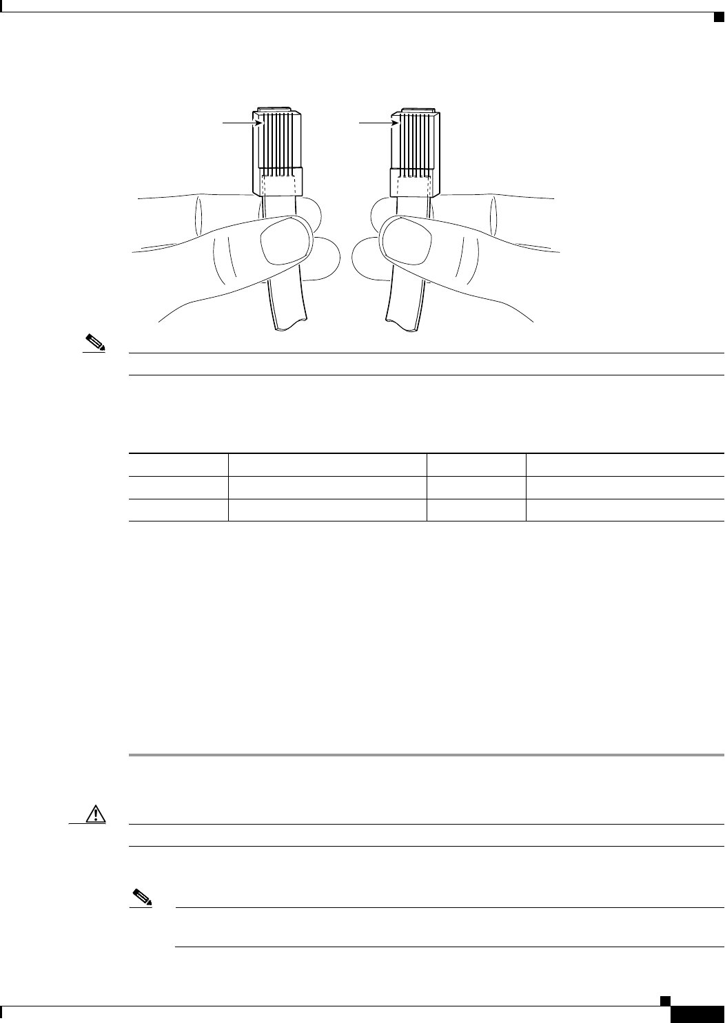
B-7
Cisco uBR10012 Universal Broadband Router Hardware Installation Guide
OL-18259-10
Appendix B Cable Specifications
Connecting a Cable to an RJ-45 Connector
Figure B-7 RJ-45 Straight-Through Cable Identification
Note If your cable was purchased from Cisco Systems, pin 1 is white.
Table B-3 lists the pinouts for the two Fast Ethernet ports.
Connecting a Cable to an RJ-45 Connector
Use the following information to build your own cables with RJ45 connectors.
Tools
•Category 3cable or Category 5 cable
•RJ45 connectors
•Wire stripping tool
•Crimping tool—for the RJ45 connector
Step 1 Use the wire stripper to cut the outer jacket of the wire about 1 inch to 1.5 inches from the end of the
cable.
Caution When cutting the cable jacket, make sure that you do not damage the wires in the jacket.
Step 2 Arrange the wires in the order that you want to install them into the RJ45 connector.
Note The order of the wires is dependant on what type of connection you are making: crossover,
rollover, or straight-through.
62740
Pin 1 Pin 1
Table B-3 10Base-T RJ-45 Connector Pinouts
RJ-45 Pin Description RJ-45 Pin Description
1Tx+ 3Rx+
2Tx– 6Rx–
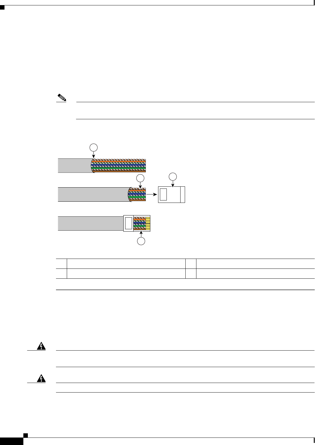
B-8
Cisco uBR10012 Universal Broadband Router Hardware Installation Guide
OL-18259-10
Appendix B Cable Specifications
Fiber-Optic Cables and Connectors
Step 3 After arranging the wires in the correct order, cut them back so there is about 1/2 inch available to install
in the connector.
Step 4 Push the cable into the connector so that the jacket is past the plastic wedge at the rear of the connector
and the wires are at the end of the connector underneath the gold crimping pins. Make sure each wire
goes into the appropriate location.
Step 5 Use your crimping tool to crimp the cable. Check your connection by tugging slightly on the cable.
Recrimp as necessary.
Note When you use the crimping tool, the plastic wedge is pressed into the cable jacket to hold the
cable in place and the crimping pins are pushed down into the wires in the connector channels.
Figure B-8 Installing Cable in an RJ45 Connector
Fiber-Optic Cables and Connectors
The following warnings apply when you work with fiber-optic cables and ports.
Warning
Invisible laser radiation may be emitted from disconnected fibers or connectors. Do not stare into
beams or view directly with optical instruments.
Statement 1051
Warning
Laser radiation is present when the system is open and interlocks are bypassed.
Statement 1009
127878
1
3
2
4
1Jacket cut here 3RJ45 connector
2Wire cut to one half inch in length 4Cable installed in RJ45 connector
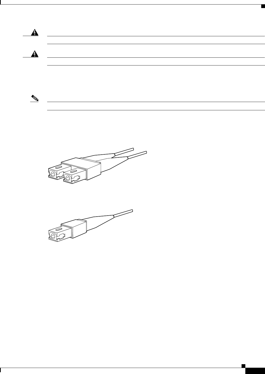
B-9
Cisco uBR10012 Universal Broadband Router Hardware Installation Guide
OL-18259-10
Appendix B Cable Specifications
Fiber-Optic Cables and Connectors
Warning
Class 1 laser product
Statement 1008
Warning
Class 1 LED product
Statement 1027
Use a single-mode or multimode fiber-optic interface cable to connect your Cisco uBR10012 router to
another router or switch.
In general, multimode cables are gray or orange, and single-mode cables are yellow.
Note Single-mode and multimode fiber-optic cables are not available from Cisco Systems, Inc.
For SONET or SDH single-mode and multimode fiber-optic connections, use one duplex SC-type
connector (Figure B-9) or two simplex SC-type connectors. (See Figure B-10.)
Figure B-9 Duplex SC Cable Connector
Figure B-10 Simplex SC Cable Connector
Attach either one duplex fiber cable or two simplex fiber cables between the DPT port adapter and the
device to which the DPT port adapter is connected.
Observe the receive (RX) and transmit (TX) cable relationship shown in Figure B-11.
38548
38547
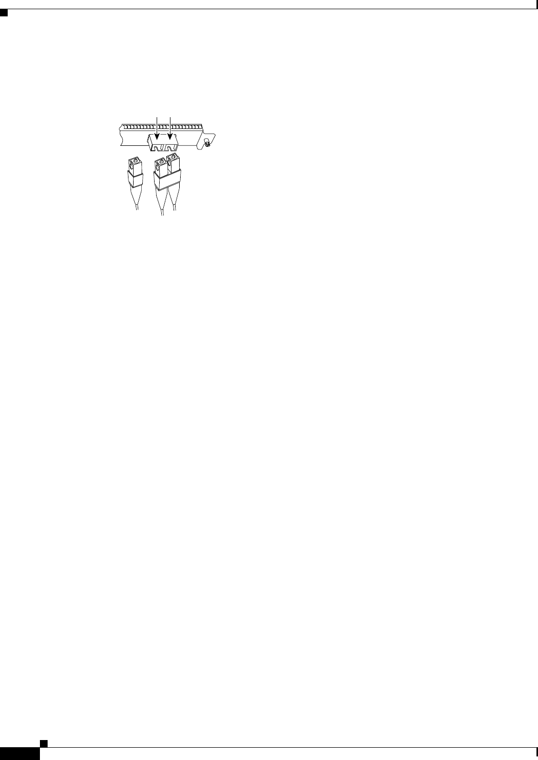
B-10
Cisco uBR10012 Universal Broadband Router Hardware Installation Guide
OL-18259-10
Appendix B Cable Specifications
Fiber-Optic Cables and Connectors
Figure B-11 Attaching Simplex or Duplex Fiber-Optic Cables
25168
SONET/SDH with simplex
or duplex SC connectors
To network
Simplex
RX TX
Duplex

C-1
Cisco uBR10012 Universal Broadband Router Hardware Installation Guide
APPENDIX
C
Frequency Allocation
This appendix provides information on broadcast and cable television NTSC and PAL/SECAM
standards and frequencies used around the world.
There are three standards for transmitting video. They are defined by the method of encoding color onto
a monochrome signal. The methods are defined as:
•NTSC—National Television System Committee.
NTSC is the current standard used for analog television in the United States and elsewhere. NTSC
supports color television transmission in a 6 MHz channel bandwidth and has 525 interlaced scan
lines. Two fields are interlaced to make one frame with a frame rate of 29.97 frames per second and
a field rate of 59.94 fields per second. A fraction (~8%) of the available bandwidth is used for signal
synchronization between the transmitter and the receiver giving an effective resolution of 640x480.
The aspect ratio, or ratio of picture width to picture height, is 4:3.
•PAL—Phase Alternating Line.
PAL is a composite color system similar to NTSC. In PAL, however, the color difference signals
alternate phase at the horizontal line rate. PAL video consists of a 625-line frame, a frame rate of 25
Hz, and a field rate of 50 Hz. As with NTSC, ~8% of the available bandwidth is used for
synchronization yielding an effective resolution of 768x576. The aspect ratio is 4:3. The PAL
standard and it's variants are used primarily in Europe, China, Asia, Africa, Australia, Brazil, and
Argentina.
•SECAM—SEquential Couleur Avec Memoire.
SECAM is a color television broadcasting system using 625 picture lines and a 50-hertz (Hz) field
rate, in which the two color-difference signals are transmitted sequentially instead of
simultaneously.
General NTSC information is covered in Table C-4 and Table C-5. General PAL/SECAM information is
covered in Table C-7. Use the information in Table C-1, Table C-2, and Table C-3 to compare analog
television standards used around the world.
Check these Web sites for more information about world-wide frequency allocation.
http://www.blondertongue.com/CATV-Broadband-Reference-Literature
http://www.geo-orbit.org/sizepgs/ntscp.html#anchor1016493
http://www.acterna.com
http://www.apple.com
http://www.c-cor.com
http://www.atxincorporated.com
http://www.alkenmrs.com
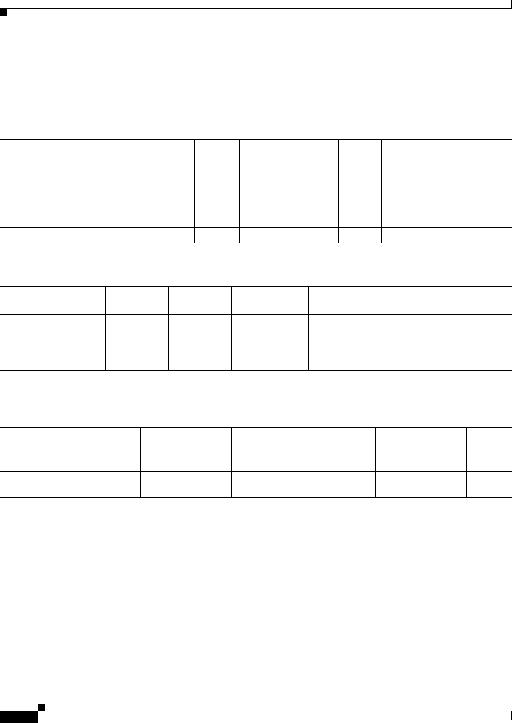
C-2
Cisco uBR10012 Universal Broadband Router Hardware Installation Guide
Appendix C Frequency Allocation
Standards Comparisons
Standards Comparisons
The following tables (Table C-1, Table C-2, and Table C-3) include data from Recommendation ITU-R
BT.470.6, Conventional Television Systems (1998) and provide a comparison of the different standards.
Table C-1 Analog Television System Baseband Video Parameters
M N B, B1, D1, G H I D, K K1 L
Lines per frame 525 625 625 625 625 625 625 625
Field rate (Hz) Monochrome: 60
Color: 59.94
50 50 50 50 50 50 50
Horizontal rate (Hz) Monochrome: 15,750
Color: 15,734.264
15,625 15,625 15,625 15,625 15,625 15,625 15,625
Video bandwidth (Mhz) 4.2 4.2 5 5 5.5 6 6 6
Table C-2 Analog Television Chrominance Subcarrier Frequencies
M/NTSC M/PAL
B, B1, D, D1, G, H,
K, N/PAL I/PAL
B, D, G, H, K, K1,
L/SECAM N/PAL1
1. This value applies to the combination N/PAL used in Argentina.
Chrominance subcarrier
frequency (Hz) 3,579,545
± 10
3,575611.49
± 10
4,433,618.75
± 5
4,433,618.75
± 1
fOR =4,406,250
± 2,000
fOB =4,250,000
± 2,000
3,582,056.25
± 5
Table C-3 Analog Television System RF Parameters
M N B, B1, G H I D, D1, K K1 L
Channel bandwidth at RF (MHz) 66B=7
B1, G=8
88888
Frequency separation between
visual and aural carrier (MHz) 4.5 4.5 5.5 5.5 5.9996 6.5 6.5 6.5

C-3
Cisco uBR10012 Universal Broadband Router Hardware Installation Guide
Appendix C Frequency Allocation
NTSC Cable Television Channels and Relative Frequencies
NTSC Cable Television Channels and Relative Frequencies
Table C-4 provides information on the NTSC frequency map for standard 6-MHz channels in North,
Central, and South America as well as parts of Asia. Table C-5 lists NTSC assignments for Japan.
Table C-4 NTSC Cable Television Channels and Relative Frequencies
Channel
No.1Channel
No., EIA
Bandwidth
(MHz)
Visual
Carrier (MHz)
Center
Freq.
Aural Carrier
(MHz)
Incrementally Related
Carrier
Harmonically Related
Carrier
Visual Aural Visual Aural
T-7 none 5.75-11.75 7 8.75 11.5 N/A N/A N/A N/A
T-8 none 11.75-17.75 13 14.75 17.5 N/A N/A N/A N/A
T-9 none 17.75-23.75 19 10.75 23.5 N/A N/A N/A N/A
T-10 none 23.75-29.75 25 26.75 29.5 N/A N/A N/A N/A
T-11 none 29.75-35.75 31 32.75 35.5 N/A N/A N/A N/A
T-12 none 35.75-41.75 37 38.75 41.5 N/A N/A N/A N/A
T-13 none 41.75-47.75 43 44.75 47.5 N/A N/A N/A N/A
TV-IF none 40.0-46.0 45.75 44.0 41.25 N/A N/A N/A N/A
2 2 54.0-60.0 55.25 57.0 59.75 55.2625 59.7625 54.0027 58.5027
3 3 60.0-66.0 61.25 63.0 65.75 61.2625 65.7625 60.0030 64.5030
4 4 66.0-72.0 67.25 69.0 71.75 67.2625 71.7625 66.0033 70.5030
5 5 76.0-82.0 77.25 79.0 81.75 79.2625 83.7625 78.0039 82.5039
6 6 82.0-88.0 83.25 85.0 87.75 85.2625 89.7625 84.0042 88.5042
FM 88.0-108.0
A-5 95 90.0-96.0 91.25 93.0 95.75 91.2625 95.7625 90.0045 94.5045
A-4 96 96.0-102.0 97.25 99.0 101.75 97.2625 101.7625 96.0048 100.5048
A-3 97 102.0-108.0 103.25 105.0 107.75 103.2625 107.7625 102.0051 106.5051
A-2 982108.0-114.0 109.25 111.0 113.75 109.2750 113.7750 Cannot lock to comb
A-1 992114.0-120.0 115.25 117.0 119.75 115.2750 119.7750 Reference channel,
Refer to FCC
regulations
A14
2120.0-126.0 121.25 123.0 125.75 121.2625 125.7625 120.0060 124.5060
B15
2126.0-132.0 127.25 129.0 131.75 127.2625 131.7625 126.0063 130.5063
C16
2132.0-138.0 133.25 135.0 137.75 133.2625 137.7625 132.0066 136.5066
D 17 138.0-144.0 139.25 141.0 143.75 139.2625 143.7625 138.0069 142.5069
E 18 144.0-150.0 145.25 147.0 149.75 145.2625 149.7625 144.0072 148.5072
F 19 150.0-156.0 151.25 153.0 155.75 151.2625 155.7625 150.0075 154.5075
G 20 156.0-162.0 157.25 159.0 161.75 157.2625 161.7625 156.0078 160.5078
H 21 162.0-168.0 163.25 165.0 167.75 163.2625 167.7625 162.0081 166.5081
I 22 168.0-174.0 169.25 171.0 173.75 169.2625 173.7625 168.0084 172.5084
7 7 174.0-180.0 175.25 177.0 179.75 175.2625 179.7625 174.0087 178.5087

C-4
Cisco uBR10012 Universal Broadband Router Hardware Installation Guide
Appendix C Frequency Allocation
NTSC Cable Television Channels and Relative Frequencies
8 8 180.0-186.0 181.25 183.0 185.75 181.2625 185.7625 180.0090 184.5090
9 9 186.0-192.0 187.25 189.0 191.75 187.2625 191.7625 186.0093 190.5093
10 10 192.0-198.0 193.25 195.0 197.75 193.2625 197.7625 192.0096 196.5096
11 11 198.0-204.0 199.25 201.0 203.75 199.2625 203.7625 198.0099 202.5099
12 12 204.0-210.0 205.25 207.0 209.75 205.2625 209.7625 204.0102 208.5102
13 13 210.0-216.0 211.25 213.0 215.75 211.2625 215.7625 210.0105 214.5105
J 23 216.0-222.0 217.25 219.0 221.75 217.2625 211.7625 216.0108 220.5108
K24
2222.0-228.0 223.25 225.0 227.75 223.2625 227.7625 222.0111 226.5111
L25
2228.0-234.0 229.25 231.0 233.75 229.2625 233.7625 228.0114 232.5114
M26
2234.0-240.0 235.25 237.0 239.75 235.2625 239.7625 234.0117 238.5117
N27
2240.0-246.0 241.25 243.0 245.75 241.2625 245.7625 240.0120 244.5120
O28
2246.0-252.0 247.25 249.0 251.75 247.2625 251.7625 246.0123 250.5123
P29
2252.0-258.0 253.25 255.0 257.75 253.2625 257.7625 252.0126 256.5126
Q30
2258.0-264.0 259.25 261.0 263.75 259.2625 263.7625 258.0129 262.5129
R31
2264.0-270.0 265.25 267.0 269.75 265.2625 269.7625 264.0132 268.5132
S32
2270.0-276.0 271.25 273.0 275.75 271.2625 275.7625 270.0135 274.5135
T33
2276.0-282.0 277.25 279.0 281.75 277.2625 281.7625 276.0138 270.5138
U34
2282.0-288.0 283.25 285.0 287.75 283.2625 287.7625 282.0141 286.5141
V35
2288.0-294.0 289.25 291.0 293.75 289.2625 293.7625 288.0144 292.5144
W36
2294.0-300.0 295.25 297.0 299.75 295.2625 299.7625 294.0147 298.5147
AA 372300.0-306.0 301.25 303.0 305.75 301.2625 305.7625 300.0150 304.5150
BB 382306.0-312.0 307.25 309.0 311.75 307.2625 311.7625 306.0153 310.5153
CC 392312.0-318.0 313.25 315.0 317.75 313.2625 317.7625 312.0156 316.5156
DD 402318.0-324.0 319.25 321.0 323.75 319.2625 323.7625 318.0159 322.5159
EE 412324.0-330.0 325.25 327.0 329.75 325.2625 329.7625 324.0162 328.5162
FF 422330.0-336.0 331.25 333.0 335.75 331.2625 335.7625 330.0165 334.5165
GG 432336.0-342.0 337.25 339.0 341.75 337.2625 341.7625 336.0168 340.5168
HH 442342.0-348.0 343.25 345.0 347.75 343.2625 347.7625 342.0171 346.5171
II 452348.0-354.0 349.25 351.0 353.75 349.2625 353.7625 348.0174 352.5174
JJ 462354.0-360.0 355.25 357.0 359.75 355.2625 359.7625 354.0177 358.5177
KK 472360.0-366.0 361.25 363.0 365.75 361.2625 365.7625 360.0180 364.5180
LL 482366.0-372.0 367.25 369.0 371.75 367.2625 371.7625 366.0183 370.5183
MM 492372.0-378.0 373.25 375.0 377.75 373.2625 377.7625 372.0186 376.5186
NN 502378.0-384.0 379.25 381.0 383.75 379.2625 383.7625 378.0189 382.5189
OO 512384.0-390.0 385.25 387.0 389.75 385.2625 389.7625 384.0192 388.5192
Table C-4 NTSC Cable Television Channels and Relative Frequencies (continued)
Channel
No.1Channel
No., EIA
Bandwidth
(MHz)
Visual
Carrier (MHz)
Center
Freq.
Aural Carrier
(MHz)
Incrementally Related
Carrier
Harmonically Related
Carrier
Visual Aural Visual Aural

C-5
Cisco uBR10012 Universal Broadband Router Hardware Installation Guide
Appendix C Frequency Allocation
NTSC Cable Television Channels and Relative Frequencies
PP 522390.0-396.0 391.25 393.0 395.75 391.2625 395.7625 390.0195 394.5195
QQ 532396.0-402.0 397.25 399.0 401.75 397.2625 401.7625 396.0198 400.5198
RR 54 402.0-408.0 403.25 405.0 407.75 403.2625 407.7625 402.0201 406.5201
SS 55 408.0-414.0 409.25 411.0 413.75 409.2625 413.7625 408.0204 412.5204
TT 56 414.0-420.0 415.25 417.0 419.75 415.2625 419.7625 414.0207 418.5207
UU 57 420.0-426.0 421.25 423.0 425.75 421.2625 425.7625 420.0210 424.5210
VV 58 426.0-432.0 427.25 429.0 431.75 427.2625 431.7625 426.0213 430.5213
WW 59 432.0-438.0 433.25 435.0 437.75 433.2625 437.7625 432.0216 436.5216
XX 60 438.0-444.0 439.25 441.0 443.75 439.2625 443.7625 438.0219 442.5219
YY 61 444.0-450.0 445.25 447.0 449.75 445.2625 449.7625 444.0222 448.5222
ZZ 62 450.0-456.0 451.25 453.0 455.75 451.2625 455.7625 450.0225 454.5225
63 456.0-462.0 457.25 459.0 461.75 457.2625 461.7625 456.0228 460.5228
64 462.0-468.0 463.25 465.0 467.75 463.2625 467.7625 462.0231 466.5231
65 468.0-474.0 469.25 471.0 473.75 469.2625 473.7625 468.0234 472.5234
66 474.0-480.0 475.25 477.0 479.75 475.2625 479.7625 474.0237 478.5237
67 480.0-486.0 481.25 483.0 485.75 481.2625 485.7625 480.0240 484.5240
68 486.0-492.0 487.25 489.0 491.75 487.2625 491.7625 486.0243 490.5243
69 492.0-498.0 493.25 495.0 497.75 493.2625 497.7625 492.0246 496.5246
70 498.0-504.0 499.25 501.0 503.75 499.2625 503.7625 498.0249 502.5249
71 504.0-510.0 505.25 507.0 509.75 505.2625 509.7625 504.0252 508.5252
72 510.0-516.0 511.25 513.0 515.75 511.2625 515.7625 510.0255 514.5255
73 516.0-522.0 517.25 519.0 521.75 517.2625 521.7625 516.0258 520.5258
74 522.0-528.0 523.25 525.0 527.75 523.2625 527.7625 522.0261 526.5261
75 528.0-534.0 529.25 531.0 533.75 529.2625 533.7625 528.0264 532.5264
76 534.0-540.0 535.25 537.0 539.75 535.2625 539.7625 534.0267 538.5267
77 540.0-546.0 541.25 543.0 545.75 541.2625 545.7625 540.0270 544.5270
78 546.0-552.0 547.25 549.0 551.75 547.2625 551.7625 556.0273 550.5273
79 552.0-558.0 553.25 555.0 557.75 553.2625 557.7625 552.0276 556.5276
80 558.0-564.0 559.25 561.0 563.75 559.2625 563.7625 558.0279 562.5279
81 564.0-570.0 565.25 567.0 569.75 565.2625 569.7625 564.0282 568.5282
82 570.0-576.0 571.25 573.0 575.75 571.2625 575.7625 570.0285 574.5285
83 576.0-582.0 577.25 579.0 581.75 577.2625 581.7625 576.0288 580.5288
84 582.0-588.0 583.25 585.0 587.75 583.2625 587.7625 582.0291 586.5291
85 588.0-594.0 589.25 591.0 593.75 589.2625 593.7625 588.0294 592.5294
86 594.0-600.0 595.25 597.0 599.75 595.2625 599.7625 594.0297 598.5297
Table C-4 NTSC Cable Television Channels and Relative Frequencies (continued)
Channel
No.1Channel
No., EIA
Bandwidth
(MHz)
Visual
Carrier (MHz)
Center
Freq.
Aural Carrier
(MHz)
Incrementally Related
Carrier
Harmonically Related
Carrier
Visual Aural Visual Aural

C-6
Cisco uBR10012 Universal Broadband Router Hardware Installation Guide
Appendix C Frequency Allocation
NTSC Cable Television Channels and Relative Frequencies
87 600.0-606.0 601.25 603.0 605.75 601.2625 605.7625 600.0300 604.5300
88 606.0-612.0 607.25 609.0 611.75 607.2625 611.7625 606.0303 610.5303
89 612.0-618.0 613.25 615.0 617.75 613.2625 617.7625 612.0306 616.5306
90 618.0-624.0 619.25 621.0 623.75 619.2625 623.7625 618.0309 622.5309
91 624.0-630.0 625.25 627.0 629.75 625.2625 629.7625 624.0312 628.5312
92 630.0-636.0 631.25 633.0 635.75 631.2625 635.7625 630.0315 634.5315
93 636.0-642.0 637.25 639.0 641.75 637.2625 641.7625 636.0318 640.5318
94 642.0-648.0 643.25 645.0 647.75 643.2625 647.7625 642.0321 646.5321
100 648.0-654.0 649.25 651.0 653.75 649.2625 653.7625 648.0324 652.5324
101 654.0-660.0 655.25 657.0 659.75 655.2625 659.7625 654.0327 658.5327
102 660.0-666.0 661.25 663.0 665.75 661.2625 665.7625 660.0330 664.5330
103 666.0-672.0 667.25 669.0 671.75 667.2625 671.7625 666.0333 670.5333
104 672.0-678.0 673.25 675.0 677.75 673.2625 677.7625 672.0336 676.5336
105 678.0-684.0 679.25 681.0 683.75 679.2625 683.7625 678.0339 682.5339
106 684.0-690.0 685.25 687.0 689.75 685.2625 689.7625 684.0342 688.5342
107 690.0-696.0 691.25 693.0 695.75 691.2625 695.7625 690.0345 694.5345
108 696.0-702.0 697.25 699.0 701.75 697.2625 701.7625 696.0348 700.5348
109 702.0-708.0 703.25 705.0 707.75 703.2625 707.7625 702.0351 706.5351
110 708.0-714.0 709.25 711.0 713.75 709.2625 713.7625 708.0354 712.5354
111 714.0-720.0 715.25 717.0 719.75 715.2625 719.7625 714.0357 718.5357
112 720.0-726.0 721.25 723.0 725.75 721.2625 725.7625 720.0360 724.5360
113 726.0-732.0 727.25 729.0 731.75 727.2625 731.7625 726.0363 730.5363
114 732.0-738.0 733.25 735.0 737.75 733.2625 737.7625 732.0366 736.5366
115 738.0-744.0 739.25 741.0 743.75 739.2625 743.7625 738.0369 742.5369
116 744.0-750.0 745.25 747.0 749.75 745.2625 749.7625 744.0372 748.5372
117 750.0-756.0 751.25 753.0 755.75 751.2625 755.7625 750.0375 754.5375
118 756.0-762.0 757.25 759.0 761.75 757.2625 761.7625 756.0378 760.5378
119 762.0-768.0 763.25 765.0 767.75 763.2625 767.7625 762.0381 766.5381
120 768.0-674.0 769.25 771.0 773.75 769.2625 773.7625 768.0384 772.5384
121 774.0-780.0 775.25 777.0 779.75 775.2625 779.7625 774.0387 778.5387
122 780.0-786.0 781.25 783.0 785.75 781.2625 785.7625 780.0390 784.5390
123 786.0-792.0 787.25 789.0 791.75 787.2625 791.7625 786.0393 790.5393
124 792.0-798.0 793.25 795.0 797.75 793.2625 797.7625 792.0396 796.5396
125 798.0-804.0 799.25 801.0 803.75 799.2625 803.7625 798.0399 802.5399
126 804.0-810.0 805.25 807.0 809.75 805.2625 809.7625 804.0402 808.5402
Table C-4 NTSC Cable Television Channels and Relative Frequencies (continued)
Channel
No.1Channel
No., EIA
Bandwidth
(MHz)
Visual
Carrier (MHz)
Center
Freq.
Aural Carrier
(MHz)
Incrementally Related
Carrier
Harmonically Related
Carrier
Visual Aural Visual Aural

C-7
Cisco uBR10012 Universal Broadband Router Hardware Installation Guide
Appendix C Frequency Allocation
NTSC Cable Television Channels and Relative Frequencies
127 810.0-816.0 811.25 813.0 815.75 811.2625 815.7625 810.0405 814.5405
128 816.0-822.0 817.25 819.0 821.75 817.2625 821.7625 816.0408 820.5408
129 822.0-828.0 823.25 825.0 827.75 823.2625 827.7625 822.0411 826.5411
130 828.0-834.0 829.25 831.0 833.75 829.2625 833.7625 828.0414 832.5414
131 834.0-840.0 835.25 837.0 839.75 835.2625 839.7625 834.0417 838.5417
132 840.0-846.0 841.25 843.0 845.75 841.2625 845.7625 840.0420 844.5420
133 846.0-852.0 847.25 849.0 851.75 847.2625 851.7625 846.0423 850.5423
134 852.0-858.0 853.25 855.0 857.75 853.2625 857.7625 852.0426 856.5426
135 858.0-864.0 859.25 861.0 863.75 859.2625 863.7625 858.0429 862.5429
136 864.0-870.0 865.25 867.0 869.75 865.2625 869.7625 864.0432 868.5432
137 870.0-876.0 871.25 873.0 875.75 871.2625 875.7625 870.0435 874.5435
138 876.0-882.0 877.25 879.0 881.75 877.2625 881.7625 876.0438 880.5438
139 882.0-888.0 883.25 885.0 887.75 883.2625 887.7625 882.0441 886.5441
140 888.0-894.0 889.25 891.0 893.75 889.2625 893.7625 888.0444 892.5444
141 894.0-900.0 895.25 897.0 899.75 895.2625 899.7625 894.0447 898.5447
142 900.0-906.0 901.25 903.0 905.75 901.2625 905.7625 900.0450 904.5450
143 906.0-912.0 907.25 909.0 911.75 907.2625 911.7625 906.0453 910.5453
144 912.0-918.0 913.25 915.0 917.75 913.2625 917.7625 912.0456 916.5456
145 918.0-924.0 919.25 921.0 923.75 919.2625 923.7625 918.0459 922.5459
146 924.0-930.0 925.25 927.0 929.75 925.2625 929.7625 924.0462 928.5462
147 930.0-936.0 931.25 933.0 935.75 931.2625 935.7625 930.0465 934.5465
148 936.0-942.0 937.25 939.0 941.75 937.2625 941.7625 936.0468 940.5468
149 942.0-948.0 943.25 945.0 947.75 943.2625 947.7625 942.0471 946.5471
150 948.0-954.0 949.25 951.0 953.75 949.2625 953.7625 948.0474 952.5474
151 954.0-960.0 955.25 957.0 959.75 955.2625 959.7625 954.0477 958.5477
152 960.0-966.0 961.25 963.0 965.75 961.2625 965.7625 960.0480 964.5480
153 966.0-972.0 967.25 969.0 971.75 967.2625 971.7625 966.0483 970.5483
154 972.0-978.0 973.25 975.0 977.75 973.2625 977.7625 972.0486 976.5486
155 978.0-984.0 979.25 981.0 983.75 979.2625 983.7625 978.0489 982.5489
156 984.0-990.0 985.25 987.0 989.75 985.2625 989.7625 984.0492 988.5492
157 990.0-996.0 991.25 993.0 995.75 991.2625 995.7625 990.0495 994.5495
158 996.0-1002.0 997.25 999.0 1001.75 997.2625 1001.7625 996.0498 1000.5498
1. This column is for historical channel listings.
2. Aeronautical channels visual carrier frequency tolerance +/–5 kHz.
Table C-4 NTSC Cable Television Channels and Relative Frequencies (continued)
Channel
No.1Channel
No., EIA
Bandwidth
(MHz)
Visual
Carrier (MHz)
Center
Freq.
Aural Carrier
(MHz)
Incrementally Related
Carrier
Harmonically Related
Carrier
Visual Aural Visual Aural

C-8
Cisco uBR10012 Universal Broadband Router Hardware Installation Guide
Appendix C Frequency Allocation
NTSC (M) Cable Television Channel Frequencies for Japan
NTSC (M) Cable Television Channel Frequencies for Japan
Japan uses NTSC (M) with different channel assignments.
Table C-5 Japanese Channel Assignments
Channel Number
Bandwidth
(MHz)
Visual Carrier
(MHz) Center Frequency
Aural Carrier
(MHz)
1 90.0-96.0 91.25 93.00 95.75
2 96.0-102.0 97.25 99.00 101.75
3 102.0-108.0 103.25 105.00 107.75
4 170.0-176.0 171.25 173.00 175.75
5 176.0-182.0 177.25 179.00 181.75
6 182.0-188.0 183.25 185.00 187.75
7 188.0-194.0 189.25 191.00 193.75
8 192.0-198.0 193.25 195.00 197.75
9 198.0-204.0 199.25 201.00 203.75
10 204.0-210.0 205.25 207.00 209.75
11 210.0-216.0 211.25 213.00 215.75
12 216.0-222.0 217.25 219.00 221.75
C13 108.0-114.0 109.25 111.00 113.75
C14 114.0-120.0 115.25 117.00 119.75
C15 120.0-126.0 121.25 123.00 125.75
C16 126.0-132.0 125.25 129.00 131.75
C17 132.0-138.0 133.25 135.00 137.75
C18 138.0-144.0 139.25 141.00 143.75
C19 144.0-150.0 145.25 147.00 149.75
C20 150.0-156.0 151.25 153.00 155.75
C21 156.0-162.0 157.25 159.00 161.75
C22 164.0-170.0 165.25 167.00 169.75
C23 222.0-228.0 223.25 225.00 227.75
C24 230.0-236.0 231.25 233.00 235.75
C25 236.0-242.0 237.25 239.00 241.75
C26 242.0-248.0 243.25 245.00 247.75
C27 248.0-254.0 249.25 251.00 253.75
C28 254.0-258.0 253.25 257.00 257.75
C29 258.0-264.0 259.25 261.00 263.75
C30 264.0-270.0 265.25 267.00 269.75
C31 270.0-276.0 271.25 273.00 275.75
C32 276.0-282.0 277.25 279.00 281.75

C-9
Cisco uBR10012 Universal Broadband Router Hardware Installation Guide
Appendix C Frequency Allocation
NTSC (M) Cable Television Channel Frequencies for Japan
C33 282.0-288.0 283.25 285.00 287.75
C34 288.0-294.0 289.25 291.00 293.75
C35 294.0-300.0 295.25 297.00 299.75
C36 300.0-306.0 301.25 303.00 305.75
C37 306.0-312.0 307.25 309.00 311.75
C38 312.0-318.0 313.25 315.00 317.75
C39 318.0-324.0 319.25 321.00 323.75
C40 324.0-330.0 325.25 327.00 329.75
C41 330.0-336.0 331.25 333.00 335.75
C42 336.0-342.0 337.25 339.00 341.75
C43 342.0-348.0 343.25 345.00 347.75
C44 348.0-354.0 349.25 351.00 353.75
C45 354.0-360.0 355.25 357.00 359.75
C46 360.0-366.0 361.25 363.00 365.75
C47 366.0-372.0 367.25 369.00 371.75
C48 372.0-378.0 373.25 375.00 377.75
C49 378.0-384.0 379.25 381.00 383.75
C50 384.0-390.0 385.25 387.00 389.75
C51 390.0-396.0 391.25 393.00 395.75
C52 396.0-402.0 397.25 399.00 401.75
C53 402.0-408.0 403.25 405.00 407.75
C54 408.0-414.0 409.25 411.00 413.75
C55 414.0-420.0 415.25 417.00 419.75
C56 420.0-426.0 421.25 423.00 425.75
C57 426.0-432.0 427.25 429.00 431.75
C58 432.0-438.0 433.25 435.00 437.75
C59 438.0-444.0 439.25 441.00 443.75
C60 444.0-450.0 445.25 447.00 449.75
C61 450.0-456.0 451.25 453.00 455.75
C62 456.0-462.0 457.25 459.00 461.75
C63 462.0-468.0 463.25 465.00 467.75
Table C-5 Japanese Channel Assignments (continued)
Channel Number
Bandwidth
(MHz)
Visual Carrier
(MHz) Center Frequency
Aural Carrier
(MHz)
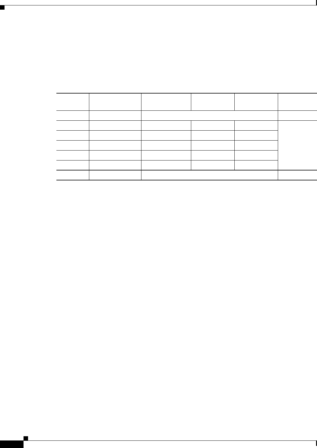
C-10
Cisco uBR10012 Universal Broadband Router Hardware Installation Guide
Appendix C Frequency Allocation
NTSC Cable Television Channel Frequencies for the Republic of Korea
NTSC Cable Television Channel Frequencies for the Republic of
Korea
Korea uses NTSC (VHF, UHF) with different channel assignments.
Table C-6 Korean Channel Assignments
Channel
Number
Bandwidth
(MHz)
Visual Carrier
(MHz)
Center
Frequency
Aural Carrier
(MHz) Usage
5.75-41.75 Return path
2 54.0-60.0 55.25 57.00 59.75
CATV
3 60.0-66.0 61.25 63.00 65.75
4 66.0-72.0 67.25 69.00 71.75
5 76.0-82.0 77.25 79.00 81.75
6 82.0-88.0 83.25 85.00 87.75
88.0-108 Music band

C-11
Cisco uBR10012 Universal Broadband Router Hardware Installation Guide
Appendix C Frequency Allocation
NTSC Cable Television Channel Frequencies for the Republic of Korea
14 120.0-126.0 121.25 123.0 125.75
CATV
15 126.0-132.0 127.25 129.0 131.75
16 132.0-138.0 133.25 135.0 137.75
17 138.0-144.0 139.25 141.0 143.75
18 144.0-150.0 145.25 147.0 149.75
19 150.0-156.0 151.25 153.0 155.75
20 156.0-162.0 157.25 159.0 161.75
21 162.0-168.0 163.25 165.0 167.75
22 168.0-174.0 169.25 171.0 173.75
7 174.0-180.0 175.25 177.0 179.75
8 180.0-186.0 181.25 183.0 185.75
9 186.0-192.0 187.25 189.0 191.75
10 192.0-198.0 193.25 195.0 197.75
11 198.0-204.0 199.25 201.0 203.75
12 204.0-210.0 205.25 207.0 209.75
13 210.0-216.0 211.25 213.0 215.75
23 216.0-222.0 217.25 219.0 221.75
241222.0-228.0 223.25 225.0 227.75
251228.0-234.0 229.25 231.0 233.75
261234.0-240.0 235.25 237.0 239.75
271240.0-246.0 241.25 243.0 245.75
281246.0-252.0 247.25 249.0 251.75
291252.0-258.0 253.25 255.0 257.75
301258.0-264.0 259.25 261.0 263.75
311264.0-270.0 265.25 267.0 269.75
Table C-6 Korean Channel Assignments (continued)
Channel
Number
Bandwidth
(MHz)
Visual Carrier
(MHz)
Center
Frequency
Aural Carrier
(MHz) Usage

C-12
Cisco uBR10012 Universal Broadband Router Hardware Installation Guide
Appendix C Frequency Allocation
NTSC Cable Television Channel Frequencies for the Republic of Korea
321270.0-276.0 271.25 273.0 275.75
CATV
331276.0-282.0 277.25 279.0 281.75
341282.0-288.0 283.25 285.0 287.75
351288.0-294.0 289.25 291.0 293.75
361294.0-300.0 295.25 297.0 299.75
371300.0-306.0 301.25 303.0 305.75
381306.0-312.0 307.25 309.0 311.75
391312.0-318.0 313.25 315.0 317.75
401318.0-324.0 319.25 321.0 323.75
411324.0-330.0 325.25 327.0 329.75
421330.0-336.0 331.25 333.0 335.75
431336.0-342.0 337.25 339.0 341.75
441342.0-348.0 343.25 345.0 347.75
451348.0-354.0 349.25 351.0 353.75
461354.0-360.0 355.25 357.0 359.75
471360.0-366.0 361.25 363.0 365.75
481366.0-372.0 367.25 369.0 371.75
491372.0-378.0 373.25 375.0 377.75
501378.0-384.0 379.25 381.0 383.75
511384.0-390.0 385.25 387.0 389.75
521390.0-396.0 391.25 393.0 395.75
531396.0-402.0 397.25 399.0 401.75
54 402.0-408.0 403.25 405.0 407.75
55 408.0-414.0 409.25 411.0 413.75
56 414.0-420.0 415.25 417.0 419.75
57 420.0-426.0 421.25 423.0 425.75
58 426.0-432.0 427.25 429.0 431.75
59 432.0-438.0 433.25 435.0 437.75
60 438.0-444.0 439.25 441.0 443.75
61 444.0-450.0 445.25 447.0 449.75
62 450.0-456.0 451.25 453.0 455.75
63 456.0-462.0 457.25 459.0 461.75
64 462.0-468.0 463.25 465.0 467.75
65 468.0-474.0 469.25 471.0 473.75
66 474.0-480.0 475.25 477.0 479.75
Table C-6 Korean Channel Assignments (continued)
Channel
Number
Bandwidth
(MHz)
Visual Carrier
(MHz)
Center
Frequency
Aural Carrier
(MHz) Usage

C-13
Cisco uBR10012 Universal Broadband Router Hardware Installation Guide
Appendix C Frequency Allocation
NTSC Cable Television Channel Frequencies for the Republic of Korea
67 480.0-486.0 481.25 483.0 485.75
CATV
68 486.0-492.0 487.25 489.0 491.75
69 492.0-498.0 493.25 495.0 497.75
70 498.0-504.0 499.25 501.0 503.75
71 504.0-510.0 505.25 507.0 509.75
72 510.0-516.0 511.25 513.0 515.75
73 516.0-522.0 517.25 519.0 521.75
74 522.0-528.0 523.25 525.0 527.75
75 528.0-534.0 529.25 531.0 533.75
76 534.0-540.0 535.25 537.0 539.75
77 540.0-546.0 541.25 543.0 545.75
78 546.0-552.0 547.25 549.0 551.75
79 552.0-558.0 553.25 555.0 557.75
80 558.0-564.0 559.25 561.0 563.75
81 564.0-570.0 565.25 567.0 569.75
82 570.0-576.0 571.25 573.0 575.75
83 576.0-582.0 577.25 579.0 581.75
84 582.0-588.0 583.25 585.0 587.75
85 588.0-594.0 589.25 591.0 593.75
86 594.0-600.0 595.25 597.0 599.75
87 600.0-606.0 601.25 603.0 605.75
88 606.0-612.0 607.25 609.0 611.75
89 612.0-618.0 613.25 615.0 617.75
90 618.0-624.0 619.25 621.0 623.75
91 624.0-630.0 625.25 627.0 629.75
92 630.0-636.0 631.25 633.0 635.75
93 636.0-642.0 637.25 639.0 641.75
94 642.0-648.0 643.25 645.0 647.75
95 648.0-654.0 649.25 651.0 653.75
96 654.0-660.0 655.25 657.0 659.75
97 660.0-666.0 661.25 663.0 665.75
98 666.0-672.0 667.25 669.0 671.75
99 672.0-678.0 673.25 675.0 677.75
100 678.0-684.0 679.25 681.0 683.75
101 684.0-690.0 685.25 687.0 689.75
Table C-6 Korean Channel Assignments (continued)
Channel
Number
Bandwidth
(MHz)
Visual Carrier
(MHz)
Center
Frequency
Aural Carrier
(MHz) Usage
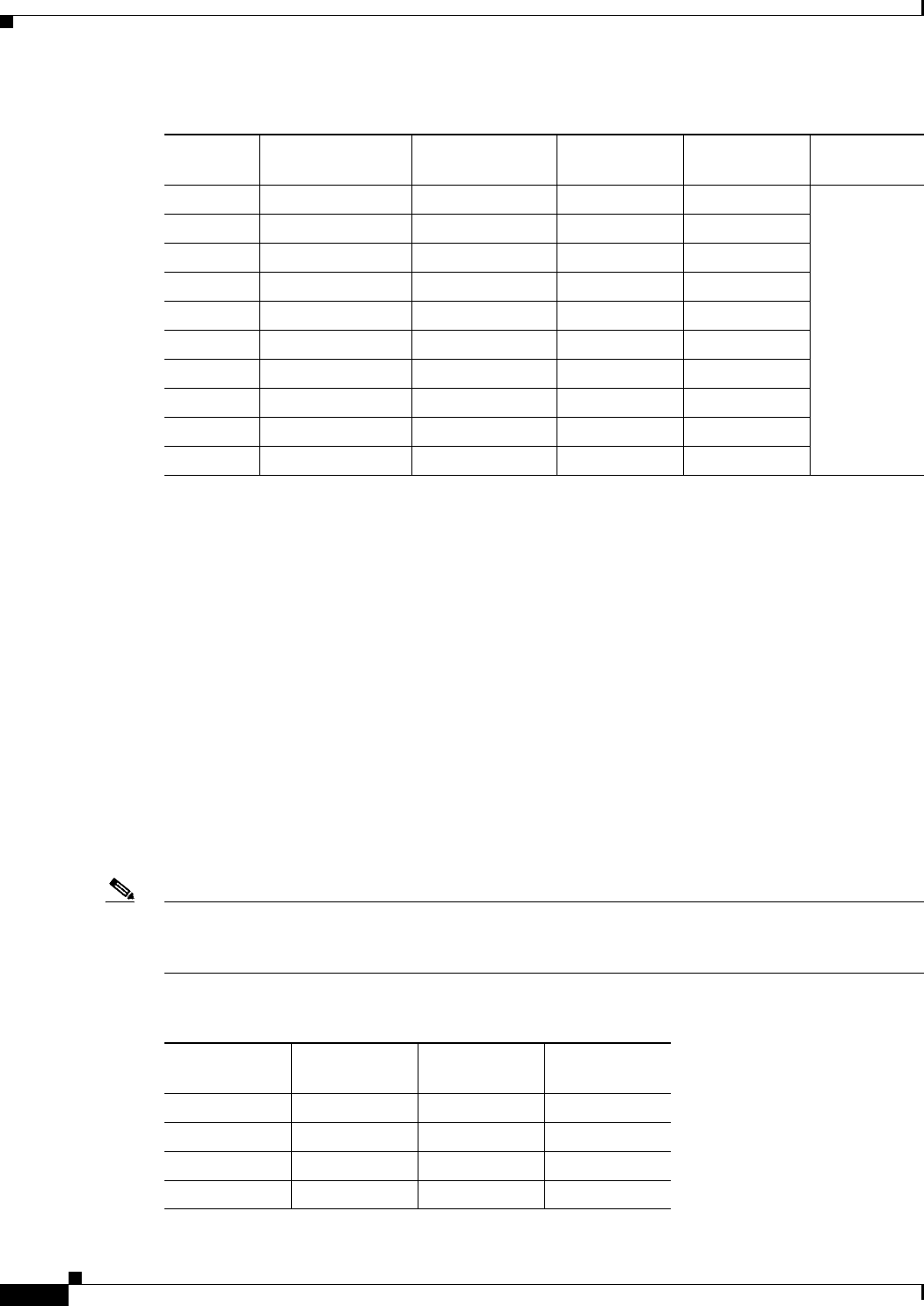
C-14
Cisco uBR10012 Universal Broadband Router Hardware Installation Guide
Appendix C Frequency Allocation
PAL/SECAM Cable Television Channels and Relative Frequencies
PAL/SECAM Cable Television Channels and Relative
Frequencies
Table C-7 provides information on the Phase Alternating Line (PAL) and SEquential Couleur Avec
Memoire (SECAM) frequency map for standard 7and 8 MHz channel bands in Europe.
The FCS (reference subcarrier frequency) for color integration is different for different countries. As
well, the channel/frequency designations is different for different countries. For a summary of the ITU
designations for PAL/SECAM systems and Recommendation ITU-R BT.470.6 standards, refer to
Table C-1, Table C-2, and Table C-3. These tables provide general information that may help determine
frequency allocations for specific countries. Table C-7 is a frequency allocation table for PAL B and G
locations. Also note that some countries use different schemes for VHF and UHF. Table C-8 is a
frequency allocation table for PAL D and K locations for the People’s Republic of China.
More information can be found at the Web sites listed on page E-1.
Note The downstream frequency plan will include all center frequencies between 112 and 858 MHz on 250
kHz increments. It is up to the operator to decide which frequencies to use to meet national and network
requirements
102 690.0-696.0 691.25 693.0 695.75
CATV
103 696.0-702.0 697.25 699.0 701.75
104 702.0-708.0 703.25 705.0 707.75
105 708.0-714.0 709.25 711.0 713.75
106 714.0-720.0 715.25 717.0 719.75
107 720.0-726.0 721.25 723.0 725.75
108 726.0-732.0 727.25 729.0 731.75
109 732.0-738.0 733.25 735.0 737.75
110 738.0-744.0 739.25 741.0 743.75
111 744.0-750.0 745.25 747.0 749.75
1. Aeronautical channels visual carrier frequency tolerance +/–5 kHz.
Table C-6 Korean Channel Assignments (continued)
Channel
Number
Bandwidth
(MHz)
Visual Carrier
(MHz)
Center
Frequency
Aural Carrier
(MHz) Usage
Table C-7 Cable Television Channels and Relative Frequencies, PAL B and G
Channel
Number
Bandwidth
(MHz)
Visual Carrier
(MHz)
Aural Carrier
(MHz)
E2 47.0-54.0 48.25 53.75
E3 54.0-61.0 55.25 60.75
E4 61.0-68.0 62.25 67.75
S3 118.0-125.0 119.25 124.75

C-15
Cisco uBR10012 Universal Broadband Router Hardware Installation Guide
Appendix C Frequency Allocation
PAL/SECAM Cable Television Channels and Relative Frequencies
S4 125.0-132.0 126.25 131.75
S5 132.0-139.0 133.25 138.75
S6 139.0-146.0 140.25 145.75
S7 146.0-153.0 147.25 152.75
S8 153.0-160.0 154.25 159.75
S9 160.0-167.0 161.25 166.75
S10 167.0-174.0 168.25 173.75
E5 174.0-181.0 175.25 180.75
E6 181.0-188.0 182.25 187.75
E7 188.0-195.0 189.25 194.5
E8 195.0-202.0 196.25 201.75
E9 202.0-209.0 203.25 208.75
E10 209.0-216.0 210.25 215.75
E11 216.0-223.0 217.25 222.75
E12 223.0-230.0 224.25 229.75
S11 230.0-237.0 231.25 236.75
S12 237.0-244.0 238.25 243.75
S13 244.0-251.0 245.25 250.75
S14 251.0-258.0 252.25 257.75
S15 258.0-265.0 259.25 264.75
S16 265.0-272.0 266.25 271.75
S17 272.0-279.0 273.25 278.75
S18 279.0-286.0 280.25 285.75
S19 286.0-293.0 287.25 289.75
S20 293.0-300.0 294.25 299.75
S21 302.0-310.0 303.25 308.75
S22 310.0-318.0 311.25 316.75
S23 318.0-326.0 319.25 324.75
S24 326.0-334.0 327.25 332.75
S25 334.0-342.0 335.25 340.75
S26 342.0-350.0 343.25 348.75
S27 350.0-358.0 351.25 356.75
S28 358.0-366.0 359.25 364.75
S29 366.0-374.0 367.25 372.05
S30 374.0-382.0 375.25 380.75
Table C-7 Cable Television Channels and Relative Frequencies, PAL B and G (continued)
Channel
Number
Bandwidth
(MHz)
Visual Carrier
(MHz)
Aural Carrier
(MHz)

C-16
Cisco uBR10012 Universal Broadband Router Hardware Installation Guide
Appendix C Frequency Allocation
PAL/SECAM Cable Television Channels and Relative Frequencies
S31 382.0-390.0 383.25 388.75
S32 390.0-398.0 391.25 396.75
S33 398.0-406.0 399.25 404.75
S34 406.0-414.0 407.25 412.75
S35 414.0-422.0 415.25 420.75
S36 422.0-430.0 423.25 428.75
S37 430.0-438.0 431.25 436.75
S38 438.0-446.0 439.25 444.75
S39 446.0-454.0 447.25 452.75
S40 454.0-462.0 455.25 460.75
S41 462.0-470.0 463.25 468.75
21 470.0-478.0 471.25 476.75
22 478.0-486.0 479.25 484.75
23 486.0-494.0 487.25 492.7‘5
24 494.0-502.0 495.25 500.75
25 502.0-510.0 503.25 508.75
26 510.0-518.0 511.25 516.75
27 518.0-526.0 519.25 524.75
28 526.0-534.0 527.25 532.75
29 534.0-542.0 535.25 540.75
30 542.0-550.0 543.25 548.75
31 550.0-558.0 551.25 556.75
32 558.0-566.0 559.25 564.75
33 566.0-574.0 567.25 572.75
34 574.0-582.0 575.25 580.725
35 582.0-590.0 583.25 588.75
36 590.0-598.0 591.25 596.75
37 598.0-606.0 599.25 604.75
38 606.0-614.0 607.25 612.75
39 614.0-622.0 615.25 620.75
40 622.0-630.0 623.25 628.75
41 630.0-638.0 631.25 636.75
42 638.0-646.0 639.25 644.75
43 646.0-654.0 647.25 652.75
44 654.0-662.0 655.25 660.75
Table C-7 Cable Television Channels and Relative Frequencies, PAL B and G (continued)
Channel
Number
Bandwidth
(MHz)
Visual Carrier
(MHz)
Aural Carrier
(MHz)

C-17
Cisco uBR10012 Universal Broadband Router Hardware Installation Guide
Appendix C Frequency Allocation
PAL/SECAM Cable Television Channels and Relative Frequencies
45 662.0-670.0 663.25 668.75
46 670.0-678.0 671.25 676.75
47 678.0-686.0 679.25 684.75
48 686.0-694.0 687.25 692.75
49 694.0-702.0 695.25 700.75
50 702.0-710.0 703.25 708.75
51 710.0-718.0 711.25 716.75
52 718.0-726.0 719.25 724.75
53 726.0-734.0 727.25 732.75
54 734.0-742.0 735.25 740.75
55 742.0-750.0 743.25 748.75
56 750.0-758.0 751.25 756.75
57 758.0-766.0 759.25 764.75
58 766.0-774.0 767.25 772.75
59 774.0-782.0 775.25 780.75
60 782.0-790.0 783.25 788.75
61 790.0-798.0 791.25 796.75
62 798.0-806.0 799.25 804.75
63 806.0-814.0 807.25 812.75
64 814.0-822.0 815.25 820.75
65 822.0-830.0 823.25 828.75
66 830.0-838.0 831.25 836.75
67 838.0-846.0 839.25 844.75
68 846.0-854.0 847.25 852.75
69 854.0-862.0 855.25 860.75
Table C-7 Cable Television Channels and Relative Frequencies, PAL B and G (continued)
Channel
Number
Bandwidth
(MHz)
Visual Carrier
(MHz)
Aural Carrier
(MHz)

C-18
Cisco uBR10012 Universal Broadband Router Hardware Installation Guide
Appendix C Frequency Allocation
PAL SECAM (D/K) Cable Television Channel Frequencies for the People’s Republic of China
PAL SECAM (D/K) Cable Television Channel Frequencies for the
People’s Republic of China
Note The downstream frequency plan includes all center frequencies between 112 and 862 MHz in 250 kHz
increments. It is up to the operator to decide which frequencies to use to meet national and network
requirements
Table C-8 Cable Television Channels and Relative Frequencies, PAL D and K
Channel
Number
Bandwidth
(MHz)
Visual Carrier
(MHz)
Aural Carrier
(MHz)
Z1 112.0-119.0 112.25 118.75
Z2 120.0-127.0 120.25 126.75
Z3 128.0-135.0 128.25 134.75
Z4 136.0-143.0 136.25 142.75
Z5 144.0-151.0 144.25 150.75
Z6 152.0-159.0 152.25 158.75
Z7 160.0-167.0 160.25 166.75
DS6 168.0-175.0 168.25 174.75
DS7 176.0-183.0 176.25 182.75
DS8 184.0-191.0 184.25 190.75
DS9 192.0-199.0 192.25 198.75
DS10 200.0-207.0 200.25 206.75
DS11 208.0-215.0 208.25 214.75
DS12 216.0-223.0 216.25 222.5
Z8 224.0-231.0 224.25 230.75
Z9 232.0-239.0 232.25 238.75
Z10 240.0-247.0 240.25 246.75
Z11 248.0-255.0 248.25 254.75
Z12 256.0-263.0 256.25 262.75
Z13 264.0-271.0 264.25 270.75
Z14 272.0-279.0 272.25 278.75
Z15 280.0-287.0 280.25 286.75
Z16 288.0-295.0 288.25 294.75
Z17 296.0-303.0 296.25 302.75
Z18 304.0-311.0 304.25 310.75
Z19 312.0-319.0 312.25 318.75
Z20 320.0-327.0 320.25 326.75
Z21 328.0-335.0 328.25 334.75

C-19
Cisco uBR10012 Universal Broadband Router Hardware Installation Guide
Appendix C Frequency Allocation
PAL SECAM (D/K) Cable Television Channel Frequencies for the People’s Republic of China
Z22 336.0-343.0 336.25 342.75
Z23 344.0-351.0 344.25 350.75
Z24 352.0-359.0 352.25 358.75
Z25 362.0-367.0 362.25 366.75
Z26 368.0-375.0 368.25 374.75
Z27 376.0-383.0 376.25 382.75
Z28 384.0-391.0 384.25 390.75
Z29 393.0-399.0 392.25 398.75
Z30 400.0-407.0 400.25 406.75
Z32 408.0-415.0 408.25 414.05
Z32 416.0-423.0 416.25 422.75
Z33 424.0-431.0 424.25 430.75
Z34 432.0-439.0 432.25 438.75
Z35 440.0-447.0 440.25 446.75
Z36 448.0-455.0 448.25 454.75
Z37 456.0-463.0 456.25 462.75
DS13 471.0-478.0 471.25 477.75
DS14 479.0-486.0 479.25 485.75
DS15 487.0-494.0 487.25 493.75
DS16 495.0-502.0 495.25 501.75
DS17 503.0-510.0 503.25 509.75
DS18 511.0-518.0 511.25 517.75
DS19 519.0-526.0 519.25 525.75
DS20 527.0-534.0 527.25 533.75
DS21 535.0-542.0 535.25 541.75
DS22 543.0-550.0 543.25 549.75
DS23 551.0-558.0 551.25 557.75
DS24 559.0-566.0 559.25 565.75
Z38 567.0-574.0 567.25 573.75
Z39 575.0-582.0 575.25 581.75
Z40 583.0-590.0 583.25 589.75
Z41 591.0-598.0 591.25 597.75
Z42 599.0-606.0 599.25 605.75
DS25 607.0-614.0 607.25 613.75
DS26 615.0-622.0 615.25 621.75
Table C-8 Cable Television Channels and Relative Frequencies, PAL D and K (continued)
Channel
Number
Bandwidth
(MHz)
Visual Carrier
(MHz)
Aural Carrier
(MHz)

C-20
Cisco uBR10012 Universal Broadband Router Hardware Installation Guide
Appendix C Frequency Allocation
PAL SECAM (D/K) Cable Television Channel Frequencies for the People’s Republic of China
DS27 623.0-630.0 623.25 629.725
DS28 631.0-638.0 631.25 637.75
DS29 639.0-646.0 639.25 645.75
DS30 647.0-654.0 647.25 653.75
DS31 655.0-662.0 655.25 661.75
DS32 663.0-670.0 663.25 669.75
DS33 671.0-678.0 671.25 677.75
DS34 679.0-686.0 679.25 685.75
DS35 687.0-694.0 687.25 693.75
DS36 695.0-702.0 695.25 701.75
DS37 703.0-710.0 703.25 709.75
DS38 711.0-718.0 711.25 717.75
DS39 719.0-726.0 719.25 725.75
DS40 727.0-730.0 727.25 729.75
DS41 735.0-742.0 735.25 741.75
DS42 743.0-750.0 743.25 749.75
DS43 751.0-758.0 751.25 757.75
DS44 759.0-766.0 759.25 765.75
DS45 767.0-774.0 767.25 773.75
DS46 775.0-782.0 775.25 781.75
DS47 783.0-790.0 783.25 789.75
DS48 791.0-798.0 791.25 797.75
DS49 799.0-806.0 799.25 805.75
DS50 807.0-814.0 807.25 813.75
DS51 815.0-822.0 815.25 821.75
DS52 823.0-730.0 823.25 829.75
DS53 831.0-838.0 831.25 837.75
DS54 839.0-846.0 839.25 845.75
DS55 847.0-854.0 847.25 853.75
DS56 855.0-862.0 855.25 861.75
Table C-8 Cable Television Channels and Relative Frequencies, PAL D and K (continued)
Channel
Number
Bandwidth
(MHz)
Visual Carrier
(MHz)
Aural Carrier
(MHz)
D-1
Cisco uBR10012 Universal Broadband Router Hardware Installation Guide
APPENDIX
D
Manufacturers for Hardware Components
Table D-1 and Table D-2 provide contact information for manufacturers, web sites, and product
offerings required to prepare and provision a North American cable headend site for two-way data.
Table D-3 and Table D-4 provide contact information for manufacturers, web sites, and product
offerings required to prepare and provision a European cable headend site for two-way data.
Table D-5 provides a list of parts and manufacturers used with the cable interface line card.
Table D-6 provides a list manufacturers for the external AC-input power shelves that are used with the
Cisco uBR10012 router.
North American Channel Plans
Table D-1 Manufacturers for North American Headend Provisioning Requirements
Manufacturer1Web Site or Phone Number Products/Model
Upconverters
Barco http://www.barco.com Gemini
Motorola2 http://www.gi.com CDCM2000
Scientific Atlanta http://www.sciatl.com Continuum 9860, 9861
Vecima Networks, Inc. http://www.vecima.com/ HD4040, MA4040
Diplex Filters
Eagle Comtronics http://www.eaglecomtronics.com Diplex filters
Microwave Filter Company, Inc. http://www.microwavefilter.com Diplex filters
PCI Technologies http://www.pci.com Diplex filters
Viewsonics http://www.viewsonics.com Diplex filters
Coaxial Jumpers, Attenuators, Splitters, and Taps
Viewsonics http://www.viewsonics.com Variable attenuators,
Comb generators,
Cisco uBR kit (splitter, diplex filter,
attenuators)
Vecima Networks, Inc. http://www.vecima.com/ Cisco uBR kit (splitter, diplex filter,
attenuators)
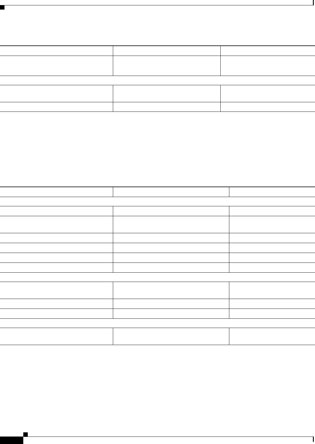
D-2
Cisco uBR10012 Universal Broadband Router Hardware Installation Guide
Appendix D Manufacturers for Hardware Components
North American Channel Plans
In addition, Cisco recommends the following manufacturers, web sites, and product offerings for various
measurement devices you will need to prepare and provision a North American cable headend site for
two-way data.
White Sands Engineering, Inc http://www.whitesandsengineering.com
1 800-jumpers or 602 581-0331
Coaxial jumpers
GPS Receivers
Agilent3 http://www.home.agilent.com/agilent/ho
me.jspx?&cc=IN&lc=eng
Agilent 85960B, 85961B
Symmetricom http://www.symmetricom.com TS2500, TS2700, TS3000
1. The lead times for upconverters can run from 2 to 18 weeks. Contact the upconverter manufacturers listed above for current information on lead times.
2. Formerly General Instrument
3. Formerly Hewlett-Packard Test and Measurement Division.
Table D-1 Manufacturers for North American Headend Provisioning Requirements (continued)
Manufacturer1Web Site or Phone Number Products/Model
Table D-2 Manufacturers for North American Headend Measurement Devices
Manufacturer Web Site or Phone Number Products/Model
Digital Signal Level Meters/QAM Analyzers
Acterna http://www.acterna.com SDA-5000, w/Option 4B
Agilent1
1. Formerly Hewlett-Packard Test and Measurement Division.
http://www.home.agilent.com/agilent/home.
jspx?&cc=IN&lc=eng
Agilent 8594Q, N1776A
Telsey2
2. Formerly Tektronics DMA division
http://www.telsey.it DMA120, DMA122
Sencore http://www.sencore.com QAM-B970
Sunrise Telecom3
3. Formerly Hukk Engineering and Avantron.
http://www.sunrisetelecom.com CR1200R, AT2000RQ
Trilithic http://www.trilithic.com 860DSP w/Option QA1
Spectrum Analyzers
Agilent http://www.home.agilent.com/agilent/home.
jspx?&cc=IN&lc=eng
Agilent 8591C, N1776A
Tektronics http://www.tek.com 2715
Sunrise Telecom http://www.sunrisetelecom.com AT2000R
Vector Signal Analyzers
Agilent http://www.home.agilent.com/agilent/home.
jspx?&cc=IN&lc=eng
Agilent 89411A

D-3
Cisco uBR10012 Universal Broadband Router Hardware Installation Guide
Appendix D Manufacturers for Hardware Components
European Channel Plans
European Channel Plans
In addition, Cisco recommends the following manufacturers, web sites, and product offerings for various
measurement devices you will need to prepare and provision a European cable headend site for two-way
data.
Table D-3 Manufacturers for European Headend Provisioning Requirements
Manufacturer 1
1. The lead times for upconverters can run from 2 to 18 weeks. Contact the upconverter manufacturers listed above for current information on lead times.
Web Site or Phone Number Products/Model
Upconverters
Barco http://www.barco.com Gemini
Motorola2
2. Formerly General Instrument
http://www.gi.com CDCM2000
Scientific Atlanta http://www.sciatl.com Continuum
Vecima Networks, Inc. http://www.vecima.com/ HD4040, MA4040
Diplex Filters
Eagle Comtronics http://www.eaglecomtronics.com Diplex filters
Microwave Filter Company, Inc. http://www.microwavefilter.com Diplex filters
PCI Technologies http://www.pci.com Diplex filters
Viewsonics http://www.viewsonics.com Diplex filters
Coaxial Jumpers, Attenuators, Splitters, and Taps
Viewsonics http://www.viewsonics.com Variable attenuators,
Comb generators,
Cisco kit (splitter, diplex filter,
attenuators, coax jumpers
Vecima Networks, Inc. http://www.vecima.com/ Cisco uBR kit (splitter, diplex filter,
attenuators)
White Sands Engineering, Inc http://www.whitesandsengineering.com
1 800-jumpers or 602 581-0331
Coaxial jumpers
GPS Receivers
Agilent3
3. Formerly Hewlett-Packard Test and Measurement Division.
http://www.home.agilent.com/agilent/ho
me.jspx?&cc=IN&lc=eng
Agilent 85960B, 85961B
Symmetricom http://www.symmetricom.com TS2500, TS2700, TS3000
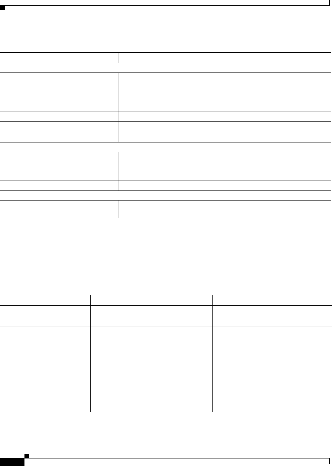
D-4
Cisco uBR10012 Universal Broadband Router Hardware Installation Guide
Appendix D Manufacturers for Hardware Components
Cable Kits and Tools
Cable Kits and Tools
Table D-4 Manufacturers for European Headend Measurement Devices
Manufacturer Web Site or Phone Number Products/Model
Digital Signal Level Meters/QAM Analysers
Acterna http://www.acterna.com SDA-5000 w/Option 4B
Agilent1
1. Formerly Hewlett-Packard Test and Measurement Division
http://www.home.agilent.com/agilent/home.
jspx?&cc=IN&lc=eng
Agilent 8594Q, N1776A
Sunrise Telecom2
2. Formerly Hukk Engineering and Avantron.
http://www.sunrisetelecom.com AT2000RQ
Swires Research http://www.swire.com TVA 2000-Q
Telsey3
3. Formerly Tektronics DMA division
http://www.telsey.it DMA121, DMA122
Trilithic http://www.trilithic.com 860DSP w/Option QA1
Spectrum Analyzers
Agilent http://www.home.agilent.com/agilent/home.
jspx?&cc=IN&lc=eng
Agilent 8591C
Tektronix http://www.tek.com 2715
Sunrise Telecom http://www.sunrisetelecom.com AT2000R
Vector Signal Analyzers
Agilent http://www.home.agilent.com/agilent/home.
jspx?&cc=IN&lc=eng
Agilent 89411A
Table D-5 Tool Manufactures
Manufacturer Web Site or Phone Number Products/Model
Belden Electronics division http://www.belden.com 75–ohm precision miniature video cable
JohnsonComponents http://www.johnsoncomponents.com Universal cable holder
White Sands Engineering, Inc
Note For a list of part
numbers, see the FRU
documentation.1
1. For cable interface line card documentation, see the following URL:
www.cisco.com/en/US/products/hw/cable/ps2209/prod_installation_guides_list.html
http://www.whitesandsengineering.com
1 800-jumpers or 602 581-0331
Cable kit (3m MCX to F cables)
Cable kit with pre configured cables
Cable extraction tool
Universal cable holder
MCX connector strip tool
MCX connector crimper tool
MCX fixed pin connector
MCX connector to F connector adapter
F connector strip tool
F connector crimper tool
F connectors

D-5
Cisco uBR10012 Universal Broadband Router Hardware Installation Guide
Appendix D Manufacturers for Hardware Components
External AC-Input Power Shelves
External AC-Input Power Shelves
Table D-6 AC-input Power Shelves Manufactures
Manufacturer Web Site or Phone Number Products/Model
Lineage1
1. For ordering, visit www.arrow.com
http://www.lineagepower.com Lineage Power AC-DC Power Supply
J85480S1 L30

D-6
Cisco uBR10012 Universal Broadband Router Hardware Installation Guide
Appendix D Manufacturers for Hardware Components
External AC-Input Power Shelves

GL-1
Cisco uBR10012 Universal Broadband Router Hardware Installation Guide
GLOSSARY
Symbols
1+1 APS See APS.
10Base-T 10-Mbps baseband Ethernet specification using two pairs of twisted-pair cabling (Category 3, 4, or 5):
one pair for transmitting data and the other for receiving data. 10Base-T, which is part of the IEEE
802.3 specification, has a distance limit of approximately 328 feet (100 meters) per segment. See also
IEEE 802.3 and Ethernet.
100Base-T 100-Mbps baseband Fast Ethernet specification using UTP wiring. Like the 10Base-T technology on
which it is based, 100Base-T sends link pulses over the network segment when no traffic is present.
However, these link pulses contain more information than those used in 10Base-T. The 100Base-T
specification is based on the IEEE 802.3 standard. See also 10Base-T, Fast Ethernet, and
IEEE 802.3.
1000Base-LX/LH 1000-Mbps Gigabit Ethernet specification using two strands of multimode or single mode fiber-optic
cable per link. To guarantee proper signal recovery, a 1000Base-LX/LH link cannot exceed 1804 feet
(550 meters) in length over multimode fiber or 32,810 feet (10 km) in length over single mode fiber.
Based on the IEEE 802.3 standard with reach over single mode fiber extended from 5 km to 10 km. See
also 1000Base-SX, 1000Base-ZX, Gigabit Ethernet, and
IEEE 802.3.
1000Base-SX 1000-Mbps Gigabit Ethernet specification using two strands of multimode fiber-optic cable per link.
To guarantee proper signal recovery, a 1000Base-SX link cannot exceed 1804 feet (550 meters) in
length. The 1000Base-SX specification is based on the IEEE 802.3 standard. See also
1000Base-LX/LH, 1000Base-ZX, Gigabit Ethernet, and IEEE 802.3.
1000Base-T 1000Base-T (GLC-T) SFP module connects a Cisco Gigabit Interface Converter (GBIC) port to
Category 5 wiring via a standard RJ-45 interface. The maximum Category 5 wiring distance is 100 m.
The module provides with an option of connecting to a backhaul network interface.
1000Base-X 1000-Mbps Gigabit Ethernet specification that refers to the 1000Base-CX, 1000Base-SX, and
1000Base-LX standards for Gigabit Ethernet over fiber-optic cabling. The 1000Base-X specification is
based on the IEEE 802.3 standard. See also 1000Base-SX, 1000Base-LX/LH, 1000Base-ZX, Gigabit
Ethernet, and IEEE 802.3.
1000Base-ZX 1000-Mbps Gigabit Ethernet specification using two strands of single mode fiber-optic cable per link.
To guarantee proper signal recovery, a 1000Base-ZX link cannot be longer than 62.1 mi (100 km). This
is a Cisco specification. See also 1000Base-SX, 1000Base-LX/LH, Gigabit Ethernet, and IEEE 802.3.
802.x A set of IEEE standards for the definition of LAN protocols.

Glossary
GL-2
Cisco uBR10012 Universal Broadband Router Hardware Installation Guide
A
AAL ATM adaptation layer. Service-dependent sublayer of the data link layer. The AAL accepts data from
different applications and presents it to the ATM layer in the form of 48-byte ATM payload segments.
AALs consist of two sublayers:the convergence sublayer and the segmentation and reassembly
sublayer. Four types of AAL recommended by the ITU-T are AAL1, AAL2, AAL3/4, and AAL5; the
Cisco uBR10012 uses AAL5.
Access list List kept by routers to control access to or from the router for a number of services. For example, access
lists can be used to prevent packets with a certain IP address from leaving a particular interface on the
router.
Add drop
Multiplexer
See ADM.
ADM Add Drop Multiplexer. A multiplexer that allows a signal to be added into or dropped out of a SONET
span. See also SONET.
Alarm A status condition that shows that a module or port is experiencing an abnormal operating condition.
See also Critical alarm, Major alarm, and Minor alarm.
Application-specific
integrated circuit
See ASIC.
APS Automatic Protection Switching. A SONET switching mechanism that achieves network resiliency by
automatically switching from a primary circuit to a secondary circuit. This switching process occurs if
the primary circuit fails or if the error rate on the primary line exceeds a set threshold. The Cisco 10000
ESR supports 1+1 APS, which provides permanent electrical bridging to the service and protection
equipment, placed at both ends of the circuit.
ASIC Application-specific integrated circuit. A chip that is built for a specific application.
Asynchronous
Transfer Mode
See ATM .
ATM Asynchronous Transfer Mode. International standard for cell relay in which multiple service types
(such as voice, video, or data) are conveyed in fixed-length (53-byte) cells. Fixed-length cells allow
cell processing to occur in hardware, thereby reducing transit delays. ATM is designed to take
advantage of high-speed transmission media such as E3, SONET, and T3.
Authentication In security, the verification of the identity of a person or process.
Automatic
protection
switching
See APS.
Alarm A status condition that shows that a module or port is experiencing an abnormal operating condition.
See also Critical alarm, Major alarm, and Minor alarm.

Glossary
GL-3
Cisco uBR10012 Universal Broadband Router Hardware Installation Guide
B
Backplane The circuit board at the back of the chassis that all components plug into. It provides the physical
connection between an interface processor or line card, and the data and power distribution buses inside
a chassis.
Bellcore Bell Communications Research. Former name of the organization that performs research and
development on behalf of the Regional Bell Operating Companies (RBOCs). Bellcore is now called
Telcordia.
BER Bit error rate. The ratio of received bits that contain errors.
BGP Border Gateway Protocol. An interdomain routing protocol that replaces EGP. BGP exchanges
connection information with other BGP systems. It is defined by RFC 1163.
Bit error rate See BER.
Border Gateway
Protocol
See BGP.
Broadcast Data packet that is sent to all nodes on a network. Broadcasts are identified by a broadcast address.
Compare with Multicast and Unicast.
C
CCITT Consultative Committee for International Telegraph and Telephone. International organization
responsible for the development of communications standards. Now called the ITU-T. (See ITU-T.)
CEF Cisco Express Forwarding. An advanced Layer 3 IP switching technology designed for
high-performance, highly resilient Layer 3 IP backbone switching. CEF optimizes network
performance and scalability for networks with large and dynamic traffic patterns, such as the Internet,
on networks characterized by intensive Web-based applications or interactive sessions.
Central Office See CO.
Channel Communication path. Multiple channels can be multiplexed over a single cable in certain
environments.
Cisco Express
Forwarding
See CEF.
Cisco IOS Cisco system software that provides common functionality, scalability, and security for Cisco products.
Cisco IOS allows centralized, integrated, and automated installation and management of internetworks,
while ensuring support for a wide variety of protocols, media, services, and platforms.
Clear channel DS3 A framed DS3 signal which is not multiplexed from 28 DS1 signals. Sometimes referred to as
unchannelized DS3.
CLI Command line interface. Interface that allows the user to interact with the operating system by entering
commands and optional arguments at the command prompt.

Glossary
GL-4
Cisco uBR10012 Universal Broadband Router Hardware Installation Guide
CO Central office. The local telephone company office to which all local loops in a given area connect and
in which circuit switching of subscriber lines occurs.
Command Line
Interface
See CLI.
Console Data terminal equipment (DTE) through which commands are entered into a host.
Critical alarm An alarm condition that might affect most or all subscribers that connect to the reporting node. To
obtain more information about a problem, use the
show facility-alarm status command. See also Major alarm and Minor alarm.
D
Data terminal
equipment
See DTE.
DCE Data circuit-terminating equipment (ITU-T expansion). Devices and connections of a communications
network that comprise the network end of the user-to-network interface. The DCE provides a physical
connection to the network, forwards traffic, and provides a clocking signal used to synchronize data
transmission between DCE and DTE devices. Modems and interface cards are examples of DCE.
Compare with DTE.
DRAM Dynamic random access memory. RAM that stores information in capacitors that must be periodically
refreshed. Delays can occur because DRAMs are inaccessible to the processor when refreshing their
contents. However, DRAMs are less complex and have greater capacity than SRAMs. See also SRAM.
DS0 Digital signal level 0. Framing specification used in transmitting digital signals over a single channel
at 64 kbps on a T1 facility. Compare with DS1 and DS3.
DS1 Digital signal level 1. Framing specification used in transmitting digital signals at 1.544 Mbps on a T1
facility (in the United States) or at 2.108 Mbps on an E1 facility (in Europe). Compare with DS0 and
DS3.
DS3 Digital signal level 3. Framing specification used for transmitting digital signals at 44.736 Mbps on a
T3 facility. Compare with DS0 and DS1.
DSU Data Service Unit. Device used in digital transmission that adapts the physical interface on a DTE
device to a transmission facility such as T1 or E1. The DSU is also responsible for such functions as
signal timing. Often used with CSU, as in CSU/DSU.
DTE Data terminal equipment. Device at the user end of a user-network interface that serves as a data source,
destination, or both. DTE connects to a data network through a DCE device (for example, a modem)
and typically uses clocking signals generated by the DCE. DTE includes devices such as computers,
protocol translators, and multiplexers.
Dynamic random
access memory
See DRAM.

Glossary
GL-5
Cisco uBR10012 Universal Broadband Router Hardware Installation Guide
E
E1 Wide-area digital transmission scheme used predominantly in Europe that carries data at a rate of 2.048
Mbps. E1 lines can be leased for private use from common carriers. Compare with T1; see also DS1.
Edge Services
Router
See ESR.
Electromagnetic
interference
See EMI.
Electrostatic
discharge
See ESD.
EMI Electromagnetic interference. Interference by electromagnetic signals that can cause reduced data
integrity and increased error rates on transmission channels.
EMP Electromagnetic pulse. Caused by lightning and other high-energy phenomena. Capable of coupling
enough energy into unshielded conductors to destroy electronic devices.
ESD Electrostatic discharge. Discharge of stored static electricity that can damage electronic equipment and
impair electrical circuitry, resulting in complete or intermittent failures.
ESR Edge Services Router. A router that aggregates and routes traffic from thousands of low- and
medium-bandwidth subscriber connections Into a few high-bandwidth connections to the Internet core.
Ethernet Baseband LAN specification. Ethernet networks use CSMA/CD and run over a variety of cable types
at 10 Mbps, 100 Mbps, and 1000 Mbps. Ethernet is similar to the IEEE 802.3 series of standards. See
also Fast Ethernet, Gigabit Ethernet, IEEE 802.3.
F
Fast Ethernet Any of a number of 100-Mbps Ethernet specifications. Fast Ethernet offers a speed increase 10 times
that of the 10Base-T Ethernet specification, while preserving qualities such as frame format, MAC
mechanisms, and MTU. Existing 10Base-T applications and network management tools can be used on
Fast Ethernet networks. The Fast Ethernet specification is based on an extension to the IEEE 802.3
specification. Compare with Ethernet and Gigabit Ethernet. See also 100Base-T and IEEE 802.3.
Fiber-optic cable Physical medium capable of conducting modulated light transmission. Compared with other
transmission media, fiber-optic cable is more expensive, but it is not susceptible to electromagnetic
interference and is capable of higher data rates. Sometimes called optical fiber.
Field-replaceable
unit
See FRU.
Flash memory Nonvolatile storage that can be electrically erased and reprogrammed so that software images can be
stored, booted, and rewritten as necessary. Flash memory was developed by Intel and is licensed to
other semiconductor companies.

Glossary
GL-6
Cisco uBR10012 Universal Broadband Router Hardware Installation Guide
Frame Relay Industry-standard, switched data link layer protocol that handles multiple virtual circuits using HDLC
encapsulation between connected devices. Frame Relay is more efficient than X.25, the protocol for
which it is generally considered a replacement.
FRU Field replaceable unit. A component that can be removed from a network device and replaced in the
field. Line cards, power modules, and fan modules are typically FRUs.
G
GBIC Gigabit Ethernet converter. An interface module used by Gigabit Ethernet and Fibre Channel to convert
the serial electrical signals to the transmission medium’s physical layer signalling, which is typically
optical. GBIC modules can be hot-swapped and contain ID and system information that a switch or
router can use to determine the network device's capabilities. Different GBICs handle different types
of fiber cable. See 1000Base-LX/LH, 1000Base-SX, and 1000Base-ZX.
Gigabit Ethernet Gigabit Ethernet. Ethernet running at a transmission speed of 1 billion bits per second.
Gigabit Interface
Converter
See GBIC.
H
HHGE Half-Height Gigabit Ethernet
Hot swapping Feature that permits the addition, replacement, or removal of cards without interrupting the system
power, entering console commands, or causing other software or interfaces to shut down. Sometimes
called online insertion and removal (OIR).
I
IEEE Institute of Electrical and Electronics Engineers. Professional organization whose activities include the
development of communications and network standards. IEEE LAN standards are the currently
predominant LAN standards.
IEEE 802.3 IEEE LAN protocol that specifies an implementation of the physical layer and the MAC sublayer of
the data link layer. IEEE 802.3 uses CSMA/CD access at a variety of speeds over a variety of physical
media. Extensions to the IEEE 802.3 standard specify implementations for Fast Ethernet and Gigabit
Ethernet.
Institute of Electrical
and Electronics
Engineers
See IEEE.
Intermediate reach See IR.
Internet service
provider
See ISP.

Glossary
GL-7
Cisco uBR10012 Universal Broadband Router Hardware Installation Guide
IOS Internet Operating System. See Cisco IOS.
IP Internet Protocol. Network layer protocol in the TCP/IP stack offering a connectionless internetwork
service. IP provides features for addressing, type-of-service specification, fragmentation and
reassembly, and security. Defined in RFC 791.
IP multicast Routing technique that allows IP traffic to be propagated from one source to a number of destinations
or from many sources to many destinations. Rather than sending one packet to each destination, one
packet is sent to a multicast group identified by a single IP destination group address.
IR Intermediate reach. SONET/SDH specification for transmit power and receive sensitivity that achieves
a 9.3-mile (15-km) reach.
ISP Internet Service Provider. A company that provides Internet access to other companies and individuals.
ITU-T International Telecommunication Union Telecommunication Standardization Sector. International
body that develops worldwide standards for telecommunications technologies. The ITU-T carries out
the functions of the former CCITT.
L
LAN Local-area network. High-speed, low-error data network covering a relatively small geographic area
(up to a few thousand meters). LANs connect workstations, peripherals, terminals, and other devices
in a single building or some other geographically limited area. LAN standards specify cabling and
signaling at the physical and data link layers of the OSI model. Ethernet, FDDI, and Token Ring are
widely used LAN technologies. Compare with MAN and WAN.
Line card Any I/O card that can be inserted in a modular chassis.
LMI Local Management Interface. A set of enhancements to the basic Frame Relay specification. LMI
includes support for a keepalive mechanism, which verifies that data is flowing; a multicast
mechanism, which provides the network server with its local DLCI and the multicast DLCI; global
addressing, which gives DLCIs global rather than local significance in Frame Relay networks; and a
status mechanism, which provides an on-going status report on the DLCIs known to the switch. Known
as LMT in ANSI terminology.
Local-area network See LAN.
Loopback test A test in which signals are sent and then directed back toward their source from some point along the
communications path. Loopback tests are often used to test network interface usability.
LOS Loss of signal. A SONET port status indicator that activates when an LOS defect occurs and does not
clear throughout the alarm integration period, which is typically 2.5 seconds. An LOS defect occurs
when the OC-3 port receives all zeros for 20 microseconds (+.3 ms). This occurrence begins the alarm
integration period. If this period elapses without the detection of two consecutive frames in which there
are no 20-ms periods of signal loss, the LOS indicator activates. The LOS indicator clears when an LOS
defect is not detected for an interval equal to the alarm deactivation period (typically 10 seconds).

Glossary
GL-8
Cisco uBR10012 Universal Broadband Router Hardware Installation Guide
M
M13 Generic term for equipment that multiplexes DS1s into DS3s. Sometimes used to describe a specific
DS3 multiplex format. Some standards use this term to describe a synchronous multiplexing format
also know as SYNTRAN. In many cases M13 does not refer to the SYNTRAN format, but instead
refers to the format also known as M23.
M23 A method of multiplexing four DS1 signals into a DS2 signal, then multiplexing seven DS2 signals into
a DS3 signal.
MAC Media Access Control. Lower of the two sublayers of the data link layer defined by the IEEE. The MAC
sublayer handles access to shared media.
MAC address Standardized data link layer address that is required for each port or device that connects to a LAN.
Other devices in the network use these addresses to locate specific ports in the network, and to create
and update routing tables and data structures. MAC addresses are 6 bytes long and are controlled by
the IEEE. Also known as a hardware address, MAC-layer address, or physical address.
Major alarm One of a group of alarm conditions that are considered the second most severe of all reportable alarms.
Major alarms affect several subscribers who connect to the reporting node. You can use the show
facility-alarm status IOS command to obtain more information about the problem. See also Critical
alarm and Minor alarm.
MAN Metropolitan-area network. A network that spans a metropolitan area. Generally, a MAN spans a larger
geographic area than a LAN, but a smaller geographic area than a WAN. Compare with LAN and WA N .
Management
Information Base
See MIB.
Media Access
Control
See MAC.
Metropolitan-area
network
See MAN.
MIB Management Information Base. Database of network management information that is used and
maintained by a network management protocol such as SNMP or CMIP. The value of a MIB object can
be changed or retrieved using SNMP or CMIP commands, usually through a GUI-based network
management system. MIB objects are organized in a tree structure that includes public (standard) and
private (proprietary) branches.
Minor alarm One of a group of alarm conditions that are considered the third most severe of all reportable alarms.
Minor alarms affect a single or small number of subscribers who connect to the reporting node. You
can use the show facility-alarm status IOS command to obtain more information about the problem.
See also Critical alarm and Major alarm.
MLP Multilink Point-to-Point Protocol. A method of splitting, recombining, and sequencing datagrams
across multiple logical data links.
MMF Multimode fiber. Optical fiber supporting propagation of multiple frequencies of light. See also
Single-mode fiber.
MPLS Multiprotocol Label Switching. An emerging industry standard upon which tag switching is based.

Glossary
GL-9
Cisco uBR10012 Universal Broadband Router Hardware Installation Guide
Multicast Single packets copied by the network and sent to a specific subset of network addresses. These
addresses are specified in the Destination Address field. Compare with Broadcast and Unicast.
Multilink
Point-to-Point
See MLP.
Multimode fiber See MMF.
Multiplexing An activity in which multiple logical signals are transmitted simultaneously across a single physical
channel.
Multiprotocol Label
Switching
See MPLS.
N
NEBS Network Equipment Building Systems. The Telcordia (formerly Bellcore) requirements for equipment
deployed in a central office environment. Covers spatial, hardware, crafts person interface, thermal, fire
resistance, handling and transportation, earthquake and vibration, airborne contaminants, grounding,
acoustical noise, illumination, EMC, and ESD requirements.
Network Equipment
Building Systems
See NEBS.
Network
termination unit
See NTU.
Nonvolatile RAM See NVRAM.
NTU Network terminating unit. The network equipment that connects directly to the data terminal
equipment.
NVRAM Nonvolatile RAM. RAM that retains its contents when a unit is powered off.
O
OC Optical carrier. A series of physical protocols (OC-1, OC-2, OC-3, and so forth), defined for SONET
optical signal transmissions. OC signal levels put STS frames onto fiber-optic lines at a variety of
speeds. The base rate is 51.84 Mbps (OC-1); each signal level thereafter operates at a speed divisible
by that number (thus, OC-3 runs at 155.52 Mbps).
ODL Optical data link.
OIR Online insertion and removal. Feature that permits the addition, replacement, or removal of cards
without interrupting the system power, entering console commands, or causing other software or
interfaces to shut down. Same as hot-swapping.
Online insertion and
removal
See OIR.

Glossary
GL-10
Cisco uBR10012 Universal Broadband Router Hardware Installation Guide
Optical carrier See OC.
Optical fiber See Fiber-optic cable.
P
Packet Logical grouping of information that includes a header containing control information and (usually)
user data. Packets are most often used to refer to network layer units of data. The terms datagram,
frame, message, and segment are also used to describe logical information groupings at various layers
of the OSI reference model and in various technology circles.
Packet Over SONET See POS.
Packet switching Networking method in which nodes share bandwidth with each other by sending packets.
Parallel Express
Forwarding
See PXF Network Processors.
PCMCIA Flash disk
card
A portable (credit-card size), nonvolatile storage device. PCMCIA flash disk cards use Flash
technology to store data. PCMCIA stands for Personal Computer Memory Card International
Association, which sets the standard for this technology. Also called PC card.
PEM Power entry module. A hardware module that distributes power to the chassis.
Performance
Routing Engine
See PRE.
Point of Presence See POP.
Point-to-Point
Protocol
See PPP.
POP Point of presence. A physical location where an interexchange carrier installed equipment to
interconnect with a local exchange carrier.
POS Packet Over SONET. A high-speed means of transmitting data over a SONET fiber-optic transmission
system through a direct fiber connection to a data switch or router. POS is a point-to-point dedicated
leased-line approach intended purely for high-speed data applications. POS allows a user organization
to pass data in its native format, without the addition of any significant level of overhead in the form
of signaling and control information.
POST Power-on self test. A set of hardware diagnostics that runs on a hardware device when that device is
powered on.
Power Entry Module See PEM.
Power-on self test See POST.
PPP Point-to-Point Protocol. Provides router-to-router and host-to-network connections over synchronous
and asynchronous circuits.

Glossary
GL-11
Cisco uBR10012 Universal Broadband Router Hardware Installation Guide
PRE Performance routing engine. The central routing unit for the Cisco uBR10012 universal broadband
router. The PRE performs all Layer 2 and Layer 3 packet manipulation related to routing and
forwarding through the Cisco uBR10012 routers. Use dual PREs in a single chassis for redundancy. See
also PXF Network Processors.
PXF Network
Processors
Parallel eXpress Forwarding network processors. A pair of programmable ASICs that perform parallel
processing to support high performance Layer 3 forwarding.
Q
QoS Quality of service. A measure of performance for a transmission system that reflects its transmission
quality and service availability.
QPPB QoS Policy Propagation by BGP. A feature that classifies packets by IP precedence based on BGP
community lists, BGP autonomous system paths, and access lists. After a packet is classified, other
quality of service features such as committed access rate (CAR) and Weighted Random Early Detection
(WRED) can specify and enforce policies to fit a business model.
Quality of Service See QoS.
R
RAM Random-access memory. Volatile memory that can be read and written by a microprocessor.
Random Access
Memory
See RAM.
Read only memory See ROM.
Redundancy In internetworking, the duplication of devices, services, or connections so that, in the event of a failure,
the redundant devices, services, or connections can perform the work of those that failed.
Remote monitoring See RMON.
Request for
comments
See RFC.
RFC Request for comments. A document series used as the primary means for communicating information
about the Internet. Some RFCs are designated by the IAB as Internet standards. Most RFCs document
protocol specifications such as Telnet and FTP, but some are humorous or historical. RFCs are available
online from numerous sources.
RMON Remote Monitoring. MIB agent specification described in RFC 1271 that defines functions for the
remote monitoring of networked devices. The RMON specification provides numerous monitoring,
problem detection, and reporting capabilities.
ROM Read only memory. Nonvolatile memory that can be read, but not written, by the microprocessor.

Glossary
GL-12
Cisco uBR10012 Universal Broadband Router Hardware Installation Guide
S
SAR Segmentation and reassembly. One of the two sublayers of the AAL common part convergence
sublayer, responsible for dividing (at the source) and reassembling (at the destination) the protocol data
units (PDUs) passed from the convergence sublayer. The SAR sublayer takes the PDUs processed by
the convergence sublayer and, after dividing them into 48-byte pieces of payload data, passes them to
the ATM layer for further processing. See also AAL.
SFP small formfactor pluggable (module) as in GBIC
Short reach See SR.
Simple Network
Management
Protocol
See SNMP.
Single-mode fiber See SMF.
SMF Single-mode fiber. Fiber-optic cabling with a narrow core that allows light to enter only at a single
angle. Such cabling has higher bandwidth than multimode fiber, but requires a light source with a
narrow spectral width (for example, a laser). Also called monomode fiber. See also Multimode fiber.
SNMP Simple Network Management Protocol. Network management protocol used almost exclusively in
TCP/IP networks. SNMP provides a means to monitor and control network devices, and to manage
configurations, statistics collection, performance, and security. See also SNMP2.
SNMP2 SNMP Version 2. Version 2 of the network management protocol. SNMP2 supports centralized as well
as distributed network management strategies, and includes improvements in the SMI, protocol
operations, management architecture, and security. See also SNMP.
SONET Synchronous Optical Network. High-speed synchronous network specification developed by Bellcore
and designed to run on optical fiber. STS-1 is the basic building block of SONET. It was approved as
an international standard in 1988.
SR Short reach. SONET/SDH specification for transmit power and receive sensitivity that achieves a
1.2-mile (2 km) reach.
SRAM A type of RAM that retains its contents for as long as power is supplied. SRAM does not require
constant refreshing, like DRAM. Compare with DRAM.
Subrate DS3 A generic term to describe a process in which the bandwidth of a clear channel DS3 is limited to a lower
rate. Several proprietary formats exist.
Synchronous
Optical Network
See SONET.
T
T1 Digital WAN carrier facility. T1 transmits DS1-formatted data at 1.544 Mbps through the telephone
switching network.

Glossary
GL-13
Cisco uBR10012 Universal Broadband Router Hardware Installation Guide
T3 Digital WAN carrier facility. T3 transmits DS3-formatted data at 44.736 Mbps through the telephone
switching network.
TAC A Cisco Technical Assistance Center. There are four TACs worldwide.
TACACS Terminal Access Controller Access Control System. Authentication protocol, developed by the DDN
community, that provides remote access authentication and related services, such as event logging.
User passwords are administered in a central database rather than in individual routers, providing an
easily scalable network security solution.
TACACS+ Terminal Access Controller Access Control System Plus. Proprietary Cisco enhancement to Terminal
Access Controller Access Control System (TACACS). Provides additional support for authentication,
authorization, and accounting.
TCC+ See Timing, Communication, and Control Plus (TCC+) card.
TDM Time-division multiplexing. A technique in which information from multiple channels can be allocated
bandwidth on a single wire based on preassigned time slots. Bandwidth is allocated to each channel
regardless of whether the station has data to transmit.
Telcordia Organization that performs research and development on behalf of the Regional Bell Operating
Companies (RBOCs). Formerly called Bellcore.
TELNET Standard terminal emulation protocol in the TCP/IP protocol stack. Telnet is used for remote terminal
connection, enabling users to log in to remote systems and use resources as if they were connected to
a local system. Telnet is defined in RFC 854.
Terminal Access
Controller Access
Control System Plus
See TACACS+.
TFTP Trivial File Transfer Protocol. Simplified version of FTP that allows files to be transferred from one
computer to another over a network.
Time-division
multiplexing
See TDM.
Timing,
Communication,
and Control Plus
The Timing, Communication, and Control Plus (TCC+) card in the Cisco uBR10012 chassis monitors
the cable interface line cards and power supply usage, controls the LCD display on the front panel, and
provides inputs for an external reference clock that is synced to a Stratum 1 source.
Traffic management A technique for avoiding congestion and shaping and policing traffic. It allows links to operate at high
levels of utilization by scaling back lower-priority, delay-tolerant traffic at the edge of the network
when congestion begins to occur.
Traffic shaping Use of queues to limit surges that can congest a network. Data is buffered and then sent into the network
in regulated amounts to ensure that the traffic will fit within the promised traffic envelope for the
particular connection. Traffic shaping is used in ATM, Frame Relay, and other types of networks. Also
known as metering, shaping, or smoothing.

Glossary
GL-14
Cisco uBR10012 Universal Broadband Router Hardware Installation Guide
U
UBR See Universal Broadband Router.
Unchannelized DS3 See Clear channel DS3.
Unicast A message sent to a single network destination. Compare with Broadcast and Multicast.
Universal
Broadband Router
A Cisco Cable Modem Termination System (CMTS) and carrier-class router that provides broadband
high-speed data, broadband entertainment, and IP telephony solutions over a coaxial cable network.
Utility Card Another name used in the software screens for the Timing, Communication, and Control Plus (TCC+)
card.
V
Virtual Private
Network
See VPN.
VLAN Virtual LAN. A group of devices on one or more LANs that are configured (using management
software) so that they can communicate as if they were attached to the same wire, when in fact they are
located on a number of different LAN segments. Because VLANs are based on logical instead of
physical connections, they are extremely flexible.
VoIP Voice over IP. Voice over IP enables a router to carry voice traffic (for example, telephone calls and
faxes) over an IP network.
VPN Virtual private network. A secure, end-to-end private network constructed over a third-party or public
network such as the Internet.
VT-nVirtual tributary level n. The SONET format for mapping a lower-rate signal into a SONET payload.
For example, VT-1.5 is used to transport a DS1 signal. See also DS1 and SONET.
W
WAN Wide-area network. A data communications network that serves users across a broad geographic area
and often uses transmission devices provided by a common carrier (such as a telephone company or
service provider).
Weighted Fair
Queuing
See WFQ.
Weighted Random
Early Detection
See WRED.
WFQ Weighted Fair Queuing. Congestion management algorithm that identifies conversations (in the form
of traffic streams), separates packets that belong to each conversation, and ensures that capacity is
shared fairly between these individual conversations. WFQ is an automatic way of stabilizing network
behavior during congestion and results in better performance and fewer retransmissions.

Glossary
GL-15
Cisco uBR10012 Universal Broadband Router Hardware Installation Guide
Wide-area network See WA N .
WRED Weighted Random Early Detection. RED uses an algorithm to randomly discard packets.The result of
the drop is that the source detects the dropped traffic and slows its transmission. WRED combines the
capabilities of the RED algorithm with IP precedence. This combination provides for preferential
traffic handling for higher-priority packets. It can selectively discard lower-priority traffic when the
interface starts to get congested and provide differentiated performance characteristics for different
classes of service.

Glossary
GL-16
Cisco uBR10012 Universal Broadband Router Hardware Installation Guide
