High Integrity Pressure Protectiong System HIPPS Intensity Systems Brochure (HIPPS)
High-Integrity Pressure Protection System (HIPPS) hipps-brochure Resource Library
User Manual: High Intensity Pressure Systems Brochure (HIPPS) Resource Library
Open the PDF directly: View PDF ![]() .
.
Page Count: 16
High-Integrity Pressure
Protection System (HIPPS)
Dependable pressure protection for downstream systems
01
HIPPS
Applications
■ Wellhead flowline
■ Pipeline and compressor stations
■ Flaring systems
■ Separation and processing facilities
■ Gas plants
■ Gas storage
■ Floating production storage and offloading
(FPSO) vessels
■ Offshore platforms
■ Onshore operations
When operating in high-pressure
environments and production
fields, an overpressure event can
cause damage to the environment,
infrastructure, and personnel.
Mitigating that risk on production
wells and flowlines is a challenge
that can be met with a HIPPS.
A HIPPS is designed and built
in accordance with IEC 61508
and IEC 61511 standards. These
international standards refer
to safety functions and safety
instrumented systems when
Dependable pressure protection for downstream systems
discussing a solution to protect
equipment, personnel, and
environment. A system that
closes the source of overpressure
within the required timeframe and
incorporates redundancy within
the initiators (pressure sensors),
logic solver, and final elements
(shutdown valves) with at least
the same reliability as a safety
relief valve is usually identified as
a HIPPS.
02
A HIPPS is a safety instrumented system designed to prevent
overpressurization of a piping system and processing facility.
Benefits
■ Protects downstream equipment
■ Minimizes flare system requirements
■ Reduces weight of downstream systems
■ Maximizes system availability
■ Reduces high-pressure pipelines or vessel overpressure risk
■ Improves economic viability of a development
■ Reduces risk to a facility, plant, or flowline
■ Reduces the total load of relief in a relief or flare system
Features
■ High-integrity, flexible mechanical and electronic design
■ Pneumatic and hydraulic actuator options (conventional or compact)
■ Self-contained hydraulic system
■ Partial- or full-stroke testing (automated or mechanical)
■ SIL 3 certified design
■ System diagnostics and status feedback
■ Conformance to safety regulations and environmental policies
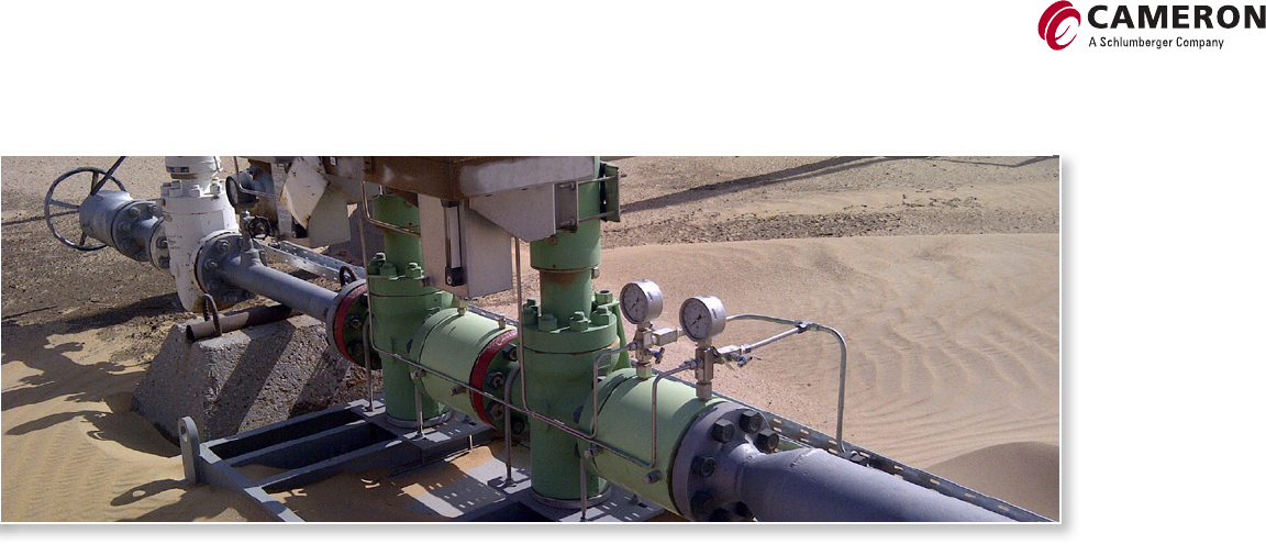
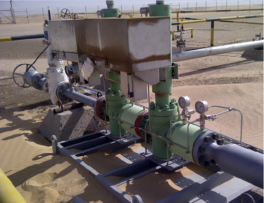
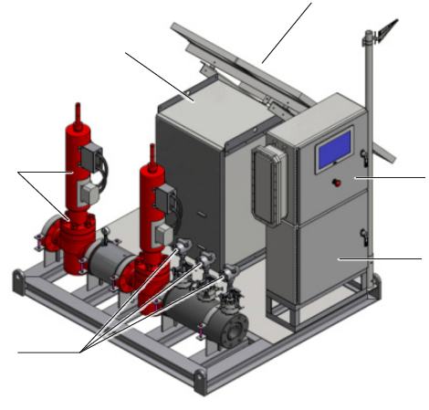
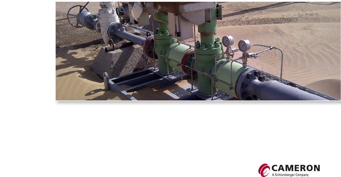
Mechanical HIPPS skid in Saudi Arabia.
03
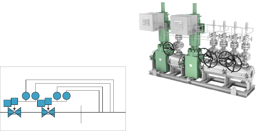
Hydraulic HIPPS
The hydraulic (mechanical) HIPPS provides a self-contained, independent
protection system operated on demand with one-out-of-two (1oo2) or
two-out-of-three (2oo3) (voting) pressure sensor inputs, a hydraulic logic
solver, and two spring-return hydraulically actuated safety valves. The unit is
typically self powered and can be provided with additional real-time controls
via a hydraulic power unit (HPU). This pressurizes the system and opens the
safety shutdown valves. The system remains open (armed) until an abnormal
condition is detected. If an abnormal condition is detected, then the system
closes the two actuated final element valves, protecting the downstream
production or facility.
Hydraulic (mechanical) HIPPS safety loop.
Hydraulic HIPPS.
PSH PSHPSH PSH Mechanical
initiators
HPU HPU
Final elements 600 lbm1,500 lbm
04
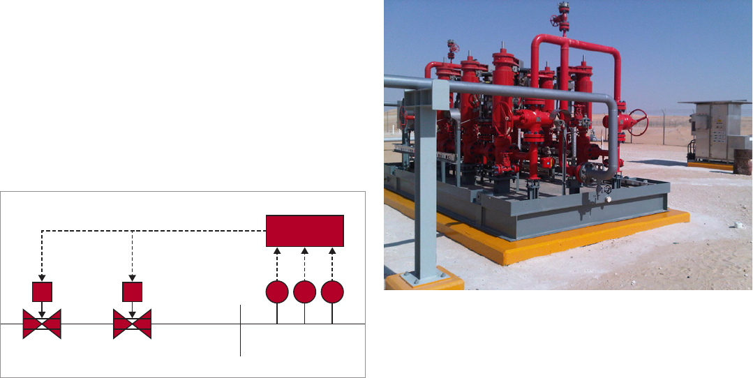
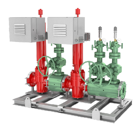
Electronic HIPPS.
Electronic HIPPS
The electronic HIPPS is a self-contained, independent system operated on
demand with 1oo2 or 2oo3 (voting) pressure transmitter inputs, an electronic
logic solver, and two spring-return hydraulically actuated safety valves. The
unit can be self powered with a manual hand pump or HPU and can also
be configured to operate using facility power sources. This pressurizes the
system and opens the safety shutdown valves. The system remains open until
an abnormal condition is detected. If such an event is detected, the system
closes the two actuated final element valves, protecting the downstream
production or facility.
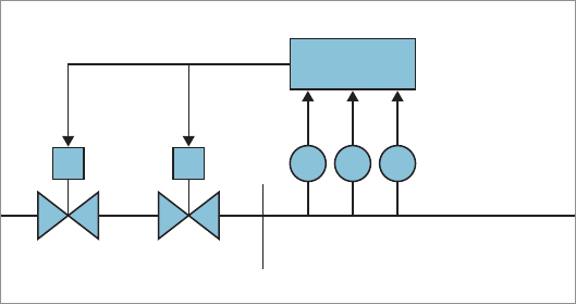
Electronic HIPPS safety loop.
Logic
PT PTPT
Initiators
Final elements 600 lbm1,500 lbm
Logic solver
05
How a HIPPS Works
The primary function of HIPPS is to detect high-pressure conditions and close
isolation valves to protect lower-rated downstream infrastructure. The system
operates autonomously and is independent of the facilities’ process shutdown
(PSD), emergency shutdown (ESD), or control systems. HIPPS are fail-close by
design based on the signal of an overpressure event and can be configured to
operate on other events, such as a loss of motive power of instrument signal.
It is typically fail-close for any loss of instrument air, hydraulic power, electric
power, or instrument signals. Each HIPPS loop is independent. A HIPPS is
designed with redundant safety functions to reduce the risk of failure on
demand and to maximize availability.
Typical safety loop.
Logic
PT PTPT Initiator
Final elements 600 lbm1,500 lbm
Logic solver

A safety instrumented system (SIS) prevents or reduces hazardous events by taking a process to a safe
state when predetermined conditions are met. An SIS can be an ESD, safety interlock system, or safety
shutdown system. Each SIS has one or more safety instrumented functions (SIFs).
Each SIF loop is a combination of logic solvers, sensors, solenoids, and final control elements, such as an
automated valve. Every SIF within an SIS will have a safety integrity level (SIL), which is a measure of the
system performance in terms of probability of failure on demand (PFD). These SIL levels may be the same
or may differ depending on the process. An entire system does not need to have the same SIL level for
each safety function.
06
Safety Instrumented Systems
Probability of Failure on Demand
Safety integrity level Risk reduction factor Probability of failure on demand
SIL 4 100,000 to 10,000 10− to 10−
SIL 3 10,000 to 1,000 10− to 10−³
SIL 2 1,000 to 100 10−³ to 10−²
SIL 4 100 to 10 10−² to 10−¹
Refer to 61508-1 in the IEC Standards.
Advantages
■ 25+ years of HIPPS application experience
■ Complete solutions provider
■ Best-in-class field-proven gate and ball valves
■ Best-in-class field-proven linear and quarter-
turn actuation
■ Global full-service support
07
The Cameron HIPPS comprises two ESD valves,
a 1oo2 logic solver, and typically three pressure
transmitters with 2oo3 voting logic.
Components include
■ sensors that detect high pressures or flow rates
1oo2, 2oo3, or both
■ logic solver that processes the input from the
sensors to the final element
■ SIL 3 rated final elements that bring the
process to a final safe state, isolating the
source of overpressure.
We manufacture HIPPS to meet customer requirements using the
following components:
■ complete system design to meet HIPPS standards
■ API 6A fail-safe gate valves
■ API 6A linear hydraulic spring-return actuators
■ API 6D quarter-turn ball valves
■ API 6D quarter-turn or spring-return actuators
■ skids designed for HIPPS
■ controls or HPU designs (mechanical or electrical with logic solvers)
■ solenoid valves
■ pressure transmitters
■ pressure sensors.
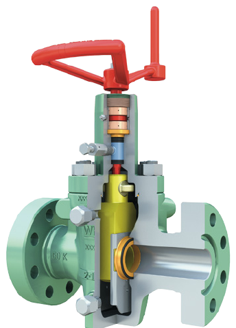
HIPPS Components
Final element—
valves, actuators, and
solenoids
Sensors
Logic solver
Battery storage
Solar arrays (optional)
HPU
HIPPS components.
08
The Cameron HIPPS is an independently instrumented system designed with
higher integrity compared with PSD and ESD systems. Suitable for onshore
and offshore installations requiring high-integrity pressure protection of
downstream systems, a HIPPS is used to prevent a system from exceeding its
rated pressure level. The Cameron HIPPS is SIL 3 certified and incorporates
our field-proven valves and actuators, such as the FLS* extreme service
API 6A slab-style gate valve and GROVE* valves. Pneumatic and hydraulic
actuators, such as the Saf-T-Gard* MH Series hydraulic piston actuators and
LEDEEN* actuators, are supplied. A HIPPS is considered the barrier between
the high- and low-pressure sections of an installation or production facility.
The HIPPS combines Cameron products into an independent, stand-alone
system for any application within the oil and gas industry. Cameron provides
the systems in a variety of configurations, including mechanical and electronic
standalone packages.
Each Cameron HIPPS includes two ESD valves (final elements), a logic solver, and pressure
transmitters arranged in a configuration that fits individual applications.
09
LEDEEN actuators
Consistent engineering design and efficient modular assembly
of LEDEEN actuators increases operational flexibility. The
low-pressure-air, high-pressure-gas, and hydraulic products
enable on-demand double-acting, spring-fail close-open or
manual override operations. This feature maintains product
consistency throughout any project requirement, regardless
of valve size, class, actuator supply medium, pressure, or
actuator function requirements. In addition, the consistent
design provides a significant reduction in the quantity of
recommended spare parts and seal kits, which reduces costs
within maintenance programs.
Advantages
■ Complete controls package designed to meet performance
requirements as required
● Redundancy
● Partial stroking
● Diagnostics
● HPUs
■ Fail-safe spring-return and double-acting design
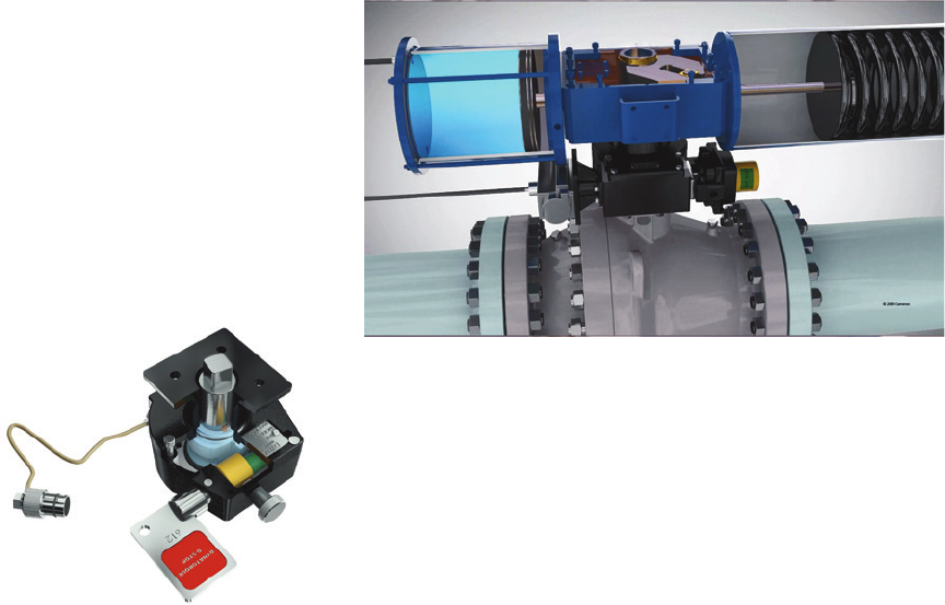
API 6D Quarter-Turn Actuators
LEDEEN pneumatic spring-return actuator.
10
DYNATORQUE D-Stop partial-stroke test device.
DYNATORQUE valve accessories
Cameron is a single-source solution for both standard and customized
gears and automated valve accessories, including declutchable and
nondeclutchable manual overrides; the DYNATORQUE D-Stop* partial-
stroke test device; the DYNATORQUE D-Lock* valve-locking device; spur
and miter gears; handwheels; and ground position indicators.
Advantages
■ Mechanical partial stroke that does not rely on additional hydraulic
or pneumatic controls
■ Keyable for manual intervention only or automated for control
room diagnostics
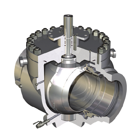
API 6D Ball Valves
GROVE side-entry and top-entry trunnion mounted ball valves are designed to API 6A and 6D standards in a wide range of diameters and
pressure classes. Split-body construction enables using forged materials in various grades of carbon, stainless, and high-alloy steel, which
equips the valves for some of the most severe service conditions. Top-entry valves facilitate maintenance, even when the valves are welded in
line, reducing total leak paths.
Advantages
■ Nominal sizes ranging from
● 1½ in to 60 in
● ASME Class 150 to Class 2500
● API 2,000 to 10,000 psi [13.8 to 68.9 MPa]
■ Bidirectional design that provides flow direction versatility
■ Double-block-and bleed (DBB) capabilities
■ Soft or metal-to-metal sealing (for example, ball-to-seat and seat-to-body)
■ Self-relieving (SR) or double-piston-effect (DPE) dual-barrier seat sealing design
■ Explosive-decompression-resistant thermoplastic or elastomer seals depending on
service conditions
■ Possibility for both stem and seat emergency injection systems
■ Low-fugitive-emissions (FE) stem design options to latest industry standards
■ Fire-safe designs
■ SIL 3 certification
■ Third-party certification available when required GROVE BT2 top-entry ball valve.
11
12
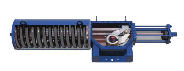
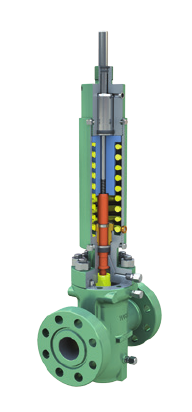
Saf-T-Gard MH Series hydraulic piston actuators
Designed for use with most manufacturers’ gate valves, the Saf-T-Gard MH Series actuators provide a
reliable and robust solution for harsh and remote environments. They are recommended for high-thrust
applications and for large-bore and high-pressure valves when there is no gas source or when the well gas
is too sour.
Advantages
■ Top-mounted power head for ease of maintenance
■ Rising stem design that provides visual indication of valve position
(also available in nonrising stem)
■ 360° of head and housing for optimized positioning of inlet and outlet ports
■ Nonpressurized housing for simple and timely seal replacement
■ Corrosion-resistant materials with Ever-Slik® corrosion-resistant barrier coating externally coated on
all nonstainless-steel components
Standard actuator specifications
■ API 6A actuators for use with 1/-in through 9/-in nominal gate valves
■ Piston sizes ranging from 3 in to 14 in
■ 6,000-psi maximum operating pressure
■ API 6A Appendix F, PR-2 qualification
■ SIL rated
■ Wide range of options and accessories
API 6A Hydraulic Actuators
Saf-T-Gard MH Series hydraulic piston actuator.
Standard bonnet data
■ Standard stem and bonnet materials
dependent on temperature class
■ Standard bonnet backseat test and packing
leak indicator port provided
■ Available PSL 1, 2, 3, and 4 qualification
13
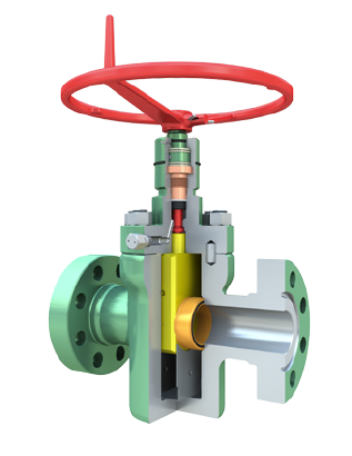
FL and FLS gate valves
The FL* API 6A slab-style gate valve and FLS extreme service API 6A slab-
style gate valve feature a forged body and are readily adapted to multiple
actuator designs. The FL gate valve is available in nominal sizes ranging
from 2/ in to 4/ in and working pressures from 2,000 to 5,000 psi
[13.8 to 34.5 MPa]. The FLS gate valve is available in nominal sizes ranging
from 1/ in to 11 in and working pressures from 2,000 to 20,000 psi
[137.9 MPa]. The FLS gate valve is the standard valve for critical
requirements, including extreme sour gas applications.
Advantages
■ Bidirectional sealing—The FL gate valve has a symmetrical, bidirectional
design without a preferred direction of operation. The seal diameters and
bearing areas of the seats are designed to prevent trapping of pressure
inside the valve cavity.
■ Metal-to-metal sealing—The FL gate valve features bonnet, gate-to-seat,
and seat-to-body seals, which all include metal-to-metal sealing.
■ Reliability through streamlined design—One-piece floating seats and a
floating slab gate provide reliable performance due to the simplicity of
operation and a minimum number of sealing interfaces. Cavity clearances
are carefully controlled to limit the amount of float needed, and special
modified acme threads at the gate-to-stem interface provide sufficient
freedom of movement in all directions to affect a positive downstream seal. API 6A gate valve.
API 6A Gate Valves
■ Lip seals—The FL gate valve incorporates one lip seal, and the FLS gate
valve incorporates two lip seals between the seat and body. The lip seals
are spring-loaded and include pressure-energized, nonelastomeric seals
that assist in low-pressure sealing and protect against intrusion of particle
contaminants into the body cavity and seal areas.
14
M Saf-T-Seal API 6A power-actuated fullbore through-conduit gate valve.
M Saf-T-Seal gate valve
The M Saf-T-Seal* API 6A power-actuated fullbore through-conduit gate valve
delivers leading sealing performance across a wide range of conditions.
This gate valve is available in sizes from 2/ in to 4/ in, with pressure
ratings from 2,000 to 5,000 psi, and with either flanged or threaded
connections. The M Saf-T-Seal gate valve is available in trims for most types of
oilfield service, including sour gas and API 6A SSV Class I and II applications.
The valve can be fitted with a Cameron pneumatic, hydraulic, or electric
actuator or with non-Cameron actuators.
Advantages
■ Fullbore, through-conduit API 6A gate valve
■ Bidirectional design
■ Metal-to-metal sealing at the gate-to-seat and seat-to-body seals
■ Seat skirts that reduce loss of valve body lubricant
■ Field-replaceable valve cavity parts
■ Cast valve body
■ API 6A PR-2 qualification
cameron.slb.com/HIPPS
High-Integrity Pressure
Protection System (HIPPS)
*Mark of Schlumberger
Other company, product, and service names
are the properties of their respective owners.
Copyright © 2016 Schlumberger. All rights reserved. 16-SUR-178595
