L100 M Series Inverters | Addendum To Inverter Instruction Manual Hitachi
User Manual: L100
Open the PDF directly: View PDF ![]() .
.
Page Count: 34

Addendum Number: NBZ574XB
Addendum for Manual: NB576XDecember 2003
L100-M Series
Inverters
In This Addendum.... page
— Getting Started ................................................. 3
— Inverter Mounting and Installation .................. 10
— Configuring Drive Parameters........................ 15
— Operations and Monitoring............................. 21
— Inverter System Accessories.......................... 28
— Troubleshooting and Maintenance ................. 29
— Drive Parameter Settings Tables.................... 30
Addendum to L100 Series
Inverter Instruction Manual
2
Revisions
Revision History Table
No. Revision Comments Date of Issue Addendum
No.
Initial Release of Addendum NBZ574X May 2002 NBZ574X
1 Add -MFR2 product type to content throughout addendum July 2003 NBZ574XA
2 Page 18, add option code 19 restriction
Pages 19–34, shift page contents forward by 1 page
Update cover, revisions page
Dec. 2003 NBZ574XB

L100-M Inverter 3
Getting Started
This section provides specification details for L100-M Series inverters corresponding to
Chapter 1, “Getting Started,” in the L100 Inverter Instruction Manual.
Main Features
Congratulations on your purchase of an L100-M Series Hitachi inverter! Like the
standard L100 Series inverters, this inverter drive features state-of-the-art circuitry and
components, exceptionally small footprint, and high performance. The Hitachi L100-M
product line includes three additional inverter models to cover motor sizes 1/4, 1/2, and
1 horsepower in 100VAC power input versions. The main features are:
• 100V Class inverters
• UL versions, type -MFU2 and -MFR2 (see note below)
• V/f (volts-per-hertz) control algorithm, selectable for either constant or reduced torque
loads
• Convenient keypad for parameter settings
• Three-wire control interface
• Up/Down electronic motorized speed pot function
• Built-in RS-422 communications interface to allow configuration from a PC and for
field bus external modules.
• Sixteen programmable speed levels
• Two-step acceleration and deceleration curves
• PID control adjusts motor speed automatically to maintain a process variable value
NOTE: The -MFU2 and -MFR2 product types have the same features, with the follow-
ing exception: The intelligent inputs on the -MFU2 models are the sinking type (require
a connection to +24VDC to turn ON). The intelligent inputs on the -MFR2 models are
the sourcing type (require a connection to logic GND to turn ON). See “Wiring Diagram
Conventions” on page 21.
The design in Hitachi inverters overcomes many of the traditional trade-offs between
speed, torque and efficiency. The performance characteristics are:
• Output frequency range from 0.5 to 360 Hz
• Continuous operation at 100% torque within a 1:10 speed range (6/60 Hz / 5/50 Hz)
without motor derating
Getting Started
4
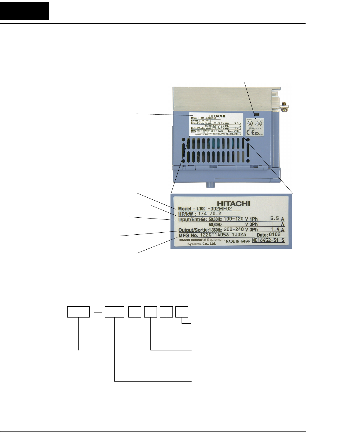
Inverter Specifications Label
The Hitachi L100-M Series inverters have product labels located on the right side of the
housing, as pictured below. Be sure to verify that the specifications on the labels match
your power source, motor, and application safety requirements.
Model Number Convention
The model number for a specific inverter contains useful information about its operating
characteristics. Refer to the model number legend below:
Inverter model number
Motor capacity for this model
Output Rating:
Frequency, voltage, current
Manufacturing codes:
Lot number, date, etc.
Specifications label
Regulatory agency approvals
Power Input Rating:
frequency, voltage, phase, current
L100 002 M F U 2
Version number (_, 1, 2, ...)
Restricted distribution:
U=USA, R=Japan
Input voltage:
M = single-phase 100V class
Applicable motor capacity in kW
002 = 0.2 kW
004 = 0.4 kW
007 = 0.75 kW
Configuration type
F = with digital operator (keypad)
Series name
L100-M Inverter 5
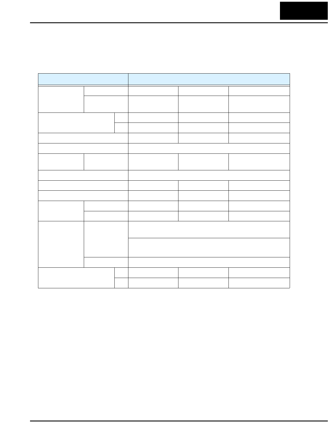
Model-specific tables for 100V class inverters
The following table is specific to L100-M Series inverters. Note that “General Specifica-
tions” on page 6 apply to all L100-M inverters. Footnotes for both tables follow the table
below.
Item 100V Class Specifications
L100-M invert-
ers, 100V models
CE version — — —
UL versions 002MFU2,
002MFR2
004MFU2,
004MFR2
007MFU2,
007MFR2
Applicable motor size *2 kW 0.2 0.4 0.75
HP 0.25 0.5 1
Rated capacity (230V) kVA *10 0.5 1.0 1.6
Rated input voltage 1-phase: 100V to 120V, +5/–10%; 50/60 Hz ±5%
Rated input
current (A)
1-phase 5.5 10 16
Rated output voltage *3 3-phase 0 to 230V (corresponding to 2 times input voltage)
Rated output current (A) 1.4 2.6 4.0
Efficiency at 100% rated output (%) 92.2 93.2 94.8
Watt loss,
approximate (W)
at 70% output 13 21 31
at 100% output 17 29 41
Braking Dynamic
braking, approx.
% torque, (short
time stop from
50 / 60 Hz) *5
100%: ≤ 50Hz
50%: ≤ 60Hz
Capacitive feedback type, dynamic braking unit and braking
resistor optional, individually installed
DC braking Variable operating frequency, time, and braking force
Weight kg 1.1 1.2 1.5
lb 2.4 2.6 3.3
Getting Started
6
Footnotes for the preceding table and the table that follows:
*1: The protection method conforms to JEM 1030.
*2: The applicable motor refers to Hitachi standard 3-phase motor (4-pole). When using other
motors, care must be taken to prevent the rated motor current (50/60 Hz) from exceeding the
rated output current of the inverter.
*3: The output voltage decreases as the main supply voltage decreases (except when using the
AVR function). In any case, the output voltage cannot exceed the input power supply
voltage.
*4: To operate the motor beyond 50/60 Hz, consult the motor manufacturer for the maximum
allowable rotation speed.
*5: The braking torque via capacitive feedback is the average deceleration torque at the shortest
deceleration (stopping from 50/60 Hz as indicated). It is not continuous regenerative braking
torque. The average deceleration torque varies with motor loss. This value decreases when
operating beyond 50 Hz. Note that a braking unit is not included in the inverter. If a large
regenerative torque is required, the optional regenerative braking unit should be used.
*6: The frequency command is the maximum frequency at 9.8V for input voltage 0 to 10 VDC,
or at 19.6 mA for input current 4 to 20 mA. If this characteristic is not satisfactory for your
application, contact your Hitachi sales representative.
*7: If operating the inverter in an ambient temperature of 40–50° C, reduce the carrier frequency
to 2.1 kHz, derate the output current by 80%, and remove the top housing cover. Note that
removing the top cover will nullify the NEMA rating for the inverter housing.
*8: The storage temperature refers to the short-term temperature during transport.
*9: Conforms to the test method specified in JIS C0911 (1984). For the model types excluded in
the standard specifications, contact your Hitachi sales representative.
*10:The output voltage of xxxMFU / xxxMFR is 230V.
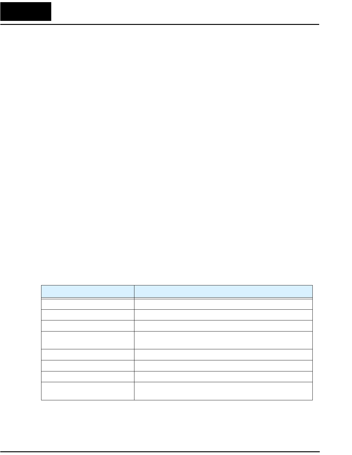
General Specifications
The following table applies to all L100-M inverters.
Item General Specifications
Protective housing *1 IP20
Control method Sine wave pulse-width modulation (PWM) control
Output frequency range *4 0.5 to 360 Hz
Frequency accuracy Digital command: 0.01% of the maximum frequency
Analog command: 0.1% of the maximum frequency (25°C ± 10°C)
Frequency setting resolution Digital: 0.1 Hz; Analog: max. frequency/1000
Volt./Freq. characteristic V/f optionally variable, V/f control (constant torque, reduced torque)
Overload current rating 150%, 60 seconds
Acceleration/deceleration time 0.1 to 3000 sec., (linear accel/decel), second accel/decel setting
available
L100-M Inverter 7
Input
signal
Freq.
setting
Operator panel Up and Down keys / Value settings
Potentiometer Analog setting
External signal
*6
0 to 10 VDC (input impedance 10k Ohms), 4 to 20 mA (input
impedance 250 Ohms), Potentiometer (1k to 2k Ohms, 2W)
FWD/
REV
Run
Operator panel Run/Stop (Forward/Reverse run change by command)
External signal Forward run/stop, Reverse run/stop
Intelligent input
terminal
FW (forward run command), RV (reverse run command), CF1~CF4
(multi-stage speed setting), JG (jog command), 2CH (2-stage accel./
decel. command), FRS (free run stop command), EXT (external
trip), USP (startup function), SFT (soft lock), AT (analog current
input select signal), RS (reset), PTC (thermal protection), STA (start,
3-wire interface), STP (stop, 3-wire interface), F/R (FW/RV 3-wire
interface), UP (remote control Up function, motorized speed pot.),
DWN (remote control Down function, motorized speed pot.), OPE
(operator control)
Output
signal
Intelligent output
terminal
RUN (run status signal), FA1,2 (frequency arrival signal), OL
(overload advance notice signal), OD (PID error deviation signal),
AL (alarm signal)
Frequency monitor PWM output; Select analog output frequency monitor, analog output
current monitor or digital output frequency monitor
Alarm output contact ON for inverter alarm (1C contacts, both normally open or closed
avail.)
Other functions AVR function, curved accel/decel profile, upper and lower limiters,
16-stage speed profile, fine adjustment of start frequency, carrier
frequency change (0.5 to 16 kHz) frequency jump, gain and bias
setting, process jogging, electronic thermal level adjustment, retry
function, trip history monitor
Protective function Over-current, over-voltage, under-voltage, overload, extreme high/
low temperature, CPU error, memory error, ground fault detection at
startup, internal communication error, electronic thermal
Operat-
ing
Environ
ment
Temperature Operating (ambient): -10 to 50°C (*7) / Storage: -25 to 70°C (*8)
Humidity 20 to 90% humidity (non-condensing)
Vibration *9 5.9 m/s2 (0.6G), 10 to 55 Hz
Location Altitude 1,000 m or less, indoors (no corrosive gasses or dust)
Coating color Light purple, cooling fins in base color of aluminum
Options Remote operator unit, copy unit, cables for the units, dynamic
braking unit, braking resistor, AC reactor, DC reactor, noise filter,
DIN rail mounting
Standards EN 61800-3 EMC Guidelines in connection with optional line filter
modules in line with installation guidelines, EN 50718 Low-Voltage
Guideline, UL, cUL
Marking UL, cUL
Item General Specifications
Getting Started
8
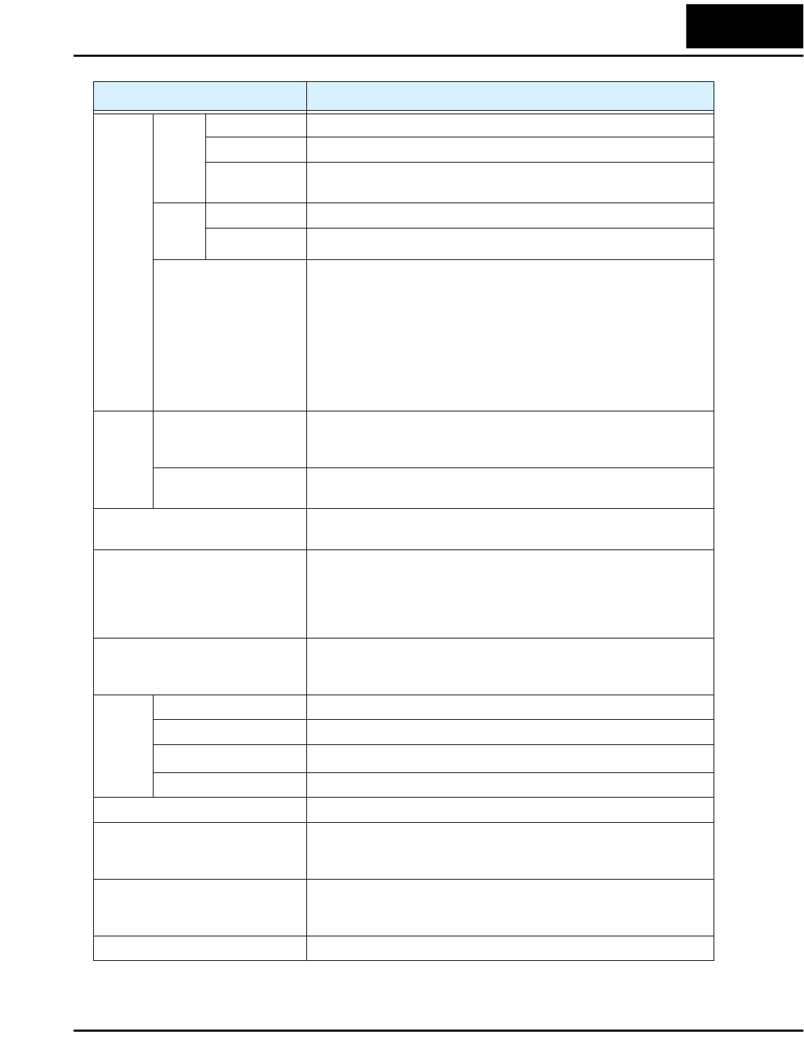
Derating Curves
The maximum available inverter current output is limited by the carrier frequency and
ambient temperature. The carrier frequency is the inverter’s internal power switching
frequency, settable from 0.5 kHz to 16 kHz. Choosing a higher carrier frequency tends to
decrease audible noise, but it also increases the internal heating of the inverter, thus
decreasing (derating) the maximum current output capability. Ambient temperature is
the temperature just outside the inverter housing—such as inside the control cabinet
where the inverter is mounted. A higher ambient temperature decreases (derates) the
inverter’s maximum current output capacity.
Use the following derating curves to help determine the optimal carrier frequency setting
for your inverter, and to find the output current derating. Be sure to use the proper curve
for your particular L100-M inverter model number.
L100–002MFU2/MFR2
0.5246810121416
70%
80%
90%
100%
95%
85%
75%
% of rated
output current
Carrier frequency
kHz
Standard ratings at 40°C
Ratings at 50°C max. with top cover removed
Legend:
L100-M Inverter 9
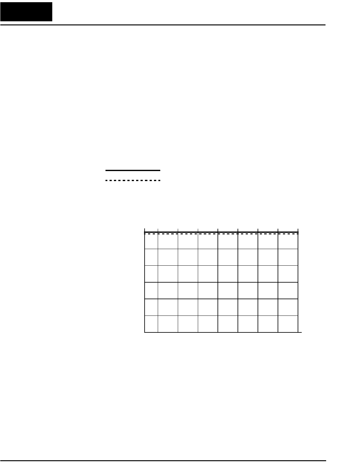
Derating curves, continued...
L100–007MFU2/MFR2
0.5246810121416
70%
80%
90%
100%
95%
85%
75%
% of rated
output current
Carrier frequency
kHz
L100–004MFU2/MFR2
0.5246810121416
70%
80%
90%
100%
95%
85%
75%
% of rated
output current
Carrier frequency
kHz
Inverter Mounting and Installation
10
Inverter Mounting and Installation
This section provides details for L100-M Series installation corresponding to Chapter 2,
“Inverter Mounting and Installation,” in the L100 Inverter Instruction Manual.
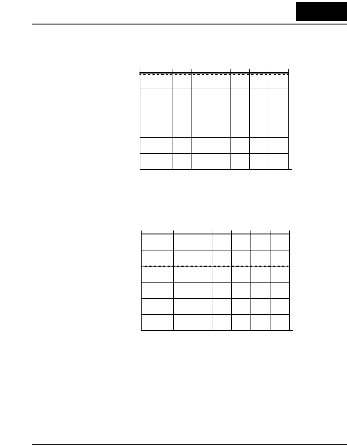
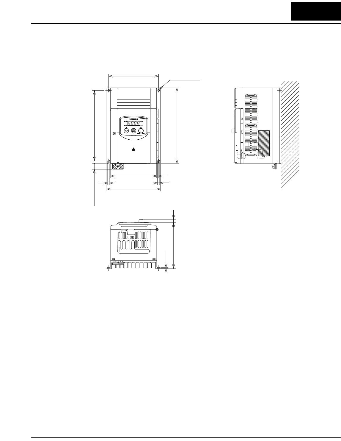
Check Inverter Dimensions
Locate the applicable drawing below or on the next page for your inverter.
Dimensions are given in millimeters (inches) format.
4(0.16)
130(5.12)
110(4.33)
5(0.20)-F4.5(0.18)
119(4.69)
118(4.65)
128(5.04)
5(0.20) 5(0.20)
10(0.39)
110(4.33) 7(0.28)
2.6(0.10)
L100 -002MFU2
-004MFU2
-002MFR2
-004MFR2
L100-M Inverter 11
Dimensional drawings continued...
180(7.09)
5(0.20)-F4.5(0.18)
119(4.69)
168(6.61)
128(5.04)
5(0.20)
5(0.20)
10(0.39)
110(4.33) 4(0.16)
110(4.33) 7(0.28)
2.6(0.10)
L100 -007MFU2
-007MFR2
Inverter Mounting and Installation
12
Preparing for Wiring
It is very important to perform the wiring carefully and correctly. Before proceeding,
please study the cation and warning messages below.
WARNING: “Use 60/75°C Cu wire only” or equivalent.
WARNING: “Open Type Equipment.”
WARNING: “A Class 2 circuit wired with Class 1 wire” or equivalent.
WARNING: “Suitable for use on a circuit capable of delivering not more than 5,000
rms symmetrical amperes, 120 V maximum.” For models with suffix M (such as
004MFU2).
HIGH VOLTAGE: Be sure to ground the unit. Otherwise, there is a danger of electric
shock and/or fire.
HIGH VOLTAGE: Wiring work shall be carried out only by qualified personnel. Other-
wise, there is a danger of electric shock and/or fire.
HIGH VOLTAGE: Implement wiring after checking that the power supply is OFF. Oth-
erwise, you may incur electric shock and/or fire.
WARNING: Do not connect wiring to an inverter or operate an inverter that is not
mounted according the instructions given in this manual. Otherwise, there is a danger of
electric shock and/or injury to personnel.
L100-M Inverter 13
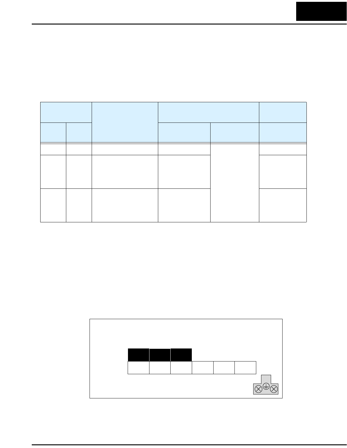
Determining Wire and Fuse Sizes
The maximum motor currents in your application determines the recommended wire
size. The following table gives the wire size in AWG. The “Power Lines” column applies
to the inverter input power, output wires to the motor, the earth ground connection, and
any system components such as braking resistors and filters. The “Signal Lines” column
applies to any wire connecting to the two green 7 and 8-position connectors just inside
the front panel half-door.
Note 1: Field wiring must be made by a UL-listed and CSA-certified closed-loop
terminal connector sized for the wire gauge involved. Connector must be
fixed by using the crimping tool specified by the connector manufacturer.
Note 2: Be sure to consider the capacity of the circuit breaker to be used.
Note 3: Be sure to use a larger wire gauge if power line length exceeds 66 ft (20m).
Note 4: Use 18 AWG / 0.75 mm2 wire for the alarm signal wire ([AL0], [AL1], [AL2]
terminals).
The terminal arrangement below corresponds to all L100-M Series inverter models.
Motor Output
(kW/HP)
Inverter Model
Wiring Applicable
equipment
kW HP Power Lines Signal Lines Fuse (UL-rated,
class J, 600V)
0.2 1/4 L100-002MFU2/MFR2 AWG16 / 1.3 mm2
18 to 28 AWG /
0.14 to 0.75 mm2
shielded wire
(see Note 4)
10A (single ph.)
0.4 1/2 L100-004MFU2/MFR2 Input:
AWG14 / 2.1 mm2
Output:
AWG16 / 1.3 mm2
15A (single ph.)
0.75 1 L100-007MFU2/MFR2 Input:
AWG12 / 3.3 mm2
Output:
AWG16 / 1.3 mm2
20A (single ph.)
(/) +–
L1 N/L3 U/T1 V/T2
–002MFU2/MFR2 to –007MFU2/MFR2
Chassis
Ground
W/T3
Inverter Mounting and Installation
14
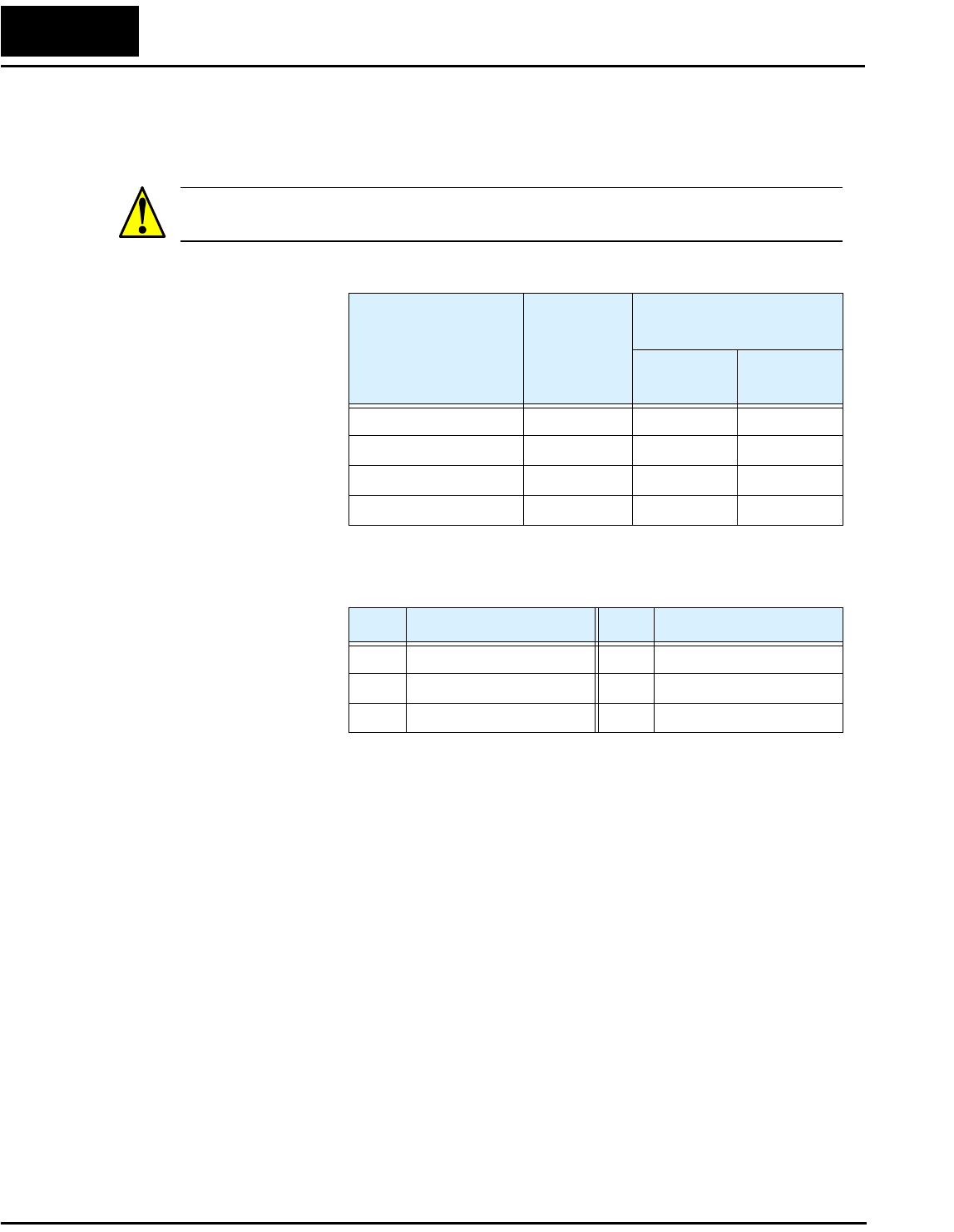
Terminal Dimensions and Torque Specs
The terminal screw dimensions for all L100 inverters are listed in table below. This
information is useful in sizing spade lug or ring lug connectors for wire terminations.
CAUTION: Fasten the screws with the specified fastening torque in the table below.
Check for any loosening of screws. Otherwise, there is the danger of fire.
When connecting wiring, use the tightening torque listed in the following table to safely
attach wiring to the connectors.
Connector
Number of
Screw
Terminals
Models 002MFU2/MFR2–
007MFU2/MFR2
Screw
Diameter Width (mm)
Power Terminals 12 M4 9
Control Signal 15 M2 —
Alarm Signal 3 M3 —
Ground Terminals 2 M4 —
Screw Tightening Torque Screw Tightening Torque
M2 0.2 N•m (max. 0.25 N•m) M4 1.2 N•m (max. 1.3 N•m)
M3 0.5 N•m (max. 0.6 N•m) M5 2.0 N•m (max. 2.2 N•m)
M3.5 0.8 N•m (max. 0.9 N•m) — —
L100-M Inverter 15
Configuring Drive Parameters
This section provides details for L100-M Series configuration corresponding to
Chapter 3, “Configuring Drive Parameters,” in the L100 Inverter Instruction Manual.
Relative to standard L100 Series inverters, Hitachi L100-M Series inverters have
additional parameters and functions, or parameters with a different setting range. These
include D_16, F_04, B_12, B_13, B_32, C_01 to C_05, C_70, C_71, C_72, and C_79.
The tables in this section list only these parameters as they apply to L100-M Series
inverters.
“D” Group: Monitoring Functions
L100-M Series inverters add the following to the monitoring functions.
“F” Group: Main Profile Parameters
For parameter F_04, L100-M Series inverters have the additional “02 Terminal” setting.
With F_04=02, the inverters use [FW] and [RV] inputs in real time to determine the
direction of rotation for the keypad Run key. For more information on Run key operation
and interaction with [FW] and [RV] terminals, see page “Forward Run/Stop and Reverse
Run/Stop Commands:” on page 23.
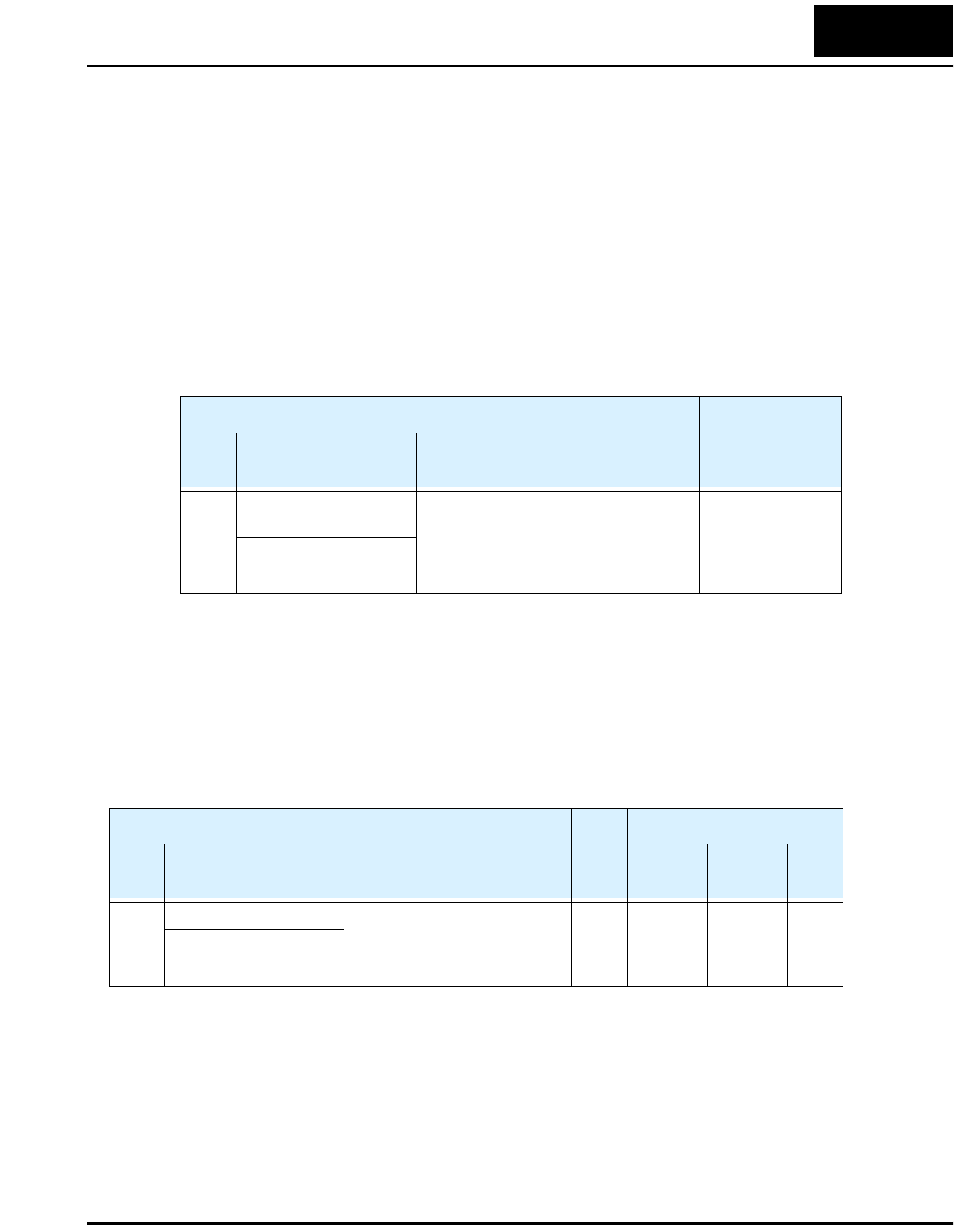
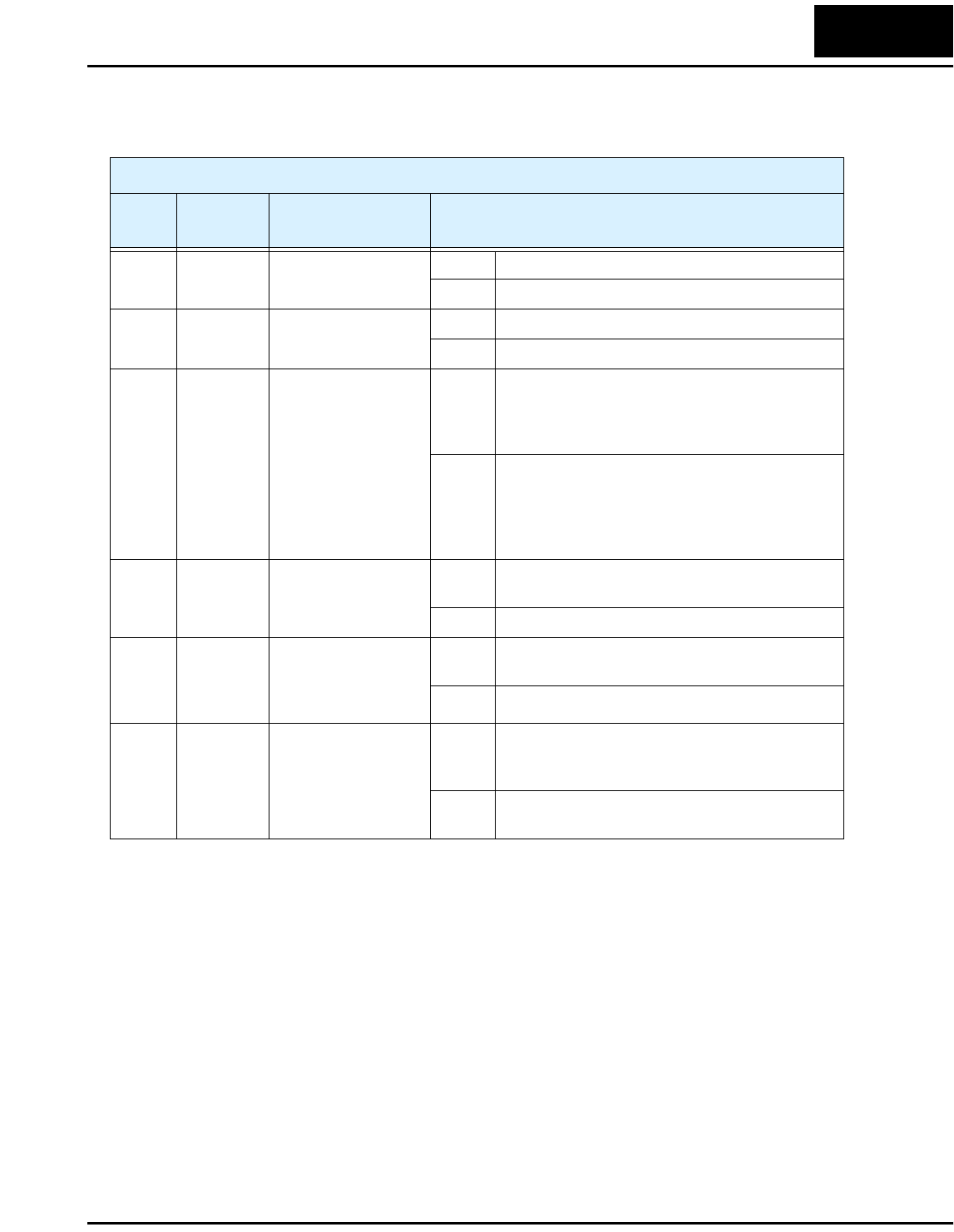
“D” Function Run
Mode
Edit
Range and Units
Func.
Code
Name /
SRW Display Description
D_16 Cumulative operation
RUN time monitor
Displays total time the inverter
has been in RUN mode in
hours.
— 0 to 9999 / 1000
to 9999/
100 to 999
(10,000 to 99,900)
hrs.
RUN 0000000hr
“F” Function Run
Mode
Edit
Defaults
Func.
Code
Name /
SRW Display Description –MFU2 –MFR2 Units
F_04 Keypad Run key routing Two options; select codes:
00 ...Forward
01 ...Reverse
02 ...Terminal
✘00 00 —
INIT DOPE FWD
Configuring Drive Parameters
16
“B” Group: Fine Tuning Functions
For the following functions, L100-M Series inverters have new ranges or descriptions.
NOTE: The set value links with the detection current of output current monitor, electric
thermal protection, and overload limit.
The three available electronic thermal characteristic curves are shown in the graph
below.
WARNING: When parameter B_12, level of electronic thermal setting, is set to device
FLA rating (Full Load Ampere nameplate rating), the device provides solid state motor
overload protection at 115% of device FLA or equivalent. Parameter B_12, level of
electronic thermal setting, is a variable parameter.
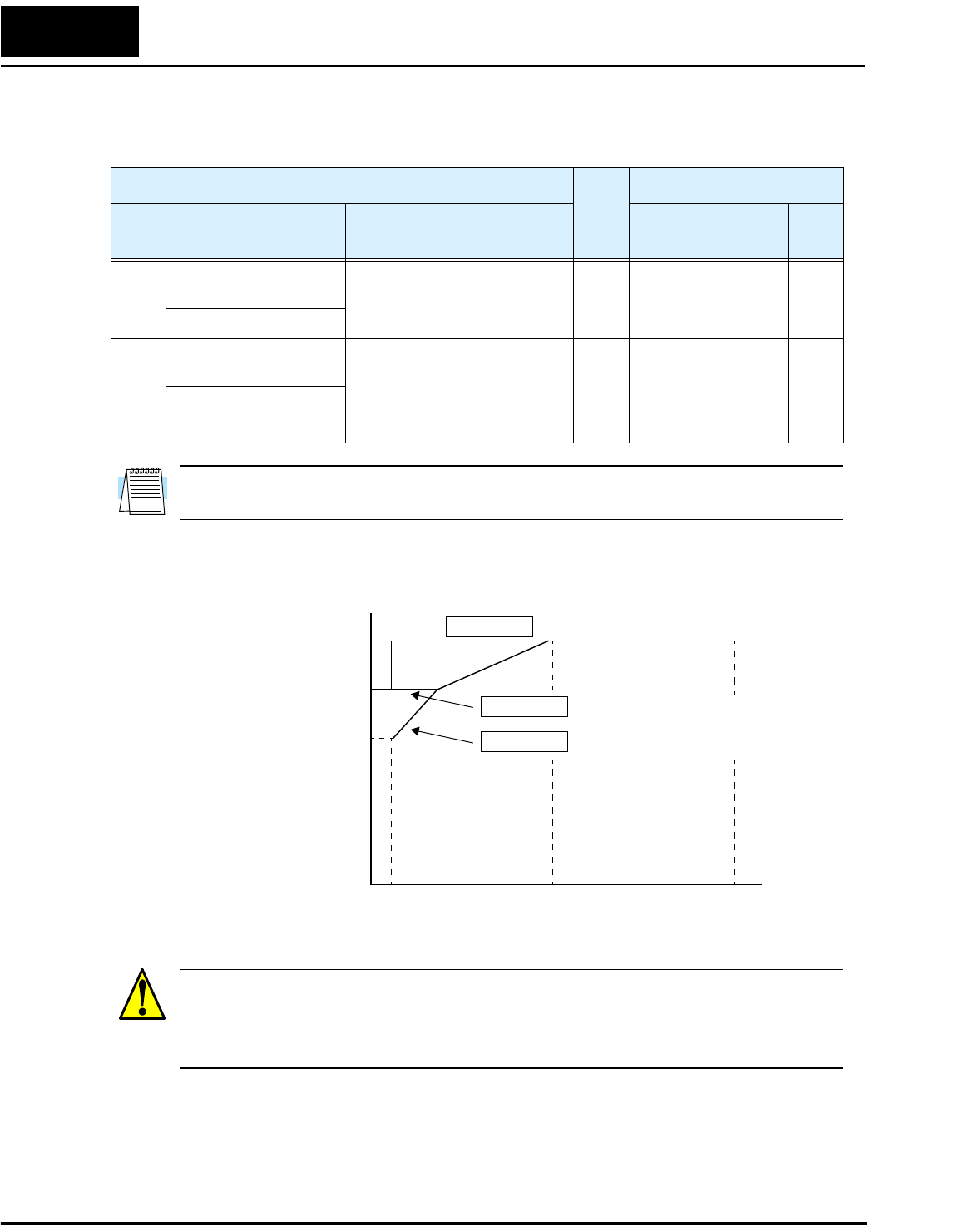
“B” Function Run
Mode
Edit
Defaults
Func.
Code
Name /
SRW Display Description –MFU2 -MFR2 Units
B_12 Level of electronic
thermal setting
Set a level between 5% and
120% for the rated inverter
current.
✘Rated current for
each inverter model
%
E-THM LVL 03.00A
B_13 Electronic thermal
characteristic
Select from three curves,
option codes:
00...Reduced torque
01...Constant torque
02...Reduced torque 2
✘01 00 —
E-THM CHAR CRT
Output frequency
Constant torque
Reduced torque 2
B_13 =01
B_13 =02
To r q u e
520 60 120
Hz
100%
80%
60%
0
B_13 =00 Reduced torque
L100-M Inverter 17
B_32: Reactive current setting – The inverter’s D_02 monitor function displays the
motor current. The display accuracy is normally ±20%, provided that the following
conditions exist:
• A single motor with standard frame size and characteristics is connected
• The inverter’s output frequency is at 50% or higher of the maximum output frequency
• The inverter’s output current is within the rated current
However, it will be necessary to calibrate the display accuracy via B_32 adjustment of
the internal no-load reactive motor current if any of these conditions exist:
• The motor is smaller than the standard maximum recommended for the inverter
• The motor is a two-pole motor type
• Two or more motors are connected in parallel to the inverter (be sure to multiply the
current by the number of motors when setting B_32)
For general purpose motors that have an undetermined internal no-load (reactive) motor
current, use the following table for typical current values. For special motors, consult the
manufacturer of your particular motor.
“B” Function Run
Mode
Edit
Defaults
Func.
Code
Name /
SRW Display Description –MFU2 –MFR2 Units
B_32 Reactive current setting Calibrate detection of motor’s
no load (reactive current) to
improve D_02 display
accuracy, range is 0 to 32
Amperes
✔40% rated current A
IO 0.00A
Motor 200V Class
HP kW Poles at 50 Hz at 60 Hz
1/8 0.1 4 0.6 A 0.5 A
1/4 0.2 2 0.6 A 0.4 A
4 0.8 A 0.7 A
— 0.3 4 1.1 A 1.1 A
1/2 0.4 2 1.2 A 0.9 A
4 1.7 A 1.2 A
6 1.9 A 1.5 A
1 0.75 2 1.9 A 1.3 A
4 2.2 A 1.7 A
6 1.8 A 2.2 A
Configuring Drive Parameters
18
C” Group: Intelligent Terminal Functions
The intelligent input terminals for L100-M Series inverters have 21 possible option
assignments.
L100-M Series inverters have the 15 intelligent input option codes of standard L100
inverters, but with the model series restriction noted below:
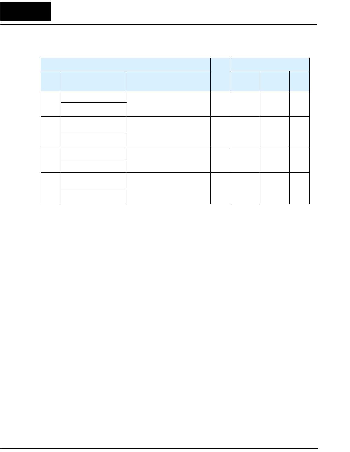
“C” Function Run
Mode
Edit
Defaults
Func.
Code
Name /
SRW Display Description –MFU2 –MFR2 Units
C_01 Terminal [1] function Select function for terminal [1]
21 options (see next section)
✘00
[FW]
00
[FW]
—
IN-TM 1 FW
C_02 Terminal [2] function Select function for terminal [2]
21 options (see next section)
✘01
[RV]
01
[RV]
—
IN-TM 2 RV
C_03 Terminal [3] function Select function for terminal [3]
21 options (see next section)
✘16
[AT]
02
[CF1]
—
IN-TM 3 AT
C_04 Terminal [4] function Select function for terminal [4]
21 options (see next section)
✘13
[USP]
03
[CF2]
—
IN-TM 4 USP
C_05 Terminal [5] function Select function for terminal [5]
21 options (see next section)
✘18
[RS]
18
[RS]
—
IN-TM 5 2CH
Input Function Summary Table
Option
Code
Terminal
Symbol Function Name Description
19 PTC PTC Thermistor
Thermal Protection
–MFR2 series only
ON When a thermistor is connected to terminals [5]
and [L], the inverter checks for over-
temperature and will cause trip event and turn
OFF output to motor
OFF A disconnect of the thermistor causes a trip
event, and the inverter turns OFF the motor
L100-M Inverter 19
L100-M Series inverters add the following 6 options to the 15 option codes for standard
L100 inverter intelligent inputs:
Input Function Summary Table
Option
Code
Terminal
Symbol Function Name Description
20 STA START
(3-wire interface)
ON Starts the motor rotation
OFF No change to present motor status
21 STP STOP
(3-wire interface)
ON Stops the motor rotation
OFF No change to present motor status
22 F/R FWD, REV
(3-wire interface)
ON Selects the direction of motor rotation: ON =
FWD. While the motor is rotating, a change of
F/R will start a deceleration, followed by a
change in direction.
OFF Selects the direction of motor rotation:
OFF =REV.
While the motor is rotating, a change of F/R will
start a deceleration, followed by a change in
direction.
27 UP Remote Control
UP Function (motor-
ized speed pot.)
ON Accelerates (increases output frequency) motor
from current frequency
OFF No change to output frequency
28 DWN Remote Control
DOWN Function
(motorized speed
pot.)
ON Decelerates (decreases output frequency) motor
from current frequency
OFF No change to output frequency
31 OPE Operator Control ON Forces the source of the output frequency setting
(A_01) and the source of the RUN command
(A_02) to be from the digital operator
OFF Source of output frequency set by (A_01) and
source of run command set by (A_02) is used
Configuring Drive Parameters
20
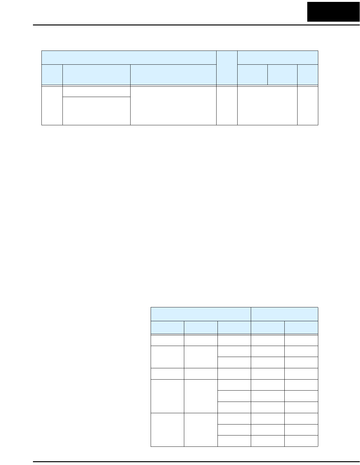
The L100-M Series inverters have added the functions below to improve serial commu-
nications:
“C” Function Run
Mode
Edit
Defaults
Func.
Code
Name /
SRW Display Description –MFU2 –MFR2 Units
C_70 Data command method Two option codes:
02...Digital operator
03...RS485
✘02 02 —
SELECT REM
C_71 Communication speed
selection
Three option codes:
04...4800 bps
05...9600 bps
06...19200 bps
✘04 04 bps
BAU 4800bps
C_72 Node allocation Set the address of the inverter
on the network.
Range is 1 to 32.
✘01 01 —
ADDRESS 01
C_79 Communication error
response
Two option codes:
00...Trip
01...Continue operation
without tripping
✘01 01 —
COM ERR TRP
L100-M Inverter 21
Operations and Monitoring
This section covers new or modified intelligent terminal functions for L100-M Series
inverters, corresponding to Chapter 4, “Operations and Monitoring,” in the L100 Inverter
Instruction Manual. The additional functions include Run key routing via [FW] or [RV]
terminals, three-wire operation, remote control up and down functions, and force opera-
tion from a digital operator (keypad).
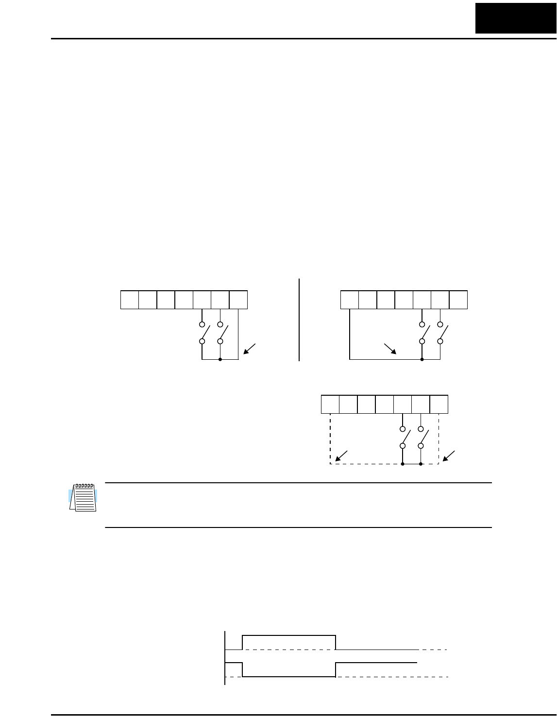
Wiring Diagram Conventions
The input wiring diagrams in this section are examples only. Default and non-default
input terminal assignments are noted throughout; your particular assignments may be
different. Input switch wiring for –xMFU2 models will connect the switch common
(return) to +24VDC, as shown below (left). Input switch wiring for –xMFR2 models will
connect the switch common (return) to Logic GND terminal [L], as shown below (right).
Each wiring example in this section shows
both the –xMFU2 and –xMFR2 input wiring
in the same diagram, as shown to the right.
DO NOT connect terminal [P24] to [L]. Be
sure the return terminal used matches your
inverter type.
NOTE: The input wiring diagrams in the L100 instruction manual match the -MFU2
models. If your inverter is the -MFR2 type, be sure to wire the inputs as instructed in this
addendum.
Waveform Diagram Conventions
The input signal waveform diagrams in this section (and in the L100 manual, Chapter 4)
assume the intelligent inputs are active high type (corresponds to -MFU2 inverter type).
If your inverter is the -MFR2 type, you must invert the ON/OFF logic sense when
observing or interpreting the input waveforms.
12345L
P24
FWRV
12345L
P24
FWRV
Wiring for -MFU2 versions Wiring for -MFR2 versions
common
(return)
common
(return)
12345L
P24
FWRV
for
-MFR2
models
for
-MFU2
models
t
-MFU2 input terminal 1
0
1
0
-MFR2 input terminal
ON OFF
ON OFF

Operations and Monitoring
22
Example Wiring Diagram
12
11
1
2
3
4
5
L
L
H
O
OI
FM
CM2
L100-M
P24
AL1
AL0
AL2
Alarm contacts,
type 1 Form C
Open collector outputs
Analog reference
R
(L1)
S
(L2)
T
N(L3)
U
(T1)
V
(T2)
W
(T3)
Motor
Forward
Reverse
Intelligent inputs,
5 terminals
4–20mA
0–10VDC
NOTE: For the wiring of intelligent I/O and analog inputs, be sure to use twisted pair / shielded cable.
Attach the shield wire for each signal to its respective common terminal at the inverter end only.
Thermistor
Meter
Analog common
Load
Freq. arrival signal
Run signal
Load
+
–
Logic output common
Input
circuits
Logic input
common
+
–
24V
+1
+
–
Braking
unit
(optional)
DC reactor
(optional)
Output
circuits
[5] configurable as
discrete input or
thermistor input
Power source,
3-phase or
1-phase, per
inverter model
Breaker,
MCCB or GFI
Input wiring for
-MFU2 models
Input wiring for
-MFR2 models
L100-M Inverter 23
Forward Run/Stop and Reverse Run/Stop Commands:
When you input the Run command via the terminal [FW], the inverter executes the
Forward Run command (high) or Stop command (low). When you input the Run
command via the terminal [RV], the inverter executes the Reverse Run command (high)
or Stop command (low).
L100-M Series inverters can also use [FW] and [RV] inputs in real time to determine the
direction of rotation for the keypad Run key. This requires setting A_02=02 (keypad
control) and Run Key Routing F_04 = 02 (terminal). The operation is shown below.
Option
Code
Terminal
Symbol Function Name State Description
00 FW Forward Run/Stop ON Inverter is in Run Mode, motor runs forward
OFF Inverter is in Stop Mode, motor stops
01 RV Reverse Run/Stop ON Inverter is in Run Mode, motor runs reverse
OFF Inverter is in Stop Mode, motor stops
Valid for inputs: C_01, C_02, C_03, C_04,
C_05
Required settings: A_02 = 01 (terminal control)
A_02 = 02 (keypad control)
Notes:
•When the Forward Run and Reverse Run
commands are active at the same time, the inverter
enters the Stop Mode.
•When a terminal associated with either [FW] or
[RV] function is configured for normally closed,
the motor starts rotation when that terminal is
disconnected or otherwise has no input voltage.
Example (default input configuration shown—
see Chapter 3 in L100 Instruction Manual):
12345L
P24
See I/O specs in the L100 Instruction Manual
FWRV
for
-MFR2
models
for
-MFU2
models
Motor
rotation t
[FW]
[RV]
Run key
Stop key
forward
reverse
1
0
1
0
1
0
1
0
+
–
Operations and Monitoring
24
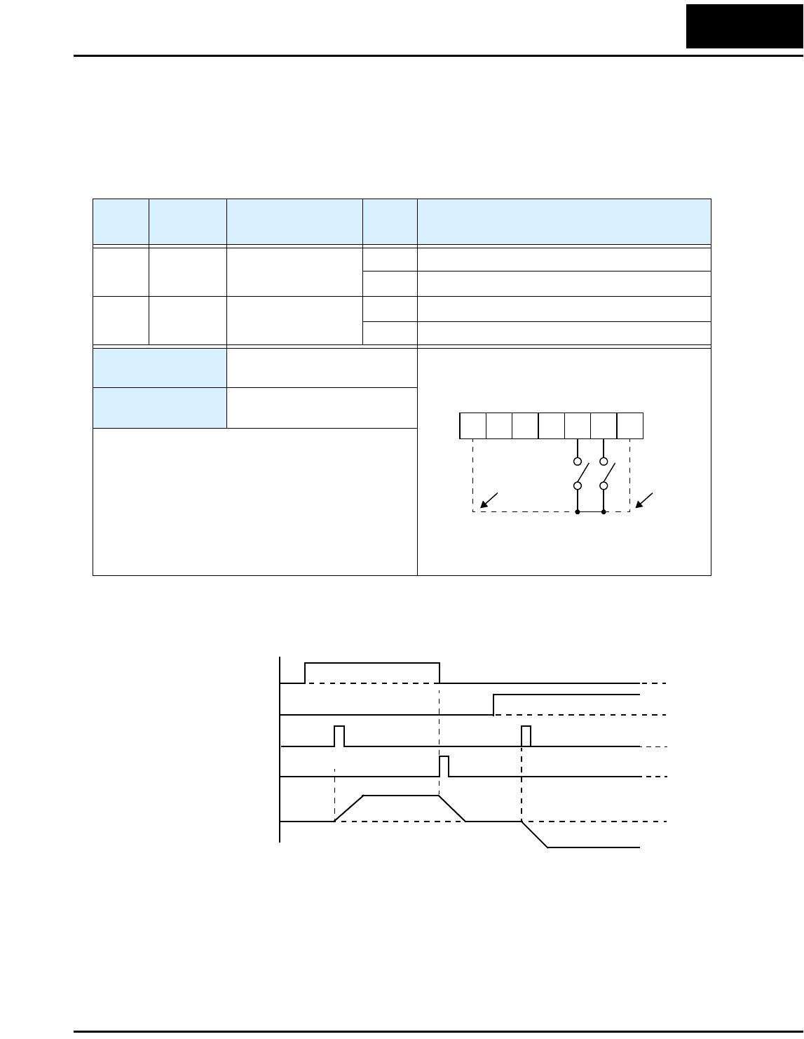
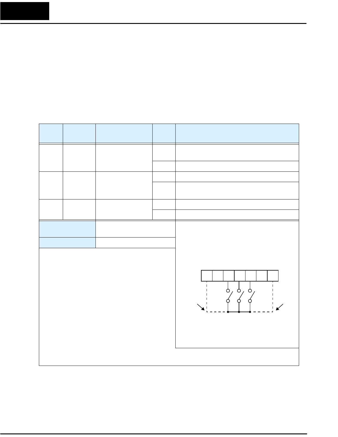
Three-wire Interface Operation
The 3-wire interface is an industry standard motor control interface. This function uses
two inputs for momentary contact start/stop control, and a third for selecting forward or
reverse direction. To implement the 3-wire interface, assign 20 [STA] (Start), 21 [STP]
(Stop), and 22 [F/R] (Forward/Reverse) to three of the intelligent input terminals. Use
momentary contact for Start and Stop. Use a selector switch such as SPST for the
Forward/Reverse input. Be sure to set the operation command selection A_02=01 for
input terminal control of motor. If you have a motor control interface that needs logic-
level control (rather than momentary pulse control), use the [FW] and [RV] inputs
instead.
Option
Code
Terminal
Symbol Function Name Input
State Description
20 STA Start Motor ON Start motor rotation on momentary contact (uses
acceleration profile)
OFF No change to motor operation
21 STP Stop Motor ON No change to motor operation
OFF Stop motor rotation on momentary contact (uses
deceleration profile)
22 F/R Forward/Reverse ON Select reverse direction of rotation
OFF Select forward direction of rotation
Valid for inputs: C_01, C_02, C_03, C_04,
C_05
Required settings: A_02 = 01
Notes:
•The STP logic is inverted. Normally the switch will
be closed, so you open the switch to stop. In this
way, a broken wire causes the motor to stop
automatically (safe design).
•When you configure the inverter for 3-wire inter-
face control, the [FW] and [RV] intelligent terminal
assignments are disabled.
•The [F/R] terminal signal level is evaluated only
when an [STA] pulse occurs.
•You must assign both the [STA] and [STP] intelli-
gent inputs in order for the three-wire function to
work.
•If you do not assign the [F/R] intelligent input terminal, the three-wire operation will be limited to the
forward direction only.
Example (requires input configuration—
see Chapter 3 in L100 Instruction Manual):
See I/O specs in the L100 Instruction Manual
12345L
P24
STAF/R
STP
for
-MFR2
models
for
-MFU2
models
L100-M Inverter 25
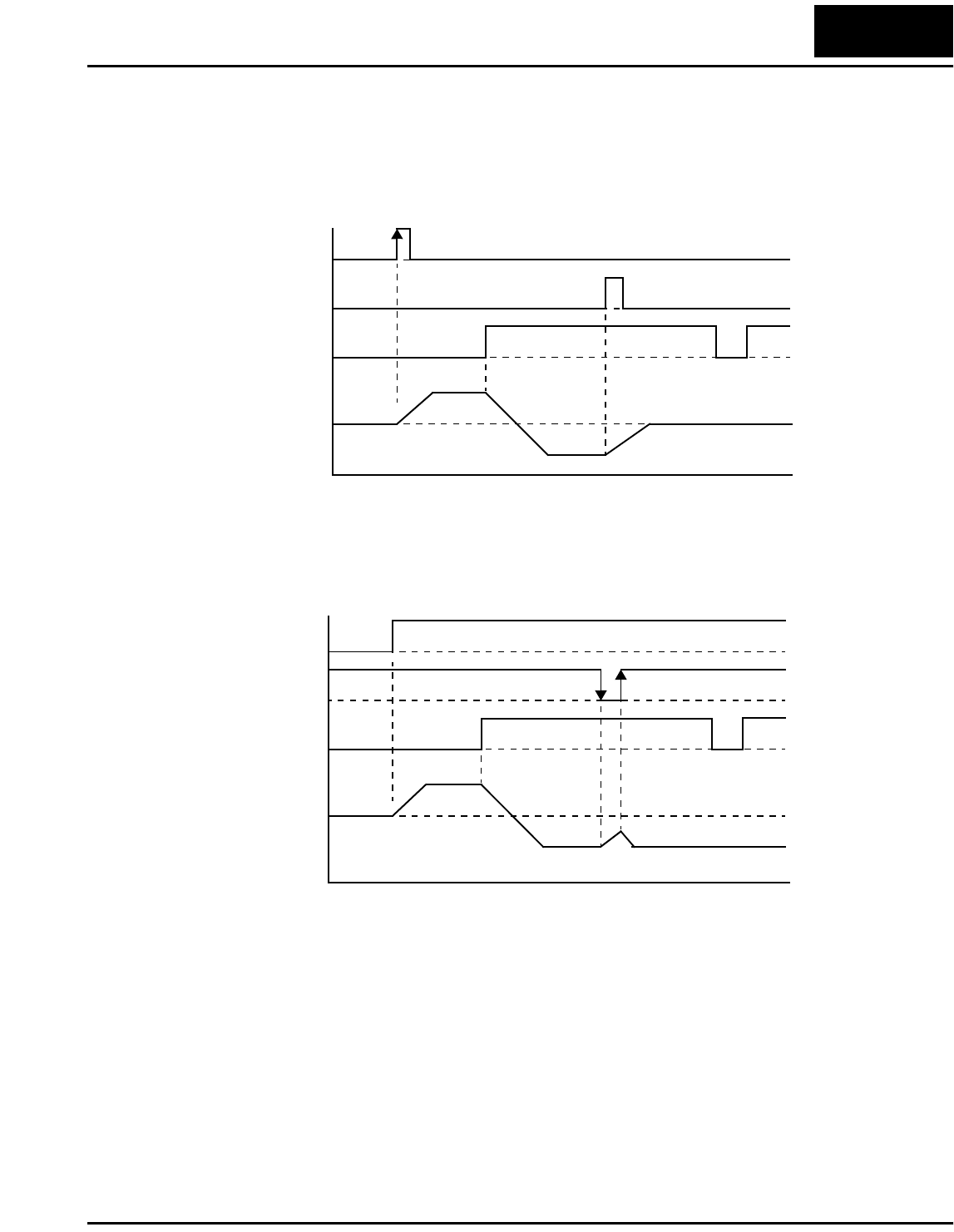
The diagram below shows the use of 3-wire control. STA (Start Motor) is an edge-sensi-
tive input; an OFF-to-ON transition gives the Start command. The control of direction is
level-sensitive, and the direction may be changed at any time. STP (Stop Motor) is also a
level-sensitive input, and the Stop signal has priority over the Start signal. Also
remember that STP is an active-low signal.
When both STA and STP signals are ON, the STP signal has priority (motor output will
be OFF). However, the motor output resumes after STP signal is no longer active if the
STA input is still ON.
Output
Frequency
t
STA
STP
F/R
Output
Frequency
t
STA
STP
F/R
Operations and Monitoring
26
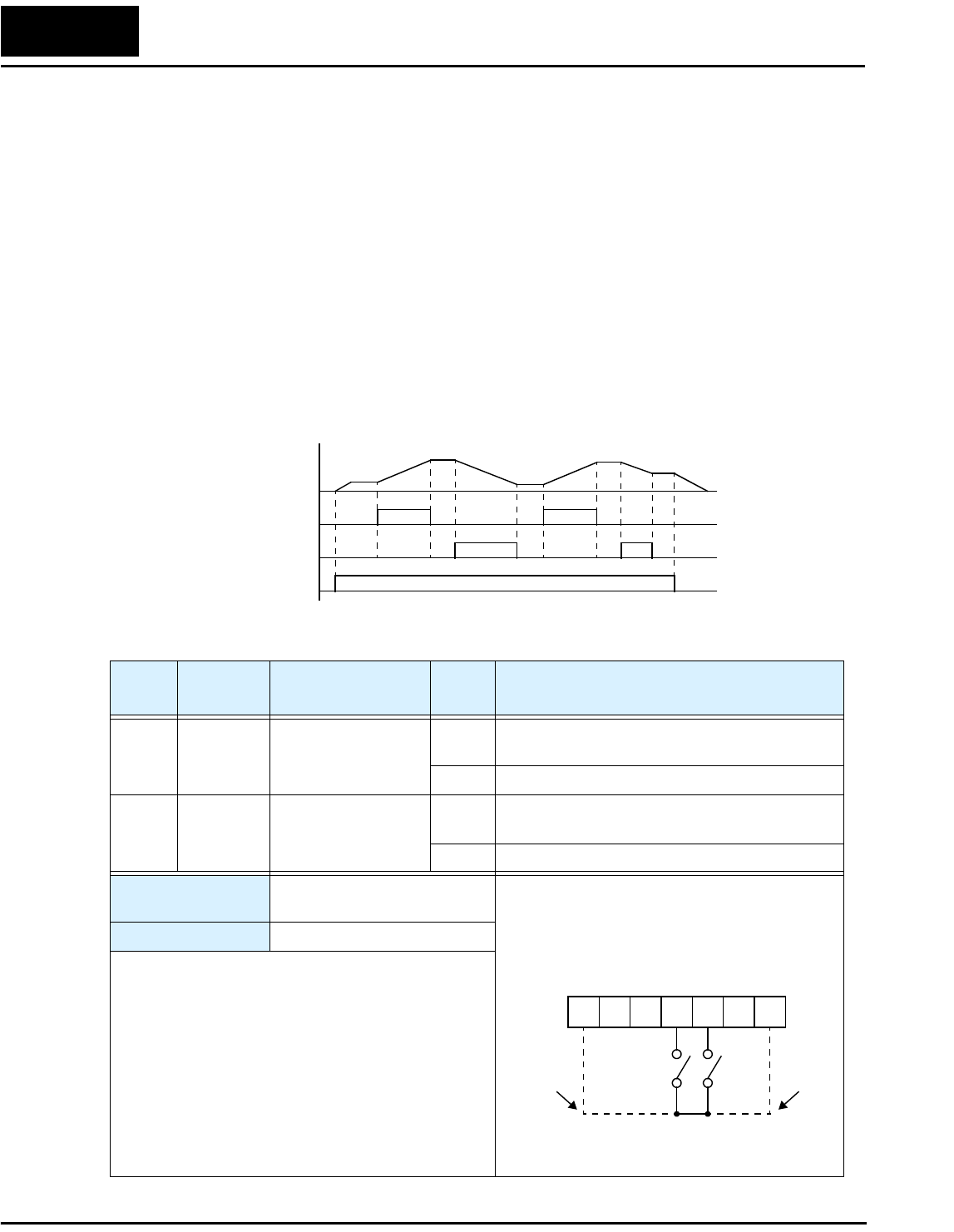
Remote Control Up and Down Functions
The [UP] [DWN] terminal functions can adjust the output frequency for remote control
while the motor is running. The acceleration time and deceleration time used with this
function is the same as for normal operation ACC1 and DEC1. The input terminals
operate as follows:
• Acceleration - When the [UP] contact is turned ON, the output frequency accelerates
from the current value. When it is turned OFF, the output frequency maintains its
current value.
• Deceleration - When the [DWN] contact is turned ON, the output frequency deceler-
ates from the current value. When it is turned OFF, the output frequency maintains its
current value.
In the graph below, the [UP] and [DWN] terminals activate while the Run command
remains ON. The output frequency responds to the [UP] and [DWN] commands.
Output
Frequency
[UP]
[DWN]
[FW] or [RV]
Option
Code
Terminal
Symbol Function Name Input
State Description
27 UP Remote Control
UP Function
ON Accelerates (increases output frequency) motor
from current frequency
OFF Output to motor operates normally
28 DWN Remote Control
DOWN Function
ON Decelerates (decreases output frequency) motor
from current frequency
OFF Output to motor operates normally
Valid for inputs: C_01, C_02, C_03, C_04,
C_05
Required settings: A_01 = 02
Notes:
•This feature is available only when the frequency
command source is programmed for operator
control. Confirm A_01 is set to 02.
•This function is not available when [JG] is in use.
•The range of output frequency is 0 Hz to the value
in A_04 (maximum frequency setting).
•The Remote Control Up/Down function varies the
inverter speed by directly writing to the F_01
output frequency setting.
Example (requires input configuration—
see Chapter 3 in L100 Instruction Manual):
See I/O specs in the L100 Instruction Manual
12345L
P24
UPDWN
for
-MFR2
models
for
-MFU2
models
L100-M Inverter 27
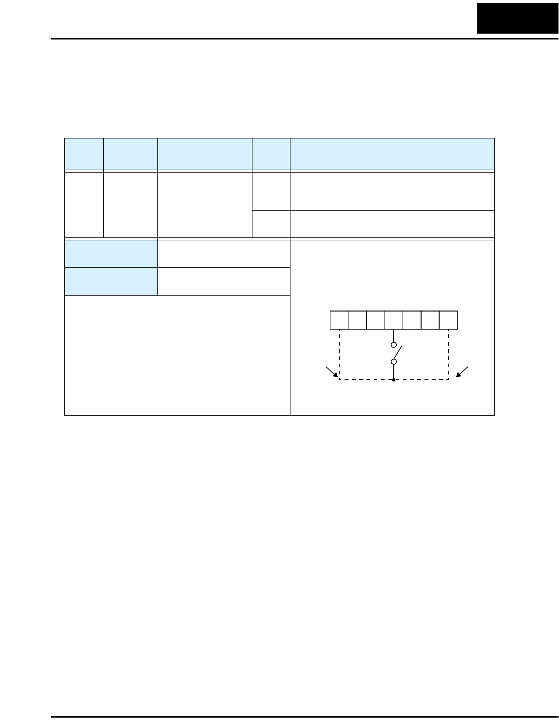
Force Operation from Digital Operator
This function permits a digital operator interface to override the Run command source
setting (A_02) when it is configured for a source other than the operator interface. When
the [OPE] terminal is ON and the operator interface gives a Run command, the inverter
uses the standard output frequency settings to operate the motor.
Option
Code
Terminal
Symbol Function Name Input
State Description
31 OPE Force Operation from
Digital Operator
ON Forces the operator interface Run command to
over-ride commands from input terminals (such
as [FW], [RV]).
OFF Run command operates normally, as configured
by A_02
Valid for inputs: C_01, C_02, C_03, C_04,
C_05
Required settings: A_01
A_02 (set not equal to 02)
Notes:
•When changing the [OPE] state during Run Mode
(inverter is driving the motor), the inverter will stop
the motor before the new [OPE] state takes effect.
•If the [OPE] input turns ON and the digital operator
gives a Run command while the inverter is already
running, the inverter stops the motor. Then the
digital operator can control the motor.
Example (requires input configuration—
see Chapter 3 in L100 Instruction Manual):
See I/O specs in the L100 Instruction Manual
12345L
P24
OPE
for
-MFR2
models
for
-MFU2
models
Inverter System Accessories
28
Inverter System Accessories
This section provides dynamic braking details for L100-M Series configuration corre-
sponding to Chapter 5, “Inverter System Accessories,” in the L100 Inverter Instruction
Manual.
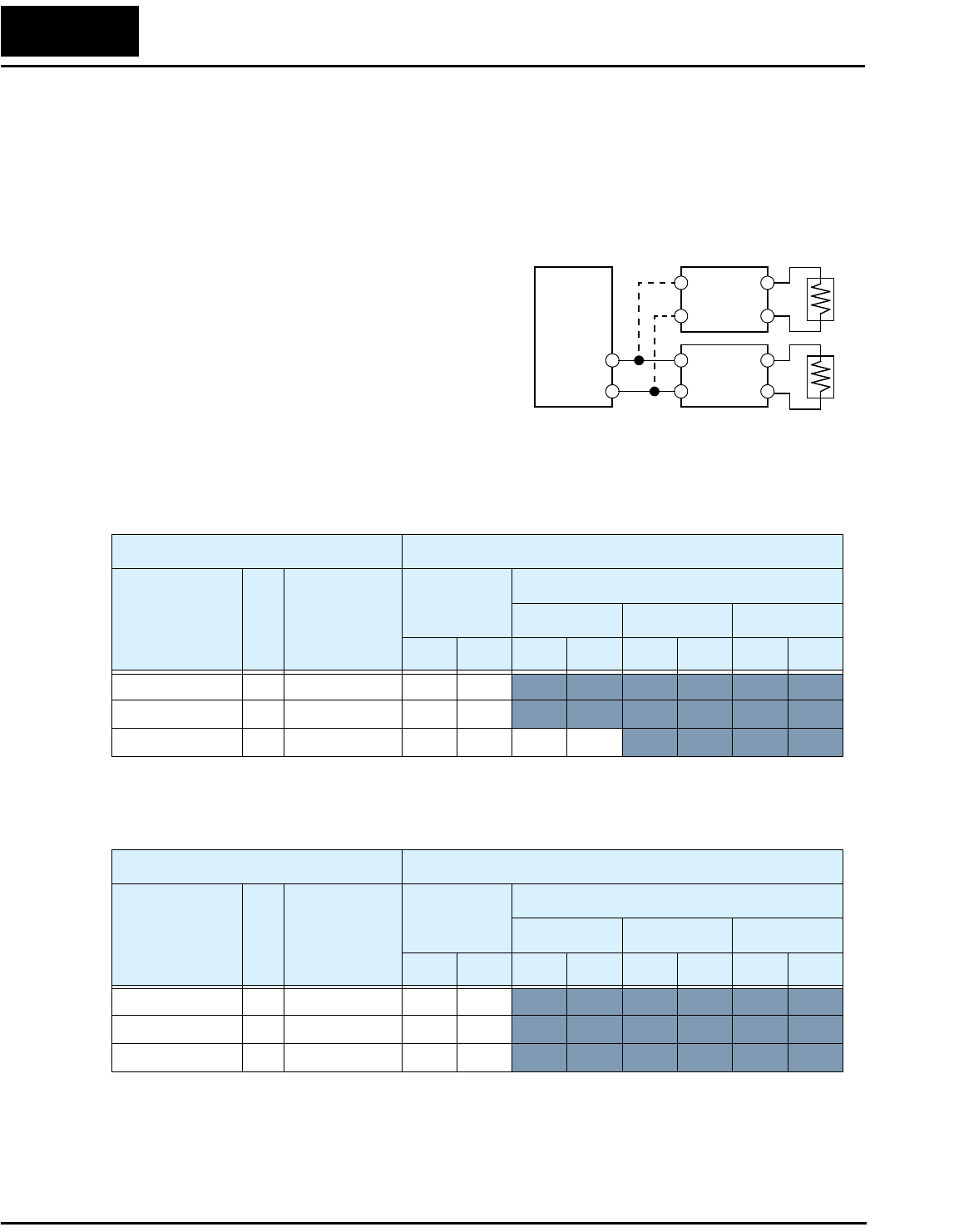
Selecting Braking Resistors for External Braking Units
The following tables specify the braking
options for L100-M inverters and the braking
torque for each option. You can connect a
single braking unit to the inverter, or two
braking units for additional stopping torque.
Use one BRD–E2 braking unit for the braking
torque listed in the following table.
Note the column meanings in the tables:
• Column “A” = Average braking torque from 60 Hz to 3 Hz.
• Column “B” = Average braking torque from 120 Hz to 3 Hz
Connect a second braking unit in parallel for additional braking torque listed in the
following table.
Inverter
+
–
Braking
unit
Braking
unit
L100-M Inverter 100V Models Braking Torque with BRD–E2 Braking Unit
Model Number HP
Braking torque
without
braking unit
Using built-in
resistor only
External resistor added
HRB1 HRB2 HRB3
A B A B A B A B
002MFU2/MFR2 1/4 50% 150% 120%
004MFU2/MFR2 1/2 50% 150% 120%
007MFU2/MFR2 1 50% 100% 80% 150% 120%
L100-M Inverter 100V Models Braking Torque with TWO (2) BRD–E2 Braking Units
Model Number HP
Braking torque
without
braking unit
Using built-in
resistor only
External resistor added
HRB1 HRB2 HRB3
A B A B A B A B
002MFU2/MFR2 1/4 50% 150% 120%
004MFU2/MFR2 1/2 50% 150% 120%
007MFU2/MFR2 1 50% 150% 120%
L100-M Inverter 29
Troubleshooting and Maintenance
This section provides details for L100-M Series error codes corresponding to Chapter 6,
“Troubleshooting and Maintenance,” in the L100 Inverter Instruction Manual.
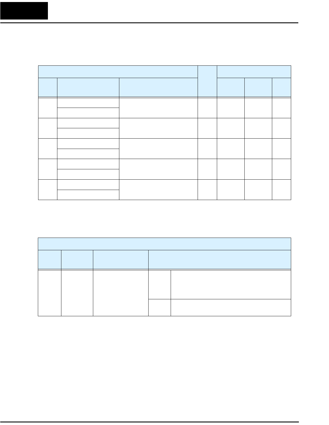
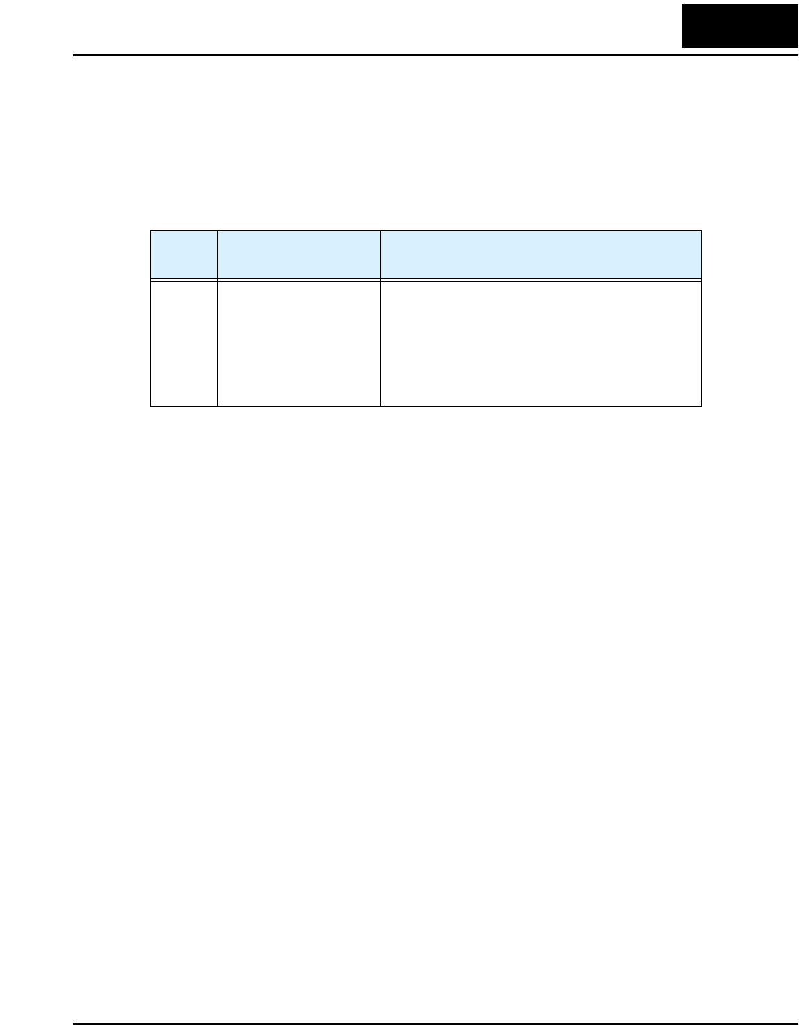
Error Codes
L100-M Series inverters have the additional error code listed below.
Error
Code Name Cause(s)
E60 Communication error •The RS422/485 serial cable may be disconnected
or have an open wire, short, etc.
•The communication error may be due to the
external device. Check whether the interruption is
for more than 3 seconds before resetting the error.
If so, the watchdog timer in the inverter is timing
out due to no response from the external device.
Drive Parameter Settings Tables
30
Drive Parameter Settings Tables
Introduction
This section lists the user-programmable parameters for the L100-M series inverters and
the default values, corresponding to Appendix B, “Drive Parameter Settings Tables,” in
the L100 Inverter Instruction Manual. The right-most column of the tables is blank, so
you can record values you have changed from the default. This involves just a few
parameters for most applications. This section presents the parameters in a format
oriented toward the keypad on the inverter.
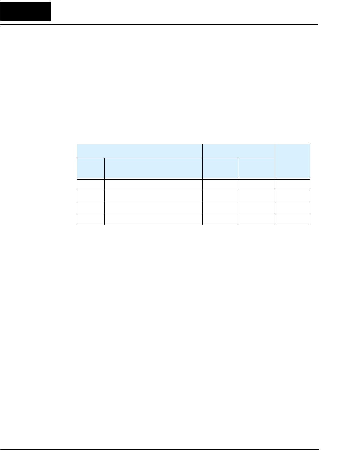
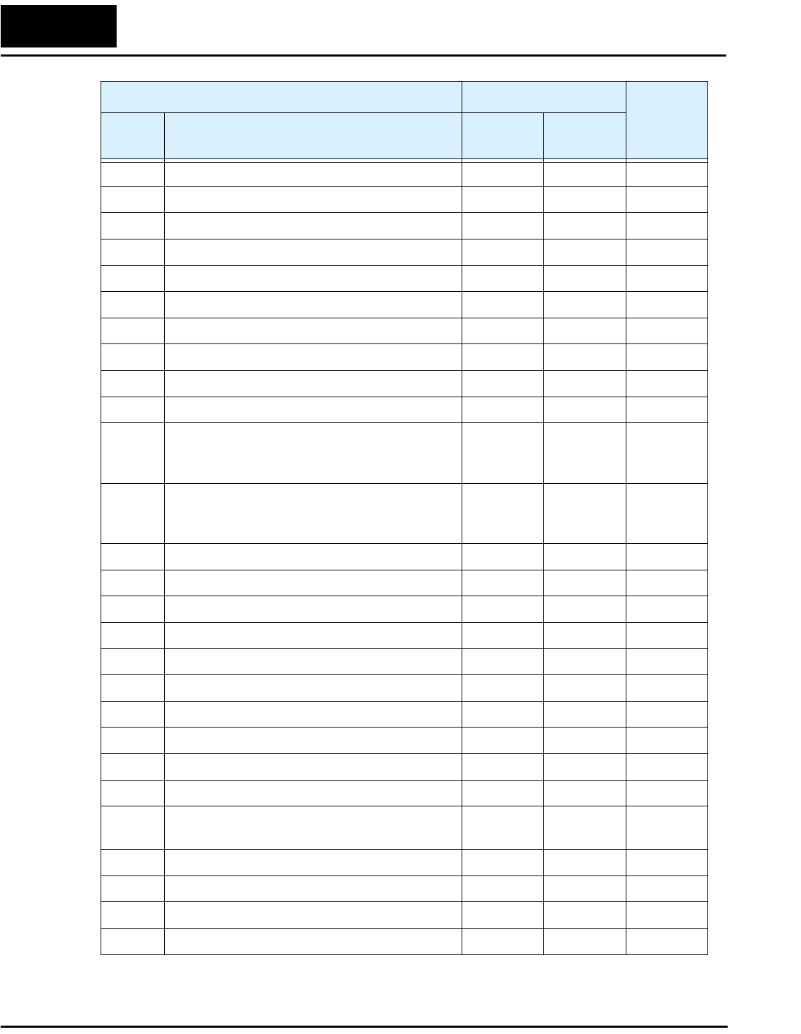
Main Profile Parameters
“F” Group Parameters Default Setting
User
Setting
Func.
Code Name -MFU2 -MFR2
F_01 Output frequency setting 0.0 0.0
F_02 Acceleration (1) 10.0 10.0
F_03 Deceleration (1) 10.0 10.0
F_04 Keypad Run key routing 00 00
L100-M Inverter 31
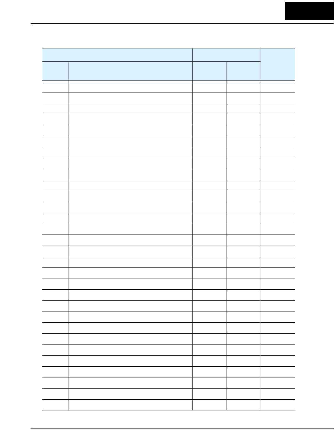
Standard Functions
“A” Group Parameters Default Setting
User
Setting
Func.
Code Name -MFU2 -MFR2
A_01 Frequency source setting 01 00
A_02 Run command source setting 01 02
A_03 Base frequency setting 60.0 60.0
A_04 Maximum frequency setting 60.0 60.0
A_11 O–L input active range start frequency 0 0
A_12 O–L input active range end frequency 0 0
A_13 O–L input active range start voltage 0 0
A_14 O–L input active range end voltage 100 100
A_15 O–L input start frequency enable 01 01
A_16 External frequency filter time constant 8 8
A_20 Multi-speed 0 setting 0 0
A_21 Multi-speed 1 setting 0 5
A_22 Multi-speed 2 setting 0 10
A_23 Multi-speed 3 setting 0 15
A_24 Multi-speed 4 setting 0 20
A_25 Multi-speed 5 setting 0 30
A_26 Multi-speed 6 setting 0 40
A_27 Multi-speed 7 setting 0 50
A_28 Multi-speed 8 setting 0 60
A_29 Multi-speed 9 setting 0 0
A_30 Multi-speed 10 setting 0 0
A_31 Multi-speed 11 setting 0 0
A_32 Multi-speed 12 setting 0 0
A_33 Multi-speed 13 setting 0 0
A_34 Multi-speed 14 setting 0 0
A_35 Multi-speed 15 setting 0 0
A_38 Jog frequency setting 1.0 1.0
A_39 Jog stop mode 00 00
A_41 Torque boost method selection 00 00
A_42 Manual torque boost value 11 11
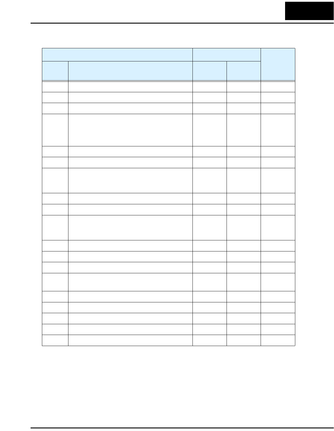
Drive Parameter Settings Tables
32
A_43 Manual torque boost frequency adjustment 10.0 10.0
A_44 V/f characteristic curve selection 00 00
A_45 V/f gain setting 100 100
A_51 DC braking enable 00 00
A_52 DC braking frequency setting 0.5 0.5
A_53 DC braking wait time 0.0 0.0
A_54 DC braking force during deceleration 0 0
A_55 DC braking time during deceleration 0.0 0.0
A_61 Frequency upper limit setting 0.0 0.0
A_62 Frequency lower limit setting 0.0 0.0
A_63,
A_65,
A_67
Jump (center) frequency setting 0.0 0.0
A_64,
A_66,
A_68
Jump (hysteresis) frequency width setting 0.5 0.5
A_71 PID Enable 00 00
A_72 PID proportional gain 1.0 1.0
A_73 PID integral time constant 1.0 1.0
A_74 PID derivative gain 0.0 0.0
A_75 PV scale conversion 1.00 1.00
A_76 PV source setting 00 00
A_81 AVR function select 02 02
A_82 AVR voltage select 230/460 200/400
A_92 Second acceleration time setting 15.0 15.0
A_93 Second deceleration time setting 15.0 15.0
A_94 Select method to switch to second accel/decel
profile
00 00
A_95 Acc1 to Acc2 frequency transition point 0.0 0.0
A_96 Dec1 to Dec2 frequency transition point 0.0 0.0
A_97 Acceleration curve selection 00 00
A_98 Deceleration curve selection 00 00
“A” Group Parameters Default Setting
User
Setting
Func.
Code Name -MFU2 -MFR2
L100-M Inverter 33
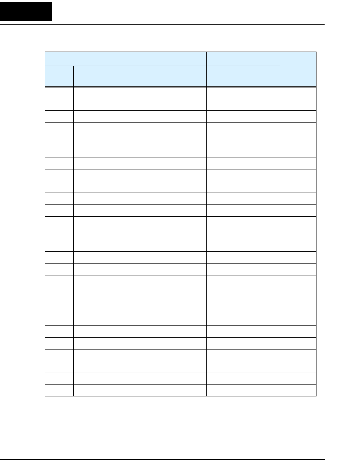
Fine Tuning Functions
“B” Group Parameters Default Setting
User
Setting
Func.
Code Name -MFU2 -MFR2
B_01 Selection of automatic restart mode 00 00
B_02 Allowable under-voltage power failure time 1.0 1.0
B_03 Retry wait time before motor restart 1.0 1.0
B_12 Level of electronic thermal setting Rated
current for
each
inverter
Rated
current for
each
inverter
B_13 Electronic thermal characteristic 01 00
B_21 Overload restriction operation mode 01 01
B_22 Overload restriction setting Rated
current x
1.25
Rated
current x
1.25
B_23 Deceleration rate at overload restriction 1.0 1.0
B_31 Software lock mode selection 01 01
B_32 Reactive current setting Rated
current x
0.40
Rated
current x
0.40
B_81 [FM] terminal analog meter adjustment 80 80
B_82 Start frequency adjustment 0.5 0.5
B_83 Carrier frequency setting 5.0 12.0
B_84 Initialization mode (parameters or trip
history)
00 00
B_85 Country code for initialization 02 00
B_86 Frequency scaling conversion factor 1.0 1.0
B_87 STOP key enable 00 00
B_88 Restart mode after FRS 00 00
B_89 Data select for digital op. OPE-J 01 01
Drive Parameter Settings Tables
34
Intelligent Terminal Functions
“C” Group Parameters Default Setting
User
Setting
Func.
Code Name -MFU2 -MFR2
C_01 Terminal [1] function 00 00
C_02 Terminal [2] function 01 01
C_03 Terminal [3] function 16 02
C_04 Terminal [4] function 13 03
C_05 Terminal [5] function 18 18
C_11 Terminal [1] active state 00 00
C_12 Terminal [2] active state 00 00
C_13 Terminal [3] active state 00 00
C_14 Terminal [4] active state 01 00
C_15 Terminal [5] active state 00 00
C_21 Terminal [11] function 01 01
C_22 Terminal [12] function 00 00
C_23 [FM] signal selection 00 00
C_31 Terminal [11] active state 00 —
C_32 Terminal [12] active state 00 —
C_33 Alarm relay terminal active state 01 01
C_41 Overload level setting Inverter
rated
current
Inverter
rated
current
C_42 Frequency arrival setting for accel 0.0 0.0
C_43 Arrival frequency setting for decel 0.0 0.0
C_44 PID deviation level setting 3.0 3.0
C_70 Data command method 02 02
C_71 Communication speed selection 04 04
C_72 Node allocation 01 01
C_79 Communication error response 01 01
C_91 Debug mode enable 00 00 Do not edit
