HP Color LaserJet 2600n Service Manual. Www.s Manuals.com. 2600 Manual
User Manual: Laser Printer HP Color LaserJet 2600 - Service manuals and Schematics, Disassembly / Assembly. Free.
Open the PDF directly: View PDF ![]() .
.
Page Count: 290 [warning: Documents this large are best viewed by clicking the View PDF Link!]
- Product information
- Installation
- Managing and maintenance
- Operational theory
- Removal and replacement
- Troubleshooting
- Troubleshooting process
- Clearing jams
- Print problems
- Functional tests (SERVICE ONLY)
- Service mode functions (SERVICE ONLY)
- Troubleshooting tools
- HP Toolbox
- Diagnostic resources
- Repetitive image defect ruler
- Firmware and software updates
- Parts and diagrams
- Product specifications
- Product warranty statements
- Regulatory statements
- Index

HP Color LaserJet 2600n
Service Manual

Copyright and License
© 2005 Copyright Hewlett-Packard
Development Company, L.P.
Reproduction, adaptation, or translation
without prior written permission is
prohibited, except as allowed under the
copyright laws.
The information contained in this document
is subject to change without notice.
The only warranties for HP products and
services are set forth in the express
warranty statements accompanying such
products and services. Nothing herein
should be construed as constituting an
additional warranty. HP shall not be liable
for technical or editorial errors or omissions
contained herein.
Q6455-90930
Edition 1, 2/2005
FCC Class A Statement
This equipment has been tested and found
to comply with the limits for a Class A
digital device, pursuant to Part 15 of the
FCC Rules. These limits are designed to
provide reasonable protection against
harmful interference when the equipment is
operated in a commercial environment.
This equipment generates, uses and can
radiate radio frequency energy and, if not
installed and used in accordance with the
instruction manual, may cause harmful
interference to radio communications.
Operation of this equipment in a residential
area is likely to cause harmful interference,
in which case the user will be required to
correct the interference at his own
expense. The end user of this product
should be aware that any changes or
modifications made to this equipment
without the approval of Hewlett-Packard
could result in the product not meeting the
Class A limits, in which case the FCC
could void the user’s authority to operate
the equipment.
Trademark Credits
Adobe Photoshop® and PostScript are
trademarks of Adobe Systems Incorporated.
CorelDRAW™ is a trademark or registered
trademark of Corel Corporation or Corel
Corporation Limited.
Microsoft®, Windows®, MS-DOS®, and
Windows NT® are U.S. registered
trademarks of Microsoft Corporation.
Netscape™ and Netscape Navigator™ are
U.S. trademarks of Netscape
Communications Corporation.
TrueType™ is a U.S. trademark of Apple
Computer, Inc.
ENERGY STAR® and the ENERGY STAR
logo® are U.S. registered marks of the
United States Environmental Protection
Agency.
Table of contents
1 Product information
Quick access to printer information.........................................................................................................2
Printer configuration................................................................................................................................3
Printer features........................................................................................................................................4
Walk around.............................................................................................................................................6
Front view (shown with optional Tray 3).................................................................................6
Back and side view.................................................................................................................7
Control panel...........................................................................................................................8
Understanding supplies status...............................................................................8
Understanding printer status..................................................................................8
Understanding control panel layout.......................................................................9
Software.................................................................................................................................................11
Supported drivers..................................................................................................................11
Software and supported operating systems........................................................11
Software for Windows...........................................................................................................11
Software for Macintosh.........................................................................................................12
Network software..................................................................................................................12
Uninstalling software.............................................................................................................12
Windows software................................................................................................12
Macintosh software..............................................................................................13
Print-media specifications......................................................................................................................14
General guidelines................................................................................................................14
Paper and print media...........................................................................................................14
Printing and storage environment.........................................................................................14
Envelopes.............................................................................................................................15
Labels....................................................................................................................................17
Transparencies.....................................................................................................................17
Media support tables.............................................................................................................17
Supported print media for Tray 1, Tray 2, and optional Tray 3............................17
Unsupported media (media to avoid)...................................................................18
2 Installation
Site preparation ....................................................................................................................................22
Operating environment ........................................................................................................22
Minimum system requirements ............................................................................................23
Requirements for PC systems ............................................................................23
Requirements for Macintosh systems (non-PostScript) .....................................23
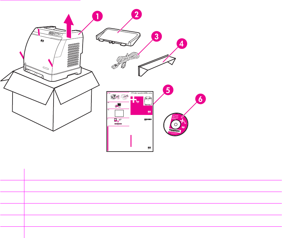
Package contents .................................................................................................................................24
Install input devices ..............................................................................................................................25
ENWW iii
Installing optional Tray 3 ......................................................................................................25
Loading Tray 1 .....................................................................................................................25
Installing supplies .................................................................................................................27
Print cartridges ....................................................................................................27
3 Managing and maintenance
Managing supplies ................................................................................................................................32
Life expectancies of supplies ...............................................................................................32
Checking and ordering supplies ..........................................................................................32
To check status using the control panel .............................................................32
To check and order supplies using HP Toolbox .................................................32
Storing supplies ...................................................................................................................33
Replacing and recycling supplies ........................................................................................33
Replacing the print cartridges .............................................................................33
HP policy on non-HP supplies .............................................................................................33
HP anti-counterfeit website ..................................................................................................33
Cleaning the printer ..............................................................................................................................34
To clean the printer at the printer .........................................................................................34
To clean the fuser using HP Toolbox ..................................................................................35
Cleaning spilled toner ..........................................................................................................35
Calibrating the printer ...........................................................................................................................36
To calibrate the printer at the printer ...................................................................................36
To calibrate the printer from the HP Toolbox .......................................................................36
4 Operational theory
Engine control system ..........................................................................................................................38
Basic sequence of operation ...............................................................................................38
Power-on sequence .............................................................................................................39
Motors and fans ...................................................................................................................39
Main motor failure detection ................................................................................40
Fan motor failure detection .................................................................................40
Image formation system .......................................................................................................................41
Image formation process .....................................................................................................43
Latent image formation .......................................................................................44
Laser/scanner system .........................................................................................45
Developing stage .................................................................................................................45
Print cartridge ......................................................................................................46
Transfer belt (ETB) ..............................................................................................47
Transfer stage ......................................................................................................................48
Separation stage ..................................................................................................................49
Fusing stage ........................................................................................................................49
Pickup and feed system .......................................................................................................................51
Manual feed slot pickup mechanism ...................................................................................53
Paper feed mechanism ........................................................................................................53
Skew correction by the registration shutter .........................................................................53
Jam detection .......................................................................................................................54
Solenoid, motor, and fan locations ......................................................................................55
Printed circuit assembly locations ........................................................................................55
250-sheet tray solenoid and printed circuit locations ..........................................................56
Service-only tools (SERVICE ONLY) ...................................................................................................58
iv ENWW
General timing chart .............................................................................................................58
Printer calibration .................................................................................................................59
5 Removal and replacement
Overview................................................................................................................................................62
Service approach...................................................................................................................................63
Pre-service procedures.........................................................................................................63
Removal and replacement procedures.................................................................................................64
Print cartridge replacement...................................................................................................64
ETB removal and replacement.............................................................................................66
Fuser removal and replacement...........................................................................................74
Formatter removal and replacement....................................................................................82
DC controller removal and replacement...............................................................................86
Separation pad removal and replacement............................................................................88
Paper pickup roller removal and replacement......................................................................89
Control panel removal and replacement...............................................................................91
6 Troubleshooting
Troubleshooting process.......................................................................................................................98
Troubleshooting checklist.....................................................................................................98
Clearing jams ........................................................................................................................................99
Paper path............................................................................................................................99
Common causes of paper jams..........................................................................................100
Where to look for jams........................................................................................................101
Jams inside the printer........................................................................................................102
Input jams...........................................................................................................................103
Tray 1.................................................................................................................103
Tray 2.................................................................................................................104
Output jams.........................................................................................................................104
Jams in the top bin.............................................................................................104
Pickup delay jam................................................................................................105
Pickup stationary jam.........................................................................................105
Delivery delay jam..............................................................................................105
Wrapping jam......................................................................................................................105
Delivery stationary jam.......................................................................................................105
Start-up residual paper jam................................................................................................105
Door open jam....................................................................................................................106
Print problems......................................................................................................................................107
Getting information..............................................................................................................107
Control panel messages....................................................................................107
Alert and warning messages.............................................................107
Critical error messages.....................................................................108
Supplies messages...........................................................................109
Status messages...............................................................................112
Status log only messages.................................................................112
Reports menu.....................................................................................................113
Configuration page.............................................................................................114
Supplies Status page.........................................................................................116
Status log...........................................................................................................116
Service menu settings........................................................................................118
ENWW v
Secondary service menu....................................................................................118
Printed image quality problems..........................................................................................119
Improving print quality........................................................................................119
Paper Types menu............................................................................119
Print Modes menu.............................................................................120
Print quality menu..............................................................................121
Understanding print-quality settings...................................................................121
To temporarily change print-quality settings.....................................122
To change print-quality settings for all future jobs............................122
Identifying and correcting printed image defects...............................................122
Print-quality checklist.........................................................................122
Paper handling issues........................................................................................................123
Wrong size/type media.......................................................................................123
Cannot select a tray or feature to use................................................................123
Performance problems.......................................................................................................123
Functional tests (SERVICE ONLY).....................................................................................................125
Engine test print..................................................................................................................125
Service mode functions (SERVICE ONLY).........................................................................................126
Cold reset............................................................................................................................126
NVRAM initializer................................................................................................................126
Super NVRAM initializer.....................................................................................................126
Restoring page counts and serial number..........................................................................127
Cleaning the ETB................................................................................................................127
Troubleshooting tools..........................................................................................................................128
Printer pages and reports...................................................................................................128
Demo page.........................................................................................................128
Configuration page.............................................................................................129
Event log............................................................................................................131
Supplies Status page.........................................................................................131
Fuser cleaning page...........................................................................................132
Print quality troubleshooting pages....................................................................132
Control panel messages (error codes)..............................................................132
Alert and warning messages.............................................................132
Critical error messages.....................................................................133
Supplies messages...........................................................................134
Status messages................................................................................................................137
Status log only messages...................................................................................................137
Service menu......................................................................................................................137
Restoring the factory-set defaults......................................................................138
To restore the factory-set defaults....................................................138
General print quality issues................................................................................................138
Solving issues with color documents..................................................................................142
HP Toolbox..........................................................................................................................................144
HP Toolbox.........................................................................................................................144
To view HP Toolbox...........................................................................................144
Troubleshooting tab...........................................................................................144
Print quality troubleshooting pages....................................................................................144
Printer calibration................................................................................................................144
Cleaning page.....................................................................................................................144
Configuration page..............................................................................................................145
vi ENWW
Diagnostic resources...........................................................................................................................146
Reports menu.....................................................................................................................146
Network/Web diagnostics tools...........................................................................................146
Repetitive image defect ruler...............................................................................................................147
Firmware and software updates..........................................................................................................148
7 Parts and diagrams
Overview .............................................................................................................................................150
Assembly locations .............................................................................................................................154
Covers ................................................................................................................................................160
Internal assemblies .............................................................................................................................162
Input devices .......................................................................................................................................186
Diagrams ............................................................................................................................................208
Alphabetical parts list...........................................................................................................................209
Numerical parts list..............................................................................................................................230
Appendix A Product specifications
Physical specifications ........................................................................................................................252
Supplies specifications .......................................................................................................................253
Print cartridge life ...............................................................................................................253
Electrical specifications ......................................................................................................................254
Environmental specifications ..............................................................................................................255
Acoustical specifications .....................................................................................................................256
Appendix B Product warranty statements
Hewlett-Packard limited warranty statement ......................................................................................258
Print Cartridge Limited Warranty Statement ......................................................................................259
Appendix C Regulatory statements
Declaration of Conformity ...................................................................................................................262
Laser safety statement .......................................................................................................................263
Canadian DOC statement ..................................................................................................................264
VCCI statement (Japan) .....................................................................................................................265
Korean EMI statement ........................................................................................................................266
Finnish laser statement ......................................................................................................................267
Index....................................................................................................................................................................269
ENWW vii
viii ENWW
List of tables
Table 1-1 Printer features.................................................................................................................................4
Table 1-2 HP Color LaserJet 2600n printer software.....................................................................................11
Table 1-3 Envelope specifications..................................................................................................................15
Table 1-4 Envelope size ranges.....................................................................................................................16
Table 1-5 Tray 1 and Tray 2 specifications....................................................................................................17
Table 1-6 Optional Tray 3 specifications........................................................................................................18
Table 3-1 Print cartridge life ..........................................................................................................................32
Table 4-1 Basic operational sequence ..........................................................................................................38
Table 4-2 Motor specifications .......................................................................................................................40
Table 5-1 User-replaceable parts...................................................................................................................62
Table 6-1 Troubleshooting checklist...............................................................................................................98
Table 6-2 Status log only messages............................................................................................................112
Table 6-3 Configuration page.......................................................................................................................114
Table 6-4 Supplies Status page...................................................................................................................116
Table 6-5 Status log messages....................................................................................................................117
Table 6-6 Print modes for paper types.........................................................................................................120
Table 6-7 Extended print modes..................................................................................................................120
Table 6-8 Optimize menu.............................................................................................................................121
Table 6-9 Performance issues......................................................................................................................123
Table 6-10 Configuration page.......................................................................................................................129
Table 6-11 Supplies Status page...................................................................................................................131
Table 6-12 Status log only messages............................................................................................................137
Table 6-13 General print quality issues..........................................................................................................138
Table 6-14 Color document issues.................................................................................................................142
Table 6-15 Repetitive image defects..............................................................................................................147
Table 7-1 Available replaceable parts .........................................................................................................150
Table 7-2 Technical support Web sites .......................................................................................................152
Table 7-3 Accessories .................................................................................................................................152
Table 7-4 Assembly locations ......................................................................................................................155
Table 7-5 External panels and covers (1 of 2) ............................................................................................157
Table 7-6 External panels and covers (2 of 2) ............................................................................................159
Table 7-7 Upper assembly cover .................................................................................................................161
Table 7-8 Internal components (1 of 3) .......................................................................................................163
Table 7-9 Internal components (2 of 3) .......................................................................................................167
Table 7-10 Internal components (3 of 3) .......................................................................................................171
Table 7-11 Control panel assembly ...............................................................................................................175
Table 7-12 Main drive assembly ....................................................................................................................177
Table 7-13 Fuser assembly ...........................................................................................................................181
Table 7-14 PCB assembly location Tray 2 ....................................................................................................185
Table 7-15 Tray 2 input tray (cassette) .........................................................................................................187
ENWW ix
Table 7-16 250-sheet input tray (cassette) ....................................................................................................191
Table 7-17 Tray 2 sheet input tray internal components ...............................................................................193
Table 7-18 Paper pick-up feeder assembly for Tray 2 ..................................................................................197
Table 7-19 Tray 3 input tray (cassette) .........................................................................................................201
Table 7-20 Paper pickup feeder assembly (Tray 3) ......................................................................................205
Table 7-21 Paper pickup feeder assembly (Tray 3) ......................................................................................207
Table 7-22 Alphabetical parts list...................................................................................................................209
Table 7-23 Numerical parts list.......................................................................................................................230
Table A-1 Printer specifications ...................................................................................................................252
Table A-2 Supplies specifications ................................................................................................................253
Table A-3 Print cartridge specifications .......................................................................................................253
Table A-4 Electrical specifications ...............................................................................................................254
Table A-5 Environmental specifications .......................................................................................................255
Table A-6 Acoustical specifications .............................................................................................................256
x ENWW
List of figures
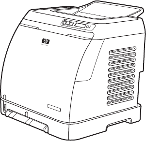
Figure 1-1 HP Color LaserJet 2600n printer......................................................................................................3
Figure 1-2 Front view (shown with optional Tray 3)...........................................................................................6
Figure 1-3 Back and side view...........................................................................................................................7
Figure 1-4 Transfer belt (ETB) and print cartridges...........................................................................................7
Figure 1-5 Model and serial number information...............................................................................................8
Figure 1-6 Control panel layout.......................................................................................................................10
Figure 1-7 Control panel display......................................................................................................................10
Figure 1-8 Envelope double side-seam construction......................................................................................16
Figure 2-1 Printer dimensions .........................................................................................................................22
Figure 2-2 Package contents ..........................................................................................................................24
Figure 4-1 Engine control system ...................................................................................................................39
Figure 4-2 Image formation system ................................................................................................................42
Figure 4-3 Image formation process ...............................................................................................................43
Figure 4-4 Latent image formation ..................................................................................................................45
Figure 4-5 Laser beam exposure ....................................................................................................................45
Figure 4-6 Developing stage ...........................................................................................................................46
Figure 4-7 Print cartridge structure .................................................................................................................47
Figure 4-8 ETB unit .........................................................................................................................................48
Figure 4-9 Transfer stage ...............................................................................................................................48
Figure 4-10 Separation stage ...........................................................................................................................49
Figure 4-11 Fusing stage ..................................................................................................................................49
Figure 4-12 Paper pickup and feed system ......................................................................................................52
Figure 4-13 Skew correction .............................................................................................................................54
Figure 4-14 Location of solenoids, motors, and fans .......................................................................................55
Figure 4-15 Location of printed circuit assemblies ...........................................................................................56
Figure 4-16 Location of 250-sheet tray solenoid and printed circuit assembly ................................................57
Figure 6-1 Paper path......................................................................................................................................99
Figure 6-2 Jam locations and stages.............................................................................................................101
Figure 6-3 Tray 2 input jam label...................................................................................................................104
Figure 6-4 Engine test print switch................................................................................................................125
Figure 7-1 Assembly location diagram .........................................................................................................154
Figure 7-2 External panels and covers (1 of 2) ............................................................................................156
Figure 7-3 External panels and covers (2 of 2) ............................................................................................158
Figure 7-4 Upper cover assembly .................................................................................................................160
Figure 7-5 Internal components (1 of 3) .......................................................................................................162
Figure 7-6 Internal components (2 of 3) .......................................................................................................166
Figure 7-7 Internal components (3 of 3) .......................................................................................................170
Figure 7-8 Control panel assembly ...............................................................................................................174
Figure 7-9 Main drive assembly ....................................................................................................................176
Figure 7-10 Fuser assembly ...........................................................................................................................180
ENWW xi
Figure 7-11 PCB assembly location (Tray 2) ..................................................................................................184
Figure 7-12 Tray 2 input tray (cassette) .........................................................................................................186
Figure 7-13 250-sheet input tray (cassette) ....................................................................................................190
Figure 7-14 Tray 2 input tray internal components .........................................................................................192
Figure 7-15 Paper pick-up feeder assembly for Tray 2 ..................................................................................196
Figure 7-16 Tray 3 input tray (cassette) .........................................................................................................200
Figure 7-17 Paper pickup feeder assembly (Tray 3) ......................................................................................204
Figure 7-18 PCB assembly location optional Tray 3 ......................................................................................206
Figure 7-19 General circuit diagram ...............................................................................................................208
Figure C-1 VCCI statement ...........................................................................................................................265
Figure C-2 Korean EMI statement .................................................................................................................266
xii ENWW

Quick access to printer information
User guide
Contains detailed information for using the printer and troubleshooting problems. This guide is
available in two formats on the CD-ROM that came with the printer: in PDF format for printing and
HTML format for online viewing. It is also available through the HP Toolbox software.
Getting started guide
Provides step-by-step instructions for installing and setting up the printer.
HP Toolbox
Use to check the printer status and settings and to view troubleshooting information and online
documentation.
Embedded Web server
Use to view and configure printer settings and networking information.
2 Chapter 1 Product information ENWW
Printer configuration
HP Color LaserJet 2600n
The HP Color LaserJet 2600n printer is available in the configuration described below.
Figure 1-1 HP Color LaserJet 2600n printer
The HP Color LaserJet 2600n printer is a four-color laser printer that prints eight pages per minute
(ppm) in both monochrome (black and white) and color.
■Trays. The printer comes with a single sheet priority feed slot (Tray 1) and a universal tray
(Tray 2) that holds up to 250 sheets of various paper types and sizes or 10 envelopes. It
supports an optional 250-sheet paper tray (optional Tray 3).
■Connectivity. The printer provides a Hi-Speed Universal Serial Bus (USB) 2.0 port for
connectivity and an HP built-in internal print server for connecting to a 10/100Base-T network.
■Memory. The printer contains 16 megabytes (MB) of synchronous dynamic random access
memory (SDRAM). No additional memory can be added.
ENWW Printer configuration 3

Printer features
Table 1-1 Printer features
Feature HP Color LaserJet 2600n printer
Color printing ■Provides laser printing in full color by using the four
process colors: cyan, magenta, yellow, and black
(CMYK).
Fast print speed ■Prints in black on letter-size paper up to 8 ppm and on
A4-size paper up to 8 ppm. Prints in color on A4/letter at
8 ppm.
Excellent print quality ■ImageREt 2400 provides 2400 dpi equivalent color
quality through a multilevel printing process.
■True 600 by 600 dots per inch (dpi) text and graphics.
■Adjustable settings to optimize print quality.
■The HP UltraPrecise print cartridge has a finer toner
formulation that provides sharper text and graphics.
Ease of use ■Few supplies to order. Supplies are easy to install.
■Convenient access to printer information and settings by
using the HP Toolbox software.
■Convenient access to all supplies and to the paper path
through the front door.
Flexible paper handling ■Trays 1 and 2 for letterhead, envelopes, labels,
transparencies, custom-sized media, postcards,
HP LaserJet glossy paper, HP LaserJet Tough paper,
heavy paper, and HP Laser Photo paper.
■A 125-sheet top output bin.
■Print on Both Sides (manually).
Interface connections ■Hi-Speed USB 2.0 port.
■The HP Color LaserJet 2600n printer includes an
HP built-in internal print server for connecting to a
10/100Base-T network.
Energy savings ■The printer automatically conserves electricity by
substantially reducing power consumption when it is not
printing.
■As an ENERGY STAR® partner, Hewlett-Packard
Company has determined that this product meets
ENERGY STAR® guidelines for energy efficiency.
ENERGY STAR® is a U.S. registered service mark of
the United States Environmental Protection Agency.
Economical printing ■N-up printing (printing more than one page on a sheet)
and Printing on Both Sides features save paper.
4 Chapter 1 Product information ENWW

Feature HP Color LaserJet 2600n printer
Supplies ■A Supplies Status page with print cartridge gauges that
show the supply levels that remain. For HP supplies only.
■No-shake cartridge design.
■Authentication for HP print cartridges.
■Internet-enabled, supplies-ordering capability.
Accessibility ■Online user guide that is compatible with text
screen-readers.
■All doors and covers can be opened by using one hand.
Expandability ■Optional Tray 3. This 250-sheet universal tray reduces
how often you have to add paper to the printer. Only
one additional 250-sheet tray can be installed on the
printer.
Memory ■16 MB of DRAM.
NOTE No additional memory can be added.
Table 1-1 Printer features (continued)
ENWW Printer features 5
Walk around
The following illustrations identify the locations and names of key components of this printer.
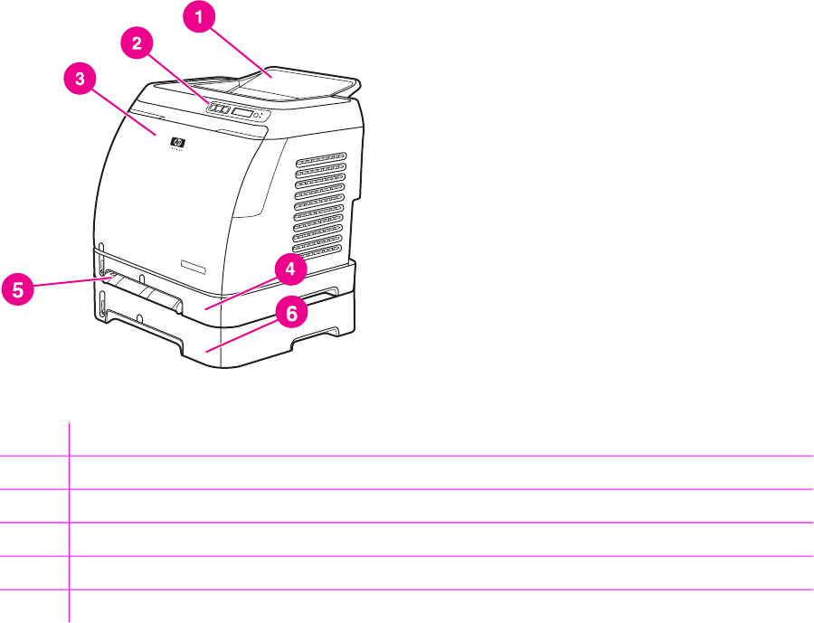
Front view (shown with optional Tray 3)
Figure 1-2 Front view (shown with optional Tray 3)
1Output bin
2Printer control panel
3Front door
4Tray 2 (250 sheets)
5Tray 1 (single sheet priority feed slot)
6Tray 3 (optional; 250 sheets)
6 Chapter 1 Product information ENWW
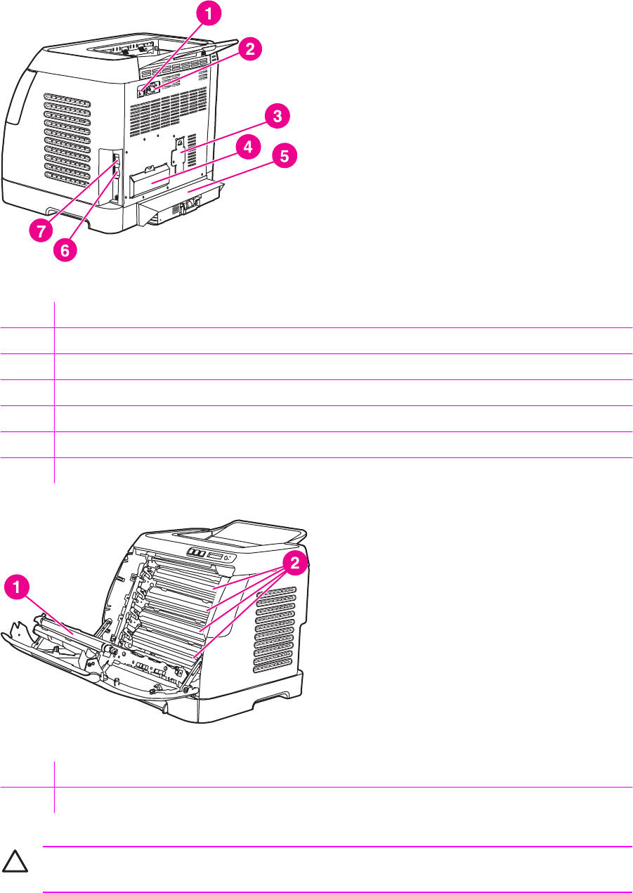
Back and side view
Figure 1-3 Back and side view
1On/off switch
2Power connection
3Engine test button access door
4Access door
5Dust cover
6HP built-in internal print server for connecting to a 10/100Base-T network
7USB connection
Figure 1-4 Transfer belt (ETB) and print cartridges
1Transfer belt (ETB)
2Print cartridges
CAUTION Do not place anything on the transfer belt , which is located on the inside of the
front door. Otherwise, the printer may be damaged, adversely affecting print quality.
ENWW Walk around 7

Model and serial number location
The model number and serial numbers are listed on identification labels located on the rear of the
printer. The model number is alphanumeric, such as Q6455A, for the HP Color LaserJet 2600n
printer. The serial number contains information about the country/region of origin, the printer version,
production code, and the production number of the printer.
Figure 1-5 Model and serial number information
Control panel
Understanding supplies status
The supplies gauges show the consumption levels of print cartridges (black, yellow, cyan, and
magenta).
Black, yellow, cyan, and magenta supplies status gauges
A ? appears instead of the consumption level when the level is not known. This can occur in the
following circumstances:
■Missing cartridges
■Incorrectly placed cartridges
■Cartridges with an error
■Some non-HP cartridges
The supplies gauge appears whenever the printer shows the Ready state with no warnings. It will
also appear when the printer shows a warning or error message concerning a print cartridge or
multiple supplies. If a supply is empty, the gauge will flash.
Understanding printer status
Cancel Job button
■When the Ready light is blinking, pressing (C
ANCEL
J
OB
) cancels the current job.
■When a supplies status gauge is blinking and the Attention light is on (indicating that a non-HP
supply has been installed), pressing (S
ELECT
) allows you to continue printing.
8 Chapter 1 Product information ENWW

CAUTION You might not receive any indication when a non-HP supply is empty. For more
information about using non-HP print cartridges, see HP policy on non-HP supplies. If you
continue printing after the supply is empty, damage to the printer can occur. See Hewlett-
Packard limited warranty statement.
Attention light
Generally, the Attention light blinks when the printer is out of paper, when a jam has occurred, or
when other problems that need attention occur.
The Attention light is on and one of the Supplies Status gauges is blinking the first time a non-HP
supply is installed.
Ready light
The Ready light is on when the printer is ready to print (experiencing no errors that prevent printing)
and blinks when it is receiving data to be printed.
Ready light and Select button
■When the Ready light is on and the Attention light is blinking, pressing (S
ELECT
) continues the
print job after you load print media for a manual feed, or clears some errors.
■When the Ready light is blinking, the front door has been opened and then closed. Press
(S
ELECT
) to return the printer to the Ready state. If you do not press (S
ELECT
), the printer
returns to the Ready state on its own.
Left and Right arrow buttons
Use the (L
EFT
ARROW
) and (R
IGHT
ARROW
) buttons to navigate through the printer control panel
menus.
A Demo page can be printed by pressing the (L
EFT
ARROW
) and (R
IGHT
ARROW
) buttons
simultaneously.
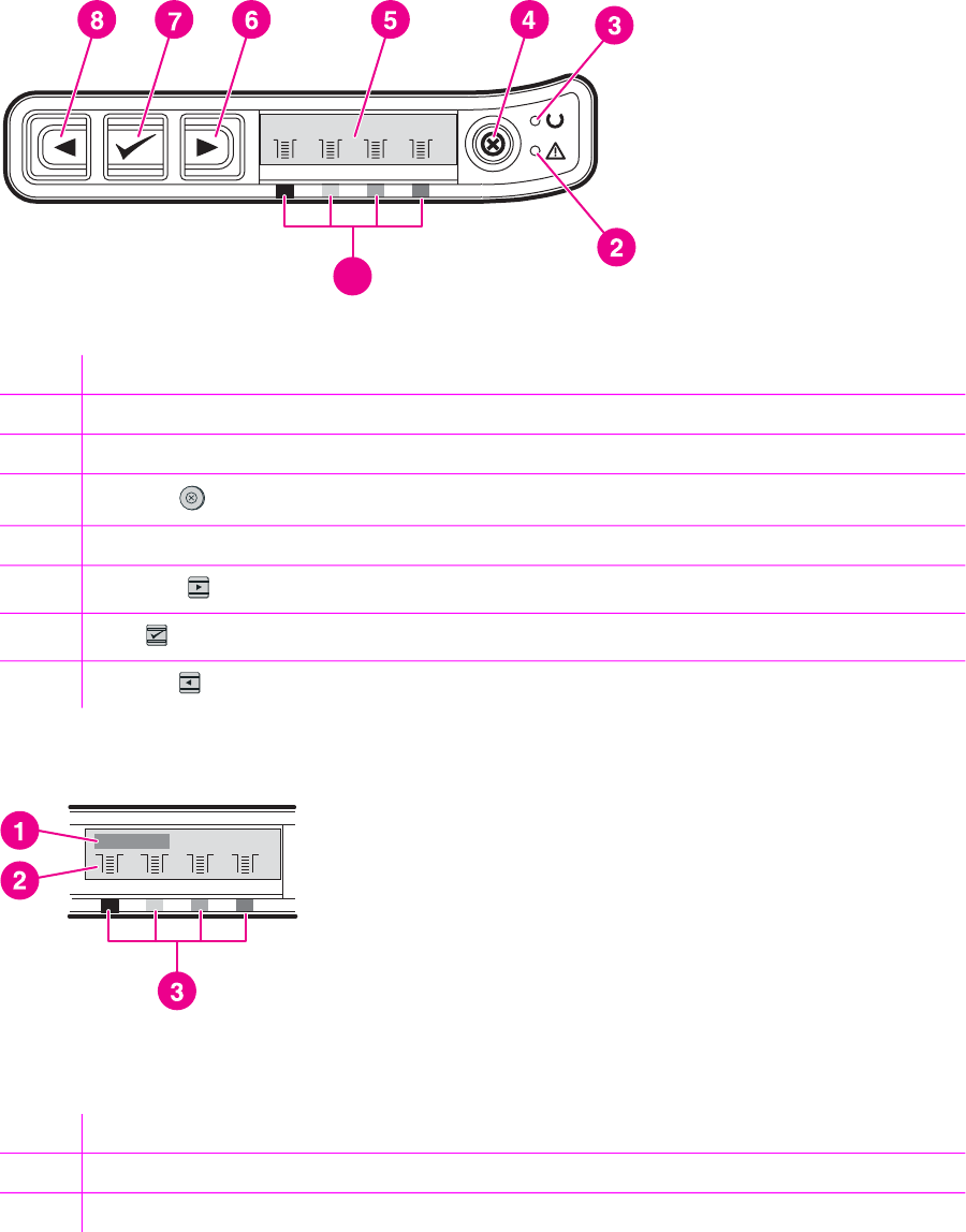
Understanding control panel layout
This section provides information about printer status and control panel layout.
Control panel layout
The printer contains the following lights and buttons on the control panel:
ENWW Walk around 9
1
Figure 1-6 Control panel layout
1Color print cartridge indicators
2Attention light (amber)
3Ready light (green)
4C
ANCEL
J
OB
button
5Message area
6R
IGHT
ARROW
button
7S
ELECT
button
8L
EFT
ARROW
button
Display
Figure 1-7 Control panel display
The printer display gives you information about the printer, job status, and levels of supplies.
1Message area
2Supplies gauges
3Print cartridge colors are indicated from left to right: black, yellow, cyan, and magenta
10 Chapter 1 Product information ENWW

Software
This section contains information about the software used with the HP Color LaserJet 2600n printer.
Supported drivers
Software and supported operating systems
For easy printer setup and access to the full range of printer features, HP strongly recommends that
you install the software that is provided. Not all software is available in all languages. See the Getting
Started Guide for installation instructions, and see the Readme file for the latest software information.
The most recent drivers, additional drivers, and other software are available from the Internet and
other sources.
The printer supports the following operating systems:
■Microsoft® Windows® 98 Second Edition and Windows Millennium Edition (Me) (Add Printer
installation)
■Microsoft® Windows® 2000 and Windows XP
■Microsoft® Windows® Server 2003
■Macintosh OS X v10.2 and later
The following table lists the software that is available for your operating system.
Table 1-2 HP Color LaserJet 2600n printer software
Feature Windows 98 Second
Edition, Me
Windows 2000 and XP Macintosh OS X v10.2 and
later
Windows Installer
Windows printer driver
HP Toolbox software
Macintosh Installer
Macintosh printer drivers
Software for Windows
When you install the software for Windows, you can directly connect the printer to a computer by
using a USB cable or you can connect the printer to the network by using HP built-in networking. See
the Getting Started Guide for installation instructions, and see the Readme file for the latest software
information.
The following software is available to all users of the printer, whether you connected the printer
directly to a computer by using a USB cable, or to the network through the HP built-in networking
internal print server.
ENWW Software 11

Printer drivers
A printer driver is a software component that provides access to printer features and provides the
means for the computer to communicate with the printer.
Using Help
The printer driver has Help dialog boxes that can be activated from the Help button in the printer
driver, the F1 key on the computer keyboard, or the question mark symbol (?) in the upper-right
corner of the printer driver. These Help dialog boxes give detailed information about the specific
printer driver. Help for the printer driver is separate from the Help for your program.
HP Toolbox
You must perform a complete software installation to use the HP Toolbox.
The HP Toolbox provides links to printer status information and help information, such as the user
guide; and tools for diagnosing and solving problems. You can also view explanations and
animations on the control panel. See Managing and maintenance for more information.
Software for Macintosh
The printer includes the following software for Macintosh computers.
Macintosh printer driver
When you install the software for Macintosh, you can directly connect the printer to a computer by
using a USB cable or you can connect the printer to the network by using HP built-in networking. If
you are connected via the network, you can configure your printer using the embedded Web server.
Network software
Supported networks
The HP Color LaserJet 2600n printer supports network printing on Windows and Mac systems.
Supported utilities/applications/tools
■HP Color LaserJet 2600n HP Toolbox
For IP configuration, in HP Toolbox, select Device Settings, and then select the Networking
tab. For more information about the HP Toolbox, see HP Toolbox.
■Embedded Web server (EWS)
If the printer is connected to a network, access the EWS by typing the printer IP address into the
address field of a Web browser, and then selecting the Networking tab.
Uninstalling software
Uninstall software by using the following directions for your operating system.
Windows software
After a printing system installation, use the uninstall icon in the HP Color LaserJet 2600n printer
program group to select and remove any or all of the HP printing system components.
12 Chapter 1 Product information ENWW

Starting the Uninstaller
1Click Start, select Programs (All Programs for Windows XP) and choose HP.
2In the HP Color LaserJet 2600n program group, click the HP Color LaserJet 2600n uninstall
icon.
3The uninstaller guides you through removing the printing system components.
NOTE For driver-only (Add Printer/New Driver) installations, delete the printer icon from the
Printers folder (Windows 98 Second Edition, Windows Me, Windows 2000, and Windows XP).
Macintosh software
To remove the printer from your Macintosh use the following steps:
1Open Print Center (v10.2) or Print Setup Utility (v10.3).
2Select the printer name.
3Select Delete.
ENWW Software 13

Print-media specifications
This section contains information about specifications for the quality of print media, guidelines for
print media usage, and guidelines for print media storage.
General guidelines
Some print media might meet all of the guidelines in this manual and still not produce satisfactory
results. This problem might be the result of improper handling, unacceptable temperature and
humidity levels, or other variables over which Hewlett-Packard has no control.
Before purchasing large quantities of print media, always test a sample and make sure that the print
media meets the requirements specified in the HP LaserJet Printer Family Print Media Guide
available at http://www.hp.com/support/ljpaperguide.
CAUTION Using print media that does not meet HP specifications can cause problems for
the printer, requiring repair. This repair is not covered by the Hewlett-Packard warranty or
service agreements.
CAUTION Use only paper designed for laser printers. Paper for inkjet printers may damage
the printer.
This printer accepts a variety of media, such as cut-sheet paper (including up to 100% recycled-fiber-
content paper), envelopes, labels, transparencies, HP LaserJet glossy paper, HP LaserJet Tough
paper, HP LaserJet Photo paper, and custom-size paper. Properties such as weight, composition,
grain, and moisture content are important factors that affect printer performance and output quality.
Print media that does not meet the guidelines outlined in this manual can cause the following
problems:
■Poor print quality
■Increased jams
■Premature wear on the printer, requiring repair
Paper and print media
For print-media specifications, see Media support tables.
Printing and storage environment
Ideally, the printing and media-storage environment should be at or near room temperature, and not
too dry or too humid. Remember that paper is hygroscopic; it absorbs and loses moisture rapidly.
Heat works with humidity to damage paper. Heat causes the moisture in paper to evaporate, while
cold causes it to condense on the sheets. Heating systems and air conditioners remove most of the
humidity from a room. As paper is opened and used, it loses moisture, causing streaks and
smudging. Humid weather or water coolers can cause the humidity to increase in a room. As paper is
opened and used it absorbs any excess moisture, causing light print and dropouts. Also, as paper
loses and gains moisture it can distort. This issue can cause jams.
As a result, paper storage and handling are as important as the paper-making process itself. Paper
storage environmental conditions directly affect the feed operation and print quality.
14 Chapter 1 Product information ENWW

Care should be taken not to purchase more paper than can be easily used in a short time (about
three months). Paper stored for long periods can experience heat and moisture extremes, which can
cause damage. Planning is important to prevent damage to a large supply of paper.
Unopened paper in sealed reams can remain stable for several months before use. Opened
packages of paper have more potential for environmental damage, especially if they are not wrapped
with a moisture-proof barrier.
The media-storage environment should be properly maintained to ensure optimum printer
performance. The required condition is 20° to 24°C (68° to 75°F), with a relative humidity of 45% to
55%. The following guidelines should be helpful when evaluating the paper's storage environment:
■Print media should be stored at or near room temperature.
■The air should not be too dry or too humid (to moderate the hygroscopic properties of paper).
■The best way to store an opened ream of paper is to rewrap it tightly in its moisture-proof
wrapping. If the printer environment is subject to extremes, unwrap only the amount of paper to
be used during the day's operation to prevent unwanted moisture changes.
■Avoid storing paper and print media near heating and air conditioning vents or near windows and
doors that are frequently open.
Envelopes
Envelopes can be printed from Tray 1 or Tray 2. Select the type of envelope that you are using from
the Print dialog box or the printer driver.
In your program, set the margins for the envelope. The following table gives typical address margins
for a commercial #10 or DL envelope.
Table 1-3 Envelope specifications
Type of address Top margin Left margin
Return address 15 mm (0.6 inch) 15 mm (0.6 inch)
Delivery address 51 mm (2 inches) 89 mm (3.5 inches)
■For the best print quality, position margins no closer than 15 mm (0.6 inch) from the edges of the
envelope.
■Avoid printing over the area where the envelope seams meet.
Envelope storage
Proper storage of envelopes helps contribute to print quality. Envelopes should be stored flat. If air is
trapped in an envelope and creates an air bubble, then the envelope might wrinkle during printing.
Envelope construction
Envelope construction is critical. Envelope fold lines can vary considerably, not only between
manufacturers, but also within a box from the same manufacturer. Successful printing on envelopes
ENWW Print-media specifications 15

depends upon the quality of the envelopes. When selecting envelopes, consider the following
components:
■Weight: The weight of the envelope paper should not exceed 90 g/m
2
(24 lb) or jamming might
occur.
■Construction: Before printing, envelopes should lie flat with less than 6 mm (0.25 inch) curl, and
should not contain air.
■Condition: Envelopes should not be wrinkled, nicked, or otherwise damaged.
■Temperature: Use envelopes that are compatible with the heat and pressure of the printer. This
printer fusing temperature is 210°C (410°F).
■Size: Use only envelopes that are within the following size ranges.
Table 1-4 Envelope size ranges
Tray Minimum Maximum
Tray 1 or Tray 2 76 x 127 mm (3 x 5 inches) 216 x 356 mm (8.5 x 14 inches)
Envelopes with double side-seams
Double side-seam construction has vertical seams at both ends of the envelope rather than diagonal
seams. This style might be more likely to wrinkle. Be sure the seam extends all the way to the corner
of the envelope as illustrated below.
1
2
Figure 1-8 Envelope double side-seam construction
1 Acceptable
2 Unacceptable
Envelopes with adhesive strips or flaps
Envelopes with a peel-off adhesive strip or with more than one flap that folds over to seal must use
adhesives that are compatible with the heat and pressure in the printer. The extra flaps and strips
might cause wrinkling, creasing, or even jams and might damage the fuser.
16 Chapter 1 Product information ENWW

Labels
Select the type of label that you are using from the Print dialog box or the printer driver.
CAUTION To avoid damaging the printer, use only labels that are recommended for laser
printers. To prevent serious jams, always use Tray 1 or Tray 2 to print on labels. Never print
on the same sheet of labels more than once or print on a partial sheet of labels.
When selecting labels, consider the quality of each component:
■Adhesives: The adhesive material should be stable at 210°C (410°F), which is the printer fusing
temperature.
■Arrangement: Only use labels with no exposed backing between them. Labels can peel off
sheets with spaces between the labels, causing serious jams.
■Curl: Before printing, labels must lie flat with no more than 13 mm (0.5 inch) of curl in any
direction.
■Condition: Do not use labels that have wrinkles, bubbles, or other indications of separation.
Transparencies
Use only Tray 1 or Tray 2 to print on transparencies. Select Transparencies from the Print dialog
box or the printer driver.
The printer supports printing on color transparencies. Use only transparencies that are
recommended for use in laser printers.
Transparencies that are used in the printer must be able to withstand 210°C (410°F), which is the
printer fusing temperature.
CAUTION To avoid damage to the printer, use only transparencies that are recommended
for use in laser printers.
Media support tables
This section contains information about the sizes, weights, and capacities of paper and other print
media that each tray supports.
Supported print media for Tray 1, Tray 2, and optional Tray 3
This section contains information about the sizes, weights, and capacities of paper and other print
media that each tray supports.
Tray 1 and Tray 2 specifications
Table 1-5 Tray 1 and Tray 2 specifications
Tray 1 and Tray 2 Dimensions
1
Weight Capacity
2
Paper Minimum: 76 x 127 mm
(3 x 5 inches)
60 to 163 g/m
2
(16 to 43 lb) Single sheet of 75 g/m
2
(20 lb) paper for Tray 1
ENWW Print-media specifications 17

Tray 1 and Tray 2 Dimensions
1
Weight Capacity
2
Maximum: 216 x 356 mm
(8.5 x 14 inches)
Up to 250 sheets for Tray 2
HP LaserJet glossy paper
and HP LaserJet photo paper
Same as the preceding
listed minimum and
maximum sizes.
75 to 163 g/m
2
(20 to 43 lb) Single sheet of HP LaserJet
glossy paper or HP LaserJet
photo paper for Tray 1
Up to 25 mm (0.99 inch)
stack height for Tray 2
HP Premium Cover paper
3
200 g/m
2
(75 lb) cover Single sheet of HP Cover
paper for Tray 1
Up to 25 mm (0.99 inch)
stack height for Tray 2
Transparencies and opaque
film
Thickness: 0.10 to 0.13 mm
(3.9 to 5.1 mils)
Single sheet of transparency
or opaque film for Tray 1
Up to 50 sheets for Tray 2
Labels Thickness: up to 0.23 mm
(up to 9 mils)
Single sheet of labels for
Tray 1
Up to 25 mm (0.99 inch)
stack height for Tray 2
Envelopes Up to 90 g/m
2
(16 to 24 lb) Single envelope for Tray 1
Up to ten envelopes for
Tray 2
1
The printer supports a wide range of standard and custom sizes of print media. Check the printer driver for supported sizes.
2
Capacity can vary depending on media weight and thickness, and environmental conditions.
3
Hewlett-Packard does not guarantee results when printing with other types of heavy paper.
Optional Tray 3 specifications
Table 1-6 Optional Tray 3 specifications
Optional Tray 3 (250–sheet
tray)
Dimensions
1
Weight Capacity
2
Paper Minimum: 76 x 127 mm
(3 x 5 inches)
Maximum: 216 x 356 mm
(8.5 x 14 inches)
60 to 163 g/m
2
(16 to 43 lb) Up to 250 sheets
1
The printer supports a wide range of standard and custom sizes of print media. Check the printer driver for supported sizes.
2
Capacity can vary depending on media weight and thickness, and environmental conditions.
Unsupported media (media to avoid)
Avoid using the following media:
■Paper that has been stapled. Staples left in reused paper will cause printer damage that will
require repairs that may not be covered under the warranty.
■Sheets of labels that have been used more than once or partial sheets of labels
Table 1-5 Tray 1 and Tray 2 specifications (continued)
18 Chapter 1 Product information ENWW
■Labels that are not specifically recommended for laser printers
■Labels that are separating from the backing sheet or are wrinkled or damaged in any way
■Transparencies that are not specifically recommended for laser printers
■Media that has been stored in a high-humidity environment
■Labels with exposed glue or adhesive
ENWW Print-media specifications 19
20 Chapter 1 Product information ENWW

Site preparation
Below are recommendations for the printer location and placement.
Operating environment
The printer must be kept in a proper location to maintain the performance level that has been set at
the factory. In particular, be sure that the environment adheres to the specifications listed in this
chapter.
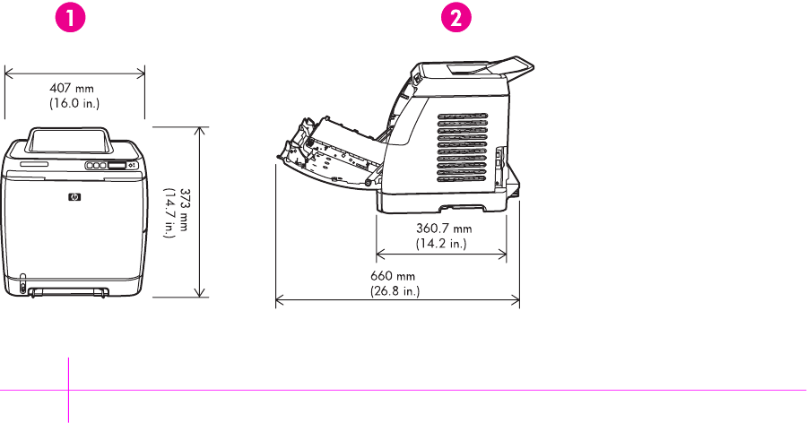
The printer must have 2 inches of space above and around it.
Figure 2-1 Printer dimensions
1Front view
2Side view
Make sure the printer has the following:
■A well-ventilated, dust-free area
■As surface that will support up to 18 kg (40 lbs)
■A constant temperature and humidity (Do not install near water sources, humidifiers, air
conditioners, refrigerators, or other major appliances.)
■A hard level surface (not more than a 2° angle)
Make sure to keep the printer away from the following:
■Direct sunlight, dust, open flames, or water
■Direct flow of exhaust from air ventilation systems
■Magnets and devices that emit a magnetic field
■Areas subject to vibration
22 Chapter 2 Installation ENWW

■Walls or other objects. There must be enough space around the printer for proper access and
ventilation
Minimum system requirements
The minimum system requirements for the HP Color LaserJet 2600n printer are listed below:
■150 MB of free hard disk space
■CD-ROM drive
■Available USB or network port
NOTE Networking is only available on Windows 2000, Windows XP, and Macintosh.
Requirements for PC systems
■Windows 98 SE and Me (driver only)
■Windows 2000 and XP (32-bit Home and Professional)
■233 MHz processor with 64 MB RAM
Requirements for Macintosh systems (non-PostScript)
■G3 processor (G4 processor recommended)
■Mac OS X 10.2 and later
ENWW Site preparation 23
Install input devices
Installing optional Tray 3
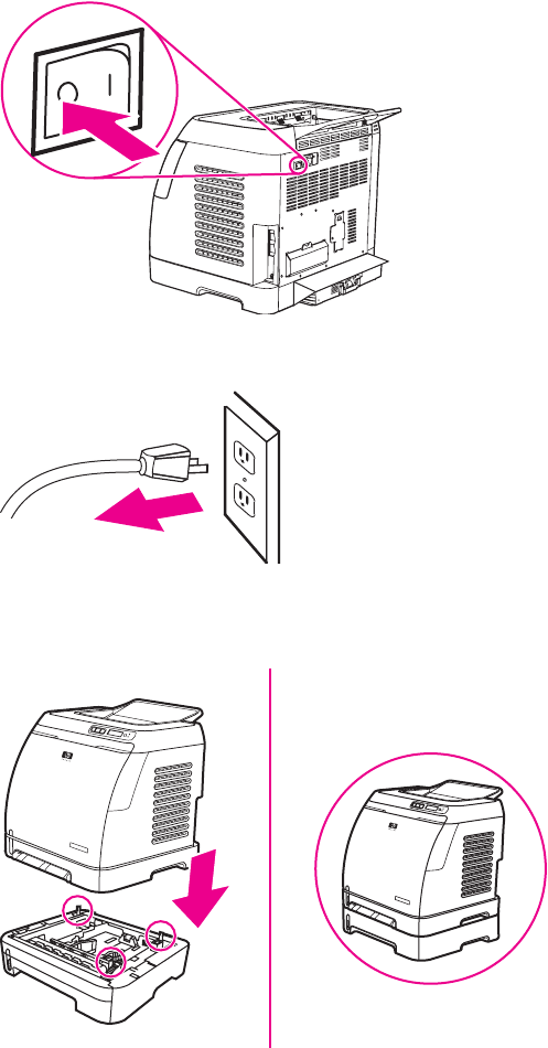
1Turn off the power switch on the printer.
2Unplug the power cable.
3Place the printer on optional Tray 3, aligning the three (3) pegs on Tray 3 with the holes on the
printer.
Loading Tray 1
Tray 1 (the single sheet priority feed slot) prints single sheets of print media or a single envelope.
Use Tray 1 when feeding one sheet of paper, or one envelope, postcard, label, HP LaserJet glossy
paper, HP LaserJet Photo paper, or transparency. You can also use Tray 1 to print the first page on
different media than the rest of the document.
ENWW Install input devices 25
For information about loading special print media such as envelopes, labels, and transparencies, see
Print-media specifications.
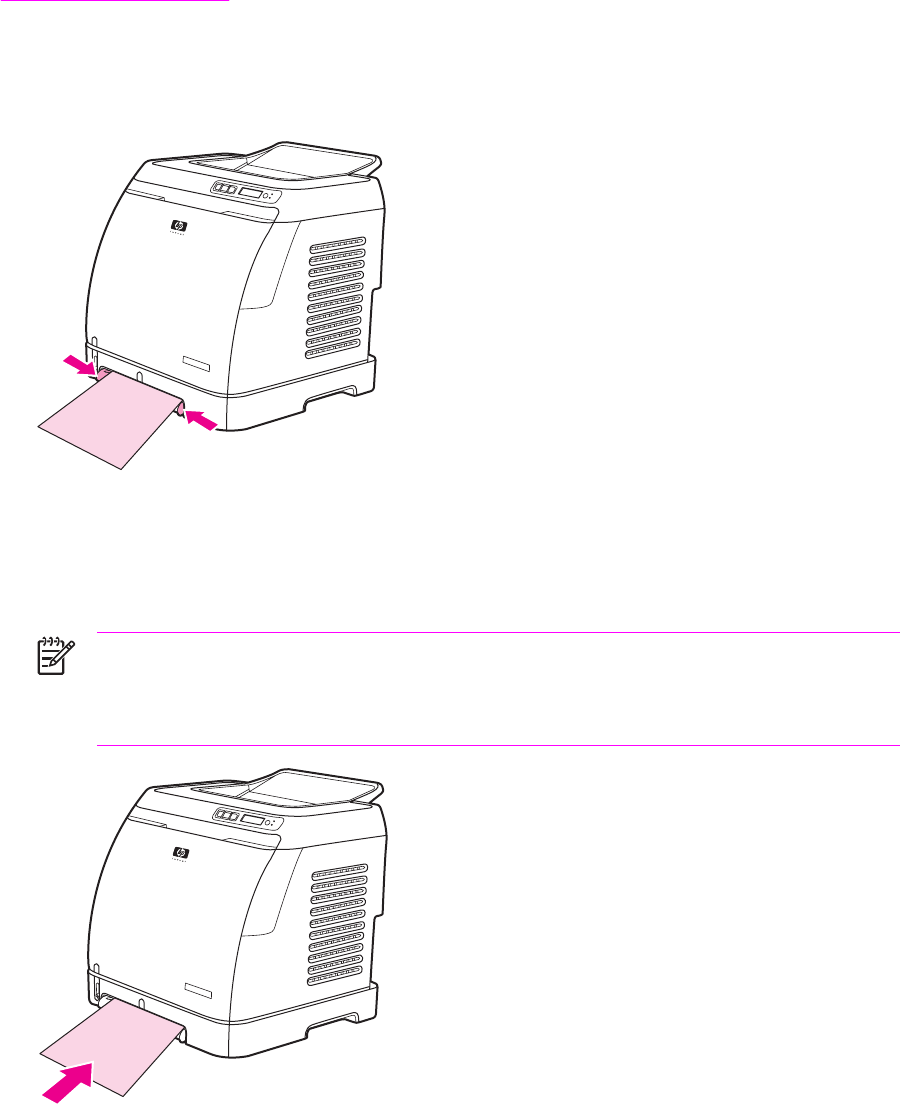
To load Tray 1
1Media guides ensure that the media is correctly fed into the printer and that the print is not
skewed. Slide the media-width guides slightly wider than the print media.
2Feed print media into Tray 1 with the side to be printed down, and the top, short edge in first.
Make sure that the media is inserted far enough into the printer for the paper feed mechanism to
grab the media. The paper will reach the sensor after 140 mm (5.5 inches) has been inserted.
The printer will then pause for .5 second before it pulls the paper into the printer. HP
recommends holding the paper on both sides when inserting.
NOTE Light weight paper may buckle if held only on the short (far) edge as it is inserted.
As paper is inserted, it trips the registration shutter. For light weight paper, holding it on
both sides near the slot increases the ability for the paper to appropriately trip this shutter.
26 Chapter 2 Installation ENWW
Installing supplies
Print cartridges
When a print cartridge approaches the end of useful life, the control panel displays a message
recommending that you order a replacement. The printer can continue to print using the current print
cartridge until the control panel displays a message instructing you to replace the cartridge.
The printer uses four colors and has a different print cartridge for each color: black (K), cyan (C),
magenta (M), and yellow (Y).
Replace a print cartridge when the printer control panel displays one of the following messages:
Replace yellow cartridge, Replace magenta cartridge, Replace cyan cartridge, Replace black
cartridge. The control panel display also indicates the color that should be replaced (unless a
genuine HP cartridge is not currently installed).
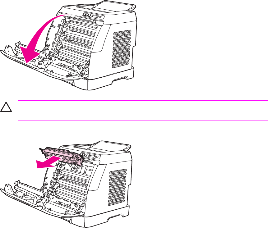
To change the print cartridge
1Turn off the printer.
2Open the front door.
CAUTION Do not place anything on the transfer belt (ETB), which is located on the
inside of the front door.
3Remove the used print cartridge from the printer.
ENWW Install input devices 27
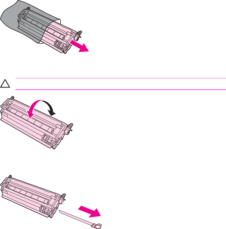
4Remove the new print cartridge from the bag. Place the used print cartridge in the bag for
recycling.
5Grasp both sides of the print cartridge by the blue handles and distribute the toner by gently
rocking the print cartridge from front to back.
CAUTION Do not touch the shutter or the surface of the roller.
6Remove the orange shipping locks and the orange shipping tape from the new print cartridge.
Discard the shipping tape and shipping locks according to local regulations.
28 Chapter 2 Installation ENWW
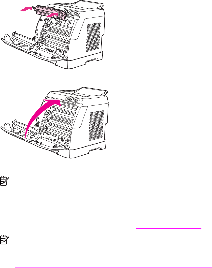
7Align the print cartridge with the tracks inside the printer, and using the handles, insert the print
cartridge until it is firmly seated.
8Firmly close the front door.
9Turn on the printer. After a short time, the control panel should display Ready.
NOTE If a cartridge is in the wrong slot or is the wrong type for the printer, the control
panel will display one of the following messages: Incorrect yellow, Incorrect magenta,
Incorrect cyan, Incorrect black.
10 Installation is complete. Place the used print cartridge in the box in which the new cartridge
arrived. See the enclosed recycling guide for recycling instructions.
11 If you are using a non-HP print cartridge, check the printer control panel for further instructions.
For more information about using non-HP print cartridges, see HP policy on non-HP supplies.
NOTE When replacing or changing a black print cartridge, a cleaning page will
automatically print. This helps prevent speckles on the front or back of printed documents.
A cleaning page can also be generated using the control panel or the HP Toolbox. For
information, see To clean the printer at the printer or To clean the fuser using HP Toolbox.
ENWW Install input devices 29
30 Chapter 2 Installation ENWW


Managing supplies
Life expectancies of supplies
Table 3-1 Print cartridge life
Print-cartridge life (based on approximately 5% coverage) Black: 2,500 pages
Yellow, cyan, and magenta: 2,000 pages each
Checking and ordering supplies
You can check the supplies status by using the printer control panel, printing a Supplies Status page,
or viewing the HP Toolbox. Hewlett-Packard recommends that you place an order for a replacement
print cartridge when you first receive the Order message for a print cartridge. For typical use, the
Order message indicates that approximately two weeks of life remains. When you use a new,
authentic HP print cartridge, you can obtain the following types of supplies information:
■Amount of cartridge remaining
■Estimated number of pages remaining
■Number of pages printed
■Other supplies information
NOTE If the printer is connected to the network, you can set the HP Toolbox to notify you by
e-mail when a print cartridge is low or is near the end of its life. If the printer is directly
connected to a computer, you can set HP Toolbox to notify you when supplies are low.
To check status using the control panel
Do one of the following:
■Check the supplies status gauges on the printer control panel. These gauges indicate when a
print cartridge is low or empty. The lights also indicate when a non-HP print cartridge is first
installed.
■To print the Supplies Status page from the printer, on the printer control panel, select Reports,
Supplies Status, and then (S
ELECT
). See Supplies Status page for more information.
If the supplies levels are low, you can order supplies through your local HP dealer, by telephone, or
online.
To check and order supplies using HP Toolbox
You can configure HP Toolbox to notify you when the supplies are low. You can choose to receive
alerts by e-mail or as a pop-up message or taskbar icon. To order supplies using the HP Toolbox, in
the Other Links area, click Order supplies. You must have Internet access to connect to the website.
32 Chapter 3 Managing and maintenance ENWW

Storing supplies
Follow these guidelines for storing print cartridges:
■Do not remove the print cartridge from its package until you are ready to use it.
CAUTION To prevent damage, do not expose the print cartridge to light for more than a
few minutes.
■See Environmental specifications for operating and storage temperature ranges.
■Store the supply in a horizontal position.
■Store the supply in a dark, dry location away from heat and magnetic sources.
Replacing and recycling supplies
Replacing the print cartridges
To install a new HP print cartridge, follow the instructions that are included on the box that contains
the new supply, or see the Getting Started Guide.
To recycle supplies, place the used supply in the box in which the new supply arrived. Use the
enclosed return label to send the used supply to HP for recycling. For complete information, see the
recycling guide that is included with each new HP supply item. Go to http://www.hp.com/go/recycle
for more information about HP's recycling program.
HP policy on non-HP supplies
Hewlett-Packard Company cannot recommend the use of non-HP supplies, either new or
remanufactured. Because they are not HP products, HP cannot influence their design or control their
quality. Service or repairs required as a result of using a non-HP supply will not be covered under
the printer warranty.
When you insert a supply into the printer, the printer will inform you if the supply is not a genuine HP
supply. If you insert a genuine HP supply that has reached the low state from another HP printer, the
printer identifies the supply as non-HP. Simply return the supply to the original printer to reactivate
HP features and functionality.
HP anti-counterfeit website
Visit the HP anti-counterfeit website at http://www.hp.com/go/anticounterfeit if the supplies status
gauges or HP Toolbox indicates that the print cartridge is not an HP print cartridge and you think that
it is genuine.
ENWW Managing supplies 33

Cleaning the printer
During the printing process, paper, toner and dust particles can accumulate inside the printer. Over
time, this buildup can cause print-quality problems such as toner specks or smearing. This printer
has a cleaning mode that can correct and prevent these types of problems.
This printer has two processes for generating cleaning pages: one is automatically generated and
one is manually generated. When a new black print cartridge is installed, a cleaning page will be
automatically generated prior to calibration. To manually generate a cleaning page, see To clean the
fuser using HP Toolbox.
To clean the printer at the printer
NOTE If you have access to HP Toolbox, HP recommends cleaning the paper path by using
HP Toolbox.
Use the following procedure to clean the printer at the printer.
1Use the (L
EFT
ARROW
) or (R
IGHT
ARROW
) button to select Service, and then press (S
ELECT
).
2Use the (L
EFT
ARROW
) or (R
IGHT
ARROW
) button to select Cleaning Mode, and then press
(S
ELECT
).
A page feeds through the printer slowly. Discard the page when the process is completed.
34 Chapter 3 Managing and maintenance ENWW
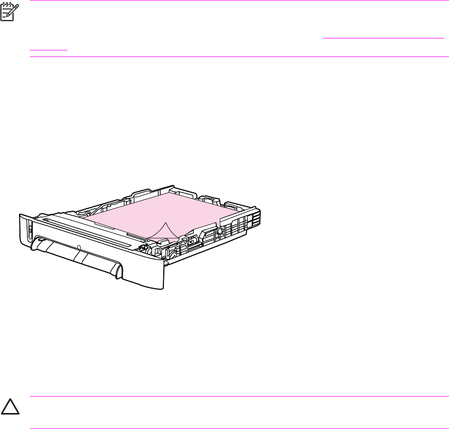
To clean the fuser using HP Toolbox
NOTE Use the following procedure to clean the fuser using the HP Toolbox. To clean the
engine when the computer is running an operating system that does not support HP Toolbox,
see the late-breaking Readme on the root of the CD-ROM, or visit http://www.hp.com/support/
clj2600n.
1Make sure that the printer is turned on and in the Ready state.
2Open the HP Toolbox.
3On the Troubleshooting tab, click Troubleshooting Tools, and then click Print. A page with a
pattern prints from the printer.
4At the printer, remove any print media in Tray 2 or optional Tray 3.
5Remove the page that printed and load it face-down into Tray 2 or optional Tray 3.
6On the Troubleshooting Tools page, click the Clean button.
Cleaning spilled toner
Defective print cartridges can develop leaks. Also, after a paper jam has occurred, some toner might
remain on the rollers and guides inside the printer. The pages that print immediately after the jam
can pick up this toner.
CAUTION When cleaning the printer, do not touch the ETB with a damp cloth or with your
fingers.
ENWW Cleaning the printer 35

Calibrating the printer
The printer automatically calibrates at various times. You can adjust the calibration settings by using
the HP Toolbox.
Environmental differences or aging print cartridges might cause fluctuations in image density. The
printer accounts for this with image stabilization control. The printer automatically calibrates at
various times to maintain the highest level of print quality. You can also request a calibration by using
the HP Toolbox.
The printer does not interrupt a print job to calibrate. It waits until the job is complete before
calibrating or cleaning. While the printer is calibrating, it pauses printing for the time that is required
to complete the calibration.
To calibrate the printer at the printer
1To calibrate from the printer, press (L
EFT
ARROW
) or (R
IGHT
ARROW
) until the display reads
SYSTEM SETUP.
2Press (S
ELECT
).
3Press (L
EFT
ARROW
) or (R
IGHT
ARROW
) until the display reads PRINT QUALITY.
4Press (S
ELECT
).
5Press (L
EFT
ARROW
) or (R
IGHT
ARROW
) until the display reads CALIBRATE COLOR.
6Press (S
ELECT
).
7Press (L
EFT
ARROW
) or (R
IGHT
ARROW
) until the display reads CALIBRATE NOW.
8Press (S
ELECT
).
9Press (S
ELECT
) to confirm CALIBRATE NOW.
To calibrate the printer from the HP Toolbox
NOTE This procedure applies to Windows operating systems only. Macintosh users should
calibrate the printer manually using the procedure above.
1Open the HP Toolbox in one of these ways:
●On the desktop, double-click the HP Toolbox icon.
●On the Start menu, point to Programs, point to HP, point to HP Color LaserJet 2600n, and
click HP Color LaserJet 2600n Toolbox.
2Click the Troubleshooting tab and then click Troubleshooting Tools (on the left side of the
screen).
3In the Calibration section, click CALIBRATE NOW.
36 Chapter 3 Managing and maintenance ENWW


Engine control system
Basic sequence of operation
The operational sequence of the printer is controlled by the microcomputer on the DC controller
printed circuit board (PCB). The purposes of each period, from power-on until the main motor stops
after the completion of printing, are listed below. See General timing chart for a detailed timing chart.
Table 4-1 Basic operational sequence
Period Purpose Remarks
WAIT (wait period) From power-on until the end
of the main motor initial drive.
To clear the drum surface
potential and to clean the
ETB.
Detects whether or not the
print cartridge is installed.
STBY (standby period) From the end of WAIT or
LSTR until the input of print
command from the
formatter. Or, from the end
of LSTR until power-off.
To keep the printer ready to
print.
INTR (initial rotation period) From the input of print
command from the formatter
until the pick-up solenoid is
turned on.
To stablize the
photosensitive drum
sensitivity for print
preparation.
PRINT (print period) From the end of INTR until
the developing high-voltage
is off.
To form the image on the
photosensitive drum based
on the VIDEO signals input
from the formatter, and to
transfer the toner image
onto paper.
LSTR (last rotation period From the developing high-
voltage off until the main
motor stops rotating.
To deliver the last page
completely. Also used to
clean the ETB.
The printer enters INTR after
the end of LSTR, when the
print command is input from
the formatter.
The engine control system coordinates all printer functions. It drives the laser/scanner system, the
image formation system, and the pickup and feed system. The engine control system contains the
following components:
■DC controller PCB
■Low-voltage power supply unit
■High-voltage power supply PCB
38 Chapter 4 Operational theory ENWW
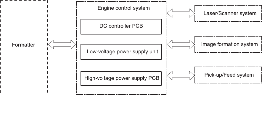
Figure 4-1 Engine control system
Power-on sequence
The power-on sequence is for the purpose of the printer initialization and checking for possible
malfunctions.
The following is the sequence from when the printer is turned on until it enters STBY mode.
1Power on
2Central processing unit (CPU) initialization
3ASIC initialization
4Video interface communication start
5Residual paper check by each sensor signaling paper presence
6Initial drive for main motor, pickup motor, and fuser/delivery motor
7Fuser heater initial drive by controlling fuser temperature targeting for 100°?C
8Initial drive for scanner motor
9Failure/Abnormality check
●Detect scanner failure
●Fuser failure
●Door open during the above periods
10 Communication with memory tag
11 Cartridge presence detection
Motors and fans
The DC controller PCB controls four motors.
ENWW Engine control system 39

The specifications of each motor are listed in the following table.
Table 4-2 Motor specifications
Name Purpose Type Direction of
rotation
Failure detection
Motor Main motor (M1) Drive ETB belt,
photosensitive
drum and
developing cylinder
DC motor CW Yes
Fuser/delivery
motor (M2)
Drive fuser
pressure roller,
delivery roller and
automatic release
of fuser pressure
Stepping motor CW/CCW No
Pickup motor (M3) Drive pickup roller
and registration
roller
Stepping motor CW No
Fan (FM1) Cool down around
cartridge
DC motor — Yes
Main motor failure detection
The CPU determines the main motor failure, stops the printer, and notifies the formatter of error
status, when it encounters the following conditions.
■Main motor start-up abnormality
The interval of the MAIN MOTOR SPEED DETECTION signal (/MAINMFG) does not become
the specified interval after 1000 ms of the main motor drive start.
■Main motor rotation abnormality
The interval of the /MAINMFG signal stays at an irregular interval for 100 ms and longer after
once it has become the specified interval.
Fan motor failure detection
The CPU determines the fan motor failure and notifies the formatter when it encounters the following
condition.
The FAN LOCK signal (FANLCK) is “H” for approximately 10 seconds and longer during fan motor
rotation.
40 Chapter 4 Operational theory ENWW
Image formation system
The image formation system serves as the nerve center of the printer and forms a toner image on
paper. It is controlled by the DC controller. The DC controller controls the laser/scanner unit and the
high-voltage power supply PCB to form an image on paper according to the VIDEO signals (VDO, /
VDO) upon reception of a print command from the formatter. There is a memory tag inside each
cartridge. The memory tags read and write data according to the command from the DC controller.
The following figure illustrates the image formation system.
ENWW Image formation system 41
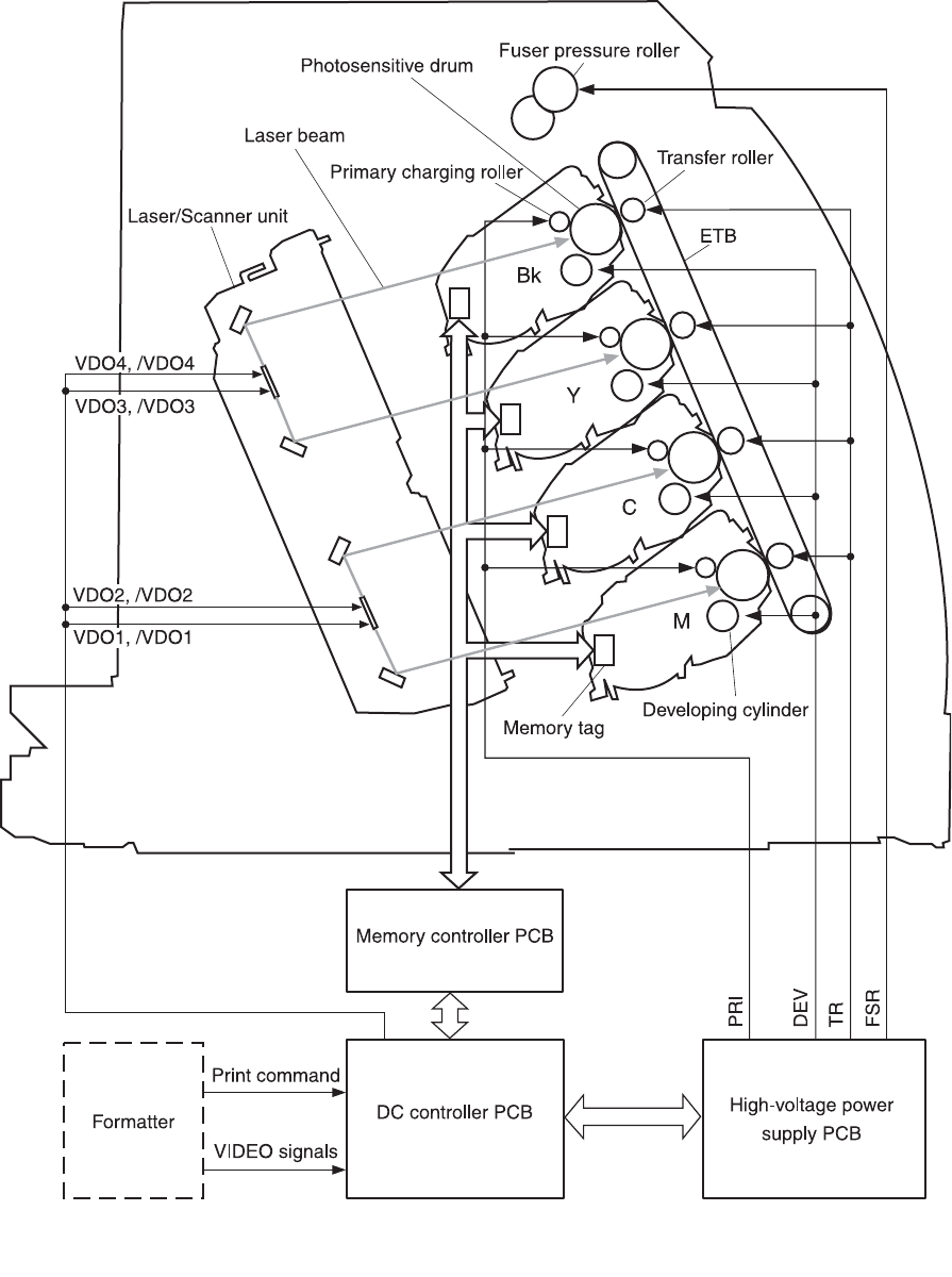
Figure 4-2 Image formation system
42 Chapter 4 Operational theory ENWW
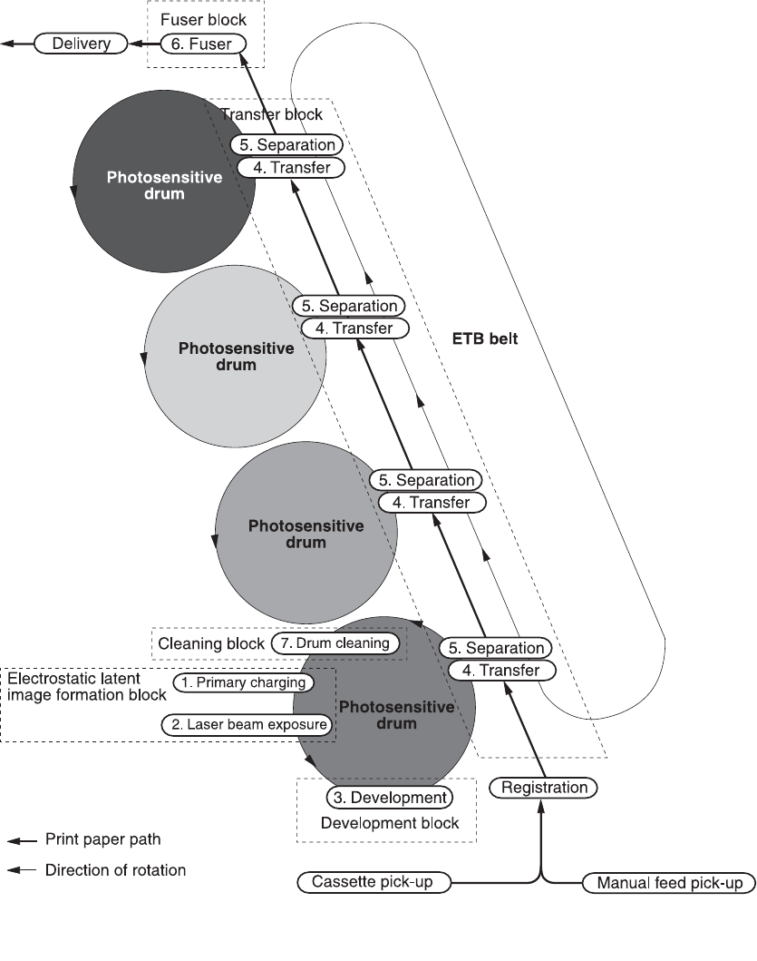
Image formation process
Figure 4-3 Image formation process
ENWW Image formation system 43
The principal process of image formation is described here. The print process can be broadly divided
into 5 stages with 7 steps. A toner image is formed on paper as it goes through each process. The
following figure illustrates the stages and steps of the print process as follows.
1Electrostatic latent image formation stage
Forms an electrostatic latent image on the photosensitive drum.
Step 1: Primary charging
Step 2: Laser beam exposure
2Developing stage
Makes the electrostatic latent image on the photosensitive drum surface visible by applying toner.
Step 3: Development
3Transfer stage
Transfers a toner image on the photosensitive drum onto paper.
Step 4: Transfer
Step 5: Separation
4Fuser stage
Fuses the toner image on paper.
Step 6: Fuser
5ETB cleaning stage
Cleans the residual toner on the photosensitive drum.
Step 7: ETB cleaning
Latent image formation
This stage consists of two steps and forms an electrostatic latent image on the photosensitive drum.
When the last step in this stage is completed, a negative electrical charge remains in the unexposed
drum surface area by the laser beam and is removed from the exposed area. The image with
negative charge on the drum is called an “electrostatic latent image” as it is invisible to human eyes.
44 Chapter 4 Operational theory ENWW

Figure 4-4 Latent image formation
Laser/scanner system
The laser/scanner system forms latent images on the photosensitive drum according to the VIDEO
signals sent from the formatter. It consists of the laser driver PCB, the scanner motor, and so forth.
The figure below illustrates the laser/scanner unit.
Figure 4-5 Laser beam exposure
Developing stage
The electrostatic latent image on the photosensitive drum surface is visualized by applying the toner
in this process. This printer utilizes the projection development method by the non-magnetic, single-
component toner.
ENWW Image formation system 45
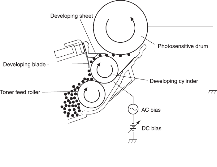
Figure 4-6 Developing stage
The toner has an insulating property and has negative charge potential from friction with the rotating
developing cylinder and the developing blade surface.
The area of the photosensitive drum, where the laser beam is exposed, has higher potential than the
toner, which is charged negatively on the cylinder. When this area contacts the toner layer
(negatively charged), the toner jumps onto the drum surface by the potential difference between the
drum surface and the cylinder (higher potential on drum side). This is called the projection
development and it visualizes the electrostatic latent image on the drum. The developing cylinder is
applied the AC bias in order to make the toner jump easier onto the drum surface and improve the
contrast of the output image.
This printer is able to adjust the image density by changing the potential difference between the
cylinder and the photosensitive drum surface according to changes of the developing DC bias based
on the IMAGE DENSITY INFORMATION signal sent from the formatter.
The developing sheet improves the print quality and also prevents toner scattering.
Print cartridge
The cartridge forms a visible toner image on the photosensitive drum. There are four print cartridges:
magenta, cyan, yellow, and black; each having identical structure.
46 Chapter 4 Operational theory ENWW
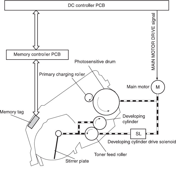
Figure 4-7 Print cartridge structure
Transfer belt (ETB)
The ETB unit feeds paper as well as transfers toner onto the paper.
The ETB unit consists of the ETB, ETB feed roller, ETB driven roller, and color misregistration/
density sensor unit.
As the main motor rotates the ETB feed roller, the ETB feed roller rotates the ETB belt. The transfer
roller and the ETB driven roller are engaged with the ETB.
During printing, the picked up paper is conveyed in between the ETB and the photosensitive drum,
and simultaneously the toner image is transferred onto the paper. The ETB is also used for color
misregistration corrective control and the image stabilization control. The pattern image for the color
misregistration or image density determination is transferred onto the belt. This pattern image is read
in the color misregistration/density sensor unit.
The following is the diagrammatic sketch of the ETB unit.
ENWW Image formation system 47
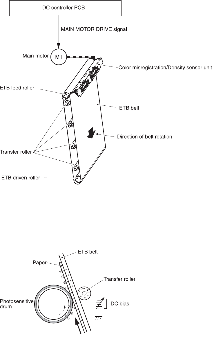
Figure 4-8 ETB unit
Transfer stage
The transfer stage is to transfer the toner image on the photosensitive drum surface onto paper.
Figure 4-9 Transfer stage
48 Chapter 4 Operational theory ENWW

The toner on the photosensitive drum surface is transferred onto the paper according to the positive
charge from the back side of the paper. Each color’s toner image is transferred in order of M, C, Y,
and K, and forms one toner image overlaying one color’s image on another.
Separation stage
Figure 4-10 Separation stage
The paper is separated from the drum by its elasticity (Curvature Separation). The static charge on
the back side of the paper is decreased with the electrostatic eliminator in order to stablize the
feeding operation and prevent the crescent spots of printing image under the low temperature and
low humidity environment.
Fusing stage
The toner image is fused onto the paper in this stage. The toner image transferred onto the paper
through the transfer stage can be smeared easily by hands since it is only attracted to the paper by
the static electricity. The paper and the toner on it are fused by pressure, fused and secondary
colored by heat to be a permanent image.
Figure 4-11 Fusing stage
The toner image on the paper is fused onto the paper by using the on-demand fuser method in this
step. This printer utilizes the ceramic heater with lower heat capacity, which warms up quickly, does
ENWW Image formation system 49
not require the power supply during STBY mode, and saves energy. As for the printer, the DC
positive bias is applied to the fuser pressure roller, so the transferred toner stays harder on the paper
and toner scattering to the fuser film (offset) is prevented.
50 Chapter 4 Operational theory ENWW

Pickup and feed system
The pickup/feed system, which picks up and feeds paper, consists of the various feed rollers. This
printer has two pickup sources: the cassette and the manual feed slot, and one delivery source: the
face-down tray. The following components are part of the pickup and feed system:
■Manual feed slot paper sensor (SR3): detects the presence of paper in the manual feed slot
■Cassette paper sensor (SR2): detects the presence of paper in the cassette
■DC controller controls the following to drive each feed roller:
■Main motor (M1)
■Fuser/delivery motor (M2)
■Pickup motor (M3)
■Solenoid (SL1)
■Solenoid (SL2)
■Solenoid (SL3)
■Photo sensors:
■SR1, SR4, and SR5 on the paper transport path detect the arrival and passage of paper
■SR9 detects the fuser pressure roller alienation in the fuser
■SR8 detects the paper width
The figure below illustrates the motors, solenoids, and sensors.
NOTE There is a short pause before the paper is picked up.
ENWW Pickup and feed system 51
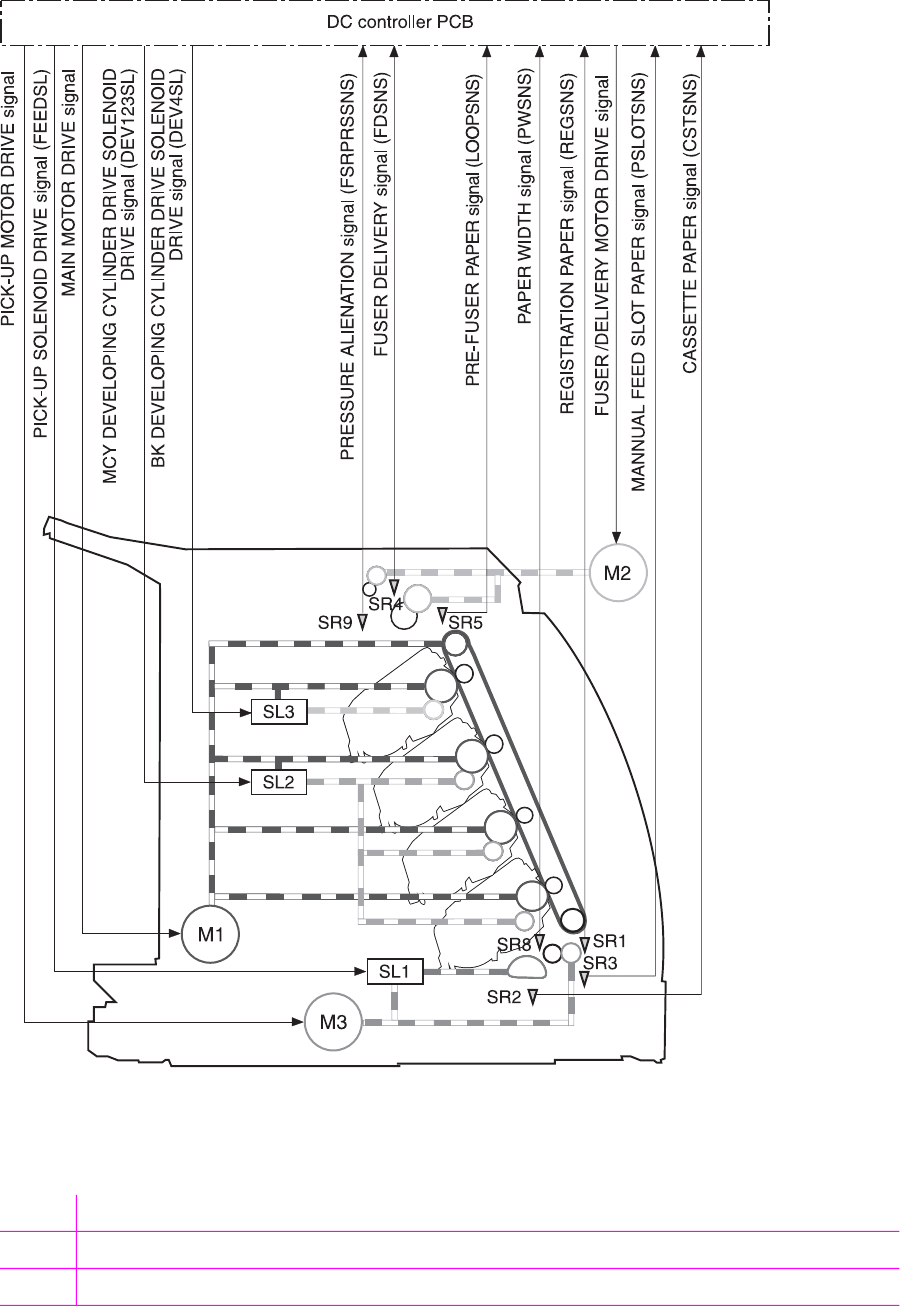
Figure 4-12 Paper pickup and feed system
SR1 Registration paper sensor
SR2 Cassette paper sensor
SR3 Manual feed slot paper sensor
52 Chapter 4 Operational theory ENWW

SR4 Fuser delivery paper sensor
SR5 Pre-fuser paper sensor
SR8 Paper width sensor
SR9 Pressure alienation sensor
M1 Main motor
M2 Fuser/Delivery motor
M3 Pickup motor
SL1 Cassette pickup solenoid
SL2 Magenta, cyan, and yellow developing cylinder drive solenoid
SL3 Black developing cylinder drive solenoid
Manual feed slot pickup mechanism
This mechanism picks up one sheet of paper only that is inserted into the manual feed slot and then
into the printer. This printer does not have a pickup roller in the manual feed slot. Instead of a pickup
roller, the registration roller picks up paper. The presence of paper in the manual feed slot is
detected by the manual feed slot paper sensor (SR3). The following is the operational sequence of
the manual feed slot pickup.
1If paper is set into the manual feed slot during STBY mode, the manual feed slot paper sensor
(SR3) detects it.
2When the paper is detected, the DC controller drives the pickup motor (M3) for 5 seconds. The
paper is fed approximately 5 mm (0.2 inch) and is then caught by the registration roller.
3After the above operational sequence, the paper is fed by the drive of the registration roller.
Paper feed mechanism
This mechanism feeds one sheet of picked up paper to the fuser. There is a paper width sensor in
the paper transport path to prevent temperature rise at the end of the fuser. It detects paper with
widths of shorter than 190 mm (7.5 inches). The following is the operational sequence of paper feed.
1Paper skew is corrected by the registration shutter when the paper is fed into the printer.
2Toner is transfered to the paper from the photosensitive drum and then the paper is fed to the
fuser/delivery stage.
Skew correction by the registration shutter
If the paper fed into the printer is skewed, when it hits the registration shutter, it will be adjusted.
Figure 4-13 Skew correction illustrates how skewed paper is corrected by the registration shutter.
ENWW Pickup and feed system 53
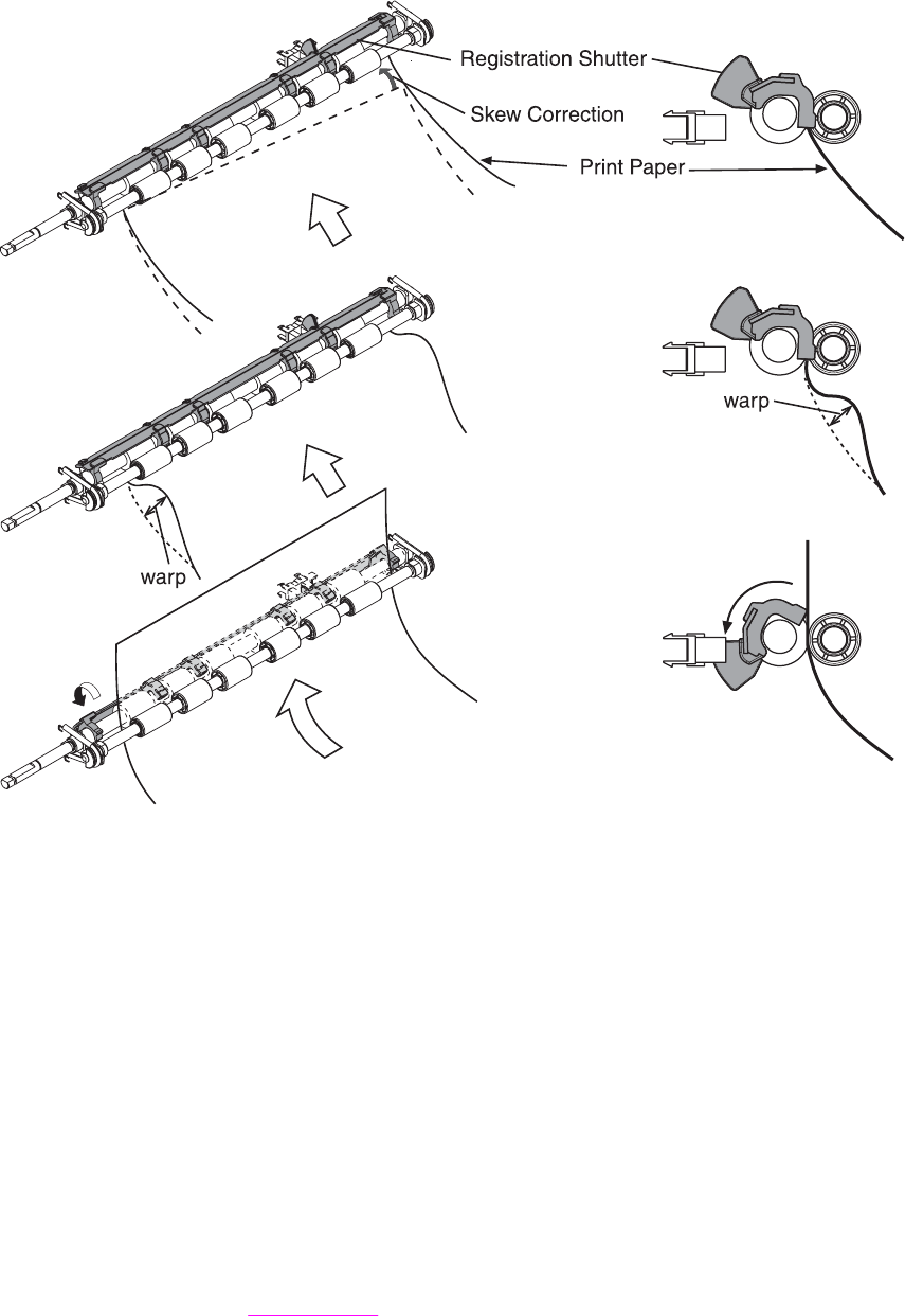
Figure 4-13 Skew correction
Jam detection
This printer is provided with the following paper detection sensors to detect the presence of paper
and whether or not the paper feed is operating normally.
■Registration paper sensor (SR1)
■Pre-fuser paper sensor (SR5)
■Fuser delivery paper sensor (SR4)
The CPU determines a paper jam by checking whether or not paper is present at the sensor at the
check timing. The check timing is stored in the memory of the CPU. If the CPU determines a jam, it
stops the print operation and notifies the formatter of a jam occurrence.
For more information, see Clearing jams.
54 Chapter 4 Operational theory ENWW
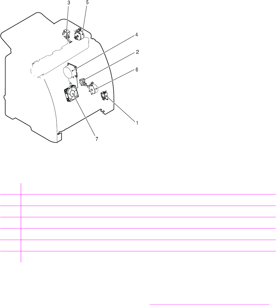
Solenoid, motor, and fan locations
The following illustration shows the locations of the solenoids, motor, and fan.
Figure 4-14 Location of solenoids, motors, and fans
1Pickup solenoid (SL1)
2Magenta, cyan, and yellow developing cylinder drive solenoid (SL2)
3Black developing cylinder drive solenoid (SL3)
4Main motor (M1)
5Fusing/delivery motor (M2)
6Pickup motor (M3)
7Fan (FM1)
Printed circuit assembly locations
The following illustration shows the locations of the printed circuit assemblies. Location of the printed
circuit assemblies and list of parts are also identified in Figure 7-11 PCB assembly location (Tray 2).
ENWW Pickup and feed system 55
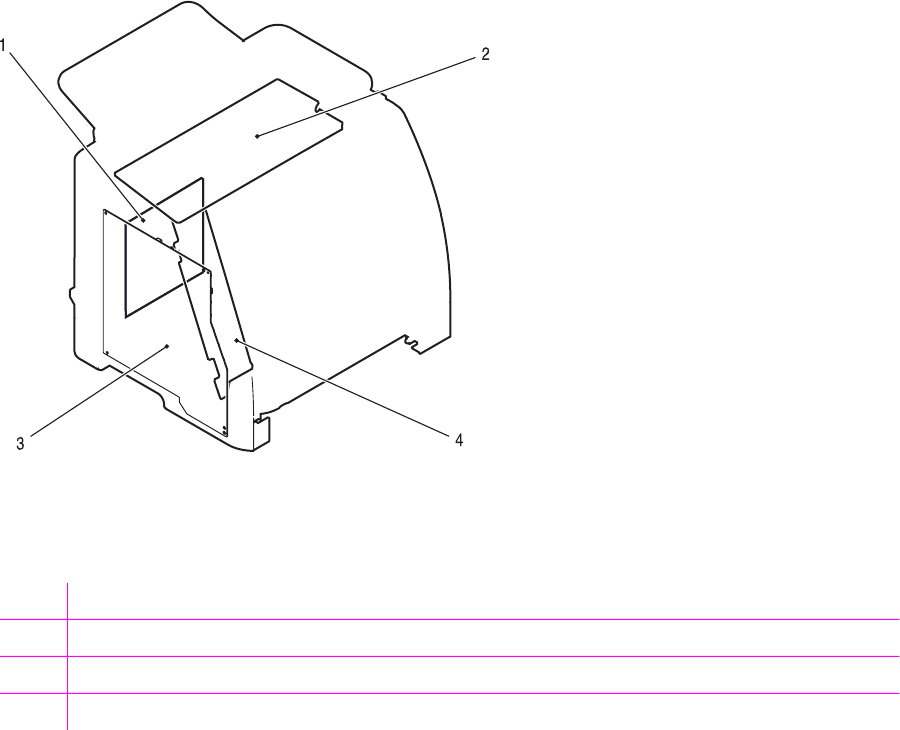
Figure 4-15 Location of printed circuit assemblies
1DC controller PCB
2Low-voltage power supply PCB
3High-voltage power supply PCB
4Memory controller PCB
250-sheet tray solenoid and printed circuit locations
The following illustration shows the locations of the 250-sheet tray solenoid and printed circuit
assembly.
56 Chapter 4 Operational theory ENWW
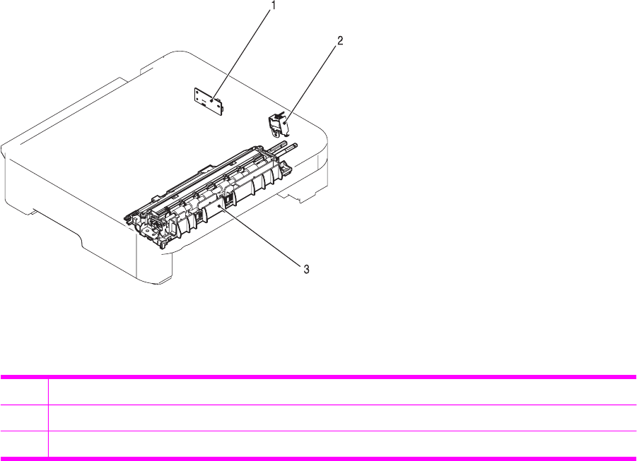
Figure 4-16 Location of 250-sheet tray solenoid and printed circuit assembly
1Paper feeder PCB
2Paper feeder pickup solenoid (SL-4)
3Paper pickup feeder unit
ENWW Pickup and feed system 57
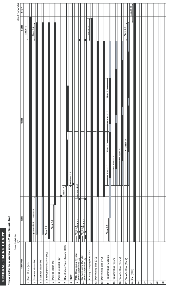
Service-only tools (SERVICE ONLY)
General timing chart
58 Chapter 4 Operational theory ENWW

Printer calibration
Calibration settings are configured with Printer Management Language (PML)/Printer Job Language
(PJL) commands, except for new cartridge installation. Calibration can also be configured using the
embedded Web server and HP Toolbox. Calibration occurs during the following conditions and
intervals:
■Power-on calibration
Calibration during power-on can be configured for the following intervals:
■Always calibrate at power-on
■Never calibrate at power-on
■Calibrate after 1-6 minutes (default is 15 minutes) of idle time after the first job since the
printer was turned on or 12, 24, 48, 96, or 168 hours (default is 48 hours) of idle time.
■Page count calibration
Calibration occurs at the end of the first job that passes 150 color pages since the previous
calibration occurred. Page count calibration settings can be configured for the following intervals:
■Do not do page count calibrations
■Calibrate after 150 pages have been printed since the last calibration. This is the default
setting.
NOTE Page count calibration cannot be set using the embedded Web server.
■Elapsed time calibration
Elapsed time calibration will occur when the first job is sent after the elapsed time is exceeded.
Use PML/PJL commands to configure the following intervals:
■Do not perform elapsed time calibration
■After 12, 24, 48, 96, or 168 hours (default is 48 hours) or more have elapsed since the last
calibration (or power-on), and after 1-6 minutes (default is 15 minutes) of idle time from the
first job after 12, 24, 48, 96, or 168 hours (default is 48 hours) have elapsed.
■On-demand calibration
Calibrate the printer using the printer control panel. For more information about printer
calibration, see Printer calibration.
■New consumable calibration
When a new print cartridge is installed, the printer will calibrate.
NOTE When a new black print cartridge is replaced, a cleaning page will print before the
printer calibrates.
If printing stops when the cartridge is out, requiring the user to either install a new cartridge or
select to print with toner out override, a calibration will not occur until the depleted cartridge is
replaced, printing resumes, and all jobs currently in the queue are finished or cancelled. This
could result in an interval of several pages where a new cartridge is using the old cartridge’s
calibration data.
ENWW Service-only tools (SERVICE ONLY) 59

Calibrating the printer at the control panel
Use the following steps to calibrate the printer using the printer control panel.
1Use the (L
EFT
ARROW
) or the (R
IGHT
ARROW
) button to select SYSTEM SETUP and then press
(S
ELECT
).
2Use the (L
EFT
ARROW
) or the (R
IGHT
ARROW
) button to select PRINT QUALITY and then press
(S
ELECT
). CALIBRATE COLOR will display on the control panel.
3Press (S
ELECT
).
4Use the (L
EFT
ARROW
) or the (R
IGHT
ARROW
) button to select CALIBRATE NOW and then
press (S
ELECT
).
5Press (S
ELECT
) to start the calibration.
60 Chapter 4 Operational theory ENWW


Overview
Removal and replacement strategy
Replace parts in the reverse order of their removal. Directions for difficult or critical replacement
procedures are included in this section.
WARNING! The sheet-metal edges of the product can be sharp. Use caution when working
on the product.
NOTE Note the length, diameter, color, type, and location of each screw. Be sure to return
each screw to its original location during reassembly. Incorrectly routed or loose wire
harnesses can interfere with other internal components and can become damaged or broken.
Frayed or pinched harness wires can be difficult to locate. When replacing wire harnesses,
always use the provided wire loops, lance points, or wire harness guides.
Electrostatic discharge
The printer contains parts that are sensitive to electrostatic discharge (ESD). Watch for the ESD
reminder shown at the left when removing printer parts. Protect the parts that are sensitive to ESD
with protective ESD pouches.
User-replaceable parts
Table 5-1 User-replaceable parts
Product name Description Part number
Separation pad and pickup rollers Replace when the printer is picking up
multiple sheets or no sheets. Trying
different paper did not resolve the
problem.
Q5956-67902
Paper tray A 250-sheet paper cassette. Q5956-67901
Dust cover Protects the output of paper cassette
from dust.
Q5956-67903
Output tray extender An extension for supporting paper in
the output bin.
Q5956-67904
Required tools
Before servicing the printer, gather the following tools:
■Phillips #2 magnetized screwdriver (152 mm (6 inch) shaft)
■Small flat-blade screwdriver
■Small needle-nose pliers
■ESD strap
■Penlight (optional)
62 Chapter 5 Removal and replacement ENWW

Service approach
Field Service on this printer is limited to a recommended time of 30 minutes, which includes
troubleshooting, teardown, and repair. Repairs that require more time should not be made and the
printer should be replaced.
The following are the major internal assemblies that can be replaced on this printer.
■Fuser
■ETB
■DC Controller
■Formatter
■Control Panel display
If troubleshooting or a Control Panel message determines that the failure is not associated with one
of these parts, do not attempt to repair the printer, but replace the unit. For more information on
messages that would indicate a printer needs to be replaced, refer to the Critical error messages
table and the Replaceable parts table.
Pre-service procedures
Follow the pre-service procedures before you perform service.
1Turn off the printer.
2Remove all media from the product.
3Place the product on an ESD mat. If an ESD mat or an ESD-protected workstation is not
available, discharge body static and ground the product chassis before servicing the product.
4Remove the print cartridges.
5Unplug the power cord and the interface cable.
6Lift the printer off of optional Tray 3 (if it is installed).
ENWW Service approach 63
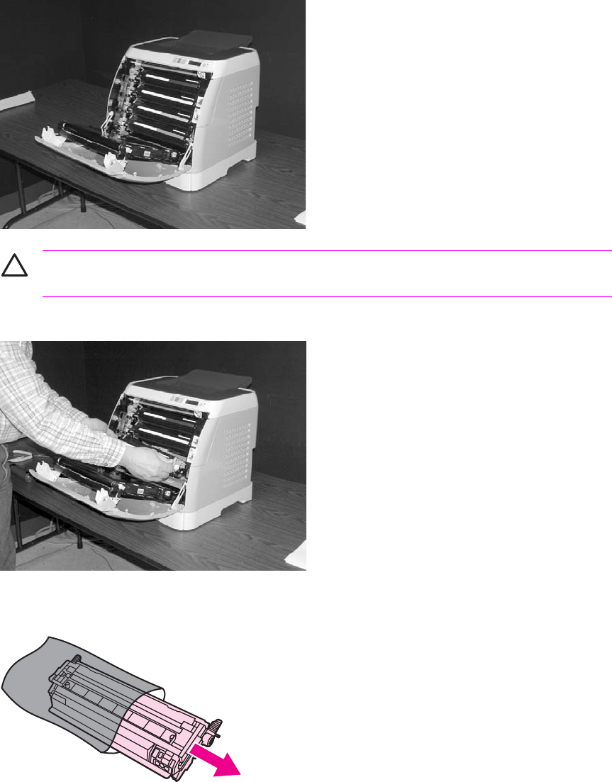
Removal and replacement procedures
Print cartridge replacement
1Open the front door.
CAUTION Do not place anything on the transfer belt (ETB), which is located on the
inside of the front door.
2Remove the used print cartridge from the printer.
3Remove the new print cartridge from the bag. Place the used print cartridge in the bag for
recycling.
64 Chapter 5 Removal and replacement ENWW
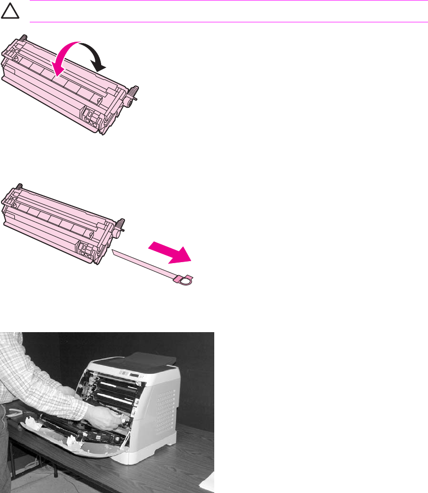
4Grasp both sides of the print cartridge by the blue handles and distribute the toner by gently
rocking the print cartridge from back to front.
CAUTION Do not touch the shutter or the surface of the roller.
5Remove the orange shipping locks and the orange shipping tape from the new print cartridge.
Discard the shipping tape and shipping locks according to local regulations.
6Align the print cartridge with the tracks inside the printer, and using the handles, insert the print
cartridge until it is firmly seated.
ENWW Removal and replacement procedures 65
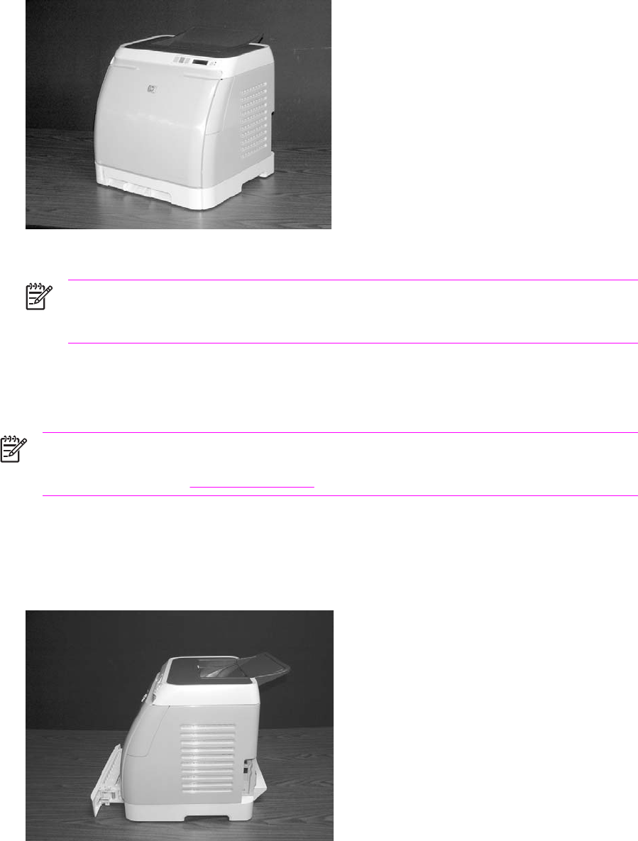
7Firmly close the front door.
After a short time, the control panel should display Ready.
NOTE If a cartridge is in the wrong slot or is the wrong type for the printer, the control
panel will display one of the following messages: Incorrect yellow, Incorrect magenta,
Incorrect cyan, or Incorrect black.
8Installation is complete. Place the used print cartridge in the box in which the new cartridge
arrived. See the enclosed recycling guide for recycling instructions.
9If you are using a non-HP print cartridge, check the printer control panel for further instructions.
NOTE When replacing or changing a black print cartridge, a cleaning page will automatically
print. This helps prevent speckles on the front or back of printed documents. For a more
thorough cleaning, see Cleaning the printer.
ETB removal and replacement
Use the following procedure to remove the ETB (RM1–1881–000CN).
1Remove or slightly pull out Tray 2 (RM1–1916–000CN).
66 Chapter 5 Removal and replacement ENWW
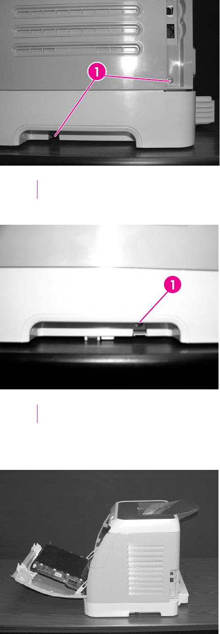
2Remove three (3) screws, two (2) from the right cover assembly and one (1) from the left cover
assembly.
1Two (2) screws on right cover assembly
1One (1) screw on left cover assembly
3Open the front door.
ENWW Removal and replacement procedures 67
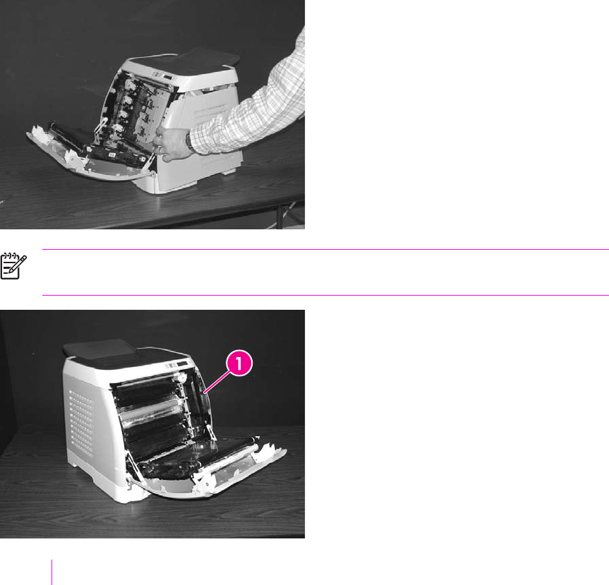
4Remove the right cover (RM1–1858–000CN), carefully twisting the front edges of the side covers
outward to remove.
NOTE To make the removal of the right cover assembly easier, release the tab on the
inside of the cover.
1Release tab
68 Chapter 5 Removal and replacement ENWW
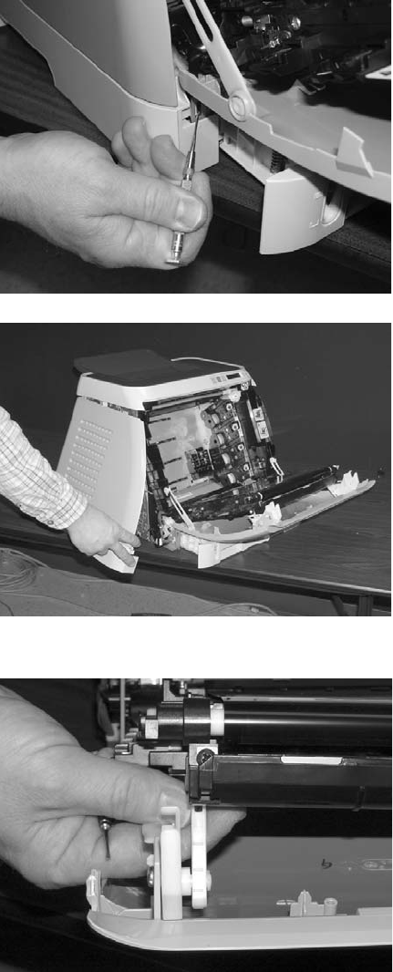
5Remove the left cover.
6Squeeze the white link lever on the left side.
ENWW Removal and replacement procedures 69
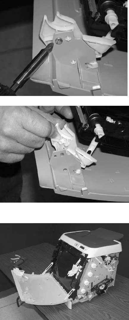
7Remove the screw on the right white plastic catch, and then remove the plastic catch.
8Close the ETB.
70 Chapter 5 Removal and replacement ENWW
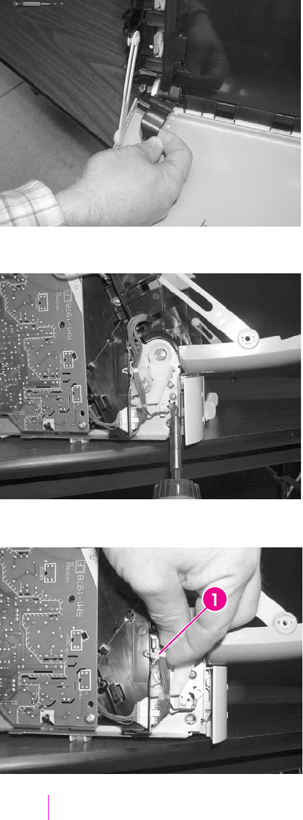
9Remove the small black cable cover (RC1–5147–000CN) on the left side of the printer by
carefully snapping it out of place.
10 Remove one (1) grounding screw from the ETB harness.
11 Pull out the white wire holder by pushing it up.
1White wire holder
ENWW Removal and replacement procedures 71
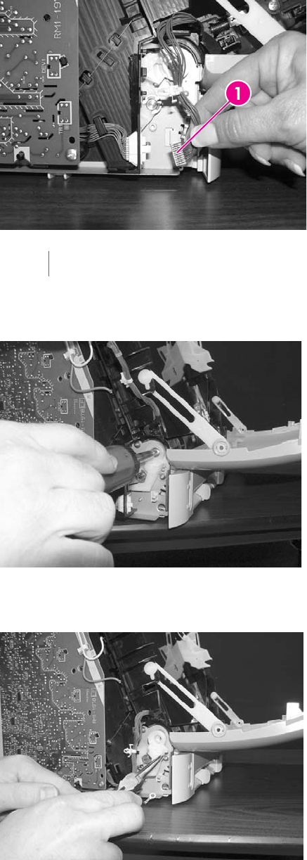
12 Pull out the ETB connector.
1ETB connector
13 Remove one (1) screw from each hinge cam on both sides.
14 Using needle-nose pliers, remove the hinge left cam (RC1–4249–000CN) and the right hinge
cam (RC1–5311–000CN).
72 Chapter 5 Removal and replacement ENWW
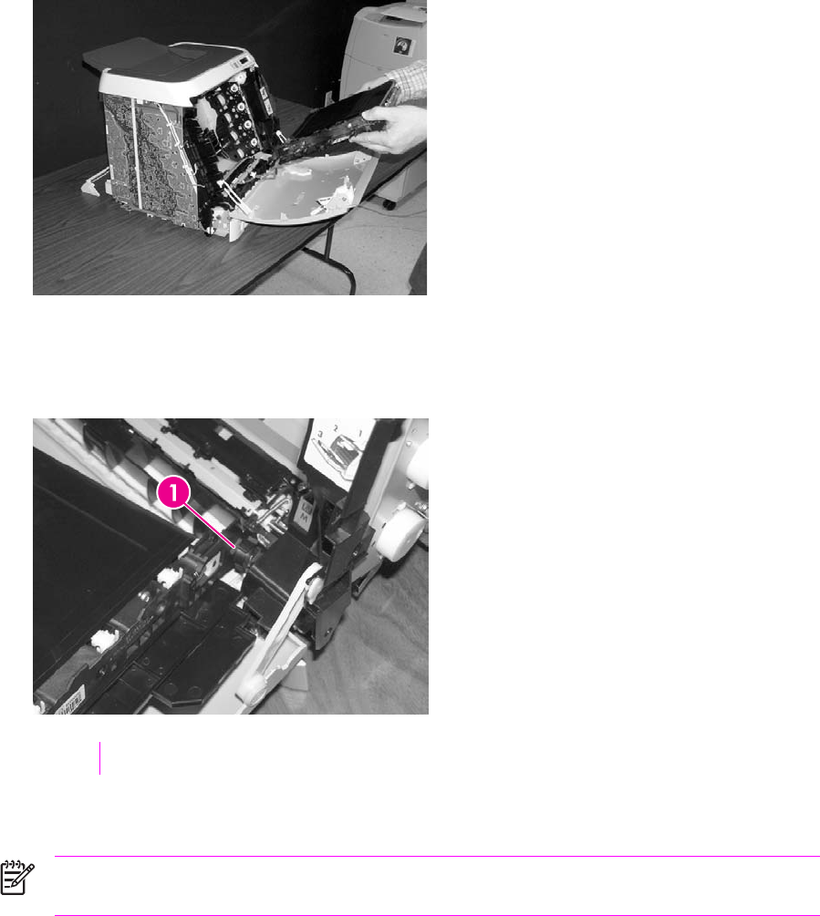
15 Remove the ETB.
Use the following procedure to replace the ETB.
1Align each foot of the ETB with the respective holes, securing the right side first, and then the left
side.
1Alignment location
2Complete replacement by following steps 1 through 14 above in reverse order.
NOTE When replacing the right cover, align the tabs on the upper edge of the right cover
and lower edge of the face-down cover with their respective slots.
ENWW Removal and replacement procedures 73
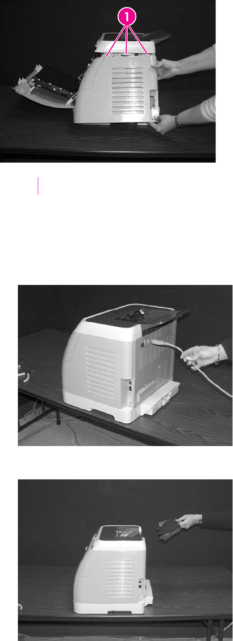
1Tabs
Fuser removal and replacement
Use the following procedure to remove the fuser.
1Unplug the power cable.
2Remove the paper delivery tray assembly (RM1–1859–000CN).
74 Chapter 5 Removal and replacement ENWW
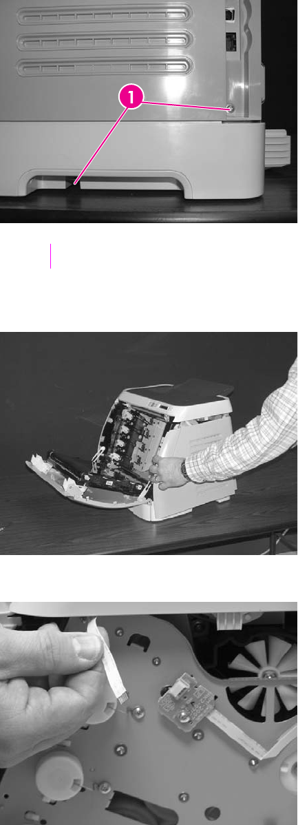
3Remove two (2) screws from the right cover assembly (RM1–1858–000CN).
1Two (2) screws
4Remove the right cover assembly, carefully disengaging the catches.
5Unplug the control panel cable.
ENWW Removal and replacement procedures 75
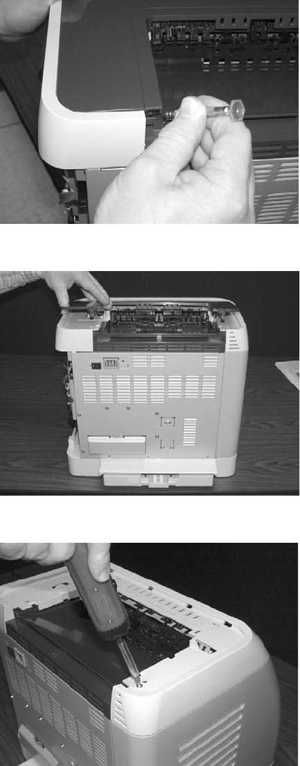
6Insert a screwdriver to loosen the release tab on each side of the upper face cover.
7Remove the upper face cover (RC1–5174–000CN).
8Remove four (4) screws from the upper cover (RC1–5176–000CN).
76 Chapter 5 Removal and replacement ENWW
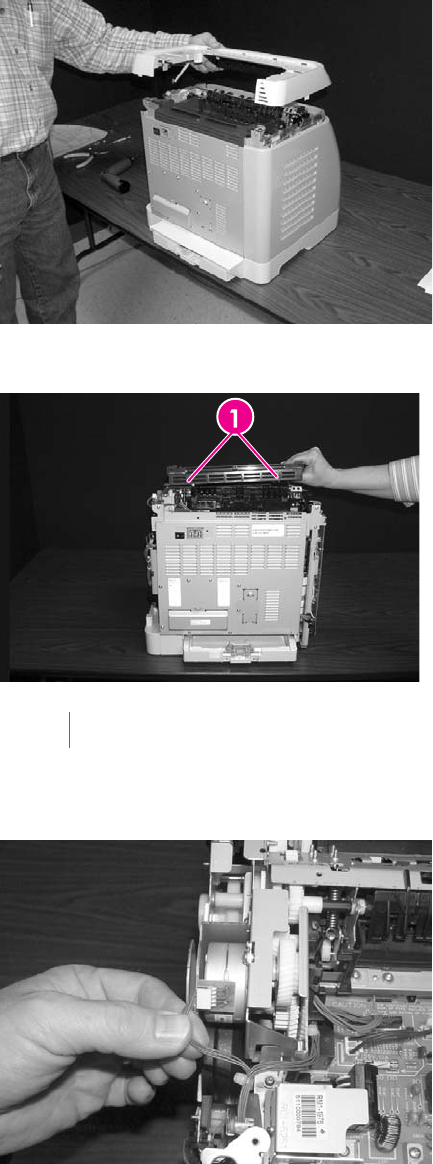
9Lift up and remove the face-down cover (RC1–5173–000CN).
10 Remove the output tray by releasing the tabs.
1Release tabs
11 Unplug the harness from the fuser motor.
ENWW Removal and replacement procedures 77
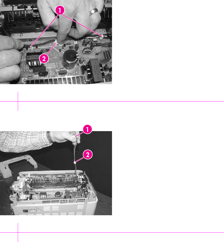
12 Open two (2) clips and remove one (1) clip to remove the fuser connector.
1Open clips
2Remove clip
1Fuser connector
2Remove clip from the board by pulling up
78 Chapter 5 Removal and replacement ENWW
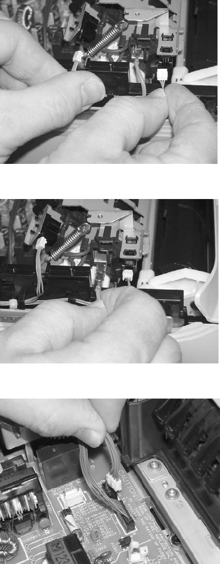
13 Unplug two (2) 3-pin optical encoder wires.
14 Unplug the red high-voltage bias wire.
15 Remove the thermistor wire.
ENWW Removal and replacement procedures 79
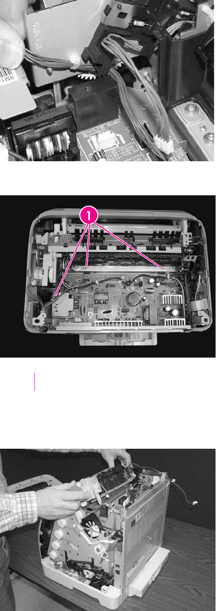
16 Remove the cables from the wiring harness.
17 Remove three (3) screws from the fuser chassis.
1Three (3) screws
18 Gently rocking if necessary, roll the fuser (RM1–1820–00CN for 110V) or (RM1–1821–000CB for
220V) forward to remove.
80 Chapter 5 Removal and replacement ENWW
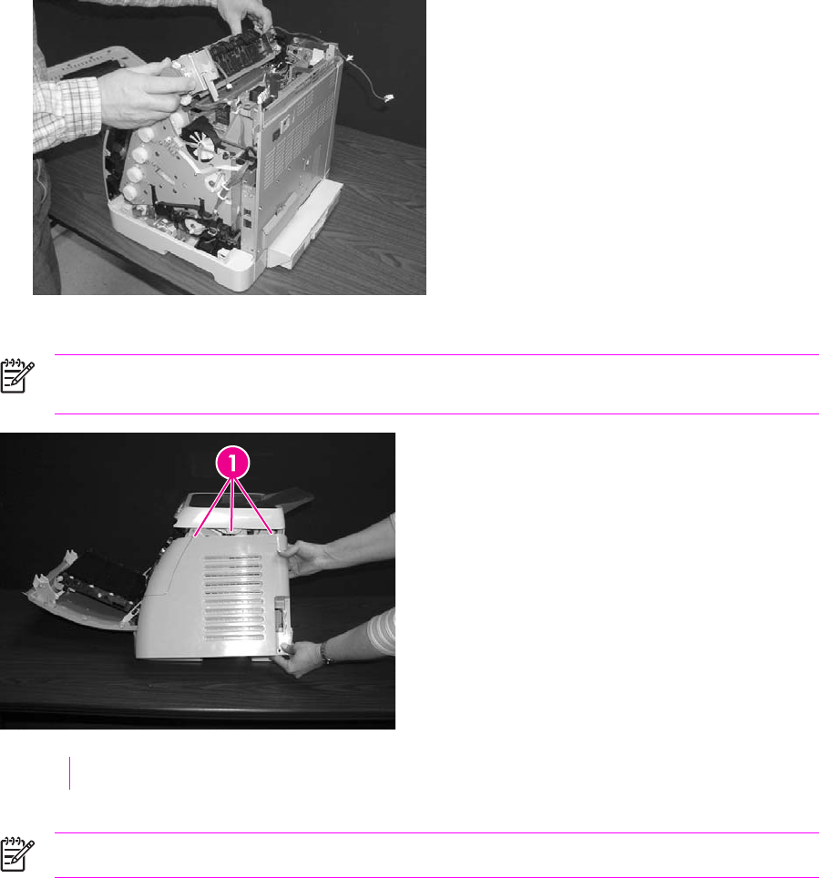
Use the following procedure to replace the fuser.
1Align the fuser tabs with their respective holes.
2Complete replacement by following steps 1 through 18 above in reverse order.
NOTE When replacing the right cover, align the tabs on the upper edge of the right cover
and lower edge of the face-down cover with their respective slots.
1Tabs
NOTE Connect the control panel cable before replacing the right cover.
ENWW Removal and replacement procedures 81
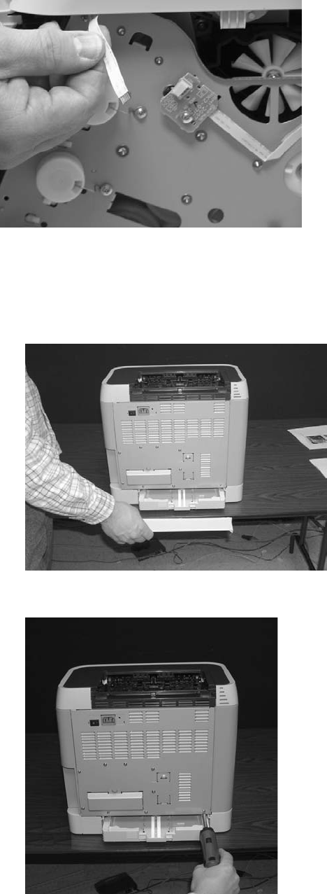
Formatter removal and replacement
Use the following procedure to remove the formatter.
1Remove the cassette dust cover (RC1–5200–000CN).
2Remove nine (9) screws from the rear plate (RC1–5227–000CN).
82 Chapter 5 Removal and replacement ENWW
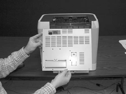
3Remove the rear plate.
ENWW Removal and replacement procedures 83
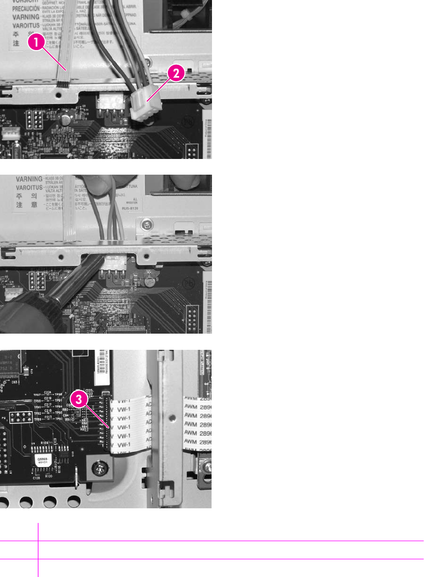
4Unplug three (3) connectors: two (2) data connectors and one (1) power connector.
1Flat cable
2Power cables
3VW-1 flat cable
84 Chapter 5 Removal and replacement ENWW
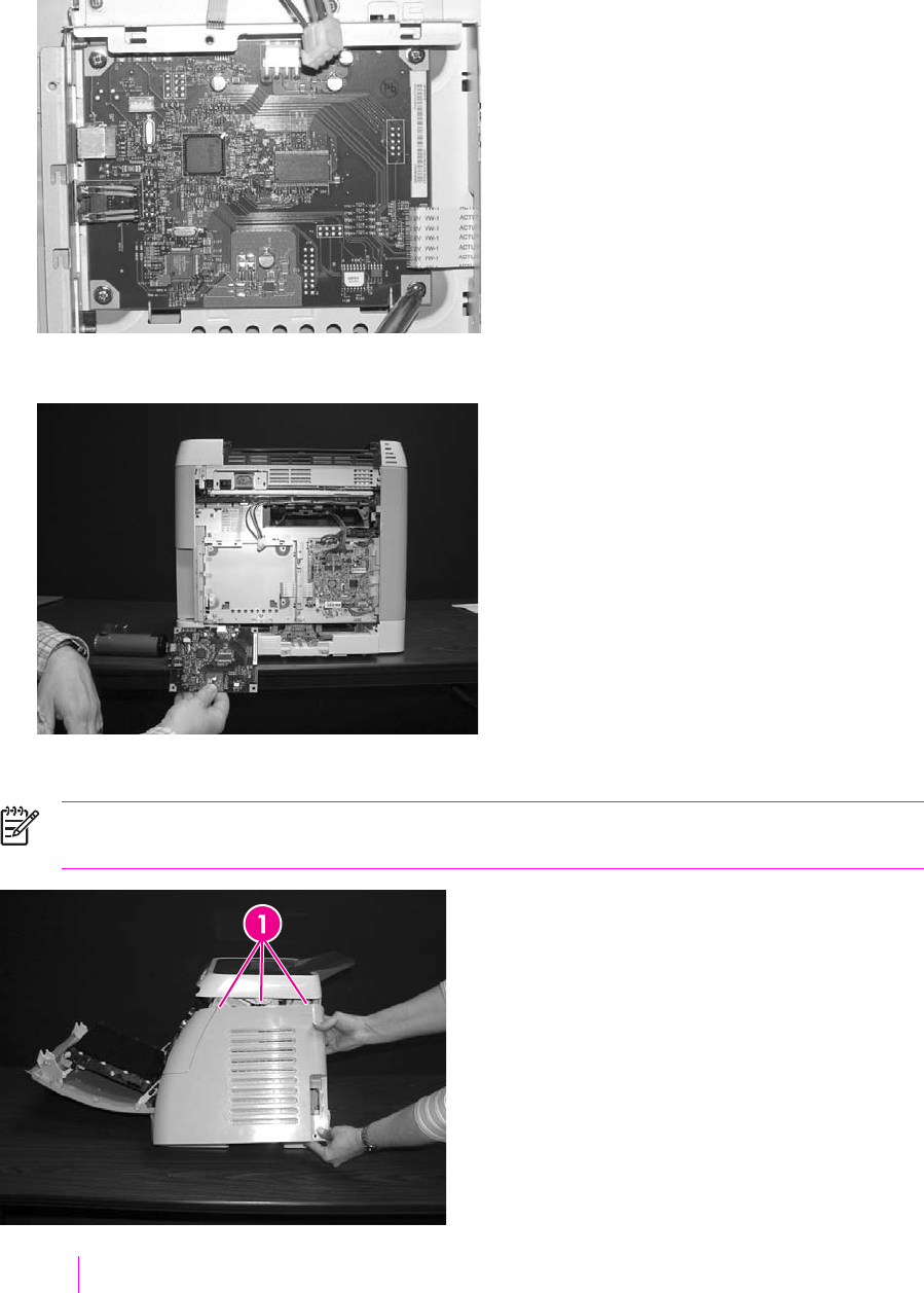
5Remove four (4) screws from the formatter.
6Lifting it up, remove the formatter.
To replace the formatter, follow steps 1 through 6 above in reverse order.
NOTE When replacing the right cover, align the tabs on the upper edge of the right cover
and lower edge of the face-down cover with their respective slots.
1Tabs
ENWW Removal and replacement procedures 85
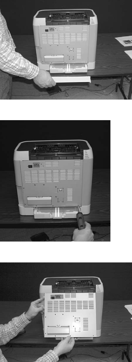
DC controller removal and replacement
Use the following procedure to remove the DC controller.
1Remove the cassette dust cover (RC1–5200–000CN).
2Remove nine (9) screws from the rear plate (RC1–5227–000CN).
3Remove the rear plate.
86 Chapter 5 Removal and replacement ENWW
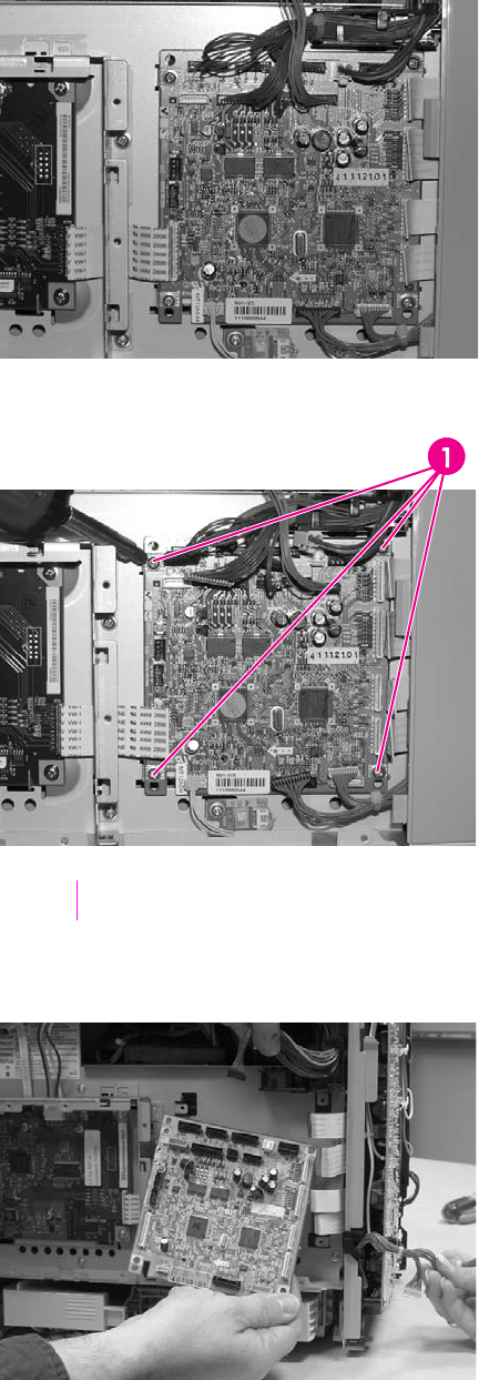
4Gently unplug 16 connectors.
5Remove four (4) screws from the DC controller.
1Four (4) screws
6Remove the DC controller PCB assembly (RM1–1975–000CN).
ENWW Removal and replacement procedures 87
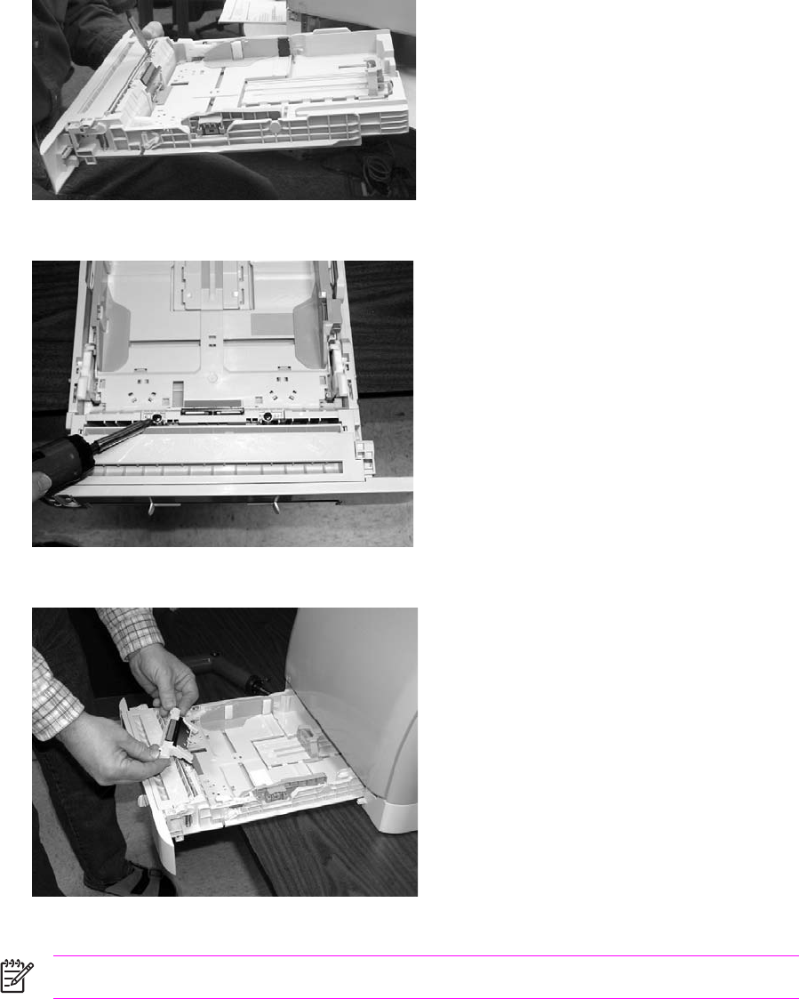
To replace the DC controller, follow steps 1 through 6 above in reverse order.
Separation pad removal and replacement
Use the following procedure to remove the separation pad.
1Remove Tray 2 (shown) or optional Tray 3.
2Remove two (2) screws that attach the separation pad.
3Remove the separation pad assembly (RC1–5356–000CN).
To replace the separation pad, follow steps 1 through 3 above in reverse order.
NOTE Align the tabs with the two (2) slots and then replace the separation pad.
88 Chapter 5 Removal and replacement ENWW
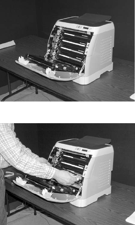
Paper pickup roller removal and replacement
Use the following procedures to remove the paper pickup roller.
1Open the front door.
2Remove the print cartridges.
ENWW Removal and replacement procedures 89
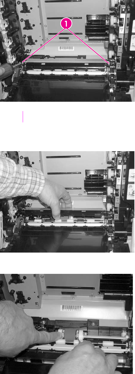
3Remove two (2) screws.
1Two (2) screws
4Remove the pre-transfer guide (RC1–5419–000CN).
5Use a small screwdriver to pull back on the tabs.
90 Chapter 5 Removal and replacement ENWW
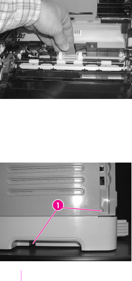
6Rotating it towards the back, remove the paper pickup roller (RC1-5440-000CN).
To replace the paper pickup roller, follow steps 1 through 6 above in reverse order.
Control panel removal and replacement
Use the following procedure to remove the control panel.
1Remove two (2) screws from the right cover assembly.
1Two (2) screws
ENWW Removal and replacement procedures 91
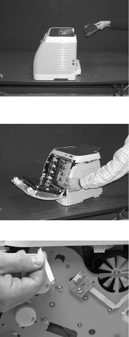
2Remove the paper delivery tray assembly (RM1–1859–000CN).
3Remove the right cover assembly (RM1–1858–000CN), carefully twisting the front edges of the
side covers outward to remove.
4Unplug the control panel cable.
92 Chapter 5 Removal and replacement ENWW
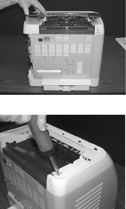
5Lift up and remove the upper face cover (RC1-5173-000CN).
6Remove four (4) screws from the upper cover (RC1–5176–000CN).
ENWW Removal and replacement procedures 93
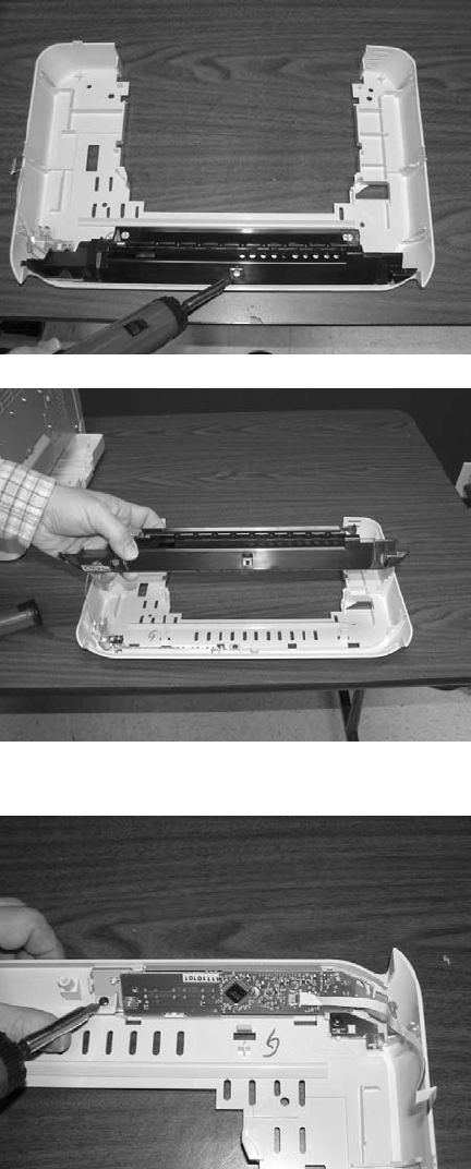
7Remove one (1) screw from the inside upper cover (RC1–5178–000CN) and then remove the
black output guide.
8Remove two (2) screws from the control panel.
94 Chapter 5 Removal and replacement ENWW
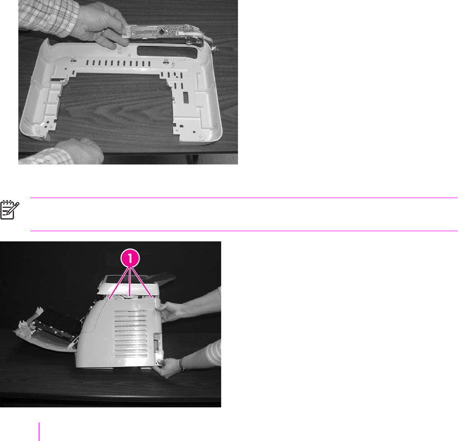
9Remove the control panel assembly (RM1–1983–000CN).
To replace the control panel, follow steps 1 through 9 above in reverse order.
NOTE When replacing the right cover, align the tabs on the upper edge of the right cover
and lower edge of the face-down cover with their respective slots.
1Tabs
ENWW Removal and replacement procedures 95
96 Chapter 5 Removal and replacement ENWW

6Troubleshooting
This troubleshooting information is organized to help you resolve printing problems. Choose the
general topic or type of problem from the following list.
●Troubleshooting process
●Clearing jams
●Print problems
●Functional tests (SERVICE ONLY)
●Service mode functions (SERVICE ONLY)
●Troubleshooting tools
●HP Toolbox
●Diagnostic resources
●Repetitive image defect ruler
●Firmware and software updates
ENWW 97

Troubleshooting process
Use the troubleshooting checklist to solve issues with the device.
Troubleshooting checklist
Follow the steps below when trying to solve a problem with the device.
Table 6-1 Troubleshooting checklist
Step
number
Verification step Possible problems Solutions
1Is the power on?
When the device is
connected to a grounded
power source, the control
panel shows Hewlett-
Packard with both the
Ready and Attention lights
blinking. The control panel
will then display
Initializing and then
Ready, at which time only
the green light will be on.
No power due to failed power source,
cable, switch, or fuse.
1 Verify that the device is plugged in.
2 Verify that the power cable is
functional and that the power
switch is on.
3 Check the power source by
plugging the device directly into
the wall or into a different outlet.
4 Test the outlet or connect another
device to the outlet to verify that
the outlet is functioning.
2 Does Ready appear in
the device control panel?
The control panel should
function without error
messages.
Control panel shows an error. See Control panel messages for a list
of common messages that will help
you correct the error.
3Do information pages
print?
Print a Configuration page.
Control panel displays an error
message.
See Control panel messages for a list
of common messages that will help
you correct the error.
Media does not move smoothly
through the device paper path.
Clean the paper path.
Poor print quality. For information, see General print
quality issues.
4 Does the device print
from the computer?
Connect the network cable
or USB cable to the device
and the computer. Use a
word-processing
application to send a print
job to the device.
Software is not installed correctly or an
error occurred during software
installation.
Uninstall and then reinstall the device
software. Verify that you are using the
correct installation procedure and the
correct port setting.
The cable is not connected correctly. Reconnect the cable.
An incorrect driver is selected. Select the proper driver.
Other devices are connected to the
USB port.
Disconnect the other devices and try
again to print.
There is a port driver problem in
Microsoft Windows.
Uninstall and then reinstall the device
software. Verify that you are using the
correct installation procedure and the
correct port setting.
If the error persists, see the support flyer that came in the device box.
98 Chapter 6 Troubleshooting ENWW
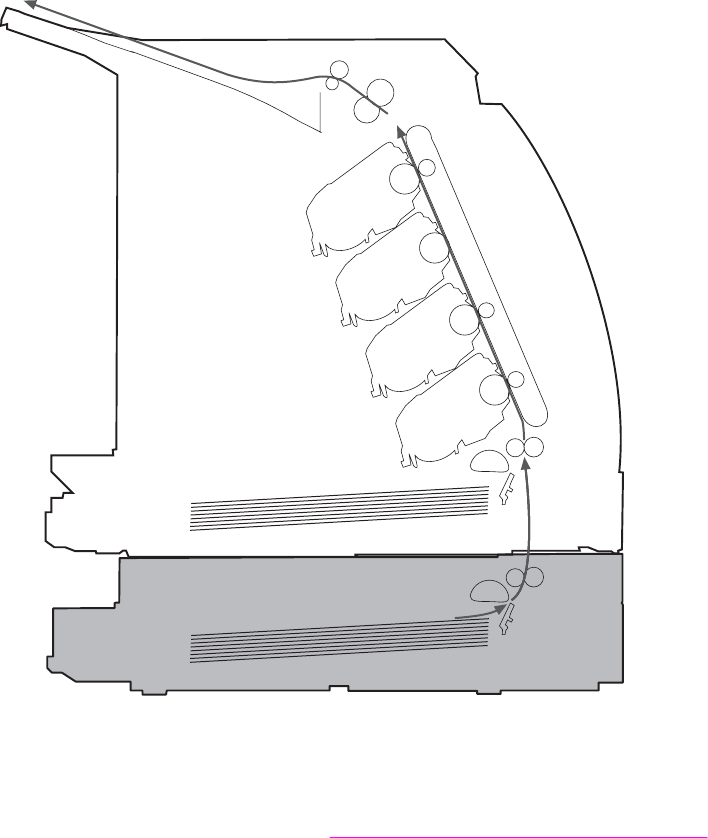

Common causes of paper jams
Occasionally, paper or other print media can become jammed during a print job. Some causes
include the following events:
Cause Solution
The input trays are loaded improperly or overfilled. Remove any excess paper from the input tray. Make sure
that the paper does not exceed the maximum stack height
mark in the input tray.
Tray 2 or optional Tray 3 is opened during a print job. Make sure that Tray 2 or optional Tray 3 is closed.
Too many sheets accumulated in the output area or sheets
blocked the output area.
Remove any accumulated sheets and clear the output area.
For information about clearing jams from the output area,
see Output jams.
The print media that is being used does not meet HP
specifications.
Use only paper that meets HP specifications. For more
information, see the HP LaserJet Printer Family Print Media
Guide or go to http://www.hp.com/support/ljpaperguide.
The environment in which the print media was stored is too
humid or too dry.
Make sure that the printer environment is within humidity
specifications. For more information, see Printing and
storage environment.
A supply item is installed incorrectly, causing repeated jams. Verify that all print cartridges and the ETB are correctly
installed.
Print media is skewed. Input tray guides are not adjusted correctly. Adjust input tray
guides so they hold the print media firmly in place without
bending it.
NOTE Do not fan paper. Fanning can create static
electricity, which can cause the paper to stick
together.
Print media is binding or sticking together. Remove paper, flex it, rotate it 180 degrees, or flip it over.
Reload paper into the input tray.
Print media is removed before it settles into the output bin. Reset the printer. Wait until the page completely settles in
the output bin before removing it.
Print media is in poor condition. Replace the paper.
Print media is not picked up by the internal rollers from
Tray 2 or Tray 3.
Remove the top sheet of paper. If the paper is heavier than
163 g/m
2
(43 lb), it may not be picked from the tray.
Print media has rough or jagged edges. Replace the paper.
Print media is perforated or embossed. This paper does not separate easily. Feed single sheets
from Tray 1.
The printer supply items have reached the end of life.
Check the printer control panel for messages prompting a
replacement of supplies, or print a supplies status page to
verify the remaining life of the supplies.
Print media was not stored correctly. Replace the print media. Print media should be stored in the
original packaging in a controlled environment.
100 Chapter 6 Troubleshooting ENWW
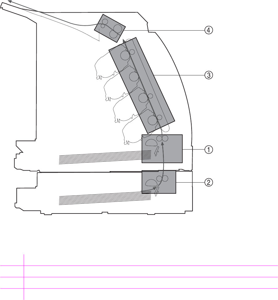
Where to look for jams
Jams can occur in these locations:
■Inside the printer
■In input areas
■In the output area
■Paper path
The following illustration identifies the stages when jams can occur.
Figure 6-2 Jam locations and stages
1Pickup stage
2Feeder stage
3Transfer/feed stage
4Fusing/delivery stage
ENWW Clearing jams 101
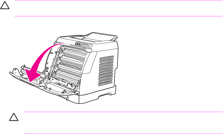
Find and remove the jam by using the instructions on the following pages. If the location of the jam is
not obvious, first look inside the printer.
Loose toner might remain in the printer after a jam. This problem should resolve itself after a few
sheets have been printed.
Each section below corresponds to an area where a paper jam could occur. Use the following
procedures to clear the jam. In all cases, grasp the jammed paper by both corners and pull slowly to
remove the paper.
Jams inside the printer
Use the following instructions to clear jams from inside the printer.
CAUTION Jams in this area might result in loose toner on the page. If you get toner on your
clothes or hands, wash them in cold water. (Hot water will set the toner into the fabric.)
1Open the front door.
CAUTION Do not place anything on the transfer belt, which is located on the
inside of the front door. Otherwise, the printer may be damaged, adversely affecting
print quality.
102 Chapter 6 Troubleshooting ENWW
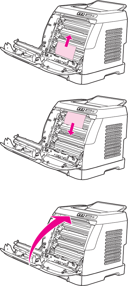
2Carefully grasp the jammed paper by both corners and pull slowly to remove the paper.
3Close the front door.
Input jams
Tray 1
If the jammed paper is easily accessible from the outside of the printer, grasp both edges of the
paper and firmly pull to remove. Otherwise, follow the directions for Tray 2.
ENWW Clearing jams 103
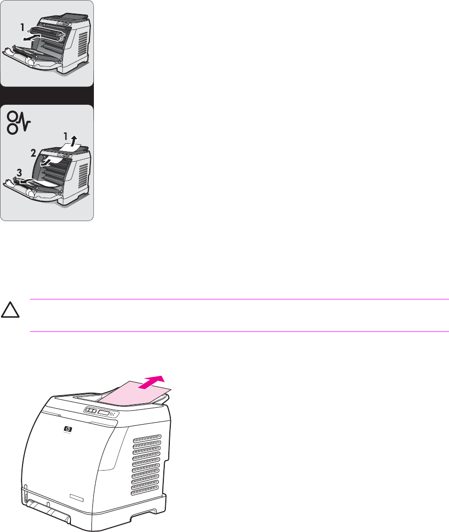
Tray 2
Open the front door of the printer and remove paper as indicated on the jam instruction label, located
on the interior right side of the printer. Input jams are indicated on the label with the number 3.
Figure 6-3 Tray 2 input jam label
Output jams
Jams in the top bin
CAUTION Jams in these areas might result in loose toner on the page. If you get toner on
your clothes or hands, wash them in cold water. (Hot water will set the toner into the fabric.)
1Carefully grasp the jammed paper by both corners and pull slowly to remove the paper from the
top bin.
104 Chapter 6 Troubleshooting ENWW
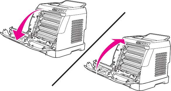
2Open and close the front door.
Pickup delay jam
The printer performs the retry control, which executes the pickup operation three times, to retrieve
the pickup delay jam caused by the pickup error. When the registration paper sensor (SR1) does not
detect the leading edge of the paper within approximately 2.5 seconds (4.5 seconds for optional
cassette) after the pickup solenoid (SL1) is turned ON, the CPU tries to pick up the paper three times.
Pickup stationary jam
The CPU determines the pickup stationary jam when the registration paper sensor (SR1) does not
detect the trailing edge of the paper within approximately 8.6 seconds after it detects the leading edge.
Delivery delay jam
The CPU determines the delivery delay jam when the fuser delivery paper sensor (SR4) does not
detect the leading edge of the paper within approximately 6.6 seconds after the registration paper
sensor (SR1) detects the leading edge.
Wrapping jam
The CPU executes the wrapping jam detection after it assesses no delivery delay jam. The CPU
determines the wrapping jam, when the fusing delivery paper sensor (SR4) detects the paper
absence before the time equivalent to paper passage of its length minus 40 mm (1.6 inches) after the
SR4 detected the leading.
Delivery stationary jam
The CPU executes the delivery stationary jam detection after it assesses no wrapping jam. The CPU
determines the delivery stationary jam, when the fuser delivery paper sensor (SR4) detects the paper
presence after the time equivalent to paper passage of its length plus 50 mm (1.9 inches) from when
it detected the trailing edge.
Start-up residual paper jam
The CPU determines the start-up residual paper jam when either the pre-fuser paper sensor (SR5)
or the fuser delivery paper width sensor (SR4) detects the paper when the initial rotation is started.
ENWW Clearing jams 105
Door open jam
The CPU determines the door open jam, when either the pre-fuser paper sensor (SR5) or the fuser
delivery paper width sensor (SR4) detects paper when a door open is detected.
106 Chapter 6 Troubleshooting ENWW

Print problems
Getting information
The following sections contain information about control panel messages, error reports, and available
service menus.
Control panel messages
The majority of the control-panel messages are intended to guide the user through typical operation.
The control-panel messages indicate the status of the current operation, and include a page count on
the second line of the display, if appropriate. When the device is printing data, control-panel
messages indicate this status. In addition, alert messages, warning messages, and critical error
messages indicate situations that might require some action.
Alert and warning messages
Control panel message Description Recommended action
Device error
Press
An internal error occurred in the device. Press (S
ELECT
) to resume the job.
Door open The printer door is open. The door must be closed before printing
can continue.
Engine comm.
error
The device experienced an internal
communication error.
This is a warning message only. Job output
might be affected.
Invalid driver You are using the incorrect printer driver. Reselect the printer driver appropriate for
your device.
Invalid entry Invalid data or response. Correct the entry.
Jam in
tray 2
A paper jam has occurred in Tray 2. Clear the jam, and then press the
(S
ELECT
) button on the control panel.
Jam in
tray 3
A paper jam has occurred in Tray 3. Clear the jam, and then press the
(S
ELECT
) button on the control panel.
Jam in
print paper path
A paper jam has occurred in the print path. Open the door and clear the jam. Then
press the (S
ELECT
) button on the control
panel.
Jam in
Cartridge area
A paper jam has occurred in the print path. Open the door and clear the jam. Then
press the (S
ELECT
) button on the control
panel.
Jam in
Output bin
A paper jam has occurred in the output area. Clear the jam, and then press the
(S
ELECT
) button on the control panel.
Load paper The HP Color LaserJet 2600n printer is out
of paper.
Please load specified paper type into the
tray indicated.
Load Tray X
[TYPE] [SIZE]
The printer is processing job, but the tray
indicated is empty.
Please load specified paper type and size
into the tray indicated.
ENWW Print problems 107

Control panel message Description Recommended action
Manual feed
Press
The printer is waiting for paper in the tray
indicated.
Load the paper as indicated.
Memory is low
Press
The device memory has been almost
completely filled.
Allow the device to finish the job, or press
(S
ELECT
) to cancel the job.
Break the job into smaller jobs that contain
fewer pages.
Misprint
Press
The printed pages have been incorrectly
placed on the paper. To continue, press the (S
ELECT
) button
on the control panel.
No paper pickup
Press
The print engine has failed to pick up a
piece of media.
In Tray 1, verify that the media was inserted
far enough into the tray. In Tray 2 or
optional Tray 3, verify that the paper-length
guide is in the correct position for the media
size that you are using.
Reload the media in the input tray and
press (S
ELECT
) to continue the job.
Unexpected size
in tray X
Unexpected paper size error. The media
size loaded in the tray does not match the
media size configured for the tray.
Verify that the print settings are set to the
specified media in the tray.
Critical error messages
Control panel message Description Recommended action
50.1 Fuser Error
50.2 Fuser Error
50.3 Fuser Error
The device has experienced an internal
hardware error.
50.1 Fuser Error—low temperature
50.3 Fuser Error—slow fuser
50.2 Fuser Error—high temperature
Turn off the device, wait at least
25 minutes, and then turn on the device.
If a surge protector is being used, remove
it. Plug the device directly into the wall
socket. Use the power switch to turn on the
device.
If this does not clear the error, replace the
fuser.
51.20 Error
51.21 Error
51.22 Error
51.23 Error
The device has experienced an internal
hardware error.
51.20 Error—black scanner error
51.21 Error—cyan scanner error
51.22 Error—magenta scanner error
51.23 Error—yellow scanner error
Turn off the power by using the power
switch, wait at least 30 seconds, and then
turn on the power and wait for the device to
initialize.
If a surge protector is being used, remove
it. Plug the device directly into the wall
socket. Use the power switch to turn the
device on.
Laser scanners are not replaceable.
Replace the engine.
55.1 Error DC controller error. The device has
experienced an internal hardware error.
Turn off the power by using the power
switch, wait at least 30 seconds, and then
turn on the power and wait for the device to
initialize.
108 Chapter 6 Troubleshooting ENWW

Control panel message Description Recommended action
If a surge protector is being used, remove
it. Plug the device directly into the wall
socket. Use the power switch to turn the
device on.
Check the engine (DCC) firmware version.
Update if needed. Replace the DCC if a
firmware upgrade does not resolve the issue.
57 Fan Error
Turn off then on
The device has experienced a problem with
its internal fan.
Turn off the power by using the power
switch, wait at least 30 seconds, and then
turn on the power and wait for the device to
initialize.
The fan is not replaceable. Replace the
engine.
Supplies messages
Control panel message Description Recommended action
10.000x Supply error E-label cannot be read or print cartridge is
not properly installed.
10.0000 = Black print cartridge
10.0001 = Cyan print cartridge
10.0002 = Magenta print cartridge
10.0003 = Yellow print cartridge
1 Reinstall print cartridge.
2 Turn on the printer.
3 If the problem is not solved, replace the
cartridge.
10.100x Supply error
alternates with
Reinstall
The supplies gauge will display the
consumption levels of print cartridges.
A print cartridge is missing.
10.1000 = Black print cartridge
10.1001 = Cyan print cartridge
10.1002 = Magenta print cartridge
10.1003 = Yellow print cartridge
Install the correct print cartridge.
HP supplies
installed
The printer transitioned from having one or
more non-HP supplies to having all HP
supplies installed.
No action required.
One of the following messages may display:
Incorrect black
Incorrect cyan
Incorrect magenta
Incorrect yellow
The <color> print cartridge not installed
correctly.
Reinstall the <color> print cartridge.
One of the following messages may display:
Install black cartridge
Install cyan cartridge
The out threshold has been reached. The supply must be replaced before
printing can continue.
ENWW Print problems 109

Control panel message Description Recommended action
Install magenta cartridge
Install yellow cartridge
The supplies gauge will display the
consumption levels of print cartridges.
Install supplies
The supplies gauge will display the
consumption levels of print cartridges.
Multiple supplies are not installed. Install correct print cartridges.
One of the following messages may display:
Non HP black
installed
Non HP cyan
installed
Non HP magenta
installed
Non HP yellow
installed
alternates with
To accept
Press
A non-HP <color> cartridge is installed. NOTE Any printer repair required
as a result of using a non-HP or
unauthorized supply is not covered
under warranty.
To use this cartridge, override by pressing
the (S
ELECT
) button on the control panel.
Non HP supply
in use
alternates with
Ready
The supplies gauge will display the
consumption levels of print cartridges.
A non HP (cloned or refilled) supply has
been installed that is not made by HP and
was overridden.
If you believe you purchased an HP supply,
please call the HP fraud hotline at
1-877-219-3183. Service or repairs
required as a result of using non-HP
supplies is not covered under HP warranty.
One of the following messages may display:
Order black
cartridge,
Order cyan
cartridge,
Order magenta
cartridge, or
Order yellow
cartridge
The <color> print cartridge low threshold
has been reached.
For more information go to the HP Color
LaserJet 2600n toolbox and click Supplies
Status. To order supplies online, click
Order Supplies.
110 Chapter 6 Troubleshooting ENWW

Control panel message Description Recommended action
alternates with
Ready
The supplies gauge will display the
consumption levels of print cartridges.
ORDER SUPPLIES
alternates with
Ready
The supplies gauge will display the
consumption levels of print cartridges.
Multiple supplies are low. For more information go to the HP Color
LaserJet 2600n toolbox and click Supplies
Status. To order supplies online, click
Order Supplies.
One of the following messages may display:
Replace black cartridge
Replace cyan cartridge
Replace magenta cartridge
Replace yellow cartridge
The out threshold has been reached. The supply must be replaced before
printing can continue.
Replace Supplies
The supplies gauge will display the
consumption levels of print cartridges.
The out threshold has been reached. The supply must be replaced before
printing can continue.
Replace supplies
Override in use
alternates with
Ready
The supplies gauge will display the
consumption levels of print cartridges.
Supply override in use. The user has
decided to continue printing beyond the out
point. A supply is low and using Override
may result in unsatisfactory print quality.
Replace the supply that is low.
Replace supply.
Override in use
alternates with
Ready
The supplies gauge will display the
consumption levels of print cartridges.
Supply override in use. The user has
decided to continue printing beyond the out
point. A supply is low and using Override
may result in unsatisfactory print quality.
Replace the supply that is low.
ENWW Print problems 111

Control panel message Description Recommended action
Unauthorized
supply in use
alternates with
Ready
The supplies gauge will display the
consumption levels of print cartridges.
A new supply has been installed that is not
made by HP and was overridden.
If you believe you purchased an HP supply,
please call the HP fraud hotline at
1-877-219-3183. Service or repairs
required as a result of using non-HP
supplies is not covered under HP warranty.
One of the following messages may display:
Unauthorized yellow
Unauthorized magenta
Unauthorized cyan
Unauthorized black
A new supply has been installed that is not
made by HP. One of these four messages
is displayed until an HP supply is installed
or (S
ELECT
) is pressed.
If you believe you purchased an HP supply,
please call the HP fraud hotline at
1-877-219-3183. Service or repairs
required as a result of using non-HP
supplies is not covered under HP warranty.
To continue printing, press (S
ELECT
).
Status messages
Status messages are used to inform the user of the current state of the system. Status messages do
not require user action or acknowledgement, and are for information only.
Control panel message Description Recommended action
Calibrating... The printer is calibrating. No action is required.
Cleaning... The printer is in cleaning mode. No action is required.
Status log only messages
The following messages are not displayed on the control panel. They are printed on the Status log.
Table 6-2 Status log only messages
Error log code Description
54.06 Color density sensor error
54.10 Color plane registration sensor(s) error
54.11 Yellow density out of range
54.12 Magenta density out of range
54.13 Cyan density out of range
54.14 Black density out of range
112 Chapter 6 Troubleshooting ENWW
Reports menu
The following reports are available from the Reports menu.
■Demo Page—used to help market the product at retail stores
■Menu structure—highlights the control panel menu layout
■Config report—details all default device settings including network configuration and information
■Supplies Status—provides information on each of the print cartridges, including estimated
pages remaining, cartridge serial number, and pages printed
ENWW Print problems 113
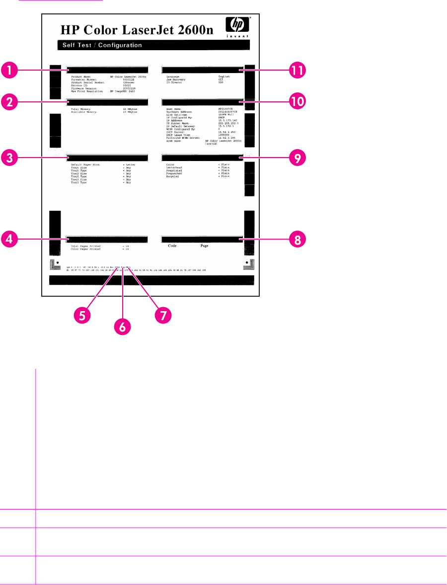
Configuration page
The Configuration page lists the current settings and properties of the printer. You can print a
Configuration page from the printer or HP Toolbox. To print the Configuration page from the printer,
see Configuration page.
Table 6-3 Configuration page
1Product information. This section contains the following basic information about the printer:
■Product name
■Formatter number
■Serial number
■Service ID
■Firmware version
■Maximum print resolution
2Memory. This section lists memory-related information, such as the total memory that is installed.
3Paper settings. This section lists information about the media type for each tray and about the type settings for
all the media that the printer supports.
4Page counts. This section lists the total number of pages printed, the number of color pages printed, and
information about paper jams.
114 Chapter 6 Troubleshooting ENWW

5DC controller version. This section lists the DC controller version.
6USB settings. This section contains information for the USB setting options.
■U=0 Hi speed
■U=4 Full speed
■U=5 Full speed auto switched from hi speed
7Extended print modes enabled. The following list contains the options for enabling extended print modes.
■DM=0 Default setting
■DM=1 Extended print mode enabled
8Status log. This section contains information about printer errors, including an error code and the page count at
which the error occurred. For a list of status log messages, see Table 6-5 Status log messages.
9Paper types. This section contains information about paper types that can be configured by the user. The default
setting is Plain.
10 Network settings. This section contains the following network information about the printer.
■Host name
■Hardware address
■LInk settings
■IP address information
■IP subnet mask
■IP default gateway
■WINS configuration information
■DHCP server and lease time information
■Preferred WINS server information
■mDNS name
11 Product settings. This section lists the following information that is gathered during software installation:
■Language
■Company name
■Jam recovery settings (if set to ON, the last page will reprint if there is a paper jam)
■I/O timeout information (default is 120 seconds)
NOTE The color bars on the sides of the Configuration page represent 100%, 75%, 50%,
and 25% coverage.
ENWW Print problems 115
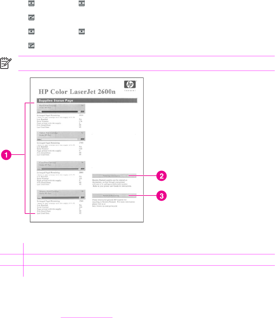
Supplies Status page
The Supplies Status page lists the remaining life of HP print cartridges. It also lists the estimated
pages remaining, number of pages printed, and other supplies information. You can print a Supplies
Status page from the printer or the HP Toolbox.
To print the Supplies Status page from the printer control panel
1Press (L
EFT
ARROW
) or (R
IGHT
ARROW
) to select the Reports menu.
2Press (S
ELECT
).
3Press (L
EFT
ARROW
) or (R
IGHT
ARROW
) to select Supplies Status.
4Press (S
ELECT
) to print the Supplies Status page.
NOTE Supplies information is also available through the HP Toolbox.
Table 6-4 Supplies Status page
1Print cartridge area
2Ordering information
3Return and recycling information
Status log
The status log for this printer is located on the Configuration page and lists the last five events. For
more information, see Configuration page.
116 Chapter 6 Troubleshooting ENWW

Table 6-5 Status log messages
Error log code Description
10.0000 Black e-label error
10.0001 Cyan e-label error
10.0002 Magenta e-label error
10.0003 Yellow e-label error
10.1000 Black e-label missing
10.1001 Cyan e-label missing
10.1002 Magenta e-label missing
10.1003 Yellow e-label missing
10.3000 Non-HP black
10.3001 Non-HP cyan
10.3002 Non-HP magenta
10.3003 Non-HP yellow
13.0000 Paper jam, Tray 1 area
13.0001 Paper jam, Tray 2 area
13.0002 Paper jam, Tray 3 area
13.0003 Paper jam, registration drum area
13.0004 Paper jam, drum fuser area
13.0005 Paper jam, fuser output area
20.0000 Memory out
21.0000 Video under run
50.1000 Low temperature fuser error
50.2000 Slow fuser error
50.3000 High temperature fuser error
50.4000 Fuser heater wire failure
50.5000 Fuser low temperature subtherm failure
50.6000 Fuser high temperature subtherm failure
52.0000 Scanner error, black laser failure
52.0100 Scanner error, cyan laser failure
52.0200 Scanner error, magenta laser failure
52.0300 Scanner error, yellow laser failure
54.0600 Density sensor error
54.1000 Color plane registration sensor error
54.2800 Sensor density contaminated
ENWW Print problems 117

Error log code Description
54.2801 Sensor color plane registration contaminated
55.0000 Engine comm fatal error
55.0001 Engine comm critical error
55.1000 DC controller memory error
57.0000 Fan motor error
57.0001 Fan cartridge failure
59.0000 Paper path/ETB rotation failure
59.0001 Paper path/ETB ramp up failure
101.0000 Color plane registration error
102.0000 DMAX calibration error
103.0000 DHALF calibration error
Service menu settings
The service menu is used to calibrate, restore factory default settings, and clean the print paper path.
The following service menu items are available:
■Restore defaults—used to reset all customer-accessible menu settings back to the factory
default settings (except language) via the control panel or software
NOTE This service menu item does not reset factory-settable settings, including
formatter number, page counts, factory paper settings, language, and so on.
■PowerSave—used to configure the amount of idle time before the engine enters sleep mode
■Cleaning mode—used to remove dust and toner from the print paper path
Secondary service menu
The secondary service menu is intended for use by manufacturing engineers, service engineers,
developers, and support personnel. This menu provides options to perform various tests and print
out special reports.
Table 6-5 Status log messages (continued)
118 Chapter 6 Troubleshooting ENWW

The following secondary service menu items are available:
■Service Reports—used to print out a continuous configuration report, translation report, and
error report
■USB Speed—enables or disables the ability for the printer to operate in high speed.
The following USB Speed setting options are available:
■Auto
■Hi speed
■Full speed
■Display test—verifies that all of the characters on the display function correctly by allowing you
to manually scroll through the characters
■Clean ETB—used to clean the ETB
■Calibrations
■All Cals
■CPR Cal
■DMAX/DHALF Cal
■DHALF Only Cal
■Test Page
To enter the secondary service menu, use the following procedure:
1Confirm that the device is in a Ready state.
2Press the button (S
ELECT
) to enter the main menu system.
3Press the button (L
EFT
ARROW
) and the button (C
ANCEL
J
OB
) simultaneously.
4Press the button (S
ELECT
) to confirm 2ndary Service.
5Press the (L
EFT
ARROW
) button and button (R
IGHT
ARROW
) to navigate to the secondary
service menu.
Printed image quality problems
Improving print quality
Use the print-quality settings in the HP Toolbox to improve print-quality problems. To access the
HP Toolbox, see HP Toolbox. The following menus contain paper type, print mode, and print-quality
settings. To restore the default settings, open the HP Toolbox and click Device Settings. Then click
Settings, Service, and in Restore Factory Settings, click Restore.
Paper Types menu
The purpose of this menu is to specify the print mode for paper types which are non-specific.
To make changes in the Paper Types menu, make the desired selections and click Apply.
ENWW Print problems 119

Table 6-6 Print modes for paper types
Print Modes for paper types Weight Default media types
Normal mode 75-89 g/m
2
Plain, color, preprinted, prepunched,
recycled
Transparency Transparencies
Labels Labels
Light 75-89 g/m
2
Light
Heavy 90-105 g/m
2
Heavy
Cardstock 106-163 g/m
2
Cardstock, bond
Light Glossy 75-105 g/m
2
Light Glossy
Glossy 106-120 g/m
2
Glossy
Heavy Glossy 121-163 g/m
2
Heavy Glossy
HP Tough paper HP Tough paper
Envelope Envelopes
Print Modes menu
Under the Print Modes menu in HP Toolbox, each Media Type will have a Fusing menu, a Transfer
menu, and a Toner menu. Select a setting for each menu item.
Media types are listed with the plain papers together, glossy papers together, and special media at
the end. To make changes in the Print Modes menu, make the desired selections and click Apply.
Table 6-7 Extended print modes
HP Toolbox extended print mode Printer adjustment Change in printer setting
Paper curl Fusing adjustment Reduced fuser temperature for less
negative paper curl
Heavy coverage Fusing adjustment Increased fuser temperature for less
positive paper curl with heavy toner
coverage
Toner offset Fusing adjustment Reduced fuser temperature for less
toner offset
Flap sealing Fusing adjustment Reduced fuser temperature to keep
envelope flaps from sealing
Less fusing Fusing adjustment Reduced fuser temperature
More fusing Fusing adjustment Increased fuser temperature
Dry paper Transfer adjustment Increased transfer bias for high
resistivity paper
Humid paper Transfer adjustment Decreased transfer bias for high
resistivity paper
Rough paper Transfer adjustment Increased transfer bias for high
resistivity paper
120 Chapter 6 Troubleshooting ENWW

HP Toolbox extended print mode Printer adjustment Change in printer setting
Less transfer current Transfer adjustment Reduced transfer bias
More transfer current Transfer adjustment Increased transfer bias
Less toner Toner adjustment Tone curve is scaled back so that solid
is not 100% halftone
Print quality menu
Under the Print Quality menu in HP Toolbox, there will be an Optimize section containing a number
of On/Off adjustments which will apply to all media types.
Table 6-8 Optimize menu
Adjustment type Default setting Extended print mode Description
Background Toner Off EEC95-9 Will reduce the developer
DC bias
Extra Cleaning Off EEC93-11 Increases rotations of the
ETB
Trailing Edge
Over-development
(full-speed)
Off EEC95-14
Trailing Edge
Over-development
(half-speed)
Off EEC95-14
Mottle Prevention Off EEC96-12 Will increase the developer
DC bias
Less Duplex Transfer Current Off EEC68-10
EEC91>16h
*
EEC92>-1
**
Decreases transfer bias on
the 2nd side of duplex jobs.
For media that has low
resistivity after fusing.
More Duplex Transfer Current Off EEC68-10
EEC91>16h
*
EEC92>+1
**
Increases transfer bias on
the 2nd side of duplex jobs.
For media that has high
resistivity after fusing.
*
> means write xxh to bits 11–15
**
> means +/-y to bits 9–15
Understanding print-quality settings
Print-quality settings affect how light or dark the print is on the page and the style in which the
graphics are printed. You can also use the print-quality settings to optimize the print quality for a
specific media type.
You can change the settings in the device properties to accommodate the types of jobs that you are
printing. The following settings are available, depending on the printer driver that you are using:
■Draft (600 dpi)
■Normal (Image REt 2400)
Table 6-7 Extended print modes (continued)
ENWW Print problems 121

NOTE Changing the resolution can change the formatting of your text.
To temporarily change print-quality settings
To change the print-quality settings only for the current software program, open the properties
through the Print Setup menu in the program that you are using to print.
To change print-quality settings for all future jobs
For Windows 98, Windows 2000, and Windows Me:
1In the Windows system tray, click Start, select Settings, and then click Printers.
2Right-click the device icon.
3Click Properties (in Windows 2000, you can also click Printing Preferences).
4Change the settings, and click OK.
For Windows XP (Classic view):
1In the Windows system tray, click Start, and then click Printers and Faxes.
2Right-click the device icon.
3Click Properties, or click Printing Preferences.
4Change the settings, and click OK.
Identifying and correcting printed image defects
Use the checklist and print-quality issues charts in this section to solve print-quality problems.
Print-quality checklist
General print-quality problems can be solved by using the following checklist:
1 Make sure that the paper or print media that you are using meets specifications. Generally,
smoother paper provides better results.
2 If you are using a special print media such as labels, transparencies, glossy, or letterhead,
ensure that you have printed by type.
3 Print a Configuration page and Supplies Status page at the device.
●Check the Supplies Status page to see if any supplies are low or empty. No information is
provided for non-HP print cartridges.
●If the pages do not print correctly, the problem is with the hardware.
4 Print a Demo page from the HP Toolbox. If the page prints, the problem is with the printer driver.
5 Try printing from a different program. If the page prints correctly, the problem is with the program
from which you were printing.
122 Chapter 6 Troubleshooting ENWW

6 Restart the computer and the device and try printing again. If the problem is not resolved, choose
one of these options:
●If the problem is affecting all printed pages, see General print quality issues.
●If the problem is affecting only pages printed in color, see Solving issues with color documents.
Paper handling issues
The following sections contains information about paper handling issues.
Wrong size/type media
Use the following procedure to troubleshoot and resolve wrong size or type media problems.
1Make sure that the software program is selecting the correct media size or type.
2Make sure that the printer driver for the software program is correctly installed, configured, and
capable of requesting the desired media size and type.
3Make sure that the paper guides are touching the edges of the stack of media.
4If the size of media requested is not loaded in the tray selected, the printer draws media from the
next default tray that contains the correct size. Load the correct media in the tray and make sure
that the tray is adjusted correctly. Load the tray with enough media to complete the print job.
(See the HP Color LaserJet 2600n User Guide for information about configuring the input trays.)
Cannot select a tray or feature to use
When you cannot select a tray or feature to use, use the following procedure to troubleshoot and
resolve problems.
1When the size of media requested is not loaded in the tray selected, the printer draws media
from the next default tray that contains the correct size. Load the correct media in the tray and
make sure that the tray is adjusted correctly. Load the tray with enough media to complete the
print job. (See the HP Color LaserJet 2600n User Guide for information about configuring the
input trays.)
2Make sure that the driver for the software program is correctly installed, configured, and capable
of requesting the desired media size and type, or feature.
Performance problems
Try the tips in this section if pages exit the device, but have nothing printed on them, or when the
device does not print any pages.
Table 6-9 Performance issues
Problem Cause Solution
Pages print but are totally blank. The sealing tape might still be in the
print cartridges.
Verify that the sealing tape has been
completely removed from the print
cartridges.
The document might contain blank
pages.
Check the document that you are
printing to see if content appears on all
of the pages.
ENWW Print problems 123

Problem Cause Solution
The device might be malfunctioning. To check the device, print a
Configuration page.
Pages print very slowly. Heavier media types can slow the print
job.
Print on a different type of media.
Complex pages will print slower. Proper fusing may require a slower
print speed to ensure the best print
quality.
Pages did not print. The device might not be pulling media
correctly.
See Paper handling issues.
The media is jamming in the device. Clear the jam.
The USB cable might be defective or
incorrectly connected.
■Disconnect the USB cable at both
ends and reconnect it.
■Try printing a job that has printed
in the past.
■Try using a different USB cable.
Other devices are running on your
computer.
The device might not share a USB
port. If you have an external hard drive
or network switchbox that is connected
to the same port as the device, the
other device might be interfering. To
connect and use the device, you must
disconnect the other device or you
must use two USB ports on the
computer.
Table 6-9 Performance issues (continued)
124 Chapter 6 Troubleshooting ENWW
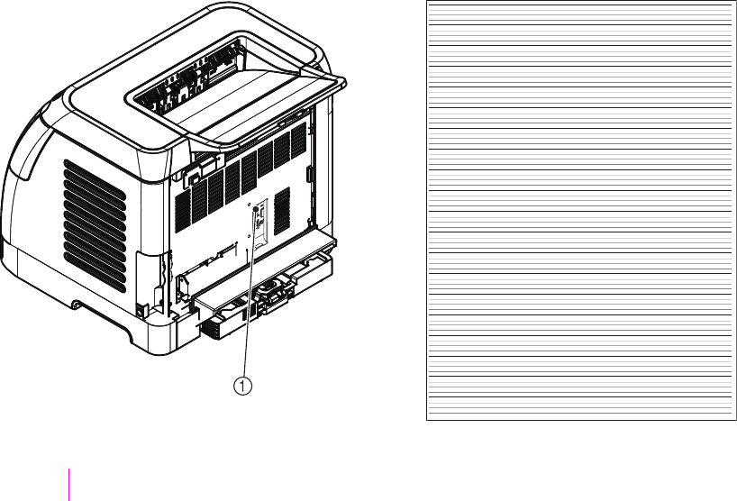
Functional tests (SERVICE ONLY)
Engine test print
The engine test print is used to confirm whether the printer operates correctly or not. It is performed
by the engine controller.
If a malfunction occurs in the printer, perform an engine test print while the printer is in STBY mode
and then press the test print switch (on the rear side of the printer) once. A one-page test pattern of
horizontal lines will print as shown below.
Figure 6-4 Engine test print switch
1Engine test print switch
ENWW Functional tests (SERVICE ONLY) 125

Service mode functions (SERVICE ONLY)
Cold reset
Cold-reset, which power-cycles the engine with a special button press, is not supported for this
printer. Instead, use the feature “Restore defaults” located in the Service menu to reset default
settings. For more information, see Service menu.
NVRAM initializer
CAUTION NVRAM initialization will erase all network settings. Before performing NVRAM
initialization, print a Configuration page, which contains network setting information.
NVRAM init will perform the following functions:
■Resets all customer-accessible menu settings via control panel and software back to the factory
default settings
■Resets the language to the value set at the factory
■Resets the default media size to cold reset media size
■Resets the symbol set to PC-8
Use the following procedure to execute an NVRAM-init.
1Turn off the printer.
2Press and hold the (S
ELECT
) and (C
ANCEL
J
OB
) buttons simultaneously.
3Turn on the printer.
4When you see the message Permanent storage init displays, release the (S
ELECT
) and
(C
ANCEL
J
OB
) buttons.
When the NVRAM init is complete, the printer will return to the Ready state.
Super NVRAM initializer
CAUTION Super NVRAM initialization will erase all network settings. Before performing
Super NVRAM initialization, print a Configuration page, which contains network setting
information.
When a super NVRAM init is performed, the printer enters the Generic Product Mode, which
changes the language and country/region settings to “undefined.”
NOTE Super NVRAM init will erase all data stored in the protected NVRAM settings.
Use the following procedure to execute a super NVRAM init.
1Turn off the printer.
2Press and hold the (L
EFT
ARROW
) and (R
IGHT
ARROW
) buttons simultaneously.
126 Chapter 6 Troubleshooting ENWW

3Turn on the printer.
4When you see the message Permanent storage init displays, release the (L
EFT
ARROW
) and
(R
IGHT
ARROW
) buttons.
When the super NVRAM init is complete, the printer will return to the Ready state.
Restoring page counts and serial number
A software utility is available on the Service and Support CD-ROM to restore page counts and serial
numbers when the formatter is replaced or when any of the following settings are lost:
■Color page count
■Total page count
■Formatter number
■Service ID
■USB serial number
To access the utility on the Service and Support CD-ROM, in the Library folder, double-click the
2600config.exe program. You can run the utility from the CD-ROM or copy it to your computer.
NOTE To use this program, the printer must be directly connected to your computer with a
USB cable.
Cleaning the ETB
To clean the ETB, use the following procedure:
1Enter the Secondary service menu. For more information, see Secondary service menu.
2Scroll through the menu and select C
LEAN
ETB.
3Press the (S
ELECT
) button to start the cleaning mode.
ENWW Service mode functions (SERVICE ONLY) 127

Troubleshooting tools
The section describes the tools that can help you solve problems with your device.
Printer pages and reports
This section describes the pages and reports that help you diagnose and solve problems with the
device.
Demo page
To print the Demo page, press the (L
EFT
ARROW
) and (R
IGHT
ARROW
) buttons on the printer
control panel simultaneously. You can also print this page from the HP Toolbox.
128 Chapter 6 Troubleshooting ENWW
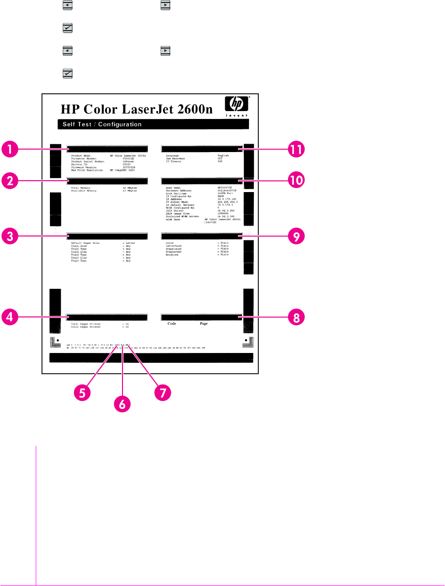
Configuration page
The Configuration page lists the current settings and properties of the printer. You can print a
Configuration page from the printer or HP Toolbox. To print the Configuration page from the printer,
complete the following steps.
1Press the (L
EFT
ARROW
) or the (R
IGHT
ARROW
) buttons to select the Reports menu.
2Press the button (S
ELECT
).
3Press the (L
EFT
ARROW
) or the (R
IGHT
ARROW
) buttons to select Config report.
4Press the button (S
ELECT
) to print the Configuration page.
Table 6-10 Configuration page
1Product information. This section contains the following basic information about the printer:
■Product name
■Formatter number
■Serial number
■Service ID
■Firmware version
■Maximum print resolution
ENWW Troubleshooting tools 129

2Memory. This section lists memory-related information, such as the total memory that is installed.
3Paper settings. This section lists information about the media type for each tray and about the type settings for
all the media that the printer supports.
4Page counts. This section lists the total number of pages printed, the number of color pages printed, and
information about paper jams.
5DC controller version. This section lists the DC controller version.
6USB settings. This section contains information for the USB setting options.
■U=0 Hi speed
■U=4 Full speed
■U=5 Full speed auto switched from hi speed
7Extended print modes enabled. The following list contains the options for enabling extended print modes.
■DM=0 Default setting
■DM=1 Extended print mode enabled
8Status log. This section contains information about printer errors, including an error log code and the page count
at which the error occurred. For a list of status log messages, see Table 6-5 Status log messages.
9Paper types. This section contains information about paper types that can be configured by the user. The default
settings are Plain.
10 Network settings. This section contains the following network information about the printer.
■Host name
■Hardware address
■LInk settings
■IP address information
■IP subnet mask
■IP default gateway
■WINS configuration information
■DHCP server and lease time information
■Preferred WINS server information
■mDNS name
11 Product settings. This section lists the following information that is gathered during software installation:
■Language
■Company name
■Jam recovery settings (if set to ON, the last page will reprint if there is a paper jam)
■I/O timeout information (default is 120 seconds)
130 Chapter 6 Troubleshooting ENWW
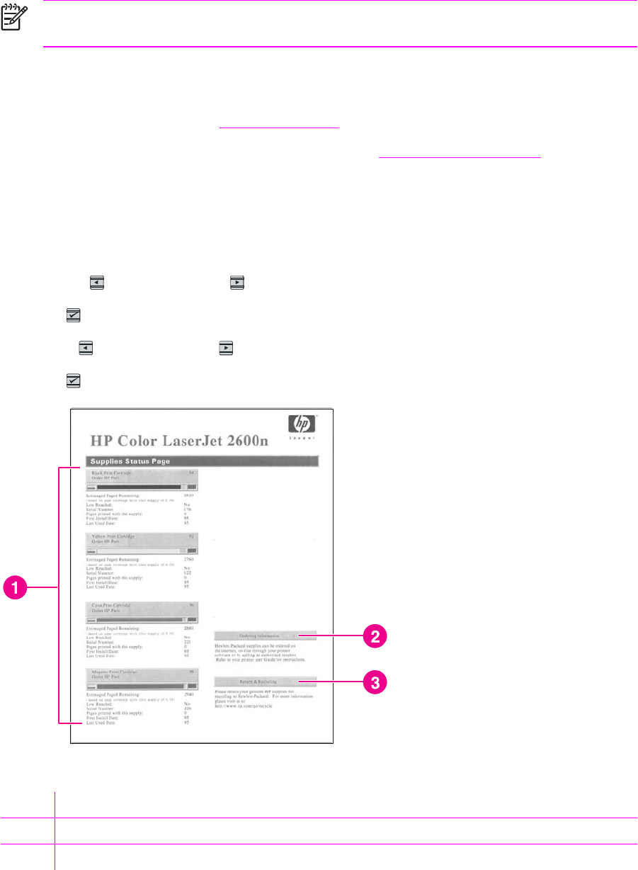
NOTE The color bars on the sides of the Configuration page represent 100%, 75%, 50%,
and 25% coverage.
Event log
Information for the last five events is available on the Configuration page under the Status log
section. For more information, see Configuration page.
For a list of messages that only appear in the event log, see Status log only messages.
Supplies Status page
The Supplies Status page lists the remaining life of the HP print cartridges. It also lists the estimated
pages remaining, number of pages printed, and other supplies information. You can print a Supplies
Status page from the device or HP Toolbox. To print from the device, complete the following steps.
1Press the (L
EFT
ARROW
) or the (R
IGHT
ARROW
) buttons to select the Reports.
2Press (S
ELECT
).
3Use the (L
EFT
ARROW
) or the (R
IGHT
ARROW
) buttons to select Supplies Status.
4Press (S
ELECT
) button to print the Supplies Status page.
Table 6-11 Supplies Status page
1Print cartridge area
2Ordering information
3Return and recycling information
ENWW Troubleshooting tools 131

Fuser cleaning page
For information about fuser cleaning pages, see Cleaning page and To clean the fuser using
HP Toolbox.
Print quality troubleshooting pages
For more information about print quality troubleshooting pages, see HP Toolbox.
Control panel messages (error codes)
The majority of the control-panel messages are intended to guide the user through typical operation.
The control-panel messages indicate the status of the current operation, and include a page count on
the second line of the display, if appropriate. When the device is printing data, control-panel
messages indicate this status. In addition, alert messages, warning messages, and critical error
messages indicate situations that might require some action.
Alert and warning messages
Control panel message Description Recommended action
Device error
Press
An internal error occurred in the device. Press (S
ELECT
) to resume the job.
Door open The printer door is open. The door must be closed before printing
can continue.
Engine comm.
error
The device experienced an internal
communication error.
This is a warning message only. Job output
might be affected.
Invalid driver You are using the incorrect printer driver. Reselect the printer driver appropriate for
your device.
Invalid entry Invalid data or response. Correct the entry.
Jam in
tray 2
A paper jam has occurred in Tray 2. Clear the jam, and then press the
(S
ELECT
) button on the control panel.
Jam in
tray 3
A paper jam has occurred in Tray 3. Clear the jam, and then press the
(S
ELECT
) button on the control panel.
Jam in
print paper path
A paper jam has occurred in the print path. Open the door and clear the jam. Then
press the (S
ELECT
) button on the control
panel.
Jam in
Cartridge area
A paper jam has occurred in the print path. Open the door and clear the jam. Then
press the (S
ELECT
) button on the control
panel.
Jam in
Output bin
A paper jam has occurred in the output area. Clear the jam, and then press the
(S
ELECT
) button on the control panel.
Load paper The HP Color LaserJet 2600n printer is out
of paper.
Please load specified paper type into the
tray indicated.
Load Tray X
[TYPE] [SIZE]
The printer is processing job, but the tray
indicated is empty.
Please load specified paper type and size
into the tray indicated.
132 Chapter 6 Troubleshooting ENWW

Control panel message Description Recommended action
Manual feed
Press
The printer is waiting for paper in the tray
indicated.
Load the paper as indicated.
Memory is low
Press
The device memory has been almost
completely filled.
Allow the device to finish the job, or press
(S
ELECT
) to cancel the job.
Break the job into smaller jobs that contain
fewer pages.
Misprint
Press
The printed pages have been incorrectly
placed on the paper. To continue, press the (S
ELECT
) button
on the control panel.
No paper pickup
Press
The print engine has failed to pick up a
piece of media.
In Tray 1, verify that the media was inserted
far enough into the tray. In Tray 2 or
optional Tray 3, verify that the paper-length
guide is in the correct position for the media
size that you are using.
Reload the media in the input tray and
press (S
ELECT
) to continue the job.
Unexpected size
in tray X
Unexpected paper size error. The media
size loaded in the tray does not match the
media size configured for the tray.
Verify that the print settings are set to the
specified media in the tray.
Critical error messages
Control panel message Description Recommended action
50.1 Fuser Error
50.2 Fuser Error
50.3 Fuser Error
The device has experienced an internal
hardware error.
50.1 Fuser Error—low temperature
50.3 Fuser Error—slow fuser
50.2 Fuser Error—high temperature
Turn off the device, wait at least
25 minutes, and then turn on the device.
If a surge protector is being used, remove
it. Plug the device directly into the wall
socket. Use the power switch to turn on the
device.
If this does not clear the error, replace the
fuser.
51.20 Error
51.21 Error
51.22 Error
51.23 Error
The device has experienced an internal
hardware error.
51.20 Error—black scanner error
51.21 Error—cyan scanner error
51.22 Error—magenta scanner error
51.23 Error—yellow scanner error
Turn off the power by using the power
switch, wait at least 30 seconds, and then
turn on the power and wait for the device to
initialize.
If a surge protector is being used, remove
it. Plug the device directly into the wall
socket. Use the power switch to turn the
device on.
Laser scanners are not replaceable.
Replace the engine.
55.1 Error DC controller error. The device has
experienced an internal hardware error.
Turn off the power by using the power
switch, wait at least 30 seconds, and then
turn on the power and wait for the device to
initialize.
ENWW Troubleshooting tools 133

Control panel message Description Recommended action
If a surge protector is being used, remove
it. Plug the device directly into the wall
socket. Use the power switch to turn the
device on.
Check the engine (DCC) firmware version.
Update if needed. Replace the DCC if a
firmware upgrade does not resolve the issue.
57 Fan Error
Turn off then on
The device has experienced a problem with
its internal fan.
Turn off the power by using the power
switch, wait at least 30 seconds, and then
turn on the power and wait for the device to
initialize.
The fan is not replaceable. Replace the
engine.
Supplies messages
Control panel message Description Recommended action
10.000x Supply error E-label cannot be read or print cartridge is
not properly installed.
10.0000 = Black print cartridge
10.0001 = Cyan print cartridge
10.0002 = Magenta print cartridge
10.0003 = Yellow print cartridge
1 Reinstall print cartridge.
2 Power cycle device.
3 If the problem is not solved, replace the
cartridge.
10.100x Supply error
alternates with
Reinstall
The supplies gauge will display the
consumption levels of print cartridges.
A print cartridge is missing.
10.1000 = Black print cartridge
10.1001 = Cyan print cartridge
10.1002 = Magenta print cartridge
10.1003 = Yellow print cartridge
Install the correct print cartridge.
HP supplies
installed
The printer transitioned from having one or
more non-HP supplies to having all HP
supplies installed.
No action required.
One of the following messages may display:
Incorrect black
Incorrect cyan
Incorrect magenta
Incorrect yellow
The <color> print cartridge not installed
correctly.
Reinstall the <color> print cartridge.
One of the following messages may display:
Install black cartridge
Install cyan cartridge
The out threshold has been reached. The supply must be replaced before
printing can continue.
134 Chapter 6 Troubleshooting ENWW

Control panel message Description Recommended action
Install magenta cartridge
Install yellow cartridge
The supplies gauge will display the
consumption levels of print cartridges.
Install supplies
The supplies gauge will display the
consumption levels of print cartridges.
Multiple supplies are not installed. Install correct print cartridges.
One of the following messages may display:
Non HP black
installed
Non HP cyan
installed
Non HP magenta
installed
Non HP yellow
installed
alternates with
To accept
Press
A non-HP <color> cartridge is installed. NOTE Any printer repair required
as a result of using a non-HP or
unauthorized supply is not covered
under warranty.
To use this cartridge, override by pressing
the (S
ELECT
) button on the control panel.
Non HP supply
in use
alternates with
Ready
The supplies gauge will display the
consumption levels of print cartridges.
A non-HP (cloned or refilled) supply has
been installed that is not made by HP and
was overridden.
If you believe you purchased an HP supply,
please call the HP fraud hotline at
1-877-219-3183 or go to the HP anti-
counterfeit website at http://www.hp.com/go/
anticounterfeit. Service or repairs required
as a result of using non-HP supplies is not
covered under HP warranty.
One of the following messages may display:
Order black
cartridge,
Order cyan
cartridge,
Order magenta
cartridge, or
Order yellow
cartridge
The <color> print cartridge low threshold
has been reached.
For more information go to the HP Color
LaserJet 2600n toolbox and click Supplies
Status. To order supplies online, click
Order Supplies.
ENWW Troubleshooting tools 135

Control panel message Description Recommended action
alternates with
Ready
The supplies gauge will display the
consumption levels of print cartridges.
ORDER SUPPLIES
alternates with
Ready
The supplies gauge will display the
consumption levels of print cartridges.
Multiple supplies are low. For more information go to the HP Color
LaserJet 2600n toolbox and click Supplies
Status. To order supplies online, click
Order Supplies.
One of the following messages may display:
Replace black cartridge
Replace cyan cartridge
Replace magenta cartridge
Replace yellow cartridge
The out threshold has been reached. The supply must be replaced before
printing can continue.
Replace Supplies
The supplies gauge will display the
consumption levels of print cartridges.
The out threshold has been reached. The supply must be replaced before
printing can continue.
Replace supplies
Override in use
alternates with
Ready
The supplies gauge will display the
consumption levels of print cartridges.
Supply override in use. The user has
decided to continue printing beyond the out
point. A supply is low and using Override
may result in unsatisfactory print quality.
Replace the supply that is low.
Replace supply.
Override in use
alternates with
Ready
The supplies gauge will display the
consumption levels of print cartridges.
Supply override in use. The user has
decided to continue printing beyond the out
point. A supply is low and using Override
may result in unsatisfactory print quality.
Replace the supply that is low.
136 Chapter 6 Troubleshooting ENWW

Control panel message Description Recommended action
Unauthorized
supply in use
alternates with
Ready
The supplies gauge will display the
consumption levels of print cartridges.
A new supply has been installed that is not
made by HP and was overridden.
If you believe you purchased an HP supply,
please call the HP fraud hotline at
1-877-219-3183. Service or repairs
required as a result of using non-HP
supplies is not covered under HP warranty.
One of the following messages may display:
Unauthorized yellow
Unauthorized magenta
Unauthorized cyan
Unauthorized black
A new supply has been installed that is not
made by HP. One of these four messages
is displayed until an HP supply is installed
or (S
ELECT
) is pressed.
If you believe you purchased an HP supply,
please call the HP fraud hotline at
1-877-219-3183. Service or repairs
required as a result of using non-HP
supplies is not covered under HP warranty.
To continue printing, press (S
ELECT
).
Status messages
Status messages are used to inform the user of the current state of the system. Status messages do
not require user action or acknowledgement, and are for information only.
Control panel message Description Recommended action
Calibrating... The printer is calibrating. No action is required.
Cleaning... The printer is in cleaning mode. No action is required.
Status log only messages
The following messages are not displayed on the control panel. They are printed on the Status log.
Table 6-12 Status log only messages
Error log code Description
54.06 Color density sensor error
54.10 Color plane registration sensor(s) error
54.11 Yellow density out of range
54.12 Magenta density out of range
54.13 Cyan density out of range
54.14 Black density out of range
Service menu
Use the control-panel Service menu to troubleshoot device problems.
ENWW Troubleshooting tools 137
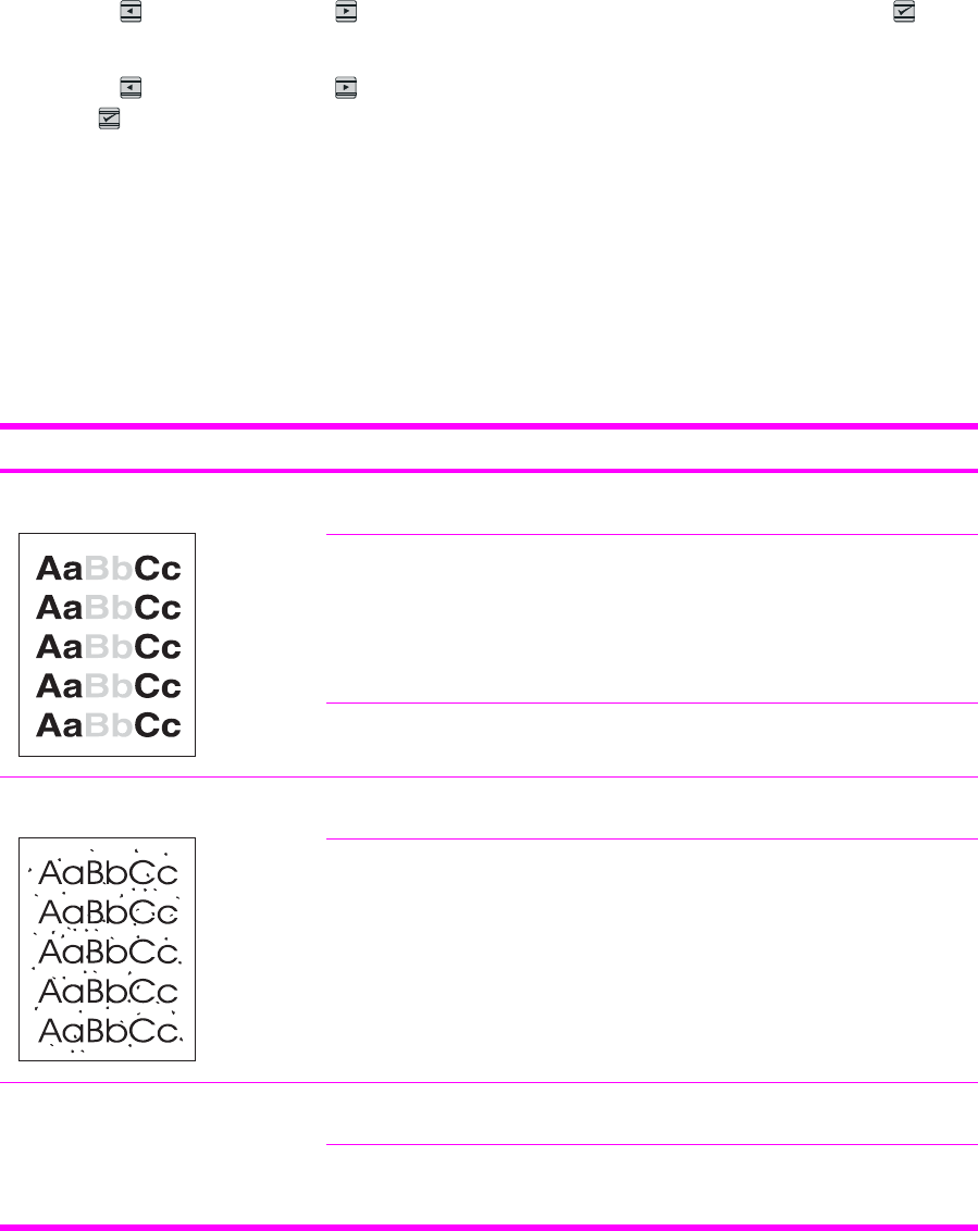
Restoring the factory-set defaults
Restoring the factory-set defaults returns all of the settings to the factory defaults.
To restore the factory-set defaults
1Use the (L
EFT
ARROW
) or the (R
IGHT
ARROW
) button to select Service, and then press
(S
ELECT
).
2Use the (L
EFT
ARROW
) or the (R
IGHT
ARROW
) button to select Restore defaults, and then
press (S
ELECT
).
The device automatically restarts.
General print quality issues
The following examples depict letter-size paper that has passed through the device short edge first.
These examples illustrate problems that would affect all of the pages that you print, whether you print
in color or in black only. The topics that follow list the typical cause and solution for each of these
examples.
Table 6-13 General print quality issues
Problem Cause Solution
Print is light or faded. The media might not meet
HP specifications.
Use media that meets HP specifications.
One or more print cartridges might be
low. If you are using non-HP print
cartridges, no messages appear on the
device control panel or in the
HP Toolbox.
Replace any low print cartridges.
If none of the print cartridges is low or
empty, remove the print cartridges one
at a time and inspect the toner roller in
each to see if the roller is damaged. If
so, replace the print cartridge.
Print the Supplies Status page to check
the remaining life.
Toner specks appear. The media might not meet HP
specifications.
Use media that meets HP specifications.
The paper path might need cleaning. Clean the paper path. See the
HP Toolbox online Help.
Dropouts appear. A single sheet of print media might be
defective.
Try reprinting the job.
The moisture content of the paper is
uneven or the paper has moist spots
on its surface.
Try different paper, such as high-
quality paper that is intended for color
laser printers.
138 Chapter 6 Troubleshooting ENWW
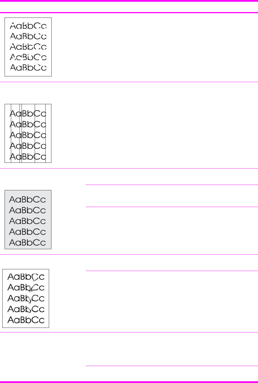
Problem Cause Solution
The paper lot is flawed. The
manufacturing processes can cause
some areas to reject toner.
Try different paper, such as high-
quality paper that is intended for color
laser printers.
Vertical streaks or bands appear on the
page.
One or more print cartridges might be
low or defective. If you are using non-
HP print cartridges, no messages
appear on the device control panel or
in the HP Toolbox.
Replace any low print cartridges.
The amount of background toner
shading becomes unacceptable.
The media might not meet HP
specifications.
Use a different paper with a lighter
basis weight.
Very dry (low humidity) conditions can
increase the amount of background
shading.
Check the device environment.
One or more print cartridges might be
low. If you are using non-HP print
cartridges, no messages appear on the
device control panel or in the
HP Toolbox.
Replace any low print cartridges.
Toner smears appear on the media. The media might not meet HP
specifications.
Use media that meets HP specifications.
If toner smears appear on the leading
edge of the paper, the media guides
are dirty, or debris has accumulated in
the print path.
Clean the media guides and the paper
path.
The toner smears easily when touched. The device is not set to print on the
type of media on which you want to
print.
In the printer driver, select the Paper
tab and set Type is to match the type
of media on which you are printing.
Print speed might be slower if you are
using heavy paper.
The media might not meet HP
specifications.
Use media that meets HP specifications.
Table 6-13 General print quality issues (continued)
ENWW Troubleshooting tools 139
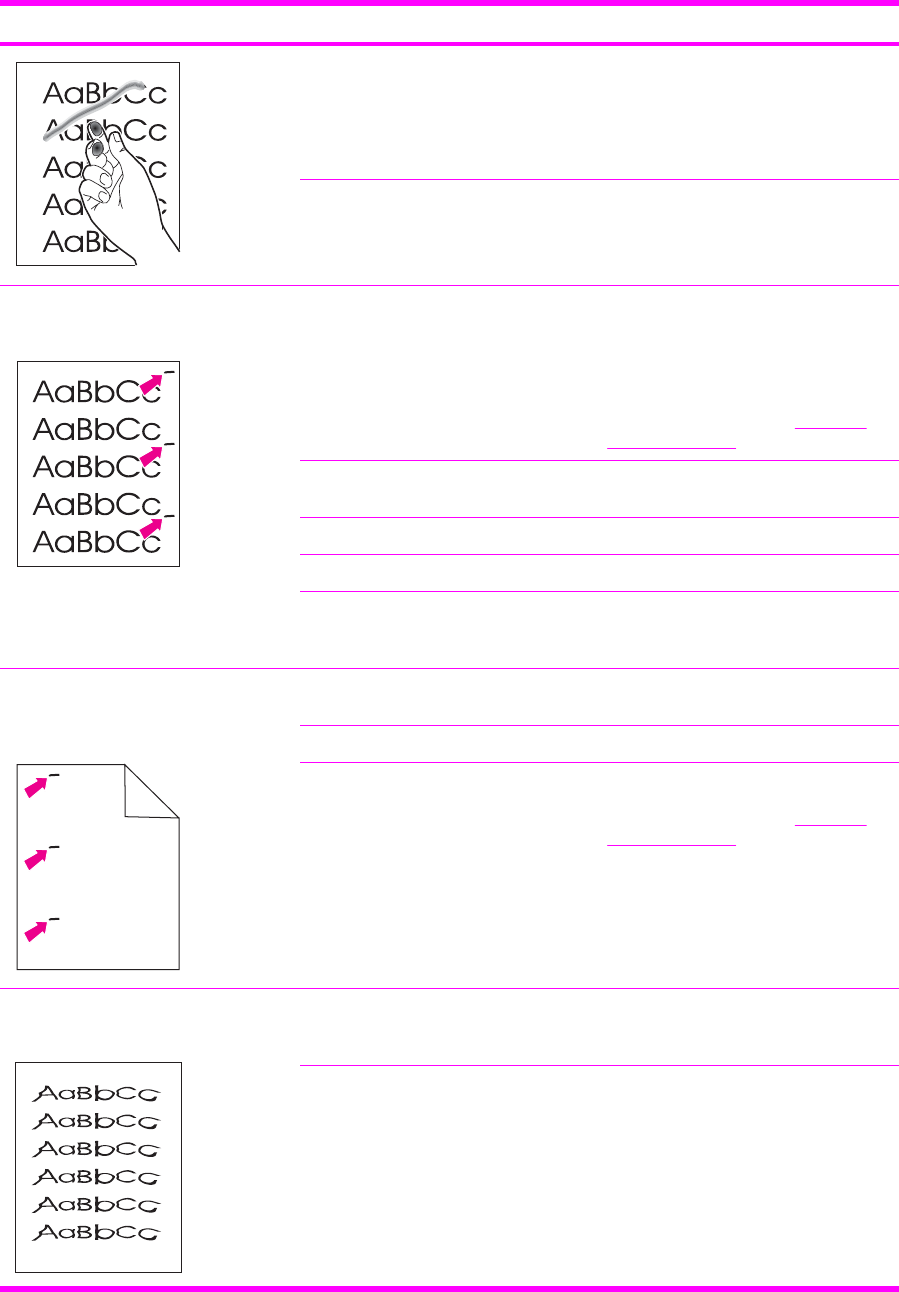
Problem Cause Solution
The paper path might need cleaning. Clean the device.
Marks repeatedly appear at even
intervals on the printed side of the page.
The device is not set to print on the
type of media on which you want to
print.
In the printer driver, select the Paper
tab and set Type is to match the type
of paper on which you are printing.
Print speed might be slower if you are
using heavy paper.
For more information, see Repetitive
image defect ruler.
Internal parts might have toner on them. The problem typically corrects itself
after a few more pages.
The paper path might need cleaning. Clean the device.
The fuser might be damaged or dirty. Clean using instructions in HP Toolbox.
A print cartridge may have a problem. To determine which cartridge has a
problem, print the PQ diagnostics page
from HP Toolbox.
Marks repeatedly appear at even
intervals on the unprinted side of the
page.
Aa
a
Internal parts might have toner on them. The problem typically corrects itself
after a few more pages.
The paper path might need cleaning. Clean the device.
The fuser might be damaged or dirty. Clean using instructions in HP Toolbox.
For more information, see Repetitive
image defect ruler.
The printed page contains misformed
characters.
The media might not meet HP
specifications.
Use a different paper, such as high-
quality paper that is intended for color
laser printers.
If characters are incorrectly formed so
that they produce a wavy effect, the
laser scanner might need service.
Verify that the problem also occurs on
the Configuration page.
Table 6-13 General print quality issues (continued)
140 Chapter 6 Troubleshooting ENWW

Problem Cause Solution
The printed page is curled or wavy. The device is not set to print on the
type of media on which you want to
print.
In the printer driver, select the Paper
tab and set Type is to match the type
of paper on which you are printing.
Print speed might be slower if you are
using heavy paper.
The media might not meet HP
specifications.
Use a different paper, such as high-
quality paper that is intended for color
laser printers.
Both high temperature and humidity
can cause paper curl.
Check the device environment.
Text or graphics are skewed on the
printed page.
The media might be loaded incorrectly. Make sure that the paper or other print
media is loaded correctly and that the
media guides are not too tight or too
loose against the stack.
The media might not meet HP
specifications.
Use a different paper, such as high-
quality paper that is intended for color
laser printers.
The printed page contains wrinkles or
creases.
The media might be loaded incorrectly. Verify that the media is loaded
correctly and that the media guides are
not too tight or too loose against the
stack.
Turn over the stack of paper in the
input tray, or try rotating the paper 180°
in the input tray.
The media might not meet HP
specifications.
Use a different paper, such as high-
quality paper that is intended for color
laser printers.
Toner appears around the printed
characters.
The media might be loaded incorrectly. Turn over the stack of paper in the tray.
If large amounts of toner have
scattered around the characters, the
paper might have high resistivity.
Use a different paper, such as high-
quality paper that is intended for color
laser printers.
Table 6-13 General print quality issues (continued)
ENWW Troubleshooting tools 141
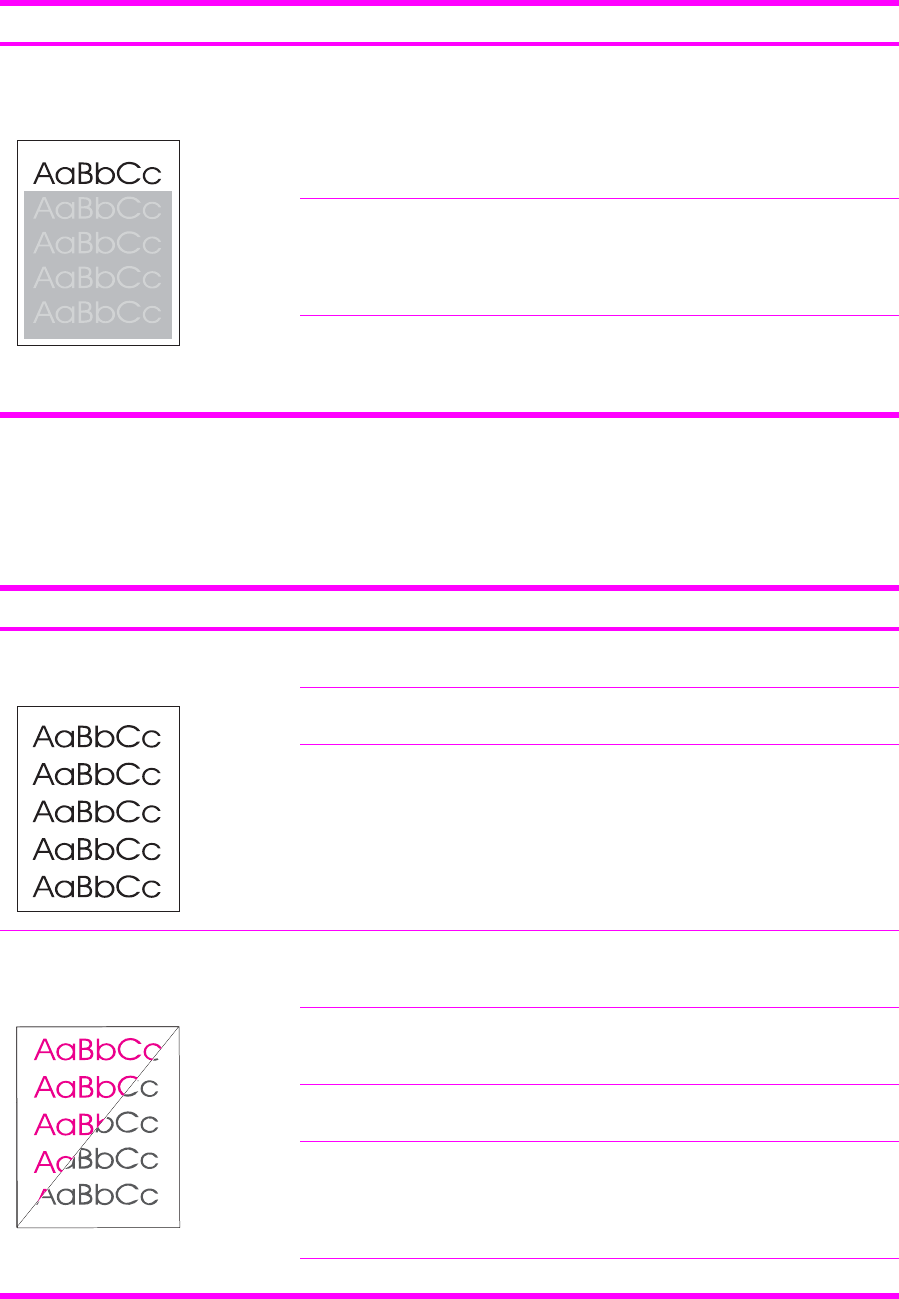
Problem Cause Solution
An image that appears at the top of the
page (in solid black) repeats farther
down the page (in a gray field).
Software settings might affect image
printing.
In your software program, change the
tone (darkness) of the field in which the
repeated image appears.
In your software program, rotate the
whole page 180° to print the lighter
image first.
The order of images printed might
affect printing.
Change the order in which the images
are printed. For example, have the
lighter image at the top of the page,
and the darker image farther down the
page.
A power surge might have affected the
device.
If the defect occurs later in a print job,
turn the device off for 10 minutes, and
then turn on the device to restart the
print job.
Solving issues with color documents
This section describes issues that can occur when you print in color.
Table 6-14 Color document issues
Problem Cause Solution
Only black is printing when the
document should be printing in color.
Color mode is not selected in your
program or printer driver.
Select color mode instead of grayscale
mode.
The correct printer driver might not be
selected in the program.
Select the correct printer driver.
The device might not be correctly
configured.
Print a Configuration page.
One or more colors are not printing, or
are inaccurate.
Sealing tape might be on the print
cartridges.
Verify that the sealing tape has been
completely removed from the print
cartridges.
The media might not meet HP
specifications.
Use a different paper, such as high-
quality paper that is intended for color
laser printers.
The device might be operating in
excessively humid conditions.
Verify that the device environment is
within humidity specifications.
One or more print cartridges might be
low. If you are using non-HP print
cartridges, no messages appear on the
device control panel or in the
HP Toolbox.
Replace any low print cartridges.
The control panel is set for override. Replace low or empty print cartridges.
Table 6-13 General print quality issues (continued)
142 Chapter 6 Troubleshooting ENWW
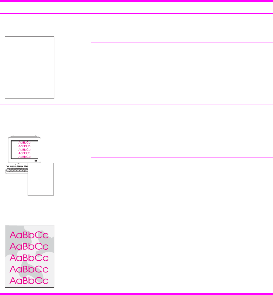
Problem Cause Solution
A color is printing inconsistently after
you load a new print cartridge.
AaBbCc
AaBbCc
AaBbCc
AaBbCc
AaBbCc
Another print cartridge might be low. If
you are using a non-HP print cartridge,
it might be low or empty but you will
receive no indication.
Remove the print cartridge for the color
that is printing inconsistently and
reinstall it.
The control panel is set for override. Replace low or empty print cartridges.
The colors on the printed page do not
match the colors as they appear on the
screen.
AaBbCc
AaBbCc
AaBbCc
AaBbCc
AaBbCc
The colors on your computer monitor
might differ from the device output.
Select Screen Match in the Color tab
of the printer driver.
If extremely light colors or extremely
dark colors on screen are not printing,
your software program might interpret
extremely light colors as white or
extremely dark colors as black.
If possible, avoid using extremely light
or extremely dark colors.
The media might not meet HP
specifications.
Use a different paper, such as high-
quality paper that is intended for color
laser printers.
The finish on the printed color page is
inconsistent.
The media might be too rough. Use a smooth paper or print media,
such as a high-quality paper that is
made for color laser printers.
Generally, smoother media produces
better results.
Table 6-14 Color document issues (continued)
ENWW Troubleshooting tools 143

HP Toolbox
HP Toolbox
HP Toolbox is a Web application that you can use for troubleshooting tasks.
To view HP Toolbox
Open HP Toolbox in one of these ways:
■On the Windows desktop, double-click the HP Toolbox icon.
■On the Windows Start menu, click Programs (All Programs in Windows XP), click HP, click
HP Color LaserJet 2600n, and then click HP Color LaserJet 2600n toolbox.
Troubleshooting tab
HP Toolbox includes a Troubleshooting tab that contains links to the following main pages:
■Clearing Jams. View information about locating and clearing jams.
■Print Problems. View Help topics that can help you solve print problems.
■Troubleshooting Tools. Employ such troubleshooting tools as a cleaning page or a color
troubleshooting page to maintain the device.
■Animated Demonstrations. View animated Help demonstrations for the device.
NOTE Other tabs on HP Toolbox might be helpful in troubleshooting device problems.
Print quality troubleshooting pages
The following features are available from the HP Toolbox.
Printer calibration
Calibrations are performed at regular intervals. For best print quality, a calibration can be performed
from the control panel. For information about calibrating the printer at the control panel, see Printer
calibration.
Calibrating the printer using HP Toolbox
Use the following steps to calibrate the printer using HP Toolbox.
1Open the HP Toolbox.
2On the Troubleshooting tab, click Calibrate now.
Cleaning page
The device features a special cleaning mode to clean the paper path.
144 Chapter 6 Troubleshooting ENWW

NOTE If you have access to HP Toolbox, HP recommends cleaning the paper path by using
HP Toolbox.
1Make sure that the printer is turned on and in the Ready state.
2Open the HP Toolbox.
3On the Troubleshooting tab, click Troubleshooting Tools, and then click Print. A page with a
pattern prints from the printer.
4At the printer, remove any print media in Tray 2 or optional Tray 3.
5Remove the page that printed and load it face-down into Tray 2 or optional Tray 3.
6At the computer, press the Clean button.
Configuration page
The Configuration page lists the current settings and properties of the printer. You can print a
Configuration page from the printer or HP Toolbox. To print the Configuration page from the printer,
see Configuration page.
ENWW HP Toolbox 145

Diagnostic resources
Reports menu
The Reports menu contains the following diagnostic tools:
■Demo page
■Menu structure report
■Configuration report
■Color supplies status
For a more detailed description about the diagnostic tools available from the Reports menu, see
Reports menu in the Print problems section.
Network/Web diagnostics tools
For information on available network and Web diagnostic tools, go to http://www.hp.com/support/
clj2600n.
146 Chapter 6 Troubleshooting ENWW

Repetitive image defect ruler
Use a repetitive image defect ruler to measure occurrences of repetitive image defects to help solve
image quality problems. Place the ruler next to the first occurrence of the defect on the page. Find
the distance between identical defects and see the Table 6-15 Repetitive image defects table to
identify the component that is causing the defect.
Table 6-15 Repetitive image defects
Measurement Component
24.7 mm (0.97 inch) Developer sleeve
26.7 mm (1.05 inches) Charge roller
32.9 mm (1.3 inches) RS roller
37.7 mm (1.48 inches) Transfer roller
54.5 mm (2.15 inches) ETB rollers
56.6 mm (2.22 inches) Fuser sleeve
62.8 mm (2.47 inches) Pressure roller
75.4 mm (2.97 inches) OPC
ENWW Repetitive image defect ruler 147

Firmware and software updates
Use the following procedure to periodically check for firmware and software updates.
1Go to http://www.hp.com/support/clj2600n.
2Select Download drivers and software and then select the appropriate operating system for
you computer.
3Follow the instructions provided on the download pages.
148 Chapter 6 Troubleshooting ENWW

7Parts and diagrams
NOTE In this chapter, part numbers are only listed for available replaceable parts.
References to non-replaceable parts are provided for identification.
This section contains the following information.
●Overview
●Assembly locations
●Covers
●Internal assemblies
●Input devices
●Diagrams
●Alphabetical parts list
●Numerical parts list
ENWW 149

Overview
Replaceable parts
The following table lists the replaceable parts available for this printer.
Table 7-1 Available replaceable parts
Description Part number Diagram
FORMATTER PCB (replacement) Q5965–67901
FLAT FLEX CABLE DCC-FORMATTER Q6456-60101
ARM, PAPER RETAINER, LEFT RC1-5096-000CN See Figure 7-6 Internal components (2
of 3).
ARM, PAPER RETAINER, RIGHT RC1-5097-000CN See Figure 7-6 Internal components (2
of 3).
RETAINER, PAPER RC1-5062-000CN See Figure 7-6 Internal components (2
of 3).
CABLE COVER UNIT RC1-5147-000CN See Figure 7-6 Internal components (2
of 3).
COVER, LEFT RC1-5183-000CN See Figure 7-3 External panels and
covers (2 of 2).
COVER, CASSETTE, LEFT RC1-5184-000CN See Figure 7-3 External panels and
covers (2 of 2).
COVER, CASSETTE, RIGHT RC1-5188-000CN See Figure 7-3 External panels and
covers (2 of 2).
COVER, CASSETTE, DUST RC1-5200-000CN See Figure 7-3 External panels and
covers (2 of 2). and Figure 7-14 Tray 2
input tray internal components.
PLATE, REAR RC1-5227-000CN See Figure 7-3 External panels and
covers (2 of 2).
ROLLER, PICK UP RC1-5440-000CN See Figure 7-15 Paper pick-up feeder
assembly for Tray 2 and Figure 7-17
Paper pickup feeder assembly (Tray 3).
COVER, FACE DOWN RC1-5173-000CN See Assembly locations.
COVER, UPPER FACE S RC1-5174-000CN See Assembly locations.
FUSER ASSY RM1-1820-000CN
110-127V
See Figure 7-10 Fuser assembly.
FUSER ASSY RM1-1821-000CN
220-240V
See Figure 7-10 Fuser assembly.
FRONT DOOR ASSY RM1-1856-000CN See Figure 7-3 External panels and
covers (2 of 2).
RIGHT COVER ASSY RM1-1858-000CN See Figure 7-3 External panels and
covers (2 of 2).
PAPER DELIVERY TRAY ASSY RM1-1859-000CN See Figure 7-3 External panels and
covers (2 of 2).
150 Chapter 7 Parts and diagrams ENWW

Description Part number Diagram
COVER, INSIDE, UPPER RC1-5178-000CN See Figure 7-4 Upper cover assembly.
ETB UNIT RM1-1885-000CN See Figure 7-6 Internal components (2
of 3).
TRAY 1 & 2 CASSETTE (tray only) RM1-1916-000CN See Figure 7-12 Tray 2 input tray
(cassette).
SEPARATION ASSY RM1-1922-000CN See Figure 7-12 Tray 2 input tray
(cassette) and Figure 7-16 Tray 3 input
tray (cassette).
FEED ASSY RM1-1923-000CN See Figure 7-12 Tray 2 input tray
(cassette).
TRAY 3 CASSETTE (tray only) RM1-1945-000CN See Figure 7-16 Tray 3 input tray
(cassette).
UPPER COVER RC1-5176-000CN See Figure 7-4 Upper cover assembly.
DC CONTROLLER PCB ASSY RM1-1975-000CN See Figure 7-7 Internal components (3
of 3) and Figure 7-11 PCB assembly
location (Tray 2).
CONTROL PANEL ASSY RM1-1983-000CN See Figure 7-8 Control panel assembly.
Black Toner Cartridge Q6000A
Cyan Toner Cartridge Q6001A
Yellow Toner Cartridge Q6002A
Magenta Toner Cartridge Q6003A
Replacement-Toner-Black Q6000–67901
Replacement-Toner-Cyan Q6001–67901
Replacement-Toner-Yellow Q6002–67901
Replacement-Toner-Magenta Q6003–67901
Tray 3 paper feeder Q6459–69001
Replacement Whole printer units 110v Q6455-67056
Replacement Whole printer units 220v Q6455-67055
Refurbished Whole printer units 110v Q6455-69056
Refurbished Whole printer units 220v Q6455-69055
Optional Tray 3 Q6459A
Replacement Tray 3 (tray and
assembly)
Q6459-69001
Order replacement parts from the following Web site:
http://www.partsdirect.hp.com
Table 7-1 Available replaceable parts (continued)
ENWW Overview 151

Related documentation and software
Order documentation and software from the companies listed in the following table; some
documentation and software is available at the following Web sites.
Table 7-2 Technical support Web sites
HP Customer Care Online
Software drivers, support documentation, and answers to
frequently asked questions
http://www.hp.com/support
HP Technical Training http://www.hp.com/education
Supplies
Printer supplies are listed in Life expectancies of supplies. Consumables are available directly from
HP at the following numbers.
■US: 1-800-538-8787
■Canada: 1-800-387-3154
Contact your local HP Parts Coordinator for other local phone numbers.
Accessories
Table 7-3 Accessories
Product name Description Product number Part number Exchange number
(replacement
number)
Optional 250-sheet tray Optional Tray 3 Q6459A Q6459–69001 RM1–1945–000CN
152 Chapter 7 Parts and diagrams ENWW
ENWW Overview 153
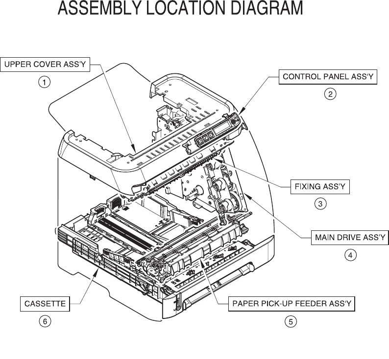
Assembly locations
Figure 7-1 Assembly location diagram
154 Chapter 7 Parts and diagrams ENWW

Table 7-4 Assembly locations
Ref Description Part number Qty
* Not set up as a service part
1 UPPER COVER *
2 CONTROL PANEL ASSEMBLY RM1-1983-000CN
3 FUSER ASSEMBLY RM1-1820-000CN (110v) or
RM1-1821-000CN (220v)
4 MAIN DRIVE ASSEMBLY *
5 PAPER PICKUP FEEDER ASSEMBLY *
6 CASSETTE RM1-1916-000CN
ENWW Assembly locations 155
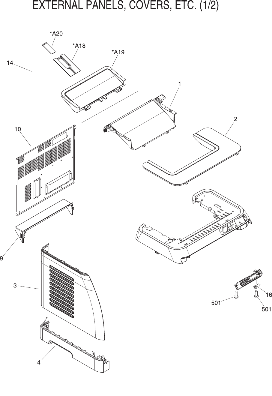
Figure 7-2 External panels and covers (1 of 2)
156 Chapter 7 Parts and diagrams ENWW

Table 7-5 External panels and covers (1 of 2)
Ref Description Part number Qty
* Not set up as a service part
EXTERNAL COVERS, PANELS, ETC. * RF
CONNECTOR, SNAP TIGHT * 1
CONNECTOR, SNAP TIGHT, BK * 1
CLIP, CABLE * 1
SADDLE, WIRE * 1
1 COVER, FACE-DOWN RC1-5173-000CN 1
2 COVER, UPPER FACE, S RC1-5174-000CN 1
3 COVER, LEFT RC1-5183-000CN 1
4 COVER, CASSETTE, LEFT RC1-5184-000CN 1
9 COVER, CASSETTE DUST RC1-5200-000CN 1
10 PLATE, REAR RC1-5227-000CN 1
14 PAPER DELIVERY TRAY ASS'Y RM1-1859-000CN 1
16 PLATE, GROUNDING * 1
501 SCREW, TAPPING,TRUSS HEAD,M3X8 * 2
A18 TRAY, EXTENSION * 1
A19 TRAY, FACE-DOWN * 1
A20 PLATE, DELIVERY BACK END LIMIT * 1
ENWW Assembly locations 157
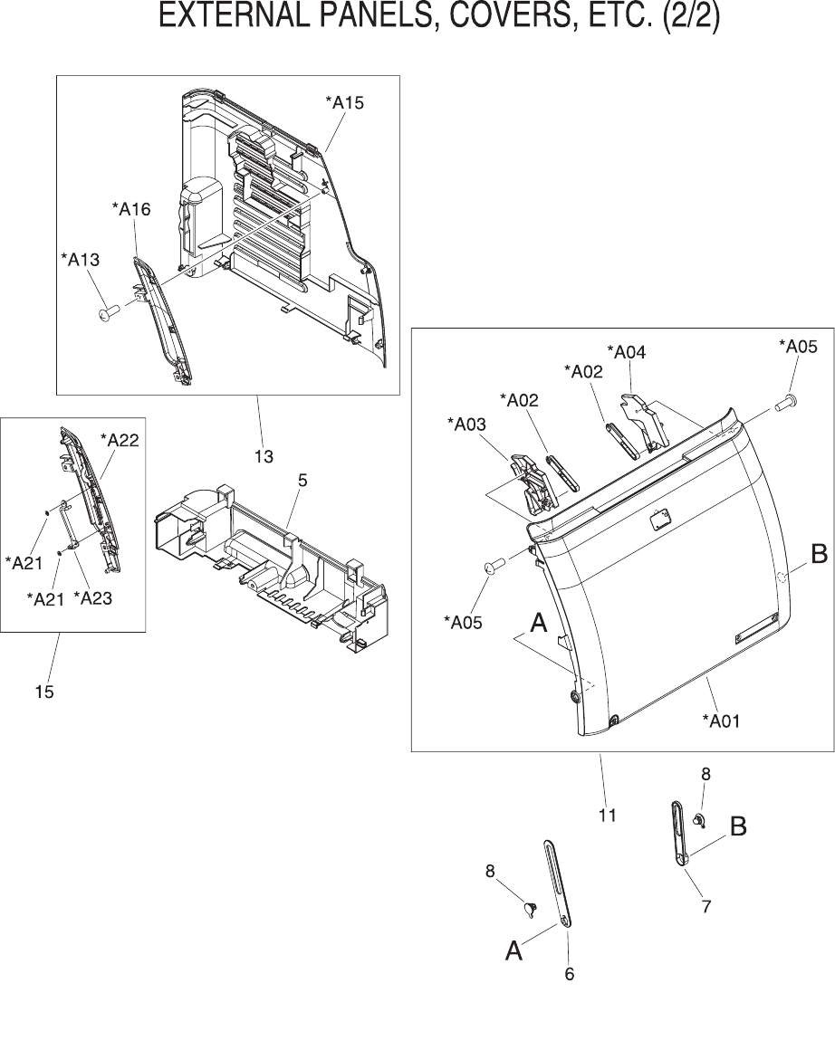
Figure 7-3 External panels and covers (2 of 2)
158 Chapter 7 Parts and diagrams ENWW

Table 7-6 External panels and covers (2 of 2)
Ref Description Part number Qty
* Not set up as a service part
EXTERNAL COVERS, PANELS, ETC. * RF
CONNECTOR, SNAP TIGHT * 1
CONNECTOR, SNAP TIGHT, BK * 1
CLIP, CABLE * 1
SADDLE, WIRE * 1
5 COVER, CASSETTE, RIGHT RC1-5188-000CN 1
6 ARM, FRONT DOOR, LEFT * 1
7 ARM, FRONT DOOR, RIGHT * 1
8 SHAFT, FRONT DOOR ARM * 2
9 COVER, CASSETTE DUST RC1-5200-000CN 1
10 PLATE, REAR RC1-5227-000CN 1
11 FRONT DOOR ASS'Y RM1-1856-000CN 1
13 RIGHT COVER ASS'Y RM1-1858-000CN 1
15 COVER, RIGHT FRONT * 1
A01 DOOR, FRONT * 1
A02 LEVER, LINK * 2
A03 LEVER, TOGGLE, LEFT * 1
A04 LEVER, TOGGLE, RIGHT * 1
A05 SCREW, TAPPING,TRUSS HEAD,M4X8 * 2
A13 SCREW, TP * 2
A15 COVER, RIGHT * 1
A16 COVER, RIGHT FRONT * 1
A21 BUSHING * 2
A22 COVER, RIGHT FRONT * 1
A23 GUIDE, LIGHT * 1
ENWW Assembly locations 159
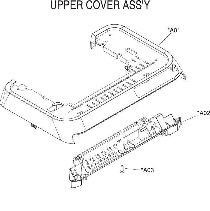
Covers
Figure 7-4 Upper cover assembly
160 Chapter 7 Parts and diagrams ENWW

Table 7-7 Upper assembly cover
Ref Description Part number Qty
* Not set up as a service part
A01 COVER, UPPER RC1-5176-000CN 1
A02 COVER, INSIDE, UPPER RC1-5178-000CN 1
A03 SCREW, TAPPING,TRUSS HEAD,M4X8 * 1
ENWW Covers 161
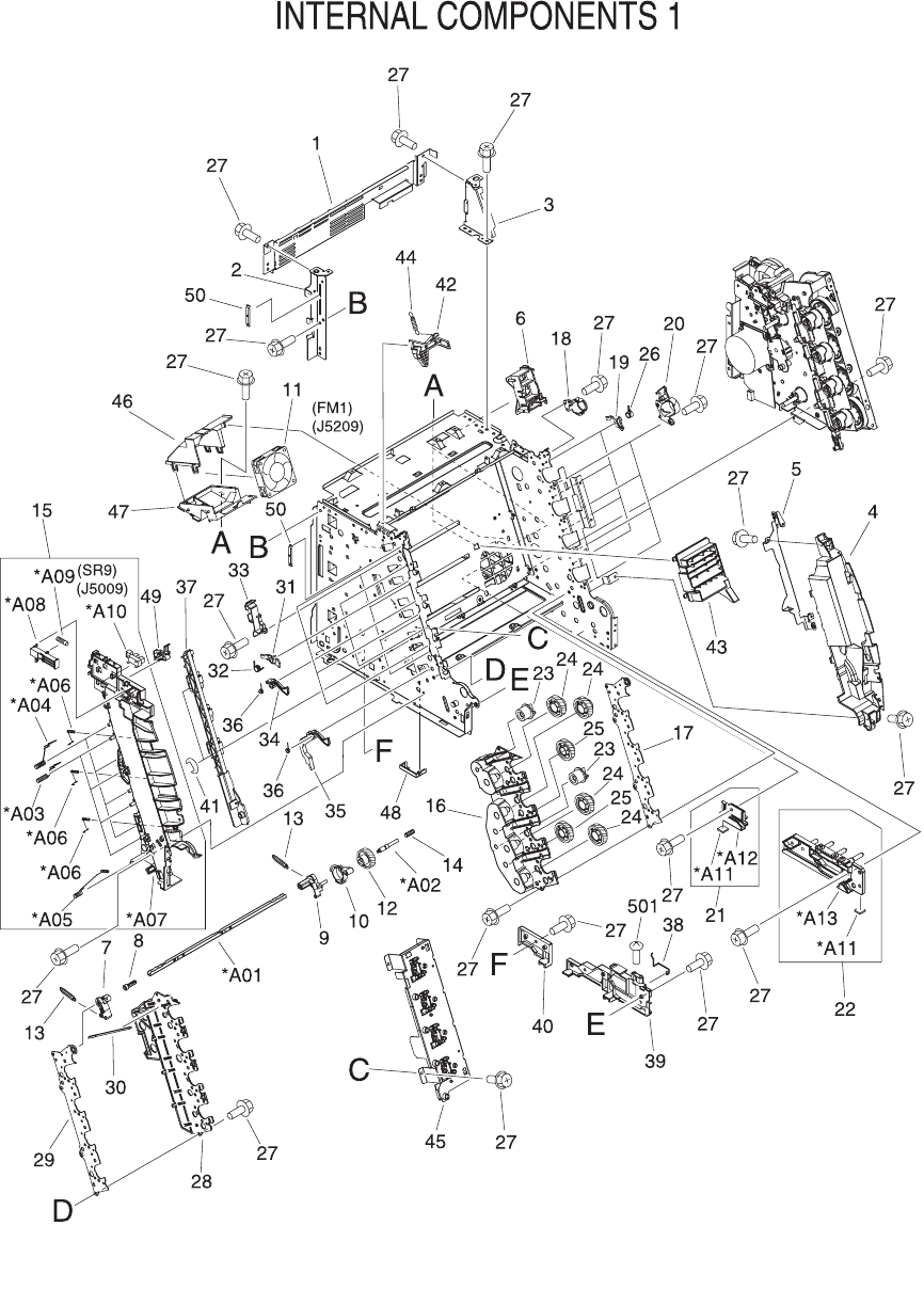
Internal assemblies
Figure 7-5 Internal components (1 of 3)
162 Chapter 7 Parts and diagrams ENWW

Table 7-8 Internal components (1 of 3)
Ref Description Part number Qty
* Not set up as a service part
INTERNAL COMPONENTS 1 * RF
1 CROSSMEMBER, TOP COVER * 1
2 BRACKET, LEFT REAR * 1
3 BRACKET, RIGHT REAR * 1
4 COVER, INSIDE, RIGHT * 1
5 BRACKET, CARD READER * 1
6 HOLDER, FAN RETAINER * 1
7 LATCH, LEFT * 1
8 BUSHING * 1
9 LATCH, RIGHT * 1
10 LEVER, ETB RELEASE * 1
11 FAN * 1
12 GEAR, 54T * 1
13 SPRING, TENSION * 2
14 SPRING, COMPRESSION * 1
15 LEFT INTERNAL COVER ASS'Y * 1
16 GUIDE, CARTRIDGE, RIGHT * 1
17 HOLDER, DRUM * 1
18 BUSHING * 1
19 PLATE, PRESSURE, RIGHT * 4
20 BUSHING * 4
21 GUIDE, CASSETTE, REAR RIGHT * 1
22 GUIDE, CASSETTE, FRONT RIGHT * 1
23 GEAR, 20T * 2
24 GEAR, 36T * 4
25 GEAR, 36T * 2
26 SPRING, TORSION * 4
27 SCREW, RS, M3X8 * 15
27 SCREW, RS, M3X8 * 14
27 SCREW, RS, M3X8 * 1
27 SCREW, RS, M3X8 * 4
28 GUIDE, CARTRIDGE, LEFT * 1
29 HOLDER, DRUM * 1
ENWW Internal assemblies 163

Ref Description Part number Qty
30 LINK, SHUTTER * 1
31 PLATE, PRESSURE, LEFT * 4
32 SPRING, TORSION * 4
33 PLATE, SHAFT * 4
34 ARM, OPEN/CLOSE * 3
35 ARM, OPEN/CLOSE * 1
36 SPRING, TORSION * 4
37 ROD, LEFT * 1
38 SPRING, GROUNDING * 1
39 GUIDE, CASSETTE, FRONT LEFT * 1
40 GUIDE, CASSETTE, REAR LEFT * 1
41 RING, E * 2
42 ARM, LASER SHUTTER * 1
43 DUCT, FAN * 1
44 SPRING, TENSION * 1
45 MEMORY CONTROLLER PCB ASS'Y * 1
46 DUCT, FAN, UPPER * 1
47 DUCT, FAN, LOWER * 1
48 HOLDER, MEMORY CONTROLLER * 1
49 FLAG, PRESSURE RELEASE SENSOR * 1
50 CLAMP, FFC * 2
501 SCREW, TAPPING,TRUSS HEAD,M4X8 * 1
A01 SHAFT, TOGGLE * 1
A02 SHAFT, ETB DRIVE * 1
A03 SPRING, GROUNDING * 4
A04 SPRING, GROUNDING * 4
A05 SPRING, GROUNDING * 1
A06 SPRING, GROUNDING * 3
A07 COVER, INSIDE, LEFT * 1
A08 ARM, INTERLOCK SWITCH * 1
A09 SPRING, COMPRESSION * 1
A10 PHOTO INTERRUPTER (SENSOR) * 1
A11 FOOT, RUBBER * 1
A12 GUIDE, CASSETTE, REAR RIGHT * 1
A13 GUIDE, CASSETTE, FRONT RIGHT * 1
164 Chapter 7 Parts and diagrams ENWW
ENWW Internal assemblies 165
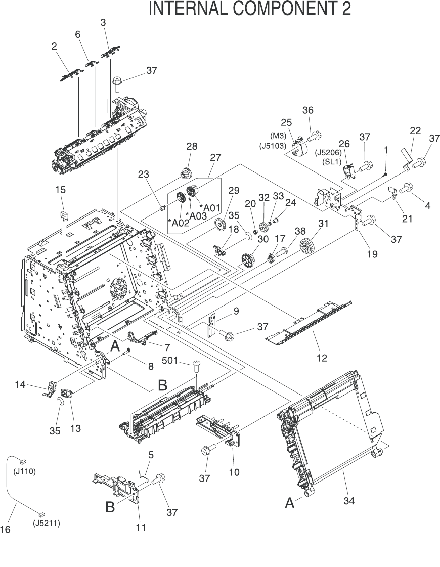
Figure 7-6 Internal components (2 of 3)
166 Chapter 7 Parts and diagrams ENWW

Table 7-9 Internal components (2 of 3)
Ref Description Part number Qty
* Not set up as a service part
INTERNAL COMPONENTS 2 * RF
1 CAP, SHAFT CONDUCTIVE * 1
2 ARM, PAPER RETAINER, LEFT RC1-5096-000CN 1
3 ARM, PAPER RETAINER, RIGHT RC1-5097-000CN 1
4 SCREW, RS, M3X6 * 1
5 SPRING, GROUNDING RC1-5147-000CN 1
6 RETAINER, PAPER RC1-5062-000CN 1
7 COVER, PICK-UP FEED CABLE * 1
8 SHAFT, FRONT DOOR * 1
9 PLATE, PANEL FIX, RIGHT FRONT * 1
10 GUIDE, CASSETTE, FRONT RIGHT * 1
11 GUIDE, CASSETTE, FRONT LEFT * 1
12 PLATE, HEAT INSULATING * 1
13 LEVER, CONNECTING, LEFT * 1
14 CAM, LEFT * 1
15 SADDLE, WIRE * 1
16 FEEDER UNIT JOINT CABLE * 2
17 CAM, HINGE, RIGHT * 1
18 LEVER, CONNECTING, RIGHT * 1
19 BASE, MOTOR * 1
20 CLUTCH, MECHANICAL * 1
21 SPRING, LEAF * 1
22 PLATE * 1
23 BUSHING * 1
24 STOP, CLUTCH * 1
25 MOTOR, STEPPING, DC * 1
26 SOLENOID * 1
27 PICKUP GEAR ASS'Y * 1
28 GEAR, 57T/20T * 1
29 GEAR, 43T/16T * 1
30 GEAR, 47T/26T * 1
31 GEAR, 40T/43T * 1
32 CAM/GEAR, 26T * 1
ENWW Internal assemblies 167

Ref Description Part number Qty
33 SPRING, COMPRESSION * 1
34 ELECT.TRANSPORT BELT ASS'Y RM1-1885-000CN 1
35 RING, E * 2
36 SCREW, RS, M3X6 * 2
37 SCREW, RS, M3X8 * 19
38 SCREW, W/WASHER, M4X18 * 2
501 SCREW, TAPPING, TRUSS HEAD, M4X8 * 2
A01 GEAR, 29T * 1
A02 GEAR, 29T * 1
A03 SPRING, COMPRESSION * 1
168 Chapter 7 Parts and diagrams ENWW
ENWW Internal assemblies 169
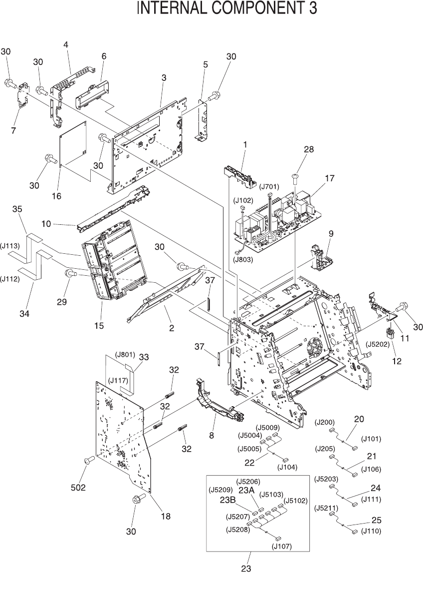
Figure 7-7 Internal components (3 of 3)
170 Chapter 7 Parts and diagrams ENWW

Table 7-10 Internal components (3 of 3)
Ref Description Part number Qty
* Not set up as a service part
INTERNAL COMPONENTS 3 * RF
1 GUIDE, CABLE, UPPER * 1
3 PLATE, SHIELD * 1
4 PLATE, SHIELD, FRONT * 1
5 PLATE, CONNECTOR * 1
6 COVER, CONTROLLER * 1
7 LID, CONTROLLER * 1
8 HOLDER, CABLE, LEFT * 1
9 HOLDER, DC CABLE * 1
10 HOLDER, CABLE, UPPER * 1
11 HOLDER, DRAWER * 1
12 CONNECTOR, DRAWER * 1
15 SCANNER UNIT * 1
16 DC CONTROLLER PCB ASS'Y RM1-1975-000CN 1
17 POWER SUPPLY PCB ASS'Y * 1
17 POWER SUPPLY PCB ASS'Y * 2
17 POWER SUPPLY PCB ASS'Y * 1
18 HIGH-VOLTAGE PCB ASS'Y * 1
20 POWER CABLE * 1
21 POWER CONTROLLER CABLE * 1
22 FIXING SENSOR CABLE * 1
23 DRIVE CABLE * 1
23A CONNECTOR, SNAP TIGHT, BK * 1
23B CONNECTOR, SNAP TIGHT, BK * 1
24 CABLE, CPR * 1
25 FEEDER UNIT JOINT CABLE * 1
28 SCREW, W/WASHER, M3X8 * 1
29 SCREW, RS, M3X10 * 4
30 SCREW, RS, M3X8 * 10
32 ROD, BEARING SUPPORT * 3
33 CABLE, FLAT * 1
34 CABLE, FLAT * 1
35 CABLE, FLAT * 1
ENWW Internal assemblies 171

Ref Description Part number Qty
37 CLAMP, FFC * 2
502 SCREW, TAPPING, TRUSS HEAD, M4X8 * 2
172 Chapter 7 Parts and diagrams ENWW
ENWW Internal assemblies 173
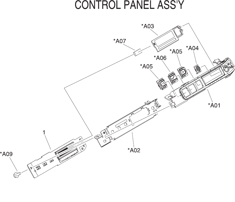
Figure 7-8 Control panel assembly
174 Chapter 7 Parts and diagrams ENWW

Table 7-11 Control panel assembly
Ref Description Part number Qty
* Not set up as a service part
CONTROL PANEL ASS'Y RM1-1983-000CN 1
1 CONTROL PANEL PCB ASS'Y * 1
1 CONTROL PANEL PCB ASS'Y * 1
A01 PANEL, CONTROL PANEL * 1
A02 PLATE, CONTROL PANEL RETAINING * 1
A03 GUIDE, CONTROL PANEL LIGHT * 1
A04 BUTTON, CONTROL PANEL, 1 * 1
A05 BUTTON, CONTROL PANEL, 2 * 2
A06 BUTTON, CONTROL PANEL, 3 * 1
A07 SPACER, CONTROL PANEL * 1
A09 SCREW, RS, M3X8 * 2
ENWW Internal assemblies 175
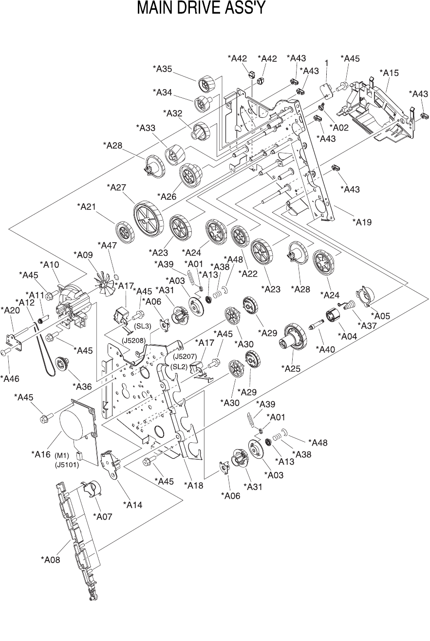
Figure 7-9 Main drive assembly
176 Chapter 7 Parts and diagrams ENWW

Table 7-12 Main drive assembly
Ref Description Part number Qty
* Not set up as a service part
MAIN DRIVE ASS'Y * 1
1 F.F.C. CONNECT PCB UNIT * 1
A01 COLLAR, SPRING * 2
A02 BUSHING * 1
A03 FLANGE, CAM GEAR * 2
A04 COVER, DRUM * 4
A05 BUSHING * 4
A06 BUSHING * 2
A07 CAM, RELEASE * 4
A08 ROD, RELEASE, RIGHT * 1
A09 FAN * 1
A10 DUCT, FAN * 1
A11 PULLEY * 1
A12 BELT, TRANSMISSION * 1
A13 STOP, CAM GEAR * 2
A14 BUSHING * 1
A15 GUIDE, DRIVE CABLE * 1
A16 MOTOR, DC * 1
A17 SOLENOID * 2
A18 PLATE, DRIVE INSIDE * 1
A19 SIDE PLATE, DRIVE * 1
A20 PLATE, FAN * 1
A21 GEAR, 81T * 1
A22 GEAR, 81T/32T * 1
A23 GEAR, 96T * 2
A24 GEAR, 53T/96T * 2
A25 GEAR, 98T * 4
A26 GEAR, 89T/53T * 1
A27 GEAR, 134T * 1
A28 GEAR, 86T * 2
A29 GEAR, 64T * 2
A30 GEAR, 64T * 2
A31 GEAR, 37T * 2
ENWW Internal assemblies 177

Ref Description Part number Qty
A32 GEAR, 27T/64T * 1
A33 GEAR, 64T * 1
A34 GEAR, 54T * 1
A35 GEAR, 54T * 1
A36 GEAR, 18T * 1
A37 SPRING, COMPRESSION * 4
A38 SPRING, COMPRESSION * 2
A39 SPRING, TENSION * 2
A40 SHAFT, DRUM GEAR * 4
A41 CONNECTOR, 2P * 2
A42 CONNECTOR, SNAP TIGHT, BK * 2
A43 CLIP, CABLE * 5
A44 CLIP, EDGE * 1
A45 SCREW, RS, M3X8 * 18
A46 SCREW, TAPPING,TRUSS HEAD,M4X8 * 2
A47 SE RING * 1
A48 RING, E * 2
178 Chapter 7 Parts and diagrams ENWW
ENWW Internal assemblies 179
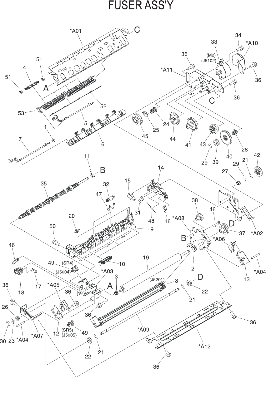
Figure 7-10 Fuser assembly
180 Chapter 7 Parts and diagrams ENWW

Table 7-13 Fuser assembly
Ref Description Part number Qty
* Not set up as a service part
FUSER ASS'Y (110v) RM1-1820-000CN 1
FUSER ASS'Y (220v) RM1-1821-000CN 1
1 SPRING, TORSION * 1
2 BUSHING * 1
3 BUSHING * 1
4 RIB, ENTRANCE GUIDE * 4
5 FLAG, INLET * 1
6 GUIDE, PAPER DELIVERY UPPER * 1
7 FLAG, PAPER DELIVERY * 1
8 FILM GUIDE ASS'Y (110v) * 1
8 FILM GUIDE ASS'Y (220v) * 1
9 GUIDE, PAPER DELIVERY LOWER * 1
10 FLAG, INTERTWINE PREVENTION * 3
11 BUSHING * 1
12 PLATE, PRESSURE, LEFT * 1
13 PLATE, PRESSURE, RIGHT * 1
14 HOLDER, RESISTOR * 1
15 SPRING, GROUNDING * 1
16 SPRING, GROUNDING * 1
17 SPRING, GROUNDING * 1
18 GUIDE, CONTACT/SENSOR SUPPORT * 1
19 ROLLER, PRESSURE * 1
20 ROLLER, FACE-DOWN BENDING * 2
21 PIN,DOWEL * 3
22 CAM, PRESSURE RELEASE * 2
23 FLAG, PRESSURE RELEASE * 1
24 HOLDER, PRESSURE RELEASE GEAR * 1
25 SPRING, LEAF * 1
26 BUSHING * 1
27 BUSHING * 1
28 SPRING, COMPRESSION * 1
29 RING, E * 2
30 RING, E 1
ENWW Internal assemblies 181

Ref Description Part number Qty
31 SPRING, GROUNDING * 1
32 ROLLER, DELIVERY * 2
33 MOTOR, STEPPING, DC * 1
34 SCREW, RS, M3X6 * 2
35 SHAFT, FACE-DOWN ROLLER * 1
36 SCREW, RS, M3X8 * 17
37 GEAR, 30T * 1
38 GEAR, 19T * 1
39 GEAR, 16T * 1
40 GEAR, 49T * 1
41 GEAR, 19T/71T * 1
42 GEAR, 27T * 1
43 GEAR, 26T * 1
44 GEAR, 20T/44T * 1
45 GEAR, 22T/38T * 1
46 SPRING, TENSION * 2
47 SPRING, TORSION * 2
48 SOLID RESISTOR, 20MOHM, 1/4W * 1
49 PHOTO INTERRUPTER (SENSOR) * 2
50 SCREW, RS, M3X8 * 1
51 CLIP, ENTRANCE GUIDE * 8
52 PLATE, GROUNDING * 1
53 GUIDE, FIXING ENTRANCE * 1
A01 FRAME, FIXING * 1
A02 SIDE PLATE, FIXING, RIGHT * 1
A03 SIDE PLATE, FIXING, LEFT * 1
A04 SHAFT, PRESSURE RELEASE * 2
A05 PLATE, PRESSURE RELEASE, LEFT * 1
A06 PLATE, PRESSURE RELEASE, RIGHT * 1
A07 SIDE PLATE, FIXING, LEFT, 2 * 1
A08 SIDE PLATE, FIXING, RIGHT, 2 * 1
A09 SHAFT, PRESSURE RELEASE CAM * 1
A10 PLATE, MOTOR ANTI-MAGNETIC * 1
A11 SIDE PLATE, GEAR * 1
A12 BASE PLATE, FIXING * 1
182 Chapter 7 Parts and diagrams ENWW
ENWW Internal assemblies 183
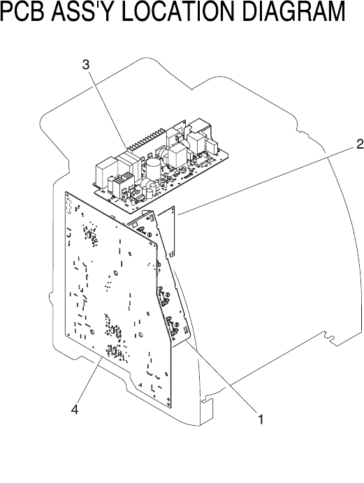
Figure 7-11 PCB assembly location (Tray 2)
184 Chapter 7 Parts and diagrams ENWW

Table 7-14 PCB assembly location Tray 2
Ref Description Part number Qty
* Not set up as a service part
PCB ASS'Y LOCATION DIAGRAM * RF
1 MEMORY CONTROLLER PCB ASS'Y * 1
2 DC CONTROLLER PCB ASS'Y RM1-1975-000CN 1
3 POWER SUPPLY PCB ASS'Y * 1
3 POWER SUPPLY PCB ASS'Y * 1
4 HIGH-VOLTAGE PCB ASS'Y * 1
ENWW Internal assemblies 185
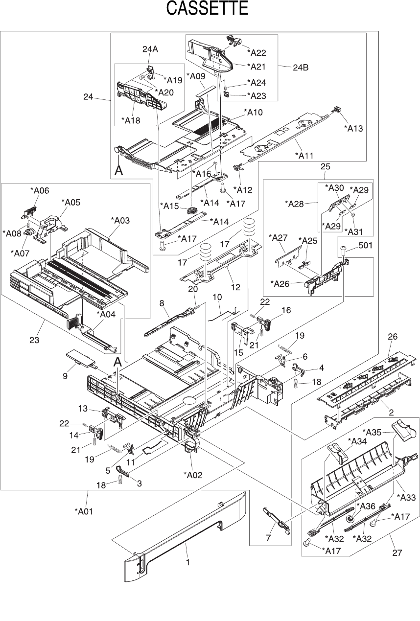
Input devices
Figure 7-12 Tray 2 input tray (cassette)
186 Chapter 7 Parts and diagrams ENWW

Table 7-15 Tray 2 input tray (cassette)
Ref Description Part number Qty
* Not set up as a service part
CASSETTE RM1-1916-000CN 1
1 PANEL, FRONT * 1
2 GUIDE, CASSETTE DUPLEX, LOWER * 1
3 STOPPER, CASSETTE, LEFT * 1
4 STOPPER, CASSETTE, RIGHT * 1
5 ARM, CLAW RELEASE, LEFT * 1
6 ARM, CLAW RELEASE, RIGHT * 1
7 ARM, REMNANT INDICATION * 1
8 ARM, PLATE LOCK RELEASE, MD. * 1
9 SIZE PLATE, PAPER * 1
10 SPRING, GROUNDING * 1
11 SPRING, GROUNDING * 1
12 PLATE, CASSETTE REINFORCEMENT * 1
13 ARM, MD. PLATE RELEASE, LEFT * 1
14 CLAW, MD. PLATE RELEASE, LEFT * 1
15 ARM, MD. PLATE RELEASE, RIGHT * 1
16 CLAW, MD. PLATE RELEASE, RIGHT * 1
17 SPRING, COMPRESSION * 2
18 SPRING, COMPRESSION * 2
19 SPRING, TENSION * 2
20 SPRING, COMPRESSION * 1
21 SPRING, COMPRESSION * 2
22 SPRING, COMPRESSION * 2
23 BACK END LIMIT PLATE ASS'Y * 1
24 MIDDLE PLATE ASS'Y * 1
24A LEFT PAPER SIDE END ASS'Y * 1
24B RIGHT PAPER SIDE END ASS'Y * 1
25 SEPARATION ASS'Y RM1-1922-000CN 1
26 GUIDE, CASSETTE DUPLEX, UPPER * 1
27 FEED ASS'Y RM1-1923-000CN 1
501 SCREW, TAPPING,TRUSS HEAD,M4X8 * 2
A01 CASSETTE BODY ASS'Y * 1
A02 BODY, CASSETTE * 1
ENWW Input devices 187

Ref Description Part number Qty
A03 PLATE, BACK END LIMIT, LARGE * 1
A04 ARM, BACK END LOCK * 1
A05 PLATE, BACK END LIMIT, SMALL * 1
A06 LEVER, BACK END LOCK RELEASE * 1
A07 STOPPER, BACK END LIMIT * 1
A08 SPRING, COMPRESSION * 1
A09 SHEET, SEPARATION * 1
A10 PLATE, MIDDLE * 1
A11 PLATE, REINFORCEMENT * 1
A12 CLAW, MIDDLE PLATE, LEFT * 1
A13 CLAW, MIDDLE PLATE, RIGHT * 1
A14 RACK * 2
A15 GEAR, 22T * 1
A16 SPRING, COMPRESSION * 1
A17 SCREW, TAPPING,TRUSS HEAD,M3X6 * 2
A17 SCREW, TAPPING,TRUSS HEAD,M3X6 * 2
A19 HOLDER, PAPER RETAINING * 2
A20 SPRING, COMPRESSION * 2
A21 PLATE, PAPER SIDE END, RIGHT * 1
A22 LEVER, SIDE END LOCK RELEASE * 1
A23 STOPPER, PAPER SIDE END * 2
A24 SPRING, COMPRESSION * 2
A25 HOLDER, PAD * 1
A26 HOLDER, SEPARATION * 1
A27 PLATE, PAPER GUIDE * 1
A28 HOLDER, PAD * 1
A29 WEIGHT, PAD * 2
A30 HOLDER, PAD * 1
A31 SPRING, COMPRESSION * 1
A32 RACK, MANUAL FEED * 2
A33 GUIDE, MANUAL FEED * 1
A34 GUIDE, FEED WIDTH, LEFT * 1
A35 GUIDE, FEED WIDTH, RIGHT * 1
A36 GEAR, 16T * 1
188 Chapter 7 Parts and diagrams ENWW
ENWW Input devices 189
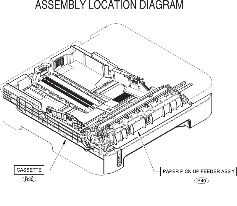
Figure 7-13 250-sheet input tray (cassette)
190 Chapter 7 Parts and diagrams ENWW

Table 7-16 250-sheet input tray (cassette)
Ref Description Part number Qty
* Not set up as a service part
R30 CASSETTE RM1-1945-000CN RF
R40 PAPER PICKUP ROLLER RC1-5440-000CN RF
ENWW Input devices 191
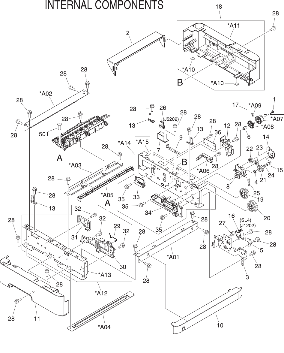
Figure 7-14 Tray 2 input tray internal components
192 Chapter 7 Parts and diagrams ENWW

Table 7-17 Tray 2 sheet input tray internal components
Ref Description Part number Qty
* Not set up as a service part
INTERNAL COMPONENTS * RF
1 CAP, CONTINUITY * 1
2 COVER, CASSETTE DUST RC1-5200-000CN 1
3 BASE, MOTOR * 1
4 CLUTCH, MECHANICAL * 1
5 SPRING, LEAF * 1
6 BUSHING * 1
7 HOLDER, DRAWER CONNECTOR * 1
8 HOLDER, SWING GEAR * 1
9 PLATE, GROUNDING * 1
10 COVER, OPTION FRONT * 1
11 COVER, OPTION LEFT * 1
12 COVER, PCB * 1
13 SHAFT, POSITIONING * 3
14 COVER, SWING GEAR * 1
15 STOP, CLUTCH * 1
16 SOLENOID * 1
17 PICKUP GEAR ASS'Y * 1
18 COVER, OPTION RIGHT * 1
19 GEAR, 47T/26T * 1
20 GEAR, 40T/43T * 1
21 CAM/GEAR, 26T * 1
22 GEAR, 19T * 1
23 GEAR, 18T * 1
24 SPRING, COMPRESSION * 1
25 SPRING, TENSION * 1
26 CONNECTOR, DRAWER * 1
27 SADDLE, WIRE * 1
28 SCREW, RS, M3X8 * 32
29 SPRING, GROUNDING * 1
30 GUIDE, CASSETTE, FRONT LEFT * 1
31 GUIDE, CASSETTE, REAR LEFT * 1
32 SCREW, RS, M3X8 * 3
ENWW Input devices 193

Ref Description Part number Qty
33 GUIDE, CASSETTE, REAR RIGHT * 1
34 GUIDE, CASSETTE, FRONT RIGHT * 1
35 SCREW, RS, M3X8 * 3
36 PAPER FEEDER PCB ASS'Y * 1
501 SCREW, TAPPING,TRUSS HEAD, M4X8 * 2
A01 CROSSMEMBER, FRONT * 1
A02 CROSSMEMBER, REAR * 1
A03 CROSSMEMBER, MIDDLE * 1
A04 CROSSMEMBER, LOWER, REAR * 2
A05 GUIDE, PAPER SENSOR CABLE, 1 * 1
A06 GUIDE, PAPER SENSOR CABLE, 2 * 1
A07 GEAR, 29T * 1
A08 GEAR, 29T * 1
A09 SPRING, COMPRESSION * 1
A10 FOOT, RUBBER * 2
A11 COVER, OPTION RIGHT * 1
A12 OPTION FRAME LEFT ASS'Y * 1
A13 FRAME, OPTION, LEFT * 1
A14 OPTION FRAME RIGHT ASS'Y * 1
A15 FRAME, OPTION, RIGHT * 1
194 Chapter 7 Parts and diagrams ENWW
ENWW Input devices 195

Figure 7-15 Paper pick-up feeder assembly for Tray 2
196 Chapter 7 Parts and diagrams ENWW

Table 7-18 Paper pick-up feeder assembly for Tray 2
Ref Description Part number Qty
* Not set up as a service part
PAPER PICKUP FEEDER ASS'Y * 1
1 GUIDE, REGISTRATION * 1
2 PLATE, REG. GROUNDING, 1 * 1
3 PLATE, REG. GROUNDING, 2 * 1
4 FLAG, SENSOR * 1
5 SPRING, TORSION * 1
6 COVER, SENSOR, TOP * 1
7 GUIDE, PRE-TRANSFER * 1
8 ROLLER, REGISTRATION DRIVE * 1
9 BUSHING * 2
10 SHUTTER, REGISTRATION * 1
11 SPRING, TORSION * 1
12 ROLLER, REGISTRATION, A * 2
13 ROLLER, REGISTRATION, B * 2
14 ROLLER, REGISTRATION, C * 2
15 BUSHING * 1
16 BUSHING * 1
17 ROLLER, PAPER PICKUP RC1-5440-000CN 1
18 HOLDER, PAPER WIDTH SENSOR * 1
19 FLAG, PAPER WIDTH SENSOR * 1
20 SPRING, TORSION * 1
21 RESISTOR, 400 OHM, 0.5W * 1
22 COVER, PICKUP FEED FRAME * 1
23 SPRING, TENSION * 2
24 PHOTO INTERRUPTER (SENSOR) * 4
25 PAPER PICKUP DRIVE ASS'Y * 1
26 FEEDER UNIT CABLE * 1
501 SCREW, TAPPING,TRUSS HEAD,M4X8 * 4
A01 FRAME, PAPER PICKUP FEEDER * 1
A02 SHAFT, REGISTRATION ROLLER * 1
A03 COVER, PICKUP FEED FRAME * 1
A04 SHEET, SCRAPER, 1 * 1
A05 SHEET, SCRAPER, 2 * 1
ENWW Input devices 197

Ref Description Part number Qty
A06 SHAFT, PAPER PICKUP DRIVE * 1
A07 BUSHING * 1
A08 BUSHING * 1
A09 ARM, CST. PAPER SENSING, 1 * 1
A10 ARM, CST. PAPER SENSING, 2 * 1
A11 HOLDER, PAPER PICKUP ROLLER * 1
A12 ROLLER, CASSETTE PAPER PICKUP * 2
A13 BUSHING * 1
A14 SPRING, COMPRESSION * 1
198 Chapter 7 Parts and diagrams ENWW
ENWW Input devices 199
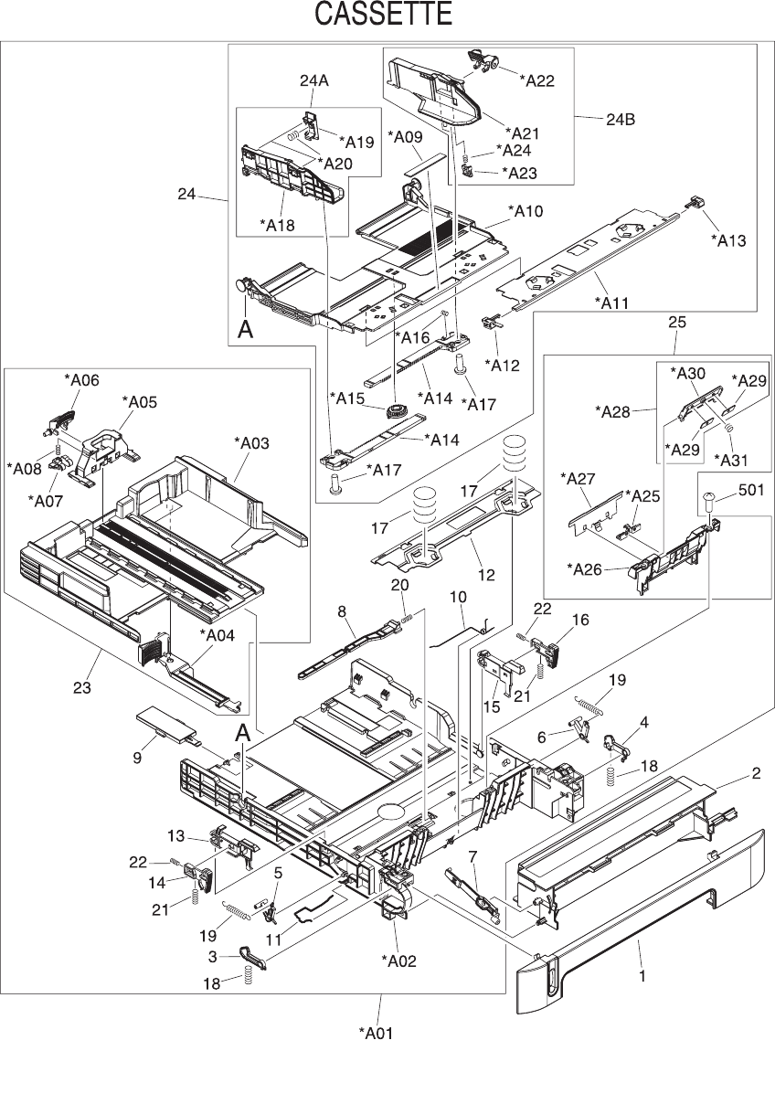
Figure 7-16 Tray 3 input tray (cassette)
200 Chapter 7 Parts and diagrams ENWW

Table 7-19 Tray 3 input tray (cassette)
Ref Description Part number Qty
* Not set up as a service part
CASSETTE RM1-1945-000CN 1
PAPER PICKUP ROLLER RC1-5440-000CN
1 PANEL, FRONT * 1
2 FRAME, FRONT * 1
3 STOPPER, CASSETTE, LEFT * 1
4 STOPPER, CASSETTE, RIGHT * 1
5 ARM, CLAW RELEASE, LEFT * 1
6 ARM, CLAW RELEASE, RIGHT * 1
7 ARM, REMNANT INDICATION * 1
8 ARM, PLATE LOCK RELEASE, MD * 1
9 SIZE PLATE, PAPER * 1
10 SPRING, GROUNDING * 1
11 SPRING, GROUNDING * 1
12 PLATE, CASSETTE REINFORCEMENT * 1
13 ARM, MD. PLATE RELEASE, LEFT * 1
14 CLAW, MD. PLATE RELEASE, LEFT * 1
15 ARM, MD. PLATE RELEASE, RIGHT * 1
16 CLAW, MD. PLATE RELEASE, RIGHT * 1
17 SPRING, COMPRESSION * 2
18 SPRING, COMPRESSION * 2
19 SPRING, TENSION * 2
20 SPRING, COMPRESSION * 1
21 SPRING, COMPRESSION * 2
22 SPRING, COMPRESSION * 2
23 BACK END LIMIT PLATE ASS'Y * 1
24 MIDDLE PLATE ASS'Y * 1
24A LEFT PAPER SIDE END ASS'Y * 1
24B RIGHT PAPER SIDE END ASS'Y * 1
25 SEPARATION ASS'Y RM1-1922-000CN 1
501 SCREW, TAPPING,TRUSS HEAD,M4X8 * 2
A01 CASSETTE BODY ASS'Y * 1
A02 BODY, CASSETTE * 1
A03 PLATE, BACK END LIMIT, LARGE * 1
ENWW Input devices 201

Ref Description Part number Qty
A04 ARM, BACK END LOCK * 1
A05 PLATE, BACK END LIMIT, SMALL * 1
A06 LEVER, BACK END LOCK RELEASE * 1
A07 STOPPER, BACK END LIMIT * 1
A08 SPRING, COMPRESSION * 1
A09 SHEET, SEPARATION * 1
A10 PLATE, MIDDLE * 1
A11 PLATE, REINFORCEMENT * 1
A12 CLAW, MIDDLE PLATE, LEFT * 1
A13 CLAW, MIDDLE PLATE, RIGHT * 1
A14 RACK * 2
A15 GEAR, 22T * 1
A16 SPRING, COMPRESSION * 1
A17 SCREW, TAPPING,TRUSS HEAD,M3X6 * 2
A18 PLATE, PAPER SIDE END, LEFT * 1
A19 HOLDER, PAPER RETAINING * 2
A20 SPRING, COMPRESSION * 2
A21 PLATE, PAPER SIDE END, RIGHT * 1
A22 LEVER, SIDE END LOCK RELEASE * 1
A23 STOPPER, PAPER SIDE END * 2
A24 SPRING, COMPRESSION * 2
A25 HOLDER, PAD * 1
A26 HOLDER, SEPARATION * 1
A27 PLATE, PAPER GUIDE * 1
A28 HOLDER, PAD * 1
A29 WEIGHT, PAD * 2
A30 HOLDER, PAD * 1
A31 SPRING, COMPRESSION * 1
202 Chapter 7 Parts and diagrams ENWW
ENWW Input devices 203
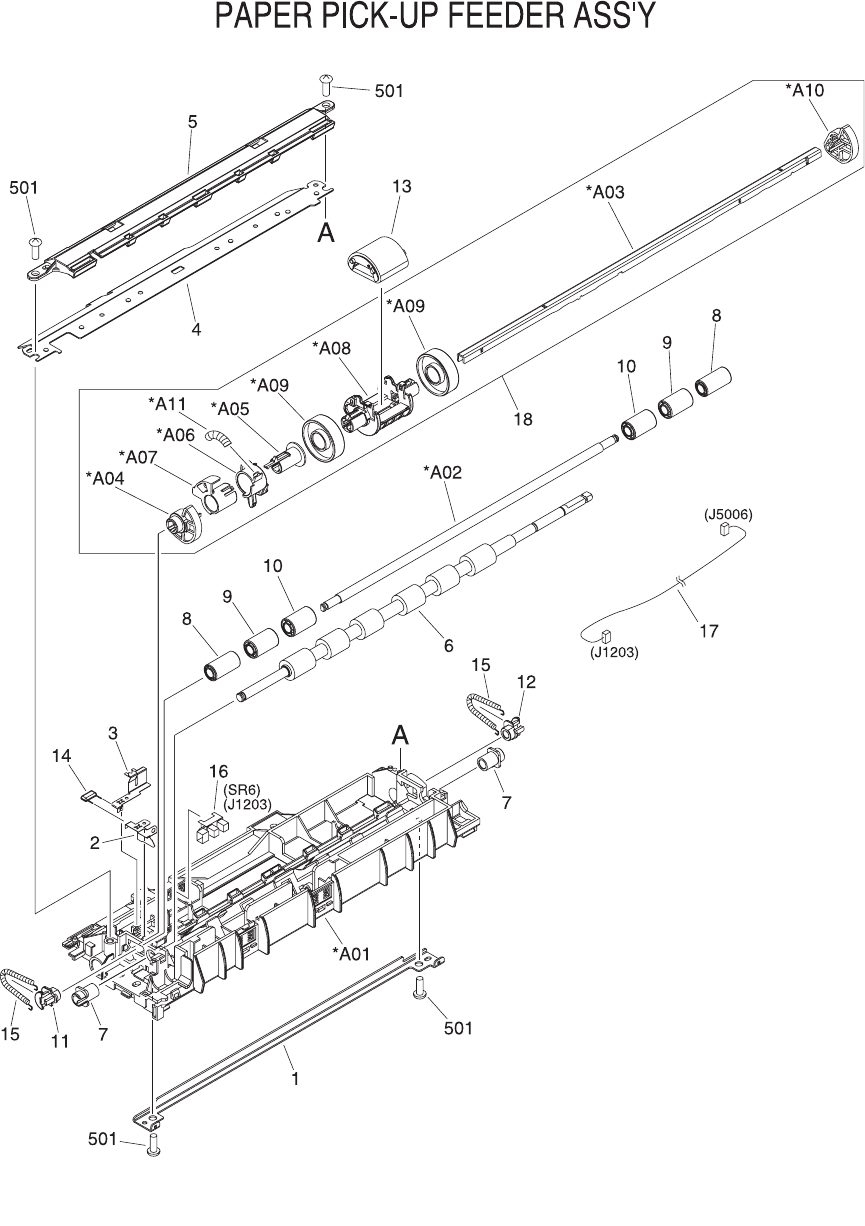
Figure 7-17 Paper pickup feeder assembly (Tray 3)
204 Chapter 7 Parts and diagrams ENWW

Table 7-20 Paper pickup feeder assembly (Tray 3)
Ref Description Part number Qty
* Not set up as a service part
PAPER PICKUP ROLLER RC1-5440-000CN 1
1 GUIDE, REGISTRATION * 1
2 PLATE, REG. GROUNDING, 1 * 1
3 PLATE, REG. GROUNDING, 2 * 1
4 COVER, PICKUP FEED FRAME * 1
5 GUIDE, PRE-TRANSFER * 1
6 ROLLER, REGISTRATION DRIVE * 1
7 BUSHING * 2
8 ROLLER, REGISTRATION, A * 2
9 ROLLER, REGISTRATION, B * 2
10 ROLLER, REGISTRATION, C * 2
11 BUSHING * 1
12 BUSHING * 1
13 ROLLER, PAPER PICKUP RC1-5440-000CN 1
14 RESISTOR, 400 OHM, 0.5W * 1
15 SPRING, TENSION * 2
16 PHOTO INTERRUPTER (SENSOR) * 1
17 CABLE, OPTION SENSOR * 1
18 PAPER PICKUP DRIVE ASS'Y * 1
501 SCREW, TAPPING,TRUSS HEAD,M4X8 * 4
A01 FRAME, PAPER PICKUP FEEDER * 1
A02 SHAFT, REGISTRATION ROLLER * 1
A03 SHAFT, PAPER PICKUP DRIVE * 1
A04 BUSHING * 1
A05 BUSHING * 1
A06 ARM, CST. PAPER SENSING, 1 * 1
A07 ARM, CST. PAPER SENSING, 2 * 1
A08 HOLDER, PAPER PICKUP ROLLER * 1
A09 ROLLER, CASSETTE PAPER PICKUP * 2
A10 BUSHING * 1
A11 SPRING, COMPRESSION * 1
ENWW Input devices 205
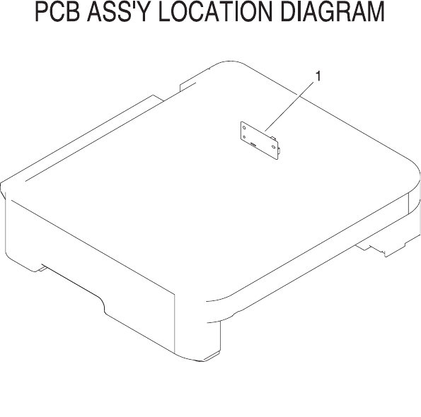
Figure 7-18 PCB assembly location optional Tray 3
206 Chapter 7 Parts and diagrams ENWW

Table 7-21 Paper pickup feeder assembly (Tray 3)
Ref Description Part number Qty
* Not set up as a service part
PCB ASS'Y LOCATION DIAGRAM * RF
1 PAPER FEEDER PCB ASS'Y * 1
ENWW Input devices 207
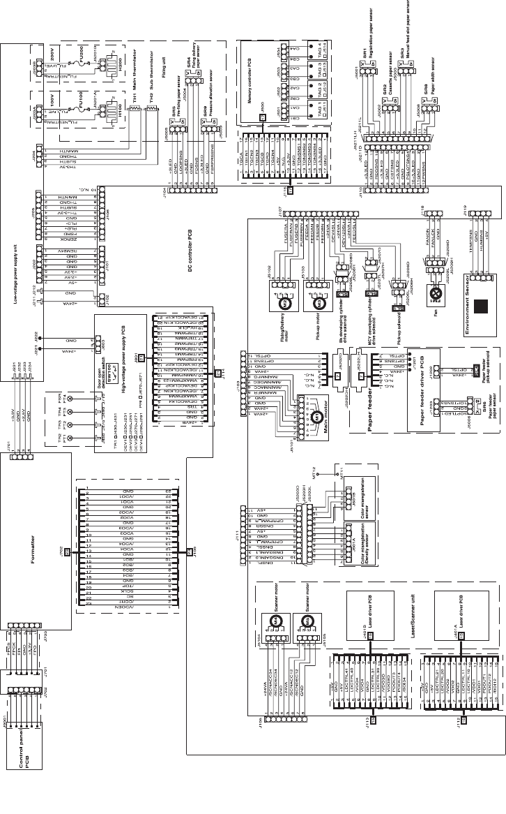
Diagrams
Figure 7-19 General circuit diagram
208 Chapter 7 Parts and diagrams ENWW

Alphabetical parts list
Table 7-22 Alphabetical parts list
Description Part number Table and page
* Not set up as a service part Assembly locations
* Not set up as a service part External panels and covers (1
of 2)
* Not set up as a service part External panels and covers (2
of 2)
* Not set up as a service part Upper assembly cover
* Not set up as a service part Internal components (1 of 3)
* Not set up as a service part Internal components (2 of 3)
* Not set up as a service part Internal components (3 of 3)
* Not set up as a service part Control panel assembly
* Not set up as a service part Main drive assembly
* Not set up as a service part Fuser assembly
* Not set up as a service part PCB assembly location Tray 2
* Not set up as a service part Tray 2 input tray (cassette)
* Not set up as a service part 250-sheet input tray (cassette)
* Not set up as a service part Tray 2 sheet input tray
internal components
* Not set up as a service part Paper pick-up feeder
assembly for Tray 2
* Not set up as a service part Tray 3 input tray (cassette)
* Not set up as a service part Paper pickup feeder
assembly (Tray 3)
* Not set up as a service part Paper pickup feeder
assembly (Tray 3)
ARM, BACK END LOCK *Tray 2 input tray (cassette)
ARM, BACK END LOCK *Tray 3 input tray (cassette)
ARM, CLAW RELEASE, LEFT *Tray 2 input tray (cassette)
ARM, CLAW RELEASE, LEFT *Tray 3 input tray (cassette)
ARM, CLAW RELEASE, RIGHT *Tray 2 input tray (cassette)
ARM, CLAW RELEASE, RIGHT *Tray 3 input tray (cassette)
ARM, CST. PAPER SENSING, 1 *Paper pick-up feeder
assembly for Tray 2
ARM, CST. PAPER SENSING, 1 *Paper pickup feeder
assembly (Tray 3)
ARM, CST. PAPER SENSING, 2 * Paper pick-up feeder
assembly for Tray 2
ENWW Alphabetical parts list 209

Description Part number Table and page
ARM, CST. PAPER SENSING, 2 *Paper pickup feeder
assembly (Tray 3)
ARM, FRONT DOOR, LEFT *External panels and covers (2
of 2)
ARM, FRONT DOOR, RIGHT *External panels and covers (2
of 2)
ARM, INTERLOCK SWITCH *Internal components (1 of 3)
ARM, LASER SHUTTER *Internal components (1 of 3)
ARM, MD. PLATE RELEASE, LEFT *Tray 2 input tray (cassette)
ARM, MD. PLATE RELEASE, LEFT *Tray 3 input tray (cassette)
ARM, MD. PLATE RELEASE, RIGHT *Tray 2 input tray (cassette)
ARM, MD. PLATE RELEASE, RIGHT *Tray 3 input tray (cassette)
ARM, OPEN/CLOSE *Internal components (1 of 3)
ARM, OPEN/CLOSE *Internal components (1 of 3)
ARM, PAPER RETAINER, LEFT RC1-5096-000CN Internal components (2 of 3)
ARM, PAPER RETAINER, RIGHT RC1-5097-000CN Internal components (2 of 3)
ARM, PLATE LOCK RELEASE, MD *Tray 3 input tray (cassette)
ARM, PLATE LOCK RELEASE, MD. *Tray 2 input tray (cassette)
ARM, REMNANT INDICATION *Tray 2 input tray (cassette)
ARM, REMNANT INDICATION *Tray 3 input tray (cassette)
BACK END LIMIT PLATE ASS'Y *Tray 2 input tray (cassette)
BACK END LIMIT PLATE ASS'Y *Tray 3 input tray (cassette)
BASE PLATE, FIXING *Fuser assembly
BASE, MOTOR *Internal components (2 of 3)
BASE, MOTOR *Tray 2 sheet input tray
internal components
BELT, TRANSMISSION *Main drive assembly
BODY, CASSETTE *Tray 2 input tray (cassette)
BODY, CASSETTE *Tray 3 input tray (cassette)
BRACKET, CARD READER *Internal components (1 of 3)
BRACKET, LEFT REAR *Internal components (1 of 3)
BRACKET, RIGHT REAR *Internal components (1 of 3)
BUSHING * External panels and covers (2
of 2)
BUSHING * Internal components (1 of 3)
BUSHING * Internal components (1 of 3)
Table 7-22 Alphabetical parts list (continued)
210 Chapter 7 Parts and diagrams ENWW

Description Part number Table and page
BUSHING * Internal components (1 of 3)
BUSHING * Internal components (2 of 3)
BUSHING * Main drive assembly
BUSHING * Main drive assembly
BUSHING * Main drive assembly
BUSHING * Main drive assembly
BUSHING * Fuser assembly
BUSHING * Fuser assembly
BUSHING * Fuser assembly
BUSHING * Fuser assembly
BUSHING * Fuser assembly
BUSHING * Tray 2 sheet input tray
internal components
BUSHING * Paper pick-up feeder
assembly for Tray 2
BUSHING * Paper pick-up feeder
assembly for Tray 2
BUSHING * Paper pick-up feeder
assembly for Tray 2
BUSHING * Paper pick-up feeder
assembly for Tray 2
BUSHING * Paper pick-up feeder
assembly for Tray 2
BUSHING * Paper pick-up feeder
assembly for Tray 2
BUSHING * Paper pickup feeder
assembly (Tray 3)
BUSHING * Paper pickup feeder
assembly (Tray 3)
BUSHING * Paper pickup feeder
assembly (Tray 3)
BUSHING * Paper pickup feeder
assembly (Tray 3)
BUSHING * Paper pickup feeder
assembly (Tray 3)
BUSHING * Paper pickup feeder
assembly (Tray 3)
BUTTON, CONTROL PANEL, 1 *Control panel assembly
BUTTON, CONTROL PANEL, 2 *Control panel assembly
BUTTON, CONTROL PANEL, 3 * Control panel assembly
Table 7-22 Alphabetical parts list (continued)
ENWW Alphabetical parts list 211

Description Part number Table and page
CABLE, CPR *Internal components (3 of 3)
CABLE, FLAT *Internal components (3 of 3)
CABLE, FLAT *Internal components (3 of 3)
CABLE, FLAT *Internal components (3 of 3)
CABLE, OPTION SENSOR *Paper pickup feeder
assembly (Tray 3)
CAM, HINGE, RIGHT *Internal components (2 of 3)
CAM, LEFT *Internal components (2 of 3)
CAM, PRESSURE RELEASE *Fuser assembly
CAM, RELEASE *Main drive assembly
CAM/GEAR, 26T *Internal components (2 of 3)
CAM/GEAR, 26T *Tray 2 sheet input tray
internal components
CAP, CONTINUITY *Tray 2 sheet input tray
internal components
CAP, SHAFT CONDUCTIVE *Internal components (2 of 3)
CASSETTE RM1-1916-000CN Assembly locations
CASSETTE RM1-1916-000CN Tray 2 input tray (cassette)
CASSETTE RM1-1945-000CN 250-sheet input tray (cassette)
CASSETTE RM1-1945-000CN Tray 3 input tray (cassette)
CASSETTE BODY ASS'Y *Tray 2 input tray (cassette)
CASSETTE BODY ASS'Y *Tray 3 input tray (cassette)
CLAMP, FFC *Internal components (1 of 3)
CLAMP, FFC *Internal components (3 of 3)
CLAW, MD. PLATE RELEASE, LEFT *Tray 2 input tray (cassette)
CLAW, MD. PLATE RELEASE, LEFT *Tray 3 input tray (cassette)
CLAW, MD. PLATE RELEASE, RIGHT *Tray 2 input tray (cassette)
CLAW, MD. PLATE RELEASE, RIGHT *Tray 3 input tray (cassette)
CLAW, MIDDLE PLATE, LEFT *Tray 2 input tray (cassette)
CLAW, MIDDLE PLATE, LEFT *Tray 3 input tray (cassette)
CLAW, MIDDLE PLATE, RIGHT *Tray 2 input tray (cassette)
CLAW, MIDDLE PLATE, RIGHT *Tray 3 input tray (cassette)
CLIP, CABLE *External panels and covers (1
of 2)
CLIP, CABLE * External panels and covers (2
of 2)
Table 7-22 Alphabetical parts list (continued)
212 Chapter 7 Parts and diagrams ENWW

Description Part number Table and page
CLIP, CABLE *Main drive assembly
CLIP, EDGE *Main drive assembly
CLIP, ENTRANCE GUIDE *Fuser assembly
CLUTCH, MECHANICAL *Internal components (2 of 3)
CLUTCH, MECHANICAL *Tray 2 sheet input tray
internal components
COLLAR, SPRING *Main drive assembly
CONNECTOR, 2P *Main drive assembly
CONNECTOR, DRAWER *Internal components (3 of 3)
CONNECTOR, DRAWER *Tray 2 sheet input tray
internal components
CONNECTOR, SNAP TIGHT *External panels and covers (1
of 2)
CONNECTOR, SNAP TIGHT *External panels and covers (2
of 2)
CONNECTOR, SNAP TIGHT, BK *External panels and covers (1
of 2)
CONNECTOR, SNAP TIGHT, BK *External panels and covers (2
of 2)
CONNECTOR, SNAP TIGHT, BK *Internal components (3 of 3)
CONNECTOR, SNAP TIGHT, BK *Internal components (3 of 3)
CONNECTOR, SNAP TIGHT, BK *Main drive assembly
CONTROL PANEL ASS'Y RM1-1983-000CN Control panel assembly
CONTROL PANEL ASSEMBLY RM1-1983-000CN Assembly locations
CONTROL PANEL PCB ASS'Y *Control panel assembly
CONTROL PANEL PCB ASS'Y *Control panel assembly
COVER, CASSETTE DUST RC1-5200-000CN External panels and covers (1
of 2)
COVER, CASSETTE DUST RC1-5200-000CN External panels and covers (2
of 2)
COVER, CASSETTE DUST RC1-5200-000CN Tray 2 sheet input tray
internal components
COVER, CASSETTE, LEFT RC1-5184-000CN External panels and covers (1
of 2)
COVER, CASSETTE, RIGHT RC1-5188-000CN External panels and covers (2
of 2)
COVER, CONTROLLER *Internal components (3 of 3)
COVER, DRUM * Main drive assembly
Table 7-22 Alphabetical parts list (continued)
ENWW Alphabetical parts list 213

Description Part number Table and page
COVER, FACE-DOWN RC1-5173-000CN External panels and covers (1
of 2)
COVER, INSIDE, LEFT *Internal components (1 of 3)
COVER, INSIDE, RIGHT *Internal components (1 of 3)
COVER, INSIDE, UPPER RC1-5178-000CN Upper assembly cover
COVER, LEFT RC1-5183-000CN External panels and covers (1
of 2)
COVER, OPTION FRONT *Tray 2 sheet input tray
internal components
COVER, OPTION LEFT *Tray 2 sheet input tray
internal components
COVER, OPTION RIGHT *Tray 2 sheet input tray
internal components
COVER, OPTION RIGHT *Tray 2 sheet input tray
internal components
COVER, PCB *Tray 2 sheet input tray
internal components
COVER, PICK-UP FEED CABLE *Internal components (2 of 3)
COVER, PICKUP FEED FRAME *Paper pick-up feeder
assembly for Tray 2
COVER, PICKUP FEED FRAME *Paper pick-up feeder
assembly for Tray 2
COVER, PICKUP FEED FRAME *Paper pickup feeder
assembly (Tray 3)
COVER, RIGHT *External panels and covers (2
of 2)
COVER, RIGHT FRONT *External panels and covers (2
of 2)
COVER, RIGHT FRONT *External panels and covers (2
of 2)
COVER, RIGHT FRONT *External panels and covers (2
of 2)
COVER, SENSOR, TOP *Paper pick-up feeder
assembly for Tray 2
COVER, SWING GEAR *Tray 2 sheet input tray
internal components
COVER, UPPER RC1-5176-000CN Upper assembly cover
COVER, UPPER FACE, S RC1-5174-000CN External panels and covers (1
of 2)
CROSSMEMBER, FRONT *Tray 2 sheet input tray
internal components
CROSSMEMBER, LOWER, REAR * Tray 2 sheet input tray
internal components
Table 7-22 Alphabetical parts list (continued)
214 Chapter 7 Parts and diagrams ENWW

Description Part number Table and page
CROSSMEMBER, MIDDLE *Tray 2 sheet input tray
internal components
CROSSMEMBER, REAR *Tray 2 sheet input tray
internal components
CROSSMEMBER, TOP COVER *Internal components (1 of 3)
DC CONTROLLER PCB ASS'Y RM1-1975-000CN Internal components (3 of 3)
DC CONTROLLER PCB ASS'Y RM1-1975-000CN PCB assembly location Tray 2
DOOR, FRONT *External panels and covers (2
of 2)
DRIVE CABLE *Internal components (3 of 3)
DUCT, FAN *Internal components (1 of 3)
DUCT, FAN *Main drive assembly
DUCT, FAN, LOWER *Internal components (1 of 3)
DUCT, FAN, UPPER *Internal components (1 of 3)
ELECT.TRANSPORT BELT ASS'Y RM1-1885-000CN Internal components (2 of 3)
EXTERNAL COVERS, PANELS, ETC. *External panels and covers (1
of 2)
EXTERNAL COVERS, PANELS, ETC. *External panels and covers (2
of 2)
F.F.C. CONNECT PCB UNIT *Main drive assembly
FAN * Internal components (1 of 3)
FAN * Main drive assembly
FEED ASS'Y RM1-1923-000CN Tray 2 input tray (cassette)
FEEDER UNIT CABLE *Paper pick-up feeder
assembly for Tray 2
FEEDER UNIT JOINT CABLE *Internal components (2 of 3)
FEEDER UNIT JOINT CABLE *Internal components (3 of 3)
FILM GUIDE ASS'Y (110v) *Fuser assembly
FILM GUIDE ASS'Y (220v) *Fuser assembly
FIXING SENSOR CABLE *Internal components (3 of 3)
FLAG, INLET *Fuser assembly
FLAG, INTERTWINE PREVENTION *Fuser assembly
FLAG, PAPER DELIVERY *Fuser assembly
FLAG, PAPER WIDTH SENSOR *Paper pick-up feeder
assembly for Tray 2
FLAG, PRESSURE RELEASE *Fuser assembly
FLAG, PRESSURE RELEASE SENSOR * Internal components (1 of 3)
Table 7-22 Alphabetical parts list (continued)
ENWW Alphabetical parts list 215

Description Part number Table and page
FLAG, SENSOR *Paper pick-up feeder
assembly for Tray 2
FLANGE, CAM GEAR *Main drive assembly
FOOT, RUBBER *Internal components (1 of 3)
FOOT, RUBBER *Tray 2 sheet input tray
internal components
FRAME, FIXING *Fuser assembly
FRAME, FRONT *Tray 3 input tray (cassette)
FRAME, OPTION, LEFT *Tray 2 sheet input tray
internal components
FRAME, OPTION, RIGHT *Tray 2 sheet input tray
internal components
FRAME, PAPER PICKUP FEEDER *Paper pick-up feeder
assembly for Tray 2
FRAME, PAPER PICKUP FEEDER *Paper pickup feeder
assembly (Tray 3)
FRONT DOOR ASS'Y RM1-1856-000CN External panels and covers (2
of 2)
FUSER ASS'Y (110v) RM1-1820-000CN Fuser assembly
FUSER ASS'Y (220v) RM1-1821-000CN Fuser assembly
FUSER ASSEMBLY RM1-1820-000CN
(110v) or
RM1-1821-000CN (220v)
Assembly locations
GEAR, 134T *Main drive assembly
GEAR, 16T *Fuser assembly
GEAR, 16T *Tray 2 input tray (cassette)
GEAR, 18T *Main drive assembly
GEAR, 18T *Tray 2 sheet input tray
internal components
GEAR, 19T *Fuser assembly
GEAR, 19T *Tray 2 sheet input tray
internal components
GEAR, 19T/71T *Fuser assembly
GEAR, 20T *Internal components (1 of 3)
GEAR, 20T/44T *Fuser assembly
GEAR, 22T *Tray 2 input tray (cassette)
GEAR, 22T *Tray 3 input tray (cassette)
GEAR, 22T/38T *Fuser assembly
GEAR, 26T * Fuser assembly
Table 7-22 Alphabetical parts list (continued)
216 Chapter 7 Parts and diagrams ENWW

Description Part number Table and page
GEAR, 27T *Fuser assembly
GEAR, 27T/64T *Main drive assembly
GEAR, 29T *Internal components (2 of 3)
GEAR, 29T *Internal components (2 of 3)
GEAR, 29T *Tray 2 sheet input tray
internal components
GEAR, 29T *Tray 2 sheet input tray
internal components
GEAR, 30T *Fuser assembly
GEAR, 36T *Internal components (1 of 3)
GEAR, 36T *Internal components (1 of 3)
GEAR, 37T *Main drive assembly
GEAR, 40T/43T *Internal components (2 of 3)
GEAR, 40T/43T *Tray 2 sheet input tray
internal components
GEAR, 43T/16T *Internal components (2 of 3)
GEAR, 47T/26T *Internal components (2 of 3)
GEAR, 47T/26T *Tray 2 sheet input tray
internal components
GEAR, 49T *Fuser assembly
GEAR, 53T/96T *Main drive assembly
GEAR, 54T *Internal components (1 of 3)
GEAR, 54T *Main drive assembly
GEAR, 54T *Main drive assembly
GEAR, 57T/20T *Internal components (2 of 3)
GEAR, 64T *Main drive assembly
GEAR, 64T *Main drive assembly
GEAR, 64T *Main drive assembly
GEAR, 81T *Main drive assembly
GEAR, 81T/32T *Main drive assembly
GEAR, 86T *Main drive assembly
GEAR, 89T/53T *Main drive assembly
GEAR, 96T *Main drive assembly
GEAR, 98T *Main drive assembly
GUIDE, CABLE, UPPER *Internal components (3 of 3)
GUIDE, CARTRIDGE, LEFT * Internal components (1 of 3)
Table 7-22 Alphabetical parts list (continued)
ENWW Alphabetical parts list 217

Description Part number Table and page
GUIDE, CARTRIDGE, RIGHT *Internal components (1 of 3)
GUIDE, CASSETTE DUPLEX, LOWER *Tray 2 input tray (cassette)
GUIDE, CASSETTE DUPLEX, UPPER *Tray 2 input tray (cassette)
GUIDE, CASSETTE, FRONT LEFT *Internal components (1 of 3)
GUIDE, CASSETTE, FRONT LEFT *Internal components (2 of 3)
GUIDE, CASSETTE, FRONT LEFT *Tray 2 sheet input tray
internal components
GUIDE, CASSETTE, FRONT RIGHT *Internal components (1 of 3)
GUIDE, CASSETTE, FRONT RIGHT *Internal components (1 of 3)
GUIDE, CASSETTE, FRONT RIGHT *Internal components (2 of 3)
GUIDE, CASSETTE, FRONT RIGHT *Tray 2 sheet input tray
internal components
GUIDE, CASSETTE, REAR LEFT *Internal components (1 of 3)
GUIDE, CASSETTE, REAR LEFT *Tray 2 sheet input tray
internal components
GUIDE, CASSETTE, REAR RIGHT *Internal components (1 of 3)
GUIDE, CASSETTE, REAR RIGHT *Internal components (1 of 3)
GUIDE, CASSETTE, REAR RIGHT *Tray 2 sheet input tray
internal components
GUIDE, CONTACT/SENSOR SUPPORT *Fuser assembly
GUIDE, CONTROL PANEL LIGHT *Control panel assembly
GUIDE, DRIVE CABLE *Main drive assembly
GUIDE, FEED WIDTH, LEFT *Tray 2 input tray (cassette)
GUIDE, FEED WIDTH, RIGHT *Tray 2 input tray (cassette)
GUIDE, FIXING ENTRANCE *Fuser assembly
GUIDE, LIGHT *External panels and covers (2
of 2)
GUIDE, MANUAL FEED *Tray 2 input tray (cassette)
GUIDE, PAPER DELIVERY LOWER *Fuser assembly
GUIDE, PAPER DELIVERY UPPER *Fuser assembly
GUIDE, PAPER SENSOR CABLE, 1 *Tray 2 sheet input tray
internal components
GUIDE, PAPER SENSOR CABLE, 2 *Tray 2 sheet input tray
internal components
GUIDE, PRE-TRANSFER *Paper pick-up feeder
assembly for Tray 2
GUIDE, PRE-TRANSFER * Paper pickup feeder
assembly (Tray 3)
Table 7-22 Alphabetical parts list (continued)
218 Chapter 7 Parts and diagrams ENWW

Description Part number Table and page
GUIDE, REGISTRATION *Paper pick-up feeder
assembly for Tray 2
GUIDE, REGISTRATION *Paper pickup feeder
assembly (Tray 3)
HIGH-VOLTAGE PCB ASS'Y *Internal components (3 of 3)
HIGH-VOLTAGE PCB ASS'Y *PCB assembly location Tray 2
HOLDER, CABLE, LEFT *Internal components (3 of 3)
HOLDER, CABLE, UPPER *Internal components (3 of 3)
HOLDER, DC CABLE *Internal components (3 of 3)
HOLDER, DRAWER *Internal components (3 of 3)
HOLDER, DRAWER CONNECTOR *Tray 2 sheet input tray
internal components
HOLDER, DRUM *Internal components (1 of 3)
HOLDER, DRUM *Internal components (1 of 3)
HOLDER, FAN RETAINER *Internal components (1 of 3)
HOLDER, MEMORY CONTROLLER *Internal components (1 of 3)
HOLDER, PAD *Tray 2 input tray (cassette)
HOLDER, PAD *Tray 2 input tray (cassette)
HOLDER, PAD *Tray 2 input tray (cassette)
HOLDER, PAD *Tray 3 input tray (cassette)
HOLDER, PAD *Tray 3 input tray (cassette)
HOLDER, PAD *Tray 3 input tray (cassette)
HOLDER, PAPER PICKUP ROLLER *Paper pick-up feeder
assembly for Tray 2
HOLDER, PAPER PICKUP ROLLER *Paper pickup feeder
assembly (Tray 3)
HOLDER, PAPER RETAINING *Tray 2 input tray (cassette)
HOLDER, PAPER RETAINING *Tray 3 input tray (cassette)
HOLDER, PAPER WIDTH SENSOR *Paper pick-up feeder
assembly for Tray 2
HOLDER, PRESSURE RELEASE GEAR *Fuser assembly
HOLDER, RESISTOR *Fuser assembly
HOLDER, SEPARATION *Tray 2 input tray (cassette)
HOLDER, SEPARATION *Tray 3 input tray (cassette)
HOLDER, SWING GEAR *Tray 2 sheet input tray
internal components
INTERNAL COMPONENTS * Tray 2 sheet input tray
internal components
Table 7-22 Alphabetical parts list (continued)
ENWW Alphabetical parts list 219

Description Part number Table and page
INTERNAL COMPONENTS 1 *Internal components (1 of 3)
INTERNAL COMPONENTS 2 *Internal components (2 of 3)
INTERNAL COMPONENTS 3 *Internal components (3 of 3)
LATCH, LEFT *Internal components (1 of 3)
LATCH, RIGHT *Internal components (1 of 3)
LEFT INTERNAL COVER ASS'Y *Internal components (1 of 3)
LEFT PAPER SIDE END ASS'Y *Tray 2 input tray (cassette)
LEFT PAPER SIDE END ASS'Y *Tray 3 input tray (cassette)
LEVER, BACK END LOCK RELEASE *Tray 2 input tray (cassette)
LEVER, BACK END LOCK RELEASE *Tray 3 input tray (cassette)
LEVER, CONNECTING, LEFT *Internal components (2 of 3)
LEVER, CONNECTING, RIGHT *Internal components (2 of 3)
LEVER, ETB RELEASE *Internal components (1 of 3)
LEVER, LINK *External panels and covers (2
of 2)
LEVER, SIDE END LOCK RELEASE *Tray 2 input tray (cassette)
LEVER, SIDE END LOCK RELEASE *Tray 3 input tray (cassette)
LEVER, TOGGLE, LEFT *External panels and covers (2
of 2)
LEVER, TOGGLE, RIGHT *External panels and covers (2
of 2)
LID, CONTROLLER *Internal components (3 of 3)
LINK, SHUTTER *Internal components (1 of 3)
MAIN DRIVE ASS'Y *Main drive assembly
MAIN DRIVE ASSEMBLY *Assembly locations
MEMORY CONTROLLER PCB ASS'Y *Internal components (1 of 3)
MEMORY CONTROLLER PCB ASS'Y *PCB assembly location Tray 2
MIDDLE PLATE ASS'Y *Tray 2 input tray (cassette)
MIDDLE PLATE ASS'Y *Tray 3 input tray (cassette)
MOTOR, DC *Main drive assembly
MOTOR, STEPPING, DC *Internal components (2 of 3)
MOTOR, STEPPING, DC *Fuser assembly
OPTION FRAME LEFT ASS'Y *Tray 2 sheet input tray
internal components
OPTION FRAME RIGHT ASS'Y * Tray 2 sheet input tray
internal components
Table 7-22 Alphabetical parts list (continued)
220 Chapter 7 Parts and diagrams ENWW

Description Part number Table and page
PANEL, CONTROL PANEL *Control panel assembly
PANEL, FRONT *Tray 2 input tray (cassette)
PANEL, FRONT *Tray 3 input tray (cassette)
PAPER DELIVERY TRAY ASS'Y RM1-1859-000CN External panels and covers (1
of 2)
PAPER FEEDER PCB ASS'Y *Tray 2 sheet input tray
internal components
PAPER FEEDER PCB ASS'Y *Paper pickup feeder
assembly (Tray 3)
PAPER PICKUP DRIVE ASS'Y *Paper pick-up feeder
assembly for Tray 2
PAPER PICKUP DRIVE ASS'Y *Paper pickup feeder
assembly (Tray 3)
PAPER PICKUP FEEDER ASS'Y *Paper pick-up feeder
assembly for Tray 2
PAPER PICKUP FEEDER ASSEMBLY *Assembly locations
PAPER PICKUP ROLLER RC1-5440-000CN 250-sheet input tray (cassette)
PAPER PICKUP ROLLER RC1-5440-000CN Tray 3 input tray (cassette)
PAPER PICKUP ROLLER RC1-5440-000CN Paper pickup feeder
assembly (Tray 3)
PCB ASS'Y LOCATION DIAGRAM *PCB assembly location Tray 2
PCB ASS'Y LOCATION DIAGRAM *Paper pickup feeder
assembly (Tray 3)
PHOTO INTERRUPTER (SENSOR) *Internal components (1 of 3)
PHOTO INTERRUPTER (SENSOR) *Fuser assembly
PHOTO INTERRUPTER (SENSOR) *Paper pick-up feeder
assembly for Tray 2
PHOTO INTERRUPTER (SENSOR) *Paper pickup feeder
assembly (Tray 3)
PICKUP GEAR ASS'Y *Internal components (2 of 3)
PICKUP GEAR ASS'Y *Tray 2 sheet input tray
internal components
PIN,DOWEL * Fuser assembly
PLATE * Internal components (2 of 3)
PLATE, BACK END LIMIT, LARGE *Tray 2 input tray (cassette)
PLATE, BACK END LIMIT, LARGE *Tray 3 input tray (cassette)
PLATE, BACK END LIMIT, SMALL *Tray 2 input tray (cassette)
PLATE, BACK END LIMIT, SMALL *Tray 3 input tray (cassette)
PLATE, CASSETTE REINFORCEMENT * Tray 2 input tray (cassette)
Table 7-22 Alphabetical parts list (continued)
ENWW Alphabetical parts list 221

Description Part number Table and page
PLATE, CASSETTE REINFORCEMENT *Tray 3 input tray (cassette)
PLATE, CONNECTOR *Internal components (3 of 3)
PLATE, CONTROL PANEL RETAINING *Control panel assembly
PLATE, DELIVERY BACK END LIMIT *External panels and covers (1
of 2)
PLATE, DRIVE INSIDE *Main drive assembly
PLATE, FAN *Main drive assembly
PLATE, GROUNDING *External panels and covers (1
of 2)
PLATE, GROUNDING *Fuser assembly
PLATE, GROUNDING *Tray 2 sheet input tray
internal components
PLATE, HEAT INSULATING *Internal components (2 of 3)
PLATE, MIDDLE *Tray 2 input tray (cassette)
PLATE, MIDDLE *Tray 3 input tray (cassette)
PLATE, MOTOR ANTI-MAGNETIC *Fuser assembly
PLATE, PANEL FIX, RIGHT FRONT *Internal components (2 of 3)
PLATE, PAPER GUIDE *Tray 2 input tray (cassette)
PLATE, PAPER GUIDE *Tray 3 input tray (cassette)
PLATE, PAPER SIDE END, LEFT *Tray 3 input tray (cassette)
PLATE, PAPER SIDE END, RIGHT *Tray 2 input tray (cassette)
PLATE, PAPER SIDE END, RIGHT *Tray 3 input tray (cassette)
PLATE, PRESSURE RELEASE, LEFT *Fuser assembly
PLATE, PRESSURE RELEASE, RIGHT *Fuser assembly
PLATE, PRESSURE, LEFT *Internal components (1 of 3)
PLATE, PRESSURE, LEFT *Fuser assembly
PLATE, PRESSURE, RIGHT *Internal components (1 of 3)
PLATE, PRESSURE, RIGHT *Fuser assembly
PLATE, REAR RC1-5227-000CN External panels and covers (1
of 2)
PLATE, REAR RC1-5227-000CN External panels and covers (2
of 2)
PLATE, REG. GROUNDING, 1 *Paper pick-up feeder
assembly for Tray 2
PLATE, REG. GROUNDING, 1 *Paper pickup feeder
assembly (Tray 3)
PLATE, REG. GROUNDING, 2 * Paper pick-up feeder
assembly for Tray 2
Table 7-22 Alphabetical parts list (continued)
222 Chapter 7 Parts and diagrams ENWW

Description Part number Table and page
PLATE, REG. GROUNDING, 2 *Paper pickup feeder
assembly (Tray 3)
PLATE, REINFORCEMENT *Tray 2 input tray (cassette)
PLATE, REINFORCEMENT *Tray 3 input tray (cassette)
PLATE, SHAFT *Internal components (1 of 3)
PLATE, SHIELD *Internal components (3 of 3)
PLATE, SHIELD, FRONT *Internal components (3 of 3)
POWER CABLE *Internal components (3 of 3)
POWER CONTROLLER CABLE *Internal components (3 of 3)
POWER SUPPLY PCB ASS'Y *Internal components (3 of 3)
POWER SUPPLY PCB ASS'Y *Internal components (3 of 3)
POWER SUPPLY PCB ASS'Y *Internal components (3 of 3)
POWER SUPPLY PCB ASS'Y *PCB assembly location Tray 2
POWER SUPPLY PCB ASS'Y *PCB assembly location Tray 2
PULLEY * Main drive assembly
RACK * Tray 2 input tray (cassette)
RACK * Tray 3 input tray (cassette)
RACK, MANUAL FEED *Tray 2 input tray (cassette)
RESISTOR, 400 OHM, 0.5W *Paper pick-up feeder
assembly for Tray 2
RESISTOR, 400 OHM, 0.5W *Paper pickup feeder
assembly (Tray 3)
RETAINER, PAPER RC1-5062-000CN Internal components (2 of 3)
RIB, ENTRANCE GUIDE *Fuser assembly
RIGHT COVER ASS'Y RM1-1858-000CN External panels and covers (2
of 2)
RIGHT PAPER SIDE END ASS'Y *Tray 2 input tray (cassette)
RIGHT PAPER SIDE END ASS'Y *Tray 3 input tray (cassette)
RING, E *Internal components (1 of 3)
RING, E *Internal components (2 of 3)
RING, E *Main drive assembly
RING, E *Fuser assembly
RING, E Fuser assembly
ROD, BEARING SUPPORT *Internal components (3 of 3)
ROD, LEFT *Internal components (1 of 3)
ROD, RELEASE, RIGHT * Main drive assembly
Table 7-22 Alphabetical parts list (continued)
ENWW Alphabetical parts list 223

Description Part number Table and page
ROLLER, CASSETTE PAPER PICKUP *Paper pick-up feeder
assembly for Tray 2
ROLLER, CASSETTE PAPER PICKUP *Paper pickup feeder
assembly (Tray 3)
ROLLER, DELIVERY *Fuser assembly
ROLLER, FACE-DOWN BENDING *Fuser assembly
ROLLER, PAPER PICKUP RC1-5440-000CN Paper pick-up feeder
assembly for Tray 2
ROLLER, PAPER PICKUP RC1-5440-000CN Paper pickup feeder
assembly (Tray 3)
ROLLER, PRESSURE *Fuser assembly
ROLLER, REGISTRATION DRIVE *Paper pick-up feeder
assembly for Tray 2
ROLLER, REGISTRATION DRIVE *Paper pickup feeder
assembly (Tray 3)
ROLLER, REGISTRATION, A *Paper pick-up feeder
assembly for Tray 2
ROLLER, REGISTRATION, A *Paper pickup feeder
assembly (Tray 3)
ROLLER, REGISTRATION, B *Paper pick-up feeder
assembly for Tray 2
ROLLER, REGISTRATION, B *Paper pickup feeder
assembly (Tray 3)
ROLLER, REGISTRATION, C *Paper pick-up feeder
assembly for Tray 2
ROLLER, REGISTRATION, C *Paper pickup feeder
assembly (Tray 3)
SADDLE, WIRE *External panels and covers (1
of 2)
SADDLE, WIRE *External panels and covers (2
of 2)
SADDLE, WIRE *Internal components (2 of 3)
SADDLE, WIRE *Tray 2 sheet input tray
internal components
SCANNER UNIT *Internal components (3 of 3)
SCREW, RS, M3X10 *Internal components (3 of 3)
SCREW, RS, M3X6 *Internal components (2 of 3)
SCREW, RS, M3X6 *Internal components (2 of 3)
SCREW, RS, M3X6 *Fuser assembly
SCREW, RS, M3X8 *Internal components (1 of 3)
SCREW, RS, M3X8 * Internal components (1 of 3)
Table 7-22 Alphabetical parts list (continued)
224 Chapter 7 Parts and diagrams ENWW

Description Part number Table and page
SCREW, RS, M3X8 *Internal components (1 of 3)
SCREW, RS, M3X8 *Internal components (1 of 3)
SCREW, RS, M3X8 *Internal components (2 of 3)
SCREW, RS, M3X8 *Internal components (3 of 3)
SCREW, RS, M3X8 *Control panel assembly
SCREW, RS, M3X8 *Main drive assembly
SCREW, RS, M3X8 *Fuser assembly
SCREW, RS, M3X8 *Fuser assembly
SCREW, RS, M3X8 *Tray 2 sheet input tray
internal components
SCREW, RS, M3X8 *Tray 2 sheet input tray
internal components
SCREW, RS, M3X8 *Tray 2 sheet input tray
internal components
SCREW, TAPPING, TRUSS HEAD, M4X8 *Internal components (2 of 3)
SCREW, TAPPING, TRUSS HEAD, M4X8 *Internal components (3 of 3)
SCREW, TAPPING,TRUSS HEAD, M4X8 *Tray 2 sheet input tray
internal components
SCREW, TAPPING,TRUSS HEAD,M3X6 *Tray 2 input tray (cassette)
SCREW, TAPPING,TRUSS HEAD,M3X6 *Tray 2 input tray (cassette)
SCREW, TAPPING,TRUSS HEAD,M3X6 *Tray 3 input tray (cassette)
SCREW, TAPPING,TRUSS HEAD,M3X8 *External panels and covers (1
of 2)
SCREW, TAPPING,TRUSS HEAD,M4X8 *External panels and covers (2
of 2)
SCREW, TAPPING,TRUSS HEAD,M4X8 *Upper assembly cover
SCREW, TAPPING,TRUSS HEAD,M4X8 *Internal components (1 of 3)
SCREW, TAPPING,TRUSS HEAD,M4X8 *Main drive assembly
SCREW, TAPPING,TRUSS HEAD,M4X8 *Tray 2 input tray (cassette)
SCREW, TAPPING,TRUSS HEAD,M4X8 *Paper pick-up feeder
assembly for Tray 2
SCREW, TAPPING,TRUSS HEAD,M4X8 *Tray 3 input tray (cassette)
SCREW, TAPPING,TRUSS HEAD,M4X8 *Paper pickup feeder
assembly (Tray 3)
SCREW, TP *External panels and covers (2
of 2)
SCREW, W/WASHER, M3X8 *Internal components (3 of 3)
SCREW, W/WASHER, M4X18 * Internal components (2 of 3)
Table 7-22 Alphabetical parts list (continued)
ENWW Alphabetical parts list 225

Description Part number Table and page
SE RING *Main drive assembly
SEPARATION ASS'Y RM1-1922-000CN Tray 2 input tray (cassette)
SEPARATION ASS'Y RM1-1922-000CN Tray 3 input tray (cassette)
SHAFT, DRUM GEAR *Main drive assembly
SHAFT, ETB DRIVE *Internal components (1 of 3)
SHAFT, FACE-DOWN ROLLER *Fuser assembly
SHAFT, FRONT DOOR *Internal components (2 of 3)
SHAFT, FRONT DOOR ARM *External panels and covers (2
of 2)
SHAFT, PAPER PICKUP DRIVE *Paper pick-up feeder
assembly for Tray 2
SHAFT, PAPER PICKUP DRIVE *Paper pickup feeder
assembly (Tray 3)
SHAFT, POSITIONING *Tray 2 sheet input tray
internal components
SHAFT, PRESSURE RELEASE *Fuser assembly
SHAFT, PRESSURE RELEASE CAM *Fuser assembly
SHAFT, REGISTRATION ROLLER *Paper pick-up feeder
assembly for Tray 2
SHAFT, REGISTRATION ROLLER *Paper pickup feeder
assembly (Tray 3)
SHAFT, TOGGLE *Internal components (1 of 3)
SHEET, SCRAPER, 1 *Paper pick-up feeder
assembly for Tray 2
SHEET, SCRAPER, 2 *Paper pick-up feeder
assembly for Tray 2
SHEET, SEPARATION *Tray 2 input tray (cassette)
SHEET, SEPARATION *Tray 3 input tray (cassette)
SHUTTER, REGISTRATION *Paper pick-up feeder
assembly for Tray 2
SIDE PLATE, DRIVE *Main drive assembly
SIDE PLATE, FIXING, LEFT *Fuser assembly
SIDE PLATE, FIXING, LEFT, 2 *Fuser assembly
SIDE PLATE, FIXING, RIGHT *Fuser assembly
SIDE PLATE, FIXING, RIGHT, 2 *Fuser assembly
SIDE PLATE, GEAR *Fuser assembly
SIZE PLATE, PAPER *Tray 2 input tray (cassette)
SIZE PLATE, PAPER * Tray 3 input tray (cassette)
Table 7-22 Alphabetical parts list (continued)
226 Chapter 7 Parts and diagrams ENWW

Description Part number Table and page
SOLENOID * Internal components (2 of 3)
SOLENOID * Main drive assembly
SOLENOID * Tray 2 sheet input tray
internal components
SOLID RESISTOR, 20MOHM, 1/4W *Fuser assembly
SPACER, CONTROL PANEL *Control panel assembly
SPRING, COMPRESSION *Internal components (1 of 3)
SPRING, COMPRESSION *Internal components (1 of 3)
SPRING, COMPRESSION *Internal components (2 of 3)
SPRING, COMPRESSION *Internal components (2 of 3)
SPRING, COMPRESSION *Main drive assembly
SPRING, COMPRESSION *Main drive assembly
SPRING, COMPRESSION *Fuser assembly
SPRING, COMPRESSION *Tray 2 input tray (cassette)
SPRING, COMPRESSION *Tray 2 input tray (cassette)
SPRING, COMPRESSION *Tray 2 input tray (cassette)
SPRING, COMPRESSION *Tray 2 input tray (cassette)
SPRING, COMPRESSION *Tray 2 input tray (cassette)
SPRING, COMPRESSION *Tray 2 input tray (cassette)
SPRING, COMPRESSION *Tray 2 input tray (cassette)
SPRING, COMPRESSION *Tray 2 input tray (cassette)
SPRING, COMPRESSION *Tray 2 input tray (cassette)
SPRING, COMPRESSION *Tray 2 input tray (cassette)
SPRING, COMPRESSION *Tray 2 sheet input tray
internal components
SPRING, COMPRESSION *Tray 2 sheet input tray
internal components
SPRING, COMPRESSION *Paper pick-up feeder
assembly for Tray 2
SPRING, COMPRESSION *Tray 3 input tray (cassette)
SPRING, COMPRESSION *Tray 3 input tray (cassette)
SPRING, COMPRESSION *Tray 3 input tray (cassette)
SPRING, COMPRESSION *Tray 3 input tray (cassette)
SPRING, COMPRESSION *Tray 3 input tray (cassette)
SPRING, COMPRESSION *Tray 3 input tray (cassette)
SPRING, COMPRESSION * Tray 3 input tray (cassette)
Table 7-22 Alphabetical parts list (continued)
ENWW Alphabetical parts list 227

Description Part number Table and page
SPRING, COMPRESSION *Tray 3 input tray (cassette)
SPRING, COMPRESSION *Tray 3 input tray (cassette)
SPRING, COMPRESSION *Tray 3 input tray (cassette)
SPRING, COMPRESSION *Paper pickup feeder
assembly (Tray 3)
SPRING, GROUNDING *Internal components (1 of 3)
SPRING, GROUNDING *Internal components (1 of 3)
SPRING, GROUNDING *Internal components (1 of 3)
SPRING, GROUNDING *Internal components (1 of 3)
SPRING, GROUNDING *Internal components (1 of 3)
SPRING, GROUNDING RC1-5147-000CN Internal components (2 of 3)
SPRING, GROUNDING *Fuser assembly
SPRING, GROUNDING *Fuser assembly
SPRING, GROUNDING *Fuser assembly
SPRING, GROUNDING *Fuser assembly
SPRING, GROUNDING *Tray 2 input tray (cassette)
SPRING, GROUNDING *Tray 2 input tray (cassette)
SPRING, GROUNDING *Tray 2 sheet input tray
internal components
SPRING, GROUNDING *Tray 3 input tray (cassette)
SPRING, GROUNDING *Tray 3 input tray (cassette)
SPRING, LEAF *Internal components (2 of 3)
SPRING, LEAF *Fuser assembly
SPRING, LEAF *Tray 2 sheet input tray
internal components
SPRING, TENSION *Internal components (1 of 3)
SPRING, TENSION *Internal components (1 of 3)
SPRING, TENSION *Main drive assembly
SPRING, TENSION *Fuser assembly
SPRING, TENSION *Tray 2 input tray (cassette)
SPRING, TENSION *Tray 2 sheet input tray
internal components
SPRING, TENSION *Paper pick-up feeder
assembly for Tray 2
SPRING, TENSION *Tray 3 input tray (cassette)
SPRING, TENSION * Paper pickup feeder
assembly (Tray 3)
Table 7-22 Alphabetical parts list (continued)
228 Chapter 7 Parts and diagrams ENWW

Description Part number Table and page
SPRING, TORSION *Internal components (1 of 3)
SPRING, TORSION *Internal components (1 of 3)
SPRING, TORSION *Internal components (1 of 3)
SPRING, TORSION *Fuser assembly
SPRING, TORSION *Fuser assembly
SPRING, TORSION *Paper pick-up feeder
assembly for Tray 2
SPRING, TORSION *Paper pick-up feeder
assembly for Tray 2
SPRING, TORSION *Paper pick-up feeder
assembly for Tray 2
STOP, CAM GEAR *Main drive assembly
STOP, CLUTCH *Internal components (2 of 3)
STOP, CLUTCH *Tray 2 sheet input tray
internal components
STOPPER, BACK END LIMIT *Tray 2 input tray (cassette)
STOPPER, BACK END LIMIT *Tray 3 input tray (cassette)
STOPPER, CASSETTE, LEFT *Tray 2 input tray (cassette)
STOPPER, CASSETTE, LEFT *Tray 3 input tray (cassette)
STOPPER, CASSETTE, RIGHT *Tray 2 input tray (cassette)
STOPPER, CASSETTE, RIGHT *Tray 3 input tray (cassette)
STOPPER, PAPER SIDE END *Tray 2 input tray (cassette)
STOPPER, PAPER SIDE END *Tray 3 input tray (cassette)
TRAY, EXTENSION *External panels and covers (1
of 2)
TRAY, FACE-DOWN *External panels and covers (1
of 2)
UPPER COVER *Assembly locations
WEIGHT, PAD *Tray 2 input tray (cassette)
WEIGHT, PAD * Tray 3 input tray (cassette)
Table 7-22 Alphabetical parts list (continued)
ENWW Alphabetical parts list 229

Numerical parts list
Table 7-23 Numerical parts list
Part number Description Table and page
* Not set up as a service part Assembly locations
* Not set up as a service part External panels and covers (1
of 2)
* Not set up as a service part External panels and covers (2
of 2)
* Not set up as a service part Upper assembly cover
* Not set up as a service part Internal components (1 of 3)
* Not set up as a service part Internal components (2 of 3)
* Not set up as a service part Internal components (3 of 3)
* Not set up as a service part Control panel assembly
* Not set up as a service part Main drive assembly
* Not set up as a service part Fuser assembly
RING, E Fuser assembly
* Not set up as a service part PCB assembly location Tray 2
* Not set up as a service part Tray 2 input tray (cassette)
* Not set up as a service part 250-sheet input tray (cassette)
* Not set up as a service part Tray 2 sheet input tray
internal components
* Not set up as a service part Paper pick-up feeder
assembly for Tray 2
* Not set up as a service part Tray 3 input tray (cassette)
* Not set up as a service part Paper pickup feeder
assembly (Tray 3)
* Not set up as a service part Paper pickup feeder
assembly (Tray 3)
*UPPER COVER Assembly locations
*MAIN DRIVE ASSEMBLY Assembly locations
*PAPER PICKUP FEEDER ASSEMBLY Assembly locations
*EXTERNAL COVERS, PANELS, ETC. External panels and covers (1
of 2)
*CONNECTOR, SNAP TIGHT External panels and covers (1
of 2)
*CONNECTOR, SNAP TIGHT, BK External panels and covers (1
of 2)
* CLIP, CABLE External panels and covers (1
of 2)
230 Chapter 7 Parts and diagrams ENWW

Part number Description Table and page
*SADDLE, WIRE External panels and covers (1
of 2)
*PLATE, GROUNDING External panels and covers (1
of 2)
*SCREW, TAPPING,TRUSS HEAD,M3X8 External panels and covers (1
of 2)
*TRAY, EXTENSION External panels and covers (1
of 2)
*TRAY, FACE-DOWN External panels and covers (1
of 2)
*PLATE, DELIVERY BACK END LIMIT External panels and covers (1
of 2)
*EXTERNAL COVERS, PANELS, ETC. External panels and covers (2
of 2)
*CONNECTOR, SNAP TIGHT External panels and covers (2
of 2)
*CONNECTOR, SNAP TIGHT, BK External panels and covers (2
of 2)
*CLIP, CABLE External panels and covers (2
of 2)
*SADDLE, WIRE External panels and covers (2
of 2)
*ARM, FRONT DOOR, LEFT External panels and covers (2
of 2)
*ARM, FRONT DOOR, RIGHT External panels and covers (2
of 2)
*SHAFT, FRONT DOOR ARM External panels and covers (2
of 2)
*COVER, RIGHT FRONT External panels and covers (2
of 2)
*DOOR, FRONT External panels and covers (2
of 2)
*LEVER, LINK External panels and covers (2
of 2)
*LEVER, TOGGLE, LEFT External panels and covers (2
of 2)
*LEVER, TOGGLE, RIGHT External panels and covers (2
of 2)
*SCREW, TAPPING,TRUSS HEAD,M4X8 External panels and covers (2
of 2)
*SCREW, TP External panels and covers (2
of 2)
* COVER, RIGHT External panels and covers (2
of 2)
Table 7-23 Numerical parts list (continued)
ENWW Numerical parts list 231

Part number Description Table and page
*COVER, RIGHT FRONT External panels and covers (2
of 2)
* BUSHING External panels and covers (2
of 2)
*COVER, RIGHT FRONT External panels and covers (2
of 2)
*GUIDE, LIGHT External panels and covers (2
of 2)
*SCREW, TAPPING,TRUSS HEAD,M4X8 Upper assembly cover
*INTERNAL COMPONENTS 1 Internal components (1 of 3)
*CROSSMEMBER, TOP COVER Internal components (1 of 3)
*BRACKET, LEFT REAR Internal components (1 of 3)
*BRACKET, RIGHT REAR Internal components (1 of 3)
*COVER, INSIDE, RIGHT Internal components (1 of 3)
*BRACKET, CARD READER Internal components (1 of 3)
*HOLDER, FAN RETAINER Internal components (1 of 3)
*LATCH, LEFT Internal components (1 of 3)
* BUSHING Internal components (1 of 3)
*LATCH, RIGHT Internal components (1 of 3)
*LEVER, ETB RELEASE Internal components (1 of 3)
* FAN Internal components (1 of 3)
*GEAR, 54T Internal components (1 of 3)
*SPRING, TENSION Internal components (1 of 3)
*SPRING, COMPRESSION Internal components (1 of 3)
*LEFT INTERNAL COVER ASS'Y Internal components (1 of 3)
*GUIDE, CARTRIDGE, RIGHT Internal components (1 of 3)
*HOLDER, DRUM Internal components (1 of 3)
* BUSHING Internal components (1 of 3)
*PLATE, PRESSURE, RIGHT Internal components (1 of 3)
* BUSHING Internal components (1 of 3)
*GUIDE, CASSETTE, REAR RIGHT Internal components (1 of 3)
*GUIDE, CASSETTE, FRONT RIGHT Internal components (1 of 3)
*GEAR, 20T Internal components (1 of 3)
*GEAR, 36T Internal components (1 of 3)
*GEAR, 36T Internal components (1 of 3)
* SPRING, TORSION Internal components (1 of 3)
Table 7-23 Numerical parts list (continued)
232 Chapter 7 Parts and diagrams ENWW

Part number Description Table and page
*SCREW, RS, M3X8 Internal components (1 of 3)
*SCREW, RS, M3X8 Internal components (1 of 3)
*SCREW, RS, M3X8 Internal components (1 of 3)
*SCREW, RS, M3X8 Internal components (1 of 3)
*GUIDE, CARTRIDGE, LEFT Internal components (1 of 3)
*HOLDER, DRUM Internal components (1 of 3)
*LINK, SHUTTER Internal components (1 of 3)
*PLATE, PRESSURE, LEFT Internal components (1 of 3)
*SPRING, TORSION Internal components (1 of 3)
*PLATE, SHAFT Internal components (1 of 3)
*ARM, OPEN/CLOSE Internal components (1 of 3)
*ARM, OPEN/CLOSE Internal components (1 of 3)
*SPRING, TORSION Internal components (1 of 3)
*ROD, LEFT Internal components (1 of 3)
*SPRING, GROUNDING Internal components (1 of 3)
*GUIDE, CASSETTE, FRONT LEFT Internal components (1 of 3)
*GUIDE, CASSETTE, REAR LEFT Internal components (1 of 3)
*RING, E Internal components (1 of 3)
*ARM, LASER SHUTTER Internal components (1 of 3)
*DUCT, FAN Internal components (1 of 3)
*SPRING, TENSION Internal components (1 of 3)
*MEMORY CONTROLLER PCB ASS'Y Internal components (1 of 3)
*DUCT, FAN, UPPER Internal components (1 of 3)
*DUCT, FAN, LOWER Internal components (1 of 3)
*HOLDER, MEMORY CONTROLLER Internal components (1 of 3)
*FLAG, PRESSURE RELEASE SENSOR Internal components (1 of 3)
*CLAMP, FFC Internal components (1 of 3)
*SCREW, TAPPING,TRUSS HEAD,M4X8 Internal components (1 of 3)
*SHAFT, TOGGLE Internal components (1 of 3)
*SHAFT, ETB DRIVE Internal components (1 of 3)
*SPRING, GROUNDING Internal components (1 of 3)
*SPRING, GROUNDING Internal components (1 of 3)
*SPRING, GROUNDING Internal components (1 of 3)
* SPRING, GROUNDING Internal components (1 of 3)
Table 7-23 Numerical parts list (continued)
ENWW Numerical parts list 233

Part number Description Table and page
*COVER, INSIDE, LEFT Internal components (1 of 3)
*ARM, INTERLOCK SWITCH Internal components (1 of 3)
*SPRING, COMPRESSION Internal components (1 of 3)
*PHOTO INTERRUPTER (SENSOR) Internal components (1 of 3)
*FOOT, RUBBER Internal components (1 of 3)
*GUIDE, CASSETTE, REAR RIGHT Internal components (1 of 3)
*GUIDE, CASSETTE, FRONT RIGHT Internal components (1 of 3)
*INTERNAL COMPONENTS 2 Internal components (2 of 3)
*CAP, SHAFT CONDUCTIVE Internal components (2 of 3)
*SCREW, RS, M3X6 Internal components (2 of 3)
*COVER, PICK-UP FEED CABLE Internal components (2 of 3)
*SHAFT, FRONT DOOR Internal components (2 of 3)
*PLATE, PANEL FIX, RIGHT FRONT Internal components (2 of 3)
*GUIDE, CASSETTE, FRONT RIGHT Internal components (2 of 3)
*GUIDE, CASSETTE, FRONT LEFT Internal components (2 of 3)
*PLATE, HEAT INSULATING Internal components (2 of 3)
*LEVER, CONNECTING, LEFT Internal components (2 of 3)
*CAM, LEFT Internal components (2 of 3)
*SADDLE, WIRE Internal components (2 of 3)
*FEEDER UNIT JOINT CABLE Internal components (2 of 3)
*CAM, HINGE, RIGHT Internal components (2 of 3)
*LEVER, CONNECTING, RIGHT Internal components (2 of 3)
*BASE, MOTOR Internal components (2 of 3)
*CLUTCH, MECHANICAL Internal components (2 of 3)
*SPRING, LEAF Internal components (2 of 3)
* PLATE Internal components (2 of 3)
* BUSHING Internal components (2 of 3)
*STOP, CLUTCH Internal components (2 of 3)
*MOTOR, STEPPING, DC Internal components (2 of 3)
* SOLENOID Internal components (2 of 3)
*PICKUP GEAR ASS'Y Internal components (2 of 3)
*GEAR, 57T/20T Internal components (2 of 3)
*GEAR, 43T/16T Internal components (2 of 3)
* GEAR, 47T/26T Internal components (2 of 3)
Table 7-23 Numerical parts list (continued)
234 Chapter 7 Parts and diagrams ENWW

Part number Description Table and page
*GEAR, 40T/43T Internal components (2 of 3)
*CAM/GEAR, 26T Internal components (2 of 3)
*SPRING, COMPRESSION Internal components (2 of 3)
*RING, E Internal components (2 of 3)
*SCREW, RS, M3X6 Internal components (2 of 3)
*SCREW, RS, M3X8 Internal components (2 of 3)
*SCREW, W/WASHER, M4X18 Internal components (2 of 3)
*SCREW, TAPPING, TRUSS HEAD, M4X8 Internal components (2 of 3)
*GEAR, 29T Internal components (2 of 3)
*GEAR, 29T Internal components (2 of 3)
*SPRING, COMPRESSION Internal components (2 of 3)
*INTERNAL COMPONENTS 3 Internal components (3 of 3)
*GUIDE, CABLE, UPPER Internal components (3 of 3)
*PLATE, SHIELD Internal components (3 of 3)
*PLATE, SHIELD, FRONT Internal components (3 of 3)
*PLATE, CONNECTOR Internal components (3 of 3)
*COVER, CONTROLLER Internal components (3 of 3)
*LID, CONTROLLER Internal components (3 of 3)
*HOLDER, CABLE, LEFT Internal components (3 of 3)
*HOLDER, DC CABLE Internal components (3 of 3)
*HOLDER, CABLE, UPPER Internal components (3 of 3)
*HOLDER, DRAWER Internal components (3 of 3)
*CONNECTOR, DRAWER Internal components (3 of 3)
*SCANNER UNIT Internal components (3 of 3)
*POWER SUPPLY PCB ASS'Y Internal components (3 of 3)
*POWER SUPPLY PCB ASS'Y Internal components (3 of 3)
*POWER SUPPLY PCB ASS'Y Internal components (3 of 3)
*HIGH-VOLTAGE PCB ASS'Y Internal components (3 of 3)
*POWER CABLE Internal components (3 of 3)
*POWER CONTROLLER CABLE Internal components (3 of 3)
*FIXING SENSOR CABLE Internal components (3 of 3)
*DRIVE CABLE Internal components (3 of 3)
*CONNECTOR, SNAP TIGHT, BK Internal components (3 of 3)
* CONNECTOR, SNAP TIGHT, BK Internal components (3 of 3)
Table 7-23 Numerical parts list (continued)
ENWW Numerical parts list 235

Part number Description Table and page
*CABLE, CPR Internal components (3 of 3)
*FEEDER UNIT JOINT CABLE Internal components (3 of 3)
*SCREW, W/WASHER, M3X8 Internal components (3 of 3)
*SCREW, RS, M3X10 Internal components (3 of 3)
*SCREW, RS, M3X8 Internal components (3 of 3)
*ROD, BEARING SUPPORT Internal components (3 of 3)
*CABLE, FLAT Internal components (3 of 3)
*CABLE, FLAT Internal components (3 of 3)
*CABLE, FLAT Internal components (3 of 3)
*CLAMP, FFC Internal components (3 of 3)
*SCREW, TAPPING, TRUSS HEAD, M4X8 Internal components (3 of 3)
*CONTROL PANEL PCB ASS'Y Control panel assembly
*CONTROL PANEL PCB ASS'Y Control panel assembly
*PANEL, CONTROL PANEL Control panel assembly
*PLATE, CONTROL PANEL RETAINING Control panel assembly
*GUIDE, CONTROL PANEL LIGHT Control panel assembly
*BUTTON, CONTROL PANEL, 1 Control panel assembly
*BUTTON, CONTROL PANEL, 2 Control panel assembly
*BUTTON, CONTROL PANEL, 3 Control panel assembly
*SPACER, CONTROL PANEL Control panel assembly
*SCREW, RS, M3X8 Control panel assembly
*MAIN DRIVE ASS'Y Main drive assembly
*F.F.C. CONNECT PCB UNIT Main drive assembly
*COLLAR, SPRING Main drive assembly
* BUSHING Main drive assembly
*FLANGE, CAM GEAR Main drive assembly
*COVER, DRUM Main drive assembly
* BUSHING Main drive assembly
* BUSHING Main drive assembly
*CAM, RELEASE Main drive assembly
*ROD, RELEASE, RIGHT Main drive assembly
* FAN Main drive assembly
*DUCT, FAN Main drive assembly
* PULLEY Main drive assembly
Table 7-23 Numerical parts list (continued)
236 Chapter 7 Parts and diagrams ENWW

Part number Description Table and page
*BELT, TRANSMISSION Main drive assembly
*STOP, CAM GEAR Main drive assembly
* BUSHING Main drive assembly
*GUIDE, DRIVE CABLE Main drive assembly
*MOTOR, DC Main drive assembly
* SOLENOID Main drive assembly
*PLATE, DRIVE INSIDE Main drive assembly
*SIDE PLATE, DRIVE Main drive assembly
*PLATE, FAN Main drive assembly
*GEAR, 81T Main drive assembly
*GEAR, 81T/32T Main drive assembly
*GEAR, 96T Main drive assembly
*GEAR, 53T/96T Main drive assembly
*GEAR, 98T Main drive assembly
*GEAR, 89T/53T Main drive assembly
*GEAR, 134T Main drive assembly
*GEAR, 86T Main drive assembly
*GEAR, 64T Main drive assembly
*GEAR, 64T Main drive assembly
*GEAR, 37T Main drive assembly
*GEAR, 27T/64T Main drive assembly
*GEAR, 64T Main drive assembly
*GEAR, 54T Main drive assembly
*GEAR, 54T Main drive assembly
*GEAR, 18T Main drive assembly
*SPRING, COMPRESSION Main drive assembly
*SPRING, COMPRESSION Main drive assembly
*SPRING, TENSION Main drive assembly
*SHAFT, DRUM GEAR Main drive assembly
*CONNECTOR, 2P Main drive assembly
*CONNECTOR, SNAP TIGHT, BK Main drive assembly
*CLIP, CABLE Main drive assembly
*CLIP, EDGE Main drive assembly
* SCREW, RS, M3X8 Main drive assembly
Table 7-23 Numerical parts list (continued)
ENWW Numerical parts list 237

Part number Description Table and page
*SCREW, TAPPING,TRUSS HEAD,M4X8 Main drive assembly
*SE RING Main drive assembly
*RING, E Main drive assembly
*SPRING, TORSION Fuser assembly
* BUSHING Fuser assembly
* BUSHING Fuser assembly
*RIB, ENTRANCE GUIDE Fuser assembly
*FLAG, INLET Fuser assembly
*GUIDE, PAPER DELIVERY UPPER Fuser assembly
*FLAG, PAPER DELIVERY Fuser assembly
*FILM GUIDE ASS'Y (110v) Fuser assembly
*FILM GUIDE ASS'Y (220v) Fuser assembly
*GUIDE, PAPER DELIVERY LOWER Fuser assembly
*FLAG, INTERTWINE PREVENTION Fuser assembly
* BUSHING Fuser assembly
*PLATE, PRESSURE, LEFT Fuser assembly
*PLATE, PRESSURE, RIGHT Fuser assembly
*HOLDER, RESISTOR Fuser assembly
*SPRING, GROUNDING Fuser assembly
*SPRING, GROUNDING Fuser assembly
*SPRING, GROUNDING Fuser assembly
*GUIDE, CONTACT/SENSOR SUPPORT Fuser assembly
*ROLLER, PRESSURE Fuser assembly
*ROLLER, FACE-DOWN BENDING Fuser assembly
* PIN,DOWEL Fuser assembly
*CAM, PRESSURE RELEASE Fuser assembly
*FLAG, PRESSURE RELEASE Fuser assembly
*HOLDER, PRESSURE RELEASE GEAR Fuser assembly
*SPRING, LEAF Fuser assembly
* BUSHING Fuser assembly
* BUSHING Fuser assembly
*SPRING, COMPRESSION Fuser assembly
*RING, E Fuser assembly
* SPRING, GROUNDING Fuser assembly
Table 7-23 Numerical parts list (continued)
238 Chapter 7 Parts and diagrams ENWW

Part number Description Table and page
*ROLLER, DELIVERY Fuser assembly
*MOTOR, STEPPING, DC Fuser assembly
*SCREW, RS, M3X6 Fuser assembly
*SHAFT, FACE-DOWN ROLLER Fuser assembly
*SCREW, RS, M3X8 Fuser assembly
*GEAR, 30T Fuser assembly
*GEAR, 19T Fuser assembly
*GEAR, 16T Fuser assembly
*GEAR, 49T Fuser assembly
*GEAR, 19T/71T Fuser assembly
*GEAR, 27T Fuser assembly
*GEAR, 26T Fuser assembly
*GEAR, 20T/44T Fuser assembly
*GEAR, 22T/38T Fuser assembly
*SPRING, TENSION Fuser assembly
*SPRING, TORSION Fuser assembly
*SOLID RESISTOR, 20MOHM, 1/4W Fuser assembly
*PHOTO INTERRUPTER (SENSOR) Fuser assembly
*SCREW, RS, M3X8 Fuser assembly
*CLIP, ENTRANCE GUIDE Fuser assembly
*PLATE, GROUNDING Fuser assembly
*GUIDE, FIXING ENTRANCE Fuser assembly
*FRAME, FIXING Fuser assembly
*SIDE PLATE, FIXING, RIGHT Fuser assembly
*SIDE PLATE, FIXING, LEFT Fuser assembly
*SHAFT, PRESSURE RELEASE Fuser assembly
*PLATE, PRESSURE RELEASE, LEFT Fuser assembly
*PLATE, PRESSURE RELEASE, RIGHT Fuser assembly
*SIDE PLATE, FIXING, LEFT, 2 Fuser assembly
*SIDE PLATE, FIXING, RIGHT, 2 Fuser assembly
*SHAFT, PRESSURE RELEASE CAM Fuser assembly
*PLATE, MOTOR ANTI-MAGNETIC Fuser assembly
*SIDE PLATE, GEAR Fuser assembly
* BASE PLATE, FIXING Fuser assembly
Table 7-23 Numerical parts list (continued)
ENWW Numerical parts list 239

Part number Description Table and page
*PCB ASS'Y LOCATION DIAGRAM PCB assembly location Tray 2
*MEMORY CONTROLLER PCB ASS'Y PCB assembly location Tray 2
*POWER SUPPLY PCB ASS'Y PCB assembly location Tray 2
*POWER SUPPLY PCB ASS'Y PCB assembly location Tray 2
*HIGH-VOLTAGE PCB ASS'Y PCB assembly location Tray 2
*PANEL, FRONT Tray 2 input tray (cassette)
*GUIDE, CASSETTE DUPLEX, LOWER Tray 2 input tray (cassette)
*STOPPER, CASSETTE, LEFT Tray 2 input tray (cassette)
*STOPPER, CASSETTE, RIGHT Tray 2 input tray (cassette)
*ARM, CLAW RELEASE, LEFT Tray 2 input tray (cassette)
*ARM, CLAW RELEASE, RIGHT Tray 2 input tray (cassette)
*ARM, REMNANT INDICATION Tray 2 input tray (cassette)
*ARM, PLATE LOCK RELEASE, MD. Tray 2 input tray (cassette)
*SIZE PLATE, PAPER Tray 2 input tray (cassette)
*SPRING, GROUNDING Tray 2 input tray (cassette)
*SPRING, GROUNDING Tray 2 input tray (cassette)
*PLATE, CASSETTE REINFORCEMENT Tray 2 input tray (cassette)
*ARM, MD. PLATE RELEASE, LEFT Tray 2 input tray (cassette)
*CLAW, MD. PLATE RELEASE, LEFT Tray 2 input tray (cassette)
*ARM, MD. PLATE RELEASE, RIGHT Tray 2 input tray (cassette)
*CLAW, MD. PLATE RELEASE, RIGHT Tray 2 input tray (cassette)
*SPRING, COMPRESSION Tray 2 input tray (cassette)
*SPRING, COMPRESSION Tray 2 input tray (cassette)
*SPRING, TENSION Tray 2 input tray (cassette)
*SPRING, COMPRESSION Tray 2 input tray (cassette)
*SPRING, COMPRESSION Tray 2 input tray (cassette)
*SPRING, COMPRESSION Tray 2 input tray (cassette)
*BACK END LIMIT PLATE ASS'Y Tray 2 input tray (cassette)
*MIDDLE PLATE ASS'Y Tray 2 input tray (cassette)
*LEFT PAPER SIDE END ASS'Y Tray 2 input tray (cassette)
*RIGHT PAPER SIDE END ASS'Y Tray 2 input tray (cassette)
*GUIDE, CASSETTE DUPLEX, UPPER Tray 2 input tray (cassette)
*SCREW, TAPPING,TRUSS HEAD,M4X8 Tray 2 input tray (cassette)
* CASSETTE BODY ASS'Y Tray 2 input tray (cassette)
Table 7-23 Numerical parts list (continued)
240 Chapter 7 Parts and diagrams ENWW

Part number Description Table and page
*BODY, CASSETTE Tray 2 input tray (cassette)
*PLATE, BACK END LIMIT, LARGE Tray 2 input tray (cassette)
*ARM, BACK END LOCK Tray 2 input tray (cassette)
*PLATE, BACK END LIMIT, SMALL Tray 2 input tray (cassette)
*LEVER, BACK END LOCK RELEASE Tray 2 input tray (cassette)
*STOPPER, BACK END LIMIT Tray 2 input tray (cassette)
*SPRING, COMPRESSION Tray 2 input tray (cassette)
*SHEET, SEPARATION Tray 2 input tray (cassette)
*PLATE, MIDDLE Tray 2 input tray (cassette)
*PLATE, REINFORCEMENT Tray 2 input tray (cassette)
*CLAW, MIDDLE PLATE, LEFT Tray 2 input tray (cassette)
*CLAW, MIDDLE PLATE, RIGHT Tray 2 input tray (cassette)
* RACK Tray 2 input tray (cassette)
*GEAR, 22T Tray 2 input tray (cassette)
*SPRING, COMPRESSION Tray 2 input tray (cassette)
*SCREW, TAPPING,TRUSS HEAD,M3X6 Tray 2 input tray (cassette)
*SCREW, TAPPING,TRUSS HEAD,M3X6 Tray 2 input tray (cassette)
*HOLDER, PAPER RETAINING Tray 2 input tray (cassette)
*SPRING, COMPRESSION Tray 2 input tray (cassette)
*PLATE, PAPER SIDE END, RIGHT Tray 2 input tray (cassette)
*LEVER, SIDE END LOCK RELEASE Tray 2 input tray (cassette)
*STOPPER, PAPER SIDE END Tray 2 input tray (cassette)
*SPRING, COMPRESSION Tray 2 input tray (cassette)
*HOLDER, PAD Tray 2 input tray (cassette)
*HOLDER, SEPARATION Tray 2 input tray (cassette)
*PLATE, PAPER GUIDE Tray 2 input tray (cassette)
*HOLDER, PAD Tray 2 input tray (cassette)
*WEIGHT, PAD Tray 2 input tray (cassette)
*HOLDER, PAD Tray 2 input tray (cassette)
*SPRING, COMPRESSION Tray 2 input tray (cassette)
*RACK, MANUAL FEED Tray 2 input tray (cassette)
*GUIDE, MANUAL FEED Tray 2 input tray (cassette)
*GUIDE, FEED WIDTH, LEFT Tray 2 input tray (cassette)
* GUIDE, FEED WIDTH, RIGHT Tray 2 input tray (cassette)
Table 7-23 Numerical parts list (continued)
ENWW Numerical parts list 241

Part number Description Table and page
*GEAR, 16T Tray 2 input tray (cassette)
*INTERNAL COMPONENTS Tray 2 sheet input tray
internal components
*CAP, CONTINUITY Tray 2 sheet input tray
internal components
*BASE, MOTOR Tray 2 sheet input tray
internal components
*CLUTCH, MECHANICAL Tray 2 sheet input tray
internal components
*SPRING, LEAF Tray 2 sheet input tray
internal components
* BUSHING Tray 2 sheet input tray
internal components
*HOLDER, DRAWER CONNECTOR Tray 2 sheet input tray
internal components
*HOLDER, SWING GEAR Tray 2 sheet input tray
internal components
*PLATE, GROUNDING Tray 2 sheet input tray
internal components
*COVER, OPTION FRONT Tray 2 sheet input tray
internal components
*COVER, OPTION LEFT Tray 2 sheet input tray
internal components
*COVER, PCB Tray 2 sheet input tray
internal components
*SHAFT, POSITIONING Tray 2 sheet input tray
internal components
*COVER, SWING GEAR Tray 2 sheet input tray
internal components
*STOP, CLUTCH Tray 2 sheet input tray
internal components
* SOLENOID Tray 2 sheet input tray
internal components
*PICKUP GEAR ASS'Y Tray 2 sheet input tray
internal components
*COVER, OPTION RIGHT Tray 2 sheet input tray
internal components
*GEAR, 47T/26T Tray 2 sheet input tray
internal components
*GEAR, 40T/43T Tray 2 sheet input tray
internal components
* CAM/GEAR, 26T Tray 2 sheet input tray
internal components
Table 7-23 Numerical parts list (continued)
242 Chapter 7 Parts and diagrams ENWW

Part number Description Table and page
*GEAR, 19T Tray 2 sheet input tray
internal components
*GEAR, 18T Tray 2 sheet input tray
internal components
*SPRING, COMPRESSION Tray 2 sheet input tray
internal components
*SPRING, TENSION Tray 2 sheet input tray
internal components
*CONNECTOR, DRAWER Tray 2 sheet input tray
internal components
*SADDLE, WIRE Tray 2 sheet input tray
internal components
*SCREW, RS, M3X8 Tray 2 sheet input tray
internal components
*SPRING, GROUNDING Tray 2 sheet input tray
internal components
*GUIDE, CASSETTE, FRONT LEFT Tray 2 sheet input tray
internal components
*GUIDE, CASSETTE, REAR LEFT Tray 2 sheet input tray
internal components
*SCREW, RS, M3X8 Tray 2 sheet input tray
internal components
*GUIDE, CASSETTE, REAR RIGHT Tray 2 sheet input tray
internal components
*GUIDE, CASSETTE, FRONT RIGHT Tray 2 sheet input tray
internal components
*SCREW, RS, M3X8 Tray 2 sheet input tray
internal components
*PAPER FEEDER PCB ASS'Y Tray 2 sheet input tray
internal components
*SCREW, TAPPING,TRUSS HEAD, M4X8 Tray 2 sheet input tray
internal components
*CROSSMEMBER, FRONT Tray 2 sheet input tray
internal components
*CROSSMEMBER, REAR Tray 2 sheet input tray
internal components
*CROSSMEMBER, MIDDLE Tray 2 sheet input tray
internal components
*CROSSMEMBER, LOWER, REAR Tray 2 sheet input tray
internal components
*GUIDE, PAPER SENSOR CABLE, 1 Tray 2 sheet input tray
internal components
* GUIDE, PAPER SENSOR CABLE, 2 Tray 2 sheet input tray
internal components
Table 7-23 Numerical parts list (continued)
ENWW Numerical parts list 243

Part number Description Table and page
*GEAR, 29T Tray 2 sheet input tray
internal components
*GEAR, 29T Tray 2 sheet input tray
internal components
*SPRING, COMPRESSION Tray 2 sheet input tray
internal components
*FOOT, RUBBER Tray 2 sheet input tray
internal components
*COVER, OPTION RIGHT Tray 2 sheet input tray
internal components
*OPTION FRAME LEFT ASS'Y Tray 2 sheet input tray
internal components
*FRAME, OPTION, LEFT Tray 2 sheet input tray
internal components
*OPTION FRAME RIGHT ASS'Y Tray 2 sheet input tray
internal components
*FRAME, OPTION, RIGHT Tray 2 sheet input tray
internal components
*PAPER PICKUP FEEDER ASS'Y Paper pick-up feeder
assembly for Tray 2
*GUIDE, REGISTRATION Paper pick-up feeder
assembly for Tray 2
*PLATE, REG. GROUNDING, 1 Paper pick-up feeder
assembly for Tray 2
*PLATE, REG. GROUNDING, 2 Paper pick-up feeder
assembly for Tray 2
*FLAG, SENSOR Paper pick-up feeder
assembly for Tray 2
*SPRING, TORSION Paper pick-up feeder
assembly for Tray 2
*COVER, SENSOR, TOP Paper pick-up feeder
assembly for Tray 2
*GUIDE, PRE-TRANSFER Paper pick-up feeder
assembly for Tray 2
*ROLLER, REGISTRATION DRIVE Paper pick-up feeder
assembly for Tray 2
* BUSHING Paper pick-up feeder
assembly for Tray 2
*SHUTTER, REGISTRATION Paper pick-up feeder
assembly for Tray 2
*SPRING, TORSION Paper pick-up feeder
assembly for Tray 2
* ROLLER, REGISTRATION, A Paper pick-up feeder
assembly for Tray 2
Table 7-23 Numerical parts list (continued)
244 Chapter 7 Parts and diagrams ENWW

Part number Description Table and page
*ROLLER, REGISTRATION, B Paper pick-up feeder
assembly for Tray 2
*ROLLER, REGISTRATION, C Paper pick-up feeder
assembly for Tray 2
* BUSHING Paper pick-up feeder
assembly for Tray 2
* BUSHING Paper pick-up feeder
assembly for Tray 2
*HOLDER, PAPER WIDTH SENSOR Paper pick-up feeder
assembly for Tray 2
*FLAG, PAPER WIDTH SENSOR Paper pick-up feeder
assembly for Tray 2
*SPRING, TORSION Paper pick-up feeder
assembly for Tray 2
*RESISTOR, 400 OHM, 0.5W Paper pick-up feeder
assembly for Tray 2
*COVER, PICKUP FEED FRAME Paper pick-up feeder
assembly for Tray 2
*SPRING, TENSION Paper pick-up feeder
assembly for Tray 2
*PHOTO INTERRUPTER (SENSOR) Paper pick-up feeder
assembly for Tray 2
*PAPER PICKUP DRIVE ASS'Y Paper pick-up feeder
assembly for Tray 2
*FEEDER UNIT CABLE Paper pick-up feeder
assembly for Tray 2
*SCREW, TAPPING,TRUSS HEAD,M4X8 Paper pick-up feeder
assembly for Tray 2
*FRAME, PAPER PICKUP FEEDER Paper pick-up feeder
assembly for Tray 2
*SHAFT, REGISTRATION ROLLER Paper pick-up feeder
assembly for Tray 2
*COVER, PICKUP FEED FRAME Paper pick-up feeder
assembly for Tray 2
*SHEET, SCRAPER, 1 Paper pick-up feeder
assembly for Tray 2
*SHEET, SCRAPER, 2 Paper pick-up feeder
assembly for Tray 2
*SHAFT, PAPER PICKUP DRIVE Paper pick-up feeder
assembly for Tray 2
* BUSHING Paper pick-up feeder
assembly for Tray 2
* BUSHING Paper pick-up feeder
assembly for Tray 2
Table 7-23 Numerical parts list (continued)
ENWW Numerical parts list 245

Part number Description Table and page
*ARM, CST. PAPER SENSING, 1 Paper pick-up feeder
assembly for Tray 2
*ARM, CST. PAPER SENSING, 2 Paper pick-up feeder
assembly for Tray 2
*HOLDER, PAPER PICKUP ROLLER Paper pick-up feeder
assembly for Tray 2
*ROLLER, CASSETTE PAPER PICKUP Paper pick-up feeder
assembly for Tray 2
* BUSHING Paper pick-up feeder
assembly for Tray 2
*SPRING, COMPRESSION Paper pick-up feeder
assembly for Tray 2
*PANEL, FRONT Tray 3 input tray (cassette)
*FRAME, FRONT Tray 3 input tray (cassette)
*STOPPER, CASSETTE, LEFT Tray 3 input tray (cassette)
*STOPPER, CASSETTE, RIGHT Tray 3 input tray (cassette)
*ARM, CLAW RELEASE, LEFT Tray 3 input tray (cassette)
*ARM, CLAW RELEASE, RIGHT Tray 3 input tray (cassette)
*ARM, REMNANT INDICATION Tray 3 input tray (cassette)
*ARM, PLATE LOCK RELEASE, MD Tray 3 input tray (cassette)
*SIZE PLATE, PAPER Tray 3 input tray (cassette)
*SPRING, GROUNDING Tray 3 input tray (cassette)
*SPRING, GROUNDING Tray 3 input tray (cassette)
*PLATE, CASSETTE REINFORCEMENT Tray 3 input tray (cassette)
*ARM, MD. PLATE RELEASE, LEFT Tray 3 input tray (cassette)
*CLAW, MD. PLATE RELEASE, LEFT Tray 3 input tray (cassette)
*ARM, MD. PLATE RELEASE, RIGHT Tray 3 input tray (cassette)
*CLAW, MD. PLATE RELEASE, RIGHT Tray 3 input tray (cassette)
*SPRING, COMPRESSION Tray 3 input tray (cassette)
*SPRING, COMPRESSION Tray 3 input tray (cassette)
*SPRING, TENSION Tray 3 input tray (cassette)
*SPRING, COMPRESSION Tray 3 input tray (cassette)
*SPRING, COMPRESSION Tray 3 input tray (cassette)
*SPRING, COMPRESSION Tray 3 input tray (cassette)
*BACK END LIMIT PLATE ASS'Y Tray 3 input tray (cassette)
*MIDDLE PLATE ASS'Y Tray 3 input tray (cassette)
* LEFT PAPER SIDE END ASS'Y Tray 3 input tray (cassette)
Table 7-23 Numerical parts list (continued)
246 Chapter 7 Parts and diagrams ENWW

Part number Description Table and page
*RIGHT PAPER SIDE END ASS'Y Tray 3 input tray (cassette)
*SCREW, TAPPING,TRUSS HEAD,M4X8 Tray 3 input tray (cassette)
*CASSETTE BODY ASS'Y Tray 3 input tray (cassette)
*BODY, CASSETTE Tray 3 input tray (cassette)
*PLATE, BACK END LIMIT, LARGE Tray 3 input tray (cassette)
*ARM, BACK END LOCK Tray 3 input tray (cassette)
*PLATE, BACK END LIMIT, SMALL Tray 3 input tray (cassette)
*LEVER, BACK END LOCK RELEASE Tray 3 input tray (cassette)
*STOPPER, BACK END LIMIT Tray 3 input tray (cassette)
*SPRING, COMPRESSION Tray 3 input tray (cassette)
*SHEET, SEPARATION Tray 3 input tray (cassette)
*PLATE, MIDDLE Tray 3 input tray (cassette)
*PLATE, REINFORCEMENT Tray 3 input tray (cassette)
*CLAW, MIDDLE PLATE, LEFT Tray 3 input tray (cassette)
*CLAW, MIDDLE PLATE, RIGHT Tray 3 input tray (cassette)
* RACK Tray 3 input tray (cassette)
*GEAR, 22T Tray 3 input tray (cassette)
*SPRING, COMPRESSION Tray 3 input tray (cassette)
*SCREW, TAPPING,TRUSS HEAD,M3X6 Tray 3 input tray (cassette)
*PLATE, PAPER SIDE END, LEFT Tray 3 input tray (cassette)
*HOLDER, PAPER RETAINING Tray 3 input tray (cassette)
*SPRING, COMPRESSION Tray 3 input tray (cassette)
*PLATE, PAPER SIDE END, RIGHT Tray 3 input tray (cassette)
*LEVER, SIDE END LOCK RELEASE Tray 3 input tray (cassette)
*STOPPER, PAPER SIDE END Tray 3 input tray (cassette)
*SPRING, COMPRESSION Tray 3 input tray (cassette)
*HOLDER, PAD Tray 3 input tray (cassette)
*HOLDER, SEPARATION Tray 3 input tray (cassette)
*PLATE, PAPER GUIDE Tray 3 input tray (cassette)
*HOLDER, PAD Tray 3 input tray (cassette)
*WEIGHT, PAD Tray 3 input tray (cassette)
*HOLDER, PAD Tray 3 input tray (cassette)
* SPRING, COMPRESSION Tray 3 input tray (cassette)
Table 7-23 Numerical parts list (continued)
ENWW Numerical parts list 247

Part number Description Table and page
*GUIDE, REGISTRATION Paper pickup feeder
assembly (Tray 3)
*PLATE, REG. GROUNDING, 1 Paper pickup feeder
assembly (Tray 3)
*PLATE, REG. GROUNDING, 2 Paper pickup feeder
assembly (Tray 3)
*COVER, PICKUP FEED FRAME Paper pickup feeder
assembly (Tray 3)
*GUIDE, PRE-TRANSFER Paper pickup feeder
assembly (Tray 3)
*ROLLER, REGISTRATION DRIVE Paper pickup feeder
assembly (Tray 3)
* BUSHING Paper pickup feeder
assembly (Tray 3)
*ROLLER, REGISTRATION, A Paper pickup feeder
assembly (Tray 3)
*ROLLER, REGISTRATION, B Paper pickup feeder
assembly (Tray 3)
*ROLLER, REGISTRATION, C Paper pickup feeder
assembly (Tray 3)
* BUSHING Paper pickup feeder
assembly (Tray 3)
* BUSHING Paper pickup feeder
assembly (Tray 3)
*RESISTOR, 400 OHM, 0.5W Paper pickup feeder
assembly (Tray 3)
*SPRING, TENSION Paper pickup feeder
assembly (Tray 3)
*PHOTO INTERRUPTER (SENSOR) Paper pickup feeder
assembly (Tray 3)
*CABLE, OPTION SENSOR Paper pickup feeder
assembly (Tray 3)
*PAPER PICKUP DRIVE ASS'Y Paper pickup feeder
assembly (Tray 3)
*SCREW, TAPPING,TRUSS HEAD,M4X8 Paper pickup feeder
assembly (Tray 3)
*FRAME, PAPER PICKUP FEEDER Paper pickup feeder
assembly (Tray 3)
*SHAFT, REGISTRATION ROLLER Paper pickup feeder
assembly (Tray 3)
*SHAFT, PAPER PICKUP DRIVE Paper pickup feeder
assembly (Tray 3)
* BUSHING Paper pickup feeder
assembly (Tray 3)
Table 7-23 Numerical parts list (continued)
248 Chapter 7 Parts and diagrams ENWW

Part number Description Table and page
* BUSHING Paper pickup feeder
assembly (Tray 3)
*ARM, CST. PAPER SENSING, 1 Paper pickup feeder
assembly (Tray 3)
*ARM, CST. PAPER SENSING, 2 Paper pickup feeder
assembly (Tray 3)
*HOLDER, PAPER PICKUP ROLLER Paper pickup feeder
assembly (Tray 3)
*ROLLER, CASSETTE PAPER PICKUP Paper pickup feeder
assembly (Tray 3)
* BUSHING Paper pickup feeder
assembly (Tray 3)
*SPRING, COMPRESSION Paper pickup feeder
assembly (Tray 3)
*PCB ASS'Y LOCATION DIAGRAM Paper pickup feeder
assembly (Tray 3)
*PAPER FEEDER PCB ASS'Y Paper pickup feeder
assembly (Tray 3)
RC1-5062-000CN RETAINER, PAPER Internal components (2 of 3)
RC1-5096-000CN ARM, PAPER RETAINER, LEFT Internal components (2 of 3)
RC1-5097-000CN ARM, PAPER RETAINER, RIGHT Internal components (2 of 3)
RC1-5147-000CN SPRING, GROUNDING Internal components (2 of 3)
RC1-5173-000CN COVER, FACE-DOWN External panels and covers (1
of 2)
RC1-5174-000CN COVER, UPPER FACE, S External panels and covers (1
of 2)
RC1-5176-000CN COVER, UPPER Upper assembly cover
RC1-5178-000CN COVER, INSIDE, UPPER Upper assembly cover
RC1-5183-000CN COVER, LEFT External panels and covers (1
of 2)
RC1-5184-000CN COVER, CASSETTE, LEFT External panels and covers (1
of 2)
RC1-5188-000CN COVER, CASSETTE, RIGHT External panels and covers (2
of 2)
RC1-5200-000CN COVER, CASSETTE DUST External panels and covers (1
of 2)
RC1-5200-000CN COVER, CASSETTE DUST External panels and covers (2
of 2)
RC1-5200-000CN COVER, CASSETTE DUST Tray 2 sheet input tray
internal components
RC1-5227-000CN PLATE, REAR External panels and covers (1
of 2)
Table 7-23 Numerical parts list (continued)
ENWW Numerical parts list 249

Part number Description Table and page
RC1-5227-000CN PLATE, REAR External panels and covers (2
of 2)
RC1-5440-000CN PAPER PICKUP ROLLER 250-sheet input tray (cassette)
RC1-5440-000CN ROLLER, PAPER PICKUP Paper pick-up feeder
assembly for Tray 2
RC1-5440-000CN PAPER PICKUP ROLLER Tray 3 input tray (cassette)
RC1-5440-000CN PAPER PICKUP ROLLER Paper pickup feeder
assembly (Tray 3)
RC1-5440-000CN ROLLER, PAPER PICKUP Paper pickup feeder
assembly (Tray 3)
RM1-1820-000CN FUSER ASS'Y (110v) Fuser assembly
RM1-1820-000CN
(110v) or
RM1-1821-000CN (220v)
FUSER ASSEMBLY Assembly locations
RM1-1821-000CN FUSER ASS'Y (220v) Fuser assembly
RM1-1856-000CN FRONT DOOR ASS'Y External panels and covers (2
of 2)
RM1-1858-000CN RIGHT COVER ASS'Y External panels and covers (2
of 2)
RM1-1859-000CN PAPER DELIVERY TRAY ASS'Y External panels and covers (1
of 2)
RM1-1885-000CN ELECT.TRANSPORT BELT ASS'Y Internal components (2 of 3)
RM1-1916-000CN CASSETTE Assembly locations
RM1-1916-000CN CASSETTE Tray 2 input tray (cassette)
RM1-1922-000CN SEPARATION ASS'Y Tray 2 input tray (cassette)
RM1-1922-000CN SEPARATION ASS'Y Tray 3 input tray (cassette)
RM1-1923-000CN FEED ASS'Y Tray 2 input tray (cassette)
RM1-1945-000CN CASSETTE 250-sheet input tray (cassette)
RM1-1945-000CN CASSETTE Tray 3 input tray (cassette)
RM1-1975-000CN DC CONTROLLER PCB ASS'Y Internal components (3 of 3)
RM1-1975-000CN DC CONTROLLER PCB ASS'Y PCB assembly location Tray 2
RM1-1983-000CN CONTROL PANEL ASSEMBLY Assembly locations
RM1-1983-000CN CONTROL PANEL ASS'Y Control panel assembly
Table 7-23 Numerical parts list (continued)
250 Chapter 7 Parts and diagrams ENWW


Physical specifications
Table A-1 Printer specifications
Product Height Depth Width Weight
HP Color LaserJet
2600n printer without
optional Tray 3 or
consumables
370 mm (14.6 inches) 453 mm (17.83 inches) 407 mm (16.02 inches) 15.67 kg (34.54 lbs)
HP Color LaserJet
2600n printer with
optional Tray 3 (250-
sheet), without
consumables
460 mm (18.1 inches) 451 mm (17.76 inches) 485 mm (18.98 inches) 20.16 kg (44.43 lbs)
252 Appendix A Product specifications ENWW

Supplies specifications
Table A-2 Supplies specifications
Print-cartridge life (based on approximately 5% coverage) Black: 2,500 pages
Yellow, cyan, and magenta: 2,000 pages each
Print cartridge life
Table A-3 Print cartridge specifications
Product name Description Part number
Black print cartridge Life of 2,500 pages at approximately
5% coverage.
Q6000A
Cyan print cartridge Life of 2,000 pages at approximately
5% coverage.
Q6001A
Yellow print cartridge Life of 2,000 pages at approximately
5% coverage.
Q6002A
Magenta print cartridge Life of 2,000 pages at approximately
5% coverage.
Q6003A
NOTE Actual yields may vary according to usage.
ENWW Supplies specifications 253

Electrical specifications
Table A-4 Electrical specifications
Item 110-volt models 220-volt models
Power supply 115-127V (+/-10%)
50/60 Hz (+/- 2 Hz)
220-240V (+/-10%)
50/60 Hz (+/- 2 Hz)
Power consumption (typical)
During printing (color) 185 W (average) 185 W (average)
During printing (black and white) 185 W (average) 185 W (average)
During standby 15 W (average) 19 W (average)
Off mode 0 W (average) 0 W (average)
Heat output
Idle 51 BTU/hr 61 BTU/hr
Rated current 12 A 6 A
CAUTION Power requirements are based on the country/region where the printer is sold.
Do not convert operating voltages. This will damage the printer and void the product warranty.
254 Appendix A Product specifications ENWW

Environmental specifications
Table A-5 Environmental specifications
Recommended
1
Operating
1
Storage
1
(Printer and print cartridge)
Temperature
20° to 27°?C (68° to 81°?F) 15° to 32.5°?C (59° to 90.5°?
F)
-20° to 40°?C (-4° to 104°?F)
Relative humidity 20% to 70% 10% to 80% 95% or less
1
Values are subject to change. See http://www.hp.com/support/clj2600n for current information.
ENWW Environmental specifications 255

Acoustical specifications
Table A-6 Acoustical specifications
Sound Power Level Declared per ISO 9296
1
Printing (8 ppm) L
WAd
= 6.6 Bels (A) [66 dB (A)]
SPL-Bystander Position Declared per ISO 9296
1
Printing (8 ppm) L
pAm
= 52 dB(A)
1
Values are subject to change. See http://www.hp.com/support/clj2600n for current information.
256 Appendix A Product specifications ENWW
B Product warranty statements
ENWW 257
Hewlett-Packard limited warranty statement
HP PRODUCT DURATION OF LIMITED WARRANTY
HP Color LaserJet 2600n 1 year, Limited Warranty
HP warrants to you, the end-user customer, that HP hardware and accessories will be free from defects in
materials and workmanship after the date of purchase, for the period specified above. If HP receives notice of
such defects during the warranty period, HP will, at its option, either repair or replace products which prove to
be defective. Replacement products may be either new or equivalent in performance to new.
HP warrants to you that HP software will not fail to execute its programming instructions after the date of
purchase, for the period specified above, due to defects in material and workmanship when properly installed
and used. If HP receives notice of such defects during the warranty period, HP will replace software which does
not execute its programming instructions due to such defects.
HP does not warrant that the operation of HP products will be uninterrupted or error free. If HP is unable, within
a reasonable time, to repair or replace any product to a condition as warranted, you will be entitled to a refund
of the purchase price upon prompt return of the product.
HP products may contain remanufactured parts equivalent to new in performance or may have been subject to
incidental use.
Warranty does not apply to defects resulting from (a) improper or inadequate maintenance or calibration, (b)
software, interfacing, parts or supplies not supplied by HP, (c) unauthorized modification or misuse, (d)
operation outside of the published environmental specifications for the product, or (e) improper site preparation
or maintenance.
TO THE EXTENT ALLOWED BY LOCAL LAW, THE ABOVE WARRANTIES ARE EXCLUSIVE AND NO
OTHER WARRANTY OR CONDITION, WHETHER WRITTEN OR ORAL, IS EXPRESSED OR IMPLIED AND
HP SPECIFICALLY DISCLAIMS ANY IMPLIED WARRANTIES OR CONDITIONS OF MERCHANTABILITY,
SATISFACTORY QUALITY, AND FITNESS FOR A PARTICULAR PURPOSE. Some countries/regions, states
or provinces do not allow limitations on the duration of an implied warranty, so the above limitation or exclusion
might not apply to you. This warranty gives you specific legal rights and you might also have other rights that
vary from country/region to country/region, state to state, or province to province. HP's limited warranty is valid
in any country/region or locality where HP has a support presence for this product and where HP has marketed
this product. The level of warranty service you receive may vary according to local standards. HP will not alter
form, fit or function of the product to make it operate in a country/region for which it was never intended to
function for legal or regulatory reasons.
TO THE EXTENT ALLOWED BY LOCAL LAW, THE REMEDIES IN THIS WARRANTY STATEMENT ARE
YOUR SOLE AND EXCLUSIVE REMEDIES. EXCEPT AS INDICATED ABOVE, IN NO EVENT WILL HP OR
ITS SUPPLIERS BE LIABLE FOR LOSS OF DATA OR FOR DIRECT, SPECIAL, INCIDENTAL,
CONSEQUENTIAL (INCLUDING LOST PROFIT OR DATA), OR OTHER DAMAGE, WHETHER BASED IN
CONTRACT, TORT, OR OTHERWISE. Some countries/regions, states or provinces do not allow the exclusion
or limitation of incidental or consequential damages, so the above limitation or exclusion may not apply to you.
THE WARRANTY TERMS CONTAINED IN THIS STATEMENT, EXCEPT TO THE EXTENT LAWFULLY
PERMITTED, DO NOT EXCLUDE, RESTRICT OR MODIFY AND ARE IN ADDITION TO THE MANDATORY
STATUTORY RIGHTS APPLICABLE TO THE SALE OF THIS PRODUCT TO YOU.
258 Appendix B Product warranty statements ENWW
Print Cartridge Limited Warranty Statement
This HP product is warranted to be free from defects in materials and workmanship.
This warranty does not apply to products that (a) have been refilled, refurbished, remanufactured or
tampered with in any way, (b) experience problems resulting from misuse, improper storage, or
operation outside of the published environmental specifications for the printer product or (c) exhibit
wear from ordinary use.
To obtain warranty service, please return the product to place of purchase (with a written description
of the problem and print samples) or contact HP Customer Support. At HP's option, HP will either
replace products that prove to be defective or refund your purchase price.
TO THE EXTENT ALLOWED BY LOCAL LAW, THE ABOVE WARRANTY IS EXCLUSIVE AND NO
OTHER WARRANTY OR CONDITION, WHETHER WRITTEN OR ORAL, IS EXPRESSED OR
IMPLIED AND HP SPECIFICALLY DISCLAIMS ANY IMPLIED WARRANTIES OR CONDITIONS OF
MERCHANTABILITY, SATISFACTORY QUALITY, AND FITNESS FOR A PARTICULAR PURPOSE.
TO THE EXTENT ALLOWED BY LOCAL LAW, IN NO EVENT WILL HP OR ITS SUPPLIERS BE
LIABLE FOR DIRECT, SPECIAL, INCIDENTAL, CONSEQUENTIAL (INCLUDING LOST PROFIT
OR DATA), OR OTHER DAMAGE, WHETHER BASED IN CONTRACT, TORT, OR OTHERWISE.
THE WARRANTY TERMS CONTAINED IN THIS STATEMENT, EXCEPT TO THE EXTENT
LAWFULLY PERMITTED, DO NOT EXCLUDE, RESTRICT OR MODIFY AND ARE IN ADDITION
TO THE MANDATORY STATUTORY RIGHTS APPLICABLE TO THE SALE OF THIS PRODUCT
TO YOU.
ENWW Print Cartridge Limited Warranty Statement 259
260 Appendix B Product warranty statements ENWW

Declaration of Conformity
Declaration of Conformity
according to ISO/IEC Guide 22 and EN 45014
Manufacturer's Name: Hewlett-Packard Company
Manufacturer's Address: 11311 Chinden Boulevard,
Boise, Idaho 83714-1021, USA
declares, that the product
Product Name: HP Color LaserJet 2600n
Regulatory Model Number
3)
:BOISB-0409-00. Including: Q6459A – Optional 250-sheet input tray
Product Options: ALL
conforms to the following Product Specifications:
Safety: IEC60950:2001-1 / EN60950: 2001-1
IEC 60825-1:1993 +A1: 1997 +A2:2001 / EN 60825-1:1994 +A11:1996 +A2:2001 (Class 1 Laser/LED Product)
GB4943-2001
EMC: CISPR 22:1997 / EN 55022:1998 Class B
1)
EN 61000-3-2:2000
EN 61000-3-3:1995/ A1:2001
EN 55024:1998
FCC Title 47 CFR, Part 15 Class B
2)
/ ICES-003, Issue 4/ GB9254-1998, GB17625.1-1998
Supplementary Information:
The product herewith complies with the requirements of the EMC Directive 89/336/EEC and the Low Voltage Directive 73/23/EEC, and
carries the CE-Marking accordingly.
1) The product was tested in a typical configuration with Hewlett-Packard Personal Computer Systems. Compliance testing of product to
standard with exception of Clause 9.5, which is not yet in effect.
2) This Device complies with Part 15 of the FCC Rules. Operation is subject to the following two conditions: (1) this device may not cause
harmful interference, and (2) this device must accept any interference received, including interference that may cause undesired operation.
3) For regulatory purposes, this product is assigned a Regulatory model number. This number should not be confused with the product
name or the product number(s).
Boise, Idaho USA
February 24th, 2005
For regulatory topics only:
Australia Contact: Product Regulations Manager, Hewlett-Packard Australia Ltd., 31-41 Joseph Street, Blackburn, Victoria 3130,
Australia,
European Contact: Your Local Hewlett-Packard Sales and Service Office or Hewlett-Packard GmbH, Department HQ-TRE /
Standards Europe, Herrenberger Strasse 140, Germany D-71034 Böblingen, , (FAX: +49-7031-14-3143),
USA Contact: Product Regulations Manager, Hewlett-Packard Company, PO Box 15, Mail Stop 160, Boise, Idaho 83707-0015,
USA, (Phone: 208-396-6000),
262 Appendix C Regulatory statements ENWW

Laser safety statement
The Center for Devices and Radiological Health (CDRH) of the U.S. Food and Drug Administration
has implemented regulations for laser products manufactured since August 1, 1976. Compliance is
mandatory for products marketed in the United States. The printer is certified as a "Class 1" laser
product under the U.S. Department of Health and Human Services (DHHS) Radiation Performance
Standard according to the Radiation Control for Health and Safety Act of 1968.
Since radiation emitted inside the printer is completely confined within protective housings and
external covers, the laser beam cannot escape during any phase of normal user operation.
WARNING! Using controls, making adjustments, or performing procedures other than those
specified in this user guide may result in exposure to hazardous radiation.
ENWW Laser safety statement 263
Canadian DOC statement
Complies with Canadian EMC Class B requirements.
« Conforme à la classe B des normes canadiennes de compatibilité électromagnétiques (CEM). »
264 Appendix C Regulatory statements ENWW
VCCI statement (Japan)
Figure C-1 VCCI statement
ENWW VCCI statement (Japan) 265
Korean EMI statement
Figure C-2 Korean EMI statement
266 Appendix C Regulatory statements ENWW
Finnish laser statement
LASERTURVALLISUUS
LUOKAN 1 LASERLAITE
KLASS 1 LASER APPARAT
HP Color LaserJet 2600n -laserkirjoitin on käyttäjän kannalta turvallinen luokan 1
laserlaite. Normaalissa käytössä kirjoittimen suojakotelointi estää lasersäteen pääsyn
laitteen ulkopuolelle.
Laitteen turvallisuusluokka on määritetty standardin EN60825-1 (1994) mukaisesti.
VAROITUS!
Laitteen käyttäminen muulla kuin käyttöohjeessa mainitulla tavalla saattaa altistaa
käyttäjän turvallisuusluokan 1 ylittävälle näkymättömälle lasersäteilylle.
VARNING!
Om apparaten används på annat sätt än i bruksanvisning specificerats, kan användaren
utsättas för osynlig laserstrålning, som överskrider gränsen för laserklass 1.
HUOLTO
HP Color LaserJet 2600n -kirjoittimen sisällä ei ole käyttäjän huollettavissa olevia kohteita.
Laitteen saa avata ja huoltaa ainoastaan sen huoltamiseen koulutettu henkilö. Tällaiseksi
huoltotoimenpiteeksi ei katsota väriainekasetin vaihtamista, paperiradan puhdistusta tai
muita käyttäjän käsikirjassa lueteltuja, käyttäjän tehtäväksi tarkoitettuja ylläpitotoimia, jotka
voidaan suorittaa ilman erikoistyökaluja.
VARO!
Mikäli kirjoittimen suojakotelo avataan, olet alttiina näkymättömälle lasersäteilylle laitteen
ollessa toiminnassa. Älä katso säteeseen.
VARNING!
Om laserprinterns skyddshölje öppnas då apparaten är i funktion, utsättas användaren för
osynlig laserstrålning. Betrakta ej strålen.
Tiedot laitteessa käytettävän laserdiodin säteilyominaisuuksista:
Aallonpituus 770-800 nm
Teho 5 mW
Luokan 3B laser
ENWW Finnish laser statement 267
268 Appendix C Regulatory statements ENWW
Index
Symbols/Numerics
600 dpi print-quality setting 121
A
accessibility 5
accessories
ordering 152
part numbers 253
acoustical specifications 256
adhesive labels
specifications 17, 18
alert messages 107, 132
Apple LaserWriter 8 driver 12
arrow buttons 9
assembly
locations 154
parts list 154
attention light 9
B
background, gray 139
bands, troubleshooting 139
bins, output
features 4
jams, clearing 104
black and white printing
troubleshooting 142
black cartridge
part number 253
status gauge 8
blank pages, troubleshooting 123
buttons, control panel 9
C
cables
USB, troubleshooting 124
calibrating printer
using HP Toolbox 144
Canadian DOC statement 264
cancel Job button 8
cardstock
specifications 17, 18
cartridges
part numbers 253
recycling 33
replacing 33, 64
status gauge 8
status page, printing 116
storage specifications 255
characters, troubleshooting 140
checklist, troubleshooting 98
cleaning
ETB 118, 127
fuser 132
mode 118
printer 34
using HP Toolbox 35, 144
clearing jams
common locations 99
input area 103
inside printer 102
output area 104
cold reset 126
color
calibration 36
troubleshooting 142
components
locating 6
configuration page 114, 128, 129
configurations, printer 3
consumables
part numbers 253
specifications 253
status gauge 8
status page, printing 116
control panel
layout 9
lights and buttons, description
9
messages 107, 132
removal and replacement 91
control panel display test 118
covers
locations 160
parts list 160
covers, document
paper specifications 17, 18
creases, troubleshooting 141
critical error messages 108, 133
crooked pages 141
curled media 141
cyan cartridge
part number 253
status gauge 8
D
DC controller
removal and replacement 86
declaration of conformity 262
defaults
restoring 118, 138
defects
correcting 122
repetitive image defects 147
demo page 113, 128
diagnostic tools
network 146
repetitive image defect ruler
147
diagrams
assemblies 154
covers 160
general circuit 208
input devices 186
internal assemblies 162
dimensions, printer 252
display
control panel 10
documentation
ordering 152
ENWW Index 269
dots per inch (dpi)
print settings 121
specifications 4
dots, troubleshooting 138
dpi (dots per inch)
print settings 121
specifications 4
drivers
operating systems supported
11
uninstalling 12
Windows, features 12
E
electrical specifications 254
energy
consumption 254
savings 4
engine cleaning 34
engine control system 38
engine test print 125
envelopes
construction 15
sizes 16
specifications 15, 18
environmental
paper specifications 14
printer specifications 255
error messages 107, 132
ETB
removal and replacement 66
event log 128, 131
F
faded print 138
Finnish laser statement 267
firmware updates 148
formatter
removal and replacement 82
fraud hotline 33
fuser
cleaning page 132
removal and replacement 74
G
general circuit diagram 208
general timing chart 58
gray background, troubleshooting
139
grayscale
troubleshooting 142
H
heavy paper
specifications 17, 18
HP fraud hotline 33
HP Toolbox
calibrating printer 36
calibrating the printer 144
cleaning page 144
configuration page 145
extended print modes 120
operating systems supported
11
print quality menu 121
print quality troubleshooting
pages 144
print types 119
toner level, checking from 32
humidity specifications
paper, storing 14
printer environment 255
I
image formation system 41
image quality
print, troubleshooting 122
input devices
locations 186
parts list 186
input trays
features 4
installing 25
media supported 17
installing
input trays 25
print cartridges 27
supplies 27
interface ports
types included 4
internal assembly
locations 162
parts list 162
J
jams
causes 100
causes of 99
delivery delay 105
delivery stationary 105
door open 106
input area 103
inside printer 102
output area 104
pickup delay 105
pickup stationary 105
start-up residual 105
troubleshooting 101
wrapping 105
K
keys, control panel 9
Korean EMI statement 266
L
labels
specifications 17, 18
laser safety statements 263
LaserWriter 8 driver 12
light print, troubleshooting 138
lightness
faded print, troubleshooting
138
lights
locating 9
lines, troubleshooting
printed pages 139
location
fan 55
model and serial number 8
printed circuit assemblies 55,
56
solenoid 56
solenoids 55
loose toner, troubleshooting 139
M
Macintosh
features supported 11
software features 12
magenta cartridge
part number 253
status gauge 8
mailing labels
specifications 17, 18
margins, envelopes 15
media
curled, troubleshooting 141
envelopes 15
jams 99
labels 17
selecting 14
specifications 14
270 Index ENWW
transparencies 17
tray 1, types supported 17
tray 2, types supported 17
tray 3, types supported 17
unsupported 18
wrinkled 141
wrong size 123
wrong type 123
memory 5
menu structure report 113
messages
alert and warning 107, 132
critical error 108, 133
error 107, 132
event log 131
event log only 112, 137
status 112, 137
status log 116
supplies 109, 134
model number 8
motors 55
N
network
diagnostic tools 146
networks supported 12
NVRAM initializer
super 126
O
operating environment,
specifications 255
operating systems supported 11
ordering
accessories 152
parts 151
supplies and accessories 253
output bins
features 4
jams, clearing 104
output quality
print, troubleshooting 122
overhead transparencies
specifications 17, 18
P
page counts
restoring 127
pages
blank 123
not printing 124
printing slowly 124
skewed 141
pages per minute 4
paper
curled, troubleshooting 141
jams 99
jams, delivery delay 105
jams, delivery stationary 105
jams, door open 106
jams, input areas 103
jams, inside the printer 102
jams, output area 104
jams, pickup delay 105
jams, pickup stationary 105
jams, start-up residual 105
jams, top bin 104
jams, wrapping 105
selecting 14
tray 1, types supported 17
tray 2, types supported 17
tray 3, types supported 17
unsupported 18
wrinkled 141
paper handling issues 123
paper input trays
features 4
media supported 17
paper output bins
features 4
jams, clearing 104
paper pickup roller
removal and replacement 89
parts
assembly locations 154
cover locations 160
input devices 186
internal assembly locations 162
ordering 151
part numbers 253
removal and replacement 61
replaceable 150
user replaceable 62
paused printing 9
performance problems 123
pickup and feed system 51
pickup rollers, ordering 62
platforms supported 11
ports
types included 4
power
requirements 254
powersave 118
print cartridges
checking 32
HP fraud hotline 33
installing 27
life expectancy 32
ordering 32
part numbers 253
recycling 33
replacing 27, 33
status gauge 8
status page, printing 116
storage specifications 255
print modes
extended 120
HP Toolbox 120
print quality
identifying defects 122
improving 119
issues 138
menu 121
settings 121
specifications 4
troubleshooting 122, 132
print quality defects
correcting 122
print types
HP Toolbox 119
printer
calibrating 59
dimensions 22
performance problems 123
printer drivers
Macintosh 12
operating systems supported
11
uninstalling 12
Windows, features 12
printing
troubleshooting 124
printing a configuration page
using HP Toolbox 145
procedure
pre-servicre 63
Q
quality
print settings 121
print, troubleshooting 122
ENWW Index 271
specifications 4
R
ready light 9
ready light and select button 9
rear output door
features 4
regulatory statements
Canadian DOC statement 264
declaration of conformity 262
Finnish laser statement 267
Korean EMI statement 266
laser safety 263
VCCI statement 265
removal
control panel 91
DC controller 86
ETB 66
formatter 82
fuser 74
paper pickup roller 89
print cartridges 64
separation pad 88
removal and replacement 61
repetitive defects, troubleshooting
142
repetitive image defect ruler 147
replaceable parts 150
replacing
control panel 91
DC controller 86
ETB 66
formatter 82
fuser 74
paper pickup roller 89
print cartridges 33, 64
separation pad 88
reports
configuration 113, 114
secondary service 118
status 113, 116
supplies status 116
supplies status page 131
reports menu 146
reset, cold 126
resolution
print settings 121
specifications 4
restoring
defaults 118
factory defaults 138
page counts 126, 127
serial number 126
restoring serial number 127
resuming printing 9
rollers, ordering 62
S
scatter, troubleshooting 141
secondary service menu
clean ETB 118
control panel display test 118
reports 118
separation pad
ordering 62
removal and replacement 88
sequence of operation 38
serial number
restoring 127
service
part numbers 253
service approach 63
service menu 137
service menu settings
cleaning mode 118
powersave 118
restoring defaults 118
service mode functions
cleaning mode 126, 127
cold reset 126
NVRAM initializer 126
super NVRAM initializer 126
site preparation 22
size, printer 252
skewed pages 141
smeared toner, troubleshooting
139
software
Macintosh, features 12
network 12
operating systems supported
11
ordering 152
supported drivers 11
uninstalling 12
updates 148
Windows systems 11
Windows, features 12
solenoid 56
solenoids 55
space requirements 22
special media
envelopes 15
labels 17
specifications 17, 18
transparencies 17
specifications
acoustical 256
envelopes 15
environmental 255
labels 17
motors and fans 39
print cartridge 253
print media 14
printer features 4
transparencies 17
trays, media supported 17
specks, troubleshooting 138
speed
specifications 4
spots, troubleshooting 138
status
printer 8
Supplies Status page, printing
116
status log 116
status page 128
storing
envelopes 15
paper 14
print cartridges 33
printer 255
supplies 33
streaks, troubleshooting 139
super NVRAM initializer 126
supplies
checking 32
life expectancy 32
messages 109, 134
ordering 32, 152
specifications 253
status gauge 8
status page 116
supplies status
HP Toolbox 116
supplies status page 131
support
part numbers 253
system requirements 23
systems
272 Index ENWW
engine control 38
image formation 41
pickup and feed 51
T
technical support
part numbers 253
web sites 152
temperature specifications
paper, storing 14
printer environment 255
text, troubleshooting
misformed characters 140
timing chart 58
toner
loose, troubleshooting 139
scatter, troubleshooting 141
smeared, troubleshooting 139
specks, troubleshooting 138
status gauge 8
Toolbox
operating systems supported
11
top output bin
features 4
transparencies
specifications 17, 18
tray 1
loading 25
trays
features 4
media supported 17
troubleshooting
blank pages 123
calibrating printer 36
checklist 98
color 142
configuration page 128
curled media 141
demo page 128
event log 128
faded print 138
jams 99
lines, printed pages 139
loose toner 139
pages not printing 124
pages printing slowly 124
print quality issues 138
process 98
repetitive defects 142
replacing print cartridges 33
reports and tools 128
skewed pages 141
status page 128
text 140
toner scatter 141
toner smear 139
toner specks 138
USB cables 124
using HP Toolbox 144
wrinkles 141
U
uninstalling software 12
updates
software and firmware 148
USB port
troubleshooting 124
type included 4
user replaceable parts 62
V
VCCI statement 265
vertical lines, troubleshooting 139
voltage requirements 254
W
warning messages 107, 132
warranty
print cartridge 259
product 258
wavy paper, troubleshooting 141
weight
printer 252
Windows
software features 11
uninstalling software 12
versions supported 11
wrinkles, troubleshooting 141
Y
yellow cartridge
part number 253
status gauge 8
ENWW Index 273
274 Index ENWW