HP LaserJet 4V, 4MV Service Manual. Www.s Manuals.com. Manual
User Manual: Laser Printer HP LaserJet 4MV - Service manuals and Schematics, Disassembly / Assembly. Free.
Open the PDF directly: View PDF ![]() .
.
Page Count: 248 [warning: Documents this large are best viewed by clicking the View PDF Link!]

Service Manual
HP LaserJet 4V / 4MV
(C3141A / C3142A)

© Copyright
Hewlett-Packard Company
1994
All Rights Reserved.
Reproduction, adaptation, or
translation without prior
written permission is
prohibited, except as
allowed under the copyright
laws.
Publication number
C3141-90929
First edition, July 1994
Printed in USA
Warranty
The information contained
in this document is subject
to change without notice.
Hewlett-Packard makes no
warranty of any kind with
regard to this material,
including, but not limited to,
the implied warranties or
merchantability and fitness
for a particular purpose.
Hewlett-Packard shall not
be liable for errors contained
herein or for incidental or
consequential damaged in
connection with the
furnishing, performance, or
use of this material.
WARNING
Electrical Shock Hazard
To avoid electrical shock,
use only supplied power
cords and connect only to
properly grounded (3-hole)
wall outlets.
Hewlett-Packard Company
11311 Chinden Boulevard
Boise, Idaho 83714

Conventions
This manual uses the following conventions:
Color is used to emphasize items which are important to the material under
discussion.
The names of major printer parts and assemblies are Capitalized.
Bold is used for emphasis, particularly in situations where italic type would
be confusing.
Italic type is used to indicate related documents or emphasis.
COMPUTER type indicates text as seen on a computer monitor.
[Keyface] indicates keys on a computer keyboard or on the printer control
panel. Examples include [Form Feed] , [Enter] and [On Line].
NOTE Notes contain important information set off from the text.
CAUTION Caution messages alert you to the possibility of damage to equipment or
loss of data.
WARNING! Warning messages alert you to the possibility of personal injury.
i

Chapter Descriptions
1Product Information
Orientation to the printer, as well as the service and repair philosophy is
discussed. Information on obtaining assistance and warranty is also here.
2Site Requirements
Here are recommendations pertaining to installation requirements.
3Operating Overview
This chapter has detailed information about the Control Panel. Sample self
tests and printer reset information are also included.
4Maintenance
Turn to this chapter for information about printer cleaning.
5Functional Overview
Here you will find the basic theory-of-operation information required to
understand the various printer systems and how they function together.
6Removal and Replacement
This chapter contains the step-by-step procedures for replacing printer field
replaceable units (FRUs). Assemblies are grouped by location in the printer.
7Troubleshooting
Diagnose printer problems here. Preliminary troubleshooting table is
followed by error messages, image defect samples, and diagnostic tools.
8Parts and Diagrams
Look here to find any field replaceable unit (FRU) in the printer. Exploded
view drawings are accompanied by complete part number tables.
AParts Index
All parts are sorted and cross-referenced here by part number and name.
BI/O Information
This appendix contains cabling and pin-out information for parallel and
LocalTalk interfaces which are supported by the printer.
CRegulatory Information
Here are required statements regarding RFI and laser safety.
Subject Index
Use the subject index to quickly locate any information in the manual.
ii

List of Figures
Figure 1-1 Sample Model and Serial Number Labels . . . . . . . . . . 1-5
Figure 1-2 Front and Rear Side View . . . . . . . . . . . . . . . . . . 1-11
Figure 1-3 Rear and Left Side View . . . . . . . . . . . . . . . . . . . 1-12
Figure 1-4 Front View with Front Cover Open . . . . . . . . . . . . . 1-13
Figure 1-5 Internal Assembly Locations (1 of 2) . . . . . . . . . . . . . 1-14
Figure 1-6 Internal Assembly Locations (2 of 2) . . . . . . . . . . . . . 1-15
Figure 1-7 Sample 5% Page Coverage . . . . . . . . . . . . . . . . . . 1-17
Figure 2-1 Printer Space Requirements . . . . . . . . . . . . . . . . . 2-4
Figure 3-1 Control Panel Layout . . . . . . . . . . . . . . . . . . . . . 3-3
Figure 3-2 Service Mode Menus . . . . . . . . . . . . . . . . . . . . . 3-16
Figure 3-3 Self Test Printout (printed in Service Mode) . . . . . . . . 3-21
Figure 3-4 Engine Test . . . . . . . . . . . . . . . . . . . . . . . . . . 3-22
Figure 5-1 Printer Functional Block Diagram . . . . . . . . . . . . . . 5-3
Figure 5-2 Power Supply/Power Distribution . . . . . . . . . . . . . . 5-4
Figure 5-3 Formatter PCA Block Diagram . . . . . . . . . . . . . . . 5-10
Figure 5-4 EconoMode vs Normal Mode . . . . . . . . . . . . . . . . . 5-12
Figure 5-5 Image Formation Block Diagram . . . . . . . . . . . . . . 5-17
Figure 5-6 Photosensitive Drum . . . . . . . . . . . . . . . . . . . . . 5-18
Figure 5-7 Drum Cleaning . . . . . . . . . . . . . . . . . . . . . . . . 5-19
Figure 5-8 Primary Charging Roller . . . . . . . . . . . . . . . . . . . 5-20
Figure 5-9 Image Writing . . . . . . . . . . . . . . . . . . . . . . . . . 5-21
Figure 5-10 Image Development . . . . . . . . . . . . . . . . . . . . . . 5-22
Figure 5-11 Image Transferring . . . . . . . . . . . . . . . . . . . . . . 5-23
Figure 5-12 Image Fusing . . . . . . . . . . . . . . . . . . . . . . . . . 5-24
Figure 5-13 Paper Path . . . . . . . . . . . . . . . . . . . . . . . . . . 5-25
Figure 5-14 Clutches and Sensors . . . . . . . . . . . . . . . . . . . . . 5-26
Figure 5-15 General Timing Diagram . . . . . . . . . . . . . . . . . . . 5-29
Figure 6-1 Phillips vs. Posidriv Screwdrivers . . . . . . . . . . . . . . 6-4
Figure 6-2 Removing the Control Panel . . . . . . . . . . . . . . . . . 6-8
Figure 6-3 Upper Cover . . . . . . . . . . . . . . . . . . . . . . . . . . 6-9
Figure 6-4 Static Charge Eliminator . . . . . . . . . . . . . . . . . . . 6-10
Figure 6-5 Removing Side Covers . . . . . . . . . . . . . . . . . . . . 6-11
Figure 6-6 Removing Rear Cover . . . . . . . . . . . . . . . . . . . . . 6-12
Figure 6-7 Exhaust Fan . . . . . . . . . . . . . . . . . . . . . . . . . 6-13
Figure 6-8 High Voltage Power Supply PCA . . . . . . . . . . . . . . 6-14
Figure 6-9 Cassette Size Sensor Assembly . . . . . . . . . . . . . . . 6-15
Figure 6-10 Card Cage . . . . . . . . . . . . . . . . . . . . . . . . . . . 6-16
Figure 6-11 Rear Exhaust Fan . . . . . . . . . . . . . . . . . . . . . . 6-17
Figure 6-12 Power Supply Unit . . . . . . . . . . . . . . . . . . . . . . 6-18
Figure 6-13 DC Controller PCA . . . . . . . . . . . . . . . . . . . . . . 6-19
Figure 6-14 Laser/Scanner Assembly . . . . . . . . . . . . . . . . . . . 6-20
Figure 6-15 Main Motor . . . . . . . . . . . . . . . . . . . . . . . . . . 6-21
Figure 6-16 Main Drive Assembly Removal (1 of 2) . . . . . . . . . . . 6-22
iii

Figure 6-17 Main Drive Assembly Removal (2 of 2) . . . . . . . . . . . 6-23
Figure 6-18 Drum Drive Assembly . . . . . . . . . . . . . . . . . . . . 6-24
Figure 6-19 Transfer Roller Assembly . . . . . . . . . . . . . . . . . . 6-25
Figure 6-20 Fusing Assembly . . . . . . . . . . . . . . . . . . . . . . . 6-26
Figure 6-21 Fuser Inlet Guide . . . . . . . . . . . . . . . . . . . . . . . 6-27
Figure 6-22 Paper Guide Plate Assembly . . . . . . . . . . . . . . . . . 6-28
Figure 6-23 MP Guide Plate . . . . . . . . . . . . . . . . . . . . . . . . 6-29
Figure 6-24 MP Drive Gears . . . . . . . . . . . . . . . . . . . . . . . 6-30
Figure 6-25 Fuser Door . . . . . . . . . . . . . . . . . . . . . . . . . . 6-31
Figure 6-26 MP Tray . . . . . . . . . . . . . . . . . . . . . . . . . . . 6-32
Figure 6-27 Front Door Assembly . . . . . . . . . . . . . . . . . . . . . 6-33
Figure 6-28 Upper and Lower Delivery Roller Assemblies . . . . . . . 6-34
Figure 6-29 Delivery Gear Assembly . . . . . . . . . . . . . . . . . . . 6-35
Figure 6-30 Cartridge Guide . . . . . . . . . . . . . . . . . . . . . . . 6-36
Figure 6-31 Cassette Pickup Roller Assembly . . . . . . . . . . . . . . 6-37
Figure 6-32 Separation Pad . . . . . . . . . . . . . . . . . . . . . . . . 6-38
Figure 6-33 Registration Roller (1 of 2) . . . . . . . . . . . . . . . . . . 6-39
Figure 6-34 Registration Roller (2 of 2) . . . . . . . . . . . . . . . . . . 6-40
Figure 6-35 Registration Roller Guide Plate . . . . . . . . . . . . . . . 6-41
Figure 6-36 Anti-Static Brush . . . . . . . . . . . . . . . . . . . . . . . 6-42
Figure 6-37 Paper Guide . . . . . . . . . . . . . . . . . . . . . . . . . 6-43
Figure 6-38 Left Side Foot . . . . . . . . . . . . . . . . . . . . . . . . . 6-44
Figure 7-1 Paper Path and Components . . . . . . . . . . . . . . . . 7-4
Figure 7-2 Engine Test Button and Printout . . . . . . . . . . . . . . 7-31
Figure 7-3 Repetitive Image Defect Ruler . . . . . . . . . . . . . . . . 7-36
Figure 7-4 DC Controller Inputs . . . . . . . . . . . . . . . . . . . . . 7-38
Figure 7-5 DC Controller Outputs (1 of 2) . . . . . . . . . . . . . . . . 7-39
Figure 7-6 DC Controller Outputs (2 of 2) . . . . . . . . . . . . . . . . 7-40
Figure 7-7 Main Wiring Diagram . . . . . . . . . . . . . . . . . . . . 7-41
Figure 8-1 Major Assembly Locations . . . . . . . . . . . . . . . . . . 8-9
Figure 8-2 Covers and Doors . . . . . . . . . . . . . . . . . . . . . . . 8-10
Figure 8-3 Foot Assemblies . . . . . . . . . . . . . . . . . . . . . . . 8-12
Figure 8-4 Front Door Components (Page 1 of 2) . . . . . . . . . . . . 8-14
Figure 8-5 Front Door Components (Page 2 of 2) . . . . . . . . . . . . 8-16
Figure 8-6 Output Components . . . . . . . . . . . . . . . . . . . . . 8-18
Figure 8-7 Internal Components (Page 1 of 4) . . . . . . . . . . . . . 8-20
Figure 8-8 Internal Components (Page 2 of 4) . . . . . . . . . . . . . 8-22
Figure 8-9 Internal Components (Page 3 of 4) . . . . . . . . . . . . . 8-24
Figure 8-10 Internal Components (Page 4 of 4) . . . . . . . . . . . . . 8-26
Figure 8-11 Card Cage Assembly . . . . . . . . . . . . . . . . . . . . . 8-28
Figure B-2 Connecting to the END of a LocalTalk Network . . . . . . B-2
Figure B-3 Connecting to the MIDDLE of a LocalTalk Network (1 of 2) B-3
Figure B-4 Connecting to the MIDDLE of a LocalTalk Network (2 of 2) B-3
Figure B-5 I/O Connector Locations . . . . . . . . . . . . . . . . . . . B-4
Figure C-1 VCCI Statement (Japan) . . . . . . . . . . . . . . . . . . . C-4
iv

List of Tables
Table 1-1 Printer Features . . . . . . . . . . . . . . . . . . . . . . . 1-3
Table 1-2 Paper Capacities and Sizes . . . . . . . . . . . . . . . . . . 1-4
Table 1-3 Printer Dimensions . . . . . . . . . . . . . . . . . . . . . . 1-6
Table 1-4 Electrical Specifications . . . . . . . . . . . . . . . . . . . 1-6
Table 1-5 Acoustic Emissions . . . . . . . . . . . . . . . . . . . . . . 1-7
Table 1-6 Related Documentation . . . . . . . . . . . . . . . . . . . . 1-19
Table 2-1 Printer and Toner Cartridge Environmental Conditions . . 2-4
Table 3-1 Indicator Lights . . . . . . . . . . . . . . . . . . . . . . . . 3-4
Table 3-2 Control Panel Keys . . . . . . . . . . . . . . . . . . . . . . 3-5
Table 3-3 Settings and Defaults . . . . . . . . . . . . . . . . . . . . . 3-6
Table 3-4 Control Panel Menu Map . . . . . . . . . . . . . . . . . . 3-7
Table 3-5 Printing Menu Items . . . . . . . . . . . . . . . . . . . . . 3-8
Table 3-6 PCL Menu Items . . . . . . . . . . . . . . . . . . . . . . . 3-9
Table 3-7 Job Menu Items . . . . . . . . . . . . . . . . . . . . . . . . 3-10
Table 3-8 Configuration Menu Items . . . . . . . . . . . . . . . . . . 3-11
Table 3-9 Memory Configuration Items . . . . . . . . . . . . . . . . 3-12
Table 3-10 Parallel Menu Items . . . . . . . . . . . . . . . . . . . . . 3-13
Table 3-11 Test Menu Items . . . . . . . . . . . . . . . . . . . . . . . 3-14
Table 3-12 Other Service Menu Items . . . . . . . . . . . . . . . . . . 3-18
Table 3-13 Menu of Resets . . . . . . . . . . . . . . . . . . . . . . . . 3-24
Table 5-1 Clutches and Sensors . . . . . . . . . . . . . . . . . . . . . 5-26
Table 7-1 Status Messages . . . . . . . . . . . . . . . . . . . . . . . 7-6
Table 7-1 Status Messages — continued . . . . . . . . . . . . . . . . 7-7
Table 7-1 Status Messages — continued . . . . . . . . . . . . . . . . 7-8
Table 7-1 Status Messages — continued . . . . . . . . . . . . . . . . 7-9
Table 7-1 Status Messages — continued . . . . . . . . . . . . . . . . 7-10
Table 7-2 Service and Error Messages . . . . . . . . . . . . . . . . . 7-11
Table 7-2 Service and Error Messages — continued . . . . . . . . . . 7-12
Table 7-2 Service and Error Messages — continued . . . . . . . . . . 7-13
Table 7-2 Service and Error Messages — continued . . . . . . . . . . 7-14
Table 7-2 Clearable Warning Messages . . . . . . . . . . . . . . . . 7-15
Table 7-4 Blank (White) Page . . . . . . . . . . . . . . . . . . . . . . 7-21
Table 7-5 Black Page . . . . . . . . . . . . . . . . . . . . . . . . . . 7-22
Table 7-6 Faded Print . . . . . . . . . . . . . . . . . . . . . . . . . . 7-23
Table 7-7 White Stripes (parallel to path) . . . . . . . . . . . . . . . 7-24
Table 7-8 Black Lines (perpendicular to path) . . . . . . . . . . . . . 7-24
Table 7-9 Black Lines (parallel to path) . . . . . . . . . . . . . . . . 7-25
Table 7-10 Repetitive Defects . . . . . . . . . . . . . . . . . . . . . . . 7-25
Table 7-11 Bubble Print . . . . . . . . . . . . . . . . . . . . . . . . . . 7-26
Table 7-12 Dropout . . . . . . . . . . . . . . . . . . . . . . . . . . . . 7-26
Table 7-13 Character Voids . . . . . . . . . . . . . . . . . . . . . . . . 7-27
Table 7-14 Background Scatter (or Leading Edge Halo) . . . . . . . . 7-28
Table 7-15 Partial Blank Page . . . . . . . . . . . . . . . . . . . . . . 7-28
v

Table 7-16 Faulty Registration . . . . . . . . . . . . . . . . . . . . . . 7-29
Table 7-17 Smeared Print . . . . . . . . . . . . . . . . . . . . . . . . 7-30
Table 7-18 Compressed Print . . . . . . . . . . . . . . . . . . . . . . 7-30
Table 7-19 Image Skew . . . . . . . . . . . . . . . . . . . . . . . . . . 7-30
Table 7-20 High Voltage System Checks . . . . . . . . . . . . . . . . 7-34
Table 7-21 Causes of Paper Curl . . . . . . . . . . . . . . . . . . . . . 7-35
Table 8-1 Accessories and Supplies . . . . . . . . . . . . . . . . . . . 8-5
Table 8-1 Accessories and Supplies - continued . . . . . . . . . . . . 8-6
Table 8-A Common Fasteners Used in the Printer . . . . . . . . . . . 8-7
Table 8-A Common Fasteners Used in the Printer - continued . . . . 8-8
Table 8-B Replaceable Cables . . . . . . . . . . . . . . . . . . . . . . 8-8
Table 8-2 Covers and Doors . . . . . . . . . . . . . . . . . . . . . . . 8-11
Table 8-3 Foot Assemblies . . . . . . . . . . . . . . . . . . . . . . . 8-13
Table 8-4 Front Door Components (1 of 2) . . . . . . . . . . . . . . . 8-15
Table 8-5 Front Door Components (2 of 2) . . . . . . . . . . . . . . . 8-17
Table 8-6 Output Components . . . . . . . . . . . . . . . . . . . . . 8-19
Table 8-7 Internal Components (1 of 4) . . . . . . . . . . . . . . . . 8-21
Table 8-8 Internal Components (2 of 4) . . . . . . . . . . . . . . . . 8-23
Table 8-9 Internal Components (3 of 4) . . . . . . . . . . . . . . . . 8-25
Table 8-10 Internal Components (4 of 4) . . . . . . . . . . . . . . . . 8-27
Table 8-11 Card Cage Assembly . . . . . . . . . . . . . . . . . . . . . 8-29
Table 8-12 Optional Lower Cassette Assembly . . . . . . . . . . . . . 8-30
Table B-1 Novell NetWare Frame Types . . . . . . . . . . . . . . . . B-6
vi

1
Product Information
Chapter Contents
Printer Features . . . . . . . . . . . . . . . . . . . . . . . . . . . . . . 1-3
Paper Capacities and Sizes . . . . . . . . . . . . . . . . . . . . . . . . . 1-4
Identification . . . . . . . . . . . . . . . . . . . . . . . . . . . . . . . . 1-5
Model and Serial Numbers . . . . . . . . . . . . . . . . . . . . . . . 1-5
Specifications . . . . . . . . . . . . . . . . . . . . . . . . . . . . . . . . 1-6
Media Selection Guidelines . . . . . . . . . . . . . . . . . . . . . . . . . 1-8
Paper . . . . . . . . . . . . . . . . . . . . . . . . . . . . . . . . . . . 1-8
Envelopes . . . . . . . . . . . . . . . . . . . . . . . . . . . . . . . . 1-8
Adhesive Labels . . . . . . . . . . . . . . . . . . . . . . . . . . . . . 1-9
Transparencies . . . . . . . . . . . . . . . . . . . . . . . . . . . . . . 1-9
Storing Print Media . . . . . . . . . . . . . . . . . . . . . . . . . . . 1-10
Shipping Print Media . . . . . . . . . . . . . . . . . . . . . . . . . . 1-10
Product Overview . . . . . . . . . . . . . . . . . . . . . . . . . . . . . . 1-11
External Assembly Locations (1 of 2) . . . . . . . . . . . . . . . . . . 1-11
External Assembly Locations (2 of 2) . . . . . . . . . . . . . . . . . . 1-12
Front Door Assemblies . . . . . . . . . . . . . . . . . . . . . . . . . . 1-13
Internal Assembly Locations (1 of 2) . . . . . . . . . . . . . . . . . . 1-14
Internal Assembly Locations (2 of 2) . . . . . . . . . . . . . . . . . . 1-15
Service Approach . . . . . . . . . . . . . . . . . . . . . . . . . . . . . 1-16
Ordering Parts . . . . . . . . . . . . . . . . . . . . . . . . . . . . . 1-16
Phone numbers for the various sources are: . . . . . . . . . . . . . . 1-16
Exchange Program . . . . . . . . . . . . . . . . . . . . . . . . . . . 1-16
Consumables . . . . . . . . . . . . . . . . . . . . . . . . . . . . . . . 1-16
Toner Cartridge Life . . . . . . . . . . . . . . . . . . . . . . . . . . 1-17
Refilled Toner Cartridges . . . . . . . . . . . . . . . . . . . . . . . . 1-18
Recycling Toner Cartridges . . . . . . . . . . . . . . . . . . . . . . . 1-18
Related Documentation and Training Media . . . . . . . . . . . . . . 1-19
Product Information 1-1

Technical Assistance . . . . . . . . . . . . . . . . . . . . . . . . . . . 1-20
HP AUDIO-TIPS . . . . . . . . . . . . . . . . . . . . . . . . . . . . 1-20
HP FIRST . . . . . . . . . . . . . . . . . . . . . . . . . . . . . . . . 1-20
HP FIRST, U.S. . . . . . . . . . . . . . . . . . . . . . . . . . . . . . 1-20
HP FIRST, Europe . . . . . . . . . . . . . . . . . . . . . . . . . . . 1-20
HP CompuServe Forum . . . . . . . . . . . . . . . . . . . . . . . . . 1-21
North American Response Center (NARC) . . . . . . . . . . . . . . . 1-21
Other Areas . . . . . . . . . . . . . . . . . . . . . . . . . . . . . . . 1-21
Warranty Statement . . . . . . . . . . . . . . . . . . . . . . . . . . . . 1-22
Warranty . . . . . . . . . . . . . . . . . . . . . . . . . . . . . . . . . 1-22
One Year Return to HP Authorized Repair Station . . . . . . . . . . 1-22
Exclusions . . . . . . . . . . . . . . . . . . . . . . . . . . . . . . . . 1-22
1-2 Product Information
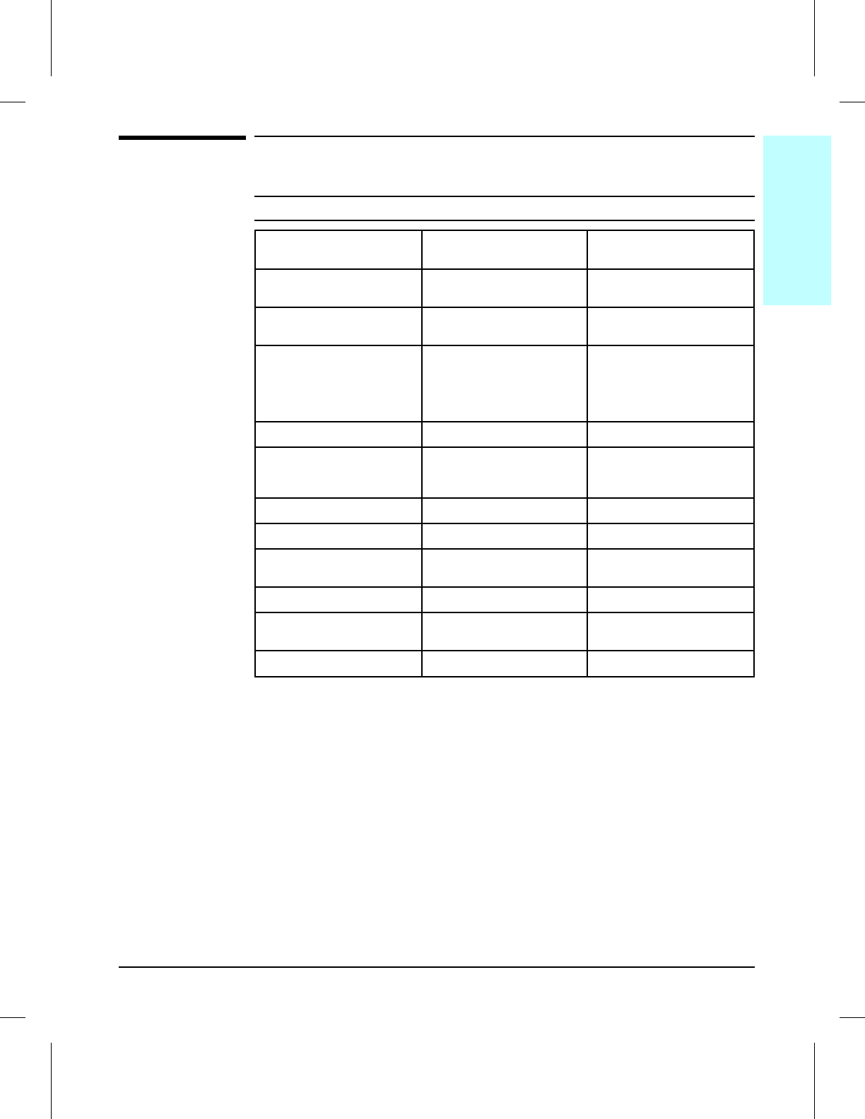
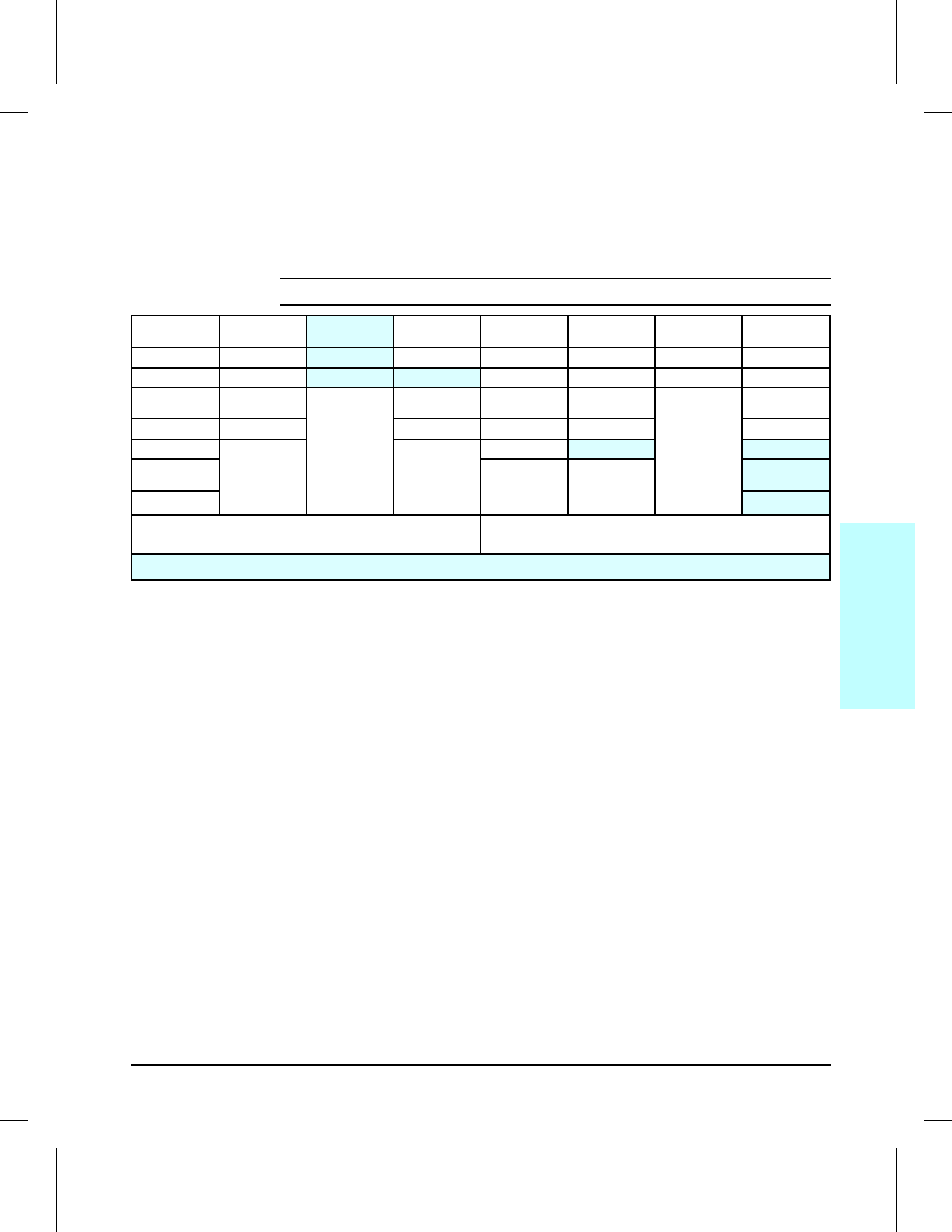
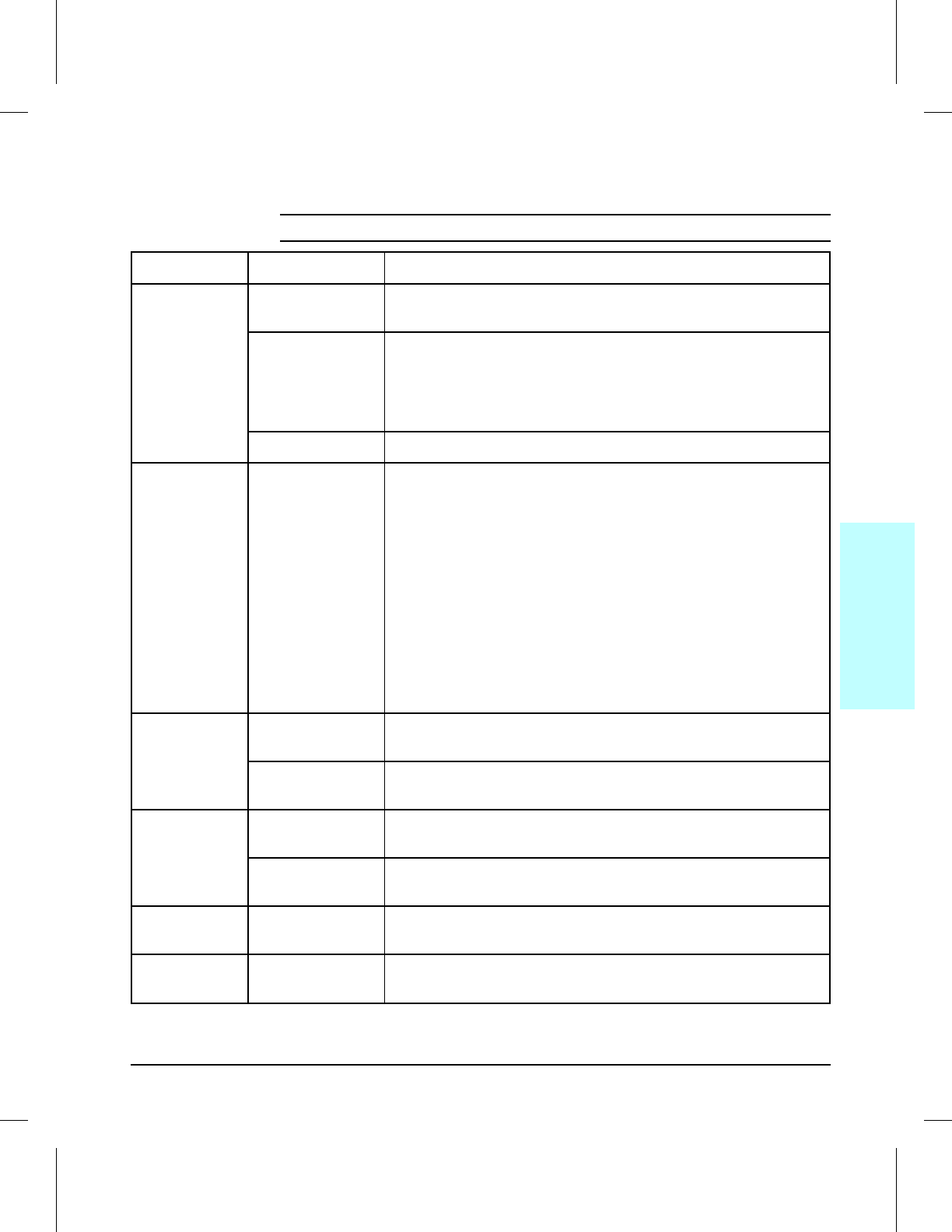
Printer Features
Features LaserJet 4V
(C3141A) LaserJet 4MV
(C3142A)
Print Speed 16 ppm letter or A4
8 ppm ledger (11x17) or A3 16 ppm letter or A4
8 ppm ledger (11x17) or A3
Text & Graphics Resolution 600 dpi; plus Resolution
Enhancement technology (REt) 600 dpi; plus Resolution
Enhancement technology (REt)
Printer Language(s)
Standard
Optional
Enhanced PCL 5
Adobe PostScript Level 2
Enhanced PCL 5
Adobe PostScript Level 2
None
Monthly Usage (pages) Up to 35,000 Up to 35,000
Memory:
Standard1
Optional (maximum)24 Mbyte
68 Mbyte total 12 Mbyte
44 Mbyte total
Internal Typefaces 45 PCL 45 PCL, 35 PostScript
Cartridge Slots 00
Standard Interfaces Bi-Tronics Parallel (IEEE 1284) Bi-Tronics Parallel (IEEE 1284)
JetDirect MIO
Power Control Power Save Mode Power Save Mode
Control Panel 8 Keys,
16 Character VFD Display 8 Keys,
16 Character VFD Display
EconoMode (toner saving) Ye s Ye s
1 Printer memory is optimized with Memory Enhancement Technology (MEt).
2 SIMMS available for use include 1, 2, 4, 8, and 16 Mbtye Modules. See “Accessories & Supplies”
in Chapter 8 for option product numbers.
Table 1-1 Printer Features
1
Product
Information
Product Information 1-3
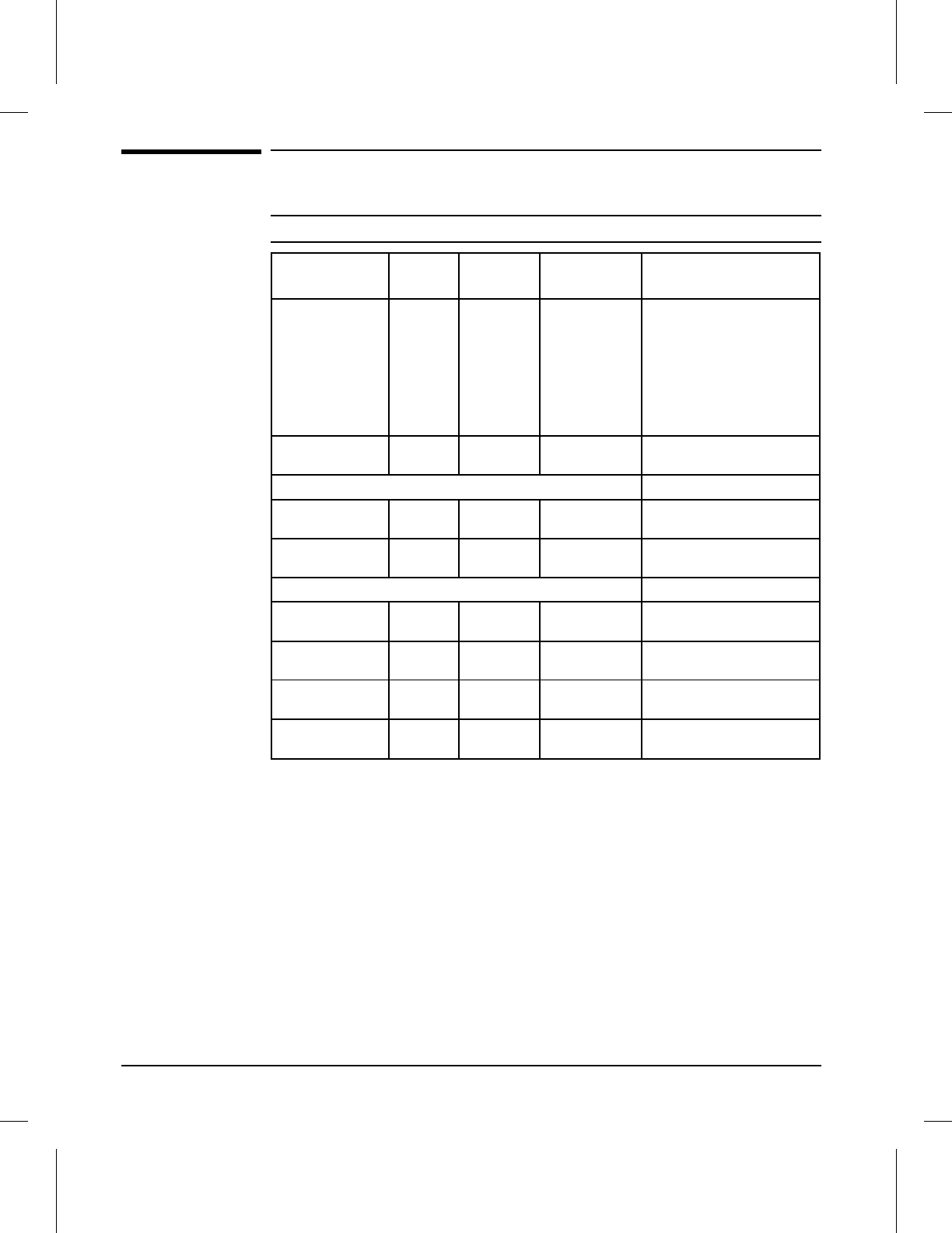
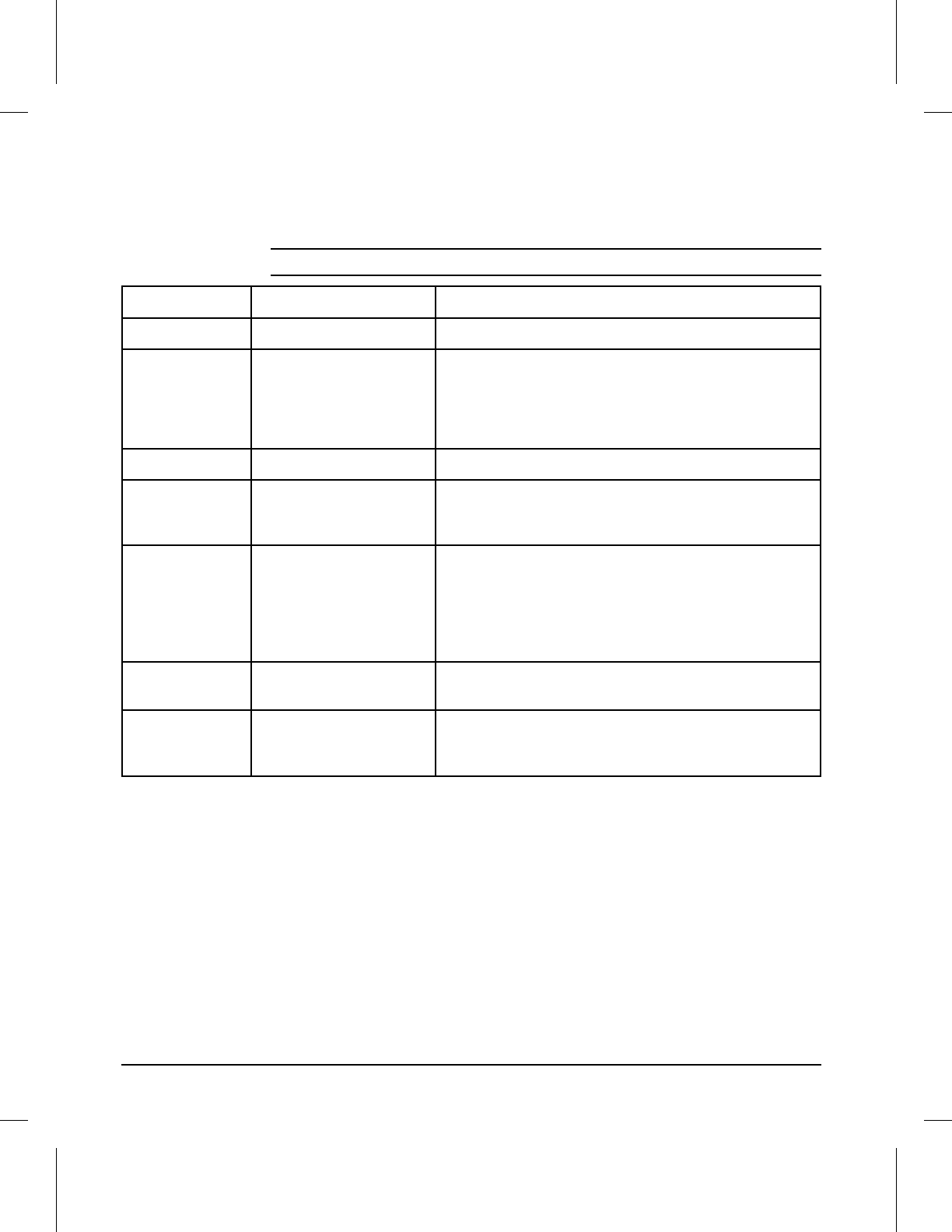
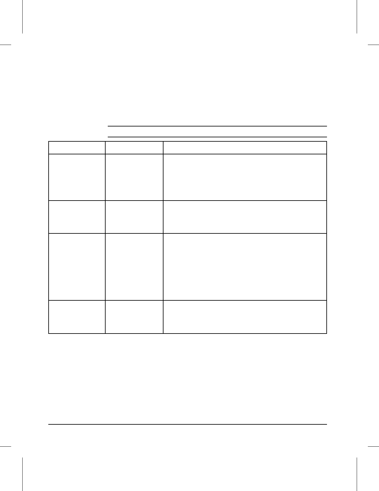
Paper Capacities and Sizes
Name Product
Number Capacity Basis
Weight Size Range
MP Tray N/A 100 sheets 17 to 28 pounds
(64 to 105 g/m2) Maximum 11.7 x 17.7 in.
(297 x 450 mm)
Minimum 3.9 x 5.8 in.
(100 x 148 mm)
Standard sizes: A3, A4,
B/Ledger, B4, B5, Letter,
Legal, Executive
Paper Output Bin N/A 250 sheets 17 to 28 pounds
(64 to 105 g/m2) N/A
Standard Cassettes
Letter/A4 C3160A 250 Sheets 17 to 28 pounds
(64 to 105 g/m2) Selectable between letter
and A4
11X17/A3 C3161A 250 Sheets 17 to 28 pounds
(64 to 105 g/m2) Selectable between ledger
and A3
Optional Cassettes
Legal C3162A 250 Sheets 17 to 28 pounds
(64 to 105 g/m2) Legal only
B4 C3163A 250 Sheets 17 to 28 pounds
(64 to 105 g/m2) JIS B4 only
B5 C3164A 250 Sheets 17 to 28 pounds
(64 to 105 g/m2) JIS B5 only
Lower Cassette C3760A 500 Sheets 17 to 28 pounds
(64 to 105 g/m2) Adjustable for letter, legal,
ledger, A4, A3, and JIS B4
Table 1-2 Paper Capacities and Sizes
1-4 Product Information
Identification
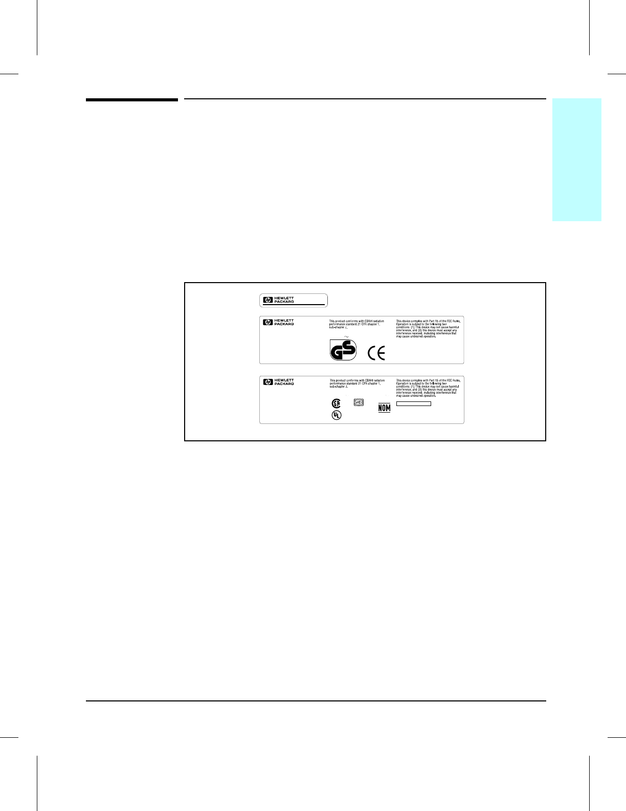
Model and Serial Numbers
The model number and serial numbers are listed on identification labels
located on the rear of the printer. The model number is alphanumeric, such
as C3141A for the HP LaserJet 4V printer.
The serial number contains information about the Country of Origin, the
Revision Level, the Production Code, and production number of the printer.
The rear labels also contain power rating and regulatory information as
shown in Figure 1-1.
Sample Model and Serial Number Labels
FCC ID: B94C3141A
HEWLETT-PACKARD
11311 CHINDEN BLVD.
BOISE, IDAHO 83714 U.S.A.
C3141A
XXXXXXXX
XXXXXXXX
Made in Japan
C3141A
RS5-8402
MANUFACTURED:
SERIAL NO.:
CE1
51742
®
®
LISTED
ITE
660F
POWER RATING:
100-120V 50-60 Hz, 5.7A 127V
60 Hz, 5.7A
geprüfte
Sicherheit
2
HEWLETT-PACKARD
11311 CHINDEN BLVD.
BOISE, IDAHO 83714 U.S.A.
C3141A
Made in Japan
RS5-8403
MANUFACTURED:
SERIAL NO.:
POWER RATING:
220-240V 50 Hz, 2.8A
CE1
C3141A
Figure 1-1
1
Product
Information
Product Information 1-5
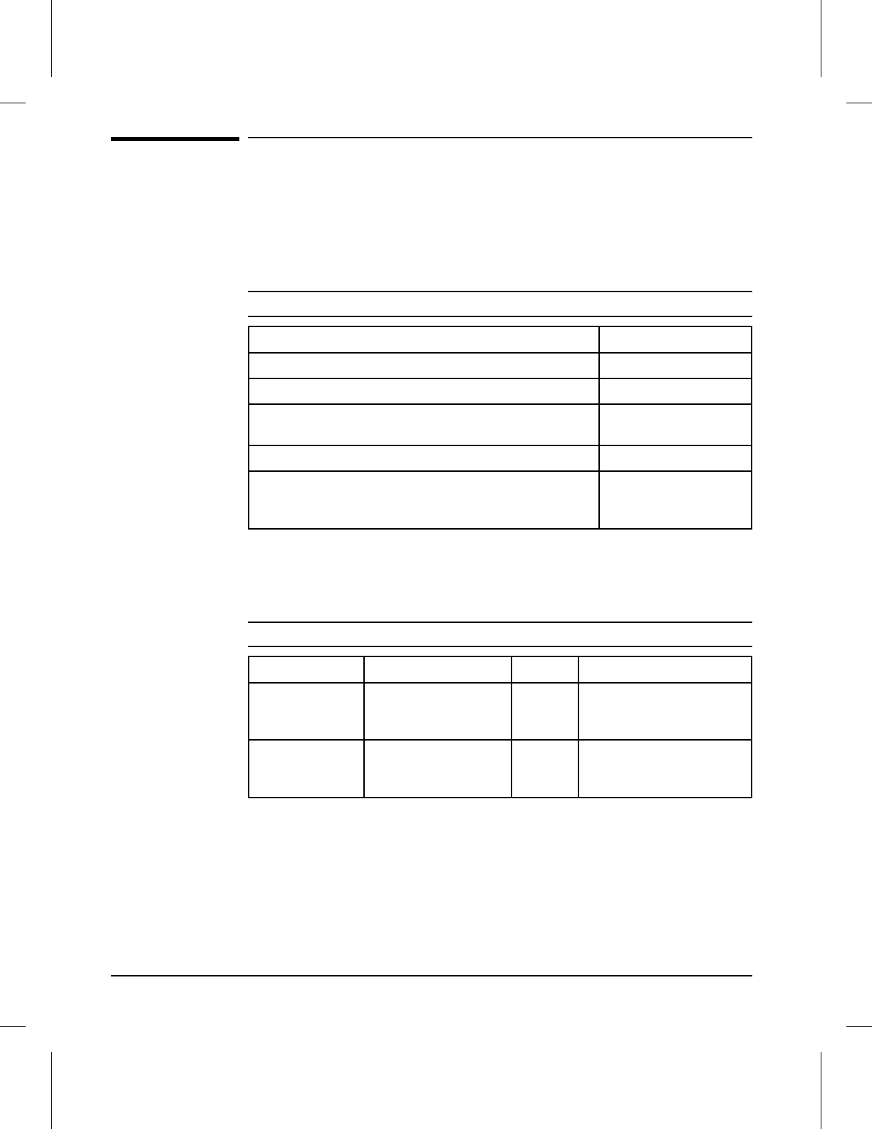
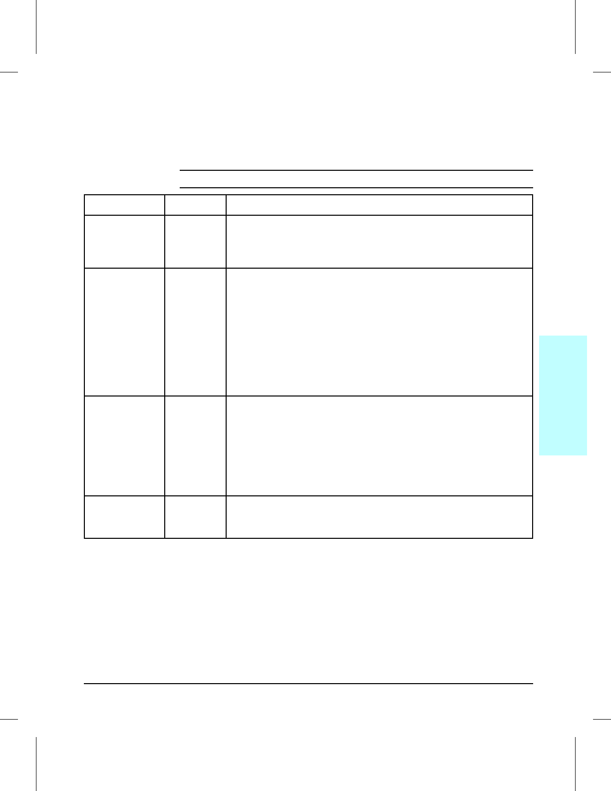
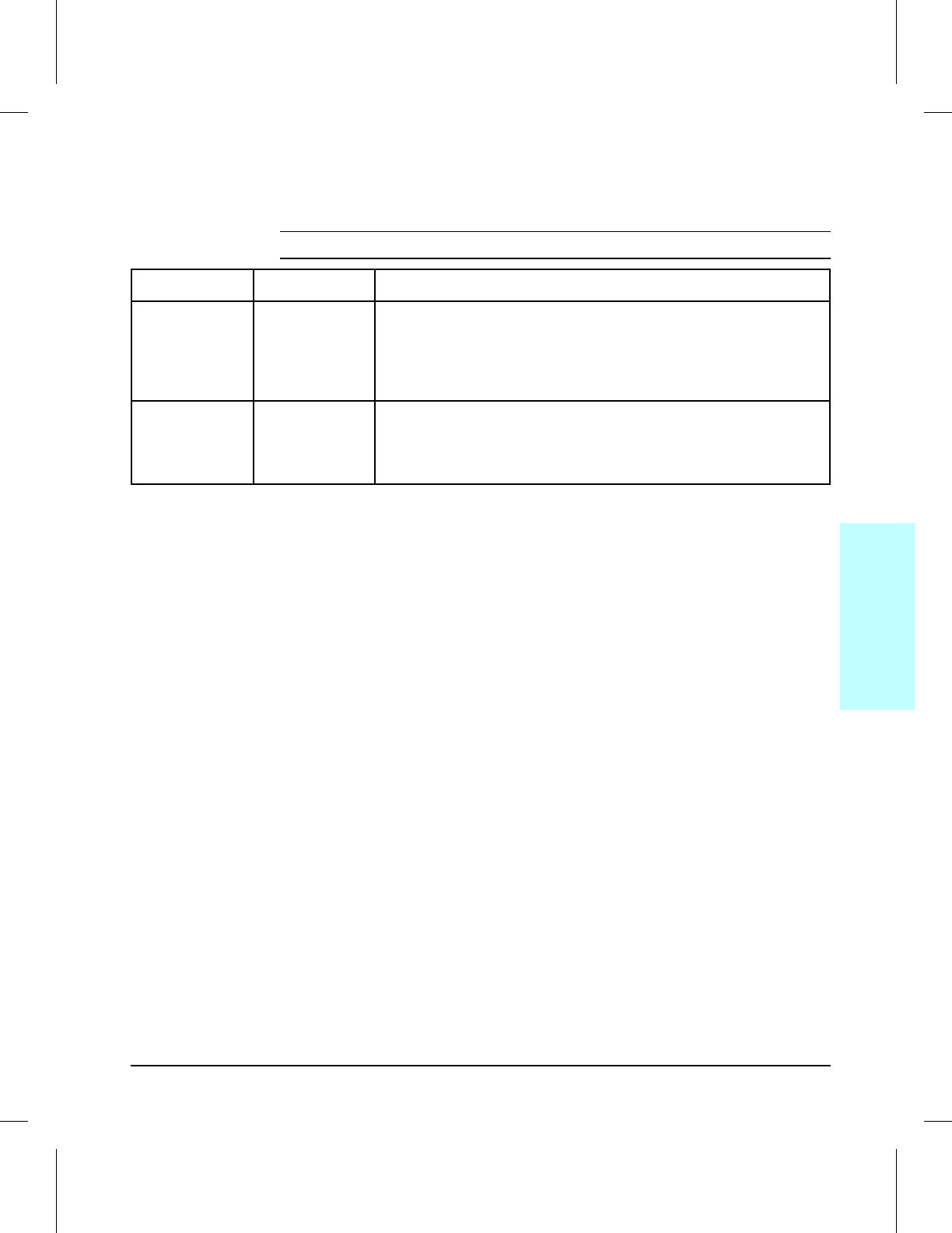
Specifications
This section contains information on physical and electrical characteristics
of the printer. For information on printer site requirements (such as
operating temperature and humidity, ventilation, etc.) see Chapter 2.
Description Dimension
Width 18 in. (46 cm)
Depth 23 in. (59 cm)
Height (standard)
(with Optional Lower Cassette) 12 in. (30 cm)
17.3 in. (44 cm)
Weight (with toner cartridge) 52 lbs. (23.5 kg)
Toner cartridge weight* 70.5 oz. (2000 g) full
56.4 oz. (1600 g)
empty
* Some quantity of toner will reside in the waste toner area of a toner cartridge when the toner
supply is exhausted. Therefore, using toner cartridge weight may be an unreliable indication of
remaining toner supply.
Table 1-3 Printer Dimensions
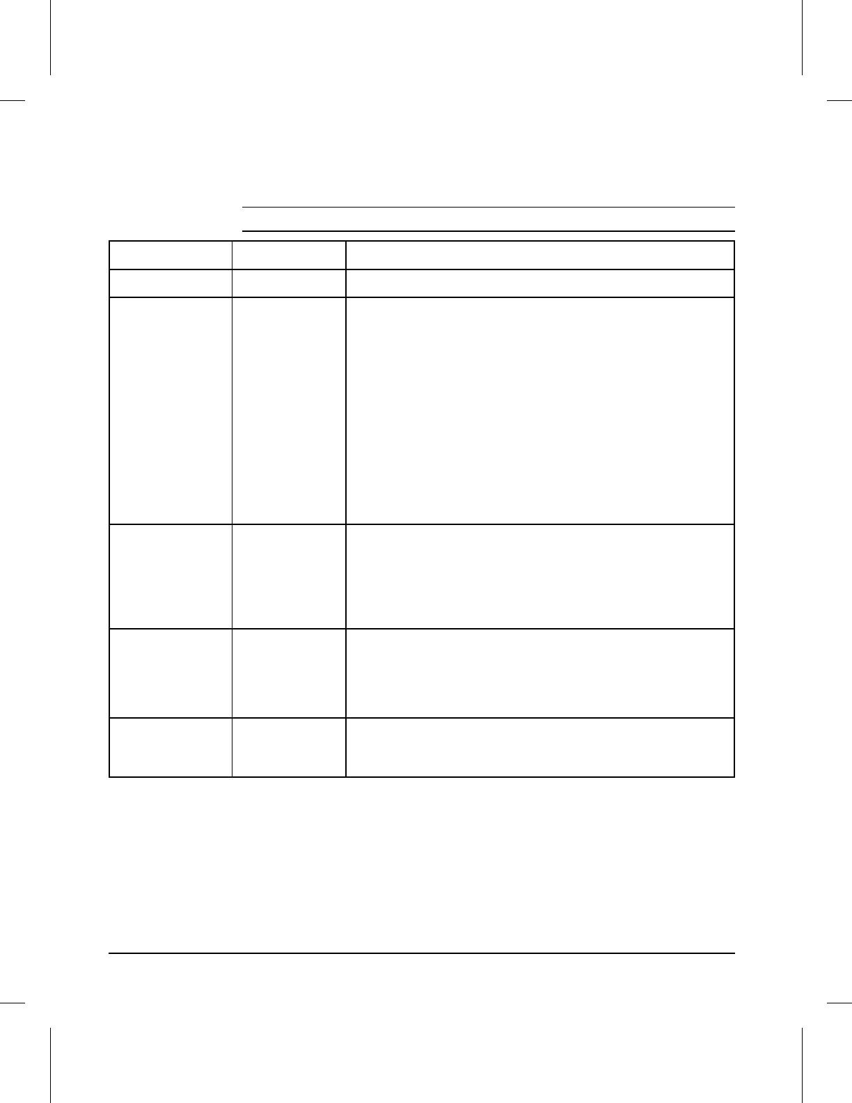
Volts Freq Amps Watts (typical)
120 Vac ± 10%
100 Vac ± 10% 50/60 Hz ± 2 Hz
50/60 Hz ± 2 Hz
12.4 @
120v printing = 385
standby = 115
Power Save Mode = 31
220 Vac ± 10%
240Vac ± 10% 50/60 Hz ± 2 Hz
50/60 Hz ± 2 Hz
5.4 @
220v printing = 400
standby = 120
Power Save Mode = 38
*Operating current requirements.
Table 1-4 Electrical Specifications
1-6 Product Information

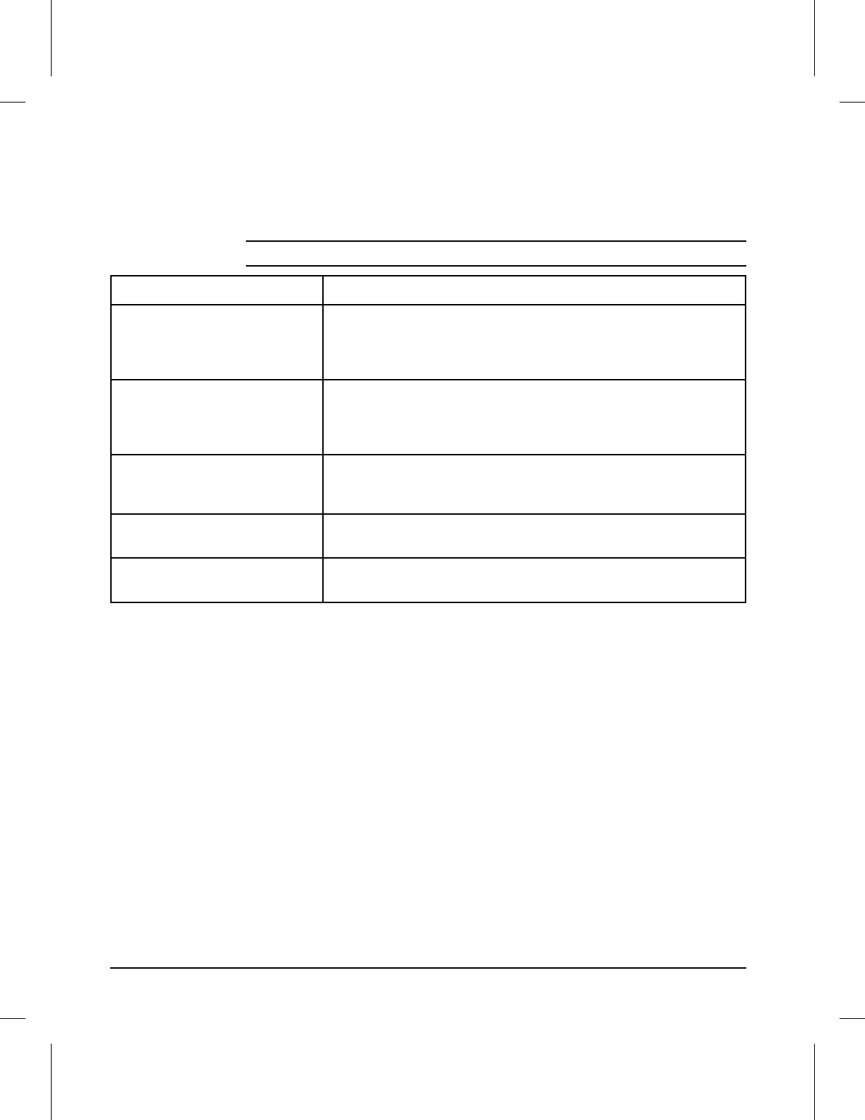
Operation position (per ISO 9296)
Printing LPA
dB(A) 55 db
Standby
Power Save
LPA dB(A)
LPA dB(A)
38 db
33 db
Bystander 1m (per ISO 9296)
Printing LPA
dB(A) 51 db
Standby
Power Save
LPA dB(A)
LPA dB(A)
34 db
29 db
Sound Power (per ISO 9296)
Printing LWAD 6.6 bels (A)
Standby
Power Save
LWAD
LWAD
4.9 bels (A)
4.4 bels (A)
Table 1-5 Acoustic Emissions
1
Product
Information
Product Information 1-7

Media Selection Guidelines
NOTE More detailed specifications are in the HP LaserJet Printer Family Paper
Specification Guide, HP Part No. 5002-1801 (See “Related Documentation
and Training Media” later in this chapter).
Paper
To achieve the best possible print quality and avoid paper jams, follow these
guidelines for selecting paper:
•Use only copier grade paper that meets all specifications in the paper
specification guide. Avoid paper with embossed lettering, perforations, or
texture that is too smooth or too rough.
•Colored paper should be of the same high quality as white photocopy paper.
The pigments must withstand the fusing temperature of 392° F (200° C) for
0.1 second without deterioration. Do not use paper with a colored coating
that was added after the paper was produced.
•Pre-printed forms must be printed with non-flammable, heat-resistant inks
that do not melt, vaporize, or release hazardous emissions when subjected
to the fusing temperature of 392° F (200° C) for 0.1 second.
•A small sample of a new print media should be tested before purchasing
large quantities.
Envelopes
CAUTION To prevent severe printer damage, do not use envelopes having windows,
clasps, snaps, or synthetic materials.
Envelopes can be printed only from the MP Tray. Choose envelopes that
are well-constructed. They should lay flat and be sharply creased. They
should not be wrinkled, nicked, or otherwise damaged. Envelope adhesive
must be compatible with the heat and pressure of the fusing process.
1-8 Product Information

Adhesive Labels
Use the following guidelines when selecting labels:
CAUTION This printer does not support use of labels with any exposed spaces.
Previous LaserJet family printers could safely print on label stock with
exposed spaces running lengthwise down the sheet.
Do not attempt to print on label sheets after any of the labels have been
removed from the sheet. Damage to the printer may result.
•Labels must be arranged on the carrier sheet so that there are no exposed
spaces on the sheet. Using label stock with spaces between rows or columns
of labels can often result in labels peeling off during printing, causing
serious jamming and possible printer damage.
•The top sheet (printing surface) must be of copier quality and provide good
toner adhesion.
•The carrier sheet (backing sheet) must be compatible with the temperatures
and pressure of the fusing process, and must be coated for easy release of
the top sheet.
•The adhesive must be stable at the 392° F (200° C) temperatures
encountered for 0.1 second in the fusing process, and must not produce
emissions that exceed exposure levels or threshold limits established by
OSHA and other safety agencies. Adhesives must not come into direct
contact with any part of the printer.
NOTE The MP Tray is recommended for printing adhesive labels.
A wide selection of suitable labels is available through Hewlett-Packard. A
list of available sizes is located in the HP LaserJet Printer Family Paper
Specification Guide, HP Part No. 5002-1801.
Transparencies
Overhead transparencies used in HP LaserJet printers must be able to
withstand the 392° F (200° C) temperatures encountered in the printer’s
fusing process for 0.1 second. Suitable transparency film is available
through Hewlett-Packard. Refer to the HP LaserJet Printer Family Paper
Specification Guide, HP Part No. 5002-1801 for details.
NOTE The MP Tray is recommended for printing transparencies.
1
Product
Information
Product Information 1-9

Storing Print Media
Follow these guidelines when stacking and storing print media:
•Store paper in its ream wrapper until ready to use.
•DO NOT store cartons or reams directly on the floor where they will absorb
a higher moisture content. Instead, place cartons on a pallet or on shelves.
•DO NOT store individual reams in a manner that causes them to curl or
warp along the edges.
•Re-wrap partially used packages of media before storing.
•DO NOT stack more than six cartons on top of each other.
•Stack each carton upright and squarely on top of the one underneath.
•DO NOT place anything on top of media, regardless of whether the paper is
packaged or unpackaged.
•Store envelopes in a protective box to avoid damaging the envelope edges.
•Keep stored media away from temperature and humidity extremes.
•DO NOT store printed documents in vinyl folders (which may contain
plasticizers) or expose the documents to petroleum based solvents.
Shipping Print Media
When shipping print media through different environments, plastic wrap all
cartons on the shipping pallet. When shipping media across bodies of
water, wrap individual cartons as well. Packaging must protect the media
from physical damage.
1-10 Product Information
Product Overview
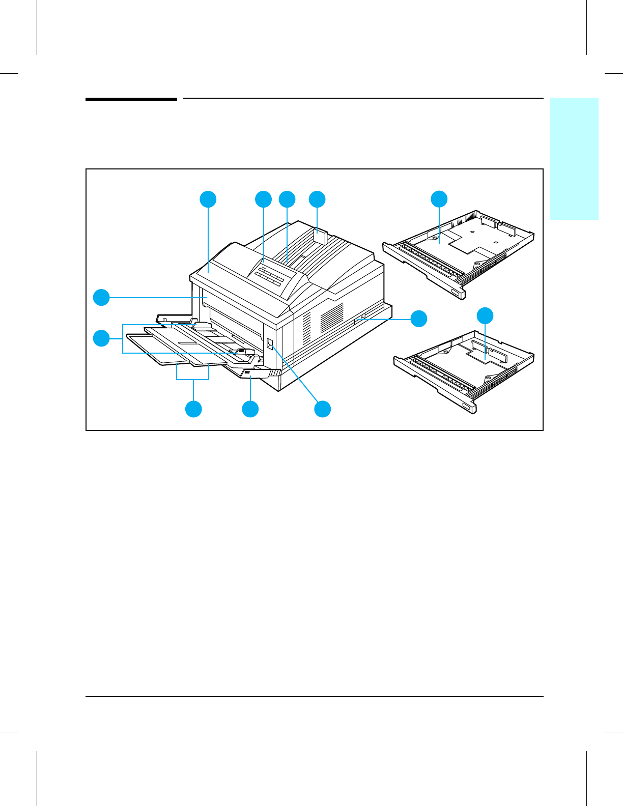
External Assembly Locations (1 of 2)
1Front Cover
2Control Panel
3Output Bin
4Adjustable Paper Stop
5250 sheet ledger (11x17) or A3 Paper Cassette
6ON/OFF Switch
7250 sheet Letter or A4 Paper Cassette
8Front Cover Release Button
9Multipurpose (MP) Tray
10 MP Tray Extension
11 MP Tray Paper Width Guides
12 Fuser Door
1
6
8
7
9
32 45
12
11
10
Figure 1-2 Front and Right Side View with MP Tray Open
1
Product
Information
Product Information 1-11
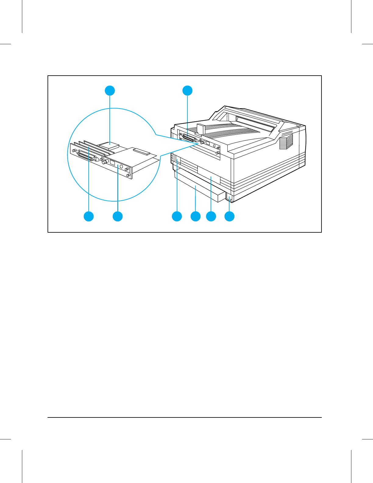
External Assembly Locations (2 of 2)
1Optional 42.8 Mbyte Disk Accessory Location
2Parallel Bi-Tronics Interface
3SIMM Slots
4Multiple I/O (MIO) slot
5Power Supply Connector
6Dust Cover for 250 sheet ledger (11x17) or A3 Paper Cassette
7Serial Number Plate
8Optional Universal Lower Cassette Connector Access
5678
2
1
3 4
Figure 1-3 Rear and Left Side View
1-12 Product Information
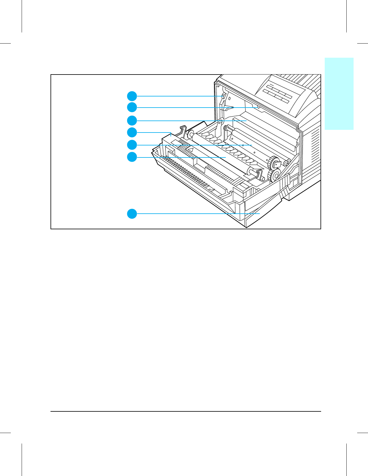
Front Door Assemblies
1Print Density Dial
2Arrow guide for installing toner cartridge in printer
3Toner cartridge cavity
4Fusing Assembly
5Registration Roller
6Transfer Roller
7Multipurpose (MP) Tray
4
3
2
1
7
5
6
1ASYDOOR
Figure 1-4 Front View with Front Cover Open (with toner cartridge removed)
1
Product
Information
Product Information 1-13
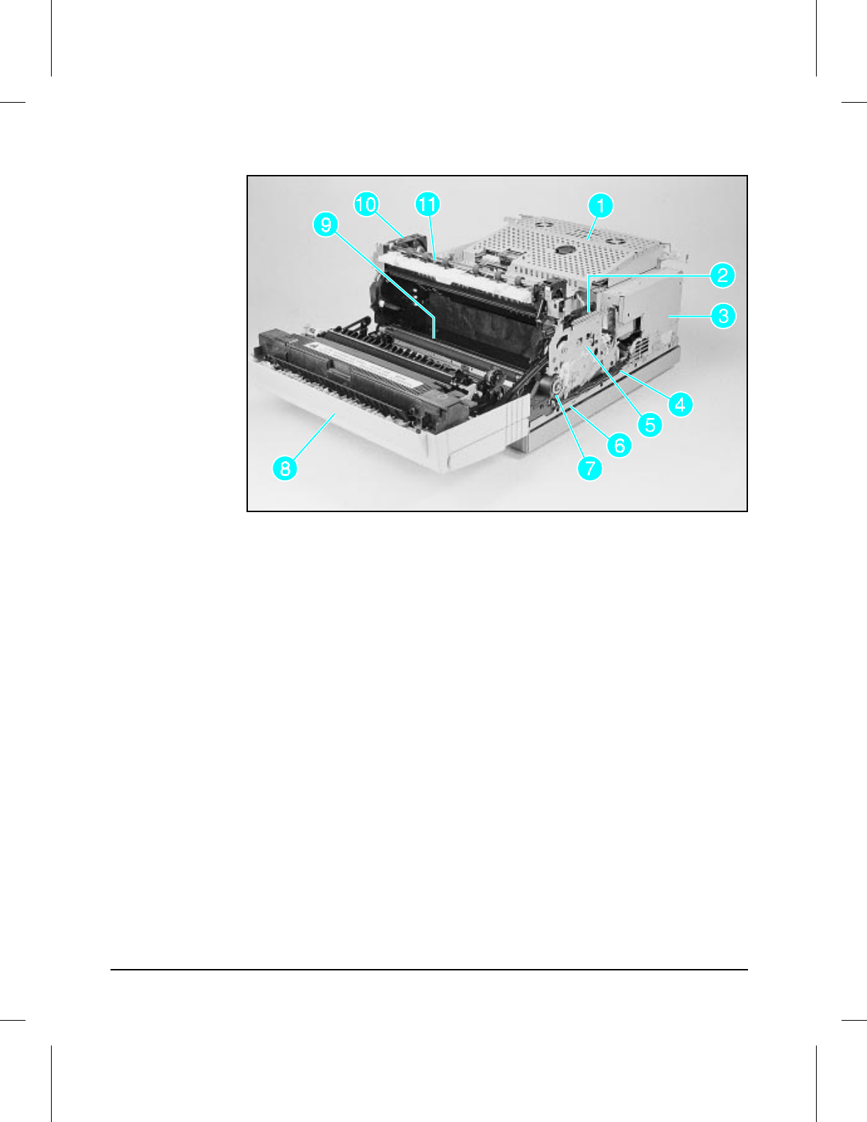
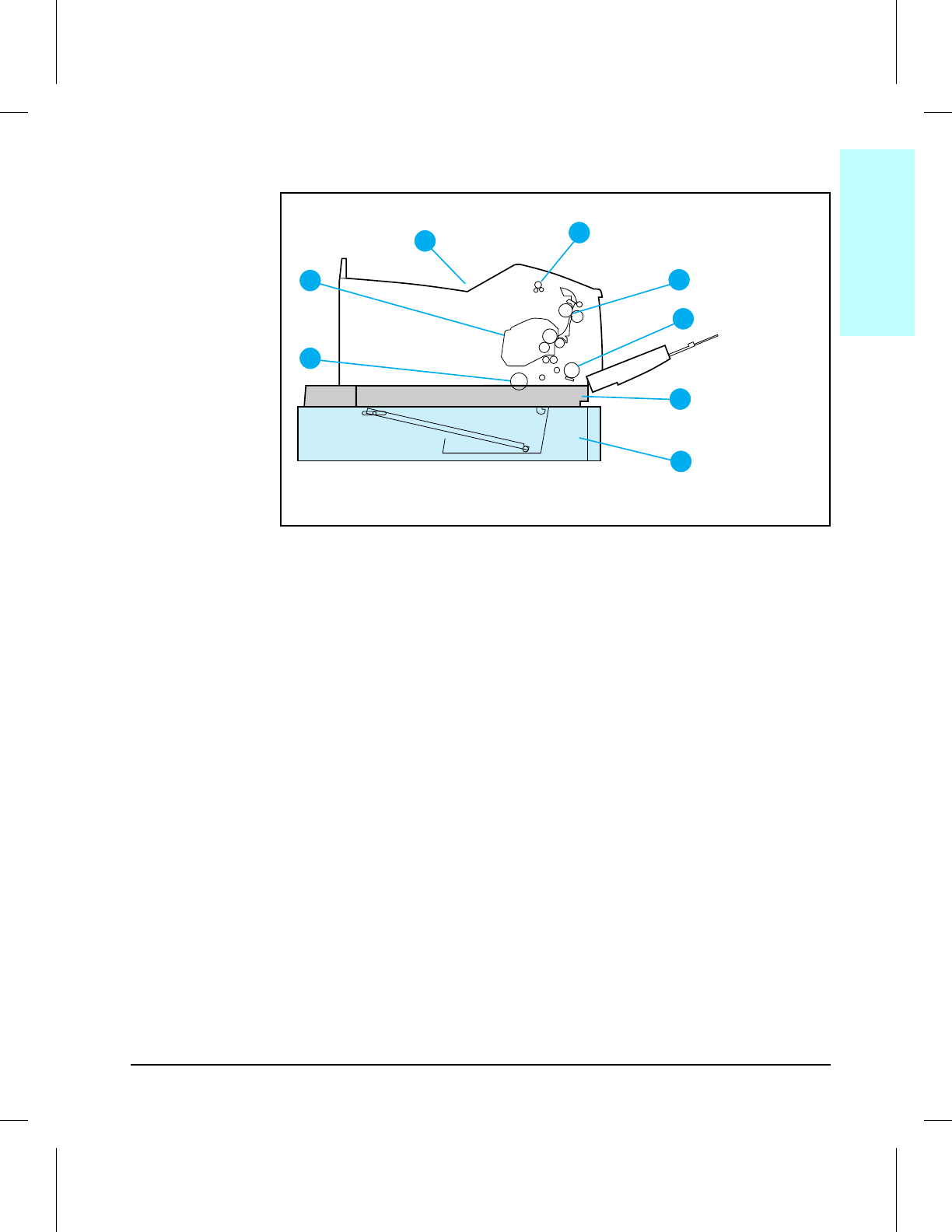
Internal Assembly Locations (1 of 2)
Internal Assembly Locations (1 of 2)
1Card Cage Assembly
2Main Motor
3Power Supply Unit
4Fusing Assembly Cable
5Main Drive Assembly
6Cassette Pickup Roller Clutch
7Registration Roller Clutch
8Front Door
9Cassette Pickup Roller (under plate)
10 Exhaust Fan (FM1)
11 Delivery Assembly
Figure 1-5I
1-14 Product Information
Internal Assembly Locations (2 of 2)
Internal Assembly Locations (2 of 2)
1Output Bin
2Delivery Assembly
3Fusing Rollers
4Transfer Roller
5Standard Paper Cassette
6Optional Lower Paper Cassette
7Cassette Pickup Roller
8Toner Cartridge
12
3
4
5
6
7
8
1ASSYSEC
Figure 1-6
1
Product
Information
Product Information 1-15

Service Approach
Repair of the printer normally begins with use of the printer’s internal
diagnostics in conjunction with the troubleshooting procedures in Chapter 7.
Once a faulty part is located, repair is generally accomplished by assembly
level replacement of Field Replaceable Units (FRUs). Some mechanical
assemblies may be repaired at the subassembly level. PCA component
replacement is not supported by Hewlett-Packard.
Ordering Parts
Field replaceable part numbers are found in Chapter 8 of this manual.
Replacement parts may be ordered from HP’s Service Materials
Organization (SMO), or Support Materials Europe (SME).
Phone numbers for the various sources are:
•SMO (Service Materials Organization)
1-800-227-8164 (U.S. only)
•SME (Support Materials Europe)
(49 7031) 142253
•HP’s Distribution Center (HPD)
1-303-353-7650
Exchange Program
HP offers remanufactured assemblies for some parts. These are identified
in Chapter 8 and can be ordered through Parts Direct Ordering (PDO), or
Support Materials Europe (SME).
Consumables
The printer has no consumables other than the toner cartridge, which may
be ordered directly from Hewlett-Packard. Refer to Chapter 8 for ordering
information.
1-16 Product Information
Toner Cartridge Life
The toner cartridge (C3900A) is designed to simplify replacement of the
major “consumable” parts. The toner cartridge contains the printing
mechanism and a supply of toner.
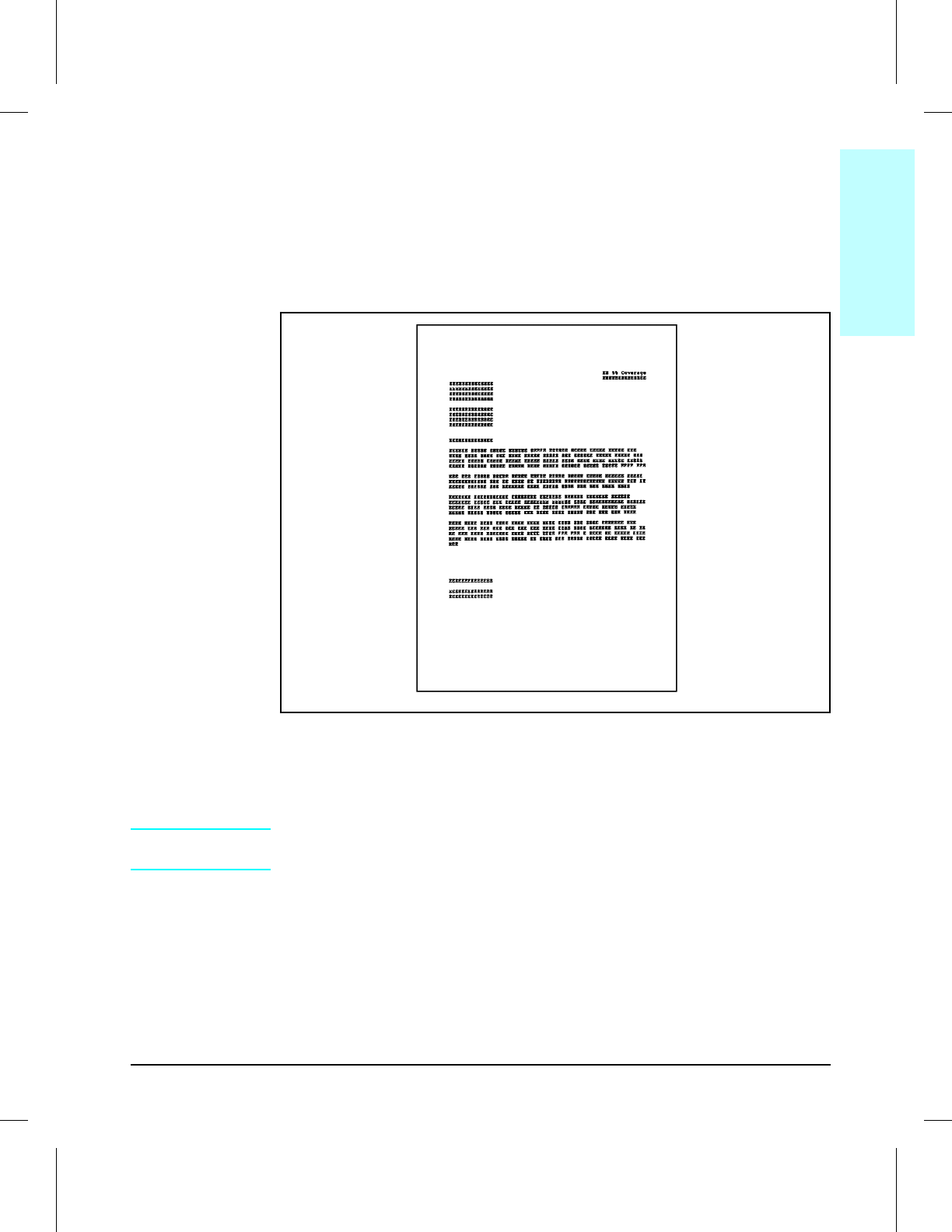
At 5% page coverage, a toner cartridge will print approximately 7500 pages
(see Figure 1-7).
Sample 5% Page Coverage
When regularly printing pages with less coverage, such as short memos, a
toner cartridge should print more than 7500 pages. However, the cartridge
may print less than 7500 pages if routinely printing very dense print.
NOTE For best results, always use a toner cartridge before the expiration date
stamped on the toner cartridge box.
Figure 1-7
1
Product
Information
Product Information 1-17

Refilled Toner Cartridges
While Hewlett-Packard does not prohibit the use of refilled toner cartridges
during the warranty period or while under a maintenance contract, their
use is not recommended for the following reasons:
•Repairs resulting from the use of refilled toner cartridges are not covered
under the Hewlett-Packard warranty or maintenance contract.
•Hewlett-Packard has no control or process to ensure that a refilled toner
cartridge functions at the high level of reliability of a new HP LaserJet
toner cartridge. Hewlett-Packard also cannot predict what the long term
reliability effect on the printer is from using different toner formulations
found in refilled cartridges.
•The print quality of HP LaserJet toner cartridges influences the customer’s
perception of the printer. Hewlett-Packard has no control over the actual
print quality of a refilled toner cartridge.
Recycling Toner Cartridges
In order to reduce waste, Hewlett-Packard utilizes a recycling program for
used toner cartridges. Cartridge components that do not wear out are
recycled. Plastics and other materials are recycled. Hewlett-Packard pays
the shipping costs from the user to the recycling plant. For each cartridge
returned, HP donates one U.S. dollar to be shared by the Nature
Conservancy and the National Wildlife Federation. To join this recycling
effort, follow the instructions inside the toner cartridge box.
1-18 Product Information
Related Documentation and Training Media
Table 1-6 lists where to order related documentation. See “Ordering Parts”
earlier in this chapter.
Description Part Number SMO SME HPD
HP LaserJet Family Quick Reference
Service Guide
5961-0531 X X
HP LaserJet 4V and 4MV Printers
User’s Manual
1
C3141-90901 X X
HP PCL5 Printer Language Technical
Reference Information Package
5961-0601 X X
HP LaserJet Printer Family Paper
Specifications Guide
5002-1801 X
Introduction to Network Printing,
Book 5961-0649 X X
Network Printing for the Enterprise,
Video 5961-0650 X X
LaserJet Basic Hardware Training Course
5961-0880 X X
Solutions Connectivity Guide
(Available from LDC 1-800-544-9976) 5962-8536E
Specific Application Drivers
X
1 Shipped with printer. (English version part number is shown. Other translations are available
see your local HP Sales Office.)
Table 1-6 Related Documentation
1
Product
Information
Product Information 1-19

Technical Assistance
HP ASAP (Automated Support Access Program) provides free technical
support information 24 hours a day, 7 days a week. The ASAP system
includes HP AUDIO-TIPS and HP FIRST, both explained below. The ASAP
service requires a touchtone phone.
HP AUDIO-TIPS
HP AUDIO-TIPS is an interactive voice response system providing
prerecorded answers to the most frequently asked questions by HP LaserJet
printer users. Helpful “System Maps” to the HP AUDIO-TIPS recordings
are available by fax through HP FIRST.
HP FIRST
HP FIRST (Fax Information Retrieval Support Technology) is a phone-in
fax service providing technical information for HP LaserJet users as well as
service personnel. Receiving a fax requires a group 3 facsimile machine or
fax card. Service related information includes:
•Service notes (HP Authorized dealers)
•Application notes
•Product Data Sheets
•Material Safety Data Sheets (MSDS)
•Typeface and accessory information
•Printer support software information
•Toner information
•Driver request form and Software Matrix.
HP FIRST, U.S.
Call the HP ASAP system (1-800-333-1917) and follow the voice prompts to
enter HP FIRST.
HP FIRST, Europe
Call HP FIRST at one of the following numbers:
U.K., 0800-96-02-71 Netherlands, 06-0222420
Belgium (Dutch), 078-111906 Germany, 0130-810061
Switzerland (German), 155-1527 Austria, 0660-8128
For English service outside the above countries, (31) 20-681-5792.
1-20 Product Information

HP CompuServe Forum
CompuServe members can download a variety of support materials
including product data sheets, software application notes, and printer
drivers for many popular software applications. Members may also post and
reply to questions in an interactive format. To access the HP Forum, type
GO HP at any prompt. For more information, or to join CompuServe, call
1-800-524-3388.
North American Response Center (NARC)
The North American Response Center (NARC) is available for technical
support to assist service technicians. The NARC can be reached at
1-800-544-9976 between 7:00 A.M. and 6:00 P.M. Mountain Standard Time,
Monday, Tuesday, Thursday and Friday. On Wednesdays the office closes
at 4:00 P.M.
Other Areas
Outside of North America and Europe, contact your local HP sales office for
assistance in obtaining technical support.
1
Product
Information
Product Information 1-21

Warranty Statement
Warranty
This warranty gives specific legal rights. There may also be other rights
which vary from area to area. Refer to Appendix E in the User’s Manual for
further warranty information.
One Year Return to HP Authorized Repair Station
Hewlett-Packard warrants the LaserJet 4V/4MV printer against defects in
materials and workmanship for a period of one year from receipt by the
customer. During the warranty period, HP will, at its option, either repair
or replace products which prove to be defective.
NOTE User maintenance components are not covered under the
HP LaserJet 4V/4MV printer factory warranty. A separate maintenance
agreement may be written to cover these components.
Exclusions
The warranty on printers shall not apply to defects resulting from:
•Improper or inadequate maintenance by customer.
•Customer supplied software or interfacing.
•Unauthorized modification or misuse.
•Operation outside of the environmental specifications for the product.
•Operation of non-supported printing media.
•Duty cycle abuse maximum (printing more than the equivalent of 35,000
single-sided pages per month).
•Operating the printer from a mechanical switchbox without a designated
surge protector.
•Improper site preparation and maintenance.
•Use of non-HP toner cartridges (see the following explanation), SIMM
memory boards, or interface boards.
The use of non-Hewlett-Packard toner cartridges does not affect either the
warranty or any maintenance contract purchased from HP. However, if an
HP LaserJet printer failure or if printer damage is found to be directly
attributable to the use of any non-HP product, the repair will not be covered
under the warranty or HP maintenance contract. Hewlett-Packard cannot
recommend use of non-HP cartridges, either new or remanufactured,
because they are not HP products and HP cannot influence or control their
quality.
1-22 Product Information

2
Site Requirements
Chapter Contents
Operating Environment . . . . . . . . . . . . . . . . . . . . . . . . . . 2-3
Space Requirements . . . . . . . . . . . . . . . . . . . . . . . . . . . . 2-4
Environmental Requirements . . . . . . . . . . . . . . . . . . . . . . . 2-4
Site Requirements 2-1

2-2 Site Requirements

Operating Environment
The environmental specifications (listed in the “Specifications” section of
Chapter 1) must be maintained to ensure the proper operation of this
printer. Consider the following points before installing the printer:
•Install in a well-ventilated, dust-free area.
•Install on a hard, flat and continuous surface, with all four printer feet
level. Do not install on carpet or other soft surfaces.
•Ensure adequate power is supplied. Printer power requirements are listed
under “Specifications,” in Chapter 1.
•Install where there is stable temperature and humidity, away from water
sources, humidifiers, air conditioners, refrigerators, or other major
appliances.
•Install away from direct sunlight, open flames, or ammonia fumes. If the
printer is placed near a window, make sure the window has a curtain or
blind to block any direct sunlight.
•Install with enough space around the printer for proper access and
ventilation (see Figure 2-1).
•Install printer away from the direct flow of exhaust from air ventilation
systems.
2
Site
Requirements
Site Requirements 2-3
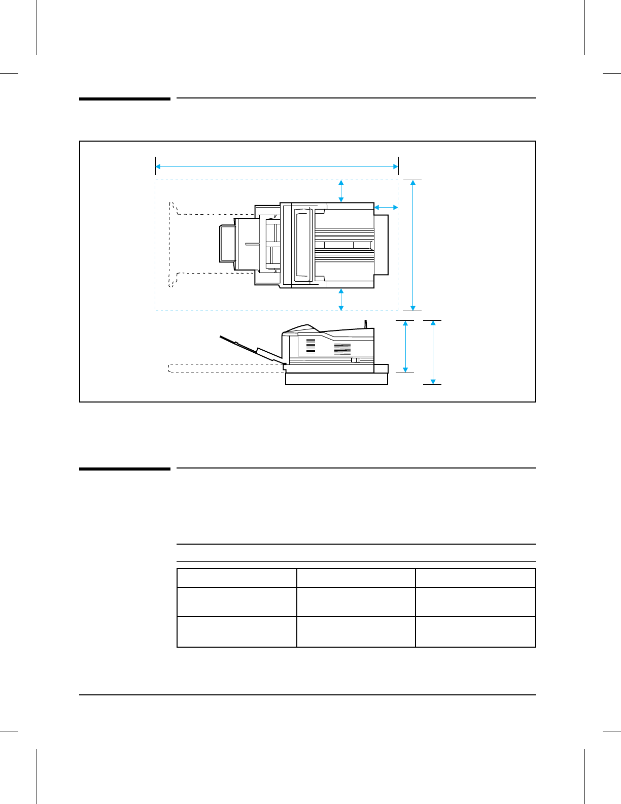
Space Requirements
Environmental Requirements
Keep the printer within the following environmental conditions for optimum
performance.
3.94 in (100mm)
3.35 in (85mm)
49.2 in (1250mm)
25.35 in (644mm)
3.54 in
(90mm)
13.38 in
(340mm)
17.3 in
(440mm)
Optional Lower Cassette
Figure 2-1 Printer Space Requirements
Item Operating Storage
Temperature 10° to 32.5° C
(50° to 90.5° F) 0° to 40° C
(32° to 105° F)
Humidity 20 to 80% RH
(with no condensation) 10 to 95% RH
(with no condensation)
Table 2-1 Printer and Toner Cartridge Environmental Conditions
2-4 Site Requirements

3
Operating Overview
Chapter Contents
Using the Control Panel . . . . . . . . . . . . . . . . . . . . . . . . . . 3-3
Control Panel Layout . . . . . . . . . . . . . . . . . . . . . . . . . . 3-3
Indicator Lights . . . . . . . . . . . . . . . . . . . . . . . . . . . . . 3-4
Control Panel Keys . . . . . . . . . . . . . . . . . . . . . . . . . . . . 3-4
Settings and Defaults . . . . . . . . . . . . . . . . . . . . . . . . . . 3-6
Setting the Display Language . . . . . . . . . . . . . . . . . . . . . . 3-6
Control Panel Menus . . . . . . . . . . . . . . . . . . . . . . . . . . . 3-7
Printing Menu . . . . . . . . . . . . . . . . . . . . . . . . . . . . . . 3-8
PCL Menu . . . . . . . . . . . . . . . . . . . . . . . . . . . . . . . . 3-9
Job Menu . . . . . . . . . . . . . . . . . . . . . . . . . . . . . . . . . 3-10
Configuration Menu . . . . . . . . . . . . . . . . . . . . . . . . . . . 3-11
Memory Configuration Menu . . . . . . . . . . . . . . . . . . . . . . 3-12
Parallel Menu . . . . . . . . . . . . . . . . . . . . . . . . . . . . . . 3-13
Test Menu . . . . . . . . . . . . . . . . . . . . . . . . . . . . . . . . 3-14
Service Mode . . . . . . . . . . . . . . . . . . . . . . . . . . . . . . . . 3-15
Power Save . . . . . . . . . . . . . . . . . . . . . . . . . . . . . . . . 3-15
Setting the Page Count and Serial Number . . . . . . . . . . . . . . 3-17
Setting the Cold Reset Default Paper Size . . . . . . . . . . . . . . . 3-18
Other Service Mode Items . . . . . . . . . . . . . . . . . . . . . . . . 3-18
Testing the Printer . . . . . . . . . . . . . . . . . . . . . . . . . . . . . 3-19
Printing a Self Test Page . . . . . . . . . . . . . . . . . . . . . . . . 3-19
Understanding the Self Test Printout . . . . . . . . . . . . . . . . . . 3-20
Self Test Printout Key . . . . . . . . . . . . . . . . . . . . . . . . . . 3-20
Engine Test . . . . . . . . . . . . . . . . . . . . . . . . . . . . . . . 3-22
Resetting the Printer . . . . . . . . . . . . . . . . . . . . . . . . . . . . 3-23
Simple Reset . . . . . . . . . . . . . . . . . . . . . . . . . . . . . . . 3-23
Cold Reset . . . . . . . . . . . . . . . . . . . . . . . . . . . . . . . . 3-23
Menu of Resets . . . . . . . . . . . . . . . . . . . . . . . . . . . . . . 3-24
Operating Overview 3-1

3-2 Operating Overview
Using the Control Panel
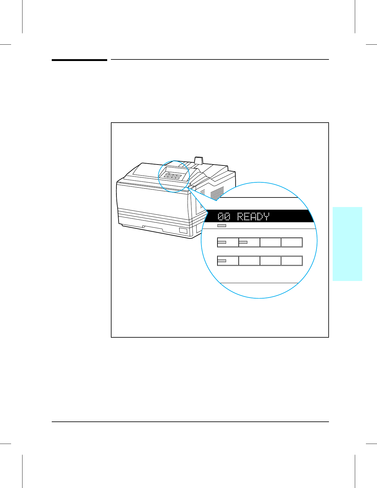
Control Panel Layout
The control panel consists of a 16-character display panel, three indicator
lights, and eight keys, three of which have alternate functions.
Control Panel Layout
On Line Form Feed MP Paper Size Enter
Menu Item
+
Shift Reset Continue
-
Ready
Figure 3-1
3
Operating
Overview
Operating Overview 3-3
Indicator Lights
The control panel indicator lights are described in the following table. The
column labeled “Do this:” includes an action only when an action is
required.
Control Panel Keys
You must take the printer off line to use control panel keys, except for the
MP Paper Size and keys related to its operation.
Each key in the top row has a single function. Three keys in the bottom row
have more than one function. The primary function name of each key
appears above the key. The alternate function name of each key appears
below the key. These alternate function names are color-coded to match the
[Shift] key, which you must hold down while selecting an alternate function.
You can rapidly scroll through some selections by holding down the [+/-] key.
When this
indicator: Looks like this: It means this: Do this:
Ready On
Flashing
Off
Ready to print.
Print job in progress.
Not ready to print.
Let job finish printing.
See display panel message.
On Line On
Flashing
Off
Ready to receive data.
Going off line.
Printer is off line. Access other keys or press [On Line]
to place printer back on line.
Form Feed On
Flashing
Off
Data still in print buffer.
Buffered data is
printing.
No buffered data in
printer.
Take printer off line; press
[Form]Feed]; press [On Line] to place
printer back on line.
Table 3-1 Indicator Lights
3-4 Operating Overview
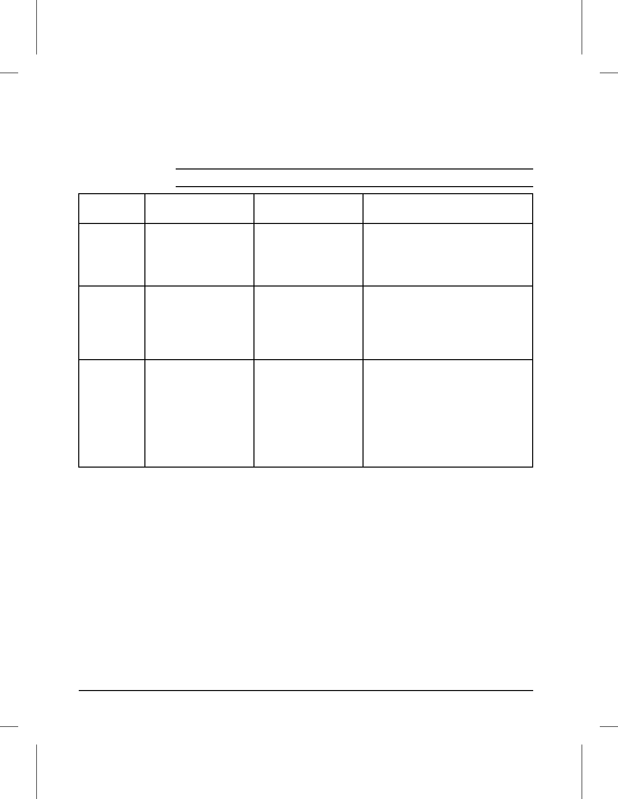
Key Explanation
[On Line] Switches the state of communication between computer and printer either on
(on line) or off (off line). For the printer to receive data, both the On Line and
Ready indicator lights must be lit.
[Form Feed] Prints any data remaining in the page buffer. Does not send a blank sheet of
paper through the printer.
[MP Paper Size] Only active when MP Tray is set to cassette (select MP TRAY=CASS in the
Configuration Menu). Selects size of paper loaded in MP Tray. Pressing [Enter]
saves your selection.
[Enter] Saves a selected control panel key setting. An asterisk (*) appears next to the
saved selection, indicating that it is now the default. Default settings remain in
place when the printer is reset or switched OFF.
[Shift] Accesses color coded alternate functions of bottom-row control panel keys.
Hold down while pressing an associated key.
[Menu] Cycles through menus, returning to 00 OFFLINE at the end of the cycle unless a
problem is encountered. When an option is added to the printer (PostScript, for
example), a menu for that option appears in the sequence (see “Control Panel
Menus” in this chapter).
Reset
[Shift] + [Reset]
Resets the printer (displays 07 RESET). Clears the page and active I/O buffers
and makes the current control panel values the defaults (see “Menu of Resets”
at the end of this chapter).
[Item] Cycles through the selected menu items. Menu items vary depending on
options installed and configuration of other menu choices.
Continue
[Shift] + [Continue]
Allows the printer to resume printing after a printer message (such as
20 MEM 0VERFLOW) has placed it off line. Clears most printer messages (such
as manual feed requests) and places the printer back on line.
[+] or [-] Press [+] to step through menu items. Hold down [+] to scroll through items.
Press or hold down [Shift] + [-] to move through items in reverse order.
Table 3-2 Control Panel Keys
3
Operating
Overview
Operating Overview 3-5
Settings and Defaults
The printer makes most printing decisions based on either temporary
settings or permanent defaults.
NOTE Settings you send from software applications override printer defaults.
Setting the Display Language
1Press and hold [Enter] while powering on. Hold [Enter] until CONFIG
LANGUAGE appears.
2Release [Enter]. 05 SELF TEST appears briefly. Wait for LANG=ENGLISH to
appear.
3Click [+] repeatedly until the desired language appears.
4Click [Enter] to save your choice. An asterisk (*) will appear beside your
language selection.
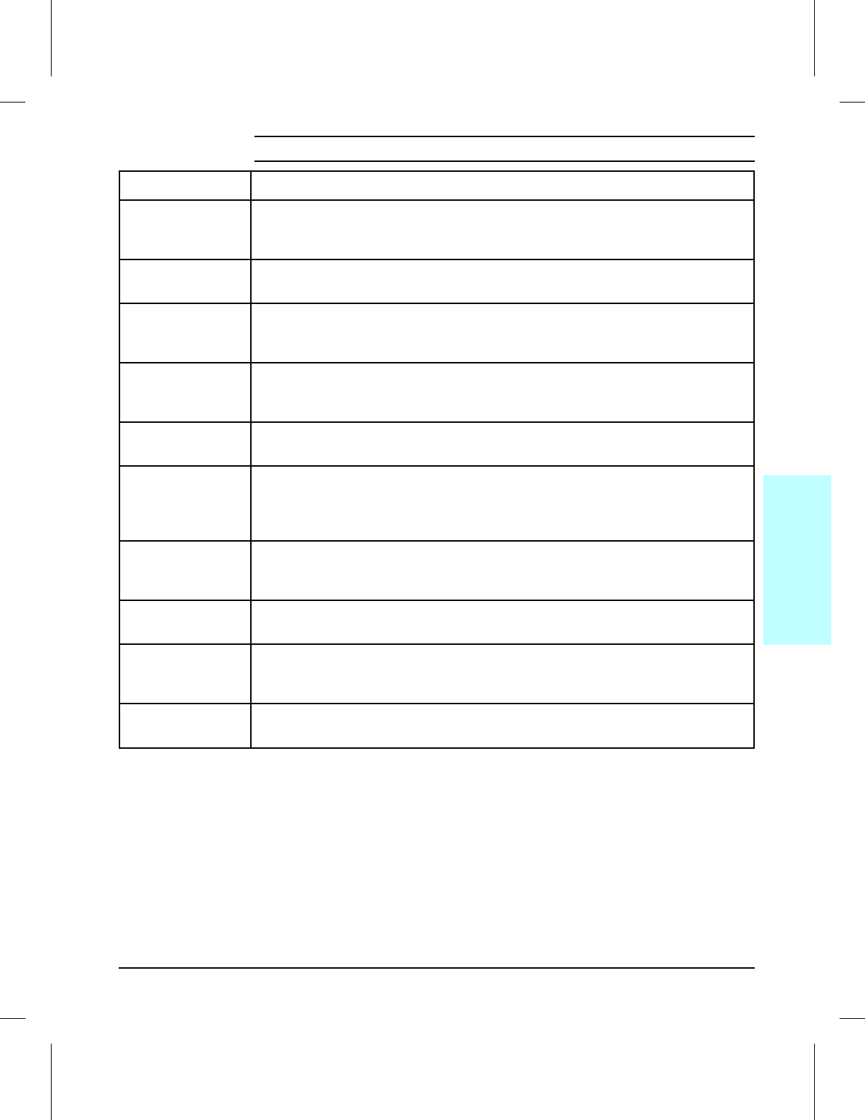
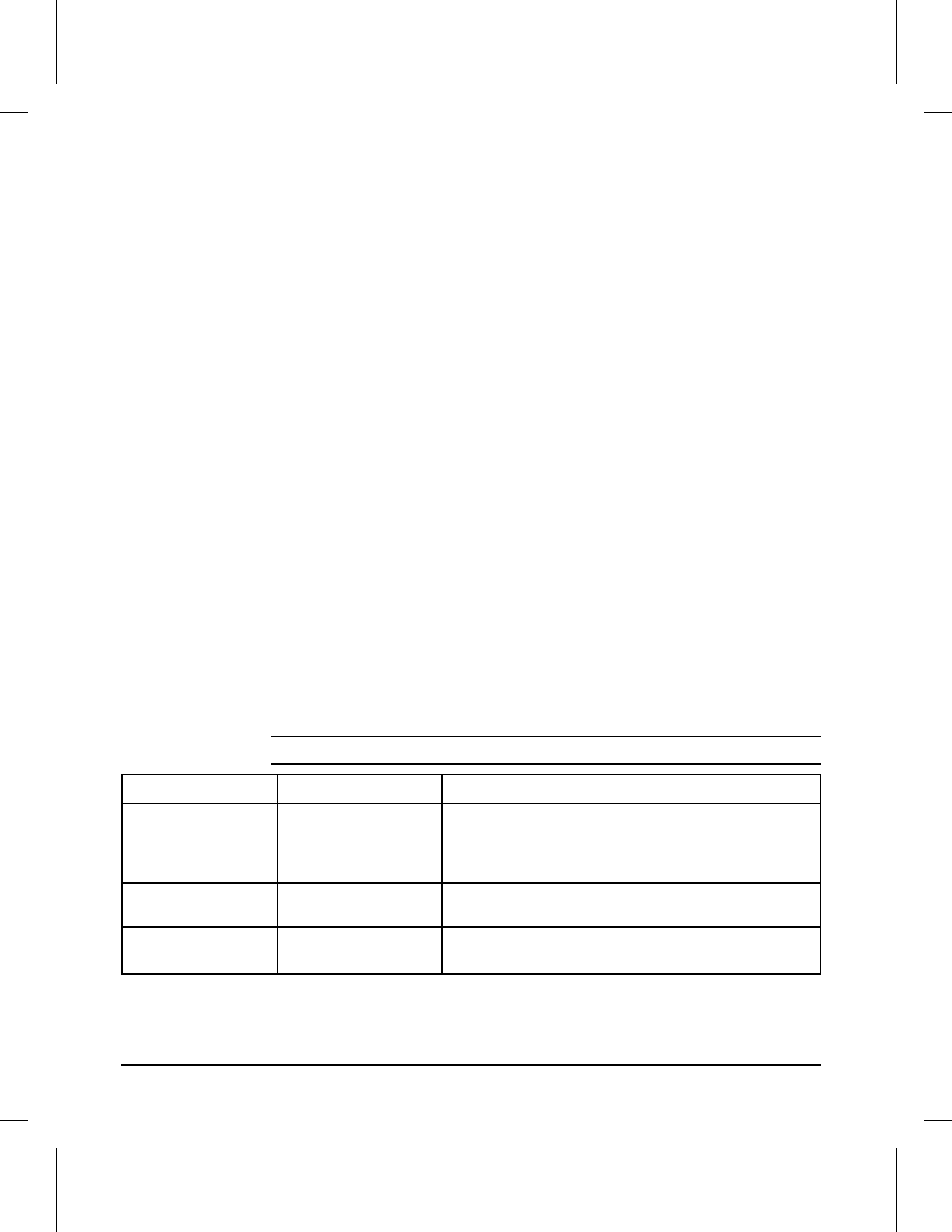
Setting or Default Explanation
Temporary setting A value set for the current print job by your software
application. For example, a request from your
software to print three copies instead of the control
panel default value of one copy is a temporary
setting. The printer continues to use the temporary
setting until you send another software request or
reset the printer.
Control panel default A value you set at the control panel by selecting a
menu item, then pressing [Enter]. An asterisk
appears following the item name to indicate that it is
now the default. The printer retains this default
when it is switched off.
Factory default The value set for each menu item at the factory.
Factory defaults are marked with an asterisk in the
menu tables on the pages that follow.
Table 3-3 Settings and Defaults
3-6 Operating Overview
Control Panel Menus
Pressing [Menu] gives you access to the menus, one after another. Each
menu is described in a separate table in this section. When options (such as
the PostScript language) are installed in the printer, new menus or menu
items automatically are added in the appropriate menus.
To select a menu item:
1Press [On Line] to take the printer off line.
2Press [Menu] repeatedly until the menu you want appears.
3Press [Item] repeatedly until the item you want appears.
4Press [+] repeatedly (or hold down [+] to scroll) until the setting you want
appears.
5Press [Enter] to save your selection. An asterisk appears next to your
selection, indicating that it is now the default.
6Press [On Line] to place the printer back on line.
PRINTING MENU PCL MENU PS MENU JOB MENU CONFIG MENU MEM CONFIG
MENU* PARALLEL MENU TEST MENU
COPIES FONT SOURCE PRT PS ERRS RESOLUTION MP TRAY IO BUFFER HIGH SPEED SELF TEST
PAPER FONT NUMBER JAM RECOVER PERSONALITY LOCK** IO SIZE ADV FNCTNS CONT SELF TEST
ORIENTATION PITCH or
PT SIZE PWR SAVE CLR WARN RESRCSAVE PCL TYPEFACE
LIST
FORM SYM SET IO TIMEOUT AUTO CONT PCL MEM PCL DEMO PAGE
MANUAL FEED LOW TONER PS MEM PS CONFIG PAGE
RET PS TYPEFACE
LIST
ECONOMODE PS DEMO PAGE
You can change these menu items either from a software
application or from the control panel. You can change these menu items only from the control panel.
Shaded items appear when the PostScript option is installed.
Additional menu items may appear if options are installed (such as MIO cards).
* These items will appear if sufficient memory is available.
** The Lock function is only available if MP Tray = Cassette.
Table 3-4 Control Panel Menu Map
3
Operating
Overview
Operating Overview 3-7
Printing Menu
You can override or change any Printing Menu setting through most
software applications. When you change a setting from the printer control
panel, the new setting becomes the printer default value.
Item Options Explanation
COPIES 1* to 999 Select any number from 1 to 999.
PAPER
LETTER**, LEGAL, A4***,
EXEC, 11x17, A3, JIS B4,
JIS B5, CUSTOM, COM10,
MONARCH, C5, DL, B5,
JPOST, JPOSTD
Sets default image size at which printer formats page
unless a software setting overrides it.
ORIENTATION P*, LP means portrait
FORM 5 to 128 LINES
(60** and 64***) Sets vertical spacing, from 5 to 128 lines, for default
paper size. Scrolls in increments of 1 line.
MANUAL FEED OFF*, ON Available only through MP Tray. When Manual Feed is
on and the MP Tray is empty, the printer goes off line
when it receives a print job and displays MF FEED
paper size
or ME FEED
envelope size
. When you place
a sheet in the MP Tray, the printer goes back on line
and prints the sheet.
RET OFF, LIGHT, MEDIUM*, DARK Refines print quality by smoothing the fine gradations
along the angles and curves of the printed image.
ECONOMODE OFF*, ON EconoMode substantially reduces the amount of toner
on the printed page; the result is similar to draft mode
on some dot matrix printers.
*Factory default. **Factory default for 110V printers. ***Factory default for 220V printers.
Table 3-5 Printing Menu Items
3-8 Operating Overview
PCL Menu
PCL Menu items allow you to choose the printer default font and symbol
set. Printer Control Language (PCL) is HP printer language. You can also
change such PCL Menu items as the FONT SOURCE through your software
application.
Item Options Explanation
FONT SOURCE I*
S
Mn
Internal fonts*
Permanent soft fonts
SIMM Module: n=slot number. Typefaces stored in one of the four
ROM SIMM slots (M1=slot 1, for example).
FONT NUMBER 0 to 999 The printer assigns a number to each typeface and lists them on the
PCL Typeface List, accessed under the Test Menu (see Table 3-4 ).
The font number appears in the Font # column of the printout.
You must select a FONT SOURCE in order for FONT NUMBER to appear.
Defaults and other conditions are as follows:
I*
S
Mn
0* is the default.
1* is the default. You can select from the control panel
only a permanent soft font that is currently in the printer.
SIMM Module; n=SIMM slot (1-4). Typefaces stored in
one of the four ROM SIMM slots (M1=slot 1, for example).
PITCH
or
PT. SIZE
Range
Pitch:
10.00*
Point:
12.00*
The pitch or point size item available depends on the FONT SOURCE
and FONT NUMBER you select.
Pitch:
Point:
For fixed-pitch outline typefaces, select pitch sizes from
.44 to 99.99.
For proportionally-spaced outline typefaces, select point
sizes from 4.00 to 999.75 in .25-point increments.
SYM SET ROMAN-8*
Many others A symbol set is a unique grouping of all the characters in a font.
PC-8 or PC-850 is recommended for line draw characters. Symbol
set charts appear in the
PCL 5 Technical Reference Manual
.
*Factory default.
Table 3-6 PCL Menu Items
3
Operating
Overview
Operating Overview 3-9
Job Menu
The items available in the Job Menu can also be changed through software
applications if an appropriate printer driver is installed.
Item Options Explanation
RESOLUTION 300 or 600* For most purposes, 600 dpi is recommended.
PERSONALTY AUTO*
PCL
PS
Personality
means printer language. The printer can switch
from its standard personality, PCL, to other personalities,
such as PostScript. When PERSONALTY is set to AUTO, the
printer analyzes each print job it receives and switches
personalities automatically.
When you make another personality the default, the printer
stops switching personalities automatically unless a software
command specifically instructs it to do so. If the PostScript
option is not installed, PERSONALTY will not display in the Job
Menu.
If you select PS as the default, you may want to set
ADV FNCTNS in the Parallel Menu to OFF.
PWRSAVE OFF, 15 MIN,
30 MIN*, 1 HR,
2 HRS, 3 HRS
Sets the amount of time the printer is idle before the fuser
shuts down. The printer automatically starts warming the
fuser when you send a print job to the printer, press a control
panel key, load or remove paper, or open the top door.
NOTE: A ten second interval is also available in Service Mode
(see “Service Mode” later in this chapter).
IO TIMEOUT 5 to 300
15* I/O timeout refers to the time, measured in seconds, that the
printer waits before ending an incomplete print job (it scrolls in
increments of 10). This setting allows you to adjust timeout for
best performance. If data from other ports appears in the
middle of the print job, increase the timeout value.
PAGEPROTCT AUTO*
ON You will not see this item unless the error 21 PRINT OVERRUN
has occurred. (See Chapter 7 for error message
troubleshooting.)
*Factory default.
Table 3-7 Job Menu Items
3-10 Operating Overview
Configuration Menu
Configuration Menu items cannot be changed from software applications.
Item Options Explanation
MP TRAY FIRST* Draws paper from the MP Tray regardless of paper size
(this setting not recommended for shared environments).
CASS The MP Tray operates as a paper cassette. Paper feeds
automatically. Paper size must be selected with the
[MP[Paper]Size] key because the MP Tray cannot sense the size
of the paper. The [MP [Paper] Size] key works only when the MP
Tray is set to CASS.
MANUAL Operates only as a manual feed tray.
LOCK NONE*
MP
PC
LC
and combinations
Locks out a tray or a combination of trays so the printer will not
draw paper. Lock-out options depend on how the MP Tray is
configured and whether an optional 500-sheet Lower Cassette
(LC) is installed. When the MP Tray = MANUAL or FIRST or no
optional Lower Cassette is installed, no paper sources are
available to be locked out. All possible options are:
NONE
MP
PC
LC
PC MP
LC MP
LC PC
No trays or cassettes locked out.
The MP Tray is locked out.
The Paper Cassette is locked out.
The optional Lower Cassette is locked out.
Only the optional Lower Cassette is available.
Only the Paper Cassette is available.
Only the MP Tray is available.
CLR WARN ON* Clearable warnings are displayed until acknowledged by
pressing [Continue].
JOB Clearable warnings are displayed from the time they are
detected until the start of the next job.
AUTO CONT ON* When an error message is displayed, printer goes offline for ten
seconds, then returns to on-line state.
OFF When an error message is displayed, printer goes offline and
remains offline until operator presses [Continue].
LOW TONER CONT* Printer remains on-line and continues to print on encountering
a 16 TONER LOW message.
STOP Printer stops and goes offline until operator changes the toner
cartridge, presses [On Line], or [Continue].
*Factory default.
Table 3-8 Configuration Menu Items
3
Operating
Overview
Operating Overview 3-11
Memory Configuration Menu
This menu contains the items for personality Resource Saving and I/O
Buffering. Depending on how the printer memory is configured, any
combination of menu items and possible values can appear. When you
change an item in this menu, the printer automatically resets, and all fonts,
macros and downloaded data in the printer are lost (except data stored on
the optional Disk Accessory). Memory Configuration Menu items can be
selected only from the printer control panel.
Item Options Explanation
IO BUFFER AUTO*
OFF**
ON
The I/O buffer is a portion of the printer memory set aside
to hold incoming data. When this item is set to AUTO, the
memory set aside for I/O buffering is automatically
determined by the printer based on available memory.
When it is set to ON, the size can be manually adjusted.
When it is set to OFF, no memory is set aside.
IO SIZE 10K and up When IO BUFFER is set to ON, I/O SIZE appears in the
menu. Use this item to add or reduce I/O buffer memory in
increments of 10 KBytes up to 100 KBytes, then in
100 KByte increments.
RESRCSAVE AUTO*
OFF**
ON
This item appears when a certain amount of memory and
a personality SIMM are installed in the printer. If it is set to
AUTO, the printer automatically determines the amount of
memory to allocate to installed personalities (languages).
When it is set to ON, additional memory management item
selections appear for each installed personality (see next
item). When it is set to OFF, no memory is allocated and
personality-dependent resources (such as fonts) are lost
when personality changes.
PCL MEM
PS MEM 0 KBytes and up When Resource Saving is set to ON, each installed
personality (for example, PCL and PostScript) is added as
a menu item. You can increase memory in increments of
100 KBytes up to the maximum.
*Factory default.
**The HP LaserJet 4MV printer is set to OFF at the factory.
Table 3-9 Memory Configuration Items
3-12 Operating Overview
Parallel Menu
Parallel Menu items can be selected only from the printer control panel. You
cannot change or override them from your software application.
Item Options Explanation
HIGH SPEED YES*
NO
The speed at which data is transmitted to the printer. YES sets
the Bi-Tronics parallel interface to run at a higher data rate
supported by newer computers. NO sets the Bi-Tronics parallel
interface to run at a slower speed compatible with older
computers.
ADV FNCTNS ON*
OFF
Choosing ADV FNCTNS=ON enables bi-directional parallel
communication, which allows the printer to send status readback
messages to the computer. Setting advance functions to ON may
slow personality switching.
*Factory default.
Table 3-10 Parallel Menu Items
3
Operating
Overview
Operating Overview 3-13
Test Menu
Test Menu items can be selected only from the printer control panel. You
cannot change or override them from your software application. See
“Testing the Printer” later in this chapter for detailed information about
running printer tests and interpreting their results.
Item Explanation
SELF TEST When SELF TEST is displayed, and you press [Enter], the printer
runs a self test during which it displays the message 05 SELF
TEST and all control panel lights are lit. During the printing portion
of the self test, the message 06 PRINTING TEST is displayed.
CONT SELF TEST
(Continuous Self Test) Prints continuous self-test pages until you press [On Line] or
[Shift] + [Continue]. Then the 04 portion of the display blinks and
several more pages print until the buffer clears. Press [On Line]
when pages stop printing.
PCL TYPE LIST
PS TYPE LIST Prints a list of the typefaces and bitmapped fonts currently
available in the printer (both internal and accessory) for PCL or
Adobe PostScript print jobs.
PCL DEMO PAGE
PS DEMO PAGE Prints a page that illustrates printer features (PCL or Adobe
PostScript).
PS CONFIG PAGE Prints PostScript-specific information, including current settings,
printable area, and memory configuration.
Table 3-11 Test Menu Items
3-14 Operating Overview

Service Mode
The Service Mode should be used only by authorized service personnel.
While in Service Mode, you can:
•Print a Service Mode Self Test.
•Verify and set the Page Count and serial number. These are displayed on
the standard self test.
•Set the Cold Reset Default. (This sets the factory default paper size to either
Letter or A4).
•Set the Demo Page=True/False. Used to remove the Demo Page option from
the self test menu.
•Set the Diagnostic Functions ON or OFF (for software developers use only).
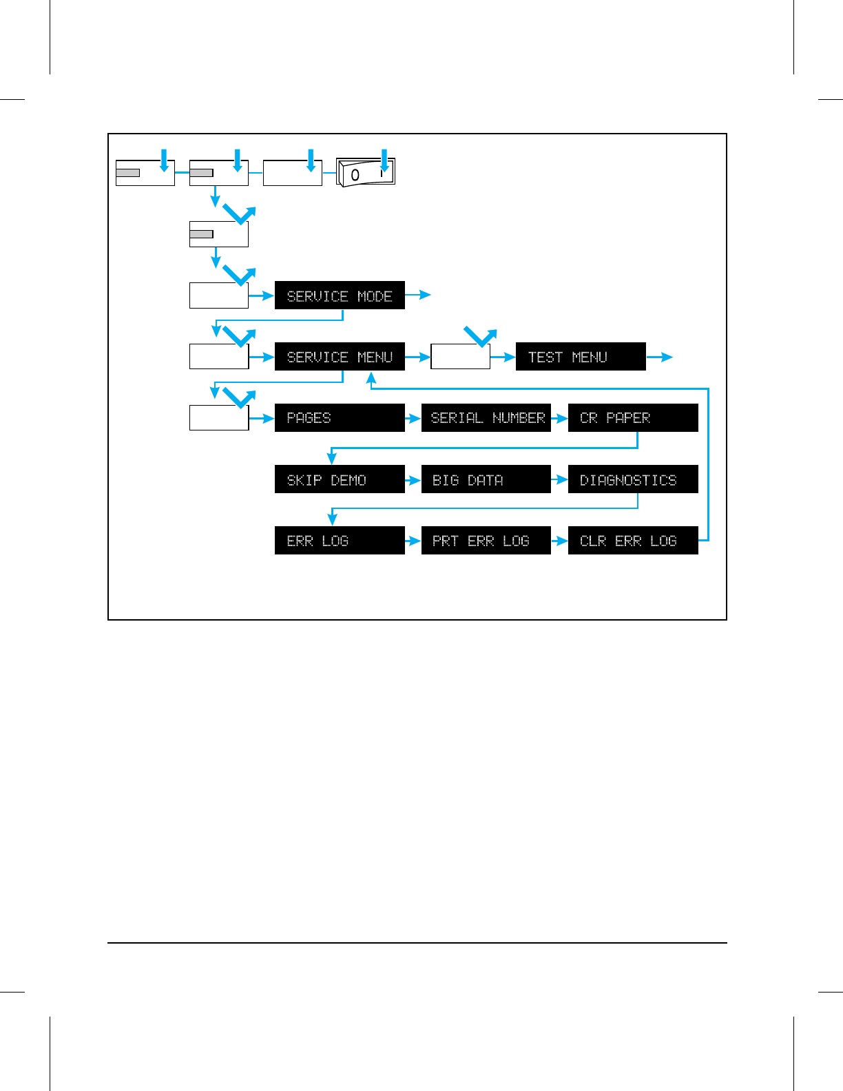
The following procedure is used to initiate the Service Mode (refer to Figure
3-2).
1Hold down the [On Line], [Form Feed], and [Enter] keys while powering ON
the printer, until all lights are illuminated and the Display Window is
blank. (If the Display Window reads 05 SELF TEST at this point, the keys
were released too soon. Repeat this step until successful.)
2Press the [Form Feed] key, then the [Enter] key. The message SERVICE MODE
is displayed briefly, then the printer automatically begins a 05 SELF TEST.
After several seconds, both Control Panel Indicators turn OFF. (The printer
may display 02 WARMING UP if it has not warmed up completely.) After the
printer has warmed up and passed the self test, SERVICE MODE is displayed.
To exit the Service Mode press the [On Line] key.
Power Save
An additional 10 second time interval is added to the Power Save function
in Service Mode.
With Service Mode displayed, press MENU until Job Menu is displayed.
1Press [Item] until PWRSAVE= is displayed.
2Press [+/-] until the desired time interval is displayed.
3Press [Enter] to save your selection.
4Press [On Line] once to return to the Service Mode. Press [On Line] again to
place the printer back on-line.
3
Operating
Overview
Operating Overview 3-15
On Line Form Feed Enter
Form Feed
Enter
Menu
Item
Wait 5 seconds
Menu
3SERVMOD
Figure 3-2 Service Mode Menus
3-16 Operating Overview

Setting the Page Count and Serial Number
The page count and serial numbers are stored in Non-Volatile Memory. If it
is necessary to replace the Formatter PCA, the page count should be set to
the current value to reflect the age of the print engine. The procedure for
setting the serial number is similar to setting the page count. Use the
following procedure to set the page count:
Before removing the old Formatter PCA, print a control panel self test to
verify the current page count and serial number of the printer, if possible.
NOTE If it is not possible to print a self test, try to verify the values before
replacing the Formatter PCA by following steps 3 through 5, below.
After verifying the page count from the old Formatter PCA, replace it with
the new PCA as described in Chapter 6.
1Enter the Service Mode as previously described in this chapter.
2When SERVICE MODE is displayed, press [Menu] to access the Service Menu.
3Press [Item to step through the menu. PAGES=XXXXXX is displayed. (XXXXXX
represents the page count currently stored in Non-Volatile Memory. The
underlined character denotes the cursor position.)
4Press [Enter] to scroll the cursor to underline the desired digit.
5Press [+/-] to select the correct value.
6Press [Enter] to store the new value in NVRAM.
7Set each digit in the same manner. Press [On Line] to return the display to
SERVICE MODE. Use the procedure described above to set the serial number
in the printer memory.
8Press [On Line] a second time to exit Service Mode.
3
Operating
Overview
Operating Overview 3-17
Setting the Cold Reset Default Paper Size
When replacing a Formatter PCA with a default paper size setting of A4, set
the Customization Variable to A4.
To set the Customization Variable:
1Enter the Service Mode as previously described in this chapter.
2Press [Menu] to access the Service Menu.
3Press [Item to step through the menu until CR PAPER=LETTER* is displayed.
4Press [+/-] to toggle between Letter and A4 paper.
5Press [Enter] to save your selection.
6Press [On Line] to return the display to SERVICE MODE.
7Press [On Line] a second time to exit Service Mode.
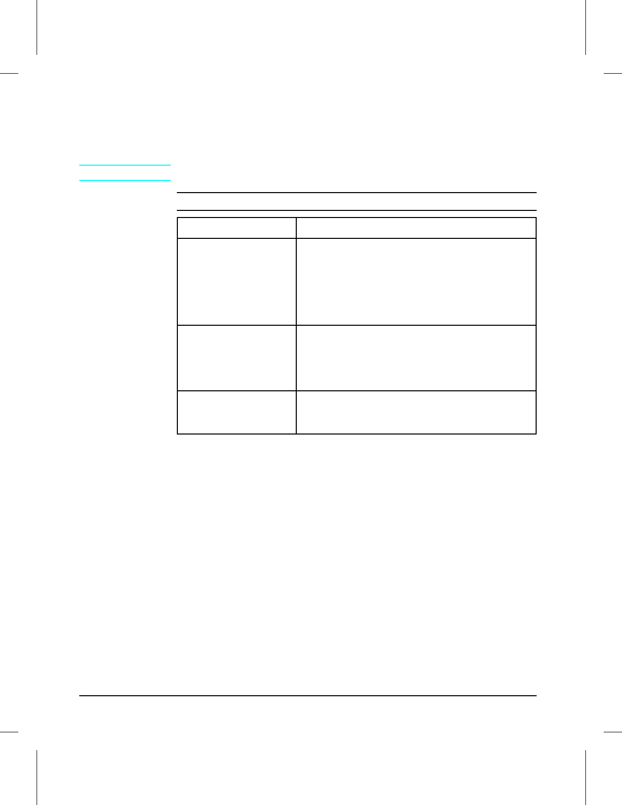
Other Service Mode Items
If any of the following items need to be changed from their default settings,
the procedure is similar to that used for setting the page count or cold reset
default, described above.
Item Default Description
SKIP DEMO FALSE Inhibits printing of PCL Demo Page when set to TRUE
BIG DATA OFF For factory test purposes. Do not change.
DIAGNOSTICS OFF For factory test purposes. Do not change.
ERR LOG N/A Contains a list of the ten most recent errors with the related page count.
PRT ERR LOG N/A Prints the error log.
CLR ERR LOG N/A Clears the error log buffer.
Table 3-12 Other Service Menu Items
3-18 Operating Overview

Testing the Printer
When you run a self test, the printer checks its internal controller and I/O
interface, then prints a test page. You can review the self test printout to
verify proper installation of such options as paper cassettes or personalities.
Printing a Self Test Page
1Press [On Line] to take the printer off line.
2Press [Menu] until TEST MENU appears.
3Press [Item] until the test you want to print appears.
4Press [Enter] to print the test.
5Press [On Line] to place the printer back on line.
NOTE When you select CONT SELF TEST, the printer prints self test pages
continuously until you press [Shift] + [Continue] or [On Line].
3
Operating
Overview
Operating Overview 3-19

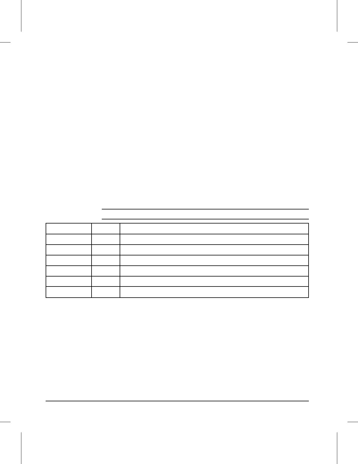
Understanding the Self Test Printout
Figure 3-3 is a sample self test printout (run from Service Mode). Numbers
in the sample printout match numbers in the key to the printout below.
The appearance of the self test printout varies depending on the options
currently installed in the printer.
Self Test Printout Key
1Menu selections: Lists selections in the order in which they appear in the
control panel display. Also includes options such as PostScript and Modular
I/Os.
2MIO information: Reserved for MIO and network statistics. For some
installed MIO options, this block of information can be as long as 20 lines
and three columns.
3Serial Number and Formatter Number: Shows version number of internal
code
4RAM size: Shows total installed printer memory.
5Page Count: Shows the number of pages the printer has printed.
6Firmware Datecode: Eight-digit date (YYYYMMDD) and version number of
formatter firmware.
7Control Panel options status: Shows status of control panel Lock and
Password functions.
8Other installed options: Lists optional paper cassettes, personalities, and
other installed options.
9Disk Accessory: Appears when the option is installed and displays access
status.
10 I/O Buffering and Resource Saving: Information about the current
configuration appears here. If the printer does not have enough memory
installed to enable I/O Buffering or Resource Saving, the amount of
additional memory needed appears here.
11 Print Pattern: Illustrates print density and quality.
12 Resolution Enhancement: When print resolution is set to 600 dpi, the REt
block appears here. The REt block illustrates current print resolution
enhancement.
13 PCL Memory Information: Shows the total amount of installed memory, and
also indicates the amount available for PCL applications (such as font
downloading software).
3-20 Operating Overview
1
13
2
3
4
5
6
7
8
9
10
11
C3295A
12
3SELFTST
Figure 3-3 Self Test Printout (printed in Service Mode)
3
Operating
Overview
Operating Overview 3-21
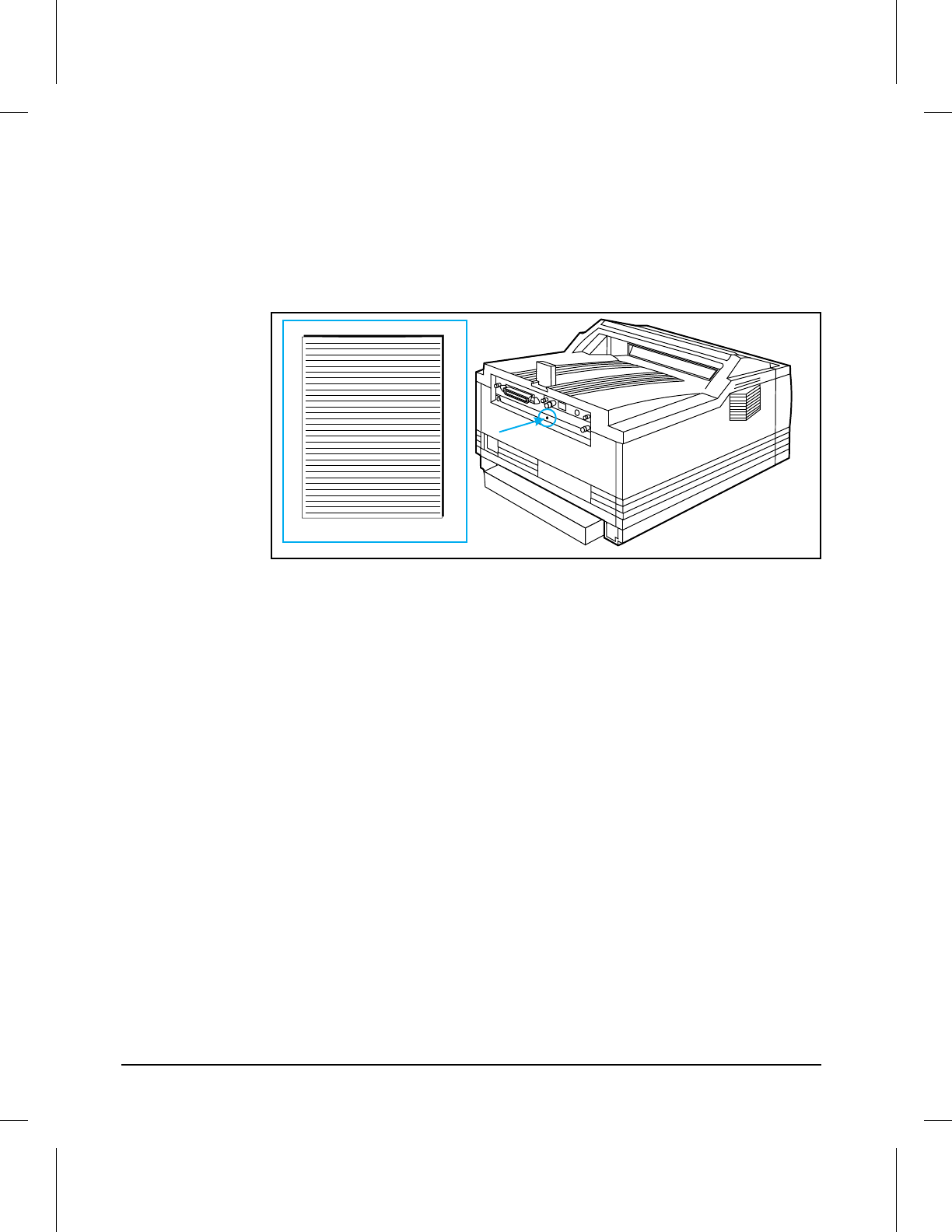
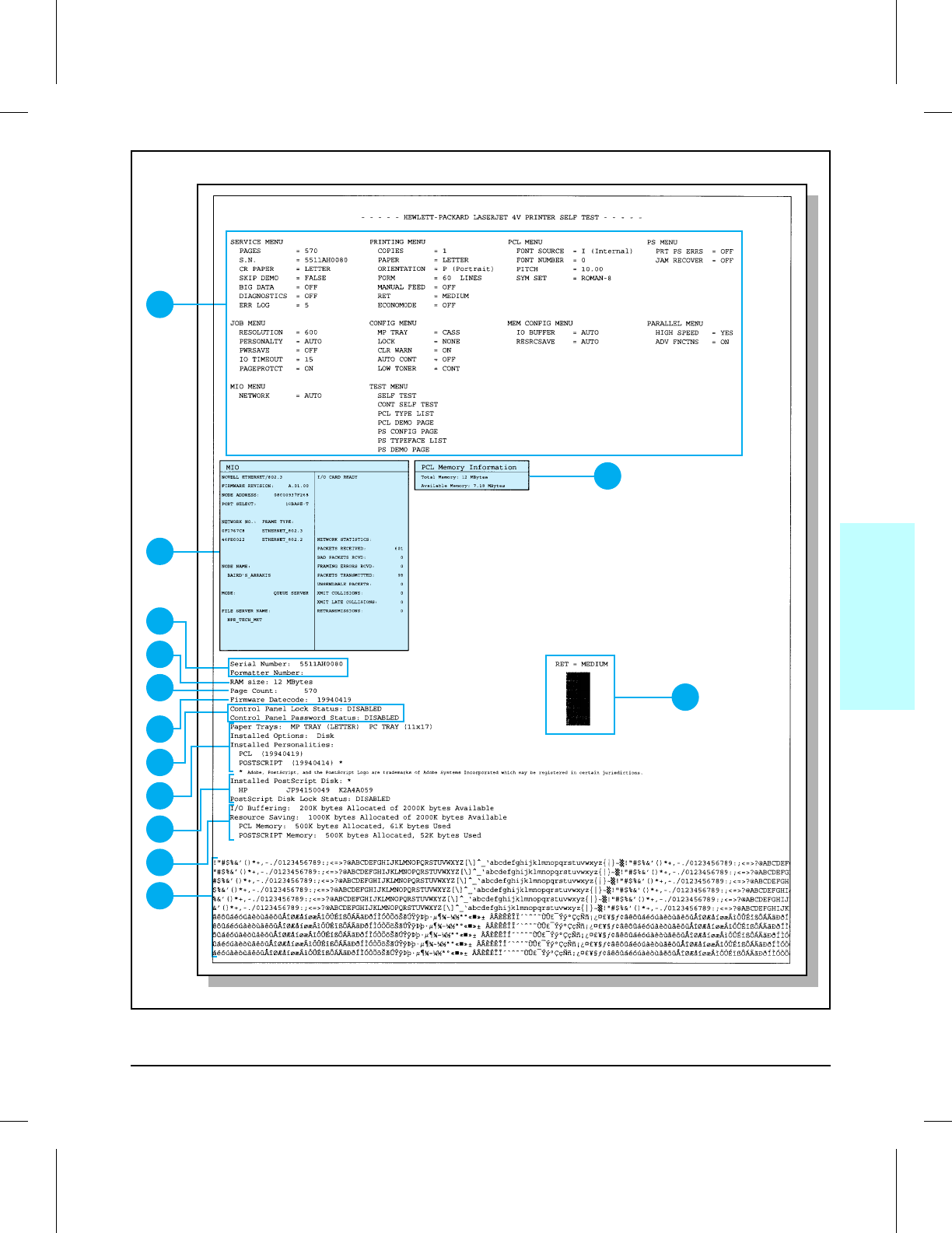
Engine Test
The engine test print can be used to verify that the print engine is
functioning correctly. The Formatter PCA is completely bypassed during an
engine test.
To print an engine test, use a non-metallic object to press the engine test
button (see Figure 3-4). A single test page is printed.
Engine Test
Engine Test Printout
3ENGTEST
Figure 3-4
3-22 Operating Overview

Resetting the Printer
Simple Reset
A simple reset does the following:
•Clears the page buffer.
•Removes all temporary typefaces and macros.
•Makes the current user-selected defaults “active” (making them the default
values until you change them again).
•Purges the input buffer of the active I/O (the other I/O buffer is not affected).
To perform a simple reset:
1Press [On Line] to take the printer off line. The [On Line] light goes off and
00 OFFLINE appears on the display.
2While holding down the [Shift] key, press [Reset] briefly.
307 RESET appears on the display. Then the printer returns to the on-line,
00 READY state.
Cold Reset
Cold Reset clears all data from the printer memory and sets all the defaults
back to the factory settings.
CAUTION Performing a Cold Reset resets the JetDirect configuration. To avoid
making changes to your configuration remove the JetDirect card before
performing a cold reset.
If possible print a control panel self-test prior to performing a Cold Reset.
This will document current settings for later reference.
3
Operating
Overview
Operating Overview 3-23
To perform a cold reset:
1Turn off the printer.
2While holding the [On Line] key down, turn the printer on. 08 COLD RESET
appears briefly on the display, then 05 SELF TEST appears. After about 30
seconds, 08 COLD RESET reappears on the display, followed by 00 OFFLINE.
The cold reset is complete.
3Press [On Line] to return the printer on line. 00 READY appears on the
display.
Menu of Resets
Additional reset options are available through the Menu of Resets. Use the
Menu of Resets option with caution. It can result in loss of buffered page
data or printer configuration data. You should only use it when:
•You wish to restore the default printer settings.
•Communication between the printer and computer is interrupted.
•You are using both the parallel I/O and MIO ports, and one of the ports is
having problems.
To access the Menu of Resets:
1Press [On Line] to take the printer off line.
2Hold down both [Shift] and [Reset] for at least 10 seconds until RESET=MENU
appears on the display.
3Use [+] or [-] to cycle through the items.
4Press [Enter] to select your choice of resets. An asterisk * appears by the
reset option.
5Press [On Line] to execute the reset.
The following table shows the three reset options.
Option Selected Printer Response Explanation
RESET=MENU 09 MENU RESET RESET=MENU performs a simple reset (see previous
page) and restores most of the printer factory default
settings. Items in the Config, Memory Configuration
and Parallel Menus are not reset.
RESET=ACTIVE I/O 09 RST ACTIVE I/O RESET=ACTIVE I/O clears the input and output buffers
for the active I/O only
and performs a simple reset.
RESET=ALL I/O 09 RESET ALL I/O RESET=ALL I/O clears the input and output buffers
for
all I/Os
and performs a simple reset.
Table 3-13 Menu of Resets
3-24 Operating Overview

4
Maintenance
NOTE This printer requires no regular maintenance except for routine cleaning
procedures, described in this chapter.
Chapter Contents
Cleaning the Printer . . . . . . . . . . . . . . . . . . . . . . . . . . . . 4-3
Cleaning Spilled Toner . . . . . . . . . . . . . . . . . . . . . . . . . 4-4
Maintenance 4-1

4-2 Maintenance

Cleaning the Printer
To maintain the print quality, thoroughly clean the printer:
•Every time you change the toner cartridge.
•After printing approximately 7,500 pages.
•Whenever print quality problems occur.
Clean the outside of the printer with a lightly water-dampened cloth. Clean
the inside with only a dry, lint-free cloth. Observe the warnings and
cautions below.
WARNING! Before you begin these steps, turn the printer OFF and unplug the power
cord to avoid shock hazard.
When cleaning around the front door area, avoid touching the fuser. It may
be HOT.
CAUTION To avoid permanent damage to the toner cartridge, do not use
ammonia-based cleaners on or around the printer.
Do not touch the transfer roller with your fingers. Contaminants on the
roller can cause print quality problems.
4
Maintenance
Maintenance 4-3
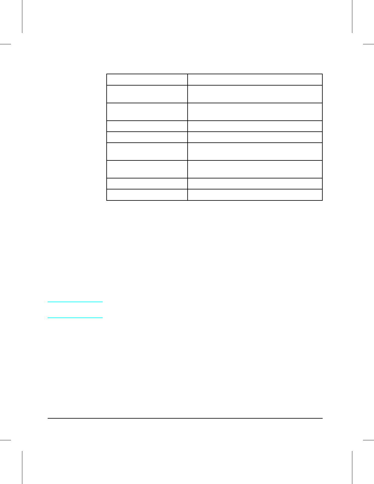
Cleaning Spilled Toner
Defective toner cartridges can develop leaks. In addition, after a paper jam
has occurred, there may be some toner remaining on the rollers and guides
inside the printer. The pages that print immediately after the jam may pick
up this toner.
Clean spilled toner with a cloth slightly dampened in cold water. Do not
touch the Transfer Roller with the damp cloth or with your fingers. Do not
use a vacuum cleaner unless it is equipped with a micro-fine particle filter.
NOTE If toner gets on your clothing, use cold water to remove it. Hot water sets
toner stains into fabric.
COMPONENT CLEANING METHOD/NOTES
Outside Covers Use a water-dampened cloth. Do not use
solvents or ammonia-based cleaners.
Inside General Use a dry, lint free cloth. Remove all dust, spilled
toner, and paper particles.
Paper Pickup Rollers Use a water-dampened lint-free cloth.
Registration Roller Use a dry lint-free cloth.
Transfer Roller Use a dry, lint-free cloth. DO NOT TOUCH with
your fingers.
Anti-Static Teeth
(adjacent to Transfer Roller) Use a dry, lint-free cloth. WARNING!: The
Anti-Static Teeth are extremely sharp.
Separation Pad Use a dry lint-free cloth.
Fuser Assembly Use a water-dampened lint-free cloth.
Table 4-1
4-4 Maintenance

5
Functional Overview
Chapter Contents
Basic Printer Functions . . . . . . . . . . . . . . . . . . . . . . . . . . . 5-3
Power Supply System . . . . . . . . . . . . . . . . . . . . . . . . . . . . 5-4
AC Power Distribution . . . . . . . . . . . . . . . . . . . . . . . . . . 5-5
Overcurrent/Overvoltage Protection . . . . . . . . . . . . . . . . . . 5-5
High Voltage Power Distribution . . . . . . . . . . . . . . . . . . . . 5-6
Toner Cartridge Microswitch (SW501) . . . . . . . . . . . . . . . . . 5-6
Print Density Adjustment . . . . . . . . . . . . . . . . . . . . . . . . 5-6
DC Controller System . . . . . . . . . . . . . . . . . . . . . . . . . . . . 5-7
DC Power Distribution . . . . . . . . . . . . . . . . . . . . . . . . . . 5-7
Laser and Scanner Drive . . . . . . . . . . . . . . . . . . . . . . . . 5-8
Paper Motion Monitoring and Control . . . . . . . . . . . . . . . . . 5-8
Clutches . . . . . . . . . . . . . . . . . . . . . . . . . . . . . . . . . 5-8
Engine Test Microswitch (SW7001) . . . . . . . . . . . . . . . . . . . 5-8
Motors . . . . . . . . . . . . . . . . . . . . . . . . . . . . . . . . . . 5-9
Formatter System . . . . . . . . . . . . . . . . . . . . . . . . . . . . . . 5-10
Power Save . . . . . . . . . . . . . . . . . . . . . . . . . . . . . . . . 5-11
Resolution Enhancement (REt) . . . . . . . . . . . . . . . . . . . . . 5-11
EconoMode . . . . . . . . . . . . . . . . . . . . . . . . . . . . . . . . 5-12
Input/Output . . . . . . . . . . . . . . . . . . . . . . . . . . . . . . . 5-13
Parallel Interface . . . . . . . . . . . . . . . . . . . . . . . . . . . . . 5-13
Modular I/O (MIO) . . . . . . . . . . . . . . . . . . . . . . . . . . . . 5-13
LocalTalk I/O . . . . . . . . . . . . . . . . . . . . . . . . . . . . . . . 5-13
CPU . . . . . . . . . . . . . . . . . . . . . . . . . . . . . . . . . . . . 5-13
Printer Memory . . . . . . . . . . . . . . . . . . . . . . . . . . . . . 5-14
Read Only Memory (ROM) . . . . . . . . . . . . . . . . . . . . . . . 5-14
Random Access Memory (RAM) . . . . . . . . . . . . . . . . . . . . . 5-14
SIMM Slots . . . . . . . . . . . . . . . . . . . . . . . . . . . . . . . . 5-14
Non-Volatile Memory (NVRAM) . . . . . . . . . . . . . . . . . . . . 5-14
Disk Accessory . . . . . . . . . . . . . . . . . . . . . . . . . . . . . . 5-14
Memory Enhancement technology (MEt) . . . . . . . . . . . . . . . . 5-15
Page Protect . . . . . . . . . . . . . . . . . . . . . . . . . . . . . . . 5-15
PJL Overview . . . . . . . . . . . . . . . . . . . . . . . . . . . . . . 5-15
PML . . . . . . . . . . . . . . . . . . . . . . . . . . . . . . . . . . . . 5-15
Functional Overview 5-1

Control Panel . . . . . . . . . . . . . . . . . . . . . . . . . . . . . . . . 5-16
Interface PCA . . . . . . . . . . . . . . . . . . . . . . . . . . . . . . . . 5-16
Image Formation System . . . . . . . . . . . . . . . . . . . . . . . . . 5-17
Toner Cartridge . . . . . . . . . . . . . . . . . . . . . . . . . . . . . 5-18
Toner Cartridge/High Voltage Power Supply Contacts . . . . . . . . 5-18
The Photosensitive Drum . . . . . . . . . . . . . . . . . . . . . . . . 5-18
Drum Cleaning . . . . . . . . . . . . . . . . . . . . . . . . . . . . . 5-19
Drum Conditioning . . . . . . . . . . . . . . . . . . . . . . . . . . . 5-20
Image Writing . . . . . . . . . . . . . . . . . . . . . . . . . . . . . . 5-21
Image Developing . . . . . . . . . . . . . . . . . . . . . . . . . . . . 5-22
Image Transferring . . . . . . . . . . . . . . . . . . . . . . . . . . . 5-23
Image Fusing . . . . . . . . . . . . . . . . . . . . . . . . . . . . . . 5-24
Paper Feed System . . . . . . . . . . . . . . . . . . . . . . . . . . . . . 5-25
Paper Path . . . . . . . . . . . . . . . . . . . . . . . . . . . . . . . . 5-25
Clutches and Sensors . . . . . . . . . . . . . . . . . . . . . . . . . . 5-26
Printing from the Paper Cassette . . . . . . . . . . . . . . . . . . . . 5-27
Printing from the MP Tray . . . . . . . . . . . . . . . . . . . . . . . 5-27
Printing from the Optional Lower Cassette . . . . . . . . . . . . . . 5-27
Paper Jam Detection . . . . . . . . . . . . . . . . . . . . . . . . . . 5-27
Basic Sequence of Operation . . . . . . . . . . . . . . . . . . . . . . . . 5-28
5-2 Functional Overview
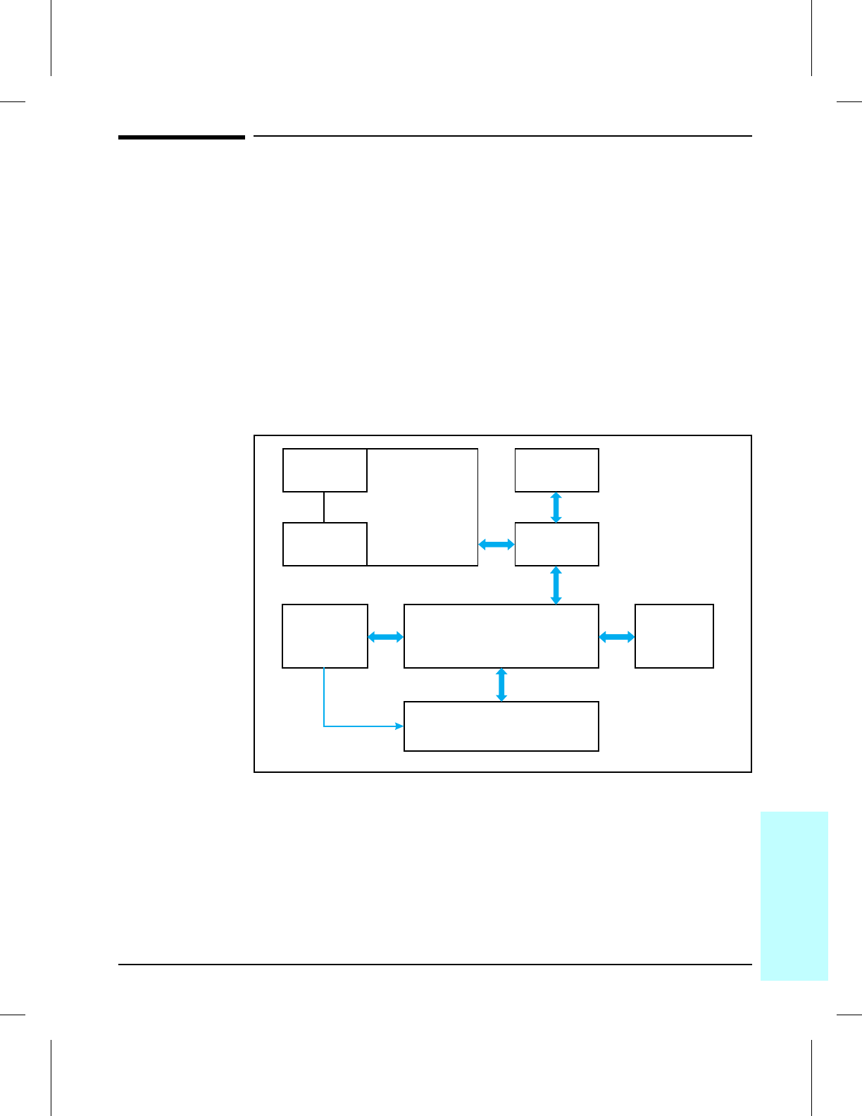
Basic Printer Functions
This chapter presents a generalized functional overview of the printer and
the printing processes. The following printer systems are discussed:
•Power Supply System
•DC Controller System
•Formatter PCA
•Control Panel
•Interface PCA
•Image Formation System
•Paper Feed System
•Basic Sequence of Operation
Figure 5-1 is a generalized block diagram of the printer:
Printer Functional Block Diagram
Formatter
PCA
Power
Supply
System
Control
Panel
Interface
PCA
DC Controller
System Paper Feed
System
Image Formation
System
MIO
Parallel
Port
5BLKDIA
Figure 5-1
5
Functional
Overview
Functional Overview 5-3
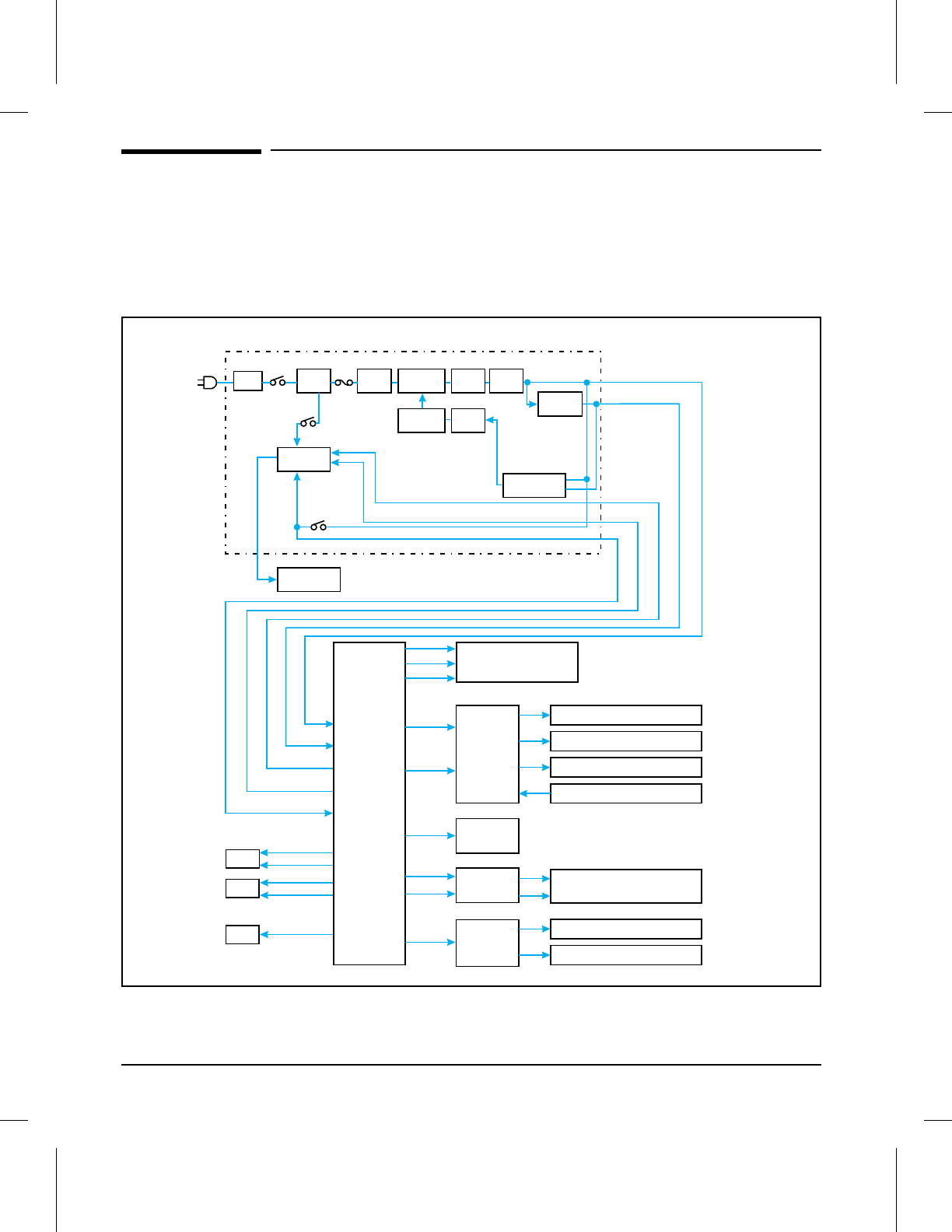
Power Supply System
The AC and DC power supply circuits are contained on the Power Supply
Unit, and the high voltage power circuitry is contained on the High Voltage
Power Supply PCA. The Power Supply and Distribution System is
illustrated in Figure 5-2.
Circuit
Breaker
CB101 Noise
Filter Filter
Fuse
(F101)
Power Switch
(SW101) Front Door
Switch
(SW102)
Fusing Heater
Drive Circuit
Power Supply Unit
24V to 5V
Switching
Transistor Trans-
former Rectifier
Control
IC Photo-
coupler
Overcurrent
Protection
Front Door Switch
(SW102)
+24V
/FUSE1ON
/FUSE2ON
/RELE
+24V
+5V
Fuser Heater
DC
Controller
Laser / Scanner Unit
High
Voltage
Power
Supply
Main
Motor (M1)
Primary Charging Roller
Developing Bias
Transfer Charging Roller
Toner Sensor
Front Door
Assembly
Exhaust Fans
Intake Fan
FM1
FM3
FM2
Interface
PCA
Sensors, Clutches, Solenoids
Control Panel
Formatter PCA
+5V
+24V
+24V
+5V
+5V
+24V
+5V
+24V
+12V
+5V
+24V
+24V
/FUSE1ON
/FUSE2ON
/RELE
+24V
+5V
+5V (Low Spd.)
+24V (High Spd.)
+5V (Low Spd.)
+5V (Low Spd.)
+24V (High Spd.)
5BLKDIA
Figure 5-2 Power Supply/Power Distribution
5-4 Functional Overview

AC Power Distribution
The AC power circuitry supplies AC voltage whenever the power cord is
connected to the AC power source and the power switch is turned ON. A
toner cartridge must be installed and the front door closed before voltage is
supplied to the Power Supply circuits, the DC Controller, the Main Motor,
or the Fusing Assembly.
Overcurrent/Overvoltage Protection
There are three overvoltage /overcurrent devices in this printer:
The resettable circuit breaker (CB101) shuts off AC input power to the
Power Supply Unit in case of an AC overcurrent condition. To reset,
remove the Upper and Right side covers and push on the small round
button located directly above the ON/OFF switch.
Fuse F101 shuts off AC input power to the +24V DC and +5V DC power
circuits. To check or replace the fuse requires the removal of the Power
Supply Unit.
In addition, the +24V DC and +5V DC power circuitry contains an
overcurrent protection circuit which automatically shuts off the output
voltage when an overcurrent condition occurs due to a short or abnormal
voltage on the load side. The protection circuit automatically resets after
the input power is cycled OFF (for at least 3 minutes) then ON.
5
Functional
Overview
Functional Overview 5-5

High Voltage Power Distribution
The High Voltage Power Supply PCA applies an overlap of DC and AC
voltage to the primary charging roller and the developing roller. This
circuit also applies a positive or negative DC voltage to the transfer
charging roller according to the instructions from the CPU on the Formatter
PCA.
This circuit also controls the image density by changing the primary AC
voltage and the developing AC bias according to the setting of the print
density dial.
Refer to Figure 5-15 for High Voltage Power Supply timing information.
Toner Cartridge Microswitch (SW501)
Microswitch SW501, located on the High Voltage Power Supply PCA , is
activated by the toner cartridge. If the toner cartridge is not installed, the
switch opens and an error is issued by the Formatter causing the display
panel message 14 NO TONER CART to be displayed. A toner cartridge must be
installed and the front door must be closed before the printer can resume
printing.
Print Density Adjustment
Adjusting print density affects the line width (boldness) of the print image.
This is accomplished by varying the developer DC bias, which controls the
amount of toner applied to the photosensitive drum. The Print Density
control is accessible behind the front door. The point of the dark arrow is
the most reduced density setting and the thick end of the dark arrow is the
most increased density setting. The default setting is at center range.
5-6 Functional Overview

DC Controller System
The following systems and functions are controlled by the DC Controller:
•DC Power Distribution
•Laser and Scanner Drive
•Paper Motion Monitoring and Control
•Clutches, (Registration, Cassette Pickup, and MP Tray Pickup)
•Engine Test Microswitch
•Motors (Main Drive, Scanner, and Fans)
Figure 5-2 shows the Power Supply and Distribution System. Refer to the
wiring diagrams at the end of Chapter 7 for detailed listings of the DC
Controller inputs and outputs.
DC Power Distribution
The DC power distribution circuitry, located on the DC Controller PCA,
distributes +5 V dc, +12 V dc, and +24 V DC as follows:
+5 V dc: Control Panel
Formatter PCA
Photosensors (PS401, PS402)
DC Controller Circuitry
Laser/Scanner Assembly
Exhaust Fans, FM1 and FM2 (low speed)
Intake Fan, FM3
+12 V dc: Laser/Scanner Assembly
+24 V dc: Laser/Scanner Assembly
High Voltage Power Supply
Clutches and Solenoids
Exhaust Fans, FM1 and FM2 (high speed)
5
Functional
Overview
Functional Overview 5-7

Laser and Scanner Drive
Based on information received from the Formatter, the DC Controller sends
signals to the Laser/Scanner Assembly to modulate the laser diode ON and
OFF and to drive the Laser/Scanner motor. Refer to “Image Formation
System,” later in this chapter for more information.
Paper Motion Monitoring and Control
The DC Controller PCA controls paper motion by continuously monitoring
the various paper sensors, and coordinating the timing with the other print
processes.
For a detailed explanation of paper movement, and the interaction of
photosensors and solenoids with the paper movement process, refer to the
section “Paper Feed System,” later in this chapter.
Clutches
The drive signals for the Registration Clutch (CL1), Cassette Pickup Clutch
(CL2), and the MP Tray Pickup Clutch (CL3) are provided by the DC
Controller PCA.
Engine Test Microswitch (SW7001)
Microswitch SW7001, located on the DC Controller, is activated manually
through an access hole at the rear of the printer. This switch causes the
print engine to perform a self test diagnostic which bypasses the Formatter
PCA and print a full page of black parallel lines. This test is useful for
troubleshooting printer problems because it isolates the print engine from
the Formatter PCA.
5-8 Functional Overview

Motors
The Main Motor (M1) is controlled by the DC Controller PCA. The Main
Motor drives the Main Drive Assembly and rotates during the Initial
Rotation period (following initial power-ON), the Print period, or the Last
Rotation Period, or whenever the printer front door is opened and closed.
The Scanner Motor is controlled and monitored by the DC Controller. It
rotates the scanner mirror during the Initial Rotation period and the Print
period.
The Fan Motors (FM1, FM2, and FM3) are controlled and monitored by
the DC Controller PCA. The Intake Fan (FM3) operates continuously, and
the Exhaust Fans (FM1 and FM2) operate at low speed in the Standby
Mode, and at high speed during the Initial Rotation, Print and Last
Rotation periods. The exhaust fans turn off in the Power Save mode after
the Fuser cools down.
5
Functional
Overview
Functional Overview 5-9
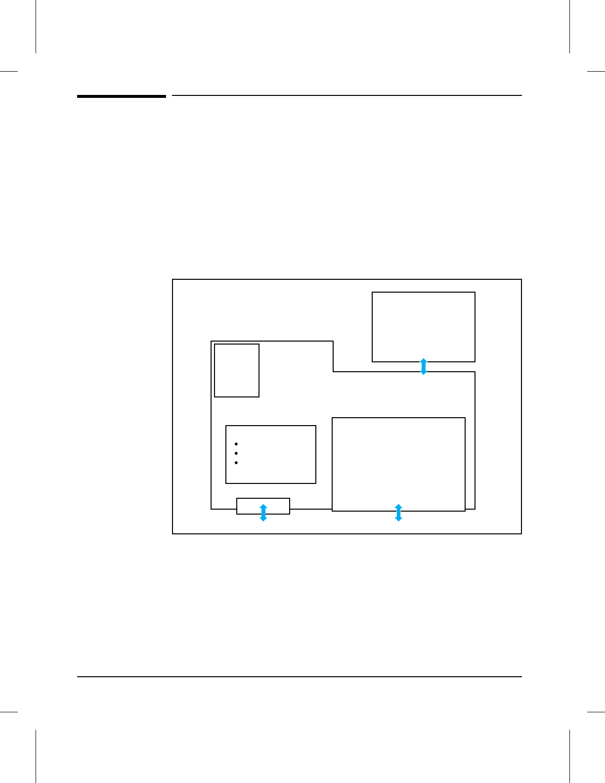
Formatter System
The Formatter PCA is responsible for the following:
•Controlling the Power Save mode.
•Receiving and processing print data from the various printer interfaces.
•Monitoring front control input and relaying printer status information
(through the front control and the Bi-Directional I/O).
•Developing and coordinating data placement and timing with the print
engine.
•Storing font information.
•Communicating with the host computer through the Bi-Directional
Interface.
Formatter PCA Block Diagram
The Formatter PCA receives print data from the Bi-Tronics Interface and
converts it into a dot image. The DC Controller synchronizes the Image
Formation System with the Paper Feed System, and signals the Formatter
to send the print image data. The Formatter sends the print image data
(dots) in the form of a VIDEO signal and the printing process begins.
The Formatter PCA also provides mounting locations for the MIO PCA,
additional memory SIMMs, the PostScript SIMM, and the Disk Accessory.
Interface
PCA
Disk
Accessory
Parallel Interface
MIO
Formatter PCA
SIMM Slots
Additional RAM
PostScript
Firmware
Upgrades
5FMTBLK
Figure 5-3
5-10 Functional Overview

Power Save
This user-adjustable feature conserves power by shutting down the fuser
and exhaust fans after the printer has been idle for 15 minutes, 30 minutes,
1 hour, 2 hours, or 3 hours. A 10 second interval is also available in Service
Mode. The printer retains all printer settings and downloaded fonts and
macros while in Power Save mode. The default setting is Power Save ON,
with a 15 minute idle time. (Power Save can also be turned OFF from the
control panel.)
The printer exits Power Save mode and enters the warm up cycle when any
of the following occur:
•A job is printed.
•A control panel key is pressed.
•The printer front door is opened and closed.
•A paper cassette is removed or installed.
NOTE Printer error messages override the Power Save message. The printer will
enter Power Save mode at the appropriate time, but the error message will
continue to be displayed.
Resolution Enhancement (REt)
The Formatter PCA contains circuitry for Resolution Enhancement
technology (REt), which modifies the standard video dot data on its way to
the DC Controller to produce “smoothed” black-to-white boundaries. REt is
user-adjustable from the control panel, or from some software applications.
Available settings are Light, Medium, Dark, or Off. The default setting is
Medium.
NOTE REt settings sent from software or printer drivers override any control
panel settings.
5
Functional
Overview
Functional Overview 5-11
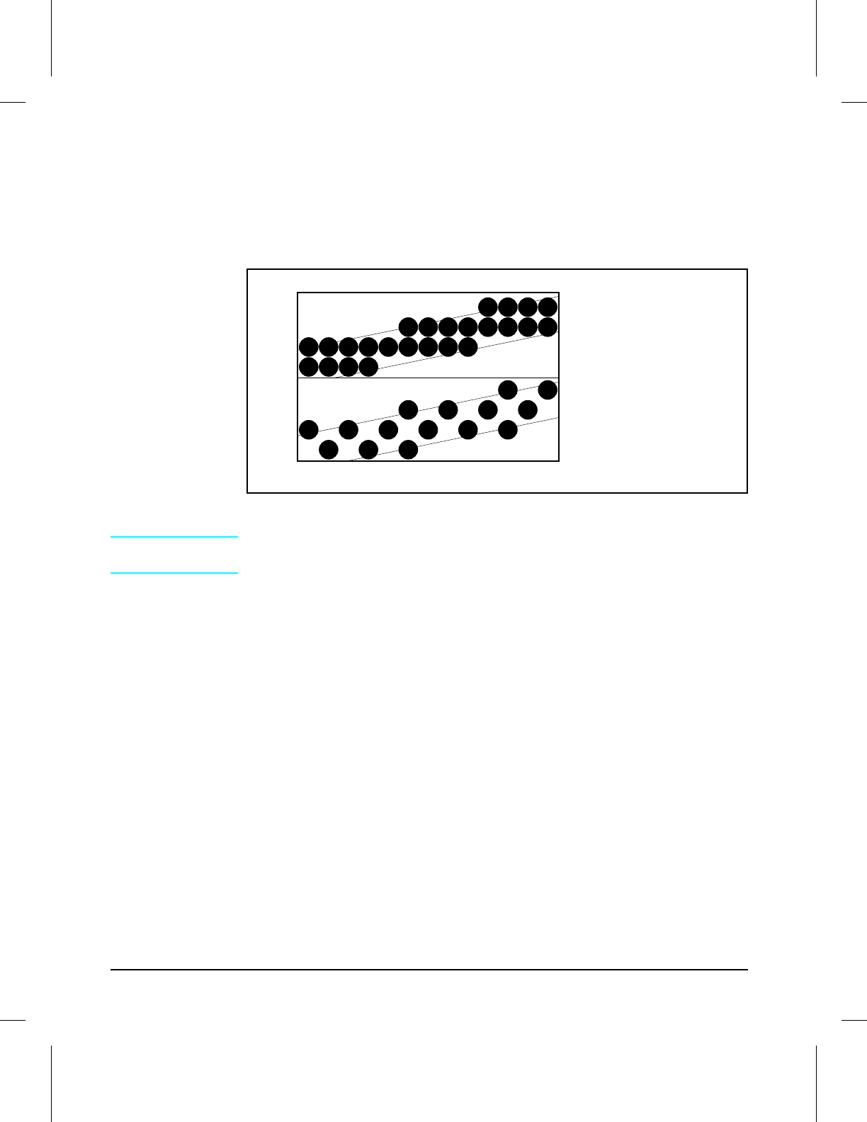
EconoMode
The EconoMode setting uses approximately 75% less toner than standard
mode printing by reducing the dot density. However, Economode does not
extend toner cartridge component life. EconoMode, which can also be
thought of as “draft mode,” is user selectable via a control panel key and
some software applications. The default setting is Off.
EconoMode vs Normal Mode
NOTE EconoMode does not affect print speed, memory usage, or extend toner
cartridge life.
Normal Mode,
Medium Density
EconoMode,
Medium Density
5ECONO
Figure 5-4
5-12 Functional Overview

Input/Output
Parallel Interface
The Formatter PCA receives incoming data through its Bi-Tronics interface
(IEEE 1284). The Bi-Tronics I/O provides high speed and two-way
communication between the printer and the host, allowing the user to
change printer settings and monitor printer status from the host computer.
The “High Speed (Yes/No)” configuration item is user-selectable. The
default setting, “Yes” allows the I/O to run at the higher speeds supported
by most newer PCs. When set to “No,” the parallel interface runs at the
slower, but compatible mode for older PCs. The “Advanced Functions
(On/Off)” configuration item is also user-selectable. The default setting,
“On” allows for two-way parallel communications. The “Off” mode disables
the advanced functionality. The Bi-Tronics I/O is compatible with the
Centronics parallel interface standard.
NOTE Refer to “Parallel Cable Pin Configuration” in Appendix B for parallel pin
assignments.
Modular I/O (MIO)
The optional Modular I/O card can be installed in the slot provided on the
Formatter PCA. It provides automatic I/O switching between multiple
computers or networks connected to the printer. The LaserJet 4MV printer
includes the J2552A HP JetDirect Multi-protocol Network Card with
LocalTalk, DIN-8, and Ethernet/IEEE802.3 10Base-T, BNC.
LocalTalk I/O
The printer implements AppleTalk networking protocol through LocalTalk
hardware. The LocalTalk network cable (HP P/N 92215N) is connected
through the MIO card accessible from the printer rear panel. (See
Appendix B for more cabling information.)
CPU
The Formatter PCA incorporates the Intel 80960CF microprocessor
operating at 33.33 MHz.
5
Functional
Overview
Functional Overview 5-13

Printer Memory
NOTE If the printer encounters difficulty managing available memory, a Clearable
Warning message will be displayed on the Control Panel. Refer to
“Clearable Warnings” in Chapter 7 for details.
Read Only Memory (ROM)
Besides storing microprocessor control programs, the ROM stores dot
patterns of internal character sets (fonts).
Random Access Memory (RAM)
The RAM contains the page and I/O buffers and the font storage area. It
stores printing and font information received from the host system, and can
also serve to temporarily store a full page of print image data before the
data is sent to the print engine (see “Page Protect”). RAM memory
capacities for each printer are shown under “Printer Features” in Chapter 1.
Memory capacities can be increased by adding SIMMs to the Formatter
PCA. Note that adding memory (SIMMs) may also increase print speed
when printing complex graphics.
SIMM Slots
The SIMM slots may be used to add memory, fonts, the PostScript
Language SIMM, or firmware upgrades.
The optional PostScript language SIMM can be installed in any of the
SIMM slots on the Formatter PCA. It allows the printer to automatically
receive and print files configured in the Adobe PostScript language . An
additional 8-Mbytes of memory is recommended for PostScript printing.
Non-Volatile Memory (NVRAM)
The printer uses NVRAM to store I/O and print environment configuration
information. The contents of NVRAM are retained when the printer power
is turned off or disconnected.
Disk Accessory
The optional Disk Accessory is mounted on the rear of the Formatter PCA.
It can be used to permanently store downloaded Adobe PostScript fonts and
forms in the printer. The disk provides 42.8 Mbytes of storage area for
these functions.
5-14 Functional Overview

Memory Enhancement technology (MEt)
The Hewlett-Packard Memory Enhancement technology (Met) effectively
doubles the standard memory through a variety of font and data
compression methods.
NOTE MEt is only available in PCL mode; it is not functional when printing in
PostScript mode.
Page Protect
Page complexity (rules, complex graphics or dense text) may exceed the
printer’s ability to create the page image fast enough to keep pace with the
Image Formation process. If Page Protect is disabled, and a page is too
complex, it may print in parts (for example, the top half on one page and the
bottom half on the next page). Some print data loss is likely in these
instances, and the printer will display the 21 PRINT OVERRUN error message.
Page Protect allows the Formatter to create the entire page image in page
buffer memory before physically moving the paper through the printer.
This process ensures that the entire page will be printed. Page Protect
applies only to PCL printing. The default setting is Auto.
PJL Overview
Printer Job Language (PJL) is an integral part of configuration, in addition
to the standard Printer Command Language (PCL). With standard
Centronics cabling, PJL allows the printer to perform functions such as:
•Two-way communication with the host computer through a
Bi-directional Parallel connection. The printer can tell the host such things
as the control panel settings, and allow the control panel settings to be
changed from the host.
•Dynamic I/O switching allows the printer to be configured with a host on
each I/O. The printer can receive data from more than one I/O
simultaneously, until the I/O buffer is full. This can occur even when the
printer is off-line.
•Context-sensitive switching allows the printer to automatically
recognize the personalities (PostScript or PCL) of each job and configure
itself to serve that personality.
•Isolation of print environment settings from one print job to the next.
For example, if a print job is sent to the printer in landscape mode, the
subsequent print jobs print in landscape only if they are formatted for
landscape printing.
PML
PML is a Printer Management Language that allows remote configuration
and status readback through the I/O ports.
5
Functional
Overview
Functional Overview 5-15

Control Panel
The Formatter PCA sends and receives printer status and command data
via a Control Panel PCA. The Control Panel consists of a 16-character
display window and an 8-key keypad. Control Panel messages can be
configured in any of several languages. Refer to “Using the Control Panel,”
in Chapter 3, and to “Printer Message Troubleshooting” in Chapter 7, for
more information.
The eight keys on the keypad are used for a variety of functions (see
Chapter 3). Keyboard overlays are available in any of several different
languages (see Chapter 8 for part numbers).
Interface PCA
The Interface PCA provides the interconnections between the Formatter
PCA, the Control Panel and the DC Controller PCA. Refer to Figure 5-1
and the Main Wiring diagram at the end of Chapter 7. The Interface PCA is
located inside the Card Cage Assembly and contains no active circuitry.
5-16 Functional Overview
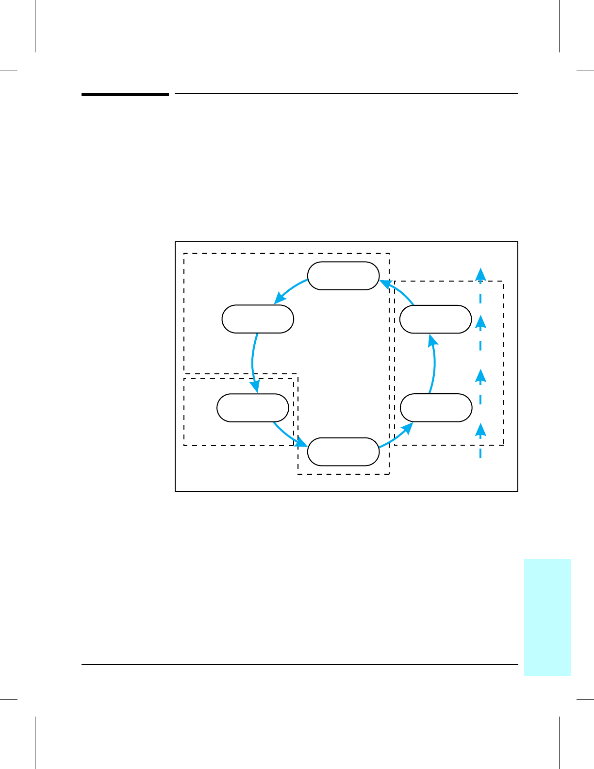
Image Formation System
Laser printing requires the interaction of several different technologies
(such as electronics, optics, and electrophotographics) to provide a printed
page. Each process functions independently and must be coordinated with
the other printer processes. Image formation consists of six processes:
1. Drum Cleaning 4. Image Developing
2. Drum Conditioning 5. Image Transferring
3. Image Writing 6. Image Fusing
Image Formation Block Diagram
Toner Cartridge
Laser / Scanner Front Door
Paper
Delivery
Print
Delivery
Drum
Cleaning
Image
Fusing
Image
Transferring
Image
Developing
Image
Writing
Drum
Conditioning
5IMFBLK
Figure 5-5
5
Functional
Overview
Functional Overview 5-17
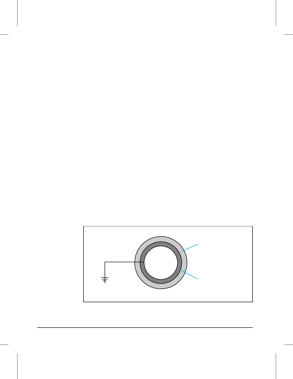
Toner Cartridge
The toner cartridge is the “heart” of the Image Formation System. It houses
the cleaning, conditioning, and developing steps of the process. The toner
cartridge contains the photosensitive drum, primary charging roller,
developing station, toner cavity, and cleaning station. Including these
components that wear, degrade, or are consumed in the replaceable toner
cartridge eliminates the need for a service call when replacement is
required.
Toner Cartridge/High Voltage Power Supply Contacts
The toner cartridge has three contacts which route voltage from the HVPS
PCA. They are:
•Upper: Primary Charge
•Middle: Developing Bias
•Lower: Toner Sensing
The Photosensitive Drum
The special properties of the photosensitive drum allow an image to be
formed on the drum surface and then transferred to paper. The drum is an
aluminum cylinder. The outside of the cylinder is coated with a layer of
organic-photoconductive material (OPC) which is non-toxic. The OPC
material has properties similar to a photo-resistor. It becomes electrically
conductive when exposed to light. When exposed to light, the negative
charges deposited on the drum are conducted to the ground potential of
the drum base. Areas not exposed to light remain non-conductive and
maintain their negative charge. The aluminum base of the photosensitive
drum is electrically connected to ground potential.
Photosensitive Drum
Photosensitive
Layer
Aluminum
Base
5PHODRM
Figure 5-6
5-18 Functional Overview
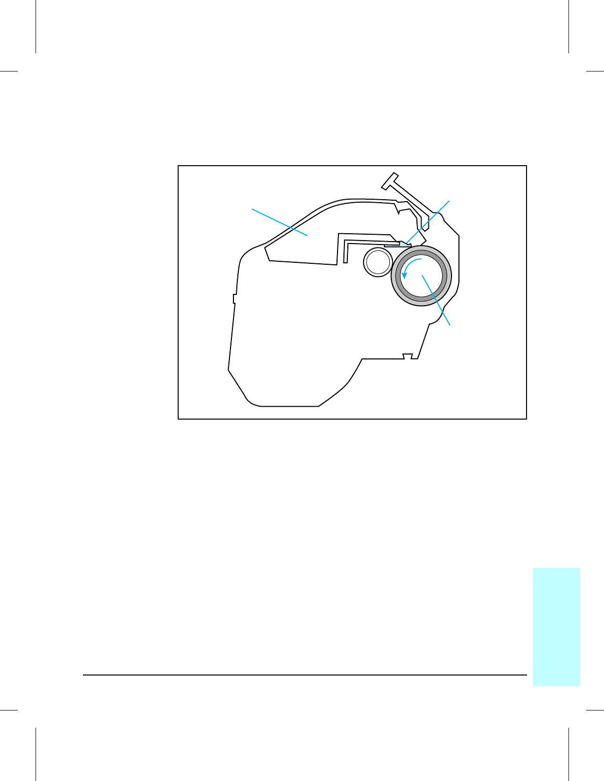
Drum Cleaning
The cleaning blade is in contact with the surface of the drum at all times.
As the drum rotates during printing, excess toner is stored in the waste
toner receptacle.
Drum Cleaning
Cleaning
Blade
Waste Toner
Receptacle
Photosensitive
Drum
Toner Cartridge
5DRMCLN
Figure 5-7
5
Functional
Overview
Functional Overview 5-19
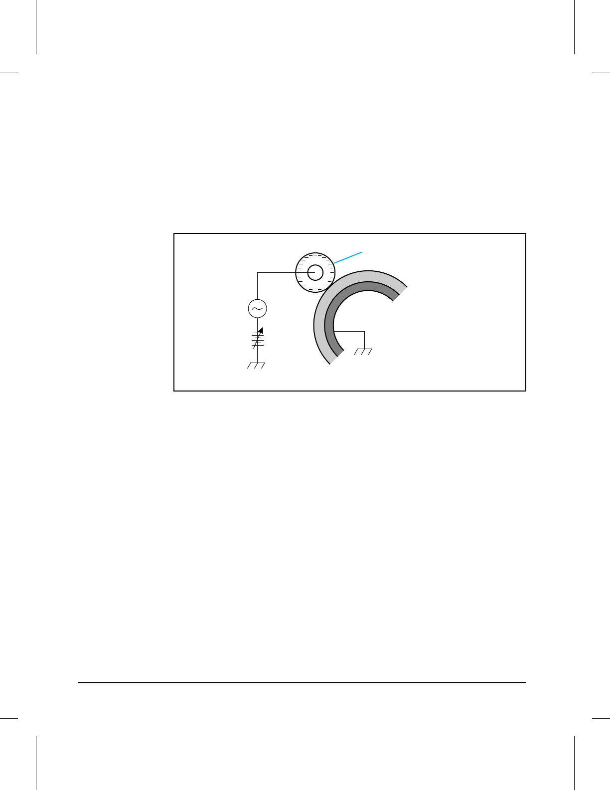
Drum Conditioning
After the drum is physically cleaned, it must be conditioned. This process
consists of applying a uniform negative charge on the surface of the drum
with the primary charging roller, located in the toner cartridge. The
primary charging roller is coated with conductive rubber with an AC bias
applied to erase any residual charges and maintain a constant drum surface
potential. In addition, a negative DC bias is applied by the charging roller
to create a uniform negative potential on the drum surface. The amount of
DC voltage is modified by the print density setting.
Primary Charging Roller
Photosensitive
Drum
Primary charging
roller
AC bias
DC bias
5PRIROL
Figure 5-8
5-20 Functional Overview
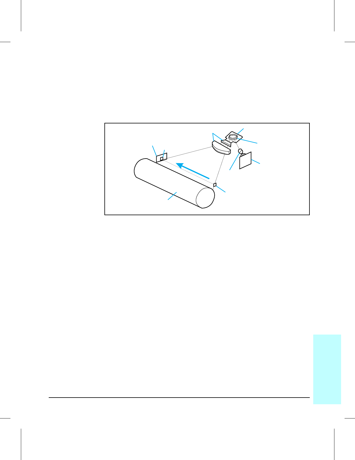
Image Writing
During the writing process, a modulated laser diode projects the beam onto
the rotating six-sided scanning mirror. As the mirror rotates, the beam
reflects off the mirror, through a set of focusing lenses, through a slot in the
rear of the toner cartridge, and onto the photosensitive drum. The beam
sweeps the drum from left to right, discharging the negative potential
wherever the beam strikes the surface. This creates a latent electrostatic
image, which later is developed into a visible image (see Figure 5-9).
Image Writing
Because the beam is sweeping the entire length of the drum and the drum is
rotating, the entire surface area of the drum can be covered. The speed of
the scanner motor (which turns the scanning mirror) and the speed of the
main motor (which turns the drum) are synchronized, and each successive
sweep of the beam is offset 1/600th of an inch. The beam can be turned on
and off to place a dot of light every 1/600th of an inch. This is how the
printer achieves its 600 x 600 dpi resolution. After the writing process, the
drum surface has an invisible (latent) electrostatic image.
At the end of each sweep, the beam strikes the beam detect lens, generating
the Beam Detect Signal (BD). The BD signal is sent to the DC Controller,
where it is converted to an electrical signal used to synchronize the output
of data (VDO) for one sweep (scan line) and to diagnose problems with the
laser diode or scanner motor.
Photosensitive Drum
BD Mirror
BDIC PCB BD Lens
Focusing
Lens
Scanning Mirror
(Hexahedron)
Scanner
Motor
Laser Driver
Cylindrical Lens
5IMGWRT
Figure 5-9
5
Functional
Overview
Functional Overview 5-21
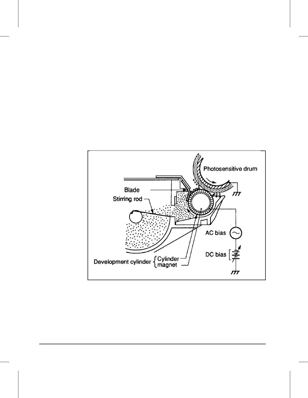
Image Developing
The developing process develops the latent electrostatic image into a visible
image on the drum. The developing unit consists of a metallic cylinder that
rotates around a fixed magnetic core inside the toner cavity. Toner is a
powdery substance made of black plastic resin bound to iron particles,
which is attracted to the magnetic core of the cylinder. A rubber blade
“brushes” the toner on the developing cylinder to a uniform thickness.
The toner particles obtain a negative surface charge by rubbing against the
developing cylinder which is connected to a negative DC supply. The
negatively charged toner is attracted to the discharged (exposed, grounded)
areas of the drum, and repelled from the negatively charged (non-exposed)
areas. An AC potential is applied to the developing cylinder to decrease the
attraction between the toner and the magnetic core of the cylinder, and to
increase the repelling action of toner against the areas of the drum not
exposed to laser light. This AC potential improves density and contrast.
Image Development
The Print Density control (behind the front door) adjusts the DC bias of the
developing cylinder by changing the force of attraction between the toner
and drum. A change in DC bias causes either more or less toner to be
attracted to the drum, which in turn either increases or decreases the print
density. Both the primary and developer DC bias voltages are changed in
response to the density setting.
5IMGDEV
Figure 5-10
5-22 Functional Overview
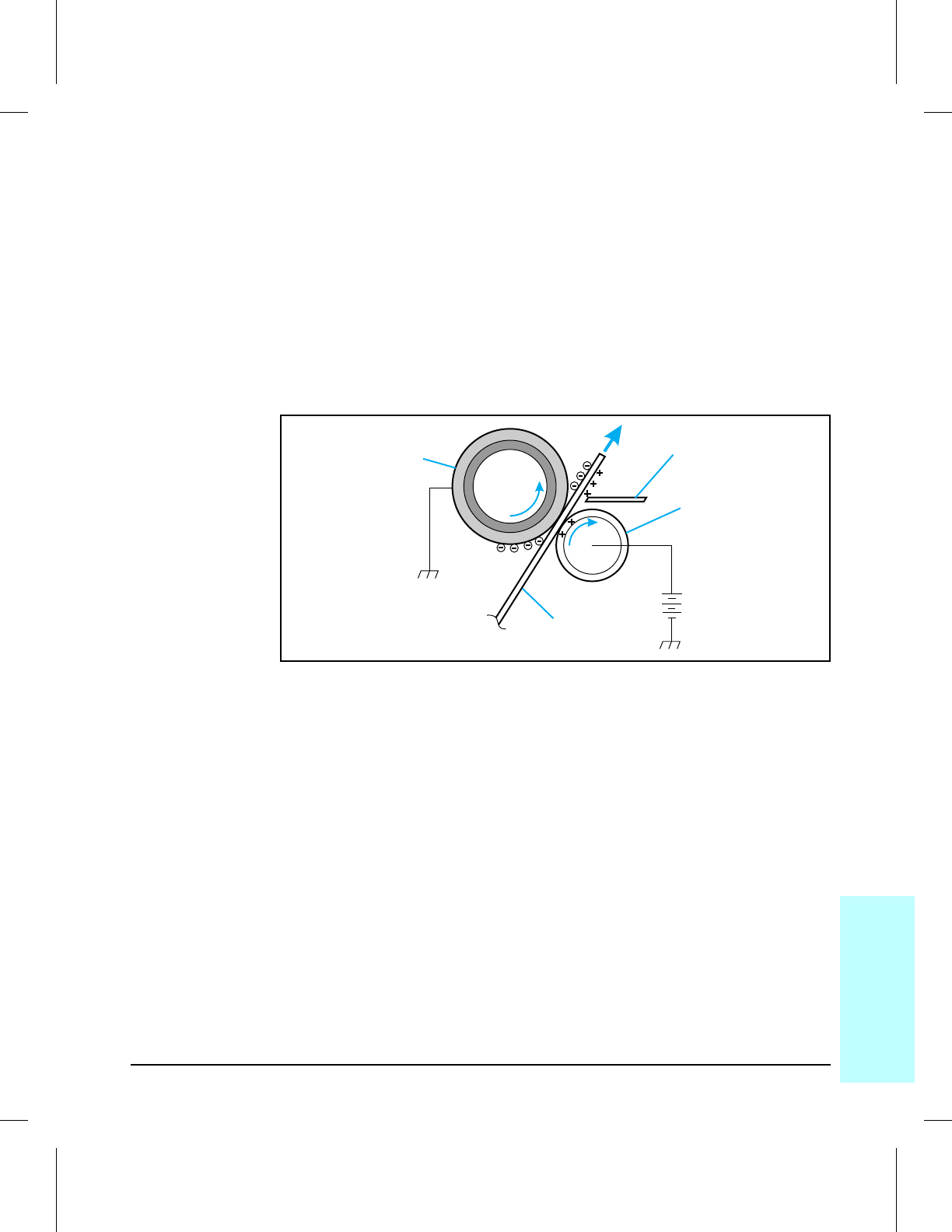
Image Transferring
During the transferring process, the toner image on the drum surface is
transferred to the paper. A positive charge applied to the back of the paper,
by the transfer roller causes the negatively charged toner on the drum
surface to be attracted to the page.
The small diameter of the drum, combined with the stiffness of the paper
causes the paper to peel away from the drum. The static eliminator teeth
also help separate the paper from the drum. The static eliminator teeth
weaken the attractive forces between the negatively charged drum surface
and the positively charged paper. Without this help, thin paper may wrap
around the drum. After separation, the drum is cleaned and conditioned for
the next image.
Image Transferring
Transfer
Charging
Roller
Photosensitive
Drum
Paper
Static Charge
Eliminator
5TRNSTG
Figure 5-11
5
Functional
Overview
Functional Overview 5-23
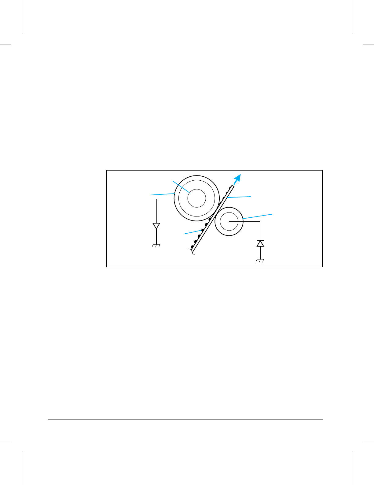
Image Fusing
During the fusing process, the toner is fused into the paper by heat and
pressure to produce a permanent image. The paper passes between a
heated fusing roller and a soft pressure roller. This melts the toner and
presses it into the paper.
The fusing roller contains a quartz-halogen lamp that provides heat for the
fusing process. Fusing temperature is monitored by the DC Controller PCA,
via thermistor TH1. The DC Controller maintains a temperature of about
180° C during print mode. If the fusing system overheats (about 220° C), a
relay opens, interrupting power to the fusing heater, causing a fuser error
(50 SERVICE) message. If the fusing system exceeds 240° C, the thermal
fuse will open, cutting off power to the fuser.
Image Fusing
Fusing Roller
Halogen Heater
Paper
Pressure
Roller
Toner
5FUSSTG
Figure 5-12
5-24 Functional Overview
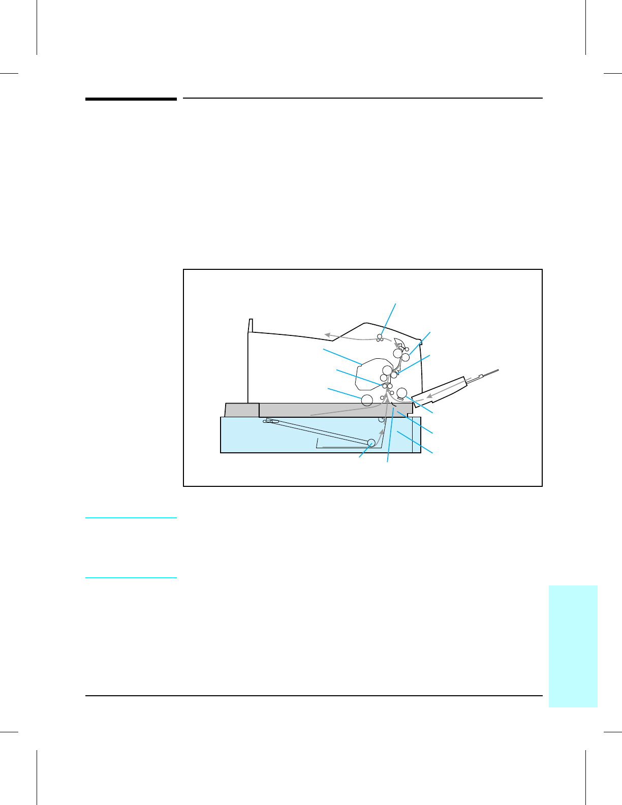
Paper Feed System
Paper Path
The paper feed system picks print media automatically from the paper
cassette, optional lower cassette, or accepts it from the MP Tray, and
delivers it to the image formation system at precisely the right time. The
system then feeds the media to the fusing station, and delivers the finished
product to the output bin on top of the printer.
Figure 5-13 shows a simplified paper path and the approximate location of
the major components.
Paper Path
NOTE: The Paper Cassette and Lower Cassette Paper Guide must be in place for
the Optional Lower Cassette to operate properly.
When the optional lower cassette is installed it becomes the default paper
source.
Output Delivery Rollers
Fusing Rollers
Transfer Charging
Roller
Registration Rollers
Cassette Pick-up
Roller
Toner Cartridge
MP Tray Pick-up
Roller
Paper Cassette
Optional Lower
Cassette
Lower Cassette Paper Guide
Lower Cassette Pickup Rollers
Figure 5-13
5
Functional
Overview
Functional Overview 5-25
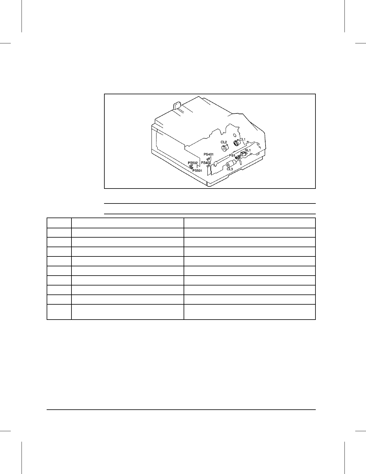
Clutches and Sensors
Figure 5-14 shows the locations of the various solenoids, photosensors and
rollers.
Clutches and Sensors
5CLUTCH
Figure 5-14
No. Name Description
PS1 MP Tray paper sensor Senses paper in the MP Tray.
PS401 Delivery Unit paper sensor Senses paper in the fuser area.
PS402 Front Door Open sensor Senses position of the printer front door.
PS501 Pickup Unit paper sensor Senses paper in the registration roller area.
PS502 Cassette paper sensor Senses presence of paper in the lower cassette.
CL1 Registration clutch Engages the registration rollers.
CL2 Cassette pickup clutch Engages the cassette pickup rollers.
CL3 MP Tray pickup clutch Engages the MP Pickup roller.
SL1 Intermediate plate pressurization solenoid Releases the spring-loaded plate, allowing paper to contact
the MP roller.
Table 5-1 Clutches and Sensors
5-26 Functional Overview

Printing from the Paper Cassette
Paper motion begins when the DC Controller PCA, after receiving a PRINT
signal, starts the Scanner Motor, the Main Motor, and the fusing heater.
The Cassette Pickup Clutch (CL2) is energized for 0.5 seconds, the pickup
roller and the registration roller rotate and feed a sheet of paper from the
Paper Cassette to the Registration Position, where the registration roller is
stopped by the Registration Clutch (CL1), if necessary, until the Scanner
and Fuser are ready.
The DC Controller sends the VSREQ signal to the Formatter PCA within a
specified amount of time after the Pickup Unit Photosensor (PS501) is
activated. The leading edge of the media is now ready to proceed to the
photosensitive drum. When the print engine receives the VSYNC and VDO
signals, the printing process begins. After the paper passes by the drum,
and through the fusing unit, it triggers the Delivery Unit Photosensor
(PS401). The paper is then fed through the output rollers and to the top
output bin.
Printing from the MP Tray
The presence of paper in the Multipurpose (MP) Tray is detected by the MP
Tray Paper Sensor (PS1). The intermediate plate pressurization solenoid
(SL1) is then activated, releasing the plate which applies upward pressure
on the paper, causing it to contact the MP pickup roller. The MP Pickup
Clutch (CL1) turns on at this time, allowing the registration roller to rotate.
This feeds the paper from the MP Tray to the registration position.
The remainder of the MP Tray print process is identical to the cassette feed
process, described above.
Printing from the Optional Lower Cassette
When printing from the optional lower cassette, any of the 250-sheet paper
cassettes must also be in place. The Pickup Arm in the optional lower
cassette feeds the paper upward through a guide slot in the 250-sheet
cassette to the Registration Roller. Once there, the operation is the same as
printing from a standard paper cassette.
Paper Jam Detection
The Pickup Unit photosensor (PS501) in the registration area and Delivery
Unit photosensor (PS401) in the output area detect when paper is moving
through the printer (see Figure 5-14 for sensor locations). If a paper jam is
detected, the DC Controller immediately stops the printing process and
causes a 13 PAPER JAM message to be displayed on the control panel.
5
Functional
Overview
Functional Overview 5-27
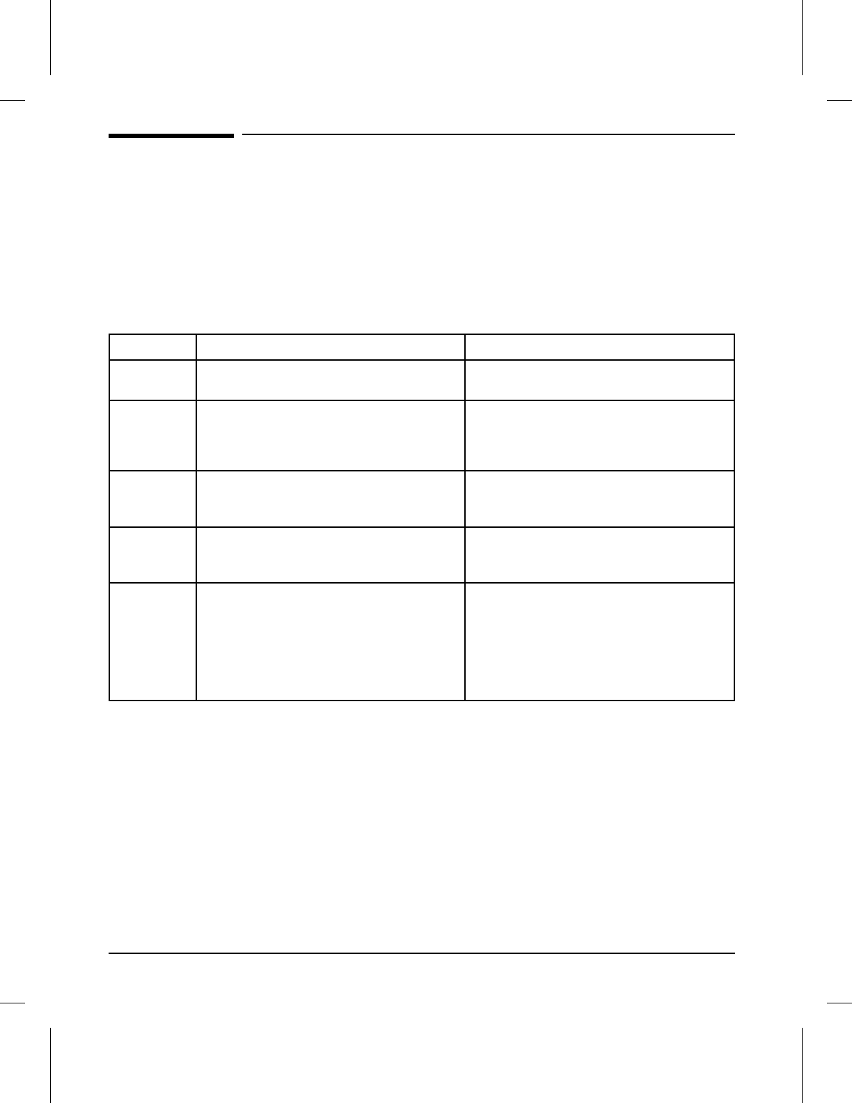
Basic Sequence of Operation
The Formatter PCA and the DC Controller PCA share information during
printer operation. The Interface PCA forms a link which operates as a
serial data bus. This allows printer status, command, and dot-image data to
be passed between the two PCAs. Figure 5-15 shows the general timing of
the printer events. The following events take place during normal printer
operation:
Period Timing Purpose
WAIT From power ON to the end of Main Motor
initial rotation. Clear the drum surface potential and
clean the Transfer Roller.
STBY
(standby) From the end of the WAIT or the LSTR
period until the input of the PRNT signal
from the Formatter. Or from the end of the
LSTR period until power OFF.
Maintain the printer in ready state.
INTR (initial
rotation) From the input of the PRNT signal from
the Formatter until the laser diode
intensity has been stabilized.
Stabilize the photosensitive drum
sensitivity in preparation for printing. Also
clean the Transfer Roller.
PRNT From the end of initial rotation until the
Scanner Motor stops. Form images on the photosensitive drum
based on the /VDO signal from the
Formatter and transfer the image to paper.
LSTR (last
rotation) From the primary voltage (DC) OFF until
the Main Motor stops.
If another PRNT signal is sent from the
Formatter, the printer returns to the INTR
period. If not, it returns to the STBY
period.
Deliver the last sheet of paper. Also clean
the Transfer Roller.
Table 5-2 Printer Timing
5-28 Functional Overview
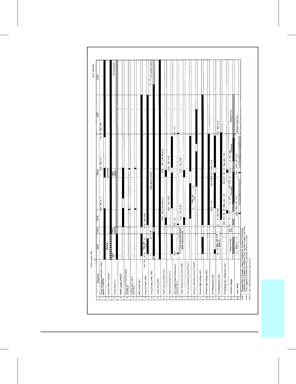
General Timing Diagram
5TMEDIAG
Figure 5-15
5
Functional
Overview
Functional Overview 5-29

5-30 Functional Overview

6
Removal and Replacement
Chapter Contents
Removal and Replacement Strategy . . . . . . . . . . . . . . . . . . . . 6-3
Required Tools . . . . . . . . . . . . . . . . . . . . . . . . . . . . . . . 6-4
User Installable Accessories . . . . . . . . . . . . . . . . . . . . . . . . 6-5
Covers and Doors . . . . . . . . . . . . . . . . . . . . . . . . . . . . . . 6-8
Control Panel . . . . . . . . . . . . . . . . . . . . . . . . . . . . . . . 6-8
Upper Cover . . . . . . . . . . . . . . . . . . . . . . . . . . . . . . . 6-9
Static Charge Eliminator . . . . . . . . . . . . . . . . . . . . . . . . 6-10
Side Covers . . . . . . . . . . . . . . . . . . . . . . . . . . . . . . . . 6-11
Rear Cover . . . . . . . . . . . . . . . . . . . . . . . . . . . . . . . . 6-12
Left Side Assemblies . . . . . . . . . . . . . . . . . . . . . . . . . . . . 6-13
Exhaust Fan (FM1) . . . . . . . . . . . . . . . . . . . . . . . . . . . 6-13
High Voltage Power Supply PCA . . . . . . . . . . . . . . . . . . . . 6-14
Cassette Size Sensor Assembly . . . . . . . . . . . . . . . . . . . . . 6-15
Rear and Top Area Assemblies . . . . . . . . . . . . . . . . . . . . . . . 6-16
Card Cage . . . . . . . . . . . . . . . . . . . . . . . . . . . . . . . . 6-16
Rear Exhaust Fan (FM2) . . . . . . . . . . . . . . . . . . . . . . . . 6-17
Power Supply Unit . . . . . . . . . . . . . . . . . . . . . . . . . . . . 6-18
DC Controller PCA . . . . . . . . . . . . . . . . . . . . . . . . . . . . 6-19
Laser/Scanner Assembly . . . . . . . . . . . . . . . . . . . . . . . . . 6-20
Right Side Assemblies . . . . . . . . . . . . . . . . . . . . . . . . . . . 6-21
Main Motor (M1) . . . . . . . . . . . . . . . . . . . . . . . . . . . . . 6-21
Main Drive Assembly . . . . . . . . . . . . . . . . . . . . . . . . . . 6-22
Drum Drive Assembly . . . . . . . . . . . . . . . . . . . . . . . . . . 6-24
Front Door Assemblies . . . . . . . . . . . . . . . . . . . . . . . . . . . 6-25
Transfer Roller Assembly . . . . . . . . . . . . . . . . . . . . . . . . 6-25
Fusing Assembly . . . . . . . . . . . . . . . . . . . . . . . . . . . . . 6-26
Fuser Inlet Guide . . . . . . . . . . . . . . . . . . . . . . . . . . . . 6-27
Paper Guide Plate Assembly . . . . . . . . . . . . . . . . . . . . . . 6-28
MP Guide Plate . . . . . . . . . . . . . . . . . . . . . . . . . . . . . 6-29
MP Drive Gears . . . . . . . . . . . . . . . . . . . . . . . . . . . . . 6-30
Fuser Door . . . . . . . . . . . . . . . . . . . . . . . . . . . . . . . . 6-31
MP Tray . . . . . . . . . . . . . . . . . . . . . . . . . . . . . . . . . 6-32
Front Door Assembly . . . . . . . . . . . . . . . . . . . . . . . . . . . 6-33
Removal and Replacement 6-1

Delivery Area Assemblies . . . . . . . . . . . . . . . . . . . . . . . . . 6-34
Upper and Lower Delivery Roller Assemblies . . . . . . . . . . . . . 6-34
Delivery Gear Assembly . . . . . . . . . . . . . . . . . . . . . . . . . 6-35
Cartridge Guide . . . . . . . . . . . . . . . . . . . . . . . . . . . . . 6-36
Cassette Pickup Roller Assembly . . . . . . . . . . . . . . . . . . . . 6-37
Separation Pad . . . . . . . . . . . . . . . . . . . . . . . . . . . . . 6-38
Registration Roller . . . . . . . . . . . . . . . . . . . . . . . . . . . 6-39
Registration Roller Guide Plate . . . . . . . . . . . . . . . . . . . . . 6-41
Anti-Static Brush . . . . . . . . . . . . . . . . . . . . . . . . . . . . 6-42
Paper Guide . . . . . . . . . . . . . . . . . . . . . . . . . . . . . . . 6-43
Bottom Assemblies . . . . . . . . . . . . . . . . . . . . . . . . . . . . . 6-44
Foot Assemblies . . . . . . . . . . . . . . . . . . . . . . . . . . . . . 6-44
6-2 Removal and Replacement

Removal and Replacement Strategy
This chapter documents removal and replacement of major assemblies.
Replacement is generally the reverse of removal. Occasionally, information
is included to provide direction for difficult or critical replacement
procedures.
WARNING! Unplug the power cord from the power outlet before attempting to service
the printer. If this warning is not followed, severe injury may result.
Never operate or service the printer with the protective cover removed from
the Laser/Scanner assembly. The reflected beam, although invisible, can
damage your eyes.
This printer has some sharp sheet metal edges which can cause injury.
CAUTION The printer contains parts that are electrostatic discharge (ESD) sensitive.
Always service printers at an ESD protected workstation. Watch for the
ESD reminder shown at left while performing removal procedures.
6Removal &
Replacement
Removal and Replacement 6-3
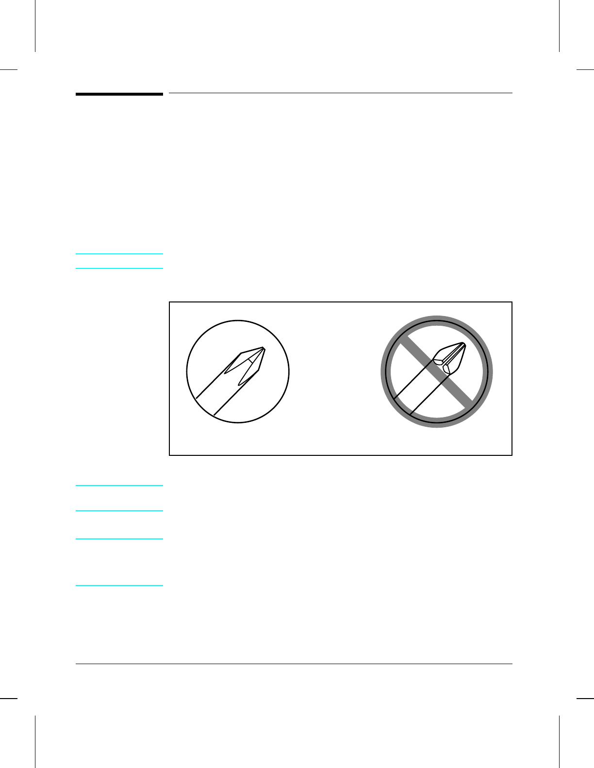
Required Tools
•#2 Magnetized Phillips Screwdriver (6-inch shaft)
•#2 Stubby Magnetized Phillips Screwdriver (1-inch shaft)
•Small flat-blade Screwdriver
•Small Pair Needle Nose Pliers
All screws used in field-replaceable printer components are Phillips head
screws which require a #2 size Phillips screwdriver. Figure 6-1 shows the
difference between a Phillips and a Pozidriv screwdriver. Note that the
Phillips tip has more beveled surfaces.
CAUTION A Posidriv screwdriver will damage the screw heads. Use Phillips only.
Phillips vs. Posidriv Screwdrivers
NOTE See Chapter 8 for a table listing screws and other common hardware used in
the printer.
CAUTION To install a self-tapping screw, first turn it counter-clockwise to align it with
the existing thread pattern, then carefully turn clockwise to tighten. Do not
over-tighten. If a self-tapping screw-hole becomes stripped, repair of the
screw-hole or replacement of the affected assembly is required.
PosidrivPhillips
Figure 6-1
6-4 Removal and Replacement
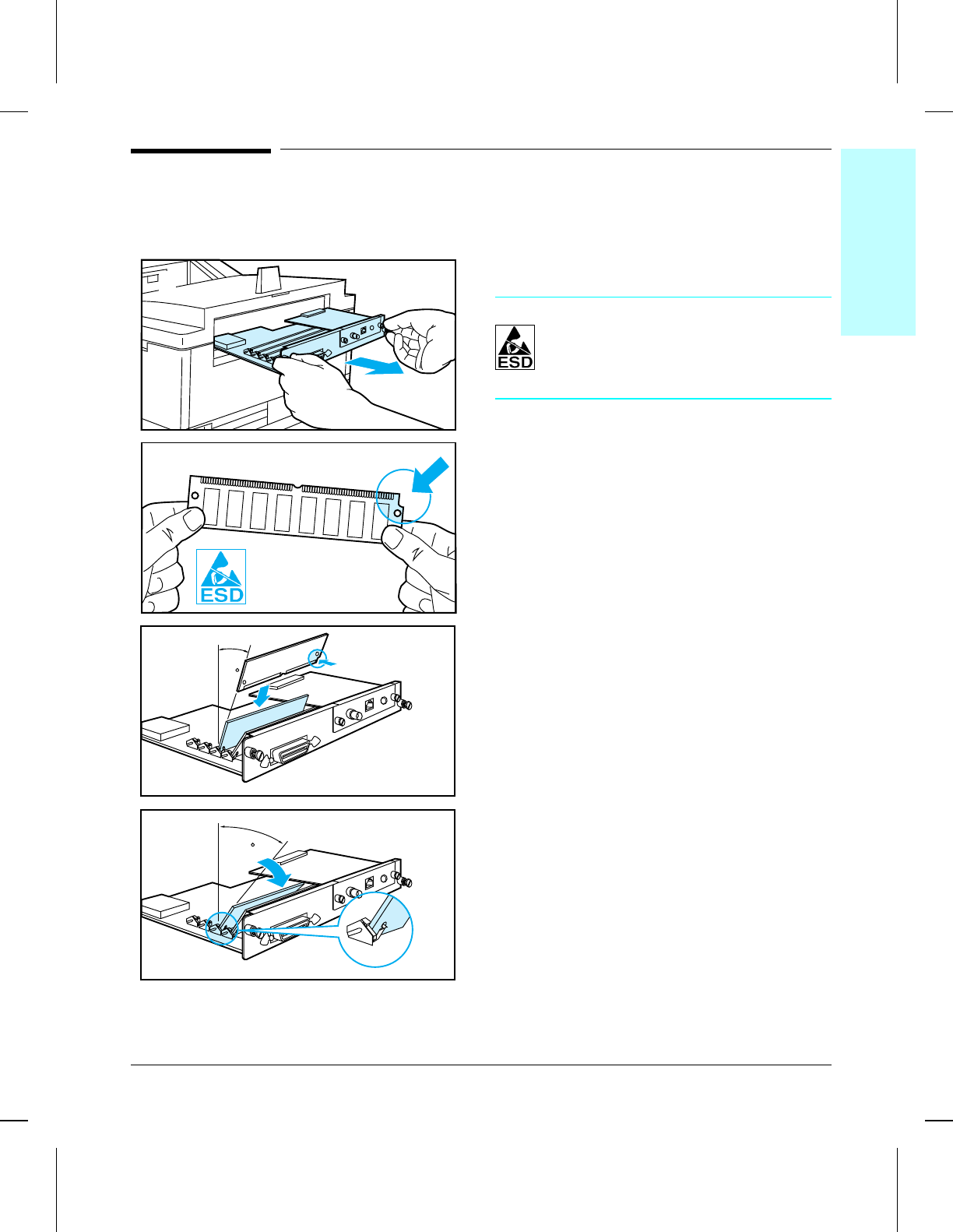
User Installable Accessories
Memory Upgrade
CAUTION
SIMMs and the Formatter PCA can be
damaged by small amounts of
electro-static discharge (ESD). Wear
an anti-static wrist strap.
1With the printer OFF and unplugged,
loosen the two captive screws and remove
the Formatter PCA.
2Remove the SIMM from the anti-static
package. Hold the board with your
forefingers on the side edges and your
thumbs against the back edge, so the
notch on one end is on the right and the
metal teeth face toward the SIMM slot
(match the positioning shown in frame 2).
3Insert the board firmly into the SIMM slot
at about a 20-degree angle. Use closest
open slot toward the back of the printer.
4Rotate the SIMM toward the back of the
printer to a 45-degree angle until it clicks
into the metal locking tabs. If it is
properly seated, it will not lift away from
the slot. (To remove a SIMM, you must
first release the metal locking tabs.)
5Slide the printer Formatter PCA back into
the printer and tighten the two screws.
6Re-attach any cables and the power cord,
then switch the printer ON and print a
self-test to verify the new memory is
available. If the SIMM is not recognized,
turn the printer OFF and reseat the
SIMM. If an error occurs, refer to
“Service and Error Messages” in
Chapter 7.
3
20
45
4
2
1
6Removal &
Replacement
Removal and Replacement 6-5
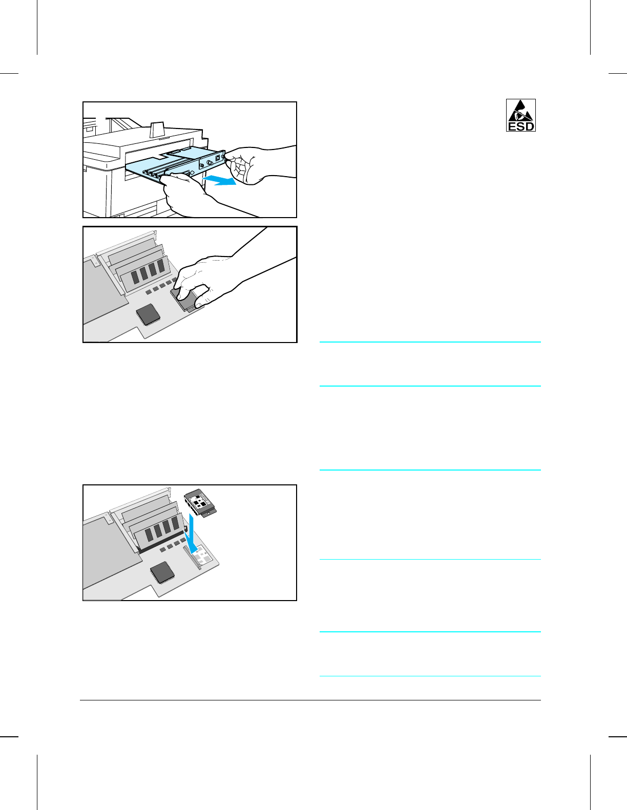
Disk Accessory
The Disk Accessory is housed under a
protective plastic cover on the left rear corner
of the Formatter PCA. The plastic cover and
the disk should be removed as one piece.
1With the printer OFF and unplugged,
loosen (2) captive screws and remove the
Formatter PCA. Place the PCA face-up
on an ESD-safe surface.
2The disk assembly is connected to the
Formatter PCA with two plastic locking
pins and a 50 pin connector. Grasp the
two sides of the disk cover near the
locking pins and lift firmly upward. The
locking pins will release along with the
connector pins of the disk.
To Reinstall:
NOTE
The PostScript option must be installed and
operating before installing the Disk Accessory.
1Hold the disk by the side edges of the cover
and align it with the diagram printed on the
formatter board. Align the connector pins
carefully to prevent bending or
mis-alignment. Align the cover locking pins
with the holes in the formatter board.
CAUTION
Never press on the center of the disk. Press
only on the edge of the cover directly above the
connector to prevent damage to the disk.
Carefully press the connector pins and cover
locking pins into place. Check the connector pins
for proper seating. Re-seat as necessary.
2Print a PostScript Configuration page
(PS CONFIG PAGE) from the control
panel. Verify the entry under “Disk
Accessory” reads “Disk Installed: YES”
and lists available capacity.
NOTE
When the disk drive is replaced, all fonts and
macros must be re-loaded.
2
1
1
6diskdrv
6-6 Removal and Replacement
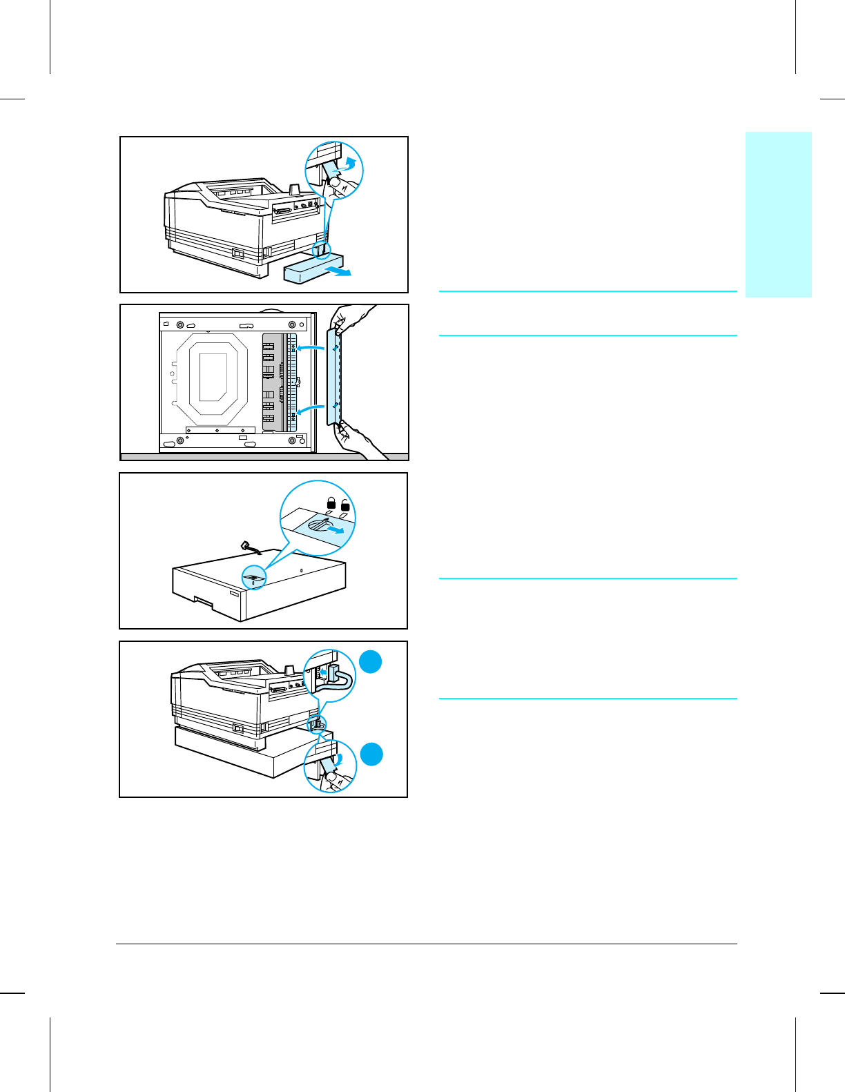
Optional Lower Cassette
The Optional Lower Cassette requires
installation of a Lower Cassette Paper Guide
on the bottom of the printer, as well as
connection of a cable to the rear of the left
foot. Before beginning, unplug the printer
from the power source and remove the toner
cartridge and paper cassette.
WARNING!
Get another person to help handle the printer.
1Remove 11 x 17 / A3 Paper Cassette dust
cover and cable connector cover from back
of printer.
2Turn the printer onto its right side (NOT
the side with exhaust vents). Install the
Lower Cassette Paper Guide and return
the printer to upright position.
3Release Lower Cassette shipping lock to
unlocked position, and set the printer onto
the Lower Cassette base, being careful to
align the locater pins.
4Connect the Lower Cassette base cable
into the connector (A), and replace the
cable connector cover (B).
NOTE:
The Paper Cassette and Lower Cassette
Paper Guide must be in place for the Lower
Cassette to operate properly.
When the Lower Cassette is installed, it
becomes the default paper source.
A
B
3
4
2
1
6Removal &
Replacement
Removal and Replacement 6-7
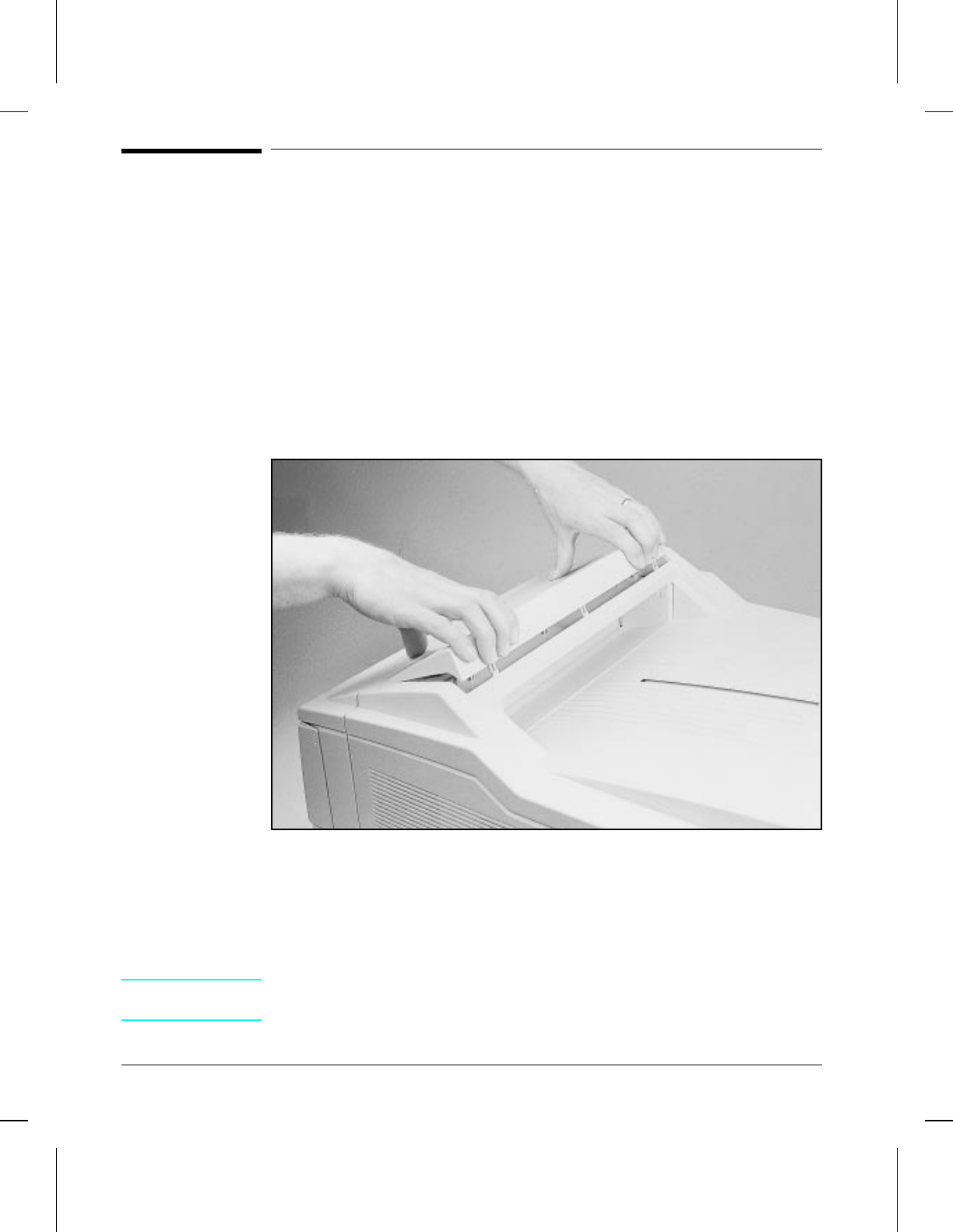
Covers and Doors
The printer covers are in four separate components: the Upper Cover (includes
the Control Panel), the Left and Right Side Covers, and the Rear Cover.
Control Panel
The Control Panel Assembly includes the Control Panel PCA and its plastic
cover as shown in Figure 6-2.
1Press the back of the control panel cover to release the retaining clips (see
Figure 6-2).
2Carefully lift the right end of the control panel cover and disconnect the
cable from the Control Panel PCA.
Removing the Control Panel
To Reinstall:
Be careful to align the tabs at the front of the Control Panel into their
alignment holes. Make sure the tabs at the back of the Control Panel are
placed inside the Upper Cover before pressing into place.
NOTE When replacing a control panel that has a non-English keyboard overlay, be
sure to remove the overlay and install on the new control panel.
6CONPNL
6CONPNLWMF
Figure 6-2
6-8 Removal and Replacement
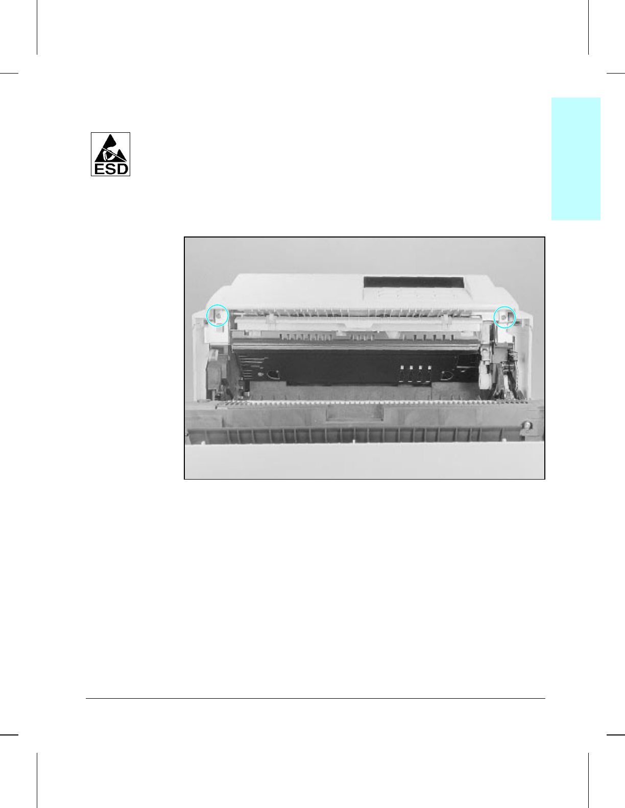
Upper Cover
The Upper Cover is held in place by two screws, which are accessed from
the front of the printer.
1Open the front door.
2Remove (2) screws shown in Figure 6-3.
3Tilt the front of the cover up, slide it to the rear, unsnap cable from retainer,
and unplug the control panel connector from the Interface PCA.
Upper Cover
6TCOVER
6TCOVERWMF
Figure 6-3
6Removal &
Replacement
Removal and Replacement 6-9
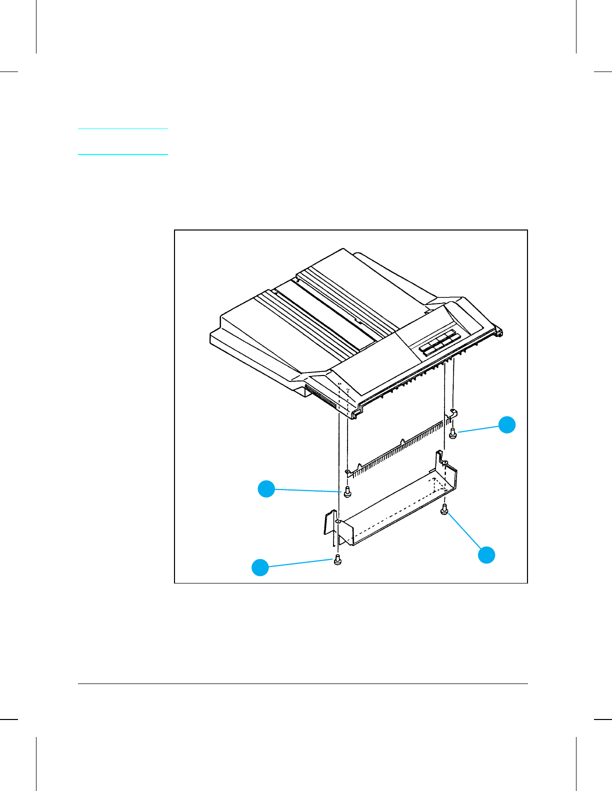
Static Charge Eliminator
CAUTION Remove the Static Charge Eliminator only if replacing. Removing it may
damage the accessory.
1Remove Upper Cover (see Figure 6-3).
2Remove delivery tray by removing (2) screws (Figure 6-4, callout 1).
3Remove (2) screws (Figure 6-4, callout 2).
4Using needlenose pliers, remove the Static Charge Eliminator.
Static Charge Eliminator
2
2
11
Figure 6-4
6-10 Removal and Replacement
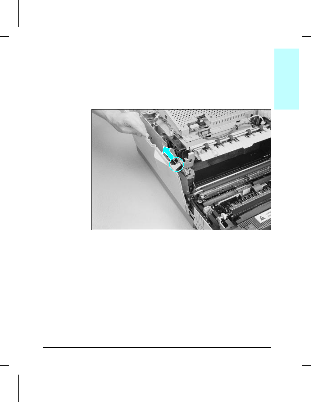
Side Covers
1Remove the Upper Cover (Figure 6-3).
NOTE The left cover tab (shown) presses to the rear; the right cover tab presses to
the front.
2Press on the tab to release the top edge of each side cover (Figure 6-5).
3Tilt the cover outward and lift up.
Removing Side Covers
To Reinstall:
Make sure the locator tabs at the bottom of the covers are properly placed in
the alignment holes in the chassis before snapping covers into place.
6LFTCVR
6LFTCVRWMF
Figure 6-5
6Removal &
Replacement
Removal and Replacement 6-11
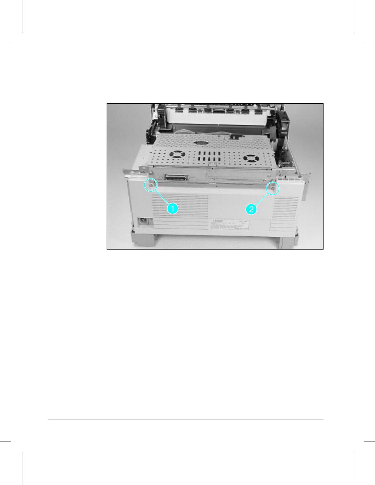
Rear Cover
1Remove (1) machine screw (Figure 6-6, callout 1) and (1) shoulder screw
(Figure 6-6, callout 2).
2Tilt the cover outward and lift off.
Removing Rear Cover
To Reinstall:
Make sure the locator tabs at the bottom of the covers are properly placed in
the alignment holes in the chassis before snapping covers into place.
6REARCVR
6REARCVRWMF
Figure 6-6
6-12 Removal and Replacement
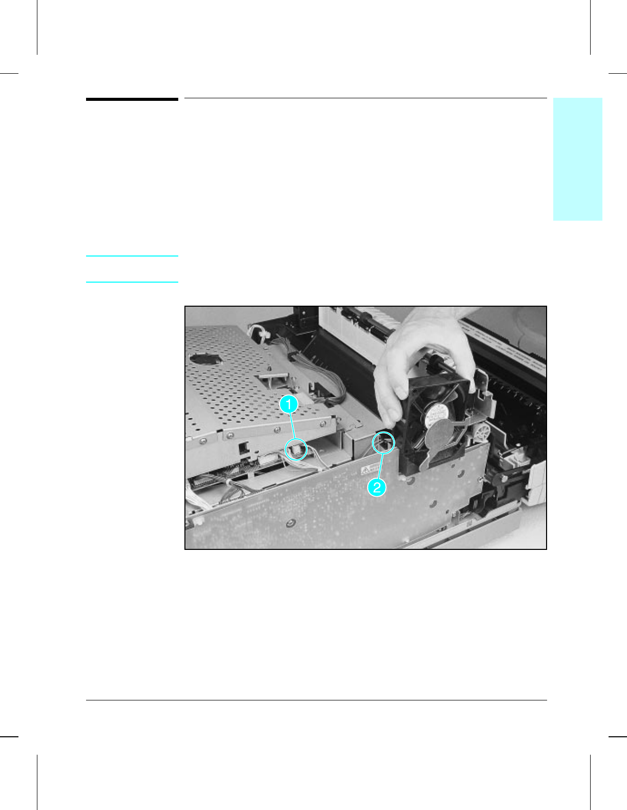
Left Side Assemblies
Exhaust Fan (FM1)
The Exhaust Fan is located on the left side of the printer, just above the
High Voltage Power Supply PCA.
1Unplug the fan connector from the DC Controller (Figure 6-7, callout 1) and
remove the cable from the (2) clips (Figure 6-7, callout 2).
2Lift the fan out of its mounting, noting the position of the cabling (attaches
to lower left outside of the fan body).
NOTE Removal of the Card Cage provides easier access to the connector on the
DC Controller PCA, especially when reconnecting (Figure 6-7, callout 1).
Exhaust Fan
To Reinstall:
Make sure that the fan is installed in the correct direction (exhaust, not
intake). The cables should be toward the outside.
6fusfan
6fusfanwmf
Figure 6-7
6Removal &
Replacement
Removal and Replacement 6-13
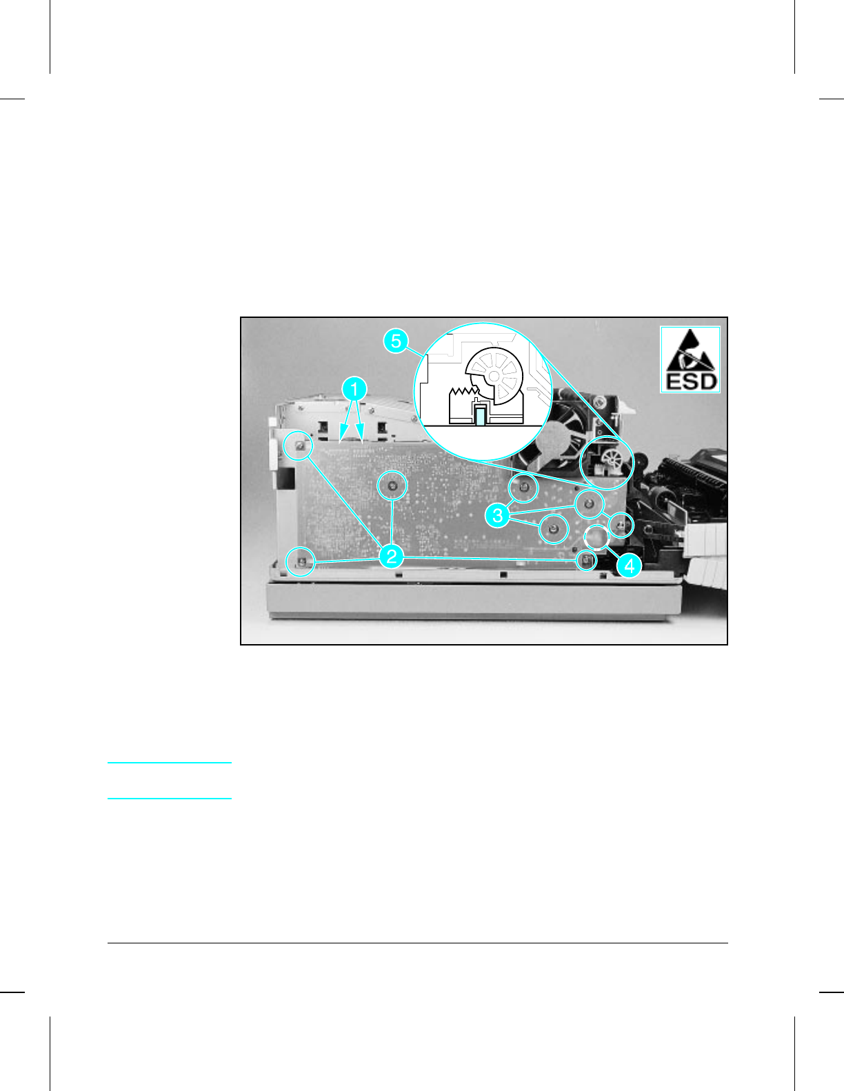
High Voltage Power Supply PCA
The High Voltage Power Supply is located along the left side of the printer.
1Remove the (2) connectors (Figure 6-8, callout 1).
2Remove (4) machine screws (Figure 6-8, callout 2).
3Remove (4) self-tapping screws (Figure 6-8, callout 3).
4Bend back the plastic cover and remove (1) machine grounding screw
located beneath the plastic cover (Figure 6-8, callout 4).
5Remove the PCA.
High Voltage Power Supply PCA
To Reinstall:
Note the position of the Print Density Dial, and how it is seated in the slide
adjustment as shown in Figure 6-8, callout 5.
CAUTION If the Print Density Dial is not seated properly, the printer will not print
properly.
6HVPS
6HVPSWMF
Figure 6-8
6-14 Removal and Replacement
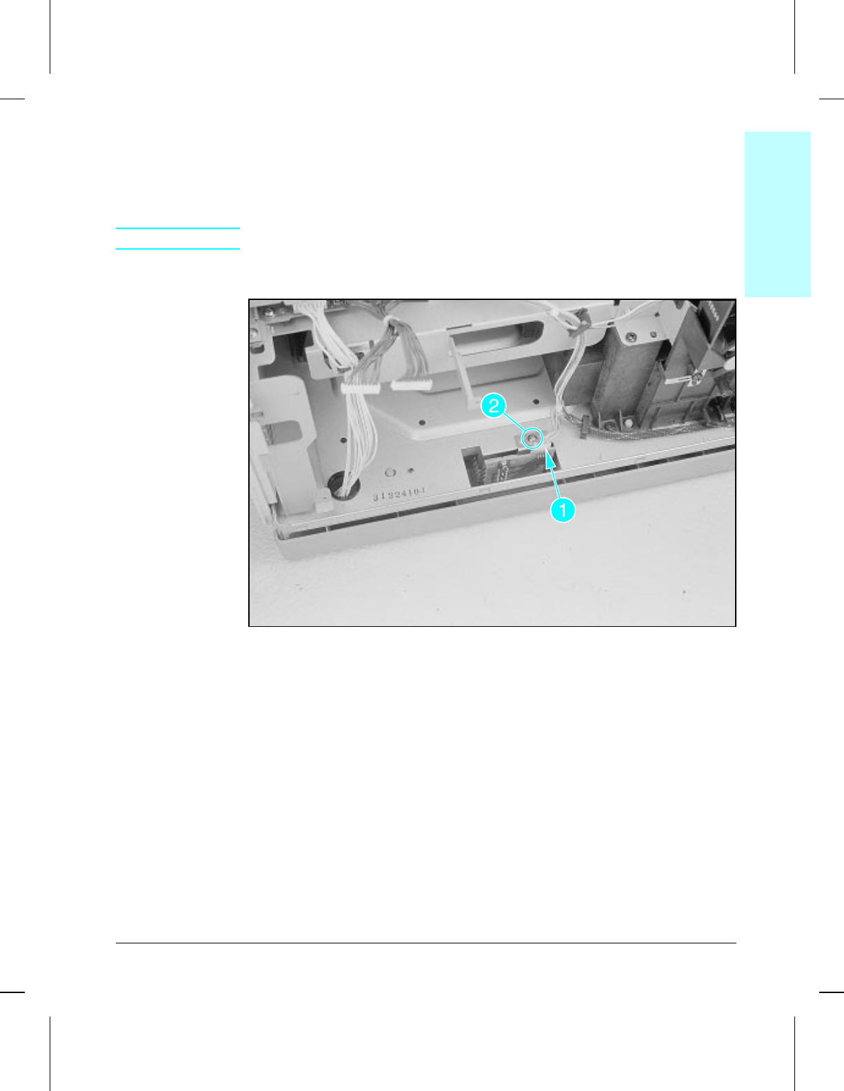
Cassette Size Sensor Assembly
1Remove the High Voltage Power Supply PCA (see Figure 6-8).
2Disconnect the cable (see Figure 6-9, callout 1).
3Remove the (1) machine screw (see Figure 6-9, callout 2).
CAUTION Be careful not to damage the sensor tabs when removing the assembly.
4Carefully lift the Cassette Size Sensor Assembly up and out of the chassis.
Cassette Size Sensor Assembly
To Reinstall:
Make sure the Cassette Size Sensor Assembly mounting bracket fits
properly over the chassis locating pins when replacing the assembly.
Make sure the connector is fully inserted into its receptacle.
6papsen
6papsenwmf
Figure 6-9
6Removal &
Replacement
Removal and Replacement 6-15
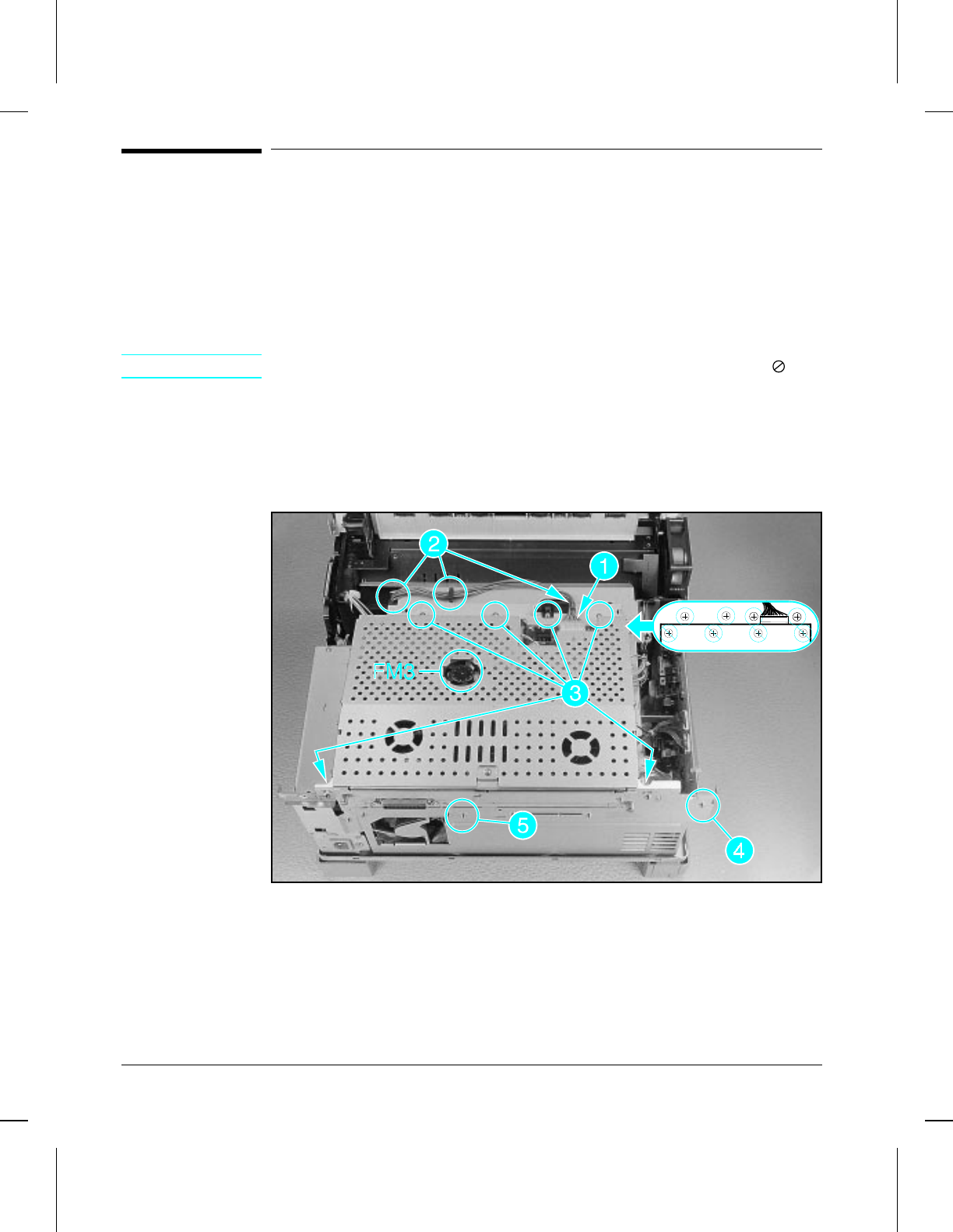
Rear and Top Area Assemblies
Card Cage
The Card Cage is located directly underneath the Upper Cover. It is not
necessary to remove the Formatter or MIO from the Card Cage.
1Disconnect the interface cable (Figure 6-10, callout 1).
2Release the cable from the (3) cable clips (Figure 6-10, callout 2).
NOTE Do not remove (2) screws indicated in Figure 6-20 by the null symbol ( ).
3Remove (6) screws (four are in line with the cable clip, and two at the rear)
from the top of the plate (Figure 6-10, callout 3).
4Remove (1) screw from the back of the plate (Figure 6-10, callout 4).
5Loosen (do not remove) (1) screw as shown in Figure 6-10, callout 5.
6Lift the Card Cage off of the printer.
Card Cage
To Reinstall:
When reinstalling the Card Cage pay careful attention to the routing of the
cables and the position of the cable clip shown in Figure 6-10, callout 2.
6cardcg
6cardcgwmf
Figure 6-10
6-16 Removal and Replacement
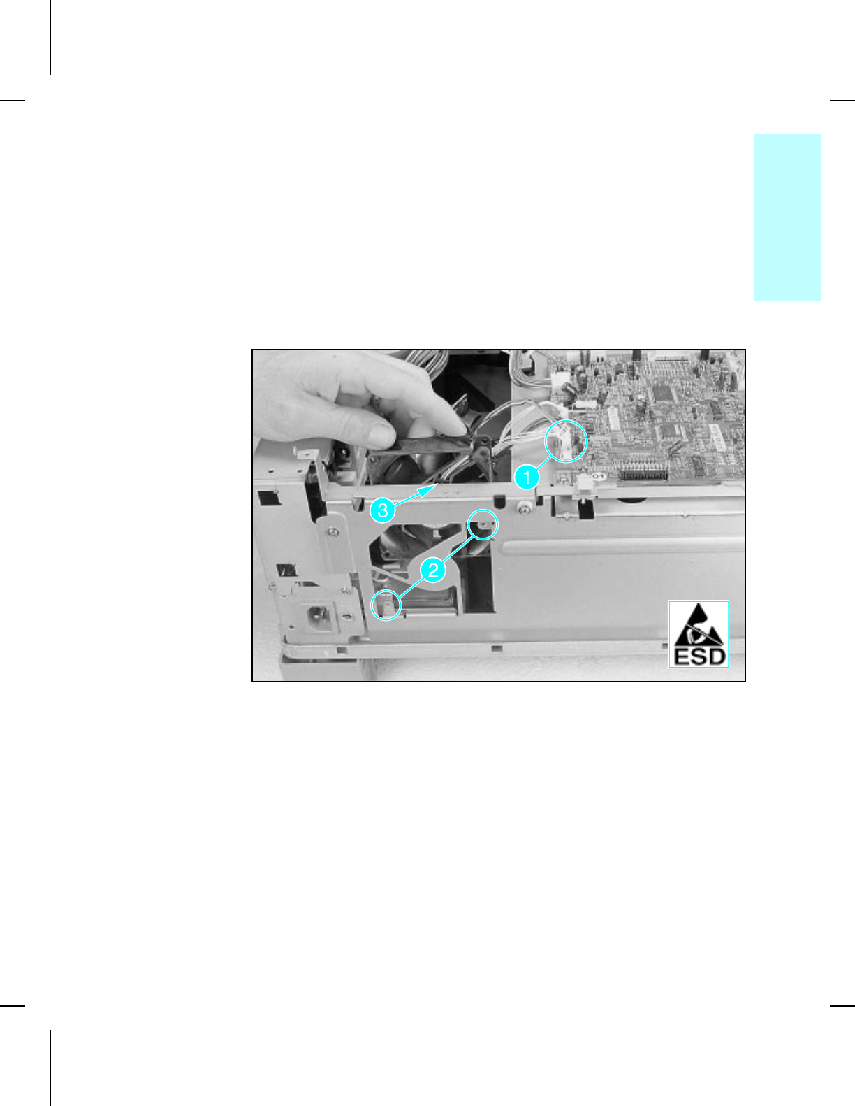
Rear Exhaust Fan (FM2)
The Rear Exhaust Fan is located on the left rear of the printer chassis, and
requires prior removal of the Card Cage assembly.
1Remove the Card Cage assembly (see Figure 6-10).
2Unplug the fan cable connector and release it from its cable clip
(Figure 6-11, callout 1).
3Remove (2) small machine screws from the rear of the printer (Figure 6-11,
callout 2).
4Lift the fan up and away from the printer chassis, noting position of the
cable on the upper right corner of the fan body (Figure 6-11, callout 3).
Rear Exhaust Fan
To Reinstall:
Make sure the fan body is seated to the rear of the chassis mounting tabs.
6cardcg
6cardcgwmf
Figure 6-11
6Removal &
Replacement
Removal and Replacement 6-17
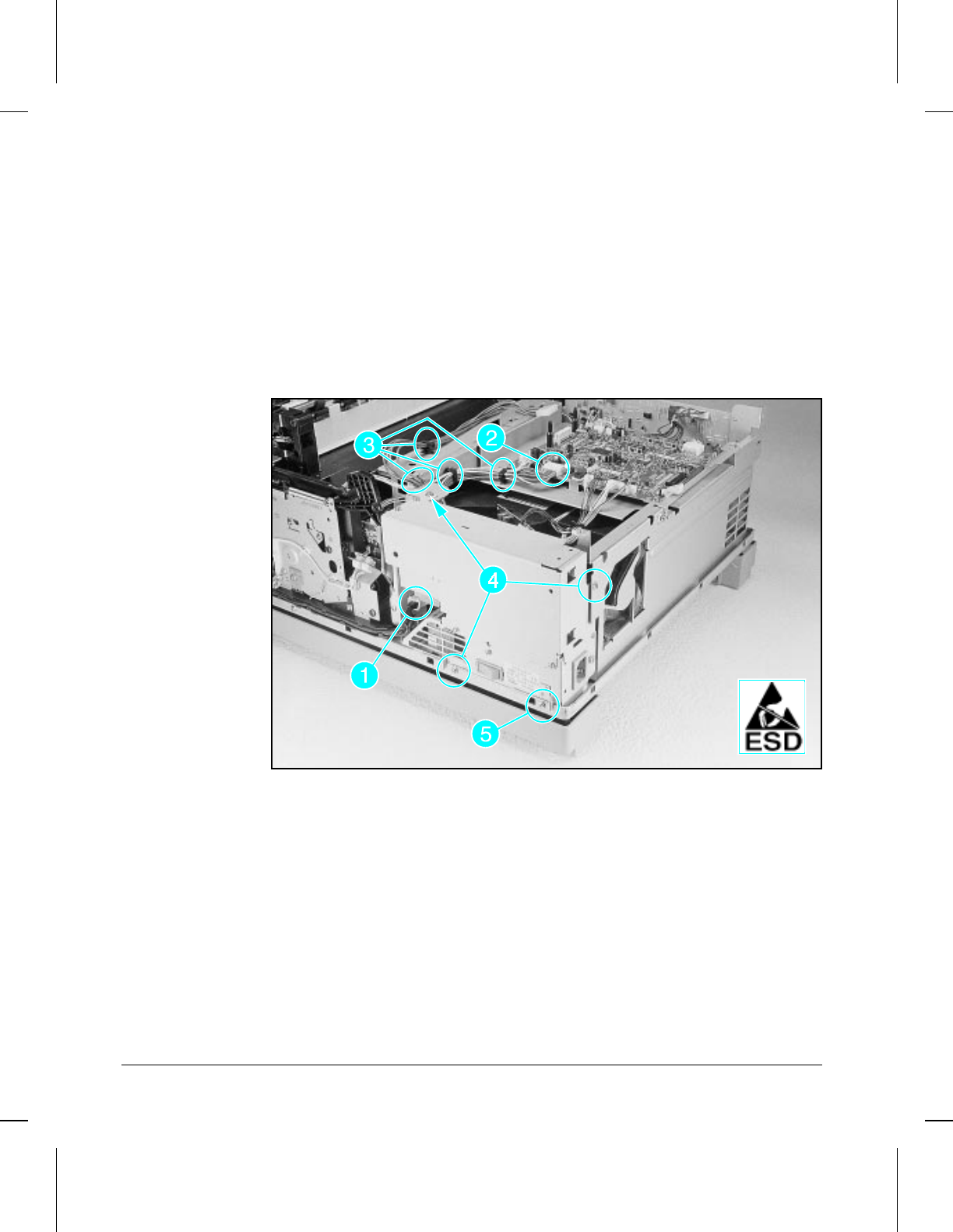
Power Supply Unit
The front door must be opened prior to removing the Power Supply Unit.
1Remove the Card Cage assembly (see Figure 6-10).
2Unplug the connector from the Fusing assembly (Figure 6-12, callout 1).
3Unplug the connector from the DC Controller PCA (Figure 6-12, callout 2).
4Remove the cables from the (4) cable clips (Figure 6-12, callout 3) and
remove the DC Controller and Formatter power cables.
5Remove (3) machine screws (Figure 6-12, callout 4).
6Remove (1) machine grounding screw with star washer (Figure 6-12, callout 5).
7Lift the assembly up to clear the chassis and pull sideways out of the printer.
Power Supply Unit
6acin
6acinwmf
Figure 6-12
6-18 Removal and Replacement
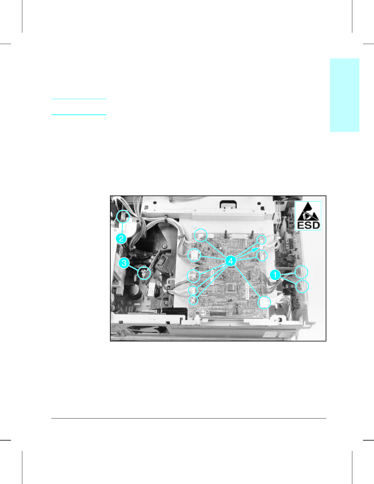
DC Controller PCA
The DC Controller PCA is located directly beneath the Card Cage assembly.
1Remove the Card Cage assembly (see Figure 6-10).
CAUTION (4) connectors are hardwired to the DC Controller and must be unplugged at
the other end of the wires.
2Unplug (2) connectors from the top edge of the High Voltage Power Supply
PCA (Figure 6-13, callout 1).
3Unplug (1) connector from the top of the main motor and release the cable
from the (3) clips (Figure 6-13, callout 2).
4Unplug (1) connector from the side of the Laser Scanner PCA and release it
from its clip (Figure 6-13, callout 3).
5Unplug (9) connectors from the PCA (Figure 6-13, callout 4).
6The DC Controller is now free. Slide it toward the back of the printer and
lift out.
DC Controller PCA
dccont
dccontwmf
Figure 6-13
6Removal &
Replacement
Removal and Replacement 6-19
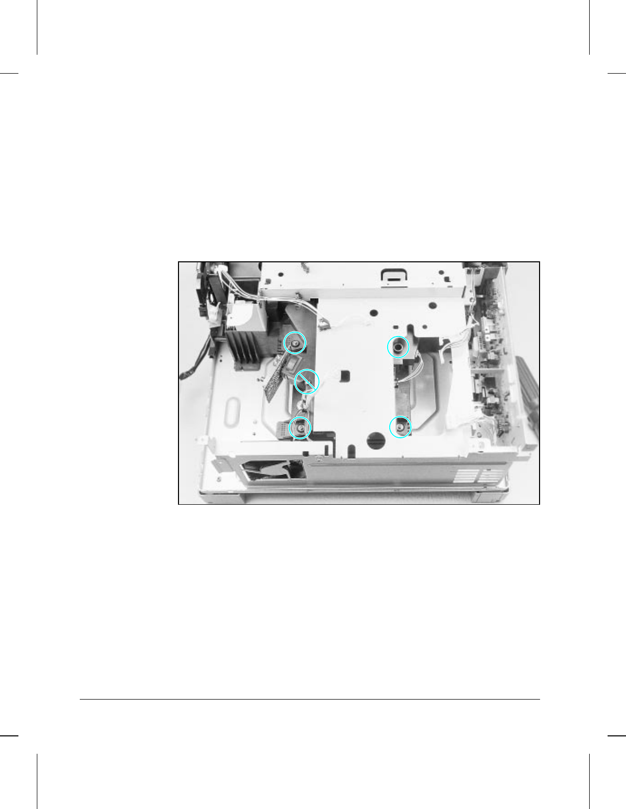
Laser/Scanner Assembly
The Laser/Scanner assembly is located under the DC Controller PCA.
1Remove the following components:
•Card Cage assembly (Figure 6-10)
•Rear Exhaust Fan (FM2) (Figure 6-11)
•Power Supply Unit (Figure 6-12)
•DC Controller PCA (Figure 6-13)
2Remove (4) long, machine screws (Figure 6-14).
3Lift up slightly to disengage from alignment pins and carefully slide the
Laser/Scanner assembly out the side of the printer chassis.
Laser/Scanner Assembly
To Reinstall:
Make sure that assembly engages alignment pins.
6scan
6scanwmf
Figure 6-14
6-20 Removal and Replacement
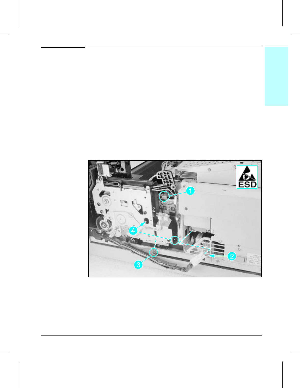
Right Side Assemblies
Main Motor (M1)
The Main Motor is located adjacent to the Power Supply Unit. Other than
the covers, the Main Motor assembly does not require removal of any other
assemblies.
1Unplug the cable connector from the top of the Main Motor (Figure 6-15,
callout 1).
2Disconnect the Fuser cable from the Power Supply Unit (Figure 6-15,
callout 2).
3Remove (1) machine screw securing the right end of the cable tray, and drop
the cable tray downward out of the way (Figure 6-15, callout 3).
4Remove (2) large diameter, machine screws (Figure 6-15, callout 4).
5The Main Motor is now free. Lift it up and out of the printer, being careful
to clear any cables.
Main Motor
To Reinstall:
Make sure that the shaft meshes properly with the gear.
Leave screws loose until both are started, then tighten.
6mainmtr
6mainmtrwmf
Figure 6-15
6Removal &
Replacement
Removal and Replacement 6-21
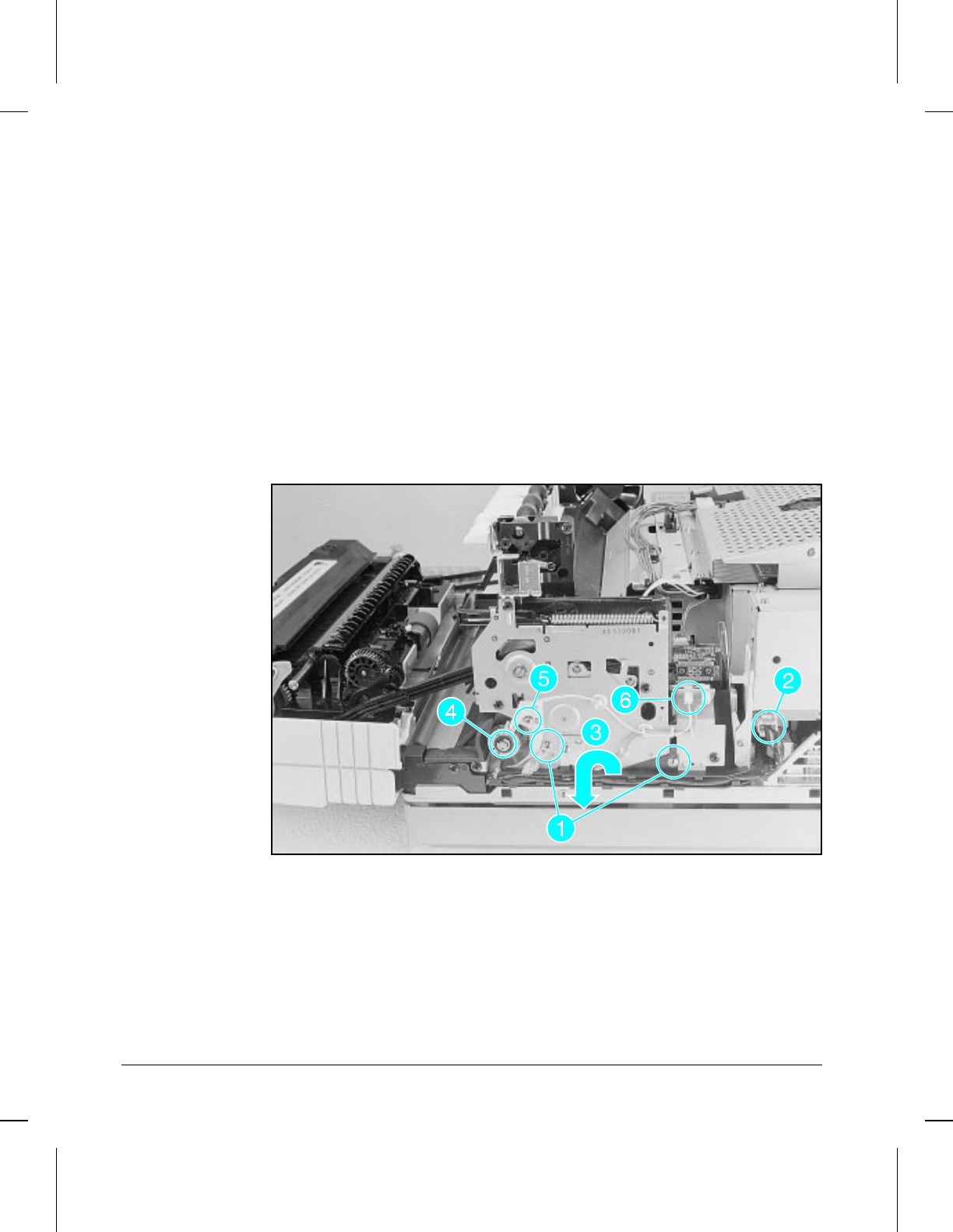
Main Drive Assembly
The Main Drive assembly is located on the right side of the printer toward
the front.
1Remove (2) machine screws (Figure 6-16, callout 1).
2Unplug the Fuser connector from the Power Supply Unit (Figure 6-16,
callout 2).
3Lift out plastic cable shield and pull the cable tray out of the way
(Figure 6-16, callout 3).
4Carefully remove the e-clip from the registration clutch shaft (Figure 6-16,
callout 4).
5Remove (1) screw from the registration clutch alignment guide and remove
the guide (Figure 6-16, callout 5).
6Unplug the registration clutch connector (Figure 6-16, callout 6).
7Slide the registration clutch off the shaft and free its cable from the cable
clips.
Main Drive Assembly Removal (1 of 2)
(continued on next page)
6geartn1
6geartn1wmf
Figure 6-16
6-22 Removal and Replacement
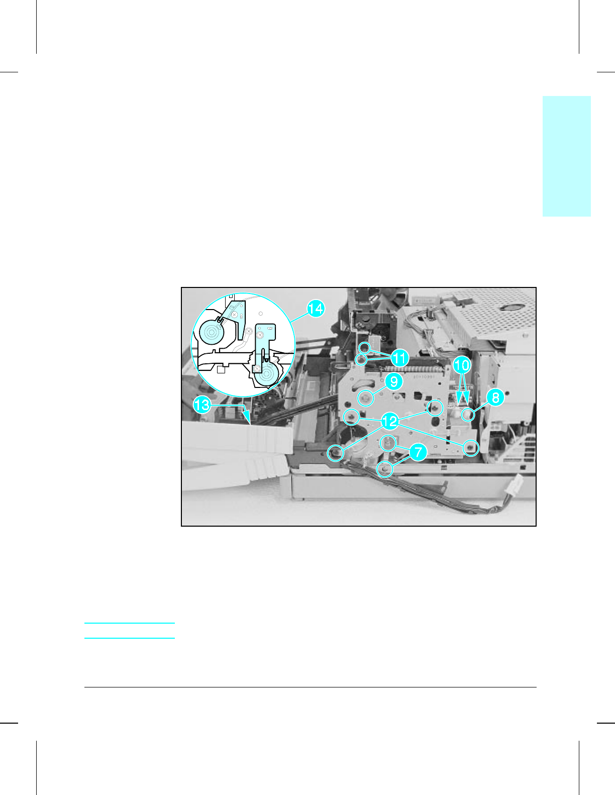
8Remove (2) screws from the pickup clutch alignment guide (metal) and
remove the guide (Figure 6-17, callout 7).
9Unplug the pickup clutch connector and remove its cable from the clips
(Figure 6-17, callout 8).
10 Carefully remove the e-clip, washers and bushing from the shaft
(Figure 6-17, callout 9).
11 Unplug the upper end of the two connectors on the Main Drive assembly
(Figure 6-17, callout 10).
12 Remove (2) self-tapping screws securing the Upper Cover mounting bracket
and remove the bracket (Figure 6-17, callout 11).
13 Remove (4) self-tapping screws (Figure 6-17, callout 12).
14 While supporting the weight of the front door, release the Front Door
retainer arm by pushing out on the retainer arm clamp (Figure 6-17,
callout 13).
15 The Main Drive assembly is now free. Slide it outward from the printer.
Main Drive Assembly Removal (2 of 2)
To Reinstall:
When reinstalling the Main Drive assembly be certain to align the
alignment tabs with the notch on both the registration roller clutch and the
pickup roller clutch (Figure 6-17, callout 14).
NOTE The smaller diameter e-clip fits on the registration clutch.
6geartrn
6geartrnwmf
Figure 6-17
6Removal &
Replacement
Removal and Replacement 6-23
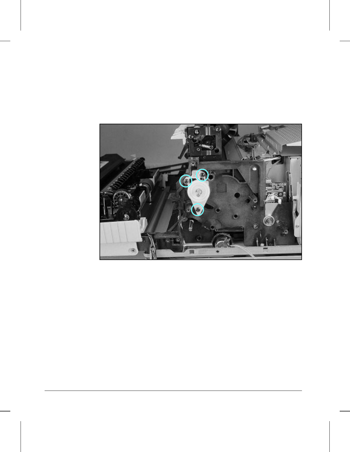
Drum Drive Assembly
The Drum Drive assembly is located directly behind the Main Drive
assembly.
1Remove the toner cartridge.
2Remove the Main Drive assembly (see Figure 6-16).
3Remove (3) self-tapping screws (Figure 6-18).
4Slide the assembly out of the printer.
Drum Drive Assembly
6drmgear
6drmgearwmf
Figure 6-18
6-24 Removal and Replacement
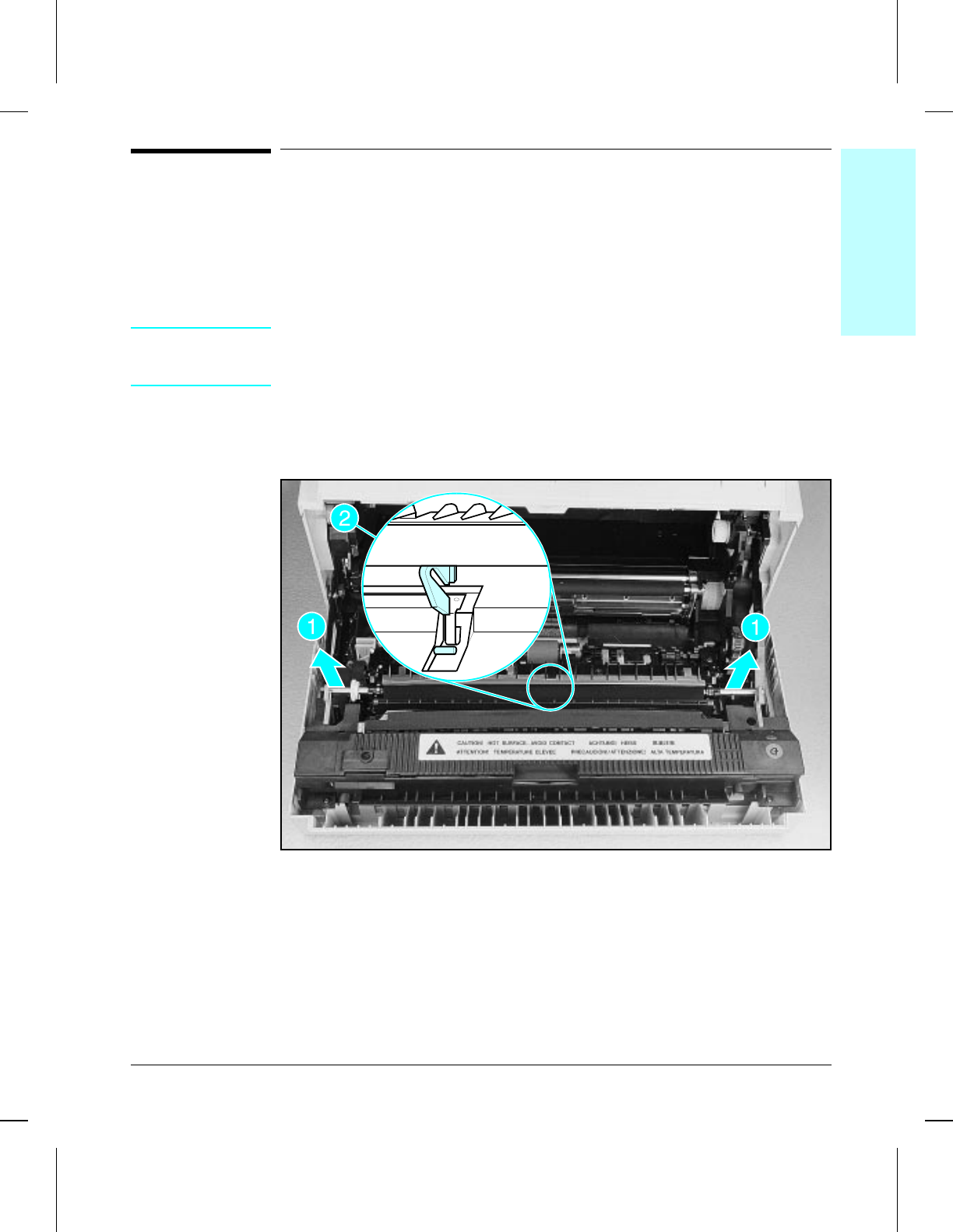
Front Door Assemblies
All Front Door assemblies can be removed without prior removal of any
covers or other components.
Transfer Roller Assembly
CAUTION Handle the Transfer Roller from the ends only. Do not touch the surface of
the Transfer Roller. Skin oils will affect its electrical characteristics,
resulting in poor image transfer.
1Grasp the shaft on either end of the Transfer Roller and lift upward to snap
out of the plastic retainer clip (Figure 6-19, callout 1).
2Lift the opposite end up and out of its retainer clip.
Transfer Roller Assembly
To Reinstall:
Be sure that the non-gear end of the shaft is to the right.
Also make sure that the alignment slot (plastic tab) on the underneath side
of the Transfer Roller slips over the locator pin (Figure 6-19, callout 2).
6tranrol
6tranrolwmf
Figure 6-19
6Removal &
Replacement
Removal and Replacement 6-25
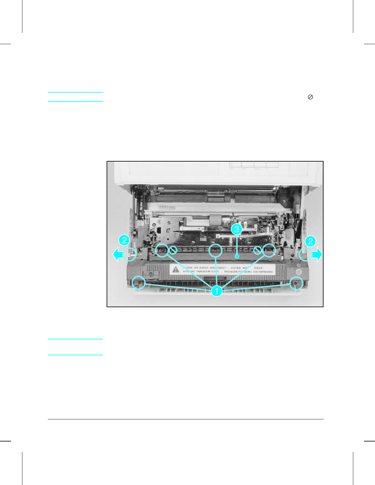
Fusing Assembly
The Fusing assembly is located on the upper portion of the printer door.
CAUTION Do not remove (2) screws indicated in (Figure 6-20) by the null symbol ( ).
1Remove the Transfer Roller (see Figure 6-19).
2Remove (5) machine shoulder screws (Figure 6-20, callout 1).
3Pull outward on the edges of the Front Door assembly to release the shaft
(Figure 6-20, callout 2).
4Lift the Fusing assembly up and out.
Fusing Assembly
To Reinstall:
CAUTION Make sure that the Protection Plate (Figure 6-20, callout 3) is in place or
damage to the toner cartridge drum will occur.
6fuser
6fuserwmf
Figure 6-20
6-26 Removal and Replacement
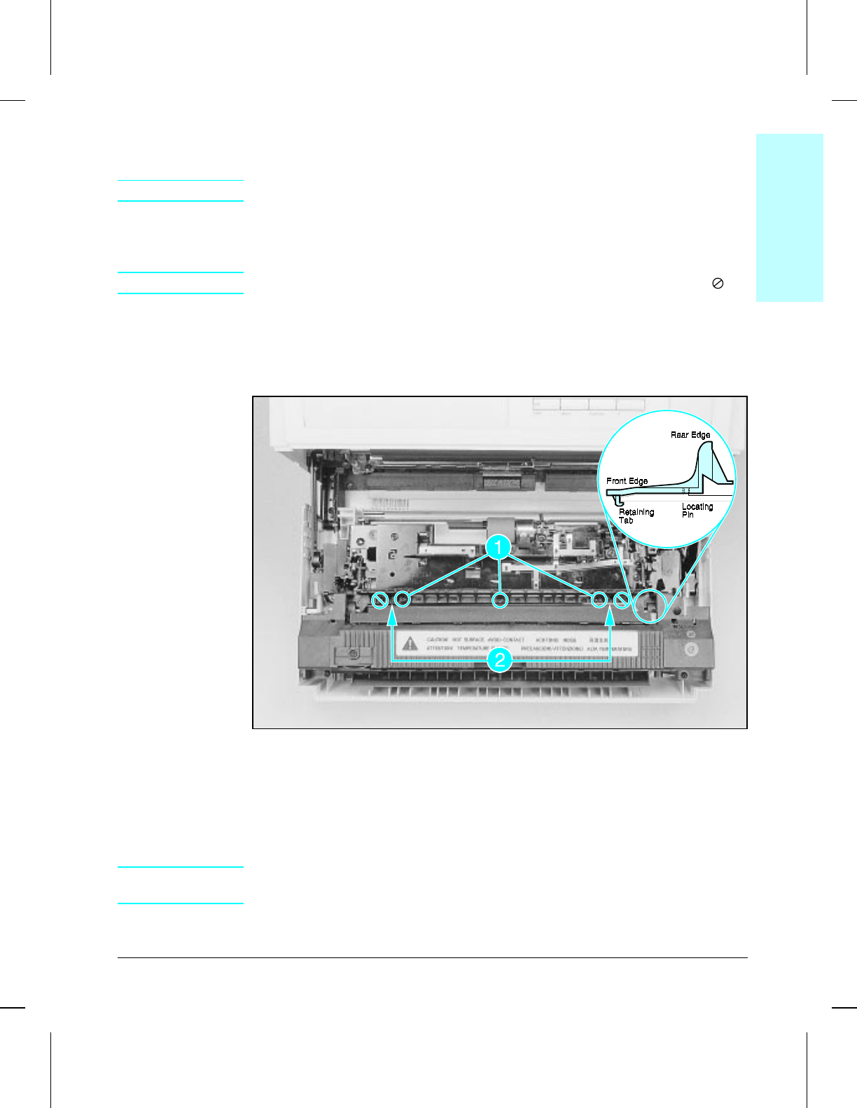
Fuser Inlet Guide
WARNING The Fuser Inlet Guide contains the anti-static teeth. They are VERY sharp.
The Fuser Inlet Guide is located inside the Front Door assembly just
forward of the Transfer Roller.
NOTE Do not remove (2) screws indicated in (Figure 6-21) by the null symbol ( ).
1Remove the Transfer Roller (See Figure 6-19).
2Remove (3) screws (washers on two end screws only) (Figure 6-21, callout 1).
3Lift the rear edge of the guide to clear locating pins (Figure 6-21, callout 2).
Push to the front while tilting the front edge upward to clear retaining tabs.
Fuser Inlet Guide
To Reinstall:
1To determine initial placement, align the guide over the locating pins but do
not snap them into place.
2While tilting the front edge downward to engage the retaining tabs, push
the guide to the rear and downward to snap over the locating pins.
CAUTION The (2) washers must be in place (one on each outer screw) and the guide
seated, with retaining tabs located correctly, or paper jams will occur.
3Replace the (3) screws, ensuring that the (2) spring washers are in place.
6inguide
6inguidewmf
Figure 6-21
6Removal &
Replacement
Removal and Replacement 6-27
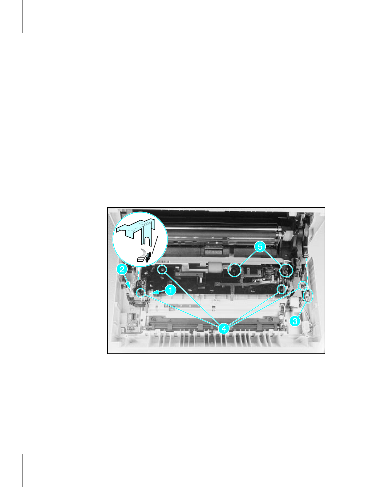
Paper Guide Plate Assembly
The Paper Guide Plate assembly contains the MP Tray pickup roller, motor,
and gear assemblies, and requires prior removal of the Transfer Roller and
Fusing assembly.
1Remove the Transfer Roller (see Figure 6-19).
2Remove the Fusing assembly, (see Figure 6-20).
3Carefully remove the small spring attached to the sensor assembly shown in
Figure 6-22, callout 1.
4From the left side of the assembly push on the retainer tab and lift off the
plastic cable shield (already removed in Figure 6-22).
5Unplug (1) connector shown in Figure 6-22, callout 2.
6Release the right door retainer arm by pushing out on the retainer arm
clamp (Figure 6-22, callout 3).
7Remove (4) self-tapping screws (Figure 6-22, callout 4).
8Remove (2) long, machine screws (Figure 6-22, callout 5).
9The Paper Guide Plate assembly is now free. Lift it upward and out of the
printer.
Paper Guide Plate Assembly
To Reinstall:
Align the two plastic alignment pins and pull the tension off the MP Guide
Plate assembly while lowering. Note that the assembly must be pressed
downward against the grounding springs before it is fully seated. Be sure
the sensor assembly spring is put back in place (Figure 6-22, callout 1).
6mpguide
6mpguidewmf
Figure 6-22
6-28 Removal and Replacement
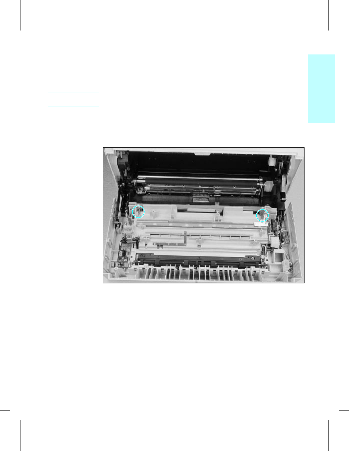
MP Guide Plate
The MP Guide plate is located adjacent to the MP Pickup Roller assembly
and requires prior removal of the Paper Guide Plate assembly.
CAUTION The springs on each end of the plate are under tension. Be careful when
releasing.
1Using needle-nosed pliers, carefully release the tension on (2) springs
(Figure 6-23).
2Snap the left and right hinge retainers off the shafts on the bottom of the
assembly. Lift the MP Guide plate assembly up and out.
MP Guide Plate
6spring
6springwmf
Figure 6-23
6Removal &
Replacement
Removal and Replacement 6-29
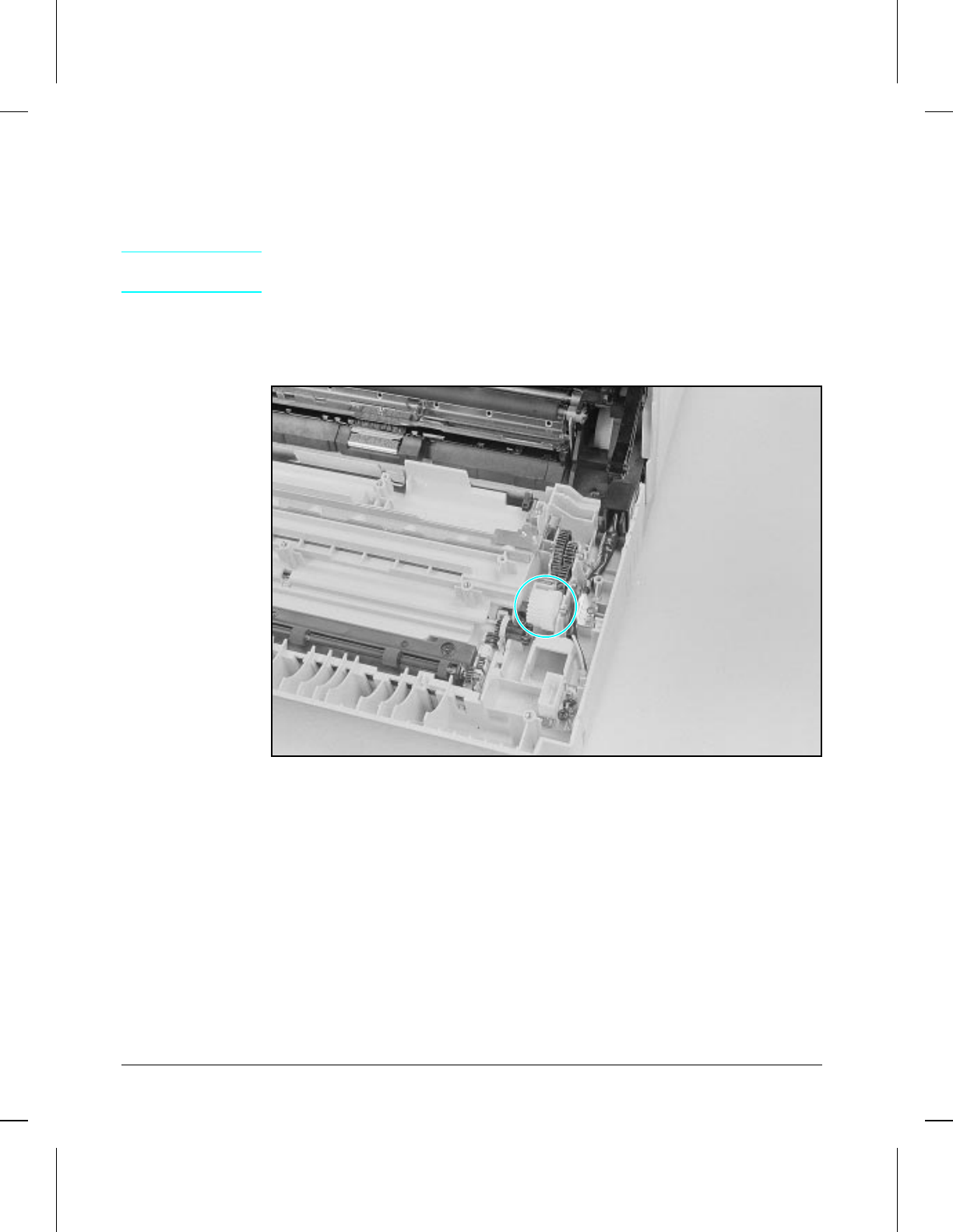
MP Drive Gears
The MP Tray Drive Gears are housed within the Front Door assembly
directly under the Paper Guide Plate assembly.
NOTE The Drive Gear that is circled in Figure 6-24 requires prior removal of the
Fuser Door (see Figure 6-25, callout 2).
1Remove the Fusing Assembly and the Paper Guide Plate assembly (see
Figures 6-20 and 6-22).
2The gears are now free (except large gear— see note above).
MP Drive Gears
To Reinstall:
Pay close attention to the shaft locations and diameters when reinstalling
the gears.
6mpgears
6mpgearswmf
Figure 6-24
6-30 Removal and Replacement
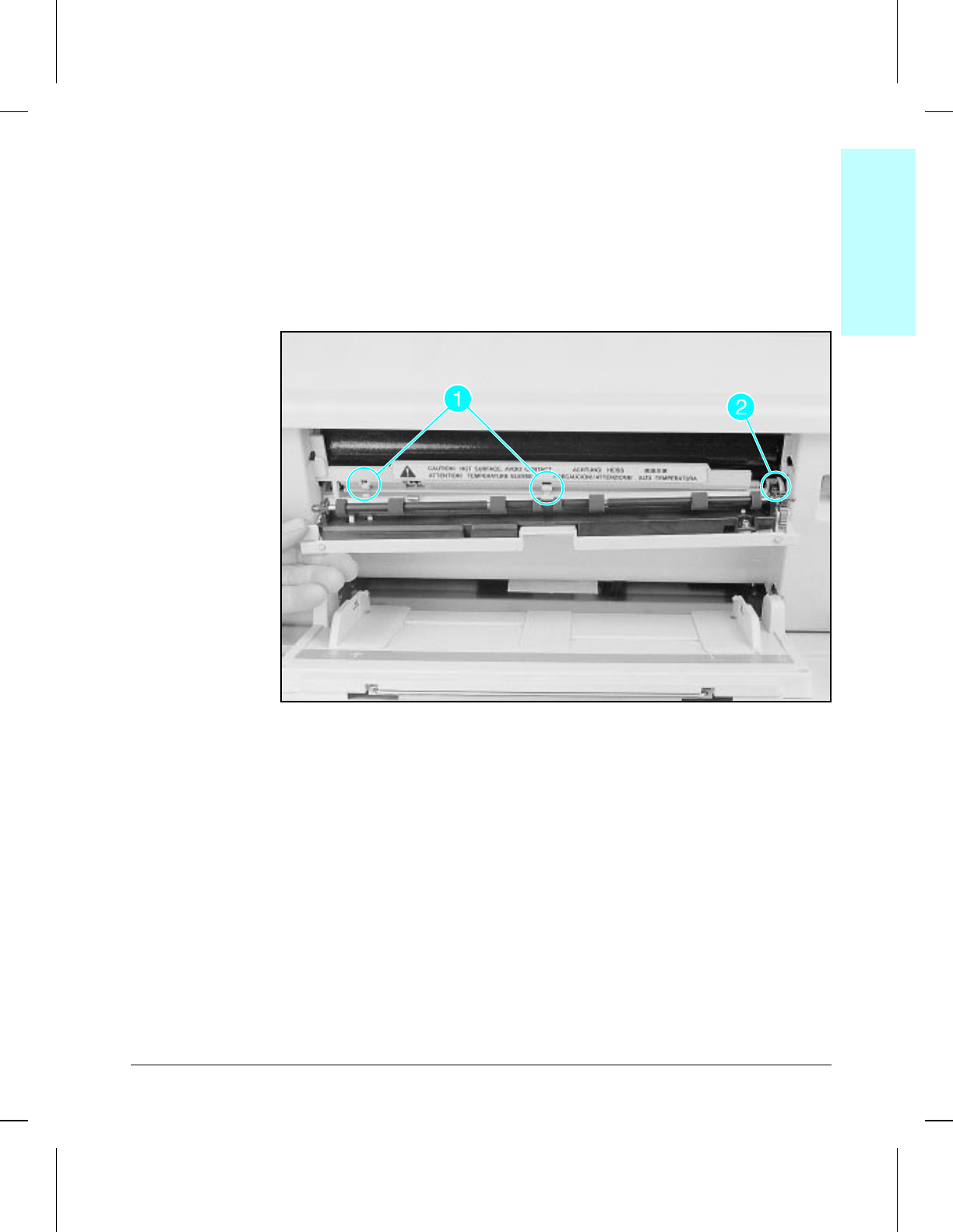
Fuser Door
The Fuser Door is accessed with the printer front door closed and the MP
Tray open.
1Open the Fuser Door part way and press downward on the left end to
release (2) plastic retainer clips from the pins (see Figure 6-25, callout 1).
2Rotate upward to nearly closed, then slide the door assembly outward and
to the left to clear the gear on the right end (Figure 6-25, callout 2).
Fuser Door
To Reinstall:
When reinstalling, align the ring on the right end with the gear before
tilting the door into place (Figure 6-25, callout 2).
6fusdoor
6fusdoorwmf
Figure 6-25
6Removal &
Replacement
Removal and Replacement 6-31
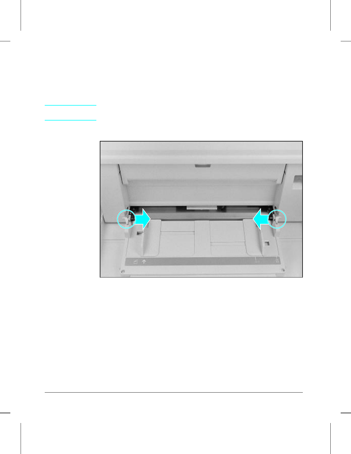
MP Tray
To remove the MP Tray the printer front door must be closed and the MP
Tray open.
1Grasp right and left edges of the MP Tray and squeeze inward to release
retainer arms.
NOTE The plastic retainer arms are designed to pop out when snapped downward.
This requires a quick, firm snapping action to free the MP Tray.
2Slide tray outward off the hinge pins (see Figure 6-26).
MP Tray
To Reinstall:
Slide the hinge tabs over the plastic hinge pins and squeeze the retainer
clips inward forcefully while lifting the door upward to close.
6mptray
6mptraywmf
Figure 6-26
6-32 Removal and Replacement
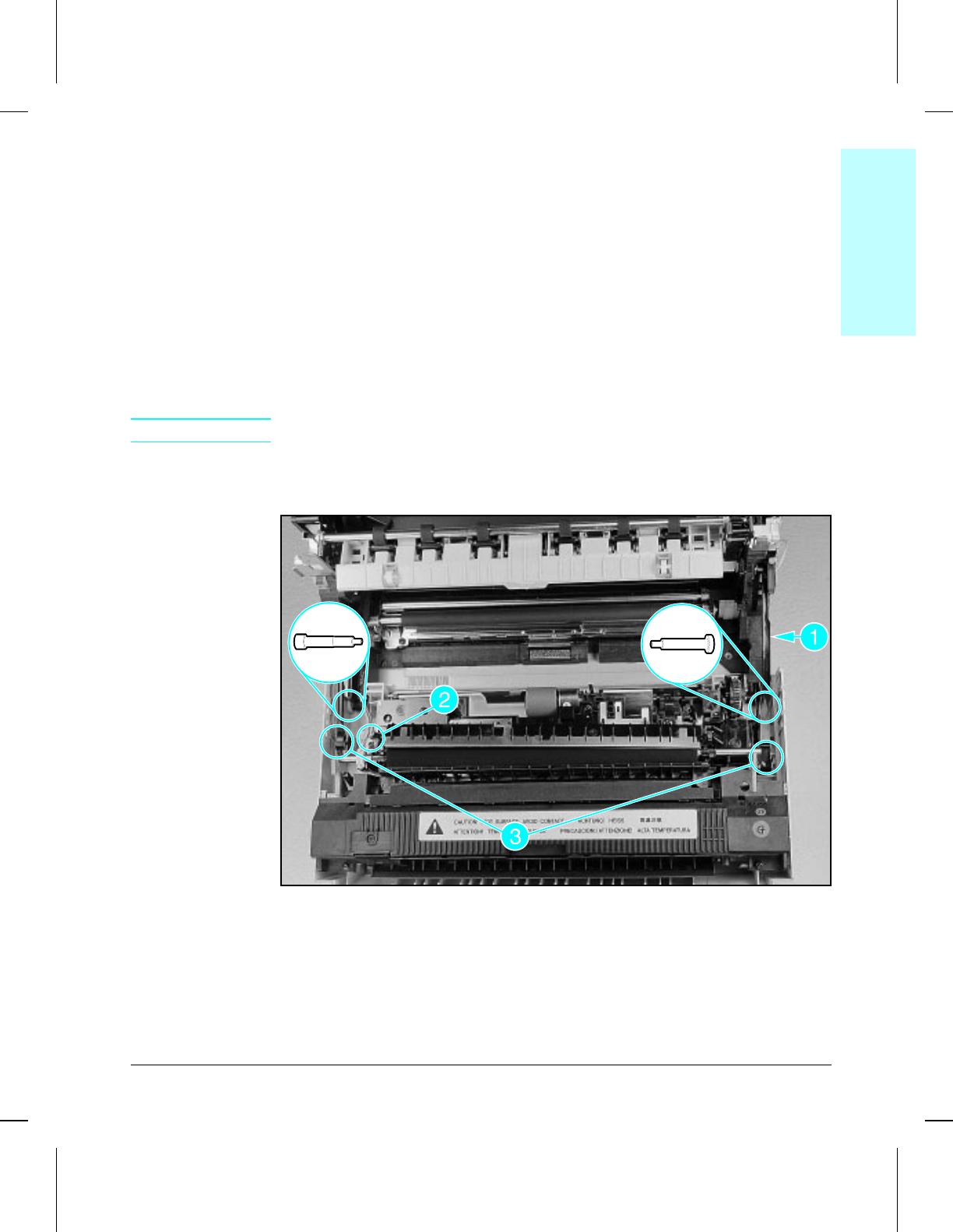
Front Door Assembly
The Front Door assembly is removed as a single assembly and requires
prior removal of the printer covers and the MP Tray.
1Remove the MP Tray (see Figure 6-26).
2Remove (1) screw (Figure 6-27, callout 1) and remove Fuser Cable tray cover.
3Unplug the Fuser Cable (on the right side of the printer) and remove (2)
screws to release the cable tray from the printer chassis (see Figure 6-16,
callout 1).
4Remove the plastic cable shield (already off in photo) and unplug the
rearmost connector on the left side (Figure 6-27, callout 2).
5Gently pry outward on the clips to release the right and left Front Door
retainer arms (Figure 6-27, callout 3).
CAUTION The door assembly is heavy. Use caution when removing the hinge pins.
6Using needle nose pliers, pull the hinge pins outward while supporting the
weight of the Front Door assembly.
Front Door Assembly
To Reinstall:
Note that the hinge pins on the Front Door assembly are different. The
right side hinge pin is transparent in color and has a larger diameter head.
The hinge pin for the left side is opaque and has a smaller diameter head.
6papdoor
6papdoorwmf
Figure 6-27
6Removal &
Replacement
Removal and Replacement 6-33
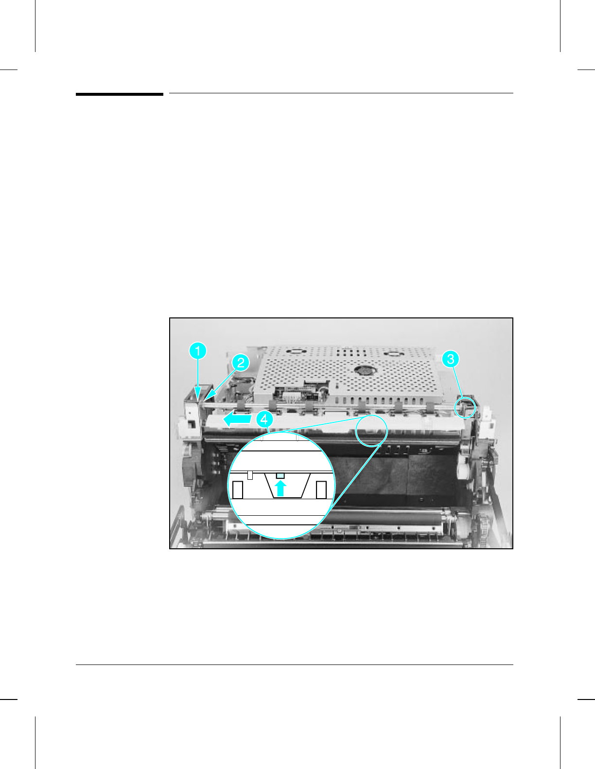
Delivery Area Assemblies
Upper and Lower Delivery Roller Assemblies
The Delivery Roller assemblies are located on top of the printer chassis and
require removal of the Upper Cover to access.
1Remove the e-clip on the left end of the upper roller shaft (Figure 6-28,
callout 1).
2Slide the bushing toward the left to clear the bracket (Figure 6-28, callout 2).
3Lift the left end of the roller shaft upward slightly and slide the right
bushing to the right out of its retainer (Figure 6-28, callout 3).
4Lift the left end of the shaft the rest of the way up and out to clear the gear
on the right end.
5Push upward on small retainer tab located under the plate assembly
(Figure 6-28, callout 4) and slide the assembly to the left to clear its
alignment tabs.
Upper and Lower Delivery Roller Assemblies
6outroll
6outrollwmf
Figure 6-28
6-34 Removal and Replacement
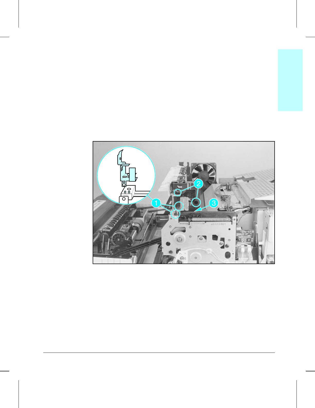
Delivery Gear Assembly
The Delivery Gear assembly is located adjacent to the Upper Delivery
Rollers on the top right end of the printer, and requires previous removal of
the Upper Delivery Roller.
1Remove the Upper Delivery Roller (Figure 6-28).
2Remove (2) self-tapping screws securing the Upper Cover support bracket
(Figure 6-29, callout 1).
3Remove (2) machine screws (Figure 6-29, callout 2).
4Remove (1) self-tapping screw securing the foot of the output roller gears to
the printer chassis (Figure 6-29, callout 3).
5Pull the gear body outward to clear the retainer tab and alignment pins and
lift it up and out of the printer.
Delivery Gear Assembly
6outgear
6outgearwmf
Figure 6-29
6Removal &
Replacement
Removal and Replacement 6-35
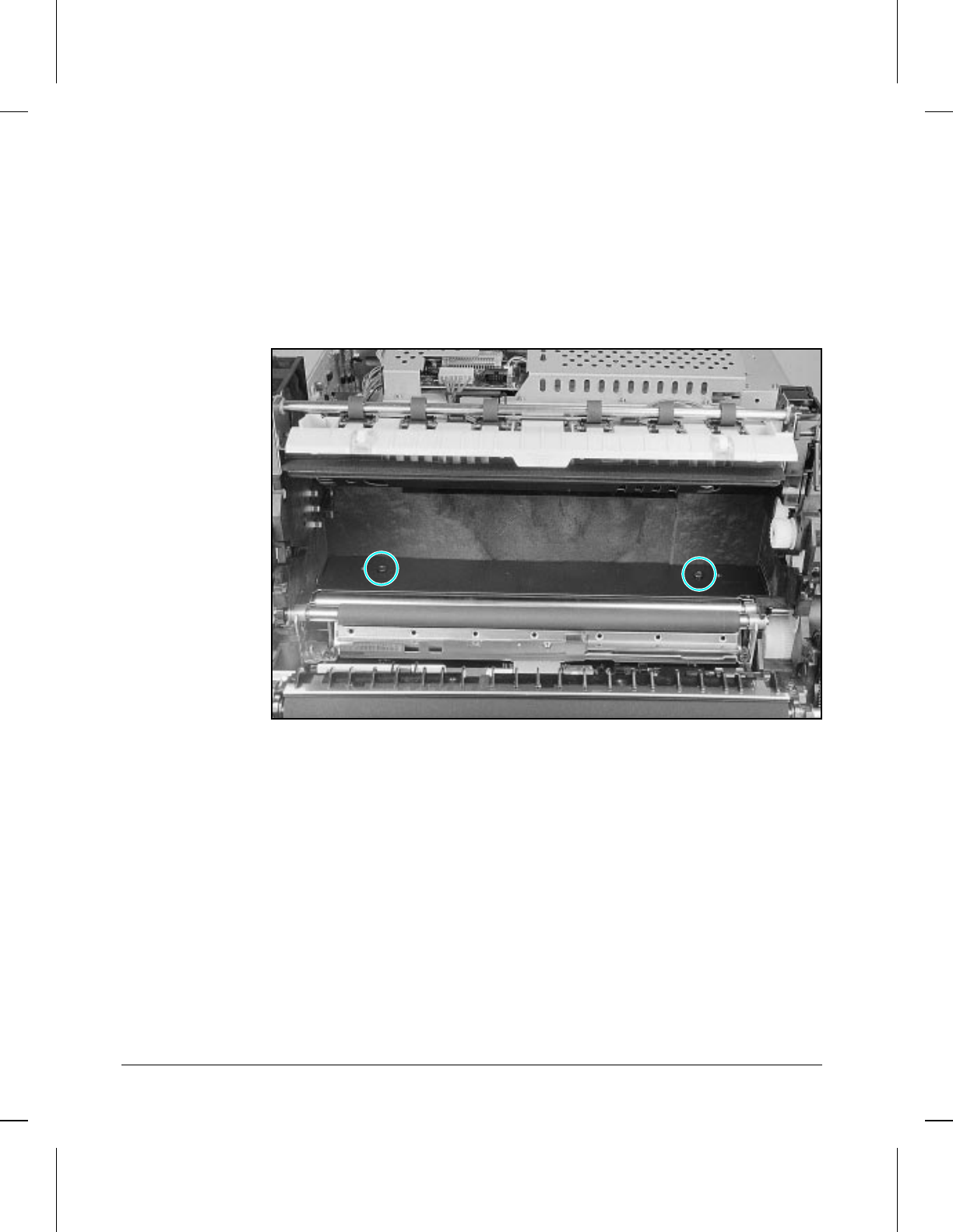
Cartridge Guide
The Cartridge Guide is located directly under the toner cartridge and
behind the Registration Rollers. Note that the removal of this guide does
not require prior removal of the Upper Cover or any upper area assemblies.
1Using a stubby Phillips screwdriver, remove the two self-tapping screws
(Figure 6-30).
2Lift the front edge of the plate upward and slide it forward, out of the
printer. Note that the plate fits tightly within the opening.
Cartridge Guide
6papgde
6papgdewmf
Figure 6-30
6-36 Removal and Replacement
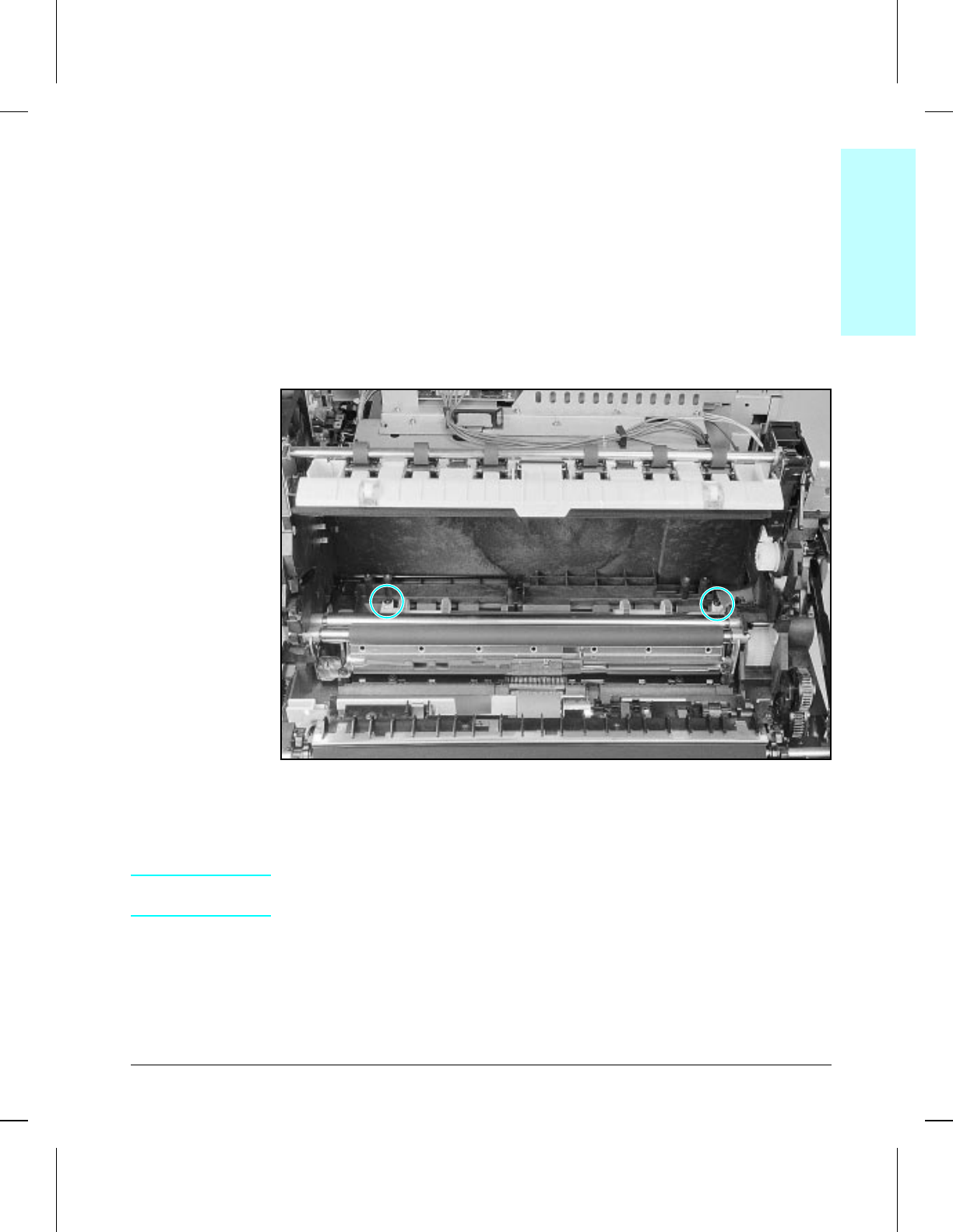
Cassette Pickup Roller Assembly
The Cassette Pickup Roller assembly is located under the Cartridge Guide.
The removal of this assembly requires prior removal of the top and right
side covers and will require a stubby Phillips screwdriver.
1Remove Paper Cassette and Cartridge Guide (Figure 6-30).
2From the right side of the printer, remove the pickup clutch alignment
guide (Figure 6-17, callouts 7 & 8). Unplug and free the clutch cable.
3Remove (2) small diameter, machine screws (Figure 6-31).
4Tilt the roller shaft upward from the left end and lift out, being careful not
to damage the cable.
Cassette Pickup Roller Assembly
To Reinstall:
1Thread the Pickup Roller Clutch Cable underneath the MP Drive Gears on
the right end while sliding the shaft into position.
CAUTION The next step is very important. If the clutch is not aligned properly, paper
will not feed.
2Align the tab on the pickup clutch alignment guide as shown previously in
Figure 6-17, callout 14.
3Align the plastic bearing retainers on each end of the shaft so the flat
portion is facing upward in proper position for the mounting screws.
6lowroll
6lowrollwmf
Figure 6-31
6Removal &
Replacement
Removal and Replacement 6-37
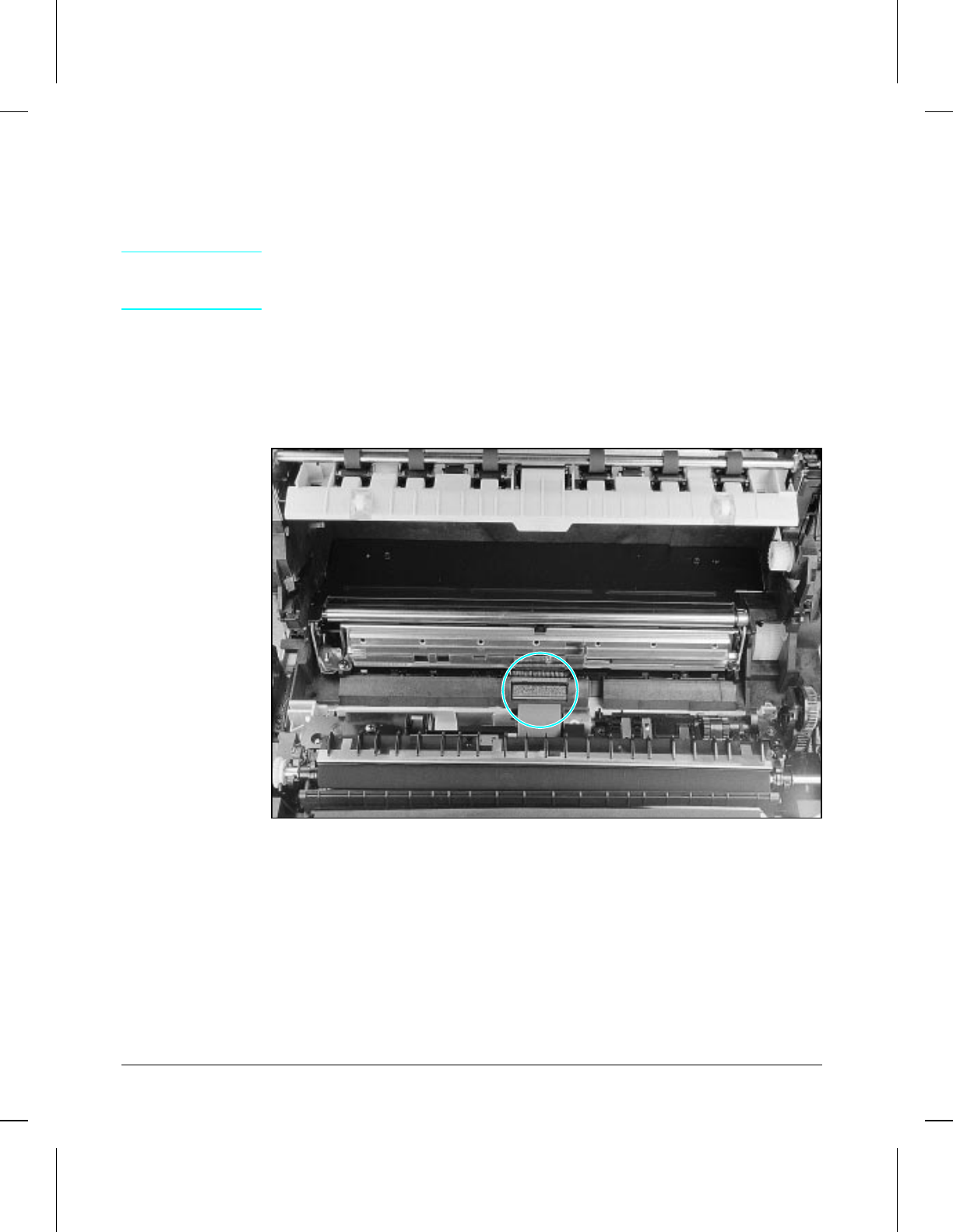
Separation Pad
The separation pad is located adjacent to the Registration Roller, and can be
removed without prior removal of any other parts.
CAUTION Removing the Separation Pad using a screwdriver is likely to damage it. Do
not attempt to remove the Separation Pad unless you have a new
replacement pad available.
To remove:
Use a small flat-blade screwdriver to pry firmly upward at either end of the
separation pad (Figure 6-32).
Separation Pad
6seppad
6seppadwmf
Figure 6-32
6-38 Removal and Replacement
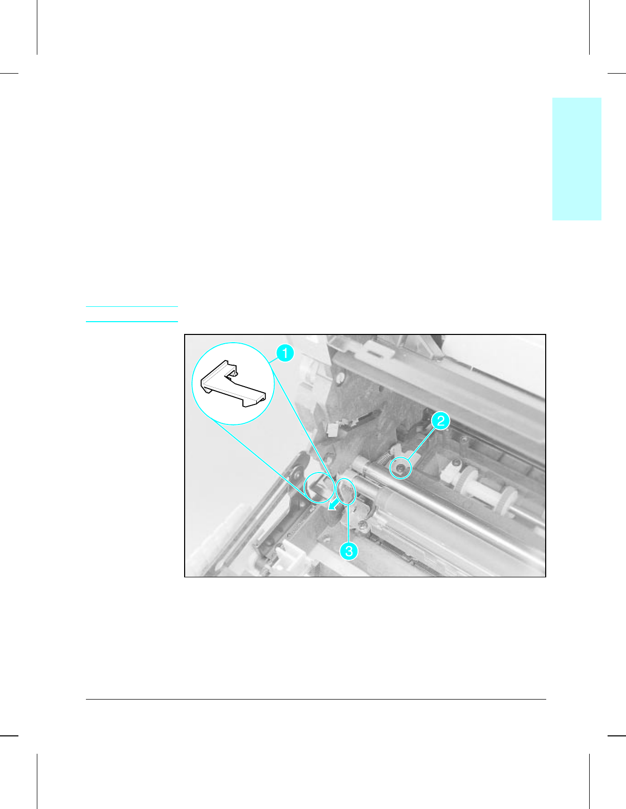
Registration Roller
The Registration Roller requires a stubby magnetic screwdriver and prior
removal of the covers and toner cartridge guide. Removal of the left end of
the Registration Roller is described below. The right end is similar except
there is no plastic retainer tab or metal grounding tab.
1Lift the end of the plastic retainer tab upward and slide to the left to remove
(Figure 6-33, callout 1).
2Remove the self-tapping screw holding the spring retainer plate in place
(Figure 6-33, callout 2). The spring retaining plate is under tension and will
pull to the front as the screw is loosened. Be careful not to drop the screw
into the printer chassis.
3Carefully pull the roller retaining arm to the front while sliding the left end
of the roller out of its alignment slot (Figure 6-33, callout 3).
4Release the right end of the roller in a similar manner.
NOTE Refer to Figure 6-34 for reinstallation details.
Registration Roller (1 of 2)
(continued on next page)
6regroll
6regrollwmf
Figure 6-33
6Removal &
Replacement
Removal and Replacement 6-39
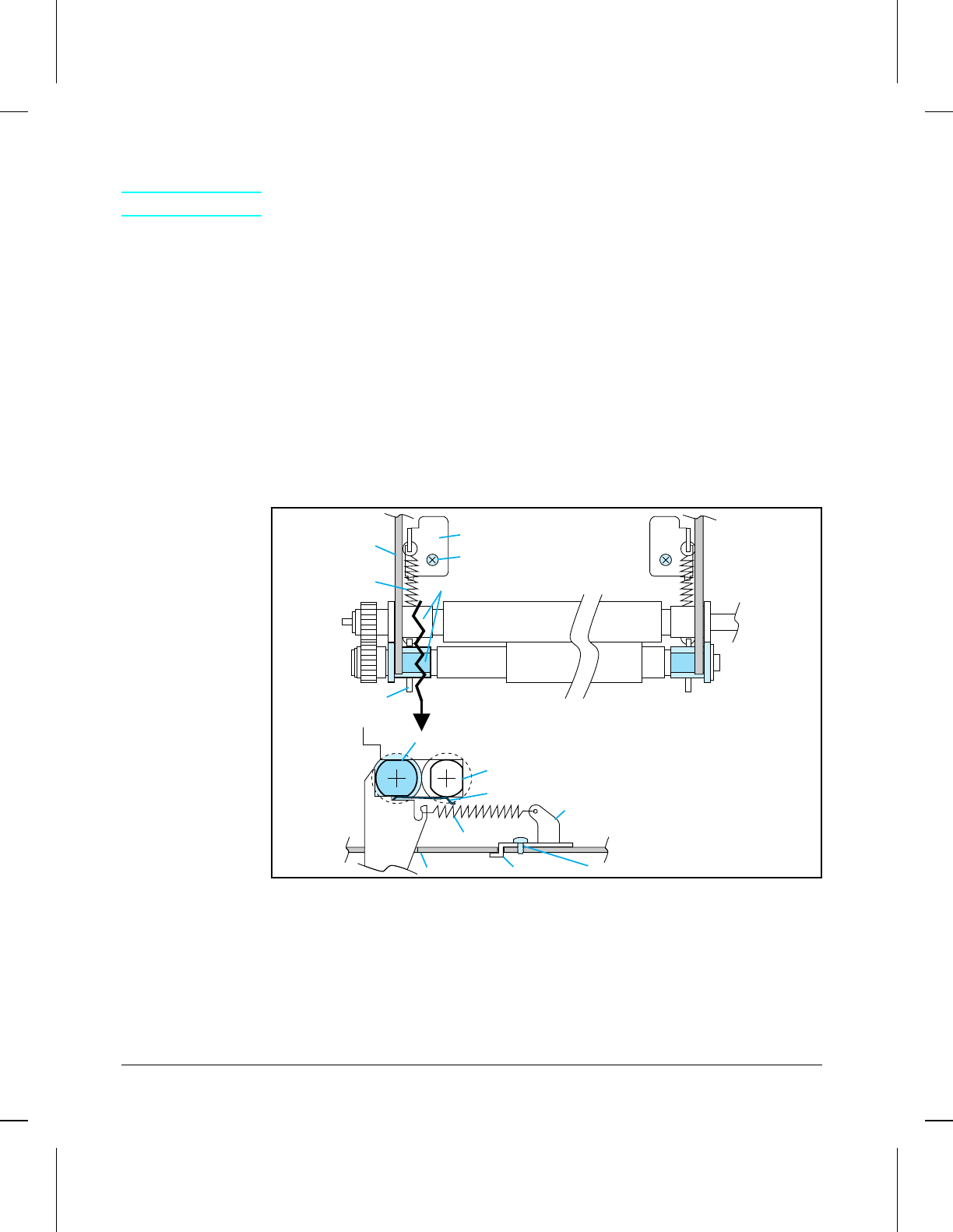
To Reinstall (Registration Roller):
NOTE Refer to Figure 6-34 while reinstalling.
1NOTE the placement of the thin metal grounding tab (see Figure 6-34, side
view) on the left retainer arm. It must slide underneath the bushing on the
rear Transfer Roller as you carefully ease the left retaining arm and left
Registration Roller bushing back into place.
2NOTE the position of the brass bushings on the ends of the Registration
Roller (see Figure 6-34, top view). The flat sides must be horizontal and
the flanges must be outside of the chassis slots.
3Make sure that the gear on the left end of the Registration Roller is properly
meshed before replacing the screws.
4Make sure that the spring retaining plate locating pin is inserted through
the hole in the chassis.
5When replacing the screws holding the spring retainer plates, rock the
plates toward the rear and hold them flat while inserting and starting the
screws. Make sure that the screws are fully tightened before proceeding.
Registration Roller (2 of 2)
TOP
VIEW
Printer
Chassis
Spring Retaining Plate
Self-tapping Screw
Spring
Rear Metal Roller
Registration
Roller
(Rubber)
Roller Retaining Arm
Brass Bushings
CROSS
SECTION
Self-tapping Screw
Spring Retaining Plate
Spring
Roller
Retaining
Arm
Registration Roller
Rear Metal Roller
Metal Grounding Finger
Printer Chassis Locating Pin
6regill
Figure 6-34
6-40 Removal and Replacement
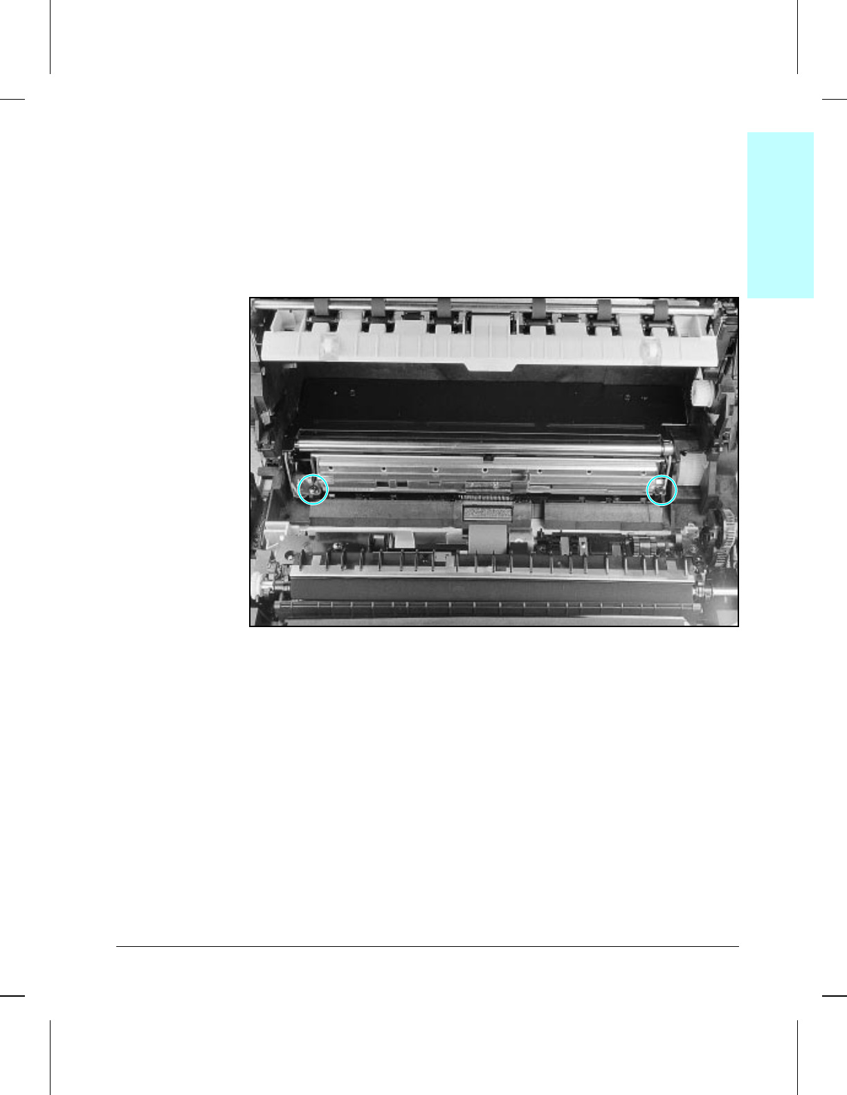
Registration Roller Guide Plate
The Registration Roller Guide Plate is a metal assembly located directly
under the Registration Roller and requires prior removal of the Registration
Roller.
1Remove the Registration Roller (see Figure 6-33).
2Remove (2) self-tapping screws (Figure 6-35).
3Lift the Registration Roller Guide Plate up and out of the printer.
Registration Roller Guide Plate
To Reinstall:
Be careful not to damage the two grounding tabs on the left end of the
Guide Plate as you insert it into place.
6seppad
6seppadwmf
Figure 6-35
6Removal &
Replacement
Removal and Replacement 6-41
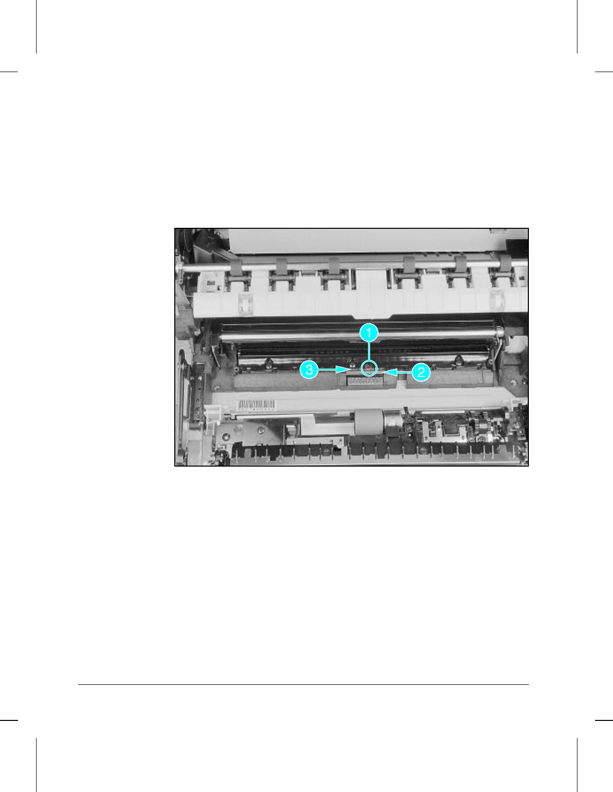
Anti-Static Brush
The Anti-Static Brush is located directly under the Registration Roller
Guide Plate.
1Remove the Registration Roller and Guide Plate (see Figure 6-35).
2Remove (1) machine grounding screw with star washer (Figure 6-36,
callout 1).
3Lift the sheet metal grounding plate out (Figure 6-36, callout 2).
4Lift the Anti-Static Brush up and out of the printer (Figure 6-36, callout 3).
Anti-Static Brush
6antibr
6antibrwmf
Figure 6-36
6-42 Removal and Replacement
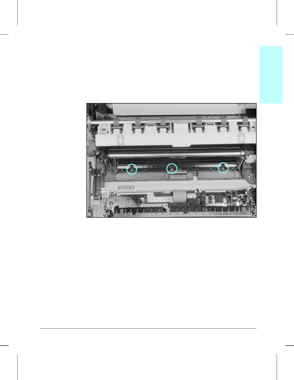
Paper Guide
The Paper Guide is a plastic plate located directly under the Registration
Roller assembly.
1Remove the Registration Roller and Guide Plate (see Figures 6-33 and
6-35).
2Remove (3) self-tapping screws (Figure 6-37).
3Carefully lift the Paper Guide up and out of the printer.
Paper Guide
6defgde
6defgdewmf
Figure 6-37
6Removal &
Replacement
Removal and Replacement 6-43
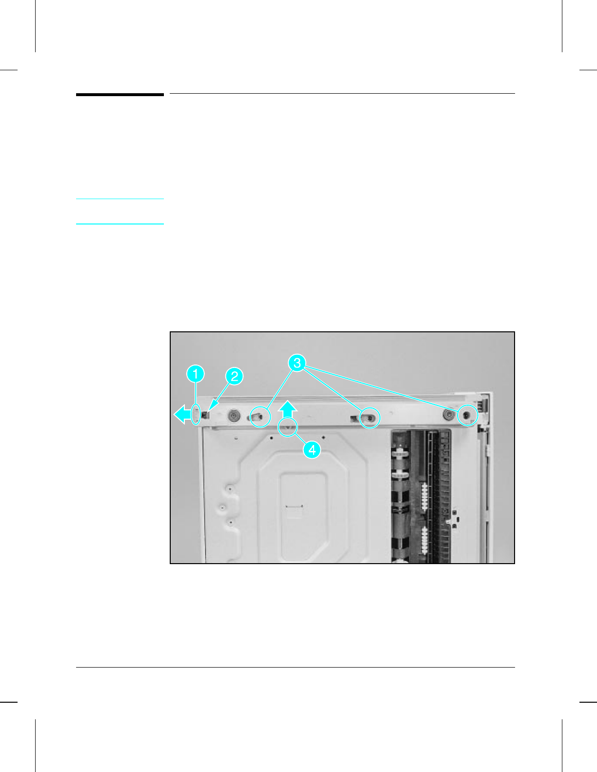
Bottom Assemblies
Foot Assemblies
The Left Side Foot removal procedure is described below. The Right Side
Foot removal is similar.
CAUTION If the left side cover is in place, do not rest the printer on its left side, as this
will damage the ventilation grill.
1Remove lower paper cassette and turn the printer on its side.
2Remove connector cover (if installed) (see Figure 6-38, callout 1).
3Remove the Optional Lower Cassette connector by depressing the retainer
ears inward (see Figure 6-38, callout 2).
4Remove (3) machine screws (see Figure 6-38, callout 3).
5Carefully pull the foot straight out while pushing the sensor tabs out of the
way (see Figure 6-38, callout 4).
Left Side Foot
To Reinstall:
Install the Optional Lower Cassette connector before reinstalling Foot
assemblies.
6footcap
6footcapwmf
Figure 6-38
6-44 Removal and Replacement

7
Troubleshooting
Chapter Contents
Preliminary Troubleshooting . . . . . . . . . . . . . . . . . . . . . . . . 7-3
Paper Path and Components . . . . . . . . . . . . . . . . . . . . . . . . 7-4
Printer Message Troubleshooting . . . . . . . . . . . . . . . . . . . . . 7-5
Priority of Errors . . . . . . . . . . . . . . . . . . . . . . . . . . . . . 7-5
Printer Status Messages . . . . . . . . . . . . . . . . . . . . . . . . . 7-6
Service and Error Messages . . . . . . . . . . . . . . . . . . . . . . 7-11
Clearable Warnings . . . . . . . . . . . . . . . . . . . . . . . . . . . 7-15
Image Formation Troubleshooting . . . . . . . . . . . . . . . . . . . . . 7-16
Check the Toner Cartridge . . . . . . . . . . . . . . . . . . . . . . . 7-16
Faulty Image Examples . . . . . . . . . . . . . . . . . . . . . . . . . 7-16
Troubleshooting Checks . . . . . . . . . . . . . . . . . . . . . . . . . . 7-31
Engine Test . . . . . . . . . . . . . . . . . . . . . . . . . . . . . . . . 7-31
Engine Test Button Location . . . . . . . . . . . . . . . . . . . . . . 7-31
Printing an Engine Test . . . . . . . . . . . . . . . . . . . . . . . . . 7-31
Half Self Test Functional Check . . . . . . . . . . . . . . . . . . . . . 7-32
Drum Rotation Functional Check . . . . . . . . . . . . . . . . . . . . 7-33
High-Voltage Power Supply Check . . . . . . . . . . . . . . . . . . . 7-34
Paper Curl . . . . . . . . . . . . . . . . . . . . . . . . . . . . . . . . 7-35
Troubleshooting Tools . . . . . . . . . . . . . . . . . . . . . . . . . . . 7-36
Repetitive Image Defect Ruler . . . . . . . . . . . . . . . . . . . . . . 7-36
Wiring Diagrams . . . . . . . . . . . . . . . . . . . . . . . . . . . . . 7-37
Troubleshooting 7-1

7-2 Troubleshooting
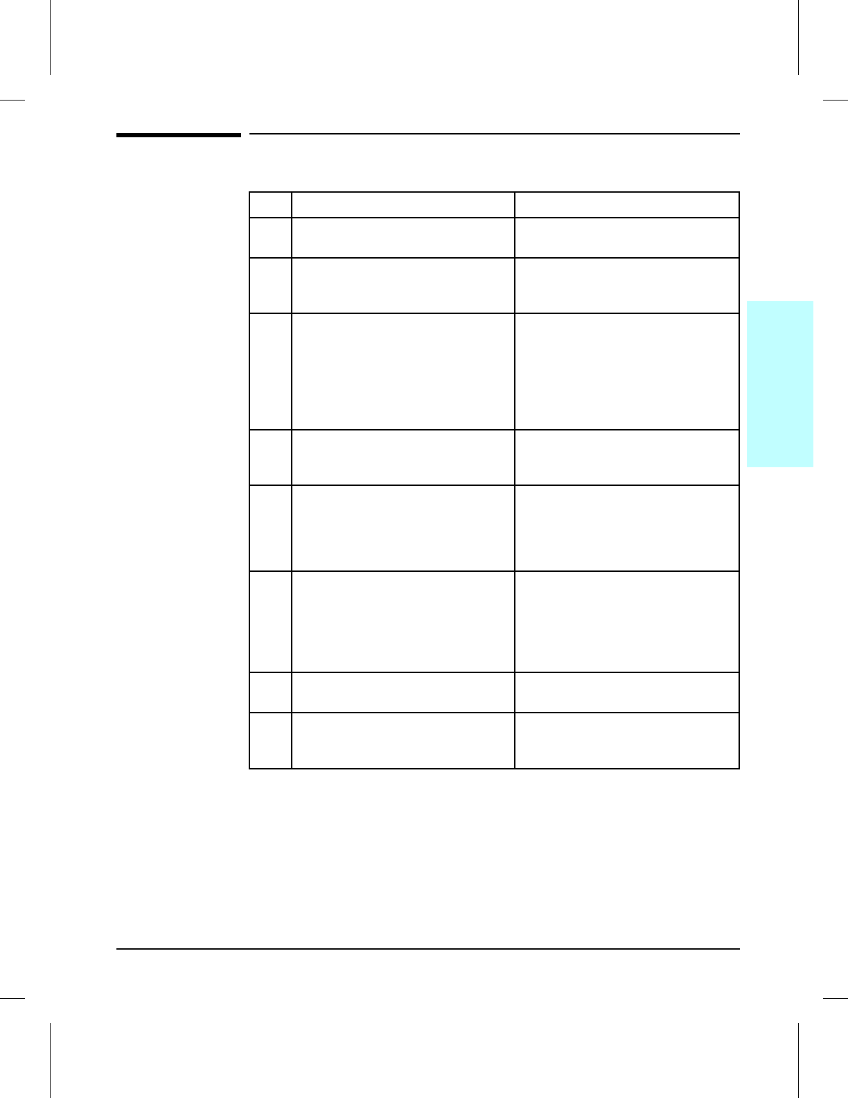
Preliminary Troubleshooting
Step Description Corrective Action
1. Disconnect printer from network (if
applicable). n/a
2. Ensure that toner cartridge is
installed, front door is closed, and
AC power is applied.
n/a
3. Verify power distribution by
listening to fans, Main Motor, and
Laser/Scanner Motor.
Troubleshoot power supply
distribution system.
• Check all connectors
• Check CB101 in power
supply unit
• Check F101 in power
supply unit
4. Check for control panel messages. Refer to “Printer Message
Troubleshooting” later in this
chapter.
5. Perform Engine Test. If there is an image problem, see
“Image Formation Troubleshooting”
later in this chapter.
If no page is printed, troubleshoot
as a DC Controller problem.
6. Perform Control Panel Self Test. If there is an image problem, refer
to “Image Formation
Troubleshooting” later in this
chapter.
If no page is printed, troubleshoot
as a Formatter problem.
7. Verify proper software drivers have
been installed. Install drivers.
8. Connect printer to network (if
applicable) and verify network
operation.
Contact network administrator for
assistance.
7
Troubleshooting
Troubleshooting 7-3
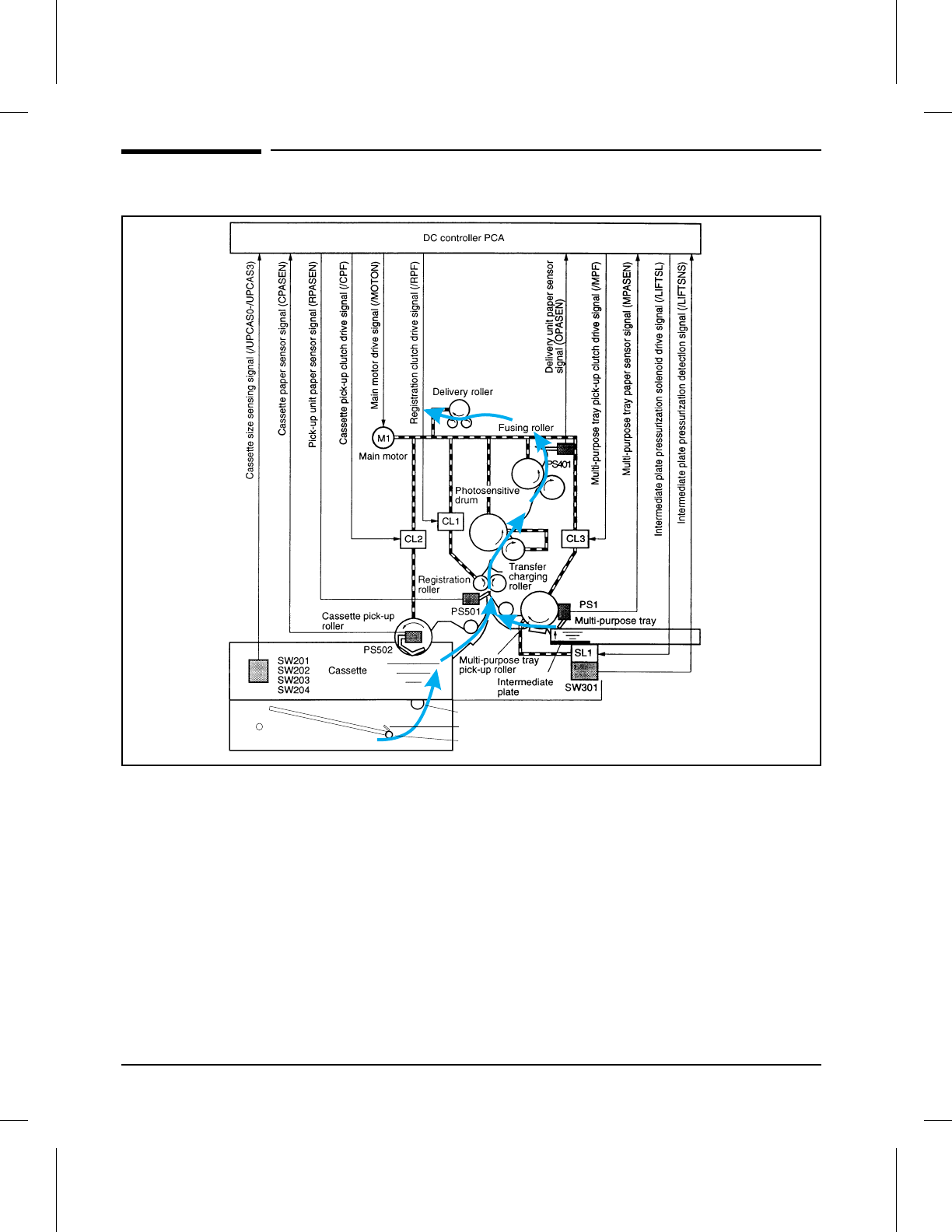
Paper Path and Components
Optional Lower Cassette
Lower Cassette Pickup Rollers
Paper Out Sensor
Lower Cassette Exit Sensor
7PAPPATH
Figure 7-1 Paper Path and Components
7-4 Troubleshooting

Printer Message Troubleshooting
The control panel alphanumeric display provides the following information:
•Status Messages (refer to Table 7-1)
•Service and Error Messages (refer to Table 7-2)
•Clearable Warnings (refer to Table 7-3)
NOTE Before troubleshooting the printer, cycle the power to the printer to see if
the error persists.
Priority of Errors
Each error has a priority in relation to the others. If there is more than one
error condition at the same time, the highest priority error will be
displayed. The priority of errors is:
1Service Errors
2Door Open/No Toner Cartridge
3Paper Jam
4Paper Out
5Memory Error
6Manual Feed
7
Troubleshooting
Troubleshooting 7-5
Printer Status Messages
The following table lists printer messages and their meanings and describes
recommended actions. Messages that begin with a number are listed first,
followed by messages that begin with a letter.
Message Description Recommended Action
Numeric Listings
[Blank Display]
Nothing displayed at power-up. Control panel
display remains blank. If fans are functional on power-up:
1. Verify the input power, then check that CB101
and F101 are not open.
2. Check and reseat connector from the Control
Panel to the Formatter PCA.
3. Remove any interface cables to the host.
4. Print an Engine Test to determine if the print
engine is functional. If so, replace the Control
Panel, then the Formatter PCA.
00 READY The default ready message. The printer is
ready to use. No action required.
00 POWERSAVE Printer is in Power Save mode. In Power
Save mode all control panel keys operate
normally.
Press any control panel key to take printer out of
Power Save mode. Receipt of data or an error
condition will also take the printer out of Power
Save mode. The display will read 02 WARMING
UP, and the job will print when the fuser has
warmed.
00 OFFLINE Printer is off line and cannot receive data. Press [On Line].
02 WARMING UP The printer is warming up and is not ready to
accept data. Wait until the printer signals ready. If the message
remains on continuously:
1. Disconnect interface cable from the printer,
power off, then on. Problem may be caused by
connecting the parallel cable to a serial port, or a
bad host interface.
2. Check if Fusing Assembly is warming up. If not,
replace the Fusing Assembly.
3. Replace the DC Controller PCA.
4. Replace the Power Supply Unit.
5. Replace the Formatter PCA.
04 SELF TEST Printing a continuous self test. Press [On Line] or [Shift] + [Continue] to stop the
test. Several more pages may print.
05 SELF TEST Printer self test in process (non-printing). No action required.
06 PRINTING TEST Printing a self test. No action required.
06 TYPEFACE LIST Printing a Typeface List. (Note that
PCL/PostScript formats are different.) No action required.
Table 7-1 Status Messages
7-6 Troubleshooting
Message Description Recommended Action
06 DEMO PAGE Printing a Demonstration Page. (Note that
PCL/PostScript formats are different.) No action required.
06 CONFIG PAGE Printing a Configuration Page. No action required.
07 RESET Follows a control panel [Shift] + [Reset]
selection. The printer returns all Printing,
PCL, Job, and installed personality (PS, etc.)
Menu items to user-selected settings and
clears buffered page data, clears temporary
soft fonts, and clears temporary macros.
No action required unless the printer is receiving
data. You may have to press [Shift] + [Reset]
several times to prevent printing unwanted pages.
08 COLD RESET The printer returns all Printing, PCL, Job,
Config, Mem Config, Parallel, MIO (if
installed), and the installed personality (PCL,
PS, etc.) Menu settings to their factory default
configurations, except for page count, MP Tray
size, and display language.
Reconfigure the printer and MIO. When you install
an MIO card, to reinitialize the control panel you
may need to perform a cold reset. (Note: In a
shared environment, this task should only be
performed by the system administrator.) To
perform a cold reset, hold down [On Line] while
switching the printer ON until 08 COLD RESET
appears in the display.
09 MENU RESET Clears the page buffer, removes temporary
data such as downloaded fonts, and sets
user-selected defaults (such as Power Save)
to their factory defaults.
To access, press [Shift] + [Reset] for about 10
seconds until RESET=MENU appears, then use
the [+] key to select the kind of reset you want.
09 RST ACTIVE I/O Clears the page buffer and removes
temporary data such as downloaded fonts,
but affects the active I/O port only.
Same as 09 MENU RESET above.
09 RESET ALL I/O Clears the page buffer and removes
temporary data such as downloaded fonts,
but affects all I/O ports.
Same as 09 MENU RESET above.
10 RESET TO SAVE You changed menu items while data,
temporary fonts, or temporary macros were
present in printer memory or while the printer
was in the middle of a job.
Reset the printer. There are two choices:
1. To immediately activate the selections, press
[Shift] + [Reset] until 07 RESET appears (you will
delete temporary macros, fonts, and buffered data).
2. Press [Shift] + [Continue] or [On Line]. Your
changes will remain recorded in the menu (marked
with an *), but will not become active until the printer
is reset or the printer detects the end of the job.
Table 7-1 Status Messages — continued
7
Troubleshooting
Troubleshooting 7-7
Message Description Recommended Action
12 PRINTER OPEN The front door is not firmly closed, or the
toner cartridge is not installed correctly. Make sure the toner cartridge is fully
seated and the front door is firmly
closed. If the message persists:
1. With the front door open, check
that the sensor flag for Front Door
Open Sensor (PS402) is not broken or
stuck. (PS402 is located on the
small Front Door Unit Terminal PCA
on the front door under the Transfer
Roller.)
2. Check functionality of the toner cartridge
microswitch (SW501) on the High Voltage PCA
(activated by metal tab in the rear wall of the toner
cartridge cavity, adjacent to the high voltage contacts).
3. Replace the DC Controller PCA.
13 PAPER JAM Paper is jammed in the paper path, or a paper
jam sensor may be stuck, causing a false
paper jam warning.
The jam rate specifications are:
MP TRAY: 1 per 6000
CASSETTE: 1 per 4000
NOTE: Many variables can affect actual
frequency of jams. The above
specifications are intended as a general
guideline only.
Remove jammed paper
(see “Clearing Paper
Jams” in the
User’s Manual
). The front door must
be opened and closed again before pressing
[On Line] to resume.
The following are the most likely causes of
repeated paper jam problems:
1. Paper cassettes not correctly loaded (refer to
the
User’s Manual
).
2. Print media does not meet specs or is in poor
condition (refer to the
Paper Specifications Guide
).
3. The printer needs cleaning (refer to Chapter 4).
4. Pickup, Registration or Output rollers
contaminated, worn or damaged.
5. Toner cartridge gears are worn or damaged (try
a different cartridge).
6. Other paper path gears worn or damaged.
If no paper jams are found but the message
persists (false paper jams):
1. Check paper jam sensor flags for sticking or
damage. Paper movement is monitored by (2)
paper sensors. PS 501, the Pickup Unit Sensor is
located on the High Voltage Power Supply PCA
high voltage power supply PCA;pickup unit sensor.
PS401 is located on the small front door Unit
Terminal PCA on the front door under the Fusing
Assembly (remove the Fusing Assembly to see).
2. Replace the DC Controller PCA.
Table 7-1 Status Messages — continued
7-8 Troubleshooting

Message Description Recommended Action
14 NO TONER CART The toner cartridge is missing or not installed
correctly. Insert a toner cartridge or make sure the cartridge
is fully seated and the front door is fully closed,
then press [On Line] to resume.
If the error persists:
1. Check functionality of the toner cartridge
microswitch (SW501) on the High Voltage PCA
(activated by metal tab in the rear wall of the toner
cartridge cavity, adjacent to the high voltage
contacts).
2. Check that the sensor flag for Front Door Open
Sensor (PS402) is not broken or stuck. (PS402 is
located on the small front door Unit Terminal PCA on
the front door under the Transfer Roller.)
3. Replace the DC Controller PCA.
16 TONER LOW The toner cartridge is running out of toner. If
TONER LOW=CONT* is displayed, the printer
will continue printing; if TONER LOW=STOP,
the printer will stop printing and go off line.
Shake the toner cartridge or replace it. If TONER
LOW=STOP, press [On Line] or [Shift] + [Continue]
to allow printing to continue (print quality will
gradually degrade).
If the message persists:
1. Check the contact points on the left end of the
toner cartridge and inside the toner cartridge cavity.
(The Toner Low contact is the lower of the three.)
2. Replace the High Voltage PCA.
18 MIO INIT The MIO card is initializing. This is a status
message; during initialization the MIO is not
active, but since the printer supports I/O
switching, the printer remains on line.
No action required. Display will clear
automatically (this may take up to a minute,
depending on the card). However, if the message
remains after 5 minutes a problem may exist in the
network card or host. Consult the network
documentation that came with the MIO card.
18 MIO NOT READY The MIO card is not ready. The Bi-Tronics
parallel port will continue to operate normally. If the printer MIO card is operating correctly and
communicating with the network, this message will
disappear after approximately one minute and no
action is required. If the MIO card is unable to
communicate with the network, this message will
remain for five minutes and then go away. In this
case the printer is not communicating with the
network (even though the message is no longer
present). The problem may be a bad MIO card,
bad cable/connection on the network, or a
network problem. Consult the network
documentation that came with the MIO card.
Table 7-1 Status Messages — continued
7
Troubleshooting
Troubleshooting 7-9
Message Description Recommended Action
Alphabetical Listings
FS DISK FAILURE Printer detected a disk failure. Printer operation may continue, provided access
to the disk is not required. (The printer will
substitute fonts if necessary.)
Press [Shift] + [Continue], to continue printing
when this error occurs.
Switch the printer OFF and then back ON. If the
error continues:
1. Remove and reseat the disk drive, ensuring that
the connector pins are fully seated in the
connector on the Formatter PCA.
2. Run a control panel self test to verify presence
of the disk drive (look for the text, “Installed
options: Disk”).
3. If the error persists, replace the disk drive.
MENUS LOCKED The network administrator has locked out
access to the control panel menu system,
except for the Test Menu and MP Tray size.
See the network or printer administrator.
ME FEED
envelope size
The printer requested that an envelope be
manually fed. Envelope size may be: COM10,
MONARCH, DL, C5, B5, JPOST, or JPOSTD.
Insert the appropriate envelope size into the MP
Tray and press [On Line] or [Shift] + [Continue] if
MP Tray is not in “first” mode to print from the
envelope feeder.
MF FEED
paper size
The printer requested that media be manually
fed. Paper size may be: LETTER, LEGAL, A4,
EXEC, 11x17, A3, JIS B4, JIS B5, CUSTOM.
Insert the appropriate paper size into the MP Tray
and press [On Line]; or, press [Shift] + [Continue]
(if the MP Tray is not in “first” mode).
MP LOAD,
PC LOAD, or
LC LOAD
paper size,
or
envelope size
The printer received a request for a paper or
envelope size not available in the printer. MP LOAD: Load MP Tray with the requested
media. If the size is not selected in the printer
control panel, use the [MP[Paper[Size] key to enter
the requested size, or press [Shift] + [Continue] to
draw the requested size from another source, if
available.
Note: If MP LOAD remains in the display, you may
have to clear the buffer by resetting the printer.
Press [Shift] + [Reset].
PC or LC LOAD: Load the Paper Cassette or
Lower Cassette with the requested media. Also,
the back paper guide in the cassette must be set
to the correct media size (the printer determines
the media size by reading the location of this
guide).
Table 7-1 Status Messages — continued
7-10 Troubleshooting
Service and Error Messages
Message Description Recommended Action
20 MEM OVERFLOW The printer received more data from the
computer than can fit in its available user
memory.
Press [Shift] + [Continue] to print the transferred
data (data loss may result), then: make more
memory available in the printer by removing some
fonts, macros, or any other data from memory; or,
simplify the page sent to the printer; or, install
additional memory. (Note, if AUTO CONT=ON the
printer will automatically continue printing when
this error occurs).
21 PRINT OVERRUN The data (dense text, rules, raster or vector
graphics) sent to the printer was too complex. Press [Shift] + [Continue] to resume printing. (Note,
if AUTO CONT=ON the printer will automatically
continue printing when this error occurs). Some
data loss may occur. Try to simplify the print job. If
you must print the job “as is,” set
PAGEPROTCT=ON in the Job Menu, print the job,
then return PAGEPROTCT=AUTO. Do not leave
PAGEPROTCT set to ON as it will
degrade
performance.
22 PAR IO ERROR,
22 MIO ERROR
For Bi-Tronics parallel (PAR) configuration,
the computer and printer are not
communicating because of improper signal
protocols. This is an I/O buffer overrun error.
Parallel Configuration: may mean a loose
cable connection or a bad or poor quality
cable.
MIO Configuration: This is an I/O buffer
overrun error.
Press [Shift] + [Continue] to clear the error
message (data will be lost). If the error continues:
Parallel Configuration: check for loose cable; use a
high-quality cable (HP 24542D or equivalent).
(Note: some non-HP parallel cables may be
missing pin connections.)
If the printer is using an I/O other than the
Bi-Tronics parallel I/O, see the manual for that
device.
40 MIO ERROR Indicates an abnormal connection break
occurred while transferring data from the
computer.
Press [Shift] + [Continue] to clear the error
message. If the printer is using an I/O other than
the Bi-Tronics parallel I/O, see the manual for that
device.
41.[X] ERROR
X=1, 2, 4, or 5
A temporary printing error occurred. Remove the page from the output bin and press
[Shift] + [Continue]. The page containing the error
will automatically be reprinted. (Note, if AUTO
CONT=ON the printer will automatically continue
printing when this error occurs.)
41.3 PAPER ERROR The wrong size paper was fed from the MP
Tray or the printer picked two sheets of paper
at once.
Ensure that the paper is within the specifications
.
If the page jammed, remove the jam.
Press
[Shift] + [Continue] and the page
containing the error will automatically be reprinted.
NOTE: If AUTO CONT=ON the printer will
automatically continue printing when this error
occurs. Refer to the error 13 PAPER JAM earlier in
this table for more information.
Table 7-2 Service and Error Messages
7
Troubleshooting
Troubleshooting 7-11
Message Description Recommended Action
50 SERVICE Fuser malfunction, resulting from either an
overheating or underheating condition. Switch the printer OFF
for at least 20 minutes
and
then back ON.
If the error continues:
1. Verify that the Fusing Assembly is installed
correctly and is fully seated into its connectors (no
bent pins or pins outside their receptacles).
2. Reseat or replace the fuser cable assembly.
51 ERROR Beam detect malfunction. Press [Shift] + [Continue] to resume operation.
(Note, if AUTO CONT=ON the printer will
automatically continue printing when this error
occurs.) If error persists:
1. Check cable from DC Controller to
Laser/Scanner Assembly.
2. Replace Laser/Scanner Assembly.
3. Replace DC Controller PCA.
52 SERVICE Scanner malfunction. Switch the printer OFF and then back ON. If the
error continues:
1. Check cable from DC Controller to
Laser/Scanner Assembly.
2. Replace Laser/Scanner Assembly.
3. Replace DC Controller PCA.
53.XY.ZZ ERROR SIMM memory error:
X (Hardware Type):
0: ROM
1: RAM
Y (Hardware Device):
0: Internal Memory
1: SIMM Slot 1
2: SIMM Slot 2
3: SIMM Slot 3
4: SIMM Slot 4
ZZ (Error Number):
0: Unsupported memory
1: Unrecognized memory
2: Unsupported memory size
3: Failed RAM test
4: Exceeded maximum RAM size
5: Exceeded maximum ROM size
6: Invalid SIMM speed
7: SIMM reporting information
incorrectly
8: SIMM RAM parity error
9: SIMM ROM needs to be
mapped to an unsupported
address
10: SIMM address conflict
11: ROM out of bounds
12: Could not make temporary
mapping
Make sure the SIMM board is installed correctly.
Replace the SIMM that caused the error.
NOTE: If no replacement SIMM is available, press
[Shift] + [Continue] to continue. The SIMM that
caused the error will not be configured. If the
SIMM device has more than one bank of memory,
the good banks will be configured.
Table 7-2 Service and Error Messages — continued
7-12 Troubleshooting
Message Description Recommended Action
55 ERROR Communication error between DC Controller
and Formatter PCA. Switch the printer OFF and then back ON. If the
error continues:
1. Check cable from DC Controller to
Laser/Scanner Assembly.
2. Replace Laser/Scanner Assembly.
3. Replace DC Controller PCA.
57 SERVICE Main motor failure. Switch the printer OFF and then back ON. If the
error continues:
1. Check cabling between Main Motor and DC
Controller PCA.
2. Replace the Main Motor.
3. Replace the DC Controller.
58.[x] SERVICE Fan motor failure.
x = 1 — FM1
2 — FM2
3 — FM3
Switch the printer OFF and then back ON. If the
error continues:
1. Check cabling between fan motor(s) and DC
Controller PCA.
2. Replace the faulty fan motor.
3. Replace the DC Controller.
61.[x] SERVICE
X=0 - 4
The printer encountered a parity error when
accessing the RAM
memory SIMM in slot “X”.
If X=0, the slot with the defective SIMM could
not be determined.
Switch the printer OFF and then ON. If the error is
still present:
1. Verify that the SIMM board is correctly installed.
2. Switch the printer OFF and remove the SIMM
board. Switch the printer back ON. If the error
message does not appear, replace the faulty
SIMM.
3. If the message remains, repeat the process for
each remaining SIMM to isolate.
4. If message remains with no SIMMs present,
replace the Formatter PCA.
62.[x] SERVICE
X=0 - 6
The printer identified a problem while
checking its memory
. “X” refers to the device
the printer was checking when it encountered
the error.
0: Internal Memory
1–4: SIMM Slot
6: Cache
Switch the printer OFF and then ON. If the error is
still present:
1. Verify that the SIMM board is correctly installed.
2. Switch the printer OFF and remove the SIMM
board. Switch the printer back ON. If the error
message does not appear, replace the faulty
SIMM.
3. If the message remains, repeat the process for
each remaining SIMM to isolate.
4. If message remains with no SIMMs present,
replace the Formatter PCA.
63 through 67
SERVICE Internal RAM, scan buffer, Dynamic RAM
controller, or miscellaneous interface
hardware error.
Switch the printer OFF, then back ON. If the error
persists, replace the Formatter PCA.
68 ERROR Nonvolatile memory (NVRAM) error. Press [Shift] + [Continue], then check the control
panel settings for changes (print a self test).
68 SERVICE
or 68
READY/SERVICE
The nonvolatile memory (NVRAM) is full. Press [Shift] + [Continue] ; the 00 READY message
will be replaced by 68 READY/SERVICE until the
condition is cleared. If you switch the printer OFF,
then ON, you may lose settings. (To check settings,
print a self test). If the error persists, replace the
Formatter PCA.
Table 7-2 Service and Error Messages — continued
7
Troubleshooting
Troubleshooting 7-13
Message Description Recommended Action
70 or 71 ERROR A language (personality) SIMM problem was
identified. SIMM not compatible with
firmware.
Remove or replace the language (personality)
SIMM.
79 SERVICE [xxxx] A Formatter firmware error occurred. The
numbers [xxxx] following the error indicate
the specific kind of error.
Write the error message and the four digit code
down before continuing. Switch the printer OFF,
then back ON.
1. Remove SIMMs one at a time and recycle power
to isolate.
2. If the problem persists, and the printer has an
MIO card installed, remove the MIO and try using
the parallel interface, if possible.
3. Replace the Formatter PCA. (Include the error
message code with the defective PCA and return
for evaluation.)
80 SERVICE [xxxx] The printer detected a problem in the MIO
card. The numbers [xxxx] following the error
message indicate the specific type of error.
Write the error message and the four digit code
down before continuing. Switch the printer OFF,
then back ON.
If the error persists:
1. Remove and reseat the MIO card.
2. Check for bent pins on the MIO connection.
3. Replace the MIO card.
4. Replace the Formatter PCA.
(Include the error message and code with the
defective PCA and return for evaluation.)
Table 7-2 Service and Error Messages — continued
7-14 Troubleshooting
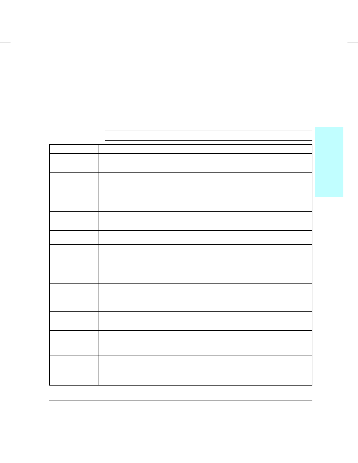
Clearable Warnings
A clearable warning message indicates that the printer changed settings in
order to complete the print job. A clearable warning usually occurs when a
transient condition, such as an invalid or uninstalled personality, or lack of
memory causes a temporary change. A number of clearable warnings can
appear while printing a job. The printer will remain on line while the
message is displayed. Clear the message by pressing [Shift] + [Continue]. It is
possible to eliminate the need to respond to clearable warning messages
(see “Configuration Menu” in Chapter 3).
Message Meaning
W0 JOB 600/A4 Because the job parameters of print resolution and page protection could not be met with the
available memory, the job was printed at a print resolution of 600 dpi but reduced to a page protect
setting of A4.
W1 IMAGE ADAPT The printer received a graphics print file that was too complex to print at the requested print
resolution. Check the printout for loss of data or print quality. NOTE: if
this warning occurs frequently, install additional memory.
W2 INVALID PERS The job was not printed because you requested a personality, such as PostScript, that is not installed.
Install the personality that matches the personality of the files you are sending, together with enough
memory to support that personality.
W3 JOB ABORTED The printer was forced to abort the print job because there is not enough installed memory to
support the current printer language (PostScript, for example). Install
additional memory.
WD DISK NOT INIT The printer was unable to read the root directory from the disk. Use the disk initialization utility to
initialize the disk.
W8 JOB 600/OFF Because the job parameters of print resolution and page protection could not be met with the
available memory, the job was printed at a print resolution of 600 dpi and page protect was turned
OFF.
W9 JOB 600/LTR Because the job parameters of print resolution and page protection could not be met with the
available memory, the job was printed at a print resolution of 600 dpi but reduced to a page protect
setting of LETTER.
WM JOB 300 The job was printed at 300 dpi. NOTE: if this warning occurs frequently, install additional memory.
WM JOB 600/A3 Because the job parameters of print resolution and page protection could not be met with the
available memory, the job was printed at a print resolution of 600 dpi but reduced to a page protect
setting of A3.
WM JOB 600/LGL Because the job parameters of print resolution and page protection could not be met with the
available memory, the job was printed at a print resolution of 600 dpi but reduced to a page protect
setting of LEGAL.
WM MEM CNFIG N/A The printer did not have enough memory when switched ON to support the previous
settings for I/O Buffering and/or Resource Saving, probably because you
removed a memory SIMM, or added a new personality SIMM. (You can check
settings by printing a self test.)
WM CHK MEM CNFIG I/O Buffering and/or Resource Saving settings were altered when the printer was
switched on because the printer did not have enough memory. This usually
occurs after memory has been removed from the printer. (You can check
settings by printing a self test.) Adding additional memory should correct
this problem.
Table 7-3 Clearable Warning Messages
7
Troubleshooting
Troubleshooting 7-15

Image Formation Troubleshooting
Check the Toner Cartridge
Image formation defects are many times the result of toner cartridge
problems. If there is any doubt, always replace the toner cartridge before
troubleshooting image defects.
Use the following check list to ensure that the toner cartridge is still
operable.
•Inspect the toner cartridge for remaining toner.
•Check the expiration date of the toner cartridge (stamped on the cartridge
box).
•Check the toner cartridge to see if it has been disassembled or refilled.
•Ensure that the toner cartridge is seated properly in the cavity.
•Inspect the cartridge for leaking toner through worn seals. (If the drum has
been manually rotated it may have caused internal damage and toner spills
may result).
•Check the surface of the photosensitive drum in the cartridge to see if it has
been damaged or scratched. Touching the drum will contaminate the
photosensitive surface and may cause spotting and defects during printing.
•White areas on the page may indicate that the drum has been exposed to
light for too long. If white areas appear, stop the printer and wait a few
minutes. This process should eliminate most defective images. If not, the
toner cartridge may be placed in a dark environment for several days, which
may restore some life to the drum.
Faulty Image Examples
This section illustrates some image defects and their possible causes. Since
there are many variables in the printing process, it is possible to encounter
image defects that are not illustrated in the following illustrations. If you
find a defect that is not illustrated, record the probable cause along with the
printing environmental conditions and save a copy of the defect for future
reference.
Each example is followed by a table that lists in order the probable causes of
the image defect.
7-16 Troubleshooting
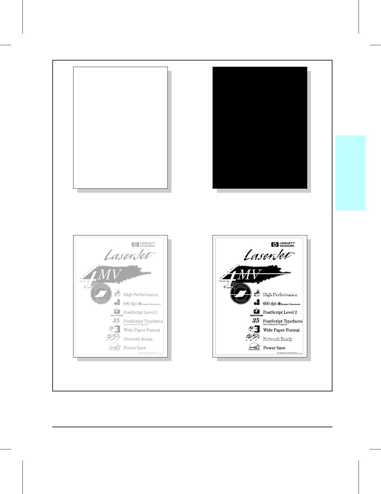
BLANK PAGE
(see Table 7-4, page 7-21) BLACK PAGE
(see Table 7-5, page 7-22)
FADED PRINT
(see Table 7-6, page 7-23) WHITE STRIPES (parallel to path)
(see Table 7-7, page 7-24)
7
Troubleshooting
Troubleshooting 7-17
BLACK LINES (perpendicular to path)
(see Table 7-8, page 7-24) BLACK LINES (parallel to path)
(see Table 7-9, page 7-25)
REPETITIVE DEFECTS
(see Table 7-10, page 7-25) BUBBLE PRINT
(see Table 7-11, page 7-26)
7-18 Troubleshooting
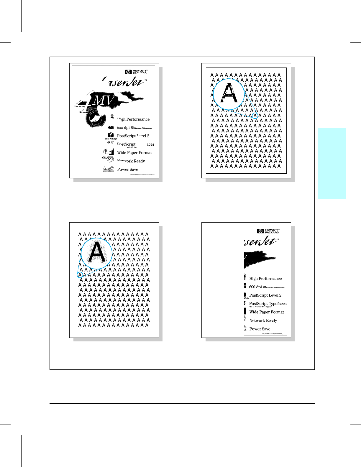
DROPOUT
(see Table 7-12, page 7-26) CHARACTER VOIDS
(see Table 7-13, page 7-27)
BACKGROUND SCATTER
(or Leading Edge Halo)
(see Table 7-15, page 7-28)
PARTIAL BLANK PAGE
(see Table 7-14, page 7-28)
7
Troubleshooting
Troubleshooting 7-19
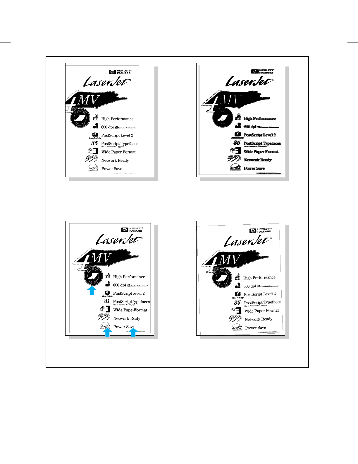
FAULTY REGISTRATION
(see Table 7-16, page 7-29) SMEARED PRINT
(see Table 7-17, page 7-30)
COMPRESSED PRINT
(see Table 7-18, page 7-30) IMAGE SKEW
(see Table 7-19, page 7-30)
7-20 Troubleshooting
Possible Cause Recommended Action
OCCASIONAL BLANK PAGES:
1. Software Configuration. Make sure the application software is not sending
incorrect page length requests, or extra page
eject commands.
2. Network Configuration. Some sharing devices
on networks may generate a blank page as a
separator.
Check with the Network Administrator.
3. Multiple Feeds. The printer may be feeding
two or more pages at once because the paper is
difficult to separate.
Remove the paper from the paper cassette and fan
the paper edges to separate the pages (see
HP
LaserJet Printer Family Paper Specifications Guide)
.
ALL PAGES BLANK:
1. Sealing tape left in toner cartridge. Remove the sealing tape.
2. Empty or defective toner cartridge. 1. If unsure, weigh the cartridge:
Full weight = 2000 grams (70.6 oz)
Empty weight = 1600 grams (56.5 oz)
NOTE: Some toner may reside in the waste toner
cavity, affecting the weight of the cartridge.
2. Perform the “Drum Rotation Functional Check”
described later in this chapter or try a known good
toner cartridge. Replace the toner cartridge if
necessary.
3. Defective or contaminated Transfer Roller.
Without a functional Transfer Roller, toner cannot
be pulled from the photosensitive drum to the
paper.
Check roller installation and contact. Perform the
“Half Self Test Functional Check” described later
in this chapter. If there is an image on the drum,
but not on paper, replace the Transfer Roller.
4. High voltage connector springs are dirty or
defective. The high voltage connectors are
mounted on the High Voltage Power Supply PCA
and protrude into the toner cartridge cavity.
Check the springs for functionality. Clean if dirty,
replace if defective or missing.
5. Laser/Scanner door not opening properly. 1. Remove and re-seat the toner cartridge.
2. Check the Laser/Scanner shutter door for
proper operation. If defective, replace the
Laser/Scanner Assembly.
6. High Voltage Power Supply is defective. Replace the High Voltage Power Supply PCA.
7. DC Controller PCA is defective. The DC
Controller supplies the proper voltage to the High
Voltage Power Supply PCA.
Replace the DC Controller PCA.
Table 7-4 Blank (White) Page
7
Troubleshooting
Troubleshooting 7-21
Possible Cause Recommended Action
1. Defective toner cartridge. Replace the toner cartridge.
2. Light is leaking into the printer. Ensure all covers are in place.
3. High voltage contact springs are dirty or
defective. The high voltage contacts are
mounted on the High Voltage Power Supply PCA
and protrude into the toner cartridge cavity.
Inspect and clean the high voltage contacts. If
damaged, replace the High Voltage Power
Supply PCA.
4. High voltage power supply circuit is defective
(not supplying the correct negative voltage). Replace the High Voltage Power Supply PCA.
5. DC Controller PCA is defective. If the DC
Controller turns ON the laser beam continuously,
the entire surface of the Photosensitive drum is
neutralized causing a completely black page.
Replace the DC Controller PCA.
6. Laser/Scanner Assembly is faulty (turning
laser on continuously). Replace the Laser/Scanner Assembly.
7. Connectors between the Laser/Scanner unit
and DC Controller are not seated properly or are
defective.
Inspect and reseat the connectors. Replace
cables as necessary.
Table 7-5 Black Page
7-22 Troubleshooting
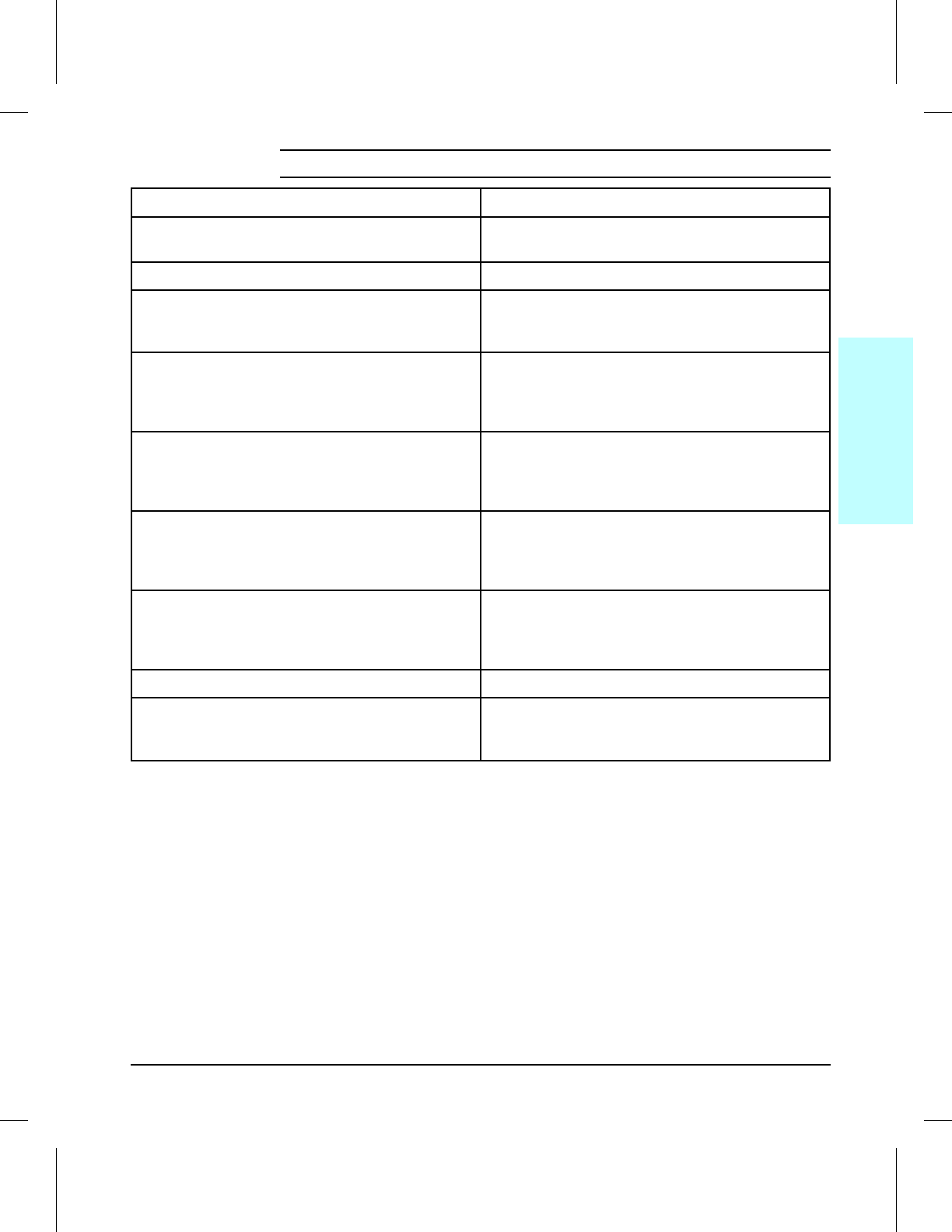
Possible Cause Recommended Action
1. Toner supply is low. Shake the cartridge gently to redistribute the
toner, or replace the cartridge.
2. Print Density is set incorrectly. Change to a darker setting and retry printing.
3. EconoMode is on. EconoMode saves toner by
reducing the dot density. This may appear to be
a print quality problem in some cases.
Turn EconoMode off.
4. Paper does not meet specs. The moisture
content, conductivity, or surface finish may not
work correctly with the electrophotographic
process.
Try a different paper lot (see
HP LaserJet Printer
Family Paper Specifications Guide
).
5. Transfer Roller is defective or incorrectly
installed. If the transfer roller loses conductivity, it
cannot effectively pull toner from the drum to the
paper.
Inspect the Transfer Roller for proper installation
and contact. If the Transfer Roller is damaged,
replace it.
6. Laser/Scanner door is not opening properly. 1. Remove and re-seat the toner cartridge.
2. Check the Laser/Scanner shutter door for
proper operation. If defective, replace the
Laser/Scanner Assembly.
7. High voltage contact springs are dirty or
defective. The high voltage contacts are
mounted on the High Voltage Power Supply PCA
and protrude into the toner cartridge cavity.
Check the contacts for functionality. If dirty, clean
using alcohol; if damaged, replace the High
Voltage Power Supply PCA.
8. High Voltage Power Supply PCA is defective. Replace the High Voltage Power Supply PCA.
9. DC Controller PCA is defective. The DC
Controller supplies the proper voltage to the High
Voltage Power Supply PCA.
Replace the DC Controller PCA.
Table 7-6 Faded Print
7
Troubleshooting
Troubleshooting 7-23
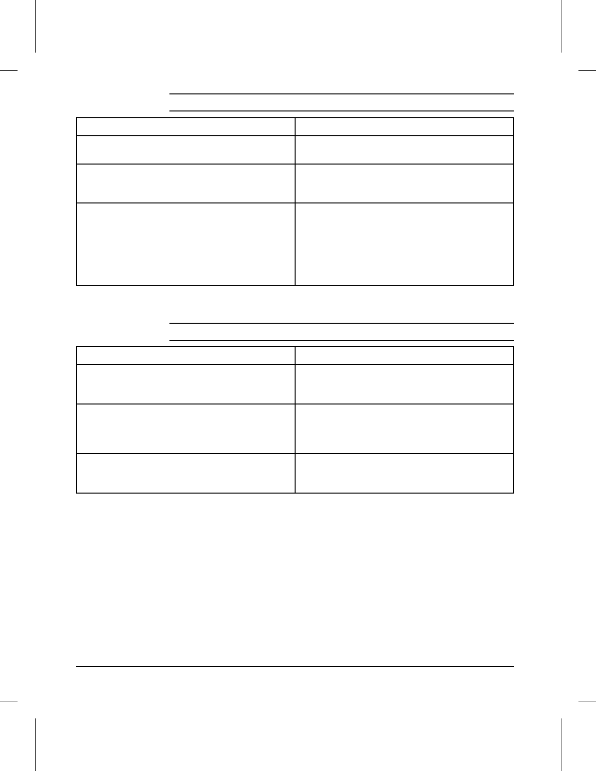
Possible Cause Recommended Action
1. Toner cartridge is nearly empty. This can
cause uneven toner distribution. Remove the toner cartridge and shake it gently.
The cartridge will soon require replacement.
2. Toner cartridge has been exposed to too much
light. Store the toner cartridge in a darkened
environment for several days. This may restore
the photosensitive potential.
3. Foreign objects in beam path. Any foreign
objects will block the light from developing an
image on the Photosensitive drum.
Remove the toner cartridge and check for
damage. Replace the toner cartridge if it is
damaged.
Remove the Printer Cover and inspect the path
from the Laser/Scanner to the toner cartridge
drum, looking for foreign objects in the beam path.
Table 7-7 White Stripes (parallel to path)
Possible Cause Recommended Action
1. Toner cartridge is damaged. Inspect the toner cartridge for a scratched
photosensitive drum or toner leaking through
worn seals. Replace as necessary.
2. Fusing Assembly is contaminated or damaged. Inspect the Fusing Assembly for toner build-up or
scratches on the fuser rollers. Try cleaning with
alcohol. Replace the Fusing Assembly if
damaged.
3. Static Eliminator Strip teeth are contaminated
or defective. Remove and inspect (see Chapter 6 for removal
procedure). Clean using compressed air.
Replace if damaged.
Table 7-8 Black Lines (perpendicular to path)
7-24 Troubleshooting
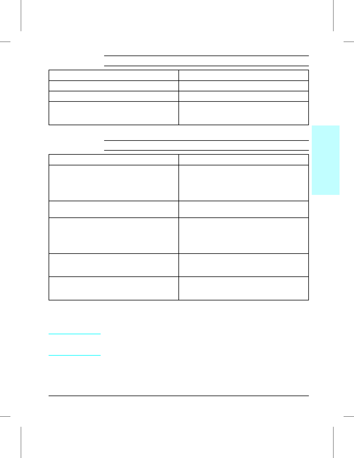
NOTE When troubleshooting repetitive image defects, use the Repetitive Image
Defect Ruler, supplied in Figure 7-3 to measure the distance between
recurring defects.
Possible Cause Recommended Action
1. Toner cartridge not seated properly. Remove the cartridge and reinsert it.
2. Toner cartridge defective. Replace the cartridge.
3. Repetitive defect. If the lines are repeated at a
consistent interval down the page, this is a
repetitive defect.
Refer to Table 7-10 (next), as well as the “Repetitive
Image Defect Ruler,” (Figure 7-3).
Table 7-9 Black Lines (parallel to path)
Possible Cause Recommended Action
1. Toner cartridge is damaged. The
circumference of the photoconductive drum
inside the toner cartridge is 94 mm (3.7 inches).
If the defect repeats at this interval, the defect is
associated with the drum (see note below).
Inspect the drum for scratches or damage.
Replace the toner cartridge.
2. Dirty Rollers. Any dirty roller in the paper path
may result in a repetitive print defect. Examine and clean rollers in the paper path
(refer to Chapter 4).
3. Fusing Assembly is dirty or defective. The
circumference of the lower fusing Pressure Roller
is 86 mm (3.46 inches). If the defect repeats at
this interval, the defect is associated with the
Pressure Roller (see note below).
Clean the Fusing Assembly using alcohol. If the
problem persists, replace the Fusing Assembly.
4. Gears are worn, causing slippage or jumping. Inspect the gears driving the toner cartridge and
the Fuser. Replace the Main Drive Assembly if
necessary.
5. Paper does not meet specs. The surface of
the paper may be too coarse, causing repeated
marks.
Try a different paper lot (see
HP LaserJet Printer
Family Paper Specifications Guide
).
Table 7-10 Repetitive Defects
7
Troubleshooting
Troubleshooting 7-25
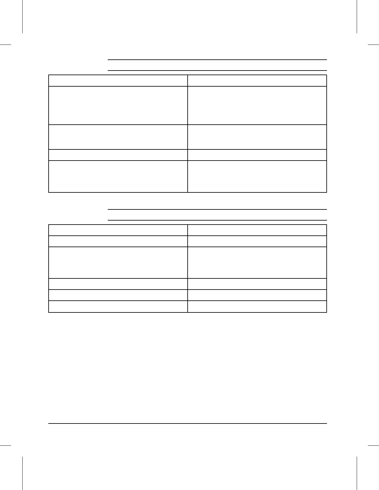
Possible Cause Recommended Action
1. The density adjustment slider switch on the
High Voltage Power Supply PCA slider switch is
not aligned properly with the Print Density Dial.
This causes the drum surface potential to be out
of range.
1. Check the position of the Print Density Dial in
the slider switch. If out of position, remove and
reseat the High Voltage Power Supply PCA.
2. Replace the High Voltage Power Supply PCA.
2. Toner build-up in the Fusing Assembly. Toner
build-up can physically damage the Fusing
Assembly.
Remove and clean the Fusing Assembly (see
Chapter 6).
3. Leaking toner cartridge. Replace the toner cartridge.
4. Paper does not meet specs. The paper
moisture content, conductivity, or surface finish
may not work correctly with the
electrophotographic process.
Try a different paper lot (see
HP LaserJet Printer
Family Paper Specifications Guide
).
Table 7-11 Bubble Print
Possible Cause Recommended Action
1. Single sheet of paper defective. Try reprinting the job.
2. Paper does not meet specs. The paper
moisture content, conductivity, or surface finish
may not work correctly with the
electrophotographic process.
Try a different paper lot (see
HP LaserJet Printer
Family Paper Specifications Guide
).
3. DC Controller defective (low primary voltage). Replace the DC Controller.
4. High Voltage Power Supply PCA defective Replace the High Voltage Power Supply PCA.
5. Transfer Roller defective. Replace the Transfer Roller.
Table 7-12 Dropout
7-26 Troubleshooting
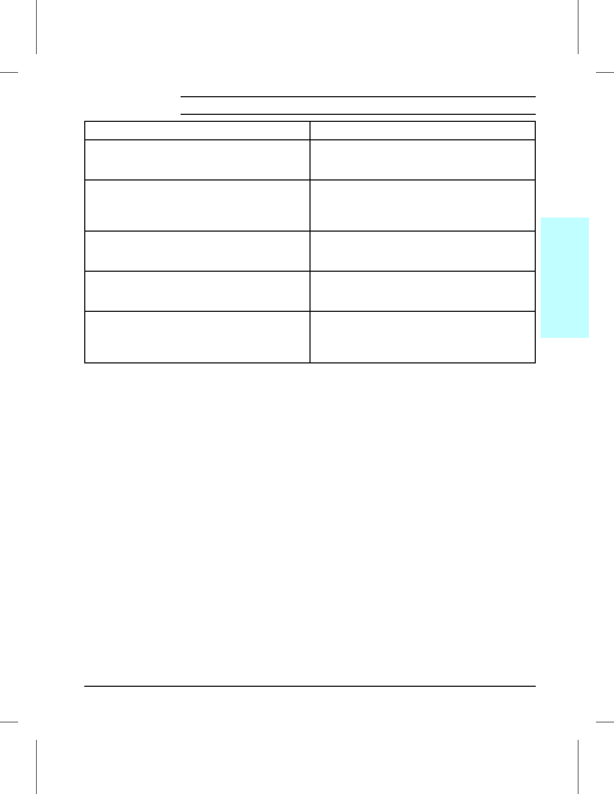
Possible Cause Recommended Action
1. Paper surface too rough. Toner migrates to low
spots, leaving higher areas void. Use paper with correct finish (smoothness)
meeting HP specifications (see
HP LaserJet
Printer Family Paper Specifications Guide
).
2. Printing on wrong side of paper. The label on the
ream of paper indicates which side to print on. The
different surface properties of some papers may
cause problems if loaded wrong side up.
Check for the arrow on the paper wrapper. Be
sure paper is loaded with the arrow pointing UP
in the paper cassettes, or arrow pointing DOWN
in the MP Tray.
3. Paper surface too smooth for proper toner
adhesion. Use paper with correct finish (smoothness)
meeting HP specifications (see
HP LaserJet
Printer Family Paper Specifications Guide
).
4. Bad transparencies. Transparencies can have
this problem because they are not designed for
proper toner adhesion.
Use Hewlett-Packard approved transparencies
(see
HP LaserJet Printer Family Paper
Specifications Guide
).
5. Bad Transfer Roller. If the Transfer Roller has
finger oils on its surface, is dirty or is worn-out,
this problem can result.
Clean the Transfer Roller using a dry, lint-free
cloth. DO NOT touch the Transfer Roller with
your fingers. If the problem persists, replace the
Transfer Roller Assembly.
Table 7-13 Character Voids
7
Troubleshooting
Troubleshooting 7-27
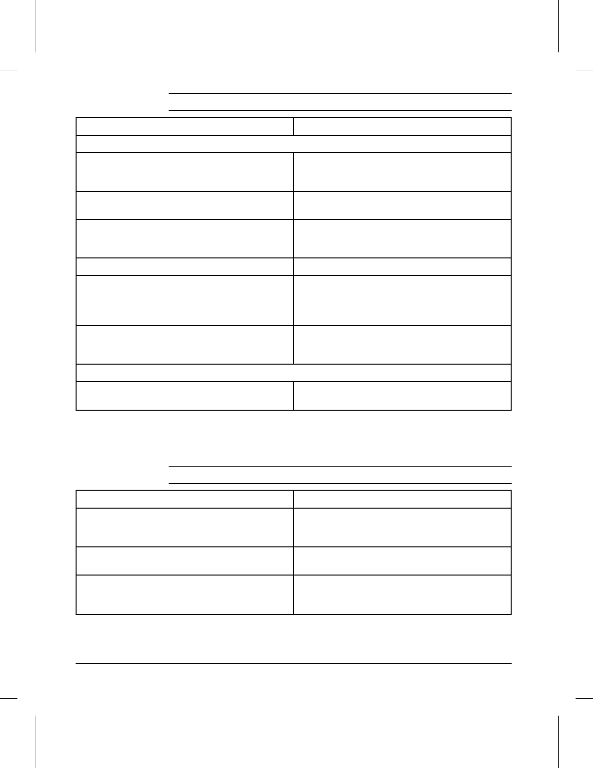
Possible Cause Recommended Action
Random Background Scatter
1. Bad Media. The moisture content, conductivity
or surface finish may not work correctly with the
electrophotographic process.
Try a different media (see
HP LaserJet Printer
Family Paper Specifications Guide
).
2. Inside of printer is dirty (toner may have leaked
out of the toner cartridge). Clean inside of printer (see Chapter 4). Install a
new toner cartridge if leaking.
3. Printing on envelope seams. Printing on an
envelope seam can cause a background scatter
problem.
Move the text to an area without seams. If not
printing on seams, try a higher print density
setting (see item 6, below).
4. Defective toner cartridge. Install a new toner cartridge.
5. Dirty or worn Transfer Roller. A worn Transfer
Roller can cause background due to improper
bias voltages.
Clean the Transfer Roller using a dry, lint-free
cloth. DO NOT touch the Transfer Roller with
your fingers. If the problem persists, replace the
Transfer Roller Assembly.
6. Print Density set too low. If the Print Density is
set too low, then background scatter can result,
particularly with envelopes and heavier papers.
Adjust the print density to a higher setting.
Background Scatter at Leading Edge Only (Leading Edge Halo)
1. This problem is caused by toner buildup in the
Fuser Inlet Guide. Replace Fuser Inlet Guide (see Chapter 6).
Table 7-14 Background Scatter (or Leading Edge Halo)
Possible Cause Recommended Action
1. Page too complex. The printer can not create
the image fast enough to keep pace with the print
engine.
Set Page Protect to ON or AUTO.
2. Not enough memory. The page is too complex
for standard printer memory. Add printer memory. As an alternative, simplify
the print job.
3. Printing on legal-size paper when software is
specifying letter size (this will also cause paper
jams).
Review software selection. Ensure that printing
is on selected size.
Table 7-15 Partial Blank Page
7-28 Troubleshooting
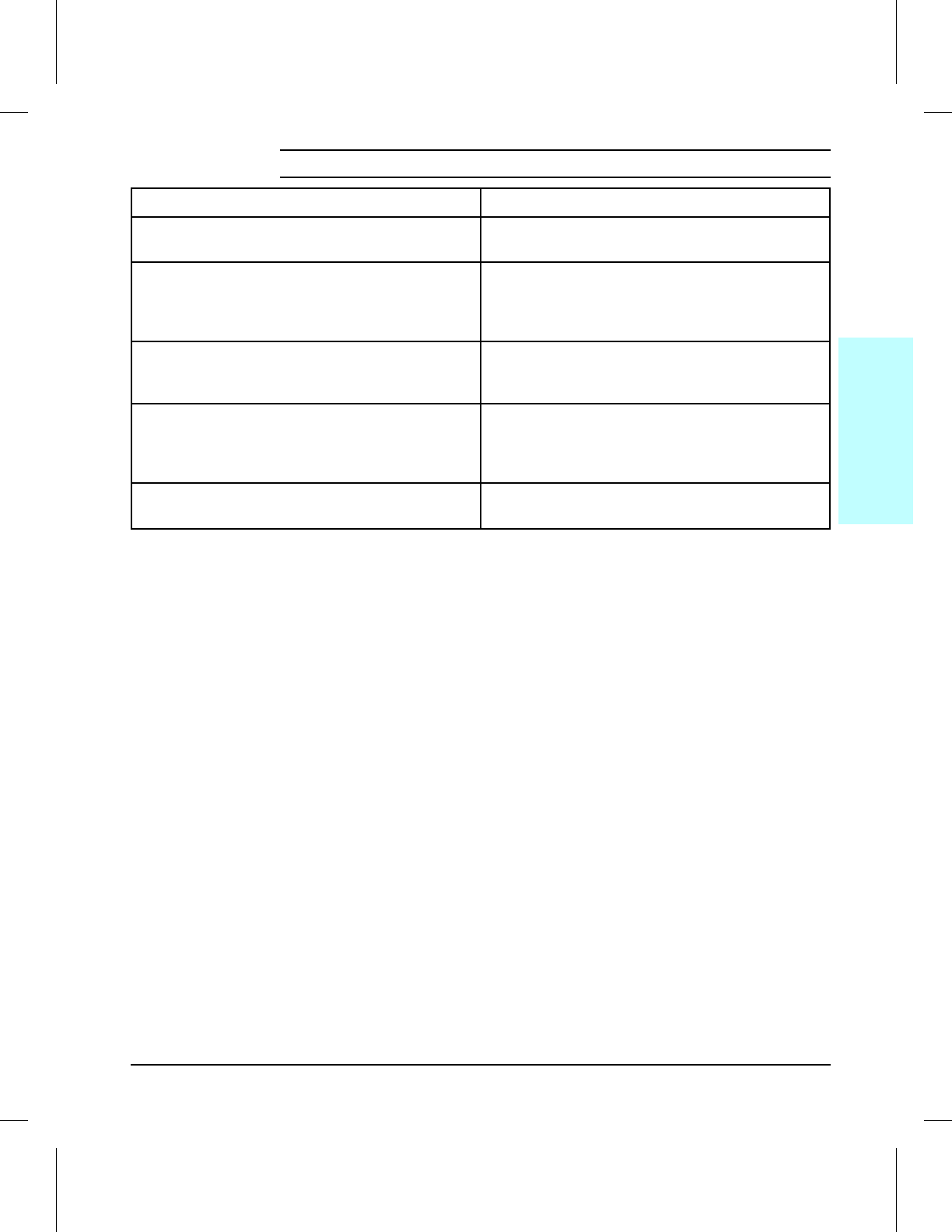
Possible Cause Recommended Action
1. Overloaded paper cassette. If the cassette is
overloaded, the Pickup Rollers may not pick correctly. Reload proper amount of paper squarely in the
cassette. Review paper loading with the customer.
2. Paper guide on the paper cassette adjusted
too tight. If the guide is pushing too tightly
against the paper, it may be delayed in being
pulled into the printer.
Verify that the paper guide is adjusted for the
correct paper size and is locked into position.
Note that too loose a setting may cause image
skewing.
3. Paper does not meet specs. The surface of the
paper may be too smooth for the Pickup and Feed
Rollers to correctly feed paper into the printer.
Try a different paper lot (see
HP LaserJet Printer
Family Paper Specifications Guide
).
4. Worn or broken drive gears. If any gear within
the drive train or paper path becomes
excessively worn or dirty, erratic paper movement
can result.
Replace the defective gear or Main Drive
assembly.
5. Worn Pickup, or Registration Rollers. Paper is
not being picked-up consistently. Inspect all paper path rollers, looking for wear,
cracks, or glazing. Replace the worn rollers.
Table 7-16 Faulty Registration
7
Troubleshooting
Troubleshooting 7-29
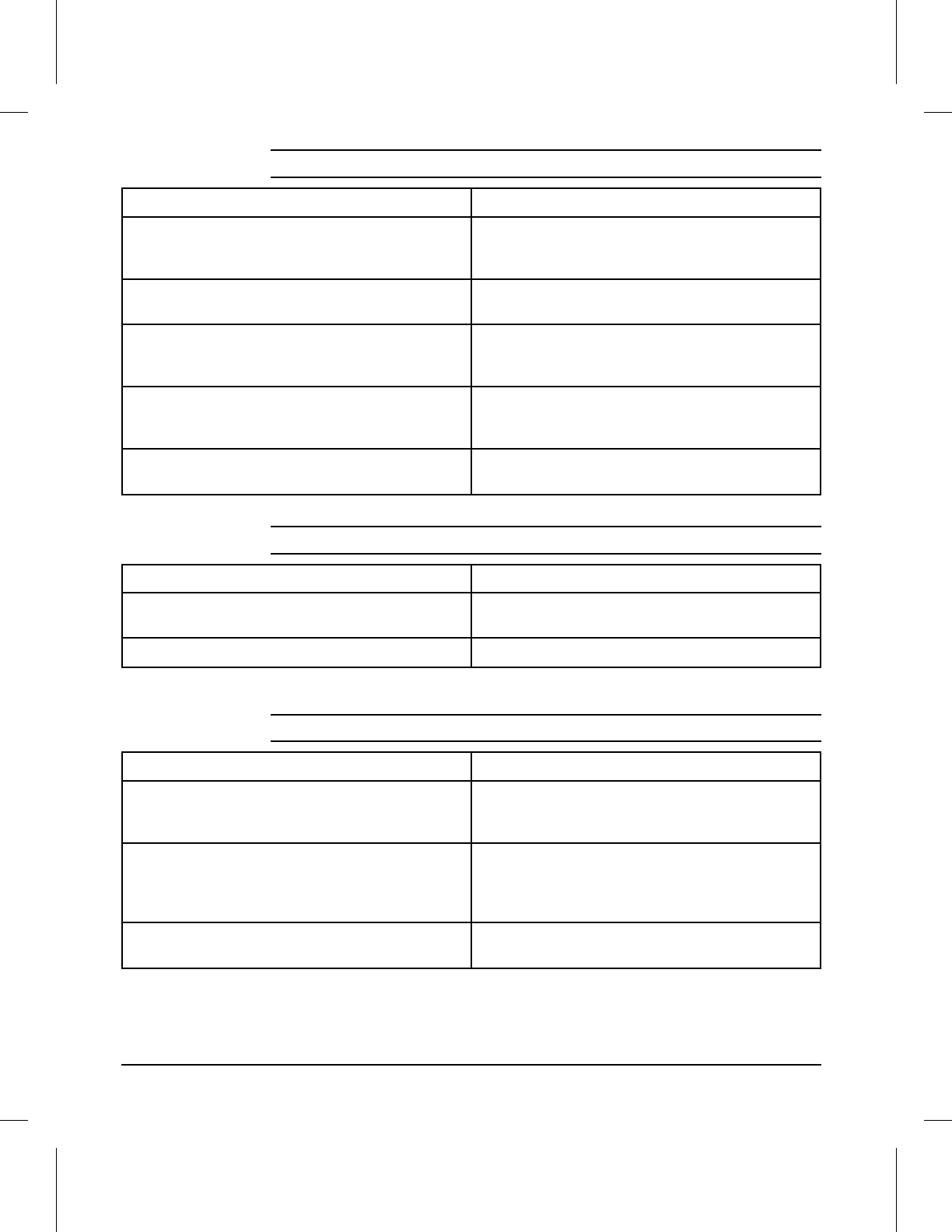
Possible Cause Recommended Action
1. Bad media. The moisture content, conductivity, or
surface finish of the media being printed may not
work correctly with the electrophotographic process.
Try a different paper lot or other media (see
HP
LaserJet Printer Family Paper Specifications
Guide
).
2. Dirty Fusing Rollers. Toner build-up can cause
the print on a page to smear. Remove and inspect the Fusing Assembly for
excessive toner build-up. Clean using alcohol.
3. The Static Eliminator Strip is dirty or is not
grounded, allowing a static charge to remain on
the page.
Clean or replace the Anti-Static Brush. Use
compressed air to clean (see “Anti -Static Brush”
in Chapter 6).
4. Fusing Assembly is defective. The print will
smear if the Fusing Assembly is not heated
sufficiently to bond the toner image to the paper.
Replace the Fusing Assembly.
5. DC Controller is defective. The DC Controller
regulates fusing roller temperature. If a new Fusing Assembly does not resolve the
problem, replace the DC Controller PCA.
Table 7-17 Smeared Print
Possible Cause Recommended Action
1. Toner cartridge bushings are too tight. This
may occur on refilled toner cartridges. Replace the toner cartridge.
2. Broken or worn gear. Inspect and replace the worn gear or assembly.
Table 7-18 Compressed Print
Possible Cause Recommended Action
1. Paper is loaded incorrectly. If the paper is not
installed flush into the paper cassette, a skewing
problem will result.
Remove paper from the tray and install paper
correctly. Position the paper guide correctly for
the paper size being used.
2. Bad Paper Lot. Paper that is manufactured
poorly or inconsistently, or that has too smooth or
too rough a surface texture can cause an image
skew problem.
Try a different paper lot (see
HP LaserJet Printer
Family Paper Specifications Guide
).
3. Worn Pickup and/or Registration Rollers.
Paper is not being picked-up consistently. Inspect all paper path rollers, looking for wear,
cracks, or glazing. Replace the worn rollers.
Table 7-19 Image Skew
7-30 Troubleshooting
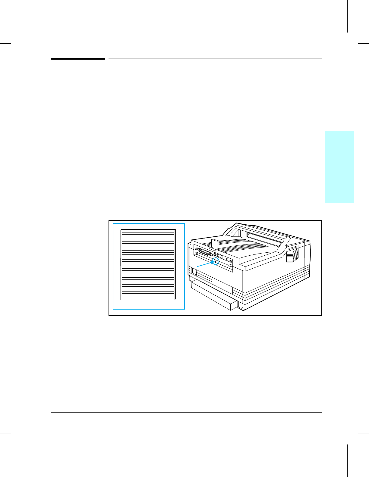
Troubleshooting Checks
Engine Test
The engine test print is used to verify that the print engine is functioning
correctly. The Formatter PCA is completely bypassed during an engine test.
This test is very useful for isolating printer problems. The engine test
prints a full page of horizontal lines down the entire printable area, and is
also useful for checking and adjusting registration.
Engine Test Button Location
The engine test print button (SW7001) is located on the DC Controller PCA.
It is accessible through a hole at the rear of the printer.
Printing an Engine Test
To print an engine test, use a non-metallic object to press the engine test
button (see Figure 7-2). A single test page is printed.
Engine Test Button and Printout
Engine Test Printout
7ENGTST Figure 7-2
7
Troubleshooting
Troubleshooting 7-31

Half Self Test Functional Check
The electrophotographic process can be subdivided into the following stages:
•Cleaning (removing excess toner from drum surface)
•Conditioning (placing a uniform electrical charge on drum)
•Writing (laser strikes surface of drum to create latent image)
•Development (formation of the toner image on drum)
•Transfer (charge to transfer the image to paper)
•Fusing (heat and pressure to produce a permanent image)
The purpose of the Half Self Test Check is to determine which process is
malfunctioning. Perform the test as follows:
1Initiate a printer control panel self test.
2Open the Front Door after the paper advances half-way through the printer
(about five seconds after the Main Motor begins rotation). The leading edge
of the paper should have advanced past the toner cartridge.
3Remove the toner cartridge.
4Open the toner cartridge’s drum shield to view the drum’s surface.
If a dark and distinct toner image is present on the drum’s surface, assume
that the first four functions of the electrophotographic process are
functioning (cleaning, conditioning, writing and developing - see Chapter 5),
and troubleshoot the failure as a transfer or fusing problem.
If NO image is present on the photosensitive drum, perform the following
functional checks:
1Drum Rotation Functional Check.
2High Voltage Power Supply Check.
7-32 Troubleshooting

Drum Rotation Functional Check
The photosensitive drum, located in the toner cartridge, must rotate for the
print process to work. The photosensitive drum receives its drive from the
Main Drive assembly. To verify whether the drum is rotating:
1Open the Front Door.
2Remove the toner cartridge.
3Mark the cartridge’s drive gear with a felt-tipped marker. Note the position
of the mark.
4Install the toner cartridge, and close the Front Door. The start-up sequence
should rotate the drum enough to move the mark.
5Open the printer, and inspect the gear that was marked in step 3. Verify
that the mark moved. If the mark did not move, inspect the Main Drive
assembly to ensure that it is meshing with the toner cartridge gears. If the
drive gears appear functional, and the drum does not move, replace the
toner cartridge.
NOTE This test is especially important if refilled toner cartridges have been used.
7
Troubleshooting
Troubleshooting 7-33
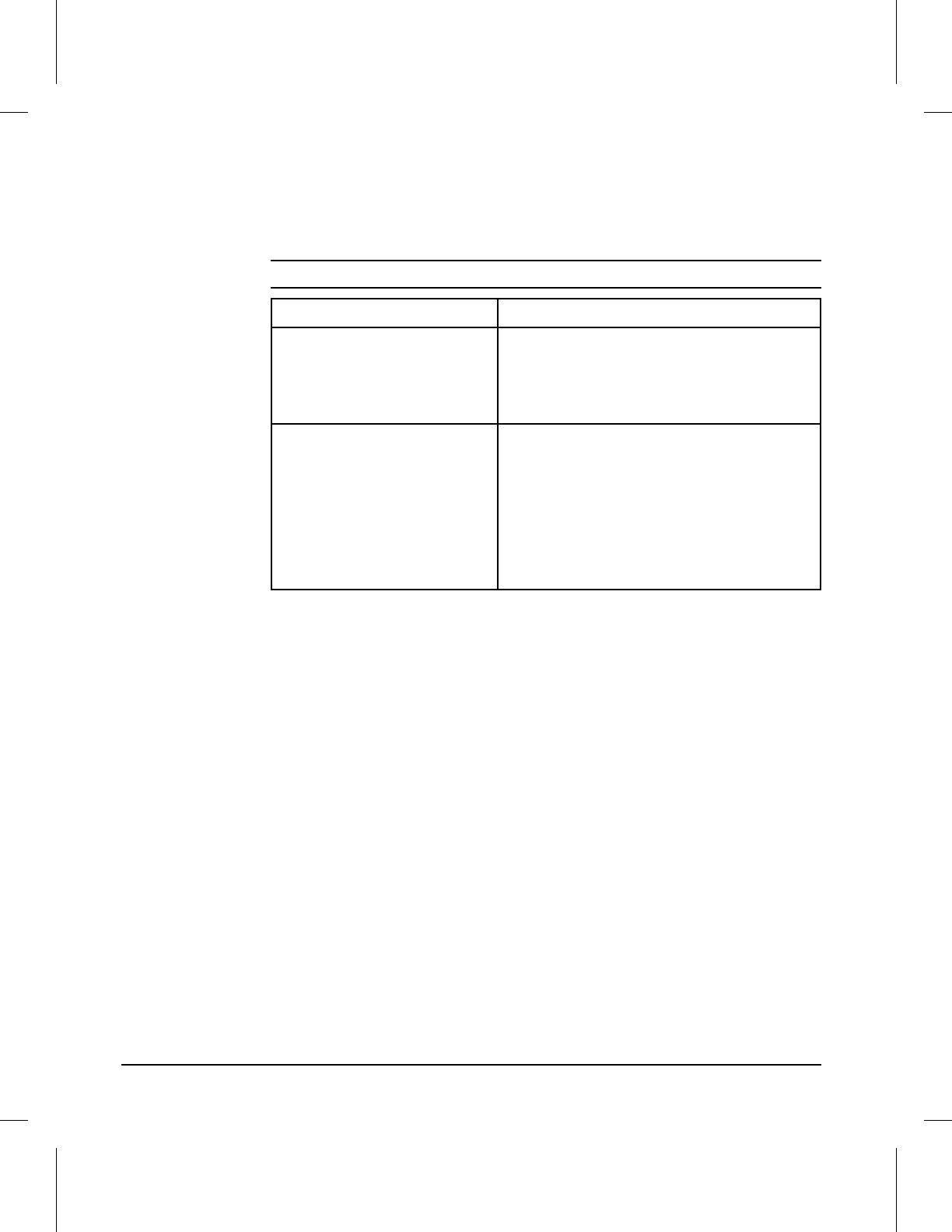
High-Voltage Power Supply Check
The High-Voltage Power Supply PCA provides the necessary voltages for
the electrophotographic processes. A method for verifying the high-voltage
system is given in the table below.
CHECKS ACTION
1. Toner cartridge connection
points. Visually inspect the three connection points
on the inside left end of the toner cartridge. If
they are dirty or corroded, clean the
connections. Clean using alcohol only. If
damaged, replace the toner cartridge.
2. High voltage contacts. The high voltage contact springs mount on
the High Voltage Power Supply PCA and
protrude through the toner cartridge cavity to
contact the toner cartridge. Verify that the
contacts are not dirty or corroded, and that
the spring action is functional. If dirty, clean
using alcohol only; if damaged, replace the
High Voltage Power Supply PCA (see
Chapter 6 for procedure).
Table 7-20 High Voltage System Checks
7-34 Troubleshooting
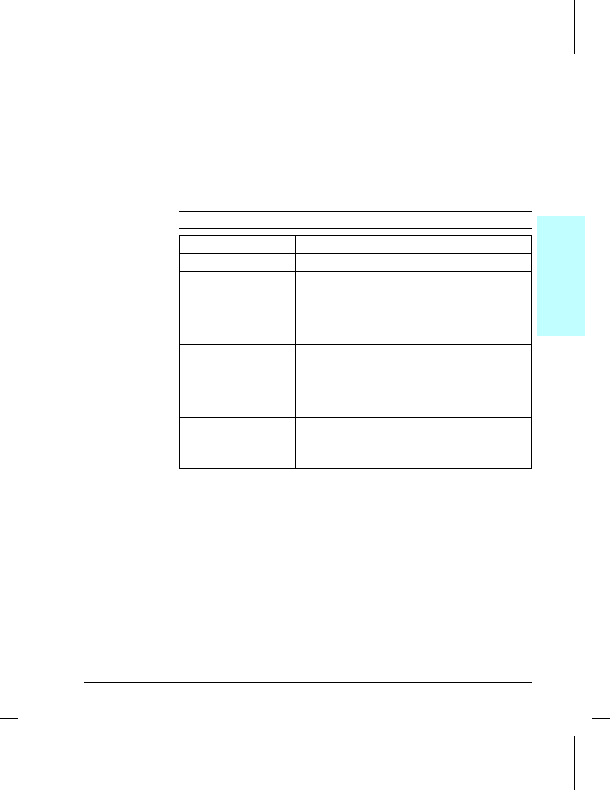
Paper Curl
Paper curl is inherent to the laser printing processes, and occurs when
paper is subjected to heat. Paper curl tends to relax as the paper cools
while resting on a flat surface. The specification for maximum paper curl
when the paper is lying flat before print is 5 mm (0.2 inches).
Although paper curl cannot be totally eliminated, some steps can be taken
to lessen its impact, as suggested in the following table.
Possible Cause Recommended Action
1. Paper Path Try using MP Tray.
2. Paper Surface The recommended printing surface of the page is
usually marked on the end of a ream of paper,
indicated by a small arrow and the phrase “print this
side first.” Load paper in the Paper Cassette with
the recommended printing surface facing UP
(facing down in the MP Tray).
3. Paper Storing and
Handling Over time, paper assumes the characteristics of its
storage environment (in a humid environment,
paper absorbs moisture; in a dry environment,
paper loses moisture). Paper with higher moisture
content will tend to curl more. Evaluate the storage
conditions of the paper.
4. Paper Type All paper is manufactured differently (different
textures, moisture content, drying processes,
composition, etc.). Change the type of paper being
used and re-evaluate the paper curl results.
Table 7-21 Causes of Paper Curl
7
Troubleshooting
Troubleshooting 7-35
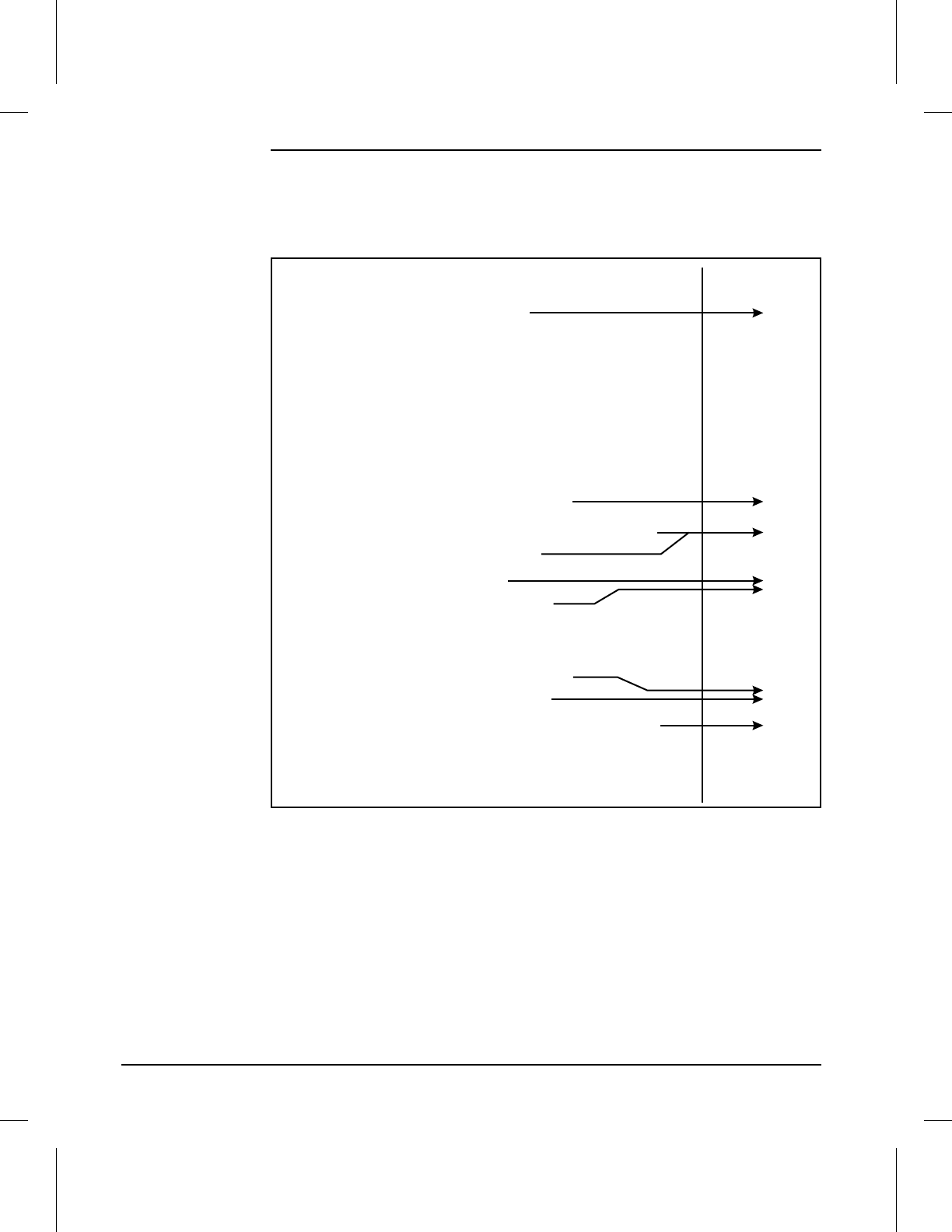
Troubleshooting Tools
Repetitive Image Defect Ruler
Repetitive Image Defect Ruler
First occurence of print defect
Primary Charging Roller 43 mm (1.7 in)
Face Down Delivery (Upper) Roller 50 mm (1.96 in)
Registration Roller 50 mm (1.96 in)
Transfer Roller 61 mm (2.4 in)
Developing Cylinder 63 mm (2.48 in)
Fusing Pressure Roller 86 mm (3.38 in)
Upper Fusing Roller 88 mm (3.46 in)
Toner Cartridge Photosensitive Drum 94 mm (3.7 in)
7DFTRUL
Figure 7-3
7-36 Troubleshooting

Wiring Diagrams
This section contains the following diagrams:
Figure 7-4. DC Controller Inputs (1 sheet)
Figure 7-5. DC Controller Outputs (1 of 2)
Figure 7-6. DC Controller Outputs (2 of 2)
Figure 7-7. Main Wiring Diagram (1 sheet, fold-out)
7
Troubleshooting
Troubleshooting 7-37
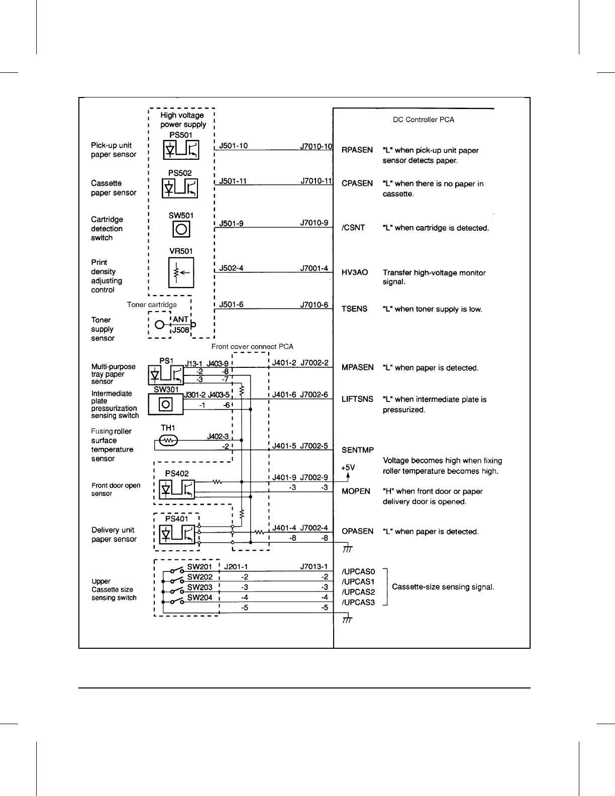
7DCIN
Figure 7-4 DC Controller Inputs
7-38 Troubleshooting
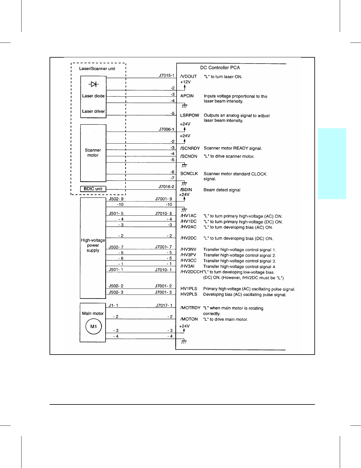
7DCOUT1
Figure 7-5 DC Controller Outputs (1 of 2)
7
Troubleshooting
Troubleshooting 7-39
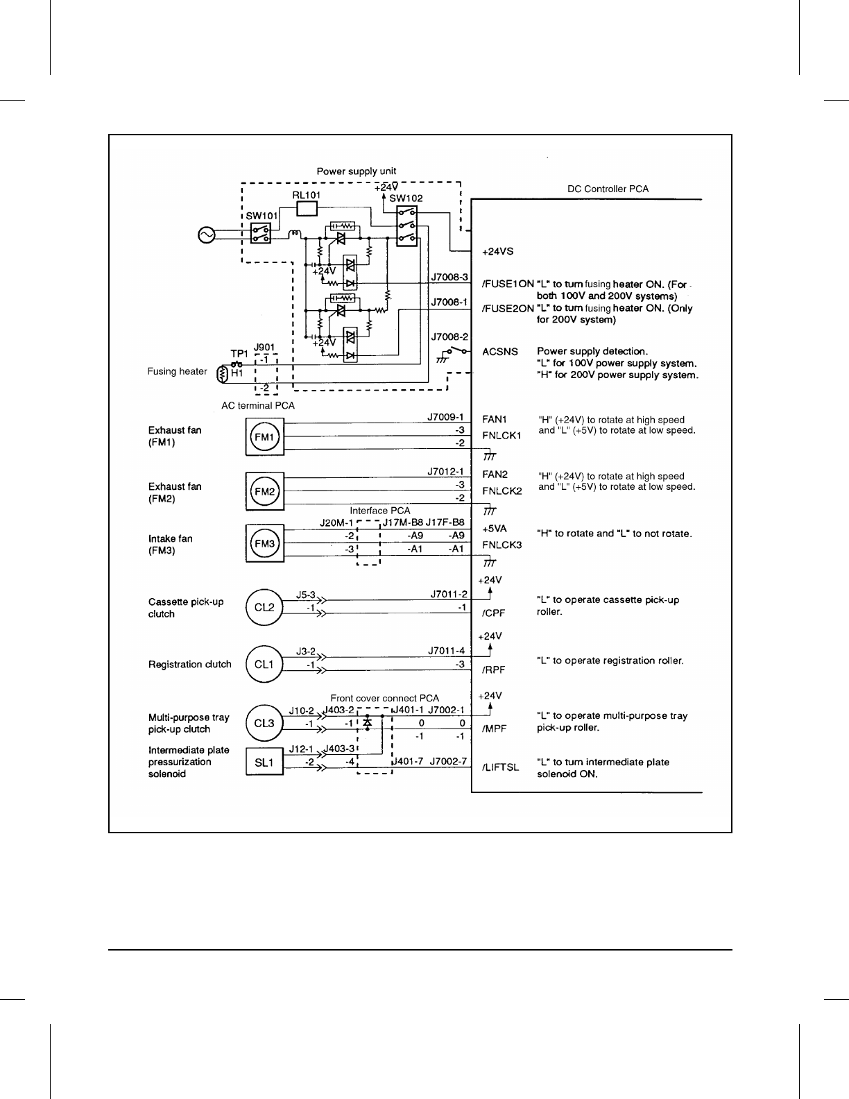
7DCOUT2
Figure 7-6 DC Controller Outputs (2 of 2)
7-40 Troubleshooting

7WIRING
Figure 7-7 Main Wiring Diagram
7
Troubleshooting
Troubleshooting 7-41

7-42 Troubleshooting

8
Parts and Diagrams
Chapter Contents
How to Use the Part Lists and Diagrams . . . . . . . . . . . . . . . . . 8-3
Ordering Parts . . . . . . . . . . . . . . . . . . . . . . . . . . . . . . 8-3
Ordering Consumables . . . . . . . . . . . . . . . . . . . . . . . . . . 8-4
Accessories and Supplies . . . . . . . . . . . . . . . . . . . . . . . . . . 8-5
Common Hardware and Replaceable Cables . . . . . . . . . . . . . . . 8-7
Illustrations and Parts Lists . . . . . . . . . . . . . . . . . . . . . 8-9 – 8-30
Parts and Diagrams 8-1

8-2 Parts and Diagrams

How to Use the Part Lists and Diagrams
The figures in this chapter illustrate the major subassemblies in the printer
and their component parts. A table (material list) follows each exploded
assembly diagram. Each table lists the reference designator (item number)
for each part, the associated part number for the item, the quantity, and a
description of the part.
While looking for a part number, pay careful attention to the voltage listed
in the description column to ensure that the part number selected is for the
correct model of printer.
Ordering Parts
All standard part numbers listed are stocked and may be ordered from HP’s
Support Materials Organization (SMO), or Support Materials Europe (SME).
Hewlett-Packard Co.
Support Materials Organization
8050 Foothills Blvd.
Roseville, CA 95678
Parts Direct Ordering: 1-800-227-8164 (U.S. Only)
Hewlett-Packard Co.
Support Materials, Europe
Wolf-Hirth Strasse 33
D-7030 Böblingen, Germany
(49 7031) 14-2253
Contact your local HP Parts Coordinator for other local phone numbers.
8
Parts and
Diagrams
Parts and Diagrams 8-3

Ordering Consumables
Consumables and accessories such as those listed on Table 8-1 may be
ordered from Hewlett-Packard.
The phone numbers are:
U.S.: 1-800-538-8787
Canada: 1-800-387-3154
(Toronto) 516-671-8383
United Kingdom: 0734-441212
Germany: 0130-3322
Contact your local HP Parts Coordinator for other local phone numbers.
NOTE Parts that have no reference designator or part number are not field
replacement parts and cannot be ordered through SMO.
8-4 Parts and Diagrams
Accessories and Supplies
The following items are available through your local authorized HP dealer.
To find a dealer near you (or if your dealer is temporarily out of stock), call
the HP Customer Information Center (800) 752-0900.
NOTE Refer to “Related Documentation” in Chapter 1 for documentation and
training media product numbers.
Item Product Number Description
Toner Cartridge C3900A Replacement toner cartridge.
Memory upgrades 1 MByte - C3130A
2 MByte - C3131A
4 MByte - C3132A
8 MByte - C3133A
16 MByte - C3146A
You can upgrade to a total of 68
MBytes of memory in the HP
LaserJet 4V and upgrade to 52
MBytes in the HP LaserJet 4MV.
Adobe’s PostScript Level 2 C3160A You can add Adobe’s Level 2
PostScript language by installing
this SIMM in your printer.
(Additional memory required.) It is
standard in the 4MV printer.
250-sheet replacement Paper
Cassette C3160A 250 sheet adjustable between
Letter and A4.
C3161A 250 sheet adjustable between
11x17 and A3.
C3162A 250 sheets legal only.
C3163A 250 sheets JIS B4 only.
C3164A 250 sheets JIS B5 only.
500-sheet Universal Lower
Cassette Base Unit (includes
500-sheet paper cassette)
C3760A 500 sheets adjustable for Letter,
legal, 11x17, A4, A3, JIS B4.
(See Table 8-12 for replacable
parts.)500-sheet replacement paper
cassette for Universal Lower
Cassette Base
C3761A
Bi-Tronics Parallel cable 24542D Bi-Tronics parallel cable.
C2950A 2 meter, IEEE 1284 compliant.
C2951A 3 meter, IEEE 1284 compliant.
Table 8-1 Accessories and Supplies
8
Parts and
Diagrams
Parts and Diagrams 8-5
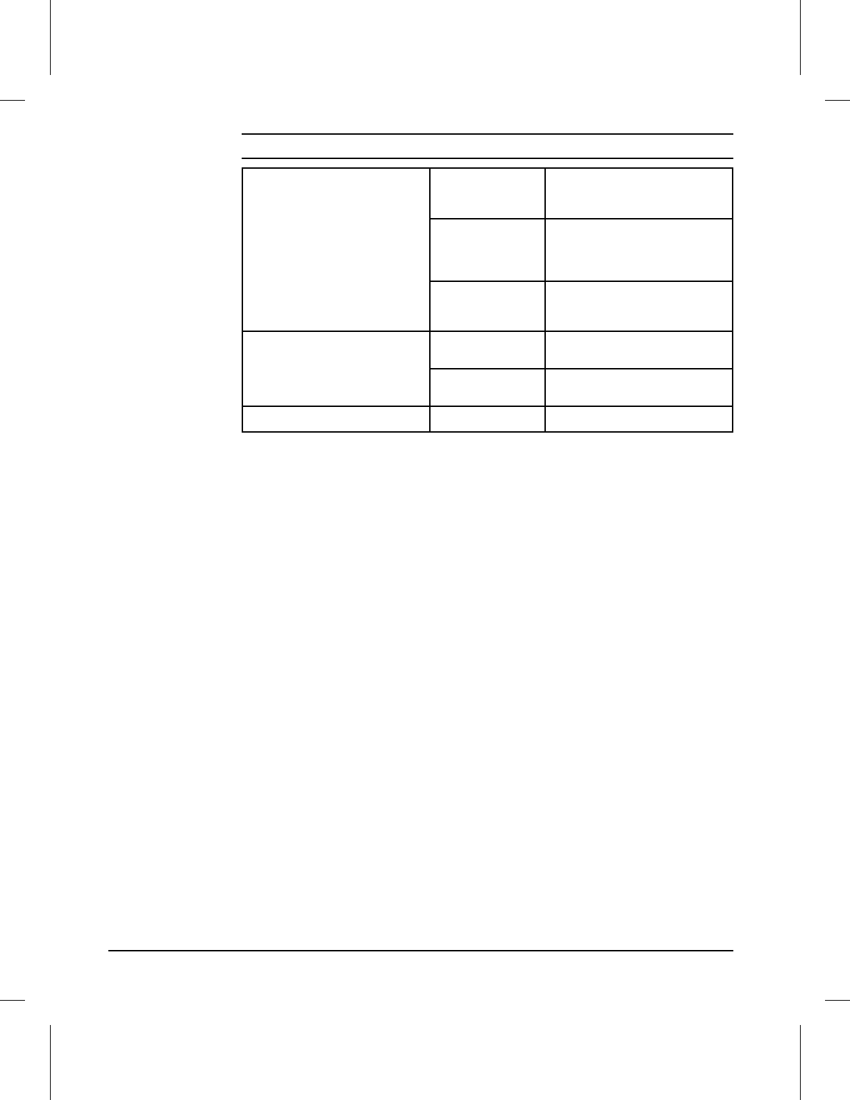
Modular I/O and Network Cards J2550A HP JetDirect Multi-protocol Network
Card with Ethernet/IEEE802.3
10Base-T
J2552A HP JetDirect Multi-protocol Network
Card with LocalTalk DIN-8 and
Ethernet/IEEE802.3 10Base-T
BNC. (Standard in 4MV.)
J2553A HP JetDirect Multi-protocol Network
Card with Token Ring (DB9 and
RJ45).
UNIX Interface Software J2374B HP JetDirect interface software for
HP-UX systems.
J2375B HP JetDirect interface software for
SunOS and Solaris UNIX systems.
Disk Accessory C3295A 42.8 MBytes
Table 8-1 Accessories and Supplies - continued
8-6 Parts and Diagrams
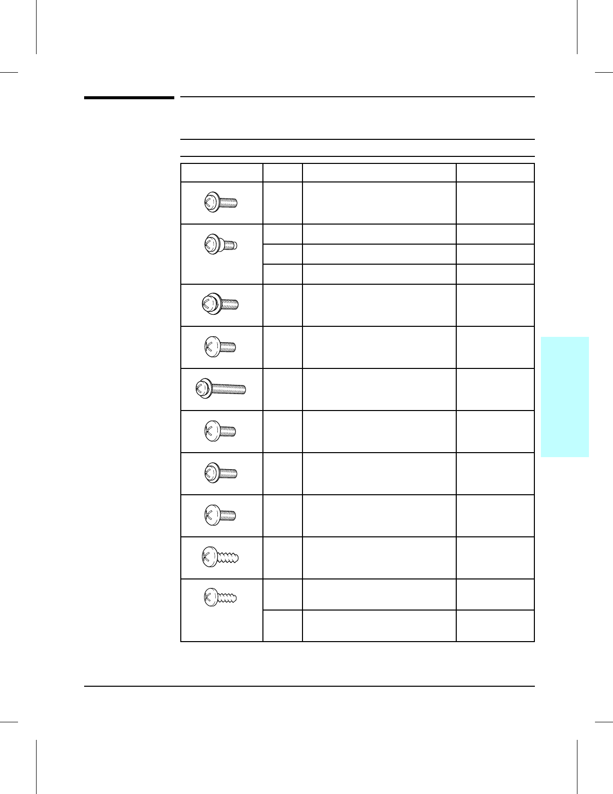
Common Hardware and Replaceable Cables
Example Ref Description Part Number
CH101 Screw, Trus Head, w/Washer FA9-1449-000
CH102 Screw, Stepped, M3 RA1-7636-000
CH103 Screw, Stepped, M3X4 RB1-5489-000
CH104 Screw, Stepped, M3 RB1-5552-000
CH105 Screw, w/Washer, M3X8 XA9-0253-000
CH106 Screw, TP, M3X6 XA9-0267-000
CH107 Screw, M3X25 XA9-0375-000
CH108 Screw, BH3X6(S) XB1-2300-607
CH109 Screw, Mach, Trus Head M3X8 XB1-2302-507
CH110 Screw, Machine M4X8 XB1-2400-809
CH111 Screw, Tap Binding Head M4X8 XB4-7400-809
CH112 Screw, Pan Head Self-tap XB4-7401-007
CH113 Screw, Bind Head Self-tap XB4-7401-009
Table 8-A Common Fasteners Used in the Printer
8SCREW_C
8SCREW_B
8SCREW_L
8SCREW_A
8SCREW_M
8SCREW_A
8SCREW_N
8SCREW_F
8
Parts and
Diagrams
Parts and Diagrams 8-7
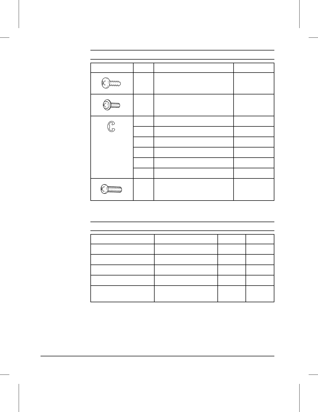
Example Ref Description Part Number
CH114 Screw, Machine M3X8 XB6-7300-809
CH115 Screw, TP, M3X16 XB6-7301-609
CH116 Retaining Ring (e-type) XD2-1100-242
CH117 Retaining Ring (e-type) XD2-1100-322
CH118 Retaining Ring (e-type) XD2-1100-402
CH119 Retaining Ring (e-type) XD2-1100-502
CH120 Retaining Ring (e-type) XD2-1100-642
CH121 Retaining Ring (e-type) XG9-0260-000
CH122 Screw, Mach, M3X14 XB1-2301-407
Table 8-A Common Fasteners Used in the Printer - continued
Description Part No. Fig Ref
Cable, Beam Detect RG5-1442-000 8-9 10
Option Cable Assembly RG5-1446-000 8-3 11B
Clutch Cable RG5-1447-000 8-8 18
DC Cable Assembly RG5-0239-000 8-8 17
Display Panel Cable
Assembly RG5-1485-000 8-2 14
Table 8-B Replaceable Cables
8SCREW_K
8SCREW_H
8-8 Parts and Diagrams
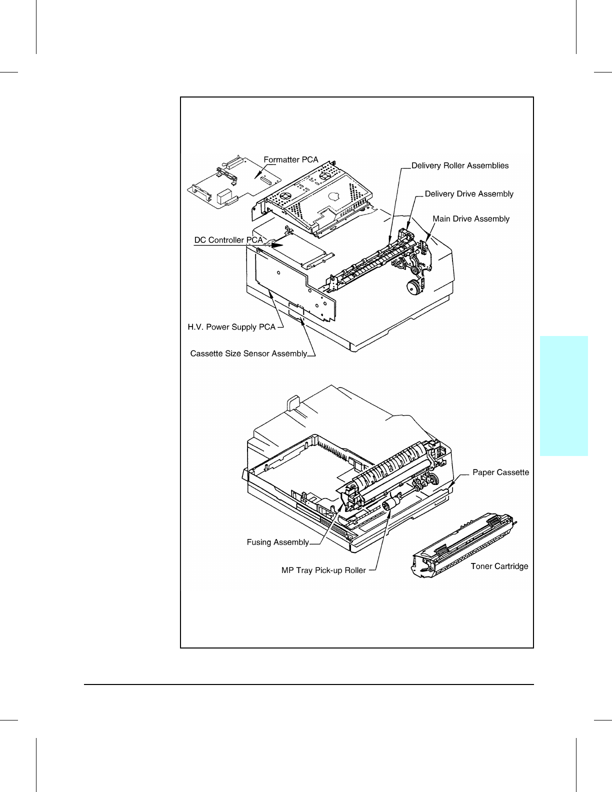
Major Assembly Locations
8ASYLOC1
Figure 8-1
8
Parts and
Diagrams
Parts and Diagrams 8-9
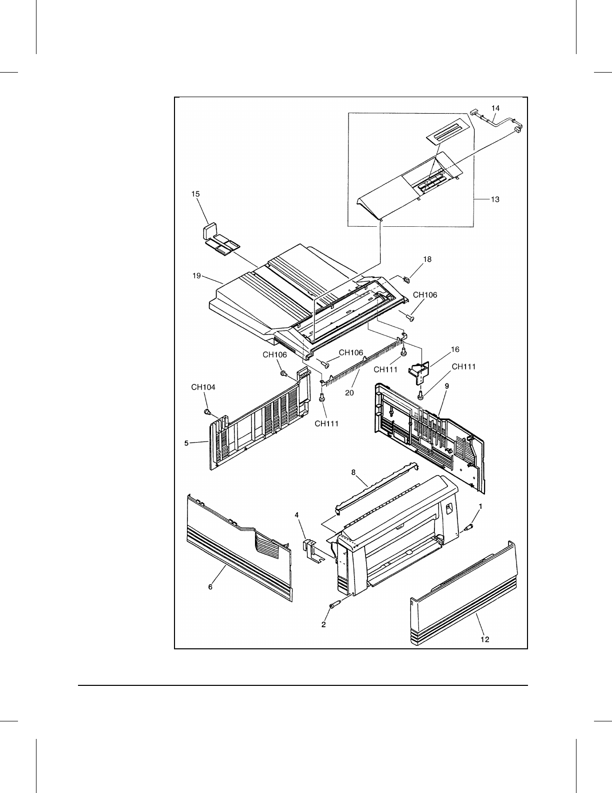
Covers and Doors
8EXTCOV1
Figure 8-2
8-10 Parts and Diagrams
Ref Part No. Qty Description
1 RA2-0448-000 1 Pivot
2 RB1-1291-000 1 Shaft, 2
4 RB1-1421-000 1 Cover
5 RB1-5562-000 1 Panel, Rear
6 RB1-5563-000 1 Panel, Left
8 RF5-1141-000 1 Guide, Plate, Protection
9 RF5-1166-000 1 Panel, Right
12 RG5-1562-000 1 Multi-purpose Tray Assembly 100/115V
12 RG5-1563-000 1 Multi-purpose Tray Assembly 220/240V
13 RG5-1539-000 1 Display Panel Assembly 100/115V
13 RG5-1540-000 1 Display Panel Assembly 220/240V
14 RG5-1485-000 1 Display Panel Cable Assembly
15 RF5-1173-000 1 Slider
16 RB1-1336-000 1 Cover, Cable
18 WT2-5018-000 2 Clip, Cable
19 RG5-1541-000 1 Upper Cover Assembly
20 RB1-5467-000 1 Eliminator, Static Charge
CH104 RB1-5552-000 1 Screw, Stepped, M3
CH106 XA9-0267-000 1 Screw, TP, M3X6
CH111 XB4-7400-809 7 Screw, Tapping, Truss Head
Table 8-2 Covers and Doors
8
Parts and
Diagrams
Parts and Diagrams 8-11
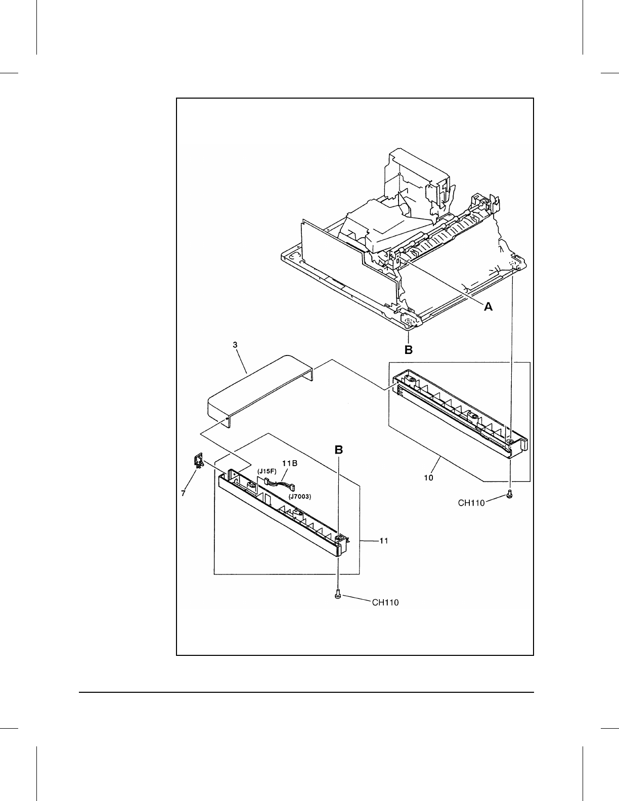
Foot Assemblies
8EXTCOV2
Figure 8-3
8-12 Parts and Diagrams
Ref Part No. Qty Description
3 RB1-5575-000 1 Cover, Rear Cassette
7 RF5-1176-000 1 Plate, Cover
10 RG5-1550-000 1 Right Foot Assembly
11 RG5-1551-000 1 Left Foot Assembly
CH110 XB1-2400-809 1 Screw, Machine M4X8
11B RG5-1446-000 1 Option Cable Assembly
Table 8-3 Foot Assemblies
8
Parts and
Diagrams
Parts and Diagrams 8-13
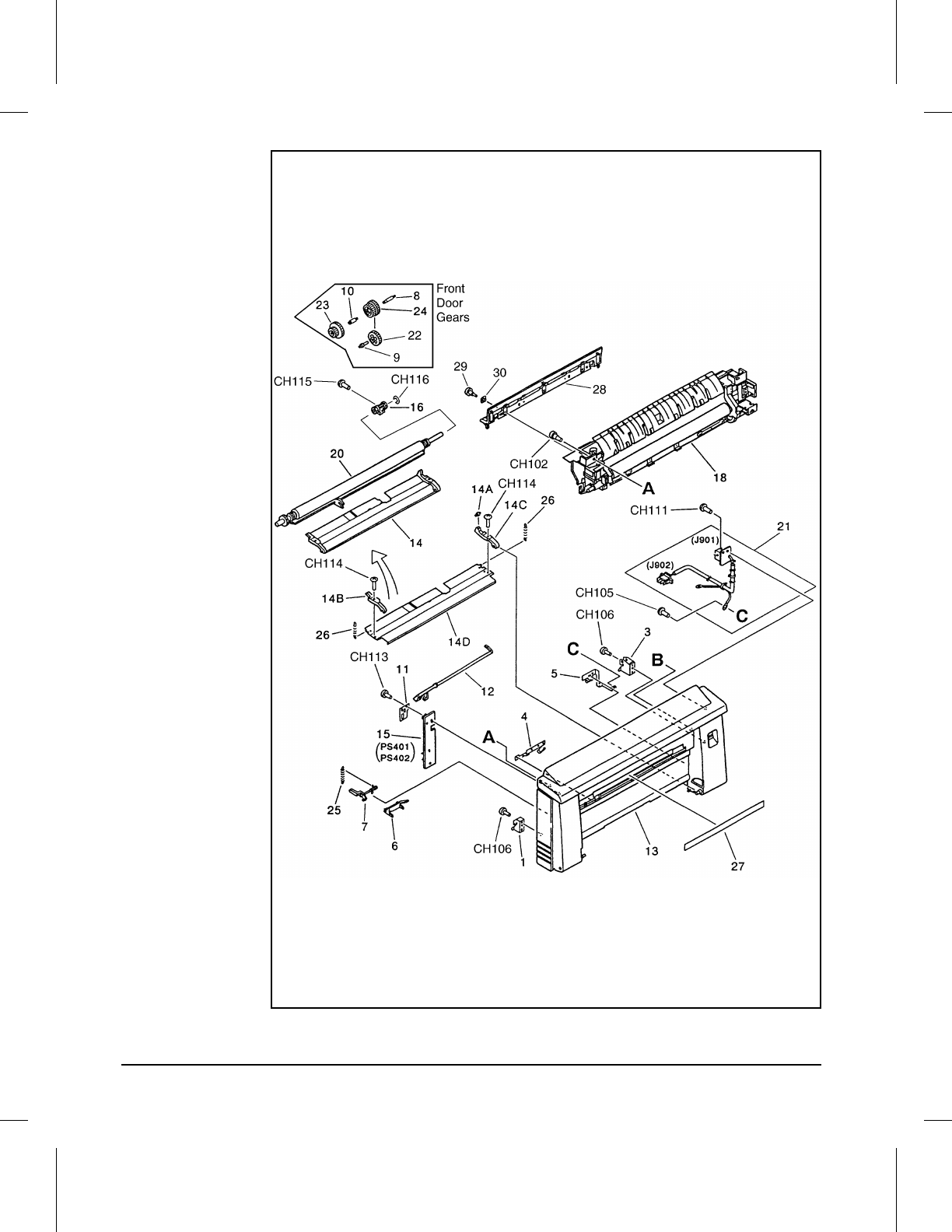
Front Door Components (Page 1 of 2)
8FNTCOV1
Figure 8-4
8-14 Parts and Diagrams
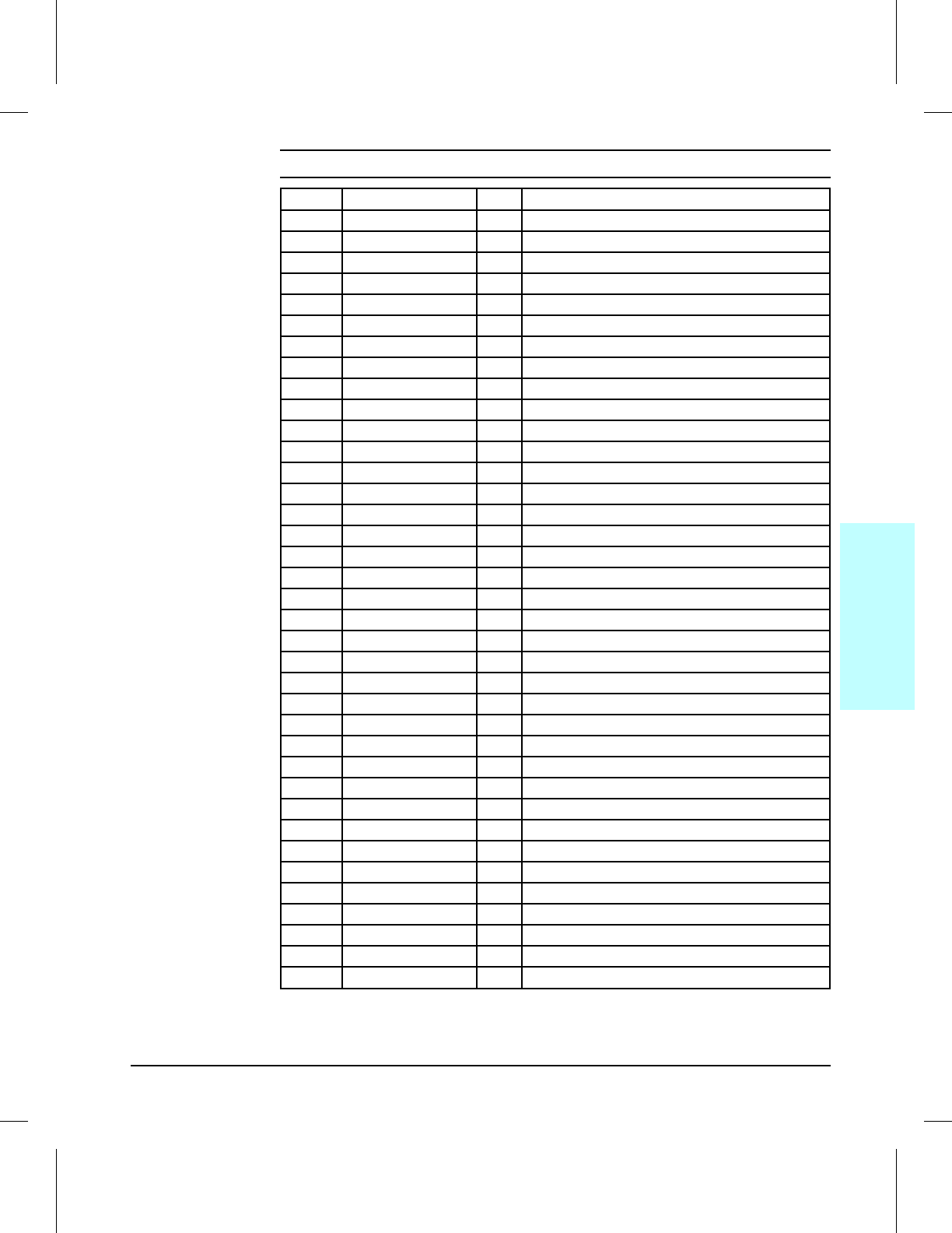
Ref Part No. Qty Description
1 RA1-7563-000 1 Mount
3 RA2-0418-000 1 Mount, Rod
4 RB1-1399-000 1 Plate, Continuity, 1
5 RB1-1400-000 1 Plate, Continuity, 2
6 RB1-1438-000 1 Lever, Sensor, A
7 RA2-0420-000 1 Lever, Door Sensing, B
8 RB1-1422-000 1 Shaft, Gear, A
9 RB1-1423-000 1 Shaft, Gear, B
10 RB1-1424-000 1 Shaft, Gear, C
11 RB1-1429-000 1 Guide, Connector
12 RF5-0400-000 1 Lever, Sensor, Delivery
13 RF5-1165-000 1 Cover, Front
14 RG5-0209-000 1 Paper Guide Plate Assembly
15 RG5-0231-000 1 Front Cover Connect PCA Assembly
16 RG5-0505-000 1 Delivery Drive Assembly
18 RG5-1420-000 1 Fusing Assembly 100/115V
18 RG5-1406-000 1 Fusing Assembly 220/240V
18 C3141-69002 1 Exchange Fusing Assembly 100/115V
18 C3141-69001 1 Exchange Fusing Assembly 220/240V
20 RG5-1410-000 1 Transfer Roller Holder Assembly
21 RG5-1417-000 1 AC Terminal PCA Assembly
22 RS5-0186-000 1 Gear, 34T
23 RS5-0187-000 1 Gear, 21T/40T
24 RS5-0576-000 1 Gear, 25T/33T
25 RS5-2125-000 1 Spring, Tension
26 RS5-2128-000 2 Spring, Tension
27 RS5-8128-000 1 Label, Caution, High Temp
28 RF5-1150-000 1 Guide, Entrance
29 RA1-7636-000 3 Screw, Stepped M3
30 XD9-0079-000 2 Washer, Wave
CH102 RA1-7636-000 1 Screw, Stepped, M3
CH105 XA9-0253-000 1 Screw, W/Washer, M3X8
CH106 XA9-0267-000 1 Screw, TP, M3X6
CH113 XB4-7401-009 1 Screw, Bind Head Self-tap
CH114 XB6-7300-809 1 Screw, Machine M3X8
CH115 XB6-7301-609 1 Screw, TP, M3X16
CH116 XD2-1100-242 1 Retaining Ring (e-type)
Table 8-4 Front Door Components (1 of 2)
8
Parts and
Diagrams
Parts and Diagrams 8-15
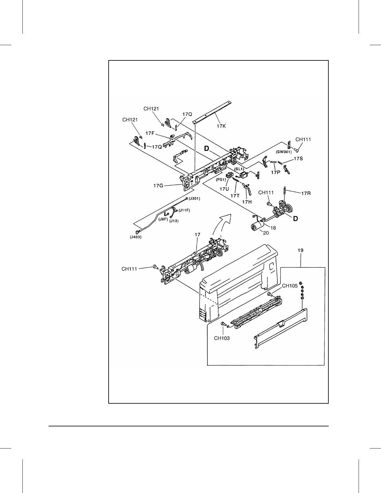
Front Door Components (Page 2 of 2)
8FNTCOV2
Figure 8-5
8-16 Parts and Diagrams

Ref Part No. Qty Description
17 RG5-1404-000 1 Paper Guide Plate Assembly
19 RG5-1552-000 1 Front Door Assembly
20 RB1-1411-000 1 Roller, Pickup
CH103 RB1-5489-000 1 Screw, Stepped, M3X4
CH105 XA9-0253-000 1 Screw, W/Washer, M3X8
CH111 XB4-7400-809 2 Screw, Tap Binding Head M4X8
CH121 XG9-0260-000 1 Retaining Ring (e-type)
17P RS1-2342-000 1 Spring, Tension
17Q RS5-2118-000 2 Spring, Tension
17R RS5-2122-000 1 Spring, Tension
17S RS5-2126-000 1 Spring, Tension
17T RS5-2129-000 1 Spring, Tension
Table 8-5 Front Door Components (2 of 2)
8
Parts and
Diagrams
Parts and Diagrams 8-17
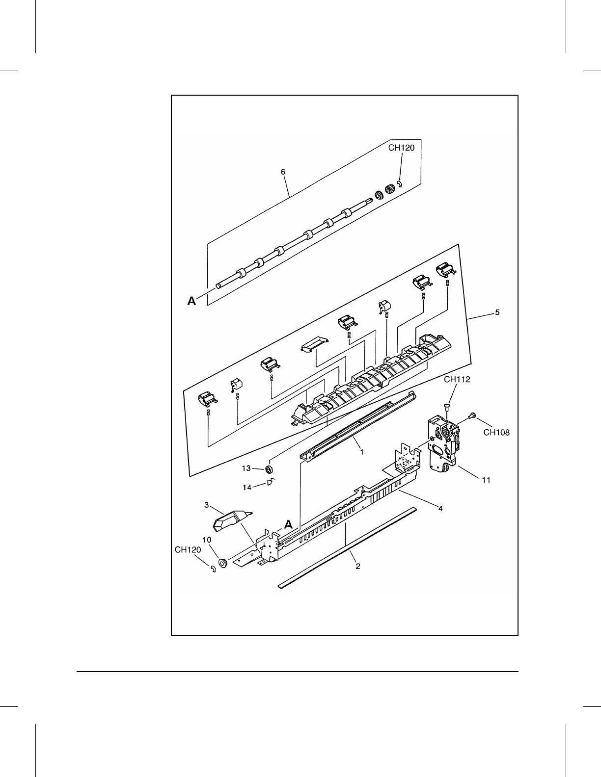
Output Components
8INTCOV
Figure 8-6
8-18 Parts and Diagrams
Ref Part No. Qty Description
1 RB1-1352-040 1 Shutter, Laser
2 RB1-5457-000 1 Cover, Louver
3 RB1-5459-000 1 Pad, Shutter
4 RB1-5460-000 1 Cover, Center
5 RG5-1545-000 1 Guide, Delivery Unit
6 RG5-0198-000 1 Face Down Delivery Assembly
7 RG5-0200-000 6 FD Roller Assembly
10 RS5-1004-000 1 Bushing
11 RG5-1396-000 1 Gear Mounting Assembly
CH108 XB1-2300-607 1 Screw, BH3X6(S)
CH112 XB4-7401-007 1 Screw, Pan Head Self-tap
CH120 XD2-1100-642 2 Retaining Ring (e-type)
Table 8-6 Output Components
8
Parts and
Diagrams
Parts and Diagrams 8-19
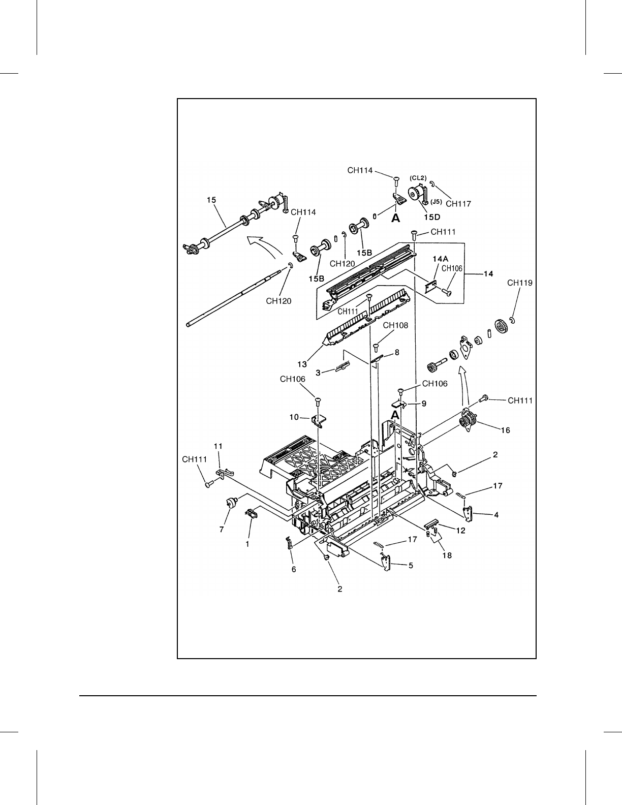
Internal Components (Page 1 of 4)
8INTCOM1
Figure 8-7
8-20 Parts and Diagrams
Ref Part No. Qty Description
1 RA2-0298-000 1 Rack
2 RA2-0321-000 1 Bushing
3 RB1-1274-000 1 Eliminator, Static Charge
4 RB1-1317-000 1 Plate, Pressure, Right
5 RB1-1318-000 1 Plate, Pressure, Left
6 RB1-1324-000 1 Lever
7 RB1-1343-000 1 Knob, Print Density
8 RB1-1344-000 1 Bracket, Anti-static Brush
9 RB1-1349-000 1 Hook, Right
10 RB1-1350-000 1 Hook, Left
11 RB1-5454-000 1 Spring, Leaf
12 RF5-0302-000 1 Separation Pad
13 RF5-0395-000 1 Guide, Paper
14 RF5-0396-000 1 Guide
15 RG5-1391-000 1 Pickup Roller Assembly
15B RB1-1386-000 2 Roller, Pickup
15D RH7-5095-000 1 Clutch, Electromagnetic
16 RG5-1399-000 1 Drum Drive Assembly
17 RS5-2117-000 2 Spring, Tension
18 RS5-2123-000 2 Spring, Compression
CH106 XA9-0267-000 2 Screw, TP, M3X6
CH108 XB1-2300-607 1 Screw, BH3X6(S)
CH111 XB4-7400-809 1 Screw, Tap Binding Head M4X8
CH114 XB6-7300-809 1 Screw, Machine M3X8
CH117 XD2-1100-322 1 Retaining Ring (e-type)
CH119 XD2-1100-502 1 Retaining Ring (e-type)
CH120 XD2-1100-642 1 Retaining Ring (e-type)
Table 8-7 Internal Components (1 of 4)
8
Parts and
Diagrams
Parts and Diagrams 8-21
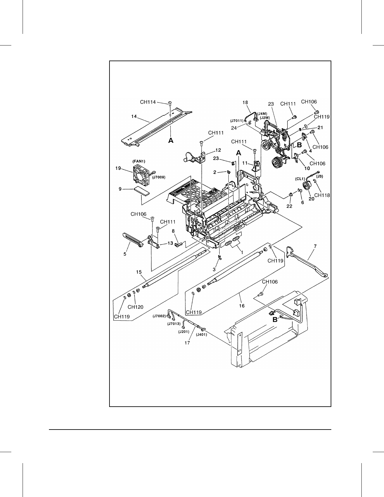
Internal Components (Page 2 of 4)
8INTCOM2
Figure 8-8
8-22 Parts and Diagrams
Ref Part No. Qty Description
1 RA2-0308-000 2 Roller, Guide
2 RA2-0311-000 1 Bushing, Sensor
3 RA2-0312-000 2 Claw
4 RB1-1292-000 1 Plate, Stop, Clutch, R
5 RB1-1294-000 1 Rod, Left
6 RB1-1367-000 1 Retainer
7 RB1-1385-000 1 Rod
8 RB1-2748-000 1 Stopper, Registration
10 RB1-5442-000 1 Plate, Stop, Clutch
11 RB1-5445-000 1 Plate, Mounting, Right
12 RB1-5490-000 1 Plate, Mounting, Left
13 RF5-0331-000 1 Plate, Rod, Left
14 RF5-1142-000 1 Guide, Cartridge
15 RG5-0194-000 1 Registration Roller Assembly, Metal
16 RG5-0195-000 1 Registration Roller Assembly, Rubber
17 RG5-0239-000 1 DC Cable Assembly
18 RG5-1447-000 1 Clutch Cable
19 RH7-1126-000 1 Fan (FM1)
20 RH7-5094-000 1 Clutch, Electromagnetic
21 RS5-1058-000 1 Bushing
22 RS5-1147-000 1 Bushing
23 RG5-1398-000 1 Main Drive Assembly
24 WT2-0388-000 5 Clip, Cable
CH106 XA9-0267-000 1 Screw, TP, M3X6
CH111 XB4-7400-809 1 Screw, Tap Binding Head M4X8
CH114 XB6-7300-809 1 Screw, Machine M3X8
CH118 XD2-1100-402 1 Retaining Ring (e-type)
CH119 XD2-1100-502 3 Retaining Ring (e-type)
CH120 XD2-1100-642 1 Retaining Ring (e-type)
Table 8-8 Internal Components (2 of 4)
8
Parts and
Diagrams
Parts and Diagrams 8-23
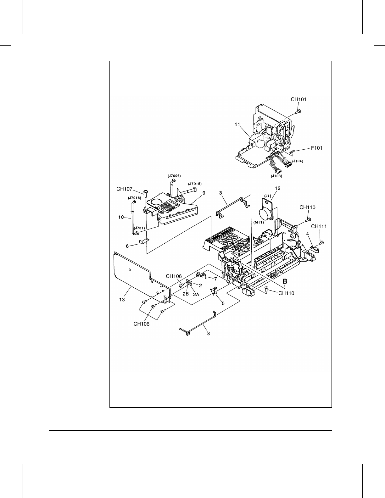
Internal Components (Page 3 of 4)
8INTCOM3
Figure 8-9
8-24 Parts and Diagrams
Ref Part No. Qty Description
2 FG2-4647-000 1 Sub Transfer Assembly
3 RB1-1278-000 1 Lever, Paper Sensing
4 RB1-1286-000 1 Cover, E
5 RB1-1325-000 1 Plate
7 RF5-0326-000 1 Plate, Contact Transfer
8 RF5-0397-000 1 Lever, Sensor, Front, Reg
9 RG5-1383-000 1 Laser/Scanner Assembly
10 RG5-1442-000 1 Cable, Beam Detect
11 RH3-2150-000 1 Power Supply Assembly 100/115V
11 RH3-2151-000 1 Power Supply Assembly 220/240V
12 RH7-1199-000 1 Motor, DC 17.5W
13 RG5-1435-000 1 HV Power Supply Assembly
CH101 FA9-1449-000 1 Screw, Truss Head, w/Washer
CH106 XA9-0267-000 1 Screw, TP, M3X6
CH107 XA9-0375-000 1 Screw, M3X25
CH110 XB1-2400-809 1 Screw, Machine M4X8
CH111 XB4-7400-809 1 Screw, Tap Binding HeaD M4X8
F101 WD1-0224-000 1 Fuse, 125V, 6.3A
F101 WD1-0643-151 1 Fuse, 250V, 3.15A
Table 8-9 Internal Components (3 of 4)
8
Parts and
Diagrams
Parts and Diagrams 8-25
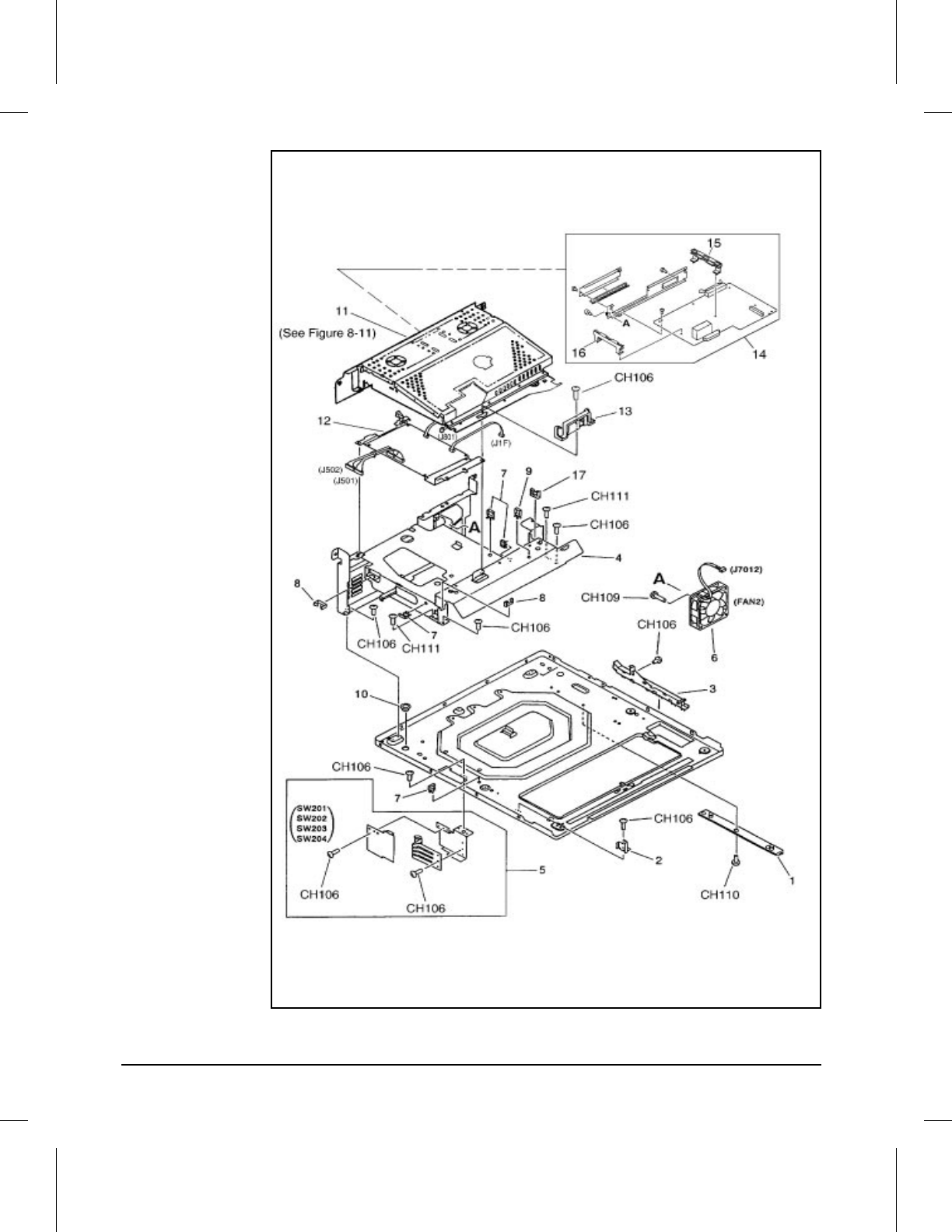
Internal Components (Page 4 of 4)
8INTCOM4
Figure 8-10
8-26 Parts and Diagrams
Ref Part No. Qty Description
1 RB1-1273-000 1 Guide, Cassette
2 RB1-1346-000 1 Plate, HVT
3 RB1-1380-020 1 Bracket, Cable
4 RB1-5446-000 1 Plate, Rear Shield
5 RG5-1416-000 1 Cass Size Sensor Assembly
6 RH7-1214-000 1 Fan (FM2)
7 WT2-0317-000 4 Clip, Cable
8 WT2-5011-000 2 Clip, Cable
9 WT2-5018-000 1 Clip, Cable
10 WT2-5114-000 1 Bushing
11 RG5-1560-000 1 Card Cage Assembly
12 RG5-1559-000 1 DC Controller PCA Assembly
12 C3141-69003 1 Exchange DC Controller PCA Assembly
13 RB1-5559-000 1 Clamp, Cable
14 C3143-67901 1 Formatter PCA
14 C3143-69001 1 Exchange Formatter PCA
15 RB1-5786-000 1 MIO Cover Plate
16 RB1-5789-000 2 MIO Guide Rail
17 WT2-9501-000 1 Holder, Cable
CH106 XA9-0267-000 2 Screw, TP, M3X6
CH109 XB1-2302-507 1 Screw, Mach, Trus Head M3X25
CH110 XB1-2400-809 1 Screw, Machine M4X8
CH111 XB4-7400-809 1 Screw, Tap Binding Head M4X8
Table 8-10 Internal Components (4 of 4)
8
Parts and
Diagrams
Parts and Diagrams 8-27
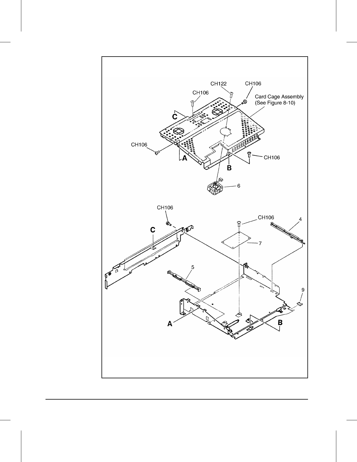
Card Cage Assembly
8CRDCAGE
Figure 8-11
8-28 Parts and Diagrams

Ref Part No. Qty Description
4 RB1-5557-000 1 Rail, Slide, Right
5 RB1-5558-000 1 Rail, Slide, Left
6 RH7-1218-000 1 Fan (FM3)
7 RG5-1484-000 1 Small Interface PCA
CH106 XA9-0267-000 6 Screw, TP, M3X6
CH122 XB1-2301-407 1 Screw, Mach, Trus Head M3X14
Table 8-11 Card Cage Assembly
8
Parts and
Diagrams
Parts and Diagrams 8-29
Ref Part No. Qty Description
N/A C3760-60001 1 Lower Cassette Assembly
N/A C3760-69001 1 Exchange Lower Cassette Assembly
N/A C3760-60503 1 Lower Cassette Paper Guide
N/A C3760-60502 1 Lower Cassette Paper Tray
N/A C3760-60501 1 Lower Cassette Pickup Roller
Table 8-12 Optional Lower Cassette Assembly
8-30 Parts and Diagrams

A
Parts Index
Parts Index A-1
Alphabetical Parts Index
Description Part No. Fig Ref
AC Terminal PCA Assembly RG5-1417-000 8-4 21
Bracket, Anti-static Brush RB1-1344-000 8-7 8
Bracket, Cable RB1-1380-020 8-10 3
Bushing RA2-0321-000 8-7 2
Bushing RS5-1004-000 8-6 10
Bushing RS5-1058-000 8-8 21
Bushing RS5-1147-000 8-8 22
Bushing WT2-5114-000 8-10 10
Bushing, Sensor RA2-0311-000 8-8 2
Cable, Beam Detect RG5-1442-000 8-9 10
Card Cage Assembly RG5-1560-000 8-10 11
Cass Size Sensor Assembly RG5-1416-000 8-10 5
Clamp, Cable RB1-5559-000 8-10 13
Claw RA2-0312-000 8-8 3
Clip, Cable WT2-5018-000 8-2 18
Clip, Cable WT2-0317-000 8-10 7
Clip, Cable WT2-0388-000 8-8 24
Clip, Cable WT2-5011-000 8-10 8
Clip, Cable WT2-5018-000 8-10 9
Clutch Cable RG5-1447-000 8-8 18
Clutch, Electromagnetic RH7-5094-000 8-8 20
Clutch, Electromagnetic RH7-5095-000 8-7 15D
Cover RB1-1421-000 8-2 4
Cover, Cable RB1-1336-000 8-2 16
Cover, Center RB1-5460-000 8-6 4
Cover, E RB1-1286-000 8-9 4
Cover, Front RF5-1165-000 8-4 13
Cover, Louver RB1-5457-000 8-6 2
Table A-1 Alphabetical Parts List
A-2 Parts Index

Description Part No. Fig Ref
Cover, Rear Cassette RB1-5575-000 8-3 3
DC Cable Assembly RG5-0239-000 8-8 17
DC Controller PCA Assembly RG5-1559-000 8-10 12
Delivery Drive Assembly RG5-0505-000 8-4 16
Display Panel Assembly 100/115V RG5-1539-000 8-2 13
Display Panel Assembly 220/240V RG5-1540-000 8-2 13
Display Panel Cable Assembly RG5-1485-000 8-2 14
Drum Drive Assembly RG5-1399-000 8-7 16
Eliminator, Static Charge RB1-1274-000 8-7 3
Eliminator, Static Charge RB1-5467-000 8-2 20
Exchange DC Controller PCA Assembly C3141-69003 8-10 12
Exchange Formatter PCA Assembly C3143-69001 8-10 14
Exchange Fusing Assembly 100/115V C3141-69002 8-4 18
Exchange Fusing Assembly 220/240V C3141-69001 8-4 18
Exchange Lower Cassette Assembly C3760-69001 8-12 N/A
Face Down Delivery Assembly RG5-0198-000 8-6 6
Fan (FM1) RH7-1126-000 8-8 19
Fan (FM2) RH7-1214-000 8-10 6
Fan (FM3) RH7-1218-000 8-11 6
FD Roller Assembly RG5-0200-000 8-6 7
Formatter PCA C3143-67901 8-10 14
Front Cover Connect PCA Assembly RG5-0231-000 8-4 15
Front Door Assembly RG5-1552-000 8-5 19
Fuse, 125V, 6.3A WD1-0224-000 8-9 F101
Fuse, 250V, 3.15A WD1-0643-151 8-9 F101
Fusing Assembly 100/115V RG5-1420-000 8-4 18
Fusing Assembly 220/240V RG5-1406-000 8-4 18
Gear Mounting Assembly RG5-1396-000 8-6 11
Gear, 21T/40T RS5-0187-000 8-4 23
Gear, 25T/33T RS5-0576-000 8-4 24
Table A-1 Alphabetical Parts List - continued
A
Parts
Index
Parts Index A-3

Description Part No. Fig Ref
Gear, 34T RS5-0186-000 8-4 22
Guide RF5-0396-000 8-7 14
Guide, Cartridge RF5-1142-000 8-8 14
Guide, Cassette RB1-1273-000 8-10 1
Guide, Connector RB1-1429-000 8-4 11
Guide, Delivery Unit RG5-1545-000 8-6 5
Guide, Entrance RF5-1150-000 8-4 28
Guide, Paper RF5-0395-000 8-7 13
Guide, Plate, Protection RF5-1141-000 8-2 8
Holder, Cable WT2-9501-000 8-10 17
Hook, Left RB1-1350-000 8-7 10
Hook, Right RB1-1349-000 8-7 9
HV Power Supply Assembly RG5-1435-000 8-9 13
Knob, Print Density RB1-1343-000 8-7 7
Label, Caution, High Temp RS5-8128-000 8-4 27
Laser/Scanner Assembly RG5-1383-000 8-9 9
Left Foot Assembly RG5-1551-000 8-3 11
Lever RB1-1324-000 8-7 6
Lever, Door Sensing, B RA2-0420-000 8-4 7
Lever, Paper Sensing RB1-1278-000 8-9 3
Lever, Sensor, A RB1-1438-000 8-4 6
Lever, Sensor, Delivery RF5-0400-000 8-4 12
Lever, Sensor, Front, REG RF5-0397-000 8-9 8
Lower Cassette Assembly C3760-60001 8-12 N/A
Lower Cassette Paper Guide C3760-60503 8-12 N/A
Lower Cassette Paper Tray C3760-60502 8-12 N/A
Lower Cassette Pickup Roller C3760-60501 8-12 N/A
Main Drive Assembly RG5-1398-000 8-8 23
MIO Cover Plate RB1-5786-000 8-10 15
MIO Guide Rail RB1-5789-000 8-10 16
Table A-1 Alphabetical Parts List - continued
A-4 Parts Index

Description Part No. Fig Ref
Motor, DC 17.5W RH7-1199-000 8-9 12
Mount RA1-7563-000 8-4 1
Mount, Rod RA2-0418-000 8-4 3
Multi-purpose Tray Assembly 100/115V RG5-1562-000 8-2 12
Multi-purpose Tray Assembly 220/240V RG5-1563-000 8-2 12
Option Cable Assembly RG5-1446-000 8-3 11B
Pad, Separation RF5-0302-000 8-7 12
Pad, Shutter RB1-5459-000 8-6 3
Panel, Left RB1-5563-000 8-2 6
Panel, Rear RB1-5562-000 8-2 5
Panel, Right RF5-1166-000 8-2 9
Paper Guide Plate Assembly RG5-0209-000 8-4 14
Paper Guide Plate Assembly RG5-1404-000 8-5 17
Pickup Roller Assembly RG5-1391-000 8-7 15
Pivot RA2-0448-000 8-2 1
Plate RB1-1325-000 8-9 5
Plate, Contact Transfer RF5-0326-000 8-9 7
Plate, Continuity, 1 RB1-1399-000 8-4 4
Plate, Continuity, 2 RB1-1400-000 8-4 5
Plate, Cover RF5-1176-000 8-3 7
Plate, HVT RB1-1346-000 8-10 2
Plate, Mounting, Left RB1-5490-000 8-8 12
Plate, Mounting, Right RB1-5445-000 8-8 11
Plate, Pressure, Left RB1-1318-000 8-7 5
Plate, Pressure, Right RB1-1317-000 8-7 4
Plate, Rear Shield RB1-5446-000 8-10 4
Plate, Rod, Left RF5-0331-000 8-8 13
Plate, Stop, Clutch RB1-5442-000 8-8 10
Plate, Stop, Clutch, R RB1-1292-000 8-8 4
Power Supply Assembly 100/115V RH3-2150-000 8-9 11
Table A-1 Alphabetical Parts List - continued
A
Parts
Index
Parts Index A-5
Description Part No. Fig Ref
Power Supply Assembly 220/240V RH3-2151-000 8-9 11
Rack RA2-0298-000 8-7 1
Rail, Slide, Left RB1-5558-000 8-11 5
Rail, Slide, Right RB1-5557-000 8-11 4
Registration Roller Assembly, Metal RG5-0194-000 8-8 15
Registration Roller Assembly, Rubber RG5-0195-000 8-8 16
Retainer RB1-1367-000 8-8 6
Retaining Ring (e-type) XD2-1100-242 8-4 116
Retaining Ring (e-type) XD2-1100-322 8-7 117
Retaining Ring (e-type) XD2-1100-402 8-8 118
Retaining Ring (e-type) XD2-1100-502 8-7 119
Retaining Ring (e-type) XD2-1100-502 8-8 119
Retaining Ring (e-type) XD2-1100-642 8-6 120
Retaining Ring (e-type) XD2-1100-642 8-7 120
Retaining Ring (e-type) XD2-1100-642 8-8 120
Retaining Ring (e-type) XG9-0260-000 8-5 121
Right Foot Assembly RG5-1550-000 8-3 10
Rod RB1-1385-000 8-8 7
Rod, Left RB1-1294-000 8-8 5
Roller, Guide RA2-0308-000 8-8 1
Roller, Pickup RB1-1411-000 8-5 20
Roller, Pickup RB1-1386-000 8-7 15B
Screw, BH3X6(S) XB1-2300-607 8-6 108
Screw, BH3X6(S) XB1-2300-607 8-7 108
Screw, Bind Head Self-tap XB4-7401-009 8-4 113
Screw, M3X25 XA9-0375-000 8-9 107
Screw, Machine, Trus Head M3X14 XB1-2301-407 8-11 122
Screw, Machine, Trus Head M3X25 XB1-2302-507 8-10 109
Screw, Machine M3X8 XB6-7300-809 8-4 114
Screw, Machine M3X8 XB6-7300-809 8-7 114
Table A-1 Alphabetical Parts List - continued
A-6 Parts Index
Description Part No. Fig Ref
Screw, Machine M3X8 XB6-7300-809 8-8 114
Screw, Machine M4X8 XB1-2400-809 8-3 110
Screw, Machine M4X8 XB1-2400-809 8-9 110
Screw, Machine M4X8 XB1-2400-809 8-10 110
Screw, Pan Head Self-tap XB4-7401-007 8-6 112
Screw, Stepped M3 RA1-7636-000 8-4 29
Screw, Stepped, M3 RA1-7636-000 8-4 102
Screw, Stepped, M3 RB1-5552-000 8-2 104
Screw, Stepped, M3X4 RB1-5489-000 8-5 103
Screw, Tap Binding Head M4X8 XB4-7400-809 8-5 111
Screw, Tap Binding Head M4X8 XB4-7400-809 8-7 111
Screw, Tap Binding Head M4X8 XB4-7400-809 8-8 111
Screw, Tap Binding Head M4X8 XB4-7400-809 8-9 111
Screw, Tap Binding Head M4X8 XB4-7400-809 8-10 111
Screw, Tapping, Trus Head XB4-7400-809 8-2 CH111
Screw, TP, M3X16 XB6-7301-609 8-4 115
Screw, TP, M3X6 XA9-0267-000 8-2 106
Screw, TP, M3X6 XA9-0267-000 8-4 106
Screw, TP, M3X6 XA9-0267-000 8-7 106
Screw, TP, M3X6 XA9-0267-000 8-8 106
Screw, TP, M3X6 XA9-0267-000 8-9 106
Screw, TP, M3X6 XA9-0267-000 8-10 106
Screw, TP, M3X6 XA9-0267-000 8-11 106
Screw, Trus Head, w/washer FA9-1449-000 8-9 101
Screw, w/washer, M3X8 XA9-0253-000 8-4 105
Screw, w/washer, M3X8 XA9-0253-000 8-5 105
Shaft, 2 RB1-1291-000 8-2 2
Shaft, Gear, A RB1-1422-000 8-4 8
Shaft, Gear, B RB1-1423-000 8-4 9
Shaft, Gear, C RB1-1424-000 8-4 10
Table A-1 Alphabetical Parts List - continued
A
Parts
Index
Parts Index A-7
Description Part No. Fig Ref
Shutter, Laser RB1-1352-040 8-6 1
Slider RF5-1173-000 8-2 15
Small Interface PCA RG5-1484-000 8-11 7
Spring, Compression RS5-2123-000 8-7 18
Spring, Leaf RB1-5454-000 8-7 11
Spring, Tension RS1-2342-000 8-5 17P
Spring, Tension RS5-2117-000 8-7 17
Spring, Tension RS5-2118-000 8-5 17Q
Spring, Tension RS5-2122-000 8-5 17R
Spring, Tension RS5-2125-000 8-4 25
Spring, Tension RS5-2126-000 8-5 17S
Spring, Tension RS5-2128-000 8-4 26
Spring, Tension RS5-2129-000 8-5 17T
Springs, Separation Pad RS5-2123-000 8-7 18
Stopper, Registration RB1-2748-000 8-8 8
Sub Transfer Assembly FG2-4647-000 8-9 2
Transfer Roller Holder Assembly RG5-1410-000 8-4 20
Upper Cover Assembly RG5-1541-000 8-2 19
Washer, Wave XD9-0079-000 8-4 30
Table A-1 Alphabetical Parts List - continued
A-8 Parts Index
Numerical Parts Index
Part No. Description Fig Ref
C3141-69001 Exchange Fusing Assembly 220/240V 8-4 18
C3141-69002 Exchange Fusing Assembly 100/115V 8-4 18
C3141-69003 Exchange DC Controller PCA Assembly 8-10 12
C3143-67901 Formatter PCA 8-10 14
C3143-69001 Exchange Formatter PCA 8-10 14
C3760-60001 Lower Cassette Assembly 8-12 N/A
C3760-60501 Lower Cassette Pickup Roller 8-12 N/A
C3760-60502 Lower Cassette Paper Tray 8-12 N/A
C3760-60503 Lower Cassette Paper Guide 8-12 N/A
C3760-69001 Exchange Lower Cassette Assembly 8-12 N/A
FA9-1449-000 Screw, Trus Head, w/washer 8-9 101
FG2-4647-000 Sub Transfer Assembly 8-9 2
RA1-7563-000 Mount 8-4 1
RA1-7636-000 Screw, Stepped M3 8-4 29
RA1-7636-000 Screw, Stepped, M3 8-4 102
RA2-0298-000 Rack 8-7 1
RA2-0308-000 Roller, Guide 8-8 1
RA2-0311-000 Bushing, Sensor 8-8 2
RA2-0312-000 Claw 8-8 3
RA2-0321-000 Bushing 8-7 2
RA2-0418-000 Mount, Rod 8-4 3
RA2-0420-000 Lever, Door Sensing, B 8-4 7
RA2-0448-000 Pivot 8-2 1
RB1-1273-000 Guide, Cassette 8-10 1
RB1-1274-000 Eliminator, Static Charge 8-7 3
RB1-1278-000 Lever, Paper Sensing 8-9 3
RB1-1286-000 Cover, E 8-9 4
RB1-1291-000 Shaft, 2 8-2 2
Table A-2 Numerical Parts List
A
Parts
Index
Parts Index A-9
Part No. Description Fig Ref
RB1-1292-000 Plate, Stop, Clutch, R 8-8 4
RB1-1294-000 Rod, Left 8-8 5
RB1-1317-000 Plate, Pressure, Right 8-7 4
RB1-1318-000 Plate, Pressure, Left 8-7 5
RB1-1324-000 Lever 8-7 6
RB1-1325-000 Plate 8-9 5
RB1-1336-000 Cover, Cable 8-2 16
RB1-1343-000 Knob, Print Density 8-7 7
RB1-1344-000 Bracket, Anti-static Brush 8-7 8
RB1-1346-000 Plate, HVT 8-10 2
RB1-1349-000 Hook, Right 8-7 9
RB1-1350-000 Hook, Left 8-7 10
RB1-1352-040 Shutter, Laser 8-6 1
RB1-1367-000 Retainer 8-8 6
RB1-1380-020 Bracket, Cable 8-10 3
RB1-1385-000 Rod 8-8 7
RB1-1386-000 Roller, Pickup 8-7 15B
RB1-1399-000 Plate, Continuity, 1 8-4 4
RB1-1400-000 Plate, Continuity, 2 8-4 5
RB1-1411-000 Roller, Pickup 8-5 20
RB1-1421-000 Cover 8-2 4
RB1-1422-000 Shaft, Gear, A 8-4 8
RB1-1423-000 Shaft, Gear, B 8-4 9
RB1-1424-000 Shaft, Gear, C 8-4 10
RB1-1429-000 Guide, Connector 8-4 11
RB1-1438-000 Lever, Sensor, A 8-4 6
RB1-2748-000 Stopper, Registration 8-8 8
RB1-5442-000 Plate, Stop, Clutch 8-8 10
RB1-5445-000 Plate, Mounting, Right 8-8 11
RB1-5446-000 Plate, Rear Shield 8-10 4
Table A-2 Numerical Parts List - continued
A-10 Parts Index

Part No. Description Fig Ref
RB1-5454-000 Spring, Leaf 8-7 11
RB1-5457-000 Cover, Louver 8-6 2
RB1-5459-000 Pad, Shutter 8-6 3
RB1-5460-000 Cover, Center 8-6 4
RB1-5467-000 Eliminator, Static Charge 8-2 20
RB1-5489-000 Screw, Stepped, M3X4 8-5 103
RB1-5490-000 Plate, Mounting, Left 8-8 12
RB1-5552-000 Screw, Stepped, M3 8-2 104
RB1-5557-000 Rail, Slide, Right 8-11 4
RB1-5558-000 Rail, Slide, Left 8-11 5
RB1-5559-000 Clamp, Cable 8-10 13
RB1-5562-000 Panel, Rear 8-2 5
RB1-5563-000 Panel, Left 8-2 6
RB1-5575-000 Cover, Rear Cassette 8-3 3
RB1-5786-000 MIO Guide Plate 8-10 15
RB1-5789-000 MIO Guide Rail 8-10 16
RF5-0302-000 Pad, Separation 8-7 12
RF5-0326-000 Plate, Contact Transfer 8-9 7
RF5-0331-000 Plate, Rod, Left 8-8 13
RF5-0395-000 Guide, Paper 8-7 13
RF5-0396-000 Guide 8-7 14
RF5-0397-000 Lever, Sensor, Front, REG 8-9 8
RF5-0400-000 Lever, Sensor, Delivery 8-4 12
RF5-1141-000 Guide, Plate, Protection 8-2 8
RF5-1142-000 Guide, Cartridge 8-8 14
RF5-1150-000 Guide, Entrance 8-4 28
RF5-1165-000 Cover, Front 8-4 13
RF5-1166-000 Panel, Right 8-2 9
RF5-1173-000 Slider 8-2 15
RF5-1176-000 Plate, Cover 8-3 7
Table A-2 Numerical Parts List - continued
A
Parts
Index
Parts Index A-11

Part No. Description Fig Ref
RG5-0194-000 Registration Roller Assembly, Metal 8-8 15
RG5-0195-000 Registration Roller Assembly, Rubber 8-8 16
RG5-0198-000 Face Down Delivery Assembly 8-6 6
RG5-0200-000 FD Roller Assembly 8-6 7
RG5-0209-000 Paper Guide Plate Assembly 8-4 14
RG5-0231-000 Front Cover Connect PCA Assembly 8-4 15
RG5-0239-000 DC Cable Assembly 8-8 17
RG5-0505-000 Delivery Drive Assembly 8-4 16
RG5-1383-000 Laser/Scanner Assembly 8-9 9
RG5-1391-000 Pickup Roller Assembly 8-7 15
RG5-1396-000 Gear Mounting Assembly 8-6 11
RG5-1398-000 Main Drive Assembly 8-8 23
RG5-1399-000 Drum Drive Assembly 8-7 16
RG5-1404-000 Paper Guide Plate Assembly 8-5 17
RG5-1410-000 Transfer Roller Holder Assembly 8-4 20
RG5-1416-000 Cass Size Sensor Assembly 8-10 5
RG5-1417-000 AC Terminal PCA Assembly 8-4 21
RG5-1435-000 HV Power Supply Assembly 8-9 13
RG5-1442-000 Cable, Beam Detect 8-9 10
RG5-1446-000 Option Cable Assembly 8-3 11B
RG5-1447-000 Clutch Cable 8-8 18
RG5-1484-000 Small Interface PCA 8-11 7
RG5-1485-000 Display Panel Cable Assembly 8-2 14
RG5-1539-000 Display Panel Assembly 100/115V 8-2 13
RG5-1540-000 Display Panel Assembly 220/240V 8-2 13
RG5-1541-000 Upper Cover Assembly 8-2 19
RG5-1545-000 Guide, Delivery Unit 8-6 5
RG5-1550-000 Right Foot Assembly 8-3 10
RG5-1551-000 Left Foot Assembly 8-3 11
RG5-1552-000 Front Door Assembly 8-5 19
Table A-2 Numerical Parts List - continued
A-12 Parts Index
Part No. Description Fig Ref
RG5-1557-000 Fusing Assembly 100/115V 8-4 18
RG5-1558-000 Fusing Assembly 220/240V 8-4 18
RG5-1559-000 DC Controller PCA Assembly 8-10 12
RG5-1560-000 Card Cage Assembly 8-10 11
RG5-1562-000 Multi-purpose Tray Assembly 100/115V 8-2 12
RG5-1563-000 Multi-purpose Tray Assembly 220/240V 8-2 12
RH3-2150-000 Power Supply Assembly 100/115V 8-9 11
RH3-2151-000 Power Supply Assembly 220/240V 8-9 11
RH7-1126-000 Fan (FM1) 8-8 19
RH7-1199-000 Motor, DC 17.5W 8-9 12
RH7-1214-000 Fan (FM2) 8-10 6
RH7-1218-000 Fan (FM3) 8-11 6
RH7-5094-000 Clutch, Electromagnetic 8-8 20
RH7-5095-000 Clutch, Electromagnetic 8-7 15D
RS1-2342-000 Spring, Tension 8-5 17P
RS5-0186-000 Gear, 34T 8-4 22
RS5-0187-000 Gear, 21T/40T 8-4 23
RS5-0576-000 Gear, 25T/33T 8-4 24
RS5-1004-000 Bushing 8-6 10
RS5-1058-000 Bushing 8-8 21
RS5-1147-000 Bushing 8-8 22
RS5-2117-000 Spring, Tension 8-7 17
RS5-2118-000 Spring, Tension 8-5 17Q
RS5-2122-000 Spring, Tension 8-5 17R
RS5-2123-000 Spring, Compression 8-7 18
RS5-2125-000 Spring, Tension 8-4 25
RS5-2126-000 Spring, Tension 8-5 17S
RS5-2128-000 Spring, Tension 8-4 26
RS5-2129-000 Spring, Tension 8-5 17T
RS5-8128-000 Label, Caution, High Temp 8-4 27
Table A-2 Numerical Parts List - continued
A
Parts
Index
Parts Index A-13

Part No. Description Fig Ref
WD1-0224-000 Fuse, 125V, 6.3A 8-9 F101
WD1-0643-151 Fuse, 250V, 3.15A 8-9 F101
WT2-0317-000 Clip, Cable 8-10 7
WT2-0388-000 Clip, Cable 8-8 24
WT2-5011-000 Clip, Cable 8-10 8
WT2-5018-000 Clip, Cable 8-2 18
WT2-5018-000 Clip, Cable 8-10 9
WT2-5114-000 Bushing 8-10 10
WT2-9501-000 Holder, Cable 8-10 17
XA9-0253-000 Screw, w/washer, M3X8 8-4 105
XA9-0253-000 Screw, w/washer, M3X8 8-5 105
XA9-0267-000 Screw, TP, M3X6 8-2 106
XA9-0267-000 Screw, TP, M3X6 8-4 106
XA9-0267-000 Screw, TP, M3X6 8-7 106
XA9-0267-000 Screw, TP, M3X6 8-8 106
XA9-0267-000 Screw, TP, M3X6 8-9 106
XA9-0267-000 Screw, TP, M3X6 8-10 106
XA9-0267-000 Screw, TP, M3X6 8-11 106
XA9-0375-000 Screw, M3X25 8-9 107
XB1-2300-607 Screw, BH3X6(S) 8-6 108
XB1-2300-607 Screw, BH3X6(S) 8-7 108
XB1-2301-407 Screw, Machine, Trus Head M3X14 8-11 122
XB1-2302-507 Screw, Machine, Trus Head M3X25 8-10 109
XB1-2400-809 Screw, Machine M4X8 8-3 110
XB1-2400-809 Screw, Machine M4X8 8-9 110
XB1-2400-809 Screw, Machine M4X8 8-10 110
XB4-7400-809 Screw, Tap Binding Head M4X8 8-5 111
XB4-7400-809 Screw, Tap Binding Head M4X8 8-7 111
XB4-7400-809 Screw, Tap Binding Head M4X8 8-8 111
XB4-7400-809 Screw, Tap Binding Head M4X8 8-9 111
Table A-2 Numerical Parts List - continued
A-14 Parts Index
Part No. Description Fig Ref
XB4-7400-809 Screw, Tap Binding Head M4X8 8-10 111
XB4-7400-809 Screw, Tapping, Trus Head 8-2 CH111
XB4-7401-007 Screw, Pan Head Self-tap 8-6 112
XB4-7401-009 Screw, Bind Head Self-tap 8-4 113
XB6-7300-809 Screw, Machine M3X8 8-4 114
XB6-7300-809 Screw, Machine M3X8 8-7 114
XB6-7300-809 Screw, Machine M3X8 8-8 114
XB6-7301-609 Screw, TP, M3X16 8-4 115
XD2-1100-242 Retaining Ring (e-type) 8-4 116
XD2-1100-322 Retaining Ring (e-type) 8-7 117
XD2-1100-402 Retaining Ring (e-type) 8-8 118
XD2-1100-502 Retaining Ring (e-type) 8-7 119
XD2-1100-502 Retaining Ring (e-type) 8-8 119
XD2-1100-642 Retaining Ring (e-type) 8-6 120
XD2-1100-642 Retaining Ring (e-type) 8-7 120
XD2-1100-642 Retaining Ring (e-type) 8-8 120
XD9-0079-000 Washer, Wave 8-4 30
XG9-0260-000 Retaining Ring (e-type) 8-5 121
Table A-2 Numerical Parts List - continued
A
Parts
Index
Parts Index A-15

A-16 Parts Index
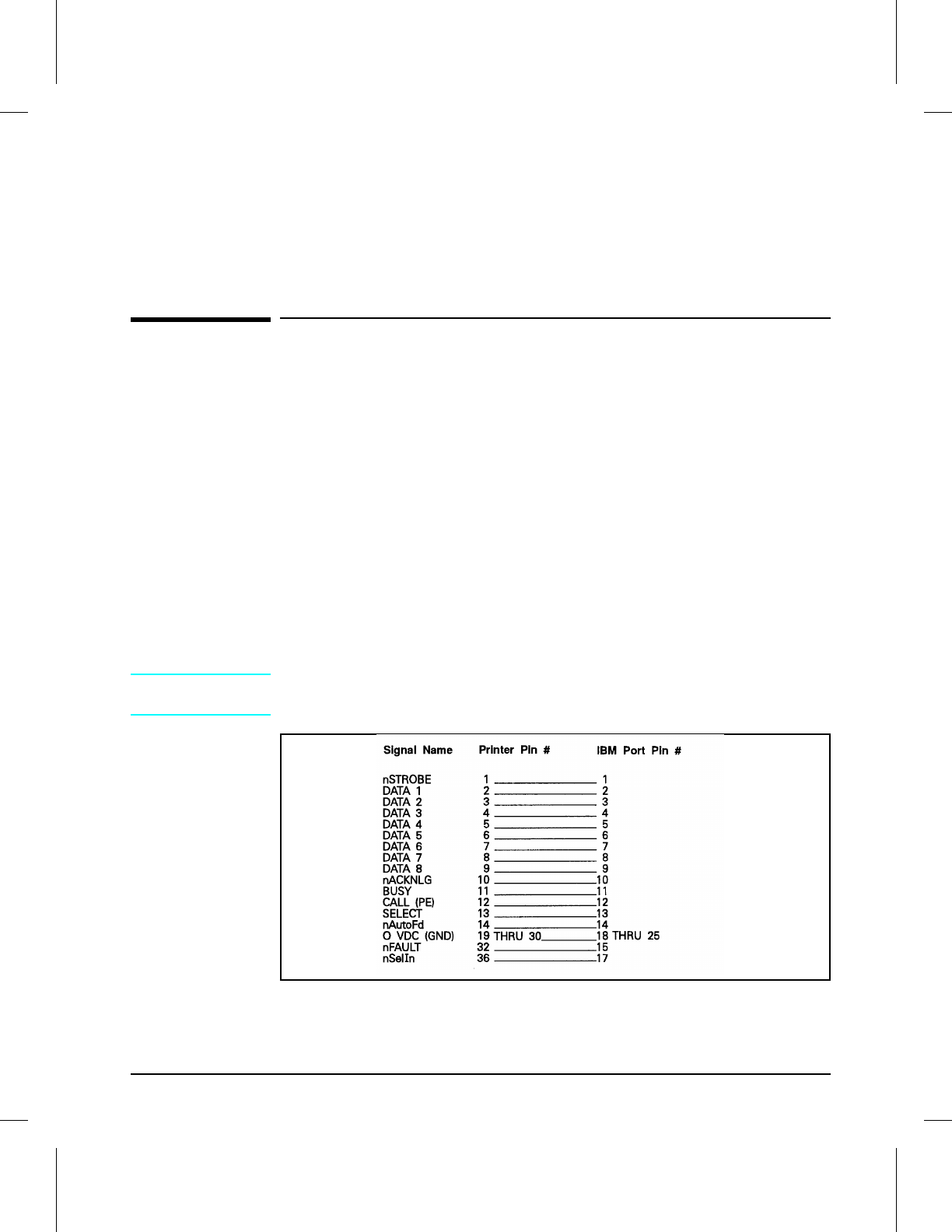
B
I/O Information
Bi-Tronics Parallel Cable Information
The Bi-Tronics parallel interface is compatible with Centronics parallel
interfaces. To take advantage of its enhanced capabilities such as
bi-directional communication between the computer and printer, faster
transmission of data, and auto configuration of printer drivers the customer
must have:
•Support in software applications for these features.
•A parallel cable with the correct pin configuration (see below).
Parallel Cable Pin Configuration
For best results, use the C24542D, C2950A, C2951A cable, or equivalent.
Most existing parallel cables support Bi-Tronics communication, but some
might have incompatible pin assignments.
CAUTION Ensure that all power and interface cables on the printer and host computer
are properly grounded in compliance with local codes.
Parallel Cable Pin Assignments (C24542D)
Figure B-1
I/O Information B-1
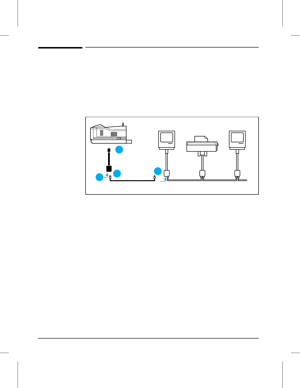
Connecting to LocalTalk Networks
The printer does not come with a LocalTalk network cable. Use a standard
LocalTalk network cable and connector kit, such as the HP LocalTalk
Network Cable Kit, part number 92215N. You will need one connector kit
for each printer on the network, and another for each Macintosh computer
on the network.
Connecting to the END of a LocalTalk Network
Connecting to the END of a LocalTalk Network
1Disconnect the printer from its power source. Insert the connector box cable
into the LocalTalk port of the printer.
2Insert one end of the cable into the new connector box.
3If the connector box is not self-terminating, insert a terminating resistor
into the connector box.
4Insert the other end of the cable into the last connector box on the network.
(Remove the terminating resistor if necessary.)
5Reconnect the printer to its power source.
2
1
34
Figure B-2
B-2 I/O Information
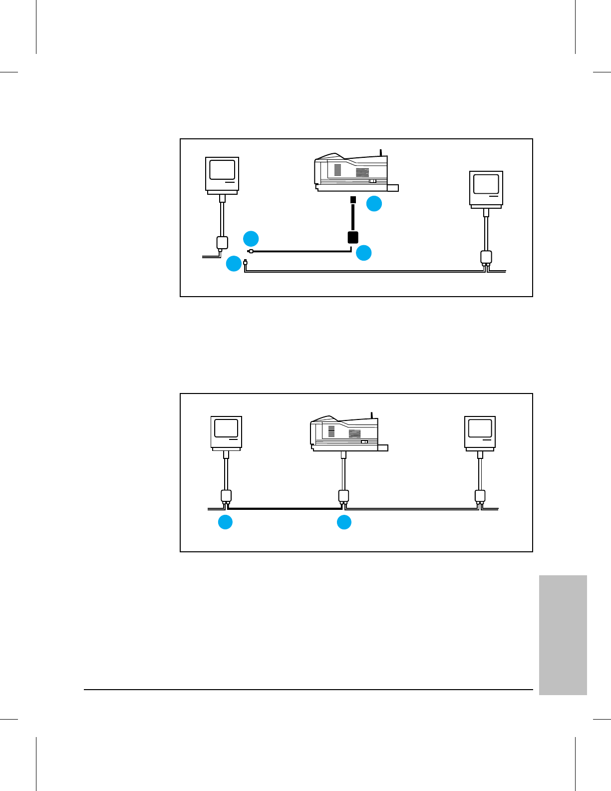
Connecting to the MIDDLE of a LocalTalk
Network
Connecting to the MIDDLE of a LocalTalk Network (1 of 2)
1Disconnect the printer from its power source. Insert the new connector box
cable into the LocalTalk port of the printer.
2Insert one end of the new cable into the connector box.
3Place the other end of the new cable next to a connector box on the network.
4Unplug one cable from the connector box on the network.
Connecting to the MIDDLE of a LocalTalk Network (2 of 2)
5Insert the new cable into the connector box on the network.
6Insert the cable you removed from the network into the new connector box.
Then, reconnect the printer to its power source.
2
1
3
4
Figure B-3
56
Figure B-4
B
I/O Information
I/O Information B-3

Connecting to a Network.
The printer supports up to four different cables: Bi-Tronics parallel, (Figure
B-5, callout 1), BNC (ThinLAN) (Figure B-5, callout 2), 10Base-T (RJ-45)
(Figure B-5, callout 3), and DIN-8 (LocalTalk) (Figure B-5, callout 4). Select
the appropriate interface cable from those shown below for the system and
connect the cable or cables to the printer.
I/O Connector Locations
The cable used to connect the printer to the network, a BNC “T” connector,
and a 50 Ohm terminator are not provided with the printer. They must be
purchased separately.
NOTE You may attach either a ThinLAN cable or a 10Base-T cable, but not both at
the same time.
BNC Interface
Attach one section of the ThinLAN cable to one side of the BNC “T”
connector. Attach another ThinLAN cable section or a 50 Ohm terminator
to the other side. If you are attaching the printer to the end of your network
you must connect a 50 Ohm terminator.
10Base-T Interface
Plug the connector of the twisted-pair network cable into the 10Base-T jack
(RJ-45) on the HP JetDirect card. The other end of the cable should then be
attached to a twisted-pair hub/concentrator.
1
2
3
4
BINTFACE
Figure B-5
B-4 I/O Information

DIN-8 (LocalTalk) Interface
Plug the end of the DIN-8 cable into the LocalTalk port on the HP JetDirect
card.
NOTE If you are using only the LocalTalk port, 18 MIO NOT READY will appear
every time you turn on the printer. This message will automatically
disappear after 5 minutes.
Optional Network Configuration.
The following is for HP LaserJet 4MV printers only.
Certain network parameters for Novell NetWare, UNIX (HP-UX, Solaris, or
SunOS), and EtherTalk networks might need to be set depending upon the
network configuration. The following describes the parameters and
procedures to set those parameters.
By factory default, all supported network protocols are enabled in the HP
LaserJet 4MV printer.
Disabling unused protocols will:
•Rid the network of unwanted broadcast messages from the printer.
•Provide better control over who prints to the printer.
•Provide only pertinent information on the self test page.
•Allow the display of warning messages on the printer control panel display
to show protocol-specific error conditions. The procedures for disabling the
network protocols is found later in this appendix.
Software which allows configuration on the supported networks is included
with the printer, except for UNIX (AIX, HP-UX, Solaris, or SunOS) which
must be purchased separately.
Network software configuration information for the printer is located in the
HP JetDirect Network Interface Configuration Guide included with the HP
LaserJet 4MV printer.
To Enter the MIO Menu:
1Press [On Line] to take the printer offline.
2Press [Menu] until MIO MENU appears.
3Press [Item] until CFG NETWORK=NO * appears.
4Press [+] until CFG NETWORK=YES appears.
5Press [Enter]. CFG NETWORK=YES * appears.
B
I/O Information
I/O Information B-5
Configuring Novell NetWare Frame Type Parameters.
Normally selecting a NetWare frame type is not required. The HP JetDirect
card automatically selects a NetWare frame type, and only when this
selection is incorrect do you have to set the NetWare frame type through the
HP LaserJet 4MV control panel. The NetWare frame type is displayed on
the self test page.
To manually configure Novell NetWare parameters:
1Press [Item] until CFG NOVELL=NO * appears.
2Press [+] until CFG NOVELL=YES * appears.
3Press [Enter]. CFG NOVELL=YES * appears.
4Press [Item]. FRAME=AUTO * appears.
5To configure the Novell NetWare protocol, Press [+] to select one of these
frame types:
6Press [Enter] to save the selection. An asterisk * appears.
7If other protocols will be used, continue with the next section. Otherwise,
skip to “Disable Network Protocols” at the end of this appendix.
Frame Type Description
AUTO (default) All listed Novell frame types will be allowed.
EN_8023 Limit frame types to IPX over IEEE 802.3 frames. All
others will be counted and discarded.
EN_II Limit frame types to IPX over Ethernet II frames. All
others will be counted and discarded.
EN_8022 Limit frame types to IPX over IEEE 802.2 frames. All
others will be counted and discarded.
EN_SNAP Limit frame types to IPX over SNAP with Ethernet
frames. All others will be counted and discarded.
Table B-1 Novell NetWare Frame Types on an HP JetDirect Ethernet Card
B-6 I/O Information

Configuring TCP/IP Parameters
The HP JetAdmin utility for UNIX (sold separately) may be used to
configure TCP/IP parameters. If you do not have the HP JetAdmin utility
for UNIX, or you are using a UNIX system other than HP-UX, Solaris, or
SunOS, you may use the control panel of the printer to configure these
TCP/IP parameters manually:
•Usage of the bootp file for configuration parameters (the default is to use
the bootp file) IP address (4 bytes)
•Subnet mask (4 bytes)
•Syslog server IP address (4 bytes)
•Default gateway (4 bytes)
TCP connection timeout (in seconds)
To manually configure TCP/IP parameters:
1Press [Item]. CFG TCP/IP=NO * appears.
2Press [+]. CFG TCP/IP=YES appears.
3Press [Enter]. CFG TCP/IP=YES * appears.
4Press [Item] to manually configure TCP.IP parameters. BOOTP=YES *
appears. If you keep BOOTP=YES *, then the values for the TCP/IP
parameters will be provided by the bootp file, no other TCP/IP configuring is
necessary.
5Press [+] to change the value of the BOOTP=parameter. BOOTP = NO
appears.
6Press [Enter] to save the selection. BOOTP=NO * appears. If you selected
BOOTP=NO *, then you will be prompted to configure each of the TCP/IP
parameters.
7Press [Item] to continue configuring.*** IP BYTE 1 = ALUE * *** appears.
8Press [+] until the value of the first byte of the IP address appears on the
control panel display. Note that if you Press and hold [+] , the value will
scroll rapidly.
9Press [Enter] to save the value.
10 Press [Item] to continue. Repeat steps 8 and 9 to configure the remaining
bytes of the IP address.
11 Repeat steps 8 through 10 to configure the subnet mask bytes (SM), syslog
server IP address (LG), default gateway (GW), and timeout (TIMEOUT).
12 If no other protocol is enabled, Press [On Line]. After completing this guide
refer to the HP JetDirect Network Interface Configuration Guide for
configuration instructions.
B
I/O Information
I/O Information B-7

Configuring Apple EtherTalk Phase Parameter
To configure EtherTalk parameters:
1If you do not want to configure the phase parameter, Press [On Line].
2Press [Item]. CFG ETALK=NO * appears.
3Press [+]. CFG ETALK=YES appears.
4Press [Enter]. CFG ETALK=YES * appears.
5Press [Item]. Phase=2 * appears.
6Press [+] to change the phase parameter. Phase=1 appears.
7Press [Enter] to save the new value. Phase=1 * appears.
8Press [On Line]. You may want to configure the AppleTalk name and assign
a preferred EtherTalk Zone.
9After completing this guide refer to the HP JetDirect Interface
Configuration Guide for further configuration instructions on using the HP
LaserJet Utility.
B-8 I/O Information

Disable Network Protocols (Optional).
1Press [On Line] to take the printer offline.
2Press [Menu] repeatedly until MIO MENU appears.
3Press [Item]. CFG NETWORK=NO * appears.
4Press [+]. CFG NETWORK=YES * appears.
5Press [Enter]. CFG NETWORK YES * appears.
6Press [Item] to scroll through each network protocol. NOVELL=ON * appears.
To Disable Novell NetWare:
1Press [+] to change to NOVELL=OFF.
2Press [Enter] to save the new status. NOVELL=OFF * appears.
3Press [Item] to continue configuring. DLC/LLC=ON * appears.
To Disable DLC/LLC:
1Press [+] to change to DLC/LLC.
2Press [Enter] to save the new status. DLC/LLC * appears.
3Press [Item] to continue configuring. TCP/IP=ON * appears.
To Disable TCP/IP:
1Press [+] to change to TCP/IP=OFF.
2Press [Enter] to save the new status. TCP/IP=OFF * appears.
3Press [Item] to continue configuring. ATALK=ON * appears.
To Disable Apple EtherTalk and LocalTalk:
1Press [+] to change to ATALK=OFF.
2Press [Enter] to save the new status. ATALK=OFF * appears.
3Press [Item] to continue configuring.
B
I/O Information
I/O Information B-9

B-10 I/O Information

C
Regulatory Information
Laser Safety (U.S.A.)
The Center for Devices and Radiological Health (CDRH) of the U.S. Food
and Drug Administration implemented regulations for laser products
manufactured since August 1, 1976. Compliance is mandatory for products
marketed in the United States.
This printer is certified as a “Class 1” laser product under the U.S.
Department of Health and Human Services (DHHS) Radiation Performance
Standard according to the Radiation Control for Health and Safety Act of
1968. Since radiation emitted inside this printer is completely confined
within protective housings and external covers, the laser beam cannot
escape during any phase of normal user operation.
WARNING! Never operate or service the printer with the protective cover removed from
the Laser/Scanner Assembly. The reflected beam, although invisible, can
damage your eyes.
Regulatory Information C-1

Laser Statement (Finland)
The following applies to printer operation and servicing in Finland.
LASERTURVALLISUUS
LUOKAN 1 LASERLAITE
KLASS 1 LASER APPARAT
HP LaserJet(s) 4V and 4MV laserkirjoitin on käyttäjän kannalta
turvallinen luokan 1 laserlaite. Normaalissa käyt"ssä kirjoittimen
suojakotelointi estää lasersäteen pääsyn laitteen ulkopuolelle.
Kirjoittimen on hyväksynyt Suomessa laserturvallisuuden osalta Sähk"tarkastuskeskus.
Laitteen turvallisuusluokka on määritetty valtioneuvoston päät"ksen N:o 472/1985 ja
standardin EN 60825 (1991) mukaisesti.
VAROITUS ! Laitteen käyttäminen muulla kuin käytt"ohjeessa mainitulla tavalla saattaa
altistaa käyttäjän turvallisuusluokan 1 ylittävälle näkymätt"mälle lasersäteilylle.
VARNING ! Om apparaten används på annat sätt än i bruksanvisning specificerats, kan
användaren utsättas f"r osynlig laserstrålning, som “verskrider gränsen f”r laserklass 1.
HUOLTO HP LaserJet(s) 4M and 4MV kirjoittimen sisällä ei ole käyttäjän huollettavissa
olevia kohteita. Laitteen saa avata ja huoltaa ainoastaan sen huoltamiseen koulutettu henkil".
Tällaiseksi huoltotoimenpiteeksi ei katsota väriainekasetin vaihtamista, paperiradan
puhdistusta tai muita käyttäjän käsikirjassa lueteltuja, käyttäjän tehtäväksi tarkoitettuja
ylläpitotoimia, jotka voidaan suorittaa ilman erikoisty"kaluja.
VARO ! Mikäli kirjoittimen suojakotelo avataan, olet alttiina näkymätt"mälle lasersäteilylle
laitteen ollessa toiminnassa. Älä katso säteeseen.
VARNING ! Om laserprinterns skyddsh"lje “ppnas då apparaten är i funktion, utsättas
användaren f”r osynlig laserstrålning. Betrakta ej strålen.
Tiedot laitteessa käytettävän laserdiodin säteilyominaisuuksista:
Aallonpituus 777,795 nm
Teho 5 mW
Luokan 3B laser
C-2 Regulatory Information

Toner Safety
NOTE In case of toner spills, skin and clothing are best cleaned by removing as
much toner as possible with a dry tissue, then washing with cold water. Hot
water causes toner to permanently set into clothing.
MSDS Information
A Material Safety Data Sheet (MSDS) for toner or any other chemical used
in the printer is available through Hewlett-Packard’s Customer Information
Center by either mail or fax.
By mail:
To obtain an MSDS for the HP C3900A toner cartridges through the mail,
call the Customer Information Center (CIC) at 1-800-752-0900 between
6 A.M. and 5 P.M. Pacific Standard Time.
By fax:
To obtain an MSDS for the HP C3900A toner cartridges by fax, call HP
ASAP (Automated Support Access Program) at 1-800-333-1917 and follow
the instructions for using the HP FIRST fax service.
NOTE See “Technical Assistance” earlier in this chapter for more information on
the HP FIRST service.
Ozone Emission
These printers do not use high voltage corona wires in the
electrophotographic process, and therefore generate no measurable ozone
gas (O3). The printers instead use charging rollers in the toner cartridge
and in the print engine.
C
Regulatory
Information
Regulatory Information C-3
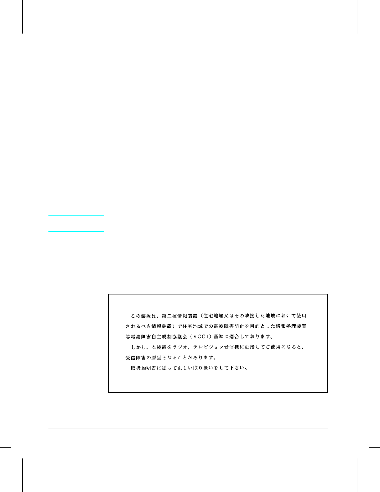
FCC Statement (Class B)
Note: This equipment has been tested and found to comply with the limits
for a Class B digital device, pursuant to part 15 of the FCC rules. These
limits are designed to provide reasonable protection against harmful
interference in a residential installation. This equipment generates, uses,
and can radiate radio frequency energy and, if not installed and used in
accordance with the instructions, may cause harmful interference to radio
communications. However, there is no guarantee that interference will not
occur in a particular installation. If this equipment does cause harmful
interference to radio or television reception, which can be determined by
turning the equipment off and on, the user is encouraged to try to correct
the interference by one or more of the following measures:
•Reorient or relocate the receiving antenna.
•Increase the separation between the equipment and the receiver.
•Connect the equipment into an outlet on a circuit different from that to
which the receiver is connected.
•Consult the dealer or an experienced radio/TV technician for help. Any
changes or modifications not expressly approved by Hewlett-Packard could
void the user’s authority to operate this equipment.
NOTE Use of a shielded interface cable is required to comply within the Class B
limits in Part 15 of FCC rules.
VCCI Statement (Japan)
The VCCI statement below is required in Japan. It is similar to the FCC
regulatory statement.
VCCI Statement (Japan)
Figure C-1
C-4 Regulatory Information

Index
#
00 OFFLINE, status message 7-6
00 POWERSAVE, status message
7-6
00 READY, status message 7-6
02 WARMING UP, status message
7-6
04 SELF TEST, status message 7-6
05 SELF TEST, status message 7-6
06 DEMO PAGE, status message
7-7
06 PRINTING TEST, status
message 7-6
06 TYPEFACE LIST, status
message 7-6
07 RESET, status message 7-7
08 COLD RESET, status message
7-7
09 RESET ALL I/O, status message
7-7
09 RST ACTIVE I/O, status
message 7-7
10 RESET TO SAVE, status
message 7-7
12 PRINTER OPEN, status
message 7-7
13 PAPER JAM, status message 7-8
14 NO TONER CART, status
message 7-8
16 TONER LOW, status message
7-8
18 MIO INIT, status message 7-9
18 MIO NOT READY, status
message 7-9
20 MEM OVERFLOW, service or
error message 7-11
21 PRINT OVERRUN, service or
error message 7-11
22 MIO ERROR, service or error
message 7-11
40 MIO ERROR, service or error
message 7-11
41.3 PAPER ERROR, service or
error message 7-11
51 ERROR, service or error
message 7-12
52 SERVICE, service or error
message 7-12
53.XY.ZZ ERROR, service or error
message 7-12
55 ERROR, service or error
message 7-13
57 SERVICE, service or error
message 7-13
58.[x] SERVICE, service or error
message 7-13
61.[x] SERVICE, service or error
message 7-13
63 through 67 SERVICE, service or
error message 7-13
68 READY/SERVICE, service or
error message 7-13
68 SERVICE, service or error
message 7-13
70 or 71 ERROR, service or error
message 7-14
A
AC power distribution 5-5
circuitry 5-5
accessories
user installable 6-5
accessories and supplies 8-5
acoustic emissions 1-7
adhesive labels 1-9
MP tray 1-9
specifications 1-9
Adobe PostScript 5-14
ADV FNCTNS, parallel menu item
3-13
anti-static brush
removal and replacement 6-42
assemblies
front door 1-13, 6-25 - 6-27, 6-30,
6-33, 8-17
assistance, technical 1-20
AUDIO-TIPS, HP 1-20
AUTO CONT, configuration menu
item 3-11
B
background scatter 7-28
black lines 7-24 - 7-25
black page 7-22
blank (white) page 7-21
blank page, partial 7-28
bottom assemblies 6-44
foot assemblies 6-44
bubble print 7-26
C
cables
replaceable 8-7
capacities: output tray 1-3
card cage
assembly 8-28
removal and replacement 6-16
cartridge guide
removal and replacement 6-36
cartridge slots 1-3
cassette pickup roller assembly
removal and replacement 6-37
CDRH C-1
Center for Devices and Radiological
Health (CDRH) C-1
Centronics parallel interface B-1
character set
selection 3-9
character set, selection 3-9
character voids 7-27
circuit breaker, resettable 5-5
circuit protection 5-5
class 1 laser product C-1
class B digital device C-4
cleaning
printer 4-3
spilled toner 4-4
clearable warning messages 5-14,
7-5, 7-15
W0 JOB 600/A4 7-15
W1 IMAGE ADAPT 7-15
W2 INVALID PERS 7-15
W3 JOB ABORTED 7-15
W8 JOB 600/OFF 7-15
W9 JOB 600/LTR 7-15
WD DISK NOT INIT 7-15
WM [personality] MEM FULL
7-15
WM CHK MEM CNFIG 7-15
WM JOB 300 7-15
WM JOB 600/A3 7-15
WM JOB 600/LGL 7-15
WM MEM CNFIG N/A 7-15
CLR WARN, configuration menu
item 3-11
clutches 5-8
DC controller 5-7
voltages 5-7
clutches and sensors 5-26
cold reset
default 3-15, 3-18
documenting 3-23
performing 3-24, 7-7
printer memory 3-23
reinitializing control panel 7-7
resetting JetDirect configuration
3-23
common hardware 8-7
compressed print 7-30
Compuserve Forum, HP 1-21
configuration menu 3-11
default settings 3-11
MP TRAY 7-8
configuration menu items
AUTO CONT 3-11
CLR WARN 3-11
LOCK 3-11
LOW TONER 3-11
MP TRAY 3-11
consumables
ordering 8-4
printer 1-16
Index
Index-1

CONT SELF TEST, test menu 3-19
CONT SELF TEST, test menu item
3-14
context-sensitive switching, PJL
5-15
continue key 3-5
Continuous Self Test
selection 3-14
stopping 3-14
control panel 1-3, 3-5, 3-8, 3-20
assembly 6-8
configuration menu 3-11
CONT SELF TEST 3-19
cover 6-8
defaults 3-5 - 3-6, 5-11
described 5-16
features 1-3, 1-11, 3-3 - 3-5, 3-7 -
3-8,
3-12 - 3-14, 3-17, 3-20, 5-11
FONT SOURCE 3-9
indicator lights 3-4
interfaces 5-16
job menu 3-10
keys 3-4 - 3-5, 5-11
layout 3-3
lock and password 3-20
memory configuration menu 3-12
menu map 3-7
menus 3-7
messages 5-16, 5-27, 7-6 - 7-9,
7-15
MEt 5-11
MP TRAY 7-8
options status 3-20
parallel menu 3-13
PCA 5-16, 6-8
PCL menu 3-9
power save 5-11
printing menu 3-8
PS CONFIG PAGE 6-6
PWRSAVE 3-15
removal and replacement 6-8
selecting items 3-7
self test 3-17
self test for printer errors 7-6
self test information 3-20
setting defaults 3-6
settings 5-11, 5-15
temporary settings 3-6
test menu 3-14
using 3-3
control panel cover
removal and replacement 6-8
control panel key
continue 3-5
enter 3-5
item 3-5
menu 3-5
minus (-) 3-5
MP paper size 3-5
on line 3-5
plus (+) 3-5
reset 3-5
shift 3-5
COPIES, printing menu item 3-8
copies, selection 3-8
cover and doors 6-8
control panel 6-8
rear cover 6-12
side covers 6-11
static charge eliminator 6-10
upper cover 6-9
covers 8-10
CPU, Intel 8096CF microprocessor
5-13
formatter PCA 5-6
CPU, printer 5-13
D
datecode
self test information 3-20
DC controller PCA
removal and replacement 6-19
DC Controller system 5-7
DC power distribution
circuitry 5-7
DC controller system 5-7
explained 5-7
default settings 3-6
control panel 3-5
power save 5-11
default, factory 7-7, B-5
defaults
cold reset 3-15
control panel 5-11
factory 3-6
see also factory defaults
optional lower cassette 5-25
override 3-6
paper source 5-25
PCL menu 3-9
permanent 3-6
printing menu 3-8
defaults;factory 3-6
defect ruler, repetitive image 7-36
delivery area assemblies 6-34
anti-static brush 6-42
cartridge guide 6-36
cassette pickup roller assembly
6-37
delivery gear assembly 6-35
paper guide 6-43
registration roller 6-39
registration roller guide plate
6-41
separation pad 6-38
upper and lower delivery roller
assemblies 6-34
delivery gear assembly
removal and replacement 6-35
Department of Health and Human
Services (DHHS) C-1
developing process 5-22
DHHS C-1
diagnostics, service menu 3-18
diagrams 8-3
dimensions, printer 1-6
disk accessory 3-20, 5-14
formatter PCA 5-10
installing 6-6
location 1-12, 5-14, 6-6
PostScript option 6-6
printer reset 3-12
removal and replacement 6-6
distribtution system, power supply
5-4
distribution system
AC 5-5
distribution system, power supply
5-4, 5-7
documentation
network 7-9
related 1-19
doors 8-10
dropout 7-26
drum
photosensitive 5-6, 5-18, 7-16,
7-32 - 7-33
drum cleaning process
described 5-17, 5-19
drum conditioning
described 5-17, 5-20
drum drive assembly
removal and replacement 6-24
drum rotation functional check 7-33
dynamic I/O switching, PJL 5-15
E
EconoMode 1-3, 5-12
print quality 7-23
print speed 5-12, 7-23
vs. normal mode 5-12
ECONOMODE, printing menu item
3-8
electrical specifications 1-6
emissions
acoustic 1-7
engine test 3-22, 7-31
printing 7-31
engine test button location 7-31
engine test microswitch, SW7001
5-8, 7-31
Enter key 3-5
envelopes 1-8
background scatter 7-28
MP tray 1-8
printer damage 1-8
specifications 1-8
storing 1-10
windows 1-8
environment
operating 2-3
environmental requirements 2-4
error messages 7-6 - 7-9, 7-11, 7-15
see also printer messages
exchange program 1-16
exhaust fan, FM1
removal and replacement 6-13
external assembly locations 1-11 -
1-12
F
factory defaults 3-6, 7-7, B-5
Index
Index-2

cold reset 3-15
faded print 7-23
fan motor
described 5-9
messages 7-13
faulty image examples 7-16
faulty registration 7-29
fax information service (HP FIRST)
1-20
FCC statement C-4
features
control panel 1-3, 1-11, 3-3 - 3-5,
3-7 - 3-8, 3-12 - 3-14, 3-17, 3-20, 5-11
Finland laser statement C-2
firmware datecode
self test information 3-20
firmware, date code 3-20
FM1, fan motor 5-9
FM2, fan motor 5-9
FM3, fan motor 5-9
font
storage 5-14
Font Number
selecting for PCL 3-9
FONT NUMBER, PCL menu item
3-9
Font Source
selecting for PCL 3-9
FONT SOURCE, PCL menu item
3-9
FONT SOURCE, PCL menu
selection 3-9
fonts 3-12, 5-14, 6-6, 7-11
Adobe PostScript 5-14
default 3-9
downloaded 5-11, 5-14, 7-7, 7-15
internal 1-3
internal character sets 5-14
software 3-20
source 3-9
storing 5-10
substituting 7-9
symbol set 3-9
temporary 7-7
temporary soft 7-7
fonts, internal 1-3
foot assemblies 8-12
removal and replacement 6-44
form feed
light 3-4
form feed key 3-5, 3-15
form feed light 3-4
FORM, printing menu item 3-8
formatter number
self test information 3-20
formatter PCA
Bi-tronics interface 5-13
block diagram 5-10
control panel PCA 5-16
damage 6-5
DC controller PCA 5-28
described 5-10
disk accessory 5-10
engine test print 3-22
HVPS PCA 5-6
Intel 80969CF microprocessor
5-13
MIO card 5-13
MIO PCA 5-10
page count 3-17
PostScript SIMM 5-10
replacing 3-17 - 3-18
REt 5-11
self test bypass 5-8
SIMMs 5-10, 5-14
voltages 5-7
formatter system
described 5-10
front door assemblies 1-13, 6-25 -
6-27, 6-30, 6-33, 8-17
front door assembly 6-33
fuser door 6-31
fuser inlet guide 6-27
fusing assembly 6-26
MP drive gears 6-30
MP guide plate 6-29
MP tray 6-32
paper guide assembly 6-28
transfer roller assembly 6-25
front door assembly
removal and replacement 6-33
front door components 8-14, 8-16
FS DISK FAILURE, status
message 7-9
functional overview 5-1 - 5-30
functions, basic printer 5-3
fuser door
removal and replacement 6-31
fuser inlet guide
removal and replacement 6-27
fusing assembly
removal and replacement 6-26
fusing process 5-24
G
guidelines
media selection 1-8
H
half self test check
purpose 7-32
half self test functional check 7-32
hardware, common 8-7
High Speed
selection 3-13
HIGH SPEED, parallel menu item
3-13
high voltage power distribution 5-6
high voltage power supply PCA 5-4,
5-6
DC controller 7-21, 7-23
density adjustment 7-26
high voltage connectors 7-21 -
7-23, 7-34
microswitch SW501 5-6
pickup unit senor 7-10
high-voltage power supply check
7-34
HP AUDO-TIPS 1-20
HP CompuServe Forum 1-21
HP FIRST (Fax Information
Retrieval Support Technology)
1-20
HP’s Distribution Center 1-16
HPD, HP’s Distribution Center
1-16, 1-19
HV system 7-34
HVPS PCA
removal and replacement 6-14
I
I/O
reset 3-24
self-test information 3-20
size, selection 3-12
Timeout, selection 3-10
I/O buffering
self test information 3-20
I/O resets 3-24
identification, labels 1-5
identification, printer 1-5
image developing 5-17, 5-22
image formation system
block diagram 5-17
DC controller 5-10
described 5-17
features 5-17
printer functions 5-3
toner cartridge 5-18, 7-16
image formation troubleshooting
7-16
image fusing 5-17, 5-24
image size 3-8
image skew 7-30
image transferring 5-17, 5-23
image writing 5-17, 5-21
indicator lights
control panel 3-3
ready 3-5
input
described 5-13
interal assembly locations 1-14 -
1-15
interface PCA
described 5-16, 5-28
location 5-16
printer functions 5-3
interfaces
standard 1-3
internal assembly locations 1-14 -
1-15
internal code number 3-20
internal components 8-20, 8-22,
8-24, 8-26
internal typefaces 1-3
INTR, printer timing 5-28
IO BUFFER, memory configuration
menu item 3-12
IO SIZE, memory configuration
menu item 3-12
item key 3-5
J
jam, paper 7-8
Index
Index-3

Japanese VCCI Statement C-4
job menu 3-10
default settings 3-10
PWRSAVE 3-15
job menu item
PAGEPROTCT 3-10
PERSONALTY 3-10
PWRSAVE 3-10
RESOLUTION 3-10
K
key
continue 3-5
enter 3-5
form feed 3-15
item 3-5
menu 3-5
minus (-) 3-5
MP paper size 3-5
online 3-5
plus (+) 3-5
reset 3-5
shift 3-5
keys
control panel 3-5
L
labels, adhesive 1-9
languages
PCL 3-9
languages, printer 1-3, 3-9, 8-5
laser and scanner drive 5-8
laser drive 5-8
laser safety information C-1
Laser Safety, USA C-1
laser statement, Finland C-2
laser/scanner assembly
removal and replacement 6-20
LC LOAD, status message 7-10
LC TRAY EMPTY, status message
7-10
left side assemblies 6-13
cassette size sensor assembly 6-15
exhaust fan 6-13
HVPS PCA 6-14
lights, indicator 3-3, 3-5
lines per page
selection 3-8
LocalTalk
cable B-2
connecting B-2 - B-3
disabling B-9
hardware 5-13
I/O 5-13
interface 5-13, 8-6, B-4 - B-5
network cable 5-13
LOCK
selection 3-11
lock and password
self test information 3-20
LOCK, configuration menu item
3-11
LOW TONER, configuration menu
item 3-11
lower cassette
option 5-25, 5-27, 6-7, 6-44
LSTR, printer timing 5-28
M
main drive assembly
removal and replacement 6-22
main motor, M1
described 5-9
location 6-21
messages 7-13
reinstalling 6-21
removal and replacement 6-21
synchronized with scanner motor
5-21
main wiring diagram 7-37
maintenance 4-1 - 4-4
major assembly locations 8-9
Manual Feed
selection 3-8
manual feed printing 5-27
MANUAL FEED, printing menu
item 3-8
Material Safety Data Sheet, MSDS
C-3
media selection guidelines 1-8
memory
buffer 5-15
configuration 3-12
error messages 7-15
MEt 1-3, 5-15
non-volatile 3-17, 5-14
PCL 3-20
PostScript 5-14
printer 1-3, 3-12, 3-17, 3-20, 3-23,
5-12, 5-14,
6-5, 7-7, 7-11, 7-13, 7-15, 7-28, 8-5
RAM 5-14
ROM 5-14
SIMM 1-22
standard printer 7-28
upgrades 8-5
memory configuration menu 3-12
control panel 3-12
default settings 3-12
memory configuration menu items
IO BUFFER 3-12
IO SIZE 3-12
PCL MEM 3-12
PS MEM 3-12
RESRCSAVE 3-12
memory enhancement technology
5-15
described 5-15
memory upgrade
removal and replacement 6-5
menu
memory configuration 3-12
menu key 3-5
menu of resets 3-24
menu selections
self test information 3-20
menu selections, saving 3-7
menus
control panel 3-7
MENUS LOCKED, status message
7-9
Menus, control panel
map of menus 3-7
MEt 5-15
MF FEED message 7-9
MF FEED, message 7-9
microswitch
SW501 5-6, 7-7 - 7-8
SW7001 5-8, 7-31
minus key 3-5
MIO
card 5-13
cold reset 7-7
initializing 7-9
installing card 7-7
Jet Direct 1-3
menu 3-20, B-5, B-9
messages 7-9
modular I/O card 5-13
options 3-20
PCA 5-10
ports 3-24
reserved 3-20
self test information 3-20
slot 1-12
model number 1-5
model, printer 8-3
modular I/O (MIO) 5-13
motors
described 5-9
MP drive gears
removal and replacement 6-30
MP guide plate assembly
removal and replacement 6-29
MP LOAD, status message 7-10
MP tray 1-8, 1-11, 3-5, 5-25 - 5-27,
6-31 - 6-33,
7-8 - 7-11, 7-27, 7-35
adhesive labels 1-9
capacities and paper sizes 1-4, 3-5
drive gears 6-30
extension 1-11
manual feed printing 5-27
paper sensor 5-26 - 5-27
paper width guides 1-11
pickup 5-7
pickup clutch 5-8, 5-26
pickup roller 6-28
print process 5-27
removal and replacement 6-32
transparencies 1-9
MP TRAY, configuration menu 7-8
MP TRAY, configuration menu item
3-11
MP tray
capacities and paper sizes 7-7, 7-9
MSDS C-3
multipurpose tray 5-27
see also MP tray
N
NARC (North American Response
Center) 1-21
Index
Index-4

NVRAM (non-volatile memory) 5-14
O
on line
key 3-5
light 3-4
one year return 1-22
operating environment 2-3
operating overview 3-1 - 3-24
operation, basic sequence 5-28
optional cassette
capacities 1-4
optional lower cassette
default paper source 5-25
guide 5-25
installing 6-7
paper feed system 5-25
pickup arm 5-27
printing 5-27
reinstalling 6-44
removal and replacement 6-7
optional printer memory 1-3
ordering
related documentation 1-19
ordering consumables 8-4
ordering parts 1-16, 8-3
orientation
portrait (vertical) and L means
landscape 3-8
ORIENTATION, printing menu
item 3-8
output
described 5-13
output components 8-18
overcurrent
dc protection circuitry 5-5
devices 5-5
protection 5-5
overhead transparencies 1-9, 7-27
overhead transparency
specifications 1-9
overview
operating 3-1 - 3-24
overvoltage
devices 5-5
protection 5-5
ozone emission C-3
P
page count
setting 3-15, 3-17, 3-20
page coverage, 5% 1-17
page protect
available memory 7-15
described 5-15
disabled 5-15
page buffer 5-15
PCL printing 5-15
selection 7-11
setting 7-11, 7-15, 7-28
page usage, monthly 1-3
PAGEPROTCT
seepage protect
PAGEPROTCT, job menu item 3-10
PageProtect
see also 21 PRINT OVERRUN
paper
selection 3-8
paper capacities 1-3 - 1-4
paper cassette 1-11 - 1-12, 1-15
guide 6-7, 7-29
jam 7-8
loading 7-30, 7-35
messages 7-10
optional lower cassette 5-25
overload 7-29
printing 5-27
replacement 8-5
paper curl 7-35
paper feed system
clutches and sensors 5-7 - 5-8,
5-26
descriped 5-25
paper path 5-25, 7-4, 7-8, 7-25,
7-29 - 7-30, 7-35
paper guide
removal and replacement 6-43
paper guide plate assembly
removal and replacement 6-28
paper jam 6-27
check list 7-8
DC controller 5-27
false warning 7-8
messages 7-5, 7-8
paper selection 1-8
paper size 7-28
sensor 7-8
sensor flags 7-8
toner 4-4
paper jam detection
described 5-27
paper motion, control 5-8
paper motion, monitoring 5-8
paper path 5-25
components 7-4
described 5-25
dirty roller 7-25
gears 7-8, 7-29
jammed 7-8
location 5-25
MP tray 7-35
rollers 7-29 - 7-30
paper sensors 5-8, 7-8
paper sizes 3-4, 3-15, 3-18, 7-9 -
7-10, 7-29 - 7-30
label 7-10
paper specifications 1-8, 7-8, 7-21,
7-23, 7-25 - 7-30
PAPER, printing menu item 3-8
parallel interface
Bi-Tronics B-1
Centronics 5-13
Centronics parallel interface B-1
described 5-13
MIO 7-14
settings 5-13
parallel menu 3-13
control panel 3-13
default settings 3-13
parallel menu items
ADV FNCTNS 3-13
HIGH SPEED 3-13
partial blank page 7-28
parts
HP’s Distribution Center 1-16
HPD 1-16, 1-19
ordering 1-16, 8-3
Parts Direct Ordering 1-16, 8-3
PDO, Parts Direct Ordering 1-16,
1-19, 8-3
phone numbers 1-16, 8-4
SME, Support Materials Europe
1-19
parts and diagrams 8-1 - 8-30
Parts Center Europe (PCE) 1-16
Parts Direct Ordering 1-16, 8-3
parts lists 8-3
PC INSTALL, status message 7-10
PC LOAD, status message 7-10
PC TRAY EMPTY, status message
7-10
PCL 3-9
menu 3-9
Type List 3-14
PCL Demo Page
control panel selection 3-14
PCL DEMO PAGE, test menu item
3-14
PCL MEM, memory configuration
menu item 3-12
PCL memory
self test information 3-20
PCL menu 3-9
default settings 3-9
FONT SOURCE 3-9
PCL menu item
FONT NUMBER 3-9
FONT SOURCE 3-9
PITCH 3-9
PT. SIZE 3-9
SYM SET 3-9
PCL TYPE LIST, test menu item
3-14
PDO, Parts Direct Ordering 1-16,
1-19, 8-3
Personality
selection 3-10
PERSONALTY, job menu item 3-10
phone numbers
technical assistance 1-20
phone numbers, parts 1-16, 8-4
photosensitive drum 5-18
check list 7-32
damage 7-16
described 5-18
located 7-33
main drive 7-33
print density 5-6
photosensitive drum cleaning 5-17,
5-19
photosensitive drum conditioning
5-17, 5-20
pin configuration
Index
Index-5

parallel B-1
Pitch
selection 3-9
PITCH, PCL menu item 3-9
PJL overview 5-15
PJL, Printer Display Language
Centronics cabeling 5-15
context-sensitive switching 5-15
described 5-15
dynamic I/O switching 5-15
print environment settings 5-15
two-way communication 5-15
plus key 3-5
PML, Printer Management
Language
described 5-15
point size
selection 3-9
PostScript
selection 3-10
potrait orientation 3-8
power control 1-3
power distribution, AC 5-5
power save mode 1-3, 1-6, 3-15, 5-9
- 5-11, 7-6 - 7-7
default setting 5-11
message 5-11
power save, selection 3-15
power supply
circuits 5-5
unit 5-5, 6-18, 6-20 - 6-22
power supply system 5-4, 5-7
power supply unit
removal and replacement 6-18
preliminary troubleshooting 7-3
primary charging roller 5-20
print capacity, toner 1-17
print density
adjusting 5-6
bias voltages 5-22
dial 1-13, 6-14
location 5-6
print pattern 3-20
print density adjustment explained
5-6
print density control explained 5-22
print environment settings, PJL
5-15
print media
adhesive labels 1-9
automatic selection 5-25
envelopes 1-8, 1-10, 7-28
new 1-8
shipping 1-10
specifications 1-8, 7-8
storing 1-10
transparencies 1-9, 7-27
print overrun message 7-11
print quality 3-8
cleaning printer 4-3
complex image 7-15
EconoMode 7-23
HP LaserJet toner cartridges 1-18
paper guidelines 1-8
refilled toner cartridges 1-18
toner low 7-8
transfer roller 4-3
print resolution 1-3, 3-20, 5-21, 7-15
print speed 1-3, 5-12, 5-14
printer
buffer memory 5-15
cleaning 4-3
fonts 1-3
memory 1-3, 1-22, 3-12, 3-17,
3-20, 3-23, 5-12,
5-14, 6-5, 7-7, 7-11, 7-13, 7-15, 7-28,
8-5
memory configuration 3-12
memory upgrade 6-5, 8-5
MEt 5-15
model number 1-5
non-volatile memory 3-17, 5-14
optional memory 1-3
PCL memory 3-20
serial number 1-5
standard memory 1-3, 7-28
testing 3-19
typefaces 7-6
printer comparison
memory 1-3
printer damage
adhesive labels 1-9
envelopes 1-8
non-HP product 1-22
printer dimensions 1-6
printer features 1-3
comparison 1-3
internal typefaces 1-3
languages 1-3
memory 1-3
monthly usage 1-3
speed 1-3
printer fonts
substituting 7-9
printer functions, basic 5-3
printer job language, PJL 5-15
printer languages 1-3
Adobe PostScript 5-14
Adobe’s PostScript Level 2 8-5
PCL 3-9
printer message troubleshooting 7-5
printer messages
00 OFFLINE 7-6
00 POWERSAVE 7-6
00 READY 7-6
02 WARMING UP 7-6
04 SELF TEST 7-6
05 SELF TEST 7-6
06 DEMO PAGE 7-7
06 PRINTING TEST 7-6
06 TYPEFACE LIST 7-6
07 RESET 7-7
08 COLD RESET 7-7
09 RESET ALL I/O 7-7
09 RST ACTIVE I/O 7-7
10 RESET TO SAVE 7-7
12 PRINTER OPEN 7-7
13 PAPER JAM 7-8
14 NO TONER CART 7-8
16 TONER LOW 7-8
18 MIO INIT 7-9
18 MIO NOT READY 7-9
20 MEM OVERFLOW 7-11
21 PRINT OVERRUN 7-11
22 MIO ERROR 7-11
40 MIO ERROR 7-11
41.3 PAPER ERROR 7-11
51 ERROR 7-12
52 SERVICE 7-12
53.XY.ZZ ERROR 7-12
55 ERROR 7-13
57 SERVICE 7-13
58.[x] SERVICE 7-13
61.[x] SERVICE 7-13
63 through 67 SERVICE 7-13
68 READY/SERVICE 7-13
68 SERVICE 7-13
70 or 71 ERROR 7-14
clearable warning 5-14, 7-5, 7-15
control panel 7-6
error 7-6
fan motor failure 7-13
FS DISK FAILURE 7-9
LC LOAD 7-10
LC TRAY EMPTY 7-10
main motor failure 7-13
manual feed 7-5
memory error 5-27, 7-5
MENUS LOCKED 7-9
MF FEED 7-9
MIO 7-9
MP LOAD 7-10
paper out 7-5
PC INSTALL 7-10
PC LOAD 7-10
PC TRAY EMPTY 7-10
self test 7-6
status 7-6
toner cartridge 7-5
troubleshooting 7-5
W0 JOB 600/A4 7-15
W1 IMAGE ADAPT 7-15
W2 INVALID PERS 7-15
W3 JOB ABORTED 7-15
W8 JOB 600/OFF 7-15
W9 JOB 600/LTR 7-15
WD DISK NOT INIT 7-15
WM [personality] MEM FULL
7-15
WM CHK MEM CNFIG 7-15
WM JOB 300 7-15
WM JOB 600/A3 7-15
WM JOB 600/LGL 7-15
WM MEM CNFIG N/A 7-15
62. 7-13
79 SERVICE 7-14
printer reset 3-23
printer space requirements 2-4
printer timing 5-28
INTR 5-28
LSTR 5-28
PRNT 5-28
Index
Index-6

STBY 5-28
WAIT 5-28
printing menu 3-8
default settings 3-8
printing menu item
COPIES 3-8
ECONOMODE 3-8
FORM 3-8
MANUAL FEED 3-8
ORIENTATION 3-8
PAPER 3-8
RET 3-8
priority of errors 7-5
PRNT, printer timing 5-28
product information 1-1 - 1-22
product overview 1-11
PS CONFIG PAGE, test menu 6-6
PS CONFIG PAGE, test menu item
3-14
PS DEMO PAGE, test menu item
3-14
PS MEM, memory configuration
menu item 3-12
PS TYPE LIST, test menu item 3-14
PT. SIZE, PCL menu item 3-9
PWRSAVE
see also power save
PWRSAVE, job menu 3-15
PWRSAVE, job menu item 3-10
R
radio frequency interference, RFI
C-4
RAM 5-14
described 5-14
messages 7-12 - 7-13
ram size
self test information 3-20
random access memory
described 5-14
read only memory
described 5-14
ready light 3-4
rear and top area assmblies 6-16
card cage 6-16
DC controller PCA 6-19
laser/scanner assembly 6-20
power supply unit 6-18
rear exhaust fan, FM2 6-17
rear cover
removal and replacement 6-12
rear exhaust fan, FM2
removal and replacement 6-17
recycling toner cartridges 1-18
refilled toner cartridges 1-18
registration roller
removal and replacement 6-39
registration roller guide plate
removal and replacement 6-41
regulatory information C-1 - C-4
related documentation 1-19
remanufactured assemblies 1-16
removal and replacement 6-1 - 6-45
anti-static brush 6-42
card cage 6-16
cartridge guide 6-36
cassette pickup roller assembly
6-37
control panel 6-8
cover and doors 6-8
DC controller PCA 6-19
delivery gear assembly 6-35
disk accessory 6-6
drum drive assembly 6-24
exhaust fan, FM1 6-13
foot assemblies 6-44
front door assembly 6-33
fuser door 6-31
fuser inlet guide 6-27
fusing assembly 6-26
HVPS PCA 6-14
laser/scanner assembly 6-20
main drive assembly 6-22
main motor, M1 6-21
memory upgrade 6-5
MP drive gears 6-30
MP guide plate assembly 6-29
MP tray 6-32
paper guide 6-43
paper guide plate assembly 6-28
power supply unit 6-18
rear cover 6-12
rear exhaust fan, FM2 6-17
registration roller 6-39
registration roller guide plate
6-41
separation pad 6-38
side covers 6-11
static charge eliminator 6-10
strategy 6-3
transfer roller assembly 6-25
upper and lower delivery roller
assemblies 6-34
upper cover 6-9
repair philosophy 1-16
repetitive defects 7-25
repetitive image defect ruler 7-36
replaceable cables 8-7
required tools 6-4
requirements
environmental 2-4
site 1-6, 2-1 - 2-4
space 2-4
reset
cold 3-23, 7-7
I/O 3-24
I/Os 3-24
menu 7-7
options 3-24
simple 3-23
reset key 3-5
reset to save 7-7
resettable circuit breaker 5-5
resetting printer 3-23
Resolution
selection 3-10
Resolution Enhancement
technology 1-3, 5-11
described 5-11
self test information 3-20
status 3-20
RESOLUTION, job menu item 3-10
resolution, print 1-3, 3-20, 5-21,
7-15
resource saving 3-12, 3-20, 7-15
selection 3-12
self test information 3-20
status 3-20
RESRCSAVE, memory
configuration menu item 3-12
RET, printing menu item 3-8
REt, Resolution Enhancement
technology 1-3, 3-20, 5-11
return philosophy 1-22
right side assemblies 6-21
drum drive assembly 6-24
main drive assembly 6-22
main motor, M1 6-21
ROM 5-14
character sets 5-14
dot patterns 5-14
map message 7-12
size message 7-12
S
safety
toner C-3
saving menu selections 3-7
scanner drive 5-8
scanner motor
described 5-9
synchronized with main motor
5-21
Self Test
appearance 3-20
continuous printing 3-19
control panel 3-20
demo page option 3-15
disabling protocols B-5
disk accessory information 3-20
disk drive 7-9
engine 3-22
explained 3-20
features 3-19
firmware datecode information
3-20
formatter number information
3-20
I/O buffering information 3-20
installing options 3-19
menu selection information 3-20
microswitch SW7001 5-8
MIO information 3-20
NetWare frame type B-6
other options information 3-20
page count 3-15
page count information 3-20
PCL memory information 3-20
print pattern information 3-20
printing continuous 7-6
printing test page 3-19
printout key 3-20
Index
Index-7

ram size information 3-20
replacing formatter PCA 3-17
resource saving information 3-20
REt information 3-20
sample 3-20
selection 3-14
serial number 3-15
serial number information 3-20
verifing page count 3-17
SELF TEST, test menu item 3-14
sensors 5-26
described 5-26
separation pad
removal and replacement 6-38
sequence of operation 5-28
serial number 1-5
information 1-5
labels 1-5
plate 1-12
printer memory 3-17
self test 3-15, 3-17
self test information 3-20
setting 3-17
service and error messages 7-11 -
7-14
see also printer messages (for
complete listing)
service approach 1-16
service errors 7-5
service mode 3-15
authorized personnel 3-15
exiting 3-15
features 3-15
initiating 3-15
items 3-18
menu 3-17
power save mode 3-15
self test 3-15
settings and defaults 3-6
shift key 3-5
shipping print media 1-10
side covers
removal and replacement 6-11
SIMM memory 1-22
SIMM slots 1-12
described 5-14
formatter PCA 5-14
PostScript 5-14
simple reset 3-23
site requirements 1-6, 2-1 - 2-4
skip demo, service menu item 3-18
slots
cartridge 1-3
SME, Support Materials Europe
1-19
smeared print 7-30
soft fonts, temporary 7-7
space requirements 2-4
specifications
adhesive labels 1-9
electrical 1-6
envelopes 1-8
MP tray 7-8
paper 1-8, 1-19, 7-8, 7-11, 7-21,
7-23, 7-25 - 7-30
printer 1-6, 1-22, 2-3
transparency 1-9
standard cassette
capacities 1-4
standard interfaces 1-3
standard printer memory 1-3, 7-28
static charge eliminator
removal and replacement 6-10
status messages 7-6 - 7-10
see also printer messages (for
complete listing)
STBY, printer timing 5-28
storing print media 1-10
supplies 8-5
see also accessories and supplies
SW501, toner cartridge microswitch
5-6, 7-7 - 7-8
SW7001, engine test microswitch
5-8
SW7001, location 7-31
SYM SET, PCL menu item 3-9
symbol set 3-9
selection 3-9
T
technical assistance 1-20
temporary
settings 3-6
temporary settings 3-6
control panel 3-6
temporary soft fonts 7-7
test menu 3-14
CONT SELF TEST 3-19
default settings 3-14
PS CONFIG PAGE 6-6
test menu items
CONT SELF TEST 3-14
PCL DEMO PAGE 3-14
PCL TYPE LIST 3-14
PS CONFIG PAGE 3-14
PS DEMO PAGE 3-14
PS TYPE LIST 3-14
SELF TEST 3-14
test, engine 3-22
tests
printer 3-19
toner cartridge 1-15 - 1-17
bushings 7-30
capacity 1-17
cavity 1-13
charging rollers C-3
check list 7-16
cleaning spills 4-4
connection points 7-34
damage 6-26, 7-24 - 7-25, 7-34
defective 4-4, 7-21 - 7-22, 7-28
described 5-18, 5-21
drum cleaning 5-17, 5-19
drum conditioning 5-17, 5-20
drum rotation check 7-33
expiration 1-17
faulty image exampes 7-16
gears 7-8, 7-25
HVPS contacts 5-18
image formation 7-16
image formation system 5-18
installing 1-13
leaking 7-26, 7-28
life expectancy 1-17
light exposure 7-24
MSDS C-3
non-HP 1-22
photosensitive drum 5-6, 5-18,
7-16, 7-32 - 7-33
print quality 1-18
printer message 5-6, 7-5, 7-7 - 7-8
recycling 1-18
refilled 1-18, 7-30, 7-33
replacement 8-5
sealing tape 7-21
toner distribution 7-24
used 1-18
warranty 1-18
toner cartridge microswitch, SW501
5-6, 7-7 - 7-8
toner low message 7-8
toner safety C-3
tools, required 6-4
top area assemblies 6-16
training media 1-19
transfer roller assembly
removal and replacement 6-25
transferring process 5-23
transparencies 1-9, 7-27
bad 7-27
MP tray 1-9
overhead 1-9
temperature specifications 1-9
transparency specifications 1-9
troubleshooting 7-1 - 7-42
messages 7-6 - 7-9, 7-15
troubleshooting checks 7-31
troubleshooting flowchart 7-3
troubleshooting tools 7-36
troubleshooting, preliminary 7-3
two-way communication, PJL 5-15
typefaces
internal 1-3
list 7-6
temporary 3-23
U
upper and lower delivery roller
assemblies
removal and replacement 6-34
upper cover
removal and replacement 6-9
user installable accessories 6-5
disk accessory 6-6
memory upgrade 6-5
optional lower cassette 6-7
V
VCCI Statement, Japan C-4
veritcal spacing 3-8
Index
Index-8

W
W0 JOB 600/A4, clearable warning
message 7-15
W1 IMAGE ADAPT, clearable
warning message 7-15
W2 INVALID PERS, clearable
warning message 7-15
W3 JOB ABORTED, clearable
warning message 7-15
W8 JOB 600/OFF, clearable
warning message 7-15
W9 JOB 600/LTR, clearable warning
message 7-15
WAIT, printer timing 5-28
warning messages 7-15
warranty 1-22
WD DISK NOT INIT, clearable
warning message 7-15
white stripes 7-24
wiring diagrams, main 7-37
WM MEM FULL, clearable warning
message 7-15
WM CHK MEM CNFIG, clearable
warning message 7-15
WM JOB 300, clearable warning
message 7-15
WM JOB 600/A3, clearable warning
message 7-15
WM JOB 600/LGL, clearable
warning message 7-15
WM MEM CNFIG N/A, clearable
warning message 7-15
writing process 5-21
Index
Index-9