I.MX RT1050 Manufacturing User's Guide
User Manual:
Open the PDF directly: View PDF ![]() .
.
Page Count: 56
- i.MX RT1050 Manufacturing User's Guide
- Contents
- 1 Introduction
- 2 Overview
- 3 i.MX RT bootable image
- 4 Generate i.MX RT bootable image
- 5 Generate SB file for bootable image programming
- 5.1 Generate SB file for FlexSPI NOR image programming
- 5.2 Generate SB file for FlexSPI NAND image programming
- 5.3 Generate SB file for SD image programming
- 5.4 Generate SB file for eMMC image programming
- 5.5 Generate SB file for Serial NOR/EEPROM image programming
- 5.6 Generate SB file for SEMC NOR image programming
- 5.7 Generate SB file for SEMC NAND image programming
- 5.8 Generate SB file for fuse program
- 6 Program bootable image
- 7 Appendix
- 8 Revision history

i.MX RT1050 Manufacturing User's Guide
NXP Semiconductors Document Number: IMXMCUMFUUG
User's Guide Rev. 3, December 2018

Contents
Chapter 1 Introduction........................................................................................ 4
Chapter 2 Overview............................................................................................. 5
2.1 i.MX RT Boot ROM...................................................................................................................................................... 5
2.2 MCUBOOT-based Flashloader ................................................................................................................................... 5
2.3 Host utilities .................................................................................................................................................................5
2.4 Terminology..................................................................................................................................................................5
Chapter 3 i.MX RT bootable image.....................................................................7
3.1 Bootable image layout in target flash device................................................................................................................7
3.2 Boot image format........................................................................................................................................................7
3.2.1 IVT and boot data......................................................................................................................................... 8
3.2.2 Boot data structure........................................................................................................................................8
3.3 Signed image............................................................................................................................................................... 9
3.4 Encrypted image.......................................................................................................................................................... 9
Chapter 4 Generate i.MX RT bootable image.................................................. 10
4.1 Description of the elftosb utility.................................................................................................................................. 10
4.1.1 The elftosb utility options............................................................................................................................. 10
4.1.2 BD file ......................................................................................................................................................... 10
4.1.3 BD file for i.MX RT bootable image generation............................................................................................ 11
4.1.3.1 Options block................................................................................................................................ 11
4.1.3.2 Sources block .............................................................................................................................. 12
4.1.3.3 Constants block............................................................................................................................ 12
4.1.3.4 Section blocks ..............................................................................................................................12
4.1.4 BD file for memory programming.................................................................................................................20
4.2 Generate unsigned normal i.MX RT bootable image.................................................................................................21
4.3 Generate signed normal i.MX RT bootable image.....................................................................................................21
4.4 Generate encrypted normal i.MX RT bootable image................................................................................................23
4.5 Generate Plugin boot image...................................................................................................................................... 26
Chapter 5 Generate SB file for bootable image programming...................... 27
5.1 Generate SB file for FlexSPI NOR image programming............................................................................................ 27
5.1.1 Generate Normal Bootable Image...............................................................................................................27
5.1.2 Generate SB file for plaintext FlexSPI NOR image programming................................................................27
5.1.3 Generate SB file for FlexSPI NOR Image encryption and programming..................................................... 28
5.2 Generate SB file for FlexSPI NAND image programming.......................................................................................... 29
5.2.1 Generate SB file for FlexSPI NAND image programming........................................................................... 30
5.2.2 Generate SB file for encrypted FlexSPI NAND Image and KeyBlob programming.....................................30
5.3 Generate SB file for SD image programming.............................................................................................................31
5.3.1 Steps to Generate SB file for SD image programming................................................................................32
5.4 Generate SB file for eMMC image programming....................................................................................................... 33
5.4.1 Normal mode.............................................................................................................................................. 33
5.4.2 Fast Mode................................................................................................................................................... 34
5.5 Generate SB file for Serial NOR/EEPROM image programming............................................................................... 35
5.6 Generate SB file for SEMC NOR image programming.............................................................................................. 36
5.7 Generate SB file for SEMC NAND image programming............................................................................................ 37
Contents
i.MX RT1050 Manufacturing User's Guide, Rev. 3, December 2018
2NXP Semiconductors

5.8 Generate SB file for fuse program..............................................................................................................................38
Chapter 6 Program bootable image................................................................. 40
6.1 MfgTool...................................................................................................................................................................... 40
6.1.1 MfgTool Directory structure..........................................................................................................................40
6.1.2 Preparation before image programming using MfgTool............................................................................... 42
6.2 Connect to the i.MX RT Platform............................................................................................................................... 42
6.3 Program bootable image during development............................................................................................................42
6.4 Program bootable image for production..................................................................................................................... 43
Chapter 7 Appendix........................................................................................... 44
7.1 Plugin boot application............................................................................................................................................... 44
7.1.1 Principles for Plugin boot application design................................................................................................44
7.1.2 Boot Flow of Plugin boot application............................................................................................................ 44
7.1.3 Example Plugin boot application to enable non-XIP boot on FlexSPI NOR.................................................44
7.1.4 Images loaded by plugin boot application.................................................................................................... 46
7.2 Example of complete manufacturing flow................................................................................................................... 46
7.2.1 Manufacturing process in Development phase............................................................................................46
7.2.1.1 Create i.MX RT bootable image.................................................................................................... 46
7.2.1.2 Create SB file for HyperFlash programming..................................................................................47
7.2.1.3 Program Image to Flash using MfgTool.........................................................................................48
7.2.2 Manufacturing process in Production phase................................................................................................ 48
7.2.2.1 Generate signed i.MX RT bootable image....................................................................................49
7.2.2.2 Create SB file for Fuse programming............................................................................................51
7.2.2.3 Create SB file for Image encryption and programming for Hyper Flash....................................... 52
7.2.2.4 Create signed Flashloader image.................................................................................................52
7.2.2.5 Program Image to Flash using MfgTool........................................................................................ 53
7.3 Generate KeyBlob manually....................................................................................................................................... 53
Chapter 8 Revision history............................................................................... 55
Contents
i.MX RT1050 Manufacturing User's Guide, Rev. 3, December 2018
NXP Semiconductors 3

Chapter 1
Introduction
This document describes the generation of bootable image for i.MX RT devices. It also explains the process to interface i.MX RT
Boot ROM and MCUBOOT-based Flashloader and to program a bootable image into the external flash including:
• QuadSPI NOR/Octal Flash / HyperFlash
• Serial NAND
• eMMC
• SD
• Parallel NOR
• SLC raw NAND
• SPI NOR/EEPROM
The i.MX RT Boot ROM resides in the ROM and enables RAM loading. The Flashloader is loaded into SRAM and facilitates
loading of boot images from boot devices into RAM. It also authenticates and executes the boot image.
This document introduces the Flashloader, a companion tool to i.MX RT Boot ROM, and a complete solution for programming
boot images to bootable devices. The Flashloader runs in SRAM so it should be downloaded to SRAM typically via ROM serial
download interface. The Flashloader prepares and configures the devices for boot. It creates boot configuration structure on the
bootable media, assists in programming encrypted images, generates key blobs, and communicates with master on serial
peripherals like USB and UART using MCUBOOT commands interface protocol in downloading boot images.
It also introduces the elftosb utility. The elftosb utility converts an elf images to signed, encrypted, and bootable image for i.MX
RT devices. It also creates all the boot structures like image vector table, boot data, etc. It generates the input command sequence
file required to code sign or encrypt the image using the NXP signing tool (cst). It also calls the cst to generate the signatures and
packs it as a boot image acceptable by boot ROM.
The document describes the usage of MfgTool.exe (Manufacturing Tool) in a manufacturing environment for production of devices
(programming boot images on the bootable media using all the available tools).
Introduction
i.MX RT1050 Manufacturing User's Guide, Rev. 3, December 2018
4NXP Semiconductors

Chapter 2
Overview
2.1 i.MX RT Boot ROM
The i.MX RT Boot ROM is a standard bootloader for all i.MX RT devices. It resides in ROM and supports booting from external
flash devices for both XIP and non-XIP boot cases. It also provides serial downloader feature via UART or USB-HID interface into
the internal RAM of i.MX RT devices.
The i.MX RT Boot ROM is a specific implementation of the existing i.MX MPU ROM Bootloader. For flash programming, the i.MX
RT Boot ROM provides serial downloader feature powered by SDP command interface. For additional information, see chapter,
“System Boot” in i.MX RT1050 Processor Reference Manual (document IMXRT1050RM). The MfgTool then can load the MCU
Boot based Flashloader into internal SRAM and jump to the Flashloader to enable Flash programming features.
2.2 MCUBOOT-based Flashloader
The MCUBOOT-based Flashloader is a specific implementation of the MCU Bootloader. It is used as a one-time programming
aid for manufacturing. Most of the MCUBOOT commands are supported in the Flashloader to enable external Flash programming.
See MCU Flashloader Reference Manual for details.
2.3 Host utilities
The MfgTool is a GUI host program used to interface with devices running i.MX RT Boot ROM under serial downloader mode. It
can also be used to program an application image by interfacing with the Flashloader.
The blhost is a command-line host program used to interface with devices running MCUBOOT-based bootloaders. It is part of
MfgTool release.
The elftosb utility is a command-line host program used to generate bootable images for i.MX RT Boot ROM.
The cst is a command-line host program used to generate certificates, image signatures, and encrypt images for i.MX RT Boot
ROM.
2.4 Terminology
Table 1 summarizes the terms and abbreviations included in this document.
Table 1. Terminology and Abbreviations
Terminology Description
MCUBOOT MCU Bootloader
KeyBlob KeyBlob is a data structure that wraps the DEK for image decryption using AES-CCM algorithm
DEK “Key” used to decrypt the encrypted bootable image
Table continues on the next page...
i.MX RT Boot ROM
i.MX RT1050 Manufacturing User's Guide, Rev. 3, December 2018
NXP Semiconductors 5

Table 1. Terminology and Abbreviations (continued)
SB file The SB file is the NXP binary file format for bootable images. The file consists of sections,
sequence of bootloader commands, and data that assists MCU Bootloader in programming the
image to target memory. The image data can also be encrypted in the SB file. The file can be
downloaded to the target using the MCU Bootloader receive-sb-file command.
CST Code Signing Tool
XIP Execute-In-Place
Overview
i.MX RT1050 Manufacturing User's Guide, Rev. 3, December 2018
6NXP Semiconductors
Chapter 3
i.MX RT bootable image
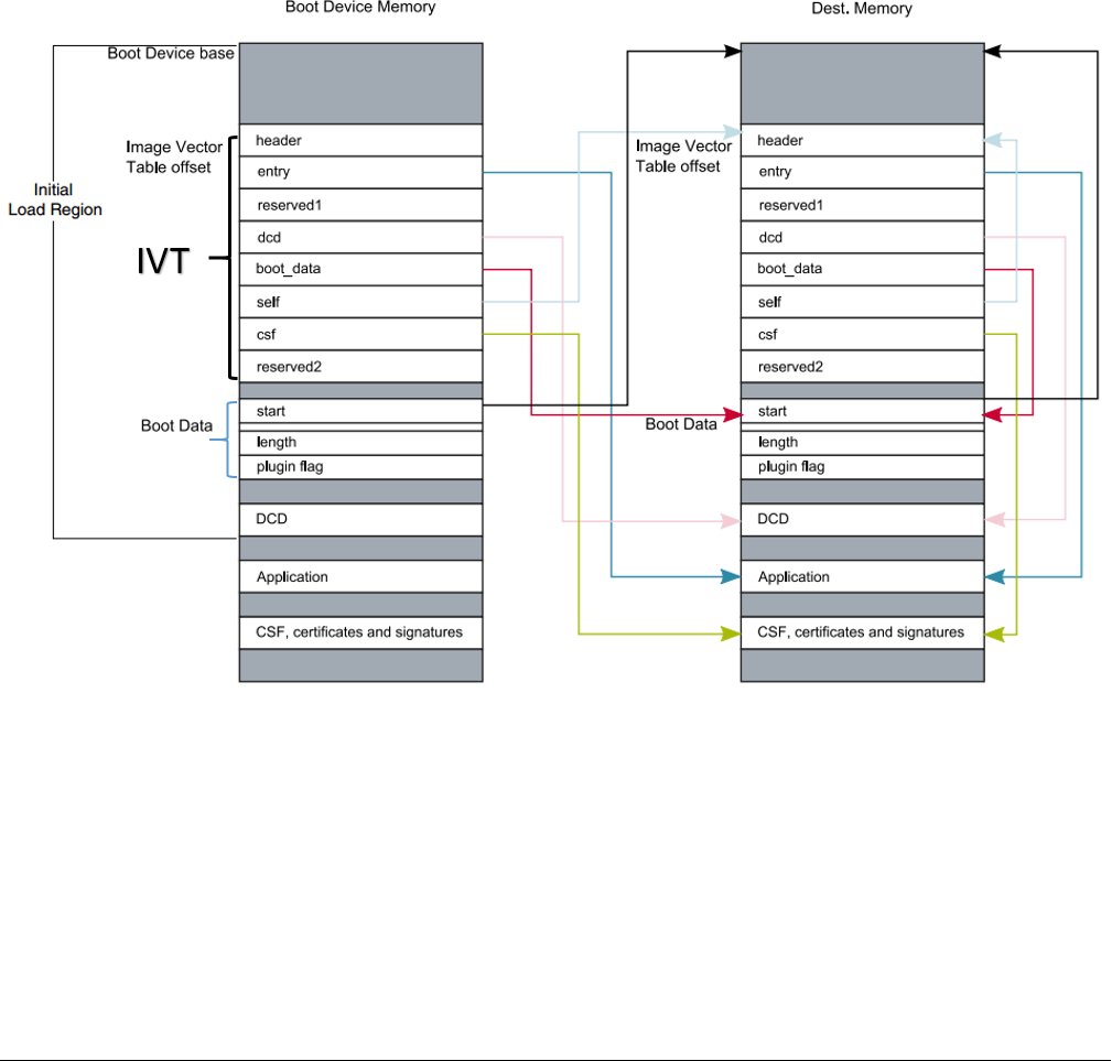
3.1 Bootable image layout in target flash device
There are two types of supported boot image:
• XIP (Execute-In-Place) boot image: This type of boot image is only applicable to Serial NOR devices connected to
QuadSPI or FlexSPI interfaces and Parallel NOR devices connected to WEIM or SEMC interface. The boot device memory
is identical to the destination memory. ROM can boot this boot image directly.
• Non-XIP boot image: This type of boot image is usually for the NAND, SD, and eMMC devices that does not support the
XIP feature. The boot device memory is different from the destination memory. ROM loads the boot image from the Boot
device memory to Destination memory and then boots from the Destination memory.
Figure 1. Bootable image layout
3.2 Boot image format
This section describes the boot image format and data structures. For ease-of-use, the elftosb utility is provided to help customers
automatically generate the boot image format file. The elftosb utility usage is described later in this document.
Some data structures must be included in the bootable image. The bootable image consists of
Bootable image layout in target flash device
i.MX RT1050 Manufacturing User's Guide, Rev. 3, December 2018
NXP Semiconductors 7

• Image Vector Table (IVT): a list of pointers located at a fixed address that ROM examines to determine where the other
components of the bootable image are located
• Boot Data: a table that indicates the bootable image location, image size in bytes and the plugin flag
• Device configuration data (DCD) (optional): IC configuration data, usually is used to configure DDR/SDRAM memory. This
is optional
• User application and data
• CSF (optional): signature block for Secure Boot, generated by CST
• KeyBlob (optional) – a data structure consists of wrapped DEK for encrypt boot
Each bootable image starts with appropriate IVT. In general, for the external memory devices that support XIP feature, the IVT
offset is 0x1000 else it is 0x400. For example, for FlexSPI NOR on RT1050, the IVT must start at address 0x60001000 (start
address is 0x6000_0000, IVT offset is 0x1000). Refer to corresponding Processor Reference Manual for additional information.
3.2.1 IVT and boot data
The IVT is the data structure that the Boot ROM reads from the boot devices supplying the bootable image containing the required
data components to perform a successful boot.
See the Program image section in the System Boot Chapter of the device reference manual for more details
Table 2. IVT data structure
Offset Field Description
0x00 - 0x03 header • Byte 0 tag, fixed to 0xD1
• Byte 1,2 length, bit endian format containing the overall length of the
IVT in bytes, fixed to 0x00, 0x20
• Byte 3: version, valid values: 0x40, 0x41, 0x42, 0x43
0x04 - 0x07 entry Absolute address of the first instruction to execute from the image, or the
vector address of the image
0x08 - 0x0b reserved1 Reserved for future use, set to 0
0x0c - 0x0f dcd Absolute address of the image DCD. It is optional, so this field can be set
to NULL if no DCD is required.
0x10 - 0x13 boot_data Absolute address of the boot data
0x14 - 0x17 self Absolute address of the IVT.
0x18 - 0x1b csf Absolute address of the Command Sequence File (CSF) used by the
HAB library
0x1c - 0x1f reserved2 Reserved, set to 0
3.2.2 Boot data structure
Table 3. Boot Data structure
Offset Field Description
0x00-0x03 start Absolute address of the bootable image
0x04-0x07 length Size of the bootable image
0x08-0x0b plugin Plugin flag, set to 0 if it is a normal boot image
i.MX RT bootable image
i.MX RT1050 Manufacturing User's Guide, Rev. 3, December 2018
8NXP Semiconductors

3.3 Signed image
The bootable image can be signed by CST tool. The tool generates the CSF data in the binary file format that consists of command
sequences and signatures based on given input command sequence file (csf file). Refer to the documentation in the CST release
package for further details.
In this document, a simple method is introduced to generate signed images using elftosb utility.
3.4 Encrypted image
There are two types of encrypted image formats:
Encrypted XIP image format
The Flashloader generates the encrypted XIP image using the AES CTR algorithm when programming the image on the device.
On execution, the hardware engine does on-the-fly decryption.
Encrypted image generated by CST
To increase the security level, the bootable image can be signed and further encrypted by the CST. The KeyBlob must be generated
on the device. The hardware deletes all sensitive keys if any security violation happens, so the sensitive keys cannot be cloned.
In this document, a simple method is introduced to generate signed images using elftosb utility.
Signed image
i.MX RT1050 Manufacturing User's Guide, Rev. 3, December 2018
NXP Semiconductors 9

Chapter 4
Generate i.MX RT bootable image
There are two types of bootable image for i.MX RT devices.
• Normal boot image: This type of image can boot directly by boot ROM.
• Plugin boot image: This type of image can be used to load a boot image from devices that are not natively supported by
boot ROM.
Both types of images can be unsigned, signed, and encrypted for different production phases and different security level
requirements:
• Unsigned Image: The image does not contain authentication-related data and is used during development phase.
• Signed Image: The image contains authentication-related data (CSF section) and is used during production phase.
• Encrypted Image: The image contains encrypted application data and authentication-related data and is used during the
production phase with higher security requirement.
The above types of bootable images can be generated by using the elftosb utility. The detailed usage of the elftosb utility is
available in elftosb User's Guide.
4.1 Description of the elftosb utility
The elftosb utility is a command-line host program used to generate the i.MX RT bootable image for the i.MX RT Boot ROM. The
utility also generates wrapped binary file with command sequences and a bootable image. To create a SB file, use command-
line options and an input text file (also called BD or command file).
4.1.1 The elftosb utility options
Table 4 shows the command line options used to create the i.MX RT bootable image.
Table 4. elftosb utility options
Option Description
-f Specify the bootable image format
To create the i.MX RT bootable image, the usage for family argument “-f” is: “-f imx”
To create the SB file, the usage is: “-f kinetis”
-c Command file to generate corresponding bootable image
For example, “-c program_flexspi_nor_hyperflash.bd”
-o Output file path
For example, “-o ivt_flashloader.bin”
-V Print extra detailed log information
-? Print help info
4.1.2 BD file
Each BD file consists of the following four blocks: options, sources, constants, section
Generate i.MX RT bootable image
i.MX RT1050 Manufacturing User's Guide, Rev. 3, December 2018
10 NXP Semiconductors

• The image paths are typically defined in the “sources” block.
• The constant variables are defined in the “constants” block.
• The memory configuration and programming-related operations are defined in the “section” block.
There are two types of BD files that are supported by the elftosb utility. The first type of file is used for the i.MX RT bootable image
generation. The “-f imx” option is mandatory during boot image generation using the elftosb utility. The second type of file contains
commands that are mainly used for memory programming. The “-f kinetis” flag is mandatory in this use case.
4.1.3 BD file for i.MX RT bootable image generation
The BD file for i.MX RT bootable image generation usually consists of four blocks. These are options, sources, constants, and
section.
4.1.3.1 Options block
Table 5 shows the options used to generate a bootable image for the Options block.
Table 5. Supported options in the “Options” block
Options Description
Flags Generates unsigned, signed, encrypted boot images, and plugin images:
• bit 2 - Encrypted image flag
• bit 3 - Signed image flag
• bit 4 - Plugin image flag
For example:
• 0x00 - unsigned image
• 0x08 - signed image
• 0x04 - encrypted image (encrypted image is always a signed image)
• 0x18 - signed plugin image
startAddress Provides the starting address of the target memory where image should be loaded by ROM.
ivtOffset Provides offset where the IVT data structure must appear in the boot image. The default is 0x400 if
not specified.
The valid value is 0x400 or 0x1000 for i.MX RT boot image.
initialLoadSize Defines the start of the executable image data from elf or the srec file.
The default value is 0x2000 if not specified.
In general, this value should be 0x1000 or 0x2000.
DCDFilePath Defines the path to DCD file.
If not specified, the DCD pointer in the IVT will be set to NULL (0) else the dcd file contents will be
loaded at offset 0x40 from ivtOffset. The dcd file size is limited to (initialLoadSize - ivtOffset-0x40).
cstFolderPath Defines the path for platform dependent CST. (windows, linux)
If not specified, elftosb tool will search for cst executable in same path as elftosb executable.
Table continues on the next page...
Description of the elftosb utility
i.MX RT1050 Manufacturing User's Guide, Rev. 3, December 2018
NXP Semiconductors 11

Table 5. Supported options in the “Options” block (continued)
entryPointAddress Provides the entry point address for ELF or SREC image.
If not specified, ELF image uses its source image entry point address but SREC image will use default
entry point address (0).
4.1.3.2 Sources block
Typically, all the application image paths are provided in this section. Currently, the ELF file and SREC file are supported for i.MX
RT Bootable image generation, for example:
sources {
elfFile = extern(0);
}
4.1.3.3 Constants block
The Constants block provides a constant variable that is used to generate CSF data for image authentication and decryption. The
Constants block is optional for an unsigned image. The supported constants are listed below.
Constants {
SEC_CSF_HEADER = 20;
SEC_CSF_INSTALL_SRK = 21;
SEC_CSF_INSTALL_CSFK = 22;
SEC_CSF_INSTALL_NOCAK = 23;
SEC_CSF_AUTHENTICATE_CSF = 24;
SEC_CSF_INSTALL_KEY = 25;
SEC_CSF_ AUTHENTICATE_DATA = 26;
SEC_CSF_INSTALL_SECRET_KEY = 27;
SEC_CSF_DECRYPT_DATA = 28;
SEC_NOP = 29;
SEC_SET_MID = 30;
SEC_SET_ENGINE = 31;
SEC_INIT = 32;
SEC_UNLOCK = 33;
}
4.1.3.4 Section blocks
The Section blocks are used to create the sections for an i.MX RT bootable image, for example, all sections for CSF data. For the
unsigned image, the Section block is simple, just a fixed blank section, as shown below.
section (0)
{
}
For signed and encrypted image, the following sections are defined for elftosb utility to generate the CSF descriptor file which is
required by CST for CSF data generation.
• SEC_CSF_HEADER
This section defines the necessary elements required for CSF Header generation as well as default values used for other sections
throughout the remaining CSF.
Generate i.MX RT bootable image
i.MX RT1050 Manufacturing User's Guide, Rev. 3, December 2018
12 NXP Semiconductors

Table 6. Elements for CSF Header section generation
Element Description
Header_Version HAB library version
Valid values: 4.0, 4.1, 4.2, 4.3
Header_HashAlgorithm Default Hash Algorithm
Valid values: sha1, sha256, sha512
Header_Engine Default Engine
Valid values: ANY, DCP, CAAM, SW
Header_EngineConfiguration Default Engine Configuration
Recommended value: 0
Header_CertificateFormat Default Certificate Format
Valid values: WTLS, X509
Header_SignatureFormat Default signature format
Valid values: PKCS, CMS
Header_SecurityConfiguration Fused security configuration
Valid values: Engineering, Production
Header_UID Generic (matches any value)
U0, U1,... Un
where each Ui=0..255 and n<255
Header_CustomerCode Value expected in “customer code” fuses
0..255
An example section block is shown as follows.
section (SEC_CSF_HEADER;
Header_Version="4.3",
Header_HashAlgorithm="sha256",
Header_Engine="DCP",
Header_EngineConfiguration=0,
Header_CertificateFormat="x509",
Header_SignatureFormat="CMS"
)
{
}
• SEC_CSF_INSTALL_SRK
This section contains the elements to authenticate and install the root public key for use in subsequent sections, as shown in the
following table.
Description of the elftosb utility
i.MX RT1050 Manufacturing User's Guide, Rev. 3, December 2018
NXP Semiconductors 13

Table 7. Elements for CSF Install SRK section generation
Element Description
InstallSRK_Table Path pointing to the Super Root Key Table file
InstallSRK_Source SRK index with the SRK table
InstallSRK_HashAlgorithm SRK table hash algorithm.
Valid values: SHA1, SHA256 and SHA512
An example section block is shown as follows.
section (SEC_CSF_INSTALL_SRK;
InstallSRK_Table="keys/SRK_1_2_3_4_table.bin", // "valid file path"
InstallSRK_SourceIndex=0
)
{
}
• SEC_CSF_INSTALL_CSFK
This section consists of the elements used to authenticate and install a public key for use in subsequent sections.
Table 8. Elements for CSF Install CSFK section generation
Element Description
InstallCSFK_File File path pointing to CSFK certificate
InstallCSFK_CertificateFormat CSFK certificate format
Valid values: WTLS, X509
section (SEC_CSF_INSTALL_CSFK;
InstallCSFK_File="crts/CSF1_1_sha256_2048_65537_v3_usr_crt.pem", // "valid file path"
InstallCSFK_CertificateFormat="x509" // "x509"
)
{
}
• SEC_CSF_INSTALL_NOCAK
The Install NOCAK command authenticates and installs a public key for use with the fast authentication mechanism (HAB 4.1.2
and later only). With this mechanism, one key is used for all signatures.
The following table lists the install NOCAK command arguments.
Table 9. Elements for CSF Install NOCAK section generation
Element Description
InstallNOCAK_File File path pointing to CSFK certificate
InstallNOCAK_CertificateFormat CSFK certificate format
Valid values: WTLS, X509
Generate i.MX RT bootable image
i.MX RT1050 Manufacturing User's Guide, Rev. 3, December 2018
14 NXP Semiconductors

An example section block is shown as follows:
section (SEC_CSF_INSTALL_NOCAK;
InstallNOCAK_File= "crts/SRK1_sha256_2048_65537_v3_usr_crt.pem") // "valid file path"
InstallNOCAK_CertificateFormat= "WTLS" // "WTLS", "X509"
)
{
}
• SEC_CSF_AUTHENTICATE_CSF
This section is used to authenticate the CSF from which it is executed using the CSFK mentioned in the section above. The default
setting is enough. See the following table for more details.
Table 10. Elements for CSF Authenticate CSF section generation
Element Description
AuthenticateCSF_Engine CSF signature hash engine
Valid values: ANY, SAHARA, RTIC, DCP, CAAM and SW
AuthenticateCSF_EngineConfiguration Configuration flags for the hash engine. Note that the hash is computed over
an internal RAM copy of the CSF
Valid engine configuration values corresponding to engine name.
AuthenticateCSF_SignatureFormat CSF signature format
Valid values: PKCS1, CMS
An example section block is shown as follows:
section (SEC_CSF_AUTHENTICATE_CSF)
{
}
• SEC_CSF_INSTALL_KEY
This section consists of elements used to authenticate and install a public key for use in subsequent sections, as shown in the
following table.
Table 11. Elements for CSF Install Key section generation
Element Description
InstallKey_File File path pointing to a Public key file
InstallKey_VerificationIndex Verification key index in Key store
Valid values: 0, 2, 3, 4
InstallKey_TargetIndex Target key index in key store
Valid values: 2, 3, 4
InstallKey_CertificateFormat Valid values: WTLS, X509
Table continues on the next page...
Description of the elftosb utility
i.MX RT1050 Manufacturing User's Guide, Rev. 3, December 2018
NXP Semiconductors 15

Table 11. Elements for CSF Install Key section generation (continued)
InstallKey_HashAlgorithm Hash algorithm for certificate binding.
If present, a hash of the certificate specified in the File argument is included
in the command to prevent installation from other sharing the same
verification key
Valid values: SHA1, SHA256, SHA512
section (SEC_CSF_INSTALL_KEY;
InstallKey_File="crts/IMG1_1_sha256_2048_65537_v3_usr_crt.pem",
InstallKey_VerificationIndex=0, // Accepts integer or string
InstallKey_TargetIndex=2) // Accepts integer or string
{
}
• SEC_CSF_AUTHENTICATE_DATA
This section contains elements that are used to verify the authenticity of pre-loaded data in memory.
Table 12. Elements for CSF Authenticate Data section generation
Element Description
AuthenticateData_VerificationIndex Verification key index in key store
AuthenticateData_Engine Data signature hash engine
Valid values: ANY, DCP, CAAM, SW
AuthenticateData_EngineConfiguration Configuration flags for the engine
AuthenticateData_SignatureFormat Data signature format
Valid values: PKCS1, CMS
AuthenticateData_Binding 64-bit unique ID (UID) for binding.
If present, authentication succeeds only if the UID fuse value matches this
argument, and the TYPE fuse value matches the Security Configuration
argument from the Header command
Valid values:
U0, U1, ... U7
with
Ui: 0, ..., 255.
UID bytes separated by commas
An example section block is shown as follows:
section (SEC_CSF_AUTHENTICATE_DATA;
AuthenticateData_VerificationIndex=2,
AuthenticateData_Engine="DCP",
AuthenticateData_EngineConfiguration=0)
{
}
Generate i.MX RT bootable image
i.MX RT1050 Manufacturing User's Guide, Rev. 3, December 2018
16 NXP Semiconductors

• SEC_CSF_INSTALL_SECRET_KEY
This section contains elements used to install the secret key to the MCU secret key store, which is used for Keyblob decryption.
This section is required for encrypted image generation and not for signed image.
Table 13. Elements for CSF Install Secret Key section generation
Element Description
SecretKey_Name Specifies the file path used for CST to generate the random decryption key
file
SecretKey_Length Key length in bits
Valid values: 128, 192, and 256
SecretKey_VerifyIndex Master KEK index
Valid values: 0 or 1
SecretKey_TargetIndex Target secret key store index
Valid values: 0-3
SecretKey_BlobAddress Internal or external DDR address
An example section block is shown as follows:
section (SEC_CSF_INSTALL_SECRET_KEY;
SecretKey_Name="dek.bin",
SecretKey_Length=128,
SecretKey_VerifyIndex=0,
SecretKey_TargetIndex=0)
{
}
• SEC_CSF_DECRYPT_DATA
This section is required for encrypted image generation and not for signed image. It contains the necessary elements used to
decrypt and authenticate a list of code/data blocks using the secret key stored in the secret key store, as shown in the following
table.
Table 14. Elements for CSF Decrypt Data section generation
Element Description
Decrypt_Engine MAC engine
Valid value: CAAM, DCP
Decrypt_EngineConfiguration Configuration flags for the engine
Default value: 0
Decrypt_VerifyIndex Secret key index in the Secret key store
Valid values: 0-3
Table continues on the next page...
Description of the elftosb utility
i.MX RT1050 Manufacturing User's Guide, Rev. 3, December 2018
NXP Semiconductors 17

Table 14. Elements for CSF Decrypt Data section generation (continued)
Decrypt_MacBytes Size of MAC in bytes
If engine is CAAM, the valid value is even number between 4-16. The
recommended value is 16.
If engine is DCP, the valid value is 16.
An example section block is shown as follows.
section (SEC_CSF_DECRYPT_DATA;
Decrypt_Engine="DCP",
Decrypt_EngineConfiguration="0", // "valid engine configuration values"
Decrypt_VerifyIndex=0,
Decrypt_MacBytes=16)
{
}
• SEC_NOP
The command in this section has no effect. It also has no arguments.
An example section block is shown as follows.
section (SEC_NOP)
// NOP command has no arguments
{
}
• SEC_SET_MID
The Set MID command selects a range of fuse locations to use as a manufacturing identifier (MID). MID values are bound with
Authenticate Data signatures when verified using keys with the MID binding flag in the Install Key command.
Table 15. Elements for CSF Set MID section generation
Element Description
SetMID_Bank Fuse bank containing MID.
Valid values: 0, …, 255
SetMID_Row Starting row number of MID within bank.
Valid values: 0, …, 255
SetMID_Fuse Starting fuse of MID within row.
Valid values: 0, …, 255
SetMID_Bits Number of bits for MID.
Valid values: 0, …, 255
An example section block is shown as follows:
section (SEC_SET_MID;
SetMID_Bank = 4,
SetMID_Row = 0,
Generate i.MX RT bootable image
i.MX RT1050 Manufacturing User's Guide, Rev. 3, December 2018
18 NXP Semiconductors

SetMID_Fuse = 7,
SetMID_Bits = 64)
{
}
• SEC_SET_ENGINE
The Set Engine command selects the default engine and engine configuration for a given algorithm.
Table 16. Elements for CSF Set Engine section generation
Element Description
SetEngine_Engine Engine
Use ANY to restore the HAB internal criteria.
Valid values: ANY, SAHARA, RTIC, DCP, CAAM and SW
SetEngine_HashAlgorithm Hash algorithm
Valid values: SHA1, SHA256 and SHA512
SetEngine_EngineConfiguration Configuration flags for the engine.
Valid engine configuration values corresponding to engine name.
An example section block is shown as follows:
section (SEC_SET_ENGINE;
SetEngine_HashAlgorithm = "sha256",
SetEngine_Engine = "DCP",
SetEngine_EngineConfiguration = "0")
{
}
• SEC_INIT
The Init command initializes specified engine features when exiting the internal boot ROM.
Table 17. Elements for CSF Init section generation
Element Description
INIT_Engine Engine to initialize
Valid value – SRTC
INIT_Features Comma-separated list of features to initialize
Valid engine feature corresponding to engine argument.
An example section block is shown as follows:
section (SEC_INIT;
Init_Engine = "SRTC")
// Init_Features= "MID"
{
}
• SEC_UNLOCK The Unlock command prevents specified engine features from being locked when exiting the internal boot ROM.
Description of the elftosb utility
i.MX RT1050 Manufacturing User's Guide, Rev. 3, December 2018
NXP Semiconductors 19

Table 18. Elements for CSF Unlock section generation
Element Description
Unlock_Engine Engine to unlock
Valid values: SRTC, CAAM, SNVS and OCOTP
Unlock_features Comma-separated list of features to unlock
Valid engine feature corresponding to engine argument.
Unlock_UID Device specific 64-bit UID
U0, U1, …, U7 with Ui=0...255
UID bytes separated by commas
An example section block is shown as follows:
section (SEC_UNLOCK;
Unlock_Engine = "OCOTP",
Unlock_features = "JTAG, SRK REVOKE",
Unlock_UID = "0x01, 0x23, 0x45, 0x67, 0x89, 0xab, 0xcd, 0xef")
{
}
4.1.4 BD file for memory programming
Typically, “load”, “enable”, and “erase” commands are the most commonly used commands in a BD file for memory programming.
1. “load” command: It can be used to load raw binary, srec file, elf file, hex string, etc. It also supports loading data to
external memory devices, for example:
• Load itcm_boot_image.bin > 0x8000; (Load data to ITCM)
• Load flexspi_nor_boot_image.bin > 0x60001000; (Load data to the memory mapped memory device)
• Load semc_nor_boot_image.bin > 0x80001000; (Load data to SEMC NOR, memory mapped memory device)
• Load spinand boot_image.bin > 0x04; (Load data to SPI NAND)
• Load sdcard boot_image.bin > 0x400; (Load data to the SD Card)
• Load mmccard boot_image.bin > 0x400; (Load data to eMMC)
• Load spieeprom boot_image.bin > 0x400; (Load data to SPI EEPROM/NOR)
• Load semcnand boot_image.bin > 0x400; (Load data to SLC raw NAND via SEMC)
• Load fuse 0x00000000 > 0x10; (Load data to the Fuse block)
2. “enable” command: It is used to configure external memory devices, for example:
• Enable flexspinor 0x1000
• Enable spinand 0x1000
• Enable sdcard 0x1000
• Enable mmccard 0x1000
• Enable spieeprom 0x1000
• Enable semcnor 0x1000
• Enable semcnand 0x1000
Generate i.MX RT bootable image
i.MX RT1050 Manufacturing User's Guide, Rev. 3, December 2018
20 NXP Semiconductors
3. “erase” command: It is used to erase a memory range in the selected memory device. For example:
• Erase 0x60000000..0x60010000 (Erase 64 KB from FlexSPI NOR)
• Erase spinand 0x4..0x08 (Erase 4 blocks from SPI NAND)
• Erase sdcard 0x400..0x14000
• Erase mmccard 0x400..0x14000
• Erase spieeprom 0x400..0x14000
• Erase semcnand 0x400..0x14000
4.2 Generate unsigned normal i.MX RT bootable image
Typically, the unsigned bootable image is generated and programmed to the destination memory during the development phase.
The elftosb utility supports unsigned bootable image generation using options, BD file, and ELF/SREC file generated by toolchain.
Taking the Flashloader project as an example, here are the steps to create a bootable image for Flashloader.
Step 1: Create a BD file. For unsigned image creation, the “constants” block is optional, as shown below.
options {
flags = 0x00;
startAddress = 0x20000000;
ivtOffset = 0x400;
initialLoadSize = 0x2000;
}
sources {
elfFile = extern(0);
}
section (0)
{
}
After the BD file is created, place it into the same folder that holds elftosb utility executable.
Step 2: Copy Flashloader.srec provided in the release package into the same folder that holds elftosb utility executable.
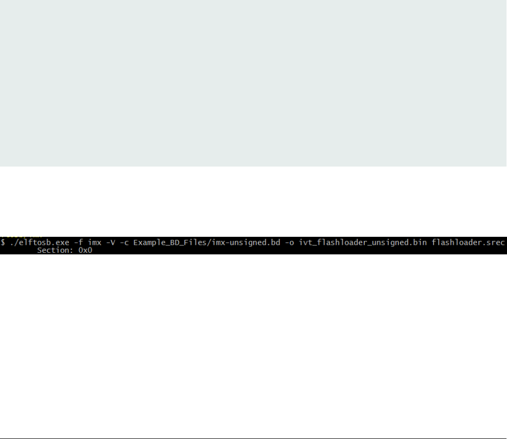
Step 3: Generate the Bootable image using elftosb utility.
Figure 2. Example command to generate unsigned boot image
Then, there are two bootable images generated by elftosb utility. The first one is ivt_flashloader_unsigned.bin. The memory
regions from 0 to ivt_offset are filled with padding bytes (all 0x00s).
The second one is ivt_flashloader_nopadding.bin, which starts from ivtdata directly without any padding before ivt.
4.3 Generate signed normal i.MX RT bootable image
To generate a signed bootable image using elftosb utility, perform the following steps:
Generate unsigned normal i.MX RT bootable image
i.MX RT1050 Manufacturing User's Guide, Rev. 3, December 2018
NXP Semiconductors 21

Step 1: Create a BD file. The BD file can be as follows.
options {
flags = 0x08;
startAddress = 0x60000000;
ivtOffset = 0x1000;
initialLoadSize = 0x2000;
}
sources {
elfFile = extern(0);
}
constants {
SEC_CSF_HEADER = 20;
SEC_CSF_INSTALL_SRK = 21;
SEC_CSF_INSTALL_CSFK = 22;
SEC_CSF_INSTALL_NOCAK = 23;
SEC_CSF_AUTHENTICATE_CSF = 24;
SEC_CSF_INSTALL_KEY = 25;
SEC_CSF_AUTHENTICATE_DATA = 26;
SEC_CSF_INSTALL_SECRET_KEY = 27;
SEC_CSF_DECRYPT_DATA = 28;
SEC_NOP = 29;
SEC_SET_MID = 30;
SEC_SET_ENGINE = 31;
SEC_INIT = 32;
SEC_UNLOCK = 33;
}
section (SEC_CSF_HEADER;
Header_Version="4.2",
Header_HashAlgorithm="sha256",
Header_Engine="DCP",
Header_EngineConfiguration=0,
Header_CertificateFormat="x509",
Header_SignatureFormat="CMS"
)
{
}
section (SEC_CSF_INSTALL_SRK;
InstallSRK_Table="keys/SRK_1_2_3_4_table.bin", // "valid file path"
InstallSRK_SourceIndex=0
)
{
}
section (SEC_CSF_INSTALL_CSFK;
InstallCSFK_File="crts/CSF1_1_sha256_2048_65537_v3_usr_crt.pem", // "valid file path"
InstallCSFK_CertificateFormat="x509" // "x509"
)
{
}
section (SEC_CSF_AUTHENTICATE_CSF)
{
}
section (SEC_CSF_INSTALL_KEY;
Generate i.MX RT bootable image
i.MX RT1050 Manufacturing User's Guide, Rev. 3, December 2018
22 NXP Semiconductors

InstallKey_File="crts/IMG1_1_sha256_2048_65537_v3_usr_crt.pem",
InstallKey_VerificationIndex=0, // Accepts integer or string
InstallKey_TargetIndex=2) // Accepts integer or string
{
}
section (SEC_CSF_AUTHENTICATE_DATA;
AuthenticateData_VerificationIndex=2,
AuthenticateData_Engine="DCP",
AuthenticateData_EngineConfiguration=0)
{
}
section (SEC_SET_ENGINE;
SetEngine_HashAlgorithm = "sha256", // "sha1", "Sha256", "sha512"
SetEngine_Engine = "DCP", // "ANY", "SAHARA", "RTIC", "DCP", "CAAM" and "SW"
SetEngine_EngineConfiguration = "0") // "valid engine configuration values"
{
}
section (SEC_UNLOCK;
Unlock_Engine = "SNVS",
Unlock_features = "ZMK WRITE"
)
{
}
After the blank BD file is created, place it into the same folder that holds elftosb utility executable.
Step 2: Copy Flashloader.srec provided in the release package into the same folder that holds elftosb utility executable.
Step 3: Copy the “cst” executable, “crts” folder, and “keys” folder from “<cst_installation_dir>” to the same folder that holds elftosb
utility executable.
Step 4: Generate a bootable image using elftosb utility.
Figure 3. Example command to generate a signed boot image
Then, there are two bootable images generated by elftosb utility. The first one is ivt_flashloader_signed.bin. The memory regions
from 0 to ivt_offset is filled with padding bytes (all 0x00s). The second one is ivt_flashloader_signed_nopadding.bin, which starts
from ivt_offset directly. The CSF section is generated and appended to the unsigned bootable image successfully.
4.4 Generate encrypted normal i.MX RT bootable image
To generate an encrypted image, perform the following steps:
Step 1: Create a BD file.
options {
flags = 0x0c;
startAddress = 0x20000000;
ivtOffset = 0x400;
initialLoadSize = 0x2000;
}
Generate encrypted normal i.MX RT bootable image
i.MX RT1050 Manufacturing User's Guide, Rev. 3, December 2018
NXP Semiconductors 23

sources {
elfFile = extern(0);
}
constants {
SEC_CSF_HEADER = 20;
SEC_CSF_INSTALL_SRK = 21;
SEC_CSF_INSTALL_CSFK = 22;
SEC_CSF_INSTALL_NOCAK = 23;
SEC_CSF_AUTHENTICATE_CSF = 24;
SEC_CSF_INSTALL_KEY = 25;
SEC_CSF_AUTHENTICATE_DATA = 26;
SEC_CSF_INSTALL_SECRET_KEY = 27;
SEC_CSF_DECRYPT_DATA = 28;
SEC_NOP = 29;
SEC_SET_MID = 30;
SEC_SET_ENGINE = 31;
SEC_INIT = 32;
SEC_UNLOCK = 33;
}
section (SEC_CSF_HEADER;
Header_Version="4.3",
Header_HashAlgorithm="sha256",
Header_Engine="DCP",
Header_EngineConfiguration=0,
Header_CertificateFormat="x509",
Header_SignatureFormat="CMS"
)
{
}
section (SEC_CSF_INSTALL_SRK;
InstallSRK_Table="keys/SRK_1_2_3_4_table.bin", // "valid file path"
InstallSRK_SourceIndex=0
)
{
}
section (SEC_CSF_INSTALL_CSFK;
InstallCSFK_File="crts/CSF1_1_sha256_2048_65537_v3_usr_crt.pem", // "valid file path"
InstallCSFK_CertificateFormat="x509" // "x509"
)
{
}
section (SEC_CSF_AUTHENTICATE_CSF)
{
}
section (SEC_CSF_INSTALL_KEY;
InstallKey_File="crts/IMG1_1_sha256_2048_65537_v3_usr_crt.pem",
InstallKey_VerificationIndex=0, // Accepts integer or string
InstallKey_TargetIndex=2) // Accepts integer or string
{
}
section (SEC_CSF_AUTHENTICATE_DATA;
AuthenticateData_VerificationIndex=2,
Generate i.MX RT bootable image
i.MX RT1050 Manufacturing User's Guide, Rev. 3, December 2018
24 NXP Semiconductors
AuthenticateData_Engine="DCP",
AuthenticateData_EngineConfiguration=0)
{
}
section (SEC_CSF_INSTALL_SECRET_KEY;
SecretKey_Name="dek.bin",
SecretKey_Length=128,
SecretKey_VerifyIndex=0,
SecretKey_TargetIndex=0)
{
}
section (SEC_CSF_DECRYPT_DATA;
Decrypt_Engine="DCP",
Decrypt_EngineConfiguration="0", // "valid engine configuration values"
Decrypt_VerifyIndex=0,
Decrypt_MacBytes=16)
{
}
Step 2: Copy Flashloader.srec provided in the release package into the same folder that holds elftosb utility executable.
Step 3: Copy the “cst” executable, “crts” folder, and “keys” folder from “<cst_installation_dir>” to the same folder that holds elftosb
utility executable.
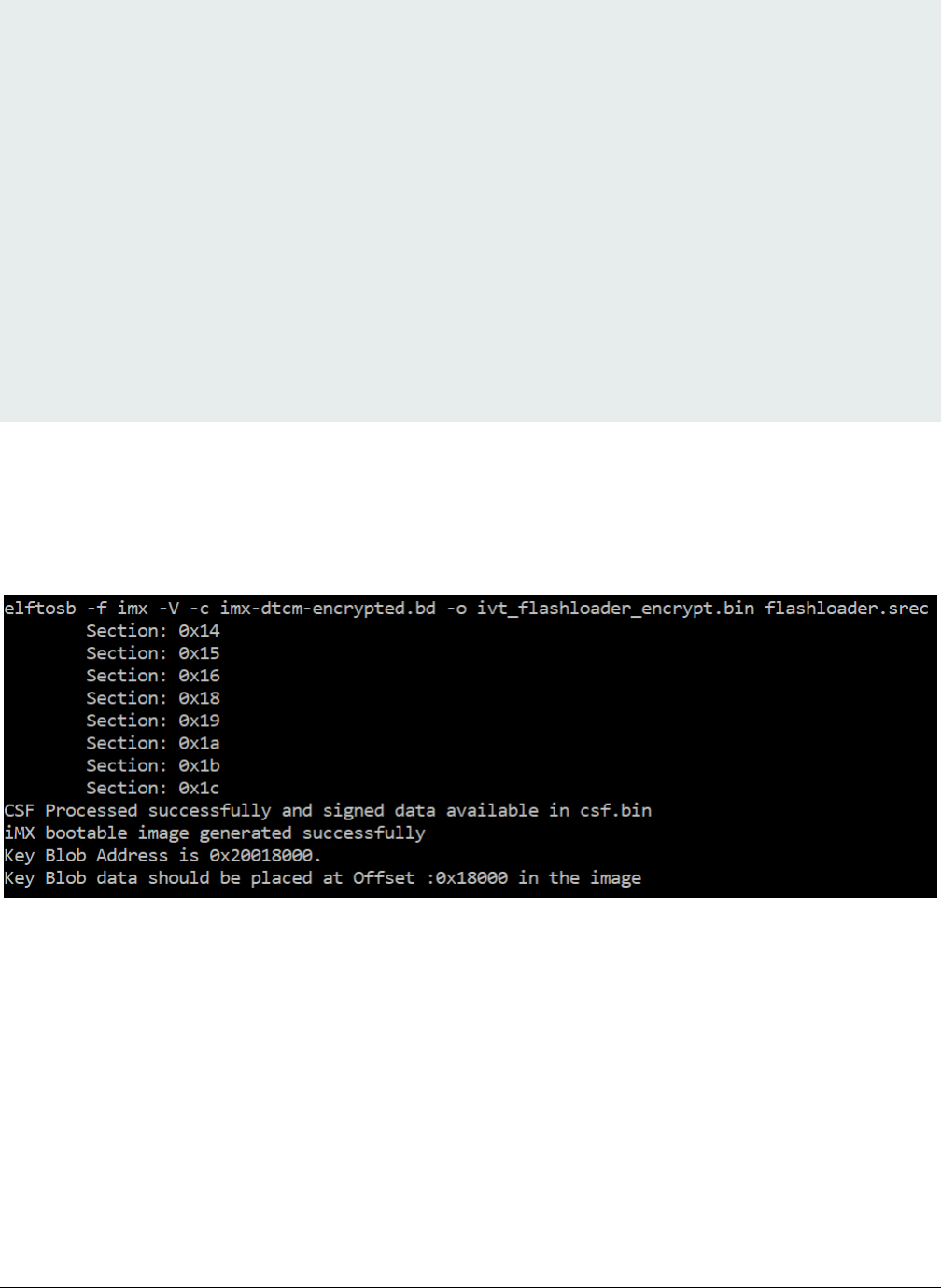
Step 4: Generate an encrypted bootable image using elftosb utility.
Figure 4. Example command to generate encrypt image
Then, there are two bootable images generated by elftosb utility. The first one is ivt_flashloader_encrypt.bin. The memory regions
from 0 to ivt_offset are filled with padding bytes (all 0x00s).
The Key Blob offset printed out in the example above is used in later section.
The second one is ivt_flashloader_encrypt_nopadding.bin, which starts from ivt_offset directly. The CSF section is generated and
appended to the unsigned bootable image successfully.
Step 5: Generate the KeyBlob section using Flashloader.
The encrypted image generated by elftosb utility is incomplete because the KeyBlob section must be generated on the SoC side
only.
There are two methods to generate the KeyBlob block:
Generate encrypted normal i.MX RT bootable image
i.MX RT1050 Manufacturing User's Guide, Rev. 3, December 2018
NXP Semiconductors 25

• Generate KeyBlob using the “generate-key-blob <dek_file> <blob_file>” command supported by Flashloader and blhost.
See Appendix for more details.
• Generate KeyBlob during manufacturing and use the KeyBlob option block. See Chapter 5 for more details.
4.5 Generate Plugin boot image
The plugin boot image generation process is similar as the one for normal boot image. The only difference is that the bit 4 in the
“flags” element within the “options” block must be set to 1, in other words, the valid flags value list for the plugin boot image is
{0x10, 0x18, 0x1c}.
An example BD file for plugin boot image generation is shown as follows.
options {
flags = 0x10;
startAddress = 0x60000000;
ivtOffset = 0x1000;
initialLoadSize = 0x2000;
}
sources {
elfFile = extern(0);
}
section (0)
{
}
Generate i.MX RT bootable image
i.MX RT1050 Manufacturing User's Guide, Rev. 3, December 2018
26 NXP Semiconductors
Chapter 5
Generate SB file for bootable image programming
To make the manufacturing process easier, all the commands supported by Flashloader and bootable image, can be wrapped
into a single SB file. Even if there are any changes in the application, MfgTool still uses this SB file to manufacture. The SB file
can be updated separately without updating scripts for MfgTool use.
In this section, a bootable image will be created using the method introduced in former chapter. Then corresponding SB file is
generated using the bootable image. The corresponding BD file is prepared first to generate SB file for bootable image.
5.1 Generate SB file for FlexSPI NOR image programming
5.1.1 Generate Normal Bootable Image
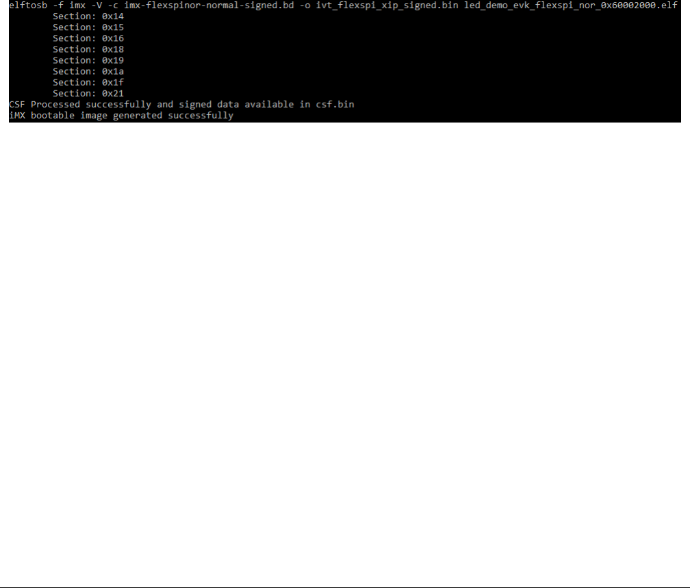
For example, in RT1050, the FlexSPI NOR memory starts from address 0x6000_0000 and IVT from offset 0x1000. After following
the steps in section 4.2, Generate unsigned normal i.MX RT bootable image, and BD file generation, here is the usage of elftosb
utility to create bootable image for FlexSPI NOR. All the BD files are provided in the release package. The figure below refers to
the example command to generate signed image.
Figure 5. Example command to generate signed FlexSPI boot image
After running above command, a file with suffix “_nopadding.bin” is programed into destination memory via subsequent SB file
based on this binary.
5.1.2 Generate SB file for plaintext FlexSPI NOR image
programming
Usually, a BD file for FlexSPI NOR boot consists of 7 parts.
1. The bootable image file path is provided in sources block
2. The FlexSPI NOR Configuration Option block is provided in section block
3. To enable FlexSPI NOR access, the “enable” command must be provided following above option block.
4. In case the Flash device is not erased, an “erase” command is required before programming data to Flash device. The
erase operation is time consuming and is not required for a blank Flash device (factory setting) during Manufacturing.
5. The FlexSPI NOR Configuration Block (FNORCB) is required for FlexSPI NOR boot. To program the FNORCB
generated by FlexSPI NOR Configuration Option block, a special magic number ‘0xF000000F” must load into RAM first
6. To notify the Flashloader to program the FNORCB, an “enable” command must be used following the magic number
loading
7. After above operation, Flashloader can program the bootable image binary into Serial NOR Flash through FlexSPI
module using load command
Generate SB file for FlexSPI NOR image programming
i.MX RT1050 Manufacturing User's Guide, Rev. 3, December 2018
NXP Semiconductors 27
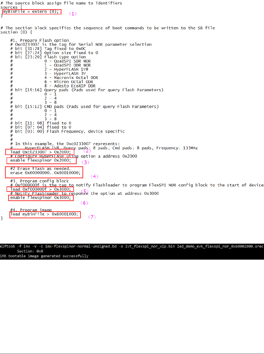
A simple example containing the above steps is shown in the figure below.
Figure 6. Example BD file for FlexSPI NOR programming
Here is an example to generate SB file using elftosb utility, ivt_flexspi_nor_xip.bin and BD file shown in figure below.
Figure 7. Example command to generate SB file for FlexSPI NOR programming
After above command, a file named boot_image.sb will be created in the same folder that holds elftosb utility executable.
5.1.3 Generate SB file for FlexSPI NOR Image encryption and
programming
Usually, a BD file for FlexSPI NOR image encryption and programming consists of 7 parts.
1. The bootable image file path is provided in sources block
2. Enable FlexSPI NOR access using FlexSPI NOR Configuration Option block
Generate SB file for bootable image programming
i.MX RT1050 Manufacturing User's Guide, Rev. 3, December 2018
28 NXP Semiconductors
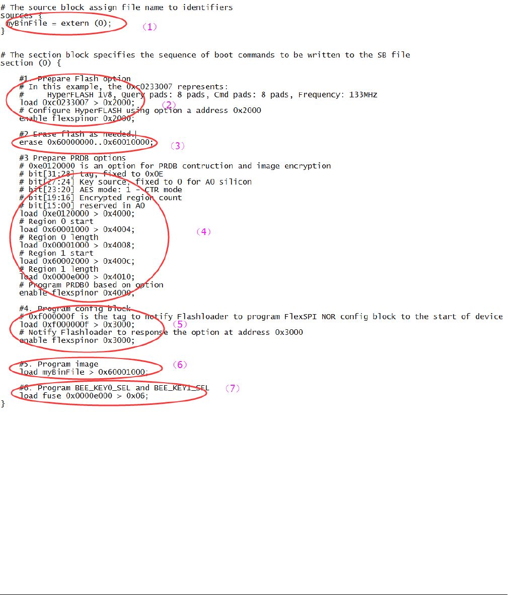
3. Erase the Flash device if it is not blank. The erase operation is time consuming and is not required for a blank Flash
device (factory setting) during Manufacturing.
4. Enable image encryption using PRDB option block
5. Program FNORCB using magic number
6. Program boot image binary into Serial NOR via FlexSPI module
7. Enable Encrypted XIP fuse bits.
Figure 8. Example BD file for encrypted FlexSPI NOR image generation and programming
The steps to generate SB file is the same as above section.
5.2 Generate SB file for FlexSPI NAND image programming
For FlexSPI NAND boot, the IVT offset is always 0x400. However, to reduce effort in calculating the start address for each firmware
region, the Flashloader supports programming the FlexSPI NAND boot image to corresponding firmware region in block
granularity. So, the bootable image without “_nopadding” suffix will be used.
Generate SB file for FlexSPI NAND image programming
i.MX RT1050 Manufacturing User's Guide, Rev. 3, December 2018
NXP Semiconductors 29
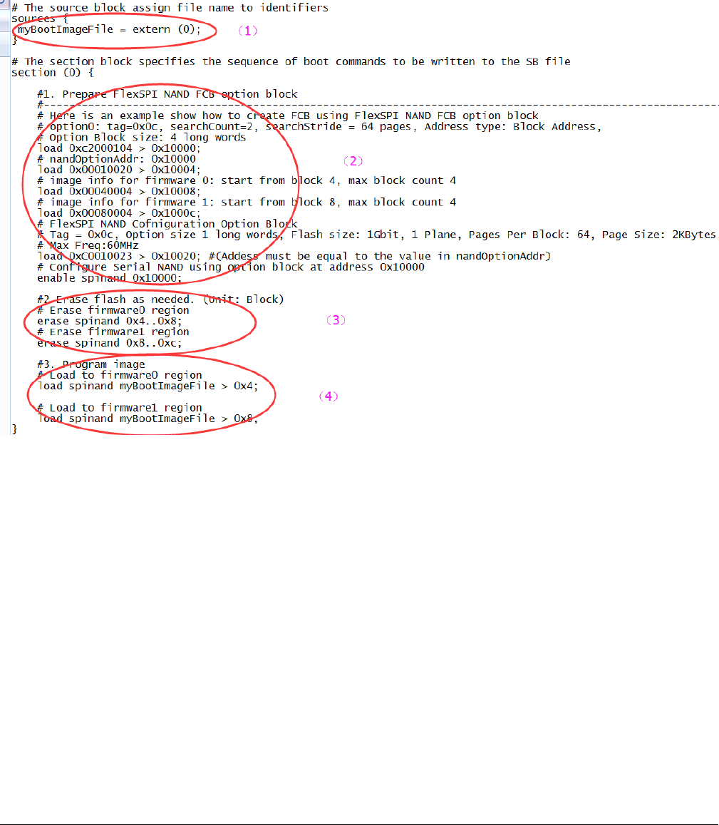
5.2.1 Generate SB file for FlexSPI NAND image programming
In general, a BD file for FlexSPI NAND image programming consists of 4 parts.
1. The bootable image file path is provided in sources block
2. Enable FlexSPI NAND access using FlexSPI NAND Configuration Option block
3. Erase SPI NAND device as needed
4. Program boot image binary into Serial NAND via FlexSPI module
Figure 9. Example BD file for FlexSPI NAND image programming
5.2.2 Generate SB file for encrypted FlexSPI NAND Image and
KeyBlob programming
Generally, the BD file for FlexSPI NAND image programming with KeyBlob consists of 7 parts.
1. The bootable image file path is provided in sources block
2. Enable FlexSPI NAND access using FlexSPI NAND Configuration Option block
3. Erase SPI NAND device as needed
4. Program boot image binary into Serial NAND via FlexSPI module
5. Update KeyBlob information using KeyBlob Option block
6. Program KeyBlob block into SPI NAND for firmware 0
7. Program KeyBlob block into SPI NAND for firmware 1
An example BD file is shown in the figure below.
Generate SB file for bootable image programming
i.MX RT1050 Manufacturing User's Guide, Rev. 3, December 2018
30 NXP Semiconductors
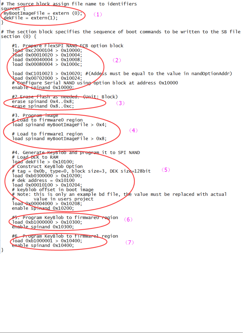
Figure 10. Example BD file for encrypted FlexSPI NAND image and KeyBlob programming
5.3 Generate SB file for SD image programming
The SD image always starts at offset 0x400. The i.MX RT boot image generated by elftosb utility with “_nopadding.bin” will be
used for programming.
Generate SB file for SD image programming
i.MX RT1050 Manufacturing User's Guide, Rev. 3, December 2018
NXP Semiconductors 31
5.3.1 Steps to Generate SB file for SD image programming
In general, there are six steps in the BD file to program the bootable image to SD card.
1. The bootable image file path is provided in sources block
2. Prepare SDCard option block
3. Enable SDCard access using enable command
4. Erase SD card memory as needed
5. Program boot image binary into SD card
6. Program optimal SD boot parameters into Fuse (optional, remove it if it is not required in actual project)
An example is shown in the figure below.
Figure 11. Example BD file for SD boot image programming
The steps to generate SB file for encrypted SD boot image and KeyBlob programming is similar to FlexSPI NAND. See example
below for more details.
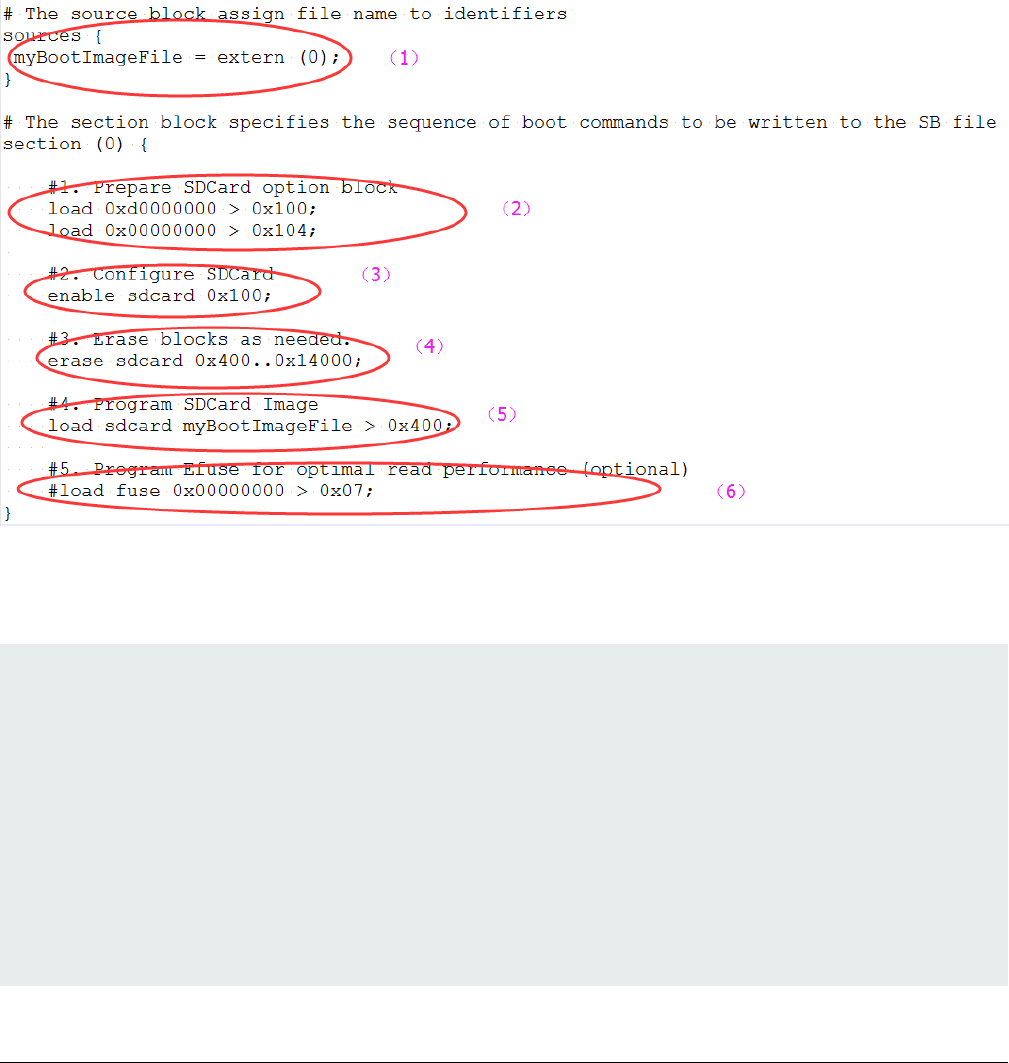
# The source block assign file name to identifiers
sources {
myBootImageFile = extern (0);
dekFile = extern (1);
}
# The section block specifies the sequence of boot commands to be written to the SB file
section (0) {
#1. Prepare SDCard option block
load 0xd0000000 > 0x100;
load 0x00000000 > 0x104;
#2. Configure SDCard
enable sdcard 0x100;
Generate SB file for bootable image programming
i.MX RT1050 Manufacturing User's Guide, Rev. 3, December 2018
32 NXP Semiconductors

#3. Erase blocks as needed.
erase sdcard 0x400..0x14000;
#4. Program SDCard Image
load sdcard myBootImageFile > 0x400;
#5. Generate KeyBlob and program it to SD Card
# Load DEK to RAM
load dekFile > 0x10100;
# Construct KeyBlob Option
#---------------------------------------------------------------------------
# bit [31:28] tag, fixed to 0x0b
# bit [27:24] type, 0 - Update KeyBlob context, 1 Program Keyblob to SPI NAND
# bit [23:20] keyblob option block size, must equal to 3 if type =0,
# reserved if type = 1
# bit [19:08] Reserved
# bit [07:04] DEK size, 0-128bit 1-192bit 2-256 bit, only applicable if type=0
# bit [03:00] Firmware Index, only applicable if type = 1
# if type = 0, next words indicate the address that holds dek
# the 3rd word
#----------------------------------------------------------------------------
# tag = 0x0b, type=0, block size=3, DEK size=128bit
load 0xb0300000 > 0x10200;
# dek address = 0x10100
load 0x00010100 > 0x10204;
# keyblob offset in boot image
# Note: this is only an example bd file, the value must be replaced with actual
# value in users project
load 0x00004000 > 0x10208;
enable sdcard 0x10200;
#6. Program KeyBlob to firmware0 region
load 0xb1000000 > 0x10300;
enable sdcard 0x10300;
#7. Program Efuse for optimal read performance (optional)
#load fuse 0x00000000 > 0x07;
}
5.4 Generate SB file for eMMC image programming
The eMMC image always starts at offset 0x400. The i.MX RT boot image generated by elftosb utility with “_nopadding.bin” will
be used for programming.
There are two types of eMMC boot mode: Normal boot and Fast boot
5.4.1 Normal mode
There are 6 steps in the BD file to program the bootable image to eMMC for normal boot mode.
1. The bootable image file path is provided in sources block
2. Prepare eMMC option block
3. Enable eMMC access using enable command
Generate SB file for eMMC image programming
i.MX RT1050 Manufacturing User's Guide, Rev. 3, December 2018
NXP Semiconductors 33
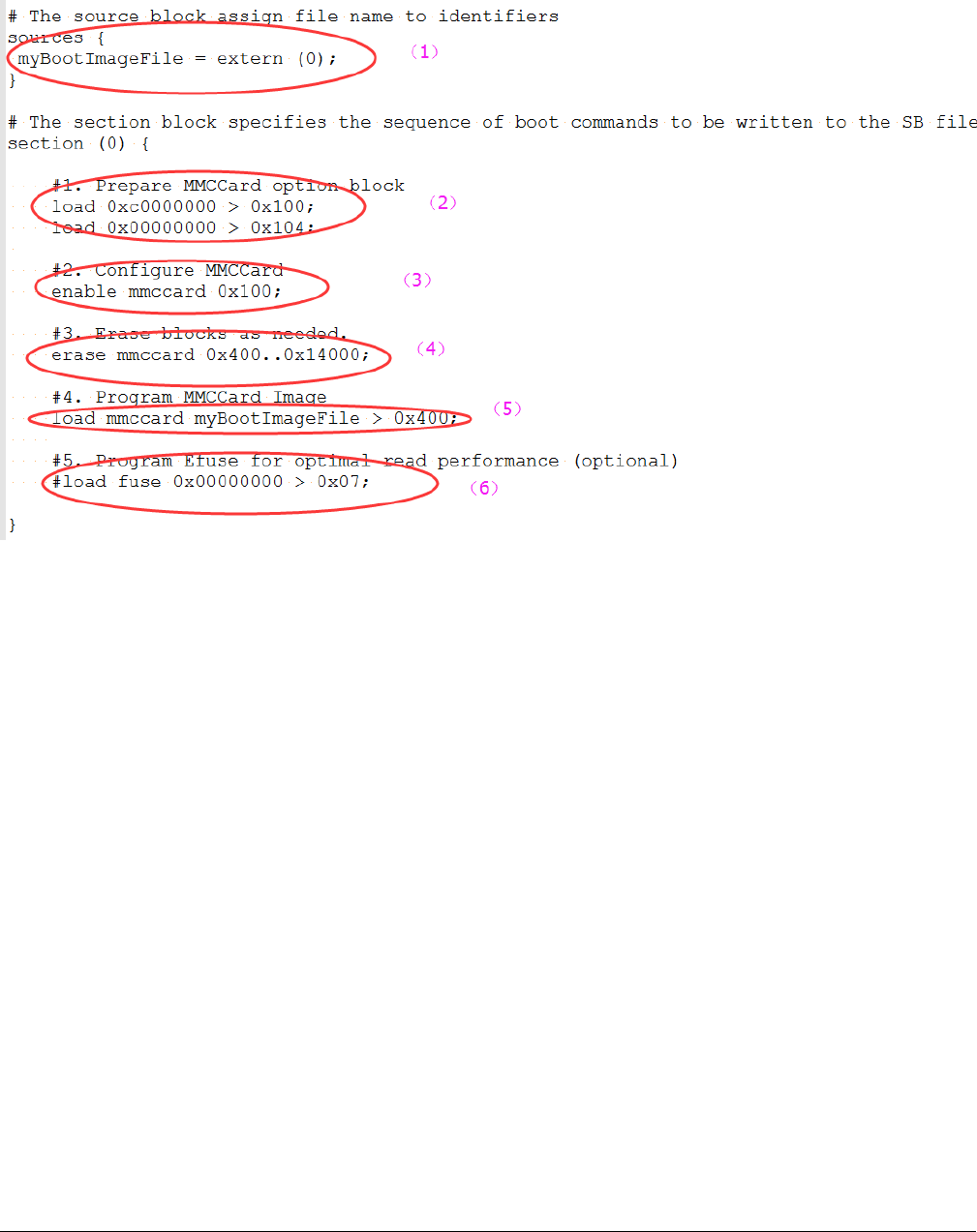
4. Erase eMMC card memory as needed
5. Program boot image binary into eMMC
6. Program optimal eMMC boot parameters into Fuse (optional, remove it if it is not required in actual project).
Figure 12. Example BD file for eMMC boot image programming for Normal boot mode
5.4.2 Fast Mode
There are nine steps in the BD file to program the bootable image to eMMC for Fast boot mode.
1. The bootable image file path is provided in “sources” block
2. Prepare eMMC option block and enable eMMC access using “enable” command
3. Erase eMMC card memory as needed.
4. Program boot image binary into eMMC
5. Program optimal eMMC boot parameters into Fuse (optional, remove it if it is not required in actual project).
6. Prepare 2nd eMMC option block
7. Re-enable eMMC access using new option block
8. Erase data in User Data area as required
9. Load User Data file to User Data area
Generate SB file for bootable image programming
i.MX RT1050 Manufacturing User's Guide, Rev. 3, December 2018
34 NXP Semiconductors
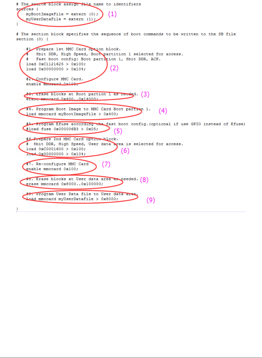
Figure 13. Example BD file for eMMC boot image programming for Fast boot mode
The BD file for encrypted eMMC boot image and KeyBlob programming is similar to SD.
5.5 Generate SB file for Serial NOR/EEPROM image
programming
There are five steps in the BD file to program the bootable image to SD card.
1. The bootable image file path is provided in sources block
2. Prepare Serial NOR/EEPROM option block and enable Serial NOR/EEPROM access using enable command.
3. Erase Serial NOR/EEPROM memory as required
4. Program boot image binary into Serial NOR/EEPROM device
5. Enable Recovery Boot via Serial NOR/EEPROM as required
An example is shown the figure below.
Generate SB file for Serial NOR/EEPROM image programming
i.MX RT1050 Manufacturing User's Guide, Rev. 3, December 2018
NXP Semiconductors 35
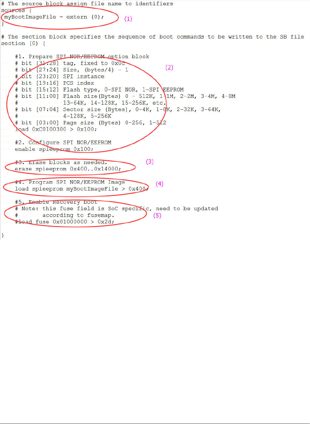
Figure 14. Example BD file for Serial NOR/EEPROM boot image programming
The BD file for encrypted SPI EEPRM/NOR boot image and KeyBlob programming is similar to SD.
5.6 Generate SB file for SEMC NOR image programming
In general, there are 5 steps in the BD file to program the bootable image to SD card.
1. The bootable image file path is provided in sources block
2. Prepare SEMC NOR option block and SEMC NOR access using enable command.
3. Erase SEMC NOR memory as required
4. Program boot image binary into SEMC NOR device
5. Program optimal SEMC NOR access parameters to Fuse as required
An example BD file is shown in the figure below.
Generate SB file for bootable image programming
i.MX RT1050 Manufacturing User's Guide, Rev. 3, December 2018
36 NXP Semiconductors
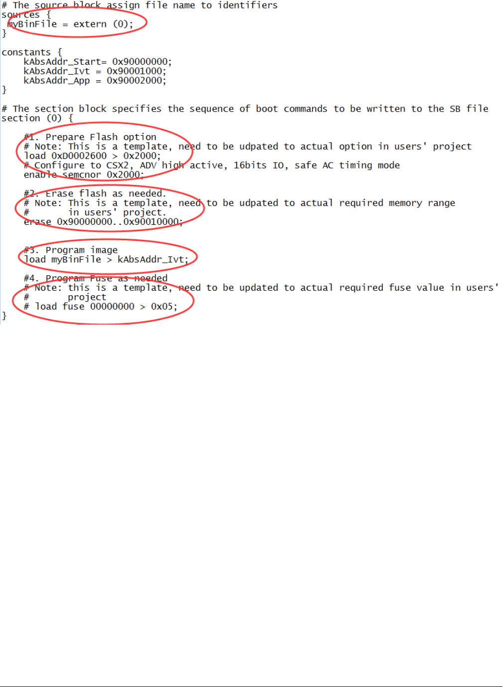
Figure 15. Example BD file for SEMC NOR boot image programming
5.7 Generate SB file for SEMC NAND image programming
There are 5 steps in the BD file to program the bootable image to SD card.
1. The bootable image file path is provided in sources block
2. Prepare SEMC NAND FCB option block and SEMC NAND access using enable command
3. Erase SEMC NAND memory as required
4. Program boot image binary into SEMC NAND device
5. Program optimal SEMC NAND access parameters to Fuse as required
An example is shown in figure below.
Generate SB file for SEMC NAND image programming
i.MX RT1050 Manufacturing User's Guide, Rev. 3, December 2018
NXP Semiconductors 37
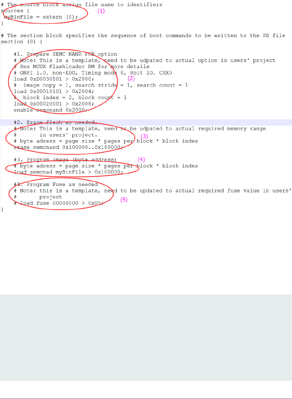
Figure 16. Example BD file for SEMC NAND boot image programming
5.8 Generate SB file for fuse program
In certain cases, the fuse must be programmed first to enable specific features for selected boot devices or security levels. For
example, to enable Fast boot mode for eMMC, enable HAB closed mode, the fuse must be programmed first.
The elftosb utility can support programming Fuse using built-in supported “load fuse” command, an example to program SRK
table and enable HAB closed mode is shown as follows.
# The source block assign file name to identifiers
sources {
}
constants {
}
section (0) {
# Program SRK table
load fuse 0xD132E7F1 > 0x18;
load fuse 0x63CD795E > 0x19;
load fuse 0x8FF38102 > 0x1A;
Generate SB file for bootable image programming
i.MX RT1050 Manufacturing User's Guide, Rev. 3, December 2018
38 NXP Semiconductors

load fuse 0x22A78E77 > 0x1B;
load fuse 0x01019c82 > 0x1C;
load fuse 0xFC3AC699 > 0x1D;
load fuse 0xF2C327A3 > 0x1E;
load fuse 0xDAC9214E > 0x1F;
# Program SEC_CONFIG to enable HAB closed mode
load fuse 0x00000002 > 0x06;
}
Generate SB file for fuse program
i.MX RT1050 Manufacturing User's Guide, Rev. 3, December 2018
NXP Semiconductors 39
Chapter 6
Program bootable image
Bootable image programming is supported by MfgTool only.
6.1 MfgTool
The MfgTool supports i.MX RT Boot ROM and MCUBOOT-based Flashloader. It can be used in factory production environment.
The MfgTool can detect i.MX RT Boot ROM devices connected to PC and invokes “blhost” to program the image on target memory
devices connected to i.MX RT device.
The template of MfgTool configuration profile is provided along with this document. It is applicable to most use cases without any
modifications.
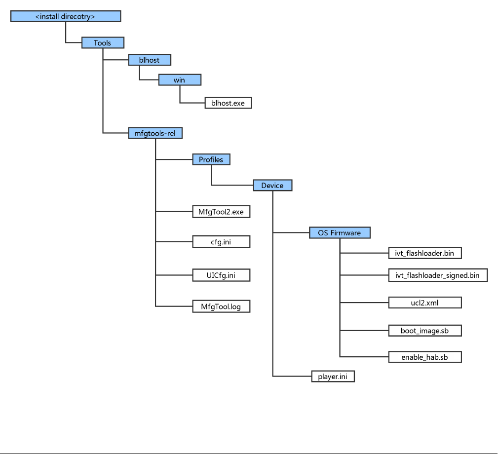
6.1.1 MfgTool Directory structure
Figure 17. MfgTool organization
Program bootable image
i.MX RT1050 Manufacturing User's Guide, Rev. 3, December 2018
40 NXP Semiconductors
1. In the release package, the mfgtools-rel folder appears in the tools folder along with blhost folder
2. The blhost.exe appears in the blhost/win folder and the MfgTools executable “MfgTool2.exe”
3. The Profiles folder contains the profile for the supported devices that include an “OS Firmware” folder and player.ini file
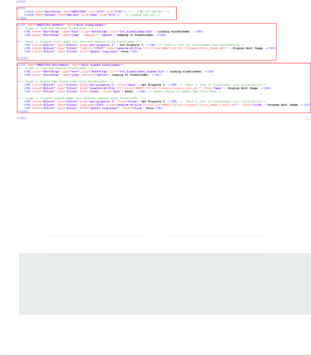
4. The ucl2.xml file in the OS Firmware folder is the main XML that MfgTool processes. It contains the flow of the manufacturing
process for the device. The process includes identification parameters for the device and blhost commands parameter to
identify the device connected to the PC host and a set of blhost commands required for updating the image. The ucl2.xml
file can be customized to suit custom setup or manufacturing process flow. The folder contains an example xml files for
user’s reference. An example ucl2.xml is shown below. In general, it defines the supported states and lists
Figure 18. Example UCL2.xml settings
5. The “ivt_flashloader.bin” file under the “OS firmware” is the Flashloader released to support image programming
6. The “ivt_flashloader_signed.bin” file under the “OS firmware” is the bootable Flashloader image file generated by users for
SecureBoot solution in production phase, it can be generated by following section 4.3
7. The “boot_image.sb” file under the “OS firmware” is the wrapped file with command sequences and bootable images
generated using elftosb utility by users
8. The “enable_hab.sb” file under the “OS firmware” is the wrapped file with command sequences that programs Fuses to
enable HAB closed mode, which is generated using elftosb utility by users
9. The play.ini in the “Device” profile folder contains configurable parameters for the manufacturing tool application
10. The cfg.ini and UICfg.ini files provide customizable parameters for the look and feel of the tool’s GUI. The cfg.ini in tool’s
GUI is used to select “chip”, “platform” and “name” in list. Refer to the example below
Select appropriate “chip” from Device list, “name” from list in ucl2.xml in Device/OS Firmware folder.
NOTE
[profiles]
chip = MXRT105X
[platform]
board =
[LIST]
name = MXRT105X-DevBoot
11. UlCfg.ini is used to select the number of instances supported by MfgTool UI. The valid instance range is 1-4
MfgTool
i.MX RT1050 Manufacturing User's Guide, Rev. 3, December 2018
NXP Semiconductors 41
12. The MfgTool.log text file is a useful tool to debug failures reported on MfgTool UI. The MfgTool logs the entire command
line string which was used to invoke blhost and collects the output response text the blhost puts out on stdout into the
MfgTool log file. The log file should be the considered first while troubleshooting
6.1.2 Preparation before image programming using MfgTool
See Chapter 4, Generate i.MX RT bootable image and Chapter 5, Generate SB file for bootable image programming for more
details.
6.2 Connect to the i.MX RT Platform
The i.MX RT platform can be connected to a host computer to interface with the i.MX RT Boot ROM application. After the platform
is connected in serial downloader mode, use the MfgTool to program bootable image into the target flash memory. If the connection
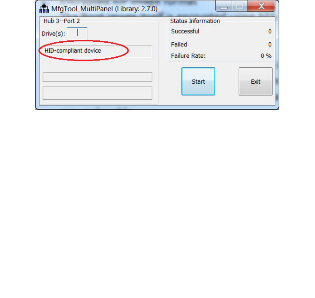
establishes successfully and the cfg.ini, UlCfg.ini are configured appropriately, the device will be recognized by MfgTool figure
below.
Figure 19. MfgTool GUI with device connected
6.3 Program bootable image during development
In development phase, the device may be in HAB open mode for most use cases. Users can configure the “name” field in cfg.ini
file as <Device>-DevBoot, then prepare the boot_image.sb file using elftosb utility. After the “boot_image.sb” is generated, place
it into “<Device>/OS Firmware/” folder. Then put device into serial downloader mode and connect it to host PC. After opening the
MfgTool.exe and click “Start” to trigger a programming sequence. When the programming completes, the window shown in figure
below appears. To exit MfgTool, click “Stop” and “Exit” in turn.
Program bootable image
i.MX RT1050 Manufacturing User's Guide, Rev. 3, December 2018
42 NXP Semiconductors
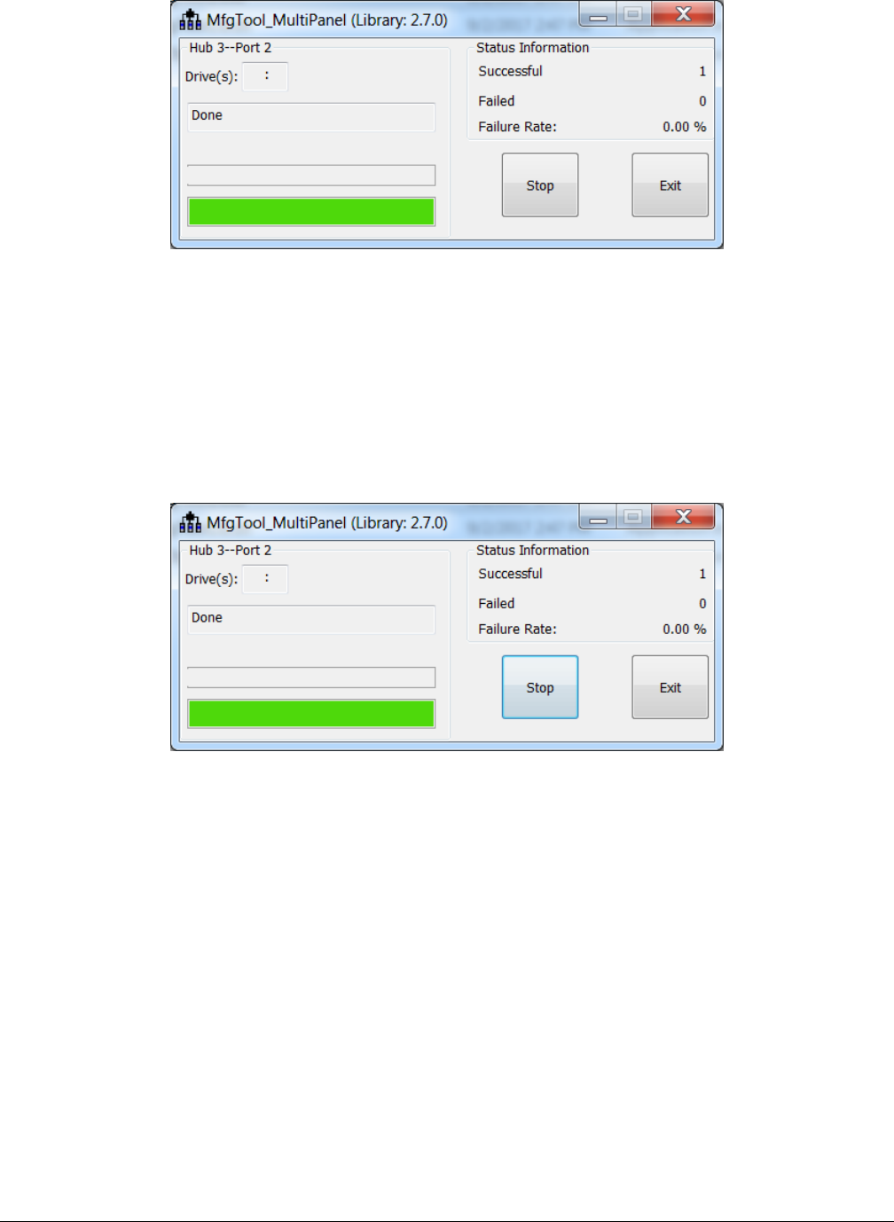
Figure 20. Successful result for programming with MfgTool for DevBoot
6.4 Program bootable image for production
In production phase, the device can be in HAB closed mode for most use cases. Users can configure the “name” field in cfg.ini
file as <Device>-SecureBoot, then prepare the boot_image.sb file, enable_hab.sb and ivt_flashloader_signed.bin using elftosb
utility. After all are generated, place them into “<Device>/OS Firmware/” folder, then put device in serial downloader, connect it to
host PC. Open MfgTool.exe and click “Start” to trigger a programming sequence. After the programming completes, the below
window will be seen. To exit MfgTool, click “Stop” and “Exit” in turn.
Figure 21. Successful result for programming with MfgTool for SecureBoot
Program bootable image for production
i.MX RT1050 Manufacturing User's Guide, Rev. 3, December 2018
NXP Semiconductors 43

Chapter 7
Appendix
7.1 Plugin boot application
The plugin boot application is usually used to enable boot features that are not natively supported by Boot ROM, for example,
• Boot from USB disk
• Boot from Ethernet,
• DDR/SDRAM configuration
• Redundant boot/reliable boot
The prototype of plugin boot application is:
bool (*plugin_download)(void **start, size_t *bytes, uint32_t *ivt_offset);
7.1.1 Principles for Plugin boot application design
The Boot ROM needs to jump between Plugin boot image and the normal boot image that is loaded by the plugin boot application.
To avoid any impact on the ROM boot flow, here are some recommended principles for plugin boot application design.
1. The plugin boot application must not use the memory that is currently reserved for ROM use
2. The plugin boot application should use minimum stack spaces to avoid the possibility of stack overflow caused by plugin
boot application
3. The plugin boot application must consider Watchdog service, if the WDOG enable bit is enabled in the Fuse block
7.1.2 Boot Flow of Plugin boot application
The boot flow for Plugin boot application is as follows
1. Boot ROM loads the XIP plugin boot image, does authentication and execution and then jump to plugin boot application
2. The plugin boot application loads the signed Non-XIP image from address 0x60008000 and jumps back to Boot ROM
3. Boot ROM does authentication/decryption based on the parameters output by plugin boot application and jumps to the
non-XIP boot image after authenticating successfully
7.1.3 Example Plugin boot application to enable non-XIP boot on
FlexSPI NOR
The Non-XIP boot case is not natively supported by some i.MX RT Boot ROM devices. In this case, a simple plugin boot image
can be created to enable non-XIP boot case for these boot devices.
The basic flow of how Plugin boot works is as follows:
Here are the example codes for plugin boot application for RT10xx FlexSPI NOR boot.
#define BOOT_IMAGE_LOAD_BASE 0x60008000
enum
{
kTag_HAB_IVT = 0xd1,
};
Appendix
i.MX RT1050 Manufacturing User's Guide, Rev. 3, December 2018
44 NXP Semiconductors

typedef struct _hab_hdr
{
uint8_t tag;
uint8_t len[2];
uint8_t version;
} hab_hdr_t;
typedef struct _hab_ivt
{
hab_hdr_t hdr;
uint32_t entry;
uint32_t reserved1;
uint32_t dcd;
uint32_t boot_data;
uint32_t self;
uint32_t csf;
uint32_t reserved2;
} hab_ivt_t;
//!@brief Boot data structure
typedef struct _boot_data
{
uint32_t start;
uint32_t length;
uint32_t plugin;
uint32_t reserved;
} boot_data_t;
//!@brief Boot Image header, including both IVT and BOOT_DATA
typedef struct _boot_image_hdr
{
hab_ivt_t ivt;
boot_data_t boot_data;
} boot_image_hdr_t;
/*!@brief Plugin Download function
*
* This function is used to copy non-xip boot image from Flash to RAM
*
*/
bool plugin_download(void **start, size_t *bytes, uint32_t *ivt_offset)
{
bool result = false;
const boot_image_hdr_t *boot_hdr;
//Search IVT
uint32_t ivt_offset_list[3] = {0, 0x400, 0x1000};
uint32_t search_index = 0;
while (search_index < sizeof(ivt_offset_list) / sizeof(ivt_offset_list[0]))
{
boot_hdr = (const boot_image_hdr_t *)(ivt_offset_list[search_index] +
BOOT_IMAGE_LOAD_BASE);
if (boot_hdr->ivt.hdr.tag != kTag_HAB_IVT)
{
search_index++;
continue;
}
*start = (void *)boot_hdr->boot_data.start;
Plugin boot application
i.MX RT1050 Manufacturing User's Guide, Rev. 3, December 2018
NXP Semiconductors 45

*bytes = boot_hdr->boot_data.length;
*ivt_offset = boot_hdr->ivt.self - boot_hdr->boot_data.start;
uint32_t *dst = (uint32_t *)boot_hdr->boot_data.start;
uint32_t *src = (uint32_t *)((uint32_t)boot_hdr - *ivt_offset);
size_t remaining_length = ((*byte + 3) & ~0x03) / 4;
while (remaining_length--)
{
*dst++ = *src++;
}
result = true;
break;
}
return result;
}
7.1.4 Images loaded by plugin boot application
The image loaded by Plugin boot application can be either XIP image or the non-XIP image. Refer to Chapter 4, Generate i.MX
RT bootable image for more details.
7.2 Example of complete manufacturing flow
Taking a pre-compiled led-demo as an example, a quick start guide is provided in this section to demonstrate the complete
manufacturing flow for FlexSPI NOR boot based on RT1050-EVK board.
7.2.1 Manufacturing process in Development phase
In development phase, mostly the image is unsigned and it is mainly for functional test.
7.2.1.1 Create i.MX RT bootable image
Following Chapter 4, based on the memory map assigned for RT105x SoC, here are the steps to generate i.MX RT bootable
image using elftosb utility.
1. Generate the BD file for boot image generation. The BD file content is showed as follows.
options {
flags = 0x00;
startAddress = 0x60000000;
ivtOffset = 0x1000;
initialLoadSize = 0x2000;
}
sources {
elfFile = extern(0);
}
section (0)
{
}
2. Generate the i.MX RT bootable image using elftosb utility.
Appendix
i.MX RT1050 Manufacturing User's Guide, Rev. 3, December 2018
46 NXP Semiconductors

Here is the example command:
Figure 22. Example command to generate FlexSPI NOR boot image
• ivt_flexspi_nor_xip.bin
• ivt_flexspi_nor_xip_nopadding.bin
The ivt_flexspi_nor_xip_nopadding.bin will be used to generate SB file for HyperFlash programming in subsequent section.
7.2.1.2 Create SB file for HyperFlash programming
An example to generate the SB file for HyperFlash programming for RT1050-EVKB board is shown as follows.
# The source block assign file name to identifiers
sources {
myBinFile = extern (0);
}
constants {
kAbsAddr_Start= 0x60000000;
kAbsAddr_Ivt = 0x60001000;
kAbsAddr_App = 0x60002000;
}
# The section block specifies the sequence of boot commands to be written to the SB file
section (0) {
#1. Prepare Flash option
# 0xc0233007 is the tag for Serial NOR parameter selection
# bit [31:28] Tag fixed to 0x0C
# bit [27:24] Option size fixed to 0
# bit [23:20] Flash type option
# 0 - QuadSPI SDR NOR
# 1 - QUadSPI DDR NOR
# 2 - HyperFLASH 1V8
# 3 - HyperFLASH 3V
# 4 - Macronix Octal DDR
# 6 - Micron Octal DDR
# 8 - Adesto EcoXIP DDR
# bit [19:16] Query pads (Pads used for query Flash Parameters)
# 0 - 1
# 2 - 4
# 3 - 8
# bit [15:12] CMD pads (Pads used for command)
# 0 - 1
# 2 - 4
# 3 - 8
# bit [11: 08] fixed to 0
# bit [07: 04] fixed to 0
# bit [03: 00] Flash Frequency, device specific
#
# In this example, the 0xc0233007 represents:
# HyperFLASH 1V8, Query pads: 8 pads, Cmd pads: 8 pads, Frequency: 133MHz
load 0xc0233007 > 0x2000;
# Configure HyperFLASH using option a address 0x2000
enable flexspinor 0x2000;
Example of complete manufacturing flow
i.MX RT1050 Manufacturing User's Guide, Rev. 3, December 2018
NXP Semiconductors 47
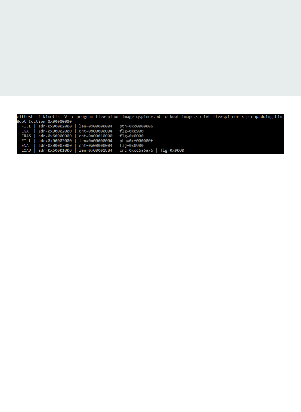
#2 Erase flash as needed.(Here only 1MBytes are erased)
erase 0x60000000..0x60100000;
#3. Program config block
# 0xf000000f is the tag to notify Flashloader to program FlexSPI NOR config block to the start of
device
load 0xf000000f > 0x3000;
# Notify Flashloader to response the option at address 0x3000
enable flexspinor 0x3000;
#5. Program image
load myBinFile > kAbsAddr_Ivt;
}
After the BD file is ready, the next step is to generate the boot_image.sb file that is for MfgTool use later. Here is the example
command:
Figure 23. Example command to generate SB file for FlexSPI NOR programming
After performing above command, the boot_image.sb is generated in elftosb utility folder.
7.2.1.3 Program Image to Flash using MfgTool
Use the following steps to program a boot image into a flash device
1. Copy the boot_image.sb file to “<mfgtool_root_dir>/Profiles/device_name/OS Firmware” folder
2. Change the “name” under “[List]” to MXRT105x-SecureBoot in cfg.ini file in <mfgtool_root_dir> folder
3. Put the device_name-EVK board to Serial Downloader mode by setting SW7 to “1-OFF, 2-ON, 3-OFF, 4-ON”
4. Power up device_name-EVK board and insert USB cable to J9
5. Open MfgTool, it will show as the detected device like the one shown in Figure 19 .
6. Click “Start”, MfgTool will do manufacturing process. After completion, it will show the status as success as shown in
Figure 20. Click “Stop” and close the MfgTool
7. Put the device_name-EVK board to internal boot mode and select HyperFlash as boot device by setting SW7 to “1-OFF,
2-ON, 3-ON, 4-OFF”. Then reset the device to start running application.
7.2.2 Manufacturing process in Production phase
In production phase, the image requires to be signed and even encrypted. In this case, the device must be configured to HAB
closed mode.
Assuming the PKI tree is ready for cst use, copy “ca”, “crts”, and “keys” folder and cst executable to the folder that holds elftosb
utility executable, as shown below
Appendix
i.MX RT1050 Manufacturing User's Guide, Rev. 3, December 2018
48 NXP Semiconductors
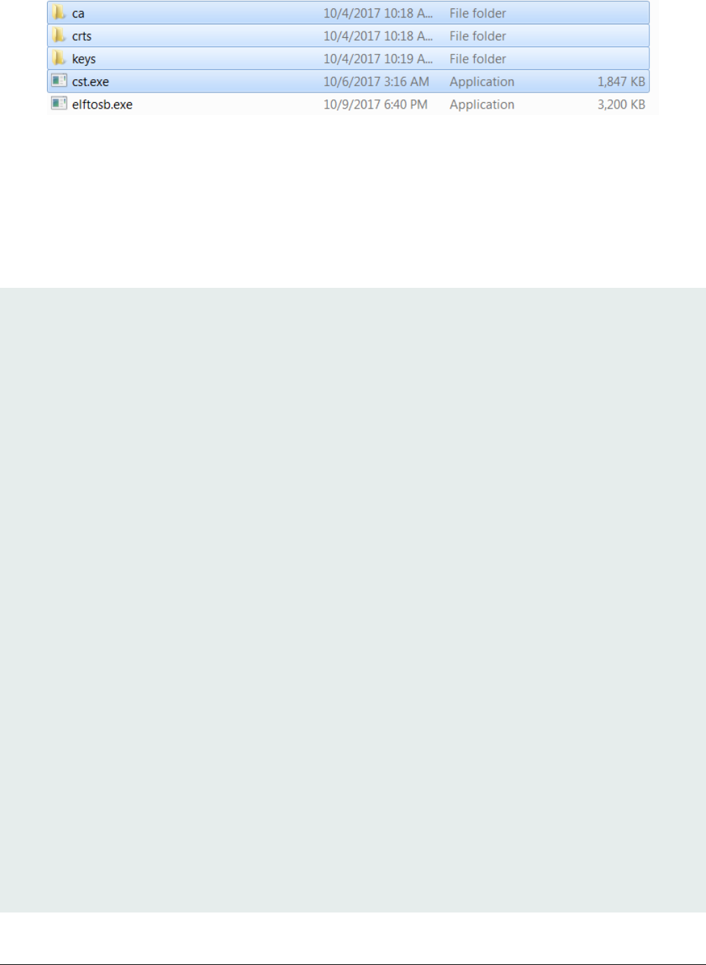
Figure 24. Copy required key and certs for signed image generation
7.2.2.1 Generate signed i.MX RT bootable image
To generate a bootable image for a specific memory, users need to know the memory map of i.MX RT device SoC. Details of
generating bootable image can be found in Chapter 4. Here are the steps to generate signed i.MX RT bootable image using elftosb
utility.
1. Generate the BD file for boot image generation. The BD file content is showed in figure below. It is also available in the
release package in “<sdk_package>/middleware/mcu-boot/bin/Tools/bd_file/imxrt10xx” folder.
options {
flags = 0x08;
startAddress = 0x0000000;
ivtOffset = 0x1000;
initialLoadSize = 0x2000;
//DCDFilePath = "dcd.bin";
# Note: This is required if the cst and elftsb are not in the same folder
//cstFolderPath = "path/CSTFolder";
# Note: This is required if the default entrypoint is not the Reset_Handler
# Please set the entryPointAddress to base address of Vector table
//entryPointAddress = 0x0002000;
}
sources {
elfFile = extern(0);
}
constants {
SEC_CSF_HEADER = 20;
SEC_CSF_INSTALL_SRK = 21;
SEC_CSF_INSTALL_CSFK = 22;
SEC_CSF_INSTALL_NOCAK = 23;
SEC_CSF_AUTHENTICATE_CSF = 24;
SEC_CSF_INSTALL_KEY = 25;
SEC_CSF_AUTHENTICATE_DATA = 26;
SEC_CSF_INSTALL_SECRET_KEY = 27;
SEC_CSF_DECRYPT_DATA = 28;
SEC_NOP = 29;
SEC_SET_MID = 30;
SEC_SET_ENGINE = 31;
SEC_INIT = 32;
SEC_UNLOCK = 33;
}
section (SEC_CSF_HEADER;
Header_Version="4.2",
Header_HashAlgorithm="sha256",
Header_Engine="DCP",
Header_EngineConfiguration=0,
Header_CertificateFormat="x509",
Example of complete manufacturing flow
i.MX RT1050 Manufacturing User's Guide, Rev. 3, December 2018
NXP Semiconductors 49

Header_SignatureFormat="CMS")
{
}
section (SEC_CSF_INSTALL_SRK;
InstallSRK_Table="keys/SRK_1_2_3_4_table.bin", // "valid file path"
InstallSRK_SourceIndex=0)
{
}
section (SEC_CSF_INSTALL_CSFK;
InstallCSFK_File="crts/CSF1_1_sha256_2048_65537_v3_usr_crt.pem", // "valid file path"
InstallCSFK_CertificateFormat="x509") // "x509"
{
}
section (SEC_CSF_AUTHENTICATE_CSF)
{
}
section (SEC_CSF_INSTALL_KEY;
InstallKey_File="crts/IMG1_1_sha256_2048_65537_v3_usr_crt.pem",
InstallKey_VerificationIndex=0, // Accepts integer or string
InstallKey_TargetIndex=2) // Accepts integer or string
{
}
section (SEC_CSF_AUTHENTICATE_DATA;
AuthenticateData_VerificationIndex=2,
AuthenticateData_Engine="DCP",
AuthenticateData_EngineConfiguration=0)
{
}
section (SEC_SET_ENGINE;
SetEngine_HashAlgorithm = "sha256", // "sha1", "Sha256", "sha512"
SetEngine_Engine = "DCP", // "ANY", "SAHARA", "RTIC", "DCP", "CAAM" and "SW"
SetEngine_EngineConfiguration = "0") // "valid engine configuration values"
{
}
section (SEC_UNLOCK;
Unlock_Engine = "SNVS, OCOTP", // "SRTC", "CAAM", SNVS and OCOTP
Unlock_features = "ZMK WRITE, SRK REVOKE")
{
}
2. Generate the i.MX RT bootable image using elftosb utility file.
Here is the example command:
After above command, two bootable images are generated:
• ivt_flexspi_nor_xip_signed.bin
• ivt_flexspi_nor_xip_signed_nopadding.bin
The ivt_flexspi_nor_xip_signed_nopadding.bin will be used to generate SB file for HyperFlash programming in subsequent
section.
Appendix
i.MX RT1050 Manufacturing User's Guide, Rev. 3, December 2018
50 NXP Semiconductors
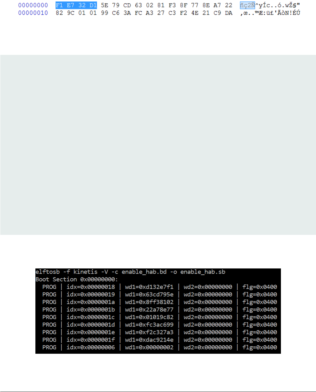
7.2.2.2 Create SB file for Fuse programming
In the keys folder, there is a file named “SRK_1_2_3_4_fuse.bin”. This is the HASH table for SRK authentication during boot. It
must be programmed to fuses to enable secure boot mode.
Below is an example file
Figure 25. Example SRK_1_2_3_4_fuse.bin file
Below is an example BD file which shows the procedure to program fuses. The fuse field is a 32-bit long word data. It will be
programmed into fuses by Flashloader in little-endian mode.
# The source block assign file name to identifiers
sources {
}
constants {
}
# The section block specifies the sequence of boot commands to be written to the SB file
# Note: this is just a template, please update it to actual values in users' project
section (0) {
# Program SRK table
load fuse 0xD132E7F1 > 0x18;
load fuse 0x63CD795E > 0x19;
load fuse 0x8FF38102 > 0x1A;
load fuse 0x22A78E77 > 0x1B;
load fuse 0x01019c82 > 0x1C;
load fuse 0xFC3AC699 > 0x1D;
load fuse 0xF2C327A3 > 0x1E;
load fuse 0xDAC9214E > 0x1F;
# Program SEC_CONFIG to enable HAB closed mode
load fuse 0x00000002 > 0x06;
}
The last command in above BD file is used to enable HAB closed mode by setting SEC_CONFIG [1] bit in the fuse to 1.
After BD file is ready, the next step is to create SB file for Fuse programming to enable HAB closed mode.
An example command is shown below:
Figure 26. Example command to generate SB file for Fuse programming
Example of complete manufacturing flow
i.MX RT1050 Manufacturing User's Guide, Rev. 3, December 2018
NXP Semiconductors 51
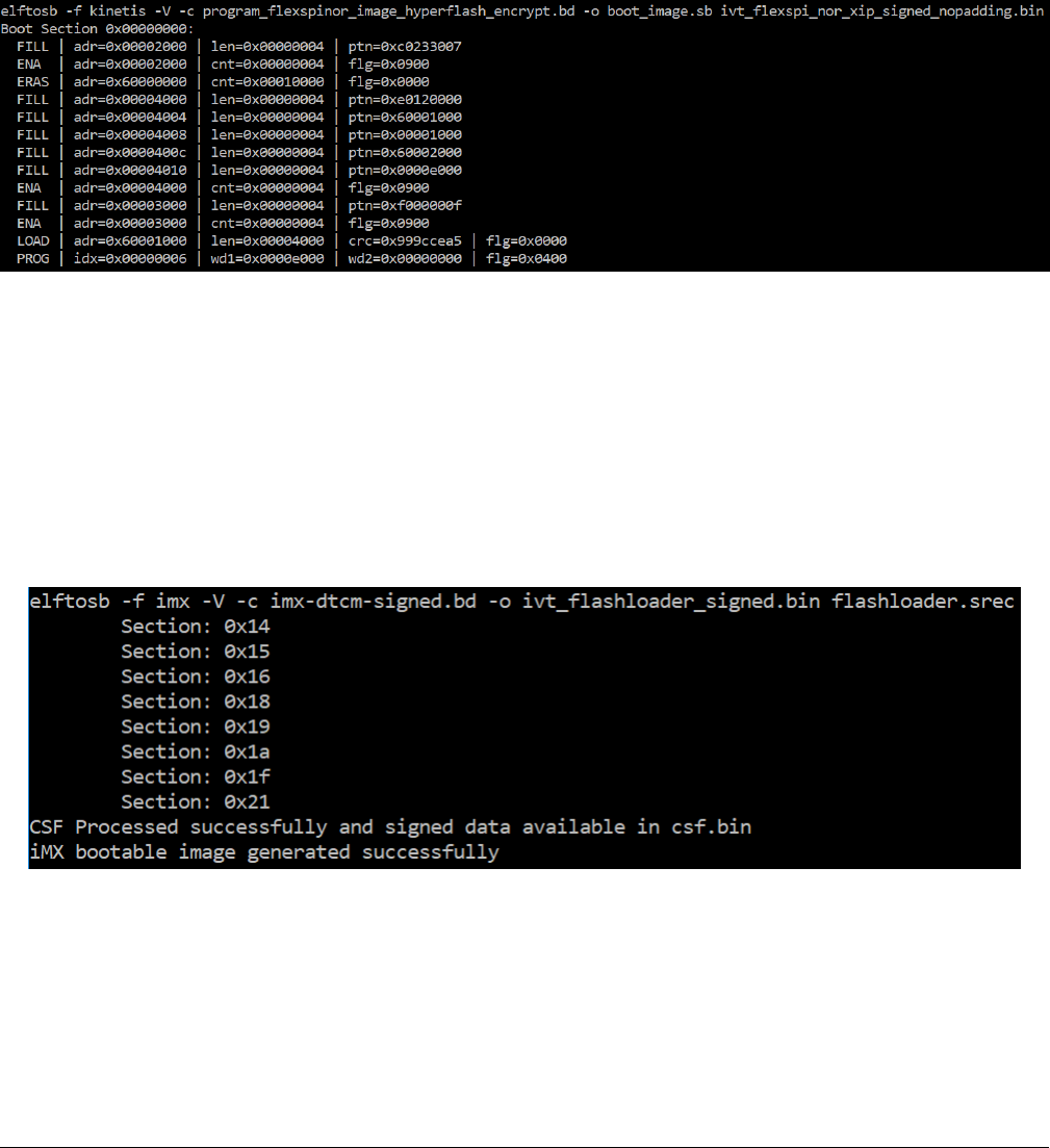
After the command “enable_hab.bd -o enable_hab.sb” in Figure above is executed, a file named “enable_hab.sb” gets generated.
It is required in MfgTool for SecureBoot solution.
7.2.2.3 Create SB file for Image encryption and programming for
Hyper Flash
Following chapter 5, here is an example to generate the SB file for image encryption and programming on HyperFlash for RT1050-
EVK board.
Refer to the BD file in Section 5.1.3, Generate SB file for FlexSPI NOR Image encryption and programming.
After the BD file is ready, the next step is to generate the SB file. Refer below for an example command.
Figure 27. Example command to generate SB file for FlexSPI NOR image encryption and programming
After the command “program_flexspinor_image_hyperflash_encrypt.bd -o boot_image.sb
ivt_flexspi_nor_xip_signed_nopadding.bin” in Figure above , a file named “boot_image.sb” is generated in the folder that contains
elftosb utility executable.
7.2.2.4 Create signed Flashloader image
The BD file for signed Flashloader image generation is similar as the one in section Generate signed i.MX bootable image
The only difference is that the startAddress is 0x20000000 and IVTOffset is 0x400.
After the BD file is ready, the next step is to generate i.MX boot image using elftosb utility. The example command is as below:
Figure 28. Example command for Signed Flashloader image generation
After the command “imx-dtcm-signed.bd -o ivt_flashloader_signed.bin flashloader.srec” in Figure above , two bootable images
are generated:
• ivt_flashloader_signed.bin
• ivt_flashloader_signed_nopadding.bin
Appendix
i.MX RT1050 Manufacturing User's Guide, Rev. 3, December 2018
52 NXP Semiconductors
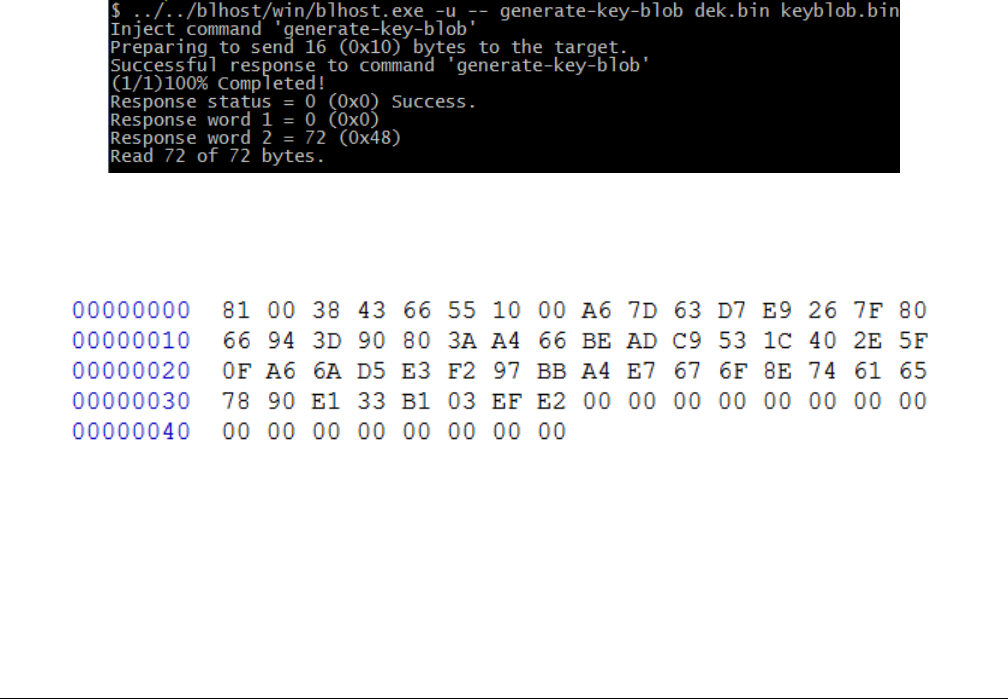
The first one is required by MfgTool for Secure Boot.
7.2.2.5 Program Image to Flash using MfgTool
Here are the steps to program boot image into Flash device
1. Copy the boot_image.sb file, ivt_flashloader_signed.bin and enable_hab.sb to “<mfgtool_root_dir>/Profiles/
device_name/OS Firmware” folder
2. Change the “name” under “[List]” to device_name-SecureBoot in cfg.ini file in <mfgtool_root_dir> folder
3. Put the device_name-EVK board to Serial Downloader mode by setting SW7 to “1-OFF, 2-ON, 3-OFF, 4-ON”
4. Power up device_name-EVK board, and insert USB cable to J9
5. Open MfgTool, it will show the detected device like the one shown in Figure 19 .
6. Click “Start”, MfgTool will do manufacturing process and after completion, it will show the status as success as shown in
Figure 20 . Click “Stop” and close the MfgTool
7. Put the device_name-EVK board to internal boot mode and select HyperFlash as boot device by setting SW7 to “1-OFF,
2-ON, 3-ON, 4-OFF”. Then reset the device to start running the application.
7.3 Generate KeyBlob manually
Users may need to generate the Keyblob manually in some cases. Flashloader supports such usage with blhost.
The KeyBlob must be generated when the device works under HAB closed mode with signed Flashloader application.
Assuming the dek.bin is ready (generated by elftosb utility during encrypted image generation). Here is an example command to
generate KeyBlob block.
Figure 29. Generate KeyBlob using Flashloader
After the command, “blhost.exe -u –generate-key-blob dek.bin keyblob.bin” in figure below is executed, a “keyblob.bin” file gets
generated.
Figure 30. Example KeyBlob
With the encrypted image generated by elftosb utility and keyblob.bin generated by flashloader, it is also feasible to combine the
encrypted image and keyblob.bin. Then create a complete encrypted boot image with a Hex Editor. In this example, the KeyBlob
offset is 0x18000 in the boot image.
Figure below is an example piece of encrypted image combined by Hex Editor.
Generate KeyBlob manually
i.MX RT1050 Manufacturing User's Guide, Rev. 3, December 2018
NXP Semiconductors 53

Figure 31. Create complete encrypted image using Hex editor
Appendix
i.MX RT1050 Manufacturing User's Guide, Rev. 3, December 2018
54 NXP Semiconductors

Chapter 8
Revision history
Table 19 summarizes the changes done to this document since the initial release.
Table 19. Revision history
Revision number Date Substantial changes
0 10/2017 Initial release
1 05/2018 MCU Bootloader v2.5.0 release
2 09/2018 MCU Bootloader v2.6.0 release
3 11/2018 MCU Bootloader v2.7.0 release
i.MX RT1050 Manufacturing User's Guide, Rev. 3, December 2018
NXP Semiconductors 55

How To Reach Us
Home Page:
nxp.com
Web Support:
nxp.com/support
Information in this document is provided solely to enable system and software implementers to
use NXP products. There are no express or implied copyright licenses granted hereunder to
design or fabricate any integrated circuits based on the information in this document. NXP
reserves the right to make changes without further notice to any products herein.
NXP makes no warranty, representation, or guarantee regarding the suitability of its products for
any particular purpose, nor does NXP assume any liability arising out of the application or use
of any product or circuit, and specifically disclaims any and all liability, including without limitation
consequential or incidental damages. “Typical” parameters that may be provided in NXP data
sheets and/or specifications can and do vary in different applications, and actual performance
may vary over time. All operating parameters, including “typicals,” must be validated for each
customer application by customer's technical experts. NXP does not convey any license under
its patent rights nor the rights of others. NXP sells products pursuant to standard terms and
conditions of sale, which can be found at the following address: nxp.com/
SalesTermsandConditions.
NXP, the NXP logo, NXP SECURE CONNECTIONS FOR A SMARTER WORLD, COOLFLUX,
EMBRACE, GREENCHIP, HITAG, I2C BUS, ICODE, JCOP, LIFE VIBES, MIFARE, MIFARE
CLASSIC, MIFARE DESFire, MIFARE PLUS, MIFARE FLEX, MANTIS, MIFARE ULTRALIGHT,
MIFARE4MOBILE, MIGLO, NTAG, ROADLINK, SMARTLX, SMARTMX, STARPLUG, TOPFET,
TRENCHMOS, UCODE, Freescale, the Freescale logo, AltiVec, C‑5, CodeTEST, CodeWarrior,
ColdFire, ColdFire+, C‑Ware, the Energy Efficient Solutions logo, Kinetis, Layerscape, MagniV,
mobileGT, PEG, PowerQUICC, Processor Expert, QorIQ, QorIQ Qonverge, Ready Play,
SafeAssure, the SafeAssure logo, StarCore, Symphony, VortiQa, Vybrid, Airfast, BeeKit,
BeeStack, CoreNet, Flexis, MXC, Platform in a Package, QUICC Engine, SMARTMOS, Tower,
TurboLink, and UMEMS are trademarks of NXP B.V. All other product or service names are the
property of their respective owners. Arm, AMBA, Arm Powered, Artisan, Cortex, Jazelle, Keil,
SecurCore, Thumb, TrustZone, and μVision are registered trademarks of Arm Limited (or its
subsidiaries) in the EU and/or elsewhere. Arm7, Arm9, Arm11, big.LITTLE, CoreLink, CoreSight,
DesignStart, Mali, Mbed, NEON, POP, Sensinode, Socrates, ULINK and Versatile are trademarks
of Arm Limited (or its subsidiaries) in the EU and/or elsewhere. All rights reserved. Oracle and
Java are registered trademarks of Oracle and/or its affiliates. The Power Architecture and
Power.org word marks and the Power and Power.org logos and related marks are trademarks
and service marks licensed by Power.org.
Ⓒ 2018 NXP B.V.
© NXP B.V. 2018. All rights reserved.
For more information, please visit: http://www.nxp.com
For sales office addresses, please send an email to: salesaddresses@nxp.com
Date of release: December 2018
Document identifier: IMXMCUMFUUG
