I.MX 6 Graphics User's Guide User’s
User Manual:
Open the PDF directly: View PDF ![]() .
.
Page Count: 150 [warning: Documents this large are best viewed by clicking the View PDF Link!]
- Chapter 1 Introduction
- Chapter 2 i.MX 6 G2D API
- Chapter 3 i.MX 6 EGL and OGL Extension Support
- Chapter 4 i.MX 6 Framebuffer API
- Chapter 5 OpenCL
- 5.1 Overview
- 5.2 Vivante OpenCL Implementation
- 5.3 Optimization for OpenCL Embedded Profile
- 5.3.1 Use preferred multiple of work-group size
- 5.3.2 Use multiple work-groups of reduced size
- 5.3.3 Pack work-item data
- 5.3.4 Improve locality
- 5.3.5 Minimize use of 1KB local memory
- 5.3.6 Use 16 Byte Memory Read/Write size
- 5.3.7 Use _RTZ rounding mode
- 5.3.8 Use native functions
- 5.3.9 Use Buffers instead of Images
- 5.4 OpenCL Debug Messages
- Chapter 6 Freescale XServer Video Driver
- Chapter 7 Vivante Software Tool Kit
- 7.1 Vivante Tool Kit overview
- 7.2 vEmulator
- 7.2.1 Supported operating systems and graphics hardware
- 7.2.2 vEmulator components
- 7.2.3 vEmulator for OpenCL
- 7.2.4 Supported extensions
- 7.2.5 vEmulator environment variable setup
- 7.2.6 Sample code overview
- 7.2.7 Building and running the code examples
- 7.2.8 OpenGL ES 1.1 examples
- 7.2.8.1 Tutorial1: rotating three-color triangle
- 7.2.8.2 Tutorial2: rotating six-color cube
- 7.2.8.3 Tutorial3: rotating multi-textured cube
- 7.2.8.4 Tutorial4: lighting and fog
- 7.2.8.5 Tutorial5: blending and bit-mapped fonts
- 7.2.8.6 Tutorial6: particles using point sprites
- 7.2.8.7 Tutorial7: vertex buffer objects
- 7.2.9 OpenGL ES 2.0 examples
- 7.3 vShader
- 7.4 vCompiler
- 7.5 vTexture
- 7.6 vProfiler and vAnalyzer
- 7.6.1 Fundamentals of performance optimization
- 7.6.2 vProfiler setup for the Linux OS
- 7.6.3 vProfiler setup for the Android platform
- 7.6.4 vProfiler collecting performance data
- 7.6.5 vAnalyzer viewing and analyzing a run-time profile
- 7.6.6 vAnalyzer charts
- 7.6.7 vAnalyzer viewers
- 7.7 vTracer
- 7.8 vPlayer
- 7.9 Debug and performance counters
- Chapter 8 Freescale GPU Tools
- Chapter 9 GPU Memory Introduction
- Chapter 10 Application Programming Recommendations
- 10.1 Understand the system configuration and target application
- 10.2 Optimize off chip data transfer such as accessing off-chip DDR memory/mobile DDR memory
- 10.3 Avoid random cache or memory accesses
- 10.4 Optimize your use of system memory
- 10.5 Target a fixed frame rate that is visibly smooth
- 10.6 Minimize GL state changes
- 10.7 Batch primitives to minimize the number of draw calls
- 10.8 Perform calculations per vertex instead of per fragment/pixel
- 10.9 Enable early-Z, hierarchical-Z and back face culling
- 10.10 Use branching carefully
- 10.11 Do not use static or stack data as vertex data - use VBOs instead
- 10.12 Use dynamic VBO if data is changing frame by frame
- 10.13 Tessellate your data so that Hierarchical Z (HZ) can do its job
- 10.14 Use dynamic textures as a texture cache (texture atlas)
- 10.15 If you use many small triangle strips, stitch them together
- 10.16 Specify EGL configuration attributes precisely
- 10.17 Use aligned texture/render buffers
- 10.18 Disable MSAA rendering unless high quality is needed
- 10.19 Avoid partial clears
- 10.20 Avoid mask operations
- 10.21 Use MIPMAP textures
- 10.22 Use compressed textures if constricted by RAM/ROM budget
- 10.23 Draw objects from near to far if possible
- 10.24 Avoid indexed triangle strips.
- 10.25 Vertex attribute stride should not be larger than 256 bytes
- 10.26 Avoid binding buffers to mixed index/vertex array
- 10.27 Avoid using CPU to update texture/buffer contexts during render
- 10.28 Avoid frequent context switching
- 10.29 Optimize resources within a shader
- 10.30 Avoid using glScissor Clear for small regions
- Chapter 11 Demo Framework
- 11.1 Summaries
- 11.2 Introduction
- 11.3 Design overview
- 11.4 High level overview
- 11.5 Demo application details
- 11.6 Helper Class Overview
- 11.7 Android SDK+NDK on Windows OS build guide
- 11.8 Ubuntu build guide
- 11.9 Windows OS build guide
- 11.10 Yocto build guide
- 11.11 FslContentSync.py notes
- 11.12 Roadmap – Upcoming features
- 11.13 Known limitations

Freescale Semiconductor Document Number: IMX6GRAPHICUG
Rev. L3.14.28_1.0.0-ga, 04/2015
© Freescale Semiconductor, Inc., 2015. All rights reserved.
i.MX 6 Graphics User’s Guide

i.MX 6 Graphics User’s Guide, Rev. L3.14.28_1.0.0-ga, 04/2015
2 Freescale Semiconductor
Contents
Chapter 1 Introduction ............................................................................................................................................. 5
Chapter 2 i.MX 6 G2D API ......................................................................................................................................... 5
2.1 Overview ...................................................................................................................................................... 5
2.2 Enumerations and structures ....................................................................................................................... 5
2.3 G2D function descriptions ............................................................................................................................ 9
2.4 Sample codes for G2D API usage ............................................................................................................... 13
Chapter 3 i.MX 6 EGL and OGL Extension Support ................................................................................................. 16
3.1 Introduction ............................................................................................................................................... 16
3.2 EGL extension support ............................................................................................................................... 16
3.3 OpenGL ES extension support .................................................................................................................... 18
3.4 Extension GL_VIV_direct_texture .............................................................................................................. 22
3.5 Extension GL_VIV_texture_border_clamp ................................................................................................. 25
Chapter 4 i.MX 6 Framebuffer API.......................................................................................................................... 27
4.1 Overview .................................................................................................................................................... 27
4.2 API data types and environment variables ................................................................................................ 27
4.3 API description and syntax ......................................................................................................................... 29
Chapter 5 OpenCL ................................................................................................................................................... 36
5.1 Overview .................................................................................................................................................... 36
5.2 Vivante OpenCL Implementation ............................................................................................................... 38
5.3 Optimization for OpenCL Embedded Profile .............................................................................................. 40
5.4 OpenCL Debug Messages ........................................................................................................................... 42
Chapter 6 Freescale XServer Video Driver .............................................................................................................. 44
6.1 EXA driver ................................................................................................................................................... 44
6.2 XRandR ....................................................................................................................................................... 45
Chapter 7 Vivante Software Tool Kit ...................................................................................................................... 56
7.1 Vivante Tool Kit overview .......................................................................................................................... 56
7.2 vEmulator ................................................................................................................................................... 57
7.3 vShader ...................................................................................................................................................... 68
7.4 vCompiler ................................................................................................................................................... 76
7.5 vTexture ..................................................................................................................................................... 80
7.6 vProfiler and vAnalyzer .............................................................................................................................. 84
7.7 vTracer ....................................................................................................................................................... 97
7.8 vPlayer ...................................................................................................................................................... 103
7.9 Debug and performance counters ........................................................................................................... 106
Chapter 8 Freescale GPU Tools ............................................................................................................................ 108

i.MX 6 Graphics User’s Guide, Rev. L3.14.28_1.0.0-ga, 04/2015
3 Freescale Semiconductor
8.1 gpuinfo tool .............................................................................................................................................. 108
8.2 gmem_info tool ........................................................................................................................................ 110
8.3 Freescale apitrace user guide................................................................................................................... 111
Chapter 9 GPU Memory Introduction .................................................................................................................. 117
9.1 GPU memory overview ............................................................................................................................ 117
9.2 GPU memory pools .................................................................................................................................. 117
9.3 GPU memory allocators ........................................................................................................................... 117
9.4 GPU reserved memory ............................................................................................................................. 118
9.5 GPU memory base address ...................................................................................................................... 118
Chapter 10 Application Programming Recommendations ................................................................................. 120
10.1 Understand the system configuration and target application ................................................................. 120
10.2 Optimize off chip data transfer such as accessing off-chip DDR memory/mobile DDR memory ............ 120
10.3 Avoid random cache or memory accesses ............................................................................................... 120
10.4 Optimize your use of system memory ..................................................................................................... 120
10.5 Target a fixed frame rate that is visibly smooth....................................................................................... 120
10.6 Minimize GL state changes ...................................................................................................................... 121
10.7 Batch primitives to minimize the number of draw calls .......................................................................... 121
10.8 Perform calculations per vertex instead of per fragment/pixel ............................................................... 121
10.9 Enable early-Z, hierarchical-Z and back face culling ................................................................................. 121
10.10 Use branching carefully ....................................................................................................................... 122
10.11 Do not use static or stack data as vertex data - use VBOs instead ...................................................... 122
10.12 Use dynamic VBO if data is changing frame by frame ......................................................................... 122
10.13 Tessellate your data so that Hierarchical Z (HZ) can do its job ............................................................ 123
10.14 Use dynamic textures as a texture cache (texture atlas) ..................................................................... 123
10.15 If you use many small triangle strips, stitch them together ................................................................ 123
10.16 Specify EGL configuration attributes precisely .................................................................................... 123
10.17 Use aligned texture/render buffers ..................................................................................................... 123
10.18 Disable MSAA rendering unless high quality is needed ....................................................................... 124
10.19 Avoid partial clears .............................................................................................................................. 124
10.20 Avoid mask operations ........................................................................................................................ 124
10.21 Use MIPMAP textures .......................................................................................................................... 124
10.22 Use compressed textures if constricted by RAM/ROM budget ........................................................... 124
10.23 Draw objects from near to far if possible ............................................................................................ 124
10.24 Avoid indexed triangle strips. .............................................................................................................. 124
10.25 Vertex attribute stride should not be larger than 256 bytes ............................................................... 125
10.26 Avoid binding buffers to mixed index/vertex array ............................................................................. 125

i.MX 6 Graphics User’s Guide, Rev. L3.14.28_1.0.0-ga, 04/2015
4 Freescale Semiconductor
10.27 Avoid using CPU to update texture/buffer contexts during render .................................................... 125
10.28 Avoid frequent context switching ........................................................................................................ 125
10.29 Optimize resources within a shader .................................................................................................... 125
10.30 Avoid using glScissor Clear for small regions ....................................................................................... 125
Chapter 11 Demo Framework ............................................................................................................................ 126
11.1 Summaries................................................................................................................................................ 126
11.2 Introduction ............................................................................................................................................. 126
11.3 Design overview ....................................................................................................................................... 127
11.4 High level overview .................................................................................................................................. 128
11.5 Demo application details ......................................................................................................................... 128
11.6 Helper Class Overview .............................................................................................................................. 133
11.7 Android SDK+NDK on Windows OS build guide ....................................................................................... 138
11.8 Ubuntu build guide .................................................................................................................................. 139
11.9 Windows OS build guide .......................................................................................................................... 142
11.10 Yocto build guide ................................................................................................................................. 144
11.11 FslContentSync.py notes ...................................................................................................................... 148
11.12 Roadmap – Upcoming features ........................................................................................................... 148
11.13 Known limitations ................................................................................................................................ 149

i.MX 6 Graphics User’s Guide, Rev. L3.14.28_1.0.0-ga, 04/2015
5 Freescale Semiconductor
Chapter 1 Introduction
The purpose of this document is to provide information on graphic APIs and driver support. Each chapter describes
a specific set of APIs or driver integration as well as specific hardware acceleration customization. The target
audiences for this document are developers writing graphics applications or video drivers.
Chapter 2 i.MX 6 G2D API
2.1 Overview
The G2D API (Application Programming Interface) is designed to be easy to understand and to use the 2D BLT
function. It allows the user to implement the customized applications with simple interfaces. It is hardware and
platform independent for i.MX 6 2D Graphics.
G2D API supports the following features but is not limited to these:
Simple BLT operation from source to destination
Alpha blending for source and destination with Porter-Duff rules
High performance memory copy from source to destination
Up-scaling and down-scaling from source to destination
90/180/270 degree rotation from source to destination
Horizontal and vertical flip from source to destination
Enhanced visual quality with dither for pixel precision-loss
High performance memory clear for destination
Pixel-level cropping for source surface
Global alpha blending for source only
Asynchronous mode and sync
Contiguous memory allocator
Support VG engine
The G2D API document includes a detailed interface description and sample code for reference.
The API is designed with C-Style coding and can be used in both C and C++ applications.
2.2 Enumerations and structures
This chapter describes all enumeration and structure definitions in G2D.
2.2.1 g2d_format enumeration
This enumeration describes the pixel format for source and destination.
Table 1 g2d_format enumeration
Name
Numeric
Description
G2D_RGB565
0
RGB565 pixel format
G2D_RGBA8888
1
32bit-RGBA pixel format
G2D_RGBX8888
2
32bit-RGBX without alpha blending
G2D_BGRA8888
3
32bit-BGRA pixel format
G2D_BGRX8888
4
32bit-BGRX without alpha blending
G2D_BGR565
5
16bit-BGR565 pixel format
G2D_ARGBA8888
6
32bit-ARGB pixel format
i.MX 6 Graphics User’s Guide, Rev. L3.14.28_1.0.0-ga, 04/2015
6 Freescale Semiconductor
G2D_ABGR8888
7
32bit-ABGR pixel format
G2D_XRGB8888
8
32bit-XRGB without alpha
G2D_XBGR8888
9
32bit-XBGR without alpha
G2D_NV12
20
Y plane followed by interleaved U/V plane
G2D_I420
21
Y, U, V are within separate planes
G2D_YV12
22
Y, V, U are within separate planes
G2D_NV21
23
Y plane followed by interleaved V/U plane
G2D_YUYV
24
interleaved Y/U/Y/V plane
G2D_YVYU
25
interleaved Y/V/Y/U plane
G2D_UYVY
26
interleaved U/Y/V/Y plane
G2D_VYUY
27
interleaved V/Y/U/Y plane
G2D_NV16
28
Y plane followed by interleaved U/V plane
G2D_NV61
29
Y plane followed by interleaved V/U plane
2.2.2 g2d_blend_func enumeration
This enumeration describes the blend factor for source and destination.
Table 2 g2d_blend_func enumeration
Name
Numeric
Description
G2D_ZERO
0
Blend factor with 0
G2D_ONE
1
Blend factor with 1
G2D_SRC_ALPHA
2
Blend factor with source alpha
G2D_ONE_MINUS_SRC_ALPHA
3
Blend factor with 1 - source alpha
G2D_DST_ALPHA
4
Blend factor with destination alpha
G2D_ONE_MINUS_DST_ALPHA
5
Blend factor with 1 - destination alpha
2.2.3 g2d_cap_mode enumeration
This enumeration describes the alternative capability in 2D BLT.
Table 3 g2d_cap_mode enumeration
Name
Numeric
Description
G2D_BLEND
0
Enable alpha blend in 2D BLT
G2D_DITHER
1
Enable dither in 2D BLT
G2D_GLOBAL_ALPHA
2
Enable global alpha in blend
Note: G2D_GLOBAL_ALPHA is only valid when G2D_BLEND is enabled.
2.2.4 g2d_rotation enumeration
This enumeration describes the rotation mode in 2D BLT.
i.MX 6 Graphics User’s Guide, Rev. L3.14.28_1.0.0-ga, 04/2015
7 Freescale Semiconductor
Table 4 g2d_rotation enumeration
Name
Numeric
Description
G2D_ROTATION_0
0
No rotation
G2D_ROTATION_90
1
Rotation with 90 degree
G2D_ROTATION_180
2
Rotation with 180 degree
G2D_ROTATION_270
3
Rotation with 270 degree
G2D_FLIP_H
4
Horizontal flip
G2D_FLIP_V
5
Vertical flip
2.2.5 g2d_cache_mode enumeration
This enumeration describes the cache operation mode.
Table 5 g2d_cache_mode enumeration
Name
Numeric
Description
G2D_CACHE_CLEAN
0
Clean the cacheable buffer
G2D_CACHE_FLUSH
1
Clean and invalidate cacheable buffer
G2D_GLOBAL_INVALIDATE
2
Invalidate the cacheable buffer
2.2.6 g2d_hardware_type enumeration
This enumeration describes the supported hardware type.
Table 6 g2d_hardware_type enumeration
Name
Numeric
Description
G2D_HARDWARE_2D
0
2D hardware type by default
G2D_HARDWARE_VG
1
VG hardware type
2.2.7 g2d_surface structure
This structure describes the surface with operation attributes.
Table 7 g2d_surface structure
g2d_surface Members
Type
Description
format
g2d_format
Pixel format of surface buffer
planes[3]
Int
Physical addresses of surface buffer
left
Int
Left offset in blit rectangle
top
Int
Top offset in blit rectangle
right
Int
Right offset in blit rectangle
bottom
Int
Left offset in blit rectangle
stride
Int
RGB/Y stride of surface buffer
i.MX 6 Graphics User’s Guide, Rev. L3.14.28_1.0.0-ga, 04/2015
8 Freescale Semiconductor
width
Int
Surface width in pixel unit
height
Int
Surface height in pixel unit
blendfunc
g2d_blend_func
Alpha blend mode
global_alpha
Int
Global alpha value 0~255
clrcolor
Int
Clear color is 32bit RGBA
rot
g2d_rotation
Rotation mode
Notes:
RGB and YUV formats can be set in source surface, but only RGB format can be set in destination surface.
RGB pixel buffer only uses planes [0], buffer address is with 16bytes alignment,
NV12: Y in planes [0], UV in planes [1], with 64bytes alignment,
I420: Y in planes [0], U in planes [1], U in planes [2], with 64 bytes alignment
The cropped region in source surface is specified with left, top, right and bottom parameters.
RGB stride alignment is 16bytes for source and destination surface,
NV12 stride alignment is 8bytes for source surface, UV stride = Y stride,
I420 stride alignment is 8bytes for source surface, U stride=V stride = ½ Y stride.
G2D_ROTATION_0/G2D_FLIP_H/G2D_FLIP_V shall be set in source surface, and the clockwise rotation
degree shall be set in destination surface.
Application should calculate the rotated position and set it for destination surface.
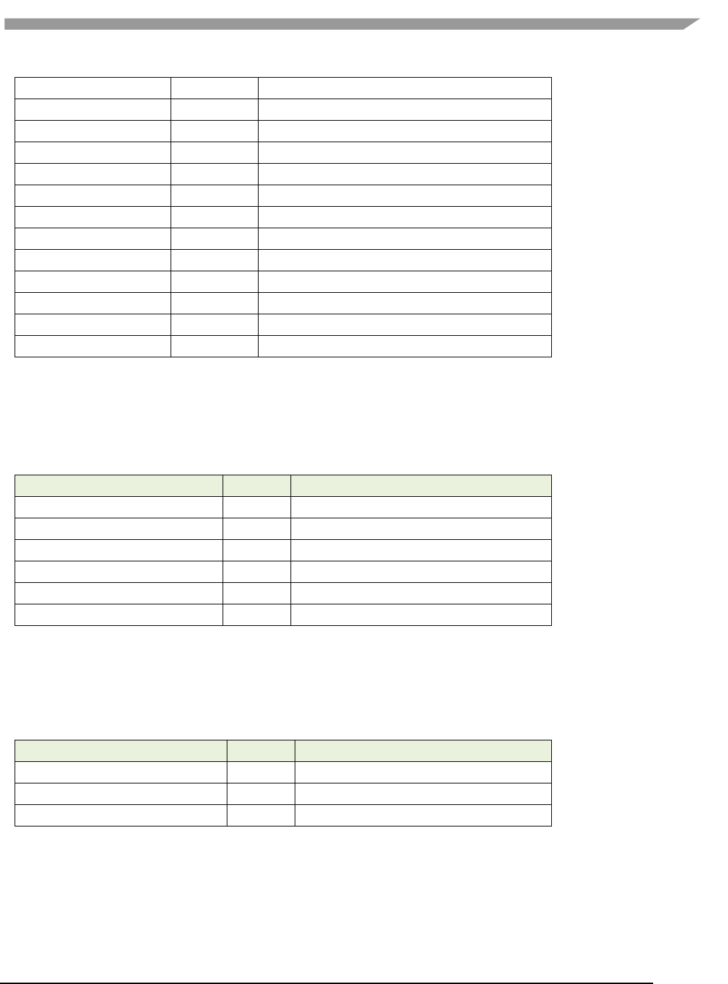
The geometry definition of surface structure is described as below:
stride
left
top
bottom
right
width
Planes
height
Figure 1 g2d_surface structure
2.2.8 g2d_buf structure
This structure describes the buffer used as g2d interfaces.
Table 8 g2d_buf structure
g2d_buf Members
Type
Description
buf_handle
void *
The handle associated with buffer

i.MX 6 Graphics User’s Guide, Rev. L3.14.28_1.0.0-ga, 04/2015
9 Freescale Semiconductor
buf_vaddr
void *
Virtual address of the buffer
buf_paddr
int
Physical address of the buffer
buf_size
int
The actual size of the buffer
2.3 G2D function descriptions
2.3.1 g2d_open
Description:
Open G2D device and return a handle.
Syntax:
int g2d_open(void **handle);
Parameters:
handle Pointer to receive g2d device handle
Returns:
Success with 0, fail with -1
2.3.2 g2d_close
Description:
Close g2d device with the handle.
Syntax:
int g2d_close(void *handle);
Parameters:
handle g2d device handle
Returns:
Success with 0, fail with -1
2.3.3 g2d_make_current
Description:
Set the specific hardware type for current context, default is G2D_HARDWARE_2D.
Syntax:
int g2d_make_current(void *handle, enum g2d_hardware_type type);
Parameters:
handle g2d device handle
type g2d hardware type
Returns:
Success with 0, fail with -1

i.MX 6 Graphics User’s Guide, Rev. L3.14.28_1.0.0-ga, 04/2015
10 Freescale Semiconductor
2.3.4 g2d_clear
Description:
Clear a specific area.
Syntax:
int g2d_clear(void *handle, struct g2d_surface *area);
Parameters:
handle g2d device handle
area the area to be cleared
Returns:
Success with 0, fail with -1
2.3.5 g2d_blit
Description:
G2d blit from source to destination with alternative operation (Blend, Dither, etc.).
Syntax:
int g2d_blit(void *handle, struct g2d_surface *src, struct g2d_surface *dst);
Parameters:
handle g2d device handle
src source surface
dst destination surface
Returns:
Success with 0, fail with -1
2.3.6 g2d_copy
Description:
G2d copy with specified size.
Syntax:
int g2d_copy(void *handle, struct g2d_buf *d, struct g2d_buf* s, int size);
Parameters:
handle g2d device handle
d destination buffer
s source buffer
size copy bytes
Limitations:
If the destination buffer is cacheable, it must be invalidated before g2d_copy
due to the alignment limitation of g2d driver.
Returns:

i.MX 6 Graphics User’s Guide, Rev. L3.14.28_1.0.0-ga, 04/2015
11 Freescale Semiconductor
Success with 0, fail with -1
2.3.7 g2d_query_cap
Description:
Query the alternative capability enablement.
Syntax:
int g2d_query_cap(void *handle, enum g2d_cap_mode cap, int *enable);
Parameters:
handle g2d device handle
cap g2d capability to query
enable Pointer to receive g2d capability enablement
Returns: Success with 0, fail with -1
2.3.8 g2d_enable
Description:
Enable g2d capability with the specific mode
Syntax:
int g2d_enable(void *handle, enum g2d_cap_mode cap);
Parameters:
handle g2d device handle
cap g2d capability to enable
Returns:
Success with 0, fail with -1
2.3.9 g2d_disable
Description:
Enable g2d capability with the specific mode.
Syntax:
int g2d_disable (void *handle, enum g2d_cap_mode cap);
Parameters:
handle g2d device handle
cap g2d capability to disable
Returns:
Success with 0, fail with -1

i.MX 6 Graphics User’s Guide, Rev. L3.14.28_1.0.0-ga, 04/2015
12 Freescale Semiconductor
2.3.10 g2d_cache_op
Description:
Perform cache operations for the cacheable buffer allocated through g2d driver.
Syntax:
int g2d_cache_op (struct g2d_buf *buf, enum g2d_cache_mode op);
Parameters:
buf the buffer to be handled with cache operations
op cache operation type
Returns:
Success with 0, fail with -1
2.3.11 g2d_alloc
Description:
Allocate a buffer through g2d device
Syntax:
struct g2d_buf *g2d_alloc(int size, int cacheable);
Parameters:
size allocated bytes
cacheable 0, non-cacheable, 1, cacheable attribute defined by system
Returns:
Success with valid g2d buffer pointer, fail with 0
2.3.12 g2d_free
Description:
Free the buffer through g2d device.
Syntax:
int g2d_free(struct g2d_buf *buf);
Parameters:
buf g2d buffer to free
Returns:
Success with 0, fail with -1
2.3.13 g2d_flush
Description:
Flush g2d command and return without completing pipeline.
Syntax:
int g2d_flush (void *handle);

i.MX 6 Graphics User’s Guide, Rev. L3.14.28_1.0.0-ga, 04/2015
13 Freescale Semiconductor
Parameters:
handle g2d device handle
Returns:
Success with 0, fail with -1
2.3.14 g2d_finish
Description:
Flush g2d command and then return when pipeline is finished.
Syntax:
int g2d_finish (void *handle);
Parameters:
handle g2d device handle
Returns:
Success with 0, fail with -1
2.4 Sample codes for G2D API usage
This chapter provides the brief prototype codes with G2D API.
2.4.1 Color space conversion from YUV to RGB
g2d_open(&handle);
src.planes[0] = buf_y;
src.planes[1] = buf_u;
src.planes[2] = buf_v;
src.left = crop.left;
src.top = crop.top;
src.right = crop.right;
src.bottom = crop.bottom;
src.stride = y_stride;
src.width = y_width;
src.height = y_height;
src.rot = G2D_ROTATION_0;
src.format = G2D_I420;
dst.planes[0] = buf_rgba;
dst.left = 0;
dst.top = 0;
dst.right = disp_width;
dst.bottom = disp_height;
dst.stride = disp_width;
dst.width = disp_width;

i.MX 6 Graphics User’s Guide, Rev. L3.14.28_1.0.0-ga, 04/2015
14 Freescale Semiconductor
dst.height = disp_height;
dst.rot = G2D_ROTATION_0;
dst.format = G2D_RGBA8888;
g2d_blit(handle, &src, &dst);
g2d_finish(handle);
g2d_close(handle);
2.4.2 Alpha blend in source over mode
g2d_open(&handle);
src.planes[0] = src_buf;
src.left = 0;
src.top = 0;
src.right = test_width;
src.bottom = test_height;
src.stride = test_width;
src.width = test_width;
src.height = test_height;
src.rot = G2D_ROTATION_0;
src.format = G2D_RGBA8888;
src.blendfunc = G2D_ONE;
dst.planes[0] = dst_buf;
dst.left = 0;
dst.top = 0;
dst.right = test_width;
dst.bottom = test_height;
dst.stride = test_width;
dst.width = test_width;
dst.height = test_height;
dst.format = G2D_RGBA8888;
dst.rot = G2D_ROTATION_0;
dst.blendfunc = G2D_ONE_MINUS_SRC_ALPHA;
g2d_enable(handle,G2D_BLEND);
g2d_blit(handle, &src, &dst);
g2d_finish(handle);
g2d_disable(handle,G2D_BLEND);
g2d_close(handle);
2.4.3 Source cropping and destination rotation
g2d_open(&handle);
src.planes[0] = src_buf;

i.MX 6 Graphics User’s Guide, Rev. L3.14.28_1.0.0-ga, 04/2015
15 Freescale Semiconductor
src.left = crop.left;
src.top = crop.left;
src.right = crop.right;
src.bottom = crop.bottom;
src.stride = src_stride;
src.width = src_width;
src.height = src_height;
src.format = G2D_RGBA8888;
src.rot = G2D_ROTATION_0;//G2D_FLIP_H or G2D_FLIP_V
dst.planes[0] = dst_buf;
dst.left = 0;
dst.top = 0;
dst.right = dst_width;
dst.bottom = dst_height;
dst.stride = dst_width;
dst.width = dst_width;
dst.height = dst_height;
dst.format = G2D_RGBA8888;
dst.rot = G2D_ROTATION_90;
g2d_blit(handle, &src, &dst);
g2d_finish(handle);
g2d_close(handle);
i.MX 6 Graphics User’s Guide, Rev. L3.14.28_1.0.0-ga, 04/2015
16 Freescale Semiconductor
Chapter 3 i.MX 6 EGL and OGL Extension Support
3.1 Introduction
The following tables list the level of support for EGL and OES extensions available with i.MX 6 hardware and
software. Support levels are current as of the date of the document and subject to change.
Two tables are provided. The first table lists the EGL interface extensions. The second table lists extensions for
OpenGL ES 1.1, OpenGL ES 2.0, and OpenGL ES 3.0.
Key:
Extension Name and Number: Each listed extension is derived from the relevant khronos.org webpage list and
includes the extension number as well as a hyperlink to the khronos description of the extension.
Yes: Support is currently available.
No: Support is not available. (Reasons for lack of support may vary: the extension may be proprietary or obsolete,
or not applicable to the specified OES version.)
N/A: Support is not provided as the extension is not applicable in this and subsequent versions of the specification.
3.2 EGL extension support
The following table includes the list of all current EGL Extensions and indicates their support level.
(list from www.khronos.org/registry/egl/ as of 1/24/2013)
Table 9 EGL extension support
EGL Extension Number, Name, and hyperlink
Supported?
1. EGL_KHR_config_attribs
No
2. EGL_KHR_lock_surface
Yes
3. EGL_KHR_image
Yes
4. EGL_KHR_vg_parent_image
No
5. EGL_KHR_gl_texture_2D_image
EGL_KHR_gl_texture_cubemap_image
EGL_KHR_gl_texture_3D_image
EGL_KHR_gl_renderbuffer_image
Yes
Yes
No
Yes
6. EGL_KHR_reusable_sync
Yes
8. EGL_KHR_image_base
Yes
9. EGL_KHR_image_pixmap
Yes
10. EGL_IMG_context_priority
No
16. EGL_KHR_lock_surface2
No
17. EGL_NV_coverage_sample
No
18. EGL_NV_depth_nonlinear
No
19. EGL_NV_sync
No
20. EGL_KHR_fence_sync
Yes
24. EGL_HI_clientpixmap
No
25. EGL_HI_colorformats
No
26. EGL_MESA_drm_image
No
27. EGL_NV_post_sub_buffer
No
28. EGL_ANGLE_query_surface_pointer
No
29. EGL_ANGLE_surface_d3d_texture_2d_share_handle
No
30. EGL_NV_coverage_sample_resolve
No

i.MX 6 Graphics User’s Guide, Rev. L3.14.28_1.0.0-ga, 04/2015
17 Freescale Semiconductor
31. EGL_NV_system_time
No
32. EGL_KHR_stream
No
33. EGL_KHR_stream_consumer_gltexture
No
34. EGL_KHR_stream_producer_eglsurface
No
35. EGL_KHR_stream_producer_aldatalocator
No
36. EGL_KHR_stream_fifo
No
37. EGL_EXT_create_context_robustness
Yes
38. EGL_ANGLE_d3d_share_handle_client_buffer
No
39. EGL_KHR_create_context
Yes
40. EGL_KHR_surfaceless_context
No
41. EGL_KHR_stream_cross_process_fd
No
42. EGL_EXT_multiview_window
No
43. EGL_KHR_wait_sync
No
44. EGL_NV_post_convert_rounding
No
45. EGL_NV_native_query
No
46. EGL_NV_3dvision_surface
No
47. EGL_ANDROID_framebuffer_target
No
48. EGL_ANDROID_blob_cache
No
49. EGL_ANDROID_image_native_buffer
Yes
50. EGL_ANDROID_native_fence_sync
Yes
51. EGL_ANDROID_recordable
No
52. EGL_EXT_buffer_age
Yes
53. EGL_EXT_image_dma_buf_import
No
54. EGL_ARM_pixmap_multisample_discard
No
55. EGL_EXT_swap_buffers_with_damage
No
56. EGL_NV_stream_sync
No
57. EGL_EXT_platform_base
No
58. EGL_EXT_client_extensions
No
59. EGL_EXT_platform_x11
No
60. EGL_KHR_cl_event
No
61. EGL_KHR_get_all_proc_addresses
EGL_KHR_client_get_all_proc_addresses
No
No
62. EGL_MESA_platform_gbm
No
63. EGL_EXT_platform_wayland
No
64. EGL_KHR_lock_surface3
No
65. EGL_KHR_cl_event2
No
66. EGL_KHR_gl_colorspace
No
67. EGL_ANDROID_get_render_buffer
Yes
68. EGL_ANDROID_swap_rectangle
Yes
i.MX 6 Graphics User’s Guide, Rev. L3.14.28_1.0.0-ga, 04/2015
18 Freescale Semiconductor
3.3 OpenGL ES extension support
The following table includes the list of all current OpenGL ES Extensions and indicates their support level.
(list from www.khronos.org/registry/gles/ as of 9/27/2012)
Table 10 OpenGL ES extension support
Extension Number, Name and hyperlink
ES1.1
ES2.0/3.0
1. GL_OES_blend_equation_separate
Yes
N/A
2. GL_OES_blend_func_separate
Yes
N/A
3. GL_OES_blend_subtract
Yes
N/A
4. GL_OES_byte_coordinates
Yes
N/A
5. GL_OES_compressed_ETC1_RGB8_texture
Yes
Yes
6. GL_OES_compressed_paletted_texture
Yes
Yes
7. GL_OES_draw_texture
Yes
N/A
8. GL_OES_extended_matrix_palette
Yes
No
9. GL_OES_fixed_point
Yes
No
10. GL_OES_framebuffer_object
Yes
N/A
11. GL_OES_matrix_get
Yes
N/A
12. GL_OES_matrix_palette
Yes
N/A
14. GL_OES_point_size_array
Yes
No
15. GL_OES_point_sprite
Yes
No
16. GL_OES_query_matrix
Yes
N/A
17. GL_OES_read_format
Yes
No
18. GL_OES_single_precision
Yes
No
19. GL_OES_stencil_wrap
Yes
No
20. GL_OES_texture_cube_map
Yes
N/A
21. GL_OES_texture_env_crossbar
No
No
22. GL_OES_texture_mirrored_repeat
Yes
N/A
23. GL_OES_EGL_image
Yes
Yes
24. GL_OES_depth24
Yes
Yes
25. GL_OES_depth32
No
No
26. GL_OES_element_index_uint
Yes
Yes
27. GL_OES_fbo_render_mipmap
Yes
Yes
28. GL_OES_fragment_precision_high
No
Yes
29. GL_OES_mapbuffer
Yes
Yes
30. GL_OES_rgb8_rgba8
Yes
Yes
31. GL_OES_stencil1
Yes
Yes
32. GL_OES_stencil4
Yes
Yes
33. GL_OES_stencil8
Yes
N/A
34. GL_OES_texture_3D
No
No
35. GL_OES_texture_float_linear
GL_OES_texture_half_float_linear
No
No
No
No
36. GL_OES_texture_float
GL_OES_texture_half_float
No
No
No
No
37. GL_OES_texture_npot
Yes
Yes
38. GL_OES_vertex_half_float
Yes
Yes
39. GL_AMD_compressed_3DC_texture
No
No
40. GL_AMD_compressed_ATC_texture
No
No
i.MX 6 Graphics User’s Guide, Rev. L3.14.28_1.0.0-ga, 04/2015
19 Freescale Semiconductor
Extension Number, Name and hyperlink
ES1.1
ES2.0/3.0
41. GL_EXT_texture_filter_anisotropic
Yes
Yes
42. GL_EXT_texture_type_2_10_10_10_REV
No
Yes
43. GL_OES_depth_texture
No
Yes
44. GL_OES_packed_depth_stencil
Yes
Yes
45. GL_OES_standard_derivatives
No
Yes
46. GL_OES_vertex_type_10_10_10_2
No
Yes
47. GL_OES_get_program_binary
No
Yes
48. GL_AMD_program_binary_Z400
No
No
49. GL_EXT_texture_compression_dxt1
50. GL_AMD_performance_monitor
No
No
51. GL_EXT_texture_format_BGRA8888
Yes
Yes
52. GL_NV_fence
No
No
53. GL_IMG_read_format
No
No
54. GL_IMG_texture_compression_pvrtc
No
No
55. GL_QCOM_driver_control
No
No
56. GL_QCOM_performance_monitor_global_mode
No
No
57. GL_IMG_user_clip_plane
No
No
58. GL_IMG_texture_env_enhanced_fixed_function
No
No
59. GL_APPLE_texture_2D_limited_npot
No
No
60. GL_EXT_texture_lod_bias
Yes
N/A
61. GL_QCOM_writeonly_rendering
No
No
62. GL_QCOM_extended_get
No
No
63. GL_QCOM_extended_get2
No
No
64. GL_EXT_discard_framebuffer
No
Yes
65. GL_EXT_blend_minmax
Yes
Yes
66. GL_EXT_read_format_bgra
Yes
Yes
67. GL_IMG_program_binary
No
No
68. GL_IMG_shader_binary
No
No
69. GL_EXT_multi_draw_arrays
GL_SUN_multi_draw_arrays
Yes
No
Yes
No
70. GL_QCOM_tiled_rendering
No
No
71. GL_OES_vertex_array_object
No
No
72. GL_NV_coverage_sample
No
No
73. GL_NV_depth_nonlinear
No
No
74. GL_IMG_multisampled_render_to_texture
No
No
75. GL_OES_EGL_sync
Yes
N/A
76. GL_APPLE_rgb_422
No
No
77. GL_EXT_shader_texture_lod
No
No
78. GL_APPLE_framebuffer_multisample
No
No
79. GL_APPLE_texture_format_BGRA8888
No
No
80. GL_APPLE_texture_max_level
No
No
81. GL_ARM_mali_shader_binary
No
No
82. GL_ARM_rgba8
No
No
83. GL_ANGLE_framebuffer_blit
No
No
84. GL_ANGLE_framebuffer_multisample
No
No
85. GL_VIV_shader_binary
No
Yes
86. GL_EXT_frag_depth
No
Yes
i.MX 6 Graphics User’s Guide, Rev. L3.14.28_1.0.0-ga, 04/2015
20 Freescale Semiconductor
Extension Number, Name and hyperlink
ES1.1
ES2.0/3.0
87. GL_OES_EGL_image_external
Yes
Yes
88. GL_DMP_shader_binary
No
No
89. GL_QCOM_alpha_test
No
No
90. GL_EXT_unpack_subimage
No
N/A
91. GL_NV_draw_buffers
No
No
92. GL_NV_fbo_color_attachments
No
No
93. GL_NV_read_buffer
No
No
94. GL_NV_read_depth_stencil
No
No
95. GL_NV_texture_compression_s3tc_update
No
No
96. GL_NV_texture_npot_2D_mipmap
No
No
97. GL_EXT_color_buffer_half_float
No
No
98. GL_EXT_debug_label
No
No
99. GL_EXT_debug_marker
No
No
100. GL_EXT_occlusion_query_boolean
No
No
101. GL_EXT_separate_shader_objects
No
No
102. GL_EXT_shadow_samplers
No
No
103. GL_EXT_texture_rg
No
No
104. GL_NV_EGL_stream_consumer_external
No
No
105. GL_EXT_sRGB
No
No
106. GL_EXT_multisampled_render_to_texture
No
Yes
107. GL_EXT_robustness
No
Yes
108. GL_EXT_texture_storage
No
No
109. GL_ANGLE_instanced_arrays
No
No
110. GL_ANGLE_pack_reverse_row_order
No
No
111. GL_ANGLE_texture_compression_dxt3
GL_ANGLE_texture_compression_dxt5
No
No
No
No
112. GL_ANGLE_texture_usage
No
No
113. GL_ANGLE_translated_shader_source
No
No
114. GL_FJ_shader_binary_GCCSO
No
No
115. GL_OES_required_internalformat
No
No
116. GL_OES_surfaceless_context
No
No
117. GL_KHR_texture_compression_astc_ldr
No
No
118. GL_KHR_debug
No
No
119. GL_QCOM_binning_control
No
No
120. GL_ARM_mali_program_binary
No
No
121. GL_EXT_map_buffer_range
No
No
122. GL_EXT_shader_framebuffer_fetch
No
No
123. GL_APPLE_copy_texture_levels
No
No
124. GL_APPLE_sync
No
No
125. GL_EXT_multiview_draw_buffers
No
No
126. GL_NV_draw_texture
No
No
127. GL_NV_packed_float
No
No
128. GL_NV_texture_compression_s3tc
No
No
129. GL_NV_3dvision_settings
No
No
130. GL_NV_texture_compression_latc
No
No
131. GL_NV_platform_binary
No
No
132. GL_NV_pack_subimage
No
No

i.MX 6 Graphics User’s Guide, Rev. L3.14.28_1.0.0-ga, 04/2015
21 Freescale Semiconductor
Extension Number, Name and hyperlink
ES1.1
ES2.0/3.0
133. GL_NV_texture_array
No
No
134. GL_NV_pixel_buffer_object
No
No
135. GL_NV_bgr
No
No
136. GL_OES_depth_texture_cube_map
No
No
137. GL_EXT_color_buffer_float
No
No
138. GL_ANGLE_depth_texture
No
No
139. GL_ANGLE_program_binary
No
No
140. GL_IMG_texture_compression_pvrtc2
No
No
141. GL_NV_draw_instanced
No
No
142. GL_NV_framebuffer_blit
No
No
143. GL_NV_framebuffer_multisample
No
No
144. GL_NV_generate_mipmap_sRGB
No
No
145. GL_NV_instanced_arrays
No
No
146. GL_NV_shadow_samplers_array
No
No
147. GL_NV_shadow_samplers_cube
No
No
148. GL_NV_sRGB_formats
No
No
149. GL_NV_texture_border_clamp
No
No
150. GL_VIV_direct_texture
Yes
Yes
151. GL_EXT_disjoint_timer_query
No
No
152. GL_EXT_draw_buffers
No
No
153. GL_EXT_texture_sRGB_decode
No
No
154. GL_EXT_sRGB_write_control
No
No
155. GL_EXT_texture_compression_s3tc
No
No
156. GL_EXT_pvrtc_sRGB
No
No
157. GL_EXT_instanced_arrays
No
No
158. GL_EXT_draw_instanced
No
No
159. GL_NV_copy_buffer
No
No
160. GL_NV_explicit_attrib_location
No
No
161. GL_NV_non_square_matrices
No
No
162. GL_EXT_shader_integer_mix
No
No
163. GL_OES_texture_compression_astc
No
No
164. GL_NV_blend_equation_advanced
GL_NV_blend_equation_advanced_coherent
No
No
No
No

i.MX 6 Graphics User’s Guide, Rev. L3.14.28_1.0.0-ga, 04/2015
22 Freescale Semiconductor
Extension Number, Name and hyperlink
ES1.1
ES2.0/3.0
165. GL_INTEL_performance_query
No
No
166. GL_VIV_texture_border_clamp
No
No
3.4 Extension GL_VIV_direct_texture
Name
VIV_direct_texture
Name strings
GL_VIV_direct_texture
IPStatus
Contact Freescale Semiconductor regarding any intellectual property questions associated with this extension.
Status
Implemented: July, 2011
Version
Last modified: 29 July, 2011
Revision: 2
Number
Unassigned
Dependencies
OpenGL ES 1.1 is required. OpenGL ES 2.0 support is available.
Overview
Create a texture with direct access support. This is useful when an application desires to use the same texture over and over
while frequently updating its content. It could also be used for mapping live video to a texture. A video decoder could write its
result directly to the texture and then the texture could be directly rendered onto a 3D shape. glTexDirectVIVMap is similar
to glTexDirectVIV. The only difference is that it has two inputs, “Logical” and “Physical,” which support mapping a user
space memory or a physical address into the texture surface.
New Procedures and Functions
glTexDirectVIV
Syntax:
GL_API void GL_APIENTRY
glTexDirectVIV (
GLenum Target,
GLsizei Width,
GLsizei Height,
GLenum Format,
GLvoid ** Pixels
);

i.MX 6 Graphics User’s Guide, Rev. L3.14.28_1.0.0-ga, 04/2015
23 Freescale Semiconductor
Parameters
Target
Target texture. Must be GL_TEXTURE_2D.
Width
Height
Size of LOD 0. Width must be 16 pixel aligned. The width and
height of LOD 0 of the texture is specified by the Width and Height
parameters. The driver may auto-generate the rest of LODs if the
hardware supports high quality scaling (for non-power of 2
textures) and LOD generation. If the hardware does not support
high quality scaling and LOD generation, the texture will remain a
single-LOD texture.
Format
You can choose the format of the pixel data from the following
formats: GL_VIV_YV12, GL_VIV_NV12, GL_VIV_NV21,
GL_VIV_YUY2, GL_VIV_UYVY, GL_RGBA, and GL_BGRA_EXT.
If the format is GL_VIV_YV12, glTexDirectVIV creates a planar
YV12 4:2:0 texture and the format of the Pixels array is as
follows: Yplane, Vplane, Uplane.
If the format is GL_VIV_NV12, glTexDirectVIV creates a planar
NV12 4:2:0 texture and the format of the Pixels array is as
follows: Yplane, UVplane.
If the format is GL_VIV_NV21, glTexDirectVIV creates a planar
NV21 4:2:0 texture and the format of the Pixels array is as
follows: Yplane, VUplane.
If the format is GL_VIV_YUY2 or GL_VIV_UYVY, glTexDirectVIV
creates a packed 4:2:2 texture and the Pixels array contains
only one pointer to the packed YUV texture.
If Format is GL_RGBA, glTexDirectVIV creates a pixel array
with four GL_UNSIGNED_BYTE components: the first byte for
red pixels, the second byte for green pixels, the third byte for
blue, and the fourth byte for alpha.
If Format is GL_BGRA_EXT, glTexDirectVIV creates a pixel
array with four GL_UNSIGNED_BYTE components: the first
byte for blue pixels, the second byte for green pixels, the third
byte for red, and the fourth byte for alpha.
Pixels
Stores the memory pointer created by the driver.
Output
If the function succeeds, it returns a pointer, or, for some YUV formats, it returns a set of pointers that
directly point to the texture. The pointer(s) will be returned in the user-allocated array pointed to by the
Pixels parameter.
GlTexDirectVIVMap
Syntax:
GL_API void GL_APIENTRY
glTexDirectVIVMap (
Glenum Target,
Glsizei Width,
Glsizei Height,
Glenum Format,
Glvoid ** Logical,

i.MX 6 Graphics User’s Guide, Rev. L3.14.28_1.0.0-ga, 04/2015
24 Freescale Semiconductor
const Gluint * Physical
);
Parameters
Target
Target texture. Must be GL_TEXTURE_2D.
Width
Height
Size of LOD 0. Width must be 16 pixel aligned. See glTexDirectVIV.
Format
Same as glTexDirectVIV Format.
Logical
Pointer to the logical address of the application-defined texture
buffer. Logical address must be 64 bit (8 byte) aligned.
Physical
Pointer to the physical address of the application-defined buffer to
the texture, or ~0 if no physical address has been provided.
GlTexDirectInvalidateVIV
Syntax:
GL_API void GL_APIENTRY
glTexDirectInvalidateVIV (
Glenum Target
);
Parameters
Target
Target texture. Must be GL_TEXTURE_2D.
New Tokens
GL_VIV_YV12
0x8FC0
GL_VIV_NV12
0x8FC1
GL_VIV_YUY2
0x8FC2
GL_VIV_UYVY
0x8FC3
GL_VIV_NV21
0x8FC4
Error codes
GL_INVALID_ENUM
Target is not GL_TEXTURE_2D, or format is not a valid format.
GL_INVALID_VALUE
Width or Height parameter is less than 1.
GL_OUT_OF_MEMORY
A memory allocation error occurred.
GL_INVALID_OPERATION
Specified format is not supported by the hardware, or
no texture is bound to the active texture unit, or
some other error occurs during the call.
Example 1.
First, call glTexDirectVIV to get a pointer.
Second, copy the texture data to this memory address.

i.MX 6 Graphics User’s Guide, Rev. L3.14.28_1.0.0-ga, 04/2015
25 Freescale Semiconductor
Then, call glTexDirectInvalidateVIV to apply the texture before you draw something with that texture.
… …
glTexDirectVIV(GL_TEXUTURE_2D, 512, 512, GL_VIV_YV12, &texels);
… …
GlTexDirectInvalidateVIV(GL_TEXTURE_2D);
…
glDrawArrays(…);
…
Example 2.
First, call glTexDirectVIVMap to map Logical and Physical address to the texture.
Second, you can modify Logical and Physical data.
Then, call glTexDirectInvalidateVIV to apply the texture before you draw something with that texture.
… …
char *Logical = (char*) malloc (sizeof(char)*size);
Gluint physical = ~0U;
glTexDirectVIVMap(GL_TEXUTURE_2D, 512, 512, GL_VIV_YV12,
(void**)&Logical, &25hysical);
… …
GlTexDirectInvalidateVIV(GL_TEXTURE_2D);
…
glDrawArrays(…);
Issues
None
3.5 Extension GL_VIV_texture_border_clamp
Name
VIV_texture_border_clamp
Name Strings
GL_VIV_texture_border_clamp
Status
Implemented September 2012.
Version
Last modified: 27 September 2012
Vivante revision: 1
Number
Unassigned
Dependencies
This extension is implemented for use with OpenGL ES 1.1 and OpenGL ES 2.0.

i.MX 6 Graphics User’s Guide, Rev. L3.14.28_1.0.0-ga, 04/2015
26 Freescale Semiconductor
This extension is based on OpenGL ARB Extension #13: GL_ARB_texture_border_clamp:
www.opengl.org/registry/specs/ARB/texture_border_clamp.txt. See also vendor extension GL_SGIS_texture_border_clamp,
www.opengl.org/registry/specs/SGIS/texture_border_clamp.txt.
Overview
This extension was adapted from the OpenGL extension for use with OpenGL ES implementations. The OpenGL ARB Extension
13 description applies here as well:
“The base OpenGL provides clamping such that the texture coordinates are limited to exactly the range
[0,1]. When a texture coordinate is clamped using this algorithm, the texture sampling filter straddles the
edge of the texture image, taking 1/2 its sample values from within the texture image, and the other 1/2
from the texture border. It is sometimes desirable for a texture to be clamped to the border color, rather
than to an average of the border and edge colors.
This extension defines an additional texture clamping algorithm. CLAMP_TO_BORDER_[VIV] clamps texture
coordinates at all mipmap levels such that NEAREST and LINEAR filters return only the color of the border
texels.”
The color returned is derived only from border texels and cannot be configured.
Issues
None
New Tokens
Accepted by the <param> parameter of TexParameteri and TexParameterf, and by the <params> parameter of
TexParameteriv and TexParameterfv, when their <pname> parameter is TEXTURE_WRAP_S, TEXTURE_WRAP_T, or
TEXTURE_WRAP_R:
CLAMP_TO_BORDER_VIV
0x812D
Errors
None.
New State
Only the type information changes for these parameters.
See OES 2.0 Specification Section 3.7.4, page 75-76, Table 3.10, “Texture parameters and their values.”
i.MX 6 Graphics User’s Guide, Rev. L3.14.28_1.0.0-ga, 04/2015
27 Freescale Semiconductor
Chapter 4 i.MX 6 Framebuffer API
4.1 Overview
The graphics software includes i.MX 6 Framebuffer (FB) API which enables users to easily create and port their
graphics applications by using a framebuffer device without the need to expend additional effort handling
platform-related tasks. i.MX 6 Framebuffer API focuses on providing mechanisms for controlling display, window,
and pixmap render surfaces.
The EGL Native Platform Graphics Interface provides mechanisms for creating rendering surfaces onto which client
APIs can draw, creating graphics contexts for client APIs, and synchronizing drawing by client APIs as well as native
platform rendering APIs. This enables seamless rendering using Khronos APIs such as OpenGL ES and OpenVG for
high-performance, accelerated, mixed-mode 2D, and 3D rendering. For further information on EGL, see
www.khronos.org/registry/egl. The API described in this document is compatible with EGL version 1.4 of the
specification.
This API document is current as of the software version specified in the document revision history. The following
platforms are supported:
Linux® OS/X11
Android™ platform
Windows® Embedded Compact OS
4.2 API data types and environment variables
4.2.1 Data types
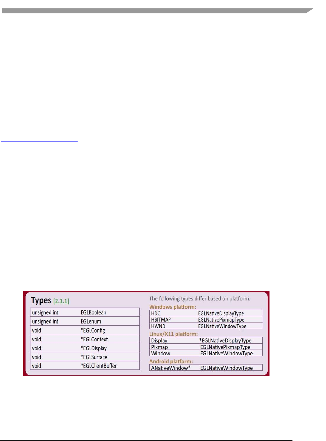
The GPU software provides platform independent member definitions for the following EGL types:
typedef struct _FBDisplay * EGLNativeDisplayType;
typedef struct _FBWindow * EGLNativeWindowType;
typedef struct _FBPixmap * EGLNativePixmapType;
Figure 2 Types as listed on EGL 1.4 API Quick Reference Card
(from www.khronos.org/files/egl-1-4-quick-reference-card.pdf)

i.MX 6 Graphics User’s Guide, Rev. L3.14.28_1.0.0-ga, 04/2015
28 Freescale Semiconductor
4.2.2 Environment variables
Table 11 i.MX 6 FB API environment variables
Environment Variables
Description
FB_MULTI_BUFFER
To use multiple-buffer rendering, set the environment variable
FB_MULTI_BUFFER to an unsigned integer value, which indicates the
number of buffers required. Maximum is 3.
Recommended values: 2 or 3.
The FB_MULTI_BUFFER variable can be set to any positive integer value.
If set to 1, the multiple buffer function is not enabled.
If set to 2 or 3, the driver will run as users expect.
If set to a value more than 3, the driver will use 3 as the buffer
count.
FB_FRAMEBUFFER_0,
FB_FRAMEBUFFER_1,
FB_FRAMEBUFFER_2,
FB_FRAMEBUFFER_n
To open a specified framebuffer device, set the environment variable
FB_FRAMEBUFFER_n to a proper value (for example,
FB_FRAMEBUFFER_0 = /dev/fb0).
Allowed values for n: any positive integer.
Note: If there are no environment variables set, the driver will try to use
the default framebuffer devices (fb0 for index 0, fb1 for index 1, fb2 for
index 2, fb3 for index 3, and so on).
FB_IGNORE_DISPLAY_SIZE
When set to a positive integer and a window’s initial size request is
greater than the display size, the window size will not be reduced to fit
within the display. Global.
Allowed values: any positive integer.
Note: The drivers will read the value from this environment variable as a
Boolean to check if the user wants to ignore the display size when
creating a window.
If the variable is set to value, 0, or this environment variable is not
set, then the driver when creating window will use display size to
cut down the size of the window to ensure that the entire window
area is inside the display screen.
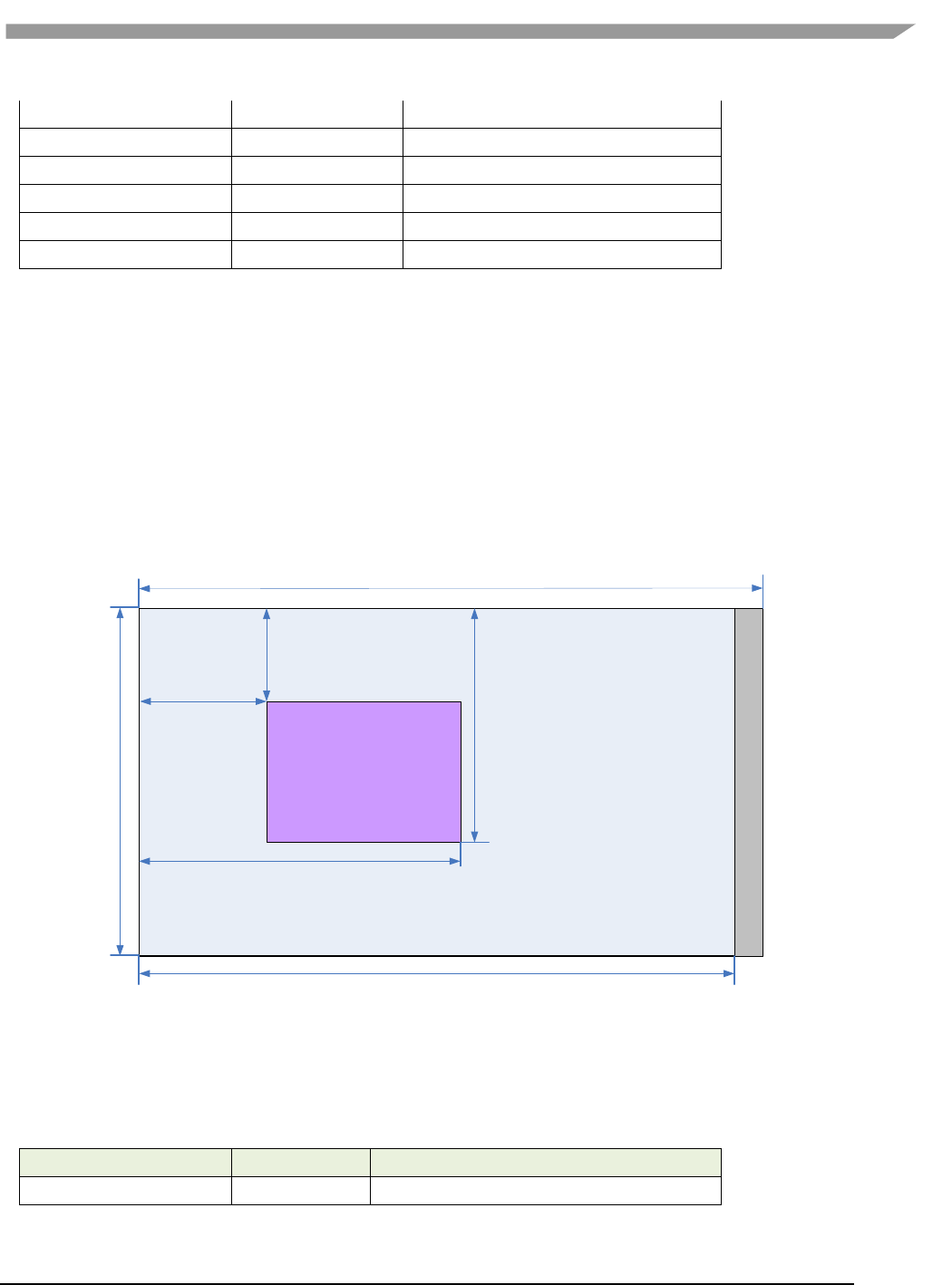
If the user sets this variable to 1, or any positive integer value, then
the window area can be partly or entirely outside of the display
screen area (see the image below in which the ignore display size is
equal to 1).
Below are some usage syntax examples for environment variables:
To create a window with its size different from the display size, use the environment variable
FB_IGNORE_DISPLAY_SIZE. Example usage syntax:
export FB_IGNORE_DISPLAY_SIZE=1
window
Display

i.MX 6 Graphics User’s Guide, Rev. L3.14.28_1.0.0-ga, 04/2015
29 Freescale Semiconductor
To let the driver use multiple buffers to do swap work, use the environment variable FB_MULTI_BUFFER. Example
usage syntax:
export FB_MULTI_BUFFER=2
To specify the display device, use the environment variable FB_FRAMEBUFFER_n, where n = any positive integer.
Example usage syntax:
export FB_FRAMEBUFFER_0=/dev/fb0
export FB_FRAMEBUFFER_1=/dev/fb1
export FB_FRAMEBUFFER_2=/dev/fb2
export FB_FRAMEBUFFER_3=/dev/fb3
4.3 API description and syntax
fbGetDisplay
Description:
This function is used to get the default display of the framebuffer device.
To open the framebuffer device, set an environment variable FB_FRAMEBUFFER_n to the framebuffer location.
Syntax:
EGLNativeDisplayType
fbGetDisplay (
void * context
);
Parameters:
context Pointer to the native display instance.
Return Values:
The function returns a pointer to the EGL native display instance if successful; otherwise, it returns a NULL pointer.
fbGetDisplayByIndex
Description:
This function is used to get a specified display within a multiple framebuffer environment by providing an index
number.
To use multiple buffers when rendering, set the environment variable FB_MULTI_BUFFER to an unsigned integer
value, which indicates the number of buffers. Maximum is 3.
To open a specific framebuffer device, set environment variables to their proper values (e.g., set
FB_FRAMEBUFFER_0 = /dev/fb0). If there are no environment variables set, the driver will try to use the default fb
devices (fb0 for index 0, fb1 for index 1, fb2 for index 2, fb3 for index 3, and so on).
Syntax:
EGLNativeDisplayType

i.MX 6 Graphics User’s Guide, Rev. L3.14.28_1.0.0-ga, 04/2015
30 Freescale Semiconductor
fbGetDisplayByIndex (
int DisplayIndex
);
Parameters:
DisplayIndex An integer value where the integer is associated with one of the following environment
variables for framebuffer devices:
FB_FRAMEBUFFER_0
FB_FRAMEBUFFER_1
FB_FRAMEBUFFER_2
FB_FRAMEBUFFER_n
Return Value:
The function returns a pointer to the EGL native display instance if successful; otherwise, it returns a NULL pointer.
fbGetDisplayGeometry
Description:
This function is used to get display width and height information.
Syntax:
void
fbGetDisplayGeometry (
EGLNativeDisplayType Display,
int * Width,
int * Height
);
Parameters:
Display [in] Pointer to EGL native display instance created by fbGetDisplay.
Width [out] Pointer that receives the width of the display.
Height [out] Pointer that receives the height of the display.
fbGetDisplayInfo
Description:
This function is used to get display information.
Syntax:
void
fbGetDisplayInfo (
EGLNativeDisplayType Display,
int * Width,
int * Height,
unsigned long * Physical,
int * Stride,
int * BitsPerPixel
);
Parameters:
Display [in] A pointer to the EGL native display instance created by fbGetDisplay.
Width [out] A pointer to the location that contains the width of the display.

i.MX 6 Graphics User’s Guide, Rev. L3.14.28_1.0.0-ga, 04/2015
31 Freescale Semiconductor
Height [out] A pointer to the location that contains the height of the display.
Physical [out] A pointer to the location that contains the physical start address of the display.
Stride [out] A pointer to the location that contains the stride of the display.
BitsPerPixel [out] A pointer to the location that contains the pixel depth of the display.
fbDestroyDisplay
Description:
This function is used to destroy a display.
Syntax:
void
fbDestroyDisplay (
EGLNativeDisplayType Display
);
Parameters:
Display [in] Pointer to EGL native display instance created by fbGetDisplay.
fbCreateWindow
Description:
This function is used to create a window for the framebuffer platform with the specified position and size. If
width/height is 0, it will use the display width/height as its value.
Note: When either window X + width or the Y + height is larger than the display’s width or height respectively, the
API will reduce the window size to force the whole window inside the display screen limits. To avoid reducing the
window size in this scenario, users can set a value of “1” to the environment variable FB_IGNORE_DISPLAY_SIZE.
Syntax:
EGLNativeWindowType
fbCreateWindow (
EGLNativeDisplayType Display,
int X,
int Y,
int Width,
int Height
);
Parameters:
Display [in] Pointer to EGL native display instance created by fbGetDisplay.
X [in] Specifies the initial horizontal position of the window.
Y [in] Specifies the initial vertical position of the window.
Width [in] Specifies the width of the window.
Height [in] Specifies the height of the window in device units.

i.MX 6 Graphics User’s Guide, Rev. L3.14.28_1.0.0-ga, 04/2015
32 Freescale Semiconductor
Return Value:
The function returns a pointer to the EGL native window instance if successful; otherwise, it returns a NULL
pointer.
fbGetWindowGeometry
Description:
This function is used to get window position and size information.
Syntax:
void
fbGetWindowGeometry (
EGLNativeWindowType Window,
int * X,
int * Y,
int * Width,
int * Height
);
Parameters:
Window [in] Pointer to EGL native window instance created by fbCreateWindow.
X [out] Pointer that receives the horizontal position value of the window.
Y [out] Pointer that receives the vertical position value of the window.
Width [out] Pointer that receives the width value of the window.
Height [out] Pointer that receives the height value of the window.
fbGetWindowInfo
Description:
This function is used to get window position and size and address information.
Syntax:
void
fbGetWindowInfo (
EGLNativeWindowType Window,
int * X,
int * Y,
int * Width,
int * Height
int * BitsPerPixel,
unsigned int * Offset
);
Parameters:
Window [in] A pointer to the EGL native window instance created by fbCreateWindow.
X [out] A pointer to the location that contains the horizontal position value of the window.
Y [out] A pointer to the location that contains the vertical position value of the window.
Width [out] A pointer to the location that contains the width of the window.
Height [out] A pointer to the location that contains the height of the window.
BitsPerPixel [out] A pointer to the location that contains the pixel depth of the window.

i.MX 6 Graphics User’s Guide, Rev. L3.14.28_1.0.0-ga, 04/2015
33 Freescale Semiconductor
Offset [out] A pointer to the location that contains the offset of the window.
fbDestroyWindow
Description:
This function is used to destroy a window.
Syntax:
void
fbDestroyWindow (
EGLNativeWindowType Window
);
Parameters:
Window [in] Pointer to EGL native window instance created by fbCreateWindow.
fbCreatePixmap
Description:
This function is used to create a pixmap of a specific size on the specified framebuffer device. If either the width or
height is 0, the function will fail to create a pixmap and return NULL.
Syntax:
EGLNativePixmapType
fbCreatePixmap (
EGLNativeDisplayType Display,
int Width,
int Height
);
Parameters:
Display [in] Pointer to the EGL native display instance created by fbGetDisplay.
Width [in] Specifies the width of the pixmap.
Height [in] Specifies the height of the pixmap.
Return Value:
The function returns a pointer to the EGL native pixmap instance if successful; otherwise, it returns a NULL pointer.
fbCreatePixmapWithBpp
Description:
This function is used to create a pixmap of a specific size and bit depth on the specified framebuffer device. If
either the width or height is 0, the function will fail to create a pixmap and return NULL.
Syntax:
EGLNativePixmapType
fbCreatePixmapWithBpp (

i.MX 6 Graphics User’s Guide, Rev. L3.14.28_1.0.0-ga, 04/2015
34 Freescale Semiconductor
EGLNativeDisplayType Display,
int Width,
int Height
int BitsPerPixel
);
Parameters:
Display [in]A pointer to the EGL native display instance created by fbGetDisplay.
Width [in] Specifies the width of the pixmap.
Height [in] Specifies the height of the pixmap.
BitsPerPixel [in] Specifies the bit depth of the pixmap.
Return Value:
The function returns a pointer to the EGL native pixmap instance if successful; otherwise, it returns a NULL pointer.
fbGetPixmapGeometry
Description:
This function is used to get pixmap size information.
Syntax:
void
fbGetPixmapGeometry (
EGLNativePixmapType Pixmap,
int * Width,
int * Height
);
Parameters:
Pixmap [in] Pointer to the EGL native pixmap instance created by fbCreatePixmap.
Width [out] Pointer that receives a width value for pixmap.
Height [out] Pointer that receives a height value for pixmap.
fbGetPixmapInfo
Description:
This function is used to get pixmap size and depth information.
Syntax:
void
fbGetPixmapInfo (
EGLNativePixmapType Pixmap,
int * Width,
int * Height
int * BitsPerPixel
int * Stride,
void ** Bits
);
Parameters:
Pixmap [in] A pointer to the EGL native pixmap instance created by fbCreatePixmap.
Width [out] A pointer to the location that contains a width value for pixmap.

i.MX 6 Graphics User’s Guide, Rev. L3.14.28_1.0.0-ga, 04/2015
35 Freescale Semiconductor
Height [out] A pointer to the location that contains a height value for pixmap.
BitsPerPixel [out] A pointer to the location that contains the pixel depth of the pixmap.
Stride [out] A pointer to the location that contains the stride of the pixmap.
Bits [out] A pointer to the location that contains the bit address of the pixmap.
fbDestroyPixmap
Description:
This function is used to destroy a pixmap.
Syntax:
void
fbDestroyPixmap (
EGLNativePixmapType Pixmap
);
Parameters:
Pixmap [in] Pointer to the EGL native pixmap instance created by fbCreatePixmap.

i.MX 6 Graphics User’s Guide, Rev. L3.14.28_1.0.0-ga, 04/2015
36 Freescale Semiconductor
Chapter 5 OpenCL
5.1 Overview
5.1.1 General Description
OpenCL (Open Computing Language) is an open industry standard application programming interface (API) used to
program multiple devices including GPUs, CPUs, as well as other devices organized as part of a single
computational platform. The OpenCL standard targets a wide range of devices from mobile phones, tablets, PCs,
and consumer electronic (CE) devices, all the way to embedded applications such as automotive and image
processing functions. The API takes advantage of all resources in a platform to fully utilize all compute capability
and to efficiently process the growing complexity of incoming data streams from multiple I/O (input / output)
sources. I/O streams can be camera inputs, images, scientific or mathematical data, and any other form of complex
data that can make use of data or task parallelism.
OpenCL uses parallel execution SIMD (single instruction, multiple data) engines found in GPUs to enhance data
computational density by performing massively parallel data processing on multiple data items, across multiple
compute engines. Each compute unit has its own arithmetic logic units (ALUs), including pipelined floating point
(FP), integer (INT) units and a special function unit (SFU) that can perform computations as well as transcendental
operations. The parallel computations and associated series of operations is called a kernel, and the GPU cores can
execute a kernel on thousands of work-items in parallel at any given time.
At a high level, OpenCL provides both a programming language and a framework to enable parallel programming.
OpenCL includes APIs, libraries and a runtime system to assist and support software development. With OpenCL it
is possible to write general purpose programs that can execute directly on GPUs, without needing to know
graphics architecture details or using 3D graphics APIs like OpenGL or DirectX. OpenCL also provides a low-level
hardware abstraction layer(HAL) as well as a framework that exposes many details of the underlying hardware
layer and thus allows the programmer to take full advantage of the hardware.
For more details on all the capabilities of OpenCL please refer to the following specifications from the Khronos
Group:
• OpenCL 1.1 Specification
www.khronos.org/registry/cl/specs/opencl-1.1.pdf
• OpenCL 1.1 C++ Bindings Specification
www.khronos.org/registry/cl/specs/opencl-cplusplus-1.1.pdf
5.1.2 OpenCL Profiles
In addition to Full Profile, the OpenCL specification also includes an Embedded Profile which relaxes the OpenCL
compliance requirements for mobile and embedded devices. The main commons and differences between OpenCL
1.1/1.2 EP(Embedded Profile) and FP(Full Profile) come down to:
Commons:
Both EP and FP will significantly offload the CPU of parallel, multi-threaded tasks.
For both EP and FP double precision and half-precision floating point are optional.
Difference:
Full Profile is for highly complex, accurate, and real time computations, while Embedded Profile is a
small subset targeting smaller devices (handheld, mobile, embedded) that perform GPGPU/OpenCL
processing with relaxed data type and precision requirements (image processing, augmented reality,
gesture recognition, and more).
64 bit integers are required for FP and optional for EP.

i.MX 6 Graphics User’s Guide, Rev. L3.14.28_1.0.0-ga, 04/2015
37 Freescale Semiconductor
EP requires either RTZ or RTE. FP requires both.
Computational precision (ULP) requirements in EP are relaxed.
Atomic instruction support is not required in EP.
3D Image support is not required in EP.
Minimum requirements for constant buffer size, object allocation size, constant argument counts and
local memory sizes are scaled down in EP.
And more (in general EP is a scaled down version of FP).
Die size and power increase with FP because of the higher requirements, features and memory sizes.
5.1.3 Vivante OpenCL Embedded Compatible IP
As of the date of this document, select Vivante GPGPU cores are compatible with OpenCL Embedded Profile
version 1.1. Hardware capability deltas include:
Table 1. Vivante OpenCL Embedded Profile Hardware
Hardware and revision
GC2000
Feature
5.1.0.rc8a
Compute Devices (GPGPU cores)
1
Compute Units per device (Shader cores)
4
Processing Elements per compute unit
4
Profile
Embedded
Preferred work-group/ thread group size
16
Max count global work-items each dim
64K
Max count of work-items each dim per work-group
1K
Local Storage Registers On-chip
64
Instruction Memory
512
Texture Samplers
8 PS + 4 VS
Texture Samplers available to OCL
(HW, unlimited via SW)
4
L1 Cache Size
4 KB
L1 Cache Banks
1
L1 Cache Sets/Bank
4
L1 Cache Ways/Set
16
L1 Cache Line Size
64B
L1 Cache MC ports
1
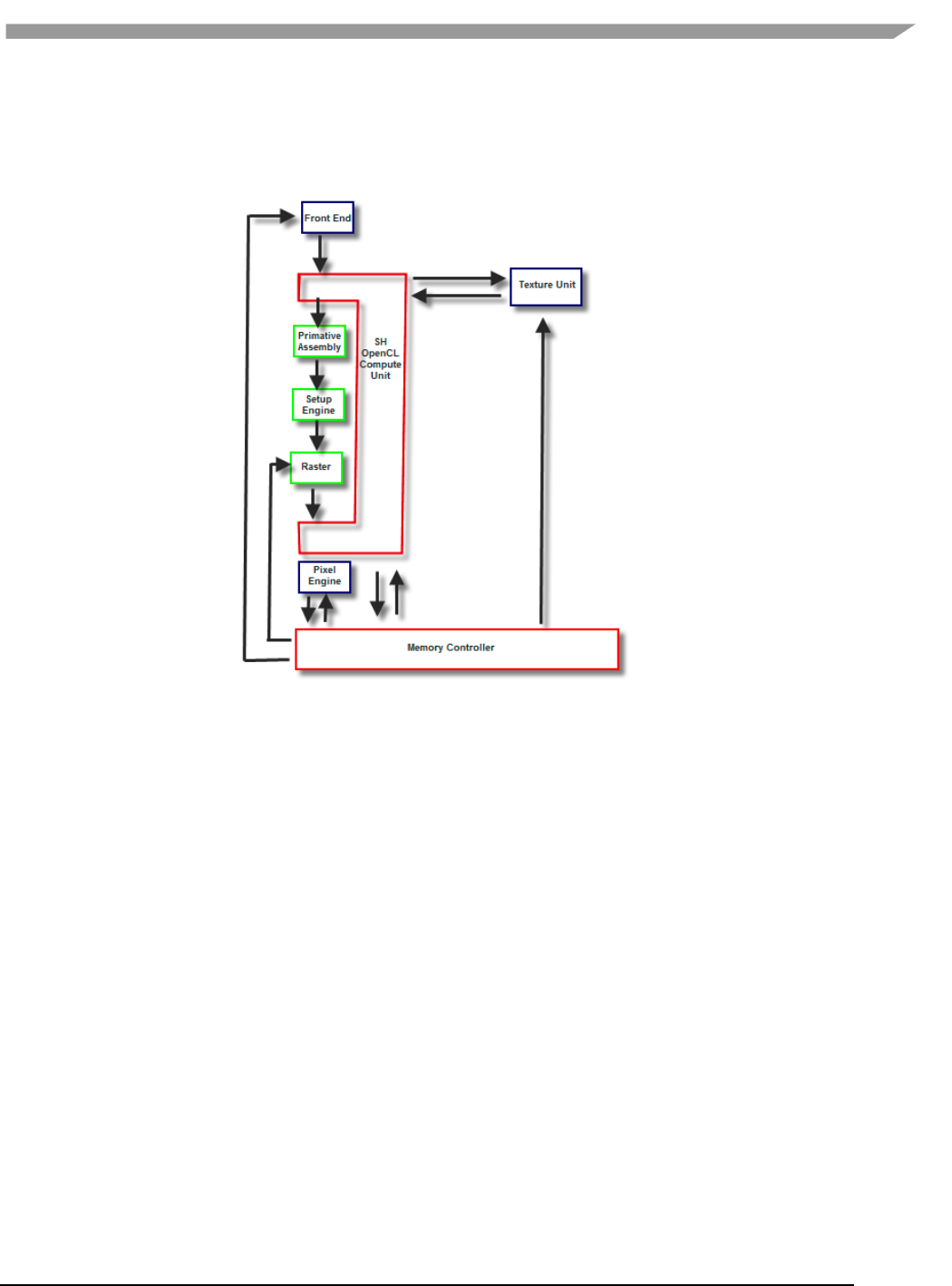
i.MX 6 Graphics User’s Guide, Rev. L3.14.28_1.0.0-ga, 04/2015
38 Freescale Semiconductor
5.2 Vivante OpenCL Implementation
5.2.1 OpenCL Pipeline
Figure 3 Vivante OpenCL Data Pipeline for a OpenCL Compute Device
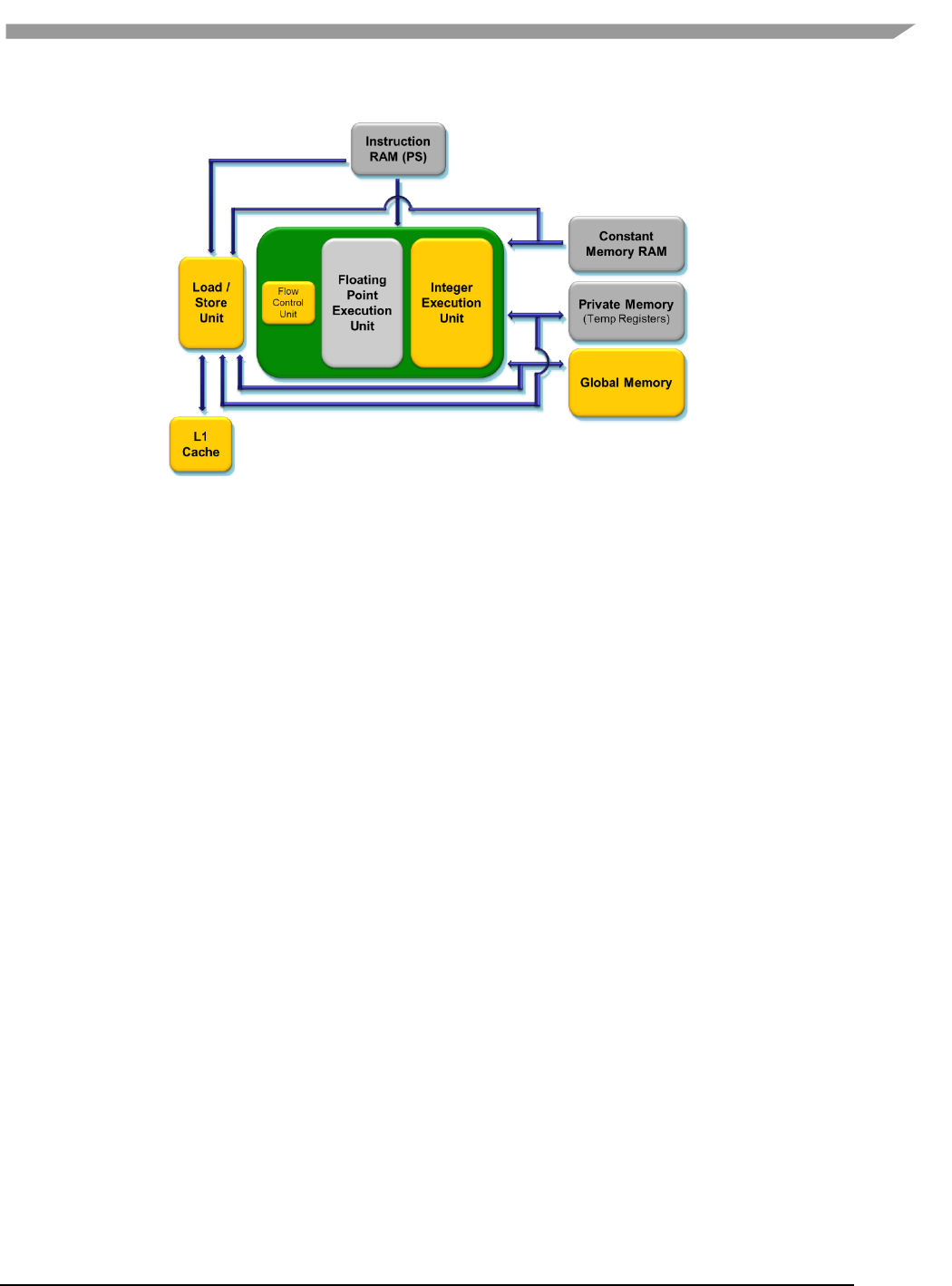
i.MX 6 Graphics User’s Guide, Rev. L3.14.28_1.0.0-ga, 04/2015
39 Freescale Semiconductor
Figure 4 Vivante OpenCL Compute Device Showing Memory Scheme
5.2.2 Front End
The front end passes the instructions and constant data as State Loads to the OpenCL Compute Unit (Shader)
block. State Loads program instructions and constant data and work groups initiate execution on the instructions
and the constants loaded.
5.2.3 The OpenCL Compute Unit
All OpenCL executions occur in this block and all work-groups in a compute unit should belong to the same kernel.
Threads from a work-group will be grouped into internal “Thread-groups”. All the threads in a thread-group
execute in parallel. Barrier instruction is supported to enforce synchronization within a work-group.
The compute unit contains Local Memory and the L1 Cache and is where the Load/Store instruction to access
global memory originates. The compute unit can accommodate multiple work-groups (based on the temporary
register and local memory usage) simultaneously.
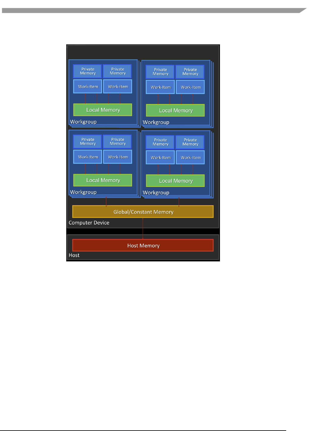
i.MX 6 Graphics User’s Guide, Rev. L3.14.28_1.0.0-ga, 04/2015
40 Freescale Semiconductor
5.2.4 Memory Hierarchy
Figure 5 OpenCL Memory Hierarchy
5.3 Optimization for OpenCL Embedded Profile
OpenCL EP (Embedded Profile) is basically a scaled down version of OpenCL FP(Full Profile) and thus may require
extra optimization. The guidelines below will help with the optimization of Vivante OpenCL Embedded Profile
GPGPU cores.
When optimizing code on Vivante hardware, it is important to remember a few key points to get the best
performance from the hardware:
• Take advantage of algorithm and data parallelism
• Choose the correct execution configuration (more details below)
• Overlap memory transfer from different levels of the OpenCL memory hierarchy with simultaneous
thread execution
• Maximize memory bandwidth and minimize data transfers (large transfers are more beneficial than many
smaller transfers because of the impact of latency)
• Maximize instruction throughput and minimize instruction count

i.MX 6 Graphics User’s Guide, Rev. L3.14.28_1.0.0-ga, 04/2015
41 Freescale Semiconductor
5.3.1 Use preferred multiple of work-group size
The work-group size should be a multiple of the thread group size, otherwise some threads will remain idle and the
application will not fully utilize all the compute resources. For example, if the work-group size is 8 and the Vivante
core supports 16, then only half the compute resources will be used. For example, in some early Vivante GPGPU
revisions, the work-group size limit is 192 and the thread group size is 16. Refer to the Overview section on OpenCL
Compatible IP for IP specific capabilities.
5.3.2 Use multiple work-groups of reduced size
Multiple work groups need to be set to reduce synchronization penalties. To prevent stalls at barriers, it is
recommended to have at least four (4) work-groups to keep the cores busy or as long as the number of work-
groups is greater than or equal to two (2). One work-group is very inefficient; four or more is preferred and helps
avoid latency.
5.3.3 Pack work-item data
It is important to pack data to extract the optimal performance from the SIMD ALU hardware and align the data
into a format supported by the hardware. Efficient use of the Vivante GPGPU core requires that the kernel
contains enough parallelism to fill all four vector units. Work-items in the same thread group have the same
program counter and execute the same instruction for each cycle. Whenever possible, pack together work-items
that follow the same direction (e.g., on branches) since the granularity will be very close and you will see less
divergence and higher performance. If each work-item handles less than or equal to 8 bytes, it is better to combine
two or more work-items into one to improve utilization of the SIMD ALU.
5.3.4 Improve locality
If the input data is an array-of-structs, and each work-item needs to access only a small part of the struct across
many array elements at different stages, it may be better to convert and use a struct-of-arrays or several different
arrays as input to improve data locality and avoid cache thrashing.
If each work-item needs to process a row of data without sharing any data with other work-items, it is better to
check if the algorithm can be converted to make each work-item process a column of data so that data accessed by
adjacent work-items can share the same cache lines.
5.3.5 Minimize use of 1KB local memory
The OpenCL Embedded Profile specification defines the minimum requirement for local memory to be 1KB to pass
conformance testing. Based on algorithm analysis and profiling different image and computer vision algorithms,
we found that a 1KB local memory size was too small to benefit those algorithms. In most cases, those algorithms
actually slowed down when using 1KB local memory. To increase performance, we recommend not using local
memory since it is more efficient to transfer larger chunks of data from system memory to keep the OpenCL
pipeline full.
Note: if local memory type is CL_GLOBAL, the local memory is emulated using global memory, and the
performance will be the same as global memory. There is extra overhead on data copy from global to local, which
will slow down the performance.
5.3.6 Use 16 Byte Memory Read/Write size
When accessing memory, it is important to minimize the read/write count and to ensure L1 cache utilization is high
to reduce outstanding read/write requests. Since the internal GPGPU read-write-request queue has a limit, if the
queue and L1 cache are filled, then the GPGPU will remain idle.

i.MX 6 Graphics User’s Guide, Rev. L3.14.28_1.0.0-ga, 04/2015
42 Freescale Semiconductor
5.3.7 Use _RTZ rounding mode
Wherever possible, use _RTZ (round to zero) since it is natively supported in hardware with one instruction.
Support for _RTE (round to nearest even) is optional in OpenCL EP and is only supported in Vivante GPGPU EP
hardware from 2013. This function will be handled in software for EP cores if necessary.
5.3.8 Use native functions
5.3.8.1 Use native_function() for increased performance
There are two types of runtime math libraries available to developers. Native_function() and regular function().
• Function(): slower, computationally expensive, higher instruction count, and greater accuracy
• Native_function(): faster, computationally inexpensive, lower instruction count (sometimes reduced to
one instruction), and lower accuracy.
• If accuracy is not important but speed/performance is, use native math functions that map directly to the
Vivante GPGPU hardware.
For image processing computations that do not require high accuracy, use native instructions to significantly lower
the instruction count and speed up performance. Based on actual analysis and performance profiling with the
Vivante GPGPU, we found that using native_function() instructions such as sin, cos, etc., will reduce the instruction
count from many instructions to one or two instructions. Use of native functions also sped performance by 3x-10x.
5.3.8.2 Use native_divide and native_reciprocal for faster floating point calculations
There are two use cases for floating point division which a user can select:
• Normal use of the division operator ( / ) in OpenCL has high precision and covers all corner cases. This
operator generates more instructions and runs slower.
• Native Divide: this case uses the built-in function native_divide or native_reciprocal, which will uses what
the hardware supports. The Vivante OpenCL compiler generates one or two instructions for each native_divide or
native_reciprocal instruction. If there are no corner cases in applications, such as NaN, INF, or (2^127) / (2^127), it
is better to use native_divide since it is faster.
5.3.8.3 Use compile option for native functions
Both the function() and native_function() methods are supported in the Vivante GPGPUs, so it is up to the
developer to use whichever method makes sense for their application. If the OpenCL program uses the standard
division operator and a developer wants to use native_divide or native_reciprocal without modifying their
program, the Vivante OpenCL compiler has a simple option “-cl-fast-relaxed-math” that uses native built-in
functions during compilation.
5.3.9 Use Buffers instead of Images
For the following image functions, it is better to use buffers instead of images.
• read_image{f/i/ui/h}
• write_image{f/i/ui/h}
Write_image* functions are implemented by software; it is better to use buffers to reduce the additional overhead
involved in checking for size, format, etc. Since a few formats are not supported by Vivante GPGPU hardware,
some built-in read_image() functions will be implemented in software. The software implementation uses more
instructions with many steps of “condition” checking. To improve performance, we recommend using buffers since
it reduces instruction count.
5.4 OpenCL Debug Messages
When writing OpenCL applications, it is important to check the code returned by the API. Since the return codes
specified in the OpenCL specification may not be descriptive enough to isolate where the problem is located, the

i.MX 6 Graphics User’s Guide, Rev. L3.14.28_1.0.0-ga, 04/2015
43 Freescale Semiconductor
Vivante OpenCL driver provides an environment variable, VIV_DEBUG to help debug problems. When VIV_DEBUG
is set to -MSG_LEVEL:ERROR, the Vivante OpenCL driver will print onscreen error messages as well as return the
error code to the caller.
The following error code descriptions and suggested workarounds are provided.
5.4.1 OCL-007005: (clCreateKernel) Cannot Link Kernel
One of the following “Not Enough” messages usually precedes this message. Issuer will indicate the real reason for
the problem which may be:
Not Enough Register Memory (constant or temp)
Not Enough Instruction Memory
5.4.2 Not Enough Register Memory
Local variables, including arrays, are implemented using temp registers. If an array is larger than then number of
available temp registers, a link-time failure will occur.
WORKAROUNDS:
1. If the array size is more than 64, use an array address to force the compiler to use private memory instead
of temp registers.
2. If there are many variables, use variable addresses to force the compiler to use private memory to reduce
register usage.
Note that there is performance degradation when using private memory instead of registers. It is better to change
the algorithm to use a smaller array or less variables.
5.4.3 Not Enough Instruction Memory
WORKAROUNDS:
1. Replace sin/cos/tan/divide/powr/exp/exp2/exp10/log/log2/log10/sqrt/rsqrt/recip with
native_sin/native_divide, etc.
2. Convert unrolled-loops back to loops.
3. Use buffer instead of image for write, and for reads which are not linear-filtered.
4. If the program is just too long, it should be split into two or more programs with intermediate data saved
from one program to next.
5.4.4 GlobalWorkSize over Hardware Limit
WORKAROUND:
1. Split one clEnqueueNDRangeKernel into several instances. Change the kernel source to compute real
global/local/group ID using offset as a parameter.
2. Convert one dimension to two dimensions, or two dimensions to three. For example, one dimension of
1M work-items can be converted to a GlobalWorkSize of 64K x16 work-items. The kernel function needs
modification to reflect the change of dimension.

i.MX 6 Graphics User’s Guide, Rev. L3.14.28_1.0.0-ga, 04/2015
44 Freescale Semiconductor
Chapter 6 Freescale XServer Video Driver
6.1 EXA driver
XServer video driver is designed to help XServer to render desktop onto a screen. It manages the display driver,
and provides rendering acceleration and other display features, such as rotation and multiple display methods.
Freescale video driver implements XServer’s EXcellent Architecture (EXA).
6.1.1 EXA driver options
These options are used in the configuration file /etc/X11/xorg.conf:
Section "Device"
Identifier "i.MX Accelerated Framebuffer Device"
Driver "vivante"
Option "fbdev" "/dev/fb1"
Option "vivante_fbdev" "/dev/fb1"
Option "SyncDraw" "false"
EndSection
Table 12 EXA driver options
Option
Meaning
Default Value
Comment
ShadowFB
Whether to enable the
shadow frame buffer (FB).
False
Deprecated technology. It rotates the FB. If
it is enabled, acceleration is disabled.
Rotate
Rotation of FB.
<null>
Deprecated technology. It can be CW/CCW/
UD. If it is set to one of these values,
Shadow FB is automatically enabled.
Rotation cannot change after XServer is
started.
NoAccel
Disables EXA acceleration.
False
If it is set to True, the EXA functions are not
accelerated by the GPU.
VivCacheMem
Pixmap created by GPU is
generally cacheable.
True
Normal Pixmaps are created cacheable.
Special Pixmaps used for EGL are still non-
cacheable.
SyncDraw
Wait for the GPU to
complete for every single
drawing.
False
This will affect the performance if it is set
to True.
6.1.2 24 bpp pixmap
The GPU can only accelerate a 16 bpp or 32 bpp pixmap. For a 24 bpp screen, a 32 bpp buffer is actually reserved.
6.1.3 Shared pixmap extension
The Shared Pixmap Extension (SHM) pixmap will be described in next release.

i.MX 6 Graphics User’s Guide, Rev. L3.14.28_1.0.0-ga, 04/2015
45 Freescale Semiconductor
6.1.4 How to disable XRandR
For an embedded device that does not support XRandR (for which the memory can be reduced), set
“gEnableXRandR” to False in vivante_fbdev_driver.c.
6.1.5 Cursor
Freescale hardware IPU does not provide a hardware cursor.
6.1.6 DRI
DRI is designed to accelerate OpenGL rendering. It enables the GPU direct render to the on-screen buffer. Due to
the lack of hard cursor support, and because often the window location is not well aligned, the GPU cannot render
to screen directly. Therefore, DRI is not fully used.
DRI is supported in this video driver. DRI2 or DRI3 is not supported.
6.1.7 Tearing
XServer (and early Microsoft Windows OS) does not support double buffering for the screen. There will be a copy
from off-screen buffer to target on-screen area (or direct rendering to on-screen). The operation cannot be
completed in the blank time of the display, and the IPU cannot provide an ideal VSYNC signal. Therefore, there will
be tearing.
To remove tearing, a GLES compositor is needed. This tearing free feature will be described in next release.
6.2 XRandR
This video driver supports XRandR.
The X Resize, Rotate and Reflect Extension (RandR) is an X Window System extension, which allows clients to
dynamically resize, rotate, and reflect the root window of a screen (en.wikipedia.org/wiki/Xrandr).
6.2.1 Useful commands
If the display supports multiple resolution types, use the following commands for a query:
root@imx6qsabresd:~# export DISPLAY=:0.0
root@imx6qsabresd:~# xrandr
Screen 0: minimum 240 x 240, current 1920 x 1080, maximum 8192 x 8192
DISP3 BG connected 1920x1080+0+0 (normal left inverted right x axis y axis) 0mm x 0mm
S:1920x1080p-50 50.0*
S:1920x1080p-60 60.0
S:1280x720p-50 50.0
S:1280x720p-60 60.0
S:720x576p-50 50.0
S:720x480p-60 59.9
V:640x480p-60 60.0
S:640x480p-60 59.9
If using the console serial port for the command line interface, the DISPLAY environment variable is not configured
by default and the xrandr command will fail. The solution is to set the DISPLAY environment variable. (Reference:
see manpage for X)
root@imx6qsabresd:~# xrandr
Can't open display
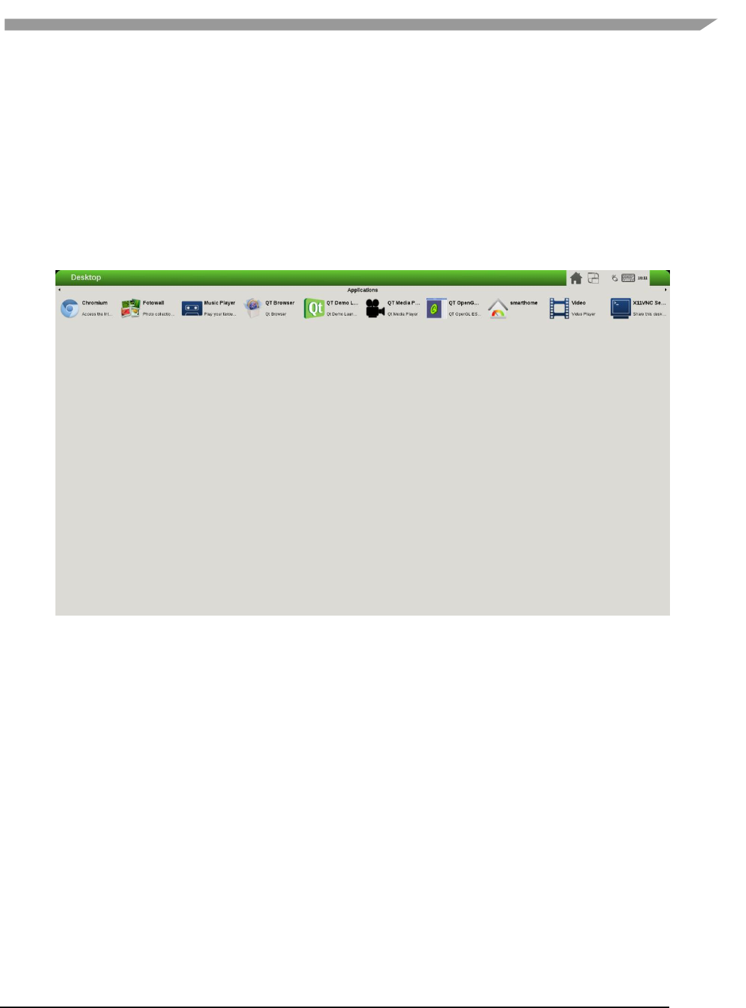
i.MX 6 Graphics User’s Guide, Rev. L3.14.28_1.0.0-ga, 04/2015
46 Freescale Semiconductor
root@imx6qsabresd:~# echo $DISPLAY
root@imx6qsabresd:~# export DISPLAY=:0.0
root@imx6qsabresd:~# xrandr
Screen 0: minimum 240 x 240, current 1024 x 768, maximum 8192 x 8192
DISP4 BG - DI1 connected 1024x768+0+0 (normal left inverted right x axis y axis) 0mm x
0mm
U:1024x768p-60 60.0*+
Change the resolution:
root@imx6qsabresd:~# xrandr -s 1920x1080
Figure 6 Changeing the resolution
i.MX 6 Graphics User’s Guide, Rev. L3.14.28_1.0.0-ga, 04/2015
47 Freescale Semiconductor
Rotate the screen:
root@imx6qsabresd:~# xrandr -o left:
Figure 7 Rotating the screen

i.MX 6 Graphics User’s Guide, Rev. L3.14.28_1.0.0-ga, 04/2015
48 Freescale Semiconductor
root@imx6qsabresd:~# xrandr -o right:
Figure 8 Rotating the screen
i.MX 6 Graphics User’s Guide, Rev. L3.14.28_1.0.0-ga, 04/2015
49 Freescale Semiconductor
root@imx6qsabresd:~# xrandr -o inverted:
Figure 9 Rotating the screen

i.MX 6 Graphics User’s Guide, Rev. L3.14.28_1.0.0-ga, 04/2015
50 Freescale Semiconductor
Reflect the screen:
root@imx6qsabresd:~# xrandr -x
Figure 10 Reflecting the screen
i.MX 6 Graphics User’s Guide, Rev. L3.14.28_1.0.0-ga, 04/2015
51 Freescale Semiconductor
root@imx6qsabresd:~# xrandr -y
Figure 11 Reflecting the screen
i.MX 6 Graphics User’s Guide, Rev. L3.14.28_1.0.0-ga, 04/2015
52 Freescale Semiconductor
Restore to normal state:
root@imx6qsabresd:~# xrandr -o normal:
Figure 12 Restoring to normal state
6.2.2 Rendering the desktop on overlay
/dev/fb1 is the overlay device on the same screen as /dev/fb0; and /dev/fb3 is the overlay of /dev/fb2. Use
xorg.conf to specify fb1 or fb3:
Section "Device"
Identifier "i.MX Accelerated Framebuffer Device"
Driver "vivante"
Option "fbdev" "/dev/fb1"
Option "vivante_fbdev" "/dev/fb1"
EndSection
After rebooting the system, the desktop will be rendered on the overlay:
i.MX 6 Graphics User’s Guide, Rev. L3.14.28_1.0.0-ga, 04/2015
53 Freescale Semiconductor
Figure 13 Rendering the desktop on overlay
If the size is too small (240x240), XRandR can be used to define a new mode.
1. Get the output name:
root@imx6qsabresd:~# xrandr
Screen 0: minimum 240 x 240, current 240 x 320, maximum 8192 x 8192
DISP4 FG connected 240x320+0+0 (normal left inverted right x axis y axis) 0mm x 0mm
U:240x320p-60 60.0*
2. Define a new mode:
root@imx6qsabresd:~# xrandr --newmode "640x480R" 23.50 640 688 720 800 480 483 487 494 +hsync -
vsync
3. Add the newly created mode:
root@imx6qsabresd:~# xrandr --addmode "DISP4 FG" 640x480R
4. Check the modes:
root@imx6qsabresd:~# xrandr
Screen 0: minimum 240 x 240, current 240 x 320, maximum 8192 x 8192
DISP4 FG connected 240x320+0+0 (normal left inverted right x axis y axis) 0mm x 0mm
U:240x320p-60 60.0*
640x480R 59.5
i.MX 6 Graphics User’s Guide, Rev. L3.14.28_1.0.0-ga, 04/2015
54 Freescale Semiconductor
5. Switch to a new mode:
root@imx6qsabresd:~# xrandr -s 640x480
Figure 14 Switching to a new mode
Note:
The overlay size cannot exceed the display size. For example, if LVDS is 1024x768, the overlay size cannot
be larger than this.
Timings for overlay are meaningless, but wrong timings may damage your display, so be careful when
creating a new display mode for your display.
If fb3 is used, fb2 must be enabled. Otherwise, fb3 is invisible.
6.2.3 Process of selecting the HDMI default resolution
The process of selecting the HDMI default resolution is as follows:
1. Set the user preferred mode (must be within the initial size).
2. Set the display preferred mode (must be within the initial size).
3. Check the aspect (if not found, use 4:3. Find the biggest resolution within the initial size for the aspect
ratio).
4. Check the first mode.
Initial size: initial FB virtual size or configured maximum size.
To specify the user preferred mode, add the option “PreferredMode” or “modes”.

i.MX 6 Graphics User’s Guide, Rev. L3.14.28_1.0.0-ga, 04/2015
55 Freescale Semiconductor
6.2.4 Performance
The performance will decrease in the case of screen rotation or mirroring.
6.2.5 Memory consumption
The video driver supports a maximum of 1920x1080@32bpp. To support rotation, a shadow buffer is reserved, so
the total memory consumption is 16 MB (1920x1080x4x2).

i.MX 6 Graphics User’s Guide, Rev. L3.14.28_1.0.0-ga, 04/2015
56 Freescale Semiconductor
Chapter 7 Vivante Software Tool Kit
7.1 Vivante Tool Kit overview
The Vivante Tool Kit (VTK) is a set of applications designed to be used by graphics application developers to rapidly
develop and port graphics applications either stand alone, or as part of an IDE targeting a system-on-chip (SoC)
platform containing an embedded GPU.
7.1.1 VTK component overview
The VTK includes a graphics and OpenCL emulator (vEmulator) to enable embedded graphics and compute
application development on a PC platform, a driver and hardware performance profiling utility (vProfiler), and a
visual analyzer (vAnalyzer) for graphing the performance metrics. Also provided are pre-processing utilities for
stand-alone development of optimized shader programs (vShader) and for compiling shader code (vCompiler) into
binary executables targeting Vivante accelerated hardware platforms. An image transfer utility (vTexture) provides
compression and decompression options.
Figure 15 Vivante Tool Kit vTools components
7.1.2 VTK operating system requirements
Most VTK vTools applications are designed to run on Microsoft Windows operating systems. The following systems
are compatible with current releases of vTools:
• Microsoft Windows XP Professional, with Service Pack 2 or later
• Microsoft Windows Vista with Service Pack 2 or later
• Microsoft Windows 7 Professional
Some components, such as the vProfiler, are run on other platforms. Refer to the individual vTools component
detail description.

i.MX 6 Graphics User’s Guide, Rev. L3.14.28_1.0.0-ga, 04/2015
57 Freescale Semiconductor
7.1.3 VTK installation
The vProfiler tool is not included in the VTK. This tool can be built by setting a build command option when making
the Vivante Graphics Drivers.
The VTK package contains a vtools folder. Inside this folder are six .zip packages which can be individually
extracted. As an example, if you have a system with WinRAR installed, right click and select Extract Here. A folder
will be created with the same name as the .zip file.
• vAnalyze.zip
• vCompiler.zip
• vEmulator.zip
• vShader.zip
• vTexture.zip
• vTracer.zip
Each vTools extracted folder will contain a SETUP.exe and a vToolName.msi file. The tool can be installed
independently by running the SETUP.exe located in that tool’s folder. Typical licensing and folder placement
options may appear as part of the installation prompts.
vAnalyzer and vShader have a Windows GUI. vEmulator is a library. vCompiler and vTexture are utilities run from
the command line.
NOTES:
• The default installation location for the VTK is usually a folder named something like C:\Program
Files\Vivante\vToolName, where vToolName is the name of the tool being installed. Some systems may install to a
Program Files (x86) folder.
• Windows navigation instructions such as Control Panel navigation will vary with the different Windows operating
systems.
• Administrator rights may be required to install the tool.
• If you are installing an update version, use Windows Add/Remove programs to remove the installed version of
the tool, before installing the update version.
7.2 vEmulator
Vivante’s vEmulator duplicates the graphics and compute functionality of the Khronos APIs—namely, OpenGL ES
3.0, 2.0, 1.1 and OpenCL 1.1—in a desktop PC environment. This enables developers to write and test applications
for Vivante embedded GPU cores prior to their availability, using the graphics cards on Windows XP or Windows
Vista™or Windows 7 PC platforms.
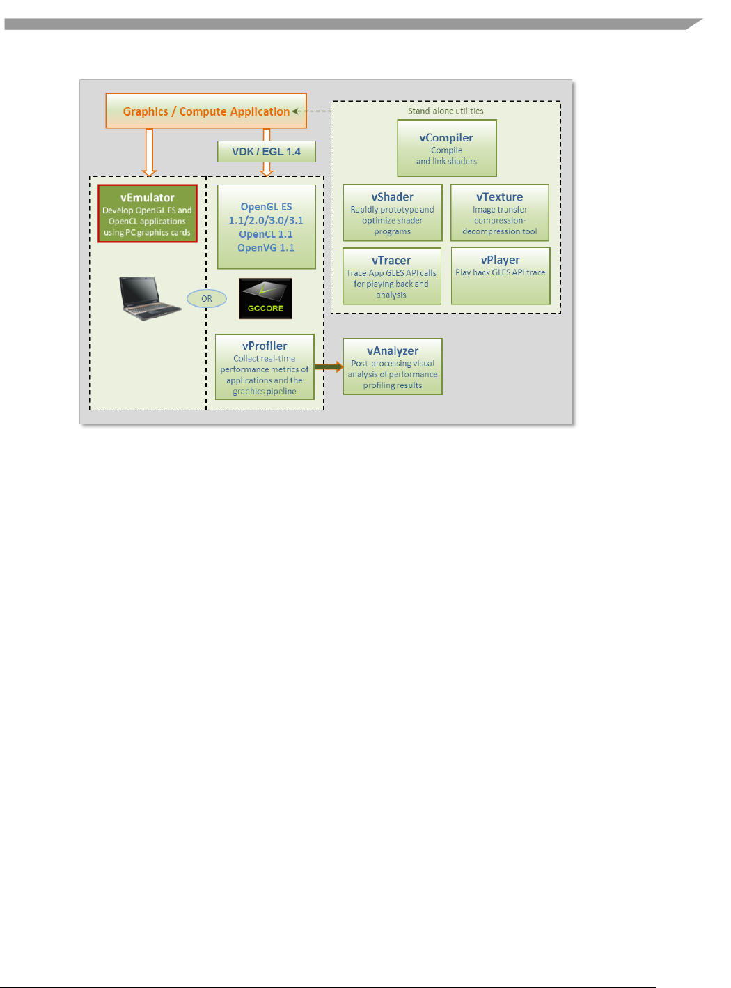
i.MX 6 Graphics User’s Guide, Rev. L3.14.28_1.0.0-ga, 04/2015
58 Freescale Semiconductor
Figure 16 vEmulator embedded graphics emulator
vEmulator is not an application, but rather a set of libraries that convert Khronos mobile API function calls into
OpenGL desktop or OpenCL function calls. These libraries can be accessed directly by the graphics / compute
application.
7.2.1 Supported operating systems and graphics hardware
vEmulator libraries are available for Microsoft Windows XP, Windows Vista and Windows 7 operating systems:
Microsoft Windows XP Professional, with Service Pack 2 or later
Microsoft Windows Vista with Service Pack 2 or later
Microsoft Windows 7 Professional
vEmulator has been tested on popular graphics cards, including:
NVIDIA GeForce GTX 200 series with driver version 182.05or later
NVIDIA GeForce 9000 and 8000 series with driver version 182.05or later
NVIDIA GeForce 8400 GSwithForceWare driver version 176.44 or later
ATI Radeon HD 3000 and 4000 series with driver version Catalyst 9.1 or later
vEmulator for OpenGL ES 3 has been tested on the nVidia GeForce GT430 card with driver version 310.90.
Additional graphics cards will be added as testing is confirmed.
7.2.1.1 Specifying platform mode for Windows OS
vEmulator supports both 32-bit and 64-bit operation on the same host (from VTK 1.61). The install will use the
following locations for vEmulator files on Windows platforms:
C:\Program Files\vivante\vEmulator\x86 (for 32-bit emulation)
C:\Program Files\vivante\vEmulator\x64 (for 64-bit emulation)
Start Menu location: All Programs\Vivante\vEmulator\x86 (for 32-bit)
Start Menu location: All Programs\Vivante\vEmulator\x64 (for 64-bit)
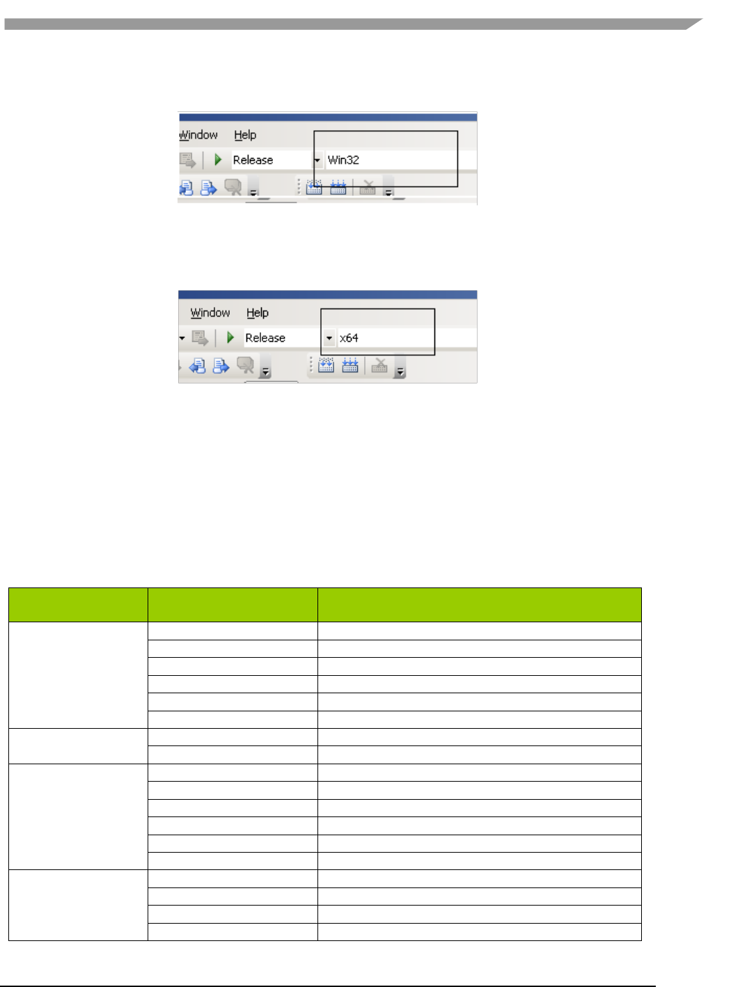
i.MX 6 Graphics User’s Guide, Rev. L3.14.28_1.0.0-ga, 04/2015
59 Freescale Semiconductor
To run samples for 32-bit emulation in the x86 folder, select the platform option Win32 from the dropdown list
box in the toolbar area:
Figure 17 Selecting Win32
To run samples for 64-bit emulation in the x64 folder, select the platform option x64 from the dropdown list box in
the toolbar area:
Figure 18 Selecting x64
7.2.2 vEmulator components
vEmulator libraries are packaged with the Vivante VTK installer. Once installed, the libraries will reside in a folder
vEmulator in the VTK installation path, which can be specified by the user at time of installation. The default
location of the Vivante VTK is:
C:\Program Files\Vivante
The vEmulator folder contains everything that is needed for emulation. The vEmulator directory structure and its
files are described in the following table.
Table 13 vEmulator Directory Contents
vEmulator
subdirectory
Filename
Description
bin
libEGL.dll
Dynamic library for invoking EGL at runtime
libGLESv1_CM.dll
Dynamic library for OpenGL ES 1.1 emulation
libGLESv2x.dll
Dynamic library for OpenGL ES 2.0 emulation
libGLESv3.dll
Dynamic library for OpenGL ES 3.0 emulation
libOpenCL.dll
Dynamic library for OpenCL 1.1 emulation
libVEmulatorVDK.dll
Dynamic library for vEmulator VDK functions
inc
gc_vdk.h
Vivante VDK declarations
gc_vdk_types.h
Vivante VDK type declarations
inc/EGL
gc_sdk.h
Vivante SDK declarations and definitions
egl.h
EGL declarations
eglext.h
EGL extension declarations
eglplatform.h
Platform specific EGL declarations
eglrename.h
Rename for building static link driver
eglunname.h
For mixed usage of ES11, ES20
inc/GLES
eglvivante.h
Vivante EGL declarations
egl.h
EGL declarations
gl.h
OpenGL 1.1 declarations
glext.h
OpenGL1.1 extension declarations
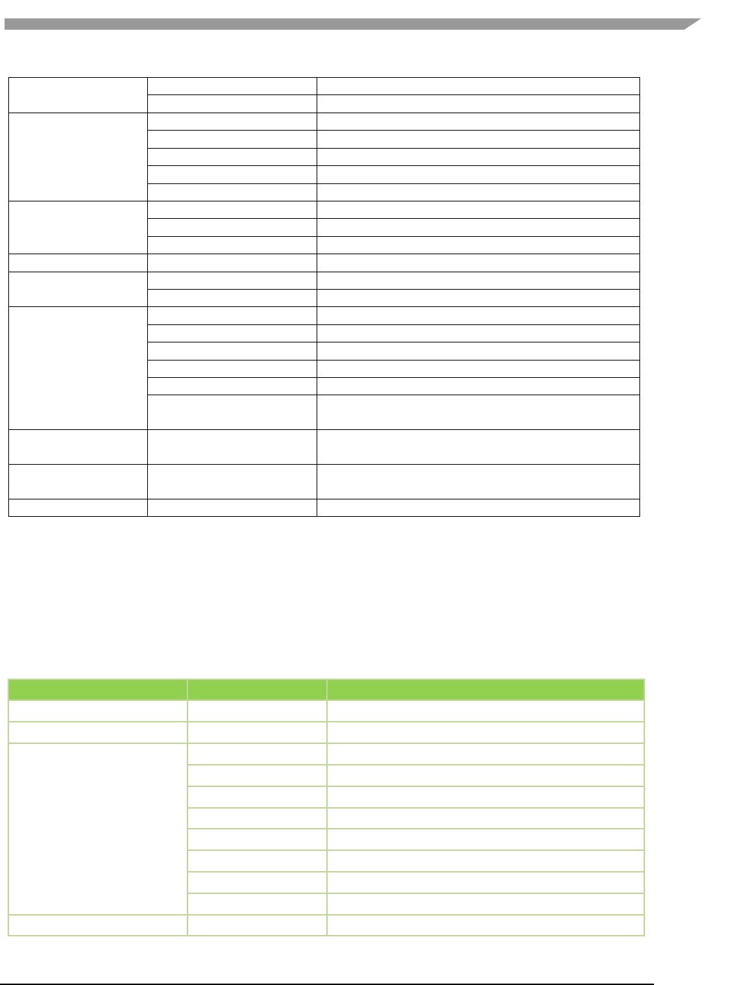
i.MX 6 Graphics User’s Guide, Rev. L3.14.28_1.0.0-ga, 04/2015
60 Freescale Semiconductor
glplatform.h
Platform specific OpenGL 1.1 declarations
glrename.h
Rename for building static link driver
inc/GLES2
glunname.h
For mixed usage of ES11, ES20
gl2.h
OpenGL 2.0 declarations
gl2ext.h
OpenGL 2.0 extension declarations
gl2platform.h
Platform specific OpenGL 2.0 declarations
gl2rename.h
Rename for building static link driver
inc/GLES3
gl2unname.h
Unified name definitions
gl3.h
OpenGL 3.0 declarations
gl3ext.h
OpenGL 3.0 extension declarations
gl3platform.h
Platform specific OpenGL 3.0 declarations
inc/hal
inc/KHR
gc_hal_eglplatform_type.h
Vivante HAL platform specific struct declarations
khrplatform.h
Platform specific Khronos declarations
lib
samples/es11, /es20
libEGL.lib
Static library for linking EGL functions
libGLESv1_CM.lib
Static library for linking OpenGL ES 1.1 functions
libGLESv2x.lib
Static library for linking OpenGL ES 2.0 functions
libGLESv3x.lib
Static library for linking OpenGL ES 3.0 functions
libVEmulatorVDK.lib
Static library for linking vEmulator VDK functions
tutorials.sln
Microsoft Visual Studio® project solution file for
samples
samples/es11/tutoria
lN
-- Varies with N --
Sample OpenGL ES 1.1 applications
samples/es20/tutoria
lN
-- Varies with N --
Sample OpenGL ES 2.0 applications
bin
libEGL.dll
Dynamic library for invoking EGL at runtime
7.2.3 vEmulator for OpenCL
If your edition of vEmulator includes support for OpenCL, additional files may be present. For OpenCL emulation
using vEmulator on your PC, please refer to the OpenCL emulator readme file (OCL_Readme.txt) in the vEmulator
folder for additional installation instruction.
Note: An additional environment variable CL_ON_GC2100 needs to be set for simulation for GC2100. The value
can be any characters, as long as it is not null. This variable does not need to be set for other OCL cores.
Table 14 vEmulator Files for OpenCL 1.1
vEmulator subdirectory
Filename
Description
OCL_Readme.txt
Readme file for OpenCL 1.1
bin
libOpenCL.dll
Dynamic library for invoking OCL at runtime
inc/CL
cl.h
OpenCL 1.1 core API header file
cl.hpp
OpenCL 1.1 C++ binding header file
cl_d3d10.h
OpenCL 1.1KhronosOCL/Direct3D extensions header file
cl_ext.h
OpenCL 1.1 extensions header file
cl_gl.h
OpenCL 1.1Khronos OCL/OpenGL extensions header file
cl_gl_ext.h
OpenCL 1.1Vivante OCL/OpenGL extensions header file
cl_platform.h
Platform specific OCL declarations
opencl.h
Vivante HAL version
lib
libOpenCL.lib
Dynamic library for linking OpenCL functions

i.MX 6 Graphics User’s Guide, Rev. L3.14.28_1.0.0-ga, 04/2015
61 Freescale Semiconductor
samples/cl11
cl_sample.cpp
Sample OpenCL 1.1 source code
samples/cl11
cl_sample.sln
Sample OpenCL 1.1 Visual Studio solution file
samples/cl11
cl_sample.vcproj
Sample OpenCL 1.1 Visual Studio solution project file
samples/cl11
square.cl
Sample OpenCL 1.1 kernel file
7.2.4 Supported extensions
Refer to Section “EGL and OES Extensions Support” for a list of supported and custom extensions available for EGL
and OpenGL ES.
Software extensions have not been added to vEmulator for OpenGL ES 2.0. vEmulator relies on the extensions
available with the installed version of native OpenGL.
7.2.5 vEmulator environment variable setup
There are two steps to running an OpenGL ES or OpenCL application with vEmulator:
Step 1. Link to the vEmulator *.lib static libraries at build time when creating an application
executable image.
Step 2. Provide a path to the vEmulator *.dll dynamic libraries during run-time.
These steps require a one-time setup in which the location of the vEmulator libraries is added to the Microsoft
Windows system environment variable named “Path.” In our example, the following string would be added to the
system “Path” variable: C:\Program Files\vivante\vEmulator\lib.
To add vEmulator DLL files to the Windows XP system path:
a. Click Start then click Control Panel then double-click System
Vista: then click Advanced system settings from the Tasks list in the upper-
leftcorner of the window.
Windows 7: in the System and Security window, click System, then on the left menu
column click Advanced system settings.
b. Select the Advanced tab, then click on the Environment Variables… button.
An Environment Variables dialogue box will pop up, with two panes for variables.
c. Select Path, and then click on the Edit… button.
d. In the Variable value: field type the following environment variables in the order you want
them found. For instance:
C:\Program Files\vivante\vEmulator\lib;<current path>
Note: The system parses a path string in left-to-right order when looking for a file. Whatever
it finds first is what will be used.
e. If the Vivante Core is GC2100, an additional variable CL_ON_GC2100 should be set to any
non-null value.
f. Click OK.
Click OK to close the Environment Variables dialogue window.
Click OK to close the System Properties dialogue window.

i.MX 6 Graphics User’s Guide, Rev. L3.14.28_1.0.0-ga, 04/2015
62 Freescale Semiconductor
Close the Control Panel > System window.
7.2.6 Sample code overview
In the discussions that follow about the various sample programs included with the vEmulator distribution, we
assume that vEmulator has been installed in the default location within the vivante/VTK folder:
C:\Program Files\vivante\vEmulator
Relative to this path:
run-time dlls are located at …\bin
include-files are found at …\inc
library files are located at …\lib\<API>
examples are located at …\samples\<API>\tutorial*
where API is one of: es11or es20
The code examples are distributed with working *.exe executable images so that the VTK user can see how the
results should look.
They are presented in a tutorial fashion, progressing from simpler programs to more complex as the tutorial
number increases.
7.2.7 Building and running the code examples
The steps to build and run are identical for all code examples, regardless of the API (es11 or es20). There are two
general guidelines to keep in mind.
1. A Visual Studio project has environment variables that allow the specification of additional paths to “include”
and “library” files when a source module from that project is being built. The Visual Studio projects that are
part of the vEmulator distribution package are configured out-of-the-box for building all of the sample code
executables, relative to the location where vEmulator is installed. Specifically the additional paths are set as
“$(SolutionDir)..\..\inc” and “$(SolutionDir)..\..\lib”.
If \samples is moved, or if the VTK user begins with the provided projects as templates for developing
applications in a directory that is not directly under the \vEmulator installation, then the project path
variables must be adjusted accordingly. For example:
To access these path variables for tutorial1, first launch the tutorials.sln
Right-click on tutorial1, then select Properties (at the bottom of the pop-up menu)
Under “Configuration Properties” > “C/C++” > “General”, edit the Additional Include Directories
entry
o E.g., change ..\..\..\inc to C:\Program Files\vivante\vEmulator\inc
Under “Configuration Properties” >“Linker” > “General”, edit the Additional Library
Directories entry
o E.g., change ..\..\..\lib to C:\Program Files\vivante\vEmulator\lib
2. Make sure that the system environment variable PATH contains a path to the vEmulator DLL files. (See above
section on vEmulatorEnvironment Variable Setup, above.) Remember that the path is order-dependent;
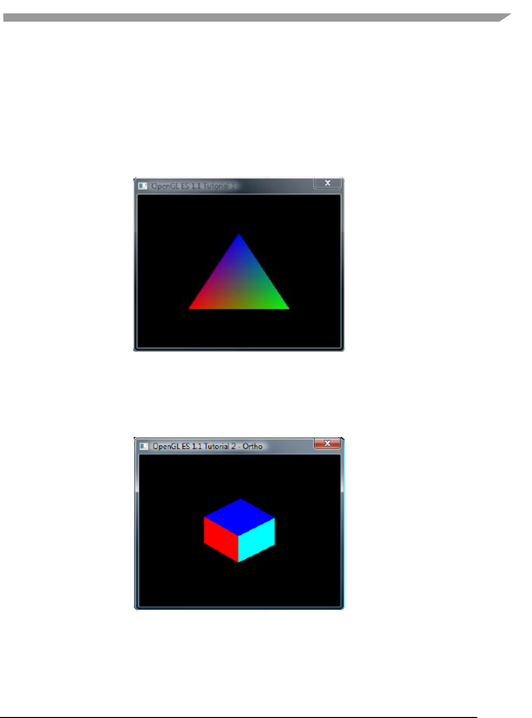
i.MX 6 Graphics User’s Guide, Rev. L3.14.28_1.0.0-ga, 04/2015
63 Freescale Semiconductor
whatever the system finds first will be used. If there is more than one DLL with the same name, double-check
that the path to the desired one is listed first in the PATH string.
7.2.8 OpenGL ES 1.1 examples
7.2.8.1 Tutorial1: rotating three-color triangle
Renders a cube centered at the origin with a different color on each face. Flat shading is used. The cube rotates
about the vertical axis. The default projection is ORTHO, which can be toggled between ORTHO and PERSPECTIVE
by left-clicking in the display window with the mouse or pressing Enter.
Figure 19 Rotating three-color triangle
7.2.8.2 Tutorial2: rotating six-color cube
Renders a cube centered at the origin with a different color on each face. Flat shading is used. The cube rotates
about the vertical axis. The default projection is ORTHO, which can be toggled between ORTHO and PERSPECTIVE
by left-clicking in the display window with the mouse or pressing Enter.
Figure 20 Rotating six-color cube
7.2.8.3 Tutorial3: rotating multi-textured cube
This example takes the cube of the previous example with PERSPECTIVE projection, loads two textures from file
and combines them using GL_ADD blending mode, and applies the resulting texture to the cube faces.
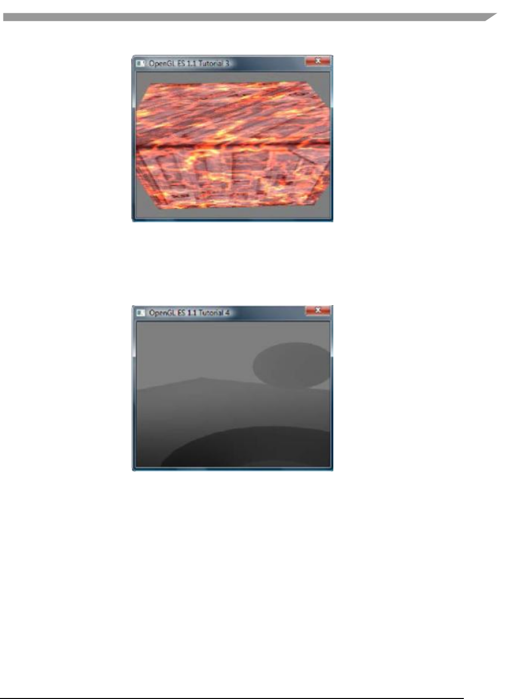
i.MX 6 Graphics User’s Guide, Rev. L3.14.28_1.0.0-ga, 04/2015
64 Freescale Semiconductor
Figure 21 Rotating multi-textured cube
7.2.8.4 Tutorial4: lighting and fog
What appears to be a torus, a cone, and an oblate spheroid orbiting about the center of a plane is actually a single
mesh being lit by a single rotating, diffuse light source. Green fog is added to the scene by left-clicking on the
display window with the mouse or pressing Enter.
Figure 22 Lighting and fog
7.2.8.5 Tutorial5: blending and bit-mapped fonts
This example makes use of alpha blending to animate sprites across the display, and it also instructs how to create
a bit-mapped font from a texture. Jumbled letters iteratively print and move across the display as they unscramble
into a text message.
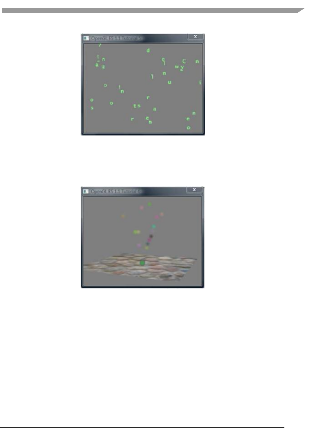
i.MX 6 Graphics User’s Guide, Rev. L3.14.28_1.0.0-ga, 04/2015
65 Freescale Semiconductor
Figure 23 Blending and bit-mapped fonts
7.2.8.6 Tutorial6: particles using point sprites
This example reuses the bit-mapped font technique from the previous tutorial, but it adds a particle generator to
simulate and animate particles being emitted from the textured plane. All computation is performed in fixed-point
arithmetic.
Figure 24 Particles using point sprites
7.2.8.7 Tutorial7: vertex buffer objects
Using Vertex Buffer Objects (VBO) can substantially increase performance by reducing the bandwidth required to
transmit geometry data. Information such vertex, normal vector, color, and so on is sent once to locate device
video memory and then bound and used as needed, rather than being read from system memory every time. This
example illustrates how to create and use vertex buffer objects.
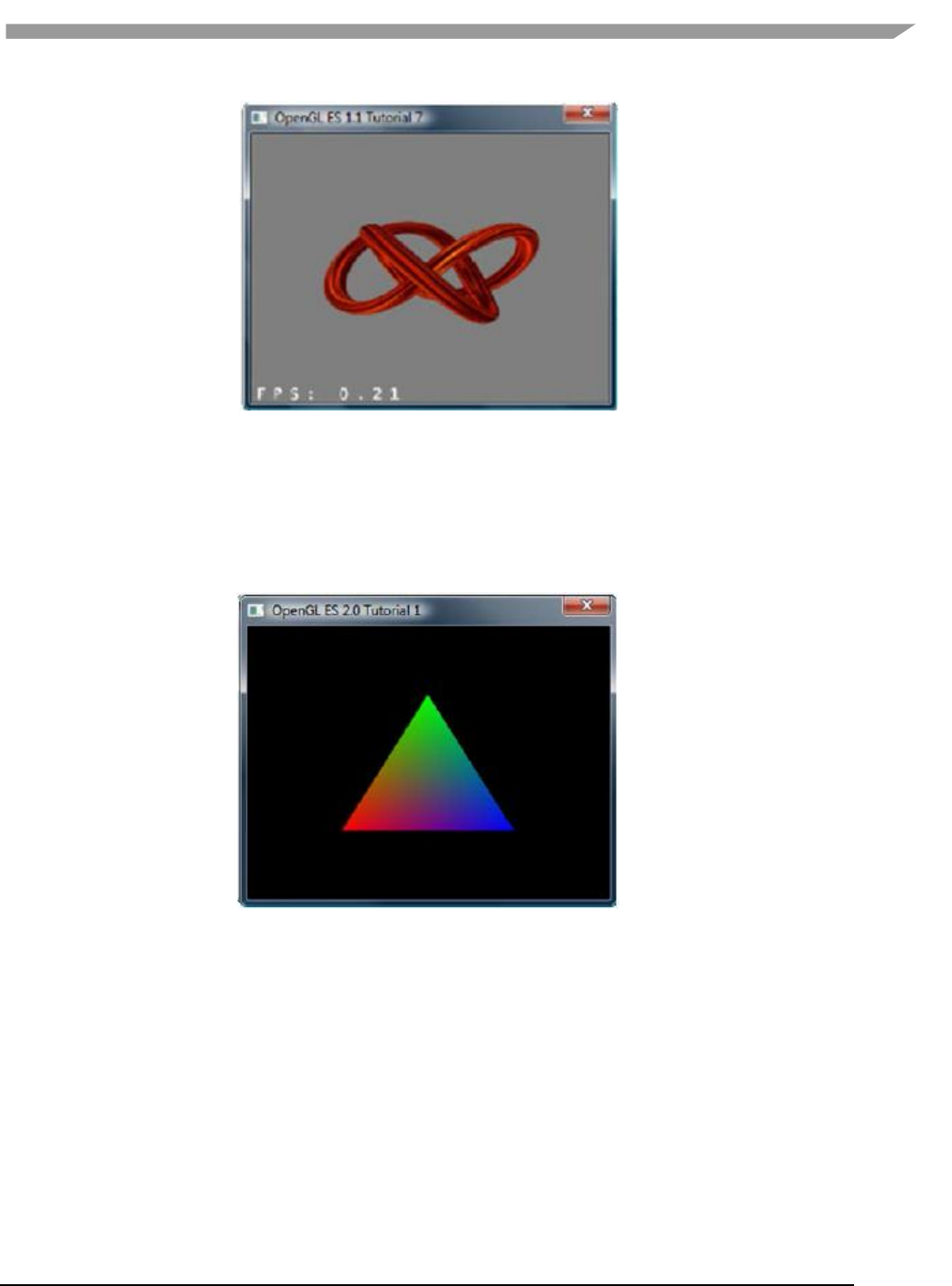
i.MX 6 Graphics User’s Guide, Rev. L3.14.28_1.0.0-ga, 04/2015
66 Freescale Semiconductor
Figure 25 Vertex buffer objects
7.2.9 OpenGL ES 2.0 examples
7.2.9.1 Tutorial1: rotating three-color triangle
A single triangle is rendered with a different color at each vertex, Gouraud shading for blending, rotational
animation in the final display. This is the same example as es11/tutorial1, only implemented in OpenGL ES 2.0.
Figure 26 Rotating three-color triangle
7.2.9.2 Tutorial2: rotating six-color cube
Renders a cube centered at the origin with a different color on each face, and rotates it about the vertical axis.
Similar to the es11/tutorial2 example, the default projection is ORTHO. But there is no toggle for PERSPECTIVE.
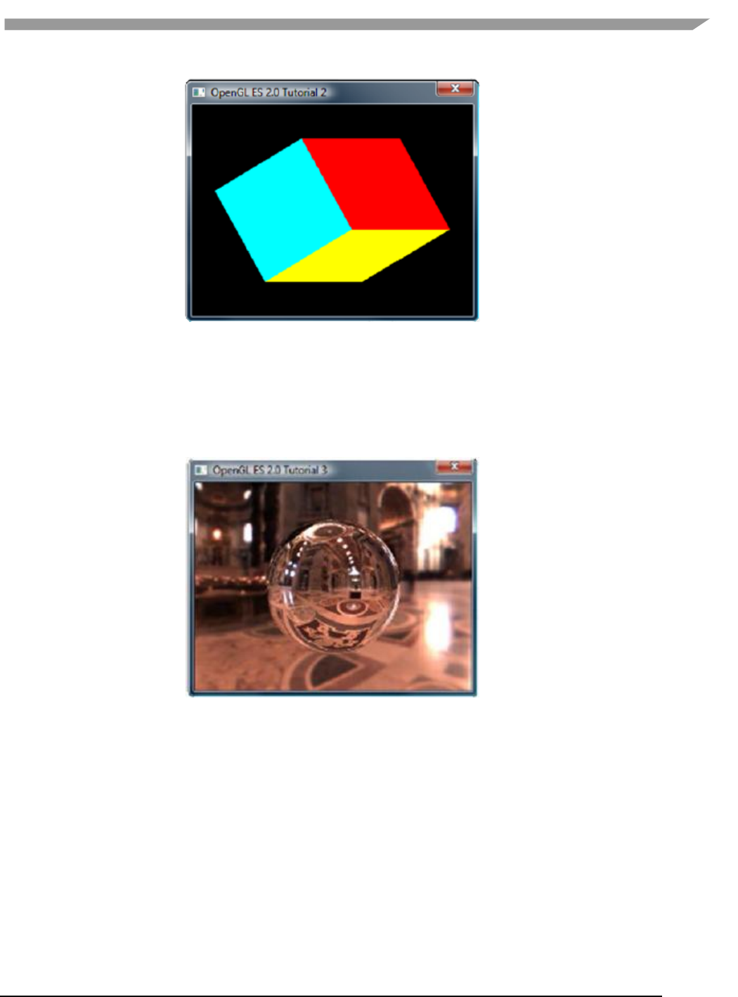
i.MX 6 Graphics User’s Guide, Rev. L3.14.28_1.0.0-ga, 04/2015
67 Freescale Semiconductor
Figure 27 Rotating six-color cube
7.2.9.3 Tutorial3: rotating reflecting ball
A ball made of a mirroring material and centered at the origin spins about its Y-axis and reflects the scene
surrounding it.
Note: if the program cannot be executed and print “GL error” in the console, please remove the line “return”
before the line of “DeleteCubeTexture(cubeTexData);”
Figure 28 Rotating reflecting ball
7.2.9.4 Tutorial4: rotating refracting ball
This example is the same as the previous one, except that the ball is made of clear glass which refracts the
surrounding environment.
Note: if the program cannot be executed and print “GL error” in the console, please remove the line “return”
before the line of “DeleteCubeTexture(cubeTexData);”
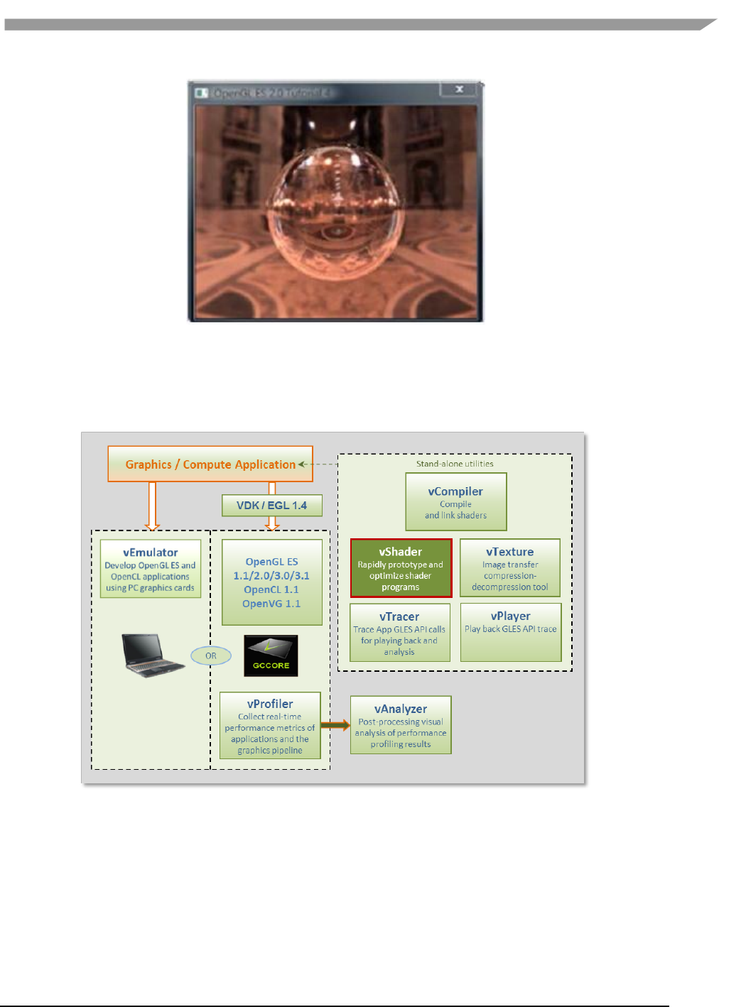
i.MX 6 Graphics User’s Guide, Rev. L3.14.28_1.0.0-ga, 04/2015
68 Freescale Semiconductor
Figure 29 Rotating refracting ball
7.3 vShader
vShader is a complete off-line environment for editing, previewing, analyzing, and optimizing shader programs.
Figure 30 vShader shader editor
vShader allows users to:
Map any texture onto shaders
Import user-defined meshes
Bind mesh attributes to shaders
Set uniforms in shaders
View shader compiler output for optimization hints
Predict hardware performance

i.MX 6 Graphics User’s Guide, Rev. L3.14.28_1.0.0-ga, 04/2015
69 Freescale Semiconductor
7.3.1 vShader components
By default, the vShader executable installs in the following location within the Vivante Toolkit directories:
C:\Program Files\Vivante\vShade.
The vShader package includes samples of shader programs, a number of standard meshes (sphere, cube, tea pot,
pyramid, etc.) and a text editor. These extra features will help programmers get a quick start on creating their
shader programs.
By combining vertex shaders and fragment shaders into a single shader program, an application can produce a
shader effect. A project can make use of many shader effects, which can share vertex and fragment shaders,
mixing and matching to achieve the desired results.
The scope of this guide is to cover the vShader user interface. The tutorials provided with the vShader package are
there to help the reader learn about shaders, if needed.
7.3.2 Getting started with vShader
Once the vShader utility is launched by clicking on a shortcut or directly on the executable vShader.exe projects
can be created, developed and saved. Project files have an extension .vsp.
7.3.2.1 Creating a new project
To create a new project, locate the main menu bar: Select File then New Project…
Depending on the current project status, one of three things will happen:
1. If this is the first time vShader is launched, then there is no project already open and selecting “File > New
Project…” will appear to have no effect.
2. If there have been no changes to the current project since the last save, then the current project will close and
a new, empty project will be opened.
3. If the current project has been modified, then a dialog box will pop up to ask if you want to save the changes.
Choosing Yes will commit the changes to the current project, which will then be closed, and a new, empty
project will be opened.
7.3.2.2 Opening an existing project
To open an existing project, locate the main menu bar:
To open an existing project, locate the main menu bar:
1. Select File then Open Project…
2. Double-click on the desired project from the list that pops up, or single-click on the project name and click OK.
The project will load into vShader and appear in the state it was last saved.
7.3.2.3 Saving a project
To save a project, locate the main menu bar:
1. Select File then Save Project…
2. In the resulting dialog box indicate where to save the project, then click OK.
7.3.3 vShaderNavigation
The vShader application runs on the Windows XP, Windows Vista and Windows 7 platforms and is driven from a
graphical user interface as shown in the figure below.
Main components of the GUI include:
on upper portion of window: a Menu Bar, Menu Icons,
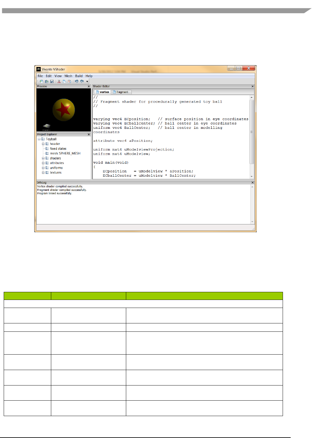
i.MX 6 Graphics User’s Guide, Rev. L3.14.28_1.0.0-ga, 04/2015
70 Freescale Semiconductor
on left: Preview pane, Project Explorer pane
on right: Shader Editor pane
on lower portion of window: InfoLog pane.
Figure 31 vShader GUI main window
7.3.3.1 vShader menu bar
The main window opens when a user launches vShader. The main menu bar contains drop-down menus for File,
Edit, View, Mesh, Build, and Help.
Table 15 vShader menu commands
Menu Name
Menu Command
Description
File
New Project…
Create a new project file; if a project is currently open, then
the user is prompted to choose whether to save it first.
Open Project…
Browse for and load a .vsp VShader project.
Save Project…
Save the current project; if this is the first time saving this
project, then the user is prompted to choose where to save
it.
Load Vertex…
Browse for and load a vertex shader from an existing text
file.
Load Fragment…
Browse for and load a fragment shader from an existing
text file.
Save VertexShader As…
Prompts for filename and location to save the active vertex
shader.
Save FragmentShader As…
Prompts for filename and location to save the active
fragment shader.
i.MX 6 Graphics User’s Guide, Rev. L3.14.28_1.0.0-ga, 04/2015
71 Freescale Semiconductor
Exit
Close all open files and exit VShader.
Edit
Undo [Ctrl-z]
Revert to a previous edit state (Note: Undo is only 1-level
deep)
Redo [Ctrl-y]
Re-apply the last “undone” edit command (Note: Redo is
only 1-level deep)
Cut [Ctrl-x]
Delete the selected item(s) and save a copy in the paste
buffer
Copy [Ctrl-c]
Save a copy of the selected item(s) item in the paste buffer
Paste [Ctrl-v]
Insert the contents of the paste buffer
Delete [Del or Bkspc]
Remove the selected item(s)
Select All [Ctrl-a]
Highlight all items in the current view
View
Reset Preview
Reset Preview window.
Snapshot
Save current preview image to bitmap bmp file. A dialog
will display to let user choose where to save the bmp.
Perspective
Use perspective projection in the Shader Preview pane
Ortho
Use orthographic projection in the Shader Preview pane
Tool Bar
Show or hide toolbar icons
Preview Window
Show or hide Preview window
Project Explorer
Show or hide Project Explorer window
Shader Editor
Show or hide Shader Editor window
InfoLog
Show or hide InfoLog window
Mesh
Conic
Looks like a spiral horn.
Cube
A 3D cube.
Klein
The Klein bottle.
Plane
A 2D square.
Sphere
A ball.
Teapot
The Utah teapot.
Torus
Looks like a donut.
Trefoil
A trefoil knot.
Custom Mesh…
Browse for and open a 3DS
mesh file.
Build
Compile
Compile the active shader.
Link
Link the vertex and fragment shaders into a shader
program, and apply it to the mesh showing in the Shader
Preview window pane.
Clear InfoLog
Remove all text currently showing in the InfoLog window
pane.

i.MX 6 Graphics User’s Guide, Rev. L3.14.28_1.0.0-ga, 04/2015
72 Freescale Semiconductor
Help
About
Information about the version of VShader being used.
7.3.3.2 vShader Window OS panes
There are four window panes in the vShader GUI: Preview, Project Explorer, Shader Editor, and InfoLog. Each pane
can be resized by left-mouse-dragging the pane edge. A pane can be hidden by clicking the X in the upper-right
corner of the pane, or by un-checking the box next to its name in the View pull-down of the main menu. Restoring
a hidden window pane is done by checking the appropriate box in the View pull-down menu.
Individual panes in the vShader application can be resized, relocated or converted to detached windows, as in the
example to the right.
Note: Changes made to pane arrangement are not restored on application or project relaunch.
Figure 32 vShader moveable panes
7.3.3.2.1 Preview
The shader Preview pane shows the current effect of the shaders on the chosen mesh geometry. A different mesh
may be chosen either via the Mesh pull-down menu in the menu bar near the top of the vShader main window or
by right-mouse clicking in the Preview pane.
When using the right-click method, the user also can choose between perspective and orthographic views of the
mesh, can reset the view orientation to the default, or can save the current view in the Preview window as a
bitmap file by selecting Snapshot.
The object in the Preview window can be rotated, translated, and scaled. Rotation is controlled by left-mouse-
drag; translation is done by holding the Ctrl key plus left-mouse-drag; scaling the image is seen by holding the Alt
key while applying left-mouse-drag.
When shader variables are changed, the shader preview updates automatically. When shader programs are
changed they must be recompiled and relinked by the user, through the Build menu. The Preview display will
automatically update to reflect the new Build.
7.3.3.3 Project explorer
The Project Explorer displays all of the project resources in a familiar tree structure. The root of the tree is the
project name, and the branches and leaves classify the resources. Folders can be expanded by clicking on the plus
sign next to them, and they can be collapsed by choosing the minus sign. By right-mouse clicking on any resource
name, the user can view and usually edit that resource.
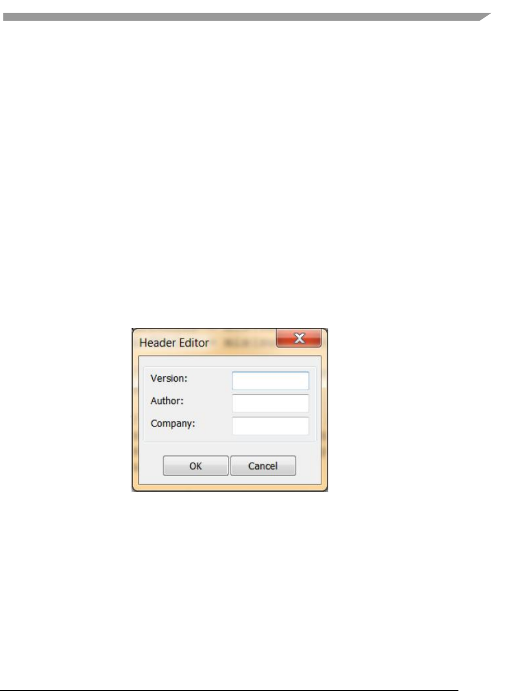
i.MX 6 Graphics User’s Guide, Rev. L3.14.28_1.0.0-ga, 04/2015
73 Freescale Semiconductor
7.3.3.3.1 Shader editor
The Shader Editor is a work area for entering and modifying shader programs. There are two tabs: one for vertex
shader, and one for fragment shader. Changes made to a shader must be compiled and linked in order for their
effect to appear in the Shader Preview.
Compiling can be done by selecting Build then Compile from the main menu bar. Likewise, linking and applying the
shaders is performed by choosing Build then Link.
7.3.3.3.2 Info log
The Info Log window pane receives diagnostic messages from the compiler and linker, so that the user can see if
the current shaders have built without errors. This pane can be cleared of text by selecting the Build then Clear
InfoLog entry in the main menu.
7.3.4 vShader project resources
Project resources are accessible from the Project Explorer pane. Click on the item and an Editor pop-up dialog will
appear where the user can enter alternate values. Resources include: header, fixed states, mesh, shaders,
attributes, uniforms, and textures.
7.3.4.1 Header
Some project identifying information, namely version, author, and company. Expand the folder to see the settings,
or right-click (or double-click) the folder to edit them.
Figure 33 Header editor
7.3.4.2 Fixed states
The Fixed State Editor is a list of OpenGL ES 2.0 fixed states settings, such as depth test enable/disable, etc. It
allows the user to set all fixed states manually. Right-click or double click to display an edit dialog.

i.MX 6 Graphics User’s Guide, Rev. L3.14.28_1.0.0-ga, 04/2015
74 Freescale Semiconductor
Figure 34 Fixed states
7.3.4.3 Mesh
This resource shows the name of the mesh which is currently being displayed in the Preview pane. It does not have
a pop-up window. Right-click on the mesh name to select a different mesh can be selected from the resulting pull-
down menu.
7.3.4.4 Shaders
Left-click on the plus sign next to the “shaders” folder to reveal the two sub nodes in this section, which are vertex
and fragment. Double-click (or right-click and then choose Active) on either shader to bring it forward in the
Shader Editor for editing.
7.3.4.5 Attributes
The Attribute Editor dialog displays all attributes bound to the current project. It allows the user to add new
attributes, and edit or remove existing attributes. Right click on Attributes to add a new one. Click on the plus sign
to expand the attributes list, and then double-click to edit a particular attribute. Also, by right-clicking on an
attribute, you can edit or remove that attribute or add a new one. Up to 12 attributes are allowed.
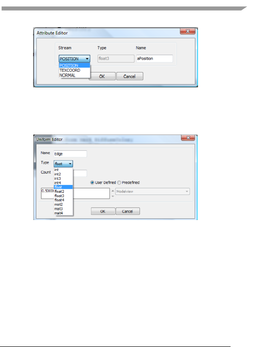
i.MX 6 Graphics User’s Guide, Rev. L3.14.28_1.0.0-ga, 04/2015
75 Freescale Semiconductor
Figure 35 Attributes
7.3.4.6 Uniforms
This displays all uniforms bound to the current project. Right click on Uniforms to add a new one, or expand the list
and double-click on a given uniform to bring up the Uniform Editor dialog. When a uniform is right-clicked, the user
can add new uniforms, or edit or remove existing uniforms. Up to 160 uniforms are allowed.
Figure 36 Uniforms
7.3.4.7 Textures
The Texture Editor dialog allows the user to select a texture for each of up to 8 texture units. The effect of applying
each texture is seen immediately in the Shader Preview pane.
The texture selection option list is created from the texture files located in the “textures” subfolder of the project.
The list can be expanded by adding textures to the textures folder, formatted as bitmap files.
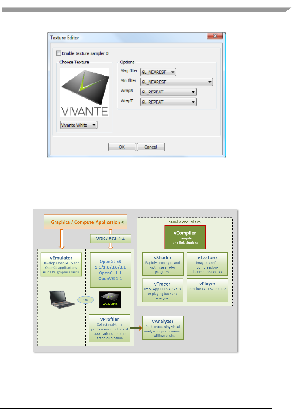
i.MX 6 Graphics User’s Guide, Rev. L3.14.28_1.0.0-ga, 04/2015
76 Freescale Semiconductor
Figure 37 Textures
7.4 vCompiler
vCompiler is an off-line compiler and linker for translating vertex and fragment shaders written in OpenGL ES
Shading Language (ESSL) into binary executables targeting Vivante accelerated hardware platforms. vCompiler is
driven by a simple command-line interface.
Figure 38 vCompiler compiler/linker

i.MX 6 Graphics User’s Guide, Rev. L3.14.28_1.0.0-ga, 04/2015
77 Freescale Semiconductor
7.4.1 vCompiler command line syntax
7.4.1.1 Syntax:
Optional inputs are indicated by italic font.
vCompiler [-c] [-h] [-l] [-On] [-v] [-x <shaderType>] [-o <outputFileName>]
<shaderInputFileName> <shaderInputFileName_2>
7.4.1.2 Input parameters (required):
shaderInputFileName
shader input file name, which must contain one of the following
file extensions:
vert
vertex shader source file
frag
fragment shader source file
vgcSL
previously compiled vertex shader input/output
file
pgcSL
previously compiled pixel shader input/output file
7.4.1.3 Input parameters (optional):
shaderInputFileName_2 up to two shader files can be specified. The second shader file is
optional but must have one of the file extensions described above for
shader InputFileName. If the first shader is a vertex shader, this
second shader should be a fragment shader; conversely if the first
shader is a fragment shader, the second should be a pixel shader.
Note: pre-compiled and compiled shaders may be mixed, as long as
one is a vertex shader and the other a fragment shader.
-c Compile each vertex .vert file into a vgcSL file and/or fragment shader
.frag file into a pgcSL only, with no merged result file of type .gcPGM.
If the –c option is not specified:
a)When only one shader is specified, that shader will be compiled into
a .[v/p]gcSL file.
b) When two shaders are specified, one is assumed to be a vertex
shader and the other a fragment shader. Each shader can be
either a previously compiled .vgcSL or .pgcSL. file or a .vert or .frag
still to be compiled. The two will be merged into a .gcPGM file
after successful compilation.
-f <gpuConfigurationFile> Specifies a configuration file (from VTK 1.6.2). If –f is not specified, the
file viv_gpu.config in the vCompiler working directory will be used
as the default configuration file. Example syntax:
vCompiler –f viv_gpu_880.config foo.vert bar.frag
Note: vCompiler will not work correctly if the GPU
configuration file cannot be found or contains incorrect
content. See Section on vCompiler Core-Specific Configuration
for .config file content organization.
-h Shows a help message on all the command options.

i.MX 6 Graphics User’s Guide, Rev. L3.14.28_1.0.0-ga, 04/2015
78 Freescale Semiconductor
-l Create a log file. The log file name is created by taking the first input
file name, then replacing its file extension with “.log”. If the input file
name does not have a file extension, .log is appended, e.g.,
myvert.vert => myvert.log
inputfrag => inputfrag.log
-o <outputFileName> Specify the output file name. If the path is other than the current
directory, it must also be specified. Any extension can be specified. If
the extension is not specified, the following are
outputFileName supported default types:
vgcSL compiled vertex shader output file, usually compiled
from a .vert input source file (default result for single
file compile)
pgcSL compiled pixel shader output file, usually compiled
from a .frag source input file.
gcPGM compiled file merging vertex shader and
fragment/pixel shader into a single output file
-On Optimization level. Default is –O1:
-O0 Disable optimizations
-O1- -O9 Indicates on which level optimization should be done.
The default is level 1. Note: Optimization is actually
implemented in the compiler, not vCompiler.
-s Deprecated from 5.0.11_p5; instead, use file viv_gpu.config in the
vCompiler work directory contains GPU core specific configuration
detail.
-v Verbose; prints compiler version and diagnostic messages to STDOUT.
-x<shaderType> Explicitly specifies the type of shader instead of relying on the file
extension. This option applies to all following input files until the next
-x option.
ShaderType: supported values for Shader type include:
vert vertex shader source file
frag fragment shader source file
vgcSL compiled vertex shader input/output file
pgcSL compiled pixel shader input/output file
-x none revert back to recognizing shader type according to the file name
extension.
7.4.1.4 vCompiler output
Output files are placed in the current directory, unless another directory is specified with the –o option. The files
can be of the three types described above under outputFileName value of the –o option.

i.MX 6 Graphics User’s Guide, Rev. L3.14.28_1.0.0-ga, 04/2015
79 Freescale Semiconductor
7.4.1.5 vCompiler syntax examples
vCompiler foo.vert
produces foo.vgcSL
vCompiler bar.frag
produces bar.pgcSL
vCompiler foo.vert bar.frag
produces foo.gcPGM
vCompiler -v -l -O1 foo.vert bar.frag
produces foo.gcPMG and foo.log
vCompiler -v -l -O1 -o foo_bar foo.vert bar.frag
produces foo_bar.gcPGM and foo_bar.log
7.4.2 vCompiler core-specific configuration
To ensure the shader binaries generated by vCompiler work correctly and optimally on the specified GPU, you
need to specify the GPU before starting to run vCompiler.
There are two or more configuration files (available in VTK 1.6.1) in the vCompiler installation directory. For
example:
viv_gpu.config configuration file for GC2000-5108a (default)
viv_gpu_880.config configuration file for GC880-5106
To change the GPU configuration, you can rename the GPU file that you want to use to viv_gpu.config. For
example, on a Linux OS platform, you can use the following commands:
mv viv_gpu.config viv_gpu_2100.config
mv viv_gpu_880.config viv_gpu.config
Keep in mind that the content of these files should not be modified, and the viv_gpu.config file must be in the
vCompiler work directory. If customization is required, note that the format for the file contents is fixed and only
the value for each parameter may be changed.
Here is the default viv_gpu.config file:
chipModel = 0x2000;
chipRevision = 0x5108;
chipFeatures = 0xE0296CAD;
chipMinorFeatures = 0xC9799EFF;
chipMinorFeatures1 = 0x2EFBF2D9;
chipMinorFeatures2 = 0x00000000;
chipMinorFeatures3 = 0x00000000;
chipMinorFeatures4 = 0x00000000;
chipMinorFeatures5 = 0x00000000;
chipMinorFeatures6 = 0x00000000;
pixelPipes = 2;
streamCount = 8;
registerMax = 64;
threadCount = 1024;
shaderCoreCount = 4;
vertexCacheSize = 16;
vertexOutputBufferSize = 512;
instructionCount = 512;
numConstants = 168;
bufferSize = 0;
varyingsCount = 11;
superTileMode = 1;

i.MX 6 Graphics User’s Guide, Rev. L3.14.28_1.0.0-ga, 04/2015
80 Freescale Semiconductor
7.5 vTexture
The Vivante vTexture tool is a command line tool which provides compression and decompression functions to
help developers transfer image formats.
Figure 39 vTexture Image Transfer Tool
7.5.1 Formats
7.5.1.1 Supported formats
The vTexture tool supports:
• compression of uncompressed TGA format files to any of the following formats:
o DXT1
o DXT3
o DXT5
o ETC1
o ETC2
• decompression to uncompressed TGA format of the following compressed format file types:
o DXT1
o DXT3
o DXT5
o ETC1
o ETC2
The compressed DXTn format image file will be stored as a DDS file, and the ETCn format image will be stored as a
PKM or KTX file.
The TGA format either the RGBA or RGB color model and ETCn format provides an image following the RGB color
model RGB888. Note that compressing a TGA image of RGBA format to an ETCn format will result in a loss of alpha
values.

i.MX 6 Graphics User’s Guide, Rev. L3.14.28_1.0.0-ga, 04/2015
81 Freescale Semiconductor
7.5.1.2 Supported formats for tile and de-tile conversions
vTexture supports conversions between linear textures and the tile configurations supported in Vivante hardware:
Linear no tiling
Tile 4x4 tile
Supertile 64x64 tile
The following two tile configurations are supported by some hardware, but not routinely utilized in Vivante
software:
Multi-tile A split-tile (possible, but rarely used).
Multi-supertile A split or multi-supertile surface can occur with GC2000 and above, where,
each pixel engine of the multi-pipe renders into a different render buffer and
each render buffer is supertiled.
Formats supported for tile format conversions include the following:
source data
o BMP
o TGA
output data
o BMP
o raw data of a specified type. Supported formats are: RGBA8888 BGRA8888 RGB888
BGR888 RGB565 BGR565 ARGB1555
7.5.1.3 vTexture output formats
Output from the compress option:
• DXTn format image file will be stored as a DDS file,
• ETC1 and ETC2 format images will be stored as a PKM or KTM file.
Output from the decompress option:
• all supported formats will be decompressed to an uncompressed TGA file.
Output from tile / de-tile options:
• BMP if –r not specified
• RAW if –r specified.
7.5.1.4 vTexture RAW output file format definition
The Vivante vTexture Tools RAW file is a Vivante-defined file. The file extension is .RAW.
The format consists of the following:
Table 16 Vivante RAW file header and pixel data definition
Vivante RAW File Header
and Pixel Data Definition
Size
16 bytes
Data type
Detail
Width in pixels
4 bytes
INT
Number of pixels
Height in pixels
4 bytes
INT
Number of pixels
Pixel format
4 bytes
INT
Integer value of numeric for a
supported format, as defined in
gceSURF_FORMAT enumeration:
Supported Format
Numeric
ARGB_1555
208
RGB_565
209
BGR_888
210

i.MX 6 Graphics User’s Guide, Rev. L3.14.28_1.0.0-ga, 04/2015
82 Freescale Semiconductor
BGRX_8888
211
BGRA_8888
212
BGR_565
302
RGB_888
303
RGBX_8888
305
RGBA_8888
306
These value can also be found in
samples(Named TiledTexture).
Tile format
1 byte
BOOL
bit 0: tile
bit 1 supertile
bit 5: flag for multi-
other bits reserved
Supertile format
1 byte
INT
Integer value:
0 = supertile layout mode 0
1 = supertile layout mode 1
2 = supertile layout mode 2
Reserved
2 bytes
not used
7.5.2 Set vTexture environment variable
The following table summarizes the only environment variable that vTexture currently expects.
Table 17 vTexture Environment Variables
Environment Variable
Description
PATH
set PATH=%PATH%;"C:\Program Files\Vivante\vTexture\"
7.5.3 Command line syntax
Open a Command prompt.
Navigate to the folder which contains the vTexture files (for example, C:\Program Files (x86)\Vivante\vTexture).
Launch the vTexture or vTextureTools application using the command line syntax described below.
7.5.4 Syntax
The usage of the command line tool is as follows for compression/decompression:
vTextureTools -c TYPE [-s SPEED] –src FILE [–dest FILE]
or
vTextureTools -d TYPE –src FILE [–dest FILE]
The usage of the command line tool is as follows for tiling/de-tiling:
vTextureTools -t|-st [-2 [–r|--raw=FORMAT] –m LAYOUT] –src FILE [–dest FILE]
or
vTextureTools -dt -t|-st [-2 [–r|--raw=FORMAT] –m LAYOUT] –src FILE [–dest FILE]
7.5.4.1 General Parameters
General parameters:
-h
show help
-src [FILE]
source file - input image path and filename.
Note:
for option –c compress, the application expects an input filename with a .TGA
extension;
for –d decompression the application expects .DDS, .KTX or .PKM ;

i.MX 6 Graphics User’s Guide, Rev. L3.14.28_1.0.0-ga, 04/2015
83 Freescale Semiconductor
for –t tile the application expects .BMP or .TGA;
for –dt detile the application expects .BMP or .TGA
-dest [FILE]
destination file - image path and filename.
Note: the application expects a filename with a .TGA, .DDS, .KTX or .PKM
extension for compress/uncompress or .BMP or .RAW for tile/detile.
If the -dest parameter is not set, vTexture will auto generate a name for the
newly generated file, using the source file name as the prefix appending critical
parameters and file type information.
7.5.4.2 Compression/Decompression parameters
These parameters are used for compression and decompression:
-c
compress a source image of format uncompressed TGA
[TYPE] specify the target output compression format:
-DXT1
compress image to DXT1 format (default format).
-DXT3
compress image to DXT3 format.
-DXT5
compress image to DXT5 format.
-ETC1
compress image to ETC1 format.
-ETC2
compress image to ETC2 format .
-d
decompress a source image of format specified by the value [TYPE].
The resulting file type will be uncompressed TGA.
This option decompresses DXT1, DXT3, DXT5, ECT1 or ETC2 format image to TGA
format.
Note: [TYPE] supported tga. namely, we can only use -d tga
-s
compression [SPEED] mode for ETCn images:
slow
medium
fast (default)
7.5.4.3 Tile/De-Tile parameters
These parameters are used for tiling and de-tiling between linear and tiled formats:
-t
Convert linear data to tiled texture output
-st
Enable supertile format. This option is an alternate to –t. If –st and –t are
used together, -st will be set.
-dt
De-tile: Convert tiled texture to linear texture output
-2
Tile/de-tile in multi- format. Tile format is multi-tiled (when used with –t) or
multi-supertiled (with –st).
-m
[LAYOUT]: layout mode for supertiled or multi-supertiled textures:
0: Legacy supertile mode (default).
1: Supertile mode when hardware has HZ.
2: Supertile mode when hardware has NEW_HZ or FAST_MSAA.
-r
Specify output data as raw pixel output instead of BMP.
Use: --raw=rgb565 to specify raw pixel [FORMAT]. Supported raw formats
(7) are:

i.MX 6 Graphics User’s Guide, Rev. L3.14.28_1.0.0-ga, 04/2015
84 Freescale Semiconductor
rgba8888, bgra8888, rgb888, bgr888, rgb565, bgr565, argb1555.
7.5.4.4 vTexture syntax examples
COMPRESS:
vTextureTools -c dxt1 -src d:\myfile.tga -dest c:\compress.dds
vTextureTools -c etc2 -src d:\myfile.tga -dest c:\compress.pkm
vTextureTools -c etc2 -src d:\myfile.tga -dest c:\compress.ktx
vTextureTools -c etc1 -s slow -src d:\myfile.tga -dest c:\compress.pkm
vTextureTools -c etc2 -s slow -src d:\myfile.tga -dest c:\compress.ktx
DECOMPRESS:
vTextureTools -d etc1–srcC:/vtexin/myfile2.pkm –dest C:/vtextout/myfile2.tga
vTextureTools -d –srcC:/vtexin/myfile3.dds –dest C:/vtextout/myfile3.tga (assumes DXT1)
vTextureTools -d tga -src d:\myfile.dds -dest c:\decompress.tga
vTextureTools–dtga -src d:\myfile.ktx -dest c:\decompress.tga
TILE: LINEAR TO TILE CONVERSION:
Tile linear texture to standard tile texture
vTextureTools.exe -t -src 123.bmp
Tile linear texture to multi-tiled texture
vTextureTools.exe -t -2 -src 123.bmp
Tile linear texture to supertiled texture
vTextureTools.exe -st -src 123.bmp
Tile linear texture to multi-supertiled texture
vTextureTools.exe -2 –st-src 123.bmp
Tile linear texture to multi-supertiled texture and output rgb565
vTextureTools.exe -2 --raw=rgb565 -src 123.bmp
Tile linear texture to multi-supertiled texture with layout mode 2
vTextureTools.exe -st -2 -m 2 -src 123.bmp
DE-TILE: TILED TO LINEAR CONVERSION:
De-tile tiled texture to linear texture
vTextureTools.exe –dt -t -src 123-tiled.bmp
De-tile supertiled texture to linear texture
vTextureTools.exe -dt -st -src 123-supertiled.bmp
De-tile multi-supertiled texture to linear texture
vTextureTools.exe –dt -t -2 -src 123-tiled-multi-tiled.bmp
De-tile multi-Super-tiled texture with layout mode 2 to linear texture
vTextureTools.exe -dt -st -2 -m 2 -src 123-multi-supertiled-2.bmp
7.6 vProfiler and vAnalyzer
vProfiler is a run-time environment for collecting performance statistics of an application and the graphics pipeline.
vAnalyzer is a utility for graphically displaying the data gathered by vProfiler and aiding in visual analysis of
graphics performance. Used together, these tools can assist software developers in optimizing application
performance on Vivante enabled platforms. The GPU includes performance counters that track a variety of GPU
functions. vProfiler gathers data from these counters during runtime and can track data for a range of frames or a
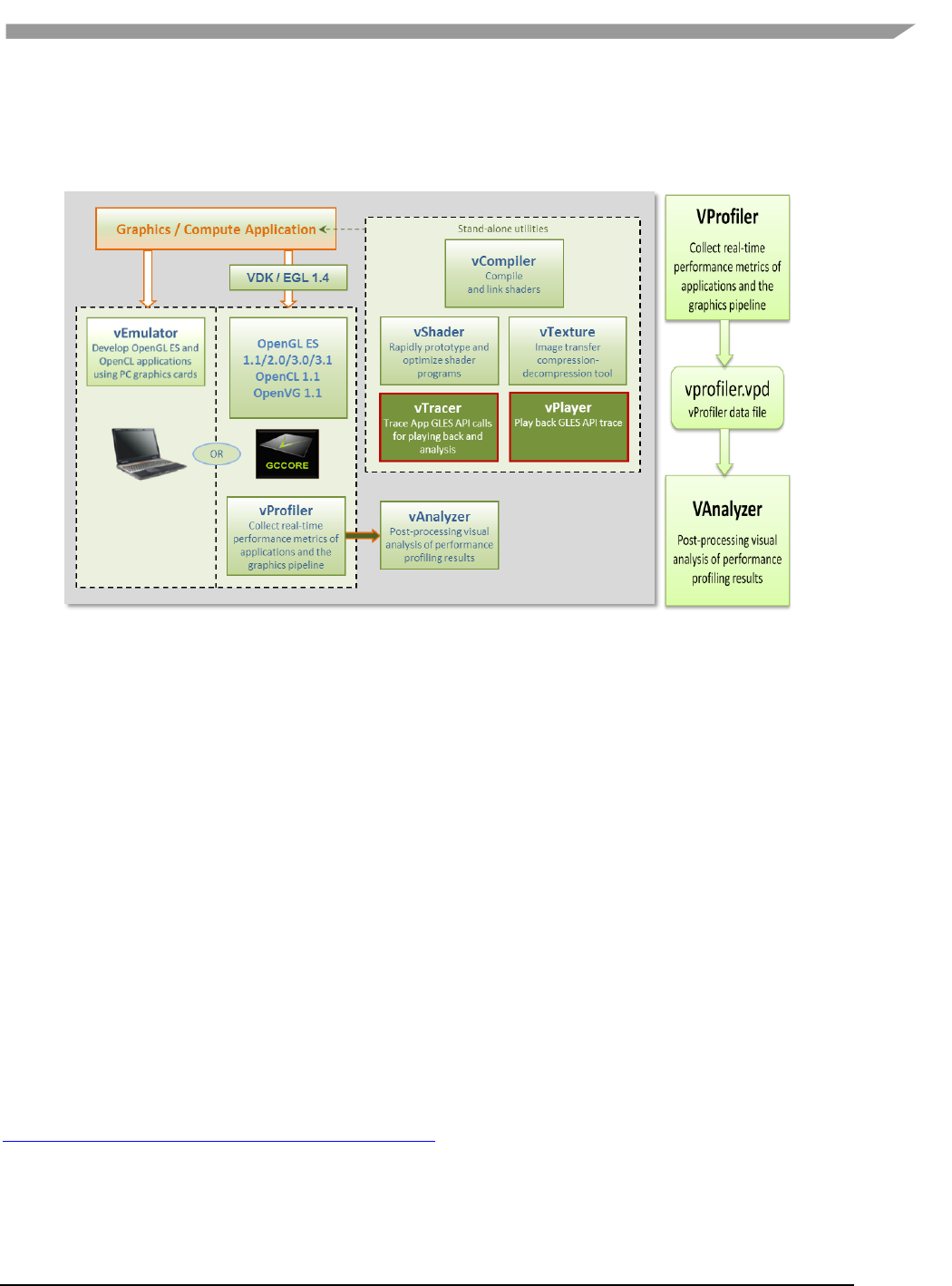
i.MX 6 Graphics User’s Guide, Rev. L3.14.28_1.0.0-ga, 04/2015
85 Freescale Semiconductor
single frame from any application. Appendix A contains a partial list of the data gathered by the hardware
performance counters. Additional counters are present in the software drivers and hardware access layer.
Figure 40 vProfiler performance profiling save data for review in the vAnalyzer visual analyzer
7.6.1 Fundamentals of performance optimization
Whenever an application runs on a computer, it makes use of one or more of the available resources. These
compute resources include the CPU, the graphics processor, caches and memory, hard disks, and possibly even the
network. Viewed simplistically, it will always be the case that one of these resources will be the limiting factor in
how quickly the application can finish its tasks. This limiting resource is the performance bottleneck. Remove this
bottleneck, and application performance should be improved. Note, however, that removing one limiting factor
will always promote something else to become the new performance bottleneck.
The goal of optimizing, or tuning, application performance is to balance the use of resources so that none of them
holds back the application more than any of the others. In practice there is no single, simple way to tune an
application. The whole system needs to be considered, including the size and speed of individual components as
well as interactions and dependencies among components.
vProfiler collects information on GPU usage and on calls to Vivante functions within the graphics pipeline. As such
it provides an excellent view into what is happening on the GCCORE graphics processor at any point in time, down
to the individual frame. So when your application performance is GPU-bound, vProfiler and vAnalyzer are the right
tools to help you determine why.
Please note that the initial determination regarding which component of your computer system is the
performance bottleneck—CPU, GPU, memory, etc.—is the domain of system performance analyzers and is outside
the scope of the GPU tools. A list of such performance analysis tools can be found at Wikipedia:
en.wikipedia.org/wiki/List_of_performance_analysis_tools.

i.MX 6 Graphics User’s Guide, Rev. L3.14.28_1.0.0-ga, 04/2015
86 Freescale Semiconductor
7.6.2 vProfiler setup for the Linux OS
The VTK Windows package includes vAnalyzer for the Windows OS environment. The vProfiler tool can be
compiled for the Linux OS, as per the instructions below.
vProfiler stores software and hardware counters captured per frame in the vprofiler.vpd file. vAnalyzer reads
the .vpd file and allows the user to browse all counters, visualize application performance bottlenecks, and
measure system utilization of that application run. Presently, vProfiler does not store frame buffer images due to
excessive overhead that changes the behavior of applications.
7.6.2.1 Enable vProfiler option in kernel
When building Vivante Graphics Drivers in a Linux OS environment, the driver is built with vProfiler capability.
To activate vProfiler functionality, build the drivers per the instructions in Section “How to Build the GCCORE
Drivers for the Linux OS” in the Vivante Driver Development Guide.In Step 3 of the subsection “Run on the target
board” where you use insmod to insert the GAL kernel driver, use the command line to add the gpuProfiler=1
option, or add the option into an existing .sh script similar to the following:
#!/system/bin/sh
#
insmod /system/lib/modules/galcore.ko gpuProfiler=1 [OPTIONS]
chmod 777 /dev/graphics/*
7.6.2.2 Enable vProfiler option in u-boot
vProfiler can also be enabled from U-Boot with kernel command parameters. Minimum Linux kernel version 3.10.y
needs to support this galcore.powerManagement=0 galcore.showArgs=1 galcore.gpuProfiler=1.
7.6.2.3 Set vProfiler environment variables
The following table summarizes the environment variables that vProfiler supports. (Note that environment variable
names for the Linux OS were changed from driver releases 4.6.9.p13 and 5.0.7 and toolkit release 1.5.)
Table 18 vProfiler Environment Variables for the Linux OS
Environment Variable
Description
VIV_PROFILE
[0] Disable vProfiler (default), [1] Enable vProfiler,[2] Control via application call, [3]
Allows control over which frames to profile with vProfiler
VP_OUTPUT
Specify the output file name of vProfiler (default is vprofiler.vpd)
VP_FRAME_NUM
When VIV_PROFILE=1, specify the number of frames dumped by vProfiler.
VP_FRAME_START
When VIV_PROFILE=3, specify the frame to start profiling with vProfiler.
VP_FRAME_END
When VIV_PROFILE=3, specify the frame to end profiling with vProfiler.
VP_SYNC_MODE
Enable [1] or disable [0] the synchronous mode of vProfiler (default is synchronous
enabled)
7.6.2.3.1 VIV_PROFILE
The environment variable VIV_PROFILE can be used to control enable /disable and set profiling modes for vProfiler.
VIV_PROFILE=0:
By default, vProfiler is disabled in the driver. If vProfiler has been enabled and you wish to disable
it,set VIV_PROFILE equal to 0:
export VIV_PROFILE=0

i.MX 6 Graphics User’s Guide, Rev. L3.14.28_1.0.0-ga, 04/2015
87 Freescale Semiconductor
VIV_PROFILE=1:
To enable vProfiler, set VIV_PROFILE to 1:
export VIV_PROFILE=1
To limit the number of frames to analyze, use the environment variable VP_FRAME_NUM. (This
option is available only when VIV_PROFILE=1.) For example, this example setting will make
vProfiler dump performance data for the first 100 frames.
export VP_FRAME_NUM=100
VIV_PROFILE=2:
Mode VIV_PROFILE=2 (available from VTK 1.5.7) provides support for
glEnable(GL_PROFILE_VIV) and glDisable(GL_PROFILE_VIV), which are used to
choose which frames are to be profiled. In this mode, vProfiler is disabled by default. It begins to
do profiling only after a glEnable(GL_PROFILE_VIV) call from the application. And it will stop
profiling when glDisable(GL_PROFILE_VIV) is called. Note that the flag is only checked at every
frame end, i.e., in eglSwapBuffers. To use this mode, set VIV_PROFILE to 2:
export VIV_PROFILE=2
VIV_PROFILE=3:
Setting VIV_PROFILE to 3 (available from VTK 1.5.8) provides support for two environment
variables VP_FRAME_START and VP_FRAME_END, which are used to choose which frames are
to be profiled. In this mode, vProfiler is disabled by default. It begins to do profiling starting at
the frame number specified by VP_FRAME_START, and it ends the profiling after the frame
number specified by VP_FRAME_END. For example to use this mode, set VIV_PROFILE to 3:
export VIV_PROFILE=3
export VP_FRAME_START=10
export VP_FRAME_END=90
NOTE: The GPU profiling mode requires the GPU Power Management (PM) functions to be disabled to get the
precise profiling data. When kernel module “galcore” is inserted with gpuProfiler=1, the PM functions in the driver
are not disabled. The PM functions are disabled when VIV_PROFILE is set to 1, 2, or 3, and the application starts.
The PM functions are enabled when VIV_PROFILE is set to 0, and the application starts again.
7.6.2.3.2 VP_OUTPUT
The output file of vProfiler is vprofiler.vpd by default. To specify an alternate filename use the environment
variable VP_OUTPUT. For example,
exportVP_OUTPUT =sample.vpd
7.6.2.3.3 VP_SYNC_MODE
To get accurate values from the GPU counters, vProfiler needs to commit the GPU commands at the end of every
frame; this is so-called synchronous mode. The environment variable VP_SYNC_MODE can be used to enable or
disable synchronous mode. By default, vProfiler works in synchronous mode. The command below will make
vProfiler work in asynchronous mode.
export VP_SYNC_MODE=0
7.6.3 vProfiler setup for the Android platform
The vProfiler tool can be set up for use with the Android platform, as per the instructions below.

i.MX 6 Graphics User’s Guide, Rev. L3.14.28_1.0.0-ga, 04/2015
88 Freescale Semiconductor
7.6.3.1 Enable vProfiler option in kernel
When building Vivante Graphics Drivers in an Android environment, build the drivers per the instructions in the
Vivante Driver Development Guide section entitled “How to Build the GCCORE Drivers for Android.” In Step 2 of
the subsection “Run on the Target board”, use the provided install-recovery.sh script or add the gpuProfiler=1
option into your existing .sh script similar to the following:
#!/system/bin/sh
#
insmod /system/lib/modules/galcore.ko gpuProfiler=1 [OPTIONS]
chmod 777 /dev/graphics/*
Put the install-recovery.sh file in the target Android system’s /system/etc/ folder. Continue following
the instructions in the Vivante Driver Development Guide or the readme guide in your driver source package.
Use adb push to migrate the drivers to your target system, and then reboot your target Android system.
NOTE: If you use an install-recovery.sh script as described above, and cannot reboot the
Android platform successfully, you may have encountered a problem with file access
permissions. Workaround: run adb shell. Go to /system/etc/, then run the command
chmod 777 install-recovery.sh.
7.6.3.2 Setting property options for vProfiler
The following table summarizes the property options that vProfiler supports through running the commands adb
shell setprop [OPTIONS]. These options are similar to the environment variables available for the Linux OS.
Table 19 vProfiler Set Property Options for Android
adb shell setprop OPTIONS
Description
setprop VIV_PROFILE 0
Run this command in adb shell to disable vProfiler in the drivers
setprop VIV_PROFILE 1
Run this command in adb shell to enable vProfiler in the drivers
setprop VIV_PROFILE 2
Run this command in adb shell to have vProfiler enable/disable
controlled in the application by glEnable(GL_PROFILE_VIV) and
glDisable(GL_PROFILE_VIV calls. (available from VTK 1.5.7)
setprop VIV_PROFILE 3
setprop VP_FRAME_START
setprop VP_FRAME_END
Run these commands in adb shell to have vProfiler start-stop at
frames specified in VP_FRAME_START and VP_FRAME_END.
(available from VTK 1.5.8)
setprop VP_PROCESS_NAME appname
Run this command in adb shell to specify the application you
need to profile. Change the app name as needed to profile another
application.
NOTES:
There may be different sub-case names used by an app. Be sure to
accurately specify a case name to match the name that you saw on
the command line when using ps command.
This option is only available for the Android platform, not available
for the Linux OS.
setprop VP_OUTPUT newpath
Run this command in adb shell to specify a new location for
vProfiler output.
By default, the vpd file will created under /sdcard/. If an
application has no access to the SD card, you can specify another
path where the application does have write permission.
NOTE: For applications which initialize during Android system boot

i.MX 6 Graphics User’s Guide, Rev. L3.14.28_1.0.0-ga, 04/2015
89 Freescale Semiconductor
startup, such as launcher, you need to kill the process after you
change to a new path. When the application automatically restarts,
then your vpd will be accessible where you want it.
setprop VP_FRAME_NUM xxx
Run this command in adb shell to limit the number of frames to
analyze. For example, to make vProfiler dump performance data for
the first 100 frames: setprop VP_FRAME_NUM 100
NOTES:
Only use when VIV_PROFILER is set to 1.
When this option is not used, the profile file generated when running
an application for a long time can be very large. This takes up a large
amount of disk space and also makes it hard to view the data in
vAnalyzer.
setprop VP_SYNC_MODE 0
setprop VP_SYNC_MODE 1
Run this command in adb shell to enable or disable synchronous
mode. By default, vProfiler works in synchronous mode (=1). To get
accurate values from the GPU counters, vProfiler needs to commit
the GPU commands at the end of every frame; this is so-called
synchronous mode. This example command will make vProfiler work
in asynchronous mode: setpropVP_SYNC_MODE0
7.6.4 vProfiler collecting performance data
vProfiler is implemented by utilizing hardware counters and a group of instrumentations inserted into drivers that
are controlled by compilation flags.
7.6.4.1 Performance counters
vProfiler counters are divided into five sets: HAL (Vivante Graphics driver), (shader) program, OpenGL and
OpenVG. The counters provide detailed per frame runtime information about the application that can help the
developer monitor and tune an application’s resource usage. The following table briefly lists the various profile
counter sets. For further information, see Appendix A at the end of this document.
Table 20 Performance Counter Types
Counter Type
Description
HALCounters
Driver memory usage
Program
Statistics of the shaders loaded in the GPU (Note: Available only for OpenGL ES 2.0 applications.)
OGLCounters
Various OpenGL (OpenGL ES 20 or 11) counters, such as API usage and primitives drawn.
OVGCounters
Various OpenVG counters, such as API usage and primitives drawn.
7.6.5 vAnalyzer viewing and analyzing a run-time profile
vAnalyzer is a GUI-based tool whose purpose is to help the user view and analyze GPU performance data that was
collected using counters during an application run. The performance data from a binary file(*.vpd) written by
vProfiler is displayed by vAnalyzer both in text lists and as line graphs. vAnalyzer features a multi-tab, multi-pane,
graphical user interface that gives the user several ways to inspect any frame in a captured animation sequence.
7.6.5.1 Loading profile files
vAnalyzer accepts a profile for input, which is a .vpd file of performance data created by the Vivante vProfiler
during a run. For example, the saved file may have a name such as sample.vpd.
A .vpd file can be selected using the File/Load Profile Data menu option.
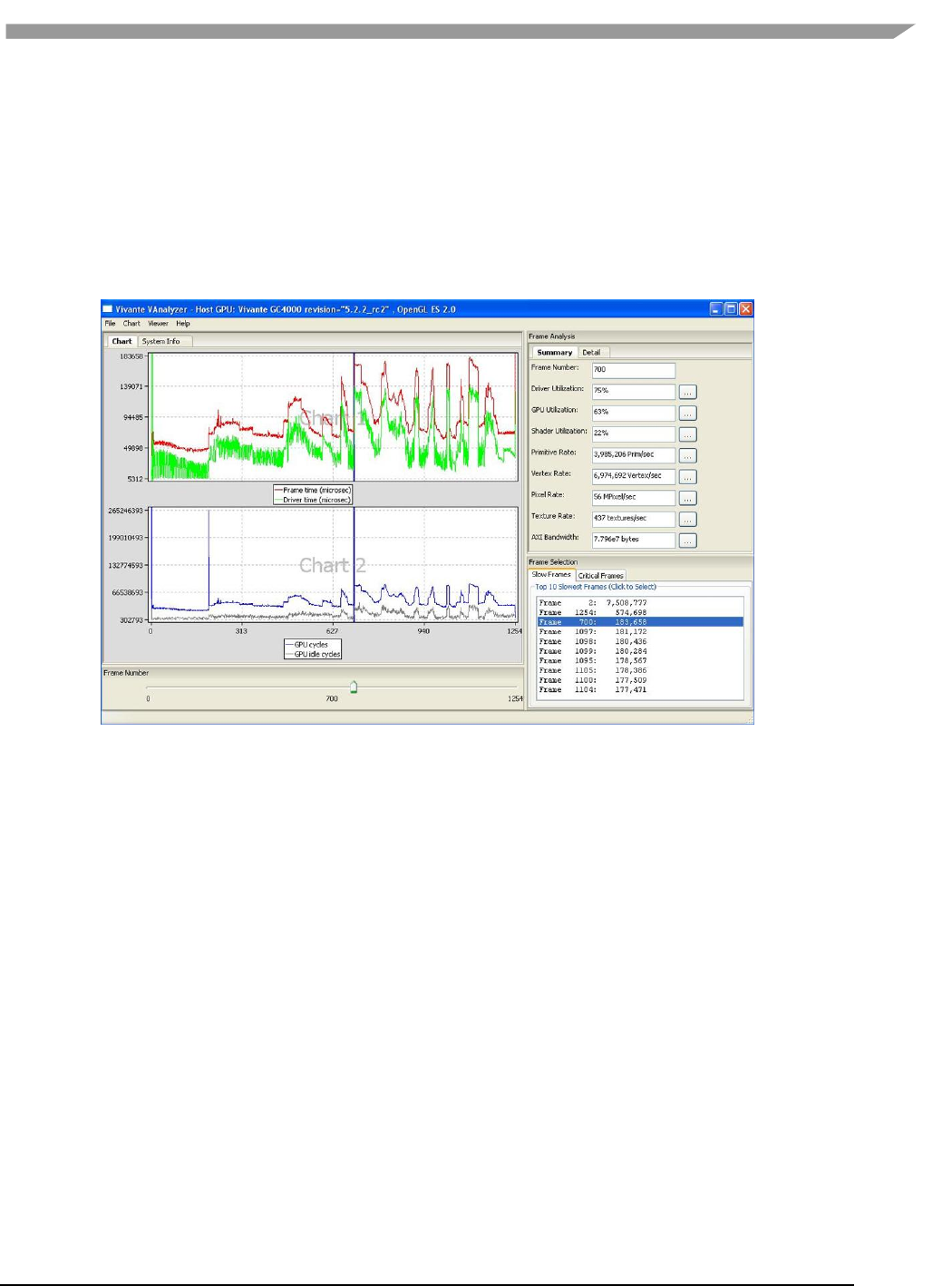
i.MX 6 Graphics User’s Guide, Rev. L3.14.28_1.0.0-ga, 04/2015
90 Freescale Semiconductor
When a performance profile is loaded, vAnalyzer populates the title bar with information about the GPU and the
CPU.
The vAnalyzer screen shot below shows the vAnalyzer GUI immediately after loading a.vpd performance file, and
moving the frame number slider to frame 700. By default, the main pane of the vAnalyzer window will display the
Charts tab which provides charts for frame time, driver time and GPU idle cycles. Additional charts can be added in
the graph window by selecting from the list of variables on the right. Different combinations of counters can be
displayed in graphical and list form to illustrate resource utilization for any portion of the profiled application. A
second tab contains system information.
Figure 41 vAnalyzer GUI Main Window
7.6.5.2 vAnalyzer menu bar
The vAnalyzer main window opens when a user launches vAnalyzer. The main menu bar contains drop-down
menus for File,Chart, Viewer and Help. Menu options include the following:
File
– Load Profile Data: load a .vpd profile file
– Export Current Frame Data: dump all the counters for the frame being viewed to a .cvs file
– Exit: exit vAnalyzer
Chart
– Create chart: create a new chart
– Customize chart: add or delete counters in an existing chart
– Remove chart: delete a chart
– Export data from chart: dump the counters in a chart to a .csv file
– Save chart to png: dump the chart to a .png file
– View: zoom in, zoom out or fit the chart
Viewer
– OpenGL function call viewer: display the OpenGL function call statistics
– Program viewer: display the shader program statistics
Help
– About: gives version information for vAnalyzer
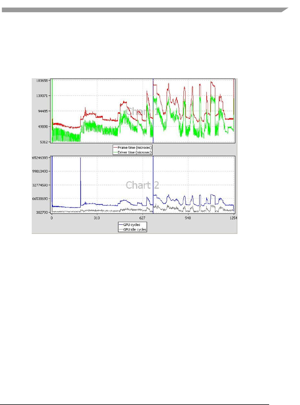
i.MX 6 Graphics User’s Guide, Rev. L3.14.28_1.0.0-ga, 04/2015
91 Freescale Semiconductor
7.6.6 vAnalyzer charts
7.6.6.1 vAnalyzer upper left pane: chart tab and menu options
On the Chart tab in the vAnalyzer main window two default line graphs are displayed.
Figure 42 vAnalyzer Performance Counter Charts
7.6.6.2 Chart customization
Chart / Customize: Additional performance counters can be added to existing chart using the Customize Chart
dialog window, which can be invoked from the drop menu Chart/Customize, or from a pop-up menu which can be
invoked by right clicking in the Chart tab area.
Create New Chart: A new chart can be added in a similar way. A single chart can display up to four (4) counters,
and the Chart pane can hold up to eight (8) charts. Thus a maximum of thirty-two (32) counters can be graphed at
the same time.
Remove Chart: Any chart can be removed from the display using the drop menu Chart / Remove Chart.
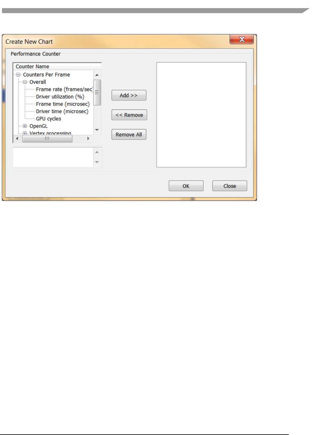
i.MX 6 Graphics User’s Guide, Rev. L3.14.28_1.0.0-ga, 04/2015
92 Freescale Semiconductor
Figure 43 vAnalyzer Create New Chart Dialog
7.6.6.2.1 Chart components and navigation
Frame Marker: On the plots displayed in the chart example above there is a blue, vertical frame marker. This
marks the current frame position in the timeline.
Zoom:
Zooming in on a set of frames can be achieved in one of two ways.
• One method is to hold down the left mouse button and then sweep a selection box across a range of
frame numbers, either on a plot itself or in the common X-axis (frame numbers) in the “Chart” pane, before
releasing the mouse button. All charts in the “Chart” pane will zoom in to the same range of frames.
• Alternatively, if your mouse has a scroll wheel, you may also zoom in by rolling the wheel forward--toward
the screen.
To zoom out move the scroll wheel backward, toward you.
To reset zoom to the default, which will show the entire timeline, press the escape key (ESC) on the keyboard. The
chart view will change to include all frames, from start to end.
7.6.6.2.2 Data export
The performance counters in a chart can be dumped to a .csv file by selecting from the dropdown menu Chart /
Export Data From. The .csv file can be viewed using Excel or another text viewer.
The chart can also be dumped to a .png file by selecting from the main menu Chart / Save chart to PNG.
7.6.6.3 vAnalyzer lower left pane: frame number slider bar
In the lower left pane of the vAnalyzer window, there is a Frame Number gauge in the form of a slider bar.
Numbers at each end of the bar indicate the initial frame (0) and the last frame available in the loaded sample. By
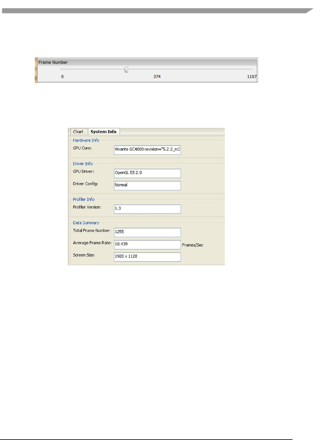
i.MX 6 Graphics User’s Guide, Rev. L3.14.28_1.0.0-ga, 04/2015
93 Freescale Semiconductor
left-clicking and holding the slider, the user can change which frame is selected for analysis. When the frame
number is changed, the blue vertical line which indicates the current frame will move, and the reported Frame
Number will change in the upper right pane Frame Analysis Summary.
Figure 44 vAnalyzer Frame Number Slider Bar
7.6.6.4 vAnalyzer left pane: System Info tab
When a .vpd profile is loaded, system information about the profiled machine populates the fields on the System
Info pane. Some information is repeated in the title bar of the main GUI for quick reference.
Figure 45 vAnalyzer System Info Tab
7.6.6.5 vAnalyzer upper right pane: Frame Analysis
A selection of performance counters for the frame being viewed are displayed on the right side of the vAnalyzer
main GUI. The user can convert this pane to a pop-up window by dragging the pane outside the application
window. Drag it back to the right pane area of the application window to reintegrate the pane.
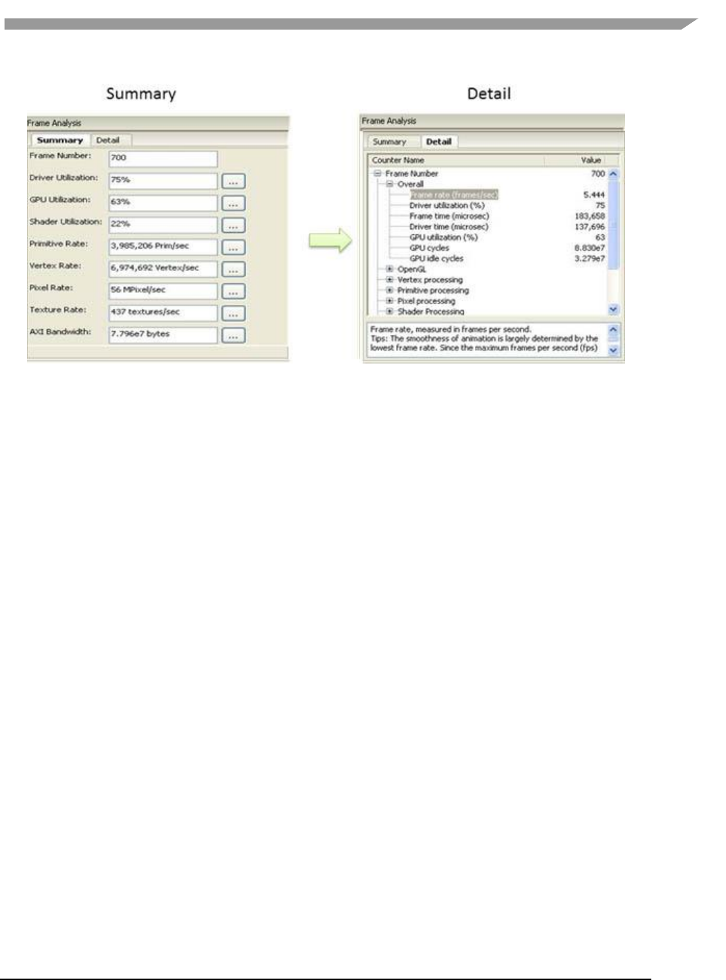
i.MX 6 Graphics User’s Guide, Rev. L3.14.28_1.0.0-ga, 04/2015
94 Freescale Semiconductor
Figure 46 vAnalyzer Frame Analysis Summary and Detail Tabs
7.6.6.5.1 Summary tab
The Summary tab displays summary information for the frame being viewed.
The Selected Frame Number can be changed by entering a new frame number in the text box at the top of the list.
The user must press Enter after the input to activate the change. Then Summary values, sliders, and charts all
change to reflect the newly entered frame number.
The Summary values below frame number are not directly changeable. They change only when the frame number
is changed, either in the Summary tab, by moving the Frame Number slider, or by selecting a frame from the
Frame Selection pane. Clicking the “…” button to the right of a Summary item will bring up the corresponding
counters in the Detailtab. For example, clicking the “…” button to the right ofPrimitive Rate: switches the view to
the Detail tab and expands the Primitive processingcatogory. Clicking the “…” button forDriver Utilization: brings
up the pop-p window OpenGL function call viewer.
7.6.6.5.2 Detail tab
The Detail tab reports values for overall performance evaluation, such as Frame Rate, Driver Utilization, and GPU
cycles. Additionally counter detail is accessible on this tab. The categories of available counters in the Detail
tabare: Overall, OpenGL, Vertex processing, Primitive processing, Pixel processing, Shader Processing, Texturing
and AXI Bandwidth. Appendix A lists performance as well as hardware counters.
7.6.6.6 vAnalyzer lower right pane: Frame Selection
As with the Frame Analysis pane, this pane can be dragged to display as an independent popup window.
7.6.6.6.1 Slow Frames tab
The “Slow Frames” tab lists the ten (10) slowest frames in the animation sequence, by time in ascending order
from slowest to tenth slowest.
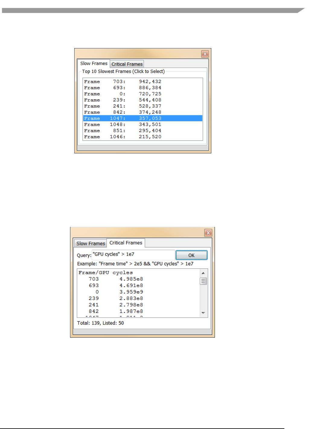
i.MX 6 Graphics User’s Guide, Rev. L3.14.28_1.0.0-ga, 04/2015
95 Freescale Semiconductor
The user can left click on any entry, or can use the arrow keys to move up and down the list, and the display in
each of the other GUI panes will change to match that frame.
Figure 47 vAnalyzer Frame Selection Slow Frames Tab
7.6.6.6.2 Critical Frames tab
Select the “Critical Frames” tab to customize the criteria by which a frame is chosen for inspection. One or more of
the performance counters can be specified in building the query, which also allows for AND and OR logic.
Queries should follow a pattern such as:
“counter name” condition(‘<’,’>’,’==’) values.
Users can identify counter names from those in the Frame Analysis pane Detail tab. An example is provided just
below the Query input text box.
Figure 48 vAnalyzer Frame Selection Critical Frames Tab
7.6.7 vAnalyzer viewers
The Viewer information pop-up window can be launched by selecting Viewer/Function Call Viewer or
Viewer/Program Viewer from the Main menu. The selected Viewer will appear in a pop-up window.
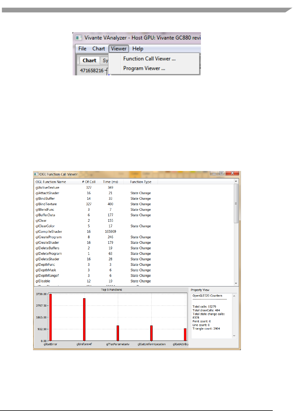
i.MX 6 Graphics User’s Guide, Rev. L3.14.28_1.0.0-ga, 04/2015
96 Freescale Semiconductor
Figure 49 vAnalyzer viewers
7.6.7.1 OpenGL Function Call viewer
The OpenGL function call viewer includes three information areas.
The OGL Function Name area contains a table which lists the available OpenGL ES functions by Function Name
and Function Type, the run time and the number of times each has been called for this frame. Functions can
be sorted by clicking in the column heading area. For example, you can sort the functions by call count or run
time by clicking the title bar of “# of Call” or “Time (ms)”.
The Top 5 Functions area contains a histogram which shows the top 5 call count of the listed OpenGL
functions.
The Property view area shows the summary when no function is selected; while it shows performance hints
for the function when one is selected.
Figure 50 vAnalyzer OpenGL function call viewer window
7.6.7.2 Program viewer
For a given Frame Number, the Program Viewer gives the statistics for shader programs: uniforms, attributes, and
the number of instructions in the shader. This is only for OpenGLES2, ES3 profile data. The description of the item
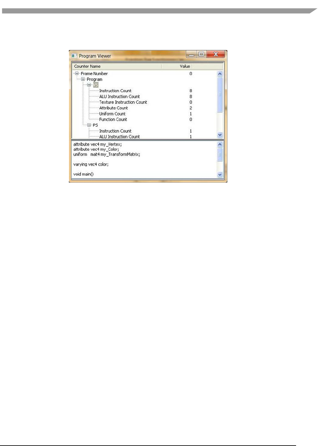
i.MX 6 Graphics User’s Guide, Rev. L3.14.28_1.0.0-ga, 04/2015
97 Freescale Semiconductor
will be displayed in the lower text window when selecting the item. Expand by clicking on VS or PS submenu to
expand the detail for that shader’s source code.
Figure 51 vAnalyzer Program Viewer
7.7 vTracer
The Vivante vTracer package includes two components, vTracer and vPlayer. vTracer is a tool which can record an
application’s EGL 1.4 and OpenGL ES 1.1/2.0/3.0 API traces on the Linux OS or Android platform. vTracer supports
two trace modes for Linux OS: Intercept Trace Mode and Direct Trace Mode. Intercept Trace Mode is the mode
used with the Android platform.
The package also includes vPlayer, a tool for playing back the recorded API trace files.
This section will discuss setup and use of vTracer. The following section describes vPlayer.
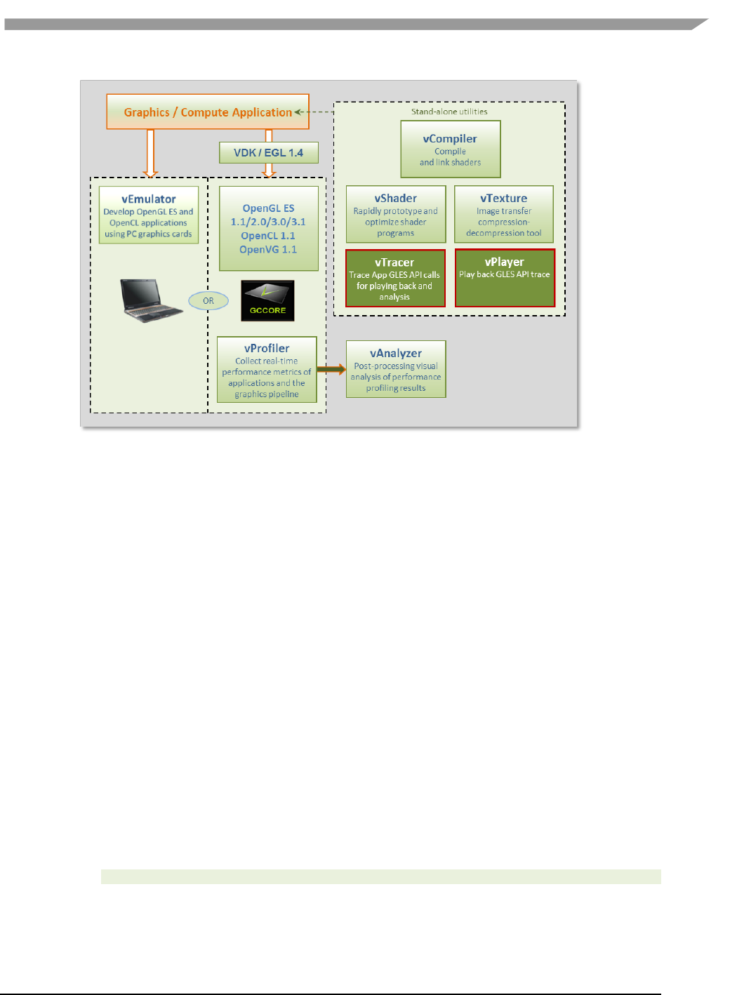
i.MX 6 Graphics User’s Guide, Rev. L3.14.28_1.0.0-ga, 04/2015
98 Freescale Semiconductor
Figure 52 vTracer API trace and vPlayer for trace playback
7.7.1 vTracer setup
7.7.1.1 Prerequisites
For the Linux OS and Linux Embedded OS, the vTracer instructions below assume you have already installed and
correctly configured a Vivante Driver Package for the Linux OS:
VIVANTE_GAL_Unified_Src_drv_xxx.tgz
For the Android platform, install and correctly configure both the Vivante OpenGL ES and Android Driver
Packages:
VIVANTE_GAL_Unified_Src_drv_xxx.tgz
VIVANTE_GAL_Unified_Src_drv_android-addon_xxx.tgz
Additionally, the instructions assume you have already downloaded are ready to expand the Vivante Toolkit
Package which contains a vTracer.zip file:
VivanteVTK-v1.xx.tgz
NOTE: Different versions of vTracer and vPlayer are prepared for Linux backends FBDev, X11 and QNX.
7.7.1.2 Extracting the vTracer package
Extract the vTracer release package (*.tar.gz). For example:
tar zxv VIVANTE-vTracer.tar.gz
For the Linux OS, the files included in the package which will be used for vTracer setup on the Linux OS include:
vTracer/bin/linux/libGLES_vtracer.so
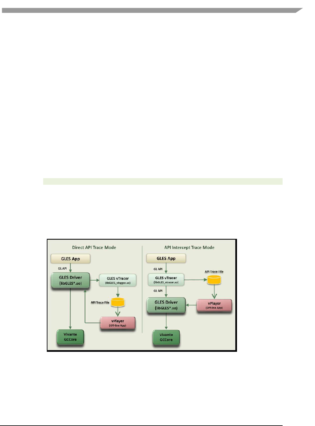
i.MX 6 Graphics User’s Guide, Rev. L3.14.28_1.0.0-ga, 04/2015
99 Freescale Semiconductor
vTracer/bin/linux/libGLES_vlogger.so
vTracer/bin/linux/vtracer.conf
For the Android platform, the files included in the package which will be used for vTracer setup on the Android
platform include:
vTracer/bin/android/libGLES_vtracer.so
vTracer/bin/android/vtracer.conf
Files included in the package which will be used for vPlayer include:
vTracer/bin/linux/vplayer(for Linux OS)
vTracer/bin/android/vplayer.apk(for the Android platform)
vTracer/bin/windows/vplayer.exe (for the Windows OS)
7.7.1.3 Installing the vTracer library
For the Linux OS: Copy the tracer librarieslibGLES_vtracer.so and libGLES_vlogger.so to the Linux
OS/usr/lib directory.
For the Android platform: The pre-built vTracer library libGLES_vtracer.so for ARM Android devices needs to be
uploaded to the Android device directly through adb:
adb push vTracer/bin/android/libGLES_vtracer.so /system/lib/egl
7.7.1.4 Setting the Linux OS environment variables for Trace mode
This step is not required for Android systems.
On the Linux OS, vTracer supports two trace modes: Intercept Trace Mode and Direct Trace Mode.
libGLES_vtracer.so supports the intercept trace mode and libGLES_vlogger.so supports the direct
trace mode. Either trace mode can be used to generate the application’s API trace file, but the two trace modes
should not be used simultaneously. Configuration of trace mode is controlled through environment variables.
Figure 53 vTracer Has Two API Trace Modes for the Linux OS
7.7.1.4.1 Setting vTracer environment variable for Intercept Trace mode
Set the environment variable LD_PRELOAD to specify libGLES_vtracer.so as the pre-load dynamic linked library:
export LD_PRELOAD=/usr/lib/libGLES_vtracer.so

i.MX 6 Graphics User’s Guide, Rev. L3.14.28_1.0.0-ga, 04/2015
100 Freescale Semiconductor
NOTE: Clear the environment variable LD_PRELOAD before running vPlayer. Otherwise, vPlayer play back will be
traced again!
export LD_PRELOAD=
7.7.1.4.2 Setting vTracer environment variable for Direct Trace mode
Note that Direct Trace Mode is only available for the Linux OS and requires software releases 5.0.9 or later; it is not
supported with 4.6.9.x software.
Set the environment variable VIV_TRACE to 2 to enable direct trace mode:
exportVIV_TRACE=2
Refer to the table below for other values for VIV_TRACE. By default, vPlayer will reset the environment variable
VIV_TRACE to 0 to avoid tracing the vPlayer playback again.
You can use the vPlayer option "--enable-trace" to enable the VIV_TRACE environment variable. When this option
is selected, vPlayer honors the current setting for VIV_TRACE. If this option is not used, vPlayer will disable tracing
and overwrite the current VIV_TRACE setting.
7.7.1.4.3 vTracer environment variables summary
The following table summarizes the the Linux OS environment variables that vTracer supports.
Table 21 vTracer Environment Variables for the Linux OS
Environment Variable
Description
LD_PRELOAD
= libGLES_vtracer.so (specifies the name of the pre-load dynamic linked library
=NOTE: Clear this variable before running vPlayer.
VIV_TRACE
=0 Disables all levels of API trace functions.
=1 Enables simple API dump on the console display.
This is performed by the Vivante GLES3.0 driver itself (without the need for
the external vTracer library libGLES_vlogger.so).
=2 Enables Direct Trace Mode
FB_IGNORE_DISPLAY_SIZE
or
X_IGNORE_DISPLAY_SIZE
or
DRI_IGNORE_DISPLAY_SIZE
=0Clip window to device Display size
=1Do not clip window to the device limits for width and height.
(from 5.0.11.p4, VTK 1.5.9)
7.7.2 vTracer configuration
vTracer configuration options can be controlled through the vtracer.conf file. Most options are similar for the
Linux OS and Android environments.
7.7.2.1 vTracer optional configuration on the Linux OS
This step is optional for both trace modes on the Linux OS.
Copy the vTracer configuration file bin/linux/vtracer.conf to the local directory (put vtracer.conf file together with
your GLES program).
Edit the vtracer.conf file which contains multiple settings to control vTracer behavior. Refer to the file for the
default settings provided in your specific release.

i.MX 6 Graphics User’s Guide, Rev. L3.14.28_1.0.0-ga, 04/2015
101 Freescale Semiconductor
Table 22 vTracer Configuration Options for the Linux OS
vTracer option
Description
cmdline
Specifies the token used to identify the App process that should be traced.
The token is read from /proc/self/cmdline. default: cmdline=?
codec
Specifies the API trace file format: binary or ascii. default: codec=binary
device
Must be set as device=stdio (default)
egl_library
path and filename location of egl library
default is /usr/lib/libEGL.so
end_frame
Specifies the frame number at which the vTracer trace will end. Default for
the Linux OS: end_frame=0 (indicates there is no end limit).
extension
Specifies the API trace file extension. default: extension=bin
gles1_library
path and filename location of OpenGL ES 1.0 library
default is /usr/lib/libGLESv1_CM.so
gles2_library
path and filename location of OpenGL ES 2.0/3.0 library
default is /usr/lib/libGLESv2.so
overwrite
When overwrite=1 vTracer will overwrite an existing trace file of the same
filename. default: overwrite=1.
path
Specifies the path where the API trace files will be placed. default: path=./
sync
Set sync=1 to specify to sync data to disk after every API call. default:
sync=0
type
Must be set as type=output (default)
verbose
Specifies if vTracer prints out verbose messages while tracing. default:
verbose=0
7.7.2.2 vTracer configuration on the Android platform
vTracer for the Android platform requires a configuration file to work properly. Edit the vTracer configuration file
bin/android/vtracer.conf to specify which application process on the Android platform is to be traced.
Only the cmdline setting which names the application to be traces is required. Other configuration settings in the
vtracer.conf file are optional. Default values are usually appropriate.
After any changes to the vtracer.conf file are saved, upload the file to the Android device using adb:
adb remount
adb push vTracer/bin/android/vtracer.conf /system/lib/egl
Table 23 vTracer configuration options for the Android platform
vTracer option for the Android
platform
Description
REQUIRED SETTING
cmdline=application_name
Specifies the token used to identify the App process that should be traced. The
token is read from /proc/self/cmdline. A valid application name must be provided.
For example:
cmdline=se.nena.nenamark2
Note that when launching native applications, the application needs to be launched
with a full path if the full path is specified here, i.e., if
cmdline=/system/bin/demo you should start the application with
/system/bin/demo.
Note: Android application names can be looked up with the following command:
adb shell ps
OPTIONAL SETTINGS
codec
Specifies the API trace file format: binary or ascii.default: codec=binary.

i.MX 6 Graphics User’s Guide, Rev. L3.14.28_1.0.0-ga, 04/2015
102 Freescale Semiconductor
device
Must be set as device=stdio (default)
egl_library
path and filename location of egl library:/system/lib/egl/libEGL_VIVANTE.so*
end_frame
Specifies the frame number at which the vTracer trace will end.Default value may
vary per OS. For the Android platform, to trace only the first 100
frames:end_frame=100.
Default end_frame=0 means not set.
extension
Specifies the API trace file extension. default for the Android platform:
extension=ARM.bin
gles1_library
path and filename location of OpenGL ES 1.0 library
/system/lib/egl/libGLESv1_CM_VIVANTE.so*
gles2_library
path and filename location of OpenGL ES 2.0/3.0/3.1 library
/system/lib/egl/libGLESv2_VIVANTE.so*
overwrite
When overwrite=1 vTracer will overwrite an existing trace file of the same file
name.default: overwrite=1.
path
Specifies the path where the API trace files will be placed.
defaultpath=/sdcard/traces/
Note: the path must have write permission for any users on the Android
platform!
sync
Set sync=1 to specify to sync data to disk after every API call. default: sync=0
type
Must be set as type=output (default)
verbose
Specifies if vTracer prints out verbose messages while tracing. default: verbose=0
*vTracer works on other vendors Android platforms as well. File location values can be set to other vendor’s
EGL/GLES libraries to trace applications on other platforms.
7.7.3 Enable vTracer
7.7.3.1 Enable vTracer on the Linux OS
vTracer is available for use as soon as the libraries and environment variables are in place.
7.7.3.2 Enable vTracer on the Android platform
For Android versions 2.5.x through 4.3:
Recommended: backup your existing egl.cfg file before performing the following.
To enable the vTracer library libGLES_vtracer.so as the EGL/GLES API entry point, modify the egl.cfg file on the
Android OS using the following commands:
adb remount
adb shell
echo "0 1 vtracer" > /system/lib/egl/egl.cfg
To disable the vTracer library libGLES_vtracer.so and restore the default Vivante EGL/GLES libraries as API entry
points, use the following commands:
echo "0 1 VIVANTE" > /system/lib/egl/egl.cfg
For Android versions from 4.4:
For Android 4.4, no egl.cfg file is required in /system/lib/egl. Once the library libGLES_vtracer.so is pushed into
the /system/lib/egl/ directory, vTracer is enabled.
As long as the application specified in the vtracer.conf file is launched after the library push, the binary trace file
will be generated. If you want to trace an application which was running before that operation, you need to kill the
process of that application, and then restart the application.

i.MX 6 Graphics User’s Guide, Rev. L3.14.28_1.0.0-ga, 04/2015
103 Freescale Semiconductor
7.7.4 Using vTracer to generate API Trace files for applications
7.7.4.1 Launch vTracer
On the Linux OS, simply launch the application to be traced.
On the Android platform, launch the application that is specified in the vtracer.conf cmdline option. When
launching native applications, the application needs to be launched with its full path if the full path is specified in
vtracer.conf cmdline, i.e., if cmdline=/system/bin/demo you should start the application with
/system/bin/demo.
7.7.4.2 Android output messages
Android output messages can be checked with logcat:
adb logcat | grep "vtracer"
The following output messages indicate vTracer is working properly:
D/libEGL ( 2825): loaded /system/lib/egl/libGLES_vtracer.so
I/vtracer ( 2825): Initializing VIVANTE vTracer.
I/vtracer ( 2825): reading configuration file at /system/lib/egl/tracer.conf for pid: 2825
I/vtracer ( 2825): Opened stdio binary trace file
/sdcard/traces/tracer_se.nena.nenamark1.ARM.bin
7.7.4.3 Generated trace files
A set of API trace files (one trace file per thread) will be generated at the local directory specified by the
vtracer.confpath option (by default this is path=./ for the Linux OS or path=/sdcard/traces/for the Android
platform). The trace files can be generated to a different location by changing the value for path in vtracer.conf.
The application rendering threads' API trace files can be played back using the Vivante vPlayer tool on the Linux
OS, Android or Windows platforms. Note that non-rendering threads' trace files cannot be played back as they
don't have EGL/GLES API traces.
On the Android platform, the command adb pull filename can be used to retrieve a generated API trace file
from the Android device. For example:
adb pull /sdcard/traces/tracer_se.nena.nenamark1.ARM.bin
7.8 vPlayer
The vPlayer software tool facilitates play back of the recorded EGL/GLES API trace file in a Linux OS, Android
platform, or Windows OS environment. To facilitate debugging, the vPlayer application is capable of running trace
files created on another platform.
vPlayer for the Linux OS and Windows OS includes hot key controls, while vPlayer for the Android platform uses
touchscreen controls and inputs.
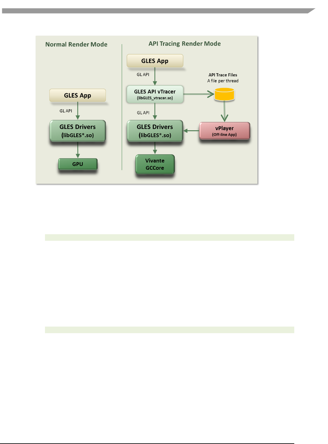
i.MX 6 Graphics User’s Guide, Rev. L3.14.28_1.0.0-ga, 04/2015
104 Freescale Semiconductor
Figure 54 Rendering with vPlayer
7.8.1 vPlayer setup
The instructions below assume you have already downloaded and expanded the Vivante Toolkit Package and
extracted the vPlayer executables from the vTracer zip file. For example:
tar zxv VIVANTE-vTracer.tar.gz
should provide the following vPlayer application files:
vTracer/bin/linux/vplayer (for Linux OS)
vTracer/bin/android/vplayer.apk (for Android platform)
vTracer/bin/windows/vplayer.exe (for Windows OS)
7.8.2 vPlayer command line syntax for the Linux OS and Windows operating systems
7.8.2.1 Syntax
On the Linux and Windows operating systems, the syntax to launch vPlayer from the command line is:
vplayer [options] tracefilename
NOTE: If you use Intercept Trace Mode on The Linux OS (by setting a value for the environment variable
LD_PRELOAD, be sure to clear the environment variable LD_PRELOAD to disable pre-loading the
libGLES_vtracer.so library before running vPlayer. If you fail to do this step, Linux OS vPlayer play back will be
traced again!
7.8.2.2 Input parameters [required]
tracefilename
full path and file name of the API trace file (previously generated with
vTracer, usually a .BIN file) to play back. For example,
on the Linux OS: ./vplayer /workspaces/glb2.7.bin
on the Android platform in vplayer.conf file:

i.MX 6 Graphics User’s Guide, Rev. L3.14.28_1.0.0-ga, 04/2015
105 Freescale Semiconductor
/sdcard/traces/glb2.7.ARM.bin
7.8.2.3 Input parameters [optional]
The first two characters in each option are “--“. Options are available for the Linux OS, Android platform, and
Windows OS vPlayer unless indicated otherwise.
--config N
Use the specified display EGL config
--default-config
Force use of a hard coded default display config
--default-context
Use default window surface, config and context
--dumparray
Dump array contents in hex
--dumpbmp
Dump each frame into a bmp file
--dumpshader
Dump GLSL shader source code
--enable-trace
Enable VIV_TRACE environment variable. If not set, the VIV_TRACE
environment variable setting value will be ignored. If this option is used,
then the current value of the VIV_TRACE environment variable will be used.
--end E
End frame for rendering (vPlayer will pause at frame E and skip rendering
the frames after frame E)
--error
Insert eglGetError/glGetError after each API call
--finish
Insert glFinish after each API call
--fps Interval
Output average FPS and interval FPS information
--help
Print/output to console a help list of options for vPlayer
--repeat N
Repeat play back N times from --start to --end.
--showframenumber
Print the current frame number that vPlayer is playing.
--start F
Start frame for rendering (vPlayer will skip rendering the frames before
frame F).
--swapbuf
Call eglSwapBuffers after each GL draw call (glDrawArrays, glDrawElements,
etc.).
--targetkey
Reads inputs from target device.
By default, vPlayer reads the key presses from the console terminal on the
host device. The option --targetkey enables vPlayer to read key presses
from the target device.
On Linux and Windows operating systems: allows key inputs to pause,
resume, etc. see Hot Keys, below.
On the Android platform: By default, touch screen input is enabled on the
Android platform for trace playback control (single frame, pause/resume.
The option --targetkey disables touch screen input to vPlayer on the
Android platform.
--verbose
Print data parsed from the API trace file.
--zoom
Enable zoom to fit the target device screen.
7.8.2.4 vPlayer hot keys for Linux OS and Windows OS
vPlayer playback can be controlled by hot keys on the keyboard when using Linux and Windows operating systems.
By default, vPlayer reads key strokes from the console terminal on the host device. Using the option --targetkey
enables vPlayer to read key strokes from the target device.
The following Hot Keys are available for control of playback in vPlayer:
Esc Exit application
M Pause / Resume the playback
Q Exit application
SPACE Render a single frame and then pause
When the options --start F --end E are used for playback, vPlayer will skip rendering frames before frame F and
pause after rendering frame E. Use the SPACE key or M key to control playback of the remaining frames.

i.MX 6 Graphics User’s Guide, Rev. L3.14.28_1.0.0-ga, 04/2015
106 Freescale Semiconductor
7.8.3 Running vPlayer on the Android platform
A configuration file (vplayer.conf) is used to control settings for vPlayer on Android platforms, since a command
line is not available.
7.8.3.1 Launching vPlayer
Touch the vPlayer icon on the Android desktop to launch vPlayer and play back the API trace file specified in the
/sdcard/vivante/vplayer.conffile.
7.8.3.2 vPlayer options for the Android platform
Playback options will be those as specified in the vplayer.conf configuration file. These match the options available
as command line input parameters for Linux and Windows operating systems, as described above.
Here is an example vplayer.conf file:
--start 10 -–end 100 /sdcard/traces/glb2.7.ARM.bin
The vPlayer will skip rendering frames 1 ~ 9 and then pause after rendering frame 10. Then you can use touch to
control the playback of frames 11 ~ 100.
7.8.3.3 vPlayer touch controls for rendering on the Android platform
vPlayer supports the following touch controls during API trace file play back:
Single Frame Rendering
Touch the left-half of the screen on the Android device, and vPlayer will
render a single frame then pause with every touch.
Pause/Resume Rendering
Touch the right-half of the screen on the Android device, and vPlayer
will pause or resume the rendering with every touch.
7.9 Debug and performance counters
Availability of some counters will vary depending on core capabilities and software source tree.
7.9.1 AXI bandwidth
• Read bandwidth (byte)
• Write bandwidth (byte)
• Total bandwidth (byte)
• AXI cycles when read request stalled
• AXI cycles when write request stalled
• AXI cycles when write data stalled
7.9.2 Overall
• Frame rate (frames/sec)
• Driver utilization (%)
• Frame time (microsec)
• Driver time (microsec)
• GPU utilization (%)
• GPU cycles
• GPU idle cycles
7.9.3 OpenGL
• Total calls
• Total draw calls

i.MX 6 Graphics User’s Guide, Rev. L3.14.28_1.0.0-ga, 04/2015
107 Freescale Semiconductor
• Total state change calls
• Point count
• Line count
• Triangle count
7.9.4 Pixel processing
• Valid pixel count
• % alpha test fail
• % depth&stencil test fail
• Overdraw
7.9.5 Shader processing
• VS instruction count
• VS branch instruction count
• VS texture fetch count
• Rendered vertex count
• PS instruction count
• PS branch instruction count
• PS texture fetch count
• Rendered pixel count
7.9.6 Texturing
• Total bilinear requests
• Total trilinear requests
• Total texture requests
• Total discarded texture requests
7.9.7 Vertex processing
• Input vertex count
• Vertics per batch
• Vertics per primitive
7.9.8 Vertex shader and fragment shader
(per shader, for ES20 and ES30 applications only)
• Total instruction count
• ALU instruction count
• Texture instruction count
• Function calls
• Attribute count

i.MX 6 Graphics User’s Guide, Rev. L3.14.28_1.0.0-ga, 04/2015
108 Freescale Semiconductor
Chapter 8 Freescale GPU Tools
8.1 gpuinfo tool
8.1.1 Introduction
gpuinfo is a script to gather gpu runtime status through debugfs interface. It exports below information:
GPU hardware information.
GPU total memory usage.
GPU memory usage of certain process or all processes (user space only).
GPU idle percentage.
8.1.2 Usage
The script is located at Yocto rootfs /unit_tests/. There are three ways to run it.
1. Normal run to get all gpu related processes information:
>/unit_tests/gpuinfo.sh
2. Get gpu information for certain process by clarifying the process id.
The process id (pid) can be got by command ps or top. Take the process 1035 as example.
>/unit_tests/gpuinfo.sh 1035
3. Get the gpu information for certain process by clarifying part of process name.
Take the process sample_test_fbo as an example.
>/unit_tests/gpuinfo.sh sample_test_fbo
or
>/unit_tests/gpuinfo.sh sample
or
>/unit_tests/gpuinfo.sh test
8.1.3 Sample log information
8.1.3.1 GPU hardware information:
This section shows all GPU cores model name and revision information with index in the SoC.
The sample information:
GPU Info
gpu : 0
model : 2000
revision : 5108
gpu : 1
model : 320
revision : 5007
gpu : 2
model : 355
revision : 1215

i.MX 6 Graphics User’s Guide, Rev. L3.14.28_1.0.0-ga, 04/2015
109 Freescale Semiconductor
8.1.3.2 Total memory information
This part will show total GPU memory information.
Table 24 Total memory information
gcvPOOL_SYSTEM:
GPU reserved system memory.
gcvPOOL_CONTIGUOUS:
contiguous memory allocated from CMA pool, low
memory zone and high memory zone.
gcvPOOL_VIRTUAL:
non-contigous memory allocated from low memory
zone and high memory zone.
NON PAGED MEMORY:
Allocated from CMA pool(mainly for command
buffer)
The sample information:
VIDEO MEMORY:
gcvPOOL_SYSTEM:
Free : 124170474 B
Used : 10047254 B
Total : 134217728 B
gcvPOOL_CONTIGUOUS:
Used : 0 B
gcvPOOL_VIRTUAL:
Used : 0 B
NON PAGED MEMORY:
Used : 0 B
Paged memory Info
low: 892928 bytes
high: 0 bytes
CMA memory info
cma: 0 bytes
8.1.3.3 Process user space GPU memory usage information
This part will show detail user space GPU memory usage per process.
Table 25 User space GPU memory usage
Index
memory for index buffer.
Vertex
memory for vertex data buffer.
Texture
memory for texture buffer.
RT
memory for render target buffer.
Depth
memory for depth buffer.
Bitmap
memory for bitmap buffer.
TS
memory for tile status buffer.
Image
memory for vg image buffer.
Mask
memory for vg mask buffer.
Scissor
memory for vg scissor buffer.
HZDepth
memory for hierarchical Z depth buffer.

i.MX 6 Graphics User’s Guide, Rev. L3.14.28_1.0.0-ga, 04/2015
110 Freescale Semiconductor
The sample information:
VidMem Usage (Process 1106):
Counter: vidMem (for each surface type)
All Index Vertex Texture RT Depth Bitmap TS Image Mask Scissor
HZDepth
Current 10047254 489362 1213248 435200 3866624 3727360 0 36352 0
0 0 245760
Maximum 10047254 489362 1213248 435200 3866624 3727360 0 36352 0
0 0 245760
Total 10047254 489362 1213248 435200 3866624 3727360 0 36352 0
0 0 245760
Counter: vidMem (for each pool)All 1 2 3 4 5 6 7
8 9
Current 10047254 0 0 0 0 0 10047254 0 0
0
Maximum 10047254 0 0 0 0 0 10047254 0 0
0
Total 10047254 0 0 0 0 0 10047254 0 0
0
Counter: nonPaged
All
Current 0
Maximum 0
Total 0
Counter: contiguous
All
Current 0
Maximum 0
Total 0
Counter: mapUserMemory
All
Current 0
Maximum 0
Total 0
Counter: mapMemory
All
Current 134217728
Maximum 134217728
Total 134217728
8.1.3.4 GPU idle percentage
This part will show GPU idle percentage in past 1s.
The sample information:
>>>>>>>>>>>>>>>>>>>>>>>>>>>>>>>>>>>>>>>>>>>>>>>>>>>>>>>>>
Idle percentage:0.00%
>>>>>>>>>>>>>>>>>>>>>>>>>>>>>>>>>>>>>>>>>>>>>>>>>>>>>>>>>
8.2 gmem_info tool
The gmem_info tool is developed to trace the overall memory utilization in classification of memory
pools.(referring to chapter 8.2)
The available memory size is reported for the reserved pool.
GPU idle time is reported from the last capture.
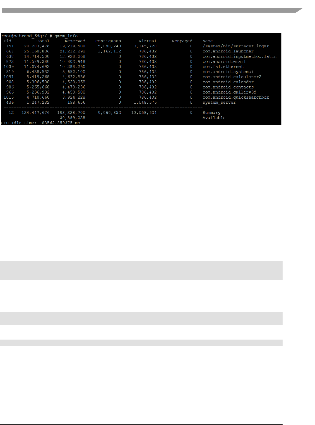
i.MX 6 Graphics User’s Guide, Rev. L3.14.28_1.0.0-ga, 04/2015
111 Freescale Semiconductor
Figure 55 gmem_info tool
8.3 Freescale apitrace user guide
8.3.1 Introduction
Freescale apitrace is a set of tools enhanced from open source project apitrace. Freescale version adds support to
Freescale i.MX 6 chipsets which use Vivante GPU IP. This tool can dump OpenGL/GLES1.1/GLES2.0/GLES3.0 API
calls and replay on a wide range of other devices.
8.3.2 Install
8.3.2.1 Yocto X11
Preinstalled in the BSP. You can also get it from apitrace/linux/arm-X11-hfp/
8.3.2.2 Yocto FB/DFB/Wayland
Need install by hand:
cp apitrace/linux/arm-nonX-hfp/bin/* /usr/bin
cp -r apitrace/linux/arm-nonX-hfp/lib/apitrace /usr/lib
cp -r apitrace/linux/arm-nonX-hfp/share/doc/apitrace/ /usr/share/doc/
8.3.2.3 Android Platform
It will be preinstalled in next release. Currently have to install them by hand:
Mount release package to android system:
mkdir /data/share; busybo mount -t nfs -o nolock <host> /data/share
cp -r apitrace/android/apitrace /data/
A convenient alternative:
adb push apitrace/android/ /data/local/tmp/
Note 1: If install to a directory other than /data/apitrace, please update apitrace/bin/apitrace_dalvik.sh to use the
new path.
Note 2: Pay attention to file attributes. Must grant access to the whole file path of eglretrace.so for normal user,
because java applications are running as normal user even if it is started by root user.

i.MX 6 Graphics User’s Guide, Rev. L3.14.28_1.0.0-ga, 04/2015
112 Freescale Semiconductor
8.3.2.4 PC
It also can run on PC. It is recommended to install to PC to take advantage of qapitrace.
Currently supports Ubuntu 14.04 LTS, 64-bit.
sudo apt-get install libgles1-mesa libgles2-mesa libqt4-dev
cp gpu-south-tools-release/0.1/apitrace/linux/x64/bin/* /usr/bin
cp -r gpu-south-tools-release/0.1/apitrace/linux/x64/lib/apitrace /usr/lib
cp -r apitrace/linux/x64/share/doc/apitrace/ /usr/share/doc/
8.3.3 Usage
8.3.3.1 Trace OpenGL ES1.1/2.0/3.0 application
apitrace trace --api=egl <app name and arguments>
e.g., apitrace trace --api=egl es2gears_x11
It will generate trace file (.trace) under current directory. To specify a new path, use --output=<path_name>
8.3.3.2 Trace OpenGL ES 1.1/2.0/3.0 Java application on the Android platform
On the Android platform, a GLES application can be native (e.g., frameworks/native/opengl/angeles). This type of
application can be traced as normal Linux application. Some other applications involving java virtual machine
cannot run in this way. A script apitrace_dalvik.sh is provided to run this type of application. This is an example to
trace com.android.settings:
sh /data/apitrace/bin/apitrace_dalvik.sh com.android.settings start
To stop tracing, run:
sh /data/apitrace/bin/apitrace_dalvik.sh com.android.settings stop
Because there is no “current” directory for java application, the trace file is stored to under /sdcard/
If apitrace is installed in a different directory, need update apitrace_dalvik.sh by hand
8.3.3.3 Trace OpenGL application
apitrace trace --api=glx <app name and arguments>
Only X11 backend supports this feature
8.3.3.4 Replay
This utility is also called retrace. It reads in the trace file and executes OpenGL(ES) APIs one by one. Each
OpenGL(ES) API call will be processed by a callback function. In that callback function, a hook can be inserted for
debug or analysis purposes.
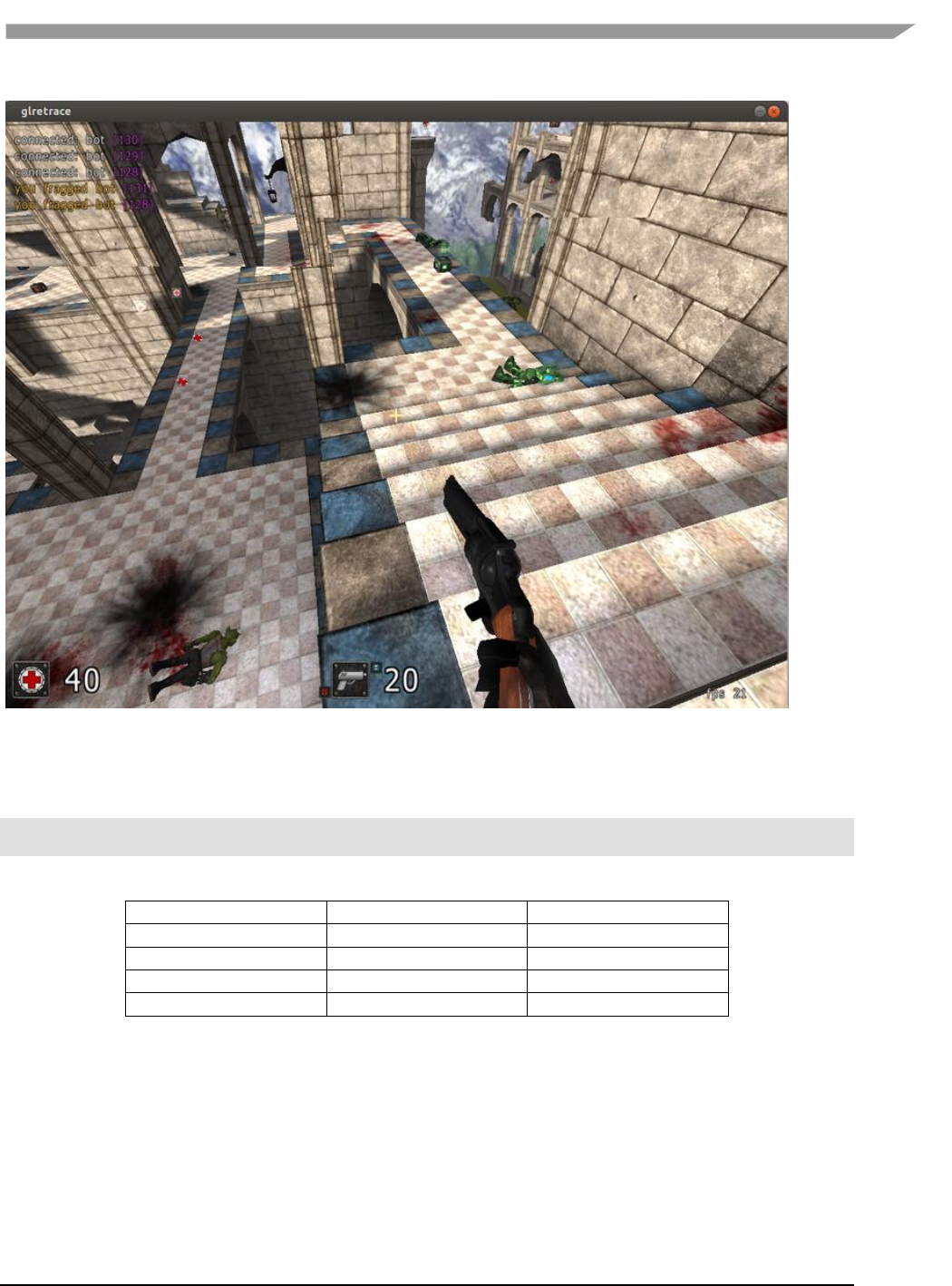
i.MX 6 Graphics User’s Guide, Rev. L3.14.28_1.0.0-ga, 04/2015
113 Freescale Semiconductor
Figure 56 Replay
OpenGL ES 1.1/2.0/3.0 applications can be replayed with eglretrace; Open GL applications can be replayed with
glretrace:
eglretrace <trace file>
glretrace <trace file>
Supported platforms:
eglretrace
Glretrace
Yocto-X11
X
X
Yocto-FB/DFB/Wayland
X
Android
PC
X
X
For ES 3.0 replay, only Freescale i.MX 6 supports this feature. It is not available on PC.
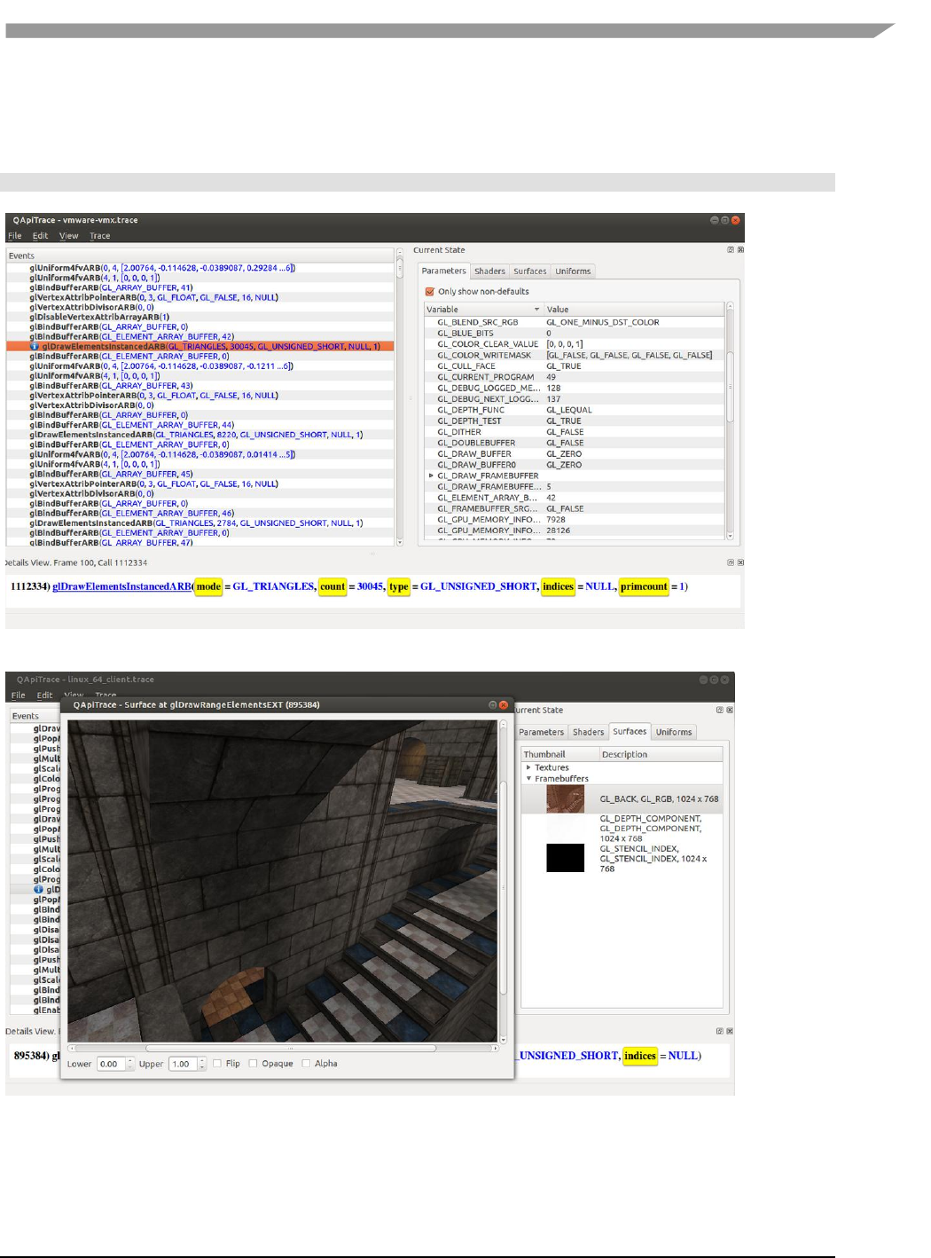
i.MX 6 Graphics User’s Guide, Rev. L3.14.28_1.0.0-ga, 04/2015
114 Freescale Semiconductor
8.3.3.5 Analysis
qapitrace provides a detailed look at the trace file. It can only run on a PC. Verified on Ubuntu 14.04 LTS 64-bit. The
command is:
qapitrace <trace file name>
Figure 57 Checking state of every API call
Figure 58 Checking Framebuffer
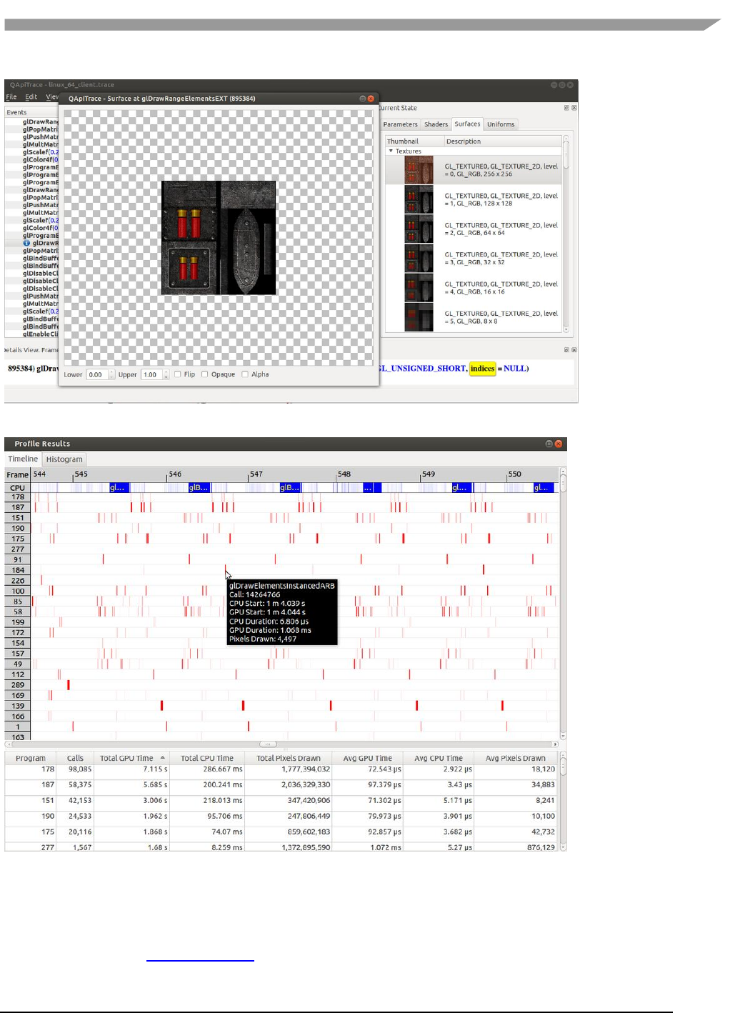


i.MX 6 Graphics User’s Guide, Rev. L3.14.28_1.0.0-ga, 04/2015
117 Freescale Semiconductor
Chapter 9 GPU Memory Introduction
9.1 GPU memory overview
OpenGL-ES
o Texture buffer
o Vertex buffer
o Index buffer
o PBuffer surface
o Color buffer
o Z/Stencil buffer
o HZ depth buffer
o Tiled status buffer
o 3D Command buffer
o 3D Context buffer
OpenVG
o Image buffer
o Tessellation buffer
o VG command buffer
o VG context buffer
2D buffers
o 2D command buffer
o 2D temporary buffer
9.2 GPU memory pools
Reserved memory
In the Linux 3.10.y kernel, the memory is reserved from CMA implemented in the GPU kernel driver, the
size can be changed through U-boot args with “galcore.contiguoussize =xxx”
The memory allocation and lock very fast, but cannot support cacheable attribute.
Contiguous memory
The contiguous memory is from CMA or Normal or Highmem with alloc_pages_exact.
The GPU driver tries the CMA allocator for non-cacheable request first. If CMA memory is used up, it goes
to system allocator.
The CMA allocator does not support the cacheable attribute, the system allocator supports cacheable
attribute, but the memory performance is slow with the additional cache flush operations.
Virtual memory pool
The contiguous memory is from Normal or Highmem with multiple page_alloc.
The memory support cacheable attribute, but slow with GPU MMU and cache flush.
The GPU virtual command buffer is allocated from virtual memory pool directly.
Nonpaged memory pool
In the 5.x GPU driver, this pool is not used any more
9.3 GPU memory allocators
Two kinds of allocators are implemented in i.MX 6 GPU kernel driver, refer to drivers/mxc/gpu-viv/
The video memory allocator implementation is very complicated. The memory is from the reserved pool,
system contiguous pool (supports CMA), or system virtual pool (enables GPU MMU).
The CMA allocator supports non-cacheable contiguous memory. It is implemented as a part of contiguous
pool. When the system requests contiguous memory, the allocator tries CMA first. If CMA is used up, it
goes to allocate the system contiguous pages.
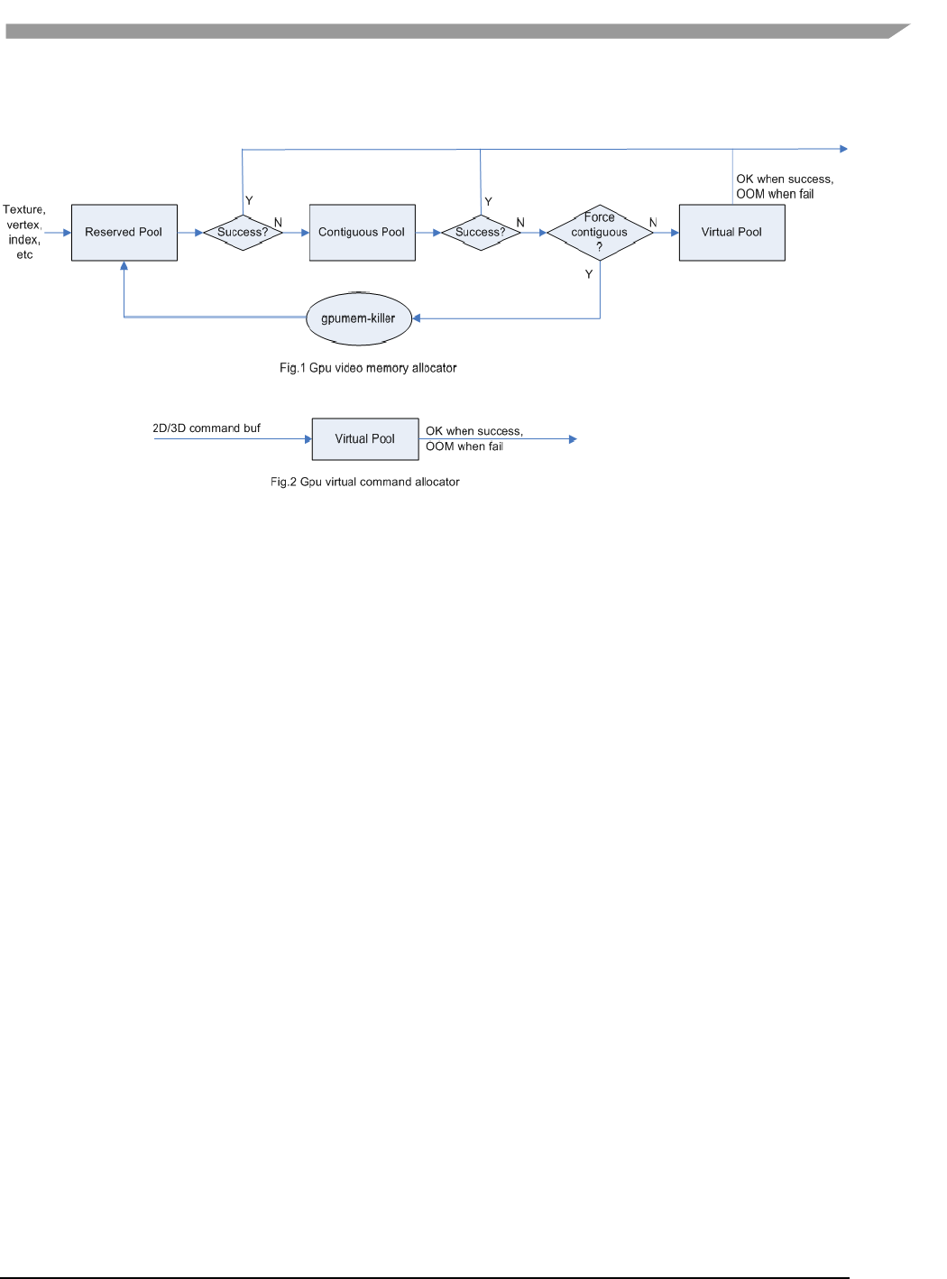
i.MX 6 Graphics User’s Guide, Rev. L3.14.28_1.0.0-ga, 04/2015
118 Freescale Semiconductor
GPU memory-killer is implemented for special requirement of force contiguous GPU memory.
Figure 61 GPU memory allocators
9.4 GPU reserved memory
The reserved memory is managed by two dual linked lists, one is free list, and another is node list.
When allocate the reserved memory, free list will be scanned from head to tail until a available node is
selected, it is very fast but will make more memory fragments, under test, 10~20M of 128M is not
available to use after a lot of allocate/free operations.
When the available node is selected, it will be removed from free list, but it always keep the dual linked
nodes to merge the conjoint available memory when freed.
The reserved memory is mapped once when application process is attached, during 3D application
running, the memory map/un-map operations are very fast, the virtual address is just calculated with
logical base and offset.
9.5 GPU memory base address
GPU support contiguous physical memory within (0~2G) address directly:
o GPU address = CPU Physical address – GPU BaseAddress
GPU MMU will be enabled for two kinds of memory type as below:
o Separated page memory from Virtual memory pool
o Contiguous page memory with address out of (0~2G)
BaseAddress should be set to RAM start address to achieve the better performance by reducing GPU
MMU mapping.

i.MX 6 Graphics User’s Guide, Rev. L3.14.28_1.0.0-ga, 04/2015
119 Freescale Semiconductor
Figure 62 GPU memory base address

i.MX 6 Graphics User’s Guide, Rev. L3.14.28_1.0.0-ga, 04/2015
120 Freescale Semiconductor
Chapter 10 Application Programming Recommendations
The recommendations listed below take a holistic approach centered on overall system level optimizations that
balance graphics and system resources.
10.1 Understand the system configuration and target application
Knowing details about the application and use case will allow developers to correctly utilize the hardware
resources in an ideal access pattern. For example, an implementation for a 2D or 3D GUI could be rendered in a
single pass instead of multiple passes if the draw call sequence is correctly ordered. In addition, knowing the most
common graphics function calls will allow developers to parallelize rendering to maximize performance.
Using Vivante and vendor specific SoC profiling tools, you can determine bottlenecks in the GPU and CPU and
make changes as needed. For example, in a 3D game, most CPU cycles may be spent on audio processing, AI, and
physics and less on rendering or scene setup for the GPU. In this case the application is CPU-bound and
configurations dealing with non-graphics tasks need to be reviewed and modified. If the system is GPU-bound,
then the profiler can point out where the GPU programming code bottlenecks are located and which sections to
optimize to remove restrictions.
10.2 Optimize off chip data transfer such as accessing off-chip DDR
memory/mobile DDR memory
Any data transfer off-chip takes bandwidth and resources from other functional blocks in the SoC, increases power,
and causes additional cycles of latency and delay as the GPU pipeline needs to wait for data to return from
memory. Using on-chip cache and writing the application to better take advantage of cache locality and coherency
will increase performance. In addition, accessing the GPU frame buffer from the CPU (not recommended) will
cause the driver to flush all queued render commands in the command buffer, slowing down performance as the
GPU has to wait since the command queue is partially empty (inefficient use of resources) and CPU-GPU
synchronization is not parallelized.
10.3 Avoid random cache or memory accesses
Cache thrashing, misses, and the need to access data in external memory causes performance hits. An example
would be random texture cache access since it is expensive when performing per-pixel texture reads if the texture
units need to access the cache randomly and go off-chip if there is a cache miss.
10.4 Optimize your use of system memory
Memory is a valuable resource that needs to be shared between the GPU (frame buffer), CPU, system, and other
applications. If you allocate too much memory for your OpenGL ES application, less memory will be available for
the rest of the system, which may impact system performance. Claim enough memory as needed for your
application then deallocate it as soon as your application no longer needs it. For example, you can allocate a depth
buffer only when needed or if your application only needs partial resources, load the necessary items initially and
load the rest later.
10.5 Target a fixed frame rate that is visibly smooth
Smooth frame rate is achieved from a combination of a constant FPS and the lowest FPS (frames per second) that
is visually acceptable. There is a trade-off between power and frame rates since the graphics engine loading
increases with higher FPS. If the application is smooth at 30 FPS and no visual differences for the application are

i.MX 6 Graphics User’s Guide, Rev. L3.14.28_1.0.0-ga, 04/2015
121 Freescale Semiconductor
perceived at 50 FPS, then the developer should cap the FPS at 30 since the extra 20 FPS do not make a visual
difference. The FPS limit will also guarantee an achievable frame rate at all times. The savings in FPS will help lower
GPU and system power consumption.
10.6 Minimize GL state changes
Setting up state values between draw calls adds significant overhead to application performance so they must be
minimized. Most of these call setups are redundant since you are saving / restoring states prior to drawing. Try to
avoid setting up multiple state calls between draw calls or setting the same values for multiple calls. Sometimes
when a specific texture is used, it is better to sort draw calls around that texture to avoid texture thrashing which
inhibits performance. Application developers should also try to group state changes.
10.7 Batch primitives to minimize the number of draw calls
When your application submits primitives to be processed by OpenGL ES, the CPU spends time preparing
commands for the GPU hardware to execute. If you batch your draw calls into fewer calls, you reduce the CPU
overhead and increase draw call efficiency. Batch processing allows a group of draw calls to be quickly executed
without any intervention from the CPU (driver or application) in a fire-and-forget method.
Some examples of batching primitives are:
Branching in shaders may allow better batching since each branch can be grouped together for execution.
For primitives like triangle strips, the developer can combine multiple strips that share the same state to
save successive draw calls (and state changes) into a single batch call that uses the same state (single
setup) for many triangles.
Developers can also consolidate primitives that are drawn in close proximity to take advantage of spatial
relationships. If the batched primitives are too far apart, it is more difficult for the application to
effectively cull if they are not visible in the frame.
10.8 Perform calculations per vertex instead of per fragment/pixel
Since the number of vertices is usually much less than the number of fragments/pixels, it is cheaper to do per
vertex calculations to save processing power.
10.9 Enable early-Z, hierarchical-Z and back face culling
Hardware support of depth testing to determine if objects are in the user’s field of view are used to save workload
and processing on vertex and pixel processing. If the object is in view, then the vertices are sent down the pipeline
for processing. If the object is hidden or not viewable, the triangles are culled and not sent to the pipeline. This
improves graphics performance since computations are only spent on visible objects. If the application already
knows details about the contents and relative position of objects in the scene or screen, the developer can use that
information to automatically bound areas that never need to be touched (for example an automotive application
that has multiple layers of dials where parts of the underlying dials are occluded can have the application avoid
occluded areas from the beginning). Another optimization is to perform basic culling on the CPU since the CPU has
first-hand information about the scene details and object positions so it knows what scene data to send to the
GPU.

i.MX 6 Graphics User’s Guide, Rev. L3.14.28_1.0.0-ga, 04/2015
122 Freescale Semiconductor
10.10 Use branching carefully
Static branches perform well since states are known but they tend to use many general purpose registers. An
example is a long shader that combines multiple shaders into a single, large shader that reduces state changes and
batch draw calls. Dynamic branching has non-constant overhead since it processes multiple pixels as one and
everything executes whether a branch is taken or not. In other words, dynamic branching goes through different
permutations/branches in parallel to reach the correct results. If all pixels take the same path, then performance
will be good. The more pixels processed translates to higher overhead and lower performance. For dynamic
branching, smaller pixel sizes/groups are optimal for throughput. Developers need to be aware of branching in
their code to make sure excessive calculations and branches are efficient. Profiling tools can help determine if
certain parts of code are optimized or not.
10.11 Do not use static or stack data as vertex data - use VBOs instead
A vertex buffer object (VBO) is a buffer object that provides the benefits of vertex array and display list and allows
a substantial performance gain for uploading data (vertex position, color, normals, and texture coordinates) to the
GPU. VBOs create buffer objects in memory and allow the GPU to directly access memory without CPU
intervention (DMA). The memory manager can optimize buffer placement using feedback from the application.
VBOs can also handle static and dynamic data sets and are managed by the Vivante driver. The benefits of each
are:
A vertex array reduces the number of function calls and allows redundant data to be shared
between related vertices, instead of re-sending all the data each time. Access to data can be
referenced by the array index.
The display list allows commands to be stored for later execution and can be used repeatedly over
multiple frames without re-transmitting data, thus minimizing CPU cycles to transfer data. The
display list can also be shared by multiple OpenGL / OpenGL ES clients so they can access the same
buffer with the corresponding identifier. If you put computationally expensive operations (ex.
lighting or material calculations) inside display lists, then these computations will be processed
once when the list is created and the final result can be re-used multiple times without needing to
re-calculate again.
If you combine the benefits of both by using VBO, performance will increase over static or stack data sets.
10.12 Use dynamic VBO if data is changing frame by frame
Locking a static vertex buffer while the GPU is using it can create a performance penalty since the GPU needs to
finish reading the vertex data from the buffer before it can return to the calling application. Locking and rendering
from a static buffer many times per frame also prevents the GPU buffering render commands since it mush finish
commands before returning the lock pointer. Without buffered commands the GPU remains idle until the
application finishes filling the vertex buffer and issues the draw commands.
If the scene data never changes from frame to frame then a static buffer may be sufficient. With newer
applications (ex. games, maps) that have dynamic viewports where vertex data changes multiple times per frame
or frame-to-frame, then a dynamic VBO is required to ensure performance is still met. If the current buffer is being
used by the GPU when a lock is called, a pointer to a new buffer location is returned to the application to ensure
updated data is written to the new buffer. The GPU can still access the old data (current buffer) while the
application puts updated data into the new buffer. The Vivante memory management unit and driver will
automatically take care of allocating, re-allocating, or destroying buffers.

i.MX 6 Graphics User’s Guide, Rev. L3.14.28_1.0.0-ga, 04/2015
123 Freescale Semiconductor
You can implement dynamic VBO depending on your preference, but one recommendation is to allocate a 1 MB
dynamic VBO block and upload data to using different offsets for each dynamic buffer. If the buffer overflows you
can loop back and use location offset 0 again.
10.13 Tessellate your data so that Hierarchical Z (HZ) can do its job
We can break this into how OpenGL and OpenGL ES handle this case.
OpenGL only renders simple convex polygons (edges only intersect at vertices with no duplicate vertices and only
two edges meet at any vertex), in addition to points, lines, and triangles. If the application requires concave
polygons (polygons with holes or intersecting edges), those polygons need to be subdivided into simple convex
polygons, which is called tessellation (subdividing a polygon mesh into a bunch of smaller meshes). Once you have
all the meshes in place our HZ hardware can automatically cull hidden polygons to efficiently process the frame,
effectively breaking the frame into smaller chunks that can be processed very fast.
OpenGL ES only renders triangles, lines, and points. The same concepts apply as in OpenGL, which is to avoid very
large polygons by breaking them down into smaller polygons where our internal GPU scheduler can distribute
them into multiple threads to fully parallelize the process and remove hidden polygons.
10.14 Use dynamic textures as a texture cache (texture atlas)
The main reason for using dynamic textures as a cache is the application developer can create one larger texture
that is subdivided into different regions (texture atlas). The application can upload data into each region and use
an application side texture atlas to access the data. Each dynamic texture and sub-region can be locked, written to,
and unlocked each frame, as needed. This method of allocating once is more efficient than using multiple smaller
textures that need to be allocated, generated, and then destroyed each time.
10.15 If you use many small triangle strips, stitch them together
It is better to combine several small, spatially related triangle strips together into a larger triangle stip to minimize
overhead and increase performance. For each triangle strip, there are overhead and start up costs that are
required by the CPU and GPU, including state loads. If there are too many small triangle strips that need to be
loaded, this will impact performance. An application developer can combine multiple triangle strips by adding a
degenerate triangle to join the strips together. The overhead to restart multiple new strips is much higher than
adding the degenerate triangle.
10.16 Specify EGL configuration attributes precisely
To obtain a 16 bit/pixel window buffer for rendering, the EGL config attributes need to be specified precisely
according to the EGL spec. Specifying inaccurate EGL attributes may result in getting a 32-bit bit/pixel window
buffer which doubles the bandwidth requirement for rendering which in turn leads to lower performance.
10.17 Use aligned texture/render buffers
The GPUs work on buffers with HW specific width/height alignment for better efficiency. Please use the available
API to query the GPU buffer alignment and allocate the texture / render buffers to satisfy these requirements, to
avoid the cost of copies to aligned shadow memory.

i.MX 6 Graphics User’s Guide, Rev. L3.14.28_1.0.0-ga, 04/2015
124 Freescale Semiconductor
10.18 Disable MSAA rendering unless high quality is needed
Although MSAA rendering can achieve higher image quality with smoother lines and triangle edges, it requires
much higher (4x, 8x) bandwidth because it has to rendering a single pixel 4x/8x times. So, if high rendering quality
is not required, MSAA should be disabled.
10.19 Avoid partial clears
Most GPUs have special hardware logic to do a fast clear of an entire buffer. So it is better to utilize the fast clear
function to clear the entire buffer then render graphics again, instead of doing a partial clear to preserve a graphics
region. If a partial clear is required by the application, make sure the clear area is aligned according to the GPU
specific requirements. Unaligned partial clears are expensive and should be avoided.
10.20 Avoid mask operations
Do not use mask unless the mask is 0 (other than when you need a specific render quality). Clearing a surface with
mask (color /depth stencil mask) could have a performance penalty.Pixel mask operations are normally pretty
expensive on some GPUs as the mask operation has to be done on every single pixel.
10.21 Use MIPMAP textures
MIPMAP textures enable the application to sample a lower resolution texture image (1/2, 1/4, 1/8, 1/16, ... size of
the original texture image) when the triangle is rendering further away from the view point. Thus, the bandwidth
required to read the texture image is reduced which leads to better performance.
10.22 Use compressed textures if constricted by RAM/ROM budget
Compressed textures are normally only a fraction (up to 1/8) of the original texture size. Using compressed
textures reduces the storage requirements in memory and can also reduce the required texture upload bandwidth,
when using a format that is supported natively by the hardware.
Compressed textures should not be chosen, if only for the purposes of reducing the memory bandwidth required
for sampling of the texture during rendering. This is because due to a fixed read request size from the GPU, the
memory controller load will be the same as for an uncompressed texture.
10.23 Draw objects from near to far if possible
Drawing objects from near to far normally has better performance because the objects in the near foreground can
block entire or partial objects in the background. Most GPUs have early Z rejection logic to reject the pixels that
will fail a Z compare. The GPU can skip fragment shader computations on these rejected pixels.
10.24 Avoid indexed triangle strips.
Index triangle strips can usually maximize the vertex cache utilization as each set of vertex data can be used in two
triangles. There is however an errata in the GC2000 and GC880 GPUs which requires a SW conversion of indexed
triangle strips to triangle lists in the driver. For small strips the conversion overhead is neglible, but for large
geometries a different primitive type should be used.

i.MX 6 Graphics User’s Guide, Rev. L3.14.28_1.0.0-ga, 04/2015
125 Freescale Semiconductor
10.25 Vertex attribute stride should not be larger than 256 bytes
Most Vivante GPUs provide native support for a 256 byte vertex attribute stride. If the vertex attribute stride is
larger than 256 bytes, then the driver has to copy the vertex data around. Hardware versions v55 and higher (such
as the GC7000L v55) support a 2048 byte vertex attribute stride as required in the OES3.1 spec.
10.26 Avoid binding buffers to mixed index/vertex array
Most of Vivante GPUs do not natively support mixed index/vertex arrays. So the Vivante driver must copy the
index and vertex data around to form separate vertex data streams for the GPU. Avoid mixing index and vertex
data so the driver does not have to incur a performance hit while performing this task.
10.27 Avoid using CPU to update texture/buffer contexts during render
Do not use the CPU to update texture/buffer contexts in the middle of rendering. Using the CPU to update
texture/buffer causes the rendering pipeline to flush and stall, so that CPU can safely update the buffer contents.
The pipeline flush/stall/resume will cause significant performance impact.
10.28 Avoid frequent context switching
Context switch is an inherently expensive operation as many GPU states need to be reset to start a new rendering
context. Thus, frequent context switching will have a negative impact on application performance.
10.29 Optimize resources within a shader
Most GPUs have optimal support for a limited amount of resources (uniforms, varying, etc.). Using resources
beyond the optimal working set will cause the GPU to fetch/store resources from a lower performance memory
pool and shader performance will be negatively impacted.
10.30 Avoid using glScissor Clear for small regions
glScissor Clear for small regions (less than 16x8 aligned window) will fall back to CPU so the performance is not
optimal.

i.MX 6 Graphics User’s Guide, Rev. L3.14.28_1.0.0-ga, 04/2015
126 Freescale Semiconductor
Chapter 11 Demo Framework
11.1 Summaries
This document describes the Freescale Demo Framework, targeted at platform agnostic development of graphical
demos. It covers the goals, architecture and instructions of how to use it across platforms, examples and best
practices.
11.1.1 Executive summary
• Write a demo application once.
• Run it on the Android platform, Yocto Linux OS, Ubuntu and MS Windows OS.
• Easily portable to additional platforms.
• Supports: OpenGL ES2, OpenGL ES3, with OpenVG and G2D planned for future release.
11.1.2 Technical overview
• Written in a limited subset of C++11 and uses RAII to manage resources.
• Uses a limited subset of STL to make it easier to port.
• No copyleft restrictions from GPL/LGPL licenses
• Allows for direct access to the expected API’s (EGL,ES2, ES3)
• Provides optional helper classes for commonly used tasks
− Matrix, Vector3, GLShader, GLTexture, etc.
• Services
− Keyboard and mouse
− Persistent data manager
− Assets management (models, textures)
• Defines a standard way for handling
− Init, shutdown and window resize.
− Program input arguments.
− Input events like keyboard, mouse and touch.
− Fixed time-step and variable time-step demo implementations.
− Logging functionality.
11.2 Introduction
The Demo Framework is a multi-platform framework that enables demos to run on various platforms without any
changes. The framework abstracts away all the boilerplate and OS specific code of allocating surfaces, creating the
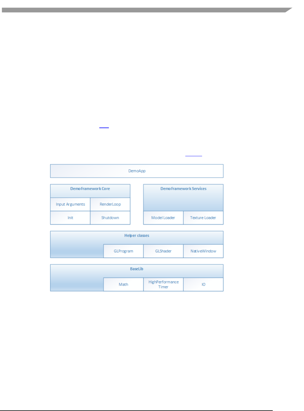
i.MX 6 Graphics User’s Guide, Rev. L3.14.28_1.0.0-ga, 04/2015
127 Freescale Semiconductor
context, model loading, texture loading, shader compilation, render loop, animation ticks, benchmarking graph
overlays etc. This allows the demo/benchmark developer to focus on writing rendering code. It also enables them
to develop demos on PC or the Android platform where the tool chain and debug facilities allows for faster
turnaround time and then take the working code and deploy without code changes to the supported platforms.
The platforms we currently support are Windows OS (for development via emulated backends), Android NDK and
Linux OS with various windowing systems. The framework allows us to provide ‘real’ comparative benchmarks
between the different OS and windowing systems we support, since we can run the exact same demo/benchmark
code on them all.
The long term plans for the framework include extending it with support for OpenVG, G2D and other relevant
API’s.
11.3 Design overview
The framework is written in C++ and uses RAII to manage resources. The resource management code focuses on
‘ease of use’ over raw performance, since it’s mainly run on construction and destruction of the demo.
To allow the demo framework to be easily portable to new platforms its functionality is split into two parts: ‘core’
and ‘services’. The core framework depends on a limited subset of STL to make it easier to port. Framework
services come with their own set of library requirements. The model importer Assimp requires boost to be
available on the platform.
Figure 63 Design overview
Beside the demo framework core and demo framework services there is a set of helper classes for commonly used
functionality, which makes it easier to write demo’s for the API’s we support. The helper classes do not depend on
the demo framework and can be used in any program for the given API. For example for OpenGL ES, there is a
GLShader and GLProgram class which hides away the complexities of compiling the shader object and linking the
program object and since they are RAII objects, they also clean up after themselves once you are done with them.
Since our primarily supported BSPs are Linux OS based, we decided to utilize an input argument framework that is
compatible with the standard UNIX parameter format, like the one exposed by getopt (We do however not utilize
getopt to remain GPL free across platforms).
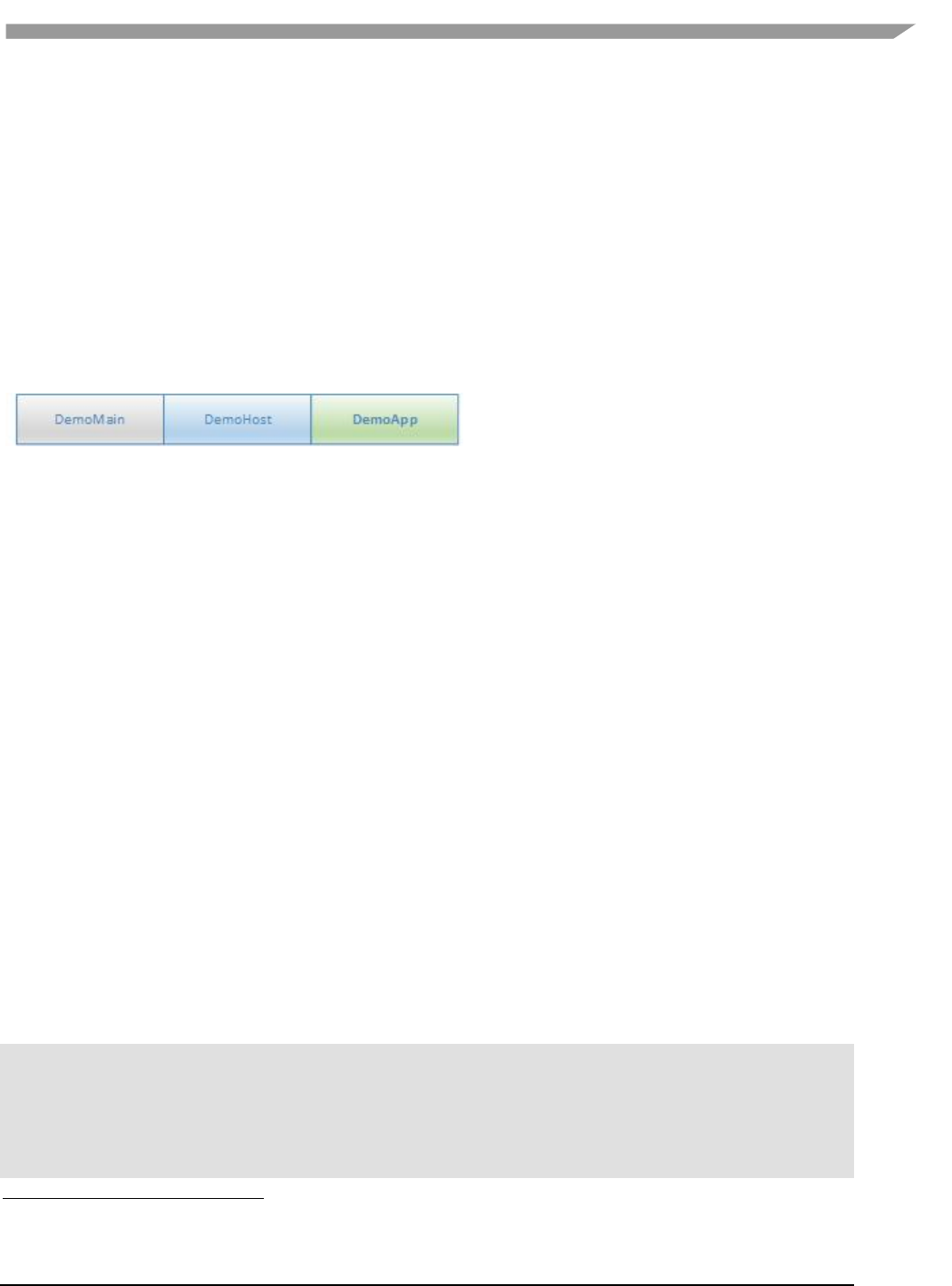
i.MX 6 Graphics User’s Guide, Rev. L3.14.28_1.0.0-ga, 04/2015
128 Freescale Semiconductor
11.4 High level overview
The framework consist of three high level domains.
11.4.1 DemoMain
All the code that binds everything together and it is platform independent.
1. It gets the current demo setup
a. Which demo host to utilize for the demo.
b. Which demo app that needs to be run.
2. It parses the input arguments
3. It launches the demo host.
4. It logs any errors that might occur.
11.4.2 DemoHost
The demo-host is responsible for init and shutdown of the host environment and running the main loop.
The main loop utilizes the DemoAppManager to control the life of the DemoApp.
In other words, the DemoHost is the graphics API specific code needed to initialize and shutdown a given API and
some code to run a render loop. All the API and platform independent code of the render loop resides inside the
DemoAppManager class.
The exact capabilities of a DemoHost are also platform dependent. For example, some EGL implementations
support running OpenVG and OpenGL ES, allowing a demo app to utilize both API’s at once. This is not something
that is supported by most windows emulation layers.
11.4.3 DemoApp
A demo application written for one or more specific APIs which are supported by a specific DemoHost. The demo is
usually platform independent – the exception to the rule is if it depends on specific features that only exist on
certain platforms.
11.5 Demo application details
The following description of the demo application details uses a GLES2 demo named ‘S01_SimpleTriangle’ as
example. It lists the default methods that a demo should implement, the way it can provide customized
parameters to the windowing system and how asset management is made platform agnostic.
11.5.1 Demo method overview
This is a list of the methods that every Demo App is most likely to override1.
// Init
S01_SimpleTriangle(const DemoAppConfig& config)
// Shutdown
~S01_SimpleTriangle()
// OPTIONAL: Custom resize logic (if the app requested it). The default logic is to
// restart the app.
void Resized(const Point2& size)
1 See DemoFramework\FslDemoApp\include\FslDemoApp\ADemoApp.hpp for a complete list.

i.MX 6 Graphics User’s Guide, Rev. L3.14.28_1.0.0-ga, 04/2015
129 Freescale Semiconductor
// OPTIONAL: Fixed time step update method that will be called the set number of times
// per second. The fixed time step update is often used for physics.
void FixedUpdate(const DemoTime& demoTime)
// OPTIONAL: Variable time step update method.
void Update(const DemoTime& demoTime)
// Put the rendering calls here
void Draw()
When the constructor is invoked, the Demo Host API will already be setup and ready for use, the demo framework
will use EGL to configure things as requested by your EGL config and API version.
It is recommended that you do all your setup in the constructor.
This also means that you should never try to shutdown EGL in the destructor since the framework will do it at the
appropriate time. The destructor should only worry about resources that your demo app actually allocated by
itself.
11.5.1.1 Resized
The resized method will be called if the screen resolution changes (if your app never changes resolution this will
never be called)2.
11.5.1.2 FixedUpdate
Is a fixed time-step update method that will be called the set number of times per second. The fixed time step
update is often used for physics3.
11.5.1.3 Update
Will be called once before every draw call and you will normally update your animation using delta time.
For example if you need to move your object 10 units horizontally per second you would do something like
m_positionX += 10 * demoTime.DeltaTime;
11.5.1.4 Draw
Should be used to render graphics.
11.5.2 Fixed or variable timestep update
Depending on what your demo is doing, you might use one or the other - or both. It’s actually a very complex topic
once you start to dig into it, but in general anything that need precision and predictable/repeatable calculations,
like for example physics, often benefits from using fixed time steps. It really depends on your algorithm and it’s
recommended to do a couple of google searches on fixed vs variable, since there are lots of arguments for both.
It’s also worth noting that game engines like Unity3D4 support both methods.
11.5.3 Execution order of methods during a frame
The methods will be called in this order
• Events (if any occurred)5
• Resized6
2 This version of the framework always restart the app, so this will never be called.
3 This version uses a fixed update frequency of 60 ticks per second. This will be configurable in the future.
4 unity3d.com/
5 For an example of event handling see the “DemoApps\GLES2\InputEvents” sample.

i.MX 6 Graphics User’s Guide, Rev. L3.14.28_1.0.0-ga, 04/2015
130 Freescale Semiconductor
• FixedUpdate (0-N calls. The first frame will always have a FixedUpdate call)
• Update
• Draw
After the draw call, a swap will occur.
11.5.4 Exit
The demo app can request an exit to occur, or it can be terminated via an external request.
In both cases one of the following things occur.
1. If the app has been constructed and has received a FixedUpdate, then it will finish its FixedUpdate,
Update, Draw, swap sequence before its shutdown.
2. If the app requests a shutdown during construction, the app will be destroyed before calling any other
method on the object (and no swap will occur).
The app can request an exit to occur by calling:
GetDemoAppControl()->RequestExit(1);
11.5.5 Dealing with screen resolution changes
Per default the app is destroyed and recreated when a resolution change occurs7.
It is left up to the DemoApp to save and restore demo specific state.
11.5.6 Content loading
The framework supports loading files from the Content folder on all platforms.
Given a content folder like this:
Content/Texture1.bmp
Content/Stuff/Readme.txt
You can load the files via the IContentManager service that can be accessed by calling
std::shared_ptr<IContentManager> contentManager = GetContentManager();
You can then load files like this:
Binary file:
std::vector<uint8_t> content;
contentManager->ReadAllBytes(content, "MyData.bin");
Text file:
const std::string content = contentManager-
>ReadAllText("Stuff/Readme.txt");
Bitmap file8:
Bitmap bitmap;
contentManager->Read(bitmap, "Texture1.bmp", PixelFormat::RGB888);
6 In this version of the framework this is never called as the app will be recreated on screen size changes
(future versions will allow demo apps to handle resize events if they so desire)
7 Future versions will allow demo apps to handle resize events if they so desire.
8 The current framework only supports a limited subset of BMP images (24 and 32BPP). This will be
extended in a future version where we expect to have DevIL support.

i.MX 6 Graphics User’s Guide, Rev. L3.14.28_1.0.0-ga, 04/2015
131 Freescale Semiconductor

i.MX 6 Graphics User’s Guide, Rev. L3.14.28_1.0.0-ga, 04/2015
132 Freescale Semiconductor
If you prefer to control the loading yourself you can retrieve the path to the files like this:
IO::Path contentPath = contentManager->GetContentPath();
IO::Path myData = IO::Path::Combine(contentPath, "MyData.bin");
IO::Path readmePath = IO::Path::Combine(contentPath, "Stuff/Readme.txt");
IO::Path texture1Path = IO::Path::Combine(contentPath, "Texture1.bmp");
You can then open the files with any method you prefer.
Both methods works for all supported platforms.
For detailed information about how the content is handled on each platform, see the build guide appendixes.
The details of the available helper classes for a Demo Application are described in 11.6.
11.5.7 Demo registration
This is done in the S01_SimpleTriangle_Register.cpp file.
namespace
{
// Custom EGL config (Will overwrite the settings for the listed values.
// however an exact EGL config can be used)
static const EGLint g_eglConfigAttribs[] =
{
EGL_RED_SIZE, 5,
EGL_GREEN_SIZE, 6,
EGL_BLUE_SIZE, 5,
EGL_ALPHA_SIZE, 0,
EGL_SAMPLES, 0,
EGL_NONE
};
}
// configure the demo environment to run this demo app in a OpenGLES2 host environment
FSL_REGISTER_OPENGLES2_DEMO(S01_SimpleTriangle,DemoAppHostConfigEGL(g_eglConfigAttribs
));
Since the demo framework is controlling the main method, you need to register your application with the Demo
Host specific macro (in this case the OpenGL ES2 host), for the framework to register your demo class.

i.MX 6 Graphics User’s Guide, Rev. L3.14.28_1.0.0-ga, 04/2015
133 Freescale Semiconductor
11.6 Helper Class Overview
11.6.1 FslBase
Provides basic functionality missing from C++ standard libraries.
11.6.1.1 Bits
BitsUtil
Utility methods for working with bits
ByteArrayUtil
Utility methods for reading and writing values from byte arrays in a
specific endian format. This functionality is useful when working on
platform independent load and save methods.
11.6.1.2 IO
Platform independent IO.
Directory
Helper methods for working on directories.
GetCurrentWorkingDirectory.
File
Helper methods for working with files
Checking if file exists.
File length.
Read all content from a file.
Path
A UTF8 path class and helper methods for working on it.
Combing paths.
Extracting directory or filename.
Getting the full path from a relative path.
11.6.1.3 Log
Platform independent logging.
Instead of using printf or std::cout to log information it’s better to utilize the provided logging macro’s since work
across all supported platforms.
Log
Various logging macros
FSLLOG
FSLLOG_IF
FSLLOG_WARNING
FSLLOG_WARNING_IF
FSLLOG_ERROR
FSLLOG_ERROR_IF

i.MX 6 Graphics User’s Guide, Rev. L3.14.28_1.0.0-ga, 04/2015
134 Freescale Semiconductor
11.6.1.4 Math
Mainly focused on math functionality useful for working with graphics. It focuses on ease of use instead of raw
performance.
MathHelper
Various commonly used helper methods and constants like
PI
Clamping
Lerp
Conversions between radians and angles
PowerOfTwo
Matrix
Matrix helper methods like
Perspective
Rotate
Translate
Scale
Multiply
Point2
A 2D integer point.
Rectangle
A integer based rectangle with helper methods like
Union
Intersection
Vector2
A 2d float point with helper methods like
Dot
Length
Lerp
Min, max
Normalize
Reflect
Vector3
A 3d float point with helper methods like
Cross
Dot
Length
Lerp
Min, max
Normalize
Reflect
Transform by matrix
Vector4
A 4d float point with helper methods like
Dot
Length
Lerp
Min, max
Normalize
Reflect
Transform by matrix

i.MX 6 Graphics User’s Guide, Rev. L3.14.28_1.0.0-ga, 04/2015
135 Freescale Semiconductor
11.6.1.5 String
Various string functionality
StringParseUtil
Various utility method for converting a string to a number.
UTF8String
A UTF8 string representation.
11.6.1.6 System
HighResolutionTimer
A platform independent high resolution timer.
11.6.1.7 FslGraphics
Bitmap
A RAII class to manage bitmap data.
BitmapUtil
Contains various helper methods that works on the bitmap class.
Horizontal flip
Pixel format conversion
RawBitmap
Read only bitmap information.
RawBitmapEx
Writeable access to bitmap information
RawBitmapUtil
Low level helper methods that work on RawBitmap’s
Horizontal flip
Padding clear
Swizzle
11.6.1.8 IO
BMPUtil
A simple helper class for loading and saving BMP images.
It’s not recommended to utilize it directly. Instead utilize the framework
for loading images9.
See Content loading for more details.
9 A future version will also add saving to the ContentManager.

i.MX 6 Graphics User’s Guide, Rev. L3.14.28_1.0.0-ga, 04/2015
136 Freescale Semiconductor
11.6.1.9 Vertices
API independent vertex helper classes.
VertexDeclaration
Defines how a vertex is constructed in an API independent way.
VertexElementEx
Defines a vertex element
VertexPositionColor
A vertex comprised of
position
color.
VertexPositionColorNormalTexture
A vertex comprised of
position
color
normal
texture coordinates
VertexPositionColorTexture
A vertex comprised of
position
color
texture coordinates
VertexPositionNormalTexture
A vertex comprised of
position
normal
texture coordinates
VertexPositionTexture
A vertex comprised of
position
texture coordinates

i.MX 6 Graphics User’s Guide, Rev. L3.14.28_1.0.0-ga, 04/2015
137 Freescale Semiconductor
11.6.2 FslGraphicsGLES2
RAII based helper classes for common GLES2 operations.
GLCheck
Various helper macro’s for checking and transforming OpenGL ES errors
to exception.
GLIndexBuffer
A RAII based index buffer.
uint8_t and uint16_t based index buffers.
Easy creation and update.
GLProgram
A RAII based GL program encapsulation.
Vertex and fragment shader combination.
GLShader
A RAII based GL shader encapsulation.
Compilation and logging.
GLTexture
A RAII based GL texture encapsulation.
Can be created from either FslGraphics RawBitmap’s or Bitmaps.
Easy content update.
Supports both normal and cubemap textures.
GLUtil
Contains various utility methods for OpenGL ES2
Capture screenshots
GLVertexBuffer
A RAII based vertex buffer.
Easy creation and updating from Custom or FslGraphics.Vertices.
Helper methods for quickly enabling/disabling Attribs
11.6.3 FslGraphicsGLES3
RAII based helper classes for common GLES3 operations.
GLES3 has the exact same helper classes as GLES2 and the following additions:
GLVertexArray
A RAII based vertex array.
Easy creation

i.MX 6 Graphics User’s Guide, Rev. L3.14.28_1.0.0-ga, 04/2015
138 Freescale Semiconductor
11.7 Android SDK+NDK on Windows OS build guide
11.7.1 Prerequisites
JDK (32 bit)
IMPORTANT: Make sure to configure JAVA_HOME to point to the JDK directory
Android SDK (32 bit)
Once it’s installed it’s a good idea to run "SDK Manager.exe" and make sure everything is up to date.
IMPORTANT: Make sure to configure ANDROID_HOME to point to the android sdk directory
IMPORTANT: Make sure that you have the Android Lollipop 5.0.0 (API 19) SDK Platform installed.
Android NDK (32 bit)
IMPORTANT: Make sure to configure ANDROID_NDK to point to the Android NDK directory
Ant
IMPORTANT: Make sure to configure ANT_HOME to point to the ant directory
Extra info: www.androidengineer.com/2010/06/using-ant-to-automate-building-android.html
Python 2.7.x
o For 32bit Windows OS
o For 64bit Windows OS
11.7.2 Environment setup
1. Start a windows console (cmd.exe) in the DemoFramework folder.
2. Run the 'prepare.bat' file located in the root of the framework folder to configure the necessary
environment variables and paths. Please beware that the prepare.bat file requires the current working
directory to be the root of your demoframework folder to function (which is also the folder it resides in).
11.7.3 Compiling and running an existing sample application
In this example we will utilize the GLES2 S06_Texturing app.
1. Make sure that you performed the environment setup.
2. Change directory to the sample directory:
cd DemoApps\GLES2\S06_Texturing\Android
3. Build and install the app APK (See the ant notes for more details)
ant debug install
11.7.4 Creating a new GLES2 demo project named 'CoolNewDemo'
1. Make sure that you performed the environment setup.
2. Change directory to the GLES2 sample directory:
cd DemoApps/GLES2
3. Create the project template using the FslNewDemoProject.py script
FslNewDemoProject.py all -t GLES2 CoolNewDemo
4. Change directory to the newly created project folder 'CoolNewDemo'

i.MX 6 Graphics User’s Guide, Rev. L3.14.28_1.0.0-ga, 04/2015
139 Freescale Semiconductor
cd CoolNewDemo
5. Generate build files for the Android platform, Ubuntu and Yocto (this step will be simplified soon)
FslBuildGen.py
When you add the generated build.sh to git on Windows OS, remember to set the executable bit using:
git update-index --chmod=+x build.sh
6. Change directory to the android folder 'CoolNewDemo'
cd Android
7. Build and install the app APK
ant debug install
If you add source files to a project or change the Fsl.gen file then run the FslBuildGen.py script in the project root
folder to regenerate the various build files.
11.7.5 Notes
11.7.5.1 Content
As long as you utilize one of the methods above to load the resources, you don’t really need to know the following.
However if you experience problems it might be useful for you to know.
Under Android platform builds, we package all content using the Android 'assets' system. Since the system
requires that the asset files are located under it's 'assets' folder (located at Android/assets in our samples) we
utilize a one way folder synchronization utility called 'FslContentSync.py' to ensure that all files and directories
under Content exist inside the asset folder as well. The synchronization script is automatically invoked during the
Android build process. To complicate things further the Android assets cannot normally be accessed via filenames
using standard C/C++ methods. Because of this the assets are 'unpacked' on target to either the external or
internal file system which allows us to open the files any way we like. Unfortunately this means that there will be a
slight unpacking delay the first time a sample is executed.
11.7.5.2 Command line app building via Ant
developer.android.com/tools/building/building-cmdline.html
11.8 Ubuntu build guide
11.8.1 Prerequisites
Ubuntu14.04 64 bit
Build tools and xrand
sudo apt-get install build-essential libxrandr-dev
Python 2.7
It should be part of the default Ubuntu14.04 install.
A OpenGL ES 2+ emulator
o Mesa OpenGL ES 2
sudo apt-get install libgles2-mesa-dev

i.MX 6 Graphics User’s Guide, Rev. L3.14.28_1.0.0-ga, 04/2015
140 Freescale Semiconductor
o Arm Mali OpenGL ES 3.0 Emulator V1.4.1 (64 bit)
wget
http://malideveloper.arm.com/downloads/tools/emulator/1.4.1/Mali_OpenGL_E
S_Emulator-1.4.1-Linux-64bit.deb
sudo dpkg -i Mali_OpenGL_ES_Emulator-1.4.1-Linux-64bit.deb
11.8.2 Environment setup
1. Start a terminal (ctrl+alt t) in the DemoFramework folder
2. Run the 'prepare.sh' file located in the root of the framework folder to configure the necessary
environment variables and paths. Please beware that the prepare.sh file requires the current working
directory to be the root of your demoframework folder to function (which is also the folder it resides in).
source prepare.sh
11.8.3 Compiling all samples
1. Make sure that you performed the environment setup
2. Compile everything (a good rule of thumb for '-j N' is number of cpu cores * 2)
./build.sh -j 2
11.8.4 Compiling and running an existing sample application
In this example we will utilize the GLES2 S06_Texturing app.
1. Make sure that you performed the environment setup
2. Change directory to the sample directory:
cd DemoApps/GLES2/S06_Texturing
3. Compile the project (a good rule of thumb for '-j N' is number of cpu cores * 2)
./build.sh -j 2
11.8.5 Creating a new GLES2 demo project named 'CoolNewDemo'
1. Make sure that you performed the environment setup
2. Change directory to the GLES2 sample directory:
cd DemoApps/GLES2
3. Create the project template using the FslNewDemoProject.py script
FslNewDemoProject.py all -t GLES2 CoolNewDemo
4. Change directory to the newly created project folder 'CoolNewDemo'
cd CoolNewDemo
5. Generate build files for the Android platform, Ubuntu and Yocto (this step will be simplified soon)
FslBuildGen.py
chmod u+x build.sh
6. Compile the project (a good rule of thumb for '-j N' is number of cpu cores * 2)

i.MX 6 Graphics User’s Guide, Rev. L3.14.28_1.0.0-ga, 04/2015
141 Freescale Semiconductor
./build.sh -j 2
If you add source files to a project or change the Fsl.gen file then run the FslBuildGen.py script in the project root
folder to regenerate the various build files.

i.MX 6 Graphics User’s Guide, Rev. L3.14.28_1.0.0-ga, 04/2015
142 Freescale Semiconductor
11.8.6 NOTES:
11.8.6.1 Content
As long as you utilize one of the methods above to load the resources, you don’t really need to know the following.
However if you experience problems it might be useful for you to know.
The ubuntu build expects the content folder to be located at "<executable directory>/content". Since the binary is
put in the sample root directory where the content folder is located, there should be no problem loading the
resources.
11.8.6.2 Manual environment setup
1. Configure your FSL_GRAPHICS_SDK to point to the downloaded sdk without the ending backslash:
export FSL_GRAPHICS_SDK=~/fsl/YourDemoFrameworkFolder
2. For easy access to the python scripts (not required for building)
PATH=$PATH:$FSL_GRAPHICS_SDK/.Config
11.8.6.3 Override platform auto-detection
To override the platform auto detection code set the following variable
export FSL_PLATFORM_NAME=Ubuntu
11.8.6.4 Executable location
The final executable will be placed in the root of the demo application folder. If it is moved the content folder (if it
exist) needs to be copied to the same location.
11.9 Windows OS build guide
11.9.1 Prerequisites
Visual Studio 2013 (community edition or better)
Python 2.7.x
o For 32bit windows
o For 64bit windows
A OpenGL ES 2+ emulator
o ARM Mali OpenGL ES 3.0 Emulator V1.4.1 (32 bit)
o Vivante OpenGL ES Emulator
To get started its recommended to utilize the ARM Mali OpenGL ES 3.0 emulator (32 bit) which this guide will
assume you are using.
11.9.2 Environment setup
1. Start a windows console (cmd.exe) in the DemoFramework folder
2. Run the 'prepare.bat' file located in the root of the framework folder to configure the necessary environment
variables and paths. Please beware that the prepare.bat file requires the current working directory to be the
root of your demoframework folder to function (which is also the folder it resides in).

i.MX 6 Graphics User’s Guide, Rev. L3.14.28_1.0.0-ga, 04/2015
143 Freescale Semiconductor
11.9.3 Compiling and running an existing sample application
In this example we will utilize the GLES2 S06_Texturing app.
1. Make sure that you performed the environment setup
2. Change directory to the sample directory:
cd DemoApps\GLES2\S06_Texturing
3. Launch Microsoft Visual Studio using the ARM Mali Emulator:
.StartProject_Arm.bat
4. Compile and run the project (The default is to press F5)
To utilize the vivante emulator use .StartProject_Vivante.bat instead of .StartProject_Arm.bat
11.9.4 Creating a new GLES2 demo project named 'CoolNewDemo'
1. Make sure that you performed the environment setup
2. Change directory to the GLES2 sample directory:
cd DemoApps/GLES2
3. Create the project template using the FslNewDemoProject.py script
FslNewDemoProject.py all -t GLES2 CoolNewDemo
4. Change directory to the newly created project folder 'CoolNewDemo'
cd CoolNewDemo
5. Generate build files for the Android platform, Ubuntu and Yocto (this step will be simplified soon)
FslBuildGen.py
When you add the generated build.sh to git on the Windows OS then please remember to set the
executable bit using:
git update-index --chmod=+x build.sh
6. Launch Microsoft Visual Studio using the ARM Mali Emulator:
.StartProject_Arm.bat
7. Compile and run the project (The default is to press F5) or start creating your new demo.
If you add source files to a project or change the Fsl.gen file then run the FslBuildGen.py script in the project root
folder to regenerate the various build files.
11.9.5 Notes
11.9.5.1 Content
As long as you utilize one of the methods above to load the resources, you don’t really need to know the following.
However if you experience problems it might be useful for you to know.
The Windows OS build expects the content folder to be located at "<current working directory>/content". When
you launch the sample via the Microsoft Visual Studio project the current working directory will be equal to the
sample root directory where the content folder is located, so there should be no problem loading the resources.
11.9.5.2 Switching between emulators
The Microsoft Visual Studio projects have been configured so that emulator builds can coexist without interfering
with each other. Furthermore the only the emulator dependent parts will be rebuild when changing emulator.
So all in all it ought to be very fast to switch between emulators.
11.9.5.3 Executable location
The executable location is based upon the build type release/debug and which emulator you are using and

i.MX 6 Graphics User’s Guide, Rev. L3.14.28_1.0.0-ga, 04/2015
144 Freescale Semiconductor
So the executable for a demo called S06_Texturing build as debug and using the arm emulator will be located
under
bin\S06_Texturing\Debug_ARM\
The content folder is located at
Content
If you want to move them then make sure that both the S06_Texturing.exe and Content folder is moved to the
same location like this:
S06_Texturing.exe
Content
11.10 Yocto build guide
11.10.1 Prerequisites
Python 2.7
It should be part of the default Ubuntu12.04 install.
A working Yocto build
For example follow one of these:
o git.freescale.com/git/cgit.cgi/imx/meta-fsl-bsp-release.git/tree/imx/README?h=daisy_3.10.31-
1.1.0_beta
o community.freescale.com/docs/DOC-94866
One of these:
X11 Yocto image
Example:
MACHINE=imx6qsabreauto source fsl-setup-release.sh -b build-x11 -e x11
bitbake fsl-image-gui
bitbake meta-toolchain
bbitbake meta-ide-support
Extracted rootfs
We assume your Yocto build dir is located at ~/fsl-release-bsp/build-x11 and that the rootfs will be
unpacked to ~/unpacked-rootfs/build-x11 and the image is called fsl-image-gui-imx6qsabresd-
20141013154554.rootfs.tar.bz2 (you will need to locate your image name)
runqemu-extract-sdk ~/fsl-release-bsp/build-
x11/tmp/deploy/images/imx6qsabresd/fsl-image-gui-imx6qsabresd-
20141013154554.rootfs.tar.bz2 ~/unpacked-rootfs/build-x11
FB Yocto image
Example:
MACHINE=imx6qsabreauto source fsl-setup-release.sh -b build-fb -e fb
bitbake fsl-image-gui
bitbake meta-toolchain
bitbake meta-ide-support
Extracted rootfs
We assume your Yocto build dir is located at ~/fsl-release-bsp/build-fb and that the rootfs will be

i.MX 6 Graphics User’s Guide, Rev. L3.14.28_1.0.0-ga, 04/2015
145 Freescale Semiconductor
unpacked to ~/unpacked-rootfs/build-fb and the image is called fsl-image-gui-imx6qsabresd-
20141013154554.rootfs.tar.bz2 (you will need to locate your image name)
runqemu-extract-sdk ~/fsl-release-bsp/build-
fb/tmp/deploy/images/imx6qsabresd/fsl-image-gui-imx6qsabresd-
20141013154554.rootfs.tar.bz2 ~/unpacked-rootfs/build-fb
Wayland Yocto image
Example:
MACHINE=imx6qsabreauto source fsl-setup-release.sh -b build-wayland -e wayland
bitbake fsl-image-gui
bitbake meta-toolchain
bitbake meta-ide-support
Extracted rootfs
We assume your Yocto build dir is located at ~/fsl-release-bsp/build-wayland and that the rootfs will be
unpacked to ~/unpacked-rootfs/build-wayland and the image is called fsl-image-gui-imx6qsabresd-
20141013154554.rootfs.tar.bz2 (you will need to locate your image name)
runqemu-extract-sdk ~/fsl-release-bsp/build-
wayland/tmp/deploy/images/imx6qsabresd/fsl-image-gui-imx6qsabresd-
20141013154554.rootfs.tar.bz2 ~/unpacked-rootfs/build-wayland
DirectFB Yocto image
Example:
MACHINE=imx6qsabresd source fsl-setup-release.sh -b build-dfb -e dfb
bitbake fsl-image-gui
bitbake meta-toolchain
bitbake meta-ide-support
Extracted rootfs
We assume your Yocto build dir is located at ~/fsl-release-bsp/build-dfb and that the rootfs will be
unpacked to ~/unpacked-rootfs/build-dfb and the image is called fsl-image-gui-imx6qsabresd-
20141013154554.rootfs.tar.bz2 (you will need to locate your image name)
runqemu-extract-sdk ~/fsl-release-bsp/build-
dfb/tmp/deploy/images/imx6qsabresd/fsl-image-gui-imx6qsabresd-
20141013154554.rootfs.tar.bz2 ~/unpacked-rootfs/build-dfb

i.MX 6 Graphics User’s Guide, Rev. L3.14.28_1.0.0-ga, 04/2015
146 Freescale Semiconductor
This guide assumes that you are using an X11 image.
11.10.2 Yocto environment setup:
Prepare the Yocto build environment
pushd ~/fsl-release-bsp
MACHINE=imx6qsabreauto source fsl-setup-release.sh -b build-x11 -e x11
cd tmp
source environment-setup-cortexa9hf-vfp-neon-poky-linux-gnueabi
export ROOTFS=~/unpacked-rootfs/build-x11
popd
11.10.3 Demo framework environment setup
1. Make sure that you performed the Yocto setup
2. cd to the demoframework folder
3. Run the 'prepare.sh' file located in the root of the framework folder to configure the necessary environment
variables and paths. Please beware that the prepare.sh file requires the current working directory to be the
root of your demoframework folder to function (which is also the folder it resides in).
source prepare.sh
11.10.4 Compiling all samples
1. Make sure that you performed the demo framework environment setup
2. Compile everything (a good rule of thumb for '-j N' is number of cpu cores * 2)
./build.sh -f GNUmakefile_Yocto -j 2 EGLBackend=x11
EGLBackend can be set to either: DirectFB, FB, Wayland or X11
11.10.5 Compiling and running an existing sample application
In this example we will utilize the GLES2 S06_Texturing app.
1. Make sure that you performed the demo framework environment setup.
2. Change directory to the sample directory:
cd DemoApps/GLES2/S06_Texturing
3. Compile the project (a good rule of thumb for '-j N' is number of cpu cores * 2)
./build.sh -f GNUmakefile_Yocto -j 2 EGLBackend=x11
EGLBackend can be set to either: DirectFB, FB, Wayland or X11

i.MX 6 Graphics User’s Guide, Rev. L3.14.28_1.0.0-ga, 04/2015
147 Freescale Semiconductor
11.10.6 Creating a new GLES2 demo project named 'CoolNewDemo'
1. Make sure that you performed the demo framework environment setup.
2. Change directory to the GLES2 sample directory:
cd DemoApps/GLES2
3. Create the project template using the FslNewDemoProject.py script
FslNewDemoProject.py all -t GLES2 CoolNewDemo
4. Change directory to the newly created project folder 'CoolNewDemo'
cd CoolNewDemo
5. Generate build files for the Android platform, Ubuntu and Yocto (this step will be simplified soon)
FslBuildGen.py
chmod u+x build.sh
6. Compile the project (a good rule of thumb for '-j N' is number of cpu cores * 2)
./build.sh -f GNUmakefile_Yocto -j 2 EGLBackend=x11
EGLBackend can be set to either: DirectFB, FB, Wayland or X11
If you add source files to a project or change the Fsl.gen file then run the FslBuildGen.py script in the project root
folder to regenerate the various build files.
11.10.7 NOTES
11.10.7.1 Content
As long as you utilize one of the methods above to load the resources, you don’t really need to know the following.
However if you experience problems it might be useful for you to know.
The Yocto build expects the content folder to be located at "<executable directory>/content".
A1.1.1. Manual environment setup:
Configure your FSL_GRAPHICS_SDK to point to the downloaded sdk without the ending backslash:
export FSL_GRAPHICS_SDK=~/fsl/YourDemoFrameworkFolder
1. For easy access to the python scripts
PATH=$PATH:$FSL_GRAPHICS_SDK/.Config
11.10.7.2 Override platform auto-detection
To override the platform auto detection code set the following variable
export FSL_PLATFORM_NAME=Yocto

i.MX 6 Graphics User’s Guide, Rev. L3.14.28_1.0.0-ga, 04/2015
148 Freescale Semiconductor
11.10.7.3 Building for multiple backends
The makefiles have been configured so that the builds for all backends can coexist without interfering with each
other. Furthermore the only the backend dependent parts will be rebuild when changing backend.
So all in all it ought to be very fast to switch between backends.
The demo app executables will be post fixed with the backend its build for to ensure no conflicts occurs.
11.10.7.4 Executable location
The final executable will be placed in the root of the demo application folder. If it is moved the content folder (if it
exist) needs to be copied to the same location.
The executables follows this naming scheme:
<DemoAppName>_<BackendName>[<TargetPostFix>]
So a debug build of S06_Texturing for the DirectFB backend will be called
S06_Texturing_DirectFB_d
A release build of S06_Texturing for the X11 backend will be called
S06_Texturing_X11
11.11 FslContentSync.py notes
Does not copy files that start with a '.' in its file or directory name.
Does not allow files to contain ".." in its name.
Do not utilize file names that only differ by casing like this:
o Shader.txt
o shader.txt
Due to the Android asset packer it’s not recommended to use Unicode file names as they are unsupported
by the Android tool at the moment.
11.12 Roadmap – Upcoming features
11.12.1 Technical overview
• Graphics API support
− OpenVG
− G2D
• Services
− Model loader via Assimp
− Image loading via DevIL
• Implementation of standard way for handling
− Demo time stepping: pause, single step, slow motion.
− Screenshot support.
− A performance graph

i.MX 6 Graphics User’s Guide, Rev. L3.14.28_1.0.0-ga, 04/2015
149 Freescale Semiconductor
11.13 Known limitations
11.13.1 General
The Android platform, Ubuntu and Windows OS support is considered experimental for this release.
FslBuildGen does not update the Visual Studio Windows projects.
11.13.2 Android platform
The Android platform does not handle Unicode file names inside the 'content' folder. So do not utilize
Unicode for filenames stored in Content. The culprit is the Android assets folder which we utilize for
content files.

Document Number: IMX6GRAPHICUG
Rev. L3.14.28_1.0.0-ga
04/2015
Information in this document is provided solely to enable system and software
implementers to use Freescale products. There are no express or implied copyright
licenses granted hereunder to design or fabricate any integrated circuits based on the
information in this document.
Freescale reserves the right to make changes without further notice to any products
herein. Freescale makes no warranty, representation, or guarantee regarding the
suitability of its products for any particular purpose, nor does Freescale assume any
liability arising out of the application or use of any product or circuit, and specifically
disclaims any and all liability, including without limitation consequential or incidental
damages. “Typical” parameters that may be provided in Freescale data sheets and/or
specifications can and do vary in different applications, and actual performance may
vary over time. All operating parameters, including “typicals,” must be validated for
each customer application by customer’s technical experts. Freescale does not convey
any license under its patent rights nor the rights of others. Freescale sells products
pursuant to standard terms and conditions of sale, which can be found at the following
address: freescale.com/SalesTermsandConditions.
How to Reach Us:
Home Page:
freescale.com
Web Support:
freescale.com/support
Freescale and the Freescale logo are trademarks of Freescale Semiconductor, Inc.,
Reg. U.S. Pat. & Tm. Off. All other product or service names are the property of their
respective owners. ARM and ARM Cortex-A9 are registered trademarks of ARM
Limited.
© 2015 Freescale Semiconductor, Inc.
