I.MX Linux® User's Guide Linux
User Manual:
Open the PDF directly: View PDF ![]() .
.
Page Count: 49
- About This Book
- Introduction
- Basic Terminal Setup
- Booting Linux OS
- Software overview
- Manufacturing Tool
- Preparing an SD/MMC card to boot
- Downloading images
- How to boot the i.MX boards
- Booting from an SD card in slot SD1
- Booting from an SD card in slot SD2
- Booting from an SD card in slot SD3
- Booting from an SD card in slot SD4
- Booting from eMMC
- Booting from SATA
- Booting from NAND
- Booting from SPI-NOR
- Booting from EIM (Parallel) NOR
- Booting from QuadSPI
- Serial download mode for the Manufacturing Tool
- Flash memory maps
- Running Linux OS on the target
- Enabling Solo Emulation
- Power Management
- Multimedia
- Freescale multimedia packages
- Building limited access packages
- Multimedia use cases
- Pulseaudio input/output settings
- Overlaysink usage
- Installing gstreamer1.0-libav into rootfs
- Graphics
- Security
- Connectivity
- Revision History

1 About This Book
This document explains how to build and install the Freescale
Linux® OS BSP, where BSP stands for Board Support
Package, on the i.MX platform. It also covers special
Freescale features and how to use them.
This document provides the steps to run the i.MX platform,
including board DIP switch settings, and instructions on
configuring and using the U-Boot bootloader.
The later chapters describe how to use some Freescale special
features when running the Linux OS kernel.
Features covered in this guide may be specific to particular
boards or SOCs. For the capabilities of a particular board or
SOC, see the i.MX Linux® Release Notes (IMXLXRN).
1.1 Audience
This document is intended for software, hardware, and system
engineers who are planning to use the product, and for anyone
who wants to understand more about the product.
1.2 Conventions
This document uses the following conventions:
Freescale Semiconductor Document Number: IMXLUG
User's Guide Rev. L4.1.15_1.0.0-ga, 03/2016
i.MX Linux® User's Guide
© 2016 Freescale Semiconductor, Inc.
Contents
1 About This Book............................. ....................... 1
2 Introduction.............................................................3
3 Basic Terminal Setup.............................................. 3
4 Booting Linux OS......................... ..........................4
5 Enabling Solo Emulation...................................... 30
6 Power Management...............................................30
7 Multimedia............................ ............................... 32
8 Graphics.................................................................45
9 Security............................... .................................. 47
10 Connectivity........................... .............................. 48
11 Revision History................................................... 48

•Courier New font: This font is used to identify commands, explicit command parameters, code examples,
expressions, data types, and directives.
1.3 Supported hardware SoCs and boards
These are the systems covered in this guide:
• i.MX 6Quad SABRE-SD Board and Platform
• i.MX 6DualLite SABRE-SD Platform
• i.MX 6Quad SABRE-AI Platform
• i.MX 6DualLite SABRE-AI Platform
• i.MX 6SoloLite EVK
• i.MX 6SoloX SABRE-SD Platform
• i.MX 6SoloX SABRE-AI Platform
• i.MX 6QuadPlus SABRE-AI platform
• i.MX 6QuadPlus SABRE-SD platform
• i.MX 6UltraLite EVK platform
Some abbreviations are used in places in this document.
• SABRE-SD refers to the i.MX 6Quad SABRE-SD, i.MX 6DualLite SABRE-SD, i.MX 6QuadPlus SABRE-SD, and
i.MX 7Dual SABRE-SD boards.
• SABRE-AI refers to the i.MX 6Quad SABRE-AI, i.MX 6DualLite SABRE-AI, and i.MX 6QuadPlus SABRE-AI
boards.
• SoloLite refers to the i.MX 6SoloLite Board.
• SoloX or SX refers to the i.MX 6SoloX SABRE-SD and SABRE-AI boards.
• UL refers to the i.MX 6UltraLite board
1.4 References
This release includes the following references and additional information.
•i.MX Linux® Release Notes (IMXLXRN) - Provides the release information.
•i.MX Linux® User's Guide (IMXLUG) - Contains the information on installing U-Boot and Linux OS and using i.MX-
specific features.
•Freescale Yocto Project User's Guide (IMXLXYOCTOUG) - Contains the instructions for setting up and building
Linux OS in the Yocto Project.
•i.MX Linux® Reference Manual (IMXLXRM) - Contains the information on Linux drivers for i.MX.
•i.MX 6 Graphics User's Guide (IMX6GRAPHICUG) - Describes the graphics used.
•i.MX BSP Porting Guide (IMXXBSPPG) - Contains the instructions on porting the BSP to a new board.
•i.MX VPU Application Programming Interface Linux® Reference Manual (IMXVPUAPI) - Provides the reference
information on the VPU API.
The quick start guides contain basic information on the board and setting it up. They are on the NXP website.
•SABRE Platform Quick Start Guide (IMX6QSDPQSG)
•SABRE Board Quick Start Guide (IMX6QSDBQSG)
•SABRE Automotive Infotainment Quick Start Guide (IMX6SABREINFOQSG)
•i.MX 6SoloLite Evaluation Kit Quick Start Guide (IMX6SLEVKQSG)
Documentation is available online at nxp.com.
• i.MX 6 information is at nxp.com/iMX6series
• i.MX 6 SABRE information is at nxp.com/imxSABRE
About This Book
i.MX Linux® User's Guide , Rev. L4.1.15_1.0.0-ga, 03/2016
2 Freescale Semiconductor, Inc.

• i.MX 6SoloLite EVK information is at nxp.com/6SLEVK
• i.MX 7Dual information is at nxp.com/webapp/sps/site/prod_summary.jsp?code=i.MX7D
• i.MX 6UltraLite information is at nxp.com/webapp/sps/site/prod_summary.jsp?code=i.MX6UL.
2 Introduction
The i.MX Linux BSP is a collection of binary files, source code, and support files that can be used to create a U-Boot
bootloader, a Linux kernel image, and a root file system for i.MX development systems. The Yocto Project is the framework
of choice to build the images described in this document, although other methods can be used.
All the information on how to set up the Linux host machine, how to run and configure a Yocto Project, generate an image,
and generate a rootfs, are covered in the Freescale Yocto Project User's Guide (IMXLXYOCTOUG).
When Linux OS is running, this guide provides information on how to use some special features that Freescale SoCs provide.
The release notes provides the features that are supported on a particular board.
3Basic Terminal Setup
The i.MX boards can communicate with a host server (Windows® OS or Linux OS) using a serial cable. Common serial
communication programs such as HyperTerminal, Tera Term, or PuTTY can be used. The example below describes the serial
terminal setup using HyperTerminal on a Windows host.
The i.MX 6Quad/QuadPlus/DualLite SABRE-AI boards connect to the host server using a serial cable.
The i.MX 6 SABRE-SD, i.MX 6SoloLite EVK, i.MX 6SoloX SABRE-AI, i.MX 7Dual SABRE-SD, and i.MX 6UltraLite
EVK boards connect the host driver using the micro USB connector. The USB to serial driver can be found under
www.ftdichip.com/Drivers/VCP.htm.
1. Connect the target and the PC running Windows OS using a serial cable on i.MX 6 SABRE-AI boards or a micro-B
USB cable on i.MX 6 SABRE boards.
2. Open HyperTerminal on the PC running Windows OS and select the settings as shown in the following figure.
Introduction
i.MX Linux® User's Guide , Rev. L4.1.15_1.0.0-ga, 03/2016
Freescale Semiconductor, Inc. 3

Figure 1. Teraterm settings for terminal setup
4Booting Linux OS
Before the Linux OS kernel can boot on an i.MX board, the images (U-Boot, Linux kernel, device tree, and rootfs) need to be
copied to a boot device and the boot switches need to be set to boot that device. There are various ways that this can be done
for different boards, boot devices, and results desired. This section explains how to prepare a boot device, where files need to
be in the memory map, how to set switches for booting, and how to boot Linux OS from U-Boot.
4.1 Software overview
This section describes the software needed for the board to be able to boot and run Linux OS. To boot a Linux image, four
elements are needed:
• Bootloader (U-Boot)
• Linux kernel image (zImage)
• A device tree file (.dtb) for the board being used
• A root file system (rootfs) for the particular Linux image
The system can be configured for a specific graphical backend. The graphical backends are X11, XWayland, and Frame
Buffer.
4.1.1 Bootloader
U-Boot is the tool recommended as the bootloader. U-Boot must be loaded onto a device to be able to boot from it. U-Boot
images are board-specific and can be configured to support booting from different sources.
Booting Linux OS
i.MX Linux® User's Guide , Rev. L4.1.15_1.0.0-ga, 03/2016
4 Freescale Semiconductor, Inc.

The pre-built or Yocto Project default bootloader names start with the name of the bootloader followed by the name of the
platform and board and followed by the name of the device that this image is configured to boot from: u-boot-[platform]
[board]_[machine configuration].imx. If no boot device is specified, it boots from SD/MMC.
The manufacturing tool can be used to load U-Boot onto all devices. U-Boot can be loaded directly onto an SD card using the
Linux dd command. U-Boot can be used to load a U-Boot image onto some other devices.
4.1.2 Linux kernel image and device tree
This Freescale i.MX BSP contains a pre-built kernel image based on the 4.1.15 version of the Linux kernel and the device
tree files associated with each platform.
The same kernel image is used for all the i.MX boards. Device trees are kernel configuration files that allow a common
kernel to boot with different pin settings for different boards or configurations. Device tree files use the .dtb extension. The
configuration for a device tree can be found in the Linux source code under arch/arm/boot/dts in the *.dts files.
The i.MX Linux delivery package contains pre-built device tree files for the i.MX boards in various configurations. File
names for the prebuilt images are named zImage--[kernel]-[platform]-[board]-[configuration].dtb.
The *ldo.dtb device trees are used for LDO-enabled feature support. By default, the LDO bypass is enabled. If your board
has the CPU set to 1.2 GHZ, you should use the *ldo.dtb device tree instead of the default, because LDO bypass mode is not
supported on the CPU at 1.2 GHZ. The device tree *hdcp.dtb is used to enable the DHCP feature because of a pin conflict,
which requires this to be configured at build time.
4.1.3 Root file system
The root file system package (or rootfs) provides busybox, common libraries, and other fundamental elements.
The i.MX BSP package contains several root file systems. The file system includes Freescale-specific libraries and common
Linux utilites. They are named with the following convention: [image recipe]-[backend]-[platform][board].[ext3|sdcard]. The
ext3 extension indicates a standard file system. It can be mounted as NFS, or its contents can be stored on a boot media such
as an SD/MMC card.
The graphical backend to be used is also defined by the rootfs.
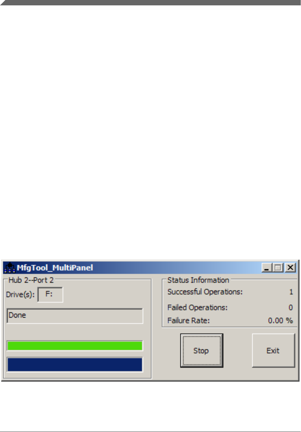
4.2 Manufacturing Tool
The Manufacturing Tool, named MfgTool, is a tool that runs on a Windows OS host and is used to download images to
different devices on an i.MX board. The tar.gz file can be found with the pre-built images.
4.2.1 Configuring MfgTool
Unzip Mfgtools-Rel-[version]_UPDATER.tar.gz.
Instructions for MfgTool V2 can be found in the file Profiles/[SOC] Linux Update/OS Firmware/ucl2.xml. Read
and update the ucl2.xml file to understand the operations before using MfgTool.
It is important to correctly configure the cfg.ini and UICfg.ini files. For example, if only one board is supported,
PortMgrDlg=1 should be set in UICfg.ini. If four boards are supported, PortMgrDlg=4 should be set. Incorrect
configuration causes MfgTool to malfunction.
Booting Linux OS
i.MX Linux® User's Guide , Rev. L4.1.15_1.0.0-ga, 03/2016
Freescale Semiconductor, Inc. 5
NOTE
For i.MX 6SoloX, the default settings in the cfg.ini file need to be changed as follows.
MfgTool looks for the settings in the ucl2.xml file.
[profiles]
chip = Linux
[platform]
board = SabreSD
[LIST]
name = SDCard
[variable]
board = sabresd
mmc = 0
sxuboot=17x17arm2
sxdtb=17x17-arm2
ldo=
4.2.2 Using MfgTool
Follow these instructions to use the MfgTool V2:
1. Connect a USB cable from a computer to the USB OTG port on the board.
2. Connect a USB cable from the OTG-to-UART port to the computer for console output.
3. Open a Terminal emulator program. See Section "Basic Terminal Setup" in this document.
4. Set the boot pin to MfgTool mode. See Section "Serial download mode for the Manufacturing Tool" in this document.
5. Choose the correct file and double-click it to launch MfgTool host tool.
6. The default profile of the Manufacturing Tool assumes that your file system is packed and compressed using the bzip2
algorithm. An example can be found in the MfgTool release package in the folder Profiles\Linux\OS Firmware
\files. To create this file, run the following commands as a root user on Linux OS. You can also modify the profile
to support other formats.
7. After the image downloading is done, set the boot pin to boot up the board. See Section "How to boot the i.MX boards"
in the document.
Figure 2. Programming SD with the Manufacturing Tool – image downloading
Booting Linux OS
i.MX Linux® User's Guide , Rev. L4.1.15_1.0.0-ga, 03/2016
6 Freescale Semiconductor, Inc.

NOTE
The Manufacturing Tool may sometimes report an error message when it is
downloading the file system to an SD card. This can be caused by insufficient
space on the SD card due to a small partition size. To fix this, unzip the file
Profiles\Linux\OS Firmware\mksdcard.sh.tar and modify the script to
increase the size of the partition and create more partitions according to your file
system requirements. After the modification is done, tar the script again.
4.3 Preparing an SD/MMC card to boot
This section describes the steps to prepare an SD/MMC card to boot up an i.MX board using a Linux host machine. These
instructions apply to SD and MMC cards although for brevity, often only SD card is listed.
For a Linux image to be able to run, four separate pieces are needed: the Linux kernel image (zImage), the device tree file
(*.dtb), the U-Boot boot loader image, and the root file system (*.ext3 or *.ext4).
A .sdcard image contains all four images properly configured for an SD card. The release contains a pre-built .sdcard image
that is built specifically for the one board configuration. It runs the X11 graphical backend. It does not run on other boards
unless U-Boot, the device tree, and rootfs are changed.
The Yocto Project build creates an SD card image that can be flashed directly. This is the simplest way to load everything
needed onto the card with one command.
When more flexibility is desired, the individual components can be loaded separately, and those instructions are included
here as well. An SD card can be loaded with the individual components one-by-one or the .sdcard image can be loaded and
the individual parts can be overwritten with the specific components.
The rootfs on the default .sdcard image is limited to a bit less than 4 GB, but re-partitioning and re-loading the rootfs can
increase that to the size of the card. The rootfs can also be changed to specify the graphical backend that is used.
The device tree file (.dtb) contains board and configuration-specific changes to the kernel. Change the device tree file to
change the kernel for a different i.MX board or configuration.
By default, the release uses the following layout for the images on the SD card. The kernel image and DTB move to use the
FAT partition without a fixed raw address on the SD card. The users have to change the U-Boot boot environment if the fixed
raw address is required.
Table 1. Image layout
Start address (sectors) Size (sectors) Format Description
0x400 bytes (2) 0x9FFC00 bytes (20478) RAW U-Boot and reserved area
0xa00000 bytes (20480) 500 Mbytes (1024000) FAT Kernel zImage and DTBs
0x25800000 bytes (1228800) Remaining space Ext3/Ext4 Rootfs
4.3.1 Preparing the card
An SD/MMC card reader, such as a USB card reader, is required. It is used to transfer the bootloader and kernel images to
initialize the partition table and copy the root file system. To simplify the instructions, it is assumed that a 4GB SD/MMC
card is used.
Any Linux distribution can be used for the following procedure.
Booting Linux OS
i.MX Linux® User's Guide , Rev. L4.1.15_1.0.0-ga, 03/2016
Freescale Semiconductor, Inc. 7

The Linux kernel running on the Linux host assigns a device node to the SD/MMC card reader. The kernel might decide the
device node name or udev rules might be used. In the following instructions, it is assumed that udev is not used.
To identify the device node assigned to the SD/MMC card, carry out the following command:
$ cat /proc/partitions
major minor #blocks name
8 0 78125000 sda
8 1 75095811 sda1
8 2 1 sda2
8 5 3028221 sda5
8 32 488386584 sdc
8 33 488386552 sdc1
8 16 3921920 sdb
8 18 3905535 sdb1
In this example, the device node assigned is /dev/sdb (a block is 512 Bytes).
NOTE
Make sure that the device node is correct for the SD/MMC card. Otherwise, it may
damage your operating system or data on your computer.
4.3.2 Copying the full SD card image
The SD card image (with the extension .sdcard) contains U-Boot, the Linux image and device trees, and the rootfs for a 4 GB
SD card. The image can be installed on the SD card with one command if flexibility is not required.
Carry out the following command to copy the SD card image to the SD/MMC card. Change sdx below to match the one used
by the SD card.
$ sudo dd if=<image name>.sdcard of=/dev/sdx bs=1M && sync
The entire contents of the SD card are replaced. If the SD card is larger than 4 GB, the additional space is not accessible.
4.3.3 Partitioning the SD/MMC card
The full SD card image already contains partitions. This section describes how to set up the partitions manually. This needs
to be done to individually load the bootloader, kernel, and rootfs.
There are various ways to partition an SD card. Essentially, the bootloader image needs to be at the beginning of the card,
followed by the Linux image and the device tree file. These can either be in separate partitions or not. The root file system
does need to be in a partition that starts after the Linux section. Make sure that each section has enough space. The example
below creates two partitions.
On most Linux host operating systems, the SD card is mounted automatically upon insertion. Therefore, before running fdisk,
make sure that the SD card is unmounted if it was previously mounted (through sudo umount /dev/sdx).
Start by running fdisk with root permissions. Use the instructions above to determine the card ID. We are using sdx here as
an example.
$ sudo fdisk /dev/sdx
Type the following parameters (each followed by <ENTER>):
p [lists the current partitions]
d [to delete existing partitions. Repeat this until no unnecessary partitions
are reported by the 'p' command to start fresh.]
n [create a new partition]
p [create a primary partition - use for both partitions]
Booting Linux OS
i.MX Linux® User's Guide , Rev. L4.1.15_1.0.0-ga, 03/2016
8 Freescale Semiconductor, Inc.

1 [the first partition]
20480 [starting at offset sector]
1024000 [size for the first partition to be used for the boot images]
p [to check the partitions]
n
p
2
1228800 [starting at offset sector, which leaves enough space for the kernel,
the bootloader and its configuration data]
<enter> [using the default value will create a partition that extends to
the last sector of the media]
p [to check the partitions]
w [this writes the partition table to the media and fdisk exits]
4.3.4 Copying a bootloader image
This section describes how to load only the boot loader image when the full SD card image is not used. Execute the following
command to copy the U-Boot image to the SD/MMC card.
$ sudo dd if=<U-Boot image> of=/dev/sdx bs=512 seek=2 conv=fsync
The first 1 KB of the SD/MMC card, which includes the partition table, is preserved.
NOTE
Users need to modify configurations for fused parts. For example, the i.MX 6UltraLite
has four parts, G0, G1, G2, and G3.
The fused modules are as follows:
• G0: TSC,ADC2, FLEXCAN1, FLEXCAN2, FREQ_MON, TEMP_MON,
VOLT_MONLCDIF, CSI, ENET2, CAAM, USB_OTG2, SAI23, BEE,
UART5678, PWM5678, ECSPI34, I2C34, GPT2, and EPIT2.
• G1: TSC, ADC2, FLEXCAN2, FREQ_MON, TEMP_MON, VOLT_MON,
LCDIF, CSI, ENET2, and BEE.
• G2: FREQ_MON, TEMP_MON, VOLT_MON, and BEE.
• G3: No fused module.
U-Boot configuration changes:
G0:
/* #define CONFIG_VIDEO */
#define CONFIG_FEC_ENET_DEV 0
/* #define CONFIG_CMD_BEE */
#define CONFIG_USB_MAX_CONTROLLER_COUNT 1
G1:
/* #define CONFIG_VIDEO */
#define CONFIG_FEC_ENET_DEV 0
/* #define CONFIG_CMD_BEE */
G2:
/* #define CONFIG_CMD_BEE */
G3: No change.
Booting Linux OS
i.MX Linux® User's Guide , Rev. L4.1.15_1.0.0-ga, 03/2016
Freescale Semiconductor, Inc. 9

4.3.5 Copying the kernel image and DTB file
This section describes how to load the kernel image and DTB when the full SD card image is not used. The pre-built SD card
image uses the VFAT partition for storing kernel image and DTB, which requires a VFAT partition that is mounted as a
Linux drive and the files are simply copied into it. This is the preferred method.
Another method that can be used is for users to put the kernel image and DTB to the fixed raw address of the SD card by
using the dd command. The later method needs to modify the U-Boot default environment variables for loading the kernel
image and DTB.
Default: VFAT partition
1. Format partition 1 on the card as VFAT with this command:
$ sudo mkfs.vfat /dev/sdx1
2. Mount the formatted partition with this command:
$ mkdir mountpoint
$ sudo mount /dev/sdx1 mountpoint
3. Copy the zImage and *.dtb files to the mountpoint by using cp. The device tree names should match the mount point
specified by U-Boot. Be sure to un-mount the partition with this command:
$ sudo umount mountpoint
Alternative: Fixed raw address
The following command can be used to copy the kernel image to the SD/MMC card:
$ sudo dd if=zImage_imx_v7_defconfig of=/dev/sdx bs=512 seek=2048 conv=fsync
Each of them copies zImage to the media at offset 1 MB (bs x seek = 512 x 2048 = 1 MB).
The i.MX DTB image can be copied by using the copy command and copying the file to the 2nd partition or the following
commands copy an i.MX DTB image to the SD/MMC card by using dd. Choose a command for your board:
$ sudo dd if=zImage-imx6qp-sabreauto.dtb of=/dev/sdx bs=512 seek=20480 conv=fsync
$ sudo dd if=zImage-imx6q-sabreauto.dtb of=/dev/sdx bs=512 seek=20480 conv=fsync
$ sudo dd if=zImage-imx6q-sabresd.dtb of=/dev/sdx bs=512 seek=20480 conv=fsync
$ sudo dd if=zImage-imx6sl-evk.dtb of=/dev/sdx bs=512 seek=20480 conv=fsync
$ sudo dd if=zImage-imx7d-sdb.dtb of=/dev/sdx bs=512 seek=20480 conv=fsync
$ sudo dd if=zImage-imx6qp-sabresd.dtb of=/dev/sdx bs=512 seek=20480 conv=fsync
This copies the board-specific .dtb file to the media at offset 10 MB (bs x seek = 512 x 20480 = 10 MB).
The following command can be used to copy the kernel image to the i.MX 6UltraLite EVK board:
$ sudo dd if=zImage-imx6ul-14x14-evk.dtb of=/dev/sdx bs=512 seek=20480 conv=fsync
4.3.6 Copying the root file system (rootfs)
This section describes how to load the rootfs image when the full SD card image is not used.
Copy the target file system to a partition that only contains the rootfs. This example uses partition 2 for the rootfs. First
format the partition. The file system format ext3 or ext4 is a good option for the removable media due to the built-in
journaling. Replace sdx with the partition in use in your configuration.
$ sudo mkfs.ext3 /dev/sdx2
Or
$ sudo mkfs.ext4 /dev/sdx2
Copy the target file system to the partition:
Booting Linux OS
i.MX Linux® User's Guide , Rev. L4.1.15_1.0.0-ga, 03/2016
10 Freescale Semiconductor, Inc.

$ mkdir /home/user/mountpoint
$ sudo mount /dev/sdx2 /home/user/mountpoint
Extract a rootfs package to a directory: extract fsl-image-gui-imx6qpsabreauto.ext3 to /home/user/rootfs for
example:
$ sudo mount -o loop -t ext3 fsl-image-gui-imx6qpsabreauto.ext3 /home/user/rootfs
The rootfs directory needs to be created manually.
Assume that the root file system files are located in /home/user/rootfs as in the previous step:
$ cd /home/user/rootfs
$ sudo cp -a * /home/user/mountpoint
$ sudo umount /home/user/mountpoint
$ sudo umount /home/user/rootfs
$ sync
NOTE
Copying the file system takes several minutes depending on the size of your rootfs.
The file system content is now on the media.
4.4 Downloading images
Images can be downloaded to a device using a U-Boot image that is already loaded on the boot device or by using the
Manufacturing Tool, MfgTool. Use a terminal program to communicate with the i.MX boards.
4.4.1 Downloading images using U-Boot
The following sections describe how to download images using the U-Boot bootloader.
The commands described below are generally useful when using U-Boot. Additional commands and information can be
found by typing help at the U-Boot prompt.
The U-Boot print command can be used to check environment variable values.
The setenv command can be used to set environment variable values.
4.4.1.1 Downloading an image to MMC/SD
This section describes how to download U-Boot to an MMC/SD card that is not the one used to boot from.
Insert an MMC/SD card into the SD card slot. This is slot SD3 on i.MX 6 SABRE boards and SD1 on i.MX 6SoloLite
boards, SD2 on i.MX 6UltraLite EVK board and SD1 on i.MX 7Dual SABRE-SD board.
To flash the original U-Boot, see Preparing an SD/MMC card to boot.
The U-Boot bootloader is able to download images from a TFTP server into RAM and to write from RAM to an SD card. For
this operation, the Ethernet interface is used and U-Boot environment variables are initialized for network communications.
The boot media contains U-Boot, which is executed upon power-on. Press any key before the value of the U-Boot
environment variable, "bootdelay", decreases and before it times out. The default setting is 1 second to display the U-Boot
prompt.
1. To clean up the environment variables stored on MMC/SD to their defaults, carry out the following command in the U-
Boot console:
Booting Linux OS
i.MX Linux® User's Guide , Rev. L4.1.15_1.0.0-ga, 03/2016
Freescale Semiconductor, Inc. 11

U-Boot > env default -f -a
U-Boot > save
U-Boot > reset
2. Configure the U-Boot environment for network communications. The folllowing is an example. The lines preceded by
the "#" character are comments and have no effect.
U-Boot > setenv serverip <your TFTPserver ip>
U-Boot > setenv bootfile <your kernel zImage name on the TFTP server>
U-Boot > setenv fdt_file <your dtb image name on the TFTP server>
The user can set a fake MAC address through ethaddr enviroment if the MAC address is not fused.
U-Boot > setenv ethaddr 00:01:02:03:04:05
U-Boot > save
3. Copy zImage to the TFTP server. Then download it to RAM:
U-Boot > dhcp
4. Query the information about the MMC/SD card.
U-Boot > mmc dev
U-Boot > mmcinfo
5. Check the usage of the "mmc" command. The "blk#" is equal to "<the offset of read/write>/<block length of the
card>". The "cnt" is equal to "<the size of read/write>/<block length of the card>".
U-Boot > help mmc
mmc - MMC sub system
Usage:
mmc read addr blk# cnt
mmc write addr blk# cnt
mmc erase blk# cnt
mmc rescan
mmc part - lists available partition on current mmc device
mmc dev [dev] [part] - show or set current mmc device [partition]
mmc list - lists available devices
6. Program the kernel zImage located in RAM at ${loadaddr} into the SD card. For example, the command to write the
image with the size 0x800000 from ${loadaddr} to the offset of 0x100000 of the microSD card. See the following
examples for the definition of the mmc parameters.
blk# = (microSD Offset)/(SD block length) = 0x100000/0x200 = 0x800
cnt = (image Size)/(SD block length) = 0x800000/0x200 = 0x4000
This example assumes that the kernel image is equal to 0x800000. If the kernel image exceeds 0x800000, increase the
image length. After issuing the TFTP command, filesize U-Boot environment variable is set with the number of bytes
transferred. This can be checked to determine the correct size needed for the calculation. Use the U-Boot command
printenv to see the value.
U-Boot > mmc dev 2 0
U-Boot > tftpboot ${loadaddr} ${bootfile}
### Suppose the kernel zImage is less than 8M.
U-Boot > mmc write ${loadaddr} 0x800 0x4000
7. Program the dtb file located in RAM at ${fdt_addr} into the microSD.
U-Boot > tftpboot ${fdt_addr} ${fdt_file}
U-Boot > mmc write ${fdt_addr} 0x5000 0x800
8. On i.MX 6 SABRE boards, you can boot the system through the rootfs in the SD card by the HannStar LVDS. The
kernel MMC module now uses a fixed mmcblk index for the uSDHC slot. The SD3 slot uses mmcblk2 on i.MX 6
SABRE boards, the SD1 slot uses mmcblk0 on the i.MX 7Dual SABRE-SD board, and the SD2 slot uses mmcblk1 on
the i.MX 6UltraLite board.
9. Boot the board.
Booting Linux OS
i.MX Linux® User's Guide , Rev. L4.1.15_1.0.0-ga, 03/2016
12 Freescale Semiconductor, Inc.

U-Boot >setenv bootcmd_mmc 'run bootargs_base mmcargs;mmc dev;mmc
read ${loadaddr} 0x800 0x4000;mmc read ${fdt_addr} 0x5000 0x800;bootz ${loadaddr} - $
{fdt_addr}'
U-Boot > setenv bootcmd 'run bootcmd_mmc'
U-Boot > saveenv
4.4.1.2 Using eMMC
There is an eMMC chip on i.MX SABRE boards. It is accessed through SDHC4 on i.MX 6 SABRE boards or SDHC3 on
i.MX 7Dual SABRE-SD board. The following steps describe how to use this memory device.
1. Carry out the following command on the U-Boot console to clean up the environments stored on eMMC:
U-Boot > env default -f -a
U-Boot > save
U-Boot > reset
2. Configure the boot pin. Power on the board and set the U-Boot environment variables as required. For example,
U-Boot > setenv serverip <your tftpserver ip>
U-Boot > setenv bootfile <your kernel zImage name on the tftp server>
U-Boot > setenv fdt_file <your dtb image name on the tftp server>
### The user can set fake MAC address via ethaddr enviroment if the MAC address is not
fused
U-Boot > setenv ethaddr 00:01:02:03:04:05
U-Boot > save
3. Copy zImage to the TFTP server. Then download it to RAM:
U-Boot > dhcp
4. Query the information about the eMMC chip.
U-Boot > mmc dev
U-Boot > mmcinfo
5. Check the usage of the "mmc" command. "blk#" is equal to "<the offset of read/write>/<block length of the card>".
"cnt" is equal to "<the size of read/write>/<block length of the card>".
mmc read addr blk# cnt
mmc write addr blk# cnt
mmc erase blk# cnt
mmc rescan
mmc part - lists available partition on current mmc device
mmc dev [dev] [part] - show or set current mmc device [partition]
mmc list - lists available devices
6. Program the kernel zImage into eMMC. For example, the command below writes the image with the size 0x800000
from ${loadaddr} to the offset 0x100000 of the eMMC chip. Here, the following equations are used: 0x800
=0x100000/0x200, 0x4000=0x800000/0x200. The block size of this card is 0x200. This example assumes that the
kernel image is less than 0x800000 bytes. If the kernel image exceeds 0x800000, enlarge the image length.
### Select mmc dev 2 (USDHC4) on the i.MX 6 SABRESD board:
U-Boot > mmc dev 2 0
### Select mmc dev 1 (USDHC3) on the i.MX 7Dual SABRESD board:
U-Boot > mmc dev 1 0
### Select mmc dev 1 (USDHC2) on the i.MX 6UltraLite EVK board:
U-Boot > mmc dev 1 0
### Suppose kernel zImage is less than 8 MB:
U-Boot > tftpboot ${loadaddr} ${bootfile}
U-Boot > mmc write ${loadaddr} 0x800 0x4000
7. Program the dtb file located in RAM at ${fdt_addr} into the eMMC chip.
U-Boot > tftpboot ${fdt_addr} ${fdt_file}
U-Boot > mmc write ${fdt_addr} 0x5000 0x800
Booting Linux OS
i.MX Linux® User's Guide , Rev. L4.1.15_1.0.0-ga, 03/2016
Freescale Semiconductor, Inc. 13

8. Boot up the system through RFS in eMMC by HannStar LVDS. The kernel MMC module now uses the fixed mmcblk
indices for the USDHC slots. The eMMC/SD4 slot in i.MX 6 SABRE boards is mmcblk3. The eMMC5.0/SD3 slot on
the i.MX 7Dual SABRE board is mmcblk2.
U-Boot > setenv mmcboot 'run bootargs_base mmcargs; mmc dev 2;
mmc read ${loadaddr} 0x800 0x4000; mmc read ${fdt_addr} 0x5000 0x800;bootz ${loadaddr}
- ${fdt_addr} '
U-Boot > setenv bootcmd 'run mmcboot'
U-Boot > saveenv
9. Boot up the system through RFS in eMMC by the CLAA WVGA panel:
• For i.MX 6 boards:
U-Boot > setenv mmcargs 'setenv bootargs ${bootargs}
root=/dev/mmcblk3p2 rootwait rw video=mxcfb0:dev=lcd,CLAA-WVGA,if=RGB565 ip=dhcp'
• For i.MX 7Dual SABRE boards:
U-Boot > setenv mmcargs 'setenv bootargs ${bootargs}
root=/dev/mmcblk2p2 rootwait rw video=mxcfb0:dev=lcd,CLAA-WVGA,if=RGB565 ip=dhcp'
10. Boot up the system through RFS in eMMC by HDMI:
• For i.MX 6 boards:
U-Boot > setenv mmcargs 'setenv bootargs ${bootargs} root=/dev/mmcblk3p2 rootwait
rw video=mxcfb0:dev=hdmi,1920x1080M@60,if=RGB24'
• For i.MX 7Dual SABRE boards:
U-Boot > setenv mmcargs 'setenv bootargs ${bootargs} root=/dev/mmcblk2p2 rootwait
rw video=mxcfb0:dev=hdmi,1920x1080M@60,if=RGB24'
To program the rootfs to MMC/SD, see Using an i.MX board as the host server to create a rootfs or Preparing an SD/MMC
card to boot.
4.4.1.3 Flashing U-Boot on SPI-NOR from U-Boot
Flashing directly to SPI-NOR with TFTPBoot is limited to i.MX 6 SABRE-AI boards. To flash U-Boot on SPI-NOR,
perform the following steps:
1. Boot from an SD card.
2. Set Jumper J3 to position: 2-3.
3. Fetch the U-Boot image with built-in SPI-NOR support. This example uses u-boot.imx.
----------------
tftpboot ${loadaddr} u-boot.imx
-----------------
4. Flash the U-Boot image in SPI-NOR.
-----------------
sf probe
sf erase 0 0x80000
sf write ${loadaddr} 0x400 0x7FC00
----------------
5. Set boot switches to boot from SPI-NOR on SABRE-AI.
• S2-1 1
• S2-2 1
• S2-3 0
• S2-4 0
• S1-[1:10] X
Booting Linux OS
i.MX Linux® User's Guide , Rev. L4.1.15_1.0.0-ga, 03/2016
14 Freescale Semiconductor, Inc.

6. Reboot the target board.
4.4.1.4 Flashing U-Boot on Parallel NOR from U-Boot
Flashing directly to Parallel NOR with TFTPBoot is limited to i.MX 6 SABRE-AI boards. To flash U-Boot on Parallel NOR,
perform the following steps:
1. Boot from an SD card.
2. TFTP the U-Boot image.
tftpboot ${loadaddr} u-boot.imx
3. Flash the U-Boot image.
cp.b ${loadaddr} 0x1000 ${filesize}
4. Change boot switches and reboot.
S2 all 0
S1-6 1 others 0
5. By default, rootfs is mounted on NFS.
4.4.1.5 Flashing an ARM® Cortex®-M4 image on QuadSPI
i.MX 6SoloX SABRE-SD and SABRE-AI boards have an ARM Cortex-M4 processor and QuadSPI memory that can be
used to flash an image to it.
U-Boot has a default script to flash the ARM Cortex-M4 image from the SD card VFAT partition. To execute the script,
perform the following steps:
1. Copy the ARM Cortex-M4 image to the first VFAT partition of the boot SD card. Name the file to “m4_qspi.bin”.
2. Boot from the SD card.
3. Flash the ARM Cortex-M4 image from the SD card to the NOR flash on QuadSPI2 PortB CS0 on the i.MX 6SoloX
SABRE-SD board or QuadSPI1 PortB CS0 on the i.MX 6SoloX SABRE-AI board.
----------------
run update_m4_from_sd
-----------------
Alternatively, users can flash the ARM Cortex-M4 image from TFTP by performing the following steps:
1. Boot from the SD card.
2. TFTP the ARM Cortex-M4 image.
-----------------
tftp ${loadaddr} m4_qspi.bin
----------------
3. Select the NOR flash on QuadSPI2 PortB CS0 on the i.MX 6SoloX SABRE-SD board or QuadSPI1 PortB CS0 on the
i.MX 6SoloX SABRE-AI board.
-----------------
sf probe 1:0
----------------
4. Flash the ARM Cortex-M4 image to the selected NOR flash. The erase size is ${filesize}, around 64 Kbytes. This
example assumes that it is 128 Kbytes.
-----------------
sf erase 0x0 0x20000
sf write ${loadaddr} 0x0 ${filesize}
----------------
Booting Linux OS
i.MX Linux® User's Guide , Rev. L4.1.15_1.0.0-ga, 03/2016
Freescale Semiconductor, Inc. 15

4.4.2 Using an i.MX board as the host server to create a rootfs
Linux OS provides multiple methods to program images to the storage device. This section describes how to use the i.MX
platform as a Linux host server to create the rootfs on an MMC/SD card or the SATA device. The following example is for
an SD card. The device file node name needs to be changed for a SATA device.
1. Boot from NFS or other storage. Determine your SD card device ID. It could be mmcblk* or sd*. (The index is
determined by the USDHC controller index.) Check the partition information with the command:
$ cat /proc/partitions
2. To create a partition on the MMC/SD card, use the fdisk command (requires root privileges) in the Linux console:
root@freescale ~$ sudo fdisk /dev/$SD
Replace $SD above with the name of your device.
3. If this is a new SD card, you may get the following message:
The device contains neither a valid DOS partition table, nor Sun, SGI or OSF disk label
Building a new DOS disklabel. Changes will remain in memory only,
until you decide to write them. After that the previous content
won't be recoverable.
The number of cylinders for this disk is set to 124368.
There is nothing wrong with that, but this is larger than 1024,
and could in certain setups cause problems with:
1) software that runs at boot time (e.g., old versions of LILO)
2) booting and partitioning software from other OSs
(e.g., DOS FDISK, OS/2 FDISK)
The usual prompt and commands to partition the card are as follows. Text in boldface indicates what the user types.
Command (m for help): p
Disk /dev/sdd: 3965 MB, 3965190144 bytes
4 heads, 32 sectors/track, 60504 cylinders, total 7744512 sectors
Units = sectors of 1 * 512 = 512 bytes
Sector size (logical/physical): 512 bytes / 512 bytes
I/O size (minimum/optimal): 512 bytes / 512 bytes
Disk identifier: 0x00080bff
Device Boot Start End Blocks Id System
4. As described in Flash memory maps, the rootfs partition should be located after the kernel image. The first 0x800000
bytes can be reserved for MBR, bootloader, and kernel sections. From the log shown above, the Units of the current
MMC/SD card is 32768 bytes. The beginning cylinder of the first partition can be set to "0x300000/32768 = 96." The
last cylinder can be set according to the rootfs size. Create a new partition by typing the letters in bold:
Command (m for help): n
e extended
p primary partition (1-4)
Select (default p): p
Partition number (1-4): 1
First cylinder (1-124368, default 1): 96
Last cylinder or +size or +sizeM or +sizeK (96-124368, default 124368): Using
default value 124368
Command (m for help): w
The partition table has been altered!
Calling ioctl() to re-read $SD partition table
5. Check the partitions (see above) to determine the name of the partition. $PARTITION is used here to indicate the
partition to be formatted. Format the MMC/SD partitions as ext3 or ext4 type. For example, to use ext3:
root@freescale ~$ mkfs.ext3 /dev/$PARTITION
mke2fs 1.42 (29-Nov-2011)
Filesystem label=
Booting Linux OS
i.MX Linux® User's Guide , Rev. L4.1.15_1.0.0-ga, 03/2016
16 Freescale Semiconductor, Inc.

OS type: Linux
Block size=4096 (log=2)
Fragment size=4096 (log=2)
248992 inodes, 994184 blocks
49709 blocks (5.00%) reserved for the super user
First data block=0
Maximum filesystem blocks=1019215872
31 block groups
32768 blocks per group, 32768 fragments per group
8032 inodes per group
Superblock backups stored on blocks:
32768, 98304, 163840, 229376, 294912, 819200, 884736
Writing inode tables: done
Creating journal (16384 blocks): done
Writing superblocks and filesystem accounting information: done
This filesystem will be automatically checked every 20 mounts or
180 days, whichever comes first. Use tune2fs -c or -i to override.
6. Copy the rootfs contents to the MMC/SD card. The name may vary from the one used below. Check the directory for
the rootfs desired. (Copy the *.ext2 to NFS rootfs).
mkdir /mnt/tmpmnt
mount -t ext3 -o loop /fsl-image-gui-imx6qsabresd.ext3 /mnt/tmpmnt
cd /mnt
mkdir mmcblk0p1
mount -t ext3 /dev/$PARTITION /mnt/mmcblk0p1
cp -af /mnt/tmpmnt/* /mnt/mmcblk0p1/
umount /mnt/mmcblk0p1
umount /mnt/tmpmnt
7. Type sync to write the contents to MMC/SD.
8. Type poweroff to power down the system. Follow the instructions in Running Linux OS on the target to boot the image
from the MMC/SD card.
NOTE
By default, v2013.04 and later versions of U-Boot support loading the kernel image and
DTB file from the SD/MMC vfat partition by using the fatload command. To use this
feature, perform the following steps:
1. Format the first partition (for example 32M) of the SD/MMC card with vfat
filesystem.
2. Copy zImage and the DTB file into the VFAT partition after you mount the VFAT
partition into your host computer.
3. Make sure that the zImage and DTB file name are synchronized with the file name
pointed to by the U-Boot environment variables: fdt_file and image. Use the print
command under U-Boot to display these two environment variables. For example:
print fdt_file image
4. U-Boot loads the kernel image and the DTB file from your VFAT partition
automatically when you boot from the SD/MMC card.
4.5 How to boot the i.MX boards
When U-Boot is loaded onto one of the devices that support booting, the DIP switches can be used to boot from that device.
The boot modes of the i.MX boards are controlled by the boot configuration DIP switches on the board. For help locating the
boot configuration switches, see the quick start guide for the specific board as listed under References above.
The following sections list basic boot setup configurations. The tables below represent the DIP switch settings for the switch
blocks on the specified boards. An X means that particular switch setting does not affect this action.
Booting Linux OS
i.MX Linux® User's Guide , Rev. L4.1.15_1.0.0-ga, 03/2016
Freescale Semiconductor, Inc. 17
4.5.1 Booting from an SD card in slot SD1
The following table shows the DIP switch settings for booting from the SD card slot labeled SD1 on the i.MX 7Dual
SABRE-SD boards.
Table 2. Booting from SD1 on i.MX 7Dual SABRE-SD
Switch D1 D2 D3 D4 D5 D6 D7 D8
SW2 OFF OFF ON OFF OFF OFF OFF OFF
SW3 ON OFF - - - - - -
4.5.2 Booting from an SD card in slot SD2
The SD card slot that is labeled SD2 indicates that this slot is connected to the uSDHC pin SD2 on the processor. Most
boards label this slot as SD2. This slot is referred to as SD2 in this document.
i.MX 6 SABRE-SD boards
The following table shows the DIP switch settings for booting from the SD card slot labeled SD2 and J500 on the i.MX 6
SABRE-SD boards. The SD2 card slot is located beside the LVDS1 connection on the back of the board.
Table 3. Booting from SD2 (J500) on i.MX 6 SABRE-SD
Switch D1 D2 D3 D4 D5 D6 D7 D8
SW6 ON OFF OFF OFF OFF OFF ON OFF
i.MX 6SoloLite boards
The i.MX 6SoloLite boards have three SD card slots on the main board. The one on the end is labeled as the SD2 slot. The
following table shows the DIP switch settings for booting from SD2.
Table 4. Booting from SD2 on i.MX 6SoloLite
Switch D1 D2 D3 D4 D5 D6 D7 D8
SW3 OFF ON OFF OFF OFF OFF OFF OFF
SW4 OFF OFF ON OFF ON ON OFF OFF
SW5 OFF OFF OFF OFF OFF OFF OFF OFF
S1 OFF ON - - - - - -
The i.MX 6UltraLite EVK board has one TF card slot on the CPU board. This slot uses the USDHC2 controller. The
following table shows the DIP switch settings for booting from the TF slot.
Table 5. Booting from TF on i.MX 6UltraLite
Switch D1 D2 D3 D4
SW601 OFF OFF ON OFF
SW602 ON OFF - -
Booting Linux OS
i.MX Linux® User's Guide , Rev. L4.1.15_1.0.0-ga, 03/2016
18 Freescale Semiconductor, Inc.

4.5.3 Booting from an SD card in slot SD3
The SD card slot that is labeled SD3 indicates that this slot is connected to the uSDHC pin SD3 on the processor. Most
boards label this slot as SD3. This slot is referred to as SD3 in this document.
i.MX 6 SABRE-AI boards
The following table shows the DIP switch settings to boot from an SD card in slot SD3 on i.MX 6 SABRE-AI boards.
Table 6. Booting from an SD card in slot SD3 on i.MX 6 SABRE-AI boards
Switch D1 D2 D3 D4 D5 D6 D7 D8 D9 D10
S1 X X X OFF ON X X X X X
S2 X OFF ON OFF - - - - - -
S3 OFF OFF ON OFF - - - - - -
i.MX 6SoloX SABRE-AI boards
The following table shows the DIP switch settings to boot from an SD card in slot SD3 on i.MX 6SoloX SABRE-AI boards.
Table 7. Booting from an MMC card in Slot SD3 on i.MX 6SoloX SABRE-AI boards
Switch D1 D2 D3 D4 D5 D6 D7 D8
S4 OFF ON OFF X OFF OFF ON OFF
S3 X OFF OFF OFF ON ON OFF OFF
S1 OFF OFF ON OFF - - - -
i.MX 6 SABRE-SD boards
The following table shows the DIP switch settings for booting from SD3, also labeled as J507. The SD3 slot is located
between the HDMI and UART ports.
Table 8. Booting from an SD card in slot SD3 on i.MX 6 SABRE-SD boards
Switch D1 D2 D3 D4 D5 D6 D7 D8
SW6 OFF ON OFF OFF OFF OFF ON OFF
4.5.4 Booting from an SD card in slot SD4
The following table describes the dip switch settings for booting from an SD card in slot SD4.
The SD4 slot is on the center of the edge of the SoloX board.
Table 9. Booting from an SD card in slot SD4 on i.MX 6SoloX SABRE-SD
Switch D1 D2 D3 D4 D5 D6 D7 D8
SW10 OFF OFF OFF OFF OFF OFF OFF OFF
SW11 OFF OFF ON ON ON OFF OFF OFF
Table continues on the next page...
Booting Linux OS
i.MX Linux® User's Guide , Rev. L4.1.15_1.0.0-ga, 03/2016
Freescale Semiconductor, Inc. 19

Table 9. Booting from an SD card in slot SD4 on i.MX 6SoloX SABRE-SD (continued)
Switch D1 D2 D3 D4 D5 D6 D7 D8
SW12 OFF ON OFF OFF OFF OFF OFF OFF
Table 10. Booting from an MMC card in slot SD4 on i.MX 6SoloX SABRE-SD
Switch D1 D2 D3 D4 D5 D6 D7 D8
SW10 OFF OFF OFF OFF OFF OFF OFF OFF
SW11 OFF OFF ON ON ON OFF OFF OFF
SW12 OFF ON ON OFF OFF OFF OFF OFF
4.5.5 Booting from eMMC
eMMC 4.4 is a chip permanently attached to the board that uses the SD4 pin connections from the i.MX 6 processor. For
more information on switch settings, see table "MMC/eMMC Boot Fusemap" in the IC reference manual.
The i.MX 6SoloLite EVK requires a daughter card with the eMMC chip mounted on it. The following table shows the boot
switch settings to boot from eMMC4.4 on i.MX 6SoloLite EVK.
Table 11. Booting from eMMC4.4 boot in 4 bit SDR mode on i.MX 6SoloLite
EVK
Switch D1 D2 D3 D4 D5 D6 D7 D8
SW3 OFF ON ON OFF OFF OFF OFF OFF
SW4 OFF OFF ON OFF ON OFF OFF OFF
The following table shows the boot switch settings to boot from eMMC4.4 (SDIN5C2-8G) on i.MX 6 SABRE-SD boards.
Table 12. Booting from eMMC on i.MX 6 SABRE-SD boards
Switch D1 D2 D3 D4 D5 D6 D7 D8
SW6 ON ON OFF ON OFF ON ON OFF
4.5.6 Booting from SATA
The following switch settings enable booting from SATA.
SATA booting is supported only by the i.MX 6Quad/6QuadPlus SABRE boards.
Table 13. Booting from SATA on i.MX 6 SABRE-SD boards
Switch D1 D2 D3 D4 D5 D6 D7 D8
SW6 OFF OFF OFF OFF OFF ON OFF OFF
Booting Linux OS
i.MX Linux® User's Guide , Rev. L4.1.15_1.0.0-ga, 03/2016
20 Freescale Semiconductor, Inc.

4.5.7 Booting from NAND
The following table shows the DIP switch settings needed to boot from NAND on i.MX 6 SABRE-AI boards.
Table 14. Booting from NAND on i.MX 6 SABRE-AI
Switch D1 D2 D3 D4 D5 D6 D7 D8 D9 D10
S1 OFF OFF OFF ON OFF OFF OFF OFF OFF OFF
S2 OFF OFF OFF ON - - - - - -
S3 OFF OFF ON OFF - - - - - -
The following table shows the DIP switch settings needed to boot from NAND for i.MX 6SoloX SABRE-AI boards.
Table 15. Booting from NAND on i.MX 6 SoloX SABRE-AI
Switch D1 D2 D3 D4 D5 D6 D7 D8
S4 OFF OFF OFF OFF OFF OFF OFF ON
S3 OFF OFF OFF OFF OFF OFF OFF OFF
S1 OFF OFF ON OFF - - - -
4.5.8 Booting from SPI-NOR
Enable booting from SPI NOR on i.MX 6 SABRE-AI boards by placing a jumper on J3 between pins 2 and 3.
Table 16. Booting from SPI-NOR on i.MX 6 SABRE-AI boards
Switch D1 D2 D3 D4 D5 D6 D7 D8 D9 D10
S1 X X X X X X X X X X
S2 ON ON OFF OFF OFF OFF OFF OFF OFF OFF
S3 OFF OFF ON OFF - - - - - -
Table 17. Booting from SPI-NOR on i.MX 6SoloLite EVK
Switch D1 D2 D3 D4 D5 D6 D7 D8
Switch D1 D2 D3 D4 D5 D6 D7 D8
SW3 OFF OFF ON ON OFF OFF OFF OFF
SW4 OFF OFF OFF OFF OFF OFF OFF OFF
SW5 OFF OFF OFF OFF ON OFF OFF OFF
4.5.9 Booting from EIM (Parallel) NOR
The following table shows the DIP switch settings to boot from NOR.
Booting Linux OS
i.MX Linux® User's Guide , Rev. L4.1.15_1.0.0-ga, 03/2016
Freescale Semiconductor, Inc. 21

Table 18. Booting From EIM NOR on i.MX 6 SABRE-AI boards
Switch D1 D2 D3 D4 D5 D6 D7 D8 D9 D10
S1 X X X OFF OFF ON X X X X
S2 X OFF OFF OFF - - - - - -
S3 OFF OFF ON OFF - - - - - -
NOTE
SPI and EIM NOR have pin conflicts on i.MX 6 SABRE-AI boards. Neither can be used
for the same configuration. The default U-Boot configuration is set to SPI NOR.
4.5.10 Booting from QuadSPI
The following tables list the DIP switch settings for booting from QuadSPI.
Table 19. Booting from QuadSPI on i.MX 6SoloX SABRE-SD
Switch D1 D2 D3 D4 D5 D6 D7 D8
SW10 OFF OFF OFF OFF OFF OFF OFF OFF
SW11 OFF OFF OFF OFF OFF OFF OFF OFF
SW12 OFF OFF OFF ON ON OFF OFF OFF
Table 20. Booting from QuadSPI on i.MX 6SoloX SABRE-AI
Switch D1 D2 D3 D4 D5 D6 D7 D8
SW4 OFF OFF OFF OFF ON OFF OFF OFF
SW3 OFF OFF OFF OFF OFF OFF OFF OFF
SW1 OFF OFF ON OFF - - - -
Table 21. Booting from QuadSPI on i.MX 6UltraLite EVK
Switch D1 D2 D3 D4
SW601 OFF OFF OFF OFF
SW602 ON OFF - -
4.5.11 Serial download mode for the Manufacturing Tool
No dedicated boot DIP switches are reserved for serial download mode on i.MX 6 SABRE-SD and i.MX 6SoloLite boards.
There are various ways to enter serial download mode. One way is to set the boot mode to boot from SD slot SD3 (set SW6
DIP switches 2 and 7 to on, and the rest are off). Do not insert the SD card into slot SD3, and power on the board. After the
message "HID Compliant device" is displayed, the board enters serial download mode. Then insert the SD card into SD slot
SD3. Another way to do this is to configure an invalid boot switch setting, such as setting all the DIP switches of SW6 to off.
Booting Linux OS
i.MX Linux® User's Guide , Rev. L4.1.15_1.0.0-ga, 03/2016
22 Freescale Semiconductor, Inc.

Table 22. Setup for the Manufacturing Tool on i.MX 6SoloLite EVK
Switch D1 (BOOT_MODE0) D2 (BOOT_MODE1)
S1 ON OFF
The following table shows the boot switch settings for i.MX 6 SABRE-AI boards, which are used to enter serial download
mode for the Manufacturing Tool. If the boot image in the boot media is not validated, the system also enters the serial
download mode.
Table 23. Setup for the Manufacturing Tool on i.MX 6 SABRE-AI boards
Switch D1 D2 D3 D4
S3 OFF ON OFF OFF
Table 24. Setup for Manufacturing Tool on i.MX 6UltraLite EVK board
Switch D1 D2
SW602 OFF ON
4.6 Flash memory maps
This section describes the software layout in memory on memory devices used on the i.MX boards.
This information is useful for understanding subsequent sections about image downloading and how the images are placed in
memory.
The mtdparts directive can be used in the Linux boot command to specify memory mapping. The following example briefly
describes how to use memory maps. Memory is allocated in the order of how it is listed. The dash (-) indicates the the rest of
the memory.
mtdparts=[memory type designator]:[size]([name of partition]),[size]([name of partition]),-
([name of final partition])
4.6.1 MMC/SD/SATA memory map
The MMC/SD/SATA memory scheme is different from the NAND and NOR flash, which are deployed in the BSP software.
The MMC/SD/SATA must keep the first sector (512 bytes) as the Master Boot Record (MBR) in order to use MMC/SD as
the rootfs.
Upon boot up, the MBR is executed to look up the partition table to determine which partition to use for booting. The
bootloader should be after the MBR. The kernel image and rootfs may be stored at any address after the bootloader. By
default, the the U-Boot boot arguments uses the first FAT partition for kernel and DTB, and the following ext3 partition for
the root file system. Alternatively, users can store the kernel and the DTB in any raw memory area after the bootloader. The
boot arguments must be updated to match any changed memory addresses.
The MBR can be generated through the fdisk command when creating partitions in MMC/SD cards on a Linux host server.
Booting Linux OS
i.MX Linux® User's Guide , Rev. L4.1.15_1.0.0-ga, 03/2016
Freescale Semiconductor, Inc. 23

4.6.2 NAND flash memory map
The NAND flash memory map is configured from the Linux kernel command line.
For example:
mtdparts=gpmi-nand:64m(boot),16m(kernel),16m(dtb),-(rootfs)
4.6.3 Parallel NOR flash memory map
The default configuration contains only one parallel NOR partition. The parallel NOR device is generally 4 MB. U-Boot is
loaded at the beginning of parallel NOR so that the device can boot from it. The default configuration is that on boot up, U-
Boot loads the kernel, DTB, and root file system from the SD/MMC card into DDRAM. The end user can change the default
settings according to their needs. More partitions can be added through the kernel command line. The memory type
designator for the command below consists of the NOR address and the designator. This information can be found in the
imx .dtsi device tree file in arch/arm/boot/dts. The following is an example of what might be added to the Linux boot
command line:
mtdparts=8000000.nor:1m(uboot),-(rootfs)
The address for parallel NOR is 0x8000000 for i.MX 6 SABRE-AI.
4.6.4 SPI-NOR flash memory map
The SPI-NOR flash memory can be configured using the Linux kernel command line.
U-Boot should be loaded at the 1 KB offset of the SPI-NOR memory, so that the device can boot from it. The default
configuration is that on boot up, U-Boot loads the kernel, DTB, and root file system from the SD/MMC card into DDRAM.
The end user can change the default settings according to their needs. More partitions can be added through the kernel
command line. The following is an example of what might be added to the Linux boot command line:
mtdparts=spi32766.0:768k(uboot),8k(env),128k(dtb),-(kernel)
4.6.5 QuadSPI flash memory map
The QuadSPI flash memory can be configured using the Linux kernel command line.
U-Boot is loaded at the beginning of the QuadSPI memory so that the device can boot from it. The default configuration is
that on boot up, U-Boot loads the kernel, DTB, and root file system from the SD/MMC card into DDRAM. The end user can
change the default settings according to their requirements. More partitions can be added through the kernel command line.
The following is an example of what might be added to the Linux boot command line:
mtdparts=21e4000.qspi:1m(uboot),8m(kernel),1m(dtb),-(user)
U-Boot has the mapping below to help in accessing the QuadSPI flash in U-Boot for non-parallel mode.
Table 25. U-Boot mapping for QuadSPI
Device on hardware Device in U-Boot Memory address in U-Boot Remark
QuadSPI1 Port A CS0 sf probe 0:0 on i.MX 6SoloX SABRE-AI
board and i.MX 7Dual SABRE-SD board
and i.MX 6UltraLite EVK board
0x60000000 -
Table continues on the next page...
Booting Linux OS
i.MX Linux® User's Guide , Rev. L4.1.15_1.0.0-ga, 03/2016
24 Freescale Semiconductor, Inc.

Table 25. U-Boot mapping for QuadSPI (continued)
Device on hardware Device in U-Boot Memory address in U-Boot Remark
QuadSPI1 Port B CS0 sf probe 1:0 on i.MX 6 SoloX SABRE-AI
board
0x68000000 -
QuadSPI2 Port A CS0 sf probe 0:0 on i.MX 6SoloX SABRE-SD
board
0x70000000 -
QuadSPI2 Port B CS0 sf probe 1:0 on i.MX 6SoloX SABRE-SD
board
0x78000000 -
4.7 Running Linux OS on the target
This section explains how to run a Linux image on the target using U-Boot.
These instructions assume that you have downloaded the kernel image using the instructions in Downloading images or
Preparing an SD/MMC card to boot. If you have not set up your Serial Terminal, see Basic Terminal Setup.
The basic procedure for running Linux OS on an i.MX board is follows. This document uses a specific set of environment
variable names to make it easier to describe the settings. Each type of setting is described in its own section as follows.
1. Power on the board.
2. When U-Boot comes up, set the environment variables specific to your machine and configuration. Common settings
are described below and settings specific to a device are described in separate sections.
3. Save the environment setup:
U-Boot > saveenv
4. Run the boot command:
U-Boot > run bootcmd
The commands env default -f -a and saveenv can be used to return to the default environment.
Specifying the console
The console for debug and command-line control can be specified on the Linux boot command line. The SABRE-AI board
uses ttymxc3, so it is not same for all boards. It is usually specified as follows, but the baudrate and the port can be modified.
Therefore, for NFS, it might be ttymxc3.
U-Boot > setenv consoleinfo 'console=ttymxc0,115200'
Specifying displays
The display information can be specified on the Linux boot command line. It is not dependant on the source of the Linux
image. If nothing is specified for the display, the settings in the device tree is used. Add ${displayinfo} to the
environment macro containing bootargs. The specific parameters can be found in the i.MX Linux® Release Notes
(IMXLXRN). The following are some examples of what these might look like.
•U-Boot > setenv displayinfo 'video=mxcfb0:dev=hdmi,1920x1080M@60,if=RGB24' for an HDMI
display
•U-Boot > setenv displayinfo 'video=mxcfb1:dev=ldb video=mxcfb0:dev=hdmi,
1920x1080M@60,if=RGB24' for LVDS and HDMI dual displays
•U-Boot > setenv displayinfo 'video=mxcfb0:dev=lcd,if=RGB565' for an LCD
Booting Linux OS
i.MX Linux® User's Guide , Rev. L4.1.15_1.0.0-ga, 03/2016
Freescale Semiconductor, Inc. 25

•U-Boot > setenv displayinfo 'video=mxcepdcfb:E060SCM,bpp=16
max17135:pass=2,vcom=-2030000' for an EPDC connection
•U-Boot > setenv displayinfo 'video=mxcfb0:mxcfb0:dev=lcd,if=RGB565
video=mxcfb1:dev=hdmi,1920x1080M@60,if=RGB24' for LCD and HDMI dual displays
Specifying memory addresses
The addresses in the memory where the kernel and device tree are loaded to do not change based on the device that runs
Linux OS. The instructions in this chapter use the environment variables loadaddr and ftd_addr to indicate these values.
The following table shows what addresses are used on different i.MX boards.
Table 26. Board-specific default values
Variable 6Quad,
6QuadPlus,
and 6DualLite
SABRE (AI
and SD)
SoloLite SoloX 7Dual
SABRE-SD
6UltraLite
EVK
Description
loadaddr 0x12000000 0x80800000 0x80800000 0x80800000 0x80800000 Address in the memory the
kernel are loaded to
fdt_addr 0x18000000 0x83000000 0x83000000 0x83000000 0x83000000 Address in the memory the
device tree code are copied
to
In addition, fdt_file is used to specify the filename of the device tree file. The commands used to set the U-Boot
environment variables are as follows:
U-Boot > setenv loadaddr 0x12000000
U-Boot > setenv fdt_addr 0x18000000
U-Boot > setenv fdt_file 'imx6q-sabresd.dtb'
Specifying the location of the root file system
The rootfs can be located on a device on the board or on NFS. The settings below show some options for specifying these.
•U-Boot > setenv rootfsinfo 'root=/dev/nfs ip=dhcp nfsroot=${serverip}:${nfsroot},v3,tcp'
•U-Boot > setenv rootfsinfo 'root=/dev/nfs ip=dhcp weim-nor nfsroot=${serverip}:$
{nfsroot},v3,tcp'
•U-Boot > setenv rootfsinfo 'ubi.mtd=3 root=ubi0:rootfs rootfstype=ubifs rootwait rw
mtdparts=gpmi-nand:16m(boot),16m(kernel),16m(dtb),-(rootfs)'
•U-Boot > setenv rootfsinfo 'root=/dev/mmcblk0p2 rootwait rw'
Special settings
SoloLite, Solo and UltraLite can specify uart_from_osc on the command line to specify that the OSC clock rather than
PLL3 should be used. This allows the system to enter low power mode.
U-Boot > setenv special 'uart_from_osc'
Building the command line
For clarification, this document groups the bootargs into one macro as follows:
U-Boot > setenv bootargsset 'setenv bootargs ${consoleinfo} ${rootfsinfo} ${displayinfo} $
{special}'
The executed boot command then looks like as follows. Arguments vary by device.
Booting Linux OS
i.MX Linux® User's Guide , Rev. L4.1.15_1.0.0-ga, 03/2016
26 Freescale Semiconductor, Inc.

U-Boot > setenv bootcmd 'run bootargsset; {settings for device}; bootz ${loadaddr} - $
{fdt_addr}'
4.7.1 Running Linux OS from MMC/SD
This scenario assumes that the board is configured to boot U-Boot, that the Linux kernel image is named zImage and is stored
on the SD card in an MSDOS FAT partition, and one or more device tree files are also stored in this partition. The rootfs is
also stored on the SD/MMC card in another partition.
When U-Boot boots up, it detects the slot where it is booting from and automatically sets mmcdev and mmcroot to use the
rootfs on that SD card. In this scenario, the same SD card can be used to boot from any SD card slot on an i.MX 6 board,
without changing any U-Boot settings. From the U-Boot command line, type boot to run Linux OS.
The following instructions can be used if the default settings are not desired.
Set mmcautodetect to "no" to turn off the automatic setting of the SD card slot in mmcdev and mmcroot. The U-Boot
mmcdev is based on the soldered SD/MMC connections, so it varies depending on the board. The U-Boot mmc dev 0 is the
lowest numbered SD slot present, 1 is the next, and so on. The Linux kernel, though, indexes all the uSDHC controllers
whether they are present or not. The following table shows this mapping.
Table 27. Linux uSDHC relationships
uSDHC mmcroot
uSDHC 1 mmcblk0*
uSDHC 2 mmcblk1*
uSDHC 3 mmcblk2*
uSDHC 4 mmcblk3*
In the default configuration of the SD card, and the example here, U-Boot is at the 1024 byte offset before the first partition,
partition 1 is the partition with the Linux kernel and device trees, and partition 2 is the rootfs.
Setting up the environment variables
For convenience, this document uses a standard set of variables to describe the information in the Linux command line. The
values used here may be different for different machines or configurations. See the following table for some ideas on values.
By default, U-Boot supports setting mmcdev and mmcroot automatically based on the uSDHC slot that we are booting from.
This assumes zImage, the device tree file (DTB), and the rootfs are on the same SD/MMC card. To set these environment
variables manually, set mmcautodetect to no to disable the feature.
The following is one way to set up the items needed to boot Linux OS.
U-Boot > setenv mmcpart 1
U-Boot > setenv loadfdt 'fatload mmc ${mmcdev}:${mmcpart} ${fdt_addr} ${fdt_file}'
U-Boot > setenv loadkernel 'fatload mmc ${mmcdev}:${mmcpart} ${loadaddr} zImage'
U-Boot > setenv bootcmd 'mmc dev ${mmcdev}; run loadkernel; run mmcargs; run loadfdt; bootz $
{loadaddr} - ${fdt_addr};'
The descriptions of the variables used above are as follows:
•mmcpart - This is the partition on the MMC/SD card containing the kernel image.
•mmcroot - The location of the root file system on the MMC SD card along with directives for the boot command for
the rootfs.
NOTE
The U-Boot environment on the pre-built SD card does not match this. It is more
complex so that it can automatically deal with more variations. The example above is
designed to be easier to understand and use manually.
Booting Linux OS
i.MX Linux® User's Guide , Rev. L4.1.15_1.0.0-ga, 03/2016
Freescale Semiconductor, Inc. 27

Reading the kernel image from eMMC
eMMC has user area, boot partition 1, and boot partition 2. To switch between the eMMC partitions, the user needs to use the
command mmc dev [dev id] [partition id]. For example,
mmc dev 2 0 ---> user area
mmc dev 2 1 ---> boot partition 1
mmc dev 2 2 ---> boot partition 2
4.7.2 Running the image from NAND
NAND can be found on i.MX 6 SABRE-AI boards.
Power up the board, and then enter the commands provided. The following settings may be used to boot the Linux system
from NAND.
Assume that the kernel image starts from the address 0x1400000 byte (the block starting address is 0x800). The kernel image
size is less than 0x400000 byte. The rootfs is located in /dev/mtd2.
U-Boot > setenv bootcmd 'run bootargsset; nand read ${loadaddr} 0x1000000 0x800000; nand
read ${fdt_addr} 0x2000000 0x100000; bootz ${loadaddr} - ${fdt_addr}'
4.7.3 Running Linux OS from Parallel NOR
Parallel NOR is available on i.MX 6 SABRE-AI boards. The following procedure can be used to boot the system from
Parallel NOR.
1. Assume that the kernel image starts at address 0xc0000 bytes.
2. At the U-Boot prompt, set up these variables:
U-Boot > setenv bootcmd 'run bootargsset; cp.b 0x80c0000 ${loadaddr} 0x800000;cp.b
0x80a0000 ${fdt_addr} 0x20000;bootz ${loadaddr} - ${fdt_addr} '
4.7.4 Running the Linux OS image from QuadSPI
QuadSPI is available on i.MX 6SoloX SABRE-SD boards, i.MX 7Dual SABRE-SD boards, and i.MX 6UltraLite EVK
boards. The following procedure may be used to boot the Linux system from QuadSPI NOR.
1. Assume that the kernel image starts from the address 0xA00000 byte and the DTB file starts from address 0x800000.
2. At the U-Boot prompt, set the following environment variables:
U-Boot > setenv bootcmd 'run bootargsset; sf probe; sf read ${loadaddr} 0xA00000
0x2000; sf read ${fdt_addr} 0x800000 0x800; bootz ${loadaddr} - ${fdt_addr} '
4.7.5 Running the Linux image from NFS
To boot from NFS, set the following environment variables at the U-Boot prompt:
U-Boot > setenv serverip 10.192.225.216
U-Boot > setenv image <your kernel zImage name on the TFTP server>
U-Boot > setenv fdt_file <your dtb image name on the TFTP server>
U-Boot > setenv rootfsinfo 'setenv bootargs ${bootargs} root=/dev/nfs ip=dhcp \
nfsroot=${serverip}:/data/rootfs_home/rootfs_mx6,v3,tcp'
U-Boot > setenv bootcmd_net 'run rootfsinfo; dhcp ${image}; dhcp ${fdt_addr} \
Booting Linux OS
i.MX Linux® User's Guide , Rev. L4.1.15_1.0.0-ga, 03/2016
28 Freescale Semiconductor, Inc.

${fdt_file}; bootz ${loadaddr} - ${fdt_addr}'
U-Boot > setenv bootcmd 'run bootcmd_net'
NOTE
If the MAC address has not been burned into the fuses, you must set the MAC address to
use the network in U-Boot.
setenv ethaddr xx:xx:xx:xx:xx:xx
4.7.6 Running the ARM Cortex-M4 image
On i.MX 6SoloX boards, there are two ways to boot ARM Cortex-M4 images in U-Boot:
1. ARM Cortex-M4 processor Normal Up (supported on i.MX 6SoloX SABRE-AI and SABRE-SD boards). Performed
by running the U-Boot command. Requires:
a. U-Boot normal SD image if ARM Cortex®-A9 processor boots from the SD card. U-Boot normal QSPI image if
ARM Cortex-A9 processor boots from the QSPI NOR flash.
b. Kernel DTB: imx6sx-sdb-m4.dtb for i.MX 6SoloX SABRE-SD board. imx6sx-sabreauto-m4.dtb for i.MX
6SoloX SABRE-AI board.
c. Have the ARM Cortex-M4 image burned. (NOR flash of QuadSPI2 PortB CS0 for i.MX 6SoloX SABRE-SD
board. NOR flash of QuadSPI1 PortB CS0 for i.MX 6SoloX SABRE-AI board.)
2. ARM Cortex-M4 processor Fast Up (only supported on i.MX 6SoloX SABRE-SD boards). Initiated by U-Boot at a
very early boot phase to meet the requirement of ARM Cortex-M4 processor booting in 50 ms. No U-Boot command is
involved. Requires:
a. U-Boot ARM Cortex-M4 fast up image and ARM Cortex-A9 processor must boot from the QSPI2 NOR flash.
b. Kernel DTB: imx6sx-sdb-m4.dtb
c. Have the ARM Cortex-M4 image burned. (NOR flash of QuadSPI2 PortB CS0)
To facilitate the ARM Cortex-M4 processor Normal Up, a script has been added to the default U-Boot. The following steps
may help users who need to run the Cortex-M4 processor Normal Up script.
1. Power on the board.
2. On the i.MX 6SoloX SABRE-SD board, assumed that the ARM Cortex-M4 image is at address 0x78000000 (NOR
flash of QuadSPI2 PortB CS0). On the i.MX 6SoloX SABRE-AI board, assumed that the ARM Cortex-M4 image is at
address 0x68000000 (NOR flash of QuadSPI1 PortB CS0).
At the U-Boot prompt:
U-Boot > run m4boot
Or users can perform the commands without depending on the script:
U-Boot > sf probe 1:0
For the i.MX 6SoloX SABRE-SD board:
U-Boot > bootaux 0x78000000
For the i.MX 6SoloX SABRE-AI board:
U-Boot > bootaux 0x68000000
NOTE
For how to add the MCC demo to the kernel and limit RAM available to kernel to use it,
see Chapter 53 "i.MX 6 SoloX MultiCore Communication (MCC)" of the i.MX Linux®
Reference Manual (IMXLXRM).
Booting Linux OS
i.MX Linux® User's Guide , Rev. L4.1.15_1.0.0-ga, 03/2016
Freescale Semiconductor, Inc. 29

4.7.7 Linux OS login
The default login username for the Freescale Linux OS is root with no password.
5 Enabling Solo Emulation
Solo emulation can be enabled on the i.MX 6 SABRE-SD and i.MX 6 SABRE-AI boards. This is achieved by using a
specific U-Boot configuration in the bootloader build process.
When this Solo emulation is enabled on the i.MX 6 SABRE platforms, the capabilities of the i.MX 6DualLite change to the
following:
• One CPU enabled
• 32-bit data bus on DDR RAM
• 1 GB of RAM for i.MX 6DualLite SABRE-AI
• 512 MB of RAM for i.MX 6DualLite SABRE-SD
To build U-Boot for an i.MX 6Solo on an i.MX 6DualLite SABRE-SD card, use the following command:
MACHINE=imx6solosabresd bitbake u-boot-imx
To build U-Boot for an i.MX 6Solo on an i.MX 6DualLite SABRE-AI card, use the following command:
MACHINE=imx6solosabreauto bitbake u-boot-imx
6Power Management
The i.MX power management uses the standard Linux interface. Check the standard Linux power documentation for
information on the standard commands. The i.MX Linux® Reference Manual (IMXLXRM) contains information on the
power modes that are available and other Freescale-specific information in the power management section.
There are three main power management techniques on i.MX boards: suspend and resume commands, CPU frequency
scaling, and bus frequency scaling. They are described in the following sections.
6.1 Suspend and resume
The power state can be changed by setting the standard Linux state, /sys/power/state. The command used to set the
power state into suspend mode, available from the command line, is echo mem > /sys/power/state. The value mem can
be replaced by any of the valid power states, as described by the i.MX Linux® Reference Manual (IMXLXRM).
Use one of the following methods to wake up the system from suspend mode.
• The debug UART can be set as a wakeup source with:
echo enabled > /sys/class/tty/ttymxc0/power/wakeup
• RTC can be used to enter and exit from suspend mode by using the command:
/unit_tests/rtcwakeup.out –m mem –s 10
This command indicates to sleep for 10 secs. This command automatically sets the power state to mem mode.
Enabling Solo Emulation
i.MX Linux® User's Guide , Rev. L4.1.15_1.0.0-ga, 03/2016
30 Freescale Semiconductor, Inc.

6.2 CPU frequency scaling
Scaling governors are used in the Linux kernel to set the CPU frequency. CPU frequencies can be scaled automatically
depending on the system load either in response to ACPI events or manually by userspace programs. For more information
about governors, read governors.txt from www.kernel.org/doc/Documentation/cpu-freq/governors.txt.
The following are some of the more frequently used commands:
These commands return information about the system and the current settings.
• The kernel is pre-configured to support only certain frequencies. The list of frequencies currently supported can be
obtained from:
cat /sys/devices/system/cpu/cpu0/cpufreq/scaling_available_frequencies
• To get the available scaling governors:
cat /sys/devices/system/cpu/*/cpufreq/scaling_available_governors
• To check the current CPU frequency:
cat /sys/devices/system/cpu/*/cpufreq/cpuinfo_cur_freq
The frequency is displayed depending on the governor set.
• To check the maximum frequency:
cat /sys/devices/system/cpu/*/cpufreq/cpuinfo_max_freq
• To check the minimum frequency:
cat /sys/devices/system/cpu/*/cpufreq/cpuinfo_min_freq
These commands set a constant CPU frequency:
• Use the maximum frequency:
echo performance > /sys/devices/system/cpu/cpu0/cpufreq/scaling_governor
• Use the current frequency to be the constant frequency:
echo userspace > /sys/devices/system/cpu/cpu0/cpufreq/scaling_governor
• The following two commands set the scaling governor to a specified frequency, if that frequency is supported. If the
frequency is not supported, the closest supported frequency is used:
echo userspace > /sys/devices/system/cpu/cpu0/cpufreq/scaling_governor
echo <frequency> > /sys/devices/system/cpu/cpu0/cpufreq/scaling_setspeed
6.3 Bus frequency scaling
The system automatically adjusts the bus frequency (DDR, AHB, etc.) for optimal performance based on the devices that are
active.
The bus frequency driver is enabled by default. The following DDR frequencies are supported:
• Normal DDR frequency – 528 MHz or 400 MHz
• Audio DDR frequency – 50 MHz on i.MX 6Quad, i.MX 6DualLite, and i.MX 6SoloX; and 100 Mhz on i.MX
6SoloLite
• Low power idle DDR frequency – 24 MHz
• Ultra Low power IDLE DDR frequency – 1 MHz (only on i.MX 6SoloLite)
Power Management
i.MX Linux® User's Guide , Rev. L4.1.15_1.0.0-ga, 03/2016
Freescale Semiconductor, Inc. 31

In order to enter a low power idle DDR frequency, ensure that all devices that require high DDR frequency are disabled.
Most drivers do active clock management, but certain commands can be used to avoid waiting for timeouts to occur:
echo 1 > /sys/class/graphics/fb0/blank -> to blank the display (may need to blank fb1, fb2, and so on, if more
than one display is active).
ifconfig eth0 down -> disables the Ethernet module. On i.MX 6SoloX, should also disable ethernet 1 (eth1).
On most systems, the chip enters low power IDLE mode after the above two commands are executed.
To manipulate bus frequency, use the following commands to achieve the results desired:
cat /sys/bus/platform/drivers/imx6_busfreq/busfreq.[id]/enable -> displays the status of bus frequency.
echo 0 > /sys/bus/platform/drivers/imx6_busfreq/busfreq.[id]/enable -> disables bus frequency.
echo 1 > /sys/bus/platform/drivers/imx6_busfreq/busfreq.[id]/enable -> enables bus frequency.
The i.MX Linux® Reference Manual (IMXLXRM) has more information on the bus frequency in the chapter about DVFS.
7Multimedia
Freescale provides audio optimized software codecs, parsers, hardware acceleration units, and associated plugins. The
Freescale provided GStreamer plugins access the Freescale multimedia libraries and hardware acceleration units. This
chapter provides various multimedia use cases with GStreamer command line examples.
7.1 Freescale multimedia packages
Due to license limitations, Freescale multimedia packages can be found in two locations:
• Standard packages: provided on the Freescale mirror.
• Limited access packages: provided on nxp.com with controlled access.
For details, see the i.MX Release Notes (IMXLXRN).
7.2 Building limited access packages
Place the limited access package in the downloads directory and read the readme file in each package.
For example, README-microsoft in the package fslcodec-microsoft-$version.tar.gz.
7.3 Multimedia use cases
GStreamer is the default multimedia framework on Linux OS. The following sections provide examples of GStreamer
commands to perform the specific functions indicated. The following table shows how this document refers to common
functions and what the actual command is.
Table 28. Command mapping
Variable $GSTL $PLAYBIN $GPLAY $GSTINSPECT
GStreamer 1.x gst-launch-1.0 playbin gplay-1.0 gst-inspect-1.0
Multimedia
i.MX Linux® User's Guide , Rev. L4.1.15_1.0.0-ga, 03/2016
32 Freescale Semiconductor, Inc.

One option is to set these as environment variables as shown in the following examples. You can use the full path to the
command on your system.
export GSTL=gst-launch-1.0
export PLAYBIN=playbin
export GPLAY=gplay-1.0
export GSTINSPECT=gst-inspect-1.0
In this document, variables are often used to describe the command parameters that have multiple options. These variables
are of the format $description where the type of values that can be used are described. The possible options can be found in
the Section about Multimedia in the i.MX Linux® Release Notes (IMXLXRN) for Freescale-specific options, or at
"gstreamer.freedesktop.org/ for the community options.
The GStreamer command line pipes the input through various plugins. Each plugin section of the command line is marked by
an excalmatory mark (!). Each plugin can have arguments of its own that appear on the command line after the plugin name
and before the next excalmatory mark (!). Use $GSTINSPECT $plugin to get information on a plugin and what arguments it
can use.
Square brackets ([ ]) indicate optional parts of the command line.
7.3.1 Playback use cases
Playbacks include the following:
• Audio-only playback
• Video-only playback
• Audio/Video file playback
• Other methods for playback
7.3.1.1 Audio-only playback
An audio-only playback command uses this format:
$GSTL filesrc location=$clip_name [typefind=true] ! [$id3parse] ! queue !
$audio_parser_plugins
! $audio_decoder_plugin ! $audio_sink_plugin
If the file to be played contains an ID3 header, use the ID3 parser. If the file does not have an ID3 header, this has no effect.
This example plays an MP3 file.
$GSTL filesrc location=test.mp3 ! id3demux ! queue ! mpegaudioparse ! beepdec ! pulsesink
7.3.1.2 Video-only playback
$GSTL filesrc location=test.video typefind=true
! $capsfilter ! $demuxer_plugin ! queue max-size-time=0
! $video_decoder_plugin ! $video_sink_plugin
An MP4 video file playback might look like this:
$GSTL filesrc location=test.mp4 typefind=true
! video/quicktime ! aiurdemux ! queue max-size-time=0
! vpudec ! overlaysink
7.3.1.3 Audio/Video file playback
A command to play a video file with audio might look like this:
Multimedia
i.MX Linux® User's Guide , Rev. L4.1.15_1.0.0-ga, 03/2016
Freescale Semiconductor, Inc. 33

$GSTL filesrc location=test_file typefind=true ! $capsfilter
! $demuxer_plugin name=demux demux.
! queue max-size-buffers=0 max-size-time=0 ! $video_decoder_plugin
! $video_sink_plugin demux.
! queue max-size-buffers=0 max-size-time=0 ! $audio_decoder_plugin
! $audio_sink_plugin
An example of this for an AVI file is as follows:
For the plattforms without VPU hardware, $video_deocder_plugin could be a software decoder plugin like avdec_h264.
7.3.1.4 Multichannel audio playback
For the multichannel audio playback settings to be used when pulseaudio is enabled, see Pulseaudio input/output settings.
7.3.1.5 Other methods for playback
You can use the $PLAYBIN plugin or the Freescale $GPLAY command line player for media file playback.
$GSTL $PLAYBIN uri=file:///mnt/sdcard/test.avi
$GPLAY /mnt/sdcard/test.avi
7.3.1.6 Video playback to multiple displays
Video playback to multiple displays can be supported by a video sink plugin.
This use case requires that the system boots in multiple-display mode (dual/triple/four, the number of displays supported is
determined by the SOC and the BSP). For how to configure the system to boot in this mode, see the i.MX 6 BSP Porting
Guide (IMX6BSPPG).
To configure the video sink plugin for multidisplay mode, see Overlaysink usage later in this document.
7.3.1.6.1 Playing different videos on different displays
The command line to play two videos on different displays might look like this:
$GSTL $PLAYBIN uri=file:///$file1 playbin uri=file:///$file2 video-sink="overlaysink
display-master=false display-slave=true"
7.3.1.6.2 Routing the same video to different displays
A video can be displayed on multiple displays with a command as follows:
$GSTL $PLAYBIN uri=file:///$filename video-sink="overlaysink display-slave=true"
7.3.1.6.3 Multiple videos overlay
The overlaysink plugin provide support for compositing multiple videos together and rendering them to the same display.
The result might look like the following image.
Multimedia
i.MX Linux® User's Guide , Rev. L4.1.15_1.0.0-ga, 03/2016
34 Freescale Semiconductor, Inc.
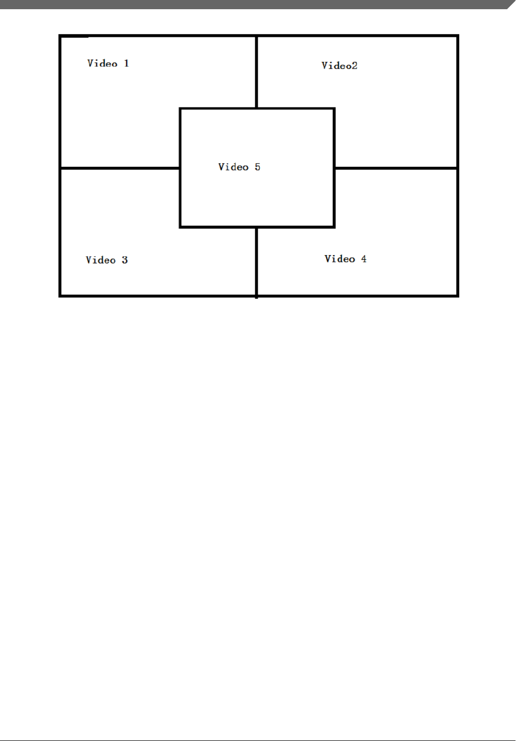
Figure 3. Multiple video overlay
gst-launch-1.0 playbin uri=file://$FILE1
video-sink="overlaysink overlay-width=512 overlay-height=384"
playbin uri=file://$FILE2 flags=0x41
video-sink="overlaysink overlay-left=512 overlay-width=512 overlay-height=384"
playbin uri=file://$FILE3 flags=0x41
video-sink="overlaysink overlay-top=384 overlay-width=512 overlay-height=384"
playbin uri=file://$FILE4 flags=0x41
video-sink="overlaysink overlay-left=512 overlay-top=384 overlay-width=512
overlay-height=384"
playbin uri=file://$FILE5 flags=0x41
video-sink="overlaysink overlay-left=352 overlay-top=264 overlay-width=320
overlay-height=240 zorder=1"
7.3.2 Audio encoding
Here are some examples for MP3 encoding.
$GSTL filesrc location=test.wav ! wavparse ! imxmp3enc bitrate=48 quality=1
! filesink location=output.mp3
7.3.3 Video encoding
Video encoding requires VPU hardware, so this command will only work on a SOC with a VPU.
$GSTL filesrc location=test.yuv
! videoparse format=2 witdh=$WIDTH height=$HEIGHT framerate=30/1
! vpuenc_xxx ! $MUXER ! filesink location=$output
• The target encoder codec type could be MPEG4, H263, H264, or MJPEG.
• The vpuenc_xxx can be vpuenc_mpeg4, vpuenc_h263, vpuenc_h264, and vpuenc_jpeg.
Multimedia
i.MX Linux® User's Guide , Rev. L4.1.15_1.0.0-ga, 03/2016
Freescale Semiconductor, Inc. 35

• The $MUXER can be set to qtmux, matroskamux, mp4mux, avimux, or flvmux.
• Different muxers support different encoded codec types. Use $GSTINSPECT $MUXER to see the capabilities of the
muxer to be used.
7.3.4 Transcoding
Transcoding is converting a file from one video encoding to another.
$GSTL filesrc location=$filename typefind=true ! $capsfilter ! aiurdemux
! vpudec ! imxvideoconvert_ipu ! $CAPS1 ! vpuenc_xxx ! matroskamux ! filesink
location=720p.mkv
capsfilter is the container's mime type. CAPS1 is the target video resolution, and the vpuenc_xxx can be vpuenc_mpeg4,
vpuenc_h263, vpuenc_h264, and vpuenc_jpeg..
For example:
gst-launch-1.0 filesrc location=$FILE.mp4 typefind=true ! video/quicktime ! aiurdemux !
vpudec ! imxvideoconvert_ipu ! video/x-raw,format=NV12,width=1280,height=720 ! vpuenc_h263 !
matroskamux ! filesink location=$FILE.mkv
7.3.5 Audio recording
The following examples show how to make an MP3 or WMA audio recording.
• MP3 recording
$GSTL pulsesrc num-buffers=$NUMBER blocksize=$SIZE ! imxmp3enc
! filesink location=output.mp3
•
NOTE
The recording duration is calculated as $NUMBER * $SIZE * 8 / (samplerate * channel *
bit width).
Thus, to record 10 seconds of a stereo channel sample with a 44.1K sample rate and a 16
bit width, use the following command:
$GSTL alsasrc num-buffers=430 blocksize=4096 ! imxmp3enc
! filesink location=output.mp3
7.3.6 Video recording
Video recording is done using the camera input, so this activity only applies to platforms with a camera. Different cameras
need to be set with different capture modes for special resolutions. See Chapter "Supporting the i.MX 6Dual/6Quad/6Solo/
6DualLite Camera Sensor with CSI" in the i.MX BSP Porting Guide (IMXBSPPG).
Use the $GSTINSPECT command to obtain more information about the codec property.
An example of recording might look like this:
$GSTL imxv4l2src device=$DEVICE num-buffers=300 ! $INPUT_CAPS ! queue ! vpuenc_h264
! $ $MUXER ! filesink location=output.$EXTENSION
• $DEVICE could be set to /dev/video, /dev/video0, or /dev/video1 according to the system video input device.
Multimedia
i.MX Linux® User's Guide , Rev. L4.1.15_1.0.0-ga, 03/2016
36 Freescale Semiconductor, Inc.

• $INPUT_CAPS should be set to 'video/x-
raw,format=(string)NV12,width=1920,height=1080,framerate=(fraction)30/1'.
• $MUXER can be set as to qtmux, matroskamux, mp4mux, avimux, or flvmux.
• $EXTENSION is filename extension according to the muxer type.
7.3.7 Audio/Video recording
A command used to record audio and video together might look like this:
$GSTL –e imxv4l2src device=$DEVICE ! $INPUT_CAPS ! queue ! vpuenc_h264 ! queue
! mux. pulsesrc ! 'audio/x-raw, rate=44100, channels=2' ! imxmp3enc ! queue
! mux. $MUXER name=mux ! filesink location= output.$EXTENSION
• $INPUT_CAPS should be set to 'video/x-raw, format=(string)NV12, width=1920, height=1080,
framerate=(fraction)30/1’.
• $MUXER can be set as to qtmux, matroskamux, mp4mux, avimux, or flvmux.
Common parameters are as follws:
•-e indicates to send EOS when the user presses Ctrl+C to avoid output corruption.
•$EXTENSION is the filename extension according to the multiplexer type.
7.3.8 Camera preview
This example displays what the camera sees. It is only available on platforms with a camera.
$GSTL imxv4l2src ! 'video/x-raw, format=(string)$FORMAT,
width=$WIDTH, height=$HEIGHT, framerate=(fraction)30/1'
! imxv4l2sink
Camera preview example:
$GSTL imxv4l2src device=/dev/video1 ! 'video/x-raw,
format=(string)UYVY,width=640,height=480,framerate=(fraction)30/1'
! imxv4l2sink
Parameter comments:
• Get the camera support format and resolution using gst-inspect-1.0 imxv4l2src.
• Set caps filter according to the camera's supported capabilities if the user needs other format or resolution.
• Ensure that the right caps filter has been set, which also needs to be supported by imxv4l2sink.
7.3.9 Recording the TV-in source
The TV-in source plugin gets video frames from the TV decoder. It is based on the V4l2 capture interface. A command line
example is follows:
gst-launch-1.0 imxv4l2src ! imxv4l2sink
NOTE
The TV decoder is ADV7180. It supports NTSC and PAL TV mode. The output video
frame is interlaced, so the sink plugin needs to enable deinterlace. The default value of
imxv4l2sink deinterface is True.
Multimedia
i.MX Linux® User's Guide , Rev. L4.1.15_1.0.0-ga, 03/2016
Freescale Semiconductor, Inc. 37

7.3.10 Web camera
The following command line is an example of how to record and transfer web camera input.
$GSTL imxv4l2src device=/dev/video1 ! vpuenc_h264 ! rtph264pay ! udpsink host=$HOST_IP
HOST_IP is the IP/multicast group to send the packets to.
This command line is an example of how to receive and display web camera input.
$GSTL udpsrc ! application/x-rtp ! rtph264depay ! vpudec ! imxv4l2sink
7.3.11 HTTP streaming
The HTTP streaming includes the following:
• Manual pipeline
$GSTL souphttpsrc location= http://SERVER/test.avi ! typefind
! aiurdemux name=demux demux. ! queue max-size-buffers=0 max-size-time=0
! vpudec ! $video_sink_plugin demux. ! queue max-size-buffers=0 max-size-time=0
! beepdec ! $audio_sink_plugin
• PLAYBIN
$GSTL $PLAYBIN uri=http://SERVER/test.avi
• GPLAY
$GPLAY http://SERVER/test.avi
7.3.12 Real Time Streaming Protocol (RTSP) playback
You can use the following command to see the GStreamer RTP depacketize plugins:
$GSTINSPECT | grep depay
RTSP streams can be played with a manual pipline or by using playbin. The format of the commands is as follows.
• Manual pipeline
$GSTL rtspsrc location=$RTSP_URI name=source
! queue ! $video_rtp_depacketize_plugin ! $vpu_dec ! $video_sink_plugin source.
! queue ! $audio_rtp_depacketize_plugin ! $audio_parse_plugin ! beepdec !
$audio_sink_plugin
• PLAYBIN
$GSTL $PLAYBIN uri=$RTSP_URI
Two properties of rtspsrc that are useful for RTSP streaming are:
•Latency: This is the extra added latency of the pipeline, with the default value of 200 ms. If you need low-latency
RTSP streaming playback, you can set this property to a smaller value.
•Buffer-mode: This property is used to control the buffering algorithm in use. It includes four modes:
• None: Outgoing timestamps are calculated directly from the RTP timestamps, not good for real-time applications.
• Slave: Calculates the skew between the sender and receiver and produces smoothed adjusted outgoing
timestamps, good for low latency communications.
Multimedia
i.MX Linux® User's Guide , Rev. L4.1.15_1.0.0-ga, 03/2016
38 Freescale Semiconductor, Inc.

• Buffer: Buffer packets between low and high watermarks, good for streaming communication.
• Auto: Chooses the three modes above depending on the stream. This is the default setting.
If you need to pause or resume the RTSP streaming playback, you need to use a buffer-mode of slave or none for rtspsrc,
as in buffer-mode=buffer. After resuming, the timestamp is forced to start from 0, and this will cause buffers to be
dropped after resuming.
Manual pipeline example:
$GSTL rtspsrc location=rtsp://10.192.241.11:8554/test name=source
! queue ! rtph264depay ! vpudec ! overlaysink source.
! queue ! rtpmp4gdepay ! aacparse ! beepdec ! pulsesink
Playback will not exit automatically in GStreamer 1.x, if buffer-mode is set to buffer in the rtpsrc plugin.
7.3.13 RTP/UDP MPEGTS streaming
There are some points to keep in mind when doing RTP/UDP MPEGTS Streaming:
• The source file that the UDP/RTP server sends must be in TS format.
• Start the server one second earlier than the time client starts.
• Two properties of aiurdemux that are useful for UDP/RTP TS streaming are:
streaming-latency: This is the extra added latency of the pipeline, and the default value is 400 ms. This value is
designed for the situation when the client starts first. If the value is too small, the whole pipeline may not run due to
lack of audio or video buffers. In that situation, you should cancel the current command and restart the pipeline. If the
value is too large, you will need to wait for a long time to see the video after starting the server.
low_latency_tolerance: This value is a range that total latency can jitter around streaming-latency. This property is
disabled by default. When the user sets this value, the maximum latency is (streaming-latency +
low_latency_tolerance).
The UDP MPEGTS Streaming command line format looks like this:
$GSTL udpsrc do-timestamp=false uri=$UDP_URI caps="video/mpegts"
! aiurdemux streaming_latency=400 name=d d. ! queue ! $vpu_dec
! queue ! $video_render_sink sync=true d. ! queue ! beepdec ! $audio_sink_plugin
sync=true
$GSTL udpsrc do-timestamp=false uri=udp://10.192.241.255:10000 caps="video/mpegts"
! aiurdemux streaming_latency=400 name=d d. ! queue ! vpudec
! queue ! overlaysink sync=true d. ! queue ! beepdec ! pulsesink sync=true
The format for a RTP MPEGTS streaming command is covered as follows:
$GSTL udpsrc do-timestamp=false uri=$RTP_URI caps="application/x-rtp"
! rtpmp2tdepay ! aiurdemux streaming_latency=400 name=d d. ! queue ! $vpu_dec
! queue ! $video_render_sink sync=true d. ! queue ! beepdec ! $audio_sink_plugin
sync=true
$GSTL udpsrc do-timestamp=false uri=udp://10.192.241.255:10000 caps="application/x-rtp"
! rtpmp2tdepay ! aiurdemux streaming_latency=400 name=d d.
! queue ! vpudec ! queue ! overlaysink sync=true d. ! queue ! beepdec
! pulsesink sync=true
Multimedia
i.MX Linux® User's Guide , Rev. L4.1.15_1.0.0-ga, 03/2016
Freescale Semiconductor, Inc. 39

7.3.14 RTSP streaming server
The RTSP streaming server use case is based on the open source gst-rtsp-server package. It uses the Freescale aiurdemux
plugin to demultiplex the file to audio or video elementary streams and to send them out through RTP. You can start the
RTSP streaming server on one board, and play it on another board with the RTSP streaming playback commands.
The gst-rtsp-server package is not installed by default in the Yocto Project release. You can follow these steps to build and
install it.
1. Enable the layer meta-openembedded/meta-multimedia:
Add the line BBLAYERS += "${BSPDIR}/sources/meta-openembedded/meta-multimedia" to the
configuration file $yocto_root/build/conf/bblayers.conf.
2. Include gst-rtsp-server into the image build:
Add the line IMAGE_INSTALL_append += "gst-rtsp-server" to the configuration file $yocto_root/build/
conf/local.conf.
3. Run bitbake for your image to build with gst-rstp-server.
4. You can find the test-uri binary in the folder:
$yocto_root/build/tmp/work/cortexa9hf-vfp-neon-poky-linux-gnueabi/gst-rtsp-server/$version/gst-rtsp-server-$version/
build/ examples/.libs/
5. Flash the image.
Copy test-uri into /usr/bin in the rootfs on your board and assign execute permission to it.
Some information on running the tool is as follows:
• Command:
test-uri $RTSP_URI
For example:
test-uri file:///home/root/temp/TestSource/mp4/1.mp4
• Server address:
rtsp://$SERVER_IP:8554/test
For example:
rtsp://10.192.241.106:8554/test
• Client operations supported are Play, Stop, Pause, Resume, and Seek.
7.3.15 Video conversion
There are three video conversion plugins, imxvideoconvert_ipu, imxvideoconvert_g2d, and imxvideoconvert_pxp. All of
them can be used to perform video color space conversion, resize, and rotate. imxvideoconvert_ipu can also be used to
perform video deinterlacing. They can be used to connect before ximagesink to enable the video rendering on X Windows or
used in transcoding to change video size, rotation, or deinterlacing.
Use gst-inspect-1.0 to get each convertor's capability and supported input and output formats. Note that imxvideoconvert_g2d
can only performance color space converting to RGB space.
CSC
gst-launch-1.0 videotestsrc ! video/x-raw,format=NV12 ! imxvideoconvert_{xxx} ! video/x-
raw,format=RGB16 ! ximagesink display=:0
Multimedia
i.MX Linux® User's Guide , Rev. L4.1.15_1.0.0-ga, 03/2016
40 Freescale Semiconductor, Inc.

Resize
gst-launch-1.0 videotestsrc ! video/x-raw,format=NV12,width=800,height=600 !
imxvideoconvert_{xxx} ! video/x-raw, width=640, height=480 ! ximagesink display=:0
Rotate
gst-launch-1.0 videotestsrc ! imxvideoconvert_{xxx} rotation=2 ! ximagesink display=:0
Deinterlacing
gst-launch-1.0 playbin uri=file://$FILE video-sink="imxvideoconvert_ipu deinterlace=3 !
ximagesink display=:0 sync=false"
Transcoding
gst-launch-1.0 filesrc location=$FILE.mp4 typefind=true ! video/quicktime ! aiurdemux !
vpudec ! imxvideoconvert_ipu ! video/x-raw,format=NV12,width=1280,height=720 ! vpuenc_h263 !
avimux ! filesink location=$FILE.avi
Combination
It is possible to combine CSC, resize, rotate, and deinterlace at one time. Both of imxvideoconvert_ipu and
imxvideoconvert_g2d can be used at the same time in a pipeline. The following is an example:
gst-launch-1.0 videotestsrc ! video/x-raw,format=I420,width=1280,height=800,interlace-
mode=interleaved ! imxvideoconvert_ipu rotation=2 deinterlace=3 ! video/x-
raw,format=NV12,width=800,height=600 ! vpuenc_h264 ! vpudec ! imxvideoconvert_g2d
rotation=3 ! video/x-raw,format=RGB16,width=640,height=480 ! ximagesink sync=false display=:0
7.3.16 Video composition
There are three video compositor elements: imxcompositor_ipu, imxcompositor_g2d, and imxcompositor_pxp. Each of them
uses corresponding hardware to accelerate video composition. They can be used to composite multiple videos into one. The
video position, size, and rotation can be specified while composition. Video color space conversion is also performed
automatically if input and output video are not same. Each video can be set an alpha and z-order value to get alpha blending
and video blending sequence.
Note that imxcompositor_g2d only can output RGB color space format. Use gst-inspect-1.0 to get more detailed information,
including the supported input and output video format.
• Composite two videos into one.
gst-launch-1.0 imxcompositor_{xxx} name=comp sink_1::xpos=160 sink_1::ypos=120 !
overlaysink videotestsrc ! comp.sink_0 videotestsrc ! comp.sink_1
• Composite two videos into one with red background color.
gst-launch-1.0 imxcompositor_{xxx} background=0x000000FF name=comp sink_1::xpos=160
sink_1::ypos=120 ! overlaysink videotestsrc ! comp.sink_0 videotestsrc ! comp.sink_1
• Composite two videos into one with CSC, resize, and rotate.
gst-launch-1.0 imxcompositor_{xxx} name=comp sink_0::width=640 sink_0::height=480
sink_1::xpos=160 sink_1::ypos=120 sink_1::width=640 sink_1::height=480
sink_1::rotate=1 !
video/x-raw,format=RGB16 ! overlaysink videotestsrc !
video/x-raw,format=NV12,width=320,height=240 ! comp.sink_0 videotestsrc !
video/x-raw,format=I420,width=320,height=240 ! comp.sink_1
• Composite three videos into one with CSC, resize, rotate, alpha, z-order, and keep aspect ratio.
gst-launch-1.0 imxcompositor_{xxx} name=comp sink_0::width=640 sink_0::height=480
sink_0::alpha=0.5 sink_0::z-order=3 sink_1::alpha=0.8 sink_1::z-order=2
sink_1::xpos=160
sink_1::ypos=120 sink_1::width=640 sink_1::height=480 sink_1::rotate=1
sink_2::xpos=320
Multimedia
i.MX Linux® User's Guide , Rev. L4.1.15_1.0.0-ga, 03/2016
Freescale Semiconductor, Inc. 41

sink_2::ypos=240 sink_2::width=500 sink_2::height=500 sink_2::alpha=0.6
sink_2::keep-ratio=true ! video/x-raw,format=RGB16 ! overlaysink videotestsrc !
video/x-raw,format=NV12,width=320,height=240 ! comp.sink_0 videotestsrc !
video/x-raw,format=I420,width=320,height=240 ! comp.sink_1 videotestsrc !
video/x-raw,format=RGB16,width=320,height=240 ! comp.sink_2
7.4 Pulseaudio input/output settings
If pulseaudio is installed in the rootfs, the pulseaudio input/output settings may need to be set. Pulse audio is only available
for the X11 back-end Yocto Project rootfs.
Audio output settings
Use the pactl command to list all the available audio sinks:
$ pactl list sinks
A list of available audio sinks are displayed:
Sink #0
State: SUSPENDED
Name: alsa_output.platform-soc-audio.1.analog-stereo
Description: sgtl5000-audio Analog Stereo
...
...
Sink #1
State: SUSPENDED
Name: alsa_output.platform-soc-audio.4.analog-stereo
Description: imx-hdmi-soc Analog Stereo
...
...
Use the pacmd command to set the default audio sink according to the sink number in the list shown above:
$ pacmd set-default-sink $sink-number
$sink-number could be 0 or 1 in the example above.
After setting the default sink, use the command below to verify the audio path:
$ gst-launch audiotestsrc ! pulsesink
Audio input settings
Use the pactl command to list all the available audio sources:
$ pactl list sources
A list of available audio sources are displayed:
Source #0
State: SUSPENDED
Name: alsa_output.platform-soc-audio.1.analog-stereo.monitor
Description: Monitor of sgtl5000-audio Analog Stereo
...
...
Source #1
State: SUSPENDED
Name: alsa_input.platform-soc-audio.1.analog-stereo
Description: sgtl5000-audio Analog Stereo ...
...
...
Use the pacmd command to set the default audio source according to the source number in the list shown above:
Multimedia
i.MX Linux® User's Guide , Rev. L4.1.15_1.0.0-ga, 03/2016
42 Freescale Semiconductor, Inc.

$ pacmd set-default-source $sink-number
$sink-number could be 0 or 1 in the example above. If record and playback at the same time is not needed, there is no need to
set the monitor mode.
The pulseaudio I/O path setting status can be checked with:
$ pactl stat
Multichannel output support settings
For those boards that need to output multiple channels, these are the steps needed to enable the multichannel output profile:
1. Use the pacmd command to list the available cards:
$ pacmd list-cards
The available sound cards and the profiles supported are listed.
2 card(s) available.
index: 0
name: <alsa_card.platform-sound-cs42888.34>
driver: <module-alsa-card.c>
owner module: 6
properties:
alsa.card = "0"
alsa.card_name = "cs42888-audio"
...
...
profiles:
input:analog-mono: Analog Mono Input (priority 1, available: unknown)
input:analog-stereo: Analog Stereo Input (priority 60, available:
unknown)
...
...
active profile: <output:analog-stereo+input:analog-stereo>
...
...
2. Use the pacmd command to set the profile for particular features.
$ pacmd set-card-profile $CARD $PROFILE
$CARD is the card name listed by pacmd list-cards (e.g., alsa_card.platform-sound-cs42888.34 in the example
above), and $PROFILE is the profile name. These are also listed by pamcd list-cards. (e.g., output:analog-
surround-51 in the example above).
3. After setting the card profile, use $ pactl list sinks and $pacmd set-default-sink $sink-number to set
the default sink.
7.5 Overlaysink usage
The overlaysink plugin is based on the GPU. It provides two main functions for video rendering:
• Video Overlay: composites multiple video playbacks into the same display.
• Multiple Display: shows videos to multiple displays, up to four displays.
overlaysink uses a configuration file to set the display device parameters, located in /usr/share. For i.MX 6Quald/
6DualLite, the configuration file name is imx_6q_display_config. For i.MX 6SoloX/6SoloLite, the configuration file
name is imx_6sx_display_config.
The configuration syntax is:
[Display Name]
Multimedia
i.MX Linux® User's Guide , Rev. L4.1.15_1.0.0-ga, 03/2016
Freescale Semiconductor, Inc. 43

Mandatory. Specify the display name, used in overlaysink property display-x to enable the x display.
device
Mandatory. Specify the display device (v4l2 output) name, such as /dev/video17.
fmt
Optional. Specify the display device color format, set "RGBP" for RGB565 16 bit display or "RGBx" for RGB8888 32 bit
display. The default is "RGBP".
width
Optional. Specify the width of the display, and the default is the screen width.
height
Optional. Specify the height of the display, and the default is the screen height.
alpha
Optional. Specify the global alpha value, the value range is 0-255, and the default is 0.
color_key
Optional. Specify the color key value, and the default is disabled.
The following is an example of the display configuration for dual display mode, LVDS(master) + HDMI(slave).
# LVDS display
[master]
device = /dev/video17
fmt = RGBP
width = 1024
height = 768
alpha = 0
# HDMI display
[slave]
device = /dev/video18
fmt = RGBP
width = 1920
height = 1080
7.6 Installing gstreamer1.0-libav into rootfs
The following steps show how to install gstreamer1.0-libav into a rootfs image.
1. Add the following lines into the configuration file conf/local.conf.
IMAGE_INSTALL_append = " gstreamer1.0-libav"
LICENSE_FLAGS_WHITELIST = "commercial"
2. Build gstreamer1.0-libav.
$ bitbake gstreamer1.0-libav
3. Build the rootfs image.
$ bitbake $image_name
Multimedia
i.MX Linux® User's Guide , Rev. L4.1.15_1.0.0-ga, 03/2016
44 Freescale Semiconductor, Inc.

8 Graphics
There are a number of graphics tools, tests, and example programs that are built and installed in the Linux rootfs. There will
be some variation on what is included based on the build and packages selected, the board, and the backend specified. This
section describes some of them.
The kernel module version of graphics used on the system can be found by running the following command on the board:
dmesg | grep Galcore
The user-side GPU drivers version of graphics can be displayed using the following command on the board:
grep VERSION /usr/lib/libGAL*
When reporting problems with graphics, this version number is needed.
8.1 fsl-gpu-sdk
This graphics package contains source for several graphics examples for OpenGLES 2.0 and OpenGLES 3.0 apis for X11,
Framebuffer, and XWayland graphical backends. These applications show that the graphics acceleration is working for
different APIs. The package includes samples, demo code, and documentation for working with the i.MX 6 family of graphic
cores. More details about this SDK are in the i.MX 6 Graphics User's Guide. This SDK is only supported for hardware that
has OpenGLES hardware acceleration.
8.2 G2D-fsl-samples
G2D Application Programming Interface (API) is designed to make it easy to use and understand the 2D BLT functions. It
allows the user to implement customized applications with simple interfaces. It is hardware and platform independent when
using 2D graphics.
G2D API supports the following features and more:
• Simple BLT operation from source to destination
• Alpha blend for source and destination with Porter-Duff rules
• High-performance memory copy from source to destination
• Up-scaling and down-scaling from source to destination
• 90/180/270 degree rotation from source to destination
• Horizontal and vertical flip from source to destination
• Enhanced visual quality with dither for pixel precision-loss
• High performance memory clear for destination
• Pixel-level cropping for source surface
• Global alpha blend for source only
• Asynchronous mode and synchronization
• Contiguous memory allocator
• VG engine
The G2D API document includes the detailed interface description and sample code for reference. The API is designed with
C-Style code and can be used in both C and C++ applications.
•g2d
• g2d_test
• Overlay Test
• g2d_overlay_test
Graphics
i.MX Linux® User's Guide , Rev. L4.1.15_1.0.0-ga, 03/2016
Freescale Semiconductor, Inc. 45

8.3 viv_samples
The directory viv_samples is found under /opt. It contains binary samples for OpenGL ES 1.1/2.0, OpenVG 1.1, and
HAL tests.
The following are the basic sanity tests, which could help to make sure that the system is configured correctly.
• cl11: This contains unit tests and FFT samples for OpenCL 1.1 Embedded Profile. OpenCL is implemented on the
i.MX 6Quad and i.MX 6DualLite boards.
• es20: This contains tests for Open GLES 2.0.
• vv_launcher
• coverflow.sh
• vv_launcher
• hal: This contains a variety of 2D unit tests.
• tvui
• unit_test
• tiger: A simple OpenVG application with a rotating tiger head. This is to demonstrate OpenVG.
• vdk: Contains sanity tests for OpenGL ES 1.1 and OpenGL ES 2.0.
The tiger and vdk tests show that hardware acceleration is being used. They will not run without it.
• UnitTest
• clinfo
• loadstore
• math
• threadwalker
• test_vivante
• functions_and_kernels
• illegal_vector_sizes
• initializers
• multi_dimensional_arrays
• reserved_data_types
• structs_and_enums
• unions
• unsupported_extensions
• fft
8.4 Qt 5
Qt 5 is built into the Linux image in the Yocto Project environment with the command bitkake fsl-image-qt5.
To run the Qt 5 examples on the board, the platform and input plugin need to be specified. Different backends require
different graphics plugins, as shown in the following table.
Table 29. Graphics plugins for backends
Backend Graphics
FB eglfs
XWayland wayland-egl
X11 xcb
Graphics
i.MX Linux® User's Guide , Rev. L4.1.15_1.0.0-ga, 03/2016
46 Freescale Semiconductor, Inc.

DirectFB is not yet supported.
It is often useful to specifically set the display variable and allow access to the X server. The commands below will do that.
Check the xhost man page for additional ways to use that command. These commands often fix the problem that causes the
"Could not connect to display" error message.
export DISPLAY=:0.0
xhost +
The command lines for some of the Qt 5 sample applications are as follows. For XWayland, it sometimes helps to add --
fullscreen to the command line. The Qt 5 desktop may contain links to these examples.
•Qt5_CinematicExperience -platform ${GRAPHICS} -plugin evdevtouch:/dev/input/event0
•/usr/share/qt5nmapcarousedemo-1.0/Qt5_NMap_CarouselDemo -platform ${GRAPHICS} -plugin
evdevtouch:/dev/input/event0
•/usr/bin/qt5/qmlscene -platform ${GRAPHICS} -plugin evdevtouch:/dev/input/event0 /usr/
share/qt5ledscreen-1.0/example_hello.qml
•/usr/bin/qt5/qmlscene -platform ${GRAPHICS} -plugin evdevtouch:/dev/input/event0 /usr/
share/qt5ledscreen-1.0/example_billboard.qml
•/usr/bin/qt5/qmlscene -platform ${GRAPHICS} -plugin evdevtouch:/dev/input/event0 /usr/
share/qt5ledscreen-1.0/example_combo.qml
Some examples must be run from a particular directory. The first column in the following table shows the directory and the
second column shows the command to run in that directory. The examples are usually installed in /usr/share.
Table 30. Example directories and command lines
Directory Command
qt5everywheredemo-1.0 ./QtDemo -platform ${GRAPHICS} -plugin evdevtouch:/dev/input/event0
qtpatientcare-1.0 ./patientcare -platform ${GRAPHICS} -plugin evdevtouch:/dev/input/event0
qtsmarthome-1.0 ./smarthome -platform ${GRAPHICS} -plugin evdevtouch:/dev/input/event0
quitbattery-1.0.0 ./QUItBattery -platform ${GRAPHICS} -plugin evdevtouch:/dev/input/event0
9 Security
Using the Freescale CryptoDev security driver causes the system to run much faster than without it.
The CAAM drivers are accelerated through the CryptoDev interface. The openssl command can be used to show the system
speed without CryptoDev .
openssl speed -evp aes-128-cbc -engine cryptodev
An example of the key portion of the output is as follows. Library load errors may occur but they can be ignored.
Doing aes-128-cbc for 3s on 16 size blocks: 4177732 aes-128-cbc's in 2.99s
Doing aes-128-cbc for 3s on 64 size blocks: 1149097 aes-128-cbc's in 3.01s
Doing aes-128-cbc for 3s on 256 size blocks: 297714 aes-128-cbc's in 3.00s
Doing aes-128-cbc for 3s on 1024 size blocks: 75118 aes-128-cbc's in 3.00s
Doing aes-128-cbc for 3s on 8192 size blocks: 9414 aes-128-cbc's in 3.00s
Start CryptoDev and run the openssl command again. This time you should be able to see that the timeing values show the
accelerated values. As the block sizes increase, the elapsed time decreases.
modprobe cryptodev
openssl speed -evp aes-128-cbc -engine cryptodev
Here is an example of the accelerated output:
Security
i.MX Linux® User's Guide , Rev. L4.1.15_1.0.0-ga, 03/2016
Freescale Semiconductor, Inc. 47
Doing aes-128-cbc for 3s on 16 size blocks: 36915 aes-128-cbc's in 0.10s
Doing aes-128-cbc for 3s on 64 size blocks: 34651 aes-128-cbc's in 0.05s
Doing aes-128-cbc for 3s on 256 size blocks: 25926 aes-128-cbc's in 0.10s
Doing aes-128-cbc for 3s on 1024 size blocks: 20274 aes-128-cbc's in 0.04s
Doing aes-128-cbc for 3s on 8192 size blocks: 5656 aes-128-cbc's in 0.02s
10 Connectivity
This section describes the connectivity for Bluetooth wireless technology and Wi-Fi.
• Bluetooth support works best with a USB dongle with either BlueZ4 or BlueZ5. For this release, BlueZ5 is default. To
switch between BlueZ4 and BlueZ5, it requires a clean build and changes in local.conf. BlueZ4 and BlueZ5 both use
different tools. More information about these tools is in the readme-bluez.txt file in the meta-fsl-bsp-release layer.
Bluetooth wireless technology is enabled in the default kernel configuration. To disable Bluetooth wireless technology,
run the following command:
bitbake linux-imx -c menuconfig
Then, disable Bluetooth wireless technology. Bluetooth wireless technology works with a USB dongle.
• Broadcom Wi-Fi and Bluetooth wireless technology support require the Broadcom firmware package download of fsl-
bcmdhd_[version].tar.gz from freescale.com. The Broadcom device drivers are integrated into the kernel but to
function require the firmware package download and integration.
11 Revision History
This table provides the revision history.
Table 31. Revision History
Revision number Date Substantive changes
L4.1.15_1.0.0-ga 03/2016 Initial release
Connectivity
i.MX Linux® User's Guide , Rev. L4.1.15_1.0.0-ga, 03/2016
48 Freescale Semiconductor, Inc.

Information in this document is provided solely to enable system and software
implementers to use Freescale products. There are no express or implied copyright
licenses granted hereunder to design or fabricate any integrated circuits based on the
information in this document.
Freescale reserves the right to make changes without further notice to any products
herein. Freescale makes no warranty, representation, or guarantee regarding the
suitability of its products for any particular purpose, nor does Freescale assume any
liability arising out of the application or use of any product or circuit, and specifically
disclaims any and all liability, including without limitation consequential or incidental
damages. “Typical” parameters that may be provided in Freescale data sheets and/or
specifications can and do vary in different applications, and actual performance may
vary over time. All operating parameters, including “typicals,” must be validated for
each customer application by customer’s technical experts. Freescale does not convey
any license under its patent rights nor the rights of others. Freescale sells products
pursuant to standard terms and conditions of sale, which can be found at the following
address: freescale.com/SalesTermsandConditions.
How to Reach Us:
Home Page:
nxp.com
Web Support:
nxp.com/support
Freescale and the Freescale logo are trademarks of Freescale Semiconductor, Inc.,
Reg. U.S. Pat. & Tm. Off. All other product or service names are the property of their
respective owners. ARM, ARM Powered, and Cortex are registered trademarks of
ARM Limited (or its subsidiaries) in the EU and/or elsewhere. All rights reserved.
© 2016 Freescale Semiconductor, Inc.
Document Number: IMXLUG
Rev. L4.1.15_1.0.0-ga
03/2016
