102537 SPF LPF RFID Data Sheet Sept 2016 IDEM Non Contact Coded Safety Switches Operating Instructions
User Manual: IDEM Non-Contact RFID Coded Safety Switches Operating Instructions Safety Switch Instruction Inserts - AutomationDirect
Open the PDF directly: View PDF ![]() .
.
Page Count: 2
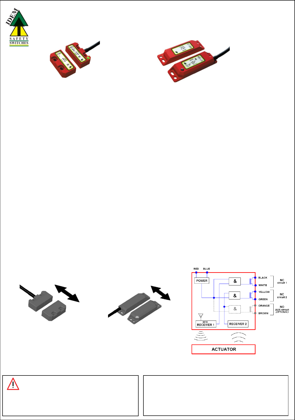
Non-Contact RFID Coded Safety Switches
SPF
SP
types
L
P
types
Actuator Operating
Directions
:
Align actuator and switch using the target lines
SP
F
and LP
F
Operating Instructions
READ AND UNDERSTAND THESE INSTRUCTIONS BEFORE
INSTALLING, OPERATING, OR MAINTAINING THIS EQUIPMENT.
The product is designed to be a component of a customized safety oriented control system. It is the responsibility of each manufacturer to ensure the correct overall functionality of its systems and
machines. IDEM, its subsidiaries and affiliates, are not in a position to guarantee all of the characteristics of a given system or product not designed by IDEM.
APPLICATION:
RFID Coded Non-Contact Safety Switches are designed to interlock hinged, sliding or removable guard doors. They are specifically advantageous when:
a) poor guard alignment exists
b) high level anti-tamper is required
c) high hygiene requirements exist e.g. food industry hose down
d) long mechanical life is required (no moving or touching parts)
When used in combination with a Dual Channel Safety Relay or Control Device, Non-Contact Safety Switches can be used to provide protection up to Category 4 and PLe to ISO13849-1.
OPERATION:
All RFID Coded Non-Contact Safety Switches are designed to conform to EN60947-5-3 and be used as directed by ISO14119 and EN ISO12100.
They have coded RFID and magnetic sensing which provides a wide (>10mm) sensing distance and provides a high tolerance to misalignment after sensing. They can operate in extreme
environments of temperature and moisture. The switches are provided factory coded either uniquely (U types) or by a Master code (M types).
For U types the individual code numbers are shown on the reverse of the switch / actuator. For Master coded types
any actuator will operate any switch.
If a Master type (M) actuator is to be changed then a re-teach process is needed. Power down – place new actuator to switch – Power up.
IMPORTANT:
Record any RFID codes as required by factory rules or with reference to any risk assessment for the particular application.
The Risk Assessment for the particular application should include the risk of spare actuators. Spare actuators should not be readily available and must be securely controlled.
The safety functions and mechanics must be tested regularly. For applications were infrequent guard access is foreseeable, the system must have a manual function test to detect a possible
accumulation of faults. At least once per month for PLe Cat3/4 or once per year for PLd Cat3 (ISO13849-1). Where possible it is recommended that the control system of the machine demands
and monitors these tests, and stops or prevents the machine from starting if the test is not done. (See ISO14119).
INSTALLATION:
Installation of all RFID Coded Non-Contact Safety Switches must be in accordance with a risk assessment for the individual application.
The use of a Safety Relay or Control Device is required for monitoring RFID Coded switches. These devices monitor 2 redundant circuits as per ISO13849-1 for up to PLe / Category 4 protection.
M4 mounting bolts must be used to fix the switches. Tightening torque for mounting bolts to ensure reliable fixing is 1.0 Nm. Always mount on Non Ferrous materials.
The recommended setting gap is 5mm. The Safety Switch must not be used as a mechanical stop or be adjusted by striking with a hammer.
The actuator must not be allowed to strike the switch. Do not mount adjacent switches or actuators closer than 30mm.
Typical misalignment tolerance after setting is 5mm.
After installation always check each switch function by opening and closing each guard individually in turn and ensuring that the Green LED on the switch and the LEDs on the Safety Relay or
Control Device are illuminated when the switch is closed and are extinguished when the switch is open. Check that the machine stops and cannot be re-started when each switch is open.
Diagnostics:
LED Green ‘on’ = NC1 and NC2 closed.
MAINTENANCE:
Monthly: Check alignment
of actuator and look for signs of mechanical damage to the switch casing.
Check wiring for signs of damage.
Check each switch function by opening and closing each guard individually in turn and ensuring that the Green LED on the
switch and the appropriate LED’s on the Control Device are illuminated when the switch is closed and are extinguished when
the switch is open. Check that the machine stops and cannot be re-started when each switch is open.
WARNING: DO NOT DEFEAT, TAMPER, OR BYPASS THE SAFETY FUNCTION.
FAILURE TO DO SO CAN RESULT IN DEATH OR SERIOUS INJURY.
AVERTISSMENT: NE PAS DESACTIVER, MODIFIER, RETIRER, OU CONTOURNER
CETI INTERVERROUILLAGE IL PEUT EN RESULTER DES
BLESSURES GRAVES DU PERSONNEL UTILISATEUR.
Original Instructions.
To request this data sheet in other languages please contact info@idemsafety.com
Um dieses Datenblatt in Deutscher Sprache wenden Sie sich bitte anfordern info@idemsafety.com
Pour obtenir cette fiche en Français, veuillez contacter info@idemsafety.com
Para solicitar esta hoja de datos en Español, por favor contacto con info@idemsafety.com
LPF
Non-Contact RFID Coded Safety Switches
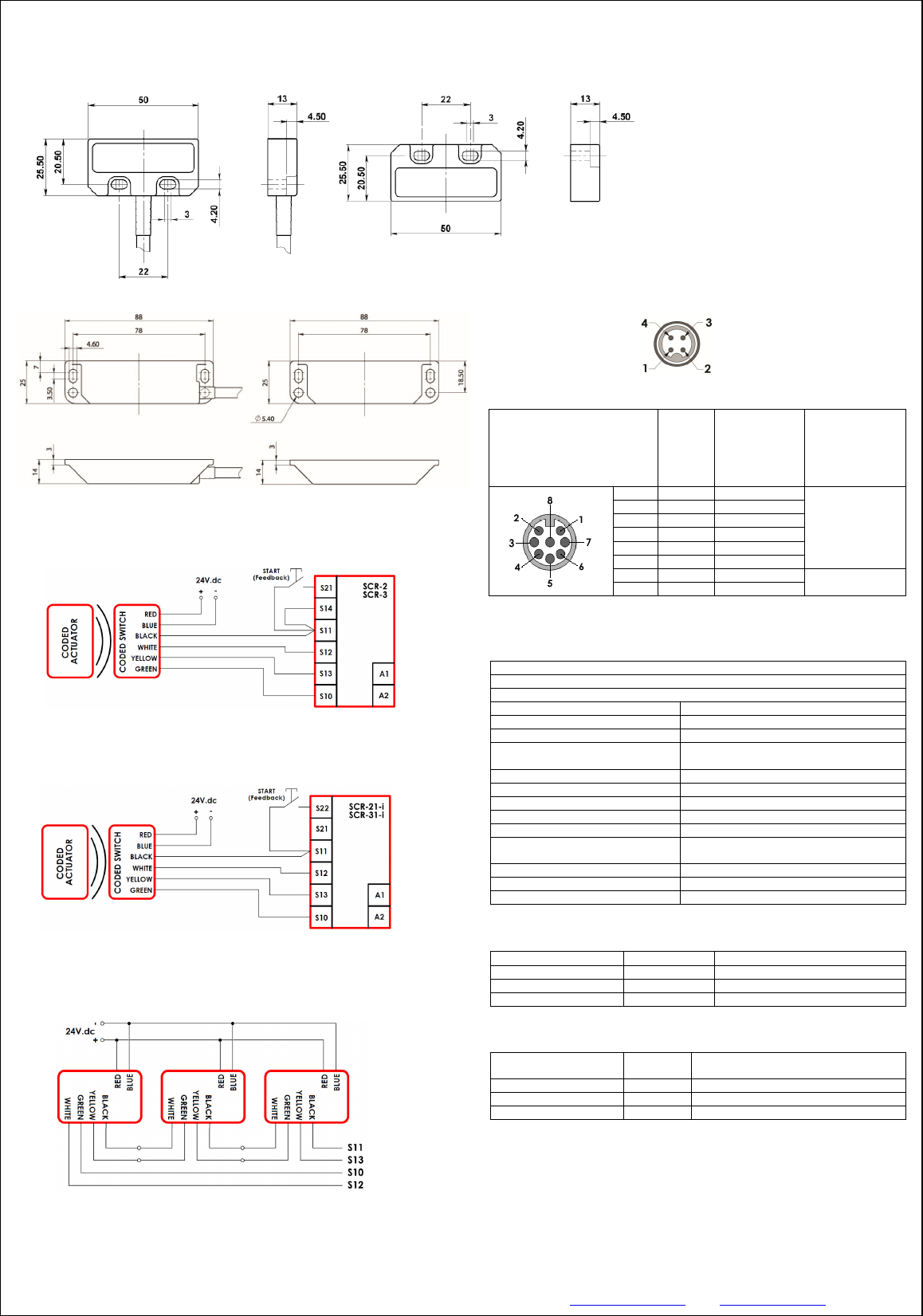
Standard Quick Connect (QC)
M12 8 way Male Plug
(on Flying Lead 250mm)
(Pin view from switch)
Flying
Lead
Colours
Circuit
(Actuator
present)
Output Types
Solid State
8
Orange
Auxiliary (NO)
24V.dc
200mA.Max.
(minimum internal
resistance 8.5ohms)
5
Brown
Auxiliary (NO)
4
Yellow
NC 2
6
Green
NC 2
7
Black
NC 1
1
White
NC 1
2
Red
Supply +24Vdc
+/
-
10%
USE SELV / PELV
3
Blue
Supply 0Vdc
Standards:
ISO14119
EN 60947
-
5
-
3 EN 60204
-
1 ISO 13849
-
1 EN 62061 UL508
Technical
Data:
Dielectric Withstand:
250V.ac
Insulation Resistance:
100 Mohms
Recommended setting gap:
5mm
Switching Distance:
Sao
10mm Close
Sar 20mm Open
Tolerance to Misalignment:
5mm in any direction from 5mm setting gap
Switching frequency:
1.0 Hz maximum
Approach speed:
200mm/m to 1000mm/s
Body material:
Polyester
Temperature Range:
-
25/80C
105C for CIP/SIP c
leaning
(temporary)
Enclosure Protection:
IP67 and IP69K
(QC versions IP67 for connector)
Cable Type:
PVC
8 core 6mm O.D.
Mounting Bolts:
2 x M4 Tightening torque 1.0 Nm
Mounting Position:
Any
Safety Integrity Level
SIL3
PFH (1/h)
4.77E
-
10
Corresponds to 4.8% of SIL3
PFD
4.18E
-
05
Corresponds to 4.2% of SIL3
Proof Test Interval T
1
20a
Performance Level
e
If both channels are used in combination with a
SIL3/PLe control device
Category
Cat4
MTTF
d
1100a
Diagnos
tic Coverage DC
99% (high)
Switch Dimensions (mm)
SP
Housing and Actuator
LP Housing and Actuator
IDEM SAFETY SWITCHES Ltd., 2 Ormside Close, Hindley Industrial Estate, Hindley Green, Wigan, WN2 4HR UK. Tel: +44 (0)1942 257070 Fax.: +44 (0)1942 257076
IDEM (USA) 4416 Technology Drive, Fremont, CA 94538 Tel:510-445-0751 Fax:1866-431-7064 email: sales@idemsafety.com Web: www.idemsafety.com
Doc: 102537
Sept. 2016
NC1 Pin 4
NC2 Pin 2
Supply +24Vdc Pin 1
Supply 0Vdc Pin 3
Alternative Quick Connect Flying Lead (QC) – M12 4-Way Male
Pin view from Switch
For all switches the NC circuits are closed when the guard is closed and the actuator is present.
Characteristic Data acc
ording
to IEC62061 (use
d
as a sub system)
Characteristic Data acc
ording
to
EN ISO13849
-
1
Number of operating days per year:
d
op
= 365d
Number of operating hours per day: hop = 24h
B10d no mechanical parts implemented
When the product is used deviant from these assumptions (different load, operating frequency,
etc.) the values have to be adjusted accordingly.
Information with regard to UL 508:
Type 1 Enclosures.
Maximum temperature 50ºC. Maximum output 24V.dc 100mA.
Powered by Class 2 or equivalent.
Single sw
itch to SCR
-
2
or SCR
-
3
Safety Relay
Single switch to SCR
-
21
-
i or SCR
-
31
-
i Safety Relay (Viper series)
S
eri
es connection to SCR relays
