Im609 SQUARE WAVE TIG 275 B
User Manual: SQUARE WAVE TIG 275 IM609-B
Open the PDF directly: View PDF ![]() .
.
Page Count: 46
- Table of Contents
- Safety
- Installation
- Technical Specifications
- Select Suitable Location
- Stacking
- Lifting and Moving
- Tilting
- Environmental Rating
- Machine Grounding and High Frequency Interference Protection
- Supply Connections
- Input Reconnect Procedure
- Output Connections
- Work Cable Connection
- Tig Torch Connections
- Twist-Mate Adapter for LA-9 and LA-17 Tig Torch
- Twist-Mate Adapter for LW-18 and LW-20 Tig Torch
- Stick Electrode Cable Connection
- Installation of Field Installed Options
- Operation
- Accessories
- Maintenance
- Troubleshooting
- Wiring Diagrams & Dimension Print
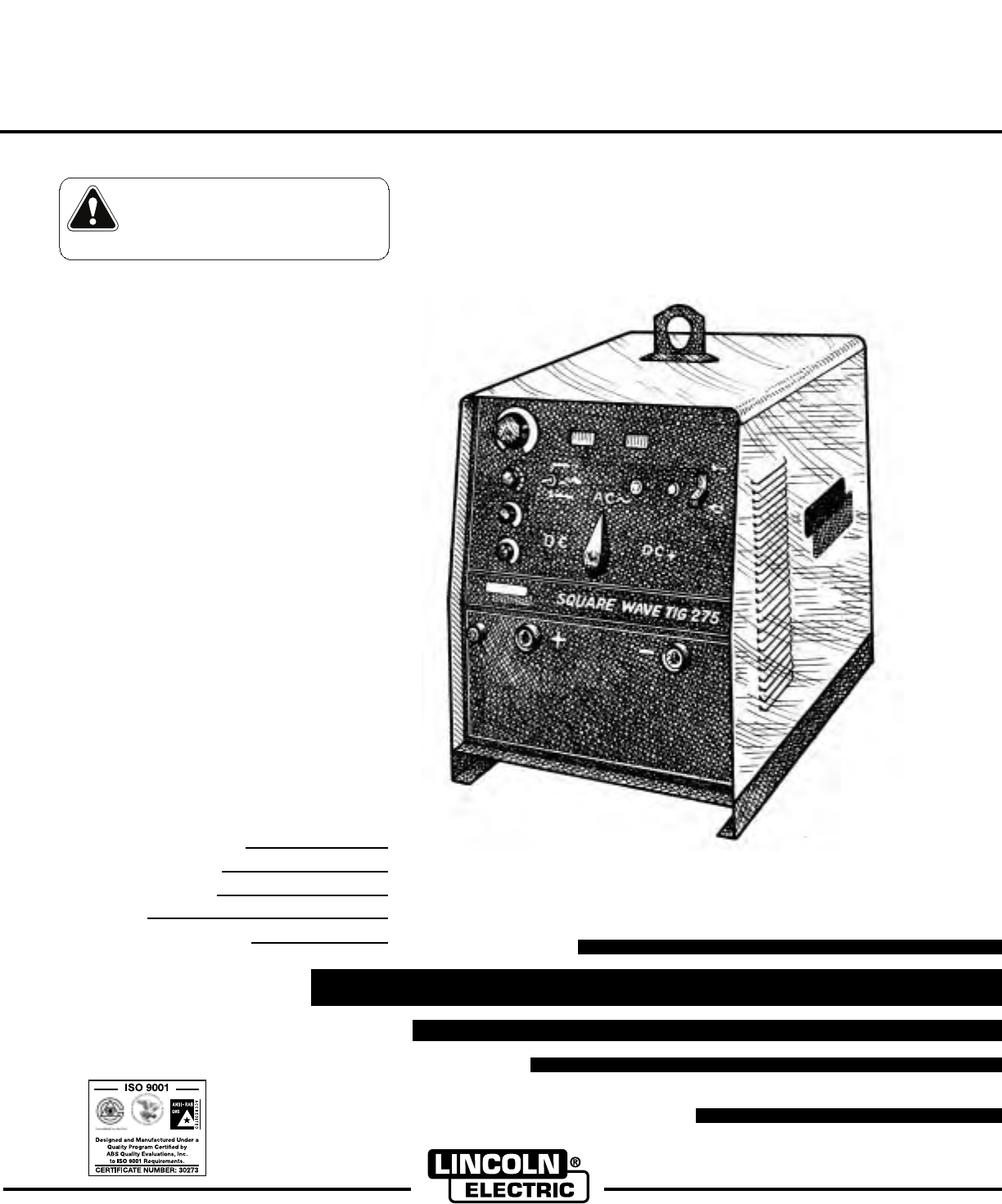
Square Wave TIG 275
OPERATOR’S MANUAL
IM609-B
May, 2001
Safety Depends on You
Lincoln arc welding and cutting
equipment is designed and built
with safety in mind. However, your
overall safety can be increased by
proper installation ... and thoughtful
operation on your part. DO NOT
INSTALL, OPERATE OR REPAIR
THIS EQUIPMENT WITHOUT
READING THIS MANUAL AND
THE SAFETY PRECAUTIONS
CONTAINED THROUGHOUT.
And, most importantly, think before
you act and be careful.
For use with machines having Code Numbers: 10523,
10524,
10525,
10605,
10738
• Sales and Service through Subsidiaries and Distributors Worldwide •
Cleveland, Ohio 44117-1199 U.S.A. TEL: 216.481.8100 FAX: 216.486.1751 WEB SITE: www.lincolnelectric.com
• World's Leader in Welding and Cutting Products •
Date of Purchase:
Serial Number:
Code Number:
Model:
Where Purchased:
Copyright © 2001 Lincoln Global Inc.
This manual covers equipment which is no
longer in production by The Lincoln Electric Co.
Specications and availability of optional
features may have changed.
FOR ENGINE
powered equipment.
1.a. Turn the engine off before troubleshooting and maintenance
work unless the maintenance work requires it to be running.
____________________________________________________
1.b. Operate engines in open, well-ventilated
areas or vent the engine exhaust fumes
outdoors.
____________________________________________________
1.c. Do not add the fuel near an open flame weld-
ing arc or when the engine is running. Stop
the engine and allow it to cool before refuel-
ing to prevent spilled fuel from vaporizing on
contact with hot engine parts and igniting. Do
not spill fuel when filling tank. If fuel is spilled,
wipe it up and do not start engine until fumes
have been eliminated.
____________________________________________________
1.d. Keep all equipment safety guards, covers and devices in posi-
tion and in good repair.Keep hands, hair, clothing and tools
away from V-belts, gears, fans and all other moving parts
when starting, operating or repairing equipment.
____________________________________________________
1.e. In some cases it may be necessary to remove safety
guards to perform required maintenance. Remove
guards only when necessary and replace them when the
maintenance requiring their removal is complete.
Always use the greatest care when working near moving
parts.
___________________________________________________
1.f. Do not put your hands near the engine fan. Do
not attempt to override the governor or idler
by pushing on the throttle control rods while
the engine is running.
___________________________________________________
1.g. To prevent accidentally starting gasoline engines while
turning the engine or welding generator during maintenance
work, disconnect the spark plug wires, distributor cap or
magneto wire as appropriate.
i
SAFETY
i
ARC WELDING CAN BE HAZARDOUS. PROTECT YOURSELF AND OTHERS FROM POSSIBLE SERIOUS INJURY OR DEATH.
KEEP CHILDREN AWAY. PACEMAKER WEARERS SHOULD CONSULT WITH THEIR DOCTOR BEFORE OPERATING.
Read and understand the following safety highlights. For additional safety information, it is strongly recommended that you pur-
chase a copy of “Safety in Welding & Cutting - ANSI Standard Z49.1” from the American Welding Society, P.O. Box 351040,
Miami, Florida 33135 or CSA Standard W117.2-1974. A Free copy of “Arc Welding Safety” booklet E205 is available from the
Lincoln Electric Company, 22801 St. Clair Avenue, Cleveland, Ohio 44117-1199.
BE SURE THAT ALL INSTALLATION, OPERATION, MAINTENANCE AND REPAIR PROCEDURES ARE
PERFORMED ONLY BY QUALIFIED INDIVIDUALS.
WARNING
Mar ‘95
ELECTRIC AND
MAGNETIC FIELDS
may be dangerous
2.a. Electric current flowing through any conductor causes
localized Electric and Magnetic Fields (EMF). Welding
current creates EMF fields around welding cables and
welding machines
2.b. EMF fields may interfere with some pacemakers, and
welders having a pacemaker should consult their physician
before welding.
2.c. Exposure to EMF fields in welding may have other health
effects which are now not known.
2.d. All welders should use the following procedures in order to
minimize exposure to EMF fields from the welding circuit:
2.d.1.
Route the electrode and work cables together - Secure
them with tape when possible.
2.d.2. Never coil the electrode lead around your body.
2.d.3. Do not place your body between the electrode and
work cables. If the electrode cable is on your right
side, the work cable should also be on your right side.
2.d.4. Connect the work cable to the workpiece as close as
possible to the area being welded.
2.d.5. Do not work next to welding power source.
1.h. To avoid scalding, do not remove the
radiator pressure cap when the engine is
hot.
For Diesel Engines: Diesel engine exhaust and
some of its constituents are known to the State
of California to cause cancer, birth defects, and
other reproductive harm.
For Gasoline Engines: The engine exhaust from
this product contains chemicals known to the
State of California to cause cancer, birth defects,
or other reproductive harm.
CALIFORNIA PROPOSITION 65 WARNINGS
ii
SAFETY
ii
ARC RAYS can burn.
4.a. Use a shield with the proper filter and cover
plates to protect your eyes from sparks and
the rays of the arc when welding or observing
open arc welding. Headshield and filter lens
should conform to ANSI Z87. I standards.
4.b. Use suitable clothing made from durable flame-resistant
material to protect your skin and that of your helpers from
the arc rays.
4.c. Protect other nearby personnel with suitable, non-flammable
screening and/or warn them not to watch the arc nor expose
themselves to the arc rays or to hot spatter or metal.
ELECTRIC SHOCK can kill.
3.a. The electrode and work (or ground) circuits
are electrically “hot” when the welder is on.
Do not touch these “hot” parts with your bare
skin or wet clothing. Wear dry, hole-free
gloves to insulate hands.
3.b. Insulate yourself from work and ground using dry insulation.
Make certain the insulation is large enough to cover your full
area of physical contact with work and ground.
In addition to the normal safety precautions, if welding
must be performed under electrically hazardous
conditions (in damp locations or while wearing wet
clothing; on metal structures such as floors, gratings or
scaffolds; when in cramped positions such as sitting,
kneeling or lying, if there is a high risk of unavoidable or
accidental contact with the workpiece or ground) use
the following equipment:
• Semiautomatic DC Constant Voltage (Wire) Welder.
• DC Manual (Stick) Welder.
• AC Welder with Reduced Voltage Control.
3.c. In semiautomatic or automatic wire welding, the electrode,
electrode reel, welding head, nozzle or semiautomatic
welding gun are also electrically “hot”.
3.d. Always be sure the work cable makes a good electrical
connection with the metal being welded. The connection
should be as close as possible to the area being welded.
3.e. Ground the work or metal to be welded to a good electrical
(earth) ground.
3.f.
Maintain the electrode holder, work clamp, welding cable and
welding machine in good, safe operating condition. Replace
damaged insulation.
3.g. Never dip the electrode in water for cooling.
3.h. Never simultaneously touch electrically “hot” parts of
electrode holders connected to two welders because voltage
between the two can be the total of the open circuit voltage
of both welders.
3.i. When working above floor level, use a safety belt to protect
yourself from a fall should you get a shock.
3.j. Also see Items 6.c. and 8.
FUMES AND GASES
can be dangerous.
5.a. Welding may produce fumes and gases
hazardous to health. Avoid breathing these
fumes and gases.When welding, keep
your head out of the fume. Use enough
ventilation and/or exhaust at the arc to keep
fumes and gases away from the breathing zone. When
welding with electrodes which require special
ventilation such as stainless or hard facing (see
instructions on container or MSDS) or on lead or
cadmium plated steel and other metals or coatings
which produce highly toxic fumes, keep exposure as
low as possible and below Threshold Limit Values (TLV)
using local exhaust or mechanical ventilation. In
confined spaces or in some circumstances, outdoors, a
respirator may be required. Additional precautions are
also required when welding on galvanized steel.
5.b.
Do not weld in locations near chlorinated hydrocarbon
vapors
coming from degreasing, cleaning or spraying operations.
The heat and rays of the arc can react with solvent vapors
to
form phosgene, a highly toxic gas, and other irritating
products.
5.c. Shielding gases used for arc welding can displace air and
cause injury or death. Always use enough ventilation,
especially in confined areas, to insure breathing air is safe.
5.d. Read and understand the manufacturer’s instructions for this
equipment and the consumables to be used, including the
material safety data sheet (MSDS) and follow your
employer’s safety practices. MSDS forms are available from
your welding distributor or from the manufacturer.
5.e. Also see item 1.b. Mar ‘95
FOR ELECTRICALLY
powered equipment.
8.a. Turn off input power using the disconnect
switch at the fuse box before working on
the equipment.
8.b. Install equipment in accordance with the U.S. National
Electrical Code, all local codes and the manufacturer’s
recommendations.
8.c. Ground the equipment in accordance with the U.S. National
Electrical Code and the manufacturer’s recommendations.
CYLINDER may explode
if damaged.
7.a. Use only compressed gas cylinders
containing the correct shielding gas for the
process used and properly operating
regulators designed for the gas and
pressure used. All hoses, fittings, etc. should be suitable for
the application and maintained in good condition.
7.b. Always keep cylinders in an upright position securely
chained to an undercarriage or fixed support.
7.c. Cylinders should be located:
• Away from areas where they may be struck or subjected to
physical damage.
• A safe distance from arc welding or cutting operations and
any other source of heat, sparks, or flame.
7.d. Never allow the electrode, electrode holder or any other
electrically “hot” parts to touch a cylinder.
7.e. Keep your head and face away from the cylinder valve outlet
when opening the cylinder valve.
7.f. Valve protection caps should always be in place and hand
tight except when the cylinder is in use or connected for
use.
7.g. Read and follow the instructions on compressed gas
cylinders, associated equipment, and CGA publication P-l,
“Precautions for Safe Handling of Compressed Gases in
Cylinders,” available from the Compressed Gas Association
1235 Jefferson Davis Highway, Arlington, VA 22202.
iii
SAFETY
iii
Mar ‘95
WELDING SPARKS can
cause fire or explosion.
6.a.
Remove fire hazards from the welding area.
If this is not possible, cover them to prevent
the welding sparks from starting a fire.
Remember that welding sparks and hot
materials from welding can easily go through small cracks
and openings to adjacent areas. Avoid welding near
hydraulic lines. Have a fire extinguisher readily available.
6.b. Where compressed gases are to be used at the job site,
special precautions should be used to prevent hazardous
situations. Refer to “Safety in Welding and Cutting” (ANSI
Standard Z49.1) and the operating information for the
equipment being used.
6.c. When not welding, make certain no part of the electrode
circuit is touching the work or ground. Accidental contact can
cause overheating and create a fire hazard.
6.d. Do not heat, cut or weld tanks, drums or containers until the
proper steps have been taken to insure that such procedures
will not cause flammable or toxic vapors from substances
inside. They can cause an explosion even
though
they have
been “cleaned”. For information, purchase “Recommended
Safe Practices for the
Preparation
for Welding and Cutting of
Containers and Piping That Have Held Hazardous
Substances”, AWS F4.1 from the American Welding Society
(see address above).
6.e. Vent hollow castings or containers before heating, cutting or
welding. They may explode.
6.f.
Sparks and spatter are thrown from the welding arc. Wear oil
free protective garments such as leather gloves, heavy shirt,
cuffless trousers, high shoes and a cap over your hair. Wear
ear plugs when welding out of position or in confined places.
Always wear safety glasses with side shields when in a
welding area.
6.g. Connect the work cable to the work as close to the welding
area as practical. Work cables connected to the building
framework or other locations away from the welding area
increase the possibility of the welding current passing
through lifting chains, crane cables or other alternate circuits.
This can create fire hazards or overheat lifting chains or
cables until they fail.
6.h. Also see item 1.c.

iv
SAFETY
iv
PRÉCAUTIONS DE SÛRETÉ
Pour votre propre protection lire et observer toutes les instructions
et les précautions de sûreté specifiques qui parraissent dans ce
manuel aussi bien que les précautions de sûreté générales suiv-
antes:
Sûreté Pour Soudage A L’Arc
1. Protegez-vous contre la secousse électrique:
a. Les circuits à l’électrode et à la piéce sont sous tension
quand la machine à souder est en marche. Eviter toujours
tout contact entre les parties sous tension et la peau nue
ou les vétements mouillés. Porter des gants secs et sans
trous pour isoler les mains.
b. Faire trés attention de bien s’isoler de la masse quand on
soude dans des endroits humides, ou sur un plancher met-
allique ou des grilles metalliques, principalement dans
les positions assis ou couché pour lesquelles une grande
partie du corps peut être en contact avec la masse.
c. Maintenir le porte-électrode, la pince de masse, le câble de
soudage et la machine à souder en bon et sûr état defonc-
tionnement.
d.Ne jamais plonger le porte-électrode dans l’eau pour le
refroidir.
e. Ne jamais toucher simultanément les parties sous tension
des porte-électrodes connectés à deux machines à soud-
er parce que la tension entre les deux pinces peut être le
total de la tension à vide des deux machines.
f. Si on utilise la machine à souder comme une source de
courant pour soudage semi-automatique, ces precautions
pour le porte-électrode s’applicuent aussi au pistolet de
soudage.
2. Dans le cas de travail au dessus du niveau du sol, se protéger
contre les chutes dans le cas ou on recoit un choc. Ne jamais
enrouler le câble-électrode autour de n’importe quelle partie
du corps.
3. Un coup d’arc peut être plus sévère qu’un coup de soliel,
donc:
a. Utiliser un bon masque avec un verre filtrant approprié
ainsi qu’un verre blanc afin de se protéger les yeux du ray-
onnement de l’arc et des projections quand on soude ou
quand on regarde l’arc.
b. Porter des vêtements convenables afin de protéger la peau
de soudeur et des aides contre le rayonnement de l‘arc.
c. Protéger l’autre personnel travaillant à proximité au
soudage à l’aide d’écrans appropriés et non-inflammables.
4. Des gouttes de laitier en fusion sont émises de l’arc de
soudage. Se protéger avec des vêtements de protection libres
de l’huile, tels que les gants en cuir, chemise épaisse, pan-
talons sans revers, et chaussures montantes.
5. Toujours porter des lunettes de sécurité dans la zone de
soudage. Utiliser des lunettes avec écrans lateraux dans les
zones où l’on pique le laitier.
6. Eloigner les matériaux inflammables ou les recouvrir afin de
prévenir tout risque d’incendie dû aux étincelles.
7. Quand on ne soude pas, poser la pince à une endroit isolé de
la masse. Un court-circuit accidental peut provoquer un
échauffement et un risque d’incendie.
8. S’assurer que la masse est connectée le plus prés possible de
la zone de travail qu’il est pratique de le faire. Si on place la
masse sur la charpente de la construction ou d’autres endroits
éloignés de la zone de travail, on augmente le risque de voir
passer le courant de soudage par les chaines de levage,
câbles de grue, ou autres circuits. Cela peut provoquer des
risques d’incendie ou d’echauffement des chaines et des
câbles jusqu’à ce qu’ils se rompent.
9. Assurer une ventilation suffisante dans la zone de soudage.
Ceci est particuliérement important pour le soudage de tôles
galvanisées plombées, ou cadmiées ou tout autre métal qui
produit des fumeés toxiques.
10. Ne pas souder en présence de vapeurs de chlore provenant
d’opérations de dégraissage, nettoyage ou pistolage. La
chaleur ou les rayons de l’arc peuvent réagir avec les vapeurs
du solvant pour produire du phosgéne (gas fortement toxique)
ou autres produits irritants.
11. Pour obtenir de plus amples renseignements sur la sûreté, voir
le code “Code for safety in welding and cutting” CSA Standard
W 117.2-1974.
PRÉCAUTIONS DE SÛRETÉ POUR
LES MACHINES À SOUDER À
TRANSFORMATEUR ET À
REDRESSEUR
1. Relier à la terre le chassis du poste conformement au code de
l’électricité et aux recommendations du fabricant. Le dispositif
de montage ou la piece à souder doit être branché à une
bonne mise à la terre.
2. Autant que possible, I’installation et l’entretien du poste seront
effectués par un électricien qualifié.
3. Avant de faires des travaux à l’interieur de poste, la debranch-
er à l’interrupteur à la boite de fusibles.
4. Garder tous les couvercles et dispositifs de sûreté à leur
place.
Mar. ‘93
Thank You for selecting a QUALITY product by Lincoln Electric. We want you
to take pride in operating this Lincoln Electric Company product •••
as much pride as we have in bringing this product to you!
Read this Operators Manual completely before attempting to use this equipment. Save this manual and keep it
handy for quick reference. Pay particular attention to the safety instructions we have provided for your protection.
The level of seriousness to be applied to each is explained below:
WARNING
This statement appears where the information must be followed exactly to avoid serious personal injury or
loss of life.
This statement appears where the information must be followed to avoid minor personal injury or damage to
this equipment.
CAUTION
Please Examine Carton and Equipment For Damage Immediately
When this equipment is shipped, title passes to the purchaser upon receipt by the carrier. Consequently, Claims
for material damaged in shipment must be made by the purchaser against the transportation company at the
time the shipment is received.
Please record your equipment identification information below for future reference. This information can be found
on your machine nameplate.
Model Name & Number _____________________________________
Code & Serial Number _____________________________________
Date of Purchase _____________________________________
Whenever you request replacement parts for or information on this equipment always supply the information you
have recorded above.
vv

vivi TABLE OF CONTENTS
Page
Installation .......................................................................................................Section A
Technical Specifications.................................................................................A-1, A-2
Select Suitable Location........................................................................................A-3
Stacking .................................................................................................................A-3
Lifting and Moving .................................................................................................A-3
Tilting. ....................................................................................................................A-3
Environmental Rating ...........................................................................................A-3
Machine Grounding and High Frequency Interference Protection ........................A-3
Supply Connections...............................................................................................A-4
Input Reconnect Procedures.................................................................................A-5
Output Connections...............................................................................................A-7
Work Cable Connections.......................................................................................A-7
TIG Torch Connections ..........................................................................................A-8
Twist-Mate Adapter for LA-9 and LA-17 TIG Torch................................................A-9
Twist-Mate Adapter for LW-18 and LW-20 TIG Torch ............................................A-9
Stick Electrode Cable Connection .......................................................................A-10
Installation of Field Installed Options...................................................................A-10
Operation .........................................................................................................Section B
Safety Precautions ...............................................................................................B-1
Graphic Symbol Definitions ...................................................................................B-2
General Description...............................................................................................B-4
Recommended Processes and Equipment ...........................................................B-4
Design Features and Advantages .........................................................................B-4
Limitations..............................................................................................................B-5
Duty Cycle and Time Period..................................................................................B-5
Controls and Settings ............................................................................................B-6
Welding Operation .................................................................................................B-7
Auxiliary Power ....................................................................................................B-10
Accessories.....................................................................................................Section C
Accessories Included with Machine ......................................................................C-1
Optional Accessories.............................................................................................C-1
Maintenance ....................................................................................................Section D
Safety Precautions ................................................................................................D-1
Routine and Periodic Maintenance .......................................................................D-1
Overload Protection...............................................................................................D-1
Service Procedures...............................................................................................D-1
Component Location and Access .........................................................................D-2
Spark Gap Adjustment ..........................................................................................D-2
Troubleshooting ..............................................................................................Section E
Safety Precautions.................................................................................................E-1
How To Use Troubleshooting Guide ......................................................................E-1
Troubleshooting Guide...........................................................................................E-2
PC Board Troubleshooting.....................................................................................E-7
Wiring Diagrams & Dimension Print .............................................................Section F
Parts List......................................................................................................P316 Series
Parts List......................................................................................................P383 Series
A-1
INSTALLATION
SQUARE WAVE TIG 275
A-1
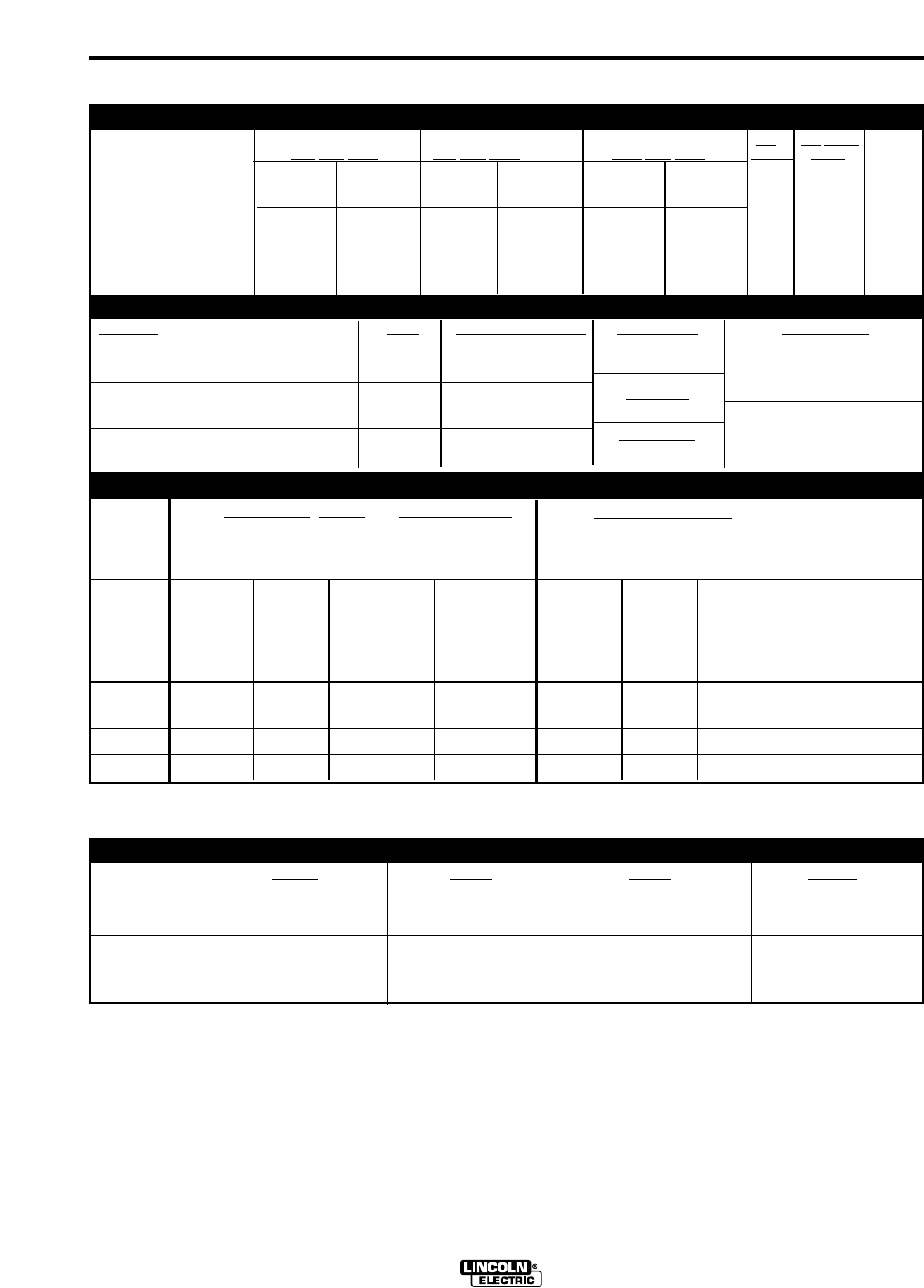
TECHNICAL SPECIFICATIONS - Square Wave TIG 275 (K1617-1, and -2)
For AC/DC Stick, DC TIG and Balanced ACTIG
Welding at 275A 40% Duty Cycle
w/o Optional K1620-1 Power Factor Capacitors
Based on the 1996 U.S. National Electrical Code
For Unbalanced ACTIG Welding above 180A,
255A 40% Duty Cycle, Maximum Penetration
w/o Optional K1620-1 Power Factor Capacitors
Based on the 1996 U.S. National Electrical Code
INPUT - SINGLE PHASE ONLY
RECOMMENDED INPUT WIRE AND FUSE SIZES
Input
Voltage /
phase/
Frequency
208/1/60
230/1/60
460/1/60
575/1/60
Input
Amperes
111
100
50
40
Type 75°C
Copper Ground
Wire in
Conduit AWG
(IEC) Sizes
6 (13.3 mm2)
6 (13.3 mm2)
10 (5.3 mm2)
10 (5.3 mm2)
Fuse
(Super Lag)
or Breaker
Size(1)
125
125
60
50
Type 75°C
Copper Wire in
Conduit AWG
(IEC) Sizes
40°C (104°F) Ambient
4 (21.2 mm2)
4 (21.2 mm2)
8 (8.4 mm2)
10 (5.3 mm2)
Type 75°C
Copper Ground
Wire in
Conduit AWG
(IEC) Sizes
6 (13.3 mm2)
6 (13.3 mm2)
8 (8.4 mm2)
10 (5.3 mm2)
Type 75°C
Copper Wire in
Conduit AWG
(IEC) Sizes
40°C (104°F) Ambient
3 (25.0 mm2)
3 (25.0 mm2)
8 (8.4 mm2)
8 (8.4 mm2)
Input
Amperes
130
120
61
49
Height Width Depth Weight
Power 24.06 in. 19.15 in. 28.00 in. Approx. 330 lbs.
Source 611 mm 486 mm 711 mm 150 kg.
Lift Hook add 3.57” (91 mm)
Power Source 33.40 in. 27.65 in. 40.65 in. Approx. 375 lbs.
on 848 mm 702 mm 1033 mm 170 kg.
Undercarriage
PHYSICAL DIMENSIONS
Fuse
(Super Lag)
or Breaker
Size(1)
150
150
70
60
(1) Also called “inverse time” or “thermal/magnetic” circuit breakers; circuit breakers which have a delay in tripping action that decreases as the magnitude of cur-
rent increases.
Code
Number
10523
10525
10605
Input Current at Input Current at Input Current at Idle Idle Power
40% Duty Cycle 60% Duty Cycle 100% Duty Cycle Current Power
DC STICK, DC STICK, DC STICK,
DC TIG,
UNBALANCED AC TIG
DC TIG,
UNBALANCED AC TIG
DC TIG,
UNBALANCED AC TIG
BALANCED AC TIG BALANCED AC TIG BALANCED AC TIG
95/86/43 130/120/61 76/69/34 106/97/50 57/52/26 82/75/38 5/4/2 900 WMax.
43/35 61/49 34/28 50/41 26/21 38/31 2/1.5 900 WMax.
95/86/43 130/120/61 76/69/34 106/97/50 57/52/26 82/75/38 5/4/2 900 WMax.
Standard
Voltage
208/230/460/1/60 (K1617-1)
460/575/1/60 (K1617-2)
208/230/460/1/60 (K1617-1)
RATED OUTPUT & ADDITIONAL OUTPUT CAPACITY
Duty Cycle Amps Volts at Rated Amperes Current Range Auxiliary Power
40% Duty Cycle AC/DC Stick 275 A 31.0 V 5-315 Amps 115 Volts AC, 10 Amps
NEMA Class II (40) AC/DC TIG 255 A 16.1 V Grounded NEMA-5-15R
Receptacle and
60% Duty Cycle AC/DC Stick 225 A 29.0 V MAX O.C.V.10 Amp Circuit Breaker
AC/DC TIG 200 A 15.4 V AC & DC 80V
100% Duty Cycle AC/DC Stick 175 A 27.0 V Normal O.C.V.
AC/DC TIG 150 A 14.8 V 72 V (AC) 59 V (DC)
A-2
INSTALLATION
SQUARE WAVE TIG 275
A-2
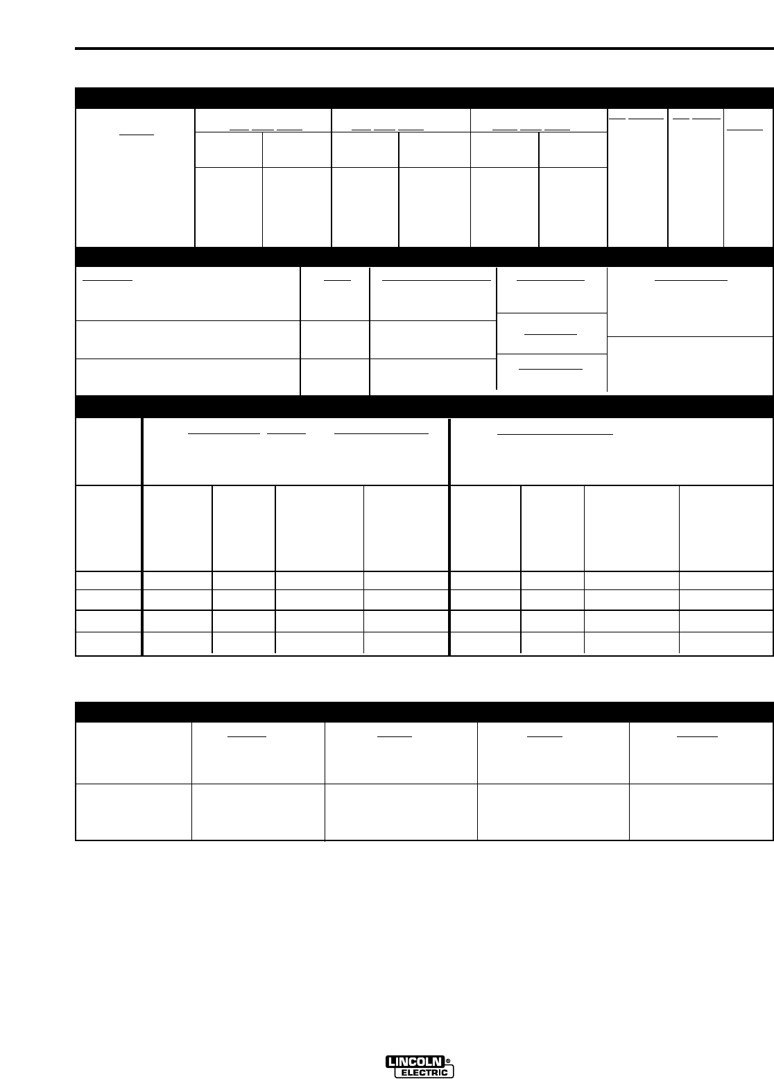
TECHNICAL SPECIFICATIONS - Square Wave TIG 275 (K1618-1)
For AC/DC Stick, DC TIG and Balanced ACTIG
Welding at 275A 40% Duty Cycle
w/o Optional K1620-1 Power Factor Capacitors
Based on the 1996 U.S. National Electrical Code
For Unbalanced ACTIG Welding above 180A,
255A 40% Duty Cycle, Maximum Penetration
w/o Optional K1620-1 Power Factor Capacitors
Based on the 1996 U.S. National Electrical Code
INPUT - SINGLE PHASE ONLY
RECOMMENDED INPUT WIRE AND FUSE SIZES
Input
Voltage /
phase/
Frequency
220/1/50/60
380/1/50/60
415/1/50/60
Input
Amperes
106
60
55
Type 75°C
Copper Ground
Wire in
Conduit AWG
(IEC) Sizes
6 (13.3 mm2)
8 (8.4 mm2)
8 (8.4 mm2)
Fuse
(Super Lag)
or Breaker
Size(1)
125
70
70
Type 75°C
Copper Wire in
Conduit AWG
(IEC) Sizes
40°C (104°F) Ambient
4 (21.2 mm2)
8 (8.4 mm2)
8 (8.4 mm2)
Type 75°C
Copper Ground
Wire in
Conduit AWG
(IEC) Sizes
6 (13.3 mm2)
8 (8.4 mm2)
8 (8.4 mm2)
Type 75°C
Copper Wire in
Conduit AWG
(IEC) Sizes
40°C (104°F) Ambient
3 (25.0 mm2)
6 (13.3 mm2)
6 (13.3 mm2)
Input
Amperes
139
79
72
Height Width Depth Weight
Power 24.06 in. 19.15 in. 28.00 in. Approx. 340 lbs.
Source 611 mm 486 mm 711 mm 154 kg.
Lift Hook add 3.57” (91 mm)
Power Source 33.40 in. 27.65 in. 40.65 in. Approx. 385 lbs.
on 848 mm 702 mm 1033 mm 175 kg.
Undercarriage
PHYSICAL DIMENSIONS
Fuse
(Super Lag)
or Breaker
Size(1)
175
90
90
(1) Also called “inverse time” or “thermal/magnetic” circuit breakers; circuit breakers which have a delay in tripping action that decreases as the magnitude of cur-
rent increases.
Code
Number
10524
Input Current at Input Current at Input Current at Idle Current Idle Power
40% Duty Cycle 60% Duty Cycle 100% Duty Cycle
DC STICK, DC STICK, DC STICK,
DC TIG,
UNBALANCED AC TIG
DC TIG,
UNBALANCED AC TIG
DC TIG,
UNBALANCED AC TIG
BALANCED AC TIG BALANCED AC TIG BALANCED AC TIG
99/57/52 139/79/72 83/45/421 12/64/59 63/36/33 86/49/45 8/6/5 900 WMax.
Standard
Voltage
220/380/415/1/50/60
RATED OUTPUT & ADDITIONAL OUTPUT CAPACITY
Duty Cycle Amps Volts at Rated Amperes Current Range Auxiliary Power
40% Duty Cycle AC/DC Stick 275 A 31.0 V 5-315 Amps 220 Volts AC, 2 Amps
NEMA Class II (40) AC/DC TIG 255 A 20.2 V Schuko Receptacle
and 2 Amp Circuit Breaker
60% Duty Cycle AC/DC Stick 225 A 29.0 V MAX O.C.V.
AC/DC TIG 200 A 18.0 V AC & DC 80V
100% Duty Cycle AC/DC Stick 175 A 27.0 V Normal O.C.V.
AC/DC TIG 150 A 16.0 V 72 V (AC) 59 V (DC)
A-3
INSTALLATION
SQUARE WAVE TIG 275
A-3
ELECTRIC SHOCK can kill.
•Only qualified personnel should
perform this installation.
•Turn the input power OFF at the
disconnect switch or fuse box
before working on this
equipment.
• Do not touch electrically hot parts.
• Always connect the Square Wave TIG 275 grounding screw
(located on the right rear corner of the base) to a good electrical
earth ground.
• Always connect the Square Wave TIG 275 to a power supply
grounded per the National Electrical Code and any local codes.
WARNING
Read entire installation section before starting
installation.
Safety Precautions
SELECT SUITABLE LOCATION
Place the welder where clean cooling air can freely cir-
culate in through the rear louvers and out through the
side louvers. Dirt, dust or any foreign material that can
be drawn into the welder should be kept at a minimum.
Failure to observe these precautions can result in
excessive operating temperatures and nuisance trips.
STACKING
Square Wave TIG 275’s cannot be stacked.
LIFTING AND MOVING
The Square Wave TIG 275 should be lifted with a hoist.
(It weighs approximately 330 lbs./150 kg.) An optional
undercarriage is available to easily move the unit. Refer
to the Accessories section of this manual. The Square
Wave TIG 275 is designed to be used with a K932-1
Undercarriage. Complete installation instructions are
included with the K932-1 Undercarriage. When the
undercarriage is properly installed, the Square Wave
TIG 275 lift bale is nonfunctional. Do not attempt to lift
the power source with the undercarriage attached.
The undercarriage is designed for hand moving only;
mechanized towing can lead to personal injury and/or
damage to the Square Wave TIG 275.
TILTING
Each machine must be placed on a secure, level
surface, either directly or on a recommended
undercarriage. The machine may topple over if this
procedure is not followed.
ENVIRONMENTAL RATING
The Square Wave TIG 275 power source carries an
IP21 environmental rating. It may be used in normal
industrial and commercial environments. It is rated for
use in damp, dirty rain-sheltered environments.
MACHINE GROUNDING AND HIGH FRE-
QUENCY INTERFERENCE PROTECTION
The frame of the welder must be grounded. A ground
screw marked with the symbol is located at the right rear
corner of the base for this purpose. See your local and nation-
al electrical codes for proper grounding methods.
The spark gap oscillator in the high frequency generator, being
similar to a radio transmitter, can be blamed for many radio, TV
and electronic equipment interference problems. These prob-
lems may be the result of radiated interference. Proper ground-
ing methods can reduce or eliminate radiated interference.
The Square Wave TIG 275 has been field tested under rec-
ommended installation conditions and has been found to com-
ply with F.C.C. allowable radiation limits. A certificate (S14929)
is being sent with each welder for customer convenience. If he
desires or is required to obtain certification of compliance with
F.C.C. RF Energy Radiation Limits, this certificate can be used.
It is the customer's responsibility to obtain this certification. This
welder has also been found to comply with NEMA standards
for high frequency stabilized power sources.
Radiated interference can develop in the following four
ways:
1. Direct interference radiated from the welder.
2. Direct interference radiated from the welding leads.
3. Direct interference radiated from feedback into the
power lines.
4. Interference from re-radiation of “pickup” by
ungrounded metallic objects.
Keeping these contributing factors in mind, installing
equipment per the following instructions should mini-
mize problems.
1. Keep the welder power supply lines as short as pos-
sible and enclose as much of them as possible in
rigid metallic conduit or equivalent shielding for a
distance of 50 feet (15.2m). There should be good
electrical contact between this conduit and the
welder case ground. Both ends of the conduit
should be connected to a driven ground and the
entire length should be continuous.
A-4
INSTALLATION
SQUARE WAVE TIG 275
A-4
2. Keep the work and electrode leads as short as pos-
sible and as close together as possible. Lengths
should not exceed 25 ft (7.6m). Tape the leads
together when practical.
3. Be sure the torch and work cable rubber coverings
are free of cuts and cracks that allow high frequen-
cy leakage. Cables with high natural rubber content,
such as Lincoln Stable-Arc® better resist high fre-
quency leakage than neoprene and other synthetic
rubber insulated cables.
4. Keep the torch in good repair and all connections
tight to reduce high frequency leakage.
5. The work piece must be connected to an earth
ground close to the work clamp, using one of the fol-
lowing methods:
a) A metal underground water pipe in direct contact
with the earth for ten feet or more.
b) A 3/4” (19mm) galvanized pipe or a 5/8” (16mm)
solid galvanized iron, steel or copper rod driven
at least eight feet into the ground.
The ground should be securely made and the ground-
ing cable should be as short as possible using cable of
the same size as the work cable, or larger. Grounding
to the building frame electrical conduit or a long pipe
system can result in re-radiation, effectively making
these members radiating antennas. (This is not recom-
mended).
6. Keep all access panels and covers securely in
place.
7. All electrical conductors within 50 ft (15.2m) of the
welder should be enclosed in grounded rigid metal-
lic conduit or equivalent shielding. Flexible helically-
wrapped metallic conduit is generally not suitable.
8. When the welder is enclosed in a metal building, the
metal building should be connected to several good
earth driven electrical grounds (as in 5 (b) above)
around the periphery of the building.
Failure to observe these recommended installation
procedures can cause radio or TV and electronic
equipment interference problems and result in unsatis-
factory welding performance resulting from lost high
frequency power.
1On European, 50/60 Hz. models, entry is through a 1.75 inch (46mm) diam-
eter hole. A reducing washer and plastic strain relief good for 18.0 to 25.4 mm
(.709 to 1.00 inch) cords is provided. For larger input conductors a customer
supplied plastic strain relief should be used.
SUPPLY CONNECTIONS
Be sure the voltage, phase, and frequency of the input
power is as specified on the rating plate, located on the
rear of the machine.
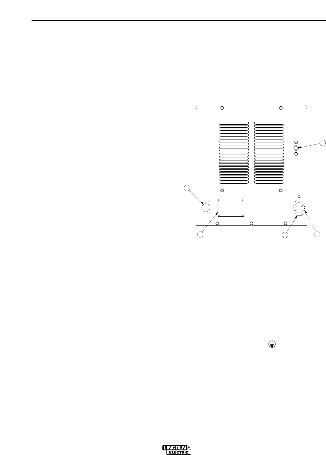
See Figure A.1 for the location of the rating plate, the
entry hole, and the reconnect panel.
FIGURE A.1
1. Input Entry 4. 220V Receptacle & Breaker
2. Rating Plate (50/60 HZ. Machines Only.)
3. 115V Receptacle & Breaker 5. Gas Input Fitting
(60 HZ. Machines only)
Remove the right case side to reveal the reconnect
panel. Welder supply line entry provision is in the case
rear panel. Entry is through a 1.4 inch (36 mm) diam-
eter hole in the case back.1
All connections should be made in accordance with all
local codes and national electrical codes. Installation
by a qualified electrician is recommended.
1. Connect the terminal marked (at the base of the
welder below the reconnect panel) to an earth ground.
2. Connect the input leads to terminals marked L1 (U)
and L2 (V) on the reconnect panel. Use a single phase
line or one phase of a two or three phase line.
1
2
5
34

A-5
INSTALLATION
SQUARE WAVE TIG 275
A-5
Fuse the input circuit with the recommended super lag
fuses or delay type1circuit breakers. Choose an input
and grounding wire size according to local or national
codes or refer to the Technical Specifications page at
the beginning of this section. Using fuses or circuit
breakers smaller than recommended may result in
"nuisance" tripping from welder inrush currents even if
not welding at high currents.
Unbalanced AC TIG welding draws higher input cur-
rents than those for Stick, DC TIG, or Balanced AC TIG
welding. The welder is designed for these higher input
currents. However, where unbalanced AC TIG welding
above 180 amps is planned, the higher input currents
require larger input wire sizes and fuses per the
Technical Specifications page at the beginning of
this section.
INPUT RECONNECT PROCEDURE
On multiple input voltage welders, be sure the recon-
nect panel is connected per the following instructions
for the voltage being supplied to the welder.
FAILURE TO FOLLOW THESE INSTRUCTIONS
CAN CAUSE IMMEDIATE FAILURE OF COMPO-
NENTS WITHIN THE WELDER.
------------------------------------------------------------------------
Welders are shipped connected for the highest input
voltage as listed on the rating plate.To change this con-
nection, refer to the following instructions:
1. Remove the right case side to reveal the reconnect
panel.
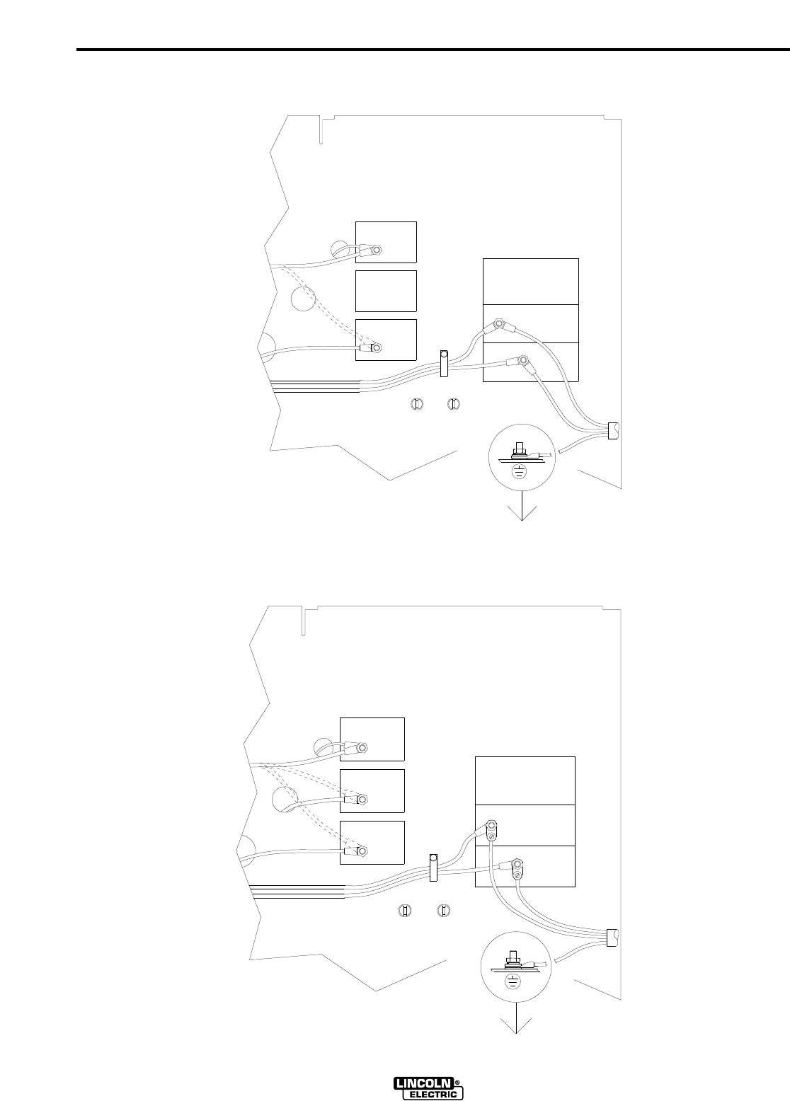
2. Reconnect the lead marked A to the terminal stud
corresponding to the input voltage used. Refer to
the figure representing the model being reconnect-
ed:
Figure A.2 208/230/460/1/60 Domestic Model
Figure A.3 460/575/1/60 Domestic/Canadian Model
Figure A.4 220/380/415/1/50/60 European Model
(Con’t)
460V
3 (MID)
4 (HIGH)
230V
power at the disconnect switch or fuse box before making any connections. Use
input and grounding lead sizes as specified in the operating manual. Failure to follow
instructions below can cause immediate failure of components within the welder.
Powered by high voltage which can kill. Turn off all input
5.
208V
2.
L1 (U)
4.
3.
2 (LOW)
1. Connect the input power leads to the input terminals, L1 (U) and L2 (V), at the right
below. Connect the input power leads with the hardware provided. Completely
tighten all fasteners.
Connect a grounding lead to the ground stud located on the machine base near
the input terminals.
Welders are shipped connected for the highest rated single phase input voltage
with the lead marked "A" connected to the stud marked "4 (HIGH)".
For middle range input, reconnect the lead marked "A" to the stud marked "3 (MID)".
For low range input, reconnect the lead marked "A" to the stud marked "2 (LOW)".
SINGLE PHASE INPUT POWER SUPPLY CONNECTION INSTRUCTIONS:
SINGLE
PHASE
INPUT
L2 (V)
POWER FACTOR CAPACITORS
LEADS FOR OPTIONAL
208/230/460 DOMESTIC MODEL
WARNING:
Figure A.2
Reconnect Panel Instructions for 208/230/460 Domestic Model
1Also called "inverse time" or "thermal/magnetic" circuit breakers; circuit
breakers which have a delay in tripping action that decreases as the magni-
tude of the current increases.
CAUTION
A-6
INSTALLATION
SQUARE WAVE TIG 275
A-6
575V
460V
WARNING:
Powered by high voltage which can kill. Turn off all input
Connect the input power leads to the input terminals, L1 (U) and L2 (V), at the right
below. Connect the input power leads with the hardware provided. Completely
tighten all fasteners.
Connect a grounding lead to the ground stud located on the machine base near
the input terminals.
Welders are shipped connected for the highest rated single phase input voltage
with the lead marked "A" connected to the stud marked "4 (HIGH)".
For middle range input, reconnect the lead marked "A" to the stud marked "3 (MID)".
For low range input, reconnect the lead marked "A" to the stud marked "2 (LOW)".
power at the disconnect switch or fuse box before making any connections. Use
input and grounding lead sizes as specified in the operating manual. Failure to follow
instructions below can cause immediate failure of components within the welder.
SINGLE PHASE INPUT POWER SUPPLY CONNECTION INSTRUCTIONS:
2.
3 (MID)
2 (LOW)
L2 (V)
L1 (U)
5.
4.
3.
LEADS FOR OPTIONAL
POWER FACTOR CAPACITORS
4 (HIGH)
INPUT
PHASE
SINGLE
1.
460/575 CANADIAN MODEL
Figure A.3
Reconnect Panel Instructions for 460/575 Canadian Model
415V
380V
220V
1. Connect the input power leads to the input terminals, L1 (U) and L2 (V), at the right
below. Connect the input power leads with the hardware provided. Completely
tighten all fasteners.
Connect a grounding lead to the ground stud located on the machine base near
the input terminals.
Welders are shipped connected for the highest rated single phase input voltage
with the lead marked "A" connected to the stud marked "4 (HIGH)".
For middle range input, reconnect the lead marked "A" to the stud marked "3 (MID)".
For low range input, reconnect the lead marked "A" to the stud marked "2 (LOW)".
Powered by high voltage which can kill. Turn off all input
power at the disconnect switch or fuse box before making any connections. Use
input and grounding lead sizes as specified in the operating manual. Failure to follow
instructions below can cause immediate failure of components within the welder.
WARNING:
SINGLE PHASE INPUT POWER SUPPLY CONNECTION INSTRUCTIONS:
5.
4.
3.
2.
LEADS FOR OPTIONAL
L2 (V)
L1 (U)
2 (LOW)
3 (MID)
4 (HIGH)
SINGLE
PHASE
INPUT
POWER FACTOR CAPACITORS
220/380/415 EUROPEAN MODEL
Figure A.4
Reconnect Panel Instructions for 220/380/415 European Model
A-7
INSTALLATION
SQUARE WAVE TIG 275
A-7
Designations on the reconnect panel LOW, MID, and
HIGH correspond to the nameplated input voltages of
a triple voltage welder. Dual voltage welders use only
LOW and HIGH.
EXAMPLE: On a 208/230/460 volt welder, LOW is
208V, MID is 230V, and HIGH is 460V.
3. Make sure all connections are tight. Replace the
case side and all screws.
OUTPUT CONNECTIONS
To avoid being startled by a high frequency shock,
keep the TIG torch and cables in good condition.
------------------------------------------------------------------------
ELECTRIC SHOCK can kill.
•Turn the power switch of the power
source “OFF” before installing adapters
on cable or when connecting or discon-
necting adapter plugs to power source.
----------------------------------------------------------------------------
See Figure B.1 for the location of the work and elec-
trode terminals, the gas and optional water solenoids,
and the Remote Receptacle.The Square Wave TIG
275 is equipped with Twist-Mate connectors for the
electrode and work connection.
WORK CABLE CONNECTION
The Twist-Mate connection allows fast and reliable
work cable attachment to the work terminal of the
Square Wave TIG 275 welding power supply.
Assemble the work cable by attaching the correct
Twist-Mate adapter and work clamp to an adequately-
sized welding cable. The Twist-Mate cable plug includ-
ed with the machine is designed to accept a welding
cable size of of #2 to #1. See Table A.1 and A.2 for rec-
ommended sizes and corresponding hardware.
Assemble the correct Twist-Mate-adapter plug to the
work cable as follows:
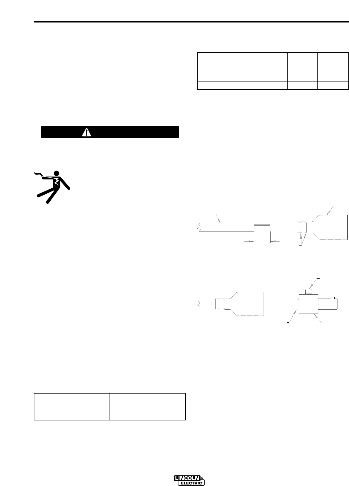
1. Skin the cable jacket to 1.00 in (25.4 mm) for a #2
thru 2/0 (35 thru 70 mm2) cable. Skin the cable
jacket to 1.50 in (38.1 mm) for a 2/0 thru 3/0 (70 thru
95 mm2) cable.
2. If necessary, trim the cable end of the rubber boot
to match the diameter of the cable.
3. Slide the rubber boot onto the skinned cable end.
Use soap for lubricant if required.
4. Slide the copper tube into the brass plug. Insert
skinned cable into the copper tube.
5. Tighten set screw(s) to collapse copper tube.
Screw(s) must apply firm pressure against welding
cable.
6. Slide the rubber boot over the brass plug. The rub-
ber boot must be positioned to completely cover all
electrical surfaces after the plug is locked into the
receptacle. For more details see S18737PRINT or
instructions included with the adapter kit.
WARNING
TABLE A.1
Cable Sizes for Combined Lengths of Copper
Electrode and Work Cable
Machine Size
Lengths up to
100 ft 100 to 200 ft 200 to 250 ft
275 Amp
40% Duty Cycle #1 (42.4mm2) 1/0 (53.5mm2) 2/0 (67.4mm2)
TABLE A.2
Recommended Work and Stick Electrode
Components
Twist Mate
Cable Plug
for Work
Lead
(#2 to #1)
Twist Mate
Cable Plug
for Work
Lead
(1/0 to 2/0)
Twist Mate
Cable Plug
for Work
Lead
(2/0 to 3/0)
Work
Clamp
Electrode
Holder
K852-50 K852-70 K852-95 K910-1 K909-4
SEE
WELDING CABLE
TRIM
ABOVE
BOOT
COPPER TUBE
SET SCREW
(70-95 SIZE MAY
HAVE 2 SET
BRASS PLUG
SCREWS)

A-8
INSTALLATION
SQUARE WAVE TIG 275
A-8
TIG TORCH CONNECTION
The Twist-Mate connection allows fast and reliable TIG
torch attachment to the electrode terminal of the
Square Wave TIG 275 welding power supply. Twist-
Mate TIG adapters are made of brass, combining high
electrical conductivity with mechanical strength. They
are available in several sizes and styles to accommo-
date a wide selection of gas and water-cooled TIG
torches.
• Air-Cooled TIG Torch connections refer to TWIST-
MATE ADAPTER for LA-9 and LA-17 TIG TORCH
Section.
• Water-Cooled TIG Torch connections refer to TWIST-
MATE ADAPTER for LW-18 and LW-20 TIG TORCH
Section.
Any torch having hoses and cables equipped with
Compressed Gas Association (CGA) style fittings can
be connected to an appropriate Twist-Mate adapter
(see ACCESSORIES section).
The power source must
be switched off while making any of these connections.
Do not operate a water-cooled torch without an ade-
quate coolant supply. Set-ups using recirculated
coolant require that the cooler be switched on and run-
ning. If the water solenoid valve option is used with a
cooler, the coolant does not flow until the solenoid is
actuated.
For set-ups using water as a single-pass through
coolant, install a strainer into the system upstream of
the Square Wave TIG 275 to reduce the concentration
of particles that could contaminate the system.
Otherwise, flow passages could become obstructed or
clogged, causing torch overheating or failure. The
optional water solenoid valve may also malfunction.
When the water solenoid valve option is installed into
the Square Wave TIG 275, connect the coolant supply
line from either cooler outlet or single-pass supply to
the “Water Inlet” fitting located on the machine’s case
front. Connect the TIG torch’s smaller water fitting to
the “Water Out” fitting also located on the case front. A
non-metallic coolant line is required between the elec-
trode connection and the drain or cooler inlet. This
reduces the possibility of an electrical hazard.
TIG welding torches are available with 12.5 and 25 foot
(3.8 and 7.6 m, respectively) long cables. Use the
shorter length whenever possible to reduce radio inter-
ference problems.
The high-pressure cylinder of inert shielding gas must
be equipped with a flow regulator that limits the gas
pressure to 150 psi maximum at the machine’s gas
inlet. This brass inlet fitting is located on the rear panel
of the Square Wave TIG 275. Install a hose between
the gas flow meter and the inlet fitting.
For other conditions, consult the manufacturer’s
instructions for the water cooler or TIG torch being
used.
CYLINDER could explode
if damaged.
•Keep cylinder upright and chained
to a support.
•Keep cylinder away from areas where it could be
damaged.
•Never allow the torch to touch the cylinder.
•Keep cylinder away from live electrical circuits.
•Maximum inlet pressure 150 psi.
___________________________________________
WARNING
A-9
INSTALLATION
SQUARE WAVE TIG 275
A-9
TWIST-MATE ADAPTER FOR LA-9
and LA-17 TIG TORCH
The Twist-Mate connection allows fast and reliable TIG
torch connections to the electrode terminal of the
Square Wave TIG 275. The Twist-Mate adapter, strain
relief boot and retaining compound needed to connect
an LA-9 or LA-17 torch (or any equivalent air-cooled
TIG torch with a right-hand male 3/8-24 fitting) are
included with the Square Wave TIG 275.
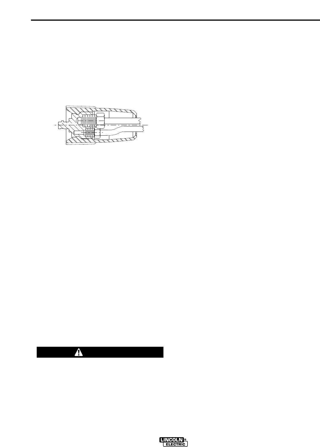
Assemble the the LA-9 or LA-17 TIG torch to the Twist-
Mate adapter as follows:
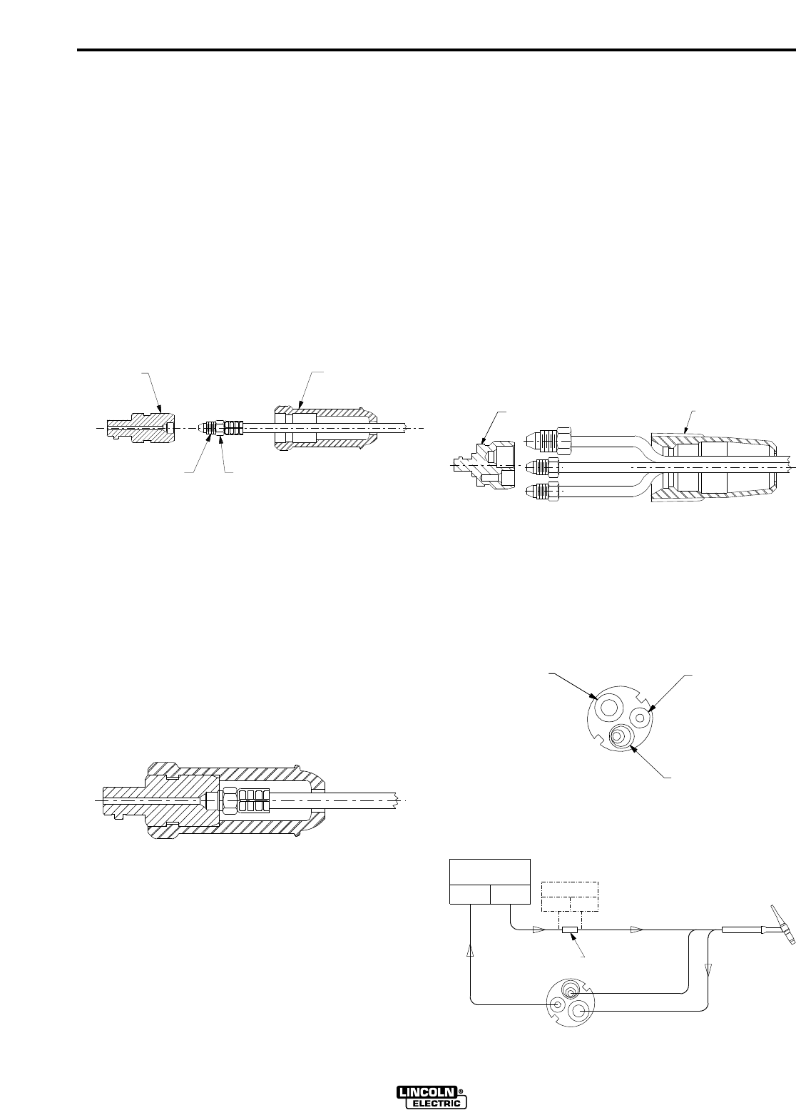
1. Slide the strain relief boot over the TIG torch’s
power cable with gas fitting.
2. Apply a small amount of retaining compound to the
fitting threads as shown. Thread the fitting to the
TIG adapter and tighten to ensure a sealed gas
connection and a good electrical connection. (35-45
in-lbs)
3. Hold the TIG adapter, with cable installed, firmly in
place by securing it into the Twist- Mate receptacle
on the power source or into a padded vise. Align
the hex in the boot with the hex on the adapter.
Firmly push the boot onto the adapter, rocking the
boot to assist installation. Use soap for lubricant if
required.
4. Examine the strain relief boot and TIG adapter for
correct assembly. The boot should nest into the
Twist-Mate receptacle on the power source. All
electrical surfaces should be completely covered
when in the Twist-Mate receptacle on the power
source. For more details see M19115PRINT includ-
ed with the machine.
TWIST-MATE ADAPTER FOR LW-18
and LW-20 TIG TORCH
The Twist-Mate connection allows fast and reliable TIG
torch connections to the electrode terminal of the
Square Wave TIG 275. The Twist-Mate adapter and
strain relief boot needed to connect an LW-18 or LW-20
torch (or any equivalent water-cooled TIG torch with
the fittings shown in the diagrams under step 2 and 3.)
are included with the Square Wave TIG 275.
Assemble the the LW-18 or LW-20 TIG torch to the
Twist-Mate adapter as follows:
1. Slide the strain relief boot over the TIG torch’s
power/water cable (large fitting) and gas hose
(small fitting without notches on hex). Also slide a
water hose into the strain relief boot as shown.
2. Thread the power/water cable (large fitting) from the
torch to the large port on the TIG adapter and tigten
to ensure a water tight connection. Next, thread the
gas hose (small fitting without notches on hex) to
the port marked “G” on the TIG adapter and tighten
to ensure a sealed gas connection. Next, thread the
water hose to cooler (or to water drain) to the port
marked “W” on the TIG adapter.
3. Check all connections made in step 2 for gas and
water leaks before proceding.
T
IG ADAPTER
TIG TORCH POWER CABLE WITH GAS FITING
RETAINING COMPOUND
STRAIN RELIEF BOOT
STRAIN RELIEF BOOT
TIG ADAPTER
WATER HOSE
GAS HOSE FROM TORCH
POWER/WATER CABLE FROM TORCH
G
W
PORT (RH 5/8-18)
PORT (LH 5/8-18)
GAS CONNECTION
CONNECTION
POWER/WATER
PORT (LH 7/8-14)
WATER CONNECTION
COMPLETED ASSEMBLY
W
G
"IN"
OR
COOLANT
OPTIONAL
WATER HOSE
"OUT"
COOLANT
FLOW
WATER SOLENOID KIT
WATER
(RH 5/8-18 MALE FITTING)
WATER HOSE FROM TORCH
GAS HOSE FROM TORCH
(SEPARATELY PROVIDED)
(SEPARATELY PROVIDED)
HOSE COUPLER
COOLANT
LW-18 OR LW-20
TIG TORCH
(SEPARATELY PROVIDED)
(LH 5/8-18 MALE FITTING)
"OUT"
"IN" COOLANT
MAGNUM
CONNECTION DIAGRAM
POWER/WATER CABLE FROM TORCH
(LH 7/8-14 MALE FITTING)
WATER HOSE
(SEPARATELY PROVIDED)
WATER COOLER
A-10
INSTALLATION
SQUARE WAVE TIG 275
A-10
4. Hold the TIG adapter, with cables and hoses
installed, firmly in place by securing it into the Twist-
Mate receptacle on the power source or into a
padded vise. Apply a thin film of lubricant to the
boot’s lead in chamfer area. Also apply lubricant to
the lead in chamfer and 2" diameter on the TIG
adapter. Next align the strain relief boot keys with
the TIG adapter slots. Now firmly push the boot
onto the adapter, rocking the boot to assist installa-
tion.
5. Examine the strain relief boot and TIG adapter for
correct assembly. The boot should nest into the
Twist-Mate receptacle on the power source. The
boot face will be 1/8 inch away from the machine
front. All electrical surfaces should be completely
covered when in the Twist-Mate receptacle on the
power source. For more details see M19116PRINT
included with the machine.
STICK ELECTRODE CABLE CONNECTION
The Twist-Mate connection allows fast and reliable
stick electrode attachment to the electrode terminal of
the Square Wave TIG 275 welding power supply.
Assemble the stick electrode cable by attaching the
correct Twist-Mate adapter and electrode holder to an
adequately-sized welding cable. The Twist-Mate cable
plug is NOT provided with the machine for the stick
electrode connection. See Table A.1 and A.2 for rec-
ommended sizes and corresponding hardware.
Assemble the correct Twist-Mate adapter plug to the
stick electrode cable as detailed in “Work Cable
Connection”.
DO NOT CONNECT A TIG TORCH AND STICK
ELECTRODE CABLE AT THE SAME TIME. THEY
WILL BOTH BE ELECTRICALLY HOT WHENEVER
THE OUTPUT CONTACTOR IS ENERGIZED.
------------------------------------------------------------------------
INSTALLATION OF FIELD INSTALLED
OPTIONS
Installation instructions are included with the following
accessories:
K559-2 Magnum Cooler Mounting Bracket
K932-1 Undercarriage When the undercarriage is
properly installed, the Square Wave TIG 275 lift bale is
nonfunctional. Do not attempt to lift the power source
with the undercarriage attached. The undercarriage is
designed for hand moving only; mechanized towing
can lead to personal injury and/or damage to the
Square Wave TIG 275.
K1619-1 TIG Pulser Kit
K1620-1 Power Factor Capacitor Kit
K1621-1 Water Solenoid Kit
K1622-1 Twist Mate Adapter Kit for LA9 & LA17
Torches (Included with Machine)
K1622-2 Twist Mate Adapter Kit for LW18 & LW20
Torches (Included with Machine)
K1622-3 Twist Mate Adapter Kit for LA26 Torch
K852-50 Twist Mate Cable Plug for #2 to #1 Work Lead
(Included with Machine)
K852-70 Twist Mate Cable Plug for 1/0 to 2/0 Work
Lead
K852-95 Twist Mate Cable Plug for 2/0 to 3/0 Work
Lead
Installation of the K963-1 or K963-2 Hand Amptrol, the
K814 Arc Start Switch and the K870 Foot Amptrol are
as follows:
Connect the 6-pin MS-type (Amphenol) connector to
the Remote Receptacle (See Figure 3). Secure with
the threaded collar.
COMPLETED ASSEMBLY
WARNING
B-1
OPERATION
B-1
SQUARE WAVE TIG 275
ELECTRIC SHOCK
can kill.
• Do not touch electrically live parts or
electrode with skin or wet clothing.
•
Insulate yourself from work and ground.
• Always wear dry insulating gloves.
•
Read and follow “Electric Shock Warnings”
in the Safety section if welding must be per-
formed under electrically hazardous condi-
tions such as welding in wet areas or on or
in the workpiece.
FUMES AND GASES
can be dangerous.
• Keep your head out of fumes.
• Use ventilation or exhaust to
remove fumes from breathing
zone.
WELDING SPARKS
can cause fire or
explosion
• Keep flammable material away.
• Do not weld on containers that
have held combustibles.
ARC RAYS
can burn.
• Wear eye, ear and body
protection.
SAFETY PRECAUTIONS
Read and understand this entire section before operat-
ing the machine.
Observe additional Safety Guidelines detailed in
the beginning of this manual.
WARNING
B-2
OPERATION
B-2
SQUARE WAVE TIG 275
2
A
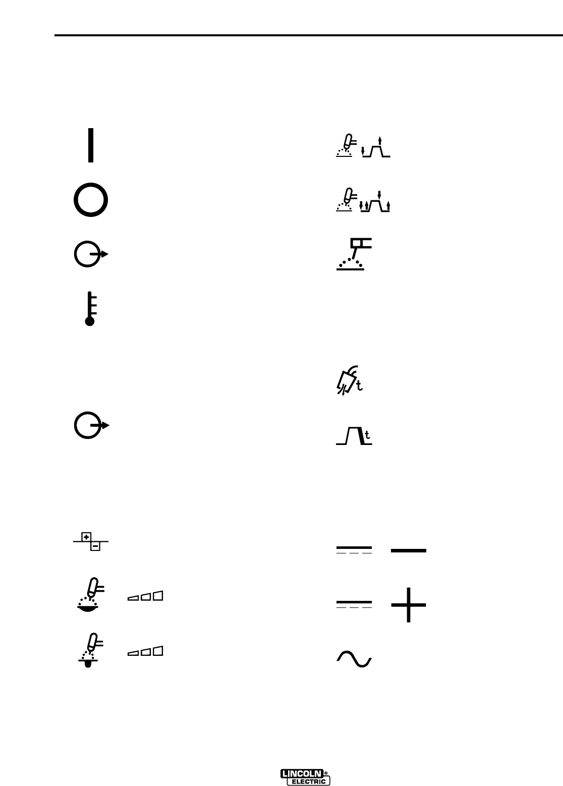
GRAPHIC SYMBOLS THAT APPEAR ON
THIS MACHINE OR IN THIS MANUAL
&
&
POWER SWITCH
SYMBOL MEANING
ON
OUTPUT CONTROL
SYMBOL MEANING
CURRENT CONTROL
(OUTPUT)
OFF
INPUT POWER
OVER
TEMPERATURE
AC WAVE BALANCE CONTROL
SYMBOL MEANING
AC WAVE BALANCE
CLEAN (INCREASING
POSITIVE POLARITY)
PENETRATE (INCREASING
NEGATIVE POLARITY)
MODE SWITCH
SYMBOL MEANING
TIG 2-STEP
TIG 4-STEP
STICK
POLARITY SWITCH
SYMBOL MEANING
DC- POLARITY
DC+ POLARITY
AC POLARITY
POST FLOW CONTROL AND
DOWN SLOPE TIME CONTROL
SYMBOL MEANING
POST FLOW TIME
DOWN SLOPE TIME
&
&
B-3
OPERATION
B-3
SQUARE WAVE TIG 275
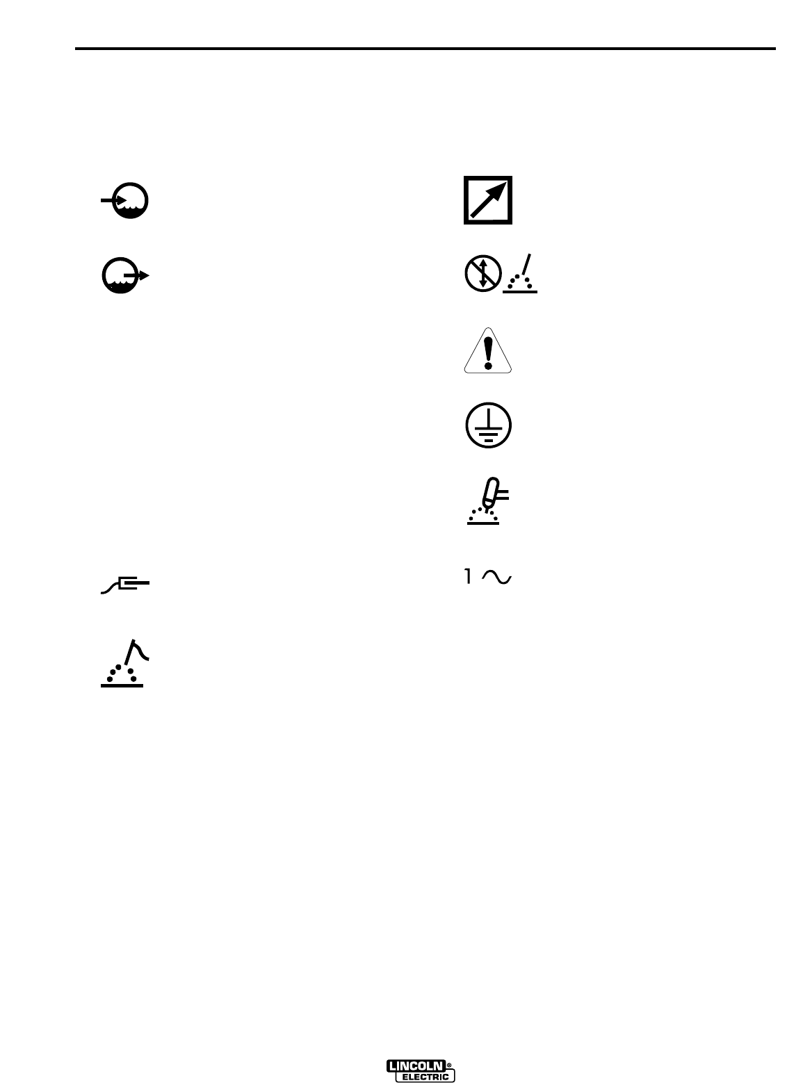
GRAPHIC SYMBOLS THAT APPEAR ON
THIS MACHINE OR IN THIS MANUAL
OPTIONAL WATER SOLENOID CONNECTIONS
SYMBOL MEANING
WATER (COOLANT)
INPUT
OUTPUT CONNECTIONS
SYMBOL MEANING
WORK
CONNECTION
ELECTRODE
CONNECTION
WATER (COOLANT)
OUTPUT
ADDITIONAL SYMBOLS
SYMBOL MEANING
REMOTE CONTROL
DO NOT SWITCH
WHILE WELDING
WARNING
PROTECTIVE
GROUND
TIG (GTAW)
SINGLE PHASE
SINGLE PHASE
TRANSFORMER
AC & DC RECTIFIER
POWER SOURCE

B-4
OPERATION
B-4
GENERAL DESCRIPTION
The Square Wave TIG 275 is a constant current, single
range square wave AC/DC TIG (GTAW) arc welding
power source with built-in high frequency stabilization.
It also has stick (SMAW) capability. A TIG Pulser Kit,
Power Factor Capacitor Kit, and a Water Solenoid Kit
are available as field installed options.
The Square Wave TIG 275 includes advanced features
such as Presettable Digital Meters, Auto Balance™, 2-
Step/4-Step operation, adjustable Down slope Time
control and Fan as Needed. It also features Twist Mate
connections for the electrode and work leads. In addi-
tion, fixed preflow and variable post flow timers are
included to control the shielding gas, as well as the
water flow when using the optional water solenoid.
RECOMMENDED PROCESSES AND
EQUIPMENT
The Square Wave TIG 275 is recommended for the TIG
(GTAW) and stick (SMAW) welding processes within its
output capacity of 5 to 315 amps, on both AC and DC
polarity. It is compatible with all Magnum TIG acces-
sories, as well as many industry standard items, such
as TIG torches, hoses, and water coolers.
DESIGN FEATURES AND ADVANTAGES
• Meets NEMA CLASS II (40) and IP21 environmental
certification. CSA NRTL/C certified (Domestic and
Canadian Models Only).
• Meets IEC-974-1 and IP21 environmental certifica-
tion. CE certified (European Model Only).
• Built in Digital Ammeter and Voltmeter for precise
process control. When not welding, the digital amme-
ter displays the peak current set with the output con-
trol knob. This allows the user to easily preset the
peak current within the full output range of the
machine. This includes a persistence feature which
captures and continues to display the peak welding
current and it’s corresponding voltage for five sec-
onds after the weld is completed.
• AC Wave Balance control knob provides flexibility to
the customer. Set it to the Auto Balance position and
the circuitry automatically provides the proper
amount of cleaning and penetration for normal AC
TIG welding. For special applications simply dial in
the amount of cleaning and penetration needed.
• Fan As Needed (FAN) circuit turns ‘ON’ the fan only
when cooling is needed. FAN minimizes the amount
of dust, dirt, and other foreign material drawn into the
machine. A build up of these materials can cause
excessive operating temperatures and nuisance shut
downs.
• 2-STEP/4-STEP TIG/STICK mode control switch. 4-
STEP mode requires the use of an optional Arc Start
Switch. This welding mode reduces fatigue by elimi-
nating the need to manually control the weld current
during the weld.
• Down Slope Time control is active in 4-STEP TIG
mode. It controls the amount of time (approximately
1 to 10 seconds) it takes the weld current to ramp
down from the Preset level to 25% ±10% of that level.
• Post Flow Time control is active in the 2 and 4-STEP
TIG modes. It controls the amount of time (approxi-
mately 5 to 50 seconds) the shielding gas flows after
the weld is completed.
• Robotic Interface connection on the PC board can be
connected to the machines Remote Receptacle for
automated welding procedures. This interface allows
remote control of the trigger and output current of the
machine as well as providing a signal when the weld
is established. (For details contact the Lincoln Automation Center)
• Built in High Frequency Generator automatically per-
forms in the correct mode. If the machine is in STICK
mode, the HF stays ‘OFF’. IF the machine is in DC
TIG mode, the HF comes ‘ON’ and stays on until the
arc is established. IF the machine is in AC TIG mode,
the HF comes ‘ON’ and stays on continuously to sta-
bilize the arc.
• Automatic Local/Remote current selection. The
machine automatically senses if an Amptrol, Arc Start
Switch or TIG Pulser is plugged in and transfers cur-
rent control from local to remote.
• Built in preflow time of 0.5 seconds. Preflow time is
eliminated if welding restarts during the pervious
weld’s post flow. This avoids unnecessary delays
when making repeated welds.
• Simple dial and switch design provides the customer
with flexible control of the welding process without
unnecessary complication. Controls which are not
needed in the weld mode selected are automatically
locked out.
• Twist Mate connectors are provided for the electrode
and work connections. This style connector makes
the gas and current connections for the TIG torch at
the same time. (Adapter plugs are provided)
SQUARE WAVE TIG 275

B-5
OPERATION
B-5
• DC+/AC/DC- Polarity Switch allows the welder to
change polarity without reconnecting leads.
• Provides excellent arc starting and stability through-
out the machines wide current range (5 to 315 Amps)
to handle the vast majority of TIG welding applica-
tions.
• Simple output current dial allows the user to preset
the peak current within the full output range of the
machine.
• Highly resistant to AC arc rectification.
• Thermostatically protected to prevent equipment
damage.
• No tungsten spitting within current range of electrode.
• Designed to make maintenance and servicing easy.
• 115 Volt Receptacle with 10 Amp Circuit Breaker.
Domestic and Canadian Models Only.
• 220 Volt European (Schuko) type Receptacle with 2
Amp Circuit Breaker. European Model Only.
• Low Voltage Trigger Circuit (18 VAC) for maximum
operator safety.
• Remote Receptacle for Amptrol or Arc Start Switch
connection.
• Gas Valve Inlet fitting conforms to Compressed Gas
Association (CGA) standards.
LIMITATIONS
The Square Wave TIG 275 is not recommended for AC
TIG welding when high concentrations of helium gas
are used for shielding. This causes starting and arc
rectification problems. Also the Square Wave 275 is
not recommended for arc gouging due to it's limited
output capacity. The Square Wave TIG 275 is also not
recommended for pipe thawing.
DUTY CYCLE AND TIME PERIOD
The duty cycle is based upon a 10 minute time period;
i.e., for 40% duty cycle, it is 4 minutes welding and 6
minutes idling. If the duty cycle(s) are significantly
exceeded, the thermostatic protection will shut off the
output until the machine cools to a normal operating
temperature. (Refer to Technical Specifications
page)
SQUARE WAVE TIG 275
B-6
OPERATION
B-6
1. Current Control - This knob is used to set
the welding current from 5 to 315 amps. Read the
complete Operating Instructions section for more
information on Local and Remote setting of current.
2. AC Wave Balance Control - This knob is
active in the AC TIG mode only. It is used to set the
amount of cleaning and/or penetration produced
during an AC TIG weld. Auto Balance™ automati-
cally sets the AC Wave balance according to the
welding current. If manual adjustment is desired,
the balance can be adjusted from +0 (maximum
cleaning) to +10 (maximum penetration).
Read the Advanced Features section for a com-
plete explanation of the AC Wave Balance.
3. Post Flow Time Control - This knob is active
in the TIG mode only. It adjusts the post flow time
from 5 to 50 seconds for shielding gas. It also
adjusts cooling water flow when the optional
K1621-1 Water Solenoid Kit is used.
4. Down Slope Time Control - This knob is
active in 4-Step TIG mode only. It adjusts the time
(from 0.5 to 10 seconds) the welding output takes to
ramp down from the preset level to 25% ±10% of
that level.
5. Mode Switch - A three position toggle switch used
to select the welding mode. Refer to the WELDING
OPERATION section for more information on how
the machine functions in each of the following
modes:
Stick: This mode is used for the stick electrode
(SMAW) welding process. In this position the only
active control is the output current control. The output
terminals are continuously energized.
2-Step TIG: This mode is used for the TIG (GTAW)
welding process. An Arc Start switch must be used to
weld. The Down Slope Time has no effect in this mode.
4-Step TIG: This mode is used for the TIG (GTAW)
welding process. An Arc Start switch must be used to
weld. All controls are active in this mode.
SQUARE WAVE TIG 275
CONTROLS AND SETTINGS
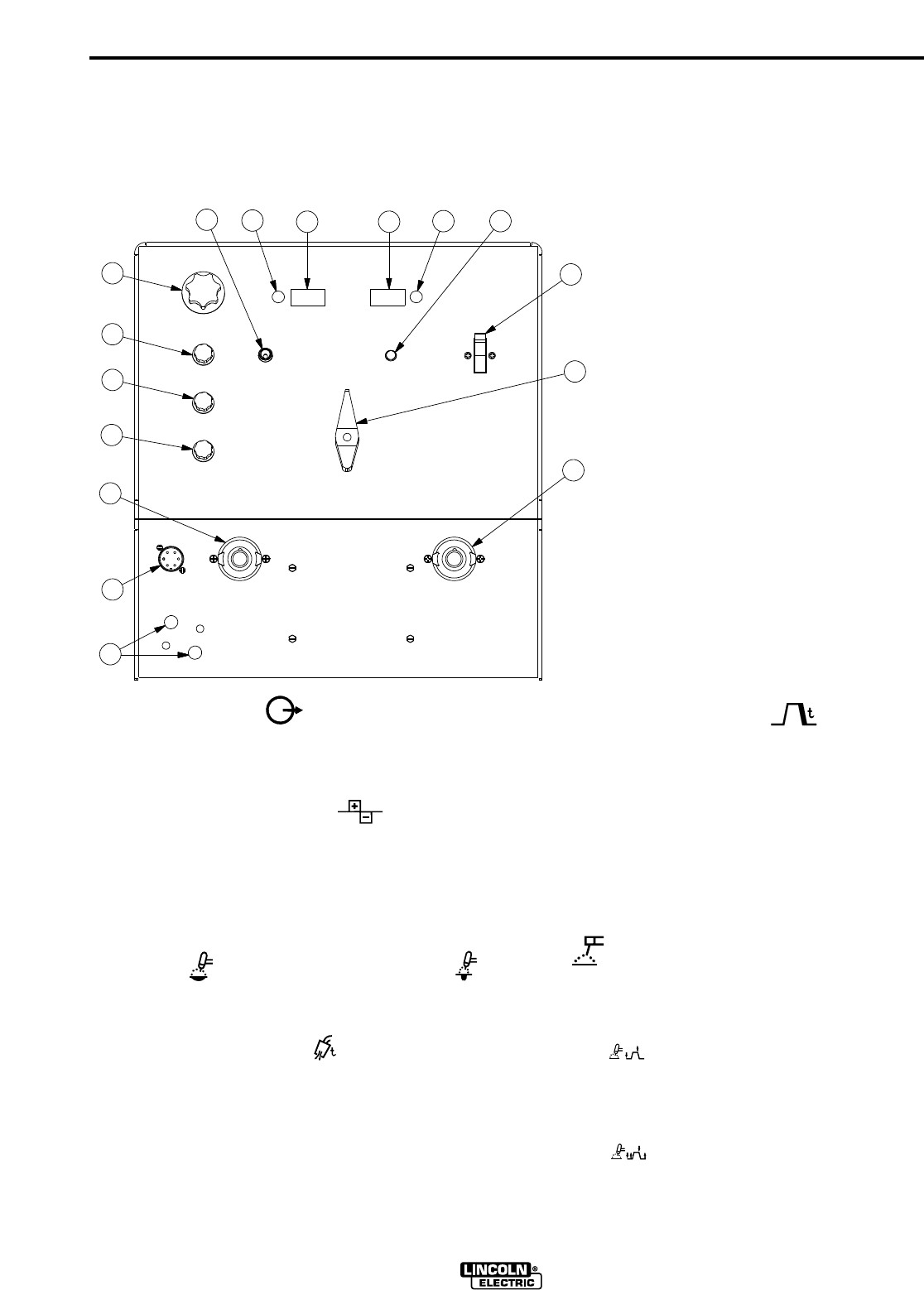
All operator controls and adjustments are located on the case front of the Square Wave TIG 275. Refer to Figure
B.1 and corresponding explanations following.
FIGURE B.1 - CONTROL PANEL
10
6
578
69
11
12
13
14
15
1
2
3
4
1. Output Control Knob
2. AC Wave Balance Knob
3. Post Flow Knob
4. Down Slope Time Knob
5. Mode Switch
6. Trimmer Potentiometer
7. Digital Ammeter
8. Digital Voltmeter
9. Thermal Protection Light
10. Power Switch
11. Polarity Switch
12. Electrode Connection (Twist-Mate Connector)
13. Work Connection (Twist-Mate Connector)
14. Remote Control Amphenol
15. Water Solenoid (Optional)
A
2

B-7
OPERATION
B-7
6. Trimmer Potentiometers - Allows the meters to
be calibrated in the field.
7. Digital Ammeter - The ammeter displays actual
welding current during a weld cycle and displays
the peak current for approximately 5 seconds after
welding is complete. Otherwise the machine’s set
current is displayed. Read the complete Operating
Instructions section for more information on the
Ammeter.
8. Digital Voltmeter - This meter displays welding
voltage, as measured on the output studs of the
Square Wave TIG 275. After welding is complete,
the meter displays the welding voltage correspond-
ing to the peak welding current and displays this
value for approximately 5 seconds
9. Thermal Protection Light - A yellow light which
only lights when an over temperature situation
occurs. See the Maintenance Section for more
information on thermostatic protection.
10. Power Switch - Turns power “ON” or
“OFF” to the welder. When switched “ON” the
digital meters will illuminate, indicating that the
power is on.
11. Polarity Switch - Selects DC+, + AC
or DC- - welding polarity without reconnecting
leads. DO NOT SWITCH WHILE WELDING.
12. Twist Mate Electrode and
13. Work Connections - Easy to connect elec-
trode and work connections. This style Electrode
Connection makes the gas and current connec-
tions for the TIG torch at the same time. (Adapter
plugs are provided with the machine.)
14. Remote Receptacle - For Amptrol, Arc Start
Switch or Robotic Interface connection.
15. Optional Water Solenoid Connections -
Easy to install this optional feature which allows
for water flow control for water cooled torches.
WELDING OPERATION
TIG WELDING
Familiarize yourself with the Controls and Settings
Section before attempting operation of the Square
Wave TIG 275.
TIG WELDING GUIDELINES
TIG welding can be done in either the TIG 2-Step
or the TIG 4-Step Weld Mode. TIG 2-Step is typ-
ically used with Hand or Foot Amptrols, with Remote
Current control. TIG 4-Step typically uses an Arc Start
switch and Local Current Control, because it provides
a very brief current upslope, and a .5 to 10 second
adjustable current downslope. TIG 4-Step also func-
tions like a trigger interlock, making it unnecessary to
hold down the Arc Start switch during a weld. If remote
current control is desired in this mode, a device which
provides separate arc start and current control must be
used. Read the TIG Welding Sequence of Operation
sections for more details on 2-Step and 4-Step opera-
tion.
Recommended tungsten electrode sizes, stickouts,
currents, cup or nozzle sizes are shown in Table B.1.
SINCE WELDING APPLICATIONS CAN VARY, THIS
CHART IS INTENDED AS A GUIDE ONLY.
SQUARE WAVE TIG 275
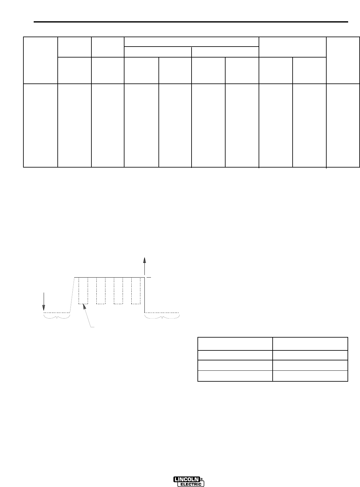
B-8
OPERATION
B-8
SQUARE WAVE TIG 275
(1) When used with argon gas. The current ranges shown must be reduced when using argon/helium or
pure helium shielding gasses.
(2) Tungsten electrodes are classified as follows by the American Welding Society (AWS):
Pure ...............EWP
1% Thoriated . .......EWTh-1
2% Thoriated . .......EWTh-2
Though not yet recognized by the AWS, Ceriated Tungsten is now widely accepted as a substitute for
2% Thoriated Tungsten in AC and DC applications.
(3) DCEP is not commonly used in these sizes.
(4) TIG torch nozzle “sizes” are in multiples of 1/16ths of an inch:
#4 = 1/4 in. (6 mm)
#5 = 5/16 in. (8 mm)
#6 = 3/8 in. (10 mm)
#7 = 7/16 in. (11 mm)
#8 = 1/2 in. (12.5 mm)
#10 = 5/8 in. (16 mm)
(5)
TIG torch nozzles are typically made from alumina ceramic. Special applications may require lava nozzles,
which are less prone to breakage, but cannot withstand high temperatures and high duty cycles.
TABLE B.1 TYPICAL CURRENT RANGES FOR TUNGSTEN ELECTRODES (2)
.010 (.25)
0.020 (.50)
0.040 (1.0)
1/16 (1.6)
3/32 (2.4)
1/8 (3.2)
5/32 (4.0)
3/16 (4.8)
1/4 (6.4)
2-15
5-20
15-80
70-150
150-250
250-400
400-500
500-750
750-1000
(3)
(3)
(3)
10-20
15-30
25-40
40-55
55-80
80-125
2-15
5-15
10-60
50-100
100-160
150-210
200-275
250-350
325-450
2-15
5-20
15-80
70-150
140-235
225-325
300-400
400-500
500-630
2-15
10-20
20-30
30-80
60-130
100-180
100-240
190-300
250-400
---
5-20
20-60
60-120
100-180
160-250
200-320
290-390
340-525
3-8 (2-4)
5-10 (3-5)
5-10 (3-5)
5-10 (3-5)
13-17 (6-8)
15-23 (7-11)
21-25 (10-12)
23-27 (11-13)
28-32 (13-15)
3-8 (2-4)
5-10 (3-5)
5-10 (3-5)
9-13 (4-6)
11-15 (5-7)
11-15 (5-7)
13-17 (6-8)
18-22 (8-10)
23-27(11-13)
#4, #5, #6
#5, #6
#6, #7, #8
#8, #10
1%, 2%
Thoriated
Tungsten
1%, 2%
Thoriated
Tungsten
Pure
Tungsten
1%, 2%
Thoriated
Tungsten
Zirconiated
Pure
Tungsten
1%, 2%
Thoriated
Tungsten
Zirconiated Aluminum
Stainless
Steel
Tungsten
Electrode
Diameter
in. (mm)
TIG Torch
Nozzle
Size (4),(5)
DCEN ( -) DCEP ( +)Unbalanced Wave Balanced Wave
AC Approximate Argon
Gas Flow Rate
C.F.H. (1/min.)
TIG WELDING SEQUENCE OF OPERATION
WELDING IN TIG MODE (2-STEP)
In 2-STEP mode an Arc Start switch or Amptrol must
be used. The switch or Amptrol is pressed to start the
weld. (Step 1) Output continues until the switch or
Amptrol is released. (Step 2)
1. Connect the Twist Mate plug to the receptacle locat-
ed on the front of the machine.The connection locks
into place with a quarter turn making both the power
and gas connections. See the TIG TORCH CON-
NECTION section to install the Twist Mate plug on
your torch.
2. Connect an Arc Start Switch or an Amptrol to the
Remote Amphenol.
3. Turn the welder, gas supply and water supply (if
equipped), on. The digital ammeter/voltmeter dis-
plays will illuminate when the power is on. NOTE:
Cooling fan may not be “ON” when not welding.
(See MAINTENANCE Section)
4. Set the MODE switch to “2-STEP TIG”.
5. Set the peak current displayed on the digital amme-
ter with the output control knob.
6. Select AC or DC- electrode polarity. See Table B.2.
7. If welding with AC polarity, set the AC Wave
Balance Knob to Auto Balance™. This gives the
optimum ratio between cleaning and penetration,
automatically adjusted for the output current. If
manual adjustment of the AC Wave Balance is
desired, adjust the wave balance to the desired set-
tings. See the Advanced Features section for more
information on setting and using the AC Wave
Balance.
TABLE B.2
RECOMMENDED POLARITY
SETTINGS FOR TIG WELDING
Type of Welding
Electrode
Polarity
Stainless Steel
Aluminum & Magnesium
Other Metals
DC-
AC
DC-
PRESS
(STEP #1)
PREFLOW
(0.5 sec FIXED) OPTIONAL
TIG PULSER
RELEASE
(STEP #2)
PRESET CURRENT
POSTFLOW
(0.5 to 10 sec. ADJUSTABLE
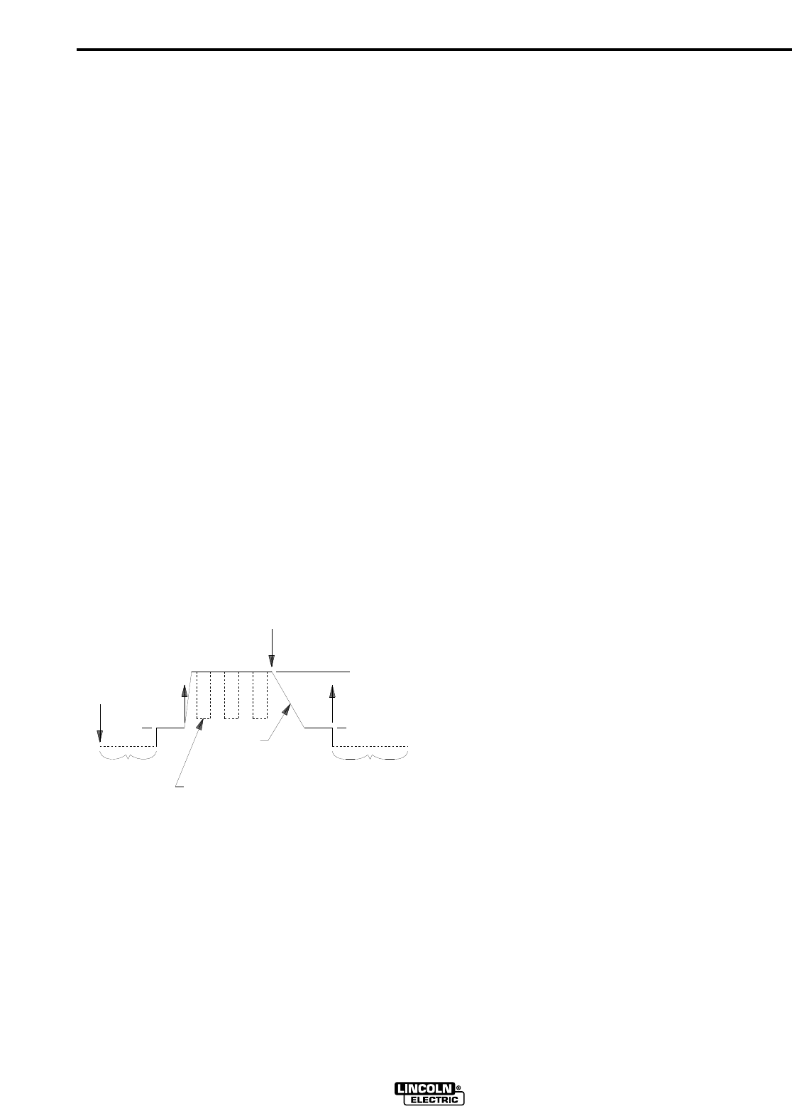
B-9
OPERATION
B-9
8. Set the Post Flow Time with the post flow knob.
Post flow control knob adjusts the time that the
shielding gas flows (and cooling water flow, if the
optional water solenoid is used) after the weld
cycle. Use short post flow times with low currents
and small tungstens, use long post flow times at
high output currents with large tungstens.
9. With the torch held safely away from everything,
press the Arc Start Switch or Amptrol and set the
gas flow meter. Release the switch or Amptrol. The
welder is now ready for welding.
10. Position the tungsten electrode at the start of the
weld at a 65˚ to 75˚ angle with the horizontal so
that the electrode is approximately 1/8" (4 mm)
above the work piece. Press the Arc Start Switch.
This opens the gas (and optional water solenoid)
valves to automatically purge air from the hose
and torch. After a 0.5 second preflow time, the
high frequency becomes available to strike the arc.
11. Hold the Arc Start Switch or Amptrol down until an
arc is established. If using an Amptrol, read the
Section on Hand and Foot Amptrol Operation.
Release the Arc Start Switch or Amptrol to stop
the arc and start the Post Flow timer. After the
Post Flow time has expired, the gas and (optional
water solenoid) valves will close. To make anoth-
er weld, repeat steps 10 and 11.
WELDING IN TIG MODE (4-STEP)
In 4-STEP mode an Arc Start switch must be used.
The switch is pressed and then released to start the
weld cycle. Pressing and releasing the switch a sec-
ond time ends the weld cycle. This eliminates the need
to continuously hold down the switch during the weld.
The process works as follows:
(STEP #1) First Press: Initiates a 0.5 second preflow
of shielding gas then starts the weld at a current equal
to 5 Amps or 25% +/- 10 % of preset current (whichev-
er is greater).
(STEP #2) First Release: The output current ramps up
to the preset level in 0.5 seconds.
(STEP #3) Second Press: The output current ramps
down to 5 Amps or 25% +/- 10 % of the preset current
(whichever is greater). The time it takes to ramp down
can be adjusted from approximately 0.5 to 10 seconds
with the Down Slope Time control knob.
(STEP #4) Second Release: Output is turned off stop-
ping the weld and starting the 5 to 50 seconds post
flow set with the Post Flow control knob.
1. Connect the Twist Mate plug to the receptacle locat-
ed on the front of the machine. The connection
locks into place with a quarter turn making both the
power and gas connections. See the TIG TORCH
CONNECTION section to install the Twist Mate plug
on your torch.
2. Connect an Arc Start Switch to the Remote
Amphenol.
3. Turn the welder, gas supply and water supply (if so
equipped), on. The digital ammeter/voltmeter dis-
play will illuminate when the power is on. NOTE:
Cooling fan may not be “ON” when not welding.
(See MAINTENANCE section)
4. Set the MODE switch to “4-STEP TIG”.
5. Set the peak current displayed on the digital amme-
ter with the output control knob.
6. Select AC or DC- electrode polarity. See Table B.2.
7. If welding with AC polarity, set the AC Wave
Balance Knob to Auto Balance™. This gives the
optimum ratio between cleaning and penetration,
automatically adjusted for the output current. If
manual adjustment of the AC Wave Balance is
desired, adjust the wave balance to the desired set-
tings. See the Advanced Features section for more
information on setting and using the AC Wave
Balance.
8. Set the Post Flow time with the Post Flow knob.
Post Flow time provides shielding gas flow (and
cooling water, if used) after the weld. Use short
Post Flow times with low currents and small tung-
stens and long Post flow times at high output cur-
rents and large tungstens.
9. Set the Downslope Time with the Downslope Time
Knob. This will adjust the time of the crater fill peri-
od.
SQUARE WAVE TIG 275
PRESS #1
(STEP #1)
PREFLOW
(0.5 sec. FIXED)
OPTIONAL
TIG PULSER
DOWNSLOPE
(0.5 to 10 sec. ADJUSTABLE
START
CURRENT
RELEASE #1
(STEP #2)
PRESS #2
(STEP #3)
PRESET CURRENT
RELEASE #2
(STEP #4)
CRATER CURRENT
POSTFLOW
(5 to 50 sec. ADJUSTABLE)

B-10
OPERATION
B-10
10. With the torch held safely away from everything,
press the Arc Start Switch and set the gas flow
meter. Release the switch. The welder is now ready
for welding.
11. Position the tungsten electrode at the start of the
weld at a 65˚ to 75˚ angle with the horizontal so that
the electrode is approximately 1/8" (4 mm) above the
work piece. Press the Arc Start Switch. This opens
the gas and water valves to automatically purge air
from the hose and torch. After a 0.5 second preflow
time, the high frequency becomes available to strike
the arc.
12. Hold the Arc Start Switch down until an arc is estab-
lished. The arc will start at a low current value that is
equal to 25% +/- 10 % of the preset current estab-
lished in Step 5 or 5 Amps, whichever is greater.
13. Release the Arc Start Switch and the current will
ramp up to the preset maximum current in 0.5 sec-
onds and remain there indefinitely.
14. Press the Arc Start Switch a second time to initiate
the Down Slope time. The current will ramp down to
a crater fill level of 25% +/- 10 % of the preset current
or 5 Amps whichever is greater within the time set
with the Down Slope knob in Step 9.
15. Release the Arc Start Switch to stop the arc and start
the Post Flow timer. After the post flow time has
expired, the gas and optional water valves will close.
The make another weld, repeat steps 11 through 15.
HAND AND FOOT AMPTROL OPERATION
Both the Hand and Foot Amptrol work in a similar man-
ner. They are meant to be used for remote current con-
trol. The TIG 2-Step mode must be selected when
using an Amptrol for remote current control.
For simplicity, the following explanation will refer only to
"Amptrols", meaning both Foot and Hand models. The
term "minimum" refers to a Foot pedal in the "up" posi-
tion, as it would be with no foot pressure, or a Hand
Amptrol in the relaxed position, with no thumb pres-
sure. "Maximum" refers to a fully depressed Foot
Amptrol, or a fully extended Hand Amptrol.
The Amptrol is capable of controlling the output current
from 5 amps to the preset current on the output control
knob. For example, if the preset is at 200 amps, the
Amptrol, when depressed just past its minimum posi-
tion, will cause the Square Wave TIG 275 to weld at 5
amps. At the Amptrol's maximum position, the output
will be near 200 amps.
It is important to note that, for many applications, the
tungsten will not start an arc at only 5 amps. (Refer to
the TIG Welding Guidelines for recommended tungsten
currents.) To start an arc reliably, it is important to
depress the Amptrol far enough so that the machine
output current is near the tungsten operating range. In
the example above, a 3/32" tungsten may be used on
DC- to weld near 200 amps. To start the weld, the
operator may have to depress the Amptrol approxi-
mately 1/4 of the way down, or to nearly 50 amps, in
order to start the arc. Merely depressing the Amptrol to
its 5 amp minimum position will not start the arc.
ADVANCED TIG WELDING FEATURES
AC WAVE BALANCE AND AUTO BALANCE™
The AC Wave Balance feature is unique to the Square
Wave TIG 275. It is active only in AC TIG mode. It con-
trols the amount of positive and negative current in the
AC output.
The Square Wave TIG 275 allows the operator to select
Auto Balance™. This selection provides automatic
adjustment of the AC Wave Balance; it is suitable for
most welding conditions. Auto Balance™ gives the
ideal amount of cleaning and penetration, based on the
welding current output.
Manual adjustment of the AC Wave Balance is also
possible. Manual Balance settings vary from 0 (maxi-
mum cleaning) to 10 (maximum penetration). A setting
of 3 yields a balanced output (equal amounts of clean-
ing and penetration). Use the following as a guide
when setting the Balance manually:
BALANCED (3): The amounts of positive and nega-
tive are the same.
CLEANING (0 to 2): Provides more positive current
than negative current. Since the positive cur-
rent produces the "cleaning" or oxide removal
on aluminum, this setting is used for welding on
heavily oxidized aluminum.
PENETRATION (4 to 10): Provides more negative cur-
rent than positive. The arc plasma will be more
concentrated and more easily directed to
where the heat is needed. Higher penetration
settings allow a given size of tungsten to carry
more current.
CAUTION: Use only the amount of cleaning required
because the greater amount of positive current will
heat the tungsten more and possibly cause it to melt or
"spit". Also, the arc is usually more flared and less sta-
ble with more cleaning current.
In general, use just enough "cleaning" to remove
oxides and to give good wetting of the puddle.
SQUARE WAVE TIG 275

B-11
OPERATION
B-11
STICK WELDING
1. Turn the welder “ON”.The digital ammeter/voltmeter
will illuminate when the power is on.
2. Set the Mode Switch to “STICK”. Set the output cur-
rent displayed on the digital ammeter with the
Output Control Knob. No other functions or adjust-
ments operate in the Stick Mode.
3. Select the desired DC+/AC/DC- electrode polarity.
4. Clamp the electrode in the electrode holder, start
the weld by lightly touching the electrode to the
work. Stop the weld by pulling the electrode away
from the work piece.
AUXILIARY POWER
60 HERTZ DOMESTIC MACHINES
The Square Wave TIG 275 machines rated for 60 Hz
operation provides 10 amps of 115 volt AC power at a
standard NEMA 5-15R receptacle, located on the
lower case back of the machine. This circuit is protect-
ed from shorts and overloading by a 10 amp circuit
breaker, located next to the receptacle. The auxiliary
circuit is intended for running water coolers and small
power tools, whose current draw is within the 10 amp
rating. Note that some types of equipment, especially
pumps and large motors, have starting currents which
are significantly higher than their running current.
These higher starting currents may cause the circuit
breaker to open. If this situation occurs, the user
should refrain from using the Square Wave TIG 275
auxiliary for that equipment.
50/60 HERTZ EUROPEAN MACHINES
The Square Wave TIG 275 machines rated for 50/60Hz
operation provides 2 amps of 220 volt AC power at a
continental European (Schuko) type receptacle, locat-
ed on the lower case back of the machine. This circuit
is protected from shorts and overloading by a 2 amp
circuit breaker, located above the receptacle. The aux-
iliary circuit is intended for running water coolers
whose current draw is within the 2 amp rating of the
receptacle. Note that some types of equipment, espe-
cially pumps and motors, have starting currents which
are significantly higher than their running currents.
These higher starting currents may cause the circuit
breaker to open. If this situation occurs, the user
should refrain from using the Square Wave TIG 275
auxiliary for that equipment.
SQUARE WAVE TIG 275

C-1
ACCESSORIES
C-1
ACCESSORIES INCLUDED WITH
MACHINE
K852-50 - Twist Mate Cable Plug for #2 to #1 Work
Lead.
K1622-1 - Twist Mate Adapter Kit for LA9 and LA17
Torches.
K1622-2 - Twist Mate Adapter Kit for LW18 and LW20
Torches.
OPTIONAL ACCESSORIES
K963-1, -2 - Hand Amptrol
K870 - Foot Amptrol
K814 - Arc Start Switch
K559-2 - Magnum® Cooler Mounting Bracket
K932-1 - Undercarriage When the undercarriage is
properly installed, the Square Wave TIG 275 lift bale is
nonfunctional. Do not attempt to lift the power source
with the undercarriage attached. The undercarriage is
designed for hand moving only; mechanized towing
can lead to personal injury and/or damage to the
Square Wave TIG 275.
K1619-1 - TIG Pulser Kit
K1620-1 - Power Factor Capacitor Kit
K1621-1 - Water Solenoid Kit
K1622-3 - Twist Mate Adapter Kit for LA26 Torch
K852-70 - Twist Mate Cable Plug for 1/0 to 2/0 Work
Lead
K852-95 - Twist Mate Cable Plug for 2/0 to 3/0 Work
Lead
SQUARE WAVE TIG 275

D-1
MAINTENANCE
D-1
SQUARE WAVE TIG 275
ELECTRIC SHOCK can kill.
•Only qualified personnel should
perform this maintenance.
•Turn the input power OFF at the
disconnect switch or fuse box
before working on this
equipment.
•Do not touch electrically hot
parts.
To avoid receiving a high frequency shock, keep the
TIG torch and cables in good condition.
Very little routine maintenance is necessary to keep
your Square Wave TIG 275 running in top condition.
No specific schedule can be set for performing the fol-
lowing items; factors such as hours of usage and
machine environment should be considered when
establishing a maintenance schedule.
1. Periodically blow out dust and dirt which may accu-
mulate within the welder using an air stream.
2. Inspect welder output and control cables for fraying,
cuts, and bare spots.
3. Inspect the spark gap at regular intervals to main-
tain the recommended spacing. See the Service
Procedures Section for complete information on
spark gap settings.
4. The fan motor has sealed ball bearings which
require no maintenance.
SAFETY PRECAUTIONS
ROUTINE AND PERIODIC MAINTENANCE
WARNING
WARNING
OVERLOAD PROTECTION
THERMOSTATIC PROTECTION
This welder has thermostatic protection from excessive
duty cycles, overloads, loss of cooling, and high ambi-
ent temperatures. When the welder is subjected to an
overload or loss of cooling, a thermostat will open. This
condition will be indicated by the illumination of the yel-
low Thermostatic Protection Light on the case front
(see Figure 3). The fan will continue to run to cool the
power source. No welding is possible until the machine
is allowed to cool and the Thermostatic Protection
Light goes out.
FAN AS NEEDED (F.A.N.)
The Square Wave TIG 275 has the F.A.N. circuit fea-
ture, which means the cooling fan will operate only
while welding; then for about 6 minutes after welding
has stopped. The cooling fan will operate continuous-
ly if the yellow Thermostatic Protection Light in “ON”.
(See Design Features and Advantages Section)
SERVICE PROCEDURES
Use extreme caution when working with the secondary
circuit of the high frequency transformer. Turn the input
power off using the disconnect switch or fuse box
before working inside the machine. This is particularly
important when working on the secondary circuit of the
high voltage transformer (T3) because the output volt-
age is dangerously high.
DO NOT APPLY POWER TO THE SQUARE WAVE
TIG 275 WITH THE SIDES AND ROOF REMOVED.
The case front and case back assemblies tend to lean
in towards the center assembly; there is a danger of a
short circuit when this occurs. If you must troubleshoot
the machine with power applied, do so with the roof in
place, and check for shorts before applying power.
------------------------------------------------------------------------
Operation of the Square Wave TIG 275 should be trou-
ble-free for the life of the machine. Should a malfunc-
tion occur, however, the following procedures will be
useful to trained service personnel with experience in
repairing arc welding equipment.
WARNING
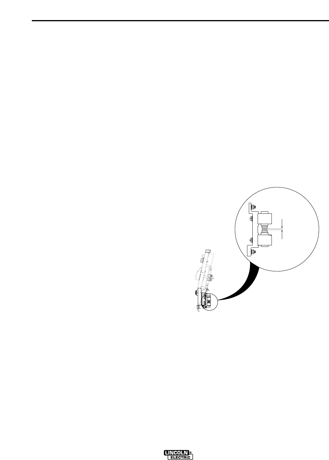
D-2
MAINTENANCE
D-2
COMPONENT LOCATION AND ACCESS
Control PC Board:
Remove the left case side. Use a 3/8" Nut Driver or
other suitable tool.
Note: The Case side can be removed while roof is in
place, as long as the three screws which secure the
roof to the case side are removed. The PC Board is
mounted on left divider assembly and can be removed
with a phillips head screwdriver.
Display PC Board, Arc Starter/Bypass PC
Board:
Remove the roof and both case sides. Use a 3/8" Nut
Driver or other suitable tool. These PC Boards are
located on the inside case front of the machine.
Spark Gap Assembly, High Voltage
Transformer:
Remove the right case side. Use a 3/8" Nut Driver or
other suitable tool. The high voltage transformer is
mounted to the base. The spark gap assembly is locat-
ed on the inside case front.
Main Rectifier:
Remove the roof and both case sides. Next, remove
the case back assembly. Use a 3/8" Nut Driver or other
suitable tool. The main rectifier is mounted to the main
transformer, in front of the cooling fan.
SPARK GAP ADJUSTMENT
The spark gap is set at the factory to a gap of 0.015
inches (0.4 mm). This setting is adequate for most
applications. Where less high frequency is desired, the
setting can be reduced to 0.008 inches (0.2 mm).
To adjust the spark, first be sure that the input power to
the machine is ‘OFF’ AT THE DISCONNECT SWITCH
OR FUSE BOX. The high voltages developed in the
high frequency circuit can be lethal. Next, remove the
right case side. Use a 3/8" Nut Driver or other suitable
tool. Disconnect the two push on wires to the spark
gap blocks and pull back the dust shield. Check the
spark gap spacing with a feeler gauge. If adjustment is
required, pull off one of the two leads going to the alu-
minum spark gap blocks. Adjust the gap by loosening
the Allen head screw, reset the gap and tightening the
screw in the new position. Replace the dust shield and
the two leads removed earlier. Reinstall the case side.
SQUARE WAVE TIG 275
.015 Spark Gap
RIGHT SIDE VIEW OF MACHINE
FIGURE D.1 SPARK GAP

E-1
TROUBLESHOOTING
E-1
SQUARE WAVE TIG 275
If for any reason you do not understand the test procedures or are unable to perform the tests/repairs safely, contact your Local
Lincoln Authorized Field Service Facility for technical troubleshooting assistance before you proceed.
CAUTION
This Troubleshooting Guide is provided to
help you locate and repair possible machine
malfunctions. Simply follow the three-step
procedure listed below.
Step 1. LOCATE PROBLEM (SYMPTOM).
Look under the column labeled “PROBLEM
(SYMPTOMS)”. This column describes pos-
sible symptoms that the machine may exhib-
it. Find the listing that best describes the
symptom that the machine is exhibiting.
Symptoms are grouped into the following
categories: output problems, function prob-
lems, TIG mode problems, TIG welding prob-
lems and Stick welding Problems.
Step 2. PERFORM EXTERNAL TESTS.
The second column labeled “POSSIBLE
AREAS OF MISADJUSTMENT(S)”lists the
obvious external possibilities that may con-
tribute to the machine symptom. Perform
these tests/checks in the order listed. In
general, these tests can be conducted with-
out removing the case wrap-around cover.
Step 3. RECOMMENDED COURSE OF
ACTION
If you have exhausted all of the items in step
2. Contact your Local Lincoln Authorized
Field Service Facility.
HOW TO USE TROUBLESHOOTING GUIDE
Service and Repair should only be performed by Lincoln Electric Factory Trained Personnel.
Unauthorized repairs performed on this equipment may result in danger to the technician
and machine operator and will invalidate your factory warranty. For your safety and to avoid
Electrical Shock, please observe all safety notes and precautions detailed throughout this
manual.
__________________________________________________________________________
WARNING
DO NOT use a volt-ohm meter to measure output voltages in TIG mode. The High
Frequency Arc Starter voltage can damage the meter.
CAUTION

E-2
TROUBLESHOOTING
E-2
SQUARE WAVE TIG 275
Observe all Safety Guidelines detailed throughout this manual
If for any reason you do not understand the test procedures or are unable to perform the tests/repairs safely, contact your Local
Lincoln Authorized Field Service Facility for technical troubleshooting assistance before you proceed.
CAUTION
GENERAL MACHINE TROUBLE
PROBLEMS
(SYMPTOMS)
POSSIBLE AREAS OF
MISADJUSTMENTS(S)
RECOMMENDED
COURSE OF ACTION
Machine will not turn on.
No machine output.
Control panel display does not func-
tion, but the output is normal.
The Voltmeter always reads "000",
but the output is normal.
1. Input supply not "hot". Check input sup-
ply line voltage and fuses.
2. Input power switch (S1) faulty. Check
and replace.
1. Make sure the input Power Switch (S1) is
in the “ON”position.
2. A protective thermostat may be open.
An open thermostat disables machine
output. Allow machine to cool and ther-
mostat will close. The yellow thermal
light (TL1) should be lit in this condition.
3. If the machine is not “hot”(i.e. you have
not been welding) and the thermostat
light is lit, the thermostat wiring or a ther-
mostat may be faulty. Check for continu-
ity between leads 313 and 314 at P3 on
the Control PC Board. If not present,
test each wire and thermostat individual-
ly.
4. The Control PC Board may be faulty.
See PC Board Troubleshooting
Procedures
5. Main Transformer (T1) may be faulty.
1. Check for loose connections at the
Control PC Board (P4) or at the Display
Board (P20 & P21)..
2. The Display PC Board may be faulty.
See PC Board Troubleshooting
Procedures.
3. The Control PC Board may be faulty.
See PC Board Troubleshooting
Procedures.
1. Check leads 252 and 253 and their con-
nections to the Polarity Switch (S2) and
to the Control PC Board connection (J6).
2. The Display PC Board may be faulty.
See PC Board Troubleshooting
Procedures.
Contact your Local Lincoln Authorized
Field Service Facility for technical
troubleshooting assistance.

E-3
TROUBLESHOOTING
E-3
SQUARE WAVE TIG 275
Observe all Safety Guidelines detailed throughout this manual
If for any reason you do not understand the test procedures or are unable to perform the tests/repairs safely, contact your Local
Lincoln Authorized Field Service Facility for technical troubleshooting assistance before you proceed.
CAUTION
GENERAL MACHINE TROUBLE
PROBLEMS
(SYMPTOMS)
POSSIBLE AREAS OF
MISADJUSTMENTS(S)
RECOMMENDED
COURSE OF ACTION
The Ammeter displays “000", but the
machine has output with no control.
One of the meters is blank.
Accessories plugged into the 115
volt receptacle do not work.
(220 volt receptacle on European
model only)
Machine regularly overheats; ther-
mostat (s) open.
1. The shunt lead connections may be
open. Check the red lead (222) and
white lead (221) twisted pair all the way
from the shunt back to the Control PC
board connector (J2).
2. The Control PC Board may be faulty.
See PC Board Troubleshooting
Procedures.
1. Check for loose connections at Control
PC Board (P4) and at the Display PC
Board (20 & 21)The Display.
2. The Display PC Board may be faulty.
See PC Board Troubleshooting
Procedures.
1. Is accessory defective? Plug it into a
known "hot" receptacle to see if it works.
2. Circuit Breaker CB may be open. Before
resetting the circuit breaker, find out why
it opened. See the Auxiliary Power sec-
tion for more information.
1. Check for proper voltage at fan.
If proper voltage is present, but fan is not
rotating or is rotating slowly, replace fan
motor.
If proper voltage is not present, but fan is
not rotating or is rotating slowly, the out-
put fan circuit on the control PC Board
may be faulty.
2. Dirt and dust have clogged the cooling
channels inside the machine. Blow out
the machine with clean, dry compressed
air.
3. Are the duty cycles being exceeded?
Read the Instruction Manual thoroughly
for duty cycle information.
4. Is there adequate clearance around the
side and back of the machine, especially
near the intake and exhaust louvers? Do
not block the flow of cooling air during
operation.
Contact your Local Lincoln Authorized
Field Service Facility for technical
troubleshooting assistance.

E-4
TROUBLESHOOTING
E-4
SQUARE WAVE TIG 275
Observe all Safety Guidelines detailed throughout this manual
If for any reason you do not understand the test procedures or are unable to perform the tests/repairs safely, contact your Local
Lincoln Authorized Field Service Facility for technical troubleshooting assistance before you proceed.
CAUTION
GENERAL MACHINE TROUBLE
PROBLEMS
(SYMPTOMS)
POSSIBLE AREAS OF
MISADJUSTMENTS(S)
RECOMMENDED
COURSE OF ACTION
The machine makes a very loud
buzzing noise in DC stick, or in DC
TIG when the Arc Start Switch or
Amptrol is pressed.
The machine has output and the
meters are “ON”but there is no high
frequency present and the gas sole-
noid does not function.
High frequency is present, but bad
starting at low currents.
(Approximately 15 Amps and below)
Stick electrode "Blasts Off" when
touched to the work piece.
Cannot adjust AC Wave Balance.
Variable or sluggish welding arc.
1. Diode D1 may be shorted. Check
and replace.
2. One of the main SCR’s may be
shorted. Check and replace.
1. Check and replace 5 Amp Fuse
(F1) located below the Control PC
Board on the right. (Fuse is pre-
sent on European models only)
1. Check and replace 5 Amp Fuse
(F2) located below the Control PC
Board on the left. (Fuse is present
on European models only)
1. Weld current is set too high for
electrode size. Reduce the preset
current.
2. One of the main SCR’s may be
shorted.
3. The Control PC Board may be
faulty. See PC Board
Troubleshooting Procedures.
1. AC Wave Balance Function is only
operational in the AC TIG mode.
2. The Control PC Board may be
faulty. See PC Board
Troubleshooting Procedures.
1. Poor work or electrode connec-
tion.
2. Welding leads too small. Use
larger work and electrode leads
3. Welding current set too low.
Contact your Local Lincoln Authorized
Field Service Facility for technical
troubleshooting assistance.
Contact your Local Lincoln Authorized
Field Service Facility for technical
troubleshooting assistance.
APR96
STICK WELDING TROUBLE

E-5
TROUBLESHOOTING
E-5
SQUARE WAVE TIG 275
Observe all Safety Guidelines detailed throughout this manual
If for any reason you do not understand the test procedures or are unable to perform the tests/repairs safely, contact your Local
Lincoln Authorized Field Service Facility for technical troubleshooting assistance before you proceed.
CAUTION
TIG WELDING TROUBLE
PROBLEMS
(SYMPTOMS)
POSSIBLE AREAS OF
MISADJUSTMENTS(S)
RECOMMENDED
COURSE OF ACTION
Machine does not respond (no gas
flow, no high frequency, no open cir-
cuit voltage) when Arc Start Switch
or Amptrol is pressed. Thermal light
is not lit.
No gas or water flow (with optional
water solenoid) when Arc Start
Switch or Amptrol is pressed in the
TIG Weld Mode.
No High Frequency.
1. Defective Arc Start Switch or
Amptrol. Check for continuity
between pins D and E on cable
connector when Arc Start Switch
or Amptrol is pressed.
2. The Control PC Board may be
faulty. See PC Board
Troubleshooting Procedures.
1. Gas supply is empty or not turned
on.
2. Pinched, disconnected, or leaking
gas or water hose.
3. Gas and/or water lines or sole-
noids are blocked with dirt. Clean
out and use filters to prevent reoc-
currence.
4. Defective gas and/or water sole-
noid. Check and replace.
5. The Control PC Board may be
faulty. See PC Board
Troubleshooting Procedures.
1. Spark gap is too large. Reset gap
per Periodic Maintenance Section
instructions.
2. Check gas solenoid operation. If it
is not working, check 115V circuit
from Main Transformer (T1).
Check Fuse (F1) on European
models only.
3. Defective high voltage transformer
(T2). Check and replace.
4. One or more of the following
components may be open: R5 or
C6. Check and replace.
5. The Control PC Board may be
faulty. See PC Board
Troubleshooting Procedures.
Contact your Local Lincoln Authorized
Field Service Facility for technical
troubleshooting assistance.

E-6
TROUBLESHOOTING
E-6
SQUARE WAVE TIG 275
Observe all Safety Guidelines detailed throughout this manual
If for any reason you do not understand the test procedures or are unable to perform the tests/repairs safely, contact your Local
Lincoln Authorized Field Service Facility for technical troubleshooting assistance before you proceed.
CAUTION
TIG WELDING TROUBLE
PROBLEMS
(SYMPTOMS)
POSSIBLE AREAS OF
MISADJUSTMENTS(S)
RECOMMENDED
COURSE OF ACTION
Weak High Frequency.
Output quits momentarily; gas flow
and high frequency are also inter-
rupted.
1. Spark gap is too close. Reset
gap per Periodic Maintenance
Section instructions.
2. Work and electrode cables in
poor condition, allowing high fre-
quency to "leak" to ground. Use
good quality cables, preferably
those with a high natural rubber
content, and as short as possi-
ble.
3. No shielding gas. Adjust gas
flow for a flow of 10 to 30 CFH
(4.7 to 14.1 1/min) for most appli-
cations. (High frequency will not
jump from the tungsten to work
without shielding gas).
1. May be caused by high frequen-
cy interference. Is the machine
grounded properly, according to
the installation instructions? Are
there other machines in the area
which may be strong sources of
high frequency? Make sure that
they are also properly installed
and grounded.
2. Some internal ground connec-
tions may have become loose.
Check that the screws which
mount the Control PC Board and
the Bypass Stabilizer PC Board
are tight. Also, all case parts
should be in place, and the case
screws should be tight.
Contact your Local Lincoln Authorized
Field Service Facility for technical
troubleshooting assistance.

E-7
TROUBLESHOOTING
E-7
SQUARE WAVE TIG 275
If for any reason you do not understand the test procedures or are unable to perform the tests/repairs safely, contact your Local
Lincoln Authorized Field Service Facility for technical troubleshooting assistance before you proceed.
CAUTION
PC BOARD TROUBLESHOOTING
PROCEDURE
Before replacing a PC Board which is suspected of being
defective, visually inspect the PC Board in question for any
electrical or mechanical damage to any of the components or
conductors on the board, partially insulated molex pins or
connectors.
a. If there is no visible damage to the PC Board, install a new
one and see if this remedies the problem. If the problem
is remedied, reinstall the old PC Board to see if the prob-
lem still exists. If the problem no longer exists with old PC
Board:
1. Check the PC Board harness connector pins for
corrosion, contamination or looseness.
2. Check leads in the plug harness for loose or
intermittent connections.
b. If PC Board has visible electrical damage, before possibly
subjecting the new PC Board to the same cause of failure,
check for possible shorts, opens or grounds caused by:
1. Frayed or pinched lead insulation.
2. Poor lead termination, such as a poor contact or
a short to adjacent connection or surface.
3. Shorted or open control cable leads, or other
external leads.
4. Foreign matter or interference behind the PC
Boards.
c. If PC Board has visible mechanical damage, inspect for
cause, then remedy before installing a replacement PC
Board.
If there is damage to the PC Board or if replacing PC
Board corrects problem, return it to the local Lincoln
Electric Field Service Shop.
INPUT - BYPASS PC BOARD (EUROPEAN
MODELS ONLY)
This board is mounted to the case front and connects
to the input power at the line switch. It passes excess
high frequency to ground, protecting the machine and
power line. For proper operation it must be securely
grounded, by means of its ground and mounting
screws to the case front. The quick connect terminals
from the line switch must be fully seated. Failures of
this board should be very rare.
BYPASS / STABILIZER PC BOARD
The board is mounted between the output terminals. It
passes excess high frequency to ground before it can
reach the inside of the machine. For proper operation,
it must be securely grounded, by means of its ground
and mounting screws, to the case front. Failures of this
board should be very rare.
DISPLAY PC BOARD
The board is mounted directly to the front panel. The
Control P.C. Board supplies power and metering infor-
mation to the board.
CONTROL PC BOARD
This board, located on the left divider assembly, is the
heart of the machine. All welding output is controlled
by this board. The Display board receives its informa-
tion from the Control board as well. Very little external
diagnostic work can be performed on this board. If one
control or function of the machine does not appear to
be working, it is best to trace out the wiring associated
with that function all the way back to the Control board
with an ohmmeter. If all checks out there, verify that
the following voltages are present at the output of the
auxiliary leads at the main transformer, T1.
CONTROL PC BOARD
AUXILIARY LEAD VOLTAGES
Main Transformer (T1) Plug P8 Approximate
Auxiliary Lead Number Locations Voltage
209 to 210 1 to 9 18 VAC
201 to 204 4 to 6 18 VAC
231 to 232A 2 to 12 115 VAC
211A to 212 13 to 14 23 VAC
Often, replacement with a known good board is the
best service method. Remove the board that is sus-
pected to be defective. Carefully look over the board,
checking for burnt traces or components. If none are
found, install the known good board. If the trouble goes
away, reinstall the suspected bad board to confirm that
the board was indeed at fault. If the problem is now
gone with the original board installed, the problem is
probably with one of the leads or connectors going to
the board.
Consult the Lincoln Service Department if further trou-
bleshooting assistance is required.
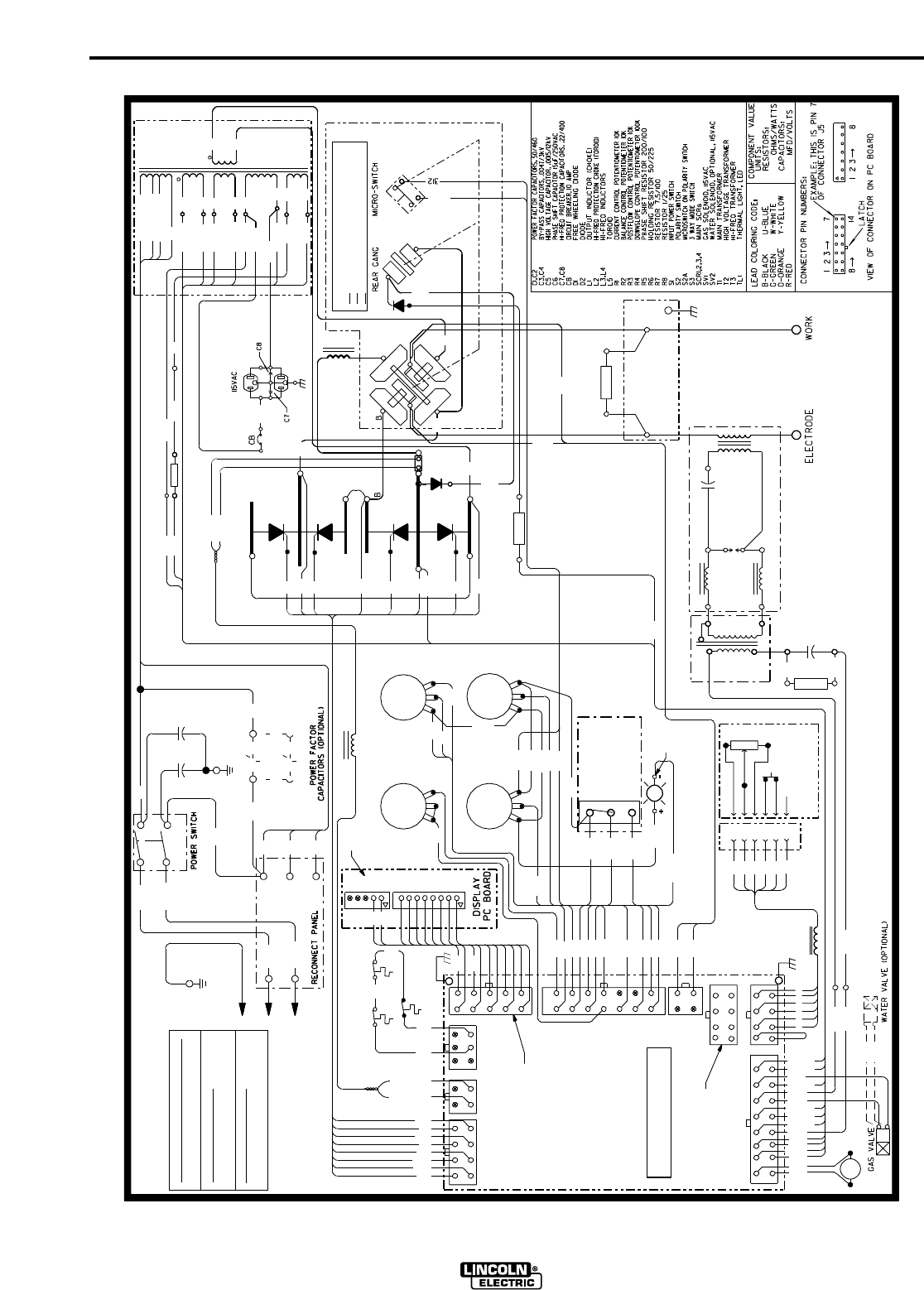
F-1
WIRING DIAGRAM
F-1
SQUARE WAVE TIG 275
B 232
R 222
(U)
(V)
L1
255
254
L1
L2
C1
RECEPTACLE
G1
G2
SCR4
246
2 STEP TIG
BRASS
115VAC
251
TERMINAL
243
248
H4
POS
D
FRONT GANG
ELECTRICAL SYMBOLS PER E1537.
276
A
F
J6
C
C
E
J7A
ARC STARTER AS'BLY
253
N.A. CONNECTION IS PIN TO PIN BETWEEN
248
A
BB
R5
236B
208 VOLT CONNECTION
NEG
H4 (460V)
F
232B
232 211B
231B
R8
232A
211A
POLARITY SWITCH MICRO SWITCH
232C
THERMOSTAT
W 221 (+)
218
G1
G2
B 242
STABILIZER
TL1
277 Y
CONTROL PC BOARD
THERMAL LIGHT
243
4 STEP TIG
POLARITY
S2
LOW
NO
314
216
G4
217
(REAR VIEW, SHOWN
X4
X1
R
W
B
B
W
W
B
D
10K A-B
210
231
209
235
238
234
212
204
201
236
261
247
211A
232A
220A
H1
NC
CLOSED
CLOSED
OPEN
R1
277
J20
R4
276
J21
277A
H2
W 209
18VAC
X7
R 210
W 201
X8
L2
460 VOLT CONNECTION (AS SHOWN)
CONNECT A TO HIGH (H4)
TO GROUND PER
230 VOLT CONNECTION
CONNECT A TO MID (H3)
7-24-98
C
L2
SV1
235A
234A
F
S
BALANCE CONTROL
X5
L4
C5
T2
F
E
D
C
X2
X1
T1
78VAC
S
W 204
A-C, D-E, B-F
B-D, C-E, A-F, G-H
G
DC+
211
DC-
C6
277B
245
254
J2
J1
255
AT MINIMUM
D
F
J7
J8
PC BOARD
T3
GAP
SPARK
L3
REMOTE
CURRENT CONTROL
H1
SECONDARY
THERMOSTAT
CHOKE
(V)
H3
250
MID
X10
X9
18VAC
X3
212
S2A
275C
H
L10747
WIRING DIAGRAM - SQUARE WAVE TIG 275 (208/230/460/1/60)
A
S1
H3 (230V)
H2 (208V)
H1
211
B 231
C4C3
L1
D1
R7
216
J4 AND J20 (i.e. PIN 1 TO PIN 1).
N.B. ROBOTIC INTERFACE CONNECTION.
N.C. NOT PRESENT ON EARLIER PC BOARDS.
STICK
X2
NEG
X6
23VAC
AC
115VAC
SCR3
SWITCH
E
F
ELECTRICAL CODE
NATIONAL
316
HIGH
236
FAN
TM
238
TIG
OR
AMPTROL
J5
R3
270
313
J5
PULSER
237
OPTIONAL
MODE SWITCH
312
275B
275C
N.B.
TOROID
THERMOSTAT
PRIMARY
A
253
252
236A
245
SV2
242
DOWNSLOPE CONTROL
POSTFLOW CONTROL
POS
B-D, A-E, C-F, G-H
IN AC POSITION)
S3
275
249
246
312
D2
(+)
SCR1
W 221
B
SCR2
315
275A
252
275
251
247
(-)
277C
220
J4
S
G3
J3
(U)
220A
G4
R 222 (-)
220
217
G3
218
C2
R2
A
CONNECT A TO LOW (H2)
F
R6
BYPASS/
E
REMOTE
L5
TOROID
260
N.A.
N.C.

F-2
WIRING DIAGRAM
F-2
SQUARE WAVE TIG 275
380 VOLT CONNECTION
312
MODE SWITCH
STICK
243
248
AT MINIMUM
D
F
260
N.C.
N.A.
N.B.
50
B
C
PRIMARY
TOROID
THERMOSTAT
H5
313
255
217
G3
R 222 (-)
G1
C2
F2
DOWNSLOPE CONTROL
G
A-C, D-E, B-F
B-D, C-E, A-F, G-H
CONNECTOR PIN NUMBERS:
TL1
R6
S2A
AC
D2
G3
217
275C
275B
4 STEP TIG
G-GREEN
R-RED
O-ORANGE
REAR GANG
DC+
DC-
CURRENT CONTROL
R3
N.A. CONNECTION IS PIN TO PIN BETWEEN
ARC STARTER AS'BLY
S
R5
236B
TIG
OR
TM
E
276
A
F
J6
C
C
E
J7A
SV2
REMOTE
245
252
253
236A
J7
POSTFLOW CONTROL
238
231
238
B
234
232A
OHMS/WATTS
THERMOSTAT
(U)
CAPACITORS:
RESISTORS:
MFD/VOLTS
UNITS:
COMPONENT VALUE
SV2
SCR1,2,3,4
S3
R7
STABILIZER
J8
TL1 -
+
B 242
S2
Y
POLARITY
THERMAL LIGHT
277
243
W 221 (+)
PC BOARD
AA
B
C
D
E
RECEPTACLE
SV1
AMPTROL
D2
REMOTE
L3
T2
115VAC
211A
220A
32
THERMAL LIGHT, LED
HI-FREQ TRANSFORMER
HIGH VOLTAGE TRANSFORMER
MAIN TRANSFORMER
WATER SOLENOID, OPTIONAL, 115VAC
VIEW OF CONNECTOR ON PC BOARD
3 WAY MODE SWITCH
ELECTRICAL SYMBOLS PER E1537.
CB
FAN
234A
23VAC
235A
GAS VALVE
WATER VALVE (OPTIONAL)
SV1
L2
SECONDARY
THERMOSTAT
CHOKE
312
H4
POS
H5 (440 V)
F1
A
H3
(V)
X1
78VAC
F
T1
115VAC
X9
51
D
E
B
L2
(-)
253
OPEN
SCR2
CLOSED
CLOSED
MICRO-SWITCH
NC
FRONT GANG
IRONFRONT
FREE WHEELING DIODE
DIODE
C6
HI-FREQ INDUCTORS
F2
L1
L2
L5
MAIN SCRs
R3
GAS SOLENOID, 115VAC
W-WHITE
Y-YELLOW
3
J5
NO
314
216
G4
220
NEG
R
W
B
B
W
W
X2
277C
275A
LOW
(V)
MID
(U)
50
POLARITY SWITCH MICRO SWITCH
G2
POWER FACTOR
CB
(+)
W 221
10-16-98
SCR4
232A
PROTECTIVE BONDING CIRCUIT
TO GROUND PER
NEG
T3
S2
TOROID
S1
FUSE, 5A FAST BLOW
R4
R2
TOROID
L5
F1
D
F
D1
F
10K A-B
R6
252
J4
246
J3
312
2 STEP TIG
BRASS
TERMINAL
S2A
316
A
R1
220
220A
277
DOWNSLOPE CONTROL POTENTIOMETER 100K
PHASE SHIFT RESISTOR 200/100
211B
R2
CASEBASE
277B
245
DISPLAY
255
254
S3
275
J2
249
246
J1
8
14
8
LATCH
0F CONNECTOR J5
7
EXAMPLE: THIS IS PIN 7
21
236
B-BLACK
LEAD COLORING CODE:
PULSER
HI-FREQ PROTECTION CHOKE (TOROID)
OUTPUT INDUCTOR (CHOKE)
275C
OPTIONAL
T3
B
210
209
235
212
204
201
236
261
247
F
S
X4
X5
X3
X10
18VAC
211
H1
H4 (415V)
H3 (380V)
H2 (220V)
52
212
B 231
B 232
W 201
D1
G4
216
248
PC BOARD
BYPASS
ELECTRICAL CODE
B-D, A-E, C-F, G-H
218
L2
CAPACITORS (OPTIONAL)
415 VOLT CONNECTION (AS SHOWN)
H1
C1
SCR3
G1
G2
218
X1
HIGH
R8
PC BOARD
R5
POSTFLOW CONTROL POTENTIOMETER 10K
BALANCE CONTROL POTENTIOMETER 10K
CURRENT CONTROL POTENTIOMETER 10K
247
BYPASS/
T1
T2
CONTROL PC BOARD
U-BLUE
POWER FACTOR CAPACITORS, 50/460
C5
(REAR VIEW, SHOWN
L4
B
242
J5
251
237
275
WIRING DIAGRAM - SQUARE WAVE TIG 275 (220/380/415/1/50/60)
CONNECT A TO HIGH (H4)
CONNECT A TO MID (H3)
220 VOLT CONNECTION
CONNECT A TO LOW (H2) NATIONAL
J21
254
F
J20 270
277A
HIGH VOLTAGE CAPACITOR, .0015/12kV
PHASE SHIFT CAPACITOR 15uF/250VAC
S
18VAC
X2
R 222
220VAC
POWER SWITCH
211A
S1
L1
H2
X12
220VAC
X11
RECONNECT PANEL
BACK
W X7
W 204
CASE
T1
315
C1,C2
C5
IN AC POSITION)
SWITCH
HOLDING RESISTOR 50/225
276
251
R4
SPARK
GAP
ELECTRODE
1
BALANCE CONTROL
N.B. ROBOTIC INTERFACE CONNECTION.
J4 AND J20 (i.e. PIN 1 TO PIN 1).
WORK
POLARITY SWITCH
N.C. NOT PRESENT ON EARLIER PC BOARDS.
INPUT POWER SWITCH
RESISTOR 1/25
RESISTOR 7.5/100
FUSE, 5A FAST BLOW
CIRCUIT BREAKER, 2 AMP
C6
H
L1
R7
H1
POS
X8
X6
W 209
R 210
211
232
L10747-1
R8
SCR1
MICROSWITCH ON POLARITY SWITCH
L3,L4
R1
L1
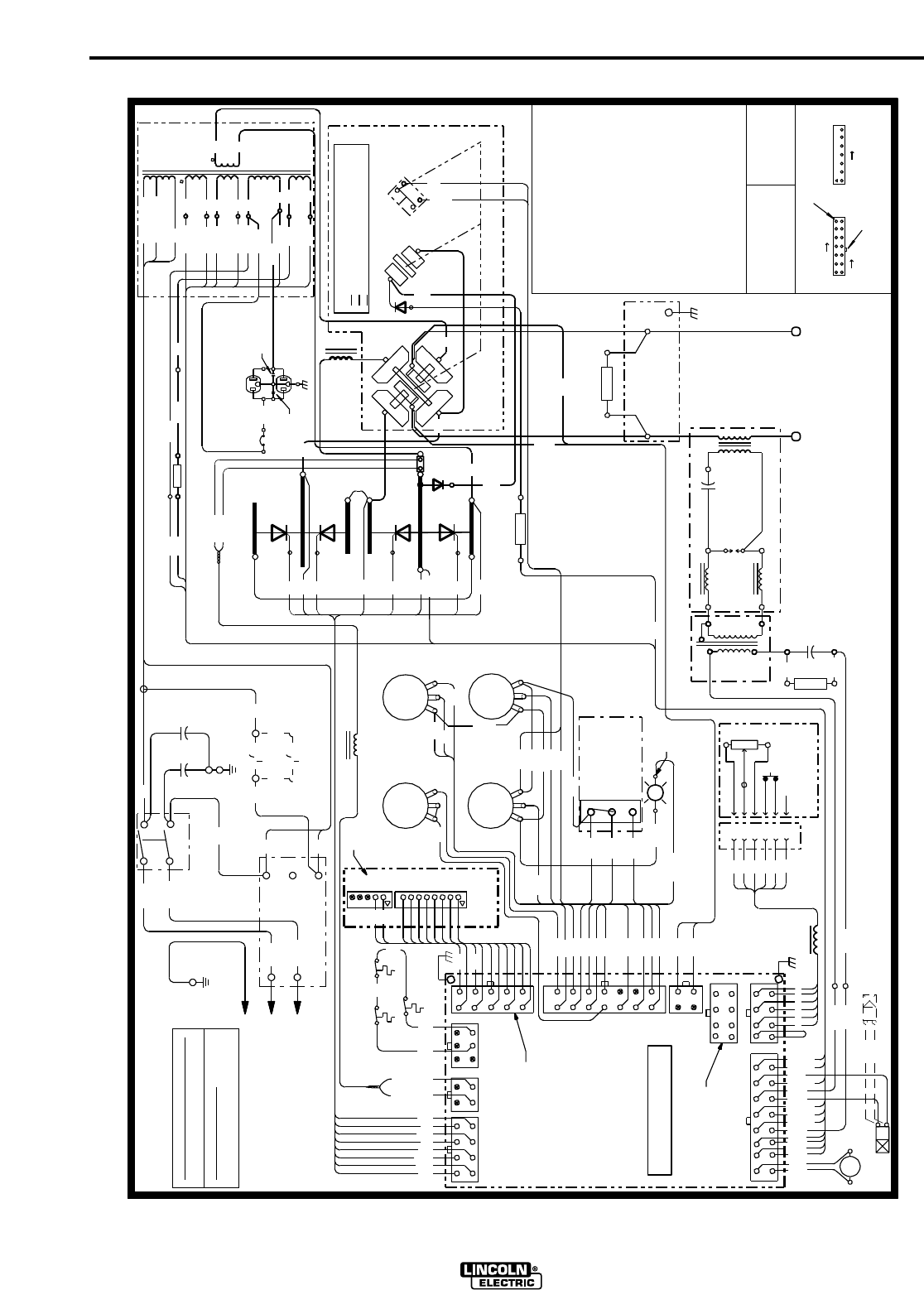
F-3
WIRING DIAGRAM
F-3
SQUARE WAVE TIG 275
B 232
R1
R2
R3
T3
R 222
POSTFLOW CONTROL POTENTIOMETER 10K
PHASE SHIFT RESISTOR 200/100
(U)
(V)
L1
255
254
L1
L2
C1
RECONNECT PANEL
R3
RECEPTACLE
G2
R5
SCR4
246
2 STEP TIG
BRASS
115VAC
251
TERMINAL
243
248
D2
MAIN TRANSFORMER
HI-FREQ TRANSFORMER
D1
(+)
HIGH VOLTAGE TRANSFORMER
SCR1
W 221
B
SCR2
VIEW OF CONNECTOR ON PC BOARD
ELECTRICAL SYMBOLS PER E1537.
276
A
F
J6
C
C
E
J7A
TOROIDL5
ARC STARTER AS'BLY
253
N.A. CONNECTION IS PIN TO PIN BETWEEN
248
A
BB
R5
236B
250
G4
STICK
218
G1
CAPACITORS (OPTIONAL)
211A
THERMOSTAT
W 221 (+)
218
G1
G2
R8
R7
S3
B 242
STABILIZER
SCR1,2,3,4
+-
TL1
OHMS/WATTS
COMPONENT VALUE
UNITS:
SV2
RESISTORS:
277
MFD/VOLTS
CAPACITORS:
Y
CONTROL PC BOARD
THERMAL LIGHT
243
4 STEP TIG
POLARITY
S2
261
X2
THERMOSTAT
SECONDARY
CHOKE
NEG
X6
23VAC
X4
115VAC
PC BOARD
X8
X7
18VAC
10-16-98
W 201
R 210
W 209
232A
N.B. ROBOTIC INTERFACE CONNECTION.
10K A-B
H2 (460V)
HI-FREQ PROTECTION CAPACITORS, .22/400
(REAR VIEW, SHOWN
E
C1,C2
DOWNSLOPE CONTROL POTENTIOMETER 100K
C5
C6
RESISTOR 7.5/100
RESISTOR 1/25
INPUT POWER SWITCH
CB
EXAMPLE: THIS IS PIN 7
POLARITY SWITCH
0F CONNECTOR J5
MICROSWITCH ON POLARITY SWITCH
3 WAY MODE SWITCH
L1
MAIN SCRs
GAS SOLENOID, 115VAC
B
LATCH
CURRENT CONTROL
L2
N.C. NOT PRESENT ON EARLIER PC BOARDS.
SV1
SV1
S1
R4
AMPTROL
W
R
B
B
W
H
B
W
D
H1
NC
MICRO-SWITCH
CLOSED
CLOSED
OPEN
R1
277
J20
R4
276
J21
277A
LOW
NO
314
216
G4
B
217
H4
POS
D
FRONT GANG
R2
BALANCE CONTROL
LEAD COLORING CODE:
B-BLACK
21
8
X5
L4
L3,L4
C5
T2
F
E
D
C
X2
X1
T1
78VAC
S
W 204
A-C, D-E, B-F
B-D, C-E, A-F, G-H
G
C8
DC+
211
REAR GANG
DC-
115VAC
R6
S2A
TL1
G-GREEN
O-ORANGE
R-RED
CONNECTOR PIN NUMBERS:
C6
277B
245
DISPLAY
254
J2
J1
255
AT MINIMUM
D
F
J7
J8
7
14
U-BLUE
Y-YELLOW
W-WHITE
OUTPUT INDUCTOR (CHOKE)
POWER FACTOR CAPACITORS, 50/460
T1
C3,C4
T2
PC BOARD
T3
GAP
SPARK
L3
REMOTE
260
HIGH
C
AC
D2
L10747-2
3
WATER SOLENOID, OPTIONAL, 115VAC
21
THERMAL LIGHT, LED
C7
316
(U)
POWER FACTOR
C2
R 222 (-)
A
ELECTRICAL CODE
POWER SWITCH
NATIONAL
TO GROUND PER
CONNECT A TO LOW (H2)
CONNECT A TO HIGH (H4)
575 VOLT CONNECTION (AS SHOWN)
TIG
247
312
NEG
275C
S2A
POLARITY SWITCH MICRO SWITCH
HI-FREQ INDUCTORS
CURRENT CONTROL POTENTIOMETER 10K
BALANCE CONTROL POTENTIOMETER 10K
F
231B
232B
F
OR
TM
E
H4 (575V)
H1
211
B 231
C4C3
L1
460 VOLT CONNECTION
SWITCH
SCR3
D1
R6
WORK
BYPASS/
R7
216
315
J4 AND J20 (i.e. PIN 1 TO PIN 1).
J5
238
236
WATER VALVE (OPTIONAL)
234A
235A
FAN
GAS VALVE
3
J5
ELECTRODE
PULSER
237
OPTIONAL
MODE SWITCH
CB
312
275B
275C
N.B.
TOROID
THERMOSTAT
PRIMARY
S2
A
253
252
236A
245
SV2
242
DOWNSLOPE CONTROL
POSTFLOW CONTROL
POS
B-D, A-E, C-F, G-H
IN AC POSITION)
HOLDING RESISTOR 50/225
C7,C8
S3
275
249
246
312
H1
(V)
X1
MID
S
F
X10
X9
18VAC
X3
212
232C
8
WIRING DIAGRAM - SQUARE WAVE TIG 275 (460/575/1/60)
S1
L2
CIRCUIT BREAKER, 10 AMP
L2
275A
252
275
251
247
(-)
277C
220
J4
S
G3
J3
H2
220A
BY-PASS CAPACITORS, .0047/3kV
HIGH VOLTAGE CAPACITOR, .0015/12kV
PHASE SHIFT CAPACITOR 15uF/250VAC
FREE WHEELING DIODE
DIODE
HI-FREQ PROTECTION CHOKE (TOROID)
313
270
220
217
G3
211B
232
R8
REMOTE
L5
TOROID
209
210
235
231
238
234
232A
204
211A
236
212
201
220A
N.A.
N.C.
A
F
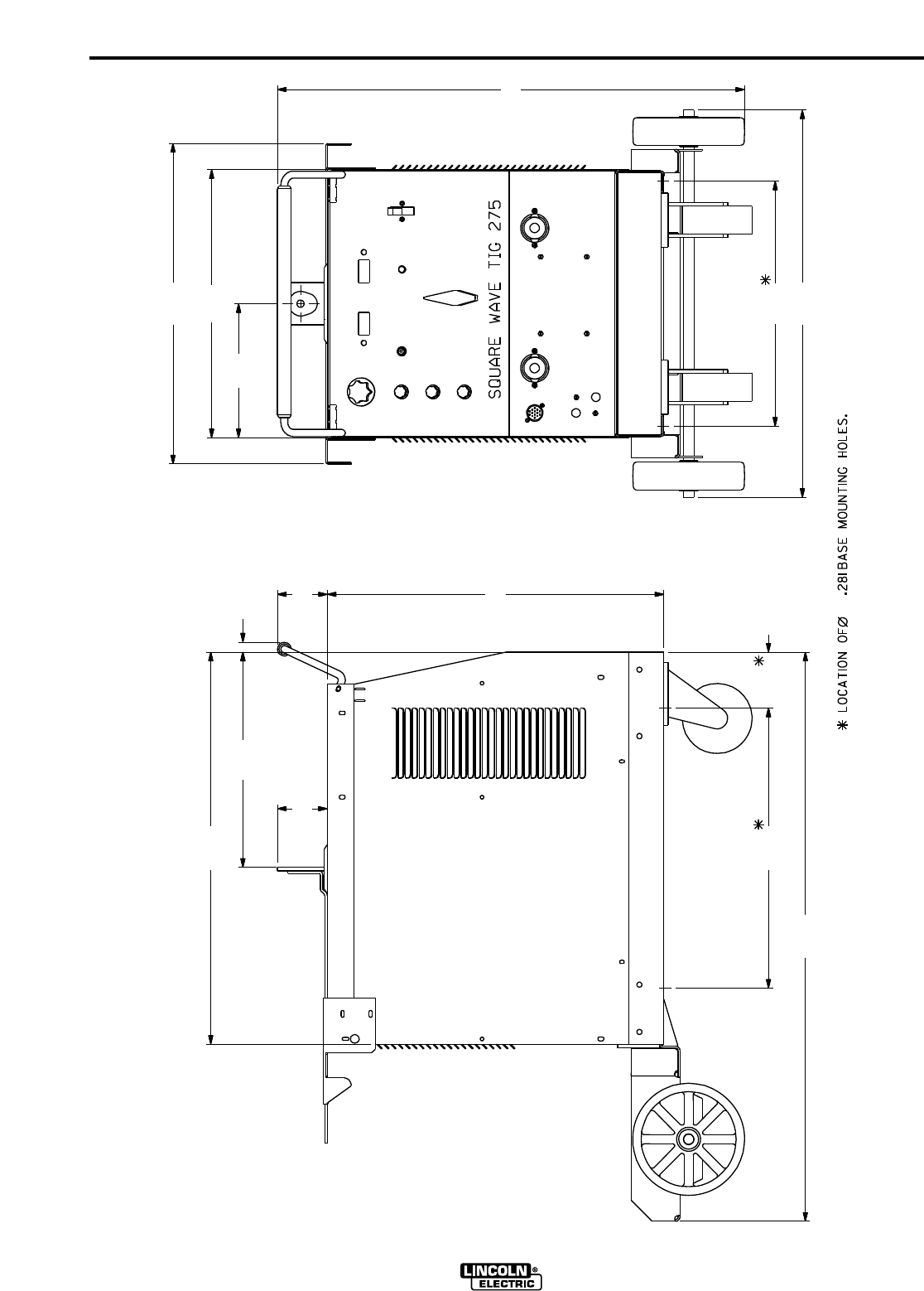
DIMENSION PRINT
SQUARE WAVE TIG 275
20.00
40.65
4.00
24.06
3.57
.7115.37
28.00
3.57
17.50
A
M19118
9.57
19.15
22.89
33.40
27.65
F-4F-4
Now Available...12th Edition
The Procedure Handbook of Arc Welding
With over 500,000 copies of previous editions published
since 1933, the Procedure Handbook is considered by many to
be the “Bible”of the arc welding industry.
This printing will go fast so don’t delay. Place your
order now using the coupon below.
The hardbound book contains over 750 pages of welding infor-
mation, techniques and procedures. Much of this material
has never been included in any other book.
A must for all welders, supervisors, engineers and
designers. Many welding instructors will want to use the book as
a reference for all students by taking advantage of the low quan-
tity discount prices which include shipping by
4th class parcel post.
$15.00 postage paid U.S.A. Mainland
How To Read Shop Drawings
The book contains the latest information and application
data on the American Welding Society Standard Welding
Symbols. Detailed discussion tells how engineers and drafts-
men use the “short-cut”language of symbols to pass on
assembly and welding information to shop personnel.
Practical exercises and examples develop the reader’s
ability
to visualize mechanically drawn objects as they will appear in
their assembled form.
187 pages with more than 100 illustrations. Size 8-1/2”x
11”
Durable, cloth-covered board binding.
$4.50 postage paid U.S.A.
Mainland
New Lessons in Arc Welding
Lessons, simply written, cover manipulatory techniques;
machine and electrode characteristics; related subjects, such
as distortion; and supplemental information on arc welding
applications, speeds and costs. Practice materials, exercises,
questions and answers are suggested for each
lesson.
528 pages, well illustrated, 6”x 9”size, bound in simulated,
gold embossed leather.
$5.00 postage paid U.S.A.
Mainland
Need Welding Training?
The Lincoln Electric Company operates the oldest and
most respected Arc Welding School in the United States at its
corporate
headquarters in Cleveland, Ohio. Over 100,000 students
have graduated. Tuition is low and the training is
“hands on”
For details write: Lincoln Welding School
22801 St. Clair Ave.
Cleveland, Ohio 44117-1199.
and ask for bulletin ED-80 or call 216-383-2259 and ask
for the
Welding School Registrar.
Lincoln Welding School
BASIC COURSE $700.00
5 weeks of fundamentals
There is a 10% discount on all orders of $50.00 or more for shipment at one time to one location.
Orders of $50 or less before discount or orders outside of North America must be prepaid with charge, check or money order in U.S. Funds Only.
Prices include shipment by 4 th Class Book Rate for U.S.A. Mainland Only.Please allow up to 4 weeks for delivery.
UPS Shipping for North America Only.All prepaid orders that request UPS shipment please add:
$5.00 For order value up to $49.99
$10.00 For order value between $50.00 & $99.99
$15.00 For order value between $100.00 & $149.00
For North America invoiced orders over $50.00 & credit card orders, if UPS is requested, it will be invoiced or charged to you at cost.
Outside U.S.A. Mainland order must be prepaid in U.S. Funds. Please add $2.00 per book for surface mail or $15.00 per book for air parcel post shipment.
METHOD OF PAYMENT: (Sorry, No C.O.D. Orders)
CHECK ONE:
Name: _______________________________________________
Please Invoice (only if order is over $50.00) Address: _______________________________________________
Check or Money Order Enclosed, U.S. Funds only _______________________________________________
Credit Card - Telephone: _______________________________________________
Signature as it appears on Charge Card:
Account No. |_|_|_|_|_|_|_|_|_|_|_|_|_|_|_|_|_|_|_|_|_| Exp Date |_|_| |_|_| ______________________
Month Year
USE THIS FORM TO ORDER:
Order from: BOOK DIVISION, The Lincoln Electric Company, 22801 St. Clair Avenue, Cleveland, Ohio 44117-1199
BOOKS OR FREE INFORMATIVE CATALOGS Telephone: 216-383-2211 or, for fastest service, FAX this completed form to: 216-361-5901.
Lincoln Welding School Titles: Price Code Quantity Cost
(ED-80) New Lessons in Arc Welding $5.00 L
Seminar Information Procedure Handbook “Twelfth Edition”$15.00 PH
(ED-45) How to Read Shop Drawings $4.50 H
Educational Video Information Incentive Management $5.00 IM
(ED-93) A New Approach to Industrial Economics $5.00 NA
James F. Lincoln Arc Welding The American Century of John C. Lincoln $5.00 AC
Foundation Book Information Welding Preheat Calculator $3.00 WC-8
(JFLF-515) Pipe Welding Charts $4.50 ED-89
SUB TOTAL
Additional Shipping Costs if any
TOTAL COST
Mas ter Ca rd
VISA ®
AMERICAN EXPRESS
Mas ter Ca rdMasterCard
®
AMERICAN EXPRESS
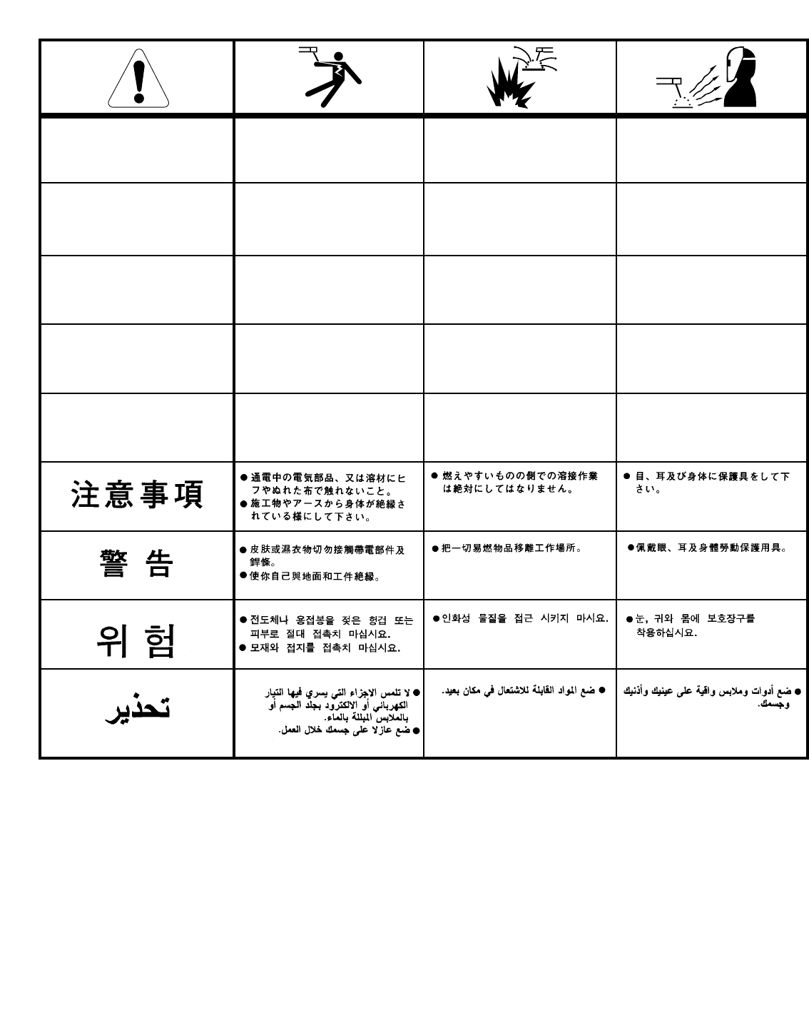
WARNING
AVISO DE
PRECAUCION
ATTENTION
WARNUNG
ATENÇÃO
Spanish
French
German
Portuguese
Japanese
Chinese
Korean
Arabic
READ AND UNDERSTAND THE MANUFACTURER’S INSTRUCTION FOR THIS EQUIPMENT AND THE CONSUMABLES TO
BE USED AND FOLLOW YOUR EMPLOYER’S SAFETY PRACTICES.
SE RECOMIENDA LEER Y ENTENDER LAS INSTRUCCIONES DEL FABRICANTE PARA EL USO DE ESTE EQUIPO Y LOS
CONSUMIBLES QUE VA A UTILIZAR, SIGA LAS MEDIDAS DE SEGURIDAD DE SU SUPERVISOR.
LISEZ ET COMPRENEZ LES INSTRUCTIONS DU FABRICANT EN CE QUI REGARDE CET EQUIPMENT ET LES PRODUITS A
ETRE EMPLOYES ET SUIVEZ LES PROCEDURES DE SECURITE DE VOTRE EMPLOYEUR.
LESEN SIE UND BEFOLGEN SIE DIE BETRIEBSANLEITUNG DER ANLAGE UND DEN ELEKTRODENEINSATZ DES HER-
STELLERS. DIE UNFALLVERHÜTUNGSVORSCHRIFTEN DES ARBEITGEBERS SIND EBENFALLS ZU BEACHTEN.
●Do not touch electrically live parts or
electrode with skin or wet clothing.
●Insulate yourself from work and
ground.
●No toque las partes o los electrodos
bajo carga con la piel o ropa moja-
da.
●Aislese del trabajo y de la tierra.
●Ne laissez ni la peau ni des vête-
ments mouillés entrer en contact
avec des pièces sous tension.
●Isolez-vous du travail et de la terre.
●Berühren Sie keine stromführenden
Teile oder Elektroden mit Ihrem
Körper oder feuchter Kleidung!
●Isolieren Sie sich von den
Elektroden und dem Erdboden!
●Não toque partes elétricas e elec-
trodos com a pele ou roupa molha-
da.
●Isole-se da peça e terra.
●Keep flammable materials away.
●Mantenga el material combustible
fuera del área de trabajo.
●Gardez à l’écart de tout matériel
inflammable.
●Entfernen Sie brennbarres Material!
●Mantenha inflamáveis bem guarda-
dos.
●Wear eye, ear and body protection.
●Protéjase los ojos, los oídos y el
cuerpo.
●Protégez vos yeux, vos oreilles et
votre corps.
●Tragen Sie Augen-, Ohren- und Kör-
perschutz!
●Use proteção para a vista, ouvido e
corpo.
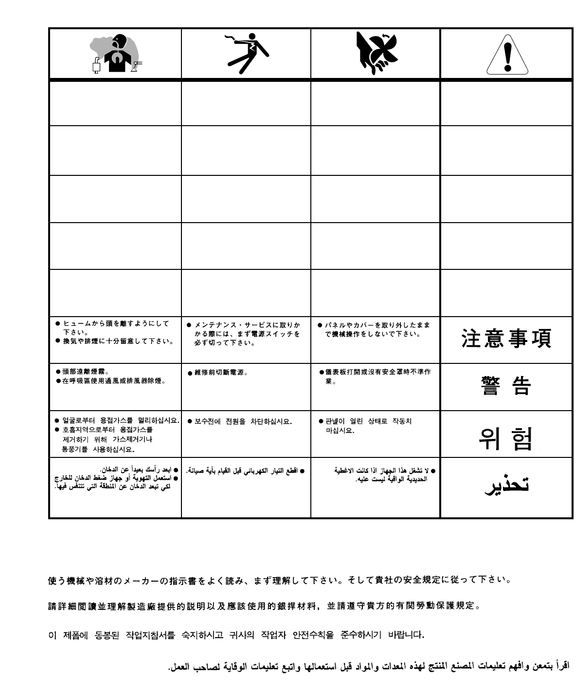
WARNING
AVISO DE
PRECAUCION
ATTENTION
WARNUNG
ATENÇÃO
Spanish
French
German
Portuguese
Japanese
Chinese
Korean
Arabic
LEIA E COMPREENDA AS INSTRUÇÕES DO FABRICANTE PARA ESTE EQUIPAMENTO E AS PARTES DE USO, E SIGA AS
PRÁTICAS DE SEGURANÇA DO EMPREGADOR.
●Keep your head out of fumes.
●Use ventilation or exhaust to
remove fumes from breathing zone.
●Los humos fuera de la zona de res-
piración.
●Mantenga la cabeza fuera de los
humos. Utilice ventilación o
aspiración para gases.
●Gardez la tête à l’écart des fumées.
●Utilisez un ventilateur ou un aspira-
teur pour ôter les fumées des zones
de travail.
●Vermeiden Sie das Einatmen von
Schweibrauch!
●Sorgen Sie für gute Be- und
Entlüftung des Arbeitsplatzes!
●Mantenha seu rosto da fumaça.
●Use ventilação e exhaustão para
remover fumo da zona respiratória.
●Turn power off before servicing.
●Desconectar el cable de ali-
mentación de poder de la máquina
antes de iniciar cualquier servicio.
●Débranchez le courant avant l’entre-
tien.
●Strom vor Wartungsarbeiten
abschalten! (Netzstrom völlig öff-
nen; Maschine anhalten!)
●Não opere com as tampas removidas.
●Desligue a corrente antes de fazer
serviço.
●Não toque as partes elétricas nuas.
●Do not operate with panel open or
guards off.
●No operar con panel abierto o
guardas quitadas.
●N’opérez pas avec les panneaux
ouverts ou avec les dispositifs de
protection enlevés.
●Anlage nie ohne Schutzgehäuse
oder Innenschutzverkleidung in
Betrieb setzen!
●Mantenha-se afastado das partes
moventes.
●Não opere com os paineis abertos
ou guardas removidas.

• Sales and Service through Subsidiaries and Distributors Worldwide •
Cleveland, Ohio 44117-1199 U.S.A. TEL: 216.481.8100 FAX: 216.486.1751 WEB SITE: www.lincolnelectric.com
• World's Leader in Welding and Cutting Products •
