Im676 RED D ARC PM 255
User Manual: RED-D-ARC PM 255
Open the PDF directly: View PDF ![]() .
.
Page Count: 38
- Table of Contents
- Safety
- Installation
- Operation
- Safety Precautions
- Product Description
- Recommended Processes and Equipment
- Welding Capability
- Limitations
- Description of Controls
- Wire Drive Roll
- Wire Size Conversion Parts
- Procedure for Changing Drive Roll
- Wire Reel Loading
- Mounting of 10 to 44 lbs. Spools
- To Start the Welder
- Feeding Wire Electrode
- Idle Roll Pressure Setting
- Setting Run-In Speed
- Making A Weld
- Avoiding Wire Feeding Problems
- Fan Control
- Input Line Voltage Protection
- Wire Feed Overload Protection
- Welding Thermal Overload Protection
- Overcurrent Protection
- Welding Procedure Information
- Accessories
- Maintenance
- Troubleshooting
- Wiring and Dimension Diagrams

RED-D-ARC
PM 255
Red-D-Arc Spec-Built Welding Equipment
This RED-D-ARC welder is built to RED-D-ARC Extreme Duty
design specifications by Lincoln Electric.
Safety Depends on You
This welder is designed and built with safety in mind.
However, your overall safety can be increased by proper installation
... and thoughtful operation on your part.
DO NOT INSTALL, OPERATE OR REPAIR THIS EQUIPMENT
WITHOUT READING THIS MANUAL AND THE SAFETY
PRECAUTIONS CONTAINED THROUGHOUT.
And, most importantly, think before you act and be careful.
For use with machines having Code Numbers: 10709
North America’s Largest Fleet of Welding Equipment
1-800-245-3660
OPERATOR’S MANUAL
IM676
MARCH, 2001
FOR ENGINE
powered equipment.
1.a. Turn the engine off before troubleshooting and maintenance
work unless the maintenance work requires it to be running.
____________________________________________________
1.b. Operate engines in open, well-ventilated
areas or vent the engine exhaust fumes
outdoors.
____________________________________________________
1.c. Do not add the fuel near an open flame
welding arc or when the engine is running.
Stop the engine and allow it to cool before
refueling to prevent spilled fuel from vaporiz-
ing on contact with hot engine parts and
igniting. Do not spill fuel when filling tank. If
fuel is spilled, wipe it up and do not start
engine until fumes have been eliminated.
____________________________________________________
1.d. Keep all equipment safety guards, covers and devices in
position and in good repair.Keep hands, hair, clothing and
tools away from V-belts, gears, fans and all other moving
parts when starting, operating or repairing equipment.
____________________________________________________
1.e. In some cases it may be necessary to remove safety
guards to perform required maintenance. Remove
guards only when necessary and replace them when the
maintenance requiring their removal is complete.
Always use the greatest care when working near moving
parts.
___________________________________________________
1.f. Do not put your hands near the engine fan.
Do not attempt to override the governor or
idler by pushing on the throttle control rods
while the engine is running.
___________________________________________________
1.g. To prevent accidentally starting gasoline engines while
turning the engine or welding generator during maintenance
work, disconnect the spark plug wires, distributor cap or
magneto wire as appropriate.
i
SAFETY
i
ARC WELDING CAN BE HAZARDOUS. PROTECT YOURSELF AND OTHERS FROM POSSIBLE SERIOUS INJURY OR DEATH.
KEEP CHILDREN AWAY. PACEMAKER WEARERS SHOULD CONSULT WITH THEIR DOCTOR BEFORE OPERATING.
Read and understand the following safety highlights. For additional safety information, it is strongly recommended that you
purchase a copy of “Safety in Welding & Cutting - ANSI Standard Z49.1” from the American Welding Society, P.O. Box
351040, Miami, Florida 33135 or CSA Standard W117.2-1974. A Free copy of “Arc Welding Safety” booklet E205 is available
from the Lincoln Electric Company, 22801 St. Clair Avenue, Cleveland, Ohio 44117-1199.
BE SURE THAT ALL INSTALLATION, OPERATION, MAINTENANCE AND REPAIR PROCEDURES ARE
PERFORMED ONLY BY QUALIFIED INDIVIDUALS.
WARNING
Mar ‘95
ELECTRIC AND
MAGNETIC FIELDS
may be dangerous
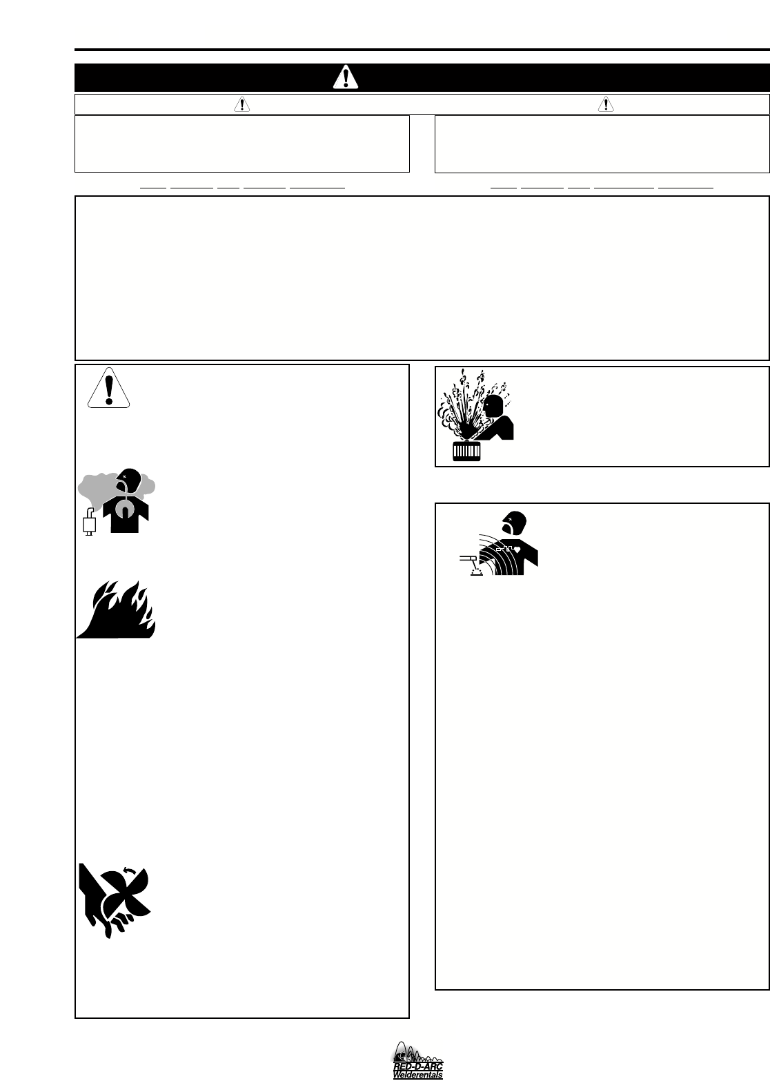
2.a. Electric current flowing through any conductor causes
localized Electric and Magnetic Fields (EMF). Welding
current creates EMF fields around welding cables and
welding machines
2.b. EMF fields may interfere with some pacemakers, and
welders having a pacemaker should consult their physician
before welding.
2.c. Exposure to EMF fields in welding may have other health
effects which are now not known.
2.d. All welders should use the following procedures in order to
minimize exposure to EMF fields from the welding circuit:
2.d.1.
Route the electrode and work cables together - Secure
them with tape when possible.
2.d.2. Never coil the electrode lead around your body.
2.d.3. Do not place your body between the electrode and
work cables. If the electrode cable is on your right
side, the work cable should also be on your right side.
2.d.4. Connect the work cable to the workpiece as close as
possible to the area being welded.
2.d.5. Do not work next to welding power source.
1.h. To avoid scalding, do not remove the
radiator pressure cap when the engine is
hot.
CALIFORNIA PROPOSITION 65 WARNINGS
Diesel engine exhaust and some of its constituents
are known to the State of California to cause can-
cer, birth defects, and other reproductive harm.
The engine exhaust from this product contains
chemicals known to the State of California to cause
cancer, birth defects, or other reproductive harm.
The Above For Diesel Engines The Above For Gasoline Engines
PM255
ii
SAFETY
ii
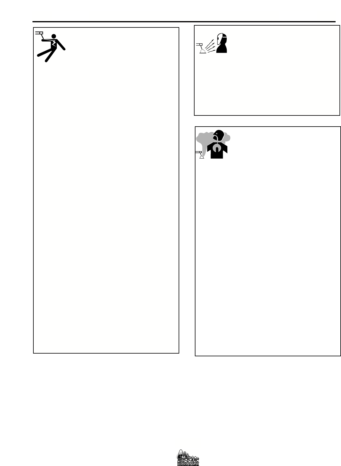
ARC RAYS can burn.
4.a. Use a shield with the proper filter and cover
plates to protect your eyes from sparks and
the rays of the arc when welding or observing
open arc welding. Headshield and filter lens
should conform to ANSI Z87. I standards.
4.b. Use suitable clothing made from durable flame-resistant
material to protect your skin and that of your helpers from
the arc rays.
4.c. Protect other nearby personnel with suitable, non-flammable
screening and/or warn them not to watch the arc nor expose
themselves to the arc rays or to hot spatter or metal.
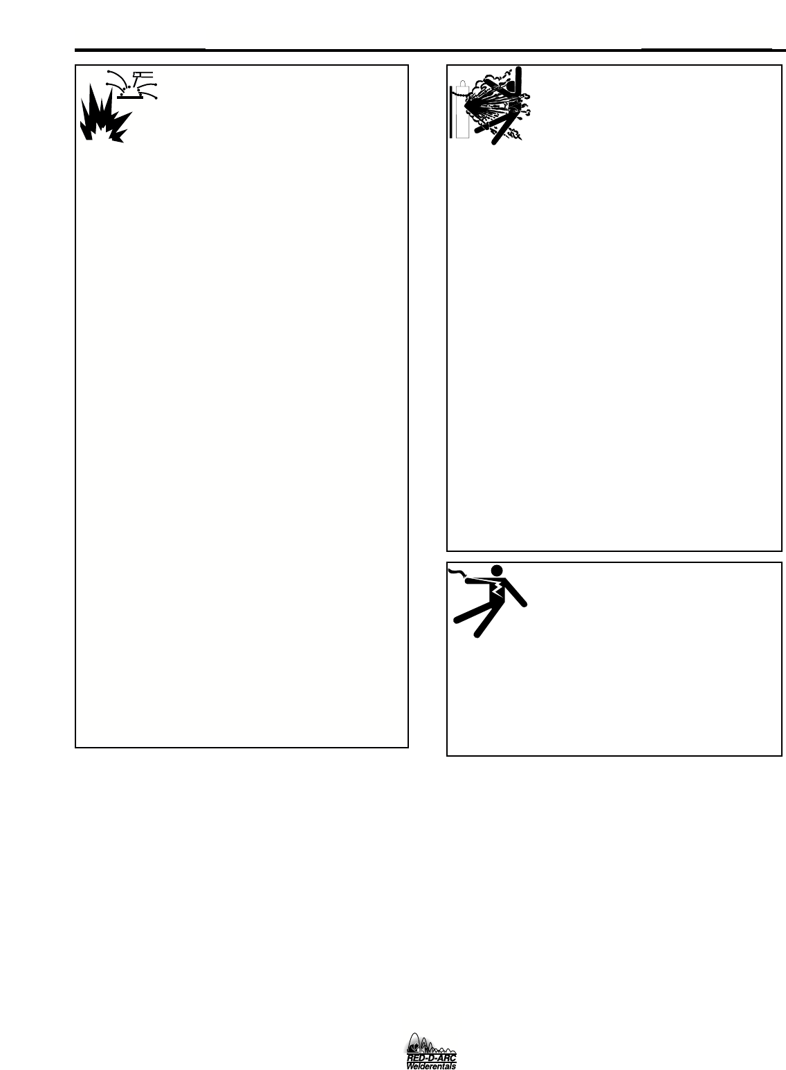
ELECTRIC SHOCK can
kill.
3.a. The electrode and work (or ground) circuits
are electrically “hot” when the welder is on.
Do not touch these “hot” parts with your bare
skin or wet clothing. Wear dry, hole-free
gloves to insulate hands.
3.b. Insulate yourself from work and ground using dry insulation.
Make certain the insulation is large enough to cover your full
area of physical contact with work and ground.
In addition to the normal safety precautions, if welding
must be performed under electrically hazardous
conditions (in damp locations or while wearing wet
clothing; on metal structures such as floors, gratings or
scaffolds; when in cramped positions such as sitting,
kneeling or lying, if there is a high risk of unavoidable or
accidental contact with the workpiece or ground) use
the following equipment:
• Semiautomatic DC Constant Voltage (Wire) Welder.
• DC Manual (Stick) Welder.
• AC Welder with Reduced Voltage Control.
3.c. In semiautomatic or automatic wire welding, the electrode,
electrode reel, welding head, nozzle or semiautomatic
welding gun are also electrically “hot”.
3.d. Always be sure the work cable makes a good electrical
connection with the metal being welded. The connection
should be as close as possible to the area being welded.
3.e. Ground the work or metal to be welded to a good electrical
(earth) ground.
3.f.
Maintain the electrode holder, work clamp, welding cable and
welding machine in good, safe operating condition. Replace
damaged insulation.
3.g. Never dip the electrode in water for cooling.
3.h. Never simultaneously touch electrically “hot” parts of
electrode holders connected to two welders because voltage
between the two can be the total of the open circuit voltage
of both welders.
3.i. When working above floor level, use a safety belt to protect
yourself from a fall should you get a shock.
3.j. Also see Items 6.c. and 8.
PM 255
FUMES AND GASES
can be dangerous.
5.a. Welding may produce fumes and gases
hazardous to health. Avoid breathing these
fumes and gases.When welding, keep
your head out of the fume. Use enough
ventilation and/or exhaust at the arc to keep
fumes and gases away from the breathing zone. When
welding with electrodes which require special
ventilation such as stainless or hard facing (see
instructions on container or MSDS) or on lead or
cadmium plated steel and other metals or coatings
which produce highly toxic fumes, keep exposure as
low as possible and below Threshold Limit Values (TLV)
using local exhaust or mechanical ventilation. In
confined spaces or in some circumstances, outdoors, a
respirator may be required. Additional precautions are
also required when welding on galvanized steel.
5.b.
Do not weld in locations near chlorinated hydrocarbon
vapors
coming from degreasing, cleaning or spraying operations.
The heat and rays of the arc can react with solvent vapors
to
form phosgene, a highly toxic gas, and other irritating prod-
ucts.
5.c. Shielding gases used for arc welding can displace air and
cause injury or death. Always use enough ventilation,
especially in confined areas, to insure breathing air is safe.
5.d. Read and understand the manufacturer’s instructions for this
equipment and the consumables to be used, including the
material safety data sheet (MSDS) and follow your
employer’s safety practices. MSDS forms are available from
your welding distributor or from the manufacturer.
5.e. Also see item 1.b.
Mar ‘95
FOR ELECTRICALLY
powered equipment.
8.a. Turn off input power using the disconnect
switch at the fuse box before working on
the equipment.
8.b. Install equipment in accordance with the U.S. National
Electrical Code, all local codes and the manufacturer’s
recommendations.
8.c. Ground the equipment in accordance with the U.S. National
Electrical Code and the manufacturer’s recommendations.
CYLINDER may explode
if damaged.
7.a. Use only compressed gas cylinders
containing the correct shielding gas for the
process used and properly operating
regulators designed for the gas and
pressure used. All hoses, fittings, etc. should be suitable for
the application and maintained in good condition.
7.b. Always keep cylinders in an upright position securely
chained to an undercarriage or fixed support.
7.c. Cylinders should be located:
• Away from areas where they may be struck or subjected to
physical damage.
• A safe distance from arc welding or cutting operations and
any other source of heat, sparks, or flame.
7.d. Never allow the electrode, electrode holder or any other
electrically “hot” parts to touch a cylinder.
7.e. Keep your head and face away from the cylinder valve outlet
when opening the cylinder valve.
7.f. Valve protection caps should always be in place and hand
tight except when the cylinder is in use or connected for
use.
7.g. Read and follow the instructions on compressed gas
cylinders, associated equipment, and CGA publication P-l,
“Precautions for Safe Handling of Compressed Gases in
Cylinders,” available from the Compressed Gas Association
1235 Jefferson Davis Highway, Arlington, VA 22202.
iii
SAFETY
iii
Mar ‘95
WELDING SPARKS can
cause fire or explosion.
6.a.
Remove fire hazards from the welding area.
If this is not possible, cover them to prevent
the welding sparks from starting a fire.
Remember that welding sparks and hot
materials from welding can easily go through small cracks
and openings to adjacent areas. Avoid welding near
hydraulic lines. Have a fire extinguisher readily available.
6.b. Where compressed gases are to be used at the job site,
special precautions should be used to prevent hazardous
situations. Refer to “Safety in Welding and Cutting” (ANSI
Standard Z49.1) and the operating information for the
equipment being used.
6.c. When not welding, make certain no part of the electrode
circuit is touching the work or ground. Accidental contact
can cause overheating and create a fire hazard.
6.d. Do not heat, cut or weld tanks, drums or containers until the
proper steps have been taken to insure that such procedures
will not cause flammable or toxic vapors from substances
inside. They can cause an explosion even
though
they have
been “cleaned”. For information, purchase “Recommended
Safe Practices for the
Preparation
for Welding and Cutting of
Containers and Piping That Have Held Hazardous
Substances”, AWS F4.1 from the American Welding Society
(see address above).
6.e. Vent hollow castings or containers before heating, cutting or
welding. They may explode.
6.f.
Sparks and spatter are thrown from the welding arc. Wear oil
free protective garments such as leather gloves, heavy shirt,
cuffless trousers, high shoes and a cap over your hair. Wear
ear plugs when welding out of position or in confined places.
Always wear safety glasses with side shields when in a
welding area.
6.g. Connect the work cable to the work as close to the welding
area as practical. Work cables connected to the building
framework or other locations away from the welding area
increase the possibility of the welding current passing
through lifting chains, crane cables or other alternate cir-
cuits. This can create fire hazards or overheat lifting chains
or cables until they fail.
6.h. Also see item 1.c.
PM 255

iv
SAFETY
iv
PRÉCAUTIONS DE SÛRETÉ
Pour votre propre protection lire et observer toutes les instructions
et les précautions de sûreté specifiques qui parraissent dans ce
manuel aussi bien que les précautions de sûreté générales suiv-
antes:
Sûreté Pour Soudage A L’Arc
1. Protegez-vous contre la secousse électrique:
a. Les circuits à l’électrode et à la piéce sont sous tension
quand la machine à souder est en marche. Eviter toujours
tout contact entre les parties sous tension et la peau nue
ou les vétements mouillés. Porter des gants secs et sans
trous pour isoler les mains.
b. Faire trés attention de bien s’isoler de la masse quand on
soude dans des endroits humides, ou sur un plancher
metallique ou des grilles metalliques, principalement dans
les positions assis ou couché pour lesquelles une grande
partie du corps peut être en contact avec la masse.
c. Maintenir le porte-électrode, la pince de masse, le câble
de soudage et la machine à souder en bon et sûr état
defonctionnement.
d.Ne jamais plonger le porte-électrode dans l’eau pour le
refroidir.
e. Ne jamais toucher simultanément les parties sous tension
des porte-électrodes connectés à deux machines à soud-
er parce que la tension entre les deux pinces peut être le
total de la tension à vide des deux machines.
f. Si on utilise la machine à souder comme une source de
courant pour soudage semi-automatique, ces precautions
pour le porte-électrode s’applicuent aussi au pistolet de
soudage.
2. Dans le cas de travail au dessus du niveau du sol, se pro-
téger contre les chutes dans le cas ou on recoit un choc. Ne
jamais enrouler le câble-électrode autour de n’importe quelle
partie du corps.
3. Un coup d’arc peut être plus sévère qu’un coup de soliel,
donc:
a. Utiliser un bon masque avec un verre filtrant approprié
ainsi qu’un verre blanc afin de se protéger les yeux du
rayonnement de l’arc et des projections quand on soude
ou quand on regarde l’arc.
b. Porter des vêtements convenables afin de protéger la
peau de soudeur et des aides contre le rayonnement de
l‘arc.
c. Protéger l’autre personnel travaillant à proximité au
soudage à l’aide d’écrans appropriés et non-inflamma-
bles.
4. Des gouttes de laitier en fusion sont émises de l’arc de
soudage. Se protéger avec des vêtements de protection
libres de l’huile, tels que les gants en cuir, chemise épaisse,
pantalons sans revers, et chaussures montantes.
5. Toujours porter des lunettes de sécurité dans la zone de
soudage. Utiliser des lunettes avec écrans lateraux dans les
zones où l’on pique le laitier.
6. Eloigner les matériaux inflammables ou les recouvrir afin de
prévenir tout risque d’incendie dû aux étincelles.
7. Quand on ne soude pas, poser la pince à une endroit isolé de
la masse. Un court-circuit accidental peut provoquer un
échauffement et un risque d’incendie.
8. S’assurer que la masse est connectée le plus prés possible
de la zone de travail qu’il est pratique de le faire. Si on place
la masse sur la charpente de la construction ou d’autres
endroits éloignés de la zone de travail, on augmente le risque
de voir passer le courant de soudage par les chaines de lev-
age, câbles de grue, ou autres circuits. Cela peut provoquer
des risques d’incendie ou d’echauffement des chaines et des
câbles jusqu’à ce qu’ils se rompent.
9. Assurer une ventilation suffisante dans la zone de soudage.
Ceci est particuliérement important pour le soudage de tôles
galvanisées plombées, ou cadmiées ou tout autre métal qui
produit des fumeés toxiques.
10. Ne pas souder en présence de vapeurs de chlore provenant
d’opérations de dégraissage, nettoyage ou pistolage. La
chaleur ou les rayons de l’arc peuvent réagir avec les vapeurs
du solvant pour produire du phosgéne (gas fortement toxique)
ou autres produits irritants.
11. Pour obtenir de plus amples renseignements sur la sûreté,
voir le code “Code for safety in welding and cutting” CSA
Standard W 117.2-1974.
PRÉCAUTIONS DE SÛRETÉ POUR
LES MACHINES À SOUDER À
TRANSFORMATEUR ET À
REDRESSEUR
1. Relier à la terre le chassis du poste conformement au code de
l’électricité et aux recommendations du fabricant. Le dispositif
de montage ou la piece à souder doit être branché à une
bonne mise à la terre.
2. Autant que possible, I’installation et l’entretien du poste seront
effectués par un électricien qualifié.
3. Avant de faires des travaux à l’interieur de poste, la debranch-
er à l’interrupteur à la boite de fusibles.
4. Garder tous les couvercles et dispositifs de sûreté à leur
place.
Mar. ‘93
PM 255

PM 255
Thank You for selecting a QUALITY product. We want you to take pride in
operating this product ••• as much pride as we have in bringing
this product to you!
Read this Operators Manual completely before attempting to use this equipment. Save this manual and keep it
handy for quick reference. Pay particular attention to the safety instructions we have provided for your protection.
The level of seriousness to be applied to each is explained below:
WARNING
This statement appears where the information must be followed exactly to avoid serious personal injury or
loss of life.
This statement appears where the information must be followed to avoid minor personal injury or damage to
this equipment.
CAUTION
Please Examine Carton and Equipment For Damage Immediately
When this equipment is shipped, title passes to the purchaser upon receipt by the carrier. Consequently, Claims
for material damaged in shipment must be made by the purchaser against the transportation company at the
time the shipment is received.
Please record your equipment identification information below for future reference. This information can be
found on your machine nameplate.
Model Name & Number _____________________________________
Code & Serial Number _____________________________________
Date of Purchase _____________________________________
Whenever you request replacement parts for or information on this equipment always supply the information
you have recorded above.
vv

vi
vi
MASTER TABLE OF CONTENTS FOR ALL SECTIONS
Page
Installation .......................................................................................................Section A
Technical Specifications ........................................................................................A-1
Safety Precautions.................................................................................................A-2
Uncrating the PM 255............................................................................................A-2
Location .................................................................................................................A-2
Input Power, Grounding and connection Diagrams .......................................A-2, A-3
Output Polarity Connections..................................................................................A-4
Gun and Cable Installation ....................................................................................A-5
Shielding Gas ........................................................................................................A-5
Operation .........................................................................................................Section B
Safety Precautions.................................................................................................B-1
Product Description ...............................................................................................B-2
Recommended Processes and Equipment ...........................................................B-2
Welding Capability.................................................................................................B-2
Limitations..............................................................................................................B-2
Description of Controls ..........................................................................................B-2
Wire Drive Roll.......................................................................................................B-2
Wire Size Conversion parts ...................................................................................B-2
Procedure for Changing Drive Roll........................................................................B-3
Wire Reel Loading .................................................................................................B-3
Mounting of 10 to 44 lbs. Spools ...........................................................................B-3
To Start the Welder................................................................................................B-3
Feeding Wire Electrode .........................................................................................B-4
Idle Roll Pressure Setting ......................................................................................B-4
Setting Run-in Speed.............................................................................................B-4
Making a Weld.......................................................................................................B-5
Avoiding Wire Feeding Problems ..........................................................................B-5
Fan Control............................................................................................................B-6
Input Line Voltage Protection.................................................................................B-6
Wire Feed overload Protection ..............................................................................B-6
Welding Thermal Overload Protection...................................................................B-6
Overcurrent Protection...........................................................................................B-6
Welding Procedure Information .............................................................................B-6
Accessories.....................................................................................................Section C
Drive Roll Kits........................................................................................................C-1
Aluminum Feeding Kit (Optional K1703-1)............................................................C-1
K363P Readi-Reel Adapter ...................................................................................C-1
Dual Cylinder Mounting Kit (K1702-1)...................................................................C-1
Alternative Magnum GMAW Gun and Cable Assemblies .....................................C-1
Magnum Gun Connection Kit (Optional K466-6)...................................................C-1
Timer Kit Installation (Optional K1701-1)...............................................................C-1
Operating Instructions for Timer Kit ................................................................C-2
Spool Gun Adapter Kit (Optional K1700-1) ...........................................................C-3
Making a Weld with the Spool Gun Adapter Kit and Spool Gun Installed.......C-3
PM 255

vii vii
MASTER TABLE OF CONTENTS FOR ALL SECTIONS (cont.)
Page
Maintenance ....................................................................................................Section D
Safety Precautions ................................................................................................D-1
General Maintenance ............................................................................................D-1
Drive Rolls and guide Tubes .................................................................................D-1
Contact Tip and Gas Nozzle Installation ...............................................................D-1
Gun Tubes and Nozzles........................................................................................D-1
Cable Cleaning......................................................................................................D-1
Liner Removal and Replacement ..........................................................................D-2
Gun Handle Disassembly......................................................................................D-2
Accessories and Expendable Replacement Parts................................................D-3
Troubleshooting..............................................................................................Section E
How to Use Troubleshooting Guide.......................................................................E-1
Troubleshooting Guide ............................................................................E-2 thru E-4
Wiring and Dimension Diagrams......................................................................Section F
Parts Manual....................................................................................................Appendix
PM 255 ...................................................................................................P382 Series
Magnum 250L Gun .....................................................................................P202-H.2
PM 255
A-1
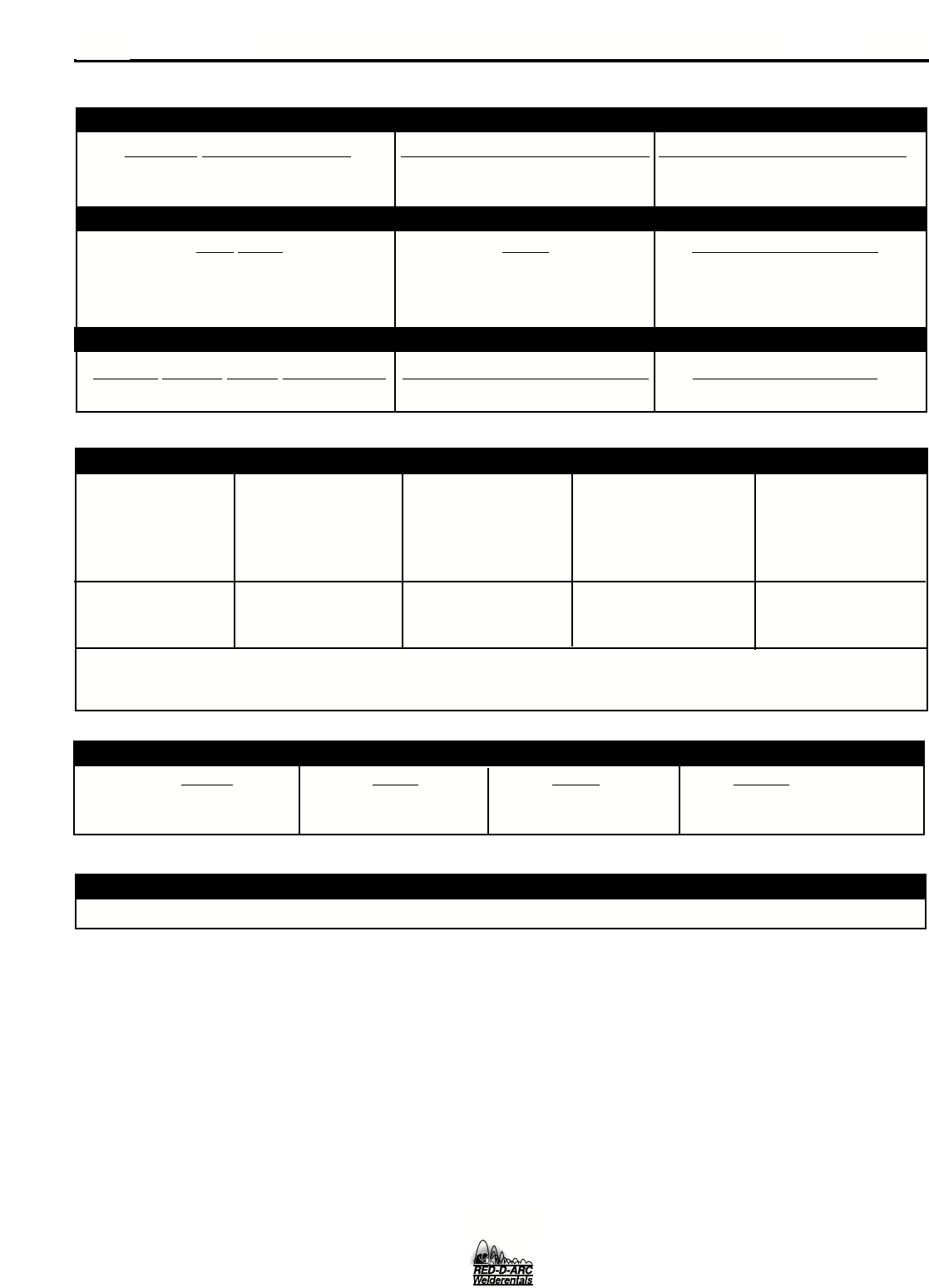
A-1 INSTALLATION
75°C Copper Wire 75°C Copper Wire
Input Ampere in Conduit in Conduit
Input Voltage/ Fuse or Breaker Rating On AWG (IEC) Sizes AWG (IEC) Sizes
(For lengths (For lengths
Frequency (Hz) Size (Super Lag) Nameplate up to 100 ft.) exceeding 100 ft.)
230/60 60 46 10 (6 mm2) 8 (10 mm2)
460/60 30 24 14 (2.5 mm2) 12 (4 mm2)
575/60 25 19 14 (2.5 mm2) 12 (4 mm2)
NOTE: Use #10 AWG Grounding Wire
TECHNICAL SPECIFICATIONS – PM 255
INPUT – SINGLE PHASE ONLY
RATED OUTPUT
OUTPUT
RECOMMENDED INPUT WIRE AND FUSE SIZES
Height Width Depth Weight
31.79 in 18.88 in 38.78 in 220 Ibs
808 mm 480 mm 985 mm 100 kg
PHYSICAL DIMENSIONS
Wire Speed 50 – 700 IPM (1.27 – 17.8 m/minute)
WIRE SPEED RANGE
Standard Voltage/Frequency
Input Current @ 200 Amp Rated Output Input Current @ 250 Amp Rated Output
230/460/575/60 Hz 41/20/16 Amps 50/24/19
Duty Cycle Amps Volts at Rated Amperes
40% 250 Amps 26 Volts
60% 200 Amps 28 Volts
100% 145 Amps 26 Volts
Welding Current Range (Continuous) Maximum Open Circuit Voltage Welding Voltage Range
30 – 300 Amps 40 Volts 10-28 Volts
PM 255

A-2 A-2
INSTALLATION
INPUT POWER, GROUNDING AND
CONNECTION DIAGRAMS
1. Before starting the installation, check with the local
power company if there is any question about
whether your power supply is adequate for the volt-
age, amperes, phase, and frequency specified on
the welder nameplate. Also be sure the planned
installation will meet the U.S. National Electrical
Code and local code requirements. This welder
may be operated from a single phase line or from
one phase of a two or three phase line.
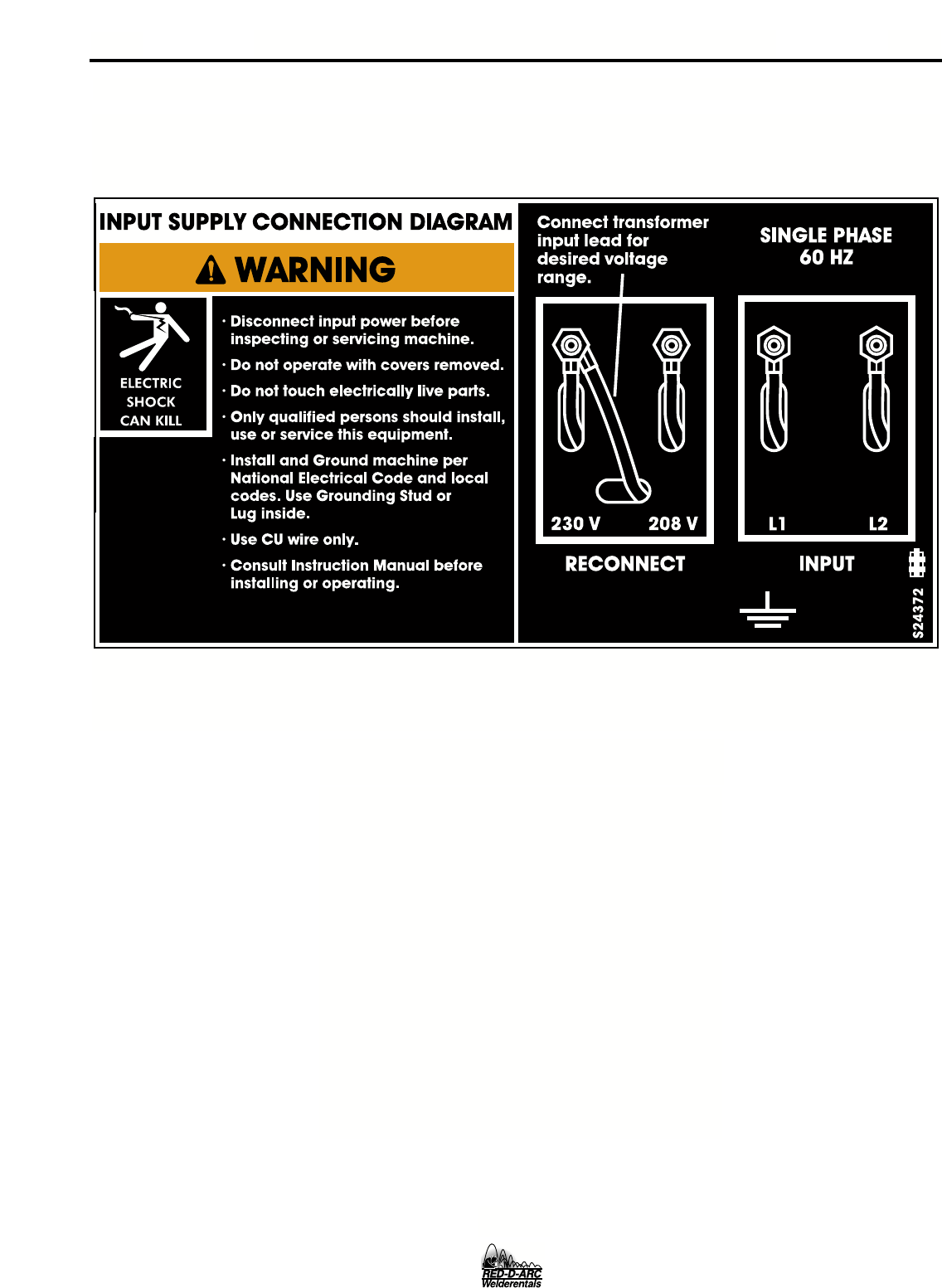
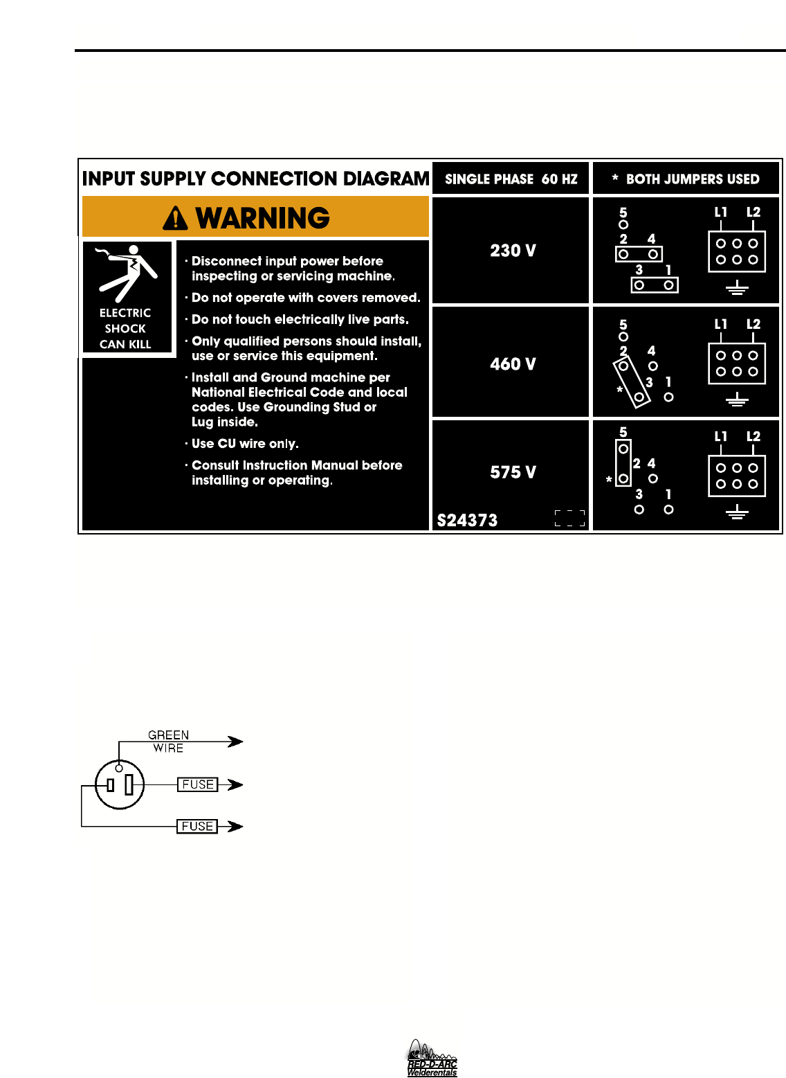
2. Models that have multiple input voltages specified
on the nameplate (e.g. 208/230) are shipped con-
nected for the highest voltage. If the welder is to be
operated on lower voltage, it must be reconnected
according to the instructions in Figure A.1 for dual
voltage machines and Figure A.2 for triple voltage
machines.
Make certain that the input power is electrically
disconnected before removing the screw on the
reconnect panel access cover.
Read entire installation section before starting
installation.
SAFETY PRECAUTIONS
ELECTRIC SHOCK can kill.
• Only qualified personnel should perform
this installation.
• Only personnel that have read and under-
stood the PM 255 Operating Manual should
install and operate this equipment.
• Machine must be grounded per any nation-
al, local or other applicable electrical
codes.
• The POWER MIG power switch is to be in
the OFF position when installing work
cable and gun and when connecting other
equipment.
WARNING
UNCRATING THE PM 255
Cut banding and lift off cardboard carton. Cut banding
holding the machine to the skid. Remove foam and
corrugated packing material. Untape accessories from
Gas Bottle Platform. Unscrew the two wood screws (at
the Gas Bottle Platform) holding the machine to the
skid. Roll the machine off the skid assembly.
LOCATION
Locate the welder in a dry location where there is free
circulation of clean air into the louvers in the back and
out the front. A location that minimizes the amount of
smoke and dirt drawn into the rear louvers reduces
the chance of dirt accumulation that can block air pas-
sages and cause overheating.
ELECTRIC SHOCK can kill.
• Do not touch electrically live parts such as
output terminals or internal wiring.
• All input power must be electrically dis-
connected before proceeding.
WARNING
WARNING
PM 255
A-3
A-3 INSTALLATION
4. Using the instructions in Figure A.3, have a quali-
fied electrician connect the receptacle or cable to
the input power lines and the system ground per
the U.S. National Electrical Code and any applica-
ble local codes. See “Technical Specifications” at
the beginning of this chapter for proper wire sizes.
For long runs over 100 feet, larger copper wires
should be used. Fuse the two hot lines with super
lag type fuses as shown in the following diagram.
The center contact in the receptacle is for the
grounding connection. A green wire in the input
cable connects this contact to the frame of the
welder. This ensures proper grounding of the
welder frame when the welder plug is inserted into
the receptacle.
FIGURE A.1 — Dual Voltage Machine Input Connections
3. The 230/460/575 volt 60 Hz model is not equipped
with an input cable or a plug.
PM 255
A-4A-4 INSTALLATION
FIGURE A.3 — Receptacle Diagram
CONNECT TO A SYSTEM
GROUNDING WIRE. SEE
THE UNITED STATES
NATIONAL ELECTRICAL
CODE AND/OR LOCAL
CODES FOR OTHER
DETAILS AND MEANS
FOR PROPER GROUND-
ING.
CONNECT TO HOT
WIRES OF A THREE-
WIRE, SINGLE PHASE
SYSTEM OR TO ONE
PHASE OF A TWO OR
THREE PHASE SYSTEM.
OUTPUT POLARITY CONNECTIONS
The welder, as shipped from the factory, is connected
for electrode positive (+) polarity. This is the normal
polarity for GMA welding.
If negative (–) polarity is required, interchange the
connection of the two cables located in the wire drive
compartment near the front panel. The electrode
cable, which is attached to the wire drive, is to be
connected to the negative (–) labeled terminal and
the work lead, which is attached to the work clamp, is
to be connected to the positive (+) labeled terminal.
FIGURE A.2 — Triple Voltage Machine Input Connections
PM 255

GUN AND CABLE INSTALLATION
The Magnum 250L gun and cable provided with the
PM 255 is factory installed with a liner for .035-.045"
(0.9-1.2 mm) electrode and an .035" (0.9 mm) contact
tip. Install the .045 tip (also provided) if this wire size
is being used.
Turn the welder power switch off before installing
gun and cable.
1. Lay the cable out straight.
2. Unscrew knurled screw on the drive unit front end
(inside wire feed compartment) until tip of screw no
longer protrudes into gun opening as seen from
front of machine.
3. Insert the male end of gun cable into the female
casting through opening in front panel. Make sure
connector is fully inserted and tighten knurled
screw.
4. Connect the gun trigger connector from the gun
and cable to the mating receptacle inside the com-
partment located above the gun connection made
in item 3 above. Make sure that the keyways are
aligned, insert and tighten retaining ring.
SHIELDING GAS
(For Gas Metal Arc Welding Processes)
Customer must provide cylinder of appropriate type
shielding gas for the process being used.
A gas flow regulator, for CO2or Argon blend gas, and
an inlet gas hose are factory provided with the PM
255.
Install shielding gas supply as follows:
1. Set gas cylinder on rear platform of PM 255. Hook
chain in place to secure cylinder to rear of welder.
WARNING
A-5
A-5 INSTALLATION
WARNING
2. Remove the cylinder cap. Inspect the cylinder
valves and regulator for damaged threads, dirt,
dust, oil or grease. Remove dust and dirt with a
clean cloth.
DO NOT ATTACH THE REGULATOR IF OIL,
GREASE OR DAMAGE IS PRESENT! Inform your
gas supplier of this condition. Oil or grease in the
presence of high pressure oxygen is explosive.
3. Stand to one side away from the outlet and open
the cylinder valve for an instant. This blows away
any dust or dirt which may have accumulated in the
valve outlet.
Be sure to keep your face away from the valve
outlet when “cracking” the valve.
4. Attach the flow regulator to the cylinder valve and
tighten the union nut(s) securely with a wrench.
NOTE: If connecting to 100% CO2cylinder, insert reg-
ulator adapter between regulator and cylinder
valve. If adapter is equipped with a plastic
washer, be sure it is seated for connection to
the CO2cylinder.
5. Attach one end of the inlet gas hose to the outlet
fitting of the flow regulator, the other end to the PM
255 rear fitting, and tighten the union nuts securely
with a wrench.
6. Before opening the cylinder valve, turn the regula-
tor adjusting knob counterclockwise until the
adjusting spring pressure is released.
7. Standing to one side, open the cylinder valve slow-
ly a fraction of a turn. When the cylinder pressure
gauge pointer stops moving, open the valve fully.
Never stand directly in front of or behind the flow
regulator when opening the cylinder valve. Always
stand to one side.
8. The flow regulator is adjustable. Adjust it to the flow
rate recommended for the procedure and process
being used before making the weld.
CYLINDER may explode if
damaged.
• Gas under pressure is explosive. Always
keep gas cylinders in an upright position
and always keep chained to undercarriage
or stationary support. See American
National Standard Z-49.1, “Safety in
Welding and Cutting” published by the
American Welding Society.
WARNING
PM 255
WARNING
B-1
B-1 OPERATION
Read entire Operation section before
operating the PM 255.
ELECTRIC SHOCK can kill.
• Do not touch electrically live
parts or electrode with skin or
wet clothing. Insulate yourself
from work and ground.
• Always wear dry insulating
gloves.
FUMES AND GASES can be
dangerous.
• Keep your head out of fumes.
• Use ventilation or exhaust to
remove fumes from breathing
zone.
WELDING SPARKS can
cause fire or explosion.
• Keep flammable material away.
• Do not weld on closed contain-
ers.
ARC RAYS can burn eyes
and skin.
• Wear eye, ear and body protec-
tion.
Observe all safety information throughout
this manual.
WARNING
PM 255

B-2B-2 OPERATION
PRODUCT DESCRIPTION
The PM 255 is a complete semiautomatic constant
voltage DC arc welding machine built to meet NEMA
specifications. It combines a constant voltage power
source and a constant speed wire feeder with a micro-
computer-based controller to form a reliable high-per-
formance welding system. A simple control scheme,
consisting of continuous full range voltage and wire
feed speed controls, provides versatility with ease of
use and accuracy.
Other features include a 2" (51 mm) O.D. wire reel
spindle with adjustable brake, an integral gas cylinder
mounting undercarriage, an adjustable CO2or Argon
blend flow regulator with cylinder pressure gauge and
inlet hose, a 12 ft. (3.6 m) Magnum 250L GMAW gun
and cable with fixed (flush) nozzle, a 10 ft. (3.0 m)
power cable with plug and mating receptacle, and a
10 ft. (3.0 m) work cable with clamp.
An Optional Timer kit provides variable burnback con-
trol, a spot function, a selectable 4-step trigger inter-
lock and adjustable “Run In” for wire starting optimiza-
tion. Also optional are a Spool Gun Adapter kit, a Dual
Cylinder Mounting kit and an Aluminum Feeding Kit
for push feeding with standard built in feeder.
RECOMMENDED PROCESSES AND
EQUIPMENT
The PM 255 is recommended for GMA welding
processes using 10 to 44 lb (4.5 to 20 kg) 2" (51 mm)
I.D. spools or Readi-Reel®coils (with optional
adapter) of .025" through .045" (0.6 – 1.2 mm) solid
steel, .035" (0.9 mm) stainless, 3/64" (1.2 mm) alu-
minum and .045" (1.2 mm) Outershield®; as well as
.035" (0.9 mm) and .045" (1.2 mm) Innershield®self-
shielding electrodes.
The PM 255 is factory equipped to feed .035" (0.9
mm) electrodes and provides tip, guide, and drive rolls
for .045(1.2mm) electrode. It also includes a 200A,
60% duty cycle (or 250A, 40% duty cycle) rated, 12 ft.
(3.6 m) GMAW gun and cable assembly equipped for
these wire sizes. Use of GMAW processes requires a
supply of shielding gas.
WELDING CAPABILITY
The PM 255 is rated at 250 amps @ 26 volts, at a
40% duty cycle based on a ten minute cycle time. It is
capable of higher duty cycles at lower output currents
and capable of up to 300 Amps at lower duty cycles.
LIMITATIONS
The PM 255 MAY NOT operate satisfactorily if pow-
ered with a portable or in-plant generating system.
DESCRIPTION OF CONTROLS
Power ON/OFF Switch — Place the lever in the “ON”
position to energize the PM 255. When the power is
on, the red LED display lights illuminate.
Voltage Control — This is a continuous control that
gives full range adjustment of power source output
voltage. It can be adjusted while welding over its 10 to
28 volt range.
Wire Speed Control — This controls the wire feed
speed from 50 – 700 inches per minute (1.2 – 17.8
m/min). The control can be preset on the dial to the
setting specified on the Procedure Decal on the inside
of the wire compartment door. Wire speed is not
affected when changes are made in the voltage con-
trol.
WIRE DRIVE ROLL
The drive rolls installed with the PM 255 each have
two grooves, both for .030-.035" (0.8-0.9 mm) solid
steel electrode. Drive roll size is indicated by the sten-
cilling on the exposed side of the drive roll. If feeding
problems occur, then the drive roll may be reversed or
changed. See “Procedure for Changing Drive Roll” in
this section. This information also appears on the
Procedure Decal on the door inside the wire compart-
ment. An additional drive roll set is provided for
.045"(1.2mm) solid steel electrode, packaged stan-
dard with each machine.
WIRE SIZE CONVERSION PARTS
The PM 255 is rated to feed .025 through .045" (0.6-
1.2 mm) solid or cored electrode sizes.
The drive roll kits and Magnum 250L gun and cable
parts are available to feed different sizes and types of
electrodes. See Accessories section.
PM 255
B-3
B-3 OPERATION
PROCEDURE FOR CHANGING
DRIVE AND IDLE ROLL SETS
1. Turn off the power source.
2. Release the pressure on the idle roll by swinging
the adjustable pressure arm down toward the back
of the machine. Lift the cast idle roll assembly and
allow it to sit in an upright position..
3. Remove the outside wire guide retaining plate by
loosening the two large knurled screws.
4. Twist the drive roll retaining mechanism to the
unlocked position as shown below and remove the
drive roll. (See Figure A.4)
5. Remove the inside wire guide plate.
6. Replace the drive and idle rolls and inside wire
guide with a set marked for the new wire size.
NOTE: Be sure that the gun liner and contact tip
are also sized to match the selected wire size.
7. Manually feed the wire from the wire reel, over the
drive roll groove and through the wire guide and
then into the brass bushing of the gun and cable
assembly.
8. Replace the outside wire guide retaining plate by
tightening the two large knurled screws. Reposition
the adjustable pressure arm to its original position
to apply pressure. Adjust pressure as necessary.
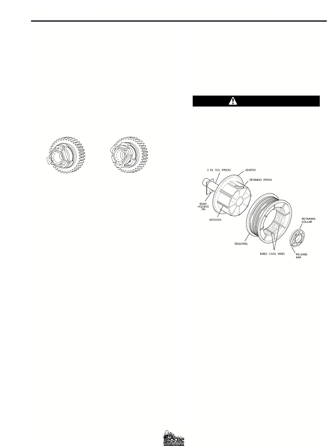
WIRE REEL LOADING - READI-REELS,
SPOOLS OR COILS
To Mount a 30 Lb. (14 kg) Readi-Reel Package
(Using the Molded Plastic K363-P Readi-Reel
Adapter:)
1. Open the Wire Drive Compartment Door
2. Depress the Release Bar on the Retaining Collar and
remove it from the spindle.
3. Place the Optional Adapter on the spindle
4. Re-install the Retaining Collar. Make sure that the Release
Bar “pops up” and that the collar retainers fully engage the
retaining ring groove on the spindle.
5. Rotate the spindle and adapter so the retaining spring is at
the 12 o'clock position.
6. Position the Readi-Reel so that it will rotate in a direction when feed-
ing so as to be de- reeled from top of the coil.
7. Set one of the Readi-Reel inside cage wires on the slot in the retain-
ing spring tab.
8. Lower the Readi-Reel to depress the retaining spring and align the
other inside cage wires with the grooves in the molded adapter.
9. Slide cage all the way onto the adapter until the retaining spring
"pops up" fully.
CHECK TO BE SURE THE RETAINING SPRING HAS FULLY
RETURNED TO THE LOCKING POSITION AND HAS SECURELY
LOCKED THE READI-REEL CAGE IN PLACE. RETAINING SPRING
MUST REST ON THE CAGE, NOT THE WELDING ELECTRODE.
-----------------------------------------------------------------------------------------------
10. To remove Readi-Reel from Adapter, depress retaining spring tab
with thumb while pulling the Readi-Reel cage from the molded
adapter with both hands. Do not remove adapter from spindle.
FIGURE B.1
To Mount 10 to 44 Lb. (4.5-20 kg) Spools (12"/300
mm Diameter) or 14Lb.(6 Kg) Innershield Coils:
(For 13-14 lb. (6 Kg) Innershield coils, a K435 Coil Adapter must be
used).
1. Open the Wire Drive Compartment Door
2. Depress the Release Bar on the Retaining Collar and remove it
from the spindle.
3. Place the spool on the spindle making certain the spindle brake
pin enters one of the holes in the back side of the spool (Note:
an arrow mark on the spindle lines up with the brake holding pin
to assist in lining up a hole). Be certain the wire comes off the
reel in a direction so as to de-reel from the top of the coil.
4. Re-install the Retaining Collar. Make sure that the Release Bar
“pops up” and that the collar retainers fully engage the retaining
ring groove on the spindle.
TO START THE WELDER
Turn the “Power Switch” switch to “ON”. This lights the red LED dis-
play lights. With the desired voltage and wire speed selected, oper-
ate the gun trigger for welder output and to energize the wire feed
motor.
and wire speed selected, operate the gun trigger
for welder output and to energize the wire feed motor.
CAUTION
PM 255
LOCKED POSITION
UNLOCKED POSITION
FIGURE A.4

B-4 B-4
OPERATION
FEEDING WIRE ELECTRODE
When triggering, the electrode and drive mecha-
nism are electrically “hot” relative to work and
ground and remain “hot” several seconds after
the gun trigger is released.
NOTE: Check that drive rolls, guide plates and gun
parts are proper for the wire size and type being used.
Refer to Table C.1 in Accessories section.
1. Turn the Readi-Reel or spool until the free end of
the electrode is accessible.
2. While securely holding the electrode, cut off the
bent end and straighten the first six inches. (If the
electrode is not properly straightened, it may not
feed properly through the wire drive system).
3. Release the pressure on the idle roll by swinging
the adjustable pressure arm down toward the back
of the machine. Lift the cast idle roll assembly and
allow it to sit in an upright position. Leave the outer
wire guide plate installed. Manually feed the wire
through the incoming guide bushing and through
the guide plates (over the drive roll groove). Push a
sufficient wire length to assure that the wire has fed
into the gun and cable assembly without restriction.
Reposition the adjustable pressure arm to its origi-
nal position to apply pressure to the wire.
4. Press gun trigger to feed the electrode wire through
the gun.
IDLE ROLL PRESSURE SETTING
The idle roll pressure adjustment knob is set at the
factory at the #2 hash mark. This is an approximate
setting. The optimum idle roll pressure varies with
type of wire, wire diameter, surface conditions, lubri-
cation, and hardness. As a general rule, hard wires
may require greater pressure, and soft, or aluminum
wire, may require less pressure than the factory set-
ting. The optimum idle roll setting can be determined
as follows:
1. Press end of gun against a solid object that is elec-
trically isolated from the welder output and press
the gun trigger for several seconds.
2. If the wire “birdnests”, jams or breaks at the drive
roll, the idle roll pressure is too great. Back the
adjustment knob out 1/2 turn, run new wire through
gun, and repeat above steps.
3. If the only result was drive roll slippage, loosen the
adjustment knob on the conductor plate and pull
the gun cable forward about 6" (15 cm). There
should be a slight waviness in the expose wire. If
there is not waviness, the pressure is too low.
Tighten the adjustment knob 1/4 turn, reinstall the
gun cable and repeat the above steps.
SETTING RUN-IN SPEED ON STAN-
DARD POWER MIG FEEDER
FAST OR SLOW RUN-IN MODE SELECTION,
(When Timer Option is not installed)
The PM 255 is factory set for fast run-in mode where
the wire feed will accelerate directly to the preset wire
feed speed when the gun trigger is closed.
Slow run-in mode may also be selected, where it will
initially feed wire at 50 IPM until output current is
sensed or for 1.0 seconds, whichever occurs first.
After which it will accelerate to the preset wire feed
speed.
NOTE: See operating instructions for Timer Option Kit
if it is installed, as it provides its own Run-in operation.
INSTRUCTIONS TO ENTER SLOW RUN-IN
1. Turn power OFF on front panel of PM 255.
2. Turn the wire feed speed dial to minimum, fully
counterclockwise.
3. With the gun trigger closed, turn the power ON at
the front panel of the PM 255.
4. The display will read “SLO run”.
INSTRUCTIONS TO ENTER FAST RUN-IN
1. Turn power OFF on front panel of PM 255.
2. Turn the wire feed speed dial to maximum, fully
clockwise.
3. With the gun trigger closed, turn the power ON at
the front panel of the PM 255.
4. The display will read “FAS run”.
NOTE:
Arc starting characteristics may be effected when
using the fast run-in mode since optimum starting
processes are being overridden.
On the initial trigger closure at power up, no output
power or wire feed will be available until the trigger is
opened and reclosed, regardless of wire feed speed
dial setting.
WARNING
PM 255

B-5B-5 OPERATION
It is not necessary to repeat either of the above proce-
dures each time the unit is powered up. The unit will
remember the run-in mode from the previous power
down and return you to that same state upon your
next power up. Thus, you need only perform one of
the above procedures when you want to change the
run-in mode.
MAKING A WELD
1. Check that the electrode polarity is correct for the
process being used, then turn the power switch
ON.
2. Set desired arc voltage and wire speed for the
particular electrode wire, material type and thick-
ness, and gas (for GMAW) being used. Use the
Application Chart on the door inside the wire com-
partment as a quick reference for some common
welding procedures.
3. If Timer Kit is installed, select the desired mode as
described in “Operating Instructions for Timer Kit”
in the Accessories section. Refer to the
Accessories section for additional welding infor-
mation pertaining to Spot mode.
4. Press the trigger to feed the wire electrode
through the gun and cable and then cut the elec-
trode within approximately 3/8" (10 mm) of the
end of the contact tip [3/4" (20 mm) Outershield®].
NOTE: If set for slow run-in when the trigger is pulled,
the wire feeder feeds wire at low speed regardless of
the set wire feed speed until the welding arc starts or
1 second has elapsed. This feature enhances starting
and makes it easier to set the stickout. The 1 second
limit permits high speed loading of the gun and cable.
To change run-in mode, see “Setting Run-In Speed” in
this section, if the Timer Kit is not installed, or Timer
Kit Operation section if installed.
5. If welding gas is to be used, turn on the gas sup-
ply and set the required flow rate (typically 25-35
CFH; 12-16 liters/min).
6. When using Innershield electrode, the gas nozzle
may be removed from the insulation on the end of
the gun and replaced with the gasless nozzle.
This will give improved visibility and eliminate the
possibility of the gas nozzle overheating.
7. Connect work cable to metal to be welded. Work
clamp must make good electrical contact to the
work. The work must also be grounded as stated
in “Arc Welding Safety Precautions”.
When using an open arc process, it is necessary
to use correct eye, head, and body protection.
8. Position electrode over joint. End of electrode may
be lightly touching the work.
9. Lower welding helmet, close gun trigger, and
begin welding. Hold the gun so the contact tip to
work distance is about 3/8" (10 mm) [3/4" (20 mm)
for Outershield].
10. To stop welding, release the gun trigger and then
pull the gun away from the work after the arc goes
out.
11. When no more welding is to be done, close valve
on gas cylinder (if used), momentarily operate gun
trigger to release gas pressure, and turn off PM
255.
AVOIDING WIRE FEEDING
PROBLEMS
Wire feeding problems can be avoided by observing
the following gun handling procedures:
a. Do not kink or pull cable around sharp corners.
b. Keep the gun cable as straight as possible when
welding or loading electrode through cable.
c. Do not allow dolly wheels or trucks to run over
cables.
d. Keep cable clean by following maintenance instruc-
tions.
e. Use only clean, rust-free electrode. The Lincoln
electrodes have proper surface lubrication.
f. Replace contact tip when the arc starts to become
unstable or the contact tip end is fused or
deformed.
g. Keep wire reel spindle brake tension to minimum
required to prevent excess reel over-travel which
may cause wire “loop-offs” from coil.
h. Use proper drive rolls and wire drive idle roll pres-
sure for wire size and type being used.
WARNING
PM 255

B-6B-6 OPERATION
FAN CONTROL
The fan is designed to come on automatically when a
weld arc is established. The fan will stay on for a mini-
mum of 6 minutes after the weld arc is terminated.
The fan will also stay on when the machine’s welding
and feeding are disabled during thermostatic over
temperature protection. (See Welding Thermal
Overload Protection)
INPUT LINE VOLTAGE PROTECTION
High Line Voltage — If the line voltage exceeds
125% of rated input voltage, the output will be
reduced to the lower level to protect voltage rating of
the capacitor bank.
Low Line Voltage — You may not be able to get
maximum output from the machine if the line voltage
is less than rated input. The unit will continue to weld,
but the output may be less than what is set.
WIRE FEED OVERLOAD
PROTECTION
The PM 255 has solid state overload protection of the
wire drive motor. If the motor becomes overloaded,
the protection circuitry turns off the wire feed speed
and gas solenoid. Check for proper size tip, liner, and
drive rolls, for any obstructions or bends in the gun
cable, and any other factors that would impede the
wire feeding. to resume welding, simply pull the trig-
ger. There is no circuit breaker to reset, as the protec-
tion is done with reliable solid state electronics.
WELDING THERMAL OVERLOAD
PROTECTION
The PM 255 has built-in protective thermostats that
respond to excessive temperature. They open the
wire feed and welder output circuits if the machine
exceeds the maximum safe operating temperature
because of a frequent overload, or high ambient tem-
perature plus overload. The thermostats automatically
reset when the temperature reaches a safe operating
level and welding and feeding are allowed again,
when gun is retriggered.
OVERCURRENT PROTECTION
The machine will automatically reduce the output if the
load on the machine exceeds 300 to 320 amperes.
This protects the welding power SCR’s from exces-
sive short circuit currents and from exceeding their
temperature rating before the thermostats can react.
Welding Procedure Information
Note: See inside cover of machine for additional, commonly used welding procedure information.
PM 255

C-1
C-1 ACCESSORIES
DRIVE ROLL KITS
Refer to Table C.1 for various drive roll kits that are
available for the PM 255. All items in Bold are sup-
plied standard with the POWER MIG.
TABLE C.1
3/64" (1.2 mm) ALUMINUM
FEEDING KIT (K1703-1)
This kit helps push feeding aluminum through stan-
dard machine feeder and gun. It provides gun and
wire drive conversion parts to weld with 3/64" (1.2
mm) aluminum wire. 5356 alloy aluminum wire is rec-
ommended for best push feeding performance.
Kit includes drive rolls and wire guide plate for the
wire drive, liner and two contact tips for the gun, along
with installation instructions.
K363P READI-REEL ADAPTER
The K363P Readi-Reel Adapter mounts to the 2" spin-
dle. It is needed to mount the 22-30 lb. Readi-Reels.
DUAL CYLINDER MOUNTING KIT
(K1702-1)
Permits stable side-by-side mounting of two full size
(9" dia. x 5' high) gas cylinders with “no lift” loading.
Simple installation and easy instructions provided.
Includes upper and lower cylinder supports, wheel
axles and mounting hardware.
ALTERNATIVE MAGNUM GMAW
GUN AND CABLE ASSEMBLIES
The following Magnum 250L gun and cable assem-
blies are separately available for use with the PM 255.
Each is rated 200 amps 60% duty cycle (or 250 amps
40% duty) and is equipped with the integrated con-
nector, twist-lock trigger connector, fixed nozzle and
insulator, and includes a liner, diffuser, and contact
tips for the wire sizes specified:
MAGNUM GUN CONNECTION KIT
(Optional K466-6)
Using the optional K466-6 Magnum Connection kit for
the PM 255 permits use of standard Magnum 200,
300 or 400 gun and cable assemblies.
TIMER KIT INSTALLATION
(Optional K1701-1)
The timer kit adds selectable 4-step trigger interlock,
spot and Run-In functions and manual adjustment of
burnback time. Install as follows, or per the instruc-
tions included with the kit:
Remove all input power to the PM 255 before pro-
ceeding.
1. Verify that the following items have been included
in the kit:
A. Timer board/with harness and panel assembly .
B. Two screws.
2. Prepare for kit installation by turning the power
switch off and disconnecting power from the
machine.
3. Remove the lower cover panel from the front of the
machine by removing the two screws which secure
it using a screwdriver.
Wire Size Drive Roll Kit
.023”-.030” (0.6-0.8 mm)
KP1696-030S
Solid .035” (0.9 mm) KP1696-035S
Steel .045” (1.2 mm) KP1696-045S
Cored .035” (0.9 mm) KP1697-035C
.045” (1.2 mm) KP1697-045C
Aluminum
3/64” (1.2 mm) KP1695-3/64A
WARNING
English Wire Metric Wire
Length Part No. Size Size
10' (3.0 m) K533-1
12' (3.6 m) K533-2 .035 – .045" 0.9 – 1.2 mm
15' (4.5 m) K533-3
10' *3.0 m) K533-4
12' (3.6 m) K533-5 .025 – .030" 0.6 – 0.8 mm
15' (4.5 m) K533-6
PM 255

C-2 C-2
ACCESSORIES
4. Attach the rectangular 10-pin plug connector on the
timer kit wiring harness to the mating receptacle
connector located directly behind the removed
cover panel. Be sure that the latch on the connec-
tor is aligned with the one on the board and insert it
until the latch engages.
5. Align the timer panel for installation and carefully
insert the printed circuit board and wiring harness
through the opening. Make sure the wiring harness
is not pinched between panels or between printed
circuit board and front panel cover.
6. Secure the timer assembly with either the two sup-
plied screws or with the original screws. The instal-
lation is now complete. Refer to the following sec-
tion for operating instructions.
OPERATING INSTRUCTIONS FOR
TIMER KIT
If the optional Timer Kit (K1701-1) is installed, select
the desired mode with the selector switch:
A. Normal Welding mode provides weld power only
while the trigger switch is depressed. This is the
same operation as when the Timer Kit is not
installed.
B. 4-Step Trigger interlock mode eliminates the need
to hold the gun trigger while welding. It operates in
4 steps:
1. Close trigger and establish welding arc.
2. Release trigger and continue welding.
3. Reclose trigger near end of weld.
4. Release trigger again to stop welding.
If the arc is broken while using this feature, the
machine will reset to the “trigger off” condition auto-
matically.
C. Spot Weld Mode is is used for tack welding parts
into position or for spot plug welds to hold thin
sheet metal together prior to manual stitch or con-
tinuous welding. To use this feature, adjust the
On-Time (0-5 seconds) as appropriate to obtain the
desired results. Closing the trigger initiates a single
timed spot weld cycle. Plug welds are made by
using a punch to make a 3/16" (5 mm) diameter
hole in the top sheet and arc welding through the
hole into the back sheet.
To make spot plug welds, punch 3/16" (5 mm)
holes in the top sheet. Set the Spot Time control to
approximately 1.2 seconds and set the procedure
for the metal thickness to be welded. Install spot
weld nozzle (if available) on gun and press it
against the top sheet so the top and bottom sheets
are tight together. Close trigger and hold it closed
until the arc goes out. If a spot weld nozzle is not
used, smoother welds will result by moving the
welding wire in a small circle during the weld.
D. Burnback Time control provides manual adjust-
ment of the burnback time (0-250 milliseconds) for
any selected welding mode. this control should be
set as low as possible without the wire “sticking” in
the puddle after each weld. Too long of a burnback
time may form a “ball” on the end of the wire, or
may “flash back” to the gun tip.
E. Run-In Mode is used to adjust the starting wire
feed speed. Starting conditions for certain welding
applications can be improved with adjustment to
the Run-In speed. The control allows for initial
starting speeds from 50 - 150 IPM. After the arc is
started, the set point on the wire feed speed control
will dominate. Note that the Run-in is not functional
with the spool gun. Also note that if Run-in is set
fully counter clockwise to “OFF”, Run-in speed will
equal the preset WFS on the machine.
PM 255
C-3
C-3 ACCESSORIES
SPOOL GUN ADAPTER KIT
(K1700-1) (Included in the K1692-1)
Remove all input power to the PM 255 before pro-
ceeding.
The Spool Gun Adapter Kit provides direct connection
and use of the K1692-1 Spool Gun (with remote
speed control) with the PM 255 wire feed welder.
It also provides gun trigger switch transfer between
the machine’s use with its feeder gun or the spool gun
for same polarity welding with different wire and gas
processes.
The kit includes a spool gun adapter module assem-
bly with a single connecting plug, a rear gas inlet set-
ting with hose and mounting hardware with installation
and operation instructions.
The spool gun module is intended for use with
Prince™Spool Guns only. Use with other units
may cause damage to the equipment. For Spool
Gun operation, refer to the instruction manual pro-
vided with the Prince™Spool Gun. (IM599), MK
091-0416.
MAKING A WELD WITH THE SPOOL GUN,
SPOOL GUN (K1692-1) INSTALLED
NOTE: The K1692-1 includes the K1700-1, as
shipped. The PM 255 control circuitry is designed to
sense either the spool gun or (built in) wire feeder trig-
ger circuitry. After the spool gun adapter kit (K1700-1)
has been installed, the spool gun can easily be
plugged in and will be ready to use.
Closing either gun trigger will cause the electrode
of both guns to be electrically “HOT”. Be sure
unused gun is positioned so electrode or tip will
not contact metal case or other metal common to
work.
1. Pulling the trigger for the built-in feeder gun:
a. Disables spool gun operation.
b. Closing feeder gun trigger starts feeder gun
welding and makes both electrodes electrically
“HOT”.
2. Pulling SPOOL GUN Trigger:
a. Disables built-in feeder gun operation.
b. Closing spool gun trigger starts spool gun weld-
ing and makes both electrodes electrically
“HOT”.
3. Operation with PM 255:
a. Turn the PM 255 input power ON.
b. Adjusting the voltage control will increase or
decrease your welding voltage.
c. Adjusting the wire speed control on the spool
gun will increase or decrease the spool gun
wire feed speed.
4. The following procedure settings for Aluminum
4043 can be used as initial settings for making test
welds to determine final settings:
5. To return to normal PM 255 welding, release the
spool gun trigger and reset feeder gun voltage pro-
cedure setting if necessary.
6. Operation with Timer Option Kit (K1701-1) installed
in PM 255:
All Timer Option Kit functions, except Run-in, are
functional with the spool gun. (See operating
instructions for Timer Option Kit.
WARNING
CAUTION
CAUTION
Wire Dia. WFS Setting Arc Voltage
In. (mm) Spool Gun Setting
.030" (.8 mm) 270 15V
.035" (.9 mm) 250 16V
3/64" (1.2 mm) 240 20V
PM 255

D-1
D-1 MAINTENANCE
3. If using optional adjustable slip-on nozzles, see
Table D.2 in this section.
•Be sure the nozzle insulator is fully screwed
onto the gun tube and does not block the gas
holes in the diffuser.
•Slip the appropriate gas nozzle onto the nozzle
insulator. Either a standard .50" (12.7 mm) or
optional .62" (15.9 mm) I.D. slip-on gas nozzle
may be used and should be selected based on
the welding application.
Adjust the gas nozzle as appropriate for the
GMAW process to be used. Typically, the con-
tact tip end should be flush to .12" (3.2 mm)
extended for the short-circuiting transfer
process and .12" (3.2 mm) recessed for spray
transfer.
GUN TUBES AND NOZZLES
1. Replace worn contact tips as required.
2. Remove spatter from inside of gas nozzle and from
tip after each 10 minutes of arc time or as required.
GUN CABLE CLEANING
To help prevent feeding problems, clean cable liner
after using approximately 300 pounds (136 kg) of
electrode. Remove the cable from the wire feeder and
lay it out straight on the floor. Remove the contact tip
from the gun. Using an air hose and only partial pres-
sure, gently blow out the cable liner from the gas dif-
fuser end.
Excessive pressure at the start may cause the dirt
to form a plug.
Flex the cable over its entire length and again blow
out the cable. Repeat this procedure until no further
dirt comes out. If this has been done and feed prob-
lems are experienced, try liner replacement, and refer
to trouble shooting section on rough wire feeding.
SAFETY PRECAUTIONS
ELECTRIC SHOCK can kill.
• Have an electrician install and
service this equipment.
• Turn the input power off at the
fuse box before working on
equipment
• Do not touch electrically hot
parts.
GENERAL MAINTENANCE
In extremely dusty locations, dirt may clog the air pas-
sages causing the welder to run hot. Blow dirt out of
the welder with low-pressure air at regular intervals to
eliminate excessive dirt and dust build-up on internal
parts.
The fan motors have sealed ball bearings which
require no service.
DRIVE ROLLS AND GUIDE PLATES
After every coil of wire, inspect the wire drive mecha-
nism. Clean it as necessary by blowing with low pres-
sure compressed air. Do not use solvents for cleaning
the idle roll because it may wash the lubricant out of
the bearing. All drive rolls are stamped with the wire
sizes they will feed. If a wire size other than that
stamped on the roll is used, the drive roll must be
changed.
For instructions on replacing or changing drive roll,
see “Wire Drive Rolls” in Operation section.
CONTACT TIP AND GAS NOZZLE
INSTALLATION
1. Choose the correct size contact tip for the elec-
trode being used (wire size is stenciled on the side
of the contact tip) and screw it snugly into the gas
diffuser.
2. Screw the appropriate fixed gas nozzle fully onto
the diffuser. Either the standard .50" (12.7 mm)
flush nozzle or other optional flush or recessed
(spray arc) nozzle sizes may be used. (See Table
D.2 in this section.)
WARNING
PM 255
Counterclockwise
➣
D-2 D-2
MAINTENANCE
7. Screw the gas diffuser onto the end of the gun tube
and securely tighten. Be sure the gas diffuser is
correct for the liner being used. (See table and dif-
fuser stencil.)
8. Tighten the set screw in the side of the gas diffuser
against the cable liner using a 5/64" (2.0 mm) Allen
wrench.
This screw should only be gently tightened.
Overtightening will split or collapse the liner and
cause poor wire feeding.
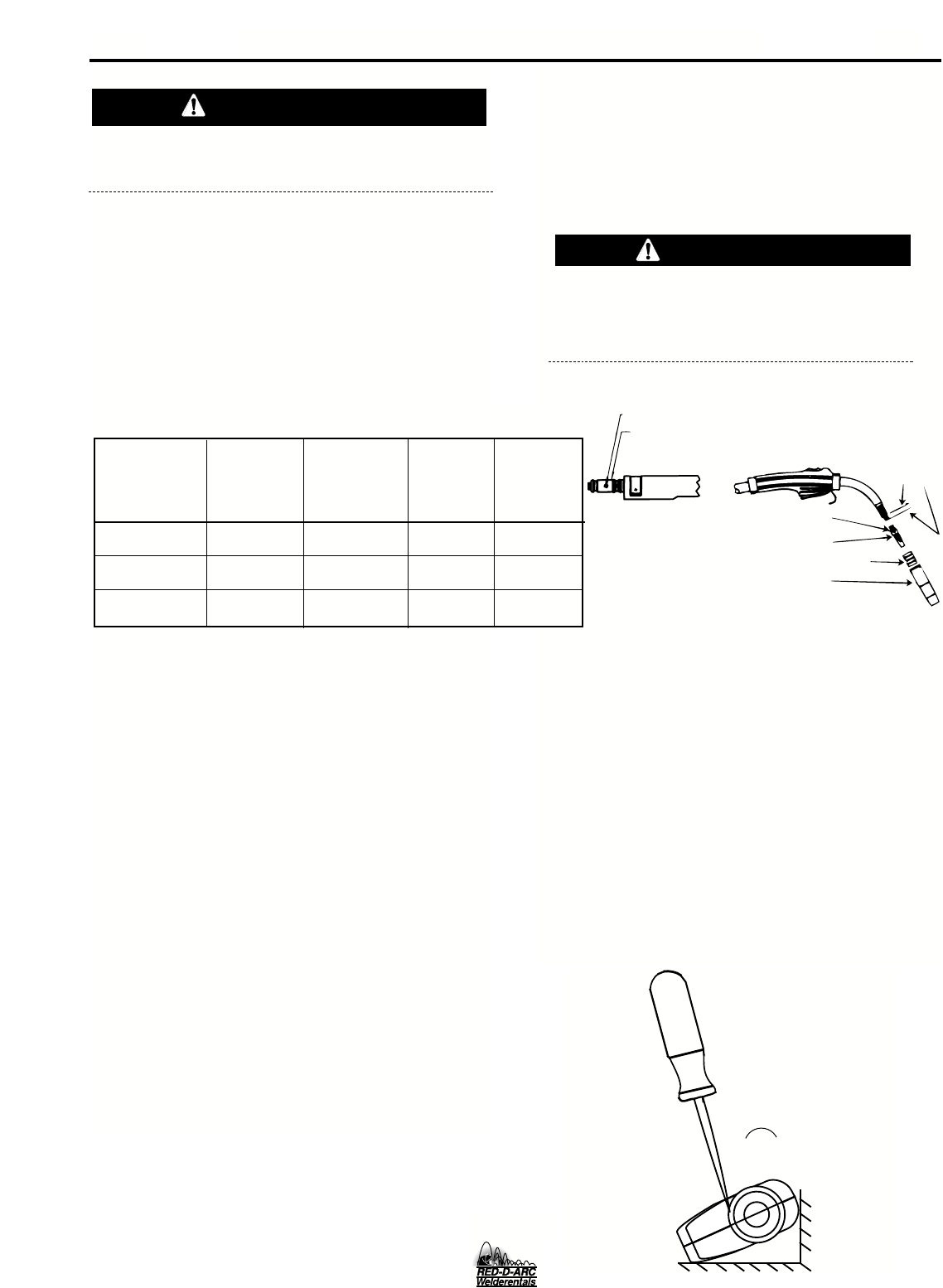
GUN HANDLE
DISASSEMBLY
The internal parts of the gun handle may be inspected
or serviced if necessary.
The gun handle consists of two halves that are held
together with a collar on each end. To open up the
handle, turn the collars approximately 60 degrees
counterclockwise (the same direction as removing a
right hand thread) until the collar reaches a stop. Then
pull the collar off the gun handle. If the collars are diffi-
cult to turn, position the gun handle against a corner,
place a screwdriver against the tab on the collar and
give the screwdriver a sharp blow to turn the collar
past an internal locking rib.
LINER REMOVAL AND REPLACEMENT
NOTE: Changing the liner for a different wire size
requires replacement of the gas diffuser per Table D.1
to properly secure the different liner.
LINER REMOVAL, INSTALLATION AND TRIMMING
INSTRUCTIONS FOR MAGNUM 250L
NOTE: The variation in cable lengths prevents the
interchangeability of liners between guns. Once a liner
has been cut for a particular gun, it should not be
installed in another gun unless it can meet the liner
cutoff length requirement. Liners are shipped with the
jacket of the liner extended the proper amount.
1. Remove the gas nozzle and nozzle insulator, if
used, to locate the set screw in the gas diffuser
which is used to hold the old liner in place. Loosen
the set screw with a 5/64" (2.0 mm) Allen wrench.
2. Remove the gas diffuser from the gun tube.
3. Lay the gun and cable out straight on a flat surface.
Loosen the set screw located in the brass connec-
tor at the feeder end of the cable and pull the liner
out of the cable.
4. Insert a new untrimmed liner into the connector
end of the cable. Be sure the liner bushing is sten-
cilled appropriately for the wire size bing used.
5. Fully seat the liner bushing into the connector.
tighten the set screw on the brass cable connector.
the gas diffuser, at this time, should not be
installed onto the end of the gun tube.
6. With the gas diffusor still removed from the gun
tube, be sure the cable is straight, and then trim
the liner to the length shown in Figure D.1.
Remove any burrs from the end of the liner.
CAUTION
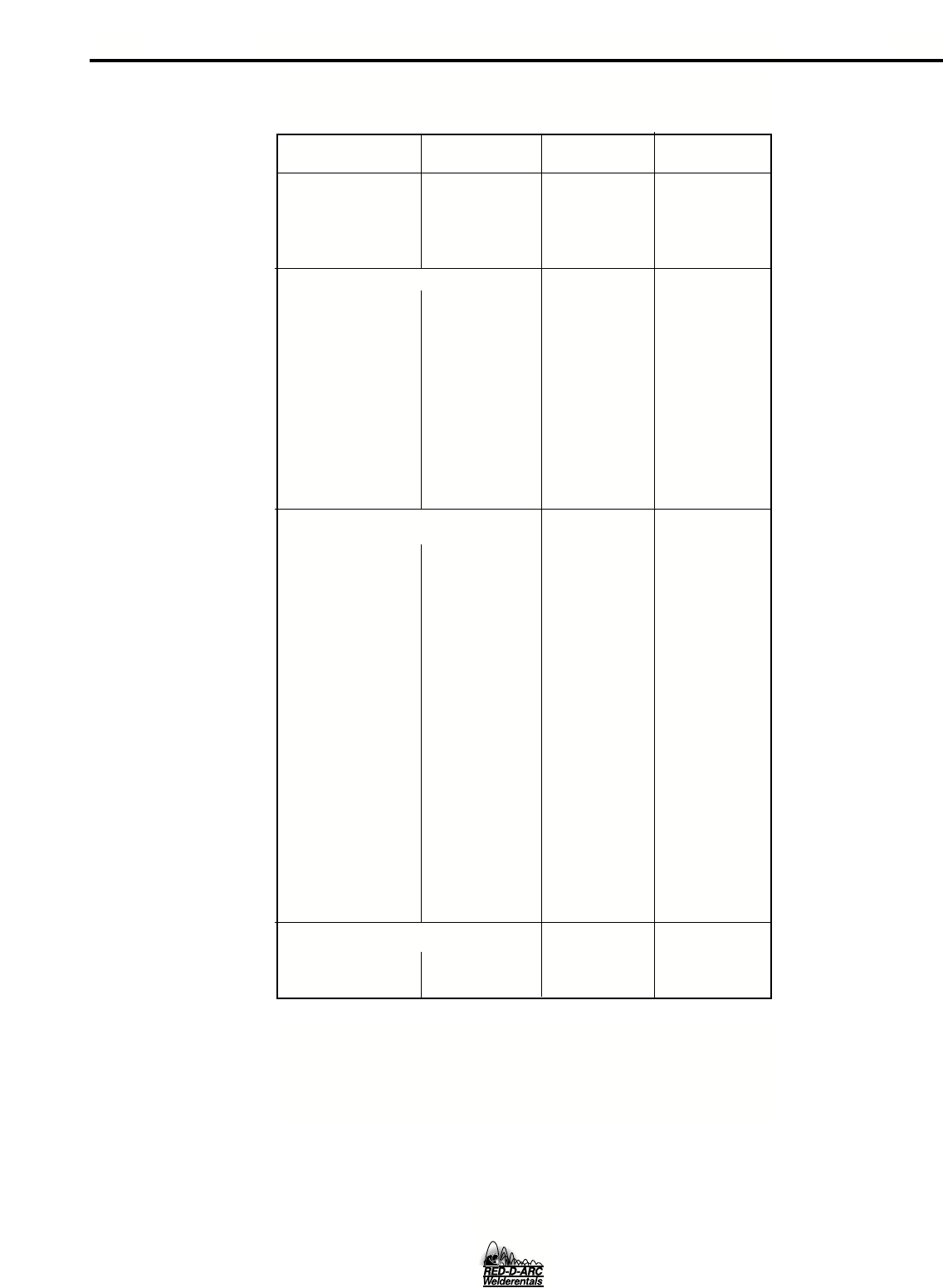
Fixed Adjustable
Nozzle Nozzle
Replacement Size Stencilled Gas Diffuser Gas Diffuser
Diameter of Liner Part on End of Part No. Part No.
Electrodes Used Number Liner Bushing (and Stencil) (and Stencil)
.025-.030" Steel M16087-2 .030 (0.8 mm) S19418-3 S19418-2
(0.6-0.8 mm)
.035-.045" Steel M16087-1 .045 (1.2 mm) S19418-3 S19418-1
(0.9-1.2 mm)
3/64" Aluminum M17714-1 3/64" (1.2 mm) S19418-3 S19418-1
(1.2 mm)
TABLE D.1
CAUTION
SET SCREW
SET SCREW
BRASS CABLE CONNECTOR
GAS DIFFUSER
NOZZLE INSULATOR (IF USED)
GAS NOZZLE
1-1/4"
(31.8mm)
LINER
TRIM
LENGTH
PM 255
FIG D.1
D-3
D-3 MAINTENANCE
English Metric
Description Part No. Size Size
CABLE LINER
For 15' (4.5 m) or M16087-2 .025 – .030" 0.6 – 0.8 mm
shorter Cable M16087-1 .035 – .045" 0.9 – 1.2 mm
M17714-1 3/64" 1.2 mm
(Alum. wire) (Alum. wire)
CONTACT TIPS
Standard Duty S19391-6 .025" 0.6 mm
S19391-7 .030" 0.8 mm
S19391-1 * .035" 0.9 mm
S19391-2 * .045" 1.2 mm
Heavy Duty S19392-1 .035" 0.9 mm
S19292-2 .045" 1.2 mm
Tapered S19393-5 .025" 0.6 mm
S19393-6 .030" 0.8 mm
S19393-1 .035" 0.9 mm
S19393-2 .045" 1.2 mm
Tab (For Aluminum) S18697-46 3/64" 1.2 mm
(Alum. Wire) (Alum. Wire)
GAS NOZZLES
Fixed (Flush) M16081-1 3/8" 9.5 mm
M16081-2 * 1/2" 12.7 mm
M16081-3 5/8" 15.9 mm
Fixed (Recessed) M16080-1 3/8" 9.5 mm
M16080-2 1/2" 12.7 mm
M16080-3 5/8" 15.9 mm
Requires: Gas
Diffuser As'bly S19418-3 * .025 – .045" 0.6 – 1.2 mm
Adjustable Slip-On M16093-2 1/2" 12.7 mm
M16093-1 5/8" 15.9 mm
Requires:
Nozzle Insulator S19417-1
As’bly
Requires:
Gas Diffuser S19418-2 .025 – .030" 0.6 – 0.8 mm
As’bly S19418-1 .035 – .045" 0.9 – 1.2 mm
Gasless Nozzle M16938 Δ
(For Innershield)
GUN TUBE ASSEMBLIES
Standard (60°) S18920 *
45°S19890
TABLE D.2
ACCESSORIES AND EXPENDABLE REPLACEMENT PARTS
FOR MAGNUM 250L GUN AND CABLE ASSEMBLIES
* Included with PM 255
ΔRequires S19418-1 Gas Diffuser Assembly.
PM 255

E-1
TROUBLESHOOTING
E-1
PM 255
If for any reason you do not understand the test procedures or are unable to perform the tests/repairs safely, contact your
Local Authorized Field Service Facility for technical troubleshooting assistance before you proceed.
CAUTION
This Troubleshooting Guide is provided to help you
locate and repair possible machine malfunctions.
Simply follow the three-step procedure listed below.
Step 1. LOCATE PROBLEM (SYMPTOM).
Look under the column labeled “PROBLEM (SYMP-
TOMS)”. This column describes possible symptoms
that the machine may exhibit. Find the listing that
best describes the symptom that the machine is
exhibiting.
Step 2. POSSIBLE CAUSE.
The second column labeled “POSSIBLE CAUSE” lists
the obvious external possibilities that may contribute
to the machine symptom.
Step 3. RECOMMENDED COURSE OF ACTION
This column provides a course of action for the
Possible Cause, generally it states to contact your
local Authorized Field Service Facility.
If you do not understand or are unable to perform the
Recommended Course of Action safely, contact your
local Authorized Field Service Facility.
HOW TO USE TROUBLESHOOTING GUIDE
Service and Repair should only be performed by Factory Trained Personnel. Unauthorized repairs
performed on this equipment may result in danger to the technician and machine operator and will
invalidate your factory warranty. For your safety and to avoid Electrical Shock, please observe all
safety notes and precautions detailed throughout this manual.
__________________________________________________________________________
WARNING

E-2 E-2
TROUBLESHOOTING
PROBLEMS
(SYMPTOMS)
Major Physical or Electrical
Damage is Evident
There is no wire feed or open cir-
cuit voltage when the gun trigger is
pulled. The machine displays are
lit indicating input power to the PM
255.
Output voltage and wire feed is pre-
sent when gun trigger is not pulled
(not activated).
Machine output is low. Welds are
“cold”, weld bead is rounded or
bumped up demonstrating poor
wetting into plate.
POSSIBLE AREAS OF
MISADJUSTMENT(S)
1. Contact your Local Lincoln
Authorized Field Service Facility.
1 The gun trigger or cable may be
faulty. Check or replace gun
assembly.
2. The thermal protection circuit
may be activated. If this is the
case, the display will show “too
hot”. Allowing the machine to
cool will clear the error condition.
3. Make sure input voltage is cor-
rect and matches nameplate rat-
ing and reconnect panel configu-
ration.
1. Remove gun assembly from
machine. If problem is solved
gun assembly is faulty. Repair or
replace.
2. If problem persists when gun
assembly is removed from
machine then the problem is
within the PM 255.
1. Check input voltage. Make sure
input voltage matches name-
plate rating and reconnect panel
configuration.
2. Make sure settings for wire feed
speed and voltage are correct
for process being used.
3. Make sure output polarity is cor-
rect for process being used.
4. Check welding cables and gun
assembly for loose or faulty con-
nections.
RECOMMENDED
COURSE OF ACTION
If all recommended possible areas
of misadjustment have been
checked and the problem persists,
Contact your local Authorized
Field Service Facility.
OUTPUT PROBLEMS
If for any reason you do not understand the test procedures or are unable to perform the tests/repairs safely, contact your
LOCAL AUTHORIZED FIELD SERVICE FACILITY for assistance before you proceed.
CAUTION
PM 255
Observe all Safety Guidelines detailed throughout this manual

E-3
E-3 TROUBLESHOOTING
PROBLEMS
(SYMPTOMS)
Poor arc striking with electrode
sticking or blasting off.
POSSIBLE AREAS OF
MISADJUSTMENT(S)
1. Make sure settings for wire feed
speed and voltage are correct
for process being used.
2. The Run-In (Fast or Slow) speed
may be wrong for process and
technique being used. See
Operation Section.
3. The gas shielding may be
improper for process being used.
RECOMMENDED
COURSE OF ACTION
If all recommended possible areas
of misadjustment have been
checked and the problem persists,
Contact your local Authorized
Field Service Facility.
OUTPUT PROBLEMS
If for any reason you do not understand the test procedures or are unable to perform the tests/repairs safely, contact your
LOCAL AUTHORIZED FIELD SERVICE FACILITY for assistance before you proceed.
CAUTION
PROBLEMS
(SYMPTOMS)
Rough wire feeding or wire will not
feed but drive rolls are turning.
The wire feed stops while welding.
When trigger is released and pulled
again the wire feed starts.
POSSIBLE AREAS OF
MISADJUSTMENT(S)
1.
The gun cable may be kinked or twisted.
2.
The wire may be jammed in the gun
cable, or gun cable may be dirty.
3. Check drive roll tension and
position of grooves.
4.
Check for worn or loose drive rolls.
5.
The electrode may be rusty or dirty.
6. Check for damaged or incorrect
contact tip.
7. Check wire spindle for ease of
rotation and adjust break ten-
sion knob if necessary.
1. Check the wire feed drive rolls
and motor for smooth operation.
2. Check for restrictions in the wire
feed path. Check the gun and
cable for restrictions.
3. Make sure gun liner and tip are
correct for wire size being used.
4.
Make sure drive rolls and guide plates
are clean and are the correct size.
5. If K1701-1 Timer Option Kit is
installed, make sure the spot timer
knob is set to off.
6. Check spindle for ease of rotation.
RECOMMENDED
COURSE OF ACTION
If all recommended possible areas
of misadjustment have been
checked and the problem persists,
Contact your local Authorized
Field Service Facility.
FEEDING PROBLEMS
PM 255
Observe all Safety Guidelines detailed throughout this manual

E-4
E-4 TROUBLESHOOTING
PROBLEMS
(SYMPTOMS)
Gas does not flow when gun trigger
is pulled.
POSSIBLE AREAS OF
MISADJUSTMENT(S)
1. Make sure gas supply is con-
nected properly and turned “on”.
2. If the gas solenoid does actuate
(click) when the gun trigger is
pulled there may be a restriction
in the gas supply line.
3. The gun cable assembly may be
faulty. Check or replace.
4. If gas solenoid does not operate
when gun trigger is pulled the
problem is within the PM 255.
5. Make sure the gun is pushed all
the way into gun mount and is
properly seated.
RECOMMENDED
COURSE OF ACTION
If all recommended possible areas
of misadjustment have been
checked and the problem persists,
Contact your local Authorized
Field Service Facility.
GAS FLOW PROBLEMS
If for any reason you do not understand the test procedures or are unable to perform the tests/repairs safely, contact your
LOCAL AUTHORIZED FIELD SERVICE FACILITY for assistance before you proceed.
CAUTION
PM 255
Observe all Safety Guidelines detailed throughout this manual
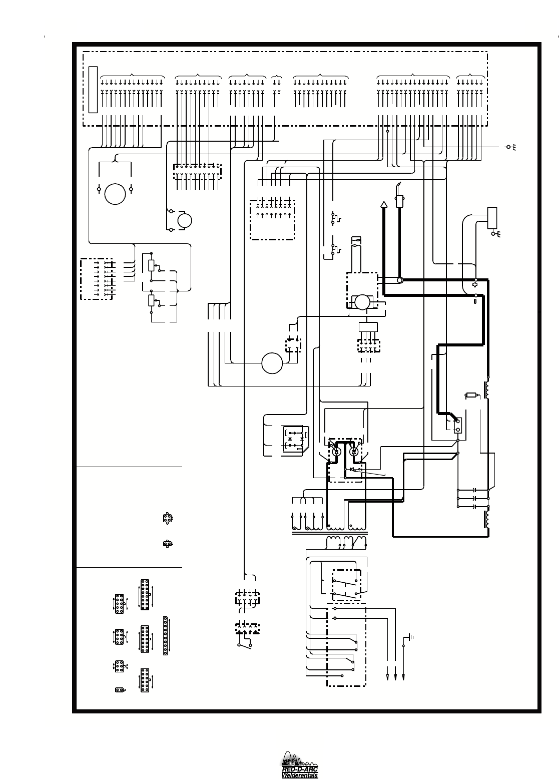
F-1 F-1
WIRING DIAGRAMS
1
209
555
B
W
515
254
262
207
P.M.
208S
J9
B
T
A
C
H
D1
ASBLY
2-01A
11
1
28.4V
14.2V
14.2V
116.6V
515
206A
SCI
541A
326
543
206B
353
GENERAL INFORMATION
CAVITY NUMBERING SEQUENCE
(COMPONENT SIDE OF P.C. BOARD)
1
2
1
J7
1
16
J5
9
TO
WORK
CAVITY
J13
WIRE FEED
SPEED
C1 THRU C3
31,000 MFD
50V
4
-
U
515B
555
206B
206
204S
3
2
SCR HEATSINK
ASSEMBLY
THERMOSTAT
8
7
6
5
4
3
L10980
204
G1
X7
325A
324
SCI
390
FOR SPOOL GUN OPTION
OUTPUT
CHOKE
+
X4
206B
G2
209S
H4
**
COLOR CODE:
H5
GUN
TRIGGER
POWER
TRANSFORMER
4
2
324
325
324
H3
J3
7
7
5
209R
320B
W
G1
3
4
1
2
3
4
7
CURRENT AND DUTY CYCLE OF IMMEDIATE AND
FUTURE APPLICATIONS.
5
3
-
N.B. THIS DIAGRAM SHOWS THE "ELECTRODE" POLARITY
SNUBBER
BOARD
D2
BAFFLE
MOUNTED
RECTIFIER
DIODE
BRIDGE
W
207
B
205
390
10
256
206S
205
352
X9
**
325B
DISPLAY
BOARD
X5
208R
209R
354
8
12
2
3
4
8
6
5
7
14
15
16
J12
1
2
209
208
206
354
325B
GND
320
353
252
2
1
4
2
3
13
12
10
6
5
1
2
208R
208
204S
209S
500
256
551
552
206B
251
555
X8
515B
G2
325
J11
1
1
2
3
X8
3
4
C3
+
C2C1
X2
X3
R4
INDICATES CONNECTOR CAVITY NO.
U - BLUE
R - RED
W - WHITE
B - BLACK
SECONDARY VOLTAGES SHOWN
ARE NO LOAD RMS VALUES
OUTPUT CHOKE
THERMOSTAT
++
B
206S
L1
H2
H5
5
R
H4
H1
4
2
1
3
H1
LINE
SWITCH
S1
RECONNECT
PANEL
(SHOWN CONNECTED
FOR 230V)
TO SINGLE PHASE
SUPPLY LINE
TO GROUND PER
NATIONAL ELECTRICAL
CODE
ARC
VOLTAGE
10
6
5
1
J4
4
3
14
8
252
253
5
4
2
FOR TIMER
OPTION
6
GAS
SOLENOID
4
3
2
1
261
263
204
L2
15 OHMS
100 W
R1
204B
+
208S
6
R.F. FILTER
SCR 2
254A
R3
FAN
MOTOR
392
254253
X6
X7 X7
X1
H1
H2
H1H3
H4
W
B
L2L1
**
1
6
8
9
10
J5
28.4V
J6
320
**
R.F.
CHOKE
AS'BLY
GND
4
9
10
11
12
13
1
2
3
4
5
J7
5
6
J8
515B
550
X6
NOTES:
N.A. WELDING CABLE MUST BE OF PROPER CAPACITY FOR THE
J1
2
108
(NON-LEAD SIDE OF CONNECTOR)
21
J10
1
7
1
1
J2
J4
6
7
8
3
9
1
10
5
7
8
9
260
264
267
265
14
11
J2
J1
9
8
1
2
CONTROL BOARD
6
7
8
X9
X9
X5
POWER FACTOR
ENHANCEMENT
CHOKE
251
325
1
J6
J8 J9
65
4
6
1
J3
NUMBERING SEQUENCE
12
7
J12
8
2
J11
J13
4
3
1
352
J10
POWER MIG 255 (230/460/575V)
515
500
551
550
552
ELECTRICAL SYMBOLS PER E1537
SCR 1
SCR HEATSINK
MOTOR/
GEARBOX
B
X6
X5
X8
CONDUCTOR STRAP AND WORK STUD.
OFF AND REVERSE LEAD CONNECTIONS AT CABLE
"POSITIVE". TO CHANGE POLARITY, TURN THE UNIT
392
W
PM 255
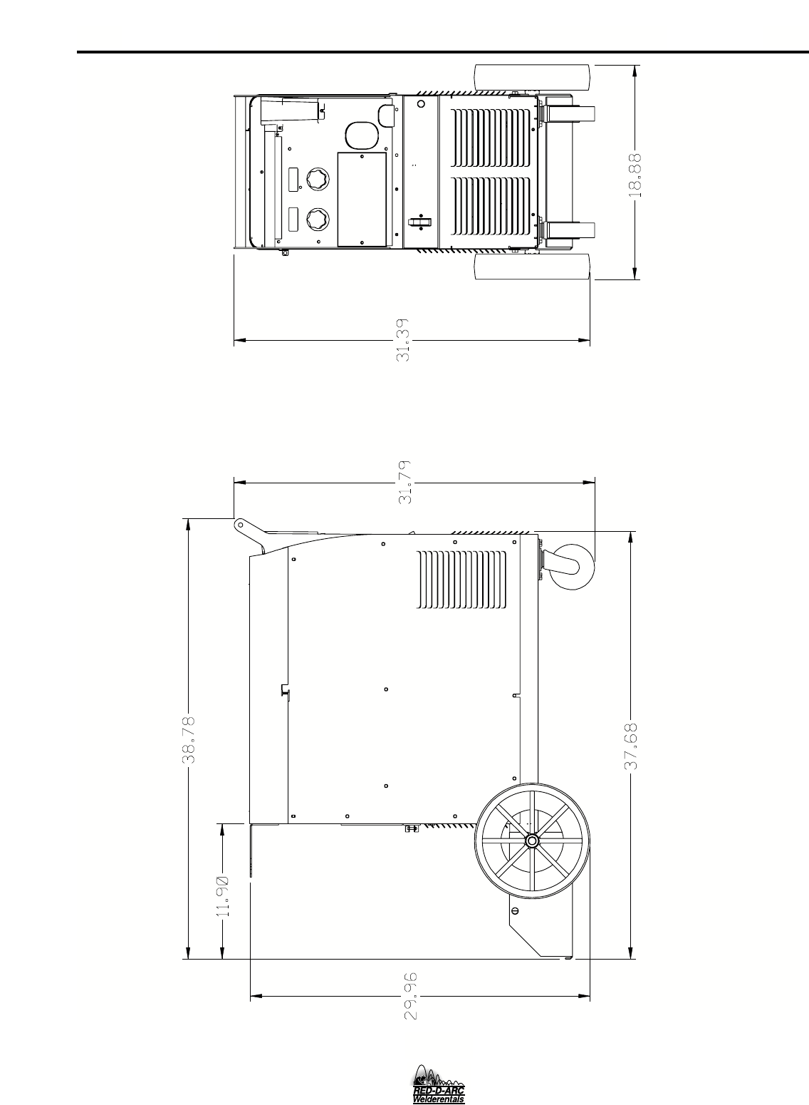
F-2
F-2 DIMENSION PRINT
3-00F
M19231
PM 255

NOTES
PM 255

NOTES
PM 255

NOTES
PM 255
Now Available...12th Edition
The Procedure Handbook of Arc Welding
With over 500,000 copies of previous editions published
since 1933, the Procedure Handbook is considered by many to
be the “Bible” of the arc welding industry.
This printing will go fast so don’t delay. Place your
order now using the coupon below.
The hardbound book contains over 750 pages of welding
information, techniques and procedures. Much of this material
has never been included in any other book.
A must for all welders, supervisors, engineers and
designers. Many welding instructors will want to use the book
as a reference for all students by taking advantage of the low
quantity discount prices which include shipping by
4th class parcel post.
$15.00 postage paid U.S.A. Mainland
How To Read Shop Drawings
The book contains the latest information and application
data on the American Welding Society Standard Welding
Symbols. Detailed discussion tells how engineers and
draftsmen use the “short-cut” language of symbols to pass
on assembly and welding information to shop personnel.
Practical exercises and examples develop the reader’s
ability
to visualize mechanically drawn objects as they will appear
in their assembled form.
187 pages with more than 100 illustrations. Size 8-1/2” x
11”
Durable, cloth-covered board binding.
$4.50 postage paid U.S.A.
Mainland
New Lessons in Arc Welding
Lessons, simply written, cover manipulatory techniques;
machine and electrode characteristics; related subjects,
such as distortion; and supplemental information on arc
welding applications, speeds and costs. Practice materials,
exercises, questions and answers are suggested for each
lesson.
528 pages, well illustrated, 6” x 9” size, bound in simulated,
gold embossed leather. $5.00 postage paid U.S.A.
Mainland
Need Welding Training?
The Lincoln Electric Company operates the oldest and
most respected Arc Welding School in the United States at its
corporate
headquarters in Cleveland, Ohio. Over 100,000 stu-
dents have graduated. Tuition is low and the training is
“hands on”
For details write: Lincoln Welding School
22801 St. Clair Ave.
Cleveland, Ohio 44117-1199.
and ask for bulletin ED-80 or call 216-383-2259 and ask
for the
Welding School Registrar.
Lincoln Welding School
BASIC COURSE $700.00
5 weeks of fundamentals
There is a 10% discount on all orders of $50.00 or more for shipment at one time to one location.
Orders of $50 or less before discount or orders outside of North America must be prepaid with charge, check or money order in U.S. Funds Only.
Prices include shipment by 4thClass Book Rate for U.S.A. Mainland Only. Please allow up to 4 weeks for delivery.
UPS Shipping for North America Only. All prepaid orders that request UPS shipment please add:
$5.00 For order value up to $49.99
$10.00 For order value between $50.00 & $99.99
$15.00 For order value between $100.00 & $149.00
For North America invoiced orders over $50.00 & credit card orders, if UPS is requested, it will be invoiced or charged to you at cost.
Outside U.S.A. Mainland order must be prepaid in U.S. Funds. Please add $2.00 per book for surface mail or $15.00 per book for air parcel post shipment.
METHOD OF PAYMENT: (Sorry, No C.O.D. Orders)
CHECK ONE: Name: _______________________________________________
Please Invoice (only if order is over $50.00) Address: _______________________________________________
Check or Money Order Enclosed, U.S. Funds only _______________________________________________
Credit Card - Telephone:_______________________________________________
Signature as it appears on Charge Card:
Account No. |_|_|_|_|_|_|_|_|_|_|_|_|_|_|_|_|_|_|_|_|_| Exp Date |_|_| |_|_| ______________________
Month Year
USE THIS FORM TO ORDER:
Order from: BOOK DIVISION, The Lincoln Electric Company, 22801 St. Clair Avenue, Cleveland, Ohio 44117-1199
BOOKS OR FREE INFORMATIVE CATALOGS Telephone: 216-383-2211 or, for fastest service, FAX this completed form to: 216-361-5901.
Lincoln Welding School Titles: Price Code Quantity Cost
(ED-80) New Lessons in Arc Welding $5.00 L
Seminar Information Procedure Handbook “Twelfth Edition”$15.00 PH
(ED-45) How to Read Shop Drawings $4.50 H
Educational Video Information Incentive Management $5.00 IM
(ED-93) A New Approach to Industrial Economics $5.00 NA
James F. Lincoln Arc Welding The American Century of John C. Lincoln $5.00 AC
Foundation Book Information Welding Preheat Calculator $3.00 WC-8
(JFLF-515) Pipe Welding Charts $4.50 ED-89 SUB TOTAL
Additional Shipping Costs if any
TOTAL COST
MasterCard
VISA ®
AMERICAN EXPRESS
MasterCardMasterCard
®
AMERICAN EXPRESS
WARNING
AVISO DE
PRECAUCION
ATTENTION
WARNUNG
ATENÇÃO
Spanish
French
German
Portuguese
Japanese
Chinese
Korean
Arabic
READ AND UNDERSTAND THE MANUFACTURER’S INSTRUCTION FOR THIS EQUIPMENT AND THE CONSUMABLES TO BE
USED AND FOLLOW YOUR EMPLOYER’S SAFETY PRACTICES.
SE RECOMIENDA LEER Y ENTENDER LAS INSTRUCCIONES DEL FABRICANTE PARA EL USO DE ESTE EQUIPO Y LOS
CONSUMIBLES QUE VA A UTILIZAR, SIGA LAS MEDIDAS DE SEGURIDAD DE SU SUPERVISOR.
LISEZ ET COMPRENEZ LES INSTRUCTIONS DU FABRICANT EN CE QUI REGARDE CET EQUIPMENT ET LES PRODUITS A
ETRE EMPLOYES ET SUIVEZ LES PROCEDURES DE SECURITE DE VOTRE EMPLOYEUR.
LESEN SIE UND BEFOLGEN SIE DIE BETRIEBSANLEITUNG DER ANLAGE UND DEN ELEKTRODENEINSATZ DES HER-
STELLERS. DIE UNFALLVERHÜTUNGSVORSCHRIFTEN DES ARBEITGEBERS SIND EBENFALLS ZU BEACHTEN.
●Do not touch electrically live parts or
electrode with skin or wet clothing.
●Insulate yourself from work and
ground.
●No toque las partes o los electrodos
bajo carga con la piel o ropa moja-
da.
●Aislese del trabajo y de la tierra.
●Ne laissez ni la peau ni des vête-
ments mouillés entrer en contact
avec des pièces sous tension.
●Isolez-vous du travail et de la terre.
●Berühren Sie keine stromführenden
Teile oder Elektroden mit Ihrem
Körper oder feuchter Kleidung!
●Isolieren Sie sich von den
Elektroden und dem Erdboden!
●Não toque partes elétricas e elec-
trodos com a pele ou roupa molha-
da.
●Isole-se da peça e terra.
●Keep flammable materials away.
●Mantenga el material combustible
fuera del área de trabajo.
●Gardez à l’écart de tout matériel
inflammable.
●Entfernen Sie brennbarres Material!
●Mantenha inflamáveis bem guarda-
dos.
●Wear eye, ear and body protection.
●Protéjase los ojos, los oídos y el
cuerpo.
●Protégez vos yeux, vos oreilles et
votre corps.
●Tragen Sie Augen-, Ohren- und Kör-
perschutz!
●Use proteção para a vista, ouvido e
corpo.
WARNING
AVISO DE
PRECAUCION
ATTENTION
WARNUNG
ATENÇÃO
Spanish
French
German
Portuguese
Japanese
Chinese
Korean
Arabic
LEIA E COMPREENDA AS INSTRUÇÕES DO FABRICANTE PARA ESTE EQUIPAMENTO E AS PARTES DE USO, E SIGA AS
PRÁTICAS DE SEGURANÇA DO EMPREGADOR.
●Keep your head out of fumes.
●Use ventilation or exhaust to
remove fumes from breathing zone.
●Los humos fuera de la zona de res-
piración.
●Mantenga la cabeza fuera de los
humos. Utilice ventilación o
aspiración para gases.
●Gardez la tête à l’écart des fumées.
●Utilisez un ventilateur ou un aspira-
teur pour ôter les fumées des zones
de travail.
●Vermeiden Sie das Einatmen von
Schweibrauch!
●Sorgen Sie für gute Be- und
Entlüftung des Arbeitsplatzes!
●Mantenha seu rosto da fumaça.
●Use ventilação e exhaustão para
remover fumo da zona respiratória.
●Turn power off before servicing.
●Desconectar el cable de ali-
mentación de poder de la máquina
antes de iniciar cualquier servicio.
●Débranchez le courant avant l’entre-
tien.
●Strom vor Wartungsarbeiten
abschalten! (Netzstrom völlig öff-
nen; Maschine anhalten!)
●Não opere com as tampas removidas.
●Desligue a corrente antes de fazer
serviço.
●Não toque as partes elétricas nuas.
●Do not operate with panel open or
guards off.
●No operar con panel abierto o
guardas quitadas.
●N’opérez pas avec les panneaux
ouverts ou avec les dispositifs de
protection enlevés.
●Anlage nie ohne Schutzgehäuse
oder Innenschutzverkleidung in
Betrieb setzen!
●Mantenha-se afastado das partes
moventes.
●Não opere com os paineis abertos
ou guardas removidas.

• Sales and Service through Subsidiaries and Distributors Worldwide •
Cleveland, Ohio 44117-1199 U.S.A. TEL: 216.481.8100 FAX: 216.486.1751 WEB SITE: www.lincolnelectric.com
• World's Leader in Welding and Cutting Products •
