ImagePRESS C7010VPS Customer Expectations Version 4 Image PRESS CED V4
User Manual: IMAGEPRESS C7010VPS
Open the PDF directly: View PDF ![]() .
.
Page Count: 69
- Cover
- Contents
- Important, Disclaimer, and Legal Notices
- 1. Introduction
- 2. Product Overview
- 3. Machine Dimensions and Space Requirements
- 4. Power/Electrical Requirements
- 5. Environmental Factors and Requirements
- 6. Specifications
- 6.1 Main Unit
- 6.2 PRISMAsync Controller
- 6.3 Color Image Reader-H1
- 6.4 Feeder (DADF-R1)
- 6.5 POD Deck-A1/Secondary POD Deck-A1
- 6.6 Paper Deck-AC1
- 6.7 Stack Bypass-A1
- 6.8 Tab Feeding Attachment-C1
- 6.9 Professional Puncher-B1 and Professional Puncher Integration Unit-A1
- 6.10 Finisher-AJ1
- 6.11 Saddle Finisher-AJ2
- 6.12 Puncher Unit-BB1
- 6.13 Document Insertion Unit-C1
- 6.14 High Capacity Stacker-C1
- 6.15 High Capacity Stacker-F1
- 6.16 Booklet Trimmer-D1
- 6.17 Two-Knife Booklet Trimmer-A1
- 6.18 SDD Square Fold Booklet-Maker with Two-Knife Trimmer
- 6.19 Perfect Binder-B1
- 7. System Options and Software
- 8. Installation Review
- 9. Customer Productivity Program
- 10. Consumables
- 11. Toner Container and Hopper Unit Yields
- 12. Waste Toner Yields
- 13. Estimated Performance Standards
- 14. Optimum Monthly Product Performance
- 15. Machine Reliability and Productivity
- 16. Media Usage/Compatibility
- 17. Responsibility Matrix
imagePRESS C7010VPS
Customer Expectations Document
Version 4
Engineering Services and Solutions Division
Business Imaging Solutions Group, Canon U.S.A., Inc.
Version 4 imagePRESS C7010VPS Customer Expectations Document Page 2
Contents
1. Introduction ............................................................................................................. 6
2. Product Overview ................................................................................................... 6
2.1 Summary of Functions .................................................................................... 7
2.2 Offset Press vs. Digital imagePRESS ............................................................. 7
2.3 PRISMAsync Controller................................................................................... 8
2.3.1 PRISMAsync Standard Software ....................................................... 9
2.3.2 PRISMAsync System Backup .......................................................... 10
2.3.3 PRISMAsync Firmware Updates ..................................................... 10
2.4 Notes on the Engine’s Hard Disks ................................................................. 11
2.5 Customer-Defined Image Quality Adjustments and Recommendations ........ 12
2.6 Professional Input/Output Accessories ......................................................... 13
3. Machine Dimensions and Space Requirements ................................................ 14
3.1 Dimensions ................................................................................................... 14
3.2 Weight ........................................................................................................... 15
3.3 Installation and Service Space ...................................................................... 16
3.3.1 Minimum Space Requirements to Transport the Machine and Turn
Hallway Corners .............................................................................. 17
3.3.2 Dimensions Diagrams ...................................................................... 18
3.3.3 Installation Space Diagrams ............................................................ 19
3.4 Recommended Floor Space Requirements .................................................. 21
3.5 Floor Structure Requirements ....................................................................... 21
4. Power/Electrical Requirements ........................................................................... 22
4.1 Power Requirements for the Main Unit and Optional Accessories ................ 23
5. Environmental Factors and Requirements......................................................... 25
5.1 Temperature and Humidity Conditions .......................................................... 25
5.2 Temperature Gradient ................................................................................... 25
5.3 Ventilation ..................................................................................................... 26
5.4 Elevation Limitations ..................................................................................... 26
5.5 Lighting.......................................................................................................... 26
5.6 Sunlight ......................................................................................................... 26
5.7 Ammonia ....................................................................................................... 26
Version 4 imagePRESS C7010VPS Customer Expectations Document Page 3
6. Specifications ....................................................................................................... 27
6.1 Main Unit ....................................................................................................... 27
6.2 PRISMAsync Controller................................................................................. 29
6.2.1 USB Stick ......................................................................................... 31
6.3 Color Image Reader-H1 ................................................................................ 31
6.4 Feeder (DADF-R1) ........................................................................................ 32
6.5 POD Deck-A1/Secondary POD Deck-A1 ...................................................... 33
6.6 Paper Deck-AC1 ........................................................................................... 33
6.7 Stack Bypass-A1 ........................................................................................... 34
6.8 Tab Feeding Attachment-C1 ......................................................................... 34
6.9 Professional Puncher-B1 and Professional Puncher Integration Unit-A1 ...... 34
6.10 Finisher-AJ1 .................................................................................................. 35
6.11 Saddle Finisher-AJ2 ...................................................................................... 38
6.12 Puncher Unit-BB1 ......................................................................................... 41
6.13 Document Insertion Unit-C1 .......................................................................... 41
6.14 High Capacity Stacker-C1 ............................................................................. 42
6.15 High Capacity Stacker-F1 ............................................................................. 42
6.16 Booklet Trimmer-D1 ...................................................................................... 43
6.17 Two-Knife Booklet Trimmer-A1 ..................................................................... 44
6.18 SDD Square Fold Booklet-Maker with Two-Knife Trimmer ........................... 45
6.19 Perfect Binder-B1 .......................................................................................... 46
7. System Options and Software ............................................................................. 47
7.1 Remote Viewer .............................................................................................. 47
7.2 Asian Font Sets ............................................................................................. 47
7.3 PRISMAaccess ............................................................................................. 47
8. Installation Review ............................................................................................... 48
8.1 Installation Time ............................................................................................ 48
8.2 Customer Responsibilities ............................................................................. 49
9. Customer Productivity Program ......................................................................... 50
10. Consumables ........................................................................................................ 50
10.1 Consumable Parts ......................................................................................... 50
10.1.1 Estimated Life of Consumables ....................................................... 51
11. Toner Container and Hopper Unit Yields ........................................................... 52
12. Waste Toner Yields .............................................................................................. 52
13. Estimated Performance Standards ..................................................................... 53
14. Optimum Monthly Product Performance ............................................................ 54
15. Machine Reliability and Productivity .................................................................. 55
15.1 Machine Reliability and Service Call Ratio .................................................... 55
15.2 Print Speed ................................................................................................... 56
15.3 Mixed Media Productivity .............................................................................. 58
15.4 Two Hour Unattended Operation .................................................................. 58
15.5 Paper, Toner, and Waste Toner Replacement .............................................. 59
Version 4 imagePRESS C7010VPS Customer Expectations Document Page 4
16. Media Usage/Compatibility .................................................................................. 60
16.1 Media Characteristics by Media Library Parameters ..................................... 60
16.2 Media Specific Adjustments .......................................................................... 61
16.3 Print Quality Adjustment Settings .................................................................. 63
16.4 Paper Handling and Storage ......................................................................... 64
16.5 Selecting the Correct Media .......................................................................... 65
16.6 Paper Grain and Curl .................................................................................... 66
16.7 Note for Customers Who Cut Their Own Paper ............................................ 67
16.8 Paper Sizes and Feed Location Chart .......................................................... 68
17. Responsibility Matrix ........................................................................................... 69

Version 4 imagePRESS C7010VPS Customer Expectations Document Page 5
IMPORTANT
The purpose of this Customer Expectations Document is to explain the current
features and capabilities of the imagePRESS C7010VPS, and provide customers
information about what to expect before purchasing the machine.
The information included in this document has been pulled from various sources,
including product reference guides, service guides, and user manuals.
Specifications and other information contained herein may vary slightly, and in a
non-material way, from actual device values, including those found in advertising
and other printed matter. Part numbers, yield information, and specifications are
subject to change without notice. Accordingly, the latest specifications for the
machine may not be found in this document. As new information becomes
available, this document will be revised. Canon authorized dealers can access the
latest revision of this document from the Download Center page on the e-Support
Web site (support.cusa.canon.com).
DISCLAIMER
NEITHER CANON NOR ITS SUPPLIERS NOR ANY AUTHORIZED SERVICE
PROVIDER SHALL BE LIABLE FOR PERSONAL INJURY OR PROPERTY DAMAGE
(UNLESS CAUSED SOLELY AND DIRECTLY BY THE NEGLIGENCE OF CANON
OR ANY AUTHORIZED SERVICE PROVIDER), LOSS OF REVENUE OR PROFIT,
FAILURE TO REALIZE SAVINGS OR OTHER BENEFITS, EXPENDITURES FOR
SUBSTITUTE EQUIPMENT OR SERVICES, LOSS OR CORRUPTION OF DATA,
INCLUDING, WITHOUT LIMITATION, DATA STORED ON THE PRODUCT’S HARD
DISK DRIVE, STORAGE CHARGES OR OTHER SPECIAL, INCIDENTAL OR
CONSEQUENTIAL DAMAGES CAUSED BY THE USE, MISUSE OR INABILITY TO
USE THE PRODUCT, REGARDLESS OF THE LEGAL THEORY ON WHICH THE
CLAIM IS BASED AND EVEN IF CANON OR ITS SUPPLIERS OR ANY
AUTHORIZED SERVICE PROVIDER HAS BEEN ADVISED OF THE POSSIBILITY
OF SUCH DAMAGES. NOR SHALL RECOVERY OF ANY KIND AGAINST CANON
OR ITS SUPPLIERS OR ANY AUTHORIZED SERVICE PROVIDER BE GREATER IN
AMOUNT THAN THE PURCHASE PRICE OF THE PRODUCT CAUSING THE
ALLEGED DAMAGE. WITHOUT LIMITING THE FOREGOING, THE PURCHASER
ASSUMES ALL RISKS AND LIABILITY FOR LOSS, DAMAGE OR INJURY TO
PERSONS AND THE PROPERTY OF THE PURCHASER OR OTHERS ARISING
OUT OF THE POSSESSION, USE, MISUSE, OR INABILITY TO USE THE PRODUCT
NOT CAUSED SOLELY AND DIRECTLY BY THE NEGLIGENCE OF CANON OR
ANY AUTHORIZED SERVICE PROVIDER.
Copyright 2013 by Canon U.S.A., Inc. All rights reserved.
Product and company names used herein are, or may be, the registered trademarks or
trademarks of their respective owners.
Version 4 imagePRESS C7010VPS Customer Expectations Document Page 6
1. Introduction
The Canon imagePRESS C7010VPS Customer Expectations Document contains
information about the features and capabilities of the Canon imagePRESS
C7010VPS. This document should be used as part of the presale and
preinstallation planning processes to help clarify the requirements and
responsibilities associated with supporting, owning, and operating the
imagePRESS C7010VPS. It is also recommended that those interested in
purchasing the imagePRESS C7010VPS have, and familiarize themselves with,
the information in this document prior to making their purchase.
2. Product Overview
The Canon imagePRESS C7010VPS is the first co-development product of Canon
and Océ. This machine integrates Canon’s imagePRESS engine and accessories
with Océ’s PRISMAsync controller and operation management.
The Canon imagePRESS C7010VPS brings the following capabilities to users in a
high-volume, mid-production office environment, including commercial printers,
Print-for-Pay, graphic arts, direct mail, and CRD customers:
• Printing speeds of up to 70 ppm (pages per minute) (LTR, Color and
Black-and-White). Copying speeds reach up to 70 ppm after the first copy set is
output.
• One integrated 15” full-color touch screen operation panel for the total system.
• One media catalog for the total system.
• High-image quality on various media with a large image area, keeps the color
consistent and durable.
• Prints up to 1,200 x 1,200 dpi (dots per inch).
• Scans in up to 600 x 600 dpi, and then outputs the image in up to 1,200 x 1,200
dpi interpolated resolution. This results in higher quality characters, smoother
corners, and cleaner gradient transitions. Text appears sharper, and graphics
appear clear and detailed.
• Vacuum feed, active registration, dual fusing systems, and decurler technologies
ensure reliable media handling from 16 lb bond to 120 lb cover (60 to 325 g/m2).
• PRISMAsync controller offers scheduling feedback software for production
planning on the user interface for up to 8 hours.
• Operator’s attention light with adjustable “warn-ahead” timing.
Version 4 imagePRESS C7010VPS Customer Expectations Document Page 7
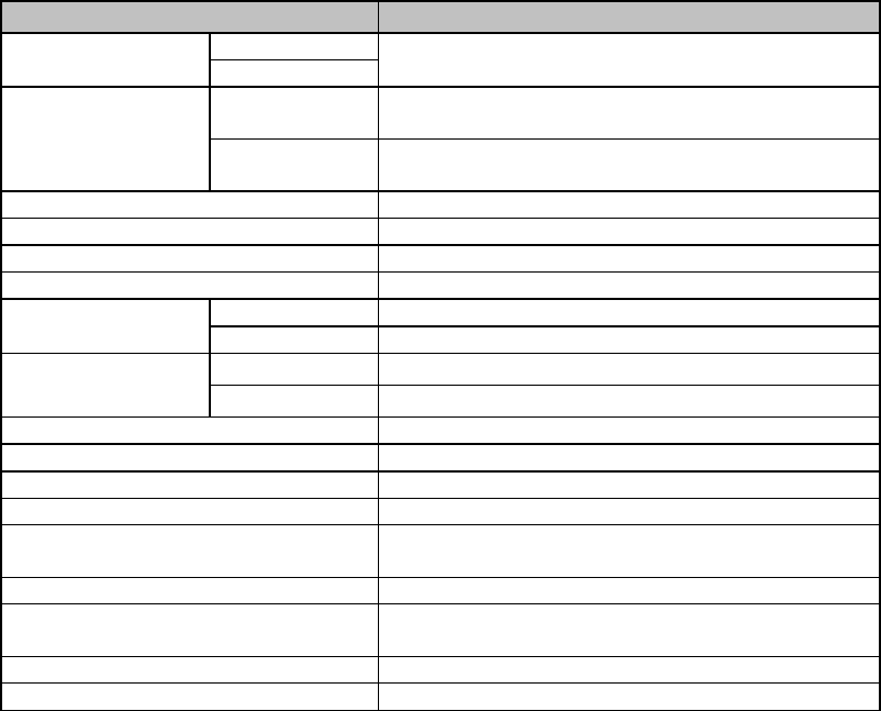
2.1 Summary of Functions
Function
imagePRESS C7010VPS
Print Speed (LTR)
B&W
70 ppm
Color
Scan Speed with
Optional Color
Image Reader and
DADF (LTR)
Scan to file
2-Sided: 15 ipm (images per minute),
1-Sided: 25 ipm
Copy First Set, 1-Sided: 25 ipm, 2-Sided: 15 ipm
Following Sets: Output at full engine speed
DADF
Optional duplex automatic document feeder
DADF Capacity
100 sheets (20 lb bond (80 g/m²))
Engine Resolution
1,200 x 1,200 dpi
Gradations
256 levels
Paper Size
Minimum
7 1/8” x 7 1/8”
Maximum
13” x 19.2”
Paper Weight Drawers 16 lb bond to 120 lb cover (60 to 325 g/m²)
Stack Bypass 17 lb bond to 140 lb index (64 to 256 g/m²)
Maximum Imageable Area
12.7” x 19” (323 mm x 482.7 mm)*1
HDD Capacity
80 GB x 2 (scanning)
Printer Memory
1.5 GB
Controller
Standard Océ PRISMAsync Color Controller
Security
Standard with E-Shredding license enabled on
the PRISMAsync controller
Copy
Optional with the Color Image Reader-H1
Scan*2
Standard with Scanning license enabled on the
PRISMAsync controller.
Print
Standard
Network
Standard Ethernet 10/100/1000 Base-TX
*1 The maximum guaranteed print size is 12.6” x 19” (320.6 mm x 482.7 mm).
*2 Requires the optional Color Image Reader-H1.
2.2 Offset Press vs. Digital imagePRESS
Offset printing is a technique that transfers (or “offsets”) an inked image from a
plate to a rubber blanket, and then to the printing surface. This enables the offset
press to maintain a consistent and high image quality over long print runs because
the plate never touches the paper. The process requires a substantial investment
in equipment and setup time to achieve these results.
A digital press uses an electrostatic process to produce “offset-like” image quality
at a fraction of the cost of an offset press. In the imagePRESS C7010VPS digital
press, the drum is imaged; the toner is applied, and then transferred to the ITB
(Intermediate Transfer Belt). The ITB then transfers all four toner colors to the
paper in one single pass. The small toner particle size captures a greater color
gamut space, closer to that of an offset press.
Version 4 imagePRESS C7010VPS Customer Expectations Document Page 8
2.3 PRISMAsync Controller
The imagePRESS C7010VPS is powered by Océ’s PRISMAsync Color Print
Controller.
The PRISMAsync controller seamlessly enables the customer to streamline their
workflow and turnout more work in less time with the following features:
• Scheduler - Plan-ahead functionality for multiple jobs simultaneously. The
scheduler only shows an estimated job completion time, not the actual time it
may take to complete a job. The actual job completion time may vary, depending
on mixed media jobs, mixplex jobs, selected Finishing settings, and color
adjustments.
• A waiting and scheduled jobs queue and printed jobs archive.
• One queue and job management for printing and copying.
• Streaming (spooling, RIPing, printing, and cleaning up simultaneously).
• Multiple standard and customizable workflow profiles.
• Media-based operation with PRISMA media catalog.
• PRISMAsync controller settings are accessible via a Web browser.
• Professional high-speed and accurate color processing achieved with the Adobe
ACE (Adobe Color Engine) color management module and dedicated GPU
(Graphics Processor Unit).
• Calibration per media family and halftone.
• Spot color editing, including CMYK value definition for spot color tints.
• CMYK curve editing per media family and halftone*1.
• RGB editing*1 – Adjust the brightness, contrast, and color to reach the quality of
the scanned or printed image.
• USB printing and Scan to USB functionality*1. To use the Scan to USB function,
the Scanning license must be activated, and the optional Color Image Reader-H1
must be attached to the machine.
• Unlimited color preset definitions for reuse.
• Workflow automation via SMB, LPR (Line Printer Request) queues, and PDF/PS
hot folders, as well as driver templates.
• Standard E-Shredding and Scanning licenses. To use the Scanning function, the
optional Color Image Reader-H1 must be attached to the machine.
• Standard X-Rite i1 Spectrophotometer.
• Standard Océ PRISMAprepare one (1) concurrent user license (includes the first
year of maintenance and one (1) license for Adobe Acrobat Professional V9).
• Perfect binding support with the optional Perfect Binder-B1 via PRISMAprepare
software or printer driver*1.
*1 PRISMAsync Firmware Version 1.3 or later is required to use this feature.

Version 4 imagePRESS C7010VPS Customer Expectations Document Page 9
2.3.1 PRISMAsync Standard Software
This section describes the software bundle that is packaged with the
PRISMAsync controller. The bundle combines the Scan to file, E-Shredding, and
PRISMAprepare licenses in one license file that must be installed on the
PRISMAsync controller.
Scan to file: The scanning license supports the following scan to file
destinations: FTP, e-mail, hold queue, waiting jobs, and
PRISMAaccess.
E-Shredding: E-Shredding ensures that printed files are deleted and
overwritten completely from the PRISMAsync controller and
imagePRESS engine.
Available erase options within E-Shredding are:
• Gutmann - All jobs on the system are erased in 35
overwrite passes.
• US DOD 5220.22m, 8-306.d - All jobs on the system are
erased in three overwrite passes.
• Custom - The end-user can define the number of overwrite
passes manually.
The hard disk random erase functionality (Data Erase Kit) is
part of the E-Shredding license.
IMPORTANT
E-Shredding has an impact on product performance.
Depending on the E-Shredding settings (number of
overwrites) and the complexity of the processed job data,
an impact of 10% to 40% can be expected on product
performance.
PRISMAprepare: PRISMAprepare is for customers who require advanced
impositioning features for complex documents, such as
manuals with mixed media and tabs and mailings or books
with color inserts. PRISMAprepare also provides customers
with the following capabilities:
• Document preparation with full preview for production
printing.
• Define settings per page for complex print jobs.
• Send print jobs to the printer.
• Send print jobs to the PostScript printers in the network.

Version 4 imagePRESS C7010VPS Customer Expectations Document Page 10
2.3.2 PRISMAsync System Backup
To backup the PRISMAsync system settings and licenses, a technician must use
the USB key included in the PRISMAsync box.
To backup the PRISMAsync’s firmware, a technician must use a specific type of
USB stick (available for purchase), as described in “USB Stick,” on p. 31.
The USB key and USB stick are the same types of physical hardware (flash
drives); however, they are both used for different purposes.
It is strongly recommended that technicians make a backup of the system after
installation, major system changes, or upgrades on the provided USB key.
The USB key must be left with the PRISMAsync controller.
2.3.3 PRISMAsync Firmware Updates
It is recommended that a technician use a specific kind of USB stick to upgrade
or restore the PRISMAsync controller firmware. The USB stick is NOT included in
the PRISMAsync box.
The USB stick used for upgrading the controller firmware must adhere to specific
technical requirements. For the USB stick’s technical requirements, see “USB
Stick,” on p. 31.
IMPORTANT
• Before downloading new firmware on the USB stick, the USB stick must be
formatted (all contents on the stick erased). During the firmware update
process, the current firmware on the PRISMAsync controller is erased and
replaced by the newly installed firmware. Therefore, it is highly recommended
that the technician backup the PRISMAsync system settings and licenses on
the USB key first. Then, after the firmware is updated (using the USB stick), the
installed licenses and settings can be restored using the USB key.
• Once the USB stick has been used to update firmware on the PRISMAsync
controller, it cannot be used again until the format process is repeated.
• The USB key and USB stick should not be used interchangeably.
• Using a USB stick that does not meet the specific technical requirements, may
result in an error when backing up the system settings or an error when
installing firmware.

Version 4 imagePRESS C7010VPS Customer Expectations Document Page 11
2.4 Notes on the Engine’s Hard Disks
The imagePRESS C7010VPS engine has two hard disks to realize high-speed
data transfer by striping – a set of data is divided and written onto both hard disks
simultaneously.
Always turn OFF the machine by activating the automatic shutdown sequence. For
more information, see the Canon imagePRESS C7010VPS, C6010VPS, and
C6010S User Manual. Never turn OFF the system with the main power switch.
Turning the machine OFF via the main power switch may negatively impact the
performance and life of the engine’s hard drives.
If one of the two hard drives is damaged, it is necessary to replace both drives, as
the imagePRESS C7010VPS system software is spanned over both drives.
IMPORTANT
Make sure to replace the two hard disks with Canon Genuine Service Parts (not
store bought) at the same time. Canon U.S.A., Inc. does not guarantee operation
if only one hard disk is replaced, or if non Canon Genuine Service Parts are used.
Version 4 imagePRESS C7010VPS Customer Expectations Document Page 12
2.5 Customer-Defined Image Quality Adjustments and Recommendations
Customer-defined image quality adjustments enable the customer to enhance the
productivity of the machine. There are several ways to maintain color consistency
for each job. The recommendations below aim at reproducing optimal images
under variable factors (i.e., changes in the environment, etc.).
To achieve the best image quality, the following factors are recommended:
• Tighter control of the temperature and humidity will result in tighter color
consistency in the device.
• The device must be properly maintained, which includes performing preventative
maintenance as scheduled.
• Optimal quality is maintained through the calibration of media families in use.
Additionally, each halftone can be calibrated per media family for an environment
that requires the highest degree of color control.
• The customer can also maintain proper color calibration on the device by
performing a Shading Correction and Auto Gradation Adjustment once a day. For
optimal quality, the customer should perform an Auto Gradation Adjustment
whenever a change in print quality is noticed and when dither pattern
adjustments are made. It is strongly suggested that the customer uses one
media for the Auto Gradation Adjustment daily. The media for optimal color
control should be consistent with Hammermill 28 lb color laser.
• Some customers may want to incorporate a Color Management workflow that
consists of not only the above, but also utilizes the Color and Imaging features
included with the PRISMAsync controller.
Best Practices: While working, Color Management must be implemented with
consistency. This, along with a stable environment and a well-maintained system,
will make the customer’s ability to achieve color reproducibility more efficient.
Discipline and consistency are the keys.

Version 4 imagePRESS C7010VPS Customer Expectations Document Page 13
2.6 Professional Input/Output Accessories
The imagePRESS C7010VPS features many input and output accessories that
allow customers working in office environments to complete large jobs directly from
the machine. For more information on the input and output accessories that can be
attached to the machine, see “Specifications,” on p. 27.
Input Accessories
• POD Deck-A1/Secondary POD Deck-A1
• Paper Deck-AC1
• Color Image Reader-H1
• DADF-R1
• Stack Bypass-A1
Finishing (Output) Accessories
• Professional Puncher-B1 & Professional Puncher Integration Unit-A1
• High Capacity Stacker-C1 (x 2)
• High Capacity Stacker-F1 (Requires PRISMAsync Firmware Version 2.1)
• Saddle Finisher-AJ2
• Finisher-AJ1
• Puncher Unit-BB1
• Booklet Trimmer-D1
• Two-Knife Booklet Trimmer-A1
• Document Insertion Unit-C1
• Perfect Binder-B1 (Requires PRISMAsync Firmware Version 1.3)
• SDD (Smart Dedicated Design) Square Fold Booklet-Maker with Two-Knife
Trimmer
IMPORTANT
• Only the Saddle Finisher-AJ2 or Finisher-AJ1 can be installed. They cannot be
installed together.
• Only the Two-Knife Booklet Trimmer-A1 or SDD Square Fold Booklet-Maker with
Two-Knife Trimmer can be installed.
• The Booklet Trimmer-D1 requires the Saddle Finisher-AJ2. The Two-Knife
Booklet Trimmer-A1 requires the Booklet Trimmer-D1, the Perfect Binder-B1
requires either the Finisher-AJ1 or Saddle Finisher-AJ2, and the SDD Square
Fold Booklet-Maker with Two-Knife Trimmer requires the Booklet Trimmer-D1.
• Only one High Capacity Stacker-F1 can be attached to the machine.
• The High Capacity Stacker-C1 and High Capacity Stacker-F1 cannot be installed
together.
• The Feeder DADF-R1 requires the Color Image Reader-H1.

Version 4 imagePRESS C7010VPS Customer Expectations Document Page 14
3. Machine Dimensions and Space Requirements
3.1 Dimensions
The following table includes the width, height, and depth dimensions (in inches and
millimeters) of the main unit and optional accessories.
Unit
Width
Depth
Height
Main Unit*1
w/o Operation Panel
101.8” 2,586 mm 45.4” 1,152 mm 52.4” 1,330 mm
Main Unit w/Operation
Panel & Attention Light
101.8” 2,586 mm 45.4” 1,152 mm 68.9” 1,750 mm
PRISMAsync Controller
7.9”
200 mm
16.9”
430 mm
16.5”
420 mm
POD Deck-A1
38.7”
982 mm
31.2”
792 mm
43.1”
1,095 mm
POD Deck-A1 &
Secondary PODDeck-A1
70.6” 1,793 mm 31.2" 792 mm 43.1” 1,095 mm
Paper Deck-AC1
23.7”
601 mm
24.4”
621 mm
22.4”
570 mm
Stack Bypass-A1*4
15.7”
398 mm
21.4”
544 mm
13.4”
339 mm
Color Image Reader-H1
28.8”
732 mm
23.4”
595 mm
4.1”
105 mm
DADF-R1
25.4”
646 mm
22.4”
570 mm
5.6”
143 mm
Professional Puncher-B1
& Professional Puncher
Integration Unit-A1
22.0” 560 mm 31.2” 792 mm 40.9” 1,040 mm
High Capacity
Stacker-C1
33.9” 860 mm 30.1” 765 mm 48.8” 1,240 mm
High Capacity
Stacker-F1
35.4” 899 mm 29.3” 745 mm 40.9”*7 1,040 mm*7
Saddle Finisher-AJ2*3
41.7”
1,060 mm
31.2”
792 mm
46.5”
1,180 mm
Finisher-AJ1*2
35.0”
890 mm
31.2”
792 mm
46.5”
1,180 mm
Puncher Unit-BB1
Part of the Finisher-AJ1 or Saddle Finisher-AJ2
Booklet Trimmer-D1*2 &
Saddle Finisher-AJ2
*3
74.4” 1,890 mm 31.2” 792 mm 46.5” 1,180 mm
Booklet Trimmer-D1,
Two-Knife Booklet
Trimmer-A1, & Saddle
Finisher-AJ2
95.7” 2,431 mm 31.2” 792 mm 46.5” 1,180 mm
Document Insertion
Unit-C1
24.6” 625 mm 26.3” 667 mm 8.4” 213 mm
Perfect Binder-B1*5
36.3”
922 mm
31.1”
791 mm
53.5”
1,360 mm
Square Fold
Booklet-Maker &
Two-Knife Trimmer
*6
62.3” 1,582 mm 51.1” 1,298 mm 51.0” 1,295 mm
*1 The Marking Engine, Sub Station, and Power Station Unit all make up what is hereinafter
referred to as the “Main Unit.”
*2 The expansion tray is attached.
*3 The auxiliary booklet tray is attached.
*4 The auxiliary tray is extended.
*5 Includes the document insertion unit.
*6 The Square Fold Booklet-Maker Conveyor Tray is fully extended.
*7 When the eject tray is extended the depth is 49.2” (1,250 mm).

Version 4 imagePRESS C7010VPS Customer Expectations Document Page 15
3.2 Weight
The weights of the main unit, feeding and finishing options (in pounds and
kilograms) are listed in the table below.
Unit
Weight
Main Unit
2,645 lb
1,200 kg
Operation Panel
9.3 lb
4.2 kg
PRISMAsync Controller
35 lb
16 kg
Operator’s Attention Light
2.2 lb
1 kg
POD Deck-A1
551 lb
250 kg
Secondary POD Deck-A1
507 lb
230 kg
Paper Deck-AC1
112 lb
51 kg
Stack Bypass-A1
11.9 lb
5.4 kg
Color Image Reader-H1
38.5 lb
17.5 kg
DADF-R1
48.5 lb
22 kg
Professional Puncher-B1
176 lb
80 kg
Professional Puncher Integration Unit-A1
88 lb
40 kg
High Capacity Stacker-C1
478 lb
217 kg
High Capacity Stacker-F1
264.6 lb
120 kg
Saddle Finisher-AJ2
397 lb
180 kg
Finisher-AJ1
287 lb
130 kg
Puncher Unit-BB1*1
7 lb
3 kg
Booklet Trimmer-D1
335 lb
152 kg
Two-Knife Booklet Trimmer-A1
320 lb
145 kg
Document Insertion Unit-C1
37.5 lb
17 kg
Perfect Binder-B1*2
697 lb
316 kg
Square Fold Booklet-Maker & Two-Knife
Trimmer
573 lb 260 kg
*1 Installed inside the optional Finisher-AJ1 or Saddle Finisher-AJ2.
*2 Includes the document insertion unit.

Version 4 imagePRESS C7010VPS Customer Expectations Document Page 16
3.3 Installation and Service Space
The installation site must provide enough space for unrestricted operation,
maintenance work, and proper ventilation. The machine dimensions are in
diagrams on the following pages. Every attempt should be made to install the
equipment in a room that is large enough for the proper servicing and maintenance
of the equipment, and ensure that issues, such as ventilation, odors, and dust
accumulation are not a concern.
IMPORTANT
• Keep the back of the machine, with all of its doors and access panels open, at
least 31.5” (800 mm) away from a wall.
• Keep the front and sides of the machine, with all of its doors and access panels
open, at least 19.7” (500 mm) away from a wall.
• The floor must be level (with no bows) for the stabilization and support of the
machine.
• The minimum doorway opening that the machine passes through prior to
installation must be at least 36” wide.
• The minimum elevator depth used to transport the machine prior to installation
must be at least 56”.
• At least 44 3/4” (1,135 mm) in width is necessary to negotiate turns prior to
installation.
• The machine should not be moved once it is in place.

Version 4 imagePRESS C7010VPS Customer Expectations Document Page 17
3.3.1 Minimum Space Requirements to Transport the Machine and Turn Hallway
Corners
The following table represents the minimum width that is necessary to turn
hallway corners and transport the machine to its final installation site.
Equipment
Dimensions When Transporting
(Width x Depth)
Minimum Corridor Width
Required
Marking Engine 54 3/4” x 43 1/2”
(1,390 mm x 1,105 mm)
89 5/8”
(2,276 mm)
Sub Station 47 1/4” x 31 1/8”
(1,200 mm x 792 mm)
76 1/4”
(1,938 mm)
Power Station Unit 54 1/2” x 8 1/8”
(1,383 mm x 227 mm)
74 7/8”
(1,902 mm)
POD Deck-A1 38 5/8” x 31 1/4”
(982 mm x 792 mm)
69 3/8”
(1,762 mm)
Secondary POD Deck-A1 31 1/4” x 29 3/8”
(792 mm x 745 mm)
62 1/2”
(1,587 mm)
Professional Puncher-B1 12” x 31 1/4”
(305 mm x 792 mm)
53 1/8”
(1,349 mm)
Professional Puncher
Integration Unit-A1 9 7/8” x 31 1/4”
(250 mm x 792 mm)
52 3/8”
(1,331 mm)
High Capacity Stacker-C1 33 7/8” x 30 1/8”
(860 mm x 765 mm)
65”
(1,651 mm)
Saddle Finisher-AJ2 41 5/8” x 31 1/4”
(1,060 mm x 792 mm)
64”
(1,626 mm)
Finisher-AJ1 35” x 31 1/4”
(890 mm x 792 mm)
64”
(1,626 mm)
Booklet Trimmer-D1 62” x 31 1/4”
(1,575 mm x 792 mm)
88 3/4”
(2,254 mm)
Two-Knife Booklet
Trimmer-A1 30 3/8” x 31 1/4”
(770 mm x 792 mm)
56 5/8”
(1,439 mm)
Document Insertion
Unit-C1 24 5/8” x 26 1/4”
(625 mm x 667 mm)
55 5/8”
(1,414 mm)
Perfect Binder-B1 36 5/16” x 31 1/8”
(922 mm x 791 mm)
67 1/2”
(1,715 mm)
NOTE
The Marking Engine, Sub Station, and Power Station Unit are transported
separately.
Version 4 imagePRESS C7010VPS Customer Expectations Document Page 18
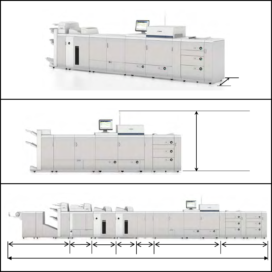
3.3.2 Dimensions Diagrams
Approx.
95.7”
Approx.
33.9”
Approx.
33.9”
Approx.
101.8”
Approx.
70.6”
Approximately 395.6”
Approx.
45.4”
Provide at least 31.5” behind the machine, and
19.7” in front and on the sides of the machine
(with all doors and access panels open).
Approx.
36.3”
Approx.
22.0”
Approx.
68.9”

Version 4 imagePRESS C7010VPS Customer Expectations Document Page 19
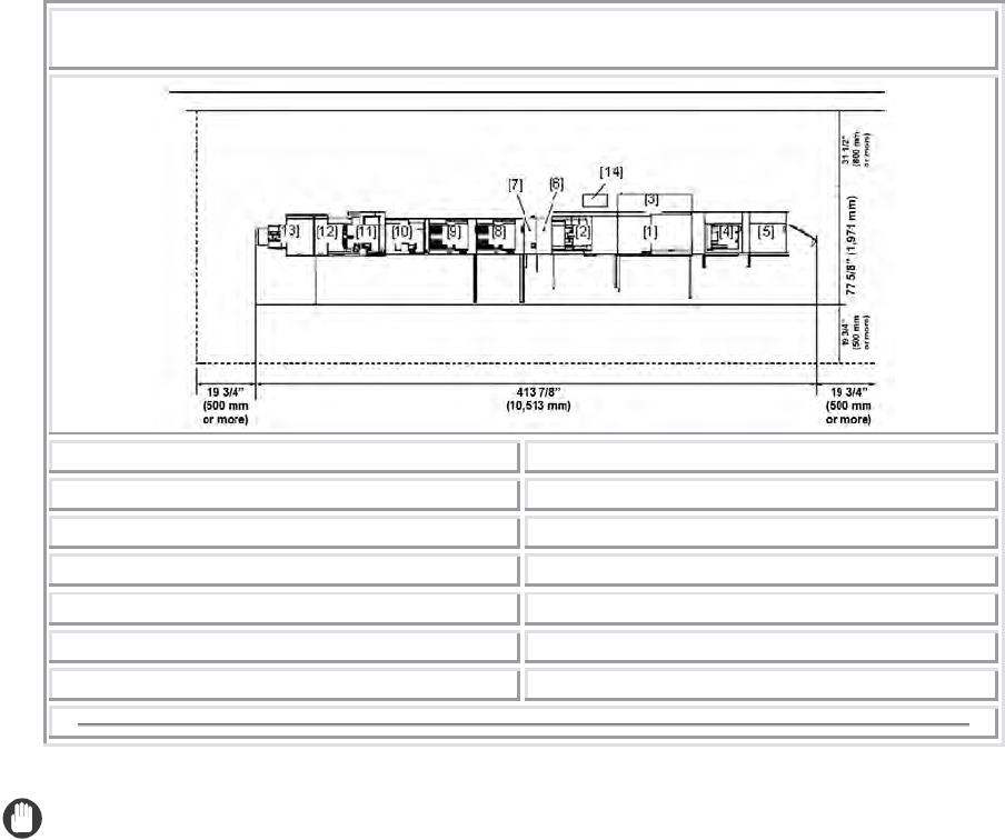
3.3.3 Installation Space Diagrams
The approximate installation space requirements may differ, depending on how
the machine is configured and the optional accessories attached.
There must be enough space around the machine. The following diagrams show the
minimum dimensions; whenever possible, make sure there will be more space than indicated.
The optional Finisher-AJ1 is attached.
[1] Marking Engine
[4] Finisher-AJ1
[2] Sub Station
[5] PRISMAsync Controller
[3] Power Station Unit
The optional High Capacity Stacker-C1 and Paper Deck-AC1 are attached.
[1] Marking Engine
[4] Paper Deck-AC1
[2] Sub Station
[5] High Capacity Stacker-C1
[3] Power Station Unit
[6] PRISMAsync Controller
Version 4 imagePRESS C7010VPS Customer Expectations Document Page 20
Maximum Configuration
[1] Marking Engine
[8] High Capacity Stacker-C1
[2] Sub Station*1
[9] High Capacity Stacker-C1 (Secondary)
[3] Power Station Unit
[10] Perfect Binder-B1
[4] POD Deck-A1
[11] Finisher-AJ1/Saddle Finisher-AJ2
[5] Secondary POD Deck-A1
[12] Booklet Trimmer-D1
[6] Professional Puncher-B1
[13] Two-Knife Booklet Trimmer-A1
[7] Professional Puncher Integration Unit-A1 [14] PRISMAsync Controller
*1 The Sub Station is shown with the optional Color Image Reader-H1 and DADF-R1 on top.
IMPORTANT
• The maximum configuration (fully configured machine) includes 1-POD
Deck-A1, 1-Secondary POD Deck-A1, the Main Unit (Marking Engine, Sub
Station, and Power Station Unit), PRISMAsync Controller, Color Image
Reader-H1, DADF-R1, Professional Puncher-B1 and Professional Puncher
Integration Unit-A1, 2-High Capacity Stackers-C1, Perfect Binder-B1, Saddle
Finisher-AJ2, Booklet Trimmer-D1, and Two-Knife Booklet Trimmer-A1.
• The fully configured width of the machine includes opening space for the POD
Deck door and the extended tray of the Two-Knife Booklet Trimmer.
• The optional SDD Square Fold Booklet-Maker with Two-Knife Trimmer is not
shown in the configuration diagrams above. If the SDD Square Fold
Booklet-Maker with Two-Knife Trimmer is attached to the machine, make sure
that there is approximately 41.2” (1,046 mm) of space added to the installation
space and floor design.
• The optional High Capacity Stacker-F1 is not shown in the configuration
diagrams above. If the High Capacity Stacker-F1 is attached to the machine,
make sure that there is approximately 35.4” (899 mm) of space added to the
installation space and floor design.
• There is approximately 1/5” (5 mm) of space between each of the following
attached accessories: the High Capacity Stacker-C1 or High Capacity
Stacker-F1, Perfect Binder-B1, Finisher-AJ1 or Saddle Finisher-AJ2, Booklet
Trimmer-D1, and SDD Square Fold Booklet-Maker with Two-Knife Trimmer.

Version 4 imagePRESS C7010VPS Customer Expectations Document Page 21
3.4 Recommended Floor Space Requirements
For a fully configured imagePRESS C7010VPS, it is recommended that there be at
least 37.8’ (W) x 10.7’ (D) of level floor space.
IMPORTANT
• The imagePRESS C7010VPS was created to be modular in design. Floor space,
budget, monthly copy/print volume, and applications will determine which
configuration works best.
• If the SDD Square Fold Booklet-Maker with Two-Knife Trimmer is attached to the
machine, make sure that there is approximately 41.2” (1,046 mm) of space
added to the installation space and floor design.
• If the High Capacity Stacker-F1 is attached to the machine, make sure that there
is approximately 35.4” (899 mm) of space added to the installation space and
floor design.
• Some type of finishing option (Saddle Finisher-AJ2, Finisher-AJ1, High Capacity
Stacker-C1, or High Capacity Stacker-F1) is required.
• Any configuration of up to 1-POD Deck-A1, 1-Secondary POD Deck-A1, and
2-High Capacity Stackers-C1 may be attached to the machine at once.
• Only one High Capacity Stacker-F1 can be attached to the machine.
3.5 Floor Structure Requirements
The floor on which this machine is installed must have strength of at least
92.2 lb/ft2 (450 kg/m2). If the floor does not have this level of strength, consult a
building contractor before installing the machine.
The weight of the machine is distributed on the floor through the adjusters and
wheels. Do not install the machine on an unstable floor or platform.
37.8’ (11.5 m)
10.7’ (3.3 m)

Version 4 imagePRESS C7010VPS Customer Expectations Document Page 22
4. Power/Electrical Requirements
The imagePRESS C7010VPS requires a NEMA L21-30 receptacle for the main
unit and proper operation.
NEMA L21-30 Receptacle

Version 4 imagePRESS C7010VPS Customer Expectations Document Page 23
4.1 Power Requirements for the Main Unit and Optional Accessories
Part or Accessory Power Supply
Power Supply Cord/Plug
Specifications
Length of
Power Cord
Main Unit
3 Phase 208 V/30 A
outlet Y Configuration
NEMA L21-30 9’ 8” (3 m)
PRISMAsync Controller
w/Operation Panel and
Attention Light
1-120 V/15 A outlet NEMA 5-15 13.9’ (4.2 m)
POD Deck-A1*1
1-208 V/15 A outlet
(regardless of the
number of POD Decks
connected)
NEMA 6-15
UL498, 2-pole, 3-wire,
grounding devices rated
250 V/15 A
6’ (1.8 m)
Paper Deck-AC1*2
From the main unit
—
—
Color Image
Reader-H1
*2
From the main unit — —
DADF-R1*2
From the main unit
—
—
High Capacity
Stacker-C1*3
1-120 V/15 A outlet
(regardless of the
number of stackers
connected)
NEMA 5-15 6’ (1.8 m)
High Capacity
Stacker-F1
1-120 V/15 A outlet NEMA 5-15 6’ (1.8 m)
Professional Puncher-
B1 & Professional
Puncher Integration
Unit-A1
*4
1-120 V/15 A outlet NEMA 5-15 6’ (1.8 m)
Saddle Finisher-AJ2 1-120 V/15 A outlet
NEMA 5-15
UL498, 2-pole, 3-wire,
grounding devices rated
250 V/15 A
6’ (1.8 m)
Finisher-AJ1 1-120 V/15 A outlet
NEMA 5-15
UL498, 2-pole, 3-wire,
grounding devices rated
250 V/15 A
6’ (1.8 m)
Documentation
Insertion Unit-C1
*2
From the finisher — —
Puncher Unit-BB1*2
From the finisher
—
—
Booklet Trimmer-D1
From the finisher
—
—
Stack Bypass-A1*2
From the main unit
—
—
Two-Knife Booklet
Trimmer-A1
1-120 V/15 A outlet NEMA 5-15 6’ (1.8 m)
Perfect Binder-B1 1-208 V/15 A outlet
NEMA 6-15
UL498, 2-pole, 3-wire,
grounding devices rated
250 V/15 A
9’ (3 m)
Square Fold Booklet-
Maker & Two-Knife
Trimmer
*5
1-120 V/15 A outlet NEMA 5-15 6’ (1.8 m)
External Start Interface
Kit for the SDD
Two-Knife Trimmer
1-120 V/15 A outlet NEMA 5-15 6’ (1.8 m)
*1 The Secondary POD Deck-A1 draws power from the POD Deck-A1.
*2 Does not require any additional outlets.
*3 If a second High Capacity Stacker-C1 is connected, the second stacker draws power from the first
stacker.
*4 The Professional Puncher Integration Unit-A1 provides the Professional Puncher-B1 with power.
*5 The SDD Two-Knife Trimmer provides the SDD Square Fold Booklet-Maker with power.

Version 4 imagePRESS C7010VPS Customer Expectations Document Page 24
The following illustration shows the relative position of the power outlets and
voltage requirements of each optional accessory item.
IMPORTANT
• Phase converters and step down transformers are not supported.
• We recommend an additional standard 115 V/15 A outlet for service tools, such
as a laptop computer or vacuum that may be used when servicing or configuring
the machine.
• Use only a dedicated and properly grounded outlet for the main unit. It is also
strongly suggested to use dedicated and properly grounded outlets for each
optional accessory. Do not use extension cords. The ground connection serves
to provide the internal electronics with a reference voltage. Faulty or poor ground
sources will cause this reference voltage to fall into a range that no longer serves
as a reliable reference voltage. The internal logic and programming of the
imagePRESS C7010VPS will not perform reliably because there is an insufficient
difference between the internal operating signal voltages and the poor ground
reference signal. A qualified electrician can measure and provide the ground
source that the imagePRESS C7010VPS or any computer controlled office
equipment requires.
• Before installation, confirm that all necessary receptacles are available.
Version 4 imagePRESS C7010VPS Customer Expectations Document Page 25
5. Environmental Factors and Requirements
This section describes the necessary environmental factors and requirements in
which the machine should be operated to achieve the best image quality and print
results.
5.1 Temperature and Humidity Conditions
The optimal humidity range is 30% to 70% RH (Relative Humidity) with a room
temperature of 68°F to 80.6°F (20°C to 27°C). Make sure to maintain a constant
temperature and humidity within this range. Otherwise, there is a risk that
productivity, paper feeding, image quality, and reliability may be affected if the
machine is operated outside of these guidelines.
The machine should not be installed in locations with significant shifts in
temperature or humidity. Areas containing water, or equipment that can
significantly alter room temperature or humidity, such as a space heater, stove, or
portable air conditioner, should be avoided.
The optimal humidity range for storing paper is 30% to 70% RH (Relative Humidity)
with a room temperature of 68°F to 80.6°F (20°C to 27°C). Storing paper in a
location that does not meet these specifications may affect paper feeding and
image quality. For example, if the humidity is too high, paper curling and paper
jams will increase. If the humidity is too low, paper may shrink or lose resistance,
and toner will not adhere to the paper as well.
Only use paper that has fully acclimatized to the environment in which the machine
is installed. Using paper that has been stored in a different environment (with a
different temperature and humidity), may cause paper jams or result in poor print
quality.
5.2 Temperature Gradient
If a sudden temperature change occurs, may have an adverse affect on image
positioning. Sudden temperature changes may cause the paper to bend or
contract, cause the machine to malfunction, and form condensation. Every effort
should be made to maintain consistent temperature and humidity levels in the
operating environment at all times for the imagePRESS C7010VPS.
If a humidifier must be used to regulate the humidity, use one that has a mineral
filter on it.
Version 4 imagePRESS C7010VPS Customer Expectations Document Page 26
5.3 Ventilation
Ensure that there is an air exchange rate of at least 1.5 times per hour, and at least
3,885 ft3 (110 m3) of space in the location where the machine will be installed.
This machine generates a slight amount of ozone during normal use. Although
sensitivity to ozone may vary, this amount is not harmful. Ozone may be more
noticeable during extended use or long production runs, especially in poorly
ventilated rooms. It is recommended that the room be appropriately ventilated,
sufficient to maintain a comfortable working environment, in areas of machine
operation.
5.4 Elevation Limitations
Install this machine at an elevation below 13,123’ (4,000 m) and at an air pressure
less than 607.8 hPa.
5.5 Lighting
We recommend installing the machine in a location with at least 500 lux
(29 1/2” (75 cm) above the floor) for normal operation and maintenance.
5.6 Sunlight
Avoid installing the machine in direct sunlight. Direct sunlight has adverse effects
on toner consistency and image quality. If direct sunlight is unavoidable, use
curtains to shade the machine. Make sure that the curtains do not block the
machine’s ventilation slots or louvers, or interfere with the electrical cord or power
supply.
5.7 Ammonia
Avoid installing the machine where ammonia is emitted. In a sufficient amount,
ammonia will attack the surfaces of the machine’s paper feed and image quality
components, thereby shortening their useful life and increasing the need for
periodic and remedial maintenance.
A professional assessment of the air quality in the room in which the machine is to
be installed is recommended prior to its installation.

Version 4 imagePRESS C7010VPS Customer Expectations Document Page 27
6. Specifications
This chapter explains the specifications of the main unit and optional accessories.
The specifications provided are approximate values for the user’s reference only,
and are subject to change without notice for product improvement or future
release.
6.1 Main Unit
Item Specifications
Name Canon imagePRESS C7010VPS
Type Console
Drum Photosensitive OPC Drum x 4
Color Supported Full Color
Engine Resolution Up to 1,200 dpi x 1,200 dpi
Reading Resolution Up to 600 dpi x 600 dpi
Number of Gradations 256
Memory 1.5 GB (standard)
Hard Disk 80 GB x 2
Paper Size/Weight/Type
Size: 13” x 19”, 12” x 18”, 11” x 17”, LGL, LTR, LTRR, EXEC, and
Irregular Size (7 1/8” x 7 1/8” to 13” x 19 13/64”
(182 mm x 182 mm to 330.2 mm x 487.7 mm))
Weight: 16 lb bond to 120 lb cover (60 to 325 g/m2)
Thickness: Fewer than 350 µm
Type: Thin, Plain, Heavy, Recycled, Color, Pre-punched, Bond Paper,
Transparency, Labels, Tab Paper, Coated, Texture Paper, Vellum
Margin Top Margin: 1/8” (2.5 mm)
Left and Right Margins: 1/8” (2.5 mm)
Bottom Margin: 1/8” (2.5 mm)
Warm-Up Time
After Powering ON: Fewer than 7 minutes
Returning from the Sleep mode: Fewer than 7 minutes
Activation time may vary, depending on the conditions under which the
machine is being used. (In all cases, at a room temperature of 68°F.)
First Output Time Approximately 33 seconds
Maximum Imageable
Area 12.7” x 19” (323 mm x 482.7 mm)*1
Front-to-Back
Registration Tolerance
Active Registration: Up to ± 0.5 mm
Tolerance simplex/first side duplex printing:
Up to ±0.5 mm in feed direction and cross-feed direction
Tolerance second side automatic duplex printing:
Up to ±0.5 mm in feed direction and cross-feed direction
Front-to-back alignment can vary up to a maximum of 1 mm in feed direction,
1 mm in cross-feed direction, and 1.4 mm diagonally.
*1 The maximum guaranteed print size is 12.6” x 19” (320.6 mm x 482.7 mm).

Version 4 imagePRESS C7010VPS Customer Expectations Document Page 28
Main Unit Table Continued
Item Specifications
Copy/Print Speed
(Except when paper is
fed from the optional
Stack Bypass-A1)
13” x 19”
Approximately 33.6 sheets/minute
(16 lb bond to 80 lb cover (60 to 209 g/m2))
Approximately 31.3 sheets/minute
(80 to 120 lb cover (210 to 325 g/m
2
))
12” x 18”
Approximately 35.7 sheets/minute
(16 lb bond to 80 lb cover (60 to 209 g/m2))
Approximately 33.1 sheets/minute
(80 to 120 lb cover (210 to 325 g/m
2
))
11” x 17”
Approximately 37.6 sheets/minute
(16 lb bond to 80 lb cover (60 to 209 g/m2))
Approximately 35.0 sheets/minute
(80 to 120 lb cover (210 to 325 g/m
2
))
LGL
Approximately 41.8 sheets/minute
(16 to 28 lb bond (60 to 105 g/m2))
Approximately 33.3 sheets/minute
(28 lb bond to 63 lb cover (106 to 170 g/m2))
Approximately 25.1 sheets/minute
(63 to 120 lb cover (171 to 325 g/m
2
))
LTR
Approximately 70.0 sheets/minute
(16 lb bond to 120 lb cover (60 to 325 g/m
2
))
LTRR
Approximately 53.2 sheets/minute
(16 to 28 lb bond (60 to 105 g/m2))
Approximately 42.4 sheets/minute
(28 lb bond to 63 lb cover (106 to 170 g/m2))
Approximately 31.9 sheets/minute
(63 to 120 lb cover (171 to 325 g/m
2
))
EXEC
Approximately 71.6 sheets/minute
(16 lb bond to 63 lb cover (60 to 170 g/m2))
Approximately 61.1 sheets/minute
(63 to 120 lb cover (171 to 325 g/m
2
))
The copy/print speeds above may not be achieved if the user copies/prints in
the conditions below:
• If different paper types are used at the same time
• If different paper sizes are used at the same time
• If copying/printing as one- and two-sided documents at the same time. For
example, the main document is copied/printed as one-sided, and the cover
and sheet insertions are copied/printed as two-sided while bookbinding.
• If a saddle stitched booklet is created using one or two sheets
• If paper whose length of the feeding direction is 18” (457.2 mm) or more is
used, while creating a saddle stitched booklet.
Paper Feeding System/
Capacity Up to 1,000 sheets x 2 paper decks (20 lb bond (80 g/m2))
Multiple Copies 1 to 9,999 sheets
Power Source 3-phase, 5-wire 208 V AC, 60 Hz, 30 A (one power cord)
Maximum Power
Consumption
Maximum: Approximately 8.5 kW
In Sleep Mode: Approximately 187 W (including the PRISMAsync
controller, operation panel, and attention light)
Noise Printing: Approximately 82 dB
Standby: Approximately 75.7 dB
Dimensions (H x W x D)
Without Operation Panel:
52 3/8” x 101 7/8” x 45 3/8” (1,330 mm x 2,586 mm x 1,152 mm)
With Operation Panel and Attention Light:
68 7/8” x 101 7/8” x 45 3/8” (1,750 mm x 2,586 mm x 1,152 mm)
Weight Approximately 2,645 lb (1,200 kg)
Version 4 imagePRESS C7010VPS Customer Expectations Document Page 29
Main Unit Table Continued
Item Specifications
Installation Space
(W x D)
101 7/8” x 45 3/8” (2,586 mm x 1,152 mm) (main unit only)
182 5/8” x 45 3/8” (4,638 mm x 1,152 mm) (when the optional POD Deck-A1
and Saddle Finisher-AJ2 are attached)
111 1/4” x 73 3/8” (2,826 mm x 1,862 mm) (when clearing paper jams, main
unit only)
201 1/4” x 73 3/8” (5,111 mm x 1,862 mm) (when clearing paper jams, and
when the optional POD Deck-A1 and Saddle Finisher-AJ2 are attached)
Altitude 13,123’ (4,000 m (607.8 hPa)) maximum
Temperature while in
Use 68 to 80.6°F (20 to 27°C)
Humidity 30 to 70% RH
6.2 PRISMAsync Controller
Item Specifications
Server Type External
Operating System Windows XPe SP3
Processor Intel QuadCore i7
GPU nVidea GeForce GTS450
Memory
4 GB
Hard Disk 3 x 3.5” SATA II, 250 GB, 7,200 RPM
Interface
Ethernet 10/100/1000 Base-T, TCP/IP (LPR/LPD, 9100 Socket, SMB),
Static IP/Auto IP (DHCP)
Page Description
Languages
Adobe PostScript 3 (3019), PDF 1.7, Extension Level 3 (for Acrobat 9);
PDF-X, Optimized PS, Optimized PDF
Print Drivers
• Windows Vista, Windows 7 (32- and 64-bit)
• Macintosh OS X 10.4, 10.5, 10.6 (32-bit)
•
PPD
Protocols SNMP v1, v2c, and v3, Host resources MIB, System Group MIB II, Printer
MIB, Job Monitor MIB, LDAP
Fonts
136 Type 1 fonts for Roman languages
User import of PS fonts via the Settings Editor
Optional Adobe Asian fonts:
• Japanese: 5 Morisawa fonts (no Heisel fonts)
• Chinese: 2 fonts for simplified Chinese, 1 font for traditional Chinese
• Korean: 1 font for Korean
Spot Color Libraries
HKS K, HKS K 3000+, HKS N, HKS N 3000+ Pantone Goe
(Uncoated/Coated), Pantone+ Solid (Uncoated/Coated)

Version 4 imagePRESS C7010VPS Customer Expectations Document Page 30
PRISMAsync Controller Table Continued
Item Specifications
Power Source Including the Operation Panel and Attention Light:
100-240 V, 15 A, 50 to 60 Hz
Maximum Power
Consumption
Including the Operation Panel and Attention Light:
Maximum: Approximately 181 W
Running: Approximately 165 W
Ready: Approximately 130 W
Sleep Mode: Approximately 117 W
Dimensions (H x W x D) 16.5” x 7.9” 16.9” (420 mm x 200 mm x 430 mm)
Weight Approximately 35 lb (16 kg)
Security
E-Shredding, HTTPS, SNMP v3
Password protection per user role (key operator, system administrator,
service technician)
Languages American English, British English, Czech, Danish, Dutch, Finnish, French,
German, Hungarian, Italian, Norwegian, Polish, Portuguese, Russian,
Simplified Chinese, Spanish, Swedish, Japanese
Options
Remote Viewer License, Asian font sets: Korean, Japanese, Simplified
Chinese, Traditional Chinese
Version 4 imagePRESS C7010VPS Customer Expectations Document Page 31
6.2.1 USB Stick
Item Specifications
USB Connection Speed USB 2.0 High-Speed certified, USB 1.1 backward compatible
USB Stick Size ≥ 2 GB, 4 GB is recommended
Bootable Media Support Yes (Mandatory)
File System Support Bootable NTFS and FAT32 (Intel)
Drivers
Windows generic drivers for USB mass storage.
No specific drivers or specific setup.
Bios Recognition USB HDD device
USB Stick Technology SLC (Single Level Cell) (Mandatory)
Encryption No hardware data encryption.
Software on the USB stick is allowed.
*1
U3 Support Not allowed.
Biometric Support Not allowed.
Micro-Drive Not allowed.
Ready Boost Certified Yes (Mandatory)
Minimal
Throughputs
File Size
512 B
32 KB
256 KB
2 MB
64 MB
Read
1.5 MB
8 MB
20 MB
23 MB
24 MB
Write
0.1 MB
0.8 MB
4 MB
4 MB
8 MB
Housing Rubber housing (shock resistant) is preferred.
LCD Screen Not allowed.
Activity Indication LED Yes
Tested & Supported USB
Sticks*2
• OCZ ATV – Supplier Ref#: OCZUSBATVxG
*3
• Corsair Flash Voyager GT – Supplier Ref#: CMFUSB2.0-16GBGT
•
Patriot Xporter XT Boost – Supplier Ref#: PEFxGUSB
*3
Minimum Manufacturer
Warranty
5 years
*1 Encryption software on the USB stick is allowed only if it is possible to automatically format the stick
(e.g., with the Format command), and does not involve any additional human action.
*2 USB sticks that have not been tested cannot be used.
*3 “x” is the size of the USB stick (e.g., OCZUSBATV4G = 4 GB USB stick).
6.3 Color Image Reader-H1
Item Specifications
Type Flatbed
Image Sensor CCD
Resolution for Reading Up to 600 dpi x 600 dpi
Acceptable Originals Sheet, book, three dimensional objects (up to 4.4 lb (2 kg))
Paper Sizes 11” x 17”, LGL, LTR, LTRR, STMT, STMTR, or EXEC
Power Source/
Consumption
From the main unit.
140 W maximum
Dimensions (H x W x D)
4 1/8” x 28 7/8” x 23 1/2” (105 mm x 732 mm x 595 mm) (excluding the
document feeder)
Weight Approximately 38.5 lb (17.5 kg) (excluding the document feeder)

Version 4 imagePRESS C7010VPS Customer Expectations Document Page 32
6.4 Feeder (DADF-R1)
Item Specifications
Original Feeding
Mechanism Automatic Document Feeder
Size and Weight of
Originals
Original Supply Tray:
11” x 17”, LGL, LTR, LTRR, or STMT (STMT originals cannot be placed
horizontally (STMTR).)
1-sided scanning: 13 to 57 lb bond (50 to 216 g/m2)
2-sided scanning: 13 to 57 lb bond (50 to 216 g/m2) for LTR, and
13 to 53 lb bond (50 to 200 g/m2) for 11” x 17”, LGL, and
LTRR
SADF Tray:
11” x 17”, LGL, LTR, LTRR, or STMT (STMT originals cannot be placed
horizontally (STMTR).)
10 to 57 lb bond (38 to 216 g/m
2
)
Original Tray Capacity
Original Supply Tray:
100 sheets (20 lb bond (80 g/m2))
SADF Tray:
1 sheet
Original Replacement
Speed
Copying: 50 sheets/minute (LTR)
Scanning: 80 sheets/minute*1 maximum (LTR at 300 dpi)
*1 The original replacement speed may vary, depending on the scanning mode
and original type.
Scan Speed Scan to file: Simplex: 25 ipm, Duplex: 15 ipm
Copy: First Set Simplex: 25 ipm, Duplex: 15 ipm
Following Sets: Output at full engine speed
Power Source/
Consumption From the main unit.
100 W maximum
Dimensions
(H x W x D)/Weight 5 5/8” x 25 1/2” x 22 1/2” (143 mm x 646 mm x 570 mm)
Approximately 48.5 lb (22 kg) (excluding the output tray)

Version 4 imagePRESS C7010VPS Customer Expectations Document Page 33
6.5 POD Deck-A1/Secondary POD Deck-A1
Item Specifications
Paper Size/Weight/Type
Size: 13” x 19”, 12” x 18”, 11” x 17”, LGL, LTR, LTRR, EXEC, and Irregular
Size (7 1/8” x 7 1/8” to 13” x 19 13/64”
(182 mm x 182 mm to 330.2 mm x 487.7 mm))
Weight: 16 lb bond to 120 lb cover (60 to 325 g/m2)
Type: Thin, Plain, Heavy, Recycled, Color, Pre-punched, Bond Paper,
Transparency, Labels, Coated, Texture Paper, Vellum
Paper Deck Capacity Upper and Middle Decks: 1,000 sheets x 2 paper decks (20 lb bond (80 g/m2))
Lower Deck: 2,000 sheets x 1 paper deck (20 lb bond (80 g/m2))
Power Source
POD Deck-A1: 200 to 208 V AC, 50/60 Hz, 6 A
Secondary POD Deck-A1: From POD Deck-A1
(200 to 240 V AC, 50/60 Hz, 2.8 A)
Maximum Power
Consumption POD Deck-A1 Only: 750 W
POD Deck-A1 + Secondary POD Deck-A1: 1,380 W
Dimensions (H x W x D)/
Weight
POD Deck-A1 Only:
43 1/8” x 38 5/8” x 31 1/4” (1,095 mm x 982 mm x 792 mm) (including the
escape tray)
Approximately 551 lb (250 kg)
POD Deck-A1 + Secondary POD Deck-A1:
43 1/8” x 70 5/8” x 31 1/4” (1,095 mm x 1,793 mm x 792 mm) (including the
escape tray)
Approximately 1,058 lb (480 kg)
6.6 Paper Deck-AC1
Item Specifications
Paper Size/Weight/Type
Size: 13” x 19”, 12” x 18”, 11” x 17”, LGL, LTR, or LTRR
Weight: 17 lb bond to 110 lb cover (64 to 300 g/m2)
Type: Thin, Plain, Heavy, Recycled, Color, Pre-punched, Bond Paper,
Transparency, Labels, Coated, Texture Paper, Vellum
Paper Deck Capacity 3,500 sheets (20 lb bond (80 g/m2))
Power Source From the main unit.
Maximum Power
Consumption
280 W (including the deck heater)
Dimensions (H x W x D)/
Weight 22 1/2” x 23 5/8” x 24 1/2” (570 mm x 601 mm x 621 mm)
Approximately 112.4 lb (51 kg)

Version 4 imagePRESS C7010VPS Customer Expectations Document Page 34
6.7 Stack Bypass-A1
Item Specifications
Paper Size/Weight/Type
Size: 13” x 19”, 12” x 18”, 11” x 17”, LGL, LTR, LTRR, STMTR, EXEC, and
Irregular Size (5 31/64” x 7 1/8” to 13” x 19 13/64”
(139.7 mm x 182 mm to 330.2 mm x 487.7 mm))
Weight: 17 lb bond to 140 lb index (64 to 256 g/m2)
Type: Thin, Plain, Heavy, Recycled, Color, Pre-punched, Bond Paper,
Transparency, Labels, Coated
*1
, Texture Paper, Vellum
Paper Capacity 100 sheets (20 lb bond (80 g/m2))
*1 Place coated paper one sheet at a time into the stack bypass.
6.8 Tab Feeding Attachment-C1
Item Specifications
Paper Size LTR
Paper Capacity 300 to 400 sheets (27 lb bond (100 g/m2)) (or 1 3/4” (45 mm) in height)
Paper Holder Size 10 5/8” (270 mm)
Dimensions (H x W x D)/
Weight 4 3/4” x 10 7/8” 14 5/32” (121 mm x 277 mm x 360 mm)
Approximately 2.6 lb (1.2 kg)
6.9 Professional Puncher-B1 and Professional Puncher Integration Unit-A1
Item Specifications
Paper Size LTR, Tab Paper (9” x 11”)
Paper Weight
The paper weight and paper stocks differ, depending on the selected die set.
Plain Paper: 20 lb bond to 80 lb cover (75 to 216 g/m2)
Coated Paper: 32 lb bond to 80 lb cover (120 to 216 g/m
2
)
Paper Type Thin, Plain, Heavy, Recycled, Color, Bond, Tab Paper, Coated, Texture, and
Vellum
Punch Patterns
Plastic Comb Binding (19 holes), Twin Loop Binding (32 holes), Twin Loop
Binding (21 holes), Color Coil Binding (44 holes), Velo Bind (11 holes),
Loose-Leaf Binding (3 holes), Loose-Leaf Binding (5 holes), ProClick Binding
(32 holes)
Waste Tray Capacity Varies by die set type.
25,000 sheets maximum (3-hole die set, 20 lb bond (80 g/m2))
Power Source 120 to 127 V AC, 60 Hz, 5.5 A
Maximum Power
Consumption Professional Puncher-B1: 310 W
Professional Puncher Integration Unit-A1: 130 W
Dimensions (H x W x D)/
Weight 41” x 22” x 31 1/2” (1,040 mm x 560 mm x 800 mm)
Approximately 258 lb (117 kg)

Version 4 imagePRESS C7010VPS Customer Expectations Document Page 35
6.10 Finisher-AJ1
Item Specifications
Paper Size/Weight/Type
Size: 13” x 19”, 12” x 18”, 11” x 17”, LGL, LTR, LTRR, STMTR, EXEC, and
Irregular Size (5 31/64” x 7 1/8” to 13” x 19 13/64”
(139.7 mm x 182 mm to 330.2 mm x 487.7 mm))
Weight: 16 lb bond to 120 lb cover (60 to 325 g/m2)
Type: Thin, Plain, Heavy, Recycled, Color, Pre-punched, Bond Paper,
Transparency, Labels, Tab Paper, Coated, Texture Paper, Vellum
Capacity Per Tray
No Collating Mode
Tray A:
If the High Volume Stack Mode is set to ‘Off’:
13” x 19”, 12” x 18”, 11” x 17”, LGL, LTR, LTRR, STMTR, EXEC: 1,000 sheets
(or 5 3/4” (147 mm) in height)
If the High Volume Stack Mode is set to ‘On’:
(The maximum stack volume may vary, depending on the paper type.)
LTR, LTRR, STMTR, EXEC: 3,000 sheets (or 16 5/8” (423 mm) in height)
11” x 17”, LGL: 1,500 sheets (or 8 1/2” (216 mm) in height)
Tray B:
LTR, LTRR, EXEC: 2,000 sheets (or 11 1/4” (285 mm) in height)
13” x 19”, 12” x 18”, 11” x 17”, LGL: 1,000 sheets (or 5 3/4” (147 mm) in height)
Collate or Group Mode
Tray A:
If the High Volume Stack Mode is set to ‘Off’:
12” x 18”, 11” x 17”, LGL, LTR, LTRR, STMTR, EXEC: 1,000 sheets (or 5 3/4”
(147 mm) in height)
If the High Volume Stack Mode is set to ‘On’:
(The maximum stack volume may vary, depending on the paper type.)
LTR, LTRR, STMTR, EXEC: 3,000 sheets (or 16 5/8” (423 mm) in height)
11” x 17”, LGL: 1,500 sheets (or 8 1/2” (216 mm) in height)
Tray B:
LTR, LTRR, EXEC: 2,000 sheets (or 11 1/4” (285 mm) in height)
12” x 18”, 11” x 17”, LGL: 1,000 sheets (or 5 3/4” (147 mm) in height)

Version 4 imagePRESS C7010VPS Customer Expectations Document Page 36
Finisher-AJ1 Table Continued
Item Specifications
Capacity Per Tray
Continued
Staple Mode
Tray A:
11” x 17”, LGL, LTR, LTRR, EXEC: 1,000 sheets/100 sets (or 5 3/4”
(147 mm) in height)
Tray B:
LTR, LTRR, EXEC: 2,000 sheets/100 sets (or 11 1/4” (285 mm) in height)
11” x 17”, LGL: 1,000 sheets/100 sets (or 5 3/4” (147 mm) in height)
No Collating Mode with Different Paper Sizes:
Tray A:
Regardless of the High Volume Stack Mode:
13” x 19”, 12” x 18”, 11” x 17”, LGL, LTR, LTRR, STMTR, EXEC: 1,000 sheets
(or 5 3/4” (147 mm) in height)
Tray B:
13” x 19”, 12” x 18”, 11” x 17”, LGL, LTR, LTRR, EXEC:
1,000 sheets (or 5 3/4” (147 mm) in height)
Collate or Group Mode with Different Paper Sizes:
Tray A:
Regardless of the High Volume Stack Mode:
12” x 18”, 11” x 17”, LGL, LTR, LTRR, STMTR, EXEC: 1,000 sheets (or 5 3/4”
(147 mm) in height)
Tray B:
12” x 18”, 11” x 17”, LGL, LTR, LTRR, EXEC: 1,000 sheets (or 5 3/4”
(147 mm) in height)
Staple Mode with Different Paper Sizes:
Tray A:
11” x 17”, LGL, LTR, LTRR, EXEC: 1,000 sheets/100 sets (or 5 3/4”
(147 mm) in height)
Tray B:
11” x 17”, LGL, LTR, LTRR, EXEC: 1,000 sheets/100 sets (or 5 3/4”
(147 mm) in height)

Version 4 imagePRESS C7010VPS Customer Expectations Document Page 37
Finisher-AJ1 Table Continued
Item Specifications
Max. Stapling
Capacity/Available
Staple Size
When the Standard Staple Cartridge Is Attached:
(The maximum stapling capacity may vary, depending on the paper type and
weight.)
LTR, EXEC: 100 sheets (20 lb bond (80 g/m2)) or Heavy paper
stacked less than 1/2” (11 mm) high
98 sheets (20 lb bond (80 g/m2)) + 2 sheets
(110 lb cover (300 g/m2))
11” x 17”, LGL, LTRR: 50 sheets (20 lb bond (80 g/m2)) or Heavy paper
stacked less than 1/4” (5.5 mm) high
48 sheets (20 lb bond (80 g/m2)) + 2 sheets
(110 lb cover (300 g/m2))
Corner Stapling: 11” x 17”, LGL, LTR, LTRR, EXEC
Double Stapling: 11” x 17”, LGL, LTR, LTRR, EXEC
Power Source 120 to 127 V AC, 60 Hz, 8 A
Maximum Power
Consumption 450 W
Dimensions
(H x W x D)/Weight
46 1/2” x 31 1/2” (35”*1) x 31 1/4” (1,180 mm x 800 mm (890 mm*1) x 792 mm)
Approximately 286.6 lb (130 kg)
*1 When the extension tray is pulled out.

Version 4 imagePRESS C7010VPS Customer Expectations Document Page 38
6.11 Saddle Finisher-AJ2
Item Specifications
Paper Size/Weight/Type
Size: 13” x 19”, 12” x 18”, 11” x 17”, LGL, LTR, LTRR, STMTR, EXEC, and
Irregular Size (5 31/64” x 7 1/8” to 13” x 19 13/64”
(139.7 mm x 182 mm to 330.2 mm x 487.7 mm))
Weight: 16 lb bond to 120 lb cover (60 to 325 g/m2)
Type: Thin, Plain, Heavy, Recycled, Color, Pre-punched, Bond Paper,
Transparency, Labels, Tab Paper, Coated, Texture Paper, Vellum
Capacity Per Tray
No Collating Mode
Tray A:
If the High Volume Stack Mode is set to ‘Off’:
13” x 19”, 12” x 18”, 11” x 17”, LGL, LTR, LTRR, STMTR, EXEC: 1,000 sheets
(or 5 3/4” (147 mm) in height)
If the High Volume Stack Mode is set to ‘On’:
(The maximum stack volume may vary, depending on the paper type.) (When
the optional Booklet Trimmer-D1/optional Booklet Trimmer-D1 and Two-Knife
Booklet Trimmer-A1 are attached, the High Volume Stack Mode is not
available.)
LTR, LTRR, STMTR, EXEC: 3,000 sheets (or 16 5/8” (423 mm) in height)
11” x 17”, LGL: 1,500 sheets (or 8 1/2” (216 mm) in height)
Tray B:
LTR, LTRR, EXEC: 2,000 sheets (or 11 1/4” (285 mm) in height)
13” x 19”, 12” x 18”, 11” x 17”, LGL: 1,000 sheets (or 5 3/4” (147 mm) in height)
Collate or Group Mode
Tray A:
If the High Volume Stack Mode is set to ‘Off’:
12” x 18”, 11” x 17”, LGL, LTR, LTRR, STMTR, EXEC: 1,000 sheets (or 5 3/4”
(147 mm) in height)
If the High Volume Stack Mode is set to ‘On’:
(The maximum stack volume may vary, depending on the paper type.)
LTR, LTRR, STMTR, EXEC: 3,000 sheets (or 16 5/8” (423 mm) in height)
11” x 17”, LGL: 1,500 sheets (or 8 1/2” (216 mm) in height)
Tray B:
LTR, LTRR, EXEC: 2,000 sheets (or 11 1/4” (285 mm) in height)
12” x 18”, 11” x 17”, LGL: 1,000 sheets (or 5 3/4” (147 mm) in height)

Version 4 imagePRESS C7010VPS Customer Expectations Document Page 39
Saddle Finisher-AJ2 Table Continued
Item Specifications
Capacity Per Tray
Continued
Staple Mode
Tray A: (When the optional Booklet Trimmer-D1/optional Booklet Trimmer-D1
and Two-Knife Booklet Trimmer-A1 are attached, stapled output cannot be
sorted to Tray A.)
11” x 17”, LGL, LTR, LTRR, EXEC: 1,000 sheets/100 sets (or 5 3/4”
(147 mm) in height)
Tray B:
LTR, LTRR, EXEC: 2,000 sheets/100 sets (or 11 1/4” (285 mm) in height)
11” x 17”, LGL: 1,000 sheets/100 sets (or 5 3/4” (147 mm) in height)
No Collating Mode with Different Paper Sizes:
Tray A:
Regardless of the High Volume Stack Mode:
13” x 19”, 12” x 18”, 11” x 17”, LGL, LTR, LTRR, STMTR, EXEC: 1,000 sheets
(or 5 3/4” (147 mm) in height)
Tray B:
13” x 19”, 12” x 18”, 11” x 17”, LGL, LTR, LTRR, EXEC:
1,000 sheets (or 5 3/4” (147 mm) in height)
Collate or Group Mode with Different Paper Sizes:
Tray A:
Regardless of the High Volume Stack Mode:
12” x 18”, 11” x 17”, LGL, LTR, LTRR, STMTR, EXEC: 1,000 sheets (or 5 3/4”
(147 mm) in height)
Tray B:
12” x 18”, 11” x 17”, LGL, LTR, LTRR, EXEC: 1,000 sheets (or 5 3/4”
(147 mm) in height)
Staple Mode with Different Paper Sizes:
Tray A:
11” x 17”, LGL, LTR, LTRR, EXEC: 1,000 sheets/100 sets (or 5 3/4”
(147 mm) in height)
Tray B:
11” x 17”, LGL, LTR, LTRR, EXEC: 1,000 sheets/100 sets (or 5 3/4”
(147 mm) in height)

Version 4 imagePRESS C7010VPS Customer Expectations Document Page 40
Saddle Finisher-AJ2 Table Continued
Item Specifications
Max. Stapling
Capacity/Available
Staple Size
When the Standard Staple Cartridge Is Attached:
(The maximum stapling capacity may vary, depending on the paper type and
weight.)
LTR, EXEC: 100 sheets (20 lb bond (80 g/m2)) or Heavy paper
stacked less than 1/2” (11 mm) high
98 sheets (20 lb bond (80 g/m2)) + 2 sheets
(110 lb cover (300 g/m2))
11” x 17”, LGL, LTRR: 50 sheets (20 lb bond (80 g/m2)) or Heavy paper
stacked less than 1/4” (5.5 mm) high
48 sheets (20 lb bond (80 g/m2)) + 2 sheets
(110 lb cover (300 g/m2))
Corner Stapling: 11” x 17”, LGL, LTR, LTRR, EXEC
Double Stapling: 11” x 17”, LGL, LTR, LTRR, EXEC
Available Saddle Stitch
Capacity/Size
Saddle stitch: 25 sheets (20 lb bond (80 g/m2))
Saddle fold: 5 sheets (20 lb bond (80 g/m2))
Size: 13” x 19”, 12” x 18”, 11” x 17”, LGL, LTRR, and
Irregular Size (8 1/4” x 11” to 13” x 19 13/64”
(210 mm x 279.4 mm to 330.2 mm x 487.7 mm))
Weight of cover sheet: (17 lb bond to 110 lb cover (64 to 300 g/m2))
(The available number of sheets for saddle stitching may decrease, depending
on the paper weight or paper type.)
Power Source 120 to 127 V AC, 60 Hz, 8 A
Maximum Power
Consumption 450 W
Dimensions
(H x W x D)/Weight
46 1/2” x 31 1/2” (41 3/4”*1) x 31 1/4” (1,180 mm x 800 mm (1,060 mm*1) x
792 mm)
Approximately 396.8 lb (180 kg)
*1 When the auxiliary booklet tray is pulled out.

Version 4 imagePRESS C7010VPS Customer Expectations Document Page 41
6.12 Puncher Unit-BB1
Item Specifications
Paper Size/Weight/Type
Size: 11” x 17”, LGL*1, LTR, LTRR*1, or EXEC
Weight: 16 lb bond to 73 lb cover (60 to 200 g/m2)
Type: Thin, Plain, Heavy, Recycled, Color, Bond Paper, Tab Paper,
Coated, Texture Paper
*1 For two holes only.
Punch Hole Quantity,
Hole Diameter Two holes: 3/8” (8 mm)
Three holes: 3/8” (8 mm)
Distance between Punch
Holes Two holes: 2 3/4” (70 mm)
Three holes: 4 1/4” (108 mm)
Paper Size in Which Holes
Can be Punched Two holes: LGL and LTRR
Three holes: 11" x 17” and LTR
Punch Waste Tray
Capacity
When approximately 6,000*1 sheets of paper have been punched.
*1 This number may vary, depending on the surrounding environment, paper
type, and paper weight.
Power Source From the finisher.
Weight Approximately 6.6 lb (3 kg) inside the finisher
6.13 Document Insertion Unit-C1
Item Specifications
Paper Size/Weight/Type
Upper Tray: LTR, LTRR, EXEC, and Irregular Size (7 1/8” x 7 1/8” to
11 11/16” x 13” (182 mm x 182 mm to 297 mm x 330.2 mm))
Lower Tray: 13” x 19”, 12” x 18”, 11” x 17”, LGL, LTR, LTRR, EXEC, and
Irregular Size (7 1/8” x 7 1/8” to 13” x 19 13/64”
(182 mm x 182 mm to 330.2 mm x 487.7 mm))
Weight: 16 lb bond to 110 lb cover (60 to 300 g/m2)
Type: Thin, Plain, Heavy, Recycled, Color, Pre-punched, Bond Paper,
Coated, Texture Paper, Vellum
Paper Capacity Upper Tray: 200 sheets (20 lb bond (80 g/m2))
Lower Tray: 200 sheets (20 lb bond (80 g/m2))
Power Source/Maximum
Power Consumption From the finisher.
72 W
Dimensions (H x W x D)/
Weight 8 3/8” x 24 5/8” x 26 1/4” (213 mm x 625 mm x 667 mm)
Approximately 37.4 lb (17 kg)
Version 4 imagePRESS C7010VPS Customer Expectations Document Page 42
6.14 High Capacity Stacker-C1
Item Specifications
Paper Size
Stack Tray: 11” x 17”, 12” x 18”, 13” x 19”, LGL, LTR, LTRR, EXEC,
Tab Paper (LTR)*1, and Irregular Size (8 1/2” x 7 1/8” to 13” x 19 13/64”
(216 mm x 182 mm to 330.2 mm x 487.7 mm))
Proof Tray: 11” x 17”, 12” x 18”, 13” x 19”, LGL, LTR, LTRR, EXEC, STMTR,
Post Card, Tab Paper (LTR), and Irregular Size
(5 1/2” x 7 1/8” to 13” x 19 13/64”
(139.7 mm x 182 mm to 330.2 mm x 487.7 mm))
Paper Capacity 6,000 sheets maximum
Number of Trays 2 trays
Tray Capacity Proof Tray: 1,000 sheets
Stack Tray: 5,000 sheets*2
Paper Size/Weight Size: 13” x 19.2” maximum
Weight: 16 lb bond to 120 lb cover (60 to 325 g/m2)
Stacking Modes Straight, Offset
Power Source 120 to 127 V, 50/60 Hz, 7 A
Maximum Power
Consumption 300 W
Dimensions (H x W x D)/
Weight 48 7/8” x 33 7/8” x 30 1/8” (1,240 mm x 860 mm x 765 mm)
Approximately 478.5 lb (217 kg)
*1 Outputting tab paper to the High Capacity Stacker’s Proof Tray may improve stacking performance.
*2 The maximum stack capacity may differ, depending on the content or paper type. The maximum stack
capacity is limited to 2,000 sheets when EXEC paper is used.
6.15 High Capacity Stacker-F1
Item Specifications
Paper Size
Top Tray, Stack Tray, Eject Tray:
13” x 19”, 12” x 18”, 11” x 17”, LGL, LTR, LTRR, STMTR, EXEC, EXECR,
Custom Size: 5 1/2” x 7 1/8” to 13” x 19 13/64” (140 mm x 182 mm to
330.2 mm x 487.7 mm)
Paper Weight 14 lb bond to 120 lb cover (50 to 325 g/m2)
Tray Capacity
Top Tray:
200 sheets (20 lb bond (80 g/m2)) or stacked up to 0.8” (20 mm)
Stack Tray (Internal):
3,000 sheets (20 lb bond (80 g/m2)) or stacked up to 14” (355 mm)
Eject Tray (External):
3,000 sheets (20 lb bond (80 g/m
2
)) or stacked up to 14” (355 mm)
Stacking Modes Straight, Offset
Power Source 120 to 127 V, 60 Hz, 10 A, NEMA 5-15
Maximum Power
Consumption 300 W
Dimensions (W x D x H) 35.4” x 29.3” x 40.9” (899 mm x 745 mm x 1,040 mm)
35.4” x 49.2” x 40.9” (899 mm x 745 mm x 1,250 mm) (When the eject tray is
extended)
Weight Approximately 264.6 lb (120 kg)

Version 4 imagePRESS C7010VPS Customer Expectations Document Page 43
6.16 Booklet Trimmer-D1
Item Specifications
Margin Trimming Method Upper knife reciprocating fore-edge
Trim Amount 0.08” to 0.78” (2 mm to 20 mm)
Maximum Number of
Sheets*1 50 sheets (20 lb bond (80 g/m
2
))
48 sheets (20 lb bond (80 g/m2)) + 2 sheets (110 lb cover (300 g/m2))
Acceptable Paper Sizes 13” x 19.2”, 12” x 18”, 11” x 17”, LGL, LTRR
Acceptable Paper
Weights 16 lb bond to 120 lb cover (60 to 325 g/m2)
Booklet Waste Tray
Capacity 1,500 sheets of trimmed strips
(width 0.78” (20 mm), LTR paper (20 lb bond (80 g/m2))
Conveyor Capacity Conveyor belt - 30 booklets
(or 40 sheets of an LTR booklet (20 lb bond (80 g/m2))
Power Source From the finisher.
Maximum Power
Consumption 300 W
Dimensions (H x W x D)/
Weight
41” x 62” x 30 3/8” (1,040 mm x 1,575 mm x 770 mm)
(without conveyor and delivery tray)
Approximately 335 lb (152 kg)
*1 If the cover sheet is thinner than the other sheets in the booklet, the cover sheet may be scratched. It is
recommended to use a thicker sheet for the cover sheet.

Version 4 imagePRESS C7010VPS Customer Expectations Document Page 44
6.17 Two-Knife Booklet Trimmer-A1
Item Specifications
Margin Trimming Method Upper knife, reciprocating top-bottom
Maximum Number of
Sheets*1 50 sheets (20 lb bond (80 g/m
2
))
48 sheets (20 lb bond (80 g/m2)) + 2 sheets (110 lb cover (300 g/m2))
Acceptable Paper Sizes 13” x 19.2”, 12” x 18”, 11” x 17”, LGL, LTRR
Acceptable Paper
Weights 16 lb bond to 120 lb cover (60 to 325 g/m2)
Trimming Width Top-bottom: 0.08” to 0.59” (2 mm to 15 mm)
Minimum width of booklet in top and bottom directions: 7.48” (190 mm)
Trim Box Capacity 1,500 sheets of trimmed strips
(width 0.59” (15 mm), LTR paper (20 lb bond (80 g/m2))
Conveyor Capacity*2 Conveyor belt - 30 booklets
(or 40 sheets of an LTR booklet (20 lb bond (80 g/m2))
Power Source 120 to 127 V AC, 50/60 Hz, 4 A
Maximum Power
Consumption 440 W
Dimensions (H x W x D)/
Weight
41” x 21.1” x 30.4” (1,040 mm x 536 mm x 770 mm)
(without conveyor and delivery trays)
Approximately 319 lb (145 kg) (without conveyor and delivery trays)
*1 If the cover sheet is thinner than the other sheets in the booklet, the cover sheet may be scratched. It is
recommended to use a thicker sheet for the cover sheet.
*2 The Two-Knife Booklet Trimmer-A1 does not come with a conveyor tray. It can only be used with the
optional Booklet Trimmer-D1’s conveyor tray. Therefore, the conveyor capacity is the same as the
booklet trimmer’s conveyor tray.

Version 4 imagePRESS C7010VPS Customer Expectations Document Page 45
6.18 SDD Square Fold Booklet-Maker with Two-Knife Trimmer
Item Specifications
Input Accessory Booklet Trimmer-D1 is required.
Pass Through Width
(No Trimming) Approximately 8.27” (210 mm) to 12.60” (320 mm)
Booklet Trimming
Input Width*1: Approximately 8.27” (210 mm) to 12.60” (320 mm)
Output Width: Approximately 7.87” (200 mm) to 12.60” (320 mm)
Input/Output Length: Approximately 4.71” (120 mm) to 9.60” (244 mm)
Acceptable Paper
Weights 16 lb bond to 110 lb cover (60 to 300 g/m2)
Trimming Width Each Side: 0.08” to 1.38” (2 mm to 35 mm)
Together: 0.16” to 2.76” (4 mm to 70 mm)
Asymmetrical Trim
(Offset Capability) Approximately ±0.59” (15 mm)
Minimal Booklet Staple
Clearance (from Top to
Bottom)
Approximately 1.57” (40 mm)
Booklet Sheet Capacity Up to 25 sheets (20 lb bond (80 g/m2))
Maximum Productivity Up to 800 booklets/hour (up to 100 pages (20 lb bond (80 g/m2))
Power Source 120 V AC, 60 Hz, 15 A
Maximum Power
Consumption Approximately 740 W
Dimensions (H x W x D) 51” x 62.3” x 51.1” (1,295 mm x 1,582 mm x 1,298 mm)
(with the conveyor tray fully extended)
Weight Approximately 573 lb (260 kg)
*1 If a booklet’s input height is greater than 12.60” (320 mm), it must be trimmed to 12.60” (320 mm) or
fewer inches/millimeters.

Version 4 imagePRESS C7010VPS Customer Expectations Document Page 46
6.19 Perfect Binder-B1
Item Specifications
Binding Method Hot glue at spine with wraparound cover
Cutting Method Stack rotation 3-direction or 1-direction (fore-edge) cutting
No cutting is also available.
Booklet Thickness Approximately 0.1” to 1” (1 mm to 25 mm) (not including covers)
Booklet Size
(after 3-direction cutting)*1 Width:
*2
8” to 11.7” (203 mm to 297 mm)
Length: 5.4” to 8.5” (138 mm to 216 mm)
Cutting Range*1 Width:
*2
0.6” to 3.06” (13 mm to 79 mm)
Length: 0.3” to 1.9” (6.5 mm to 49.5 mm)
Cover Sheet Size Width:
*2
10.1” to 13” (257 mm to 330.2 mm)
Length: 14.4” to 19.2” (364 mm to 487.7 mm)
Body/Slip Sheet Size*1 Width:
*2
10.1” to 12.6” (257 mm to 320 mm)
Length: 7.2” to 9” (182 mm to 228.6 mm)
Paper Weight Body: 16 to 43 lb bond (60 to 163 g/m
2
)
Cover:*3 24 to 80 lb bond (90 to 300 g/m2)
Maximum Binding Capacity
16 lb bond (60 g/m
2
): 30 to 200 sheets
17 to 20 lb bond (64 to 80 g/m2): 10 to 200 sheets
20 to 28 lb bond (81 to 105 g/m2): 10 to 150 sheets
28 to 43 lb bond (106 to 163 g/m
2
): 1 to 10 sheets (slip sheet only)
Margin Trimming Three Sides or No Trimming
Side: 0.26” x 1.9” (6.5 mm x 49.5 mm)
Top/Bottom: 0.26” x 1.5” (6.5 mm x 39.5 mm)
Paper that Can Go through the
Binder/Pass-Through Transfer
Section
Size: Depends on the printer specifications
Weight: 16 lb bond to 120 lb cover (60 to 325 g/m2)
Glue Capacity
Approximately 0.8 lb (380 grams)
(This is enough for approximately 135 booklets when binding 100
sheets of LTR-size booklets of 17 lb bond (64 g/m
2
) paper.)
Trimmer Waste Unit Capacity
When binding 100 LTR sheets and cutting them to B5 (6.9” x 9.8”
(176 mm x 250 mm)), there is space for the cuttings from
approximately 15 booklets.
Tray Capacity
Approximately 5” (127 mm)
(This is equivalent to:
10 booklets of 100 body/slip sheets (17 lb bond (64 g/m2)) +
one cover sheet (34 lb bond (128 g/m2)),
or approximately 1,000 sheets of paper total.)
Warm Up Time Fewer than 7 minutes
Power Source 208 V, 60 Hz, 2.6 A
Maximum Power Consumption 623 W
Dimensions (H x W x D) with
Inserter
53.5” x 36.3” x 31.1” (1,360 mm x 922 mm x 791 mm) (including the
document insertion unit)
Weight Approximately 697 lb (316 kg)
*1 The width can be adjusted in the range of ±0.03” (±1 mm), and the length can be adjusted in the range of
±0.01” (±0.5 mm).
*2 The width refers to the feeding edge of the paper.
*3 Use grain short paper for the cover if the paper weight is 67 lb bond (251 g/m2) or higher.
Version 4 imagePRESS C7010VPS Customer Expectations Document Page 47
7. System Options and Software
The functionality of the imagePRESS C7010VPS can be expanded by installing
system related optional accessories and software. This section describes the
system related optional accessories, software, and their functions.
7.1 Remote Viewer
The Remote Viewer license enables users to access the status window of the
machine remotely from any computer on the same network. The remote
information that is provided includes:
• The current machine status.
• A fixed timeline of up to 30 minutes with a moving bar below it that shows the
time left for all print jobs to complete.
7.2 Asian Font Sets
The Asian Font Sets provide up to five Asian fonts, such as Korean, Traditional
Chinese, Simplified Chinese, and Japanese.
7.3 PRISMAaccess
The optional PRISMAaccess software enables users to manage print jobs from
print submission to finishing, as well as maintain control over print costs via online
PDF previews, cost estimation, cost quotation, and budget approval. With
PRISMAaccess, users can also link to PRISMAprepare, link to all production
printers, and link to a local reprint archive.

Version 4 imagePRESS C7010VPS Customer Expectations Document Page 48
8. Installation Review
This chapter describes the necessary number of technicians required to install the
machine properly, the time required to install the main unit and optional equipment,
and customer installation responsibilities.
8.1 Installation Time
The time required to install the imagePRESS C7010VPS depends on the options
and accessories to be installed, and the number of technicians performing the
installation. Customers should discuss the time requirements with their servicing
dealer and schedule the installation accordingly.
IMPORTANT
• Set up time may vary due to the following conditions:
- Forklift availability and its operator
- Narrow hallways, or a need to remove doors to enter rooms
- Uneven or damaged floors making leveling the equipment difficult and time
consuming
• With the aforementioned conditions in mind, an installation of only the main unit
can take between 4 to 6 hours. If accessories are included in the installation, the
times in the table on the following page must be added.

Version 4 imagePRESS C7010VPS Customer Expectations Document Page 49
The table below indicates the estimated length of time needed to unpack and
install the machine and optional accessories. The estimated installation times are
based on a minimum of two (2) experienced technicians.
Description Estimated Time
Main Unit 130 minutes
PRISMAsync Controller 15 minutes
Operation Panel 15 minutes
Operator Attention Light 5 minutes
POD Deck-A1 35 minutes
Secondary POD Deck-A1 50 minutes
Paper Deck-AC1 15 minutes
High Capacity Stacker-C1 30 minutes
High Capacity Stacker-F1 60 minutes
Finisher-AJ1/Saddle Finisher-AJ2 15 minutes
Professional Puncher-B1 + Professional Puncher Integration Unit-A1 15 minutes
Booklet Trimmer-D1 30 minutes
Color Image Reader-H1 50 minutes
DADF-R1 20 minutes
Document Insertion Unit-C1 20 minutes
Stack Bypass-A1 15 minutes
Puncher Unit-BB1 25 minutes
Two-Knife Booklet Trimmer-A1 10 minutes
Perfect Binder-B1 60 minutes
SDD Square Fold Booklet-Maker + Two-Knife Trimmer 120 minutes
8.2 Customer Responsibilities
Item Comment
Identify location for equipment.
Area meets installation space and service space
requirements.
Verify strength of floor and level. Certified by structural engineers.
Ensure that the equipment can be
delivered to the site.
Path is clear and unobstructed.
Confirm proper electrical outlets and
power are available.
Dedicated power, and enough outlets for equipment
(including accessories).
Area meets environmental
specifications.
Temperature and humidity are within specifications,
venting provided if necessary.
Network connections available. If desired.

Version 4 imagePRESS C7010VPS Customer Expectations Document Page 50
9. Customer Productivity Program
The CPP (Customer Productivity Program) enables owners of the imagePRESS
C7010VPS the ability to perform proactive maintenance and self-service on their
machine.
The Operator Maintenance mode is embedded in the PRISMAsync controller, and
guides only key operators with the skills and knowledge to perform preventative
maintenance with an interactive instructional application.
The benefits of the CPP are maximized uptime, higher monthly print volume,
reduced dealer service calls, and optimized machine performance. Consult the
servicing dealer for program details.
10. Consumables
Consumables are all products and materials that are consumed with regular use
and cannot be reused. Such consumables include, but are not limited to, paper,
chemicals, and toner. A number of factors go into the approximate life expectancy
of a consumable item, including paper size and the amount of coverage per page.
Operate the machine within the following usage conditions to achieve optimal
machine performance.
Item
Condition
Operating Temperature 68°F to 80.6°F (20°C to 27°C)
Operating Humidity 30% to 70%
Optimal Performance Range Per Month 70,000 to 300,000
*1
Image Ratio 48% total: 12% each color
*1 Based on 28 lb LTR size paper, and under the above optimal environmental conditions.
10.1 Consumable Parts
Consumable parts are defined as those parts having a limited life that will be
reached during a customer’s specific machine operation, and then should be
replaced as needed. Examples of consumable parts include, but are not limited to
feed rollers, cleaning blades, and fixing assembly components.
An estimated consumable parts life can be provided by a service technician to
assist in the initial parts/supplies planning. A consumable part’s life expectancy is
directly related to usage factors, such as paper size, paper quality, environment,
usage application, and machine maintenance. Therefore, consumable parts do not
have a warranty, and Canon U.S.A., Inc. cannot guarantee a minimum life.
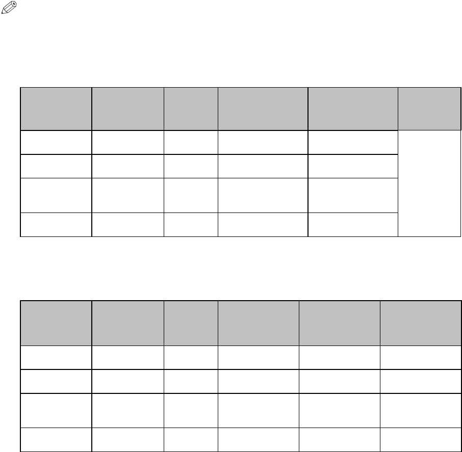
Version 4 imagePRESS C7010VPS Customer Expectations Document Page 51
10.1.1 Estimated Life of Consumables
The tables below state the estimated life expectancy yields based on LTR size
paper. Using paper larger than LTR reduces the supply yields and parts life
accordingly.
NOTE
All consumable supplies shown in the tables below are for reference purposes
only, and are subject to change without notice.
Toner
Item Part Number Quantity
Estimated Yield
(LTR @ 10%
Image Ratio)
(Copies/Prints)
Estimated Yield
(LTR @ 12%
Image Ratio)
(Copies/Prints)
Remarks
IPQ-2 Black
Toner 0436B003AA 1 35,500 30,000
8.75%
image ratio:
Approx.
40,000
sheets*1
IPQ-2 Cyan
Toner 0437B003AA 1 35,500 30,000
IPQ-2
Magenta
Toner 0438B003AA 1 35,500 30,000
IPQ-2 Yellow
Toner 0439B003AA 1 35,500 30,000
*1 The actual consumption of toner varies, depending on saturation, coverage of original, paper type, and
job mode.
Starter Toner
Item Part Number Quantity Estimated
Yield (LTR)
(Copies/Prints)
Estimated Yield
(11” x 17” @
80%)
(Copies/Prints)
Estimated Yield
(11” x 17” @
50%)
(Copies/Prints)
Black Starter
(Developer) 0440B001AA 1 750,000 416,667 500,000
Cyan Starter
(Developer) 0441B001AA 1 750,000 416,667 500,000
Magenta
Starter
(Developer) 0442B001AA 1 250,000 138,889 166,667
Yellow Starter
(Developer) 0443B001AA 1 750,000 416,667 500,000
Version 4 imagePRESS C7010VPS Customer Expectations Document Page 52
11. Toner Container and Hopper Unit Yields
A toner container holds approximately 1,700 grams of toner, and will yield
approximately 30,000 impressions at 12% coverage.
The hopper unit holds approximately 2,000 grams, and will yield approximately
40,000 impressions at 8.75% coverage.
12. Waste Toner Yields
The waste toner bottle collects the waste toner during the printing process.
The operator should replace the waste toner bottle with the provided spare bottle
when the message indicating that the waste toner bottle is near full is displayed (at
approximately 60,000 LTR prints).
The waste toner bottle may be replaced while the machine is running since
collected waste toner can be accumulated temporarily in the waste toner buffer (up
to approximately 20,000 sheets of LTR paper). When the waste toner buffer
becomes full, the imagePRESS C7010VPS stops.
The dealer should empty the full waste toner bottle and dispose of the toner waste
only in a manner that is applicable to the law in the geographical area where the
machine is located.
Upon replacement of the waste toner bottle, any accumulated toner in the waste
toner buffer empties into the new waste toner bottle.

Version 4 imagePRESS C7010VPS Customer Expectations Document Page 53
13. Estimated Performance Standards
The EPS (Estimated Performance Standard) is an estimate of the maximum print
and scan volumes the machine can achieve in its life span, depending on certain
variables:
• If the machine is maintained and serviced by a Canon authorized service
technician
• If only Genuine Canon service and consumable parts are used
The actual performance of the machine may vary, based on customer usage
factors, such as the environment in which the machine is installed, the types of
jobs performed, and the types of media used.
The following EPS values are for reference purposes only, and are based on the
use of LTR size paper.
Item Estimated Life
Reader Unit (Optional) Approximately 1,000,000 sheets (LTR)
Printer*1
Approximately 18,000,000 sheets (LTR)*2 or 5 years,
whichever is earlier
Stack Bypass-A1 (Optional) Approximately 1,000,000 sheets (LTR)
PRISMAsync Controller Approximately 5 years
*1 A high-durability parts change is required at approximately 9,000,000 sheets.
*2 The machine will continue operating after approximately 18 million sheets; however,
performance, copy quality, maintenance costs, etc. cannot be guaranteed.

Version 4 imagePRESS C7010VPS Customer Expectations Document Page 54
14. Optimum Monthly Product Performance
The table below describes the differences between the optimum PCV (Print Copy
Volume) and maximum PCV. Please note that the numbers in the table are for
reference purposes only, and depend strongly on the type of media selected and
environmental conditions. For information on the optimal environmental conditions
for the machine, see “Environmental Factors and Requirements,” on p. 25.
Monthly PCV Type Description
Number of LTR
Prints/Copies
Optimum PCV
This is the print/copy volume range that the
equipment was intended to run on a regular
basis to maintain a high level of performance
and print/copy quality. Running the equipment
within this range ensures that no undue stress
is placed on components, and it allows time
for the proper servicing and maintenance of
the equipment.
70,000 to 300,000
Maximum PCV
This is the maximum number of pages the
machine can produce within a one-month
period. However, sustained use of the
machine at this print/copy level will impact the
long term performance and durability of the
machine. It is recommended to stay within the
optimum print/copy volume to reduce a
possible increase in servicing and
maintenance issues.
1,000,000
IMPORTANT
If the machine consistently runs at or above the upper end of the optimum PCV,
consider purchasing additional machines or higher volume machines.

Version 4 imagePRESS C7010VPS Customer Expectations Document Page 55
15. Machine Reliability and Productivity
This chapter describes the reliability and productivity of the imagePRESS
C7010VPS.
15.1 Machine Reliability and Service Call Ratio
The service call ratio varies, depending on the total print volume, installation
environment, image ratio, paper size, and paper type.
Usage
Factors
Monthly Print Volume
120,000
80,000
50,000
Print Volume Over a 5 Year
Maintenance Agreement
7,200,000 4,800,000 3,000,000
Color Ratio
90%
Large/Heavy
Paper Ratio
CMP*1
80%
CRD*2
50%
Toner Coverage for Each
Color
12%
Media Type
100% Plain Paper
Configuration (Main Unit and
Accessories)
• Main Unit
• PRISMAsync Controller
• 1-POD Deck
•
Saddle Finisher
Labor
Work Time*3
170 Minutes
Travel Time*4
30 Minutes
Service Average CBV*5
CMP*1
22,600
19,500
16,300
CRD*2
29,780
23,800
18,300
Visit Ratio*6
CMP*1
5.3
4.1
3.1
CRD*2
4.0
3.4
2.7
*1 CMP (Commercial Print)
*2 CRD (Central Reproduction Department)
*3 The Work Time (minutes per visits) is the average amount of time a service technician needs
to service a machine. This number may vary, depending on the service technician’s
experience and the service required during each site visit.
*4 The Travel Time (minutes per visits) is the average amount of time a service technician needs
to travel from site to site. This number may vary, depending on the local service map.
*5 The Average CBV (Copies Between Visits) is the estimated number of total sheets between
service visits. The CBV takes into account all service visits throughout the term of the
maintenance agreement. The actual CBV may vary, depending on the MCV (Monthly Copy
Volume), large paper ratio, and service required.
*6 The Visit Ratio is the estimated number of service visits per month.

Version 4 imagePRESS C7010VPS Customer Expectations Document Page 56
15.2 Print Speed
One of the key features of the imagePRESS C7010VPS is its print speed
technology. The imagePRESS C7010VPS maintains print speed regardless of
paper weight. A letter-sized sheet of bond paper weighing 16 lb (60 g/m2) will print
at 70 ppm. Also, the same sized sheet at 120 lb cover (325 g/m2) will print at
70 ppm.
Most stocks will maintain their speed regardless of their weight. However, a
decrease in print speed may be experienced when using heavier weight paper
stocks narrower than 8.5” x 11”. The fixing rollers cannot disperse the heat
uniformly when paper smaller than 11” (LTR and LGL) is run through the machine.
This also may cause blistering and image deformity.
The table below describes the printing speeds one should expect when printing
one- or two-sided documents on the indicated paper size and type.
Paper Size Paper
Weight
(g/m2)
1-Sided (ppm)
2-Sided (ppm)
Main Unit
w/POD
Deck
Side
Paper
Deck
*1
Stack
Bypass
Main Unit
w/POD
Deck
Side
Paper
Deck
*1
Stack
Bypass
STMTR
60 – 105
N/A
N/A
50.0
N/A
N/A
N/A
106 – 170
N/A
N/A
50.0
N/A
N/A
N/A
171 – 325
N/A
N/A
41.3
N/A
N/A
N/A
EXEC
60 – 105
71.6
71.6
50.0
71.6
71.6
50.0
106 – 170
71.6
71.6
50.0
71.6
71.6
50.0
171 – 325
61.1
61.1
50.0
61.1
61.1
50.0
LTR
60 – 105
70.0
70.0
50.0
70.0
70.0
50.0
106 – 170
70.0
70.0
50.0
70.0
70.0
50.0
171 – 325
70.0
70.0
50.0
70.0
70.0
50.0
EXECR
60 – 105
55.8
N/A
N/A
45.0
N/A
N/A
106 – 170
44.4
N/A
N/A
44.4
N/A
N/A
171 – 325
33.4
N/A
N/A
33.4
N/A
N/A
LTRR
60 – 105
53.2
53.2
38.6
45.0
45.0
38.6
106 – 170
42.4
42.4
38.6
42.4
42.4
38.6
171 – 325
31.9
31.9
31.9
31.9
31.9
31.9
LGL
60 – 105
41.8
41.8
30.4
41.8
41.8
30.4
106 – 170
33.3
33.3
30.4
33.3
33.3
30.4
171 – 325
25.1
25.1
25.1
25.1
25.1
25.1
11” x 17”
60 – 105
37.6
37.6
25.0
37.6
37.6
25.0
106 – 220
37.6
37.6
25.0
37.6
37.6
25.0
221 – 325
35.0
35.0
25.0
35.0
35.0
25.0
12” x 18”
60 – 105
35.7
35.7
23.6
35.7
35.7
23.6
106 – 220
35.7
35.7
23.6
35.7
35.7
23.6
221 – 325
33.1
33.1
23.6
33.1
33.1
23.6
*1 The paper weight is changed from 60 to 105 g/m2 to 64 to 105 g/m2, and from 171 to 325 g/m2 to
171 to 300 g/m2.

Version 4 imagePRESS C7010VPS Customer Expectations Document Page 57
Print Speed Table Continued
Paper Size Paper
Weight
(g/m2)
1-Sided (ppm)
2-Sided (ppm)
Main Unit
w/POD
Deck
Side
Paper
Deck
*1
Stack
Bypass
Main Unit
w/POD
Deck
Side
Paper
Deck
*1
Stack
Bypass
13” x 19”
60 – 105
33.6
33.6
22.4
33.6
33.6
22.4
106 – 220
33.6
33.6
22.4
33.6
33.6
22.4
221 – 325
31.3
31.3
22.4
31.3
31.3
22.4
13” x 19.2”
60 – 105
33.3
33.3
22.1
33.3
33.3
22.1
106 – 220
33.3
33.3
22.1
33.3
33.3
22.1
221 – 325
31.0
31.0
22.1
31.0
31.0
22.1
LTR-Tab
60 – 105
66.9
N/A
47.8
N/A
N/A
N/A
106 – 170
66.9
N/A
47.8
N/A
N/A
N/A
171 – 325
66.9
N/A
47.8
N/A
N/A
N/A
*1 The paper weight is changed from 60 to 105 g/m2 to 64 to 105 g/m2, and from 171 to 325 g/m2 to
171 to 300 g/m2.
IMPORTANT
The print speeds in the table above may not be achieved if the user prints in the
conditions below:
− If 20 to 28 lb bond (80 to 105 g/m2) coated paper and greater than 67 lb cover
(181 g/m2) paper are used at the same time.
− If 28 to 34 lb bond (106 to 127 g/m2) coated paper and greater than 140 lb
index (257 g/m2) paper are used at the same time.
− If papers of differing lengths are fed together at the same time.
− If the main document is printed as one-sided and the cover and sheet insertions
are printed as two-sided while bookbinding.
− If a saddle stitched booklet with one or two sheets is created.
− If tab paper and other paper types are used at the same time.
− If paper whose length of the feeding direction is 18” (457.2 mm) or more is used,
while creating a saddle stitched booklet.
Version 4 imagePRESS C7010VPS Customer Expectations Document Page 58
15.3 Mixed Media Productivity
The imagePRESS C7010VPS is capable of processing jobs that contain mixed
media; however, the machine’s productivity may be reduced if one or more of the
following print conditions occur during a job run:
• Using paper with different paper weights
• Using single and double-sided printing
• Inserting tab paper
• Inserting paper from the Document Insertion Unit-C1
• Using different image magnifications for both sides of a sheet
• The amount of paper in the Paper Deck-AC1 falls below 100 sheets
• Saddle-folding only one sheet
• Stapling heavy paper
• A large print job is running and the finisher switches from the tray that is full to
another tray.
15.4 Two Hour Unattended Operation
The imagePRESS C7010VPS was designed for true production environments.
With its productivity and reliability enhancements and technologies, the machine
can run up to two hours with no operator intervention. Before beginning an
unattended run, the operator should check the following conditions:
1. The paper decks must be full (2-POD Decks, 2-High Capacity Stackers; any
paper weight).
2. Toner coverage area averages 10% for each color.
3. Toner bottles are full.
4. Both stackers are empty.
Any simplex or duplex job may be produced without any operator intervention
during the two hours. Also, if a two-sided job on LTR paper (or any larger size
paper) is running, only 1-POD Deck-A1 and 1-High Capacity Stacker-C1 are
required.
Version 4 imagePRESS C7010VPS Customer Expectations Document Page 59
15.5 Paper, Toner, and Waste Toner Replacement
The imagePRESS operator can maintain productivity by removing, replacing, and
refilling the paper, toner, and waste toner while the machine is running.
The paper trays can also be opened and refilled during operation. The tray that is
being utilized by the machine during production, however, will be locked. Once the
job completes, or the machine switches to another tray, the empty tray unlocks,
allowing the operator to prepare for the next job, and add more paper. No
productivity is affected, and jobs finish quicker. The drawers will not always run dry
when switching.
Similar to the paper, the toner bottle may be removed and replaced while a job is
printing. The imagePRESS C7010VPS has a large toner hopper, making it
possible for the machine to run much longer without replacing the toner bottle right
away. Therefore, productivity and image quality are not affected, and jobs finish in
the same amount of time.
Finally, the waste toner bottle is required to be replaced when full. However, this
bottle may be removed while the machine is running. Therefore, the operator will
remain productive, and not notice any changes in speed or quality.

Version 4 imagePRESS C7010VPS Customer Expectations Document Page 60
16. Media Usage/Compatibility
The imagePRESS C7010VPS maintains reliable, predictable, and high-quality
output. Consistency of the output is dependent on knowing and compensating for
variables of a print job. The imagePRESS C7010VPS incorporates many control
systems which compensate for environmental and print process conditions.
Another variable is the print media. Knowing the characteristics of the media
facilitates optimal print output.
16.1 Media Characteristics by Media Library Parameters
The table below describes the standard media library characteristics and
parameters.
Characteristics
Parameters
Name
Set the name of the media.
Type
Set the brand name of the paper.
Size
Select the size of the paper from the drop-down list, including
custom size paper.
Width
Specify the width of the custom paper in millimeters or
inches.
Length
Specify the length of the custom paper in millimeters or
inches.
Tab sheet
Select the check box to use tab paper, and then enter the
cycle length (how many tabs in one set).
Insert
Select the check box to use the paper as a sheet insertion,
and then enter the cycle length (how many sheet insertions
in a set).
Cycle length
Set the value 1 to N. Where “N” is the number of sheets in
one cycle. Must specify the cycle length when specifying tab
sheets or sheet insertions.
Punch count
Specify how many holes are in the pre-punched paper.
Weight
Specify the weight of the paper in g/m2 or lb.
Color
Specify the color of the paper. This setting acts as an
identifier to display the color of the paper on the operation
panel.
RGB Color
Specify the RGB color value (0-255) for identification
purposes on the operation panel.
Media family
Specify the media family to which the custom paper belongs
(e.g., Coated, Uncoated, custom).
Media type
Specify the type of paper (e.g., Vellum, Coated, Textured).
Advanced: Grain direction
Specify the paper’s fiber direction (e.g., Horizontal (Short
grain) or Vertical (Long grain).

Version 4 imagePRESS C7010VPS Customer Expectations Document Page 61
16.2 Media Specific Adjustments
The media specific adjustments are for customers who want to precisely adjust the
image quality and front-to-back registration per paper type that is registered in the
machine.
The following settings can be manually adjusted through the Settings Editor >
Media > select a registered media type > Printer adjustment icon. However, if
media adjustments must be made, it is recommended to first use the Image
Location Wizard from the machine’s operation panel.
The table below describes the Printer adjustment settings and each setting’s
description.
Setting
Description
Registration: Front and Back
X shift (mm or inch)
Make a fine adjustment to enable printing with the correct
alignment of the image from the leading edge of the paper
in the feed direction.
(From ±50 mm in 0.1 mm increments)
Y shift (mm or inch)
Make a fine adjustment to enable printing with the correct
alignment of the image from the side edge of the paper
perpendicular to the feed direction.
(From ±50 mm in 0.1 mm increments)
X elongation (0.01%)
Make a fine adjustment to the image size in the feed
direction. (From ±1% in 0.01% increments)
Y elongation (0.01%) Make a fine adjustment to the image size perpendicular to
the feed direction. (From ±1% in 0.01% increments)
Skew
Make a fine adjustment to the skew tolerance of the
image. (From ±2 in 1 increments)
Back lead edge alignment auto
correction
Select the check box to have the machine automatically
adjust the back lead edge alignment of the image.
Finishing
Saddle stitch position
adjustment
Make a fine adjustment to the saddle stitch position if the
saddle stitch position is slightly offset from the center of
the paper in millimeters or inches.(From ±2.00 mm)
Saddle stitch fold position
adjustment
Make a fine adjustment to the saddle stitch fold position if
the saddle fold is not exactly in the center of the paper in
millimeters or inches. (From ±2.00 mm)
Punch hole position adjustment
Make a fine adjustment to the hole punch position on the
paper in millimeters or inches. (From ±2.00 mm)

Version 4 imagePRESS C7010VPS Customer Expectations Document Page 62
Printer Adjustment Settings Table Continued
Setting
Description
Advanced
Decurl
Output face down
Output face up
Make a fine adjustment to the paper curl level when the
output is face down or face up in millimeters or inches.
(From ±15 levels)
Gloss adjustment
Make a fine adjustment to the paper gloss.
(From ±2 levels)
Separate
Make an adjustment to the paper separation fan level if
feeding or uneven transfer problems from the optional
side paper deck occur. (From 1 to 7 levels)
Image clear level adjustment
Improves the ITB’s cleaning performance.
(From ±10 levels)
Secondary transfer voltage
Front/Back
Make an adjustment to the secondary transfer bias (on
the front and back sides of the paper) if any faulty images
with uneven densities or color fading appears.
(From ±10 levels)
Trail end white patch correction
Front/Back: Threshold/Amount
Make an adjustment to improve the white patch/fading at
the trail end of the paper.
Threshold: From ±10 levels
Amount: From ±20 levels
Version 4 imagePRESS C7010VPS Customer Expectations Document Page 63
16.3 Print Quality Adjustment Settings
The Print Quality Adjustment settings are for customers who want to make fine
adjustments to the printed image. The Print Quality Adjustment settings must be
enabled by a service technician. For more information on specifying the Print
Quality Adjustment settings, see the Operation Information User Manual included
with the machine.
The following settings can be adjusted through the Settings Editor > Preferences >
System adjustments menu:
•
Fixing roller auto refresh level
•
Color cast correction*1
• Tail end color fading/graininess
correction
• White gap correction
• Fixing temperature mode switch
*2
•
Uneven gloss correction
• Low temperature environment
mode*3
*1 Correct color casting per color (Cyan, Magenta, Yellow, and Black).
*2 A decrease in productivity may occur if a job contains different paper thicknesses or types.
Productivity may be improved by setting the Fixing temperature mode switch setting to one of
the Productivity Priority modes.
*3 If printing on heavy paper in an L/L environment, the fixing for the first 10 or more pages may
be insufficient if the pages contain high-density images. Slowing the print speed for a certain
duration in a low-temperature environment may improve any fixing issues.
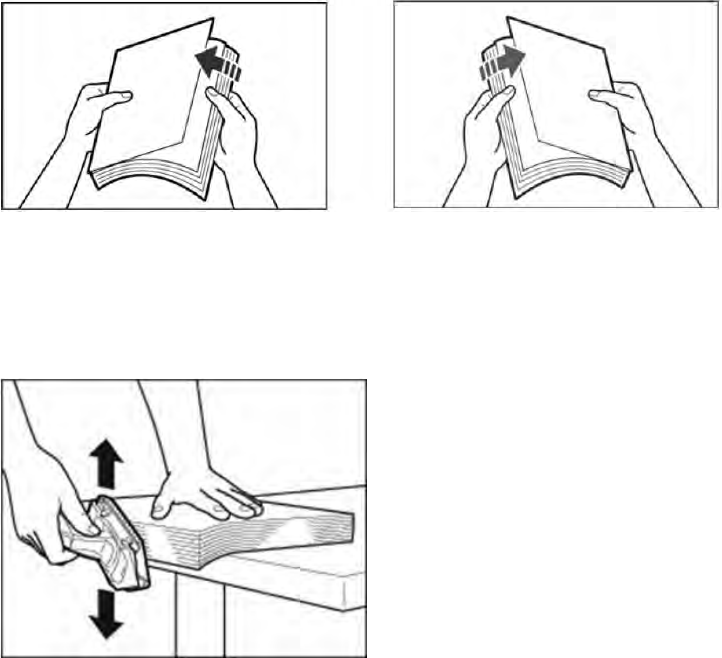
Version 4 imagePRESS C7010VPS Customer Expectations Document Page 64
16.4 Paper Handling and Storage
• The permissible humidity range for paper storage is 30% to 70% (with a room
temperature of 68°F to 80.6°F (20°C to 27°C)). Storing paper in a location that
does not meet these specifications may affect paper feeding and image quality.
• Only use paper that has fully acclimatized to the environment in which the
machine is installed. Using paper that has been stored in a different environment
(with a different temperature and humidity), may cause paper jams or result in
poor print quality.
• We recommend using paper immediately after opening the package. Rewrap any
remaining paper in its original package, and store it on a flat surface.
• Before loading paper, make sure to fan the sheets thoroughly so that air runs
through the sheets, as shown in the diagrams below.
• When you cut paper, the cutting sides of the paper must be made smooth. Use
an abrasive to make the four cutting sides smooth. Otherwise, streaks may
appear on the image, paper feeding may be affected, part life may be reduced, or
service calls may increase. Make sure to put the paper on a flat table to use the
abrasive, and move the abrasive perpendicular to the paper approximately three
times.
Version 4 imagePRESS C7010VPS Customer Expectations Document Page 65
16.5 Selecting the Correct Media
Canon U.S.A., Inc. publishes a Specialty Media Handling Guide for the
imagePRESS C7010VPS’s predecessor series, imagePRESS C7000VP series,
which provides detailed information on approved media. Major topics in this
document include:
• Acceptable Paper
• Problems Caused by Paper Curl
• Storing/Editing Irregular Paper Types
• Acceptable Paper Type List
To obtain the Specialty Media Handling Guide, contact a local authorized Canon
dealer for details.
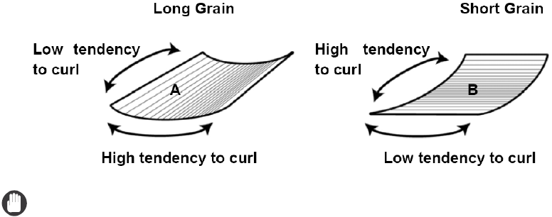
Version 4 imagePRESS C7010VPS Customer Expectations Document Page 66
16.6 Paper Grain and Curl
Paper grain and curl can dramatically affect the reliability of machines utilizing an
electrostatic process like the imagePRESS C7010VPS. Paper used in an offset
press is usually cut for short edge feeding. This type of paper is not as reliable as
paper made for machines utilizing an electrostatic process, which is cut for long
edge feeding. Also, the composition of electrostatic paper is different from offset
paper, and produces better quality results in a digital press machine. When
selecting paper for the imagePRESS C7010VPS, select paper intended for use in
electrostatic machines, such as laser printers and copiers.
If paper jams or poor print quality occur when paper is fed from the optional stack
bypass or paper decks, paper curl is often the cause. The paper stiffness, direction
of curl, and amount of curl have a strong influence on how well the paper is
transported through the machine. If paper is curled, straighten out the paper by
gently curling it in the opposite direction to which it is curled.
Paper stiffness depends on the direction of the paper grain. Paper tends to curl in
the direction parallel to the grain.
IMPORTANT
• When using LTR or smaller paper sizes we recommend using paper with a grain
parallel to the long edge (A). For paper sizes larger than 11” x 17”, we
recommend using paper with a grain parallel to the short edge (B). When using
coated paper thinner than 105 g/m2, we recommend using paper with a grain
perpendicular to the feeding direction of the paper.
• If 12 point, 243 g/m2 paper is used in the Saddle Stitch mode, it is best to use
paper that is cross-grained. Thick, long grain paper does not fold as easily.
Cross-grained paper is more flexible, resulting in a smoother crease along the
direction of the fold.

Version 4 imagePRESS C7010VPS Customer Expectations Document Page 67
16.7 Note for Customers Who Cut Their Own Paper
Customers who cut their own paper may experience:
• An increase of paper dust in the machine
• Shortening the life of the machine’s fixing rollers due to excessive wear from the
rough side of the cut paper
• Paper jams due to paper dust getting into areas of the machine where it is not
meant to be
• Improper paper feeding
• Paper registration inaccuracies
Follow the precautions below to minimize the above issues:
• Have a process in place to regularly make sure that the cutting blades are
sharpened, and that cuts are made as clean as possible.
• Place the paper with the factory mill cut sides facing to the right (leading edge),
and to the front of the machine when feeding paper from a location other than the
stack bypass. If paper is fed from the stack bypass, place the paper with the
factory mill cut sides facing to the left (leading edge), and to the front of the
machine.
• Pay special attention to the paper grain orientation when cutting it. For more
information on paper grain, see “Paper Grain and Curl,” on p. 66.
• The best results for color consistency and front-to-back registration are obtained
by using factory mill cut, digital compatible paper.

Version 4 imagePRESS C7010VPS Customer Expectations Document Page 68
16.8 Paper Sizes and Feed Location Chart
The table below represents the available paper sizes and feed locations. The
Stack Bypass-A1, POD Decks, Paper Deck-AC1, and Document Insertion Unit-C1
are optional.
: Available —: Unavailable
Paper
Size Width x
Length
Paper Source
Paper
Decks
of the
Main
Unit
Stack
Bypass-
A1
POD Deck-
A1/Secondary
POD Deck-A1
Paper
Deck-AC1
Document
Insertion
Unit-C1
Upper Tray
Document
Insertion
Unit-C1
Lower Tray
13” x 19” 13” x 19”
—
12” x 18” 12” x 18”
—
11” x 17” 11” x 17”
—
LGL 8 1/2” x 14”
—
LTR 8 1/2” x 11”
LTRR 11” x 8 1/2”
STMTR 5 1/2” x
8 1/2”
— — — — —
EXEC 7 1/4” x
10 1/2”
—
Irregular
Size 1
12” x 7 1/8”
to
13” x 19.2”
(304.9 mm
x 182 mm
to 330.2
mm x
487.7 mm)
— —
Irregular
Size 2
7 1/8” x
7 1/8” to
12” x 19.2”
(182 mm x
182 mm to
304.8 mm
x 487.7
mm)
— *1
Irregular
Size 3
5 31/64” x
7 1/8” to
7 11/64” to
19.2”
(139.7 mm
x 182 mm
to 181.9
mm to
487.7 mm)
— — — — —
*1 Only the irregular size (7 1/8” x 7 1/8” to 11 11/16” x 13” (182 mm x 182 mm to 297 mm x 330.2 mm) can
be loaded.

Version 4 imagePRESS C7010VPS Customer Expectations Document Page 69
17. Responsibility Matrix
Please discuss this Responsibility Matrix with your customer and check off who
owns each action in the table below. Responsibility
Action Customer Dealer
Ensure adequate space and power to properly install machine.
Verify floor strength and level.
Ensure that the equipment can be delivered to the site, and that
the path is clear and unobstructed.
Unpack all delivered items.
Install all system hardware.
Connect all system components.
Install printer files and PRISMAsync controller.
Ensure network configuration, and confirm that the device is
attached to the network.
Install client workstation network software.
Load additional fonts (as required).
Order and replace, as necessary, customer replaceable items
(i.e., drum cartridges, toner, etc.).
Order and replace the waste toner container, as necessary.
Provide technical support.
Provide on-site support.
Establish an installation file of a typical job, and retain for future
reference.
Perform Shading Correction once a day.
*1
Perform Auto Gradation Adjustment once a day.
*1
Perform a Media family calibration for color consistency once a
day.
*1
*1 For more information, see Chapter 11, “Maintenance and Calibration,” in the Operating
Information User Manual included with the machine.
Primary customer applications for using this equipment:
Special considerations or performance limitations:
I have received a copy of this document.
Customer:
Sales Person:
