Ins13478 5 Z Wave 500 Series Appl. Prg. Guide V6.71.01
User Manual:
Open the PDF directly: View PDF ![]() .
.
Page Count: 442 [warning: Documents this large are best viewed by clicking the View PDF Link!]
- 1 Abbreviations
- 2 Introduction
- 3 Z-Wave Software Architecture
- 3.1 Z-Wave System Startup Code
- 3.2 Z-Wave Main Loop
- 3.3 Z-Wave Protocol Layers
- 3.4 Z-Wave Routing Principles
- 3.5 Z-Wave Application Layer
- 3.6 Z-Wave Software Timers
- 3.7 Z-Wave Hardware Timers
- 3.8 Z-Wave Hardware Interrupts
- 3.9 Interrupt service routines.
- 3.10 Z-Wave Nodes
- 4 Z-Wave Application Interfaces
- 4.1 API usage guidelines
- 4.2 Z-Wave Libraries
- 4.3 Z-Wave Common API
- 4.3.1 Required Application Functions
- 4.3.1.1 ApplicationInitHW
- 4.3.1.2 ApplicationInitSW
- 4.3.1.3 ApplicationTestPoll
- 4.3.1.4 ApplicationPoll
- 4.3.1.5 ApplicationCommandHandler (Not Bridge Controller library)
- 4.3.1.6 ApplicationNodeInformation
- 4.3.1.7 ApplicationSlaveUpdate (Only slave libraries)
- 4.3.1.8 ApplicationControllerUpdate (Only controller libraries)
- 4.3.1.9 ApplicationCommandHandler_Bridge (Only bridge controller library)
- 4.3.1.10 ApplicationSlaveNodeInformation (Only bridge controller library)
- 4.3.1.11 ApplicationRfNotify
- 4.3.1.12 ApplicationSecureKeysRequested (Only slave libraries)
- 4.3.1.13 ApplicationSecureAuthenticationRequested (Only slave libraries)
- 4.3.2 Z-Wave Basis API
- 4.3.2.1 ZW_ExploreRequestInclusion
- 4.3.2.2 ZW_ExploreRequestExclusion
- 4.3.2.3 ZW_GetBackgroundRSSI
- 4.3.2.4 ZW_GetProtocolStatus
- 4.3.2.5 ZW_GetRandomWord
- 4.3.2.6 ZW_Random
- 4.3.2.7 ZW_RegisterBackgroundRSSICallback
- 4.3.2.8 ZW_RFPowerLevelSet
- 4.3.2.9 ZW_RFPowerLevelGet
- 4.3.2.10 ZW_RequestNetWorkUpdate
- 4.3.2.11 ZW_RFPowerlevelRediscoverySet
- 4.3.2.12 ZW_SendNodeInformation
- 4.3.2.13 ZW_SendTestFrame
- 4.3.2.14 ZW_SetExtIntLevel
- 4.3.2.15 ZW_SetPromiscuousMode (Only controller libraries)
- 4.3.2.16 ZW_SetRFReceiveMode
- 4.3.2.17 ZW_Type_Library
- 4.3.2.18 ZW_Version
- 4.3.2.19 ZW_VERSION_MAJOR / ZW_VERSION_MINOR / ZW_VERSION_BETA
- 4.3.2.20 ZW_WatchDogEnable
- 4.3.2.21 ZW_WatchDogDisable
- 4.3.2.22 ZW_WatchDogKick
- 4.3.2.23 ZW_GetTxTimer
- 4.3.2.24 ZW_ClearTxTimers
- 4.3.2.25 ZW_GetNetworkStats
- 4.3.2.26 ZW_ClearNetworkStats
- 4.3.3 Z-Wave Transport API
- 4.3.3.1 ZW_SendData
- 4.3.3.2 ZW_SendDataEx (Only slave libraries)
- 4.3.3.3 ZW_SendData_Bridge
- 4.3.3.4 ZW_SendDataMulti
- 4.3.3.5 ZW_SendDataMultiEx (Only slave libraries)
- 4.3.3.6 ZW_SendDataMulti_Bridge
- 4.3.3.7 ZW_SendDataAbort
- 4.3.3.8 ZW_LockRoute (Only controllers)
- 4.3.3.9 ZW_LockRoute (Only slaves)
- 4.3.3.10 ZW_SendConst
- 4.3.3.11 ZW_SetListenBeforeTalkThreshold
- 4.3.3.12 ZW_Transport_CommandClassVersionGet
- 4.3.3.13 ZW_GetDefaultPowerLevels
- 4.3.3.14 ZW_SetDefaultPowerLevels
- 4.3.4 ZWave Firmware Update API
- 4.3.5 Z-Wave Node Mask API
- 4.3.6 IO API
- 4.3.7 GPIO macros
- 4.3.8 Z-Wave NVM Memory API
- 4.3.8.1 MemoryGetID
- 4.3.8.2 MemoryGetByte
- 4.3.8.3 MemoryPutByte
- 4.3.8.4 MemoryGetBuffer
- 4.3.8.5 MemoryPutBuffer
- 4.3.8.6 ZW_EepromInit
- 4.3.8.7 ZW_MemoryFlush
- 4.3.8.9 ZW_NVRCheck
- 4.3.8.10 NVM_get_id
- 4.3.8.11 NVM_ext_read_long_byte
- 4.3.8.12 NVM_ext_write_long_byte
- 4.3.8.13 NVM_ext_read_long_buffer
- 4.3.8.14 NVM_ext_write_long_buffer
- 4.3.9 Z-Wave Timer API
- 4.3.10 Power Control API
- 4.3.11 SPI interface API
- 4.3.11.1 Operation
- 4.3.11.2 ZW_SPI0_init
- 4.3.11.3 ZW_SPI0_enable
- 4.3.11.4 ZW_SPI0_rx_get
- 4.3.11.5 ZW_SPI0_tx_set
- 4.3.11.6 ZW_SPI0_active_get
- 4.3.11.7 ZW_SPI0_coll_get
- 4.3.11.8 ZW_SPI0_int_enable
- 4.3.11.9 ZW_SPI0_int_get
- 4.3.11.10 ZW_SPI0_int_clear
- 4.3.11.11 ZW_SPI1_init
- 4.3.11.12 ZW_SPI1_enable
- 4.3.11.13 ZW_SPI1_rx_get
- 4.3.11.14 ZW_SPI1_tx_set
- 4.3.11.15 ZW_SPI1_active_get
- 4.3.11.16 ZW_SPI1_coll_get
- 4.3.11.17 ZW_SPI1_int_enable
- 4.3.11.18 ZW_SPI1_int_get
- 4.3.11.19 ZW_SPI1_int_clear
- 4.3.12 ADC interface API
- 4.3.12.1 ZW_ADC_init
- 4.3.12.2 ZW_ADC_power_enable
- 4.3.12.3 ZW_ADC_enable
- 4.3.12.4 ZW_ADC_pin_select
- 4.3.12.5 ZW_ADC_threshold_mode_set
- 4.3.12.6 ZW_ADC_threshold_set
- 4.3.12.7 ZW_ADC_int_enable
- 4.3.12.8 ZW_ADC_int_clear
- 4.3.12.9 ZW_ADC_is_fired
- 4.3.12.10 ZW_ADC_result_get
- 4.3.12.11 ZW_ADC_buffer_enable
- 4.3.12.12 ZW_ADC_auto_zero_set
- 4.3.12.13 ZW_ADC_resolution_set
- 4.3.13 UART interface API
- 4.3.13.1 Transmission
- 4.3.13.2 Reception
- 4.3.13.3 RS232
- 4.3.13.4 Integration
- 4.3.13.5 Operation
- 4.3.13.6 ZW_UART0_init / ZW_UART1_init
- 4.3.13.7 ZW_UART0_rx_data_get / ZW_UART1_rx_data_get
- 4.3.13.8 ZW_UART0_rx_data_wait_get / ZW_UART1_rx_data_wait_get
- 4.3.13.9 ZW_UART0_tx_active_get / ZW_UART1_tx_active_get
- 4.3.13.10 ZW_UART0_tx_data_set / ZW_UART1_tx_data_set
- 4.3.13.11 ZW_UART0_tx_send_num / ZW_UART1_tx_send_num
- 4.3.13.12 ZW_UART0_tx_send_str / ZW_UART1_tx_send_str
- 4.3.13.13 ZW_UART0_INT_ENABLE / ZW_UART1_INT_ENABLE
- 4.3.13.14 ZW_UART0_INT_DISABLE / ZW_UART1_INT_DISABLE
- 4.3.13.15 ZW_UART0_tx_send_nl / ZW_UART1_tx_send_nl
- 4.3.13.16 ZW_UART0_tx_int_clear / ZW_UART1_tx_int_clear
- 4.3.13.17 ZW_UART0_rx_int_clear / ZW_UART1_rx_int_clear
- 4.3.13.18 ZW_UART0_tx_int_get / ZW_UART1_tx_int_get
- 4.3.13.19 ZW_UART0_rx_int_get / ZW_UART1_rx_int_get
- 4.3.13.20 ZW_UART0_rx_enable / ZW_UART1_rx_enable
- 4.3.13.21 ZW_UART0_tx_enable / ZW_UART1_tx_enable
- 4.3.14 Application HW Timers/PWM interface API
- 4.3.14.1 ZW_TIMER0_init
- 4.3.14.2 ZW_TIMER1_init
- 4.3.14.3 ZW_TIMER0_INT_CLEAR / ZW_TIMER1_INT_CLEAR
- 4.3.14.4 ZW_TIMER0_INT_ENABLE / ZW_TIMER1_INT_ENABLE
- 4.3.14.5 ZW_TIMER0_ENABLE / ZW_TIMER1_ENABLE
- 4.3.14.6 ZW_TIMER0_ext_clk / ZW_TIMER1_ext_clk
- 4.3.14.7 ZW_TIMER0_LOWBYTE_SET / ZW_TIMER1_LOWBYTE_SET
- 4.3.14.8 ZW_TIMER0_HIGHBYTE_SET / ZW_TIMER1_HIGHBYTE_SET
- 4.3.14.9 ZW_TIMER0_HIGHBYTE_GET / ZW_TIMER1_HIGHBYTE_GET
- 4.3.14.10 ZW_TIMER0_LOWBYTE_GET / ZW_TIMER1_LOWBYTE_GET
- 4.3.14.11 ZW_TIMER0_word_get / ZW_TIMER1_word_get
- 4.3.14.12 ZW_GPTIMER_init
- 4.3.14.13 ZW_GPTIMER_int_clear
- 4.3.14.14 ZW_GPTIMER_int_get
- 4.3.14.15 ZW_GPTIMER_int_enable
- 4.3.14.16 ZW_GPTIMER_enable
- 4.3.14.17 ZW_GPTIMER_pause
- 4.3.14.18 ZW_GPTIMER_reload_set
- 4.3.14.19 ZW_GPTIMER_reload_get
- 4.3.14.20 ZW_GPTIMER_get
- 4.3.14.21 ZW_PWM_init
- 4.3.14.22 ZW_PWM_enable
- 4.3.14.23 ZW_PWM_int_clear
- 4.3.14.24 ZW_PWM_int_get
- 4.3.14.25 ZW_PWM_int_enable
- 4.3.14.26 ZW_PWM_waveform_set
- 4.3.14.27 ZW_PWM_waveform_get
- 4.3.15 Security API
- 4.3.15.1 ZW_GetSecurityKeys (Only slave libraries)
- 4.3.15.2 ZW_s2_inclusion_init(Only slave libraries)
- 4.3.15.3 ZW_SetSecurityS2InclusionPublicDSK_CSA(Only slave libraries)
- 4.3.15.4 ZW_GetSecurityS2PublicDSK(Only slave libraries)
- 4.3.15.5 ZW_SetSecurityS2CriticalNodeID (Only routing slave library)
- 4.3.15.6 ZW_SetSecurityS0NetworkKey (Only enhanced 232 slave library)
- 4.3.16 AES API
- 4.3.17 TRIAC Controller API
- 4.3.18 LED Controller API
- 4.3.19 Infrared Controller API
- 4.3.19.1 Carrier Detector/Generator
- 4.3.19.2 Organization of Mark/Space data in Memory
- 4.3.19.3 IR Transmitter
- 4.3.19.4 IR Receiver
- 4.3.19.5 ZW_IR_tx_init
- 4.3.19.6 ZW_IR_tx_data
- 4.3.19.7 ZW_IR_tx_status_get
- 4.3.19.8 ZW_IR_learn_init
- 4.3.19.9 ZW_IR_learn_data
- 4.3.19.10 ZW_IR_learn_status_get
- 4.3.19.11 ZW_IR_status_clear
- 4.3.19.12 ZW_IR_disable
- 4.3.20 Keypad Scanner Controller API
- 4.3.21 USB/UART common API
- 4.3.22 Flash API
- 4.3.23 CRC API
- 4.3.1 Required Application Functions
- 4.4 Z-Wave Controller API
- 4.4.1 ZW_AddNodeToNetwork
- 4.4.1.1 bMode parameter
- 4.4.1.2 completedFunc parameter
- 4.4.1.2.1 ADD_NODE_STATUS_LEARN_READY status
- 4.4.1.2.2 ADD_NODE_STATUS_NODE_FOUND status
- 4.4.1.2.3 ADD_NODE_STATUS_ADDING_SLAVE status
- 4.4.1.2.4 ADD_NODE_STATUS_ADDING_CONTROLLER status
- 4.4.1.2.5 ADD_NODE_STATUS_PROTOCOL_DONE status
- 4.4.1.2.6 ADD_NODE_STATUS_DONE status
- 4.4.1.2.7 ADD_NODE_STATUS_FAILED status
- 4.4.1.2.8 ADD_NODE_STATUS_NOT_PRIMARY status
- 4.4.1.3 completedFunc callback timeouts
- 4.4.2 ZW_AreNodesNeighbours
- 4.4.3 ZW_AssignReturnRoute
- 4.4.4 ZW_AssignSUCReturnRoute
- 4.4.5 ZW_AssignPriorityReturnRoute
- 4.4.6 ZW_AssignPrioritySUCReturnRoute
- 4.4.7 ZW_ControllerChange
- 4.4.8 ZW_DeleteReturnRoute
- 4.4.9 ZW_DeleteSUCReturnRoute
- 4.4.10 ZW_GetControllerCapabilities
- 4.4.11 ZW_GetNeighborCount
- 4.4.12 ZW_GetPriorityRoute
- 4.4.13 ZW_SetPriorityRoute
- 4.4.14 ZW_GetNodeProtocolInfo
- 4.4.15 ZW_GetRoutingInfo
- 4.4.16 ZW_GetSUCNodeID
- 4.4.17 ZW_IsFailedNode
- 4.4.18 ZW_IsPrimaryCtrl
- 4.4.19 ZW_RemoveFailedNode
- 4.4.20 ZW_ReplaceFailedNode
- 4.4.21 ZW_RemoveNodeFromNetwork
- 4.4.21.1 bMode parameter
- 4.4.21.2 completedFunc parameter
- 4.4.21.2.1 REMOVE_NODE_STATUS_LEARN_READY status
- 4.4.21.2.2 REMOVE_NODE_STATUS_NODE_FOUND status
- 4.4.21.2.3 REMOVE_NODE_STATUS_REMOVING_SLAVE status
- 4.4.21.2.4 REMOVE_NODE_STATUS_REMOVING_CONTROLLER status
- 4.4.21.2.5 REMOVE_NODE_STATUS_DONE status
- 4.4.21.2.6 REMOVE_NODE_STATUS_FAILED status
- 4.4.21.2.7 ADD_NODE_STATUS_NOT_PRIMARY status
- 4.4.21.3 completedFunc callback timeouts
- 4.4.22 ZW_RemoveNodeIDFromNetwork
- 4.4.23 ZW_ReplicationReceiveComplete
- 4.4.24 ZW_ReplicationSend
- 4.4.25 ZW_RequestNodeInfo
- 4.4.26 ZW_RequestNodeNeighborUpdate
- 4.4.27 ZW_SendSUCID
- 4.4.28 ZW_SetDefault
- 4.4.29 ZW_SetLearnMode
- 4.4.30 ZW_SetRoutingInfo
- 4.4.31 ZW_SetRoutingMAX
- 4.4.32 ZW_SetSUCNodeID
- 4.4.1 ZW_AddNodeToNetwork
- 4.5 Z-Wave Static Controller API
- 4.6 Z-Wave Bridge Controller API
- 4.7 Z-Wave Portable Controller API
- 4.8 Z-Wave Slave API
- 4.9 Z-Wave Routing and Enhanced 232 Slave API
- 4.10 Serial Command Line Debugger
- 4.11 RF Settings in App_RFSetup.c file
- 5 Application Note: SUC/SIS Implementation
- 6 Application Note: Controller Shift Implementation
- 7 Application Note: Z-Wave Protocol Versions
- 8 References
- Index

CONFIDENTIAL
Instruction
Z-Wave 500 Series Appl. Programmers Guide v6.71.01
Document No.:
INS13478
Version:
5
Description:
-
Written By:
JFR;JBU;PSH;EFH;JBU;ABR;JSI;SSE;TRO
Date:
2017-02-28
Reviewed By:
PSH;BBR;JFR;JKA;JSI;JBU;ABUENDIA;LTHOMSEN;CRASMUSSEN;SSE
Restrictions:
Partners Only
Approved by:
Date CET Initials Name Justification
2017-02-28 13:45:50 NTJ Niels Thybo Johansen
This document is the property of Sigma Designs Inc. The data contained herein, in
whole or in part, may not be duplicated, used or disclosed outside the recipient for
any purpose. This restriction does not limit the recipient's right to use information
contained in the data if it is obtained from another source without restriction.

INS13478-5 Z-Wave 500 Series Appl. Programmers Guide v6.71.01 2017-02-28
Sigma Designs Inc.
Revision Record and Tables of Contents
Page ii of xi
CONFIDENTIAL
REVISION RECORD
Doc. Rev
Date
By
Pages affected
Brief description of changes
1
20160107
JFR
All
Based on INS13044-6 - Z-Wave 500 Series Appl. Prg. Guide v6.60.00.
1
20160125
JSI
4.3.2.25
Updated parameter descriptions.
1
20160125
JBU
4.3.1.12
4.3.1.15
Added ApplicationSecureKeysRequested and
ApplicationSecureCommandsSupported.
1
20160127
JFR
4.2.1
4.3.15
Updated table containing library functionality.
Added API handling security keys on application level.
1
20160128
JBU
4.3.1.2 & 4.3.3.2
Updated ZW_SendDataEx documentation and ApplicationInitSW.
1
20160202
JSI
4.3.3.12,
4.3.3.2,
4.3.3.5
4.3.15.1
4.3.15.6
Added ZW_Transport_CommandClassVersionGet.
Updated ZW_SendDataEx description.
Added ZW_SendDataMultiEx.
Updated ZW_GetSecurityKeys description with SerialAPI usage.
Updated ZW_SetNetworkKeyS0 description with SerialAPI usage.
2
20160406
JFR
3.10.4
4.3.3.11
Added limitations wrt. Security S2.
Changed default threshold value to 64(dec)
2
20160812
PSH
4.3.3.11
Changed the description of ZW_SetListenBeforeTalkThreshold()
2
20160817
JSI
4.3.15.1, 4.3.15.2,
4.3.15.3, 4.3.15.4,
4.3.15.5, 4.3.15.6 &
4.3.1.15
Updated ZW_GetSecurityKeys.
Added ZW_s2_inclusion_init.
Added ZW_SetSecurityS2InclusionPublicDSK_CSA.
Added ZW_GetSecurityS2PublicDSK.
Added ZW_SetSecurityS2CriticalNodeID.
Updated ZW_SetSecurityS0NetworkKey.
Added ApplicationSecurityEvent.
3
20160818
JFR
4.1.1
Revised external NVM part.
4
20161019
JFR
Frontpage
4.3.1.5
4.2.1, 4.3.1.5,
4.3.1.9 and 4.3.2.15
4.3.21
4.3.17
Changed to SDK 6.71.00
ApplicationCommandHandler updated with secure key
All controllers supporting promiscuous mode
Updated ZW_InitSerialIF and ZW_FinishSerialIF
Triac Controller API updated
4
20161111
JSI
4.3.1.10
4.3.1.5, 4.3.1.9 and
4.3.2.15
4.4.19
Updated SerialAPI section describing current embedded sample
application implementation
Updated promiscuous mode description
Updated ZW_RemoveFailedNode description
4
20161115
TRO
4.3.3.11
Add SerialAPI support
4
20161212
PSH
4.4.17
Updated description of ZW_IsFailedNode()
4
20161222
JFR
4.4.21
Added network wide exclusion option
5
20170206
PSH
JFR
4.3.3.13 & 4.3.3.14
4.3.14.4
Updated to SDK version 6.71.01
Disable text corrected
5
20170223
PSH
4.3.2.12
Added warning to ZW_SendNodeInformation() about use in controllers

INS13478-5 Z-Wave 500 Series Appl. Programmers Guide v6.71.01 2017-02-28
Sigma Designs Inc.
Revision Record and Tables of Contents
Page iii of xi
CONFIDENTIAL
Table of Contents
1 ABBREVIATIONS ................................................................................................................................. 1
2 INTRODUCTION ................................................................................................................................... 3
2.1 Purpose .............................................................................................................................................. 3
2.2 Audience and Prerequisites ............................................................................................................... 3
2.3 Key words to Indicate Requirement Levels ........................................................................................ 3
3 Z-WAVE SOFTWARE ARCHITECTURE ............................................................................................. 4
3.1 Z-Wave System Startup Code ............................................................................................................ 5
3.2 Z-Wave Main Loop ............................................................................................................................. 5
3.3 Z-Wave Protocol Layers ..................................................................................................................... 5
3.4 Z-Wave Routing Principles ................................................................................................................. 5
3.5 Z-Wave Application Layer .................................................................................................................. 7
3.6 Z-Wave Software Timers .................................................................................................................... 9
3.7 Z-Wave Hardware Timers ................................................................................................................10
3.8 Z-Wave Hardware Interrupts ............................................................................................................10
3.9 Interrupt service routines. .................................................................................................................11
3.9.1 SFR pages .............................................................................................................................11
3.9.2 Calling functions from ISR ......................................................................................................11
3.10 Z-Wave Nodes..................................................................................................................................12
3.10.1 Z-Wave Portable Controller Node ..........................................................................................12
3.10.2 Z-Wave Static Controller Node ..............................................................................................14
3.10.3 Z-Wave Bridge Controller Node .............................................................................................15
3.10.4 Z-Wave Routing Slave Node..................................................................................................17
3.10.5 Z-Wave Enhanced 232 Slave Node .......................................................................................20
3.10.6 Adding and Removing Nodes to/from the network ................................................................21
3.10.6.1 Adding a node normally. .................................................................................................22
3.10.6.2 Adding a new controller and make it the primary controller ...........................................22
3.10.6.3 SUC ID Server (SIS) ......................................................................................................22
3.10.7 The Automatic Network Update .............................................................................................22
4 Z-WAVE APPLICATION INTERFACES .............................................................................................23
4.1 API usage guidelines ........................................................................................................................23
4.1.1 Code space, data space and internal/external NVM ............................................................23
4.1.2 Buffer protection .....................................................................................................................23
4.1.3 Overlapping API calls .............................................................................................................23
4.1.4 Error handling. ........................................................................................................................24
4.2 Z-Wave Libraries ..............................................................................................................................24
4.2.1 Library Functionality ...............................................................................................................24
4.2.1.1 Library Functionality without a SIS .................................................................................25
4.2.1.2 Library Functionality with a SIS ......................................................................................26
4.3 Z-Wave Common API ......................................................................................................................27
4.3.1 Required Application Functions .............................................................................................27
4.3.1.1 ApplicationInitHW ...........................................................................................................28
4.3.1.2 ApplicationInitSW ...........................................................................................................29
4.3.1.3 ApplicationTestPoll .........................................................................................................30
4.3.1.4 ApplicationPoll ................................................................................................................31
4.3.1.5 ApplicationCommandHandler (Not Bridge Controller library) ........................................32
4.3.1.6 ApplicationNodeInformation ...........................................................................................35
4.3.1.7 ApplicationSlaveUpdate (Only slave libraries) ...............................................................39
4.3.1.8 ApplicationControllerUpdate (Only controller libraries) ..................................................40
4.3.1.9 ApplicationCommandHandler_Bridge (Only bridge controller library) ...........................42
4.3.1.10 ApplicationSlaveNodeInformation (Only bridge controller library) .................................44
4.3.1.11 ApplicationRfNotify .........................................................................................................45

INS13478-5 Z-Wave 500 Series Appl. Programmers Guide v6.71.01 2017-02-28
Sigma Designs Inc.
Revision Record and Tables of Contents
Page iv of xi
CONFIDENTIAL
4.3.1.12 ApplicationSecureKeysRequested (Only slave libraries) ...............................................46
4.3.1.13 ApplicationSecureAuthenticationRequested (Only slave libraries) ................................47
4.3.1.14 ApplicationSecureCommandsSupported (Only slave libraries) .....................................48
4.3.1.15 ApplicationSecurityEvent(Only slave libraries) ...............................................................49
4.3.2 Z-Wave Basis API ..................................................................................................................50
4.3.2.1 ZW_ExploreRequestInclusion ........................................................................................50
4.3.2.2 ZW_ExploreRequestExclusion .......................................................................................51
4.3.2.3 ZW_GetBackgroundRSSI ..............................................................................................52
4.3.2.4 ZW_GetProtocolStatus ...................................................................................................54
4.3.2.5 ZW_GetRandomWord ....................................................................................................55
4.3.2.6 ZW_Random ..................................................................................................................57
4.3.2.7 ZW_RegisterBackgroundRSSICallback .........................................................................58
4.3.2.8 ZW_RFPowerLevelSet ...................................................................................................60
4.3.2.9 ZW_RFPowerLevelGet ..................................................................................................61
4.3.2.10 ZW_RequestNetWorkUpdate .........................................................................................62
4.3.2.11 ZW_RFPowerlevelRediscoverySet ................................................................................64
4.3.2.12 ZW_SendNodeInformation .............................................................................................66
4.3.2.13 ZW_SendTestFrame ......................................................................................................68
4.3.2.14 ZW_SetExtIntLevel .........................................................................................................70
4.3.2.15 ZW_SetPromiscuousMode (Only controller libraries) ....................................................71
4.3.2.16 ZW_SetRFReceiveMode ................................................................................................72
4.3.2.17 ZW_Type_Library ...........................................................................................................73
4.3.2.18 ZW_Version ....................................................................................................................74
4.3.2.19 ZW_VERSION_MAJOR / ZW_VERSION_MINOR / ZW_VERSION_BETA ..................75
4.3.2.20 ZW_WatchDogEnable ....................................................................................................76
4.3.2.21 ZW_WatchDogDisable ...................................................................................................77
4.3.2.22 ZW_WatchDogKick ........................................................................................................78
4.3.2.23 ZW_GetTxTimer .............................................................................................................79
4.3.2.24 ZW_ClearTxTimers ........................................................................................................80
4.3.2.25 ZW_GetNetworkStats .....................................................................................................81
4.3.2.26 ZW_ClearNetworkStats ..................................................................................................82
4.3.3 Z-Wave Transport API ...........................................................................................................83
4.3.3.1 ZW_SendData ................................................................................................................84
4.3.3.2 ZW_SendDataEx (Only slave libraries) ..........................................................................94
4.3.3.3 ZW_SendData_Bridge .................................................................................................101
4.3.3.4 ZW_SendDataMulti ......................................................................................................104
4.3.3.5 ZW_SendDataMultiEx (Only slave libraries) ................................................................106
4.3.3.6 ZW_SendDataMulti_Bridge ..........................................................................................108
4.3.3.7 ZW_SendDataAbort .....................................................................................................111
4.3.3.8 ZW_LockRoute (Only controllers) ................................................................................112
4.3.3.9 ZW_LockRoute (Only slaves) .......................................................................................113
4.3.3.10 ZW_SendConst ............................................................................................................114
4.3.3.11 ZW_SetListenBeforeTalkThreshold .............................................................................115
4.3.3.12 ZW_Transport_CommandClassVersionGet .................................................................116
4.3.3.13 ZW_GetDefaultPowerLevels ........................................................................................117
4.3.3.14 ZW_SetDefaultPowerLevels ........................................................................................118
4.3.4 ZWave Firmware Update API ..............................................................................................119
4.3.4.1 ZW_FirmwareUpdate_NVM_Init ..................................................................................120
4.3.4.2 ZW_FirmwareUpdate_NVM_Set_NEWIMAGE ............................................................121
4.3.4.3 ZW_FirmwareUpdate_NVM_Get_NEWIMAGE ...........................................................122
4.3.4.4 ZW_FirmwareUpdate_NVM_UpdateCRC16 ................................................................123
4.3.4.5 ZW_FirmwareUpdate_NVM_isValidCRC16 .................................................................124
4.3.4.6 ZW_FirmwareUpdate_NVM_Write ...............................................................................125
4.3.5 Z-Wave Node Mask API .......................................................................................................126
4.3.5.1 ZW_NodeMaskSetBit ...................................................................................................127
4.3.5.2 ZW_NodeMaskClearBit ................................................................................................128
4.3.5.3 ZW_NodeMaskClear ....................................................................................................129

INS13478-5 Z-Wave 500 Series Appl. Programmers Guide v6.71.01 2017-02-28
Sigma Designs Inc.
Revision Record and Tables of Contents
Page v of xi
CONFIDENTIAL
4.3.5.4 ZW_NodeMaskBitsIn ....................................................................................................130
4.3.5.5 ZW_NodeMaskNodeIn .................................................................................................131
4.3.6 IO API ...................................................................................................................................132
4.3.6.1 ZW_IOS_enable ...........................................................................................................132
4.3.6.2 ZW_IOS_set .................................................................................................................133
4.3.6.3 ZW_IOS_get .................................................................................................................134
4.3.7 GPIO macros .......................................................................................................................135
4.3.7.1 PIN_OUT ......................................................................................................................135
4.3.7.2 PIN_IN ..........................................................................................................................136
4.3.7.3 PIN_LOW .....................................................................................................................137
4.3.7.4 PIN_HIGH .....................................................................................................................138
4.3.7.5 PIN_TOGGLE...............................................................................................................139
4.3.7.6 PIN_GET ......................................................................................................................140
4.3.8 Z-Wave NVM Memory API ...................................................................................................141
4.3.8.1 MemoryGetID ...............................................................................................................142
4.3.8.2 MemoryGetByte............................................................................................................143
4.3.8.3 MemoryPutByte ............................................................................................................144
4.3.8.4 MemoryGetBuffer .........................................................................................................145
4.3.8.5 MemoryPutBuffer..........................................................................................................146
4.3.8.6 ZW_EepromInit.............................................................................................................147
4.3.8.7 ZW_MemoryFlush ........................................................................................................148
4.3.8.8 ZW_NVRGetValue .......................................................................................................149
4.3.8.9 ZW_NVRCheck ............................................................................................................150
4.3.8.10 NVM_get_id ..................................................................................................................151
4.3.8.11 NVM_ext_read_long_byte ............................................................................................152
4.3.8.12 NVM_ext_write_long_byte ...........................................................................................153
4.3.8.13 NVM_ext_read_long_buffer .........................................................................................154
4.3.8.14 NVM_ext_write_long_buffer .........................................................................................155
4.3.9 Z-Wave Timer API ................................................................................................................156
4.3.9.1 TimerStart .....................................................................................................................157
4.3.9.2 TimerRestart .................................................................................................................158
4.3.9.3 TimerCancel .................................................................................................................159
4.3.10 Power Control API ................................................................................................................160
4.3.10.1 ZW_SetSleepMode ......................................................................................................160
4.3.10.2 ZW_SetWutTimeout .....................................................................................................163
4.3.11 SPI interface API ..................................................................................................................164
4.3.11.1 Operation ......................................................................................................................164
4.3.11.2 ZW_SPI0_init ................................................................................................................165
4.3.11.3 ZW_SPI0_enable .........................................................................................................167
4.3.11.4 ZW_SPI0_rx_get ..........................................................................................................168
4.3.11.5 ZW_SPI0_tx_set...........................................................................................................169
4.3.11.6 ZW_SPI0_active_get ....................................................................................................170
4.3.11.7 ZW_SPI0_coll_get ........................................................................................................171
4.3.11.8 ZW_SPI0_int_enable ...................................................................................................172
4.3.11.9 ZW_SPI0_int_get .........................................................................................................173
4.3.11.10 ZW_SPI0_int_clear ......................................................................................................174
4.3.11.11 ZW_SPI1_init ................................................................................................................175
4.3.11.12 ZW_SPI1_enable .........................................................................................................176
4.3.11.13 ZW_SPI1_rx_get ..........................................................................................................177
4.3.11.14 ZW_SPI1_tx_set...........................................................................................................178
4.3.11.15 ZW_SPI1_active_get ....................................................................................................179
4.3.11.16 ZW_SPI1_coll_get ........................................................................................................180
4.3.11.17 ZW_SPI1_int_enable ...................................................................................................181
4.3.11.18 ZW_SPI1_int_get .........................................................................................................182
4.3.11.19 ZW_SPI1_int_clear ......................................................................................................183
4.3.12 ADC interface API ................................................................................................................184
4.3.12.1 ZW_ADC_init ................................................................................................................188

INS13478-5 Z-Wave 500 Series Appl. Programmers Guide v6.71.01 2017-02-28
Sigma Designs Inc.
Revision Record and Tables of Contents
Page vi of xi
CONFIDENTIAL
4.3.12.2 ZW_ADC_power_enable ..............................................................................................191
4.3.12.3 ZW_ADC_enable..........................................................................................................192
4.3.12.4 ZW_ADC_pin_select ....................................................................................................193
4.3.12.5 ZW_ADC_threshold_mode_set....................................................................................194
4.3.12.6 ZW_ADC_threshold_set ...............................................................................................195
4.3.12.7 ZW_ADC_int_enable ....................................................................................................196
4.3.12.8 ZW_ADC_int_clear .......................................................................................................197
4.3.12.9 ZW_ADC_is_fired .........................................................................................................198
4.3.12.10 ZW_ADC_result_get ....................................................................................................199
4.3.12.11 ZW_ADC_buffer_enable ..............................................................................................200
4.3.12.12 ZW_ADC_auto_zero_set .............................................................................................201
4.3.12.13 ZW_ADC_resolution_set ..............................................................................................202
4.3.13 UART interface API ..............................................................................................................203
4.3.13.1 Transmission ................................................................................................................203
4.3.13.2 Reception .....................................................................................................................203
4.3.13.3 RS232 ...........................................................................................................................203
4.3.13.4 Integration .....................................................................................................................204
4.3.13.5 Operation ......................................................................................................................205
4.3.13.6 ZW_UART0_init / ZW_UART1_init ..............................................................................206
4.3.13.7 ZW_UART0_rx_data_get / ZW_UART1_rx_data_get .................................................207
4.3.13.8 ZW_UART0_rx_data_wait_get / ZW_UART1_rx_data_wait_get ................................208
4.3.13.9 ZW_UART0_tx_active_get / ZW_UART1_tx_active_get .............................................209
4.3.13.10 ZW_UART0_tx_data_set / ZW_UART1_tx_data_set ..................................................210
4.3.13.11 ZW_UART0_tx_send_num / ZW_UART1_tx_send_num ............................................211
4.3.13.12 ZW_UART0_tx_send_str / ZW_UART1_tx_send_str ..................................................212
4.3.13.13 ZW_UART0_INT_ENABLE / ZW_UART1_INT_ENABLE ...........................................213
4.3.13.14 ZW_UART0_INT_DISABLE / ZW_UART1_INT_DISABLE .........................................214
4.3.13.15 ZW_UART0_tx_send_nl / ZW_UART1_tx_send_nl.....................................................215
4.3.13.16 ZW_UART0_tx_int_clear / ZW_UART1_tx_int_clear...................................................216
4.3.13.17 ZW_UART0_rx_int_clear / ZW_UART1_rx_int_clear ..................................................217
4.3.13.18 ZW_UART0_tx_int_get / ZW_UART1_tx_int_get ........................................................218
4.3.13.19 ZW_UART0_rx_int_get / ZW_UART1_rx_int_get ........................................................219
4.3.13.20 ZW_UART0_rx_enable / ZW_UART1_rx_enable ........................................................220
4.3.13.21 ZW_UART0_tx_enable / ZW_UART1_tx_enable ........................................................221
4.3.14 Application HW Timers/PWM interface API .........................................................................222
4.3.14.1 ZW_TIMER0_init ..........................................................................................................223
4.3.14.2 ZW_TIMER1_init ..........................................................................................................224
4.3.14.3 ZW_TIMER0_INT_CLEAR / ZW_TIMER1_INT_CLEAR .............................................225
4.3.14.4 ZW_TIMER0_INT_ENABLE / ZW_TIMER1_INT_ENABLE ........................................226
4.3.14.5 ZW_TIMER0_ENABLE / ZW_TIMER1_ENABLE ........................................................227
4.3.14.6 ZW_TIMER0_ext_clk / ZW_TIMER1_ext_clk ..............................................................228
4.3.14.7 ZW_TIMER0_LOWBYTE_SET / ZW_TIMER1_LOWBYTE_SET ...............................229
4.3.14.8 ZW_TIMER0_HIGHBYTE_SET / ZW_TIMER1_HIGHBYTE_SET ..............................230
4.3.14.9 ZW_TIMER0_HIGHBYTE_GET / ZW_TIMER1_HIGHBYTE_GET .............................231
4.3.14.10 ZW_TIMER0_LOWBYTE_GET / ZW_TIMER1_LOWBYTE_GET ..............................232
4.3.14.11 ZW_TIMER0_word_get / ZW_TIMER1_word_get .......................................................233
4.3.14.12 ZW_GPTIMER_init .......................................................................................................234
4.3.14.13 ZW_GPTIMER_int_clear ..............................................................................................235
4.3.14.14 ZW_GPTIMER_int_get .................................................................................................236
4.3.14.15 ZW_GPTIMER_int_enable ...........................................................................................237
4.3.14.16 ZW_GPTIMER_enable .................................................................................................238
4.3.14.17 ZW_GPTIMER_pause ..................................................................................................239
4.3.14.18 ZW_GPTIMER_reload_set ...........................................................................................240
4.3.14.19 ZW_GPTIMER_reload_get ..........................................................................................241
4.3.14.20 ZW_GPTIMER_get ......................................................................................................242
4.3.14.21 ZW_PWM_init ...............................................................................................................243
4.3.14.22 ZW_PWM_enable ........................................................................................................244

INS13478-5 Z-Wave 500 Series Appl. Programmers Guide v6.71.01 2017-02-28
Sigma Designs Inc.
Revision Record and Tables of Contents
Page vii of xi
CONFIDENTIAL
4.3.14.23 ZW_PWM_int_clear .....................................................................................................245
4.3.14.24 ZW_PWM_int_get ........................................................................................................246
4.3.14.25 ZW_PWM_int_enable ..................................................................................................247
4.3.14.26 ZW_PWM_waveform_set .............................................................................................248
4.3.14.27 ZW_PWM_waveform_get ............................................................................................249
4.3.15 Security API .........................................................................................................................250
4.3.15.1 ZW_GetSecurityKeys (Only slave libraries) .................................................................250
4.3.15.2 ZW_s2_inclusion_init(Only slave libraries) ..................................................................251
4.3.15.3 ZW_SetSecurityS2InclusionPublicDSK_CSA(Only slave libraries) .............................252
4.3.15.4 ZW_GetSecurityS2PublicDSK(Only slave libraries) ....................................................253
4.3.15.5 ZW_SetSecurityS2CriticalNodeID (Only routing slave library) ....................................253
4.3.15.6 ZW_SetSecurityS0NetworkKey (Only enhanced 232 slave library) ............................255
4.3.16 AES API ...............................................................................................................................256
4.3.16.1 ZW_AES_ecb_set ........................................................................................................258
4.3.16.2 ZW_AES_ecb_get ........................................................................................................259
4.3.16.3 ZW_AES_enable ..........................................................................................................260
4.3.16.4 ZW_AES_swap_data ...................................................................................................261
4.3.16.5 ZW_AES_active_get ....................................................................................................262
4.3.16.6 ZW_AES_int_enable_get .............................................................................................263
4.3.16.7 ZW_AES_int_get ..........................................................................................................264
4.3.16.8 ZW_AES_int_clear .......................................................................................................265
4.3.16.9 ZW_AES_ecb/ZW_AES_ecb_dma ..............................................................................266
4.3.17 TRIAC Controller API ...........................................................................................................267
4.3.17.1 ZW_TRIAC_init.............................................................................................................268
4.3.17.2 ZW_TRIAC_enable ......................................................................................................276
4.3.17.3 ZW_TRIAC_dimlevel_set .............................................................................................277
4.3.17.4 ZW_TRIAC_int_enable ................................................................................................278
4.3.17.5 ZW_TRIAC_int_get ......................................................................................................279
4.3.17.6 ZW_TRIAC_int_clear ...................................................................................................280
4.3.18 LED Controller API ...............................................................................................................281
4.3.18.1 ZW_LED_init ................................................................................................................282
4.3.18.2 ZW_LED_waveforms_set .............................................................................................283
4.3.18.3 ZW_LED_waveform_set ..............................................................................................284
4.3.18.4 ZW_LED_data_busy ....................................................................................................285
4.3.19 Infrared Controller API .........................................................................................................286
4.3.19.1 Carrier Detector/Generator ...........................................................................................287
4.3.19.2 Organization of Mark/Space data in Memory ...............................................................287
4.3.19.3 IR Transmitter ...............................................................................................................289
4.3.19.4 IR Receiver ...................................................................................................................291
4.3.19.5 ZW_IR_tx_init ...............................................................................................................294
4.3.19.6 ZW_IR_tx_data.............................................................................................................296
4.3.19.7 ZW_IR_tx_status_get ...................................................................................................297
4.3.19.8 ZW_IR_learn_init ..........................................................................................................298
4.3.19.9 ZW_IR_learn_data .......................................................................................................300
4.3.19.10 ZW_IR_learn_status_get ..............................................................................................301
4.3.19.11 ZW_IR_status_clear .....................................................................................................303
4.3.19.12 ZW_IR_disable .............................................................................................................304
4.3.20 Keypad Scanner Controller API ...........................................................................................305
4.3.20.1 ZW_KS_init ...................................................................................................................308
4.3.20.2 ZW_KS_enable ............................................................................................................310
4.3.20.3 ZW_KS_pd_enable ......................................................................................................311
4.3.21 USB/UART common API .....................................................................................................312
4.3.21.1 ZW_InitSerialIf ..............................................................................................................313
4.3.21.2 ZW_FinishSerialIf .........................................................................................................314
4.3.21.3 ZW_SerialCheck...........................................................................................................315
4.3.21.4 ZW_SerialGetByte ........................................................................................................316
4.3.21.5 ZW_SerialPutByte ........................................................................................................317

INS13478-5 Z-Wave 500 Series Appl. Programmers Guide v6.71.01 2017-02-28
Sigma Designs Inc.
Revision Record and Tables of Contents
Page viii of xi
CONFIDENTIAL
4.3.22 Flash API ..............................................................................................................................318
4.3.22.1 ZW_FLASH_code_prog_unlock ...................................................................................319
4.3.22.2 ZW_FLASH_code_prog_lock .......................................................................................320
4.3.22.3 ZW_FLASH_code_sector_erase ..................................................................................321
4.3.22.4 ZW_FLASH_code_page_prog .....................................................................................322
4.3.22.5 ZW_FLASH_auto_prog_set .........................................................................................323
4.3.23 CRC API ...............................................................................................................................324
4.3.23.1 ZW_CheckCrc16 ..........................................................................................................324
4.3.23.2 ZW_CreateCrc16..........................................................................................................325
4.4 Z-Wave Controller API ...................................................................................................................326
4.4.1 ZW_AddNodeToNetwork .....................................................................................................326
4.4.1.1 bMode parameter .........................................................................................................326
4.4.1.2 completedFunc parameter ...........................................................................................329
4.4.1.3 completedFunc callback timeouts ................................................................................332
4.4.2 ZW_AreNodesNeighbours ...................................................................................................338
4.4.3 ZW_AssignReturnRoute ......................................................................................................339
4.4.4 ZW_AssignSUCReturnRoute ...............................................................................................341
4.4.5 ZW_AssignPriorityReturnRoute ...........................................................................................342
4.4.6 ZW_AssignPrioritySUCReturnRoute ...................................................................................344
4.4.7 ZW_ControllerChange .........................................................................................................346
4.4.8 ZW_DeleteReturnRoute .......................................................................................................348
4.4.9 ZW_DeleteSUCReturnRoute ...............................................................................................349
4.4.10 ZW_GetControllerCapabilities..............................................................................................350
4.4.11 ZW_GetNeighborCount ........................................................................................................351
4.4.12 ZW_GetPriorityRoute ...........................................................................................................352
4.4.13 ZW_SetPriorityRoute ...........................................................................................................353
4.4.14 ZW_GetNodeProtocolInfo ....................................................................................................354
4.4.15 ZW_GetRoutingInfo .............................................................................................................355
4.4.16 ZW_GetSUCNodeID ............................................................................................................357
4.4.17 ZW_IsFailedNode ................................................................................................................358
4.4.18 ZW_IsPrimaryCtrl .................................................................................................................359
4.4.19 ZW_RemoveFailedNode ......................................................................................................360
4.4.20 ZW_ReplaceFailedNode ......................................................................................................362
4.4.21 ZW_RemoveNodeFromNetwork ..........................................................................................364
4.4.21.1 bMode parameter .........................................................................................................365
4.4.21.2 completedFunc parameter ...........................................................................................366
4.4.21.3 completedFunc callback timeouts ................................................................................368
4.4.22 ZW_RemoveNodeIDFromNetwork ......................................................................................373
4.4.22.1 bMode parameter .........................................................................................................373
4.4.22.2 bNodeID parameter ......................................................................................................373
4.4.22.3 completedFunc parameter ...........................................................................................373
4.4.23 ZW_ReplicationReceiveComplete .......................................................................................374
4.4.24 ZW_ReplicationSend ...........................................................................................................375
4.4.25 ZW_RequestNodeInfo ..........................................................................................................376
4.4.26 ZW_RequestNodeNeighborUpdate .....................................................................................377
4.4.27 ZW_SendSUCID ..................................................................................................................379
4.4.28 ZW_SetDefault .....................................................................................................................380
4.4.29 ZW_SetLearnMode ..............................................................................................................381
4.4.30 ZW_SetRoutingInfo ..............................................................................................................384
4.4.31 ZW_SetRoutingMAX ............................................................................................................385
4.4.32 ZW_SetSUCNodeID ............................................................................................................386
4.5 Z-Wave Static Controller API .........................................................................................................388
4.5.1 ZW_CreateNewPrimaryCtrl ..................................................................................................388
4.6 Z-Wave Bridge Controller API ........................................................................................................390
4.6.1 ZW_SendSlaveNodeInformation .........................................................................................390
4.6.2 ZW_SetSlaveLearnMode .....................................................................................................392
4.6.3 ZW_IsVirtualNode ................................................................................................................395

INS13478-5 Z-Wave 500 Series Appl. Programmers Guide v6.71.01 2017-02-28
Sigma Designs Inc.
Revision Record and Tables of Contents
Page ix of xi
CONFIDENTIAL
4.6.4 ZW_GetVirtualNodes ...........................................................................................................396
4.7 Z-Wave Portable Controller API .....................................................................................................397
4.7.1 zwTransmitCount .................................................................................................................397
4.7.2 ZW_StoreNodeInfo ..............................................................................................................398
4.7.3 ZW_StoreHomeID ................................................................................................................399
4.8 Z-Wave Slave API ..........................................................................................................................400
4.8.1 ZW_SetDefault .....................................................................................................................400
4.8.2 ZW_SetLearnMode ..............................................................................................................400
4.9 Z-Wave Routing and Enhanced 232 Slave API .............................................................................402
4.9.1 ZW_GetSUCNodeID ............................................................................................................403
4.9.2 ZW_IsNodeWithinDirectRange ............................................................................................404
4.9.3 ZW_RediscoveryNeeded .....................................................................................................405
4.9.4 ZW_RequestNewRouteDestinations ...................................................................................407
4.9.5 ZW_RequestNodeInfo ..........................................................................................................408
4.10 Serial Command Line Debugger ....................................................................................................409
4.10.1 ZW_DebugInit ......................................................................................................................411
4.10.2 ZW_DebugPoll .....................................................................................................................412
4.11 RF Settings in App_RFSetup.c file .................................................................................................412
5 APPLICATION NOTE: SUC/SIS IMPLEMENTATION .....................................................................414
5.1 Implementing SUC/SIS support in all nodes ..................................................................................414
5.2 Static Controllers ............................................................................................................................414
5.2.1 Request for becoming a SUC Node ID Server (SIS) ...........................................................414
5.2.2 Updates from the Primary Controller ...................................................................................414
5.2.3 Assigning SUC Routes to Routing Slaves ...........................................................................415
5.2.4 Receiving Requests for Network Updates ...........................................................................415
5.3 The Primary Controller ...................................................................................................................415
5.4 Secondary Controllers ....................................................................................................................415
5.4.1 Knowing the SUC/SIS ..........................................................................................................416
5.4.2 Asking for and receiving updates .........................................................................................416
5.5 Inclusion Controllers .......................................................................................................................416
5.6 Routing Slaves ...............................................................................................................................417
6 APPLICATION NOTE: CONTROLLER SHIFT IMPLEMENTATION ...............................................419
7 APPLICATION NOTE: Z-WAVE PROTOCOL VERSIONS .............................................................420
8 REFERENCES ..................................................................................................................................422
INDEX .......................................................................................................................................................423
List of Figures
Figure 1. Software architecture ................................................................................................................... 4
Figure 2. Multiple copies of the same Set frame ......................................................................................... 8
Figure 3. Multiple copies of the same Get/Report frame ............................................................................. 8
Figure 4. Simultaneous communication to a number of nodes ................................................................... 9
Figure 5. Portable controller node architecture ......................................................................................... 13
Figure 6. Routing slave node architecture ................................................................................................. 17
Figure 7. Enhanced 232 slave node architecture ...................................................................................... 20
Figure 8. Node Information Frame structure on application level ............................................................. 38
Figure 9. Application state machine for ZW_SendData ............................................................................ 91
Figure 10. Threshold functionality when threshold gradient set to high .................................................. 184
Figure 11. Threshold functionality when threshold gradient set to low ................................................... 184
Figure 12. Configuration of input pins...................................................................................................... 185
Figure 13, ADC code sample snippets using an I/O as input .................................................................. 186

INS13478-5 Z-Wave 500 Series Appl. Programmers Guide v6.71.01 2017-02-28
Sigma Designs Inc.
Revision Record and Tables of Contents
Page x of xi
CONFIDENTIAL
Figure 14, ADC code sample snippets using battery monitoring mode .................................................. 187
Figure 15. Serial Waveform ..................................................................................................................... 203
Figure 16. RS232 Setup .......................................................................................................................... 203
Figure 17. Principle of clock control for Timer0 ....................................................................................... 222
Figure 18. Principle of clock control (mode 0-2) for Timer1 .................................................................... 222
Figure 19. PWM waveform ...................................................................................................................... 248
Figure 20. Example of ECB ciphering. Vectors are from FIPS-197. ..................................................... 257
Figure 21. Half-bridge A zero-x signal ..................................................................................................... 272
Figure 22. Example of half-bridge B zero-x signal .................................................................................. 272
Figure 23. Example 1 of a full bridge zero-x signal ................................................................................. 273
Figure 24. Example 2 of a full bridge zero-x signal ................................................................................. 273
Figure 25. Masked Zero-X signal ............................................................................................................ 273
Figure 26. PulseLength and PulseRepLength used in Triac Mode (resistive load) ................................ 274
Figure 27 TRIAC output in FET Trailing Edge Mode (example with resistive load) ................................ 275
Figure 28 TRIAC output in FET Leading Edge Mode (example with resistive load) ............................... 275
Figure 29. External IR hardware .............................................................................................................. 286
Figure 30. IR signal with and without carrier ........................................................................................... 286
Figure 31. IR Coded message with carrier .............................................................................................. 287
Figure 32. Carrier waveform .................................................................................................................... 287
Figure 33. Mark/Space Data Memory Organization ................................................................................ 288
Figure 34. Code example on use of IR transmitter .................................................................................. 291
Figure 35. Code example on use of IR receiver ...................................................................................... 293
Figure 36. Keypad matix .......................................................................................................................... 305
Figure 37. Scan flow ................................................................................................................................ 305
Figure 38. Example of the API calls for the KeyPad scanner.................................................................. 306
Figure 39. Adding a node to the network................................................................................................. 334
Figure 40. Node Information frame structure without command classes ................................................ 354
Figure 41. Removing a node from the network ....................................................................................... 370
Figure 42. Inclusion (add) of a node having a SUC in the network ......................................................... 414
Figure 43. Requesting network updates from a SUC/SIS in the network ............................................... 415
Figure 44. Inclusion (add) of a node having a SIS in the network ........................................................... 416
Figure 45. Lost routing slave frame flow.................................................................................................. 418
Figure 46. Controller shift frame flow ....................................................................................................... 419
List of Tables
Table 1. 200/300/400/500 Series Z-Wave SoCs hardware timer allocation ............................................. 10
Table 2. 200/300/400/500 Series Z-Wave SoC Application ISR availability ............................................. 10
Table 3. Library functionality ...................................................................................................................... 24
Table 4. Library functionality without a SIS ............................................................................................... 25
Table 5. Library functionality with a SIS .................................................................................................... 26
Table 6. ApplicationPoll frequency ............................................................................................................ 31
Table 7, RSSI encoding ............................................................................................................................. 52
Table 8. SendData :: txOptions ................................................................................................................. 85
Table 9. Use of transmit options for controller libraries ............................................................................. 86
Table 10. txStatus values .......................................................................................................................... 87
Table 11. Maximum payload size .............................................................................................................. 88
Table 12. ZW_SendData : State/Event processing ................................................................................... 92
Table 13. txStatus values .......................................................................................................................... 95
Table 14. Maximum payload size .............................................................................................................. 95
Table 15. AddNode :: bMode ................................................................................................................... 326
Table 16. AddNode :: completedFunc :: learnNodeInfo .......................................................................... 329
Table 17. AddNode :: completedFunc :: learnNodeInfo.bStatus ............................................................. 330
Table 18. AddNode : State/Event processing – 1 ................................................................................... 335
Table 19. AddNode : State/Event processing – 2 ................................................................................... 336

INS13478-5 Z-Wave 500 Series Appl. Programmers Guide v6.71.01 2017-02-28
Sigma Designs Inc.
Revision Record and Tables of Contents
Page xi of xi
CONFIDENTIAL
Table 20. AddNode : State/Event processing – 3 ................................................................................... 337
Table 21. RemoveNode :: bMode ............................................................................................................ 365
Table 22. RemoveNode :: completedFunc :: learnNodeInfo ................................................................... 366
Table 23. RemoveNode :: completedFunc :: learnNodeInfo.bStatus ...................................................... 367
Table 24. RemoveNode : State/Event processing - 1 ............................................................................. 371
Table 25. RemoveNode : State/Event processing - 2 ............................................................................. 372
Table 26. App_RFSetup.a51 module definitions for 500 Series Z-Wave SoC ....................................... 412
Table 27, Z-Wave Protocol version for a given Software Developer’s Kit version .................................. 421

INS13478-5 Z-Wave 500 Series Appl. Programmers Guide v6.71.01 2017-02-28
Sigma Designs Inc.
Abbreviations
Page 1 of 431
1 ABBREVIATIONS
Abbreviation
Explanation
ACK
Acknowledge
AES
The Advanced Encryption Standard is a symmetric block cipher algorithm. The
AES is a NIST-standard cryptographic cipher that uses a block length of 128 bits
and key lengths of 128, 192 or 256 bits. Officially replacing the Triple DES method
in 2001, AES uses the Rijndael algorithm developed by Joan Daemen and Vincent
Rijmen of Belgium.
ANZ
Australia/New Zealand
AODV
Ad hoc On-Demand Distance Vector (AODV) Routing.
API
Application Programming Interface
APR
Application Priority Route
ASIC
Application Specific Integrated Circuit
CR
Carriage Return, move the position of the cursor to the first position on the same
line.
DLL
Dynamic Link Library
DUT
Device Under Test
ECB
Electronic CookBook (block cipher mode)
ERTT
Enhanced Reliability Test tool
EU
Europe
FET
Field-Effect Transistor
FLiRS
Frequently Listening Routing Slave. Communication to a FLiRS node can be
established by a wakeup beam.
GNU
An organization devoted to the creation and support of Open Source software
HK
Hong Kong
HW
Hardware
IGBT
Insulated Gate Bipolar Transistor
IL
Israel
IN
India
IR
InfraRed
ISR
Interrupt Service Routines
JP
Japan
KR
South Korea
LF
Line Feed, Move cursor to the next line
LRC
Longitudinal Redundancy Check
LS
Less significant
LWR
Last Working Route
MS
Most significant
MTP
Many Times Programmable memory
MY
Malaysia
NAK
Not Acknowledged
NLWR
Next to Last Working Route
NVM
Non-Volatile Memory
NVR
Non-Volatile Read memory (cannot write)
NWI
Network Wide Inclusion (add node out of direct range)
NWE
Network Wide Exclusion (remove node out of direct range)
OTA
Over The Air (e.g. making a firmware update wireless)
OTW
Over The Wire (e.g. making a firmware update via the serial API interface)
PA
Power Amplifier
POR
Power On Reset
PRBS
Pseudo-Random Binary Sequence
PRNG
Pseudo-Random Number Generator
PWM
Pulse Width Modulator

INS13478-5 Z-Wave 500 Series Appl. Programmers Guide v6.71.01 2017-02-28
Sigma Designs Inc.
Abbreviations
Page 2 of 431
Abbreviation
Explanation
RF
Radio Frequency
RFRNG
Radio Frequency Random Number Generator
RU
Russian Federation
SDK
Software Developer’s Kit
SFR
Special Function Registers
SIS
SUC ID Server
SoC
System-on-Chip
SOF
Start Of Frame
SPI
Serial Peripheral Interface
SUC
Static Update Controller
UPnP
Universal Plug and Play
US
United States
WUT
Wake Up Timer
XML
eXtensible Markup Language

INS13478-5 Z-Wave 500 Series Appl. Programmers Guide v6.71.01 2017-02-28
Sigma Designs Inc.
Introduction
Page 3 of 431
2 INTRODUCTION
2.1 Purpose
The Application Programming Guide gives guidance for developing Z-Wave application programs, which
use the Z-Wave application programming interface (API) to access the Z-Wave Protocol services and
500 Series SoC resources. For host processor application development using the serial API refer also to
[2].
For details about working in the 500 Series environment, refer to [9].
The document is also an API reference guide for programmers.
2.2 Audience and Prerequisites
The audience is Z-Wave partners and Sigma Designs involved in application development. The
application programmer should be familiar with the PK51 Keil Development Tool Kit for 8051 micro
controllers.
2.3 Key words to Indicate Requirement Levels
The guidelines outlined in IETF RFC 2119 “Key words for use in RFCs to Indicate Requirement Levels”
[12] apply:
The key words "MUST", "MUST NOT", "REQUIRED", "SHALL", "SHALL NOT", "SHOULD", "SHOULD
NOT", "RECOMMENDED", "MAY", and "OPTIONAL" in this document are to be interpreted as described
in RFC 2119.
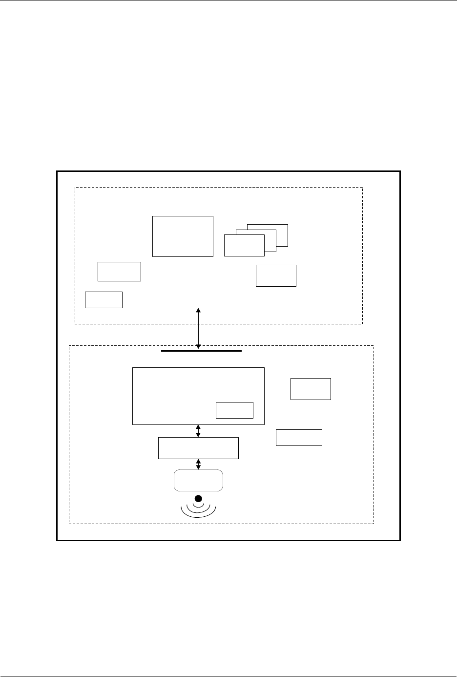
INS13478-5 Z-Wave 500 Series Appl. Programmers Guide v6.71.01 2017-02-28
Sigma Designs Inc.
Z-Wave Software Architecture
Page 4 of 431
3 Z-WAVE SOFTWARE ARCHITECTURE
Z-Wave software relies on polling of functions, command complete callback function calls, and delayed
function calls.
The software is split into two groups of program modules: Z-Wave basis software and Application
software. The Z-Wave basis software includes system startup code, low-level poll function, main poll
loop, Z-Wave protocol layers, and memory and timer service functions. From the Z-Wave basis point of
view the Application software include application hardware and software initialization functions,
application state machine (called from the Z-Wave main poll loop), command complete callback
functions, and a received command handler function. In addition to that, the application software can
include hardware drivers.
Completed
callback
function
Completed
callback
function
Z-Wave protocol layers
RF Hardware
Z-Wave Application layer
Z-Wave application Interface
Z-Wave modules
Timer
Mainloop
HW Init
Low-level poll
Application modules
Received
command
handler
Application state
machine Completed
callback
function
SW Init
Figure 1. Software architecture

INS13478-5 Z-Wave 500 Series Appl. Programmers Guide v6.71.01 2017-02-28
Sigma Designs Inc.
Z-Wave Software Architecture
Page 5 of 431
3.1 Z-Wave System Startup Code
The Z-Wave modules include the system startup function (main). The Z-Wave system startup function
first initializes the Z-Wave hardware and then calls the application hardware initialization function
ApplicationInitHW. Then initializing the Z-Wave software (including the software timer used by the timer
module), initializes the NVM if necessary and finally calling the application software initialization function
ApplicationInitSW. Execution then proceeds in the Z-Wave main loop.
Notice: Initialization of the external NVM is now handled internally by the Z-Wave protocol library. The
protocol will now delete and initialize the NVM on bootup if a 16 bit validation field in the NVM is not
correct Therefore the NVM initialization file extern_epp.hex is now obsoleted.
3.2 Z-Wave Main Loop
The Z-Wave main loop will call the list of Z-Wave protocol functions, including the ApplicationPoll
function and the ApplicationCommandHandler function (if a frame was received) in round robin order.
The functions must therefore be designed to return to the caller as fast as possible to allow the MCU to
do other tasks. Busy loops are not allowed. This will make it possible to receive Z-Wave data, transfer
data via the UART and check user-activated buttons, etc. “simultaneously”. In order not to disrupt the
radio communication and the protocol, no application function must execute code for more than 5ms
without returning.
For production testing the application can be forced into the ApplicationTestPoll function instead of the
ApplicationPoll function.
3.3 Z-Wave Protocol Layers
When transmission of data to another node is requested, the Z-Wave protocol layer adds a frame header
and a checksum to the data before transmission. The protocol layer also handles frame retransmissions,
as well as routing of frames through “repeater” nodes to Z-Wave nodes that are not within direct RF
communication reach. When the frame transmission is completed, an application-specified transmit
complete callback function is called. The transmission complete callback function includes a parameter
that indicates the transmission result. The transmission complete callback function indicate also when
the next frame can be send to avoid overwriting the transmit queue.
The Z-Wave frame receiver module (within the MAC layer) can include more than one frame receive
buffer, so the upper layers can interpret one frame while the next frame is received.
3.4 Z-Wave Routing Principles
The Z-Wave protocol use source routing, which is a technique whereby the sender of a frame specifies
the exact route the frame must take to reach the destination node. Source routing assumes that the
sender knows the topology of the network, and can therefore determine a route having a minimum
number of hops. The Z-Wave protocol supports up to four repeaters between sender and destination
node. Routing can also be used to reach FLiRS destination nodes. Source routing allows implementation
of a leightweight protocol by avoiding distributed topologies in all repeaters. Nodes containing the
topology can also assign routes to a topology-less node enabling it to communicate with a number of
destination nodes using routes.
In case sender fails to reach destination node using routes an explorer mechanism can be launched on
demand to discover a working route to the destination node in question. The explorer mechanism builds

INS13478-5 Z-Wave 500 Series Appl. Programmers Guide v6.71.01 2017-02-28
Sigma Designs Inc.
Z-Wave Software Architecture
Page 6 of 431
on AODV routing with adjustments for source routing and memory footprint. Explorer frames implement
managed multi-hop broadcast forwarding and returns a working route to sender as result. The application
payload piggybacks on explorer frame to reduce latency.
The routing algorithm in controllers store information about successful attempts to reach a destination
node avoiding repetition of previously failed attempts. The last successful route used between sender
and destination node are stored in NVM and is called Last Working Route(LWR). The LWR list
comprises of 232 destination nodes having up to two routes each, called the LWR and the Next to Last
Working Route (NLWR). A LWR/NLWR can contain either a direct or a routed route. Updating LWR and
NLWR happens in the following situations (if new route != current LWR):
When receiving a successful explorer frame route, new route becomes LWR and old LWR becomes
NLWR.
When receiving a successful routed/direct request from another node, new route becomes LWR and
old LWR becomes NLWR
When receiving a successful acknowledge for a transmitted explorer frame, new route becomes
LWR and old LWR becomes NLWR.
When receiving a successful acknowledge for a transmitted NLWR, NLWR becomes LWR.
When receiving a successful acknowledge for a transmitted routed/direct frame, new route becomes
LWR and old LWR becomes NLWR.
Incase a LWR/NLWR fails the LWR and NLWR are updated as follows:
If a LWR fails; it is ‘exiled’ to become the NLWR and the current NLWR (if present) is tried as the
next route.
If a NLWR fails it is removed.
The Application can, instead of having both the LWR and the NLWR entries for a destination node,
overload the LWR with an Application Priority Route (APR), which then upgrades the NLWR to LWR
status as the protocol now is down to one dynamic LWR for the destination node in question. The APR
will after being set always be tried prior to any possible present LWR. The APR can only be removed by
the Application. If destination node has an APR defined the updating of the LWR happens in the
following situations (if new route != APR AND new route != LWR)
When receiving a successful explorer frame route, new route becomes LWR.
When receiving a successful routed/direct request from another node, new route becomes LWR.
When receiving a successful acknowledge for a transmitted explorer frame, new route becomes
LWR.
When receiving a successful acknowledge for a transmitted routed/direct frame, new route becomes
LWR.
Incase LWR fails it is removed.
The routing algorithm in slaves store information about successful attempts to reach a destination node
in response routes after the following principles:
When receiving a successful explorer frame route, new route becomes a new Response Route.
When receiving a successful routed/direct request from another node, new route becomes a new
Response Route.
When receiving a successful acknowledge for a transmitted explorer frame, new route becomes a
new Response Route.
When receiving a successful acknowledge for a transmitted routed/direct frame, new route becomes
a new Response Route.
Incase Response Route fails it is removed.

INS13478-5 Z-Wave 500 Series Appl. Programmers Guide v6.71.01 2017-02-28
Sigma Designs Inc.
Z-Wave Software Architecture
Page 7 of 431
However, the response routes only contains up to two routes to different destination nodes. A response
route for a new destination node overwrites the oldest of the two buffered response routes. A new
response route for an existing destination overwrites the old response route for that specific destination.
The routing attempts depend on the Z-Wave library and transmit options used in the node, for details
refer to section 3.10.
The source routing algorithm does not alter the topology due to failed attempts or store any statistics
regarding link quality.
3.5 Z-Wave Application Layer
The application layer provides the interface to the communications environment which is used by the
application process. The application software is located in the hardware initialization function
ApplicationInitHW, software initialization function ApplicationInitSW, application state machine (called
from the Z-Wave main poll loop) ApplicationPoll, command complete callback functions, and a receive
command handler function ApplicationCommandHandler.
The application implements communication on application level with other nodes in the network. On
application level, a framework is defined of Device and Command Classes to obtain interoperability
between Z-Wave enabled products from different vendors. For details of the Z-Wave+ framework refer to
[4], [5], [6] and [7]. For details of the old Z-Wave framework but still interoperable refer to [1], [6] and [7].
The basic structure of these commands provides the capability to set parameters in a node and to
request parameters from a node responding with a report containing the requested parameters. The
Device and Command Classes are defined in the header file ZW_classcmd.h.
Wireless communication is by nature unreliable because a well-defined coverage area simply does not
exist since propagation characteristics are dynamic and unpredictable. The Z-Wave protocol minimizes
these "noise and distortion" problems by using a transmission mechanisms of the frame there include
two re-transmissions to ensure reliable communication. In addition are single casts acknowledged by the
receiving node so the application is notified about how the transmission went. No precautions can
unfortunately prevent that multiple copies of the same frame are passed to the application. Therefore is it
very important to implement a robust state machine on application level there can handle multiple copies
of the same frame. Below are shown a couple of examples how this can happen:

INS13478-5 Z-Wave 500 Series Appl. Programmers Guide v6.71.01 2017-02-28
Sigma Designs Inc.
Z-Wave Software Architecture
Page 8 of 431
Figure 2. Multiple copies of the same Set frame
Figure 3. Multiple copies of the same Get/Report frame
The Z-Wave protocol is designed to have low latency on the expense of handling simultaneously
communication to a number of nodes in the Z-Wave network. To obtain this is the number of random
Ack
Node A
Node B
Ack
Set Cmd
Set Cmd (Retry)
Time
Random
backoff
Report
Node A
Node B
Ack
Ack
Get Cmd
Get Cmd (Retry)
Time
Ack
Report
Ack

INS13478-5 Z-Wave 500 Series Appl. Programmers Guide v6.71.01 2017-02-28
Sigma Designs Inc.
Z-Wave Software Architecture
Page 9 of 431
backoff values limited to 4 (0, 1, 2, and 3). The figure below shows how simultaneous communication to
even a small number of nodes easily can block the communication completely.
Figure 4. Simultaneous communication to a number of nodes
Avoid simultaneous request to a number of nodes in a Z-Wave network in case the nodes in question
respond on the application level.
3.6 Z-Wave Software Timers
The Z-Wave timer module is designed to handle a limited number of simultaneous active software timers.
The Z-Wave basis software reserves some of these timers for protocol timeouts.
A delayed function call is initiated by a TimerStart API call to the timer module, which saves the function
address, sets up the timeout value and returns a timer-handle. The timer-handle can be used to cancel
the timeout action e.g. an action completed before the time runs out.
The timer can also be used for frequent inspection of special hardware e.g. a keypad. Specifying the time
settings to 50 ms and repeating forever will call the timer call-back function every 50 msec.
100% of the nodes responds
Node A
Nodes within direct range
Get Cmd as Broadcast
Time
25% of the nodes responds (RB=0)
25% of the nodes responds (RB=1)
25% of the nodes responds (RB=2)
25% of the nodes responds (RB=3)

INS13478-5 Z-Wave 500 Series Appl. Programmers Guide v6.71.01 2017-02-28
Sigma Designs Inc.
Z-Wave Software Architecture
Page 10 of 431
3.7 Z-Wave Hardware Timers
The 200/300/400/500 Series Z-Wave SoCs have a number of hardware timers/counters. Some are
reserved by the protocol and others are free to be used by the application as shown in the table below:
Table 1. 200/300/400/500 Series Z-Wave SoCs hardware timer allocation
200 Series
300 Series
400 Series
500 Series
TIMER0
Protocol
system clock
Protocol
system clock
Available for
the application
Available for
the application
TIMER1
Available for
the application
Available for
the application
Used by the
protocol
Available for
the application
GPTIMER
Available for
the application
Available for
the application
Available for
the application
Available for
the application
The TIMER0 and TIMER1 are standard 8051 timers/counters.
3.8 Z-Wave Hardware Interrupts
Application interrupt service routines (ISR) must use 8051 register bank 0. However, do not use USING 0
attribute when declaring ISR’s. The Z-Wave protocol uses 8051 register bank 1 for protocol ISR’s, see
table below regarding application ISR availability:
Table 2. 200/300/400/500 Series Z-Wave SoC Application ISR availability
200 Series
300 Series
400 Series
500 Series
INUM_INT1
INUM_TIMER1
INUM_SERIAL
INUM_SPI
INUM_TRIAC
INUM_GP_TIMER
INUM_ADC
INUM_INT1
INUM_TIMER1
INUM_SERIAL
INUM_SPI
INUM_TRIAC
INUM_GP_TIMER
INUM_ADC
INUM_INT0
INUM_TIMER0
INUM_SERIAL0
INUM_SPI0
INUM_TRIAC
INUM_GP_TIMER
INUM_ADC
INUM_USB
INUM_IR
INUM_INT0
INUM_INT1
INUM_TIMER0
INUM_SERIAL0
INUM_SPI0
INUM_TRIAC
INUM_GP_TIMER
INUM_ADC
INUM_USB
INUM_IR
The duration of an application interrupt routine must be below 80us.
Refer to ZW020x.h, ZW030x.h, ZW040x.h and ZW050x.h header files with respect to ISR definitions. For
an example, refer to UART ISR in serial API sample application.

INS13478-5 Z-Wave 500 Series Appl. Programmers Guide v6.71.01 2017-02-28
Sigma Designs Inc.
Z-Wave Software Architecture
Page 11 of 431
3.9 Interrupt service routines.
When using interrupt service routines from one of the hardware interfaces such as ADC, GP timer or
UART, one should be aware of certain issues as described in the following sections.
3.9.1 SFR pages
The 500 Series Z-Wave SoC uses multiple pages of 8051 SFR registers. The page selection is set using
SFRPAGE. Consequently the SFRPAGE must be preserved when calling an Interrupt Service Routine
(ISR) in your code. In order to do this the intrinsic functions _push_() and _pop_() must be called.
Function _push_() must be called when the ISR starts, and _pop_() just before returning from the ISR.
For example, the ISR of the ADC should be look as follow:
#include <INTRINS.H>
void ADC_int(void) interrupt INUM_ADC
{
_push_(SFRPAGE)
1
;
call api’s
_pop_(SFRPAGE);
}
3.9.2 Calling functions from ISR
The 8051 core of the 500 Series Z-Wave SoC has no register-to-register move. Therefore, the compiler
generates register to memory moves instead. Since the compiler knows the register bank, the physical
address of a register in a register bank can be calculated. For example, when the compiler calculates the
address of register R2 in register bank 0, the address is 0x02. If the register bank selected is not really 0,
then the function overwrites this register. This might result in unpredictable behavior of the program.
This technique of accessing a register using its absolute address is called absolute register addressing.
In the Z-Wave system the system timer and RF interrupt use register bank 1. The default register bank
used for non-interrupt code is register bank 0. Therefore, if a function is called from an ISR it might be
looking in the wrong place for its register values.
To solve this problem, one of these solutions can be used:
1. Use the C51’s REGISTERBANK directive to specify that a certain function uses the same
register bank as the ISR that calls the function. Hence, no code is generated in the function to
switch the register bank. For example:
#pragma registerbank(1)
void foo (void)
{
}
2. Use the NOAREGS directive to specify that the compiler should not use absolute register
addressing. This make the function register bank independent so that it may be called from any
function that uses a different register bank than the default.
1
The _push_ and _pop_ functions are intrinsic functions and the header file INTRINS.H. Therefore, INTRINS.H should be included
in order to be able to use them.

INS13478-5 Z-Wave 500 Series Appl. Programmers Guide v6.71.01 2017-02-28
Sigma Designs Inc.
Z-Wave Software Architecture
Page 12 of 431
3.10 Z-Wave Nodes
From a protocol point of view, there are five types of Z-Wave nodes: Portable Controller nodes, Static
Controller nodes, Bridge Controller nodes, Routing Slave nodes, and Enhanced 232 Slave nodes. All
controller based nodes stores information about other nodes in the Z-Wave network. The node
information includes the nodes each of the nodes can communicate with (routing information). The
Installation node will present itself as a Controller node, which includes extra functionality to help a
professional installer setup, configure, and troubleshoot a Z-Wave network. The bridge controller node
stores information about the nodes in the Z-Wave network and in addition is it possible to generate up to
128 Virtual Slave nodes.
3.10.1 Z-Wave Portable Controller Node
The software components of a Z-Wave portable controller are split into the controller application and the
Z-Wave-Controller basis software, which includes the Z-Wave protocol layers and control of the various
data stored into the NVM.
Portable controller nodes include an external NVM in which the non-volatile application data area can be
placed. The Z-Wave basis software has reserved the first area of the external NVM.
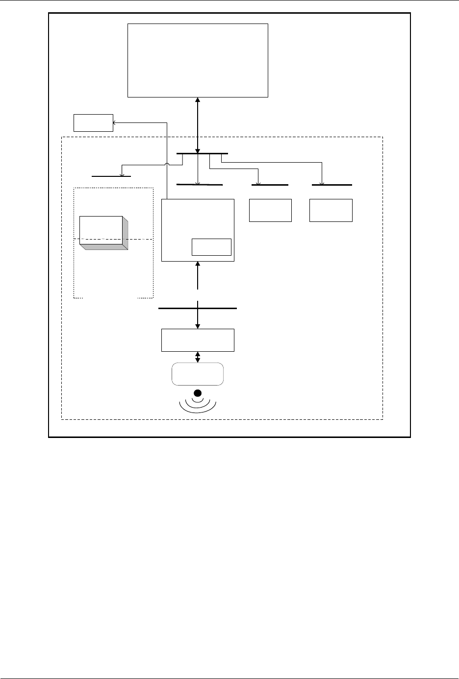
INS13478-5 Z-Wave 500 Series Appl. Programmers Guide v6.71.01 2017-02-28
Sigma Designs Inc.
Z-Wave Software Architecture
Page 13 of 431
Controller
Application
Z-Wave protocol
Transport API
RF Hardware
Z-Wave
Controller
EEPROM/Flash
External
EEPROM
Controller API
Z-Wave Controller
Timer
Mainloop
HW Init
Z-Wave data
Appl. data
RTC
Memory API
RTC APITimer API
Basis API
Figure 5. Portable controller node architecture
The Portable Controller node has a unique home ID number assigned, which is stored in the Z-Wave
basis area of the external NVM. Care must be taken, when reprogramming the external NVM, that
different controller nodes do not get the same home ID number.
When new Slave nodes are registered to the Z-Wave network, the Controller node assigns the home ID
and a unique node ID to the Slave node. The Slave node stores the home ID and node ID.
When a controller is primary, it will send any networks changes to the SUC node in the network.
Controllers can request network topology updates from the SUC node.
The routing attempts done by a portable controller to reach the destination node are as follows:

INS13478-5 Z-Wave 500 Series Appl. Programmers Guide v6.71.01 2017-02-28
Sigma Designs Inc.
Z-Wave Software Architecture
Page 14 of 431
If APR, LWR and NLWR all are non-existing and TRANSMIT_OPTION_ACK set. Try direct with
retries.
If APR exist and TRANSMIT_OPTION_ACK set. Try direct without retries. In case it fails, try the
APR. If APR fails then try LWR if it exist and if it also fails then remove the LWR.
If APR do not exist, LWR exist and TRANSMIT_OPTION_ACK set. Try direct without retries. In
case it fails, try the LWR. In case the LWR also fails, ‘exile’ it to become NLWR and try old
NLWR if it exist. if the NLWR also fails, remove it.
If APR do not exist, LWR do not exist, NLWR exist and TRANSMIT_OPTION_ACK set. Try
direct without retries. In case it fails, try the NLWR. In case the NLWR also fails remove it.
If TRANSMIT_OPTION_ACK and TRANSMIT_OPTION_AUTO_ROUTE are set then calculate
up to two routing attempts per entry/repeater node. In case TRANSMIT_OPTION_EXPLORE
set, a maximum number limits number of tries.
If TRANSMIT_OPTION_ACK and TRANSMIT_OPTION_NO_ROUTE are set, then direct with
retries.
If TRANSMIT_OPTION_ACK and TRANSMIT_OPTION_EXPLORE are set then issue an
explore frame as last resort.
When developing application software the header file “ZW_controller_api.h” also include the other
Z-Wave API header files e.g. ZW_timer_api.h.
The following define must be set when compiling the application: ZW_CONTROLLER.
The application must be linked with ZW_CONTROLLER_PORTABLE_ZWS.LIB
( = 050X for 500 Series Z-Wave modules, etc).
3.10.2 Z-Wave Static Controller Node
The software components of a Z-Wave static controller node are split into a Static Controller application
and the Z-Wave Static Controller basis software, which includes the Z-Wave protocol layers and control
of the various data stored into the NVM.
The difference between the static controller and the controller described in chapter 3.10.1 is that the
static controller cannot be powered down, that is it cannot be used for battery-operated devices. The
static controller has the ability to look for neighbors when requested by a controller. This ability makes it
possible for a primary controller to assign static routes from a routing slave to a static controller.
The Static Controller can be set as a SUC node, so it can sends network topology updates to any
requesting secondary controller. A secondary static controller not functioning as SUC can also request
network Topology updates.
The routing attempts done by a static controller to reach the destination node are as follows:

INS13478-5 Z-Wave 500 Series Appl. Programmers Guide v6.71.01 2017-02-28
Sigma Designs Inc.
Z-Wave Software Architecture
Page 15 of 431
If APR, LWR and NLWR all are non-existing and TRANSMIT_OPTION_ACK set. Try direct when
neighbors with retries.
If APR exist and TRANSMIT_OPTION_ACK set. Try the APR. If APR fails then try LWR if it exist
and if it also fails then remove the LWR and try direct if neighbor.
If APR do not exist, LWR exist and TRANSMIT_OPTION_ACK set. Try the LWR. In case the
LWR fails, ‘exile’ it to become NLWR and try old NLWR if it exist. if the NLWR also fails, remove
it and try direct if neighbor.
If APR do not exist, LWR do not exist, NLWR exist and TRANSMIT_OPTION_ACK set. Try the
NLWR. In case the NLWR fails remove it and try direct if neighbor.
If TRANSMIT_OPTION_ACK and TRANSMIT_OPTION_AUTO_ROUTE are set then calculate
up to two routing attempts per entry/repeater node. If enough routes exist try a settable
maximum number of tries.
If TRANSMIT_OPTION_ACK and TRANSMIT_OPTION_NO_ROUTE are set, then direct with
retries.
If TRANSMIT_OPTION_ACK and TRANSMIT_OPTION_EXPLORE are set then issue an
explore frame as last resort.
When developing application software the header file “ZW_controller_static_api.h” also include the other
Z-Wave API header files e.g. ZW_timer_api.h.
The following define is being included compiling the application: ZW_CONTROLLER_STATIC.
The application must be linked with ZW_CONTROLLER_STATIC_ZWS.LIB
( = 050X for 500 Series Z-Wave modules, etc).
3.10.3 Z-Wave Bridge Controller Node
The software components of a Z-Wave Bridge Controller node are split into a Bridge Controller
application and the Z-Wave Bridge Controller basis software, which includes the Z-Wave protocol layer.
The Bridge Controller is essential a Z-Wave Static Controller node, which incorporates extra functionality
that can be used to implement controllers, targeted for bridging between the Z-Wave network and others
network (ex. UPnP).
The Bridge application interface is an extended Static Controller application interface, which besides the
Static Controller application interface functionality gives the application the possibility to manage Virtual
Slave nodes. Virtual Slave nodes is a routing slave node without repeater and assign return route
functionality, which physically resides in the Bridge Controller. This makes it possible for other Z-Wave
nodes to address up to 128 Slave nodes that can be bridged to some functionality or to devices, which
resides on a foreign Network type.
The routing attempts done by a bridge controller to reach the destination node are as follows:

INS13478-5 Z-Wave 500 Series Appl. Programmers Guide v6.71.01 2017-02-28
Sigma Designs Inc.
Z-Wave Software Architecture
Page 16 of 431
If APR, LWR and NLWR all are non-existing and TRANSMIT_OPTION_ACK set. Try direct when
neighbors with retries.
If APR exist and TRANSMIT_OPTION_ACK set. Try the APR. If APR fails then try LWR if it exist
and if it also fails then remove the LWR and try direct if neighbor.
If APR do not exist, LWR exist and TRANSMIT_OPTION_ACK set. Try the LWR. In case the
LWR fails, ‘exile’ it to become NLWR and try old NLWR if it exist. if the NLWR also fails, remove
it and try direct if neighbor.
If APR do not exist, LWR do not exist, NLWR exist and TRANSMIT_OPTION_ACK set. Try the
NLWR. In case the NLWR fails remove it and try direct if neighbor.
If TRANSMIT_OPTION_ACK and TRANSMIT_OPTION_AUTO_ROUTE are set then calculate
up to two routing attempts per entry/repeater node. In case TRANSMIT_OPTION_EXPLORE
set, a maximum number limits number of tries.
If TRANSMIT_OPTION_ACK and TRANSMIT_OPTION_AUTO_ROUTE are set, then direct with
retries.
If TRANSMIT_OPTION_ACK and TRANSMIT_OPTION_EXPLORE are set then issue an
explore frame as last resort.
When developing application software the header file “ZW_controller_bridge_api.h” also include the other
Z-Wave API header files.
The following define is being included compiling the application: ZW_CONTROLLER_BRIDGE.
The application must be linked with ZW_CONTROLLER_BRIDGE_ZWS.LIB
( = 050X for 500 Series Z-Wave modules, etc).
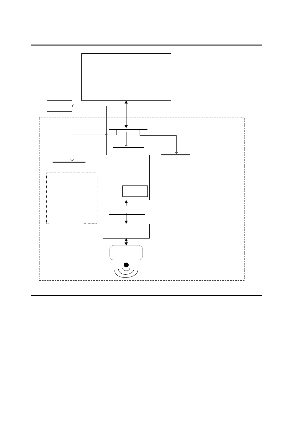
INS13478-5 Z-Wave 500 Series Appl. Programmers Guide v6.71.01 2017-02-28
Sigma Designs Inc.
Z-Wave Software Architecture
Page 17 of 431
3.10.4 Z-Wave Routing Slave Node
The software components of a Z-Wave routing slave node are split into a Slave application and the
Z-Wave-Slave basis software, which includes the Z-Wave protocol layers.
Slave
Application
Z-Wave protocol
Transport API
RF Hardware
Z-Wave
Slave
Data Flash Area
Slave API
Z-Wave Slave
Timer
Mainloop
HW Init
Z-Wave data
Appl. data
Memory API
Timer API
Basis API
Figure 6. Routing slave node architecture
The routing slave is capable of initiating communication. Examples of a routing slave could be a wall
control or temperature sensor. If a user activates the wall control, the routing slave sends an “on”
command to a lamp (slave).
The routing slave does not have a complete routing table. Frames are sent to destinations configured
during association. The association is performed via a controller. If routing is needed for reaching the
destinations, it is also up to the controller to calculate the routes.
Routing slave nodes have an area of 256 bytes MTP (Many Times Programmable memory) for storing
data. The Z-Wave basis software reserves the first part of this area, and application data uses the
remaning part.
The home ID is set to a randomly generated value and node ID is zero. When registering a slave node to
a Z-Wave network the slave node receive home and node ID from the networks primary controller node.
These IDs are stored in the Z-Wave basis data area in the flash.

INS13478-5 Z-Wave 500 Series Appl. Programmers Guide v6.71.01 2017-02-28
Sigma Designs Inc.
Z-Wave Software Architecture
Page 18 of 431
The routing slave can send unsolicited and non-routed broadcasts, singlecasts, and multicasts.
Singlecasts can also be routed. Further, it can respond with a routed singlecast (response route) in case
another node has requested this by sending a routed singlecast to it. A received multicast or broadcast
results in a response route without routing.
A temperature sensor based on a routing slave may be battery operated. To improve battery lifetime, the
application may bring the node into sleep mode most of the time. Using the wake-up timer (WUT), the
application may wake up once per second, measure the temperature and go back to sleep. In case the
measurement exceeded some threshold, a command (e.g. “start heating”) may be sent to a heating
device before going back to sleep.
The routing attempts done by a routing slave to reach the destination node are as follows:
If TRANSMIT_OPTION_ACK is set and destination is available in response routes, try response
route.
If TRANSMIT_OPTION_ACK and TRANSMIT_OPTION_AUTO_ROUTE are set then try return
routes if any exists for specified destination.
If TRANSMIT_OPTION_ACK and TRANSMIT_OPTION_AUTO_ROUTE are set then try direct.
If TRANSMIT_OPTION_ACK and TRANSMIT_OPTION_EXPLORE are set, issue an explore
frame as last resort.
The return routes comprises of up to five destinations having up to 4 routes each. Return routes can
contain a no repeater route (direct) up to a full 4 repeater route.
The return routes are tried in the order of priority, highest first. The priority of the return routes are
dynamically updated when return routes either succeed or fails.
The Application can set a Priority Return Route, which always will have the highest priority and therefor
always be tried as the first return route and can only be removed by the Application. The priority return
route will when set use one of the available 4 route entries.
New routes/direct are qualified for return route insertion by checking if the destination exist and
route/direct do not exist. In that event the new route/direct entry will be placed either in a free route or the
one having lowest priority.

INS13478-5 Z-Wave 500 Series Appl. Programmers Guide v6.71.01 2017-02-28
Sigma Designs Inc.
Z-Wave Software Architecture
Page 19 of 431
A number of limitations are unfortunately necessary with respect to Security S2 due to lack of external
NVM:
All key classes supported but only one can be active after inclusion (add).
Slave routing based devices will when entering Sleep mode save the “Most Recently Used”
(MRU) S2 SPAN entry in critical RAM. The MRU S2 SPAN entry are restored on power up if a
valid S2 SPAN entry resides in critical RAM.
S2 Public-Private key pair resides in Protocol part of NVR and written to NVR at production.
Refer to [17] for details.
Cannot send S2 multicast but do support S2 multicast receive.
The table below show the NVM memory budget of the full routing slave with S0/S2 functionality included
is as follows:
#
Functionality
Bytes
1
Home ID, Node ID, magic bytes and SUC return routes.
25
2
Return routes: 5 destinations having 4 full hop routes each
5 destinations x (1 destination byte + 4 x (4 hop bytes + 1 aux. byte))
105
3
Keyclass byte – Which security keyclass is active – Only ONE keyclass can be
active at any time, can be either S0, S2 (3 keyclasses)
1
4
S0/S2 Network key
16
5
Critical SPAN nodeID – Identifies the SPAN, which is saved in Critical RAM
when going into Sleepmode and reloaded on wakeup from Sleepmode – This
means that no resync (S2) is needed for the Critical SPAN nodeID after wakeup
from Sleepmode. If equal to ZERO the MRU SPAN entry will be stored/restored.
1
The routing slave NVM is placed in the MTP (Total of 255 Bytes) resulting in 107 Bytes available for the
application.
No SPAN/MPAN are saved in NVM, which for a FLiRS node would mean that the node needs to sync
every time it wakes up in case it want to communicate with another node. But to minimize the resync
after Sleepmode we do save ONE SPAN in Critical RAM (retention RAM).
The Critical RAM is 128 Bytes retention memory – Currently 32 Bytes are allocated for Application and
96 bytes are allocated for protocol. The table below shows the protocol Critical RAM requirement for a
Routing Slave with one SPAN entry.
#
Functionality
Bytes
1
Protocol usage: phyRfData, ResponseRoutes, FLiRS, NodeID, HomeID etc.
51
2
1 S2 SPAN
39
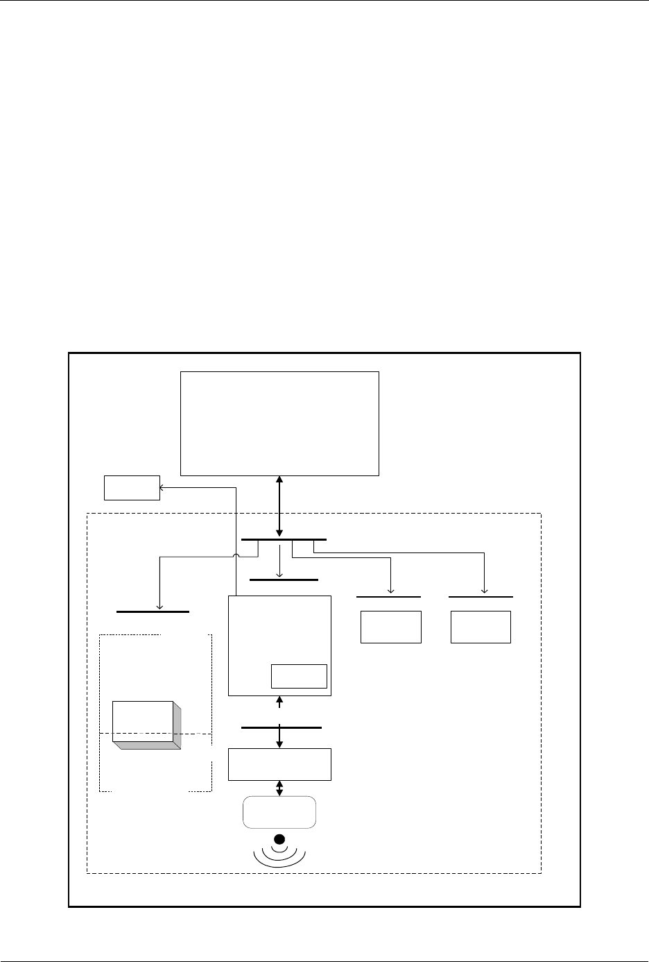
INS13478-5 Z-Wave 500 Series Appl. Programmers Guide v6.71.01 2017-02-28
Sigma Designs Inc.
Z-Wave Software Architecture
Page 20 of 431
The ECDH keypair for routing slaves is stored in the NVR [17] and must be generated and pre-
programmed during production. The updated NVR layout must be used when producing a SDK 6.70
based routing slaves. The routing slave cannot detect if the keypair is missing.
When developing application software the header file “ZW_slave_routing_api.h” also include the other
Z-Wave API header files e.g. ZW_timer_api.h.
The following define will be generated by the headerfile, if it does not already exist when when compiling
the application: ZW_SLAVE.
The application must be linked with ZW_SLAVE_ROUTING_ZWS.LIB
( = 050X for 500 Series Z-Wave modules, etc).
3.10.5 Z-Wave Enhanced 232 Slave Node
The Z-Wave enhanced 232 slave has the same basic functionality as a Z-Wave routing slave node, but
offers return route assignment of up to 232 destination nodes instead of 5.
Slave
Application
Z-Wave protocol
Transport API
RF Hardware
Z-Wave
Slave
Slave API
Z-Wave Slave
Timer
Mainloop
HW Init
Memory API
Timer API
Basis API
RTC
RTC API
EEPROM
External
EEPROM
Z-Wave
data
Appl. data
Figure 7. Enhanced 232 slave node architecture

INS13478-5 Z-Wave 500 Series Appl. Programmers Guide v6.71.01 2017-02-28
Sigma Designs Inc.
Z-Wave Software Architecture
Page 21 of 431
Enhanced 232 slave nodes have an external NVM and a WUT. The Z-Wave basis software reserves the
first area of the external NVM: The last area of the NVM is reserved for the application data.
The routing attempts done by an enhanced 232 slave to reach the destination node are as follows:
If TRANSMIT_OPTION_ACK is set and destination is available in response routes, try response
route.
If TRANSMIT_OPTION_ACK and TRANSMIT_OPTION_AUTO_ROUTE are set then try return
routes if any exists for specified destination.
If TRANSMIT_OPTION_ACK and TRANSMIT_OPTION_AUTO_ROUTE are set then try direct.
If TRANSMIT_OPTION_ACK and TRANSMIT_OPTION_EXPLORE are set, issue an explore
frame as last resort.
The return route comprises of up to 232 destinations having up to four routes each. Return routes can
contain a no repeater route (direct) up to a full 4 repeater route.
The return routes are tried in the order of priority, highest first. The priority of the return routes are
dynamically updated when return routes either succeed or fails.
The Application can set a Priority Return Route, which always will have the highest priority and therefor
always be tried as the first return route and can only be removed by the Application. The priority return
route will when set use one of the available 4 route entries.
New routes/direct are qualified for return route insertion by checking if the destination exist and
route/direct do not exist. In that event the new route/direct entry will be placed either in a free route or the
one having lowest priority.
When developing application software the header file “ZW_slave_32_api.h” also include the other
Z-Wave API header files e.g. ZW_timer_api.h.
The following define will be generated by the headerfile, if it does not already exist when compiling the
application: ZW_SLAVE and ZW_SLAVE_32.
The application must be linked with ZW_SLAVE_ENHANCED_232_ZWS.LIB
( = 050X for 500 Series Z-Wave modules, etc).
3.10.6 Adding and Removing Nodes to/from the network
Its only controllers that can add new nodes to the Z-Wave network, and reset them again is the primary
or inclusion controller. The home ID of the Primary Z-Wave Controller identifies a Z-Wave network.
Information about the result of a learn process is passed to the callback function in a variable with the
following structure:
typedef struct _LEARN_INFO_
{
BYTE bStatus; /* Status of learn mode */
BYTE bSource; /* Node id of the node that send node info */
BYTE *pCmd; /* Pointer to Application Node information */
BYTE bLen; /* Node info length */
} LEARN_INFO;
When adding nodes to the network the controller have a number of choices of how to add, and what
nodes to add to the network.

INS13478-5 Z-Wave 500 Series Appl. Programmers Guide v6.71.01 2017-02-28
Sigma Designs Inc.
Z-Wave Software Architecture
Page 22 of 431
3.10.6.1 Adding a node normally.
The normal way to add a node to the network is to use ZW_AddNodeToNetwork() function on the
primary controller, and use the function ZW_SetLearnMode() on the node that should be included into
the network.
3.10.6.2 Adding a new controller and make it the primary controller
A primary controller can add a controller to the network and in the same process give the role as primary
controller to the new controller. This is done by using the ZW_ControllerChange() on the primary
controller, and use the function ZW_SetLearnMode() on the controller that should be included into the
network.. Note that the original primary controller will become a secondary controller when the inclusion
(add) is finished.
3.10.6.3 SUC ID Server (SIS)
Previously Z-Wave offered a Static Update Controller (SUC) functionality that could be enabled in a static
controller. This functionality can no longer be enabled alone but is now an intregrated part of the SUC ID
Server (SIS). The SIS becomes the primary controller in the network because it always has the latest
update of the network topology and capability to include/exclude nodes in the network. When including a
controller to the network it becomes an inclusion controller because it has the capability to
include/exclude nodes in the network via the SIS. The inclusion controller’s network topology is dated
from last time a node was included or it requested a network update from the SIS. The SUC and the SIS
functionality can not be spilt and will always be avalible on the same controller
3.10.7 The Automatic Network Update
A Z-Wave network consists of slaves, a primary controller and secondary controllers. New nodes can
only be added and removed to/from the network by using the primary controller. This could cause
secondary controllers and routing slaves to misbehave, if for instance a preferred repeater node is
removed. Without automatic network updating a new replication (copy) has to be made from the primary
controller to all secondary controllers and routing slaves should also be manually updated with the
changes. In networks with several controller and routing slave nodes, this process will be cumbersome.
To automate this process, an automatic network update scheme has been introduced to the Z-Wave
protocol. To use this scheme a static controller must be available in the network. This static controller is
dedicated to hold a copy of the network topology and the latest changes that have occurred to the
network. The static controller used in the Automatic update scheme is called the SUC ID Server (SIS).
Each time a node is added, deleted or a routing change occurs, the inclusion controller will send the
node information to the SIS. Other controllers can then ask the SIS if any updates are pending. The SIS
will then in turn respond with any changes since last time this controller asked for updates. In the
controller requesting an update, ApplicationControllerUpdate will be called to notify the application that
a new node has been added or removed in the network.
The SIS holds up to 64 changes of the network. If a node requests an update after more than 64
changes occurred, then it will get a complete copy (see ZW_RequestNetWorkUpdate).
Routing slaves have the ability to request updates for its known destination nodes. If any changes have
occurred to the network, the SIS will send updated route information for the destination nodes to the
Routing slave that requested the update. The Routing slave application will be notified when the process
is done, but will not get information about any changes to its routes.
If an inclusion controller sends a new node’s node information and its routes to the SIS while it is
updating another controller, the updating process will be aborted to process the new nodes information.

INS13478-5 Z-Wave 500 Series Appl. Programmers Guide v6.71.01 2017-02-28
Sigma Designs Inc.
Z-Wave Application Interfaces
Page 23 of 431
4 Z-WAVE APPLICATION INTERFACES
The Z-Wave basis software consists of a number of different modules. Time critical functions are written
in assembler while the other Z-Wave modules are written in C. The Z-Wave API consists of a number of
C functions which give the application programmer direct access to the Z-Wave functionality.
4.1 API usage guidelines
The following guidelines should be followed when making a Z-Wave application.
4.1.1 Code space, data space and internal/external NVM
One code bank of 32KB memory in flash is allocated for application development. The data SRAM
avalible for the application is 4KB.
To enable full utilization of the 500 series with respect to future protocol features and OTA firmware
update results in the following recommendations for external NVM:
Minimum requirements when selecting external NVM for devices without OTA firmware update support:
16KB – Will not be upgradeable to future protocol versions requiring additional NVM (Not
recommended)
32KB – Will be upgradeable to future protocol versions requiring additional NVM
(Recommended)
Minimum requirements when selecting external NVM for devices without OTA firmware update support:
128KB – Required for slave devices
256KB – Required for controller devices
Initialization of the external NVM is completely handled by the Z-Wave protocol and for details about data
layout in external NVM refer to [9]. For selection of external NVM refer also to [16].
4.1.2 Buffer protection
Some API calls has one parameter that is a pointer to a buffer in the application SRAM area and another
parameter that is a pointer to a callback function. When using these API functions in Z-Wave, it is
important that the application does not change the contents of the buffer before the last callback from the
API function has been issued. If the content of the buffer is changed before that callback, the Z-Wave
protocol might perform the function on invalid data.
4.1.3 Overlapping API calls
In general, it should be avoided to call an API function before the previously started API function is
finished and has called the callback function for the last time. Due to the limited resources available for
the API not all combinations of API calls will work, some API calls will use the same state machine or the
same buffers so if multiple functions is started one or both of the functions might fail.

INS13478-5 Z-Wave 500 Series Appl. Programmers Guide v6.71.01 2017-02-28
Sigma Designs Inc.
Z-Wave Application Interfaces
Page 24 of 431
4.1.4 Error handling.
For purpose of robustness, an application implementation may choose to guard callback API calls whith
a timer. In this guide, a timeout value for each API call, which uses a callback, is given. In some functions
it is necessarry to to execute some commands in order to recover from a timeout exception. Recovery
handling is described for each operation.
4.2 Z-Wave Libraries
4.2.1 Library Functionality
Each of the API’s provided in the Developer’s Kit contains a subset of the full Z-Wave functionality; the
table below shows what kind of functionality the API’s support independent of the network configuration:
Table 3. Library functionality
Routing
Slave
Enhanced
232 Slave
Portable
Controller
Static
Controller
Bridge
Controller
Basic Functionality
Singlecast (non-secure)
X
X
X
X
X
Multicast (non-secure)
X
X
X
X
X
Broadcast (non-secure)
X
X
X
X
X
Controller replication (copy)
-
-
X
X
X
Promiscuous mode
-
-
X
X
X
Random number generator
X
X
X
X
X
Able to act as NWI center
-
-
X
X
X
Able to be included via the NWI mechanism
X
X
X
X
X
Able to issue an explorer frame
X
X
X
X
X
Able to forward an explorer frame
X
X
-
X
X
S0 Security (singlecast)
X
X
-
-
-
S2 Security (singlecase and multicast)
X
X
-
-
-
Memory Location
NVM data located in internal MTP
X
-
-
-
-
NVM data located in external FLASH/EEPROM
-
X
X
X
X
Firmware update with automatic NVM data conversion
-
X
X
X
X
Network Management
Network router (repeater)
X1
X1
-
X1
X1
Assign routes to routing slave
-
-
X
X
X
Routing slave functionality
X
X
-
-
-
Access to routing table
-
-
X
-
-
Maintain virtual slave nodes
-
-
-
-
X2
Able to be a FLiRS node
X
X
-
-
-
Able to beam when repeater
X
X
-
X
X
Able to create route containing beam
X3
X2
X
X
X
1
Only if “always listening”
2
Only when secondary controller
3
Only when return routes are assigned by a controller capable of creating routes containing beam

INS13478-5 Z-Wave 500 Series Appl. Programmers Guide v6.71.01 2017-02-28
Sigma Designs Inc.
Z-Wave Application Interfaces
Page 25 of 431
4.2.1.1 Library Functionality without a SIS
Some of the API’s functionality provided on the Developer’s Kit depends on the network configuration.
The table below shows what kind of functionality the API’s support without a SIS in the Z-Wave network:
Table 4. Library functionality without a SIS
Routing
Slave
Enhanced
232 Slave
Portable
Controller
Static
Controller
Bridge
Controller
Network Management
Controller replication (copy)
-
-
X
X
X
Controller shift
-
-
X1
X1
X1
Create new primary controller
-
-
-
-
-
Request network updates
-
-
-
-
-
Request rediscovery of a node
-
-
X1
X1
X1
Remove failing nodes
-
-
X1
X1
X1
Replace failing nodes
-
-
X1
X1
X1
Provide routing table info
-
-
X
X
X
1
Only when primary controller

INS13478-5 Z-Wave 500 Series Appl. Programmers Guide v6.71.01 2017-02-28
Sigma Designs Inc.
Z-Wave Application Interfaces
Page 26 of 431
4.2.1.2 Library Functionality with a SIS
Some of the API’s functionality provided on the Developer’s Kit depends on the network configuration.
The table below shows what kind of functionality the API’s support with a SUC ID Server (SIS) in the
Z-Wave network:
Table 5. Library functionality with a SIS
Routing Slave
Enhanced 232
Slave
Portable
Controller
Static
Controller
Bridge
Controller
Network Management
Controller replication (copy)
-
-
X
X
X
Controller shift
-
-
-
-
-
Create new primary controller
-
-
-
-
-
Request network updates
X
X
X
X
X
Request rediscovery of a node
-
-
X1
X1
X1
Remove failing nodes
-
-
X1
X1
X1
Replace failing nodes
-
-
X1
X1
X1
Set static ctrl. to SIS
-
-
X2
X2
X2
Work as SIS
-
-
-
X
X
Work as inclusion controller
X
X
X
“I’m lost“ – provide help
X3
X3
X3
X4
X
Provide routing table info
-
-
X
X
X
Note that the ability to provide help for “I’m lost” requests is limited to forwarding the request to the SIS.
Only the portable controller configured as SIS can actually do the updating of the device.
1 Only when primary/inclusion controller
2 Only when primary controller
3 Only if “always listening”
4 The library without repeater functionality cannot provide help or forward help requests.

INS13478-5 Z-Wave 500 Series Appl. Programmers Guide v6.71.01 2017-02-28
Sigma Designs Inc.
Z-Wave Application Interfaces
Page 27 of 431
4.3 Z-Wave Common API
This section describes interface functions that are implemented within all Z-Wave nodes. The first
subsection defines functions that must be implemented within the application modules, while the second
subsection defines the functions that are implemented within the Z-Wave basis library.
Functions that does not complete the requested action before returning to the application (e.g.
ZW_SEND_DATA) have a callback function pointer as one of the entry parameters. Unless explicitly
specified this function pointer can be set to NULL (no action to take on completion).
A serial API implementation provide an interface to the major part of interface functions via a serial port.
The SDK contains a serial API application [13], which enables a host processor to control the interface
functions via a serial port.
4.3.1 Required Application Functions
The Z-Wave library requires the functions mentioned here implemented within the Application layer.

INS13478-5 Z-Wave 500 Series Appl. Programmers Guide v6.71.01 2017-02-28
Sigma Designs Inc.
Z-Wave Application Interfaces
Page 28 of 431
4.3.1.1 ApplicationInitHW
BYTE ApplicationInitHW( BYTE bWakeupReason )
ApplicationInitHW is used to initialize hardware used by the application. The Z-Wave hardware
initialization function set all application IO pins to input mode. The ApplicationInitHW function MUST be
called by the Z-Wave main function during system startup. At this point of time the Z-Wave timer system
is not started so waiting on hardware to get ready SHOULD be done by MCU busy loops.
Defined in: ZW_basis_api.h
Return value:
BYTE
TRUE
Application hardware initialized
FALSE
Application hardware initialization failed.
Protocol enters test mode and Calls
ApplicationTestPoll
Parameters:
bWakeupReason IN
Wakeup flags:
ZW_WAKEUP_RESET
Woken up by reset or external interrupt
ZW_WAKEUP_WUT
Woken up by the WUT timer
ZW_WAKEUP_SENSOR
Woken up by a wakeup beam
ZW_WAKEUP_WATCHDOG
Reset because of a watchdog timeout
ZW_WAKEUP_EXT_INT
Woken up by external interrupt
ZW_WAKEUP_POR
Reset by Power on reset circuit
Serial API (Not supported)

INS13478-5 Z-Wave 500 Series Appl. Programmers Guide v6.71.01 2017-02-28
Sigma Designs Inc.
Z-Wave Application Interfaces
Page 29 of 431
4.3.1.2 ApplicationInitSW
BYTE ApplicationInitSW( ZW_NVM_STATUS bNvmStatus )
ApplicationInitSW is used to initialize memory used by the application and driver software.
ApplicationInitSW MUST be called from the Z-Wave main function during system startup. Notice that
watchdog is enabled by default and MUST be kicked by the application to avoid resetting the system
(See ZW_WatchDogKick).
Defined in: ZW_basis_api.h
Return value:
BYTE
TRUE
Application software initialized
FALSE
Application software initialization failed.
(No Z-Wave basis action implemented
yet)
Parameters:
ZW_NVM_STATUS
bNvmStatus IN
Status of NVM initialization during
power-up
ZW_NVM_INITIALIZED
NVM was empty or invalid during
startup and has now been initialized as
first time startup.
ZW_NVM_VALID
NVM is valid, that is in normal running
condition.
ZW_NVM_UPDATED
NVM has been updated to match the
layout of a newly installed firmware.
Nvm is thus ready for normal
operation.
Serial API (Not supported)

INS13478-5 Z-Wave 500 Series Appl. Programmers Guide v6.71.01 2017-02-28
Sigma Designs Inc.
Z-Wave Application Interfaces
Page 30 of 431
4.3.1.3 ApplicationTestPoll
void ApplicationTestPoll( void )
The ApplicationTestPoll function is the entry point from the Z-Wave basis software to the application
software when the production test mode is enabled in the protocol. This will happen when
ApplicationInitHW returns FALSE. The ApplicationTestPoll function will be called indefinitely until the
device is reset. The device must be reset and ApplicationInitHW must return TRUE in order to exit this
mode. When ApplicationTestPoll is called the protocol will acknowledge frames sent to home ID equal
to 0x00000000 and node ID as follows.
Device
Node ID
Slave
0x00
Controllers before Dev. Kit v3.40
0xEF
Controllers from Dev. Kit v3.40 or later
0x01
The following API calls are only available in production test mode:
1. ZW_EepromInit is used to initialize the external NVM. Remember to initialize controllers with a
unique home ID that typically can be transferred via the UART on the production line.
2. ZW_SendConst is used to validate RF communication. Remember to enable RF communication
when testing products based on a portable controller, routing slave or enhanced 232 slave.
Defined in: ZW_basis_api.h
Serial API (Not supported)

INS13478-5 Z-Wave 500 Series Appl. Programmers Guide v6.71.01 2017-02-28
Sigma Designs Inc.
Z-Wave Application Interfaces
Page 31 of 431
4.3.1.4 ApplicationPoll
void ApplicationPoll( void )
The ApplicationPoll function is the entry point from the Z-Wave basis software to the application
software modules. The ApplicationPoll function is called from the Z-Wave main loop when no low-level
time critical actions are active. In order not to disrupt the radio communication and the protocol, the
application code MUST return within 2ms measured from the call of ApplicationPoll.
To determine the ApplicationPoll frequency (see table below) is a LED Dimmer application modified to be
able to measure how often ApplicationPoll is called via an output pin. The minimum value is measured
when the module is idle, i.e. no RF communication, no push button activation etc. The maximum value is
measured when the ERTT application at the same time sends Basic Set Commands (value equal 0) as
fast as possible to the LED Dimmer (DUT).
Table 6. ApplicationPoll frequency
ZW0201
LED Dimmer
ZW0301
LED Dimm,er
400 Series
LED Dimmer
500 Series
LED Dimmer
Minimum
7.2 us
7.2 us
80 us
80 us
Maximum
2.4 ms
2.4 ms
180 us
180 us
The abovementioned output pin mapped to the ApplicationPoll SHOULD also be used during application
testing to ensure that the application code never runs for more than 2ms even in worst-case scenarios;
setting the pin high when entering and low when leaving the ApplicationPoll function.
Defined in: ZW_basis_api.h
Serial API (Not supported)

INS13478-5 Z-Wave 500 Series Appl. Programmers Guide v6.71.01 2017-02-28
Sigma Designs Inc.
Z-Wave Application Interfaces
Page 32 of 431
4.3.1.5 ApplicationCommandHandler (Not Bridge Controller library)
void ApplicationCommandHandler( ZW_APPLICATION_TX_BUFFER *pCmd,
BYTE cmdLength,
RECEIVE_OPTIONS_TYPE *rxopt)
The Z-Wave protocol will call the ApplicationCommandHandler function when an application command
or request has been received from another node. The receive buffer is released when returning from this
function. The type of frame used by the request can be determined (single cast, mulitcast or broadcast
frame). This is used to avoid flooding the network by responding on a multicast or broadcast. In order not
to disrupt the radio communication and the protocol, no application function must execute code for more
than 5ms without returning.
Except for the Bridge Controller library, this function MUST be implemented by the Application layer.
NOTE: For Controllers the rxopt->securityKey is ALWAYS SECURITY_KEY_NONE.

INS13478-5 Z-Wave 500 Series Appl. Programmers Guide v6.71.01 2017-02-28
Sigma Designs Inc.
Z-Wave Application Interfaces
Page 33 of 431
Defined in: ZW_basis_api.h
Parameters:
rxopt->rxStatus IN
Received frame status flags
Refer to ZW_transport_API.h
header file
RECEIVE_STATUS_ROUTED_BUSY
xxxxxxx1
A response route is locked by the
application
RECEIVE_STATUS_LOW_POWER
xxxxxx1x
Received at low output power
level
RECEIVE_STATUS_TYPE_SINGLE
xxxx00xx
Received a single cast frame
RECEIVE_STATUS_TYPE_BROAD
xxxx01xx
Received a broadcast frame
RECEIVE_STATUS_TYPE_MULTI
xxxx10xx
Received a multicast frame
RECEIVE_STATUS_TYPE_EXPLORE
xxx10xxx
Received an explore frame
RECEIVE_STATUS_FOREIGN_FRAME
x1xxxxxx
The received frame is not
addressed to this node (Only valid
in promiscuous mode)
rxopt->destNode IN
Command destination Node ID
Only valid in promiscuous mode
and for singlecast frames.
rxopt->sourceNode
IN
Command sender Node ID
rxopt->rxRSSIVal IN
RSSI measurement of the received frame
This is a signed 8-bit value.
Values from
RSSI_RESERVED_START to
124 are reserved.
All values below
RSSI_RESERVED_START are
received power in dBms.
RSSI_NOT_AVAILABLE - RSSI
measurement not available
RSSI_MAX_POWER_SATURAT
ED - Receiver saturated. RSSI too
high to measure precisely
RSSI_BELOW_SENSITIVITY -
No signal detected. The RSSI is
too low to measure precisely.

INS13478-5 Z-Wave 500 Series Appl. Programmers Guide v6.71.01 2017-02-28
Sigma Designs Inc.
Z-Wave Application Interfaces
Page 34 of 431
rxopt->securityKey
IN
Security key frame was decrypted with.
Refer to ZW_security_api.h
header file.
SECURITY_KEY_NONE
Nonsecure transmission – no
decryption done.
SECURITY_KEY_S2_UNAUTHENTICAT
ED
S2 Unauthenticated key
SECURITY_KEY_S2_AUTHENTICATED
S2 Authenticated key
SECURITY_KEY_S2_ACCESS
S2 Access key
SECURITY_KEY_S0
Security Scheme 0 key
pCmd IN
Payload from the received frame.
The command class is the very
first byte.
cmdLength IN
Number of Command class bytes.
Serial API:
ZW->HOST: REQ | 0x04 | rxStatus | sourceNode | cmdLength | pCmd[] | rxRSSIVal | securityKey
When a foreign frame is received in promiscuous mode:
ZW->HOST: REQ | 0xD1 | rxStatus | sourceNode | cmdLength | pCmd[] | destNode |
multiNodeMaskLen [| multiNodeMask[multiNodeMaskLen]] | rxRSSIVal
The destNode parameter is only valid for singlecast frames.
If multiNodeMaskLen is ZERO the next parameter in SerialAPI frame is rssiVal.

INS13478-5 Z-Wave 500 Series Appl. Programmers Guide v6.71.01 2017-02-28
Sigma Designs Inc.
Z-Wave Application Interfaces
Page 35 of 431
4.3.1.6 ApplicationNodeInformation
void ApplicationNodeInformation(BYTE *deviceOptionsMask,
APPL_NODE_TYPE *nodeType,
BYTE **nodeParm,
BYTE *parmLength )
The Z-Wave Application Layer MUST use the ApplicationNodeInformation function to generate the
Node Information frame and to save information about node capabilities. All Z-Wave application related
fields of the Node Information structure MUST be initialized by this function. For a description of the
Generic Device Classes, Specific Device Classes, and Command Classes refer to [4], [5], [6] and [7].
The deviceOptionsMask is a Bit mask where Listening and Optional functionality flags MUST be set or
cleared accordingly to the nodes capabilities.
The listening option in the deviceOptionsMask (APPLICATION_NODEINFO_LISTENING) indicates a
continuously powered node ready to receive frames. A listening node assists as repeater in the network.
The non-listening option in the deviceOptionsMask (APPLICATION_NODEINFO_NOT_LISTENING)
indicates a battery-operated node that power off RF reception when idle (prolongs battery lifetime)..
The optional functionality option in the deviceOptionsMask
(APPLICATION_NODEINFO_OPTIONAL_FUNCTIONALITY) indicates that this node supports other
command classes than the mandatory classes for the selected generic and specific device class.
Examples:
To set a device as Listening with Optional Functionality:
*deviceOptionsMask = APPLICATION_NODEINFO_LISTENING |
APPLICATION_NODEINFO_OPTIONAL_FUNCTIONALITY;
To set a device as not listening and with no Optional functionality support:
*deviceOptionsMask = APPLICATION_NODEINFO_NOT_LISTENING;
Note for Controllers: Because controller libraries store some basic information about themselves from
ApplicationNodeInformation in nonvolatile memory. ApplicationNodeInformation should be set to the
correct values before Application return from ApplicationInitHW(), for applications where this cannot be
done. The Application must call ZW_SetDefault() after updating ApplicationNodeInformation in order
to force the Z-Wave library to store the correct values.
A way to verify if ApplicationNodeInformation is stored by the protocol is to call
ZW_GetNodeProtocolInfo to verify that Generic and specific nodetype are correct. If they differ from
what is expected, the Application should Set the ApplicationNodeInformation to the correct values and
call ZW_SetDefault() to force the protocol to update its information.

INS13478-5 Z-Wave 500 Series Appl. Programmers Guide v6.71.01 2017-02-28
Sigma Designs Inc.
Z-Wave Application Interfaces
Page 36 of 431
Defined in: ZW_basis_api.h
Parameters:
deviceOptionsMask
OUT
Bitmask with options
APPLICATION_NODEINFO_LISTENING
In case this node is
always listening (typically
AC powered nodes) and
stationary.
APPLICATION_NODEINFO_NOT_LISTENING
In case this node is non-
listening (typically battery
powered nodes).
APPLICATION_NODEINFO_
OPTIONAL_FUNCTIONALITY
If the node supports other
command classes than
the ones mandatory for
this nodes Generic and
Specific Device Class
APPLICATION_FREQ_LISTENING_MODE_250ms
This option bit should be
set if the node should act
as a Frequently Listening
Routing Slave with a
wakeup interval of 250ms.
This option is only
available on Routing
Slaves. This option is not
available on 3-channel
systems (the JP
frequency).
APPLICATION_FREQ_LISTENING_MODE_1000ms
This option bit should be
set if the node should act
as a Frequently Listening
Routing Slave with a
wakeup interval of 250ms.
This option is only
available on Routing
Slaves.
nodeType OUT
Pointer to structure with the Device Class:
(*nodeType).generic
The Generic Device Class
[5]. Do not enter zero in
this field.
(*nodeType).specific
The Specific Device Class
[5].

INS13478-5 Z-Wave 500 Series Appl. Programmers Guide v6.71.01 2017-02-28
Sigma Designs Inc.
Z-Wave Application Interfaces
Page 37 of 431
nodeParm OUT
Command Class buffer pointer.
Command Classes [6]
and [7] supported by the
device itself and optional
Command Classes the
device can control in
other devices.
parmLength OUT
Number of Command Class bytes.
Serial API:
HOST->ZW: REQ | 0x03 | deviceOptionsMask | generic | specific | parmLength | nodeParm[ ]
The ApplicationNodeInformation is replaced by SerialAPI_ApplicationNodeInformation. Used to
set information that will be used in subsequent calls to ZW_SendNodeInformation. Replaces the
functionality provided by the ApplicationNodeInformation() callback function.
void SerialAPI_ApplicationNodeInformation(BYTE deviceOptionsMask,
APPL_NODE_TYPE *nodeType,
BYTE *nodeParm,
BYTE parmLength)
The define APPL_NODEPARM_MAX in serialappl.h must be modified accordingly to the number of
command classes to be notified. Prior to either start or join a Z-Wave network the HOST needs to
initially setup the Node Information Frame (NIF) which should define the type of Z-Wave node the
SerialAPI module is supposed to be. For the NIF to be stored in the protocol NVM area as well as in the
application NVM area the HOST need to perform the following steps:
1. HOST->ZW: send SerialAPI_ApplicationNodeInformation() with NIF information
2. HOST->ZW: send ZW_SetDefault()

INS13478-5 Z-Wave 500 Series Appl. Programmers Guide v6.71.01 2017-02-28
Sigma Designs Inc.
Z-Wave Application Interfaces
Page 38 of 431
The figure below lists the Node Information Frame structure on application level. The Z-Wave Protocol
creates this frame via ApplicationNodeInformation. The Node Information Frame structure when
transmitted by RF does not include the Basic byte descriptor field. The Basic byte descriptor field on
application level is deducted from the Capability and Security byte descriptor fields.
Byte descriptor \ bit number
7
6
5
4
3
2
1
0
Capability
Liste-
ning
Z-Wave Protocol Specific Part
Security
Opt.
Func.
Z-Wave Protocol Specific Part
Reserved
Z-Wave Protocol Specific Part
Basic
Basic Device Class (Z-Wave Protocol Specific Part)
Generic
Generic Device Class
Specific
Specific Device Class
NodeInfo[0]
Command Class 1
…
…
NodeInfo[n-1]
Command Class n
Figure 8. Node Information Frame structure on application level
WARNING: Must use deviceOptionsMask parameter and associated defines to initialize Node
Information Frame with respect to listening, non-listening and optional functionality options.

INS13478-5 Z-Wave 500 Series Appl. Programmers Guide v6.71.01 2017-02-28
Sigma Designs Inc.
Z-Wave Application Interfaces
Page 39 of 431
4.3.1.7 ApplicationSlaveUpdate (Only slave libraries)
void ApplicationSlaveUpdate ( BYTE bStatus,
BYTE bNodeID,
BYTE *pCmd,
BYTE bLen)
The Z-Wave protocol MAY notify a slave application by calling ApplicationSlaveUpdate when a Node
Information Frame has been received. The Z-Wave protocol MAY refrain from calling the function if the
protocol is currently expecting node information.
All slave libraries requires this function implemented by the application.
Defined in: ZW_slave_api.h
Parameters:
bStatus IN
The status, value could be one of the following:
UPDATE_STATE_NODE_INFO_RECEIVED
A node has sent its Node Info while
the Z-Wave protocol is idle.
bNodeID IN
The updated node’s node ID (1..232).
pCmd IN
Pointer of the updated node’s node info.
bLen IN
The length of the pCmd parameter.
Serial API:
ZW->HOST: REQ | 0x49 | bStatus | bNodeID | bLen | basic | generic | specific | commandclasses[ ]

INS13478-5 Z-Wave 500 Series Appl. Programmers Guide v6.71.01 2017-02-28
Sigma Designs Inc.
Z-Wave Application Interfaces
Page 40 of 431
4.3.1.8 ApplicationControllerUpdate (Only controller libraries)
void ApplicationControllerUpdate (BYTE bStatus,
BYTE bNodeID,
BYTE *pCmd,
BYTE bLen)
A controller application MAY use the information provided by ApplicationControllerUpdate to update
local data structures.
The Z-Wave protocol MUST notify a controller application by calling ApplicationControllerUpdate when
a new node has been added or deleted from the controller through the network management features.
The Z-Wave protocol MUST call ApplicationControllerUpdate in response to ZW_RequestNodeInfo
being called by the controller application. The Z-Wave protocol MAY notify a controller application by
calling ApplicationControllerUpdate when a Node Information Frame has been received. The Z-Wave
protocol MAY refrain from calling the function if the protocol is currently expecting a Node Information
frame.
ApplicationControllerUpdate MUST be called in a controller node operating as SIS each time a node is
added or deleted by the primary controller. ApplicationControllerUpdate MUST be called in a controller
node operating as SIS each time a node is added/deleted by an inclusion controller.
A controller application MAY send a ZW_RequestNetWorkUpdate command to a SIS or SIS node. In
response, the SIS MUST return update information for each node change since the last update handled
by the requesting controller node. The application of the requesting controller node MAY receive multiple
calls to ApplicationControllerUpdate in response to ZW_RequestNetWorkUpdate.
The Z-Wave protocol MUST NOT call ApplicationControllerUpdate in a controller node acting as
primary controller or inclusion controller when a node is added or deleted.
Any controller application MUST implement this function.
Defined in: ZW_controller_api.h
Parameters:
bStatus IN
The status of the update process, value could
be one of the following:
UPDATE_STATE_NEW_ID_ASSIGNED
A new node has been added to the
network
UPDATE_STATE_DELETE_DONE
A node has been deleted from the
network
UPDATE_STATE_NODE_INFO_RECEIVED
A node has sent its node info either
unsolicited or as a response to a
ZW_RequestNodeInfo call
UPDATE_STATE_SUC_ID
The SIS node Id was updated
bNodeID IN
The updated node’s node ID (1..232).

INS13478-5 Z-Wave 500 Series Appl. Programmers Guide v6.71.01 2017-02-28
Sigma Designs Inc.
Z-Wave Application Interfaces
Page 41 of 431
pCmd IN
Pointer of the updated node’s node info.
bLen IN
The length of the pCmd parameter.
Serial API:
ZW->HOST: REQ | 0x49 | bStatus | bNodeID | bLen | basic | generic | specific | commandclasses[ ]
ApplicationControllerUpdate via the Serial API also have the possibility for receiving the status
UPDATE_STATE_NODE_INFO_REQ_FAILED, which means that a node did not acknowledge a
ZW_RequestNodeInfo call.

INS13478-5 Z-Wave 500 Series Appl. Programmers Guide v6.71.01 2017-02-28
Sigma Designs Inc.
Z-Wave Application Interfaces
Page 42 of 431
4.3.1.9 ApplicationCommandHandler_Bridge (Only bridge controller library)
void ApplicationCommandHandler_Bridge(ZW_MULTI_DEST multi,
ZW_APPLICATION_TX_BUFFER *pCmd,
BYTE cmdLength,
RECEIVE_OPTIONS_TYPE *rxopt)
The Z-Wave protocol MUST call the ApplicationCommandHandler_Bridge function when an
application command has been received from another node to the Bridge Controller or an existing virtual
slave node. The Z-Wave protocol MUST NOT reuse the receive buffer until the application has exited
this function.
A bridge controller application MUST implement this function.
Defined in: ZW_controller_bridge_api.h
Parameters:
rxopt->rxStatus
IN
Frame header info:
RECEIVE_STATUS_ROUTED_BUSY
xxxxxxx1
A response route is locked by the
application
RECEIVE_STATUS_LOW_POWER
xxxxxx1x
Received at low output power level
RECEIVE_STATUS_TYPE_SINGLE
xxxx00xx
Received a single cast frame
RECEIVE_STATUS_TYPE_BROAD
xxxx01xx
Received a broadcast frame
RECEIVE_STATUS_TYPE_MULTI
xxxx10xx
Received a multicast frame
RECEIVE_STATUS_TYPE_EXPLORE
xxx1xxxx
Received an explore frame
RECEIVE_STATUS_FOREIGN_FRAME
x1xxxxxx
The received frame is not
addressed to this node (Only valid
in promiscuous mode) but are
addressed to another node
belonging to same HomeID as
current node.
rxopt->destNode
IN
Command receiving Node ID. Either Bridge
Controller Node ID, virtual slave Node ID or
if in promiscuous mode Node ID on node
belonging to same HomeID as current node.
If received frame is a multicast frame then
destNode is not valid and multi points to a
multicast structure containing the destination
nodes.

INS13478-5 Z-Wave 500 Series Appl. Programmers Guide v6.71.01 2017-02-28
Sigma Designs Inc.
Z-Wave Application Interfaces
Page 43 of 431
rxopt-
>sourceNode IN
Command sender Node ID.
rxopt->rxRSSIVal
IN
RSSI measurement of the received frame
This is a signed 8-bit value.
Values from
RSSI_RESERVED_START to 124
are reserved.
All values below
RSSI_RESERVED_START are
received power in dBms.
RSSI_NOT_AVAILABLE - RSSI
measurement not available
RSSI_MAX_POWER_SATURATED
- Receiver saturated. RSSI too high
to measure precisely
RSSI_BELOW_SENSITIVITY - No
signal detected. The RSSI is too
low to measure precisely.
pCmd IN
Payload from the received frame. The
command class is the very first byte.
cmdLength IN
Number of Command class bytes.
Serial API:
ZW->HOST: REQ | 0xA8 | rxStatus | destNodeID | srcNodeID | cmdLength | pCmd[ ] |
multiDestsOffset_NodeMaskLen | multiDestsNodeMask | rxRSSIVal
When a foreign frame is received in promiscuous mode:
ZW->HOST: REQ | 0xD1 | rxStatus | sourceNode | cmdLength | pCmd[] | destNode |
multiNodeMaskLen [| multiNodeMask[multiNodeMaskLen]] | rxRSSIVal
The destNode parameter is only valid for singlecast frames.
If multiNodeMaskLen is ZERO the next parameter in SerialAPI frame is rxRSSIVal.

INS13478-5 Z-Wave 500 Series Appl. Programmers Guide v6.71.01 2017-02-28
Sigma Designs Inc.
Z-Wave Application Interfaces
Page 44 of 431
4.3.1.10 ApplicationSlaveNodeInformation (Only bridge controller library)
void ApplicationSlaveNodeInformation(BYTE destNode,
BYTE *listening,
APPL_NODE_TYPE *nodeType,
BYTE **nodeParm,
BYTE *parmLength)
Request Application Virtual Slave Node information. The Z-Wave protocol layer calls
ApplicationSlaveNodeInformation just before transmitting a "Node Information" frame.
The Z-Wave Bridge Controller library requires this function implemented by the application.
Defined in: ZW_controller_bridge_api.h
Parameters:
destNode IN
Which Virtual Node do we want the node
information from.
listening OUT
TRUE if this node is always listening and
not moving.
nodeType OUT
Pointer to structure with the Device Class:
(*nodeType).generic
The Generic Device Class [5].
Do not enter zero in this field.
(*nodeType).specific
The Specific Device Class [5].
nodeParm OUT
Command Class buffer pointer.
Command Classes [6] and [7]
supported by the device itself
and optional Command
Classes the device can control
in other devices.
parmLength OUT
Number of Command Class bytes.
Serial API:
The ApplicationSlaveNodeInformation is replaced by
SerialAPI_ApplicationSlaveNodeInformation. Used to set node information for all Virtual Slave
Nodes in the embedded module this node information will then be used in all subsequent calls to
ZW_SendSlaveNodeInformation regardless if using different destNode value as only one Virtual Slave
Node node information are kept in RAM at a time. Replaces the functionality provided by the
ApplicationSlaveNodeInformation() callback function.
void SerialAPI_ApplicationSlaveNodeInformation(BYTE destNode,
BYTE listening,
APPL_NODE_TYPE * nodeType,
BYTE *nodeParm,
BYTE parmLength)
HOST->ZW: REQ | 0xA0 | destNode | listening | genericType | specificType | parmLength | nodeParm[]

INS13478-5 Z-Wave 500 Series Appl. Programmers Guide v6.71.01 2017-02-28
Sigma Designs Inc.
Z-Wave Application Interfaces
Page 45 of 431
4.3.1.11 ApplicationRfNotify
void ApplicationRfNotify (BYTE rfState)
This function is used to inform the application about the current state of the radio enabling control of an
external power amplifier (PA). The Z-Wave protocol will call the ApplicationRfNotify function when the
radio changes state as follows:
From Tx to Rx
From Rx to Tx
From powere down to Rx
From power down to Tx
When PA is powered up
When PA is powered down
This enables the application to control an external PA using the appropriate number of I/O pins. For
details, refer to [14].
A device incorporating an external PA, MUST set the parameter FLASH_APPL_PLL_STEPUP_OFFS in
App_RFSetup.a51 to 0 (zero) for adjustment of the signal quality. This is necessary to be able to pass a
FCC compliance test.
The ApplicationRfNotify function MUST be defined in the application regardless not used for controlling
an external PA.
Defined in: ZW_basis_api.h
Parameters:
rfState IN
The current state of the radio.
Refer to ZW_transport_API.h header file
ZW_RF_TX_MODE
The radio is in Tx state. Previous state is
either Rx or power down
ZW_RF_RX_MODE
The radio in Rx or power down state.
Previous state is ether Tx or power down
ZW_RF_PA_ON
The radio in Tx moode and the PA is
powered on
ZW_RF_PA_OFF
The radio in Tx mode and the PA is
powered off
Serial API:
Not implemented

INS13478-5 Z-Wave 500 Series Appl. Programmers Guide v6.71.01 2017-02-28
Sigma Designs Inc.
Z-Wave Application Interfaces
Page 46 of 431
4.3.1.12 ApplicationSecureKeysRequested (Only slave libraries)
BYTE ApplicationSecureKeysRequested(void);
This function lets the application select which Security network keys are requested during inclusion (add)
to a Security 2 capable controller. The including controller may grant all or a subset of the requested
keys.
This function is only required in slave_routing and slave_enhanced_232 based applications.
Defined in: ZW_security_api.h
Return value:
BYTE
Bitmask of requested keys. The possible values are
Refer to ZW_security_API.h header
file
SECURITY_KEY_S2_UNAUTHENTICATED_BIT
Request the unauthenticated key.
SECURITY_KEY_S2_AUTHENTICATED_BIT
Request the authenticated key.
SECURITY_KEY_S2_ACCESS_BIT
Request the Access Control key.
SECURITY_KEY_S0_BIT
Request the Security scheme 0 key
for backwards compatibility.
Serial API:
Not implemented.
The Requested Security keys can either be set through the Serial API
FUNC_ID_ZW_SECURITY_SETUP function
E_SECURITY_SETUP_CMD_SET_SECURITY_INCLUSION_REQUESTED_KEYS (See 4.3.15.1) or
at compile-time through the config_app.h file for SerialAPIPlus. See the
REQUESTED_SECURITY_KEYS define.

INS13478-5 Z-Wave 500 Series Appl. Programmers Guide v6.71.01 2017-02-28
Sigma Designs Inc.
Z-Wave Application Interfaces
Page 47 of 431
4.3.1.13 ApplicationSecureAuthenticationRequested (Only slave libraries)
BYTE ApplicationSecureAuthenticationRequested(void);
This function lets the application select which Security network authentication are requested during
inclusion (add) to a Security 2 capable controller.
This function is only required in slave_routing and slave_enhanced_232 based applications.
Defined in: ZW_security_api.h
Return value:
BYTE
S2 Inclusion Authentication method. The possible
values are
Refer to ZW_security_API.h header
file
SECURITY_AUTHENTICATION_SSA
Request Server Side Authentication.
SECURITY_AUTHENTICATION_CSA
Request Client Side Authentication.
Serial API:
Not implemented.
The Requested Authentication can either be set through the Serial API
FUNC_ID_ZW_SECURITY_SETUP function
E_SECURITY_SETUP_CMD_SET_SECURITY_INCLUSION_REQUESTED_AUTHENTICATION (See
4.3.15.1) or at compile-time through the config_app.h file for SerialAPIPlus. See the
REQUESTED_SECURITY_AUTHENTICATION define.

INS13478-5 Z-Wave 500 Series Appl. Programmers Guide v6.71.01 2017-02-28
Sigma Designs Inc.
Z-Wave Application Interfaces
Page 48 of 431
4.3.1.14 ApplicationSecureCommandsSupported (Only slave libraries)
void
ApplicationSecureCommandsSupported(
enum SECURITY_KEY eKey,
BYTE **pCmdClasses,
BYTE *pLength);
The application uses this function to notify the protocol of the command classes it supports using each
security key.
This function is only required in slave_routing and slave_enhanced_232 based applications.
Defined in: ZW_security_api.h
Parameters:
eKey IN
The security key to report on.
pCmdClasses OUT
Cmd classes supported using eKey
pLength OUT
Length of pCmdClasses
Serial API:
This SerialAPI call replaces the functionality provided by the
ApplicationSecureCommandsSupported() callback function. Must be set prior to inclusion (add). Will
be cached in NVM of the SerialAPI embedded node and needs to be set only once.
The define APPL_NODEPARM_MAX in serialappl.h must be modified accordingly to the number of
command classes to be notified.
HOST->ZW: REQ | 0x0C
| unincluded_pLength | unincluded_nodeParm[]
| included_unsecure_p | included_unsecure_nodeParm[]
| pLength | pCmdClasses
Note: unincluded_nodeParm is sent to ApplicationNodeInformation when the node is not included
and when the node is unsecurely included. included_unsecure_nodeParm is being sent to
ApplicationNodeInformation when the node is securely included. pLength and pCmdClasses is sent
to ApplicationSecureCommandsSupported.

INS13478-5 Z-Wave 500 Series Appl. Programmers Guide v6.71.01 2017-02-28
Sigma Designs Inc.
Z-Wave Application Interfaces
Page 49 of 431
4.3.1.15 ApplicationSecurityEvent(Only slave libraries)
void
ApplicationSecurityEvent(
s_application_security_event_data_t *securityEvent
);
The protocol uses this function to notify the application of security events.
This function is only required in slave_routing and slave_enhanced_232 based applications.
Defined in: ZW_security_api.h
Parameters:
s_application_security_event_data_t IN
securityEvent->event
securityEvent->eventDataLength
securityEvent->eventData
Security Event
descriptor
SecurityEvent can contain following events:
event = E_APPLICATION_SECURITY_EVENT_S2_INCLUSION_REQUEST_DSK_CSA
(eventDataLength = 0). This event occurs when node is in LearnMode and the S2 Inclusion (add)
requires the CSA DSK (a fragment of the including Controller DSK) to finish. The application should
then deliver the CSA DSK by calling ZW_SetSecurityS2InclusionPublicDSK_CSA (See 4.3.15.3)
accordingly.
Serial API:
ZW->HOST: 0x9D | event | evenDataLength | eventData[eventDataLength]

INS13478-5 Z-Wave 500 Series Appl. Programmers Guide v6.71.01 2017-02-28
Sigma Designs Inc.
Z-Wave Application Interfaces
Page 50 of 431
4.3.2 Z-Wave Basis API
This section defines functions that are implemented in all Z-Wave nodes.
4.3.2.1 ZW_ExploreRequestInclusion
BYTE ZW_ExploreRequestInclusion()
An application MAY use this function to initiate a Network-Wide Inclusion process. In response to the
call, the Z-Wave protocol MUST send out an explorer frame requesting inclusion (add) into a network.
The application MUST enable Learn Mode (refer to 4.4.29 for controllers or 4.8.2 for slaves) with the
parameter ZW_SET_LEARN_MODE_NWI before calling this function.
A controller in Network-Wide Inclusion mode MAY accept the inclusion request. In that case, the
application requesting inclusion MUST get notified through the callback function specified when calling
the ZW_SetLearnMode() function. Once a callback is received from ZW_SetLearnMode() saying that the
inclusion process has started, the application MUST NOT make further calls to this function.
NOTE: An application SHOULD NOT call this function more than once every 4 seconds.
Defined in: ZW_basis_api.h
Return value:
BYTE
TRUE
Inclusion request queued for transmission
FALSE
Node is not in learn mode
Serial API
HOST->ZW: REQ | 0x5E
ZW->HOST: RES | 0x5E | retVal

INS13478-5 Z-Wave 500 Series Appl. Programmers Guide v6.71.01 2017-02-28
Sigma Designs Inc.
Z-Wave Application Interfaces
Page 51 of 431
4.3.2.2 ZW_ExploreRequestExclusion
BYTE ZW_ExploreRequestExclusion()
An application MAY use this function to initiate a Network-Wide Exclusion process. In response to the
call, the Z-Wave protocol MUST send out an explorer frame requesting exclusion (remove) out of a
network.
The application MUST enable Learn Mode Mode (refer to 4.4.29 for controllers or 4.8.2 for slaves) with
the parameter ZW_SET_LEARN_MODE_NWE before calling this function and thereby enabling the
node to be excluded routed.
A controller in Network-Wide Exclusion mode MAY accept the exclusion request. In that case, the
application requesting exclusion MUST get notified through the callback function specified when calling
the ZW_SetLearnMode() function. Once a callback is received from ZW_SetLearnMode() saying that the
exclusion process has started, the application MUST NOT make further calls to this function.
NOTE: Only an excluding controller on the same HomeID as the excludee can do a routed exclusion.
NOTE: An application SHOULD NOT call this function more than once every 4 seconds.
Defined in: ZW_basis_api.h
Return value:
BYTE
TRUE
Exclusion (remove) request queued for transmission
FALSE
Node is not in learn mode
Serial API
HOST->ZW: REQ | 0x5F
ZW->HOST: RES | 0x5F | retVal

INS13478-5 Z-Wave 500 Series Appl. Programmers Guide v6.71.01 2017-02-28
Sigma Designs Inc.
Z-Wave Application Interfaces
Page 52 of 431
4.3.2.3 ZW_GetBackgroundRSSI
Void ZW_GetBackgroundRSSI(RSSI_LEVELS *rssi_levels)
This function returns the most recent background RSSI levels detected. The RSSI is only measured
when the radio is in receive mode.
Defined in: ZW_basis_api.h
Return value:
RSSI_LEVELS*
Returns a pointer to a struct containing
the rssi levels for each channel in dBms.
The rssi levels struct is defined as
typedef struct {
signed char rssi_dBm[NUM_CHANNELS];
} RSSI_LEVELS;
Each value in the rssi_dBm contains an RSSI value encoded according to Table 7.
NUM_CHANNELS is 2 or 3 depending on the geographic region of the product.
The rssi level in a single channel is contained in a BYTE encoded as a signed integer:
Table 7, RSSI encoding
Bit pattern
Value (signed)
Meaning
0x7F
127
RSSI_NOT_AVAILABLE.
Returned by ZW_GetBackgroundRSSI if the node has not yet
had time to sample the rssi since powerup. Returned by
ZW_SendData for unused hops.
0x7E
126
RSSI_MAX_POWER_SATURATED
0x7D
125
RSSI_BELOW_SENSITIVITY.
No signal detected.
…
…
Reserved
0xE0
-32
-32 dBm
0xDF
-33
-33 dBm
…
…
…
0xA2
-94
-94 dBm

INS13478-5 Z-Wave 500 Series Appl. Programmers Guide v6.71.01 2017-02-28
Sigma Designs Inc.
Z-Wave Application Interfaces
Page 53 of 431
0xA1
-95
Reserved
…
…
Reserved
0x80
-128
Reserved
Notes: The rssi level is defined as the RSSI measured at the antenna when no Z-Wave traffic is present.
The dynamic range of rssi measurements on a 500-series Z-Wave chip is from -94 dBm to -32 dBm. The
precision of the measurement is +/- 2 dBm. The returned values assume a path loss of ~7 dBm from chip
input to antenna. This corresponds to a typical SAW filter and antenna. For maximum accuracy, these
readings should be calibrated with RF measurements performed on a final product including the final
antenna design.
Serial API
HOST->ZW: REQ | 0x3B
ZW->HOST: RES | 0x3B | Ch0 | Ch1 for 2-channel systems OR
ZW->HOST: RES | 0x3B | Ch0 | Ch1 | Ch2 for 3-channel systems

INS13478-5 Z-Wave 500 Series Appl. Programmers Guide v6.71.01 2017-02-28
Sigma Designs Inc.
Z-Wave Application Interfaces
Page 54 of 431
4.3.2.4 ZW_GetProtocolStatus
BYTE ZW_GetProtocolStatus(void)
Macro: ZW_GET_PROTOCOL_STATUS()
The application MAY request the status of the protocol by calling this function.
In response to this function, the Z-Wave protocol MUST return a bitmask reporting the current status of
the protocol.
Defined in: ZW_basis_api.h
Return value:
BYTE
Returns the protocol status as one of the
following:
Zero
Protocol is idle.
ZW_PROTOCOL_STATUS_ROUTING
Protocol is analyzing the routing table.
ZW_PROTOCOL_STATUS_SUC
SIS sends pending updates.
Serial API
HOST->ZW: REQ | 0xBF
ZW->HOST: RES | 0xBF | retVal

INS13478-5 Z-Wave 500 Series Appl. Programmers Guide v6.71.01 2017-02-28
Sigma Designs Inc.
Z-Wave Application Interfaces
Page 55 of 431
4.3.2.5 ZW_GetRandomWord
BYTE ZW_GetRandomWord(BYTE *randomWord)
Macro: ZW_GET_RANDOM_WORD(randomWord)
An application SHOULD NOT use this function during normal operation as the radio communication is
disabled during function execution. The function MAY however be used for algorithms depending on true
randomness, e.g. as a seed generator for Pseudo-Random Number Generator (PRNG) functions used
for security encryption. Instead, the function ZW_Random SHOULD be used (refer to 4.3.2.6).
This function returns a random word using the 500 series built-in hardware random number generator
based on (internal) RF noise (RFRNG).
Defined in: ZW_basis_api.h
Return value:
BOOL
TRUE
If possible to generate random number.
FALSE
If not possible – will happen if RF is busy
at the time of the function call.
Parameters:
randomWord OUT
Pointer to word variable, which
should receive the random word.

INS13478-5 Z-Wave 500 Series Appl. Programmers Guide v6.71.01 2017-02-28
Sigma Designs Inc.
Z-Wave Application Interfaces
Page 56 of 431
Serial API
The Serial API function 0x1C makes use of the ZW_GetRandomWord to generate a specified number
of random bytes:
Call ZW_GetRandomWord until enough random bytes generated or ZW_GetRandomWord
returns FALSE.
Return result to HOST.
HOST -> ZW: REQ | 0x1C | [noRandomBytes]
noRandomBytes
Number of random bytes needed. Optional if not
present or equal ZERO then 2 random bytes are
returned Range 1...32 random bytes are
supported.
ZW -> HOST: RES | 0x1C | randomGenerationSuccess | noRandomBytesGenerated |
noRandomGenerated[noRandomBytesGenerated]
randomGenerationSuccess
TRUE if random bytes could be generated
FALSE if no random bytes could be generated
noRandomBytesGenerated
Number of random numbers generated
noRandomBytesGenerated[]
Array of generated random bytes

INS13478-5 Z-Wave 500 Series Appl. Programmers Guide v6.71.01 2017-02-28
Sigma Designs Inc.
Z-Wave Application Interfaces
Page 57 of 431
4.3.2.6 ZW_Random
BYTE ZW_Random( void )
Macro: ZW_RANDOM()
This function implements a simple pseudo-random number generator that generates a sequence of
numbers, the elements of which are approximately independent of each other. The same sequence of
pseudo-random numbers will be repeated in case the module is power cycled.
An application MAY use this function for implementing random behavior, e.g. when multiple nodes
respond to a multicast message. The Z-Wave protocol MAY also use this function for random backoff,
etc.
Due to its simple nature, an application MUST NOT use this function for obtaining random values for
security key calculation and encryption.
Defined in: ZW_basis_api.h
Return value:
BYTE
Random number (0 – 0xFF)
Serial API
HOST->ZW: REQ | 0x1D
ZW->HOST: RES | 0x1D | rndNo

INS13478-5 Z-Wave 500 Series Appl. Programmers Guide v6.71.01 2017-02-28
Sigma Designs Inc.
Z-Wave Application Interfaces
Page 58 of 431
4.3.2.7 ZW_RegisterBackgroundRSSICallback
void ZW_RegisterBackgroundRSSICallback(
VOID_CALLBACKFUNC(cbFun)(RSSI_LEVELS *))
ZW_RegisterBackgroundRSSICallback registers a callback function that is called whenever new
background RSSI measurements for all channel are ready.
The callback function is invoked with a pointer argument to a structure containing the RSSI values per
channel.
Defined in: ZW_basis_api.h
Parameters:
cbFun IN
Function pointer to the callback
function. The callback function must
accept a RSSI_LEVELS pointer as its
first and only argument.
The callback function must accept a pointer argument to a RSSI_LEVELS structure containing the RSSI
values per channel. The RSSI_LEVELS structure is defined as:
typedef struct {
signed char rssi_dBm[NUM_CHANNELS];
} RSSI_LEVELS;
NUM_CHANNELS has a value of 2 or 3 depending on geographical region.
The RSSI values in rssi_dBm are signed byte values with the largest positive values having
special meanings. On a 500-series Z-Wave chip, RSSI values between -94 dBm and -32
dBm are returned. RSSI_MAX_POWER_SATURATED is returned if the received background
noise exceeds -32 dBm. RSSI_BELOW_SENSITIVITY is returned if the received noise
power is below -94 dBm. The precision of the reading is +/- 2 dBms.
The frequency of callbacks is typically around 100 Hz. But it depends on many factors,
including how much work is performed in ApplicationPoll and how many interrupts are
generated. Customers with specific requirements on the sampling frequency is adviced to
validate their customized firmware.
A note on loss calibration
(The power levels returned are power levels at the antenna. A path loss of approx. 7 dBms
from antenna to chip RF input is assumed to account for SAW filter loss, antenna loss,
temperature variations and other factors. For precise readings, it is important to calibrate
the measurement to the antenna design of the finished product.

INS13478-5 Z-Wave 500 Series Appl. Programmers Guide v6.71.01 2017-02-28
Sigma Designs Inc.
Z-Wave Application Interfaces
Page 59 of 431
Example use
#include <ZW_basis_api.h>
void ZCB_rssi_level_callback( RSSI_LEVELS *noise);
code const void (code * ZCB_rssi_level_callback_p)(RSSI_LEVELS*) =
&ZCB_rssi_level_callback;
/*========================== ZCB_rssi_level_callback ==================
** Callback func for rssi level detection
**
**--------------------------------------------------------------------------
*/
void /* RET Nothing */
ZCB_rssi_level_callback(
RSSI_LEVELS *rssi) /* IN RSSI levels pointer */
{
/* Do something with rssi values...*/
ZW_DEBUG_SEND_NUM(noise->rssi_dBm[0]);
ZW_DEBUG_SEND_NUM(noise->rssi_dBm[1]);
#ifdef ZW_3CH_SYSTEM
ZW_DEBUG_SEND_NUM(noise->rssi_dBm[2]);
#endif
}
/*============================== ApplicationInitSW =====================
=
** Initialization of the Application Software
**
**--------------------------------------------------------------------------
*/
BYTE /*RET TRUE */
ApplicationInitSW(void) /*IN Nothing */
{
/* Other initialization code here... */
ZW_RegisterBackgroundRSSICallback(ZCB_rssi_level_callback);
}
Serial API:
Not available via SerialAPI. See the ZW_GetBackgroundRSSI() function instead.

INS13478-5 Z-Wave 500 Series Appl. Programmers Guide v6.71.01 2017-02-28
Sigma Designs Inc.
Z-Wave Application Interfaces
Page 60 of 431
4.3.2.8 ZW_RFPowerLevelSet
BYTE ZW_RFPowerLevelSet(BYTE powerLevel )
Macro: ZW_RF_POWERLEVEL_SET(POWERLEVEL)
An application MAY use this function to set the power level used for RF transmission. The actual RF
power is dependent on the settings for transmit power level in App_RFSetup.a51. If this value is changed
from the default library value the resulting power levels might differ from the intended values. The
returned value is however always the actual one used.
NOTE: This function should only be used in an install/test link situation and the power level
should always be set back to normal Power when the testing is done.
Defined in: ZW_basis_api.h
Parameters:
powerLevel IN
Powerlevel to use in RF
transmission, valid values:
normalPower
Max power possible
minus1dB
Normal power - 1dB (mapped to minus2dB1)
minus2dB
Normal power - 2dB
minus3dB
Normal power - 3dB (mapped to minus4dB)
minus4dB
Normal power - 4dB
minus5dB
Normal power - 5dB (mapped to minus6dB)
minus6dB
Normal power - 6dB
minus7dB
Normal power - 7dB (mapped to minus8dB)
minus8dB
Normal power - 8dB
minus9dB
Normal power - 9dB (mapped to minus10dB)
Return value:
BYTE
The powerlevel set.
Serial API (Serial API protocol version 4):
HOST->ZW: REQ | 0x17 | powerLevel
ZW->HOST: RES | 0x17 | retVal
1
500 Series support only -2dB power level steps

INS13478-5 Z-Wave 500 Series Appl. Programmers Guide v6.71.01 2017-02-28
Sigma Designs Inc.
Z-Wave Application Interfaces
Page 61 of 431
4.3.2.9 ZW_RFPowerLevelGet
BYTE ZW_RFPowerLevelGet( void )
Macro: ZW_RF_POWERLEVEL_GET()
Get the current power level used in RF transmitting.
NOTE: This function should only be used in an install/test link situation.
Defined in: ZW_basis_api.h
Return value:
BYTE
The power level currently in effect during
RF transmissions.
Serial API
HOST->ZW: REQ | 0xBA
ZW->HOST: RES | 0xBA | powerlevel

INS13478-5 Z-Wave 500 Series Appl. Programmers Guide v6.71.01 2017-02-28
Sigma Designs Inc.
Z-Wave Application Interfaces
Page 62 of 431
4.3.2.10 ZW_RequestNetWorkUpdate
BYTE ZW_RequestNetWorkUpdate ( VOID_CALLBACKFUNC (completedFunc)(BYTE txStatus,
TX_STATUS_TYPE* txStatusReport))
Macro: ZW_REQUEST_NETWORK_UPDATE (func)
This API call is used to request a network update from a SUC/SIS controller. Any changes are reported
to the application by calling the ApplicationControllerUpdate).
All controllers MAY use this call if there is a SUC/SIS in the network. Secondary controllers MUST NOT
use this call if there is no SUC/SIS in the network.
All types of routing slaves MAY use this call if there is a SUC/SIS in the network. Routing Slaves MUST
NOT use this call if there is no SUC/SIS in the network. In case the Routing Slave has called
ZW_RequestNewRouteDestinations prior to ZW_RequestNetWorkUpdate, then Return Routes for the
destinations specified by the application in ZW_RequestNewRouteDestinations will be updated along
with the SUC Return Route.
Checking if a SUC/SIS is known by the node is done using the API call ZW_GetSUCNodeID.
NOTE: The SUC/SIS can only handle one network update process at a time. If another request is made
during a network update process then the latest requesting node receives a ZW_SUC_UPDATE_WAIT
status.
WARNING: This API call will generate a lot of network activity that will use bandwidth and stress the
SUC/SIS in the network. Therefore, network updates SHOULD be requested as seldom as possible and
never more often that once every hour from a controller.
Defined in: ZW_controller_api.h and ZW_slave_routing_api.h
Return value:
BYTE
TRUE
If the updating process is started.
FALSE
If the requesting controller is the SUC
node or the SUC node is unknown.
Parameters:
completedFunc
IN
Transmit complete call back.

INS13478-5 Z-Wave 500 Series Appl. Programmers Guide v6.71.01 2017-02-28
Sigma Designs Inc.
Z-Wave Application Interfaces
Page 63 of 431
Callback function Parameters:
txStatus IN
Status of command:
ZW_SUC_UPDATE_DONE
The update process succeeded.
ZW_SUC_UPDATE_ABORT
The update process aborted because of
an error.
ZW_SUC_UPDATE_WAIT
The SUC node is busy.
ZW_SUC_UPDATE_DISABLED
The SUC functionality is disabled.
ZW_SUC_UPDATE_OVERFLOW
The controller requested an update after
more than 64 changes have occurred in
the network. The update information is
then out of date in respect to that
controller. In this situation the controller
have to make a replication (copy) before
trying to request any new network
updates.
txStatusReport
IN
(see ZW_SendData)
Serial API:
HOST->ZW: REQ | 0x53 | funcID
Notice: funcID is used to correlate callback with original request. Callback is disabled by setting funcID
equal to zero in original request.
ZW->HOST: RES | 0x53 | retVal
ZW->HOST: REQ | 0x53 | funcID | txStatus

INS13478-5 Z-Wave 500 Series Appl. Programmers Guide v6.71.01 2017-02-28
Sigma Designs Inc.
Z-Wave Application Interfaces
Page 64 of 431
4.3.2.11 ZW_RFPowerlevelRediscoverySet
void ZW_RFPowerlevelRediscoverySet(BYTE bNewPower)
Macro: ZW_RF_POWERLEVEL_REDISCOVERY_SET(bNewPower)
This function MAY be used to set the power level locally in the node when finding neighbors.
The default power level used for rediscovery is normal power minus 6dB. The default power level
SHOULD be used. The call to ZW_RFPowerlevelRediscoverySet MAY be omitted if the default power
level is to be used.
It is NOT RECOMMENDED to use other power levels. Increased power levels may cause weak RF links
to be included in the routing table. Weak RF links can increase latency in the network due to retries to
get through. Further reduced power levels may cause nodes with good link properties to not be
discovered. This may lead to increased latency due to additional hops to the destination.
A call to this function affects the power level used for all future neighbor discovery operations.
The function can be called from ApplicationInit or during runtime from ApplicationPoll or Application-
CommandHandler.
Defined in: ZW_basis_api.h
Parameters:
bNewPower IN
Powerlevel to use when doing
neighbor discovery, valid values:
normalPower
Max power possible
minus1dB
Normal power - 1dB (mapped to minus2dB1)
minus2dB
Normal power - 2dB
minus3dB
Normal power - 3dB (mapped to minus4dB)
minus4dB
Normal power - 4dB
minus5dB
Normal power - 5dB (mapped to minus6dB)
minus6dB
Normal power - 6dB
minus7dB
Normal power - 7dB (mapped to minus8dB)
minus8dB
Normal power - 8dB
minus9dB
Normal power - 9dB (mapped to minus10dB)
Serial API:
1
400 Series support only -2dB power level steps

INS13478-5 Z-Wave 500 Series Appl. Programmers Guide v6.71.01 2017-02-28
Sigma Designs Inc.
Z-Wave Application Interfaces
Page 65 of 431
HOST->ZW: REQ | 0x1E | powerLevel

INS13478-5 Z-Wave 500 Series Appl. Programmers Guide v6.71.01 2017-02-28
Sigma Designs Inc.
Z-Wave Application Interfaces
Page 66 of 431
4.3.2.12 ZW_SendNodeInformation
BYTE ZW_SendNodeInformation(BYTE destNode,
BYTE txOptions,
VOID_CALLBACKFUNC(completedFunc)(BYTE txStatus))
Macro: ZW_SEND_NODE_INFO(node,option,func)
Create and transmit a “Node Information” frame. The Z-Wave transport layer builds a frame, request
application node information (see ApplicationNodeInformation) and queue the “Node Information”
frame for transmission. The completed call back function (completedFunc) is called when the
transmission is complete.
The Node Information Frame is a protocol frame and will therefore not be directly available to the
application on the receiver. The API call ZW_SetLearnMode() can be used to instruct the protocol to
pass the Node Information Frame to the application.
When ZW_SendNodeInformation() is used in learn mode for adding or removing the node from the
network the transmit option TRANSMIT_OPTION_LOW_POWER should NOT be used.
NOTE: ZW_SendNodeInformation uses the transmit queue in the API, so using other transmit functions
before the complete callback has been called by the API is not recommended.
WARNING: It is not allowed to call ZW_SendNodeInformation() from a controller when
ZW_SetLearnMode() is active.
Defined in: ZW_basis_api.h
Return value:
BYTE
TRUE
If frame was put in the transmit queue
FALSE
If it was not (callback will not be called)
Parameters:
destNode IN
Destination Node ID
(NODE_BROADCAST == all nodes)
txOptions IN
Transmit option flags.
(see ZW_SendData)
completedFunc
IN
Transmit completed call back function
Callback function Parameters:
txStatus IN
(see ZW_SendData)
txStatusReport IN
(see ZW_SendData)
Serial API:
HOST->ZW: REQ | 0x12 | destNode | txOptions | funcID

INS13478-5 Z-Wave 500 Series Appl. Programmers Guide v6.71.01 2017-02-28
Sigma Designs Inc.
Z-Wave Application Interfaces
Page 67 of 431
ZW->HOST: RES | 0x12 | retVal
ZW->HOST: REQ | 0x12 | funcID | txStatus

INS13478-5 Z-Wave 500 Series Appl. Programmers Guide v6.71.01 2017-02-28
Sigma Designs Inc.
Z-Wave Application Interfaces
Page 68 of 431
4.3.2.13 ZW_SendTestFrame
BYTE ZW_SendTestFrame( BYTE nodeID,
BYTE powerlevel,
VOID_CALLBACKFUNC(func)(BYTE txStatus, TX_STATUS_TYPE*
txStatusReport))
Macro: ZW_SEND_TEST_FRAME(nodeID, power, func)
Send a test frame directly to nodeID without any routing, RF transmission power is previously set to
powerlevel by calling ZW_RF_POWERLEVEL_SET. The test frame is acknowledged at the RF
transmission powerlevel indicated by the parameter powerlevel by nodeID (if the test frame got through).
This test will be done using 9600 kbit/s transmission rate.
NOTE: This function should only be used in an install/test link situation.
Defined in: ZW_basis_api.h
Parameters:
nodeID IN
Node ID on the node ID (1..232)
the test frame should be
transmitted to.
powerLevel IN
Powerlevel to use in RF
transmission, valid values:
normalPower
Max power possible
minus1dB
Normal power - 1dB (mapped to minus2dB1)
minus2dB
Normal power - 2dB
minus3dB
Normal power - 3dB (mapped to minus4dB)
minus4dB
Normal power - 4dB
minus5dB
Normal power - 5dB (mapped to minus6dB)
minus6dB
Normal power - 6dB
minus7dB
Normal power - 7dB (mapped to minus8dB)
minus8dB
Normal power - 8dB
minus9dB
Normal power - 9dB (mapped to minus10dB)
func IN
Call back function called when
done.
1
200/300 Series support only -2dB power level steps

INS13478-5 Z-Wave 500 Series Appl. Programmers Guide v6.71.01 2017-02-28
Sigma Designs Inc.
Z-Wave Application Interfaces
Page 69 of 431
Callback function Parameters:
txStatus IN
(see ZW_SendData)
txStatusReport IN
(see ZW_SendData)
Return value:
BYTE
FALSE
If transmit queue overflow.
Serial API
HOST->ZW: REQ | 0xBE | nodeID| powerlevel | funcID
ZW->HOST: RES | 0xBE | retVal
ZW->HOST: REQ | 0xBE | funcID | txStatus

INS13478-5 Z-Wave 500 Series Appl. Programmers Guide v6.71.01 2017-02-28
Sigma Designs Inc.
Z-Wave Application Interfaces
Page 70 of 431
4.3.2.14 ZW_SetExtIntLevel
void ZW_SetExtIntLevel( BYTE intSrc,
BYTE triggerLevel)
Macro: ZW_SET_EXT_INT_LEVEL(SRC, TRIGGER_LEVEL)
This function MAY be used to set the trigger level for external interrupts. Level triggered interrupt MUST
be selected as follows:
Level Triggered
External interrupt 0
IT0 = 0;
External interrupt 1
IT1 = 0;
Defined in: ZW_basis_api.h
Parameters:
intSrc IN
The external interrupt valid values:
ZW_INT0
External interrupt 0 (Pin P1.0)
ZW_INT1
External interrupt 1 (Pin P1.1)
triggerLevel IN
The external interrupt trigger level:
TRUE
Set the interrupt trigger to high level
FALSE
Set the interrupt trigger to low level
Serial API
HOST->ZW: REQ | 0xB9 | intSrc | triggerLevel

INS13478-5 Z-Wave 500 Series Appl. Programmers Guide v6.71.01 2017-02-28
Sigma Designs Inc.
Z-Wave Application Interfaces
Page 71 of 431
4.3.2.15 ZW_SetPromiscuousMode (Only controller libraries)
void ZW_SetPromiscuousMode(BOOL state)
Macro: ZW_SET_PROMISCUOUS_MODE(state)
The API call ZW_SetPromiscuousMode enable / disable promiscuous mode.
A Controller in promiscuous mode will transfer payload from a promiscuously received application frame
destined and originated from nodes residing in same network (HomeID). The promiscuously received
application frame (only end destination frame) will be transferred to the application through
ApplicationCommandHandler / ApplicationCommandHandler_Bridge with the
RECEIVE_STATUS_FOREIGN_FRAME bit set in rxStatus.
A promiscuously application received frame is defined as:
A frame transmitted using the same HomeID as the promiscuous controller itself.
A frame neither originated by nor destined the promiscuous controller itself.
A frame containing the application command class payload
An end destination frame is defined as either:
Direct frame,
Outgoing routed frame sent by last repeater,
Multicast frame or
Explore frame
With the following exceptions when the controller is a repeater itself:
Explore frames the controller actively repeats is not transferred to the application.
Routed frames with the controller as the last repeater - only one promiscuously received
application frame is transferred through ApplicationCommandHandler /
ApplicationCommandHandler_Bridge and is transferred on the receiving of the frame transmitted
by the previous Repeater. This is done even if the controller, as repeater, does retries. Acting as
repeater the controller will try transmitting up to 3 times before giving up -> Routed Error.
Promiscuously received frames are delivered to the application via the ApplicationCommandHandler /
ApplicationCommandHandler_Bridge callback function (see section 4.3.1.5 / 4.3.1.9).
Defined in: ZW_basis_api.h
Parameters:
state IN
TRUE to enable the promiscuous mode,
FALSE to disable it.
Serial API:
HOST->ZW: REQ | 0xD0 | state
See section 4.3.1.5 / 4.3.1.9 for callback syntax when a frame has been promiscuously received.

INS13478-5 Z-Wave 500 Series Appl. Programmers Guide v6.71.01 2017-02-28
Sigma Designs Inc.
Z-Wave Application Interfaces
Page 72 of 431
4.3.2.16 ZW_SetRFReceiveMode
BYTE ZW_SetRFReceiveMode( BYTE mode )
Macro: ZW_SET_RX_MODE(mode)
ZW_SetRFReceiveMode is used to power down the RF when not in use e.g. expects nothing to be
received. ZW_SetRFReceiveMode can also be used to set the RF into receive mode. This functionality
is useful in battery powered Z-Wave nodes e.g. the Z-Wave Remote Controller. The RF is automatic
powered up when transmitting data.
Defined in: ZW_basis_api.h
Return value:
BYTE
TRUE
If operation was successful
FALSE
If operation was none successful
Parameters:
mode IN
TRUE
On: Set the RF in receive mode and
starts the receive data sampling
FALSE
Off: Set the RF in power down mode (for
battery power save).
Serial API
HOST->ZW: REQ | 0x10 | mode
ZW->HOST: RES | 0x10 | retVal

INS13478-5 Z-Wave 500 Series Appl. Programmers Guide v6.71.01 2017-02-28
Sigma Designs Inc.
Z-Wave Application Interfaces
Page 73 of 431
4.3.2.17 ZW_Type_Library
BYTE ZW_Type_Library( void )
Macro: ZW_TYPE_LIBRARY()
Get the Z-Wave library type.
Defined in: ZW_basis_api.h
Return value:
BYTE
Returns the library type as one of the
following:
ZW_LIB_CONTROLLER_STATIC
Static controller library
ZW_LIB_CONTROLLER_BRIDGE
Bridge controller library
ZW_LIB_CONTROLLER
Portable controller library
ZW_LIB_SLAVE_ENHANCED
Enhanced 232 slave library
ZW_LIB_SLAVE_ROUTING
Routing slave library
ZW_LIB_SLAVE
Slave library
ZW_LIB_INSTALLER
Installer library
Serial API
HOST->ZW: REQ | 0xBD
ZW->HOST: RES | 0xBD | retVal

INS13478-5 Z-Wave 500 Series Appl. Programmers Guide v6.71.01 2017-02-28
Sigma Designs Inc.
Z-Wave Application Interfaces
Page 74 of 431
4.3.2.18 ZW_Version
BYTE ZW_Version( BYTE *buffer )
Macro: ZW_VERSION(buffer)
Get the Z-Wave basis API library version.
Defined in: ZW_basis_api.h
Parameters:
buffer OUT
Returns the API library version in text
using the format:
Z-Wave x.yy
where x.yy is the library version.
Return value:
BYTE
Returns the library type as one of the
following:
ZW_LIB_CONTROLLER_STATIC
Static controller library
ZW_LIB_CONTROLLER_BRIDGE
Bridge controller library
ZW_LIB_CONTROLLER
Portable controller library
ZW_LIB_SLAVE_ENHANCED
Enhanced 232 slave library
ZW_LIB_SLAVE_ROUTING
Routing slave library
ZW_LIB_SLAVE
Slave library
ZW_LIB_INSTALLER
Installer library
Serial API:
HOST->ZW: REQ | 0x15
ZW->HOST: RES | 0x15 | buffer (12 bytes) | library type

INS13478-5 Z-Wave 500 Series Appl. Programmers Guide v6.71.01 2017-02-28
Sigma Designs Inc.
Z-Wave Application Interfaces
Page 75 of 431
4.3.2.19 ZW_VERSION_MAJOR / ZW_VERSION_MINOR / ZW_VERSION_BETA
Macro: ZW_VERSION_MAJOR/ZW_VERSION_MINOR/ ZW_VERSION_BETA
These #defines can be used to get a decimal value of the used Z-Wave library. ZW_VERSION_MINOR
should be 0 padded when displayed to users EG: ZW_VERSION_MAJOR = 1 ZW_VERSION_MINOR
=2 should be shown as: 1.02 to the user where as ZW_VERSION_MAJOR = 1 ZW_VERSION_MINOR
=20 should be shown as 1.20.
ZW_VERSION_BETA is only defined for beta releases of the Z-Wave Library. In which case it is defined
as a single char for instance: 'b'
Defined in: ZW_basis_api.h
Serial API (Not supported)

INS13478-5 Z-Wave 500 Series Appl. Programmers Guide v6.71.01 2017-02-28
Sigma Designs Inc.
Z-Wave Application Interfaces
Page 76 of 431
4.3.2.20 ZW_WatchDogEnable
void ZW_WatchDogEnable(void)
Macro: ZW_WATCHDOG_ENABLE()
This function may be used to enable the 500 Series Z-Wave SoC built-in watchdog.
It is possible to implement a reliable safety system with a hardware watchdog; resetting the entire
hardware if a part of the system stops operating correctly. Properly designed, the watchdog handler
monitors a critical chain of conditions that must be met before the watchdog is kicked again. Please refer
to 4.3.2.22.
By default, the watchdog is disabled. The watchdog SHOULD be enabled in released product firmware.
It is however RECOMMENDED that the watchdog is not enabled during development and testing prior to
final release testing. An enabled watchdog may prevent firmware crashes and stalls from being
discovered during development and initial testing. As a side note, debugging a system with an enabled
watchdog can be a challenge.
Defined in: ZW_basis_api.h
Serial API
HOST->ZW: REQ | 0xB6

INS13478-5 Z-Wave 500 Series Appl. Programmers Guide v6.71.01 2017-02-28
Sigma Designs Inc.
Z-Wave Application Interfaces
Page 77 of 431
4.3.2.21 ZW_WatchDogDisable
void ZW_WatchDogDisable(void)
Macro: ZW_WATCHDOG_DISABLE ()
This function may be used to disable the 500 Series Z-Wave SoC built in watchdog.
Defined in: ZW_basis_api.h
Serial API
HOST->ZW: REQ | 0xB7

INS13478-5 Z-Wave 500 Series Appl. Programmers Guide v6.71.01 2017-02-28
Sigma Designs Inc.
Z-Wave Application Interfaces
Page 78 of 431
4.3.2.22 ZW_WatchDogKick
void ZW_WatchDogKick(void)
Macro: ZW_WATCHDOG_KICK ()
This function SHOULD be used to keep the watchdog timer from resetting the 500 Series Z-Wave SoC.
The watchdog timeout interval is 1 second. If enabled, the watchdog MUST be kicked at least one time
per interval. Failing to do so will cause the 500 Series Z-Wave SoC to be reset.
It is possible to implement a reliable safety system with a hardware watchdog; resetting the entire
hardware if a part of the system stops operating correctly. Properly designed, the watchdog handler
monitors a critical chain of conditions that must be met before the watchdog is kicked again.
It is RECOMMENDED that the designer seeks inspiration in the literature for the design of a reliable
watchdog handler.
The resulting executable code does not necessarily require much code space. As a minimum, one
SHOULD call ZW_WatchDogKick from the function ApplicationPoll.
An unconditional call of ZW_WatchDogKick from ApplicationPoll will however only catch Z-Wave
protocol exceptions. Without the abovementioned critical chain of conditions, an application may hang
infinitely in an unforeseen state without getting reset by the hardware watchdog.
The watchdog SHOULD be kicked one or more times from the function ApplicationInitSW to avoid
unintentional reset of the application during initialization.
Defined in: ZW_basis_api.h
Serial API
HOST->ZW: REQ | 0xB8

INS13478-5 Z-Wave 500 Series Appl. Programmers Guide v6.71.01 2017-02-28
Sigma Designs Inc.
Z-Wave Application Interfaces
Page 79 of 431
4.3.2.23 ZW_GetTxTimer
void ZW_GetTxTimer( BYTE bChannel,
DWORD *dwTxTime)
This function gets the protocols internal tx timer for the specified channel. The returned value is in milli
seconds from the last call to ZW_ClearTxTimers(). The tx timers are updated by the protocol exery time a
frame is send.
Defined in: ZW_basis_api.h
Parameters:
bChannel IN
The channel to get the tx timer from.
Valid channels are 0, 1 and 2
dwTxTime OUT
The time the transmitter has been
active since the last reset or call to
ZW_ClearTxTimers()
Serial API:
HOST->ZW: REQ | 0x38
ZW->HOST: RES | 0x38 | TxTimeChannel0 | TxTimeChannel1 | TxTimeChannel2

INS13478-5 Z-Wave 500 Series Appl. Programmers Guide v6.71.01 2017-02-28
Sigma Designs Inc.
Z-Wave Application Interfaces
Page 80 of 431
4.3.2.24 ZW_ClearTxTimers
void ZW_ClearTxTimers(void)
This function clears the protocols internal tx timers. The tx timers are updated by the protocol exery time
a frame is send.
Defined in: ZW_basis_api.h
Serial API
HOST->ZW: REQ | 0x37

INS13478-5 Z-Wave 500 Series Appl. Programmers Guide v6.71.01 2017-02-28
Sigma Designs Inc.
Z-Wave Application Interfaces
Page 81 of 431
4.3.2.25 ZW_GetNetworkStats
void ZW_GetNetworkStats(S_NETWORK_STATISTICS *sNetworkStats)
This function retrieves the current Network Statistics as collected by the Z-Wave protocol. The Z-Wave
protocol will continuesly update any Network Statistics counter until it reaches 65535, which then
indicates that the specific counter has reached 65535 or more occurrences. The Network Statistics
counters are cleared either on module startup or by calling ZW_ClearNetworkStats().
Defined in: ZW_basis_api.h
Parameters:
*sNetworkStats
OUT
typedef struct _S_NETWORK_STATISTICS_
{ WORD wRFTxFrames
WORD wRFTxLBTBackOffs;
WORD wRFRxFrames;
WORD wRFRxLRCErrors;
WORD wRFRxCRC16Errors;
WORD wRFRxForeignHomeID;
} S_NETWORK_STATISTICS;
Transmitted Frames –
including Retries and ACKs
Receiving Z-Wave frame or
RSSI detected to be too high
for starting transmission. 3
channel will if too high RSSI
change channel on next try to
start same frame transmission.
2 channel will Fail frame after 1
second of continuously LBT
Backoffs.
Received Frames (No errors)
Received Checksum Errors (2
channel only)
Received CRC16 Errors
Received Foreign Home ID
Serial API:
HOST->ZW: REQ | 0x3A
ZW->HOST: RES | 0x3A | wRFTxFrames_MSB | wRFTxFrames_LSB | wRFTxLBTBackOffs_MSB |
wRFTxLBTBackOffs_LSB | wRFRxFrames_MSB | wRFRxFrames_LSB | wRFRxLRCErrors_MSB |
wRFRxLRCErrors_LSB | wRFRxCRC16Errors_MSB | wRFRxCRC16Errors_LSB |
wRFRxForeignHomeID_MSB | wRFRxForeignHomeID_LSB

INS13478-5 Z-Wave 500 Series Appl. Programmers Guide v6.71.01 2017-02-28
Sigma Designs Inc.
Z-Wave Application Interfaces
Page 82 of 431
4.3.2.26 ZW_ClearNetworkStats
void ZW_ClearNetworkStats(void)
This function clears the current Network Statistics collected by the Z-Wave protocol.
Defined in: ZW_basis_api.h
Serial API
HOST->ZW: REQ | 0x39
ZW->HOST: RES | 0x01

INS13478-5 Z-Wave 500 Series Appl. Programmers Guide v6.71.01 2017-02-28
Sigma Designs Inc.
Z-Wave Application Interfaces
Page 83 of 431
4.3.3 Z-Wave Transport API
The Z-Wave transport layer controls transfer of data between Z-Wave nodes including retransmission,
frame check and acknowledgement. The Z-Wave transport interface includes functions for transfer of
data to other Z-Wave nodes. Application data received from other nodes is handed over to the
application via the ApplicationCommandHandler function. The ZW_MAX_NODES define defines the
maximum of nodes possible in a Z-Wave network.

INS13478-5 Z-Wave 500 Series Appl. Programmers Guide v6.71.01 2017-02-28
Sigma Designs Inc.
Z-Wave Application Interfaces
Page 84 of 431
4.3.3.1 ZW_SendData
BYTE ZW_SendData(BYTE nodeID,
BYTE *pData,
BYTE dataLength,
BYTE txOptions,
VOID_CALLBACKFUNC(completedFunc)(BYTE txStatus,
TX_STATUS_TYPE* txStatusReport ))
NOTE: Not supported by the Enhanced 232 Slave library, use ZW_SendDataEx instead.
Macro: ZW_SEND_DATA(node,data,length,options,func)
This function MAY be used to transmit contents of a data buffer to a single node or all nodes (broadcast).
The data buffer contents are encapsulated in a Z-Wave transport frame by adding a protocol header and
a checksum trailer. The frame is appended to the end of the transmit queue (first in; first out) and
transmitted whenever possible.
The protocol layer automatically handles the necessary signaling when the ZW_SendData function is
used to initiate a transmission to a FliRS node.
A bridge controller library MUST NOT send to a virtual node belonging to the bridge itself.
The following parameters MUST be specified for the SendData function.
4.3.3.1.1 nodeID parameter
The nodeID parameter MUST specify the destination nodeID.
The nodeID parameter MAY specify the broadcast nodeID (0xFF).
4.3.3.1.2 *pData parameter
The *pData parameter MUST specify a pointer to a data buffer containing a valid Z-Wave command.
The data buffer referenced by the *pData parameter MUST contain the number of bytes indicated by the
dataLength parameter.
4.3.3.1.3 dataLength parameter
The data buffer referenced by the *pData parameter is used to hold a valid Z-Wave command.
The dataLength parameter MUST specify the length of the Z-Wave command.
4.3.3.1.4 txOptions parameter
The calling application MUST compose the txOptions parameter value by combining relevant options
chosen from the table below.
One or more callbacks to the completedFunc pointer indicate the status of the operation.
The TRANSMIT_OPTION_ACK option SHOULD be used to request that an acknowledgement is
returned by the destination node. If the TRANSMIT_OPTION_ACK transmit option is specified, the
protocol layer monitors the arrival of the acknowledgement frame. Up to two retransmissions may be
attempted if no acknowledgement frame is received.

INS13478-5 Z-Wave 500 Series Appl. Programmers Guide v6.71.01 2017-02-28
Sigma Designs Inc.
Z-Wave Application Interfaces
Page 85 of 431
The application SHOULD specify the TRANSMIT_OPTION_AUTO_ROUTE option. This will enable
mesh routing to destinations which are out of direct range.
The TRANSMIT_OPTION_NO_ROUTE option MAY be specified to limit the transmission to direct range
for special application purposes.
Table 8. SendData :: txOptions
TRANSMIT_OPTION_
Description
Priority
ACK
Request acknowledged transmission.
If ACK is disabled (0), all other
options are ignored by the
SendData function
NO_ROUTE
Request acknowledged transmission and
explicitly disable routing.
ACK MUST be enabled (1)
AUTO_ROUTE
Request acknowledged transmission and
allow routing.
If TRANSMIT_OPTION_AUTO_ROUTE ==
0, only the Last Working Route is used
for routing if direct range transmission
fails.
If TRANSMIT_OPTION_AUTO_ROUTE ==
1, routed transmission uses the Last
Working Route and routing table if direct
range transmission fails
ACK MUST be enabled (1)
NO_ROUTE MUST be
disabled (0)
EXPLORE
Request acknowledged transmission and
allow routing. Allow dynamic route
resolution if Last Working Route, routing
table and direct range transmission fails.
ACK MUST be enabled (1)
NO_ROUTE MUST be
disabled (0)
AUTO_ROUTE SHOULD be
enabled (1)
If the broadcast nodeID (0xFF) is specified, the txOptions parameter SHOULD carry the following option
values
TRANSMIT_OPTION_ACK = 0
TRANSMIT_OPTION_NO_ROUTE = 1
TRANSMIT_OPTION_AUTO_ROUTE = 0
TRANSMIT_OPTION_EXPLORE = 0

INS13478-5 Z-Wave 500 Series Appl. Programmers Guide v6.71.01 2017-02-28
Sigma Designs Inc.
Z-Wave Application Interfaces
Page 86 of 431
Table 9. Use of transmit options for controller libraries
TRANSMIT_OPTION_
Protocol behaviour
NO_ROUTE
ACK
AUTO_ROUTE
1
0
(ignore)
Transmit frame with no routing, nor retransmission;
just as if it was a broadcast frame.
1
1
(ignore)
Frame will be transmitted with direct communication
i.e. no routing regardless whether a APR or a LWR
exist or not.
0
1
0
In case direct transmission fails, the frame will be
transmitted using LWR if one exists to the destination
in question.
0
1
1
If direct communication fails, then attempt with LWR.
If LWR also fails or simply do not exist to the
destination, then routes from the routing table will be
used.
4.3.3.1.4.1 TRANSMIT_OPTION_ACK
The transmit option TRANSMIT_OPTION_ACK MAY be used to request the destination node to return a
transfer acknowledgement. The Z-Wave protocol layer will retry the transmission if no acknowledgement
is received.
The transmit option TRANSMIT_OPTION_ACK SHOULD be specified for all normal application
communication.
If the nodeID parameter specifies the broadcast nodeID (0xFF), the Z-Wave protocol layer ignores the
transmit option TRANSMIT_OPTION_ACK.
4.3.3.1.4.2 TRANSMIT_OPTION_NO_ROUTE
The transmit option TRANSMIT_OPTION_NO_ROUTE MAY be used to force the protocol to send the
frame without routing. All available routing information is ignored.
The transmit option TRANSMIT_OPTION_NO_ROUTE SHOULD NOT be specified for normal
application communication.
If the nodeID parameter specifies the broadcast nodeID (0xFF), the Z-Wave protocol layer ignores the
transmit option TRANSMIT_OPTION_NO_ROUTE.
4.3.3.1.4.3 TRANSMIT_OPTION_AUTO_ROUTE
The transmit option TRANSMIT_OPTION_AUTO_ROUTE MAY be used to enable routing.
The Z-Wave protocol layer will then try transmitting the frame via repeater nodes in case destination
node is out of direct range.
Controller nodes MAY use the TRANSMIT_OPTION_AUTO_ROUTE to enable routing via Last Working
Routes, calculated routes and routes discovered via dynamic route resolution.
Routing Slave and Enhanced 232 Slave nodes MAY use the TRANSMIT_OPTION_AUTO_ROUTE to
enable routing via return routes for the actual destination nodeID (if any exist).

INS13478-5 Z-Wave 500 Series Appl. Programmers Guide v6.71.01 2017-02-28
Sigma Designs Inc.
Z-Wave Application Interfaces
Page 87 of 431
If the nodeID parameter specifies the broadcast nodeID (0xFF), the Z-Wave protocol layer ignores the
transmit option TRANSMIT_OPTION_AUTO_ROUTE.
4.3.3.1.4.4 TRANSMIT_OPTION_EXPLORE
The transmit option TRANSMIT_OPTION_EXPLORE MAY be used to enable dynamic route resolution.
Dynamic route resolution allows a node to discover new routes if all known routes are failing.
An explorer frame cannot wake up FLiRS nodes.
An explorer frame uses normal RF power level minus 6dB. This is also the power level used by a node
finding its neighbors.
The API function ZW_SetRoutingMAX MAY be used to specify the maximum number of routing attempts
based on routing table lookups to use before the Z-Wave protocol layer resorts to dynamic route
resolution.
A default value of five routing attempts SHOULD be used.
For backwards compatibility reasons, transmissions to nodes which do not support dynamic route
resolution will ignore the transmit option flag TRANSMIT_OPTION_EXPLORE.
4.3.3.1.4.5 TRANSMIT_OPTION_LOW_POWER
The TRANSMIT_OPTION_LOW_POWER option should only be used when the two nodes that are
communicating are close to each other (<2 meter). In all other cases, this option SHOULD NOT be used.
4.3.3.1.4.6 completedFunc
The completedFunc parameter MUST specify the calling address of a function that can be called when
the SendData frame transmission completes. Completion includes a range of possible situations:
Direct range frame was successfully transmitted (as requested) without acknowledgement
Direct range frame was successfully acknowledged
Routed frame was successfully acknowledged
The transmit status txStatus indicates how the transmission operation was completed.
Table 10. txStatus values
txStatus
Description
TRANSMIT_COMPLETE_OK
The operation was successful.
TRANSMIT_COMPLETE_NO_ACK
No acknowledgement was received from the destination
node.
TRANSMIT_COMPLETE_FAIL
Indicates that the network is busy (jammed).

INS13478-5 Z-Wave 500 Series Appl. Programmers Guide v6.71.01 2017-02-28
Sigma Designs Inc.
Z-Wave Application Interfaces
Page 88 of 431
WARNING: Allways use the completeFunc callback to determine when the next frame can be send.
Calling the ZW_SendData or ZW_SendDataMulti in a loop without checking the completeFunc callback
will overflow the transmit queue and eventually fail. The data buffer in the application must not be
changed before completeFunc callback is received because it is only the pointer there is passed to the
transmit queue.
4.3.3.1.5 Payload size
The maximum size of a frame is 64 bytes. The protocol header and checksum takes 10 bytes in a single
cast or broadcast frame leaving 54 bytes for the payload. A S0 security enabled single cast takes 20
bytes as overhead. The maximum dataLength field depends on the transmit options and whether a non-
secure/secure frame is used.
Table 11. Maximum payload size
Transmit option
Maximum dataLength
Notice: Always use lowest maximum dataLength
depending on options used.
Non-secure
Secure
TRANSMIT_OPTION_EXPLORE
46 bytes
26 bytes
TRANSMIT_OPTION_AUTO_ROUTE
48 bytes
28 bytes
TRANSMIT_OPTION_NO_ROUTE
54 bytes
34 bytes
4.3.3.1.6 Embedded API function prototypes
Defined in: ZW_transport_api.h
Return value:
BYTE
FALSE
If transmit queue overflow
Parameters:
nodeID IN
Destination node ID
(NODE_BROADCAST == all nodes)
The frame will also be transmitted in case
the source node ID is equal destination
node ID
pData IN
Data buffer pointer
dataLength IN
Data buffer length
The maximum dataLength field depends
on the transmit options and whether a
non-secure/secure frame is used. For
details, see section 3.4. The payload
must be minimum one byte.

INS13478-5 Z-Wave 500 Series Appl. Programmers Guide v6.71.01 2017-02-28
Sigma Designs Inc.
Z-Wave Application Interfaces
Page 89 of 431
txOptions IN
Transmit option flags:
TRANSMIT_OPTION_LOW_POWER
Transmit at low output power level (1/3 of
normal RF range).
TRANSMIT_OPTION_NO_ROUTE
Only send this frame directly, even if a
response route exist
TRANSMIT_OPTION_ACK
Request acknowledge from destination
node.
TRANSMIT_OPTION_AUTO_ROUTE
Controllers:
Request retransmission via repeater
nodes (at normal output power level).
Number of max routes can be set using
ZW_SetRoutingMax
Routing and Enhanced 232 Slaves:
Send the frame to nodeID using the
return routes assigned for nodeID to the
routing/enhanced 232 slave, if no routes
are valid then transmit directly to nodeID
(if nodeID = NODE_BROADCAST then
the frame will be a BROADCAST).
If return routes exists and the nodeID =
NODE_BROADCAST then the frame will
be transmitted to all assigned return route
destinations. If nodeID !=
NODE_BROADCAST then the frame will
be transmitted via the assigned return
routes for nodeID.
TRANSMIT_OPTION_EXPLORE
Transmit frame as an explore frame if
everything else fails.
completedFunc
Transmit completed call back function

INS13478-5 Z-Wave 500 Series Appl. Programmers Guide v6.71.01 2017-02-28
Sigma Designs Inc.
Z-Wave Application Interfaces
Page 90 of 431
Callback function Parameters:
txStatus
Transmit completion status:
TRANSMIT_COMPLETE_OK
Successfully
TRANSMIT_COMPLETE_NO_ACK
No acknowledge is received before
timeout from the destination node.
Acknowledge is discarded in case it
is received after the timeout.
TRANSMIT_COMPLETE_FAIL
Not possible to transmit data
because the Z-Wave network is
busy (jammed).
txStatusReport
typedef struct _TX_STATUS_TYPE_
{ WORD wTransmitTicks;
BYTE bRepeaters;
struct rssi_dBm rssi_values;
BYTE bACKChannelNo;
BYTE bLastTxChannelNo;
E_ROUTING_SCHEME
bRouteSchemeState;
BYTE
pLastUsedRoute[LAST_USED_ROUTE_SIZE];
BYTE bRouteTries;
S_ROUTE_LINK bLastFailedLink;
} TX_STATUS_TYPE;
Passed 10ms ticks
Repeaters in route
Rssi value for each hop
(see Table 7).
Channel ack was received on
Channel frame was send on
The last used routing scheme
Last used route (5 byte array)
Routing attempts
Last route that failed
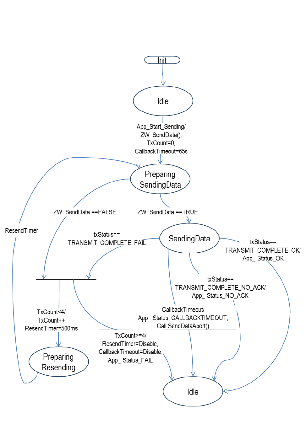
INS13478-5 Z-Wave 500 Series Appl. Programmers Guide v6.71.01 2017-02-28
Sigma Designs Inc.
Z-Wave Application Interfaces
Page 91 of 431
Timeout: 65s. This is a worst case scenario that happens very seldom. The ZW_SendData call typically
returns a callback.
Exception recovery: If a timeout occurs, it is important to call ZW_SendDataAbort to stop the sending of
the frame.
Figure 9. Application state machine for ZW_SendData
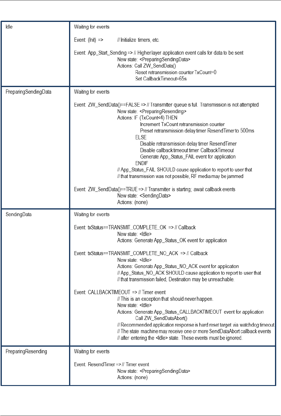
INS13478-5 Z-Wave 500 Series Appl. Programmers Guide v6.71.01 2017-02-28
Sigma Designs Inc.
Z-Wave Application Interfaces
Page 92 of 431
Table 12. ZW_SendData : State/Event processing

INS13478-5 Z-Wave 500 Series Appl. Programmers Guide v6.71.01 2017-02-28
Sigma Designs Inc.
Z-Wave Application Interfaces
Page 93 of 431
4.3.3.1.7 Serial API function prototypes
HOST->ZW: REQ | 0x13 | nodeID | dataLength | pData[ ] | txOptions | funcID
ZW->HOST: RES | 0x13 | RetVal
If either (funcID == 0) OR (RetVal == FALSE) -> no callback
If (funcID != 0) AND (RetVal == TRUE) then callback returns with:
ZW->HOST: REQ | 0x13 | funcID | txStatus
SerialAPI targets supporting IMA
The Devkit 6.60.00 adds a txStatusReport structure to the ZW_SendData callback parameter and this
have been introduced into the IMA supporting SerialAPI targets by extending the number of parameters
in the ZW_SendData callback parameter list.
HOST->ZW: REQ | 0x13 | nodeID | dataLength | pData[ ] | txOptions | funcID
ZW->HOST: RES | 0x13 | RetVal
If either (funcID == 0) OR (RetVal == FALSE) -> no callback
If (funcID != 0) AND (RetVal == TRUE) then callback returns with:
ZW->HOST: REQ | 0x13 | funcID | txStatus | wTransmitTicksMSB | wTransmitTicksLSB | bRepeaters |
rssi_values.incoming[0] | rssi_values.incoming[1] | rssi_values.incoming[2] | rssi_values.incoming[3] |
rssi_values.incoming[4] | bACKChannelNo | bLastTxChannelNo | bRouteSchemeState | repeater0 |
repeater1 | repeater2 | repeater3 | routespeed | bRouteTries | bLastFailedLink.from | bLastFailedLink.to
The SerialAPI command FUNC_ID_SERIAL_API_SETUP (0x0B) has been added to enable/disable the
transmission of the txStatusReport structure to HOST on ZW_SendData callback.
Notice: For IMA enabled targets the transmission of txStatusReport to HOST is ENABLED at module
startup. For NON IMA enabled targets the transmission of txStatusReport to HOST is DISABLED at
module startup.
HOST->ZW: REQ | 0x0B | 0x02 | bEnable
ZW->HOST: RES | 0x0B | 0x02 | RetVal
bEnable = 1 -> ENABLE txStatusReport transmission to HOST on ZW_SendData callback.
bEnable = 0 -> DISABLE txStatusReport transmission to HOST on ZW_SendData callback.
RetVal = 1 -> Operation executed successfully.
RetVal = 0 -> Operation executed unsuccessfully.
Notice:
Serial API version is unchanged despite changed format in ZW-SendData for this particular
application.

INS13478-5 Z-Wave 500 Series Appl. Programmers Guide v6.71.01 2017-02-28
Sigma Designs Inc.
Z-Wave Application Interfaces
Page 94 of 431
4.3.3.2 ZW_SendDataEx (Only slave libraries)
ZW_SENDDATA_EX_RETURN_CODES ZW_SendDataEx(BYTE *pData,
BYTE dataLength,
TRANSMIT_OPTIONS_TYPE * pTxOptionsEx,
VOID_CALLBACKFUNC(completedFunc)(BYTE txStatus,
TX_STATUS_TYPE* txStatusReport ))
NOTE: Only supported by the Enhanced 232 and Routing Slave libraries. All Controller libraries
based applications must use ZW_SendData.
NOTE: Broadcast are only allowed unsecure.
This function MAY be used to transmit either unsecure or secure (S0, S2) contents of specified data
buffer to a single node or all nodes (broadcast). The data buffer is optionally security encapsulated and
then encapsulated in a Z-Wave transport frame by adding a protocol header and a checksum trailer. The
frame is appended to the end of the transmit queue (first in; first out) and transmitted whenever possible.
The protocol layer automatically handles the necessary signaling when the ZW_SendDataEx function is
used to initiate a transmission to a FliRS node.
The following parameters MUST be specified for the SendDataEx function.
4.3.3.2.1 *pData parameter
The *pData parameter MUST specify a pointer to a data buffer containing a valid Z-Wave command.
The data buffer referenced by the *pData parameter MUST contain the number of bytes indicated by the
dataLength parameter.
4.3.3.2.2 dataLength parameter
The data buffer referenced by the *pData parameter is used to hold a valid Z-Wave command.
The dataLength parameter MUST specify the length of the Z-Wave command.
4.3.3.2.3 pTxOptionsEx parameter
The calling application MUST fill the application TRANSMIT_OPTIONS_TYPE structure the
pTxOptionsEx parameter referes to by setting relevant TRANSMIT_OPTIONS_TYPE members:
4.3.3.2.3.1 destNode
Destination node for the specified payload data.
4.3.3.2.3.2 bSrcNode
Reserved for future use.
4.3.3.2.3.3 txOptions
See ZW_Sendata txOptions parameter description (4.3.3.1.4)
4.3.3.2.3.4 txSecOptions
Options for enabling specific Security S2 funtionality.
4.3.3.2.3.5 securityKey
Security key to use for sending.
4.3.3.2.3.6 txOptions2

INS13478-5 Z-Wave 500 Series Appl. Programmers Guide v6.71.01 2017-02-28
Sigma Designs Inc.
Z-Wave Application Interfaces
Page 95 of 431
Reserved for future use.
4.3.3.2.4 completedFunc
The completedFunc parameter MUST specify the calling address of a function that can be called when
the SendData frame transmission completes. Completion includes a range of possible situations:
Direct range frame was successfully transmitted (as requested) without acknowledgement
Direct range frame was successfully acknowledged
Routed frame was successfully acknowledged
The transmit status txStatus indicates how the transmission operation was completed.
Table 13. txStatus values
txStatus
Description
TRANSMIT_COMPLETE_OK
The operation was successful.
TRANSMIT_COMPLETE_NO_ACK
No acknowledgement was received from the destination
node.
TRANSMIT_COMPLETE_FAIL
Indicates that the network is busy (jammed).
WARNING: Allways use the completeFunc callback to determine when the next frame can be send.
4.3.3.2.5 Payload size
The maximum size of a frame is 64 bytes. The protocol header and checksum takes 10 bytes in a single
cast or broadcast frame leaving 54 bytes for the payload. A S0 security enabled single cast takes 20
bytes as overhead. The maximum dataLength field depends on the transmit options and whether a non-
secure/secure frame is used.
Table 14. Maximum payload size
Transmit option
Maximum dataLength
Notice: Always use lowest maximum dataLength
depending on options used.
Non-secure
Security
S0
Security2
TRANSMIT_OPTION_EXPLORE
46 bytes
26 bytes
46 bytes
TRANSMIT_OPTION_AUTO_ROUTE
48 bytes
28 bytes
46 bytes
TRANSMIT_OPTION_NO_ROUTE
54 bytes
34 bytes
46 bytes

INS13478-5 Z-Wave 500 Series Appl. Programmers Guide v6.71.01 2017-02-28
Sigma Designs Inc.
Z-Wave Application Interfaces
Page 96 of 431
4.3.3.2.6 Embedded API function prototypes
Defined in: ZW_transport_api.h
Return value:
ZW_SENDDATA_EX_RETURN_C
ODES
ZW_TX_FAILED
If not queued in
transmit queue.
No callback will be
done.
ZW_TX_IN_PROGRESS
If frame is queued
for transmission.
Parameters:
txOptionsEx
.destNode IN
Destination node ID
(NODE_BROADCAST == all nodes)
The frame will
also be
transmitted in
case the source
node ID is equal
destination node
ID
pData IN
Data buffer pointer
dataLength IN
Data buffer length
The maximum
dataLength field
depends on the
transmit options
and whether a
non-
secure/secure
frame is used. For
details, see
section 3.4. The
payload must be
minimum one
byte.

INS13478-5 Z-Wave 500 Series Appl. Programmers Guide v6.71.01 2017-02-28
Sigma Designs Inc.
Z-Wave Application Interfaces
Page 97 of 431
txOptionsEx
.txOptions IN
Transmit option flags:
TRANSMIT_OPTION_LOW_POWER
Transmit at low
output power level
(1/3 of normal RF
range).
TRANSMIT_OPTION_NO_ROUTE
Only send this
frame directly,
even if a response
route exist
TRANSMIT_OPTION_ACK
Request
acknowledge from
destination node.
TRANSMIT_OPTION_AUTO_ROUTE
Send the frame to
nodeID using the
return routes
assigned for
nodeID to the
enhanced 232
slave, if no routes
are valid then
transmit directly to
nodeID (if nodeID
=
NODE_BROADC
AST then the
frame will be a
BROADCAST).
If return routes
exists and the
nodeID =
NODE_BROADC
AST then the
frame will be
transmitted to all
assigned return
route destinations.
If nodeID !=
NODE_BROADC
AST then the
frame will be
transmitted via the
assigned return
routes for nodeID.
TRANSMIT_OPTION_EXPLORE
Transmit frame as
an explore frame
if everything else
fails.
txOptionsEx
.bSrcNode IN
Reserved for future use.

INS13478-5 Z-Wave 500 Series Appl. Programmers Guide v6.71.01 2017-02-28
Sigma Designs Inc.
Z-Wave Application Interfaces
Page 98 of 431
txOptionsEx
.txSecOptions IN
Security2-specific options
S2_TXOPTION_VERIFY_DELIVERY
This flag will
activate frame
delivery
verification. In this
transmission
mode
ZW_SendDataEx
will try to verify
that the receiver
understood the
sent
message.This is
done by waiting a
little to see if the
node will respond
nonce report to
the encrypted
message. If the
node does
respond with a
nonce report then
the option will
automatically
cause the system
to re-sync the
node, and deliver
the message.
S2_TXOPTION_SINGLECAST_FOLLOWUP
This flag must be
present on all
single cast
followup
messages to a
multicast.
S2_TXOPTION_FIRST_SINGLECAST_FOL
LOWUP
This flag must be
present on the
first, and only the
first singlecast
followup message
in a multicast
transmission.
txOptionsEx
.securityKey IN
Select security key for transmission
SECURITY_KEY_NONE
Nonsecure
transmission
SECURITY_KEY_S2_UNAUTHENTICATED
Use S2
Unauthenticated
key

INS13478-5 Z-Wave 500 Series Appl. Programmers Guide v6.71.01 2017-02-28
Sigma Designs Inc.
Z-Wave Application Interfaces
Page 99 of 431
SECURITY_KEY_S2_AUTHENTICATED
Use S2
Authenticated key
SECURITY_KEY_S2_ACCESS
Use S2 Access
key
SECURITY_KEY_S0
Use Security
Scheme 0 key
txOptionsEx
.txOptions2 IN
More transmit option flags.
Reserved for future use. Must be set to
0x00.
completedFunc
Transmit completed call back function

INS13478-5 Z-Wave 500 Series Appl. Programmers Guide v6.71.01 2017-02-28
Sigma Designs Inc.
Z-Wave Application Interfaces
Page 100 of 431
Callback function Parameters:
txStatus
Transmit completion status:
TRANSMIT_COMPLETE_OK
Successfully
TRANSMIT_COMPLETE_NO_ACK
No acknowledge is received before
timeout from the destination node.
Acknowledge is discarded in case it
is received after the timeout.
TRANSMIT_COMPLETE_FAIL
Not possible to transmit data
because the Z-Wave network is
busy (jammed).
txStatusReport
typedef struct _TX_STATUS_TYPE_
{ WORD wTransmitTicks;
BYTE bRepeaters;
struct rssi_dBm rssi_values;
BYTE bACKChannelNo;
BYTE bLastTxChannelNo;
E_ROUTING_SCHEME
bRouteSchemeState;
BYTE
pLastUsedRoute[LAST_USED_ROUTE_SIZE];
BYTE bRouteTries;
S_ROUTE_LINK bLastFailedLink;
} TX_STATUS_TYPE;
Passed 10ms ticks
Repeaters in route
Rssi value for each hop
(see Table 7).
Channel ack was received on
Channel frame was send on
The last used routing scheme
Last used route (5 byte array)
Routing attempts
Last route that failed
4.3.3.2.7 Serial API function prototypes
HOST->ZW: REQ | 0x0E | nodeID | dataLength | pData[ ] | txOptions | txSecOptions | securityKey |
txOptions2 | funcID
ZW->HOST: RES | 0x0E | RetVal
If either (funcID == 0) OR (RetVal == FALSE) -> no callback
If (funcID != 0) AND (RetVal == TRUE) then callback returns with:
ZW->HOST: REQ | 0x0E | funcID | txStatus | wTransmitTicksMSB | wTransmitTicksLSB | bRepeaters |
rssi_values.incoming[0] | rssi_values.incoming[1] | rssi_values.incoming[2] | rssi_values.incoming[3] |
rssi_values.incoming[4] | bACKChannelNo | bLastTxChannelNo | bRouteSchemeState | repeater0 |
repeater1 | repeater2 | repeater3 | routespeed | bRouteTries | bLastFailedLink.from | bLastFailedLink.to

INS13478-5 Z-Wave 500 Series Appl. Programmers Guide v6.71.01 2017-02-28
Sigma Designs Inc.
Z-Wave Application Interfaces
Page 101 of 431
4.3.3.3 ZW_SendData_Bridge
BYTE ZW_SendData_Bridge( BYTE srcNodeID,
BYTE destNodeID,
BYTE *pData,
BYTE dataLength,
BYTE txOptions,
Void (*completedFunc)(BYTE txStatus,
TX_STATUS_TYPE* txStatusReport))
NOTE: Only supported by the Bridge Controller library. For backward compatibility macros for
the Bridge Controller library has been made for ZW_SendData(node,data,length,options,func) and
ZW_SEND_DATA(node,data,length,options,func)
Macro: ZW_SEND_DATA_BRIDGE(srcnodeid, destnodeid, data, length, options, func)
Transmit the data buffer to a single Z-Wave Node or all Z-Wave Nodes (broadcast). The data buffer is
queued to the end of the transmit queue (first in; first out) and when ready for transmission the Z-Wave
protocol layer frames the data with a protocol header in front and a checksum at the end.
The transmit option TRANSMIT_OPTION_ACK requests the destination node to return a transfer
acknowledge to ensure proper transmission. The transmitting node will retry the transmission if no
acknowledge received. The Controller nodes can add the TRANSMIT_OPTION_AUTO_ROUTE flag to
the transmit option parameter. The Controller will then try transmitting the frame via repeater nodes if the
direct transmission failed.
The transmit option TRANSMIT_OPTION_NO_ROUTE force the protocol to send the frame without
routing, even if a response route exist.
To enable dynamic route resolution a new transmit option TRANSMIT_OPTION_EXPLORE must be
appended to the well known send API calls. This instruct the protocol to transmit the frame as an explore
frame to the destination node if source routing fails. An explore frame uses normal RF power level minus
6dB similar to a node finding neighbors. It is also possible to specify the maximum number of source
routing attempts before the explorer frame kicks in using the API call ZW_SetRoutingMAX. Default value
is five with respect to maximum number of source routing attempts. When communicating with nodes,
which do not support dynamic route resolution the transmit option flag TRANSMIT_OPTION_EXPLORE
is ignored. Notice that an explorer frame cannot wake up FLiRS nodes.
The completedFunc is called when the frame transmission completes, that is when transmitted if ACK is
not requested; when acknowledge received from the destination node, or when routed acknowledge
completed if the frame was transmitted via one or more repeater nodes. The transmit status
TRANSMIT_COMPLETE_NO_ACK indicate that no acknowledge is received from the destination node.
The transmit status TRANSMIT_COMPLETE_FAIL indicate that the Z-Wave network is busy (jammed).
The TRANSMIT_OPTION_LOW_POWER option should only be used when the two nodes that are
communicating are close to each other (<2 meter). In all other cases this option should not be used.
NOTE: Always use the completeFunc callback to determine when the transmit is done. The
completeFunc should flag the application state machine that the transmit has been done and next
state/action can be started. A frame transmit should always be started through the application state
machine in order to be sure that the transmit buffer is ready for sending next frame. Calling the
ZW_SendData_Bridge in a loop without using the completeFunc callback will overflow the transmit
queue and eventually fail. The payload data buffer in the application must not be changed before
completeFunc callback is received because it is only the pointer that is passed to the transmit queue.

INS13478-5 Z-Wave 500 Series Appl. Programmers Guide v6.71.01 2017-02-28
Sigma Designs Inc.
Z-Wave Application Interfaces
Page 102 of 431
Defined in: ZW_transport_api.h
Return value:
BYTE
FALSE
If transmit queue overflow
Parameters:
srcNodeID IN
Source node ID. Valid values:
NODE_BROADCAST = Bridge
Controller NodeID.
Bridge Controller NodeID.
Virtual Slave NodeID (only existing
Virtual Slave NodeIDs).
destNodeID IN
Destination node ID
(NODE_BROADCAST == all nodes)
The frame will also be transmitted in case
the source node ID is equal destination
node ID
pData IN
Data buffer pointer
dataLength IN
Data buffer length
The maximum dataLength field depends
on the transmit options and whether a
non-secure/secure frame is used. The
payload must be minimum one byte.
txOptions IN
Transmit option flags:
TRANSMIT_OPTION_LOW_POWER
Transmit at low output power level (1/3 of
normal RF range).
TRANSMIT_OPTION_NO_ROUTE
Only send this frame directly, even if a
response route exist
TRANSMIT_OPTION_EXPLORE
Transmit frame as an Explore frame if all
else fails
TRANSMIT_OPTION_ACK
Request acknowledge from destination
node.
TRANSMIT_OPTION_AUTO_ROUTE
Request retransmission via repeater
nodes (at normal output power level).
completedFunc
Transmit completed call back function

INS13478-5 Z-Wave 500 Series Appl. Programmers Guide v6.71.01 2017-02-28
Sigma Designs Inc.
Z-Wave Application Interfaces
Page 103 of 431
Callback function Parameters:
txStatus
Transmit completion status:
TRANSMIT_COMPLETE_OK
Successfully
TRANSMIT_COMPLETE_NO_ACK
No acknowledge is received before timeout
from the destination node. Acknowledge is
discarded in case it is received after the
timeout.
TRANSMIT_COMPLETE_FAIL
Not possible to transmit data because the
Z-Wave network is busy (jammed).
txStatusReport
See ZW_SendData
Serial API:
HOST->ZW: REQ | 0xA9 | srcNodeID | destNodeID | dataLength | pData[ ] | txOptions | pRoute[4] |
funcID
Devkit 6.x+ -> pRoute[4] not used – use pRoute[4] = {0, 0, 0, 0}
ZW->HOST: RES | 0xA9 | RetVal
ZW->HOST: REQ | 0xA9 | funcID | txStatus
| wTransmitTicksMSB | wTransmitTicksLSB
| bRepeaters
| rssi_values.incoming[0] | rssi_values.incoming[1] | rssi_values.incoming[2]
| rssi_values.incoming[3] | rssi_values.incoming[4]
| bAckChannelNo | | bLastTxChannelNo
| bRouteSchemeState
| repeater0 | repeater1 | repeater2 | repeater3 | routespeed | bRouteTries
| bLastFailedLink.from | bLastFailedLink.to

INS13478-5 Z-Wave 500 Series Appl. Programmers Guide v6.71.01 2017-02-28
Sigma Designs Inc.
Z-Wave Application Interfaces
Page 104 of 431
4.3.3.4 ZW_SendDataMulti
BYTE ZW_SendDataMulti(BYTE *pNodeIDList,
BYTE *pData,
BYTE dataLength,
BYTE txOptions,
Void (*completedFunc)(BYTE txStatus))
Macro: ZW_SEND_DATA_MULTI(nodelist,data,length,options,func)
NOTE: This function is not available in the Bridge Controller library (See
ZW_SendDataMulti_Bridge).
Transmit the data buffer to a list of Z-Wave Nodes (multicast frame). If the transmit optionflag
TRANSMIT_OPTION_ACK is set the data buffer is also sent as a singlecast frame to each of the
Z-Wave Nodes in the node list.
The completedFunc is called when the frame transmission completes in the case that ACK is not
requested; When TRANSMIT_OPTION_ACK is requested the callback function is called when all single
casts have been transmitted and acknowledged.
The transmit status TRANSMIT_COMPLETE_NO_ACK indicate that no acknowledge is received from
the destination node. The transmit status TRANSMIT_COMPLETE_FAIL indicate that the Z-Wave
network is busy (jammed). The data pointed to by pNodeIDList should not be changed before the
callback is called.
NOTE: Allways use the completeFunc callback to determine when the next frame can be send. Calling
the ZW_SendData or ZW_SendDataMulti in a loop without checking the completeFunc callback will
overflow the transmit queue and eventually fail. The data buffer in the application must not be changed
before completeFunc callback is received because it is only the pointer there is passed to the transmit
queue.
Defined in: ZW_transport_api.h
Return value:
BYTE
FALSE
If transmit queue overflow

INS13478-5 Z-Wave 500 Series Appl. Programmers Guide v6.71.01 2017-02-28
Sigma Designs Inc.
Z-Wave Application Interfaces
Page 105 of 431
Parameters:
pNodeIDList IN
List of destination node ID's
This is a fixed length bit-mask.
Pdata IN
Data buffer pointer
DataLength IN
Data buffer length
The maximum size of a packet is 64
bytes. The protocol header, multicast
addresses and checksum takes 39 bytes
in a multicast frame leaving 25 bytes for
the payload. The payload must be
minimum one byte.
TxOptions IN
Transmit option flags:
TRANSMIT_OPTION_LOW_POWER
Transmit at low output power level (1/3
of normal RF range).
TRANSMIT_OPTION_EXPLORE
If TRANSMIT_OPTION_ACK is set the
will make the node try sending as an
Explore frame if all else fails when doing
the single cast transmits
TRANSMIT_OPTION_ACK
The multicast frame will be followed by a
number of single cast frames to each of
the destination nodes and request
acknowledge from each destination
node.
TRANSMIT_OPTION_AUTO_ROUTE
(Controller API only)
Request retransmission on single cast
frames via repeater nodes (at normal
output power level)
completedFunc
Transmit completed call back function
Callback function Parameters:
txStatus IN
(see ZW_SendData)
Serial API:
HOST->ZW: REQ | 0x14 | numberNodes | pNodeIDList[ ] | dataLength | pData[ ] | txOptions | funcID
ZW->HOST: RES | 0x14 | RetVal
ZW->HOST: REQ | 0x14 | funcID | txStatus

INS13478-5 Z-Wave 500 Series Appl. Programmers Guide v6.71.01 2017-02-28
Sigma Designs Inc.
Z-Wave Application Interfaces
Page 106 of 431
4.3.3.5 ZW_SendDataMultiEx (Only slave libraries)
ZW_SENDDATA_EX_RETURN_CODES ZW_SendDataMultiEx(BYTE *pData,
BYTE dataLength,
TRANSMIT_MULTI_OPTIONS_TYPE *pTxOptionsMultiEx,
Void (*completedFunc)(BYTE txStatus))
NOTE: Only supported by the Enhanced 232 and Routing Slave libraries.
Transmit the data buffer using S2 multicast to a list of Z-Wave Nodes. Only the multicast frame is
transmitted, if singlecast frames are needed then application needs to do this using ZW_SendDataEx for
every node in the group.
NOTE: Can only be called successfully if node is S2 included and txOptionsEx.securityKey is set to a
supported S2 key.
The completedFunc is called when the frame transmission completes.
The transmit status TRANSMIT_COMPLETE_FAIL indicate that the Z-Wave network is busy (jammed).
NOTE: Allways use the completeFunc callback to determine when the next frame can be send. Trying to
transmit in a loop without checking the completeFunc callback will overflow the transmit queue and
eventually fail.
Defined in: ZW_transport_api.h
Return value:
ZW_SENDDATA_EX_RETURN_CODES
ZW_TX_FAILED
If not queued in transmit
queue. No callback will
be done.
ZW_TX_IN_PROGRESS
If frame is queued for
transmission.

INS13478-5 Z-Wave 500 Series Appl. Programmers Guide v6.71.01 2017-02-28
Sigma Designs Inc.
Z-Wave Application Interfaces
Page 107 of 431
Parameters:
txOptionsMultiEx
.groupID IN
Destination groupID
Group which is to
receive the S2 Multicast
frame
pData IN
Data buffer pointer
dataLength IN
Data buffer length
The maximum
dataLength field
depends on the transmit
options and whether a
non-secure/secure frame
is used. For details, see
section 3.4. The payload
must be minimum one
byte.
txOptionsMultiEx
.txOptions IN
Reserved to future use.
txOptionsEx
.securityKey IN
Select security key for transmission
SECURITY_KEY_S2_UNAUTHENTICATED
Use S2 Unauthenticated
key
SECURITY_KEY_S2_AUTHENTICATED
Use S2 Authenticated
key
SECURITY_KEY_S2_ACCESS
Use S2 Access key
completedFunc
Transmit completed call back function
Callback function Parameters:
txStatus IN
(see ZW_SendData)
Serial API:
HOST->ZW: REQ | 0x0F | dataLength | pData[ ] | txOptions | securityKey | groupID | funcID
ZW->HOST: RES | 0x0F | RetVal
If either (funcID == 0) OR (RetVal == FALSE) -> no callback
If (funcID != 0) AND (RetVal == TRUE) then callback returns with:
ZW->HOST: REQ | 0x0F | funcID | txStatus

INS13478-5 Z-Wave 500 Series Appl. Programmers Guide v6.71.01 2017-02-28
Sigma Designs Inc.
Z-Wave Application Interfaces
Page 108 of 431
4.3.3.6 ZW_SendDataMulti_Bridge
BYTE ZW_SendDataMulti_Bridge(BYTE srcNodeID,
BYTE *pNodeIDList,
BYTE *pData,
BYTE dataLength,
BYTE txOptions,
Void (*completedFunc)(BYTE txStatus))
Macro: ZW_SEND_DATA_MULTI_BRIDGE(srcnodid,nodelist,data,length,options,func)
NOTE: This function is only available in the Bridge Controller library.
Transmit the data buffer to a list of Z-Wave Nodes (multicast frame). If the transmit optionflag
TRANSMIT_OPTION_ACK is set the data buffer is also sent as a singlecast frame to each of the
Z-Wave Nodes in the node list.
The completedFunc is called when the frame transmission completes in the case that ACK is not
requested; When TRANSMIT_OPTION_ACK is requested the callback function is called when all single
casts have been transmitted and acknowledged.
The transmit status TRANSMIT_COMPLETE_NO_ACK indicate that no acknowledge is received from
the destination node. The transmit status TRANSMIT_COMPLETE_FAIL indicate that the Z-Wave
network is busy (jammed). The data pointed to by pNodeIDList should not be changed before the
callback is called.
NOTE: Allways use the completeFunc callback to determine when the next frame can be send. Calling
the ZW_SendData_Bridge or ZW_SendDataMulti_Bridge in a loop without checking the completeFunc
callback will overflow the transmit queue and eventually fail. The data buffer in the application must not
be changed before completeFunc callback is received because it’s only the pointer there is passed to the
transmit queue.
Defined in: ZW_transport_api.h
Return value:
BYTE
FALSE
If transmit queue overflow

INS13478-5 Z-Wave 500 Series Appl. Programmers Guide v6.71.01 2017-02-28
Sigma Designs Inc.
Z-Wave Application Interfaces
Page 109 of 431
Parameters:
srcNodeID IN
Source node ID. Valid values:
NODE_BROADCAST = Bridge
Controller NodeID.
Bridge Controller NodeID.
Virtual Slave NodeID (only existing
Virtual Slave NodeIDs).
pNodeIDList IN
List of destination node ID's
This is a fixed length bit-mask.
Pdata IN
Data buffer pointer
DataLength IN
Data buffer length
The maximum size of a packet is 64
bytes. The protocol header, multicast
addresses and checksum takes 39 bytes
in a multicast frame leaving 25 bytes for
the payload. In case routed single casts
follow multicast the source routing info
takes up to 6 bytes depending on the
number of hops leaving minimum 19
bytes for the payload. In case it is a
singlecast, which piggyback on an
explorer frame overhead is 8 bytes
leaving minimum 17 bytes for the
payload. The payload must be minimum
one byte.
TxOptions IN
Transmit option flags:
TRANSMIT_OPTION_LOW_POWER
Transmit at low output power level (1/3 of
normal RF range).
TRANSMIT_OPTION_EXPLORE
If TRANSMIT_OPTION_ACK is set the
will make the node try sending as an
Explore frame if all else fails when doing
the single cast transmits
TRANSMIT_OPTION_ACK
The multicast frame will be followed by a
number of single cast frames to each of
the destination nodes and request
acknowledge from each destination node.
TRANSMIT_OPTION_AUTO_ROUTE
Request retransmission on single cast
frames via repeater nodes (at normal
output power level)
completedFunc
Transmit completed call back function
Callback function Parameters:
txStatus IN
(see ZW_SendData)

INS13478-5 Z-Wave 500 Series Appl. Programmers Guide v6.71.01 2017-02-28
Sigma Designs Inc.
Z-Wave Application Interfaces
Page 110 of 431
Serial API:
HOST->ZW: REQ | 0xAB | srcNodeID | numberNodes | pNodeIDList[ ] | dataLength | pData[ ] |
txOptions | funcID
ZW->HOST: RES | 0xAB | RetVal
ZW->HOST: REQ | 0xAB | funcID | txStatus

INS13478-5 Z-Wave 500 Series Appl. Programmers Guide v6.71.01 2017-02-28
Sigma Designs Inc.
Z-Wave Application Interfaces
Page 111 of 431
4.3.3.7 ZW_SendDataAbort
void ZW_SendDataAbort( void )
Macro: ZW_SEND_DATA_ABORT
Abort the ongoing transmit started with ZW_SendData() or ZW_SendDataMulti(). If an ongoing
transmission is aborted, the callback function from the send call will return with the status
TRANSMIT_COMPLETE_NO_ACK.
Defined in: ZW_transport_api.h
Serial API:
HOST->ZW: REQ | 0x16

INS13478-5 Z-Wave 500 Series Appl. Programmers Guide v6.71.01 2017-02-28
Sigma Designs Inc.
Z-Wave Application Interfaces
Page 112 of 431
4.3.3.8 ZW_LockRoute (Only controllers)
void ZW_LockRoute( bLockRoute )
Macro: ZW_LOCK_ROUTE
This function locks and unlocks all last working routes (LWR) for purging.
Defined in: ZW_transport_api.h
Parameters:
bLockRoute IN
Lock and unlocks all LWR
TRUE lock all LWR – no purging allowed.
FALSE unlock purging of LWR
Serial API
HOST->ZW: REQ | 0x90 | bLockRoute

INS13478-5 Z-Wave 500 Series Appl. Programmers Guide v6.71.01 2017-02-28
Sigma Designs Inc.
Z-Wave Application Interfaces
Page 113 of 431
4.3.3.9 ZW_LockRoute (Only slaves)
void ZW_LockRoute( node )
Macro: ZW_LOCK_ROUTE
This function locks and unlocks response route for a given node ID.
Defined in: ZW_transport_api.h
Parameters:
node IN
Lock and unlocks response
route for a given node ID
node = 1..232 lock response route for the specified
node ID.
node = 0 unlock response route.
Serial API
HOST->ZW: REQ | 0x90 | node

INS13478-5 Z-Wave 500 Series Appl. Programmers Guide v6.71.01 2017-02-28
Sigma Designs Inc.
Z-Wave Application Interfaces
Page 114 of 431
4.3.3.10 ZW_SendConst
void ZW_SendConst(BYTE bStart, BYTE bChNo, BYTE bSignalType )
This function start/stop generating RF test signal.
The test signal can be on of the following:
Test signal with only the carrier frequency.
Test signal with a modulated carrier frequency; the signal will switch between sending logical 1
frequency and logical zero frequency
The function also selects which channel to send the test signal on.
This API call can only be called in production test mode from ApplicationTestPoll.
The API should only be called when starting\stopping a test.
Defined in: ZW_transport_api.h
Parameters:
bStart IN
Start/Stop generating RF test
signal
TRUE start sending RF test signal.
FALSE stop sending RF test signal
bChNot IN
The number of channel to
send the test signal on.
0..1 for 2 channels targets
0..2 for 3 channels targets
bSignalType IN
type of the RF test signal to
generater
ZW_RF_TEST_SIGNAL_CARRIER
ZW_RF_TEST_SIGNAL_CARRIER_MODULATED
Serial API (Not supported)

INS13478-5 Z-Wave 500 Series Appl. Programmers Guide v6.71.01 2017-02-28
Sigma Designs Inc.
Z-Wave Application Interfaces
Page 115 of 431
4.3.3.11 ZW_SetListenBeforeTalkThreshold
void ZW_SetListenBeforeTalkThreshold(BYTE bChannel, BYTE bThreshold )
This function sets the “Listen Before Talk” threshold that controlles at what RSSI level a Z-Wave node
will refuse to transmit because of noise. The default threshold value is set to a value corresponding to the
RF regulatory requirements for a Z-Wave module in the specific country. The appropriate value range
goes from 34(dec) to 78(dec) and each threshold step corresponds to a 1.5dB input power step.
Region
Default
Threshold
(dec)
dBm
JP
50
-80
KR
64
-65
EU, US, HK, ANZ, CN, IL, IN, MY & RU
64
-65
For instance, if a SAW filter with an insertion loss of 3dB is inserted between the antenna feed-point and
the chip on a JP product, the threshold value should be set to 48(dec) .
NOTICE: In some contries (JP and KR) the value of the LBT threshold is specified in the RF regulatory
for the country and must be set to the value corresponding to the regulatory requirements.
Parameters:
bChannel IN
Channel number the Threshold should
be set for. Valid channel numbers are
0,1 and 2
bThreshold IN
The threshold the RSSI should use.
Valid threshold range is from 34(dec) to
78(dec).
Defined in: ZW_transport_api.h
Serial API
HOST->ZW: REQ | 0x3C | bChannel | bThreshold
ZW->HOST: RES | 0x3C | TRUE

INS13478-5 Z-Wave 500 Series Appl. Programmers Guide v6.71.01 2017-02-28
Sigma Designs Inc.
Z-Wave Application Interfaces
Page 116 of 431
4.3.3.12 ZW_Transport_CommandClassVersionGet
BYTE ZW_CommandClassVersionGet(BYTE commandClass)
This function is used to determine the version of the Command Classes handled by the Z-Wave protocol.
SHOULD be used as a default case when receiving VERSION GET for Command Class not supported
by Application.
Defined in: ZW_transport_api.h
Return value:
BYTE
1..
UNKNOWN_VERSION
Command Class Version of the Z-
Wave protocol handled
commandClass.
Specified Command Class not handled
by the Z-Wave protocol.
Parameters:
commandClass IN
BYTE
Command Class ID for whom Version is
needed.
Serial API (Not supported)

INS13478-5 Z-Wave 500 Series Appl. Programmers Guide v6.71.01 2017-02-28
Sigma Designs Inc.
Z-Wave Application Interfaces
Page 117 of 431
4.3.3.13 ZW_GetDefaultPowerLevels
BYTE ZW_GetDefaultPowerLevels(BYTE *pPowerLevels)
This API call is reserved for serial API binaries delivered by Sigma Designs.
Defined in: ZW_basis_api.h
Serial API (Not supported, see SERIAL_API_SETUP_CMD_TX_POWERLEVEL_GET in [2])

INS13478-5 Z-Wave 500 Series Appl. Programmers Guide v6.71.01 2017-02-28
Sigma Designs Inc.
Z-Wave Application Interfaces
Page 118 of 431
4.3.3.14 ZW_SetDefaultPowerLevels
BYTE ZW_SetDefaultPowerLevels(BYTE bNormalPower0, BYTE bNormalPower1,
BYTE bNormalPower2, BYTE bLowPower0,
BYTE bLowPower1, BYTE bLowPower2)
This API call is reserved for serial API binaries delivered by Sigma Designs.
Defined in: ZW_basis_api.h
Serial API (Not supported, see SERIAL_API_SETUP_CMD_TX_POWERLEVEL_SET in [2])

INS13478-5 Z-Wave 500 Series Appl. Programmers Guide v6.71.01 2017-02-28
Sigma Designs Inc.
Z-Wave Application Interfaces
Page 119 of 431
4.3.4 ZWave Firmware Update API
The Firmware Update API provides functionality which together with the SDK supplied ZW_Bootloader
module and a big enough external NVM makes it possible to implement firmware update. Currently the
external NVM needs to be minimum 1Mbit(128KB) in size to allow for Firmware Updates, but this
minimum requirement indicates that the firmware image must have a maximum size for it to be possible
to fit in the 1 Mbit NVM together with protocol and application NVM data. The Max firmware using 1Mbit
NVM introduces effectively a maximum on the possible usage of BANK3: 0x20000 – 0x7800 – (3 *
0x8000) = 0x2000, which equals 8KB. If a NVM bigger or equal to 2Mbit a full 128KB firmware image can
be updated.
NOTE: The Application MUST call ZW_FirmwareUpdate_NVM_Init prior to calling any other Firmware
Update module functionality. If ZW_FirmwareUpdate_NVM_Init returns FALSE it means Firmware
Update is NOT possible with attached NVM.
Serial API: The Firmware Update API is also supported by the serial API enabling firmware update via
Serial API also called Over The Wire (OTW) firmware update. This is an alternative to program the chip
in programming mode [3] via SPI, UART or USB. However, OTW requires a target containing a boot
loader and serial API support. The PC Controller supports OTW firmware update via the serial API, refer
to [15] for details.
The Firmware Update functionality contains several functions and are all controlled through the
FUNC_ID_ZW_FIRMWARE_UPDATE_NVM serialAPI funcID:
HOST->ZW: REQ | 0x78 | FIRMWARE_UPDATE_NVM_functionality | functionalityParameters[]
Defined FIRMWARE_UPDATE_NVM_functionality:
FIRMWARE_UPDATE_NVM_INIT = 0
FIRMWARE_UPDATE_NVM_SET_NEW_IMAGE = 1
FIRMWARE_UPDATE_NVM_GET_NEW_IMAGE = 2
FIRMWARE_UPDATE_NVM_UPDATE_CRC16 = 3
FIRMWARE_UPDATE_NVM_IS_VALID_CRC16 = 4
FIRMWARE_UPDATE_NVM_WRITE = 5

INS13478-5 Z-Wave 500 Series Appl. Programmers Guide v6.71.01 2017-02-28
Sigma Designs Inc.
Z-Wave Application Interfaces
Page 120 of 431
4.3.4.1 ZW_FirmwareUpdate_NVM_Init
BYTE ZW_FirmwareUpdate_NVM_Init()
Initialize the Firmware Update functionality. The initialization includes determining if attached NVM can
be used for Firmware Update. If it is determined the the attached NVM do not support (or if
ZW_Firmware_Update_NVM_Init has not been called) following calls to any other
FirmwareUpdate_NVM_xyz functionality will do nothing.
defined in: ZW_firmware_update_nvm_api.h
Return value:
BYTE
NVM_FIRMWARE_UPDATE_SUPPORTED
If NVM is Firmware Update
compatible.
NVM_FIRMWARE_UPDATE_NOT_SUPPORTED
If NVM is NOT Firmware Update
compatible
Serial API
HOST->ZW: REQ | 0x78 | 0x00
ZW->HOST: RES | 0x78 | 0x00 | retVal

INS13478-5 Z-Wave 500 Series Appl. Programmers Guide v6.71.01 2017-02-28
Sigma Designs Inc.
Z-Wave Application Interfaces
Page 121 of 431
4.3.4.2 ZW_FirmwareUpdate_NVM_Set_NEWIMAGE
BYTE ZW_FirmwareUpdate_NVM_Set_NEWIMAGE(BYTE bValue)
Set the NEWIMAGE marker in NVM. Used to signal to ZW_Bootloader if a new Firmware Image are
present in NVM or not.
NOTE: The Application MUST call ZW_FirmwareUpdate_NVM_Init prior to calling any other Firmware
Update module functionality. If ZW_FirmwareUpdate_NVM_Init returns FALSE it means Firmware
Update is NOT possible with attached NVM.
Return value:
BYTE
TRUE
If specified bValue has been written to NVM
FALSE
If the Firmware NEWIMAGE value is already set to
bValue
Defined in: ZW_firmware_update_nvm_api.h
Parameters:
bValue IN
Value to set “NEWIMAGE” mark to in NVM, which
ZW_Bootloader uses to determine if a possible new
Firmware exist in external NVM.
FIRMWARE_UPDATE_NVM_NEWIMAGE_NEW
informs the Bootloader that a possible NEW firmware
image exist in external NVM.
FIRMWARE_UPDATE_NVM_NEWIMAGE_NOT_NEW
informs the ZW_Bootloader that NO NEW firmware
image exists in external NVM
Serial API
HOST->ZW: REQ | 0x78 | 0x01 | value
ZW->HOST: RES | 0x78 | 0x01 | retVal

INS13478-5 Z-Wave 500 Series Appl. Programmers Guide v6.71.01 2017-02-28
Sigma Designs Inc.
Z-Wave Application Interfaces
Page 122 of 431
4.3.4.3 ZW_FirmwareUpdate_NVM_Get_NEWIMAGE
BYTE ZW_FirmwareUpdate_NVM_Get_NEWIMAGE()
Get New Firmware Image available indicator in NVM. The New Firmware Image indicator is used to
signal the ZW_Bootloader if a possible new Firmware Image is present in NVM.
NOTE: The Application MUST call ZW_FirmwareUpdate_NVM_Init prior to calling any other Firmware
Update module functionality. If ZW_FirmwareUpdate_NVM_Init returns FALSE it means Firmware
Update is NOT possible with attached NVM.
Defined in: ZW_firmware_update_nvm_api.h
Return value:
BYTE
FIRMWARE_UPDATE_NVM_NEWIMAGE_NOT_NEW
If Indicator indicates NO NEW
Firmware Image present
FIRMWARE_UPDATE_NVM_NEWIMAGE_NEW
If Indicator indicates NEW
Firmware Image is present in
NVM
Serial API
HOST->ZW: REQ | 0x78 | 0x02
ZW->HOST: RES | 0x78 | 0x02 | retVal

INS13478-5 Z-Wave 500 Series Appl. Programmers Guide v6.71.01 2017-02-28
Sigma Designs Inc.
Z-Wave Application Interfaces
Page 123 of 431
4.3.4.4 ZW_FirmwareUpdate_NVM_UpdateCRC16
WORD ZW_FirmwareUpdate_NVM_UpdateCRC16(WORD crc,
DWORD nvmOffset,
WORD blockSize)
Calculate CRC16 for specified NVM block of data.
Defined in: ZW_firmware_update_nvm_api.h
Return value:
WORD
0x0000-0xFFFF
Resulting CRC16 value after CRC16 calculation on
specified block of data in external NVM
Parameters:
crc IN
Seed CRC16 value to start CRC16
calculation with
nvmOffset IN
Offset into NVM (full address space)
where block of data are placed
blockSize IN
Size of block of data in NVM to calculate
CRC16 on
Serial API
HOST->ZW: REQ | 0x78 | 0x03 | offset3byte(MSB) | offset3byte | offset2byte(LSB) | length2byte(MSB)
| length2byte(LSB) | seedCRC16_high | seedCRC16_low
ZW->HOST: RES | 0x78 | 0x03 | resCRC16_high | resCRC16_low

INS13478-5 Z-Wave 500 Series Appl. Programmers Guide v6.71.01 2017-02-28
Sigma Designs Inc.
Z-Wave Application Interfaces
Page 124 of 431
4.3.4.5 ZW_FirmwareUpdate_NVM_isValidCRC16
BYTE ZW_FirmwareUpdate_NVM_isValidCRC16(WORD *presCRC16)
Check if Firmware present in NVM is valid using Firmware Descriptor information regarding BANK sizes
and the corresponding firmware CRC16 calculated and placed in the Firmware Descriptor structure at
compile/link time (fixbootcrc tool). Uses variables initialized by ZW_FirmwareUpdate_NVM_Init to
determine where in NVM to find the stored firmware, if present. On return the resulting CRC16 is placed
in the WORD which presCRC16 points at.
NOTE: The Application MUST call ZW_FirmwareUpdate_NVM_Init prior to calling any other Firmware
Update module functionality. If ZW_FirmwareUpdate_NVM_Init returns FALSE it means Firmware
Update is NOT possible with attached NVM.
Defined in: ZW_firmware_update_nvm_api.h
Return value:
BYTE
TRUE
If NVM contains a valid ZW_Bootloader upgradable
Firmware
FALSE
If NVM do NOT contain a valid ZW_Bootloader
upgradable Firmware
Parameters:
*resCRC16
OUT
ZERO
0x0001-0xFFFF
if NVM contains a valid ZW_Bootloader Firmware
if NVM do not contain a valid ZW_Bootloader
Firmware
Serial API
HOST->ZW: REQ | 0x78 | 0x04
ZW->HOST: RES | 0x78 | 0x04 | retVal | resCRC16_high | resCRC16_low

INS13478-5 Z-Wave 500 Series Appl. Programmers Guide v6.71.01 2017-02-28
Sigma Designs Inc.
Z-Wave Application Interfaces
Page 125 of 431
4.3.4.6 ZW_FirmwareUpdate_NVM_Write
BYTE ZW_FirmwareUpdate_NVM_Write(BYTE *sourceBuffer,
WORD fw_bufsize,
DWORD firmwareOffset)
Write Firmware.Image block to NVM if applicable.
Uses variables initialized by the ZW_FirmwareUpdate_NVM_Init together with the specified firmware
offset (where the sourceBuffer belongs) to determine if and where in the external NVM space the
sourceBuffer should be written, so that the Bootloader can later do the actual Firmware Update if update
was successful.
NOTE: The Application MUST call ZW_FirmwareUpdate_NVM_Init prior to calling any other Firmware
Update module functionality. If ZW_FirmwareUpdate_NVM_Init returns FALSE it means Firmware
Update is NOT possible with attached NVM.
Defined in: ZW_firmware_update_nvm_api.h
Return value:
BYTE
TRUE
If specified sourceBuffer has been written to NVM
FALSE
If the sourceBuffer contents already are present at
specified firmware offset in NVM
Parameters:
sourceBuffer IN
Buffer containing data to write to NVM
fw_bufsize IN
Size of block to write the NVM
firmwareOffset IN
Offset in firmware where sourceBuffer
should be written in NVM
Serial API
HOST->ZW: REQ | 0x78 | 0x05 |offset3byte(MSB) | offset3byte | offset2byte(LSB) | length2byte(MSB) |
length2byte(LSB) | buffer[]
ZW->HOST: RES | 0x78 | 0x05 | retVal

INS13478-5 Z-Wave 500 Series Appl. Programmers Guide v6.71.01 2017-02-28
Sigma Designs Inc.
Z-Wave Application Interfaces
Page 126 of 431
4.3.5 Z-Wave Node Mask API
The Node Mask API contains a set of functions to manipulate bit masks. This API is not necessary when
writing a Z-Wave application, but is provided as an easy way to work with node ID lists as bit masks.

INS13478-5 Z-Wave 500 Series Appl. Programmers Guide v6.71.01 2017-02-28
Sigma Designs Inc.
Z-Wave Application Interfaces
Page 127 of 431
4.3.5.1 ZW_NodeMaskSetBit
void ZW_NodeMaskSetBit( BYTE_P pMask,
BYTE bNodeID)
Macro: ZW_NODE_MASK_SET_BIT(pMask, bNodeID)
Set the node bit in a node bit mask.
Defined in: ZW_nodemask_api.h
Parameters:
pMask IN
Pointer to node mask
bnodeID IN
Node id (1..232) to set in node mask
Serial API (Not supported)

INS13478-5 Z-Wave 500 Series Appl. Programmers Guide v6.71.01 2017-02-28
Sigma Designs Inc.
Z-Wave Application Interfaces
Page 128 of 431
4.3.5.2 ZW_NodeMaskClearBit
void ZW_NodeMaskClearBit( BYTE_P pMask,
BYTE bNodeID)
Macro: ZW_NODE_MASK_CLEAR_BIT(pMask, bNodeID)
Clear the node bit in a node bit mask.
Defined in: ZW_nodemask_api.h
Parameters:
PMask IN
Pointer to node mask
bNodeID IN
Node ID (1..232) to clear in node mask
Serial API (Not supported)

INS13478-5 Z-Wave 500 Series Appl. Programmers Guide v6.71.01 2017-02-28
Sigma Designs Inc.
Z-Wave Application Interfaces
Page 129 of 431
4.3.5.3 ZW_NodeMaskClear
void ZW_NodeMaskClear( BYTE_P pMask,
BYTE bLength)
Macro: ZW_NODE_MASK_CLEAR(pMask, bLength)
Clear all bits in a node mask.
Defined in: ZW_nodemask_api.h
Parameters:
pMask IN
Pointer to node mask
bLength IN
Length of node mask
Serial API (Not supported)

INS13478-5 Z-Wave 500 Series Appl. Programmers Guide v6.71.01 2017-02-28
Sigma Designs Inc.
Z-Wave Application Interfaces
Page 130 of 431
4.3.5.4 ZW_NodeMaskBitsIn
BYTE ZW_NodeMaskBitsIn( BYTE_P pMask,
BYTE bLength)
Macro: ZW_NODE_MASK_BITS_IN (pMask, bLength)
Number of bits set in node mask.
Defined in: ZW_nodemask_api.h
Return value:
BYTE
Number of bits set in node mask
Parameters:
pMask IN
Pointer to node mask
bLength IN
Length of node mask
Serial API (Not supported)

INS13478-5 Z-Wave 500 Series Appl. Programmers Guide v6.71.01 2017-02-28
Sigma Designs Inc.
Z-Wave Application Interfaces
Page 131 of 431
4.3.5.5 ZW_NodeMaskNodeIn
BYTE ZW_NodeMaskNodeIn ( BYTE_P pMask,
BYTE bNode)
Macro: ZW_NODE_MASK_NODE_IN (pMask, bNode)
Check if a node is in a node mask.
Defined in: ZW_nodemask_api.h
Return value:
BYTE
ZERO
If not in node mask
NONEZERO
If in node mask
Parameters:
pMask IN
Pointer to node mask
bNode IN
Node to clear in node mask
Serial API (Not supported)

INS13478-5 Z-Wave 500 Series Appl. Programmers Guide v6.71.01 2017-02-28
Sigma Designs Inc.
Z-Wave Application Interfaces
Page 132 of 431
4.3.6 IO API
The 500 Series Z-Wave SoC has four ports: P0, P1, P2, and P3. All IO’s can be set as either input or
output. The initial state of IO’s are input mode with the internal pull-up enabled. The IO cells are push/pull
cells. When an IO is set as input, a pull-up can be enabled optionally on the input pin of that IO.
The IO’s can be used either as a general purpose IO (GPIO) or for some of the IO’s, it can be used by
one or more of the built-in HW peripherals. The IO’s are default set as GPIO’s. This means that they are
directly controlled by the MCU. If a built-in HW peripheral is enabled it can take over control of the IO,
this means the direction of the IO, the pull-up state or the output state. In the case where several HW
peripherals that it takes control over can use a particular IO. The control is prioritized, for example pin
P0.4 on a SD3502 support the following functions: GPIO, Key scanner Column 4 output and LED0 output
module (Listed with lowest priority first). Refer to the relevant Z-Wave module datasheet for a complete
overview of IO functions supported.
The state of the IO’s must be fixed before the 500 Series Z-Wave SoC is put into powerdown mode and
must be enabled after the 500 Series Z-Wave SoC is powered-up. This is done to avoid unwanted
glitches on the IO’s when the 500 Series Z-Wave SoC is powered up.
4.3.6.1 ZW_IOS_enable
void ZW_IOS_enable( BYTE bStatus)
This function is used to unlock or lock the state of the GPIO
Defined in: ZW_basis_api.h
Parameters:
bStatus IN
Lock or Unlock the state of the IO pins
TRUE
The state of the IO pins can now be
changed. If the state of a IO pin was
changed before the IO’s are enabled then
the change will be made when the IO’s are
enabled
FALSE
The state of the IO pins are now locked
and any changes made to the state will not
be made until the IO’s are enable again
Serial API (Not supported)

INS13478-5 Z-Wave 500 Series Appl. Programmers Guide v6.71.01 2017-02-28
Sigma Designs Inc.
Z-Wave Application Interfaces
Page 133 of 431
4.3.6.2 ZW_IOS_set
void ZW_IOS_set( BYTE bPort,
BYTE bDirection,
BYTE bValue)
This function is used to set the state of the GPIO’s In ApplicationInitHW().
Defined in: ZW_basis_api.h
Parameters:
bPort IN
0-3
Port number
0 => P0, 1 => P1, 2 => P2, 3 => P3
bDirection IN
bit pattern
Direction.
0b=output, 1b=input.
E.g. 0xF0=> upper 4 IO's are inputs and
the lower 4 IO's are outputs
bValue IN
bit pattern
Output setting / Pull-up state
When an IO is set as output the
corresponding bit in bValue will determine
the output setting:
1b=high
0b=low
When an IO is set as input the
corresponding bit in bValue will determine
the state of the pull-up resistor in the IO
cell:
1b=pull-up disabled
0b=pull-up enabled
Serial API (Not supported)

INS13478-5 Z-Wave 500 Series Appl. Programmers Guide v6.71.01 2017-02-28
Sigma Designs Inc.
Z-Wave Application Interfaces
Page 134 of 431
4.3.6.3 ZW_IOS_get
void ZW_IOS_get( BYTE *bPort,
BYTE *bDirection,
BYTE *bValue)
This function is used to read the state of the GPIO’s In ApplicationInitHW().
Defined in: ZW_basis_api.h
Parameters:
bPort IN
0-3
Port number
0 => P0, 1 => P1, 2 => P2, 3 => P3
bDirection OUT
bit pattern
Direction.
0b=output, 1b=input.
E.g. 0xF0=> upper 4 IO's are inputs and
the lower 4 IO's are outputs
bValue OUT
bit pattern
Output setting / Pull-up state
When an IO is set as output the
corresponding bit in bValue will determine
the output setting:
1b=high
0b=low
When an IO is set as input the
corresponding bit in bValue will determine
the state of the pull-up resistor in the IO
cell:
1b=pull-up disabled
0b=pull-up enabled
Serial API (Not supported)

INS13478-5 Z-Wave 500 Series Appl. Programmers Guide v6.71.01 2017-02-28
Sigma Designs Inc.
Z-Wave Application Interfaces
Page 135 of 431
4.3.7 GPIO macros
The GPIOs MAY be controlled individually via a set of helper macros. These macros can set a GPIO as
input/output, set the state of the output GPIO or read the value of an input GPIO.
The GPIO name MUST be specified as a parameter in all the macros. The format of the pin name is as
follow:
P(port number)(IO number)
thus IO pin 3 in port 1 name will be P13.
WARNING: Be aware of limitations when using GPIO macros in ApplicationInitHW(). Refer to the
individual GPIO macros for details.
4.3.7.1 PIN_OUT
PIN_OUT(pin)
This macro sets a GPIO as an output IO.
Defined in: ZW_pindefs.h
Parameters:
pin IN
Pxy
Name of a GPIOr
x = port number; y = IO number
Example:
PIN_OUT(P12);

INS13478-5 Z-Wave 500 Series Appl. Programmers Guide v6.71.01 2017-02-28
Sigma Designs Inc.
Z-Wave Application Interfaces
Page 136 of 431
4.3.7.2 PIN_IN
PIN_IN(pin, pullup)
This macro sets a GPIO as an input and determines whether the internal pullup is enabled or disabled.
Defined in: ZW_pindefs.h
Parameters:
pin IN
Pxy
Name of a GPIO
x = port number; y = IO number
pullup IN
Boolean
Pull-up state.
0b=disabled, 1b=enabled.
Example:
PIN_IN(P30,TRUE);

INS13478-5 Z-Wave 500 Series Appl. Programmers Guide v6.71.01 2017-02-28
Sigma Designs Inc.
Z-Wave Application Interfaces
Page 137 of 431
4.3.7.3 PIN_LOW
PIN_LOW(pin)
This macro sets the state of an output GPIO to low.
WARNING: This macro can be called in ApplicationInitHW() but GPIO output level will first change
immediately after exit of ApplicationInitHW().
Defined in: ZW_pindefs.h
Parameters:
pin IN
Pxy
Name of a GPIOr
x = port number; y = IO number
Example:
PIN_LOW(P12);

INS13478-5 Z-Wave 500 Series Appl. Programmers Guide v6.71.01 2017-02-28
Sigma Designs Inc.
Z-Wave Application Interfaces
Page 138 of 431
4.3.7.4 PIN_HIGH
PIN_HIGH(pin)
This macro sets the state of an output GPIO to HIGH.
WARNING: This macro can be called in ApplicationInitHW() but GPIO output level will first change
immediately after exit of ApplicationInitHW().
Defined in: ZW_pindefs.h
Parameters:
pin IN
Pxy
Name of a GPIOr
x = port number; y = IO number
Example:
PIN_HIGH(P12);

INS13478-5 Z-Wave 500 Series Appl. Programmers Guide v6.71.01 2017-02-28
Sigma Designs Inc.
Z-Wave Application Interfaces
Page 139 of 431
4.3.7.5 PIN_TOGGLE
PIN_TOGGLE(pin)
This macro toggle the state of an output GPIO from high to low or low to high.
WARNING: This macro can be called in ApplicationInitHW() but GPIO output level will first change
immediately after exit of ApplicationInitHW().
Defined in: ZW_pindefs.h
Parameters:
pin IN
Pxy
Name of a GPIOr
x = port number; y = IO number
Example:
PIN_TOGGLE(P12);

INS13478-5 Z-Wave 500 Series Appl. Programmers Guide v6.71.01 2017-02-28
Sigma Designs Inc.
Z-Wave Application Interfaces
Page 140 of 431
4.3.7.6 PIN_GET
PIN_GET(pin)
This macro gets the state of the pin of a GPIO.
WARNING: The API call ZW_IOS_enable MUST be called before calling PIN_GET in
ApplicationInitHW(). It is not necessary to call ZW_IOS_enable in case PIN_GET is not called in
ApplicationInitHW().
Defined in: ZW_pindefs.h
Parameters:
pin IN
Pxy
Name of a GPIOr
x = port number; y = IO number
Return value
BOOL
TRUE
FALSE
The pin is high
The pin is low
Example:
a=PIN_GET(P12);

INS13478-5 Z-Wave 500 Series Appl. Programmers Guide v6.71.01 2017-02-28
Sigma Designs Inc.
Z-Wave Application Interfaces
Page 141 of 431
4.3.8 Z-Wave NVM Memory API
The memory application interface handles accesses to the application data area in NVM.
Routing slave nodes use MTP for storing application data. Enhanced 232 slave and all controller nodes
use an external NVM for storing application data. The Z-Wave protocol uses the first part of the external
NVM for home ID, node ID, routing table etc. The external NVM is accessed via the SPI1 interface and
using P2.5 as chip select. Alternative chip select pins, refer to [13].
NVM variables are declared and defined just like any other variables, apart from the needed use of the
"far" keyword: However, when declaring NVM variables use the #pragma ORDER at the top of the file to
keep the variables in order. When adding a new variable then append it at the end of the defined far
variables. Obsoleting a variable remember to keep a dummy far variable to maintain the variables offset.
BYTE far EEOFFSET_SENSOR_LEVEL_far; /* Just an example */
NVM variables declared like this will be located in a virtual XDATA class called HDATA ranging from
address 0x10000 and upwards. The application NVM variables are located at offset 0x16000 (0x13000
for 16K NVM). The NVM variables can only be accessed through the NVM Memory API, and not directly.
The way you should access the NVM variables are like this:
ZW_MEM_PUT_BYTE((WORD)&EEOFFSET_SENSOR_LEVEL_far, toggleBasicSet); /* An example */
The map file from the linker tells you where your variable are located like this:
02016006H HDATA BYTE EEOFFSET_SENSOR_LEVEL_far /* An example */
where the first two digits means external data. The last 6 digits are the address of the variable, which is
offset by 0x10000 from the physical NVM chip address.
The NVM variables will not be initialized at reset or power on. Only the first time the device is started, the
pre-initialized variables will be initialized, because we have a sanity check of the contents. Example of a
pre-initialized far variable:
BYTE far EEOFFSET_SENSOR_LEVEL_far = 0xff; /* Just an example */
You can force an initialization of the pre-initialized NVM contents by calling ZW_SetDefault();
NOTE: The MCU halts while the API is writing to flash memory, so care should be taken not to write to

INS13478-5 Z-Wave 500 Series Appl. Programmers Guide v6.71.01 2017-02-28
Sigma Designs Inc.
Z-Wave Application Interfaces
Page 142 of 431
4.3.8.1 MemoryGetID
void MemoryGetID(BYTE *pHomeID, BYTE *pNodeID )
Macro: ZW_MEMORY_GET_ID(homeID, nodeID)
The MemoryGetID function copy the Home-ID and Node-ID from the NVM to the specified RAM
addresses.
NOTE: A NULL pointer can be given as the pHomeID parameter if the application is only interested in
reading the Node ID.
Defined in: ZW_mem_api.h
Parameters:
pHomeID OUT
Home-ID pointer
pNodeID OUT
Node-ID pointer
Serial API:
HOST->ZW: REQ | 0x20
ZW->HOST: RES | 0x20 | HomeId(4 bytes) | NodeId

INS13478-5 Z-Wave 500 Series Appl. Programmers Guide v6.71.01 2017-02-28
Sigma Designs Inc.
Z-Wave Application Interfaces
Page 143 of 431
4.3.8.2 MemoryGetByte
BYTE MemoryGetByte(WORD offset )
Macro: ZW_MEM_GET_BYTE(offset)
Read one byte from the NVM allocated for the application.
If a write operation is in progress, the write queue will be checked for the actual data.
Defined in: ZW_mem_api.h
Return value:
BYTE
Data from the application area of the
external NVM
Parameters:
offset IN
Address of declared far variable
(see section 4.3.8).
Serial API:
HOST->ZW:
REQ
0x21
offset(MSB) offset into host application NVM memory array
offset(LSB)
ZW->HOST:
RES
0x22
retVal data byte read

INS13478-5 Z-Wave 500 Series Appl. Programmers Guide v6.71.01 2017-02-28
Sigma Designs Inc.
Z-Wave Application Interfaces
Page 144 of 431
4.3.8.3 MemoryPutByte
BYTE MemoryPutByte(WORD offset, BYTE data )
Macro: ZW_MEM_PUT_BYTE(offset,data)
Write one byte to the application area of the NVM.
On controllers and enhanced 232 slaves this function is based on external NVM and a long write time (2-
5 msec.) must be taken into consideration when implementing the application.
The data to be written to FLASH are not written immediately to the FLASH. Instead it is saved in a RAM
buffer and then written when the RF is not active and it is more than 200ms ago the buffer was
accessed.
Defined in: ZW_mem_api.h
Return value:
BYTE
FALSE
If write buffer full.
Parameters:
offset IN
Address of declared far variable
(see section 4.3.8).
data IN
Data to store
Serial API:
HOST->ZW:
REQ
0x22
offset(MSB) offset into host application NVM memory array
offset(LSB)
data
ZW->HOST:
RES
0x22
retVal retVal=0 ==> error |
retVal=1 ==> OK (NVM no change) |
retVal>=2 ==> OK (NVM data bytes written + 1)

INS13478-5 Z-Wave 500 Series Appl. Programmers Guide v6.71.01 2017-02-28
Sigma Designs Inc.
Z-Wave Application Interfaces
Page 145 of 431
4.3.8.4 MemoryGetBuffer
void MemoryGetBuffer( WORD offset,
BYTE *buffer,
BYTE length )
Macro: ZW_MEM_GET_BUFFER(offset,buffer,length)
Read a number of bytes from the NVM allocated for the application.
If a write operation is in progress, the write queue will be checked for the actual data.
Defined in: ZW_mem_api.h
Parameters:
offset IN
Address of declared far variable
(see section 4.3.8).
buffer IN
Buffer pointer
length IN
Number of bytes to read
Serial API:
HOST->ZW:
REQ
0x23
offset(MSB) offset into host application NVM memory array
offset(LSB)
length desired length of read operation
ZW->HOST:
RES
0x23
buffer[] buffer
ZW->HOST: RES | 0x23 | buffer[ ]

INS13478-5 Z-Wave 500 Series Appl. Programmers Guide v6.71.01 2017-02-28
Sigma Designs Inc.
Z-Wave Application Interfaces
Page 146 of 431
4.3.8.5 MemoryPutBuffer
BYTE MemoryPutBuffer( WORD offset,
BYTE *buffer,
WORD length,
VOID_CALLBACKFUNC(func)(void))
Macro: ZW_MEM_PUT_BUFFER(offset,buffer,length, func)
Copy a number of bytes from a RAM buffer to the application area of the NVM.
If an area is to be set to zero there is no need to specify a buffer, just specify a NULL pointer.
Defined in: ZW_mem_api.h
Return value:
BYTE
FALSE
If the buffer put queue is full.
Parameters:
offset IN
Address of declared far variable
(see section 4.3.8).
buffer IN
Buffer pointer
If NULL all of the area will be set to 0x00
length IN
Number of bytes to read
func IN
Buffer write completed function pointer
Serial API:
HOST->ZW:
REQ
0x24
offset(MSB) offset into host application NVM memory array
offset(LSB)
length(MSB) desired length of write operation
length(LSB)
buffer[] buffer
funcID
ZW->HOST:
RES
0x24
retVal=0 ==> error |
retVal=1 ==> OK (NVM no change) |
retVal>=2 ==> OK (NVM data bytes written + 1)
ZW->HOST:
REQ
0x24
funcID

INS13478-5 Z-Wave 500 Series Appl. Programmers Guide v6.71.01 2017-02-28
Sigma Designs Inc.
Z-Wave Application Interfaces
Page 147 of 431
4.3.8.6 ZW_EepromInit
BOOL ZW_EepromInit(BYTE *homeID)
Macro: ZW_EEPROM_INIT(HOMEID)
Initialize the external NVM by writing zeros to the entire NVM. The API then writes the content of homeID
if not zero to the home ID address in the external NVM.
This API call can only be called in production test mode from ApplicationTestPoll.
NOTE: This function is not implemented in Routing Slave API Library due to lack of external NVM.
Defined in: ZW_mem_api.h
Return value:
BOOL
TRUE
If the external NVM initialized
successfully
FALSE
Initialization failed
Parameters:
homeID IN
The home ID to be written to the external
NVM.
Serial API (Not supported)

INS13478-5 Z-Wave 500 Series Appl. Programmers Guide v6.71.01 2017-02-28
Sigma Designs Inc.
Z-Wave Application Interfaces
Page 148 of 431
4.3.8.7 ZW_MemoryFlush
void ZW_MemoryFlush(void)
Macro: ZW_MEM_FLUSH()
This call writes data immediately to the application area of the NVM.
The data to be written to FLASH are not written immediately to the FLASH. Instead it is saved in a SRAM
buffer and then written when the RF is not active and it is more than 200ms ago the buffer was
accessed. This function can be used to write data immediately to FLASH without waiting for the RF to be
idle.
NOTE: This function is only implemented in Routing Slave API libraries because they are the only
libaries that use a temporary SRAM buffer. The other libraries use an external NVM. Data is written
directly to the external NVM.
Defined in: ZW_mem_api.h

INS13478-5 Z-Wave 500 Series Appl. Programmers Guide v6.71.01 2017-02-28
Sigma Designs Inc.
Z-Wave Application Interfaces
Page 149 of 431
4.3.8.8 ZW_NVRGetValue
void NVRGetValue(BYTE bOffset, BYTE bLength, BYTE *pNVRValue)
Macro: None
Read a value from the NVR Flash memory area. The function will check the checksum of the NVR
page and if the checksum is correct the function will read the value in NVR. If the checksum is incorrect
the default unitialized value 0xFF will be read from all fields. The valid offset goes from 0x00 to 0xEF
and to hide the lock bits from the application it is offset with 0x10 compared to the addresses that can
be seen in the Z-Wave programmer when doing a raw read of the NVR.
The offset of a specific value can be found using the NVR_FLASH_STRUCT. An example of reading
the NVM Type could be:
ZW_NVRGetValue(offsetof(NVR_FLASH_STRUCT, bNVMType) , 1, &bMyNVMType);
Defined in: ZW_nvr_api.h
Return value:
pNVRValue
OUT
NVR Value.
Valid values are 0x00-0xFF where a
values of 0xFF indicates that the field in
the NVR is not valid
Parameters:
bOffset IN
Offset of the NVR value as given by the
NVR_FLASH_STRUCT
bLength IN
Length of the NVR value that should be
read
Serial API:
HOST->ZW: REQ | 0x28 | offset | length
ZW->HOST: RES | 0x28 | NVRdata[]

INS13478-5 Z-Wave 500 Series Appl. Programmers Guide v6.71.01 2017-02-28
Sigma Designs Inc.
Z-Wave Application Interfaces
Page 150 of 431
4.3.8.9 ZW_NVRCheck
BOOL ZW_NVRCheck()
Macro: None
Check if the NVR Flash page contains a valid CRC field [17].
Defined in: ZW_nvr_api.h
Return value:
BOOL
FALSE, NVR Flash contens is not valid
TRUE, NVR Flash contens is valid
Serial API:
Not supported

INS13478-5 Z-Wave 500 Series Appl. Programmers Guide v6.71.01 2017-02-28
Sigma Designs Inc.
Z-Wave Application Interfaces
Page 151 of 431
4.3.8.10 NVM_get_id
void NVM_get_id(NVM_TYPE_T *pNVMid)
Macro: None
Get NVM ID from external NVM. The NVM ID is collected using a NVM “read ID” command, but not all
supported NVMs support this command, so the memoryCapacity is set according to the NVM
information in the NVR.
NOTE: This function is only available in libraries that has an external NVM.
Defined in: ZW_firmware_bootloader_defs.h
Return value:
pNVMid OUT
NVM ID structure.
pNVMid->manufacturerID
Valid values for manufacturerID:
0x00-0xFE,
NVM_MANUFACTURER_UNKNOWN
pNVMid->memoryType
Valid values for memoryType:
NVM_TYPE_FLASH,
NVM_TYPE_EEPROM (all NVMs not
supporting NVM read ID command)
pNVMid->memoryCapacity
Valid values for memoryCapacity:
NVM_SIZE_16KB, NVM_SIZE_32KB,
NVM_SIZE_128KB, NVM_SIZE_256KB,
NVM_SIZE_512KB,
NVM_SIZE_UNKNOWN
Serial API:
HOST->ZW: REQ | 0x29
ZW->HOST: RES | 0x29 | length | NVMid

INS13478-5 Z-Wave 500 Series Appl. Programmers Guide v6.71.01 2017-02-28
Sigma Designs Inc.
Z-Wave Application Interfaces
Page 152 of 431
4.3.8.11 NVM_ext_read_long_byte
BYTE NVM_ext_read_long_byte(DWORD offset )
Macro: None
Read a byte from external NVM at address offset.
NOTE: This function is used when doing OTA, and it is only avalible in libraries that has an external
NVM.
Defined in: ZW_firmware_bootloader_defs.h
Return value:
BYTE
Data read from the external NVM
Parameters:
offset IN
Offset where to data is to be read.
Currently only the 3 least significant
bytes are used when addressing the
NVM
Serial API:
HOST->ZW: REQ | 0x2C | offset3byte(MSB) | offset3byte | offset3byte(LSB)
ZW->HOST: RES | 0x2C | retval

INS13478-5 Z-Wave 500 Series Appl. Programmers Guide v6.71.01 2017-02-28
Sigma Designs Inc.
Z-Wave Application Interfaces
Page 153 of 431
4.3.8.12 NVM_ext_write_long_byte
BYTE NVM_ext_write_long_byte(DWORD offset, BYTE data )
Macro: None
Write a byte to external NVM at address offset.
NOTE: This function is used when doing OTA, and it is only avalible in libraries that has an external
NVM.
WARNING: This function can write in the full NVM address space and is not offset to start at the
application area. So care should be taken when using this function to avoid writing in the protocol NVM
area.
Defined in: ZW_firmware_bootloader_defs.h
Return value:
BYTE
FALSE
TRUE
If no write was needed.
If write was done
Parameters:
offset IN
Offset where to data is to be written.
Currently only the 3 least significant
bytes are used when addressing the
NVM.
data IN
Data to write to external NVM
Serial API:
HOST->ZW: REQ | 0x2D | offset3byte(MSB) | offset3byte | offset3byte(LSB) | data
ZW->HOST: RES | 0x2D | retval

INS13478-5 Z-Wave 500 Series Appl. Programmers Guide v6.71.01 2017-02-28
Sigma Designs Inc.
Z-Wave Application Interfaces
Page 154 of 431
4.3.8.13 NVM_ext_read_long_buffer
void NVM_ext_read_long_buffer( DWORD offset,
BYTE *buffer,
WORD length )
Macro: None
Read a number of bytes from external NVM starting from address offset.
NOTE: This function is used when doing OTA, and it is only avalible in libraries that has an external
NVM.
Defined in: ZW_firmware_bootloader_defs.h
Parameters:
offset IN
Offset from where data is to be read.
Currently only the 3 least significant
bytes are used when addressing the
NVM
buffer OUT
Buffer pointer
length IN
Number of bytes to read
Serial API:
ZW->HOST: REQ | 0x2A | offset3byte(MSB) | offset3byte | offset3byte(LSB) | length(MSB) |
length(LSB)
ZW->HOST: RES | 0x2A | buffer[]

INS13478-5 Z-Wave 500 Series Appl. Programmers Guide v6.71.01 2017-02-28
Sigma Designs Inc.
Z-Wave Application Interfaces
Page 155 of 431
4.3.8.14 NVM_ext_write_long_buffer
byte NVM_ext_write_long_buffer( DWORD offset,
BYTE *buffer,
WORD length )
Macro: None
Write a number of bytes to external NVM starting from address offset.
NOTE: This function is used when doing OTA, and it is only avalible in libraries that has an external
NVM.
WARNING: This function can write in the full NVM address space and is not offset to start at the
application area. So care should be taken when using this function to avoid writing in the protocol NVM
area.
Defined in: ZW_firmware_bootloader_defs.h
Return Value:
BYTE
FALSE
TRUE
If no write was needed.
If write was done
Parameters:
offset IN
Offset where to data is to be written.
Currently only the 3 least significant
bytes are used when addressing the
NVM.
buffer IN
Buffer pointer
length IN
Number of bytes to write
Serial API:
HOST->ZW: REQ | 0x2B | offset3byte(MSB) | offset3byte | offset3byte(LSB) | length(MSB) |
length(LSB) | buffer[]
ZW->HOST: RES | 0x2B | retval

INS13478-5 Z-Wave 500 Series Appl. Programmers Guide v6.71.01 2017-02-28
Sigma Designs Inc.
Z-Wave Application Interfaces
Page 156 of 431
4.3.9 Z-Wave Timer API
The Z-Wave Timer API provides a set a functions which MAY be used by an application to control the
timing of events. Applications SHOULD use the Z-Wave Timer API functions. The Z-Wave Timer API
supports a high number of concurrent software timer instances.
In addition to the software timers, the application MAY use one or two hardware timers provided by the
8051 architecture. Before using a hardware timer, the application designer MUST make sure that the
actual hardware timer is not already allocated for use by the Z-Wave protocol library. Refer to section
3.7.
Software timers are based on a “tick-function” every 10 ms. The “tick-function” triggers a global tick
counter and a number of active timers. The global tick counter is incremented on each “tick”. Active
software timers are decremented on each “tick”. When an active timer value reaches 0, the registered
timer function is called. The timer function is called from the Z-Wave main loop (non-interrupt
environment).
Software timers provide limited accuracy. They are stopped while changing RF transmission direction
and during sleep mode. The global tick counter and software timers will continue from their current state
when resuming operation after sleep mode.
Software timers are targeted for a limited time duration. Longer timers may implemented by the
application designer by multiple software timer periods combined with referring to the global tick counter.
The global tick counter is stored in the global variable:
WORD tickTime

INS13478-5 Z-Wave 500 Series Appl. Programmers Guide v6.71.01 2017-02-28
Sigma Designs Inc.
Z-Wave Application Interfaces
Page 157 of 431
4.3.9.1 TimerStart
BYTE TimerStart( VOID_CALLBACKFUNC(func)(),
BYTE bTimerTicks,
BYTE bRepeats)
Macro: ZW_TIMER_START(func, bTimerTicks, bRepeats)
Register a function that is called when the specified time has elapsed. Remember to check if the timer is
allocated by testing the return value. The call back function is called "bRepeats" times before the timer is
stopped. It’s possible to have up to 5 timers running simultaneously.
Defined in: ZW_timer_api.h
Return value:
BYTE
Timer handle (timer table index). 0xFF
is returned if the timer start operation
failed.
The timer handle is used when calling
other timer functions such as
TimerRestart, etc.
Parameters:
pFunc IN
Timeout function address (not NULL).
bTimerTicks IN
Timeout value (value * 10 ms).
Predefined values:
TIMER_ONE_SECOND
bRepeats IN
Number of function calls. Maximum
value is 253. Predefined values:
TIMER_ONE_TIME
TIMER_FOREVER
Serial API (Not supported)

INS13478-5 Z-Wave 500 Series Appl. Programmers Guide v6.71.01 2017-02-28
Sigma Designs Inc.
Z-Wave Application Interfaces
Page 158 of 431
4.3.9.2 TimerRestart
BYTE TimerRestart( BYTE bTimerHandle)
Macro: ZW_TIMER_RESTART(BYTE bTimerHandle)
Set the specified timer’s tick count to the initial value (extend timeout value).
NOTE: There is no protection in the API against calling this function with a wrong handler, so care should
be taken not to use a handler of a timer that has already expired or been canceled.
Defined in: ZW_timer_api.h
Return value:
BYTE
TRUE
Timer restarted
Parameters:
bTimerHandle IN
Timer to restart
Serial API (Not supported)

INS13478-5 Z-Wave 500 Series Appl. Programmers Guide v6.71.01 2017-02-28
Sigma Designs Inc.
Z-Wave Application Interfaces
Page 159 of 431
4.3.9.3 TimerCancel
BYTE TimerCancel(BYTE bTimerHandle)
Macro: ZW_TIMER_CANCEL( bTimerHandle)
Stop and unregister the specified timer.
NOTE: There is no protection in the API against calling this function with a wrong handler, so care should
be taken not to use a handler of a timer that has already expired.
Defined in: ZW_timer_api.h
Return value:
BYTE
TRUE
Timer cancelled
Parameters:
bTimerHandle IN
Timer number to stop
Serial API (Not supported)

INS13478-5 Z-Wave 500 Series Appl. Programmers Guide v6.71.01 2017-02-28
Sigma Designs Inc.
Z-Wave Application Interfaces
Page 160 of 431
4.3.10 Power Control API
The 500 Series Z-Wave SoC has two types of power down modes: WUT mode and Stop mode.
Stopped mode is the lowest power mode of the SoC where all circuitry is shut down except for a small
basic block that keeps the IO states.
WUT mode is identical to Stopped mode except for enabling of a low power ring oscillator that ticks every
second or 1/128 second. The WUT timer can wake up the chip after a programmable period of time.
Wake up of the two modes can also be accomplished by an external source (EXT1 pin).
During power down mode is a small part of the RAM powered called Critical Memory.
4.3.10.1 ZW_SetSleepMode
BOOL ZW_SetSleepMode( BYTE mode,
BYTE intEnable,
BYTE beamCount )
Macro: ZW_SET_SLEEP_MODE(MODE,MASK_INT)
This function MAY be used to set the SoC in a specified power down mode. Battery-operated devices
may use this functionality in order to save power when idle.
If the Z-Wave protocol is currently busy, the node may stay awake for some time after the application
issues a call to ZW_SetSleepMode(). When the protocol is idle, (stopped RF transmission etc.) the MCU
will power down.
The RF transceiver is turned off so nothing can be received while in WUT or Stop mode. The ADC is also
disabled when in WUT or Stop mode. The Z-Wave main loop is stopped until the MCU is awake again.
Refer to the mode parameter description regarding how the MCU can be wakened up from sleep mode.
In STOP and WUT modes interrupt(s) may be masked out so they cannot wake up the chip.
Any external hardware controlled by the application should be turned off before returning from the
application poll function. The Z-Wave main loop is stopped until the MCU is wakened.
The chip resumes from sleep mode via a reset event. Thus, all temporary state must be re-established
after the sleep mode.
It is RECOMMENDED that applications implementing FLiRS node functionality stays awake for two
seconds after receiving a frame; either singlecast or multicast. This allows a transmitting node to send
additional frames to the FLiRS node without prepending a beam to each frame. A two second stay-
awake period after each received frame allows a FLiRS to quickly initiate secure communication and to
transfer long payloads such as security certificates and firmware images.
When the ASIC is in power-down mode the EXT1 pin can get the SoC out of the power-down state by
asserting it. This mode of operation can be activated by setting the IntEnable parameter in
ZW_SetSleepMode to ZW_INT_MASK_EXT1. If the EXT1 pin is asserted when the SoC is in power-
down mode, the ASIC will wake up from reset. If we are in FLIRS mode and the EXT1 pin is asserted
and the unasserted during beam search then it will not wakeup the SoC. If we are in FLIRS mode and
WUT timeout occur and an event on EXT1 happens simultaneously, the Z-Wave protocol will search for
a beam, and if no beam is detected, then it will power down again. So to make sure that an event in
EXT1 is detected when in FLiRS mode we should ensure that it is asserted longer than the beam search
time (2.5ms for 2 channels and 4ms for 3 channels).

INS13478-5 Z-Wave 500 Series Appl. Programmers Guide v6.71.01 2017-02-28
Sigma Designs Inc.
Z-Wave Application Interfaces
Page 161 of 431
Warning: Using EXT1 pin as both an external interrupt source by setting EX1 = 1 and as wake up
source for a FLiRS node requires that the EXT1 Interrupt Service Routine (ISR) can handle wake up
events in an appropriate manner.
NOTE: This function is only implemented in Routing Slave, Enhanced 232 Slave and Portable Controller
API libraries.
Defined in: ZW_power_api.h
Return values
BOOL
TRUE
The chip will power down when the
protocol is ready
FALSE
The protocol can not power down because a
wakeup beam is being received, try again
later.
Parameters:
mode IN
Specify the type of power save mode:
ZW_STOP_MODE
The whole chip is turned down. The chip
can be wakened up again by Hardware
reset or by the external interrupt INT1.
ZW_WUT_MODE
The chip is powered down, and it can
only be waked by the timer timeout or by
the external interrupt INT1. The timeout
interval of the WUT timer is controlled by
the API call ZW_SetWutTimeout.
ZW_WUT_FAST_MODE
This mode has the same functionality as
ZW_WUT_MODE, except that the timer
resolution is 1/128 s. The maximum
timeout value is 2 s.
ZW_FREQUENTLY_LISTENING_MODE
This mode make the module enter a
Frequently Listening mode where the
module will wakeup for a few
milliseconds every 1000 ms or 250 ms
and check for radio transmissions to the
module (See 4.3.1.6 for details about
selecting wakeup speed). The application
will only wakeup if there is incoming RF
traffic or if the intEnable or beamCount
parameters are used.

INS13478-5 Z-Wave 500 Series Appl. Programmers Guide v6.71.01 2017-02-28
Sigma Designs Inc.
Z-Wave Application Interfaces
Page 162 of 431
intEnable IN
Interrupt enable bit mask. If a bit mask is
1, the corresponding interrupt is enabled
and this interrupt will wakeup the chip
from power down. Valid bit masks are:
ZW_INT_MASK_EXT1
External interrupt 1 (PIN P1_1) is
enabled as interrupt source
0x00
No external Interrupts will wakeup.
Useful in WUT mode
beamCount IN
Frequently listening WUT wakeups
0x00
No WUT wakeups in Frequently listening
mode. Both macro and serial API call use
this value when called.
0x01-0xFF
Number of frequently listening wakeup
interval between the module does a
normal WUT wakeup. This parameter is
only used if mode is set to
ZW_FREQUENTLY_LISTENING_MODE.
Serial API
HOST->ZW: REQ | 0x11 | mode | intEnable

INS13478-5 Z-Wave 500 Series Appl. Programmers Guide v6.71.01 2017-02-28
Sigma Designs Inc.
Z-Wave Application Interfaces
Page 163 of 431
4.3.10.2 ZW_SetWutTimeout
void ZW_SetWutTimeout (BYTE wutTimeout)
Macro: ZW_SET_WUT_TIMEOUT(TIME)
ZW_SetWutTimeout is speficially intended to set the WUT timer interval.
The chip resumes from sleep mode via a reset event. Thus, ZW_SetWutTimeout SHOULD be called
before every call to ZW_SetSleepMode when enabling ZW_WUT_MODE. If not calling
ZW_SetWutTimeout, a default value of 0 (zero) will be used (corresponding to 1 second).
The timer resolution of the WUT timer is one second. The maximum timeout value is 256 secs.
NOTE: This function is only implemented in Routing Slave, Enhanced 232 Slave and Portable Controller
API libraries.
Defined in: ZW_power_api.h
Parameters:
wutTimeout IN
The Wakeup Timer timeout value.
The unit is the second.
The resolution is 8 bit.
[0..255] => [1 sec .. 256 sec]
Serial API
HOST->ZW: REQ | 0xB4 | wutTimeout

INS13478-5 Z-Wave 500 Series Appl. Programmers Guide v6.71.01 2017-02-28
Sigma Designs Inc.
Z-Wave Application Interfaces
Page 164 of 431
4.3.11 SPI interface API
The 500 Series Z-Wave SoC offers up to two SPI interfaces:
SPI0: operate as a SPI master or as a SPI slave
SPI1: operates as a SPI master
The SPI master, SPI1, is reserved by the Z-Wave protocol, if the 500 Series Z-Wave SoC is programmed
as one of the following Z-Wave nodes types: Portable Controller, Static Controller, Bridge Controller, or
Enhanced 232 Slave.
The state of the IO's used for SCK, MOSI, MISO and SS_N automatically setup by the SPI once it is
enabled.
The SS_N input is used as SPI Slave Select for an SPI setup as a slave. If the SPI controller is master
and it needs to select the slave(s), this has to be controlled by the application SW and an extra IO pin(s)
has to be used for that purpose.
4.3.11.1 Operation
Data to be transmitted is written to a SPI data register, one byte at the time and data received is read
from a SPI data register one byte at the time.
A SPI interrupt is set when the SPI interface has transferred a byte on the SPI interface. T

INS13478-5 Z-Wave 500 Series Appl. Programmers Guide v6.71.01 2017-02-28
Sigma Designs Inc.
Z-Wave Application Interfaces
Page 165 of 431
4.3.11.2 ZW_SPI0_init
void ZW_SPI0_init(BYTE bSpiInit)
Initializes the 500 Series Z-Wave SoC built-in SPI0 master/slave controller. Notice that not all 500 Series
Z-Wave SoC/modules has this SPI available on the pin-out and for some Z-Wave device types this SPI is
reserved for the Z-Wave protocol.
This function sets the SPI clock speed, the signaling mode and the data order. E.g.:
ZW_SPI0_init(SPI_SPEED_8_MHZ|SPI_MODE_0|SPI_MSB_FIRST)
Sets clock speed to 8MHz, SPI clock idle to low, data sampled at rising edge and clocked at
falling edge, and sends most significant bit first.
Defined in: ZW_spi_api.h
Parameters:
bSpiInit IN
bit mask:
Speed of the SPI clock (master mode only)
SPI_SPEED_8_MHZ
SPI_SPEED_4_MHZ
SPI_SPEED_2_MHZ
SPI_SPEED_1_MHZ
SPI clock runs at @8MHz
SPI clock runs at @4MHz
SPI clock runs at @2MHz
SPI clock runs at @1MHz
SPI signaling modes1
SPI_MODE_0
SPI_MODE_1
SPI_ MODE_2
SPI_ MODE_3
SPI clock idle low, data sampled at
rising edge and clocked at falling edge
SPI clock idle low, data sampled at
falling edge and clocked at rising edge
SPI clock idle high, data sampled at
falling edge and clocked at rising edge
SPI clock idle high, data sampled at
rising edge and clocked at falling edge
Data order
SPI_MSB_FIRST
SPI_LSB_FIRST
send MSB bit first
send LSB bit first
Master/Slave
SPI_MASTER
SPI_SLAVE
enable SPI master mode
enable SPI slave mdoe
1
In the 400 series API SPI_MODE_0 was called SPI_SIG_MODE_1, SPI_MODE_1 was called SPI_SIG_MODE_2, etc. The 400
names can still be used ina 500 Series application, but beware of the numbering.

INS13478-5 Z-Wave 500 Series Appl. Programmers Guide v6.71.01 2017-02-28
Sigma Designs Inc.
Z-Wave Application Interfaces
Page 166 of 431
Slave Select (Slave mode only)
SPI_SS_N_SS
SPI_SS_N_GPIO
use io SS_N IO as the slave select
signal input when the 500 Series
Z-Wave SoC is in SPI slave mode
slave controller is always enabled
when the 500 Series Z-Wave SoC is in
SPI slave mode. The IO, SS_N, can
freely be used as a GPIO or for
another HW function.
Serial API (Not supported)

INS13478-5 Z-Wave 500 Series Appl. Programmers Guide v6.71.01 2017-02-28
Sigma Designs Inc.
Z-Wave Application Interfaces
Page 167 of 431
4.3.11.3 ZW_SPI0_enable
void ZW_SPI0_enable(BYTE bState)
Function enables the SPI0 master and allocates the pins MISO0, MOSI0, and SCK0. If SPI_SS_N_SS
is set in ZW_SPI0_init() then also SS_N0 is allocated.
Defined in: ZW_spi_api.h
Parameters:
bState IN
TRUE
enable the SPI0 controller
FALSE
disable the SPI0 controller
Serial API (Not supported)

INS13478-5 Z-Wave 500 Series Appl. Programmers Guide v6.71.01 2017-02-28
Sigma Designs Inc.
Z-Wave Application Interfaces
Page 168 of 431
4.3.11.4 ZW_SPI0_rx_get
BYTE ZW_SPI0_rx_get(void)
Function returns a previously received byte from SPI0.
This function does not wait until data has been received.
Defined in: ZW_spi_api.h
Return value:
BYTE
Received data.
Serial API (Not supported)

INS13478-5 Z-Wave 500 Series Appl. Programmers Guide v6.71.01 2017-02-28
Sigma Designs Inc.
Z-Wave Application Interfaces
Page 169 of 431
4.3.11.5 ZW_SPI0_tx_set
void ZW_SPI0_tx_set(BYTE data)
For SPI master:
Function starts transmission over the SPI0. Waits until SPI0 transmitter is idle before it sends the new
data and will then immediately return before the serial transmission has taken place.
For SPI slave:
Function transfers a data byte to the SPI0 register. Waits until SPI0 transmitter is idle before it transfers
the new data, but it will not ensure that the transfer of data to the SPI0 register didn't happen without
colliding with the next byte transfer. Use the function ZW_SPI0_rx_coll_get() to check whether a collition
has occurred. The function will then immediately return possibly before the serial transmission is started
(initiated by the SPI master).
Defined in: ZW_spi_api.h
Parameters:
data IN
Data to be send.
Serial API (Not supported)

INS13478-5 Z-Wave 500 Series Appl. Programmers Guide v6.71.01 2017-02-28
Sigma Designs Inc.
Z-Wave Application Interfaces
Page 170 of 431
4.3.11.6 ZW_SPI0_active_get
BYTE ZW_SPI0_active_get(void)
Read the SPI0 send data status.
Defined in: ZW_spi_api.h
Return value:
BYTE
non-zero
SPI0 Transmitter is busy
zero (0x00)
SPI0 Transmitter is idle
Serial API (Not supported)

INS13478-5 Z-Wave 500 Series Appl. Programmers Guide v6.71.01 2017-02-28
Sigma Designs Inc.
Z-Wave Application Interfaces
Page 171 of 431
4.3.11.7 ZW_SPI0_coll_get
BYTE ZW_SPI0_coll_get(void)
This function returns the state of the SPI0 collision flag and then clears the collision flag.
Defined in: ZW_spi_api.h
Return value:
BYTE
non-zero
SPI0 data collided
zero (0x00)
SPI0 no collisions
Serial API (Not supported)

INS13478-5 Z-Wave 500 Series Appl. Programmers Guide v6.71.01 2017-02-28
Sigma Designs Inc.
Z-Wave Application Interfaces
Page 172 of 431
4.3.11.8 ZW_SPI0_int_enable
void ZW_SPI0_int_enable(BYTE boEnable)
Call will enable or disable the SPI0 interrupt. If enabled an interrupt routine must be defined. Default is the SPI0
interrupt is disabled.
NOTE: If the SPI0 interrupt is used, then the SPI0 interrupt flag should be reset before returning from the interrupt
routine by calling ZW_SPI0_int_clear.
.
Defined in: ZW_spi_api.h
Parameters:
boEnable IN
TRUE
Enables the SPI0 interrupt.
FALSE
Disables the SPI0 interrupt.
Serial API (Not supported)

INS13478-5 Z-Wave 500 Series Appl. Programmers Guide v6.71.01 2017-02-28
Sigma Designs Inc.
Z-Wave Application Interfaces
Page 173 of 431
4.3.11.9 ZW_SPI0_int_get
BYTE ZW_SPI0_int_get(void)
This function returns the state of the SPI0 interrupt/transmission done flag.
Defined in: ZW_spi_api.h
Return value:
BYTE
non-zero
SPI0 interrupt/transmission flag is set
zero (0x00)
SPI0 interrupt/transmission flag is cleared
Serial API (Not supported)

INS13478-5 Z-Wave 500 Series Appl. Programmers Guide v6.71.01 2017-02-28
Sigma Designs Inc.
Z-Wave Application Interfaces
Page 174 of 431
4.3.11.10 ZW_SPI0_int_clear
void ZW_SPI0_int_clear(void)
Function clears the SPI0 interrupt/transmission done flag
Defined in: ZW_spi_api.h
Serial API (Not supported)

INS13478-5 Z-Wave 500 Series Appl. Programmers Guide v6.71.01 2017-02-28
Sigma Designs Inc.
Z-Wave Application Interfaces
Page 175 of 431
4.3.11.11 ZW_SPI1_init
void ZW_SPI1_init(BYTE bSpiInit)
Initializes the 500 Series Z-Wave SoC built-in SPI master controller, SPI1. Notice that not all 500 Series
Z-Wave SoC/modules has this SPI available on the pin-out and for some Z-Wave device types this SPI is
reserved for the Z-Wave protocol.
The function sets the SPI clock speed, the signaling mode and the data order. E.g.:
ZW_SPI1_init(SPI_SPEED_8_MHZ|SPI_MODE_0|SPI_MSB_FIRST)
Sets clock speed to 8MHz, SPI clock idle to low, data sampled at rising edge and clocked at
falling edge, and sends most significant bit first.
Defined in: ZW_spi_api.h
Parameters:
bSpiInit IN
bit mask:
Speed of the SPI clock
SPI_SPEED_8_MHZ
SPI_SPEED_4_MHZ
SPI_SPEED_2_MHZ
SPI_SPEED_1_MHZ
SPI clock runs at @8MHz
SPI clock runs at @4MHz
SPI clock runs at @2MHz
SPI clock runs at @1MHz
SPI signaling modes1
SPI_MODE_0
SPI_MODE_1
SPI_ MODE_2
SPI_ MODE_3
SPI clock idle low, data sampled at rising
edge and clocked at falling edge
SPI clock idle low, data sampled at falling
edge and clocked at rising edge
SPI clock idle high, data sampled at
falling edge and clocked at rising edge
SPI clock idle high, data sampled at
rising edge and clocked at falling edge
Data order
SPI_MSB_FIRST
SPI_LSB_FIRST
send MSB bit first
send LSB bit first
Serial API (Not supported)
1
In the 400 series API SPI_MODE_0 was called SPI_SIG_MODE_1, SPI_MODE_1 was called SPI_SIG_MODE_2, etc. The 400
names can still be used ina 500 Series application, but beware of the numbering.

INS13478-5 Z-Wave 500 Series Appl. Programmers Guide v6.71.01 2017-02-28
Sigma Designs Inc.
Z-Wave Application Interfaces
Page 176 of 431
4.3.11.12 ZW_SPI1_enable
void ZW_SPI1_enable(BYTE bState)
Function enables the SPI1 master and allocates the pins MISO1, MOSI1, and SCK1.
Defined in: ZW_spi_api.h
Parameters:
bState IN
TRUE
enable the SPI1 controller
FALSE
disable the SPI1 controller
Serial API (Not supported)

INS13478-5 Z-Wave 500 Series Appl. Programmers Guide v6.71.01 2017-02-28
Sigma Designs Inc.
Z-Wave Application Interfaces
Page 177 of 431
4.3.11.13 ZW_SPI1_rx_get
BYTE ZW_SPI1_rx_get(void)
This function returns a previously received byte from SPI1.
This function does not wait until data has been received.
Defined in: ZW_spi_api.h
Return value:
BYTE
Received data.
Serial API (Not supported)

INS13478-5 Z-Wave 500 Series Appl. Programmers Guide v6.71.01 2017-02-28
Sigma Designs Inc.
Z-Wave Application Interfaces
Page 178 of 431
4.3.11.14 ZW_SPI1_tx_set
void ZW_SPI1_tx_set(BYTE data)
Function starts transmission over the SPI1. Waits until SPI1 transmitter is idle before it sends the new
data and will then immediately return before the serial transmission has taken place.
Defined in: ZW_spi_api.h
Parameters:
data IN
Data to be send.
Serial API (Not supported)

INS13478-5 Z-Wave 500 Series Appl. Programmers Guide v6.71.01 2017-02-28
Sigma Designs Inc.
Z-Wave Application Interfaces
Page 179 of 431
4.3.11.15 ZW_SPI1_active_get
BYTE ZW_SPI1_active_get(void)
Read the SPI1 send data status.
Defined in: ZW_spi_api.h
Return value:
BYTE
non-zero
SPI1 Transmitter is busy
zero (0x00)
SPI1 Transmitter is idle
Serial API (Not supported)

INS13478-5 Z-Wave 500 Series Appl. Programmers Guide v6.71.01 2017-02-28
Sigma Designs Inc.
Z-Wave Application Interfaces
Page 180 of 431
4.3.11.16 ZW_SPI1_coll_get
BYTE ZW_SPI1_coll_get(void)
This function returns the state of the SPI1 collision flag and then clears the collision flag.
Defined in: ZW_spi_api.h
Return value:
BYTE
non-zero
SPI1 data collided
zero (0x00)
SPI1 no collisions
Serial API (Not supported)

INS13478-5 Z-Wave 500 Series Appl. Programmers Guide v6.71.01 2017-02-28
Sigma Designs Inc.
Z-Wave Application Interfaces
Page 181 of 431
4.3.11.17 ZW_SPI1_int_enable
void ZW_SPI1_int_enable(BYTE boEnable)
Call will enable or disable the SPI1 interrupt. If enabled an interrupt routine must be defined. Default is the SPI1
interrupt is disabled.
NOTE: If the SPI1 interrupt is used, then the SPI1 interrupt flag should be reset before returning from the interrupt
routine by calling ZW_SPI1_int_clear.
.
Defined in: ZW_spi_api.h
Parameters:
boEnable IN
TRUE
Enables the SPI1 interrupt.
FALSE
Disables the SPI1 interrupt.
Serial API (Not supported)

INS13478-5 Z-Wave 500 Series Appl. Programmers Guide v6.71.01 2017-02-28
Sigma Designs Inc.
Z-Wave Application Interfaces
Page 182 of 431
4.3.11.18 ZW_SPI1_int_get
BYTE ZW_SPI1_int_get(void)
This function returns the state of the SPI1 interrupt/transmission done flag.
Defined in: ZW_spi_api.h
Return value:
BYTE
non-zero
SPI1 interrupt/transmission flag is set
zero (0x00)
SPI1 interrupt/transmission flag is cleared
Serial API (Not supported)

INS13478-5 Z-Wave 500 Series Appl. Programmers Guide v6.71.01 2017-02-28
Sigma Designs Inc.
Z-Wave Application Interfaces
Page 183 of 431
4.3.11.19 ZW_SPI1_int_clear
void ZW_SPI1_int_clear(void)
Function clears the SPI1 interrupt/transmission done flag
Defined in: ZW_spi_api.h
Serial API (Not supported)

INS13478-5 Z-Wave 500 Series Appl. Programmers Guide v6.71.01 2017-02-28
Sigma Designs Inc.
Z-Wave Application Interfaces
Page 184 of 431
4.3.12 ADC interface API
The ADC interface API provides access to an 8/12-bit ADC with input multiplexer.
Refer to [11] for a detailed description of the ADC hardware.
The ADC MAY be used for monitoring battery levels [10], voltages across various sensors etc. The ADC
MAY be configured to generate an interrupt request if the measured voltage is above, below or equal to a
threshold depending on the configuration settings. The ADC MAY use up to 4 GPIO as inputs depending
on its configuration. Input pins that are not enabled MAY be used as GPIO's for by other peripherals.
Three sources can work as voltage-references for the ADC, namely either the power-supply for the chip,
an internal 1.2V voltage-reference or the P3.7 pin (ADC_PIN3). The maximum sample rate when in
continuous conversion mode is 23.6k sample/s for 8 bit conversions and 10.9k sample/s for 12 bit
conversions.
The figures below show when the ADC interrupt is released dependent on, how the ADC threshold
gradient is set:
Voltage
Time
Threshold
ADC
interrupt
ADC conversion
results
Figure 10. Threshold functionality when threshold gradient set to high
Voltage
Time
Threshold
ADC
interrupt
ADC conversion
results
Figure 11. Threshold functionality when threshold gradient set to low

INS13478-5 Z-Wave 500 Series Appl. Programmers Guide v6.71.01 2017-02-28
Sigma Designs Inc.
Z-Wave Application Interfaces
Page 185 of 431
The figure below shows how the connections to the ADC can be configured:
P3.6
P3.7
P3.4
P3.5
Internal Ref.
VDD
Internal Ref.
GND
Buf.
Internal generated (test m.)
Interrupt
Out Comparator
SFR
ADC
Vin
Vref+
Vref-
BG
Figure 12. Configuration of input pins
/*************************************************
* To be placed in interrupt routine module
**************************************************/
void
adc_int (void) interrupt INUM_ADC
{
_push_(SFRPAGE);
ZW_ADC_int_clear();
adc_triggered=TRUE;
adc_value=ZW_ADC_result_get();
_pop_(SFRPAGE);
}
:
/*************************************************
* To be placed in applicationInitHW()
**************************************************/
// Power up ADC and set ADC conversion mode, references, pins
ZW_ADC_init(ADC_IO_MULTI_MODE,ADC_REF_U_VDD,ADC_REF_L_VSS,\
ADC_PIN1|ADC_PIN2);
// Set auto zero period
ZW_ADC_auto_zero_set(ADC_AZPL_128);
// Set ADC resolution
ZW_ADC_resolution_set(ADC_8_BIT);
// Clear ADC interrupt flag
ZW_ADC_int_clear();
// Enable ADC interrupt
ZW_ADC_int_enable(TRUE);
:

INS13478-5 Z-Wave 500 Series Appl. Programmers Guide v6.71.01 2017-02-28
Sigma Designs Inc.
Z-Wave Application Interfaces
Page 186 of 431
/*************************************************
* To be placed in applicationPoll()
**************************************************/
if (state==powerUp)
{
// select ADC input pin
if (measure==sensor1)
{
// sensor 1 is on ADC pin 1
ZW_ADC_pin_select(ADC_PIN1);
// enable lower threshold
ZW_ADC_threshold_mode_set(ADC_THRES_LOWER);
// set threshold level to ~25% of VDD
ZW_ADC_threshold_set(0x0040);
}
else
{
// sensor 2 is on ADC pin 2
ZW_ADC_pin_select(ADC_PIN2);
// enable upper threshold
ZW_ADC_threshold_mode_set(ADC_THRES_UPPER);
// set threshold level to ~50% of VDD
ZW_ADC_threshold_set(0x0080);
}
// Start ADC
ZW_ADC_enable(TRUE);
state=xxx;
}
:
if (state==running)
{
// React on sampled ADC value
if (adc_triggered)
{
if (measure==sensor1)
do_something1(adc_value);
else
do_something2(adc_value);
adc_triggered=FALSE;
}
:
}
Figure 13, ADC code sample snippets using an I/O as input

INS13478-5 Z-Wave 500 Series Appl. Programmers Guide v6.71.01 2017-02-28
Sigma Designs Inc.
Z-Wave Application Interfaces
Page 187 of 431
/*************************************************
* To be placed in applicationInitHW()
**************************************************/
// Set ADC to battery monitoring mode, other parameters are ignored
ZW_ADC_init(ADC_BATT_SINGLE_MODE, 0, 0, 0);
// Set auto zero period
ZW_ADC_auto_zero_set(ADC_AZPL_128);
// Set ADC resolution
ZW_ADC_resolution_set(ADC_12_BIT);
/*************************************************
* To be placed in applicationPoll()
**************************************************/
if (state==startBatteryVoltageMeasurement)
{
// Power up ADC
ZW_ADC_power_enable(TRUE);
// Start ADC
ZW_ADC_enable(TRUE);
state=awatingBatteryVoltageMeasurement;
}
:
if ((state==awatingBatteryVoltageMeasurement)
{
battLevel=ZW_ADC_result_get();
if (battLevel!= ADC_NOT_FINISHED))
{
// Calc battery level in mV (Vbg is the band gab voltage)
battVol=(DWORD)Vbg*4096/(DWORD)battLevel
// Return battery voltage in mV
send(battVol);
state=xxx;
// Power down ADC
ZW_ADC_power_enable(FALSE);
}
}
Figure 14, ADC code sample snippets using battery monitoring mode

INS13478-5 Z-Wave 500 Series Appl. Programmers Guide v6.71.01 2017-02-28
Sigma Designs Inc.
Z-Wave Application Interfaces
Page 188 of 431
4.3.12.1 ZW_ADC_init
void ZW_ADC_init ( BYTE bMode,
BYTE bUpper_ref,
BYTE bLower_ref,
BYTE bPin_en)
This function MAY be used to power up and initialize the ADC unit. The ADC unit may be operated in two
different modes, battery monitoring mode and I/O mode.
In battery monitoring mode the ADC will automatically be configured to have the VDD as upper reference
voltage, VSS as lower reference voltage and the band gap as the ADC input. In battery monitoring mode
the parameters bUpper_ref, bLower_ref and bPin_en are ignored.
Refer to [10] for a detailed description of battery monitoring mode and of battery powered Z-Wave
applications in general..
In I/O mode the ADC unit can sample four hardware inputs with user selectable upper and lower voltage
references.
The upper reference voltage can be set to be VDD, internal bandgab or external voltage on ADC_PIN3.
Lower reference voltage can be set to be either VSS (GND) or external voltage on pin ADC_PIN2.
If called in I/O mode, the parameter bPin_en MUST be used to enable one or more of the I/O pins
P3.4 .. P3.7 (ADC_PIN0 .. ADC_PIN3) as ADC inputs pins. If a pin is enabled as ADC input this pin can
not be used as a GPIO at the same time. Be aware that enabling other peripherals (like Keypad scanner,
IR and Triac Controller) can overrule this setting.
Even though the bPin_en is set, no I/O pin will be selected as the active ADC input by this function. To
select the active ADC input, ZW_ADC_pin_select MUST be called before ZW_ADC_enable(TRUE) is
called.
The ADC can either run in single conversion mode or multi (continuous) conversion mode
Refer to [11] for a detailed description of the ADC hardware and of PCB layout.

INS13478-5 Z-Wave 500 Series Appl. Programmers Guide v6.71.01 2017-02-28
Sigma Designs Inc.
Z-Wave Application Interfaces
Page 189 of 431
Defined in: ZW_adcdriv_api.h
Parameters
bMode IN
ADC_IO_MULTI_ MODE
Set the ADC in multi conversion mode
ADC input will be from the I/O's. The ADC will
continue converting until it is stopped.
ADC_IO_SINGLE_ MODE
Set the ADC in single conversion mode
ADC input will be from the I/O's. The ADC will
convert one time then stop.
ADC_BATT_MULTI_MODE
Set the ADC in battery monitoring mode.
The chip supply voltage (VDD) is selected as upper
reference. GND will be selected as lower
reference voltage. The ADC input will be the band
gap circuit. The ADC will continue converting until it
is stopped.
ADC_BATT_SINGLE_MODE
Set the ADC in battery monitoring mode.
The chip supply voltage (VDD) is selected as upper
reference. GND will be selected as lower reference
voltage. The ADC input will be the band gap circuit.
The ADC will convert one time then stop.
bUpper_ref
Ignored when battery monitoring mode is enabled
ADC_REF_U_VDD
Select the chip power supply (VDD) as the upper
reference voltage.
Ignored when ADC in battery monitor mode.
ADC_REF_U_EXT
Select IO P3.7 as the upper reference voltage.
Ignored when ADC in battery monitor mode.
ADC_REF_U_BGAB
Select the band gab circuit as the upper reference
voltage.
Ignored when ADC in battery monitor mode.
bLower_ref
Ignored when battery monitoring mode is enabled
ADC_REF_L_VSS
Select the ground (VSS) as the lower reference
voltage.
Ignored when ADC in battery monitor mode.
ADC_REF_L_EXT
Select IO P3.6 as lower reference voltage.
Ignored when ADC in battery monitor mode.

INS13478-5 Z-Wave 500 Series Appl. Programmers Guide v6.71.01 2017-02-28
Sigma Designs Inc.
Z-Wave Application Interfaces
Page 190 of 431
bPin_en
Ignored when battery monitoring mode is enabled
Bitmask
Select which IO to enable as ADC inputs.
Selected pins MUST NOT be used as GPIOs
ADC_PIN0
ADC_PIN1
ADC_PIN2
ADC_PIN3
Select I/O P3.4 as an ADC input
Select I/O P3.5 as an ADC input
Select I/O P3.6 as an ADC input
Select I/O P3.7 as an ADC input
Serial API (Not supported)

INS13478-5 Z-Wave 500 Series Appl. Programmers Guide v6.71.01 2017-02-28
Sigma Designs Inc.
Z-Wave Application Interfaces
Page 191 of 431
4.3.12.2 ZW_ADC_power_enable
void ZW_ADC_power_enable(BYTE boEnable)
This function SHOULD be used to control when the ADC unit is powered. ADC is powered down, when
the module enters sleep mode.
Calling ZW_ADC_init() will power up the ADC.
Defined in: ZW_adcdriv_api.h
Parameters:
boEnable IN
TRUE
Turn the ADC power on
FALSE
Turn the ADC power off.
The ADC will cancel any activity
immediately.
Serial API (Not supported)

INS13478-5 Z-Wave 500 Series Appl. Programmers Guide v6.71.01 2017-02-28
Sigma Designs Inc.
Z-Wave Application Interfaces
Page 192 of 431
4.3.12.3 ZW_ADC_enable
void ZW_ADC_enable(BYTE boStart)
This function MAY be used to start / stop the ADC unit.
If ZW_ADC_enable(FALSE) is called when the ADC unit is currently performing multi conversions, any
current running conversion process will continue running is has finished whereafter this function call will
return.
If the ADC is powered off ZW_ADC_power_enable(TRUE) MUST be called before
ZW_ADC_enable(TRUE) is called.
Defined in: ZW_adcdriv_api.h
Parameters:
boStart IN
TRUE
Start the ADC and begin conversion
FALSE
Single mode: stop the ADC.
Multi mode: wait for conversion to finish
then stop ADC
Serial API (Not supported)

INS13478-5 Z-Wave 500 Series Appl. Programmers Guide v6.71.01 2017-02-28
Sigma Designs Inc.
Z-Wave Application Interfaces
Page 193 of 431
4.3.12.4 ZW_ADC_pin_select
void ZW_ADC_pin_select(BYTE bAdcPin)
This function MAY be used to select the IO pin to use as the active ADC input.
Not applicable in battery monitoring mode.
The IO pin MUST be enabled as an ADC input before calling ZW_ADC_enable(TRUE).
Defined in: ZW_adcdriv_api.h
Parameters:
bAdcPin IN
ADC_PIN0
ADC_PIN1
ADC_PIN2
ADC_PIN3
Select I/O P3.4 as an ADC input
Select I/O P3.5 as an ADC input
Select I/O P3.6 as an ADC input
Select I/O P3.7 as an ADC input
Serial API (Not supported)

INS13478-5 Z-Wave 500 Series Appl. Programmers Guide v6.71.01 2017-02-28
Sigma Designs Inc.
Z-Wave Application Interfaces
Page 194 of 431
4.3.12.5 ZW_ADC_threshold_mode_set
void ZW_ADC_threshold_mode_set(BYTE bThresMode)
This function MAY be used to set the threshold mode of the ADC unit.
The threshold mode controls when the ADC generates an interrupt request.
Use ZW_ADC_threshold_set() to set the actual threshold level.
Defined in: ZW_adcdriv_api.h
Parameters:
bThresMode
ADC_THRES_UPPER
Generate an interrupt request when input is
above/equal to the threshold value
ADC_THRES_LOWER
Generate an interrupt request when input is
below/equal to the threshold value
Serial API (Not supported)

INS13478-5 Z-Wave 500 Series Appl. Programmers Guide v6.71.01 2017-02-28
Sigma Designs Inc.
Z-Wave Application Interfaces
Page 195 of 431
4.3.12.6 ZW_ADC_threshold_set
void ZW_ADC_threshold_set(WORD wThreshold)
This function MAY be used to set the ADC threshold value.
Depending on the threshold mode (set by ZW_ADC_threshold_mode_set) , the threshold value is used
to trigger an interrupt when the sampled value is above/equal or below/equal the threshold value.
The API ZW_ADC_ threshold_mode_set MUST be called before calling this function.
Defined in: ZW_adcdriv_api.h
Parameters:
wThreshold IN
8-bit resolution
Threshold value range is 0 .. 255
12-bit resolution
Threshold value range is 0 .. 4095
Serial API (Not supported)

INS13478-5 Z-Wave 500 Series Appl. Programmers Guide v6.71.01 2017-02-28
Sigma Designs Inc.
Z-Wave Application Interfaces
Page 196 of 431
4.3.12.7 ZW_ADC_int_enable
void ZW_ADC_int_enable(BYTE boEnable)
Thus function MAY be used to enable or disable ADC interrupt requests. If enabled an interrupt routine
MUST be defined. The ADC interrupt is disabled by default.
If ADC interrupts are enabled, the ADC interrupt flag MUST be reset by calling ZW_ADC_int_clear
before returning from the interrupt routine.
Defined in: ZW_adcdriv_api.h
Parameters:
boEnable IN
TRUE
Enable the ADC interrupt
FALSE
Disable the ADC interrupt
Serial API (Not supported)

INS13478-5 Z-Wave 500 Series Appl. Programmers Guide v6.71.01 2017-02-28
Sigma Designs Inc.
Z-Wave Application Interfaces
Page 197 of 431
4.3.12.8 ZW_ADC_int_clear
void ZW_ADC_int_clear(void)
If ADC interrupts are enabled, this function MUST be called before returning from the interrupt routine.
Defined in: ZW_adcdriv_api.h
Serial API (Not supported)

INS13478-5 Z-Wave 500 Series Appl. Programmers Guide v6.71.01 2017-02-28
Sigma Designs Inc.
Z-Wave Application Interfaces
Page 198 of 431
4.3.12.9 ZW_ADC_is_fired
BOOL ZW_ADC_is_fired(void)
This function MAY be used to check if the most recent ADC conversion result meets the threshold
criterion.
Defined in: ZW_adcdriv_api.h
Retrun value:
BOOL
TRUE
The most recent conversion result meets
the threshold criterion
FALSE
ADC conversion is not finished or the
most recent conversion result does not
meet the threshold criterion
Serial API (Not supported)

INS13478-5 Z-Wave 500 Series Appl. Programmers Guide v6.71.01 2017-02-28
Sigma Designs Inc.
Z-Wave Application Interfaces
Page 199 of 431
4.3.12.10 ZW_ADC_result_get
WORD ZW_ADC_result_get(void)
This function MAY be used to read back the result of the most recent ADC conversion. The return value
is an 8-bit or 12-bit integer depending on the ADC resolution mode. The value ADC_NOT_FINISHED
may be returned in case the ADC conversion process is still running.
Defined in: ZW_adcdriv_api.h
Return value:
WORD
8-bit resolution
Return value range is 0 .. 255 in bits 0..7
The 8 MS bits of the return value MUST be ignored
12-bit resolution
Return value range is 0 .. 4095 in bits 0..11
The 4 MS bits of the return value MUST be ignored.
Serial API (Not supported)

INS13478-5 Z-Wave 500 Series Appl. Programmers Guide v6.71.01 2017-02-28
Sigma Designs Inc.
Z-Wave Application Interfaces
Page 200 of 431
4.3.12.11 ZW_ADC_buffer_enable
void ZW_ADC_buffer_enable(BYTE boEnable)
This function MAY be used to enable or disable an input buffer between the analog input and the ADC
converter. The input buffer is disabled by default.
The input buffer SHOULD be enabled when interfacing to a high impedance analog input. A high
impedance analog input connected directly to the ADC converter may cause increased ADC settling
time.
Not applicable in battery monitoring mode.
Defined in: ZW_adcdriv_api.h
Parameters:
boEnable
TRUE
FALSE
Enable the input buffer
Disable the input buffer
Serial API (Not supported)

INS13478-5 Z-Wave 500 Series Appl. Programmers Guide v6.71.01 2017-02-28
Sigma Designs Inc.
Z-Wave Application Interfaces
Page 201 of 431
4.3.12.12 ZW_ADC_auto_zero_set
void ZW_ADC_auto_zero_set(BYTE bAzpl)
This function MAY be used to define the ADC sampling period. Default value is ADC_AZPL_128.
It is RECOMMENDED to use longer sampling periods for high impedance analog inputs.
Defined in: ZW_adcdriv_api.h
Parameters:
bAzpl
ADC_AZPL_1024
Set the autozero period to 128us
RECOMMENDED for high impedance
analog inputs
ADC_AZPL_512
Set the autozero period to 64us
RECOMMENDED for medium to high impedance
analog inputs.
ADC_ZPL_256
Set the autozero period to 32us
RECOMMENDED for medium to low impedance
analog inputs.
ADC_ZPL_128
Set the autozero period to 6
RECOMMENDED for low impedance analog inputs.
Serial API (Not supported)

INS13478-5 Z-Wave 500 Series Appl. Programmers Guide v6.71.01 2017-02-28
Sigma Designs Inc.
Z-Wave Application Interfaces
Page 202 of 431
4.3.12.13 ZW_ADC_resolution_set
void ZW_ADC_resolution_set(BYTE bReso)
Thus function SHOULD be used to set the resolution of the ADC.
The threshold value SHOULD also be updated when changing the ADC resolution.
Apart from setting the resolution this function will, together with the auto zero period, also set the
sampling rate.
When resolution is ADC_8_BIT the sampling rate is 23.6k samples/s @autozero=128
17.1k samples/s @autozero=256
11.1k samples/s @autozero=512
6.5k samples/s @autozero=1024
When resolution is ADC_16_BIT the sampling rate is 10.9k samples/s @autozero=128
9.3k samples/s @autozero=256
7.2k samples/s @autozero=512
4.9k samples/s @autozero=1024
Defined in: ZW_adcdriv_api.h
Parameters:
bReso
ADC_12_BIT
Set the ADC resolution to 12 bits
ADC_8_BIT
Set the ADC resolution to 8 bits
Serial API (Not supported)

INS13478-5 Z-Wave 500 Series Appl. Programmers Guide v6.71.01 2017-02-28
Sigma Designs Inc.
Z-Wave Application Interfaces
Page 203 of 431
4.3.13 UART interface API
The UART (Universal Asynchronous Receiver Transmitter) interface is for serial communication with
external devices such as PC’s, host controllers etc. The two UART interfaces transmits data in an
asynchronous way, and is a two-way communication protocol, using 2 pins each as a communications
means: TxD and RxD. The two pins can be enabled and disabled individually. If only using RX mode the
TxD pin can be used as general IO pins and vice versa. The UART’s use dedicated timers and do not
take up any 8051 timer resources.
Since the two UART’s are identical the description of each function is collapsed using the notation
UARTx, where x is either 0 or 1.
The UARTx supports full duplex and can operate with the baud rates between 9.6kbaud and 230.4
kbaud. (See under ZW_UARTx_init)
The interface operates with 8 bit words, one start bit (low), one stop bit (high) and no parity. This setup is
hardwired and can not be changed.
The UARTx shifts data in/out in the following order: start bit, data bits (LSB first) and stop bit. The figure
below gives the waveform of a serial byte.
START
BIT D0 D1 D2 D3 D4 D5 D6 D7 STOP
BIT
Figure 15. Serial Waveform
4.3.13.1 Transmission
An interrupt is released when D7 has been sent on the TxD pin. A new byte can be written to the buffer
when the interrupt has been released.
4.3.13.2 Reception
The reception is activated by a falling edge on RxD. If the falling edge is not verified by the majority
voting on the start bit, then the serial port stops reception and waits for another falling edge on RxD.
When the MSB of the byte has been received a stop bit is expected. The first 2/3 of the stop bit is
sampled and a majority decision is made on these samples. The interrupt will be released if the stop bit
is recognized as high.
When 2/3 of the stop bit has been received the serial port waits for another high-to-low transition (start
bit) on the RxD pin.
4.3.13.3 RS232
Connecting a RS232 level converter to the 2 pins of a UART interface makes the 500 Series Z-Wave
SoC able to communicate according to the RS232 standard.
RS232
DRIVER
TxD
GND
RxD
TxD
RxD RxD
TxD
RS232
UART
DEVICE
Figure 16. RS232 Setup

INS13478-5 Z-Wave 500 Series Appl. Programmers Guide v6.71.01 2017-02-28
Sigma Designs Inc.
Z-Wave Application Interfaces
Page 204 of 431
4.3.13.4 Integration
Before using the UARTx the UART should be initialized and mapped to the IO pins. This initialization
should be performed in the initialization function ApplicationInitHW. The initialization and IO mapping is
performed using the ZW_UARTx_init functions and if needed the ZW_UART0_zm5202_mode_enable
function. There are no requirements to the order of calling these functions.
The use of the UART is typically performed in the ApplicationPoll. The UART is then polled and
characters are received / transmitted. Alternatively, the UART can be serviced in an ISR, but this
approach is often to slow for higher baudrates.
A UART application typically writes a character or string to a teminal. This can be performed by
initializing the modem as described above in ApplicationInitHW and then calling
ZW_UARTx_tx_send_str(BYTE *str) for an entire string. The function wait until the UART is ready
before sending each character. However in some cases it is not desirable to wait until the UART is ready
before continuing code execution. In this case it is better to poll to see if the UART is ready and then
transmit characters when the UART is ready. In this case a different set of functions are needed as given
below.
if (!ZW_UART0_tx_active_get())
{
ZW_UART0_tx_send_str();
}
Another possibility is to use the interrupt flags:
if (ZW_UART0_tx_int_get())
{
ZW_UART0_tx_int_clear();
ZW_UART0_tx_send_str();
}
However the latter method has the disadvantage that it requires an initial write to the UART or else the
first interrupt flag will not go high and the writing will never start.
Another typical UART application is to receive a character to the 500-series Z-Wave SoC. Similarly as for
the TX setup, it is possible to poll for a new character before reading it.
An example of the preferred solution to receive characters is given below:
if (ZW_UART0_rx_int_get())
{
ZW_UART0_rx_int_clear(); // Clear flag right after detection
ch = ZW_UART0_rx_data_get(); // Where ch is of the type BYTE
...
}

INS13478-5 Z-Wave 500 Series Appl. Programmers Guide v6.71.01 2017-02-28
Sigma Designs Inc.
Z-Wave Application Interfaces
Page 205 of 431
Note: It is important to clear the interrupt flag as fast as possible after detecting the interrupt flag (even
before reading data). Omitting to do this may lead to loss of data as the interrupt flag may trigger again
before the flag is cleared. This is especially a concern at high baudrates.
The serial interface API handles transfer of data via the serial interfaces using the 500 Series Z-Wave
SoC built-in UART0 and UART1.
4.3.13.5 Operation
Data to be transmitted is written to a UART data register, one byte at the time and data received is read
from a SPI data register one byte at the time. A UART interrupt can be issued when the UART controller
has transferred a byte on the UART interface. This API supports transmissions of either a single byte, or
a data string. The received characters are read by the application one-by-one.

INS13478-5 Z-Wave 500 Series Appl. Programmers Guide v6.71.01 2017-02-28
Sigma Designs Inc.
Z-Wave Application Interfaces
Page 206 of 431
4.3.13.6 ZW_UART0_init / ZW_UART1_init
void ZW_UART0_init(WORD bBaudRate, BYTE bEnableTx, BYTE bEnableRx) /
void ZW_UART1_init(WORD bBaudRate, BYTE bEnableTx, BYTE bEnableRx)
Initializes the 500 Series Z-Wave SoC built-in UARTx to support ZM5101 and SD3502. Using ZM5202
requires an additional call ZW_UART0_zm5202_mode_enable to map to correct pin configuration. The
order of calling these functions are optional but the functions should be called in the ApplicationInitHW()
so the ports are mapped correctly when the chip starts up.
The init functions optionally enable/disable UARTx transmit and/or receive, clears the rx and tx interrupt
flags and sets the specified baud rate.
Defined in: ZW_uart_api.h
Parameters:
bBaudRate IN
Baud Rate / 100
Valid values: 96 9.6kbaud,
144 14.4kbaud,
192 19.2kbaud,
384 38.4kbaud,
576 57.6kbaud,
1152 115.2kbaud,
2304 230.4kbaud
bEnableTx IN
TRUE
Enable UARTx transmitter and allocate
TxD pin as follows:
UART0 TxD is allocated on P2.1
UART1 TxD is allocated on P3.1
FALSE
Disable UARTx Transmitter and de-
allocate TxD pin
bEnableRx IN
TRUE
Enable UARTx receiver and allocate RxD
pin as follows:
UART0 RxD is allocated on P2.0
UART1 RxD is allocated on P3.0
FALSE
Disable UARTx receiver and de-allocate
RxD pin
Serial API (Not supported)

INS13478-5 Z-Wave 500 Series Appl. Programmers Guide v6.71.01 2017-02-28
Sigma Designs Inc.
Z-Wave Application Interfaces
Page 207 of 431
4.3.13.7 ZW_UART0_rx_data_get / ZW_UART1_rx_data_get
BYTE ZW_UART0_rx_data_get(void) / BYTE ZW_UART1_rx_data_get(void)
This function returns the last received byte from UARTx. The UART should be polled using the
ZW_UART0_rx_int_get / ZW_UART1_rx_int_get to see whether a new byte is ready before calling this
function.
The function does not wait for a byte to be received but returns immediately. The alternative functions
ZW_UART0_rx_data_wait_get / ZW_UART1_rx_data_wait_get waits until a byte is received before
returning.
Defined in: ZW_uart_api.h
Return value:
BYTE
Received data.
Serial API (Not supported)

INS13478-5 Z-Wave 500 Series Appl. Programmers Guide v6.71.01 2017-02-28
Sigma Designs Inc.
Z-Wave Application Interfaces
Page 208 of 431
4.3.13.8 ZW_UART0_rx_data_wait_get / ZW_UART1_rx_data_wait_get
BYTE ZW_UART0_rx_data_wait_get(void) / BYTE ZW_UART1_rx_data_wait_get(void)
Returns a byte from the UARTx receiver. If no byte is available the function waits until data has been
received. This function should be used with extreme caution as it may freeze the system if no character
is received. In normal cases it is better to use polling, ZW_UART0_rx_int_get / ZW_UART1_rx_int_get,
to check if a new byte is received and then ZW_UART0_rx_data_get / ZW_UART1_rx_data_get to get
the byte.
Defined in: ZW_uart_api.h
Return value:
BYTE
Received data.
Serial API (Not supported)

INS13478-5 Z-Wave 500 Series Appl. Programmers Guide v6.71.01 2017-02-28
Sigma Designs Inc.
Z-Wave Application Interfaces
Page 209 of 431
4.3.13.9 ZW_UART0_tx_active_get / ZW_UART1_tx_active_get
BYTE ZW_UART0_tx_active_get(void) / BYTE ZW_UART1_tx_active_get(void)
Read the UARTx send data status. The function returns TRUE if the UART is currently busy transmitting
data. The function is typically used in a polled TX setup to check whether the UART is ready before
sending the next character using ZW_UART0_tx_data_set / ZW_UART1_tx_data_set.
Defined in: ZW_uart_api.h
Return value:
BYTE
non-zero
UARTx Transmitter is busy
zero (0x00)
UARTx Transmitter is idle
Serial API (Not supported)

INS13478-5 Z-Wave 500 Series Appl. Programmers Guide v6.71.01 2017-02-28
Sigma Designs Inc.
Z-Wave Application Interfaces
Page 210 of 431
4.3.13.10 ZW_UART0_tx_data_set / ZW_UART1_tx_data_set
void ZW_UART0_tx_data_set(BYTE data) / void ZW_UART1_tx_data_set(BYTE data)
Function sets the transmit data register
This function does not wait until UARTx transmitter is idle before it sends the new data. The function
should not be called unless the UART is ready. To check if the UART is ready is done using the
ZW_UART0_tx_active_get / ZW_UART1_tx_active_get. Data send to the UART when it is not ready
will be ignored.
Defined in: ZW_uart_api.h
Parameters:
data IN
Data to send.
Serial API (Not supported)

INS13478-5 Z-Wave 500 Series Appl. Programmers Guide v6.71.01 2017-02-28
Sigma Designs Inc.
Z-Wave Application Interfaces
Page 211 of 431
4.3.13.11 ZW_UART0_tx_send_num / ZW_UART1_tx_send_num
void ZW_UART0_tx_send_num(BYTE data) / void ZW_UART1_tx_send_num(BYTE data)
Converts a byte to a two-byte hexadecimal ASCII representation, and transmits it over the UART. This
function waits until UARTx transmitter is idle before it sends the new data. The function does not wait
until the last data byte has been sent.
See also: ZW_UART0_tx_send_str / ZW_UART1_tx_send_str
Defined in: ZW_uart_api.h
Parameters:
data IN
Byte value to be converted into two-byte
hexadecimal ASCII respresentation and
transmitted via the UART.
Serial API (Not supported)

INS13478-5 Z-Wave 500 Series Appl. Programmers Guide v6.71.01 2017-02-28
Sigma Designs Inc.
Z-Wave Application Interfaces
Page 212 of 431
4.3.13.12 ZW_UART0_tx_send_str / ZW_UART1_tx_send_str
void ZW_UART0_tx_send_str(BYTE* pStr) / void ZW_UART1_tx_send_str(BYTE* pStr)
Transmit a null terminated string over UARTx. The null data is not transmitted. This function waits until
UARTx transmitter is idle before it sends the first data byte data. The function does not wait until the last
data byte has been sent.
See also: ZW_UART0_tx_send_num / ZW_UART1_tx_send_num
Defined in: ZW_uart_api.h
Parameters:
pStr IN
Pointer to zero terminated string to be
transmitted via the UART.
Serial API (Not supported)

INS13478-5 Z-Wave 500 Series Appl. Programmers Guide v6.71.01 2017-02-28
Sigma Designs Inc.
Z-Wave Application Interfaces
Page 213 of 431
4.3.13.13 ZW_UART0_INT_ENABLE / ZW_UART1_INT_ENABLE
ZW_UART0_INT_ENABLE / ZW_UART1_INT_ENABLE
This macros enables UARTx interrupts
Defined in: ZW_uart_api.h
Serial API (Not supported)

INS13478-5 Z-Wave 500 Series Appl. Programmers Guide v6.71.01 2017-02-28
Sigma Designs Inc.
Z-Wave Application Interfaces
Page 214 of 431
4.3.13.14 ZW_UART0_INT_DISABLE / ZW_UART1_INT_DISABLE
ZW_UART0_INT_DISABLE / ZW_UART1_INT_DISABLE
This macros disables UARTx interrupts
Defined in: ZW_uart_api.h
Serial API (Not supported)

INS13478-5 Z-Wave 500 Series Appl. Programmers Guide v6.71.01 2017-02-28
Sigma Designs Inc.
Z-Wave Application Interfaces
Page 215 of 431
4.3.13.15 ZW_UART0_tx_send_nl / ZW_UART1_tx_send_nl
void ZW_UART0_tx_send_nl(void) / void ZW_UART1_tx_send_nl(void)
Transmit “new line” sequence (CR + LF) over UARTx .
See also: ZW_UART0_tx_send_num / ZW_UART1_tx_send_num and ZW_UART0_tx_send_str /
ZW_UART1_tx_send_str
Defined in: ZW_uart_api.h
Serial API (Not supported)

INS13478-5 Z-Wave 500 Series Appl. Programmers Guide v6.71.01 2017-02-28
Sigma Designs Inc.
Z-Wave Application Interfaces
Page 216 of 431
4.3.13.16 ZW_UART0_tx_int_clear / ZW_UART1_tx_int_clear
void ZW_UART0_tx_int_clear(void) / void ZW_UART1_tx_int_clear(void)
Clear the UARTx transmit interrupt/done flag.
See also: ZW_UART0_tx_int_get / ZW_UART1_tx_int_get
Defined in: ZW_uart_api.h
Serial API (Not supported)

INS13478-5 Z-Wave 500 Series Appl. Programmers Guide v6.71.01 2017-02-28
Sigma Designs Inc.
Z-Wave Application Interfaces
Page 217 of 431
4.3.13.17 ZW_UART0_rx_int_clear / ZW_UART1_rx_int_clear
void ZW_UART0_rx_int_clear(void) / void ZW_UART1_rx_int_clear(void)
Clear the UARTx receiver interrupt/ready flag.
See also: ZW_UART0_rx_int_get / ZW_UART1_rx_int_get
Defined in: ZW_uart_api.h
Serial API (Not supported)

INS13478-5 Z-Wave 500 Series Appl. Programmers Guide v6.71.01 2017-02-28
Sigma Designs Inc.
Z-Wave Application Interfaces
Page 218 of 431
4.3.13.18 ZW_UART0_tx_int_get / ZW_UART1_tx_int_get
BYTE ZW_UART0_tx_int_get(void) / BYTE ZW_UART1_tx_int_get(void)
Returns the state of the Transmitter done/interrupt flag. This function has limited used and in practice it is
preferred to check if the UART is ready using the ZW_UART0_tx_active_get /
ZW_UART1_tx_active_get function in a polled configuration. The ZW_UART0_tx_active_get /
ZW_UART1_tx_active_get does not require the interrupt flag to be cleared.
See also : ZW_UART0_tx_int_clear / ZW_UART1_tx_int_clear
Defined in: ZW_uart_api.h
Return value:
BYTE
non-zero
UARTx Transmitter done/interrupt flag is
set
zero (0x00)
UARTx Transmitter done/interrupt flag is
cleared
Serial API (Not supported)

INS13478-5 Z-Wave 500 Series Appl. Programmers Guide v6.71.01 2017-02-28
Sigma Designs Inc.
Z-Wave Application Interfaces
Page 219 of 431
4.3.13.19 ZW_UART0_rx_int_get / ZW_UART1_rx_int_get
BYTE ZW_UART0_rx_int_get(void) / BYTE ZW_UART1_rx_int_get(void)
Returns the state of the receiver data ready/interrupt flag. The flag goes high when a new byte has been
received. The flag should be cleared as soon as possible after detection in order to minimize risk of data
loss (especially at high baud rates). Clearing the interrupt flag is done using the function
ZW_UART0_rx_int_clear / ZW_UART1_rx_int_clear. When a new byte is detected the byte can be
read using the ZW_UART0_rx_data_get / ZW_UART1_rx_data_get function.
See also: ZW_UART0_rx_int_clear / ZW_UART1_rx_int_clear and ZW_UART0_rx_data_get /
ZW_UART1_rx_data_get
Defined in: ZW_uart_api.h
Return value:
BYTE
non-zero
UARTx Receiver data ready/interrupt flag
is set
zero (0x00)
UARTx receiver data ready/interrupt flag
is cleared
Serial API (Not supported)

INS13478-5 Z-Wave 500 Series Appl. Programmers Guide v6.71.01 2017-02-28
Sigma Designs Inc.
Z-Wave Application Interfaces
Page 220 of 431
4.3.13.20 ZW_UART0_rx_enable / ZW_UART1_rx_enable
void ZW_UART0_rx_enable(BYTE bState) / void ZW_UART1_rx_enable(BYTE bState)
This function is used to enable or disable the UARTx Rx function in runtime. Use the function
ZW_UARTx_init to set the initial state of the Rx function. When enabling the UARTx Rx function the
UARTx Rx pin will become an intput.
Defined in: ZW_uart_api.h
Parameters:
bState IN
TRUE
UARTx Rx enabled
FALSE
UARTx Rx disabled
Serial API (Not supported)

INS13478-5 Z-Wave 500 Series Appl. Programmers Guide v6.71.01 2017-02-28
Sigma Designs Inc.
Z-Wave Application Interfaces
Page 221 of 431
4.3.13.21 ZW_UART0_tx_enable / ZW_UART1_tx_enable
void ZW_UART0_tx_enable(BYTE bState) / void ZW_UART1_tx_enable(BYTE bState)
This function is used to enable or disable the UARTx TX function in runtime. Use the function
ZW_UARTx_init to set the initial state of the Rx function. When enabling the UARTx Tx function the
UARTx Tx pin will become an output.
Defined in: ZW_uart_api.h
Parameters:
bState IN
TRUE
UARTx Tx enabled
FALSE
UARTx Tx disabled
Serial API (Not supported)
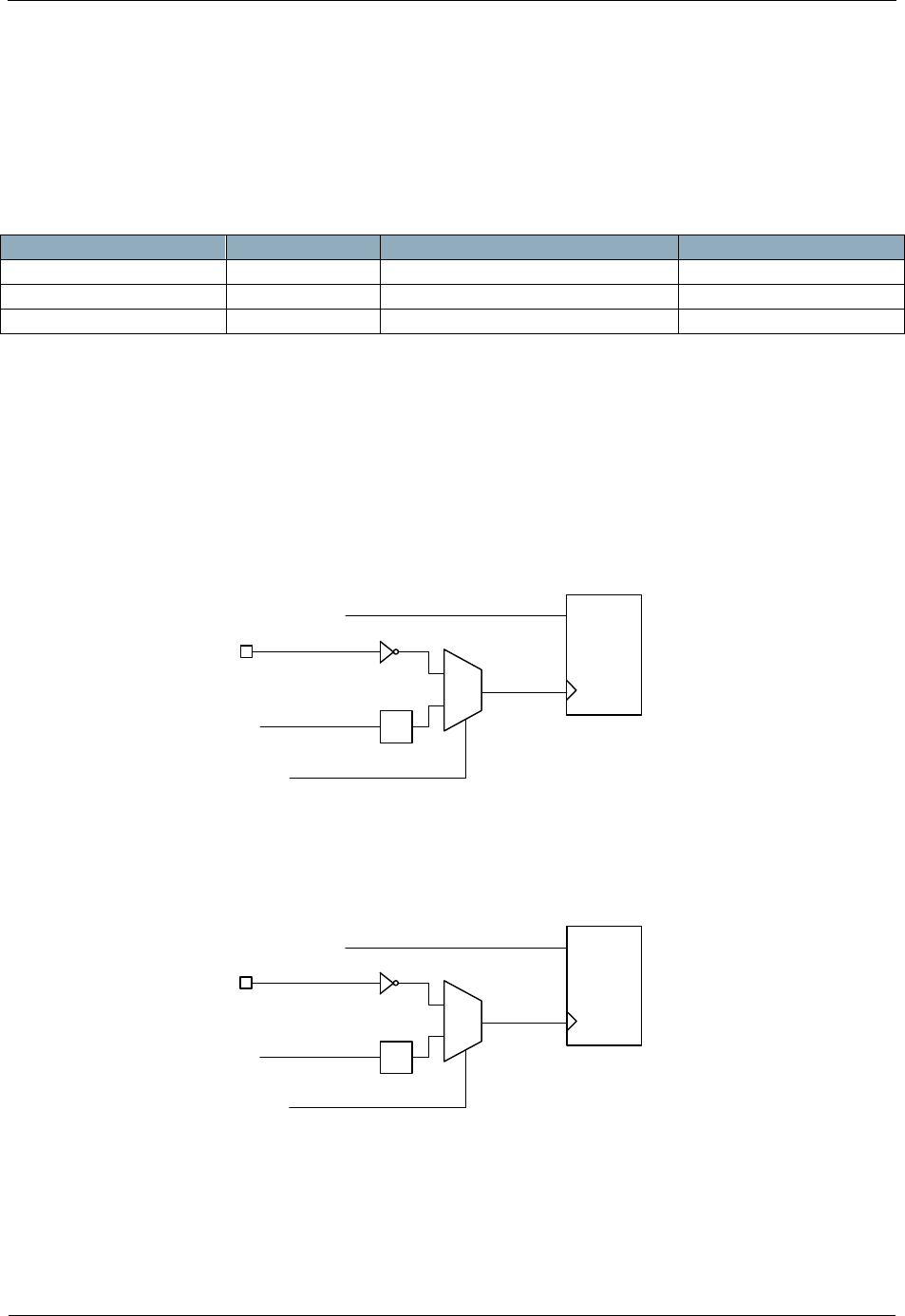
INS13478-5 Z-Wave 500 Series Appl. Programmers Guide v6.71.01 2017-02-28
Sigma Designs Inc.
Z-Wave Application Interfaces
Page 222 of 431
4.3.14 Application HW Timers/PWM interface API
The 500 Series Z-Wave SoC has three built-in HW timers available for the application:
1. Timer0
2. Timer1
3. GPTimer or PWM generator.
Timer
bits
Clocked by
Count up/down
Timer0
8/13/16
32MHz / 2 or P3.4
Counts up
Timer1
8/13/16
32MHz / 2 or P3.5
Counts up
GPTimer
16
32MHz / 8 or 32MHz / 1024
Counts down
Timer0 and Timer1 are standard 8051 timers that can be configured to:
be enabled/disabled
use the system clock divided by 2 (16MHz) or use a pin as clock source
generate an interrupt at overflow
Refer to figure below for principle diagrams of how the clock control works for Timer0.
P3.4
/2
clksys (32MHz)
ZW_TIMER0_ENABLE
ZW_TIMER0_ext_clk()
FALSE
TRUE
CE
clk
TIMER0
Figure 17. Principle of clock control for Timer0
Refer to figure below for principle diagrams of how the clock control works for Timer0.
P3.5
/2
clksys (32MHz)
ZW_TIMER1_ENABLE
ZW_TIMER1_ext_clk()
FALSE
TRUE
CE
clk
TIMER1
Figure 18. Principle of clock control (mode 0-2) for Timer1
Timer0 and Timer1 can operate in four different modes. Refer to the description of ZW_TIMER1_init

INS13478-5 Z-Wave 500 Series Appl. Programmers Guide v6.71.01 2017-02-28
Sigma Designs Inc.
Z-Wave Application Interfaces
Page 223 of 431
4.3.14.1 ZW_TIMER0_init
void ZW_TIMER0_init(BYTE bValue)
This function SHOULD be used to initialize Timer0.
Defined in: ZW_appltimer_api.h
Parameters:
bValue
Timer0 Mode:
TIMER_MODE_0
13 bit mode. The 5 lower bits of the low
register acts as a 5 bit prescaler for the
high byte
TIMER_MODE_1
16 bit mode
TIMER_MODE_2
8bit - auto reload mode. The 8bit timer
runs in the high byte register. After an
overflow the low byte register value is
loaded into the high byte register
TIMER_MODE_3
Timer 0 division mode. Timer 0 is divided
into two 8 bit timers, one controlled by the
Timer 0 control bits and the other
controlled by the Timer 1 control bits.
Warning: Enabling this will stop Timer 1
Serial API (Not supported)

INS13478-5 Z-Wave 500 Series Appl. Programmers Guide v6.71.01 2017-02-28
Sigma Designs Inc.
Z-Wave Application Interfaces
Page 224 of 431
4.3.14.2 ZW_TIMER1_init
void ZW_TIMER1_init(BYTE bValue)
This function SHOULD be used to initialize Timer1.
Defined in: ZW_appltimer_api.h
Parameters:
bValue
Timer1 Mode:
TIMER_MODE_0
13 bit mode. The 5 lower bits of the low
register acts as a 5 bit prescaler for the
high byte
TIMER_MODE_1
16 bit mode (no reload)
TIMER_MODE_2
8bit - auto reload mode. The 8bit timer
runs in the high byte register. After an
overflow the low byte register value is
loaded into the high byte register
TIMER_MODE_3
Disabled.
Warning: If Timer0 uses mode 3 then
Timer1 is stopped.
Serial API (Not supported)

INS13478-5 Z-Wave 500 Series Appl. Programmers Guide v6.71.01 2017-02-28
Sigma Designs Inc.
Z-Wave Application Interfaces
Page 225 of 431
4.3.14.3 ZW_TIMER0_INT_CLEAR / ZW_TIMER1_INT_CLEAR
ZW_TIMERx_INT_CLEAR
This macro SHOULD be used to clear timer interrupt/overflow flags.
Mode0-2: This macro clears the TIMER0/TIMER1 interrupt/overflow flag.
Mode3: This macro clears the TIMER0/TIMER1 high counter interrupt/overflow flag.
Defined in: ZW_appltimer_api.h
Serial API (Not supported)

INS13478-5 Z-Wave 500 Series Appl. Programmers Guide v6.71.01 2017-02-28
Sigma Designs Inc.
Z-Wave Application Interfaces
Page 226 of 431
4.3.14.4 ZW_TIMER0_INT_ENABLE / ZW_TIMER1_INT_ENABLE
ZW_TIMERx_INT_ENABLE(BYTE bState)
This macro SHOULD be used to enable or disable the Timer0/Timer1 interrupt.
Defined in: ZW_appltimer_api.h
Parameters:
bState IN
TRUE
Mode 0-2: TIMER0/TIMER1 interrupt is
enabled
Mode 3: TIMER0/TIMER1 high counter
interrupt is enabled
FALSE
Mode 0-2: TIMER0/TIMER1 interrupt is
disabled
Mode 3: TIMER0/TIMER1 high counter
interrupt is disabled
Serial API (Not supported)

INS13478-5 Z-Wave 500 Series Appl. Programmers Guide v6.71.01 2017-02-28
Sigma Designs Inc.
Z-Wave Application Interfaces
Page 227 of 431
4.3.14.5 ZW_TIMER0_ENABLE / ZW_TIMER1_ENABLE
ZW_TIMERx_ENABLE(BYTE bState)
This macro SHOULD be used to enable or halt Timer0/Timer1.
Defined in: ZW_appltimer_api.h
Parameters:
bState IN
TRUE
Mode 0-2: TIMER0/TIMER1 runs
Mode 3: Timer0/Timer1 high counter runs
FALSE
Mode 0-2: TIMER0/TIMER1 is halted
Mode 3: Timer0/timer1 high counter is
halted
Serial API (Not supported)

INS13478-5 Z-Wave 500 Series Appl. Programmers Guide v6.71.01 2017-02-28
Sigma Designs Inc.
Z-Wave Application Interfaces
Page 228 of 431
4.3.14.6 ZW_TIMER0_ext_clk / ZW_TIMER1_ext_clk
ZW_TIMERx_ext_clk(BYTE bState)
This function SHOULD be used to set the clock source for timer0/timer1
Defined in: ZW_appltimer_api.h
Parameters:
bState IN
TRUE
Timer0 runs on external clock (falling edge)
of P3.4.
Timer1 runs on external clock (falling edge)
of P3.5.
(synchronized to the system clock)
FALSE
Timer0/Timer1 runs on system clock
(divided by 2) - default value after reset
Serial API (Not supported)

INS13478-5 Z-Wave 500 Series Appl. Programmers Guide v6.71.01 2017-02-28
Sigma Designs Inc.
Z-Wave Application Interfaces
Page 229 of 431
4.3.14.7 ZW_TIMER0_LOWBYTE_SET / ZW_TIMER1_LOWBYTE_SET
ZW_TIMERx_LOWBYTE_SET (BYTE bValue)
This macro SHOULD be used to set the timer0/timer1 low byte value, see below.
Defined in: ZW_appltimer_api.h
Parameters:
bValue IN
The input value depends on the chosen mode:
Mode0: Lower 5 bits sets the prescaler value for the 13 bit
timer
Mode1: Sets the lower 8 bits of the 16 bit timer
Mode2: N.A.
Mode3: N.A.
Serial API (Not supported)

INS13478-5 Z-Wave 500 Series Appl. Programmers Guide v6.71.01 2017-02-28
Sigma Designs Inc.
Z-Wave Application Interfaces
Page 230 of 431
4.3.14.8 ZW_TIMER0_HIGHBYTE_SET / ZW_TIMER1_HIGHBYTE_SET
ZW_TIMERx_HIGHBYTE_SET (BYTE bValue)
This macro SHOULD be used to set the timer0/timer1 high byte value, see below.
Defined in: ZW_appltimer_api.h
Parameters:
bValue IN
The input value depends on the chosen mode:
Mode0: Sets the 8 bit timer value
Mode1: Sets the upper 8 bits of the 16 bit timer
Mode2: Sets the 8 bit reload value of the 8 bit timer0
Mode3: N.A.
Serial API (Not supported)

INS13478-5 Z-Wave 500 Series Appl. Programmers Guide v6.71.01 2017-02-28
Sigma Designs Inc.
Z-Wave Application Interfaces
Page 231 of 431
4.3.14.9 ZW_TIMER0_HIGHBYTE_GET / ZW_TIMER1_HIGHBYTE_GET
BYTE ZW_TIMERx_HIGHBYTE_GET
This macro MAY be used to query the timer0/timer1 high register value
Defined in: ZW_appltimer_api.h
Return value:
BYTE
The return value depends on the chosen mode:
Mode0: 8 bit timer value
Mode1: upper 8 bits of the 16 bit timer
Mode2: 8 bit timer value
Mode3: N.A.
Serial API (Not supported)

INS13478-5 Z-Wave 500 Series Appl. Programmers Guide v6.71.01 2017-02-28
Sigma Designs Inc.
Z-Wave Application Interfaces
Page 232 of 431
4.3.14.10 ZW_TIMER0_LOWBYTE_GET / ZW_TIMER1_LOWBYTE_GET
BYTE ZW_TIMERx_LOWBYTE_GET
This macro MAY be used to query the timer0/timer1 timer low register value
Defined in: ZW_appltimer_api.h
Return value:
BYTE
The return value depends on the chosen mode:
Mode0: 5 bit prescaler value for the 13 bit timer. (lower 5 bits)
Mode1: lower 8 bits of the 16 bit timer
Mode2: 8 bit timer value
Mode3: N.A.
Serial API (Not supported)

INS13478-5 Z-Wave 500 Series Appl. Programmers Guide v6.71.01 2017-02-28
Sigma Designs Inc.
Z-Wave Application Interfaces
Page 233 of 431
4.3.14.11 ZW_TIMER0_word_get / ZW_TIMER1_word_get
WORD ZW ZW_TIMERx_word_get (void)
This function MAY be used to query the two 8 bit timer0/timer1 register values as one 16 bit value. Used
when timer0/timer1 is set in mode 1.
Defined in: ZW_appltimer_api.h
Return value:
WORD
16bit timer value
Serial API (Not supported)

INS13478-5 Z-Wave 500 Series Appl. Programmers Guide v6.71.01 2017-02-28
Sigma Designs Inc.
Z-Wave Application Interfaces
Page 234 of 431
4.3.14.12 ZW_GPTIMER_init
void ZW_GPTIMER_init(BYTE bValue)
This function SHOULD be used to initialize the GPTimer. Calling ZW_GPTIMER_init() will disable the
PWM, since the GP Timer and the PWM share the same hardware resources. The GPTimer is
hardcoded to count down.
Defined in: ZW_appltimer_api.h
Parameters:
bValue IN
Bit mask:
Prescaler setting
PRESCALER_BIT
When set: Timer counter runs @
32MHz / 1024 = 31.25kHz
When nor set: Timer counter runs @
32MHz / 8 = 4MHz
Reload Timer
RELOAD_BIT
When set: The GPTimer counter
registers are reloaded with the reload
register value upon underrun.
When not set: The GPTimer stops upon
underrun.
Immediate write
IMWR_BIT
When set: The GP Timer counters will be
loaded with the value of the reload
register when it is disabled or
immediately when the reload values are
set.
When not set: The GP Timer counters
will be loaded with the value of the reload
register when it is disabled or when it
times out (underrun).
Serial API (Not supported)

INS13478-5 Z-Wave 500 Series Appl. Programmers Guide v6.71.01 2017-02-28
Sigma Designs Inc.
Z-Wave Application Interfaces
Page 235 of 431
4.3.14.13 ZW_GPTIMER_int_clear
void ZW_GPTIMER_int_clear (void)
This function SHOULD be used to clear the GP Timer interrupt flag.
Defined in: ZW_appltimer_api.h
Serial API (Not supported)

INS13478-5 Z-Wave 500 Series Appl. Programmers Guide v6.71.01 2017-02-28
Sigma Designs Inc.
Z-Wave Application Interfaces
Page 236 of 431
4.3.14.14 ZW_GPTIMER_int_get
BYTE ZW_GPTIMER_int_get (void)
This function MAY be used to query the state of the GP Timer interrupt flag.
Defined in: ZW_appltimer_api.h
Return value:
BYTE
0x00: interrupt flag is not set
mom-0x00: Interrupt is set
Serial API (Not supported)

INS13478-5 Z-Wave 500 Series Appl. Programmers Guide v6.71.01 2017-02-28
Sigma Designs Inc.
Z-Wave Application Interfaces
Page 237 of 431
4.3.14.15 ZW_GPTIMER_int_enable
void ZW_GPTIMER_int_enable(BYTE bState)
This function SHOULD be used to enable or disable the GPTimer interrupt.
The application designer MUST declare an Interrupt Service Routine (ISR) to handle the GP Timer
interrupt. The ISR MUST use the ISR number INUM_GP_TIMER as declared in section 3.9.
Defined in: ZW_appltimer_api.h
Parameters:
bState IN
TRUE
enable GPTimer interrupt
FALSE
disable GPTimer interrupt
Serial API (Not supported)

INS13478-5 Z-Wave 500 Series Appl. Programmers Guide v6.71.01 2017-02-28
Sigma Designs Inc.
Z-Wave Application Interfaces
Page 238 of 431
4.3.14.16 ZW_GPTIMER_enable
void ZW_GPTIMER_enable(BYTE bState)
This function SHOULD be used to enable or disable the GPTimer.
Disabling the GPTimer also clears the interrupt flag and resets the GPTimer counters.
Defined in: ZW_appltimer_api.h
Parameters:
bState IN
TRUE
enable GPTimer.
FALSE
disable GPTimer.
Serial API (Not supported)

INS13478-5 Z-Wave 500 Series Appl. Programmers Guide v6.71.01 2017-02-28
Sigma Designs Inc.
Z-Wave Application Interfaces
Page 239 of 431
4.3.14.17 ZW_GPTIMER_pause
void ZW_GPTIMER_pause(BYTE bState)
This function MAY be used to control the GPTimer pause state.
When entering the pause state, the GPTimer counters stops counting.
When leaving the pause state, the counters will start counting from the state they were in when the
pause state was entered.
Defined in: ZW_appltimer_api.h
Parameters:
bState IN
TRUE
Enter GPTimer pause state.
FALSE
Leave GPTimer pause state.
Serial API (Not supported)

INS13478-5 Z-Wave 500 Series Appl. Programmers Guide v6.71.01 2017-02-28
Sigma Designs Inc.
Z-Wave Application Interfaces
Page 240 of 431
4.3.14.18 ZW_GPTIMER_reload_set
void ZW_GPTIMER_reload_set(WORD wReloadValue)
This function SHOULD be used to set the 16 bit GPTimer reload register. This value sets the time from
where the GPTimer is enabled or is reloaded until it reaches zero (issues an interrupt).
As an example, if the GPtimer reload value is set to 0x0137 and the prescaler is set to 1024, the timer
will reach zero after 0x137 * 1024 * (32MHz)-1 = 9.95ms.
The value 0x0000 equals a timer reload value of 0x10000. E.g. if the GPtimers reload value is set to
0x0000 and the prescaler is set to 8, the timer will reach zero after 0x10000 * 8 * (32MHz)-1 = 16.38ms.
Defined in: ZW_appltimer_api.h
Parameters:
wReloadValue IN
16 bit reload value
Serial API (Not supported)

INS13478-5 Z-Wave 500 Series Appl. Programmers Guide v6.71.01 2017-02-28
Sigma Designs Inc.
Z-Wave Application Interfaces
Page 241 of 431
4.3.14.19 ZW_GPTIMER_reload_get
WORD ZW_GPTIMER_reload_get(void)
This function MAY be used to query the 16 bit GPTimer reload register value.
Defined in: ZW_appltimer_api.h
Return value:
WORD
16 bit reload value
Serial API (Not supported)

INS13478-5 Z-Wave 500 Series Appl. Programmers Guide v6.71.01 2017-02-28
Sigma Designs Inc.
Z-Wave Application Interfaces
Page 242 of 431
4.3.14.20 ZW_GPTIMER_get
WORD ZW_GPTIMER_get(void)
This function MAY be used to query the 16 bit GPTimer counter register value.
The returned value is in the range [reload_value-1;0]. As an example, if the reload value is set to
0x2A40, ZW_GPTIMER_get() will return a value in the range [0x2A3F;0].
An application SHOULD be designed to be robust if a higher value is returned, e.g. because the reload
value was not correctly stored in the chip.
Defined in: ZW_appltimer_api.h
Return value:
WORD
16 bit counter value
Serial API (Not supported)

INS13478-5 Z-Wave 500 Series Appl. Programmers Guide v6.71.01 2017-02-28
Sigma Designs Inc.
Z-Wave Application Interfaces
Page 243 of 431
4.3.14.21 ZW_PWM_init
void ZW_PWM_init(BYTE bValue)
This function SHOULD be used to initialize the pulse width modulator. Calling ZW_PWM_init() will
disable the GPTimer function, since the PWM and the GP Timer share the same hardware.
It is NOT RECOMMENDED that Immediate write mode is enabled as it introduces a risk of unintended
waveforms.
Defined in: ZW_appltimer_api.h
Parameters:
bValue IN
Bit mask:
Prescaler setting
PRESCALER_BIT
When set: PWM counter runs @
32MHz / 1024 = 31.25kHz
When nor set: PWM counter runs @
32MHz / 8 = 4MHz
Invert signal
PWMINV_BIT
When set: PWM signal is inverted.
When not set: The signal is not inverted
Immediate write
IMWR_BIT
When set: The PWM counters will be
loaded with the value of the waveform
registers when it is disabled or
immediately when the waveform values
are set.
When not set: The PWM counters will be
loaded with the value of the waveform
registers when it is disabled or at the
end of a PWM signal period.
Serial API (Not supported)

INS13478-5 Z-Wave 500 Series Appl. Programmers Guide v6.71.01 2017-02-28
Sigma Designs Inc.
Z-Wave Application Interfaces
Page 244 of 431
4.3.14.22 ZW_PWM_enable
void ZW_PWM_enable(BYTE bState)
This function SHOULD be used to enable or disable the PWM.
Disabling the PWM also clears the interrupt flag and resets the PWM counter.
Defined in: ZW_appltimer_api.h
Parameters:
bState IN
TRUE
enable PWM.
FALSE
disable PWM.
Serial API (Not supported)

INS13478-5 Z-Wave 500 Series Appl. Programmers Guide v6.71.01 2017-02-28
Sigma Designs Inc.
Z-Wave Application Interfaces
Page 245 of 431
4.3.14.23 ZW_PWM_int_clear
void ZW_PWM_int_clear (void)
This function SHOULD be used to clear the PWM interrupt flag.
Defined in: ZW_appltimer_api.h
Serial API (Not supported)

INS13478-5 Z-Wave 500 Series Appl. Programmers Guide v6.71.01 2017-02-28
Sigma Designs Inc.
Z-Wave Application Interfaces
Page 246 of 431
4.3.14.24 ZW_PWM_int_get
BYTE ZW_PWM_int_get (void)
This function MAY be used to query the state of the PWM interrupt flag.
Defined in: ZW_appltimer_api.h
Return value:
BYTE
0x00: interrupt flag is not set
non-0x00: Interrupt is set
Serial API (Not supported)

INS13478-5 Z-Wave 500 Series Appl. Programmers Guide v6.71.01 2017-02-28
Sigma Designs Inc.
Z-Wave Application Interfaces
Page 247 of 431
4.3.14.25 ZW_PWM_int_enable
void ZW_PWM_int_enable(BYTE bState)
This function SHOULD be used to enable or disable the PWM interrupt.
The PWM interrupt is triggered on the rising edge of the PWM signals (or at the falling edge of the PWM
signal if PWMINV_BIT is set in ZW_PWM_init()).
The application designer MUST declare an Interrupt Service Routine (ISR) to handle the PWM controller
interrupt. The ISR MUST use the ISR number INUM_GP_TIMER as declared in section 3.9.
Section 4.3.14.25 recommends that Immediate write is not enabled. With Immediate write disabled, the
application may unintentionaly inhibit the flow of IRQs from the PWM controller. This may happen if the
application calls ZW_PWM_waveform_set with the parameter value (0,0). Refer to 4.3.14.26 on how to
recover from this situation.
Defined in: ZW_appltimer_api.h
Parameters:
bState IN
TRUE
enable PWM interrupt
FALSE
disable PWM interrupt
Serial API (Not supported)

INS13478-5 Z-Wave 500 Series Appl. Programmers Guide v6.71.01 2017-02-28
Sigma Designs Inc.
Z-Wave Application Interfaces
Page 248 of 431
4.3.14.26 ZW_PWM_waveform_set
void ZW_PWM_waveform_set ( BYTE bHigh,
BYTE bLow)
This function SHOULD be used to set the high and low time of the PWM signal. Refer to figure below.
High time of PWM signal: thPWM = (bHigh * PRESCALER)/fsys
Low time of PWM signal tlPWM = (bLow * PRESCALER) /fsys
Total period of PWM signal: TPWM = thPWM + tlPWM
where fsys is 32MHz and
PRESCALER is 1024 when PRESCALER_BIT is set by ZW_PWM_init() and
PRESCALER is 8 when PRESCALER_BIT is not set.
NOTE: If PWMINV_BIT was set by ZW_PWM_init(), bHigh defines the duration of the low period
and bLow defines the duration of the high period..
tlPWM tlPWM
thPWM thPWM
TPWM
Figure 19. PWM waveform
Section 4.3.14.25 recommends that Immediate write is not enabled. With Immediate write disabled, the
application SHOULD NOT call ZW_PWM_waveform_set with the parameter value (0,0). In case the
parameter value (0,0) has been used, the application MUST call ZW_PWM_waveform_set with one or
two non-zero values and subsequently disable and re-enable the PWM controller by calling
ZW_PWM_enable.
While NOT RECOMMENDED, Immediate write MAY be enabled. In that case, the application MAY call
ZW_PWM_waveform_set with any parameter value.
Defined in: ZW_appltimer_api.h
Parameters:
bHigh IN
high time
bLow IN
low time
Serial API (Not supported)

INS13478-5 Z-Wave 500 Series Appl. Programmers Guide v6.71.01 2017-02-28
Sigma Designs Inc.
Z-Wave Application Interfaces
Page 249 of 431
4.3.14.27 ZW_PWM_waveform_get
void ZW_waveform_get(BYTE *bHigh,
BYTE *bLow)
This function MAY be used to query the values of the waveform registers.
Defined in: ZW_appltimer_api.h
Parameters:
bHigh OUT
high time
bLow OUT
low time
Serial API (Not supported)

INS13478-5 Z-Wave 500 Series Appl. Programmers Guide v6.71.01 2017-02-28
Sigma Designs Inc.
Z-Wave Application Interfaces
Page 250 of 431
4.3.15 Security API
This API handles security keys on application level.
4.3.15.1 ZW_GetSecurityKeys (Only slave libraries)
BYTE ZW_GetSecurityKeys()
This function returns a bitmask of security keys the node posses. The application can request
ZW_SendDataEx() to use these keys for outgoing messages. Incoming messages sent with any of these
keys will be decrypted and delivered to the application. An excluded node returns no security keys.
Defined in: ZW_security_api.h
Parameters:
BYTE OUT
Bit mask:
0x00 = SECURITY_KEY_NONE_MASK
No security keys
0x01 = SECURITY_KEY_S2_UNAUTHENTICATED_BIT
0x02 = SECURITY_KEY_S2_AUTHENTICATED_BIT
0x04 = SECURITY_KEY_S2_ACCESS_BIT
0x80 = SECURITY_KEY_S0_BIT
Serial API
HOST->ZW: REQ | 0x9C | 0
ZW->HOST: RES | 0x9C | 0 | securityKeys_bitmaskLen(1) | securityKeys_bitmask
In the Serial API the Security API functions are reached through the
FUNC_ID_ZW_SECURITY_SETUP (0x9C) and this Serial API FUNC_ID makes it possible to set the
Requested Security Keys and Requested Authentication method in a Slave Routing/Enhanced 232
based Serial API Node prior to inclusion (add). The Requested Security Keys and Authentication is
requested by the protocol during S2 inclusion.
Set Requested Security Inclusion Keys
(E_SECURITY_SETUP_CMD_SET_SECURITY_INCLUSION_REQUESTED_KEYS):
HOST->ZW: REQ | 0x9C | 5 | registeredSecurityKeysLen(1) | registeredSecurityKeys
ZW->HOST: RES | 0x9C | 5 | retValLen(1) | retVal - retVal == TRUE => success
Set Requested Security Inclusion Authentication
(E_SECURITY_SETUP_CMD_SET_SECURITY_INCLUSION_REQUESTED_AUTHENTICATION):
HOST->ZW: REQ | 0x9C | 6 | registeredSecurityAuthenticationLen(1) | registeredSecurityAuthentication
ZW->HOST: RES | 0x9C | 6 | retValLen(1) | retVal - retVal == TRUE => success

INS13478-5 Z-Wave 500 Series Appl. Programmers Guide v6.71.01 2017-02-28
Sigma Designs Inc.
Z-Wave Application Interfaces
Page 251 of 431
4.3.15.2 ZW_s2_inclusion_init(Only slave libraries)
void ZW_s2_inclusion_init(void)
Initialises the S2 inclusion machine. Must only be called if Requested Security Keys or Requested
Authentication method is changed.
Defined in: ZW_security_api.h
Serial API
Not implemented. SerialAPI Application calls ZW_s2_inclusion_init() when changing either the
Requested Security Keys or the Requested Authentication Method (See 4.3.15.1).

INS13478-5 Z-Wave 500 Series Appl. Programmers Guide v6.71.01 2017-02-28
Sigma Designs Inc.
Z-Wave Application Interfaces
Page 252 of 431
4.3.15.3 ZW_SetSecurityS2InclusionPublicDSK_CSA(Only slave libraries)
void ZW_SetSecurityS2InclusionPublicDSK_CSA(s_SecurityS2InclusionCSAPublicDSK_t
*response)
Set the Controller DSK requested by protocol through ApplicationSecurityEvent with the Security Event
E_APPLICATION_SECURITY_EVENT_S2_INCLUSION_REQUEST_DSK_CSA.
Defined in: ZW_security_api.h
Parameters:
s_SecurityS2InclusionCSAPublicDSK_t* IN
response->aCSA_DSK[4]
Pointer to 4 BYTE
Public CSA DSK
Serial API
HOST->ZW: REQ | 0x9C | 4 | bCSA_DSKLen(4) | aCSA_DSK[4]
ZW->HOST: RES | 0x9C | 4 | retValLen(1) | retVal - retVal == TRUE => success

INS13478-5 Z-Wave 500 Series Appl. Programmers Guide v6.71.01 2017-02-28
Sigma Designs Inc.
Z-Wave Application Interfaces
Page 253 of 431
4.3.15.4 ZW_GetSecurityS2PublicDSK(Only slave libraries)
void ZW_GetSecurityS2PublicDSK(BYTE *buf)
This function returns the 16 byte Public DSK for the node in the 16 byte long array buf points to – buf
most point to an array at least 16 byte in size. Can be used to do S2 SSA Authenticated inclusion (add)
by using the returned DSK to present to user which then must enter the needed part of the DSK on the
Controller when doing Authenticated S2 inclusion.
Defined in: ZW_security_api.h
Parameters:
BYTE OUT
*buf
Pointer to 16 byte array
the DSK should be written
to.
Serial API
HOST->ZW: REQ | 0x9C | 2
ZW->HOST: RES | 0x9C | 2 | publicDSKLen(16) | publicDSK[16]
4.3.15.5 ZW_SetSecurityS2CriticalNodeID (Only routing slave library)
void ZW_SetSecurityS2CriticalNodeID(BYTE bNodeID)
This function set the S2 Critical NodeID used when a S2 included slave_routing based node enter
sleepmode. When Sleepmode is entered the SPAN used in connection with S2 communicating with the
Critical NodeID is saved in Retention RAM and restored when wakeup. This makes SPAN resync not
necessary when communicating with the Critical NodeID after wakeup.
Defined in: ZW_security_api.h
Parameters:
BYTE IN
bNodeID:
0
Save MRU SPAN in
retention RAM when going
into Sleep Mode.
1 – 232
Save SPAN concerning
bNodeID (if present) in
retention when going into
Sleep Mode.
233 – 255
Reserved.
Serial API
HOST->ZW: REQ | 0x9C | 3 | bNodeIDLen(1) | nodeID

INS13478-5 Z-Wave 500 Series Appl. Programmers Guide v6.71.01 2017-02-28
Sigma Designs Inc.
Z-Wave Application Interfaces
Page 254 of 431
ZW->HOST: RES | 0x9C | 3 | retValLen(1) | retVal - retVal == TRUE => success

INS13478-5 Z-Wave 500 Series Appl. Programmers Guide v6.71.01 2017-02-28
Sigma Designs Inc.
Z-Wave Application Interfaces
Page 255 of 431
4.3.15.6 ZW_SetSecurityS0NetworkKey (Only enhanced 232 slave library)
void ZW_SetSecurityS0NetworkKey(BYTE *network_key)
This function is only used after a firmware update of an application that is securely included in a S0
based network. The call transfer the S0 network key from the application area in external NVM to the Z-
Wave Protocol area in external NVM.
Defined in: ZW_security_api.h
Parameters:
network_key IN
Array of 16 bytes
Pointer to byte array containing the S0
network key
Serial API
HOST->ZW: REQ | 0x9C | 1 | networkkeyLen(16) | network_key[16]
ZW->HOST: RES | 0x9C | 1 | retValLen(1) | retVal - retVal == TRUE => success
retVal = FALSE if ZW_SetSecurityS0NetworkKey was NOT called (network_key must be 16 bytes)
retVal = TRUE if ZW_SetSecurityS0NetworkKey was called with specified network_key

INS13478-5 Z-Wave 500 Series Appl. Programmers Guide v6.71.01 2017-02-28
Sigma Designs Inc.
Z-Wave Application Interfaces
Page 256 of 431
4.3.16 AES API
The built-in AES-128 hardware engine is a NIST standardized AES 128 block cipher. The cipher engine
is used by the Z-Wave Protocol to encrypt/decrypt Z Wave frame payload and to authenticate Z Wave
frames. In addition this AES-128 encryption engine can also be used to encrypt a 128bit data block
(Using ECB - Electronic CookBook mode) by the application.
The input and output data and key for the AES API’s are 16 bytes long char arrays. ZW_AES_ecb_set is
used to set the input data (plaintext and key) and the function ZW_AES_ecb_get is used to return the
cipher data from the AES engine. The ECB process is started using the function
ZW_AES_ecb_enable(TRUE) and it lasts about 24µs. The process can be canceled by calling
ZW_AES_ecb_enable(FALSE). The AES engine must be polled, using the function
ZW_AES_ecb_active to check when a ECB process is done. Figure below gives an example of how the
AES engine functions are called.
/* Example of ECB ciphering. Vectors are from FIPS-197 */
void ApplicationPoll()
{
:
switch (mainState)
{
:
case START_AES_TEST:
keybuffer[15] = 0x00;
keybuffer[14] = 0x01;
keybuffer[13] = 0x02;
keybuffer[12] = 0x03;
keybuffer[11] = 0x04;
keybuffer[10] = 0x05;
keybuffer[9] = 0x06;
keybuffer[8] = 0x07;
keybuffer[7] = 0x08;
keybuffer[6] = 0x09;
keybuffer[5] = 0x0A;
keybuffer[4] = 0x0B;
keybuffer[3] = 0x0C;
keybuffer[2] = 0x0D;
keybuffer[1] = 0x0E;
keybuffer[0] = 0x0F;
plainbuffer[15] = 0x00;
plainbuffer[14] = 0x11;
plainbuffer[13] = 0x22;
plainbuffer[12] = 0x33;
plainbuffer[11] = 0x44;
plainbuffer[10] = 0x55;
plainbuffer[9] = 0x66;
plainbuffer[8] = 0x77;
plainbuffer[7] = 0x88;
plainbuffer[6] = 0x99;
plainbuffer[5] = 0xAA;
plainbuffer[4] = 0xBB;
plainbuffer[3] = 0xCC;
plainbuffer[2] = 0xDD;
plainbuffer[1] = 0xEE;
plainbuffer[0] = 0xFF;
cipherbuffer[15] = 0x69;
cipherbuffer[14] = 0xC4;
cipherbuffer[13] = 0xE0;
cipherbuffer[12] = 0xD8;

INS13478-5 Z-Wave 500 Series Appl. Programmers Guide v6.71.01 2017-02-28
Sigma Designs Inc.
Z-Wave Application Interfaces
Page 257 of 431
cipherbuffer[11] = 0x6A;
cipherbuffer[10] = 0x7B;
cipherbuffer[9] = 0x04;
cipherbuffer[8] = 0x30;
cipherbuffer[7] = 0xD8;
cipherbuffer[6] = 0xCD;
cipherbuffer[5] = 0xB7;
cipherbuffer[4] = 0x80;
cipherbuffer[3] = 0x70;
cipherbuffer[2] = 0xB4;
cipherbuffer[1] = 0xC5;
cipherbuffer[0] = 0x5A;
/* Set AES ECB input data pointers */
ZW_AES_ecb_set(plainbuffer,keybuffer);
/* Start AES ECB function */
ZW_AES_enable(TRUE);
mainState= WAIT_AES_ECB;
break;
case WAIT_AES_ECB:
/* Check to se if AES ECB procedure is done */
if (ZW_AES_active_get()==FALSE)
{
ZW_AES_ecb_get(plainbuffer);
/* check against proven data */
fail=FALSE;
for (i=0;i<16;i++)
{
if (plainbuffer[i]!=chipherbuffer[i])
{
fail=TRUE;
break;
}
}
if (fail) report();
mainState= IDLE;
}
:
break;
}
}
Figure 20. Example of ECB ciphering. Vectors are from FIPS-197.

INS13478-5 Z-Wave 500 Series Appl. Programmers Guide v6.71.01 2017-02-28
Sigma Designs Inc.
Z-Wave Application Interfaces
Page 258 of 431
4.3.16.1 ZW_AES_ecb_set
void ZW_AES_ecb_set( BYTE *bData,
BYTE *bKey)
Call this function to setup the input data for the AES in ECB mode (Electronic Cookbook mode). Use the
function ZW_AES_swap_byte to swap the order of which the data from the array is read into the AES
engine.
Defined in: ZW_aes_api.h
Parameters:
bData
Array of 16 bytes
Pointer to byte array containing the data
to be encrypted.
bKey
Array of 16 bytes
Pointer to byte array containing the
encryption key
Serial API (Not supported)

INS13478-5 Z-Wave 500 Series Appl. Programmers Guide v6.71.01 2017-02-28
Sigma Designs Inc.
Z-Wave Application Interfaces
Page 259 of 431
4.3.16.2 ZW_AES_ecb_get
void ZW_AES_ecb_get(BYTE *bData)
After calling ZW_AES_ecb_set , use ZW_AES_active_get to see if the AES process is done. When this
is the case, call ZW_AES_ecb_get to transfer the result of a AES ECB process to the array bData. Use
the function ZW_AES_swap_byte to swap the order of which the data from the array is read from the
AES engine.
Defined in: ZW_aes_api.h
Parameters:
bData
Array of 16 bytes
Pointer to byte array buffer containing
encrypted data
Serial API (Not supported)

INS13478-5 Z-Wave 500 Series Appl. Programmers Guide v6.71.01 2017-02-28
Sigma Designs Inc.
Z-Wave Application Interfaces
Page 260 of 431
4.3.16.3 ZW_AES_enable
void ZW_AES_enable(BOOL bState)
Call ZW_AES_enable(TRUE) to enable the AES engine and start the ECB process. The AES engine will
automatically be disabled when a ECB process is done. Call ZW_AES_enable(FALSE) if a ECB process
is to be canceled.
Defined in: ZW_aes_api.h
Parameters:
bState
TRUE
Enable the AES and start the ECB
mode.
FALSE
Disable the AES.
Serial API (Not supported)

INS13478-5 Z-Wave 500 Series Appl. Programmers Guide v6.71.01 2017-02-28
Sigma Designs Inc.
Z-Wave Application Interfaces
Page 261 of 431
4.3.16.4 ZW_AES_swap_data
void ZW_AES_swap_data(BOOL bState)
The function is used to enable the option to swap the byte order of the data read into and read from the
the AES engine.
Defined in: ZW_aes_api.h
Parameters:
bState
TRUE
Swap data bytes.
FALSE
Do not swap data bytes
Serial API (Not supported)

INS13478-5 Z-Wave 500 Series Appl. Programmers Guide v6.71.01 2017-02-28
Sigma Designs Inc.
Z-Wave Application Interfaces
Page 262 of 431
4.3.16.5 ZW_AES_active_get
BYTE ZW_AES_active_get (void)
Returns the active/idle state of the AES engine. Use this function to see when a ECB process is done.
Defined in: ZW_aes_api.h
Return value:
BOOL
TRUE
The AES is busy.
FALSE
The AES is idle.
Serial API (Not supported)

INS13478-5 Z-Wave 500 Series Appl. Programmers Guide v6.71.01 2017-02-28
Sigma Designs Inc.
Z-Wave Application Interfaces
Page 263 of 431
4.3.16.6 ZW_AES_int_enable_get
void ZW_AES_int_enable (BYTE bState)
Call this function to enable or disable AES interrupts.
Defined in: ZW_aes_api.h
Parameters:
bState IN
TRUE
The AES interrupt is enabled.
FALSE
The AES interrupt is disabled
Serial API (Not supported)

INS13478-5 Z-Wave 500 Series Appl. Programmers Guide v6.71.01 2017-02-28
Sigma Designs Inc.
Z-Wave Application Interfaces
Page 264 of 431
4.3.16.7 ZW_AES_int_get
BYTE ZW_AES_int_get (void)
The function return the state of the AES interrupt flag.
Defined in: ZW_aes_api.h
Return value:
BYTE
0x00
The AES interrupt flag is set
non-0x00
The AES interrupt flag is cleared
Serial API (Not supported)

INS13478-5 Z-Wave 500 Series Appl. Programmers Guide v6.71.01 2017-02-28
Sigma Designs Inc.
Z-Wave Application Interfaces
Page 265 of 431
4.3.16.8 ZW_AES_int_clear
void ZW_AES_int_clear (void)
Call this function to clearthe AES interrupt flag.
Defined in: ZW_aes_api.h
Serial API (Not supported)

INS13478-5 Z-Wave 500 Series Appl. Programmers Guide v6.71.01 2017-02-28
Sigma Designs Inc.
Z-Wave Application Interfaces
Page 266 of 431
4.3.16.9 ZW_AES_ecb/ZW_AES_ecb_dma
BYTE ZW_AES_ecb ( BYTE *bKey
BYTE *bInput
BYTE *bOutput)
BYTE ZW_AES_ecb_dma ( BYTE *bKey
BYTE *bInput
BYTE *bOutput)
These functions execute a AES-128 ECB task and return the encrypted data. Once started the functions
will be blocking until the task is done.The function ZW_AES_ecb_dma will use the built-in DMA function
to transfer data between the AES engine and the XRAM, whereas the data handling will be done purely
by the 8051 using the function ZW_AES_ecb . Use the function ZW_AES_swap_byte to swap the order
of which the data bytes from the array are written to and read from the AES engine.
Defined in: ZW_aes_api.h
Parameters:
*bKey IN
pointer to byte array in lower 4kB
XRAM containing the input data (16
bytes)
*bInput IN
pointer to byte array in lower 4kB
XRAM containing the key (16 bytes)
The AES is idle.
*bOutput OUT
pointer to byte array in lower 4kB
XRAM containing the output data
(16 bytes)
The AES is idle.
Serial API (Not supported)

INS13478-5 Z-Wave 500 Series Appl. Programmers Guide v6.71.01 2017-02-28
Sigma Designs Inc.
Z-Wave Application Interfaces
Page 267 of 431
4.3.17 TRIAC Controller API
The built-in TRIAC Controller is targeted at controlled light / power dimming applications. The Triac
Controller is able to drive both TRIAC’s and FET’s/IGBT’s. The Triac Controller can dim the load with a
precision of 1000 steps in each half-period.
When controlling TRIAC’s the Triac Controller will generate one or more fire pulses in each half period of
the mains to turn on the Triac. The fire angle is set by the specified dim level. The Triac Controller will
generate multiple pulses if the fire angle is less than 90º. The multiple pulses ensure that at least one
pulse is located after the middle of a half-period, thereby ensuring that the Triac will be fired even with
fully inductive loads, while still limiting the current consumption.
When controlling a FET/IGBT the Triac Controller will generate a fire pulse with a width that is
propotional to the dim level. The pulse can be either leading or falling edge controlled.
The Triac Controller can operate in both 50Hz and 60Hz environments.
The application software can use the following TRIAC API calls to control the 500 Series Z-Wave SoC
TRIAC Controller.

INS13478-5 Z-Wave 500 Series Appl. Programmers Guide v6.71.01 2017-02-28
Sigma Designs Inc.
Z-Wave Application Interfaces
Page 268 of 431
4.3.17.1 ZW_TRIAC_init
BYTE ZW_TRIAC_init(BYTE bMode,
WORD wPulseLength,
BYTE bPulseRepLength,
BYTE bZeroXMode,
BYTE bInitMask,
BYTE bInvZerox,
BYTE bMainsFreq,
WORD wCorrection,
BYTE bCorPrescale,
BYTE bKeepOff)
ZW_TRIAC_init initializes the 500 Series Z-Wave SoC's integrated TRIAC controller. Refer to the
section after the function parameter list for a description of the setup of the different zero-cross modes
(page 272). Place this function call in ApplicationInitHW.
Defined in: ZW_triac_api.h
Parameters:
bMode IN
Mode of operation:
TRIAC_MODE
Triac mode. Multiple short pulses before
90 degrees and single short pulse after
90 degrees
FET_TRAILING_EDGE_MODE
FET/IGBT trailing edge mode. Single
pulse control signal (TRIAC) which goes
high at 0º and low in 0-180º depending
of dim level
FET_LEADING_EDGE_MODE
FET/IGBT leading edge mode. Single
pulse control signal (TRIAC) which goes
high at 0-180º depending of dim level
and goes low at the next zero-cross
wPulseLength IN
Triac Fire pulse length
Legal values: 1-250 (Triac mode)
Each step equals
MHz
n
32
, where n
is
265 in 60Hz systems
318 in 50Hz systems
E.g. setting this parameter to 40 in a
50Hz system gives a Triac pulse
length of
us
MHz 5.397
32
318
40
Not applicable in FET Modes,where this
value must be set to 0
Set this parameter so that is equals the
minimum Triac gate high time according
to the datasheet of the specific Triac in
use.
The pulse length can not exceed a
quarter of the halfperiod length. E.g. for
a 50Hz system the pulse length can not
exceed 10ms/4=2.5ms.
These relations must be fulfilled:
bPulseRepLength*4+wPulseLength<500
bPulseRepLength*4 > wPulseLength

INS13478-5 Z-Wave 500 Series Appl. Programmers Guide v6.71.01 2017-02-28
Sigma Designs Inc.
Z-Wave Application Interfaces
Page 269 of 431
bPulseRepLength IN
Triac fire pulse repetition period
Legal values: 18-125
Each step equals
MHz
n
32
4
, where n
is
265 in 60Hz systems
318 in 50Hz systems
i.e. setting this parameter to 20 in a
50Hz system gives a Triac pulse
length of
us
MHz 795
32
3184
20
Not applicable in FET Mode (Where it
must be set to 0)
This parameter sets the period from the
rising edge of one fire pulse to the rising
edge of the next fire pulse.
The Triac Controller will generate
multiple fire pulses when the fire angle is
less than 90°
These relations must be fulfilled:
bPulseRepLength*4+wPulseLength>500
bPulseRepLength > wPulseLength/4
bZeroXMode IN
Bridge types:
TRIAC_FULLBRIDGE
The TRIAC signal is sync'ed to
- the rising edges of the ZEROX signal if
bInvZerox is FALSE.
or
-the falling edges of the ZEROX signal if
bInvZerox is TRUE.
TRIAC_HALFBRIDGE_A
The TRIAC signal is sync'ed to the rising
and the falling edges of the ZEROX
signal.
TRIAC_HALFBRIDGE_B
The TRIAC signal is sync'ed to
- the rising edge of the ZEROX signal in
every second halfperiod if bInvZerox is
FALSE
or
- the falling edge of the ZEROX signal
in every second halfperiod if bInvZerox
is TRUE
bInitMask IN
Initial zero-cross mask:
TRUE
Mask out noise impulses on the mains
from the point of a detected zero-cross
to the start of the Triac fire pulse
FALSE
Do not Mask out impulse noise on the
mains from the point of a detected zero-
cross to the start of the Triac fire pulse

INS13478-5 Z-Wave 500 Series Appl. Programmers Guide v6.71.01 2017-02-28
Sigma Designs Inc.
Z-Wave Application Interfaces
Page 270 of 431
bInvZerox IN
Inverse zero-cross signal:
TRUE
Inverse zero-cross signal
FALSE
Do not inverse zero-cross signal
bMainsFreq IN
AC mains frequency:
FREQUENCY_50HZ
Using 50Hz AC mains supply
FREQUENCY_60HZ
Using 60Hz AC mains supply
wCorrection IN
ZeroX Duty-Cycle correction
Legal values: 0-1023.
The Triac controller has a timer, that
can compensate for a non-50/50
duty cycle of the ZeroX signal when
using Half Bridge Mode A or to ajust
the starting point of the second half
period when using Half Bridge Mode
B.
The timer can run on a prescalered
clock (see bCorPrescale below)
I.e. setting this parameter to 300 and
bCorPrescale to ‘1‘ gives a
correction of
s28.1
32
3
300
MHz
.
Half Bridge Mode A:
The parameter is used to
compensate from a ZeroX signal
duty-cycle that is not exactly
50/50, in half bridge mode A.
Typically, the high time of a ZeroX
signal in half bridge mode is
shorter than the low time. In this
case, setting this parameter to
value greater than 0, can correct
this mismatch. If the high time is
n ns longer than the low time, this
parameter should be set so that it
equals n/2 ns.
Half Bridge Mode B:
60Hz systems: This value should
be set to
bKeepOff
3
1
88 26
50Hz systems: This value should
be set to
bKeepOff 106 31
Full Bridge Mode:
N.A. (Set this value to0)

INS13478-5 Z-Wave 500 Series Appl. Programmers Guide v6.71.01 2017-02-28
Sigma Designs Inc.
Z-Wave Application Interfaces
Page 271 of 431
bCorPrescale
Correction prescaler
Legal values:
0: Prescaler disabled
1: Prescaler enabled
When this parameter is set to 1, the
clock signal that is used for the
correction timer (see under wCorrection
above) is prescaled by a factor of 3.
That is, the timer clock will run at
32MHz/3~10.67MHz
When this parameter is set to 0, the
correction timer will run using the system
clock (32.00MHz).
Half Bridge Mode A:
Set this parameter to 1 if the
needed correction has to be
longer than 1023*(32MHz)-1 =
31.97 μs
Half Bridge Mode B:
N.A. (Set this value to 0)
Full Bridge Mode:
N.A. (Set this value to 0)
bKeepOff
KeepOff distance
Legal values: 0-9
Use this parameter to specify the
minimum distance from the falling
edge of the Triac pulse to the zero
cross of the mains signal (ZeroX).
This parameter will also specify the
distance from where the Triac
controller starts looking for a new
ZeroX to the nominal ZeroX point.
That is, use this parameter in
regions where the mains frequency
has large deviations.
The distance for a nominel 50Hz mains
will be:
MHz
bKeepOff
s32
4318
4
9.2
The distance for a nominel 50Hz mains
can be calculated as:
MHz
bKeepOff
s32
4265
4
4.2
Return values:
BYTE
0x00
OK
0x01
Error: bPulseRepLength < wPulseLength/4:
0x02
Error: bPulseRepLength < 18
0x03
Error: bPulseRepLength*4+wPulseLength>500
Serial API (Not supported)

INS13478-5 Z-Wave 500 Series Appl. Programmers Guide v6.71.01 2017-02-28
Sigma Designs Inc.
Z-Wave Application Interfaces
Page 272 of 431
4.3.17.1.1 Zero-x configuration
Half bridge A:
In this mode, the Triac Controller uses both edges on the zero-cross signal for each period of the mains
signal. That is, the zero-cross signal is expected to go high at the beginning of the mains period and the
go low at the next zero-cross, as depicted in figure below. Since this is not usually the case, because of
input threshold level the duty cycle, the rising edge is delayed, and the falling edge is too early. This
results in a non-50/50 duty cycle, which again will result in a DC voltage over the Triac load. Use the
parameters wCorrection and bCorPrescale to correct the duty-cycle, and thereby to get rid of the DC
voltage. Setting these parameters will “delay” the falling edge in the Triac controller, as depicted in figure
below.
Mains voltage
ZEROX
Both edges are used by
the Triac Controller
Correction
Figure 21. Half-bridge A zero-x signal
Half bridge B:
In this mode, the Triac Controller only uses one edge on the zero-x signal for each period of the mains
signal. That is, the zero-x signal is expected to go high at the beginning of the mains period and the go
low before the beginning of the next period, as depicted in figure below.
Mains voltage
ZEROX
Only the rising edge of the pulse
in every second half period is
used by the Triac Controller
Figure 22. Example of half-bridge B zero-x signal

INS13478-5 Z-Wave 500 Series Appl. Programmers Guide v6.71.01 2017-02-28
Sigma Designs Inc.
Z-Wave Application Interfaces
Page 273 of 431
Full Bridge:
In this zero-x mode, the Triac Controller uses two rising edges on the zero-cross signal for each period of
the mains signal. That is, the zero-cross signal is expected to go high at the beginning of the mains
period and the go low before the beginning of the next half-period, then high again after the following
zero-cross, and finally low again before the end of the period, as depicted in the two figures below.
Mains voltage
ZEROX
Only the rising edges are used
by the Triac Controller
Figure 23. Example 1 of a full bridge zero-x signal
Mains voltage
ZEROX
Only the rising edges are used
by the Triac Controller
Figure 24. Example 2 of a full bridge zero-x signal
Zero-x mask
Once the Triac Controller is started, the ZEROX signal is masked off the whole half period, except for a
short period just before the next zero-cross. This period can be adjusted using the parameter bKeepOff.
See figure below
Mains voltage
Zero-x signal is masked Zero-x signal is masked
KeepOff KeepOff
Zero-x detected
Figure 25. Masked Zero-X signal
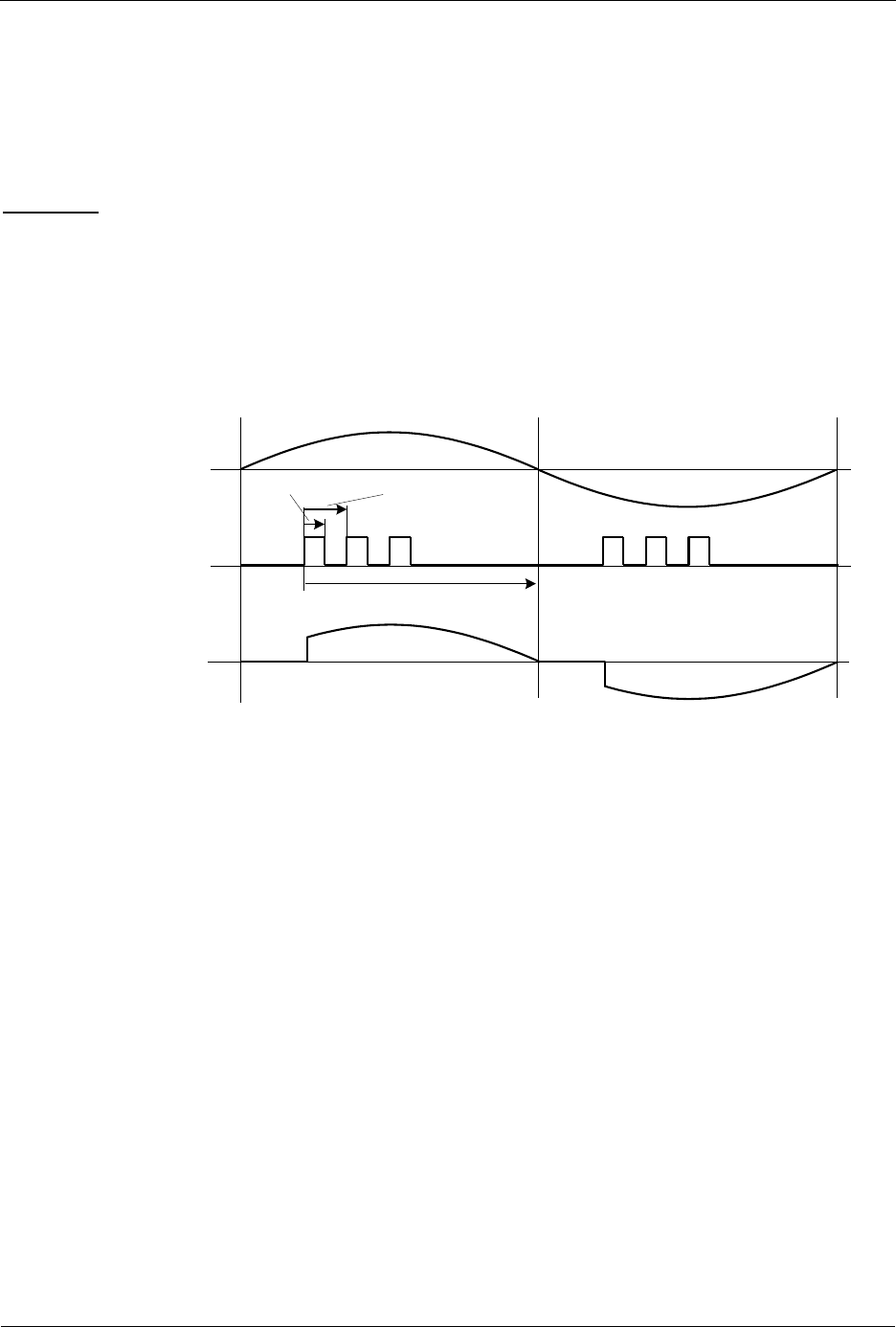
INS13478-5 Z-Wave 500 Series Appl. Programmers Guide v6.71.01 2017-02-28
Sigma Designs Inc.
Z-Wave Application Interfaces
Page 274 of 431
4.3.17.1.2 Modes of Operation
The Triac controller can operate in three modes:
Triac mode
FET trailing edge mode (for FET's and IGBT's)
FET leading mode (for FET's and IGBT's)
Triac Mode
In Triac Mode the Triac Controller will generate multiple pulses if the fire angle is less than 90º. The
length of each of the pulses is set by the parameter wPulseLength and the repetition length is set by the
parameter wPulseReplength. Depending on the dimming level the number of pulses will automatically be
calculated so that at least one full pulse is generated in the period from 90º to 180º of a halfperiod. One
pulse will be generated if the dimming level is set so that the first pulse is in the period from 90º to 180º
of a halfperiod. The dimming level, i.e. position of the first pulse, is set by the function
ZW_TRIAC_dimlevel_set. See figure below.
Mains voltage
TRIAC
PulseRepLength
PulseLength
Dim Level
Current trough load
Figure 26. PulseLength and PulseRepLength used in Triac Mode (resistive load)
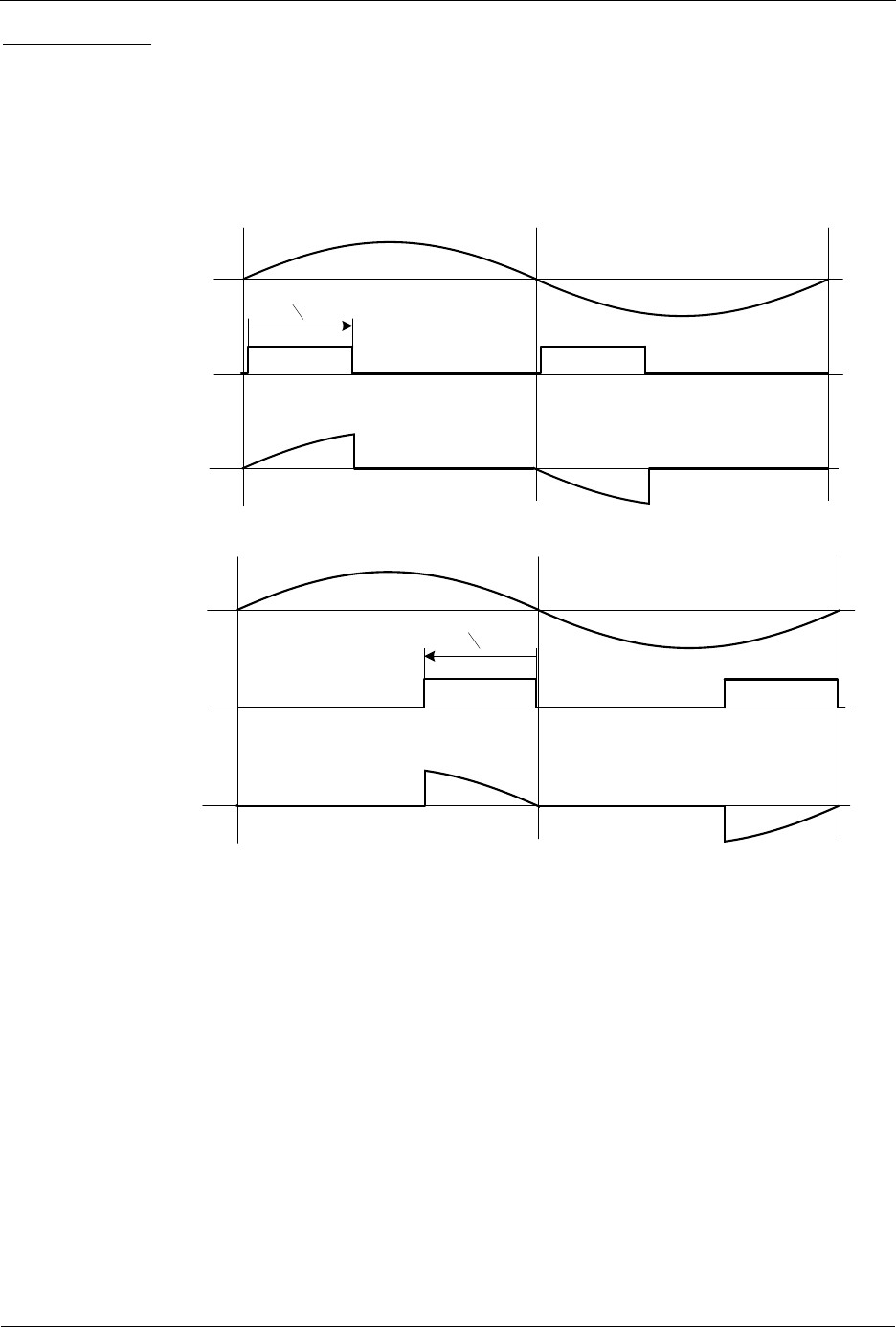
INS13478-5 Z-Wave 500 Series Appl. Programmers Guide v6.71.01 2017-02-28
Sigma Designs Inc.
Z-Wave Application Interfaces
Page 275 of 431
FET/IGBT Modes
In the FET/IGBT Modes the Triac Controller will generate one pulse per half period. The length of the
pulse is set by the function ZW_TRIAC_dimlevel_set(). In FET trailing edge mode the FET/IGBT control
signal (TRIAC) is set high at the zero-cross at 0º and set low in the halfperiod from 0º to 180º depending
of the dim level. See Figure 27. In FET leading edge mode the FET/IGBT control signal (TRIAC) is set
high in the halfperiod from 0º to 180º depending of the dim level and set low before the next zero-cross at
180º. See Figure 28
Mains voltage
Dim Level
Current through load
Control signal TRIAC
Figure 27 TRIAC output in FET Trailing Edge Mode (example with resistive load)
Mains voltage
Dim Level
Current through load
Control signal TRIAC
Figure 28 TRIAC output in FET Leading Edge Mode (example with resistive load)

INS13478-5 Z-Wave 500 Series Appl. Programmers Guide v6.71.01 2017-02-28
Sigma Designs Inc.
Z-Wave Application Interfaces
Page 276 of 431
4.3.17.2 ZW_TRIAC_enable
void ZW_TRIAC_enable(BOOL boEnable)
ZW_TRIAC_enable enables/disables the Triac Controller. When enabled the Triac controller takes
control over the TRIAC (P3.6) and the ZEROX
1
(P3.7) pins. ZW_TRIAC_init must have been called
before the Triac Controller is enabled.
Note: Calling ZW_TRIAC_enable(TRUE) will (besides from enabling the Triac Controller Fire signal
output) disable the Triac Controller ZEROX interrupt. So to use both the Triac Controller for generating
the Fire siganal output and the zero-x interrupt first call ZW_TRIAC_enable(TRUE) then call
ZW_TRIAC_int_enable(TRUE).
Defined in: ZW_triac_api.h
Parameters:
boEnable IN
TRUE or FALSE
TRUE: enables the Triac Controller
Serial API (Not supported)
1
If the PWM is enabled, see ZW_PWM_enable(), then the PWM will control the P3.7 pin

INS13478-5 Z-Wave 500 Series Appl. Programmers Guide v6.71.01 2017-02-28
Sigma Designs Inc.
Z-Wave Application Interfaces
Page 277 of 431
4.3.17.3 ZW_TRIAC_dimlevel_set
BOOL ZW_TRIAC_dimlevel_set(WORD wLevel)
ZW_TRIAC_dimlevel_set turns the Triac controller on and sets the dimming level. ZW_TRIAC_init must
have been called before the Triac Controller is started.
Defined in: ZW_triac_api.h
Parameters:
wLevel IN
Dimming level (0-1000),
where 0 is shut off and 1000 is full on
Return values:
BOOL
TRUE
The new dim level has been accepted by
the Triac Controller
FALSE
The Triac Controller has not yet read in
the previous dim level. Wait up to one
half period of the mains signal (50Hz:
10ms, 60 Hz 8.33ms) and try again
Serial API (Not supported)

INS13478-5 Z-Wave 500 Series Appl. Programmers Guide v6.71.01 2017-02-28
Sigma Designs Inc.
Z-Wave Application Interfaces
Page 278 of 431
4.3.17.4 ZW_TRIAC_int_enable
void ZW_TRIAC_int_enable(BYTE boEnable)
ZW_TRIAC_int_enable enables/disables the zero cross (ZeroX) interrupt. The ZeroX interrupt is issued
when the TRIAC controller detects a zero cross on the ZEROX signal. Hence, the Triac Controller will
take control of the ZEROX pin (P3.7) when ZW_TRIAC_int_enable(TRUE) has been called.
The ZeroX interrupt can be used to implement a SW based TRIAC controller where the TRIAC signal is
controlled by the SW. The Triac Controller will generate the ZeroX interrupt when it detects a zero cross
on the ZEROX signal, even if the Triac Controller has been disabled (by calling
ZW_TRIAC_enable(FALSE) ) as long as ZW_TRIAC_int_enable(TRUE) has been called.
Defined in: ZW_triac_api.h
Parameters:
boEnable IN
TRUE
FALSE
Enable the interrupt. The Triac controller
will issue an interrupt when a zero cross
is detected on the ZEROX signal.
Disable the Triac interrupt.
Serial API (Not supported)
The interrupt number is set by the define, INUM_TRIAC, as described in ZW050x.h

INS13478-5 Z-Wave 500 Series Appl. Programmers Guide v6.71.01 2017-02-28
Sigma Designs Inc.
Z-Wave Application Interfaces
Page 279 of 431
4.3.17.5 ZW_TRIAC_int_get
BOOL ZW_TRIAC_int_get(void)
ZW_TRIAC_int_get returns the state of the Triac Controller interrupt flag. Call
ZW_TRIAC_int_enable(TRUE) to enable the interrupt.
Defined in: ZW_triac_api.h
Return values:
BOOL
TRUE
FALSE
The Triac Controller interrupt flag is set.
The Triac Controller interrupt flag is
cleared.
Serial API (Not supported)

INS13478-5 Z-Wave 500 Series Appl. Programmers Guide v6.71.01 2017-02-28
Sigma Designs Inc.
Z-Wave Application Interfaces
Page 280 of 431
4.3.17.6 ZW_TRIAC_int_clear
void ZW_TRIAC_int_clear(void)
ZW_TRIAC_int_get clears the Triac Controller interrupt flag. Call ZW_TRIAC_int_enable(TRUE) to
enable the interrupt and use ZW_TRIAC_int_get to see whether the interrupt has been set.
Defined in: ZW_triac_api.h
Serial API (Not supported)

INS13478-5 Z-Wave 500 Series Appl. Programmers Guide v6.71.01 2017-02-28
Sigma Designs Inc.
Z-Wave Application Interfaces
Page 281 of 431
4.3.18 LED Controller API
The built-in LED Controller is targeted at LED light dimming applications. The controller can control up to
four individual channels in 3 different modes of operation. The application can use the following LED API
calls to control the 500 Series Z-Wave SoC LED Controller.

INS13478-5 Z-Wave 500 Series Appl. Programmers Guide v6.71.01 2017-02-28
Sigma Designs Inc.
Z-Wave Application Interfaces
Page 282 of 431
4.3.18.1 ZW_LED_init
void ZW_LED_init( BYTE bMode,
BYTE bChannelEn)
ZW_LED_init SHOULD be used to initialize the 500 Series Z-Wave SoC's integrated LED controller. The
function configures the desired mode of operation and the desired number of active channels. This
function SHOULD be called in ApplicationHWInit.
Defined in: ZW_led_api.h
Parameters:
bMode IN
Mode of operation type:
LED_MODE_NORMAL
In this mode, the LED controller generates a
pulse width modulated signal for each active
channel. The PWM signals has no phase
skew. The frequency of all of the PWM
signals is 32MHz/216 = 488.28Hz. The duty-
cycle of the PWM signals is set by the
ZW_LED_waveforms_set function.
LED_MODE_SKEW
The SKEW mode is same as the NORMAL
mode except that phase of the channels are
skewed. That is, the signal of channel 1 is
skewed ¼ of a period compared to the signal
of channel 0, the signal of channel 2 is
skewed ¼ of a period compared to the signal
of channel 1, etc.
LED_MODE_PRBS
In this mode, the LED controller uses a PRBS
signal generator to generate to LED signals.
The total high time in this mode equals the
total high time in the other modes.
bChannelEn IN
Bit mask of one of the channels to be
enabled
LED_CHANNEL0
Enable channel 0. The LED Controller takes
control of the P0.4 pin.
LED_CHANNEL1
Enable channel 1. The LED Controller takes
control of the P0.5 pin.
LED_CHANNEL2
Enable channel 2. The LED Controller takes
control of the P0.6 pin.
LED_CHANNEL3
Enable channel 3 The LED Controller takes
control of the P0.7 pin.
Serial API (Not supported)

INS13478-5 Z-Wave 500 Series Appl. Programmers Guide v6.71.01 2017-02-28
Sigma Designs Inc.
Z-Wave Application Interfaces
Page 283 of 431
4.3.18.2 ZW_LED_waveforms_set
void ZW_LED_waveforms_set(WORD *pwLevel)
ZW_LED_waveforms_set SHOULD be used to set the duty cycle for all LED Controller channels in one
operation. The function configures the waveform for all channels even if some channels are not enabled.
The function MUST NOT be called repeatedly, as it may run for up to 2.048ms to prevent race conditions
in the LED controller latch registers. This may affect frame reception and transmission in the protocol
layer.
Defined in: ZW_led_api.h
Parameters:
pwLevel IN
A pointer to an array with 4 16-bits
values.
0x0000-0xFFFF
Duty cycle times of the LED controller
channels. The first 16 bit element in the
array determines the value for channel 0.
The next 16 bit element determines the
value for channel 1, etc.
Serial API (Not supported)

INS13478-5 Z-Wave 500 Series Appl. Programmers Guide v6.71.01 2017-02-28
Sigma Designs Inc.
Z-Wave Application Interfaces
Page 284 of 431
4.3.18.3 ZW_LED_waveform_set
void ZW_LED_waveform_set( BYTE bChannel
WORD wLevel)
ZW_LED_waveform_set MAY be used to set the duty cycle time of one LED controller channel.
The function SHOULD NOT be called repeatedly. This may cause race conditions in the LED controller
latch registers. The companion function ZW_LED_data_busy MAY be used to check if the LED controller
is ready for a new value.
The application MUST NOT repeatedly call ZW_LED_data_busy from a busy waiting loop as this may
affect frame reception and transmission in the protocol layer.
Defined in: ZW_led_api.h
Parameters:
bChannel IN
The channel ID
LED_CHANNEL0
LED_CHANNEL1
LED_CHANNEL2
LED_CHANNEL3
wLevel
The duty cycle of the channel
0x0000-0xFFFF
Serial API (Not supported)

INS13478-5 Z-Wave 500 Series Appl. Programmers Guide v6.71.01 2017-02-28
Sigma Designs Inc.
Z-Wave Application Interfaces
Page 285 of 431
4.3.18.4 ZW_LED_data_busy
BOOL ZW_LED_data_busy(void)
ZW_LED_data_busy is used to check to see if the LED controller is ready for a new value.
The application MUST NOT repeatedly call ZW_LED_data_busy from a busy waiting loop as this may
affect frame reception and transmission in the protocol layer.
Defined in: ZW_led_api.h
Return values:
BOOL
TRUE
The LED controller cannot accept new
waveform values, since it has not yet
read in the previous data set. Wait up to
216/32MHz = 2.048ms and check again.
FALSE
The LED controller can accept new
waveform values
Serial API (Not supported)
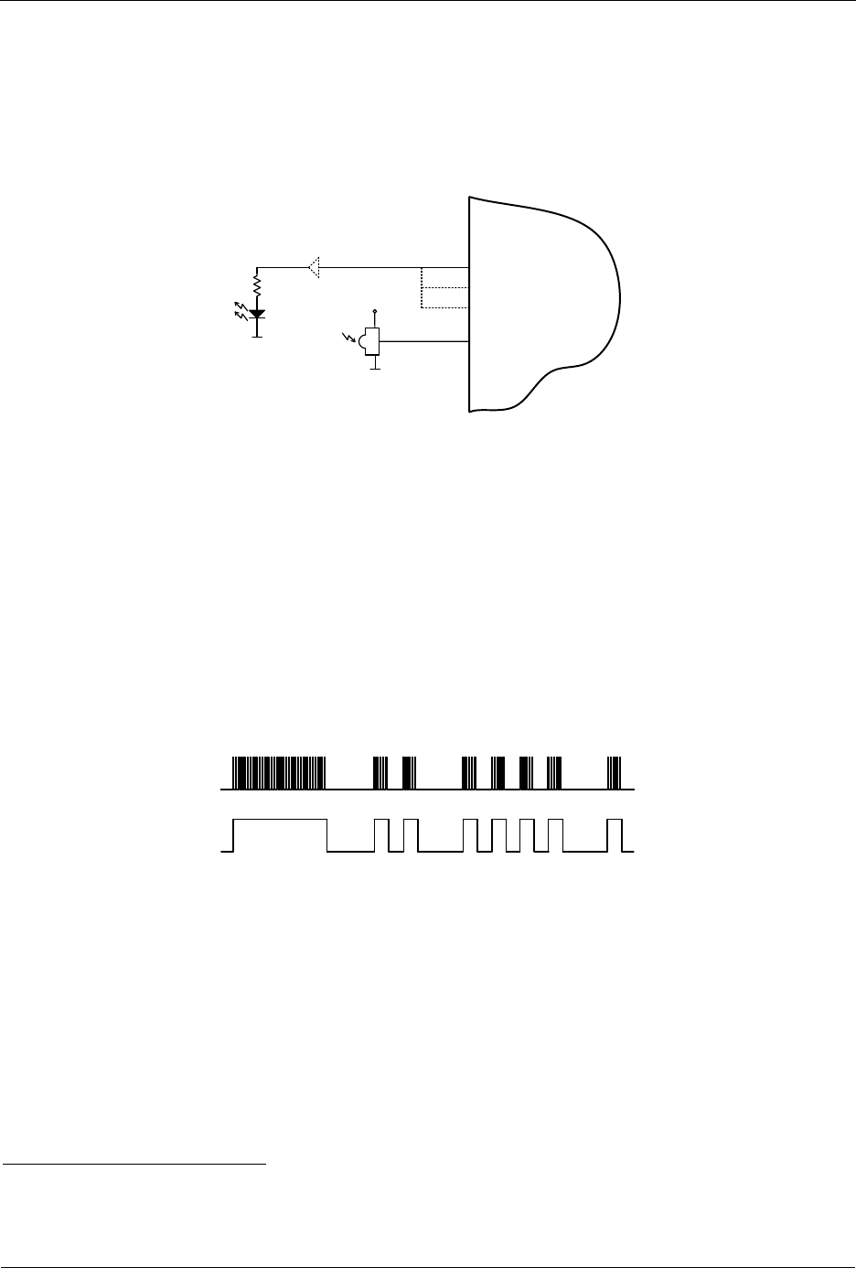
INS13478-5 Z-Wave 500 Series Appl. Programmers Guide v6.71.01 2017-02-28
Sigma Designs Inc.
Z-Wave Application Interfaces
Page 286 of 431
4.3.19 Infrared Controller API
The built-in Infrared (IR) Controller is targeted at IR remote control applications. The IR controller can
operate either as an IR transmitter or as an IR receiver. When operating as a transmitter one or more of
the three outputs (P3.4, P3.5, and P3.6) can be enabled as IR outputs that drive an IR LED, as depicted
in figure below. Each output can drive 12mA. Hence, using three outputs give a drive strength of 36mA. If
36mA is insufficient you will have to implement an external driver.
P3.5/IRTX1
P3.1/IRRX
Z-Wave Chip
P3.4/IRTX0
P3.6/IRTX2
IR LED
Optional driver
IR receiver
module
Figure 29. External IR hardware
An external IR receiver module or an IR transistor must be connected to Pin P3.1 when operating in
Receive mode. An IR receiver module has a built-in photo transistor and preamplifier with automatic gain
control and gives a digital TTL/CMOS output signal. The IR receivers can be found in two versions, with
and without demodulator. The versions without demodulator (like Vishay TSOP 98200) generates an
output signal with carrier (as depicted in the upper part of figure below), whereas the versions with
demodulator (like Vishay TSOP322xx) generates an output signal without the carrier (as depicted in the
lower part of figure below). Therefore, the one without demodulator is best for code learning applications,
where you want to be able to detect the carrier frequency. The one with modulator has improved
immunity against ambient light such as fluorescent lamps.
Using an photo transistor, where the transistor is connected directly to the 500 Series Z-Wave Chip
requires that the transmitting IR LED is placed within a short range (2”-4”) of the IR transistor, since the
IR transistor signal is analog and isn’t amplified. This circuit is also sensitive also to ambient light.
Figure 30. IR signal with and without carrier
In both cases, the IR Receiver detects widths of the marks (high/carrier on) and spaces (low) of a coded
IR message, as seen in figure below. The mark/space width data is stored in SRAM using DMA. While
running, the IR Controller requires very little MCU processing. The IR receiver is able to detect the
waveform of the carrier
1
.
The IR Transmitter generates a carrier and the marks and spaces for an IR message. The widths of the
marks and the spaces are read from SRAM using DMA.
1
Note that the IR receiver module can distort the duty cycle of the carrier.

INS13478-5 Z-Wave 500 Series Appl. Programmers Guide v6.71.01 2017-02-28
Sigma Designs Inc.
Z-Wave Application Interfaces
Page 287 of 431
Mark MarkSpace
Figure 31. IR Coded message with carrier
Both the IR Receiver and the IR Transmitter can be configured to detect/generate a wide range of IR
coding formats.
4.3.19.1 Carrier Detector/Generator
The carrier detector can detect the carrier waveform (high and low periods) of a carrier modulated IR
signal.
Carrier Low
Carrier high Carrier high
Carrier Low
Figure 32. Carrier waveform
The following bullets provide a short feature list of the Carrier Detector/generator.
1. IR Carrier Generator frequency range: 7.8kHz - 16MHz (50/50 duty cycle) or 10.4kHz -10.7MHz
(33/66 duty cycle)
2. A built-in Glitch Remover is able to remove glitches on the incoming IR signal.
3. For each detection process the IR Carrier Detector can calculate an average of the “high”
duration and an average of the “low” duration over 1 (no averaging), 2, 4, or 8 periods.
4.3.19.2 Organization of Mark/Space data in Memory
Both the IR Receiver engine and the IR Transmitter engine use SRAM to store mark/space data
information. The data is stored in the same format for both engines, as depicted in figure below. The
width of a mark is stored in 1 to 3 bytes – likewise the width of a space is stored in 1-3 bytes.
Bit 7 in each byte is used to differentiate the mark and space bytes. That is, bit 7 of all “mark”-bytes are
set to 1 and bit 7 of all “space”-bytes are set to 0.
The maximum number of bits used to describe a mark or space width is 16. The means that 3 bytes are
needed to store a 16 bit value (the upper 6 bits of the 3rd byte are unused); whereas 2 bytes are needed
to store a 14 bit value, and only one byte is needed to store a 7 bits value.
Refer to the example as depicted in figure below, where:
3 bytes are used for the start mark (PS0)
3 bytes are used for the start space (PS1)
2 bytes are used for each of the rest of the mark/spaces
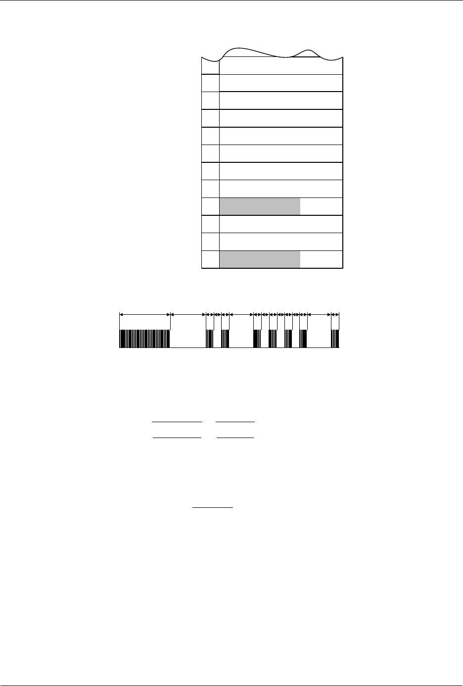
INS13478-5 Z-Wave 500 Series Appl. Programmers Guide v6.71.01 2017-02-28
Sigma Designs Inc.
Z-Wave Application Interfaces
Page 288 of 431
The maximum size of the mark/space data information is 511 bytes. The data can be stored anywhere in
the lower 4K XRAM in the 500 series Z-Wave SoC.
1
PS4[13:7]
1
PS0[13:7]
1
PS0[15:14]
1
PS0[6:0]
0
PS1[6:0]
0
0PS1[13:7]
1
PS2[6:0]
1
PS2[13:7]
0
PS3[6:0]
0
PS3[13:7]
1
PS4[6:0]
Baseaddress+00h
Baseaddress+01h
Baseaddress+02h
Baseaddress+03h
Baseaddress+04h
Baseaddress+05h
Baseaddress+06h
Baseaddress+07h
Baseaddress+08h
Baseaddress+09h
PS0
PS1
PS2
PS3
PS4
PS5
PS6
PS7
PS8
PS9
PS10
PS11
PS12
PS13
PS14
Baseaddress+0Ah
Baseaddress+0Bh
PS1[15:14]
7Bit 6 0
Figure 33. Mark/Space Data Memory Organization
The width is described as a certain count of prescaled clock periods. E.g if the prescaler is set to 1/16
and the width of a mark is 889us, the width will be stored as
LSB
MHz
us
f
prescaler
period
sys
1798
32
16
889
That is,
81.10
)2ln(
)1798ln(
11 bits are needed 2 bytes.
Since the maximum number of bits used to store each mark or space width is 16. It results in a maximum
mark or space width of:
262ms using clock divider of 128 or
1.7s using the Carrier Generator @ 36kHz

INS13478-5 Z-Wave 500 Series Appl. Programmers Guide v6.71.01 2017-02-28
Sigma Designs Inc.
Z-Wave Application Interfaces
Page 289 of 431
4.3.19.3 IR Transmitter
Before the IR transmitter can start generating the IR stream the IR Transmitter must have been
initialized, the Mark/Space data must have been built in a buffer in the lower 4kB XRAM, and the IR
interrupt is optionally enabled. The organization of the Mark/Space data is described in section 4.3.19.2.
Additionally, the Carrier Generator must be initialized.
The function ZW_IR_tx_init must be called to initialize all the needed parameters as described below
and in section 4.3.19.5:
1. The prescaler value for generating the carrier signal can be either: 1, 2, 3, 4, 5, 6, 7, or 8
resulting in a clock speed of either 32MHz, 16MHz, 32/3MHz, 8MHz, 32/5MHz, 16/3MHz,
32/7MHz, or 4MHz
2. The IR transmitter can use a prescaler that use the 32MHz clock divided by 1, 2, 4, 8, 16, 32, 64,
or 128. It can also use the rising edge of the carrier generated by the Carrier Generator.
3. The output(s) can be inverted as an option
4. The Idle state of the IR signal can be either high or low
5. One, two, or three IO’s can be used in parallel for driving an IR LED. Each output buffer can
drive 12mA.
6. The carrier wave form is set by the carrier prescaler and two parameters that sets the low and
high period of the carrier signal.
If only one IR coding style is used in a application the ZW_IR_tx_init function can be placed in
ApplicationInitHW, otherwise it can be placed in other parts of the code, typically in ApplicationPoll
The function ZW_IR_tx_data must be called when a certain IR stream is to be transmitted. The
parameters for this function sets is described below and in section 4.3.19.6
1. The address of the buffer in lower 4kB XRAM.
2. Size of IR data buffer in XRAM. The maximum size of the XRAM buffer is 511 bytes.
The IR Transmitter takes over control of the enabled IO’s (P3.4, P3.5, and/or P3.6) when the function
ZW_IR_tx_data is called and releases the control of the enabled IO’s when the IR signal has been
transmitted. Therefore, to make sure that IO’s used by the IR transmitter (P3.4, P3.5, and/or P3.6) are
output(s) and at the correct idle state, the GPIO must be set as outputs and the state must be set
accordingly.
An IR interrupt routine is supplied with the ZW_phy_infrared_040x library. A variable ir_tx_flag
(BOOL) is set TRUE when an IR message has been transmitted after ZW_IR_tx_data has been called.
The ir_tx_flag variable is cleared when calling ZW_IR_tx_data.
Once the IR Transmitter is started, use the function ZW_IR_disable to cancel the operation.
An example of how to initialize and run the IR Transmitter is shown in Figure 34.

INS13478-5 Z-Wave 500 Series Appl. Programmers Guide v6.71.01 2017-02-28
Sigma Designs Inc.
Z-Wave Application Interfaces
Page 290 of 431
void ApplicationInitHW()
{
EA=1;
EIR=1;
:
/* Carrier freq = 8MHz/(74+148)=36kHz, Carrier duty cycle 33/66 */
ZW_IR_tx_init(FALSE, // Use Mark/Space prescaler
3, // Prescaler: 32MHz/(2^3)=4MHz
FALSE, // Output is not inverted
FALSE, // Output state is low
0x03, // Enable P3.4 and P3.5
3, // Carrier prescaler set to 4 (32MHz/4=8MHz)
74, // Carrier low 74/8MHz = 9.25us
148); // Carrier high 148/8MHz = 18.5us
:
}
void ApplicationPoll()
{
BYTE bIrBuffer[16];
switch (mainState)
{
:
case SEND_PLAY:
// This IR message send a “PLAY” command
bIrBuffer[0]=0xA0;
bIrBuffer[1]=0x20;
bIrBuffer[2]=0xBF;
bIrBuffer[3]=0x20;
bIrBuffer[4]=0xA0;
bIrBuffer[5]=0x20;
bIrBuffer[6]=0xA0;
bIrBuffer[7]=0x20;
bIrBuffer[8]=0xA0;
bIrBuffer[9]=0x20;
bIrBuffer[10]=0xA0;
bIrBuffer[11]=0x20;
bIrBuffer[12]=0xBF;
bIrBuffer[13]=0x20;
bIrBuffer[14]=0xDF;
bIrBuffer[15]=0x80;
ZW_IR_status_clear(); // Clear all IR status flags

INS13478-5 Z-Wave 500 Series Appl. Programmers Guide v6.71.01 2017-02-28
Sigma Designs Inc.
Z-Wave Application Interfaces
Page 291 of 431
/* Use IrBuffer as buffer, size 16 bytes */
ZW_IR_tx_data((WORD)bIrBuffer, // Address of buffer
16); // Size of buffer
mainState=WAIT_IR_DONE;
break;
case WAIT_IR_DONE:
if (ir_tx_flag==TRUE) // Wait until IR TX flag is set
{
mainState=IDLE;
}
break;
}
}
Figure 34. Code example on use of IR transmitter
4.3.19.4 IR Receiver
Before the IR Receiver can be used to learn an incoming IR stream the IR receiver must have been
initialized, the Mark/Space data buffer must have been allocated in the lower 4kB XRAM, and the IR
interrupt must be enabled.
The organization of the Mark/Space data is described in section 4.3.19.2.
The function ZW_IR_learn_init must be called to initialize all the needed parameters as described below
and in section 4.3.19.5:
1. The Rx SRAM buffer size is configurable. (1-511 bytes)
2. The Mark/Space detector in the IR Receiver can use either a prescaler that use the 32MHz clock
divided by 1, 2, 4, 8, 16, 32, 64, or 128.
3. If the IR Receiver requires more SRAM space for the incoming IR stream, the MCU is interrupted
and an error flag is set
4. The IR Receiver can be configured to remove glitches on the incoming IR signal
5. The IR Receiver can be configured to average the detected duration of the low/high periods of
the Carrier
6. The IR input signal can be inverted as an option.
7. The IR Receiver can detect that the trailing space after the last mark of a received IR message is
longer that a specific size. This size must be set and this works at the same time as a timeout if
the message for some reason is shorter than expected.
Call the function ZW_IR_learn_data to start the learn process. The function is described below and in
section 4.3.19.9:
1. When the learn process starts the IR receiver will start out using the highest possible prescaler
value for the Carrier detector. When it then detects a carrier, it will measure the duration of the
low and high periods of the carrier and, if possible, rescale the prescaler to a lower value and
rerun the carrier measurement. This is done to achieve the highest precision of the carrier
measurement while preventing timer overflow.
2. The learn process will terminate when the IR Receiver has detected at least one Mark and then
a Space larger than a configurable amount of time, as described above.
An IR interrupt routine is supplied with the ZW_phy_infrared_040x library. A variable ir_rx_flag
(BOOL) is set TRUE when an IR message has been received. The ir_rx_flag variable is cleared
when calling ZW_IR_learn_data.

INS13478-5 Z-Wave 500 Series Appl. Programmers Guide v6.71.01 2017-02-28
Sigma Designs Inc.
Z-Wave Application Interfaces
Page 292 of 431
Call the function ZW_IR_learn_status_get to get the size of the received mark/space data, the detected
carrier characteristics and error state (status flags). The function ZW_IR_status_clear clears the status
flag.
Once the IR Receiver is started, use the function ZW_IR_disable to cancel the operation.
An example of how to initialize and run the IR Receiver is shown below.
BYTE bIrBuffer[256];
void ApplicationInitHW()
{
EA=1;
EIR=1;
ZW_IR_learn_init((WORD)bIrBuffer // Buffer address
256, // Buffer Size
4, // Prescaler: 32MHz/(2^4)=2MHz
7, // Trailing space min 2^16/2MHz=32.8ms
2, // Run average over 4 periods
1, // Remove glitches below 125ns
FALSE); // Do not invert input
}
void ApplicationPoll()
{
WORD wRxDataLen;
BYTE bRxCarrierLow;
BYTE bRxCarrierHigh;
BYTE bRxStatus;
:
switch(mainState)
{
case START_IR_LEARN:
ZW_IR_status_clear(); // Clear all IR status flags
ZW_IR_learn_data(); // Start IR Receiver
mainState=WAIT_IR_DONE;
break;
case WAIT_IR_DONE:
if (ir_rx_flag==TRUE) // Wait until IR RX flag is set
{
ZW_IR_learn_status_get( &wRxDataLen,
&bCarrierPrescaler,
&bRxCarrierLow,
&bRxCarrierHigh,
&bRxStatus);

INS13478-5 Z-Wave 500 Series Appl. Programmers Guide v6.71.01 2017-02-28
Sigma Designs Inc.
Z-Wave Application Interfaces
Page 293 of 431
if (bRxStatus == 0x00 || bRxStatus == IRSTAT_CDONE)
{
if (bRxStatus != IRSTAT_CDONE)
{
/* report that carrier could not be detected */
:
}
/* decode received data */
:
}
else
{
/* error handling */
:
}
mainState=IDLE;
}
else
{
/* Cancel the operation when boCancelIR is set
TRUE by other part of the code */
if (boCancelIR == TRUE)
ZW_IR_disable();
mainState=IDLE;
}
break;
}
}
Figure 35. Code example on use of IR receiver
The application software can use the following IR API calls to control the 500 Series Z-Wave SoC IR
Controller.

INS13478-5 Z-Wave 500 Series Appl. Programmers Guide v6.71.01 2017-02-28
Sigma Designs Inc.
Z-Wave Application Interfaces
Page 294 of 431
4.3.19.5 ZW_IR_tx_init
void ZW_IR_tx_init( BYTE boMSTimer,
BYTE bMSPrescaler,
BYTE boInvertOutput,
BYTE boHighDrive,
BYTE boIdleState,
BYTE bOutputEnable,
BYTE bCarrierPrescaler,
BYTE bCarrierLow,
BYTE bCarrierHigh)
ZW_IR_tx_init initializes the 500 Series Z-Wave SoC's integrated IR controller to Transmitter mode and
sets the required TX options.
Defined in: ZW_infrared_api.h
Parameters:
boMSTimer IN
TX Mark/Space prescaler mode:
TRUE
Mark/space generator runs on carrier
period timer. That is, the length of the
Marks/Spaces is calculated as the
carrier period multiplied by the value
read in XRAM
FALSE
Mark/space generator runs on a
prescaled timer. That is, the length of
the Marks/Spaces is calculated as
the prescaled timer period multiplied
by the value read in XRAM. Prescaler
value is set by bMSPrescaler.
bMSPrescaler IN
Mark/Space timer prescaler
Valid values: 0-7
Resulting timer clock frequency:
0: 32MHz
1: 16MHz
2: 8MHz
3: 4MHz
4: 2MHz
5: 1MHz
6: 500kHz
7: 250kHz
Not applicable when boMSTimer is
true
boInvertOutput IN
Invert IR output
TRUE
output is inverted
FALSE
output is not inverted
boHighDrive
Invert IR output
TRUE
use 12mA drive strength of IR Tx IO
output buffers
FALSE
use 8mA drive strength of IR Tx IO
out buffers

INS13478-5 Z-Wave 500 Series Appl. Programmers Guide v6.71.01 2017-02-28
Sigma Designs Inc.
Z-Wave Application Interfaces
Page 295 of 431
boIdleState IN
Idle State of IR output
TRUE
Idle state is high
FALSE
Idle state is low
bOutputEnable IN
Outputs enabled
Valid values: 0-7
000: All outputs disabled
xx1: P3.4 enabled
x1x: P3.5 enabled
1xx: P3.6 enabled
Idle state is high
bCarrierPrescaler IN
Carrier generator prescaler
Valid values: 0-7
Resulting timer clock frequency:
0: 32MHz
1: 32MHz/2
2: 32MHz/3
3: 32MHz/4
4: 32MHz/5
5: 32MHz/6
6: 32MHz/7
7: 32MHz/8
bCarrierLow IN
Carrier low time
0: 1 prescaled clock period
1: 2 prescaled clock periods
: :
255: 256 prescaled clock periods
bCarrierHigh IN
Carrier High time
0: 1 prescaled clock period
1: 2 prescaled clock periods
: :
255: 256 prescaled clock periods
Serial API (Not supported)

INS13478-5 Z-Wave 500 Series Appl. Programmers Guide v6.71.01 2017-02-28
Sigma Designs Inc.
Z-Wave Application Interfaces
Page 296 of 431
4.3.19.6 ZW_IR_tx_data
void ZW_IR_tx_data( WORD pBufferAddress,
WORD wBufferLength)
ZW_IR_tx_data sets the address and the length of the buffer containing the Mark/space data to be sent.
The IR Controller will start to transmit immediately after these values have been set.
Defined in: ZW_infrared_api.h
Parameters:
pBufferAddress IN
Address of Tx buffer in lower XRAM
memory
wBufferLength IN
Number of bytes in TX buffer. Valid
values (1-511)
Serial API (Not supported)

INS13478-5 Z-Wave 500 Series Appl. Programmers Guide v6.71.01 2017-02-28
Sigma Designs Inc.
Z-Wave Application Interfaces
Page 297 of 431
4.3.19.7 ZW_IR_tx_status_get
BYTE ZW_IR_tx_status_get(void)
ZW_IR_tx_status_get is used to check to the status of the IR controller after an IR message has been
transmitted.
Defined in: ZW_infrared_api.h
Return values:
IRSTAT_MSOVERFLOW
The format of the data in the IR buffer is
invalid. The perceived Mark/Space value
is greater than 216.
IRSTAT_PSSTARV
The IR controller’s DMA engine was not
able to read data from XRAM in time
because the access to the XRAM was
used by (an) other DMA engine(s) with
higher priority. To get rid of this error, try
to disable other DMA engines (USB, RF,
etc.) and run the IR transmitter again.
IRSTAT_ACTIVE
The IR Controller is active
Serial API (Not supported)

INS13478-5 Z-Wave 500 Series Appl. Programmers Guide v6.71.01 2017-02-28
Sigma Designs Inc.
Z-Wave Application Interfaces
Page 298 of 431
4.3.19.8 ZW_IR_learn_init
void ZW_IR_learn_init( WORD pBufferAddress,
WORD wBufferLen,
BYTE bMSPrescaler,
BYTE bTrailSpace,
BYTE bCAverager,
BYTE bCGlitchRemover,
BYTE boInvertInput)
ZW_IR_learn_init initializes the 500 Series Z-Wave SoC's integrated IR controller to receive/learn mode
and sets the required RX options.

INS13478-5 Z-Wave 500 Series Appl. Programmers Guide v6.71.01 2017-02-28
Sigma Designs Inc.
Z-Wave Application Interfaces
Page 299 of 431
Defined in: ZW_infrared_api.h
Parameters:
pBufferAddress IN
Address of Rx buffer in lower XRAM memory
wBufferLength IN
Size of RX buffer.
Valid values (1-511)
bMSPrescaler IN
Mark/Space timer prescaler
Valid values: 0-7
Resulting timer clock frequency:
0: 32MHz
1: 16MHz
2: 8MHz
3: 4MHz
4: 2MHz
5: 1MHz
6: 500kHz
7: 250kHz
bTrailSpace IN
Trailing space after last Mark. After the incoming
IR signal has been low for this period of time the
IR receiver stops.
Valid values: 0-7
0: 512 prescaled clock periods
1: 1024 prescaled clock periods
2: 2048 prescaled clock periods
3: 4096 prescaled clock periods
4: 8192 prescaled clock periods
5: 16384 prescaled clock periods
6: 32768 prescaled clock periods
7: 65536 prescaled clock periods
bCAverager IN
Average Carrier high/low length measurement
over multiple carrier periods.
Valid values: 0-3
0: 1 carrier period
1: 2 carrier periods
2: 4 carrier periods
3: 8 carrier periods (Recommended value)
bCGlitchRemover IN
Remove glitches from incoming IR signal.
Valid values: 0-3
0: disabled
1: < 125ns
2: < 250ns
3: < 500ns
boInvertInput IN
TRUE
IR input is inverted
FALSE
IR input is not inverted
Serial API (Not supported)

INS13478-5 Z-Wave 500 Series Appl. Programmers Guide v6.71.01 2017-02-28
Sigma Designs Inc.
Z-Wave Application Interfaces
Page 300 of 431
4.3.19.9 ZW_IR_learn_data
void ZW_IR_learn_data(void)
ZW_IR_learn_data clears the ir_rx_flag variable and starts the IR Controller in Rx/learn mode. Use
ZW_IR_disable to cancel on ongoing learn process.
Defined in: ZW_infrared_api.h
Serial API (Not supported)
Refer to section 0 for a detailed description of the learn function.

INS13478-5 Z-Wave 500 Series Appl. Programmers Guide v6.71.01 2017-02-28
Sigma Designs Inc.
Z-Wave Application Interfaces
Page 301 of 431
4.3.19.10 ZW_IR_learn_status_get
void ZW_IR_learn_status_get( WORD *wDataLength,
BYTE *bCarrierPrescaler,
BYTE *bCarrierLow,
BYTE *bCarrierHigh,
BYTE *bStatus)
ZW_IR_learn_status_get is used to check to the status of the IR controller, to get the length of the
received data, the detected carrier characteristics, and the error state. Call this function after a learn
operation is done, i.e. after the ir_rx_flag variable has been set.

INS13478-5 Z-Wave 500 Series Appl. Programmers Guide v6.71.01 2017-02-28
Sigma Designs Inc.
Z-Wave Application Interfaces
Page 302 of 431
Defined in: ZW_infrared_api.h
Parameters:
wDataLength OUT
Length of the received data
bCarrierPrescaler OUT
Optimal Carrier prescaler
value
Valid values: 0-7
0: 32MHz
1: 32MHz/2
2: 32MHz/3
3: 32MHz/4
4: 32MHz/5
5: 32MHz/6
6: 32MHz/7
7: 32MHz/8
bCarrierLow OUT
Length of the Low period of
the Carrier (in prescaled
system clocks)
bCarrierHigh OUT
Length of the High period of
the Carrier (in prescaled
system clocks)
bStatus OUT
IRSTAT_PSSTARV
The IR controller’s DMA engine was not
able to write data from XRAM in time
because the access to the XRAM was used
by (an) other DMA engine(s) with higher
priority. To get rid of this error, try to disable
other DMA engines (USB, RF, etc.) and
run the IR transmitter again.
IRSTAT_MSOVERFLOW
The duration of a mark/space exceeded 216
prescaled clock periods.
IRSTAT_COF
The Carrier detector failed because the
perceived carrier low/high period was too
long.
IRSTAT_CDONE
The Carrier detector completed measuring
the carrier without errors
IRSTAT_RXBUFOVERFLOW
The RX buffer was too small to store the
received IR data
IRSTAT_ACTIVE
The IR Controller is active
Serial API (Not supported)

INS13478-5 Z-Wave 500 Series Appl. Programmers Guide v6.71.01 2017-02-28
Sigma Designs Inc.
Z-Wave Application Interfaces
Page 303 of 431
4.3.19.11 ZW_IR_status_clear
void ZW_IR_status_clear(void)
ZW_IR_status_clear clears the Tx and Rx IR Status flags. Call this function before rerunning the IR
Controller.
Defined in: ZW_infrared_api.h
Serial API (Not supported)

INS13478-5 Z-Wave 500 Series Appl. Programmers Guide v6.71.01 2017-02-28
Sigma Designs Inc.
Z-Wave Application Interfaces
Page 304 of 431
4.3.19.12 ZW_IR_disable
void ZW_IR_disable(void)
This function disables any ongoing IR operation and sets the IR Controller to its idle state. Use
ZW_IR_status_clear to clear any status bit before starting the IR Transmitter or IR Receiver.
Defined in: ZW_infrared_api.h
Serial API (Not supported)
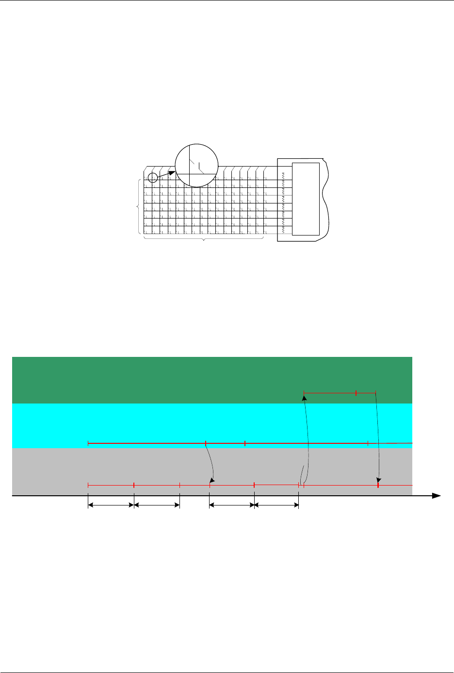
INS13478-5 Z-Wave 500 Series Appl. Programmers Guide v6.71.01 2017-02-28
Sigma Designs Inc.
Z-Wave Application Interfaces
Page 305 of 431
4.3.20 Keypad Scanner Controller API
The built-in hardware keypad scanner is able to scan a key matrix of up to 8 rows x 16 columns. When
the Keypad Scanner is activated, the 8 row inputs (P1.0-P1.7) must either be connected to the hardware
key matrix or kept open. The number of columns can be configured to the range 1-16. The actual IO’s
being used as column outputs are “KSCOL0” (P0.0) when the column count is set to one, “KSCOL0,
KSCOL1” (P0.0, P0.1) when the column count is set to two, “KSCOL0, KSCOL1, KSCOL2” (P0.0, P0.1,
P0.2) when the column count is set to three, etc. A column output can be left open, though.
ZM4101
Columns 0-15
Rows 0-7
Keypad
Scanner
Figure 36. Keypad matix
Once the Keypad Scanner is enabled, it will scan each column for an amount of time (Scan Delay). If it,
at a certain column detects a key press, it will wait for a period (Debounce delay) to get any eventual
debounce noise to disappear. Then it will detect whether the input stays stable for another amount of
time (Stable delay). The Keypad Scanner will issue an interrupt request to the MCU, if the row input is
stable for the defined amount of “Stable delay” time. See figure below.
Scan
delay Scan
delay
Scans
Column 0
KeyPad
Scanner
KeyPad
time
Scans
Column 1
Key press
in Column 2
Debounce
delay
Row input stable
Stable
delay
Scans
Column 2
Sets Key Press
interrupt flag
MCU Handles
IRQ
Clears
Key Press
Flag
Scans
Column 3
Idle
Awaits
debounce
Verifies
stable input
No keys
pressed No keys
pressed
Figure 37. Scan flow
Each of these delays can be configured by using the function ZW_KS_init, which must be called in
ApplicationInitHW as shown in figure below.

INS13478-5 Z-Wave 500 Series Appl. Programmers Guide v6.71.01 2017-02-28
Sigma Designs Inc.
Z-Wave Application Interfaces
Page 306 of 431
void KeyPadChanges(BYTE_P pbKeypadMatrix, BYTE bStatus)
{
/* Call the user defined application function
InterpretKeys with the keypad matrix as parameter */
switch (bStatus)
{
case ZW_KS_KEYPRESS_VALID:
InterpretKeys(keyPadMatrix);
break;
case ZW_KS_KEYPRESS_INVALID:
beep();
break;
case ZW_KS_KEYPRESS_RELEASED:
cleanup();
break
default:
}
}
void ApplicationInitHW(BYTE bWakeupReason)
{
:
ZW_KS_init(7, /* 8 Columns */
4, /* Column scan delay 10ms */
15, /* Debounce delay 32ms */
5, /* Row Stable delay 12ms */
10, /* Polling period of 100 ms*/
KeyPadChanges /* The callback function used to notify */
/* the application when changes occurs */
/* to the keypad matrix */
)
ZW_KS_enable(TRUE);
:
}
void ApplicationPoll()
{
:
/* Go into power down mode */
ZW_KS_pd_enable(TRUE);
ZW_SetSleepMode(WUT_MODE,ZW_INT_MASK_EXT1,0);
:
}
Figure 38. Example of the API calls for the KeyPad scanner
The Keypad ISR will detect any changes occurred to the keypad matrix. The changes to the keypad
matrix array will be polled periodically. The polling period is defined by the application through
ZW_KS_init.
Apart from setting the size of the key matrix and the delays, a callback function must be defined in
ZW_KS_init. If any changes to the keypad matrix are detected the application will be notified by calling
this user defined callback function. Figure above shows an example of how ZW_KS_init is used.
The parameter to the callback function is an array of the type BYTE. The array has 16 elements one for
each column. It has 16 elements regardless of the number of actual configured columns in use. The
element with index n holds the row-status for column number n. That is, bit 0 of an element hold the

INS13478-5 Z-Wave 500 Series Appl. Programmers Guide v6.71.01 2017-02-28
Sigma Designs Inc.
Z-Wave Application Interfaces
Page 307 of 431
status of row 0, bit 1 of an element hold the status of row 1, etc. The array is defined in the Keypad API
library.
Note: the Keypad Scanner IRQ signal is shared with “EXT1”, external interrupt 1. Therefore, that interrupt
routine must not be included in the application code, when using the Keypad Scanner.
When a key press must wake up the 500 Series Z-Wave SoC from powerdown mode,
ZW_KS_pd_enable(TRUE) must be called just before the chip is put into powerdown mode. Doing so,
will activate the external interrupt, if any key is pressed. When the 500 Series Z-Wave SoC is awake first
the function ZW_KS_init and then ZW_KS_enabled must be called to initialize and enable the Key
Scanner and thereby grab the actual key combination.

INS13478-5 Z-Wave 500 Series Appl. Programmers Guide v6.71.01 2017-02-28
Sigma Designs Inc.
Z-Wave Application Interfaces
Page 308 of 431
4.3.20.1 ZW_KS_init
void ZW_KS_init( BYTE bCols
BYTE bScanDelay
BYTE bDebounceDelay,
BYTE bStableDelay
BYTE bReportWaitTimeout,
VOID_CALLBACKFUNC(KeyPadCallBack)(BYTE_P keyMatrix, BYTE bStatus) )
ZW_KS_init initializes the 500 Series Z-Wave SoC's integrated Keypad Scanner.
Defined in: ZW_keypad_scanner_api.h
Parameters:
bCols IN
Sets the number of enabled columns.
Valid values 0-15.
0: 1 Column
1: 2 Columns
:
15: 16 Columns
E.g. setting this to 7 will enable KSCOL0-
KSCOL7 (P0.0-P0.7)
bScanDelay IN
Sets column “Scan delay”
0: 2ms
1: 4ms
:
15: 32ms
bDebounceDelay IN
Sets “debounce delay”
0: 2ms
1: 4ms
:
15: 32ms
bStableDelay IN
Sets “stable delay”
0: 2ms
1: 4ms
:
15: 32ms
bReportWaitTimeout IN
Set the timeout delay before the main
loop call the KeyPadCallBack function.
0: not valid
1: 10 ms
2: 20 ms
:
255: 2550 ms

INS13478-5 Z-Wave 500 Series Appl. Programmers Guide v6.71.01 2017-02-28
Sigma Designs Inc.
Z-Wave Application Interfaces
Page 309 of 431
KeyPadCallBack IN
The call back function that the main loop
will use to notify the application about the
changes in the keypad matrix.
The function will only be called when
changes to the keypad matrix occurs.
Parameters:
pbKeyMatrix OUT:
Pointer to the keypad matrix BYTE
array.
bStatus OUT:
Returns the status of the contents
of the key matrix as one of the
follwing:
ZW_KS_KEYPRESS_VALID
The contents of the key matrix
array is valid
ZW_KS_KEYPRESS_INVALID
The contents of the key matrix
array is invalid, i.e. more than 3
keys are pressed in an invalid
manner
ZW_KS_KEYPRESS_RELEASED
All keys have been released
Serial API (Not supported)

INS13478-5 Z-Wave 500 Series Appl. Programmers Guide v6.71.01 2017-02-28
Sigma Designs Inc.
Z-Wave Application Interfaces
Page 310 of 431
4.3.20.2 ZW_KS_enable
void ZW_KS_enable(BOOL boEnable)
ZW_KS_enable enables or disables the Keypad Scanner. Must be called in ApplicationInitHW.
Defined in: ZW_keypad_scanner_api.h
Parameters:
boEnable IN
TRUE
Enables Keypad Scanner
FALSE
Disables Keypad Scanner
Serial API (Not supported)

INS13478-5 Z-Wave 500 Series Appl. Programmers Guide v6.71.01 2017-02-28
Sigma Designs Inc.
Z-Wave Application Interfaces
Page 311 of 431
4.3.20.3 ZW_KS_pd_enable
void ZW_KS_pd_enable(BYTE boEnable)
ZW_KS_ pd_enable(TRUE) must be called before putting the 500 Series Z-Wave SoC into powerdown
mode, if the chip is to be woken by a key press.
Defined in: ZW_keypad_scanner_api.h
Parameters:
boEnable IN
TRUE
Enables Keypad Scanner Powerdown mode
FALSE
Disables Keypad Scanner Powerdown mode
Serial API (Not supported)

INS13478-5 Z-Wave 500 Series Appl. Programmers Guide v6.71.01 2017-02-28
Sigma Designs Inc.
Z-Wave Application Interfaces
Page 312 of 431
4.3.21 USB/UART common API
This is a simple unified API for using the UART0 or USB interfaces.
If the C-define “USBVCP” is defined, then all functions in this chapter will access the USB interface,
otherwise UART0 will be used
First the API calls ZW_InitSerialIf and ZW_FinishSerialIF must be called to initialize the interface, after
that data can be transferred using the put and get functions described in the following sections.
For USB: On windows you need a driver included in the DevKit. On linux and Mac no driver is needed.
On all platforms you will get a virtual serial port on the PC side. The certified USB interface complies to
USB 2.0 full speed. However, USB driver supports only Bus-Powered USB devices and not Self-
Powered.

INS13478-5 Z-Wave 500 Series Appl. Programmers Guide v6.71.01 2017-02-28
Sigma Designs Inc.
Z-Wave Application Interfaces
Page 313 of 431
4.3.21.1 ZW_InitSerialIf
void ZW_InitSerialIf( WORD wBaudRate)
This function initializes the controller using the baud rate indicated by the parameter wBaudRate. It is
important to called the function ZW_FinishSerialIf immediately after to indicate that initialization is
finished.
Notice: When using the USB-interface, this parameter does not impact the actual transmission-speed as
it is dictated by the USB standard.
Defined in: ZW_conbufio.h
Parameters:
bBaudRate IN
96=>9600baud/s, 1152=>115200baud/s
Serial API (Not supported)

INS13478-5 Z-Wave 500 Series Appl. Programmers Guide v6.71.01 2017-02-28
Sigma Designs Inc.
Z-Wave Application Interfaces
Page 314 of 431
4.3.21.2 ZW_FinishSerialIf
BOOL ZW_FinishSerialIf(void)
This function must be called immediately after ZW_InitSerialIf to indicate that initialization is finished.
Defined in: ZW_conbufio.h
Return value
Always TRUE
Serial API (Not supported)

INS13478-5 Z-Wave 500 Series Appl. Programmers Guide v6.71.01 2017-02-28
Sigma Designs Inc.
Z-Wave Application Interfaces
Page 315 of 431
4.3.21.3 ZW_SerialCheck
BYTE ZW_SerialCheck(void)
This function checks if data has been received and is ready to be read
Defined in: ZW_conbufio.h
Return value
Nonzero if there is data in the input queue
Serial API (Not supported)

INS13478-5 Z-Wave 500 Series Appl. Programmers Guide v6.71.01 2017-02-28
Sigma Designs Inc.
Z-Wave Application Interfaces
Page 316 of 431
4.3.21.4 ZW_SerialGetByte
BYTE ZW_SerialGetByte(void)
This function reads one byte from the input buffer. First use ZW_SerialCheck to make sure that there is
data available.
Defined in: ZW_conbufio.h
Return value
The byte received from the USB/UART interface
Serial API (Not supported)

INS13478-5 Z-Wave 500 Series Appl. Programmers Guide v6.71.01 2017-02-28
Sigma Designs Inc.
Z-Wave Application Interfaces
Page 317 of 431
4.3.21.5 ZW_SerialPutByte
BYTE ZW_SerialPutByte(BYTE b)
This function puts one byte into the USB/UART output buffer
Defined in: ZW_conbufio.h
Return value
Non-zero for success
Parameters:
Byte b
Data to be written to the USB/UART output buffer
Serial API (Not supported)

INS13478-5 Z-Wave 500 Series Appl. Programmers Guide v6.71.01 2017-02-28
Sigma Designs Inc.
Z-Wave Application Interfaces
Page 318 of 431
4.3.22 Flash API
The Flash API provides functions for reading the NVR area of the Flash as well as functions for erasing
and programming Flash code sectors. Each sector is 2KB and there is 64 sectors in total. The code
address range for sector 0 is 0x00000-0x07FF, sector 1 is 0x00800-0x00FFF, etc.
The Flash is erased sector by sector and each sector is programmed one page (256bytes) at a time. The
data to be programmed into the flash sector is read from the lower 4kB XRAM.
To minimize the possibility to erase or program the flash code area by a mistake a function,
ZW_FLASH_code_prog_unlock() that takes a "unlock string" as parameter, has to be called before an
erase or program operation can be execised.
Only those sectors that not have been protected by lock bits can be erased/programming by the MCU
API calls. Refer to [3] for a description of how to set the protection lock bits.
// Program sectors 10 to 13
for (sector=10;sector<14;sector++)
{
// Unlock the flash erase and program funtions
// the unlock string contains the four byte unlock string
ZW_FLASH_code_prog_unlock(&unlock[0]);
// Erase sector
if(ZW_FLASH_code_sector_erase(sector))
{
Handle error
}
// Check state
if (ZW_FLASH_prog_state())
{
Handle error
}
// lock the erase and program function
ZW_FLASH_code_prog_lock();
// program flash sector page by page
for (i=0; i<8; i++)
{
Make data ready in buffer in memory
// unlock programming
if(ZW_FLASH_code_prog_unlock(&unlock[0]))
{
Handle error
}
// program page 'i' in sector 'sector' with contents from
// XRAM starting from the address set by '&buffer'
if(ZW_FLASH_code_page_prog(&buffer,
sector,
i)) // page
{
Handle error
}
// lock the erase and program function
ZW_FLASH_code_prog_lock();
Handle error
}
}
// clear unlock to prevent undecired earse or prog operations
unlock={0x00,0x00,0x00,0x00};

INS13478-5 Z-Wave 500 Series Appl. Programmers Guide v6.71.01 2017-02-28
Sigma Designs Inc.
Z-Wave Application Interfaces
Page 319 of 431
4.3.22.1 ZW_FLASH_code_prog_unlock
BYTE ZW_Flash_code_prog_unlock(BYTE pbUnlockString)
This function enables erase and program operations on non-protected Flash code sectors.
Defined in: ZW_flash_api.h
Parameters:
pbUnlockString IN
Pointer to a 4 byte
string.
The string: 0xDE, 0xAD, 0xBE, 0xEF
Return value:
BYTE
Bit mask:
FLASH_STATE_LOCK:
Zero:
Flash erase and programming is locked
Flash erase and programming is unlocked
Serial API (Not supported)

INS13478-5 Z-Wave 500 Series Appl. Programmers Guide v6.71.01 2017-02-28
Sigma Designs Inc.
Z-Wave Application Interfaces
Page 320 of 431
4.3.22.2 ZW_FLASH_code_prog_lock
BYTE ZW_Flash_code_prog_lock(void)
This function disables erase and program operations on Flash code sectors.
Defined in: ZW_flash_api.h
Return value:
BYTE
Bit mask
FLASH_STATE_LOCK:
Zero:
Flash erase and programming is locked
Flash erase and programming is unlocked
Serial API (Not supported)

INS13478-5 Z-Wave 500 Series Appl. Programmers Guide v6.71.01 2017-02-28
Sigma Designs Inc.
Z-Wave Application Interfaces
Page 321 of 431
4.3.22.3 ZW_FLASH_code_sector_erase
BYTE ZW_Flash_code_sector_erase(BYTE bSector)
This function erases a non-protected Flash code sector. The erase operation has to be unlocked before
this function will work, refer to ZW_FLASH_code_prog_unlock(). To check which sectors that have
been protected use the function ZW_FLASH_nvr0_get() to read the protection bits in the bytes located
at the NVR0 addresses 0-7.
The MCU code execution will be halted for 5ms while the program operation is running.
Defined in: ZW_flash_api.h
Parameters:
bSector IN
Sector number (0-63).
Return value:
BYTE
Bit mask
FLASH_STATE_ERR:
FLASH_STATE_DONE:
The Flash erase process failed
The Flash erase process passed
Serial API (Not supported)

INS13478-5 Z-Wave 500 Series Appl. Programmers Guide v6.71.01 2017-02-28
Sigma Designs Inc.
Z-Wave Application Interfaces
Page 322 of 431
4.3.22.4 ZW_FLASH_code_page_prog
BYTE ZW_Flash_code_page_prog( BYTE pbRamAddress,
BYTE bSector,
BYTE bPage
This function programs a non-protected Flash code sector page with data from XRAM. The program
operation has to be unlocked before this function will work, refer to ZW_FLASH_code_prog_unlock().
To check which sectors that have been prptected use the function ZW_FLASH_nvr0_get() to read the
protection bits in the bytes located in NVR0 at the addresses 0-7.
The MCU code execution will be halted for up to 1.6ms while the program operation is running.
Defined in: ZW_flash_api.h
Parameters:
pbRamAddress IN
Pointer to data buffer in lower
4KB XRAM
bSector IN
Sector number (0-63).
bPage IN
Page number (0-7).
Return value:
BYTE
Bit mask
FLASH_STATE_LOCK:
FLASH_STATE_ERR:
FLASH_STATE_DONE:
Flash erase and programming is locked
The Flash programming process failed
The Flash programming process passed
Serial API (Not supported)

INS13478-5 Z-Wave 500 Series Appl. Programmers Guide v6.71.01 2017-02-28
Sigma Designs Inc.
Z-Wave Application Interfaces
Page 323 of 431
4.3.22.5 ZW_FLASH_auto_prog_set
void ZW_FLASH_auto_prog_set(void)
This function enables the Auto Program Mode and resets the 500 Series Z-Wave SOC after 7.8ms..
Defined in: ZW_flash_api.h
Parameters:
none
Serial API:
HOST->ZW: REQ | 0x27

INS13478-5 Z-Wave 500 Series Appl. Programmers Guide v6.71.01 2017-02-28
Sigma Designs Inc.
Z-Wave Application Interfaces
Page 324 of 431
4.3.23 CRC API
The CRC API provides functions for calculating and checking CRC-16 value of a data area. The
checksum is based on CRC-CCITT (0x1D0F).
4.3.23.1 ZW_CheckCrc16
WORD ZW_CheckCrc16( WORD crc,
BYTE pDataAddr,
WORD bDataLen)
This function calculates or check CRC-16 value of a data area having a starting address and length.
Defined in: ZW_crc.h
Parameters:
crc IN
Initialization or CRC-16
value.
To calculate CRC-16 for a given data area set
the initialization value equal to 0x1D0F. It can
also be used to carry over CRC-16 value
between separate calculations of multiple data
areas.
pDataAddr IN
Address of data area.
bDataLen IN
Size of data area.
Return value:
WORD
CRC-16 value:
Zero:
Calculated CRC-16 value
CRC-16 value matches CRC-16 input value.
Serial API (Not supported)

INS13478-5 Z-Wave 500 Series Appl. Programmers Guide v6.71.01 2017-02-28
Sigma Designs Inc.
Z-Wave Application Interfaces
Page 325 of 431
4.3.23.2 ZW_CreateCrc16
WORD ZW_CreateCrc16( BYTE pHeaderAddr,
BYTE bHeaderLen,
BYTE pPayloadAddr,
BYTE bPayloadLen)
This function calculates a combined CRC-16 value of two data areas both having a starting address and
length. This function calls ZW_CheckCrc16 twice.
Defined in: ZW_crc.h
Parameters:
pHeaderAddr IN
Pointer to address of
data area1.
bHeaderLen IN
Size of data area1.
pPayloadAddr IN
Pointer to address of
data area2.
bPayloadLen IN
Size of data area2.
Return value:
WORD
CRC-16 value:
Calculated CRC-16 value.
Serial API (Not supported)

INS13478-5 Z-Wave 500 Series Appl. Programmers Guide v6.71.01 2017-02-28
Sigma Designs Inc.
Z-Wave Application Interfaces
Page 326 of 431
4.4 Z-Wave Controller API
The Z-Wave Controller API makes it possible for different controllers to control the Z-Wave nodes and
get information about each node’s capabilities and current state. The node control commands can be
sent to a single node, all nodes or to a list of nodes (group, scene…).
4.4.1 ZW_AddNodeToNetwork
void ZW_AddNodeToNetwork(BYTE bMode,
VOID_CALLBACKFUNC(completedFunc)(LEARN_INFO *learnNodeInfo))
Macro: ZW_ADD_NODE_TO_NETWORK(bMode, func)
Defined in: ZW_controller_api.h
Serial API: Func_ID = 0x4A
HOST->ZW: REQ | 0x4A | mode | funcID
ZW->HOST: REQ | 0x4A | funcID | bStatus | bSource | bLen | basic | generic | specific | cmdclasses[ ]
ZW_AddNodeToNetwork is used to add a node to a Z-Wave network.
The AddNodeToNetwork function MAY be called by a primary controller application to invoke the
inclusion (add) of new nodes in a Z-Wave network. Slave and secondary controller applications MUST
NOT call this function.
A controller application MUST implement support for the AddNodeToNetwork function. The controller
application MUST provide a user interface for activation of the AddNodeToNetwork function.
The bMode and completedFunc parameters MUST be specified for the AddNodeToNetwork function.
Refer to Figure 39 for a state diagram outlining the processing of status callbacks and timeouts.
4.4.1.1 bMode parameter
The bMode parameter MUST be composed of commands and flags found in Table 15. The bMode
parameter MUST NOT be assigned more than one command. The bMode parameter MAY be assigned
one or more option flags. One command and multiple options are combined by logically OR’ing the
bMode flags of Table 15.
Table 15. AddNode :: bMode
bMode flag
Description
Usage
ADD_NODE_ANY
Command to initiate inclusion (add)
of new node of any type.
MUST be included when initiating
inclusion (add).
ADD_NODE_SLAVE
-
DEPRECATED. Use ADD_NODE_ANY
ADD_NODE_CONTROLLER
-
DEPRECATED. Use ADD_NODE_ANY
ADD_NODE_EXISTING
-
DEPRECATED. Use ADD_NODE_ANY
ADD_NODE_STOP
Command to abort the inclusion
(add) process. May only be used in
MAY be used to abort an active
inclusion process.

INS13478-5 Z-Wave 500 Series Appl. Programmers Guide v6.71.01 2017-02-28
Sigma Designs Inc.
Z-Wave Application Interfaces
Page 327 of 431
certain states.
MUST be used to terminate the
inclusion process when completed.
ADD_NODE_STOP_FAILED
Command to notify the remote end
when a controller replication
(copy) is aborted.
SHOULD be used if aborting a controller
replication (copy).
ADD_NODE_OPTION_
NORMAL_POWER
Option flag to enable normal
inclusion range.
SHOULD be included with ADD_NODE_
ANY to achieve normal inclusion range.
MAY be ommitted for ADD_NODE_ANY
to achieve reduced inclusion range.
ADD_NODE_OPTION_
NETWORK_WIDE
Option flag to enable Network-
Wide Inclusion (NWI).
MUST be used.
Using an illegal value as bMode parameter then ADD_NODE_ANY are used instead.
4.4.1.1.1 ADD_NODE_ANY command
To invoke inclusion (add) of a new node, a primary controller MUST call the AddNodeToNetwork function
with a bMode value including the ADD_NODE_ANY command. Slave and secondary controller nodes
MUST NOT call the AddNodeToNetwork function.
The RECOMMENDED call of the AddNodeToNetwork function () when adding nodes is as follows:
ZW_ADD_NODE_TO_NETWORK((ADD_NODE_ANY |
ADD_NODE_OPTION_NORMAL_POWER |
ADD_NODE_OPTION_NETWORK_WIDE),
completedFunc);
While defined in Z-Wave protocol libraries, it is NOT RECOMMENDED to use the ADD_NODE_SLAVE,
ADD_NODE_CONTROLLER or ADD_NODE_EXISTING command codes.

INS13478-5 Z-Wave 500 Series Appl. Programmers Guide v6.71.01 2017-02-28
Sigma Designs Inc.
Z-Wave Application Interfaces
Page 328 of 431
4.4.1.1.2 ADD_NODE_STOP command
A controller MAY use the ADD_NODE_STOP command to abort an ongoing inclusion process.
After receiving an ADD_NODE_STATUS_DONE status callback, the application MUST terminate the
inclusion process by calling the AddNodeToNetwork function one more time. This time, the
completedFunc parameter MUST be the NULL pointer.
Due to the inherent risk of creating ghost nodes with duplicate NodeIDs, a controller SHOULD NOT call
the AddNodeToNetwork function in the time window starting with the reception of an
ADD_NODE_STATUS_NODE_FOUND status callback and ending with the reception of an
ADD_NODE_STATUS_PROTOCOL_DONE status callback. An application may time out waiting for the
ADD_NODE_STATUS_PROTOCOL_DONE status callback or the application may receive an
ADD_NODE_STATUS_ FAILED status callback. In all three cases, the application MUST terminate the
inclusion process by calling AddNodeToNetwork(ADD_NODE_STOP) with a valid completedFunc
callback pointer. The API MUST return an ADD_NODE_STATUS_DONE status callback in response.
After receiving an ADD_NODE_STATUS_DONE status callback, the application MUST terminate the
inclusion process by calling the AddNodeToNetwork function one more time. This time, the
completedFunc parameter MUST be the NULL pointer.
4.4.1.1.3 ADD_NODE_STOP_FAILED command
When a new controller node is included in a Z-Wave network, the primary controller replicates protocol-
specific databases to the new controller. An optional application-specific phase may follow after protocol-
specific replication (copy).
A primary controller SHOULD use the ADD_NODE_STOP_FAILED command during the application-
specific phase to notify the receiving end of the application replication (copy) that the process is being
aborted.
4.4.1.1.4 ADD_NODE_OPTION_NORMAL_POWER option
The default power level for Z-Wave communication is the high power level. Therefore, the high power
level is frequently referred to as the normal power level.
When including a new node, the ADD_NODE_OPTION_NORMAL_POWER option SHOULD be added
to the bMode parameter.
If special application requirements dictate the need for low power transmission during inclusion (add) of a
new node, a primary controller MAY omit the ADD_NODE_OPTION_NORMAL_POWER option from the
bMode parameter. However, this is NOT RECOMMENDED.
4.4.1.1.5 ADD_NODE_OPTION_NETWORK_WIDE option
Network-Wide Inclusion (NWI) allows a new node to be included across an existing Z-Wave network
without direct range connectivity between the primary controller and the new node. The
ADD_NODE_OPTION_NETWORK_WIDE option enables NWI. NWI inclusion is backwards compatible
with old nodes that do not implement NWI support.
When including a new node, the ADD_NODE_OPTION_NETWORK_WIDE option MUST be added to
the bMode parameter.

INS13478-5 Z-Wave 500 Series Appl. Programmers Guide v6.71.01 2017-02-28
Sigma Designs Inc.
Z-Wave Application Interfaces
Page 329 of 431
4.4.1.2 completedFunc parameter
Being the exception to the rule, an application calling AddNodeToNetwork(ADD_NODE_STOP) to
confirm the reception of a ADD_NODE_STATUS_DONE return code MUST specify the NULL pointer for
the completedFunc parameter.
In all other cases, an application calling the AddNodeToNetwork function with any command and option
combination MUST specify a valid pointer to a callback function provided by the application. The callback
function MUST accept a pointer parameter to a LEARN_INFO struct. The parameter provides access to
actual status as well as companion data presenting a new node. The LEARN_INFO struct only contains
a valid pointer to the Node Information Frame of the new node when the status of the callback is
ADD_NODE_STATUS_ADDING_SLAVE or ADD_NODE_STATUS_ADDING_CONTROLLER.
Table 16. AddNode :: completedFunc :: learnNodeInfo
LEARN_NODE struct member
Description
*learnNodeInfo.bStatus
Callback status code
*learnNodeInfo.bSource
NodeID of the new node
*learnNodeInfo.bLen
Length of pCmd element following the bLen element.
If bLen is zero, there is no valid pCmd element.
*learnNodeInfo.pCmd
Pointer to Application Node Information (see
ApplicationNodeInformation - nodeParm).
NULL if no information present.

INS13478-5 Z-Wave 500 Series Appl. Programmers Guide v6.71.01 2017-02-28
Sigma Designs Inc.
Z-Wave Application Interfaces
Page 330 of 431
Individual status codes are presented in the following sections.
Table 17. AddNode :: completedFunc :: learnNodeInfo.bStatus
LEARN_NODE.bStatus
Description
ADD_NODE_STATUS_LEARN_READY
Z-Wave protocol is ready to include new node.
ADD_NODE_STATUS_NODE_FOUND
Z-Wave protocol detected node.
ADD_NODE_STATUS_ADDING_SLAVE
Z-Wave protocol included a slave type node
ADD_NODE_STATUS_ADDING_CONTROLLER
Z-Wave protocol included a controller type node
ADD_NODE_STATUS_PROTOCOL_DONE
Z-Wave protocol completed operations related to
inclusion (add). If new node type is controller, the
controller application MAY invoke application replication
(copy).
ADD_NODE_STATUS_DONE
All operations completed. Protocol is ready to return to
idle state.
ADD_NODE_STATUS_FAILED
Z-Wave protocol reports that inclusion (add) was not
successful. New node is not ready for operation
ADD_NODE_STATUS_NOT_PRIMARY
Z-Wave protocol reports that the requested operation
cannot be performed since it requires that the node is in
primary controller state.
Refer to Figure 39 for a state diagram outlining the processing of status callbacks and timeouts.

INS13478-5 Z-Wave 500 Series Appl. Programmers Guide v6.71.01 2017-02-28
Sigma Designs Inc.
Z-Wave Application Interfaces
Page 331 of 431
4.4.1.2.1 ADD_NODE_STATUS_LEARN_READY status
Z-Wave protocol is ready to include new node. An application MAY time out waiting for the
ADD_NODE_STATUS_LEARN_READY status if it does not receive the indication within 10 sec after
calling AddNodeToNetwork(ADD_NODE_ANY)
If the application times out waiting for the ADD_NODE_STATUS_LEARN_READY status, the application
MUST call AddNodeToNetwork(ADD_NODE_STOP, NULL).
4.4.1.2.2 ADD_NODE_STATUS_NODE_FOUND status
Z-Wave protocol detected node. An application MUST time out waiting for the
ADD_NODE_STATUS_NODE_FOUND status if it does not receive the indication after calling
AddNodeToNetwork(ADD_NODE_ANY). The RECOMMENDED timeout interval is 60 sec.
If the application times out waiting for the ADD_NODE_STATUS_NODE_FOUND status, the application
MUST call AddNodeToNetwork(ADD_NODE_STOP, NULL).
The application MUST NOT call AddNodeToNetwork() before the timeout occurs. This may cause the
protocol to malfunction.
4.4.1.2.3 ADD_NODE_STATUS_ADDING_SLAVE status
Z-Wave protocol included a slave type node.
An application MUST time out waiting for the ADD_NODE_STATUS_ADDING_SLAVE status if it does
not receive the indication within a time period after receiving the ADD_NODE_STATUS_NODE_FOUND
status. The RECOMMENDED timeout interval is 60 sec.
If the application times out waiting for the ADD_NODE_STATUS_ADDING_SLAVE status, the
application MUST call AddNodeToNetwork(ADD_NODE_STOP). The application MUST specify a valid
callback function. This allows the application to receive a ADD_NODE_STATUS_DONE once the
protocol has completed cleaning up its datastructures.
The application MUST NOT call AddNodeToNetwork() before the timeout occurs. This may cause the
protocol to malfunction.
4.4.1.2.4 ADD_NODE_STATUS_ADDING_CONTROLLER status
Z-Wave protocol included a controller type node.
An application MUST time out waiting for the ADD_NODE_STATUS_ADDING_CONTROLLER status if it
does not receive the indication within a time period after receiving the
ADD_NODE_STATUS_NODE_FOUND status. The RECOMMENDED timeout interval is 60 sec.
If the application times out waiting for the ADD_NODE_STATUS_ADDING_CONTROLLER status, the
application MUST call AddNodeToNetwork(ADD_NODE_STOP). The application MUST specify a valid
callback function. This allows the application to receive an ADD_NODE_STATUS_DONE once the
protocol has completed cleaning up its datastructures.
The application MUST NOT call AddNodeToNetwork() before the timeout occurs. This may cause the
protocol to malfunction.

INS13478-5 Z-Wave 500 Series Appl. Programmers Guide v6.71.01 2017-02-28
Sigma Designs Inc.
Z-Wave Application Interfaces
Page 332 of 431
4.4.1.2.5 ADD_NODE_STATUS_PROTOCOL_DONE status
Z Wave protocol completed operations related to inclusion (add). If new node type is controller, the
controller application MAY invoke application replication (copy).
In response to the ADD_NODE_STATUS_PROTOCOL_DONE , the application MUST call
AddNodeToNetwork(ADD_NODE_STOP). The application MUST specify a valid callback function. This
allows the application to receive an ADD_NODE_STATUS_DONE once the protocol has completed
cleaning up its datastructures.
An application MUST time out waiting for the ADD_NODE_STATUS_PROTOCOL_DONE status if it
does not receive the indication within a time period after receiving the
ADD_NODE_STATUS_NODE_FOUND status. The time period depends on the network size and the
node types in the network. Refer to 4.4.1.3.3.
If the application times out waiting for the ADD_NODE_STATUS_PROTOCOL_DONE status, the
application MUST call AddNodeToNetwork(ADD_NODE_STOP). The application MUST specify a valid
callback function. This allows the application to receive a ADD_NODE_STATUS_DONE once the
protocol has completed cleaning up its datastructures.
The application MUST NOT call AddNodeToNetwork() before the timeout occurs. This may cause the
protocol to malfunction.
4.4.1.2.6 ADD_NODE_STATUS_DONE status
All operations completed. Protocol is ready to return to idle state.
In response to the ADD_NODE_STATUS_DONE status callback, the application MUST call
AddNodeToNetwork(ADD_NODE_STOP, NULL). The application MUST specify the NULL pointer for the
callback function.
4.4.1.2.7 ADD_NODE_STATUS_FAILED status
An application may time out waiting for the ADD_NODE_STATUS_PROTOCOL_DONE status callback
or the application may receive an ADD_NODE_STATUS_PROTOCOL_FAILED status callback. In either
case, the application MUST terminate the inclusion process by calling
AddNodeToNetwork(ADD_NODE_STOP). Refer to 4.4.1.1.2.
4.4.1.2.8 ADD_NODE_STATUS_NOT_PRIMARY status
An application MUST NOT call the AddNodeToNetwork function if the application is not running in a
primary controller. If the function is called by an application running in slave or a secondary controller, the
API MUST return the ADD_NODE_STATUS_NOT_PRIMARY status callback.
4.4.1.3 completedFunc callback timeouts
4.4.1.3.1 ProtocolReadyTimeout
The API MUST return an ADD_NODE_STATUS_LEARN_READY status callback within less than 10 sec
after receiving a call to AddNodeToNetwork(ADD_NODE_ANY).
If an application has not received an ADD_NODE_STATUS_LEARN_READY status callback 200 msec
after calling AddNodeToNetwork(ADD_NODE_ANY), the application MAY time out and return to its idle
state.

INS13478-5 Z-Wave 500 Series Appl. Programmers Guide v6.71.01 2017-02-28
Sigma Designs Inc.
Z-Wave Application Interfaces
Page 333 of 431
4.4.1.3.2 NodeTimeout
An application MUST implement a timeout for waiting for an ADD_NODE_STATUS_NODE_FOUND
status callback.
The application SHOULD NOT wait for an ADD_NODE_STATUS_NODE_FOUND status callback for
more than 60 sec after calling AddNodeToNetwork(ADD_NODE_ANY). If timing out, the application
SHOULD abort inclusion (add).
4.4.1.3.3 AddNodeTimeout
An application MUST implement a timeout for waiting for the protocol library to complete inclusion (add).
The timeout MUST be calculated according to the formulas presented in sections 4.4.1.3.3.1 and
4.4.1.3.3.2.
4.4.1.3.3.1 New slave
AddNodeTimeout.NewSlave = 76000ms +
LISTENINGNODES*217ms +
FLIRSNODES*3517ms
where LISTENINGNODES is the number of listening nodes in the network,
and FLIRSNODES is the number of nodes in the network that are reached via beaming.
4.4.1.3.3.2 New controller
AddNodeTimeout.NewController = 76000ms +
LISTENINGNODES*217ms +
FLIRSNODES*3517ms +
NETWORKNODES*732ms,
where LISTENINGNODES is the number of listening nodes in the network,
and FLIRSNODES is the number of nodes in the network that are reached via beaming.
NETWORKNODES is the total number of nodes in the network, i.e.
NONLISTENINGNODES + LISTENINGNODES + FLIRSNODES.
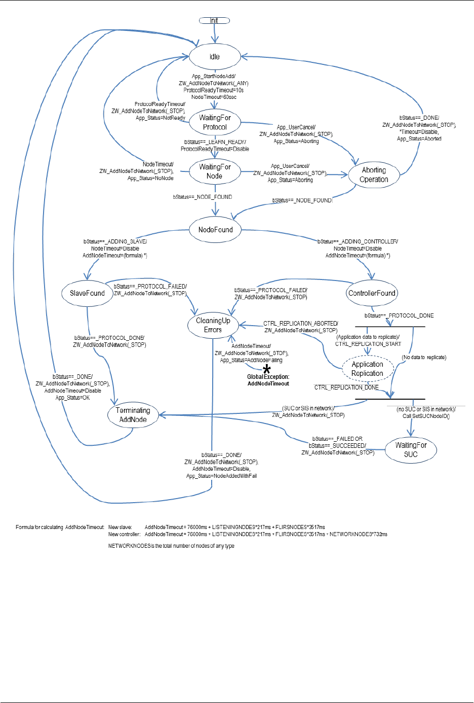
INS13478-5 Z-Wave 500 Series Appl. Programmers Guide v6.71.01 2017-02-28
Sigma Designs Inc.
Z-Wave Application Interfaces
Page 334 of 431
Figure 39. Adding a node to the network
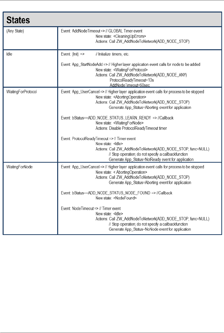
INS13478-5 Z-Wave 500 Series Appl. Programmers Guide v6.71.01 2017-02-28
Sigma Designs Inc.
Z-Wave Application Interfaces
Page 335 of 431
Table 18. AddNode : State/Event processing – 1
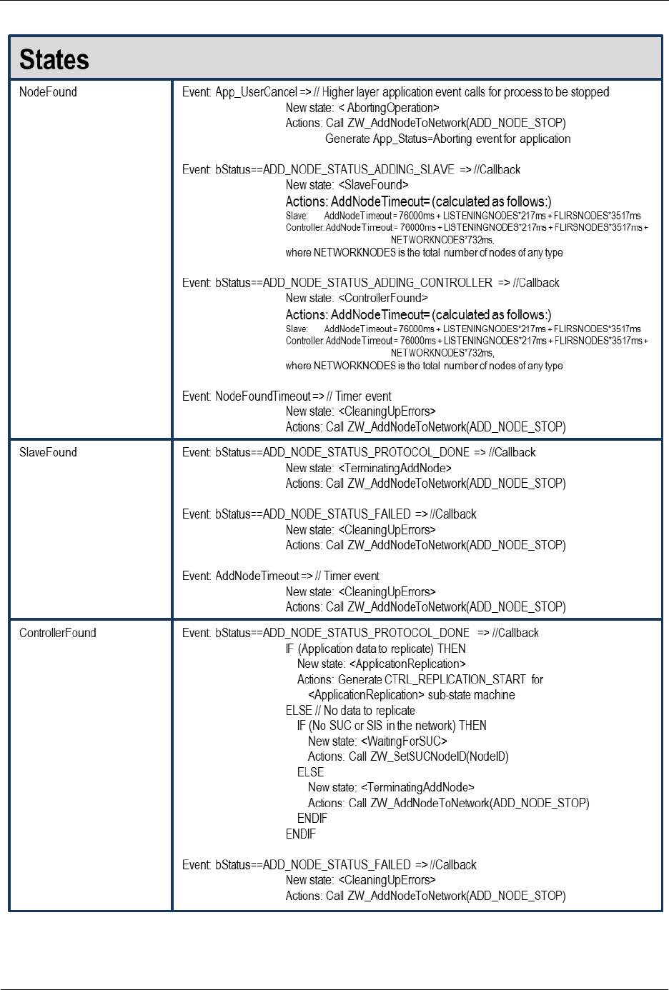
INS13478-5 Z-Wave 500 Series Appl. Programmers Guide v6.71.01 2017-02-28
Sigma Designs Inc.
Z-Wave Application Interfaces
Page 336 of 431
Table 19. AddNode : State/Event processing – 2
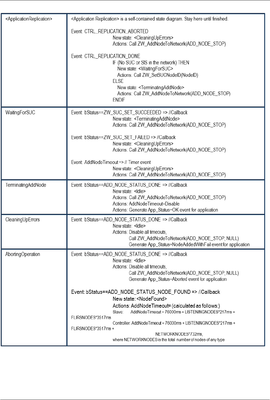
INS13478-5 Z-Wave 500 Series Appl. Programmers Guide v6.71.01 2017-02-28
Sigma Designs Inc.
Z-Wave Application Interfaces
Page 337 of 431
Table 20. AddNode : State/Event processing – 3

INS13478-5 Z-Wave 500 Series Appl. Programmers Guide v6.71.01 2017-02-28
Sigma Designs Inc.
Z-Wave Application Interfaces
Page 338 of 431
4.4.2 ZW_AreNodesNeighbours
BYTE ZW_AreNodesNeighbours( BYTE bNodeA,
BYTE bNodeB)
Macro: ZW_ARE_NODES_NEIGHBOURS (nodeA, nodeB)
Used check if two nodes are marked as being within direct range of each other
Defined in: ZW_controller_api.h
Return value:
BYTE
FALSE
Nodes are not neighbours.
TRUE
Nodes are neighbours.
Parameters:
bNodeA IN
Node ID A (1...232)
bNodeB IN
Node ID B (1...232)
Serial API
HOST->ZW: REQ | 0xBC | nodeID | nodeID
ZW->HOST: RES | 0xBC | retVal

INS13478-5 Z-Wave 500 Series Appl. Programmers Guide v6.71.01 2017-02-28
Sigma Designs Inc.
Z-Wave Application Interfaces
Page 339 of 431
4.4.3 ZW_AssignReturnRoute
BOOL ZW_AssignReturnRoute(
BYTE bSrcNodeID,
BYTE bDstNodeID,
VOID_CALLBACKFUNC(completedFunc)
(BYTE txStatus, TX_STATUS_TYPE* txStatusReport))
Macro: ZW_ASSIGN_RETURN_ROUTE(routingNodeID,destNodeID,func)
Use to assign static return routes (up to 4) to a Routing Slave or Enhanced 232 Slave node. This allows
the Routing Slave node to communicate directly with either controllers or other slave nodes. The API call
calculates the shortest routes from the Routing Slave node (bSrcNodeID) to the destination node
(bDestNodeID) and transmits the return routes to the Routing Slave node (bSrcNodeID). The destination
node is part of the return routes assigned to the slave. Up to 5 different destinations can be allocated
return routes in a Routing Slave. Attempts to assign new return routes when all 5 destinations already
are allocated will be ignored. It is possible to allocate up to 232 different destinations in an Enhanced 232
Slave. Call ZW_AssignReturnRoute repeatedly to allocate more than 5 destinations in an Enhanced
232 Slave. Use the API call ZW_DeleteReturnRoute to clear assigned return routes.
Defined in: ZW_controller_api.h
Return value:
BOOL
TRUE
If Assign return route operation started
FALSE
If an “assign/delete return route”
operation already is active.
Parameters:
bSrcNodeID IN
Node ID (1...232) of the routing slave
that should get the return routes.
bDstNodeID IN
Destination node ID (1...232)
completedFunc IN
Transmit completed call back function
Callback function Parameters:
txStatus IN
Status of return route assignment
(all status codes from ZW_SendData)
See ZW_SendData, section 4.3.3.1
TRANSMIT_COMPLETE_NOROUTE
No routes assigned because a route
between source and destination node
could not be found.
txStatusReport IN
(see ZW_SendData)
Serial API:
HOST->ZW: REQ | 0x46 | bSrcNodeID | bDstNodeID | funcID

INS13478-5 Z-Wave 500 Series Appl. Programmers Guide v6.71.01 2017-02-28
Sigma Designs Inc.
Z-Wave Application Interfaces
Page 340 of 431
ZW->HOST: RES | 0x46 | retVal
ZW->HOST: REQ | 0x46 | funcID | bStatus

INS13478-5 Z-Wave 500 Series Appl. Programmers Guide v6.71.01 2017-02-28
Sigma Designs Inc.
Z-Wave Application Interfaces
Page 341 of 431
4.4.4 ZW_AssignSUCReturnRoute
BOOL ZW_AssignSUCReturnRoute(
BYTE bSrcNodeID,
VOID_CALLBACKFUNC(completedFunc)
(BYTE txStatus, TX_STATUS_TYPE* txStatusReport))
Macro: ZW_ASSIGN_SUC_RETURN_ROUTE(srcnode,func)
Notify presence of a SUC/SIS to a Routing Slave or Enhanced 232 Slave. Furthermore is static return
routes (up to 4) assigned to the Routing Slave or Enhanced 232 Slave to enable communication with the
SUC/SIS node. The return routes can be used to get updated return routes from the SUC/SIS node by
calling ZW_RequestNetWorkUpdated in the Routing Slave or Enhanced 232 Slave.
Defined in: ZW_controller_api.h
Return value:
BOOL
TRUE
If the assign SUC return route
operation is started.
FALSE
If an “assign/delete return route”
operation already is active.
Parameters:
bSrcNodeID IN
The node ID (1...232) of the routing slave that
should get the return route to the SUC/SIS
node.
completedFunc
IN
Transmit complete call back.
Callback function Parameters:
bStatus IN
(see ZW_SendData)
txStatusReport
IN
(see ZW_SendData)
Serial API:
HOST->ZW: REQ | 0x51 | bSrcNodeID | funcID | funcID
The extra funcID is added to ensures backward compatible. This parameter has been removed starting
from dev. kit 4.1x. and onwards and has therefore no meaning anymore.
ZW->HOST: RES | 0x51 | retVal
ZW->HOST: REQ | 0x51 | funcID | bStatus

INS13478-5 Z-Wave 500 Series Appl. Programmers Guide v6.71.01 2017-02-28
Sigma Designs Inc.
Z-Wave Application Interfaces
Page 342 of 431
4.4.5 ZW_AssignPriorityReturnRoute
BOOL ZW_AssignPriorityReturnRoute(
BYTE bSrcNodeID,
BYTE bDstNodeID,
XBYTE *pPriorityRoute,
VOID_CALLBACKFUNC(completedFunc)
(BYTE txStatus, TX_STATUS_TYPE* txStatusReport))
Assign a application defined Priority Return Route to a routing or an enhanced slave that always will be
tried as the first return route attempt. The function will assign the specified Priority Return Route and if
possible it will also assign up to three return routes calculated from the routing table in the same manner
as ZW_AssignReturnRoute.
Use the API call ZW_DeleteReturnRoute to clear the assigned Priority Return Route together with the
other Return Routes.
NOTE: If the routing/enhanced slave is based on a SDK prior to 6.60 it can not be guarantied that the
first Return Route is the specified Priority Return Route. The Priority Return Route will be used but its
placement in the Return Route sequence is based on internal prioritization in the slave.
Defined in: ZW_controller_api.h
Return value:
BOOL
TRUE
If Assign return route operation started
FALSE
If an “assign/delete return route”
operation already is active.
Parameters:
bSrcNodeID IN
Node ID (1...232) of the routing slave
that should get the return routes.
bDstNodeID IN
Destination node ID (1...232)
pPriorityRoute
Pointer for a 5-byte array containing the
new Priority Return Route to be set. The
5-byte array contains 4 repeater node
bytes (index 0 - 3) and 1 routespeed
byte (index 4). The first repeater byte
(starting from index 0) equaling zero
indicates no more repeaters in route. If
the repeater at index 0 is zero then the
Priority Return Route is direct. The
routespeed byte (index 4) can be either
ZW_PRIORITY_ROUTE_SPEED_9600,
ZW_PRIORITY_ROUTE_SPEED_40K
or
ZW_PRIORITY_ROUTE_SPEED_100K
completedFunc
Transmit completed call back function

INS13478-5 Z-Wave 500 Series Appl. Programmers Guide v6.71.01 2017-02-28
Sigma Designs Inc.
Z-Wave Application Interfaces
Page 343 of 431
IN
Callback function Parameters:
txStatus IN
Status of return route assignment
(all status codes from ZW_SendData)
See ZW_SendData, section 4.3.3.1
TRANSMIT_COMPLETE_NOROUTE
No routes assigned because a route
between source and destination node
could not be found.
txStatusReport IN
(see ZW_SendData)
Serial API:
HOST->ZW: REQ | 0x4F | bSrcNodeID | bDstNodeID | PriorityRoute | funcID
ZW->HOST: RES | 0x4F | retVal
ZW->HOST: REQ | 0x4F | funcID | bStatus

INS13478-5 Z-Wave 500 Series Appl. Programmers Guide v6.71.01 2017-02-28
Sigma Designs Inc.
Z-Wave Application Interfaces
Page 344 of 431
4.4.6 ZW_AssignPrioritySUCReturnRoute
BOOL ZW_AssignPriorityReturnRoute(
BYTE bSrcNodeID,
XBYTE *pPriorityRoute,
VOID_CALLBACKFUNC(completedFunc)
(BYTE txStatus, TX_STATUS_TYPE* txStatusReport))
Assign a application defined Priority SUC Return Route to a routing or an enhanced slave that always
will be tried as the first return route attempt. The function will assign the specified Priority SUC Return
Route and if possible it will also assign up to three return routes calculated from the routing table in the
same manner as ZW_AssignSUCReturnRoute.
Use the API call ZW_DeleteSUCReturnRoute to clear the assigned Priority SUC Return Route together
with the other Return Routes.
NOTE: If the routing/enhanced slave is based on a SDK prior to 6.60 it can not be guarantied that the
first return route is the specified priority route. The priority route will be used but its placement in the
return route sequence is based on internal prioritization in the slave.
Defined in: ZW_controller_api.h
Return value:
BOOL
TRUE
If the assign Priority SUC return route
operation is started.
FALSE
If an “assign/delete return route”
operation already is active.
Parameters:
bSrcNodeID IN
The node ID (1...232) of the routing slave that
should get the Priority Return Route to the
SUC/SIS node.
pPriorityRoute
Pointer for a 5-byte array containing the new
Priority Return Route to be set. The 5-byte
array contains 4 repeater node bytes (index 0
- 3) and 1 routespeed byte (index 4). The first
repeater byte (starting from index 0) equaling
zero indicates no more repeaters in route. If
the repeater at index 0 is zero then the
Priority Return Route is direct. The
routespeed byte (index 4) can be either
ZW_PRIORITY_ROUTE_SPEED_9600,
ZW_PRIORITY_ROUTE_SPEED_40K or
ZW_PRIORITY_ROUTE_SPEED_100K
completedFunc
IN
Transmit complete call back.
Callback function Parameters:

INS13478-5 Z-Wave 500 Series Appl. Programmers Guide v6.71.01 2017-02-28
Sigma Designs Inc.
Z-Wave Application Interfaces
Page 345 of 431
bStatus IN
(see ZW_SendData)
txStatusReport
IN
(see ZW_SendData)
Serial API:
HOST->ZW: REQ | 0x58 | bSrcNodeID | PriorityRoute | funcID
ZW->HOST: RES | 0x58 | retVal
ZW->HOST: REQ | 0x58 | funcID | bStatus

INS13478-5 Z-Wave 500 Series Appl. Programmers Guide v6.71.01 2017-02-28
Sigma Designs Inc.
Z-Wave Application Interfaces
Page 346 of 431
4.4.7 ZW_ControllerChange
void ZW_ControllerChange (BYTE mode,
VOID_CALLBACKFUNC(completedFunc)(LEARN_INFO *learnNodeInfo))
Macro: ZW_CONTROLLER_CHANGE(mode, func)
ZW_ControllerChange is used to add a controller to the Z-Wave network and transfer the role as
primary controller to it.
This function has the same functionality as ZW_AddNodeToNetwork(ADD_NODE_ANY,…) except that
the new controller will be a primary controller and the controller invoking the function will become
secondary.
Defined in: ZW_controller_api.h
Parameters:
mode IN
The learn node states are:
CONTROLLER_CHANGE_START
Start the process of adding a
controller to the network.
CONTROLLER_CHANGE_STOP
Stop the controller change
CONTROLLER_CHANGE_STOP_FAILED
Stop the controller change and
report a failure
completedFunc IN
Callback function pointer (Should only be
NULL if state is turned off).

INS13478-5 Z-Wave 500 Series Appl. Programmers Guide v6.71.01 2017-02-28
Sigma Designs Inc.
Z-Wave Application Interfaces
Page 347 of 431
Callback function Parameters (completedFunc):
*learnNodeInfo.bStatus
IN
Status of learn mode:
ADD_NODE_STATUS_LEARN_READY
The controller is now
ready to include a node
into the network.
ADD_NODE_STATUS_NODE_FOUND
A node that wants to be
included into the
network has been found
ADD_NODE_STATUS_ADDING_CONTROLLER
A new controller has
been added to the
network
ADD_NODE_STATUS_PROTOCOL_DONE
The protocol part of
adding a controller is
complete, the
application can now
send data to the new
controller using
ZW_ReplicationSend()
ADD_NODE_STATUS_DONE
The new node has now
been included and the
controller is ready to
continue normal
operation again.
ADD_NODE_STATUS_FAILED
The learn process failed
*learnNodeInfo.bSource
IN
Node id of the new node
*learnNodeInfo.pCmd
IN
Pointer to Application Node information data (see
ApplicationNodeInformation - nodeParm).
NULL if no information present.
The pCmd only contain information when bLen is
not zero, so the information should be stored
when that is the case. Regardless of the bStatus.
*learnNodeInfo.bLen IN
Node info length.
Serial API:
HOST->ZW: REQ | 0x4D | mode | funcID
ZW->HOST: REQ | 0x4D | funcID | bStatus | bSource | bLen | basic | generic | specific | cmdclasses[ ]

INS13478-5 Z-Wave 500 Series Appl. Programmers Guide v6.71.01 2017-02-28
Sigma Designs Inc.
Z-Wave Application Interfaces
Page 348 of 431
4.4.8 ZW_DeleteReturnRoute
BOOL ZW_DeleteReturnRoute(
BYTE nodeID,
VOID_CALLBACKFUNC(completedFunc)
(BYTE txStatus, TX_STATUS_TYPE* txStatusReport))
Macro: ZW_DELETE_RETURN_ROUTE(nodeID, func)
Delete all static return routes from a Routing Slave or Enhanced 232 Slave node.
Defined in: ZW_controller_api.h
Return value:
BOOL
TRUE
If Delete return route operation started
FALSE
If an “assign/delete return route” operation
already is active.
Parameters:
nodeID IN
Node ID (1...232) of the routing slave
node.
completedFunc
IN
Transmit completed call back function
Callback function Parameters:
txStatus IN
(see ZW_SendData)
txStatusReport
IN
(see ZW_SendData)
Serial API:
HOST->ZW: REQ | 0x47 | nodeID | funcID
ZW->HOST: RES | 0x47 | retVal
ZW->HOST: REQ | 0x47 | funcID | bStatus

INS13478-5 Z-Wave 500 Series Appl. Programmers Guide v6.71.01 2017-02-28
Sigma Designs Inc.
Z-Wave Application Interfaces
Page 349 of 431
4.4.9 ZW_DeleteSUCReturnRoute
BOOL ZW_DeleteSUCReturnRoute(
BYTE bNodeID,
VOID_CALLBACKFUNC (completedFunc)
(BYTE txStatus, TX_STATUS_TYPE* txStatusReport))
Macro: ZW_DELETE_SUC_RETURN_ROUTE (nodeID, func)
Delete the return routes of the SUC/SIS node from a Routing Slave node or Enhanced 232 Slave node.
Defined in: ZW_controller_api.h
Return value:
BOOL
TRUE
If the delete SUC return route
operation is started.
FALSE
If an “assign/delete return route”
operation already is active.
Parameters:
bNodeID IN
Node ID (1..232) of the routing slave node.
completedFunc
IN
Transmit complete call back.
Callback function Parameters:
txStatus IN
(see ZW_SendData)
txStatusReport
IN
(see ZW_SendData)
Serial API:
HOST->ZW: REQ | 0x55 | nodeID | funcID
ZW->HOST: RES | 0x55 | retVal
ZW->HOST: REQ | 0x55 | funcID | bStatus

INS13478-5 Z-Wave 500 Series Appl. Programmers Guide v6.71.01 2017-02-28
Sigma Designs Inc.
Z-Wave Application Interfaces
Page 350 of 431
4.4.10 ZW_GetControllerCapabilities
BYTE ZW_GetControllerCapabilities(void)
Macro: ZW_GET_CONTROLLER_CAPABILITIES()
ZW_GetControllerCapabilities returns a bitmask containing the capabilities of the controller. It’s an old
type of primary controller (node ID = 0xEF) in case zero is returned.
NOTE: Not all status bits are available on all controllers’ types
Defined in: ZW_controller_api.h
Return value:
BYTE
CONTROLLER_IS_SECONDARY
If bit is set then the controller is a
secondary controller
CONTROLLER_ON_OTHER_NETWORK
If this bit is set then this controller
is not using its built-in home ID
CONTROLLER_IS_SUC
If this bit is set then this controller
is a SUC
CONTROLLER_NODEID_SERVER_PRESENT
If this bit is set then there is a
SUC ID server (SIS) in the
network and this controller can
therefore include/exclude nodes
in the network. This is called an
inclusion controller.
CONTROLLER_IS_REAL_PRIMARY
If this bit is set then this controller
was the original primary controller
in the network before the SIS was
added to the network
Serial API:
HOST->ZW: REQ | 0x05
ZW->HOST: RES | 0x05 | RetVal

INS13478-5 Z-Wave 500 Series Appl. Programmers Guide v6.71.01 2017-02-28
Sigma Designs Inc.
Z-Wave Application Interfaces
Page 351 of 431
4.4.11 ZW_GetNeighborCount
BYTE ZW_GetNeighborCount(BYTE nodeID)
Macro: ZW_GET_NEIGHBOR_COUNT (nodeID)
Used to get the number of neighbors the specified node has registered.
Defined in: ZW_controller_api.h
Return value:
BYTE
0x00-0xE7
Number of neighbors registered.
NEIGHBORS_ID_INVALID
Specified node ID is invalid.
NEIGHBORS_COUNT_FAILED
Could not access routing information - try
again later.
Parameters:
nodeID IN
Node ID (1...232) on the node to count
neighbors on.
Serial API
HOST->ZW: REQ | 0xBB | nodeID
ZW->HOST: RES | 0xBB | retVal

INS13478-5 Z-Wave 500 Series Appl. Programmers Guide v6.71.01 2017-02-28
Sigma Designs Inc.
Z-Wave Application Interfaces
Page 352 of 431
4.4.12 ZW_GetPriorityRoute
BYTE ZW_GetPriorityRoute (BYTE bNodeID, XBYTE *pPriorityRoute)
Macro: ZW_GET_PRIORITY_ROUTE(bNodeID, pPriorityRoute)
Use this API call to get the route with the highest priority. If a route has been set with the
ZW_SetPriorityRoute then that route will be returned. If no priority route has been set the call will return
the either the Last Working Route (LWR) or the Next to Last Working Route (NLWR). The LWR is the
last successful route used between sender and destination node and the NLWR is the previous LWR.
The PriorityRoute, LWR and NLWR are all stored in NVM.
Note: ZW_GetPriorityRoute superceeds the ZW_GetLastWorkingRoute functionality, which is obsoleted.
Defined in: ZW_controller_api.h
Return value:
BYTE
ZW_PRIORITY_ROUTE_APP_PR
ZW_PRIORITY_ROUTE_ZW_LWR
ZW_PRIORITY_ROUTE_ZW_NLWR
App defined Priority Route.
Last Working Route
Next to Last Working Route
FALSE
No Priority Route found for bNodeID.
Parameters:
bNodeID IN
The Node ID (1...232) specifies the
destination node whom the Priority
Route is wanted from.
pPriorityRoute
IN
Pointer to a 5-byte array where the
wanted Priority Route will be copied. The
5-byte array contains in the first 4 byte
the max 4 repeaters (index 0 - 3) and 1
routespeed byte (index 4) used in the
Route. The Route which pPriorityRoute
points to is valid if function return value
is NON ZERO. The first repeater byte
(starting from index 0) equaling zero
indicates no more repeaters in route. If
the repeater at index 0 is zero then the
Route is direct. The routespeed byte
(index 4) can be either
ZW_PRIORITY_ROUTE_SPEED_9600,
ZW_PRIORITY_ROUTE_SPEED_40K
or
ZW_PRIORITY_ROUTE_SPEED_100K
Serial API
HOST->ZW: REQ | 0x92 | bNodeID
ZW->HOST: RES | 0x92 | bNodeID | retVal | repeater0 | repeater1 | repeater2 | repeater3 | routespeed

INS13478-5 Z-Wave 500 Series Appl. Programmers Guide v6.71.01 2017-02-28
Sigma Designs Inc.
Z-Wave Application Interfaces
Page 353 of 431
4.4.13 ZW_SetPriorityRoute
BOOL ZW_SetPriorityRoute(BYTE bNodeID, XBYTE *pPriorityRoute)
Macro: ZW_SET_PRIORITY_ROUTE(bNodeID, pPriorityRoute)
Use this API call to set the Priority Routefor a destination node. The Priority Route is the route that will be
used as the first routing attempt by the protocol when transmitting to a node. The Priority Route is stored
in NVM.
Note: ZW_SetPriorityRoute superceeds the ZW_SetLastWorkingRoute functionality, which is obsoleted.
Defined in: ZW_controller_api.h
Return value:
BOOL
TRUE
The Priority Route for bNodeID was
successfully set to the specified 5-
byte Priority Route pointed out by
pPriorityRoute.
FALSE
The specified bNodeID was not valid
and no Priority Route was set.
Parameters:
bNodeID IN
The Node ID (1...232) - specifies the
destination node for whom the Priority Route
is to be set.
pPriorityRoute
IN
Pointer for a 5-byte array containing the new
Priority Route to be set. If NULL then current
APR is released (protocol now has 2 entries
for LWRs). The 5-byte array contains 4
repeater node bytes (index 0 - 3) and 1
routespeed byte (index 4). The first repeater
byte (starting from index 0) equaling zero
indicates no more repeaters in route. If the
repeater at index 0 is zero then the Priority
Route is direct. The routespeed byte (index
4) can be either
ZW_PRIORITY_ROUTE_SPEED_9600,
ZW_PRIORITY_ROUTE_SPEED_40K or
ZW_PRIORITY_ROUTE_SPEED_100K
Serial API
HOST->ZW: REQ | 0x93 | bNodeID | repeater0 | repeater1 | repeater2 | repeater3 | routespeed
ZW->HOST: RES | 0x93 | bNodeID | retVal

INS13478-5 Z-Wave 500 Series Appl. Programmers Guide v6.71.01 2017-02-28
Sigma Designs Inc.
Z-Wave Application Interfaces
Page 354 of 431
4.4.14 ZW_GetNodeProtocolInfo
void ZW_GetNodeProtocolInfo(BYTE bNodeID,
NODEINFO *nodeInfo)
Macro: ZW_GET_NODE_STATE(nodeID, nodeInfo)
Return the Node Information Frame without command classes from the NVM for a given node ID:
Byte descriptor \
Bit number
7
6
5
4
3
2
1
0
Capability
Liste-
ning
Z-Wave Protocol Specific Part
Security
Opt.
Func.
Sensor
1000ms
Sensor
250ms
Z-Wave Protocol Specific Part
Reserved
Z-Wave Protocol Specific Part
Basic
Basic Device Class (Z-Wave Protocol Specific Part)
Generic
Generic Device Class (Z-Wave Appl. Specific Part)
Specific
Specific Device Class (Z-Wave Appl. Specific Part)
Figure 40. Node Information frame structure without command classes
All the Z-Wave protocol specific fields are initialised by the protocol. The Listening flag, Generic, and
Specific Device Class fields are initialized by the application. Regarding initialization, refer to the function
ApplicationNodeInformation.
Defined in: ZW_controller_api.h
Parameters:
bNodeID IN
Node ID
1..232
nodeInfo OUT
Node info buffer (see figure above)
If (*nodeInfo).nodeType.generic is
0 then the node doesn’t exist.
Serial API:
HOST->ZW: REQ | 0x41 | bNodeID
ZW->HOST: RES | 0x41 | nodeInfo (see figure above)

INS13478-5 Z-Wave 500 Series Appl. Programmers Guide v6.71.01 2017-02-28
Sigma Designs Inc.
Z-Wave Application Interfaces
Page 355 of 431
4.4.15 ZW_GetRoutingInfo
void ZW_GetRoutingInfo(BYTE bNodeID,
BYTE_P pMask,
BYTE bOptions)
Macro: ZW_GET_ROUTING_INFO(bNodeID, pMask, bOptions)
ZW_GetRoutingInfo is a function that can be used to read out neighbor information from the protocol.
This information can be used to ensure that all nodes have a sufficient number of neighbors and to
ensure that the network is in fact one network.
The format of the data returned in the buffer pointed to by pMask is as follows:
pMask[i] (0 i < (ZW_MAX_NODES/8)
Bit
0
1
2
3
4
5
6
7
NodeID
i*8+1
i*8+2
i*8+3
i*8+4
i*8+5
i*8+6
i*8+7
i*8+8
If a bit n in pMask[i] is 1 it indicates that the node bNodeID has node (i*8)+n+1 as a neighbour. If n in
pMask[i] is 0, bNodeID cannot reach node (i*8)+n+1 directly.
Defined in: ZW_controller_api.h
Parameters:
bNodeID IN
Node ID (1…232) specifies the node whom
routing info is needed from.
pMask OUT
Pointer to buffer where routing info should be
put. The buffer should be at least
ZW_MAX_NODES/8 bytes
bOptions IN
Upper nibble (upper 4-bit in byte) is bit flag
options, lower nibble is speed. Combine exactly
one speed with any number of options.
Bit flags options for upper nibble:
GET_ROUTING_INFO_REMOVE_NON_REPS
(bRemoveNonReps)
GET_ROUTING_INFO_REMOVE_BAD
(bRemoveBad)
Remove non-repeaters from the
routing info.
Remove bad link from routing info
Bad links are a short list of nodes
which recently has failed to
answer a transmission
Speed values for lower nibble:
ZW_GET_ROUTING_INFO_9600 or
ZW_GET_ROUTING_INFO_40K or
ZW_GET_ROUTING_INFO_100K or
ZW_GET_ROUTING_INFO_ANY
Return only nodes supporting this
speed.
Only one speed value may be
used at a time.

INS13478-5 Z-Wave 500 Series Appl. Programmers Guide v6.71.01 2017-02-28
Sigma Designs Inc.
Z-Wave Application Interfaces
Page 356 of 431
Serial API:
HOST->ZW: REQ | 0x80 | bNodeID | bRemoveBad | bRemoveNonReps | funcID
ZW->HOST: RES | 0x80 | NodeMask[29]
NOTE: funcID must be set to 0.
NOTE: Serial API func FUNC_ID_GET_ROUTING_TABLE_LINE (0x80) is the Serial API command ID
for ZW_GetRoutingInfo and the current implementation do not support for specifying Speed value.

INS13478-5 Z-Wave 500 Series Appl. Programmers Guide v6.71.01 2017-02-28
Sigma Designs Inc.
Z-Wave Application Interfaces
Page 357 of 431
4.4.16 ZW_GetSUCNodeID
BYTE ZW_GetSUCNodeID(void)
Macro: ZW_GET_SUC_NODEID()
API call used to get the currently registered SUC/SIS node ID.
Defined in: ZW_controller_api.h
Return value:
BYTE
The node ID (1..232) on the currently
registered SUC/SIS, if ZERO then no
SUC/SIS available.
Serial API:
HOST->ZW: REQ | 0x56
ZW->HOST: RES | 0x56 | SUCNodeID

INS13478-5 Z-Wave 500 Series Appl. Programmers Guide v6.71.01 2017-02-28
Sigma Designs Inc.
Z-Wave Application Interfaces
Page 358 of 431
4.4.17 ZW_IsFailedNode
BYTE ZW_isFailedNode(BYTE nodeID)
Macro: ZW_IS_FAILED_NODE_ID(nodeID)
Used to test if a node ID is stored in the failed node ID list.
The failed node list is limited to 5 entries.If a node is added to a full list the node with the lowest failed
count will be replaced with the new node ID.
Defined in: ZW_controller_api.h
Return value:
BYTE
TRUE
If node ID (1..232) is in the list of failing
nodes.
Parameters:
nodeID IN
The node ID (1...232) to check.
Serial API:
HOST->ZW: REQ | 0x62 | nodeID
ZW->HOST: RES | 0x62 | retVal

INS13478-5 Z-Wave 500 Series Appl. Programmers Guide v6.71.01 2017-02-28
Sigma Designs Inc.
Z-Wave Application Interfaces
Page 359 of 431
4.4.18 ZW_IsPrimaryCtrl
BOOL ZW_IsPrimaryCtrl (void)
Macro: ZW_PRIMARYCTRL()
This function is used to request whether the controller is a primary controller or a secondary controller in
the network.
Defined in: ZW_controller_api.h
Return value:
BOOL
TRUE
Returns TRUE when the controller is a
primary controller in the network.
FALSE
Return FALSE when the controller is a
secondary controller in the network.
Serial API (Not supported)

INS13478-5 Z-Wave 500 Series Appl. Programmers Guide v6.71.01 2017-02-28
Sigma Designs Inc.
Z-Wave Application Interfaces
Page 360 of 431
4.4.19 ZW_RemoveFailedNode
BYTE ZW_RemoveFailedNode( BYTE NodeID,
VOID_CALLBACKFUNC(completedFunc)(BYTE txStatus))
Macro: ZW_REMOVE_FAILED_NODE_ID(node,func)
Used to remove a non-responding node from the routing table in the requesting controller. A non-
responding node is put onto the failed node ID list in the requesting controller. In case the node responds
again at a later stage then it is removed from the failed node ID list. A node must be on the failed node ID
list and as an extra precaution also fail to respond before it is removed. Responding nodes can’t be
removed. The call works on a primary controller and an inclusion controller.
A call back function should be provided otherwise the function will return without removing the node.
Defined in: ZW_controller_api.h
Return value (If the replacing process started successfully then the function will return):
BYTE
ZW_FAILED_NODE_REMOVE_STARTED
The removing process started
Return values (If the replacing process cannot be started then the API function will return one or more
of the following flags):
BYTE
ZW_NOT_PRIMARY_CONTROLLER
The removing process was aborted
because the controller is not the
primary one.
ZW_NO_CALLBACK_FUNCTION
The removing process was aborted
because no call back function is
used.
ZW_FAILED_NODE_NOT_FOUND
The requested process failed.
The nodeID was not found in the
controller list of failing nodes.
ZW_FAILED_NODE_REMOVE_PROCESS_BUSY
The removing process is busy.
ZW_FAILED_NODE_REMOVE_FAIL
The requested process failed.
Reasons include:
Controller is busy
The node responded to a NOP;
thus the node is no longer
failing.
Parameters:
nodeID IN
The node ID (1..232) of the failed node
to be deleted.
completedFunc
IN
Remove process completed call back
function

INS13478-5 Z-Wave 500 Series Appl. Programmers Guide v6.71.01 2017-02-28
Sigma Designs Inc.
Z-Wave Application Interfaces
Page 361 of 431
Callback function Parameters:
txStatus IN
Status of removal of failed node:
ZW_NODE_OK
The node is working properly (removed from
the failed nodes list).
ZW_FAILED_NODE_REMOVED
The failed node was removed from the failed
nodes list.
ZW_FAILED_NODE_NOT_REMOVED
The failed node was not removed because
the removing process cannot be completed.
Serial API:
HOST->ZW: REQ | 0x61 | nodeID | funcID
ZW->HOST: RES | 0x61 | retVal
ZW->HOST: REQ | 0x61 | funcID | txStatus

INS13478-5 Z-Wave 500 Series Appl. Programmers Guide v6.71.01 2017-02-28
Sigma Designs Inc.
Z-Wave Application Interfaces
Page 362 of 431
4.4.20 ZW_ReplaceFailedNode
BYTE ZW_ReplaceFailedNode( BYTE NodeID,
BOOL bNormalPower,
VOID_CALLBACKFUNC(completedFunc)(BYTE txStatus))
Macro: ZW_REPLACE_FAILED_NODE(node,func)
This function replaces a non-responding node with a new one in the requesting controller. A non-
responding node is put onto the failed node ID list in the requesting controller. In case the node responds
again at a later stage then it is removed from the failed node ID list. A node must be on the failed node ID
list and as an extra precaution also fail to respond before it is removed. Responding nodes can’t be
replace. The call works on a primary controller and an inclusion controller.
A call back function should be provided otherwise the function would return without replacing the node.
Defined in: ZW_controller_api.h
Return value (If the replacing process started successfully then the function will return):
BYTE
ZW_FAILED_NODE_REMOVE_STARTED
The replacing process has started.
Return values (If the replacing process cannot be started then the API function will return one or more
of the following flags:):
BYTE
ZW_NOT_PRIMARY_CONTROLLER
The replacing process was aborted
because the controller is not a
primary/inclusion/SIS controller.
ZW_NO_CALLBACK_FUNCTION
The replacing process was aborted
because no call back function is
used.
ZW_FAILED_NODE_NOT_FOUND
The requested process failed.
The nodeID was not found in the
controller list of failing nodes.
ZW_FAILED_NODE_REMOVE_PROCESS_BUSY
The removing process is busy.
ZW_FAILED_NODE_REMOVE_FAIL
The requested process failed.
Reasons include:
Controller is busy
The node responded to a NOP;
thus the node is no longer failing.

INS13478-5 Z-Wave 500 Series Appl. Programmers Guide v6.71.01 2017-02-28
Sigma Designs Inc.
Z-Wave Application Interfaces
Page 363 of 431
Parameters:
nodeID IN
The node ID (1…232) of the failed node
to be deleted.
bNormalPower
IN
If TRUE then using Normal RF Power.
completedFunc
IN
Replace process completed call back
function
Callback function Parameters:
txStatus IN
Status of replace of failed node:
ZW_NODE_OK
The node is working properly (removed
from the failed nodes list). Replace
process is stopped.
ZW_FAILED_NODE_REPLACE
The failed node is ready to be replaced
and controller is ready to add new node
with the nodeID of the failed node.
Meaning that the new node must now
emit a nodeinformation frame to be
included.
ZW_FAILED_NODE_REPLACE_DONE
The failed node has been replaced.
ZW_FAILED_NODE_REPLACE_FAILED
The failed node has not been replaced.
Serial API:
HOST->ZW: REQ | 0x63 | nodeID | funcID
ZW->HOST: RES | 0x63 | retVal
ZW->HOST: REQ | 0x63 | funcID | txStatus

INS13478-5 Z-Wave 500 Series Appl. Programmers Guide v6.71.01 2017-02-28
Sigma Designs Inc.
Z-Wave Application Interfaces
Page 364 of 431
4.4.21 ZW_RemoveNodeFromNetwork
void ZW_RemoveNodeFromNetwork(BYTE bMode,
VOID_CALLBACKFUNC(completedFunc)(LEARN_INFO *learnNodeInfo))
Macro: ZW_REMOVE_NODE_FROM_NETWORK(bMode, func)
Defined in: ZW_controller_api.h
Serial API: Func_ID = 0x4B
HOST->ZW: REQ | 0x4B | bMode | funcID
ZW->HOST: REQ | 0x4B | funcID | bStatus | bSource | bLen | basic | generic | specific | cmdclasses[ ]
ZW_RemoveNodeFromNetwork is used to remove a node from a Z-Wave network. It is also possible to
perform out-of-range removal of nodes from the network when repeater nodes are capable of forwarding
the new network wide exclusion (NWE) frame. It is not possible to perform out-of-range removal of nodes
based on a SDK older than SDK 6.61.xx.
The RemoveNodeFromNetwork function MAY be called by a primary controller application to invoke the
removal of nodes from a Z-Wave network. Slave and secondary controller applications MUST NOT call
this function.
A controller application MUST implement support for the RemoveNodeFromNetwork function. The
controller application MUST provide a user interface for activation of the RemoveNodeFromNetwork
function.
The bMode and completedFunc parameters MUST be specified for the RemoveNodeFromNetwork to
function.
Refer to Figure 41 for a state diagram outlining the processing of status callbacks and timeouts.

INS13478-5 Z-Wave 500 Series Appl. Programmers Guide v6.71.01 2017-02-28
Sigma Designs Inc.
Z-Wave Application Interfaces
Page 365 of 431
4.4.21.1 bMode parameter
The bMode parameter MUST be carry one of the commands found in Table 21. The bMode parameter
MUST NOT be assigned more than one command. The bMode parameter MAY be assigned one or
more option flags. One command and multiple options are combined by logically OR’ing the bMode flags
of Table 15.
Table 21. RemoveNode :: bMode
bMode flag
Description
Usage
REMOVE_NODE_ANY
Command to initiate removal of
node of any type.
MUST be included when
initiating removal.
REMOVE_NODE_SLAVE
-
DEPRECATED. Use
REMOVE_NODE_ANY
REMOVE_NODE_CONTROLLER
-
DEPRECATED. Use
REMOVE_NODE_ANY
REMOVE_NODE_STOP
Command to abort the removal
process. May only be used in
certain states.
MAY be used to abort an
active removal process.
MUST be used to
terminate the removal
process when completed.
REMOVE_NODE_OPTION_NETWORK_WIDE
Option flag to enable Network-
Wide Exclusion (NWE).
MUST be used together
with
REMOVE_NODE_ANY.
4.4.21.1.1 REMOVE_NODE_ANY command
To invoke removal of a node, a primary controller MUST call the RemoveNodeFromNetwork function with
a bMode value including the REMOVE_NODE_ANY command. Slave and secondary controller nodes
MUST NOT call the RemoveNodeFromNetwork function.
The option REMOVE_NODE_OPTION_NETWORK_WIDE MUST also be used when calling
RemoveNodeFromNetwork to enable the NWE feature. The NWE feature makes a Controller exclude a
node transmitting the ZWAVE_CMD_EXCLUDE_REQUEST protocol command frame. The
ZWAVE_CMD_EXCLUDE_REQUEST protocol command frame is essentially a Node information
protocol command frame but with ZWAVE_CMD_EXCLUDE_REQUEST as command and are only
transmitted as an explore frame.
While defined in Z-Wave protocol libraries, it is NOT RECOMMENDED to use the
REMOVE_NODE_SLAVE or REMOVE_NODE_CONTROLLER command codes.
4.4.21.1.2 REMOVE_NODE_STOP command
A controller MAY use the REMOVE_NODE_STOP command to abort an ongoing removal process.
After receiving a REMOVE_NODE_STATUS_DONE status callback, the application MUST terminate the
removal process by calling the RemoveNodeFromNetwork function one more time. This time, the
completedFunc parameter MUST be the NULL pointer.

INS13478-5 Z-Wave 500 Series Appl. Programmers Guide v6.71.01 2017-02-28
Sigma Designs Inc.
Z-Wave Application Interfaces
Page 366 of 431
4.4.21.2 completedFunc parameter
Being the exception to the rule, an application calling RemoveNodeFromNetwork(
REMOVE_NODE_STOP) to confirm the reception of a REMOVE_NODE_STATUS_DONE return code
MUST specify the NULL pointer for the completedFunc parameter.
In all other cases, an application calling the RemoveNodeFromNetwork function MUST specify a valid
pointer to a callback function provided by the application. The callback function MUST accept a pointer
parameter to a LEARN_INFO struct. The parameter provides access to actual status as well as
companion data presenting the node being removed. The LEARN_INFO struct only contains a valid
pointer to the Node Information Frame of a node when the status of the callback is
REMOVE_NODE_STATUS_REMOVING_SLAVE or
REMOVE_NODE_STATUS_REMOVING_CONTROLLER.
Table 22. RemoveNode :: completedFunc :: learnNodeInfo
LEARN_NODE struct member
Description
*learnNodeInfo.bStatus
Callback status code
*learnNodeInfo.bSource
NodeID of the node that was removed
*learnNodeInfo.bLen
Length of pCmd element following the bLen element.
If bLen is zero, there is no valid pCmd element.
*learnNodeInfo.pCmd
Pointer to Application Node Information (see
ApplicationNodeInformation - nodeParm).
NULL if no information present.
Individual status codes are presented in the following sections.

INS13478-5 Z-Wave 500 Series Appl. Programmers Guide v6.71.01 2017-02-28
Sigma Designs Inc.
Z-Wave Application Interfaces
Page 367 of 431
Table 23. RemoveNode :: completedFunc :: learnNodeInfo.bStatus
LEARN_NODE.bStatus
Description
REMOVE_NODE_STATUS_LEARN_READY
Z-Wave protocol is ready to remove a node.
REMOVE_NODE_STATUS_NODE_FOUND
Z-Wave protocol detected node.
REMOVE_NODE_STATUS_REMOVING_
SLAVE
Z-Wave protocol removed a slave type node
REMOVE_NODE_STATUS_REMOVING_
CONTROLLER
Z-Wave protocol removed a controller type node
REMOVE_NODE_STATUS_DONE
All operations completed. Protocol is ready to return to idle
state.
REMOVE_NODE_STATUS_FAILED
Z-Wave protocol reports that removal was not successful.
Node may not have been removed.
ADD_NODE_STATUS_NOT_PRIMARY
Z Wave protocol reports that the requested operation
cannot be performed since it requires that the node is in
primary controller state.
Refer to Figure 41 for a state diagram outlining the processing of status callbacks and timeouts.
4.4.21.2.1 REMOVE_NODE_STATUS_LEARN_READY status
Z-Wave protocol is ready to remove a node. An application MAY time out waiting for the
REMOVE_NODE_STATUS_LEARN_READY status if it does not receive the indication within 200 msec
after calling RemoveNodeFromNetwork(REMOVE_NODE_ANY).
If the application times out waiting for the REMOVE_NODE_STATUS_LEARN_READY status, the
application MUST call RemoveNodeFromNetwork(REMOVE_NODE_STOP, NULL).
4.4.21.2.2 REMOVE_NODE_STATUS_NODE_FOUND status
Z-Wave protocol detected node. An application MUST time out waiting for the
REMOVE_NODE_STATUS_NODE_FOUND status if it does not receive the indication after calling
RemoveNodeFromNetwork(REMOVE_NODE_ANY). The RECOMMENDED interval is 60 sec.
If the application times out waiting for the REMOVE_NODE_STATUS_NODE_FOUND status, the
application MUST call RemoveNodeFromNetwork(REMOVE_NODE_STOP, NULL).
The application MUST NOT call RemoveNodeFromNetwork() before the timeout occurs. This may cause
the protocol to malfunction.
4.4.21.2.3 REMOVE_NODE_STATUS_REMOVING_SLAVE status
Z-Wave protocol is removing a slave type node. The NodeID of the node is included in the callback.

INS13478-5 Z-Wave 500 Series Appl. Programmers Guide v6.71.01 2017-02-28
Sigma Designs Inc.
Z-Wave Application Interfaces
Page 368 of 431
An application MUST time out waiting for the REMOVE_NODE_STATUS_REMOVING_SLAVE status if
it does not receive the indication within a 14 sec after receiving the
REMOVE_NODE_STATUS_NODE_FOUND status.
If the application times out waiting for the REMOVE_NODE_STATUS_REMOVNG_SLAVE status, the
application MUST call RemoveNodeFromNetwork(REMOVE_NODE_STOP). The application MUST
specify a valid callback function. This allows the application to receive a
REMOVE_NODE_STATUS_DONE once the protocol has completed cleaning up its datastructures.
The application MUST NOT call RemoveNodeFromNetwork() before the timeout occurs. This may cause
the protocol to malfunction.
4.4.21.2.4 REMOVE_NODE_STATUS_REMOVING_CONTROLLER status
Z-Wave protocol is removing a controller type node. The NodeID of the node is included in the callback.
An application MUST time out waiting for the REMOVE_NODE_STATUS_REMOVING_CONTROLLER
status if it does not receive the indication within a 14 sec after receiving the
REMOVE_NODE_STATUS_NODE_FOUND status.
If the application times out waiting for the REMOVE_NODE_STATUS_REMOVING_CONTROLLER
status, the application MUST call RemoveNodeFromNetwork(REMOVE_NODE_STOP). The application
MUST specify a valid callback function. This allows the application to receive an
REMOVE_NODE_STATUS_DONE once the protocol has completed cleaning up its datastructures.
The application MUST NOT call RemoveNodeFromNetwork() before the timeout occurs. This may cause
the protocol to malfunction.
4.4.21.2.5 REMOVE_NODE_STATUS_DONE status
All operations completed. Protocol is ready to return to idle state.
In response to the REMOVE_NODE_STATUS_DONE status callback, the application MUST call
RemoveNodeFromNetwork(REMOVE_NODE_STOP, NULL). The application MUST specify the NULL
pointer for the callback function.
4.4.21.2.6 REMOVE_NODE_STATUS_FAILED status
If an application receives a REMOVE_NODE_STATUS_PROTOCOL_FAILED status callback, the
application MUST terminate the removal process by calling
RemoveNodeFromNetwork(REMOVE_NODE_STOP). Refer to 4.4.21.1.2.
4.4.21.2.7 ADD_NODE_STATUS_NOT_PRIMARY status
An application MUST NOT call the RemoveNodeFromNetwork function if the application is not running in
a primary controller. If the function is called by an application running in slave or a secondary controller,
the API MUST return the ADD_NODE_STATUS_NOT_PRIMARY status callback.
4.4.21.3 completedFunc callback timeouts
4.4.21.3.1 ProtocolReadyTimeout
The API MUST return a REMOVE_NODE_STATUS_LEARN_READY status callback within less than
200 msec after receiving a call to RemoveNodeFromNetwork(REMOVE_NODE_ANY).
If an application has not received a REMOVE_NODE_STATUS_LEARN_READY status callback 200
msec after calling RemoveNodeFromNetwork(REMOVE_NODE_ANY), the application MAY time out and
return to its idle state.

INS13478-5 Z-Wave 500 Series Appl. Programmers Guide v6.71.01 2017-02-28
Sigma Designs Inc.
Z-Wave Application Interfaces
Page 369 of 431
4.4.21.3.2 NodeTimeout
An application MUST implement a timeout for waiting for an REMOVE_NODE_STATUS_NODE_FOUND
status callback.
The application SHOULD NOT wait for a REMOVE_NODE_STATUS_NODE_FOUND status callback for
more than 60 sec after calling RemoveNodeFromNetwork(REMOVE_NODE_ANY). If timing out, the
application SHOULD abort removal.
4.4.21.3.3 RemoveNodeTimeout
An application MUST time out if removal has not been completed within 14 sec after the reception of the
REMOVE_NODE_STATUS_NODE_FOUND status callback.
If timing out, the application MUST evaluate the controller node list to verify that the NodeID was
removed. The removal process SHOULD be repeated if the NodeID is still found in the node list.
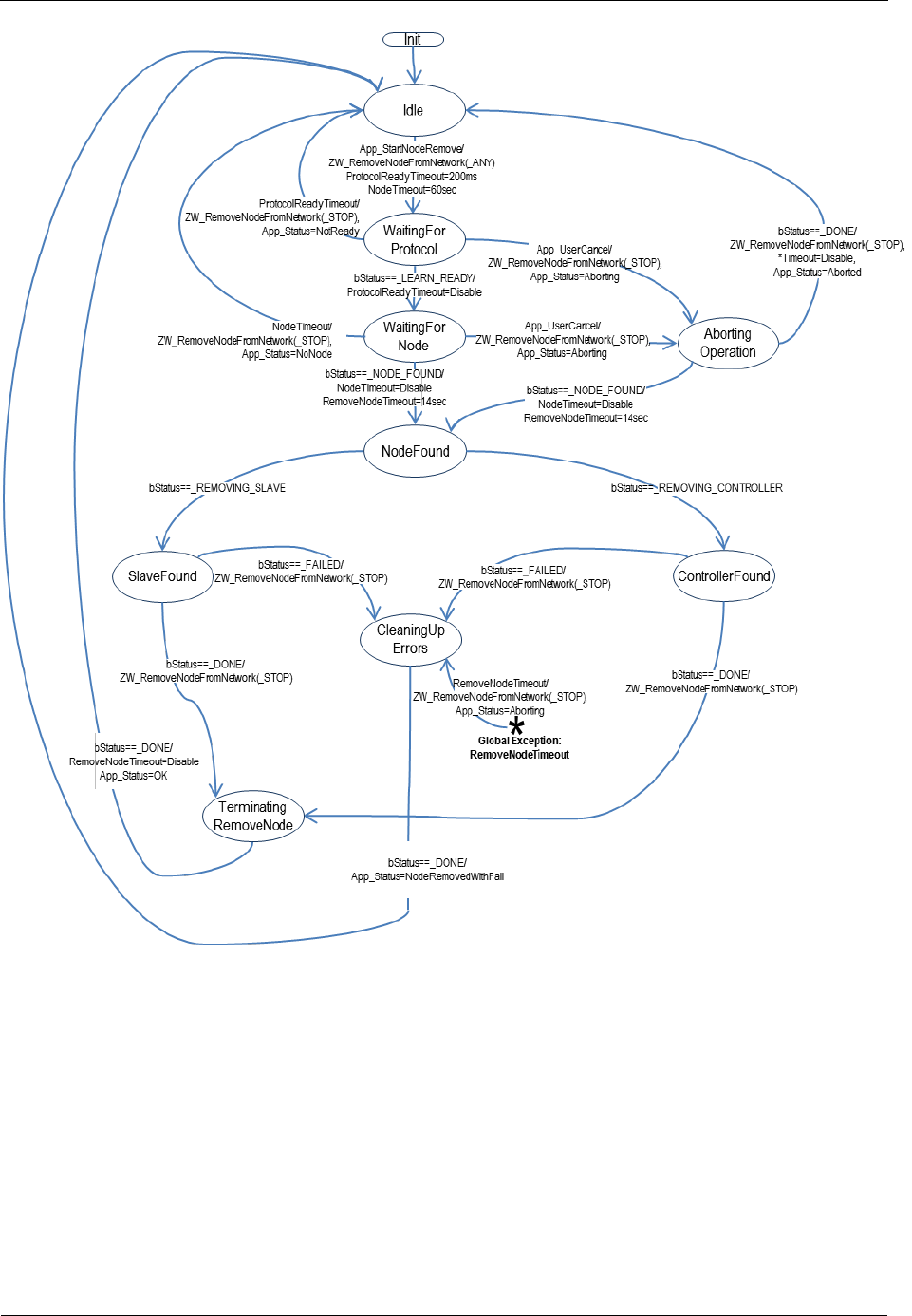
INS13478-5 Z-Wave 500 Series Appl. Programmers Guide v6.71.01 2017-02-28
Sigma Designs Inc.
Z-Wave Application Interfaces
Page 370 of 431
Figure 41. Removing a node from the network
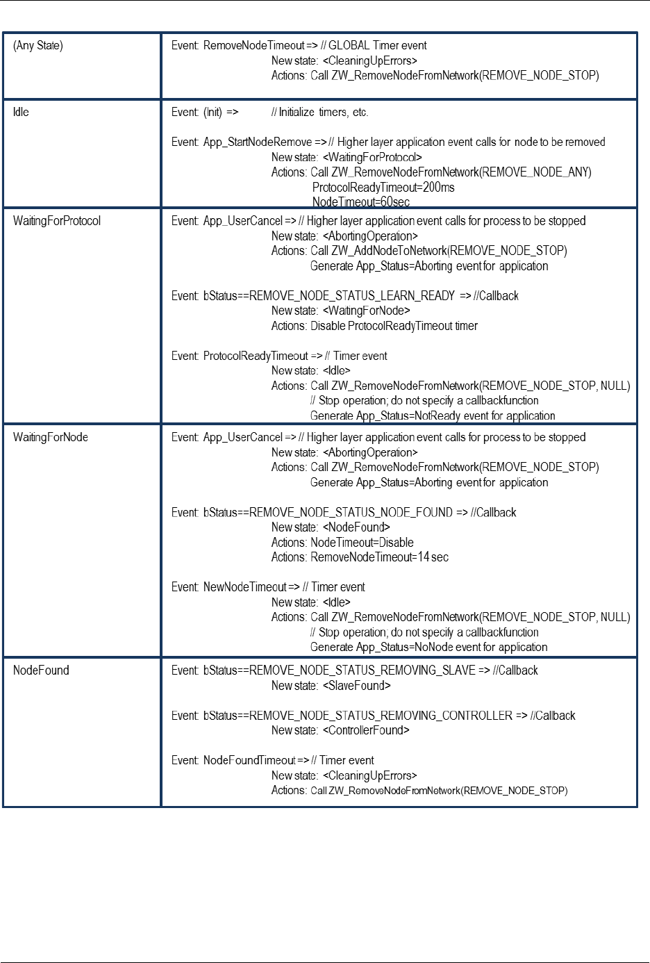
INS13478-5 Z-Wave 500 Series Appl. Programmers Guide v6.71.01 2017-02-28
Sigma Designs Inc.
Z-Wave Application Interfaces
Page 371 of 431
Table 24. RemoveNode : State/Event processing - 1
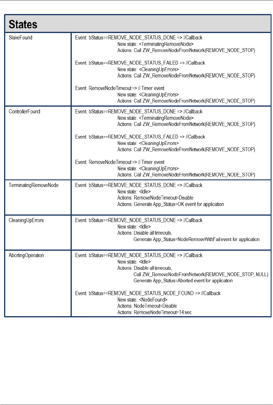
INS13478-5 Z-Wave 500 Series Appl. Programmers Guide v6.71.01 2017-02-28
Sigma Designs Inc.
Z-Wave Application Interfaces
Page 372 of 431
Table 25. RemoveNode : State/Event processing - 2

INS13478-5 Z-Wave 500 Series Appl. Programmers Guide v6.71.01 2017-02-28
Sigma Designs Inc.
Z-Wave Application Interfaces
Page 373 of 431
4.4.22 ZW_RemoveNodeIDFromNetwork
void ZW_RemoveNodeIDFromNetwork(BYTE bMode,
BYTE bNodeID,
VOID_CALLBACKFUNC(completedFunc)(LEARN_INFO *learnNodeInfo))
Macro: ZW_REMOVE_NODE_ID_FROM_NETWORKmode, nodeid, func)
Defined in: ZW_controller_api.h
Serial API: Func_ID = 0x3F
HOST->ZW: REQ | 0x3F | bMode | bNodeID | funcID
ZW->HOST: REQ | 0x3F | funcID | bStatus | bSource | bLen | basic | generic | specific | cmdclasses[ ]
ZW_RemoveNodeIDFromNetwork can be used to remove a specific node from a Z-Wave network.
The RemoveNodeIDFromNetwork function MAY be called by a primary controller application to invoke
the removal of a specific node from the Z-Wave network in question. Slave and secondary controller
applications MUST NOT call this function.
The bMode, bNodeID and completedFunc parameters MUST be specified for the
RemoveNodeIDFromNetwork function to function.
Refer to Figure 41 and substitute ZW_RemoveNodeFromNetwork with
ZW_RemoveNodeIDFromNetwork for a state diagram outlining the processing of status callbacks and
timeouts.
4.4.22.1 bMode parameter
See ZW_RemoveNodeFromNetwork 4.4.21.1 and substitute ZW_RemoveNodeFromNetwork with
ZW_RemoveNodeIDFromNetwork for a description of the bMode parameter.
4.4.22.2 bNodeID parameter
The bNodeID parameter can be used to specify that only the node with the exact nodeID as specified
can be excluded through the started exclusion process.
If a valid bNodeID value (1-232) is specified then only the specified bNodeID with the same HomeID as
the excluding controller and matching the mode settings can be removed.
If REMOVE_NODE_ID_ANY or any NONE valid nodeID (0, 233-255) is specified then
ZW_RemoveNodeIDFromNetwork functions exactly as ZW_RemoveNodeFromNetwork (See 4.4.21).
4.4.22.3 completedFunc parameter
See ZW_RemoveNodeFromNetwork 4.4.21.2 and substitute ZW_RemoveNodeFromNetwork with
ZW_RemoveNodeIDFromNetwork for a description of the completedFunc parameter.

INS13478-5 Z-Wave 500 Series Appl. Programmers Guide v6.71.01 2017-02-28
Sigma Designs Inc.
Z-Wave Application Interfaces
Page 374 of 431
4.4.23 ZW_ReplicationReceiveComplete
void ZW_ReplicationReceiveComplete(void)
Macro: ZW_REPLICATION_COMMAND_COMPLETE
Sends command completed to sending controller. Called in replication mode when a command from the
sender has been processed and indicates that the controller is ready for next packet.
Defined in: ZW_controller_api.h
Serial API:
HOST->ZW: REQ | 0x44

INS13478-5 Z-Wave 500 Series Appl. Programmers Guide v6.71.01 2017-02-28
Sigma Designs Inc.
Z-Wave Application Interfaces
Page 375 of 431
4.4.24 ZW_ReplicationSend
BYTE ZW_ReplicationSend( BYTE destNodeID,
BYTE *pData,
BYTE dataLength,
BYTE txOptions,
VOID_CALLBACKFUNC(completedFunc)(BYTE txStatus))
Macro: ZW_REPLICATION_SEND_DATA(node,data,length,options,func)
Used when the controller is in replication mode. It sends the payload and expects the receiver to respond
with a command complete message (ZW_REPLICATION_COMMAND_COMPLETE).
Messages sent using this command should always be part of the Z-Wave controller replication command
class.
Defined in: ZW_controller_api.h
Return value:
BYTE
FALSE
If transmit queue overflow.
Parameters:
destNode IN
Destination Node ID
(not equal NODE_BROADCAST).
pData IN
Data buffer pointer
dataLength IN
Data buffer length
txOptions IN
Transmit option flags. (see
ZW_SendData, but avoid using
routing!)
completedFunc
IN
Transmit completed call back function
Callback function Parameters:
txStatus IN
(see ZW_SendData)
Serial API:
HOST->ZW: REQ | 0x45 | destNodeID | dataLength | pData[ ] | txOptions | funcID
ZW->HOST: RES | 0x45 | RetVal
ZW->HOST: REQ | 0x45 | funcID | txStatus

INS13478-5 Z-Wave 500 Series Appl. Programmers Guide v6.71.01 2017-02-28
Sigma Designs Inc.
Z-Wave Application Interfaces
Page 376 of 431
4.4.25 ZW_RequestNodeInfo
BOOL ZW_RequestNodeInfo (BYTE nodeID,
VOID (*completedFunc)(BYTE txStatus))
Macro: ZW_REQUEST_NODE_INFO(NODEID)
This function is used to request the Node Information Frame from a controller based node in the network.
The Node info is retrieved using the ApplicationControllerUpdate callback function with the status
UPDATE_STATE_NODE_INFO_RECEIVED. The ZW_RequestNodeInfo API call is also available for
routing slaves.
Defined in: ZW_controller_api.h
Return value:
BOOL
TRUE
If the request could be put in the transmit
queue successfully.
FALSE
If the request could not be put in the
transmit queue. Request failed.
Parameters:
nodeID IN
The node ID (1...232) of the node to
request the Node Information Frame
from.
completedFunc
IN
Transmit complete call back.
Callback function Parameters:
txStatus IN
(see ZW_SendData)
Serial API:
HOST->ZW: REQ | 0x60 | NodeID
ZW->HOST: RES | 0x60 | retVal

INS13478-5 Z-Wave 500 Series Appl. Programmers Guide v6.71.01 2017-02-28
Sigma Designs Inc.
Z-Wave Application Interfaces
Page 377 of 431
4.4.26 ZW_RequestNodeNeighborUpdate
BYTE ZW_RequestNodeNeighborUpdate(
NODEID,
VOID_CALLBACKFUNC (completedFunc)(BYTE bStatus))
Macro: ZW_REQUEST_NODE_NEIGHBOR_UPDATE(nodeid, func)
Get the neighbors from the specified node. This call can only be called by a primary/inclusion controller.
An inclusion controller should call ZW_RequestNetWorkUpdate in advance because the inclusion
controller may not have the latest network topology.
Defined in: ZW_controller_api.h
Return value:
BYTE
TRUE
The discovery process is started and
the function will be completed by the
callback
FALSE
The discovery was not started and
the callback will not be called. The
reason for the failure can be one of
the following:
This is not a primary/inclusion
controller
There is only one node in the
network, nothing to update.
The controller is busy doing
another update.
Parameters:
nodeID IN
Node ID (1...232) of the node that the
controller wants to get new neighbors from.
Not allowed to use controllers own node ID.
completedFunc
IN
Transmit complete call back.
Callback function Parameters:
bStatus IN
Status of command:
REQUEST_NEIGHBOR_UPDATE_STARTED
Requesting neighbor list from the
node is in progress.
REQUEST_NEIGHBOR_UPDATE_DONE
New neighbor list received
REQUEST_NEIGHBOR_UPDATE_FAIL
Getting new neighbor list failed
Serial API:
HOST->ZW: REQ | 0x48 | nodeID | funcID

INS13478-5 Z-Wave 500 Series Appl. Programmers Guide v6.71.01 2017-02-28
Sigma Designs Inc.
Z-Wave Application Interfaces
Page 378 of 431
ZW->HOST: REQ | 0x48 | funcID | bStatus

INS13478-5 Z-Wave 500 Series Appl. Programmers Guide v6.71.01 2017-02-28
Sigma Designs Inc.
Z-Wave Application Interfaces
Page 379 of 431
4.4.27 ZW_SendSUCID
BYTE ZW_SendSUCID (BYTE node,
BYTE txOption,
VOID_CALLBACKFUNC (completedFunc)(BYTE txStatus,
TX_STATUS_TYPE* txStatusReport))
Macro: ZW_SEND_SUC_ID(nodeID, txOption, func)
Transmit SUC/SIS node ID from a primary controller or static controller to the controller node ID
specified. Routing slaves ignore this command, use instead ZW_AssignSUCReturnRoute.
Defined in: ZW_controller_api.h
Return value:
TRUE
In progress.
FALSE
Not a primary controller or static
controller.
Parameters:
node IN
The node ID (1...232) of the node to
receive the current SUC/SIS node ID.
txOption IN
Transmit option flags. (see
ZW_SendData)
completedFunc
IN
Transmit complete call back.
Callback function parameters:
txStatus IN
(see ZW_SendData)
txStatusReport IN
(see ZW_SendData)
Serial API:
HOST->ZW: REQ | 0x57 | node | txOption | funcID
ZW->HOST: RES | 0x57 | RetVal
ZW->HOST: REQ | 0x57 | funcID | txStatus

INS13478-5 Z-Wave 500 Series Appl. Programmers Guide v6.71.01 2017-02-28
Sigma Designs Inc.
Z-Wave Application Interfaces
Page 380 of 431
4.4.28 ZW_SetDefault
void ZW_SetDefault( VOID_CALLBACKFUNC(completedFunc)(void))
Macro: ZW_SET_DEFAULT(func)
This function set the Controller back to the factory default state. Erase all Nodes, routing information and
assigned homeID/nodeID from the NVM. In case the previous home ID was randomly generated then a
new random home ID written to the NVM (random range: 0xC0000000-0xFFFFFFFE). A home ID
outside random range reuses the initially configured home ID (configured during production).
Warning: Use this function with care as it could render a Z-Wave network unusable if the primary
controller in an existing network is set back to default.
Defined in: ZW_controller_api.h
Parameters:
completedFunc IN
Command completed call back function
Serial API:
HOST->ZW: REQ | 0x42 | funcID
ZW->HOST: REQ | 0x42 | funcID
Timeout: 1000ms
Exception Recovery: Resume normal operation, check nodelist to see if the controller has been reset. A
controller MUST have nodeID ==1 after a set default.

INS13478-5 Z-Wave 500 Series Appl. Programmers Guide v6.71.01 2017-02-28
Sigma Designs Inc.
Z-Wave Application Interfaces
Page 381 of 431
4.4.29 ZW_SetLearnMode
void ZW_SetLearnMode (BYTE mode,
VOID_CALLBACKFUNC(completedFunc)(LEARN_INFO *learnNodeInfo))
Macro: ZW_SET_LEARN_MODE(mode, func)
ZW_SetLearnMode is used to add or remove the controller to/from a Z-Wave network.
This function is used to instruct the controller to allow it to be added or removed from the network.
When a controller is added to the network the following things will happen:
1. If the current stored ID's are zero and the assigned ID’s are nonzero, the received ID's will be
stored (node was added to the network).
2. If the received ID's are zero the stored ID's will be set to zero (node was removed from the
network).
3. The controller receives updates to the node list and the routing table but the ID’s remain
unchanged.
This function will probably change the capabilities of the controller so it is recommended that the
application calls ZW_GetControllerCapabilities() after completion to check the controller status.
The learnFunc is called as the "Assign" process progresses. The returned nodeID is the nodes new
Node ID. If no "Assign" is received from the including controller the callback function will not be called. It
is then up to the application code to switch of Learn mode. Once the assignment process has been
started the Callback function may be called more than once. The learn process is not complete before
the callback function is called with LEARN_MODE_DONE.
Network wide inclusion (add) should always be used as the default mode in inclusion to ensure
compability with all implementations of Z-Wave controllers.
For information about how to use the different learn modes to make a inclusion that is compatible with all
generations of Z-Wave nodes see [4]
NOTE: Learn mode should only be enabled when necessary and disabled again as quickly as possible.
It is recommended that learn mode is not enabling for more than 2 second in
ZW_SET_LEARN_MODE_CLASSIC mode and 5 seconds in either ZW_SET_LEARN_MODE_NWI or
ZW_SET_LEARN_MODE_NWE mode.
NOTE: When the controller is already included into a network (secondary or inclusion controller) the
callback status LEARN_MODE_STARTED will not be made but the LEARN_MODE_DONE/FAILED
callback will be made as normal.
WARNING: The learn process should not be stopped with ZW_SetLearnMode(FALSE,..) between the
LEARN_MODE_STARTED and the LEARN_MODE_DONE status callback.

INS13478-5 Z-Wave 500 Series Appl. Programmers Guide v6.71.01 2017-02-28
Sigma Designs Inc.
Z-Wave Application Interfaces
Page 382 of 431
Defined in: ZW_controller_api.h
Parameters:
mode IN
The learn node states are:
ZW_SET_LEARN_MODE_CLASSIC
Start the learn mode on the
controller and only accept being
included and exluded in direct
range.
ZW_SET_LEARN_MODE_NWI
Start the learn mode on the
controller and accept routed
inclusion (add). NWI mode must
not be used for exclusion
(remove).
ZW_SET_LEARN_MODE_NWE
Start the learn mode on the
controller and accept routed
exclusion (remove) as well as
direct. NWE mode must not be
used for inclusion (add).
ZW_SET_LEARN_MODE_DISABLE
Stop learn mode on the
controller
completedFunc IN
Callback function pointer (Should only be
NULL if state is turned off).

INS13478-5 Z-Wave 500 Series Appl. Programmers Guide v6.71.01 2017-02-28
Sigma Designs Inc.
Z-Wave Application Interfaces
Page 383 of 431
Callback function Parameters (completedFunc):
*learnNodeInfo.bStatus
IN
Status of learn mode:
LEARN_MODE_STARTED
The learn process has
been started
LEARN_MODE_DONE
The learn process is
complete and the
controller is now included
into the network
LEARN_MODE_FAILED
The learn process failed.
*learnNodeInfo.bSource
IN
Node id of the new node
*learnNodeInfo.pCmd
IN
Pointer to Application Node information data
(see ApplicationNodeInformation -
nodeParm). NULL if no information present.
The pCmd only contain information when bLen is
not zero, so the information should be stored
when that is the case. Regardless of the
bStatus.
*learnNodeInfo.bLen IN
Node info length.
Serial API:
HOST->ZW: REQ | 0x50 | mode | funcID
ZW->HOST: REQ | 0x50 | funcID | bStatus | bSource | bLen | pCmd[ ]

INS13478-5 Z-Wave 500 Series Appl. Programmers Guide v6.71.01 2017-02-28
Sigma Designs Inc.
Z-Wave Application Interfaces
Page 384 of 431
4.4.30 ZW_SetRoutingInfo
void ZW_SetRoutingInfo(BYTE bNodeID,
BYTE bLength,
BYTE_P pMask )
Macro: ZW_SET_ROUTING_INFO(bNodeID, bLength, pMask)
ZW_SetRoutingInfo is a function that can be used to overwrite the current neighbor information for a
given node ID in the protocol locally.
The format of the routing info must be organised as follows:
pMask[i] (0 i < (ZW_MAX_NODES/8)
Bit
0
1
2
3
4
5
6
7
NodeID
i*8+1
i*8+2
i*8+3
i*8+4
i*8+5
i*8+6
i*8+7
i*8+8
If a bit n in pMask[i] is 1 it indicates that the node bNodeID has node (i*8)+n+1 as a neighbour. If n in
pMask[i] is 0, bNodeID cannot reach node (i*8)+n+1 directly.
Defined in: ZW_controller_api.h
Return value:
BOOL
TRUE
Neighbor information updated
successfully.
FALSE
Failed to update neighbor information.
Parameters:
bNodeID IN
Node ID (1…232) to be updated with
respect to neighbor information.
bLength IN
Routing info buffer length in bytes.
pMask IN
Pointer to buffer where routing info
should be taken from. The buffer should
be at least ZW_MAX_NODES/8 bytes
Serial API (Only Developer’s Kit v4.5x):
HOST->ZW: REQ | 0x1B | bNodeID | NodeMask[29]
ZW->HOST: RES | 0x1B | retVal

INS13478-5 Z-Wave 500 Series Appl. Programmers Guide v6.71.01 2017-02-28
Sigma Designs Inc.
Z-Wave Application Interfaces
Page 385 of 431
4.4.31 ZW_SetRoutingMAX
void ZW_SetRoutingMAX(BYTE maxRouteTries)
Use this function to set the maximum number of source routing attempts before the next mechanism
kicks-in. Default value with respect to maximum number of source routing attempts is five. See section
3.10 wrt. the routing attempts for a given Z-Wave node. Remember to enable the transmit option flag
TRANSMIT_OPTION_AUTO_ROUTE or TRANSMIT_OPTION_AUTO_ROUTE |
TRANSMIT_OPTION_EXPLORE in the send data calls.
Defined in: ZW_controller_api.h
Parameters:
maxRouteTries IN
1...20
Maximum number of source routing attempts
Serial API:
HOST->ZW: REQ | 0xD4 | maxRoutesTries
ZW->HOST: RES | 0xD4 | TRUE

INS13478-5 Z-Wave 500 Series Appl. Programmers Guide v6.71.01 2017-02-28
Sigma Designs Inc.
Z-Wave Application Interfaces
Page 386 of 431
4.4.32 ZW_SetSUCNodeID
BYTE ZW_SetSUCNodeID (BYTE nodeID,
BYTE SUCState,
BYTE bTxOption,
BYTE capabilities,
VOID_CALLBACKFUNC (completedFunc)(BYTE txStatus,
TX_STATUS_TYPE* txStatusReport))
Macro: ZW_SET_SUC_NODE_ID(nodeID, SUCState, bTxOption, capabilities, func)
Used to configure a static/bridge controller to be a SUC/SIS node or not. The primary controller should
use this function to set a static/bridge controller to be the SUC/SIS node, or it could be used to stop
previously chosen static/bridge controller being a SUC/SIS node (not recommended).
A controller can set itself to a SUC/SIS by ZW_SetSUCNodeID with its own node ID. It’s recommended
to do this when the Z-Wave network only comprise of the primary controller to get the SUC/SIS role
distributed when new nodes are included. It is possible to include a virgin primary controller with
SUC/SIS capabilities configured into another Z-Wave network.
NOTICE: It is not allowed to call ZW_SetSUCNodeID with its own node ID and SUCState = FALSE
during upstart because this prevent other nodes to set it to a SUC/SIS node.
Defined in: ZW_controller_api.h
Return value:
TRUE
If the process of configuring the
static/bridge controller is started.
FALSE
The process not started because the
calling controller is not the master or the
destination node is not a static/bridge
controller.

INS13478-5 Z-Wave 500 Series Appl. Programmers Guide v6.71.01 2017-02-28
Sigma Designs Inc.
Z-Wave Application Interfaces
Page 387 of 431
Parameters:
nodeID IN
The node ID (1...232) of the static
controller to configure.
SUCState IN
TRUE
Want the static controller to be a
SUC/SIS node.
FALSE
If the static/bridge controller should not
be a SUC/SIS node.
bTxOption IN
TRUE
Want to send the frame with low
transmission power
FALSE
Want to send the frame at normal
transmission power
capabilities IN
SUC capabilities that is enabled:
ZW_SUC_FUNC_NODEID_SERVER
Enable the node ID server functionality to
become a SIS.
completedFunc
IN
Transmit complete call back.
Callback function Parameters:
txStatus IN
Status of command:
ZW_SUC_SET_SUCCEEDED
The process ended successfully.
ZW_SUC_SET_FAILED
The process failed.
txStatusReport
IN
(see ZW_SendData)
Serial API:
HOST->ZW: REQ | 0x54 | nodeID | SUCState | bTxOption | capabilities | funcID
ZW->HOST: RES | 0x54 | RetVal
ZW->HOST: REQ | 0x54 | funcID | txStatus
In case ZW_SetSUCNodeID is called locally with the controllers own node ID then only the response is
returned. In case true is returned in the response then it can be interpreted as the command is now
executed successfully.

INS13478-5 Z-Wave 500 Series Appl. Programmers Guide v6.71.01 2017-02-28
Sigma Designs Inc.
Z-Wave Application Interfaces
Page 388 of 431
4.5 Z-Wave Static Controller API
The Static Controller application interface is an extended Controller application interface with added
functionality specific for the Static Controller.
4.5.1 ZW_CreateNewPrimaryCtrl
Void ZW_CreateNewPrimaryCtrl(BYTE mode,
VOID_CALLBACKFUNC(completedFunc)(LEARN_INFO *learnNodeInfo))
Macro: ZW_CREATE_NEW_PRIMARY_CTRL
NOTE: Legacy function. This function is no longer relevant for a controller because it is no longer
possible to have a SUC without a SIS. This function should not be used.
ZW_CreateNewPrimaryCtrl is used to add a controller to the Z-Wave network as a replacement for the
old primary controller.
This function has the same functionality as ZW_AddNodeToNetwork(ADD_NODE_CONTROLLER,…)
except that the new controller will be a primary controller and it can only be called by a SUC. The
function is not available if the SUC is a node ID server (SIS).
WARNING: This function should only be used when it is 100% certain that the original primary controller
is lost or broken and will not return to the network.
Defined in: ZW_controller_static_api.h
Parameters:
mode IN
The learn node states are:
CREATE_PRIMARY_START
Start the process of adding a a
new primary controller to the
network.
CREATE_PRIMARY_STOP
Stop the process.
CREATE_PRIMARY_STOP_FAILED
Stop the inclusion (add) and
report a failure to the other
controller.
completedFunc IN
Callback function pointer (Should only be
NULL if state is turned off).
Callback function Parameters:
*learnNodeInfo.bStatus IN
Status of learn mode:

INS13478-5 Z-Wave 500 Series Appl. Programmers Guide v6.71.01 2017-02-28
Sigma Designs Inc.
Z-Wave Application Interfaces
Page 389 of 431
ADD_NODE_STATUS_LEARN_READY
The controller is now
ready to include a
controller into the
network.
ADD_NODE_STATUS_NODE_FOUND
A controller that wants to
be included into the
network has been found
ADD_NODE_STATUS_ADDING_CONTROLLER
A new controller has
been added to the
network
ADD_NODE_STATUS_PROTOCOL_DONE
The protocol part of
adding a controller is
complete, the application
can now send data to the
new controller using
ZW_ReplicationSend()
ADD_NODE_STATUS_DONE
The new controller has
now been included and
the controller is ready to
continue normal
operation again.
ADD_NODE_STATUS_FAILED
The learn process failed
*learnNodeInfo.bSource IN
Node id of the new node
*learnNodeInfo.pCmd IN
Pointer to Application Node information data
(see ApplicationNodeInformation -
nodeParm). NULL if no information present.
The pCmd only contain information when
bLen is not zero, so the information should
be stored when that is the case. Regardless
of the bStatus.
*learnNodeInfo.bLen IN
Node info length.
Serial API:
HOST->ZW: REQ | 0x4C | mode | funcID
ZW->HOST: REQ | 0x4C | funcID | bStatus | bSource | bLen | basic | generic | specific | cmdclasses[ ]

INS13478-5 Z-Wave 500 Series Appl. Programmers Guide v6.71.01 2017-02-28
Sigma Designs Inc.
Z-Wave Application Interfaces
Page 390 of 431
4.6 Z-Wave Bridge Controller API
The Bridge Controller application interface is an extended Controller application interface with added
functionality specific for the Bridge Controller.
4.6.1 ZW_SendSlaveNodeInformation
BYTE ZW_SendSlaveNodeInformation(BYTE srcNode,
BYTE destNode,
BYTE txOptions,
VOID_CALLBACKFUNC(completedFunc)(
BYTE txStatus,
TX_STATUS_TYPE* txStatusReport))
Macro: ZW_SEND_SLAVE_NODE_INFO(srcnode, destnode, option, func)
Create and transmit a Virtual Slave node “Node Information” frame from Virtual Slave node srcNode. The
Z-Wave transport layer builds a frame, request the application slave node information (see
ApplicationSlaveNodeInformation) and queue the “Node Information” frame for transmission. The
completed call back function (completedFunc) is called when the transmission is complete.
NOTE: ZW_SendSlaveNodeInformation uses the transmit queue in the API, so using other transmit
functions before the complete callback has been called by the API might fail.
Defined in: ZW_controller_bridge_api.h
Return value:
BYTE
TRUE
If frame was put in the transmit queue.
FALSE
If transmitter queue overflow or if bridge
controller is primary or srcNode is invalid
then completedFunc will NOT be called.
Parameters:
srcNode IN
Source Virtual Slave Node ID
destNode IN
Destination Node ID
(NODE_BROADCAST == all nodes)
txOptions IN
Transmit option flags:
TRANSMIT_OPTION_LOW_POWER
Transmit at low output power level (1/3 of
normal RF range). NOTE: The
TRANSMIT_OPTION_LOW_POWER
option should only be used when the two
nodes that are communicating are close
to each other (<2 meter). In all other
cases this option should not be used.
TRANSMIT_OPTION_ACK
Request acknowledge from destination
node.

INS13478-5 Z-Wave 500 Series Appl. Programmers Guide v6.71.01 2017-02-28
Sigma Designs Inc.
Z-Wave Application Interfaces
Page 391 of 431
completedFunc IN
Transmit completed call back function
Callback function Parameters:
txStatus
(see ZW_SendData)
txStatusReport IN
(see ZW_SendData)
Serial API:
HOST->ZW: REQ | 0xA2 | srcNode | destNode | txOptions | funcID
ZW->HOST: RES | 0xA2 | retVal
ZW->HOST; REQ | 0xA2 | funcID | txStatus

INS13478-5 Z-Wave 500 Series Appl. Programmers Guide v6.71.01 2017-02-28
Sigma Designs Inc.
Z-Wave Application Interfaces
Page 392 of 431
4.6.2 ZW_SetSlaveLearnMode
BYTE ZW_SetSlaveLearnMode( BYTE node,
BYTE mode,
VOID_CALLBACKFUNC(learnSlaveFunc)(BYTE state, BYTE orgID,
BYTE newID))
Macro: ZW_SET_SLAVE_LEARN_MODE (node, mode, func)
ZW_SetSlaveLearnMode enables the possibility for enabling or disabling “Slave Learn Mode”, which
when enabled makes it possible for other controllers (primary or inclusion controllers) to add or remove a
Virtual Slave Node to the Z-Wave network. Also is it possible for the bridge controller (only when primary
or inclusion controller) to add or remove a Virtual Slave Node without involving other controllers.
Available Slave Learn Modes are:
VIRTUAL_SLAVE_LEARN_MODE_DISABLE – Disables the Slave Learn Mode so that no Virtual
Slave Node can be added or removed.
VIRTUAL_SLAVE_LEARN_MODE_ENABLE – Enables the possibility for other Primary/Inclusion
controllers to add or remove a Virtual Slave Node. To add a new Virtual Slave node to the Z-Wave
Network the provided “node” ID must be ZERO and to make it possible to remove a specific
Virtual Slave Node the provided “node” ID must be the nodeID for this specific (locally present)
Virtual Slave Node. When the Slave Learn Mode has been enabled the Virtual Slave node must
identify itself to the external Primary/Inclusion Controller node by sending a “Node Information”
frame (see ZW_SendSlaveNodeInformation) to make the add/remove operation commence.
VIRTUAL_SLAVE_LEARN_MODE_ADD - Add Virtual Slave Node to the Z-Wave network
without involving any external controller. This Slave Learn Mode is only possible when bridge
controller is either a Primary controller or an Inclusion controller.
VIRTUAL_SLAVE_LEARN_MODE_REMOVE - Remove a locally present Virtual Slave Node from
the Z-Wave network without involving any external controller. This Slave Learn Mode is only
possible when bridge controller is either a Primary controller or an Inclusion controller.
The learnSlaveFunc is called as the "Assign" process progresses. The returned “orgID” is the Virtual
Slave node put into Slave Learn Mode, the “newID” is the new Node ID. If the Slave Learn Mode is
VIRTUAL_SLAVE_LEARN_MODE_ENABLE and nothing is received from the assigning controller the
callback function will not be called. It is then up to the main application code to switch of Slave Learn
mode by setting the VIRTUAL_SLAVE_LEARN_MODE_DISABLE Slave Learn Mode. Once the
assignment process has been started the Callback function may be called more than once.
NOTE: Slave Learn Mode should only be set to VIRTUAL_SLAVE_LEARN_MODE_ENABLE when
necessary, and it should always be set to VIRTUAL_SLAVE_LEARN_MODE_DISABLE again as quickly
as possible. It is recommended that Slave Learn Mode is never set to
VIRTUAL_SLAVE_LEARN_MODE_ENABLE for more than 1 second.

INS13478-5 Z-Wave 500 Series Appl. Programmers Guide v6.71.01 2017-02-28
Sigma Designs Inc.
Z-Wave Application Interfaces
Page 393 of 431
Defined in: ZW_controller_bridge_api.h
Return value:
BYTE
TRUE
If learnSlaveMode change was
succesful.
FALSE
If learnSlaveMode change could not
be done.
Parameters:
node IN
Node ID (1...232) on node to set in Slave
Learn Mode, ZERO if new node is to be
learned.
mode IN
Valid modes:
VIRTUAL_SLAVE_LEARN_MODE_DISABLE
Disable Slave Learn Mode
VIRTUAL_SLAVE_LEARN_MODE_ENABLE
Enable Slave Learn Mode
VIRTUAL_SLAVE_LEARN_MODE_ADD
ADD: Create locally a Virtual Slave
Node and add it to the Z-Wave
network (only possible if
Primary/Inclusion Controller).
VIRTUAL_SLAVE_LEARN_MODE_REMOVE
Remove locally present Virtual Slave
Node from the Z-Wave network (only
possible if Primary/Inclusion
Controller).
learnFunc IN
Slave Learn mode complete call back
function

INS13478-5 Z-Wave 500 Series Appl. Programmers Guide v6.71.01 2017-02-28
Sigma Designs Inc.
Z-Wave Application Interfaces
Page 394 of 431
Callback function Parameters:
bStatus
Status of the assign process.
ASSIGN_COMPLETE
Is returned by the callback function when in
the
VIRTUAL_SLAVE_LEARN_MODE_ENABLE
Slave Learn Mode and assignment is done.
Now the Application can continue normal
operation.
ASSIGN_NODEID_DONE
Node ID have been assigned. The “orgID”
contains the node ID on the Virtual Slave
Node who was put into Slave Learn Mode.
The “newID” contains the new node ID for
“orgID”. If “newID” is ZERO then the “orgID”
Virtual Slave node has been deleted and the
assign operation is completed. When this
status is received the Slave Learn Mode is
complete for all Slave Learn Modes except
the
VIRTUAL_SLAVE_LEARN_MODE_ENABLE
mode.
ASSIGN_RANGE_INFO_UPDATE
Node is doing Neighbour discovery
Application should not attempt to send any
frames during this time, this is only applicable
when in
VIRTUAL_SLAVE_LEARN_MODE_ENABLE.
orgID
The original node ID that was put into
Slave Learn Mode.
newID
The new Node ID. Zero if “OrgID” was
deleted from the Z-Wave network.
Serial API:
HOST->ZW: REQ | 0xA4 | node | mode | funcID
ZW->HOST: RES | 0xA4 | retVal
ZW->HOST: REQ | 0xA4 | funcID | bStatus | OrgID | newID

INS13478-5 Z-Wave 500 Series Appl. Programmers Guide v6.71.01 2017-02-28
Sigma Designs Inc.
Z-Wave Application Interfaces
Page 395 of 431
4.6.3 ZW_IsVirtualNode
BYTE ZW_IsVirtualNode(BYTE nodeID)
Macro: ZW_IS_VIRTUAL_NODE (nodeid)
Checks if “nodeID” is a Virtual Slave node.
Defined in: ZW_controller_bridge_api.h
Return value:
BYTE
TRUE
If “nodeID” is a Virtual Slave node.
FALSE
If “nodeID” is not a Virtual Slave node.
Parameters:
nodeID IN
Node ID (1...232) on node to check if it is
a Virtual Slave node.
Serial API:
HOST->ZW: REQ | 0xA6 | nodeID
ZW->HOST: RES | 0xA6 | retVal

INS13478-5 Z-Wave 500 Series Appl. Programmers Guide v6.71.01 2017-02-28
Sigma Designs Inc.
Z-Wave Application Interfaces
Page 396 of 431
4.6.4 ZW_GetVirtualNodes
VOID ZW_GetVirtualNodes(BYTE *pnodeMask)
Macro: ZW_GET_VIRTUAL_NODES (pnodemask)
Request a buffer containing available Virtual Slave nodes in the Z-Wave network.
The format of the data returned in the buffer pointed to by pnodeMask is as follows:
pnodeMask[i] (0 i < (ZW_MAX_NODES/8)
Bit
0
1
2
3
4
5
6
7
NodeID
i*8+1
i*8+2
i*8+3
i*8+4
i*8+5
i*8+6
i*8+7
i*8+8
If bit n in pnodeMask[i] is 1, it indicates that node (i*8)+n+1 is a Virtual Slave node. If bit n in
pnodeMask[i] is 0, it indicates that node (i*8)+n+1 is not a Virtual Slave node.
Defined in: ZW_controller_bridge_api.h
Parameters:
pNodeMask IN
Pointer to nodemask (29 byte size)
buffer where the Virtual Slave
nodeMask should be copied.
Serial API:
HOST->ZW: REQ | 0xA5
ZW->HOST: RES | 0xA5 | pnodeMask[29]

INS13478-5 Z-Wave 500 Series Appl. Programmers Guide v6.71.01 2017-02-28
Sigma Designs Inc.
Z-Wave Application Interfaces
Page 397 of 431
4.7 Z-Wave Portable Controller API
The Portable application interface is basically an extended Controller interface that gives the application
access to functions that can be used to create more advanced installation tools, which provide better
diagnostics and error locating capabilities.
4.7.1 zwTransmitCount
BYTE zwTransmitCount
Macro: ZW_TX_COUNTER
ZW_TX_COUNTER is a variable that returns the number of transmits that the protocol has done since
last reset of the variable. If the number returned is 255 then the number of transmits ≥ 255. The variable
should be reset by the application, when it is to be restarted.
Defined in: ZW_controller_portable_api.h
Serial API:
To read the transmit counter:
HOST->ZW: REQ | 0x81| (FUNC_ID_GET_TX_COUNTER)
ZW->HOST: RES | 0x81 | ZW_TX_COUNTER (1 byte)
To reset the transmit counter:
HOST->ZW: REQ | 0x82| (FUNC_ID_RESET_TX_COUNTER)

INS13478-5 Z-Wave 500 Series Appl. Programmers Guide v6.71.01 2017-02-28
Sigma Designs Inc.
Z-Wave Application Interfaces
Page 398 of 431
4.7.2 ZW_StoreNodeInfo
BOOL ZW_StoreNodeInfo( BYTE bNodeID,
BYTE_P pNodeInfo,
VOID_CALLBACKFUNC(func)())
Macro: ZW_STORE_NODE_INFO(NodeID,NodeInfo,function)
ZW_StoreNodeInfo is a function that can be used to restore protocol node information from a backup or
the like. The format of the node info frame should be identical with the format used by
ZW_GET_NODE_STATE.
NOTE: The restored values will not take effect before the Z-Wave module has been reset.
Defined in: ZW_controller_portable_api.h
Return value:
BOOL
TRUE
If NodeInfo was Stored.
FALSE
If NodeInfo was not Stored. (Illegal NodeId or
MemoryWrite failed)
Parameters:
bNodeID IN
Node ID (1...232) to store information at.
pNodeInfo IN
Pointer to Node Information Frame.
func IN
Callback function. Called when data has
been stored.
Serial API:
HOST->ZW: REQ | 0x83 | bNodeID | nodeInfo (nodeInfo is a NODEINFO field) | funcID
ZW->HOST: RES | 0x83 | retVal
ZW->HOST: REQ| 0x83 | funcID

INS13478-5 Z-Wave 500 Series Appl. Programmers Guide v6.71.01 2017-02-28
Sigma Designs Inc.
Z-Wave Application Interfaces
Page 399 of 431
4.7.3 ZW_StoreHomeID
void ZW_StoreHomeID(BYTE_P pHomeID,
BYTE bNodeID)
Macro: ZW_STORE_HOME_ID(pHomeID, NodeID)
ZW_StoreHomeID is a function that can be used to restore HomeID and NodeID information from a
backup.
NOTE: The restored values will not take effect before the Z-Wave module has been reset.
Defined in: ZW_controller_portable_api.h
Parameters:
pHomeID IN
Pointer to HomeID structure to store
bNodeID IN
NodeID to store.
Serial API:
HOST->ZW: REQ | 0x84 | pHomeID[0] | pHomeID[1] | pHomeID[2] | pHomeID[3] | bNodeID

INS13478-5 Z-Wave 500 Series Appl. Programmers Guide v6.71.01 2017-02-28
Sigma Designs Inc.
Z-Wave Application Interfaces
Page 400 of 431
4.8 Z-Wave Slave API
The Slave application interface is an extension to the Basis application interface enabling
inclusion/exclusion (add/remove) of Routing Slave, and Enhanced 232 Slave nodes.
4.8.1 ZW_SetDefault
void ZW_SetDefault(void)
Macros: ZW_SET_DEFAULT
This function set the slave back to the factory default state. Erase routing information and assigned
homeID/nodeID from the external NVM. Finally write a new random home ID to the external NVM.
Defined in: ZW_slave_api.h
Serial API:
HOST->ZW: REQ | 0x42 | funcID
ZW->HOST: REQ | 0x42 | funcID
4.8.2 ZW_SetLearnMode
void ZW_SetLearnMode(BYTE mode,
VOID_CALLBACKFUNC(learnFunc)(BYTE bStatus, BYTE nodeID) )
Macro: ZW_SET_LEARN_MODE(mode, func)
ZW_SetLearnMode enable or disable home and node ID’s learn mode. Use this function to add a new
Slave node to a Z-Wave network or to remove an already added node from the network again.
The Slave node must identify itself to the including controller node by sending a Node Information Frame
(see ZW_SendNodeInformation).
When learn mode is enabled, the follwong two actions can be performed by the protocol:
1. If the current stored ID's are zero and the assigned ID’s are nonzero, the received ID's will be
stored (node was added to the network).
2. If the received ID's are zero the stored ID's will be set to zero (node was removed from the
network).
The learnFunc is called as the "Assign" process progresses. The returned nodeID is the nodes new
Node ID. If no "Assign" is received from the including controller the callback function will not be called. It
is then up to the application code to switch of Learn mode. Once the assignment process has been
started the Callback function may be called more than once. The learn process is not complete before
the callback function is called with ASSIGN_COMPLETE.
NOTE: Learn mode should only be enabled when necessary and disabled again as quickly as possible.
It is recommended that learn mode is not enabled for more than 2 seconds in

INS13478-5 Z-Wave 500 Series Appl. Programmers Guide v6.71.01 2017-02-28
Sigma Designs Inc.
Z-Wave Application Interfaces
Page 401 of 431
ZW_SET_LEARN_MODE_CLASSIC mode and 5 seconds when in either
ZW_SET_LEARN_MODE_NWI or ZW_SET_LEARN_MODE_NWE mode.
Defined in: ZW_slave_api.h
Parameters:
mode IN
ZW_SET_LEARN_MODE_CLASSIC
Start the learn mode on the slave and
only accept being included and excluded
in direct range.
ZW_SET_LEARN_MODE_NWI
Start the learn mode on the slave and
accept routed inclusion (add). NWI mode
must not be used for exclusion (remove).
ZW_SET_LEARN_MODE_NWE
Start the learn mode on the slave and
accept routed exclusion (remove). NWE
mode must not be used for inclusion
(add).
ZW_SET_LEARN_MODE_DISABLE
Stop learn mode on the slave
learnFunc IN
Node ID learn mode completed call back
function
Callback function Parameters:
bStatus
Status of the assign process
ASSIGN_COMPLETE
Assignment is done and Application can
continue normal operation.
ASSIGN_NODEID_DONE
Node ID has been assigned. More
information may follow.
ASSIGN_RANGE_INFO_UPDATE
Node is doing Neighbor discovery
Application should not attempt to send
any frames during this time.
nodeID
The new (learned) Node ID (1...232)
NOTE: The ASSIGN_COMPLETE callback is not synchronized with the ADD_NODE_STATUS_DONE
callback on the including controller. The including controller MAY start sending frames to the included
node before the ASSIGN_COMPLETE callback. In that case the included node MAY respond before the
ASSIGN_COMPLETE callback arrives. Broadcast frames received before the ASSIGN_COMPLETE
callback MUST NOT trigger a response transmission.
Serial API:
HOST->ZW: REQ | 0x50 | mode | funcID
ZW->HOST: REQ | 0x50 | funcID | bstatus | nodeID

INS13478-5 Z-Wave 500 Series Appl. Programmers Guide v6.71.01 2017-02-28
Sigma Designs Inc.
Z-Wave Application Interfaces
Page 402 of 431
4.9 Z-Wave Routing and Enhanced 232 Slave API
The Routing and Enhanced 232 Slave application interface is an extension of the Basis and Slave
application interface enabling control of other nodes in the Z-Wave network.

INS13478-5 Z-Wave 500 Series Appl. Programmers Guide v6.71.01 2017-02-28
Sigma Designs Inc.
Z-Wave Application Interfaces
Page 403 of 431
4.9.1 ZW_GetSUCNodeID
BYTE ZW_GetSUCNodeID(void)
Macro: ZW_GET_SUC_NODEID()
API call used to get the currently registered SUC/SIS node ID. A controller must have called
ZW_AssignSUCReturnRoute before a SUC/SIS node ID is registered in the routing or enhanced 232
slave.
Defined in: ZW_slave_routing_api.h
Return value:
BYTE
The node ID (1..232) on the currently
registered SUC/SIS, if ZERO then no
SUC/SIS available.
Serial API:
HOST->ZW: REQ | 0x56
ZW->HOST: RES | 0x56 | SUCNodeID

INS13478-5 Z-Wave 500 Series Appl. Programmers Guide v6.71.01 2017-02-28
Sigma Designs Inc.
Z-Wave Application Interfaces
Page 404 of 431
4.9.2 ZW_IsNodeWithinDirectRange
BYTE ZW_IsNodeWithinDirectRange(BYTE bNodeID)
Macro: ZW_IS_NODE_WITHIN_DIRECT_RANGE (bNodeID)
Check if the supplied nodeID is marked as being within direct range in any of the existing return routes.
Defined in: ZW_slave_routing_api.h
Return value:
TRUE
If node is within direct range
FALSE
If the node is beyond direct range or if
status is unknown to the protocol
Parameters:
bNodeID IN
Node id to examine
Serial API:
HOST->ZW: REQ | 0x5D | bNodeID
ZW->HOST: RES | 0x5D | retVal

INS13478-5 Z-Wave 500 Series Appl. Programmers Guide v6.71.01 2017-02-28
Sigma Designs Inc.
Z-Wave Application Interfaces
Page 405 of 431
4.9.3 ZW_RediscoveryNeeded
BYTE ZW_RediscoveryNeeded (BYTE bNodeID,
VOID_CALLBACKFUNC (completedFunc)(BYTE bStatus))
Macro: ZW_REDISCOVERY_NEEDED(nodeid, func)
This function can request a SUC/SIS controller to update the requesting nodes neighbors. The function
will try to request a neighbor rediscovery from a SUC/SIS controller in the network. In order to reach a
SUC/SIS controller it uses other nodes (bNodeID) in the network. The application must implement the
algorithm for scanning the bNodeID’s to find a node which can help.
If bNodeID supports this functionality (routing slave and enhanced 232 slave libraries), bNodeID will try
to contact a SUC/SIS controller on behalf of the node that requests the rediscovery. If the functionality is
unsupported by bNodeID ZW_ROUTE_LOST_FAILED will be returned in the callback function and the
next node can be tried.
NOTICE: It is highly recommended to use the transmit option TRANSMIT_OPTION_EXPLORE to enable
dynamic route resolution in API calls such as ZW_SendData as an alternative to
ZW_RediscoveryNeeded.
The callback function is called when the request have been processed by the protocol.
Defined in: ZW_slave_routing_api.h
Return value:
FALSE
The node is busy doing another update.
TRUE
The help process is started; status will
come in the callback.
Parameters:
bNodeID IN
Node ID (1..232) to request help from
completedFunc
IN
Transmit completed call back function

INS13478-5 Z-Wave 500 Series Appl. Programmers Guide v6.71.01 2017-02-28
Sigma Designs Inc.
Z-Wave Application Interfaces
Page 406 of 431
Callback function parameters:
ZW_ROUTE_LOST_ACCEPT
The node bNodeID accepts to forward
the help request. Wait for the next
callback to determine the outcome of the
rediscovery.
ZW_ROUTE_LOST_FAILED
The node bNodeID has responded it is
unable to help and the application can try
next node if it decides so.
ZW_ROUTE_UPDATE_ABORT
No reply was received before the protocol
has timed out. The application can try the
next node if it decides so.
ZW_ROUTE_UPDATE_DONE
The node bNodeID was able to contact a
controller and the routing information has
been updated.
Serial API:
HOST->ZW: REQ | 0x59 | bNodeID | funcID
ZW->HOST: RES | 0x59 | retVal
ZW->HOST: REQ | 0x59 | funcID | bStatus

INS13478-5 Z-Wave 500 Series Appl. Programmers Guide v6.71.01 2017-02-28
Sigma Designs Inc.
Z-Wave Application Interfaces
Page 407 of 431
4.9.4 ZW_RequestNewRouteDestinations
BYTE ZW_RequestNewRouteDestinations(BYTE *pDestList,
BYTE bDestListLen ,
VOID_CALLBACKFUNC (completedFunc)(BYTE bStatus))
Macro: ZW_REQUEST_NEW_ROUTE_DESTINATIONS (pdestList, destListLen, func)
Used to request new return route destinations from the SUC/SIS node.
NOTE: No more than the first ZW_MAX_RETURN_ROUTE_DESTINATIONS will be requested
regardless of bDestListLen.
Defined in: ZW_slave_routing_api.h
Return value:
TRUE
If the updating process is started.
FALSE
If the requesting routing slave is busy
or no SUC/SIS node known to the
slave.
Parameters:
pDestList IN
Pointer to a list of new destinations for
which return routes is needed.
bDestListLen IN
Number of destinations contained in
pDestList.
completedFunc IN
Transmit completed call back function
Callback function parameters:
ZW_ROUTE_UPDATE_DONE
The update process is ended
successfully
ZW_ROUTE_UPDATE_ABORT
The update process aborted because
of error
ZW_ROUTE_UPDATE_WAIT
The SUC/SIS node is busy
ZW_ROUTE_UPDATE_DISABLED
The SUC/SIS functionality is disabled
Serial API:
HOST->ZW: REQ | 0x5C | destList[5] | funcID
ZW->HOST: RES | 0x5C | retVal
ZW->HOST: REQ | 0x5C | funcID | bStatus

INS13478-5 Z-Wave 500 Series Appl. Programmers Guide v6.71.01 2017-02-28
Sigma Designs Inc.
Z-Wave Application Interfaces
Page 408 of 431
4.9.5 ZW_RequestNodeInfo
BOOL ZW_RequestNodeInfo (BYTE nodeID,
VOID (*completedFunc)(BYTE txStatus,
TX_STATUS_TYPE* txStatusReport))
Macro: ZW_REQUEST_NODE_INFO(NODEID)
This function is used to request the Node Information Frame from a node in the network. The Node info
is retrieved using the ApplicationSlaveUpdate callback function with the status
UPDATE_STATE_NODE_INFO_RECEIVED. The ZW_RequestNodeInfo API call is also available for
controllers.
Defined in: ZW_slave_routing_api.h
Return value:
BOOL
TRUE
If the request could be put in the transmit
queue successfully.
FALSE
If the request could not be put in the
transmit queue. Request failed.
Parameters:
nodeID IN
The node ID (1…232) of the node to
request the Node Information Frame
from.
completedFunc
IN
Transmit complete call back.
Callback function Parameters:
txStatus IN
(see ZW_SendData)
txStatusReport IN
(see ZW_SendData)
Serial API:
HOST->ZW: REQ | 0x60 | NodeID
ZW->HOST: RES | 0x60 | retVal
The Serial API implementation do not return the callback function (no parameter in the Serial API frame
refers to the callback), this is done via the ApplicationSlaveUpdate callback function:
If request nodeinfo transmission was unsuccessful, (no ACK received) then the
ApplicationSlaveUpdate is called with UPDATE_STATE_NODE_INFO_REQ_FAILED (status
only available in the Serial API implementation).

INS13478-5 Z-Wave 500 Series Appl. Programmers Guide v6.71.01 2017-02-28
Sigma Designs Inc.
Z-Wave Application Interfaces
Page 409 of 431
If request nodeinfo transmission was successful, there is no indication that it went well apart from
the returned Nodeinfo frame which should be received via the ApplicationSlaveUpdate with
status UPDATE_STATE_NODE_INFO_RECEIVED.
4.10 Serial Command Line Debugger
The debug driver is a simple single line command interpreter, operated via the serial interface (UART –
RS232). The command line debugger is used to dump and edit memory, including the memory mapped
registers.
For a controller/slave_enhanced node the debugger startup by displaying the following help text on the
debug terminal:
Z-Wave Commandline debugger Vx.nn
Keyes(VT100): BS; ^,<,> arrows; F1.
H Help
D[X|E|F] <addr> [<length>] Dump memory
E[X|E] <addr> Edit memory (Key: SP)
W[X|E|F] <addr> Watch memory location
is idata (80-FF is SFR)
X is xdata
E is External EEPROM
F is flash
>
For a slave node the debugger startup by displaying the following help text on the debug terminal:
Z-Wave Commandline debugger Vx.nn
Keyes(VT100): BS; ^,<,> arrows; F1.
H Help
D[X|I|F] <addr> [<length>] Dump memory
E[X|I] <addr> Edit memory (Key: SP)
W[X|I|F] <addr> Watch memory location
is idata (80-FF is SFR)
X is xdata
I is “Internal EEPROM” flash
F is flash
>
The command debugger is then ready to receive commands via the serial interface.

INS13478-5 Z-Wave 500 Series Appl. Programmers Guide v6.71.01 2017-02-28
Sigma Designs Inc.
Z-Wave Application Interfaces
Page 410 of 431
Special input keys:
F1 (function key 1) same as the help command line.
BS (backspace) delete the character left to the curser.
< (left arrow) move the cursor one character left.
> (right arrow) move the cursor one character right.
^ (up arrow) retrieve last command line.
Commands:
H[elp] Display the help text.
D[ump] <addr> [<length>] Dump idata (0-7F) or SFR memory (80-FF).
DX <addr> [<length>] Dump xdata (SRAM) memory.
DI <addr> [<length>] Dump “internal EEPROM” flash (slave only).
DE <addr> [<length>] Dump external EEPROM (controllers/slave_enhanced only).
DF <addr> [<length>] Dump FLASH memory.
E[dit] <addr> Edit idata (0-7F) or SFR memory (80-FF).
EX <addr> Edit xdata memory.
EI <addr> Edit “internal EEPROM” flash (slave only).
EE <addr> Edit external EEPROM (controllers/slave_enhanced only).
W[atch] <addr> Watch idata (0-7F) or SFR memory (80-FF).
WX <addr> Watch xdata memory.
WI <addr> Watch “internal EEPROM” flash (slave only).
WE <addr> Watch external EEPROM memory (controllers/slave_enhanced only).
WF <addr> Watch FLASH memory.
The Watch pointer gives the following log (when memory change):
idata SRAM memory Rnn
xdata SRAM memory Xnn
Internal EEPROM flash Inn (slave only)
External EEPROM Enn (controllers/slave_enhanced only)
Examples:
>dx 0 ; Edit offset 0x0000 and 0x0001 of xdata SRAM
0000 00 00 00 00 00 00 00 00 00 00 00 00 00 00 00 00
>ex 0 ; Edit offset 0x0000 and 0x0001 of xdata SRAM
0000 00-1 00-2
>dx 0 ; Dump offset 0x0000 to 0x000f of xdata SRAM
0000 01 02 00 00 00 00 00 00 00 00 00 00 00 00 00 00
>wx 1X02 ; Watch offset 0x0001 of xdata SRAM
>ex 1
0001 02-1X01
>

INS13478-5 Z-Wave 500 Series Appl. Programmers Guide v6.71.01 2017-02-28
Sigma Designs Inc.
Z-Wave Application Interfaces
Page 411 of 431
4.10.1 ZW_DebugInit
void ZW_DebugInit(WORD baudRate)
Macro: ZW_DEBUG_CMD_INIT(baud)
Command line debugger initialization. The macro can be placed within the application initialization
function (see function ApplicationInitSW).
Example:
ZW_DEBUG_CMD_INIT(96); /* setup command line speed to 9600 bps. */
Defined in: ZW_debug_api.h
Parameters:
baudRate IN
Baud Rate / 100 (e.g. 96 = 9600 bps,
384 = 38400 bps, 1152 = 115200 bps)
Serial API (Not supported)

INS13478-5 Z-Wave 500 Series Appl. Programmers Guide v6.71.01 2017-02-28
Sigma Designs Inc.
Z-Wave Application Interfaces
Page 412 of 431
4.10.2 ZW_DebugPoll
void ZW_DebugPoll( void )
Macro: ZW_DEBUG_CMD_POLL
Command line debugger poll function. Collect characters from the debug terminal and execute the
commands.
Should be called via the main poll loop (see function ApplicationPoll).
By using the debug macros (ZW_DEBUG_CMD_INIT, ZW_DEBUG_CMD_POLL) the command line
debugger can be enabled by defining the compile flag “ZW_DEBUG_CMD” under CDEFINES in the
makefile as follows:
CDEFINES+= EU,\
ZW_DEBUG_CMD,\
SUC_SUPPORT,\
ASSOCIATION,\
LOW_FOR_ON,\
SIMPLELED
Both the debug output (ZW_DEBUG) and the command line debugger (ZW_DEBUG_CMD) can be
enabled at the same time.
Defined in: ZW_debug_api.h
Serial API (Not supported)
4.11 RF Settings in App_RFSetup.c file
RF normal and low power transmit levels is determined in the file …\Z-Wave\IO_defines\App_RFSetup.c.
Table 26. App_RFSetup.a51 module definitions for 500 Series Z-Wave SoC
Offset
to table
start
Define name
Default
value
Description
2
FLASH_APPL_NORM_POWER_OFFS_0
FLASH_APPL_NORM_POWER_OFFS_1
FLASH_APPL_NORM_POWER_OFFS_2
0xFF
If 0xFF the default lib
value is used: 0x3F
5
FLASH_APPL_LOW_POWER_OFFS_0
FLASH_APPL_LOW_POWER_OFFS_1
FLASH_APPL_LOW_POWER_OFFS_2
0xFF
If 0xFF the default lib
value is used:0x04

INS13478-5 Z-Wave 500 Series Appl. Programmers Guide v6.71.01 2017-02-28
Sigma Designs Inc.
Z-Wave Application Interfaces
Page 413 of 431
TXnormal Power need maybe adjustment to fulfil FCC compliance tests. According to the FCC part 15,
the output-radiated power shall not exceed 94dBuV/m. This radiated power is the result of the module
output power and your product antenna gain. As the antenna gain is different from product to product,
the module output power needs to be adjusted to comply with the FCC regulations.
Use the Z-Wave Programmer [8] to find the RF power transmit levels to fulfil FCC compliance tests. The
entered RF power transmit levels overrule the ones defined in the App_RFSetup.c file. Update the
App_RFSetup.c file with the determined RF power transmit levels and build a new hex file containing the
final RF power transmit levels.
Notice that the RF power transmit levels set by the Z-Wave Programmer are erased after a OTA or OTW
firmware update. The Z-Wave Programmer must therefore not be used to set the RF power transmit
levels on the production line.
INS13478-5 Z-Wave 500 Series Appl. Programmers Guide v6.71.01 2017-02-28
Sigma Designs Inc.
Application Note: SUC/SIS Implementation
Page 414 of 431
5 APPLICATION NOTE: SUC/SIS IMPLEMENTATION
5.1 Implementing SUC/SIS support in all nodes
Having Static ID Server (SIS) support in Z-Wave products requires that several API calls must be used in
the right order. This chapter provides details about how SUC/SIS support can be implemented in the
different node types in the Z-Wave network.
5.2 Static Controllers
All static controllers has the functionality needed for acting as a SUC/SIS in the network, By default all
static controllers has the SUC/SIS functionality enabled A Static Controller will not act as a SUC/SIS
until the primary controller in the network has requested it to do so. Or the application on the static
controller has forced the controller to become SUC/SIS
5.2.1 Request for becoming a SUC Node ID Server (SIS)
The static controller will accept to become SUC/SIS if/when the primary controller request it by calling
ZW_SetSUCNodeID() with the Static controllers node ID, or the application on the static controller has
forced the controller to become SUC/SIS by calling ZW_SetSUCNodeID() with its own node ID.
There can only be one SUC/SIS in a network.
NOTE: There can only be one SUC/SIS in a network, but there can be many static controllers that are
enabled for an assignment of the SIS capabilities in a network.
5.2.2 Updates from the Primary Controller
1
Primary
Controller
Static controller
Assign homeID and NodeID
New node notification
Slave Node
Figure 42. Inclusion (add) of a node having a SUC in the network
When a new node is added to the network or an existing node is removed from the network the inclusion
controller will send a network update to the SUC/SIS to notify about the changes in the network. The
application in the SUC/SIS will be notified about such a change through the callback function
ApplicationControllerUpdate). All update of node lists and routing tables is handled by the protocol so
the call is just to notify the application in the static controller that a node has been added or removed.

INS13478-5 Z-Wave 500 Series Appl. Programmers Guide v6.71.01 2017-02-28
Sigma Designs Inc.
Application Note: SUC/SIS Implementation
Page 415 of 431
5.2.3 Assigning SUC Routes to Routing Slaves
When the SUC/SIS is present in a Z-Wave network routing slaves can ask it for updates, but the routing
slave must first be told that there is a SUC/SIS in the network and it must be told how to reach it. That is
done from the SUC/SIS by assigning a set of return routes to the routing slave so it knows how to reach
the SUC/SIS. Assigning the routes to routing slaves is done by calling ZW_AssignSUCReturnRoute
with the nodeID of the routing slave that should be configured.
NOTE: Routing slaves are notified by the presence of a SUC/SIS as a part of the inclusion (add),but it is
good practice to have the application on the SUC/SIS assign SUC/SIS return routes to new nodes so
they have a full set of updated return routes.
5.2.4 Receiving Requests for Network Updates
When a SUC/SIS receives a request for sending network updates to a secondary controller or a routing
slave, the protocol will handle all the communication needed for sending the update, so the application
doesn't need to do anything and it will not get any notifications about the request.
The SUC/SIS will also receive requests for reserving node Ids for use when other controllers add nodes
to the network. The protocol will handle all that communication without any involvement from the
application.
5.3 The Primary Controller
The primary controller is responsible for choosing what static controller in the network that should act as
a SUC/SIS. The application in a primary controller is responsible for choosing the static controller that
should be the SUC/SIS. There is no fixed strategy for how to choose the static controller, so it is entirely
up to the application to choose the controller that should become SUC/SIS. Once a static controller has
been selected the application must use the ZW_SetSUCNodeID to request that the static controller
becomes SUC/SIS.
Once a SUC/SIS has been selected, the protocol in the primary controller will automatically send
notifications to the SUC/SIS about all changes in the network topology.
NOTE: A controller can decline the role as SUC/SIS and in that case, the callback function from
ZW_SetSUCNodeID will return with a FAILED status. The static controller (legacy controller) can also
refuse to become SIS if that was what the primary controller requested, but accept to become a SUC.
5.4 Secondary Controllers
All controllers in a network containing a SUC/SIS can ask it for network topology changes and receive
the updates from the SUC/SIS. It is entirely up to the application if and when an update is needed.
Secondary
controller
Static update
controller
Request update
Topology update
Update complete
Topology update
Figure 43. Requesting network updates from a SUC/SIS in the network

INS13478-5 Z-Wave 500 Series Appl. Programmers Guide v6.71.01 2017-02-28
Sigma Designs Inc.
Application Note: SUC/SIS Implementation
Page 416 of 431
5.4.1 Knowing the SUC/SIS
The first thing the secondary controller should check is if it knows a SUC at all. Checking if a SUC is
known by the controller is done with the ZW_GetSUCNodeID call and until this call returns a valid node
ID the secondary controller can’t use the SUC. The only time a secondary controller gets information
about the presence of a SUC is during controller replication, so it is only necessary to check after a
successful controller replication.
5.4.2 Asking for and receiving updates
If a controller knows the SUC/SIS, it can ask for updates from the SUC/SIS. Asking for updates is done
using the ZW_RequestNetWorkUpdate function. If the call was successful the update process will start
and the controller application will be notified about any changes in the network through calls to
ApplicationControllerUpdate). Once the update process is completed, the callback function provided in
ZW_RequestNetWorkUpdate will be called.
If the callback functions returns with the status ZW_SUC_UPDATE_OVERFLOW then it means that
there has been more that 64 changes made to the network since the last update of this secondary
controller and it is therefore necessary to do a controller replication (copy) to get this controller updated.
NOTE: The SUC/SIS can refuse to update the controller for several reasons, and if that happens the
callback function will return with a value explaining why the update request was refused.
WARNING: Consider carefully how often the topology of the network changes and how important it is for
the application that the secondary controller is updated with the latest.
5.5 Inclusion Controllers
When a SIS is present in a Z-Wave network then all the controllers that knows the SIS will change state
to Inclusion Controllers, and the concept of primary and secondary controllers will no longer apply for the
controllers. The Inclusion controllers has the functionality of a Secondary Controller so the functionality
described in section 5.4 also applies for secondary controllers, but Inclusion Controllers are also able to
include/exclude nodes to the network on behalf of the SIS. The application in a controller can check if a
SIS is present in the network by using the ZW_GetControllerCapabilities function call. This allows the
application to adjust the user interface according to the capabilities. If a SIS is present in the network
then the CONTROLLER_NODEID_SERVER_PRESENT bit will be set and the
CONTROLLER_IS_SECONDARY bit will not be set.
Inclusion
Controlle SIS
1-Request Update
2-Topology update
5-Assign IDs
4-Reserved Node ID
3-Request Node ID
New node
Figure 44. Inclusion (add) of a node having a SIS in the network

INS13478-5 Z-Wave 500 Series Appl. Programmers Guide v6.71.01 2017-02-28
Sigma Designs Inc.
Application Note: SUC/SIS Implementation
Page 417 of 431
5.6 Routing Slaves
The routing slave can request a update of its stored return routes from a SUC/SIS by using the
ZW_RequestNetWorkUpdate API call. There is no API call in the routing slave to check if the SUC/SIS
is known by the slave so the application must just try ZW_RequestNetWorkUpdate and then determine
from the return value if the SUC/SIS is known or not. If the SUC/SIS was known and the update was a
success then the routing slave would get a callback with the status SUC_UPDATE_DONE, the slave will
not get any notifications about what was changed in the network.
A SUC/SIS can help a battery-operated routing slave to be re-discovered in case it is moved to a new
location. The lost slave initiates the dynamic route resolution process because it will be the first to
recognize that it is unable to reach the configured destinations.
The lost battery operated routing slave start to send “I’m lost” frames to each node beginning with node
ID = 1. It continues until it find a routing slave which can help it, i.e. the helping routing slave can obtain
contact with a SUC/SIS. Scanning through the node ID’s is done on application level. Other strategies to
send the “I’m lost” frame can be implemented on the application level.

INS13478-5 Z-Wave 500 Series Appl. Programmers Guide v6.71.01 2017-02-28
Sigma Designs Inc.
Application Note: SUC/SIS Implementation
Page 418 of 431
Figure 45. Lost routing slave frame flow
The helping routing slave must maximum use three hops to get to the controller, because it is the fourth
hop when the controller issues the re-discovery to the lost routing slave. All handling in the helping slave
is implemented on protocol level. In case a primary controller is found then it will check if a SUC/SIS
exists in the network. In case a SUC/SIS is available, it will be asked to execute the re-discovery
procedure. When the controller receive the request “Re-discovery node ID x” it update the routing table
with the new neighbor information. This allows the controller to execute a normal re-discovery procedure.
Lost
Routing
Slave
Maybe hops Static
controller
I'm lost
Controller Contacted
This slave is lost: NodeID
Accepted
Find Neighbors
Cmd Completed
Get Neighbors
Range information
NOPs
SUC routes
Transfer end
Helping
Routing
Slave
Lost
Routing
Slave
Maybe hops Static
controller
I'm lost
Controller Contacted
This slave is lost: NodeID
Accepted
Find Neighbors
Cmd Completed
Get Neighbors
Range information
NOPs
SUC routes
Transfer end
Helping
Routing
Slave
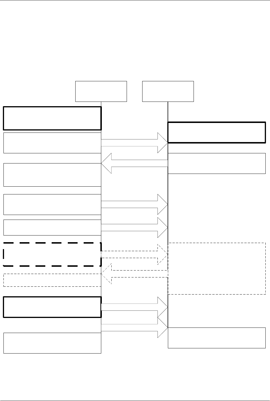
INS13478-5 Z-Wave 500 Series Appl. Programmers Guide v6.71.01 2017-02-28
Sigma Designs Inc.
Application Note: Controller Shift Implementation
Page 419 of 431
6 APPLICATION NOTE: CONTROLLER SHIFT IMPLEMENTATION
This note describes how a controller is able to include a new controller that after the inclusion (add) will
become the primary controller in the network. The controller that is taking over the primary functionality
should just enter learn mode like when it is to be included in a network. The existing primary controller
makes the controller change by calling ZW_ControllerChange(CONTROLLER_CHANGE_START,..). )
After a successfull change, the controller that called ZW_ControllerChange will be secondary and no
longer able to include devices.
Controller that
initiate the
controller change
Controller that
is to become
primary
Assign ID to node
Node Information Frame
ZW_REPLICATION_SEND
CMD_COMPLETE
Transfer end
Application calls:
ZW_ControllerChange(
CONTROLLER_CHANGE_START,
LearnHandler)
Protocol calls LearnHandler with:
ADD_NODE_STATUS_LEARN_READY
(Signal to user that Ctrl is
ready to receive NodeInfo frame)
Application call:
ZW_SetLearnMode(TRUE,Callback)
Protcocol call Callback with:
LEARN_MODE_STARTED
Protocol calls LearnHandler with
ADD_NODE_STATUS_NODE_FOUND
Protocol call
Callback with status
LEARN_MODE_DONE
Protocol calls LearnHandler with
ADD_NODE_STATUS_ADDING_CONTROLLER
Protocol calls LearnHandler with
ADD_NODE_STATUS_PROTOCOL_DONE
Application calls:
ZW_ControllerChange(
CONTROLLER_CHANGE_STOP,LearnHandl
er)
Protocol calls LearnHandler with
ADD_NODE_STATUS_DONE
Other Protocol Data
Application calls:
ZW_ReplicationSend(..,Func)
Protocol calls Func with:
ZW_REPLICATION_COMMAND_COMPLETE
Protocol calls
ApplicationCommandHandler with
Payload from ZW_REPL.._SEND
Application should handle data
and respond with:
ZW_ReplicationReceiveComplete
Change Status
Transfer Presentation
Figure 46. Controller shift frame flow

INS13478-5 Z-Wave 500 Series Appl. Programmers Guide v6.71.01 2017-02-28
Sigma Designs Inc.
Application Note: Z-Wave Protocol Versions
Page 420 of 431
7 APPLICATION NOTE: Z-WAVE PROTOCOL VERSIONS
The below table lists existing Z-Wave Protocol versions for a given Software Developer’s Kit version .
The Version Command Class [7] returns the Z-Wave Protocol version and sub version.
Software Developer’s Kit
Version
Z-Wave Protocol
Version
Z-Wave Protocol
Sub Version
6.70.01 Beta
4
45
6.70.00 Beta
4
28
6.61.00
4
33
6.60.00 Beta
4
12
6.51.09
4
38
6.51.08
4
34
6.51.07
4
24
6.51.06
4
05
6.51.04
4
01
6.51.03
3
99
6.51.02
3
95
6.51.01
3
92
6.51.00
3
83
6.50.01
3
79
6.50.00
3
71
6.11.01 (JP)
3
53
6.11.00 (JP)
3
45
6.10.01 (JP)
3
38
6.10.00
3
35
6.02.00
3
41
6.01.03
3
37
6.01.02
3
33
6.01.01 (2-ch)
3
26
6.01.00
3
10
6.00.05 Beta 1
3
07
6.00.04 Beta 1
3
06
6.00 Beta 1 Patch 3
3
04
6.00 Beta 1 Patch 2
3
03
6.00 Beta 1 Patch 1
2
99
6.00 Beta 1
2
96
5.03.00
3
28
5.02 Patch 3
2
78
5.02 Patch 2
2
64
5.02 Patch 1
2
51
5.02
2
48
5.01
2
36
5.00 Beta 1 Patch 1
2
22
5.00 Beta 1
2
16
4.55.00
3
67
4.54.02
3
52
4.54.01
3
42
4.54.00
3
40
4.53.01
3
36
4.53.00
3
34
4.52.01
3
22
4.52.00
3
20
4.51
2
97

INS13478-5 Z-Wave 500 Series Appl. Programmers Guide v6.71.01 2017-02-28
Sigma Designs Inc.
Application Note: Z-Wave Protocol Versions
Page 421 of 431
Table 27, Z-Wave Protocol version for a given Software Developer’s Kit version
Warning: Products can only be Z-Wave certified based on matured versions of the Z-Wave Protocol, i.e.
Developer’s Kit having versions different from x.y0.
4.50 Beta 1 Patch 1
2
79
4.50 Beta 1
2
74
4.30 Beta 1
2
30
4.28
2
67
4.27
2
40
4.26
2
32
4.25
2
31
4.24 Patch 1
2
28
4.24
2
24
4.23
2
17
4.22
2
09
4.21
2
06
4.20
1
97
4.11
1
91
4.10
1
78
4.07
2
27
4.06
2
23
4.05
2
07
4.04
1
99
4.03
1
81
4.02
1
69
4.01
1
68
4.00
1
59
3.40
1
53
3.31
1
44
3.30
1
37
3.22
1
39
3.21
1
25
3.20
1
21

INS13478-5 Z-Wave 500 Series Appl. Programmers Guide v6.71.01 2017-02-28
Sigma Designs Inc.
References
Page 422 of 431
8 REFERENCES
[1] SD, SDS10242, Software Design Specification, Z-Wave Device Class Specification.
[2] SD, INS12350, Instruction, Serial API Host Appl. Prg. Guide.
[3] SD, INS11681, Instruction, 500 Series Z-Wave Chip Programming Mode.
[4] SD, SDS11846, Software Design Specification, Z-Wave+ Role Type Specification.
[5] SD, SDS11847, Software Design Specification, Z-Wave+ Device Type Specification.
[6] SD, SDS12657, Software Design Specification, Z-Wave Command Class Specification, A-M.
[7] SD, SDS12652, Software Design Specification, Z-Wave Command Class Specification, N-Z.
[8] SD, INS10679, Instruction, Z-Wave Programmer User Guide.
[9] SD, INS12366, Instruction, Working in 500 Series Environment User Guide.
[10] SD, APL12665, Application Note, Battery Powered Applications Using 500 Series Z-Wave Single
Chip.
[11] SD, APL12678, Application Note, 500 Series Z-Wave Single Chip ADC.
[12] IETF RFC 2119, Key words for use in RFC’s to Indicate Requirement Levels,
http://tools.ietf.org/pdf/rfc2119.pdf.
[13] SD, INS13477, Instruction, Z-Wave 500 SDK Contents Kit v6.70.0x.
[14] SD, APL12304, Application Note, ZM4125C with External RF Front-End.
[15] SD, INS13114, Instruction, PC Based Controller v5 User Guide.
[16] SD, INS12213, Instruction, 500 Series Integration Guide.
[17] SD, SDS12467, Software Design Specification, 500 Series Z-Wave Chip NVR Flash Page
Contents.

INS13478-5 Z-Wave 500 Series Appl. Programmers Guide v6.71.01 2017-02-28
Sigma Designs Inc.
Index
Page 423 of 431
INDEX
A
App_RFSetup.c ....................................................................................................................................... 412
APPL_NODEPARM_MAX ................................................................................................................... 37, 48
Application area in non volatile memory .................................................................................................. 141
Application Priority Route ............................................................................................................................ 6
ApplicationCommandHandler (Not Bridge Controller library) .................................................................... 32
ApplicationCommandHandler_Bridge (Only bridge controller library) ....................................................... 42
ApplicationControllerUpdate ........................................................................................ 22, 62, 376, 414, 416
ApplicationControllerUpdate (Only controller libraries) ............................................................................. 40
ApplicationInitHW ...................................................................................................................................... 28
ApplicationInitSW ....................................................................................................................................... 29
ApplicationNodeInformation ...................................................................................................................... 35
ApplicationPoll ........................................................................................................................................... 31
ApplicationRfNotify .................................................................................................................................... 45
ApplicationSecureAuthenticationRequested (Only slave libraries) ........................................................... 47
ApplicationSecureCommandsSupported (Only slave libraries) ................................................................ 48
ApplicationSecureKeysRequested (Only slave libraries) .......................................................................... 46
ApplicationSecurityEvent(Only slave libraries) .......................................................................................... 49
ApplicationSlaveNodeInformation (Only bridge controller library) ............................................................. 44
ApplicationSlaveUpdate .......................................................................................................................... 408
ApplicationSlaveUpdate (Only slave libraries) .......................................................................................... 39
ApplicationTestPoll .................................................................................................................................... 30
Auto Program Mode................................................................................................................................. 323
C
Critical memory ........................................................................................................................................ 160
E
Enhanced 232 Slave................................................................................................................................ 341
EXT1 ........................................................................................................................................................ 160
External NVM ............................................................................................................................................. 12
External NVM ............................................................................................................................................. 23
F
Far keyword ............................................................................................................................................. 141
FCC compliance test ............................................................................................................................... 413
FLASH_APPL_LOW_POWER_OFFS_x................................................................................................. 412
FLASH_APPL_NORM_POWER_OFFS_x .............................................................................................. 412
FLASH_APPL_PLL_STEPUP_OFFS ....................................................................................................... 45
funcID ........................................................................................................................................................ 63
G
GPTimer .................................................................................................................................................... 10
I
Inclusion controller ............................................................................................................................. 22, 416
Interrupt ..................................................................................................................................................... 10
Interrupt service routines ........................................................................................................................... 10

INS13478-5 Z-Wave 500 Series Appl. Programmers Guide v6.71.01 2017-02-28
Sigma Designs Inc.
Index
Page 424 of 431
L
Last Working Route ..................................................................................................................................... 6
Listening flag .............................................................................................................................................. 35
M
MemoryGetBuffer .................................................................................................................................... 145
MemoryGetByte ....................................................................................................................................... 143
MemoryGetID .......................................................................................................................................... 142
MemoryPutBuffer ..................................................................................................................................... 146
MemoryPutByte ....................................................................................................................................... 144
N
Next to Last Working Route ......................................................................................................................... 6
Node Information Frame .................................................................................................................... 35, 354
NVM_ext_read_long_buffer ..................................................................................................................... 154
NVM_ext_read_long_byte ....................................................................................................................... 152
NVM_ext_write_long_buffer .................................................................................................................... 155
NVM_ext_write_long_byte ....................................................................................................................... 153
NVM_get_id ............................................................................................................................................. 151
O
OTW......................................................................................................................................................... 119
Over The Wire ......................................................................................................................................... 119
P
PIN_GET ................................................................................................................................................. 140
PIN_HIGH ................................................................................................................................................ 138
PIN_IN ..................................................................................................................................................... 136
PIN_LOW ................................................................................................................................................. 137
PIN_OUT ................................................................................................................................................. 135
PIN_TOGGLE .......................................................................................................................................... 139
Power down modes ................................................................................................................................. 160
Primary controller ......................................................................................................................... 14, 22, 414
Priority Route ........................................................................................................................................... 353
Production test ........................................................................................................................................... 30
R
Random number generator ....................................................................................................................... 55
Response routes .......................................................................................................................................... 6
Return route ............................................................................................................................................... 86
RF low power transmit levels ................................................................................................................... 412
RF normal power transmit levels ............................................................................................................. 412
Routing slave ........................................................................................................................................... 417
Routing Slave .......................................................................................................................................... 341
S
SD3502 .................................................................................................................................................... 206
SerialAPI_ApplicationNodeInformation ..................................................................................................... 37
SerialAPI_ApplicationSlaveNodeInformation ............................................................................................ 44
SIS ............................................................................................................................................................. 62
SIS ............................................................................................................................................................. 26
SIS ........................................................................................................................................................... 416
Software Developer’s Kit version ............................................................................................................. 420

INS13478-5 Z-Wave 500 Series Appl. Programmers Guide v6.71.01 2017-02-28
Sigma Designs Inc.
Index
Page 425 of 431
Source routing ............................................................................................................................................. 5
Static ID Server ........................................................................................................................................ 414
Static update controller .............................................................................................................................. 22
Stop mode ............................................................................................................................................... 160
Stop mode ............................................................................................................................................... 161
SUC ........................................................................................................................................................... 62
SUC ID Server ..................................................................................................................................... 22, 26
SUC/SIS node ......................................................................................................................................... 341
T
Timer 0 ....................................................................................................................................................... 10
Timer 1 ....................................................................................................................................................... 10
TimerCancel ............................................................................................................................................ 159
TimerRestart ............................................................................................................................................ 158
TimerStart ................................................................................................................................................ 157
TRANSMIT_OPTION_EXPLORE ........................................................................................................... 101
TXnormal Power ...................................................................................................................................... 413
W
Watchdog ................................................................................................................................................... 76
Wut fast mode .......................................................................................................................................... 161
Wut mode ................................................................................................................................................ 161
WUT mode ............................................................................................................................................... 160
Z
ZM5101 .................................................................................................................................................... 206
ZM5202 .................................................................................................................................................... 206
ZW_ GetBackgroundRSSI ......................................................................................................................... 52
ZW_ADC_auto_zero_set ......................................................................................................................... 201
ZW_ADC_buffer_enable ......................................................................................................................... 200
ZW_ADC_enable ..................................................................................................................................... 192
ZW_ADC_init ........................................................................................................................................... 188
ZW_ADC_int_clear .................................................................................................................................. 197
ZW_ADC_int_enable ............................................................................................................................... 196
ZW_ADC_is_fired .................................................................................................................................... 198
ZW_ADC_pin_select ............................................................................................................................... 193
ZW_ADC_power_enable ......................................................................................................................... 191
ZW_ADC_resolution_set ......................................................................................................................... 202
ZW_ADC_result_get ................................................................................................................................ 199
ZW_ADC_threshold_mode_set ............................................................................................................... 194
ZW_ADC_threshold_set .......................................................................................................................... 195
ZW_ADD_NODE_TO_NETWORK (Macro) ............................................................................................ 326
ZW_AddNodeToNetwork ......................................................................................................................... 326
ZW_AES_active_get................................................................................................................................ 262
ZW_AES_ecb .......................................................................................................................................... 266
ZW_AES_ecb_dma ................................................................................................................................. 266
ZW_AES_ecb_get ................................................................................................................................... 259
ZW_AES_ecb_set ................................................................................................................................... 258
ZW_AES_enable ..................................................................................................................................... 260
ZW_AES_int_clear .................................................................................................................................. 265
ZW_AES_int_enable ............................................................................................................................... 263
ZW_AES_int_get ..................................................................................................................................... 264
ZW_AES_swap_data............................................................................................................................... 261
ZW_ARE_NODES_NEIGHBOURS(Macro) ............................................................................................ 338
ZW_AreNodesNeighbours ....................................................................................................................... 338

INS13478-5 Z-Wave 500 Series Appl. Programmers Guide v6.71.01 2017-02-28
Sigma Designs Inc.
Index
Page 426 of 431
ZW_ASSIGN_RETURN_ROUTE (Macro) .............................................................................................. 339
ZW_ASSIGN_SUC_RETURN_ROUTE (Macro) ..................................................................................... 341
ZW_AssignPriorityReturnRoute ............................................................................................................... 342
ZW_AssignPrioritySUCReturnRoute ....................................................................................................... 344
ZW_AssignReturnRoute .......................................................................................................................... 339
ZW_AssignSUCReturnRoute .................................................................................................................. 341
ZW_CheckCrc16 ..................................................................................................................................... 324
ZW_ClearNetworkStats ............................................................................................................................. 82
ZW_ClearTxTimers .................................................................................................................................... 80
ZW_CONTROLLER_CHANGE (Macro).................................................................................................. 346
ZW_ControllerChange ..................................................................................................................... 346, 419
ZW_CREATE_NEW_PRIMARY_CTRL (Macro) ..................................................................................... 388
ZW_CreateCrc16 ..................................................................................................................................... 325
ZW_CreateNewPrimaryCtrl ..................................................................................................................... 388
ZW_DEBUG_CMD_INIT (Macro) ............................................................................................................ 411
ZW_DEBUG_CMD_POLL (Macro) ......................................................................................................... 412
ZW_DebugInit .......................................................................................................................................... 411
ZW_DebugPoll ......................................................................................................................................... 412
ZW_DELETE_RETURN_ROUTE (Macro) .............................................................................................. 348
ZW_DELETE_SUC_RETURN_ROUTE (Macro) .................................................................................... 349
ZW_DeleteReturnRoute .......................................................................................................................... 348
ZW_DeleteSUCReturnRoute ................................................................................................................... 349
ZW_EEPROM_INIT (Macro) ................................................................................................................... 147
ZW_EepromInit ........................................................................................................................................ 147
ZW_ExploreRequestExclusion .................................................................................................................. 51
ZW_ExploreRequestInclusion ................................................................................................................... 50
ZW_FinishSerialIf .................................................................................................................................... 314
ZW_FirmwareUpdate_NVM_Get_NEWIMAGE ...................................................................................... 122
ZW_FirmwareUpdate_NVM_Init .............................................................................................................. 120
ZW_FirmwareUpdate_NVM_isValidCRC16 ............................................................................................ 124
ZW_FirmwareUpdate_NVM_Set_NEWIMAGE ....................................................................................... 121
ZW_FirmwareUpdate_NVM_UpdateCRC16 ........................................................................................... 123
ZW_FirmwareUpdate_NVM_Write .......................................................................................................... 125
ZW_FLASH_auto_prog_set .................................................................................................................... 323
ZW_FLASH_code_page_prog ................................................................................................................ 322
ZW_FLASH_code_prog_lock .................................................................................................................. 320
ZW_FLASH_code_prog_unlock .............................................................................................................. 319
ZW_FLASH_code_sector_erase ............................................................................................................. 321
ZW_GET_CONTROLLER_CAPABILITIES (Macro) ............................................................................... 350
ZW_GET_NEIGHBOR_COUNT (Macro) ................................................................................................ 351
ZW_GET_NODE_STATE (Macro) .......................................................................................................... 354
ZW_GET_PROTOCOL_STATUS (Macro) ................................................................................................ 54
ZW_GET_RANDOM_WORD (Macro) ....................................................................................................... 55
ZW_GET_ROUTING_INFO (Macro) ....................................................................................................... 355
ZW_GET_SUC_NODEID (Macro) ................................................................................................... 357, 403
ZW_GET_VIRTUAL_NODES (Macro) .................................................................................................... 396
ZW_GetControllerCapabilities ................................................................................................................. 350
ZW_GetDefaultPowerLevels ................................................................................................................... 117
ZW_GetNeighborCount ........................................................................................................................... 351
ZW_GetNetworkStats ................................................................................................................................ 81
ZW_GetNodeProtocolInfo ....................................................................................................................... 354
ZW_GetPriorityRoute............................................................................................................................... 352
ZW_GetProtocolStatus .............................................................................................................................. 54
ZW_GetRandomWord ............................................................................................................................... 55
ZW_GetRoutingInfo ................................................................................................................................. 355
ZW_GetSecurityKeys (Only slave libraries) ............................................................................................ 250
ZW_GetSecurityS2PublicDSK(Only slave libraries) ................................................................................ 253

INS13478-5 Z-Wave 500 Series Appl. Programmers Guide v6.71.01 2017-02-28
Sigma Designs Inc.
Index
Page 427 of 431
ZW_GetSUCNodeID........................................................................................................................ 357, 403
ZW_GetTxTimers ...................................................................................................................................... 79
ZW_GetVirtualNodes ............................................................................................................................... 396
ZW_GPTIMER_enable ............................................................................................................................ 238
ZW_GPTIMER_get .................................................................................................................................. 242
ZW_GPTIMER_init .................................................................................................................................. 234
ZW_GPTIMER_int_clear ......................................................................................................................... 235
ZW_GPTIMER_int_enable ...................................................................................................................... 237
ZW_GPTIMER_int_get ............................................................................................................................ 236
ZW_GPTIMER_pause ............................................................................................................................. 239
ZW_GPTIMER_reload_get ...................................................................................................................... 241
ZW_GPTIMER_reload_set ...................................................................................................................... 240
ZW_InitSerialIf ......................................................................................................................................... 313
ZW_IOS_enable ...................................................................................................................................... 132
ZW_IOS_get ............................................................................................................................................ 134
ZW_IOS_set ............................................................................................................................................ 133
ZW_IR_disable ........................................................................................................................................ 304
ZW_IR_learn_data ................................................................................................................................... 300
ZW_IR_learn_init ..................................................................................................................................... 298
ZW_IR_learn_status_get ......................................................................................................................... 301
ZW_IR_status_clear ................................................................................................................................ 303
ZW_IR_tx_data ........................................................................................................................................ 296
ZW_IR_tx_init .......................................................................................................................................... 294
ZW_IR_tx_status_get .............................................................................................................................. 297
ZW_IS_FAILED_NODE_ID (Macro) ........................................................................................................ 358
ZW_IS_NODE_WITHIN_DIRECT_RANGE (Macro) ............................................................................... 404
ZW_IS_VIRTUAL_NODE (Macro) ........................................................................................................... 395
ZW_IsFailedNode .................................................................................................................................... 358
ZW_IsNodeWithinDirectRange ................................................................................................................ 404
ZW_IsPrimaryCtrl .................................................................................................................................... 359
ZW_IsVirtualNode .................................................................................................................................... 395
ZW_KS_enable ........................................................................................................................................ 310
ZW_KS_init .............................................................................................................................................. 308
ZW_KS_pd_enable.................................................................................................................................. 311
ZW_LED_data_busy................................................................................................................................ 285
ZW_LED_init ............................................................................................................................................ 282
ZW_LED_waveform_set .......................................................................................................................... 284
ZW_LED_waveforms_set ........................................................................................................................ 283
ZW_LOCK_ROUTE (Macro) ........................................................................................................... 112, 113
ZW_LockRoute (Only controllers) ........................................................................................................... 112
ZW_LockRoute (Only slaves) .................................................................................................................. 113
ZW_MEM_FLUSH (Macro) ..................................................................................................................... 148
ZW_MEM_GET_BUFFER (Macro) ......................................................................................................... 145
ZW_MEM_GET_BYTE (Macro) .............................................................................................................. 143
ZW_MEM_PUT_BUFFER (Macro) .......................................................................................................... 146
ZW_MEM_PUT_BYTE (Macro) ............................................................................................................... 144
ZW_MEMORY_GET_ID (Macro) ............................................................................................................ 142
ZW_MemoryFlush ................................................................................................................................... 148
ZW_NODE_MASK_BITS_IN (Macro) ..................................................................................................... 130
ZW_NODE_MASK_CLEAR (Macro) ....................................................................................................... 129
ZW_NODE_MASK_CLEAR_BIT (Macro) ............................................................................................... 128
ZW_NODE_MASK_NODE_IN (Macro) ................................................................................................... 131
ZW_NODE_MASK_SET_BIT (Macro) .................................................................................................... 127
ZW_NodeMaskBitsIn ............................................................................................................................... 130
ZW_NodeMaskClear ............................................................................................................................... 129
ZW_NodeMaskClearBit ........................................................................................................................... 128
ZW_NodeMaskNodeIn ............................................................................................................................ 131

INS13478-5 Z-Wave 500 Series Appl. Programmers Guide v6.71.01 2017-02-28
Sigma Designs Inc.
Index
Page 428 of 431
ZW_NodeMaskSetBit .............................................................................................................................. 127
ZW_NVRCheck ....................................................................................................................................... 150
ZW_NVRGetValue ................................................................................................................................... 149
ZW_PRIMARYCTRL (Macro) .................................................................................................................. 359
ZW_PWM_enable .................................................................................................................................... 244
ZW_PWM_init .......................................................................................................................................... 243
ZW_PWM_int_clear ................................................................................................................................. 245
ZW_PWM_int_enable .............................................................................................................................. 247
ZW_PWM_int_get .................................................................................................................................... 246
ZW_PWM_waveform_get ........................................................................................................................ 249
ZW_PWM_waveform_set ........................................................................................................................ 248
ZW_Random .............................................................................................................................................. 57
ZW_RANDOM (Macro) .............................................................................................................................. 57
ZW_REDISCOVERY_NEEDED (Macro) ................................................................................................ 405
ZW_RediscoveryNeeded ......................................................................................................................... 405
ZW_RegisterNoiseLevelCallback .............................................................................................................. 58
ZW_REMOVE_FAILED_NODE_ID (Macro) ........................................................................................... 360
ZW_REMOVE_NODE_FROM_NETWORK (Macro) .............................................................................. 364
ZW_REMOVE_NODE_ID_FROM_NETWORK (Macro) ......................................................................... 373
ZW_RemoveFailedNode ......................................................................................................................... 360
ZW_RemoveNodeFromNetwork ............................................................................................................. 364
ZW_RemoveNodeIDFromNetwork .......................................................................................................... 373
ZW_REPLACE_FAILED_NODE (Macro) ................................................................................................ 362
ZW_ReplaceFailedNode ......................................................................................................................... 362
ZW_REPLICATION_COMMAND_COMPLETE (Macro) ......................................................................... 374
ZW_REPLICATION_SEND_DATA (Macro) ............................................................................................ 375
ZW_ReplicationReceiveComplete ........................................................................................................... 374
ZW_ReplicationSend ............................................................................................................................... 375
ZW_REQUEST_NETWORK_UPDATE (Macro) ....................................................................................... 62
ZW_REQUEST_NEW_ROUTE_DESTINATIONS (Macro) .................................................................... 407
ZW_REQUEST_NODE_INFO (Macro) ........................................................................................... 376, 408
ZW_REQUEST_NODE_NEIGHBOR_UPDATE (Macro) ........................................................................ 377
ZW_RequestNetWorkUpdate ...................................................................................... 40, 62, 341, 416, 417
ZW_RequestNewRouteDestinations ....................................................................................................... 407
ZW_RequestNodeInfo ..................................................................................................................... 376, 408
ZW_RequestNodeNeighborUpdate ......................................................................................................... 377
ZW_RF_POWERLEVEL_GET (Macro)..................................................................................................... 61
ZW_RF_POWERLEVEL_REDISCOVERY_SET (Macro) ......................................................................... 64
ZW_RF_POWERLEVEL_SET (Macro) ..................................................................................................... 60
ZW_RFPowerLevelGet .............................................................................................................................. 61
ZW_RFPowerlevelRediscoverySet ........................................................................................................... 64
ZW_RFPowerLevelSet .............................................................................................................................. 60
ZW_s2_inclusion_init(Only slave libraries) .............................................................................................. 251
ZW_SEND_DATA (Macro) ........................................................................................................................ 84
ZW_SEND_DATA_ABORT (Macro) ........................................................................................................ 111
ZW_SEND_DATA_BRIDGE (Macro) ...................................................................................................... 101
ZW_SEND_DATA_MULTI (Macro) ......................................................................................................... 104
ZW_SEND_DATA_MULTI_BRIDGE (Macro) ......................................................................................... 108
ZW_SEND_NODE_INFO (Macro) ............................................................................................................. 66
ZW_SEND_SLAVE_NODE_INFO (Macro) ............................................................................................. 390
ZW_SEND_SUC_ID (Macro) .................................................................................................................. 379
ZW_SEND_TEST_FRAME (Macro) .......................................................................................................... 68
ZW_SendConst ....................................................................................................................................... 114
ZW_SendData ........................................................................................................................................... 84
ZW_SendData_Bridge ............................................................................................................................. 101
ZW_SendDataAbort................................................................................................................................. 111
ZW_SendDataEx (Only slave libraries) ..................................................................................................... 94

INS13478-5 Z-Wave 500 Series Appl. Programmers Guide v6.71.01 2017-02-28
Sigma Designs Inc.
Index
Page 429 of 431
ZW_SendDataMulti.................................................................................................................................. 104
ZW_SendDataMulti_Bridge ..................................................................................................................... 108
ZW_SendDataMultiEx (Only slave libraries) ........................................................................................... 106
ZW_SendNodeInformation ........................................................................................................................ 66
ZW_SendSlaveNodeInformation ............................................................................................................. 390
ZW_SendSUCID ...................................................................................................................................... 379
ZW_SendTestFrame ................................................................................................................................. 68
ZW_SerialCheck ...................................................................................................................................... 315
ZW_SerialGetByte ................................................................................................................................... 316
ZW_SerialPutByte ................................................................................................................................... 317
ZW_SET_DEFAULT (Macro) .......................................................................................................... 380, 400
ZW_SET_EXT_INT_LEVEL (Macro) ......................................................................................................... 70
ZW_SET_LEARN_MODE (Macro) .................................................................................................. 381, 400
ZW_SET_PROMISCUOUS_MODE (Macro) ............................................................................................ 71
ZW_SET_ROUTING_INFO (Macro) ....................................................................................................... 384
ZW_SET_RX_MODE (Macro) ................................................................................................................... 72
ZW_SET_SLAVE_LEARN_MODE (Macro) ............................................................................................ 392
ZW_SET_SLEEP_MODE (Macro) .......................................................................................................... 160
ZW_SET_SUC_NODE_ID (Macro) ......................................................................................................... 386
ZW_SET_WUT_TIMEOUT (Macro) ........................................................................................................ 163
ZW_SetDefault ................................................................................................................................ 380, 400
ZW_SetDefaultPowerLevels .................................................................................................................... 118
ZW_SetExtIntLevel .................................................................................................................................... 70
ZW_SetLearnMode.......................................................................................................................... 381, 400
ZW_SetListenBeforeTalkThreshold ......................................................................................................... 115
ZW_SetPriorityRoute ............................................................................................................................... 353
ZW_SetPromiscuousMode (Only controller libraries) ............................................................................... 71
ZW_SetRFReceiveMode ........................................................................................................................... 72
ZW_SetRoutingInfo ................................................................................................................................. 384
ZW_SetRoutingMAX................................................................................................................................ 385
ZW_SetSecurityS0NetworkKey (Only enhanced 232 slave library) ........................................................ 255
ZW_SetSecurityS2CriticalNodeID (Only routing slave library) ................................................................ 253
ZW_SetSecurityS2InclusionPublicDSK_CSA(Only slave libraries) ........................................................ 252
ZW_SetSlaveLearnMode ........................................................................................................................ 392
ZW_SetSleepMode.................................................................................................................................. 160
ZW_SetSUCNodeID ................................................................................................................................ 386
ZW_SetWutTimeout ................................................................................................................................ 163
ZW_SPI0_active_get ............................................................................................................................... 170
ZW_SPI0_enable ..................................................................................................................................... 167
ZW_SPI0_init ........................................................................................................................................... 165
ZW_SPI0_int_clear .................................................................................................................................. 174
ZW_SPI0_int_enable ............................................................................................................................... 172
ZW_SPI0_int_get ..................................................................................................................................... 173
ZW_SPI0_rx_get ..................................................................................................................................... 168
ZW_SPI0_tx_set ...................................................................................................................................... 169
ZW_SPI1_active_get ............................................................................................................................... 179
ZW_SPI1_coll_get ........................................................................................................................... 171, 180
ZW_SPI1_enable ..................................................................................................................................... 176
ZW_SPI1_init ........................................................................................................................................... 175
ZW_SPI1_int_clear .................................................................................................................................. 183
ZW_SPI1_int_enable ............................................................................................................................... 181
ZW_SPI1_int_get ..................................................................................................................................... 182
ZW_SPI1_rx_get ..................................................................................................................................... 177
ZW_SPI1_tx_set ...................................................................................................................................... 178
ZW_STORE_HOME_ID (Macro) ............................................................................................................. 399
ZW_STORE_NODE_INFO (Macro) ........................................................................................................ 398
ZW_StoreHomeID ................................................................................................................................... 399

INS13478-5 Z-Wave 500 Series Appl. Programmers Guide v6.71.01 2017-02-28
Sigma Designs Inc.
Index
Page 430 of 431
ZW_StoreNodeInfo .................................................................................................................................. 398
ZW_TIMER_CANCEL (Macro) ................................................................................................................ 159
ZW_TIMER_RESTART (Macro) .............................................................................................................. 158
ZW_TIMER_START (Macro) ................................................................................................................... 157
ZW_TIMER0_ENABLE / ZW_TIMER1_ENABLE (Macro) ...................................................................... 227
ZW_TIMER0_ext_clk / ZW_TIMER1_ext_clk ......................................................................................... 228
ZW_TIMER0_HIGHBYTE_GET / ZW_TIMER1_HIGHBYTE_GET (Macro) ........................................... 231
ZW_TIMER0_HIGHBYTE_SET / ZW_TIMER1_HIGHBYTE_SET (Macro) ........................................... 230
ZW_TIMER0_init (Macro) ........................................................................................................................ 223
ZW_TIMER0_INT_CLEAR / ZW_TIMER1_INT_CLEAR (Macro) ........................................................... 225
ZW_TIMER0_INT_ENABLE / ZW_TIMER1_INT_ENABLE (Macro) ...................................................... 226
ZW_TIMER0_LOWBYTE_GET / ZW_TIMER1_LOWBYTE_GET (Macro) ........................................... 232
ZW_TIMER0_LOWBYTE_SET / ZW_TIMER1_LOWBYTE_SET (Macro) ............................................. 229
ZW_TIMER0_word_get / ZW_TIMER1_word_get .................................................................................. 233
ZW_TIMER1_init ..................................................................................................................................... 222
ZW_TIMER1_init (Macro) ........................................................................................................................ 224
ZW_Transport_CommandClassVersionGet ............................................................................................ 116
ZW_TRIAC_dimlevel_set ........................................................................................................................ 277
ZW_TRIAC_enable.................................................................................................................................. 276
ZW_TRIAC_init ........................................................................................................................................ 268
ZW_TRIAC_int_clear ............................................................................................................................... 280
ZW_TRIAC_int_enable ............................................................................................................................ 278
ZW_TRIAC_int_get.................................................................................................................................. 279
ZW_TX_COUNTER (Macro) ................................................................................................................... 397
ZW_Type_Library ...................................................................................................................................... 73
ZW_TYPE_LIBRARY (Macro) ................................................................................................................... 73
ZW_UART0_init ....................................................................................................................................... 206
ZW_UART0_INT_DISABLE (Macro) ....................................................................................................... 214
ZW_UART0_INT_ENABLE (Macro) ........................................................................................................ 213
ZW_UART0_rx_data_get ........................................................................................................................ 207
ZW_UART0_rx_data_wait_get ................................................................................................................ 208
ZW_UART0_rx_enable ........................................................................................................................... 220
ZW_UART0_rx_int_clear ......................................................................................................................... 217
ZW_UART0_rx_int_get............................................................................................................................ 219
ZW_UART0_tx_active_get ...................................................................................................................... 209
ZW_UART0_tx_data_set ......................................................................................................................... 210
ZW_UART0_tx_enable ............................................................................................................................ 221
ZW_UART0_tx_int_clear ......................................................................................................................... 216
ZW_UART0_tx_int_get ............................................................................................................................ 218
ZW_UART0_tx_send_nl .......................................................................................................................... 215
ZW_UART0_tx_send_num ...................................................................................................................... 211
ZW_UART0_tx_send_str ......................................................................................................................... 212
ZW_UART1_init ....................................................................................................................................... 206
ZW_UART1_INT_DISABLE (Macro) ....................................................................................................... 214
ZW_UART1_INT_ENABLE (Macro) ........................................................................................................ 213
ZW_UART1_rx_data_get ........................................................................................................................ 207
ZW_UART1_rx_data_wait_get ................................................................................................................ 208
ZW_UART1_rx_enable ........................................................................................................................... 220
ZW_UART1_rx_int_clear ......................................................................................................................... 217
ZW_UART1_rx_int_get............................................................................................................................ 219
ZW_UART1_tx_active_get ...................................................................................................................... 209
ZW_UART1_tx_data_set ......................................................................................................................... 210
ZW_UART1_tx_enable ............................................................................................................................ 221
ZW_UART1_tx_int_clear ......................................................................................................................... 216
ZW_UART1_tx_int_get ............................................................................................................................ 218
ZW_UART1_tx_send_nl .......................................................................................................................... 215
ZW_UART1_tx_send_num ...................................................................................................................... 211

INS13478-5 Z-Wave 500 Series Appl. Programmers Guide v6.71.01 2017-02-28
Sigma Designs Inc.
Index
Page 431 of 431
ZW_UART1_tx_send_str ......................................................................................................................... 212
ZW_Version ............................................................................................................................................... 74
ZW_VERSION (Macro).............................................................................................................................. 74
ZW_VERSION_BETA (Macro) .................................................................................................................. 75
ZW_VERSION_MAJOR (Macro) ............................................................................................................... 75
ZW_VERSION_MAJOR / ZW_VERSION_MINOR / ZW_VERSION_BETA ............................................. 75
ZW_VERSION_MINOR (Macro) ............................................................................................................... 75
ZW_WATCHDOG_DISABLE (Macro) ....................................................................................................... 77
ZW_WATCHDOG_ENABLE (Macro) ........................................................................................................ 76
ZW_WATCHDOG_KICK (Macro) .............................................................................................................. 78
ZW_WatchDogDisable .............................................................................................................................. 77
ZW_WatchDogEnable ............................................................................................................................... 76
ZW_WatchDogKick .................................................................................................................................... 78
zwTransmitCount ..................................................................................................................................... 397
